cisco ucs c-series servers integrated management
TRANSCRIPT
Cisco UCS C-Series Servers Integrated Management Controller CLIConfiguration Guide, Release 1.5First Published: March 04, 2013
Last Modified: December 12, 2013
Americas HeadquartersCisco Systems, Inc.170 West Tasman DriveSan Jose, CA 95134-1706USAhttp://www.cisco.comTel: 408 526-4000 800 553-NETS (6387)Fax: 408 527-0883
Text Part Number: OL-28993-03

THE SPECIFICATIONS AND INFORMATION REGARDING THE PRODUCTS IN THIS MANUAL ARE SUBJECT TO CHANGE WITHOUT NOTICE. ALL STATEMENTS,INFORMATION, AND RECOMMENDATIONS IN THIS MANUAL ARE BELIEVED TO BE ACCURATE BUT ARE PRESENTED WITHOUT WARRANTY OF ANY KIND,EXPRESS OR IMPLIED. USERS MUST TAKE FULL RESPONSIBILITY FOR THEIR APPLICATION OF ANY PRODUCTS.
THE SOFTWARE LICENSE AND LIMITEDWARRANTY FOR THE ACCOMPANYING PRODUCT ARE SET FORTH IN THE INFORMATION PACKET THAT SHIPPED WITHTHE PRODUCT AND ARE INCORPORATED HEREIN BY THIS REFERENCE. IF YOU ARE UNABLE TO LOCATE THE SOFTWARE LICENSE OR LIMITED WARRANTY,CONTACT YOUR CISCO REPRESENTATIVE FOR A COPY.
The Cisco implementation of TCP header compression is an adaptation of a program developed by the University of California, Berkeley (UCB) as part of UCB's public domain versionof the UNIX operating system. All rights reserved. Copyright © 1981, Regents of the University of California.
NOTWITHSTANDINGANYOTHERWARRANTYHEREIN, ALL DOCUMENT FILES AND SOFTWARE OF THESE SUPPLIERS ARE PROVIDED “AS IS"WITH ALL FAULTS.CISCO AND THE ABOVE-NAMED SUPPLIERS DISCLAIM ALL WARRANTIES, EXPRESSED OR IMPLIED, INCLUDING, WITHOUT LIMITATION, THOSE OFMERCHANTABILITY, FITNESS FORA PARTICULAR PURPOSEANDNONINFRINGEMENTORARISING FROMACOURSEOFDEALING, USAGE, OR TRADE PRACTICE.
IN NO EVENT SHALL CISCO OR ITS SUPPLIERS BE LIABLE FOR ANY INDIRECT, SPECIAL, CONSEQUENTIAL, OR INCIDENTAL DAMAGES, INCLUDING, WITHOUTLIMITATION, LOST PROFITS OR LOSS OR DAMAGE TO DATA ARISING OUT OF THE USE OR INABILITY TO USE THIS MANUAL, EVEN IF CISCO OR ITS SUPPLIERSHAVE BEEN ADVISED OF THE POSSIBILITY OF SUCH DAMAGES.
Any Internet Protocol (IP) addresses and phone numbers used in this document are not intended to be actual addresses and phone numbers. Any examples, command display output, networktopology diagrams, and other figures included in the document are shown for illustrative purposes only. Any use of actual IP addresses or phone numbers in illustrative content is unintentionaland coincidental.
Cisco and the Cisco logo are trademarks or registered trademarks of Cisco and/or its affiliates in the U.S. and other countries. To view a list of Cisco trademarks, go to this URL: http://www.cisco.com/go/trademarks. Third-party trademarks mentioned are the property of their respective owners. The use of the word partner does not imply a partnershiprelationship between Cisco and any other company. (1110R)
© 2009-2013 Cisco Systems, Inc. All rights reserved.
C O N T E N T S
P r e f a c e Preface xiii
Audience xiii
Conventions xiii
New and Changed Information for this Release xv
Related Cisco UCS Documentation xvii
C H A P T E R 1 Overview 1
Overview of the Cisco UCS C-Series Rack-Mount Servers 1
Overview of the Server Software 1
Cisco Integrated Management Controller 2
CIMC CLI 3
Command Modes 3
Command Mode Table 5
Complete a Command 8
Command History 8
Committing, Discarding, and Viewing Pending Commands 8
Command Output Formats 8
Online Help for the CLI 9
C H A P T E R 2 Installing the Server OS 11
OS Installation Methods 11
KVM Console 11
Installing an OS Using the KVM Console 12
PXE Installation Servers 12
Installing an OS Using a PXE Installation Server 12
Booting an Operating System from a USB Port 13
Cisco UCS C-Series Servers Integrated Management Controller CLI Configuration Guide, Release 1.5 OL-28993-03 iii

C H A P T E R 3 Managing the Server 15
Overview to DHCP User Friendliness 15
Toggling the Locator LED 16
Toggling the Locator LED for a Hard Drive 16
Managing the Server Boot Order 17
Server Boot Order 17
Configuring the Server Boot Order 17
Viewing the Actual Server Boot Order 18
Resetting the Server 19
Shutting Down the Server 19
Managing Server Power 20
Powering On the Server 20
Powering Off the Server 20
Power Cycling the Server 21
Configuring Power Policies 22
Viewing the Power Statistics 22
Power Capping Policy 23
Configuring the Power Cap Policy 23
Configuring the Power Restore Policy 25
Configuring Fan Policies 26
Fan Control Policies 26
Configuring a Fan Policy 27
Managing the Flexible Flash Controller 28
Cisco Flexible Flash 28
Upgrading from Single Card to Dual Card Mirroring with FlexFlash 30
Configuring the Flexible Flash Controller Properties 31
Booting from the Flexible Flash 32
Resetting the Flexible Flash Controller 33
Resetting the Configuration of the Cards in the Cisco Flexible Flash Controller 34
Retaining the Configuration of the Flexible Flash Controller 35
Configuring BIOS Settings 36
Viewing BIOS Status 36
Configuring Main BIOS Settings 37
Configuring Advanced BIOS Settings 38
Cisco UCS C-Series Servers Integrated Management Controller CLI Configuration Guide, Release 1.5iv OL-28993-03
Contents
Configuring Server Management BIOS Settings 39
Restoring BIOS Defaults 39
Restoring BIOS Manufacturing Custom Defaults 40
Updating Firmware on Server Components 41
C H A P T E R 4 Viewing Server Properties 43
Viewing Server Properties 43
Viewing CIMC Properties 44
Viewing CPU Properties 44
Viewing Memory Properties 45
Viewing Power Supply Properties 46
Viewing Storage Properties 46
Viewing Storage Adapter Properties 46
Viewing the Flexible Flash Controller Properties 48
Viewing Physical Drive Properties 49
Viewing Virtual Drive Properties 50
Viewing Nvidia GPU Card Information 51
Viewing PCI Adapter Properties 52
Viewing Network Related Properties 52
Viewing LOM Properties 52
C H A P T E R 5 Viewing Server Sensors 55
Viewing Power Supply Sensors 55
Viewing Fan Sensors 56
Viewing Temperature Sensors 56
Viewing Voltage Sensors 57
Viewing Current Sensors 58
Viewing Storage Sensors 58
C H A P T E R 6 Managing Remote Presence 61
Managing the Virtual KVM 61
KVM Console 61
Enabling the Virtual KVM 62
Disabling the Virtual KVM 62
Configuring the Virtual KVM 63
Cisco UCS C-Series Servers Integrated Management Controller CLI Configuration Guide, Release 1.5 OL-28993-03 v
Contents

Configuring Virtual Media 64
Configuring a CIMC-Mapped vMedia Volume 65
Viewing CIMC-Mapped vMedia Volume Properties 66
Removing a CIMC-Mapped Mounted vMedia Volume 67
Managing Serial over LAN 68
Serial Over LAN 68
Guidelines and Restrictions for Serial Over LAN 68
Configuring Serial Over LAN 68
Launching Serial Over LAN 70
C H A P T E R 7 Managing User Accounts 71
Configuring Local Users 71
LDAP Servers 72
Configuring the LDAP Server 73
Configuring LDAP in CIMC 74
Configuring LDAP Groups in CIMC 75
Viewing User Sessions 77
Terminating a User Session 77
C H A P T E R 8 Configuring Network-Related Settings 79
Server NIC Configuration 79
Server NICs 79
Configuring Server NICs 80
Configuring Common Properties 81
Configuring IPv4 82
Configuring the Server VLAN 84
Connecting to a Port Profile 85
Network Interface Configuration 86
Overview to Network Interface Configuration 86
Configuring Interface Properties 86
Network Security Configuration 87
Network Security 87
Configuring Network Security 87
Network Time Protocol Configuration 88
Configuring Network Time Protocol Settings 88
Cisco UCS C-Series Servers Integrated Management Controller CLI Configuration Guide, Release 1.5vi OL-28993-03
Contents
C H A P T E R 9 Managing Network Adapters 91
Overview of the Cisco UCS C-Series Network Adapters 91
Viewing Network Adapter Properties 93
Configuring Network Adapter Properties 93
Managing vHBAs 94
Guidelines for Managing vHBAs 94
Viewing vHBA Properties 95
Modifying vHBA Properties 96
Creating a vHBA 100
Deleting a vHBA 101
vHBA Boot Table 102
Viewing the Boot Table 102
Creating a Boot Table Entry 102
Deleting a Boot Table Entry 103
vHBA Persistent Binding 104
Enabling Persistent Binding 105
Disabling Persistent Binding 105
Rebuilding Persistent Binding 106
Managing vNICs 107
Guidelines for Managing vNICs 107
Viewing vNIC Properties 107
Modifying vNIC Properties 108
Creating a vNIC 113
Deleting a vNIC 114
Creating Cisco usNIC Using the CIMC CLI 115
Modifying a Cisco usNIC using the CIMC CLI 118
Viewing usNIC Properties 120
Deleting Cisco usNIC from a vNIC 121
Configuring iSCSI Boot Capability 122
Configuring iSCSI Boot Capability for vNICs 122
Configuring iSCSI Boot Capability on a vNIC 122
Deleting an iSCSI Boot Configuration for a vNIC 123
Managing VM FEX 124
Virtual Machine Fabric Extender 124
Cisco UCS C-Series Servers Integrated Management Controller CLI Configuration Guide, Release 1.5 OL-28993-03 vii
Contents
Viewing VM FEX Properties 124
VM FEX Settings 126
Managing Storage Adapters 129
Create Virtual Drive from Unused Physical Drives 129
Create Virtual Drive from an Existing Drive Group 131
Clearing Foreign Configuration 132
Deleting a Virtual Drive 133
Initializing a Virtual Drive 133
Set as Boot Drive 134
Modifying Attributes of a Virtual Drive 135
Making a Dedicated Hot Spare 136
Making a Global Hot Spare 136
Preparing a Drive for Removal 137
Removing a Drive from Hot Spare Pools 138
Undo Preparing a Drive for Removal 138
Enabling Auto Learn Cycles for the Battery Backup Unit 139
Disabling Auto Learn Cycles for the Battery Backup Unit 139
Starting a Learn Cycle for a Battery Backup Unit 140
Toggling the Locator LED for a Physical Drive 141
Viewing Storage Controller Logs 141
Backing Up and Restoring the Adapter Configuration 142
Exporting the Adapter Configuration 142
Importing the Adapter Configuration 143
Restoring Adapter Defaults 144
Managing Adapter Firmware 144
Adapter Firmware 144
Installing Adapter Firmware 144
Activating Adapter Firmware 145
Resetting the Adapter 146
C H A P T E R 1 0 Configuring Communication Services 147
Configuring HTTP 147
Configuring SSH 148
Configuring XML API 149
XML API for CIMC 149
Cisco UCS C-Series Servers Integrated Management Controller CLI Configuration Guide, Release 1.5viii OL-28993-03
Contents
Enabling XML API 149
Configuring IPMI 150
IPMI Over LAN 150
Configuring IPMI over LAN 150
Configuring SNMP 151
SNMP 151
Configuring SNMP Properties 151
Configuring SNMP Trap Settings 153
Sending a Test SNMP Trap Message 154
Configuring SNMPv3 Users 154
C H A P T E R 1 1 Managing Certificates 157
Managing the Server Certificate 157
Generating a Certificate Signing Request 157
Creating a Self-Signed Certificate 159
Uploading a Server Certificate 161
C H A P T E R 1 2 Configuring Platform Event Filters 163
Platform Event Filters 163
Enabling Platform Event Alerts 163
Disabling Platform Event Alerts 164
Configuring Platform Event Filters 164
Configuring Platform Event Trap Settings 166
Interpreting Platform Event Traps 167
C H A P T E R 1 3 CIMC Firmware Management 171
Overview of Firmware 171
Obtaining Firmware from Cisco 172
Installing CIMC Firmware from a Remote Server 173
Activating Installed CIMC Firmware 174
Installing BIOS Firmware from a Remote Server 176
C H A P T E R 1 4 Viewing Faults and Logs 179
Viewing the Faults and Logs Summary 179
CIMC Log 180
Cisco UCS C-Series Servers Integrated Management Controller CLI Configuration Guide, Release 1.5 OL-28993-03 ix
Contents
Viewing the CIMC Log 180
Clearing the CIMC Log 181
Configuring the CIMC Log Threshold 181
Sending the CIMC Log to a Remote Server 182
System Event Log 184
Viewing the System Event Log 184
Clearing the System Event Log 185
C H A P T E R 1 5 Server Utilities 187
Exporting Technical Support Data 187
Rebooting the CIMC 189
Clearing the BIOS CMOS 189
Recovering from a Corrupted BIOS 190
Resetting the CIMC to Factory Defaults 191
Exporting and Importing the CIMC Configuration 192
Exporting and Importing the CIMC Configuration 192
Exporting the CIMC Configuration 192
Importing a CIMC Configuration 193
Generating Non maskable Interrupts to the Host 194
A P P E N D I X A BIOS Parameters by Server Model 197
C22 and C24 Servers 197
Main BIOS Parameters for C22 and C24 Servers 197
Advanced BIOS Parameters for C22 and C24 Servers 198
Server Management BIOS Parameters for C22 and C24 Servers 214
C220 and C240 Servers 217
Main BIOS Parameters for C220 and C240 Servers 217
Advanced BIOS Parameters for C220 and C240 Servers 217
Server Management BIOS Parameters for C220 and C240 Servers 234
C260 Servers 237
Main BIOS Parameters for C260 Servers 237
Advanced BIOS Parameters for C260 Servers 237
Server Management BIOS Parameters for C260 Servers 247
C420 Servers 250
Main BIOS Parameters for C420 Servers 250
Cisco UCS C-Series Servers Integrated Management Controller CLI Configuration Guide, Release 1.5x OL-28993-03
Contents
Advanced BIOS Parameters for C420 Servers 251
Server Management BIOS Parameters for C420 Servers 267
C460 Servers 270
Main BIOS Parameters for C460 Servers 270
Advanced BIOS Parameters for C460 Servers 270
Server Management BIOS Parameters for C460 Servers 280
Cisco UCS C-Series Servers Integrated Management Controller CLI Configuration Guide, Release 1.5 OL-28993-03 xi
Contents

Cisco UCS C-Series Servers Integrated Management Controller CLI Configuration Guide, Release 1.5xii OL-28993-03
Contents

Preface
This preface includes the following sections:
• Audience, page xiii
• Conventions, page xiii
• New and Changed Information for this Release, page xv
• Related Cisco UCS Documentation, page xvii
AudienceThis guide is intended primarily for data center administrators with responsibilities and expertise in one ormore of the following:
• Server administration
• Storage administration
• Network administration
• Network security
ConventionsIndicationText Type
GUI elements such as tab titles, area names, and field labels appear in this font.
Main titles such as window, dialog box, and wizard titles appear in this font.
GUI elements
Document titles appear in this font.Document titles
In a Text-based User Interface, text the system displays appears in this font.TUI elements
Terminal sessions and information that the system displays appear in thisfont.
System output
Cisco UCS C-Series Servers Integrated Management Controller CLI Configuration Guide, Release 1.5 OL-28993-03 xiii
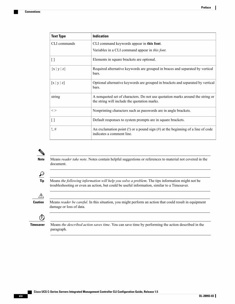
IndicationText Type
CLI command keywords appear in this font.
Variables in a CLI command appear in this font.
CLI commands
Elements in square brackets are optional.[ ]
Required alternative keywords are grouped in braces and separated by verticalbars.
{x | y | z}
Optional alternative keywords are grouped in brackets and separated by verticalbars.
[x | y | z]
A nonquoted set of characters. Do not use quotation marks around the string orthe string will include the quotation marks.
string
Nonprinting characters such as passwords are in angle brackets.< >
Default responses to system prompts are in square brackets.[ ]
An exclamation point (!) or a pound sign (#) at the beginning of a line of codeindicates a comment line.
!, #
Means reader take note. Notes contain helpful suggestions or references to material not covered in thedocument.
Note
Means the following information will help you solve a problem. The tips information might not betroubleshooting or even an action, but could be useful information, similar to a Timesaver.
Tip
Means reader be careful. In this situation, you might perform an action that could result in equipmentdamage or loss of data.
Caution
Means the described action saves time. You can save time by performing the action described in theparagraph.
Timesaver
Cisco UCS C-Series Servers Integrated Management Controller CLI Configuration Guide, Release 1.5xiv OL-28993-03
PrefaceConventions

IMPORTANT SAFETY INSTRUCTIONS
This warning symbol means danger. You are in a situation that could cause bodily injury. Before youwork on any equipment, be aware of the hazards involved with electrical circuitry and be familiar withstandard practices for preventing accidents. Use the statement number provided at the end of each warningto locate its translation in the translated safety warnings that accompanied this device.
SAVE THESE INSTRUCTIONS
Warning
New and Changed Information for this ReleaseThe following tables provide an overview of the significant changes to this guide for the current release. Thetables do not provide an exhaustive list of all changes made to the configuration guides or of the new featuresin this release.
For a complete list of all C-Series documentation, see theCiscoUCSC-Series Servers Documentation Roadmapavailable at the following URL: http://www.cisco.com/go/unifiedcomputing/c-series-doc.
New Features and Significant Behavioral Changes in Cisco Integrated Management Controller software,Release 1.5(4)
Release notes for Cisco Integrated Management Controller, Release 1.5, is available at:
http://www.cisco.com/en/US/products/ps10739/prod_release_notes_list.html
Where DocumentedDescriptionFeature
Configuring Network-RelatedSettings, on page 79
Support for setting autonegotiateand duplex modes on CIMCdedicated network ports.
Modified CIMC port settings.
Managing the Server, on page 15The SD storage is available toCIMC as a single hypervisor (HV)partition configuration.
Support for single hypervisor (HV)partition configuration.
New Features and Significant Behavioral Changes in Cisco Integrated Management Controller software,Release 1.5(3)
Release notes for Cisco Integrated Management Controller, Release 1.5, is available at:
http://www.cisco.com/en/US/products/ps10739/prod_release_notes_list.html
Where DocumentedDescriptionFeature
BIOS Parameters by ServerModel, on page 197
Following new tokens were added:
• Out-of-Band Mgmt Port
• Onboard SCU Storage SWStack
BIOS tokens
Cisco UCS C-Series Servers Integrated Management Controller CLI Configuration Guide, Release 1.5 OL-28993-03 xv
PrefaceNew and Changed Information for this Release
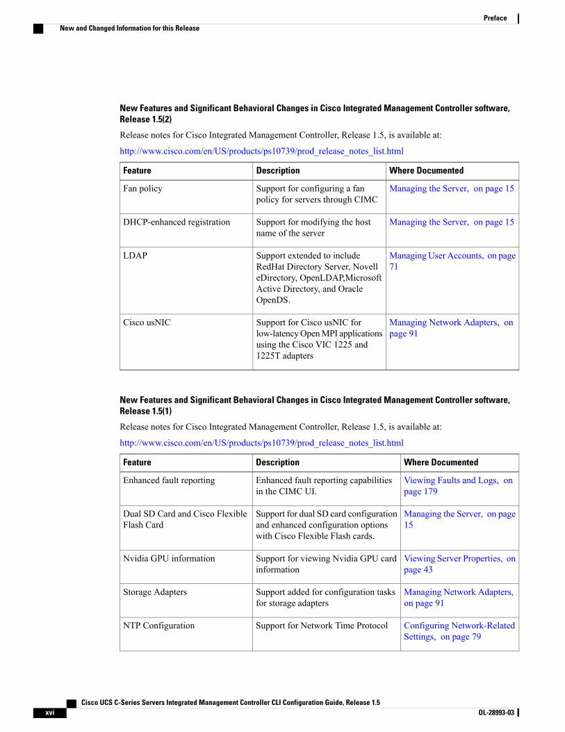
New Features and Significant Behavioral Changes in Cisco Integrated Management Controller software,Release 1.5(2)
Release notes for Cisco Integrated Management Controller, Release 1.5, is available at:
http://www.cisco.com/en/US/products/ps10739/prod_release_notes_list.html
Where DocumentedDescriptionFeature
Managing the Server, on page 15Support for configuring a fanpolicy for servers through CIMC
Fan policy
Managing the Server, on page 15Support for modifying the hostname of the server
DHCP-enhanced registration
Managing User Accounts, on page71
Support extended to includeRedHat Directory Server, NovelleDirectory, OpenLDAP,MicrosoftActive Directory, and OracleOpenDS.
LDAP
Managing Network Adapters, onpage 91
Support for Cisco usNIC forlow-latencyOpenMPI applicationsusing the Cisco VIC 1225 and1225T adapters
Cisco usNIC
New Features and Significant Behavioral Changes in Cisco Integrated Management Controller software,Release 1.5(1)
Release notes for Cisco Integrated Management Controller, Release 1.5, is available at:
http://www.cisco.com/en/US/products/ps10739/prod_release_notes_list.html
Where DocumentedDescriptionFeature
Viewing Faults and Logs, onpage 179
Enhanced fault reporting capabilitiesin the CIMC UI.
Enhanced fault reporting
Managing the Server, on page15
Support for dual SD card configurationand enhanced configuration optionswith Cisco Flexible Flash cards.
Dual SD Card and Cisco FlexibleFlash Card
Viewing Server Properties, onpage 43
Support for viewing Nvidia GPU cardinformation
Nvidia GPU information
Managing Network Adapters,on page 91
Support added for configuration tasksfor storage adapters
Storage Adapters
Configuring Network-RelatedSettings, on page 79
Support for Network Time ProtocolNTP Configuration
Cisco UCS C-Series Servers Integrated Management Controller CLI Configuration Guide, Release 1.5xvi OL-28993-03
PrefaceNew and Changed Information for this Release

Where DocumentedDescriptionFeature
Managing Network Adapters,on page 91
Support for iSCSI boot capability on avNIC
vNICs
Managing Remote Presence,on page 61
Support for configuring networkmounted vmedia volumes
Virtual Media
Configuring CommunicationServices, on page 147
Enhanced SNMPv3 and SNMP trapconfiguration is relocated in the userinterface.
Enhanced SNMP features
Configuring CommunicationServices, on page 147
Support added for CIMC control by anXML API.
XML API
Related Cisco UCS DocumentationDocumentation Roadmaps
For a complete list of all B-Series documentation, see theCiscoUCS B-Series Servers Documentation Roadmapavailable at the following URL: http://www.cisco.com/go/unifiedcomputing/b-series-doc.
For a complete list of all C-Series documentation, see theCiscoUCSC-Series Servers Documentation Roadmapavailable at the following URL: http://www.cisco.com/go/unifiedcomputing/c-series-doc.
Other Documentation Resources
An ISO file containing all B and C-Series documents is available at the following URL: http://www.cisco.com/cisco/software/type.html?mdfid=283853163&flowid=25821. From this page, click Unified ComputingSystem (UCS) Documentation Roadmap Bundle.
The ISO file is updated after every major documentation release.
Follow Cisco UCS Docs on Twitter to receive document update notifications.
Cisco UCS C-Series Servers Integrated Management Controller CLI Configuration Guide, Release 1.5 OL-28993-03 xvii
PrefaceRelated Cisco UCS Documentation

Cisco UCS C-Series Servers Integrated Management Controller CLI Configuration Guide, Release 1.5xviii OL-28993-03
PrefaceRelated Cisco UCS Documentation

C H A P T E R 1Overview
This chapter includes the following sections:
• Overview of the Cisco UCS C-Series Rack-Mount Servers, page 1
• Overview of the Server Software, page 1
• Cisco Integrated Management Controller, page 2
• CIMC CLI, page 3
Overview of the Cisco UCS C-Series Rack-Mount ServersThe Cisco UCS C-Series rack-mount servers include the following models:
• Cisco UCS C200 Rack-Mount Server
• Cisco UCS C210 Rack-Mount Server
• Cisco UCS C220 Rack-Mount Server
• Cisco UCS C240 Rack-Mount Server
• Cisco UCS C250 Rack-Mount Server
• Cisco UCS C260 Rack-Mount Server
• Cisco UCS C460 Rack-Mount Server
To determine which Cisco UCS C-Series rack-mount servers are supported by this firmware release, seethe associated Release Notes. The C-Series release notes are available at the following URL: http://www.cisco.com/en/US/products/ps10739/prod_release_notes_list.html
Note
Overview of the Server SoftwareThe Cisco UCS C-Series Rack-Mount Server ships with the CIMC firmware.
Cisco UCS C-Series Servers Integrated Management Controller CLI Configuration Guide, Release 1.5 OL-28993-03 1
CIMC Firmware
CIMC is a separate management module built into the motherboard. A dedicated ARM-based processor,separate from the main server CPU, runs the CIMC firmware. The system ships with a running version of theCIMC firmware. You can update the CIMC firmware, but no initial installation is needed.
Server OS
The Cisco UCS C-Series rack servers support operating systems such as Windows, Linux, Oracle and so on.For more information on supported operating systems, see the Hardware and Software Interoperability forStandalone C-series servers at http://www.cisco.com/en/US/products/ps10477/prod_technical_reference_list.html. You can use CIMC to install an OS on the server using the KVM console and vMedia.
You can access the available OS installation documentation from the Cisco UCS C-Series ServersDocumentation Roadmap at http://www.cisco.com/go/unifiedcomputing/c-series-doc.
Note
Cisco Integrated Management ControllerThe CIMC is the management service for the C-Series servers. CIMC runs within the server.
The CIMC management service is used only when the server is operating in Standalone Mode. If yourC-Series server is integrated into a UCS system, you must manage it using UCSManager. For informationabout using UCS Manager, see the configuration guides listed in the Cisco UCS B-Series ServersDocumentation Roadmap at http://www.cisco.com/go/unifiedcomputing/b-series-doc.
Note
Management Interfaces
You can use a web-based GUI or SSH-based CLI to access, configure, administer, and monitor the server.Almost all tasks can be performed in either interface, and the results of tasks performed in one interface aredisplayed in another. However, you cannot do the following:
• Use CIMC GUI to invoke CIMC CLI
• View a command that has been invoked through CIMC CLI in CIMC GUI
• Generate CIMC CLI output from CIMC GUI
Tasks You Can Perform in CIMC
You can use CIMC to perform the following server management tasks:
• Power on, power off, power cycle, reset and shut down the server
• Toggle the locator LED
• Configure the server boot order
• View server properties and sensors
• Manage remote presence
Cisco UCS C-Series Servers Integrated Management Controller CLI Configuration Guide, Release 1.52 OL-28993-03
OverviewCisco Integrated Management Controller
• Create and manage local user accounts, and enable remote user authentication through Active Directory
• Configure network-related settings, including NIC properties, IPv4, VLANs, and network security
• Configure communication services, including HTTP, SSH, and IPMI Over LAN
• Manage certificates
• Configure platform event filters
• Update CIMC firmware
• Monitor faults, alarms, and server status
No Operating System or Application Provisioning or Management
CIMC provisions servers, and as a result, exists below the operating system on a server. Therefore, you cannotuse it to provision or manage operating systems or applications on servers. For example, you cannot do thefollowing:
• Deploy an OS, such as Windows or Linux
• Deploy patches for software, such as an OS or an application
• Install base software components, such as anti-virus software, monitoring agents, or backup clients
• Install software applications, such as databases, application server software, or web servers
• Perform operator actions, including restarting an Oracle database, restarting printer queues, or handlingnon-CIMC user accounts
• Configure or manage external storage on the SAN or NAS storage
CIMC CLIThe CIMC CLI is a command-line management interface for Cisco UCS C-Series servers. You can launchthe CIMCCLI andmanage the server over the network by SSH or Telnet. By default, Telnet access is disabled.
A user of the CLI will be one of three roles: admin, user (can control, cannot configure), and read-only.
To recover from a lost admin password, see the Cisco UCS C-Series server installation and service guidefor your platform.
Note
Command ModesThe CLI is organized into a hierarchy of command modes, with the EXECmode being the highest-level modeof the hierarchy. Higher-level modes branch into lower-level modes. You use the scope command to movefrom higher-level modes to modes in the next lower level , and the exit command to move up one level in themode hierarchy. The top command returns to the EXEC mode.
Cisco UCS C-Series Servers Integrated Management Controller CLI Configuration Guide, Release 1.5 OL-28993-03 3
OverviewCIMC CLI

Most commandmodes are associated with managed objects. The scope command does not create managedobjects and can only access modes for which managed objects already exist.
Note
Each mode contains a set of commands that can be entered in that mode. Most of the commands available ineach mode pertain to the associated managed object. Depending on your assigned role, you may have accessto only a subset of the commands available in a mode; commands to which you do not have access are hidden.
The CLI prompt for each mode shows the full path down the mode hierarchy to the current mode. This helpsyou to determine where you are in the command mode hierarchy and can be an invaluable tool when you needto navigate through the hierarchy.
Cisco UCS C-Series Servers Integrated Management Controller CLI Configuration Guide, Release 1.54 OL-28993-03
OverviewCommand Modes
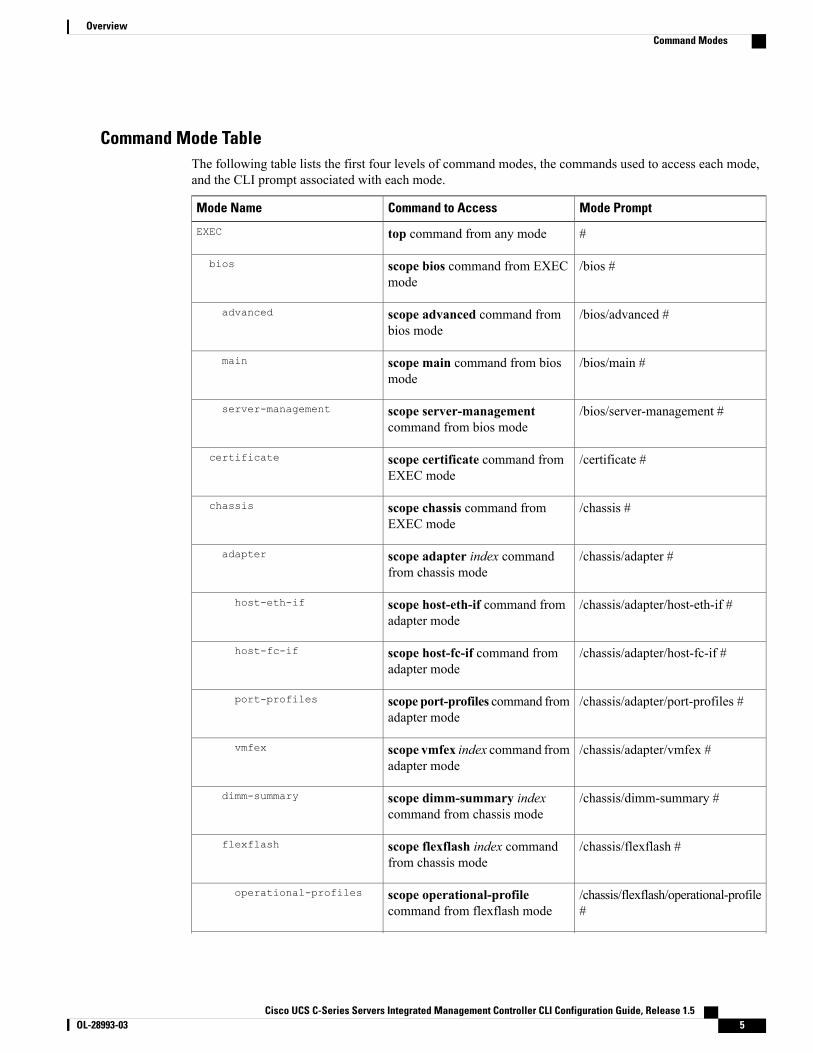
Command Mode TableThe following table lists the first four levels of command modes, the commands used to access each mode,and the CLI prompt associated with each mode.
Mode PromptCommand to AccessMode Name
#top command from any modeEXEC
/bios #scope bios command from EXECmode
bios
/bios/advanced #scope advanced command frombios mode
advanced
/bios/main #scope main command from biosmode
main
/bios/server-management #scope server-managementcommand from bios mode
server-management
/certificate #scope certificate command fromEXEC mode
certificate
/chassis #scope chassis command fromEXEC mode
chassis
/chassis/adapter #scope adapter index commandfrom chassis mode
adapter
/chassis/adapter/host-eth-if #scope host-eth-if command fromadapter mode
host-eth-if
/chassis/adapter/host-fc-if #scope host-fc-if command fromadapter mode
host-fc-if
/chassis/adapter/port-profiles #scope port-profiles command fromadapter mode
port-profiles
/chassis/adapter/vmfex #scope vmfex index command fromadapter mode
vmfex
/chassis/dimm-summary #scope dimm-summary indexcommand from chassis mode
dimm-summary
/chassis/flexflash #scope flexflash index commandfrom chassis mode
flexflash
/chassis/flexflash/operational-profile#
scope operational-profilecommand from flexflash mode
operational-profiles
Cisco UCS C-Series Servers Integrated Management Controller CLI Configuration Guide, Release 1.5 OL-28993-03 5
OverviewCommand Modes
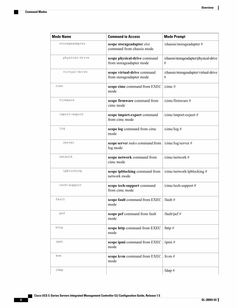
Mode PromptCommand to AccessMode Name
storageadapter /chassis/storageadapter #scope storageadapter slotcommand from chassis mode
/chassis/storageadapter/physical-drive#
scope physical-drive commandfrom storageadapter mode
physical-drive
/chassis/storageadapter/virtual-drive#
scope virtual-drive commandfrom storageadapter mode
virtual-drive
/cimc #scope cimc command from EXECmode
cimc
/cimc/firmware #scope firmware command fromcimc mode
firmware
/cimc/import-export #scope import-export commandfrom cimc mode
import-export
/cimc/log #scope log command from cimcmode
log
/cimc/log/server #scope server index command fromlog mode
server
/cimc/network #scope network command fromcimc mode
network
/cimc/network/ipblocking #scope ipblocking command fromnetwork mode
ipblocking
/cimc/tech-support #scope tech-support commandfrom cimc mode
tech-support
/fault #scope fault command from EXECmode
fault
/fault/pef #scope pef command from faultmode
pef
/http #scope http command from EXECmode
http
/ipmi #scope ipmi command from EXECmode
ipmi
/kvm #scope kvm command from EXECmode
kvm
/ldap #ldap
Cisco UCS C-Series Servers Integrated Management Controller CLI Configuration Guide, Release 1.56 OL-28993-03
OverviewCommand Modes
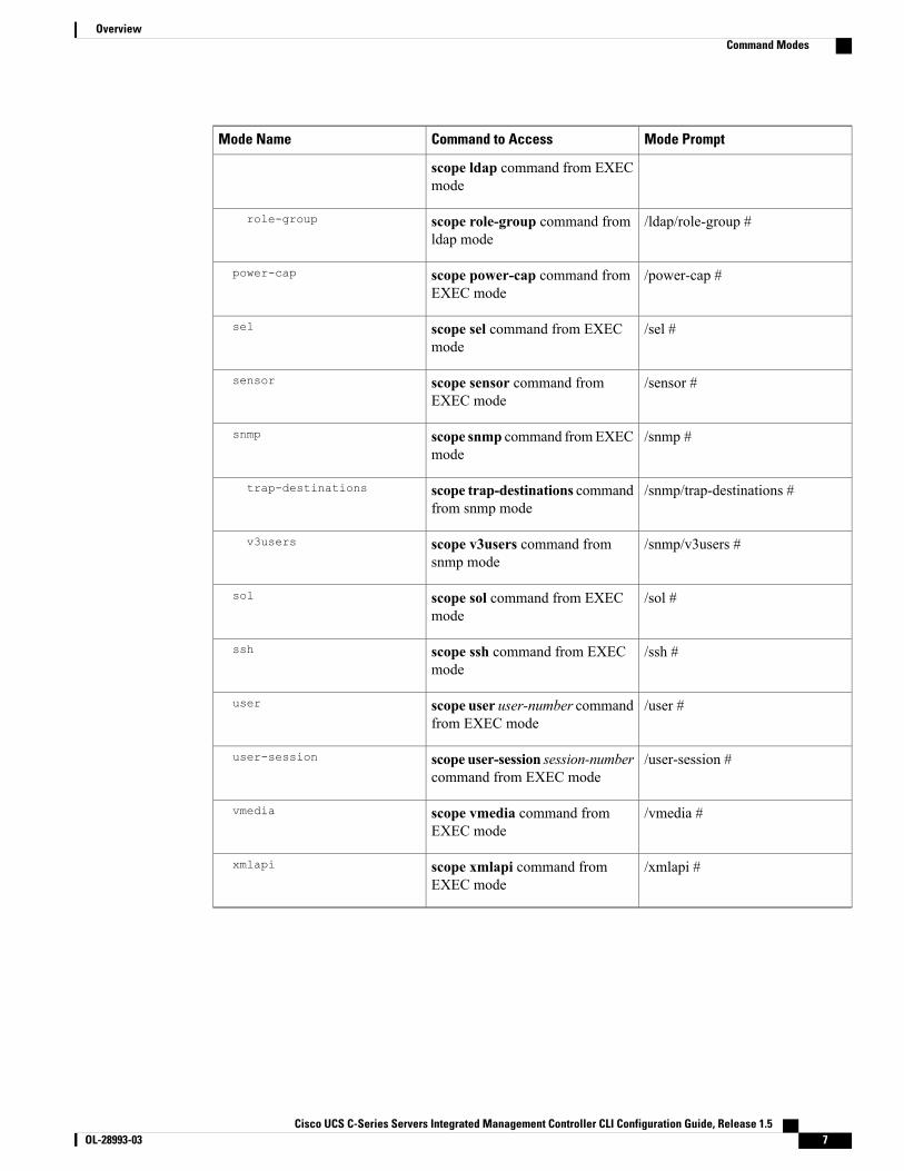
Mode PromptCommand to AccessMode Name
scope ldap command from EXECmode
/ldap/role-group #scope role-group command fromldap mode
role-group
/power-cap #scope power-cap command fromEXEC mode
power-cap
/sel #scope sel command from EXECmode
sel
/sensor #scope sensor command fromEXEC mode
sensor
/snmp #scope snmp command fromEXECmode
snmp
/snmp/trap-destinations #scope trap-destinations commandfrom snmp mode
trap-destinations
/snmp/v3users #scope v3users command fromsnmp mode
v3users
/sol #scope sol command from EXECmode
sol
/ssh #scope ssh command from EXECmode
ssh
/user #scope user user-number commandfrom EXEC mode
user
/user-session #scope user-session session-numbercommand from EXEC mode
user-session
/vmedia #scope vmedia command fromEXEC mode
vmedia
/xmlapi #scope xmlapi command fromEXEC mode
xmlapi
Cisco UCS C-Series Servers Integrated Management Controller CLI Configuration Guide, Release 1.5 OL-28993-03 7
OverviewCommand Modes
Complete a CommandYou can use the Tab key in any mode to complete a command. Partially typing a command name and pressingTab causes the command to be displayed in full or to the point where another keyword must be chosen or anargument value must be entered.
Command HistoryThe CLI stores all commands used in the current session. You can step through the previously used commandsby using the Up Arrow or DownArrow keys. The Up Arrow key steps to the previous command in the history,and the DownArrow key steps to the next command in the history. If you get to the end of the history, pressingthe Down Arrow key does nothing.
All commands in the history can be entered again by simply stepping through the history to recall the desiredcommand and pressing Enter. The command is entered as if you had manually typed it. You can also recalla command and change it before you press Enter.
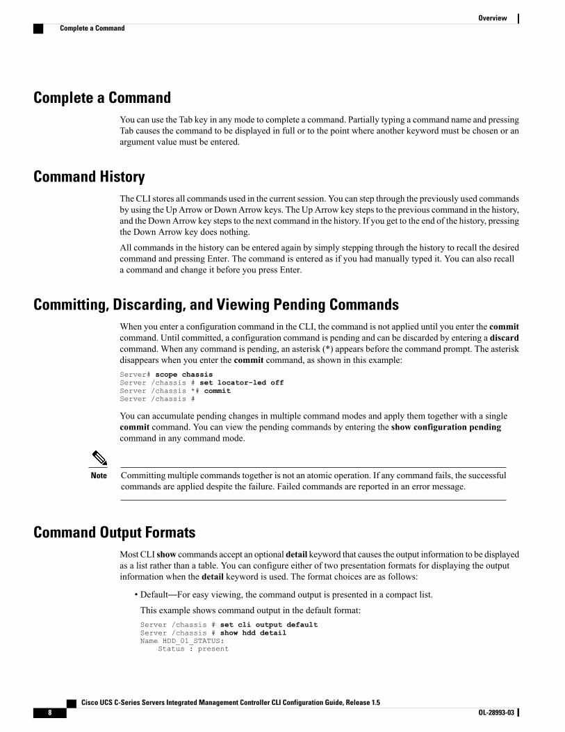
Committing, Discarding, and Viewing Pending CommandsWhen you enter a configuration command in the CLI, the command is not applied until you enter the commitcommand. Until committed, a configuration command is pending and can be discarded by entering a discardcommand. When any command is pending, an asterisk (*) appears before the command prompt. The asteriskdisappears when you enter the commit command, as shown in this example:Server# scope chassisServer /chassis # set locator-led offServer /chassis *# commitServer /chassis #
You can accumulate pending changes in multiple command modes and apply them together with a singlecommit command. You can view the pending commands by entering the show configuration pendingcommand in any command mode.
Committing multiple commands together is not an atomic operation. If any command fails, the successfulcommands are applied despite the failure. Failed commands are reported in an error message.
Note
Command Output FormatsMost CLI show commands accept an optional detail keyword that causes the output information to be displayedas a list rather than a table. You can configure either of two presentation formats for displaying the outputinformation when the detail keyword is used. The format choices are as follows:
• Default—For easy viewing, the command output is presented in a compact list.
This example shows command output in the default format:Server /chassis # set cli output defaultServer /chassis # show hdd detailName HDD_01_STATUS:
Status : present
Cisco UCS C-Series Servers Integrated Management Controller CLI Configuration Guide, Release 1.58 OL-28993-03
OverviewComplete a Command
Name HDD_02_STATUS:Status : present
Name HDD_03_STATUS:Status : present
Name HDD_04_STATUS:Status : present
Server /chassis #
• YAML—For easy parsing by scripts, the command output is presented in the YAML (YAML Ain'tMarkup Language) data serialization language, delimited by defined character strings.
This example shows command output in the YAML format:Server /chassis # set cli output yamlServer /chassis # show hdd detail---
name: HDD_01_STATUShdd-status: present
---name: HDD_02_STATUShdd-status: present
---name: HDD_03_STATUShdd-status: present
---name: HDD_04_STATUShdd-status: present
...
Server /chassis #
For detailed information about YAML, see http://www.yaml.org/about.html.
In most CLI command modes, you can enter set cli output default to configure the default format, or set clioutput yaml to configure the YAML format.
Online Help for the CLIAt any time, you can type the ? character to display the options available at the current state of the commandsyntax.
If you have not typed anything at the prompt, typing ? lists all available commands for the mode you are in.If you have partially typed a command, typing ? lists all available keywords and arguments available at yourcurrent position in the command syntax.
Cisco UCS C-Series Servers Integrated Management Controller CLI Configuration Guide, Release 1.5 OL-28993-03 9
OverviewOnline Help for the CLI

Cisco UCS C-Series Servers Integrated Management Controller CLI Configuration Guide, Release 1.510 OL-28993-03
OverviewOnline Help for the CLI
C H A P T E R 2Installing the Server OS
This chapter includes the following sections:
• OS Installation Methods, page 11
• KVM Console, page 11
• PXE Installation Servers, page 12
• Booting an Operating System from a USB Port, page 13
OS Installation MethodsC-Series servers support several operating systems. Regardless of the OS being installed, you can install iton your server using one of the following tools:
• KVM console
• PXE installation server
KVM ConsoleThe KVM console is an interface accessible from CIMC that emulates a direct keyboard, video, and mouse(KVM) connection to the server. The KVM console allows you to connect to the server from a remote location.
Instead of using CD/DVD or floppy drives physically connected to the server, the KVM console uses virtualmedia, which are actual disk drives or disk image files that are mapped to virtual CD/DVD or floppy drives.You can map any of the following to a virtual drive:
• CD/DVD or floppy drive on your computer
• Disk image files (ISO or IMG files) on your computer
• USB flash drive on your computer
• CD/DVD or floppy drive on the network
• Disk image files (ISO or IMG files) on the network
Cisco UCS C-Series Servers Integrated Management Controller CLI Configuration Guide, Release 1.5 OL-28993-03 11
• USB flash drive on the network
You can use the KVM console to install an OS on the server.
The KVM Console is operated only through the GUI. To launch the KVM Console, see the instructionsin the Cisco UCS C-Series Servers Integrated Management Controller GUI Configuration Guide.
Note
Installing an OS Using the KVM ConsoleBecause the KVM console is operated only through the GUI, you cannot install a server OS using the CLI.To install an OS using the KVM console, follow the instructions in the "Installing an OS Using the KVMConsole" section of the Cisco UCS C-Series Servers Integrated Management Controller GUI ConfigurationGuide.
Detailed guides for installing Linux, VMware, and Windows can be found at this URL: http://www.cisco.com/en/US/products/ps10493/products_installation_and_configuration_guides_list.html.
Note
PXE Installation ServersA Preboot Execution Environment (PXE) installation server allows a client to boot and install an OS from aremote location. To use this method, a PXE environment must be configured and available on your VLAN,typically a dedicated provisioning VLAN. Additionally, the server must be set to boot from the network.When the server boots, it sends a PXE request across the network. The PXE installation server acknowledgesthe request, and starts a sequence of events that installs the OS on the server.
PXE servers can use installation disks, disk images, or scripts to install an OS. Proprietary disk images canalso be used to install an OS, additional components, or applications.
PXE installation is an efficient method for installing an OS on a large number of servers. However,considering that this method requires setting up a PXE environment, it might be easier to use anotherinstallation method.
Note
Installing an OS Using a PXE Installation Server
Before You Begin
• Verify that the server can be reached over a VLAN.
• You must log in as a user with admin privileges to install an OS.
Cisco UCS C-Series Servers Integrated Management Controller CLI Configuration Guide, Release 1.512 OL-28993-03
Installing the Server OSInstalling an OS Using the KVM Console

Procedure
Step 1 Set the boot order to PXE first.Step 2 Reboot the server.
If a PXE install server is available on the VLAN, the installation process begins when the server reboots. PXEinstallations are typically automated and require no additional user input. Refer to the installation guide forthe OS being installed to guide you through the rest of the installation process.
What to Do Next
After the OS installation is complete, reset the LAN boot order to its original setting.
Booting an Operating System from a USB PortAll Cisco UCSC-series servers support booting an operating system from anyUSB port on the server. However,there are a few guidelines that you must keep in mind, prior to booting an OS from a USB port.
• To maintain the boot order configuration, it is recommended that you use an internal USB port forbooting an OS.
• The USB port must be enabled prior to booting an OS from it.
By default, the USB ports are enabled. If you have disabled a USB port, you must enable it prior tobooting an OS from it. For information on enabling a disabled USB ports, see topic Enabling or Disablingthe Internal USB Port in the server-specific installation and service guide available at the following link:
http://www.cisco.com/en/US/products/ps10493/prod_installation_guides_list.html.
• After you boot the OS from the USB port, you must set the second-level boot order so that the serverboots from that USB source every time.
For information on setting the boot order, see Configuring the Server Boot Order, on page 17.
Cisco UCS C-Series Servers Integrated Management Controller CLI Configuration Guide, Release 1.5 OL-28993-03 13
Installing the Server OSBooting an Operating System from a USB Port

Cisco UCS C-Series Servers Integrated Management Controller CLI Configuration Guide, Release 1.514 OL-28993-03
Installing the Server OSBooting an Operating System from a USB Port
C H A P T E R 3Managing the Server
This chapter includes the following sections:
• Overview to DHCP User Friendliness, page 15
• Toggling the Locator LED, page 16
• Toggling the Locator LED for a Hard Drive, page 16
• Managing the Server Boot Order, page 17
• Resetting the Server, page 19
• Shutting Down the Server, page 19
• Managing Server Power, page 20
• Configuring Power Policies, page 22
• Configuring Fan Policies, page 26
• Managing the Flexible Flash Controller, page 28
• Configuring BIOS Settings, page 36
• Updating Firmware on Server Components, page 41
Overview to DHCP User FriendlinessThe Dynamic Host Configuration Protocol (DHCP) enhancement ships with the addition of the hostname tothe DHCP packet, which can either be interpreted or displayed at the DHCP server side. The hostname is nowadded in the options field of the DHCP packet, and sent in the DHCP DISCOVER packet which was initiallysent to the DHCP server.
The default hostname of the server is changed from ucs-c2XX to CXXX-YYYYYY.Where XXX is the modelnumber and YYYYYY is the serial number of the server. This unique string acts as a client identifier, andhelps you track and map the IP addresses leased out to the CIMC from the DHCP server. The default serialnumber is provided by the manufacturer as a sticker/label on the server which helps you physically identifythe server.
Cisco UCS C-Series Servers Integrated Management Controller CLI Configuration Guide, Release 1.5 OL-28993-03 15
Toggling the Locator LEDBefore You Begin
You must log in with user or admin privileges to perform this task.
Procedure
PurposeCommand or Action
Enters chassis command mode.Server # scope chassisStep 1
Enables or disables the chassis locator LED.Server /chassis # set locator-led {on | off}Step 2
Commits the transaction to the systemconfiguration.
Server /chassis # commitStep 3
This example disables the chassis locator LED and commits the transaction:Server# scope chassisServer /chassis # set locator-led offServer /chassis *# commit
Server /chassis #
Toggling the Locator LED for a Hard DriveBefore You Begin
You must log in with user or admin privileges to perform this task.
Procedure
PurposeCommand or Action
Enters chassis command mode.Server # scope chassisStep 1
Enters hard disk drive (HDD) command mode.Server/chassis # scope hddStep 2
Where drivenum is the number of the hard drive whoselocator LED you want to set. A value of 1 turns theLED on while a value of 2 turns the LED off.
Server /chassis/hdd # set locateHDDdrivenum {1 | 2}
Step 3
This example turns on the locator LED on HDD 2:Server# scope chassisServer /chassis # scope hddServer /chassis/hdd # locateHDD 2 1HDD Locate LED Status changed to 1Server /chassis/hdd # showName Status LocateLEDStatus
Cisco UCS C-Series Servers Integrated Management Controller CLI Configuration Guide, Release 1.516 OL-28993-03
Managing the ServerToggling the Locator LED
-------------------- -------------------- --------------------HDD1_STATUS present TurnOFFHDD2_STATUS present TurnONHDD3_STATUS absent TurnOFFHDD4_STATUS absent TurnOFF
Server /chassis/hdd #
Managing the Server Boot Order
Server Boot OrderUsing CIMC, you can configure the order in which the server attempts to boot from available boot devicetypes.
When you change the boot order configuration, CIMC sends the configured boot order to the BIOS the nexttime the server is rebooted. To implement the new boot order, reboot the server after making the configurationchange. The new boot order will take effect on any subsequent reboot. The configured boot order is not sentagain until the configuration is changed again.
The actual boot order will differ from the configured boot order if either of the following conditions occur:Note
• The BIOS encounters issues while trying to boot using the configured boot order.
• A user changes the boot order directly through the BIOS.
Configuring the Server Boot Order
Do not change the boot order while the host is performing BIOS power-on self test (POST).Note
Before You Begin
You must log in with user or admin privileges to perform this task.
Procedure
PurposeCommand or Action
Enters bios command mode.Server# scope biosStep 1
Specifies the boot device options and order. You canselect one or more of the following:
Server /bios # set boot-orderdevice1[,device2[,device3[,device4[,device5]]]]
Step 2
• cdrom—Bootable CD-ROM
• fdd—Floppy disk drive
• hdd—Hard disk drive
Cisco UCS C-Series Servers Integrated Management Controller CLI Configuration Guide, Release 1.5 OL-28993-03 17
Managing the ServerManaging the Server Boot Order
PurposeCommand or Action
• pxe—PXE boot
• efi—Extensible Firmware Interface
Commits the transaction to the system configuration.Server /bios # commitStep 3
The new boot order will be used on the next BIOS boot.
This example sets the boot order and commits the transaction:Server# scope biosServer /bios # set boot-order hdd,cdrom,fdd,pxe,efiServer /bios *# commitServer /bios # show detailBIOS:
Boot Order: HDD,CDROM,FDD,PXE,EFI
Server /bios #
What to Do Next
Reboot the server to boot with your new boot order.
Viewing the Actual Server Boot OrderThe actual server boot order is the boot order actually used by the BIOS when the server last booted. Theactual boot order can differ from the boot order configured in CIMC.
Procedure
PurposeCommand or Action
Enters bios command mode.Server# scope biosStep 1
Displays the boot order actually used by the BIOSwhen the server last booted.
Server /bios # show actual-boot-order[detail]
Step 2
This example displays the actual boot order from the last boot:Server# scope biosServer /bios # show actual-boot-order
Boot Order Type Boot Device------------ ------------------------- -----------------------------------1 CD/DVD CD-ROM2 CD/DVD Cisco Virtual CD/DVD 1.183 Network Device (PXE) Cisco NIC 23:0.04 Network Device (PXE) MBA v5.0.5 Slot 01005 Network Device (PXE) MBA v5.0.5 Slot 01016 Network Device (PXE) MBA v5.0.5 Slot 02007 Network Device (PXE) MBA v5.0.5 Slot 02018 Network Device (PXE) Cisco NIC 22:0.09 Internal EFI Shell Internal EFI Shell10 FDD Cisco Virtual HDD 1.18
Cisco UCS C-Series Servers Integrated Management Controller CLI Configuration Guide, Release 1.518 OL-28993-03
Managing the ServerViewing the Actual Server Boot Order
11 FDD Cisco Virtual Floppy 1.18
Server /bios #
Resetting the Server
If any firmware or BIOS updates are in progress, do not reset the server until those tasks are complete.Important
Before You Begin
You must log in with user or admin privileges to perform this task.
Procedure
PurposeCommand or Action
Enters chassis command mode.Server# scope chassisStep 1
After a prompt to confirm, resets the server.Server /chassis # power hard-resetStep 2
This example resets the server:Server# scope chassisServer /chassis # power hard-resetThis operation will change the server's power state.Continue?[y|N]
Shutting Down the Server
If any firmware or BIOS updates are in progress, do not shut down the server until those tasks are complete.Important
Before You Begin
You must log in with user or admin privileges to perform this task.
Procedure
PurposeCommand or Action
Enters chassis mode.Server# scope chassisStep 1
Shuts down the server.Server /chassis # power shutdownStep 2
Cisco UCS C-Series Servers Integrated Management Controller CLI Configuration Guide, Release 1.5 OL-28993-03 19
Managing the ServerResetting the Server
The following example shuts down the server:Server# scope chassisServer /chassis # power shutdown
Managing Server Power
Powering On the Server
If the server was powered off other than through the CIMC, the server will not become active immediatelywhen powered on. In this case, the server will enter standby mode until the CIMC completes initialization.
Note
If any firmware or BIOS updates are in progress, do not change the server power until those tasks arecomplete.
Important
Before You Begin
You must log in with user or admin privileges to perform this task.
Procedure
PurposeCommand or Action
Enters chassis command mode.Server# scope chassisStep 1
Turns on the server.Server /chassis # power onStep 2
This example turns on the server:Server# scope chassisServer /chassis # power onThis operation will change the server's power state.Continue?[y|N]y
Server /chassis # showPower Serial Number Product Name UUID----- ------------- ------------- ------------------------------------on Not Specified Not Specified 208F0100020F000000BEA80000DEAD00
Powering Off the Server
If any firmware or BIOS updates are in progress, do not power off the server until those tasks are complete.Important
Cisco UCS C-Series Servers Integrated Management Controller CLI Configuration Guide, Release 1.520 OL-28993-03
Managing the ServerManaging Server Power
Before You Begin
You must log in with user or admin privileges to perform this task.
Procedure
PurposeCommand or Action
Enters chassis command mode.Server# scope chassisStep 1
Turns off the server.Server /chassis # power offStep 2
This example turns off the server:Server# scope chassisServer /chassis # power offThis operation will change the server's power state.Continue?[y|N]y
Server /chassis # showPower Serial Number Product Name UUID----- ------------- ------------- ------------------------------------off Not Specified Not Specified 208F0100020F000000BEA80000DEAD00
Power Cycling the Server
If any firmware or BIOS updates are in progress, do not power cycle the server until those tasks arecomplete.
Important
Before You Begin
You must log in with user or admin privileges to perform this task.
Procedure
PurposeCommand or Action
Enters chassis command mode.Server# scope chassisStep 1
Power cycles the server.Server /chassis # power cycleStep 2
This example power cycles the server:Server# scope chassisServer /chassis # power cycle
Cisco UCS C-Series Servers Integrated Management Controller CLI Configuration Guide, Release 1.5 OL-28993-03 21
Managing the ServerPower Cycling the Server

Configuring Power Policies
Viewing the Power Statistics
Procedure
PurposeCommand or Action
Displays the server power consumption statisticsand the power cap policy.
Server# show power-cap [detail]Step 1
The displayed fields are described in the following table:
DescriptionName
The power currently being used by the server, in watts.Current Consumption
The maximum number of watts consumed by the server since the lasttime it was rebooted.
Maximum Consumption
The minimum number of watts consumed by the server since the lasttime it was rebooted.
Minimum Consumption
The minimum amount of power that can be specified as the peak powercap for this server, in watts.
Minimum Configurable Limit
Themaximum amount of power that can be specified as the peak powercap for this server, in watts.
Maximum Configurable Limit
Additional fields are described in the following table:
DescriptionName
If power capping is enabled, the system monitors how much power isallocated to the server and takes the specified action if the server goesover its maximum allotment.
Enable Power Capping
The maximum number of watts that can be allocated to this server. Ifthe server requests more power than specified in this field, the systemtakes the action defined in the Non-Compliance Action field.
Enter a number of watts within the range defined by theMinimumConfigurable Limit field and theMaximum Configurable Limitfield.
Peak Power
Cisco UCS C-Series Servers Integrated Management Controller CLI Configuration Guide, Release 1.522 OL-28993-03
Managing the ServerConfiguring Power Policies
DescriptionName
The action the system should take if power capping is enabled and theserver requests more than its peak power allotment. This can be one ofthe following:
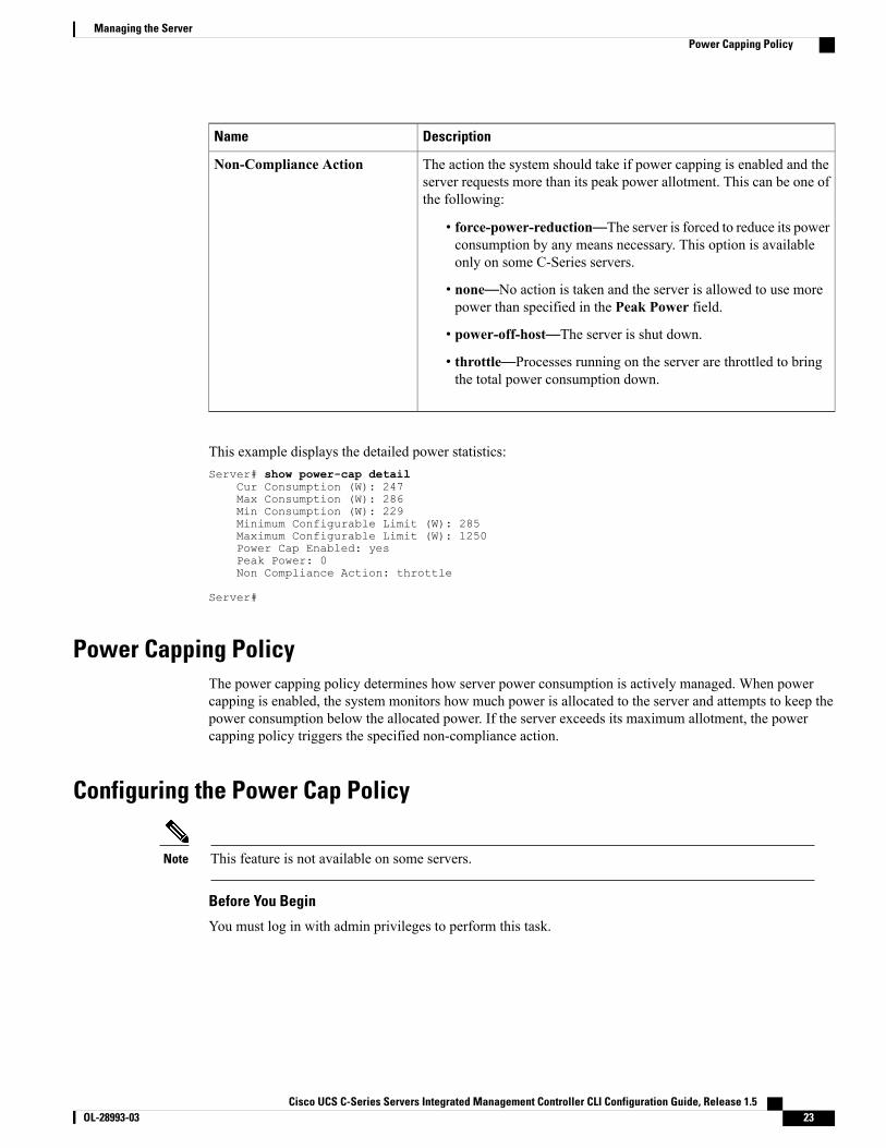
• force-power-reduction—The server is forced to reduce its powerconsumption by any means necessary. This option is availableonly on some C-Series servers.
• none—No action is taken and the server is allowed to use morepower than specified in the Peak Power field.
• power-off-host—The server is shut down.
• throttle—Processes running on the server are throttled to bringthe total power consumption down.
Non-Compliance Action
This example displays the detailed power statistics:Server# show power-cap detail
Cur Consumption (W): 247Max Consumption (W): 286Min Consumption (W): 229Minimum Configurable Limit (W): 285Maximum Configurable Limit (W): 1250Power Cap Enabled: yesPeak Power: 0Non Compliance Action: throttle
Server#
Power Capping PolicyThe power capping policy determines how server power consumption is actively managed. When powercapping is enabled, the system monitors how much power is allocated to the server and attempts to keep thepower consumption below the allocated power. If the server exceeds its maximum allotment, the powercapping policy triggers the specified non-compliance action.
Configuring the Power Cap Policy
This feature is not available on some servers.Note
Before You Begin
You must log in with admin privileges to perform this task.
Cisco UCS C-Series Servers Integrated Management Controller CLI Configuration Guide, Release 1.5 OL-28993-03 23
Managing the ServerPower Capping Policy
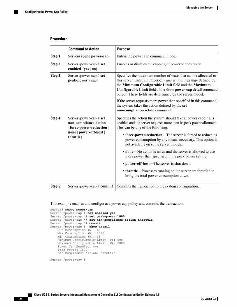
Procedure
PurposeCommand or Action
Enters the power cap command mode.Server# scope power-capStep 1
Enables or disables the capping of power to the server.Server /power-cap # setenabled {yes | no}
Step 2
Specifies the maximum number of watts that can be allocated tothis server. Enter a number of watts within the range defined by
Server /power-cap # setpeak-power watts
Step 3
theMinimum Configurable Limit field and theMaximumConfigurable Limit field of the show power-cap detail commandoutput. These fields are determined by the server model.
If the server requests more power than specified in this command,the system takes the action defined by the setnon-compliance-action command.
Specifies the action the system should take if power capping isenabled and the server requests more than its peak power allotment.This can be one of the following:
Server /power-cap # setnon-compliance-action{force-power-reduction |
Step 4
none | power-off-host |throttle} • force-power-reduction—The server is forced to reduce its
power consumption by any means necessary. This option isnot available on some server models.
• none—No action is taken and the server is allowed to usemore power than specified in the peak power setting.
• power-off-host—The server is shut down.
• throttle—Processes running on the server are throttled tobring the total power consumption down.
Commits the transaction to the system configuration.Server /power-cap # commitStep 5
This example enables and configures a power cap policy and commits the transaction:Server# scope power-capServer /power-cap # set enabled yesServer /power-cap *# set peak-power 1000Server /power-cap *# set non-compliance-action throttleServer /power-cap *# commitServer /power-cap # show detail
Cur Consumption (W): 688Max Consumption (W): 1620Min Consumption (W): 48Minimum Configurable Limit (W): 500Maximum Configurable Limit (W): 2000Power Cap Enabled: yesPeak Power: 1000Non Compliance Action: throttle
Server /power-cap #
Cisco UCS C-Series Servers Integrated Management Controller CLI Configuration Guide, Release 1.524 OL-28993-03
Managing the ServerConfiguring the Power Cap Policy
Configuring the Power Restore PolicyThe power restore policy determines how power is restored to the server after a chassis power loss.
Before You Begin
You must log in with admin privileges to perform this task.
Procedure
PurposeCommand or Action
Enters the chassis command mode.Server# scope chassisStep 1
Specifies the action to be taken when chassis power is restored.Select one of the following:
Server /chassis # set policy{power-off | power-on |restore-last-state}
Step 2
• power-off—Server power will remain off until manuallyturned on. This is the default action.
• power-on—Server power will be turned on when chassispower is restored.
• restore-last-state—Server power will return to the statebefore chassis power was lost.
When the selected action is power-on, you can select a delayin the restoration of power to the server.
(Optional)Specifies whether server power will be restored after a fixedor random time. The default is fixed. This command is acceptedonly if the power restore action is power-on.
Server /chassis # set delay{fixed | random}
Step 3
(Optional)Specifies the delay time in seconds. The range is 0 to 240; thedefault is 0.
Server /chassis # setdelay-value delay
Step 4
Commits the transaction to the system configuration.Server /chassis # commitStep 5
This example sets the power restore policy to power-on with a fixed delay of 180 seconds (3 minutes) andcommits the transaction:Server# scope chassisServer /chassis # set policy power-onServer /chassis *# set delay fixedServer /chassis *# set delay-value 180Server /chassis *# commitServer /chassis # show detailChassis:
Power: onSerial Number: QCI1404A1ITProduct Name: UCS C200 M1PID : R200-1120402UUID: 01A6E738-D8FE-DE11-76AE-8843E138AE04Locator LED: off
Cisco UCS C-Series Servers Integrated Management Controller CLI Configuration Guide, Release 1.5 OL-28993-03 25
Managing the ServerConfiguring the Power Restore Policy
Description: Testing power restorePower Restore Policy: power-onPower Delay Type: fixedPower Delay Value(sec): 180
Server /chassis #
Configuring Fan Policies
Fan Control PoliciesFan Control Policies enable you to control the fan speed to bring down server power consumption and noiselevels. Prior to these fan policies, the fan speed increased automatically when the temperature of any servercomponent exceeded the set threshold. To ensure that the fan speeds were low, the threshold temperatures ofcomponents are usually set to high values. While this behavior suited most server configurations, it did notaddress the following situations:
• Maximum CPU performance
For high performance, certain CPUs must be cooled substantially below the set threshold temperature.This required very high fan speeds which resulted in higher power consumption and increased noiselevels.
• Low power consumption
To ensure the lowest power consumption, fans must run very slowly, and in some cases, stop completelyon servers that support it. But slow fan speeds resulted in servers overheating. To avoid this situation,it is necessary to run fans at a speed that is moderately faster than the lowest possible speed.
With the introduction of fan policies, you can determine the right fan speed for the server, based on thecomponents in the server. In addition, it allows you to configure the fan speed to address problems related tomaximum CPU performance and low power consumption.
Following are the fan policies that you can choose from:
• BalancedThis is the default policy. This setting can cool almost any server configuration, but may not be suitablefor servers with PCIe cards, since these cards overheat easily.
• PerformanceThis setting can be used for server configurations where maximum fan speed is required for highperformance. With this setting, the fan speeds will run at the same speed or higher speed than that ofthe Balanced fan policy.
• Low Power
This setting is ideal for minimal configuration servers that do not contain any PCIe cards.
• High PowerThis setting can be used for server configurations that require fan speeds ranging from 60 to 85%. Thispolicy is ideal for servers that contain PCIe cards that easily overheat and have high temperatures. Theminimum fan speed set with this policy varies for each server platform, but is approximately in the rangeof 60 to 85%.
•Maximum Power
Cisco UCS C-Series Servers Integrated Management Controller CLI Configuration Guide, Release 1.526 OL-28993-03
Managing the ServerConfiguring Fan Policies
This setting can be used for server configurations that require extremely high fan speeds ranging between70% to 100%. This policy is ideal for servers that contain PCIe cards that easily overheat and haveextremely high temperatures. The minimum fan speed set with this policy varies for each server platform,but is approximately in the range of 70 to 100%.
Although you set a fan policy in CIMC, the actual speed that the fan runs at is determined by theconfiguration requirements of the server. For example, if you set the fan policy toBalanced, but the serverincludes PCIe cards that overheat easily, then the speed of the fans on the server is adjusted automatically.But the policy defined is retained as Balanced.
Note
Configuring a Fan PolicyThe fan policy determines the cooling requirements for your server. Prior to setting the fan policy, you mustdetermine if your server includes PCIe cards that overheat easily.
Before You Begin
You must log in with admin privileges to perform this task.
Procedure
PurposeCommand or Action
Enters the chassis command mode.Server# scope chassisStep 1
Enters the fan policy command mode.Server /chassis # scopefan-policy
Step 2
Sets the fan policy for the server. It can be one of the following:Server/chassis/fan-policy # setfan-policy
Step 3
• balancedThis is the default policy. This setting can cool almost any serverconfiguration, but may not be suitable for servers with PCIe cards,since these cards overheat easily.
• performanceThis setting can be used for server configurations where maximumfan speed is required for high performance. With this setting, the fanspeeds will run at the same speed or higher speed than that of thebalanced fan policy.
• low-powerThis setting is ideal for minimal configuration servers that do notcontain any PCIe cards.
• high-powerThis setting can be used for server configurations that require fanspeeds ranging from 60 to 85%. This policy is ideal for servers thatcontain PCIe cards that easily overheat and have high temperatures.
Cisco UCS C-Series Servers Integrated Management Controller CLI Configuration Guide, Release 1.5 OL-28993-03 27
Managing the ServerConfiguring a Fan Policy
PurposeCommand or Action
The minimum fan speed set with this policy varies for each serverplatform, but is approximately in the range of 60 to 85%.
• maximum-powerThis setting can be used for server configurations that requireextremely high fan speeds ranging between 70% to 100%. This policyis ideal for servers that contain PCIe cards that easily overheat andhave extremely high temperatures. The minimum fan speed set withthis policy varies for each server platform, but is approximately inthe range of 70 to 100%.
Commits the changes to the server.Server/chassis/fan-policy #commit
Step 4
This example shows how to set the fan policy to maximum power for a server:server # scope chassisserver /chassis # scope fan-policyserver /chassis/fan-policy # set fan-policy maximum-powerserver /chassis/fan-policy* # commitserver /chassis/fan-policy # show detailFan policy: maximum-powerserver /chassis/fan-policy #
Managing the Flexible Flash Controller
Cisco Flexible FlashSome C-Series Rack-Mount Servers support an internal Secure Digital (SD) memory card for storage of serversoftware tools and utilities. The SD card is hosted by the Cisco Flexible Flash storage adapter.
The SD storage is available to CIMC as a single hypervisor (HV) partition configuration. Prior versions hadfour virtual USB drives. Three were preloaded with Cisco UCS Server Configuration Utility, Cisco driversand Cisco Host Upgrade Utility, and the fourth as user-installed hypervisor. A single HV partition configurationis also created when you upgrade to the latest version of CIMC or downgrade to the prior version, and resetthe configuration.
For information about the Cisco software utilities and packages, see the Cisco UCS C-Series ServersDocumentation Roadmap at this URL:
http://www.cisco.com/go/unifiedcomputing/c-series-doc
Card Management Feature in the Cisco Flexible Flash Controller
The Cisco Flexible Flash controller supports management of both single and two SD cards as a RAID-1 pair.With the introduction of card management, you can perform the following tasks:
Cisco UCS C-Series Servers Integrated Management Controller CLI Configuration Guide, Release 1.528 OL-28993-03
Managing the ServerManaging the Flexible Flash Controller

DescriptionAction
Allows you to reset the controller.Reset Cisco Flex Flash
Allows you to reset the configuration in the selectedslot to the default configuration.
Reset Partition Defaults
Allows you to retain the configuration for an SD cardthat supports firmware version 253 and later.
Synchronize Card Configuration
Allows you to configure the SD cards on the selectedCisco Flexible Flash controller.
Configure Operational Profile
RAID Partition Enumeration
Non-RAID partitions are always enumerated from the primary card and the enumeration does not depend onthe status of the primary card.
Following is the behavior of the RAID partition enumeration when there are two cards in the Cisco FlexibleFlash controller:
BehaviorScenario
RAID partitions are enumerated if the card is healthy,and if the mode is either Primary orSecondary-active.
Single card
RAID partitions are enumerated if one of the cardsis healthy.
When only one card is healthy, all read/writeoperations occur on this healthy card. You must useUCS SCU to synchronize the two RAID partitions.
Dual paired cards
If this scenario is detected when the server isrestarting, then neither one of the RAID partitions isenumerated.
If this scenario is detected when the server is running,when a user connects a new SD card, then the cardsare not managed by the Cisco Flexible Flashcontroller. This does not affect the host enumeration.You must pair the cards to manage them. You canpair the cards using the Reset Partition Defaults orSynchronize Card Configuration options.
Dual unpaired cards
Cisco UCS C-Series Servers Integrated Management Controller CLI Configuration Guide, Release 1.5 OL-28993-03 29
Managing the ServerCisco Flexible Flash

Upgrading from Single Card to Dual Card Mirroring with FlexFlashYou can upgrade from a single card mirroring to dual card mirroring with FlexFlash in one of the followingmethods:
• Add an empty FlexFlash to the server, and then upgrade the SD firmware version from prior versionsto the latest version
For information on how to complete this task, see
• Upgrade the FlexFlash firmware to the latest version and then add an empty card to the server.
Prior to using either of these methods, you must keep in mind the following guidelines:
• To create RAID1 mirroring, the empty card that you want to add to the server must be of the exact sizeof the card that is already in the server. Identical card size is a must to set up RAID1 mirroring.
• Ensure that the card with valid data in the Hypervisor partition is marked as the primary healthy card.You can determine this state either in the CIMC GUI or from the CIMC CLI. To mark the state of thecard as primary healthy, you can either use the Reset Configuration option in the CIMC GUI or runthe reset-config command in the CIMC CLI. When you reset the configuration of a particular card, thesecondary card is marked as secondary active unhealthy.
• In a Degraded RAID health state all read-write transactions are done on the healthy card. In this scenario,data mirroring does not occur. Data mirroring occurs only in the Healthy RAID state.
• Data mirroring is only applicable to RAID partitions. In the C-series servers, only Hypervisor partitionsoperate in the RAID mode.
• If you have not configured SD cards for use with prior versions, then upgrading to the latest versionloads the latest 253 firmware and enumerates all four partitions to the host.
While upgrading versions of the FlexFlash, you may see the following error message:
Unable to communicate with Flexible Flash controller: operation ffCardsGet, status
CY_AS_ERROR_INVALID_RESPONSE”
In addition, the card status may be shown asmissing. This error occurs because you accidently switched toan alternate release or a prior version, such as 1.4(x). In this scenario, you can either revert to the latest version,or you can switch back to the FlexFlash 1.4(x) configuration. If you choose to revert to the latest CIMCversion, then the Cisco FlexFlash configuration remains intact. If you choose to switch back to the priorversion configuration, you must reset the Flexflash configuration. In this scenario, you must be aware of thefollowing:
• If multiple cards are present, and you revert to a prior version, then the second card cannot be discoveredor managed.
• If the card type is SD253, then you must run the reset-config command twice from the CIMC CLI -once to reload the old firmware on the controller and to migrate SD253 to SD247 type, and the secondtime to start the enumeration.
Cisco UCS C-Series Servers Integrated Management Controller CLI Configuration Guide, Release 1.530 OL-28993-03
Managing the ServerUpgrading from Single Card to Dual Card Mirroring with FlexFlash

Configuring the Flexible Flash Controller Properties
Before You Begin
• You must log in with admin privileges to perform this task.
• Cisco Flexible Flash must be supported by your platform.
Procedure
PurposeCommand or Action
Enters the chassis command mode.Server# scope chassisStep 1
Enters the Cisco Flexible Flash controller command modefor the specified controller. At this time, the only permissibleindex value is FlexFlash-0.
Server /chassis # scope flexflashindex
Step 2
Enters the operational profile command mode.Server /chassis/flexflash # scopeoperational-profile
Step 3
Specifies the slot in which the primary copy of the dataresides.
Server/chassis/flexflash/operational-profile
Step 4
# set raid-primary-member {slot1| slot2}
Currently, Cisco Flexible Flash cards aresupported in slot 1 and slot 2. Therefore, youcan specify slot1 or slot2.
Important
The role of the secondary RAID. The currently supportedvalue is active.
Server/chassis/flexflash/operational-profile# set raid-secondary-role {active |initializing}
Step 5
Specifies the number of read errors that are permitted whileaccessing the Cisco Flexible Flash card. If the number of
Server/chassis/flexflash/operational-profile# set read-error-count-threshold
Step 6
errors exceeds this threshold, the Cisco Flexible Flash cardis disabled and you must reset it manually before CIMCattempts to access it again.
To specify a read error threshold, enter an integer between1 and 255. To specify that the card should never be disabledregardless of the number of errors encountered, enter 0 (zero).
Specifies the number of write errors that are permitted whileaccessing the Cisco Flexible Flash card. If the number of
Server/chassis/flexflash/operational-profile# set write-error-count-threshold
Step 7
errors exceeds this threshold, the Cisco Flexible Flash cardis disabled and you must reset it manually before CIMCattempts to access it again.
To specify a write error threshold, enter an integer between1 and 255. To specify that the card should never be disabledregardless of the number of errors encountered, enter 0 (zero).
Cisco UCS C-Series Servers Integrated Management Controller CLI Configuration Guide, Release 1.5 OL-28993-03 31
Managing the ServerConfiguring the Flexible Flash Controller Properties

PurposeCommand or Action
Specifies a list of virtual drives to be made available to theserver as a USB-style drive. The options are as follows:
Server/chassis/flexflash/operational-profile# set virtual-drives-enabled list
Step 8
• SCU—The server can access the Cisco UCS ServerConfiguration Utility.
• DRIVERS—The server can access the Cisco driversvolume.
• HV—The server can access a user-installed hypervisor.
• HUU—The server can access the Cisco Host UpgradeUtility.
When specifying more than one option, you must enclosethe list in quotation marks (").
Commits the transaction to the system configuration.Server /chassis/adapter # commitStep 9
This example shows how to configure the properties of the Flash controller:Server# scope chassisServer /chassis # scope flexflash FlexFlash-0Server /chassis/flexflash # scope operational-profileServer /chassis/flexflash/operational-profile # set read-error-count-threshold 100Server /chassis/flexflash/operational-profile # set write-error-count-threshold 100Server /chassis/flexflash/operational-profile *# set raid-primary-member slot1Server /chassis/flexflash/operational-profile # set raid-secondary-role activeServer /chassis/flexflash/operational-profile *# set virtual-drives-enabled "SCU HUU"Server /chassis/flexflash/operational-profile *# commitServer /chassis/flexflash/operational-profile #
Booting from the Flexible FlashYou can specify a bootable virtual drive on the Cisco Flexible Flash card that will override the default bootpriority the next time the server is restarted, regardless of the default boot order defined for the server. Thespecified boot device is used only once. After the server has rebooted, this setting is ignored.
Before you reboot the server, ensure that the virtual drive you select is enabled on the Cisco Flexible Flashcard.
After you upgrade to the latest verison of CIMC or downgrade to a prior version, and reset the configuration,the server boots through the HV partition only. If the prior version has valid SCU data, then the serverwill boot through SCU in spite of single HV partition.
Note
Before You Begin
• You must log in with admin privileges to perform this task.
• Cisco Flexible Flash must be supported by your platform.
Cisco UCS C-Series Servers Integrated Management Controller CLI Configuration Guide, Release 1.532 OL-28993-03
Managing the ServerBooting from the Flexible Flash

Procedure
PurposeCommand or Action
Enters the BIOS command mode.Server# scope biosStep 1
The virtual drive from which the server attempts to boot thenext time it is restarted. This can be one of the following:
Server /bios # setboot-override {None | SCU |HV | HUU}
Step 2
• None—The server uses the default boot order
• SCU—The server boots from the Cisco UCS ServerConfiguration Utility
• HV—The server boots from the hypervisor virtual drive
• HUU—The server boots from the Cisco Host UpgradeUtility
Commits the transaction to the system configuration.Server /bios # commitStep 3
This example specifies that the server boots from the Cisco UCS Server Configuration Utility the next timeit is restarted:Server# scope biosServer /bios # set boot-override SCUCommitting the boot override BIOS will try boot tothe specified boot device first. Failure to detectthe boot device BIOS will boot from the listconfigured in the BIOS boot order.Server /bios *# commitServer /bios #
Resetting the Flexible Flash ControllerIn normal operation, it should not be necessary to reset the Cisco Flexible Flash. We recommend that youperform this procedure only when explicitly directed to do so by a technical support representative.
This operation will disrupt traffic to the virtual drives on the Cisco Flexible Flash controller.Note
Before You Begin
• You must log in with admin privileges to perform this task.
• Cisco Flexible Flash must be supported by your platform.
Cisco UCS C-Series Servers Integrated Management Controller CLI Configuration Guide, Release 1.5 OL-28993-03 33
Managing the ServerResetting the Flexible Flash Controller
Procedure
PurposeCommand or Action
Enters the chassis command mode.Server# scope chassisStep 1
Enters the Cisco Flexible Flash controller commandmode for the specified controller. At this time, the onlypermissible index value is FlexFlash-0.
Server /chassis # scope flexflashindex
Step 2
Resets the Cisco Flexible Flash controller.Server /chassis/flexflash # resetStep 3
This example resets the flash controller:Server# scope chassisServer /chassis # scope flexflash FlexFlash-0Server /chassis/flexflash # resetThis operation will reset Cisco Flexible Flash controller.Host traffic to VDs on this device will be disrupted.Continue?[y|N] y
Server /chassis/flexflash #
Resetting the Configuration of the Cards in the Cisco Flexible Flash ControllerYou can reset the configuration of a selected slot in the Cisco Flexible Flash controller to the defaultconfiguration.
When you reset the configuration of the slots in the Cisco Flexible Flash card, the following situations occur:
• The card in the selected slot is marked as primary healthy.
• The card in the other slot is marked as secondary-active unhealthy.
• One RAID partition is created.
• The card read/write error counts and read/write threshold are set to 0.
• Host connectivity could be disrupted.
If you upgrade to the latest version and select reset configuration option, a single hypervisor (HV) partitionis created, and the existing four partition configurations are erased. This may also result in data loss. You canretrieve the lost data only if you have not done any data writes into HV partition, and downgrade to priorversion.
Before You Begin
• You must log in with admin privileges to perform this task.
• Cisco Flexible Flash must be supported on your server.
Cisco UCS C-Series Servers Integrated Management Controller CLI Configuration Guide, Release 1.534 OL-28993-03
Managing the ServerResetting the Configuration of the Cards in the Cisco Flexible Flash Controller
Procedure
PurposeCommand or Action
Enters the chassis command mode.Server# scope chassisStep 1
Enters the Cisco Flexible Flash controller commandmode for the specified controller. At this time, theonly permissible index value is FlexFlash-0.
Server /chassis # scope flexflash indexStep 2
Resets the configuration of the selected slot to thedefault configuration.
Server /chassis/flexflash #reset-partition-defaults primary slotID
Step 3
This example shows how to reset the configuration from a slot to the default configuration:Server# scope chassisServer /chassis # scope flexflash FlexFlash-0Server /chassis/flexflash # reset-partition-defaults slot1
This action will mark the slot1 as the healthy primary slot, and slot2 (if card exists)as unhealthy secondary active.This operation may disturb the host connectivity as well.Continue? [y|N] y
Server /chassis/flexflash/operational-profile #
Retaining the Configuration of the Flexible Flash ControllerYou can copy the configuration of a given slot in the Cisco Flexible Flash card to the other slot. However,the slot from which the configuration is copied from must be of the SDK523 type. You can retain theconfiguration in the following situations:
• There are two unpaired FlexFlash
• The server is operating from a single FlexFlash, and an unpaired FlexFlash is in the other slot.
• One FlexFlash supports firmware version 253, and the other FlexFlash is unpartitioned.
Before You Begin
• You must log in with admin privileges to perform this task.
• Cisco Flexible Flash must be supported on your server.
Procedure
PurposeCommand or Action
Enters the chassis command mode.Server# scope chassisStep 1
Cisco UCS C-Series Servers Integrated Management Controller CLI Configuration Guide, Release 1.5 OL-28993-03 35
Managing the ServerRetaining the Configuration of the Flexible Flash Controller
PurposeCommand or Action
Enters the Cisco Flexible Flash controller commandmode for the specified controller. At this time, theonly permissible index value is FlexFlash-0.
Server /chassis # scope flexflash indexStep 2
Copies the configuration from the primary slot tothe secondary slot.
Server /chassis/flexflash #synchronize-card-configurationprimaryslot ID
Step 3
This example shows how to copy the configuration from one slot to the other:Server# scope chassisServer /chassis # scope flexflash FlexFlash-0Server /chassis/flexflash # synchronize-card-configuration slot1
This action will copy the config of slot1 to both the slots, mark slot1 as healthy,primary slot and slot2 (card must be present) as unhealthy secondary active.This operation may disturb the host connectivity as well.Continue? [y|N] y
Server /chassis/flexflash/operational-profile #
Configuring BIOS Settings
Viewing BIOS Status
Procedure
PurposeCommand or Action
Enters the BIOS command mode.Server# scope biosStep 1
Displays details of the BIOS status.Server /bios # show detailStep 2
The BIOS status information contains the following fields:
DescriptionName
The version string of the running BIOS.BIOS Version
The order of bootable target types that the server willattempt to use.
Boot Order
This can be None, SCU, HV, or HUU.Boot Override Priority
The status of any pending firmware update orrecovery action.
FW Update/Recovery Status
Cisco UCS C-Series Servers Integrated Management Controller CLI Configuration Guide, Release 1.536 OL-28993-03
Managing the ServerConfiguring BIOS Settings

DescriptionName
The percentage of completion of the most recentfirmware update or recovery action.
FW Update/Recovery Progress
This example displays the BIOS status:Server# scope biosServer /bios # show detail
BIOS Version: "C460M1.1.2.2a.0 (Build Date: 01/12/2011)"Boot Order: EFI,CDROM,HDDBoot Override Priority:FW Update/Recovery Status: NONEFW Update/Recovery Progress: 100
Server /bios #
Configuring Main BIOS Settings
Before You Begin
You must log in with admin privileges to perform this task.
Procedure
PurposeCommand or Action
Enters the BIOS command mode.Server# scope biosStep 1
Enters the main BIOS settings command mode.Server /bios # scope mainStep 2
The BIOS parameters available depend on the model of the serverthat you are using. For descriptions and information about the optionsfor each BIOS setting, see one the following topics:
Configure the BIOSsettings.
Step 3
• Main BIOS Parameters for C22 and C24 Servers , on page197
• Main BIOS Parameters for C200 and C210 Servers
• Main BIOS Parameters for C250 Servers
• Main BIOS Parameters for C260 Servers , on page 237
• Main BIOS Parameters for C460 Servers , on page 270
Commits the transaction to the system configuration.Server /bios/main #commit
Step 4
Changes are applied on the next server reboot. If server power ison, you are prompted to choose whether to reboot now.
This example configures the BIOS to pause the boot upon a critical POST error and commits the transaction:Server# scope biosServer /bios # scope main
Cisco UCS C-Series Servers Integrated Management Controller CLI Configuration Guide, Release 1.5 OL-28993-03 37
Managing the ServerConfiguring Main BIOS Settings
Server /bios/main # set POSTErrorPause EnabledServer /bios/main *# commitChanges to BIOS set-up parameters will require a reboot.Do you want to reboot the system?[y|N] nChanges will be applied on next reboot.Server /bios/main #
Configuring Advanced BIOS Settings
Depending on your installed hardware, some configuration options described in this topic may not appear.Note
Before You Begin
You must log in with admin privileges to perform this task.
Procedure
PurposeCommand or Action
Enters the BIOS command mode.Server# scope biosStep 1
Enters the advanced BIOS settings command mode.Server /bios # scopeadvanced
Step 2
The BIOS parameters available depend on the model of the serverthat you are using. For descriptions and information about theoptions for each BIOS setting, see one the following topics:
Configure the BIOSsettings.
Step 3
• Advanced BIOS Parameters for C22 and C24 Servers , onpage 198
• Advanced BIOS Parameters for C200 and C210 Servers
• Advanced BIOS Parameters for C250 Servers
• Advanced BIOS Parameters for C260 Servers , on page 237
• Advanced BIOS Parameters for C460 Servers , on page 270
Commits the transaction to the system configuration.Server /bios/advanced #commit
Step 4
Changes are applied on the next server reboot. If server power ison, you are prompted to choose whether to reboot now.
This example enables low voltage DDR memory mode and commits the transaction:Server# scope biosServer /bios # scope advancedServer /bios/advanced # set LvDDRMode EnabledServer /bios/advanced *# commitChanges to BIOS set-up parameters will require a reboot.Do you want to reboot the system?[y|N] nChanges will be applied on next reboot.Server /bios/advanced #
Cisco UCS C-Series Servers Integrated Management Controller CLI Configuration Guide, Release 1.538 OL-28993-03
Managing the ServerConfiguring Advanced BIOS Settings
Configuring Server Management BIOS Settings
Before You Begin
You must log in with admin privileges to perform this task.
Procedure
PurposeCommand or Action
Enters the BIOS command mode.Server# scope biosStep 1
Enters the server management BIOS settings command mode.Server /bios # scopeserver-management
Step 2
The BIOS parameters available depend on the model of the serverthat you are using. For descriptions and information about theoptions for each BIOS setting, see one the following topics:
Configure the BIOS settings.Step 3
• Server Management BIOS Parameters for C22 and C24Servers , on page 214
• Server Management BIOS Parameters for C200 and C210Servers
• Server Management BIOS Parameters for C250 Servers
• Server Management BIOS Parameters for C260 Servers , onpage 247
• Server Management BIOS Parameters for C460 Servers , onpage 280
Commits the transaction to the system configuration.Server/bios/server-management #commit
Step 4
Changes are applied on the next server reboot. If server power ison, you are prompted to choose whether to reboot now.
This example enables automatic detection of the BMC and commits the transaction:Server# scope biosServer /bios # scope server-managementServer /bios/server-management # set BMCPnP EnabledServer /bios/server-management *# commitChanges to BIOS set-up parameters will require a reboot.Do you want to reboot the system?[y|N] nChanges will be applied on next reboot.Server /bios/server-management #
Restoring BIOS Defaults
Before You Begin
You must log in as a user with admin privileges to perform this task.
Cisco UCS C-Series Servers Integrated Management Controller CLI Configuration Guide, Release 1.5 OL-28993-03 39
Managing the ServerConfiguring Server Management BIOS Settings
Procedure
PurposeCommand or Action
Enters the BIOS command mode.Server# scope biosStep 1
Restores BIOS default settings. This commandinitiates a reboot.
Server /bios # bios-setup-defaultStep 2
This example restores BIOS default settings:Server# scope biosServer /bios # bios-setup-defaultThis operation will reset the BIOS set-up tokens to factory defaults.All your configuration will be lost.Changes to BIOS set-up parameters will initiate a reboot.Continue?[y|N]y
Restoring BIOS Manufacturing Custom DefaultsIn instances where the components of the BIOS no longer function as desired, you can restore the BIOS setup tokens to the manufacturing default values.
This action is only available for some C-Series servers.Note
Before You Begin
• You must log in with admin privileges to perform this task.
• The server must be powered off.
Procedure
PurposeCommand or Action
Enters the BIOS command mode.Server# scope biosStep 1
Restores the set up tokens to the manufacturingdefault values.
Server /bios # restore-mfg-defaultsStep 2
This example shows how to restore the BIOS set up tokens to the manufacturing default values:Server # scope biosServer /bios # restore-mfg-defaultsThis operation will reset the BIOS set-up tokens to manufacturing defaults.The system will be powered on.Continue? [y|n] NServer /bios #
Cisco UCS C-Series Servers Integrated Management Controller CLI Configuration Guide, Release 1.540 OL-28993-03
Managing the ServerRestoring BIOS Manufacturing Custom Defaults
Updating Firmware on Server Components
If any firmware or BIOS updates are in progress, do not reset the server until those tasks are complete.Important
Before You Begin
You must log in with user or admin privileges to perform this task.
Procedure
PurposeCommand or Action
Enters chassis command mode.Server# scope chassisStep 1
Enters chassis command mode.Server /chassis # scope firmwareStep 2
Displays the firmware update required on somecomponents message.
Server /chassis/firmware # show detailStep 3
Updates the firmware on the server components.Server /chassis/firmware # update-allStep 4
This example resets the server:Server# scope chassisServer /chassis # scope firmwareServer /chassis / firmware # show detail
Firmware update required on some components,please run update-all (under chassis/firmware scope).
Server /chassis / firmware # update-all
Cisco UCS C-Series Servers Integrated Management Controller CLI Configuration Guide, Release 1.5 OL-28993-03 41
Managing the ServerUpdating Firmware on Server Components

Cisco UCS C-Series Servers Integrated Management Controller CLI Configuration Guide, Release 1.542 OL-28993-03
Managing the ServerUpdating Firmware on Server Components
C H A P T E R 4Viewing Server Properties
This chapter includes the following sections:
• Viewing Server Properties, page 43
• Viewing CIMC Properties, page 44
• Viewing CPU Properties, page 44
• Viewing Memory Properties, page 45
• Viewing Power Supply Properties, page 46
• Viewing Storage Properties, page 46
• Viewing PCI Adapter Properties, page 52
• Viewing Network Related Properties, page 52
Viewing Server PropertiesProcedure
PurposeCommand or Action
Displays server properties.Server# show chassis [detail]Step 1
This example displays server properties:Server# show chassis detailChassis:
Power: onSerial Number: QCI140205ZGProduct Name: UCS C210 M2PID : R210-2121605WUUID: FFFFFFFF-FFFF-FFFF-FFFF-FFFFFFFFFFFFLocator LED: offDescription:Power Restore Policy: power-offPower Delay Type: fixedPower Delay Value(sec): 0
Cisco UCS C-Series Servers Integrated Management Controller CLI Configuration Guide, Release 1.5 OL-28993-03 43
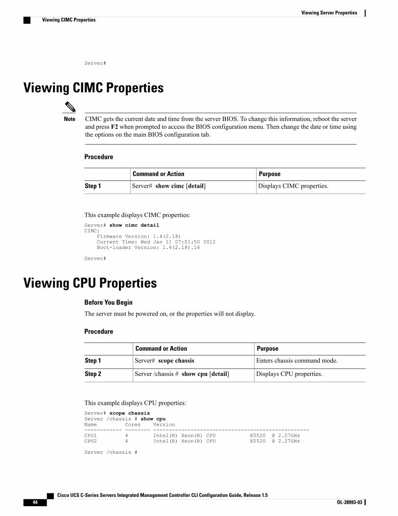
Server#
Viewing CIMC Properties
CIMC gets the current date and time from the server BIOS. To change this information, reboot the serverand press F2 when prompted to access the BIOS configuration menu. Then change the date or time usingthe options on the main BIOS configuration tab.
Note
Procedure
PurposeCommand or Action
Displays CIMC properties.Server# show cimc [detail]Step 1
This example displays CIMC properties:Server# show cimc detailCIMC:
Firmware Version: 1.4(2.18)Current Time: Wed Jan 11 07:01:50 2012Boot-loader Version: 1.4(2.18).16
Server#
Viewing CPU PropertiesBefore You Begin
The server must be powered on, or the properties will not display.
Procedure
PurposeCommand or Action
Enters chassis command mode.Server# scope chassisStep 1
Displays CPU properties.Server /chassis # show cpu [detail]Step 2
This example displays CPU properties:Server# scope chassisServer /chassis # show cpuName Cores Version------------ -------- --------------------------------------------------CPU1 4 Intel(R) Xeon(R) CPU E5520 @ 2.27GHzCPU2 4 Intel(R) Xeon(R) CPU E5520 @ 2.27GHz
Server /chassis #
Cisco UCS C-Series Servers Integrated Management Controller CLI Configuration Guide, Release 1.544 OL-28993-03
Viewing Server PropertiesViewing CIMC Properties
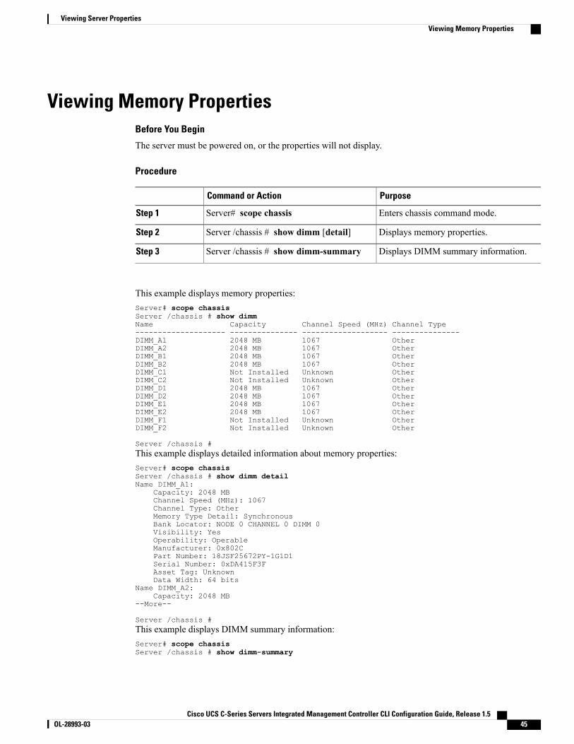
Viewing Memory PropertiesBefore You Begin
The server must be powered on, or the properties will not display.
Procedure
PurposeCommand or Action
Enters chassis command mode.Server# scope chassisStep 1
Displays memory properties.Server /chassis # show dimm [detail]Step 2
Displays DIMM summary information.Server /chassis # show dimm-summaryStep 3
This example displays memory properties:Server# scope chassisServer /chassis # show dimmName Capacity Channel Speed (MHz) Channel Type-------------------- --------------- ------------------- ---------------DIMM_A1 2048 MB 1067 OtherDIMM_A2 2048 MB 1067 OtherDIMM_B1 2048 MB 1067 OtherDIMM_B2 2048 MB 1067 OtherDIMM_C1 Not Installed Unknown OtherDIMM_C2 Not Installed Unknown OtherDIMM_D1 2048 MB 1067 OtherDIMM_D2 2048 MB 1067 OtherDIMM_E1 2048 MB 1067 OtherDIMM_E2 2048 MB 1067 OtherDIMM_F1 Not Installed Unknown OtherDIMM_F2 Not Installed Unknown Other
Server /chassis #This example displays detailed information about memory properties:Server# scope chassisServer /chassis # show dimm detailName DIMM_A1:
Capacity: 2048 MBChannel Speed (MHz): 1067Channel Type: OtherMemory Type Detail: SynchronousBank Locator: NODE 0 CHANNEL 0 DIMM 0Visibility: YesOperability: OperableManufacturer: 0x802CPart Number: 18JSF25672PY-1G1D1Serial Number: 0xDA415F3FAsset Tag: UnknownData Width: 64 bits
Name DIMM_A2:Capacity: 2048 MB
--More--
Server /chassis #This example displays DIMM summary information:Server# scope chassisServer /chassis # show dimm-summary
Cisco UCS C-Series Servers Integrated Management Controller CLI Configuration Guide, Release 1.5 OL-28993-03 45
Viewing Server PropertiesViewing Memory Properties
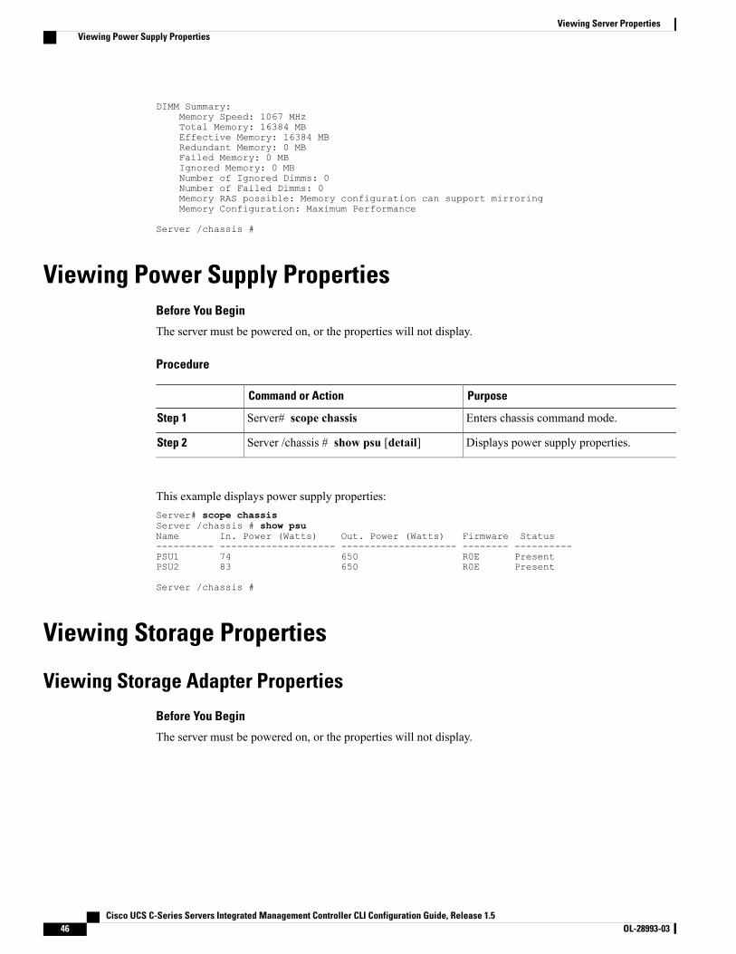
DIMM Summary:Memory Speed: 1067 MHzTotal Memory: 16384 MBEffective Memory: 16384 MBRedundant Memory: 0 MBFailed Memory: 0 MBIgnored Memory: 0 MBNumber of Ignored Dimms: 0Number of Failed Dimms: 0Memory RAS possible: Memory configuration can support mirroringMemory Configuration: Maximum Performance
Server /chassis #
Viewing Power Supply PropertiesBefore You Begin
The server must be powered on, or the properties will not display.
Procedure
PurposeCommand or Action
Enters chassis command mode.Server# scope chassisStep 1
Displays power supply properties.Server /chassis # show psu [detail]Step 2
This example displays power supply properties:Server# scope chassisServer /chassis # show psuName In. Power (Watts) Out. Power (Watts) Firmware Status---------- -------------------- -------------------- -------- ----------PSU1 74 650 R0E PresentPSU2 83 650 R0E Present
Server /chassis #
Viewing Storage Properties
Viewing Storage Adapter Properties
Before You Begin
The server must be powered on, or the properties will not display.
Cisco UCS C-Series Servers Integrated Management Controller CLI Configuration Guide, Release 1.546 OL-28993-03
Viewing Server PropertiesViewing Power Supply Properties
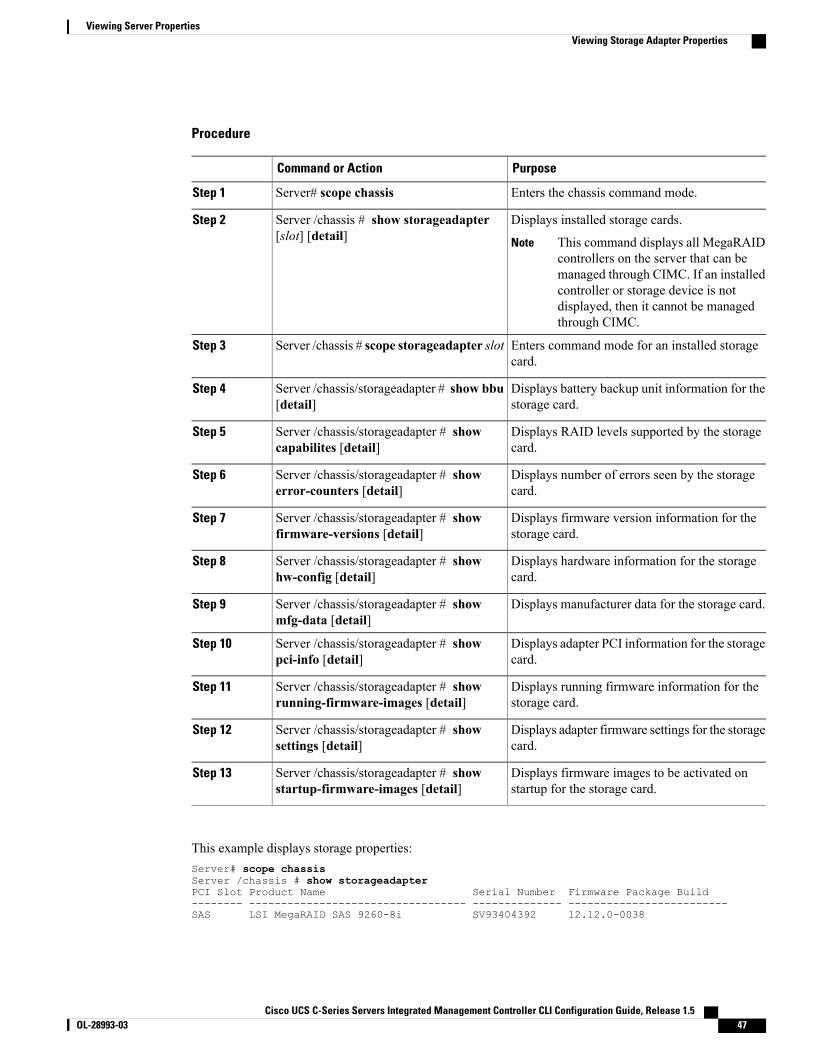
Procedure
PurposeCommand or Action
Enters the chassis command mode.Server# scope chassisStep 1
Displays installed storage cards.Server /chassis # show storageadapter[slot] [detail]
Step 2
This command displays all MegaRAIDcontrollers on the server that can bemanaged through CIMC. If an installedcontroller or storage device is notdisplayed, then it cannot be managedthrough CIMC.
Note
Enters command mode for an installed storagecard.
Server /chassis # scope storageadapter slotStep 3
Displays battery backup unit information for thestorage card.
Server /chassis/storageadapter # show bbu[detail]
Step 4
Displays RAID levels supported by the storagecard.
Server /chassis/storageadapter # showcapabilites [detail]
Step 5
Displays number of errors seen by the storagecard.
Server /chassis/storageadapter # showerror-counters [detail]
Step 6
Displays firmware version information for thestorage card.
Server /chassis/storageadapter # showfirmware-versions [detail]
Step 7
Displays hardware information for the storagecard.
Server /chassis/storageadapter # showhw-config [detail]
Step 8
Displays manufacturer data for the storage card.Server /chassis/storageadapter # showmfg-data [detail]
Step 9
Displays adapter PCI information for the storagecard.
Server /chassis/storageadapter # showpci-info [detail]
Step 10
Displays running firmware information for thestorage card.
Server /chassis/storageadapter # showrunning-firmware-images [detail]
Step 11
Displays adapter firmware settings for the storagecard.
Server /chassis/storageadapter # showsettings [detail]
Step 12
Displays firmware images to be activated onstartup for the storage card.
Server /chassis/storageadapter # showstartup-firmware-images [detail]
Step 13
This example displays storage properties:Server# scope chassisServer /chassis # show storageadapterPCI Slot Product Name Serial Number Firmware Package Build-------- ---------------------------------- -------------- -------------------------SAS LSI MegaRAID SAS 9260-8i SV93404392 12.12.0-0038
Cisco UCS C-Series Servers Integrated Management Controller CLI Configuration Guide, Release 1.5 OL-28993-03 47
Viewing Server PropertiesViewing Storage Adapter Properties
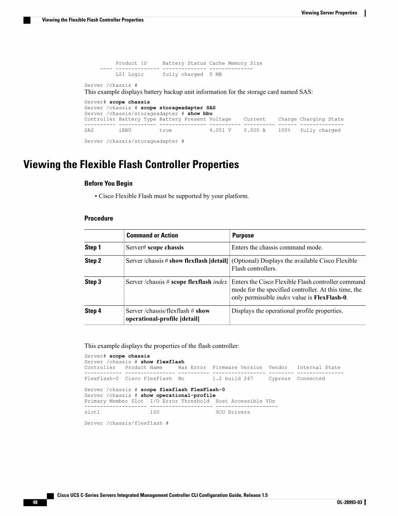
Product ID Battery Status Cache Memory Size---- -------------- -------------- --------------
LSI Logic fully charged 0 MB
Server /chassis #This example displays battery backup unit information for the storage card named SAS:Server# scope chassisServer /chassis # scope storageadapter SASServer /chassis/storageadapter # show bbuController Battery Type Battery Present Voltage Current Charge Charging State---------- ------------ --------------- ---------- ---------- ------ --------------SAS iBBU true 4.051 V 0.000 A 100% fully charged
Server /chassis/storageadapter #
Viewing the Flexible Flash Controller Properties
Before You Begin
• Cisco Flexible Flash must be supported by your platform.
Procedure
PurposeCommand or Action
Enters the chassis command mode.Server# scope chassisStep 1
(Optional) Displays the available Cisco FlexibleFlash controllers.
Server /chassis # show flexflash [detail]Step 2
Enters the Cisco Flexible Flash controller commandmode for the specified controller. At this time, theonly permissible index value is FlexFlash-0.
Server /chassis # scope flexflash indexStep 3
Displays the operational profile properties.Server /chassis/flexflash # showoperational-profile [detail]
Step 4
This example displays the properties of the flash controller:Server# scope chassisServer /chassis # show flexflashController Product Name Has Error Firmware Version Vendor Internal State------------ ---------------- ---------- ----------------- -------- ---------------FlexFlash-0 Cisco FlexFlash No 1.2 build 247 Cypress Connected
Server /chassis # scope flexflash FlexFlash-0Server /chassis # show operational-profilePrimary Member Slot I/O Error Threshold Host Accessible VDs-------------------- -------------------- --------------------slot1 100 SCU Drivers
Server /chassis/flexflash #
Cisco UCS C-Series Servers Integrated Management Controller CLI Configuration Guide, Release 1.548 OL-28993-03
Viewing Server PropertiesViewing the Flexible Flash Controller Properties
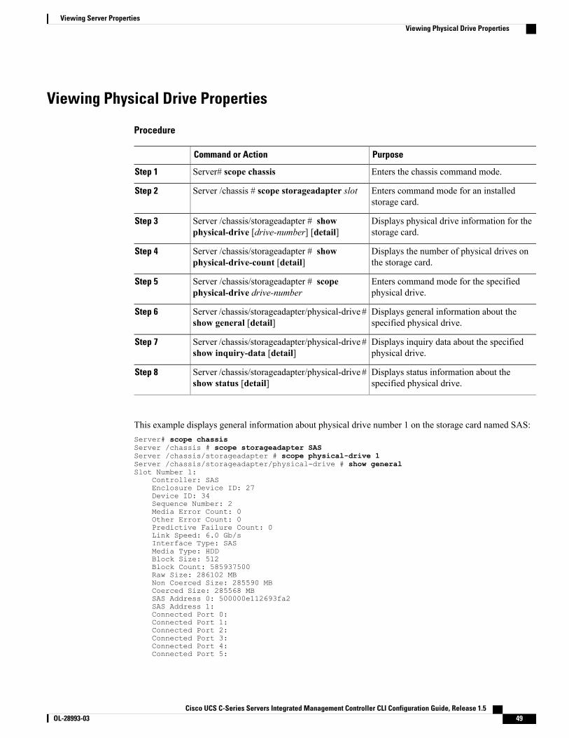
Viewing Physical Drive Properties
Procedure
PurposeCommand or Action
Enters the chassis command mode.Server# scope chassisStep 1
Enters command mode for an installedstorage card.
Server /chassis # scope storageadapter slotStep 2
Displays physical drive information for thestorage card.
Server /chassis/storageadapter # showphysical-drive [drive-number] [detail]
Step 3
Displays the number of physical drives onthe storage card.
Server /chassis/storageadapter # showphysical-drive-count [detail]
Step 4
Enters command mode for the specifiedphysical drive.
Server /chassis/storageadapter # scopephysical-drive drive-number
Step 5
Displays general information about thespecified physical drive.
Server /chassis/storageadapter/physical-drive #show general [detail]
Step 6
Displays inquiry data about the specifiedphysical drive.
Server /chassis/storageadapter/physical-drive #show inquiry-data [detail]
Step 7
Displays status information about thespecified physical drive.
Server /chassis/storageadapter/physical-drive #show status [detail]
Step 8
This example displays general information about physical drive number 1 on the storage card named SAS:Server# scope chassisServer /chassis # scope storageadapter SASServer /chassis/storageadapter # scope physical-drive 1Server /chassis/storageadapter/physical-drive # show generalSlot Number 1:
Controller: SASEnclosure Device ID: 27Device ID: 34Sequence Number: 2Media Error Count: 0Other Error Count: 0Predictive Failure Count: 0Link Speed: 6.0 Gb/sInterface Type: SASMedia Type: HDDBlock Size: 512Block Count: 585937500Raw Size: 286102 MBNon Coerced Size: 285590 MBCoerced Size: 285568 MBSAS Address 0: 500000e112693fa2SAS Address 1:Connected Port 0:Connected Port 1:Connected Port 2:Connected Port 3:Connected Port 4:Connected Port 5:
Cisco UCS C-Series Servers Integrated Management Controller CLI Configuration Guide, Release 1.5 OL-28993-03 49
Viewing Server PropertiesViewing Physical Drive Properties
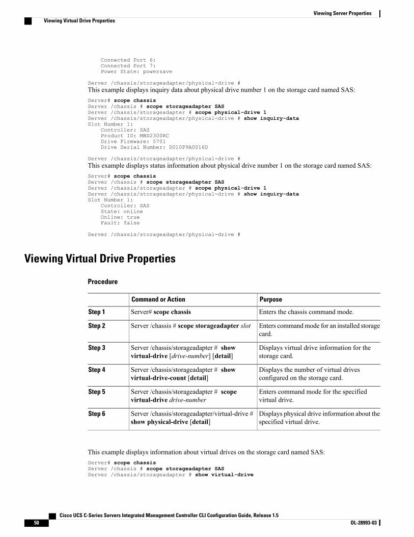
Connected Port 6:Connected Port 7:Power State: powersave
Server /chassis/storageadapter/physical-drive #This example displays inquiry data about physical drive number 1 on the storage card named SAS:Server# scope chassisServer /chassis # scope storageadapter SASServer /chassis/storageadapter # scope physical-drive 1Server /chassis/storageadapter/physical-drive # show inquiry-dataSlot Number 1:
Controller: SASProduct ID: MBD2300RCDrive Firmware: 5701Drive Serial Number: D010P9A0016D
Server /chassis/storageadapter/physical-drive #This example displays status information about physical drive number 1 on the storage card named SAS:Server# scope chassisServer /chassis # scope storageadapter SASServer /chassis/storageadapter # scope physical-drive 1Server /chassis/storageadapter/physical-drive # show inquiry-dataSlot Number 1:
Controller: SASState: onlineOnline: trueFault: false
Server /chassis/storageadapter/physical-drive #
Viewing Virtual Drive Properties
Procedure
PurposeCommand or Action
Enters the chassis command mode.Server# scope chassisStep 1
Enters commandmode for an installed storagecard.
Server /chassis # scope storageadapter slotStep 2
Displays virtual drive information for thestorage card.
Server /chassis/storageadapter # showvirtual-drive [drive-number] [detail]
Step 3
Displays the number of virtual drivesconfigured on the storage card.
Server /chassis/storageadapter # showvirtual-drive-count [detail]
Step 4
Enters command mode for the specifiedvirtual drive.
Server /chassis/storageadapter # scopevirtual-drive drive-number
Step 5
Displays physical drive information about thespecified virtual drive.
Server /chassis/storageadapter/virtual-drive #show physical-drive [detail]
Step 6
This example displays information about virtual drives on the storage card named SAS:Server# scope chassisServer /chassis # scope storageadapter SASServer /chassis/storageadapter # show virtual-drive
Cisco UCS C-Series Servers Integrated Management Controller CLI Configuration Guide, Release 1.550 OL-28993-03
Viewing Server PropertiesViewing Virtual Drive Properties

Virtual Drive Status Name Size RAID Level-------------- --------------- ------------------------ ---------- ----------0 Optimal SLES1SP1beta5 30720 MB RAID 01 Optimal RHEL5.5 30720 MB RAID 02 Optimal W2K8R2_DC 30720 MB RAID 03 Optimal VD_3 30720 MB RAID 04 Optimal ESX4.0u2 30720 MB RAID 05 Optimal VMs 285568 MB RAID 06 Optimal RHEL6-35GB 35840 MB RAID 07 Optimal OS_Ins_Test_DR 158720 MB RAID 08 Optimal 285568 MB RAID 1
Server /chassis/storageadapter #This example displays physical drive information about virtual drive number 1 on the storage card namedSAS:Server# scope chassisServer /chassis # scope storageadapter SASServer /chassis/storageadapter # scope virtual-drive 1Server /chassis/storageadapter/virtual-drive # show physical-driveSpan Physical Drive Status Starting Block Number Of Blocks----- -------------- ---------- -------------- ----------------0 12 online 62914560 62914560
Server /chassis/storageadapter/virtual-drive #
Viewing Nvidia GPU Card InformationThese commands are not available on all UCS C-series servers.
Before You Begin
The server must be powered on to view information on the Nvidia GPU cards.
Procedure
PurposeCommand or Action
Enters the chassis command mode.Server# scope chassisStep 1
Displays the available Nvidia GPU cards on thesystem.
Server /chassis # show gpuStep 2
Enters the GPU card command mode. Specify theslot number of the GPU card.
Server /chassis # scope gpuslot-number
Step 3
Displays temperature information on the GPUcards.
Server /chassis/gpu # show gpu-listStep 4
This example shows how to view the temperature information of the available GPU cards on the system:Server # scope chassisServer /chassis # show gpu
Slot Product Name Num of GPUs---- ------------ -----------5 Nvidia GRID K2 @ BD 2
Server /chassis # scope gpu 5Server /chassis/gpu # show gpu-list
Cisco UCS C-Series Servers Integrated Management Controller CLI Configuration Guide, Release 1.5 OL-28993-03 51
Viewing Server PropertiesViewing Nvidia GPU Card Information

GPU ID Temperature------ -----------0 321 33
Server /chassis/gpu #
Viewing PCI Adapter PropertiesBefore You Begin
The server must be powered on, or the properties will not display.
Procedure
PurposeCommand or Action
Enters the chassis command mode.Server# scope chassisStep 1
Displays PCI adapter properties.Server /chassis # show pci-adapter [detail]Step 2
This example displays PCI adapter properties:Server# scope chassisServer /chassis # show pci-adapterName Slot Vendor ID Device ID Product Name---------------- ----- ------------ ------------ -------------------------PCIe Adapter1 1 0x1137 0x0042 Cisco UCS P81E Virtual...PCIe Adapter2 5 0x1077 0x2432 Qlogic QLE2462 4Gb dua...
Server /chassis #
Viewing Network Related Properties
Viewing LOM PropertiesYou can view the MAC addresses of the LAN On Motherboard (LOM) Ethernet ports.
Procedure
PurposeCommand or Action
Enters the chassis command mode.Server# scope chassisStep 1
Enters the specific network adapter commandmode.
Server /chassis # scope network-adapter slotID
Step 2
Displays the MAC addresses of the LOMports.
Server /chassis/network-adapter # showmac-list [detail]
Step 3
Cisco UCS C-Series Servers Integrated Management Controller CLI Configuration Guide, Release 1.552 OL-28993-03
Viewing Server PropertiesViewing PCI Adapter Properties

This example shows how to display the MAC addresses of the LOM ports:Server# scope chassisServer /chassis # scope network-adapter LServer /chassis/network-adapter # show mac-listInterface ID MAC Address------------- --------------------eth0 010000002000eth1 010000002000
Server /chassis/network-adapter #
Cisco UCS C-Series Servers Integrated Management Controller CLI Configuration Guide, Release 1.5 OL-28993-03 53
Viewing Server PropertiesViewing LOM Properties

Cisco UCS C-Series Servers Integrated Management Controller CLI Configuration Guide, Release 1.554 OL-28993-03
Viewing Server PropertiesViewing LOM Properties

C H A P T E R 5Viewing Server Sensors
This chapter includes the following sections:
• Viewing Power Supply Sensors, page 55
• Viewing Fan Sensors, page 56
• Viewing Temperature Sensors, page 56
• Viewing Voltage Sensors, page 57
• Viewing Current Sensors, page 58
• Viewing Storage Sensors, page 58
Viewing Power Supply SensorsProcedure
PurposeCommand or Action
Enters sensor command mode.Server# scope sensorStep 1
Displays power supply sensor statistics for theserver.
Server /sensor # show psu [detail]Step 2
Displays power supply redundancy sensor statusfor the server.
Server /sensor # show psu-redundancy[detail]
Step 3
This example displays power supply sensor statistics:Server# scope sensorServer /sensor # show psuName Sensor Status Reading Units Min. Warning Max. Warning
Min. Failure Max. Failure-------------------- -------------------- ---------- ---------- ------------------------------ --------------- ---------------PSU1_STATUS Normal present
Cisco UCS C-Series Servers Integrated Management Controller CLI Configuration Guide, Release 1.5 OL-28993-03 55

PSU2_STATUS Normal present
Server /sensor # show psu-redundancyName Reading Sensor Status-------------------- ---------- --------------------PSU_REDUNDANCY full Normal
Server /sensor #
Viewing Fan SensorsProcedure
PurposeCommand or Action
Enters sensor command mode.Server# scope sensorStep 1
Displays fan sensor statistics for the server.Server /sensor # show fan [detail]Step 2
This example displays fan sensor statistics:Server# scope sensorServer /sensor # show fanName Sensor Status Reading Units Min. Warning Max. WarningMin. Failure Max. Failure-------------------- -------------- ---------- ---------- --------------- ------------------------------ ---------------W793_FAN2_TACH1 Normal 2400 RPM N/A N/A800 N/AW793_FAN2_TACH2 Normal 2400 RPM N/A N/A800 N/AW793_FAN3_TACH1 Normal 2300 RPM N/A N/A800 N/AW793_FAN3_TACH2 Normal 2300 RPM N/A N/A800 N/AW793_FAN4_TACH1 Normal 2400 RPM N/A N/A800 N/AW793_FAN4_TACH2 Normal 1600 RPM N/A N/A800 N/A
Server /sensor #
Viewing Temperature SensorsProcedure
PurposeCommand or Action
Enters sensor command mode.Server# scope sensorStep 1
Displays temperature sensor statistics for theserver.
Server /sensor # show temperature [detail]Step 2
Cisco UCS C-Series Servers Integrated Management Controller CLI Configuration Guide, Release 1.556 OL-28993-03
Viewing Server SensorsViewing Fan Sensors
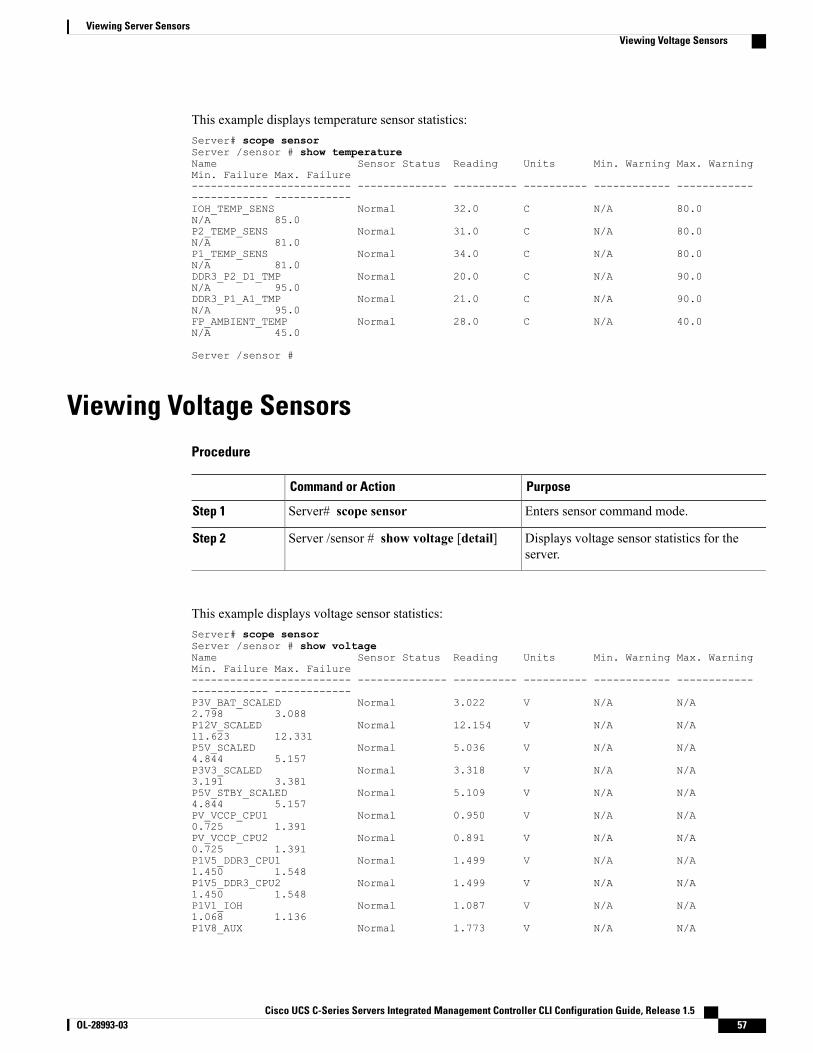
This example displays temperature sensor statistics:Server# scope sensorServer /sensor # show temperatureName Sensor Status Reading Units Min. Warning Max. WarningMin. Failure Max. Failure------------------------- -------------- ---------- ---------- ------------ ------------------------ ------------IOH_TEMP_SENS Normal 32.0 C N/A 80.0N/A 85.0P2_TEMP_SENS Normal 31.0 C N/A 80.0N/A 81.0P1_TEMP_SENS Normal 34.0 C N/A 80.0N/A 81.0DDR3_P2_D1_TMP Normal 20.0 C N/A 90.0N/A 95.0DDR3_P1_A1_TMP Normal 21.0 C N/A 90.0N/A 95.0FP_AMBIENT_TEMP Normal 28.0 C N/A 40.0N/A 45.0
Server /sensor #
Viewing Voltage SensorsProcedure
PurposeCommand or Action
Enters sensor command mode.Server# scope sensorStep 1
Displays voltage sensor statistics for theserver.
Server /sensor # show voltage [detail]Step 2
This example displays voltage sensor statistics:Server# scope sensorServer /sensor # show voltageName Sensor Status Reading Units Min. Warning Max. WarningMin. Failure Max. Failure------------------------- -------------- ---------- ---------- ------------ ------------------------ ------------P3V_BAT_SCALED Normal 3.022 V N/A N/A2.798 3.088P12V_SCALED Normal 12.154 V N/A N/A11.623 12.331P5V_SCALED Normal 5.036 V N/A N/A4.844 5.157P3V3_SCALED Normal 3.318 V N/A N/A3.191 3.381P5V_STBY_SCALED Normal 5.109 V N/A N/A4.844 5.157PV_VCCP_CPU1 Normal 0.950 V N/A N/A0.725 1.391PV_VCCP_CPU2 Normal 0.891 V N/A N/A0.725 1.391P1V5_DDR3_CPU1 Normal 1.499 V N/A N/A1.450 1.548P1V5_DDR3_CPU2 Normal 1.499 V N/A N/A1.450 1.548P1V1_IOH Normal 1.087 V N/A N/A1.068 1.136P1V8_AUX Normal 1.773 V N/A N/A
Cisco UCS C-Series Servers Integrated Management Controller CLI Configuration Guide, Release 1.5 OL-28993-03 57
Viewing Server SensorsViewing Voltage Sensors
1.744 1.852
Server /sensor #
Viewing Current SensorsProcedure
PurposeCommand or Action
Enters sensor command mode.Server# scope sensorStep 1
Displays current sensor statistics for the server.Server /sensor # show current [detail]Step 2
This example displays current sensor statistics:Server# scope sensorServer /sensor # show currentName Sensor Status Reading Units Min. Warning Max. WarningMin. Failure Max. Failure------------------------- -------------- ---------- ---------- ------------ ------------------------ ------------VR_P2_IMON Normal 16.00 AMP N/A 147.20N/A 164.80VR_P1_IMON Normal 27.20 AMP N/A 147.20N/A 164.80
Server /sensor #
Viewing Storage SensorsProcedure
PurposeCommand or Action
Enters chassis command mode.Server# scope chassisStep 1
Displays storage sensor information.Server /chassis # show hdd [detail]Step 2
The displayed fields are described in the following table:DescriptionName
The name of the storage device.Name column
A brief description of the storage device status.Status column
Cisco UCS C-Series Servers Integrated Management Controller CLI Configuration Guide, Release 1.558 OL-28993-03
Viewing Server SensorsViewing Current Sensors

DescriptionName
The current LED color, if any.
To make the physical LED on the storage device blink, select Turn Onfrom the drop-down list. To let the storage device control whether theLED blinks, select Turn Off.
This information is only available for some C-Seriesservers.
Note
LED Status column
This example displays storage sensor information:Server# scope chassisServer /chassis # show hddName Status-------------------- --------------------HDD_01_STATUS presentHDD_02_STATUS presentHDD_03_STATUS presentHDD_04_STATUS present
Server /chassis #
Cisco UCS C-Series Servers Integrated Management Controller CLI Configuration Guide, Release 1.5 OL-28993-03 59
Viewing Server SensorsViewing Storage Sensors

Cisco UCS C-Series Servers Integrated Management Controller CLI Configuration Guide, Release 1.560 OL-28993-03
Viewing Server SensorsViewing Storage Sensors
C H A P T E R 6Managing Remote Presence
This chapter includes the following sections:
• Managing the Virtual KVM, page 61
• Configuring Virtual Media, page 64
• Managing Serial over LAN, page 68
Managing the Virtual KVM
KVM ConsoleThe KVM console is an interface accessible from CIMC that emulates a direct keyboard, video, and mouse(KVM) connection to the server. The KVM console allows you to connect to the server from a remote location.
Instead of using CD/DVD or floppy drives physically connected to the server, the KVM console uses virtualmedia, which are actual disk drives or disk image files that are mapped to virtual CD/DVD or floppy drives.You can map any of the following to a virtual drive:
• CD/DVD or floppy drive on your computer
• Disk image files (ISO or IMG files) on your computer
• USB flash drive on your computer
• CD/DVD or floppy drive on the network
• Disk image files (ISO or IMG files) on the network
• USB flash drive on the network
You can use the KVM console to install an OS on the server.
The KVM Console is operated only through the GUI. To launch the KVM Console, see the instructionsin the Cisco UCS C-Series Servers Integrated Management Controller GUI Configuration Guide.
Note
Cisco UCS C-Series Servers Integrated Management Controller CLI Configuration Guide, Release 1.5 OL-28993-03 61
Enabling the Virtual KVM
Before You Begin
You must log in as a user with admin privileges to enable the virtual KVM.
Procedure
PurposeCommand or Action
Enters KVM command mode.Server# scope kvmStep 1
Enables the virtual KVM.Server /kvm # set enabled yesStep 2
Commits the transaction to the systemconfiguration.
Server /kvm # commitStep 3
(Optional) Displays the virtual KVMconfiguration.
Server /kvm # show [detail]Step 4
This example enables the virtual KVM:Server# scope kvmServer /kvm # set enabled yesServer /kvm *# commitServer /kvm # showEncryption Enabled Local Video Active Sessions Enabled KVM Port------------------ ---------------- --------------- ------- --------no yes 0 yes 2068
Server /kvm #
Disabling the Virtual KVM
Before You Begin
You must log in as a user with admin privileges to disable the virtual KVM.
Procedure
PurposeCommand or Action
Enters KVM command mode.Server# scope kvmStep 1
Disables the virtual KVM.Server /kvm # set enabled noStep 2
Disabling the virtual KVM disables access tothe virtual media feature, but does not detachthe virtual media devices if virtual media isenabled.
Note
Cisco UCS C-Series Servers Integrated Management Controller CLI Configuration Guide, Release 1.562 OL-28993-03
Managing Remote PresenceEnabling the Virtual KVM

PurposeCommand or Action
Commits the transaction to the system configuration.Server /kvm # commitStep 3
(Optional) Displays the virtual KVM configuration.Server /kvm # show [detail]Step 4
This example disables the virtual KVM:Server# scope kvmServer /kvm # set enabled noServer /kvm *# commitServer /kvm # showEncryption Enabled Local Video Active Sessions Enabled KVM Port------------------ ---------------- --------------- ------- --------no yes 0 no 2068
Server /kvm #
Configuring the Virtual KVM
Before You Begin
You must log in as a user with admin privileges to configure the virtual KVM.
Procedure
PurposeCommand or Action
Enters KVM command mode.Server# scope kvmStep 1
Enables or disables the virtual KVM.Server /kvm # set enabled {yes | no}Step 2
If encryption is enabled, the server encrypts all videoinformation sent through the KVM.
Server /kvm # set encrypted {yes |no}
Step 3
Specifies the port used for KVM communication.Server /kvm # set kvm-port portStep 4
If local video is yes, the KVM session is alsodisplayed on any monitor attached to the server.
Server /kvm # set local-video {yes |no}
Step 5
Specifies the maximum number of concurrent KVMsessions allowed. The sessions argument is an integerbetween 1 and 4.
Server /kvm # set max-sessionssessions
Step 6
Commits the transaction to the system configuration.Server /kvm # commitStep 7
(Optional) Displays the virtual KVM configuration.Server /kvm # show [detail]Step 8
This example configures the virtual KVM and displays the configuration:Server# scope kvmServer /kvm # set enabled yesServer /kvm *# set encrypted no
Cisco UCS C-Series Servers Integrated Management Controller CLI Configuration Guide, Release 1.5 OL-28993-03 63
Managing Remote PresenceConfiguring the Virtual KVM
Server /kvm *# set kvm-port 2068Server /kvm *# set max-sessions 4Server /kvm *# set local-video yesServer /kvm *# commitServer /kvm # show detailKVM Settings:
Encryption Enabled: noMax Sessions: 4Local Video: yesActive Sessions: 0Enabled: yesKVM Port: 2068
Server /kvm #
What to Do Next
Launch the virtual KVM from the GUI.
Configuring Virtual MediaBefore You Begin
You must log in as a user with admin privileges to configure virtual media.
Procedure
PurposeCommand or Action
Enters virtual media command mode.Server# scope vmediaStep 1
Enables or disables virtual media. By default, virtual media isdisabled.
Server /vmedia # set enabled{yes | no}
Step 2
Disabling virtual media detaches the virtual CD,virtual floppy, and virtual HDD devices from the host.
Note
Enables or disables virtual media encryption.Server /vmedia # setencryption {yes | no}
Step 3
Enables or disables low power USB.Server /vmedia # setlow-power-usb-enabled {yes |no}
Step 4
While mapping an ISO to a server which has a UCSVIC P81E card and the NIC is in Cisco Card mode:
Note
• If the low power USB is enabled, after mappingthe ISO and rebooting the host the card resetsand ISO mapping is lost. The virtual drives arenot visible on the boot selection menu.
• If the low power USB is disabled, after mappingthe ISO, and rebooting the host and the CIMC,the virtual drivers appear on the boot selectionmenu as expected.
Commits the transaction to the system configuration.Server /vmedia # commitStep 5
Cisco UCS C-Series Servers Integrated Management Controller CLI Configuration Guide, Release 1.564 OL-28993-03
Managing Remote PresenceConfiguring Virtual Media
PurposeCommand or Action
(Optional) Displays the virtual media configuration.Server /vmedia # show [detail]Step 6
This example configures virtual media encryption:Server# scope vmediaServer /vmedia # set enabled yesServer /vmedia *# set encryption yesServer /vmedia *# set low-power-use-enabled noServer /vmedia *# commitServer /vmedia # show detailvMedia Settings:
Encryption Enabled: yesEnabled: yesMax Sessions: 1Active Sessions: 0Low Power USB Enabled: no
Server /vmedia #
What to Do Next
Use the KVM to attach virtual media devices to a host.
Configuring a CIMC-Mapped vMedia Volume
Before You Begin
You must log in with admin privileges to perform this task.
Procedure
PurposeCommand or Action
Enters the virtual media command mode.Server # scope vmediaStep 1
Maps a CIFS file for vMedia. Youmust specify the following:Server /vmedia # map-cifs{volume-name | remote-share |remote-file-path [mount options]
Step 2
• Name of the volume to create
• Remote share including IP address and the exporteddirectory
• Path of the remote file corresponding to the exporteddirectory.
• (Optional) Mapping options
• Username and password to connect to the server
Maps an NFS file for vMedia. You must specify thefollowing:
Server /vmedia # map-nfs{volume-name | remote-share |remote-file-path} [mount options]
Step 3
• Name of the volume to create
Cisco UCS C-Series Servers Integrated Management Controller CLI Configuration Guide, Release 1.5 OL-28993-03 65
Managing Remote PresenceConfiguring a CIMC-Mapped vMedia Volume

PurposeCommand or Action
• Remote share including IP address and the exporteddirectory
• Path of the remote file corresponding to the exporteddirectory.
• (Optional) Mapping options
Maps an HTTPS file for vMedia. You must specify thefollowing:
Server /vmedia # map-www{volume-name | remote-share |remote-file-path [mount options]
Step 4
• Name of the volume to create
• Remote share including IP address and the exporteddirectory
• Path of the remote file corresponding to the exporteddirectory.
• (Optional) Mapping options
• Username and password to connect to the server
This example shows how to create a CIFS CIMC-mapped vmedia settings:Server # scope vmediaServer /vmedia # map-cifs sample-volume //10.10.10.10/project /test/sampleServer username:Server password: ****Confirm password: ****
Server /vmedia #
Viewing CIMC-Mapped vMedia Volume Properties
Before You Begin
You must log in with admin privileges to perform this task.
Procedure
PurposeCommand or Action
Enters the virtual media command mode.Server # scope vmediaStep 1
Displays information on all the vmedia mappingthat are configured.
Server /vmedia # show mappings detailStep 2
Cisco UCS C-Series Servers Integrated Management Controller CLI Configuration Guide, Release 1.566 OL-28993-03
Managing Remote PresenceViewing CIMC-Mapped vMedia Volume Properties
This example shows how to view the properties of all the configured vmedia mapping:Server # scope vmediaServer /vmedia # show mappings
Volume Map-status Drive-type remote-share remote-file mount-type------ ---------- ------------ --------------------- ------------------- -----------
Huu OK removable http://10.104.236.99/ rhel-server-6.1-x86_6.iso wwwRhel OK CD http://10.104.236.99/ rhel-server-6.1-x86_6.iso www
Removing a CIMC-Mapped Mounted vMedia Volume
Before You Begin
You must log in with admin privileges to perform this task.
Procedure
PurposeCommand or Action
Enters the virtual media command mode.Server # scope vmediaStep 1
Specifies the volume name to unmap.Server /vmedia # unmap volume_nameStep 2
This example shows how to unmap a CIMC-mapped vmedia volume:Server # scope vmediaServer /vmedia # show mappings
Volume Map-status Drive-type remote-share remote-file mount-type------ ---------- ------------ --------------------- ------------------- -----------
Huu OK removable http://10.104.236.99/ rhel-server-6.1-x86_6.iso wwwRhel OK CD http://10.104.236.99/ rhel-server-6.1-x86_6.iso www
Server /vmedia # unmap huuServer /vmedia # show mappings
Volume Map-status Drive-type remote-share remote-file mount-type------ ---------- ------------ --------------------- ------------------- -----------
Rhel OK CD http://10.104.236.99/ rhel-server-6.1-x86_6.iso www
Server /vmedia #
Cisco UCS C-Series Servers Integrated Management Controller CLI Configuration Guide, Release 1.5 OL-28993-03 67
Managing Remote PresenceRemoving a CIMC-Mapped Mounted vMedia Volume

Managing Serial over LAN
Serial Over LANSerial over LAN (SoL) is a mechanism that enables the input and output of the serial port of a managed systemto be redirected via an SSH session over IP. SoL provides a means of reaching the host console via CIMC.
Guidelines and Restrictions for Serial Over LANFor redirection to SoL, the server console must have the following configuration:
• console redirection to serial port A
• no flow control
• baud rate the same as configured for SoL
• VT-100 terminal type
• legacy OS redirection disabled
The SoL session will display line-oriented information such as boot messages, and character-oriented screenmenus such as BIOS setup menus. If the server boots an operating system or application with a bitmap-orienteddisplay, such asWindows, the SoL session will no longer display. If the server boots a command-line-orientedoperating system (OS), such as Linux, you may need to perform additional configuration of the OS in orderto properly display in an SoL session.
In the SoL session, your keystrokes are transmitted to the console except for the function key F2. To send anF2 to the console, press the Escape key, then press 2.
Configuring Serial Over LAN
Before You Begin
You must log in as a user with admin privileges to configure serial over LAN (SoL).
Procedure
PurposeCommand or Action
Enters SoL command mode.Server# scope solStep 1
Enables or disables SoL on this server.Server /sol # set enabled{yes | no}
Step 2
Sets the serial baud rate the system uses for SoL communication.Server /sol # set baud-rate{9600 | 19200 | 38400 |57600 | 115200}
Step 3
The baud rate must match the baud rate configured in theserver serial console.
Note
Cisco UCS C-Series Servers Integrated Management Controller CLI Configuration Guide, Release 1.568 OL-28993-03
Managing Remote PresenceManaging Serial over LAN
PurposeCommand or Action
(Optional)Sets the serial port through which the system routes SoLcommunications.
Server /sol # set comport{com0 | com1
Step 4
This field is only available on some C-Series servers. If itis not available, the server always uses COM port 0 forSoL communication.
Note
You can specify:
• com0—SoL communication is routed through COM port 0,an externally accessible serial port that supports either aphysical RJ45 connection to an external device or a virtualSoL connection to a network device.
If you select this option, the system enables SoL and disablesthe RJ45 connection, which means that the server can nolonger support an external serial device.
• com1—SoL communication is routed through COM port 1,an internal port accessible only through SoL.
If you select this option, you can use SoL on COM port 1 andthe physical RJ45 connection on COM port 0.
Changing the comport setting disconnects any existingSoL sessions.
Note
Commits the transaction to the system configuration.Server /sol # commitStep 5
(Optional) Displays the SoL settings.Server /sol # show [detail]Step 6
This example configures SoL:Server# scope solServer /sol # set enabled yesServer /sol *# set baud-rate 115200Server /sol *# commitServer /sol # showEnabled Baud Rate(bps) Com Port------- --------------- --------yes 115200 com2Server /sol # show detailSerial Over LAN:
Enabled: yesBaud Rate(bps): 115200Com Port: com2
Server /sol #
Cisco UCS C-Series Servers Integrated Management Controller CLI Configuration Guide, Release 1.5 OL-28993-03 69
Managing Remote PresenceConfiguring Serial Over LAN
Launching Serial Over LAN
Procedure
PurposeCommand or Action
Opens a serial over LAN (SoL) connection to the redirectedserver console port. You can enter this command in anycommand mode.
Server# connect hostStep 1
What to Do Next
To end the SoL session, you must close the CLI session. For example, to end an SoL session over an SSHconnection, disconnect the SSH connection.
Cisco UCS C-Series Servers Integrated Management Controller CLI Configuration Guide, Release 1.570 OL-28993-03
Managing Remote PresenceLaunching Serial Over LAN
C H A P T E R 7Managing User Accounts
This chapter includes the following sections:
• Configuring Local Users, page 71
• LDAP Servers, page 72
• Configuring the LDAP Server, page 73
• Configuring LDAP in CIMC, page 74
• Configuring LDAP Groups in CIMC, page 75
• Viewing User Sessions, page 77
• Terminating a User Session, page 77
Configuring Local UsersBefore You Begin
You must log in as a user with admin privileges to configure or modify local user accounts.
Procedure
PurposeCommand or Action
Enters user command mode for user number usernumber.Server# scope user usernumberStep 1
Enables or disables the user account on the CIMC.Server /user # set enabled {yes| no}
Step 2
Specifies the username for the user.Server /user # set nameusername
Step 3
You are prompted to enter the password twice.Server /user # set passwordStep 4
Cisco UCS C-Series Servers Integrated Management Controller CLI Configuration Guide, Release 1.5 OL-28993-03 71
PurposeCommand or Action
Specifies the role assigned to the user. The roles are asfollows:
Server /user # set role {readonly| user | admin}
Step 5
• readonly—This user can view information but cannotmake any changes.
• user—This user can do the following:
• View all information
• Manage the power control options such as poweron, power cycle, and power off
• Launch the KVM console and virtual media
• Clear all logs
• Toggle the locator LED
• admin—This user can perform all actions availablethrough the GUI, CLI, and IPMI.
Commits the transaction to the system configuration.Server /user # commitStep 6
This example configures user 5 as an admin:Server# scope user 5Server /user # set enabled yesServer /user *# set name johnServer /user *# set passwordPlease enter password:Please confirm password:Server /user *# set role readonlyServer /user *# commitServer /user # showUser Name Role Enabled------ ---------------- -------- --------5 john readonly yes
LDAP ServersCIMC supports directory services that organize information in a directory, and manage access to thisinformation. CIMC supports Lightweight Directory Access Protocol (LDAP), which stores and maintainsdirectory information in a network. In addition, CIMC supports Microsoft Active Directory (AD). ActiveDirectory is a technology that provides a variety of network services including LDAP-like directory services,Kerberos-based authentication, and DNS-based naming. The CIMC utilizes the Kerberos-based authenticationservice of LDAP.
When LDAP is enabled in the CIMC, user authentication and role authorization is performed by the LDAPserver for user accounts not found in the local user database. The LDAP user authentication format [email protected].
Cisco UCS C-Series Servers Integrated Management Controller CLI Configuration Guide, Release 1.572 OL-28993-03
Managing User AccountsLDAP Servers
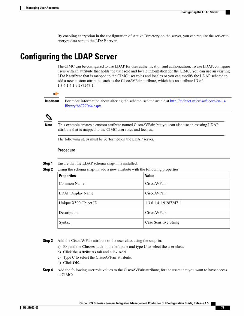
By enabling encryption in the configuration of Active Directory on the server, you can require the server toencrypt data sent to the LDAP server.
Configuring the LDAP ServerThe CIMC can be configured to use LDAP for user authentication and authorization. To use LDAP, configureusers with an attribute that holds the user role and locale information for the CIMC. You can use an existingLDAP attribute that is mapped to the CIMC user roles and locales or you can modify the LDAP schema toadd a new custom attribute, such as the CiscoAVPair attribute, which has an attribute ID of1.3.6.1.4.1.9.287247.1.
For more information about altering the schema, see the article at http://technet.microsoft.com/en-us/library/bb727064.aspx.
Important
This example creates a custom attribute named CiscoAVPair, but you can also use an existing LDAPattribute that is mapped to the CIMC user roles and locales.
Note
The following steps must be performed on the LDAP server.
Procedure
Step 1 Ensure that the LDAP schema snap-in is installed.Step 2 Using the schema snap-in, add a new attribute with the following properties:
ValueProperties
CiscoAVPairCommon Name
CiscoAVPairLDAP Display Name
1.3.6.1.4.1.9.287247.1Unique X500 Object ID
CiscoAVPairDescription
Case Sensitive StringSyntax
Step 3 Add the CiscoAVPair attribute to the user class using the snap-in:a) Expand the Classes node in the left pane and type U to select the user class.b) Click the Attributes tab and click Add.c) Type C to select the CiscoAVPair attribute.d) Click OK.
Step 4 Add the following user role values to the CiscoAVPair attribute, for the users that you want to have accessto CIMC:
Cisco UCS C-Series Servers Integrated Management Controller CLI Configuration Guide, Release 1.5 OL-28993-03 73
Managing User AccountsConfiguring the LDAP Server

CiscoAVPair Attribute ValueRole
shell:roles="admin"admin
shell:roles="user"user
shell:roles="read-only"read-only
For more information about adding values to attributes, see the article at http://technet.microsoft.com/en-us/library/bb727064.aspx.
Note
What to Do Next
Use the CIMC to configure the LDAP server.
Configuring LDAP in CIMCConfigure LDAP in CIMCwhen youwant to use an LDAP server for local user authentication and authorization.
Before You Begin
You must log in as a user with admin privileges to perform this task.
Procedure
PurposeCommand or Action
Enters the LDAP command mode.Server# scope ldapStep 1
Enables or disables LDAP security. When enabled, userauthentication and role authorization is performed by LDAPfor user accounts not found in the local user database.
Server /ldap # set enabled {yes| no}
Step 2
Specifies an LDAP domain name.Server /ldap # set domainLDAPdomain name
Step 3
Specifies the number of seconds the CIMC waits until theLDAP search operation times out. The value must be between0 and 1800 seconds.
Server /ldap # set timeoutseconds
Step 4
If encryption is enabled, the server encrypts all informationsent to AD.
Server /ldap # set encrypted{yes | no}
Step 5
Specifies the Base DN that is searched on the LDAP server.Server /ldap # set base-dndomain-name
Step 6
Specify an LDAP attribute that contains the role and localeinformation for the user. This property is always a name-value
Server /ldap # set attributename
Step 7
pair. The system queries the user record for the value thatmatches this attribute name.
Cisco UCS C-Series Servers Integrated Management Controller CLI Configuration Guide, Release 1.574 OL-28993-03
Managing User AccountsConfiguring LDAP in CIMC

PurposeCommand or Action
You can use an existing LDAP attribute that is mapped to theCIMC user roles and locales or you can create a customattribute, such as the CiscoAVPair attribute, which has thefollowing attribute ID:
1.3.6.1.4.1.9.287247.1
If you do not specify this property, user access isdenied.
Note
Specifies the account name attribute. If Active Directory isused, then specify sAMAccountName for this field.
Server /ldap # setfilter-attribute
Step 8
Commits the transaction to the system configuration.Server /ldap # commitStep 9
(Optional) Displays the LDAP configuration.Server /ldap # show [detail]Step 10
This example configures LDAP using the CiscoAVPair attribute:Server# scope ldapServer /ldap # set enabled yesServer /ldap *# set domain sample-domainServer /ldap *# set timeout 60Server /ldap *# set encrypted yesServer /ldap *# set base-dn example.comServer /ldap *# set attribute CiscoAVPairServer /ldap *# set filter-attribute sAMAccountNameServer /ldap *# commitServer /ldap # show detailLDAP Settings:
Enabled: yesEncrypted: yesDomain: sample-domainBaseDN: example.comTimeout: 60Filter-Attribute: sAMAccountNameAttribute: CiscoAvPair
Server /ldap #
What to Do Next
If you want to use LDAP groups for group authorization, see Configuring LDAP Groups in CIMC.
Configuring LDAP Groups in CIMC
When Active Directory (AD) group authorization is enabled and configured, user authentication is alsodone on the group level for users that are not found in the local user database or who are not individuallyauthorized to use CIMC in the Active Directory.
Note
Before You Begin
• You must log in as a user with admin privileges to perform this task.
Cisco UCS C-Series Servers Integrated Management Controller CLI Configuration Guide, Release 1.5 OL-28993-03 75
Managing User AccountsConfiguring LDAP Groups in CIMC
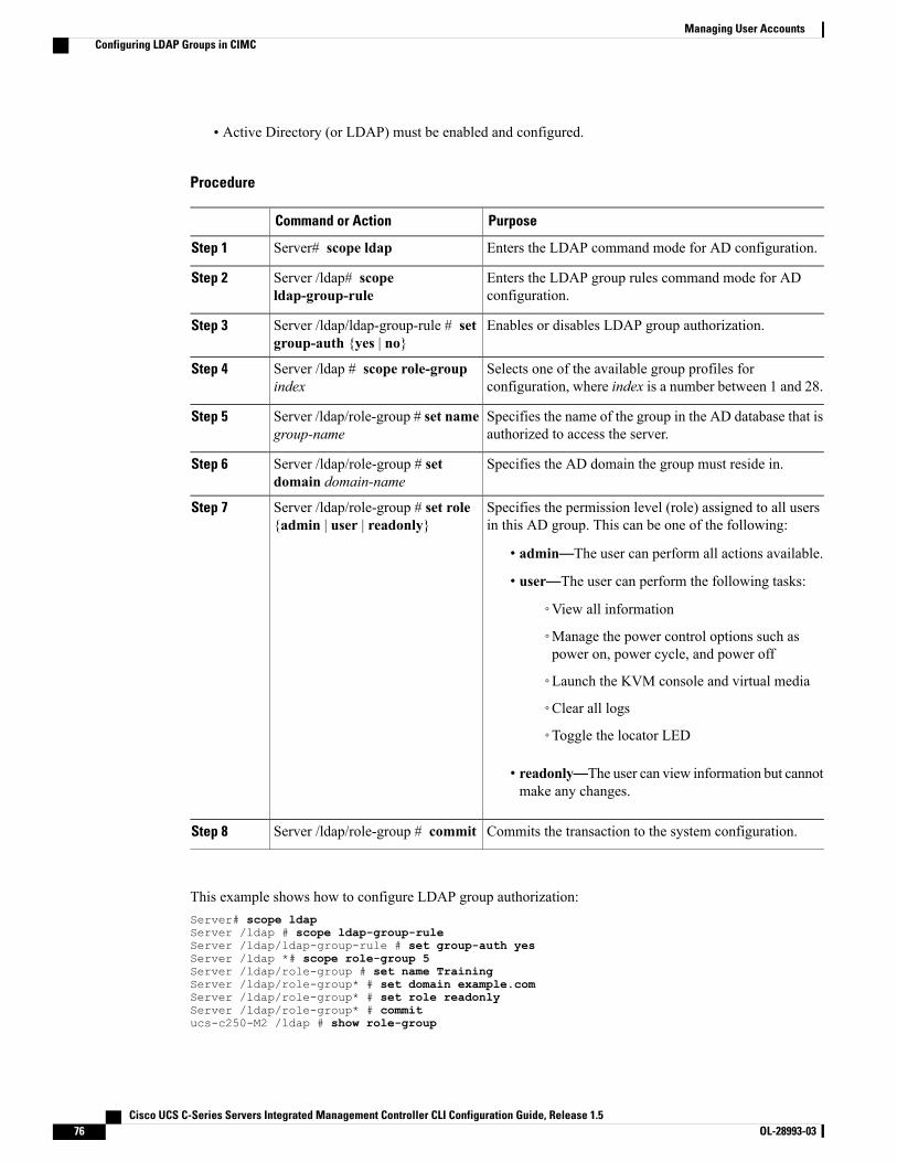
• Active Directory (or LDAP) must be enabled and configured.
Procedure
PurposeCommand or Action
Enters the LDAP command mode for AD configuration.Server# scope ldapStep 1
Enters the LDAP group rules command mode for ADconfiguration.
Server /ldap# scopeldap-group-rule
Step 2
Enables or disables LDAP group authorization.Server /ldap/ldap-group-rule # setgroup-auth {yes | no}
Step 3
Selects one of the available group profiles forconfiguration, where index is a number between 1 and 28.
Server /ldap # scope role-groupindex
Step 4
Specifies the name of the group in the AD database that isauthorized to access the server.
Server /ldap/role-group # set namegroup-name
Step 5
Specifies the AD domain the group must reside in.Server /ldap/role-group # setdomain domain-name
Step 6
Specifies the permission level (role) assigned to all usersin this AD group. This can be one of the following:
Server /ldap/role-group # set role{admin | user | readonly}
Step 7
• admin—The user can perform all actions available.
• user—The user can perform the following tasks:
◦View all information
◦Manage the power control options such aspower on, power cycle, and power off
◦Launch the KVM console and virtual media
◦Clear all logs
◦Toggle the locator LED
• readonly—The user can view information but cannotmake any changes.
Commits the transaction to the system configuration.Server /ldap/role-group # commitStep 8
This example shows how to configure LDAP group authorization:Server# scope ldapServer /ldap # scope ldap-group-ruleServer /ldap/ldap-group-rule # set group-auth yesServer /ldap *# scope role-group 5Server /ldap/role-group # set name TrainingServer /ldap/role-group* # set domain example.comServer /ldap/role-group* # set role readonlyServer /ldap/role-group* # commitucs-c250-M2 /ldap # show role-group
Cisco UCS C-Series Servers Integrated Management Controller CLI Configuration Guide, Release 1.576 OL-28993-03
Managing User AccountsConfiguring LDAP Groups in CIMC

Group Group Name Domain Name Assigned Role------ ----------- -------------- --------------1 (n/a) (n/a) admin2 (n/a) (n/a) user3 (n/a) (n/a) readonly4 (n/a) (n/a) (n/a)5 Training example.com readonly
Server /ldap/role-group #
Viewing User SessionsProcedure
PurposeCommand or Action
Displays information about current user sessions.Server# show user-sessionStep 1
The command output displays the following information about current user sessions:
DescriptionName
The unique identifier for the session.Session ID column
The username for the user.Username column
The IP address from which the user accessed the server.IP Address column
The method by which the user accessed the server.Type column
If your user account is assigned the admin user role, this columndisplays Terminate if you can force the associated user session to end.Otherwise it displays N/A.
You cannot terminate your current session from thistab.
Note
Action column
This example displays information about current user sessions:Server# show user-sessionID Name IP Address Type Killable------ ---------------- ----------------- ------------ --------15 admin 10.20.30.138 CLI yes
Server /user #
Terminating a User SessionBefore You Begin
You must log in as a user with admin privileges to terminate a user session.
Cisco UCS C-Series Servers Integrated Management Controller CLI Configuration Guide, Release 1.5 OL-28993-03 77
Managing User AccountsViewing User Sessions
Procedure
PurposeCommand or Action
Displays information about current user sessions. Theuser session to be terminated must be eligible to beterminated (killable) and must not be your own session.
Server# show user-sessionStep 1
Enters user session command mode for the numbereduser session that you want to terminate.
Server /user-session # scopeuser-session session-number
Step 2
Terminates the user session.Server /user-session # terminateStep 3
This example shows how the admin at user session 10 terminates user session 15:Server# show user-sessionID Name IP Address Type Killable------ ---------------- ----------------- ------------ --------10 admin 10.20.41.234 CLI yes15 admin 10.20.30.138 CLI yesServer# scope user-session 15Server /user-session # terminateUser session 15 terminated.
Server /user-session #
Cisco UCS C-Series Servers Integrated Management Controller CLI Configuration Guide, Release 1.578 OL-28993-03
Managing User AccountsTerminating a User Session
C H A P T E R 8Configuring Network-Related Settings
This chapter includes the following sections:
• Server NIC Configuration, page 79
• Configuring Common Properties, page 81
• Configuring IPv4, page 82
• Configuring the Server VLAN, page 84
• Connecting to a Port Profile, page 85
• Network Interface Configuration, page 86
• Network Security Configuration, page 87
• Network Time Protocol Configuration, page 88
Server NIC Configuration
Server NICs
NIC Mode
The NIC mode setting determines which ports can reach the CIMC. The following network mode options areavailable, depending on your platform:
• Dedicated—The management port is used to access the CIMC.
• Shared LOM—Any LOM (LAN On Motherboard) port can be used to access the CIMC.
• Shared LOM 10G—Any 10G LOM port can be used to access the CIMC. This option is only availablefor some adapter cards.
• Cisco Card—Any port on the adapter card can be used to access the CIMC. The Cisco adapter card hasto be installed in a slot with Network Communications Services Interface protocol (NCSI) support.
Cisco UCS C-Series Servers Integrated Management Controller CLI Configuration Guide, Release 1.5 OL-28993-03 79
• Shared LOM Extended—Any LOM port or adapter card port can be used to access the CIMC. TheCisco adapter card has to be installed in a slot with NCSI support.
NIC Redundancy
The following NIC redundancy options are available, depending on the selected NICmode and your platform:
• none—Each port associated with the configured NIC mode operates independently. The ports do notfail over if there is a problem.
• active-active—If supported, all ports associated with the configured NIC mode operate simultaneously.This increases throughput and provides multiple paths to the CIMC.
• active-standby—If a port associated with the configured NIC mode fails, traffic will fail over to oneof the other ports associated with the NIC mode.
If you select this option, make sure all ports associated with the configured NIC modeare connected to the same subnet to ensure that traffic is secure regardless of which portis used.
Note
The available redundancy modes vary depending on the selected network mode and your platform. For theavailable modes, see theHardware Installation Guide (HIG) for the type of server you are using. The C-SeriesHIGs are available at the following URL: http://www.cisco.com/en/US/products/ps10493/prod_installation_guides_list.html
Configuring Server NICsConfigure a server NIC when you want to set the NIC mode and NIC redundancy.
Before You Begin
You must log in as a user with admin privileges to configure the NIC.
Procedure
PurposeCommand or Action
Enters the CIMC command mode.Server# scope cimcStep 1
Enters the CIMC network command mode.Server /cimc # scope networkStep 2
Sets the NIC mode to one of the following:Server /cimc/network # setmode {dedicated |
Step 3
• Dedicated—The management Ethernet port is used to accessthe CIMC.
shared_lom |shared_lom_10g | shipping |cisco_card} • Shared LOM—The LAN On Motherboard (LOM) Ethernet
host ports are used to access the CIMC.If you select Shared LOM, make sure that all hostports belong to the same subnet.
Note
Cisco UCS C-Series Servers Integrated Management Controller CLI Configuration Guide, Release 1.580 OL-28993-03
Configuring Network-Related SettingsConfiguring Server NICs
PurposeCommand or Action
• Shared LOM 10G—The 10G LOM Ethernet host ports areused to access the CIMC.
• Shipping—A limited configuration for initial connection.Select another mode for normal operation.
• Cisco card—The ports on the adapter card are used to accessthe CIMC.
Sets the NIC redundancy mode when the NIC mode is SharedLOM. The redundancy mode can be one of the following:
Server /cimc/network # setredundancy {none |
Step 4
active-active |active-standby} • none—The LOM Ethernet ports operate independently and
do not fail over if there is a problem.
• active-active—If supported, all LOM Ethernet ports areutilized.
• active-standby—If one LOMEthernet port fails, traffic failsover to another LOM port.
Commits the transaction to the system configuration.Server /cimc/network #commit
Step 5
The available NIC mode and NIC redundancy modeoptions may vary depending on your platform. If youselect a mode not supported by your server, an errormessage displays when you save your changes.
Note
This example configures the CIMC network interface:Server# scope cimcServer /cimc # scope networkServer /cimc/network # set mode dedicatedServer /cimc/network *# commitServer /cimc/network #
Configuring Common PropertiesUse common properties to describe your server.
Before You Begin
You must log in as a user with admin privileges to configure common properties.
Procedure
PurposeCommand or Action
Enters the CIMC command mode.Server# scope cimcStep 1
Cisco UCS C-Series Servers Integrated Management Controller CLI Configuration Guide, Release 1.5 OL-28993-03 81
Configuring Network-Related SettingsConfiguring Common Properties
PurposeCommand or Action
Enters the CIMC network command mode.Server /cimc # scope networkStep 2
Specifies the name of the host.Server /cimc/network # sethostname host-name
Step 3
On modifying the hostname, you are prompted to confirmwhether you want to create a new self-signed certificate withCN as the new hostname.
If you enter y at the prompt, a new self-signed certificate willbe created with CN as the new hostname.
If you enter n at the prompt, only hostname will be changedand no certificate will be generated.
Commits the transaction to the system configuration.Server /cimc/network # commitStep 4
This example configures the common properties:Server# scope cimcServer /cimc # scope networkServer /cimc/network # set hostname ServerCreate new certificate with CN as new hostname? [y|N]yNew certificate will be generated on committing changes.All HTTPS and SSH sessions will be disconnected.Server /cimc/network *# commitServer /cimc/network #
What to Do Next
Changes to the network will be applied immediately. You may lose connectivity to the CIMC and may haveto log in again. Because of the new SSH session created, you may be prompted to confirm the host key.
Configuring IPv4Before You Begin
You must log in as a user with admin privileges to configure IPv4 network settings.
Procedure
PurposeCommand or Action
Enters the CIMC command mode.Server# scope cimcStep 1
Enters the CIMC network command mode.Server /cimc # scope networkStep 2
Cisco UCS C-Series Servers Integrated Management Controller CLI Configuration Guide, Release 1.582 OL-28993-03
Configuring Network-Related SettingsConfiguring IPv4
PurposeCommand or Action
Selects whether the CIMC uses DHCP.If DHCP is enabled, we recommend thatthe DHCP server be configured to reservea single IP address for the CIMC. If theCIMC is reachable through multiple portson the server, the single IP address mustbe reserved for the full range of MACaddresses of those ports.
NoteServer /cimc/network # set dhcp-enabled{yes | no}
Step 3
Specifies the IP address for the CIMC.Server /cimc/network # set v4-addripv4-address
Step 4
Specifies the subnet mask for the IP address.Server /cimc/network # set v4-netmaskipv4-netmask
Step 5
Specifies the gateway for the IP address.Server /cimc/network # set v4-gatewaygateway-ipv4-address
Step 6
Selects whether the CIMC retrieves the DNS serveraddresses from DHCP.
Server /cimc/network # set dns-use-dhcp{yes | no}
Step 7
Specifies the IP address of the primary DNS server.Server /cimc/network # setpreferred-dns-server dns1-ipv4-address
Step 8
Specifies the IP address of the secondary DNSserver.
Server /cimc/network # setalternate-dns-server dns2-ipv4-address
Step 9
Commits the transaction to the systemconfiguration.
Server /cimc/network # commitStep 10
(Optional) Displays the IPv4 network settings.Server /cimc/network # show [detail]Step 11
This example configures and displays the IPv4 network settings:Server# scope cimcServer /cimc # scope networkServer /cimc/network # set dhcp-enabled yesServer /cimc/network *# set v4-addr 10.20.30.11Server /cimc/network *# set v4-netmask 255.255.248.0Server /cimc/network *# set v4-gateway 10.20.30.1Server /cimc/network *# set dns-use-dhcp-enabled noServer /cimc/network *# set preferred-dns-server 192.168.30.31Server /cimc/network *# set alternate-dns-server 192.168.30.32Server /cimc/network *# commitServer /cimc/network # show detailNetwork Setting:
IPv4 Address: 10.20.30.11IPv4 Netmask: 255.255.248.0IPv4 Gateway: 10.20.30.1DHCP Enabled: yesObtain DNS Server by DHCP: noPreferred DNS: 192.168.30.31Alternate DNS: 192.168.30.32VLAN Enabled: noVLAN ID: 1VLAN Priority: 0Hostname: ServerMAC Address: 01:23:45:67:89:AB
Cisco UCS C-Series Servers Integrated Management Controller CLI Configuration Guide, Release 1.5 OL-28993-03 83
Configuring Network-Related SettingsConfiguring IPv4
NIC Mode: dedicatedNIC Redundancy: none
Server /cimc/network #
Configuring the Server VLANBefore You Begin
You must be logged in as admin to configure the server VLAN.
Procedure
PurposeCommand or Action
Enters the CIMC command mode.Server# scope cimcStep 1
Enters the CIMC network command mode.Server /cimc # scope networkStep 2
Selects whether the CIMC is connected to aVLAN.
Server /cimc/network # set vlan-enabled{yes | no}
Step 3
Specifies the VLAN number.Server /cimc/network # set vlan-id idStep 4
Specifies the priority of this system on theVLAN.
Server /cimc/network # set vlan-prioritypriority
Step 5
Commits the transaction to the systemconfiguration.
Server /cimc/network # commitStep 6
(Optional) Displays the network settings.Server /cimc/network # show [detail]Step 7
This example configures the server VLAN:Server# scope cimcServer /cimc # scope networkServer /cimc/network # set vlan-enabled yesServer /cimc/network *# set vlan-id 10Server /cimc/network *# set vlan-priority 32Server /cimc/network *# commitServer /cimc/network # show detailNetwork Setting:
IPv4 Address: 10.20.30.11IPv4 Netmask: 255.255.248.0IPv4 Gateway: 10.20.30.1DHCP Enabled: yesObtain DNS Server by DHCP: noPreferred DNS: 192.168.30.31Alternate DNS: 192.168.30.32VLAN Enabled: yesVLAN ID: 10VLAN Priority: 32Hostname: ServerMAC Address: 01:23:45:67:89:ABNIC Mode: dedicatedNIC Redundancy: none
Server /cimc/network #
Cisco UCS C-Series Servers Integrated Management Controller CLI Configuration Guide, Release 1.584 OL-28993-03
Configuring Network-Related SettingsConfiguring the Server VLAN

Connecting to a Port Profile
You can configure a port profile or a VLAN, but you cannot use both. If you want to use a port profile,make sure the set vlan-enabled command is set to no.
Note
Before You Begin
You must be logged in as admin to connect to a port profile.
Procedure
PurposeCommand or Action
Enters the CIMC command mode.Server# scope cimcStep 1
Enters the CIMC network command mode.Server /cimc # scope networkStep 2
Specifies the port profile CIMC should use to configure themanagement interface, the virtual Ethernet, and the VIF on
Server /cimc/network # setport-profile port_profile_name
Step 3
supported adapter cards such as the Cisco UCS VIC1225Virtual Interface Card.
Enter up to 80 alphanumeric characters. You cannot usespaces or other special characters except for - (hyphen) and_ (underscore). In addition, the port profile name cannot beginwith a hyphen.
The port profile must be defined on the switch towhich this server is connected.
Note
Commits the transaction to the system configuration.Server /cimc/network # commitStep 4
(Optional)Displays the network settings.
Server /cimc/network # show[detail]
Step 5
This example connects to port profile abcde12345:Server# scope cimcServer /cimc # scope networkServer /cimc/network # set port-profile abcde12345Server /cimc/network *# commitServer /cimc/network # show detailNetwork Setting:
IPv4 Address: 10.193.66.174IPv4 Netmask: 255.255.248.0IPv4 Gateway: 10.193.64.1DHCP Enabled: noObtain DNS Server by DHCP: noPreferred DNS: 0.0.0.0Alternate DNS: 0.0.0.0VLAN Enabled: noVLAN ID: 1VLAN Priority: 0Port Profile: abcde12345Hostname: Server
Cisco UCS C-Series Servers Integrated Management Controller CLI Configuration Guide, Release 1.5 OL-28993-03 85
Configuring Network-Related SettingsConnecting to a Port Profile
MAC Address: 50:3D:E5:9D:63:3CNIC Mode: dedicatedNIC Redundancy: none
Server /cimc/network #
Network Interface Configuration
Overview to Network Interface ConfigurationThis support is added to configure network speed and duplex mode for the CIMC management port. Autonegotiate mode and duplex mode can be set for dedicated mode only. When auto negotiate mode is enabledthe settings for duplex is ignored by the system and the network speed is set to either 1000 Mbps or 100 Mbpsas per the speed configured on the switch. When auto negotiate mode is disabled, you can set the duplex toeither Full or Half, a default speed of 100 Mbps is set, and the duplex retains its previous value.
When you reset CIMC to factory defaults, Shared LOM Extendedmode is configured to Full duplex modewith 100 Mbps speed, and auto negotiate mode is disabled. You can enable auto negotiate mode when youchange the settings to Dedicated mode.
Configuring Interface PropertiesThe settings on the switch must match with the CIMC settings to avoid any speed or duplex mismatch.
Procedure
PurposeCommand or Action
Enters the CIMC command mode.Server # scope cimcStep 1
Enters the network command mode.Server/cimc # scope networkStep 2
Enters dedicated command mode.Server/cimc/network* # set modededicated
Step 3
Enables or disables auto negotiation command mode.Server/cimc/network # setauto-negotiate {yes | no}
Step 4
• If you enter yes, the setting for duplex will beignored by the system. The CIMC retains the speedat which the switch is configured.
• If you enter no, you can set duplex. Else, a defaultspeed of 100Mbps will be applied, and duplex willretain its previous value.
Sets specified duplex mode type. By default, the duplexmode is set to Full
Server/cimc/network* # set duplex{full | half}
Step 5
This example shows how to configure the interface properties and commit the transaction:Server # scope cimcServer/cimc # scope network
Cisco UCS C-Series Servers Integrated Management Controller CLI Configuration Guide, Release 1.586 OL-28993-03
Configuring Network-Related SettingsNetwork Interface Configuration
Server/cimc/network* # set mode dedicatedServer/cimc/network # set auto-negotiate noWarning: You have chosen to set auto negotiate to noIf speed and duplex are not set then a default speed of 100Mbps will be appliedDuplex will retain its previous valueServer/cimc/network* # commitServer/cimc/network # set duplex fullServer/cimc/network* # commitServer/cimc/network #
Network Security Configuration
Network SecurityThe CIMC uses IP blocking as network security. IP blocking prevents the connection between a server orwebsite and certain IP addresses or ranges of addresses. IP blocking effectively bans undesired connectionsfrom those computers to a website, mail server, or other Internet servers.
IP banning is commonly used to protect against denial of service (DoS) attacks. CIMC bans IP addresses bysetting up an IP blocking fail count.
Configuring Network SecurityConfigure network security if you want to set up an IP blocking fail count.
Before You Begin
You must log in as a user with admin privileges to configure network security.
Procedure
PurposeCommand or Action
Enters the CIMC command mode.Server# scope cimcStep 1
Enters the CIMC network command mode.Server /cimc # scope networkStep 2
Enters the IP blocking command mode.Server /cimc/network # scopeipblocking
Step 3
Enables or disables IP blocking.Server /cimc/network/ipblocking #set enabled {yes | no}
Step 4
Sets the number of times a user can attempt to log inunsuccessfully before the system locks that user out fora specified length of time.
Server /cimc/network/ipblocking #set fail-count fail-count
Step 5
The number of unsuccessful login attempts must occurwithin the time frame specified in the IP Blocking FailWindow field.
Enter an integer between 3 and 10.
Cisco UCS C-Series Servers Integrated Management Controller CLI Configuration Guide, Release 1.5 OL-28993-03 87
Configuring Network-Related SettingsNetwork Security Configuration
PurposeCommand or Action
Sets the length of time, in seconds, in which theunsuccessful login attempts must occur in order for theuser to be locked out.
Server /cimc/network/ipblocking #set fail-window fail-seconds
Step 6
Enter an integer between 60 and 120.
Sets the number of seconds the user remains locked outif they exceed the maximum number of login attemptswithin the specified time window.
Server /cimc/network/ipblocking #set penalty-time penalty-seconds
Step 7
Enter an integer between 300 and 900.
Commits the transaction to the system configuration.Server /cimc/network/ipblocking #commit
Step 8
This example configures IP blocking:Server# scope cimcServer /cimc # scope networkServer /cimc/network # scope ipblockingServer /cimc/network/ipblocking # set enabled yesServer /cimc/network/ipblocking *# set fail-count 5Server /cimc/network/ipblocking *# set fail-window 90Server /cimc/network/ipblocking *# set penalty-time 600Server /cimc/network/ipblocking *# commitServer /cimc/network/ipblocking #
Network Time Protocol Configuration
Configuring Network Time Protocol SettingsBy default, when CIMC is reset, it synchronizes the time with the host. With the introduction of the NTPservice, you can configure CIMC to synchronize the time with an NTP server. The NTP server does not runin CIMC by default. You must enable and configure the NTP service by specifying the IP/DNS address of atleast one server or a maximum of four servers that function as NTP servers or time source servers. When youenable the NTP service, CIMC synchronizes the time with the configured NTP server. The NTP service canbe modified only through CIMC.
To enable the NTP service, it is preferable to specify the IP address of a server rather than the DNS address.Note
Before You Begin
You must log in with admin privileges to perform this task.
Cisco UCS C-Series Servers Integrated Management Controller CLI Configuration Guide, Release 1.588 OL-28993-03
Configuring Network-Related SettingsNetwork Time Protocol Configuration

Procedure
PurposeCommand or Action
Enters CIMC command mode.Server # scope cimcStep 1
Enters network command mode.Server /cimc # scope networkStep 2
Enters NTP service command mode.Server /cimc/network # scope ntpStep 3
Enables the NTP service on the server.Server /cimc/network/ntp # set enabledyes
Step 4
Commits the transaction.Server /cimc/network/ntp* # commitStep 5
Specifies the IP/DNS address of one of the fourservers that act as an NTP server or the time sourceserver.
Server /cimc/network/ntp # set server-110.120.33.44
Step 6
Specifies the IP/DNS address of one of the fourservers that act as an NTP server or the time sourceserver.
Server /cimc/network/ntp # set server-210.120.34.45
Step 7
Specifies the IP/DNS address of one of the fourservers that act as an NTP server or the time sourceserver.
Server /cimc/network/ntp # set server-310.120.35.46
Step 8
Specifies the IP/DNS address of one of the fourservers that act as an NTP server or the time sourceserver.
Server /cimc/network/ntp # set server-410.120.36.48
Step 9
Commits the transaction.Server /cimc/network/ntp # commitStep 10
This example shows how to configure the NTP service:Server # scope cimcServer /cimc # scope networkServer /cimc/network # scope ntpServer /cimc/network/ntp # set enabled yesWarning: IPMI Set SEL Time Command will bedisabled if NTP is enabled.Do you wish to continue? [y|N]yServer /cimc/network/ntp* # commitServer /cimc/network/ntp # set server-1 10.120.33.44Server /cimc/network/ntp* # set server-2 10.120.34.45Server /cimc/network/ntp* # set server-3 10.120.35.46Server /cimc/network/ntp* # set server-4 10.120.36.48Server /cimc/network/ntp* # commitServer /cimc/network/ntp #
Cisco UCS C-Series Servers Integrated Management Controller CLI Configuration Guide, Release 1.5 OL-28993-03 89
Configuring Network-Related SettingsConfiguring Network Time Protocol Settings

Cisco UCS C-Series Servers Integrated Management Controller CLI Configuration Guide, Release 1.590 OL-28993-03
Configuring Network-Related SettingsConfiguring Network Time Protocol Settings

C H A P T E R 9Managing Network Adapters
This chapter includes the following sections:
• Overview of the Cisco UCS C-Series Network Adapters, page 91
• Viewing Network Adapter Properties, page 93
• Configuring Network Adapter Properties, page 93
• Managing vHBAs, page 94
• Managing vNICs, page 107
• Managing VM FEX, page 124
• Managing Storage Adapters, page 129
• Backing Up and Restoring the Adapter Configuration, page 142
• Managing Adapter Firmware, page 144
• Resetting the Adapter, page 146
Overview of the Cisco UCS C-Series Network Adapters
The procedures in this chapter are available only when a Cisco UCS C-Series network adapter is installedin the chassis.
Note
A Cisco UCS C-Series network adapter can be installed to provide options for I/O consolidation andvirtualization support. The following adapters are available:
• Cisco UCS P81E Virtual Interface Card
• Cisco UCS VIC1225 Virtual Interface Card
The interactiveUCS Hardware and Software Interoperability Utility lets you view the supported componentsand configurations for a selected server model and software release. The utility is available at the followingURL: http://www.cisco.com/web/techdoc/ucs/interoperability/matrix/matrix.html
Cisco UCS C-Series Servers Integrated Management Controller CLI Configuration Guide, Release 1.5 OL-28993-03 91
Cisco UCS P81E Virtual Interface Card
The Cisco UCS P81E Virtual Interface Card is optimized for virtualized environments, for organizations thatseek increased mobility in their physical environments, and for data centers that want reduced costs throughNIC, HBA, cabling, and switch reduction and reducedmanagement overhead. This Fibre Channel over Ethernet(FCoE) PCIe card offers the following benefits:
• Allows up to 16 virtual Fibre Channel and 16 virtual Ethernet adapters to be provisioned in virtualizedor nonvirtualized environments using just-in-time provisioning, providing tremendous system flexibilityand allowing consolidation of multiple physical adapters.
• Delivers uncompromising virtualization support, including hardware-based implementation of CiscoVN-Link technology and pass-through switching.
• Improves system security and manageability by providing visibility and portability of network policesand security all the way to the virtual machine.
The virtual interface card makes Cisco VN-Link connections to the parent fabric interconnects, which allowsvirtual links to connect virtual NICs in virtual machines to virtual interfaces in the interconnect. In a CiscoUnified Computing System environment, virtual links then can be managed, network profiles applied, andinterfaces dynamically reprovisioned as virtual machines move between servers in the system.
Cisco UCS VIC1225 Virtual Interface Card
The Cisco UCS VIC1225 Virtual Interface Card is a high-performance, converged network adapter thatprovides acceleration for the various new operational modes introduced by server virtualization. It bringssuperior flexibility, performance, and bandwidth to the new generation of Cisco UCS C-Series Rack-MountServers.
The Cisco UCS VIC 1225 implements the Cisco Virtual Machine Fabric Extender (VM-FEX), which unifiesvirtual and physical networking into a single infrastructure. It provides virtual-machine visibility from thephysical network and a consistent network operations model for physical and virtual servers. In virtualizedenvironments, this highly configurable and self-virtualized adapter provides integrated, modular LAN interfaceson Cisco UCS C-Series Rack-Mount Servers. Additional features and capabilities include:
• Supports up to 256 PCIe virtual devices, either virtual network interface cards (vNICs) or virtual hostbus adapters (vHBAs), with high I/O operations per second (IOPS), support for lossless Ethernet, and20 Gbps to servers.
• PCIe Gen2 x16 helps assure optimal bandwidth to the host for network-intensive applications with aredundant path to the fabric interconnect.
• Half-height design reserves full-height slots in servers for Cisco certified third-party adapters.
• Centrally managed by Cisco UCS Manager with support for Microsoft Windows, Red Hat EnterpriseLinux, SUSE Linux, VMware vSphere, and Citrix XenServer.
Cisco UCS C-Series Servers Integrated Management Controller CLI Configuration Guide, Release 1.592 OL-28993-03
Managing Network AdaptersOverview of the Cisco UCS C-Series Network Adapters
Viewing Network Adapter PropertiesProcedure
PurposeCommand or Action
Enters the chassis command mode.Server# scope chassisStep 1
Displays adapter properties. To display the propertiesof a single adapter, specify the PCI slot number as theindex argument.
Server /chassis # show adapter[index] [detail]
Step 2
This example displays the properties of adapter 2:Server# scope chassisServer /chassis # show adapterPCI Slot Product Name Serial Number Product ID Vendor-------- -------------- -------------- -------------- --------------------1 UCS VIC 1225 FCH1613796C UCSC-PCIE-C... Cisco Systems Inc
Server /chassis # show adapter 2 detailPCI Slot 2:
Product Name: UCS VIC 1225Serial Number: FCH1613796CProduct ID: UCSC-PCIE-CSC-02Adapter Hardware Revision: 4Current FW Version: 2.1(0.291)NIV: DisabledFIP: EnabledConfiguration Pending: noCIMC Management Enabled : noVID: V00Vendor: Cisco Systems IncDescription:Bootloader Version: 2.1(0.291)FW Image 1 Version: 2.1(0.291)FW Image 1 State: RUNNING ACTIVATEDFW Image 2 Version: 1.6(0.547)FW Image 2 State: BACKUP INACTIVATEDFW Update Status: IdleFW Update Error: No errorFW Update Stage: No operation (0%)FW Update Overall Progress: 0%
Server /chassis #
Configuring Network Adapter PropertiesBefore You Begin
• You must log in with admin privileges to perform this task.
• A supported Virtual Interface Card (VIC) must be installed in the chassis and the server must be poweredon.
Cisco UCS C-Series Servers Integrated Management Controller CLI Configuration Guide, Release 1.5 OL-28993-03 93
Managing Network AdaptersViewing Network Adapter Properties
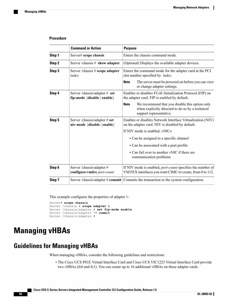
Procedure
PurposeCommand or Action
Enters the chassis command mode.Server# scope chassisStep 1
(Optional) Displays the available adapter devices.Server /chassis # show adapterStep 2
Enters the command mode for the adapter card at the PCIslot number specified by index.
Server /chassis # scope adapterindex
Step 3
The server must be powered on before you can viewor change adapter settings.
Note
Enables or disables FCoE Initialization Protocol (FIP) onthe adapter card. FIP is enabled by default.
Server /chassis/adapter # setfip-mode {disable | enable}
Step 4
We recommend that you disable this option onlywhen explicitly directed to do so by a technicalsupport representative.
Note
Enables or disables Network Interface Virtualization (NIV)on the adapter card. NIV is disabled by default.
Server /chassis/adapter # setniv-mode {disable | enable}
Step 5
If NIV mode is enabled, vNICs:
• Can be assigned to a specific channel
• Can be associated with a port profile
• Can fail over to another vNIC if there arecommunication problems
If NIV mode is enabled, port-count specifies the number ofVMFEX interfaces you want CIMC to create, from 0 to 112.
Server /chassis/adapter #configure-vmfex port-count
Step 6
Commits the transaction to the system configuration.Server /chassis/adapter # commitStep 7
This example configures the properties of adapter 1:Server# scope chassisServer /chassis # scope adapter 1Server /chassis/adapter # set fip-mode enableServer /chassis/adapter *# commitServer /chassis/adapter #
Managing vHBAs
Guidelines for Managing vHBAsWhen managing vHBAs, consider the following guidelines and restrictions:
• The Cisco UCS P81E Virtual Interface Card and Cisco UCS VIC1225 Virtual Interface Card providetwo vHBAs (fc0 and fc1). You can create up to 16 additional vHBAs on these adapter cards.
Cisco UCS C-Series Servers Integrated Management Controller CLI Configuration Guide, Release 1.594 OL-28993-03
Managing Network AdaptersManaging vHBAs
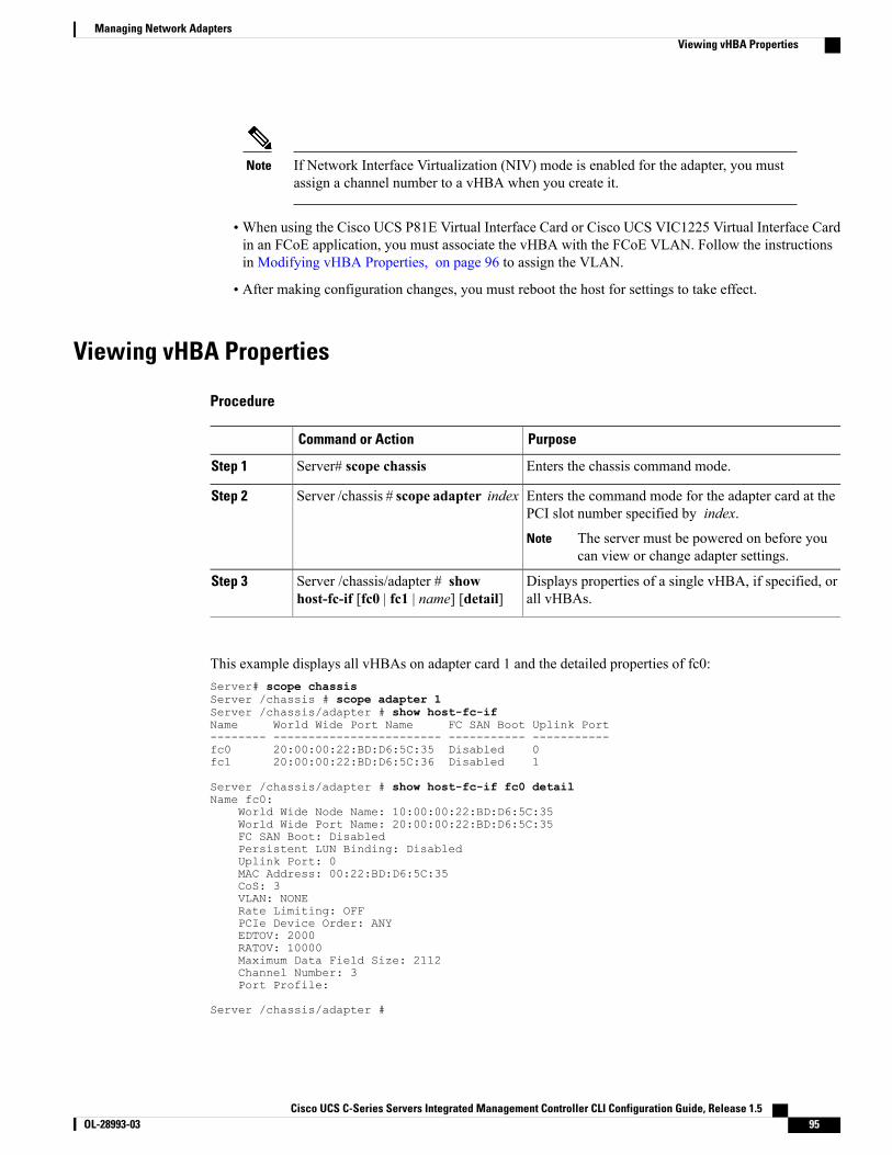
If Network Interface Virtualization (NIV) mode is enabled for the adapter, you mustassign a channel number to a vHBA when you create it.
Note
•When using the Cisco UCS P81E Virtual Interface Card or Cisco UCS VIC1225 Virtual Interface Cardin an FCoE application, you must associate the vHBA with the FCoE VLAN. Follow the instructionsin Modifying vHBA Properties, on page 96 to assign the VLAN.
• After making configuration changes, you must reboot the host for settings to take effect.
Viewing vHBA Properties
Procedure
PurposeCommand or Action
Enters the chassis command mode.Server# scope chassisStep 1
Enters the command mode for the adapter card at thePCI slot number specified by index.
Server /chassis # scope adapter indexStep 2
The server must be powered on before youcan view or change adapter settings.
Note
Displays properties of a single vHBA, if specified, orall vHBAs.
Server /chassis/adapter # showhost-fc-if [fc0 | fc1 | name] [detail]
Step 3
This example displays all vHBAs on adapter card 1 and the detailed properties of fc0:Server# scope chassisServer /chassis # scope adapter 1Server /chassis/adapter # show host-fc-ifName World Wide Port Name FC SAN Boot Uplink Port-------- ------------------------ ----------- -----------fc0 20:00:00:22:BD:D6:5C:35 Disabled 0fc1 20:00:00:22:BD:D6:5C:36 Disabled 1
Server /chassis/adapter # show host-fc-if fc0 detailName fc0:
World Wide Node Name: 10:00:00:22:BD:D6:5C:35World Wide Port Name: 20:00:00:22:BD:D6:5C:35FC SAN Boot: DisabledPersistent LUN Binding: DisabledUplink Port: 0MAC Address: 00:22:BD:D6:5C:35CoS: 3VLAN: NONERate Limiting: OFFPCIe Device Order: ANYEDTOV: 2000RATOV: 10000Maximum Data Field Size: 2112Channel Number: 3Port Profile:
Server /chassis/adapter #
Cisco UCS C-Series Servers Integrated Management Controller CLI Configuration Guide, Release 1.5 OL-28993-03 95
Managing Network AdaptersViewing vHBA Properties
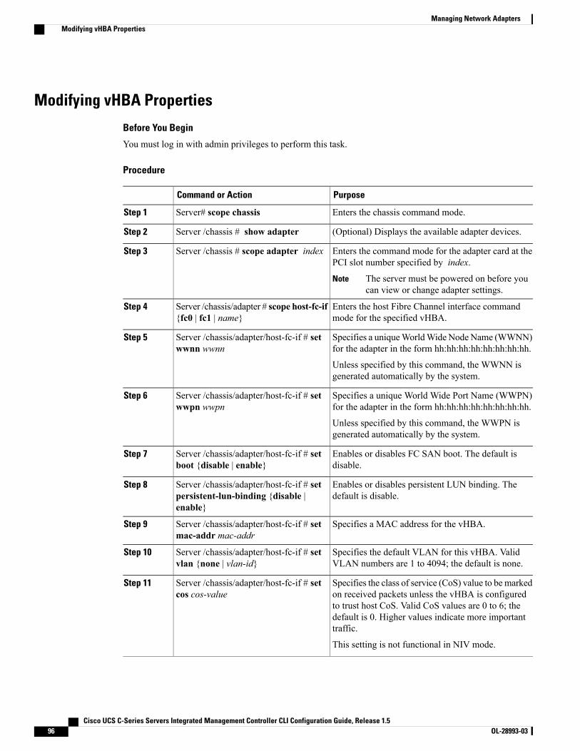
Modifying vHBA Properties
Before You Begin
You must log in with admin privileges to perform this task.
Procedure
PurposeCommand or Action
Enters the chassis command mode.Server# scope chassisStep 1
(Optional) Displays the available adapter devices.Server /chassis # show adapterStep 2
Enters the command mode for the adapter card at thePCI slot number specified by index.
Server /chassis # scope adapter indexStep 3
The server must be powered on before youcan view or change adapter settings.
Note
Enters the host Fibre Channel interface commandmode for the specified vHBA.
Server /chassis/adapter # scope host-fc-if{fc0 | fc1 | name}
Step 4
Specifies a uniqueWorldWide Node Name (WWNN)for the adapter in the form hh:hh:hh:hh:hh:hh:hh:hh.
Server /chassis/adapter/host-fc-if # setwwnn wwnn
Step 5
Unless specified by this command, the WWNN isgenerated automatically by the system.
Specifies a unique World Wide Port Name (WWPN)for the adapter in the form hh:hh:hh:hh:hh:hh:hh:hh.
Server /chassis/adapter/host-fc-if # setwwpn wwpn
Step 6
Unless specified by this command, the WWPN isgenerated automatically by the system.
Enables or disables FC SAN boot. The default isdisable.
Server /chassis/adapter/host-fc-if # setboot {disable | enable}
Step 7
Enables or disables persistent LUN binding. Thedefault is disable.
Server /chassis/adapter/host-fc-if # setpersistent-lun-binding {disable |enable}
Step 8
Specifies a MAC address for the vHBA.Server /chassis/adapter/host-fc-if # setmac-addr mac-addr
Step 9
Specifies the default VLAN for this vHBA. ValidVLAN numbers are 1 to 4094; the default is none.
Server /chassis/adapter/host-fc-if # setvlan {none | vlan-id}
Step 10
Specifies the class of service (CoS) value to bemarkedon received packets unless the vHBA is configured
Server /chassis/adapter/host-fc-if # setcos cos-value
Step 11
to trust host CoS. Valid CoS values are 0 to 6; thedefault is 0. Higher values indicate more importanttraffic.
This setting is not functional in NIV mode.
Cisco UCS C-Series Servers Integrated Management Controller CLI Configuration Guide, Release 1.596 OL-28993-03
Managing Network AdaptersModifying vHBA Properties
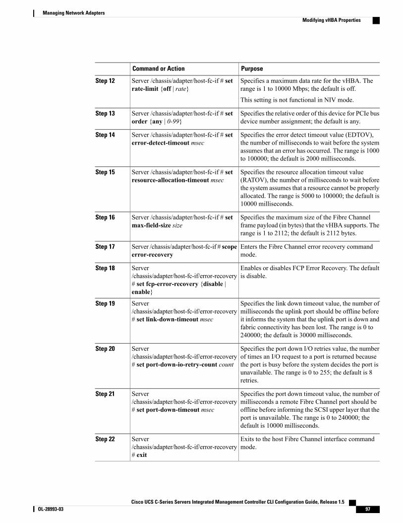
PurposeCommand or Action
Specifies a maximum data rate for the vHBA. Therange is 1 to 10000 Mbps; the default is off.
Server /chassis/adapter/host-fc-if # setrate-limit {off | rate}
Step 12
This setting is not functional in NIV mode.
Specifies the relative order of this device for PCIe busdevice number assignment; the default is any.
Server /chassis/adapter/host-fc-if # setorder {any | 0-99}
Step 13
Specifies the error detect timeout value (EDTOV),the number of milliseconds to wait before the system
Server /chassis/adapter/host-fc-if # seterror-detect-timeout msec
Step 14
assumes that an error has occurred. The range is 1000to 100000; the default is 2000 milliseconds.
Specifies the resource allocation timeout value(RATOV), the number of milliseconds to wait before
Server /chassis/adapter/host-fc-if # setresource-allocation-timeout msec
Step 15
the system assumes that a resource cannot be properlyallocated. The range is 5000 to 100000; the default is10000 milliseconds.
Specifies the maximum size of the Fibre Channelframe payload (in bytes) that the vHBA supports. Therange is 1 to 2112; the default is 2112 bytes.
Server /chassis/adapter/host-fc-if # setmax-field-size size
Step 16
Enters the Fibre Channel error recovery commandmode.
Server /chassis/adapter/host-fc-if # scopeerror-recovery
Step 17
Enables or disables FCP Error Recovery. The defaultis disable.
Server/chassis/adapter/host-fc-if/error-recovery# set fcp-error-recovery {disable |enable}
Step 18
Specifies the link down timeout value, the number ofmilliseconds the uplink port should be offline before
Server/chassis/adapter/host-fc-if/error-recovery# set link-down-timeout msec
Step 19
it informs the system that the uplink port is down andfabric connectivity has been lost. The range is 0 to240000; the default is 30000 milliseconds.
Specifies the port down I/O retries value, the numberof times an I/O request to a port is returned because
Server/chassis/adapter/host-fc-if/error-recovery# set port-down-io-retry-count count
Step 20
the port is busy before the system decides the port isunavailable. The range is 0 to 255; the default is 8retries.
Specifies the port down timeout value, the number ofmilliseconds a remote Fibre Channel port should be
Server/chassis/adapter/host-fc-if/error-recovery# set port-down-timeout msec
Step 21
offline before informing the SCSI upper layer that theport is unavailable. The range is 0 to 240000; thedefault is 10000 milliseconds.
Exits to the host Fibre Channel interface commandmode.
Server/chassis/adapter/host-fc-if/error-recovery# exit
Step 22
Cisco UCS C-Series Servers Integrated Management Controller CLI Configuration Guide, Release 1.5 OL-28993-03 97
Managing Network AdaptersModifying vHBA Properties

PurposeCommand or Action
Enters the interrupt command mode.Server /chassis/adapter/host-fc-if # scopeinterrupt
Step 23
Specifies the Fibre Channel interrupt mode. Themodes are as follows:
Server/chassis/adapter/host-fc-if/interrupt # setinterrupt-mode {intx |msi |msix}
Step 24
• intx—Line-based interrupt (INTx)
• msi—Message-Signaled Interrupt (MSI)
• msix—Message Signaled Interrupts with theoptional extension (MSIx). This is therecommended and default option.
Exits to the host Fibre Channel interface commandmode.
Server/chassis/adapter/host-fc-if/interrupt # exit
Step 25
Enters the Fibre Channel port command mode.Server /chassis/adapter/host-fc-if # scopeport
Step 26
Specifies the I/O throttle count, the number of I/Ooperations that can be pending in the vHBA at one
Server /chassis/adapter/host-fc-if/port #set outstanding-io-count count
Step 27
time. The range is 1 to 1024; the default is 512operations.
Specifies the maximum logical unit numbers (LUNs)per target, the maximum number of LUNs that the
Server /chassis/adapter/host-fc-if/port #set max-target-luns count
Step 28
driver will discover. This is usually an operatingsystem platform limitation. The range is 1 to 1024;the default is 256 LUNs.
Exits to the host Fibre Channel interface commandmode.
Server /chassis/adapter/host-fc-if/port #exit
Step 29
Enters the Fibre Channel fabric login commandmode.Server /chassis/adapter/host-fc-if # scopeport-f-logi
Step 30
Specifies the fabric login (FLOGI) retries value, thenumber of times that the system tries to log in to the
Server/chassis/adapter/host-fc-if/port-f-logi #set flogi-retries {infinite | count}
Step 31
fabric after the first failure. Enter a number between0 and 4294967295 or enter infinite ; the default isinfinite retries.
Specifies the fabric login (FLOGI) timeout value, thenumber of milliseconds that the system waits before
Server/chassis/adapter/host-fc-if/port-f-logi #set flogi-timeout msec
Step 32
it tries to log in again. The range is 1 to 255000; thedefault is 2000 milliseconds.
Exits to the host Fibre Channel interface commandmode.
Server/chassis/adapter/host-fc-if/port-f-logi #exit
Step 33
Cisco UCS C-Series Servers Integrated Management Controller CLI Configuration Guide, Release 1.598 OL-28993-03
Managing Network AdaptersModifying vHBA Properties
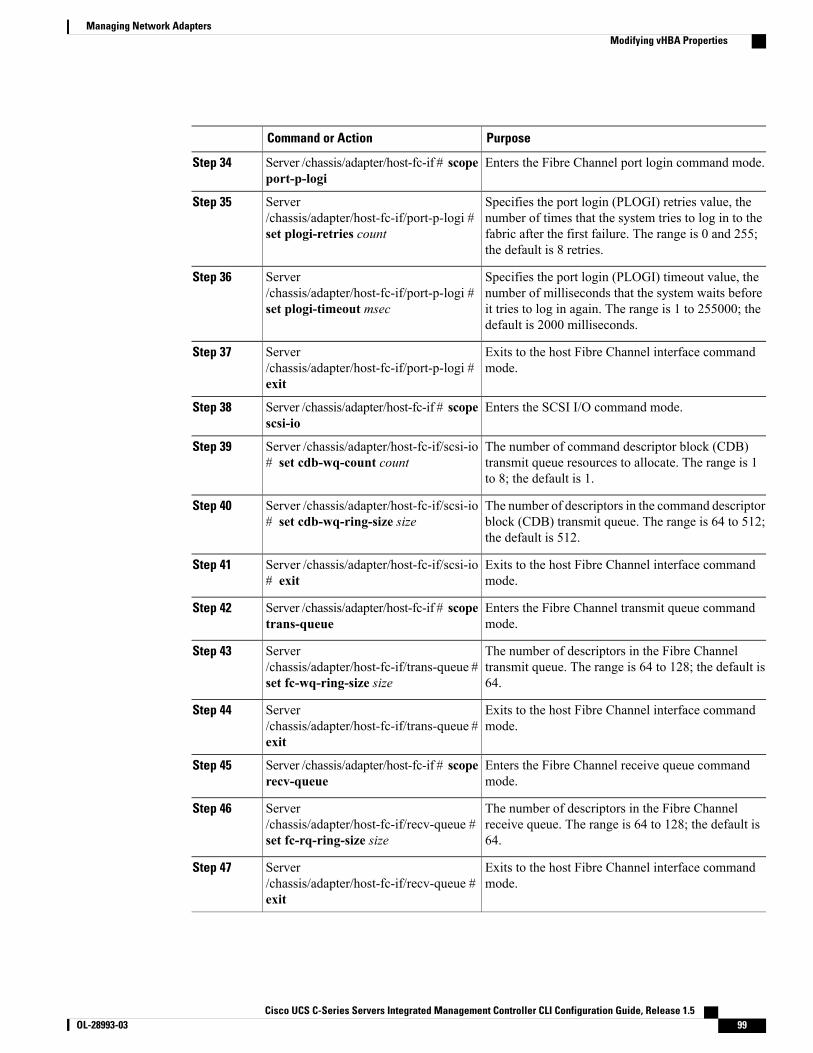
PurposeCommand or Action
Enters the Fibre Channel port login command mode.Server /chassis/adapter/host-fc-if # scopeport-p-logi
Step 34
Specifies the port login (PLOGI) retries value, thenumber of times that the system tries to log in to the
Server/chassis/adapter/host-fc-if/port-p-logi #set plogi-retries count
Step 35
fabric after the first failure. The range is 0 and 255;the default is 8 retries.
Specifies the port login (PLOGI) timeout value, thenumber of milliseconds that the system waits before
Server/chassis/adapter/host-fc-if/port-p-logi #set plogi-timeout msec
Step 36
it tries to log in again. The range is 1 to 255000; thedefault is 2000 milliseconds.
Exits to the host Fibre Channel interface commandmode.
Server/chassis/adapter/host-fc-if/port-p-logi #exit
Step 37
Enters the SCSI I/O command mode.Server /chassis/adapter/host-fc-if # scopescsi-io
Step 38
The number of command descriptor block (CDB)transmit queue resources to allocate. The range is 1to 8; the default is 1.
Server /chassis/adapter/host-fc-if/scsi-io# set cdb-wq-count count
Step 39
The number of descriptors in the command descriptorblock (CDB) transmit queue. The range is 64 to 512;the default is 512.
Server /chassis/adapter/host-fc-if/scsi-io# set cdb-wq-ring-size size
Step 40
Exits to the host Fibre Channel interface commandmode.
Server /chassis/adapter/host-fc-if/scsi-io# exit
Step 41
Enters the Fibre Channel transmit queue commandmode.
Server /chassis/adapter/host-fc-if # scopetrans-queue
Step 42
The number of descriptors in the Fibre Channeltransmit queue. The range is 64 to 128; the default is64.
Server/chassis/adapter/host-fc-if/trans-queue #set fc-wq-ring-size size
Step 43
Exits to the host Fibre Channel interface commandmode.
Server/chassis/adapter/host-fc-if/trans-queue #exit
Step 44
Enters the Fibre Channel receive queue commandmode.
Server /chassis/adapter/host-fc-if # scoperecv-queue
Step 45
The number of descriptors in the Fibre Channelreceive queue. The range is 64 to 128; the default is64.
Server/chassis/adapter/host-fc-if/recv-queue #set fc-rq-ring-size size
Step 46
Exits to the host Fibre Channel interface commandmode.
Server/chassis/adapter/host-fc-if/recv-queue #exit
Step 47
Cisco UCS C-Series Servers Integrated Management Controller CLI Configuration Guide, Release 1.5 OL-28993-03 99
Managing Network AdaptersModifying vHBA Properties
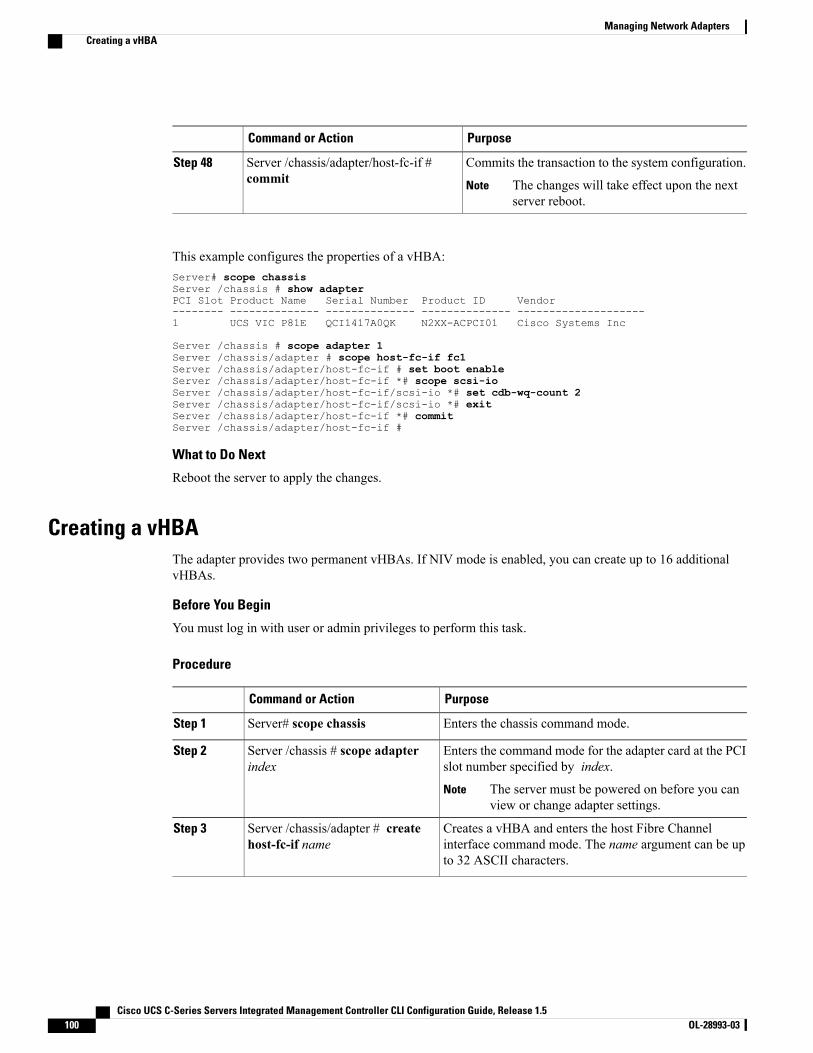
PurposeCommand or Action
Commits the transaction to the system configuration.Server /chassis/adapter/host-fc-if #commit
Step 48
The changes will take effect upon the nextserver reboot.
Note
This example configures the properties of a vHBA:Server# scope chassisServer /chassis # show adapterPCI Slot Product Name Serial Number Product ID Vendor-------- -------------- -------------- -------------- --------------------1 UCS VIC P81E QCI1417A0QK N2XX-ACPCI01 Cisco Systems Inc
Server /chassis # scope adapter 1Server /chassis/adapter # scope host-fc-if fc1Server /chassis/adapter/host-fc-if # set boot enableServer /chassis/adapter/host-fc-if *# scope scsi-ioServer /chassis/adapter/host-fc-if/scsi-io *# set cdb-wq-count 2Server /chassis/adapter/host-fc-if/scsi-io *# exitServer /chassis/adapter/host-fc-if *# commitServer /chassis/adapter/host-fc-if #
What to Do Next
Reboot the server to apply the changes.
Creating a vHBAThe adapter provides two permanent vHBAs. If NIV mode is enabled, you can create up to 16 additionalvHBAs.
Before You Begin
You must log in with user or admin privileges to perform this task.
Procedure
PurposeCommand or Action
Enters the chassis command mode.Server# scope chassisStep 1
Enters the command mode for the adapter card at the PCIslot number specified by index.
Server /chassis # scope adapterindex
Step 2
The server must be powered on before you canview or change adapter settings.
Note
Creates a vHBA and enters the host Fibre Channelinterface command mode. The name argument can be upto 32 ASCII characters.
Server /chassis/adapter # createhost-fc-if name
Step 3
Cisco UCS C-Series Servers Integrated Management Controller CLI Configuration Guide, Release 1.5100 OL-28993-03
Managing Network AdaptersCreating a vHBA
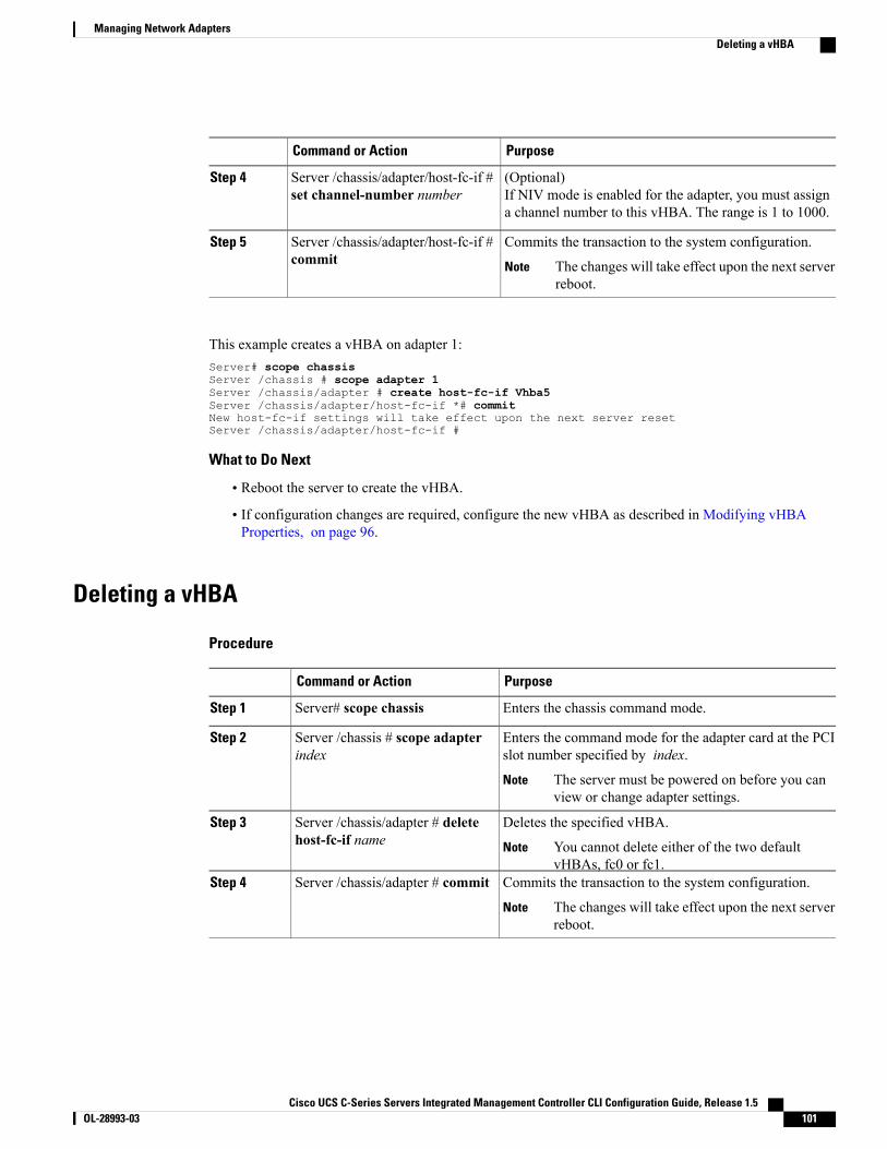
PurposeCommand or Action
(Optional)If NIV mode is enabled for the adapter, you must assigna channel number to this vHBA. The range is 1 to 1000.
Server /chassis/adapter/host-fc-if #set channel-number number
Step 4
Commits the transaction to the system configuration.Server /chassis/adapter/host-fc-if #commit
Step 5
The changes will take effect upon the next serverreboot.
Note
This example creates a vHBA on adapter 1:Server# scope chassisServer /chassis # scope adapter 1Server /chassis/adapter # create host-fc-if Vhba5Server /chassis/adapter/host-fc-if *# commitNew host-fc-if settings will take effect upon the next server resetServer /chassis/adapter/host-fc-if #
What to Do Next
• Reboot the server to create the vHBA.
• If configuration changes are required, configure the new vHBA as described in Modifying vHBAProperties, on page 96.
Deleting a vHBA
Procedure
PurposeCommand or Action
Enters the chassis command mode.Server# scope chassisStep 1
Enters the command mode for the adapter card at the PCIslot number specified by index.
Server /chassis # scope adapterindex
Step 2
The server must be powered on before you canview or change adapter settings.
Note
Deletes the specified vHBA.Server /chassis/adapter # deletehost-fc-if name
Step 3
You cannot delete either of the two defaultvHBAs, fc0 or fc1.
Note
Commits the transaction to the system configuration.Server /chassis/adapter # commitStep 4
The changes will take effect upon the next serverreboot.
Note
Cisco UCS C-Series Servers Integrated Management Controller CLI Configuration Guide, Release 1.5 OL-28993-03 101
Managing Network AdaptersDeleting a vHBA
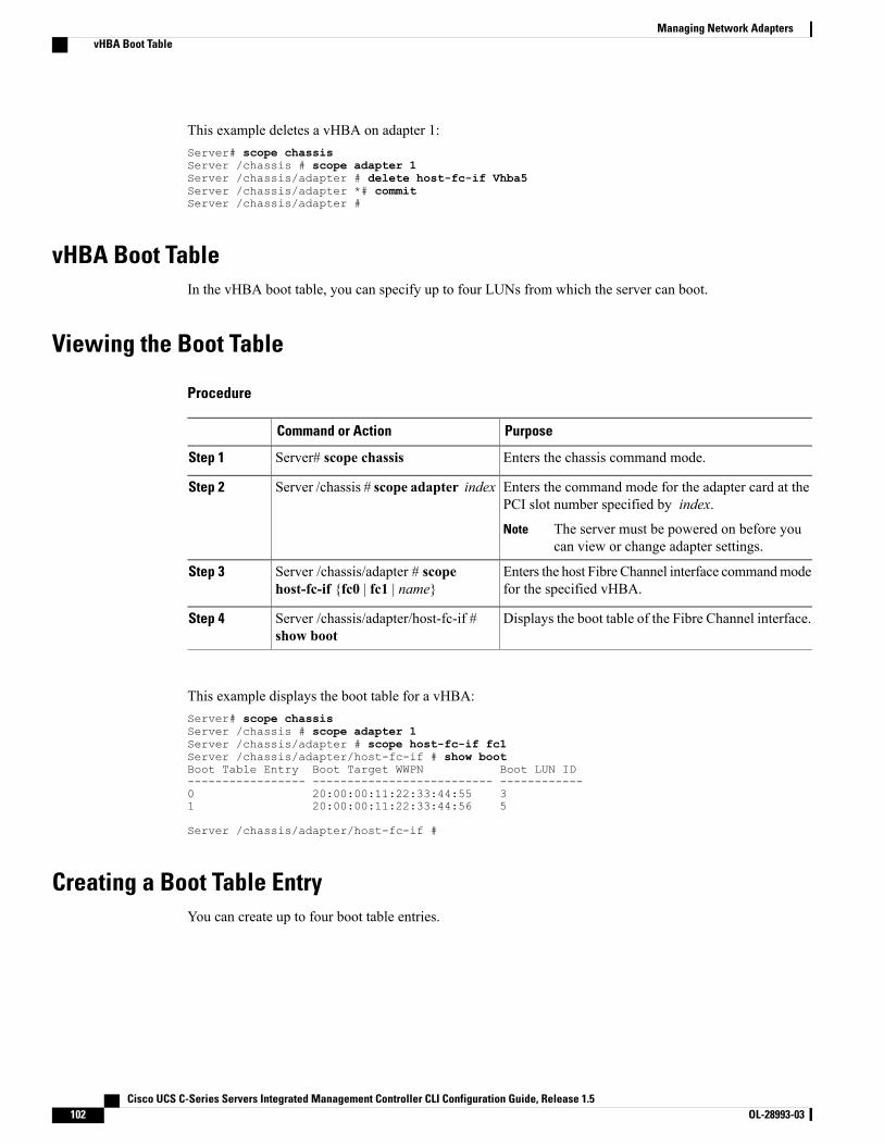
This example deletes a vHBA on adapter 1:Server# scope chassisServer /chassis # scope adapter 1Server /chassis/adapter # delete host-fc-if Vhba5Server /chassis/adapter *# commitServer /chassis/adapter #
vHBA Boot TableIn the vHBA boot table, you can specify up to four LUNs from which the server can boot.
Viewing the Boot Table
Procedure
PurposeCommand or Action
Enters the chassis command mode.Server# scope chassisStep 1
Enters the command mode for the adapter card at thePCI slot number specified by index.
Server /chassis # scope adapter indexStep 2
The server must be powered on before youcan view or change adapter settings.
Note
Enters the host Fibre Channel interface commandmodefor the specified vHBA.
Server /chassis/adapter # scopehost-fc-if {fc0 | fc1 | name}
Step 3
Displays the boot table of the Fibre Channel interface.Server /chassis/adapter/host-fc-if #show boot
Step 4
This example displays the boot table for a vHBA:Server# scope chassisServer /chassis # scope adapter 1Server /chassis/adapter # scope host-fc-if fc1Server /chassis/adapter/host-fc-if # show bootBoot Table Entry Boot Target WWPN Boot LUN ID----------------- -------------------------- ------------0 20:00:00:11:22:33:44:55 31 20:00:00:11:22:33:44:56 5
Server /chassis/adapter/host-fc-if #
Creating a Boot Table EntryYou can create up to four boot table entries.
Cisco UCS C-Series Servers Integrated Management Controller CLI Configuration Guide, Release 1.5102 OL-28993-03
Managing Network AdaptersvHBA Boot Table

Procedure
PurposeCommand or Action
Enters the chassis command mode.Server# scope chassisStep 1
Enters the command mode for the adapter card at the PCIslot number specified by index.
Server /chassis # scope adapterindex
Step 2
The server must be powered on before you canview or change adapter settings.
Note
Enters the host Fibre Channel interface command modefor the specified vHBA.
Server /chassis/adapter # scopehost-fc-if {fc0 | fc1 | name}
Step 3
Creates a boot table entry.Server /chassis/adapter/host-fc-if #create-boot-entry wwpn lun-id
Step 4
• wwpn— The World Wide Port Name (WWPN) forthe boot target in the form hh:hh:hh:hh:hh:hh:hh:hh.
• lun-id—The LUN ID of the boot LUN. The rangeis 0 to 255.
Commits the transaction to the system configuration.Server /chassis/adapter/host-fc-if #commit
Step 5
The changes will take effect upon the next serverreboot.
Note
This example creates a boot table entry for vHBA fc1:Server# scope chassisServer /chassis # scope adapter 1Server /chassis/adapter # scope host-fc-if fc1Server /chassis/adapter/host-fc-if # create-boot-entry 20:00:00:11:22:33:44:55 3Server /chassis/adapter/host-fc-if *# commitNew boot table entry will take effect upon the next server resetServer /chassis/adapter/host-fc-if #
Deleting a Boot Table Entry
Procedure
PurposeCommand or Action
Enters the chassis command mode.Server# scope chassisStep 1
Enters the commandmode for the adapter card at the PCIslot number specified by index.
Server /chassis # scope adapterindex
Step 2
The server must be powered on before you canview or change adapter settings.
Note
Cisco UCS C-Series Servers Integrated Management Controller CLI Configuration Guide, Release 1.5 OL-28993-03 103
Managing Network AdaptersDeleting a Boot Table Entry

PurposeCommand or Action
Enters the host Fibre Channel interface command modefor the specified vHBA.
Server /chassis/adapter # scopehost-fc-if {fc0 | fc1 | name}
Step 3
Displays the boot table. From the Boot Table Entry field,locate the number of the entry to be deleted.
Server /chassis/adapter/host-fc-if #show boot
Step 4
Deletes the boot table entry at the specified position inthe table. The range of entry is 0 to 3. The change willtake effect upon the next server reset.
Server /chassis/adapter/host-fc-if #delete boot entry
Step 5
Commits the transaction to the system configuration.Server /chassis/adapter/host-fc-if #commit
Step 6
The changes will take effect upon the next serverreboot.
Note
This example deletes boot table entry number 1 for the vHBA fc1:Server# scope chassisServer /chassis # scope adapter 1Server /chassis/adapter # scope host-fc-if fc1Server /chassis/adapter/host-fc-if # show bootBoot Table Entry Boot Target WWPN Boot LUN ID----------------- -------------------------- ------------0 20:00:00:11:22:33:44:55 31 20:00:00:11:22:33:44:56 5
Server /chassis/adapter/host-fc-if # delete boot 1Server /chassis/adapter/host-fc-if *# commitNew host-fc-if settings will take effect upon the next server resetServer /chassis/adapter/host-fc-if # show bootBoot Table Entry Boot Target WWPN Boot LUN ID----------------- -------------------------- ------------0 20:00:00:11:22:33:44:55 3
Server /chassis/adapter/host-fc-if #
What to Do Next
Reboot the server to apply the changes.
vHBA Persistent BindingPersistent binding ensures that the system-assigned mapping of Fibre Channel targets is maintained after areboot.
Cisco UCS C-Series Servers Integrated Management Controller CLI Configuration Guide, Release 1.5104 OL-28993-03
Managing Network AdaptersvHBA Persistent Binding
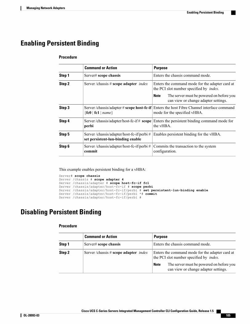
Enabling Persistent Binding
Procedure
PurposeCommand or Action
Enters the chassis command mode.Server# scope chassisStep 1
Enters the command mode for the adapter card atthe PCI slot number specified by index.
Server /chassis # scope adapter indexStep 2
The server must be powered on before youcan view or change adapter settings.
Note
Enters the host Fibre Channel interface commandmode for the specified vHBA.
Server /chassis/adapter # scope host-fc-if{fc0 | fc1 | name}
Step 3
Enters the persistent binding command mode forthe vHBA.
Server /chassis/adapter/host-fc-if # scopeperbi
Step 4
Enables persistent binding for the vHBA.Server /chassis/adapter/host-fc-if/perbi #set persistent-lun-binding enable
Step 5
Commits the transaction to the systemconfiguration.
Server /chassis/adapter/host-fc-if/perbi #commit
Step 6
This example enables persistent binding for a vHBA:Server# scope chassisServer /chassis # scope adapter 4Server /chassis/adapter # scope host-fc-if fc1Server /chassis/adapter/host-fc-if # scope perbiServer /chassis/adapter/host-fc-if/perbi # set persistent-lun-binding enableServer /chassis/adapter/host-fc-if/perbi *# commitServer /chassis/adapter/host-fc-if/perbi #
Disabling Persistent Binding
Procedure
PurposeCommand or Action
Enters the chassis command mode.Server# scope chassisStep 1
Enters the command mode for the adapter card atthe PCI slot number specified by index.
Server /chassis # scope adapter indexStep 2
The server must be powered on before youcan view or change adapter settings.
Note
Cisco UCS C-Series Servers Integrated Management Controller CLI Configuration Guide, Release 1.5 OL-28993-03 105
Managing Network AdaptersEnabling Persistent Binding
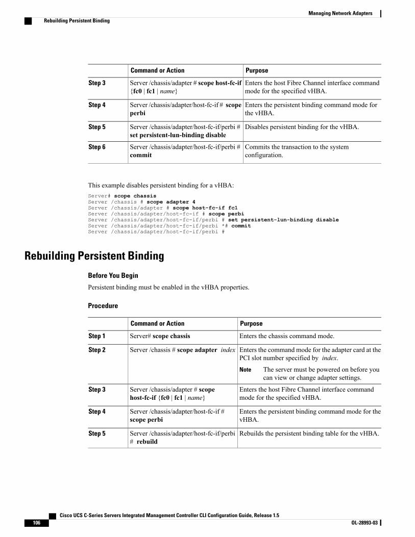
PurposeCommand or Action
Enters the host Fibre Channel interface commandmode for the specified vHBA.
Server /chassis/adapter # scope host-fc-if{fc0 | fc1 | name}
Step 3
Enters the persistent binding command mode forthe vHBA.
Server /chassis/adapter/host-fc-if # scopeperbi
Step 4
Disables persistent binding for the vHBA.Server /chassis/adapter/host-fc-if/perbi #set persistent-lun-binding disable
Step 5
Commits the transaction to the systemconfiguration.
Server /chassis/adapter/host-fc-if/perbi #commit
Step 6
This example disables persistent binding for a vHBA:Server# scope chassisServer /chassis # scope adapter 4Server /chassis/adapter # scope host-fc-if fc1Server /chassis/adapter/host-fc-if # scope perbiServer /chassis/adapter/host-fc-if/perbi # set persistent-lun-binding disableServer /chassis/adapter/host-fc-if/perbi *# commitServer /chassis/adapter/host-fc-if/perbi #
Rebuilding Persistent Binding
Before You Begin
Persistent binding must be enabled in the vHBA properties.
Procedure
PurposeCommand or Action
Enters the chassis command mode.Server# scope chassisStep 1
Enters the command mode for the adapter card at thePCI slot number specified by index.
Server /chassis # scope adapter indexStep 2
The server must be powered on before youcan view or change adapter settings.
Note
Enters the host Fibre Channel interface commandmode for the specified vHBA.
Server /chassis/adapter # scopehost-fc-if {fc0 | fc1 | name}
Step 3
Enters the persistent binding command mode for thevHBA.
Server /chassis/adapter/host-fc-if #scope perbi
Step 4
Rebuilds the persistent binding table for the vHBA.Server /chassis/adapter/host-fc-if/perbi# rebuild
Step 5
Cisco UCS C-Series Servers Integrated Management Controller CLI Configuration Guide, Release 1.5106 OL-28993-03
Managing Network AdaptersRebuilding Persistent Binding

This example rebuilds the persistent binding table for a vHBA:Server# scope chassisServer /chassis # scope adapter 4Server /chassis/adapter # scope host-fc-if fc1Server /chassis/adapter/host-fc-if # scope perbiServer /chassis/adapter/host-fc-if/perbi # rebuild
Server /chassis/adapter/host-fc-if/perbi #
Managing vNICs
Guidelines for Managing vNICsWhen managing vNICs, consider the following guidelines and restrictions:
• The Cisco UCS P81E Virtual Interface Card and Cisco UCS VIC1225 Virtual Interface Card providetwo default vNICs (eth0 and eth1). You can create up to 16 additional vNICs on these adapter cards.
If Network Interface Virtualization (NIV) mode is enabled for the adapter, you mustassign a channel number to a vNIC when you create it.
Note
• After making configuration changes, you must reboot the host for settings to take effect.
Viewing vNIC Properties
Procedure
PurposeCommand or Action
Enters the chassis command mode.Server# scope chassisStep 1
Enters the command mode for the adapter card at thePCI slot number specified by index.
Server /chassis # scope adapter indexStep 2
The server must be powered on before youcan view or change adapter settings.
Note
Displays properties of a single vNIC, if specified, orall vNICs.
Server /chassis/adapter # showhost-eth-if [eth0 | eth1 | name] [detail]
Step 3
This example displays the brief properties of all vNICs and the detailed properties of eth0:Server# scope chassisServer /chassis # scope adapter 1Server /chassis/adapter # show host-eth-ifName MTU Uplink Port MAC Address CoS VLAN PXE Boot-------- ---- ----------- ----------------- --- ---- --------eth0 1500 0 00:22:BD:D6:5C:33 0 NONE Enabledeth1 1500 1 00:22:BD:D6:5C:34 0 NONE Enabled
Cisco UCS C-Series Servers Integrated Management Controller CLI Configuration Guide, Release 1.5 OL-28993-03 107
Managing Network AdaptersManaging vNICs
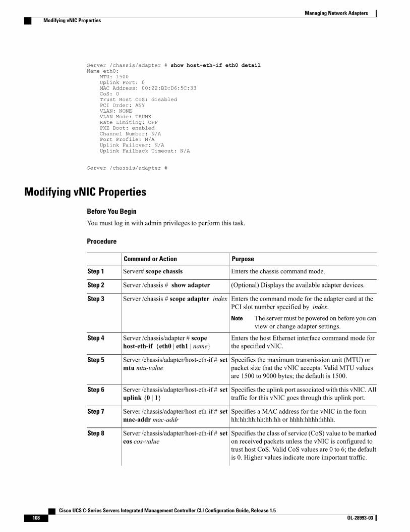
Server /chassis/adapter # show host-eth-if eth0 detailName eth0:
MTU: 1500Uplink Port: 0MAC Address: 00:22:BD:D6:5C:33CoS: 0Trust Host CoS: disabledPCI Order: ANYVLAN: NONEVLAN Mode: TRUNKRate Limiting: OFFPXE Boot: enabledChannel Number: N/APort Profile: N/AUplink Failover: N/AUplink Failback Timeout: N/A
Server /chassis/adapter #
Modifying vNIC Properties
Before You Begin
You must log in with admin privileges to perform this task.
Procedure
PurposeCommand or Action
Enters the chassis command mode.Server# scope chassisStep 1
(Optional) Displays the available adapter devices.Server /chassis # show adapterStep 2
Enters the command mode for the adapter card at thePCI slot number specified by index.
Server /chassis # scope adapter indexStep 3
The server must be powered on before you canview or change adapter settings.
Note
Enters the host Ethernet interface command mode forthe specified vNIC.
Server /chassis/adapter # scopehost-eth-if {eth0 | eth1 | name}
Step 4
Specifies the maximum transmission unit (MTU) orpacket size that the vNIC accepts. Valid MTU valuesare 1500 to 9000 bytes; the default is 1500.
Server /chassis/adapter/host-eth-if # setmtu mtu-value
Step 5
Specifies the uplink port associated with this vNIC. Alltraffic for this vNIC goes through this uplink port.
Server /chassis/adapter/host-eth-if # setuplink {0 | 1}
Step 6
Specifies a MAC address for the vNIC in the formhh:hh:hh:hh:hh:hh or hhhh:hhhh:hhhh.
Server /chassis/adapter/host-eth-if # setmac-addr mac-addr
Step 7
Specifies the class of service (CoS) value to be markedon received packets unless the vNIC is configured to
Server /chassis/adapter/host-eth-if # setcos cos-value
Step 8
trust host CoS. Valid CoS values are 0 to 6; the defaultis 0. Higher values indicate more important traffic.
Cisco UCS C-Series Servers Integrated Management Controller CLI Configuration Guide, Release 1.5108 OL-28993-03
Managing Network AdaptersModifying vNIC Properties
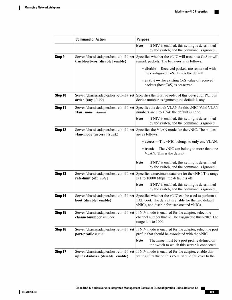
PurposeCommand or Action
If NIV is enabled, this setting is determinedby the switch, and the command is ignored.
Note
Specifies whether the vNIC will trust host CoS or willremark packets. The behavior is as follows:
Server /chassis/adapter/host-eth-if # settrust-host-cos {disable | enable}
Step 9
• disable—Received packets are remarked withthe configured CoS. This is the default.
• enable—The existing CoS value of receivedpackets (host CoS) is preserved.
Specifies the relative order of this device for PCI busdevice number assignment; the default is any.
Server /chassis/adapter/host-eth-if # setorder {any | 0-99}
Step 10
Specifies the default VLAN for this vNIC. Valid VLANnumbers are 1 to 4094; the default is none.
Server /chassis/adapter/host-eth-if # setvlan {none | vlan-id}
Step 11
If NIV is enabled, this setting is determinedby the switch, and the command is ignored.
Note
Specifies the VLAN mode for the vNIC. The modesare as follows:
Server /chassis/adapter/host-eth-if # setvlan-mode {access | trunk}
Step 12
• access—The vNIC belongs to only one VLAN.
• trunk—The vNIC can belong to more than oneVLAN. This is the default.
If NIV is enabled, this setting is determinedby the switch, and the command is ignored.
Note
Specifies a maximum data rate for the vNIC. The rangeis 1 to 10000 Mbps; the default is off.
Server /chassis/adapter/host-eth-if # setrate-limit {off | rate}
Step 13
If NIV is enabled, this setting is determinedby the switch, and the command is ignored.
Note
Specifies whether the vNIC can be used to perform aPXE boot. The default is enable for the two defaultvNICs, and disable for user-created vNICs.
Server /chassis/adapter/host-eth-if # setboot {disable | enable}
Step 14
If NIV mode is enabled for the adapter, select thechannel number that will be assigned to this vNIC. Therange is 1 to 1000.
Server /chassis/adapter/host-eth-if # setchannel-number number
Step 15
If NIV mode is enabled for the adapter, select the portprofile that should be associated with the vNIC.
Server /chassis/adapter/host-eth-if # setport-profile name
Step 16
The name must be a port profile defined onthe switch to which this server is connected.
Note
If NIV mode is enabled for the adapter, enable thissetting if traffic on this vNIC should fail over to the
Server /chassis/adapter/host-eth-if # setuplink-failover {disable | enable}
Step 17
Cisco UCS C-Series Servers Integrated Management Controller CLI Configuration Guide, Release 1.5 OL-28993-03 109
Managing Network AdaptersModifying vNIC Properties
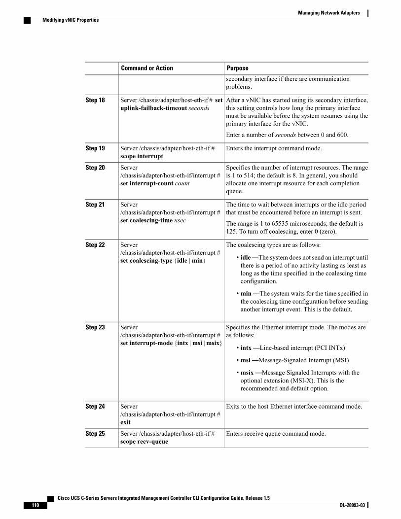
PurposeCommand or Action
secondary interface if there are communicationproblems.
After a vNIC has started using its secondary interface,this setting controls how long the primary interface
Server /chassis/adapter/host-eth-if # setuplink-failback-timeout seconds
Step 18
must be available before the system resumes using theprimary interface for the vNIC.
Enter a number of seconds between 0 and 600.
Enters the interrupt command mode.Server /chassis/adapter/host-eth-if #scope interrupt
Step 19
Specifies the number of interrupt resources. The rangeis 1 to 514; the default is 8. In general, you should
Server/chassis/adapter/host-eth-if/interrupt #set interrupt-count count
Step 20
allocate one interrupt resource for each completionqueue.
The time to wait between interrupts or the idle periodthat must be encountered before an interrupt is sent.
Server/chassis/adapter/host-eth-if/interrupt #set coalescing-time usec
Step 21
The range is 1 to 65535 microseconds; the default is125. To turn off coalescing, enter 0 (zero).
The coalescing types are as follows:Server/chassis/adapter/host-eth-if/interrupt #set coalescing-type {idle |min}
Step 22
• idle—The system does not send an interrupt untilthere is a period of no activity lasting as least aslong as the time specified in the coalescing timeconfiguration.
• min—The system waits for the time specified inthe coalescing time configuration before sendinganother interrupt event. This is the default.
Specifies the Ethernet interrupt mode. The modes areas follows:
Server/chassis/adapter/host-eth-if/interrupt #set interrupt-mode {intx |msi |msix}
Step 23
• intx—Line-based interrupt (PCI INTx)
• msi—Message-Signaled Interrupt (MSI)
• msix—Message Signaled Interrupts with theoptional extension (MSI-X). This is therecommended and default option.
Exits to the host Ethernet interface command mode.Server/chassis/adapter/host-eth-if/interrupt #exit
Step 24
Enters receive queue command mode.Server /chassis/adapter/host-eth-if #scope recv-queue
Step 25
Cisco UCS C-Series Servers Integrated Management Controller CLI Configuration Guide, Release 1.5110 OL-28993-03
Managing Network AdaptersModifying vNIC Properties
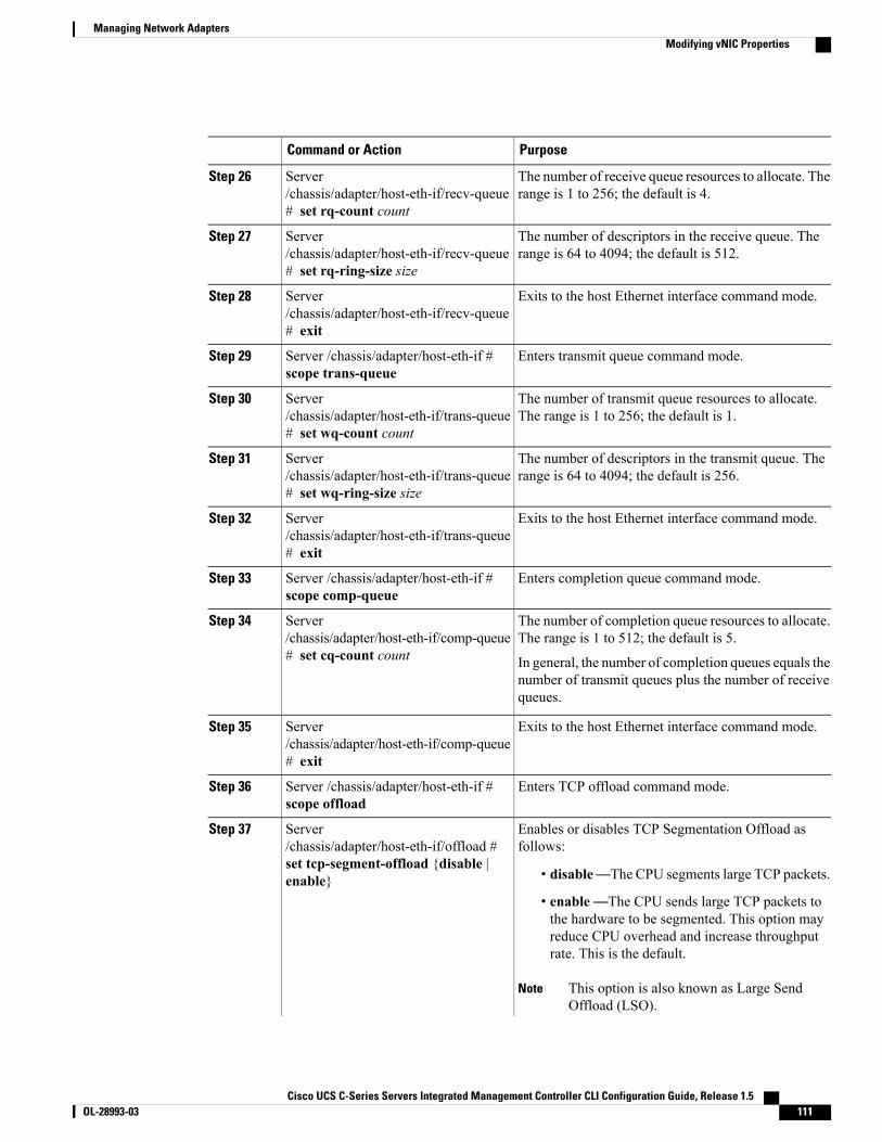
PurposeCommand or Action
The number of receive queue resources to allocate. Therange is 1 to 256; the default is 4.
Server/chassis/adapter/host-eth-if/recv-queue# set rq-count count
Step 26
The number of descriptors in the receive queue. Therange is 64 to 4094; the default is 512.
Server/chassis/adapter/host-eth-if/recv-queue# set rq-ring-size size
Step 27
Exits to the host Ethernet interface command mode.Server/chassis/adapter/host-eth-if/recv-queue# exit
Step 28
Enters transmit queue command mode.Server /chassis/adapter/host-eth-if #scope trans-queue
Step 29
The number of transmit queue resources to allocate.The range is 1 to 256; the default is 1.
Server/chassis/adapter/host-eth-if/trans-queue# set wq-count count
Step 30
The number of descriptors in the transmit queue. Therange is 64 to 4094; the default is 256.
Server/chassis/adapter/host-eth-if/trans-queue# set wq-ring-size size
Step 31
Exits to the host Ethernet interface command mode.Server/chassis/adapter/host-eth-if/trans-queue# exit
Step 32
Enters completion queue command mode.Server /chassis/adapter/host-eth-if #scope comp-queue
Step 33
The number of completion queue resources to allocate.The range is 1 to 512; the default is 5.
Server/chassis/adapter/host-eth-if/comp-queue# set cq-count count
Step 34
In general, the number of completion queues equals thenumber of transmit queues plus the number of receivequeues.
Exits to the host Ethernet interface command mode.Server/chassis/adapter/host-eth-if/comp-queue# exit
Step 35
Enters TCP offload command mode.Server /chassis/adapter/host-eth-if #scope offload
Step 36
Enables or disables TCP Segmentation Offload asfollows:
Server/chassis/adapter/host-eth-if/offload #set tcp-segment-offload {disable |enable}
Step 37
• disable—The CPU segments large TCP packets.
• enable—The CPU sends large TCP packets tothe hardware to be segmented. This option mayreduce CPU overhead and increase throughputrate. This is the default.
This option is also known as Large SendOffload (LSO).
Note
Cisco UCS C-Series Servers Integrated Management Controller CLI Configuration Guide, Release 1.5 OL-28993-03 111
Managing Network AdaptersModifying vNIC Properties

PurposeCommand or Action
Enables or disables TCP Receive Offload ChecksumValidation as follows:
Server/chassis/adapter/host-eth-if/offload #set tcp-rx-checksum-offload {disable| enable}
Step 38
• disable—The CPU validates all packetchecksums.
• enable—The CPU sends all packet checksumsto the hardware for validation. This option mayreduce CPU overhead. This is the default.
Enables or disables TCP Transmit Offload ChecksumValidation as follows:
Server/chassis/adapter/host-eth-if/offload #set tcp-tx-checksum-offload {disable| enable}
Step 39
• disable—The CPU validates all packetchecksums.
• enable—The CPU sends all packet checksumsto the hardware for validation. This option mayreduce CPU overhead. This is the default.
Enables or disables TCP Large Packet Receive Offloadas follows:
Server/chassis/adapter/host-eth-if/offload #set tcp-large-receive-offload {disable| enable}
Step 40
• disable—The CPU processes all large packets.
• enable—The hardware reassembles all segmentedpackets before sending them to the CPU. Thisoption may reduce CPU utilization and increaseinbound throughput. This is the default.
Exits to the host Ethernet interface command mode.Server/chassis/adapter/host-eth-if/offload #exit
Step 41
Enters Receive-side Scaling (RSS) command mode.Server /chassis/adapter/host-eth-if #scope rss
Step 42
Enables or disables RSS, which allows the efficientdistribution of network receive processing across
Server /chassis/adapter/host-eth-if/rss #set rss {disable | enable}
Step 43
multiple CPUs in multiprocessor systems. The defaultis enable for the two default vNICs, and disable foruser-created vNICs.
Enables or disables IPv4 RSS. The default is enable.Server /chassis/adapter/host-eth-if/rss #set rss-hash-ipv4 {disable | enable}
Step 44
Enables or disables TCP/IPv4 RSS. The default isenable.
Server /chassis/adapter/host-eth-if/rss #set rss-hash-tcp-ipv4 {disable |enable}
Step 45
Enables or disables IPv6 RSS. The default is enable.Server /chassis/adapter/host-eth-if/rss #set rss-hash-ipv6 {disable | enable}
Step 46
Cisco UCS C-Series Servers Integrated Management Controller CLI Configuration Guide, Release 1.5112 OL-28993-03
Managing Network AdaptersModifying vNIC Properties

PurposeCommand or Action
Enables or disables TCP/IPv6 RSS. The default isenable.
Server /chassis/adapter/host-eth-if/rss #set rss-hash-tcp-ipv6 {disable |enable}
Step 47
Enables or disables IPv6 Extension RSS. The defaultis disable.
Server /chassis/adapter/host-eth-if/rss #set rss-hash-ipv6-ex {disable | enable}
Step 48
Enables or disables TCP/IPv6 Extension RSS. Thedefault is disable.
Server /chassis/adapter/host-eth-if/rss #set rss-hash-tcp-ipv6-ex {disable |enable}
Step 49
Exits to the host Ethernet interface command mode.Server /chassis/adapter/host-eth-if/rss #exit
Step 50
Commits the transaction to the system configuration.Server /chassis/adapter/host-eth-if #commit
Step 51
The changes will take effect upon the nextserver reboot.
Note
This example configures the properties of a vNIC:Server# scope chassisServer /chassis # show adapterPCI Slot Product Name Serial Number Product ID Vendor-------- -------------- -------------- -------------- --------------------1 UCS VIC P81E QCI1417A0QK N2XX-ACPCI01 Cisco Systems Inc
Server /chassis # scope adapter 1Server /chassis/adapter # scope host-eth-if Test1Server /chassis/adapter/host-eth-if # set uplink 1Server /chassis/adapter/host-eth-if *# scope offloadServer /chassis/adapter/host-eth-if/offload *# set tcp-segment-offload enableServer /chassis/adapter/host-eth-if/offload *# exitServer /chassis/adapter/host-eth-if *# commitServer /chassis/adapter/host-eth-if #
What to Do Next
Reboot the server to apply the changes.
Creating a vNICThe adapter provides two permanent vNICs. You can create up to 16 additional vNICs.
Before You Begin
You must log in with user or admin privileges to perform this task.
Cisco UCS C-Series Servers Integrated Management Controller CLI Configuration Guide, Release 1.5 OL-28993-03 113
Managing Network AdaptersCreating a vNIC
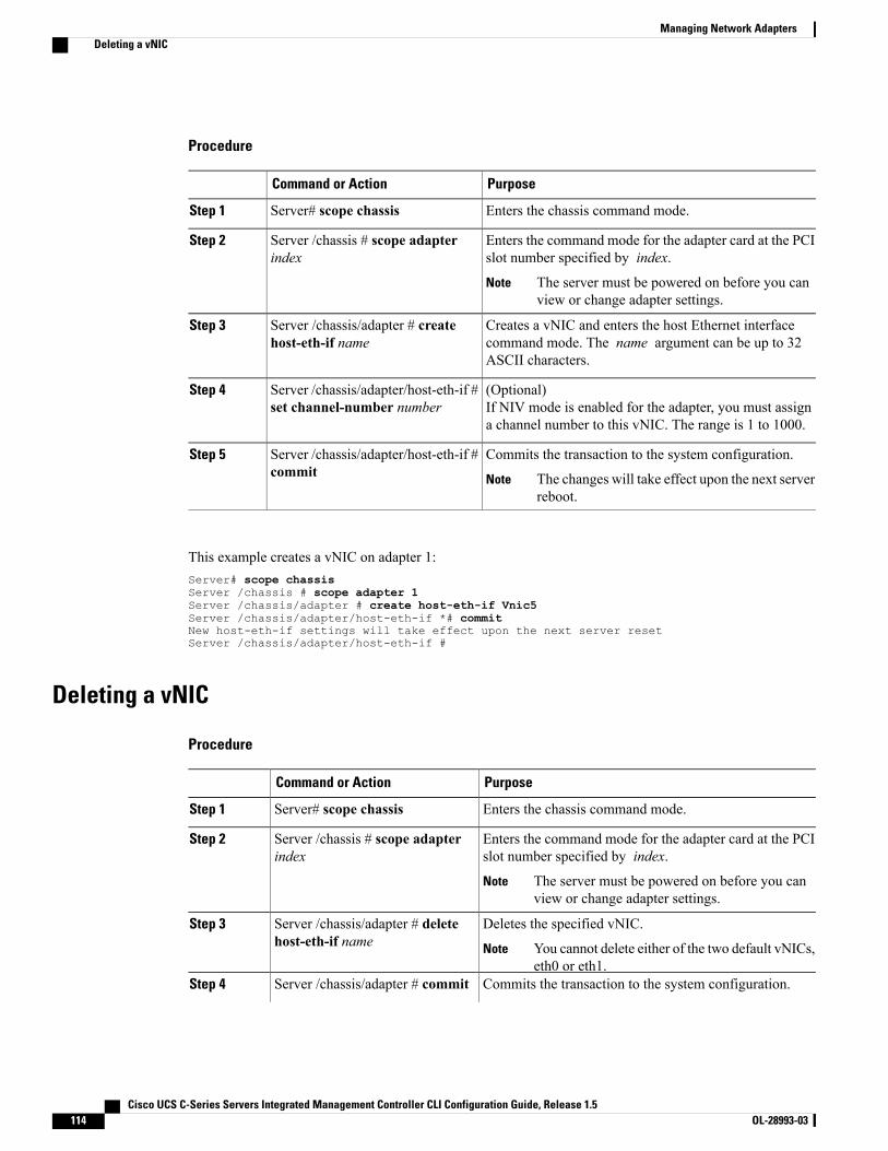
Procedure
PurposeCommand or Action
Enters the chassis command mode.Server# scope chassisStep 1
Enters the command mode for the adapter card at the PCIslot number specified by index.
Server /chassis # scope adapterindex
Step 2
The server must be powered on before you canview or change adapter settings.
Note
Creates a vNIC and enters the host Ethernet interfacecommand mode. The name argument can be up to 32ASCII characters.
Server /chassis/adapter # createhost-eth-if name
Step 3
(Optional)If NIV mode is enabled for the adapter, you must assigna channel number to this vNIC. The range is 1 to 1000.
Server /chassis/adapter/host-eth-if #set channel-number number
Step 4
Commits the transaction to the system configuration.Server /chassis/adapter/host-eth-if #commit
Step 5
The changes will take effect upon the next serverreboot.
Note
This example creates a vNIC on adapter 1:Server# scope chassisServer /chassis # scope adapter 1Server /chassis/adapter # create host-eth-if Vnic5Server /chassis/adapter/host-eth-if *# commitNew host-eth-if settings will take effect upon the next server resetServer /chassis/adapter/host-eth-if #
Deleting a vNIC
Procedure
PurposeCommand or Action
Enters the chassis command mode.Server# scope chassisStep 1
Enters the command mode for the adapter card at the PCIslot number specified by index.
Server /chassis # scope adapterindex
Step 2
The server must be powered on before you canview or change adapter settings.
Note
Deletes the specified vNIC.Server /chassis/adapter # deletehost-eth-if name
Step 3
You cannot delete either of the two default vNICs,eth0 or eth1.
Note
Commits the transaction to the system configuration.Server /chassis/adapter # commitStep 4
Cisco UCS C-Series Servers Integrated Management Controller CLI Configuration Guide, Release 1.5114 OL-28993-03
Managing Network AdaptersDeleting a vNIC
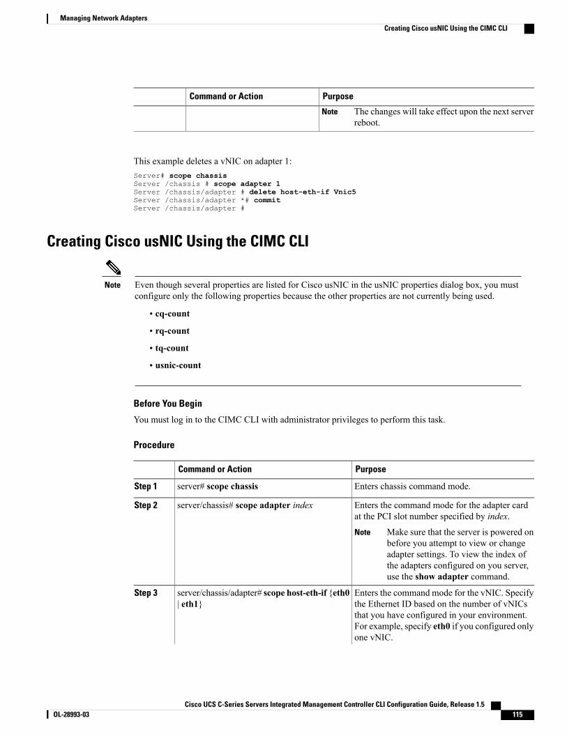
PurposeCommand or Action
The changes will take effect upon the next serverreboot.
Note
This example deletes a vNIC on adapter 1:Server# scope chassisServer /chassis # scope adapter 1Server /chassis/adapter # delete host-eth-if Vnic5Server /chassis/adapter *# commitServer /chassis/adapter #
Creating Cisco usNIC Using the CIMC CLI
Even though several properties are listed for Cisco usNIC in the usNIC properties dialog box, you mustconfigure only the following properties because the other properties are not currently being used.
Note
• cq-count
• rq-count
• tq-count
• usnic-count
Before You Begin
You must log in to the CIMC CLI with administrator privileges to perform this task.
Procedure
PurposeCommand or Action
Enters chassis command mode.server# scope chassisStep 1
Enters the command mode for the adapter cardat the PCI slot number specified by index.
server/chassis# scope adapter indexStep 2
Make sure that the server is powered onbefore you attempt to view or changeadapter settings. To view the index ofthe adapters configured on you server,use the show adapter command.
Note
Enters the command mode for the vNIC. Specifythe Ethernet ID based on the number of vNICs
server/chassis/adapter# scope host-eth-if {eth0| eth1}
Step 3
that you have configured in your environment.For example, specify eth0 if you configured onlyone vNIC.
Cisco UCS C-Series Servers Integrated Management Controller CLI Configuration Guide, Release 1.5 OL-28993-03 115
Managing Network AdaptersCreating Cisco usNIC Using the CIMC CLI
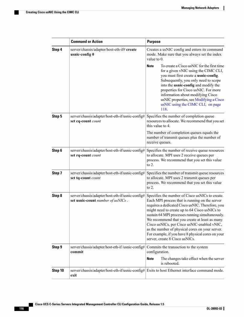
PurposeCommand or Action
Creates a usNIC config and enters its commandmode. Make sure that you always set the indexvalue to 0.
server/chassis/adapter/host-eth-if# createusnic-config 0
Step 4
To create a Cisco usNIC for the first timefor a given vNIC using the CIMC CLI,you must first create a usnic-config.Subsequently, you only need to scopeinto the usnic-config and modify theproperties for Cisco usNIC. For moreinformation about modifying CiscousNIC properties, seeModifying a CiscousNIC using the CIMC CLI, on page118.
Note
Specifies the number of completion queueresources to allocate.We recommend that you setthis value to 4.
server/chassis/adapter/host-eth-if/usnic-config#set cq-count count
Step 5
The number of completion queues equals thenumber of transmit queues plus the number ofreceive queues.
Specifies the number of receive queue resourcesto allocate. MPI uses 2 receive queues per
server/chassis/adapter/host-eth-if/usnic-config#set rq-count count
Step 6
process. We recommend that you set this valueto 2.
Specifies the number of transmit queue resourcesto allocate. MPI uses 2 transmit queues per
server/chassis/adapter/host-eth-if/usnic-config#set tq-count count
Step 7
process. We recommend that you set this valueto 2.
Specifies the number of Cisco usNICs to create.Each MPI process that is running on the server
server/chassis/adapter/host-eth-if/usnic-config#set usnic-count number of usNICs .
Step 8
requires a dedicated Cisco usNIC. Therefore, youmight need to create up to 64 Cisco usNICs tosustain 64MPI processes running simultaneously.We recommend that you create at least as manyCisco usNICs, per Cisco usNIC-enabled vNIC,as the number of physical cores on your server.For example, if you have 8 physical cores on yourserver, create 8 Cisco usNICs.
Commits the transaction to the systemconfiguration.
server/chassis/adapter/host-eth-if /usnic-config#commit
Step 9
The changes take effect when the serveris rebooted.
Note
Exits to host Ethernet interface command mode.server/chassis/adapter/host-eth-if/usnic-config#exit
Step 10
Cisco UCS C-Series Servers Integrated Management Controller CLI Configuration Guide, Release 1.5116 OL-28993-03
Managing Network AdaptersCreating Cisco usNIC Using the CIMC CLI
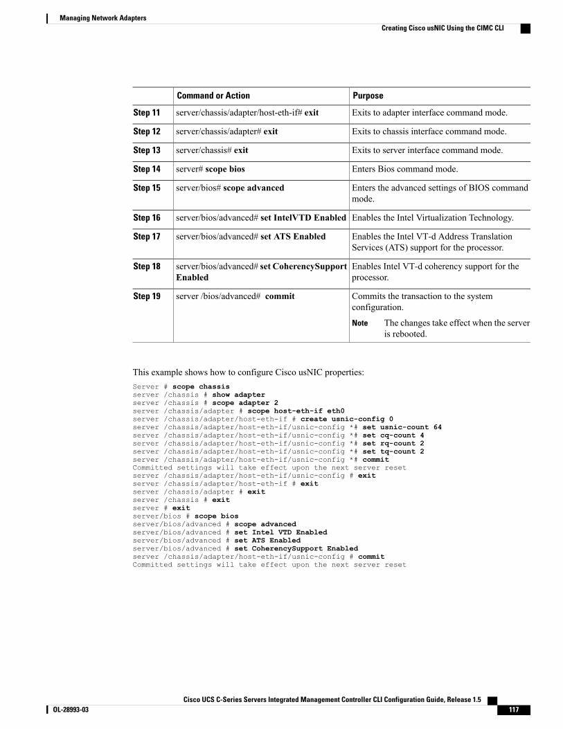
PurposeCommand or Action
Exits to adapter interface command mode.server/chassis/adapter/host-eth-if# exitStep 11
Exits to chassis interface command mode.server/chassis/adapter# exitStep 12
Exits to server interface command mode.server/chassis# exitStep 13
Enters Bios command mode.server# scope biosStep 14
Enters the advanced settings of BIOS commandmode.
server/bios# scope advancedStep 15
Enables the Intel Virtualization Technology.server/bios/advanced# set IntelVTD EnabledStep 16
Enables the Intel VT-d Address TranslationServices (ATS) support for the processor.
server/bios/advanced# set ATS EnabledStep 17
Enables Intel VT-d coherency support for theprocessor.
server/bios/advanced# set CoherencySupportEnabled
Step 18
Commits the transaction to the systemconfiguration.
server /bios/advanced# commitStep 19
The changes take effect when the serveris rebooted.
Note
This example shows how to configure Cisco usNIC properties:Server # scope chassisserver /chassis # show adapterserver /chassis # scope adapter 2server /chassis/adapter # scope host-eth-if eth0server /chassis/adapter/host-eth-if # create usnic-config 0server /chassis/adapter/host-eth-if/usnic-config *# set usnic-count 64server /chassis/adapter/host-eth-if/usnic-config *# set cq-count 4server /chassis/adapter/host-eth-if/usnic-config *# set rq-count 2server /chassis/adapter/host-eth-if/usnic-config *# set tq-count 2server /chassis/adapter/host-eth-if/usnic-config *# commitCommitted settings will take effect upon the next server resetserver /chassis/adapter/host-eth-if/usnic-config # exitserver /chassis/adapter/host-eth-if # exitserver /chassis/adapter # exitserver /chassis # exitserver # exitserver/bios # scope biosserver/bios/advanced # scope advancedserver/bios/advanced # set Intel VTD Enabledserver/bios/advanced # set ATS Enabledserver/bios/advanced # set CoherencySupport Enabledserver /chassis/adapter/host-eth-if/usnic-config # commitCommitted settings will take effect upon the next server reset
Cisco UCS C-Series Servers Integrated Management Controller CLI Configuration Guide, Release 1.5 OL-28993-03 117
Managing Network AdaptersCreating Cisco usNIC Using the CIMC CLI
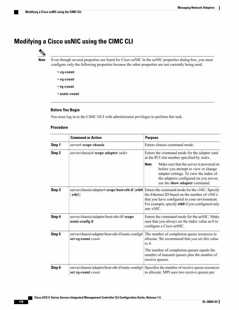
Modifying a Cisco usNIC using the CIMC CLI
Even though several properties are listed for Cisco usNIC in the usNIC properties dialog box, you mustconfigure only the following properties because the other properties are not currently being used.
Note
• cq-count
• rq-count
• tq-count
• usnic-count
Before You Begin
You must log in to the CIMC GUI with administrator privileges to perform this task.
Procedure
PurposeCommand or Action
Enters chassis command mode.server# scope chassisStep 1
Enters the command mode for the adapter cardat the PCI slot number specified by index.
server/chassis# scope adapter indexStep 2
Make sure that the server is powered onbefore you attempt to view or changeadapter settings. To view the index ofthe adapters configured on you server,use the show adapter command.
Note
Enters the commandmode for the vNIC. Specifythe Ethernet ID based on the number of vNICs
server/chassis/adapter# scope host-eth-if {eth0| eth1}
Step 3
that you have configured in your environment.For example, specify eth0 if you configured onlyone vNIC.
Enters the command mode for the usNIC. Makesure that you always set the index value as 0 toconfigure a Cisco usNIC.
server/chassis/adapter/host-eth-if# scopeusnic-config 0
Step 4
The number of completion queue resources toallocate. We recommend that you set this valueto 4.
server/chassis/adapter/host-eth-if/usnic-config#set cq-count count
Step 5
The number of completion queues equals thenumber of transmit queues plus the number ofreceive queues.
Specifies the number of receive queue resourcesto allocate. MPI uses two receive queues per
server/chassis/adapter/host-eth-if/usnic-config#set rq-count count
Step 6
Cisco UCS C-Series Servers Integrated Management Controller CLI Configuration Guide, Release 1.5118 OL-28993-03
Managing Network AdaptersModifying a Cisco usNIC using the CIMC CLI

PurposeCommand or Action
process. We recommend that you set this valueto 2.
Specifies the number of transmit queue resourcesto allocate. MPI uses two transmit queues per
server/chassis/adapter/host-eth-if/usnic-config#set tq-count count
Step 7
process. We recommend that you set this valueto 2.
Specifies the number of Cisco usNICs to create.EachMPI process running on the server requires
server/chassis/adapter/host-eth-if/usnic-config#set usnic-count number of usNICs .
Step 8
a dedicated Cisco usNIC. Therefore, you mightneed to create up to 64 Cisco usNIC to sustain64 MPI processes running simultaneously. Werecommend that you create at least as many CiscousNIC, per Cisco usNIC-enabled vNIC, as thenumber of physical cores on your server. Forexample, if you have 8 physical cores on yourserver, create 8 usNICs.
Commits the transaction to the systemconfiguration.
server /chassis/adapter/host-eth-if /usnic-config#commit
Step 9
The changes take effect when the serveris rebooted.
Note
Exits to host Ethernet interface command mode.server/chassis/adapter/host-eth-if/usnic-config#exit
Step 10
Exits to adapter interface command mode.server/chassis/adapter/host-eth-if# exitStep 11
Exits to chassis interface command mode.server/chassis/adapter# exitStep 12
Exits to server interface command mode.server/chassis# exitStep 13
Enters BIOS command mode.server# scope biosStep 14
Enters the advanced settings of BIOS commandmode.
server/bios# scope advancedStep 15
Enables the Intel Virtualization Technology.server/bios/advanced# set IntelVTD EnabledStep 16
Enables the Intel VT-d Address TranslationServices (ATS) support for the processor.
server/bios/advanced# set ATS EnabledStep 17
Enables Intel VT-d coherency support for theprocessor.
server/bios/advanced# set CoherencySupportEnabled
Step 18
Commits the transaction to the systemconfiguration.
server/bios/advanced# commitStep 19
The changes take effect when the serveris rebooted.
Note
Cisco UCS C-Series Servers Integrated Management Controller CLI Configuration Guide, Release 1.5 OL-28993-03 119
Managing Network AdaptersModifying a Cisco usNIC using the CIMC CLI
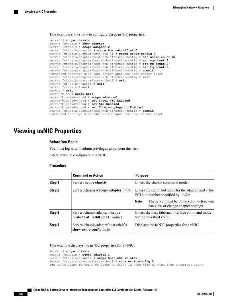
This example shows how to configure Cisco usNIC properties:server # scope chassisserver /chassis # show adapterserver /chassis # scope adapter 2server /chassis/adapter # scope host-eth-if eth0server /chassis/adapter/host-eth-if # scope usnic-config 0server /chassis/adapter/host-eth-if/usnic-config # set usnic-count 64server /chassis/adapter/host-eth-if/usnic-config # set cq-count 4server /chassis/adapter/host-eth-if/usnic-config # set rq-count 2server /chassis/adapter/host-eth-if/usnic-config # set tq-count 2server /chassis/adapter/host-eth-if/usnic-config # commitCommitted settings will take effect upon the next server resetserver /chassis/adapter/host-eth-if/usnic-config # exitserver /chassis/adapter/host-eth-if # exitserver /chassis/adapter # exitserver /chassis # exitserver # exitserver/bios # scope biosserver/bios/advanced # scope advancedserver/bios/advanced # set Intel VTD Enabledserver/bios/advanced # set ATS Enabledserver/bios/advanced # set CoherencySupport Enabledserver /chassis/adapter/host-eth-if/usnic-config # commitCommitted settings will take effect upon the next server reset
Viewing usNIC Properties
Before You Begin
You must log in with admin privileges to perform this task.
usNIC must be configured on a vNIC.
Procedure
PurposeCommand or Action
Enters the chassis command mode.Server# scope chassisStep 1
Enters the commandmode for the adapter card at thePCI slot number specified by index.
Server /chassis # scope adapter indexStep 2
The server must be powered on before youcan view or change adapter settings.
Note
Enters the host Ethernet interface command modefor the specified vNIC.
Server /chassis/adapter # scopehost-eth-if {eth0 | eth1 | name}
Step 3
Displays the usNIC properties for a vNIC.Server /chassis/adapter/host-eth-if #show usnic-config index
Step 4
This example displays the usNIC properties for a vNIC:Server # scope chassisServer /chassis # scope adapter 1Server /chassis/adapter # scope host-eth-if eth0Server /chassis/adapter/host-eth-if # show usnic-config 0Idx usNIC Count TQ Count RQ Count CQ Count TQ Ring Size RQ Ring Size Interrupt Count
Cisco UCS C-Series Servers Integrated Management Controller CLI Configuration Guide, Release 1.5120 OL-28993-03
Managing Network AdaptersViewing usNIC Properties
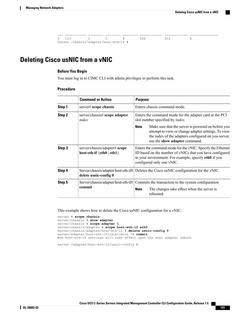
--- ----------- -------- -------- -------- ------------ ------------ ---------------0 113 2 2 4 256 512 4Server /chassis/adapter/host-eth-if #
Deleting Cisco usNIC from a vNIC
Before You Begin
You must log in to CIMC CLI with admin privileges to perform this task.
Procedure
PurposeCommand or Action
Enters chassis command mode.server# scope chassisStep 1
Enters the command mode for the adapter card at the PCIslot number specified by index.
server/chassis# scope adapterindex
Step 2
Make sure that the server is powered on before youattempt to view or change adapter settings. To viewthe index of the adapters configured on you server,use the show adapter command.
Note
Enters the commandmode for the vNIC. Specify the EthernetID based on the number of vNICs that you have configured
server/chassis/adapter# scopehost-eth-if {eth0 | eth1}
Step 3
in your environment. For example, specify eth0 if youconfigured only one vNIC.
Deletes the Cisco usNIC configuration for the vNIC.Server/chassis/adapter/host-eth-if#delete usnic-config 0
Step 4
Commits the transaction to the system configurationServer/chassis/adapter/host-eth-if#commit
Step 5
The changes take effect when the server isrebooted.
Note
This example shows how to delete the Cisco usNIC configuration for a vNIC:server # scope chassisserver/chassis # show adapterserver/chassis # scope adapter 1server/chassis/adapter # scope host-eth-if eth0Server/chassis/adapter/host-eth-if # delete usnic-config 0server/adapter/host-eth-if/iscsi-boot *# commitNew host-eth-if settings will take effect upon the next adapter reboot
server /adapter/host-eth-if/usnic-config #
Cisco UCS C-Series Servers Integrated Management Controller CLI Configuration Guide, Release 1.5 OL-28993-03 121
Managing Network AdaptersDeleting Cisco usNIC from a vNIC
Configuring iSCSI Boot Capability
Configuring iSCSI Boot Capability for vNICsWhen the rack-servers are configured in a standalone mode, and when the VIC adapters are directly attachedto the Nexus 5000 family of switches, you can configure these VIC adapters to boot the servers remotely fromiSCSI storage targets. You can configure Ethernet vNICs to enable a rack server to load the host OS imagefrom remote iSCSI target devices.
To configure the iSCSI boot capability on a vNIC:
• You must log in with admin privileges to perform this task.
• To configure a vNIC to boot a server remotely from an iSCSI storage target, you must enable the PXEboot option on the vNIC.
You can configure a maximum of 2 iSCSI vNICs for each host.Note
Configuring iSCSI Boot Capability on a vNICYou can configure a maximum of 2 iSCSI vNICs for each host.
Before You Begin
• To configure a vNIC to boot a server remotely from an iSCSI storage target, you must enable the PXEboot option on the vNIC.
• You must log in with admin privileges to perform this task.
Procedure
PurposeCommand or Action
Enters the chassis command mode.Server# scope chassisStep 1
Enters the command mode for the adapter card atthe PCI slot number specified by index.
Server /chassis # scope adapter indexStep 2
The server must be powered on beforeyou can view or change adapter settings.
Note
Enters the host Ethernet interface commandmodefor the specified vNIC.
Server /chassis/adapter # scope host-eth-if{eth0 | eth1 | name}
Step 3
Creates the iSCSI boot index for the vNIC. At thismoment, only 0 is allowed as the index.
Server /chassis/adapter/host-eth-if # createiscsi-boot index
Step 4
Cisco UCS C-Series Servers Integrated Management Controller CLI Configuration Guide, Release 1.5122 OL-28993-03
Managing Network AdaptersConfiguring iSCSI Boot Capability
PurposeCommand or Action
Creates an iSCSI target for the vNIC. The valuecan either be 0 or 1.
Server/chassis/adapter/host-eth-if/iscsi-boot* #create iscsi-target index
Step 5
Enables the DHCP network settings for the iSCSIboot.
Server/chassis/adapter/host-eth-if/iscsi-boot* # setdhcp-net-settings enabled
Step 6
Sets the initiator name. It cannot be more than 223characters.
Server/chassis/adapter/host-eth-if/iscsi-boot* # setinitiator-name string
Step 7
Enables the DHCP iSCSI settings.Server/chassis/adapter/host-eth-if/iscsi-boot* # setdhcp-iscsi-settings enabled
Step 8
Commits the transaction to the systemconfiguration.
Server/chassis/adapter/host-eth-if/iscsi-boot* #commit
Step 9
The changes will take effect upon thenext server reboot.
Note
This example shows how to configure the iSCSI boot capability for a vNIC:Server # scope chassisServer /chassis # scope adapter 1Server /chassis/adapter # scope host-eth-if eth0Server /chassis/adapter/host-eth-if # create iscsi-boot 0Server /adapter/host-eth-if/iscsi-boot *# set dhcp-net-settings enabledServer /adapter/host-eth-if/iscsi-boot *# set initiator-name iqn.2012-01.com.adser:abcdeServer /adapter/host-eth-if/iscsi-boot *# set dhcp-iscsi-settings enabledServer /adapter/host-eth-if/iscsi-boot *# commit
New host-eth-if settings will take effect upon the next server resetServer /adapter/host-eth-if/iscsi-boot #
Deleting an iSCSI Boot Configuration for a vNIC
Before You Begin
You must log in with admin privileges to perform this task.
Procedure
PurposeCommand or Action
Enters the chassis command mode.Server# scope chassisStep 1
Enters the command mode for the adapter card at thePCI slot number specified by index.
Server /chassis # scope adapter indexStep 2
The server must be powered on before youcan view or change adapter settings.
Note
Cisco UCS C-Series Servers Integrated Management Controller CLI Configuration Guide, Release 1.5 OL-28993-03 123
Managing Network AdaptersConfiguring iSCSI Boot Capability

PurposeCommand or Action
Enters the host Ethernet interface command mode forthe specified vNIC.
Server /chassis/adapter # scopehost-eth-if {eth0 | eth1 | name}
Step 3
Deletes the iSCSI boot capability for the vNIC.Server /chassis/adapter/host-eth-if #delete iscsi-boot 0
Step 4
Commits the transaction to the system configurationServer /chassis/adapter/host-eth-if* #commit
Step 5
The changes will take effect upon the nextserver reboot.
Note
This example shows how to delete the iSCSI boot capability for a vNIC:Server # scope chassisServer /chassis # scope adapter 1Server /chassis/adapter # scope host-eth-if eth0Server /chassis/adapter/host-eth-if # delete iscsi-boot 0Server /adapter/host-eth-if/iscsi-boot *# commitNew host-eth-if settings will take effect upon the next server reset
Server /adapter/host-eth-if/iscsi-boot #
Managing VM FEX
Virtual Machine Fabric ExtenderCisco Virtual Machine Fabric Extender (VM FEX) extends the (prestandard) IEEE 802.1Qbh port extenderarchitecture to virtual machines. In this architecture, each VM interface is provided with a virtual PeripheralComponent Interconnect Express (PCIe) device and a virtual port on a switch.
Viewing VM FEX Properties
Before You Begin
• The server must be powered on, or the properties will not display.
• A supported Virtual Interface Card (VIC) must be installed in the chassis and the server must be poweredon.
Procedure
PurposeCommand or Action
Enters the chassis command mode.Server# scope chassisStep 1
Enters the command mode for the adapter card at thePCI slot number specified by index.
Server /chassis # scope adapter indexStep 2
Cisco UCS C-Series Servers Integrated Management Controller CLI Configuration Guide, Release 1.5124 OL-28993-03
Managing Network AdaptersManaging VM FEX
PurposeCommand or Action
The server must be powered on before you canview or change adapter settings.
Note
Displays the general VM FEX properties. For fielddescriptions, see General Properties Settings, on page126.
Server /chassis/adapter # show vmfex[detail]
Step 3
Enters the command mode for the specified VM FEXinterface.
Server /chassis/adapter # scope vmfexname
Step 4
Displays Ethernet interrupt settings. For fielddescriptions, see Ethernet Interrupt Settings, on page127.
Server /chassis/adapter/vmfex # showinterrupt [detail]
Step 5
Displays Ethernet receive queue settings. For fielddescriptions, see Ethernet Receive Queue Settings, onpage 128.
Server /chassis/adapter/vmfex # showrecv-queue [detail]
Step 6
Displays Ethernet transmit queue settings. For fielddescriptions, see Ethernet Transmit Queue Settings, onpage 128.
Server /chassis/adapter/vmfex # showtrans-queue [detail]
Step 7
Displays completion queue settings. For fielddescriptions, see Completion Queue Settings, on page128.
Server /chassis/adapter/vmfex # showcomp-queue [detail]
Step 8
Displays TCP offload settings. For field descriptions,see TCP Offload Settings, on page 128.
Server /chassis/adapter/vmfex # showoffload [detail]
Step 9
Displays RSS settings. For field descriptions, seeReceive Side Scaling Settings, on page 129.
Server /chassis/adapter/vmfex # showrss [detail]
Step 10
This example displays the VM FEX properties:
Server /chassis/adapter # show vmfex detailName pts0:
MTU: 1500Uplink Port: 0MAC Address: 00:00:00:00:00:00CoS: N/ATrust Host CoS:PCI Order:VLAN: N/AVLAN Mode: N/ARate Limiting:PXE Boot: disabledChannel Number: 0Port Profile:Uplink Failover: EnabledUplink Failback Timeout: 5
Server /chassis/adapter # scope vmfex pts0
Server /chassis/adapter/vmfex # show interruptInterrupt Count Coalescing Time (us) Coalescing Type Interrupt Mode--------------- -------------------- --------------- ---------------
Cisco UCS C-Series Servers Integrated Management Controller CLI Configuration Guide, Release 1.5 OL-28993-03 125
Managing Network AdaptersViewing VM FEX Properties
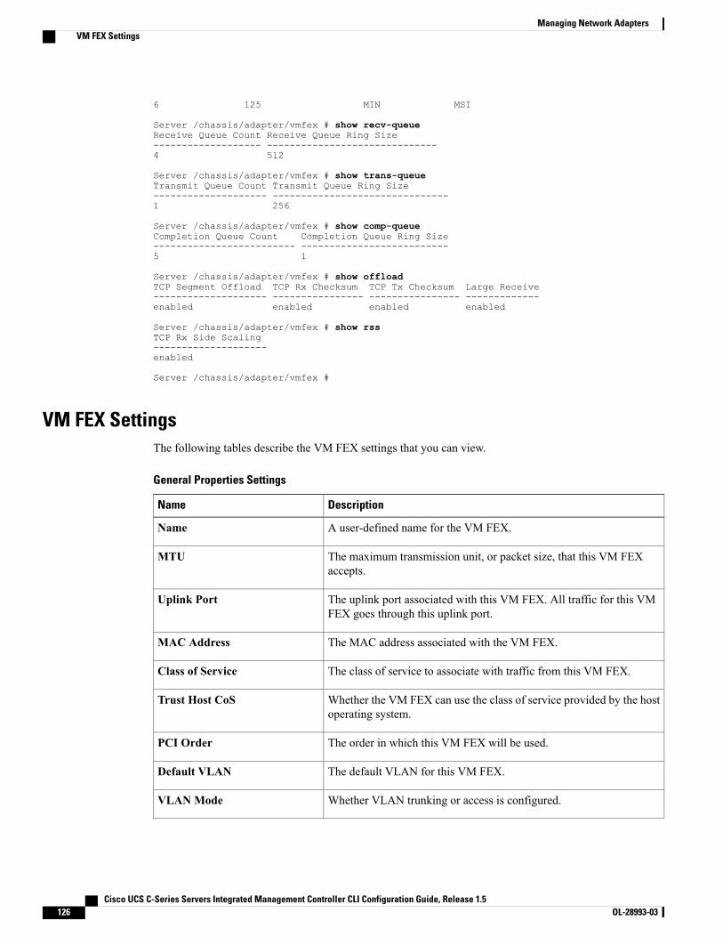
6 125 MIN MSI
Server /chassis/adapter/vmfex # show recv-queueReceive Queue Count Receive Queue Ring Size------------------- ------------------------------4 512
Server /chassis/adapter/vmfex # show trans-queueTransmit Queue Count Transmit Queue Ring Size-------------------- -------------------------------1 256
Server /chassis/adapter/vmfex # show comp-queueCompletion Queue Count Completion Queue Ring Size------------------------- --------------------------5 1
Server /chassis/adapter/vmfex # show offloadTCP Segment Offload TCP Rx Checksum TCP Tx Checksum Large Receive-------------------- ---------------- ---------------- -------------enabled enabled enabled enabled
Server /chassis/adapter/vmfex # show rssTCP Rx Side Scaling--------------------enabled
Server /chassis/adapter/vmfex #
VM FEX SettingsThe following tables describe the VM FEX settings that you can view.
General Properties Settings
DescriptionName
A user-defined name for the VM FEX.Name
The maximum transmission unit, or packet size, that this VM FEXaccepts.
MTU
The uplink port associated with this VM FEX. All traffic for this VMFEX goes through this uplink port.
Uplink Port
The MAC address associated with the VM FEX.MAC Address
The class of service to associate with traffic from this VM FEX.Class of Service
Whether the VM FEX can use the class of service provided by the hostoperating system.
Trust Host CoS
The order in which this VM FEX will be used.PCI Order
The default VLAN for this VM FEX.Default VLAN
Whether VLAN trunking or access is configured.VLANMode
Cisco UCS C-Series Servers Integrated Management Controller CLI Configuration Guide, Release 1.5126 OL-28993-03
Managing Network AdaptersVM FEX Settings
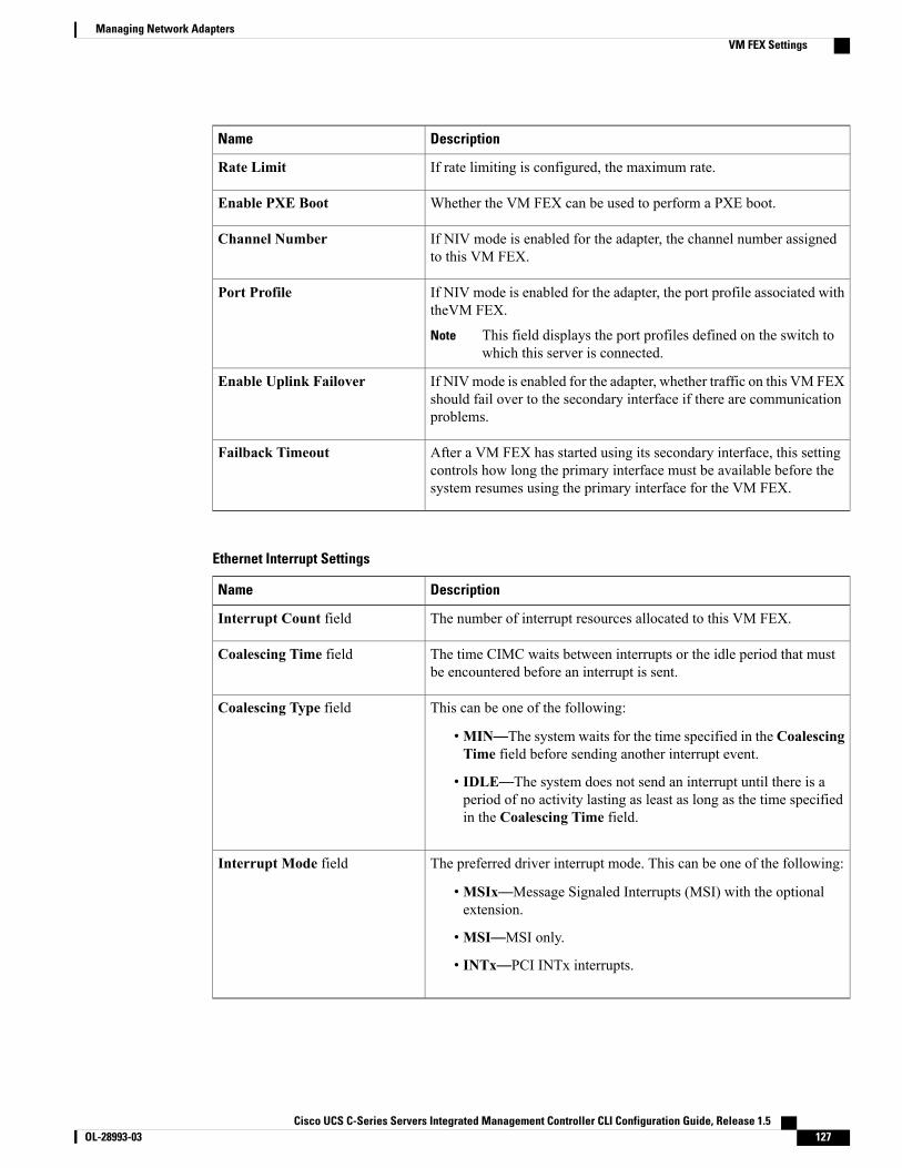
DescriptionName
If rate limiting is configured, the maximum rate.Rate Limit
Whether the VM FEX can be used to perform a PXE boot.Enable PXE Boot
If NIV mode is enabled for the adapter, the channel number assignedto this VM FEX.
Channel Number
If NIV mode is enabled for the adapter, the port profile associated withtheVM FEX.
This field displays the port profiles defined on the switch towhich this server is connected.
Note
Port Profile
If NIVmode is enabled for the adapter, whether traffic on this VM FEXshould fail over to the secondary interface if there are communicationproblems.
Enable Uplink Failover
After a VM FEX has started using its secondary interface, this settingcontrols how long the primary interface must be available before thesystem resumes using the primary interface for the VM FEX.
Failback Timeout
Ethernet Interrupt Settings
DescriptionName
The number of interrupt resources allocated to this VM FEX.Interrupt Count field
The time CIMC waits between interrupts or the idle period that mustbe encountered before an interrupt is sent.
Coalescing Time field
This can be one of the following:
•MIN—The system waits for the time specified in the CoalescingTime field before sending another interrupt event.
• IDLE—The system does not send an interrupt until there is aperiod of no activity lasting as least as long as the time specifiedin the Coalescing Time field.
Coalescing Type field
The preferred driver interrupt mode. This can be one of the following:
•MSIx—Message Signaled Interrupts (MSI) with the optionalextension.
•MSI—MSI only.
• INTx—PCI INTx interrupts.
Interrupt Mode field
Cisco UCS C-Series Servers Integrated Management Controller CLI Configuration Guide, Release 1.5 OL-28993-03 127
Managing Network AdaptersVM FEX Settings
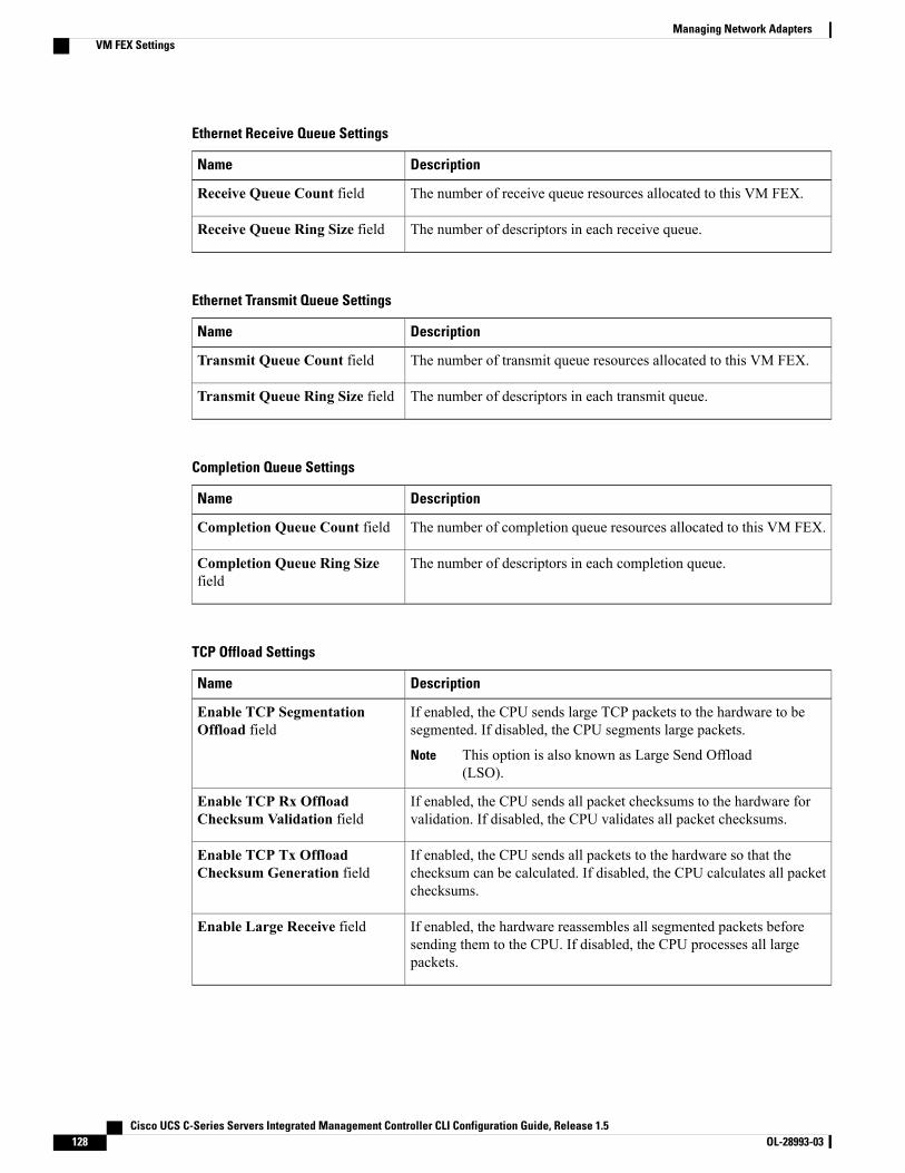
Ethernet Receive Queue Settings
DescriptionName
The number of receive queue resources allocated to this VM FEX.Receive Queue Count field
The number of descriptors in each receive queue.Receive Queue Ring Size field
Ethernet Transmit Queue Settings
DescriptionName
The number of transmit queue resources allocated to this VM FEX.Transmit Queue Count field
The number of descriptors in each transmit queue.Transmit Queue Ring Size field
Completion Queue Settings
DescriptionName
The number of completion queue resources allocated to this VM FEX.Completion Queue Count field
The number of descriptors in each completion queue.Completion Queue Ring Sizefield
TCP Offload Settings
DescriptionName
If enabled, the CPU sends large TCP packets to the hardware to besegmented. If disabled, the CPU segments large packets.
This option is also known as Large Send Offload(LSO).
Note
Enable TCP SegmentationOffload field
If enabled, the CPU sends all packet checksums to the hardware forvalidation. If disabled, the CPU validates all packet checksums.
Enable TCP Rx OffloadChecksum Validation field
If enabled, the CPU sends all packets to the hardware so that thechecksum can be calculated. If disabled, the CPU calculates all packetchecksums.
Enable TCP Tx OffloadChecksum Generation field
If enabled, the hardware reassembles all segmented packets beforesending them to the CPU. If disabled, the CPU processes all largepackets.
Enable Large Receive field
Cisco UCS C-Series Servers Integrated Management Controller CLI Configuration Guide, Release 1.5128 OL-28993-03
Managing Network AdaptersVM FEX Settings

Receive Side Scaling Settings
DescriptionName
Receive Side Scaling (RSS) distributes network receive processingacross multiple CPUs in multiprocessor systems.
If enabled, network receive processing is shared across processorswhenever possible. If disabled, network receive processing is alwayshandled by a single processor even if additional processors are available.
Enable TCPReceive Side Scalingfield
If enabled, RSS is enabled on IPv4 networks.Enable IPv4 RSS field
If enabled, RSS is enabled for TCP transmissions across IPv4 networks.Enable TCP-IPv4 RSS field
If enabled, RSS is enabled on IPv6 networks.Enable IPv6 RSS field
If enabled, RSS is enabled for TCP transmissions across IPv6 networks.Enable TCP-IPv6 RSS field
If enabled, RSS is enabled for IPv6 extensions.Enable IPv6 Extension RSS field
If enabled, RSS is enabled for TCP transmissions across IPv6 networks.Enable TCP-IPv6ExtensionRSSfield
Managing Storage Adapters
Create Virtual Drive from Unused Physical Drives
Before You Begin
You must log in with admin privileges to perform this task.
Procedure
PurposeCommand or Action
Enters the chassis command mode.Server# scope chassisStep 1
Enters command mode for an installed storage card.Server /chassis # scopestorageadapter slot
Step 2
At this point, you are prompted to enter informationcorresponding to the RAID level, the physical drives to be
Server /chassis/storageadapter #create virtual-drive
Step 3
used, the size and the write policy for the new virtual drive.Enter the appropriate information at each prompt.
When you have finished specifying the virtual driveinformation, you are prompted to confirm that theinformation is correct. Enter y (yes) to confirm, or n (no)to cancel the operation.
Cisco UCS C-Series Servers Integrated Management Controller CLI Configuration Guide, Release 1.5 OL-28993-03 129
Managing Network AdaptersManaging Storage Adapters
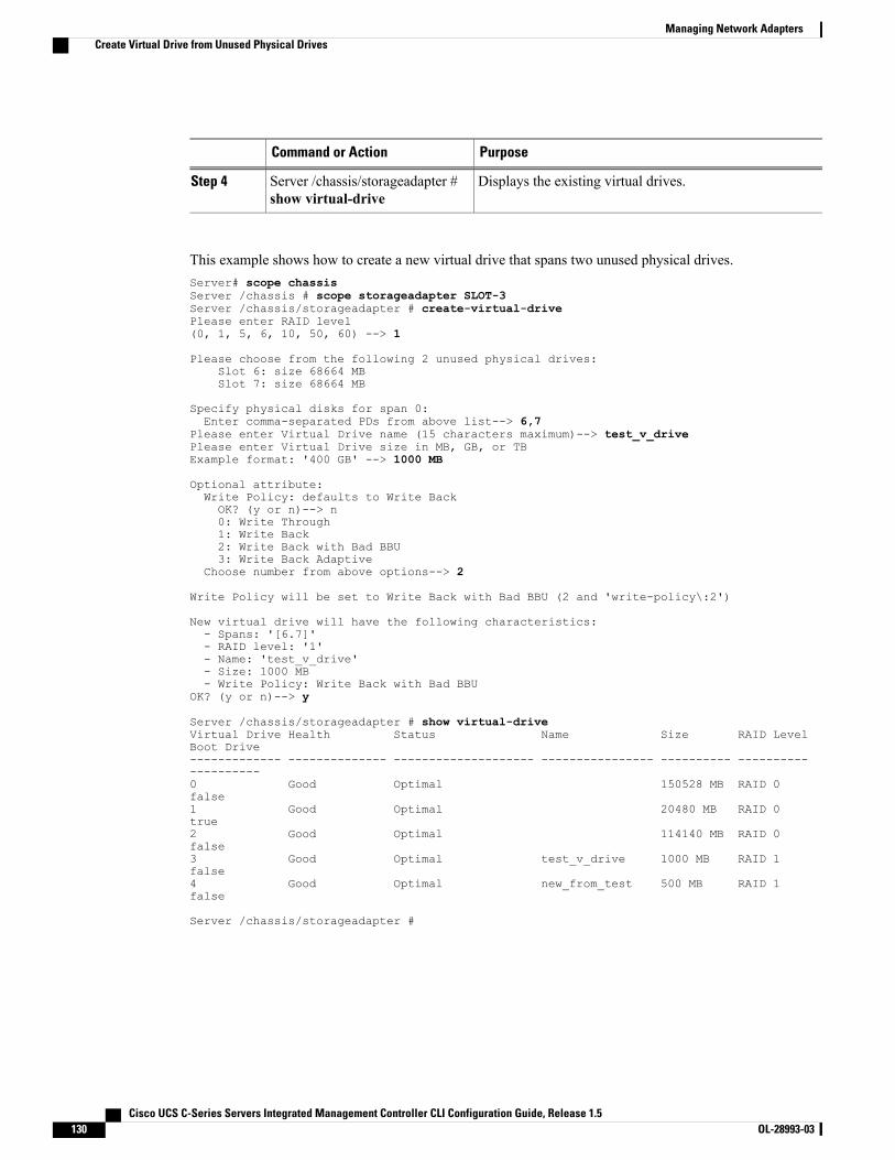
PurposeCommand or Action
Displays the existing virtual drives.Server /chassis/storageadapter #show virtual-drive
Step 4
This example shows how to create a new virtual drive that spans two unused physical drives.Server# scope chassisServer /chassis # scope storageadapter SLOT-3Server /chassis/storageadapter # create-virtual-drivePlease enter RAID level(0, 1, 5, 6, 10, 50, 60) --> 1
Please choose from the following 2 unused physical drives:Slot 6: size 68664 MBSlot 7: size 68664 MB
Specify physical disks for span 0:Enter comma-separated PDs from above list--> 6,7
Please enter Virtual Drive name (15 characters maximum)--> test_v_drivePlease enter Virtual Drive size in MB, GB, or TBExample format: '400 GB' --> 1000 MB
Optional attribute:Write Policy: defaults to Write BackOK? (y or n)--> n0: Write Through1: Write Back2: Write Back with Bad BBU3: Write Back Adaptive
Choose number from above options--> 2
Write Policy will be set to Write Back with Bad BBU (2 and 'write-policy\:2')
New virtual drive will have the following characteristics:- Spans: '[6.7]'- RAID level: '1'- Name: 'test_v_drive'- Size: 1000 MB- Write Policy: Write Back with Bad BBU
OK? (y or n)--> y
Server /chassis/storageadapter # show virtual-driveVirtual Drive Health Status Name Size RAID LevelBoot Drive------------- -------------- -------------------- ---------------- ---------- --------------------0 Good Optimal 150528 MB RAID 0false1 Good Optimal 20480 MB RAID 0true2 Good Optimal 114140 MB RAID 0false3 Good Optimal test_v_drive 1000 MB RAID 1false4 Good Optimal new_from_test 500 MB RAID 1false
Server /chassis/storageadapter #
Cisco UCS C-Series Servers Integrated Management Controller CLI Configuration Guide, Release 1.5130 OL-28993-03
Managing Network AdaptersCreate Virtual Drive from Unused Physical Drives
Create Virtual Drive from an Existing Drive Group
Before You Begin
You must log in with admin privileges to perform this task.
Procedure
PurposeCommand or Action
Enters the chassis command mode.Server# scope chassisStep 1
Enters command mode for an installed storage card.Server /chassis # scopestorageadapter slot
Step 2
At this point, you are prompted to enter informationcorresponding to the virtual drives to be used, and the size
Server /chassis/storageadapter #carve-virtual-drive
Step 3
and the write policy for the new virtual drive. Enter theappropriate information at each prompt.
When you have finished specifying the virtual driveinformation, you are prompted to confirm that theinformation is correct. Enter y (yes) to confirm, or n (no)to cancel the operation.
Displays the existing virtual drives.Server /chassis/storageadapter #show virtual-drive
Step 4
This example shows how to carve a new virtual drive out of unused space in an existing RAID 1 drive group:Server# scope chassisServer /chassis # scope storageadapter SLOT-3Server /chassis/storageadapter # carve-virtual-drive< Fetching virtual drives...>
ID Name RL VDSize MaxPossibleSize PD(s)----------------------------------------------------------------3 test_v_drive 1 1000 MB 67664 MB 6,7
Please choose from the above list the virtual drive numberwhose space the new virtual drive will share--> 3New virtual drive will share space with VD 3
Please enter Virtual Drive name (15 characters maximum)--> new_from_testPlease enter Virtual Drive size in MB, GB, or TB (maximum: 67664 MB)Example format: '400 GB' --> 500 MB
Optional attribute:Write Policy: defaults to Write BackOK? (y or n)--> y
New virtual drive will have the following characteristics:- It will share space with virtual drive 3- Name: 'new_from_test'- Size: 500 MB
OK? (y or n)--> yServer /chassis/storageadapter # show virtual-driveVirtual Drive Health Status Name Size RAID LevelBoot Drive
Cisco UCS C-Series Servers Integrated Management Controller CLI Configuration Guide, Release 1.5 OL-28993-03 131
Managing Network AdaptersCreate Virtual Drive from an Existing Drive Group
------------- -------------- -------------------- ---------------- ---------- --------------------0 Good Optimal 150528 MB RAID 0false1 Good Optimal 20480 MB RAID 0true2 Good Optimal 114140 MB RAID 0false3 Good Optimal test_v_drive 1000 MB RAID 1false4 Good Optimal new_from_test 500 MB RAID 1false
Server /chassis/storageadapter #
Clearing Foreign Configuration
This task clears all foreign configuration on the controller. Also, all configuration information from allphysical drives hosting foreign configuration is deleted. This action cannot be reverted.
Important
Before You Begin
You must log in with admin privileges to perform this task.
Procedure
PurposeCommand or Action
Enters the chassis command mode.Server# scope chassisStep 1
Enters commandmode for an installed storage card.Server /chassis # scope storageadapterslot
Step 2
You are prompted to confirm the action. Enter yesto confirm.
Server /chassis/storageadapter #clear-foreign-config
Step 3
If you do not enter yes, the action isaborted.
Note
This example shows how to clear all foreign configurations on the MegaRAID controller in slot 3:Server# scope chassisServer /chassis # scope storageadapter SLOT-3Server /chassis/storageadapter # clear-foreign-configAre you sure you want to clear all foreign configurations on this controller?All data on the drive(s) will be lost.Enter 'yes' to confirm -> yesServer /chassis/storageadapter #
Cisco UCS C-Series Servers Integrated Management Controller CLI Configuration Guide, Release 1.5132 OL-28993-03
Managing Network AdaptersClearing Foreign Configuration
Deleting a Virtual Drive
This task deletes a virtual drive, including the drives that run the booted operating system. So back up anydata that you want to retain before you delete a virtual drive.
Important
Before You Begin
You must log in with admin privileges to perform this task.
Procedure
PurposeCommand or Action
Enters the chassis command mode.Server# scope chassisStep 1
Enters command mode for an installed storagecard.
Server /chassis # scope storageadapter slotStep 2
Enters command mode for the specified virtualdrive.
Server /chassis/storageadapter # scopevirtual-drive drive-number
Step 3
You are prompted to confirm the action. Enteryes to confirm.
Server /chassis/storageadapter/virtual-drive# delete-virtual-drive
Step 4
If you do not enter yes, the action isaborted.
Note
This example shows how to delete virtual drive 3.Server# scope chassisServer /chassis # scope storageadapter SLOT-3Server /chassis/storageadapter # scope virtual-drive 3Server /chassis/storageadapter/virtual-drive # delete-virtual-driveAre you sure you want to delete virtual drive 3?All data on the drive will be lost. Enter 'yes' to confirm -> yesServer /chassis/storageadapter/virtual-drive #
Initializing a Virtual DriveAll data on a virtual drive is lost when you initialize the drive. Before you run an initialization, back up anydata on the virtual drive that you want to save.
Before You Begin
You must log in with admin privileges to perform this task.
Cisco UCS C-Series Servers Integrated Management Controller CLI Configuration Guide, Release 1.5 OL-28993-03 133
Managing Network AdaptersDeleting a Virtual Drive
Procedure
PurposeCommand or Action
Enters the chassis command mode.Server# scope chassisStep 1
Enters command mode for an installedstorage card.
Server /chassis # scope storageadapter slotStep 2
Enters command mode for the specifiedvirtual drive.
Server /chassis/storageadapter # scopevirtual-drive drive-number
Step 3
Initializes the specified virtual drive.Server /chassis/storageadapter/virtual-drive #start-initialization
Step 4
(Optional) Cancels the initialization of thespecified virtual drive.
Server /chassis/storageadapter/virtual-drive #cancel-initialization
Step 5
Displays the status of the task that is inprogress on the drive.
Server /chassis/storageadapter/physical-drive# get-operation-status
Step 6
This example shows how to initialize virtual drive 3 using fast initialization:Server# scope chassisServer /chassis # scope storageadapter SLOT-3Server /chassis/storageadapter # scope virtual-drive 3Server /chassis/storageadapter/virtual-drive # start-initializationAre you sure you want to initialize virtual drive 3?All data on the drive will be lost. Enter 'yes' to confirm -> yesFast (0) or full (1) initialization? -> 0Server /chassis/storageadapter/virtual-drive # get-operation-status
progress-percent: 20%elapsed -seconds: 30operation-in-progress: initializing virtual drive
Server /chassis/storageadapter/virtual-drive #
Set as Boot Drive
Before You Begin
You must log in with admin privileges to perform this task.
Procedure
PurposeCommand or Action
Enters the chassis command mode.Server# scope chassisStep 1
Enters commandmode for an installed storagecard.
Server /chassis # scope storageadapter slotStep 2
Cisco UCS C-Series Servers Integrated Management Controller CLI Configuration Guide, Release 1.5134 OL-28993-03
Managing Network AdaptersSet as Boot Drive

PurposeCommand or Action
Enters commandmode for the specified virtualdrive.
Server /chassis/storageadapter # scopevirtual-drive drive-number
Step 3
Specifies the controller to boot from thisvirtual drive.
Server /chassis/storageadapter #set-boot-drive
Step 4
This example shows how to specify the controller to boot from virtual drive 3:Server# scope chassisServer /chassis # scope storageadapter SLOT-3Server /chassis/storageadapter # scope virtual-drive 3Server /chassis/storageadapter/virtual-drive # set-boot-driveAre you sure you want to set virtual drive 3 as the boot drive?Enter 'yes' to confirm -> yesServer /chassis/storageadapter/virtual-drive #
Modifying Attributes of a Virtual Drive
Before You Begin
You must log in with admin privileges to perform this task.
Procedure
PurposeCommand or Action
Enters the chassis command mode.Server# scope chassisStep 1
Enters command mode for an installedstorage card.
Server /chassis # scope storageadapter slotStep 2
Enters the command mode for the virtualdrive.
Server /chassis/storageadapter # scopevirtual-drive 3
Step 3
Prompts you to select a different currentpolicy.
Server /chassis/storageadapter/virtual-drive #modify-attributes
Step 4
This example shows how to carve a new virtual drive out of unused space in an existing RAID 1 drive group:Server# scope chassisServer /chassis # scope storageadapter SLOT-3Server /chassis/storageadapter # scope virtual-driveServer /chassis/storageadapter/virtual-drive # modify-attributes
Current write policy: Write Back
0: Write Through1: Write Back2: Write Back even if Bad BBU
Choose number from above options --> 0
Cisco UCS C-Series Servers Integrated Management Controller CLI Configuration Guide, Release 1.5 OL-28993-03 135
Managing Network AdaptersModifying Attributes of a Virtual Drive
The following attribute will be modified:
- Write policy: Write Through
OK? (y or n) --> y
operation in progress.
Server /chassis/storageadapter/virtual-drive #
Making a Dedicated Hot Spare
Before You Begin
You must log in with admin privileges to perform this task.
Procedure
PurposeCommand or Action
Enters the chassis command mode.Server# scope chassisStep 1
Enters command mode for an installed storagecard.
Server /chassis # scope storageadapter slotStep 2
Enters command mode for the specifiedphysical drive.
Server /chassis/storageadapter # scopephysical-drive drive-number
Step 3
You are prompted to choose a virtual drive forwhich the dedicated hot spare is being created.
Server /chassis/storageadapter/physical-drive# make-dedicated-hot-spare
Step 4
This example shows how to make physical drive 3 a dedicated hot spare for virtual drive 6:Server# scope chassisServer /chassis # scope storageadapter SLOT-3Server /chassis/storageadapter # scope physical-drive 3Server /chassis/storageadapter/physical-drive # make-dedicated-hot-spare5: VD_OS_1, RAID 0, 102400 MB, physical disks: 16: VD_OS_2, RAID 0, 12288 MB, physical disks: 17: VD_OS_3, RAID 0, 12288 MB, physical disks: 18: VD_DATA_1, RAID 0, 12512 MB, physical disks: 19: RAID1_2358, RAID 1, 40000 MB, physical disks: 2,3,5,811: JFB_RAID1_67, RAID 1, 20000 MB, physical disks: 6,712: JFB_Crv_R1_40, RAID 1, 40000 MB, physical disks: 6,713: JFB_R1_10GB, RAID 1, 10000 MB, physical disks: 6,7
Please choose from the above 8 virtual drives-->6
Server /chassis/storageadapter/physical-drive #
Making a Global Hot Spare
Before You Begin
You must log in with admin privileges to perform this task.
Cisco UCS C-Series Servers Integrated Management Controller CLI Configuration Guide, Release 1.5136 OL-28993-03
Managing Network AdaptersMaking a Dedicated Hot Spare
Procedure
PurposeCommand or Action
Enters the chassis command mode.Server# scope chassisStep 1
Enters command mode for an installedstorage card.
Server /chassis # scope storageadapter slotStep 2
Enters command mode for the specifiedphysical drive.
Server /chassis/storageadapter # scopephysical-drive drive-number
Step 3
Server /chassis/storageadapter/physical-drive #make-global-hot-spare
Step 4
Displays the status of the task that is inprogress on the drive.
Server /chassis/storageadapter/physical-drive #get-operation-status
Step 5
This example shows how to make physical drive 3 a global hot spare:Server# scope chassisServer /chassis # scope storageadapter SLOT-3Server /chassis/storageadapter # scope physical-drive 3Server /chassis/storageadapter/physical-drive # make-global-hot-spareServer /chassis/storageadapter/physical-drive #
Preparing a Drive for RemovalYou can confirm this task only on physical drives that display the Unconfigured Good status.
Before You Begin
You must log in with admin privileges to perform this task.
Procedure
PurposeCommand or Action
Enters the chassis command mode.Server# scope chassisStep 1
Enters command mode for an installedstorage card.
Server /chassis # scope storageadapter slotStep 2
Enters command mode for the specifiedphysical drive.
Server /chassis/storageadapter # scopephysical-drive drive-number
Step 3
Server /chassis/storageadapter/physical-drive #prepare-for-removal
Step 4
This example shows how to prepare physical drive 3 for removal.Server# scope chassisServer /chassis # scope storageadapter SLOT-3
Cisco UCS C-Series Servers Integrated Management Controller CLI Configuration Guide, Release 1.5 OL-28993-03 137
Managing Network AdaptersPreparing a Drive for Removal

Server /chassis/storageadapter # scope physical-drive 3Server /chassis/storageadapter/physical-drive # prepare-for-removalServer /chassis/storageadapter/physical-drive #
Removing a Drive from Hot Spare Pools
Before You Begin
You must log in with admin privileges to perform this task.
Procedure
PurposeCommand or Action
Enters the chassis command mode.Server# scope chassisStep 1
Enters command mode for an installedstorage card.
Server /chassis # scope storageadapter slotStep 2
Enters command mode for the specifiedphysical drive.
Server /chassis/storageadapter # scopephysical-drive drive-number
Step 3
Removes a drive from the host spare pool.Server /chassis/storageadapter/physical-drive# remove-hot-spare
Step 4
This example shows how to remove physical drive 3 from the hot spare pools:Server# scope chassisServer /chassis # scope storageadapter SLOT-3Server /chassis/storageadapter # scope physical-drive 3Server /chassis/storageadapter/physical-drive # remove-hot-spareServer /chassis/storageadapter/physical-drive #
Undo Preparing a Drive for Removal
Before You Begin
You must log in with admin privileges to perform this task.
Procedure
PurposeCommand or Action
Enters the chassis command mode.Server# scope chassisStep 1
Enters command mode for an installedstorage card.
Server /chassis # scope storageadapter slotStep 2
Enters command mode for the specifiedphysical drive.
Server /chassis/storageadapter # scopephysical-drive drive-number
Step 3
Cisco UCS C-Series Servers Integrated Management Controller CLI Configuration Guide, Release 1.5138 OL-28993-03
Managing Network AdaptersRemoving a Drive from Hot Spare Pools

PurposeCommand or Action
Server /chassis/storageadapter/physical-drive #undo-prepare-for-removal
Step 4
This example shows how to respin physical drive 3 after preparing the drive for removal.Server# scope chassisServer /chassis # scope storageadapter SLOT-3Server /chassis/storageadapter # scope physical-drive 3Server /chassis/storageadapter/physical-drive # undo-prepare-for-removalServer /chassis/storageadapter/physical-drive #
Enabling Auto Learn Cycles for the Battery Backup Unit
Before You Begin
You must log in with admin privileges to perform this task.
Procedure
PurposeCommand or Action
Enters the chassis command mode.Server# scope chassisStep 1
Enters commandmode for an installed storagecard.
Server /chassis # scope storageadapter slotStep 2
Enter the battery backup unit commandmode.Server /chassis/storageadapter # scope bbuStep 3
Enables the battery auto-learn cyclesServer /chassis/storageadapter #enable-auto-learn
Step 4
This example shows how to enable the battery auto-learn cycles:Server # scope chassisServer /chassis # scope storageadapter SLOT-2Server /chassis/storageadapter # scope bbuServer /chassis/storageadapter/bbu # enable-auto-learnAutomatic BBU learn cycles will occur without notice if enabled.Are you sure? [y/n] --> yenable-auto-learn initiatedServer /chassis/storageadapter/bbu #
Disabling Auto Learn Cycles for the Battery Backup Unit
Before You Begin
You must log in with admin privileges to perform this task.
Cisco UCS C-Series Servers Integrated Management Controller CLI Configuration Guide, Release 1.5 OL-28993-03 139
Managing Network AdaptersEnabling Auto Learn Cycles for the Battery Backup Unit
Procedure
PurposeCommand or Action
Enters the chassis command mode.Server# scope chassisStep 1
Enters commandmode for an installed storagecard.
Server /chassis # scope storageadapter slotStep 2
Enter the battery backup unit commandmode.Server /chassis/storageadapter # scope bbuStep 3
Disables the battery auto-learn cyclesServer /chassis/storageadapter #disable-auto-learn
Step 4
This example shows how to disables the battery auto-learn cycles:Server # scope chassisServer /chassis # scope storageadapter SLOT-2Server /chassis/storageadapter # scope bbuServer /chassis/storageadapter/bbu # disable-auto-learnAutomatic BBU learn cycles will no longer occur if disabled.Are you sure? [y/n] --> ydisable-auto-learn initiated
Server /chassis/storageadapter/bbu #
Starting a Learn Cycle for a Battery Backup Unit
Before You Begin
You must be logged in as an admin to use this command.
Procedure
PurposeCommand or Action
Enters the chassis command mode.Server# scope chassisStep 1
Enters commandmode for an installed storagecard.
Server /chassis # scope storageadapter slotStep 2
Enter the battery backup unit commandmode.Server /chassis/storageadapter # scope bbuStep 3
Starts the learn cycle for the battery.Server /chassis/storageadapter #start-learn-cycle
Step 4
This example shows how to initiate the learn cycles for a battery:Server # scope chassisServer /chassis # scope storageadapter SLOT-2Server /chassis/storageadapter # scope bbuServer /chassis/storageadapter/bbu # start-learn-cycleServer /chassis/storageadapter/bbu #
Cisco UCS C-Series Servers Integrated Management Controller CLI Configuration Guide, Release 1.5140 OL-28993-03
Managing Network AdaptersStarting a Learn Cycle for a Battery Backup Unit
Toggling the Locator LED for a Physical Drive
Before You Begin
You must be logged in as an admin to perform this task.
Procedure
PurposeCommand or Action
Enters the chassis command mode.Server# scope chassisStep 1
Enters command mode for an installedstorage card.
Server /chassis # scope storageadapter slotStep 2
Enters the physical drive command mode.Server /chassis/storageadapter # scopephysical-drive 3
Step 3
Enables or disables the physical drive locatorLED.
Server /chassis/storageadapter/physical-drive# locator-led {on | off}
Step 4
This example shows how to enable the locator LED for physical drive 3:Server # scope chassisServer /chassis # scope storageadapter SLOT-2Server /chassis/storageadapter # scope physical-drive 3Server /chassis/storageadapter/physical-drive # locator-led onServer /chassis/storageadapter/physical-drive* # commitServer /chassis/storageadapter/physical-drive #
Viewing Storage Controller Logs
Before You Begin
You must log in with admin privileges to perform this task.
Procedure
PurposeCommand or Action
Enters the chassis command mode.Server# scope chassisStep 1
Enters commandmode for an installed storagecard.
Server /chassis # scope storageadapter slotStep 2
Displays the storage controller logs.Server /chassis/storageadapter # show logStep 3
This example shows how to display storage controller logs:Server # scope chassisServer /chassis # scope storageadapter SLOT-3
Cisco UCS C-Series Servers Integrated Management Controller CLI Configuration Guide, Release 1.5 OL-28993-03 141
Managing Network AdaptersToggling the Locator LED for a Physical Drive

Server /chassis/storageadapter # show log
Time Severity Description---- -------- -------------Fri March 1 09:52:19 2013 Warning Predictive FailureFri March 1 07:50:19 2013 Info Battery charge completeFri March 1 07:50:19 2013 Info Battery charge startedFri March 1 07:48:19 2013 Info Battery relearn completeFri March 1 07:47:19 2013 Info Battery is dischargingFri March 1 07:45:19 2013 Info Battery relearn started
Server /chassis/storageadapter #
Backing Up and Restoring the Adapter Configuration
Exporting the Adapter ConfigurationThe adapter configuration can be exported as an XML file to a TFTP server.
If any firmware or BIOS updates are in progress, do not export the adapter configuration until those tasksare complete.
Important
Before You Begin
A supported Virtual Interface Card (VIC) must be installed in the chassis and the server must be powered on.
Obtain the TFTP server IP address.
Procedure
PurposeCommand or Action
Enters the chassis command mode.Server# scope chassisStep 1
Enters the command mode for the adapter card at the PCIslot number specified by index.
Server /chassis # scope adapterindex
Step 2
The server must be powered on before you can viewor change adapter settings.
Note
Starts the export operation. The adapter configuration filewill be stored at the specified path and filename on the
Server /chassis/adapter #export-vnic protocol remoteserver IP address
Step 3
remote server at the specified IP address. The protocol canbe one of the following:
• TFTP
• FTP
• SFTP
• SCP
• HTTP
Cisco UCS C-Series Servers Integrated Management Controller CLI Configuration Guide, Release 1.5142 OL-28993-03
Managing Network AdaptersBacking Up and Restoring the Adapter Configuration

PurposeCommand or Action
This example exports the configuration of adapter 1:Server# scope chassisServer /chassis # scope adapter 1Server /chassis/adapter # export-vnic ftp 192.0.20.34 //test/dnld-ucs-k9-bundle.1.0.2h.binServer /chassis/adapter #
Importing the Adapter Configuration
If any firmware or BIOS updates are in progress, do not import the adapter configuration until those tasksare complete.
Important
Before You Begin
You must log in with admin privileges to perform this task.
Procedure
PurposeCommand or Action
Enters the chassis command mode.Server# scope chassisStep 1
Enters the command mode for the adapter card at the PCIslot number specified by index.
Server /chassis # scope adapterindex
Step 2
The server must be powered on before you canview or change adapter settings.
Note
Starts the import operation. The adapter downloads theconfiguration file from the specified path on the TFTP server
Server /chassis/adapter #import-vnic tftp-ip-addresspath-and-filename
Step 3
at the specified IP address. The configuration will beinstalled during the next server reboot.
This example imports a configuration for the adapter in PCI slot 1:Server# scope chassisServer /chassis # scope adapter 1Server /chassis/adapter # import-vnic 192.0.2.34 /ucs/backups/adapter4.xmlImport succeeded.New VNIC adapter settings will take effect upon the next server reset.Server /chassis/adapter #
What to Do Next
Reboot the server to apply the imported configuration.
Cisco UCS C-Series Servers Integrated Management Controller CLI Configuration Guide, Release 1.5 OL-28993-03 143
Managing Network AdaptersImporting the Adapter Configuration
Restoring Adapter Defaults
Before You Begin
You must log in with admin privileges to perform this task.
Procedure
PurposeCommand or Action
Enters the chassis command mode.Server# scope chassisStep 1
Restores factory default settings for the adapter atthe PCI slot number specified by the indexargument.
Server /chassis #adapter-reset-defaults index
Step 2
This example restores the default configuration of the adapter in PCI slot 1:Server# scope chassisServer /chassis # adapter-reset-defaults 1This operation will reset the adapter to factory default.All your configuration will be lost.Continue?[y|N] yServer /chassis #
Managing Adapter Firmware
Adapter FirmwareA Cisco UCS C-Series network adapter contains the following firmware components:
• Adapter firmware—The main operating firmware, consisting of an active and a backup image, can beinstalled from the CIMCGUI or CLI interface or from the Host Upgrade Utility (HUU). You can uploada firmware image from either a local file system or a TFTP server.
• Bootloader firmware—The bootloader firmware cannot be installed from the CIMC GUI or CLI. Youcan install this firmware using the Host Upgrade Utility.
Installing Adapter Firmware
If any firmware or BIOS updates are in progress, do not install the adapter firmware until those tasks arecomplete.
Important
Before You Begin
You must log in with admin privileges to perform this task.
Cisco UCS C-Series Servers Integrated Management Controller CLI Configuration Guide, Release 1.5144 OL-28993-03
Managing Network AdaptersRestoring Adapter Defaults
Procedure
PurposeCommand or Action
Enters the chassis command mode.Server# scope chassisStep 1
Downloads the specified adapter firmware file from theTFTP server, then installs the firmware as the backup
Server /chassis # update-adapter-fwtftp-ip-address path-and-filename
Step 2
image on one or two specified adapters or, if no adapter{activate | no-activate} [ pci-slot ][ pci-slot ] is specified, on all adapters. If the activate keyword is
specified, the new firmware is activated after installation.
(Optional)Clears an incomplete firmware update condition on oneor two specified adapters or, if no adapter is specified,on all adapters.
Server /chassis #recover-adapter-update [ pci-slot ][ pci-slot ]
Step 3
This example begins an adapter firmware upgrade on the adapter in PCI slot 1:Server# scope chassisServer /chassis # update-adapter-fw 192.0.2.34 /ucs/adapters/adapter4.bin activate 1Server /chassis #
What to Do Next
To activate the new firmware, see Activating Adapter Firmware, on page 145.
Activating Adapter Firmware
While the activation is in progress, do not:Important
• Reset, power off, or shut down the server.
• Reboot or reset CIMC.
• Activate any other firmware.
• Export technical support or configuration data.
Before You Begin
You must log in with admin privileges to perform this task.
Procedure
PurposeCommand or Action
Enters the chassis command mode.Server# scope chassisStep 1
Cisco UCS C-Series Servers Integrated Management Controller CLI Configuration Guide, Release 1.5 OL-28993-03 145
Managing Network AdaptersActivating Adapter Firmware
PurposeCommand or Action
Activates adapter firmware image 1 or 2 on the adapterin the specified PCI slot.
Server /chassis # activate-adapter-fwpci-slot {1 | 2}
Step 2
The changes will take effect upon the nextserver reboot.
Note
This example activates adapter firmware image 2 on the adapter in PCI slot 1:Server# scope chassisServer /chassis # activate-adapter-fw 1 2Firmware image activation suceededPlease reset the server to run the activated imageServer /chassis #
What to Do Next
Reboot the server to apply the changes.
Resetting the AdapterBefore You Begin
You must log in with admin privileges to perform this task.
Procedure
PurposeCommand or Action
Enters the chassis command mode.Server# scope chassisStep 1
Resets the adapter at the PCI slot number specified bythe index argument.
Server/chassis # adapter-reset indexStep 2
Resetting the adapter also resets thehost.
Note
This example resets the adapter in PCI slot 1:Server# scope chassisServer /chassis # adapter-reset 1This operation will reset the adapter and the host if it is on.You may lose connectivity to the CIMC and may have to log in again.Continue?[y|N] yServer /chassis #
Cisco UCS C-Series Servers Integrated Management Controller CLI Configuration Guide, Release 1.5146 OL-28993-03
Managing Network AdaptersResetting the Adapter
C H A P T E R 10Configuring Communication Services
This chapter includes the following sections:
• Configuring HTTP, page 147
• Configuring SSH, page 148
• Configuring XML API, page 149
• Configuring IPMI, page 150
• Configuring SNMP, page 151
Configuring HTTPBefore You Begin
You must log in as a user with admin privileges to configure HTTP.
Procedure
PurposeCommand or Action
Enters the HTTP command mode.Server# scope httpStep 1
Enables or disables HTTP and HTTPS service on theCIMC.
Server /http # set enabled {yes | no}Step 2
Sets the port to use for HTTP communication. Thedefault is 80.
Server /http # set http-port numberStep 3
Sets the port to use for HTTPS communication. Thedefault is 443.
Server /http # set https-port numberStep 4
Enables or disables the redirection of an HTTP requestto HTTPS.
Server /http # set http-redirect {yes| no}
Step 5
Cisco UCS C-Series Servers Integrated Management Controller CLI Configuration Guide, Release 1.5 OL-28993-03 147
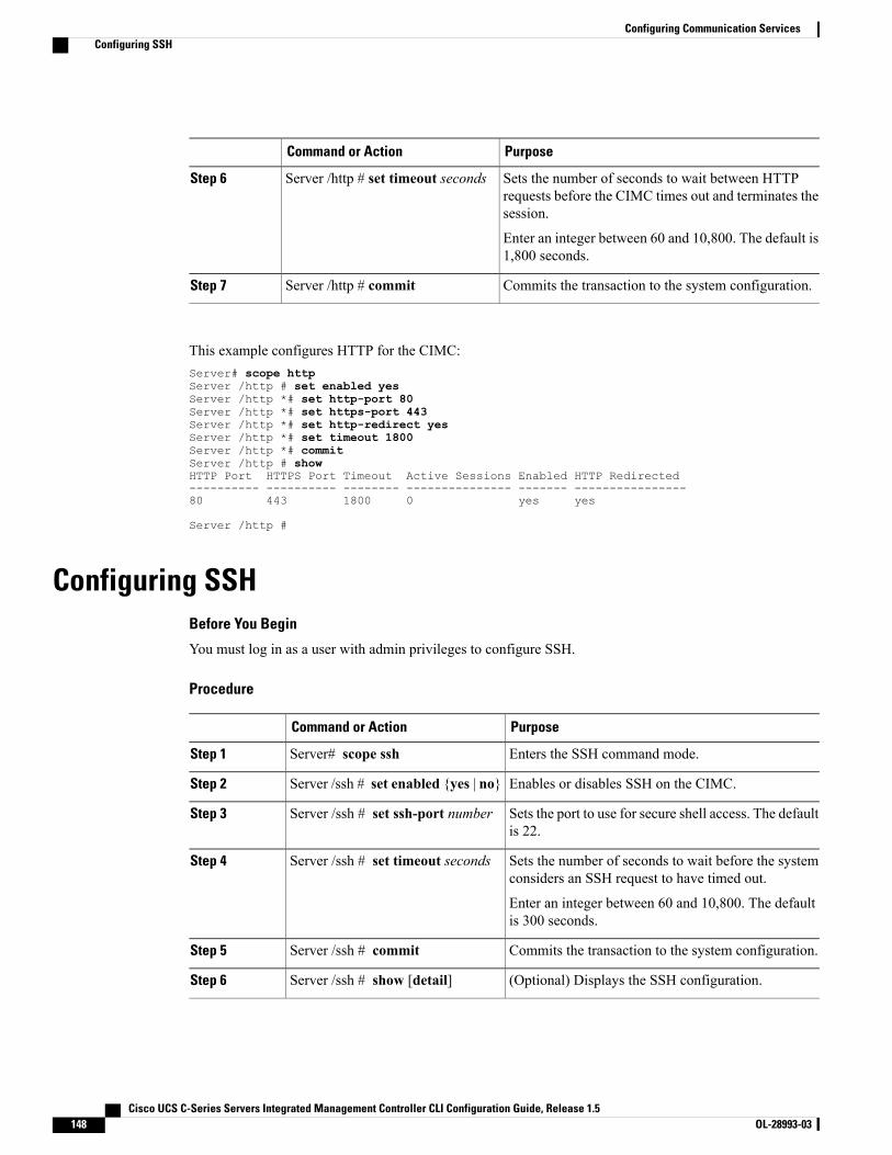
PurposeCommand or Action
Sets the number of seconds to wait between HTTPrequests before the CIMC times out and terminates thesession.
Server /http # set timeout secondsStep 6
Enter an integer between 60 and 10,800. The default is1,800 seconds.
Commits the transaction to the system configuration.Server /http # commitStep 7
This example configures HTTP for the CIMC:Server# scope httpServer /http # set enabled yesServer /http *# set http-port 80Server /http *# set https-port 443Server /http *# set http-redirect yesServer /http *# set timeout 1800Server /http *# commitServer /http # showHTTP Port HTTPS Port Timeout Active Sessions Enabled HTTP Redirected---------- ---------- -------- --------------- ------- ----------------80 443 1800 0 yes yes
Server /http #
Configuring SSHBefore You Begin
You must log in as a user with admin privileges to configure SSH.
Procedure
PurposeCommand or Action
Enters the SSH command mode.Server# scope sshStep 1
Enables or disables SSH on the CIMC.Server /ssh # set enabled {yes | no}Step 2
Sets the port to use for secure shell access. The defaultis 22.
Server /ssh # set ssh-port numberStep 3
Sets the number of seconds to wait before the systemconsiders an SSH request to have timed out.
Server /ssh # set timeout secondsStep 4
Enter an integer between 60 and 10,800. The defaultis 300 seconds.
Commits the transaction to the system configuration.Server /ssh # commitStep 5
(Optional) Displays the SSH configuration.Server /ssh # show [detail]Step 6
Cisco UCS C-Series Servers Integrated Management Controller CLI Configuration Guide, Release 1.5148 OL-28993-03
Configuring Communication ServicesConfiguring SSH
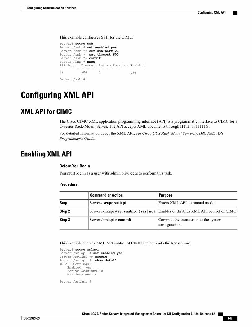
This example configures SSH for the CIMC:Server# scope sshServer /ssh # set enabled yesServer /ssh *# set ssh-port 22Server /ssh *# set timeout 600Server /ssh *# commitServer /ssh # showSSH Port Timeout Active Sessions Enabled---------- -------- --------------- -------22 600 1 yes
Server /ssh #
Configuring XML API
XML API for CIMCThe Cisco CIMC XML application programming interface (API) is a programmatic interface to CIMC for aC-Series Rack-Mount Server. The API accepts XML documents through HTTP or HTTPS.
For detailed information about the XML API, see Cisco UCS Rack-Mount Servers CIMC XML APIProgrammer’s Guide.
Enabling XML API
Before You Begin
You must log in as a user with admin privileges to perform this task.
Procedure
PurposeCommand or Action
Enters XML API command mode.Server# scope xmlapiStep 1
Enables or disables XML API control of CIMC.Server /xmlapi # set enabled {yes | no}Step 2
Commits the transaction to the systemconfiguration.
Server /xmlapi # commitStep 3
This example enables XML API control of CIMC and commits the transaction:Server# scope xmlapiServer /xmlapi # set enabled yesServer /xmlapi *# commitServer /xmlapi # show detailXMLAPI Settings:
Enabled: yesActive Sessions: 0Max Sessions: 4
Server /xmlapi #
Cisco UCS C-Series Servers Integrated Management Controller CLI Configuration Guide, Release 1.5 OL-28993-03 149
Configuring Communication ServicesConfiguring XML API
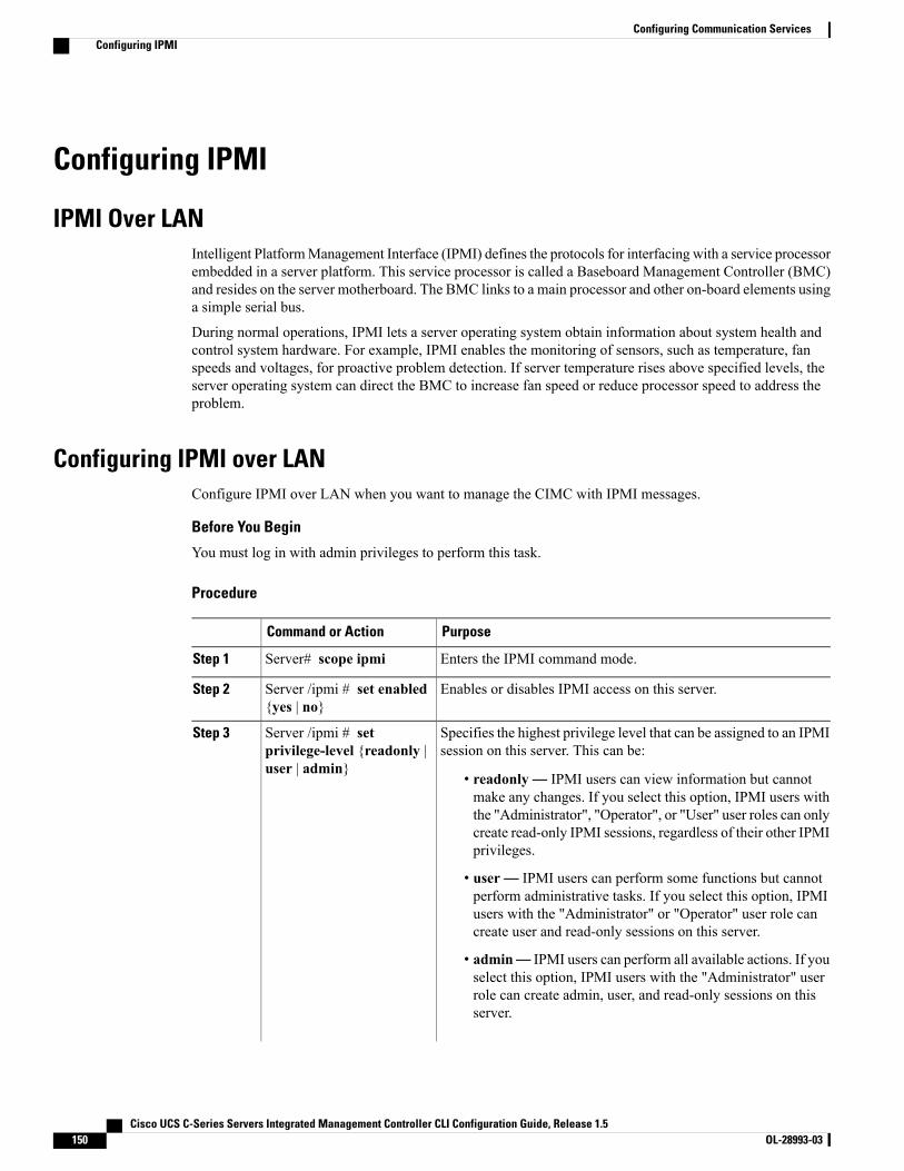
Configuring IPMI
IPMI Over LANIntelligent PlatformManagement Interface (IPMI) defines the protocols for interfacing with a service processorembedded in a server platform. This service processor is called a Baseboard Management Controller (BMC)and resides on the server motherboard. The BMC links to a main processor and other on-board elements usinga simple serial bus.
During normal operations, IPMI lets a server operating system obtain information about system health andcontrol system hardware. For example, IPMI enables the monitoring of sensors, such as temperature, fanspeeds and voltages, for proactive problem detection. If server temperature rises above specified levels, theserver operating system can direct the BMC to increase fan speed or reduce processor speed to address theproblem.
Configuring IPMI over LANConfigure IPMI over LAN when you want to manage the CIMC with IPMI messages.
Before You Begin
You must log in with admin privileges to perform this task.
Procedure
PurposeCommand or Action
Enters the IPMI command mode.Server# scope ipmiStep 1
Enables or disables IPMI access on this server.Server /ipmi # set enabled{yes | no}
Step 2
Specifies the highest privilege level that can be assigned to an IPMIsession on this server. This can be:
Server /ipmi # setprivilege-level {readonly |user | admin}
Step 3
• readonly— IPMI users can view information but cannotmake any changes. If you select this option, IPMI users withthe "Administrator", "Operator", or "User" user roles can onlycreate read-only IPMI sessions, regardless of their other IPMIprivileges.
• user— IPMI users can perform some functions but cannotperform administrative tasks. If you select this option, IPMIusers with the "Administrator" or "Operator" user role cancreate user and read-only sessions on this server.
• admin— IPMI users can perform all available actions. If youselect this option, IPMI users with the "Administrator" userrole can create admin, user, and read-only sessions on thisserver.
Cisco UCS C-Series Servers Integrated Management Controller CLI Configuration Guide, Release 1.5150 OL-28993-03
Configuring Communication ServicesConfiguring IPMI
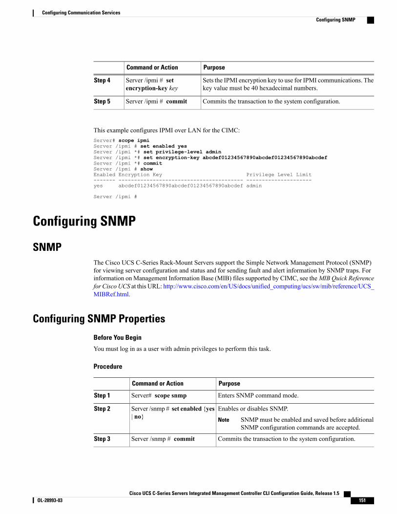
PurposeCommand or Action
Sets the IPMI encryption key to use for IPMI communications. Thekey value must be 40 hexadecimal numbers.
Server /ipmi # setencryption-key key
Step 4
Commits the transaction to the system configuration.Server /ipmi # commitStep 5
This example configures IPMI over LAN for the CIMC:Server# scope ipmiServer /ipmi # set enabled yesServer /ipmi *# set privilege-level adminServer /ipmi *# set encryption-key abcdef01234567890abcdef01234567890abcdefServer /ipmi *# commitServer /ipmi # showEnabled Encryption Key Privilege Level Limit------- ---------------------------------------- ---------------------yes abcdef01234567890abcdef01234567890abcdef admin
Server /ipmi #
Configuring SNMP
SNMPThe Cisco UCS C-Series Rack-Mount Servers support the Simple Network Management Protocol (SNMP)for viewing server configuration and status and for sending fault and alert information by SNMP traps. Forinformation on Management Information Base (MIB) files supported by CIMC, see theMIB Quick Referencefor Cisco UCS at this URL: http://www.cisco.com/en/US/docs/unified_computing/ucs/sw/mib/reference/UCS_MIBRef.html.
Configuring SNMP Properties
Before You Begin
You must log in as a user with admin privileges to perform this task.
Procedure
PurposeCommand or Action
Enters SNMP command mode.Server# scope snmpStep 1
Enables or disables SNMP.Server /snmp # set enabled {yes| no}
Step 2
SNMPmust be enabled and saved before additionalSNMP configuration commands are accepted.
Note
Commits the transaction to the system configuration.Server /snmp # commitStep 3
Cisco UCS C-Series Servers Integrated Management Controller CLI Configuration Guide, Release 1.5 OL-28993-03 151
Configuring Communication ServicesConfiguring SNMP
PurposeCommand or Action
Specifies the default SNMP v1 or v2c community name thatCIMC includes on any trap messages it sends to the SNMPhost. The name can be up to 18 characters.
Server /snmp # setcommunity-str community
Step 4
This can be one of the following : Disabled, Limited, or Full.Server /snmp #setcommunity-access
Step 5
Specifies the SNMP community group to which trapinformation should be sent. The name can be up to 18characters
Server /snmp #settrap-community-str
Step 6
Specifies the system contact person responsible for the SNMPimplementation. The contact information can be up to 254
Server /snmp # set sys-contactcontact
Step 7
characters, such as an email address or a name and telephonenumber. To enter a value that contains spaces, you mustenclose the entry with quotation marks.
Specifies the location of the host on which the SNMP agent(server) runs. The location information can be up to 254
Server /snmp # set sys-locationlocation
Step 8
characters. To enter a value that contains spaces, you mustenclose the entry with quotation marks.
Commits the transaction to the system configuration.Server /snmp # commitStep 9
This example configures the SNMP properties and commits the transaction:Server# scope snmpServer /snmp # set enabled yesServer /snmp *# commitServer /snmp # set community-str cimcpublicServer /snmp # set community-access FullServer /snmp # set trap-community-str publicServer /snmp *# set sys-contact "User Name <[email protected]> +1-408-555-1212"Server /snmp *# set sys-location "San Jose, California"Server /snmp *# commitServer /snmp # show detailSNMP Settings:
SNMP Port: 161System Contact: User Name <[email protected]> +1-408-555-1212System Location: San Jose, CaliforniaSNMP Community: cimcpublicSNMP Trap community: publicSNMP Community access: FullEnabled: yes
Server /snmp #
What to Do Next
Configure SNMP trap settings as described in Configuring SNMP Trap Settings, on page 153.
Cisco UCS C-Series Servers Integrated Management Controller CLI Configuration Guide, Release 1.5152 OL-28993-03
Configuring Communication ServicesConfiguring SNMP Properties
Configuring SNMP Trap Settings
Before You Begin
• You must log in with admin privileges to perform this task.
• SNMP must be enabled and saved before trap settings can be configured.
Procedure
PurposeCommand or Action
Enters the SNMP command mode.Server# scope snmpStep 1
Enters the SNMP trap destination command mode forthe specified destination. Four SNMP trap destinations
Server /snmp # scopetrap-destinations number
Step 2
are available. The destination number is an integerbetween 1 and 15.
Enables or disables the SNMP trap destination.Server /snmp/trap-destinations # setenabled {yes | no}
Step 3
Specify the desired SNMP version of the trap message.Server /snmp/trap-destinations # setversion {1 | 2 | 3}
Step 4
SNMPv3 traps will be delivered only tolocations where the SNMPv3 user and keyvalues are configured correctly.
Note
Specifies whether SNMP notification messages aresent as simple traps or as inform requests requiringacknowledgment by the receiver.
Server /snmp/trap-destinations # settype {trap | inform}
Step 5
The inform option can be chosen only for V2users.
Note
Server /snmp/trap-destinations # setuser user
Step 6
Specifies the destination IP address to which SNMPtrap information is sent.
Server /snmp/trap-destination # setv4-addr ip-address
Step 7
Commits the transaction to the system configuration.Server /snmp/trap-destination #commit
Step 8
This example configures general SNMP trap settings and trap destination number 1 and commits the transaction:Server# scope snmpServer /snmp # Scope trap-destinations 1Server /snmp/trap-destination *# set enabled yesServer /snmp/trap-destination *# set version 2Server /snmp/trap-destination *# set type informServer /snmp/trap-destination *# set user user1Server /snmp/trap-destination *# set v4-addr 192.2.3.4Server /snmp/trap-destination *# commitServer /snmp/trap-destination # show detailTrap Destination 1:
Cisco UCS C-Series Servers Integrated Management Controller CLI Configuration Guide, Release 1.5 OL-28993-03 153
Configuring Communication ServicesConfiguring SNMP Trap Settings

Enabled: yesSNMP version: 2Trap type: informSNMP user: user1IPv4 Address: 192.2.3.4Delete Trap: no
Server /snmp/trap-destination #
Sending a Test SNMP Trap Message
Before You Begin
You must log in with admin privileges to perform this task.
Procedure
PurposeCommand or Action
Enters the SNMP command mode.Server# scope snmpStep 1
Sends an SNMP test trap to the configured SNMP trapdestination that are enabled.
Server /snmp # sendSNMPtrapStep 2
The trap must be configured and enabled in orderto send a test message.
Note
This example sends a test message to all the enabled SNMP trap destinations:Server# scope snmpServer /snmp # sendSNMPtrapSNMP Test Trap sent to the destination.Server /snmp #
Configuring SNMPv3 Users
Before You Begin
• You must log in as a user with admin privileges to perform this task.
• SNMP must be enabled and saved before these configuration commands are accepted.
Procedure
PurposeCommand or Action
Enters the SNMP command mode.Server# scope snmpStep 1
Enters the SNMPv3 users command mode for thespecified user number.
Server /snmp # scope v3usersnumber
Step 2
Adds or deletes an SNMPv3 user. This can be one of thefollowing:
Server /snmp/v3users # set v3add{yes | no}
Step 3
Cisco UCS C-Series Servers Integrated Management Controller CLI Configuration Guide, Release 1.5154 OL-28993-03
Configuring Communication ServicesSending a Test SNMP Trap Message
PurposeCommand or Action
• yes—This user is enabled as an SNMPv3 user andis allowed to access the SNMP OID tree.
The security name and security level mustalso be configured at this time or the useraddition will fail.
Note
• no—This user configuration is deleted.
Enter an SNMP username for this user.Server /snmp/v3users # setv3security-name security-name
Step 4
Select a security level for this user. This can be one of thefollowing:
Server /snmp/v3users # setv3security-level {noauthnopriv |authnopriv | authpriv}
Step 5
• noauthnopriv—The user does not require anauthorization or privacy password.
• authnopriv—The user requires an authorizationpassword but not a privacy password. If you selectthis option, you must configure an authenticationkey.
• authpriv—The user requires both an authorizationpassword and a privacy password. If you select thisoption, you must configure an authentication keyand a private encryption key.
Select an authentication protocol for this user.Server /snmp/v3users # set v3proto{MD5 | SHA}
Step 6
Enter an authorization password for this user.Server /snmp/v3users # setv3auth-key auth-key
Step 7
Select an encryption protocol for this user.Server /snmp/v3users # setv3priv-proto {DES | AES}
Step 8
Enter a private encryption key (privacy password) for thisuser.
Server /snmp/v3users # setv3priv-auth-key priv-auth-key
Step 9
Commits the transaction to the system configuration.Server /snmp/v3users # commitStep 10
This example configures SNMPv3 user number 2 and commits the transaction:Server# scope snmpServer /snmp # scope v3users 2Server /snmp/v3users # set v3add yesServer /snmp/v3users *# set v3security-name ucsSNMPV3userServer /snmp/v3users *# set v3security-level authprivServer /snmp/v3users *# set v3proto SHAServer /snmp/v3users *# set v3auth-keyPlease enter v3auth-key:ex4mp1ek3yPlease confirm v3auth-key:ex4mp1ek3yServer /snmp/v3users *# set v3priv-proto AESServer /snmp/v3users *# set v3priv-auth-key
Cisco UCS C-Series Servers Integrated Management Controller CLI Configuration Guide, Release 1.5 OL-28993-03 155
Configuring Communication ServicesConfiguring SNMPv3 Users

Please enter v3priv-auth-key:!1@2#3$4%5^6&7*8Please confirm v3priv-auth-key:!1@2#3$4%5^6&7*8Server /snmp/v3users *# commitSettings are being applied ... allow a few minutes for the process to completeServer /snmp/v3users # show detailUser 2:
Add User: yesSecurity Name: ucsSNMPV3userSecurity Level: authprivAuth Type: SHAAuth Key: ******Encryption: AESPrivate Key: ******
Server /snmp/v3users #
Cisco UCS C-Series Servers Integrated Management Controller CLI Configuration Guide, Release 1.5156 OL-28993-03
Configuring Communication ServicesConfiguring SNMPv3 Users
C H A P T E R 11Managing Certificates
This chapter includes the following sections:
• Managing the Server Certificate, page 157
• Generating a Certificate Signing Request, page 157
• Creating a Self-Signed Certificate, page 159
• Uploading a Server Certificate, page 161
Managing the Server CertificateYou can generate a certificate signing request (CSR) to obtain a new certificate, and you can upload the newcertificate to the CIMC to replace the current server certificate. The server certificate may be signed eitherby a public Certificate Authority (CA), such as Verisign, or by your own certificate authority.
Procedure
Step 1 Generate the CSR from the CIMC.Step 2 Submit the CSR file to a certificate authority that will issue and sign your certificate. If your organization
generates its own self-signed certificates, you can use the CSR file to generate a self-signed certificate.Step 3 Upload the new certificate to the CIMC.
The uploaded certificate must be created from a CSR generated by the CIMC. Do not upload acertificate that was not created by this method.
Note
Generating a Certificate Signing RequestYou can either generate a self-signed certificate manually using the generate-csr command, or automaticallywhen you change the hostname. For information on changing the hostname and auto generation of theself-signed certificate, see Configuring Common Properties, on page 81.
To manually generate a certificate signing request, follow these steps:
Cisco UCS C-Series Servers Integrated Management Controller CLI Configuration Guide, Release 1.5 OL-28993-03 157

Before You Begin
You must log in as a user with admin privileges to configure certificates.
Procedure
PurposeCommand or Action
Enters the certificate command mode.Server# scope certificateStep 1
Launches a dialog for the generation of a certificatesigning request (CSR).
Server /certificate # generate-csrStep 2
You will be prompted to enter the following information for the certificate signing request:
The fully qualified hostname of the CIMC.Common Name (CN)
The organization requesting the certificate.Organization Name (O)
The organizational unit.Organization Unit (OU)
The city or town in which the company requestingthe certificate is headquartered.
Locality (L)
The state or province in which the companyrequesting the certificate is headquartered.
StateName (S)
The two-letter ISO country code for the country inwhich the company is headquartered.
Country Code (CC)
The administrative email contact at the company.Email
After you have entered the requested information, the system will generate and display a certificate signingrequest in the console output. A CSR file will not be created, but you can copy the CSR information from theconsole output and paste the information into a text file.
This example generates a certificate signing request:Server# scope certificateServer /certificate # generate-csrCommon Name (CN): test.example.comOrganization Name (O): Example, Inc.Organization Unit (OU): Test DepartmentLocality (L): San JoseStateName (S): CACountry Code (CC): USEmail: [email protected] to generate CSR?[y|N]y
-----BEGIN CERTIFICATE REQUEST-----MIIB/zCCAWgCAQAwgZkxCzAJBgNVBAYTAlVTMQswCQYDVQQIEwJDQTEVMBMGA1UEBxMMU2FuIEpvc2UsIENBMRUwEwYDVQQKEwxFeGFtcGxlIEluYy4xEzARBgNVBAsTClRlc3QgR3JvdXAxGTAXBgNVBAMTEHRlc3QuZXhhbXBsZS5jb20xHzAdBgkqhkiG
Cisco UCS C-Series Servers Integrated Management Controller CLI Configuration Guide, Release 1.5158 OL-28993-03
Managing CertificatesGenerating a Certificate Signing Request

9w0BCQEWEHVzZXJAZXhhbXBsZS5jb20wgZ8wDQYJKoZIhvcNAQEBBQADgY0AMIGJAoGBAMZw4nTepNIDhVzb0j7Z2Je4xAG56zmSHRMQeOGHemdh66u2/XAoLx7YCcYUZgAMivyCsKgb/6CjQtsofvzxmC/eAehuK3/SINv7wd6Vv2pBt6ZpXgD4VBNKONDlGMbkPayVlQjbG4MD2dx2+H8EH3LMtdZrgKvPxPTE+bF5wZVNAgMBAAGgJTAjBgkqhkiG9w0BCQcxFhMUQSBjaGFsbGVuZ2UgcGFzc3dvcmQwDQYJKoZIhvcNAQEFBQADgYEAG61CaJoJaVMhzCl903O6Mg51zq1zXcz75+VFj2I6rH9asckCld3mkOVx5gJUPtt5CVQpNgNLdvbDPSsXretysOhqHmp9+CLv8FDuy1CDYfuaLtvlWvfhevskV0j6mK3Ku+YiORnv6DhxrOoqau8r/hyI/L43l7IPN1HhOi3oha4=-----END CERTIFICATE REQUEST-----
Copy everything from "-----BEGIN ..." to "END CERTIFICATE REQUEST-----",paste to a file, send to your chosen CA for signing,and finally upload the signed certificate via upload command.
---OR---Continue to self sign CSR and overwrite the current certificate?All HTTPS and SSH sessions will be disconnected. [y|N]N
What to Do Next
Perform one of the following tasks:
• If you do not want to obtain a certificate from a public certificate authority, and if your organizationdoes not operate its own certificate authority, you can allow CIMC to internally generate a self-signedcertificate from the CSR and upload it immediately to the server. Type y after the final prompt in theexample to perform this action.
• If your organization operates its own certificate server for generating self-signed certificates, copy thecommand output from "-----BEGIN ..." to "END CERTIFICATE REQUEST-----" and paste to a filenamed csr.txt. Input the CSR file to your certificate server to generate a self-signed certificate.
• If you will obtain a certificate from a public certificate authority, copy the command output from"-----BEGIN ..." to "END CERTIFICATE REQUEST-----" and paste to a file named csr.txt. Submit theCSR file to the certificate authority to obtain a signed certificate.
If you did not use the first option, in which CIMC internally generates and uploads a self-signed certificate,you must upload the new certificate using the upload command in certificate command mode.
Creating a Self-Signed CertificateAs an alternative to using a public Certificate Authority (CA) to generate and sign a server certificate, youcan operate your own CA and sign your own certificates. This section shows commands for creating a CAand generating a server certificate using the OpenSSL certificate server running on Linux. For detailedinformation about OpenSSL, see http://www.openssl.org.
These commands are to be entered on a Linux server with the OpenSSL package, not in the CIMC CLI.Note
Before You Begin
Obtain and install a certificate server software package on a server within your organization.
Cisco UCS C-Series Servers Integrated Management Controller CLI Configuration Guide, Release 1.5 OL-28993-03 159
Managing CertificatesCreating a Self-Signed Certificate
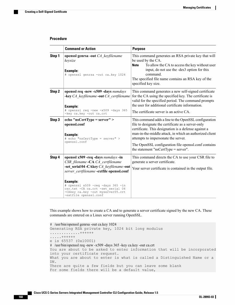
Procedure
PurposeCommand or Action
This command generates an RSA private key that willbe used by the CA.
To allow the CA to access the key without userinput, do not use the -des3 option for thiscommand.
Note
openssl genrsa -out CA_keyfilenamekeysize
Example:# openssl genrsa -out ca.key 1024
Step 1
The specified file name contains an RSA key of thespecified key size.
This command generates a new self-signed certificatefor the CA using the specified key. The certificate is
openssl req -new -x509 -days numdays-keyCA_keyfilename -outCA_certfilename
Step 2
valid for the specified period. The command promptsthe user for additional certificate information.Example:
# openssl req -new -x509 -days 365-key ca.key -out ca.crt The certificate server is an active CA.
This command adds a line to the OpenSSL configurationfile to designate the certificate as a server-only
echo "nsCertType = server" >openssl.conf
Step 3
certificate. This designation is a defense against aExample:# echo "nsCertType = server" >openssl.conf
man-in-the-middle attack, in which an authorized clientattempts to impersonate the server.
The OpenSSL configuration file openssl.conf containsthe statement "nsCertType = server".
This command directs the CA to use your CSR file togenerate a server certificate.
openssl x509 -req -days numdays -inCSR_filename -CA CA_certfilename
Step 4
-set_serial 04 -CAkeyCA_keyfilename -outserver_certfilename -extfile openssl.conf
Your server certificate is contained in the output file.
Example:# openssl x509 -req -days 365 -incsr.txt -CA ca.crt -set_serial 04-CAkey ca.key -out myserver05.crt-extfile openssl.conf
This example shows how to create a CA and to generate a server certificate signed by the new CA. Thesecommands are entered on a Linux server running OpenSSL.
# /usr/bin/openssl genrsa -out ca.key 1024Generating RSA private key, 1024 bit long modulus.............++++++.....++++++e is 65537 (0x10001)# /usr/bin/openssl req -new -x509 -days 365 -key ca.key -out ca.crtYou are about to be asked to enter information that will be incorporatedinto your certificate request.What you are about to enter is what is called a Distinguished Name or aDN.There are quite a few fields but you can leave some blankFor some fields there will be a default value,
Cisco UCS C-Series Servers Integrated Management Controller CLI Configuration Guide, Release 1.5160 OL-28993-03
Managing CertificatesCreating a Self-Signed Certificate

If you enter '.', the field will be left blank.-----Country Name (2 letter code) [GB]:USState or Province Name (full name) [Berkshire]:CaliforniaLocality Name (eg, city) [Newbury]:San JoseOrganization Name (eg, company) [My Company Ltd]:Example IncorporatedOrganizational Unit Name (eg, section) []:Unit ACommon Name (eg, your name or your server's hostname) []:example.comEmail Address []:[email protected]# echo "nsCertType = server" > openssl.conf# /usr/bin/openssl x509 -req -days 365 -in csr.txt -CA ca.crt -set_serial 01 -CAkey ca.key -out server.crt-extfile openssl.confSignature oksubject=/C=US/ST=California/L=San Jose/O=Example Inc./OU=UnitA/CN=example.com/[email protected] CA Private Key#
What to Do Next
Upload the new certificate to the CIMC.
Uploading a Server CertificateBefore You Begin
You must log in as a user with admin privileges to upload a certificate.
The certificate to be uploaded must be available as readable text. During the upload procedure, you will copythe certificate text and paste it into the CLI.
You must first generate a CSR using the CIMC certificate management CSR generation procedure, andyou must use that CSR to obtain the certificate for uploading. Do not upload a certificate that was notobtained by this method.
Note
All current HTTPS and SSH sessions are disconnected when the new server certificate is uploaded.Note
Procedure
PurposeCommand or Action
Enters the certificate command mode.Server# scope certificateStep 1
Launches a dialog for entering and uploading thenew server certificate.
Server /certificate # uploadStep 2
Copy the certificate text, paste it into the console when prompted, and type CTRL+D to upload the certificate.
Cisco UCS C-Series Servers Integrated Management Controller CLI Configuration Guide, Release 1.5 OL-28993-03 161
Managing CertificatesUploading a Server Certificate

This example uploads a new certificate to the server:Server# scope certificateServer /certificate # uploadPlease paste your certificate here, when finished, press CTRL+D.-----BEGIN CERTIFICATE-----MIIB/zCCAWgCAQAwgZkxCzAJBgNVBAYTAlVTMQswCQYDVQQIEwJDQTEVMBMGA1UEBxMMU2FuIEpvc2UsIENBMRUwEwYDVQQKEwxFeGFtcGxlIEluYy4xEzARBgNVBAsTClRlc3QgR3JvdXAxGTAXBgNVBAMTEHRlc3QuZXhhbXBsZS5jb20xHzAdBgkqhkiG9w0BCQEWEHVzZXJAZXhhbXBsZS5jb20wgZ8wDQYJKoZIhvcNAQEBBQADgY0AMIGJAoGBAMZw4nTepNIDhVzb0j7Z2Je4xAG56zmSHRMQeOGHemdh66u2/XAoLx7YCcYUZgAMivyCsKgb/6CjQtsofvzxmC/eAehuK3/SINv7wd6Vv2pBt6ZpXgD4VBNKONDlGMbkPayVlQjbG4MD2dx2+H8EH3LMtdZrgKvPxPTE+bF5wZVNAgMBAAGgJTAjBgkqhkiG9w0BCQcxFhMUQSBjaGFsbGVuZ2UgcGFzc3dvcmQwDQYJKoZIhvcNAQEFBQADgYEAG61CaJoJaVMhzCl903O6Mg51zq1zXcz75+VFj2I6rH9asckCld3mkOVx5gJUPtt5CVQpNgNLdvbDPSsXretysOhqHmp9+CLv8FDuy1CDYfuaLtvlWvfhevskV0j6mK3Ku+YiORnv6DhxrOoqau8r/hyI/L43l7IPN1HhOi3oha4=-----END CERTIFICATE-----<CTRL+D>
Cisco UCS C-Series Servers Integrated Management Controller CLI Configuration Guide, Release 1.5162 OL-28993-03
Managing CertificatesUploading a Server Certificate

C H A P T E R 12Configuring Platform Event Filters
This chapter includes the following sections:
• Platform Event Filters, page 163
• Enabling Platform Event Alerts, page 163
• Disabling Platform Event Alerts, page 164
• Configuring Platform Event Filters, page 164
• Configuring Platform Event Trap Settings, page 166
• Interpreting Platform Event Traps, page 167
Platform Event FiltersA platform event filter (PEF) can trigger an action and generate an alert when a critical hardware-related eventoccurs. For each PEF, you can choose the action to be taken (or take no action) when a platform event occurs.You can also choose to generate and send an alert when a platform event occurs. Alerts are sent as an SNMPtrap, so you must configure an SNMP trap destination before the alerts can be sent.
You can globally enable or disable the generation of platform event alerts. When disabled, alerts are not senteven if PEFs are configured to send them.
Enabling Platform Event AlertsProcedure
PurposeCommand or Action
Enters the fault command mode.Server# scope faultStep 1
Enables platform event alerts.Server /fault # setplatform-event-enabled yes
Step 2
Cisco UCS C-Series Servers Integrated Management Controller CLI Configuration Guide, Release 1.5 OL-28993-03 163
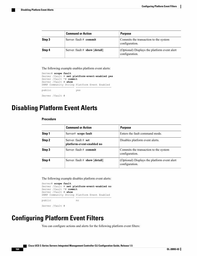
PurposeCommand or Action
Commits the transaction to the systemconfiguration.
Server /fault # commitStep 3
(Optional) Displays the platform event alertconfiguration.
Server /fault # show [detail]Step 4
The following example enables platform event alerts:Server# scope faultServer /fault # set platform-event-enabled yesServer /fault *# commitServer /fault # showSNMP Community String Platform Event Enabled--------------------- -----------------------public yes
Server /fault #
Disabling Platform Event AlertsProcedure
PurposeCommand or Action
Enters the fault command mode.Server# scope faultStep 1
Disables platform event alerts.Server /fault # setplatform-event-enabled no
Step 2
Commits the transaction to the systemconfiguration.
Server /fault # commitStep 3
(Optional) Displays the platform event alertconfiguration.
Server /fault # show [detail]Step 4
The following example disables platform event alerts:Server# scope faultServer /fault # set platform-event-enabled noServer /fault *# commitServer /fault # showSNMP Community String Platform Event Enabled--------------------- -----------------------public no
Server /fault #
Configuring Platform Event FiltersYou can configure actions and alerts for the following platform event filters:
Cisco UCS C-Series Servers Integrated Management Controller CLI Configuration Guide, Release 1.5164 OL-28993-03
Configuring Platform Event FiltersDisabling Platform Event Alerts
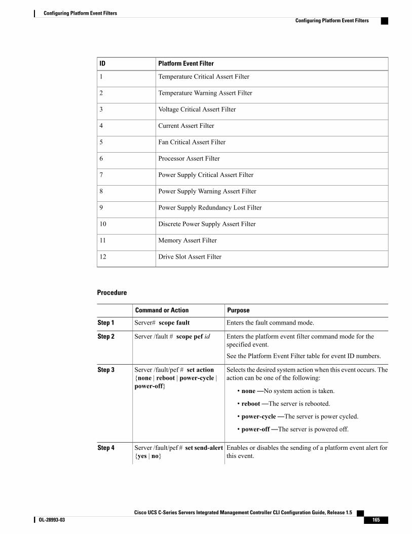
Platform Event FilterID
Temperature Critical Assert Filter1
Temperature Warning Assert Filter2
Voltage Critical Assert Filter3
Current Assert Filter4
Fan Critical Assert Filter5
Processor Assert Filter6
Power Supply Critical Assert Filter7
Power Supply Warning Assert Filter8
Power Supply Redundancy Lost Filter9
Discrete Power Supply Assert Filter10
Memory Assert Filter11
Drive Slot Assert Filter12
Procedure
PurposeCommand or Action
Enters the fault command mode.Server# scope faultStep 1
Enters the platform event filter command mode for thespecified event.
Server /fault # scope pef idStep 2
See the Platform Event Filter table for event ID numbers.
Selects the desired system action when this event occurs. Theaction can be one of the following:
Server /fault/pef # set action{none | reboot | power-cycle |power-off}
Step 3
• none—No system action is taken.
• reboot—The server is rebooted.
• power-cycle—The server is power cycled.
• power-off—The server is powered off.
Enables or disables the sending of a platform event alert forthis event.
Server /fault/pef # set send-alert{yes | no}
Step 4
Cisco UCS C-Series Servers Integrated Management Controller CLI Configuration Guide, Release 1.5 OL-28993-03 165
Configuring Platform Event FiltersConfiguring Platform Event Filters
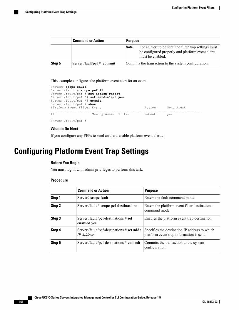
PurposeCommand or Action
For an alert to be sent, the filter trap settings mustbe configured properly and platform event alertsmust be enabled.
Note
Commits the transaction to the system configuration.Server /fault/pef # commitStep 5
This example configures the platform event alert for an event:Server# scope faultServer /fault # scope pef 11Server /fault/pef # set action rebootServer /fault/pef *# set send-alert yesServer /fault/pef *# commitServer /fault/pef # showPlatform Event Filter Event Action Send Alert--------------------- --------------------------- ----------- ------------------11 Memory Assert Filter reboot yes
Server /fault/pef #
What to Do Next
If you configure any PEFs to send an alert, enable platform event alerts.
Configuring Platform Event Trap SettingsBefore You Begin
You must log in with admin privileges to perform this task.
Procedure
PurposeCommand or Action
Enters the fault command mode.Server# scope faultStep 1
Enters the platform event filter destinationscommand mode.
Server /fault # scope pef-destinationsStep 2
Enables the platform event trap destination.Server /fault /pef-destinations # setenabled yes
Step 3
Specifies the destination IP address to whichplatform event trap information is sent.
Server /fault /pef-destinations # set addrIP Address
Step 4
Commits the transaction to the systemconfiguration.
Server /fault /pef-destinations # commitStep 5
Cisco UCS C-Series Servers Integrated Management Controller CLI Configuration Guide, Release 1.5166 OL-28993-03
Configuring Platform Event FiltersConfiguring Platform Event Trap Settings
This example configures general platform event trap settings and trap destination number 1 and commits thetransaction:Server# scope faultServer /fault # scope pef-destination 1Server /fault /pef-destinations *# set enabled yesServer /fault /pef-destinations *# set addr 1.2.3.4Server /fault /pef-destinations *# commitServer /fault /pef-destinations # show
Trap Destination 1:IP Address: 1.2.3.4Enabled: yes
Server /fault /pef-destinations #
Interpreting Platform Event TrapsA CIMC platform event alert contains an enterprise object identifier (OID) in the form1.3.6.1.4.1.3183.1.1.0.event. The first ten fields of the OID represent the following information:iso(1).org(3).dod(6).internet(1).private(4).enterprises(1).wired_for_management(3183).PET(1).version(1).version(0),indicating an IPMI platform event trap (PET) version 1.0 message. The last field is an event number, indicatingthe specific condition or alert being notified.
Platform Event Trap Descriptions
The following table provides a description of the event being notified in a platform event trap message, basedon the event number in the trap OID.
Platform Event DescriptionEvent Number [Note 1]
Test Trap0h0
Temperature Warning010107h65799
Temperature Critical010109h65801
Under Voltage, Critical020102h131330
Voltage Critical020109h131337
Current Warning030107h196871
Fan Critical040102h262402
Processor related (IOH-Thermalert/Caterr sensor) – predictive failuredeasserted
070400h459776
Processor related (IOH-Thermalert/Caterr sensor) – predictive failureasserted
070401h459777
Processor Power Warning – limit not exceeded070500h460032
Processor Power Warning – limit exceeded070501h460033
Power Supply Critical0800F5h524533
Power Supply Warning080107h524551
Cisco UCS C-Series Servers Integrated Management Controller CLI Configuration Guide, Release 1.5 OL-28993-03 167
Configuring Platform Event FiltersInterpreting Platform Event Traps
Platform Event DescriptionEvent Number [Note 1]
Discrete Power Supply Warning080401h525313
Power Supply Redundancy Lost080B01h527105
Power Supply Redundancy Restored080B02h527106
Power Supply Inserted086F00h552704
Power Supply Failure086F01h552705
Power Supply AC Lost086F03h552707
Correctable ECC Memory Errors, Release 1.3(1) and later releases,filter set to accept all reading types [Note 4]
0C0001h786433
DDR3_INFO sensor LED - RED bit asserted (Probable ECC error ona DIMM), Generic Sensor [Notes 2,3]
0C0007h786439
Correctable ECC Memory Errors, Release 1.3(1) and later releases0C0101h786689
Correctable ECC Memory Errors, Release 1.2(x) and earlier releases0C7F01h818945
DDR3_INFO sensor LED - RED bit asserted (Probable ECC error ona DIMM), 1.2(x) and earlier releases [Note 3]
0C7F07h818951
HDD sensor indicates no fault, Generic Sensor [Note 2]0D0000h851968
HDD sensor indicates a fault, Generic Sensor [Note 2]0D0004h851972
HDD Absent, Generic Sensor [Note 2]0D0800h854016
HDD Present, Generic Sensor [Note 2]0D0801h854017
HDD Present, no fault indicated0D6F00h880384
HDD Fault0D6F01h880385
HDD Not Present0D6F80h880512
HDD is deasserted but not in a fault state0D6F81h880513
Drive Slot LED Off0D7F00h884480
Drive Slot LED On0D7F01h884481
Drive Slot LED fast blink0D7F02h884482
Drive Slot LED slow blink0D7F03h884483
Drive Slot LED green0D7F04h884484
Drive Slot LED amber0D7F05h884485
Drive Slot LED blue0D7F01h884486
Drive Slot LED read0D7F01h884487
Drive Slot Online0D7F08h884488
Drive Slot Degraded0D7F09h884489
Cisco UCS C-Series Servers Integrated Management Controller CLI Configuration Guide, Release 1.5168 OL-28993-03
Configuring Platform Event FiltersInterpreting Platform Event Traps

Platform Event DescriptionEvent Number [Note 1]
Note 1: Basic information about the event number format can be found in the IPMI Platform Event TrapFormat Specification v1.0 at this URL: ftp://download.intel.com/design/servers/ipmi/pet100.pdf.
Note 2: Some platforms and releases use generic sensor implementations, while some use Cisco proprietarysensor implementations.
Note 3: In Release 1.3(1) and later releases, the ECC sensor no longer activates the LED.
Note 4: When the event filter is set to accept all reading types, bits 15:8 of the hex event number are maskedto 0. For example, event number 786689 (0C0101h) becomes 786433 (0C0001h).
Cisco UCS C-Series Servers Integrated Management Controller CLI Configuration Guide, Release 1.5 OL-28993-03 169
Configuring Platform Event FiltersInterpreting Platform Event Traps

Cisco UCS C-Series Servers Integrated Management Controller CLI Configuration Guide, Release 1.5170 OL-28993-03
Configuring Platform Event FiltersInterpreting Platform Event Traps
C H A P T E R 13CIMC Firmware Management
This chapter includes the following sections:
• Overview of Firmware, page 171
• Obtaining Firmware from Cisco, page 172
• Installing CIMC Firmware from a Remote Server, page 173
• Activating Installed CIMC Firmware, page 174
• Installing BIOS Firmware from a Remote Server, page 176
Overview of FirmwareC-Series servers use Cisco-certified firmware specific to the C-Series server model that you are using. Youcan download new releases of the firmware for all supported server models from Cisco.com.
When you install new BIOS firmware, it must be from the same software release as the CIMC firmwarerunning on the server. Do not install new BIOS firmware until after you have activated the matching CIMCfirmware or the server will not boot.
To avoid potential problems, we strongly recommend that you use the Cisco Host Upgrade Utility (HUU),which upgrades the BIOS, CIMC, and other firmware to compatible levels. For detailed information aboutthis utility, see the Cisco Host Upgrade Utility Guide for the version of the HUU that goes with the CIMCsoftware release that you want to install. The HUU guides are available at the following URL: http://www.cisco.com/en/US/products/ps10493/products_user_guide_list.html.
Caution
If you elect to update the firmware manually, you must update the CIMC firmware first. The CIMC firmwareupdate process is divided into the following stages to minimize the amount of time the server will be offline:
• Installation. During this stage, CIMC installs the selected CIMC firmware in the non-active, or backup,slot on the server.
• Activation. During this stage, CIMC sets the non-active firmware version as active and reboots theserver, causing a disruption in service. When the server reboots, the firmware in the new active slotbecomes the running version.
Cisco UCS C-Series Servers Integrated Management Controller CLI Configuration Guide, Release 1.5 OL-28993-03 171
After you activate the CIMC firmware, you can update the BIOS firmware. The server must be powered offduring the entire BIOS update process, so the process is not divided into stages. Instead, you only need toissue a single command and CIMC installs and updates the BIOS firmware as quickly as possible. Once theCIMC finishes rebooting, the server can be powered on and returned to service.
You can either upgrade an older firmware version to a newer one, or downgrade a newer firmware versionto an older one.
Note
Obtaining Firmware from CiscoProcedure
Step 1 Navigate to http://www.cisco.com/.Step 2 If you are not already logged in, click Log In at the top right-hand edge of the page and log in using your
Cisco.com credentials.Step 3 In the menu bar at the top, click Support.Step 4 Click All Downloads in the roll down menu.Step 5 If your server model is listed in the Recently Used Products list, click the server name. Otherwise, do the
following:a) In the left-hand box, click Products.b) In the center box, click Unified Computing and Servers.c) In the right-hand box, click Cisco UCS C-Series Rack-Mount Standalone Server Software.d) In the right-hand box, click the server model whose software you want to download.
Step 6 Click the Unified Computing System (UCS) Server Firmware link.Step 7 (Optional) Select a prior release from the menu bar on the left-hand side of the page.Step 8 Click the Download button associated with the Cisco Host Upgrade Utility ISO for the selected release.Step 9 Click Accept License Agreement.Step 10 Save the ISO file to a local drive.
We recommend you upgrade the CIMC and BIOS firmware on your server using this ISO file, which containsthe Cisco Host Upgrade Utility. For detailed information about this utility, see the Cisco Host Upgrade UtilityGuide for the version of the HUU that goes with the CIMC software release that you want to install. The HUUguides are available at the following URL: http://www.cisco.com/en/US/products/ps10493/products_user_guide_list.html.
Step 11 (Optional) If you plan to upgrade the CIMC and BIOS firmware manually, do the following:a) From the ISO file, open the ZIP file containing the firmware installation files.
The ZIP file is on the top-level of the ISO file, and its name follows the formatServerModel_ReleaseNumber.ZIP.
For example, C240M3_1.4.4A.ZIP.
You do not need to extract all of the files contained in this ZIP file. Instead, you only need to open it sothat you can access the BIOS firmware installation CAP file and the ZIP file containing the CIMC firmwareinstallation BIN file.
Cisco UCS C-Series Servers Integrated Management Controller CLI Configuration Guide, Release 1.5172 OL-28993-03
CIMC Firmware ManagementObtaining Firmware from Cisco
b) From the ServerModel_ReleaseNumber.ZIP file, extract the BIOS firmware installation CAPfile and save it to your local drive.The CAP file is in the ReleaseNumber/bios/cimc folder, and its name follows the formatServer-BIOS-Release-Number.CAP.
For example, 1.4.4a/bios/cimc/C240-BIOS-1-4-4c-0.CAP.
c) From the ServerModel_ReleaseNumber.ZIP file, open the ZIP file containing the CIMC firmwareinstallation files.The ZIP file is in the ReleaseNumber/cimc folder and its name follows the formatserver-model-cimc-release.zip.
For example, 1.4.4a/cimc/c240-m3-cimc.1.4.4a.zip.
You do not need to extract all of the files contained in this zip file. Instead, you only need to open it sothat you can access the CIMC firmware installation BIN file.
d) From the server-model-cimc-release.zip file, extract the full CIMC firmware installation BINfile and save it to your local drive.The BIN file is in the server-model-cimc-release folder and its name follows the formatupd-pkg-server-model-cimc.full.release.bin.
For example, c240-m3-cimc.1.4.4a/upd-pkg-c240-m3-cimc.full.1.4.4a.bin.
Step 12 (Optional) If you plan to install the firmware from a remote server, copy the BIOS installation CAP file andthe CIMC installation BIN file to the remote server you want to use.The remote server can be one of the following:
• TFTP
• FTP
• SFTP
• SCP
• HTTP
The server must have read permission for the destination folder on the remote server.
What to Do Next
Use the Cisco Host Upgrade Utility to upgrade all firmware on the server or manually install the CIMCfirmware on the server.
Installing CIMC Firmware from a Remote ServerBefore You Begin
• Log in to the CIMC CLI as a user with admin privileges.
• Obtain the Cisco Host Upgrade Utility ISO file from Cisco.com and extract the firmware installationfiles as described in Obtaining Firmware from Cisco, on page 172.
Cisco UCS C-Series Servers Integrated Management Controller CLI Configuration Guide, Release 1.5 OL-28993-03 173
CIMC Firmware ManagementInstalling CIMC Firmware from a Remote Server
If you start an update while an update is already in process, both updates will fail.Note
Procedure
PurposeCommand or Action
Enters the CIMC command mode.Server# scope cimcStep 1
Enters the CIMC firmware command mode.Server /cimc # scope firmwareStep 2
Specifies the protocol, IP address of the remote serverand the file path to the firmware file on the server. Theprotocol can be one of the following:
Server /cimc/firmware # updateprotocol IP Address path
Step 3
• TFTP
• FTP
• SFTP
• SCP
• HTTP
(Optional)Displays the progress of the firmware update.
Server /cimc/firmware # show detailStep 4
This example updates the CIMC firmware:Server# scope cimcServer /cimc # scope firmwareServer /cimc/firmware # update ftp 192.0.20.34 //test/dnld-ucs-k9-bundle.1.0.2h.bin<CR> Press Enter key
Firmware update has started.Please check the status using "show detail"Server /cimc/firmware #
What to Do Next
Activate the new firmware.
Activating Installed CIMC FirmwareBefore You Begin
Install the CIMC firmware on the server.
Cisco UCS C-Series Servers Integrated Management Controller CLI Configuration Guide, Release 1.5174 OL-28993-03
CIMC Firmware ManagementActivating Installed CIMC Firmware

While the activation is in progress, do not:Important
• Reset, power off, or shut down the server.
• Reboot or reset CIMC.
• Activate any other firmware.
• Export technical support or configuration data.
Procedure
PurposeCommand or Action
Enters the CIMC command mode.Server# scope cimcStep 1
Enters the firmware command mode.Server /cimc # scope firmwareStep 2
Displays the available firmware images andstatus.
Server /cimc/firmware # show detailStep 3
Activates the selected image. If no image numberis specified, the server activates the currentlyinactive image.
Server /cimc/firmware # activate [1 | 2]Step 4
The BMC reboots, terminating all CLI and GUIsessions until the reboot completes.
At the prompt, enter y to activate theselected firmware image.
Step 5
(Optional)Log back into the CLI and repeat steps 1–3to verify the activation.
Step 6
This example activates firmware image 1 and then verifies the activation after the BMC reboots:Server# scope cimcServer /cimc # scope firmwareServer /cimc/firmware # show detailFirmware Image Information:
Update Stage: NONEUpdate Progress: 100Current FW Version: 1.3(3a)FW Image 1 Version: 1.4(3j)FW Image 1 State: BACKUP INACTIVATEDFW Image 2 Version: 1.3(3a)FW Image 2 State: RUNNING ACTIVATEDBoot-loader Version: 1.4(3.21).18
Server /cimc/firmware # activate 1This operation will activate firmware 1 and reboot the BMC.Continue?[y|N]y..-- BMC reboot --..-- Log into CLI as Admin --
Server# scope cimc
Cisco UCS C-Series Servers Integrated Management Controller CLI Configuration Guide, Release 1.5 OL-28993-03 175
CIMC Firmware ManagementActivating Installed CIMC Firmware

Server /cimc # scope firmwareServer /cimc/firmware # show detailFirmware Image Information:
Update Stage: NONEUpdate Progress: 100Current FW Version: 1.4(3j)FW Image 1 Version: 1.4(3j)FW Image 1 State: RUNNING ACTIVATEDFW Image 2 Version: 1.3(3a)FW Image 2 State: BACKUP INACTIVATEDBoot-loader Version: 1.4(3.21).18
Installing BIOS Firmware from a Remote Server
This procedure is not available on some servers. For other BIOS installation methods, see the Cisco UCSC-Series Rack-Mount Server BIOS Upgrade Guide available at the following URL: http://www.cisco.com/en/US/docs/unified_computing/ucs/c/sw/bios/b_Upgrading_BIOS_Firmware.html.
Note
Before You Begin
• Log in to the CIMC CLI as a user with admin privileges.
• Activate the CIMC firmware that goes with the BIOS version you want to install, as described inActivating Installed CIMC Firmware, on page 174.
• Power off the server.
If you start an update while an update is already in process, both updates will fail.Note
Procedure
PurposeCommand or Action
Enters the CIMC command mode.Server# scope cimcStep 1
Enters the firmware command mode.Server /cimc # scope firmwareStep 2
Displays the available firmware images and status.Server /cimc/firmware # show detailStep 3
If the CIMC firmware version does notmatch, activate the CIMC firmwarebefore continuing with this procedureor the server will not boot. For details,see Activating Installed CIMCFirmware, on page 174.
ImportantMake sure the firmware version shownin the Current FW Version fieldmatches the BIOS firmware version youare installing.
Step 4
Returns to the server root level.Server /cimc/firmware # topStep 5
Enters the BIOS command mode.Server# scope biosStep 6
Cisco UCS C-Series Servers Integrated Management Controller CLI Configuration Guide, Release 1.5176 OL-28993-03
CIMC Firmware ManagementInstalling BIOS Firmware from a Remote Server
PurposeCommand or Action
Specifies the protocol to be used. It can be TFTP,FTP, SFTP, SCP or HTTP.
Server /bios # update protocolStep 7
Specifies the IP address or the host name of theremote server.
Server /bios # update IP AddressStep 8
Specifies the file path to the BIOS firmware file onthe remote server.
Server /bios # update pathStep 9
This example updates the BIOS firmware to CIMC software release 1.4(3j):Server# scope cimcServer /cimc # scope firmwareServer /cimc/firmware # show detailFirmware Image Information:
Update Stage: NONEUpdate Progress: 100Current FW Version: 1.4(3j)FW Image 1 Version: 1.4(3j)FW Image 1 State: RUNNING ACTIVATEDFW Image 2 Version: 1.3(3a)FW Image 2 State: BACKUP INACTIVATEDBoot-loader Version: 1.4(3.21).18
Server /cimc/firmware # topServer # scope biosServer /bios # update ftp 192.0.20.34 //upgrade_bios_files/C260-BIOS-1-4-3j-0.CAP<CR> Press Enter keyFirmware update has started.Please check the status using "show detail"Server /bios #
Cisco UCS C-Series Servers Integrated Management Controller CLI Configuration Guide, Release 1.5 OL-28993-03 177
CIMC Firmware ManagementInstalling BIOS Firmware from a Remote Server

Cisco UCS C-Series Servers Integrated Management Controller CLI Configuration Guide, Release 1.5178 OL-28993-03
CIMC Firmware ManagementInstalling BIOS Firmware from a Remote Server
C H A P T E R 14Viewing Faults and Logs
This chapter includes the following sections:
• Viewing the Faults and Logs Summary, page 179
• CIMC Log, page 180
• System Event Log, page 184
Viewing the Faults and Logs SummaryProcedure
PurposeCommand or Action
Enters fault command mode.Server # scope faultStep 1
Displays a log of all the faults.Server # show fault-entriesStep 2
This example displays a summary of faults:Server # scope faultServer /fault # show fault-entriesTime Severity Description------------------------ ------------ -----------------Sun Jun 27 04:00:52 2013 info Storage Local disk 12 missingSat Jun 26 05:00:22 2013 warning Power Supply redundancy is lost
Server /fault #
Cisco UCS C-Series Servers Integrated Management Controller CLI Configuration Guide, Release 1.5 OL-28993-03 179
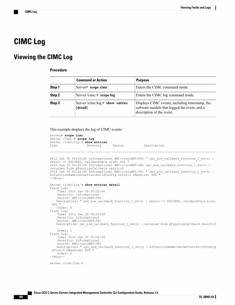
CIMC Log
Viewing the CIMC Log
Procedure
PurposeCommand or Action
Enters the CIMC command mode.Server# scope cimcStep 1
Enters the CIMC log command mode.Server /cimc # scope logStep 2
Displays CIMC events, including timestamp, thesoftware module that logged the event, and adescription of the event.
Server /cimc/log # show entries[detail]
Step 3
This example displays the log of CIMC events:Server# scope cimcServer /cimc # scope logServer /cimc/log # show entriesTime Severity Source Description
------------------- ------------- ---------------- ----------------------------------------
2012 Jan 30 05:20:45 Informational BMC:ciscoNET:961 " rpc_aim_callback_function_1_svc() -result == SUCCESS, callbackData size: 600 "2012 Jan 30 05:20:45 Informational BMC:ciscoNET:961 rpc_aim_callback_function_1_svc() -returned from pFunctionCallback result:02012 Jan 30 05:20:45 Informational BMC:ciscoNET:961 " rpc_aim_callback_function_1_svc() -szFunctionName:netGetCurrentIfConfig nSize:0 nMaxSize: 600 "--More--
Server /cimc/log # show entries detailTrace Log:
Time: 2012 Jan 30 05:20:45Severity: InformationalSource: BMC:ciscoNET:961Description: " rpc_aim_callback_function_1_svc() - result == SUCCESS, callbackData size:
600 "Order: 0
Trace Log:Time: 2012 Jan 30 05:20:45Severity: InformationalSource: BMC:ciscoNET:961Description: rpc_aim_callback_function_1_svc() - returned from pFunctionCallback result:0
Order: 1Trace Log:
Time: 2012 Jan 30 05:20:45Severity: InformationalSource: BMC:ciscoNET:961Description: " rpc_aim_callback_function_1_svc() - szFunctionName:netGetCurrentIfConfig
nSize:0 nMaxSize: 600 "Order: 2
--More--
Server /cimc/log #
Cisco UCS C-Series Servers Integrated Management Controller CLI Configuration Guide, Release 1.5180 OL-28993-03
Viewing Faults and LogsCIMC Log
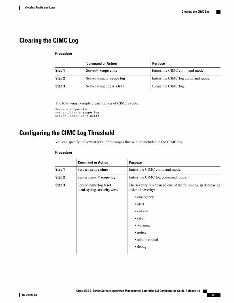
Clearing the CIMC Log
Procedure
PurposeCommand or Action
Enters the CIMC command mode.Server# scope cimcStep 1
Enters the CIMC log command mode.Server /cimc # scope logStep 2
Clears the CIMC log.Server /cimc/log # clearStep 3
The following example clears the log of CIMC events:Server# scope cimcServer /cimc # scope logServer /cimc/log # clear
Configuring the CIMC Log ThresholdYou can specify the lowest level of messages that will be included in the CIMC log.
Procedure
PurposeCommand or Action
Enters the CIMC command mode.Server# scope cimcStep 1
Enters the CIMC log command mode.Server /cimc # scope logStep 2
The severity level can be one of the following, in decreasingorder of severity:
Server /cimc/log # setlocal-syslog-severity level
Step 3
• emergency
• alert
• critical
• error
• warning
• notice
• informational
• debug
Cisco UCS C-Series Servers Integrated Management Controller CLI Configuration Guide, Release 1.5 OL-28993-03 181
Viewing Faults and LogsClearing the CIMC Log
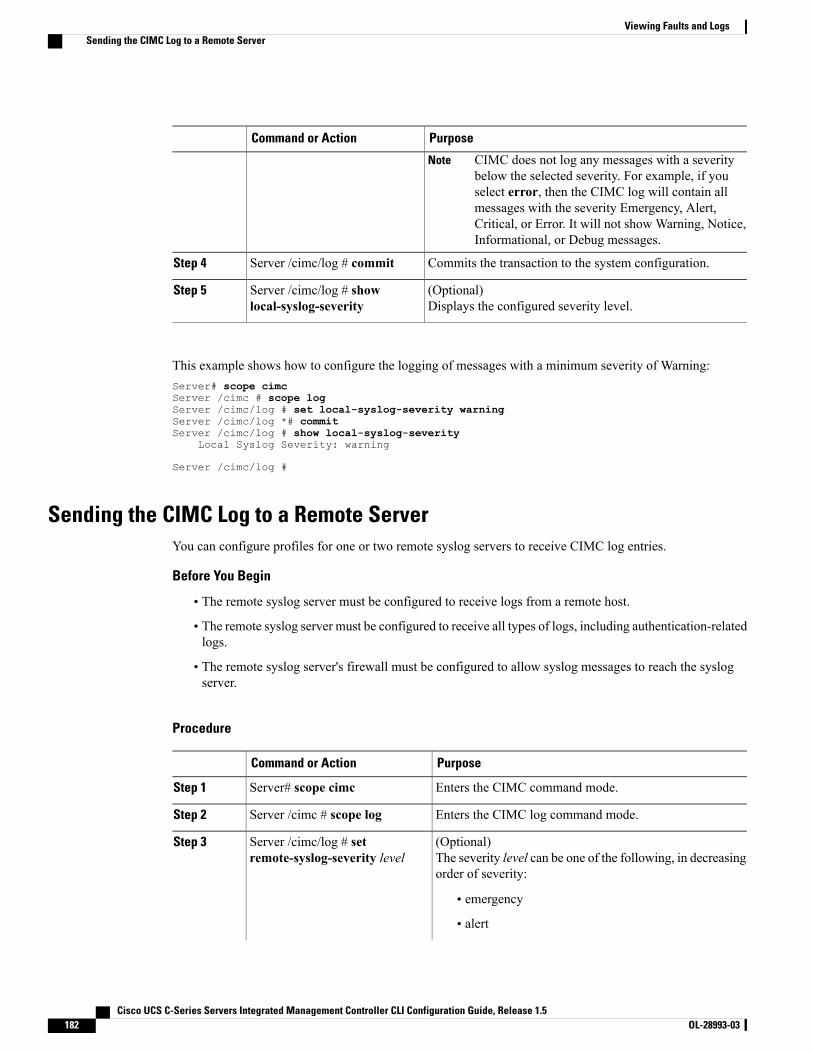
PurposeCommand or Action
CIMC does not log any messages with a severitybelow the selected severity. For example, if youselect error, then the CIMC log will contain allmessages with the severity Emergency, Alert,Critical, or Error. It will not show Warning, Notice,Informational, or Debug messages.
Note
Commits the transaction to the system configuration.Server /cimc/log # commitStep 4
(Optional)Displays the configured severity level.
Server /cimc/log # showlocal-syslog-severity
Step 5
This example shows how to configure the logging of messages with a minimum severity of Warning:Server# scope cimcServer /cimc # scope logServer /cimc/log # set local-syslog-severity warningServer /cimc/log *# commitServer /cimc/log # show local-syslog-severity
Local Syslog Severity: warning
Server /cimc/log #
Sending the CIMC Log to a Remote ServerYou can configure profiles for one or two remote syslog servers to receive CIMC log entries.
Before You Begin
• The remote syslog server must be configured to receive logs from a remote host.
• The remote syslog server must be configured to receive all types of logs, including authentication-relatedlogs.
• The remote syslog server's firewall must be configured to allow syslog messages to reach the syslogserver.
Procedure
PurposeCommand or Action
Enters the CIMC command mode.Server# scope cimcStep 1
Enters the CIMC log command mode.Server /cimc # scope logStep 2
(Optional)The severity level can be one of the following, in decreasingorder of severity:
Server /cimc/log # setremote-syslog-severity level
Step 3
• emergency
• alert
Cisco UCS C-Series Servers Integrated Management Controller CLI Configuration Guide, Release 1.5182 OL-28993-03
Viewing Faults and LogsSending the CIMC Log to a Remote Server
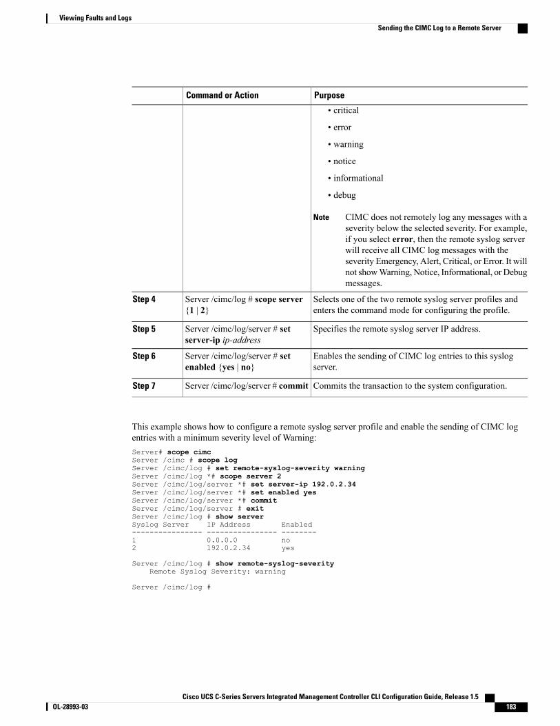
PurposeCommand or Action
• critical
• error
• warning
• notice
• informational
• debug
CIMC does not remotely log any messages with aseverity below the selected severity. For example,if you select error, then the remote syslog serverwill receive all CIMC log messages with theseverity Emergency, Alert, Critical, or Error. It willnot showWarning, Notice, Informational, or Debugmessages.
Note
Selects one of the two remote syslog server profiles andenters the command mode for configuring the profile.
Server /cimc/log # scope server{1 | 2}
Step 4
Specifies the remote syslog server IP address.Server /cimc/log/server # setserver-ip ip-address
Step 5
Enables the sending of CIMC log entries to this syslogserver.
Server /cimc/log/server # setenabled {yes | no}
Step 6
Commits the transaction to the system configuration.Server /cimc/log/server # commitStep 7
This example shows how to configure a remote syslog server profile and enable the sending of CIMC logentries with a minimum severity level of Warning:Server# scope cimcServer /cimc # scope logServer /cimc/log # set remote-syslog-severity warningServer /cimc/log *# scope server 2Server /cimc/log/server *# set server-ip 192.0.2.34Server /cimc/log/server *# set enabled yesServer /cimc/log/server *# commitServer /cimc/log/server # exitServer /cimc/log # show serverSyslog Server IP Address Enabled---------------- ---------------- --------1 0.0.0.0 no2 192.0.2.34 yes
Server /cimc/log # show remote-syslog-severityRemote Syslog Severity: warning
Server /cimc/log #
Cisco UCS C-Series Servers Integrated Management Controller CLI Configuration Guide, Release 1.5 OL-28993-03 183
Viewing Faults and LogsSending the CIMC Log to a Remote Server
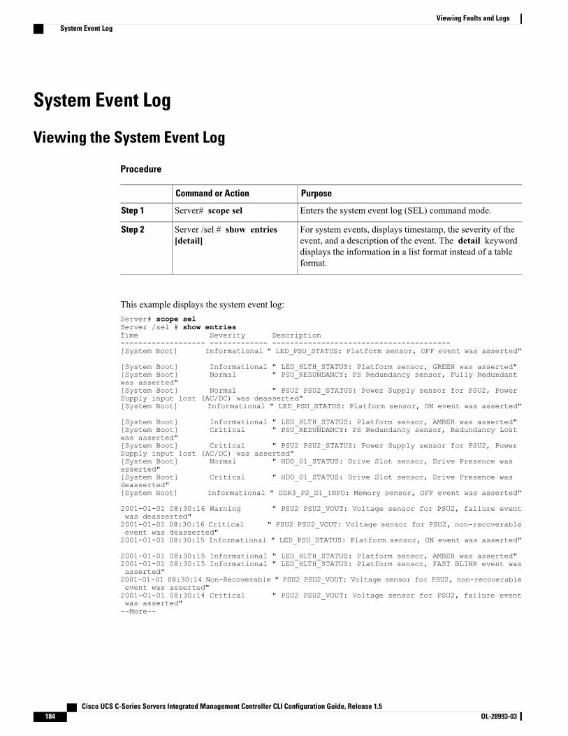
System Event Log
Viewing the System Event Log
Procedure
PurposeCommand or Action
Enters the system event log (SEL) command mode.Server# scope selStep 1
For system events, displays timestamp, the severity of theevent, and a description of the event. The detail keyword
Server /sel # show entries[detail]
Step 2
displays the information in a list format instead of a tableformat.
This example displays the system event log:Server# scope selServer /sel # show entriesTime Severity Description------------------- ------------- ----------------------------------------[System Boot] Informational " LED_PSU_STATUS: Platform sensor, OFF event was asserted"
[System Boot] Informational " LED_HLTH_STATUS: Platform sensor, GREEN was asserted"[System Boot] Normal " PSU_REDUNDANCY: PS Redundancy sensor, Fully Redundantwas asserted"[System Boot] Normal " PSU2 PSU2_STATUS: Power Supply sensor for PSU2, PowerSupply input lost (AC/DC) was deasserted"[System Boot] Informational " LED_PSU_STATUS: Platform sensor, ON event was asserted"
[System Boot] Informational " LED_HLTH_STATUS: Platform sensor, AMBER was asserted"[System Boot] Critical " PSU_REDUNDANCY: PS Redundancy sensor, Redundancy Lostwas asserted"[System Boot] Critical " PSU2 PSU2_STATUS: Power Supply sensor for PSU2, PowerSupply input lost (AC/DC) was asserted"[System Boot] Normal " HDD_01_STATUS: Drive Slot sensor, Drive Presence wasasserted"[System Boot] Critical " HDD_01_STATUS: Drive Slot sensor, Drive Presence wasdeasserted"[System Boot] Informational " DDR3_P2_D1_INFO: Memory sensor, OFF event was asserted"
2001-01-01 08:30:16 Warning " PSU2 PSU2_VOUT: Voltage sensor for PSU2, failure eventwas deasserted"2001-01-01 08:30:16 Critical " PSU2 PSU2_VOUT: Voltage sensor for PSU2, non-recoverableevent was deasserted"2001-01-01 08:30:15 Informational " LED_PSU_STATUS: Platform sensor, ON event was asserted"
2001-01-01 08:30:15 Informational " LED_HLTH_STATUS: Platform sensor, AMBER was asserted"2001-01-01 08:30:15 Informational " LED_HLTH_STATUS: Platform sensor, FAST BLINK event wasasserted"2001-01-01 08:30:14 Non-Recoverable " PSU2 PSU2_VOUT: Voltage sensor for PSU2, non-recoverableevent was asserted"2001-01-01 08:30:14 Critical " PSU2 PSU2_VOUT: Voltage sensor for PSU2, failure eventwas asserted"--More--
Cisco UCS C-Series Servers Integrated Management Controller CLI Configuration Guide, Release 1.5184 OL-28993-03
Viewing Faults and LogsSystem Event Log
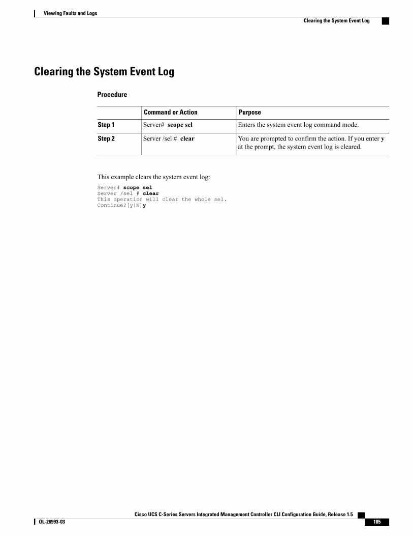
Clearing the System Event Log
Procedure
PurposeCommand or Action
Enters the system event log command mode.Server# scope selStep 1
You are prompted to confirm the action. If you enter yat the prompt, the system event log is cleared.
Server /sel # clearStep 2
This example clears the system event log:Server# scope selServer /sel # clearThis operation will clear the whole sel.Continue?[y|N]y
Cisco UCS C-Series Servers Integrated Management Controller CLI Configuration Guide, Release 1.5 OL-28993-03 185
Viewing Faults and LogsClearing the System Event Log

Cisco UCS C-Series Servers Integrated Management Controller CLI Configuration Guide, Release 1.5186 OL-28993-03
Viewing Faults and LogsClearing the System Event Log
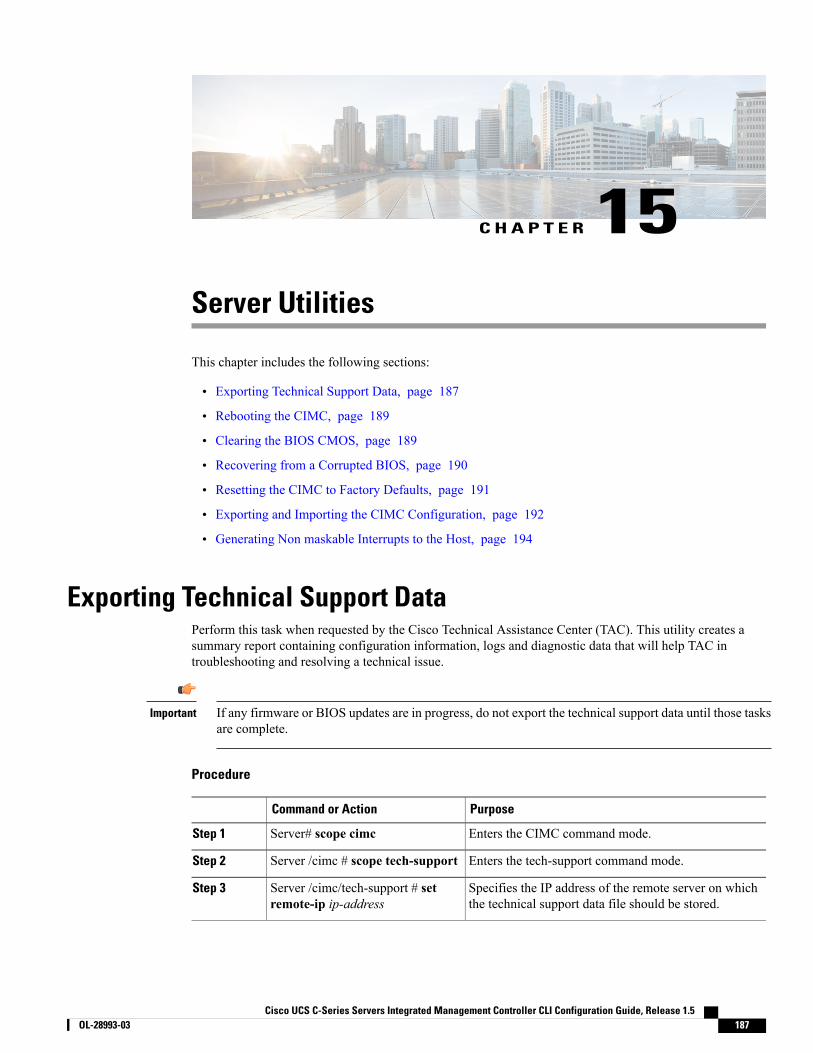
C H A P T E R 15Server Utilities
This chapter includes the following sections:
• Exporting Technical Support Data, page 187
• Rebooting the CIMC, page 189
• Clearing the BIOS CMOS, page 189
• Recovering from a Corrupted BIOS, page 190
• Resetting the CIMC to Factory Defaults, page 191
• Exporting and Importing the CIMC Configuration, page 192
• Generating Non maskable Interrupts to the Host, page 194
Exporting Technical Support DataPerform this task when requested by the Cisco Technical Assistance Center (TAC). This utility creates asummary report containing configuration information, logs and diagnostic data that will help TAC introubleshooting and resolving a technical issue.
If any firmware or BIOS updates are in progress, do not export the technical support data until those tasksare complete.
Important
Procedure
PurposeCommand or Action
Enters the CIMC command mode.Server# scope cimcStep 1
Enters the tech-support command mode.Server /cimc # scope tech-supportStep 2
Specifies the IP address of the remote server on whichthe technical support data file should be stored.
Server /cimc/tech-support # setremote-ip ip-address
Step 3
Cisco UCS C-Series Servers Integrated Management Controller CLI Configuration Guide, Release 1.5 OL-28993-03 187

PurposeCommand or Action
Specifies the file name in which the support data shouldbe stored on the remote server.When you enter this name,
Server /cimc/tech-support # setremote-path path/filename
Step 4
include the relative path for the file from the top of theserver tree to the desired location.
To have the system auto-generate the file name,enter the file name as default.tar.gz.
Tip
Specifies the protocol to connect to the remote server. Itcan be of the following types:
Server /cimc/tech-support # setremote-protocol protocol
Step 5
• tftp
• ftp
• sftp
• scp
• http
Specifies the user name on the remote server on whichthe technical support data file should be stored. This fielddoes not apply if the protocol is TFTP or HTTP.
Server /cimc/tech-support # setremote-username name
Step 6
Specifies the password on the remote server on whichthe technical support data file should be stored. This fielddoes not apply if the protocol is TFTP or HTTP.
Server /cimc/tech-support # setremote-password password
Step 7
Commits the transaction to the system configuration.Server /cimc/tech-support # commitStep 8
Begins the transfer of the data file to the remote server.Server /cimc/tech-support # startStep 9
(Optional)Displays the progress of the transfer of the data file tothe remote server.
Server /cimc/tech-support # showdetail
Step 10
(Optional)Cancels the transfer of the data file to the remote server.
Server /cimc/tech-support # cancelStep 11
This example creates a technical support data file and transfers the file to a TFTP server:Server# scope cimcServer /cimc # scope tech-supportServer /cimc/tech-support # set remote-ip 192.0.20.41Server /cimc/tech-support* # set remote-protocol tftpServer /cimc/tech-support *# set remote-path /user/user1/default.tar.gzServer /cimc/tech-support *# commitServer /cimc/tech-support # startTech Support upload started.
Server /cimc/tech-support # show detail
Tech Support:Server Address: 192.0.20.41Path: default.tar.gz
Cisco UCS C-Series Servers Integrated Management Controller CLI Configuration Guide, Release 1.5188 OL-28993-03
Server UtilitiesExporting Technical Support Data

Protocol: tftpUsername:Password: *******Progress (%): 5Status: Collecting
Server /cimc/tech-support #
What to Do Next
Provide the generated report file to Cisco TAC.
Rebooting the CIMCOn rare occasions, such as an issue with the current running firmware, troubleshooting a server may requireyou to reboot the CIMC. This procedure is not part of the normal maintenance of a server. After you rebootthe CIMC, you are logged off and the CIMC will be unavailable for a few minutes.
If you reboot the CIMC while the server is performing power-on self test (POST) or is operating in theExtensible Firmware Interface (EFI) shell, the server will be powered down until the CIMC reboot iscomplete.
Note
Procedure
PurposeCommand or Action
Enters the CIMC command mode.Server# scope cimcStep 1
The CIMC reboots.Server /cimc # rebootStep 2
This example reboots the CIMC:Server# scope cimcServer /cimc # reboot
Clearing the BIOS CMOSOn rare occasions, troubleshooting a server may require you to clear the server's BIOS CMOS memory. Thisprocedure is not part of the normal maintenance of a server.
Procedure
PurposeCommand or Action
Enters the bios command mode.Server# scope biosStep 1
Cisco UCS C-Series Servers Integrated Management Controller CLI Configuration Guide, Release 1.5 OL-28993-03 189
Server UtilitiesRebooting the CIMC
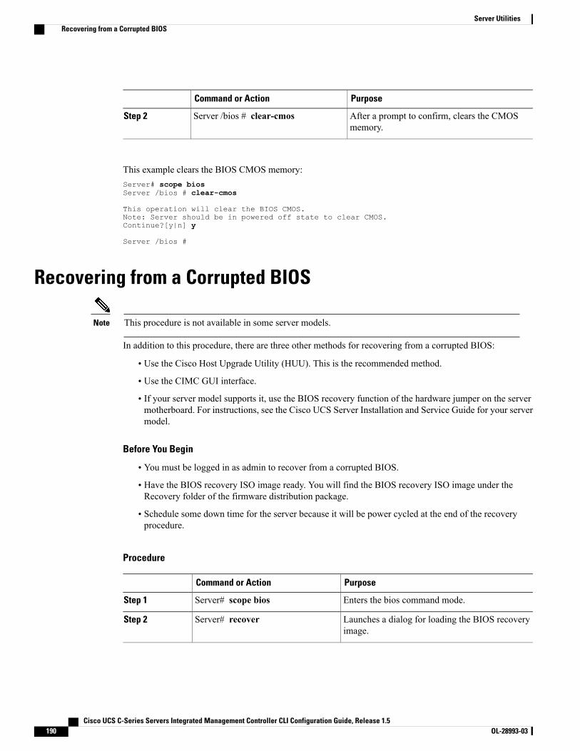
PurposeCommand or Action
After a prompt to confirm, clears the CMOSmemory.
Server /bios # clear-cmosStep 2
This example clears the BIOS CMOS memory:Server# scope biosServer /bios # clear-cmos
This operation will clear the BIOS CMOS.Note: Server should be in powered off state to clear CMOS.Continue?[y|n] y
Server /bios #
Recovering from a Corrupted BIOS
This procedure is not available in some server models.Note
In addition to this procedure, there are three other methods for recovering from a corrupted BIOS:
• Use the Cisco Host Upgrade Utility (HUU). This is the recommended method.
• Use the CIMC GUI interface.
• If your server model supports it, use the BIOS recovery function of the hardware jumper on the servermotherboard. For instructions, see the Cisco UCS Server Installation and Service Guide for your servermodel.
Before You Begin
• You must be logged in as admin to recover from a corrupted BIOS.
• Have the BIOS recovery ISO image ready. You will find the BIOS recovery ISO image under theRecovery folder of the firmware distribution package.
• Schedule some down time for the server because it will be power cycled at the end of the recoveryprocedure.
Procedure
PurposeCommand or Action
Enters the bios command mode.Server# scope biosStep 1
Launches a dialog for loading the BIOS recoveryimage.
Server# recoverStep 2
Cisco UCS C-Series Servers Integrated Management Controller CLI Configuration Guide, Release 1.5190 OL-28993-03
Server UtilitiesRecovering from a Corrupted BIOS
This example shows how to recover from a corrupted BIOS:Server# scope biosServer /bios # recoverThis operation will automatically power on the server to perform BIOS FW recovery.Continue?[y|N]y
What to Do Next
Power cycle or reset the server.
Resetting the CIMC to Factory DefaultsOn rare occasions, such as an issue with the current running firmware, troubleshooting a server may requireyou to reset the CIMC to the factory default. When this happens, all user-configurable settings are reset.
This procedure is not part of the normal server maintenance. After you reset the CIMC, you are logged offand must log in again. You may also lose connectivity and may need to reconfigure the network settings.
When you upgrade from version 1.5(1) to version 1.5(2), the hostname in the CIMC interface is retained asis. However, after upgrading to version 1.5(2), if you do a factory reset, the hostname changes toCXXX-YYYYYY format, where XXX is the model number and YYYYYY is the serial number of the server.
When you downgrade from version 1.5(2) to version 1.5(1), the hostname is retained as is. However, if youdo a factory reset, the hostname changes to ucs-cxx-mx format.
Procedure
PurposeCommand or Action
Enters the CIMC command mode.Server# scope cimcStep 1
After a prompt to confirm, the CIMC resets tofactory defaults.
Server /cimc # factory-defaultStep 2
The CIMC factory defaults include the following conditions:
• SSH is enabled for access to the CIMC CLI. Telnet is disabled.
• HTTPS is enabled for access to the CIMC GUI.
• A single user account exists (user name is admin , password is password ).
• DHCP is enabled on the management port.
• The boot order is EFI, CDROM, PXE (using LoM), FDD, HDD.
• KVM and vMedia are enabled.
• USB is enabled.
• SoL is disabled.
This example resets the CIMC to factory defaults:Server# scope cimcServer /cimc # factory-defaultThis operation will reset the CIMC configuration to factory default.
Cisco UCS C-Series Servers Integrated Management Controller CLI Configuration Guide, Release 1.5 OL-28993-03 191
Server UtilitiesResetting the CIMC to Factory Defaults

All your configuration will be lost.Continue?[y|N]
Exporting and Importing the CIMC Configuration
Exporting and Importing the CIMC ConfigurationTo perform a backup of the CIMC configuration, you take a snapshot of the system configuration and exportthe resulting CIMC configuration file to a location on your network. The export operation saves informationfrom the management plane only; it does not back up data on the servers. Sensitive configuration informationsuch as user accounts and the server certificate are not exported.
You can restore an exported CIMC configuration file to the same system or you can import it to another CIMCsystem, provided that the software version of the importing system is the same as or is configuration-compatiblewith the software version of the exporting system. When you import a configuration file to another systemas a configuration template, you must modify system-specific settings such as IP addresses and host names.An import operation modifies information on the management plane only.
The CIMC configuration file is an XML text file whose structure and elements correspond to the CIMCcommand modes.
When performing an export or import operation, consider these guidelines:
• You can perform an export or an import while the system is up and running. While an export operationhas no impact on the server or network traffic, some modifications caused by an import operation, suchas IP address changes, can disrupt traffic or cause a server reboot.
• You cannot execute an export and an import simultaneously.
Exporting the CIMC Configuration
For security reasons, this operation does not export user accounts or the server certificate.Note
If any firmware or BIOS updates are in progress, do not export the CIMC configuration until those tasksare complete.
Important
Before You Begin
Obtain the backup remote server IP address.
Procedure
PurposeCommand or Action
Enters the CIMC command mode.Server# scope cimcStep 1
Cisco UCS C-Series Servers Integrated Management Controller CLI Configuration Guide, Release 1.5192 OL-28993-03
Server UtilitiesExporting and Importing the CIMC Configuration
PurposeCommand or Action
Enters the import-export command mode.Server /cimc # scope import-exportStep 2
Starts the backup operation. The configuration file willbe stored at the specified path and file name on a remote
Server /cimc/import-export #export-config protocol ip-addresspath-and-filename
Step 3
server at the specified IP address. The remote servercould be one of the following types:
• TFTP
• FTP
• SFTP
• SCP
• HTTP
To determine whether the export operation has completed successfully, use the show detail command. Toabort the operation, type CTRL+C.
This example shows how to back up the CIMC configuration:Server# scope cimcServer /cimc # scope import-exportServer /cimc/import-export # export-config tftp 192.0.2.34 /ucs/backups/cimc5.xmlExport config started. Please check the status using "show detail".Server /cimc/import-export # show detailImport Export:
Operation: EXPORTStatus: COMPLETEDError Code: 100 (No Error)Diagnostic Message: NONE
Server /cimc/import-export #
Importing a CIMC Configuration
If any firmware or BIOS updates are in progress, do not import the CIMC configuration until those tasksare complete.
Important
Before You Begin
If you want to restore the SNMP configuration information when you import the configuration file, make surethat SNMP is disabled on this server before you do the import. If SNMP is enabled when you perform theimport, CIMC does not overwrite the current values with those saved in the configuration file.
Cisco UCS C-Series Servers Integrated Management Controller CLI Configuration Guide, Release 1.5 OL-28993-03 193
Server UtilitiesImporting a CIMC Configuration

Procedure
PurposeCommand or Action
Enters the CIMC command mode.Server# scope cimcStep 1
Enters the import-export command mode.Server /cimc # scope import-exportStep 2
Starts the import operation. The configuration file atthe specified path and file name on the remote server
Server /cimc/import-export #import-config protocol ip-addresspath-and-filename
Step 3
at the specified IP address will be imported. The remoteserver can be one of the following:
• TFTP
• FTP
• SFTP
• SCP
• HTTP
To determine whether the import operation has completed successfully, use the show detail command. Toabort the operation, type CTRL+C.
This example shows how to import a CIMC configuration:Server# scope cimcServer /cimc # scope import-exportServer /cimc/import-export # import-config tftp 192.0.2.34 /ucs/backups/cimc5.xmlImport config started. Please check the status using "show detail".Server /cimc/import-export #
Generating Non maskable Interrupts to the HostIn some situations, the server might hang and not respond to traditional debug mechanisms. By generating anon maskable interrupt (NMI) to the host, you can create and send a crash dump file of the server and use itto debug the server.
Depending on the type of operating system associated with the server, this task might restart the OS.
Procedure
PurposeCommand or Action
Enters chassis command mode.Server # scope chassisStep 1
Generates the crash dump file for the server.Server /chassis # generate-nmiStep 2
To use this command, the server must be powered on,and you must be logged in as an administrator.
Cisco UCS C-Series Servers Integrated Management Controller CLI Configuration Guide, Release 1.5194 OL-28993-03
Server UtilitiesGenerating Non maskable Interrupts to the Host

This example shows how to generate NMI signals to the host:Server # scope chassisServer /chassis # generate-nmiThis operation will send NMI to the host and may cause reboot of the OS.OS reboot depends on it's NMI configuration.Do you want to continue? [y|N] yServer /chassis #
Cisco UCS C-Series Servers Integrated Management Controller CLI Configuration Guide, Release 1.5 OL-28993-03 195
Server UtilitiesGenerating Non maskable Interrupts to the Host

Cisco UCS C-Series Servers Integrated Management Controller CLI Configuration Guide, Release 1.5196 OL-28993-03
Server UtilitiesGenerating Non maskable Interrupts to the Host
A P P E N D I X ABIOS Parameters by Server Model
This appendix contains the following sections:
• C22 and C24 Servers, page 197
• C220 and C240 Servers, page 217
• C260 Servers, page 237
• C420 Servers, page 250
• C460 Servers, page 270
C22 and C24 Servers
Main BIOS Parameters for C22 and C24 ServersDescriptionName
TPM (Trusted Platform Module) is a microchip designed to providebasic security-related functions primarily involving encryption keys.This option allows you to control the TPM Security Device support forthe system. It can be one of the following:
• Disabled—The server does not use the TPM.
• Enabled—The server uses the TPM.
We recommend that you contact your operating system vendorto make sure the operating system supports this feature.
Note
TPM Support
set TPMAdminCtrl
Cisco UCS C-Series Servers Integrated Management Controller CLI Configuration Guide, Release 1.5 OL-28993-03 197
Advanced BIOS Parameters for C22 and C24 Servers
Processor Configuration Parameters
DescriptionName
Whether the processor uses Intel Hyper-Threading Technology,which allows multithreaded software applications to executethreads in parallel within each processor. This can be one of thefollowing:
• Disabled—The processor does not permit hyperthreading.
• Enabled—The processor allows for the parallel executionof multiple threads.
We recommend that you contact your operating system vendorto make sure the operating system supports this feature.
Intel Hyper-Threading Technology
set IntelHyperThread
Allows you to disable one or more of the physical cores on theserver. This can be one of the following:
• All—Enables all physical cores. This also enables HyperThreading on the associated logical processor cores.
• 1 through n—Specifies the number of physical processorcores that can run on the server. Each physical core hasan associated logical core.
We recommend that you contact your operating system vendorto make sure the operating system supports this feature.
Number of Enabled Cores
set CoreMultiProcessing
Classifies memory areas on the server to specify whereapplication code can execute. As a result of this classification,the processor disables code execution if a malicious wormattempts to insert code in the buffer. This setting helps to preventdamage, worm propagation, and certain classes of maliciousbuffer overflow attacks. This can be one of the following:
• Disabled—The processor does not classify memory areas.
• Enabled—The processor classifies memory areas.
We recommend that you contact your operating system vendorto make sure the operating system supports this feature.
Execute Disable
set ExecuteDisable
Cisco UCS C-Series Servers Integrated Management Controller CLI Configuration Guide, Release 1.5198 OL-28993-03
BIOS Parameters by Server ModelAdvanced BIOS Parameters for C22 and C24 Servers

DescriptionName
Whether the processor uses Intel Virtualization Technology(VT), which allows a platform to run multiple operating systemsand applications in independent partitions. This can be one ofthe following:
• Disabled—The processor does not permit virtualization.
• Enabled—The processor allows multiple operatingsystems in independent partitions.
If you change this option, you must power cycle theserver before the setting takes effect.
Note
Intel VT
set IntelVT
Whether the processor uses Intel Virtualization Technology forDirected I/O (VT-d). This can be one of the following:
• Disabled—The processor does not use virtualizationtechnology.
• Enabled—The processor uses virtualization technology.
Intel VT-d
set IntelVTD
Whether the processor supports Intel VT-d Coherency. This canbe one of the following:
• Disabled—The processor does not support coherency.
• Enabled—The processor uses VT-d Coherency asrequired.
Intel VT-d Coherency Support
set CoherencySupport
Whether the processor supports Intel VT-d Address TranslationServices (ATS). This can be one of the following:
• Disabled—The processor does not support ATS.
• Enabled—The processor uses VT-d ATS as required.
Intel VT-d ATS Support
set ATS
Cisco UCS C-Series Servers Integrated Management Controller CLI Configuration Guide, Release 1.5 OL-28993-03 199
BIOS Parameters by Server ModelAdvanced BIOS Parameters for C22 and C24 Servers
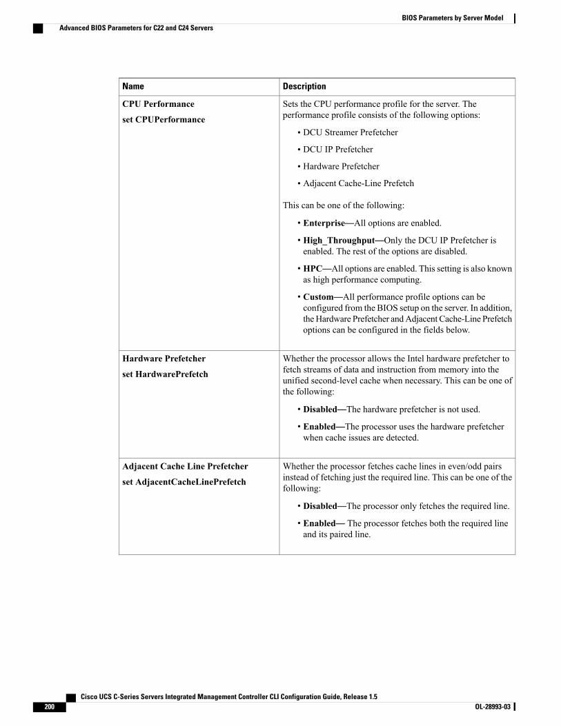
DescriptionName
Sets the CPU performance profile for the server. Theperformance profile consists of the following options:
• DCU Streamer Prefetcher
• DCU IP Prefetcher
• Hardware Prefetcher
• Adjacent Cache-Line Prefetch
This can be one of the following:
• Enterprise—All options are enabled.
• High_Throughput—Only the DCU IP Prefetcher isenabled. The rest of the options are disabled.
• HPC—All options are enabled. This setting is also knownas high performance computing.
• Custom—All performance profile options can beconfigured from the BIOS setup on the server. In addition,theHardware Prefetcher andAdjacent Cache-Line Prefetchoptions can be configured in the fields below.
CPU Performance
set CPUPerformance
Whether the processor allows the Intel hardware prefetcher tofetch streams of data and instruction from memory into theunified second-level cache when necessary. This can be one ofthe following:
• Disabled—The hardware prefetcher is not used.
• Enabled—The processor uses the hardware prefetcherwhen cache issues are detected.
Hardware Prefetcher
set HardwarePrefetch
Whether the processor fetches cache lines in even/odd pairsinstead of fetching just the required line. This can be one of thefollowing:
• Disabled—The processor only fetches the required line.
• Enabled— The processor fetches both the required lineand its paired line.
Adjacent Cache Line Prefetcher
set AdjacentCacheLinePrefetch
Cisco UCS C-Series Servers Integrated Management Controller CLI Configuration Guide, Release 1.5200 OL-28993-03
BIOS Parameters by Server ModelAdvanced BIOS Parameters for C22 and C24 Servers

DescriptionName
Whether the processor uses the DCU IP Prefetch mechanism toanalyze historical cache access patterns and preload the mostrelevant lines in the L1 cache. This can be one of the following:
• Disabled—The processor does not try to anticipate cacheread requirements and only fetches explicitly requestedlines.
• Enabled—The DCU prefetcher analyzes the cache readpattern and prefetches the next line in the cache if itdetermines that it may be needed.
DCU Streamer Prefetch
set DcuStreamerPrefetch
Whether the processor uses the DCU IP Prefetch mechanism toanalyze historical cache access patterns and preload the mostrelevant lines in the L1 cache. This can be one of the following:
• Disabled—The processor does not preload any cache data.
• Enabled—The DCU IP prefetcher preloads the L1 cachewith the data it determines to be the most relevant.
DCU IP Prefetcher
set DcuIpPrefetch
Allows processors to increase I/O performance by placing datafrom I/O devices directly into the processor cache. This settinghelps to reduce cache misses. This can be one of the following:
• Disabled—Data from I/O devices is not placed directlyinto the processor cache.
• Enabled—Data from I/O devices is placed directly intothe processor cache.
Direct Cache Access Support
set DirectCacheAccess
Cisco UCS C-Series Servers Integrated Management Controller CLI Configuration Guide, Release 1.5 OL-28993-03 201
BIOS Parameters by Server ModelAdvanced BIOS Parameters for C22 and C24 Servers

DescriptionName
Enables you to configure the CPU power management settingsfor the following options:
• Enhanced Intel Speedstep Technology
• Intel Turbo Boost Technology
• Processor Power State C6
Power Technology can be one of the following:
• Custom—The server uses the individual settings for theBIOS parameters mentioned above. You must select thisoption if you want to change any of these BIOSparameters.
• Disabled—The server does not perform any CPU powermanagement and any settings for the BIOS parametersmentioned above are ignored.
• Energy_Efficient—The server determines the best settingsfor the BIOS parameters mentioned above and ignores theindividual settings for these parameters.
Power Technology
set CPUPowerManagement
Whether the processor uses Enhanced Intel SpeedStepTechnology, which allows the system to dynamically adjustprocessor voltage and core frequency. This technology can resultin decreased average power consumption and decreased averageheat production. This can be one of the following:
• Disabled—The processor never dynamically adjusts itsvoltage or frequency.
• Enabled—The processor utilizes Enhanced IntelSpeedStep Technology and enables all supported processorsleep states to further conserve power.
We recommend that you contact your operating system vendorto make sure the operating system supports this feature.
CPUPowerManagement must be set to Custom orthe server ignores the setting for this parameter.
Note
Enhanced Intel Speedstep Technology
set EnhancedIntelSpeedStep
Cisco UCS C-Series Servers Integrated Management Controller CLI Configuration Guide, Release 1.5202 OL-28993-03
BIOS Parameters by Server ModelAdvanced BIOS Parameters for C22 and C24 Servers
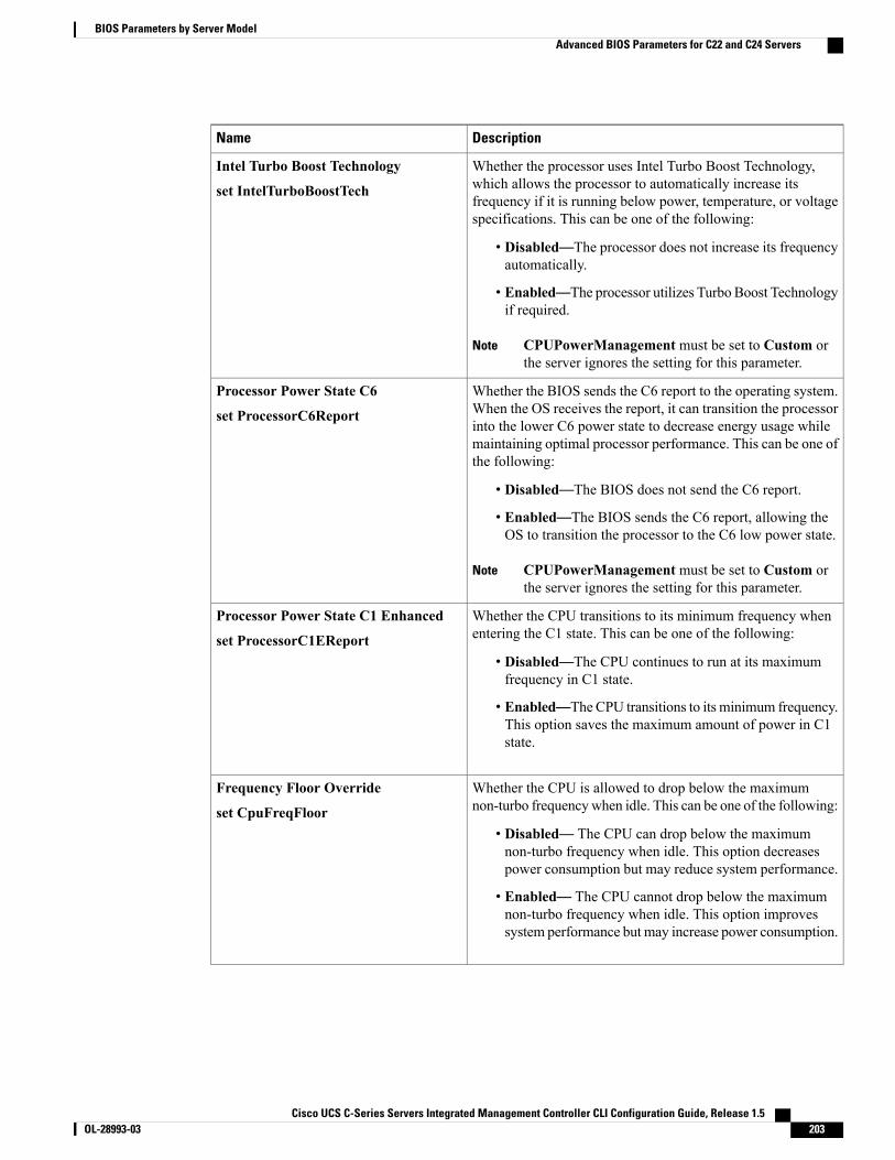
DescriptionName
Whether the processor uses Intel Turbo Boost Technology,which allows the processor to automatically increase itsfrequency if it is running below power, temperature, or voltagespecifications. This can be one of the following:
• Disabled—The processor does not increase its frequencyautomatically.
• Enabled—The processor utilizes Turbo Boost Technologyif required.
CPUPowerManagement must be set to Custom orthe server ignores the setting for this parameter.
Note
Intel Turbo Boost Technology
set IntelTurboBoostTech
Whether the BIOS sends the C6 report to the operating system.When the OS receives the report, it can transition the processorinto the lower C6 power state to decrease energy usage whilemaintaining optimal processor performance. This can be one ofthe following:
• Disabled—The BIOS does not send the C6 report.
• Enabled—The BIOS sends the C6 report, allowing theOS to transition the processor to the C6 low power state.
CPUPowerManagement must be set to Custom orthe server ignores the setting for this parameter.
Note
Processor Power State C6
set ProcessorC6Report
Whether the CPU transitions to its minimum frequency whenentering the C1 state. This can be one of the following:
• Disabled—The CPU continues to run at its maximumfrequency in C1 state.
• Enabled—The CPU transitions to its minimum frequency.This option saves the maximum amount of power in C1state.
Processor Power State C1 Enhanced
set ProcessorC1EReport
Whether the CPU is allowed to drop below the maximumnon-turbo frequencywhen idle. This can be one of the following:
• Disabled— The CPU can drop below the maximumnon-turbo frequency when idle. This option decreasespower consumption but may reduce system performance.
• Enabled— The CPU cannot drop below the maximumnon-turbo frequency when idle. This option improvessystem performance but may increase power consumption.
Frequency Floor Override
set CpuFreqFloor
Cisco UCS C-Series Servers Integrated Management Controller CLI Configuration Guide, Release 1.5 OL-28993-03 203
BIOS Parameters by Server ModelAdvanced BIOS Parameters for C22 and C24 Servers
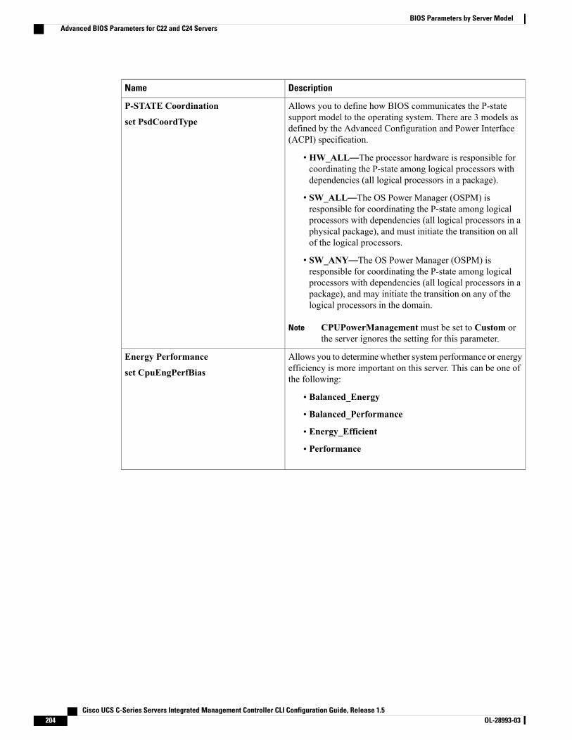
DescriptionName
Allows you to define how BIOS communicates the P-statesupport model to the operating system. There are 3 models asdefined by the Advanced Configuration and Power Interface(ACPI) specification.
• HW_ALL—The processor hardware is responsible forcoordinating the P-state among logical processors withdependencies (all logical processors in a package).
• SW_ALL—The OS Power Manager (OSPM) isresponsible for coordinating the P-state among logicalprocessors with dependencies (all logical processors in aphysical package), and must initiate the transition on allof the logical processors.
• SW_ANY—The OS Power Manager (OSPM) isresponsible for coordinating the P-state among logicalprocessors with dependencies (all logical processors in apackage), and may initiate the transition on any of thelogical processors in the domain.
CPUPowerManagement must be set to Custom orthe server ignores the setting for this parameter.
Note
P-STATE Coordination
set PsdCoordType
Allows you to determine whether system performance or energyefficiency is more important on this server. This can be one ofthe following:
• Balanced_Energy
• Balanced_Performance
• Energy_Efficient
• Performance
Energy Performance
set CpuEngPerfBias
Cisco UCS C-Series Servers Integrated Management Controller CLI Configuration Guide, Release 1.5204 OL-28993-03
BIOS Parameters by Server ModelAdvanced BIOS Parameters for C22 and C24 Servers
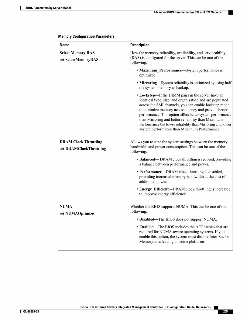
Memory Configuration Parameters
DescriptionName
How the memory reliability, availability, and serviceability(RAS) is configured for the server. This can be one of thefollowing:
•Maximum_Performance—System performance isoptimized.
•Mirroring—System reliability is optimized by using halfthe system memory as backup.
• Lockstep—If the DIMM pairs in the server have anidentical type, size, and organization and are populatedacross the SMI channels, you can enable lockstep modeto minimize memory access latency and provide betterperformance. This option offers better system performancethan Mirroring and better reliability than MaximumPerformance but lower reliability thanMirroring and lowersystem performance than Maximum Performance.
Select Memory RAS
set SelectMemoryRAS
Allows you to tune the system settings between the memorybandwidth and power consumption. This can be one of thefollowing:
• Balanced—DRAM clock throttling is reduced, providinga balance between performance and power.
• Performance—DRAM clock throttling is disabled,providing increased memory bandwidth at the cost ofadditional power.
• Energy_Efficient—DRAM clock throttling is increasedto improve energy efficiency.
DRAM Clock Throttling
set DRAMClockThrottling
Whether the BIOS supports NUMA. This can be one of thefollowing:
• Disabled—The BIOS does not support NUMA.
• Enabled—The BIOS includes the ACPI tables that arerequired for NUMA-aware operating systems. If youenable this option, the system must disable Inter-SocketMemory interleaving on some platforms.
NUMA
set NUMAOptimize
Cisco UCS C-Series Servers Integrated Management Controller CLI Configuration Guide, Release 1.5 OL-28993-03 205
BIOS Parameters by Server ModelAdvanced BIOS Parameters for C22 and C24 Servers
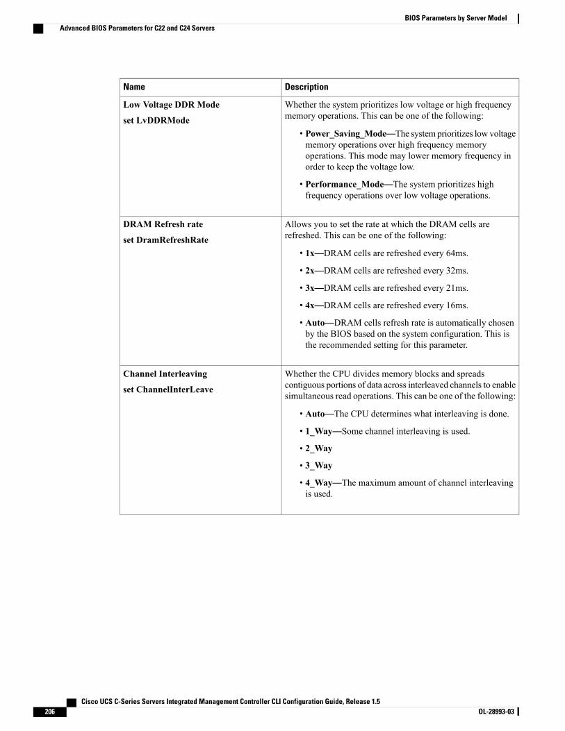
DescriptionName
Whether the system prioritizes low voltage or high frequencymemory operations. This can be one of the following:
• Power_Saving_Mode—The systemprioritizes lowvoltagememory operations over high frequency memoryoperations. This mode may lower memory frequency inorder to keep the voltage low.
• Performance_Mode—The system prioritizes highfrequency operations over low voltage operations.
Low Voltage DDR Mode
set LvDDRMode
Allows you to set the rate at which the DRAM cells arerefreshed. This can be one of the following:
• 1x—DRAM cells are refreshed every 64ms.
• 2x—DRAM cells are refreshed every 32ms.
• 3x—DRAM cells are refreshed every 21ms.
• 4x—DRAM cells are refreshed every 16ms.
• Auto—DRAM cells refresh rate is automatically chosenby the BIOS based on the system configuration. This isthe recommended setting for this parameter.
DRAM Refresh rate
set DramRefreshRate
Whether the CPU divides memory blocks and spreadscontiguous portions of data across interleaved channels to enablesimultaneous read operations. This can be one of the following:
• Auto—The CPU determines what interleaving is done.
• 1_Way—Some channel interleaving is used.
• 2_Way
• 3_Way
• 4_Way—The maximum amount of channel interleavingis used.
Channel Interleaving
set ChannelInterLeave
Cisco UCS C-Series Servers Integrated Management Controller CLI Configuration Guide, Release 1.5206 OL-28993-03
BIOS Parameters by Server ModelAdvanced BIOS Parameters for C22 and C24 Servers
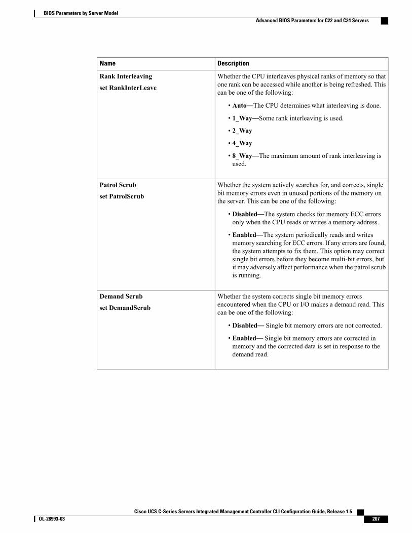
DescriptionName
Whether the CPU interleaves physical ranks of memory so thatone rank can be accessed while another is being refreshed. Thiscan be one of the following:
• Auto—The CPU determines what interleaving is done.
• 1_Way—Some rank interleaving is used.
• 2_Way
• 4_Way
• 8_Way—The maximum amount of rank interleaving isused.
Rank Interleaving
set RankInterLeave
Whether the system actively searches for, and corrects, singlebit memory errors even in unused portions of the memory onthe server. This can be one of the following:
• Disabled—The system checks for memory ECC errorsonly when the CPU reads or writes a memory address.
• Enabled—The system periodically reads and writesmemory searching for ECC errors. If any errors are found,the system attempts to fix them. This option may correctsingle bit errors before they become multi-bit errors, butit may adversely affect performance when the patrol scrubis running.
Patrol Scrub
set PatrolScrub
Whether the system corrects single bit memory errorsencountered when the CPU or I/O makes a demand read. Thiscan be one of the following:
• Disabled— Single bit memory errors are not corrected.
• Enabled— Single bit memory errors are corrected inmemory and the corrected data is set in response to thedemand read.
Demand Scrub
set DemandScrub
Cisco UCS C-Series Servers Integrated Management Controller CLI Configuration Guide, Release 1.5 OL-28993-03 207
BIOS Parameters by Server ModelAdvanced BIOS Parameters for C22 and C24 Servers
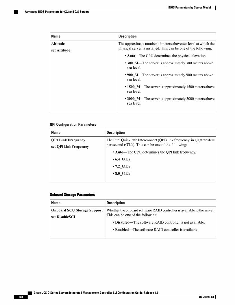
DescriptionName
The approximate number of meters above sea level at which thephysical server is installed. This can be one of the following:
• Auto—The CPU determines the physical elevation.
• 300_M—The server is approximately 300 meters abovesea level.
• 900_M—The server is approximately 900 meters abovesea level.
• 1500_M—The server is approximately 1500meters abovesea level.
• 3000_M—The server is approximately 3000meters abovesea level.
Altitude
set Altitude
QPI Configuration Parameters
DescriptionName
The Intel QuickPath Interconnect (QPI) link frequency, in gigatransfersper second (GT/s). This can be one of the following:
• Auto—The CPU determines the QPI link frequency.
• 6.4_GT/s
• 7.2_GT/s
• 8.0_GT/s
QPI Link Frequency
set QPILinkFrequency
Onboard Storage Parameters
DescriptionName
Whether the onboard software RAID controller is available to the server.This can be one of the following:
• Disabled—The software RAID controller is not available.
• Enabled—The software RAID controller is available.
Onboard SCU Storage Support
set DisableSCU
Cisco UCS C-Series Servers Integrated Management Controller CLI Configuration Guide, Release 1.5208 OL-28993-03
BIOS Parameters by Server ModelAdvanced BIOS Parameters for C22 and C24 Servers
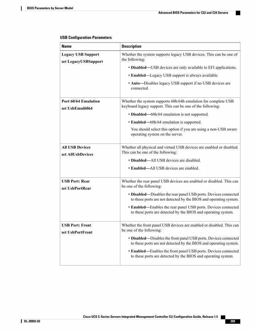
USB Configuration Parameters
DescriptionName
Whether the system supports legacy USB devices. This can be one ofthe following:
• Disabled—USB devices are only available to EFI applications.
• Enabled—Legacy USB support is always available.
• Auto—Disables legacy USB support if no USB devices areconnected.
Legacy USB Support
set LegacyUSBSupport
Whether the system supports 60h/64h emulation for complete USBkeyboard legacy support. This can be one of the following:
• Disabled—60h/64 emulation is not supported.
• Enabled—60h/64 emulation is supported.
You should select this option if you are using a non-USB awareoperating system on the server.
Port 60/64 Emulation
set UsbEmul6064
Whether all physical and virtual USB devices are enabled or disabled.This can be one of the following:
• Disabled—All USB devices are disabled.
• Enabled—All USB devices are enabled.
All USB Devices
set AllUsbDevices
Whether the rear panel USB devices are enabled or disabled. This canbe one of the following:
• Disabled—Disables the rear panel USB ports. Devices connectedto these ports are not detected by the BIOS and operating system.
• Enabled—Enables the rear panel USB ports. Devices connectedto these ports are detected by the BIOS and operating system.
USB Port: Rear
set UsbPortRear
Whether the front panel USB devices are enabled or disabled. This canbe one of the following:
• Disabled—Disables the front panel USB ports. Devices connectedto these ports are not detected by the BIOS and operating system.
• Enabled—Enables the front panel USB ports. Devices connectedto these ports are detected by the BIOS and operating system.
USB Port: Front
set UsbPortFront
Cisco UCS C-Series Servers Integrated Management Controller CLI Configuration Guide, Release 1.5 OL-28993-03 209
BIOS Parameters by Server ModelAdvanced BIOS Parameters for C22 and C24 Servers

DescriptionName
Whether the internal USB devices are enabled or disabled. This can beone of the following:
• Disabled—Disables the internal USB ports. Devices connectedto these ports are not detected by the BIOS and operating system.
• Enabled—Enables the internal USB ports. Devices connected tothese ports are detected by the BIOS and operating system.
USB Port: Internal
set UsbPortInt
Whether the KVM ports are enabled or disabled. This can be one of thefollowing:
• Disabled—Disables the KVM keyboard and/or mouse devices.Keyboard and/or mouse will not work in the KVM window.
• Enabled—Enables the KVM keyboard and/or mouse devices.
USB Port: KVM
set UsbPortKVM
Whether the virtual media devices are enabled or disabled. This can beone of the following:
• Disabled—Disables the vMedia devices.
• Enabled—Enables the vMedia devices.
USB Port: VMedia
set UsbPortVMedia
PCI Configuration Parameters
DescriptionName
Whether to enable or disable memorymapped I/O of 64-bit PCIdevices to 4GB or greater address space. Legacy option ROMsare not able to access addresses above 4GB. PCI devices thatare 64-bit compliant but use a legacy option ROM may notfunction correctly with this setting enabled. This can be one ofthe following:
• Disabled—The server does not map I/O of 64-bit PCIdevices to 4GB or greater address space.
• Enabled—The server maps I/O of 64-bit PCI devices to4GB or greater address space.
MMIO Above 4GB
set MemoryMappedIOAbove4GB
Allows you to set the level of ASPM (Active Power StateManagement) support in the BIOS. This can be one of thefollowing:
• Disabled—ASPM support is disabled in the BIOS.
• Force L0s—Force all links to L0 standby (L0s) state.
• Auto—The CPU determines the power state.
ASPM Support
set ASPMSupport
Cisco UCS C-Series Servers Integrated Management Controller CLI Configuration Guide, Release 1.5210 OL-28993-03
BIOS Parameters by Server ModelAdvanced BIOS Parameters for C22 and C24 Servers
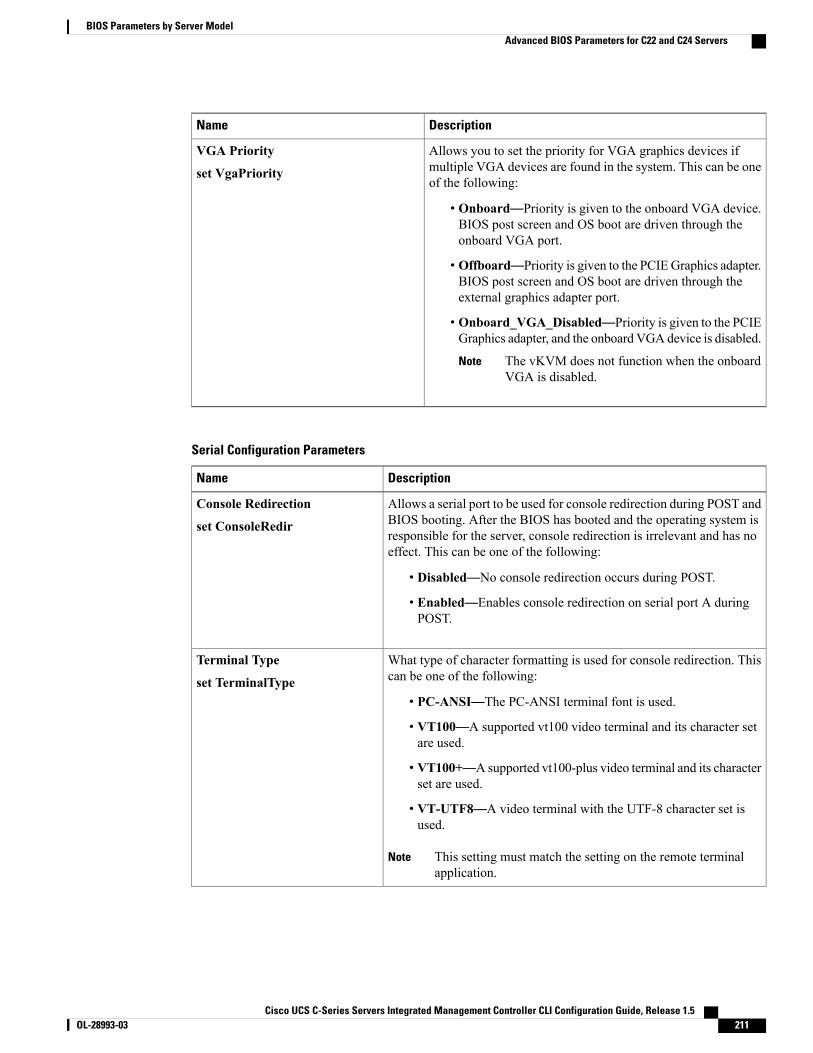
DescriptionName
Allows you to set the priority for VGA graphics devices ifmultiple VGA devices are found in the system. This can be oneof the following:
• Onboard—Priority is given to the onboard VGA device.BIOS post screen and OS boot are driven through theonboard VGA port.
• Offboard—Priority is given to the PCIEGraphics adapter.BIOS post screen and OS boot are driven through theexternal graphics adapter port.
• Onboard_VGA_Disabled—Priority is given to the PCIEGraphics adapter, and the onboard VGA device is disabled.
The vKVM does not function when the onboardVGA is disabled.
Note
VGA Priority
set VgaPriority
Serial Configuration Parameters
DescriptionName
Allows a serial port to be used for console redirection during POST andBIOS booting. After the BIOS has booted and the operating system isresponsible for the server, console redirection is irrelevant and has noeffect. This can be one of the following:
• Disabled—No console redirection occurs during POST.
• Enabled—Enables console redirection on serial port A duringPOST.
Console Redirection
set ConsoleRedir
What type of character formatting is used for console redirection. Thiscan be one of the following:
• PC-ANSI—The PC-ANSI terminal font is used.
• VT100—A supported vt100 video terminal and its character setare used.
• VT100+—A supported vt100-plus video terminal and its characterset are used.
• VT-UTF8—A video terminal with the UTF-8 character set isused.
This setting must match the setting on the remote terminalapplication.
Note
Terminal Type
set TerminalType
Cisco UCS C-Series Servers Integrated Management Controller CLI Configuration Guide, Release 1.5 OL-28993-03 211
BIOS Parameters by Server ModelAdvanced BIOS Parameters for C22 and C24 Servers

DescriptionName
What BAUD rate is used for the serial port transmission speed. If youdisable Console Redirection, this option is not available. This can beone of the following:
• 9600—A 9,600 BAUD rate is used.
• 19200—A 19,200 BAUD rate is used.
• 38400—A 38,400 BAUD rate is used.
• 57600—A 57,600 BAUD rate is used.
• 115200—A 115,200 BAUD rate is used.
This setting must match the setting on the remote terminalapplication.
Note
Bits per second
set BaudRate
Whether a handshake protocol is used for flow control. Request to Send/ Clear to Send (RTS/CTS) helps to reduce frame collisions that can beintroduced by a hidden terminal problem. This can be one of thefollowing:
• None—No flow control is used.
• Hardware_RTS/CTS—RTS/CTS is used for flow control.
This setting must match the setting on the remote terminalapplication.
Note
Flow Control
set FlowCtrl
Allows you to change the action of the PuTTY function keys and thetop row of the numeric keypad. This can be one of the following:
• VT100—The function keys generate ESC OP through ESC O[.
• LINUX—Mimics the Linux virtual console. Function keys F6 toF12 behave like the default mode, but F1 to F5 generate ESC [[Athrough ESC [[E.
• XTERMR6—Function keys F5 to F12 behave like the defaultmode. Function keys F1 to F4 generate ESC OP through ESCOS, which are the sequences produced by the top row of thekeypad on Digital terminals.
• SCO—The function keys F1 to F12 generate ESC [M throughESC [X. The function and shift keys generate ESC [Y throughESC [j. The control and function keys generate ESC [k throughESC [v. The shift, control and function keys generate ESC [wthrough ESC [{.
• ESCN—The default mode. The function keys match the generalbehavior of Digital terminals. The function keys generatesequences such as ESC [11~ and ESC [12~.
• VT400—The function keys behave like the default mode. The toprow of the numeric keypad generates ESC OP through ESC OS.
Putty KeyPad
set PuttyFunctionKeyPad
Cisco UCS C-Series Servers Integrated Management Controller CLI Configuration Guide, Release 1.5212 OL-28993-03
BIOS Parameters by Server ModelAdvanced BIOS Parameters for C22 and C24 Servers

DescriptionName
Whether BIOS console redirection should be active after BIOS POSTis complete and control given to the OS bootloader. This can be one ofthe following:
• Always_Enable—BIOS Legacy console redirection is activeduring the OS boot and run time.
• Bootloader—BIOS Legacy console redirection is disabled beforegiving control to the OS boot loader.
Redirection After BIOS POST
set RedirectionAfterPOST
Allows you to configure the COM port 0 that can be used for WindowsEmergency Management services. ACPI SPCR table is reported basedon this setup option. This can be one of the following:
• Disabled—Configures the COM port 0 as a general purpose portfor use with the Windows Operating System.
• Enabled—Configures the COM port 0 as a remote managementport for Windows Emergency Management services.
Out-of-Band Mgmt Port
set comSpcrEnable
LOM and PCIe Slots Configuration Parameters
DescriptionName
Whether all LOM ports are enabled or disabled. This can be one of thefollowing:
• Disabled—All LOM ports are disabled.
• Enabled—All LOM ports are enabled.
All Onboard LOM Ports
set AllLomPortControl
Whether Option ROM is available on the LOM port designated by n.This can be one of the following:
• Disabled—Option ROM is not available on LOM port n.
• Enabled—Option ROM is available on LOM port n.
• UEFI_Only—The expansion slot n is available for UEFI only.
• Legacy_Only—The expansion slot n is available for legacy only.
LOM Port n OptionROM
set LomOpromControlPortn
Cisco UCS C-Series Servers Integrated Management Controller CLI Configuration Guide, Release 1.5 OL-28993-03 213
BIOS Parameters by Server ModelAdvanced BIOS Parameters for C22 and C24 Servers

DescriptionName
Whether the server can use the PCIe Option ROM expansion slots. Thiscan be one of the following:
• Disabled—PCIe Option ROMs are not available.
• Enabled—PCIe Option ROMs are available.
• UEFI_Only—The expansion slot n is available for UEFI only.
• Legacy_Only—The expansion slot n is available for legacy only.
All PCIe Slots OptionROM
set PcieOptionROMs
Whether PCIe expansion slot n is available to the server. This can beone of the following:
• Disabled—The expansion slot n is not available.
• Enabled—The expansion slot n is available.
• UEFI_Only—The expansion slot n is available for UEFI only.
• Legacy_Only—The expansion slot n is available for legacy only.
PCIe Slot:n OptionROM
set Slot-n-ROM
This option allows you to restrict the maximum speed of an adaptercard installed in PCIe slot n. This can be one of the following:
• GEN1—2.5GT/s (gigatransfers per second) is themaximum speedallowed.
• GEN2—5GT/s is the maximum speed allowed.
• GEN3—8GT/s is the maximum speed allowed.
• Disabled—The maximum speed is not restricted.
For example, if you have a 3rd generation adapter card in PCIe slot 2that you want to run at a maximum of 5GT/s instead of the 8GT/s thatcard supports, set the PCIe Slot 2 Link Speed to GEN2. The systemthen ignores the card's supported maximum speed of 8GT/s and forcesit to run at a maximum of 5 GT/s.
PCIe Slot:n Link Speed
PCIe Slot:nLinkSpeed
Server Management BIOS Parameters for C22 and C24 ServersDescriptionName
Whether the FRB2 timer is used by CIMC to recover the systemif it hangs during POST. This can be one of the following:
• Disabled—The FRB2 timer is not used.
• Enabled—The FRB2 timer is started during POST andused to recover the system if necessary.
FRB-2 Timer
set FRB-2
Cisco UCS C-Series Servers Integrated Management Controller CLI Configuration Guide, Release 1.5214 OL-28993-03
BIOS Parameters by Server ModelServer Management BIOS Parameters for C22 and C24 Servers
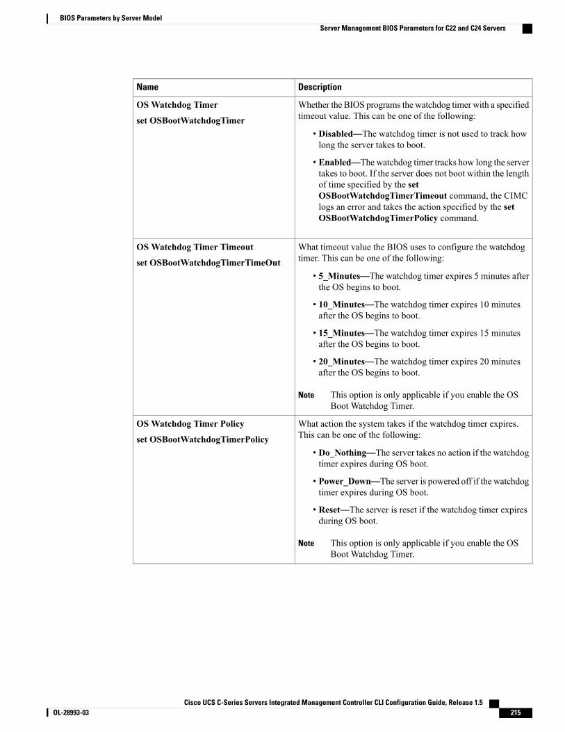
DescriptionName
Whether the BIOS programs the watchdog timer with a specifiedtimeout value. This can be one of the following:
• Disabled—The watchdog timer is not used to track howlong the server takes to boot.
• Enabled—The watchdog timer tracks how long the servertakes to boot. If the server does not boot within the lengthof time specified by the setOSBootWatchdogTimerTimeout command, the CIMClogs an error and takes the action specified by the setOSBootWatchdogTimerPolicy command.
OSWatchdog Timer
set OSBootWatchdogTimer
What timeout value the BIOS uses to configure the watchdogtimer. This can be one of the following:
• 5_Minutes—The watchdog timer expires 5 minutes afterthe OS begins to boot.
• 10_Minutes—The watchdog timer expires 10 minutesafter the OS begins to boot.
• 15_Minutes—The watchdog timer expires 15 minutesafter the OS begins to boot.
• 20_Minutes—The watchdog timer expires 20 minutesafter the OS begins to boot.
This option is only applicable if you enable the OSBoot Watchdog Timer.
Note
OSWatchdog Timer Timeout
set OSBootWatchdogTimerTimeOut
What action the system takes if the watchdog timer expires.This can be one of the following:
• Do_Nothing—The server takes no action if the watchdogtimer expires during OS boot.
• Power_Down—The server is powered off if the watchdogtimer expires during OS boot.
• Reset—The server is reset if the watchdog timer expiresduring OS boot.
This option is only applicable if you enable the OSBoot Watchdog Timer.
Note
OSWatchdog Timer Policy
set OSBootWatchdogTimerPolicy
Cisco UCS C-Series Servers Integrated Management Controller CLI Configuration Guide, Release 1.5 OL-28993-03 215
BIOS Parameters by Server ModelServer Management BIOS Parameters for C22 and C24 Servers

DescriptionName
How the server changes the boot order list defined through theCIMC GUI or CLI when there are no devices of a particulardevice type available or when the user defines a different bootorder using the server's BIOS Setup Utility.
The supported device types are:
• HDD—Hard disk drive
• FDD—Floppy disk drive
• CDROM—Bootable CD-ROM or DVD
• PXE—PXE boot
• EFI—Extensible Firmware Interface
The Boot Order Rules option can be one of the following:
• Strict—When no devices of a particular type are available,the system creates a placeholder for that device type in theboot order list. When a device of that type becomesavailable, it is added to the boot order in the previouslydefined position.
If the user defines a boot order through the server's BIOSSetup Utility, that boot order is given priority over theboot order configured through the CIMC GUI or CLI. Alldevice types defined through CIMC that are not presentin the boot order defined through the BIOS Setup Utilityare removed from the boot order list.
• Loose—When no devices of a particular type are available,the system removes that device type from the boot order.When a device of that type becomes available, the systemadds it to the end of the boot order list.
If the boot order is configured through the server's BIOSSetup Utility, that boot order is given priority over theboot order configured through the CIMC GUI or CLI. Alldevice types defined through CIMC that are not presentin the boot order defined through the BIOS Setup Utilityare moved to the end of the boot order list.
Boot Order Rules
set ManagedBootRule
Cisco UCS C-Series Servers Integrated Management Controller CLI Configuration Guide, Release 1.5216 OL-28993-03
BIOS Parameters by Server ModelServer Management BIOS Parameters for C22 and C24 Servers
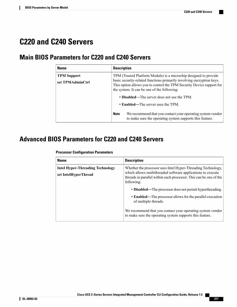
C220 and C240 Servers
Main BIOS Parameters for C220 and C240 ServersDescriptionName
TPM (Trusted Platform Module) is a microchip designed to providebasic security-related functions primarily involving encryption keys.This option allows you to control the TPM Security Device support forthe system. It can be one of the following:
• Disabled—The server does not use the TPM.
• Enabled—The server uses the TPM.
We recommend that you contact your operating system vendorto make sure the operating system supports this feature.
Note
TPM Support
set TPMAdminCtrl
Advanced BIOS Parameters for C220 and C240 Servers
Processor Configuration Parameters
DescriptionName
Whether the processor uses Intel Hyper-Threading Technology,which allows multithreaded software applications to executethreads in parallel within each processor. This can be one of thefollowing:
• Disabled—The processor does not permit hyperthreading.
• Enabled—The processor allows for the parallel executionof multiple threads.
We recommend that you contact your operating system vendorto make sure the operating system supports this feature.
Intel Hyper-Threading Technology
set IntelHyperThread
Cisco UCS C-Series Servers Integrated Management Controller CLI Configuration Guide, Release 1.5 OL-28993-03 217
BIOS Parameters by Server ModelC220 and C240 Servers
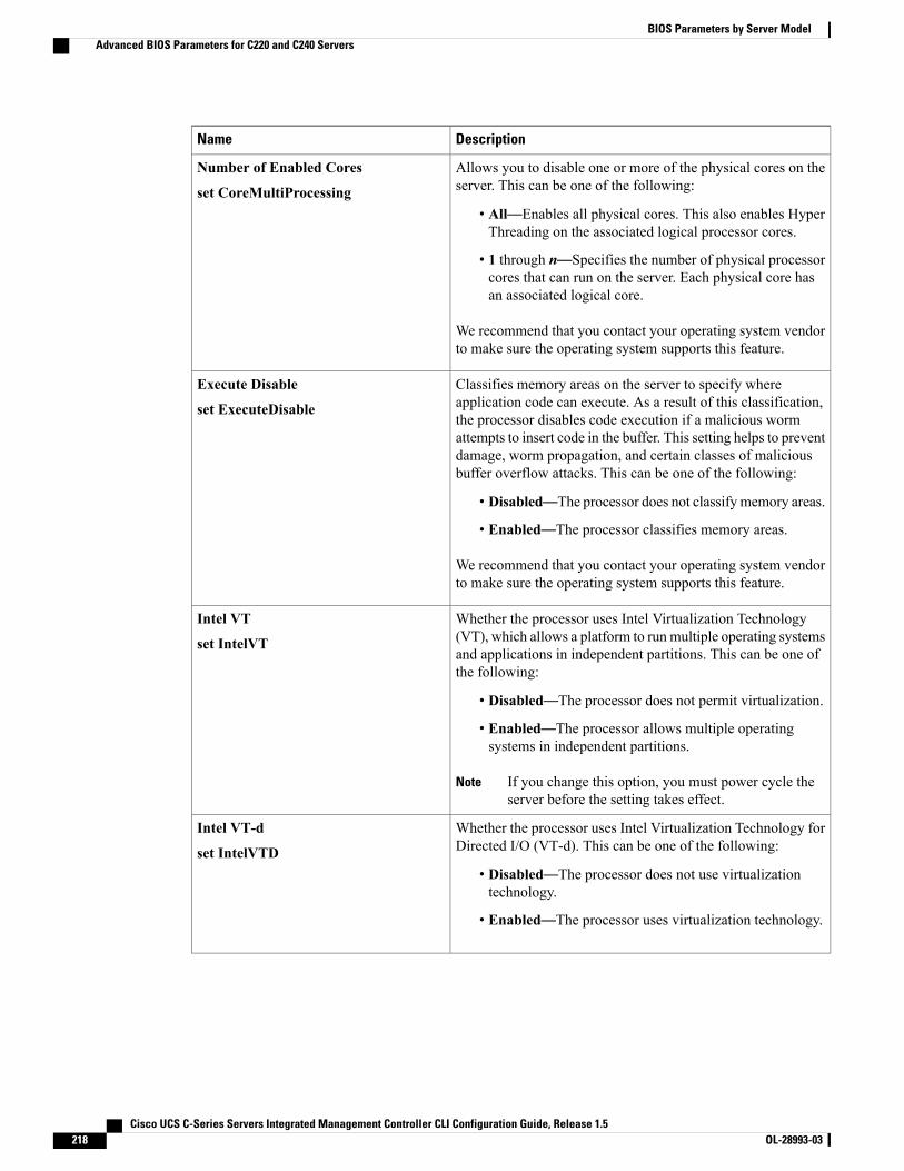
DescriptionName
Allows you to disable one or more of the physical cores on theserver. This can be one of the following:
• All—Enables all physical cores. This also enables HyperThreading on the associated logical processor cores.
• 1 through n—Specifies the number of physical processorcores that can run on the server. Each physical core hasan associated logical core.
We recommend that you contact your operating system vendorto make sure the operating system supports this feature.
Number of Enabled Cores
set CoreMultiProcessing
Classifies memory areas on the server to specify whereapplication code can execute. As a result of this classification,the processor disables code execution if a malicious wormattempts to insert code in the buffer. This setting helps to preventdamage, worm propagation, and certain classes of maliciousbuffer overflow attacks. This can be one of the following:
• Disabled—The processor does not classify memory areas.
• Enabled—The processor classifies memory areas.
We recommend that you contact your operating system vendorto make sure the operating system supports this feature.
Execute Disable
set ExecuteDisable
Whether the processor uses Intel Virtualization Technology(VT), which allows a platform to run multiple operating systemsand applications in independent partitions. This can be one ofthe following:
• Disabled—The processor does not permit virtualization.
• Enabled—The processor allows multiple operatingsystems in independent partitions.
If you change this option, you must power cycle theserver before the setting takes effect.
Note
Intel VT
set IntelVT
Whether the processor uses Intel Virtualization Technology forDirected I/O (VT-d). This can be one of the following:
• Disabled—The processor does not use virtualizationtechnology.
• Enabled—The processor uses virtualization technology.
Intel VT-d
set IntelVTD
Cisco UCS C-Series Servers Integrated Management Controller CLI Configuration Guide, Release 1.5218 OL-28993-03
BIOS Parameters by Server ModelAdvanced BIOS Parameters for C220 and C240 Servers
DescriptionName
Whether the processor supports Intel VT-d Coherency. This canbe one of the following:
• Disabled—The processor does not support coherency.
• Enabled—The processor uses VT-d Coherency asrequired.
Intel VT-d Coherency Support
set CoherencySupport
Whether the processor supports Intel VT-d Address TranslationServices (ATS). This can be one of the following:
• Disabled—The processor does not support ATS.
• Enabled—The processor uses VT-d ATS as required.
Intel VT-d ATS Support
set ATS
Sets the CPU performance profile for the server. Theperformance profile consists of the following options:
• DCU Streamer Prefetcher
• DCU IP Prefetcher
• Hardware Prefetcher
• Adjacent Cache-Line Prefetch
This can be one of the following:
• Enterprise—All options are enabled.
• High_Throughput—Only the DCU IP Prefetcher isenabled. The rest of the options are disabled.
• HPC—All options are enabled. This setting is also knownas high performance computing.
• Custom—All performance profile options can beconfigured from the BIOS setup on the server. In addition,theHardware Prefetcher andAdjacent Cache-Line Prefetchoptions can be configured in the fields below.
CPU Performance
set CPUPerformance
Whether the processor allows the Intel hardware prefetcher tofetch streams of data and instruction from memory into theunified second-level cache when necessary. This can be one ofthe following:
• Disabled—The hardware prefetcher is not used.
• Enabled—The processor uses the hardware prefetcherwhen cache issues are detected.
Hardware Prefetcher
set HardwarePrefetch
Cisco UCS C-Series Servers Integrated Management Controller CLI Configuration Guide, Release 1.5 OL-28993-03 219
BIOS Parameters by Server ModelAdvanced BIOS Parameters for C220 and C240 Servers
DescriptionName
Whether the processor fetches cache lines in even/odd pairsinstead of fetching just the required line. This can be one of thefollowing:
• Disabled—The processor only fetches the required line.
• Enabled— The processor fetches both the required lineand its paired line.
Adjacent Cache Line Prefetcher
set AdjacentCacheLinePrefetch
Whether the processor uses the DCU IP Prefetch mechanism toanalyze historical cache access patterns and preload the mostrelevant lines in the L1 cache. This can be one of the following:
• Disabled—The processor does not try to anticipate cacheread requirements and only fetches explicitly requestedlines.
• Enabled—The DCU prefetcher analyzes the cache readpattern and prefetches the next line in the cache if itdetermines that it may be needed.
DCU Streamer Prefetch
set DcuStreamerPrefetch
Whether the processor uses the DCU IP Prefetch mechanism toanalyze historical cache access patterns and preload the mostrelevant lines in the L1 cache. This can be one of the following:
• Disabled—The processor does not preload any cache data.
• Enabled—The DCU IP prefetcher preloads the L1 cachewith the data it determines to be the most relevant.
DCU IP Prefetcher
set DcuIpPrefetch
Allows processors to increase I/O performance by placing datafrom I/O devices directly into the processor cache. This settinghelps to reduce cache misses. This can be one of the following:
• Disabled—Data from I/O devices is not placed directlyinto the processor cache.
• Enabled—Data from I/O devices is placed directly intothe processor cache.
Direct Cache Access Support
set DirectCacheAccess
Cisco UCS C-Series Servers Integrated Management Controller CLI Configuration Guide, Release 1.5220 OL-28993-03
BIOS Parameters by Server ModelAdvanced BIOS Parameters for C220 and C240 Servers
DescriptionName
Enables you to configure the CPU power management settingsfor the following options:
• Enhanced Intel Speedstep Technology
• Intel Turbo Boost Technology
• Processor Power State C6
Power Technology can be one of the following:
• Custom—The server uses the individual settings for theBIOS parameters mentioned above. You must select thisoption if you want to change any of these BIOSparameters.
• Disabled—The server does not perform any CPU powermanagement and any settings for the BIOS parametersmentioned above are ignored.
• Energy_Efficient—The server determines the best settingsfor the BIOS parameters mentioned above and ignores theindividual settings for these parameters.
Power Technology
set CPUPowerManagement
Whether the processor uses Enhanced Intel SpeedStepTechnology, which allows the system to dynamically adjustprocessor voltage and core frequency. This technology can resultin decreased average power consumption and decreased averageheat production. This can be one of the following:
• Disabled—The processor never dynamically adjusts itsvoltage or frequency.
• Enabled—The processor utilizes Enhanced IntelSpeedStep Technology and enables all supported processorsleep states to further conserve power.
We recommend that you contact your operating system vendorto make sure the operating system supports this feature.
CPUPowerManagement must be set to Custom orthe server ignores the setting for this parameter.
Note
Enhanced Intel Speedstep Technology
set EnhancedIntelSpeedStep
Cisco UCS C-Series Servers Integrated Management Controller CLI Configuration Guide, Release 1.5 OL-28993-03 221
BIOS Parameters by Server ModelAdvanced BIOS Parameters for C220 and C240 Servers

DescriptionName
Whether the processor uses Intel Turbo Boost Technology,which allows the processor to automatically increase itsfrequency if it is running below power, temperature, or voltagespecifications. This can be one of the following:
• Disabled—The processor does not increase its frequencyautomatically.
• Enabled—The processor utilizes Turbo Boost Technologyif required.
CPUPowerManagement must be set to Custom orthe server ignores the setting for this parameter.
Note
Intel Turbo Boost Technology
set IntelTurboBoostTech
Whether the BIOS sends the C6 report to the operating system.When the OS receives the report, it can transition the processorinto the lower C6 power state to decrease energy usage whilemaintaining optimal processor performance. This can be one ofthe following:
• Disabled—The BIOS does not send the C6 report.
• Enabled—The BIOS sends the C6 report, allowing theOS to transition the processor to the C6 low power state.
CPUPowerManagement must be set to Custom orthe server ignores the setting for this parameter.
Note
Processor Power State C6
set ProcessorC6Report
Whether the CPU transitions to its minimum frequency whenentering the C1 state. This can be one of the following:
• Disabled—The CPU continues to run at its maximumfrequency in C1 state.
• Enabled—The CPU transitions to its minimum frequency.This option saves the maximum amount of power in C1state.
Processor Power State C1 Enhanced
set ProcessorC1EReport
Whether the CPU is allowed to drop below the maximumnon-turbo frequencywhen idle. This can be one of the following:
• Disabled— The CPU can drop below the maximumnon-turbo frequency when idle. This option decreasespower consumption but may reduce system performance.
• Enabled— The CPU cannot drop below the maximumnon-turbo frequency when idle. This option improvessystem performance but may increase power consumption.
Frequency Floor Override
set CpuFreqFloor
Cisco UCS C-Series Servers Integrated Management Controller CLI Configuration Guide, Release 1.5222 OL-28993-03
BIOS Parameters by Server ModelAdvanced BIOS Parameters for C220 and C240 Servers
DescriptionName
Allows you to define how BIOS communicates the P-statesupport model to the operating system. There are 3 models asdefined by the Advanced Configuration and Power Interface(ACPI) specification.
• HW_ALL—The processor hardware is responsible forcoordinating the P-state among logical processors withdependencies (all logical processors in a package).
• SW_ALL—The OS Power Manager (OSPM) isresponsible for coordinating the P-state among logicalprocessors with dependencies (all logical processors in aphysical package), and must initiate the transition on allof the logical processors.
• SW_ANY—The OS Power Manager (OSPM) isresponsible for coordinating the P-state among logicalprocessors with dependencies (all logical processors in apackage), and may initiate the transition on any of thelogical processors in the domain.
CPUPowerManagement must be set to Custom orthe server ignores the setting for this parameter.
Note
P-STATE Coordination
set PsdCoordType
Allows you to determine whether system performance or energyefficiency is more important on this server. This can be one ofthe following:
• Balanced_Energy
• Balanced_Performance
• Energy_Efficient
• Performance
Energy Performance
set CpuEngPerfBias
Cisco UCS C-Series Servers Integrated Management Controller CLI Configuration Guide, Release 1.5 OL-28993-03 223
BIOS Parameters by Server ModelAdvanced BIOS Parameters for C220 and C240 Servers
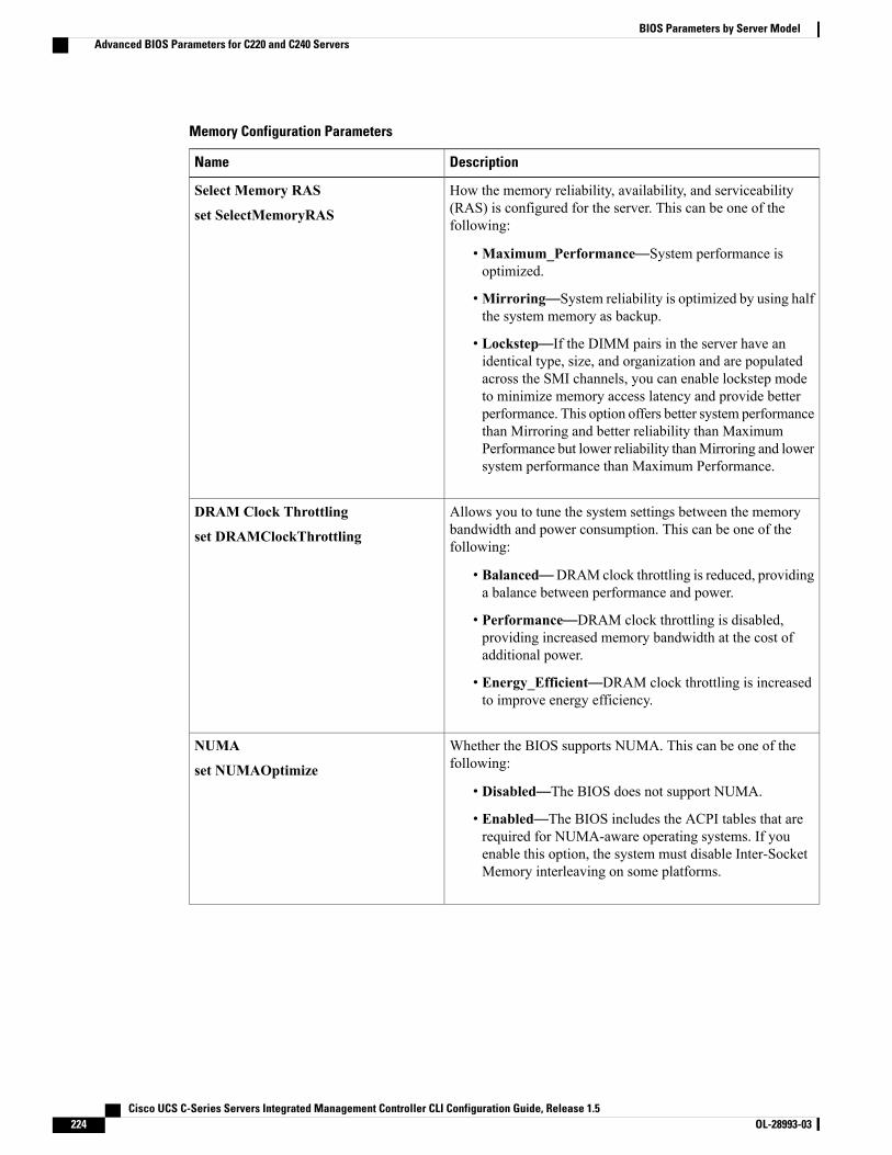
Memory Configuration Parameters
DescriptionName
How the memory reliability, availability, and serviceability(RAS) is configured for the server. This can be one of thefollowing:
•Maximum_Performance—System performance isoptimized.
•Mirroring—System reliability is optimized by using halfthe system memory as backup.
• Lockstep—If the DIMM pairs in the server have anidentical type, size, and organization and are populatedacross the SMI channels, you can enable lockstep modeto minimize memory access latency and provide betterperformance. This option offers better system performancethan Mirroring and better reliability than MaximumPerformance but lower reliability thanMirroring and lowersystem performance than Maximum Performance.
Select Memory RAS
set SelectMemoryRAS
Allows you to tune the system settings between the memorybandwidth and power consumption. This can be one of thefollowing:
• Balanced—DRAM clock throttling is reduced, providinga balance between performance and power.
• Performance—DRAM clock throttling is disabled,providing increased memory bandwidth at the cost ofadditional power.
• Energy_Efficient—DRAM clock throttling is increasedto improve energy efficiency.
DRAM Clock Throttling
set DRAMClockThrottling
Whether the BIOS supports NUMA. This can be one of thefollowing:
• Disabled—The BIOS does not support NUMA.
• Enabled—The BIOS includes the ACPI tables that arerequired for NUMA-aware operating systems. If youenable this option, the system must disable Inter-SocketMemory interleaving on some platforms.
NUMA
set NUMAOptimize
Cisco UCS C-Series Servers Integrated Management Controller CLI Configuration Guide, Release 1.5224 OL-28993-03
BIOS Parameters by Server ModelAdvanced BIOS Parameters for C220 and C240 Servers
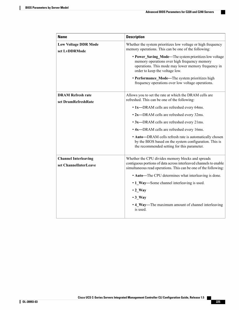
DescriptionName
Whether the system prioritizes low voltage or high frequencymemory operations. This can be one of the following:
• Power_Saving_Mode—The systemprioritizes lowvoltagememory operations over high frequency memoryoperations. This mode may lower memory frequency inorder to keep the voltage low.
• Performance_Mode—The system prioritizes highfrequency operations over low voltage operations.
Low Voltage DDR Mode
set LvDDRMode
Allows you to set the rate at which the DRAM cells arerefreshed. This can be one of the following:
• 1x—DRAM cells are refreshed every 64ms.
• 2x—DRAM cells are refreshed every 32ms.
• 3x—DRAM cells are refreshed every 21ms.
• 4x—DRAM cells are refreshed every 16ms.
• Auto—DRAM cells refresh rate is automatically chosenby the BIOS based on the system configuration. This isthe recommended setting for this parameter.
DRAM Refresh rate
set DramRefreshRate
Whether the CPU divides memory blocks and spreadscontiguous portions of data across interleaved channels to enablesimultaneous read operations. This can be one of the following:
• Auto—The CPU determines what interleaving is done.
• 1_Way—Some channel interleaving is used.
• 2_Way
• 3_Way
• 4_Way—The maximum amount of channel interleavingis used.
Channel Interleaving
set ChannelInterLeave
Cisco UCS C-Series Servers Integrated Management Controller CLI Configuration Guide, Release 1.5 OL-28993-03 225
BIOS Parameters by Server ModelAdvanced BIOS Parameters for C220 and C240 Servers
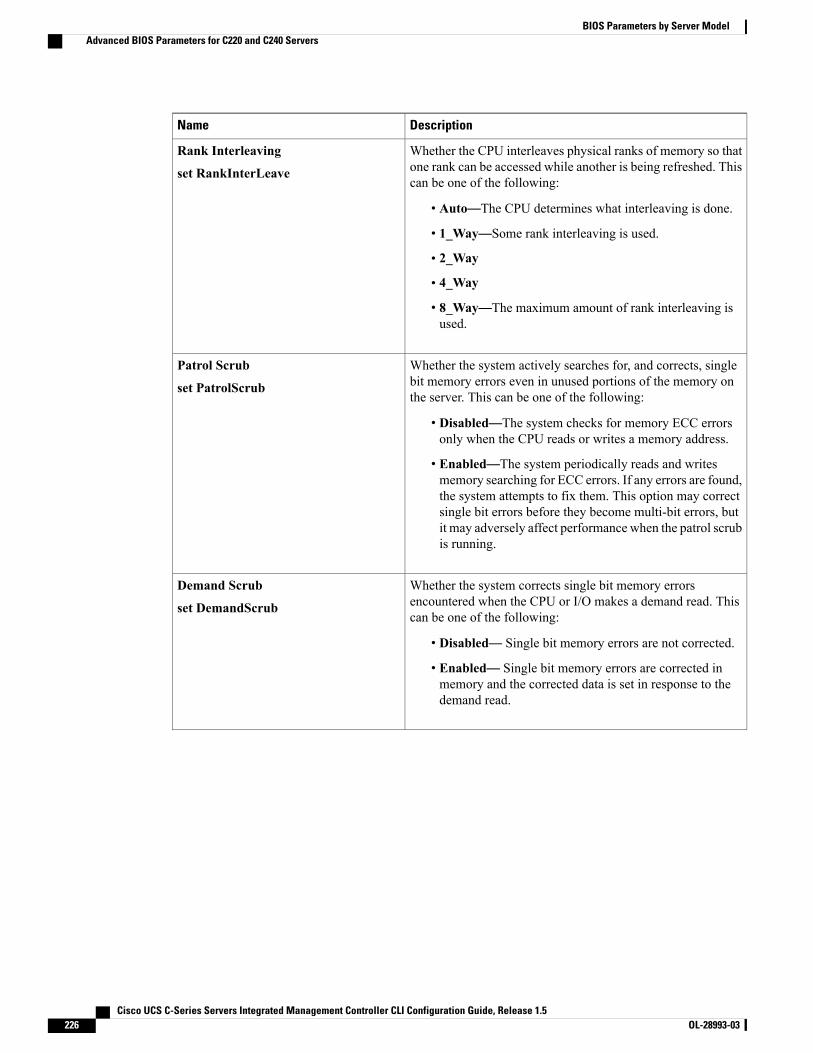
DescriptionName
Whether the CPU interleaves physical ranks of memory so thatone rank can be accessed while another is being refreshed. Thiscan be one of the following:
• Auto—The CPU determines what interleaving is done.
• 1_Way—Some rank interleaving is used.
• 2_Way
• 4_Way
• 8_Way—The maximum amount of rank interleaving isused.
Rank Interleaving
set RankInterLeave
Whether the system actively searches for, and corrects, singlebit memory errors even in unused portions of the memory onthe server. This can be one of the following:
• Disabled—The system checks for memory ECC errorsonly when the CPU reads or writes a memory address.
• Enabled—The system periodically reads and writesmemory searching for ECC errors. If any errors are found,the system attempts to fix them. This option may correctsingle bit errors before they become multi-bit errors, butit may adversely affect performance when the patrol scrubis running.
Patrol Scrub
set PatrolScrub
Whether the system corrects single bit memory errorsencountered when the CPU or I/O makes a demand read. Thiscan be one of the following:
• Disabled— Single bit memory errors are not corrected.
• Enabled— Single bit memory errors are corrected inmemory and the corrected data is set in response to thedemand read.
Demand Scrub
set DemandScrub
Cisco UCS C-Series Servers Integrated Management Controller CLI Configuration Guide, Release 1.5226 OL-28993-03
BIOS Parameters by Server ModelAdvanced BIOS Parameters for C220 and C240 Servers
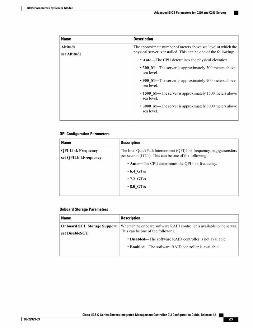
DescriptionName
The approximate number of meters above sea level at which thephysical server is installed. This can be one of the following:
• Auto—The CPU determines the physical elevation.
• 300_M—The server is approximately 300 meters abovesea level.
• 900_M—The server is approximately 900 meters abovesea level.
• 1500_M—The server is approximately 1500meters abovesea level.
• 3000_M—The server is approximately 3000meters abovesea level.
Altitude
set Altitude
QPI Configuration Parameters
DescriptionName
The Intel QuickPath Interconnect (QPI) link frequency, in gigatransfersper second (GT/s). This can be one of the following:
• Auto—The CPU determines the QPI link frequency.
• 6.4_GT/s
• 7.2_GT/s
• 8.0_GT/s
QPI Link Frequency
set QPILinkFrequency
Onboard Storage Parameters
DescriptionName
Whether the onboard software RAID controller is available to the server.This can be one of the following:
• Disabled—The software RAID controller is not available.
• Enabled—The software RAID controller is available.
Onboard SCU Storage Support
set DisableSCU
Cisco UCS C-Series Servers Integrated Management Controller CLI Configuration Guide, Release 1.5 OL-28993-03 227
BIOS Parameters by Server ModelAdvanced BIOS Parameters for C220 and C240 Servers

DescriptionName
Allows you to choose a pre-boot software stack for an onboard SCUstorage controller. This can be one of the following:
• Intel RSTe(1)
• LSI SW RAID (0)
This configuration parameter is valid only for the C220servers.
Note
Onboard SCUStorage SWStack
set PchScuOromSelect
USB Configuration Parameters
DescriptionName
Whether the system supports legacy USB devices. This can be one ofthe following:
• Disabled—USB devices are only available to EFI applications.
• Enabled—Legacy USB support is always available.
• Auto—Disables legacy USB support if no USB devices areconnected.
Legacy USB Support
set LegacyUSBSupport
Whether the system supports 60h/64h emulation for complete USBkeyboard legacy support. This can be one of the following:
• Disabled—60h/64 emulation is not supported.
• Enabled—60h/64 emulation is supported.
You should select this option if you are using a non-USB awareoperating system on the server.
Port 60/64 Emulation
set UsbEmul6064
Whether all physical and virtual USB devices are enabled or disabled.This can be one of the following:
• Disabled—All USB devices are disabled.
• Enabled—All USB devices are enabled.
All USB Devices
set AllUsbDevices
Whether the rear panel USB devices are enabled or disabled. This canbe one of the following:
• Disabled—Disables the rear panel USB ports. Devices connectedto these ports are not detected by the BIOS and operating system.
• Enabled—Enables the rear panel USB ports. Devices connectedto these ports are detected by the BIOS and operating system.
USB Port: Rear
set UsbPortRear
Cisco UCS C-Series Servers Integrated Management Controller CLI Configuration Guide, Release 1.5228 OL-28993-03
BIOS Parameters by Server ModelAdvanced BIOS Parameters for C220 and C240 Servers

DescriptionName
Whether the front panel USB devices are enabled or disabled. This canbe one of the following:
• Disabled—Disables the front panel USB ports. Devices connectedto these ports are not detected by the BIOS and operating system.
• Enabled—Enables the front panel USB ports. Devices connectedto these ports are detected by the BIOS and operating system.
USB Port: Front
set UsbPortFront
Whether the internal USB devices are enabled or disabled. This can beone of the following:
• Disabled—Disables the internal USB ports. Devices connectedto these ports are not detected by the BIOS and operating system.
• Enabled—Enables the internal USB ports. Devices connected tothese ports are detected by the BIOS and operating system.
USB Port: Internal
set UsbPortInt
Whether the KVM ports are enabled or disabled. This can be one of thefollowing:
• Disabled—Disables the KVM keyboard and/or mouse devices.Keyboard and/or mouse will not work in the KVM window.
• Enabled—Enables the KVM keyboard and/or mouse devices.
USB Port: KVM
set UsbPortKVM
Whether the virtual media devices are enabled or disabled. This can beone of the following:
• Disabled—Disables the vMedia devices.
• Enabled—Enables the vMedia devices.
USB Port: VMedia
set UsbPortVMedia
Whether the SD card drives are enabled or disabled. This can be one ofthe following:
• Disabled—Disables the SD card drives. The SD card drives arenot detected by the BIOS and operating system.
• Enabled—Enables the SD card drives.
USB Port: SD Card
set UsbPortSdCard
Cisco UCS C-Series Servers Integrated Management Controller CLI Configuration Guide, Release 1.5 OL-28993-03 229
BIOS Parameters by Server ModelAdvanced BIOS Parameters for C220 and C240 Servers
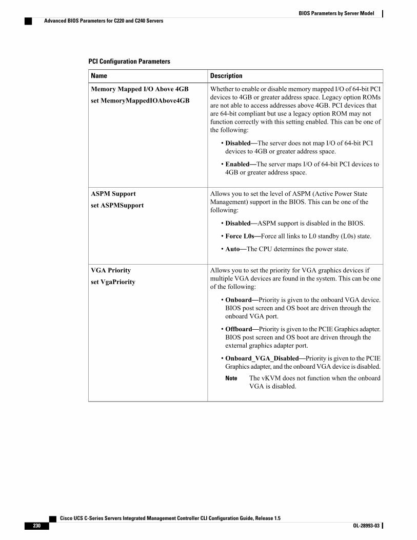
PCI Configuration Parameters
DescriptionName
Whether to enable or disable memorymapped I/O of 64-bit PCIdevices to 4GB or greater address space. Legacy option ROMsare not able to access addresses above 4GB. PCI devices thatare 64-bit compliant but use a legacy option ROM may notfunction correctly with this setting enabled. This can be one ofthe following:
• Disabled—The server does not map I/O of 64-bit PCIdevices to 4GB or greater address space.
• Enabled—The server maps I/O of 64-bit PCI devices to4GB or greater address space.
Memory Mapped I/O Above 4GB
set MemoryMappedIOAbove4GB
Allows you to set the level of ASPM (Active Power StateManagement) support in the BIOS. This can be one of thefollowing:
• Disabled—ASPM support is disabled in the BIOS.
• Force L0s—Force all links to L0 standby (L0s) state.
• Auto—The CPU determines the power state.
ASPM Support
set ASPMSupport
Allows you to set the priority for VGA graphics devices ifmultiple VGA devices are found in the system. This can be oneof the following:
• Onboard—Priority is given to the onboard VGA device.BIOS post screen and OS boot are driven through theonboard VGA port.
• Offboard—Priority is given to the PCIEGraphics adapter.BIOS post screen and OS boot are driven through theexternal graphics adapter port.
• Onboard_VGA_Disabled—Priority is given to the PCIEGraphics adapter, and the onboard VGA device is disabled.
The vKVM does not function when the onboardVGA is disabled.
Note
VGA Priority
set VgaPriority
Cisco UCS C-Series Servers Integrated Management Controller CLI Configuration Guide, Release 1.5230 OL-28993-03
BIOS Parameters by Server ModelAdvanced BIOS Parameters for C220 and C240 Servers
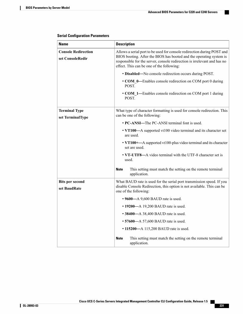
Serial Configuration Parameters
DescriptionName
Allows a serial port to be used for console redirection during POST andBIOS booting. After the BIOS has booted and the operating system isresponsible for the server, console redirection is irrelevant and has noeffect. This can be one of the following:
• Disabled—No console redirection occurs during POST.
• COM_0—Enables console redirection on COM port 0 duringPOST.
• COM_1—Enables console redirection on COM port 1 duringPOST.
Console Redirection
set ConsoleRedir
What type of character formatting is used for console redirection. Thiscan be one of the following:
• PC-ANSI—The PC-ANSI terminal font is used.
• VT100—A supported vt100 video terminal and its character setare used.
• VT100+—A supported vt100-plus video terminal and its characterset are used.
• VT-UTF8—A video terminal with the UTF-8 character set isused.
This setting must match the setting on the remote terminalapplication.
Note
Terminal Type
set TerminalType
What BAUD rate is used for the serial port transmission speed. If youdisable Console Redirection, this option is not available. This can beone of the following:
• 9600—A 9,600 BAUD rate is used.
• 19200—A 19,200 BAUD rate is used.
• 38400—A 38,400 BAUD rate is used.
• 57600—A 57,600 BAUD rate is used.
• 115200—A 115,200 BAUD rate is used.
This setting must match the setting on the remote terminalapplication.
Note
Bits per second
set BaudRate
Cisco UCS C-Series Servers Integrated Management Controller CLI Configuration Guide, Release 1.5 OL-28993-03 231
BIOS Parameters by Server ModelAdvanced BIOS Parameters for C220 and C240 Servers
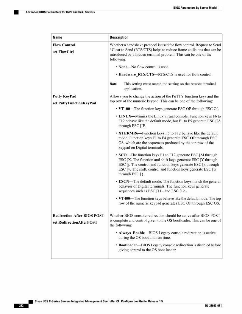
DescriptionName
Whether a handshake protocol is used for flow control. Request to Send/ Clear to Send (RTS/CTS) helps to reduce frame collisions that can beintroduced by a hidden terminal problem. This can be one of thefollowing:
• None—No flow control is used.
• Hardware_RTS/CTS—RTS/CTS is used for flow control.
This setting must match the setting on the remote terminalapplication.
Note
Flow Control
set FlowCtrl
Allows you to change the action of the PuTTY function keys and thetop row of the numeric keypad. This can be one of the following:
• VT100—The function keys generate ESC OP through ESC O[.
• LINUX—Mimics the Linux virtual console. Function keys F6 toF12 behave like the default mode, but F1 to F5 generate ESC [[Athrough ESC [[E.
• XTERMR6—Function keys F5 to F12 behave like the defaultmode. Function keys F1 to F4 generate ESC OP through ESCOS, which are the sequences produced by the top row of thekeypad on Digital terminals.
• SCO—The function keys F1 to F12 generate ESC [M throughESC [X. The function and shift keys generate ESC [Y throughESC [j. The control and function keys generate ESC [k throughESC [v. The shift, control and function keys generate ESC [wthrough ESC [{.
• ESCN—The default mode. The function keys match the generalbehavior of Digital terminals. The function keys generatesequences such as ESC [11~ and ESC [12~.
• VT400—The function keys behave like the default mode. The toprow of the numeric keypad generates ESC OP through ESC OS.
Putty KeyPad
set PuttyFunctionKeyPad
Whether BIOS console redirection should be active after BIOS POSTis complete and control given to the OS bootloader. This can be one ofthe following:
• Always_Enable—BIOS Legacy console redirection is activeduring the OS boot and run time.
• Bootloader—BIOS Legacy console redirection is disabled beforegiving control to the OS boot loader.
Redirection After BIOS POST
set RedirectionAfterPOST
Cisco UCS C-Series Servers Integrated Management Controller CLI Configuration Guide, Release 1.5232 OL-28993-03
BIOS Parameters by Server ModelAdvanced BIOS Parameters for C220 and C240 Servers
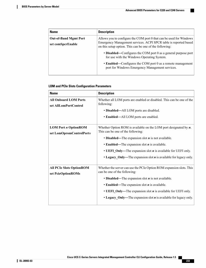
DescriptionName
Allows you to configure the COM port 0 that can be used for WindowsEmergency Management services. ACPI SPCR table is reported basedon this setup option. This can be one of the following:
• Disabled—Configures the COM port 0 as a general purpose portfor use with the Windows Operating System.
• Enabled—Configures the COM port 0 as a remote managementport for Windows Emergency Management services.
Out-of-Band Mgmt Port
set comSpcrEnable
LOM and PCIe Slots Configuration Parameters
DescriptionName
Whether all LOM ports are enabled or disabled. This can be one of thefollowing:
• Disabled—All LOM ports are disabled.
• Enabled—All LOM ports are enabled.
All Onboard LOM Ports
set AllLomPortControl
Whether Option ROM is available on the LOM port designated by n.This can be one of the following:
• Disabled—The expansion slot n is not available.
• Enabled—The expansion slot n is available.
• UEFI_Only—The expansion slot n is available for UEFI only.
• Legacy_Only—The expansion slot n is available for legacy only.
LOM Port n OptionROM
set LomOpromControlPortn
Whether the server can use the PCIe Option ROM expansion slots. Thiscan be one of the following:
• Disabled—The expansion slot n is not available.
• Enabled—The expansion slot n is available.
• UEFI_Only—The expansion slot n is available for UEFI only.
• Legacy_Only—The expansion slot n is available for legacy only.
All PCIe Slots OptionROM
set PcieOptionROMs
Cisco UCS C-Series Servers Integrated Management Controller CLI Configuration Guide, Release 1.5 OL-28993-03 233
BIOS Parameters by Server ModelAdvanced BIOS Parameters for C220 and C240 Servers

DescriptionName
Whether PCIe expansion slot n is available to the server. This can beone of the following:
• Disabled—The expansion slot n is not available.
• Enabled—The expansion slot n is available.
• UEFI_Only—The expansion slot n is available for UEFI only.
• Legacy_Only—The expansion slot n is available for legacy only.
PCIe Slot:n OptionROM
set PcieSlotnOptionROM
Whether the PCIe mezzanine slot expansion ROM is available to theserver. This can be one of the following:
• Disabled—The expansion slot n is not available.
• Enabled—The expansion slot n is available.
• UEFI_Only—The expansion slot n is available for UEFI only.
• Legacy_Only—The expansion slot n is available for legacy only.
PCIe Mezzanine OptionROM
set PcieMezzOptionROM
This option allows you to restrict the maximum speed of an adaptercard installed in PCIe slot n. This can be one of the following:
• GEN1—2.5GT/s (gigatransfers per second) is themaximum speedallowed.
• GEN2—5GT/s is the maximum speed allowed.
• GEN3—8GT/s is the maximum speed allowed.
• Disabled—The maximum speed is not restricted.
For example, if you have a 3rd generation adapter card in PCIe slot 2that you want to run at a maximum of 5GT/s instead of the 8GT/s thatcard supports, set the PCIe Slot 2 Link Speed to GEN2. The systemthen ignores the card's supported maximum speed of 8GT/s and forcesit to run at a maximum of 5 GT/s.
PCIe Slot:n Link Speed
PCIe Slot:nLinkSpeed
Server Management BIOS Parameters for C220 and C240 ServersDescriptionName
Whether the FRB2 timer is used by CIMC to recover the systemif it hangs during POST. This can be one of the following:
• Disabled—The FRB2 timer is not used.
• Enabled—The FRB2 timer is started during POST andused to recover the system if necessary.
FRB-2 Timer
set FRB-2
Cisco UCS C-Series Servers Integrated Management Controller CLI Configuration Guide, Release 1.5234 OL-28993-03
BIOS Parameters by Server ModelServer Management BIOS Parameters for C220 and C240 Servers

DescriptionName
Whether the BIOS programs the watchdog timer with a specifiedtimeout value. This can be one of the following:
• Disabled—The watchdog timer is not used to track howlong the server takes to boot.
• Enabled—The watchdog timer tracks how long the servertakes to boot. If the server does not boot within the lengthof time specified by the setOSBootWatchdogTimerTimeout command, the CIMClogs an error and takes the action specified by the setOSBootWatchdogTimerPolicy command.
OSWatchdog Timer
set OSBootWatchdogTimer
What timeout value the BIOS uses to configure the watchdogtimer. This can be one of the following:
• 5_Minutes—The watchdog timer expires 5 minutes afterthe OS begins to boot.
• 10_Minutes—The watchdog timer expires 10 minutesafter the OS begins to boot.
• 15_Minutes—The watchdog timer expires 15 minutesafter the OS begins to boot.
• 20_Minutes—The watchdog timer expires 20 minutesafter the OS begins to boot.
This option is only applicable if you enable the OSBoot Watchdog Timer.
Note
OSWatchdog Timer Timeout
set OSBootWatchdogTimerTimeOut
What action the system takes if the watchdog timer expires.This can be one of the following:
• Do_Nothing—The server takes no action if the watchdogtimer expires during OS boot.
• Power_Down—The server is powered off if the watchdogtimer expires during OS boot.
• Reset—The server is reset if the watchdog timer expiresduring OS boot.
This option is only applicable if you enable the OSBoot Watchdog Timer.
Note
OSWatchdog Timer Policy
set OSBootWatchdogTimerPolicy
Cisco UCS C-Series Servers Integrated Management Controller CLI Configuration Guide, Release 1.5 OL-28993-03 235
BIOS Parameters by Server ModelServer Management BIOS Parameters for C220 and C240 Servers
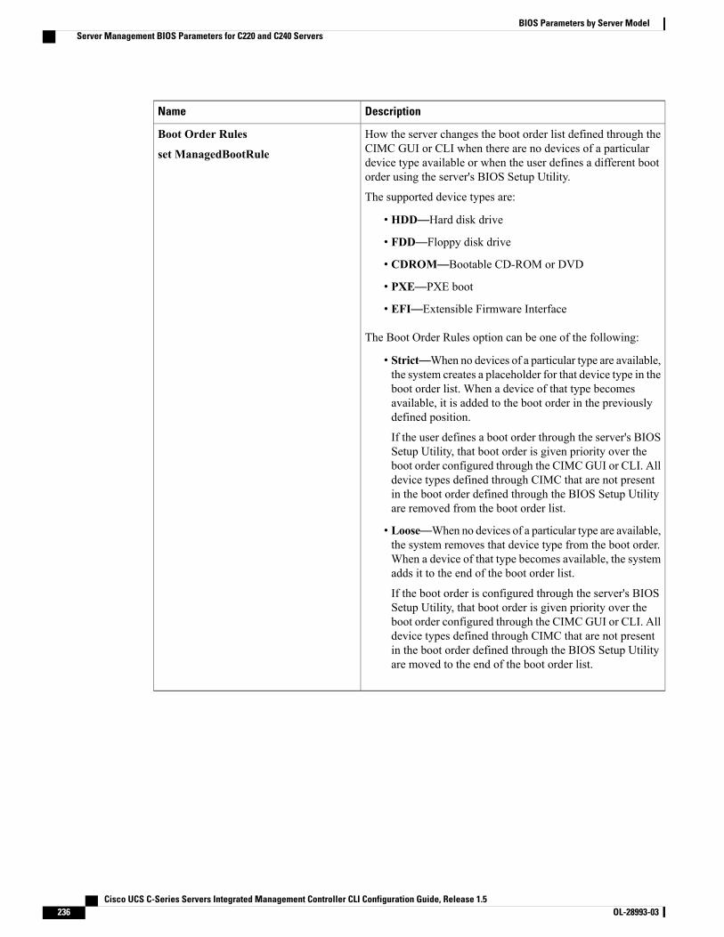
DescriptionName
How the server changes the boot order list defined through theCIMC GUI or CLI when there are no devices of a particulardevice type available or when the user defines a different bootorder using the server's BIOS Setup Utility.
The supported device types are:
• HDD—Hard disk drive
• FDD—Floppy disk drive
• CDROM—Bootable CD-ROM or DVD
• PXE—PXE boot
• EFI—Extensible Firmware Interface
The Boot Order Rules option can be one of the following:
• Strict—When no devices of a particular type are available,the system creates a placeholder for that device type in theboot order list. When a device of that type becomesavailable, it is added to the boot order in the previouslydefined position.
If the user defines a boot order through the server's BIOSSetup Utility, that boot order is given priority over theboot order configured through the CIMC GUI or CLI. Alldevice types defined through CIMC that are not presentin the boot order defined through the BIOS Setup Utilityare removed from the boot order list.
• Loose—When no devices of a particular type are available,the system removes that device type from the boot order.When a device of that type becomes available, the systemadds it to the end of the boot order list.
If the boot order is configured through the server's BIOSSetup Utility, that boot order is given priority over theboot order configured through the CIMC GUI or CLI. Alldevice types defined through CIMC that are not presentin the boot order defined through the BIOS Setup Utilityare moved to the end of the boot order list.
Boot Order Rules
set ManagedBootRule
Cisco UCS C-Series Servers Integrated Management Controller CLI Configuration Guide, Release 1.5236 OL-28993-03
BIOS Parameters by Server ModelServer Management BIOS Parameters for C220 and C240 Servers

C260 Servers
Main BIOS Parameters for C260 ServersDescriptionName
What happens when the server encounters a critical error during POST.This can be one of the following:
• Enabled—The BIOS pauses the attempt to boot the server andopens the ErrorManager when a critical error occurs during POST.
• Disabled—The BIOS continues to attempt to boot the server.
POST Error Pause
set POSTErrorPause
Whether the BIOS retries NON-EFI based boot options without waitingfor user input. This can be one of the following:
• Enabled—Continually retries NON-EFI based boot optionswithout waiting for user input.
• Disabled—Waits for user input before retrying NON-EFI basedboot options.
Boot Option Retry
set BootOptionRetry
Advanced BIOS Parameters for C260 Servers
Processor Configuration Parameters
DescriptionName
Whether the processor uses Intel Turbo Boost Technology,which allows the processor to automatically increase itsfrequency if it is running below power, temperature, or voltagespecifications. This can be one of the following:
• Disabled—The processor does not increase its frequencyautomatically.
• Enabled—The processor utilizes Turbo Boost Technologyif required.
Intel Turbo Boost Technology
set IntelTurboBoostTech
Cisco UCS C-Series Servers Integrated Management Controller CLI Configuration Guide, Release 1.5 OL-28993-03 237
BIOS Parameters by Server ModelC260 Servers

DescriptionName
Whether the processor uses Enhanced Intel SpeedStepTechnology, which allows the system to dynamically adjustprocessor voltage and core frequency. This technology can resultin decreased average power consumption and decreased averageheat production. This can be one of the following:
• Disabled—The processor never dynamically adjusts itsvoltage or frequency.
• Enabled—The processor utilizes Enhanced IntelSpeedStep Technology and enables all supported processorsleep states to further conserve power.
We recommend that you contact your operating system vendorto make sure the operating system supports this feature.
Enhanced Intel Speedstep Technology
set EnhancedIntelSpeedStep
Whether the processor uses Intel Hyper-Threading Technology,which allows multithreaded software applications to executethreads in parallel within each processor. This can be one of thefollowing:
• Disabled—The processor does not permit hyperthreading.
• Enabled—The processor allows for the parallel executionof multiple threads.
We recommend that you contact your operating system vendorto make sure the operating system supports this feature.
Intel Hyper-Threading Technology
set IntelHyperThread
Allows you to disable one or more of the physical cores on theserver. This can be one of the following:
• All—Enables all physical cores. This also enables HyperThreading on the associated logical processor cores.
• 1 through n—Specifies the number of physical processorcores that can run on the server. Each physical core hasan associated logical core.
We recommend that you contact your operating system vendorto make sure the operating system supports this feature.
Number of Enabled Cores
set CoreMultiProcessing
Cisco UCS C-Series Servers Integrated Management Controller CLI Configuration Guide, Release 1.5238 OL-28993-03
BIOS Parameters by Server ModelAdvanced BIOS Parameters for C260 Servers
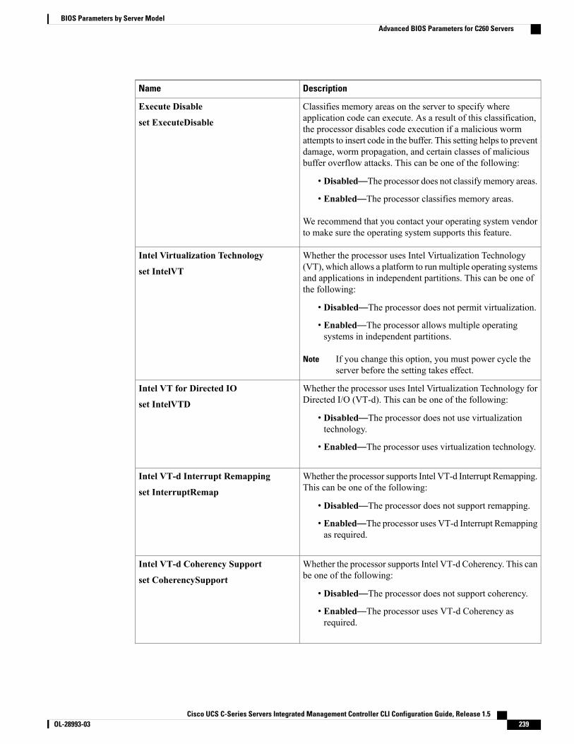
DescriptionName
Classifies memory areas on the server to specify whereapplication code can execute. As a result of this classification,the processor disables code execution if a malicious wormattempts to insert code in the buffer. This setting helps to preventdamage, worm propagation, and certain classes of maliciousbuffer overflow attacks. This can be one of the following:
• Disabled—The processor does not classify memory areas.
• Enabled—The processor classifies memory areas.
We recommend that you contact your operating system vendorto make sure the operating system supports this feature.
Execute Disable
set ExecuteDisable
Whether the processor uses Intel Virtualization Technology(VT), which allows a platform to run multiple operating systemsand applications in independent partitions. This can be one ofthe following:
• Disabled—The processor does not permit virtualization.
• Enabled—The processor allows multiple operatingsystems in independent partitions.
If you change this option, you must power cycle theserver before the setting takes effect.
Note
Intel Virtualization Technology
set IntelVT
Whether the processor uses Intel Virtualization Technology forDirected I/O (VT-d). This can be one of the following:
• Disabled—The processor does not use virtualizationtechnology.
• Enabled—The processor uses virtualization technology.
Intel VT for Directed IO
set IntelVTD
Whether the processor supports Intel VT-d Interrupt Remapping.This can be one of the following:
• Disabled—The processor does not support remapping.
• Enabled—The processor uses VT-d Interrupt Remappingas required.
Intel VT-d Interrupt Remapping
set InterruptRemap
Whether the processor supports Intel VT-d Coherency. This canbe one of the following:
• Disabled—The processor does not support coherency.
• Enabled—The processor uses VT-d Coherency asrequired.
Intel VT-d Coherency Support
set CoherencySupport
Cisco UCS C-Series Servers Integrated Management Controller CLI Configuration Guide, Release 1.5 OL-28993-03 239
BIOS Parameters by Server ModelAdvanced BIOS Parameters for C260 Servers
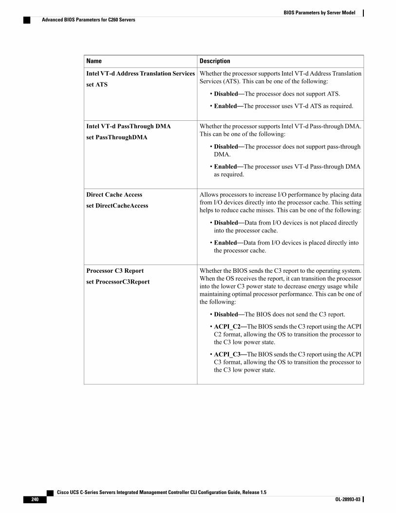
DescriptionName
Whether the processor supports Intel VT-d Address TranslationServices (ATS). This can be one of the following:
• Disabled—The processor does not support ATS.
• Enabled—The processor uses VT-d ATS as required.
Intel VT-dAddress Translation Services
set ATS
Whether the processor supports Intel VT-d Pass-through DMA.This can be one of the following:
• Disabled—The processor does not support pass-throughDMA.
• Enabled—The processor uses VT-d Pass-through DMAas required.
Intel VT-d PassThrough DMA
set PassThroughDMA
Allows processors to increase I/O performance by placing datafrom I/O devices directly into the processor cache. This settinghelps to reduce cache misses. This can be one of the following:
• Disabled—Data from I/O devices is not placed directlyinto the processor cache.
• Enabled—Data from I/O devices is placed directly intothe processor cache.
Direct Cache Access
set DirectCacheAccess
Whether the BIOS sends the C3 report to the operating system.When the OS receives the report, it can transition the processorinto the lower C3 power state to decrease energy usage whilemaintaining optimal processor performance. This can be one ofthe following:
• Disabled—The BIOS does not send the C3 report.
• ACPI_C2—TheBIOS sends the C3 report using the ACPIC2 format, allowing the OS to transition the processor tothe C3 low power state.
• ACPI_C3—TheBIOS sends the C3 report using the ACPIC3 format, allowing the OS to transition the processor tothe C3 low power state.
Processor C3 Report
set ProcessorC3Report
Cisco UCS C-Series Servers Integrated Management Controller CLI Configuration Guide, Release 1.5240 OL-28993-03
BIOS Parameters by Server ModelAdvanced BIOS Parameters for C260 Servers
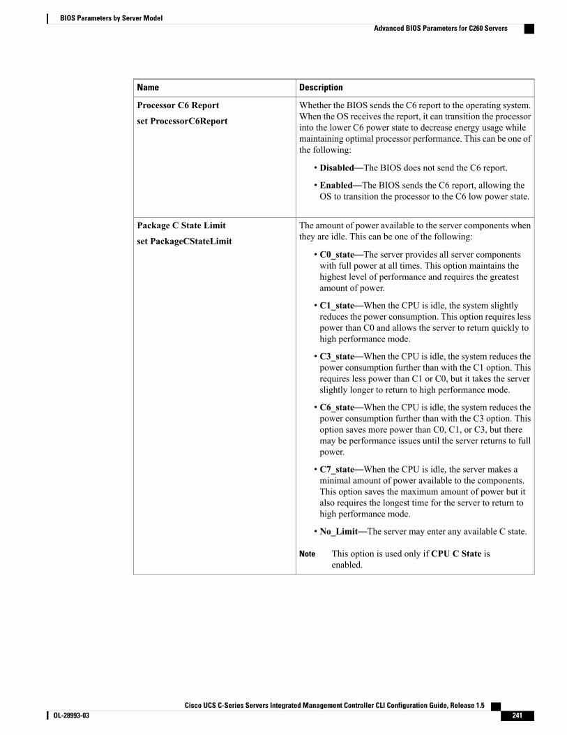
DescriptionName
Whether the BIOS sends the C6 report to the operating system.When the OS receives the report, it can transition the processorinto the lower C6 power state to decrease energy usage whilemaintaining optimal processor performance. This can be one ofthe following:
• Disabled—The BIOS does not send the C6 report.
• Enabled—The BIOS sends the C6 report, allowing theOS to transition the processor to the C6 low power state.
Processor C6 Report
set ProcessorC6Report
The amount of power available to the server components whenthey are idle. This can be one of the following:
• C0_state—The server provides all server componentswith full power at all times. This option maintains thehighest level of performance and requires the greatestamount of power.
• C1_state—When the CPU is idle, the system slightlyreduces the power consumption. This option requires lesspower than C0 and allows the server to return quickly tohigh performance mode.
• C3_state—When the CPU is idle, the system reduces thepower consumption further than with the C1 option. Thisrequires less power than C1 or C0, but it takes the serverslightly longer to return to high performance mode.
• C6_state—When the CPU is idle, the system reduces thepower consumption further than with the C3 option. Thisoption saves more power than C0, C1, or C3, but theremay be performance issues until the server returns to fullpower.
• C7_state—When the CPU is idle, the server makes aminimal amount of power available to the components.This option saves the maximum amount of power but italso requires the longest time for the server to return tohigh performance mode.
• No_Limit—The server may enter any available C state.
This option is used only if CPU C State isenabled.
Note
Package C State Limit
set PackageCStateLimit
Cisco UCS C-Series Servers Integrated Management Controller CLI Configuration Guide, Release 1.5 OL-28993-03 241
BIOS Parameters by Server ModelAdvanced BIOS Parameters for C260 Servers

DescriptionName
Whether the system can enter a power savings mode during idleperiods. This can be one of the following:
• Disabled—The system remains in high performance stateeven when idle.
• Enabled—The system can reduce power to systemcomponents such as the DIMMs and CPUs. The amountof power reduction is specified by the setPackageCStateLimit command.
CPU C State
set ProcessorCcxEnable
Whether the CPU transitions to its minimum frequency whenentering the C1 state. This can be one of the following:
• Disabled—The CPU continues to run at its maximumfrequency in C1 state.
• Enabled—The CPU transitions to its minimum frequency.This option saves the maximum amount of power in C1state.
This option is used only if ProcessorCcxEnable isenabled.
Note
C1E
set ProcessorC1eEnable
Memory Configuration Parameters
DescriptionName
How the memory reliability, availability, and serviceability(RAS) is configured for the server. This can be one of thefollowing:
•Maximum_Performance—System performance isoptimized.
•Mirroring—System reliability is optimized by using halfthe system memory as backup.
• Sparing—The system reserves some memory for use inthe event a DIMM fails. If that happens, the server takesthe DIMM offline and replaces it with the reservedmemory. This option provides less redundancy thanmirroring, but it leaves more of the memory available forprograms running on the server.
Select Memory RAS
set SelectMemoryRAS
Cisco UCS C-Series Servers Integrated Management Controller CLI Configuration Guide, Release 1.5242 OL-28993-03
BIOS Parameters by Server ModelAdvanced BIOS Parameters for C260 Servers
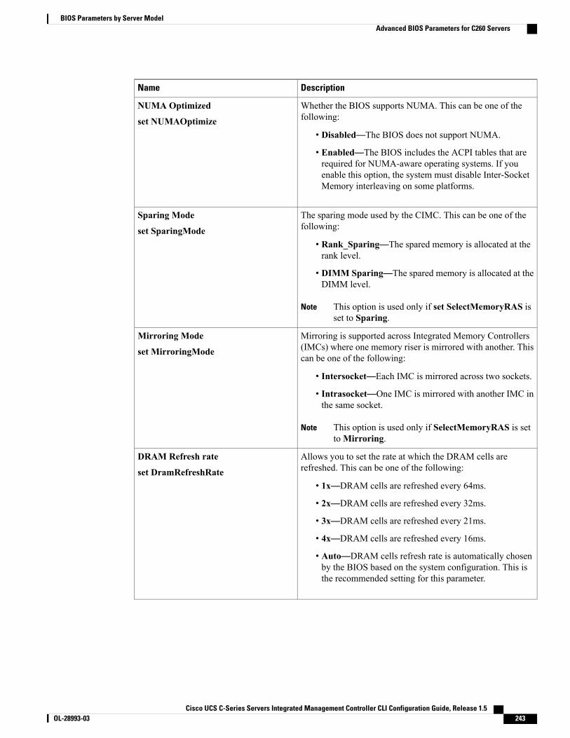
DescriptionName
Whether the BIOS supports NUMA. This can be one of thefollowing:
• Disabled—The BIOS does not support NUMA.
• Enabled—The BIOS includes the ACPI tables that arerequired for NUMA-aware operating systems. If youenable this option, the system must disable Inter-SocketMemory interleaving on some platforms.
NUMA Optimized
set NUMAOptimize
The sparing mode used by the CIMC. This can be one of thefollowing:
• Rank_Sparing—The spared memory is allocated at therank level.
• DIMM Sparing—The spared memory is allocated at theDIMM level.
This option is used only if set SelectMemoryRAS isset to Sparing.
Note
Sparing Mode
set SparingMode
Mirroring is supported across Integrated Memory Controllers(IMCs) where one memory riser is mirrored with another. Thiscan be one of the following:
• Intersocket—Each IMC is mirrored across two sockets.
• Intrasocket—One IMC is mirrored with another IMC inthe same socket.
This option is used only if SelectMemoryRAS is settoMirroring.
Note
Mirroring Mode
set MirroringMode
Allows you to set the rate at which the DRAM cells arerefreshed. This can be one of the following:
• 1x—DRAM cells are refreshed every 64ms.
• 2x—DRAM cells are refreshed every 32ms.
• 3x—DRAM cells are refreshed every 21ms.
• 4x—DRAM cells are refreshed every 16ms.
• Auto—DRAM cells refresh rate is automatically chosenby the BIOS based on the system configuration. This isthe recommended setting for this parameter.
DRAM Refresh rate
set DramRefreshRate
Cisco UCS C-Series Servers Integrated Management Controller CLI Configuration Guide, Release 1.5 OL-28993-03 243
BIOS Parameters by Server ModelAdvanced BIOS Parameters for C260 Servers

DescriptionName
Whether the system actively searches for, and corrects, singlebit memory errors even in unused portions of the memory onthe server. This can be one of the following:
• Disabled—The system checks for memory ECC errorsonly when the CPU reads or writes a memory address.
• Enabled—The system periodically reads and writesmemory searching for ECC errors. If any errors are found,the system attempts to fix them. This option may correctsingle bit errors before they become multi-bit errors, butit may adversely affect performance when the patrol scrubis running.
Patrol Scrub
set PatrolScrub
Controls the time interval between each patrol scrub memoryaccess. A lower interval scrubs the memory more often butrequires more memory bandwidth.
Select a value between 5 and 23. The default value is 8.
This option is used only if Patrol Scrub isenabled.
Note
Patrol Scrub Interval
set PatrolScrubDuration
Controls the DIMM power savings mode policy. This can beone of the following:
• Disabled—DIMMs do not enter power saving mode.
• Slow—DIMMs can enter power saving mode, but therequirements are higher. Therefore, DIMMs enter powersaving mode less frequently.
• Fast—DIMMs enter power saving mode as often aspossible.
• Auto—The BIOS controls when a DIMM enters powersaving mode based on the DIMM configuration.
CKE Low Policy
set CkeLowPolicy
Serial Port Configuration Parameters
DescriptionName
Whether serial port A is enabled or disabled. This can be one of thefollowing:
• Disabled—The serial port is disabled.
• Enabled—The serial port is enabled.
Serial A Enable
set Serial-PortA
Cisco UCS C-Series Servers Integrated Management Controller CLI Configuration Guide, Release 1.5244 OL-28993-03
BIOS Parameters by Server ModelAdvanced BIOS Parameters for C260 Servers
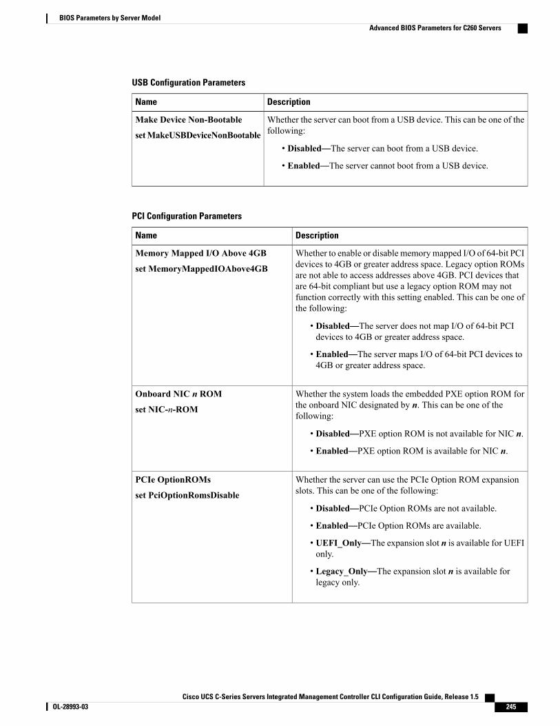
USB Configuration Parameters
DescriptionName
Whether the server can boot from a USB device. This can be one of thefollowing:
• Disabled—The server can boot from a USB device.
• Enabled—The server cannot boot from a USB device.
Make Device Non-Bootable
setMakeUSBDeviceNonBootable
PCI Configuration Parameters
DescriptionName
Whether to enable or disable memorymapped I/O of 64-bit PCIdevices to 4GB or greater address space. Legacy option ROMsare not able to access addresses above 4GB. PCI devices thatare 64-bit compliant but use a legacy option ROM may notfunction correctly with this setting enabled. This can be one ofthe following:
• Disabled—The server does not map I/O of 64-bit PCIdevices to 4GB or greater address space.
• Enabled—The server maps I/O of 64-bit PCI devices to4GB or greater address space.
Memory Mapped I/O Above 4GB
set MemoryMappedIOAbove4GB
Whether the system loads the embedded PXE option ROM forthe onboard NIC designated by n. This can be one of thefollowing:
• Disabled—PXE option ROM is not available for NIC n.
• Enabled—PXE option ROM is available for NIC n.
Onboard NIC n ROM
set NIC-n-ROM
Whether the server can use the PCIe Option ROM expansionslots. This can be one of the following:
• Disabled—PCIe Option ROMs are not available.
• Enabled—PCIe Option ROMs are available.
• UEFI_Only—The expansion slot n is available for UEFIonly.
• Legacy_Only—The expansion slot n is available forlegacy only.
PCIe OptionROMs
set PciOptionRomsDisable
Cisco UCS C-Series Servers Integrated Management Controller CLI Configuration Guide, Release 1.5 OL-28993-03 245
BIOS Parameters by Server ModelAdvanced BIOS Parameters for C260 Servers
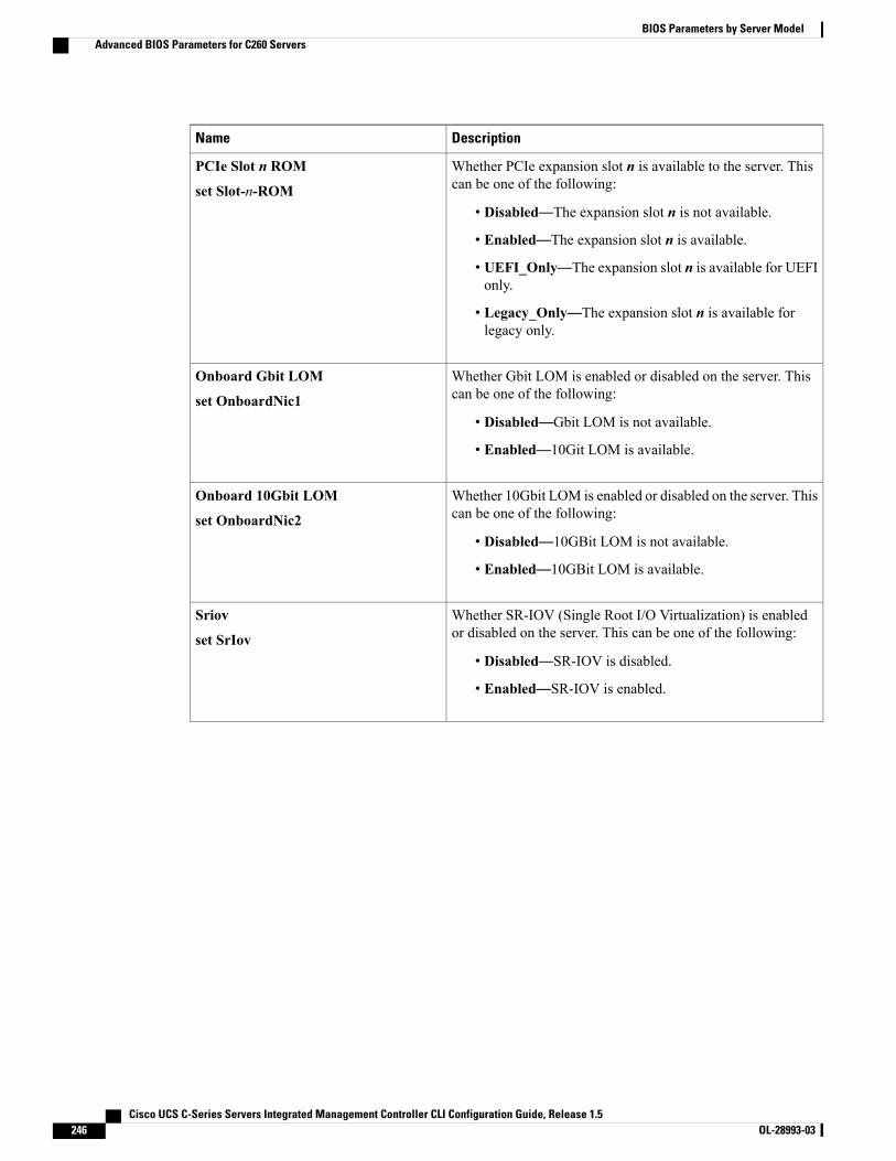
DescriptionName
Whether PCIe expansion slot n is available to the server. Thiscan be one of the following:
• Disabled—The expansion slot n is not available.
• Enabled—The expansion slot n is available.
• UEFI_Only—The expansion slot n is available for UEFIonly.
• Legacy_Only—The expansion slot n is available forlegacy only.
PCIe Slot n ROM
set Slot-n-ROM
Whether Gbit LOM is enabled or disabled on the server. Thiscan be one of the following:
• Disabled—Gbit LOM is not available.
• Enabled—10Git LOM is available.
Onboard Gbit LOM
set OnboardNic1
Whether 10Gbit LOM is enabled or disabled on the server. Thiscan be one of the following:
• Disabled—10GBit LOM is not available.
• Enabled—10GBit LOM is available.
Onboard 10Gbit LOM
set OnboardNic2
Whether SR-IOV (Single Root I/O Virtualization) is enabledor disabled on the server. This can be one of the following:
• Disabled—SR-IOV is disabled.
• Enabled—SR-IOV is enabled.
Sriov
set SrIov
Cisco UCS C-Series Servers Integrated Management Controller CLI Configuration Guide, Release 1.5246 OL-28993-03
BIOS Parameters by Server ModelAdvanced BIOS Parameters for C260 Servers
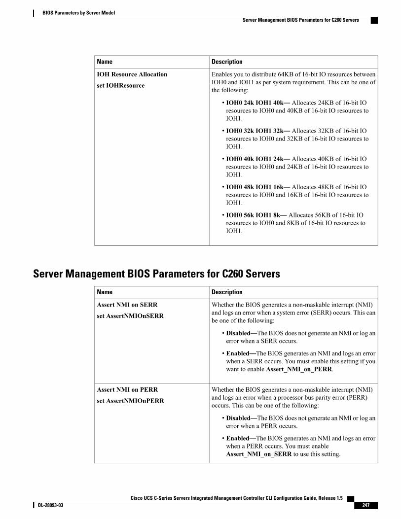
DescriptionName
Enables you to distribute 64KB of 16-bit IO resources betweenIOH0 and IOH1 as per system requirement. This can be one ofthe following:
• IOH0 24k IOH1 40k— Allocates 24KB of 16-bit IOresources to IOH0 and 40KB of 16-bit IO resources toIOH1.
• IOH0 32k IOH1 32k— Allocates 32KB of 16-bit IOresources to IOH0 and 32KB of 16-bit IO resources toIOH1.
• IOH0 40k IOH1 24k— Allocates 40KB of 16-bit IOresources to IOH0 and 24KB of 16-bit IO resources toIOH1.
• IOH0 48k IOH1 16k— Allocates 48KB of 16-bit IOresources to IOH0 and 16KB of 16-bit IO resources toIOH1.
• IOH0 56k IOH1 8k— Allocates 56KB of 16-bit IOresources to IOH0 and 8KB of 16-bit IO resources toIOH1.
IOH Resource Allocation
set IOHResource
Server Management BIOS Parameters for C260 ServersDescriptionName
Whether the BIOS generates a non-maskable interrupt (NMI)and logs an error when a system error (SERR) occurs. This canbe one of the following:
• Disabled—The BIOS does not generate an NMI or log anerror when a SERR occurs.
• Enabled—The BIOS generates an NMI and logs an errorwhen a SERR occurs. You must enable this setting if youwant to enable Assert_NMI_on_PERR.
Assert NMI on SERR
set AssertNMIOnSERR
Whether the BIOS generates a non-maskable interrupt (NMI)and logs an error when a processor bus parity error (PERR)occurs. This can be one of the following:
• Disabled—The BIOS does not generate an NMI or log anerror when a PERR occurs.
• Enabled—The BIOS generates an NMI and logs an errorwhen a PERR occurs. You must enableAssert_NMI_on_SERR to use this setting.
Assert NMI on PERR
set AssertNMIOnPERR
Cisco UCS C-Series Servers Integrated Management Controller CLI Configuration Guide, Release 1.5 OL-28993-03 247
BIOS Parameters by Server ModelServer Management BIOS Parameters for C260 Servers
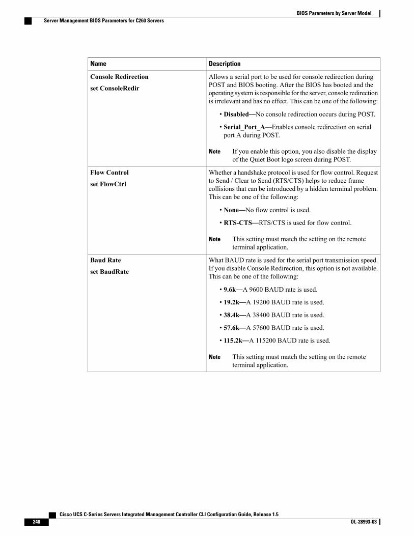
DescriptionName
Allows a serial port to be used for console redirection duringPOST and BIOS booting. After the BIOS has booted and theoperating system is responsible for the server, console redirectionis irrelevant and has no effect. This can be one of the following:
• Disabled—No console redirection occurs during POST.
• Serial_Port_A—Enables console redirection on serialport A during POST.
If you enable this option, you also disable the displayof the Quiet Boot logo screen during POST.
Note
Console Redirection
set ConsoleRedir
Whether a handshake protocol is used for flow control. Requestto Send / Clear to Send (RTS/CTS) helps to reduce framecollisions that can be introduced by a hidden terminal problem.This can be one of the following:
• None—No flow control is used.
• RTS-CTS—RTS/CTS is used for flow control.
This setting must match the setting on the remoteterminal application.
Note
Flow Control
set FlowCtrl
What BAUD rate is used for the serial port transmission speed.If you disable Console Redirection, this option is not available.This can be one of the following:
• 9.6k—A 9600 BAUD rate is used.
• 19.2k—A 19200 BAUD rate is used.
• 38.4k—A 38400 BAUD rate is used.
• 57.6k—A 57600 BAUD rate is used.
• 115.2k—A 115200 BAUD rate is used.
This setting must match the setting on the remoteterminal application.
Note
Baud Rate
set BaudRate
Cisco UCS C-Series Servers Integrated Management Controller CLI Configuration Guide, Release 1.5248 OL-28993-03
BIOS Parameters by Server ModelServer Management BIOS Parameters for C260 Servers
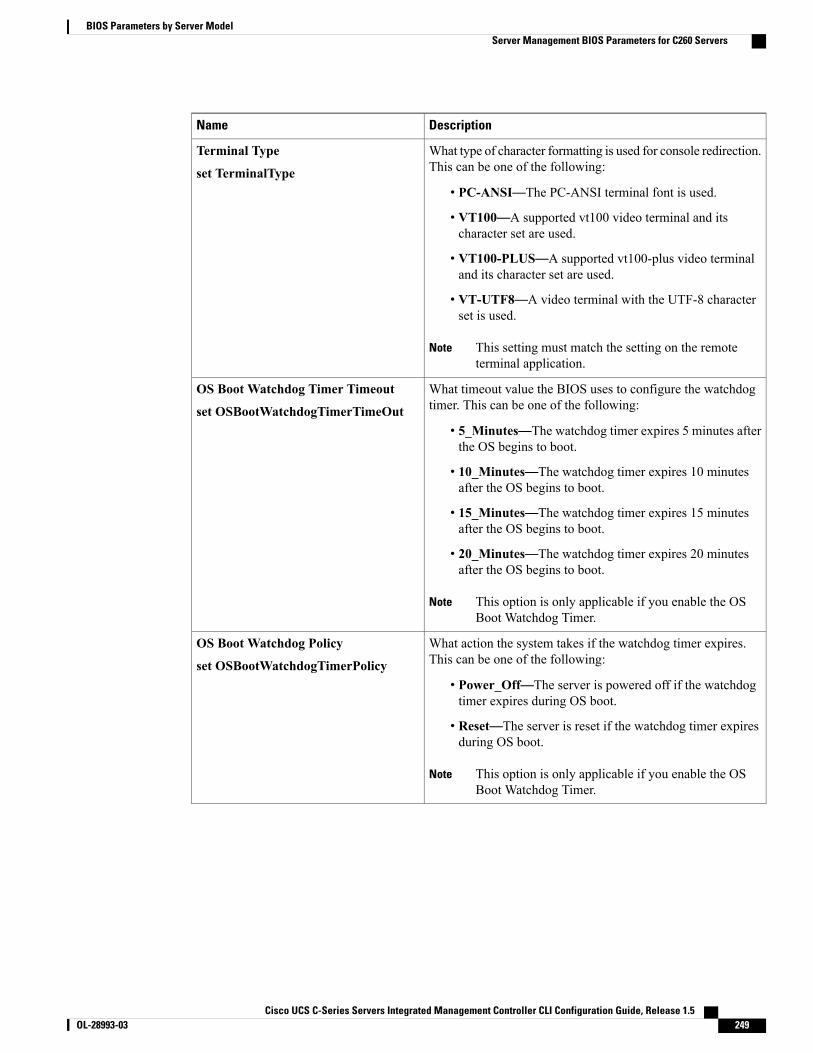
DescriptionName
What type of character formatting is used for console redirection.This can be one of the following:
• PC-ANSI—The PC-ANSI terminal font is used.
• VT100—A supported vt100 video terminal and itscharacter set are used.
• VT100-PLUS—A supported vt100-plus video terminaland its character set are used.
• VT-UTF8—A video terminal with the UTF-8 characterset is used.
This setting must match the setting on the remoteterminal application.
Note
Terminal Type
set TerminalType
What timeout value the BIOS uses to configure the watchdogtimer. This can be one of the following:
• 5_Minutes—The watchdog timer expires 5 minutes afterthe OS begins to boot.
• 10_Minutes—The watchdog timer expires 10 minutesafter the OS begins to boot.
• 15_Minutes—The watchdog timer expires 15 minutesafter the OS begins to boot.
• 20_Minutes—The watchdog timer expires 20 minutesafter the OS begins to boot.
This option is only applicable if you enable the OSBoot Watchdog Timer.
Note
OS Boot Watchdog Timer Timeout
set OSBootWatchdogTimerTimeOut
What action the system takes if the watchdog timer expires.This can be one of the following:
• Power_Off—The server is powered off if the watchdogtimer expires during OS boot.
• Reset—The server is reset if the watchdog timer expiresduring OS boot.
This option is only applicable if you enable the OSBoot Watchdog Timer.
Note
OS Boot Watchdog Policy
set OSBootWatchdogTimerPolicy
Cisco UCS C-Series Servers Integrated Management Controller CLI Configuration Guide, Release 1.5 OL-28993-03 249
BIOS Parameters by Server ModelServer Management BIOS Parameters for C260 Servers

DescriptionName
Whether redirection from a legacy operating system, such asDOS, is enabled on the serial port. This can be one of thefollowing:
• Disabled—The serial port enabled for console redirectionis hidden from the legacy operating system.
• Enabled—The serial port enabled for console redirectionis visible to the legacy operating system.
Legacy OS Redirection
set LegacyOSRedir
Whether the BIOS programs the watchdog timer with a specifiedtimeout value. This can be one of the following:
• Disabled—The watchdog timer is not used to track howlong the server takes to boot.
• Enabled—The watchdog timer tracks how long the servertakes to boot. If the server does not boot within the lengthof time specified by the setOSBootWatchdogTimerTimeout command, the CIMClogs an error and takes the action specified by the setOSBootWatchdogTimerPolicy command.
OS Boot Watchdog Timer
set OSBootWatchdogTimer
C420 Servers
Main BIOS Parameters for C420 ServersDescriptionName
TPM (Trusted Platform Module) is a microchip designed to providebasic security-related functions primarily involving encryption keys.This option allows you to control the TPM Security Device support forthe system. It can be one of the following:
• Disabled—The server does not use the TPM.
• Enabled—The server uses the TPM.
We recommend that you contact your operating system vendorto make sure the operating system supports this feature.
Note
TPM Support
set TPMAdminCtrl
Cisco UCS C-Series Servers Integrated Management Controller CLI Configuration Guide, Release 1.5250 OL-28993-03
BIOS Parameters by Server ModelC420 Servers
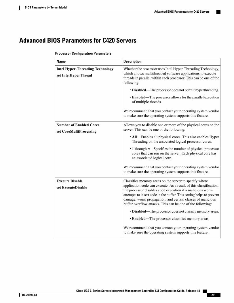
Advanced BIOS Parameters for C420 Servers
Processor Configuration Parameters
DescriptionName
Whether the processor uses Intel Hyper-Threading Technology,which allows multithreaded software applications to executethreads in parallel within each processor. This can be one of thefollowing:
• Disabled—The processor does not permit hyperthreading.
• Enabled—The processor allows for the parallel executionof multiple threads.
We recommend that you contact your operating system vendorto make sure the operating system supports this feature.
Intel Hyper-Threading Technology
set IntelHyperThread
Allows you to disable one or more of the physical cores on theserver. This can be one of the following:
• All—Enables all physical cores. This also enables HyperThreading on the associated logical processor cores.
• 1 through n—Specifies the number of physical processorcores that can run on the server. Each physical core hasan associated logical core.
We recommend that you contact your operating system vendorto make sure the operating system supports this feature.
Number of Enabled Cores
set CoreMultiProcessing
Classifies memory areas on the server to specify whereapplication code can execute. As a result of this classification,the processor disables code execution if a malicious wormattempts to insert code in the buffer. This setting helps to preventdamage, worm propagation, and certain classes of maliciousbuffer overflow attacks. This can be one of the following:
• Disabled—The processor does not classify memory areas.
• Enabled—The processor classifies memory areas.
We recommend that you contact your operating system vendorto make sure the operating system supports this feature.
Execute Disable
set ExecuteDisable
Cisco UCS C-Series Servers Integrated Management Controller CLI Configuration Guide, Release 1.5 OL-28993-03 251
BIOS Parameters by Server ModelAdvanced BIOS Parameters for C420 Servers
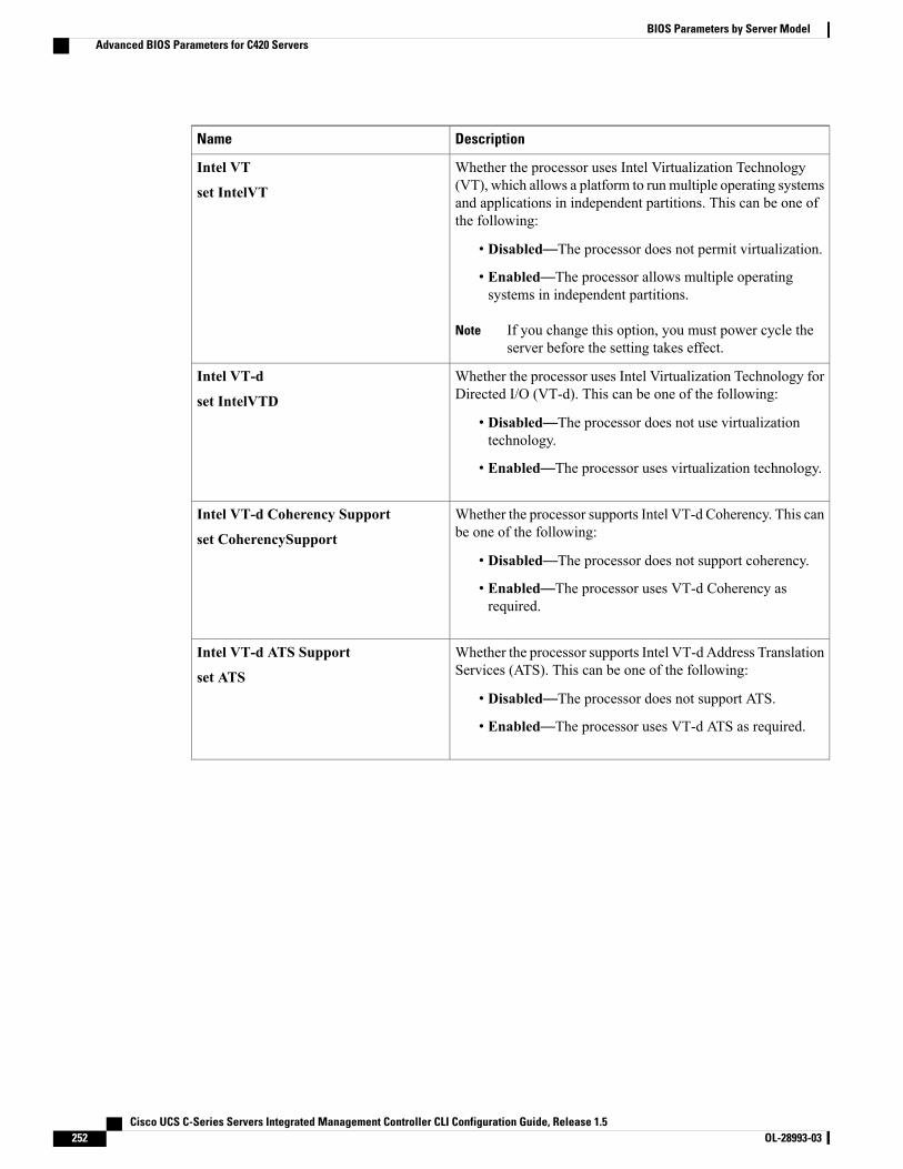
DescriptionName
Whether the processor uses Intel Virtualization Technology(VT), which allows a platform to run multiple operating systemsand applications in independent partitions. This can be one ofthe following:
• Disabled—The processor does not permit virtualization.
• Enabled—The processor allows multiple operatingsystems in independent partitions.
If you change this option, you must power cycle theserver before the setting takes effect.
Note
Intel VT
set IntelVT
Whether the processor uses Intel Virtualization Technology forDirected I/O (VT-d). This can be one of the following:
• Disabled—The processor does not use virtualizationtechnology.
• Enabled—The processor uses virtualization technology.
Intel VT-d
set IntelVTD
Whether the processor supports Intel VT-d Coherency. This canbe one of the following:
• Disabled—The processor does not support coherency.
• Enabled—The processor uses VT-d Coherency asrequired.
Intel VT-d Coherency Support
set CoherencySupport
Whether the processor supports Intel VT-d Address TranslationServices (ATS). This can be one of the following:
• Disabled—The processor does not support ATS.
• Enabled—The processor uses VT-d ATS as required.
Intel VT-d ATS Support
set ATS
Cisco UCS C-Series Servers Integrated Management Controller CLI Configuration Guide, Release 1.5252 OL-28993-03
BIOS Parameters by Server ModelAdvanced BIOS Parameters for C420 Servers

DescriptionName
Sets the CPU performance profile for the server. Theperformance profile consists of the following options:
• DCU Streamer Prefetcher
• DCU IP Prefetcher
• Hardware Prefetcher
• Adjacent Cache-Line Prefetch
This can be one of the following:
• Enterprise—All options are enabled.
• High_Throughput—Only the DCU IP Prefetcher isenabled. The rest of the options are disabled.
• HPC—All options are enabled. This setting is also knownas high performance computing.
• Custom—All performance profile options can beconfigured from the BIOS setup on the server. In addition,theHardware Prefetcher andAdjacent Cache-Line Prefetchoptions can be configured in the fields below.
CPU Performance
set CPUPerformance
Whether the processor allows the Intel hardware prefetcher tofetch streams of data and instruction from memory into theunified second-level cache when necessary. This can be one ofthe following:
• Disabled—The hardware prefetcher is not used.
• Enabled—The processor uses the hardware prefetcherwhen cache issues are detected.
Hardware Prefetcher
set HardwarePrefetch
Whether the processor fetches cache lines in even/odd pairsinstead of fetching just the required line. This can be one of thefollowing:
• Disabled—The processor only fetches the required line.
• Enabled— The processor fetches both the required lineand its paired line.
Adjacent Cache Line Prefetcher
set AdjacentCacheLinePrefetch
Cisco UCS C-Series Servers Integrated Management Controller CLI Configuration Guide, Release 1.5 OL-28993-03 253
BIOS Parameters by Server ModelAdvanced BIOS Parameters for C420 Servers
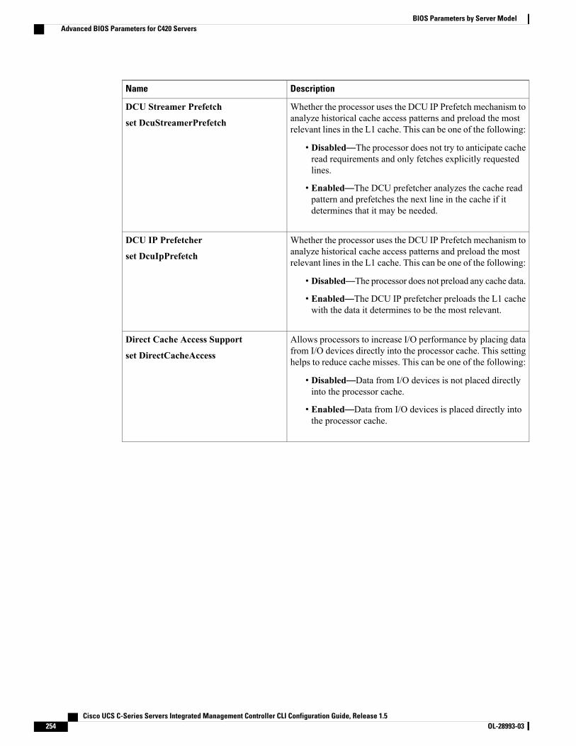
DescriptionName
Whether the processor uses the DCU IP Prefetch mechanism toanalyze historical cache access patterns and preload the mostrelevant lines in the L1 cache. This can be one of the following:
• Disabled—The processor does not try to anticipate cacheread requirements and only fetches explicitly requestedlines.
• Enabled—The DCU prefetcher analyzes the cache readpattern and prefetches the next line in the cache if itdetermines that it may be needed.
DCU Streamer Prefetch
set DcuStreamerPrefetch
Whether the processor uses the DCU IP Prefetch mechanism toanalyze historical cache access patterns and preload the mostrelevant lines in the L1 cache. This can be one of the following:
• Disabled—The processor does not preload any cache data.
• Enabled—The DCU IP prefetcher preloads the L1 cachewith the data it determines to be the most relevant.
DCU IP Prefetcher
set DcuIpPrefetch
Allows processors to increase I/O performance by placing datafrom I/O devices directly into the processor cache. This settinghelps to reduce cache misses. This can be one of the following:
• Disabled—Data from I/O devices is not placed directlyinto the processor cache.
• Enabled—Data from I/O devices is placed directly intothe processor cache.
Direct Cache Access Support
set DirectCacheAccess
Cisco UCS C-Series Servers Integrated Management Controller CLI Configuration Guide, Release 1.5254 OL-28993-03
BIOS Parameters by Server ModelAdvanced BIOS Parameters for C420 Servers
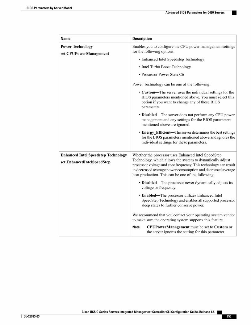
DescriptionName
Enables you to configure the CPU power management settingsfor the following options:
• Enhanced Intel Speedstep Technology
• Intel Turbo Boost Technology
• Processor Power State C6
Power Technology can be one of the following:
• Custom—The server uses the individual settings for theBIOS parameters mentioned above. You must select thisoption if you want to change any of these BIOSparameters.
• Disabled—The server does not perform any CPU powermanagement and any settings for the BIOS parametersmentioned above are ignored.
• Energy_Efficient—The server determines the best settingsfor the BIOS parameters mentioned above and ignores theindividual settings for these parameters.
Power Technology
set CPUPowerManagement
Whether the processor uses Enhanced Intel SpeedStepTechnology, which allows the system to dynamically adjustprocessor voltage and core frequency. This technology can resultin decreased average power consumption and decreased averageheat production. This can be one of the following:
• Disabled—The processor never dynamically adjusts itsvoltage or frequency.
• Enabled—The processor utilizes Enhanced IntelSpeedStep Technology and enables all supported processorsleep states to further conserve power.
We recommend that you contact your operating system vendorto make sure the operating system supports this feature.
CPUPowerManagement must be set to Custom orthe server ignores the setting for this parameter.
Note
Enhanced Intel Speedstep Technology
set EnhancedIntelSpeedStep
Cisco UCS C-Series Servers Integrated Management Controller CLI Configuration Guide, Release 1.5 OL-28993-03 255
BIOS Parameters by Server ModelAdvanced BIOS Parameters for C420 Servers
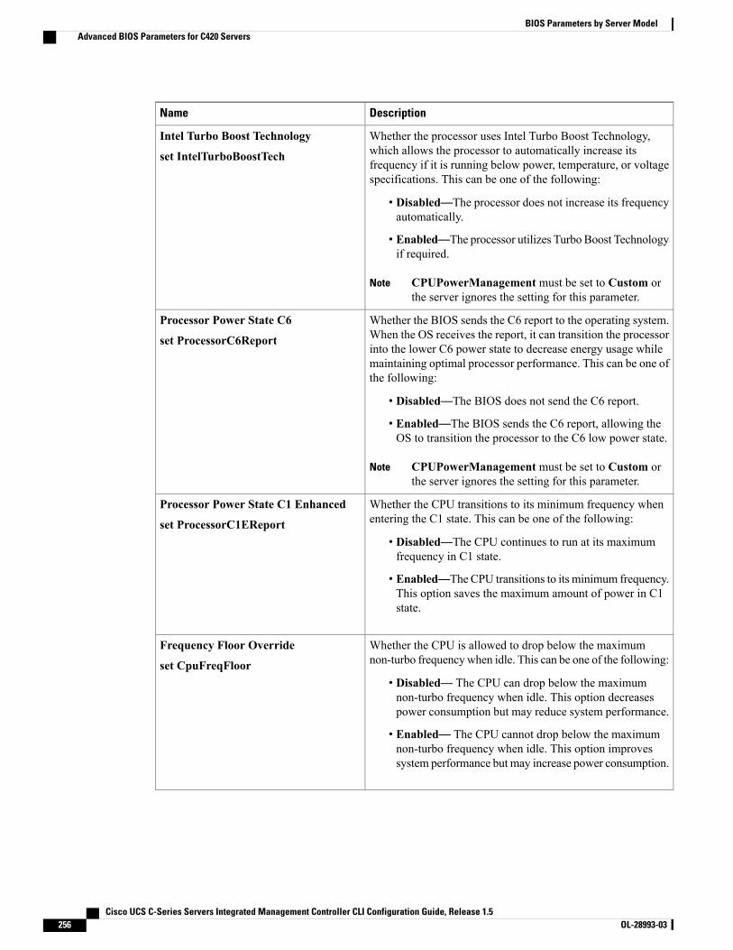
DescriptionName
Whether the processor uses Intel Turbo Boost Technology,which allows the processor to automatically increase itsfrequency if it is running below power, temperature, or voltagespecifications. This can be one of the following:
• Disabled—The processor does not increase its frequencyautomatically.
• Enabled—The processor utilizes Turbo Boost Technologyif required.
CPUPowerManagement must be set to Custom orthe server ignores the setting for this parameter.
Note
Intel Turbo Boost Technology
set IntelTurboBoostTech
Whether the BIOS sends the C6 report to the operating system.When the OS receives the report, it can transition the processorinto the lower C6 power state to decrease energy usage whilemaintaining optimal processor performance. This can be one ofthe following:
• Disabled—The BIOS does not send the C6 report.
• Enabled—The BIOS sends the C6 report, allowing theOS to transition the processor to the C6 low power state.
CPUPowerManagement must be set to Custom orthe server ignores the setting for this parameter.
Note
Processor Power State C6
set ProcessorC6Report
Whether the CPU transitions to its minimum frequency whenentering the C1 state. This can be one of the following:
• Disabled—The CPU continues to run at its maximumfrequency in C1 state.
• Enabled—The CPU transitions to its minimum frequency.This option saves the maximum amount of power in C1state.
Processor Power State C1 Enhanced
set ProcessorC1EReport
Whether the CPU is allowed to drop below the maximumnon-turbo frequencywhen idle. This can be one of the following:
• Disabled— The CPU can drop below the maximumnon-turbo frequency when idle. This option decreasespower consumption but may reduce system performance.
• Enabled— The CPU cannot drop below the maximumnon-turbo frequency when idle. This option improvessystem performance but may increase power consumption.
Frequency Floor Override
set CpuFreqFloor
Cisco UCS C-Series Servers Integrated Management Controller CLI Configuration Guide, Release 1.5256 OL-28993-03
BIOS Parameters by Server ModelAdvanced BIOS Parameters for C420 Servers

DescriptionName
Allows you to define how BIOS communicates the P-statesupport model to the operating system. There are 3 models asdefined by the Advanced Configuration and Power Interface(ACPI) specification.
• HW_ALL—The processor hardware is responsible forcoordinating the P-state among logical processors withdependencies (all logical processors in a package).
• SW_ALL—The OS Power Manager (OSPM) isresponsible for coordinating the P-state among logicalprocessors with dependencies (all logical processors in aphysical package), and must initiate the transition on allof the logical processors.
• SW_ANY—The OS Power Manager (OSPM) isresponsible for coordinating the P-state among logicalprocessors with dependencies (all logical processors in apackage), and may initiate the transition on any of thelogical processors in the domain.
CPUPowerManagement must be set to Custom orthe server ignores the setting for this parameter.
Note
P-STATE Coordination
set PsdCoordType
Allows you to determine whether system performance or energyefficiency is more important on this server. This can be one ofthe following:
• Balanced_Energy
• Balanced_Performance
• Energy_Efficient
• Performance
Energy Performance
set CpuEngPerfBias
Cisco UCS C-Series Servers Integrated Management Controller CLI Configuration Guide, Release 1.5 OL-28993-03 257
BIOS Parameters by Server ModelAdvanced BIOS Parameters for C420 Servers
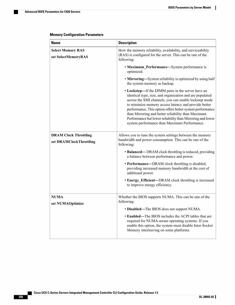
Memory Configuration Parameters
DescriptionName
How the memory reliability, availability, and serviceability(RAS) is configured for the server. This can be one of thefollowing:
•Maximum_Performance—System performance isoptimized.
•Mirroring—System reliability is optimized by using halfthe system memory as backup.
• Lockstep—If the DIMM pairs in the server have anidentical type, size, and organization and are populatedacross the SMI channels, you can enable lockstep modeto minimize memory access latency and provide betterperformance. This option offers better system performancethan Mirroring and better reliability than MaximumPerformance but lower reliability thanMirroring and lowersystem performance than Maximum Performance.
Select Memory RAS
set SelectMemoryRAS
Allows you to tune the system settings between the memorybandwidth and power consumption. This can be one of thefollowing:
• Balanced—DRAM clock throttling is reduced, providinga balance between performance and power.
• Performance—DRAM clock throttling is disabled,providing increased memory bandwidth at the cost ofadditional power.
• Energy_Efficient—DRAM clock throttling is increasedto improve energy efficiency.
DRAM Clock Throttling
set DRAMClockThrottling
Whether the BIOS supports NUMA. This can be one of thefollowing:
• Disabled—The BIOS does not support NUMA.
• Enabled—The BIOS includes the ACPI tables that arerequired for NUMA-aware operating systems. If youenable this option, the system must disable Inter-SocketMemory interleaving on some platforms.
NUMA
set NUMAOptimize
Cisco UCS C-Series Servers Integrated Management Controller CLI Configuration Guide, Release 1.5258 OL-28993-03
BIOS Parameters by Server ModelAdvanced BIOS Parameters for C420 Servers

DescriptionName
Whether the system prioritizes low voltage or high frequencymemory operations. This can be one of the following:
• Power_Saving_Mode—The systemprioritizes lowvoltagememory operations over high frequency memoryoperations. This mode may lower memory frequency inorder to keep the voltage low.
• Performance_Mode—The system prioritizes highfrequency operations over low voltage operations.
Low Voltage DDR Mode
set LvDDRMode
Allows you to set the rate at which the DRAM cells arerefreshed. This can be one of the following:
• 1x—DRAM cells are refreshed every 64ms.
• 2x—DRAM cells are refreshed every 32ms.
• 3x—DRAM cells are refreshed every 21ms.
• 4x—DRAM cells are refreshed every 16ms.
• Auto—DRAM cells refresh rate is automatically chosenby the BIOS based on the system configuration. This isthe recommended setting for this parameter.
DRAM Refresh rate
set DramRefreshRate
Whether the CPU divides memory blocks and spreadscontiguous portions of data across interleaved channels to enablesimultaneous read operations. This can be one of the following:
• Auto—The CPU determines what interleaving is done.
• 1_Way—Some channel interleaving is used.
• 2_Way
• 3_Way
• 4_Way—The maximum amount of channel interleavingis used.
Channel Interleaving
set ChannelInterLeave
Cisco UCS C-Series Servers Integrated Management Controller CLI Configuration Guide, Release 1.5 OL-28993-03 259
BIOS Parameters by Server ModelAdvanced BIOS Parameters for C420 Servers

DescriptionName
Whether the CPU interleaves physical ranks of memory so thatone rank can be accessed while another is being refreshed. Thiscan be one of the following:
• Auto—The CPU determines what interleaving is done.
• 1_Way—Some rank interleaving is used.
• 2_Way
• 4_Way
• 8_Way—The maximum amount of rank interleaving isused.
Rank Interleaving
set RankInterLeave
Whether the system actively searches for, and corrects, singlebit memory errors even in unused portions of the memory onthe server. This can be one of the following:
• Disabled—The system checks for memory ECC errorsonly when the CPU reads or writes a memory address.
• Enabled—The system periodically reads and writesmemory searching for ECC errors. If any errors are found,the system attempts to fix them. This option may correctsingle bit errors before they become multi-bit errors, butit may adversely affect performance when the patrol scrubis running.
Patrol Scrub
set PatrolScrub
Whether the system corrects single bit memory errorsencountered when the CPU or I/O makes a demand read. Thiscan be one of the following:
• Disabled— Single bit memory errors are not corrected.
• Enabled— Single bit memory errors are corrected inmemory and the corrected data is set in response to thedemand read.
Demand Scrub
set DemandScrub
Cisco UCS C-Series Servers Integrated Management Controller CLI Configuration Guide, Release 1.5260 OL-28993-03
BIOS Parameters by Server ModelAdvanced BIOS Parameters for C420 Servers

DescriptionName
The approximate number of meters above sea level at which thephysical server is installed. This can be one of the following:
• Auto—The CPU determines the physical elevation.
• 300_M—The server is approximately 300 meters abovesea level.
• 900_M—The server is approximately 900 meters abovesea level.
• 1500_M—The server is approximately 1500meters abovesea level.
• 3000_M—The server is approximately 3000meters abovesea level.
Altitude
set Altitude
QPI Configuration Parameters
DescriptionName
The Intel QuickPath Interconnect (QPI) link frequency, in gigatransfersper second (GT/s). This can be one of the following:
• Auto—The CPU determines the QPI link frequency.
• 6.4_GT/s
• 7.2_GT/s
• 8.0_GT/s
QPI Link Frequency
set QPILinkFrequency
USB Configuration Parameters
DescriptionName
Whether the system supports legacy USB devices. This can be one ofthe following:
• Disabled—USB devices are only available to EFI applications.
• Enabled—Legacy USB support is always available.
• Auto—Disables legacy USB support if no USB devices areconnected.
Legacy USB Support
set LegacyUSBSupport
Cisco UCS C-Series Servers Integrated Management Controller CLI Configuration Guide, Release 1.5 OL-28993-03 261
BIOS Parameters by Server ModelAdvanced BIOS Parameters for C420 Servers

DescriptionName
Whether all physical and virtual USB devices are enabled or disabled.This can be one of the following:
• Disabled—All USB devices are disabled.
• Enabled—All USB devices are enabled.
All USB Devices
set AllUsbDevices
Whether the rear panel USB devices are enabled or disabled. This canbe one of the following:
• Disabled—Disables the rear panel USB ports. Devices connectedto these ports are not detected by the BIOS and operating system.
• Enabled—Enables the rear panel USB ports. Devices connectedto these ports are detected by the BIOS and operating system.
USB Port: Rear
set UsbPortRear
Whether the front panel USB devices are enabled or disabled. This canbe one of the following:
• Disabled—Disables the front panel USB ports. Devices connectedto these ports are not detected by the BIOS and operating system.
• Enabled—Enables the front panel USB ports. Devices connectedto these ports are detected by the BIOS and operating system.
USB Port: Front
set UsbPortFront
Whether the internal USB devices are enabled or disabled. This can beone of the following:
• Disabled—Disables the internal USB ports. Devices connectedto these ports are not detected by the BIOS and operating system.
• Enabled—Enables the internal USB ports. Devices connected tothese ports are detected by the BIOS and operating system.
USB Port: Internal
set UsbPortInt
Whether the KVM ports are enabled or disabled. This can be one of thefollowing:
• Disabled—Disables the KVM keyboard and/or mouse devices.Keyboard and/or mouse will not work in the KVM window.
• Enabled—Enables the KVM keyboard and/or mouse devices.
USB Port: KVM
set UsbPortKVM
Whether the virtual media devices are enabled or disabled. This can beone of the following:
• Disabled—Disables the vMedia devices.
• Enabled—Enables the vMedia devices.
USB Port: VMedia
set UsbPortVMedia
Cisco UCS C-Series Servers Integrated Management Controller CLI Configuration Guide, Release 1.5262 OL-28993-03
BIOS Parameters by Server ModelAdvanced BIOS Parameters for C420 Servers
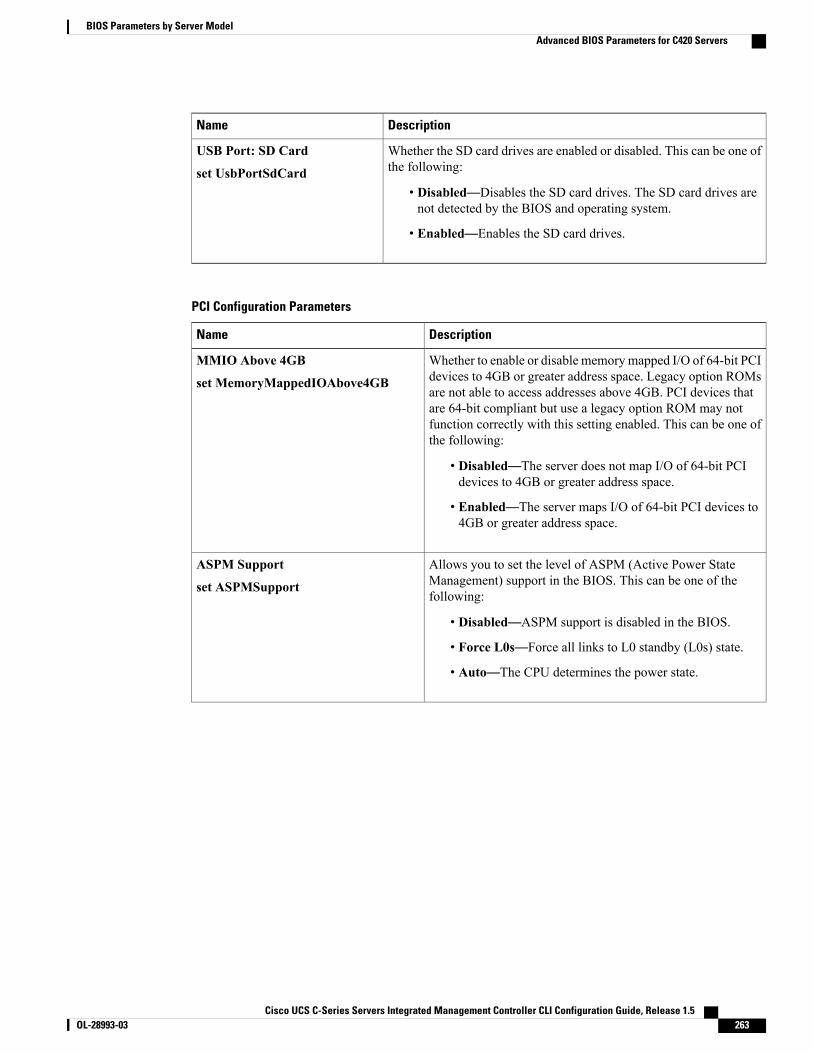
DescriptionName
Whether the SD card drives are enabled or disabled. This can be one ofthe following:
• Disabled—Disables the SD card drives. The SD card drives arenot detected by the BIOS and operating system.
• Enabled—Enables the SD card drives.
USB Port: SD Card
set UsbPortSdCard
PCI Configuration Parameters
DescriptionName
Whether to enable or disable memorymapped I/O of 64-bit PCIdevices to 4GB or greater address space. Legacy option ROMsare not able to access addresses above 4GB. PCI devices thatare 64-bit compliant but use a legacy option ROM may notfunction correctly with this setting enabled. This can be one ofthe following:
• Disabled—The server does not map I/O of 64-bit PCIdevices to 4GB or greater address space.
• Enabled—The server maps I/O of 64-bit PCI devices to4GB or greater address space.
MMIO Above 4GB
set MemoryMappedIOAbove4GB
Allows you to set the level of ASPM (Active Power StateManagement) support in the BIOS. This can be one of thefollowing:
• Disabled—ASPM support is disabled in the BIOS.
• Force L0s—Force all links to L0 standby (L0s) state.
• Auto—The CPU determines the power state.
ASPM Support
set ASPMSupport
Cisco UCS C-Series Servers Integrated Management Controller CLI Configuration Guide, Release 1.5 OL-28993-03 263
BIOS Parameters by Server ModelAdvanced BIOS Parameters for C420 Servers
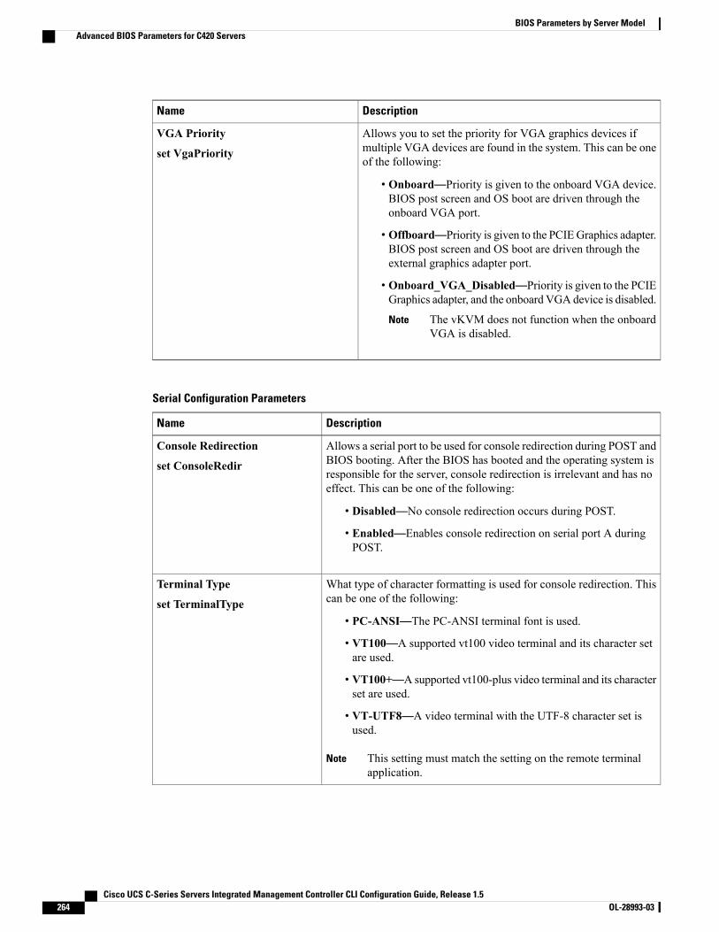
DescriptionName
Allows you to set the priority for VGA graphics devices ifmultiple VGA devices are found in the system. This can be oneof the following:
• Onboard—Priority is given to the onboard VGA device.BIOS post screen and OS boot are driven through theonboard VGA port.
• Offboard—Priority is given to the PCIEGraphics adapter.BIOS post screen and OS boot are driven through theexternal graphics adapter port.
• Onboard_VGA_Disabled—Priority is given to the PCIEGraphics adapter, and the onboard VGA device is disabled.
The vKVM does not function when the onboardVGA is disabled.
Note
VGA Priority
set VgaPriority
Serial Configuration Parameters
DescriptionName
Allows a serial port to be used for console redirection during POST andBIOS booting. After the BIOS has booted and the operating system isresponsible for the server, console redirection is irrelevant and has noeffect. This can be one of the following:
• Disabled—No console redirection occurs during POST.
• Enabled—Enables console redirection on serial port A duringPOST.
Console Redirection
set ConsoleRedir
What type of character formatting is used for console redirection. Thiscan be one of the following:
• PC-ANSI—The PC-ANSI terminal font is used.
• VT100—A supported vt100 video terminal and its character setare used.
• VT100+—A supported vt100-plus video terminal and its characterset are used.
• VT-UTF8—A video terminal with the UTF-8 character set isused.
This setting must match the setting on the remote terminalapplication.
Note
Terminal Type
set TerminalType
Cisco UCS C-Series Servers Integrated Management Controller CLI Configuration Guide, Release 1.5264 OL-28993-03
BIOS Parameters by Server ModelAdvanced BIOS Parameters for C420 Servers
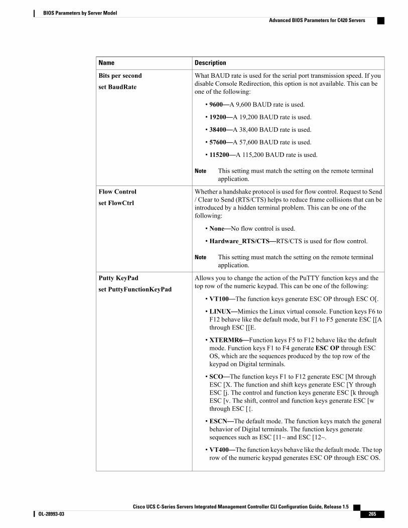
DescriptionName
What BAUD rate is used for the serial port transmission speed. If youdisable Console Redirection, this option is not available. This can beone of the following:
• 9600—A 9,600 BAUD rate is used.
• 19200—A 19,200 BAUD rate is used.
• 38400—A 38,400 BAUD rate is used.
• 57600—A 57,600 BAUD rate is used.
• 115200—A 115,200 BAUD rate is used.
This setting must match the setting on the remote terminalapplication.
Note
Bits per second
set BaudRate
Whether a handshake protocol is used for flow control. Request to Send/ Clear to Send (RTS/CTS) helps to reduce frame collisions that can beintroduced by a hidden terminal problem. This can be one of thefollowing:
• None—No flow control is used.
• Hardware_RTS/CTS—RTS/CTS is used for flow control.
This setting must match the setting on the remote terminalapplication.
Note
Flow Control
set FlowCtrl
Allows you to change the action of the PuTTY function keys and thetop row of the numeric keypad. This can be one of the following:
• VT100—The function keys generate ESC OP through ESC O[.
• LINUX—Mimics the Linux virtual console. Function keys F6 toF12 behave like the default mode, but F1 to F5 generate ESC [[Athrough ESC [[E.
• XTERMR6—Function keys F5 to F12 behave like the defaultmode. Function keys F1 to F4 generate ESC OP through ESCOS, which are the sequences produced by the top row of thekeypad on Digital terminals.
• SCO—The function keys F1 to F12 generate ESC [M throughESC [X. The function and shift keys generate ESC [Y throughESC [j. The control and function keys generate ESC [k throughESC [v. The shift, control and function keys generate ESC [wthrough ESC [{.
• ESCN—The default mode. The function keys match the generalbehavior of Digital terminals. The function keys generatesequences such as ESC [11~ and ESC [12~.
• VT400—The function keys behave like the default mode. The toprow of the numeric keypad generates ESC OP through ESC OS.
Putty KeyPad
set PuttyFunctionKeyPad
Cisco UCS C-Series Servers Integrated Management Controller CLI Configuration Guide, Release 1.5 OL-28993-03 265
BIOS Parameters by Server ModelAdvanced BIOS Parameters for C420 Servers

DescriptionName
Whether BIOS console redirection should be active after BIOS POSTis complete and control given to the OS bootloader. This can be one ofthe following:
• Always_Enable—BIOS Legacy console redirection is activeduring the OS boot and run time.
• Bootloader—BIOS Legacy console redirection is disabled beforegiving control to the OS boot loader.
Redirection After BIOS POST
set RedirectionAfterPOST
LOM and PCIe Slots Configuration Parameters
DescriptionName
Whether all LOM ports are enabled or disabled. This can be one of thefollowing:
• Disabled—All LOM ports are disabled.
• Enabled—All LOM ports are enabled.
All Onboard LOM Ports
set AllLomPortControl
Whether Option ROM is available on the LOM port designated by n.This can be one of the following:
• Disabled—Option ROM is not available on LOM port n.
• Enabled—Option ROM is available on LOM port n.
• UEFI_Only—The expansion slot n is available for UEFI only.
• Legacy_Only—The expansion slot n is available for legacy only.
LOM Port n OptionROM
set LomOpromControlPortn
Whether the server can use the PCIe Option ROM expansion slots. Thiscan be one of the following:
• Disabled—PCIe Option ROMs are not available.
• Enabled—PCIe Option ROMs are available.
• UEFI_Only—The expansion slot n is available for UEFI only.
• Legacy_Only—The expansion slot n is available for legacy only.
All PCIe Slots OptionROM
set PcieOptionROMs
Cisco UCS C-Series Servers Integrated Management Controller CLI Configuration Guide, Release 1.5266 OL-28993-03
BIOS Parameters by Server ModelAdvanced BIOS Parameters for C420 Servers

DescriptionName
Whether PCIe expansion slot n is available to the server. This can beone of the following:
• Disabled—The expansion slot n is not available.
• Enabled—The expansion slot n is available.
• UEFI_Only—The expansion slot n is available for UEFI only.
• Legacy_Only—The expansion slot n is available for legacy only.
PCIe Slot:n OptionROM
set PcieSlotnOptionROM
This option allows you to restrict the maximum speed of an adaptercard installed in PCIe slot n. This can be one of the following:
• GEN1—2.5GT/s (gigatransfers per second) is themaximum speedallowed.
• GEN2—5GT/s is the maximum speed allowed.
• GEN3—8GT/s is the maximum speed allowed.
• Disabled—The maximum speed is not restricted.
For example, if you have a 3rd generation adapter card in PCIe slot 2that you want to run at a maximum of 5GT/s instead of the 8GT/s thatcard supports, set the PCIe Slot 2 Link Speed to GEN2. The systemthen ignores the card's supported maximum speed of 8GT/s and forcesit to run at a maximum of 5 GT/s.
PCIe Slot:n Link Speed
PCIe Slot:nLinkSpeed
Server Management BIOS Parameters for C420 ServersDescriptionName
Whether the FRB2 timer is used by CIMC to recover the systemif it hangs during POST. This can be one of the following:
• Disabled—The FRB2 timer is not used.
• Enabled—The FRB2 timer is started during POST andused to recover the system if necessary.
FRB-2 Timer
set FRB-2
Cisco UCS C-Series Servers Integrated Management Controller CLI Configuration Guide, Release 1.5 OL-28993-03 267
BIOS Parameters by Server ModelServer Management BIOS Parameters for C420 Servers
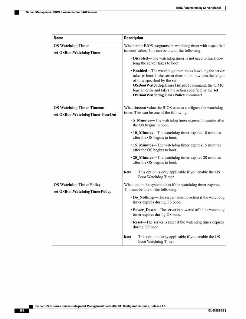
DescriptionName
Whether the BIOS programs the watchdog timer with a specifiedtimeout value. This can be one of the following:
• Disabled—The watchdog timer is not used to track howlong the server takes to boot.
• Enabled—The watchdog timer tracks how long the servertakes to boot. If the server does not boot within the lengthof time specified by the setOSBootWatchdogTimerTimeout command, the CIMClogs an error and takes the action specified by the setOSBootWatchdogTimerPolicy command.
OSWatchdog Timer
set OSBootWatchdogTimer
What timeout value the BIOS uses to configure the watchdogtimer. This can be one of the following:
• 5_Minutes—The watchdog timer expires 5 minutes afterthe OS begins to boot.
• 10_Minutes—The watchdog timer expires 10 minutesafter the OS begins to boot.
• 15_Minutes—The watchdog timer expires 15 minutesafter the OS begins to boot.
• 20_Minutes—The watchdog timer expires 20 minutesafter the OS begins to boot.
This option is only applicable if you enable the OSBoot Watchdog Timer.
Note
OSWatchdog Timer Timeout
set OSBootWatchdogTimerTimeOut
What action the system takes if the watchdog timer expires.This can be one of the following:
• Do_Nothing—The server takes no action if the watchdogtimer expires during OS boot.
• Power_Down—The server is powered off if the watchdogtimer expires during OS boot.
• Reset—The server is reset if the watchdog timer expiresduring OS boot.
This option is only applicable if you enable the OSBoot Watchdog Timer.
Note
OSWatchdog Timer Policy
set OSBootWatchdogTimerPolicy
Cisco UCS C-Series Servers Integrated Management Controller CLI Configuration Guide, Release 1.5268 OL-28993-03
BIOS Parameters by Server ModelServer Management BIOS Parameters for C420 Servers
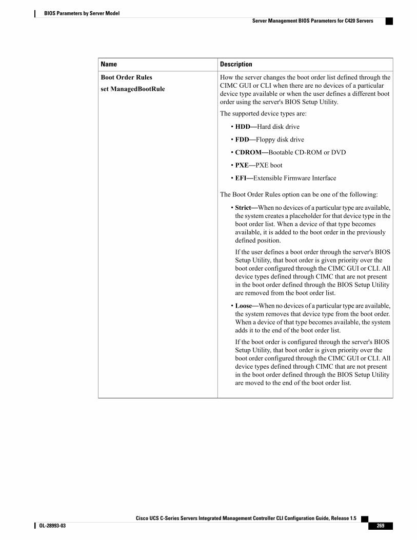
DescriptionName
How the server changes the boot order list defined through theCIMC GUI or CLI when there are no devices of a particulardevice type available or when the user defines a different bootorder using the server's BIOS Setup Utility.
The supported device types are:
• HDD—Hard disk drive
• FDD—Floppy disk drive
• CDROM—Bootable CD-ROM or DVD
• PXE—PXE boot
• EFI—Extensible Firmware Interface
The Boot Order Rules option can be one of the following:
• Strict—When no devices of a particular type are available,the system creates a placeholder for that device type in theboot order list. When a device of that type becomesavailable, it is added to the boot order in the previouslydefined position.
If the user defines a boot order through the server's BIOSSetup Utility, that boot order is given priority over theboot order configured through the CIMC GUI or CLI. Alldevice types defined through CIMC that are not presentin the boot order defined through the BIOS Setup Utilityare removed from the boot order list.
• Loose—When no devices of a particular type are available,the system removes that device type from the boot order.When a device of that type becomes available, the systemadds it to the end of the boot order list.
If the boot order is configured through the server's BIOSSetup Utility, that boot order is given priority over theboot order configured through the CIMC GUI or CLI. Alldevice types defined through CIMC that are not presentin the boot order defined through the BIOS Setup Utilityare moved to the end of the boot order list.
Boot Order Rules
set ManagedBootRule
Cisco UCS C-Series Servers Integrated Management Controller CLI Configuration Guide, Release 1.5 OL-28993-03 269
BIOS Parameters by Server ModelServer Management BIOS Parameters for C420 Servers
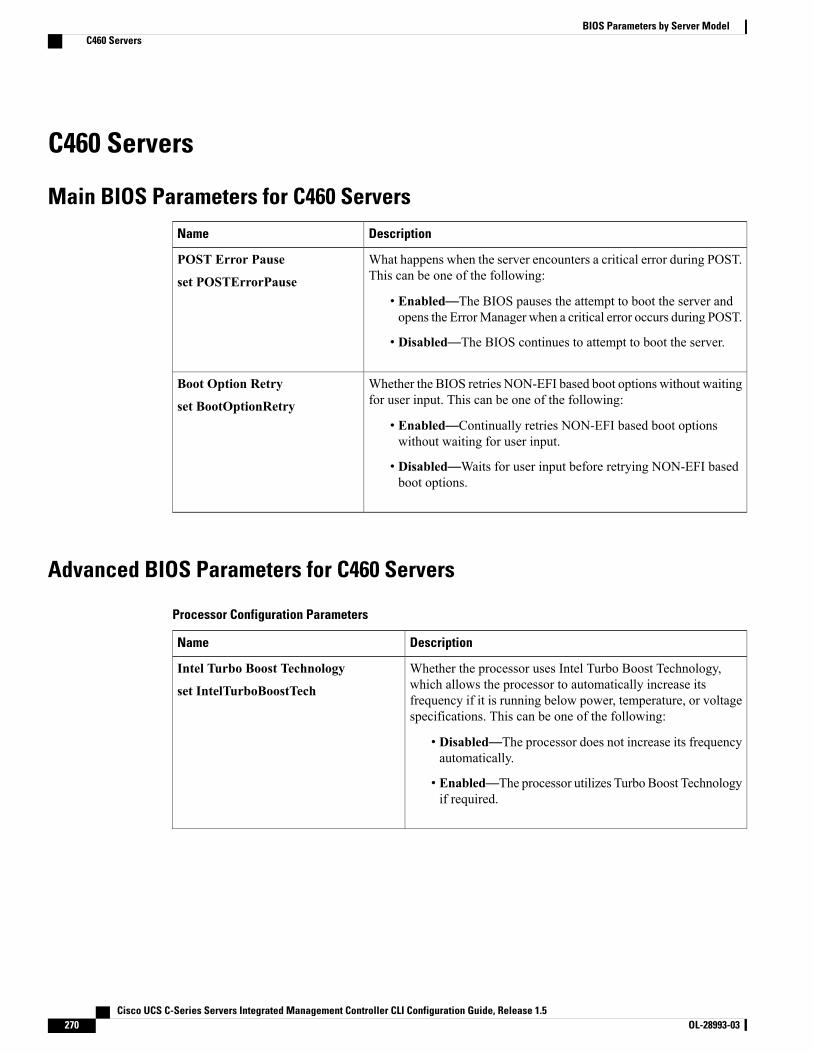
C460 Servers
Main BIOS Parameters for C460 ServersDescriptionName
What happens when the server encounters a critical error during POST.This can be one of the following:
• Enabled—The BIOS pauses the attempt to boot the server andopens the ErrorManager when a critical error occurs during POST.
• Disabled—The BIOS continues to attempt to boot the server.
POST Error Pause
set POSTErrorPause
Whether the BIOS retries NON-EFI based boot options without waitingfor user input. This can be one of the following:
• Enabled—Continually retries NON-EFI based boot optionswithout waiting for user input.
• Disabled—Waits for user input before retrying NON-EFI basedboot options.
Boot Option Retry
set BootOptionRetry
Advanced BIOS Parameters for C460 Servers
Processor Configuration Parameters
DescriptionName
Whether the processor uses Intel Turbo Boost Technology,which allows the processor to automatically increase itsfrequency if it is running below power, temperature, or voltagespecifications. This can be one of the following:
• Disabled—The processor does not increase its frequencyautomatically.
• Enabled—The processor utilizes Turbo Boost Technologyif required.
Intel Turbo Boost Technology
set IntelTurboBoostTech
Cisco UCS C-Series Servers Integrated Management Controller CLI Configuration Guide, Release 1.5270 OL-28993-03
BIOS Parameters by Server ModelC460 Servers

DescriptionName
Whether the processor uses Enhanced Intel SpeedStepTechnology, which allows the system to dynamically adjustprocessor voltage and core frequency. This technology can resultin decreased average power consumption and decreased averageheat production. This can be one of the following:
• Disabled—The processor never dynamically adjusts itsvoltage or frequency.
• Enabled—The processor utilizes Enhanced IntelSpeedStep Technology and enables all supported processorsleep states to further conserve power.
We recommend that you contact your operating system vendorto make sure the operating system supports this feature.
Enhanced Intel Speedstep Technology
set EnhancedIntelSpeedStep
Whether the processor uses Intel Hyper-Threading Technology,which allows multithreaded software applications to executethreads in parallel within each processor. This can be one of thefollowing:
• Disabled—The processor does not permit hyperthreading.
• Enabled—The processor allows for the parallel executionof multiple threads.
We recommend that you contact your operating system vendorto make sure the operating system supports this feature.
Intel Hyper-Threading Technology
set IntelHyperThread
Allows you to disable one or more of the physical cores on theserver. This can be one of the following:
• All—Enables all physical cores. This also enables HyperThreading on the associated logical processor cores.
• 1 through n—Specifies the number of physical processorcores that can run on the server. Each physical core hasan associated logical core.
We recommend that you contact your operating system vendorto make sure the operating system supports this feature.
Number of Enabled Cores
set CoreMultiProcessing
Cisco UCS C-Series Servers Integrated Management Controller CLI Configuration Guide, Release 1.5 OL-28993-03 271
BIOS Parameters by Server ModelAdvanced BIOS Parameters for C460 Servers
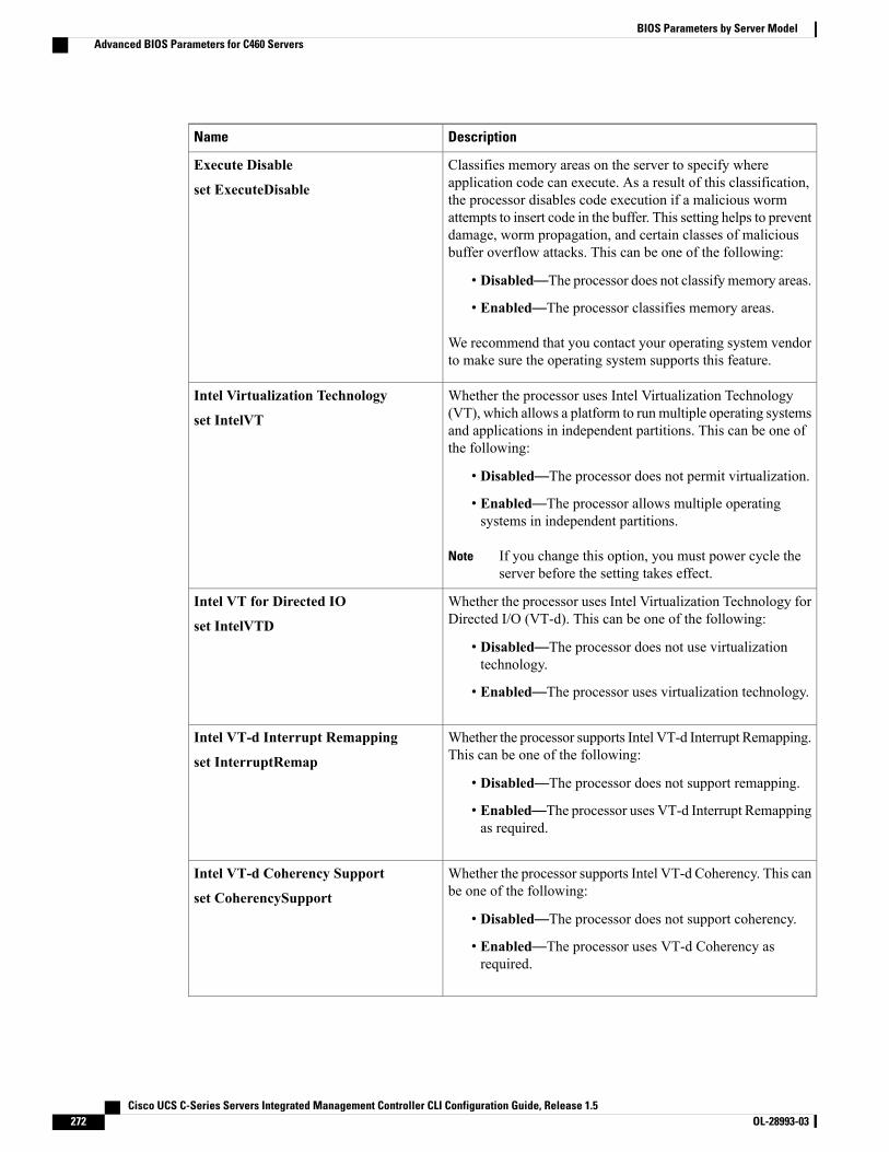
DescriptionName
Classifies memory areas on the server to specify whereapplication code can execute. As a result of this classification,the processor disables code execution if a malicious wormattempts to insert code in the buffer. This setting helps to preventdamage, worm propagation, and certain classes of maliciousbuffer overflow attacks. This can be one of the following:
• Disabled—The processor does not classify memory areas.
• Enabled—The processor classifies memory areas.
We recommend that you contact your operating system vendorto make sure the operating system supports this feature.
Execute Disable
set ExecuteDisable
Whether the processor uses Intel Virtualization Technology(VT), which allows a platform to run multiple operating systemsand applications in independent partitions. This can be one ofthe following:
• Disabled—The processor does not permit virtualization.
• Enabled—The processor allows multiple operatingsystems in independent partitions.
If you change this option, you must power cycle theserver before the setting takes effect.
Note
Intel Virtualization Technology
set IntelVT
Whether the processor uses Intel Virtualization Technology forDirected I/O (VT-d). This can be one of the following:
• Disabled—The processor does not use virtualizationtechnology.
• Enabled—The processor uses virtualization technology.
Intel VT for Directed IO
set IntelVTD
Whether the processor supports Intel VT-d Interrupt Remapping.This can be one of the following:
• Disabled—The processor does not support remapping.
• Enabled—The processor uses VT-d Interrupt Remappingas required.
Intel VT-d Interrupt Remapping
set InterruptRemap
Whether the processor supports Intel VT-d Coherency. This canbe one of the following:
• Disabled—The processor does not support coherency.
• Enabled—The processor uses VT-d Coherency asrequired.
Intel VT-d Coherency Support
set CoherencySupport
Cisco UCS C-Series Servers Integrated Management Controller CLI Configuration Guide, Release 1.5272 OL-28993-03
BIOS Parameters by Server ModelAdvanced BIOS Parameters for C460 Servers
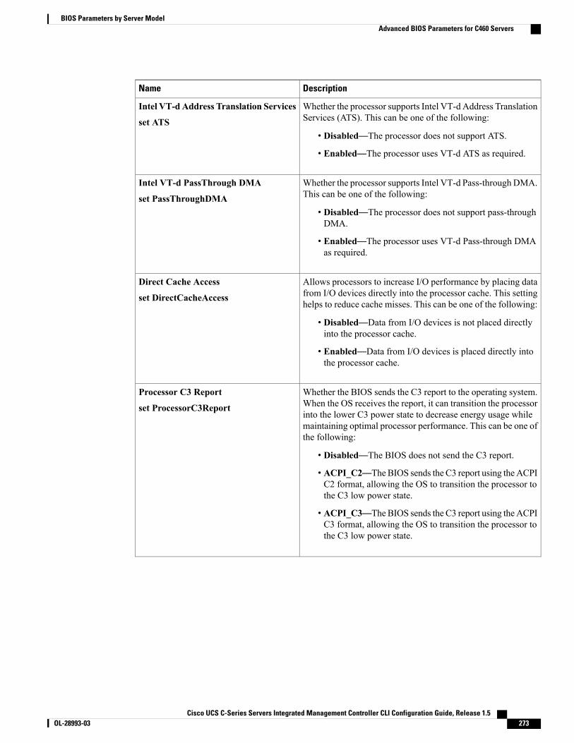
DescriptionName
Whether the processor supports Intel VT-d Address TranslationServices (ATS). This can be one of the following:
• Disabled—The processor does not support ATS.
• Enabled—The processor uses VT-d ATS as required.
Intel VT-dAddress Translation Services
set ATS
Whether the processor supports Intel VT-d Pass-through DMA.This can be one of the following:
• Disabled—The processor does not support pass-throughDMA.
• Enabled—The processor uses VT-d Pass-through DMAas required.
Intel VT-d PassThrough DMA
set PassThroughDMA
Allows processors to increase I/O performance by placing datafrom I/O devices directly into the processor cache. This settinghelps to reduce cache misses. This can be one of the following:
• Disabled—Data from I/O devices is not placed directlyinto the processor cache.
• Enabled—Data from I/O devices is placed directly intothe processor cache.
Direct Cache Access
set DirectCacheAccess
Whether the BIOS sends the C3 report to the operating system.When the OS receives the report, it can transition the processorinto the lower C3 power state to decrease energy usage whilemaintaining optimal processor performance. This can be one ofthe following:
• Disabled—The BIOS does not send the C3 report.
• ACPI_C2—TheBIOS sends the C3 report using the ACPIC2 format, allowing the OS to transition the processor tothe C3 low power state.
• ACPI_C3—TheBIOS sends the C3 report using the ACPIC3 format, allowing the OS to transition the processor tothe C3 low power state.
Processor C3 Report
set ProcessorC3Report
Cisco UCS C-Series Servers Integrated Management Controller CLI Configuration Guide, Release 1.5 OL-28993-03 273
BIOS Parameters by Server ModelAdvanced BIOS Parameters for C460 Servers
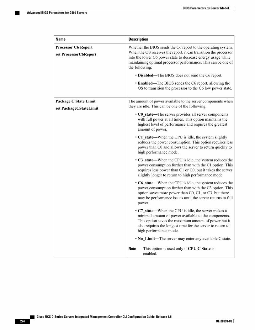
DescriptionName
Whether the BIOS sends the C6 report to the operating system.When the OS receives the report, it can transition the processorinto the lower C6 power state to decrease energy usage whilemaintaining optimal processor performance. This can be one ofthe following:
• Disabled—The BIOS does not send the C6 report.
• Enabled—The BIOS sends the C6 report, allowing theOS to transition the processor to the C6 low power state.
Processor C6 Report
set ProcessorC6Report
The amount of power available to the server components whenthey are idle. This can be one of the following:
• C0_state—The server provides all server componentswith full power at all times. This option maintains thehighest level of performance and requires the greatestamount of power.
• C1_state—When the CPU is idle, the system slightlyreduces the power consumption. This option requires lesspower than C0 and allows the server to return quickly tohigh performance mode.
• C3_state—When the CPU is idle, the system reduces thepower consumption further than with the C1 option. Thisrequires less power than C1 or C0, but it takes the serverslightly longer to return to high performance mode.
• C6_state—When the CPU is idle, the system reduces thepower consumption further than with the C3 option. Thisoption saves more power than C0, C1, or C3, but theremay be performance issues until the server returns to fullpower.
• C7_state—When the CPU is idle, the server makes aminimal amount of power available to the components.This option saves the maximum amount of power but italso requires the longest time for the server to return tohigh performance mode.
• No_Limit—The server may enter any available C state.
This option is used only if CPU C State isenabled.
Note
Package C State Limit
set PackageCStateLimit
Cisco UCS C-Series Servers Integrated Management Controller CLI Configuration Guide, Release 1.5274 OL-28993-03
BIOS Parameters by Server ModelAdvanced BIOS Parameters for C460 Servers

DescriptionName
Whether the system can enter a power savings mode during idleperiods. This can be one of the following:
• Disabled—The system remains in high performance stateeven when idle.
• Enabled—The system can reduce power to systemcomponents such as the DIMMs and CPUs. The amountof power reduction is specified by the setPackageCStateLimit command.
CPU C State
set ProcessorCcxEnable
Whether the CPU transitions to its minimum frequency whenentering the C1 state. This can be one of the following:
• Disabled—The CPU continues to run at its maximumfrequency in C1 state.
• Enabled—The CPU transitions to its minimum frequency.This option saves the maximum amount of power in C1state.
This option is used only if ProcessorCcxEnable isenabled.
Note
C1E
set ProcessorC1eEnable
Memory Configuration Parameters
DescriptionName
How the memory reliability, availability, and serviceability(RAS) is configured for the server. This can be one of thefollowing:
•Maximum_Performance—System performance isoptimized.
•Mirroring—System reliability is optimized by using halfthe system memory as backup.
• Sparing—The system reserves some memory for use inthe event a DIMM fails. If that happens, the server takesthe DIMM offline and replaces it with the reservedmemory. This option provides less redundancy thanmirroring, but it leaves more of the memory available forprograms running on the server.
Select Memory RAS
set SelectMemoryRAS
Cisco UCS C-Series Servers Integrated Management Controller CLI Configuration Guide, Release 1.5 OL-28993-03 275
BIOS Parameters by Server ModelAdvanced BIOS Parameters for C460 Servers
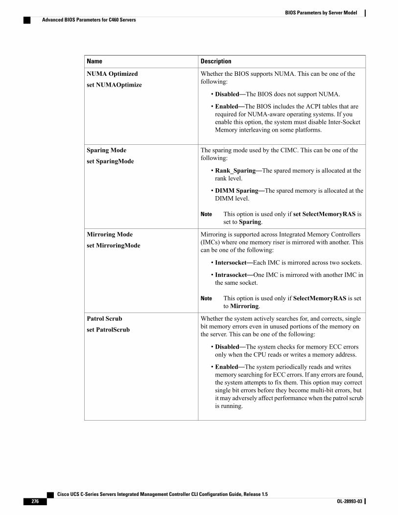
DescriptionName
Whether the BIOS supports NUMA. This can be one of thefollowing:
• Disabled—The BIOS does not support NUMA.
• Enabled—The BIOS includes the ACPI tables that arerequired for NUMA-aware operating systems. If youenable this option, the system must disable Inter-SocketMemory interleaving on some platforms.
NUMA Optimized
set NUMAOptimize
The sparing mode used by the CIMC. This can be one of thefollowing:
• Rank_Sparing—The spared memory is allocated at therank level.
• DIMM Sparing—The spared memory is allocated at theDIMM level.
This option is used only if set SelectMemoryRAS isset to Sparing.
Note
Sparing Mode
set SparingMode
Mirroring is supported across Integrated Memory Controllers(IMCs) where one memory riser is mirrored with another. Thiscan be one of the following:
• Intersocket—Each IMC is mirrored across two sockets.
• Intrasocket—One IMC is mirrored with another IMC inthe same socket.
This option is used only if SelectMemoryRAS is settoMirroring.
Note
Mirroring Mode
set MirroringMode
Whether the system actively searches for, and corrects, singlebit memory errors even in unused portions of the memory onthe server. This can be one of the following:
• Disabled—The system checks for memory ECC errorsonly when the CPU reads or writes a memory address.
• Enabled—The system periodically reads and writesmemory searching for ECC errors. If any errors are found,the system attempts to fix them. This option may correctsingle bit errors before they become multi-bit errors, butit may adversely affect performance when the patrol scrubis running.
Patrol Scrub
set PatrolScrub
Cisco UCS C-Series Servers Integrated Management Controller CLI Configuration Guide, Release 1.5276 OL-28993-03
BIOS Parameters by Server ModelAdvanced BIOS Parameters for C460 Servers
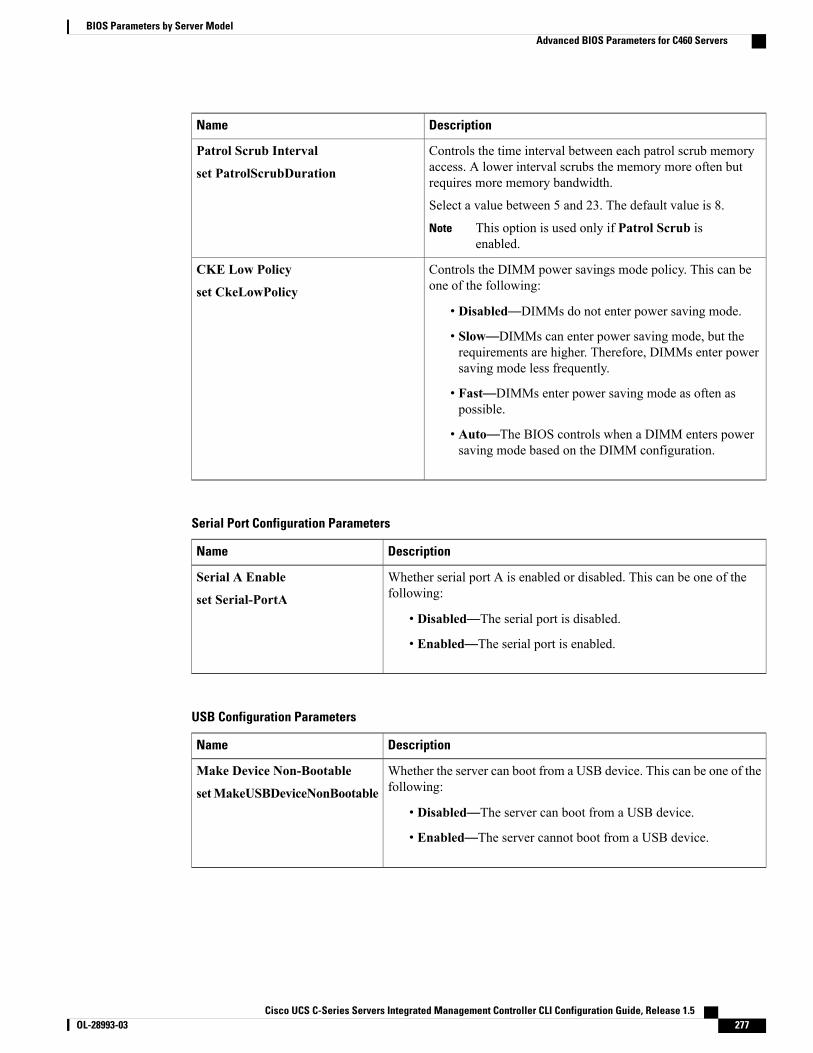
DescriptionName
Controls the time interval between each patrol scrub memoryaccess. A lower interval scrubs the memory more often butrequires more memory bandwidth.
Select a value between 5 and 23. The default value is 8.
This option is used only if Patrol Scrub isenabled.
Note
Patrol Scrub Interval
set PatrolScrubDuration
Controls the DIMM power savings mode policy. This can beone of the following:
• Disabled—DIMMs do not enter power saving mode.
• Slow—DIMMs can enter power saving mode, but therequirements are higher. Therefore, DIMMs enter powersaving mode less frequently.
• Fast—DIMMs enter power saving mode as often aspossible.
• Auto—The BIOS controls when a DIMM enters powersaving mode based on the DIMM configuration.
CKE Low Policy
set CkeLowPolicy
Serial Port Configuration Parameters
DescriptionName
Whether serial port A is enabled or disabled. This can be one of thefollowing:
• Disabled—The serial port is disabled.
• Enabled—The serial port is enabled.
Serial A Enable
set Serial-PortA
USB Configuration Parameters
DescriptionName
Whether the server can boot from a USB device. This can be one of thefollowing:
• Disabled—The server can boot from a USB device.
• Enabled—The server cannot boot from a USB device.
Make Device Non-Bootable
setMakeUSBDeviceNonBootable
Cisco UCS C-Series Servers Integrated Management Controller CLI Configuration Guide, Release 1.5 OL-28993-03 277
BIOS Parameters by Server ModelAdvanced BIOS Parameters for C460 Servers
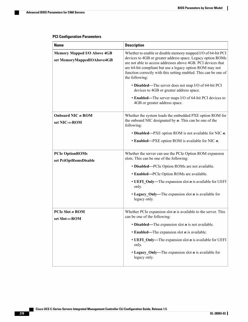
PCI Configuration Parameters
DescriptionName
Whether to enable or disable memorymapped I/O of 64-bit PCIdevices to 4GB or greater address space. Legacy option ROMsare not able to access addresses above 4GB. PCI devices thatare 64-bit compliant but use a legacy option ROM may notfunction correctly with this setting enabled. This can be one ofthe following:
• Disabled—The server does not map I/O of 64-bit PCIdevices to 4GB or greater address space.
• Enabled—The server maps I/O of 64-bit PCI devices to4GB or greater address space.
Memory Mapped I/O Above 4GB
set MemoryMappedIOAbove4GB
Whether the system loads the embedded PXE option ROM forthe onboard NIC designated by n. This can be one of thefollowing:
• Disabled—PXE option ROM is not available for NIC n.
• Enabled—PXE option ROM is available for NIC n.
Onboard NIC n ROM
set NIC-n-ROM
Whether the server can use the PCIe Option ROM expansionslots. This can be one of the following:
• Disabled—PCIe Option ROMs are not available.
• Enabled—PCIe Option ROMs are available.
• UEFI_Only—The expansion slot n is available for UEFIonly.
• Legacy_Only—The expansion slot n is available forlegacy only.
PCIe OptionROMs
set PciOptRomsDisable
Whether PCIe expansion slot n is available to the server. Thiscan be one of the following:
• Disabled—The expansion slot n is not available.
• Enabled—The expansion slot n is available.
• UEFI_Only—The expansion slot n is available for UEFIonly.
• Legacy_Only—The expansion slot n is available forlegacy only.
PCIe Slot n ROM
set Slot-n-ROM
Cisco UCS C-Series Servers Integrated Management Controller CLI Configuration Guide, Release 1.5278 OL-28993-03
BIOS Parameters by Server ModelAdvanced BIOS Parameters for C460 Servers
DescriptionName
Whether Gbit LOM is enabled or disabled on the server. Thiscan be one of the following:
• Disabled—Gbit LOM is not available.
• Enabled—10Git LOM is available.
Onboard Gbit LOM
set OnboardNic1
Whether 10Gbit LOM is enabled or disabled on the server. Thiscan be one of the following:
• Disabled—10GBit LOM is not available.
• Enabled—10GBit LOM is available.
Onboard 10Gbit LOM
set OnboardNic2
Whether SR-IOV (Single Root I/O Virtualization) is enabledor disabled on the server. This can be one of the following:
• Disabled—SR-IOV is disabled.
• Enabled—SR-IOV is enabled.
Sriov
set SrIov
Enables you to distribute 64KB of 16-bit IO resources betweenIOH0 and IOH1 as per system requirement. This can be one ofthe following:
• IOH0 24k IOH1 40k— Allocates 24KB of 16-bit IOresources to IOH0 and 40KB of 16-bit IO resources toIOH1.
• IOH0 32k IOH1 32k— Allocates 32KB of 16-bit IOresources to IOH0 and 32KB of 16-bit IO resources toIOH1.
• IOH0 40k IOH1 24k— Allocates 40KB of 16-bit IOresources to IOH0 and 24KB of 16-bit IO resources toIOH1.
• IOH0 48k IOH1 16k— Allocates 48KB of 16-bit IOresources to IOH0 and 16KB of 16-bit IO resources toIOH1.
• IOH0 56k IOH1 8k— Allocates 56KB of 16-bit IOresources to IOH0 and 8KB of 16-bit IO resources toIOH1.
IOH Resource Allocation
set IOHResource
Cisco UCS C-Series Servers Integrated Management Controller CLI Configuration Guide, Release 1.5 OL-28993-03 279
BIOS Parameters by Server ModelAdvanced BIOS Parameters for C460 Servers
Server Management BIOS Parameters for C460 ServersDescriptionName
Whether the BIOS generates a non-maskable interrupt (NMI)and logs an error when a system error (SERR) occurs. This canbe one of the following:
• Disabled—The BIOS does not generate an NMI or log anerror when a SERR occurs.
• Enabled—The BIOS generates an NMI and logs an errorwhen a SERR occurs. You must enable this setting if youwant to enable Assert_NMI_on_PERR.
Assert NMI on SERR
set AssertNMIOnSERR
Whether the BIOS generates a non-maskable interrupt (NMI)and logs an error when a processor bus parity error (PERR)occurs. This can be one of the following:
• Disabled—The BIOS does not generate an NMI or log anerror when a PERR occurs.
• Enabled—The BIOS generates an NMI and logs an errorwhen a PERR occurs. You must enableAssert_NMI_on_SERR to use this setting.
Assert NMI on PERR
set AssertNMIOnPERR
Allows a serial port to be used for console redirection duringPOST and BIOS booting. After the BIOS has booted and theoperating system is responsible for the server, console redirectionis irrelevant and has no effect. This can be one of the following:
• Disabled—No console redirection occurs during POST.
• Serial_Port_A—Enables console redirection on serialport A during POST.
If you enable this option, you also disable the displayof the Quiet Boot logo screen during POST.
Note
Console Redirection
set ConsoleRedir
Whether a handshake protocol is used for flow control. Requestto Send / Clear to Send (RTS/CTS) helps to reduce framecollisions that can be introduced by a hidden terminal problem.This can be one of the following:
• None—No flow control is used.
• RTS-CTS—RTS/CTS is used for flow control.
This setting must match the setting on the remoteterminal application.
Note
Flow Control
set FlowCtrl
Cisco UCS C-Series Servers Integrated Management Controller CLI Configuration Guide, Release 1.5280 OL-28993-03
BIOS Parameters by Server ModelServer Management BIOS Parameters for C460 Servers
DescriptionName
What BAUD rate is used for the serial port transmission speed.If you disable Console Redirection, this option is not available.This can be one of the following:
• 9.6k—A 9600 BAUD rate is used.
• 19.2k—A 19200 BAUD rate is used.
• 38.4k—A 38400 BAUD rate is used.
• 57.6k—A 57600 BAUD rate is used.
• 115.2k—A 115200 BAUD rate is used.
This setting must match the setting on the remoteterminal application.
Note
Baud Rate
set BaudRate
What type of character formatting is used for console redirection.This can be one of the following:
• PC-ANSI—The PC-ANSI terminal font is used.
• VT100—A supported vt100 video terminal and itscharacter set are used.
• VT100-PLUS—A supported vt100-plus video terminaland its character set are used.
• VT-UTF8—A video terminal with the UTF-8 characterset is used.
This setting must match the setting on the remoteterminal application.
Note
Terminal Type
set TerminalType
What timeout value the BIOS uses to configure the watchdogtimer. This can be one of the following:
• 5_Minutes—The watchdog timer expires 5 minutes afterthe OS begins to boot.
• 10_Minutes—The watchdog timer expires 10 minutesafter the OS begins to boot.
• 15_Minutes—The watchdog timer expires 15 minutesafter the OS begins to boot.
• 20_Minutes—The watchdog timer expires 20 minutesafter the OS begins to boot.
This option is only applicable if you enable the OSBoot Watchdog Timer.
Note
OS Boot Watchdog Timer Timeout
set OSBootWatchdogTimerTimeOut
Cisco UCS C-Series Servers Integrated Management Controller CLI Configuration Guide, Release 1.5 OL-28993-03 281
BIOS Parameters by Server ModelServer Management BIOS Parameters for C460 Servers
DescriptionName
What action the system takes if the watchdog timer expires.This can be one of the following:
• Power_Off—The server is powered off if the watchdogtimer expires during OS boot.
• Reset—The server is reset if the watchdog timer expiresduring OS boot.
This option is only applicable if you enable the OSBoot Watchdog Timer.
Note
OS Boot Watchdog Policy
set OSBootWatchdogTimerPolicy
Whether redirection from a legacy operating system, such asDOS, is enabled on the serial port. This can be one of thefollowing:
• Disabled—The serial port enabled for console redirectionis hidden from the legacy operating system.
• Enabled—The serial port enabled for console redirectionis visible to the legacy operating system.
Legacy OS Redirection
set LegacyOSRedir
Whether the BIOS programs the watchdog timer with a specifiedtimeout value. This can be one of the following:
• Disabled—The watchdog timer is not used to track howlong the server takes to boot.
• Enabled—The watchdog timer tracks how long the servertakes to boot. If the server does not boot within the lengthof time specified by the setOSBootWatchdogTimerTimeout command, the CIMClogs an error and takes the action specified by the setOSBootWatchdogTimerPolicy command.
OS Boot Watchdog Timer
set OSBootWatchdogTimer
Cisco UCS C-Series Servers Integrated Management Controller CLI Configuration Guide, Release 1.5282 OL-28993-03
BIOS Parameters by Server ModelServer Management BIOS Parameters for C460 Servers
I N D E X
A
Active Directory 75configuring groups 75
adapter 52, 93, 142, 143, 144, 145, 146activating firmware 145configuring properties 93exporting the configuration 142firmware 144importing the configuration 143installing firmware 144network 93PCI 52resetting 146restoring default configuration 144viewing properties 93
adapters 91overview 91
advanced BIOS parameters 198, 217, 237, 251, 270C22 and C24 servers 198C220 and C240 servers 217C260 server 237C420 servers 251C460 server 270
B
backing up 192CIMC configuration 192
bios 190recovering corrupt 190
BIOS 172, 176installing from remote server 176obtaining firmware from Cisco 172
BIOS parameters 197, 198, 214, 217, 234, 237, 247, 250, 251, 267, 270, 280
advanced parameters for C22 and C24 198advanced parameters for C220 and C240 217advanced parameters for C260 237advanced parameters for C420 251advanced parameters for C460 270
BIOS parameters (continued)main parameters for C22 and C24 197main parameters for C220 and C240 217main parameters for C260 237main parameters for C420 250main parameters for C460 270server management parameters for C22 and C24 214server management parameters for C220 and C240 234server management parameters for C260 247server management parameters for C420 267server management parameters for C460 280
BIOS settings 17, 37, 38, 39advanced 38main 37restoring defaults 39server boot order 17server management 39
BIOS status 36viewing 36
boot order 17, 18about 17configuring 17viewing 18
boot table 102, 103creating entry 102deleting entry 102, 103description 102
C
C22 and C24 servers 197, 198, 214advanced BIOS parameters 198main BIOS parameters 197server management BIOS parameters 214
C220 and C240 servers 217, 234advanced BIOS parameters 217main BIOS parameters 217server management BIOS parameters 234
C260 server 237, 247advanced BIOS parameters 237main BIOS parameters 237
Cisco UCS C-Series Servers Integrated Management Controller CLI Configuration Guide, Release 1.5 OL-28993-03 IN-1
C260 server (continued)server management BIOS parameters 247
C420 server 250, 267main BIOS parameters 250server management BIOS parameters 267
C420 servers 251advanced BIOS parameters 251
C460 server 270, 280advanced BIOS parameters 270main BIOS parameters 270server management BIOS parameters 280
certificate management 161uploading a certificate 161
CIMC 44, 171, 172, 173, 174, 180, 181, 182, 191activating firmware 174clearing log 181configuring log threshold 181firmware overview 171installing firmware from remote server 173obtaining firmware from Cisco 172resetting to factory defaults 191sending log 182viewing log 180viewing properties 44
CIMC CLI 3CIMC overview 2CIMC-mapped vmedia volume 65, 66, 67
cifs 65nfs 65removing 67viewing properties 66www 65
clearing foreign configuration 132common properties 81communication services properties 147, 148, 150
HTTP properties 147IPMI over LAN properties 150SSH properties 148
configuration 192, 193backing up 192exporting 192importing 193
configuring 27fan policy 27
CPU properties 44create virtual drive 129Create Virtual Drive 131current sensors 58
D
date 44setting 44
delete virtual drive 133disabling KVM 62disabling-auto-learn 139
E
enabling KVM 62, 63enabling-auto-learn 139encrypting virtual media 64event filters, platform 163, 164
about 163configuring 164
event log, system 184, 185clearing 185viewing 184
events 163, 164platform 163, 164
disabling alerts 164enabling alerts 163
exporting 192CIMC configuration 192
F
fan policy 26balanced 26high power 26low power 26maximum power 26performance 26
fan sensors 56fault summary 179
viewing 179faults, logs 179
viewing summary 179FEX 124
description 124viewing properties 124
FIP mode 93enabling 93
firmware 171, 172, 173, 174about 171activating 174installing from remote server 173obtaining from Cisco 172
Flexible Flash 28, 31, 32, 33, 48booting from 32
Cisco UCS C-Series Servers Integrated Management Controller CLI Configuration Guide, Release 1.5IN-2 OL-28993-03
Index

Flexible Flash (continued)configuring properties 31description 28resetting 33viewing properties 48
floppy disk emulation 64
G
generate NMI 194
H
hard drive locator LED 16hot spare 136, 138
dedicated 136global 136, 138
HTTP properties 147
I
importing 193CIMC configuration 193
initializing virtual drive 133IP blocking 87IPMI over LAN 150
description 150IPMI over LAN properties 150IPv4 properties 82iscsi-boot 122
vNIC 122
K
KVM 62, 63configuring 63disabling 62enabling 62, 63
KVM console 11, 61
L
LDAP 72, 74See also Active Directoryconfiguring in CIMC 74
See also Active DirectoryLDAP Server 73local users 71
locator LED 16hard drive 16server 16
locator-led 141bbu 141
LOM ports 52viewing properties 52
M
MAC address 52LOM ports 52
main BIOS parameters 197, 217, 237, 250, 270C22 and C24 servers 197C220 and C240 servers 217C260 server 237C420 server 250C460 server 270
making a dedicated hot spare 136making a global hot spare 136, 138memory properties 45
N
network adapter 93viewing properties 93
network properties 80, 81, 82, 84, 85common properties 81IPv4 properties 82NIC properties 80port profile properties 85VLAN properties 84
network security 87NIC properties 80NIV mode 93
enabling 93NTP settings 88Nvidia GPU card information 51
temperature 51
O
OS boot 13USB port 13
OS installation 11, 12methods 11PXE 12
Cisco UCS C-Series Servers Integrated Management Controller CLI Configuration Guide, Release 1.5 OL-28993-03 IN-3
Index
P
PCI adapter 52viewing properties 52
persistent binding 104, 105, 106description 104disabling 105enabling 105rebuilding 106
platform event filters 163, 164about 163configuring 164
platform events 167interpreting traps 167
Platform events 163, 164diabling alerts 164enabling alerts 163
port profile properties 85power cap policy 23
configuring 23power capping policy 23
about 23power cycling the server 21power restore policy 25power statistics 22
viewing 22power supply properties 46power supply sensors 55powering off the server 20powering on the server 20prepare for removal 137PXE installation 12
R
recovering from a corrupted bios 190remote presence 62, 63, 64, 68, 70
configuring serial over LAN 68launching serial over LAN 70virtual KVM 62, 63virtual media 64
reset configuration of cards, Cisco FlexFlash Controller 34resetting the server 19restore BIOS manufacturing custom defaults 40
S
SD cards 30single to dual card mirroring 30
self-signed certificate 159
sensors 55, 56, 57, 58current 58fan 56power supply 55temperature 56voltage 57
serial over LAN 68, 70configuring 68launching 70
server 43viewing properties 43
server management 16, 17, 19, 20, 21hard drive locator LED 16power cycling the server 21powering off the server 20powering on the server 20resetting the server 19server boot order 17server locator LED 16shutting down the server 19
server management BIOS parameters 214, 234, 247, 267, 280C22 and C24 servers 214C220 and C240 servers 234C260 server 247C420 server 267C460 server 280
server NICs 79server overview 1server software 1set as boot drive 134shutting down the server 19SNMP 151, 153, 154
configuring properties 151configuring SNMPv3 users 154configuring trap settings 153sending test message 154
SSH properties 148start-learn-cycle 140storage properties 46, 49, 50
viewing adapter properties 46viewing physical drive properties 49viewing virtual drive properties 50
storage sensors 58viewing 58
synchronize card configuration, FlexFlash Controller 35syslog 182
sending CIMC log 182system event log 184, 185
clearing 185viewing 184
Cisco UCS C-Series Servers Integrated Management Controller CLI Configuration Guide, Release 1.5IN-4 OL-28993-03
Index
T
technical support data 187exporting 187
Telnet 3temperature sensors 56time 44
setting 44
U
undo prepare for removal 138Updating Firmware on Server Components 41uploading a server certificate 161user management 71, 74, 77
LDAP 74local users 71terminating user sessions 77viewing user sessions 77
user sessions 77terminating 77viewing 77
usNIC 120viewing properties 120
V
vHBA 94, 95, 96, 100, 101, 102, 103, 104, 105, 106boot table 102creating 100creating boot table entry 102deleting 101deleting boot table entry 102, 103disabling persistent binding 105enabling persistent binding 105guidelines for managing 94modifying properties 96
vHBA (continued)persistent binding 104rebuilding persistent binding 106viewing properties 95
viewing storage controller logs 141virtual drive 133, 134, 135
initializing 133modifying attributes 135set as boot drive 134
virtual KVM 62, 63virtual media 64VLAN properties 84VM FEX 124
description 124viewing properties 124
vNIC 107, 108, 113, 114, 121, 122, 123creating 113deleting 114guidelines for managing 107iscsi-boot 122iscsi-boot deletion 123modifying properties 108usnic deletion 121viewing properties 107
vNICs 122iSCSI-boot guidelines 122
voltage sensors 57
X
XML API 149description 149enabling 149
Y
YAML 8
Cisco UCS C-Series Servers Integrated Management Controller CLI Configuration Guide, Release 1.5 OL-28993-03 IN-5
Index

Cisco UCS C-Series Servers Integrated Management Controller CLI Configuration Guide, Release 1.5IN-6 OL-28993-03
Index