cis022-2 assignment 1 modulation report ver.2.2 complete.pdf
TRANSCRIPT

Mr. Lee Garner 1818623
ASSIGNMENT TOP SHEET
Faculty of Creative Arts, Technologies & Science Department of Computing Science & Technology
Student Ref. No 1818623 Unit Code
CIS022-2
Unit Name Wireless Communications and Networks
Deadline for Submission(s)
Tuesday 22nd March 2019
Student's name: Lee Garner
Student's ID: 1818623
Unit Leader's Name
Dr. Enjie Liu
Assignment Details: Assignment 1
Instructions to Student:
Please note: Work presented in an assessment must be the student's own. Plagiarism is where a student copies work from another
source, published or unpublished (including the work of a fellow student) and fails to acknowledge the influence of another's work
or to attribute quotes to the author. Plagiarism is an academic offence.
Work presented in an assessment must be your own. Plagiarism is where a student copies work from another source, published or
unpublished (including the work of another student) and fails to acknowledge the influence of another’s work or to attribute quotes
to the author. Plagiarism is an academic offence and the penalty can be serious. The University’s policies relating to Plagiarism
can be found in the regulations at http://www.luton.ac.uk/livingandstudying/qa/documents. To detect possible plagiarism we may
submit your work to the national plagiarism detection facility. This searches the Internet and an extensive database of reference
material including other students’ work to identify. Once your work has been submitted to the detection service it will be stored
electronically in a database and compared against work submitted from this and other universities. It will therefore be necessary to
take electronic copies of your materials for transmission, storage and comparison purposes and for the operational back-up process.
This material will be stored in this manner indefinitely.
I have read the above information and I confirm that this work is my own and that it may be processed and stored in the
manner described.
Signature (Print Name):.Lee Garner.......................................... Date: ...20/03/2019......................
Extension deadline
CAAS agrees that the assignment may be submitted ____ days after the deadline and should be marked without penalty.
CAAS confirmation.............................................................................. .....................................
All assignments must be electronically submitted using Turnitin (via BREO) by 11:59 pm on the due date.
Mr. Lee Garner 1818623
1 of 23 pages
Abstract: This Document contains information and performance analysis detailing on two types of modulation techniques: 16-QAM and 16-PSK. Implementation of these modulation strategies in wireless communication system has been investigated theoretically and in terms of a mathematical descriptive. Based on the mathematical analysis of the Bit Error Rate (BER), expressions of 16-phase-shift keying (PSK) and 16-quadrature amplitude modulation (QAM) are analytically obtained in the presence of a phase error. By averaging the statistics of the phase error, the performance penalty can be analytically examined as a function of the phase error variance. There using Matlab to show the corresponding performance of phase modulation and amplitude modulation techniques, the Matlab codes for 16-PSK and 16-QAM have been generated and the results of the simulations have been plotted and explained in Constellation Diagrams. To reflect the performance of the two types of modulation with respect to BER are also analysed and shown respectively.
Mr. Lee Garner 1818623
2 of 23 pages
Contents
Abstract: ........................................................................................................................................................ 1
Table of Figures: ............................................................................................................................................ 3
1. Introduction: ........................................................................................................................................ 4
2. 16-Phase Shift Keying (16-PSK): ........................................................................................................... 4
2.1. QPSK Signal Generation: ............................................................................................................... 5
2.2. Constellation Diagram-1: ................................................................................................................... 6
2.2. Mathematical Description -1: ....................................................................................................... 6
3. Quadrature Amplitude Modulation (QAM): ........................................................................................ 8
3.1. Constellation Diagram-2: .............................................................................................................. 8
3.3. Mathematical Description-2: ............................................................................................................. 9
Matlab Simulation Results: ..................................................................................................................... 10
4.1. 16-PSK Simulation Results: .............................................................................................................. 10
4.2. 16-QAM Simulation Results: ............................................................................................................ 12
4.3. Comparison of BER in 16-PSK and 16-QAM Simulation Results: ..................................................... 14
4. Advantages & Drawbacks of 16-PSK and 16-QAM in Wireless Communication: .............................. 15
5. Conclusions of the 16-PSk Vs 16-QAM: .............................................................................................. 16
References .................................................................................................................................................. 17
Appendixes:................................................................................................................................................. 19
Matlab 16-PSK Code 16-PSK Matlab Code: ............................................................................................ 19
Matlab 16-QAM Code 16-QAM Matlab Code: ....................................................................................... 20
Matlab Code Comparison of BER in 16-PSK and 16-QAM: ..................................................................... 21
Mr. Lee Garner 1818623
3 of 23 pages
Table of Figures: Figure 1. Adaptive Modulation (sami s, 2016) .............................................................................................. 4
Figure 2. Schematic Representation of PSK (M, n.d.) ................................................................................... 5
Figure 3. Generation of 16-PSK signal (G, 2019) ........................................................................................... 5
Figure 4. Constellation diagram for 16-QAM AND 16-PSK (Teruo K, 2006). ................................................. 6
Figure 5. Constellation diagram for 16-PSK (S, 2008) ................................................................................... 7
Figure 6. Constellation diagram for 16-QAM (P, 1995) ................................................................................ 8
Figure 7. Generated Random bits in 16-PSK in Matlab simulation ............................................................. 10
Figure 8. Random symbols generated in 16-PSK in Matlab simulation ...................................................... 10
Figure 9. Constellation diagram of 16-PSK in Matlab simulation ............................................................... 11
Figure 10. Generated Random bits in 16-QAM in Matlab simulation ........................................................ 12
Figure 11. Random symbols generated in 16-QAM in Matlab simulation.................................................. 12
Figure 12. Constellation diagram of 16-QAM in Matlab simulation. .......................................................... 13
Figure 13. Constellation diagram of BER Probability 16-QAM and 16-PSK in Matlab simulation .............. 14
FIGURE 14. CONSTELLATION DIAGRAMS 16-PSK AND 16-QAM (R5)...................................................................... 16
Mr. Lee Garner 1818623
4 of 23 pages
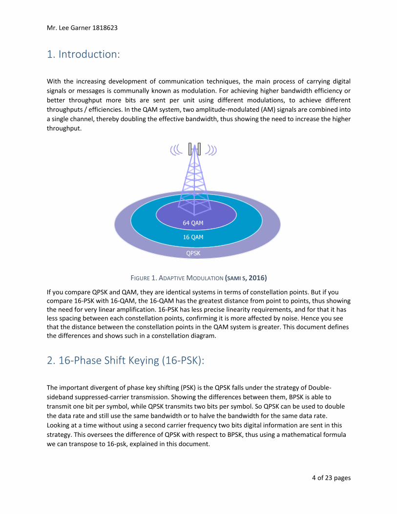
1. Introduction:
With the increasing development of communication techniques, the main process of carrying digital
signals or messages is communally known as modulation. For achieving higher bandwidth efficiency or
better throughput more bits are sent per unit using different modulations, to achieve different
throughputs / efficiencies. In the QAM system, two amplitude-modulated (AM) signals are combined into
a single channel, thereby doubling the effective bandwidth, thus showing the need to increase the higher
throughput.
FIGURE 1. ADAPTIVE MODULATION (SAMI S, 2016)
If you compare QPSK and QAM, they are identical systems in terms of constellation points. But if you compare 16-PSK with 16-QAM, the 16-QAM has the greatest distance from point to points, thus showing the need for very linear amplification. 16-PSK has less precise linearity requirements, and for that it has less spacing between each constellation points, confirming it is more affected by noise. Hence you see that the distance between the constellation points in the QAM system is greater. This document defines the differences and shows such in a constellation diagram.
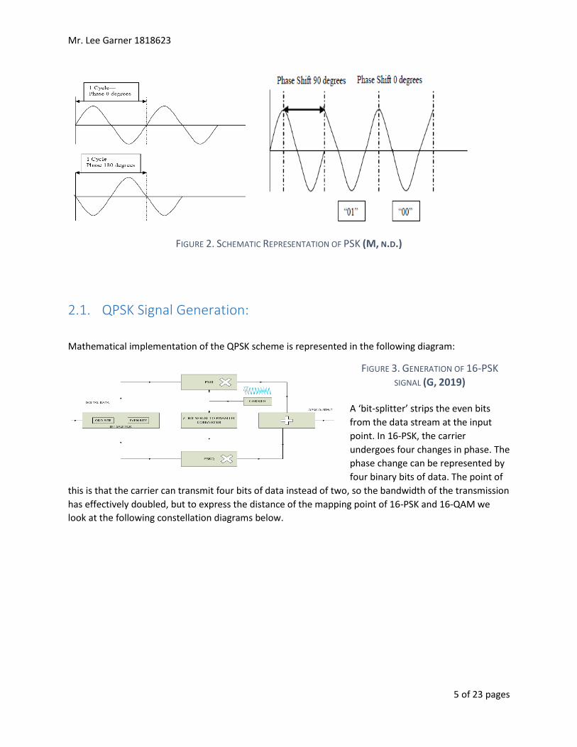
2. 16-Phase Shift Keying (16-PSK):
The important divergent of phase key shifting (PSK) is the QPSK falls under the strategy of Double-
sideband suppressed-carrier transmission. Showing the differences between them, BPSK is able to
transmit one bit per symbol, while QPSK transmits two bits per symbol. So QPSK can be used to double
the data rate and still use the same bandwidth or to halve the bandwidth for the same data rate.
Looking at a time without using a second carrier frequency two bits digital information are sent in this
strategy. This oversees the difference of QPSK with respect to BPSK, thus using a mathematical formula
we can transpose to 16-psk, explained in this document.
Mr. Lee Garner 1818623
5 of 23 pages
FIGURE 2. SCHEMATIC REPRESENTATION OF PSK (M, N.D.)
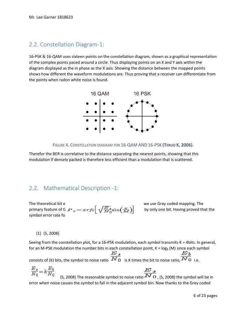
2.1. QPSK Signal Generation:
Mathematical implementation of the QPSK scheme is represented in the following diagram:
FIGURE 3. GENERATION OF 16-PSK
SIGNAL (G, 2019)
A ‘bit-splitter’ strips the even bits
from the data stream at the input
point. In 16-PSK, the carrier
undergoes four changes in phase. The
phase change can be represented by
four binary bits of data. The point of
this is that the carrier can transmit four bits of data instead of two, so the bandwidth of the transmission
has effectively doubled, but to express the distance of the mapping point of 16-PSK and 16-QAM we
look at the following constellation diagrams below.
Mr. Lee Garner 1818623
6 of 23 pages
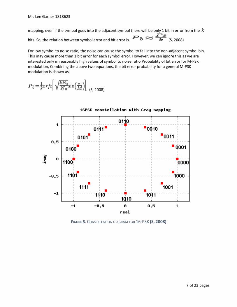
2.2. Constellation Diagram-1:
16-PSK & 16-QAM uses sixteen points on the constellation diagram, shown as a graphical representation
of the complex points paced around a circle. Thus displaying points on an X and Y axis within the
diagram displayed as the in phase as the X axis. Showing the distance between the mapped points
shows how different the waveform modulations are. Thus proving that a receiver can differentiate from
the points when radon white noise is found.
FIGURE 4. CONSTELLATION DIAGRAM FOR 16-QAM AND 16-PSK (TERUO K, 2006).
Therefor the BER is correlative to the distance separating the nearest points, showing that this
modulation if densely packed is therefore less efficient than a modulation that is scattered.
2.2. Mathematical Description -1:
The theoretical bit error rate probability for 16-PSK modulation we use Gray coded mapping. The
primary feature of Gray code is that the adjacent symbols differ by only one bit. Having proved that the
symbol error rate for an M-PSK modulation Shown is,
(1) (S, 2008)
Seeing from the constellation plot, for a 16-PSK modulation, each symbol transmits K = 4bits. In general,
for an M-PSK modulation the number bits in each constellation point, K = log₂ (M) since each symbol
consists of (K) bits, the symbol to noise ratio is K times the bit to noise ratio, i.e.
(S, 2008) The reasonable symbol to noise ratio , (S, 2008) the symbol will be in
error when noise causes the symbol to fall in the adjacent symbol bin. Now thanks to the Grey coded
Mr. Lee Garner 1818623
7 of 23 pages
mapping, even if the symbol goes into the adjacent symbol there will be only 1 bit in error from the
bits. So, the relation between symbol error and bit error is. (S, 2008)
For low symbol to noise ratio, the noise can cause the symbol to fall into the non-adjacent symbol bin. This may cause more than 1 bit error for each symbol error. However, we can ignore this as we are interested only in reasonably high values of symbol to noise ratio Probability of bit error for M-PSK modulation, Combining the above two equations, the bit error probability for a general M-PSK modulation is shown as,
. (S, 2008)
FIGURE 5. CONSTELLATION DIAGRAM FOR 16-PSK (S, 2008)
Mr. Lee Garner 1818623
8 of 23 pages
3. Quadrature Amplitude Modulation (QAM):
Quantization, defined in mathematics as well as digital signal processing, is the mapping process of
looking at values from a set of input points often expressed as a continuous set of values in a
measurable smaller set, expressed as a finite set of elements. But we have to round as well as truncation
be typical examples of the quantization processes. QAM makes extensive use of constellation diagrams.
Thus in digital modulation the number of grid points is power of 2. Therefore the most common QAM
are 16-QAM, 64-QAM and 256-QAM. But in case of the same constellation a higher order will require
closer positioning of the grid points in the output constellation diagram. This in turn will result in a
higher possibility of noise in the output diagram. Hence higher order QAM will be able to deliver larger
data. But reliability of these data will be lesser due to increased probability of bit-error for equal energy
in the constellation. Higher SNR is required to maintain lower BER with higher order QAM. We can
achieve this in two ways by reducing noise level or by increasing the energy of the signal or using both
these adjustments together.
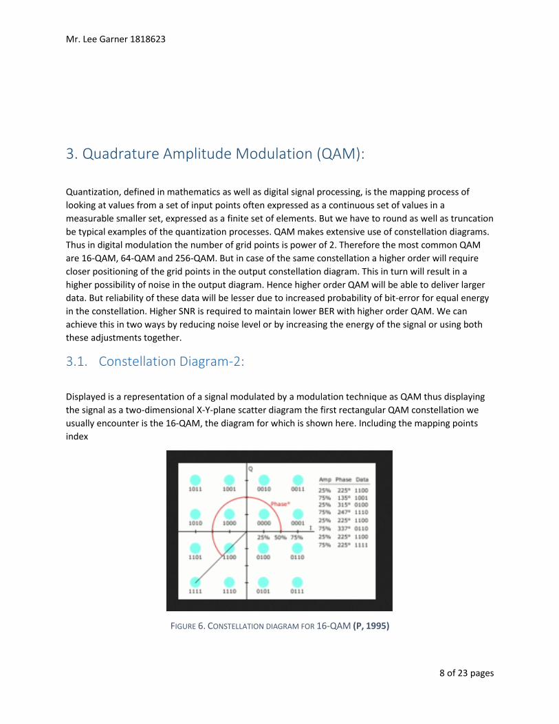
3.1. Constellation Diagram-2:
Displayed is a representation of a signal modulated by a modulation technique as QAM thus displaying
the signal as a two-dimensional X-Y-plane scatter diagram the first rectangular QAM constellation we
usually encounter is the 16-QAM, the diagram for which is shown here. Including the mapping points
index
FIGURE 6. CONSTELLATION DIAGRAM FOR 16-QAM (P, 1995)
Mr. Lee Garner 1818623
9 of 23 pages
3.3. Mathematical Description-2:
Rectangular QAM’s (such as 16-QAM) the symbol error rate can be expressed in terms of a complicated
expression. For this reason it is a common practice to express BER per carrier using the following, Gray
coded bit mapping in 16-QAM modulation
The Binary to Gray code for 16-QAM, the 4 bits in each constellation point can be considered as two bits
each on independent 4-PAM modulation on I-axis and Q-axis respectively.
With gray code bit mapping adjacent constellation symbols differ by only one bit. So, if the noise causes
the constellation to cross the decision threshold, only 1 out (K) of bits will be in error. So the relation
value of it may so happen between bit error and symbol error is, for very low
that the noise causes the constellation to fall near a diagonally located constellation point. In that case,
the each symbol error will cause two bit errors. Hence the need for approximate operator in the above
equation. However, for reasonably high value of the chances of such events are negligible.
The Bit error rate for 16PSK, since each symbol consists of K bits, the symbol to noise ratio k times the
bit to noise ratio i.e.
Where, (2) (S, 2008)
16-QAM Bit Error Rate, from describing the derivation of the 16-QAM Symbol error rate, we know that
the symbol error is. . (3) (S, 2008)
Combining the above two equations, the bit error rate for Grey coded 16QAM in Additive White
Gaussian Noise is. . (4) (S, 2008)
Mr. Lee Garner 1818623
10 of 23 pages
Matlab Simulation Results:
4.1. 16-PSK Simulation Results:
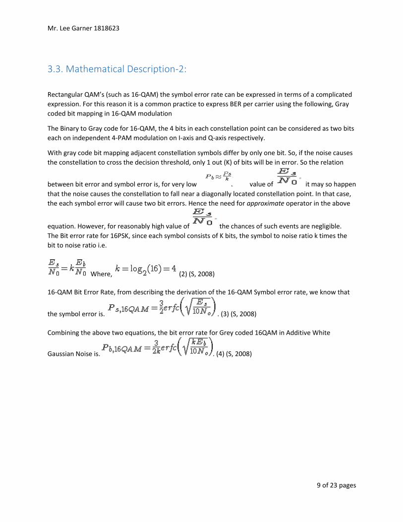
In 16-PSK simulation constellation size is fixed to 4 and 30000 bits are processed through 16-PSK
simulation. Following figure represents generated random bits. It can be observed that binary values are
distributed randomly over bit indexes.
FIGURE 7. GENERATED RANDOM BITS IN 16-PSK IN MATLAB SIMULATION
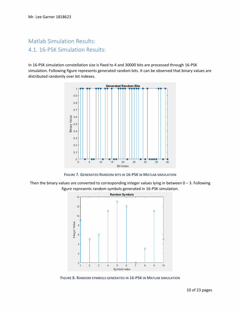
Then the binary values are converted to corresponding integer values lying in between 0 – 3. Following
figure represents random symbols generated in 16-PSK simulation.
FIGURE 8. RANDOM SYMBOLS GENERATED IN 16-PSK IN MATLAB SIMULATION
Mr. Lee Garner 1818623
11 of 23 pages
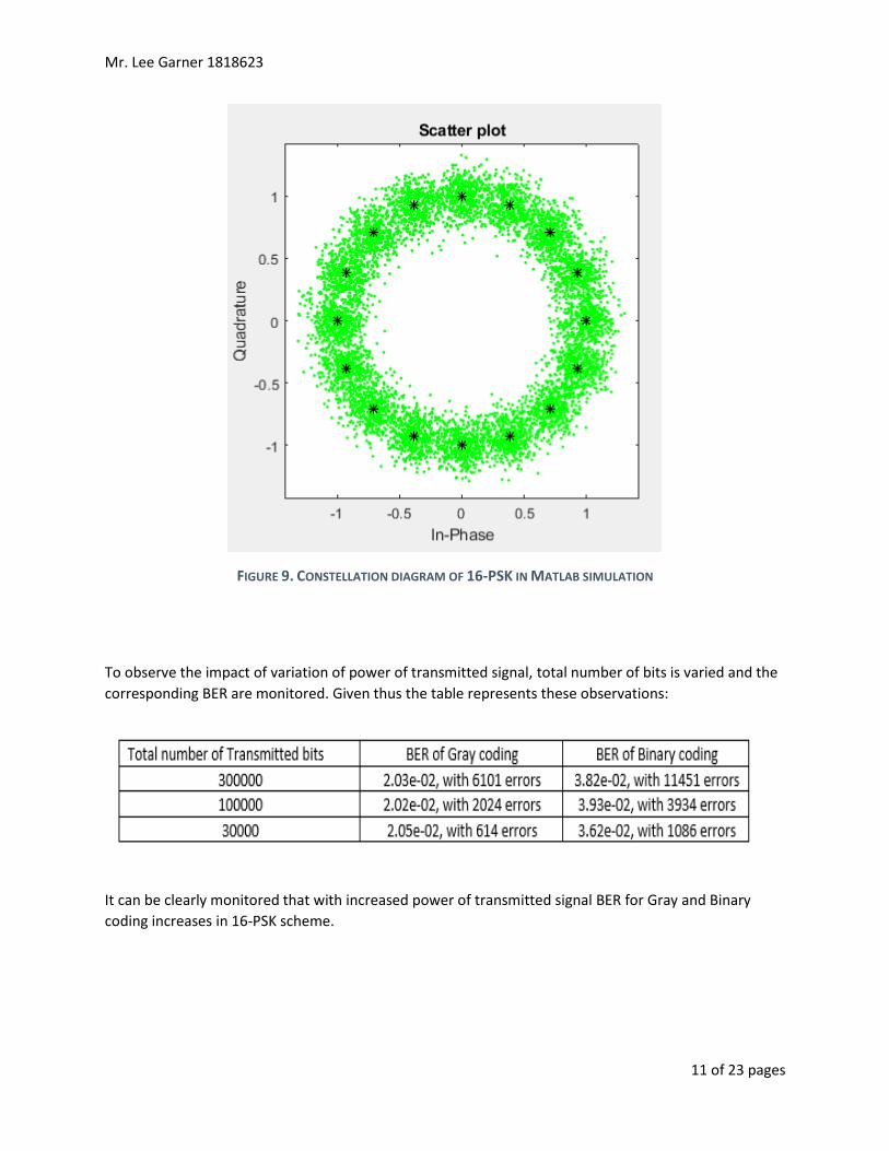
FIGURE 9. CONSTELLATION DIAGRAM OF 16-PSK IN MATLAB SIMULATION
To observe the impact of variation of power of transmitted signal, total number of bits is varied and the
corresponding BER are monitored. Given thus the table represents these observations:
It can be clearly monitored that with increased power of transmitted signal BER for Gray and Binary
coding increases in 16-PSK scheme.
Mr. Lee Garner 1818623
12 of 23 pages
4.2. 16-QAM Simulation Results:
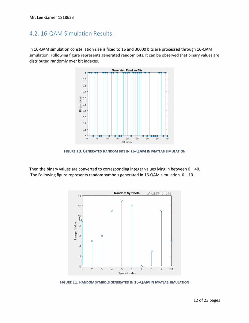
In 16-QAM simulation constellation size is fixed to 16 and 30000 bits are processed through 16-QAM
simulation. Following figure represents generated random bits. It can be observed that binary values are
distributed randomly over bit indexes.
FIGURE 10. GENERATED RANDOM BITS IN 16-QAM IN MATLAB SIMULATION
Then the binary values are converted to corresponding integer values lying in between 0 – 40.
The Following figure represents random symbols generated in 16-QAM simulation. 0 – 10.
FIGURE 11. RANDOM SYMBOLS GENERATED IN 16-QAM IN MATLAB SIMULATION
Mr. Lee Garner 1818623
13 of 23 pages
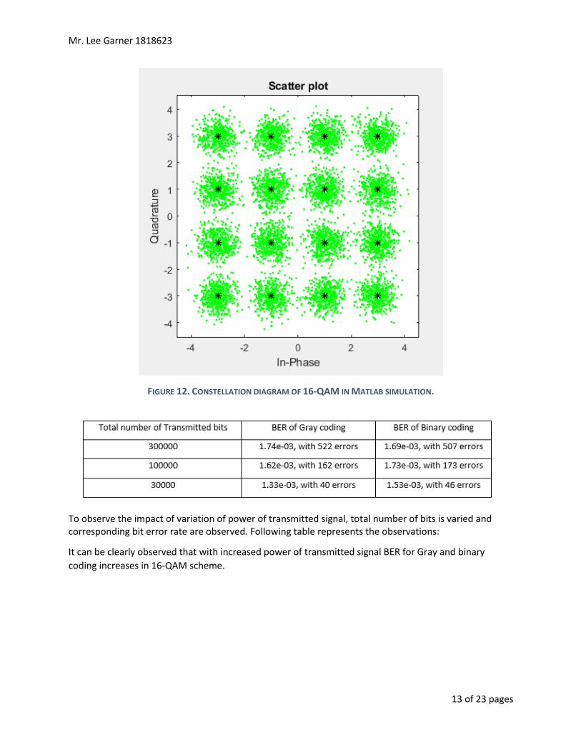
FIGURE 12. CONSTELLATION DIAGRAM OF 16-QAM IN MATLAB SIMULATION.
To observe the impact of variation of power of transmitted signal, total number of bits is varied and corresponding bit error rate are observed. Following table represents the observations:
It can be clearly observed that with increased power of transmitted signal BER for Gray and binary
coding increases in 16-QAM scheme.
Mr. Lee Garner 1818623
14 of 23 pages
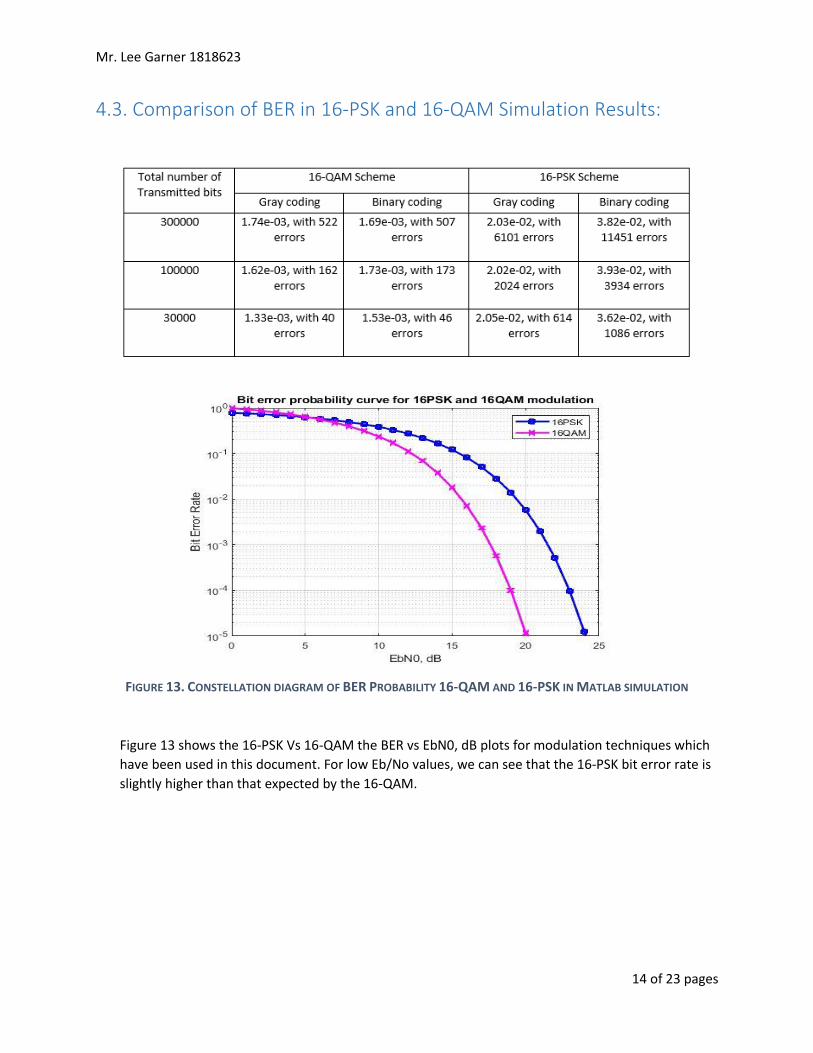
4.3. Comparison of BER in 16-PSK and 16-QAM Simulation Results:
FIGURE 13. CONSTELLATION DIAGRAM OF BER PROBABILITY 16-QAM AND 16-PSK IN MATLAB SIMULATION
Figure 13 shows the 16-PSK Vs 16-QAM the BER vs EbN0, dB plots for modulation techniques which
have been used in this document. For low Eb/No values, we can see that the 16-PSK bit error rate is
slightly higher than that expected by the 16-QAM.
Mr. Lee Garner 1818623
15 of 23 pages
4. Advantages & Drawbacks of 16-PSK and 16-QAM in Wireless Communication:
(Wireless World , 2012)
(Wireless World , 2012)
Mr. Lee Garner 1818623
16 of 23 pages
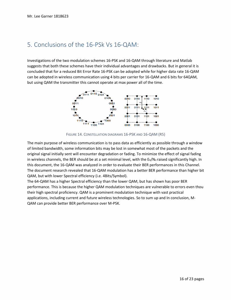
5. Conclusions of the 16-PSk Vs 16-QAM:
Investigations of the two modulation schemes 16-PSK and 16-QAM through literature and Matlab
suggests that both these schemes have their individual advantages and drawbacks. But in general it is
concluded that for a reduced Bit Error Rate 16-PSK can be adopted while for higher data rate 16-QAM
can be adopted in wireless communication using 4 bits per carrier for 16-QAM and 6 bits for 64QAM,
but using QAM the transmitter this cannot operate at max power all of the time.
FIGURE 14. CONSTELLATION DIAGRAMS 16-PSK AND 16-QAM (R5)
The main purpose of wireless communication is to pass data as efficiently as possible through a window
of limited bandwidth, some information bits may be lost in somewhat most of the packets and the
original signal initially sent will encounter degradation or fading. To minimize the effect of signal fading
in wireless channels, the BER should be at a set minimal level, with the Eb/No raised significantly high. In
this document, the 16-QAM was analyzed in order to evaluate their BER performances in this Channel.
The document research revealed that 16-QAM modulation has a better BER performance than higher bit
QAM, but with lower Spectral efficiency (i.e. 4Bits/Symbol).
The 64-QAM has a higher Spectral efficiency than the lower QAM, but has shown has poor BER
performance. This is because the higher QAM modulation techniques are vulnerable to errors even thou
their high spectral proficiency. QAM is a prominent modulation technique with vast practical
applications, including current and future wireless technologies. So to sum up and In conclusion, M-
QAM can provide better BER performance over M-PSK.
Mr. Lee Garner 1818623
17 of 23 pages
References Ahmed. Toaha, A. K. S., 2008. performance analysis of digital modulations on AWGN and fading channel.
In: performance analysis of digital modulations on AWGN and fading channel. s.l.:Lambert, p. 52.
Federal Communications Commission, 2015. Wireless services. [Online]
Available at: https://www.fcc.gov/spectrum
[Accessed 15 March 2019].
Forouzan, B., 2013. Global Edition. In: Data communications and networking fith edition. s.l.:mc graw
hill, p. 1226.
G, L., 2019. Viso block qpsk signal generation. st neots: s.n.
IEEE, 2012. Standard for Air Interface for Broadband Wireless Access Systems.. In: IEEE, ed. IEEE Std
802.16™. s.l.:IEEE, p. 1292.
Islam, I. a. H. S., 2005. Comparison of trac performance of QPSK and 16-QAM modulation techniques for
OFDM system. [Online]
Available at:
https://www.researchgate.net/publication/242235342_Comparison_of_trac_performance_of_QPSK_an
d_16-QAM_modulation_techniques_for_OFDM_system
[Accessed 15 March 2019].
M, A., 2006. Wireless Communications. In: I. Press, ed. Wireless Communications. s.l.:Wiley & Sons, p.
622.
mathuranathan.V, 2018. Wirless Communication Systems in MatLab. In: mathuranathan.V, ed. Wirless
Communication Systems in MatLab. s.l.:mathuranathan.V, p. 344.
Molisch, A., 2005. Wireless Communications. In: IEEE, ed. Wireless Communications second edition.
s.l.:Wily, p. 817.
M, R. F., n.d. Adaptive Modulation (QPSK, QAM), Pakistan: National University of Sciences and
Technology.
P, J., 1995. Quadrature amplitude modulation. Digital Communications, Volume 3rd.
Rappaport, T., n.d. wireless Communications. In: wireless Communications principles and practice.
s.l.:Pearson, p. 709.
Rfwireles-world.com, 2012. QAM-Quadrature Amplitude Modulation. [Online]
Available at: http://www.rfwireless-world.com/Terminology/QAM.html
[Accessed 14 March 2019].
Rfwireles-world.com, 2015. QPSK-Quadrature Phase Shift Keying. [Online]
Available at: http://www.rfwireless-world.com/Terminology/QPSK.html
[Accessed 14 March 2019].
sami s, a. a. m. s. a. m., 2016. Implementation of adaptive modulation for broadband wireless access
networks using cognitive radio approaches. Implementation of Adaptive Modulation for Broadband, p. 6.
Mr. Lee Garner 1818623
18 of 23 pages
S, K., 2008. DspLog Signal Processing for Communication. [Online]
Available at: http://www.dsplog.com/2008/05/18/bit-error-rate-for-16psk-modulation-using-gray-
mapping/
[Accessed 15 March 2019].
Teruo K, Y. K. K. H. M. S., 2006. Ninth International Symposium on Spread Spectrum Techniques and
Applications. Comparisons of 16QAM Modulation Schemes Considering PAPR, Volume nine, p. 5.
Wireless World , 2012. Home of RF and Wireless Vendors and Resources. [Online]
Available at: http://www.rfwireless-world.com/Terminology/Advantages-and-Disadvantages-of-QAM-
types.html
[Accessed 15 March 2019].
Mr. Lee Garner 1818623
19 of 23 pages
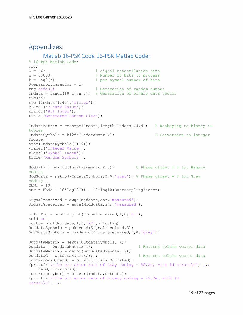
Appendixes: Matlab 16-PSK Code 16-PSK Matlab Code:
% 16-PSK Matlab Code: clc; Z = 16; % signal constellation size n = 30000; % Number of bits to process k = log2(Z); % per symbol number of bits OversamplingFactor = 1; rng default % Generation of random number Indata = randi([0 1],n,1); % Generation of binary data vector figure; stem(Indata(1:40),'filled'); ylabel('Binary Value'); xlabel('Bit Index'); title('Generated Random Bits');
IndataMatrix = reshape(Indata,length(Indata)/4,4); % Reshaping to binary 4-
tuples IndataSymbols = bi2de(IndataMatrix); % Conversion to integer figure; stem(IndataSymbols(1:10)); ylabel('Integer Value'); xlabel('Symbol Index'); title('Random Symbols');
Moddata = pskmod(IndataSymbols,Z,0); % Phase offset = 0 for Binary
coding ModGdata = pskmod(IndataSymbols,Z,0,'gray'); % Phase offset = 0 for Gray
coding EbNo = 10; snr = EbNo + 10*log10(k) - 10*log10(OversamplingFactor);
Signalreceived = awgn(Moddata,snr,'measured'); SignalGreceived = awgn(ModGdata,snr,'measured');
sPlotFig = scatterplot(Signalreceived,1,0,'g.'); hold on scatterplot(Moddata,1,0,'k*',sPlotFig) OutdataSymbols = pskdemod(Signalreceived,Z); OutGdataSymbols = pskdemod(SignalGreceived,Z,0,'gray');
OutdataMatrix = de2bi(OutdataSymbols, k); Outdata = OutdataMatrix(:); % Returns column vector data OutdataMatrixG = de2bi(OutGdataSymbols, k); OutdataG = OutdataMatrixG(:); % Returns column vector data [numErrorsG,berG] = biterr(Indata,OutdataG); fprintf('\nThe bit error rate of Gray coding = %5.2e, with %d errors\n', ... berG,numErrorsG) [numErrors,ber] = biterr(Indata,Outdata); fprintf('\nThe bit error rate of binary coding = %5.2e, with %d
errors\n', ...
Mr. Lee Garner 1818623
20 of 23 pages
ber,numErrors)
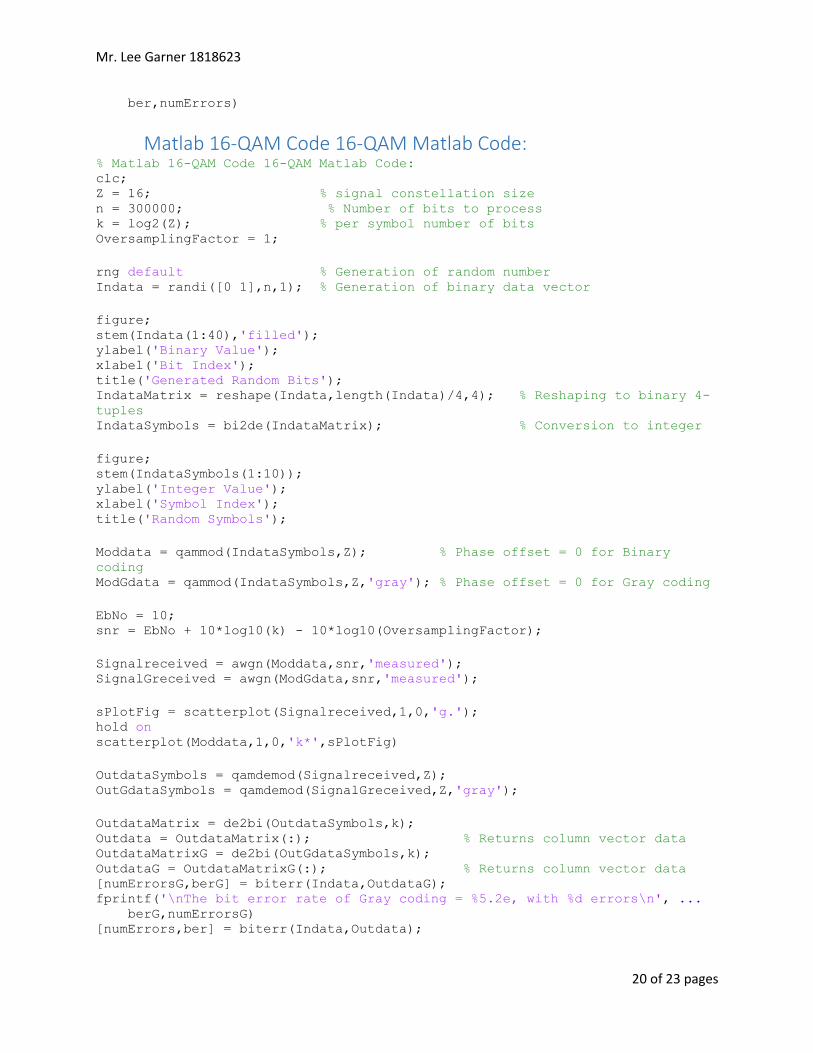
Matlab 16-QAM Code 16-QAM Matlab Code: % Matlab 16-QAM Code 16-QAM Matlab Code: clc; Z = 16; % signal constellation size n = 300000; % Number of bits to process k = log2(Z); % per symbol number of bits OversamplingFactor = 1;
rng default % Generation of random number Indata = randi([0 1],n,1); % Generation of binary data vector
figure; stem(Indata(1:40),'filled'); ylabel('Binary Value'); xlabel('Bit Index'); title('Generated Random Bits'); IndataMatrix = reshape(Indata,length(Indata)/4,4); % Reshaping to binary 4-
tuples IndataSymbols = bi2de(IndataMatrix); % Conversion to integer
figure; stem(IndataSymbols(1:10)); ylabel('Integer Value'); xlabel('Symbol Index'); title('Random Symbols');
Moddata = qammod(IndataSymbols,Z); % Phase offset = 0 for Binary
coding ModGdata = qammod(IndataSymbols,Z,'gray'); % Phase offset = 0 for Gray coding
EbNo = 10; snr = EbNo + 10*log10(k) - 10*log10(OversamplingFactor);
Signalreceived = awgn(Moddata,snr,'measured'); SignalGreceived = awgn(ModGdata,snr,'measured');
sPlotFig = scatterplot(Signalreceived,1,0,'g.'); hold on scatterplot(Moddata,1,0,'k*',sPlotFig)
OutdataSymbols = qamdemod(Signalreceived,Z); OutGdataSymbols = qamdemod(SignalGreceived,Z,'gray');
OutdataMatrix = de2bi(OutdataSymbols,k); Outdata = OutdataMatrix(:); % Returns column vector data OutdataMatrixG = de2bi(OutGdataSymbols,k); OutdataG = OutdataMatrixG(:); % Returns column vector data [numErrorsG,berG] = biterr(Indata,OutdataG); fprintf('\nThe bit error rate of Gray coding = %5.2e, with %d errors\n', ... berG,numErrorsG) [numErrors,ber] = biterr(Indata,Outdata);
Mr. Lee Garner 1818623
21 of 23 pages
fprintf('\nThe bit error rate of binary coding = %5.2e, with %d
errors\n', ... ber,numErrors)
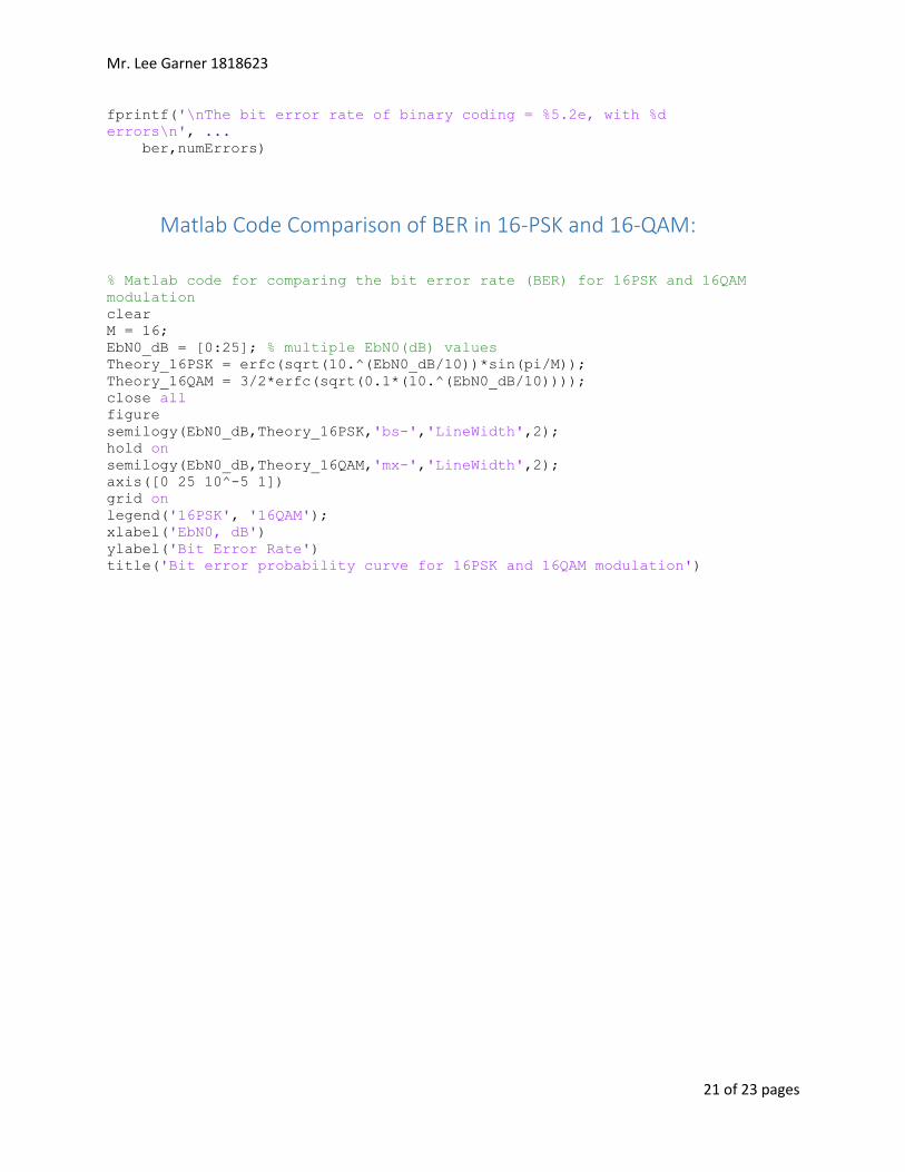
Matlab Code Comparison of BER in 16-PSK and 16-QAM:
% Matlab code for comparing the bit error rate (BER) for 16PSK and 16QAM
modulation clear M = 16; EbN0_dB = [0:25]; % multiple EbN0(dB) values Theory_16PSK = erfc(sqrt(10.^(EbN0_dB/10))*sin(pi/M)); Theory_16QAM = 3/2*erfc(sqrt(0.1*(10.^(EbN0_dB/10)))); close all figure semilogy(EbN0_dB,Theory_16PSK,'bs-','LineWidth',2); hold on semilogy(EbN0_dB,Theory_16QAM,'mx-','LineWidth',2); axis([0 25 10^-5 1]) grid on legend('16PSK', '16QAM'); xlabel('EbN0, dB') ylabel('Bit Error Rate') title('Bit error probability curve for 16PSK and 16QAM modulation')

Mr. Lee Garner 1818623
22 of 23 pages
CIS022-2 Wireless Communication and Networks, Assignment 2
Name: Lee Garner
Student number: 1818623
Names of other members of your group:
None
What is your part of work; please list the task number as indicated in the assignment brief:
ALL OF THE WORK WAS DONE BY MYSELF LEE GARNER
Tick one of the options below:
(1) I believe that the workload was equally shared and all members of the team contributed to the final report of the assignment
(2) The workload was not shared equally and some team members did not contribute to the final report
(3) I have no specific opinion about if team members had contributed to the final report
x (4) None of the above
If you ticked option (2), (3) or (4) please explain below how workload was distributed. Please feel free to
provide as many details as possible to allow fair marking. Please note that this form is only a
recommendation to the marker; the unit team reserves the right to further discuss with individual
students of the team if clarification is needed.
The work has been done by myself, due to the fact that no groups were put together, and as the older
student, the other students are already known to each other and mixed, hence I was not part of the
younger click.