chief architect® x6 user's guide
TRANSCRIPT
Chief Architect® X6User’s Guide
Professional Design & Drafting Software
Chief Architect, Inc.
6500 N. Mineral Dr.
Coeur d’Alene, Idaho 83815
www.chiefarchitect.com
chief-architect-x6-users-guide.book Page 1 Monday, December 16, 2013 4:05 PM
© 1990–2014 by Chief Architect, Inc. All rights reserved.
No part of this book or the accompanying software may be reproduced or transmitted in any form or by any means, electronic or mechanical, including photocopying, recording, or by any information storage and retrieval system, without permission in writing from Chief Architect, Inc.
Chief Architect® is a registered trademark of Chief Architect, Inc.
The Sentry Spelling-Checker Engine © 1994–2003 Wintertree Software Inc.
The City Blueprint and Country Blueprint fonts are © 1992–1999 Payne Loving Trust. All rights reserved.
This software uses the FreeImage open source image library. See http://freeimage.sourceforge.net for details. FreeImage is used under the FIPL license, version 1.0.
This software uses the Ruby open source library. See http://www.ruby-lang.org/ for details.
This application incorporates Teigha® software pursuant to a license agreement with Open Design Alliance.Teigha® Copyright © 2003-2013 by Open Design Alliance. All rights reserved.
All other trademarks and copyrights are the property of Chief Architect, Inc. or their respective owners.
Created in the United States of America.
chief-architect-x6-users-guide.book Page 2 Monday, December 16, 2013 4:05 PM
3
Contents
Chapter 1: Installation
System Requirements..........................................................................7Downloading Chief Architect .............................................................8Installing Chief Architect....................................................................8Installing Your Optional Hardware Lock.......................................14Starting Chief Architect....................................................................14Migrating Library Catalogs .............................................................15Program Updates...............................................................................17Deactivating Chief Architect Licenses.............................................17Uninstalling Chief Architect.............................................................18
Chapter 2: House Design Tutorial
Before You Begin...............................................................................20Getting Started...................................................................................20Setting Defaults..................................................................................21Drawing Walls ...................................................................................25Creating Dimension Lines ................................................................28Adjusting Wall Positions...................................................................29Creating Rooms .................................................................................32Creating a 3D View ...........................................................................38Adding Floors.....................................................................................41Adding Stairs .....................................................................................46Placing Doors and Windows.............................................................50
chief-architect-x6-users-guide.book Page 3 Monday, December 16, 2013 4:05 PM
4
Chief Architect X6 User’s Guide
Chapter 3: Roof Tutorial
Getting Started with Automatic Roof Styles...................................60Hip Roofs............................................................................................63Gable Roofs ........................................................................................63Shed Roofs..........................................................................................64Offset Gable Roofs.............................................................................65Gambrel Roofs ...................................................................................66Gull Wing Roofs ................................................................................67Half Hip Roofs ...................................................................................68Mansard Roofs...................................................................................69Finding the Start of an Upper Pitch ................................................70Roof Style Quick Reference..............................................................72Roof Returns ......................................................................................73Adding Gables over Doors and Windows .......................................74Automatic Dormers...........................................................................75Manually Drawn Dormers................................................................76Crickets and Dormer Vents..............................................................83Skylights .............................................................................................89Using the Break Wall Tool to Modify Roofs ...................................90Adding a Roof to the Stucco Beach House ......................................93Troubleshooting Automatic Roof Issues .........................................96
Chapter 4: Interior Design Tutorial
Controlling the Display of Objects.................................................101Working with Library Objects ......................................................103Applying Room Moldings ...............................................................107Applying Wall Coverings................................................................109Creating a Trey Ceiling ..................................................................111
chief-architect-x6-users-guide.book Page 4 Monday, December 16, 2013 4:05 PM
5
Chapter 5: Kitchen and Bath Design Tutorial
Adding Cabinets ..............................................................................117Placing Appliances...........................................................................122Editing Cabinets and Appliances ...................................................123Creating a Custom Countertop......................................................126Creating Architectural Blocks........................................................129Working in Cross Section/Elevation Views...................................130
Chapter 6: Materials Tutorial
Setting Materials Defaults ..............................................................135Using the Materials Panel ...............................................................137Using the Material Painter .............................................................140Blending Colors with Materials .....................................................143Using the Material Eyedropper......................................................144Using the Color Chooser .................................................................145Custom Materials, Images, and Backdrops ..................................147Generating a Materials List............................................................152
Chapter 7: Landscaping Tutorial
Creating a Terrain Perimeter.........................................................156Creating a Walkout Basement .......................................................160Creating a Retaining Wall ..............................................................163Adding a Driveway..........................................................................165Adding Terrain Features ................................................................168Adding Library Objects to Your Plan...........................................173
Chapter 8: Deck Tutorial
Decks and Porches...........................................................................177
chief-architect-x6-users-guide.book Page 5 Monday, December 16, 2013 4:05 PM
6
Chief Architect X6 User’s Guide
Drawing Decks.................................................................................178Drawing Stairs .................................................................................179Changing Planking Orientation .....................................................180Adding Exterior Furniture .............................................................182
Chapter 9: CAD Tutorial
CAD Detail Windows ......................................................................185Exploding and Modifying a CAD Block........................................186Creating a New CAD Block............................................................189CAD Detail from View ....................................................................191Creating a Plot Plan ........................................................................194
Chapter 10: Layout Tutorial
Getting Started ................................................................................203Creating a Border and Title Block ................................................204Creating a Layout Template ..........................................................208Sending Floor Plan Views to Layout .............................................209Sending Elevation Views to Layout ...............................................212Sending Details to Layout...............................................................215Sending Perspective Views to Layout............................................217Printing to PDF................................................................................219
Appendix A: End User License Agreement
chief-architect-x6-users-guide.book Page 6 Monday, December 16, 2013 4:05 PM
7
Chapter 1:
Installation
This chapter will walk you through installing your Chief Architect software.
Chapter Contents• System Requirements• Downloading Chief Architect• Installing Chief Architect• Installing Your Optional Hardware Lock
• Starting Chief Architect• Migrating Library Catalogs• Program Updates• Deactivating Chief Architect Licenses• Uninstalling Chief Architect
System RequirementsIn order to install and run Chief Architect, your computer system must meet the following minimum requirements:
• Windows® 8/7/Vista; Mac OS® X v10.8 (Mountain Lion) or newer
• 2.4 GHz processor
• 2 GB of memory (32 bit); 4 GB of memory (64 bit)
• 5 GB of available hard disk space
• Recommended minimum monitor resolution: 1152 x 860
chief-architect-x6-users-guide.book Page 7 Monday, December 16, 2013 4:05 PM
8
Chief Architect X6 Reference Manual
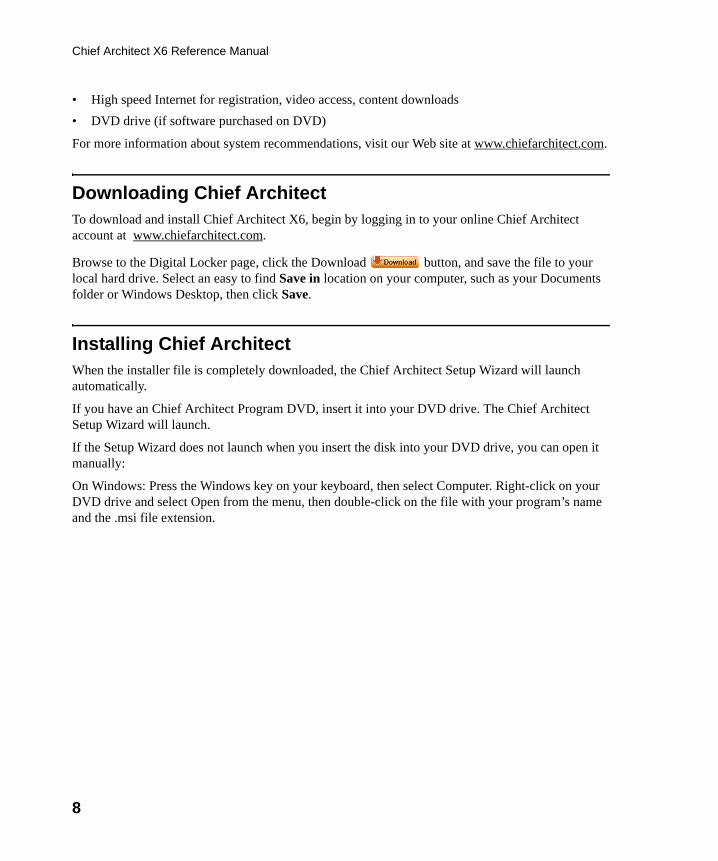
• High speed Internet for registration, video access, content downloads
• DVD drive (if software purchased on DVD)
For more information about system recommendations, visit our Web site at www.chiefarchitect.com.
Downloading Chief ArchitectTo download and install Chief Architect X6, begin by logging in to your online Chief Architect account at www.chiefarchitect.com.
Browse to the Digital Locker page, click the Download button, and save the file to your local hard drive. Select an easy to find Save in location on your computer, such as your Documents folder or Windows Desktop, then click Save.
Installing Chief ArchitectWhen the installer file is completely downloaded, the Chief Architect Setup Wizard will launch automatically.
If you have an Chief Architect Program DVD, insert it into your DVD drive. The Chief Architect Setup Wizard will launch.
If the Setup Wizard does not launch when you insert the disk into your DVD drive, you can open it manually:
On Windows: Press the Windows key on your keyboard, then select Computer. Right-click on your DVD drive and select Open from the menu, then double-click on the file with your program’s name and the .msi file extension.
chief-architect-x6-users-guide.book Page 8 Monday, December 16, 2013 4:05 PM
Installing Chief Architect
9
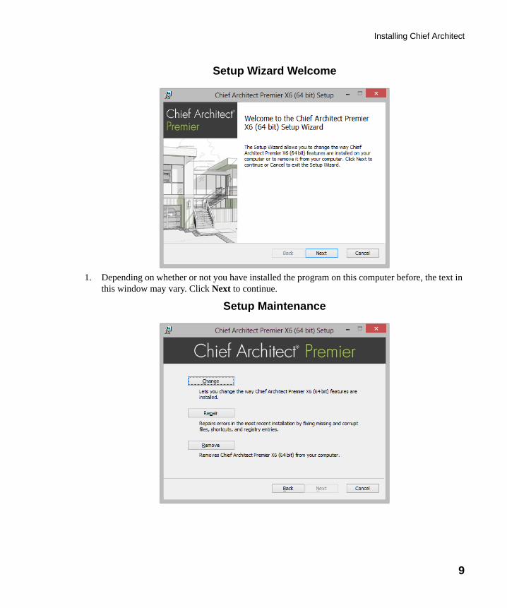
Setup Wizard Welcome
1. Depending on whether or not you have installed the program on this computer before, the text in this window may vary. Click Next to continue.
Setup Maintenance
chief-architect-x6-users-guide.book Page 9 Monday, December 16, 2013 4:05 PM
10
Chief Architect X6 Reference Manual
2. If you have installed the program before, this window will display, allowing you to reinstall or uninstall the program. If you are installing the program for the first time, this window will not display.
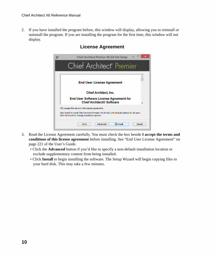
License Agreement
3. Read the License Agreement carefully. You must check the box beside I accept the terms and conditions of this license agreement before installing. See “End User License Agreement” on page 221 of the User’s Guide.• Click the Advanced button if you’d like to specify a non-default installation location or
exclude supplementary content from being installed. • Click Install to begin installing the software. The Setup Wizard will begin copying files to
your hard disk. This may take a few minutes.
chief-architect-x6-users-guide.book Page 10 Monday, December 16, 2013 4:05 PM
Installing Chief Architect
11
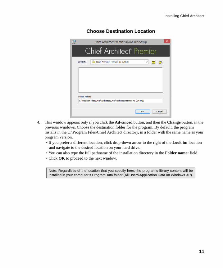
Choose Destination Location
4. This window appears only if you click the Advanced button, and then the Change button, in the previous windows. Choose the destination folder for the program. By default, the program installs in the C:\Program Files\Chief Architect directory, in a folder with the same name as your program version. • If you prefer a different location, click drop-down arrow to the right of the Look in: location
and navigate to the desired location on your hard drive. • You can also type the full pathname of the installation directory in the Folder name: field.• Click OK to proceed to the next window.
Note: Regardless of the location that you specify here, the program’s library content will beinstalled in your computer’s ProgramData folder (All Users\Application Data on Windows XP).
chief-architect-x6-users-guide.book Page 11 Monday, December 16, 2013 4:05 PM
12
Chief Architect X6 Reference Manual
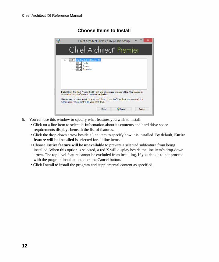
Choose Items to Install
5. You can use this window to specify what features you wish to install. • Click on a line item to select it. Information about its contents and hard drive space
requirements displays beneath the list of features.• Click the drop-down arrow beside a line item to specify how it is installed. By default, Entire
feature will be installed is selected for all line items.• Choose Entire feature will be unavailable to prevent a selected subfeature from being
installed. When this option is selected, a red X will display beside the line item’s drop-down arrow. The top level feature cannot be excluded from installing. If you decide to not proceed with the program installation, click the Cancel button.
• Click Install to install the program and supplemental content as specified.
chief-architect-x6-users-guide.book Page 12 Monday, December 16, 2013 4:05 PM
Installing Chief Architect
13
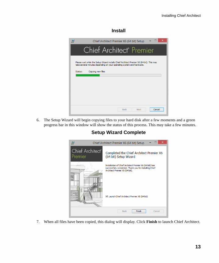
Install
6. The Setup Wizard will begin copying files to your hard disk after a few moments and a green progress bar in this window will show the status of this process. This may take a few minutes.
Setup Wizard Complete
7. When all files have been copied, this dialog will display. Click Finish to launch Chief Architect.
chief-architect-x6-users-guide.book Page 13 Monday, December 16, 2013 4:05 PM
14
Chief Architect X6 Reference Manual
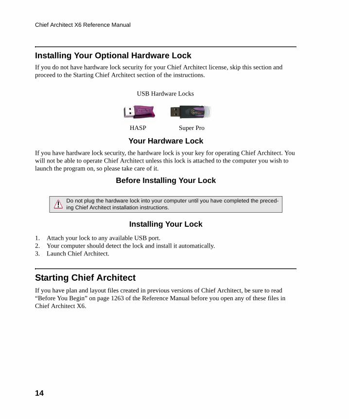
Installing Your Optional Hardware LockIf you do not have hardware lock security for your Chief Architect license, skip this section and proceed to the Starting Chief Architect section of the instructions.
Your Hardware Lock
If you have hardware lock security, the hardware lock is your key for operating Chief Architect. You will not be able to operate Chief Architect unless this lock is attached to the computer you wish to launch the program on, so please take care of it.
Before Installing Your Lock
Installing Your Lock
1. Attach your lock to any available USB port.2. Your computer should detect the lock and install it automatically.3. Launch Chief Architect.
Starting Chief ArchitectIf you have plan and layout files created in previous versions of Chief Architect, be sure to read “Before You Begin” on page 1263 of the Reference Manual before you open any of these files in Chief Architect X6.
Do not plug the hardware lock into your computer until you have completed the preced-ing Chief Architect installation instructions.
HASP
USB Hardware Locks
Super Pro
chief-architect-x6-users-guide.book Page 14 Monday, December 16, 2013 4:05 PM
Migrating Library Catalogs
15
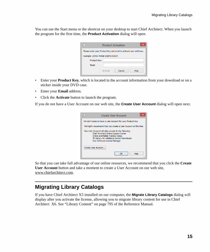
You can use the Start menu or the shortcut on your desktop to start Chief Architect. When you launch the program for the first time, the Product Activation dialog will open.
• Enter your Product Key, which is located in the account information from your download or on a sticker inside your DVD case.
• Enter your Email address.
• Click the Activate button to launch the program.
If you do not have a User Account on our web site, the Create User Account dialog will open next.
So that you can take full advantage of our online resources, we recommend that you click the Create User Account button and take a moment to create a User Account on our web site, www.chiefarchitect.com.
Migrating Library CatalogsIf you have Chief Architect X5 installed on our computer, the Migrate Library Catalogs dialog will display after you activate the license, allowing you to migrate library content for use in Chief Architect X6. See “Library Content” on page 795 of the Reference Manual.
chief-architect-x6-users-guide.book Page 15 Monday, December 16, 2013 4:05 PM
16
Chief Architect X6 Reference Manual
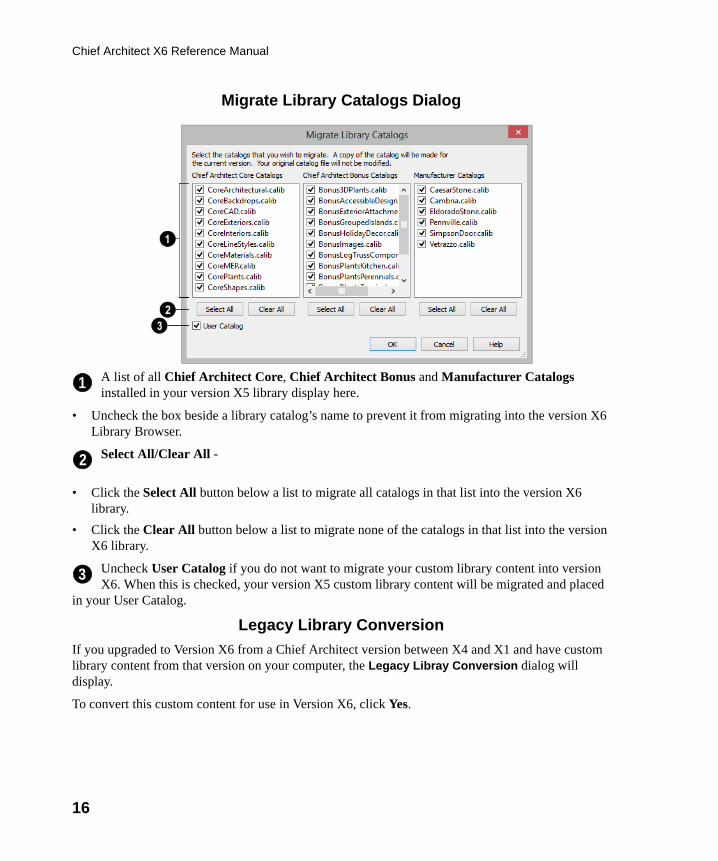
Migrate Library Catalogs Dialog
A list of all Chief Architect Core, Chief Architect Bonus and Manufacturer Catalogs installed in your version X5 library display here.
• Uncheck the box beside a library catalog’s name to prevent it from migrating into the version X6 Library Browser.
Select All/Clear All -
• Click the Select All button below a list to migrate all catalogs in that list into the version X6 library.
• Click the Clear All button below a list to migrate none of the catalogs in that list into the version X6 library.
Uncheck User Catalog if you do not want to migrate your custom library content into version X6. When this is checked, your version X5 custom library content will be migrated and placed
in your User Catalog.
Legacy Library Conversion
If you upgraded to Version X6 from a Chief Architect version between X4 and X1 and have custom library content from that version on your computer, the Legacy Libray Conversion dialog will display.
To convert this custom content for use in Version X6, click Yes.
1
2
3
chief-architect-x6-users-guide.book Page 16 Monday, December 16, 2013 4:05 PM
Program Updates
17
Library content from Chief Architect 10 or prior cannot be converted for use in Version X6 automatically; however, you can convert this content yourself. See “Legacy Library Conversion” on page 798 of the Reference Manual.
Program UpdatesFrom time to time, Chief Architect releases Chief Architect program updates that are available for download free of charge from the Chief Architect Web site, www.chiefarchitect.com.
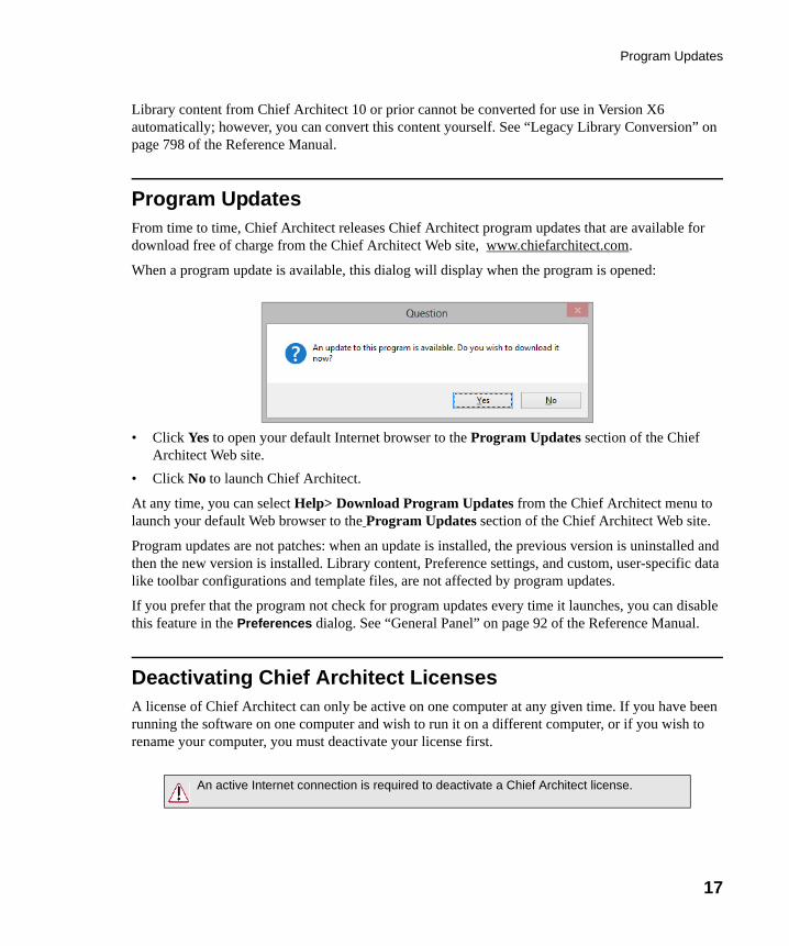
When a program update is available, this dialog will display when the program is opened:
• Click Yes to open your default Internet browser to the Program Updates section of the Chief Architect Web site.
• Click No to launch Chief Architect.
At any time, you can select Help> Download Program Updates from the Chief Architect menu to launch your default Web browser to the Program Updates section of the Chief Architect Web site.
Program updates are not patches: when an update is installed, the previous version is uninstalled and then the new version is installed. Library content, Preference settings, and custom, user-specific data like toolbar configurations and template files, are not affected by program updates.
If you prefer that the program not check for program updates every time it launches, you can disable this feature in the Preferences dialog. See “General Panel” on page 92 of the Reference Manual.
Deactivating Chief Architect LicensesA license of Chief Architect can only be active on one computer at any given time. If you have been running the software on one computer and wish to run it on a different computer, or if you wish to rename your computer, you must deactivate your license first.
An active Internet connection is required to deactivate a Chief Architect license.
chief-architect-x6-users-guide.book Page 17 Monday, December 16, 2013 4:05 PM
18
Chief Architect X6 Reference Manual
To deactivate a Chief Architect license
1. Launch Chief Architect on the computer where the license is active.2. Select Help> Deactivate License from the menu.3. A message will confirm that you wish to deactivate the license. Click Yes.4. After a pause, a second message will inform you that the license has been deactivated.
If you have installed both the 32-bit and the 64-bit version of Chief Architect X6 Premier and deactivate one of these, both will automatically become deactivated.
If you are using hardware lock security, you do not need to deactivate your license. Instead, attach the lock to the computer you wish to use before launching Chief Architect. See “Your Hardware Lock” on page 14.
Uninstalling Chief ArchitectThere are two ways that Chief Architect can be removed from your computer: from the Control Panel and using the Setup Wizard on the program disk. Please note that if you do not have an active Internet connection, your license will not become deactivated.
To remove the program using the Control Panel
1. Open the Windows Control Panel.2. Double-click Programs (in Windows XP, “Add or Remove Programs”).3. Find Chief Architect and click Remove.
To remove the program using the Setup Wizard
1. Launch your downloaded program installer or place the disc in the DVD drive and select Install Chief Architect from the Chief Architect startup window.
2. On the Setup Maintenance page, select Uninstall and click Next. A message will display, asking if you would like to remove the selected application and its components.
3. Click Yes to remove Chief Architect.
When Chief Architect is uninstalled, the Chief Architect Data folder is not removed from the system. See “Chief Architect Data” on page 49.
If an emergency forces you to reformat your hard drive, reinstall Windows, or resort to asystem restore point, be aware that none of these actions result in a normal programuninstallation or license deactivation.
chief-architect-x6-users-guide.book Page 18 Monday, December 16, 2013 4:05 PM
19
Chapter 2:
House DesignTutorial
This House Design Tutorial shows you how to get started on a design project. The tutorials that follow continue with the same plan. When you are finished, you will have created a sample plan named “Stucco Beach House.” You can then apply the tools and techniques learned to your own plans.
In this tutorial you will learn about:
• Before You Begin• Getting Started• Setting Defaults• Drawing Walls• Creating Dimension Lines
• Adjusting Wall Positions• Creating Rooms• Creating a 3D View• Adding Floors• Adding Stairs
chief-architect-x6-users-guide.book Page 19 Monday, December 16, 2013 4:05 PM
20
Chief Architect X6 User’s Guide
Before You BeginChief Architect may look differently on your screen than it does in the following tutorials.
• Screen captures are taken from a smaller window to optimize image quality, so the size and proportion of your interface may be different.
• Some features, such as the Reference Grid, have been turned off to optimize image quality. For more information, see “General Plan Defaults Dialog” on page 82 of the Reference Manual.
• Since toolbars can be customized, their default layout and location may differ. For more information, see “Toolbar Customization Dialog” on page 130 of the Reference Manual.
• As the program is updated, features may be added or removed. If you are using the latest version of Chief Architect, you may see buttons and/or menu items that have been added or removed since this tutorial was written. For more information, see “Program Updates” on page 17.
• Depending on your operating system and Windows system settings, dialogs and toolbars may appear differently than they do in the tutorials.
Getting StartedBegin by opening a new, blank plan.
To start Chief Architect
1. Click the Windows Start button and select All Programs.
2. Browse to Chief Architect> Chief Architect X6> Chief Architect X6, and click to start the program.
3. When Chief Architect launches, the Getting Started window displays. For more information, see “Startup Options” on page 28 of the Reference Manual.
• Select New Plan to open a new, blank plan.
• If you have disabled the Startup Options at startup or already have the program open,
you can select File> New Plan to open a new, blank plan.
4. You should begin work on any new file by giving it a name. To do this:
• Select File> Save from the menu to open the Save Plan File dialog.
• Specify the location on your computer where you would like to save the plan.
• Type a name for your plan.
• Click Save.
chief-architect-x6-users-guide.book Page 20 Monday, December 16, 2013 4:05 PM
Setting Defaults
21
5. It is a good idea to save your work on a regular basis as you proceed. To do this, you can:
• Select File> Save from the menu to open the Save Plan File dialog
• Click the Save button on the toolbar.
• Type Ctrl + S on your keyboard.
For more information about saving files, see “Saving, Exporting, and Backing Up Files” on page 51 of the Reference Manual.
Setting DefaultsDefault settings determine the initial characteristics of objects when they are first drawn. When set up in advance, they can help you both save time and avoid mistakes. Before you draw walls and create rooms, therefore, you should always make sure the defaults will meet your needs for the current project. For more information about defaults, see “Preferences and Default Settings” on page 67 of the Reference Manual.
While all defaults are important, there are several that can be considered critical because they help determine the size and structural characteristics of the building. These critical defaults are:
• Normal Room Defaults
• Floor Defaults
• Framing Defaults
• Wall Defaults
• Dimension Defaults
• Annotation Sets
It is recommended that whenever possible, you set these defaults before drawing anything in your plan. Changes made to these settings later on are possible, but may require extra work to review and adjust heights and wall positions.
To access a file’s default settings
1. Select Edit> Default Settings to open the Default Settings dialog.
2. Click on the white arrow next to a category to expand it and show its contents.
• Click on the black downward facing arrow to collapse the category again.
3. Select a defaults dialog that you would like to open and click the Edit button.
• You can also open the defaults dialog by double-clicking on a line item
Normal Room Defaults
The Normal Room Defaults dialog serves as the master defaults dialog for floor and ceiling structure and finish definitions on all floors. These are particularly important because they influence the overall height of the structure. For more information, see “Floor and Room Defaults” on page 316 of the Reference Manual.
chief-architect-x6-users-guide.book Page 21 Monday, December 16, 2013 4:05 PM
22
Chief Architect X6 User’s Guide
To set the Normal Room Defaults
1. In the Default Settings dialog, click the white arrow beside "Rooms", then select "Normal Rooms" from the list and click the Edit button.
2. The settings in this are similar to those on the Structure panel of the Room Specification dialog, but only four options are active here:
• Specify the default Ceiling Structure.
• Specify the default Ceiling Finish.
• Specify the default Floor Finish.
• Specify the default Floor Structure.
3. If you wish, you can also specify unique default Floor Finish definitions for Kitchen/Bath/Utility Rooms, Deck Rooms, and Garage/Porch/Slab Rooms.
Floor Defaults
The Floor Defaults dialogs let you set the default floor and ceiling structure and finish definitions for the current floor as well as the default ceiling height and room moldings. The Floor Defaults dialogs draw their default floor and ceiling structure and finish definitions from the Normal Room Defaults dialog. For more information, see “Floor Defaults Dialog” on page 418 of the Reference Manual.
To set the Floor Defaults
1. In the Default Settings dialog, select "Floor" from the list and click the Edit button to open the Floor Defaults dialog for the current floor.
• In a plan in progress with multiple floors, begin by navigating to the floor where you would like to modify the floor defaults, then open the Default Settings dialog.
2. On the Structure panel, note the Ceiling Height. The initial value is 109 1/8” (inches). Leave this value unchanged for this tutorial.
3. Click OK to close the Floor Defaults dialog.
Framing Defaults
The Framing Defaults dialog influence how all of the major structural components of the model are created: including floors and ceilings, walls, and the roof. For more details, see “Framing Defaults” on page 554 of the Reference Manual.
To set the Framing Defaults
1. In the Default Settings dialog, select "Framing", then click the Edit button to open the Framing Defaults dialog.
2. It is a good idea to review the settings on each of the panels; however, there are several settings that should be set before you start drawing:
chief-architect-x6-users-guide.book Page 22 Monday, December 16, 2013 4:05 PM
Setting Defaults
23
• On the Foundation panel, set the Floor Joist Width and On-Center Spacing.
• On the 1st Floor panel, Set the Floor Joist Width and On-Center Spacing.
• On the Roof panel, set the On Center Spacing, Rafter Type, and the Height and Width of the roof framing members.
3. When your Framing Defaults suit your needs, click OK.
Wall Defaults
The Wall Defaults dialogs let you specify the thickness, materials, and other characteristics of the walls that are drawn by each of the Wall Tools. For more information, see “Wall Type Definitions” on page 288 of the Reference Manual.
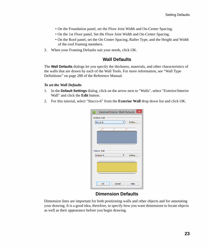
To set the Wall Defaults
1. In the Default Settings dialog, click on the arrow next to "Walls", select "Exterior/Interior Wall" and click the Edit button.
2. For this tutorial, select "Stucco-6" from the Exterior Wall drop down list and click OK.
Dimension Defaults
Dimension lines are important for both positioning walls and other objects and for annotating your drawing. It is a good idea, therefore, to specify how you want dimensions to locate objects as well as their appearance before you begin drawing.
chief-architect-x6-users-guide.book Page 23 Monday, December 16, 2013 4:05 PM
24
Chief Architect X6 User’s Guide
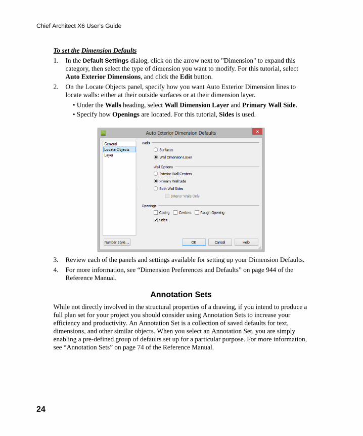
To set the Dimension Defaults
1. In the Default Settings dialog, click on the arrow next to "Dimension" to expand this category, then select the type of dimension you want to modify. For this tutorial, select Auto Exterior Dimensions, and click the Edit button.
2. On the Locate Objects panel, specify how you want Auto Exterior Dimension lines to locate walls: either at their outside surfaces or at their dimension layer.
• Under the Walls heading, select Wall Dimension Layer and Primary Wall Side.
• Specify how Openings are located. For this tutorial, Sides is used.
3. Review each of the panels and settings available for setting up your Dimension Defaults.
4. For more information, see “Dimension Preferences and Defaults” on page 944 of the Reference Manual.
Annotation Sets
While not directly involved in the structural properties of a drawing, if you intend to produce a full plan set for your project you should consider using Annotation Sets to increase your efficiency and productivity. An Annotation Set is a collection of saved defaults for text, dimensions, and other similar objects. When you select an Annotation Set, you are simply enabling a pre-defined group of defaults set up for a particular purpose. For more information, see “Annotation Sets” on page 74 of the Reference Manual.
chief-architect-x6-users-guide.book Page 24 Monday, December 16, 2013 4:05 PM
Drawing Walls
25
Other Defaults
You may want to review some of the other available defaults when setting up your template. For example, you can modify your Cabinet defaults, where you can set up your materials for Base, Wall and Full Height Cabinets so that any future cabinets placed in the plan will initially use these default settings.
Drawing WallsOnce your defaults are set, a new drawing can be started by drawing some exterior walls. When drawing walls, do not try to size or position them precisely - they can be more easily positioned after they are created. For more information, see “Walls, Railings, and Fencing” on page 247 of the Reference Manual.
To draw exterior walls
1. When drawing a structure’s perimeter walls, it is recommended that you make sure Grid Snaps are turned on. You may choose to disable them, though, once the shell walls are in position. See “Snap Behaviors” on page 156 of the Reference Manual for more information.
2. Select Build> Wall> Straight Exterior Wall from the menu or click the corresponding toolbar button, then click and drag from left to right to draw a wall. Walls can be drawn in two ways:
• If you first click using the left mouse button, each wall section will end when the mouse button is released. Place the pointer over an existing wall end and click and drag to create a new connected wall section.
• If you initially click using the right mouse button, you will draw continuously connected walls until you click both mouse buttons simultaneously (or press the Esc key). See “Continuous Wall Drawing” on page 266 of the Reference Manual.
3. There are a few things to make note of as you draw a wall.
You can save this plan as a Template for use when creating newplans. See “Creating Templates” on page 79 of the Reference Manual.
chief-architect-x6-users-guide.book Page 25 Monday, December 16, 2013 4:05 PM
26
Chief Architect X6 User’s Guide
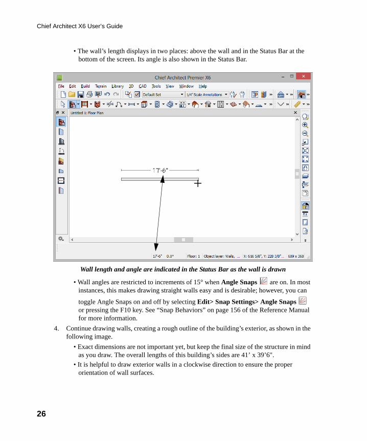
• The wall’s length displays in two places: above the wall and in the Status Bar at the bottom of the screen. Its angle is also shown in the Status Bar.
Wall length and angle are indicated in the Status Bar as the wall is drawn
• Wall angles are restricted to increments of 15° when Angle Snaps are on. In most instances, this makes drawing straight walls easy and is desirable; however, you can
toggle Angle Snaps on and off by selecting Edit> Snap Settings> Angle Snaps or pressing the F10 key. See “Snap Behaviors” on page 156 of the Reference Manual for more information.
4. Continue drawing walls, creating a rough outline of the building’s exterior, as shown in the following image.
• Exact dimensions are not important yet, but keep the final size of the structure in mind as you draw. The overall lengths of this building’s sides are 41’ x 39’6".
• It is helpful to draw exterior walls in a clockwise direction to ensure the proper orientation of wall surfaces.
chief-architect-x6-users-guide.book Page 26 Monday, December 16, 2013 4:05 PM
Drawing Walls
27
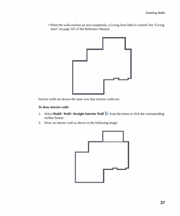
• When the walls enclose an area completely, a Living Area label is created. See “Living Area” on page 325 of the Reference Manual.
Interior walls are drawn the same way that exterior walls are.
To draw interior walls
1. Select Build> Wall> Straight Interior Wall from the menu or click the corresponding toolbar button.
2. Draw an interior wall as shown in the following image.
chief-architect-x6-users-guide.book Page 27 Monday, December 16, 2013 4:05 PM
28
Chief Architect X6 User’s Guide
To delete a wall
1. While the Select Objects tool is active, click on a wall with the pointer to select it.
2. Press the Delete key or click the Delete edit button.
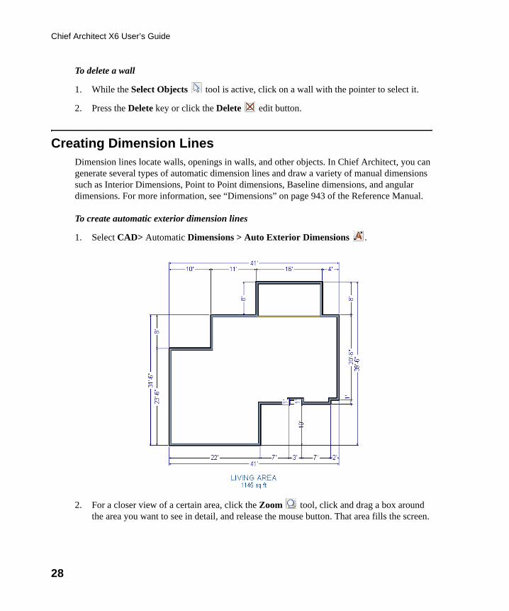
Creating Dimension LinesDimension lines locate walls, openings in walls, and other objects. In Chief Architect, you can generate several types of automatic dimension lines and draw a variety of manual dimensions such as Interior Dimensions, Point to Point dimensions, Baseline dimensions, and angular dimensions. For more information, see “Dimensions” on page 943 of the Reference Manual.
To create automatic exterior dimension lines
1. Select CAD> Automatic Dimensions > Auto Exterior Dimensions .
2. For a closer view of a certain area, click the Zoom tool, click and drag a box around the area you want to see in detail, and release the mouse button. That area fills the screen.
chief-architect-x6-users-guide.book Page 28 Monday, December 16, 2013 4:05 PM
Creating Dimension Lines
29
For more information, see “View and Window Tools” on page 845 of the Reference Manual.
3. To return to the previous zoom factor, select Window> Undo Zoom .
4. If you can’t see all the exterior dimension lines at once, select Window> Fill Window
Building Only to center your plan on screen.
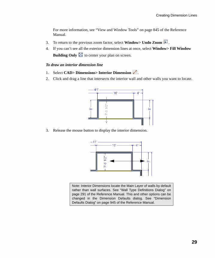
To draw an interior dimension line
1. Select CAD> Dimensions> Interior Dimension .
2. Click and drag a line that intersects the interior wall and other walls you want to locate.
3. Release the mouse button to display the interior dimension.
Note: Interior Dimensions locate the Main Layer of walls by defaultrather than wall surfaces. See “Wall Type Definitions Dialog” onpage 291 of the Reference Manual. This and other options can bechanged in the Dimension Defaults dialog. See “DimensionDefaults Dialog” on page 945 of the Reference Manual.
chief-architect-x6-users-guide.book Page 29 Monday, December 16, 2013 4:05 PM
30
Chief Architect X6 User’s Guide
Adjusting Wall PositionsNow you can adjust the spacing of walls with more precision. There are a couple of ways to move walls into position, but the fastest and most accurate uses dimension lines. For more information about using dimensions to move objects with accuracy, see “Moving Objects Using Dimensions” on page 971 of the Reference Manual.
To move walls using dimensions
1. Begin by selecting Window> Fill Window Building Only so the entire building can be seen.
2. Click the Select Objects button, then click on a wall that you want to move.
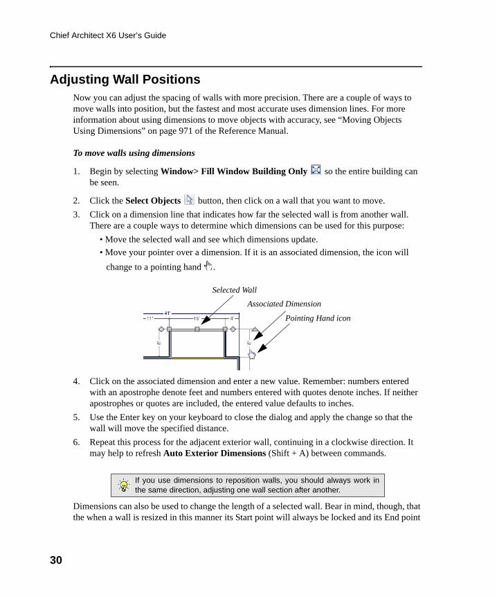
3. Click on a dimension line that indicates how far the selected wall is from another wall. There are a couple ways to determine which dimensions can be used for this purpose:
• Move the selected wall and see which dimensions update.
• Move your pointer over a dimension. If it is an associated dimension, the icon will
change to a pointing hand .
4. Click on the associated dimension and enter a new value. Remember: numbers entered with an apostrophe denote feet and numbers entered with quotes denote inches. If neither apostrophes or quotes are included, the entered value defaults to inches.
5. Use the Enter key on your keyboard to close the dialog and apply the change so that the wall will move the specified distance.
6. Repeat this process for the adjacent exterior wall, continuing in a clockwise direction. It may help to refresh Auto Exterior Dimensions (Shift + A) between commands.
Dimensions can also be used to change the length of a selected wall. Bear in mind, though, that the when a wall is resized in this manner its Start point will always be locked and its End point
If you use dimensions to reposition walls, you should always work inthe same direction, adjusting one wall section after another.
Selected Wall
Associated Dimension
Pointing Hand icon
chief-architect-x6-users-guide.book Page 30 Monday, December 16, 2013 4:05 PM
Adjusting Wall Positions
31
will always be moved. When, adjusting all the walls in a floor plan, it is often easier to move them than to resize them. See “Editing Walls” on page 272 of the Reference Manual.
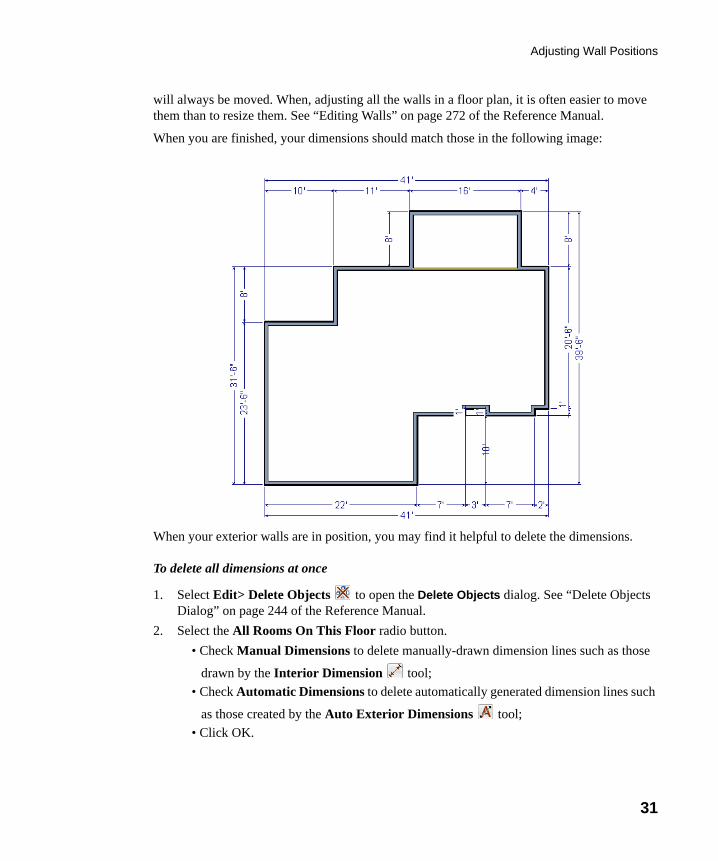
When you are finished, your dimensions should match those in the following image:
When your exterior walls are in position, you may find it helpful to delete the dimensions.
To delete all dimensions at once
1. Select Edit> Delete Objects to open the Delete Objects dialog. See “Delete Objects Dialog” on page 244 of the Reference Manual.
2. Select the All Rooms On This Floor radio button.
• Check Manual Dimensions to delete manually-drawn dimension lines such as those
drawn by the Interior Dimension tool;
• Check Automatic Dimensions to delete automatically generated dimension lines such
as those created by the Auto Exterior Dimensions tool;
• Click OK.
chief-architect-x6-users-guide.book Page 31 Monday, December 16, 2013 4:05 PM
32
Chief Architect X6 User’s Guide
Although using dimensions is generally the fastest and most accurate way to move walls, you can also move them using their edit handles and edit tools.
To move walls using their edit handle
1. Click the Select Objects tool then click on an exterior wall to select it.
2. Click and drag the Move edit handle that displays at the position along the wall where you clicked. Walls can be moved perpendicular to the direction that they are drawn.
3. As you move the wall, the dimension lines that indicate how far it is from other walls will update.
If you have difficulty positioning a wall at a particular location, try zooming in on it using
either the Zoom or Zoom In tool or by scrolling with your mouse wheel. You can also use the arrow keys on your keyboard to nudge a selected wall up, down, left, or right on-screen.
Creating RoomsOnce the exterior of the house is in place, you can begin drawing interior walls and creating rooms. Rooms are defined by the walls that enclose them and can be assigned a Room Type that applies attributes such as flooring that are typical to that type of room. For more information about rooms, see “Room Types” on page 321 of the Reference Manual.
To define rooms using interior walls
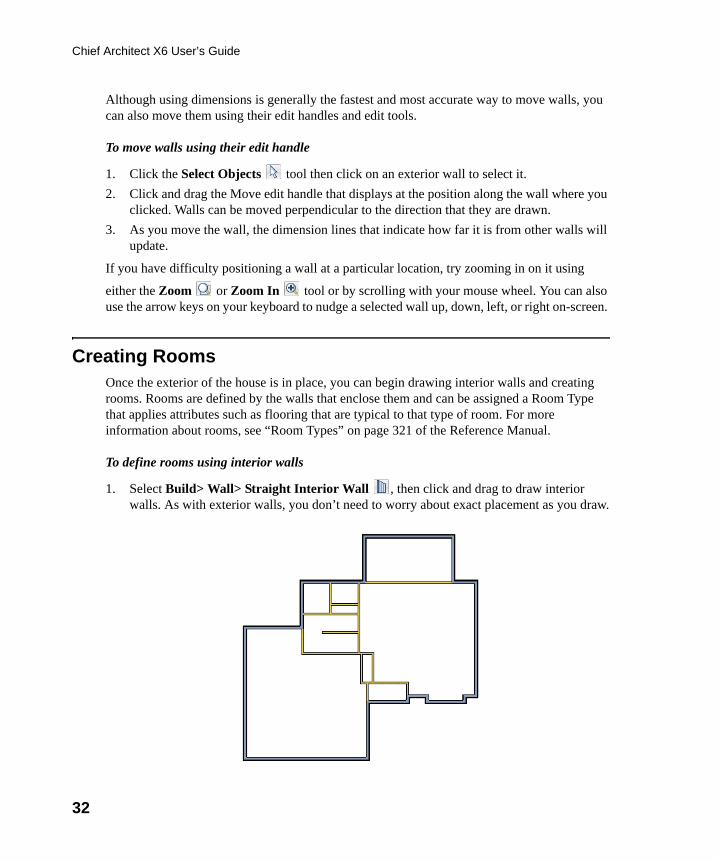
1. Select Build> Wall> Straight Interior Wall , then click and drag to draw interior walls. As with exterior walls, you don’t need to worry about exact placement as you draw.
chief-architect-x6-users-guide.book Page 32 Monday, December 16, 2013 4:05 PM
Creating Rooms
33
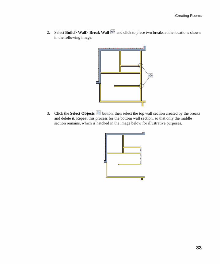
2. Select Build> Wall> Break Wall and click to place two breaks at the locations shown in the following image.
3. Click the Select Objects button, then select the top wall section created by the breaks and delete it. Repeat this process for the bottom wall section, so that only the middle section remains, which is hatched in the image below for illustrative purposes.
chief-architect-x6-users-guide.book Page 33 Monday, December 16, 2013 4:05 PM
34
Chief Architect X6 User’s Guide
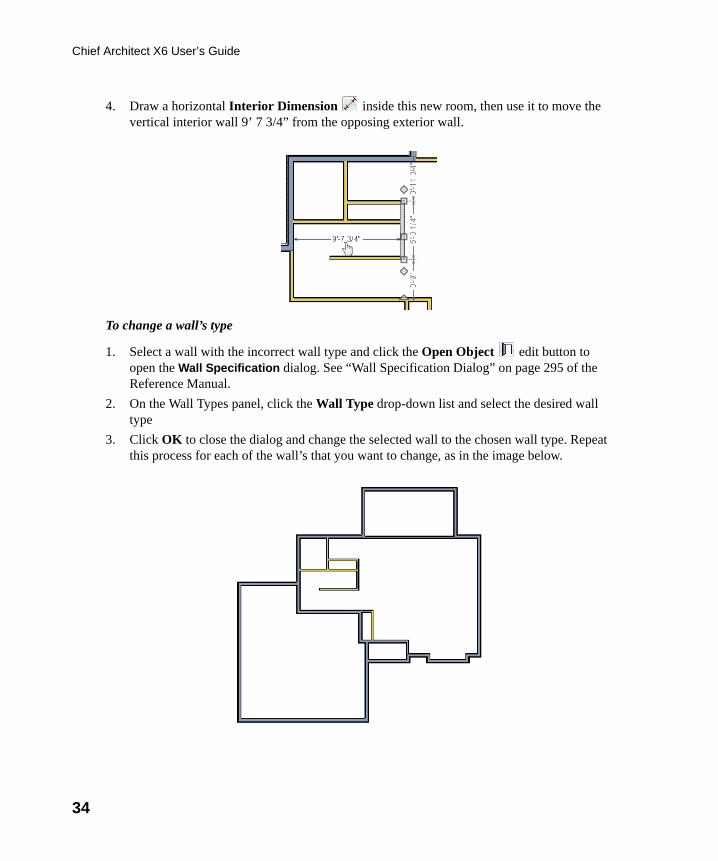
4. Draw a horizontal Interior Dimension inside this new room, then use it to move the vertical interior wall 9’ 7 3/4” from the opposing exterior wall.
To change a wall’s type
1. Select a wall with the incorrect wall type and click the Open Object edit button to open the Wall Specification dialog. See “Wall Specification Dialog” on page 295 of the Reference Manual.
2. On the Wall Types panel, click the Wall Type drop-down list and select the desired wall type
3. Click OK to close the dialog and change the selected wall to the chosen wall type. Repeat this process for each of the wall’s that you want to change, as in the image below.
chief-architect-x6-users-guide.book Page 34 Monday, December 16, 2013 4:05 PM
Creating Rooms
35
Using Room Dividers
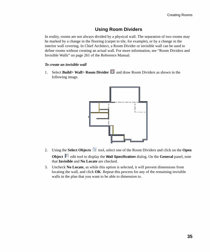
In reality, rooms are not always divided by a physical wall. The separation of two rooms may be marked by a change in the flooring (carpet to tile, for example), or by a change in the interior wall covering. In Chief Architect, a Room Divider or invisible wall can be used to define rooms without creating an actual wall. For more information, see “Room Dividers and Invisible Walls” on page 261 of the Reference Manual.
To create an invisible wall
1. Select Build> Wall> Room Divider and draw Room Dividers as shown in the following image.
2. Using the Select Objects tool, select one of the Room Dividers and click on the Open
Object edit tool to display the Wall Specification dialog. On the General panel, note that Invisible and No Locate are checked.
3. Uncheck No Locate, as while this option is selected, it will prevent dimensions from locating the wall, and click OK. Repeat this process for any of the remaining invisible walls in the plan that you want to be able to dimension to.
chief-architect-x6-users-guide.book Page 35 Monday, December 16, 2013 4:05 PM
36
Chief Architect X6 User’s Guide
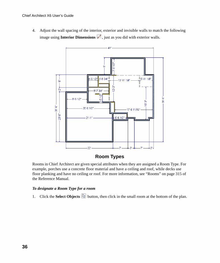
4. Adjust the wall spacing of the interior, exterior and invisible walls to match the following
image using Interior Dimensions , just as you did with exterior walls.
Room Types
Rooms in Chief Architect are given special attributes when they are assigned a Room Type. For example, porches use a concrete floor material and have a ceiling and roof, while decks use floor planking and have no ceiling or roof. For more information, see “Rooms” on page 315 of the Reference Manual.
To designate a Room Type for a room
1. Click the Select Objects button, then click in the small room at the bottom of the plan.
chief-architect-x6-users-guide.book Page 36 Monday, December 16, 2013 4:05 PM
Creating Rooms
37
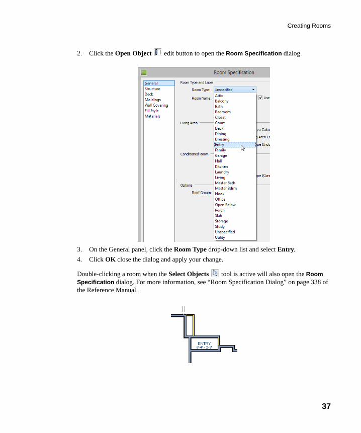
2. Click the Open Object edit button to open the Room Specification dialog.
3. On the General panel, click the Room Type drop-down list and select Entry.
4. Click OK close the dialog and apply your change.
Double-clicking a room when the Select Objects tool is active will also open the Room Specification dialog. For more information, see “Room Specification Dialog” on page 338 of the Reference Manual.
chief-architect-x6-users-guide.book Page 37 Monday, December 16, 2013 4:05 PM
38
Chief Architect X6 User’s Guide
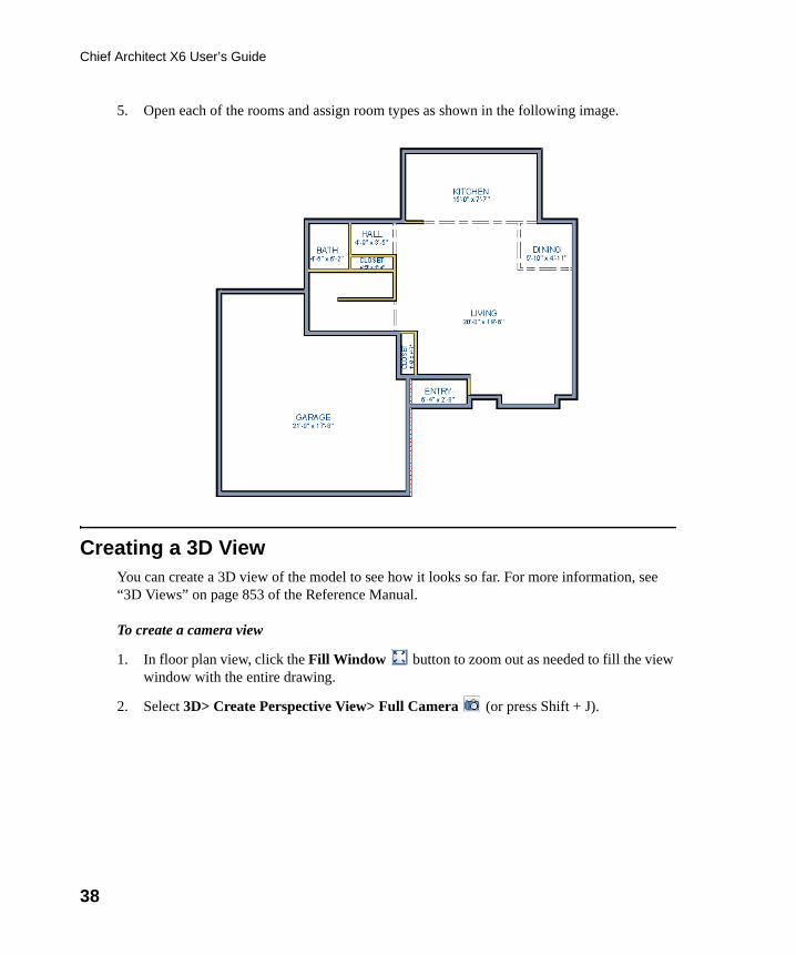
5. Open each of the rooms and assign room types as shown in the following image.
Creating a 3D ViewYou can create a 3D view of the model to see how it looks so far. For more information, see “3D Views” on page 853 of the Reference Manual.
To create a camera view
1. In floor plan view, click the Fill Window button to zoom out as needed to fill the view window with the entire drawing.
2. Select 3D> Create Perspective View> Full Camera (or press Shift + J).
chief-architect-x6-users-guide.book Page 38 Monday, December 16, 2013 4:05 PM
Creating a 3D View
39
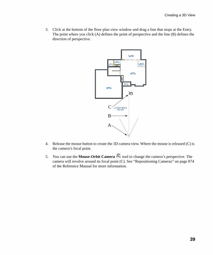
3. Click at the bottom of the floor plan view window and drag a line that stops at the Entry. The point where you click (A) defines the point of perspective and the line (B) defines the direction of perspective.
4. Release the mouse button to create the 3D camera view. Where the mouse is released (C) is the camera’s focal point.
5. You can use the Mouse-Orbit Camera tool to change the camera’s perspective. The camera will revolve around its focal point (C). See “Repositioning Cameras” on page 874 of the Reference Manual for more information.
A
B
C
chief-architect-x6-users-guide.book Page 39 Monday, December 16, 2013 4:05 PM
40
Chief Architect X6 User’s Guide
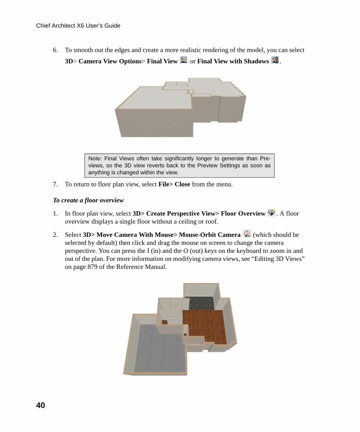
6. To smooth out the edges and create a more realistic rendering of the model, you can select
3D> Camera View Options> Final View or Final View with Shadows .
7. To return to floor plan view, select File> Close from the menu.
To create a floor overview
1. In floor plan view, select 3D> Create Perspective View> Floor Overview . A floor overview displays a single floor without a ceiling or roof.
2. Select 3D> Move Camera With Mouse> Mouse-Orbit Camera (which should be selected by default) then click and drag the mouse on screen to change the camera perspective. You can press the I (in) and the O (out) keys on the keyboard to zoom in and out of the plan. For more information on modifying camera views, see “Editing 3D Views” on page 879 of the Reference Manual.
Note: Final Views often take significantly longer to generate than Pre-views, so the 3D view reverts back to the Preview Settings as soon asanything is changed within the view.
chief-architect-x6-users-guide.book Page 40 Monday, December 16, 2013 4:05 PM
Adding Floors
41
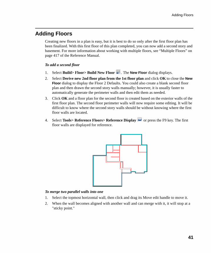
Adding FloorsCreating new floors in a plan is easy, but it is best to do so only after the first floor plan has been finalized. With this first floor of this plan completed, you can now add a second story and basement. For more information about working with multiple floors, see “Multiple Floors” on page 417 of the Reference Manual.
To add a second floor
1. Select Build> Floor> Build New Floor . The New Floor dialog displays.
2. Select Derive new 2nd floor plan from the 1st floor plan and click OK to close the New Floor dialog to display the Floor 2 Defaults. You could also create a blank second floor plan and then drawn the second story walls manually; however, it is usually faster to automatically generate the perimeter walls and then edit them as needed.
3. Click OK and a floor plan for the second floor is created based on the exterior walls of the first floor plan. The second floor perimeter walls will now require some editing. It will be difficult to know where the second story walls should be without knowing where the first floor walls are located.
4. Select Tools> Reference Floors> Reference Display or press the F9 key. The first floor walls are displayed for reference.
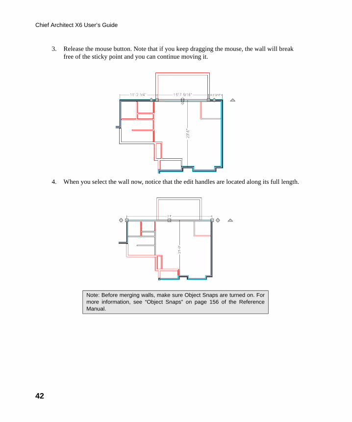
To merge two parallel walls into one
1. Select the topmost horizontal wall, then click and drag its Move edit handle to move it.
2. When the wall becomes aligned with another wall and can merge with it, it will stop at a "sticky point."
chief-architect-x6-users-guide.book Page 41 Monday, December 16, 2013 4:05 PM
42
Chief Architect X6 User’s Guide
3. Release the mouse button. Note that if you keep dragging the mouse, the wall will break free of the sticky point and you can continue moving it.
4. When you select the wall now, notice that the edit handles are located along its full length.
Note: Before merging walls, make sure Object Snaps are turned on. Formore information, see “Object Snaps” on page 156 of the ReferenceManual.
chief-architect-x6-users-guide.book Page 42 Monday, December 16, 2013 4:05 PM
Adding Floors
43
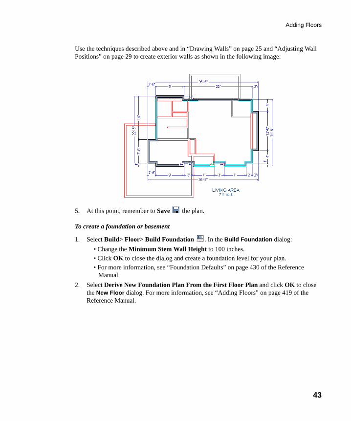
Use the techniques described above and in “Drawing Walls” on page 25 and “Adjusting Wall Positions” on page 29 to create exterior walls as shown in the following image:
5. At this point, remember to Save the plan.
To create a foundation or basement
1. Select Build> Floor> Build Foundation . In the Build Foundation dialog:
• Change the Minimum Stem Wall Height to 100 inches.
• Click OK to close the dialog and create a foundation level for your plan.
• For more information, see “Foundation Defaults” on page 430 of the Reference Manual.
2. Select Derive New Foundation Plan From the First Floor Plan and click OK to close the New Floor dialog. For more information, see “Adding Floors” on page 419 of the Reference Manual.
chief-architect-x6-users-guide.book Page 43 Monday, December 16, 2013 4:05 PM
44
Chief Architect X6 User’s Guide
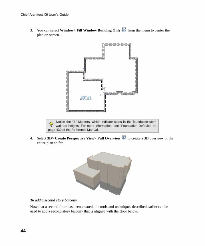
3. You can select Window> Fill Window Building Only from the menu to center the plan on screen.
4. Select 3D> Create Perspective View> Full Overview to create a 3D overview of the entire plan so far.
To add a second story balcony
Now that a second floor has been created, the tools and techniques described earlier can be used to add a second story balcony that is aligned with the floor below.
Notice the "S" Markers, which indicate steps in the foundation stemwall top heights. For more information, see “Foundation Defaults” on
page 430 of the Reference Manual.
chief-architect-x6-users-guide.book Page 44 Monday, December 16, 2013 4:05 PM
Adding Floors
45
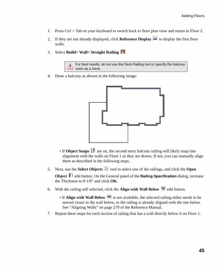
1. Press Ctrl + Tab on your keyboard to switch back to floor plan view and return to Floor 2.
2. If they are not already displayed, click Reference Display to display the first floor walls.
3. Select Build> Wall> Straight Railing .
4. Draw a balcony as shown in the following image:
• If Object Snaps are on, the second story balcony railing will likely snap into alignment with the walls on Floor 1 as they are drawn. If not, you can manually align them as described in the following steps.
5. Next, use the Select Objects tool to select one of the railings, and click the Open
Object edit button. On the General panel of the Railing Specification dialog, increase the Thickness to 8 1/8” and click OK.
6. With the railing still selected, click the Align with Wall Below edit button.
• If Align with Wall Below is not available, the selected railing either needs to be moved closer to the wall below, or the railing is already aligned with the one below. See “Aligning Walls” on page 279 of the Reference Manual.
7. Repeat these steps for each section of railing that has a wall directly below it on Floor 1.
For best results, do not use the Deck Railing tool or specify the balconyroom as a Deck.
chief-architect-x6-users-guide.book Page 45 Monday, December 16, 2013 4:05 PM
46
Chief Architect X6 User’s Guide
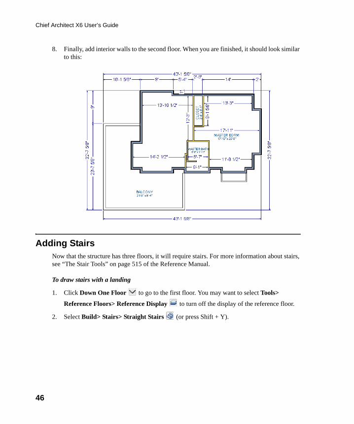
8. Finally, add interior walls to the second floor. When you are finished, it should look similar to this:
Adding StairsNow that the structure has three floors, it will require stairs. For more information about stairs, see “The Stair Tools” on page 515 of the Reference Manual.
To draw stairs with a landing
1. Click Down One Floor to go to the first floor. You may want to select Tools>
Reference Floors> Reference Display to turn off the display of the reference floor.
2. Select Build> Stairs> Straight Stairs (or press Shift + Y).
chief-architect-x6-users-guide.book Page 46 Monday, December 16, 2013 4:05 PM
Adding Stairs
47
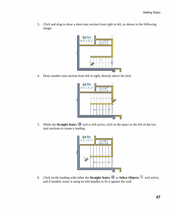
3. Click and drag to draw a short stair section from right to left, as shown in the following image:
4. Draw another stair section from left to right, directly above the first:
5. While the Straight Stairs tool is still active, click in the space to the left of the two stair sections to create a landing.
6. Click on the landing with either the Straight Stairs or Select Objects tool active, and if needed, resize it using its edit handles to fit it against the wall.
chief-architect-x6-users-guide.book Page 47 Monday, December 16, 2013 4:05 PM
48
Chief Architect X6 User’s Guide
A stairwell is simply an interior room that has been assigned the Room Type “Open Below”. See “Room Specification Dialog” on page 338 of the Reference Manual.
To create a stairwell
1. Select either of the two stair sections.
2. Click the Auto Stairwell edit button to create a stairwell.
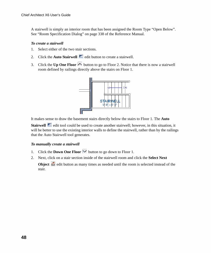
3. Click the Up One Floor button to go to Floor 2. Notice that there is now a stairwell room defined by railings directly above the stairs on Floor 1.
It makes sense to draw the basement stairs directly below the stairs to Floor 1. The Auto
Stairwell edit tool could be used to create another stairwell; however, in this situation, it will be better to use the existing interior walls to define the stairwell, rather than by the railings that the Auto Stairwell tool generates.
To manually create a stairwell
1. Click the Down One Floor button to go down to Floor 1.
2. Next, click on a stair section inside of the stairwell room and click the Select Next
Object edit button as many times as needed until the room is selected instead of the stair.
chief-architect-x6-users-guide.book Page 48 Monday, December 16, 2013 4:05 PM
Adding Stairs
49
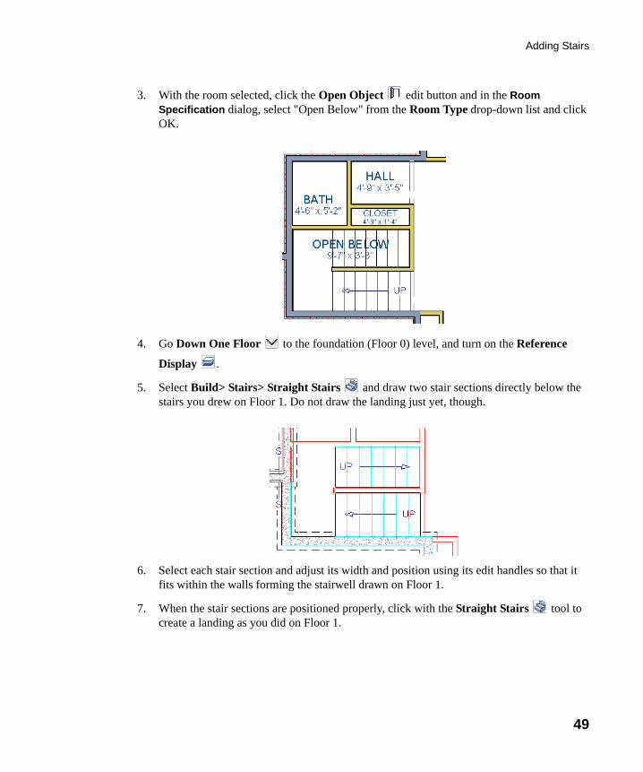
3. With the room selected, click the Open Object edit button and in the Room Specification dialog, select "Open Below" from the Room Type drop-down list and click OK.
4. Go Down One Floor to the foundation (Floor 0) level, and turn on the Reference
Display .
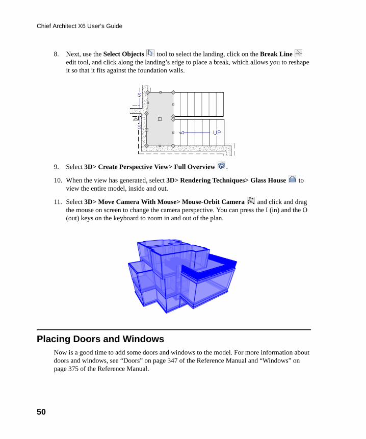
5. Select Build> Stairs> Straight Stairs and draw two stair sections directly below the stairs you drew on Floor 1. Do not draw the landing just yet, though.
6. Select each stair section and adjust its width and position using its edit handles so that it fits within the walls forming the stairwell drawn on Floor 1.
7. When the stair sections are positioned properly, click with the Straight Stairs tool to create a landing as you did on Floor 1.
chief-architect-x6-users-guide.book Page 49 Monday, December 16, 2013 4:05 PM
50
Chief Architect X6 User’s Guide
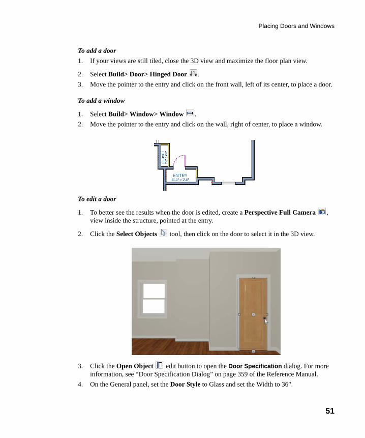
8. Next, use the Select Objects tool to select the landing, click on the Break Line edit tool, and click along the landing’s edge to place a break, which allows you to reshape it so that it fits against the foundation walls.
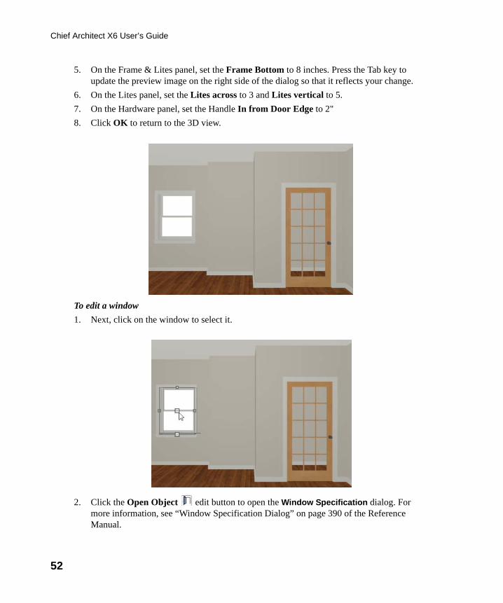
9. Select 3D> Create Perspective View> Full Overview .
10. When the view has generated, select 3D> Rendering Techniques> Glass House to view the entire model, inside and out.
11. Select 3D> Move Camera With Mouse> Mouse-Orbit Camera and click and drag the mouse on screen to change the camera perspective. You can press the I (in) and the O (out) keys on the keyboard to zoom in and out of the plan.
Placing Doors and WindowsNow is a good time to add some doors and windows to the model. For more information about doors and windows, see “Doors” on page 347 of the Reference Manual and “Windows” on page 375 of the Reference Manual.
chief-architect-x6-users-guide.book Page 50 Monday, December 16, 2013 4:05 PM
Placing Doors and Windows
51
To add a door
1. If your views are still tiled, close the 3D view and maximize the floor plan view.
2. Select Build> Door> Hinged Door .
3. Move the pointer to the entry and click on the front wall, left of its center, to place a door.
To add a window
1. Select Build> Window> Window .
2. Move the pointer to the entry and click on the wall, right of center, to place a window.
To edit a door
1. To better see the results when the door is edited, create a Perspective Full Camera , view inside the structure, pointed at the entry.
2. Click the Select Objects tool, then click on the door to select it in the 3D view.
3. Click the Open Object edit button to open the Door Specification dialog. For more information, see “Door Specification Dialog” on page 359 of the Reference Manual.
4. On the General panel, set the Door Style to Glass and set the Width to 36".
chief-architect-x6-users-guide.book Page 51 Monday, December 16, 2013 4:05 PM
52
Chief Architect X6 User’s Guide
5. On the Frame & Lites panel, set the Frame Bottom to 8 inches. Press the Tab key to update the preview image on the right side of the dialog so that it reflects your change.
6. On the Lites panel, set the Lites across to 3 and Lites vertical to 5.
7. On the Hardware panel, set the Handle In from Door Edge to 2"
8. Click OK to return to the 3D view.
To edit a window
1. Next, click on the window to select it.
2. Click the Open Object edit button to open the Window Specification dialog. For more information, see “Window Specification Dialog” on page 390 of the Reference Manual.
chief-architect-x6-users-guide.book Page 52 Monday, December 16, 2013 4:05 PM
Placing Doors and Windows
53
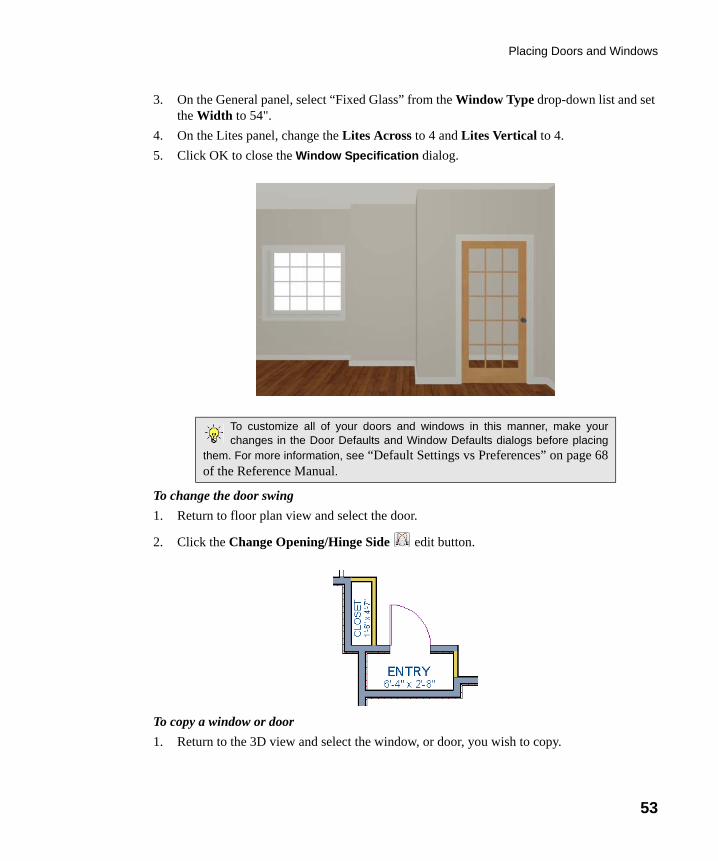
3. On the General panel, select “Fixed Glass” from the Window Type drop-down list and set the Width to 54".
4. On the Lites panel, change the Lites Across to 4 and Lites Vertical to 4.
5. Click OK to close the Window Specification dialog.
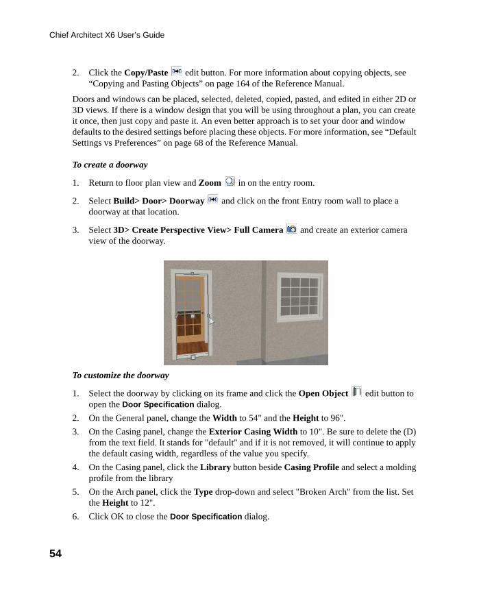
To change the door swing
1. Return to floor plan view and select the door.
2. Click the Change Opening/Hinge Side edit button.
To copy a window or door
1. Return to the 3D view and select the window, or door, you wish to copy.
To customize all of your doors and windows in this manner, make yourchanges in the Door Defaults and Window Defaults dialogs before placing
them. For more information, see “Default Settings vs Preferences” on page 68of the Reference Manual.
chief-architect-x6-users-guide.book Page 53 Monday, December 16, 2013 4:05 PM
54
Chief Architect X6 User’s Guide
2. Click the Copy/Paste edit button. For more information about copying objects, see “Copying and Pasting Objects” on page 164 of the Reference Manual.
Doors and windows can be placed, selected, deleted, copied, pasted, and edited in either 2D or 3D views. If there is a window design that you will be using throughout a plan, you can create it once, then just copy and paste it. An even better approach is to set your door and window defaults to the desired settings before placing these objects. For more information, see “Default Settings vs Preferences” on page 68 of the Reference Manual.
To create a doorway
1. Return to floor plan view and Zoom in on the entry room.
2. Select Build> Door> Doorway and click on the front Entry room wall to place a doorway at that location.
3. Select 3D> Create Perspective View> Full Camera and create an exterior camera view of the doorway.
To customize the doorway
1. Select the doorway by clicking on its frame and click the Open Object edit button to open the Door Specification dialog.
2. On the General panel, change the Width to 54" and the Height to 96".
3. On the Casing panel, change the Exterior Casing Width to 10". Be sure to delete the (D) from the text field. It stands for "default" and if it is not removed, it will continue to apply the default casing width, regardless of the value you specify.
4. On the Casing panel, click the Library button beside Casing Profile and select a molding profile from the library
5. On the Arch panel, click the Type drop-down and select "Broken Arch" from the list. Set the Height to 12".
6. Click OK to close the Door Specification dialog.
chief-architect-x6-users-guide.book Page 54 Monday, December 16, 2013 4:05 PM
Placing Doors and Windows
55
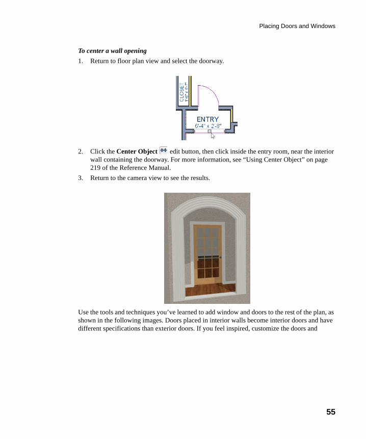
To center a wall opening
1. Return to floor plan view and select the doorway.
2. Click the Center Object edit button, then click inside the entry room, near the interior wall containing the doorway. For more information, see “Using Center Object” on page 219 of the Reference Manual.
3. Return to the camera view to see the results.
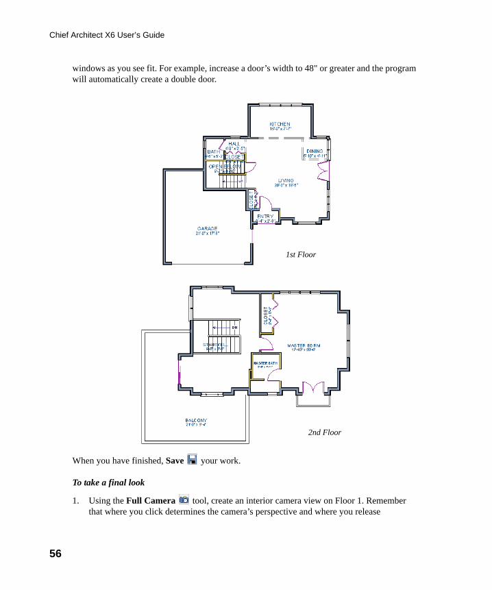
Use the tools and techniques you’ve learned to add window and doors to the rest of the plan, as shown in the following images. Doors placed in interior walls become interior doors and have different specifications than exterior doors. If you feel inspired, customize the doors and
chief-architect-x6-users-guide.book Page 55 Monday, December 16, 2013 4:05 PM
56
Chief Architect X6 User’s Guide
windows as you see fit. For example, increase a door’s width to 48" or greater and the program will automatically create a double door.
When you have finished, Save your work.
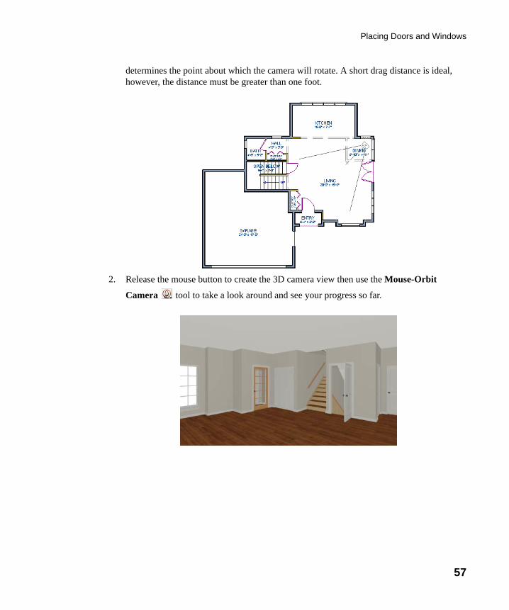
To take a final look
1. Using the Full Camera tool, create an interior camera view on Floor 1. Remember that where you click determines the camera’s perspective and where you release
1st Floor
2nd Floor
chief-architect-x6-users-guide.book Page 56 Monday, December 16, 2013 4:05 PM
Placing Doors and Windows
57
determines the point about which the camera will rotate. A short drag distance is ideal, however, the distance must be greater than one foot.
2. Release the mouse button to create the 3D camera view then use the Mouse-Orbit
Camera tool to take a look around and see your progress so far.
chief-architect-x6-users-guide.book Page 57 Monday, December 16, 2013 4:05 PM
58
Chief Architect X6 User’s Guide
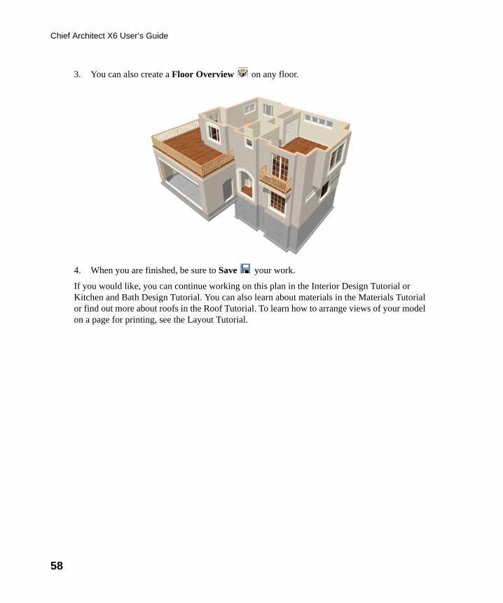
3. You can also create a Floor Overview on any floor.
4. When you are finished, be sure to Save your work.
If you would like, you can continue working on this plan in the Interior Design Tutorial or Kitchen and Bath Design Tutorial. You can also learn about materials in the Materials Tutorial or find out more about roofs in the Roof Tutorial. To learn how to arrange views of your model on a page for printing, see the Layout Tutorial.
chief-architect-x6-users-guide.book Page 58 Monday, December 16, 2013 4:05 PM
59
Chapter 3:
Roof Tutorial
The majority of Roof Tutorial describes some common roof styles that can be created using settings in the Wall Specification dialog and can be completed independent of the other tutorials. It also explains how to add gables over doors and windows, how to create dormers automatically and manually, and how to create skylights.
The Adding a Roof to the Stucco Beach House section continues where the Interior Design Tutorial left off and explains how to add a roof to that plan.
For more information about Roof Tools, see “Roofs” on page 453 of the Reference Manual.
In this tutorial you’ll learn about:
• Getting Started with Automatic Roof Styles• Hip Roofs• Gable Roofs• Shed Roofs• Offset Gable Roofs• Gambrel Roofs• Gull Wing Roofs• Half Hip Roofs• Mansard Roofs• Finding the Start of an Upper Pitch• Roof Style Quick Reference• Roof Returns
• Adding Gables over Doors and Windows• Automatic Dormers• Crickets and Dormer Vents• Manually Drawn Dormers• Skylights• Using the Break Wall Tool to Modify Roofs• Adding a Roof to the Stucco Beach House• Troubleshooting Automatic Roof Issues
chief-architect-x6-users-guide.book Page 59 Monday, December 16, 2013 4:05 PM
60
Chief Architect X6 User’s Guide
Getting Started with Automatic Roof StylesThis tutorial uses a simple, rectangular structure to explain how to create common roof styles using roof style directives assigned to the exterior walls.
To begin a new plan
1. If any plans are open, select File> Close All from the menu.
2. Select File> New Plan to open a new plan.
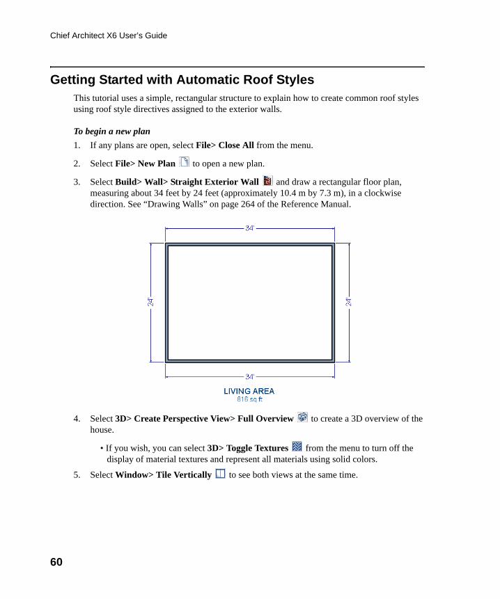
3. Select Build> Wall> Straight Exterior Wall and draw a rectangular floor plan, measuring about 34 feet by 24 feet (approximately 10.4 m by 7.3 m), in a clockwise direction. See “Drawing Walls” on page 264 of the Reference Manual.
4. Select 3D> Create Perspective View> Full Overview to create a 3D overview of the house.
• If you wish, you can select 3D> Toggle Textures from the menu to turn off the display of material textures and represent all materials using solid colors.
5. Select Window> Tile Vertically to see both views at the same time.
chief-architect-x6-users-guide.book Page 60 Monday, December 16, 2013 4:05 PM
Getting Started with Automatic Roof Styles
61
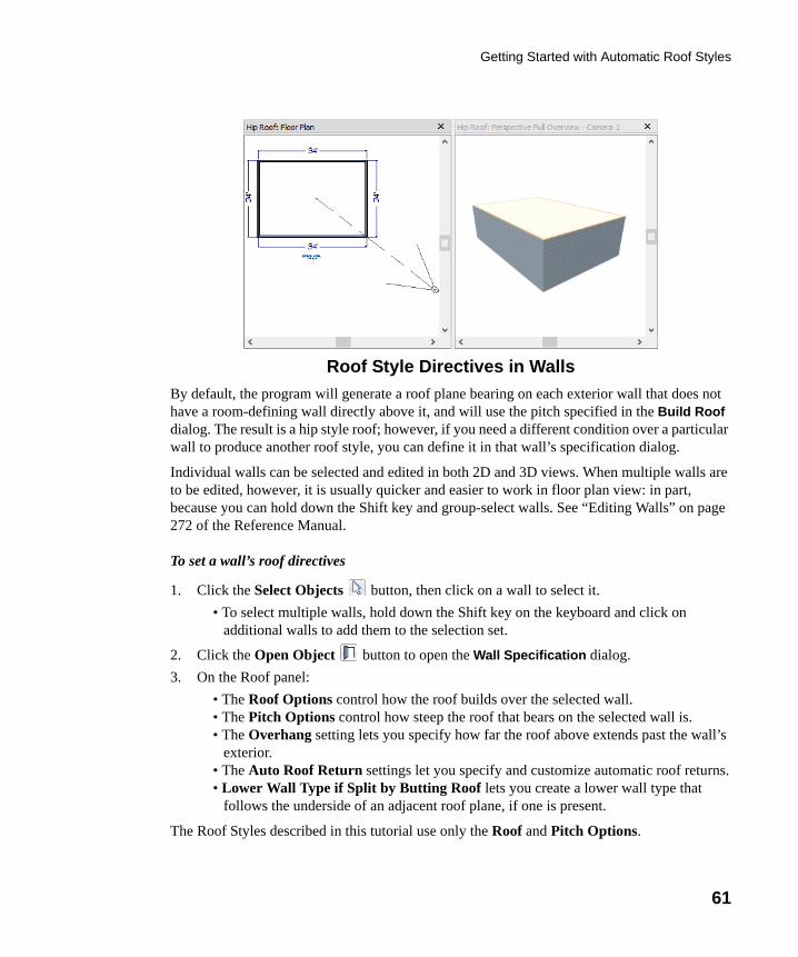
Roof Style Directives in Walls
By default, the program will generate a roof plane bearing on each exterior wall that does not have a room-defining wall directly above it, and will use the pitch specified in the Build Roof dialog. The result is a hip style roof; however, if you need a different condition over a particular wall to produce another roof style, you can define it in that wall’s specification dialog.
Individual walls can be selected and edited in both 2D and 3D views. When multiple walls are to be edited, however, it is usually quicker and easier to work in floor plan view: in part, because you can hold down the Shift key and group-select walls. See “Editing Walls” on page 272 of the Reference Manual.
To set a wall’s roof directives
1. Click the Select Objects button, then click on a wall to select it.
• To select multiple walls, hold down the Shift key on the keyboard and click on additional walls to add them to the selection set.
2. Click the Open Object button to open the Wall Specification dialog.
3. On the Roof panel:
• The Roof Options control how the roof builds over the selected wall.• The Pitch Options control how steep the roof that bears on the selected wall is.• The Overhang setting lets you specify how far the roof above extends past the wall’s
exterior.• The Auto Roof Return settings let you specify and customize automatic roof returns.• Lower Wall Type if Split by Butting Roof lets you create a lower wall type that
follows the underside of an adjacent roof plane, if one is present.
The Roof Styles described in this tutorial use only the Roof and Pitch Options.
chief-architect-x6-users-guide.book Page 61 Monday, December 16, 2013 4:05 PM
62
Chief Architect X6 User’s Guide
Attic Walls
When a roof is generated, attic walls may also be generated. An attic wall fills the space between the walls that define a room and the roof above. The triangular-shaped wall of a gable, for example, is created using an attic wall.
If you do not want to see attic walls in floor plan view, you can turn off their display.
To turn off the display of attic walls
1. In floor plan view, select Tools> Display Settings> Display Options (or press the ~ key) to open the Layer Display Options dialog.
2. Find "Walls, Attic" in the Name column, remove the check from the Display column for this item, and click OK. For more information, see “Layer Display Options Dialog” on page 144 of the Reference Manual.
Deleting Roofs
Whether a roof was drawn manually or automatically generated, deleting roof planes is easy:
• Select an individual roof plane and Delete it.
• Select Build> Roof> Delete Roof Planes to delete all roof planes in the plan.
• Select Edit> Delete Objects and in the Delete Objects dialog, select either All Rooms On This Floor or All Floors; place a check beside Roof Planes; and click OK to delete all roof planes either on the current floor or in the plan.
If a warning message states that roofs cannot be deleted while Auto Rebuild Roof is on, click the Yes button to turn off Auto Rebuild Roof and delete the roof.
Auto Rebuild Roofs
Auto Rebuild Roofs is a convenient feature in Chief Architect that automatically rebuilds the roof in a plan whenever the exterior walls or floor/ceiling heights are changed. Auto Rebuild Roofs is turned off by default, and this tutorial is presented with this feature disabled; however the information presented here also applies when it is enabled.
To turn on/off Auto Rebuild Roofs
1. Select Build> Roof> Build Roof from the menu.
2. On the Roof panel of the Build Roof dialog, check or uncheck Auto Rebuild Roofs and click OK.
chief-architect-x6-users-guide.book Page 62 Monday, December 16, 2013 4:05 PM
Hip Roofs
63
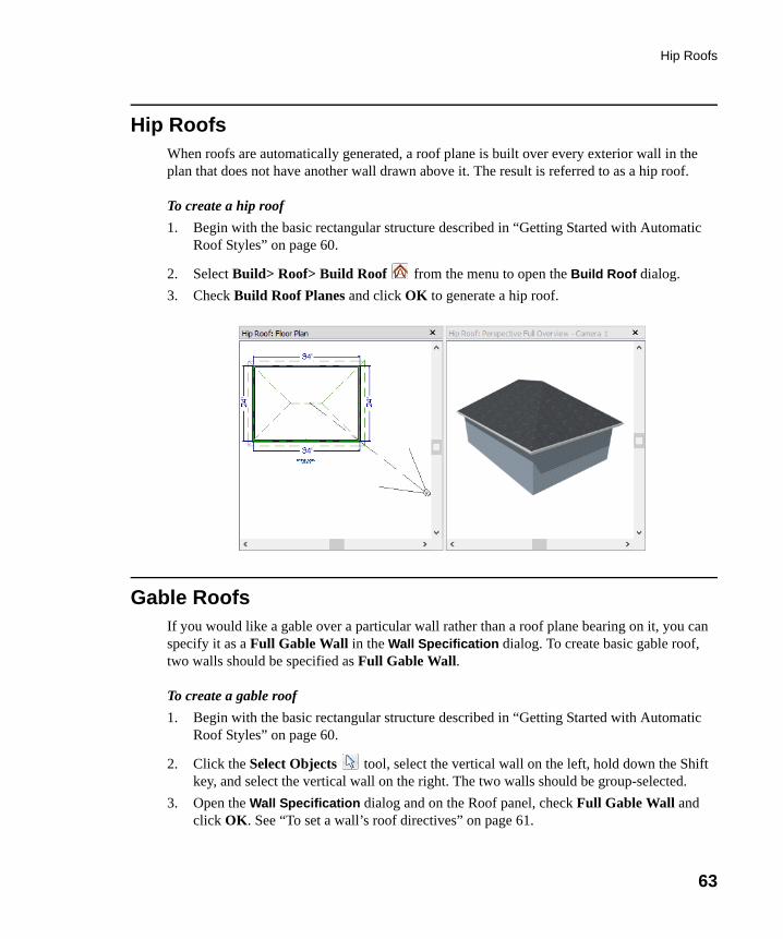
Hip RoofsWhen roofs are automatically generated, a roof plane is built over every exterior wall in the plan that does not have another wall drawn above it. The result is referred to as a hip roof.
To create a hip roof
1. Begin with the basic rectangular structure described in “Getting Started with Automatic Roof Styles” on page 60.
2. Select Build> Roof> Build Roof from the menu to open the Build Roof dialog.
3. Check Build Roof Planes and click OK to generate a hip roof.
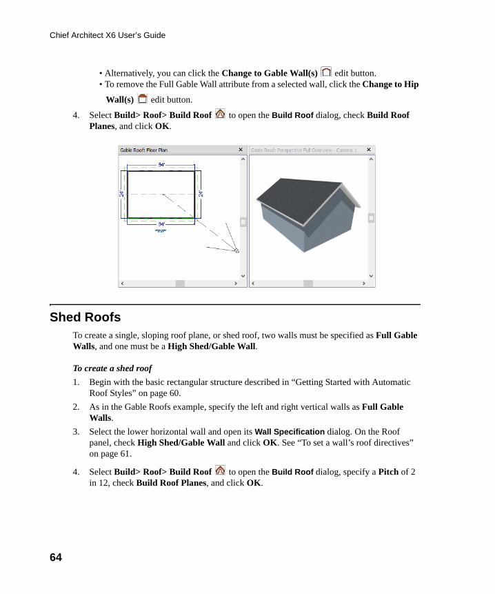
Gable RoofsIf you would like a gable over a particular wall rather than a roof plane bearing on it, you can specify it as a Full Gable Wall in the Wall Specification dialog. To create basic gable roof, two walls should be specified as Full Gable Wall.
To create a gable roof
1. Begin with the basic rectangular structure described in “Getting Started with Automatic Roof Styles” on page 60.
2. Click the Select Objects tool, select the vertical wall on the left, hold down the Shift key, and select the vertical wall on the right. The two walls should be group-selected.
3. Open the Wall Specification dialog and on the Roof panel, check Full Gable Wall and click OK. See “To set a wall’s roof directives” on page 61.
chief-architect-x6-users-guide.book Page 63 Monday, December 16, 2013 4:05 PM
64
Chief Architect X6 User’s Guide
• Alternatively, you can click the Change to Gable Wall(s) edit button.• To remove the Full Gable Wall attribute from a selected wall, click the Change to Hip
Wall(s) edit button.
4. Select Build> Roof> Build Roof to open the Build Roof dialog, check Build Roof Planes, and click OK.
Shed RoofsTo create a single, sloping roof plane, or shed roof, two walls must be specified as Full Gable Walls, and one must be a High Shed/Gable Wall.
To create a shed roof
1. Begin with the basic rectangular structure described in “Getting Started with Automatic Roof Styles” on page 60.
2. As in the Gable Roofs example, specify the left and right vertical walls as Full Gable Walls.
3. Select the lower horizontal wall and open its Wall Specification dialog. On the Roof panel, check High Shed/Gable Wall and click OK. See “To set a wall’s roof directives” on page 61.
4. Select Build> Roof> Build Roof to open the Build Roof dialog, specify a Pitch of 2 in 12, check Build Roof Planes, and click OK.
chief-architect-x6-users-guide.book Page 64 Monday, December 16, 2013 4:05 PM
Offset Gable Roofs
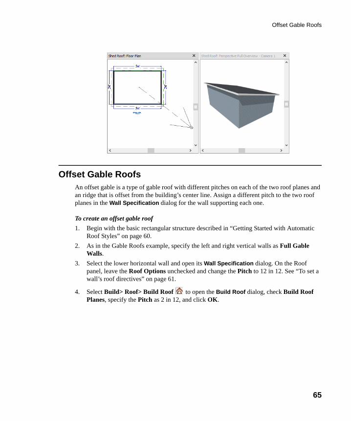
65
Offset Gable RoofsAn offset gable is a type of gable roof with different pitches on each of the two roof planes and an ridge that is offset from the building’s center line. Assign a different pitch to the two roof planes in the Wall Specification dialog for the wall supporting each one.
To create an offset gable roof
1. Begin with the basic rectangular structure described in “Getting Started with Automatic Roof Styles” on page 60.
2. As in the Gable Roofs example, specify the left and right vertical walls as Full Gable Walls.
3. Select the lower horizontal wall and open its Wall Specification dialog. On the Roof panel, leave the Roof Options unchecked and change the Pitch to 12 in 12. See “To set a wall’s roof directives” on page 61.
4. Select Build> Roof> Build Roof to open the Build Roof dialog, check Build Roof Planes, specify the Pitch as 2 in 12, and click OK.
chief-architect-x6-users-guide.book Page 65 Monday, December 16, 2013 4:05 PM
66
Chief Architect X6 User’s Guide
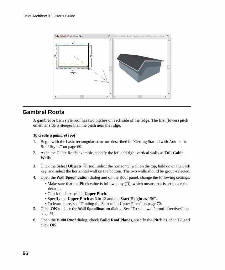
Gambrel RoofsA gambrel or barn style roof has two pitches on each side of the ridge. The first (lower) pitch on either side is steeper than the pitch near the ridge.
To create a gambrel roof
1. Begin with the basic rectangular structure described in “Getting Started with Automatic Roof Styles” on page 60.
2. As in the Gable Roofs example, specify the left and right vertical walls as Full Gable Walls.
3. Click the Select Objects tool, select the horizontal wall on the top, hold down the Shift key, and select the horizontal wall on the bottom. The two walls should be group-selected.
4. Open the Wall Specification dialog and on the Roof panel, change the following settings:
• Make sure that the Pitch value is followed by (D), which means that is set to use the default.
• Check the box beside Upper Pitch.• Specify the Upper Pitch as 6 in 12 and the Start Height as 156".• To learn more, see “Finding the Start of an Upper Pitch” on page 70.
5. Click OK to close the Wall Specification dialog. See “To set a wall’s roof directives” on page 61.
6. Open the Build Roof dialog, check Build Roof Planes, specify the Pitch as 12 in 12, and click OK.
chief-architect-x6-users-guide.book Page 66 Monday, December 16, 2013 4:05 PM
Gull Wing Roofs
67
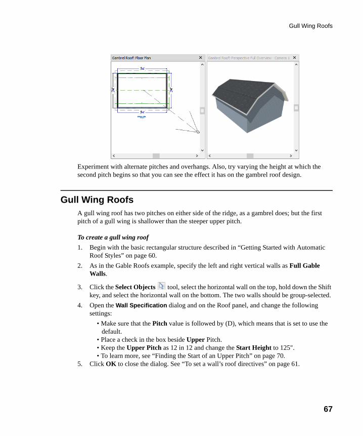
Experiment with alternate pitches and overhangs. Also, try varying the height at which the second pitch begins so that you can see the effect it has on the gambrel roof design.
Gull Wing RoofsA gull wing roof has two pitches on either side of the ridge, as a gambrel does; but the first pitch of a gull wing is shallower than the steeper upper pitch.
To create a gull wing roof
1. Begin with the basic rectangular structure described in “Getting Started with Automatic Roof Styles” on page 60.
2. As in the Gable Roofs example, specify the left and right vertical walls as Full Gable Walls.
3. Click the Select Objects tool, select the horizontal wall on the top, hold down the Shift key, and select the horizontal wall on the bottom. The two walls should be group-selected.
4. Open the Wall Specification dialog and on the Roof panel, and change the following settings:
• Make sure that the Pitch value is followed by (D), which means that is set to use the default.
• Place a check in the box beside Upper Pitch.• Keep the Upper Pitch as 12 in 12 and change the Start Height to 125".• To learn more, see “Finding the Start of an Upper Pitch” on page 70.
5. Click OK to close the dialog. See “To set a wall’s roof directives” on page 61.
chief-architect-x6-users-guide.book Page 67 Monday, December 16, 2013 4:05 PM
68
Chief Architect X6 User’s Guide
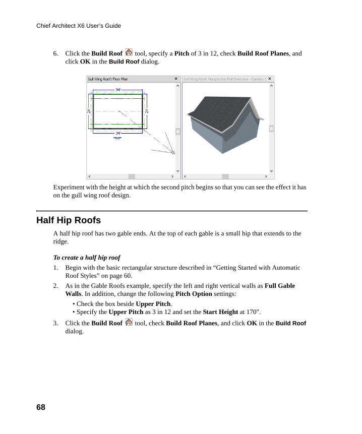
6. Click the Build Roof tool, specify a Pitch of 3 in 12, check Build Roof Planes, and click OK in the Build Roof dialog.
Experiment with the height at which the second pitch begins so that you can see the effect it has on the gull wing roof design.
Half Hip RoofsA half hip roof has two gable ends. At the top of each gable is a small hip that extends to the ridge.
To create a half hip roof
1. Begin with the basic rectangular structure described in “Getting Started with Automatic Roof Styles” on page 60.
2. As in the Gable Roofs example, specify the left and right vertical walls as Full Gable Walls. In addition, change the following Pitch Option settings:
• Check the box beside Upper Pitch.• Specify the Upper Pitch as 3 in 12 and set the Start Height at 170".
3. Click the Build Roof tool, check Build Roof Planes, and click OK in the Build Roof dialog.
chief-architect-x6-users-guide.book Page 68 Monday, December 16, 2013 4:05 PM
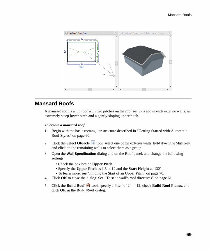
Mansard Roofs
69
Mansard RoofsA mansard roof is a hip roof with two pitches on the roof sections above each exterior walls: an extremely steep lower pitch and a gently sloping upper pitch.
To create a mansard roof
1. Begin with the basic rectangular structure described in “Getting Started with Automatic Roof Styles” on page 60.
2. Click the Select Objects tool, select one of the exterior walls, hold down the Shift key, and click on the remaining walls to select them as a group.
3. Open the Wall Specification dialog and on the Roof panel, and change the following settings:
• Check the box beside Upper Pitch.• Specify the Upper Pitch as 1.5 in 12 and the Start Height as 132". • To learn more, see “Finding the Start of an Upper Pitch” on page 70.
4. Click OK to close the dialog. See “To set a wall’s roof directives” on page 61.
5. Click the Build Roof tool, specify a Pitch of 24 in 12, check Build Roof Planes, and click OK in the Build Roof dialog.
chief-architect-x6-users-guide.book Page 69 Monday, December 16, 2013 4:05 PM
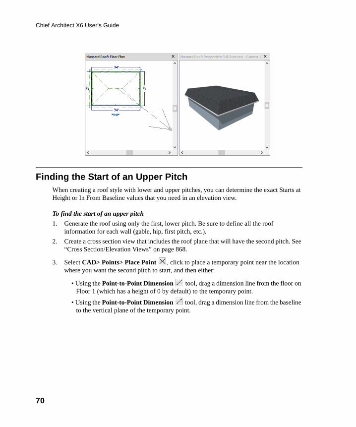
70
Chief Architect X6 User’s Guide
Finding the Start of an Upper Pitch When creating a roof style with lower and upper pitches, you can determine the exact Starts at Height or In From Baseline values that you need in an elevation view.
To find the start of an upper pitch
1. Generate the roof using only the first, lower pitch. Be sure to define all the roof information for each wall (gable, hip, first pitch, etc.).
2. Create a cross section view that includes the roof plane that will have the second pitch. See “Cross Section/Elevation Views” on page 868.
3. Select CAD> Points> Place Point , click to place a temporary point near the location where you want the second pitch to start, and then either:
• Using the Point-to-Point Dimension tool, drag a dimension line from the floor on Floor 1 (which has a height of 0 by default) to the temporary point.
• Using the Point-to-Point Dimension tool, drag a dimension line from the baseline to the vertical plane of the temporary point.
chief-architect-x6-users-guide.book Page 70 Monday, December 16, 2013 4:05 PM
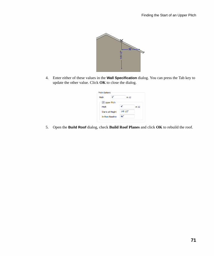
Finding the Start of an Upper Pitch
71
4. Enter either of these values in the Wall Specification dialog. You can press the Tab key to update the other value. Click OK to close the dialog.
5. Open the Build Roof dialog, check Build Roof Planes and click OK to rebuild the roof.
chief-architect-x6-users-guide.book Page 71 Monday, December 16, 2013 4:05 PM
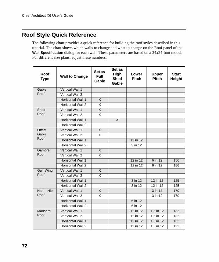
72
Chief Architect X6 User’s Guide
Roof Style Quick ReferenceThe following chart provides a quick reference for building the roof styles described in this tutorial. The chart shows which walls to change and what to change on the Roof panel of the Wall Specification dialog for each wall. These parameters are based on a 34x24-foot model. For different size plans, adjust these numbers.
Roof Type
Wall to ChangeSet as
Full Gable
Set as High Shed Gable
Lower Pitch
Upper Pitch
Start Height
GableRoof
Vertical Wall 1
Vertical Wall 2
Horizontal Wall 1 X
Horizontal Wall 2 X
ShedRoof
Vertical Wall 1 X
Vertical Wall 2 X
Horizontal Wall 1 X
Horizontal Wall 2
OffsetGableRoof
Vertical Wall 1 X
Vertical Wall 2 X
Horizontal Wall 1 12 in 12
Horizontal Wall 2 3 in 12
GambrelRoof
Vertical Wall 1 X
Vertical Wall 2 X
Horizontal Wall 1 12 in 12 6 in 12 156
Horizontal Wall 2 12 in 12 6 in 12 156
Gull WingRoof
Vertical Wall 1 X
Vertical Wall 2 X
Horizontal Wall 1 3 in 12 12 in 12 125
Horizontal Wall 2 3 in 12 12 in 12 125
Half HipRoof
Vertical Wall 1 X 3 in 12 170
Vertical Wall 2 X 3 in 12 170
Horizontal Wall 1 6 in 12
Horizontal Wall 2 6 in 12
MansardRoof
Vertical Wall 1 12 in 12 1.5 in 12 132
Vertical Wall 2 12 in 12 1.5 in 12 132
Horizontal Wall 1 12 in 12 1.5 in 12 132
Horizontal Wall 2 12 in 12 1.5 in 12 132
chief-architect-x6-users-guide.book Page 72 Monday, December 16, 2013 4:05 PM
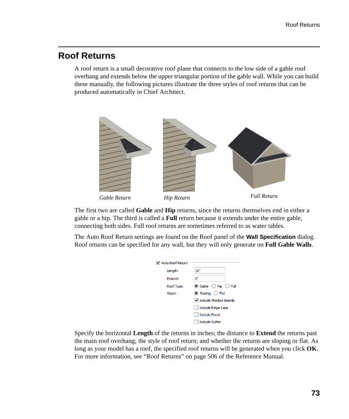
Roof Returns
73
Roof ReturnsA roof return is a small decorative roof plane that connects to the low side of a gable roof overhang and extends below the upper triangular portion of the gable wall. While you can build these manually, the following pictures illustrate the three styles of roof returns that can be produced automatically in Chief Architect.
The first two are called Gable and Hip returns, since the returns themselves end in either a gable or a hip. The third is called a Full return because it extends under the entire gable, connecting both sides. Full roof returns are sometimes referred to as water tables.
The Auto Roof Return settings are found on the Roof panel of the Wall Specification dialog. Roof returns can be specified for any wall, but they will only generate on Full Gable Walls.
Specify the horizontal Length of the returns in inches; the distance to Extend the returns past the main roof overhang; the style of roof return; and whether the returns are sloping or flat. As long as your model has a roof, the specified roof returns will be generated when you click OK. For more information, see “Roof Returns” on page 506 of the Reference Manual.
Gable Return Hip Return Full Return
chief-architect-x6-users-guide.book Page 73 Monday, December 16, 2013 4:05 PM
74
Chief Architect X6 User’s Guide
Adding Gables over Doors and WindowsYou can add a gable roof over a door or window.
To create a gable roof over a door or window
1. Select a door or window, then click the Gable Over Door/Window edit button.
2. Click the Build Roof tool, check Build Roof Planes, and click OK in the Build Roof dialog.
3. A gable is created with an overhang of one foot on each side of the door or window.
To remove a gable roof over a door or window
1. Select the door or window and click the Delete Gable Over Opening edit button.
2. Click the Build Roof tool, check Build Roof Planes, and click OK in the Build Roof dialog.
3. When you rebuild the roof, the gable will be removed.
To create a gable over several doors and/or windows
1. Select a door, window, or mulled unit.
1. Hold down the Shift key and click on additional doors and/or windows to add them to your selection set.
2. Click the Gable Over Door/Window edit button.
3. Click the Build Roof tool, check Build Roof Planes, and click OK in the Build Roof dialog to create a gable over the selected wall openings.
chief-architect-x6-users-guide.book Page 74 Monday, December 16, 2013 4:05 PM
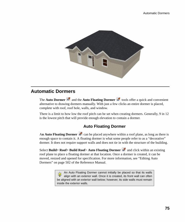
Automatic Dormers
75
Automatic Dormers
The Auto Dormer and the Auto Floating Dormer tools offer a quick and convenient alternative to drawing dormers manually. With just a few clicks an entire dormer is placed, complete with roof, roof hole, walls, and window.
There is a limit to how low the roof pitch can be set when creating dormers. Generally, 9 in 12 is the lowest pitch that will provide enough elevation to contain a dormer.
Auto Floating Dormer
An Auto Floating Dormer can be placed anywhere within a roof plane, as long as there is enough space to contain it. A floating dormer is what some people refer to as a “decorative” dormer. It does not require support walls and does not tie in with the structure of the building.
Select Build> Roof> Build Roof> Auto Floating Dormer and click within an existing roof plane to place a floating dormer at that location. Once a dormer is created, it can be moved, resized and opened for specification. For more information, see “Editing Auto Dormers” on page 502 of the Reference Manual.
An Auto Floating Dormer cannot initially be placed so that its wallsalign with an exterior wall. Once it is created, its front wall can often
be aligned with an exterior wall below; however, its side walls must remaininside the exterior walls.
chief-architect-x6-users-guide.book Page 75 Monday, December 16, 2013 4:05 PM
76
Chief Architect X6 User’s Guide
Auto Dormer
The Auto Dormer tool places a standard dormer, which has the same space and structural requirements as a manually drawn dormer. If you have not drawn dormers manually, you may benefit from learning how. For information, see “Manually Drawn Dormers” on page 76.
• Dormers can only be placed in roofs that are large and steep enough to contain them. You may need to change the pitch and/or size of a roof plane before an automatic dormer can be placed. If a warning message stating that some walls are outside the roof plane appears when you try to place an automatic dormer, try decreasing the Height value in the Dormer Defaults dialog.
• A knee wall must be present for the dormer to connect to. A knee wall will create attic space and offer structural support. A wall must be present, but it does not necessarily have to be designated as a Knee Wall in the Wall Specification dialog.
• Dormers cannot be in conflict with the ceiling on the same floor. If you need to create an open, attic condition, check Ignore Top Floor in the Build Roof dialog and generate roof planes based on the floor below the dormer. If necessary, you can then use Raise Off Plate in the Build Roof dialog to move roof planes up. See “Build Roof Dialog” on page 460 of the Reference Manual.
Once placed in your model, an automatic dormer can be repositioned and its width adjusted using its edit handles. Double-click on an automatic dormer to open the Dormer Specification dialog, which looks just like the Dormer Defaults dialog but only affects the selected dormer. You can also select the dormer window separately; resize it with its edit handles; and open it for specification. For more information about dormers, see “Dormers and Crickets” on page 500 of the Reference Manual.
Manually Drawn DormersTo create dormers in an upper floor, create a new floor for your plan and modify this floor with knee walls and windows to form gables. We’ll start with a new 40 x 30 foot plan to learn this technique.
As with automatic dormers, roof pitches of 9 in 12 or greater generally work better than shallow pitches when creating dormers because they provide enough vertical space to build the dormer within.
To create a new plan
1. Select File> Close All from the menu to close any open plans.
2. Select File> New Plan to open a new plan.
chief-architect-x6-users-guide.book Page 76 Monday, December 16, 2013 4:05 PM
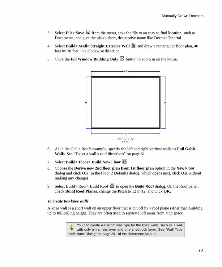
Manually Drawn Dormers
77
3. Select File> Save from the menu, save the file to an easy to find location, such as Documents, and give the plan a short, descriptive name like Dormer Tutorial.
4. Select Build> Wall> Straight Exterior Wall and draw a rectangular floor plan, 40 feet by 30 feet, in a clockwise direction.
5. Click the Fill Window Building Only button to zoom in on the house.
6. As in the Gable Roofs example, specify the left and right vertical walls as Full Gable Walls. See “To set a wall’s roof directives” on page 61.
7. Select Build> Floor> Build New Floor .
8. Choose the Derive new 2nd floor plan from 1st floor plan option in the New Floor dialog and click OK. In the Floor 2 Defaults dialog, which opens next, click OK without making any changes.
9. Select Build> Roof> Build Roof to open the Build Roof dialog. On the Roof panel, check Build Roof Planes, change the Pitch to 12 in 12, and click OK.
To create two knee walls
A knee wall is a short wall on an upper floor that is cut off by a roof plane rather than building up to full ceiling height. They are often used to separate loft areas from attic space.
You can create a custom wall type for the knee walls, such as a wallwith only a framing layer and one sheetrock layer. See “Wall Type
Definitions Dialog” on page 291 of the Reference Manual.
chief-architect-x6-users-guide.book Page 77 Monday, December 16, 2013 4:05 PM
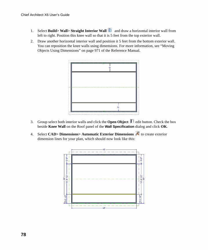
78
Chief Architect X6 User’s Guide
1. Select Build> Wall> Straight Interior Wall and draw a horizontal interior wall from left to right. Position this knee wall so that it is 5 feet from the top exterior wall.
2. Draw another horizontal interior wall and position it 5 feet from the bottom exterior wall. You can reposition the knee walls using dimensions. For more information, see “Moving Objects Using Dimensions” on page 971 of the Reference Manual.
3. Group select both interior walls and click the Open Object edit button. Check the box beside Knee Wall on the Roof panel of the Wall Specification dialog and click OK.
4. Select CAD> Dimensions> Automatic Exterior Dimensions to create exterior dimension lines for your plan, which should now look like this:
chief-architect-x6-users-guide.book Page 78 Monday, December 16, 2013 4:05 PM
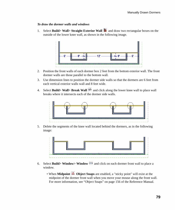
Manually Drawn Dormers
79
To draw the dormer walls and windows
1. Select Build> Wall> Straight Exterior Wall and draw two rectangular boxes on the outside of the lower knee wall, as shown in the following image.
2. Position the front walls of each dormer box 2 feet from the bottom exterior wall. The front dormer walls are those parallel to the bottom wall.
3. Use dimension lines to position the dormer side walls so that the dormers are 6 feet from each vertical exterior walls wall and 8 feet wide.
4. Select Build> Wall> Break Wall and click along the lower knee wall to place wall breaks where it intersects each of the dormer side walls.
5. Delete the segments of the knee wall located behind the dormers, as in the following image:
6. Select Build> Window> Window and click on each dormer front wall to place a window.
• When Midpoint Object Snaps are enabled, a "sticky point" will exist at the midpoint of the dormer front wall when you move your mouse along the front wall. For more information, see “Object Snaps” on page 156 of the Reference Manual.
chief-architect-x6-users-guide.book Page 79 Monday, December 16, 2013 4:05 PM
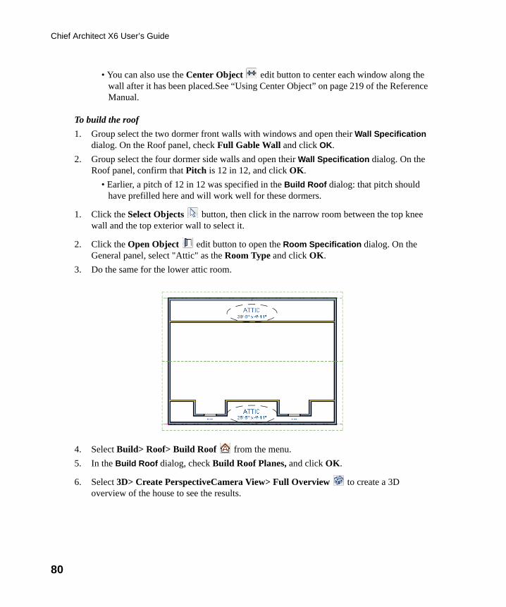
80
Chief Architect X6 User’s Guide
• You can also use the Center Object edit button to center each window along the wall after it has been placed.See “Using Center Object” on page 219 of the Reference Manual.
To build the roof
1. Group select the two dormer front walls with windows and open their Wall Specification dialog. On the Roof panel, check Full Gable Wall and click OK.
2. Group select the four dormer side walls and open their Wall Specification dialog. On the Roof panel, confirm that Pitch is 12 in 12, and click OK.
• Earlier, a pitch of 12 in 12 was specified in the Build Roof dialog: that pitch should have prefilled here and will work well for these dormers.
1. Click the Select Objects button, then click in the narrow room between the top knee wall and the top exterior wall to select it.
2. Click the Open Object edit button to open the Room Specification dialog. On the General panel, select "Attic" as the Room Type and click OK.
3. Do the same for the lower attic room.
4. Select Build> Roof> Build Roof from the menu.
5. In the Build Roof dialog, check Build Roof Planes, and click OK.
6. Select 3D> Create PerspectiveCamera View> Full Overview to create a 3D overview of the house to see the results.
chief-architect-x6-users-guide.book Page 80 Monday, December 16, 2013 4:05 PM
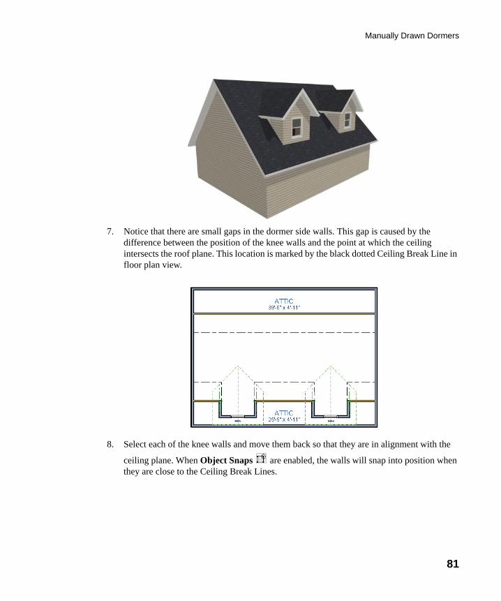
Manually Drawn Dormers
81
7. Notice that there are small gaps in the dormer side walls. This gap is caused by the difference between the position of the knee walls and the point at which the ceiling intersects the roof plane. This location is marked by the black dotted Ceiling Break Line in floor plan view.
8. Select each of the knee walls and move them back so that they are in alignment with the
ceiling plane. When Object Snaps are enabled, the walls will snap into position when they are close to the Ceiling Break Lines.
chief-architect-x6-users-guide.book Page 81 Monday, December 16, 2013 4:05 PM
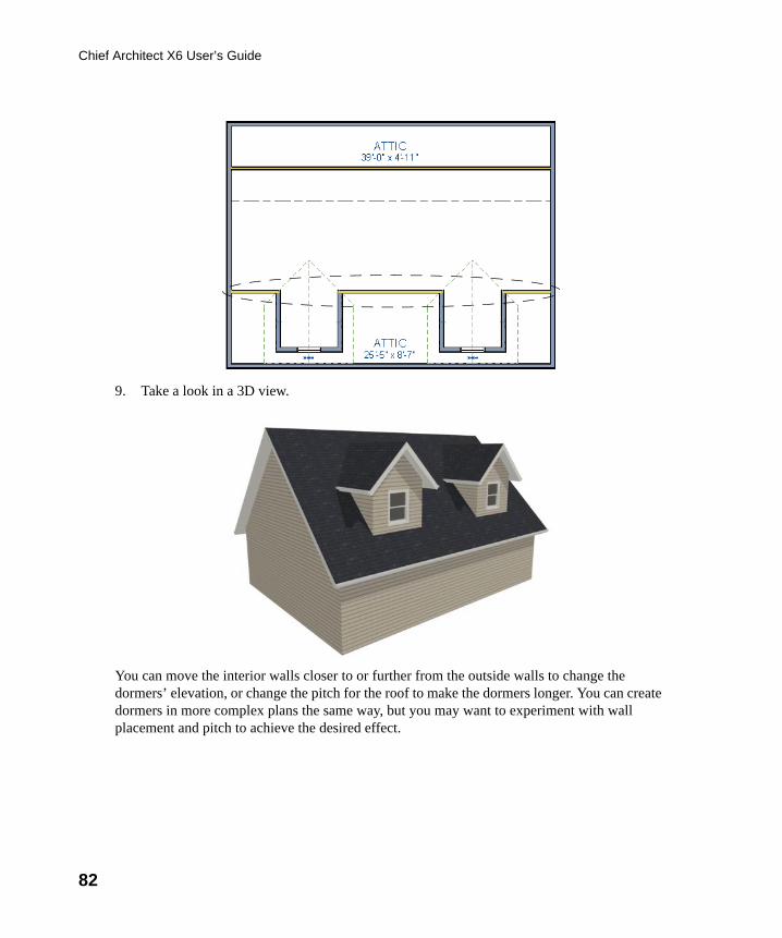
82
Chief Architect X6 User’s Guide
9. Take a look in a 3D view.
You can move the interior walls closer to or further from the outside walls to change the dormers’ elevation, or change the pitch for the roof to make the dormers longer. You can create dormers in more complex plans the same way, but you may want to experiment with wall placement and pitch to achieve the desired effect.
chief-architect-x6-users-guide.book Page 82 Monday, December 16, 2013 4:05 PM
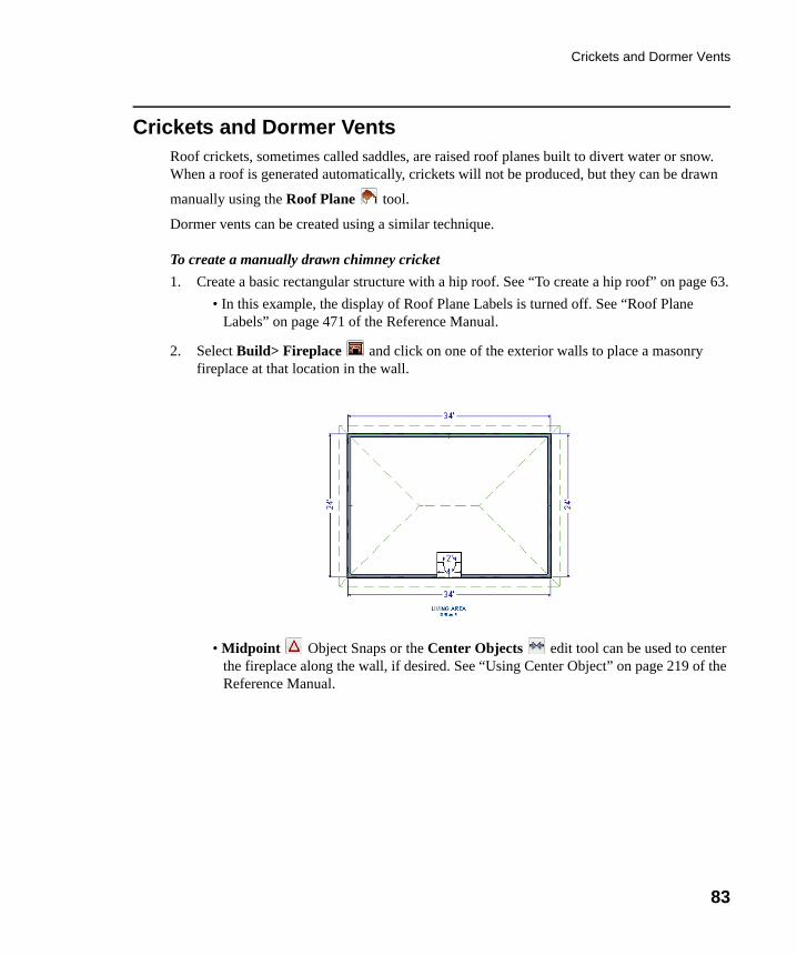
Crickets and Dormer Vents
83
Crickets and Dormer VentsRoof crickets, sometimes called saddles, are raised roof planes built to divert water or snow. When a roof is generated automatically, crickets will not be produced, but they can be drawn
manually using the Roof Plane tool.
Dormer vents can be created using a similar technique.
To create a manually drawn chimney cricket
1. Create a basic rectangular structure with a hip roof. See “To create a hip roof” on page 63.
• In this example, the display of Roof Plane Labels is turned off. See “Roof Plane Labels” on page 471 of the Reference Manual.
2. Select Build> Fireplace and click on one of the exterior walls to place a masonry fireplace at that location in the wall.
• Midpoint Object Snaps or the Center Objects edit tool can be used to center the fireplace along the wall, if desired. See “Using Center Object” on page 219 of the Reference Manual.
chief-architect-x6-users-guide.book Page 83 Monday, December 16, 2013 4:05 PM
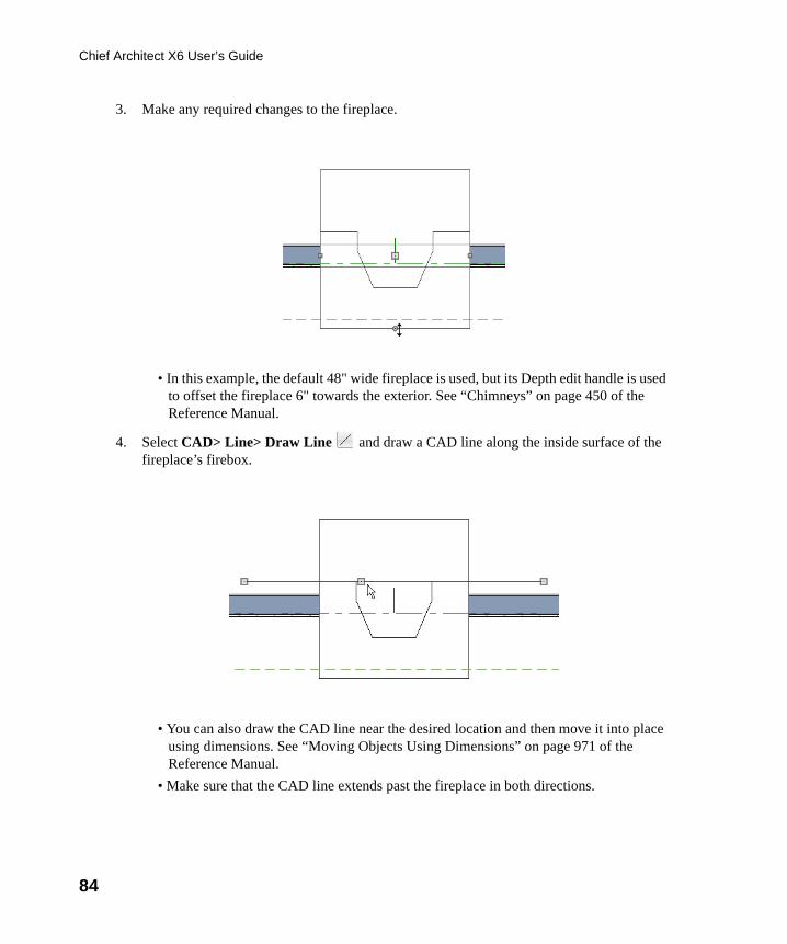
84
Chief Architect X6 User’s Guide
3. Make any required changes to the fireplace.
• In this example, the default 48" wide fireplace is used, but its Depth edit handle is used to offset the fireplace 6" towards the exterior. See “Chimneys” on page 450 of the Reference Manual.
4. Select CAD> Line> Draw Line and draw a CAD line along the inside surface of the fireplace’s firebox.
• You can also draw the CAD line near the desired location and then move it into place using dimensions. See “Moving Objects Using Dimensions” on page 971 of the Reference Manual.
• Make sure that the CAD line extends past the fireplace in both directions.
chief-architect-x6-users-guide.book Page 84 Monday, December 16, 2013 4:05 PM
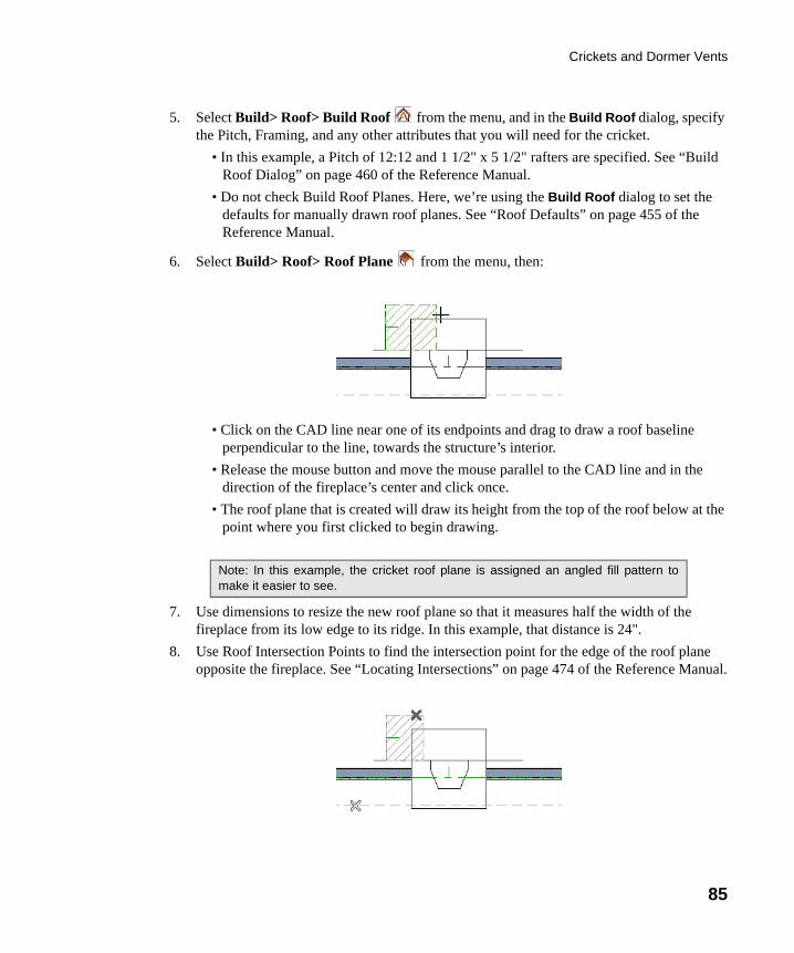
Crickets and Dormer Vents
85
5. Select Build> Roof> Build Roof from the menu, and in the Build Roof dialog, specify the Pitch, Framing, and any other attributes that you will need for the cricket.
• In this example, a Pitch of 12:12 and 1 1/2" x 5 1/2" rafters are specified. See “Build Roof Dialog” on page 460 of the Reference Manual.
• Do not check Build Roof Planes. Here, we’re using the Build Roof dialog to set the defaults for manually drawn roof planes. See “Roof Defaults” on page 455 of the Reference Manual.
6. Select Build> Roof> Roof Plane from the menu, then:
• Click on the CAD line near one of its endpoints and drag to draw a roof baseline perpendicular to the line, towards the structure’s interior.
• Release the mouse button and move the mouse parallel to the CAD line and in the direction of the fireplace’s center and click once.
• The roof plane that is created will draw its height from the top of the roof below at the point where you first clicked to begin drawing.
7. Use dimensions to resize the new roof plane so that it measures half the width of the fireplace from its low edge to its ridge. In this example, that distance is 24".
8. Use Roof Intersection Points to find the intersection point for the edge of the roof plane opposite the fireplace. See “Locating Intersections” on page 474 of the Reference Manual.
Note: In this example, the cricket roof plane is assigned an angled fill pattern tomake it easier to see.
chief-architect-x6-users-guide.book Page 85 Monday, December 16, 2013 4:05 PM
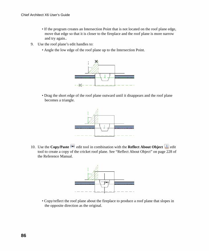
86
Chief Architect X6 User’s Guide
• If the program creates an Intersection Point that is not located on the roof plane edge, move that edge so that it is closer to the fireplace and the roof plane is more narrow and try again..
9. Use the roof plane’s edit handles to:
• Angle the low edge of the roof plane up to the Intersection Point.
• Drag the short edge of the roof plane outward until it disappears and the roof plane becomes a triangle.
10. Use the Copy/Paste edit tool in combination with the Reflect About Object edit tool to create a copy of the cricket roof plane. See “Reflect About Object” on page 228 of the Reference Manual.
• Copy/reflect the roof plane about the fireplace to produce a roof plane that slopes in the opposite direction as the original.
chief-architect-x6-users-guide.book Page 86 Monday, December 16, 2013 4:05 PM
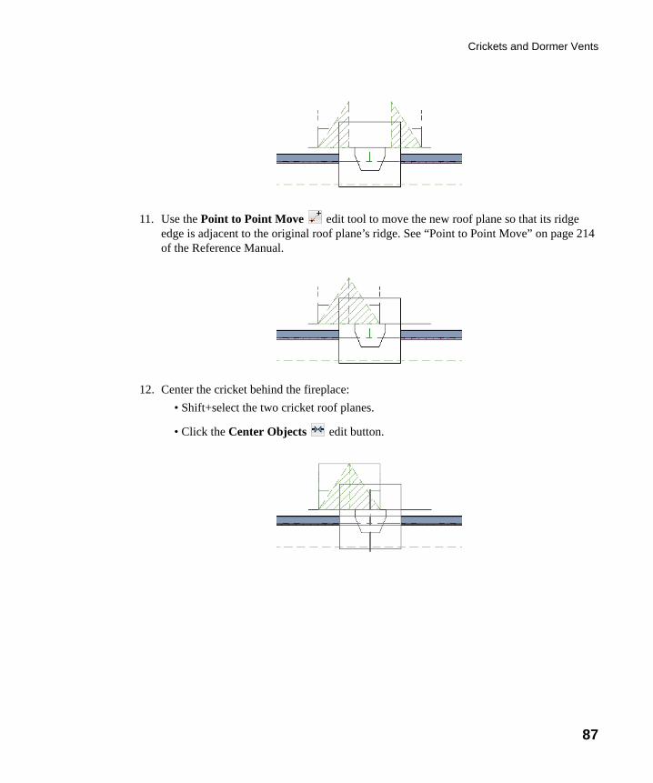
Crickets and Dormer Vents
87
11. Use the Point to Point Move edit tool to move the new roof plane so that its ridge edge is adjacent to the original roof plane’s ridge. See “Point to Point Move” on page 214 of the Reference Manual.
12. Center the cricket behind the fireplace:
• Shift+select the two cricket roof planes.
• Click the Center Objects edit button.
chief-architect-x6-users-guide.book Page 87 Monday, December 16, 2013 4:05 PM
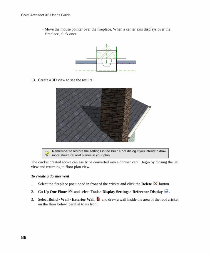
88
Chief Architect X6 User’s Guide
• Move the mouse pointer over the fireplace. When a center axis displays over the fireplace, click once.
13. Create a 3D view to see the results.
The cricket created above can easily be converted into a dormer vent. Begin by closing the 3D view and returning to floor plan view.
To create a dormer vent
1. Select the fireplace positioned in front of the cricket and click the Delete button.
2. Go Up One Floor and select Tools> Display Settings> Reference Display .
3. Select Build> Wall> Exterior Wall and draw a wall inside the area of the roof cricket on the floor below, parallel to its front.
Remember to restore the settings in the Build Roof dialog if you intend to drawmore structural roof planes in your plan.
chief-architect-x6-users-guide.book Page 88 Monday, December 16, 2013 4:05 PM
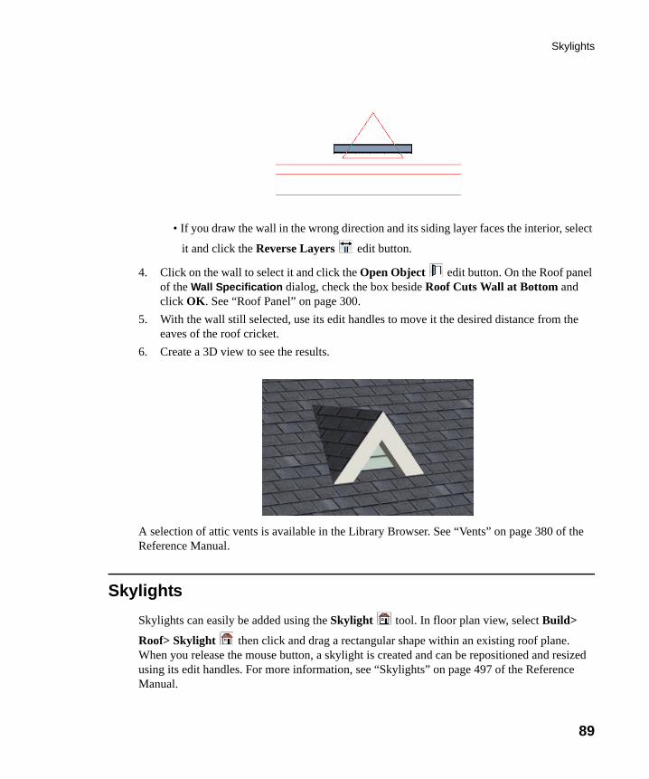
Skylights
89
• If you draw the wall in the wrong direction and its siding layer faces the interior, select
it and click the Reverse Layers edit button.
4. Click on the wall to select it and click the Open Object edit button. On the Roof panel of the Wall Specification dialog, check the box beside Roof Cuts Wall at Bottom and click OK. See “Roof Panel” on page 300.
5. With the wall still selected, use its edit handles to move it the desired distance from the eaves of the roof cricket.
6. Create a 3D view to see the results.
A selection of attic vents is available in the Library Browser. See “Vents” on page 380 of the Reference Manual.
Skylights
Skylights can easily be added using the Skylight tool. In floor plan view, select Build>
Roof> Skylight then click and drag a rectangular shape within an existing roof plane. When you release the mouse button, a skylight is created and can be repositioned and resized using its edit handles. For more information, see “Skylights” on page 497 of the Reference Manual.
chief-architect-x6-users-guide.book Page 89 Monday, December 16, 2013 4:05 PM
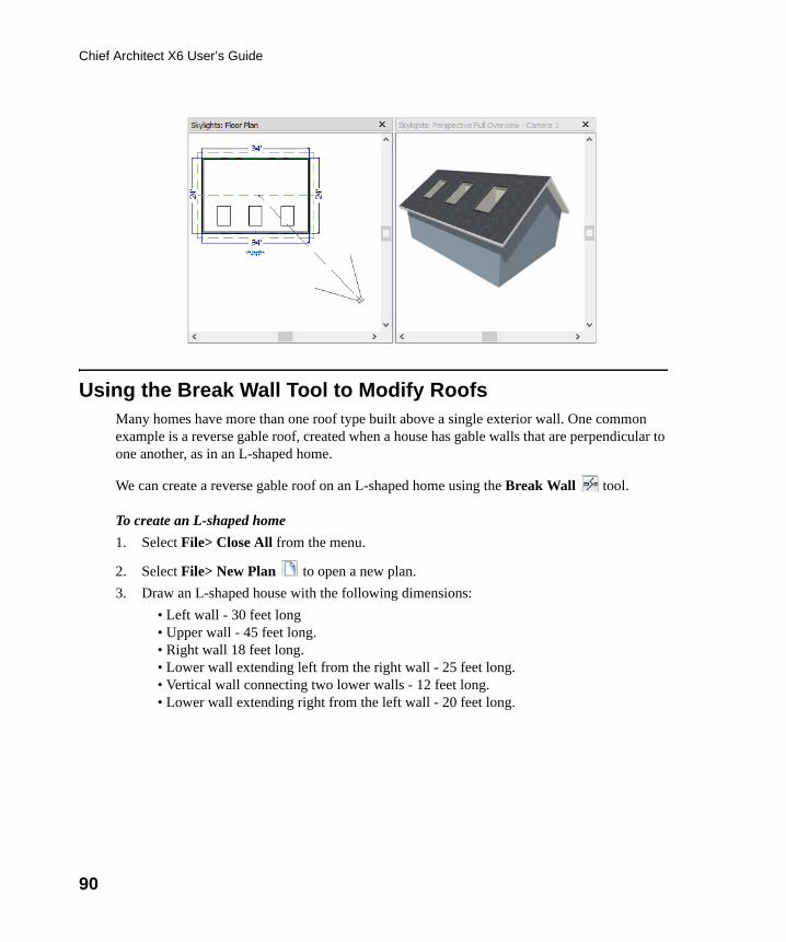
90
Chief Architect X6 User’s Guide
Using the Break Wall Tool to Modify RoofsMany homes have more than one roof type built above a single exterior wall. One common example is a reverse gable roof, created when a house has gable walls that are perpendicular to one another, as in an L-shaped home.
We can create a reverse gable roof on an L-shaped home using the Break Wall tool.
To create an L-shaped home
1. Select File> Close All from the menu.
2. Select File> New Plan to open a new plan.
3. Draw an L-shaped house with the following dimensions:
• Left wall - 30 feet long• Upper wall - 45 feet long.• Right wall 18 feet long.• Lower wall extending left from the right wall - 25 feet long.• Vertical wall connecting two lower walls - 12 feet long.• Lower wall extending right from the left wall - 20 feet long.
chief-architect-x6-users-guide.book Page 90 Monday, December 16, 2013 4:05 PM
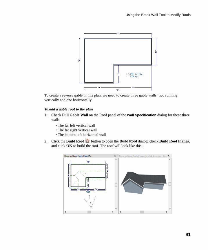
Using the Break Wall Tool to Modify Roofs
91
To create a reverse gable in this plan, we need to create three gable walls: two running vertically and one horizontally.
To add a gable roof to the plan
1. Check Full Gable Wall on the Roof panel of the Wall Specification dialog for these three walls:
• The far left vertical wall• The far right vertical wall• The bottom left horizontal wall
2. Click the Build Roof button to open the Build Roof dialog, check Build Roof Planes, and click OK to build the roof. The roof will look like this:
chief-architect-x6-users-guide.book Page 91 Monday, December 16, 2013 4:05 PM
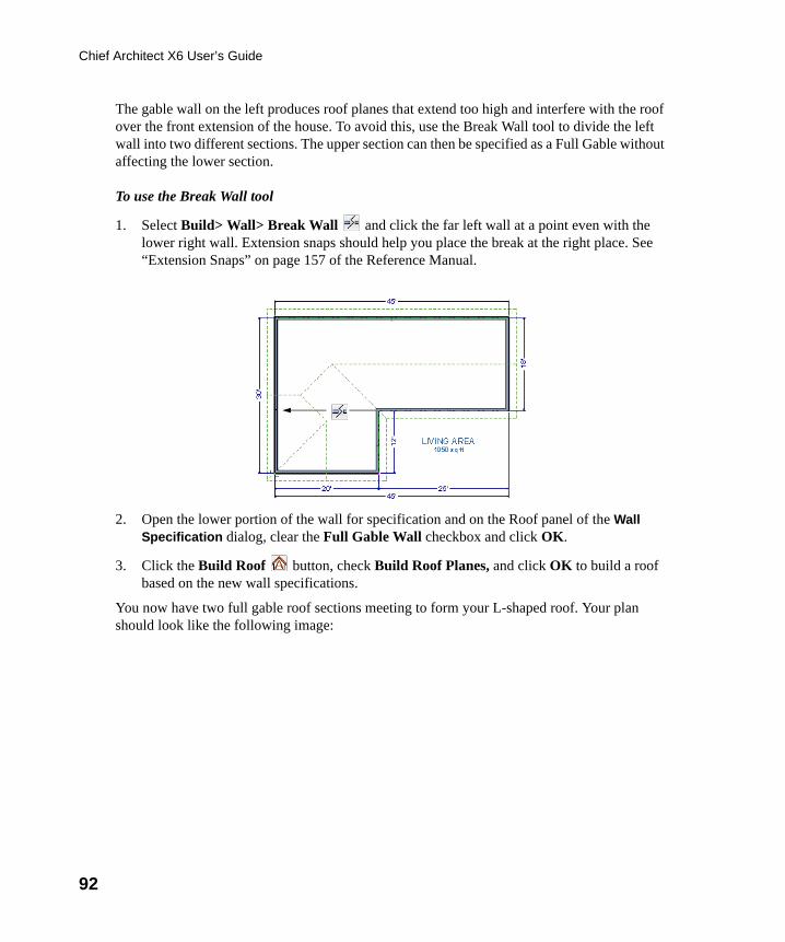
92
Chief Architect X6 User’s Guide
The gable wall on the left produces roof planes that extend too high and interfere with the roof over the front extension of the house. To avoid this, use the Break Wall tool to divide the left wall into two different sections. The upper section can then be specified as a Full Gable without affecting the lower section.
To use the Break Wall tool
1. Select Build> Wall> Break Wall and click the far left wall at a point even with the lower right wall. Extension snaps should help you place the break at the right place. See “Extension Snaps” on page 157 of the Reference Manual.
2. Open the lower portion of the wall for specification and on the Roof panel of the Wall Specification dialog, clear the Full Gable Wall checkbox and click OK.
3. Click the Build Roof button, check Build Roof Planes, and click OK to build a roof based on the new wall specifications.
You now have two full gable roof sections meeting to form your L-shaped roof. Your plan should look like the following image:
chief-architect-x6-users-guide.book Page 92 Monday, December 16, 2013 4:05 PM
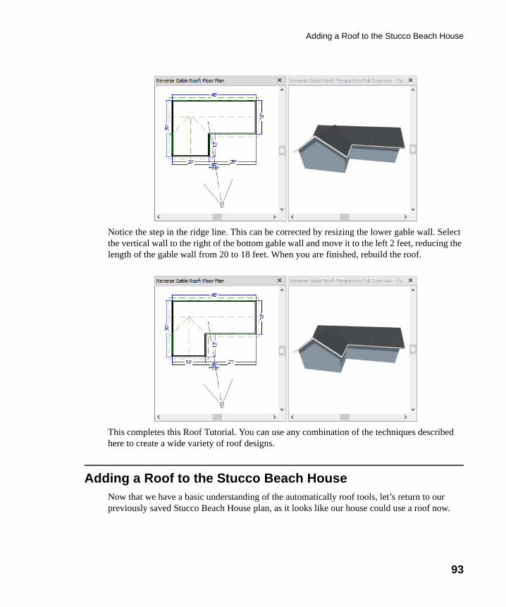
Adding a Roof to the Stucco Beach House
93
Notice the step in the ridge line. This can be corrected by resizing the lower gable wall. Select the vertical wall to the right of the bottom gable wall and move it to the left 2 feet, reducing the length of the gable wall from 20 to 18 feet. When you are finished, rebuild the roof.
This completes this Roof Tutorial. You can use any combination of the techniques described here to create a wide variety of roof designs.
Adding a Roof to the Stucco Beach HouseNow that we have a basic understanding of the automatically roof tools, let’s return to our previously saved Stucco Beach House plan, as it looks like our house could use a roof now.
chief-architect-x6-users-guide.book Page 93 Monday, December 16, 2013 4:05 PM
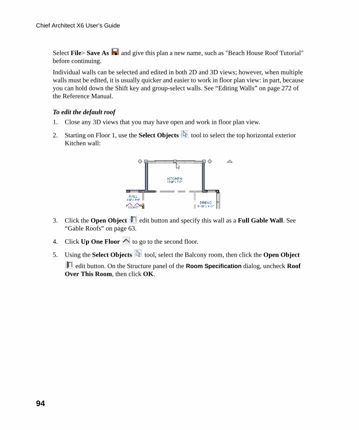
94
Chief Architect X6 User’s Guide
Select File> Save As and give this plan a new name, such as "Beach House Roof Tutorial" before continuing.
Individual walls can be selected and edited in both 2D and 3D views; however, when multiple walls must be edited, it is usually quicker and easier to work in floor plan view: in part, because you can hold down the Shift key and group-select walls. See “Editing Walls” on page 272 of the Reference Manual.
To edit the default roof
1. Close any 3D views that you may have open and work in floor plan view.
2. Starting on Floor 1, use the Select Objects tool to select the top horizontal exterior Kitchen wall:
3. Click the Open Object edit button and specify this wall as a Full Gable Wall. See “Gable Roofs” on page 63.
4. Click Up One Floor to go to the second floor.
5. Using the Select Objects tool, select the Balcony room, then click the Open Object
edit button. On the Structure panel of the Room Specification dialog, uncheck Roof Over This Room, then click OK.
chief-architect-x6-users-guide.book Page 94 Monday, December 16, 2013 4:05 PM
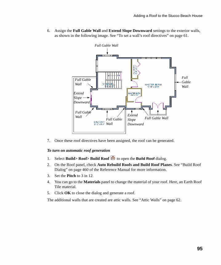
Adding a Roof to the Stucco Beach House
95
6. Assign the Full Gable Wall and Extend Slope Downward settings to the exterior walls, as shown in the following image. See “To set a wall’s roof directives” on page 61.
7. Once these roof directives have been assigned, the roof can be generated.
To turn on automatic roof generation
1. Select Build> Roof> Build Roof to open the Build Roof dialog.
2. On the Roof panel, check Auto Rebuild Roofs and Build Roof Planes. See “Build Roof Dialog” on page 460 of the Reference Manual for more information.
3. Set the Pitch to 3 in 12.
4. You can go to the Materials panel to change the material of your roof. Here, an Earth Roof Tile material.
5. Click OK to close the dialog and generate a roof.
The additional walls that are created are attic walls. See “Attic Walls” on page 62.
Full Gable Wall
Full Gable Wall
Full Gable Wall
Full Gable Wall
Extend Slope Downward
Extend Slope Downward
Full Gable Wall
Full Gable Wall
chief-architect-x6-users-guide.book Page 95 Monday, December 16, 2013 4:05 PM
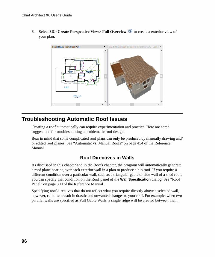
96
Chief Architect X6 User’s Guide
6. Select 3D> Create Perspective View> Full Overview to create a exterior view of your plan.
Troubleshooting Automatic Roof IssuesCreating a roof automatically can require experimentation and practice. Here are some suggestions for troubleshooting a problematic roof design.
Bear in mind that some complicated roof plans can only be produced by manually drawing and/or edited roof planes. See “Automatic vs. Manual Roofs” on page 454 of the Reference Manual.
Roof Directives in Walls
As discussed in this chapter and in the Roofs chapter, the program will automatically generate a roof plane bearing over each exterior wall in a plan to produce a hip roof. If you require a different condition over a particular wall, such as a triangular gable or side wall of a shed roof, you can specify that condition on the Roof panel of the Wall Specification dialog. See “Roof Panel” on page 300 of the Reference Manual.
Specifying roof directives that do not reflect what you require directly above a selected wall, however, can often result in drastic and unwanted changes to your roof. For example, when two parallel walls are specified as Full Gable Walls, a single ridge will be created between them.
chief-architect-x6-users-guide.book Page 96 Monday, December 16, 2013 4:05 PM
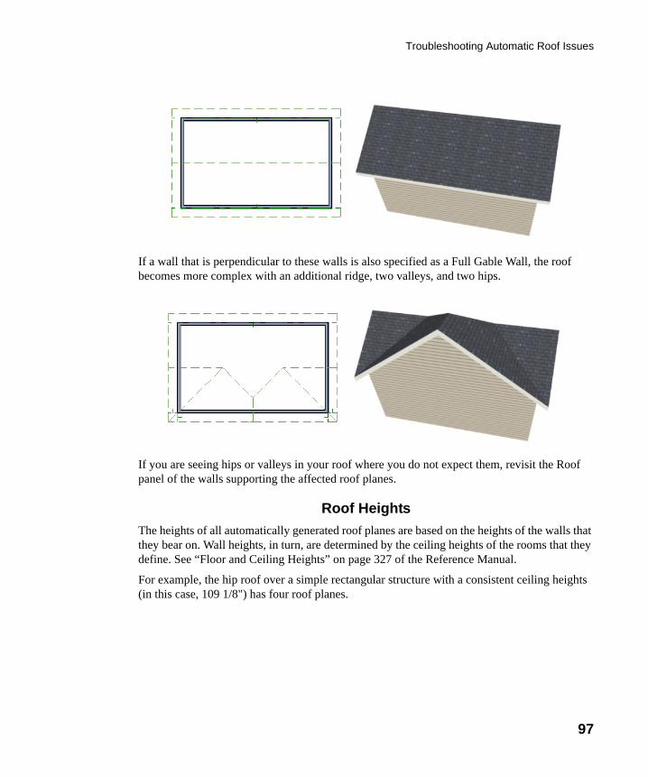
Troubleshooting Automatic Roof Issues
97
If a wall that is perpendicular to these walls is also specified as a Full Gable Wall, the roof becomes more complex with an additional ridge, two valleys, and two hips.
If you are seeing hips or valleys in your roof where you do not expect them, revisit the Roof panel of the walls supporting the affected roof planes.
Roof Heights
The heights of all automatically generated roof planes are based on the heights of the walls that they bear on. Wall heights, in turn, are determined by the ceiling heights of the rooms that they define. See “Floor and Ceiling Heights” on page 327 of the Reference Manual.
For example, the hip roof over a simple rectangular structure with a consistent ceiling heights (in this case, 109 1/8") has four roof planes.
chief-architect-x6-users-guide.book Page 97 Monday, December 16, 2013 4:05 PM
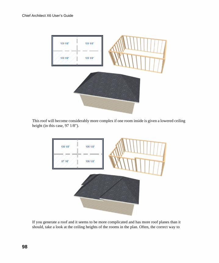
98
Chief Architect X6 User’s Guide
This roof will become considerably more complex if one room inside is given a lowered ceiling height (in this case, 97 1/8").
If you generate a roof and it seems to be more complicated and has more roof planes than it should, take a look at the ceiling heights of the rooms in the plan. Often, the correct way to
chief-architect-x6-users-guide.book Page 98 Monday, December 16, 2013 4:05 PM
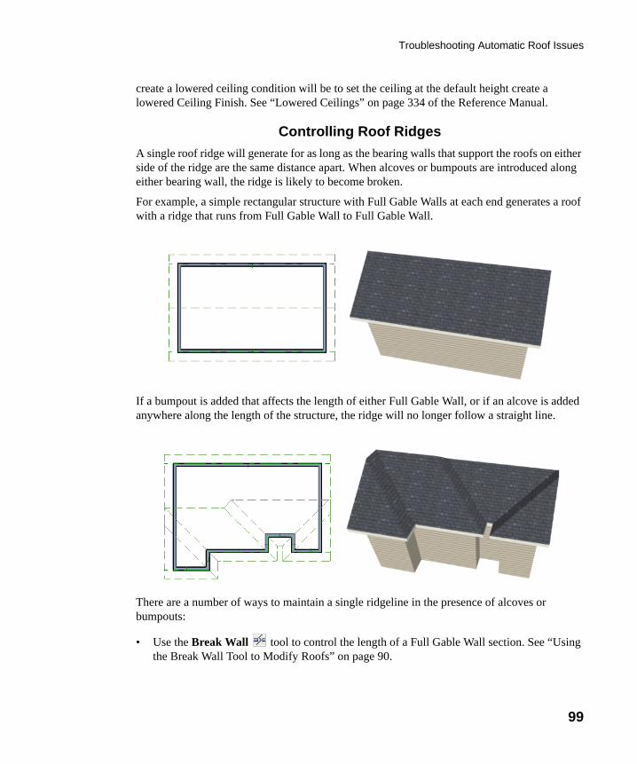
Troubleshooting Automatic Roof Issues
99
create a lowered ceiling condition will be to set the ceiling at the default height create a lowered Ceiling Finish. See “Lowered Ceilings” on page 334 of the Reference Manual.
Controlling Roof Ridges
A single roof ridge will generate for as long as the bearing walls that support the roofs on either side of the ridge are the same distance apart. When alcoves or bumpouts are introduced along either bearing wall, the ridge is likely to become broken.
For example, a simple rectangular structure with Full Gable Walls at each end generates a roof with a ridge that runs from Full Gable Wall to Full Gable Wall.
If a bumpout is added that affects the length of either Full Gable Wall, or if an alcove is added anywhere along the length of the structure, the ridge will no longer follow a straight line.
There are a number of ways to maintain a single ridgeline in the presence of alcoves or bumpouts:
• Use the Break Wall tool to control the length of a Full Gable Wall section. See “Using the Break Wall Tool to Modify Roofs” on page 90.
chief-architect-x6-users-guide.book Page 99 Monday, December 16, 2013 4:05 PM
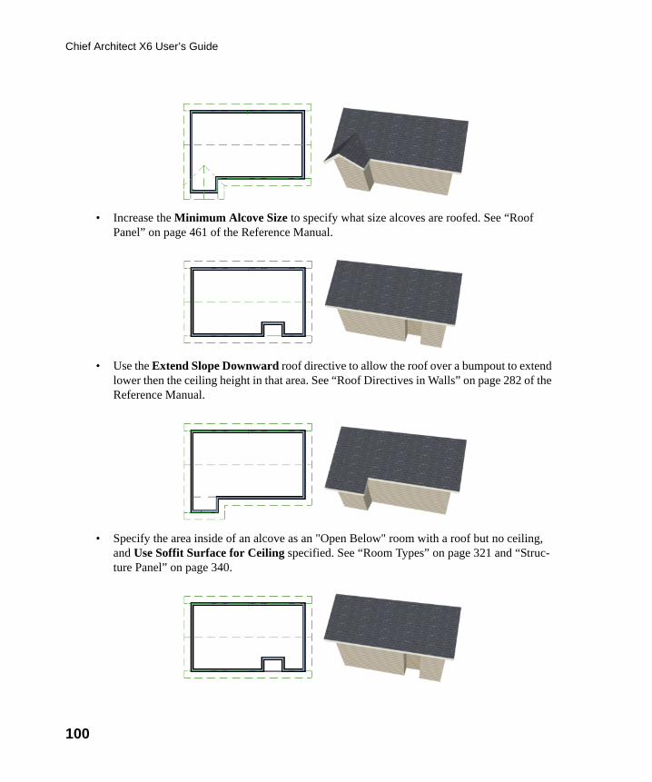
100
Chief Architect X6 User’s Guide
• Increase the Minimum Alcove Size to specify what size alcoves are roofed. See “Roof Panel” on page 461 of the Reference Manual.
• Use the Extend Slope Downward roof directive to allow the roof over a bumpout to extend lower then the ceiling height in that area. See “Roof Directives in Walls” on page 282 of the Reference Manual.
• Specify the area inside of an alcove as an "Open Below" room with a roof but no ceiling, and Use Soffit Surface for Ceiling specified. See “Room Types” on page 321 and “Struc-ture Panel” on page 340.
chief-architect-x6-users-guide.book Page 100 Monday, December 16, 2013 4:05 PM
101
Chapter 4:
Interior DesignTutorial
The Interior Design Tutorial picks up where the House Design Tutorial left off. The basic structure of the plan is complete, but the plan still needs lights, outlets, and fixtures to be a functional home. In addition, the interior could use some creature comforts such as furniture, wall coverings and moldings. You may want to save this tutorial using a new name to archive your previous work. In this tutorial, you will learn about:
• Controlling the Display of Objects• Working with Library Objects• Applying Room Moldings
• Applying Wall Coverings• Creating a Trey Ceiling
Controlling the Display of ObjectsEvery object that you create in Chief Architect exists on a layer that lets you control whether it displays as well as some aspects of its appearance. For example, the roof that was created in the House Design Tutorial will only be in the way in this tutorial, which discusses the plan’s interior. To avoid this, the "Roof Planes" layer can be turned off in floor plan view. For more information, see “Layers” on page 139 of the Reference Manual.
chief-architect-x6-users-guide.book Page 101 Monday, December 16, 2013 4:05 PM
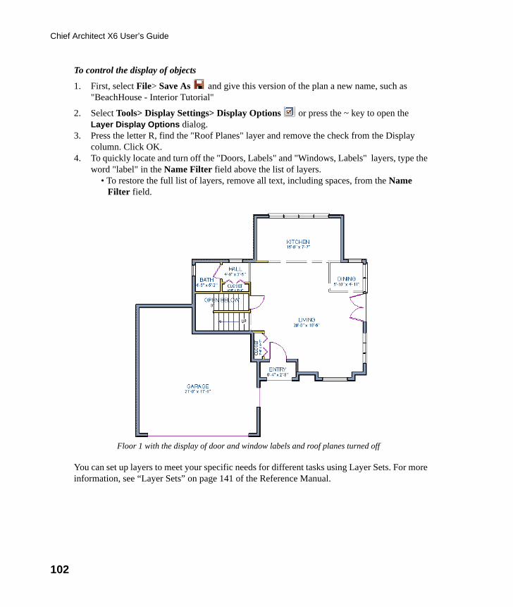
102
Chief Architect X6 User’s Guide
To control the display of objects
1. First, select File> Save As and give this version of the plan a new name, such as "BeachHouse - Interior Tutorial"
2. Select Tools> Display Settings> Display Options or press the ~ key to open the Layer Display Options dialog.
3. Press the letter R, find the "Roof Planes" layer and remove the check from the Display column. Click OK.
4. To quickly locate and turn off the "Doors, Labels" and "Windows, Labels" layers, type the word "label" in the Name Filter field above the list of layers.
• To restore the full list of layers, remove all text, including spaces, from the Name Filter field.
You can set up layers to meet your specific needs for different tasks using Layer Sets. For more information, see “Layer Sets” on page 141 of the Reference Manual.
Floor 1 with the display of door and window labels and roof planes turned off
chief-architect-x6-users-guide.book Page 102 Monday, December 16, 2013 4:05 PM
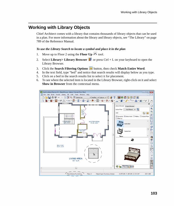
Working with Library Objects
103
Working with Library ObjectsChief Architect comes with a library that contains thousands of library objects that can be used in a plan. For more information about the library and library objects, see “The Library” on page 789 of the Reference Manual.
To use the Library Search to locate a symbol and place it in the plan
1. Move up to Floor 2 using the Floor Up tool.
2. Select Library> Library Browser or press Ctrl + L on your keyboard to open the Library Browser.
3. Click the Search Filtering Options button, then check Match Entire Word. 4. In the text field, type "bed" and notice that search results will display below as you type.5. Click on a bed in the search results list to select it for placement.6. To see where the selected item is located in the Library Browser, right-click on it and select
Show in Browser from the contextual menu.
chief-architect-x6-users-guide.book Page 103 Monday, December 16, 2013 4:05 PM
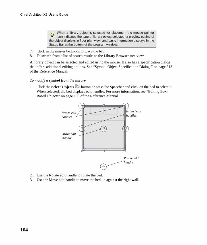
104
Chief Architect X6 User’s Guide
7. Click in the master bedroom to place the bed.8. To switch from a list of search results to the Library Browser tree view.
A library object can be selected and edited using the mouse. It also has a specification dialog that offers additional editing options. See “Symbol Object Specification Dialogs” on page 813 of the Reference Manual.
To modify a symbol from the library
1. Click the Select Objects button or press the Spacebar and click on the bed to select it. When selected, the bed displays edit handles. For more information, see “Editing Box-Based Objects” on page 198 of the Reference Manual.
2. Use the Rotate edit handle to rotate the bed.3. Use the Move edit handle to move the bed up against the right wall.
When a library object is selected for placement the mouse pointericon indicates the type of library object selected, a preview outline of
the object displays in floor plan view, and basic information displays in theStatus Bar at the bottom of the program window.
Rotate edit handle
Resize edit handles
Move edit handle
Extend edit handles
chief-architect-x6-users-guide.book Page 104 Monday, December 16, 2013 4:05 PM
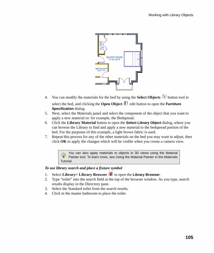
Working with Library Objects
105
4. You can modify the materials for the bed by using the Select Objects button tool to
select the bed, and clicking the Open Object edit button to open the Furniture Specification dialog.
5. Next, select the Materials panel and select the component of the object that you want to apply a new material to: for example, the Bedspread.
6. Click the Library Material button to open the Select Library Object dialog, where you can browse the Library to find and apply a new material to the bedspread portion of the bed. For the purposes of this example, a light brown fabric is used.
7. Repeat this process for any of the other materials on the bed you may want to adjust, then click OK to apply the changes which will be visible when you create a camera view.
To use library search and place a fixture symbol
1. Select Library> Library Browser to open the Library Browser. 2. Type “toilet” into the search field at the top of the browser window. As you type, search
results display in the Directory pane.3. Select the Standard toilet from the search results.4. Click in the master bathroom to place the toilet.
You can also apply materials to objects in 3D views using the MaterialPainter tool. To learn more, see Using the Material Painter in the Materials
Tutorial.
chief-architect-x6-users-guide.book Page 105 Monday, December 16, 2013 4:05 PM
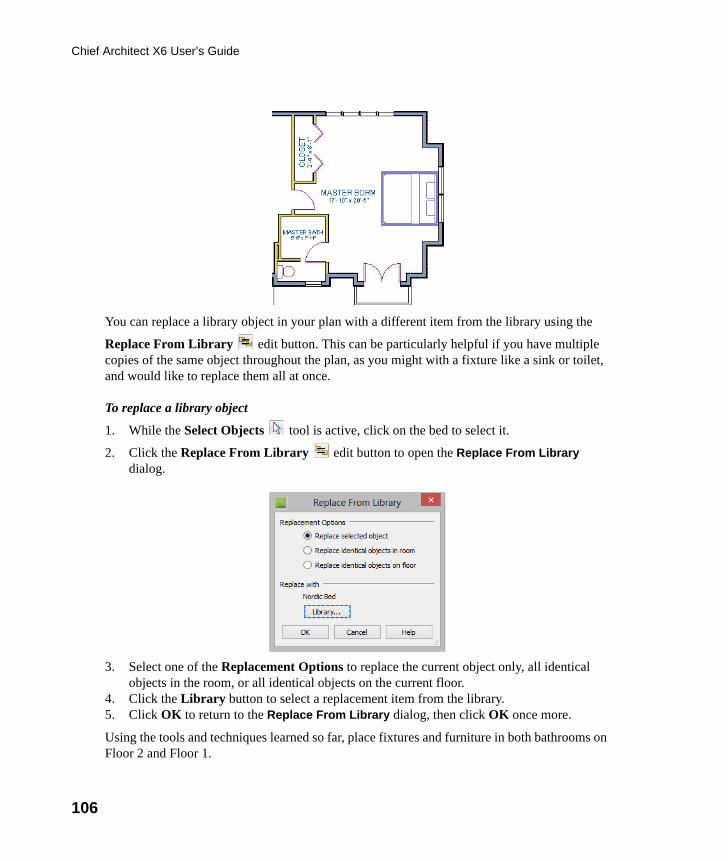
106
Chief Architect X6 User’s Guide
You can replace a library object in your plan with a different item from the library using the
Replace From Library edit button. This can be particularly helpful if you have multiple copies of the same object throughout the plan, as you might with a fixture like a sink or toilet, and would like to replace them all at once.
To replace a library object
1. While the Select Objects tool is active, click on the bed to select it.
2. Click the Replace From Library edit button to open the Replace From Library dialog.
3. Select one of the Replacement Options to replace the current object only, all identical objects in the room, or all identical objects on the current floor.
4. Click the Library button to select a replacement item from the library.5. Click OK to return to the Replace From Library dialog, then click OK once more.
Using the tools and techniques learned so far, place fixtures and furniture in both bathrooms on Floor 2 and Floor 1.
chief-architect-x6-users-guide.book Page 106 Monday, December 16, 2013 4:05 PM
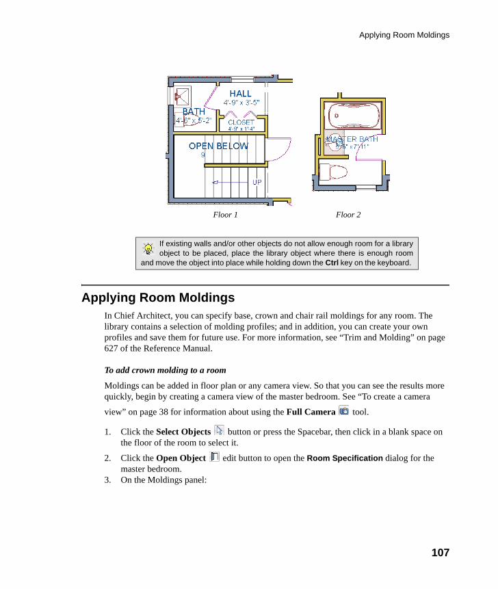
Applying Room Moldings
107
Applying Room MoldingsIn Chief Architect, you can specify base, crown and chair rail moldings for any room. The library contains a selection of molding profiles; and in addition, you can create your own profiles and save them for future use. For more information, see “Trim and Molding” on page 627 of the Reference Manual.
To add crown molding to a room
Moldings can be added in floor plan or any camera view. So that you can see the results more quickly, begin by creating a camera view of the master bedroom. See “To create a camera
view” on page 38 for information about using the Full Camera tool.
1. Click the Select Objects button or press the Spacebar, then click in a blank space on the floor of the room to select it.
2. Click the Open Object edit button to open the Room Specification dialog for the master bedroom.
3. On the Moldings panel:
If existing walls and/or other objects do not allow enough room for a libraryobject to be placed, place the library object where there is enough room
and move the object into place while holding down the Ctrl key on the keyboard.
Floor 1 Floor 2
chief-architect-x6-users-guide.book Page 107 Monday, December 16, 2013 4:05 PM
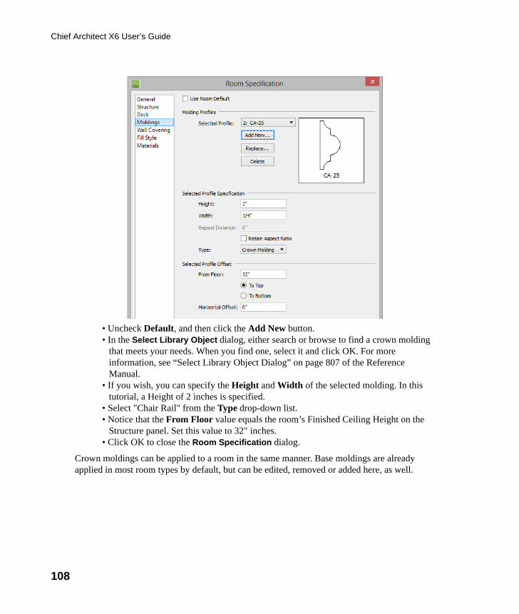
108
Chief Architect X6 User’s Guide
• Uncheck Default, and then click the Add New button. • In the Select Library Object dialog, either search or browse to find a crown molding
that meets your needs. When you find one, select it and click OK. For more information, see “Select Library Object Dialog” on page 807 of the Reference Manual.
• If you wish, you can specify the Height and Width of the selected molding. In this tutorial, a Height of 2 inches is specified.
• Select "Chair Rail" from the Type drop-down list. • Notice that the From Floor value equals the room’s Finished Ceiling Height on the
Structure panel. Set this value to 32" inches. • Click OK to close the Room Specification dialog.
Crown moldings can be applied to a room in the same manner. Base moldings are already applied in most room types by default, but can be edited, removed or added here, as well.
chief-architect-x6-users-guide.book Page 108 Monday, December 16, 2013 4:05 PM
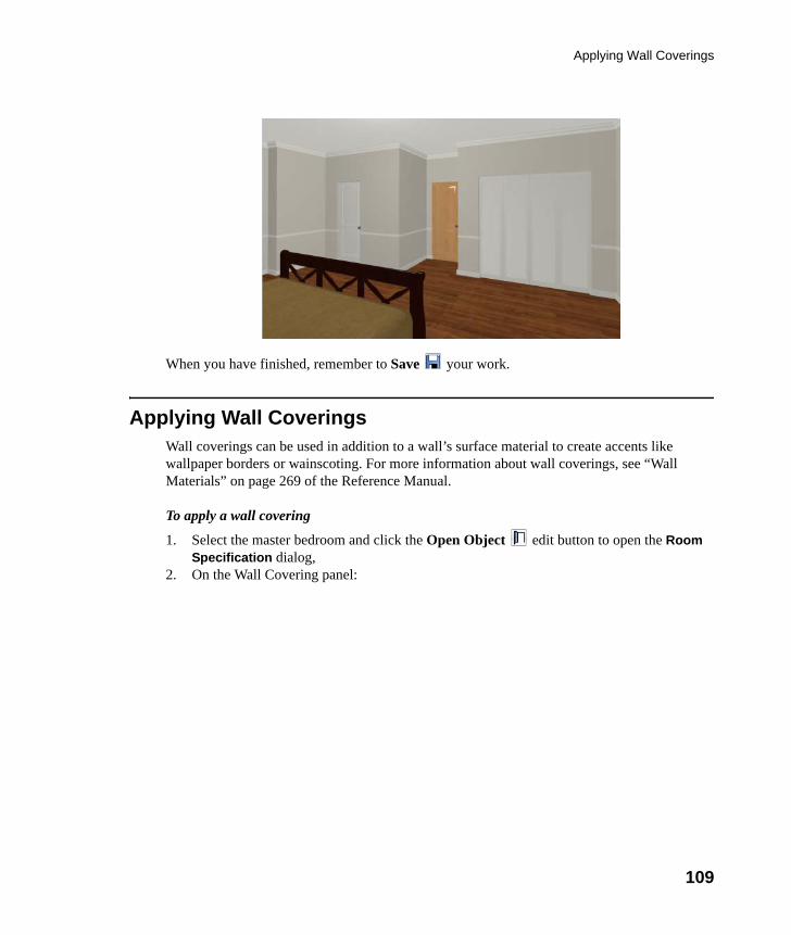
Applying Wall Coverings
109
When you have finished, remember to Save your work.
Applying Wall CoveringsWall coverings can be used in addition to a wall’s surface material to create accents like wallpaper borders or wainscoting. For more information about wall coverings, see “Wall Materials” on page 269 of the Reference Manual.
To apply a wall covering
1. Select the master bedroom and click the Open Object edit button to open the Room Specification dialog,
2. On the Wall Covering panel:
chief-architect-x6-users-guide.book Page 109 Monday, December 16, 2013 4:05 PM
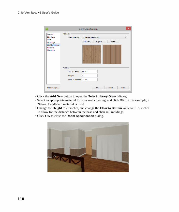
110
Chief Architect X6 User’s Guide
• Click the Add New button to open the Select Library Object dialog.• Select an appropriate material for your wall covering, and click OK. In this example, a
Natural Beadboard material is used. • Change the Height to 28 inches, and change the Floor to Bottom value to 3 1/2 inches
to allow for the distance between the base and chair rail moldings. • Click OK to close the Room Specification dialog.
chief-architect-x6-users-guide.book Page 110 Monday, December 16, 2013 4:05 PM
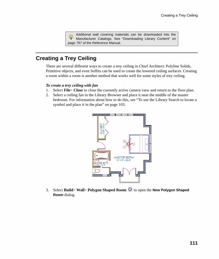
Creating a Trey Ceiling
111
Creating a Trey CeilingThere are several different ways to create a trey ceiling in Chief Architect: Polyline Solids, Primitive objects, and even Soffits can be used to create the lowered ceiling surfaces. Creating a room within a room is another method that works well for some styles of trey ceiling.
To create a trey ceiling with fan1. Select File> Close to close the currently active camera view and return to the floor plan.2. Select a ceiling fan in the Library Browser and place it near the middle of the master
bedroom. For information about how to do this, see “To use the Library Search to locate a symbol and place it in the plan” on page 103.
3. Select Build> Wall> Polygon Shaped Room to open the New Polygon Shaped Room dialog.
Additional wall covering materials can be downloaded into theManufacturer Catalogs. See “Downloading Library Content” on
page 797 of the Reference Manual.
chief-architect-x6-users-guide.book Page 111 Monday, December 16, 2013 4:05 PM
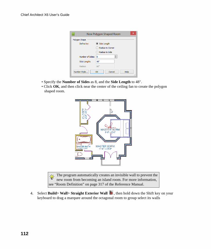
112
Chief Architect X6 User’s Guide
• Specify the Number of Sides as 8, and the Side Length to 48".• Click OK, and then click near the center of the ceiling fan to create the polygon
shaped room.
4. Select Build> Wall> Straight Exterior Wall , then hold down the Shift key on your keyboard to drag a marquee around the octagonal room to group select its walls
The program automatically creates an invisible wall to prevent the new room from becoming an island room. For more information,
see “Room Definition” on page 317 of the Reference Manual.
chief-architect-x6-users-guide.book Page 112 Monday, December 16, 2013 4:05 PM
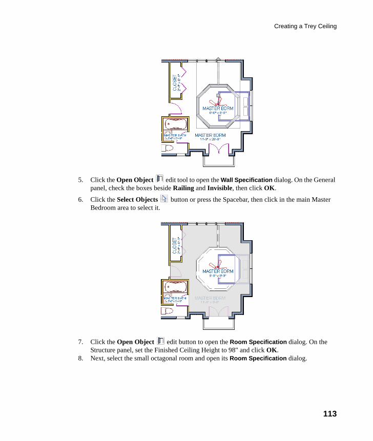
Creating a Trey Ceiling
113
5. Click the Open Object edit tool to open the Wall Specification dialog. On the General panel, check the boxes beside Railing and Invisible, then click OK.
6. Click the Select Objects button or press the Spacebar, then click in the main Master Bedroom area to select it.
7. Click the Open Object edit button to open the Room Specification dialog. On the Structure panel, set the Finished Ceiling Height to 98" and click OK.
8. Next, select the small octagonal room and open its Room Specification dialog.
chief-architect-x6-users-guide.book Page 113 Monday, December 16, 2013 4:05 PM
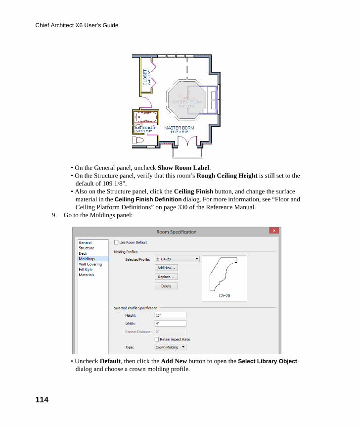
114
Chief Architect X6 User’s Guide
• On the General panel, uncheck Show Room Label.• On the Structure panel, verify that this room’s Rough Ceiling Height is still set to the
default of 109 1/8".• Also on the Structure panel, click the Ceiling Finish button, and change the surface
material in the Ceiling Finish Definition dialog. For more information, see “Floor and Ceiling Platform Definitions” on page 330 of the Reference Manual.
9. Go to the Moldings panel:
• Uncheck Default, then click the Add New button to open the Select Library Object dialog and choose a crown molding profile.
chief-architect-x6-users-guide.book Page 114 Monday, December 16, 2013 4:05 PM
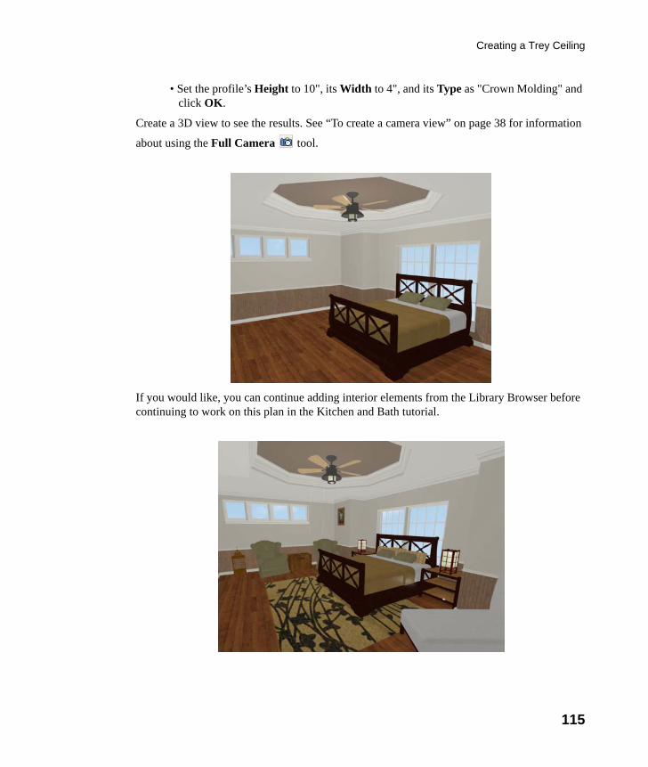
Creating a Trey Ceiling
115
• Set the profile’s Height to 10", its Width to 4", and its Type as "Crown Molding" and click OK.
Create a 3D view to see the results. See “To create a camera view” on page 38 for information
about using the Full Camera tool.
If you would like, you can continue adding interior elements from the Library Browser before continuing to work on this plan in the Kitchen and Bath tutorial.
chief-architect-x6-users-guide.book Page 115 Monday, December 16, 2013 4:05 PM

116
Chief Architect X6 User’s Guide
chief-architect-x6-users-guide.book Page 116 Monday, December 16, 2013 4:05 PM
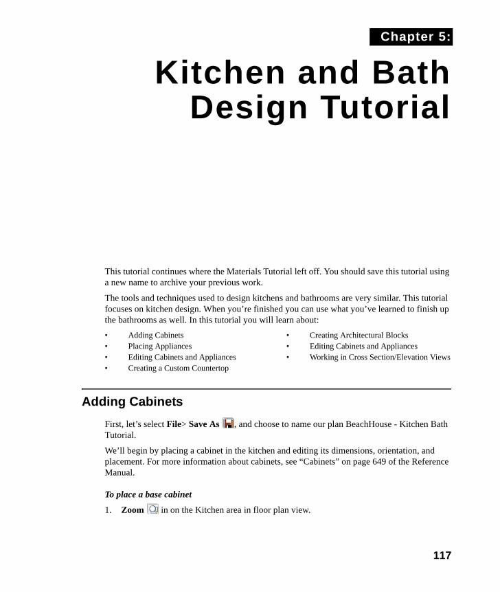
117
Chapter 5:
Kitchen and BathDesign Tutorial
This tutorial continues where the Materials Tutorial left off. You should save this tutorial using a new name to archive your previous work.
The tools and techniques used to design kitchens and bathrooms are very similar. This tutorial focuses on kitchen design. When you’re finished you can use what you’ve learned to finish up the bathrooms as well. In this tutorial you will learn about:
• Adding Cabinets• Placing Appliances• Editing Cabinets and Appliances• Creating a Custom Countertop
• Creating Architectural Blocks• Editing Cabinets and Appliances• Working in Cross Section/Elevation Views
Adding Cabinets
First, let’s select File> Save As , and choose to name our plan BeachHouse - Kitchen Bath Tutorial.
We’ll begin by placing a cabinet in the kitchen and editing its dimensions, orientation, and placement. For more information about cabinets, see “Cabinets” on page 649 of the Reference Manual.
To place a base cabinet
1. Zoom in on the Kitchen area in floor plan view.
chief-architect-x6-users-guide.book Page 117 Monday, December 16, 2013 4:05 PM
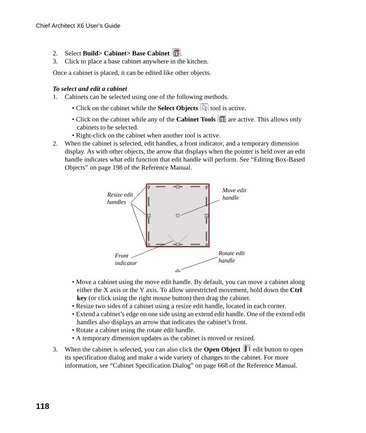
118
Chief Architect X6 User’s Guide
2. Select Build> Cabinet> Base Cabinet .3. Click to place a base cabinet anywhere in the kitchen.
Once a cabinet is placed, it can be edited like other objects.
To select and edit a cabinet1. Cabinets can be selected using one of the following methods.
• Click on the cabinet while the Select Objects tool is active.
• Click on the cabinet while any of the Cabinet Tools are active. This allows only cabinets to be selected.
• Right-click on the cabinet when another tool is active.2. When the cabinet is selected, edit handles, a front indicator, and a temporary dimension
display. As with other objects, the arrow that displays when the pointer is held over an edit handle indicates what edit function that edit handle will perform. See “Editing Box-Based Objects” on page 198 of the Reference Manual.
• Move a cabinet using the move edit handle. By default, you can move a cabinet along either the X axis or the Y axis. To allow unrestricted movement, hold down the Ctrl key (or click using the right mouse button) then drag the cabinet.
• Resize two sides of a cabinet using a resize edit handle, located in each corner. • Extend a cabinet’s edge on one side using an extend edit handle. One of the extend edit
handles also displays an arrow that indicates the cabinet’s front. • Rotate a cabinet using the rotate edit handle.• A temporary dimension updates as the cabinet is moved or resized.
3. When the cabinet is selected, you can also click the Open Object edit button to open its specification dialog and make a wide variety of changes to the cabinet. For more information, see “Cabinet Specification Dialog” on page 668 of the Reference Manual.
Resize edit handles
Rotate edit handle
Move edit handle
Front indicator
chief-architect-x6-users-guide.book Page 118 Monday, December 16, 2013 4:05 PM
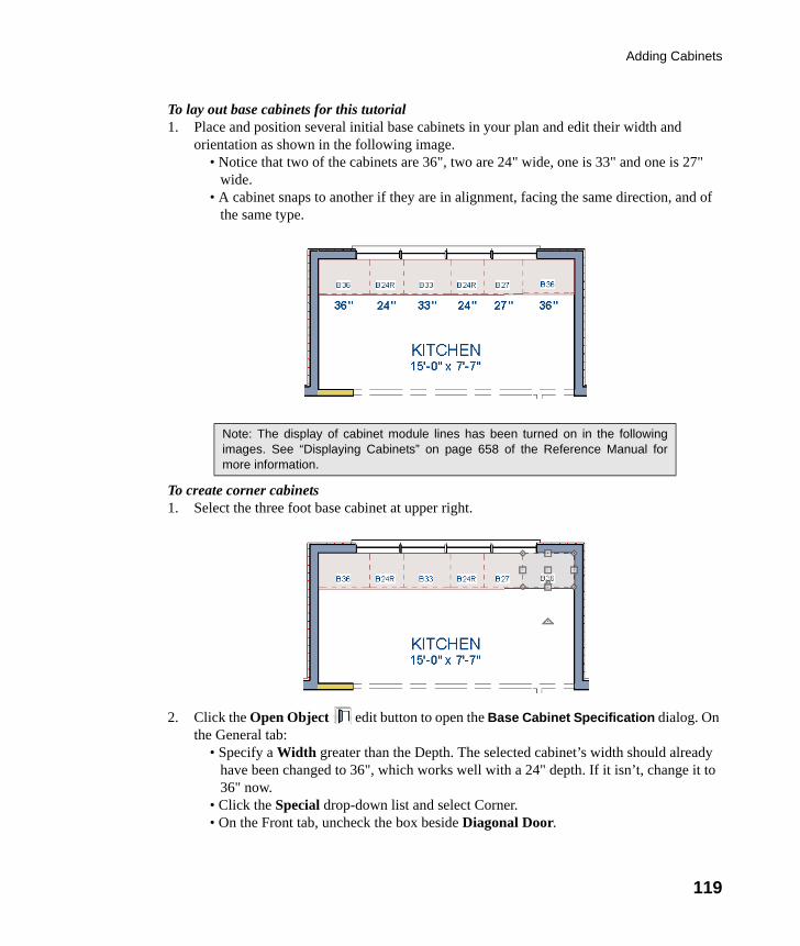
Adding Cabinets
119
To lay out base cabinets for this tutorial1. Place and position several initial base cabinets in your plan and edit their width and
orientation as shown in the following image. • Notice that two of the cabinets are 36", two are 24" wide, one is 33" and one is 27"
wide.• A cabinet snaps to another if they are in alignment, facing the same direction, and of
the same type.
To create corner cabinets 1. Select the three foot base cabinet at upper right.
2. Click the Open Object edit button to open the Base Cabinet Specification dialog. On the General tab:
• Specify a Width greater than the Depth. The selected cabinet’s width should already have been changed to 36", which works well with a 24" depth. If it isn’t, change it to 36" now.
• Click the Special drop-down list and select Corner. • On the Front tab, uncheck the box beside Diagonal Door.
Note: The display of cabinet module lines has been turned on in the followingimages. See “Displaying Cabinets” on page 658 of the Reference Manual formore information.
chief-architect-x6-users-guide.book Page 119 Monday, December 16, 2013 4:05 PM
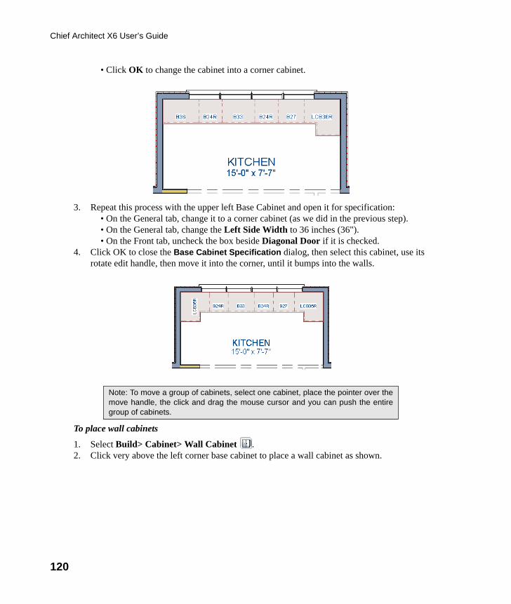
120
Chief Architect X6 User’s Guide
• Click OK to change the cabinet into a corner cabinet.
3. Repeat this process with the upper left Base Cabinet and open it for specification:• On the General tab, change it to a corner cabinet (as we did in the previous step). • On the General tab, change the Left Side Width to 36 inches (36").• On the Front tab, uncheck the box beside Diagonal Door if it is checked.
4. Click OK to close the Base Cabinet Specification dialog, then select this cabinet, use its rotate edit handle, then move it into the corner, until it bumps into the walls.
To place wall cabinets
1. Select Build> Cabinet> Wall Cabinet .2. Click very above the left corner base cabinet to place a wall cabinet as shown.
Note: To move a group of cabinets, select one cabinet, place the pointer over themove handle, the click and drag the mouse cursor and you can push the entiregroup of cabinets.
chief-architect-x6-users-guide.book Page 120 Monday, December 16, 2013 4:05 PM
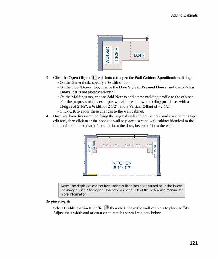
Adding Cabinets
121
3. Click the Open Object edit button to open the Wall Cabinet Specification dialog:• On the General tab, specify a Width of 33.• On the Door/Drawer tab, change the Door Style to Framed Doors, and check Glass
Doors if it is not already selected.• On the Moldings tab, choose Add New to add a new molding profile to the cabinet.
For the purposes of this example, we will use a crown molding profile set with a Height of 2 1/2", a Width of 2 1/2", and a Vertical Offset of - 2 1/2".
• Click OK to apply these changes to the wall cabinet.4. Once you have finished modifying the original wall cabinet, select it and click on the Copy
edit tool, then click near the opposite wall to place a second wall cabinet identical to the first, and rotate it so that it faces out in to the door, instead of in to the wall.
To place soffits
Select Build> Cabinet> Soffit then click above the wall cabinets to place soffits. Adjust their width and orientation to match the wall cabinets below.
Note: The display of cabinet face indicator lines has been turned on in the follow-ing images. See “Displaying Cabinets” on page 658 of the Reference Manual formore information.
chief-architect-x6-users-guide.book Page 121 Monday, December 16, 2013 4:05 PM
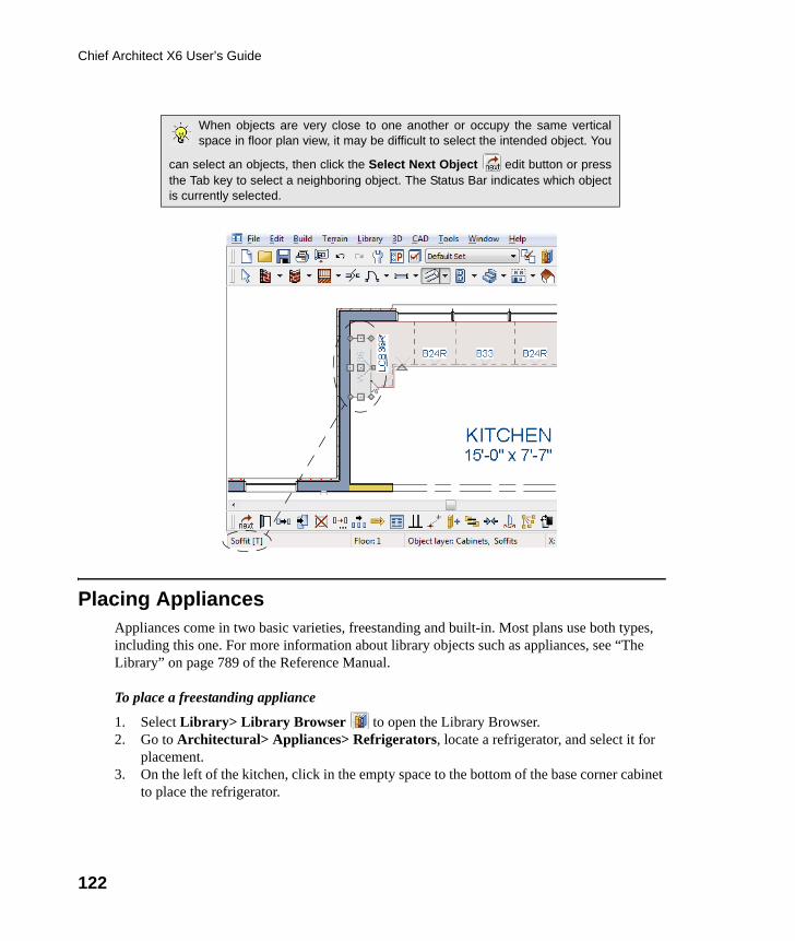
122
Chief Architect X6 User’s Guide
Placing AppliancesAppliances come in two basic varieties, freestanding and built-in. Most plans use both types, including this one. For more information about library objects such as appliances, see “The Library” on page 789 of the Reference Manual.
To place a freestanding appliance
1. Select Library> Library Browser to open the Library Browser.2. Go to Architectural> Appliances> Refrigerators, locate a refrigerator, and select it for
placement.3. On the left of the kitchen, click in the empty space to the bottom of the base corner cabinet
to place the refrigerator.
When objects are very close to one another or occupy the same verticalspace in floor plan view, it may be difficult to select the intended object. You
can select an objects, then click the Select Next Object edit button or pressthe Tab key to select a neighboring object. The Status Bar indicates which objectis currently selected.
chief-architect-x6-users-guide.book Page 122 Monday, December 16, 2013 4:05 PM
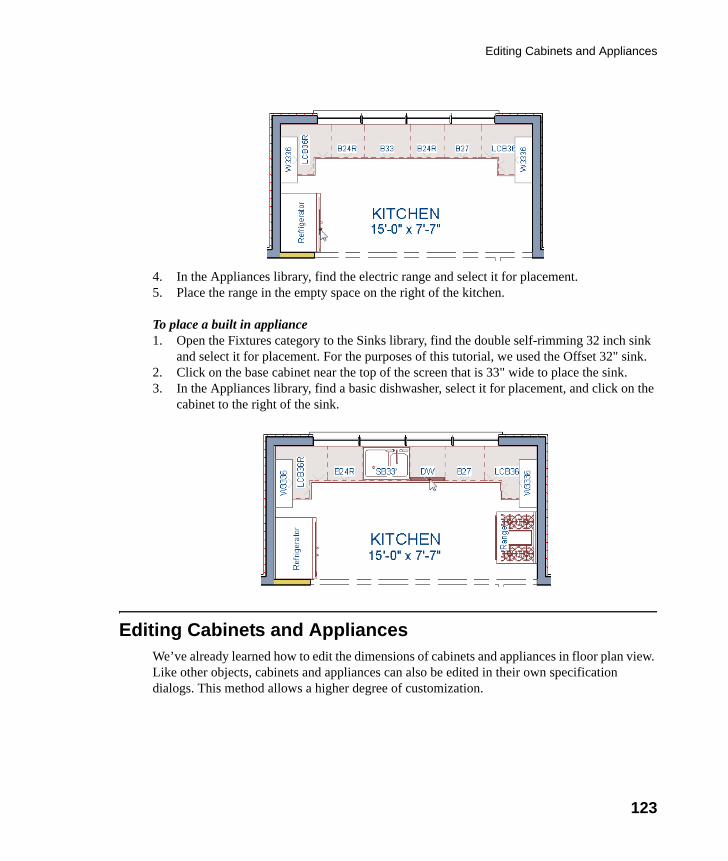
Editing Cabinets and Appliances
123
4. In the Appliances library, find the electric range and select it for placement.5. Place the range in the empty space on the right of the kitchen.
To place a built in appliance1. Open the Fixtures category to the Sinks library, find the double self-rimming 32 inch sink
and select it for placement. For the purposes of this tutorial, we used the Offset 32" sink.2. Click on the base cabinet near the top of the screen that is 33" wide to place the sink.3. In the Appliances library, find a basic dishwasher, select it for placement, and click on the
cabinet to the right of the sink.
Editing Cabinets and AppliancesWe’ve already learned how to edit the dimensions of cabinets and appliances in floor plan view. Like other objects, cabinets and appliances can also be edited in their own specification dialogs. This method allows a higher degree of customization.
chief-architect-x6-users-guide.book Page 123 Monday, December 16, 2013 4:05 PM
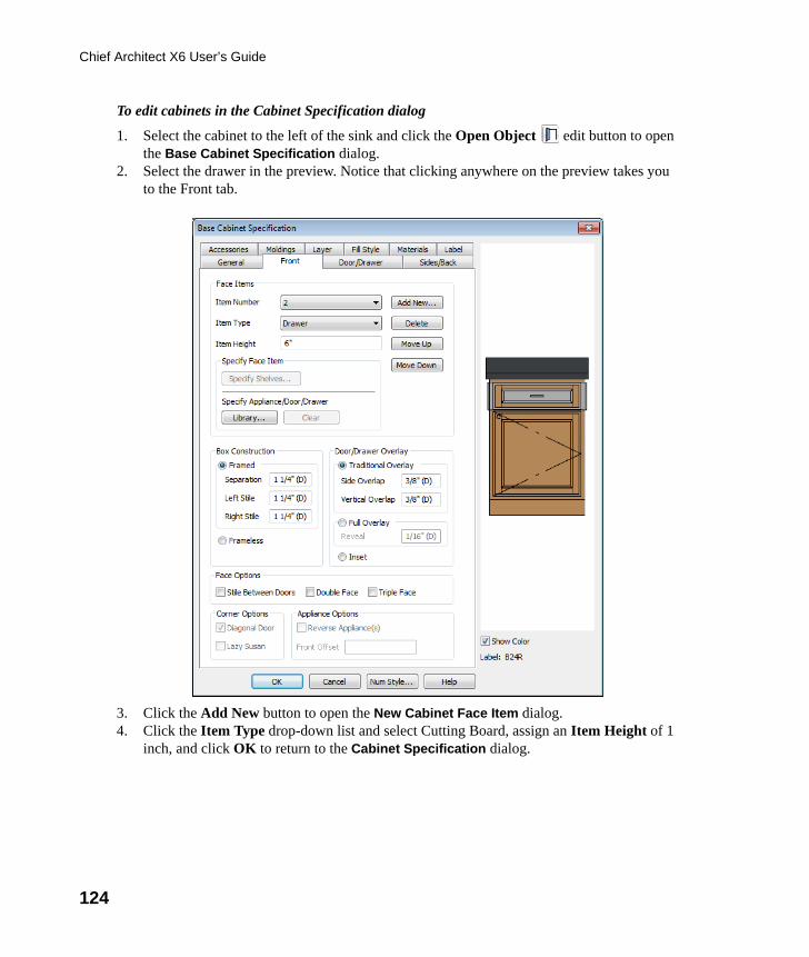
124
Chief Architect X6 User’s Guide
To edit cabinets in the Cabinet Specification dialog
1. Select the cabinet to the left of the sink and click the Open Object edit button to open the Base Cabinet Specification dialog.
2. Select the drawer in the preview. Notice that clicking anywhere on the preview takes you to the Front tab.
3. Click the Add New button to open the New Cabinet Face Item dialog.4. Click the Item Type drop-down list and select Cutting Board, assign an Item Height of 1
inch, and click OK to return to the Cabinet Specification dialog.
chief-architect-x6-users-guide.book Page 124 Monday, December 16, 2013 4:05 PM
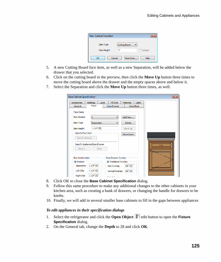
Editing Cabinets and Appliances
125
5. A new Cutting Board face item, as well as a new Separation, will be added below the drawer that you selected.
6. Click on the cutting board in the preview, then click the Move Up button three times to move the cutting board above the drawer and the empty spaces above and below it.
7. Select the Separation and click the Move Up button three times, as well.
8. Click OK to close the Base Cabinet Specification dialog.9. Follow this same procedure to make any additional changes to the other cabinets in your
kitchen area, such as creating a bank of drawers, or changing the handle for drawers to be knobs.
10. Finally, we will add in several smaller base cabinets to fill in the gaps between appliances
To edit appliances in their specification dialogs
1. Select the refrigerator and click the Open Object edit button to open the Fixture Specification dialog.
2. On the General tab, change the Depth to 28 and click OK.
chief-architect-x6-users-guide.book Page 125 Monday, December 16, 2013 4:05 PM
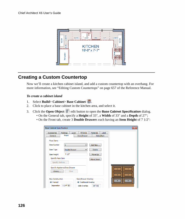
126
Chief Architect X6 User’s Guide
Creating a Custom CountertopNow we’ll create a kitchen cabinet island, and add a custom countertop with an overhang. For more information, see “Editing Custom Countertops” on page 657 of the Reference Manual.
To create a cabinet island
1. Select Build> Cabinet> Base Cabinet .2. Click to place a base cabinet in the kitchen area, and select it.
3. Click the Open Object edit button to open the Base Cabinet Specification dialog.• On the General tab, specify a Height of 33", a Width of 33" and a Depth of 27";• On the Front tab, create 3 Double Drawers each having an Item Height of 7 1/2":
chief-architect-x6-users-guide.book Page 126 Monday, December 16, 2013 4:05 PM
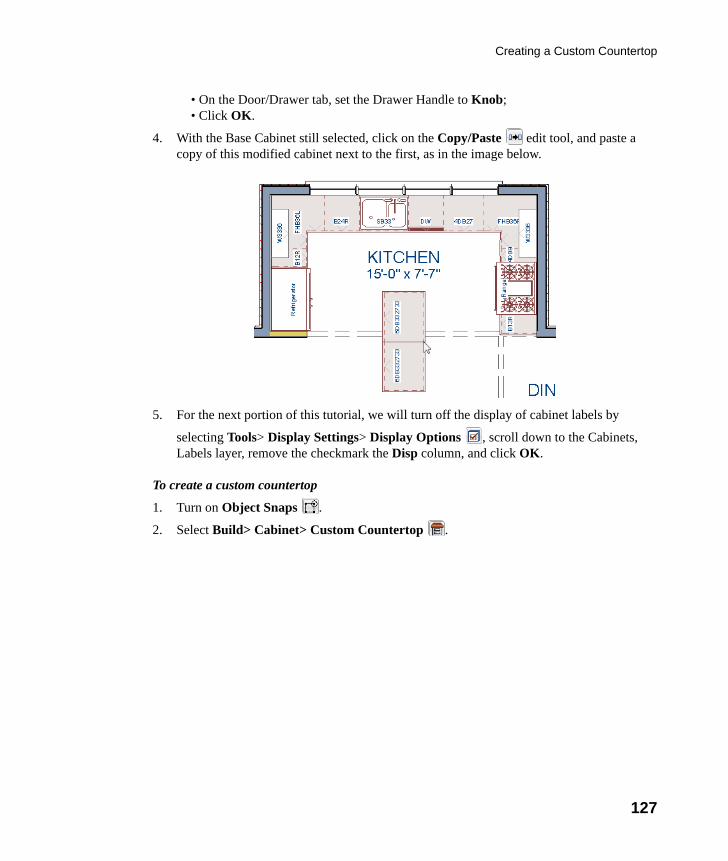
Creating a Custom Countertop
127
• On the Door/Drawer tab, set the Drawer Handle to Knob;• Click OK.
4. With the Base Cabinet still selected, click on the Copy/Paste edit tool, and paste a copy of this modified cabinet next to the first, as in the image below.
5. For the next portion of this tutorial, we will turn off the display of cabinet labels by
selecting Tools> Display Settings> Display Options , scroll down to the Cabinets, Labels layer, remove the checkmark the Disp column, and click OK.
To create a custom countertop
1. Turn on Object Snaps .
2. Select Build> Cabinet> Custom Countertop .
chief-architect-x6-users-guide.book Page 127 Monday, December 16, 2013 4:05 PM
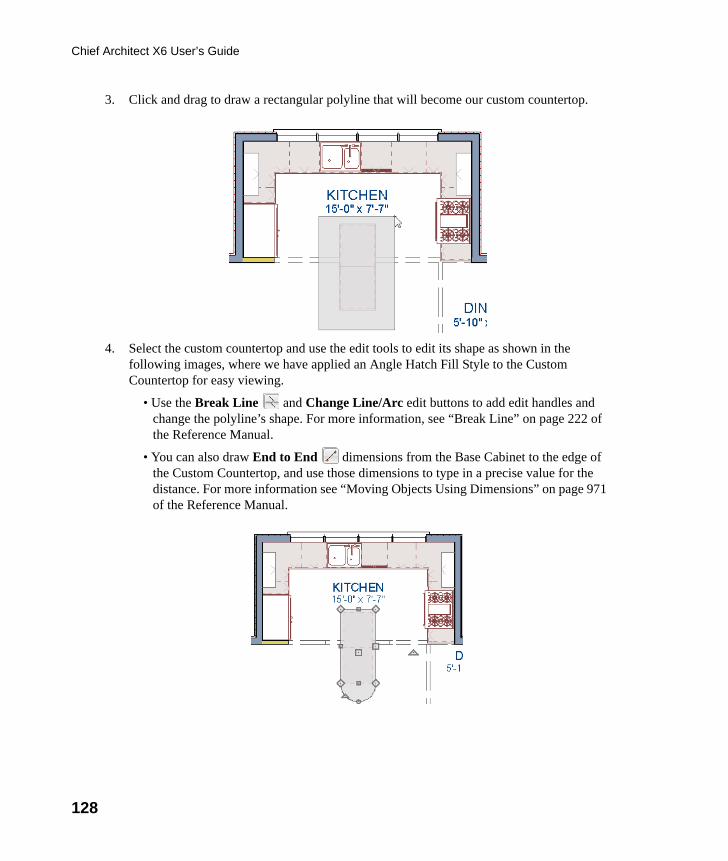
128
Chief Architect X6 User’s Guide
3. Click and drag to draw a rectangular polyline that will become our custom countertop.
4. Select the custom countertop and use the edit tools to edit its shape as shown in the following images, where we have applied an Angle Hatch Fill Style to the Custom Countertop for easy viewing.
• Use the Break Line and Change Line/Arc edit buttons to add edit handles and change the polyline’s shape. For more information, see “Break Line” on page 222 of the Reference Manual.
• You can also draw End to End dimensions from the Base Cabinet to the edge of the Custom Countertop, and use those dimensions to type in a precise value for the distance. For more information see “Moving Objects Using Dimensions” on page 971 of the Reference Manual.
chief-architect-x6-users-guide.book Page 128 Monday, December 16, 2013 4:05 PM
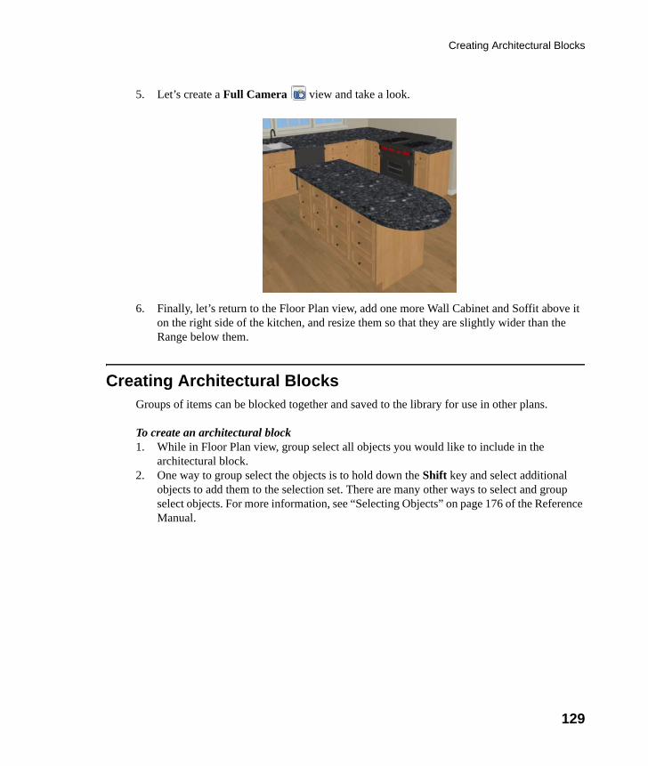
Creating Architectural Blocks
129
5. Let’s create a Full Camera view and take a look.
6. Finally, let’s return to the Floor Plan view, add one more Wall Cabinet and Soffit above it on the right side of the kitchen, and resize them so that they are slightly wider than the Range below them.
Creating Architectural BlocksGroups of items can be blocked together and saved to the library for use in other plans.
To create an architectural block1. While in Floor Plan view, group select all objects you would like to include in the
architectural block.2. One way to group select the objects is to hold down the Shift key and select additional
objects to add them to the selection set. There are many other ways to select and group select objects. For more information, see “Selecting Objects” on page 176 of the Reference Manual.
chief-architect-x6-users-guide.book Page 129 Monday, December 16, 2013 4:05 PM
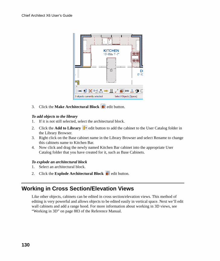
130
Chief Architect X6 User’s Guide
3. Click the Make Architectural Block edit button.
To add objects to the library1. If it is not still selected, select the architectural block.
2. Click the Add to Library edit button to add the cabinet to the User Catalog folder in the Library Browser.
3. Right click on the Base cabinet name in the Library Browser and select Rename to change this cabinets name to Kitchen Bar.
4. Now click and drag the newly named Kitchen Bar cabinet into the appropriate User Catalog folder that you have created for it, such as Base Cabinets.
To explode an architectural block1. Select an architectural block.
2. Click the Explode Architectural Block edit button.
Working in Cross Section/Elevation ViewsLike other objects, cabinets can be edited in cross section/elevation views. This method of editing is very powerful and allows objects to be edited easily in vertical space. Next we’ll edit wall cabinets and add a range hood. For more information about working in 3D views, see “Working in 3D” on page 883 of the Reference Manual.
chief-architect-x6-users-guide.book Page 130 Monday, December 16, 2013 4:05 PM
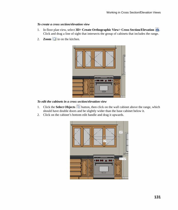
Working in Cross Section/Elevation Views
131
To create a cross section/elevation view
1. In floor plan view, select 3D> Create Orthographic View> Cross Section/Elevation . Click and drag a line of sight that intersects the group of cabinets that includes the range.
2. Zoom in on the kitchen.
To edit the cabinets in a cross section/elevation view
1. Click the Select Objects button, then click on the wall cabinet above the range, which should have double doors and be slightly wider than the base cabinet below it.
2. Click on the cabinet’s bottom edit handle and drag it upwards.
chief-architect-x6-users-guide.book Page 131 Monday, December 16, 2013 4:05 PM
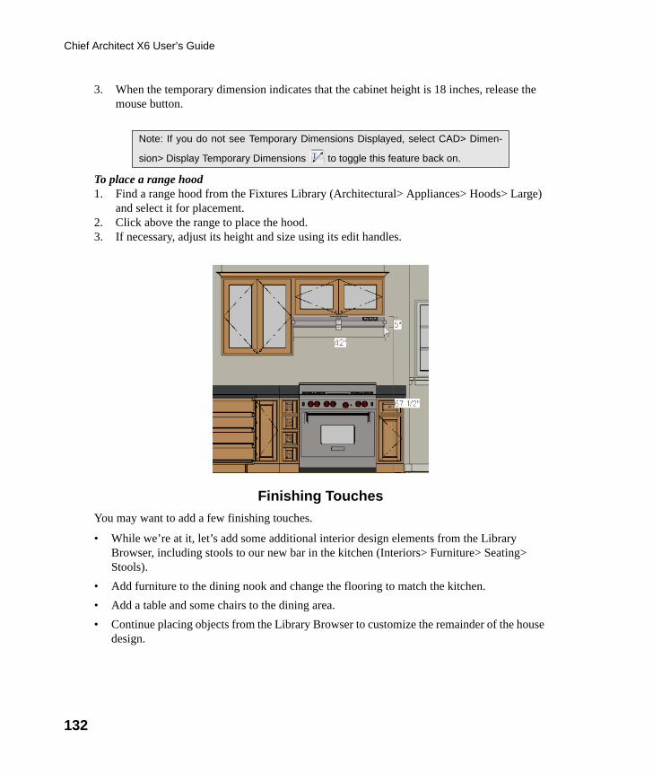
132
Chief Architect X6 User’s Guide
3. When the temporary dimension indicates that the cabinet height is 18 inches, release the mouse button.
To place a range hood1. Find a range hood from the Fixtures Library (Architectural> Appliances> Hoods> Large)
and select it for placement.2. Click above the range to place the hood.3. If necessary, adjust its height and size using its edit handles.
Finishing Touches
You may want to add a few finishing touches.
• While we’re at it, let’s add some additional interior design elements from the Library Browser, including stools to our new bar in the kitchen (Interiors> Furniture> Seating> Stools).
• Add furniture to the dining nook and change the flooring to match the kitchen.
• Add a table and some chairs to the dining area.
• Continue placing objects from the Library Browser to customize the remainder of the house design.
Note: If you do not see Temporary Dimensions Displayed, select CAD> Dimen-
sion> Display Temporary Dimensions to toggle this feature back on.
chief-architect-x6-users-guide.book Page 132 Monday, December 16, 2013 4:05 PM
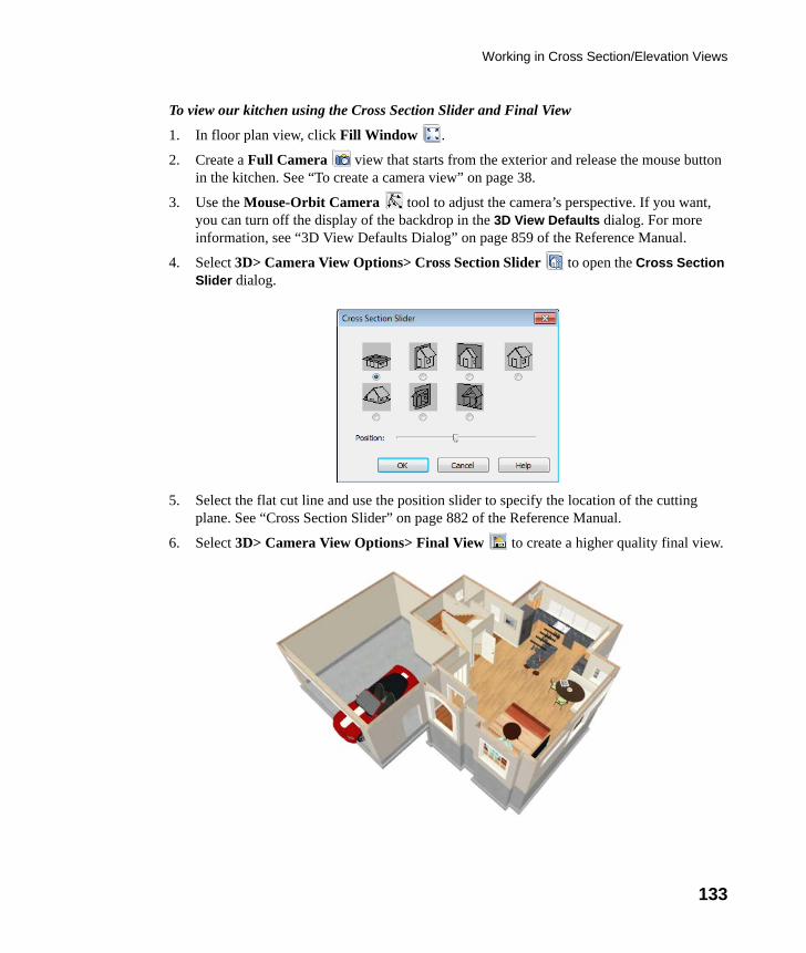
Working in Cross Section/Elevation Views
133
To view our kitchen using the Cross Section Slider and Final View
1. In floor plan view, click Fill Window .
2. Create a Full Camera view that starts from the exterior and release the mouse button in the kitchen. See “To create a camera view” on page 38.
3. Use the Mouse-Orbit Camera tool to adjust the camera’s perspective. If you want, you can turn off the display of the backdrop in the 3D View Defaults dialog. For more information, see “3D View Defaults Dialog” on page 859 of the Reference Manual.
4. Select 3D> Camera View Options> Cross Section Slider to open the Cross Section Slider dialog.
5. Select the flat cut line and use the position slider to specify the location of the cutting plane. See “Cross Section Slider” on page 882 of the Reference Manual.
6. Select 3D> Camera View Options> Final View to create a higher quality final view.
chief-architect-x6-users-guide.book Page 133 Monday, December 16, 2013 4:05 PM
134
Chief Architect X6 User’s Guide
7. In a future tutorial, we will be returning to this plan file, so be sure to Save your work.
If you would like, you can continue working on this plan in the Landscaping Tutorial. To learn how to arrange views of your model on a page for printing, see the Layout Tutorial.
chief-architect-x6-users-guide.book Page 134 Monday, December 16, 2013 4:05 PM
135
Chapter 6:
MaterialsTutorial
Materials display on the surfaces of objects in 3D views and can make a 3D view appear highly realistic. When applied to most objects, material quantities will also be calculated in the Materials List.
This tutorial continues from where the Interior Design Tutorial ended. You may want to save this tutorial using a new name to archive your previous work. In this tutorial you will learn about:
• Setting Materials Defaults• Using the Materials Panel• Using the Material Painter• Using the Material Eyedropper• Using the Color Chooser
• Blending Colors with Materials• Using the Material Eyedropper• Custom Materials, Images, and Backdrops• Generating a Materials List
Setting Materials DefaultsMaterial default settings determine the materials used by different objects when they are initially created. Setting the correct material defaults before beginning a project may help you save time. For more information, see “Preferences and Default Settings” on page 67 of the Reference Manual.
chief-architect-x6-users-guide.book Page 135 Monday, December 16, 2013 4:05 PM
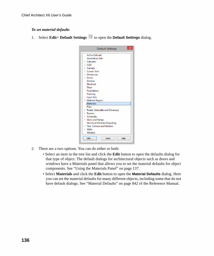
136
Chief Architect X6 User’s Guide
To set material defaults
1. Select Edit> Default Settings to open the Default Settings dialog.
2. There are a two options. You can do either or both:
• Select an item in the tree list and click the Edit button to open the defaults dialog for that type of object. The default dialogs for architectural objects such as doors and windows have a Materials panel that allows you to set the material defaults for object components. See “Using the Materials Panel” on page 137.
• Select Materials and click the Edit button to open the Material Defaults dialog. Here you can set the material defaults for many different objects, including some that do not have default dialogs. See “Material Defaults” on page 842 of the Reference Manual.
chief-architect-x6-users-guide.book Page 136 Monday, December 16, 2013 4:05 PM
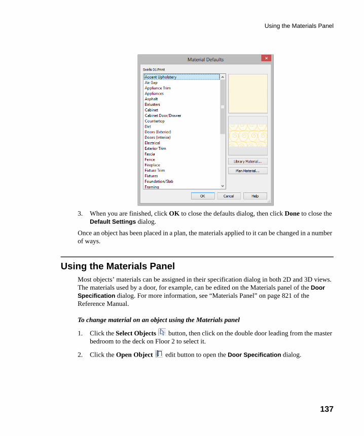
Using the Materials Panel
137
3. When you are finished, click OK to close the defaults dialog, then click Done to close the Default Settings dialog.
Once an object has been placed in a plan, the materials applied to it can be changed in a number of ways.
Using the Materials PanelMost objects’ materials can be assigned in their specification dialog in both 2D and 3D views. The materials used by a door, for example, can be edited on the Materials panel of the Door Specification dialog. For more information, see “Materials Panel” on page 821 of the Reference Manual.
To change material on an object using the Materials panel
1. Click the Select Objects button, then click on the double door leading from the master bedroom to the deck on Floor 2 to select it.
2. Click the Open Object edit button to open the Door Specification dialog.
chief-architect-x6-users-guide.book Page 137 Monday, December 16, 2013 4:05 PM
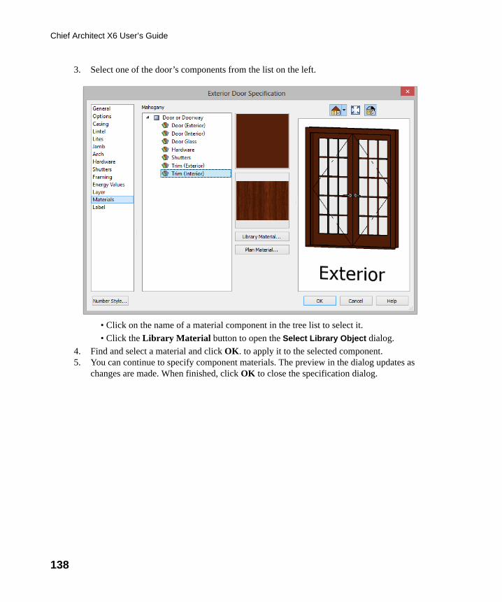
138
Chief Architect X6 User’s Guide
3. Select one of the door’s components from the list on the left.
• Click on the name of a material component in the tree list to select it.
• Click the Library Material button to open the Select Library Object dialog.
4. Find and select a material and click OK. to apply it to the selected component.5. You can continue to specify component materials. The preview in the dialog updates as
changes are made. When finished, click OK to close the specification dialog.
chief-architect-x6-users-guide.book Page 138 Monday, December 16, 2013 4:05 PM
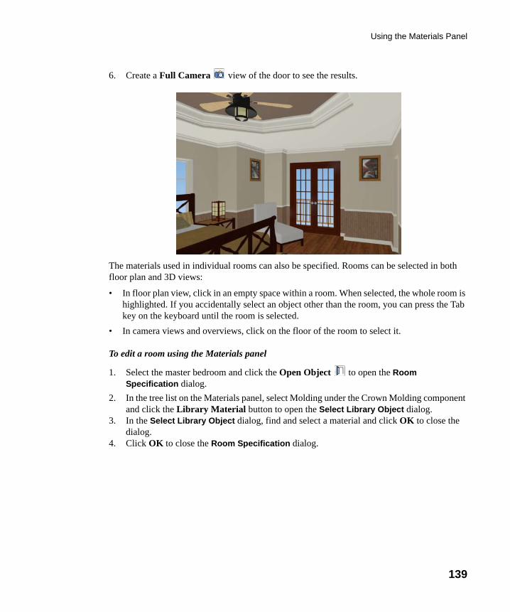
Using the Materials Panel
139
6. Create a Full Camera view of the door to see the results.
The materials used in individual rooms can also be specified. Rooms can be selected in both floor plan and 3D views:
• In floor plan view, click in an empty space within a room. When selected, the whole room is highlighted. If you accidentally select an object other than the room, you can press the Tab key on the keyboard until the room is selected.
• In camera views and overviews, click on the floor of the room to select it.
To edit a room using the Materials panel
1. Select the master bedroom and click the Open Object to open the Room Specification dialog.
2. In the tree list on the Materials panel, select Molding under the Crown Molding component and click the Library Material button to open the Select Library Object dialog.
3. In the Select Library Object dialog, find and select a material and click OK to close the dialog.
4. Click OK to close the Room Specification dialog.
chief-architect-x6-users-guide.book Page 139 Monday, December 16, 2013 4:05 PM
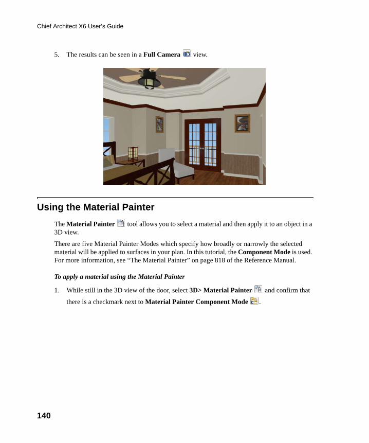
140
Chief Architect X6 User’s Guide
5. The results can be seen in a Full Camera view.
Using the Material Painter
The Material Painter tool allows you to select a material and then apply it to an object in a 3D view.
There are five Material Painter Modes which specify how broadly or narrowly the selected material will be applied to surfaces in your plan. In this tutorial, the Component Mode is used. For more information, see “The Material Painter” on page 818 of the Reference Manual.
To apply a material using the Material Painter
1. While still in the 3D view of the door, select 3D> Material Painter and confirm that
there is a checkmark next to Material Painter Component Mode .
chief-architect-x6-users-guide.book Page 140 Monday, December 16, 2013 4:05 PM
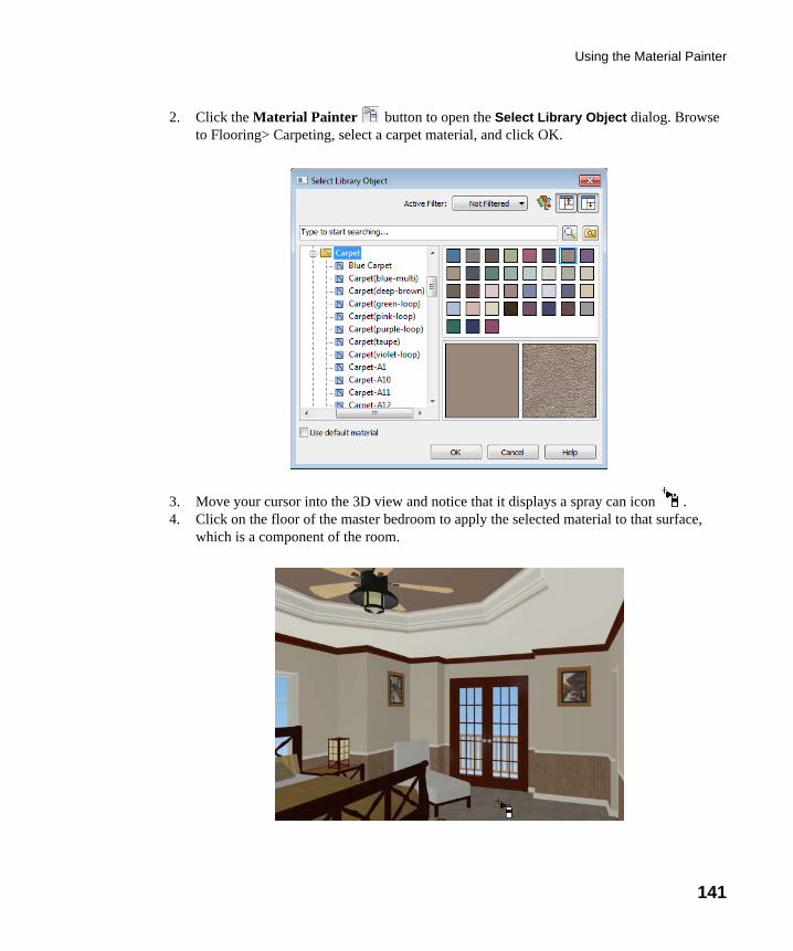
Using the Material Painter
141
2. Click the Material Painter button to open the Select Library Object dialog. Browse to Flooring> Carpeting, select a carpet material, and click OK.
3. Move your cursor into the 3D view and notice that it displays a spray can icon . 4. Click on the floor of the master bedroom to apply the selected material to that surface,
which is a component of the room.
chief-architect-x6-users-guide.book Page 141 Monday, December 16, 2013 4:05 PM
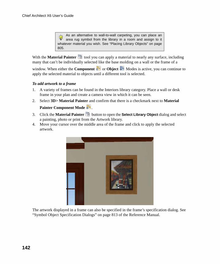
142
Chief Architect X6 User’s Guide
With the Material Painter tool you can apply a material to nearly any surface, including many that can’t be individually selected like the base molding on a wall or the frame of a
window. When either the Component or Object Modes is active, you can continue to apply the selected material to objects until a different tool is selected.
To add artwork to a frame
1. A variety of frames can be found in the Interiors library category. Place a wall or desk frame in your plan and create a camera view in which it can be seen.
2. Select 3D> Material Painter and confirm that there is a checkmark next to Material
Painter Component Mode .
3. Click the Material Painter button to open the Select Library Object dialog and select a painting, photo or print from the Artwork library.
4. Move your cursor over the middle area of the frame and click to apply the selected artwork.
The artwork displayed in a frame can also be specified in the frame’s specification dialog. See “Symbol Object Specification Dialogs” on page 813 of the Reference Manual.
As an alternative to wall-to-wall carpeting, you can place anarea rug symbol from the library in a room and assign to it
whatever material you wish. See “Placing Library Objects” on page805.
chief-architect-x6-users-guide.book Page 142 Monday, December 16, 2013 4:05 PM
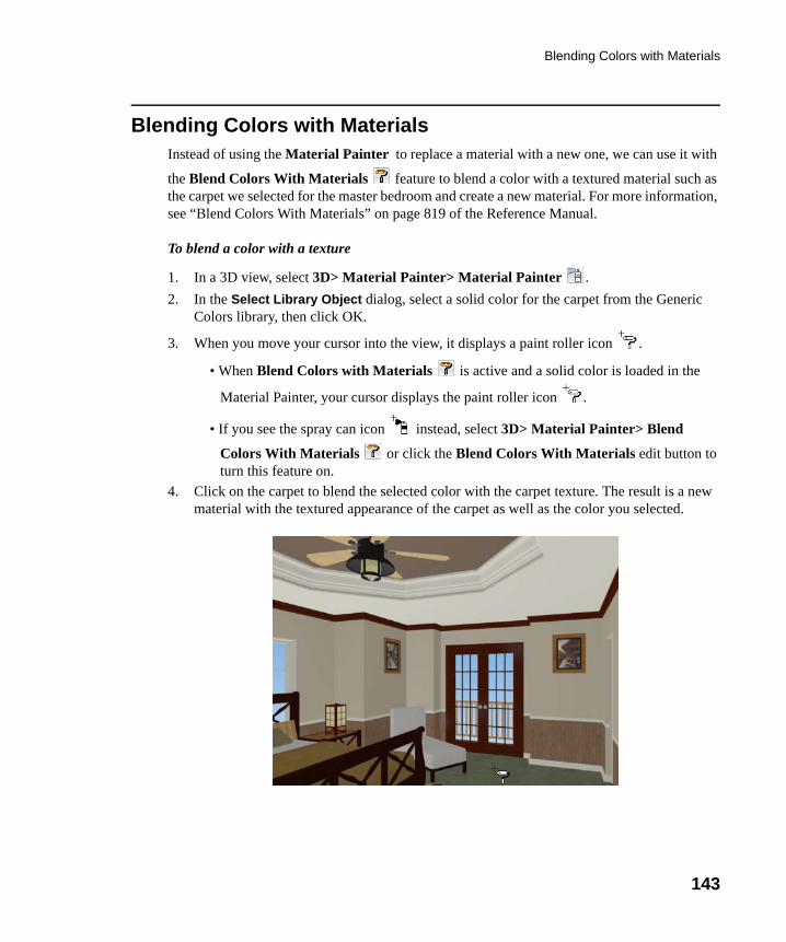
Blending Colors with Materials
143
Blending Colors with MaterialsInstead of using the Material Painter to replace a material with a new one, we can use it with
the Blend Colors With Materials feature to blend a color with a textured material such as the carpet we selected for the master bedroom and create a new material. For more information, see “Blend Colors With Materials” on page 819 of the Reference Manual.
To blend a color with a texture
1. In a 3D view, select 3D> Material Painter> Material Painter .
2. In the Select Library Object dialog, select a solid color for the carpet from the Generic Colors library, then click OK.
3. When you move your cursor into the view, it displays a paint roller icon .
• When Blend Colors with Materials is active and a solid color is loaded in the
Material Painter, your cursor displays the paint roller icon .
• If you see the spray can icon instead, select 3D> Material Painter> Blend
Colors With Materials or click the Blend Colors With Materials edit button to turn this feature on.
4. Click on the carpet to blend the selected color with the carpet texture. The result is a new material with the textured appearance of the carpet as well as the color you selected.
chief-architect-x6-users-guide.book Page 143 Monday, December 16, 2013 4:05 PM
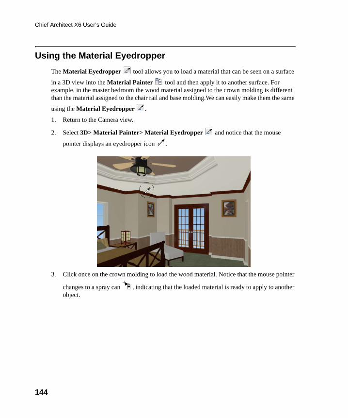
144
Chief Architect X6 User’s Guide
Using the Material Eyedropper
The Material Eyedropper tool allows you to load a material that can be seen on a surface
in a 3D view into the Material Painter tool and then apply it to another surface. For example, in the master bedroom the wood material assigned to the crown molding is different than the material assigned to the chair rail and base molding.We can easily make them the same
using the Material Eyedropper .
1. Return to the Camera view.
2. Select 3D> Material Painter> Material Eyedropper and notice that the mouse
pointer displays an eyedropper icon .
3. Click once on the crown molding to load the wood material. Notice that the mouse pointer
changes to a spray can , indicating that the loaded material is ready to apply to another object.
chief-architect-x6-users-guide.book Page 144 Monday, December 16, 2013 4:05 PM
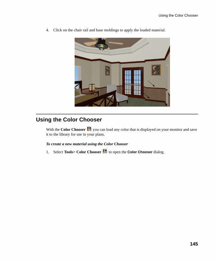
Using the Color Chooser
145
4. Click on the chair rail and base moldings to apply the loaded material.
Using the Color Chooser
With the Color Chooser you can load any color that is displayed on your monitor and save it to the library for use in your plans.
To create a new material using the Color Chooser
1. Select Tools> Color Chooser to open the Color Chooser dialog.
chief-architect-x6-users-guide.book Page 145 Monday, December 16, 2013 4:05 PM
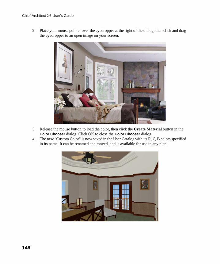
146
Chief Architect X6 User’s Guide
2. Place your mouse pointer over the eyedropper at the right of the dialog, then click and drag the eyedropper to an open image on your screen.
3. Release the mouse button to load the color, then click the Create Material button in the Color Chooser dialog. Click OK to close the Color Chooser dialog.
4. The new "Custom Color" is now saved in the User Catalog with its R, G, B colors specified in its name. It can be renamed and moved, and is available for use in any plan.
chief-architect-x6-users-guide.book Page 146 Monday, December 16, 2013 4:05 PM
Custom Materials, Images, and Backdrops
147
Custom Materials, Images, and BackdropsChief Architect allows you to customize your 3D views by importing your own materials, image objects, and backdrops that display in 3D views. For more information about images, see “Pictures, Images, and Walkthroughs” on page 1081 of the Reference Manual.
Creating Materials
Materials are special digital images that can be applied to the surfaces of objects. You can create your own custom materials and save them in the library. Bear in mind that materials typically cover a surface by tiling an image repeatedly and are specially edited so that they tile seamlessly: as a result, not all images will necessarily serve as effective materials.
Once a material is saved in the library, it can be applied to objects in any plan, either using the objects’ specification dialogs or the Material Painter tool.
To add a new material to the library
1. Select Library> Library Browser (or press Ctrl + L) to open the Library Browser.
2. Right-click on the User Catalog ‘folder and select New> Material from the contextual menu to open the Define Material dialog.
Note: The following steps make use of image files that are notincluded with the program. You can use image files that are alreadyon your computer or you can create new ones. You can even usethe same image file to create a material, an image, and a backdrop.Learning the tools and techniques described is more important thanthe appearance of the final product.
chief-architect-x6-users-guide.book Page 147 Monday, December 16, 2013 4:05 PM
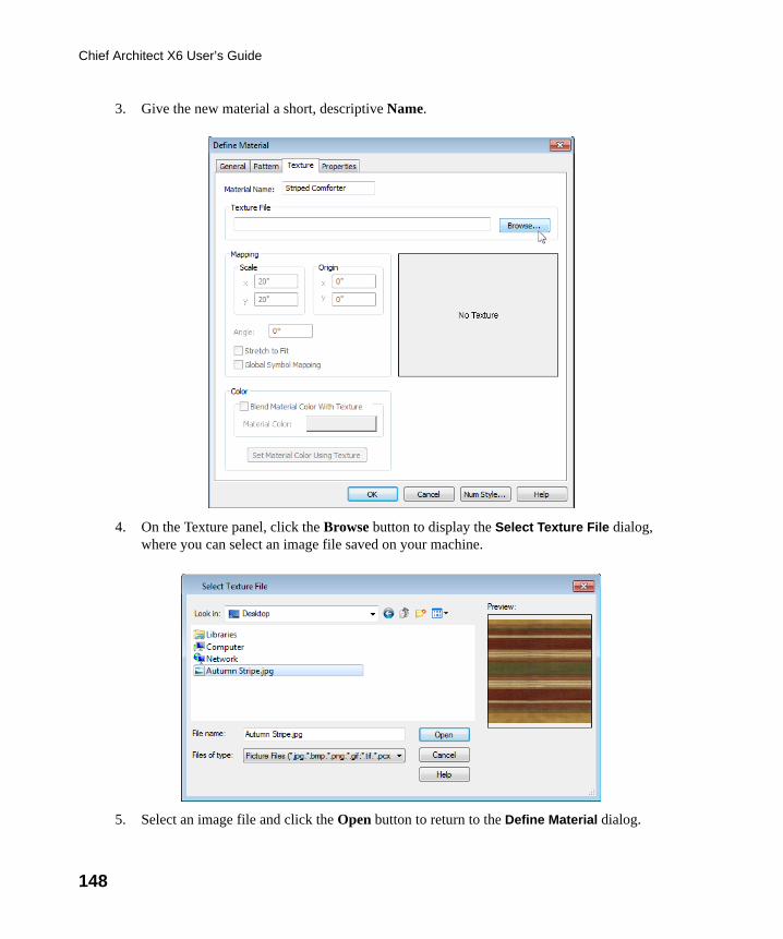
148
Chief Architect X6 User’s Guide
3. Give the new material a short, descriptive Name.
4. On the Texture panel, click the Browse button to display the Select Texture File dialog, where you can select an image file saved on your machine.
5. Select an image file and click the Open button to return to the Define Material dialog.
chief-architect-x6-users-guide.book Page 148 Monday, December 16, 2013 4:05 PM
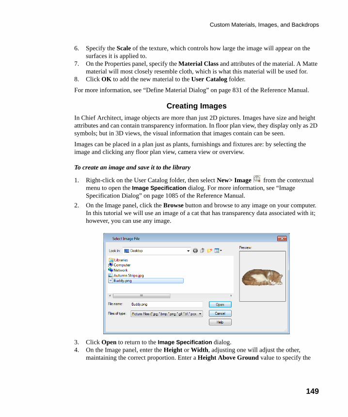
Custom Materials, Images, and Backdrops
149
6. Specify the Scale of the texture, which controls how large the image will appear on the surfaces it is applied to.
7. On the Properties panel, specify the Material Class and attributes of the material. A Matte material will most closely resemble cloth, which is what this material will be used for.
8. Click OK to add the new material to the User Catalog folder.
For more information, see “Define Material Dialog” on page 831 of the Reference Manual.
Creating Images
In Chief Architect, image objects are more than just 2D pictures. Images have size and height attributes and can contain transparency information. In floor plan view, they display only as 2D symbols; but in 3D views, the visual information that images contain can be seen.
Images can be placed in a plan just as plants, furnishings and fixtures are: by selecting the image and clicking any floor plan view, camera view or overview.
To create an image and save it to the library
1. Right-click on the User Catalog folder, then select New> Image from the contextual menu to open the Image Specification dialog. For more information, see “Image Specification Dialog” on page 1085 of the Reference Manual.
2. On the Image panel, click the Browse button and browse to any image on your computer. In this tutorial we will use an image of a cat that has transparency data associated with it; however, you can use any image.
3. Click Open to return to the Image Specification dialog.4. On the Image panel, enter the Height or Width, adjusting one will adjust the other,
maintaining the correct proportion. Enter a Height Above Ground value to specify the
chief-architect-x6-users-guide.book Page 149 Monday, December 16, 2013 4:05 PM
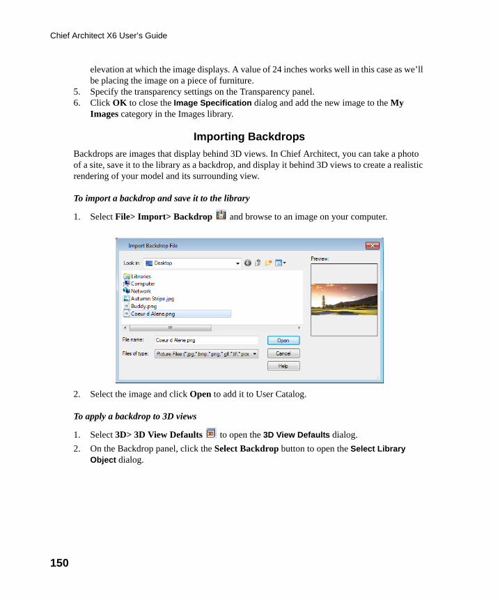
150
Chief Architect X6 User’s Guide
elevation at which the image displays. A value of 24 inches works well in this case as we’ll be placing the image on a piece of furniture.
5. Specify the transparency settings on the Transparency panel. 6. Click OK to close the Image Specification dialog and add the new image to the My
Images category in the Images library.
Importing Backdrops
Backdrops are images that display behind 3D views. In Chief Architect, you can take a photo of a site, save it to the library as a backdrop, and display it behind 3D views to create a realistic rendering of your model and its surrounding view.
To import a backdrop and save it to the library
1. Select File> Import> Backdrop and browse to an image on your computer.
2. Select the image and click Open to add it to User Catalog.
To apply a backdrop to 3D views
1. Select 3D> 3D View Defaults to open the 3D View Defaults dialog.
2. On the Backdrop panel, click the Select Backdrop button to open the Select Library Object dialog.
chief-architect-x6-users-guide.book Page 150 Monday, December 16, 2013 4:05 PM
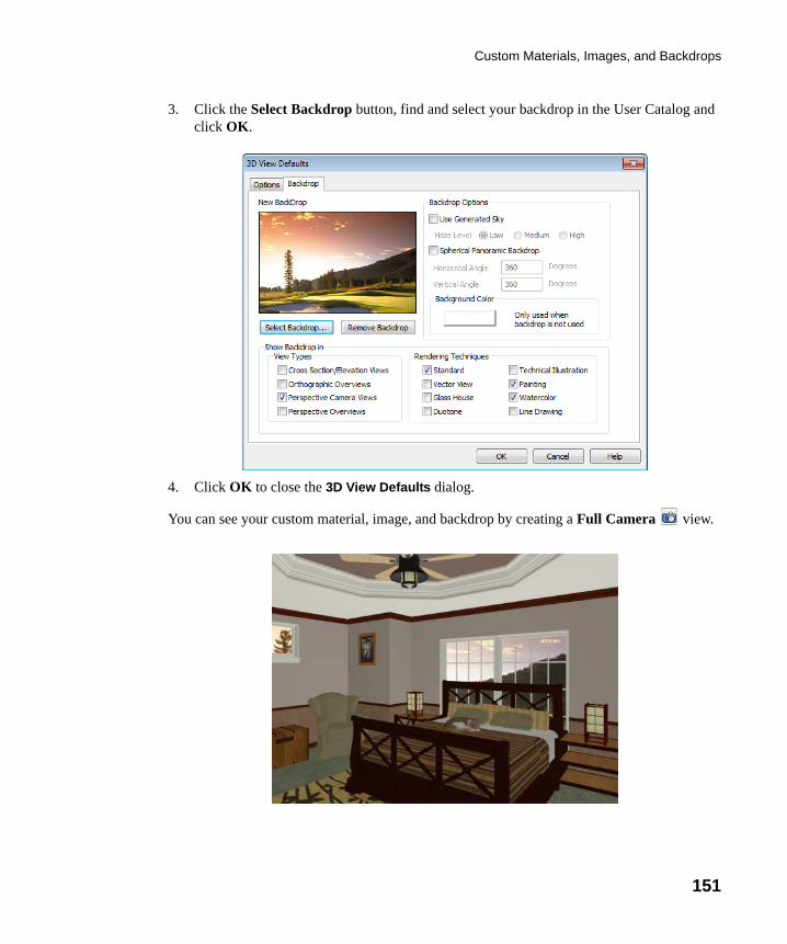
Custom Materials, Images, and Backdrops
151
3. Click the Select Backdrop button, find and select your backdrop in the User Catalog and click OK.
4. Click OK to close the 3D View Defaults dialog.
You can see your custom material, image, and backdrop by creating a Full Camera view.
chief-architect-x6-users-guide.book Page 151 Monday, December 16, 2013 4:05 PM
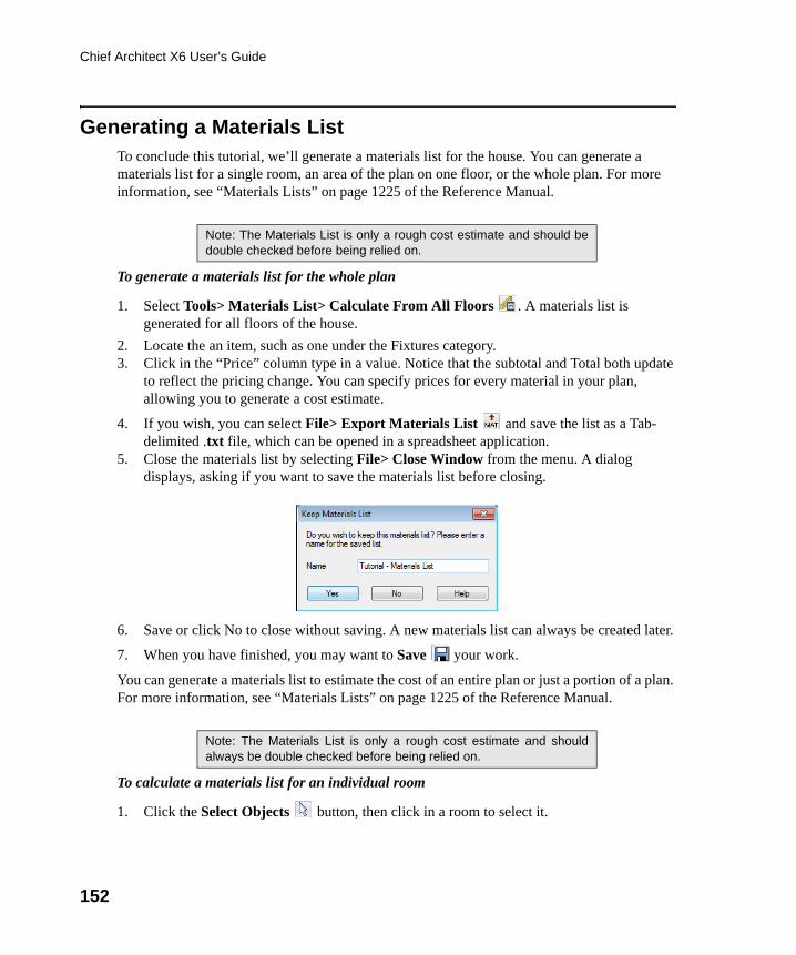
152
Chief Architect X6 User’s Guide
Generating a Materials ListTo conclude this tutorial, we’ll generate a materials list for the house. You can generate a materials list for a single room, an area of the plan on one floor, or the whole plan. For more information, see “Materials Lists” on page 1225 of the Reference Manual.
To generate a materials list for the whole plan
1. Select Tools> Materials List> Calculate From All Floors . A materials list is generated for all floors of the house.
2. Locate the an item, such as one under the Fixtures category. 3. Click in the “Price” column type in a value. Notice that the subtotal and Total both update
to reflect the pricing change. You can specify prices for every material in your plan, allowing you to generate a cost estimate.
4. If you wish, you can select File> Export Materials List and save the list as a Tab-delimited .txt file, which can be opened in a spreadsheet application.
5. Close the materials list by selecting File> Close Window from the menu. A dialog displays, asking if you want to save the materials list before closing.
6. Save or click No to close without saving. A new materials list can always be created later.
7. When you have finished, you may want to Save your work.
You can generate a materials list to estimate the cost of an entire plan or just a portion of a plan. For more information, see “Materials Lists” on page 1225 of the Reference Manual.
To calculate a materials list for an individual room
1. Click the Select Objects button, then click in a room to select it.
Note: The Materials List is only a rough cost estimate and should bedouble checked before being relied on.
Note: The Materials List is only a rough cost estimate and shouldalways be double checked before being relied on.
chief-architect-x6-users-guide.book Page 152 Monday, December 16, 2013 4:05 PM
Generating a Materials List
153
2. With the room selected, click the Calculate from Room edit button or select Tools>
Materials List> Calculate from Room . The program calculates a list of the objects and materials contained in the selected room.
To calculate a materials list for just the deck
1. In floor plan view, select Tools> Materials List> Calculate from Area .2. Click and drag a rectangle surrounding the an area to display a materials list for the area
within the rectangle. The resulting materials list only includes objects and materials located within the rectangle.
chief-architect-x6-users-guide.book Page 153 Monday, December 16, 2013 4:05 PM

154
Chief Architect X6 User’s Guide
chief-architect-x6-users-guide.book Page 154 Monday, December 16, 2013 4:05 PM
155
Chapter 7:
Landscaping Tutorial
This tutorial was written to help you learn how to use Chief Architect’s Terrain tools. In this tutorial, you will learn how to add elevation information to your terrain, how to create terrain features, and how to add plants and other objects from the library.
It is a good idea to become familiar with the terrain tools before beginning your own terrain project.
In this tutorial, you will learn about:
• Creating a Terrain Perimeter• Creating a Walkout Basement• Creating a Retaining Wall
• Adding a Driveway• Adding Library Objects to Your Plan
This tutorial continues from where the House Design Tutorial left off, so you may want to save this plan using a new name to archive your previous work.
chief-architect-x6-users-guide.book Page 155 Monday, December 16, 2013 4:05 PM
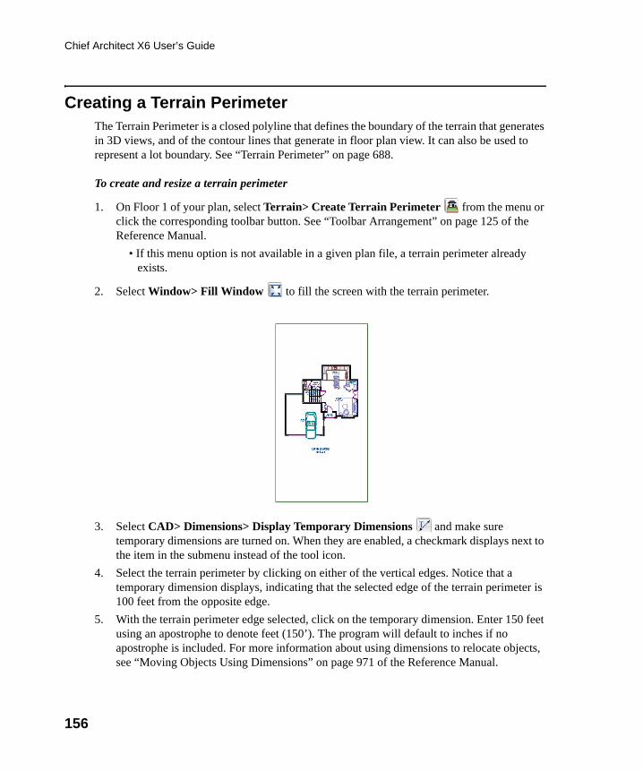
156
Chief Architect X6 User’s Guide
Creating a Terrain PerimeterThe Terrain Perimeter is a closed polyline that defines the boundary of the terrain that generates in 3D views, and of the contour lines that generate in floor plan view. It can also be used to represent a lot boundary. See “Terrain Perimeter” on page 688.
To create and resize a terrain perimeter
1. On Floor 1 of your plan, select Terrain> Create Terrain Perimeter from the menu or click the corresponding toolbar button. See “Toolbar Arrangement” on page 125 of the Reference Manual.
• If this menu option is not available in a given plan file, a terrain perimeter already exists.
2. Select Window> Fill Window to fill the screen with the terrain perimeter.
3. Select CAD> Dimensions> Display Temporary Dimensions and make sure temporary dimensions are turned on. When they are enabled, a checkmark displays next to the item in the submenu instead of the tool icon.
4. Select the terrain perimeter by clicking on either of the vertical edges. Notice that a temporary dimension displays, indicating that the selected edge of the terrain perimeter is 100 feet from the opposite edge.
5. With the terrain perimeter edge selected, click on the temporary dimension. Enter 150 feet using an apostrophe to denote feet (150’). The program will default to inches if no apostrophe is included. For more information about using dimensions to relocate objects, see “Moving Objects Using Dimensions” on page 971 of the Reference Manual.
chief-architect-x6-users-guide.book Page 156 Monday, December 16, 2013 4:05 PM
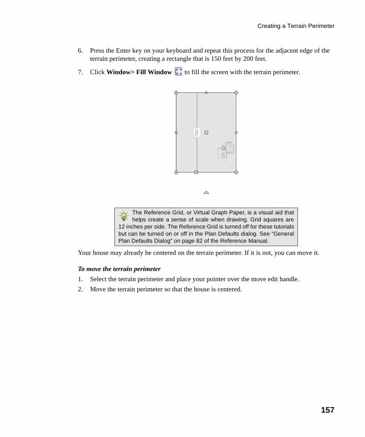
Creating a Terrain Perimeter
157
6. Press the Enter key on your keyboard and repeat this process for the adjacent edge of the terrain perimeter, creating a rectangle that is 150 feet by 200 feet.
7. Click Window> Fill Window to fill the screen with the terrain perimeter.
Your house may already be centered on the terrain perimeter. If it is not, you can move it.
To move the terrain perimeter
1. Select the terrain perimeter and place your pointer over the move edit handle.
2. Move the terrain perimeter so that the house is centered.
The Reference Grid, or Virtual Graph Paper, is a visual aid thathelps create a sense of scale when drawing. Grid squares are
12 inches per side. The Reference Grid is turned off for these tutorialsbut can be turned on or off in the Plan Defaults dialog. See “GeneralPlan Defaults Dialog” on page 82 of the Reference Manual.
chief-architect-x6-users-guide.book Page 157 Monday, December 16, 2013 4:05 PM
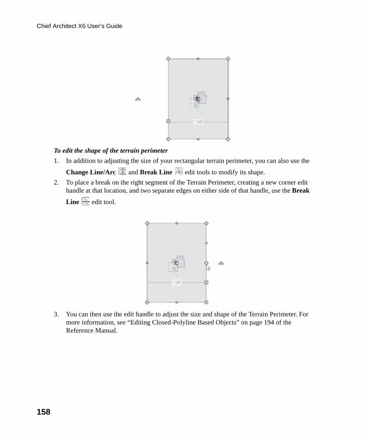
158
Chief Architect X6 User’s Guide
To edit the shape of the terrain perimeter
1. In addition to adjusting the size of your rectangular terrain perimeter, you can also use the
Change Line/Arc and Break Line edit tools to modify its shape.
2. To place a break on the right segment of the Terrain Perimeter, creating a new corner edit handle at that location, and two separate edges on either side of that handle, use the Break
Line edit tool.
3. You can then use the edit handle to adjust the size and shape of the Terrain Perimeter. For more information, see “Editing Closed-Polyline Based Objects” on page 194 of the Reference Manual.
chief-architect-x6-users-guide.book Page 158 Monday, December 16, 2013 4:05 PM
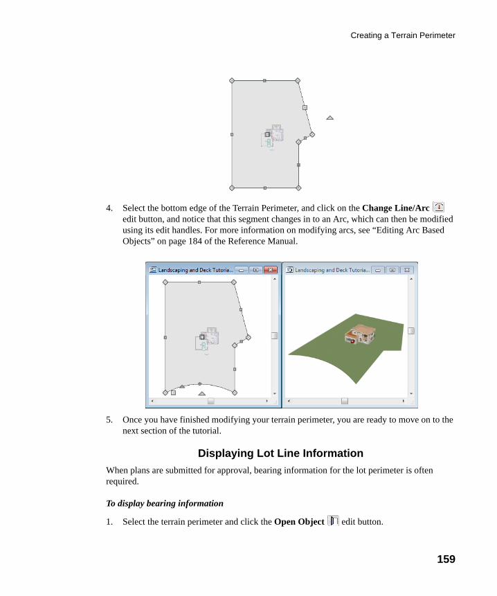
Creating a Terrain Perimeter
159
4. Select the bottom edge of the Terrain Perimeter, and click on the Change Line/Arc edit button, and notice that this segment changes in to an Arc, which can then be modified using its edit handles. For more information on modifying arcs, see “Editing Arc Based Objects” on page 184 of the Reference Manual.
5. Once you have finished modifying your terrain perimeter, you are ready to move on to the next section of the tutorial.
Displaying Lot Line Information
When plans are submitted for approval, bearing information for the lot perimeter is often required.
To display bearing information
1. Select the terrain perimeter and click the Open Object edit button.
chief-architect-x6-users-guide.book Page 159 Monday, December 16, 2013 4:05 PM
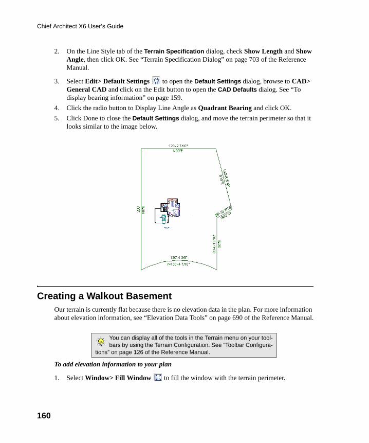
160
Chief Architect X6 User’s Guide
2. On the Line Style tab of the Terrain Specification dialog, check Show Length and Show Angle, then click OK. See “Terrain Specification Dialog” on page 703 of the Reference Manual.
3. Select Edit> Default Settings to open the Default Settings dialog, browse to CAD> General CAD and click on the Edit button to open the CAD Defaults dialog. See “To display bearing information” on page 159.
4. Click the radio button to Display Line Angle as Quadrant Bearing and click OK.
5. Click Done to close the Default Settings dialog, and move the terrain perimeter so that it looks similar to the image below.
Creating a Walkout BasementOur terrain is currently flat because there is no elevation data in the plan. For more information about elevation information, see “Elevation Data Tools” on page 690 of the Reference Manual.
To add elevation information to your plan
1. Select Window> Fill Window to fill the window with the terrain perimeter.
You can display all of the tools in the Terrain menu on your tool-bars by using the Terrain Configuration. See “Toolbar Configura-
tions” on page 126 of the Reference Manual.
chief-architect-x6-users-guide.book Page 160 Monday, December 16, 2013 4:05 PM
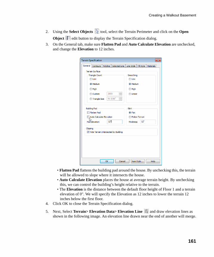
Creating a Walkout Basement
161
2. Using the Select Objects tool, select the Terrain Perimeter and click on the Open
Object edit button to display the Terrain Specification dialog.
3. On the General tab, make sure Flatten Pad and Auto Calculate Elevation are unchecked, and change the Elevation to 12 inches.
• Flatten Pad flattens the building pad around the house. By unchecking this, the terrain will be allowed to slope where it intersects the house.
• Auto Calculate Elevation places the house at average terrain height. By unchecking this, we can control the building’s height relative to the terrain.
• The Elevation is the distance between the default floor height of Floor 1 and a terrain elevation of 0". We will specify the Elevation as 12 inches to lower the terrain 12 inches below the first floor.
4. Click OK to close the Terrain Specification dialog.
5. Next, Select Terrain> Elevation Data> Elevation Line and draw elevation lines as shown in the following image. An elevation line drawn near the end of another will merge.
chief-architect-x6-users-guide.book Page 161 Monday, December 16, 2013 4:05 PM
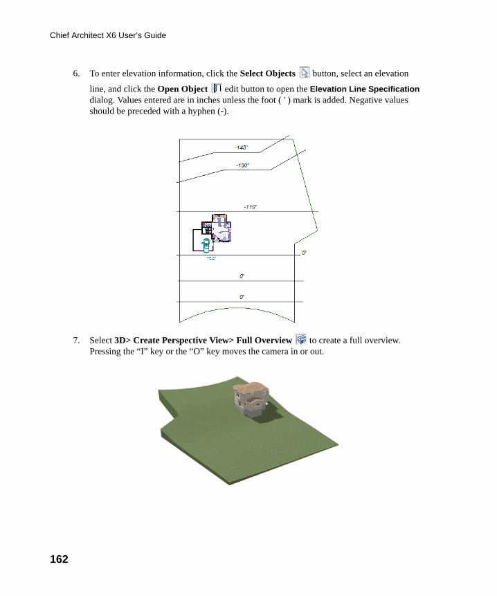
162
Chief Architect X6 User’s Guide
6. To enter elevation information, click the Select Objects button, select an elevation
line, and click the Open Object edit button to open the Elevation Line Specification dialog. Values entered are in inches unless the foot ( ' ) mark is added. Negative values should be preceded with a hyphen (-).
7. Select 3D> Create Perspective View> Full Overview to create a full overview. Pressing the “I” key or the “O” key moves the camera in or out.
chief-architect-x6-users-guide.book Page 162 Monday, December 16, 2013 4:05 PM
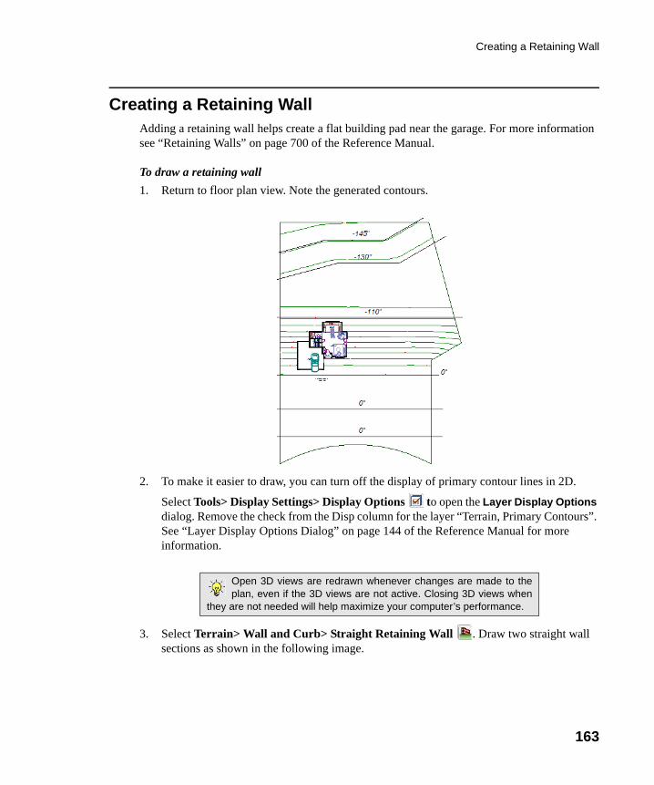
Creating a Retaining Wall
163
Creating a Retaining WallAdding a retaining wall helps create a flat building pad near the garage. For more information see “Retaining Walls” on page 700 of the Reference Manual.
To draw a retaining wall
1. Return to floor plan view. Note the generated contours.
2. To make it easier to draw, you can turn off the display of primary contour lines in 2D.
Select Tools> Display Settings> Display Options to open the Layer Display Options dialog. Remove the check from the Disp column for the layer “Terrain, Primary Contours”. See “Layer Display Options Dialog” on page 144 of the Reference Manual for more information.
3. Select Terrain> Wall and Curb> Straight Retaining Wall . Draw two straight wall sections as shown in the following image.
Open 3D views are redrawn whenever changes are made to theplan, even if the 3D views are not active. Closing 3D views when
they are not needed will help maximize your computer’s performance.
chief-architect-x6-users-guide.book Page 163 Monday, December 16, 2013 4:05 PM
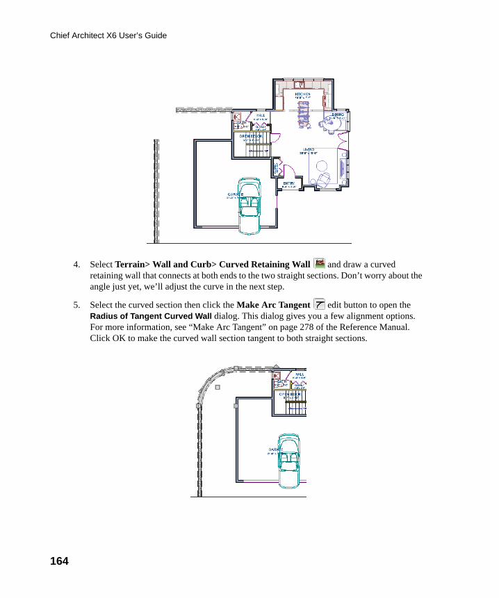
164
Chief Architect X6 User’s Guide
4. Select Terrain> Wall and Curb> Curved Retaining Wall and draw a curved retaining wall that connects at both ends to the two straight sections. Don’t worry about the angle just yet, we’ll adjust the curve in the next step.
5. Select the curved section then click the Make Arc Tangent edit button to open the Radius of Tangent Curved Wall dialog. This dialog gives you a few alignment options. For more information, see “Make Arc Tangent” on page 278 of the Reference Manual. Click OK to make the curved wall section tangent to both straight sections.
chief-architect-x6-users-guide.book Page 164 Monday, December 16, 2013 4:05 PM
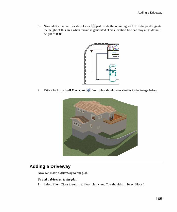
Adding a Driveway
165
6. Now add two more Elevation Lines just inside the retaining wall. This helps designate the height of this area when terrain is generated. This elevation line can stay at its default height of 0' 0”.
7. Take a look in a Full Overview . Your plan should look similar to the image below.
Adding a DrivewayNow we’ll add a driveway to our plan.
To add a driveway to the plan
1. Select File> Close to return to floor plan view. You should still be on Floor 1.
chief-architect-x6-users-guide.book Page 165 Monday, December 16, 2013 4:05 PM
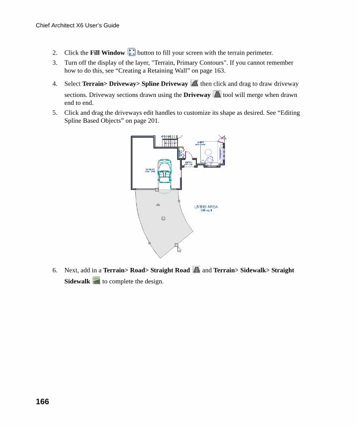
166
Chief Architect X6 User’s Guide
2. Click the Fill Window button to fill your screen with the terrain perimeter.
3. Turn off the display of the layer, "Terrain, Primary Contours". If you cannot remember how to do this, see “Creating a Retaining Wall” on page 163.
4. Select Terrain> Driveway> Spline Driveway then click and drag to draw driveway
sections. Driveway sections drawn using the Driveway tool will merge when drawn end to end.
5. Click and drag the driveways edit handles to customize its shape as desired. See “Editing Spline Based Objects” on page 201.
6. Next, add in a Terrain> Road> Straight Road and Terrain> Sidewalk> Straight
Sidewalk to complete the design.
chief-architect-x6-users-guide.book Page 166 Monday, December 16, 2013 4:05 PM
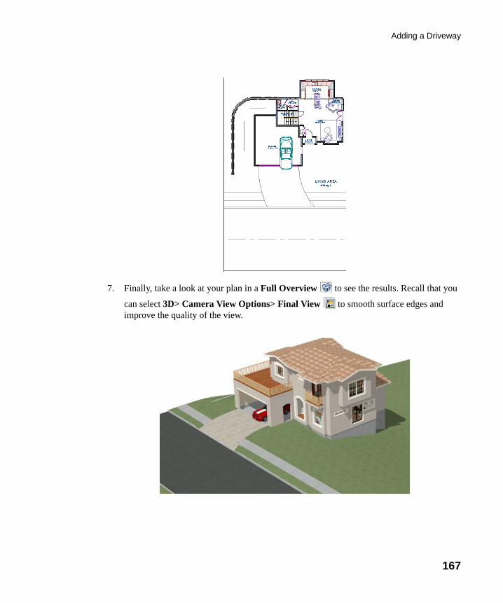
Adding a Driveway
167
7. Finally, take a look at your plan in a Full Overview to see the results. Recall that you
can select 3D> Camera View Options> Final View to smooth surface edges and improve the quality of the view.
chief-architect-x6-users-guide.book Page 167 Monday, December 16, 2013 4:05 PM
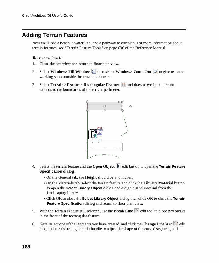
168
Chief Architect X6 User’s Guide
Adding Terrain FeaturesNow we’ll add a beach, a water line, and a pathway to our plan. For more information about terrain features, see “Terrain Feature Tools” on page 696 of the Reference Manual.
To create a beach
1. Close the overview and return to floor plan view.
2. Select Window> Fill Window then select Window> Zoom Out to give us some working space outside the terrain perimeter.
3. Select Terrain> Feature> Rectangular Feature and draw a terrain feature that extends to the boundaries of the terrain perimeter.
4. Select the terrain feature and the Open Object edit button to open the Terrain Feature Specification dialog.
• On the General tab, the Height should be at 0 inches.
• On the Materials tab, select the terrain feature and click the Library Material button to open the Select Library Object dialog and assign a sand material from the landscaping library.
• Click OK to close the Select Library Object dialog then click OK to close the Terrain Feature Specification dialog and return to floor plan view.
5. With the Terrain Feature still selected, use the Break Line edit tool to place two breaks in the front of the rectangular feature.
6. Next, select one of the segments you have created, and click the Change Line/Arc edit tool, and use the triangular edit handle to adjust the shape of the curved segment, and
chief-architect-x6-users-guide.book Page 168 Monday, December 16, 2013 4:05 PM
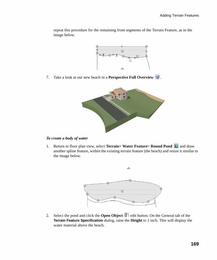
Adding Terrain Features
169
repeat this procedure for the remaining front segments of the Terrain Feature, as in the image below.
7. Take a look at our new beach in a Perspective Full Overview .
To create a body of water
1. Return to floor plan view, select Terrain> Water Feature> Round Pond and draw another spline feature, within the existing terrain feature (the beach) and resize it similar to the image below.
2. Select the pond and click the Open Object edit button. On the General tab of the Terrain Feature Specification dialog, raise the Height to 1 inch. This will display the water material above the beach.
chief-architect-x6-users-guide.book Page 169 Monday, December 16, 2013 4:05 PM
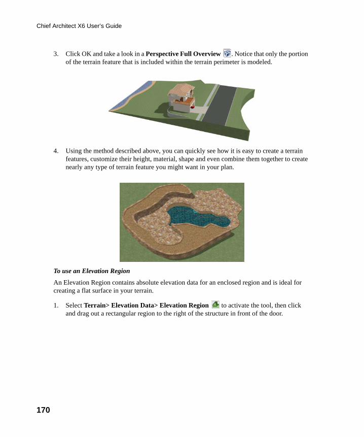
170
Chief Architect X6 User’s Guide
3. Click OK and take a look in a Perspective Full Overview . Notice that only the portion of the terrain feature that is included within the terrain perimeter is modeled.
4. Using the method described above, you can quickly see how it is easy to create a terrain features, customize their height, material, shape and even combine them together to create nearly any type of terrain feature you might want in your plan.
To use an Elevation Region
An Elevation Region contains absolute elevation data for an enclosed region and is ideal for creating a flat surface in your terrain.
1. Select Terrain> Elevation Data> Elevation Region to activate the tool, then click and drag out a rectangular region to the right of the structure in front of the door.
chief-architect-x6-users-guide.book Page 170 Monday, December 16, 2013 4:05 PM
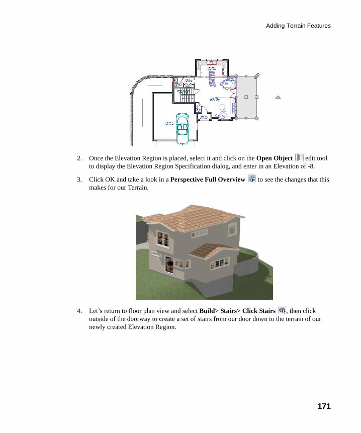
Adding Terrain Features
171
2. Once the Elevation Region is placed, select it and click on the Open Object edit tool to display the Elevation Region Specification dialog, and enter in an Elevation of -8.
3. Click OK and take a look in a Perspective Full Overview to see the changes that this makes for our Terrain.
4. Let’s return to floor plan view and select Build> Stairs> Click Stairs , then click outside of the doorway to create a set of stairs from our door down to the terrain of our newly created Elevation Region.
chief-architect-x6-users-guide.book Page 171 Monday, December 16, 2013 4:05 PM
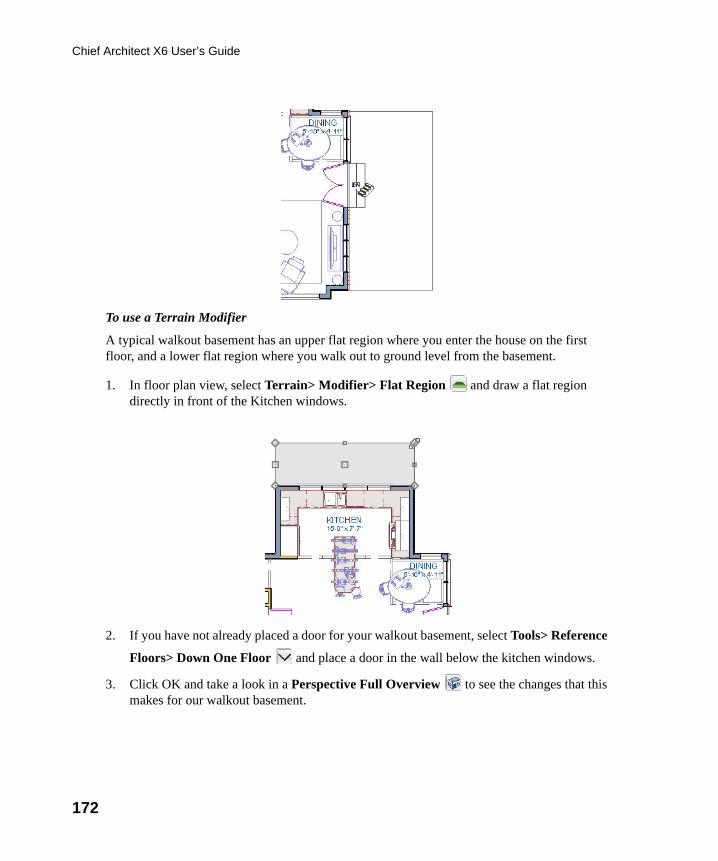
172
Chief Architect X6 User’s Guide
To use a Terrain Modifier
A typical walkout basement has an upper flat region where you enter the house on the first floor, and a lower flat region where you walk out to ground level from the basement.
1. In floor plan view, select Terrain> Modifier> Flat Region and draw a flat region directly in front of the Kitchen windows.
2. If you have not already placed a door for your walkout basement, select Tools> Reference
Floors> Down One Floor and place a door in the wall below the kitchen windows.
3. Click OK and take a look in a Perspective Full Overview to see the changes that this makes for our walkout basement.
chief-architect-x6-users-guide.book Page 172 Monday, December 16, 2013 4:05 PM
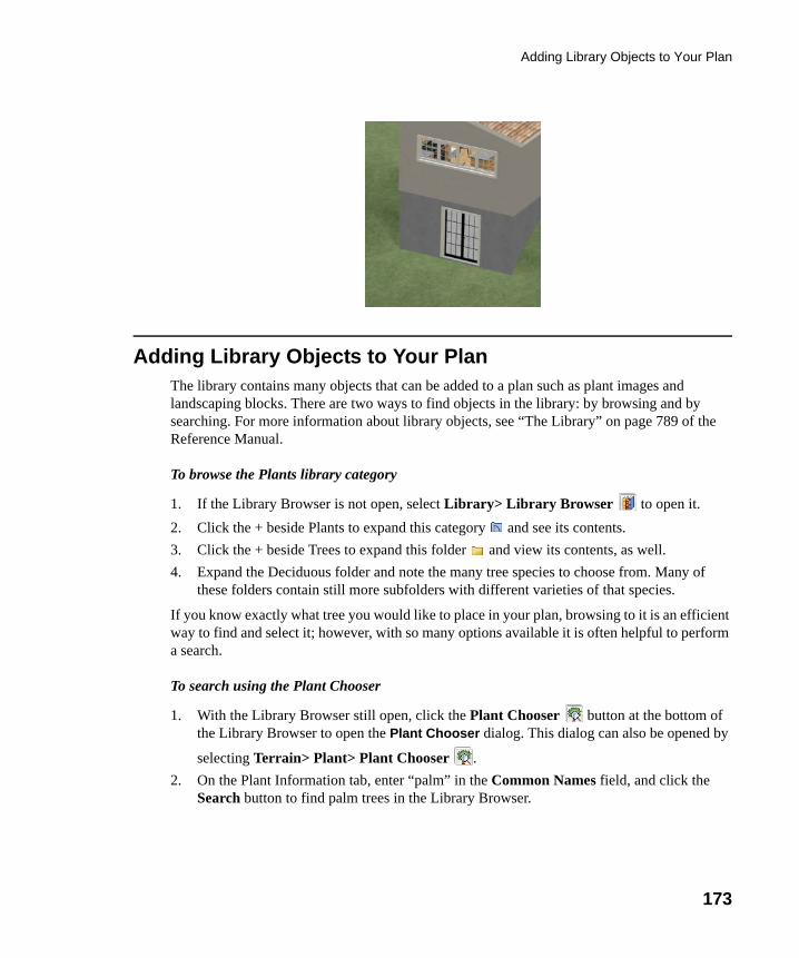
Adding Library Objects to Your Plan
173
Adding Library Objects to Your PlanThe library contains many objects that can be added to a plan such as plant images and landscaping blocks. There are two ways to find objects in the library: by browsing and by searching. For more information about library objects, see “The Library” on page 789 of the Reference Manual.
To browse the Plants library category
1. If the Library Browser is not open, select Library> Library Browser to open it.
2. Click the + beside Plants to expand this category and see its contents.
3. Click the + beside Trees to expand this folder and view its contents, as well.
4. Expand the Deciduous folder and note the many tree species to choose from. Many of these folders contain still more subfolders with different varieties of that species.
If you know exactly what tree you would like to place in your plan, browsing to it is an efficient way to find and select it; however, with so many options available it is often helpful to perform a search.
To search using the Plant Chooser
1. With the Library Browser still open, click the Plant Chooser button at the bottom of the Library Browser to open the Plant Chooser dialog. This dialog can also be opened by
selecting Terrain> Plant> Plant Chooser .
2. On the Plant Information tab, enter “palm” in the Common Names field, and click the Search button to find palm trees in the Library Browser.
chief-architect-x6-users-guide.book Page 173 Monday, December 16, 2013 4:05 PM
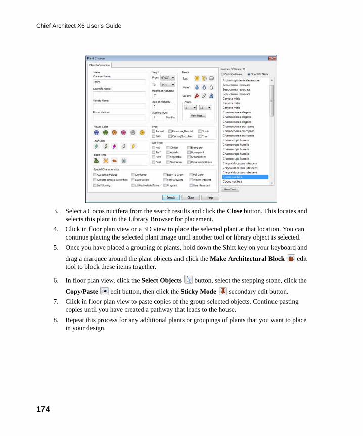
174
Chief Architect X6 User’s Guide
3. Select a Cocos nucifera from the search results and click the Close button. This locates and selects this plant in the Library Browser for placement.
4. Click in floor plan view or a 3D view to place the selected plant at that location. You can continue placing the selected plant image until another tool or library object is selected.
5. Once you have placed a grouping of plants, hold down the Shift key on your keyboard and
drag a marquee around the plant objects and click the Make Architectural Block edit tool to block these items together.
6. In floor plan view, click the Select Objects button, select the stepping stone, click the
Copy/Paste edit button, then click the Sticky Mode secondary edit button.
7. Click in floor plan view to paste copies of the group selected objects. Continue pasting copies until you have created a pathway that leads to the house.
8. Repeat this process for any additional plants or groupings of plants that you want to place in your design.
chief-architect-x6-users-guide.book Page 174 Monday, December 16, 2013 4:05 PM
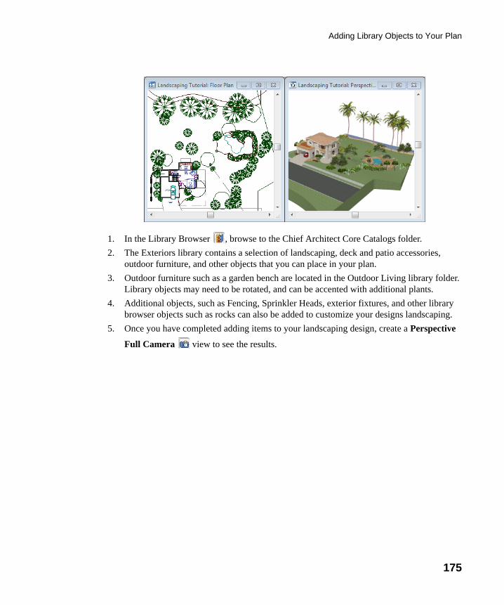
Adding Library Objects to Your Plan
175
1. In the Library Browser , browse to the Chief Architect Core Catalogs folder.
2. The Exteriors library contains a selection of landscaping, deck and patio accessories, outdoor furniture, and other objects that you can place in your plan.
3. Outdoor furniture such as a garden bench are located in the Outdoor Living library folder. Library objects may need to be rotated, and can be accented with additional plants.
4. Additional objects, such as Fencing, Sprinkler Heads, exterior fixtures, and other library browser objects such as rocks can also be added to customize your designs landscaping.
5. Once you have completed adding items to your landscaping design, create a Perspective
Full Camera view to see the results.
chief-architect-x6-users-guide.book Page 175 Monday, December 16, 2013 4:05 PM
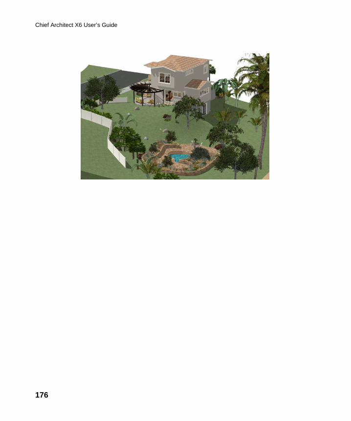
176
Chief Architect X6 User’s Guide
chief-architect-x6-users-guide.book Page 176 Monday, December 16, 2013 4:05 PM
177
Chapter 8:
Deck Tutorial
Now we’ll continue where the Landscaping Tutorial left off and create a deck off the back of the house, connecting it to the terrain with an exterior staircase. You may want to save this tutorial using a new name to archive your previous work.
In this tutorial you will learn about:
• Decks and Porches• Drawing Decks• Drawing Stairs
• Changing Planking Orientation• Adding Exterior Furniture
Decks and PorchesDecks and porches are exterior rooms that are defined by the deck railings and exterior walls
that enclose them. When an exterior room is drawn using the Deck Railing tool, the room is automatically assigned the exterior room type Deck.
Railings and Deck Railings are drawn just like walls. To illustrate this, we’ll add a deck behind the kitchen area. For more information see “Fencing Tools” on page 257 of the Reference Manual.
chief-architect-x6-users-guide.book Page 177 Monday, December 16, 2013 4:05 PM
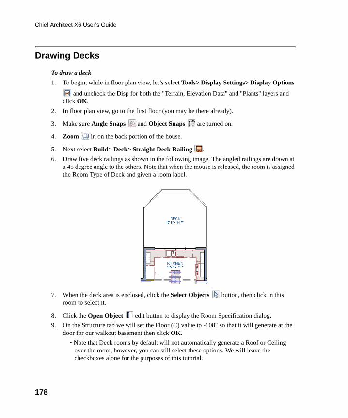
178
Chief Architect X6 User’s Guide
Drawing Decks
To draw a deck
1. To begin, while in floor plan view, let’s select Tools> Display Settings> Display Options
and uncheck the Disp for both the "Terrain, Elevation Data" and "Plants" layers and click OK.
2. In floor plan view, go to the first floor (you may be there already).
3. Make sure Angle Snaps and Object Snaps are turned on.
4. Zoom in on the back portion of the house.
5. Next select Build> Deck> Straight Deck Railing .
6. Draw five deck railings as shown in the following image. The angled railings are drawn at a 45 degree angle to the others. Note that when the mouse is released, the room is assigned the Room Type of Deck and given a room label.
7. When the deck area is enclosed, click the Select Objects button, then click in this room to select it.
8. Click the Open Object edit button to display the Room Specification dialog.
9. On the Structure tab we will set the Floor (C) value to -108" so that it will generate at the door for our walkout basement then click OK.
• Note that Deck rooms by default will not automatically generate a Roof or Ceiling over the room, however, you can still select these options. We will leave the checkboxes alone for the purposes of this tutorial.
chief-architect-x6-users-guide.book Page 178 Monday, December 16, 2013 4:05 PM
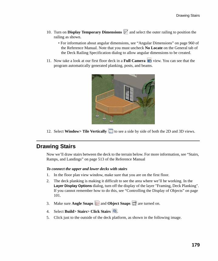
Drawing Stairs
179
10. Turn on Display Temporary Dimensions and select the outer railing to position the railing as shown.
• For information about angular dimensions, see “Angular Dimensions” on page 960 of the Reference Manual. Note that you must uncheck No Locate on the General tab of the Deck Railing Specification dialog to allow angular dimensions to be created.
11. Now take a look at our first floor deck in a Full Camera view. You can see that the program automatically generated planking, posts, and beams.
12. Select Window> Tile Vertically to see a side by side of both the 2D and 3D views.
Drawing StairsNow we’ll draw stairs between the deck to the terrain below. For more information, see “Stairs, Ramps, and Landings” on page 513 of the Reference Manual
To connect the upper and lower decks with stairs
1. In the floor plan view window, make sure that you are on the first floor.
2. The deck planking is making it difficult to see the area where we’ll be working. In the Layer Display Options dialog, turn off the display of the layer "Framing, Deck Planking". If you cannot remember how to do this, see “Controlling the Display of Objects” on page 101.
3. Make sure Angle Snaps and Object Snaps are turned on.
4. Select Build> Stairs> Click Stairs .
5. Click just to the outside of the deck platform, as shown in the following image.
chief-architect-x6-users-guide.book Page 179 Monday, December 16, 2013 4:05 PM
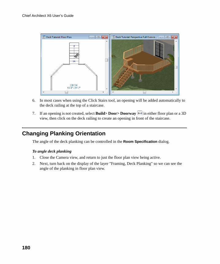
180
Chief Architect X6 User’s Guide
6. In most cases when using the Click Stairs tool, an opening will be added automatically to the deck railing at the top of a staircase.
7. If an opening is not created, select Build> Door> Doorway in either floor plan or a 3D view, then click on the deck railing to create an opening in front of the staircase.
Changing Planking OrientationThe angle of the deck planking can be controlled in the Room Specification dialog.
To angle deck planking
1. Close the Camera view, and return to just the floor plan view being active.
2. Next, turn back on the display of the layer "Framing, Deck Planking" so we can see the angle of the planking in floor plan view.
chief-architect-x6-users-guide.book Page 180 Monday, December 16, 2013 4:05 PM
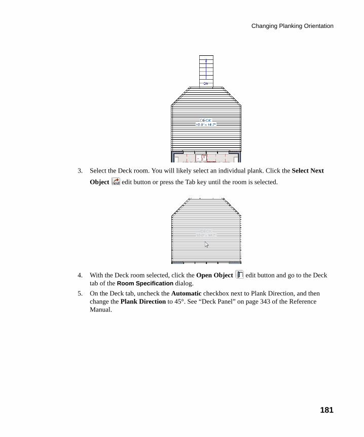
Changing Planking Orientation
181
3. Select the Deck room. You will likely select an individual plank. Click the Select Next
Object edit button or press the Tab key until the room is selected.
4. With the Deck room selected, click the Open Object edit button and go to the Deck tab of the Room Specification dialog.
5. On the Deck tab, uncheck the Automatic checkbox next to Plank Direction, and then change the Plank Direction to 45°. See “Deck Panel” on page 343 of the Reference Manual.
chief-architect-x6-users-guide.book Page 181 Monday, December 16, 2013 4:05 PM
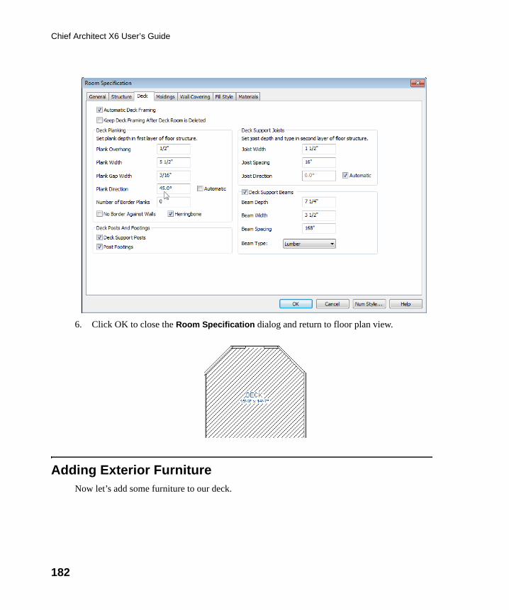
182
Chief Architect X6 User’s Guide
6. Click OK to close the Room Specification dialog and return to floor plan view.
Adding Exterior FurnitureNow let’s add some furniture to our deck.
chief-architect-x6-users-guide.book Page 182 Monday, December 16, 2013 4:05 PM
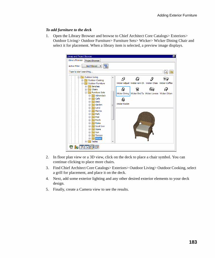
Adding Exterior Furniture
183
To add furniture to the deck
1. Open the Library Browser and browse to Chief Architect Core Catalogs> Exteriors> Outdoor Living> Outdoor Furniture> Furniture Sets> Wicker> Wicker Dining Chair and select it for placement. When a library item is selected, a preview image displays.
2. In floor plan view or a 3D view, click on the deck to place a chair symbol. You can continue clicking to place more chairs.
3. Find Chief Architect Core Catalogs> Exteriors> Outdoor Living> Outdoor Cooking, select a grill for placement, and place it on the deck.
4. Next, add some exterior lighting and any other desired exterior elements to your deck design.
5. Finally, create a Camera view to see the results.
chief-architect-x6-users-guide.book Page 183 Monday, December 16, 2013 4:05 PM
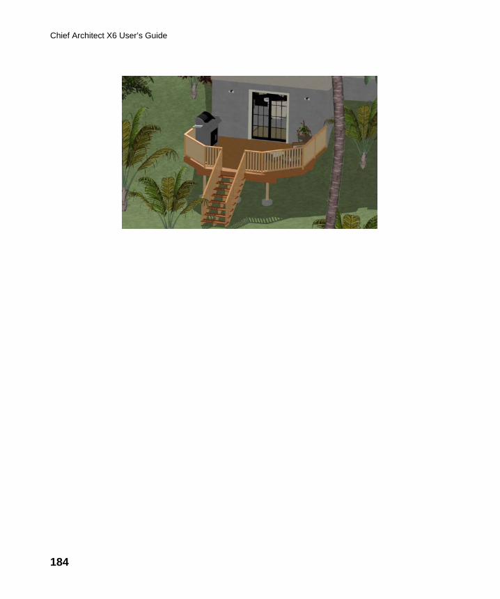
184
Chief Architect X6 User’s Guide
chief-architect-x6-users-guide.book Page 184 Monday, December 16, 2013 4:05 PM
185
Chapter 9:
CAD Tutorial
In this tutorial you’ll learn about:
• CAD Detail Windows• Exploding and Modifying a CAD Block• Creating a New CAD Block
• CAD Detail from View• Creating a Plot Plan
This tutorial continues from where the prior tutorial left off, so you may want to save this plan using a new name to archive your previous work.
CAD Detail WindowsCAD Details are special view windows for drawing, saving, and organizing any 2D drawings associated with the current plan, such as section details, plot plans, and schedules. Like other views, CAD Details are saved with the plan or layout they are created in and can be printed. If a CAD Detail is created in a plan file, it can also be sent to layout at a specified scale. See “Sending Views to Layout” on page 1188 of the Reference Manual.
To create a new CAD Detail window
1. Select CAD> CAD Detail Management to open the CAD Detail Management dialog. An alphabetical list of all CAD Details saved with the current plan displays on the left side of the dialog.
2. Click New to open the Create New CAD Detail dialog.
chief-architect-x6-users-guide.book Page 185 Monday, December 16, 2013 4:05 PM
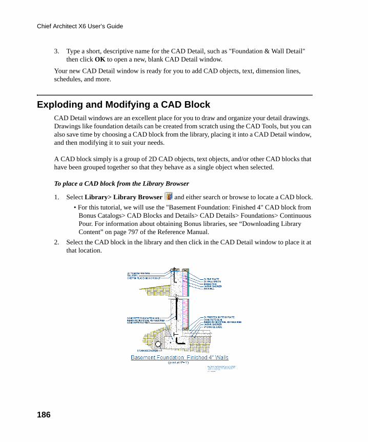
186
Chief Architect X6 User’s Guide
3. Type a short, descriptive name for the CAD Detail, such as "Foundation & Wall Detail" then click OK to open a new, blank CAD Detail window.
Your new CAD Detail window is ready for you to add CAD objects, text, dimension lines, schedules, and more.
Exploding and Modifying a CAD BlockCAD Detail windows are an excellent place for you to draw and organize your detail drawings. Drawings like foundation details can be created from scratch using the CAD Tools, but you can also save time by choosing a CAD block from the library, placing it into a CAD Detail window, and then modifying it to suit your needs.
A CAD block simply is a group of 2D CAD objects, text objects, and/or other CAD blocks that have been grouped together so that they behave as a single object when selected.
To place a CAD block from the Library Browser
1. Select Library> Library Browser and either search or browse to locate a CAD block.
• For this tutorial, we will use the "Basement Foundation: Finished 4" CAD block from Bonus Catalogs> CAD Blocks and Details> CAD Details> Foundations> Continuous Pour. For information about obtaining Bonus libraries, see “Downloading Library Content” on page 797 of the Reference Manual.
2. Select the CAD block in the library and then click in the CAD Detail window to place it at that location.
chief-architect-x6-users-guide.book Page 186 Monday, December 16, 2013 4:05 PM
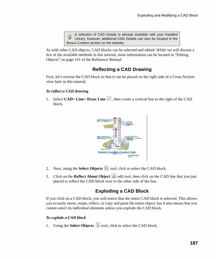
Exploding and Modifying a CAD Block
187
As with other CAD objects, CAD blocks can be selected and edited. While we will discuss a few of the available methods in this tutorial, more information can be located in “Editing Objects” on page 101 of the Reference Manual.
Reflecting a CAD Drawing
First, let’s reverse the CAD block so that it can be placed on the right side of a Cross Section view later in this tutorial.
To reflect a CAD drawing
1. Select CAD> Line> Draw Line , then create a vertical line to the right of the CAD block.
2. Next, using the Select Objects tool, click to select the CAD block.
3. Click on the Reflect About Object edit tool, then click on the CAD line that you just placed to reflect the CAD block over to the other side of the line.
Exploding a CAD Block
If you click on a CAD block, you will notice that the entire CAD block is selected. This allows you to easily move, rotate, reflect, or copy and paste the entire object; but it also means that you cannot select its individual elements unless you explode the CAD block.
To explode a CAD block
1. Using the Select Objects tool, click to select the CAD block.
A selection of CAD Details is already available with your installedLibrary, however, additional CAD Details can also be located in the
Bonus Content section on the website.
chief-architect-x6-users-guide.book Page 187 Monday, December 16, 2013 4:05 PM
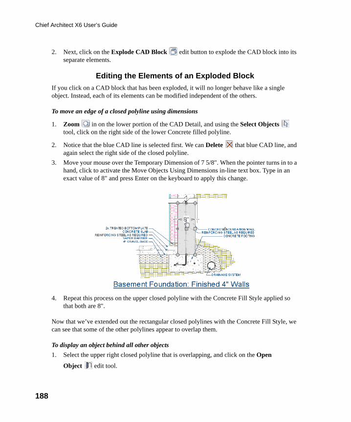
188
Chief Architect X6 User’s Guide
2. Next, click on the Explode CAD Block edit button to explode the CAD block into its separate elements.
Editing the Elements of an Exploded Block
If you click on a CAD block that has been exploded, it will no longer behave like a single object. Instead, each of its elements can be modified independent of the others.
To move an edge of a closed polyline using dimensions
1. Zoom in on the lower portion of the CAD Detail, and using the Select Objects tool, click on the right side of the lower Concrete filled polyline.
2. Notice that the blue CAD line is selected first. We can Delete that blue CAD line, and again select the right side of the closed polyline.
3. Move your mouse over the Temporary Dimension of 7 5/8". When the pointer turns in to a hand, click to activate the Move Objects Using Dimensions in-line text box. Type in an exact value of 8" and press Enter on the keyboard to apply this change.
4. Repeat this process on the upper closed polyline with the Concrete Fill Style applied so that both are 8".
Now that we’ve extended out the rectangular closed polylines with the Concrete Fill Style, we can see that some of the other polylines appear to overlap them.
To display an object behind all other objects
1. Select the upper right closed polyline that is overlapping, and click on the Open
Object edit tool.
chief-architect-x6-users-guide.book Page 188 Monday, December 16, 2013 4:05 PM
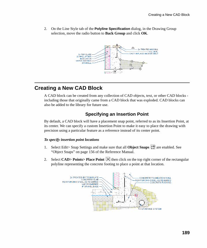
Creating a New CAD Block
189
2. On the Line Style tab of the Polyline Specification dialog, in the Drawing Group selection, move the radio button to Back Group and click OK.
Creating a New CAD BlockA CAD block can be created from any collection of CAD objects, text, or other CAD blocks - including those that originally came from a CAD block that was exploded. CAD blocks can also be added to the library for future use.
Specifying an Insertion Point
By default, a CAD block will have a placement snap point, referred to as its Insertion Point, at its center. We can specify a custom Insertion Point to make it easy to place the drawing with precision using a particular feature as a reference instead of its center point.
To specify insertion point locations
1. Select Edit> Snap Settings and make sure that all Object Snaps are enabled. See “Object Snaps” on page 156 of the Reference Manual.
2. Select CAD> Points> Place Point then click on the top right corner of the rectangular polyline representing the concrete footing to place a point at that location.
chief-architect-x6-users-guide.book Page 189 Monday, December 16, 2013 4:05 PM
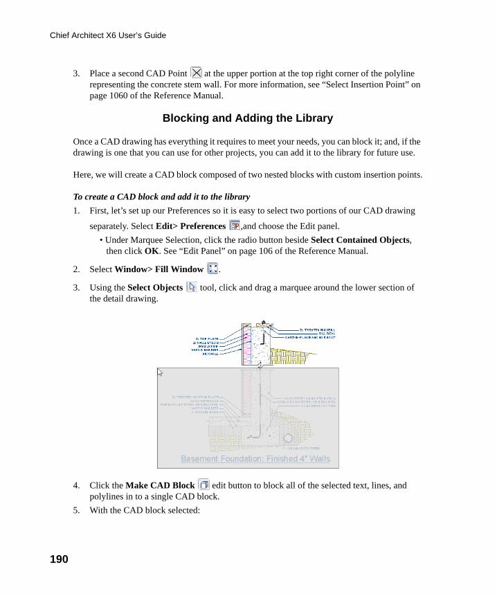
190
Chief Architect X6 User’s Guide
3. Place a second CAD Point at the upper portion at the top right corner of the polyline representing the concrete stem wall. For more information, see “Select Insertion Point” on page 1060 of the Reference Manual.
Blocking and Adding the Library
Once a CAD drawing has everything it requires to meet your needs, you can block it; and, if the drawing is one that you can use for other projects, you can add it to the library for future use.
Here, we will create a CAD block composed of two nested blocks with custom insertion points.
To create a CAD block and add it to the library
1. First, let’s set up our Preferences so it is easy to select two portions of our CAD drawing
separately. Select Edit> Preferences ,and choose the Edit panel.
• Under Marquee Selection, click the radio button beside Select Contained Objects, then click OK. See “Edit Panel” on page 106 of the Reference Manual.
2. Select Window> Fill Window .
3. Using the Select Objects tool, click and drag a marquee around the lower section of the detail drawing.
4. Click the Make CAD Block edit button to block all of the selected text, lines, and polylines in to a single CAD block.
5. With the CAD block selected:
chief-architect-x6-users-guide.book Page 190 Monday, December 16, 2013 4:05 PM
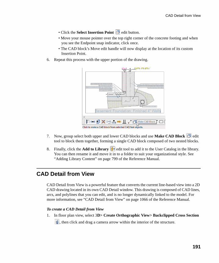
CAD Detail from View
191
• Click the Select Insertion Point edit button.
• Move your mouse pointer over the top right corner of the concrete footing and when you see the Endpoint snap indicator, click once.
• The CAD block’s Move edit handle will now display at the location of its custom Insertion Point.
6. Repeat this process with the upper portion of the drawing.
7. Now, group select both upper and lower CAD blocks and use Make CAD Block edit tool to block them together, forming a single CAD block composed of two nested blocks.
8. Finally, click the Add to Library edit tool to add it to the User Catalog in the library. You can then rename it and move it in to a folder to suit your organizational style. See “Adding Library Content” on page 799 of the Reference Manual.
CAD Detail from View
CAD Detail from View is a powerful feature that converts the current line-based view into a 2D CAD drawing located in its own CAD Detail window. This drawing is composed of CAD lines, arcs, and polylines that you can edit, and is no longer dynamically linked to the model. For more information, see “CAD Detail from View” on page 1066 of the Reference Manual.
To create a CAD Detail from View
1. In floor plan view, select 3D> Create Orthographic View> Backclipped Cross Section
, then click and drag a camera arrow within the interior of the structure.
chief-architect-x6-users-guide.book Page 191 Monday, December 16, 2013 4:05 PM
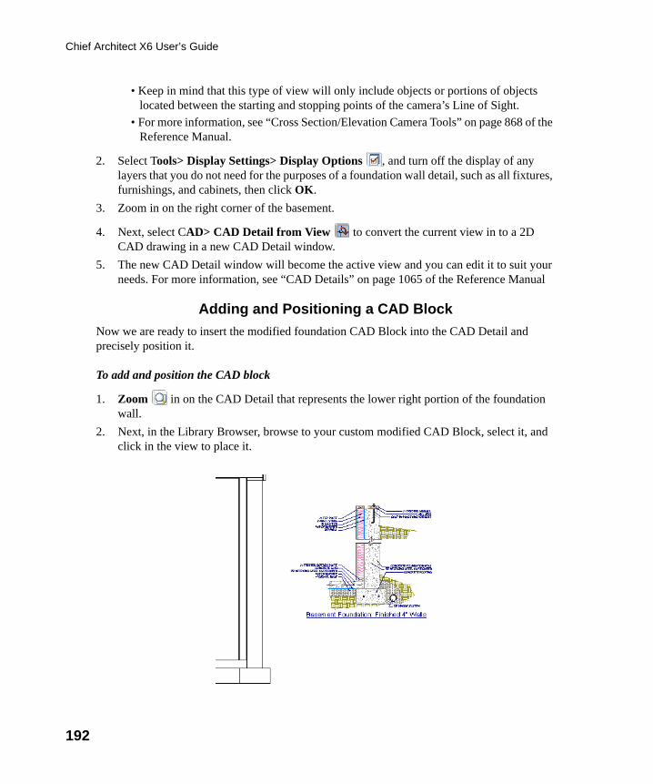
192
Chief Architect X6 User’s Guide
• Keep in mind that this type of view will only include objects or portions of objects located between the starting and stopping points of the camera’s Line of Sight.
• For more information, see “Cross Section/Elevation Camera Tools” on page 868 of the Reference Manual.
2. Select Tools> Display Settings> Display Options , and turn off the display of any layers that you do not need for the purposes of a foundation wall detail, such as all fixtures, furnishings, and cabinets, then click OK.
3. Zoom in on the right corner of the basement.
4. Next, select CAD> CAD Detail from View to convert the current view in to a 2D CAD drawing in a new CAD Detail window.
5. The new CAD Detail window will become the active view and you can edit it to suit your needs. For more information, see “CAD Details” on page 1065 of the Reference Manual
Adding and Positioning a CAD Block
Now we are ready to insert the modified foundation CAD Block into the CAD Detail and precisely position it.
To add and position the CAD block
1. Zoom in on the CAD Detail that represents the lower right portion of the foundation wall.
2. Next, in the Library Browser, browse to your custom modified CAD Block, select it, and click in the view to place it.
chief-architect-x6-users-guide.book Page 192 Monday, December 16, 2013 4:05 PM
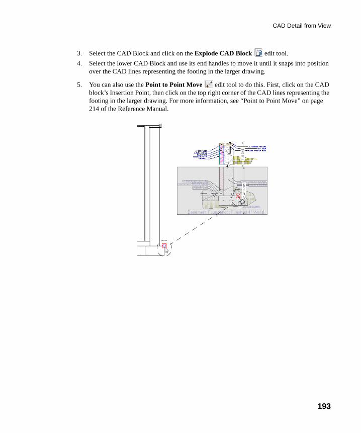
CAD Detail from View
193
3. Select the CAD Block and click on the Explode CAD Block edit tool.
4. Select the lower CAD Block and use its end handles to move it until it snaps into position over the CAD lines representing the footing in the larger drawing.
5. You can also use the Point to Point Move edit tool to do this. First, click on the CAD block’s Insertion Point, then click on the top right corner of the CAD lines representing the footing in the larger drawing. For more information, see “Point to Point Move” on page 214 of the Reference Manual.
chief-architect-x6-users-guide.book Page 193 Monday, December 16, 2013 4:05 PM
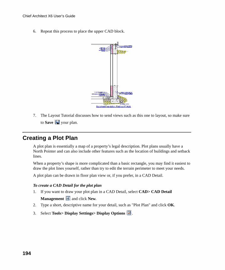
194
Chief Architect X6 User’s Guide
6. Repeat this process to place the upper CAD block.
7. The Layout Tutorial discusses how to send views such as this one to layout, so make sure
to Save your plan.
Creating a Plot PlanA plot plan is essentially a map of a property’s legal description. Plot plans usually have a North Pointer and can also include other features such as the location of buildings and setback lines.
When a property’s shape is more complicated than a basic rectangle, you may find it easiest to draw the plot lines yourself, rather than try to edit the terrain perimeter to meet your needs.
A plot plan can be drawn in floor plan view or, if you prefer, in a CAD Detail.
To create a CAD Detail for the plot plan
1. If you want to draw your plot plan in a CAD Detail, select CAD> CAD Detail
Management and click New.
2. Type a short, descriptive name for your detail, such as "Plot Plan" and click OK.
3. Select Tools> Display Settings> Display Options .
chief-architect-x6-users-guide.book Page 194 Monday, December 16, 2013 4:05 PM
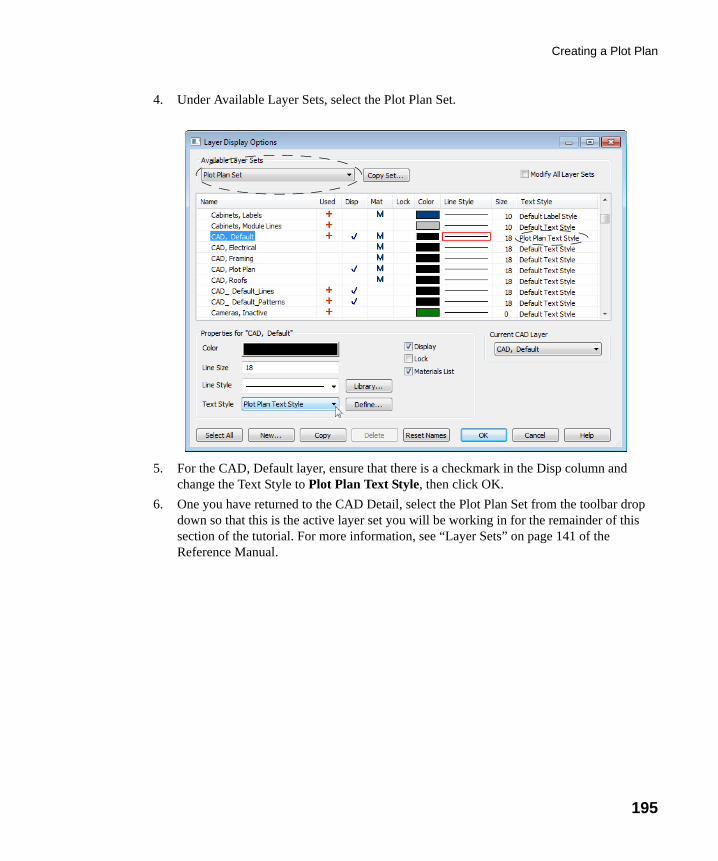
Creating a Plot Plan
195
4. Under Available Layer Sets, select the Plot Plan Set.
5. For the CAD, Default layer, ensure that there is a checkmark in the Disp column and change the Text Style to Plot Plan Text Style, then click OK.
6. One you have returned to the CAD Detail, select the Plot Plan Set from the toolbar drop down so that this is the active layer set you will be working in for the remainder of this section of the tutorial. For more information, see “Layer Sets” on page 141 of the Reference Manual.
chief-architect-x6-users-guide.book Page 195 Monday, December 16, 2013 4:05 PM
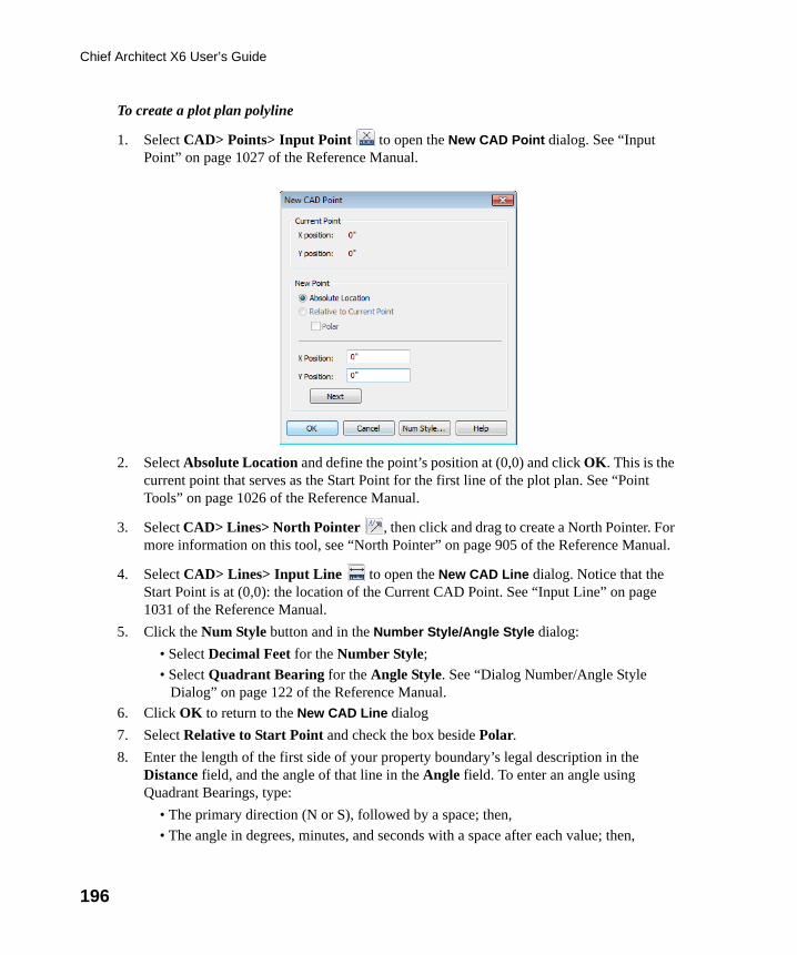
196
Chief Architect X6 User’s Guide
To create a plot plan polyline
1. Select CAD> Points> Input Point to open the New CAD Point dialog. See “Input Point” on page 1027 of the Reference Manual.
2. Select Absolute Location and define the point’s position at (0,0) and click OK. This is the current point that serves as the Start Point for the first line of the plot plan. See “Point Tools” on page 1026 of the Reference Manual.
3. Select CAD> Lines> North Pointer , then click and drag to create a North Pointer. For more information on this tool, see “North Pointer” on page 905 of the Reference Manual.
4. Select CAD> Lines> Input Line to open the New CAD Line dialog. Notice that the Start Point is at (0,0): the location of the Current CAD Point. See “Input Line” on page 1031 of the Reference Manual.
5. Click the Num Style button and in the Number Style/Angle Style dialog:
• Select Decimal Feet for the Number Style;
• Select Quadrant Bearing for the Angle Style. See “Dialog Number/Angle Style Dialog” on page 122 of the Reference Manual.
6. Click OK to return to the New CAD Line dialog
7. Select Relative to Start Point and check the box beside Polar.
8. Enter the length of the first side of your property boundary’s legal description in the Distance field, and the angle of that line in the Angle field. To enter an angle using Quadrant Bearings, type:
• The primary direction (N or S), followed by a space; then,
• The angle in degrees, minutes, and seconds with a space after each value; then,
chief-architect-x6-users-guide.book Page 196 Monday, December 16, 2013 4:05 PM
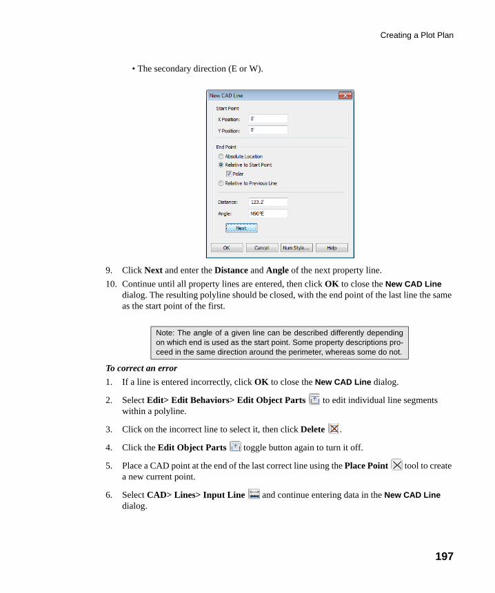
Creating a Plot Plan
197
• The secondary direction (E or W).
9. Click Next and enter the Distance and Angle of the next property line.
10. Continue until all property lines are entered, then click OK to close the New CAD Line dialog. The resulting polyline should be closed, with the end point of the last line the same as the start point of the first.
To correct an error
1. If a line is entered incorrectly, click OK to close the New CAD Line dialog.
2. Select Edit> Edit Behaviors> Edit Object Parts to edit individual line segments within a polyline.
3. Click on the incorrect line to select it, then click Delete .
4. Click the Edit Object Parts toggle button again to turn it off.
5. Place a CAD point at the end of the last correct line using the Place Point tool to create a new current point.
6. Select CAD> Lines> Input Line and continue entering data in the New CAD Line dialog.
Note: The angle of a given line can be described differently dependingon which end is used as the start point. Some property descriptions pro-ceed in the same direction around the perimeter, whereas some do not.
chief-architect-x6-users-guide.book Page 197 Monday, December 16, 2013 4:05 PM
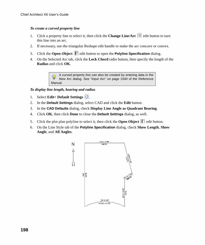
198
Chief Architect X6 User’s Guide
To create a curved property line
1. Click a property line to select it, then click the Change Line/Arc edit button to turn this line into an arc.
2. If necessary, use the triangular Reshape edit handle to make the arc concave or convex.
3. Click the Open Object edit button to open the Polyline Specification dialog.
4. On the Selected Arc tab, click the Lock Chord radio button, then specify the length of the Radius and click OK.
To display line length, bearing and radius
1. Select Edit> Default Settings .
2. In the Default Settings dialog, select CAD and click the Edit button.
3. In the CAD Defaults dialog, check Display Line Angle as Quadrant Bearing.
4. Click OK, then click Done to close the Default Settings dialog, as well.
5. Click the plot plan polyline to select it, then click the Open Object edit button.
6. On the Line Style tab of the Polyline Specification dialog, check Show Length, Show Angle, and All Angles.
A curved property line can also be created by entering data in theNew Arc dialog. See “Input Arc” on page 1040 of the Reference
Manual.
chief-architect-x6-users-guide.book Page 198 Monday, December 16, 2013 4:05 PM
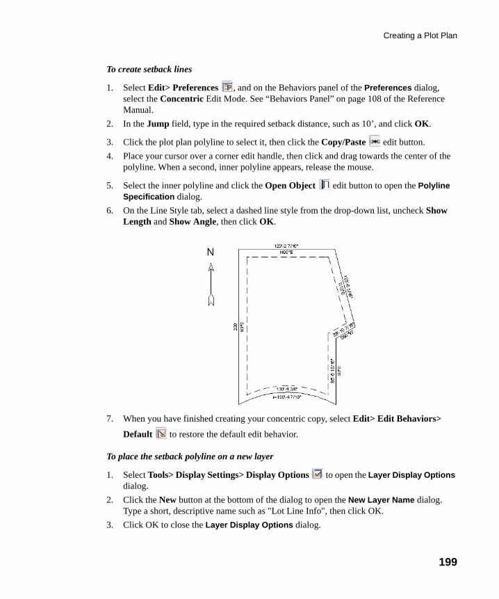
Creating a Plot Plan
199
To create setback lines
1. Select Edit> Preferences , and on the Behaviors panel of the Preferences dialog, select the Concentric Edit Mode. See “Behaviors Panel” on page 108 of the Reference Manual.
2. In the Jump field, type in the required setback distance, such as 10’, and click OK.
3. Click the plot plan polyline to select it, then click the Copy/Paste edit button.
4. Place your cursor over a corner edit handle, then click and drag towards the center of the polyline. When a second, inner polyline appears, release the mouse.
5. Select the inner polyline and click the Open Object edit button to open the Polyline Specification dialog.
6. On the Line Style tab, select a dashed line style from the drop-down list, uncheck Show Length and Show Angle, then click OK.
7. When you have finished creating your concentric copy, select Edit> Edit Behaviors>
Default to restore the default edit behavior.
To place the setback polyline on a new layer
1. Select Tools> Display Settings> Display Options to open the Layer Display Options dialog.
2. Click the New button at the bottom of the dialog to open the New Layer Name dialog. Type a short, descriptive name such as "Lot Line Info", then click OK.
3. Click OK to close the Layer Display Options dialog.
chief-architect-x6-users-guide.book Page 199 Monday, December 16, 2013 4:05 PM
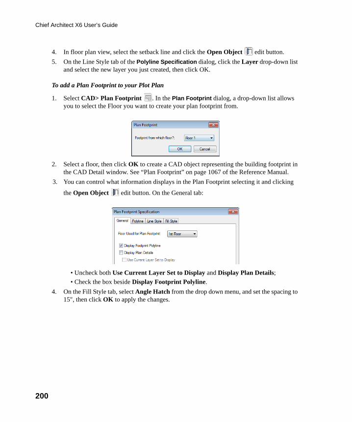
200
Chief Architect X6 User’s Guide
4. In floor plan view, select the setback line and click the Open Object edit button.
5. On the Line Style tab of the Polyline Specification dialog, click the Layer drop-down list and select the new layer you just created, then click OK.
To add a Plan Footprint to your Plot Plan
1. Select CAD> Plan Footprint . In the Plan Footprint dialog, a drop-down list allows you to select the Floor you want to create your plan footprint from.
2. Select a floor, then click OK to create a CAD object representing the building footprint in the CAD Detail window. See “Plan Footprint” on page 1067 of the Reference Manual.
3. You can control what information displays in the Plan Footprint selecting it and clicking
the Open Object edit button. On the General tab:
• Uncheck both Use Current Layer Set to Display and Display Plan Details;
• Check the box beside Display Footprint Polyline.
4. On the Fill Style tab, select Angle Hatch from the drop down menu, and set the spacing to 15", then click OK to apply the changes.
chief-architect-x6-users-guide.book Page 200 Monday, December 16, 2013 4:05 PM
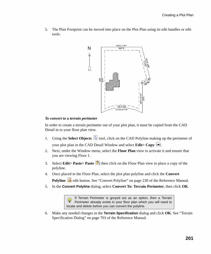
Creating a Plot Plan
201
5. The Plan Footprint can be moved into place on the Plot Plan using its edit handles or edit tools.
To convert to a terrain perimeter
In order to create a terrain perimeter out of your plot plan, it must be copied from the CAD Detail in to your floor plan view.
1. Using the Select Objects tool, click on the CAD Polyline making up the perimeter of
your plot plan in the CAD Detail Window and select Edit> Copy .
2. Next, under the Window menu, select the Floor Plan view to activate it and ensure that you are viewing Floor 1.
3. Select Edit> Paste> Paste then click on the Floor Plan view to place a copy of the polyline.
4. Once placed in the Floor Plan, select the plot plan polyline and click the Convert
Polyline edit button. See “Convert Polyline” on page 230 of the Reference Manual.
5. In the Convert Polyline dialog, select Convert To: Terrain Perimeter, then click OK.
6. Make any needed changes in the Terrain Specification dialog and click OK. See “Terrain Specification Dialog” on page 703 of the Reference Manual.
If Terrain Perimeter is greyed out as an option, then a TerrainPerimeter already exists in your floor plan which you will need to
locate and delete before you can convert the polyline.
chief-architect-x6-users-guide.book Page 201 Monday, December 16, 2013 4:05 PM
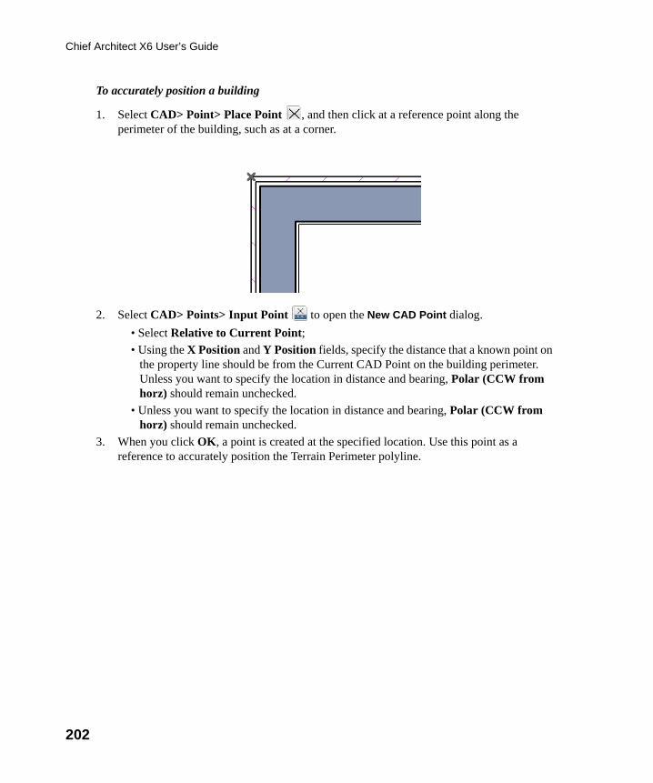
202
Chief Architect X6 User’s Guide
To accurately position a building
1. Select CAD> Point> Place Point , and then click at a reference point along the perimeter of the building, such as at a corner.
2. Select CAD> Points> Input Point to open the New CAD Point dialog.
• Select Relative to Current Point;
• Using the X Position and Y Position fields, specify the distance that a known point on the property line should be from the Current CAD Point on the building perimeter. Unless you want to specify the location in distance and bearing, Polar (CCW from horz) should remain unchecked.
• Unless you want to specify the location in distance and bearing, Polar (CCW from horz) should remain unchecked.
3. When you click OK, a point is created at the specified location. Use this point as a reference to accurately position the Terrain Perimeter polyline.
chief-architect-x6-users-guide.book Page 202 Monday, December 16, 2013 4:05 PM
203
Chapter 10:
LayoutTutorial
In this tutorial we will create a layout template, send a few views to a layout page, then save this document in PDF format.
In this tutorial you will learn about:
• Creating a Layout Template• Creating a Border and Title Block• Sending Floor Plan Views to Layout• Sending Elevation Views to Layout
• Sending Details to Layout• Sending Perspective Views to Layout• Printing to PDF
Getting StartedChief Architect uses two file types: plans and layouts. In a plan file (.plan), we design a 3D model of a structure, and in a layout file (.layout) we arrange views of that model as well as text, callouts and other annotation to produce professional quality construction documents. For complete information about layouts, see “Layout” on page 1183 of the Reference Manual.
In previous tutorials we explored aspects of creating a 3D model in a plan file. Now, we’ll create a layout file and arrange views of the model that we recently completed on the layout pages. Since we won’t be altering the model itself, it doesn’t matter which plan file you use.
chief-architect-x6-users-guide.book Page 203 Monday, December 16, 2013 4:05 PM
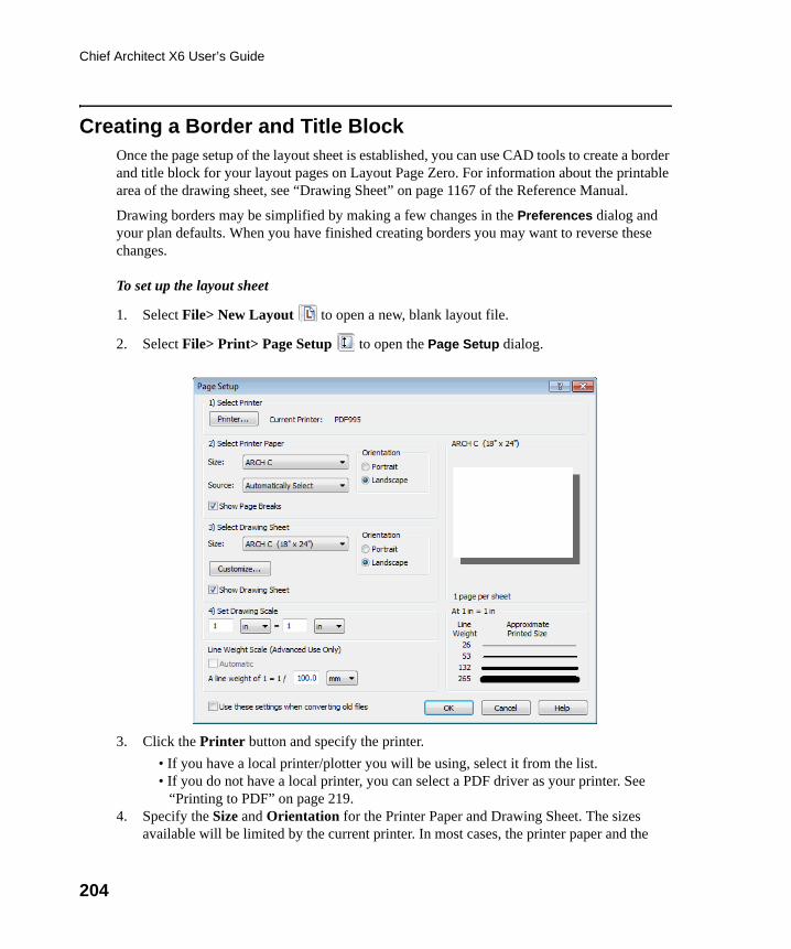
204
Chief Architect X6 User’s Guide
Creating a Border and Title BlockOnce the page setup of the layout sheet is established, you can use CAD tools to create a border and title block for your layout pages on Layout Page Zero. For information about the printable area of the drawing sheet, see “Drawing Sheet” on page 1167 of the Reference Manual.
Drawing borders may be simplified by making a few changes in the Preferences dialog and your plan defaults. When you have finished creating borders you may want to reverse these changes.
To set up the layout sheet
1. Select File> New Layout to open a new, blank layout file.
2. Select File> Print> Page Setup to open the Page Setup dialog.
3. Click the Printer button and specify the printer.
• If you have a local printer/plotter you will be using, select it from the list. • If you do not have a local printer, you can select a PDF driver as your printer. See
“Printing to PDF” on page 219.4. Specify the Size and Orientation for the Printer Paper and Drawing Sheet. The sizes
available will be limited by the current printer. In most cases, the printer paper and the
chief-architect-x6-users-guide.book Page 204 Monday, December 16, 2013 4:05 PM
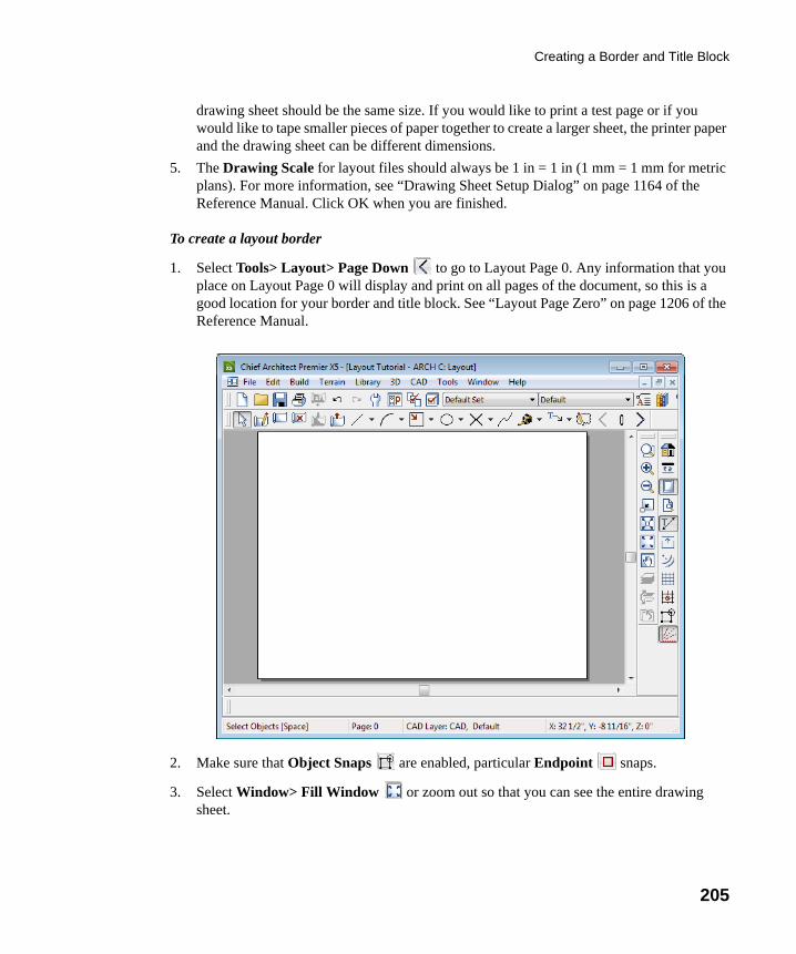
Creating a Border and Title Block
205
drawing sheet should be the same size. If you would like to print a test page or if you would like to tape smaller pieces of paper together to create a larger sheet, the printer paper and the drawing sheet can be different dimensions.
5. The Drawing Scale for layout files should always be 1 in = 1 in (1 mm = 1 mm for metric plans). For more information, see “Drawing Sheet Setup Dialog” on page 1164 of the Reference Manual. Click OK when you are finished.
To create a layout border
1. Select Tools> Layout> Page Down to go to Layout Page 0. Any information that you place on Layout Page 0 will display and print on all pages of the document, so this is a good location for your border and title block. See “Layout Page Zero” on page 1206 of the Reference Manual.
2. Make sure that Object Snaps are enabled, particular Endpoint snaps.
3. Select Window> Fill Window or zoom out so that you can see the entire drawing sheet.
chief-architect-x6-users-guide.book Page 205 Monday, December 16, 2013 4:05 PM
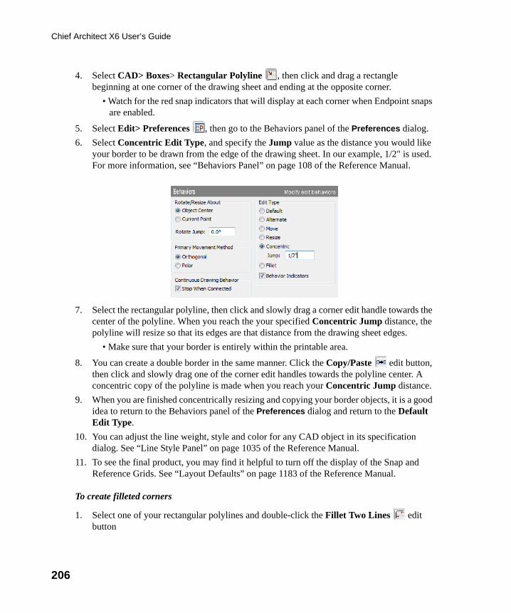
206
Chief Architect X6 User’s Guide
4. Select CAD> Boxes> Rectangular Polyline , then click and drag a rectangle beginning at one corner of the drawing sheet and ending at the opposite corner.
• Watch for the red snap indicators that will display at each corner when Endpoint snaps are enabled.
5. Select Edit> Preferences , then go to the Behaviors panel of the Preferences dialog.
6. Select Concentric Edit Type, and specify the Jump value as the distance you would like your border to be drawn from the edge of the drawing sheet. In our example, 1/2" is used. For more information, see “Behaviors Panel” on page 108 of the Reference Manual.
7. Select the rectangular polyline, then click and slowly drag a corner edit handle towards the center of the polyline. When you reach the your specified Concentric Jump distance, the polyline will resize so that its edges are that distance from the drawing sheet edges.
• Make sure that your border is entirely within the printable area.
8. You can create a double border in the same manner. Click the Copy/Paste edit button, then click and slowly drag one of the corner edit handles towards the polyline center. A concentric copy of the polyline is made when you reach your Concentric Jump distance.
9. When you are finished concentrically resizing and copying your border objects, it is a good idea to return to the Behaviors panel of the Preferences dialog and return to the Default Edit Type.
10. You can adjust the line weight, style and color for any CAD object in its specification dialog. See “Line Style Panel” on page 1035 of the Reference Manual.
11. To see the final product, you may find it helpful to turn off the display of the Snap and Reference Grids. See “Layout Defaults” on page 1183 of the Reference Manual.
To create filleted corners
1. Select one of your rectangular polylines and double-click the Fillet Two Lines edit button
chief-architect-x6-users-guide.book Page 206 Monday, December 16, 2013 4:05 PM
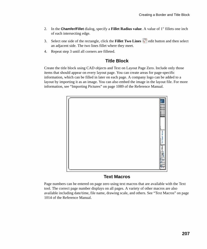
Creating a Border and Title Block
207
2. In the Chamfer/Fillet dialog, specify a Fillet Radius value. A value of 1" fillets one inch of each intersecting edge.
3. Select one side of the rectangle, click the Fillet Two Lines edit button and then select an adjacent side. The two lines fillet where they meet.
4. Repeat step 3 until all corners are filleted.
Title Block
Create the title block using CAD objects and Text on Layout Page Zero. Include only those items that should appear on every layout page. You can create areas for page-specific information, which can be filled in later on each page. A company logo can be added to a layout by importing it as an image. You can also embed the image in the layout file. For more information, see “Importing Pictures” on page 1089 of the Reference Manual.
Text Macros
Page numbers can be entered on page zero using text macros that are available with the Text tool. The correct page number displays on all pages. A variety of other macros are also available including date/time, file name, drawing scale, and others. See “Text Macros” on page 1014 of the Reference Manual.
chief-architect-x6-users-guide.book Page 207 Monday, December 16, 2013 4:05 PM
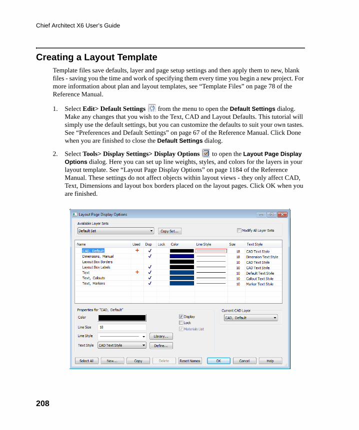
208
Chief Architect X6 User’s Guide
Creating a Layout TemplateTemplate files save defaults, layer and page setup settings and then apply them to new, blank files - saving you the time and work of specifying them every time you begin a new project. For more information about plan and layout templates, see “Template Files” on page 78 of the Reference Manual.
1. Select Edit> Default Settings from the menu to open the Default Settings dialog. Make any changes that you wish to the Text, CAD and Layout Defaults. This tutorial will simply use the default settings, but you can customize the defaults to suit your own tastes. See “Preferences and Default Settings” on page 67 of the Reference Manual. Click Done when you are finished to close the Default Settings dialog.
2. Select Tools> Display Settings> Display Options to open the Layout Page Display Options dialog. Here you can set up line weights, styles, and colors for the layers in your layout template. See “Layout Page Display Options” on page 1184 of the Reference Manual. These settings do not affect objects within layout views - they only affect CAD, Text, Dimensions and layout box borders placed on the layout pages. Click OK when you are finished.
chief-architect-x6-users-guide.book Page 208 Monday, December 16, 2013 4:05 PM
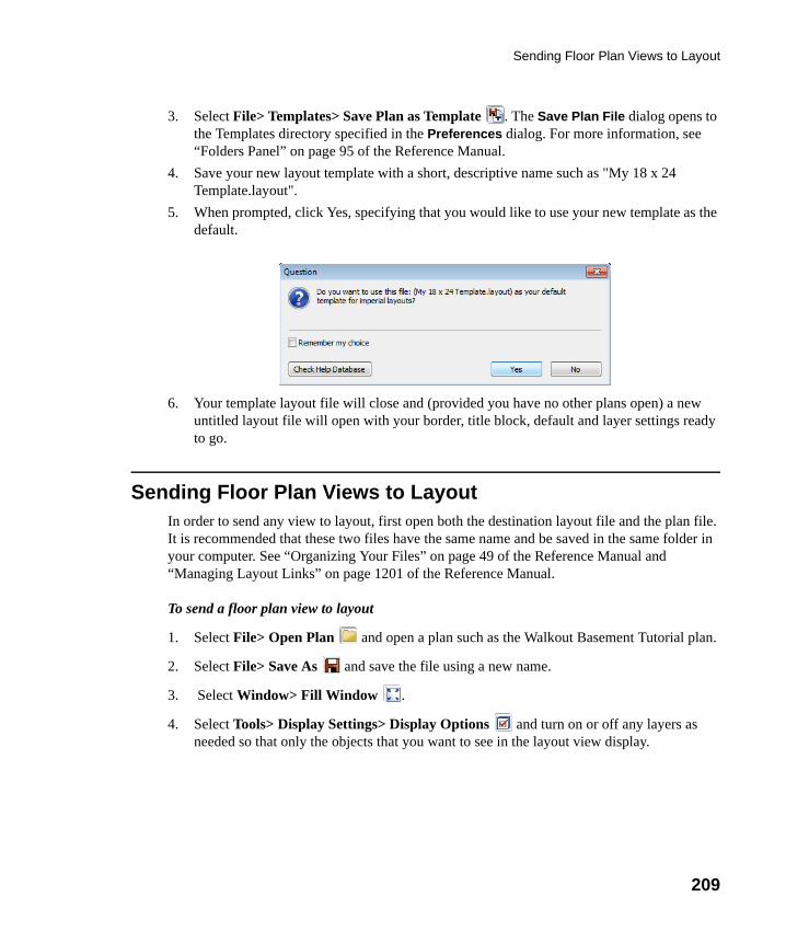
Sending Floor Plan Views to Layout
209
3. Select File> Templates> Save Plan as Template . The Save Plan File dialog opens to the Templates directory specified in the Preferences dialog. For more information, see “Folders Panel” on page 95 of the Reference Manual.
4. Save your new layout template with a short, descriptive name such as "My 18 x 24 Template.layout".
5. When prompted, click Yes, specifying that you would like to use your new template as the default.
6. Your template layout file will close and (provided you have no other plans open) a new untitled layout file will open with your border, title block, default and layer settings ready to go.
Sending Floor Plan Views to LayoutIn order to send any view to layout, first open both the destination layout file and the plan file. It is recommended that these two files have the same name and be saved in the same folder in your computer. See “Organizing Your Files” on page 49 of the Reference Manual and “Managing Layout Links” on page 1201 of the Reference Manual.
To send a floor plan view to layout
1. Select File> Open Plan and open a plan such as the Walkout Basement Tutorial plan.
2. Select File> Save As and save the file using a new name.
3. Select Window> Fill Window .
4. Select Tools> Display Settings> Display Options and turn on or off any layers as needed so that only the objects that you want to see in the layout view display.
chief-architect-x6-users-guide.book Page 209 Monday, December 16, 2013 4:05 PM
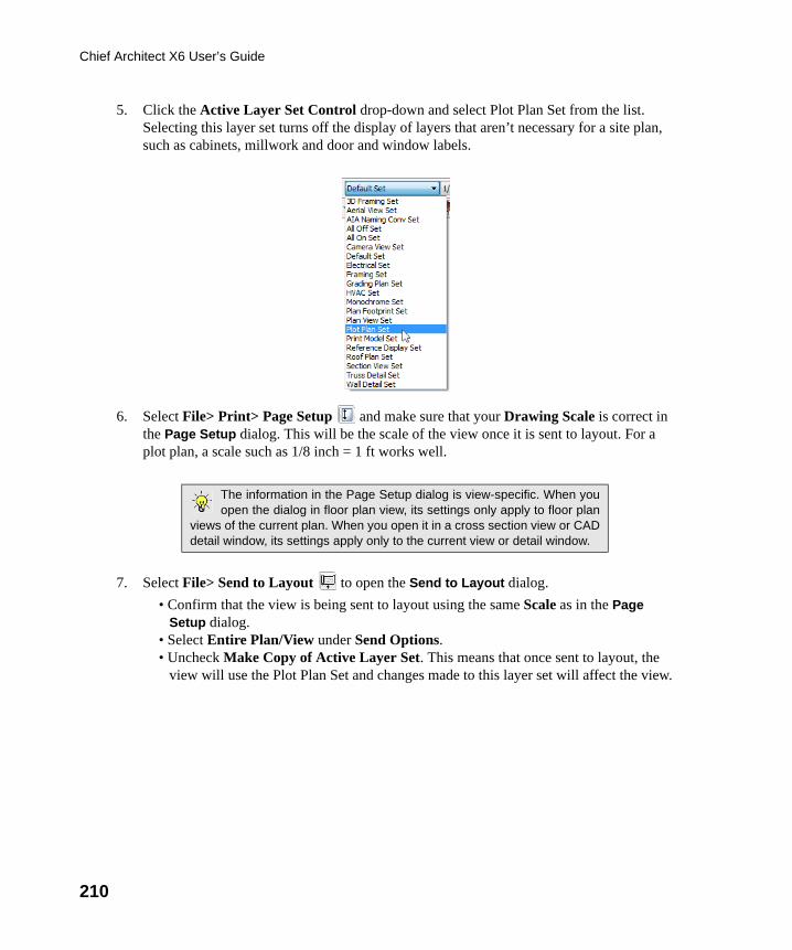
210
Chief Architect X6 User’s Guide
5. Click the Active Layer Set Control drop-down and select Plot Plan Set from the list. Selecting this layer set turns off the display of layers that aren’t necessary for a site plan, such as cabinets, millwork and door and window labels.
6. Select File> Print> Page Setup and make sure that your Drawing Scale is correct in the Page Setup dialog. This will be the scale of the view once it is sent to layout. For a plot plan, a scale such as 1/8 inch = 1 ft works well.
7. Select File> Send to Layout to open the Send to Layout dialog.
• Confirm that the view is being sent to layout using the same Scale as in the Page Setup dialog.
• Select Entire Plan/View under Send Options.• Uncheck Make Copy of Active Layer Set. This means that once sent to layout, the
view will use the Plot Plan Set and changes made to this layer set will affect the view.
The information in the Page Setup dialog is view-specific. When youopen the dialog in floor plan view, its settings only apply to floor plan
views of the current plan. When you open it in a cross section view or CADdetail window, its settings apply only to the current view or detail window.
chief-architect-x6-users-guide.book Page 210 Monday, December 16, 2013 4:05 PM

Sending Floor Plan Views to Layout
211
• Set the scale to 1/16in=1ft, under Send Position, we will Send to Layout Page # 2 and leave Show Layout Page checked so that when we click OK, the layout window will become active.
8. Click OK to send the view to layout.
9. Once sent to layout, the view can be selected and moved using its edit handles or edit buttons, and its edges can be edited like a CAD box. See “Editing Box-Based Objects” on page 198 of the Reference Manual.
10. Select Window> Previous Window (or press Ctrl + Tab) to return to floor plan view.
chief-architect-x6-users-guide.book Page 211 Monday, December 16, 2013 4:05 PM
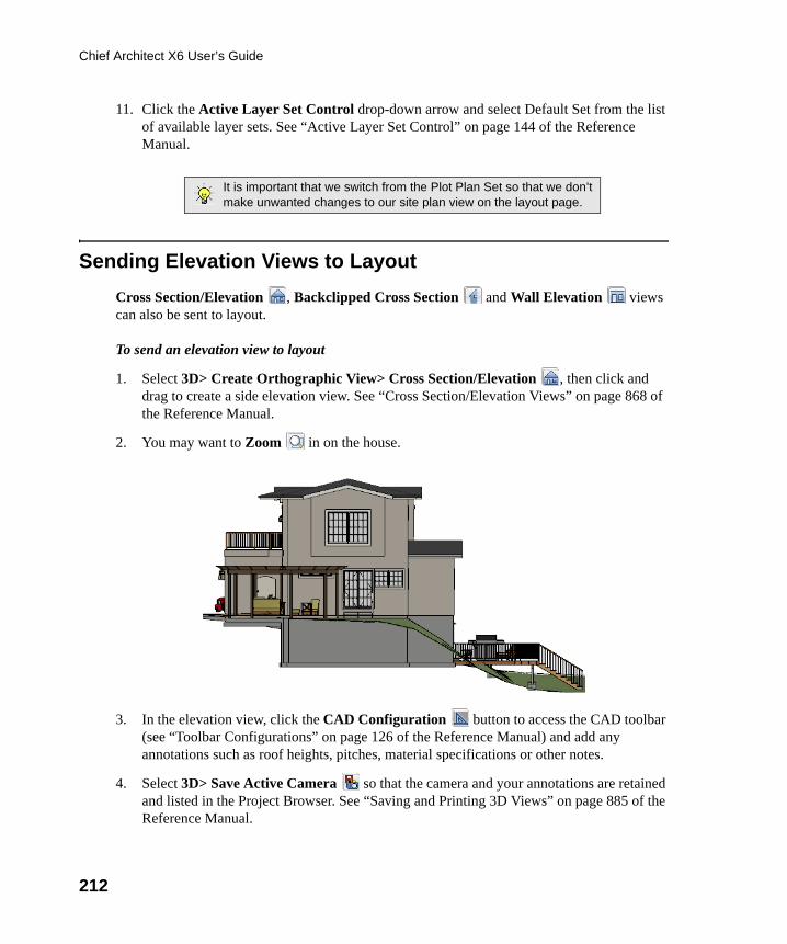
212
Chief Architect X6 User’s Guide
11. Click the Active Layer Set Control drop-down arrow and select Default Set from the list of available layer sets. See “Active Layer Set Control” on page 144 of the Reference Manual.
Sending Elevation Views to Layout
Cross Section/Elevation , Backclipped Cross Section and Wall Elevation views can also be sent to layout.
To send an elevation view to layout
1. Select 3D> Create Orthographic View> Cross Section/Elevation , then click and drag to create a side elevation view. See “Cross Section/Elevation Views” on page 868 of the Reference Manual.
2. You may want to Zoom in on the house.
3. In the elevation view, click the CAD Configuration button to access the CAD toolbar (see “Toolbar Configurations” on page 126 of the Reference Manual) and add any annotations such as roof heights, pitches, material specifications or other notes.
4. Select 3D> Save Active Camera so that the camera and your annotations are retained and listed in the Project Browser. See “Saving and Printing 3D Views” on page 885 of the Reference Manual.
It is important that we switch from the Plot Plan Set so that we don’tmake unwanted changes to our site plan view on the layout page.
chief-architect-x6-users-guide.book Page 212 Monday, December 16, 2013 4:05 PM
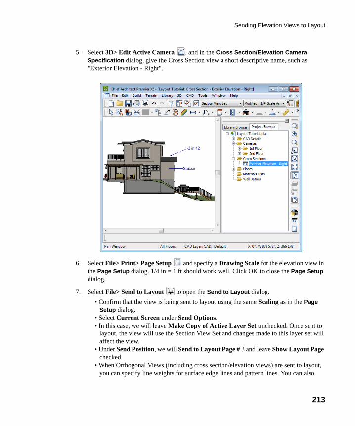
Sending Elevation Views to Layout
213
5. Select 3D> Edit Active Camera , and in the Cross Section/Elevation Camera Specification dialog, give the Cross Section view a short descriptive name, such as "Exterior Elevation - Right".
6. Select File> Print> Page Setup and specify a Drawing Scale for the elevation view in the Page Setup dialog. 1/4 in = 1 ft should work well. Click OK to close the Page Setup dialog.
7. Select File> Send to Layout to open the Send to Layout dialog.
• Confirm that the view is being sent to layout using the same Scaling as in the Page Setup dialog.
• Select Current Screen under Send Options.• In this case, we will leave Make Copy of Active Layer Set unchecked. Once sent to
layout, the view will use the Section View Set and changes made to this layer set will affect the view.
• Under Send Position, we will Send to Layout Page # 3 and leave Show Layout Page checked.
• When Orthogonal Views (including cross section/elevation views) are sent to layout, you can specify line weights for surface edge lines and pattern lines. You can also
chief-architect-x6-users-guide.book Page 213 Monday, December 16, 2013 4:05 PM
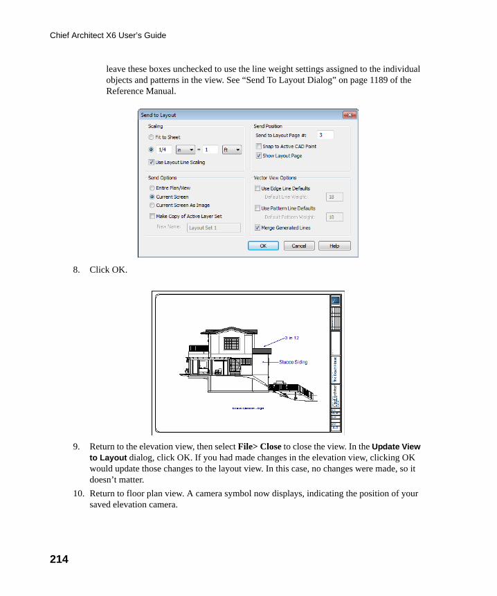
214
Chief Architect X6 User’s Guide
leave these boxes unchecked to use the line weight settings assigned to the individual objects and patterns in the view. See “Send To Layout Dialog” on page 1189 of the Reference Manual.
8. Click OK.
9. Return to the elevation view, then select File> Close to close the view. In the Update View to Layout dialog, click OK. If you had made changes in the elevation view, clicking OK would update those changes to the layout view. In this case, no changes were made, so it doesn’t matter.
10. Return to floor plan view. A camera symbol now displays, indicating the position of your saved elevation camera.
chief-architect-x6-users-guide.book Page 214 Monday, December 16, 2013 4:05 PM
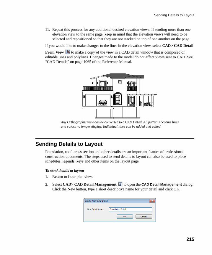
Sending Details to Layout
215
11. Repeat this process for any additional desired elevation views. If sending more than one elevation view to the same page, keep in mind that the elevation views will need to be selected and repositioned so that they are not stacked on top of one another on the page.
If you would like to make changes to the lines in the elevation view, select CAD> CAD Detail
From View to make a copy of the view in a CAD detail window that is composed of editable lines and polylines. Changes made to the model do not affect views sent to CAD. See “CAD Details” on page 1065 of the Reference Manual.
Sending Details to LayoutFoundation, roof, cross section and other details are an important feature of professional construction documents. The steps used to send details to layout can also be used to place schedules, legends, keys and other items on the layout page.
To send details to layout
1. Return to floor plan view.
2. Select CAD> CAD Detail Management to open the CAD Detail Management dialog. Click the New button, type a short descriptive name for your detail and click OK.
Any Orthographic view can be converted to a CAD Detail. All patterns become lines and colors no longer display. Individual lines can be added and edited.
chief-architect-x6-users-guide.book Page 215 Monday, December 16, 2013 4:05 PM
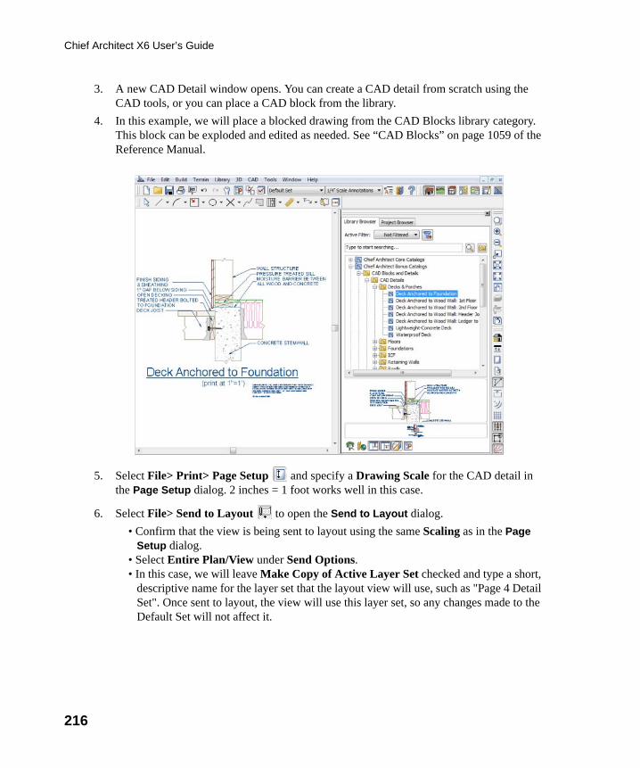
216
Chief Architect X6 User’s Guide
3. A new CAD Detail window opens. You can create a CAD detail from scratch using the CAD tools, or you can place a CAD block from the library.
4. In this example, we will place a blocked drawing from the CAD Blocks library category. This block can be exploded and edited as needed. See “CAD Blocks” on page 1059 of the Reference Manual.
5. Select File> Print> Page Setup and specify a Drawing Scale for the CAD detail in the Page Setup dialog. 2 inches = 1 foot works well in this case.
6. Select File> Send to Layout to open the Send to Layout dialog.
• Confirm that the view is being sent to layout using the same Scaling as in the Page Setup dialog.
• Select Entire Plan/View under Send Options.• In this case, we will leave Make Copy of Active Layer Set checked and type a short,
descriptive name for the layer set that the layout view will use, such as "Page 4 Detail Set". Once sent to layout, the view will use this layer set, so any changes made to the Default Set will not affect it.
chief-architect-x6-users-guide.book Page 216 Monday, December 16, 2013 4:05 PM
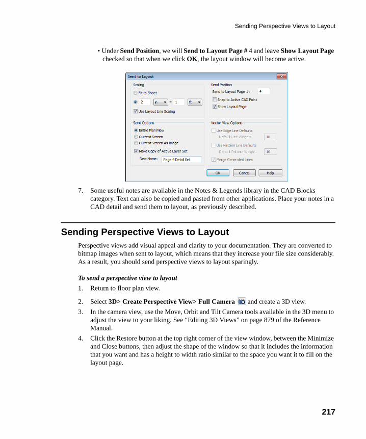
Sending Perspective Views to Layout
217
• Under Send Position, we will Send to Layout Page # 4 and leave Show Layout Page checked so that when we click OK, the layout window will become active.
7. Some useful notes are available in the Notes & Legends library in the CAD Blocks category. Text can also be copied and pasted from other applications. Place your notes in a CAD detail and send them to layout, as previously described.
Sending Perspective Views to LayoutPerspective views add visual appeal and clarity to your documentation. They are converted to bitmap images when sent to layout, which means that they increase your file size considerably. As a result, you should send perspective views to layout sparingly.
To send a perspective view to layout
1. Return to floor plan view.
2. Select 3D> Create Perspective View> Full Camera and create a 3D view.
3. In the camera view, use the Move, Orbit and Tilt Camera tools available in the 3D menu to adjust the view to your liking. See “Editing 3D Views” on page 879 of the Reference Manual.
4. Click the Restore button at the top right corner of the view window, between the Minimize and Close buttons, then adjust the shape of the window so that it includes the information that you want and has a height to width ratio similar to the space you want it to fill on the layout page.
chief-architect-x6-users-guide.book Page 217 Monday, December 16, 2013 4:05 PM
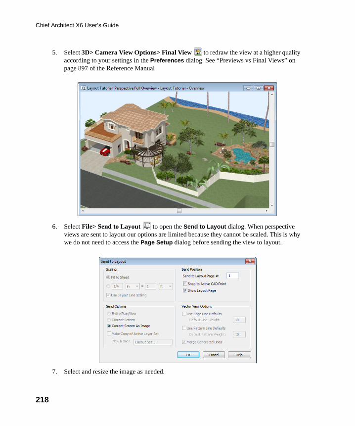
218
Chief Architect X6 User’s Guide
5. Select 3D> Camera View Options> Final View to redraw the view at a higher quality according to your settings in the Preferences dialog. See “Previews vs Final Views” on page 897 of the Reference Manual
6. Select File> Send to Layout to open the Send to Layout dialog. When perspective views are sent to layout our options are limited because they cannot be scaled. This is why we do not need to access the Page Setup dialog before sending the view to layout.
7. Select and resize the image as needed.
chief-architect-x6-users-guide.book Page 218 Monday, December 16, 2013 4:05 PM
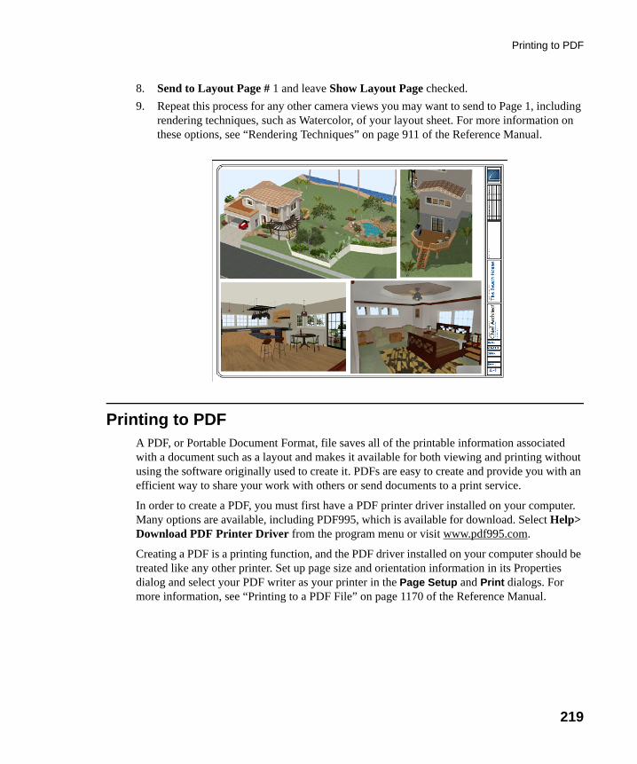
Printing to PDF
219
8. Send to Layout Page # 1 and leave Show Layout Page checked.
9. Repeat this process for any other camera views you may want to send to Page 1, including rendering techniques, such as Watercolor, of your layout sheet. For more information on these options, see “Rendering Techniques” on page 911 of the Reference Manual.
Printing to PDFA PDF, or Portable Document Format, file saves all of the printable information associated with a document such as a layout and makes it available for both viewing and printing without using the software originally used to create it. PDFs are easy to create and provide you with an efficient way to share your work with others or send documents to a print service.
In order to create a PDF, you must first have a PDF printer driver installed on your computer. Many options are available, including PDF995, which is available for download. Select Help> Download PDF Printer Driver from the program menu or visit www.pdf995.com.
Creating a PDF is a printing function, and the PDF driver installed on your computer should be treated like any other printer. Set up page size and orientation information in its Properties dialog and select your PDF writer as your printer in the Page Setup and Print dialogs. For more information, see “Printing to a PDF File” on page 1170 of the Reference Manual.
chief-architect-x6-users-guide.book Page 219 Monday, December 16, 2013 4:05 PM

220
Chief Architect X6 User’s Guide
chief-architect-x6-users-guide.book Page 220 Monday, December 16, 2013 4:05 PM
221
Appendix A
End User LicenseAgreement
Chief Architect, Inc.
End User Software License Agreement for Chief Architect® Software
NOTICE TO USER:
PLEASE READ CAREFULLY: THIS IS A CONTRACT. BY INSTALLING, COPYING OR USING THIS SOFTWARE, YOU AGREE TO BE BOUND BY ALL THE TERMS AND CONDITIONS OF THIS LICENSE AGREEMENT, ON YOUR OWN BEHALF AND ON THE BEHALF OF THE ENTITY BY WHOM YOU ARE EMPLOYED OR REPRESENT. IF YOU DO NOT AGREE WITH THE TERMS OF THIS AGREEMENT, DO NOT INSTALL, USE OR COPY THE SOFTWARE. INSTEAD, RETURN THE SOFTWARE WITHIN THE SPECIFIED GUARANTEE PERIOD TO THE PLACE OF PURCHASE FOR A REFUND OF YOUR PURCHASE PRICE.
This Chief Architect, Inc. End User License Agreement ("License Agreement", or "EULA") is a legal agreement between you (an individual or entity) and Chief Architect, Inc., and sets forth the terms and conditions under which you are licensed to use the Software. "Software" means (A) all of the contents of the CD-ROM(s), DVD(s), electronic download, online media, or any other media which is accompanied by this Agreement, including, but not limited to (i) Chief
chief-architect-x6-users-guide.book Page 221 Monday, December 16, 2013 4:05 PM
222
Chief Architect X6 User’s Guide
Architect or third party software, (ii) printed, "online" or electronic explanatory materials ("Documentation"), (iii) digital images, sample plans, textures, images, symbols, photographs, videos or other artistic works ("Graphical Files"), (B) hardware or software security key, if any, and (C) modified versions, updates, upgrades, downloadable content, additions and copies of the software, if any, licensed to you by Chief Architect, Inc. (collectively, "Updates").
1. GRANT OF LICENSE TO USE SOFTWARE: Chief Architect, Inc. grants you a non-exclusive, non-transferable (except as provided below) license ("License") to use the Software in object code only (and specifically not in source code) subject to the following terms and conditions:
(a)Software: Unless otherwise agreed to in writing, Chief Architect, Inc. grants you the right to use one copy of the Software on only one computer at one location at any one time;
(b)Storage/Network Use: You may store or install the Software on a network server or other storage device only to install and run the Software on an internal network. You must, however, purchase and dedicate a separate license of the Software for each computer and each concurrent user of the Software installed or accessed from a network server or other storage device. A single license for the Software may not be shared or used concurrently on different computers;
(c)Backup: You may make a backup copy of the Software for archival purposes. If printed Documentation accompanies the Software, it may not be copied. If the Software is accompanied by Documentation in electronic form, you may print out one (1) copy for your use which, in turn, may not be copied. A copy of the Software must include all copyright notices and this License Agreement;
(d)If you receive one copy of the Software electronically and a second copy on media, the second copy may be used for archival purposes only and may not be transferred to or used by any other person. This license does not grant you any right to any enhancement or update unless otherwise agreed to in writing by Chief Architect, Inc.;
(e)The Student Edition of the Software must be used only by a student for qualified educational purposes and only while actively studying at a qualified educational institution. The Student Edition of the Software shall not be used for commercial purposes;
(f)The NKBA Exam Version of the Software must be used only by a registered NKBA Exam applicant and only for the purpose of preparing for and taking the NKBA Exam. The NKBA Exam Version has a limited timeout period and cannot be upgraded. The NKBA Exam Version of the Software shall not be used for commercial purposes;
(g)Academic Licenses are licensed for use by educational institutions for educational purposes only. If the Software is licensed as an Academic License and you are not a qualified educational institution using the Software for qualified educational purposes, then your license(s) of the Software are invalid.
2. OTHER RIGHTS AND RESTRICTIONS:
chief-architect-x6-users-guide.book Page 222 Monday, December 16, 2013 4:05 PM
223
(a)Reverse Engineering: You may not modify, translate, reverse engineer, decompile, disassemble, or modify the Software in any way or use any other method to convert the Software or any component of the Software into human-readable code, create derivative works based upon the Software, Documentation, or Graphical Files or allow anyone else to do so;
(b)Renting: You may not rent, lease, sub-license, lend, duplicate or distribute the Software, Documentation, or Graphical Files without the prior written consent of Chief Architect, Inc., which, if given, is subject to the transferee's consent to the terms and conditions of this License Agreement;
(c)Copying: You may not copy or reproduce the Software, Documentation, or Graphical Files (except for personal back-up purposes);
(d)Upgrades: If the Software is being licensed to you as an upgrade, renewal, or update to software previously licensed to you, you must cease using the software previously licensed to you, including any copies installed on your computer hard-disk drives, once you have successfully installed and commenced use of the upgrade, renewal, or update software. You may not transfer or sell the software version previously licensed to you. Any unauthorized attempt to transfer or sell the software previously licensed to you will result in automatic termination of your current software license. You may, however, maintain a copy of the software previously licensed to you for archival purposes only;
(e)The Student Edition has a limited timeout period and cannot be upgraded;
(f)Proprietary Notices: You may not remove any proprietary notices or labels from the Software, Documentation, or Graphical Files;
(g)Protection: You may not utilize any computer hardware or software designed to defeat any hardware or software copy-protection device, should the Software be equipped with such protection. You may not disable any copy-protection or security control features of the Software;
(h)Licensing and Authentication: This Software uses security technology to authenticate your software installation and protect your license from unauthorized use. You agree to allow the Software to send this security information to the Chief Architect security servers for authentication. You may not disable any such security, licensing, or control features of the Software;
(i)Public Access: You may not copy the Software, Graphical Files, or any component of the Software onto any public network. You may not, in any manner, make it accessible to others, including via internet Web site, telecommunication transmittal, electronic bulletin board, or any other form of electronic distribution system;
(j)Distribution: This Software and all components of the Software are licensed for your use only. You may not share or distribute the Software to any other party or entity. You may share only images, textures, and symbols used by your design with other licensed users of the software; however, you may not share or distribute these files or exported versions of these
chief-architect-x6-users-guide.book Page 223 Monday, December 16, 2013 4:05 PM
224
Chief Architect X6 User’s Guide
files to any other party or entity for use as library content with other software programs. Use of Chief Architect Graphical Files as library content within other software programs is a violation of this License Agreement.
3. TRANSFERRING YOUR SOFTWARE: You may permanently transfer your license to another person or entity only upon written approval by Chief Architect, Inc., and according to the following terms and conditions:
(a)You must fill out, sign, and return to Chief Architect, Inc. the Certificate of Transfer of Ownership prior to any transfer of the Software. This is available through the Chief Architect, Inc.’s Customer Service Department. Call Chief Architect, Inc.'s Customer Service Department prior to any transfer in order to receive this document;
(b)The transferor or transferee must pay to Chief Architect, Inc. a license transfer fee for each license transferred to complete the process of transfer of ownership;
(c)You may permanently transfer a current, valid and eligible license for the Software, for which full price was paid. If you received a discount or rebate on the Software, you must pay to Chief Architect, Inc. the difference in price between your discounted price and the full price of the Software for each license transferred. You must deliver the Software to the transferee in its entirety and must not retain any copy of the Software on any computer or storage media, including backup or archival copies;
(d)You may transfer an Additional License and still retain other licenses of the Software only by paying to Chief Architect, Inc. the difference in price between the full retail price of the Software and the net price paid (including discounts and rebates) for each Additional License transferred;
(e)If you own multiple licenses and you wish to transfer a license, the license to be transferred shall be the license for which you received the largest discount or rebate;
(f)Your License will automatically terminate upon any transfer of the Software;
(g)If the Software being transferred is an Upgrade, you must cease using all prior versions of the Software, Documentation, and Graphical Files as well. You must uninstall all versions of the software and you may not use or retain any copy of any prior version of the Software;
(h)You may not transfer any earlier versions of Software which have been upgraded;
(i)You may not transfer a license of the Software that was purchased under the Chief Architect National Accounts program;
(j)You may not transfer a Not For Resale (NFR) license of the Software. You also may not transfer a Presentation license, a Student license, or an Academic license of the Software;
(k)You may not transfer any NKBA Exam Version license of the Software;
(l)The recipient of the transfer shall agree to all the terms of this License Agreement as a condition of the transfer.
chief-architect-x6-users-guide.book Page 224 Monday, December 16, 2013 4:05 PM
225
4. TITLE: Title, ownership, rights, and intellectual property rights in and to the Software, Documentation, Graphical Files, and any other accompanying materials shall remain with Chief Architect, Inc. or the respective third party. Title, ownership, rights, and intellectual property rights in and to each of the Sample Drawings and any accompanying materials shall remain with each Licensor from whom Chief Architect, Inc. licensed each Sample Drawing and any accompanying materials. Unauthorized copying of the Software, Documentation, Graphical Files, or Sample Drawings, or failure to comply with the foregoing restrictions, will result in the automatic termination of this License Agreement. Unauthorized duplication of the Software, Documentation, Graphical Files, or Sample Drawings constitutes copyright infringement and in the United States is punishable in a federal criminal action by a fine of up to $250,000 and imprisonment of up to five (5) years. In addition, federal civil penalties allow the recovery of actual damages based on the number of unauthorized copies produced or statutory damages of up to $100,000 for willful copyright infringement.
5. THIRD PARTY CONTENT: All trademarks and logos belong to their respective owners. All Graphical Files and Content, including symbols, images, textures, backdrops, text, and videos are the copyright subject matter of Chief Architect, Inc. or third parties. The Graphical Files and Content included with the Software are provided for use with the Software only. You shall not use the Graphical Files or Content included with the Software for any other purpose outside of the Software plan files. You shall not sell or distribute the Graphical Files or Content for any purpose whatsoever. You shall not use the Graphical Files or Content with other software. Chief Architect, Inc. and third party content, symbols, text, or textures shall not be copied, redistributed, or sold separately from the Software. Chief Architect, Inc. and third party product content is provided for representational purposes only. Chief Architect, Inc. and third parties assume no responsibility for any discrepancies between actual product appearance and that represented in the Software, or between actual pricing, characteristics, and specifications, and that mentioned anywhere in the Software or Documentation.
6. MONEY-BACK GUARANTEE PERIOD: The Software has a money-back guarantee for satisfaction. During the money-back guarantee period (the "Guarantee Period") following your first purchase of the Software, you may request to return the Software, Documentation, Security Device (if any), and packaging, along with the original purchase receipt, for a refund of the purchase price, less any applicable shipping fees, taxes, duties, discounts, and rebates paid. This money-back guarantee does not apply to license transfers. You agree to contact Chief Architect, Inc. in order to obtain and perform proper return material authorization ("RMA") steps prior to returning the Software. You also agree to uninstall and deactivate the Software and all of its related files and content from your computer prior to returning the product.
If, after returning the Software, Documentation, Security Device (if any), and packaging for a refund, you repurchase any version of the Software again, you are, by the act of repurchasing the Software, acknowledging satisfaction with the Software, and by doing so agree to purchase and keep the Software permanently without the option to return it for a refund.
chief-architect-x6-users-guide.book Page 225 Monday, December 16, 2013 4:05 PM
226
Chief Architect X6 User’s Guide
7. GRANT OF LICENSE TO USE SAMPLE DRAWINGS: Chief Architect, Inc. has licensed from third parties (the "Licensors") sample drawings that may be included in the Software. These Sample Drawings are provided to you by Chief Architect, Inc. solely for demonstrative and illustrative purposes to help you more quickly learn and better understand the functional capabilities of the Software, and are licensed to you solely for these limited purposes. You may not reproduce, distribute or use these Sample Drawings for any other purpose without the prior written consent of Chief Architect, Inc. and the Licensor(s) from whom these Sample Drawings were licensed by Chief Architect, Inc..
8. LIMITED SOFTWARE WARRANTY: Chief Architect, Inc. warrants that for a period of sixty (60) days from the date of your purchase of the Software as evidenced by an original copy of your receipt, the media upon which the Software is furnished will be free from defects in materials and workmanship under normal use. EXCEPT FOR THE ABOVE EXPRESS LIMITED WARRANTIES, CHIEF ARCHITECT, INC. MAKES NO WARRANTIES AS TO THE SOFTWARE, EXPRESS, IMPLIED, STATUTORY, OR IN ANY COMMUNICATION WITH YOU. CHIEF ARCHITECT, INC. SPECIFICALLY DISCLAIMS ANY OTHER WARRANTY INCLUDING THE IMPLIED WARRANTY OF MERCHANTABILITY OR FITNESS FOR A PARTICULAR PURPOSE WITH REGARD TO THE SOFTWARE, AND THE ACCOMPANYING WRITTEN MATERIALS. CHIEF ARCHITECT, INC. DOES NOT WARRANT THAT YOUR USE OF THE SOFTWARE WILL BE UNINTERRUPTED OR THAT THE OPERATION OF THE SOFTWARE WILL BE ERROR-FREE. If this Software was purchased in the United States, the above exclusions may not apply to you as some states do not allow the exclusion of implied warranties. In addition to the above warranty rights, you may also have other rights, which vary from state to state.
9. CUSTOMER REMEDIES: The entire liability of Chief Architect, Inc. and your exclusive remedy under the warranty provided as to Software set forth above will be, at Chief Architect, Inc.'s sole discretion: (i) to replace the media; (ii) to attempt to correct or work around software media errors, if any; or (iii) if the above remedies are impracticable to refund the license fee you paid, if any, for the Software. The latter remedy is subject to pre-authorized return of the Software, Documentation, Security Device (if any) and packaging to Chief Architect, Inc. or to the Authorized Chief Architect, Inc. Dealer or Reseller from whom the Product was obtained together with an original copy of your receipt.
Repaired, corrected or replaced software media and documentation shall be covered by this limited warranty for the period remaining under the warranty that covered the original Software or, if longer, for thirty (30) days after the date Chief Architect, Inc. shipped the repaired or replaced software media or documentation to you. Only if you inform Chief Architect, Inc. of the problem with the software media or documentation during the applicable warranty period and provide evidence of the date you acquired the Software will Chief Architect, Inc. honor this warranty.
10. NO WARRANTY AS TO THE SAMPLE DRAWINGS, SAMPLE PLANS, LIBRARY CONTENT, OR VIDEOS: CHIEF ARCHITECT, INC. MAKES NO WARRANTY
chief-architect-x6-users-guide.book Page 226 Monday, December 16, 2013 4:05 PM
227
WHATSOEVER AS TO THE SAMPLE DRAWINGS, SAMPLE PLANS, LIBRARY CONTENT, OR TRAINING VIDEOS WHICH ARE PROVIDED TO YOU SOLELY FOR DEMONSTRATIVE AND ILLUSTRATIVE PURPOSES. CHIEF ARCHITECT, INC. MAKES NO WARRANTY THAT THE DIMENSIONS IN THE SAMPLE DRAWINGS, SAMPLE PLANS, LIBRARY CONTENT, OR VIDEOS ARE ACCURATE AND FREE OF DISCREPANCIES. CHIEF ARCHITECT, INC. MAKES NO WARRANTY THAT THE LIBRARY CONTENT, SAMPLE DRAWINGS, OR SAMPLE PLANS COMPLY WITH ANY BUILDING CODES. THE LIBRARY CONTENT, SAMPLE DRAWINGS, AND SAMPLE PLANS ARE PROVIDED TO YOU "AS IS," AND CHIEF ARCHITECT, INC. AND THE LICENSORS OF THE LIBRARY CONTENT, SAMPLE DRAWINGS, AND SAMPLE PLANS DISCLAIM ANY AND ALL WARRANTIES WITH RESPECT TO THE LIBRARY CONTENT, SAMPLE DRAWINGS, AND SAMPLE PLANS, WHETHER EXPRESS OR IMPLIED OR ARISING BY CUSTOM OR TRADE USAGE, AND, SPECIFICALLY, MAKE NO WARRANTY OF MERCHANTABILITY OR FITNESS FOR ANY PARTICULAR PURPOSE.
11. DISCLAIMER AND LIMITATION OF LIABILITY: COMPUTER-AIDED DESIGN SOFTWARE AND OTHER TECHNICAL SOFTWARE ARE TOOLS INTENDED TO BE USED BY TRAINED AND EXPERIENCED INDIVIDUALS ONLY. THEY ARE NOT SUBSTITUTES FOR YOUR TRAINED, EXPERIENCED AND PRACTICAL JUDGMENT. COMPUTER-AIDED DESIGN SOFTWARE AND OTHER TECHNICAL SOFTWARE ARE INTENDED TO ASSIST WITH ARCHITECTURAL, PREMISES OR PRODUCT DESIGN AND ARE NOT SUBSTITUTES FOR INDEPENDENT TESTING OF STRUCTURAL INTEGRITY, ENGINEERING, SOUNDNESS, SAFETY, AND UTILITY. DUE TO THE LARGE VARIETY OF POTENTIAL APPLICATIONS FOR THE SOFTWARE, THE SOFTWARE HAS NOT BEEN TESTED IN ALL SITUATIONS UNDER WHICH IT MAY BE USED. CHIEF ARCHITECT, INC. SHALL NOT BE LIABLE IN ANY MANNER WHATSOEVER FOR THE RESULTS OBTAINED THROUGH THE USE OF THE SOFTWARE. PERSONS USING THE SOFTWARE ARE RESPONSIBLE FOR THE SUPERVISION, MANAGEMENT AND CONTROL OF THE SOFTWARE AND THEIR EMPLOYEES OR CONTRACTORS WHO USE THE SOFTWARE. THIS RESPONSIBILITY INCLUDES, BUT IS NOT LIMITED TO, THE DETERMINATION OF APPROPRIATE USES FOR THE SOFTWARE AND THE SELECTION OF THE SOFTWARE AND OTHER PROGRAMS TO ACHIEVE INTENDED RESULTS. PERSONS USING THE SOFTWARE ARE ALSO RESPONSIBLE FOR ESTABLISHING THE ADEQUACY OF INDEPENDENT PROCEDURES FOR TESTING THE RELIABILITY AND ACCURACY OF ANY PROGRAM OUTPUT, INCLUDING ALL ITEMS DESIGNED OR MEASURED BY USING THE SOFTWARE.
UNDER NO CIRCUMSTANCES WILL CHIEF ARCHITECT, INC., ITS DEALERS, RESELLERS, DISTRIBUTORS, OR THE LICENSORS OF THE GRAPHICAL FILES, SAMPLE DRAWINGS, AND SAMPLE PLANS BE LIABLE FOR ANY DAMAGES, WHETHER ARISING FROM TORT OR CONTRACT, INCLUDING LOSS OF DATA,
chief-architect-x6-users-guide.book Page 227 Monday, December 16, 2013 4:05 PM
228
Chief Architect X6 User’s Guide
LOST PROFITS, COST OF COVER, OR OTHER SPECIAL, INCIDENTAL, CONSEQUENTIAL OR INDIRECT DAMAGES ARISING OUT OF THE USE OR INABILITY TO USE THE SOFTWARE, DOCUMENTATION, GRAPHICAL FILES, OR THE SAMPLE DRAWINGS AND SAMPLE PLANS. CHIEF ARCHITECT, INC., ITS DEALERS, RESELLERS, DISTRIBUTORS, AND THE LICENSORS OF THE GRAPHICAL FILES, SAMPLE DRAWINGS, AND SAMPLE PLANS ASSUME NO LIABILITY OR RESPONSIBILITY FOR, AMONG OTHER THINGS, INADVERTENT DISCREPANCIES, CONSTRUCTION INTERPRETATIONS OR CONSTRUCTED RESULTS. THESE LIMITATIONS WILL APPLY EVEN IF CHIEF ARCHITECT, INC., ITS DEALERS, RESELLERS, DISTRIBUTORS, OR THE LICENSORS OF THE GRAPHICAL FILES, SAMPLE DRAWINGS, AND SAMPLE PLANS HAVE BEEN ADVISED OF THE POSSIBILITY OF SUCH DAMAGE. YOU ACKNOWLEDGE THAT THE LICENSE FEE REFLECTS THIS ALLOCATION OF RISK. FURTHER, IN NO EVENT SHALL THE LIABILITY OF CHIEF ARCHITECT, INC., ITS DEALERS, RESELLERS, DISTRIBUTORS, AND THE LICENSORS OF THE GRAPHICAL FILES, SAMPLE DRAWINGS, AND SAMPLE PLANS UNDER ANY PROVISION OF THIS AGREEMENT EXCEED THE LICENSE FEE PAID TO CHIEF ARCHITECT, INC. FOR THE SOFTWARE, DOCUMENTATION, GRAPHICAL FILES, AND THE SAMPLE DRAWINGS AND SAMPLE PLANS. BECAUSE SOME STATES DO NOT ALLOW THE EXCLUSION OR LIMITATION OF LIABILITY FOR CONSEQUENTIAL OR INCIDENTAL DAMAGES, THE ABOVE LIMITATION MAY NOT APPLY TO YOU.
12. TERMINATION: This license shall terminate automatically if you fail to comply with the terms, conditions, and limitations described in this license. No notice shall be required from Chief Architect, Inc. to effectuate such termination. Upon termination, you must immediately uninstall and deactivate the Software. You must also return or destroy all copies of the Software and Documentation.
13. U.S. GOVERNMENT RESTRICTED RIGHTS: The Software and Documentation are provided with RESTRICTED RIGHTS for U.S. Government customers. Use, duplication or disclosure by the Government is subject to restrictions as set forth in subparagraph (c)(1 )(ii) of The Rights in Technical Data and Computer Software clause at DFARS 252.227-7013 or subparagraphs (c)(i) and (2) of the Commercial Computer Software-Restricted Rights at 48 CFR 52.227-19 as applicable. The manufacturer is Chief Architect, Inc., 6500 N. Mineral Dr., Coeur d'Alene, Idaho 83815.
14. GOVERNING LAW: This License Agreement shall be governed by the laws of the State of Idaho without regard to conflicts of law principles. This License Agreement shall not be governed by the United Nations Convention of Contracts for the International Sale of Goods, the application of which is hereby expressly excluded. If either you or Chief Architect, Inc. employs attorneys to enforce any right arising out of this Agreement, the prevailing party shall be entitled to recover reasonable attorney's fees and costs.
chief-architect-x6-users-guide.book Page 228 Monday, December 16, 2013 4:05 PM
229
15. ENTIRE AGREEMENT: This agreement constitutes the complete and exclusive agreement between you and Chief Architect, Inc. with respect to the subject matter hereof and supersedes all prior oral or written understandings, communications or agreements not specifically incorporated herein. This agreement may not be modified except in a writing duly signed by an authorized representative of Chief Architect, Inc. and you. THE ACCEPTANCE OF ANY PURCHASE ORDER PLACED BY YOU IS EXPRESSLY MADE CONDITIONAL ON YOUR CONSENT TO THE TERMS SET FORTH HEREIN.
chief-architect-x6-users-guide.book Page 229 Monday, December 16, 2013 4:05 PM

230
Chief Architect X6 User’s Guide
chief-architect-x6-users-guide.book Page 230 Monday, December 16, 2013 4:05 PM
231
IndexNumerics
3D ViewsCreate ................................................ 38
AAbsolute Location
New line end .............................. 194, 196
AddingFloors ................................................. 41Foundations ........................................ 41Library Objects .................................. 173
Appliances ......................................... 122
ArtworkAdding ............................................... 142
AutoCalculate Elevation ............................ 161Check for Program Updates................. 17Dormers, Creating ............................... 75Exterior Dimensions ............................ 28Stairwell ............................................. 48
Auto RebuildRoofs ........................................... 60, 95
BBackdrops
Importing ........................................... 150
Basements........................................... 41
Blend Colors with Materials............. 143
BreakWall.................................................... 90
CCabinets
Base ................................................. 117Corner .............................................. 119Creating ............................................ 117Editing .............................................. 118Module Lines ............................ 119, 121Soffits ............................................... 121Wall, placing ..................................... 120
CADPoint, Current............................ 194, 196
CameraViews, Creating ................................... 38
CarpetAdding .............................................. 140
Chair RailsAdding .............................................. 107
ConcentricCopies, Creating ............................... 199
CornerCabinet ............................................. 119
Cross Section Slider ........................ 133
Cross Section/Elevations ................ 130
Crown MoldingAdding to rooms ................................ 107
DDeck
Railing .............................................. 178
DecksDrawing ............................................ 178
DefaultsMaterial ............................................ 136
chief-architect-x6-users-guide.book Page 231 Monday, December 16, 2013 4:05 PM
232
Chief Architect X6 User’s Guide
Dimensions ......................................... 28Auto Exterior ....................................... 28
DoorsAdding ................................................ 51Copying .............................................. 53Editing ................................................ 51Placing ............................................... 51
Dormers ............................................... 79Automatic ........................................... 75Manually Drawn .................................. 76
EElevation
Lines ................................................ 161
FFinal View .......................................... 133
Flatten Building Pad ........................ 161
FoundationCreating.............................................. 41
Furniture ............................................ 182
GGable
Over Door/Window .............................. 74Roofs.................................................. 63
Gambrel Roofs .................................... 66
Gull Wing Roofs .................................. 67
HHalf Hip Roofs ..................................... 68
HipRoofs.................................................. 63
IImage
Specification Dialog ........................... 149
ImagesCreating ............................................ 149
Installation ............................................. 7
InteriorDimensions ......................................... 29
Invisible Walls ..................................... 35
LLibrary Objects
Placing.............................................. 103
Library Search ................................... 103
MMansard Roofs .................................... 69
MaterialDefaults ............................................ 136Eyedropper ....................................... 144
Material Painter ................................. 140Blending............................................ 143
MaterialsApplying ............................................ 137Artwork ............................................. 142Blending............................................ 143Changing .......................................... 137Creating ............................................ 147
Materials Defaults ............................. 135
Materials List ..................................... 152
Materials Panel.................................. 137
Merging Walls...................................... 41
Molding .............................................. 107
Mouse-Orbit Camera..................... 40, 50
chief-architect-x6-users-guide.book Page 232 Monday, December 16, 2013 4:05 PM
233
OOpen
Plan ................................................... 20
PPlant Chooser .................................... 173
Plot PlanSetback Lines .................................... 199Terrain Perimeter ............................... 201
Pointsee also CAD point
Ponds .................................................. 169
Program UpdatesAuto Check ......................................... 17
RReference
Display ............................................... 41
Replace from Library ........................ 106
Retaining Wall, creating ................... 163
Roof Type Quick Reference .............. 72
RoofsAuto Dormer ....................................... 75Gable ................................................. 63Gambrel ............................................. 66Gull Wing............................................ 67Half Hip .............................................. 68Hip ..................................................... 63Mansard ............................................. 69Manual Dormers ................................. 76Returns .............................................. 73Saltbox ............................................... 65Shed .................................................. 64
RoomsCreating ............................................. 32Room Labels ...................................... 36Room Types ....................................... 36Selecting ........................................... 139
Rugs
Area rugs, creating ............................ 141
SSaltbox Roofs ..................................... 65
SelectRoom................................................ 139
ShedRoofs.................................................. 64
SkylightsCreating .............................................. 89
Soffits................................................. 121
Stair Designer ..................................... 46
Stair LandingCreating .............................................. 46
StairsDrawing ............................................ 179
Stairwell ............................................... 48Create manually .................................. 48
Starting the Program .......................... 20
Startup Options .................................. 20
TTerrain Perimeter
Plot Plan ........................................... 201
Title Blocks ....................................... 207
UUpdates
Auto Check ......................................... 17
WWall
Cabinets, placing............................... 120Coverings ......................................... 109
Walls
chief-architect-x6-users-guide.book Page 233 Monday, December 16, 2013 4:05 PM
234
Chief Architect X6 User’s Guide
Drawing .............................................. 25Merging .............................................. 41Retaining, creating ............................ 163
Water Features .................................. 169
WindowsCopying .............................................. 53Editing ................................................ 52Placing................................................ 51
chief-architect-x6-users-guide.book Page 234 Monday, December 16, 2013 4:05 PM