characterization of machined samples: ss304 and zircaloy4
TRANSCRIPT
CHARACTERIZATION OF MACHINED
SAMPLES:
SS-304L & ZIRCALOY-4
PROJECT REPORT SUBMITTED BY:
KISHLAY MISHRA
SUMMER TRAINEE AFFILIATION
Under the Guidance of
Dr. G.K. Dey
Head, Materials Science Division
Summer Trainee Internship (May‐ July 2013)
Bhabha Atomic Research Centre
Trombay, Mumbai 400 085
CERTIFICATE
This is to certify that Mr. Kishlay Mishra (IIT Kanpur) B.Tech student of the
fore mentioned college have done a project on “Characterization of
machined samples : SS-304L and Zircaloy-4” as a part of Summer
Internship conducted by HRDD, BARC, Trombay, Mumbai. The work
described in this report is bonafide work carried out by the student under
the guidance of following BARC Scientific Officer.
Dr. G.K. Dey Head, Material Science Division BARC, Trombay, Mumbai.

ACKNOWLEDGEMENT
This project is an outcome of all efforts and coordination of various people to whom I shall always be grateful.
I would like to express our sincere thanks to Dr.G.K.Dey and for taking me
under his tutelage-ship, for providing constant encouragement and useful
suggestions which proved to be of immense help during the tenure of my
training.
I take this opportunity to show our gratitude to all the employees at BARC
who had contributed their efforts, substantial time and support to help with
my assigned job. I pay my obeisance to them.
I would also like to acknowledge the contribution from Prof. I.Samajdar of
Indian Institute of Technology Bombay for extending the facilities at the
National Facility for Texture and OIM for this study.
Last but not the least i would like to express my heartfelt gratitude to the
college administration for allowing me to pursue the research in this
esteemed organization.
ABSTRACT
This study aims to understand the effects of surface machining on the
microstructure in SS-304L and Zircaloy-4, and crystalline arrangement of
machined layer. To provide a holistic picture, for every property,
comparison was done between machined surface and the bulk.
In depth characterization was carried out by Optical Microscope, FEG-
SEM, TEM, EBSD and Glancing Angle-XRD studies. SEM images depict
affected layer of approximate 8 microns from the machined edge alluding to
plastic flow of material due to machining in that region. TEM results show
presence of grains of size of around 30nm in the affected layer of SS304L .
Diffraction pattern in the TEM confirms the nanocrystalline nature of the
grains. GIancing angle-XRD shows no change of phase in both the
samples of SS304L and Zircaloy 4 in the orientation chosen for the
scanned area. EBSD shows Martensitic formation in SS304L and no phase
change in Zircaloy 4.

INTRODUCTION
Every metallic material that we use, is machined in one way or another.
Machining provides a surface finish that makes the object precise in its
dimensions and adds aesthetic value. The surface finish in turn is primarily
dictated by the surface machining and grinding operation which in practice
is one of the most important stages in the fabrication process. Conclusively,
machining is a primary requirement and is inevitable. But the problem with
machining is that it changes the microstructure of surface and creates a
layer of altered material. Through a series of experiments we hope to
accomplish a detailed investigation on the precise changes in the surface
conditions resulting from closely controlled surface finishing operation and
comparing it to the bulk.

MATERIALS USED
To obtain a wider perspective, we selected two very different materials:
· AISI grade 304L Austenitic Stainless Steel with a chemical composition (in wt.%):
0.03 max C , 18.00 - 20.00 Cr, 8.00 - 12.00 Ni, 0.75 max Si, 2.00 max Mn, 0.045 max P, 0.03 max S, and balance Fe.
· Zircaloy-4 with a chemical composition of: Zr , 0.5%Sn , 0.2%Fe , 0.1%Cr. These samples were machined using a lathe machine.
PROCEDURE
Four characterisation techniques were employed-
1.) Scanning Electron Microscopy (SEM)
■ The samples were polished at the perpendicular side of the machined
surface to study microstructural changes. Abrasive polishing was
done using emery papers of different grades(SiC grits) namely; 80,
150, 320, 420, 600, 800, 1000, 1200. Area of interest was the region
near the machined face(edge) thus, special emphasis was on that
area.
■ After Diamond polishing, the samples were then viewed under an
optical microscope to get an overview of the machined layer present
in the samples.
■ The SS304L sample was then studied under FEG-SEM after electro-
etching with oxalic acid. The machined layer was clearly visible and
could easily be differentiated from the bulk.
2.) Glancing Angle X-Ray Diffraction
■ Another set of samples from each of the two materials were prepared
for the Glancing Angle XRD. The samples were cut in a direction
parallel to the machined face and the cut surface were polished using
emery paper and diamond polishing. The machined surface and the
finely polished bulk surface were probed separately at different
depths in the analysis.
3.) Transmission Electron Microscopy (TEM)
■ TEM sample of SS-304L was prepared by making fine cuts into the
sample and obtaining multiple specimens of dimensions 2.5 mm X 2
mm X 0.5 mm. Two such specimen were pasted together so that the
machined edges are at the center, this was done to double the
probability of getting a thin area for TEM
■ Mounting cylinder was heated and the samples were glued together
using epoxy glue. Using disc grinder the samples were then polished
on emery paper(600, 800, 1000) ■ The thinned specimen was then transferred to copper grid.
■ SS304L sample was dimpled for 6 hours and the ion milled for 1 day
to electron transparency.
■ The sample prepared was not thin enough as dimpling had been done wrong the whole process was repeated.
■ TEM was done of SS304L in BARC.
■ More advanced form of TEM, TECNAI was done in Tata Institute of
Fundamental Research along with Energy Dispersive
Spectroscopy(EDS).
4.) Electron BackScattered Diffraction pattern (EBSD)
■ SS304L and Zircaloy 4 samples were polished with emery paper of grades upto 2500.
■ Diamond polishing and electropolishing of the two samples were
followed by Orientation Imaging Microscopy.
■ No pattern was obtained. The samples were then polished using colloidal Si polishing rather than electropolishing.
■ The second OIM was again unsuccessful.
■ The samples were prepared again from the start. Finer Polishing was
done upto 4000 grade of emery paper with caution followed by
diamond polishing and electropolishing.
RESULTS AND DISCUSSION
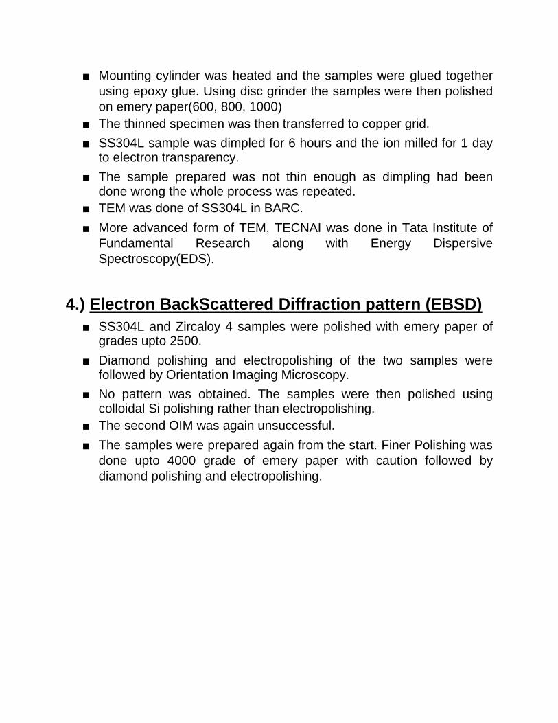
Optical Microscope:
Fig 1. SS304L showing mechanical deformation near the machined edge
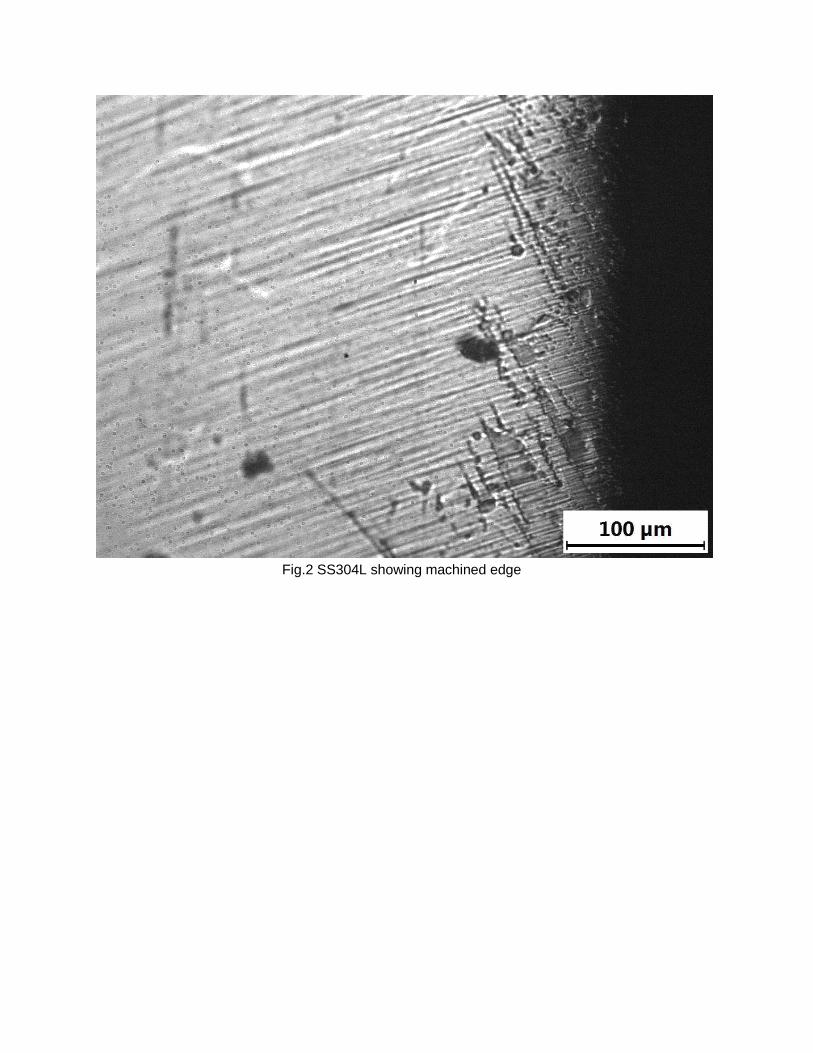
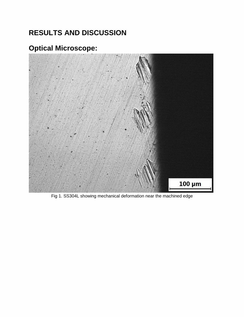
Fig.2 SS304L showing machined edge
Fig3. Zircaloy 4 showing uniform structure in the bulk and slightly deformed structure near the machined edge.
Optical microscopy was done to inspect visual differences in the bulk layer to the region near the machined edge.
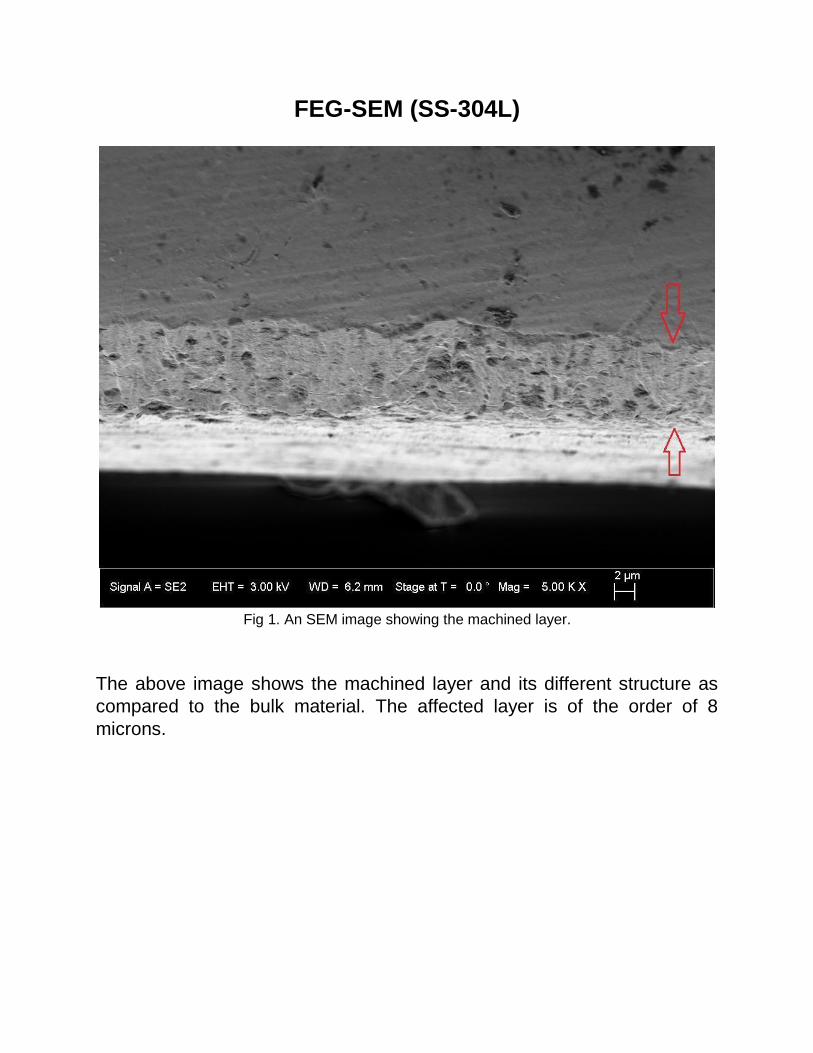
FEG-SEM (SS-304L)
Fig 1. An SEM image showing the machined layer.
The above image shows the machined layer and its different structure as
compared to the bulk material. The affected layer is of the order of 8
microns.
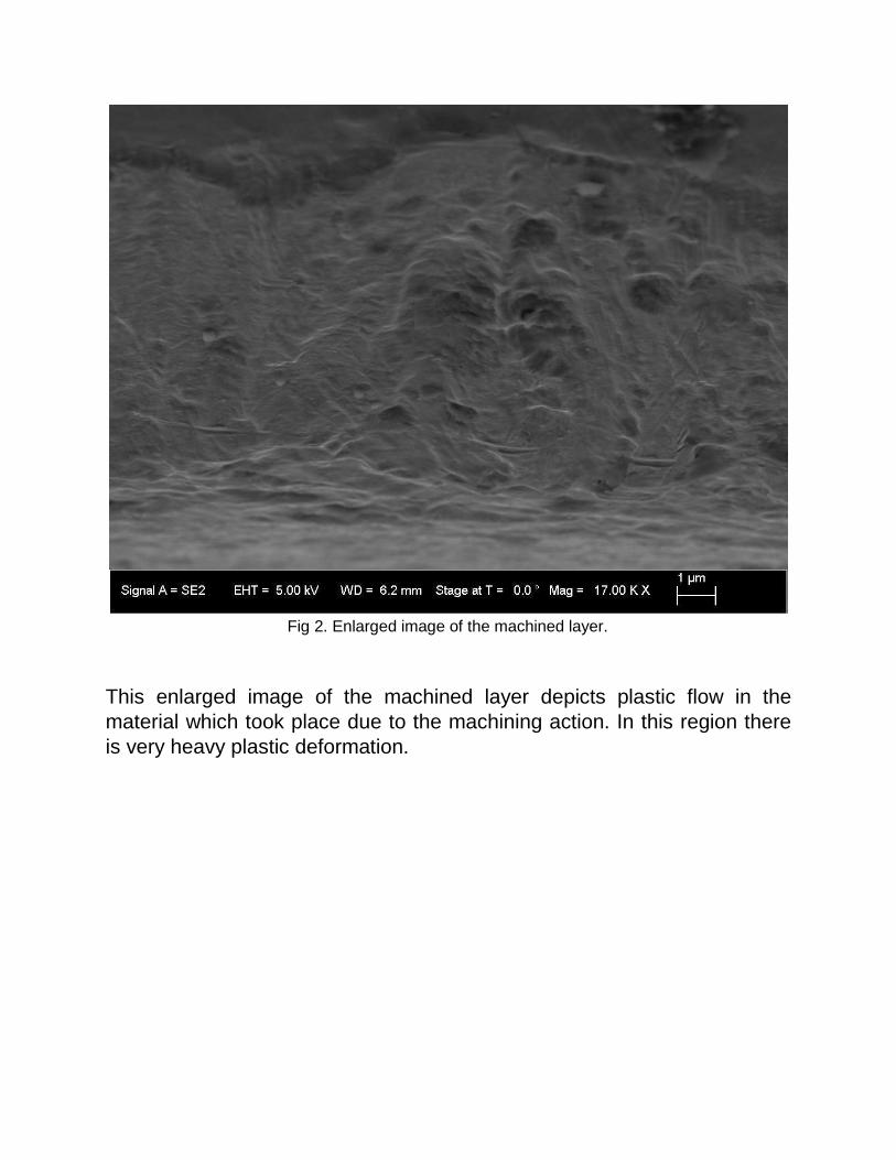
Fig 2. Enlarged image of the machined layer.
This enlarged image of the machined layer depicts plastic flow in the
material which took place due to the machining action. In this region there
is very heavy plastic deformation.
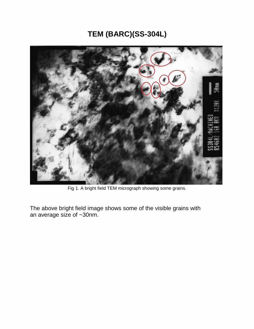
TEM (BARC)(SS-304L)
Fig 1. A bright field TEM micrograph showing some grains.
The above bright field image shows some of the visible grains with an average size of ~30nm.
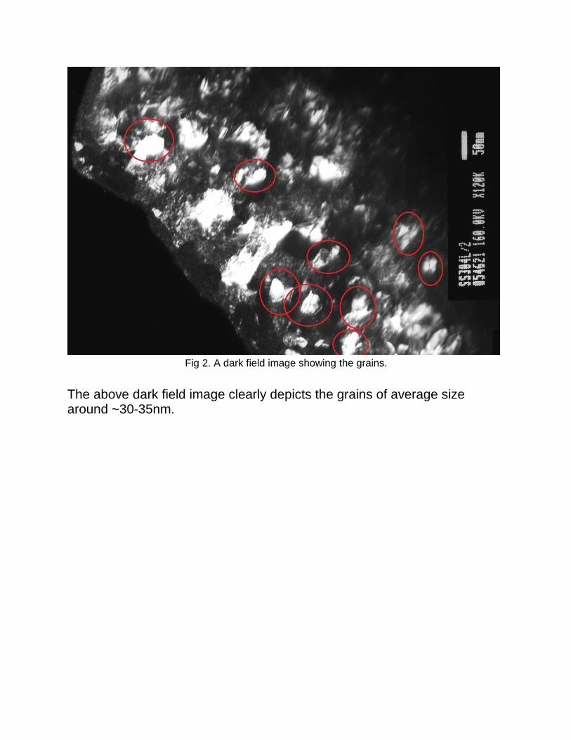
Fig 2. A dark field image showing the grains.
The above dark field image clearly depicts the grains of average size around ~30-35nm.
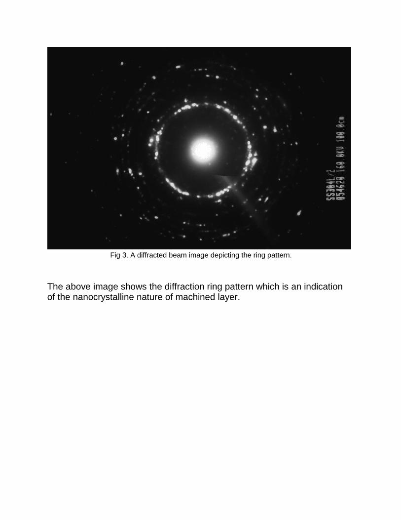
Fig 3. A diffracted beam image depicting the ring pattern.
The above image shows the diffraction ring pattern which is an indication of the nanocrystalline nature of machined layer.
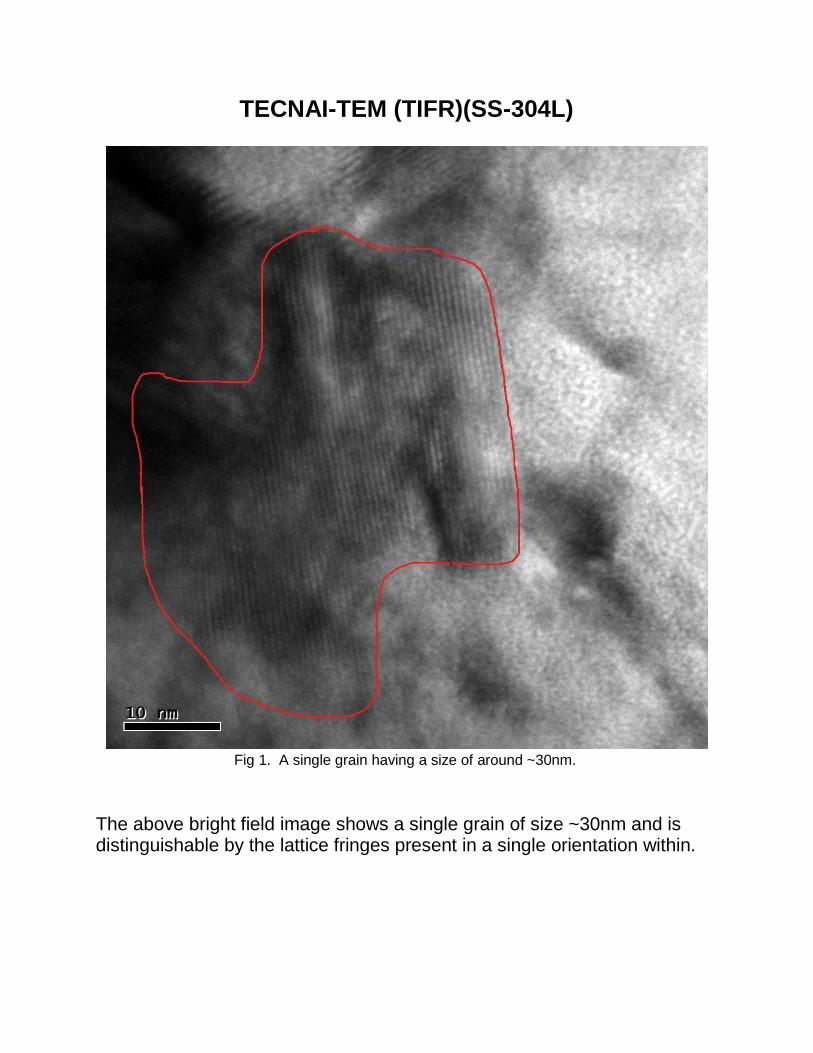
TECNAI-TEM (TIFR)(SS-304L)
Fig 1. A single grain having a size of around ~30nm.
The above bright field image shows a single grain of size ~30nm and is distinguishable by the lattice fringes present in a single orientation within.
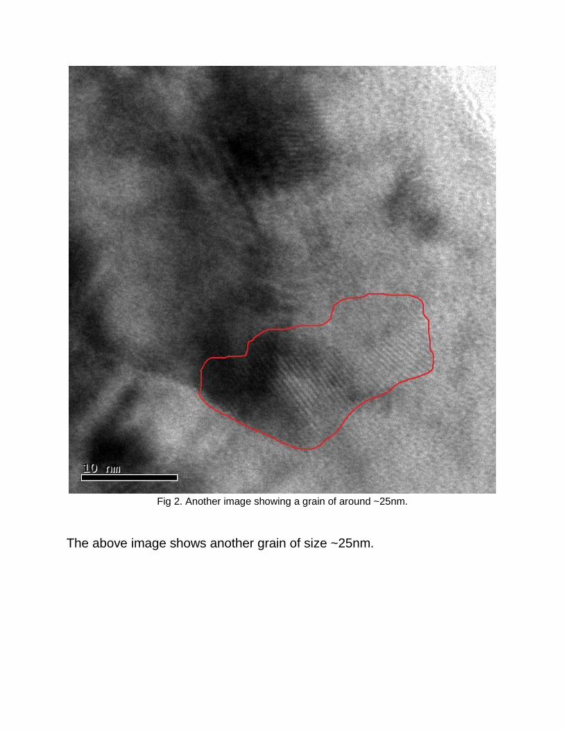
Fig 2. Another image showing a grain of around ~25nm.
The above image shows another grain of size ~25nm.
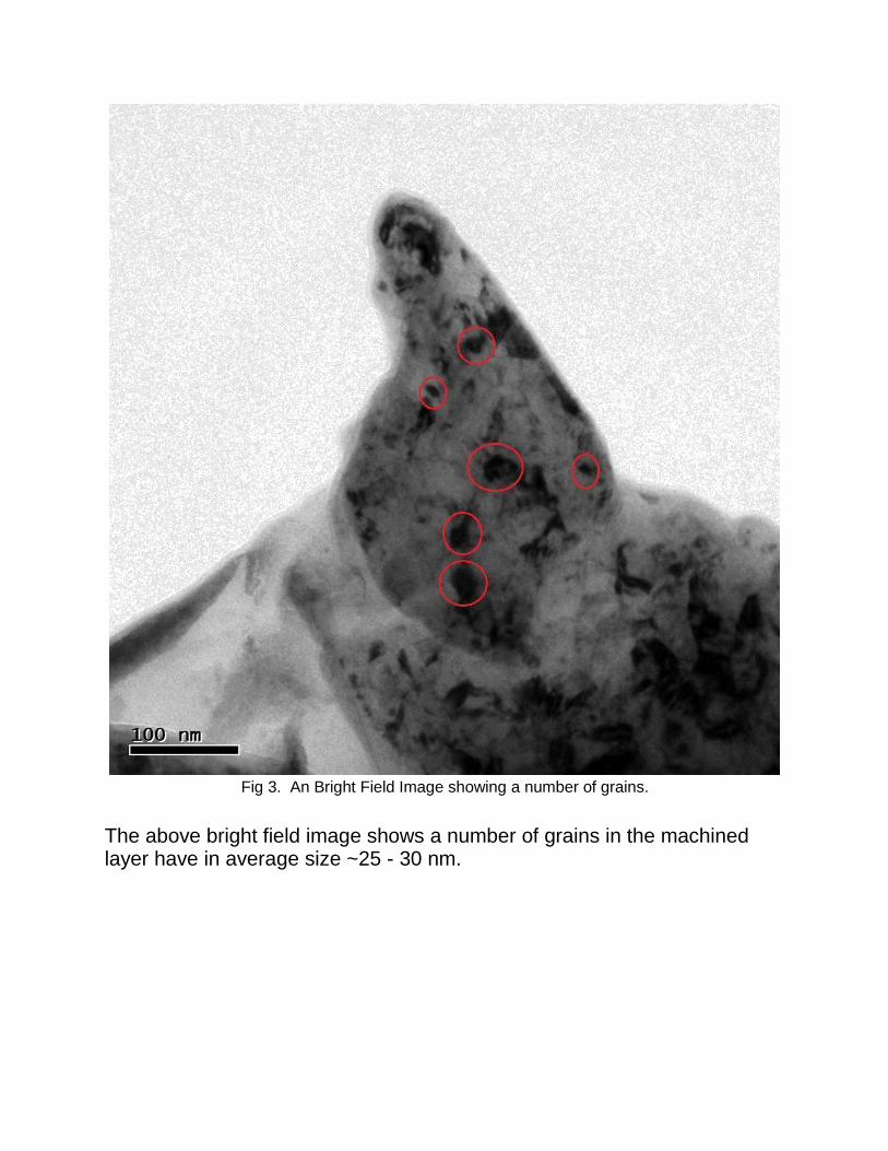
Fig 3. An Bright Field Image showing a number of grains.
The above bright field image shows a number of grains in the machined layer have in average size ~25 - 30 nm.
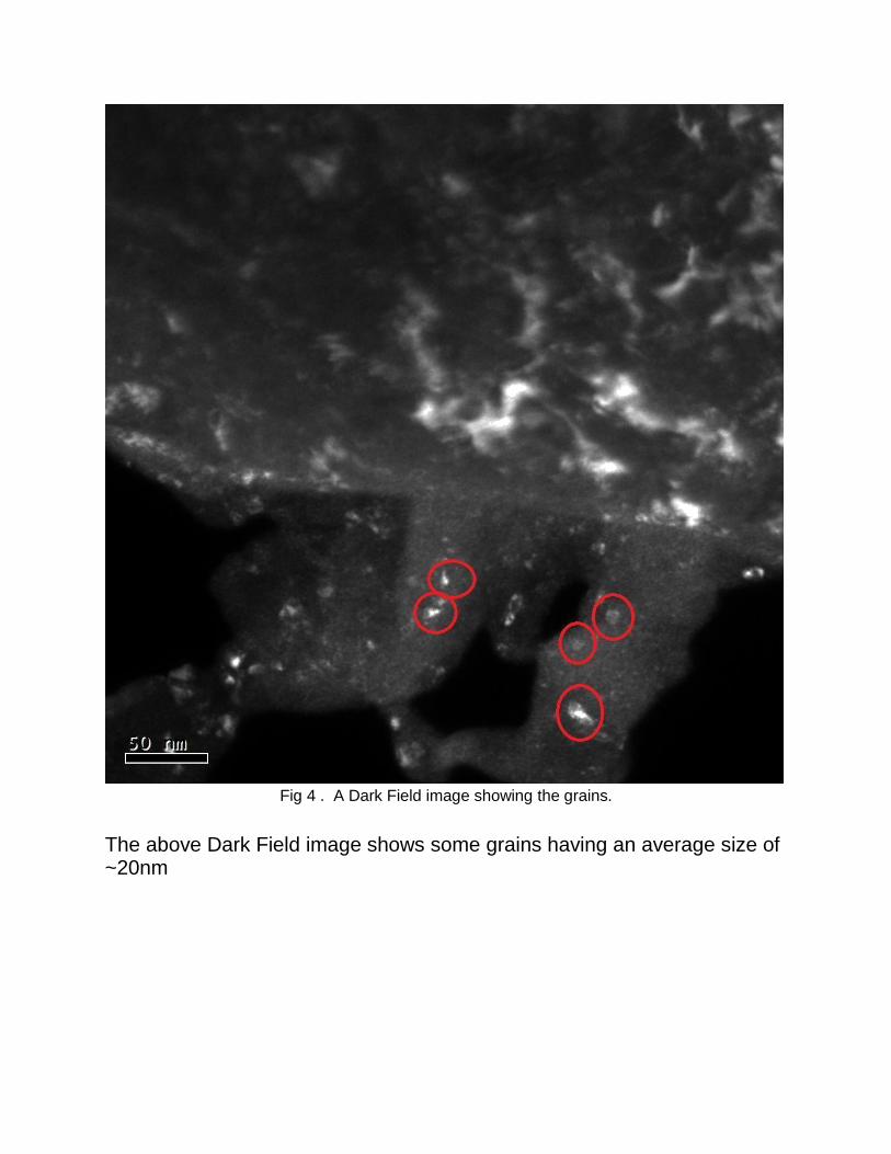
Fig 4 . A Dark Field image showing the grains.
The above Dark Field image shows some grains having an average size of ~20nm
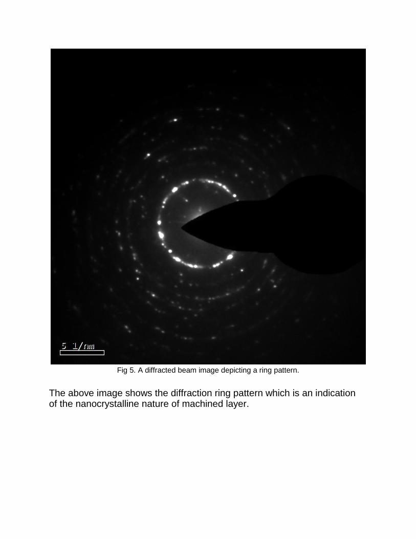
Fig 5. A diffracted beam image depicting a ring pattern.
The above image shows the diffraction ring pattern which is an indication of the nanocrystalline nature of machined layer.
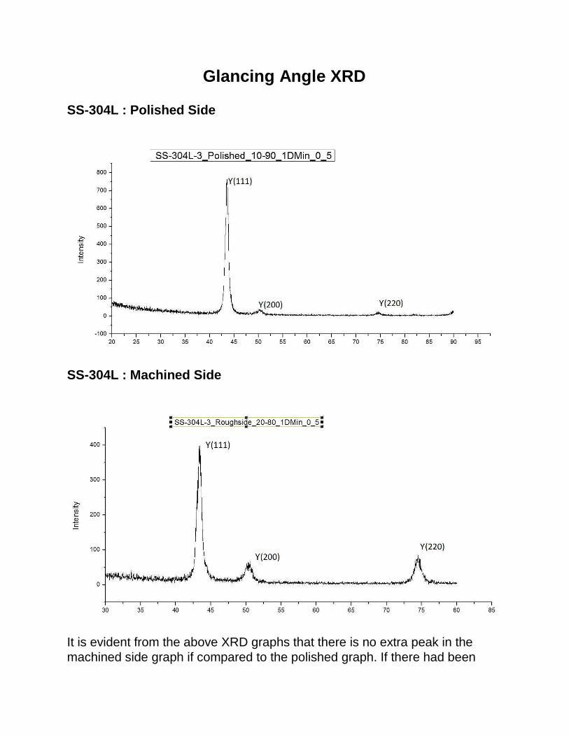
Glancing Angle XRD
SS-304L : Polished Side
SS-304L : Machined Side
It is evident from the above XRD graphs that there is no extra peak in the
machined side graph if compared to the polished graph. If there had been
any new phase formation during machining, a new peak would have been generated in the machined graph.
It might also be possible that if at all a new phase has formed in the
machined layer, its quantity is too small to detect or its peak might also lie
beyond the range of orientation(2theta value) taken here.
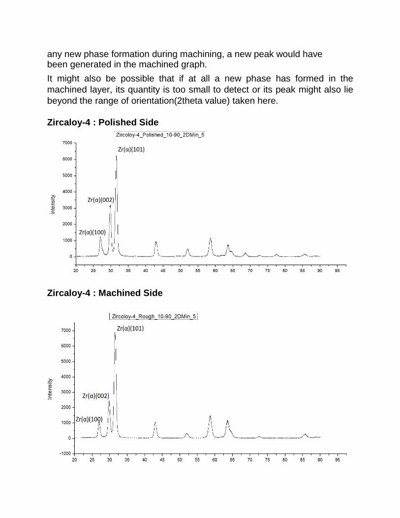
Zircaloy-4 : Polished Side
Zircaloy-4 : Machined Side

Comparing the two XRD graphs there is again no new peak formation in the machined side graph.
EBSD
SS-304L :
Details Of the process: ● Operator: support ● Calibration: 0.596700 0.676900 0.601000 ● Working Distance: 15.000000
● Number of points: 358358 ● Number of good points: 358350
● Dimensions: ● X Min: 0.00 microns ● X Max: 250.00 microns ● Y Min: 0.00 microns ● Y Max: 309.60 microns ● Step: 0.50 microns
● Average Confidence Index: 0.28 ● Average Image Quality: 810.55 ● Average Fit [degrees]: 1.50
● Phases:
•Iron - Gamma
•Iron - Alpha
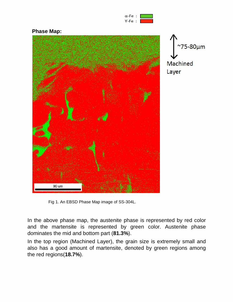
Phase Map:
Fig 1. An EBSD Phase Map image of SS-304L.
In the above phase map, the austenite phase is represented by red color
and the martensite is represented by green color. Austenite phase
dominates the mid and bottom part (81.3%).
In the top region (Machined Layer), the grain size is extremely small and
also has a good amount of martensite, denoted by green regions among
the red regions(18.7%).

Zircaloy-4:
Details of the process: ● Operator: support ● Calibration: 0.546719 0.770934 0.679779 ● Working Distance: 16.000000
● Number of points: 139653 ● Number of good points: 139653
● Dimensions:
X Min: 0.00 microns
X Max: 132.50 microns Y Min: 0.00 microns
Y Max: 227.33 microns Step: 0.50 microns
● Average Confidence Index: 0.49 ● Average Image Quality: 694.60 ● Average Fit [degrees]: 0.88 ● Phases: Zirconium (Alpha)
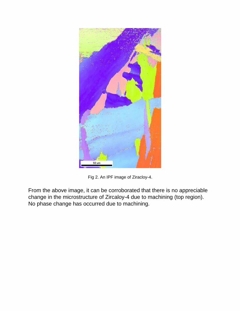
Fig 2. An IPF image of Ziracloy-4.
From the above image, it can be corroborated that there is no appreciable
change in the microstructure of Zircaloy-4 due to machining (top region).
No phase change has occurred due to machining.
CONCLUSION
1. Inferring from Optical Microscopy -Machined edge region showed deformation and non uniformity in its structure in contrast to the bulk region. 2. From SEM micrographs we can conclude that when SS304L undergoes
machining, its microstructure change upto a distance of 8 microns from its
edge. Large amount of plastic deformation takes place in that region
thereby affecting its properties.
3. From TEM micrographs, Diffraction pattern assured a nanocrystalline structure near the edges of the order of 30nm (average grain size).
4. From EBSD martensite phase was detected at 18.7 % of the total area 250 micron X 309.6 micron scanned near the machined edge of SS304L.
Fine Martensitic grains formed primarily near the machined edge to a
distance of 80 microns from the edge. This clearly states that martensite
formation took place due to machining.
5. In SS304L deformed layer extended from the edge to a distance of 8
microns whereas phase change occurred upto a distance of 80 microns.
Thus the deformed layer affected the microstructure of the specimen well
beyond its boundaries.
6. From Glancing angle XRD no different phase was recorded in SS304L
and Zircaloy 4. On the contrary EBSD showed martensitic formation thus,
we can conclude that martensite traces formed might not have been
detected due to constraints of the orientation (2theta) values chosen. When
calculated theoretically martensitic peak comes at 2theta value of 95
degrees as opposed to the 2theta range taken in the experiment 10-90
degrees
REFERENCES
1 . Microstructural changes in AISI 304L stainless steel due to surface
machining. By S. Ghosh, V.Kain , Journal Of Nuclear Material 403 (2010)
62-67.
2. Swati Ghosh, Vivekanand Kain, Materials Science and Engineering A 527 (2010) 679.
3. Microstructure of warm worked zircalloy-4. By H. Paul, M. Darrieulat, N. Vanderesse, L. Litynska, M. Miszczyk 4. Experimental Evaluation of the Rolling Reduction and Heat-Treatment
Effects on the Texture and Creep Behavior of a Zircaloy-4 Sheet. By Yoon-
soo Lim, Hyun-Gil Kim and Yong-Hwan Jeong
5. Characterization Of Thin Films by Glancing Incidence X-Ray Diffraction. By R.D. Tarey, R.S. Rastogi and K.L. Chopra