characteristic polarization states estimation in an ultrawideband context a frequency approach
TRANSCRIPT

2808 IEEE TRANSACTIONS ON GEOSCIENCE AND REMOTE SENSING, VOL. 47, NO. 8, AUGUST 2009
Characteristic Polarization States Estimation in anUltrawideband Context: A Frequency Approach
Faisal F. H. Aldhubaib and Nicholas V. Z. Shuley, Member, IEEE
Abstract—The concept of characteristic polarization states(CPSs) is extended to an ultrawideband (UWB) context. This isachieved by a sparse representation of the target UWB scatteringspectrum by a set of frequency bands associated with the targetnatural resonance modes. The polarization description involvesusing the average power within each resonant frequency band toderive the Kennaugh power matrix and, subsequently, a set ofCPSs using the Lagrangian optimization procedure. To validatethis, preliminary feature sets are formed by extracting robustinformation from each derived CPS and then implementing a cor-relation measure criterion from which the relationships betweenthese preliminary feature sets as a function of resonance orderare established. These relationships are invariant to range andtarget orientation about the radar-target direction and are robustto noise.
Index Terms—Characteristic polarization states (CPSs), radarpolarimetry, target feature, target recognition.
I. INTRODUCTION
IN REMOTE sensing polarimetry, radar system designs havefrequently incorporated ultrawideband (UWB) illumination
as either impulsive or broadband-frequency-swept measure-ments with added polarization diversity to improve targetdetection performance against clutter [1]–[3]. The UWB exci-tation is capable of obtaining high-resolution and/or -resonancesignatures, while the polarization diversity is used to enhancetarget discrimination. The term polarization diversity refers tothe radar antenna capability of being able to quickly switchbetween any pair of orthogonal polarization states (PSs) ontransmission and reception. In general, the symmetry and theorientation information embedded in the polarization scatteringoperator can be used to identify radar targets [4].
The optimal or the so-called characteristic PSs (CPSs) areable to unfold the degree of symmetry (shape) and the orien-tation of the target about the radar-target boresight direction.In fact, the CPSs represent a particular subset of the antennaPSs where the power at the receiver terminals is maximum,minimum, or null [5] for combinations of transmit and receiveorthogonal polarizations. CPSs are each parameterized usingthe four-element real-power Stokes vector, which may also begeometrically interpreted as the rectangular coordinates of a
Manuscript received October 30, 2008; revised January 1, 2009. First pub-lished April 3, 2009; current version published July 23, 2009. This work wassupported by the Australian Research Council under Grant DP0557169.
The authors are with the School of Information Technology and ElectricalEngineering, The University of Queensland, Brisbane, Qld. 4072, Australia(e-mail: [email protected]).
Digital Object Identifier 10.1109/TGRS.2009.2014564
point on a sphere (polarization or Poincaré sphere [2]). Thus,the CPS set corresponds to points on this sphere with theinteresting property that the relative positions of the CPSs onthe sphere are invariant to target orientation about the radar-target boresight direction and the antenna polarization basis.
While the concept of using CPSs to characterize a radartarget is well developed in a narrowband context, where thedegree of polarization (i.e., the ratio of the power density inthe polarized part of a wave to its total power density) is closeto unity, it has yet to be sufficiently explored in the widebandcontext. This limitation in applying CPSs to a wideband contextcan be tied to the fact that the target polarization response isa function of frequency, and therefore, spectrally nonuniformdepolarization and small degrees of polarization are to beexpected if UWB polarimetric data are directly implemented.Note that this is unlike the spectral spread due to noise, clutter,or even refraction in the transmission medium, all of whichcan be handled by pulse integration [2], where the receivertakes an average return over many pulses. As a result, the CPSconcept has only been developed with the assumption that thebackscattered wave has little or no spectral dispersion and istherefore limited to partially or completely polarized waves(see, e.g., early studies [6]–[9] and more recent investigations[10]–[15]). Whereas, for wideband target scattering caused byimpulsive or broad illumination and reception, this concept, tothe best of our knowledge, has not yet been clearly developed.
Therefore, the motivation of this paper is to attempt to bridgethe CPS concept from its original narrowband context to awideband context. To be able to achieve this, we seek a sparserepresentation of the target UWB spectrum to derive constantdescriptors that will relate robustly to the target geometricalproperties (i.e., shape and orientation). To accomplish this task,target resonance theory, as defined in the singularity expansionmethod (SEM) [16], is exploited. The SEM states that for aperfect conducting target, provided the illumination is suffi-ciently broadband, the residues and frequencies of the targetnatural resonance modes are crudely related to its geometricalshape and overall dimensions. To determine the frequency andresidue parameters of the target resonance modes, we can eitherextract them from the late time portion of the target transientresponse or approximate them from the global peaks in thetarget UWB magnitude spectrum. For the former, an extractionmethod is required and is normally applied to the transient late-time segment of the response; it can sometimes lack precisiondue to the accuracy considerations in determining the onset andthe low energy content of the late-time portion of the transient.
Unlike the former, the latter method does not requirean extraction method that is sensitive to noise, nor is the
0196-2892/$25.00 © 2009 IEEE

ALDHUBAIB AND SHULEY: CHARACTERISTIC POLARIZATION STATES ESTIMATION 2809
determination of late time onset required. Instead, frequencybands centered at the global peaks of the UWB spectrum andtheir associated average powers are used as an approximationof the target resonance modes; this is more accurate particu-larly for simple and low-damping targets where the resonantfrequency set is less dense and where their support is well local-ized in the UWB spectrum. In addition, the wideband responsearound a resonant frequency will contain specular components,thus resulting in better backscatter return. Therefore, for thesparse representation of the UWB data, we propose a resonancemode description by subdividing the target UWB spectrum intoa set of frequency bands approximately centered on each of thetarget resonant frequencies. As the proposed algorithm requiresboth the resonant frequency and the power associated with thisresonance, a certain bandwidth (support) is to be assigned foreach such resonance. For reasons that will be explained later,such bandwidths should not be selected wider than the 3-dBbandwidth of the dominant resonance. From a polarimetricpoint of view at least, the average power in a band for the twoorthogonal polarization channels can be used to represent thepolarization information of the associated resonance mode, andsubsequently, certain further polarization information about thetarget at this resonant band can be determined. Henceforth, withthis proposed sparse description, a dyadic (HH, HV; VH, VV)complex scattering matrix can be constructed for each resonantfrequency band. Then, with the aid of an optimization method,such as the Lagrange multiplier method, applied to each 4 × 4power matrix of Kronecker products (all second moments) ofeach (HH, HV; VH, VV) matrix, a set of estimated CPSs canbe found [13]. Subsequently, these estimated CPSs based onUWB data can be used as a radar target signature as well asa basis for a feature set that can be robustly used in a radartarget recognition application. Therefore, we will attempt tovalidate the concept of a multiband-based CPS, where we selectdistinctive parameters from the CPSs as a preliminary featureset. The final feature set is then constructed using a simplecorrelation distance criterion applied between these feature setsat different resonant frequency bands. Once established, weillustrate the final feature set by numerically considering anexample of two targets with similar resonant frequencies, wherewe investigate and compare results to assess the robustness ofthe proposed signature model and, subsequently, validate theconcept of using CPSs in a UWB context.
To summarize, this paper derives a robust radar feature setimplemented in the frequency domain and involves developinga feature set that is based on estimating CPSs with their as-sociated power information within multiple resonant frequencybands. Subsequently, correlation distances between respectiveCPSs for several target resonant bands are computed and areused to form the final feature set. This paper is organized asfollows. Section II gives a brief background on basic polariza-tion theory. Section III explains the formulation of the bandedscattering operators and the algorithm used to derive the finalfeature set. Section IV presents the results and verifies thefeature set sensitivity to changes in target shape via a simulateddata example. The algorithm performance with noise data isalso examined. Section VI provides conclusions and indicatesthe next steps in this procedure.
II. BACKGROUND AND FORMULATION
This section includes a brief background to the polarimetricdescription of electromagnetic scattering, the Stokes vector for-mulism, the Kennaugh power matrix formulism, determinationof the received power in the co-polarized (co-pol) and cross-polarized (x-pol) receiver channels, how to find the CPS bypower optimization using the Lagrange method, and finally, thedescription of the CPS in terms of maxima and minima in theco-pol (HH, VV) and the x-pol (VH, HV) polarization channels.
A. Polarimetric Description
The PS is a description of the polarimetric properties of anelectromagnetic wave and refers to the ellipticity (includingthe sense of rotation) and tilt angles of a general ellipticallypolarized wave. The PS is a function of the relative magnitudesand phases of two orthogonal components of the electric fieldin a plane transverse to the propagation direction. The PS ofa completely polarized wave E (i.e., orthogonal componentsare completely correlated) in the frequency domain can bedecomposed into parallel (e.g., horizontal) and perpendicular(e.g., vertical) complex components in the transverse plane,with the time–space dependence suppressed, as
E(f) =[EH(f)EV(f)
](1)
where the index f indicates the operating frequency. For targetscattering using complex voltage measurements, there are fourscattering coefficients Sqk that relate the incident and backscat-tered wave complex components q and k according to
Sqk(f) =Es
q (f)Ei
k(f), qk ∈ {HH, VH, HV, VV}. (2)
The superscripts/subscripts (i, s) denote the incident andbackscattered components, while the subscripts H and V denotethe horizontal and vertical linearly polarized directions, andtheir order represents receiving and transmitting directions,respectively. Therefore, the complex Sinclair scattering matrixcan be expressed as
[S(f)] =[
SHH(f) SHV(f)SVH(f) SVV(f)
]. (3)
SHH and SVV denote co-pol channel scattering coefficients,whereas SVH and SHV denote the x-pol channel scattering coef-ficients. For coincidental transmitter and receiver or transceiverantennas (monostatic radar), SVH = SHV by a reciprocity ar-gument for the backscattering alignment (BSA) convention,where the incident and backscattered components use the samecoordinate system convention [2].
B. Representation of PS Using the Stokes Vector
The PS of an antenna refers to the PS of the wave that istransmitted by the antenna. If the antenna has constant prop-erties during the transmission time, then the transmitted wavecan be assumed to be fully or completely polarized. It is alsopossible to use the real-power Stokes vector to describe the PS

2810 IEEE TRANSACTIONS ON GEOSCIENCE AND REMOTE SENSING, VOL. 47, NO. 8, AUGUST 2009
of the incident wave, where for a single frequency and aspect,the incident wave PS can be expressed as a function of the real-power Stokes vector g as follows:
g =
⎡⎢⎣
g0
g1
g2
g3
⎤⎥⎦ =
⎡⎢⎣|EH|2 + |EV|2|EH|2 − EV|22Re (EHE∗
V)−2Im (EHE∗
V)
⎤⎥⎦ (4)
subject to g0 =(g21 + g2
2 + g23
) 12
where ∗ denotes the conjugate.Here, g0 denotes the total instantaneous transmitted power,
g1 gives the portion of the wave that is horizontally or verticallypolarized, g2 gives the portion of the wave that is linearly ori-ented at ±π/4, and g3 gives the portion of the wave that is leftor right circularly polarized, respectively [17]. In general, thePS can be represented as a point on a polarization space, wherethe Stokes elements (g1, g2, g3) represents the Cartesian coor-dinates of the point, and g0 represents the power of the wave.
C. Power Scattering Matrix
Generally, due to noise, clutter, or movement, target prop-erties may vary slowly during the simultaneous measurementof the Sinclair matrix coefficients, and consequently, thebackscattered wave becomes partially polarized with anadditional noise-like component. However, according to [2], aslowly varying target during Sinclair scattering matrix measure-ment can be estimated with a small error by an ensemble (set ofrealizations)-averaged scattering matrix using a sufficient num-ber of realizations and then taking the second moment proper-ties (i.e., correlation terms) of the ensemble-averaged scatteringmatrix to characterize the target instead. The second momentproperties scattering in BSA are better represented by theKennaugh formulism. As a result, the Kennaugh matrix [K]can be obtained from the estimated Sinclair matrix [S] asfollows [18]:
[K] =(A
([S] ⊗ [S]∗
)A−1
), A−1 =
12A∗T
(5)
where
A =
⎛⎜⎝
1 0 0 11 0 0 −10 1 1 00 j −j 0
⎞⎟⎠ .
Here, T denotes the transpose. For convenience, the overbar “1” (average or estimated) will be omitted in what follows,bearing in mind that estimated quantities are used throughout.The product ([S] ⊗ [S]∗) is defined as the Kronecker product of[S] with its conjugate and gives the entire correlation relation-ships between [S] matrix elements. In general, the Kennaughmatrix relates incident and scattered Stokes vectors gi and gs
as follows:
gs = [K].gi. (6)
Therefore, the backscattered state depends mainly on thetarget polarization properties and the incident PS.
D. Received Power
For backscattering and in the reciprocal case, it was shown in[19] that the use of one antenna for transmitting and receivingis adequate to give maximum power, and no greater power canbe received in separate antennas for transmitting and receiving.Thus, we assume the one-antenna case (monostatic case), wherethe antenna Stokes vector ga is identical for transmit andreceive and, consequently, the incident wave Stokes vector gi
is identical to the antenna Stokes vector ga. Therefore, using(6), the power at the receiver terminals in BSA convention canbe expressed in terms of gi and [K] as
Prec = ga · gTs = gi · [K] · gT
i (7)
where gs denotes the Stokes vector of the scattered wave. Equa-tion (7) indicates that the Stokes variables of the scattered andthe incident waves, respectively, are the two physical quantitiesthat determine the power at the receiver terminals. On reception,the wave is split into co-pol and x-pol channels, with the powerat the antenna terminals established separately for each channel.Thus, the Kennaugh matrix requires a factorization into twonew Kennaugh matrices to accommodate both the co-pol andx-pol configurations [18]. As a result, the associated receivedpower in the co-pol and x-pol channels are
Pc =gi · [Kc] · gTi (8)
Px =gi · [Kx] · gTi (9)
where
[Kc] =12
⎛⎜⎝
1 0 0 00 1 0 00 0 1 00 0 0 −1
⎞⎟⎠ · [K]
[Kx] =12
⎛⎜⎝
1 0 0 00 −1 0 00 0 −1 00 0 0 1
⎞⎟⎠ · [K].
Here, the subscripts “c” and “x” denote the co-pol and x-polconfigurations, respectively. Both (8) and (9) are essentialfor deriving CPSs and the associated power levels using theLagrangian multiplier method, where we seek the incident waveCPSs represented by gi that give us the optimum co-pol andx-pol powers Pc and Px.
E. Power Optimization by Lagrange Multipliers
For the one-antenna case (monostatic case), optimization ofpowers in (8) and (9) involves properly choosing the incidentwave Stokes variables (g1, g2, g3) such that the power devel-oped at the receiving antenna terminals is maximum, minimum,or null for a given power scattering matrix. The power opti-mization will be carried out separately for the co-pol and x-polchannels, where the received powers in (8) and (9) will be max-imized and minimized by applying the Lagrangian multipliermethod to the incident wave Stokes vector gi with the constraintthat the transmit power g0 is normalized to unity. The constraint

ALDHUBAIB AND SHULEY: CHARACTERISTIC POLARIZATION STATES ESTIMATION 2811
condition Φ, written in terms of the normalized Stokes variables(g1, g2, g3) of the incident wave is then defined as
Φ(g1, g2, g3) =√
g21 + g2
2 + g23 − 1 = 0. (10)
The circumflex ∧ denotes the normalized variables, but it willbe omitted throughout for convenience.
The variations of the incident wave Stokes variables(g1, g2, g3) will lead to maximizing or minimizing the receivedpower at the antenna terminals, where the co-pol and x-pol CPSset can be found by simultaneously solving for the first partialderivatives of (8) and (9) subject to the constraint condition of(10). This procedure results in three simultaneous partial deriv-ative equations for each co-pol and x-pol channel as follows:
∂Pc
∂gn− μ
∂Φ∂gn
= 0, n = 1, 2, 3 (11)
∂Px
∂gn− μ
∂Φ∂gn
= 0, n = 1, 2, 3 (12)
where μ is the Lagrange multiplier.
F. CPSs
Solving (11) gives two pairs of co-pol CPSs; they are theorthogonal co-max pair (cm1, cm2) denoted by gcm1,2 and theco-null pair (cn1, cn2) denoted by gcn1,2. The latter are notorthogonal but define the target characteristic angle that is rep-resentative of target symmetry about the radar-target boresightline. Solving (12) gives three pairs of x-pol CPSs, these arethe orthogonal x-max pair (xm1, xm2) denoted by gxm1,2, theorthogonal x-saddle pair (xs1, xs2) denoted by gxs1,2, and theorthogonal x-null pair (xn1, xn2) denoted by gxn1,2. Typically,the CPSs together will resemble a polarization fork on thepolarization sphere, as illustrated in Fig. 1. By inserting theincident wave CPSs back into (8) and (9), we can calculate theirassociated co- and x-powers.
The CPS set for a symmetrical target has the followingunique properties.
1) The respective pairs gcm1,2, gxm1,2, gxs1,2, and gxn1,2
are antipodal on the polarization sphere, where gxn1,2 isidentical to gcm1,2.
2) All CPS pairs have similar associated powers, except thegcm1,2 pair.
3) All CPSs lie on a great circle on the sphere and the gcm2
with the smallest co-power bisects the gcn1,2 pair.4) The characteristic angle and the CPS powers are invariant
to orientation about the radar-target boresight direction.In fact, the knowledge of one co-pol max and one co-polnull PS is enough to derive the other CPS but withoutoptimal power information.
III. ALGORITHM
A. Wideband Polarization Scattering Description
Since the scattering is frequency dependent, for a widebandscattering coefficient with a spectral bandwidth B and centeredat frequency fc, we express the wideband scattering coefficient
Fig. 1. Polarization fork (with handle and tines defined by the points cm1,cm2, cn1, and cn2) in the plane of a great circle on the Poincaré sphere.Each point on the sphere, in rectangular coordinates, is given by the normalizedStokes parameters. Here, the characteristic angle is enclosed by the co-null pair,and xn1,2 are identical to cm1,2 and are not shown.
Sqk(fc;B) in index notation as a vector of Sqk(f) coefficientsas follows:
Sqk(fc;B) =
⎡⎢⎢⎢⎢⎣
Sqk(fc − B/2)...Sqk(fc)...Sqk(fc + B/2)
⎤⎥⎥⎥⎥⎦ . (13)
Therefore, the wideband complex scattering matrix can beexpressed by a matrix of four subarrays as follows:[
S(fc;B)]
=[
SHH(fc;B) SHV(fc;B)SVH(fc;B) SVV(fc;B)
]. (14)
To derive constant terms, we introduce the expected or esti-mated power terms Σqk,q′k′ of two wideband scattering coeffi-cients Sqk(fc;B) and Sq′k′(fc;B), defined in index notation asfollows:
Σqk,q′k′ =(Sqk(fc;B) · Sq′k′(fc;B)∗T
)(15)
where ∗T denotes the transpose complex conjugate. Equation(15) is the dot product between the scattering coefficient vectorsto give the power terms between the wideband scattering matrixelements, where the auto terms are the average powers (i.e.,the mean-square values) of the elements in this band and aredenoted by Σqk, where qk ≡ q′k′ (e.g., ΣHH). In general, and asnoted previously, the average power within a band is dependenton the size of the bandwidth B. Therefore, when choosing Bwe should note that for a well-localized resonance that if thebandwidth is chosen wider than that at the 3-dB level of thelocalized resonance, then the average power drops excessively.To avoid this situation, the maximum bandwidth B must notexceed the 3-dB bandwidth of a well-localized resonance.
The Kennaugh matrix associated with the wideband scatter-ing matrix [S(fc;B)] is represented by
[K] =(A
([S(fc;B)
]⊗
[S(fc;B)
]∗t)A−1
). (16)
The Kronecker product ([S(fc;B)] ⊗ [S(fc;B)]∗t) gives theentire auto and cross power terms between [S(fc;B)] matrix
2812 IEEE TRANSACTIONS ON GEOSCIENCE AND REMOTE SENSING, VOL. 47, NO. 8, AUGUST 2009
elements. Note that the superscript (∗t) in (17) implies thetranspose of the inner elements (i.e., SHH(fc;B)∗T ) of thewideband scattering matrix [S(fc;B)], not the matrix itself.
B. Feature Set
It was mentioned in Section II-F that the CPS without opti-mal power information can be derived directly, knowing the PSof one co-max and one co-null. Therefore, based on these statesand the CPS-associated powers, we will derive a preliminaryfeature set that is invariant to rotation about the radar-targetboresight direction. First, construct the associated power featureset P and the one co-max and one co-null feature set gc(m,n) asin (17) and (18), shown at the bottom of the page.
Together, feature sets P and gc(m,n) form the followingpreliminary 12-element feature set F as follows:
F =[P gc(m,n)
]T. (19)
Further processing involves generating pairwise distancesbetween the feature vector sets F1, . . . ,FM for M resonantfrequencies. For this task, we have selected a simple correlationdistance measure ρ to derive their linear correlation relation-ships as follows:
ρm1,m2 = 1 −(Fm1FT
m2
). (20)
Therefore, for M resonant frequencies, we will compute(M − 1) · (M/2) distances. The distances are then arranged(indexed) in this order (1, 2), . . . , (1,M); (2, 3), . . . , (2,M),. . . , (M − 1,M). These correlation distance quantities will berepresentative of the final radar target feature set T (M). Forexample, if three different resonant bands are used, then threecorrelation distances ρ1,2, ρ1,3, and ρ2,3 are computed using(20). In this case, and for a single target aspect angle, the finalfeature set is written as T(M) = [ρ1,2 ρ1,3 ρ2,3].
The algorithm can be summarized as follows.1) First Stage: Derive the wideband based CPS for single
aspect as follows.Step 1) Generate the target UWB and polarimetric data, and
then, using (14) and (16), construct the Kennaughwideband scattering matrices at each resonant fre-quency of interest with B not exceeding the 3-dBbandwidth of the most localized resonance.
Step 2) Derive the CPS by inserting the resultant co-pol andx-pol Kennaugh matrices in (8) and (9) and thenapply Lagrange’s method as in (11) and (12).
2) Second Stage: Construct the final feature set as follows.Step 1) Using (17) and (18), derive a preliminary feature
set F.Step 2) Using (20), derive the linear correlation rela-
tionships between F1, . . . ,FM for M resonantfrequencies.
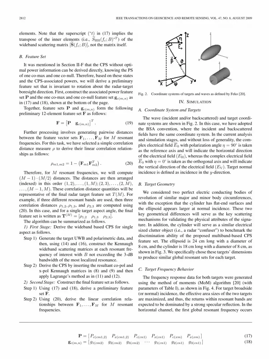
Fig. 2. Coordinate systems of targets and waves as defined by Feko [20].
IV. SIMULATION
A. Coordinate System and Targets
The wave (incident and/or backscattered) and target coordi-nate systems are shown in Fig. 2. In this case, we have adoptedthe BSA convention, where the incident and backscatteredfields have the same coordinate system. In the current analysisand simulation stages, and without loss of generality, the com-plex electrical field E0 with polarization angle η = 90◦ is takenas the reference axis and will indicate the horizontal directionof the electrical field (EH), whereas the complex electrical fieldE0 with η = 0◦ is taken as the orthogonal axis and will indicatethe vertical direction of the electrical field (EV). Target normalincidence is defined as incidence in the y-direction.
B. Target Geometry
We considered two perfect electric conducting bodies ofrevolution of similar major and minor body circumferences,with the exception that the cylinder has flat-end surfaces andthe ellipsoid appears larger at normal incidence. These twokey geometrical differences will serve as the key scatteringmechanisms for validating the physical attributes of the signa-ture. In addition, the cylinder will serve as a similar electricalsized clutter object (i.e., a radar “confuser”) to benchmark thediscrimination ability of the proposed multiband-based CPSfeature set. The ellipsoid is 24 cm long with a diameter of8 cm, and the cylinder is 18 cm long with a diameter of 8 cm, asshown in Fig. 3. We specifically chose these targets’ dimensionsto produce similar global resonant sets for each target.
C. Target Frequency Behavior
The frequency response data for both targets were generatedusing the method of moments (MoM) algorithm [20] (withparameters of Table I), as shown in Fig. 4. For target broadside(or normal) incidence, the effective area sizes of the two targetsare maximized, and thus, the returns within resonant bands areexpected to be dominated by a strong specular reflection. In thehorizontal channel, the first global resonant frequency occurs
P = [Pc(cm1,2) Px(cm1,2) Pc(cn1) Px(cn1) Pc(xm) Px(xm) ] (17)gc(m,n) = [ g1(cm2) g2(cm2) g3(cm2) · · · g1(cn1) g2(cn1) g3(cn1) ] (18)

ALDHUBAIB AND SHULEY: CHARACTERISTIC POLARIZATION STATES ESTIMATION 2813
Fig. 3. Geometry of the ellipsoid and cylinder targets. Clearly, both targetsappear as spherical targets at end-on incidence, but quite different at normalincidence.
TABLE ICHANNEL SIMULATION PARAMETERS
Fig. 4. (Black) Co-pol horizontal HH and (gray) vertical VV magnitudespectra for the (a) ellipsoid and (b) cylinder of Fig. 3; for various azimuth aspectangles.
Fig. 5. Two targets’ average power terms for narrow B as a function ofaspect. This clearly shows that the two targets start to exhibit similar scatteringbehavior near normal incidence due to the absence of the cylinder flat-end effectat these resonant frequencies.
at around 566 MHz, while in the vertical channel, it occurs ataround 1210 MHz. For a clearer view of the target’s resonantbehavior, oblique azimuth angle incidence is preferred (e.g.,ϑ = 90 and ϕ = 30) as the specular return is less dominant. Wealso notice that for each target, the HH and VV responses areidentical at zero azimuth (ϕ = 0) as the targets’ circumferencesin both the x–y and x–z planes are identical.
Theoretically at least, all resonances should appear in allchannels, depending on the energy of the resonance [21]. InFig. 4, the first global peak location in the HH channel is invari-ant with azimuth angle changes, since the target circumferencelength in the x–y plane is fixed. For both targets, and at normalincidence, the first global peaks in the HH and VV channels,respectively, were similar with slight shifts for the higher orderpeaks. In other words, the targets look electrically quite similarat the global resonant frequencies. Therefore, these two globalpeaks with the second global peak in the ellipsoid HH channel,at 1621 MHz, are selected to derive the proposed multibandCPS set. Note that the 3-dB bandwidths for the ellipsoid firstresonance in the HH channel are asymmetric, and the small-est half 3-dB bandwidths are approximately 120, 130, 110,and 150 MHz for the 90◦, 60◦, 30◦, and 0◦ azimuth angles,respectively.
V. RESULTS
We start by first validating the average power term procedureand its dependence on bandwidth by interpreting the averagepower results based on narrow B and then extending theterms into wider B and compare. Second, an example of CPSresult based on the average power of wide B is presented andcompared with the narrow CPS properties. Ultimately, the finalfeature pattern space as a function of azimuth angle, and itsperformance against noise is presented.
A. Narrowband
Let us first use (15) for both targets to calculate their averagepower terms (i.e., Σqk) for narrow B as a function of resonanceorder (denoted by the second subscript m of Σqk,m) for arange of azimuth angles. Fig. 5 shows the auto power terms

2814 IEEE TRANSACTIONS ON GEOSCIENCE AND REMOTE SENSING, VOL. 47, NO. 8, AUGUST 2009
centered on the following resonant frequencies: 566, 1210,and 1621 MHz. Because we have aligned the wave and thetarget axes in parallel (so the target is symmetrical in thetransverse plane of incidence), the theoretical target returns inx-pol channels were assumed zero. Therefore, x-pol auto termswere approximately zero and were thus excluded. From Fig. 5,we make the following observations.
1) In general, the target auto terms are stronger near normalincidence as the target’s apparent size is maximum.
2) Both targets have similar ΣHH,1 terms that dominatethe other terms in the azimuth angle range between40◦ and 90◦.
3) The third resonance terms have lows in the azimuth anglerange between 20◦ and 60◦, indicating that this resonantband has weak specular components within this range ofaspect angles.
4) Except for its first resonance auto terms, the cylinderhas strong returns near end-on incidence due to its flat-end geometry and has been resolved by the 1.21-GHzresonant frequency. Previous observations verify that po-larization descriptors at resonant bands have physicalinterpretations, and thus, a feature set derived from themcan be physically detectable.
B. Wideband
By corrupting the wideband data with additive whiteGaussian noise (AWGN) of standard deviation σw and thentaking the data ensemble average with sufficient number ofrealization (counts), the estimated wideband returns of ap-proximately 120-MHz bandwidth and centered on resonantfrequencies of 566, 1210, and 1621 MHz, as shown in Figs.6and 7, were used to derive the estimated CPS. Table II illustratesthe dependence of the average power terms on the selectedband size. For B = 120 MHz, we barely notice any drop inthe average powers compared to the narrow B case of Fig. 5;however, as B is increased to 720 MHz, the average powersplunge, which can reach −14 dB for some bands and aspectangles. Therefore, we can conclude that the average powers willmost likely deteriorate as the band size is increased beyond the3-dB bandwidth of the associated resonance.
C. CPS Sample Result and the Final Feature Set
Table III shows the CPS results for the ellipsoidal target atzero azimuth incidence for the first resonant frequency bandwith B = 120 MHz, which complies with the CPS propertiesmentioned in Section II. In addition, this ellipsoidal target CPSresult highly matches a sphere or circular disk target CPS set,which complies with the fact that the ellipsoid shape target has ashape similar to a sphere when observed from end-on incidence.These two observations verify that wideband based CPS is apermissible method to implement when describing the targetmultiband polarization information.
After deriving the remaining CPS for each band, the featureset F for a certain angle is constructed using (17) and (18)for the first three resonant frequencies. Once F1, . . . ,F3 forboth targets are obtained, the final correlation feature sets for
Fig. 6. Estimated wideband magnitude spectra of the ellipsoidal targetcentered on resonant frequencies of (a) 566 MHz, (b) 1210 MHz, and(c) 1621 MHz, with a 120-MHz band size, for (black) HH and (gray) VVpolarization channels and as a function of azimuth angle. In general, all spectraexhibited some degree of flatness, particularly near the 90◦ azimuth angle,which is an indication of the existence of similar scattering mechanisms withinthe band.
the ellipsoidal and cylindrical targets, respectively, are derivedusing (19). Fig. 8 shows targets’ final correlation feature sets’distributions within prespecified azimuth sectors of aspect an-gle. Based on this aspect configuration, and for this instance,we can see that the targets have disjoint patterns with differentdegrees of clustering. The exception was the azimuth anglesector 43◦–63◦, where both targets’ patterns overlap. This may

ALDHUBAIB AND SHULEY: CHARACTERISTIC POLARIZATION STATES ESTIMATION 2815
Fig. 7. Estimated wideband magnitude spectra of the cylindrical target cen-tered on approximate resonant frequencies of (a) 566 MHz, (b) 1210 MHz,and (c)1621 MHz, with a 120-MHz band size, for (black) HH and (gray) VVpolarization channels and as a function of azimuth angle.
be because both targets lack a strong distinctive scatteringmechanism (e.g., flat end for cylinder or larger apparent sizefor ellipsoid at normal incidence) over this range of aspect.
D. Final Feature Set Noise Performance
To examine the performance of our proposed feature againstnoise, we have corrupted the resonant wideband returns with
TABLE IIELLIPSOID TERM
√∑HH
AS A FUNCTION OF BAND SIZE B FOR THE
RESONANCE AND ASPECT OF INTEREST. COMPARED TO FIG. 5 WHERE
B IS NARROW, THE DROP IN THE ASSOCIATED AVERAGES FOR
B = 720 MHz IS CLEAR AND ROUGHLY AROUND HALF FOR BAND 1FOR ALL ASPECTS AND BANDS 2 AND 3 FOR 0 AND 30 ASPECTS
TABLE IIIELLIPSOID ESTIMATED CPSS AT FIRST RESONANCE AND B = 120 MHz
FOR END-ON INCIDENCE. BOLD ENTRIES ARE USED TO
CONSTRUCT THE FEATURE SET F1 OF (19)
Fig. 8. Targets’ correlation feature patterns in a 3-D feature space as a func-tion of azimuth angle from 1◦ to 84◦ with uniform sampling steps of 4◦ in size.
an AWGN source of 1-V standard deviation and zero mean.The signal-to-noise ratio (SNR) was then defined separatelyfor each aspect as follows. 1) For a single aspect, find thetarget total mean return value (denoted by E(
√Σ) by finding
the mean of the average power terms in all the bands andpolarization directions at this aspect. 2) This aspect SNR level isthen derived as the ratio of the target E(
√Σ) at this aspect to the

2816 IEEE TRANSACTIONS ON GEOSCIENCE AND REMOTE SENSING, VOL. 47, NO. 8, AUGUST 2009
Fig. 9. SNR level with 1-V AWGN as a function of aspect. The SNR level ishighest at normal incidence.
Fig. 10. Target signature pattern (black) for noise-free signatures and (gray)for signatures corrupted with an AWGN of 1 V and then estimated by100 realization counts. The targets’ signature patterns + are most affected bythe noise, while patterns ♦ are not affected due to their good SNR ratio.
injected 1-V AWGN. Fig. 9 defines both targets’ SNR levels asa function of aspect angle, signifying that the final feature set isquantified for very low SNR levels. Fig. 10 shows a comparisonbetween a free-noise feature pattern and a corrupted estimateof the pattern. The ellipsoid pattern is not affected by the 1-Vnoise, except within the azimuth angle sector 1◦–21◦, wherethe SNR level in this sector is about 2–4 dB. For the cylinder,the noise affect is the same as in the ellipsoid case, but forthe azimuth angle sector 1◦–21◦, the affect is less severe as thecylinder SNR level in this sector is between 8 and 11 dB. Thisindicates that good CPS estimation is achievable, even for lowSNRs. The targets’ feature patterns for the azimuth angle sector64◦–84◦ are not affected as they have good SNR levels.
VI. CONCLUSION
Based on using a set of bands relating to target resonancemode parameters (frequency and energy), we have derived amultiband-based CPS set that is related to the target physicaldimensions and that, consequently, can be used as a robust radarfeature set suitable for target recognition. The developed featureset is compact and invariant to range and target orientationabout the incidence-target direction and is noise robust. Wehave demonstrated this for two similar stationary and canonicaltargets, where a resonance only identification procedure mayexperience difficulty. Apart from the capability of identifyingsimilar targets, the procedure also provides physical interpre-tations that are sometimes lacking in other procedures. Webelieve this work to be the first step in a new approach to targetrecognition that combines a polarimetry viewpoint with that ofa target resonance description. Future work will concentrate ondesigning an identification algorithm to evaluate the identifica-tion accuracy based on this signature. The algorithm also needsto be evaluated for dielectric and complex targets. Another im-portant issue to be addressed in future work is the reduction ofthe radar signature dependency on target-incidence aspect angle.
In this paper, and because of the fact that we are dealing witha high-Q targets, resonant frequencies are merely identified aspeaks in the MoM frequency response rather than as complexresonance poles associated with an SEM expansion model (e.g.,[22]). For low-Q targets (e.g., dielectrics), the latter approach ismore applicable, and the resonant frequencies are identified asthe imaginary parts of the complex poles of the SEM expansion.In addition, we used stationary individual targets in free spaceto display the theoretical feasibility of this algorithm. Neverthe-less, for moving targets, the spread of Doppler shift is usuallymuch less than the frequency spread associated with each of theindividual resonances, and thus, Doppler shift can be ignored[23], [24]. We also note that this multiband description has theability to convey higher power into the incident wave comparedto the single impulse-based UWB excitation, and this is due tothe longer pulse duration used in multiband UWB.
REFERENCES
[1] D. Giuli, “Polarization diversity in radars,” Proc. IEEE, vol. 74, no. 2,pp. 245–269, Feb. 1986.
[2] H. Mott, Remote Sensing with Polarimetric Radar. New York: Wiley-IEEE, 2007.
ALDHUBAIB AND SHULEY: CHARACTERISTIC POLARIZATION STATES ESTIMATION 2817
[3] G. D. De Grandi, L. Jong-Sen, and D. L. Schuler, “Target detection andtexture segmentation in polarimetric SAR images using a wavelet frame:Theoretical aspects,” IEEE Trans. Geosci. Remote Sens., vol. 45, no. 11,pp. 3437–3453, Nov. 2007.
[4] R. Touzi, R. K. Raney, and F. Charbonneau, “On the use of permanentsymmetric scatterers for ship characterization,” IEEE Trans. Geosci.Remote Sens., vol. 42, no. 10, pp. 2039–2045, Oct. 2004.
[5] W.-M. Boerner, W.-L. Yan, A.-Q. Xi, and Y. Yamaguchi, “On the ba-sic principles of radar polarimetry: The target characteristic polarizationstate theory of Kennaugh, Huynen’s polarization fork concept, and itsextension to the partially polarized case,” Proc. IEEE, vol. 79, no. 10,pp. 1538–1550, Oct. 1991.
[6] F. Kuhl and R. Covelli, “Object identification by multiple observationsof the scattering matrix,” Proc. IEEE, vol. 53, no. 8, pp. 1110–1115,Aug. 1965.
[7] O. Lowenschuss, “Scattering matrix application,” Proc. IEEE, vol. 53,no. 8, pp. 988–992, Aug. 1965.
[8] J. R. Huynen, “Measurement of the target scattering matrix,” Proc. IEEE,vol. 53, no. 8, pp. 936–946, Aug. 1965.
[9] J. R. Huynen, “Phenomenological theory of radar targets,” Ph.D. disser-tation, Technische Univ. Delft, Delft, The Netherlands, 1970.
[10] J. Yang, Y. Yamaguchi, H. Yamada, Z. H. Czyz, W.-M. Boerner, H. Mott,E. Luneburg, and Y. Peng, “The characteristic polarization states and theequi-power curves,” IEEE Trans. Geosci. Remote Sens., vol. 40, no. 2,pp. 305–313, Feb. 2002.
[11] T. Huamin and Z. Zhiqun, “Target recognition based on characteristicpolarizations, in the optics region,” in Proc. IEEE NAECON, 1998,pp. 438–440.
[12] Y. Yamaguchi, W.-M. Boerner, H. J. Eom, M. Sengoku, S. Motooka,and T. Abe, “On characteristic polarization states in the cross-polarizedradar channel,” IEEE Trans. Geosci. Remote Sens., vol. 30, no. 5,pp. 1078–1080, Sep. 1992.
[13] W. M. Boerner, W. L. Yan, A. Q. Xi, and Y. Yamaguchi, “The character-istic polarization states for the coherent and partially polarized case,” inProc. 7th ICAP (IEE), 1991, pp. 383–391.
[14] A. P. Agrawal and W.-M. Boerner, “Redevelopment of Kennaugh’s targetcharacteristic polarization state theory using the polarization transforma-tion ration formalism for the coherent case,” IEEE Trans. Geosci. RemoteSens., vol. 27, no. 1, pp. 2–14, Jan. 1989.
[15] W.-M. Boerner, M. El-Arini, C.-Y. Chan, and P. Mastoris, “Polarizationdependence in electromagnetic inverse problems,” IEEE Trans. AntennasPropag., vol. AP-29, no. 2, pp. 262–271, Mar. 1981.
[16] C. E. Baum, “Signature-based target identification and pattern recogni-tion,” IEEE Antennas Propag. Mag., vol. 36, no. 3, pp. 44–51, Jun. 1994.
[17] S.-R. Cloude, “Polarimetric techniques in radar signal processing,”Microw. J., vol. 26, no. 7, pp. 119–127, Jul. 1983.
[18] W.-L. Yan and W. Boerner, “Optimal polarization states determinationof the Stokes reflection matrices [Mp] for the coherent case, and of theMuller matrix [M] for the partially polarized case,” J. Electromagn. WavesAppl., vol. 5, no. 10, pp. 1123–1149, 1991.
[19] H. Mott, Antennas for Radar and Communications: A PolarimetricApproach. Hoboken, NJ: Wiley, 1992.
[20] Feko Suit 5, 2003–2005. E.s.a. systems, Ed., 9.3.24 ed. S.A (Pty) Ltd.
[21] N. Shuley and D. Longstaff, “Role of polarisation in automatic targetrecognition using resonance descriptions,” Electron. Lett., vol. 40, no. 4,pp. 268–270, Feb. 2004.
[22] C. E. Baum, E. J. Rothwell, K.-M. Chen, and D. P. Nyquist, “The singu-larity expansion method and its application to target identification,” Proc.IEEE, vol. 79, no. 10, pp. 1481–1492, Oct. 1991.
[23] D. K. Barton and C. E. Cook, Radar Evaluation Handbook. Boston,MA: Artech House, 1991.
[24] A. W. Rihaczek and S. J. Hershkowitz, Theory and Practice of RadarTarget Identification. Boston, MA: Artech House, 2000.
Faisal F. H. Aldhubaib received the B.E. and M.Sc.degrees in electrical engineering from the Universityof Leeds, Leeds, U.K., in 1995 and 1997, respec-tively. He is currently working toward the Ph.D.degree with the Electromagnetic and Imaging Re-search Group at the School of Information Technol-ogy and Electrical Engineering, The University ofQueensland, Brisbane, Australia.
From 1997, he was a member of the teachingstaff with the College of Technological Studies, Pub-lic Authority for Applied Education and Training,
Kuwait. His current research interests include polarization- and resonance-based target identification methods.
Nicholas V. Z. Shuley (S’80–M’86) received theB.E. and M.Eng.Sc. degrees from the University ofNew South Wales, Sydney, Australia, in 1973 and1975, respectively, and the Ph.D. degree in electricalengineering from the Chalmers University of Tech-nology, Gothenburg, Sweden, in 1985.
From 1977 to 1978, he was with Microwave As-sociates, Dunstable, U.K. From 1979 to 1988, hewas a Research and Teaching Assistant, and later aPostdoctoral Scientist, with the Division of NetworkTheory, Chalmers University of Technology. From
1988 to 1998, he was with The University of Queensland, Brisbane, Australia,working with the Microwave Group. In 1996, he received a Visiting ScientistStipendium from the Spanish Government to work on electromagnetism-relatedproblems at the Department of Electronics and Electromagnetism, Faculty ofPhysics, University of Seville, Seville, Spain. From 1999 to 2001, he wasthe Head of the electronics discipline within the School of Electrical andComputer Systems Engineering, RMIT University, Melbourne, Australia. In2002, he returned to the School of Information Technology and ElectricalEngineering, The University of Queensland, where he is currently teaching andsupervising research in the areas relating to time-domain electromagnetic andnoncooperative object identification. He has carried out consulting work forthe European Space Agency. He has published extensively on electromagneticphenomena both in international journals and conference proceedings.