chapter-6 governors - rskr
TRANSCRIPT
output and regulates input accordingly. 1 action it is simple example of a mechanical feedback control system which senses the
governor senses the change in speed and then regulates the supply. Due to this type of
turbines, water in hydraulic turbines) is adjusted to the new load on the engine. Thus the
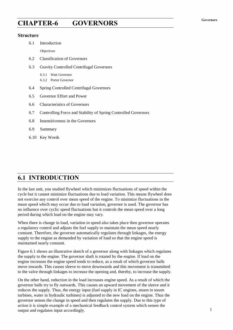
reduces the supply. Thus, the energy input (fuel supply in IC engines, steam in steam
governor balls try to fly outwards. This causes an upward movement of the sleeve and it
On the other hand, reduction in the load increases engine speed. As a result of which the
to the valve through linkages to increase the opening and, thereby, to increase the supply.
move inwards. This causes sleeve to move downwards and this movement is transmitted
engine increases the engine speed tends to reduce, as a result of which governor balls
the supply to the engine. The governor shaft is rotated by the engine. If load on the
Figure 6.1 shows an illustrative sketch of a governor along with linkages which regulates
maintained nearly constant.
supply to the engine as demanded by variation of load so that the engine speed is
constant. Therefore, the governor automatically regulates through linkages, the energy
a regulatory control and adjusts the fuel supply to maintain the mean speed nearly
When there is change in load, variation in speed also takes place then governor operates
period during which load on the engine may vary.
no influence over cyclic speed fluctuations but it controls the mean speed over a long
mean speed which may occur due to load variation, governor is used. The governor has
not exercise any control over mean speed of the engine. To minimize fluctuations in the
cycle but it cannot minimize fluctuations due to load variation. This means flywheel does
In the last unit, you studied flywheel which minimizes fluctuations of speed within the
6.1 INTRODUCTION
6.10 Key Words
6.9 Summary
6.8 Insensitiveness in the Governors
6.7 Controlling Force and Stability of Spring Controlled Governors
6.6 Characteristics of Governors
6.5 Governor Effort and Power
6.4 Spring Controlled Centrifugal Governors
6.3.2 Porter Governor
6.3.1 Watt Governor
6.3 Gravity Controlled Centrifugal Governors
6.2 Classification of Governors
Objectives
6.1 Introduction
Structure
CHAPTER-6 GOVERNORS Governors

2 used for a small machine.
dissipating the excess kinetic energy. It is very simple in construction and can be centrifugal governors, the sleeve movement is very small. It controls the speed by
This type of governor is used for driving a gramophone. As compared to the
Pickering Governors
are more sensitive than centrifugal governors.
change in speed itself as in case of centrifugal governors. Thus, these governors
balls. The movement of the balls is due to the rate of change of speed instead of
engine shaft or flywheel by change in speed are utilized for the movement of the
In these governors, the inertia forces caused by the angular acceleration of the
Inertia and Flywheel Governors
commonly used because of simplicity in operation.
One of this type of governors is shown in Figure 6.1. These governors are
change in the speed of the engine is utilized for movement of the governor sleeve.
In these governors, the change in centrifugal forces of the rotating masses due to
Centrifugal Governors
(c) Pickering governors.
(b) Inertia and flywheel governors
(a) Centrifugal governors
The broad classification of governor can be made depending on their operation.
6.2 CLASSIFICATION OF GOVERNORS
compare different type of governors.
know stability of spring controlled governors, and
know characteristics of governors,
analyze different type of governors,
classify governors,
After studying this unit, you should be able to
Objectives
Figure 6.1 : Governor and Linkages
Pulley Engine
Lener
Bell Crank
g g m m
C C F F
Theory of Machines

Figure 6.2 : Watt Governor 3
(a) (b)
mg C F
Sleeve
Ball Ball
as shown in Figure 5.2(a).
The upper arms are connected to the spindle and lower arms are connected to the sleeve
output shaft of the prime mover. The balls are mounted at the junction of the two arms.
This governor was used by James Watt in his steam engine. The spindle is driven by the
6.3.1 Watt Governor
The proell governor is most sensitive out of these three.
this limits its field of application. Porter governor is more sensitive than watt governor.
extension of lower arms. The sensitiveness of watt governor is poor at high speed and
junction of upper and lower arms. In case of proell governor the balls are placed at the
governor have heavy dead weight at the sleeve. In porter governor balls are placed at the
Watt governor does not carry dead weight at the sleeve. Porter governor and proell
(c) Proell governor
(b) Porter governor
(a) Watt governor
There are three commonly used gravity controlled centrifugal governors :
GOVERNORS
6.3 GRAVITY CONTROLLED CENTRIFUGAL
movement of sleeve or balls. These governors are comparatively smaller in size.
In these governors, a helical spring or several springs are utilized to control the
Spring Controlled Centrifugal Governors
are comparatively larger in size.
weight of sleeve itself which controls movement of the sleeve. These governors
In this type of governors there is gravity force due to weight on the sleeve or
Gravity Controlled Centrifugal Governors
(b) Spring controlled centrifugal governors.
(a) Gravity controlled centrifugal governors, and
Depending on the construction these governors are of two types :
6.2.1 Types of Centrifugal Governors Governors
4 of them rotate with the spindle. We can consider one-half of governor for equilibrium.
spindle or slightly away. The lower arms support dead weight and connect balls also. All of arms. The top arms OA and OB connect balls to the hinge O. The hinge may be on the
A schematic diagram of the porter governor is shown in Figure 6.4(a). There are two sets
6.3.2 Porter Governor
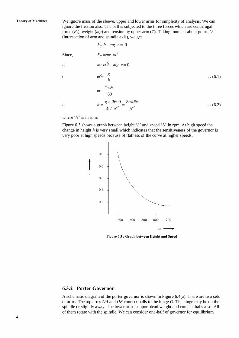
Figure 6.3 : Graph between Height and Speed
N
300 400 500 600 700
0.2
0.4
0.6 h
0.6
0.8
very poor at high speeds because of flatness of the curve at higher speeds.
change in height h is very small which indicates that the sensitiveness of the governor is
Figure 6.3 shows a graph between height ‘h’ and speed ‘N’ in rpm. At high speed the
where ‘N’ is in rpm.
4 N N 2 2 2 h . . . (6.2)
g 3600 894.56
60
2 N
h or . . . (6.1)
2 g
mr h mg r 0 2
C Since, F mr 2
C F h mg r 0
(intersection of arm and spindle axis), we get
force (F ), weight (mg) and tension by upper arm (T). Taking moment about point O c
ignore the friction also. The ball is subjected to the three forces which are centrifugal
We ignore mass of the sleeve, upper and lower arms for simplicity of analysis. We can Theory of Machines

5 expression in Eq. (6.4) becomes
friction at the sleeve is to be considered, W should be replaced by (W f). The
and by (W – f) for falling speed as friction opposes the motion of sleeve. Therefore, if the If friction at the sleeve is f, the force at the sleeve should be replaced by W + f for rising
Figure 6.4 : Porter Governor
(a) (b)
2 C W
D I
Sleeve C
Load (w) w 2 T
Links Central
2 T
A B C F r
Ball 1 T
Spindle 1 T
Arms O O
h 2 w 1 (1 K ) . . . (6.4) 2 g W
h tan
r
tan where K
tan
r 2 w or tan 1 (1 K ) . . . (6.3) 2 g W
g 2 w tan r w tan 1 1 2 w W tan
g C F r 2 w
2 C or F w tan (tan tan )
W
AD 2 AD C or F wID W ID DC
2 C F AD w ID IC 0
W
sleeve, we get
Taking moment of all forces acting on the ball about I and neglecting friction at the
I is the instantaneous centre of the lower arm.
r be the radius of rotation of the ball from axis, and
c F be the centrifugal force,
1 2 T and T be tension in upper and lower arms, respectively,
Let w be the weight of the ball, Governors
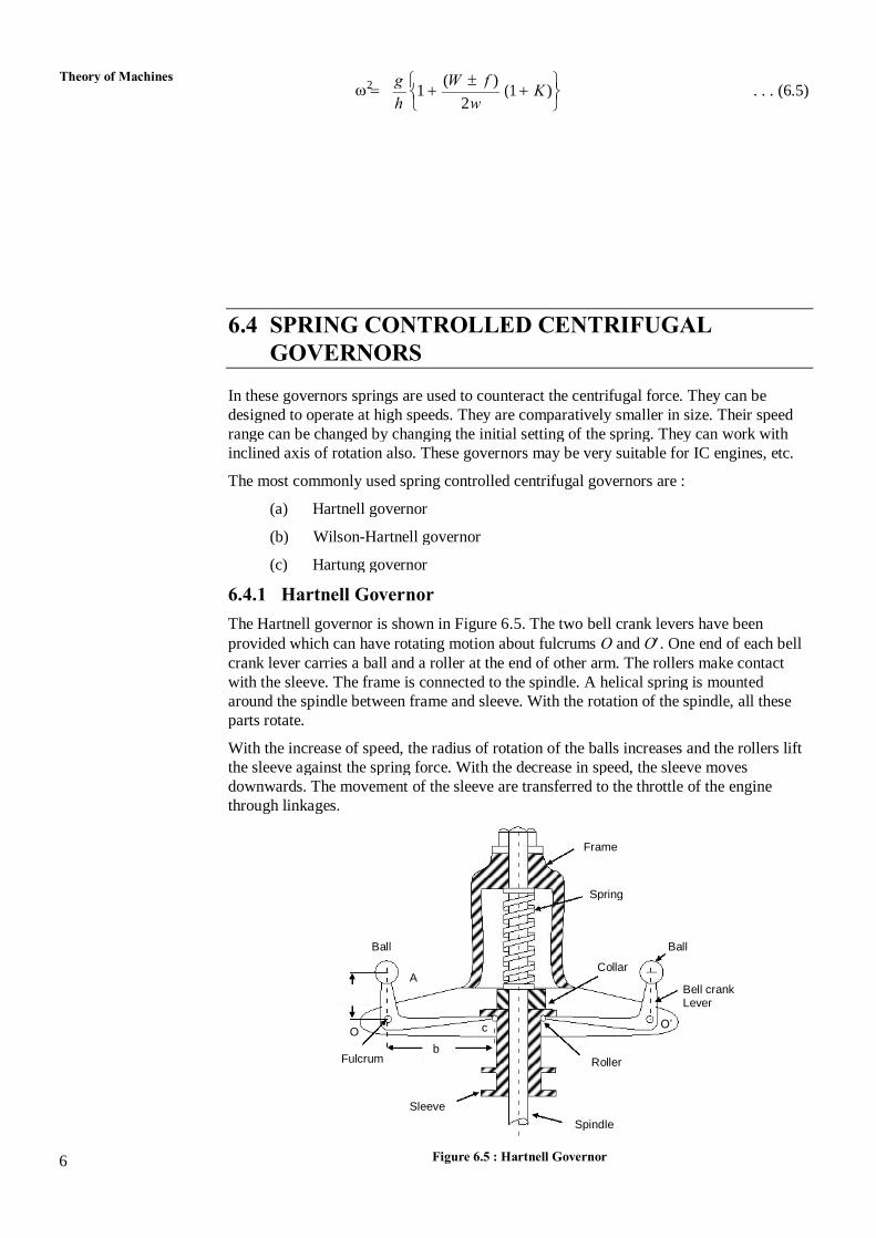
6 Figure 6.5 : Hartnell Governor
Spindle
Sleeve
Roller Fulcrum b
O c O’
Lever Bell crank
A Collar
Ball Ball
Spring
Frame
through linkages.
downwards. The movement of the sleeve are transferred to the throttle of the engine
the sleeve against the spring force. With the decrease in speed, the sleeve moves
With the increase of speed, the radius of rotation of the balls increases and the rollers lift
parts rotate.
around the spindle between frame and sleeve. With the rotation of the spindle, all these
with the sleeve. The frame is connected to the spindle. A helical spring is mounted
crank lever carries a ball and a roller at the end of other arm. The rollers make contact
provided which can have rotating motion about fulcrums O and O. One end of each bell
The Hartnell governor is shown in Figure 6.5. The two bell crank levers have been
6.4.1 Hartnell Governor
(c) Hartung governor
(b) Wilson-Hartnell governor
(a) Hartnell governor
The most commonly used spring controlled centrifugal governors are :
inclined axis of rotation also. These governors may be very suitable for IC engines, etc.
range can be changed by changing the initial setting of the spring. They can work with
designed to operate at high speeds. They are comparatively smaller in size. Their speed
In these governors springs are used to counteract the centrifugal force. They can be
GOVERNORS
6.4 SPRING CONTROLLED CENTRIFUGAL
h 2 w 1 (1 K ) . . . (6.5) 2 g ( W f ) Theory of Machines

7
2 a C 2 2 or ( F ) mg tan . . . (6.10) 2 ( Mg S ) b
2 0 C 2 2 2 2 M ( F ) a cos mg a sin b cos 2 ( Mg S )
the moments of all the forces about O
Considering the position of the ball at radius ‘r ’ as shown in Figure 5.6(b) and taking 2
Figure 6.6
(a) (b)
at fulcrum 1 Reaction C
2 b g + S ) 1 (M 2 C’ 1 x 1
O’ 2 O 1 C’ 2 x
1 2 2 C 2
g + S ) 2 (M r
a
mg mg
C 1 C 2 (F ) (F ) 2 A’
1 1 A’ A 2 A
1 2 r r
2 a C 1 1 or ( F ) mg tan . . . (5.9) 1 ( Mg S ) b
2 0 C 1 1 1 1 M ( F ) a cos mg a sin b cos 0 1 ( Mg S )
moments of all the forces about O
Considering the position of the ball at radius ‘r ’, as shown in Figure 5.6(a) and taking 1
b = Length of sleeve arm of bell-crank lever, i.e. distance OC.
a = Length of ball arm of bell-crank lever, i.e. distance OA, and
r = Distance of fulcrum O from the governor axis or radius of rotation,
s = Stiffness of spring or the force required to compress the spring by one m,
2 2 C 2 (F ) = Centrifugal force corresponding to maximum speed m r , 2
1 1 C 1 (F ) = Centrifugal force corresponding to minimum speed m r , 2
1 2 and = Corresponding minimum and maximum angular velocities, in r/s,
2 N = Maximum speed of governor at maximum radius, in rpm,
1 N = Minimum speed of governor at minimum radius, in rpm,
M = Mass of sleeve, in kg,
m = Mass of each ball, in kg,
2 S = Spring force exerted on sleeve at maximum radius, in N,
1 S = Spring force exerted on sleeve at minimum radius, in N,
2 r = Maximum radius of rotation of ball centre from spindle axis, in m,
1 Let r = Minimum radius of rotation of ball centre from spindle axis, in m, Governors
8 becomes zero.
upwards and sleeve starts moving to the new equilibrium position where net force
governor speed increases, there will be a net force on the sleeve to move it
When governor speed is constant the net force at the sleeve is zero. When
speed.
It is defined as the mean force exerted on the sleeve during a given change in
Governor Effort
governors.
Governor effort and power can be used to compare the effectiveness of different type of
6.5 GOVERNOR EFFORT AND POWER
or spring controlled type? Give reasons.
For IC engines, which type of governor you will prefer whether dead weight type
SAQ 4
2 1 ( r r ) C C 1 C 2 C 1 F ( F ) {( F ) ( ) } F . . . (6.14) 1 ( r r )
2 1 1 b r r b ( r r ) s 2 2 C C 1 C 2 C 1 a a F ( F ) ( F ) ( F )
2 2
For ball radius ‘r’
2 1 b ( r r ) or stiffness of spring ‘s’ 2 . . . (6.13) C 2 C 1 a ( F ) ( F )
2
a 2 C 2 C 1 ( F ) ( F ) s 2 1 b ( r r )
2
a 2 1 2 1 S S Total lift s ( r r s )
b
a a a 2 1 b ( r r ) 1 2 ( r r ) ( r r ) b
1 2 b ()
1 2 1 2 Total lift (x x ) (b b )
2 a C 2 C 1
( F ) ( F ) 2 1 ( S S ) b
2 a C 2 and ( F ) . . . (6.12) 2 ( Mg S ) b
2 a C 1 ( F ) . . . (6.11) 1 ( Mg S ) b
1 2 force, the terms mg tan and mg tan may be ignored. 1 2 If and are very small and mass of the ball is negligible as compared to the spring Theory of Machines

9 60 2 (1 c N ) w 2 h . . . (6.17) 1 w W g
sleeve
If the speed increases to (1 + c) N and height remains the same by increasing the load on
60 2 N w 2 h . . . (6.16)
w W g
given by equation
When speed is N rpm and let the angles and are equal so that K = 1, the height h is
1 speed increases from N to (1 + c) N = W – W.
Downward force to be applied when the rising of sleeve is to be prevented when
is h. 1 (1 + c) N. This means that W is the weight of sleeve when height of governor
1 Let W = New weight of sleeve so that the rising of sleeve is prevented when the speed is
place, a downward force will have to be exerted on the sleeve.
Figure 6.7(b). In order to prevent the sleeve from rising when the increase of speed takes
The equilibrium position of the governor for the increased speed is shown in
1 h = Height of governor corresponding to increased speed (1 + c ) N.
= N + c . N = (1 + c) N, and . . . (6.15)
Increased speed = Equilibrium speed + Increase of speed,
in speed.
c = A factor which when multiplied to equilibrium speed, gives the increase
h = Height of governor corresponding to speed N, and
W = Weight of sleeve in N,
Let N = Equilibrium speed corresponding to configuration shown in Figure 6.7(a),
Figure 6.7 shows the two positions of a Porter governor.
Figure 6.7
(a) (b)
x
w mg
1 h h
O O
be used for any other type of governor also.
The effort and power of a Porter governor has been determined. The same principle can
6.5.1 Determination of Governor Effort and Power
Power of governor = Governor effort Displacement of sleeve
It is defined as the work done at the sleeve for a given change in speed. Therefore,
Governor Power Governors
10 each speed which is within the speed range of the governor.
A governor is said to be stable when there is one radius of rotation of the balls for
Stability
Different governors can be compared on the basis of following characteristics:
6.6 CHARACTERISTICS OF GOVERNORS
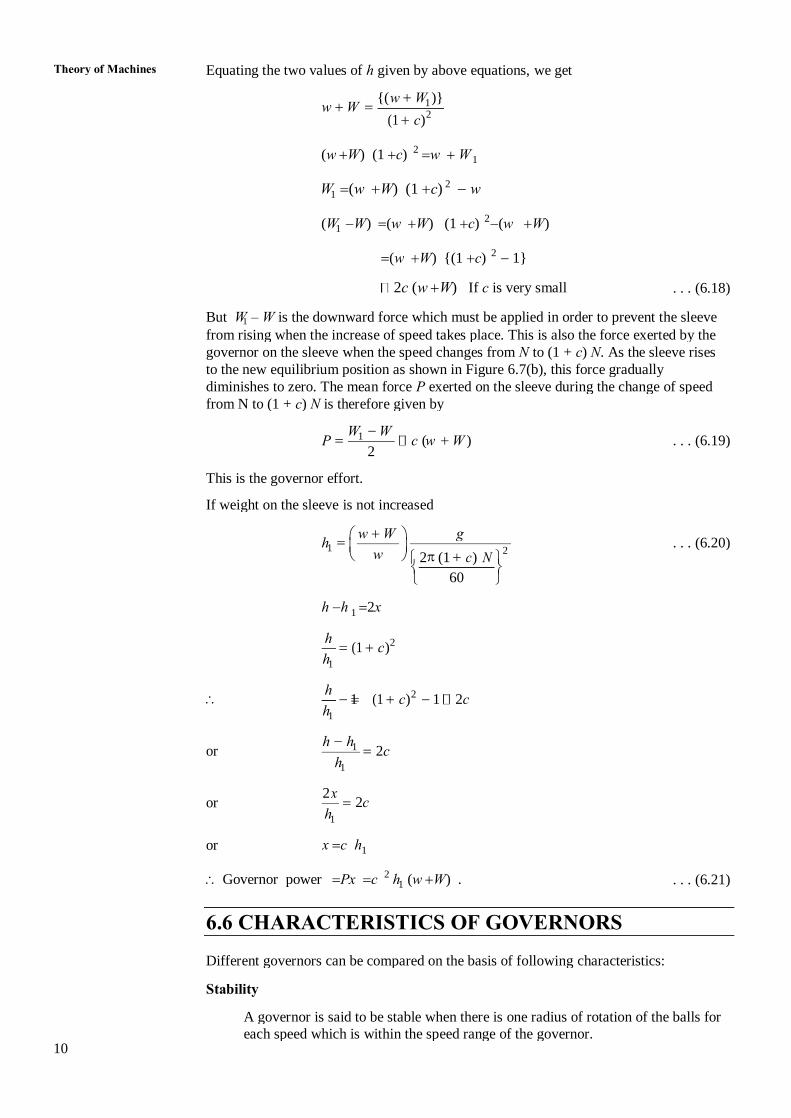
1 Governor power Px c h (w W) . . . . (6.21) 2
1 or x c h
1 h or 2 c
2 x
1 h or 2 c 1 h h
1 h 1 (1 c ) 1 2 c 2 h
1 h (1 c ) 2 h
1 h h 2x
60 2 (1 c N ) w 2 1 h . . . (6.20)
w W g
If weight on the sleeve is not increased
This is the governor effort.
2 P c w ( W ) . . . (6.19) 1 W W
from N to (1 + c) N is therefore given by
diminishes to zero. The mean force P exerted on the sleeve during the change of speed
to the new equilibrium position as shown in Figure 6.7(b), this force gradually
governor on the sleeve when the speed changes from N to (1 + c) N. As the sleeve rises
from rising when the increase of speed takes place. This is also the force exerted by the 1 But W – W is the downward force which must be applied in order to prevent the sleeve
2c (w W) If c is very small . . . (6.18)
(w W) {(1 c) 1} 2
1 (W W) (w W) (1 c) (w W) 2
1 W (w W) (1 c) w 2
1 (w W) (1 c) w W 2
(1 c ) 2
w W 1 {( w W )}
Equating the two values of h given by above equations, we get Theory of Machines
the increase in speed. 11
Therefore, for a stable governor slope in controlling force diagram should increase with
r i.e. tan N . . . (6.24)
2 F
slope of the curve.
r For controlling force diagram in which ‘F’ is plotted against radius ‘r’, represents
F
r 60 Or m F 2 N
2
The controlling force ‘F’ = m r. 2
ball. It is equal and acts opposite to the direction of centrifugal force.
radial line towards the axis is called controlling force. This force acts at the centre of the
The resultant external force which controls the movement of the ball and acts along the
SPRING CONTROLLED GOVERNORS
6.7 CONTROLLING FORCE AND STABILITY OF
the sensitiveness of the governor, the problem of hunting becomes more acute.
of controlling it. This phenomenon is known as hunting of the governor. Higher
due to resonance. The governor, then, tends to intensity the speed variation instead
oscillations of the governor, this results in increase of amplitude of oscillations
frequency of fluctuations in engine speed coincides with the natural frequency of
due to inertia. This results in setting up of oscillations in engine speed. If the
desired position. Sleeve then moves back but again overshoots the desired position
sleeve moves towards the new position but because of inertia if overshoots the
Whenever there is change in speed due to the change in load on the engine, the
Hunting
speed range is zero and this type of governor shall maintain constant speed.
radii of rotation in the working range. Therefore, for an isochronous governor the
A governor is said to be isochronous if equilibrium speed is constant for all the
Isochronism
2 1 where N – N = Speed range from no load to full load.
2 1 N ( N N ) Sensitiveness . . . (6.23) 2 1 2 1 N N 2( N N )
to the mean speed. The smaller the ratio more sensitive the governor will be
sensitiveness of the governor shall be determined by the ratio of speed range
sensitive the governor will be. According to this definition, the
(b) The smaller the change in speed from no load to the full load, the more
1 2 N N Sensitiveness . . . (6.22)
N
more sensitive.
the governor for a given displacement of the sleeve, the governor will be
sleeve due to a fractional change in speed. Smaller the change in speed of
(a) A governor is said to be sensitive when there is larger displacement of the
part of prime mover.
(b) When the governor is fitted in the prime mover and it is treated as
(a) When the governor is considered as a single entity.
The sensitiveness can be defined under the two situations :
Sensitiveness Governors

12 equation cannot represent stable governor but unstable governor.
r As r increases, speed increases, or tan reduces. Hence this
F
r r F ar b or a . . . (6.28)
F b
the curve will be
controlling force axis (i.e. y-axis) above the origin. The equation of
(c) If b is positive, then controlling force curve AB will intersect the
r F ar or a constant . . . (6.27)
F
Hence for isochronous, the equation will be
radius of rotation and hence the governor will become isochronous.
r will pass through the origin. The ratio will be constant for all
F
(b) If b in the above equation is zero then the controlling force curve OC
this equation represents stable governor.
r As r increases increase and thereby tan increases. Therefore,
F
r r F a r . b or a . . . (6.26)
F b
when produced. Then the equation of the curve will be of the form
must intersect the controlling force axis (i.e. y-axis) below the origin,
increases. Hence the controlling force curve DE for a stable governor
r (a) We know that for a stable governor, the ratio must increase as r
F
These three cases are as follows :
Figure 6.8 : Stability of Spring Controlled Governors
Radius of Rotation D O
A
Stable F = ar –b
E
Isochronous F = ar C
Unstable F = ar + b
B
where a and b are constants. In the above equation b may be +ve, or –ve or zero.
F ar b; F ar or F ar b . . . (6.25)
equation can be,
variation of controlling force ‘F’ with radius of rotation ‘r’, hence, straight line
line for spring controlled governors. As controlling force curve represents the
spring controlled governors. The controlling force curve is approximately straight
Figure 5.8 shows the controlling force curves for stable, isochronous and unstable
Stability of Spring-controlled Governors Theory of Machines
13 For k = 1.
1 1 Height 'h ' l r 0.25 0.15 0.2 m 2 2 2 2
Maximum radius ‘r ’ = 20 cm = 0.2 m 2
Minimum radius ‘r ’ = 15 cm = 0.15 m 1
Arm length ‘l’ = 25 cm = 0.25 m
Central load ‘W’ = 30 g N
Given data : Ball weight ‘w’ = 5 g N
Solution
value of 20 cm for the maximum speed. Determine speed range.
radius of rotation of balls is 15 cm when the sleeve begins to rise and reaches a
The mass of each ball is 5 kg and mass on central load of the sleeve is 30 kg. The
The arms of a Porter governor are 25 cm long and pivoted on the governor axis.
Example 6.1
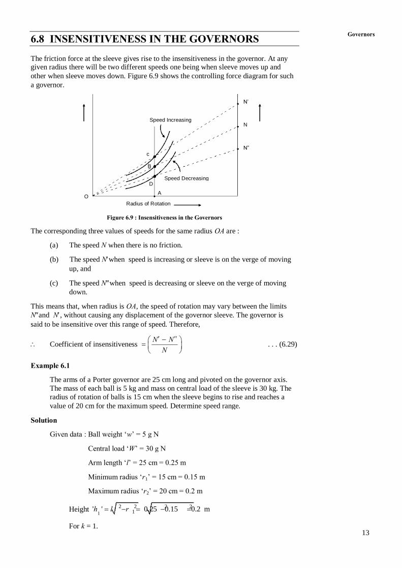
N Coefficient of insensitiveness . . . (6.29) N N
said to be insensitive over this range of speed. Therefore,
Nand N, without causing any displacement of the governor sleeve. The governor is
This means that, when radius is OA, the speed of rotation may vary between the limits
down.
(c) The speed Nwhen speed is decreasing or sleeve on the verge of moving
up, and
(b) The speed Nwhen speed is increasing or sleeve is on the verge of moving
(a) The speed N when there is no friction.
The corresponding three values of speeds for the same radius OA are :
Figure 6.9 : Insensitiveness in the Governors
Radius of Rotation
O A
D Speed Decreasing
B
c N”
N Speed Increasing
N’
a governor.
other when sleeve moves down. Figure 6.9 shows the controlling force diagram for such
given radius there will be two different speeds one being when sleeve moves up and The friction force at the sleeve gives rise to the insensitiveness in the governor. At any
6.8 INSENSITIVENESS IN THE GOVERNORS Governors
14 Neglecting the effect of obliquity of arms.
Minimum speed = 0.95 = 0.95 52.36 = 49.74 r/s
Maximum speed = 10.05 = 1.05 52.36 = 54.98 r/s
60 52.36 r/s
2 500
2 Maximum radius r = 7 cm + 1 = 8 cm
1 Minimum radius r = 7 cm – 1 = 6 cm
a b
Ball mass ‘m’ = 2 kg
Friction force ‘f’ = 25 N
Sleeve mass ‘M’ = 6 kg
Solution
friction.
(c) Governor effort and power for 1% change in the speed if there is no
(b) Initial compression in the spring, and
(a) Spring rate,
sleeve arms are equal, find,
equivalent to 25 N at the sleeve. The mass of the ball is 2 kg. If ball arm and
is 2 cm with 5% of change in speed. The mass of sleeve is 6 kg and friction is
this speed, ball arm is normal and sleeve is at mid position. The sleeve movement
In a Hartnell governor the radius of rotation is 7 cm when speed is 500 rpm. At
Example 6.2
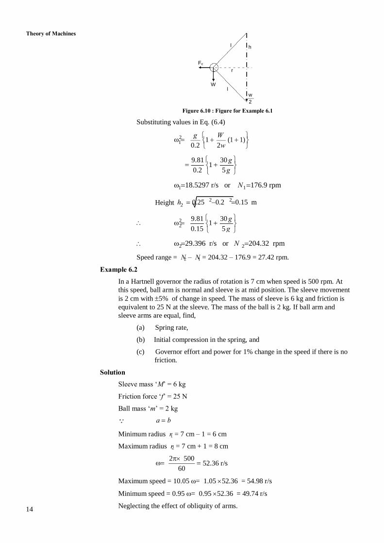
2 1 Speed range = N – N = 204.32 – 176.9 = 27.42 rpm.
2 2 29.396 r/s or N 204.32 rpm
0.15 5 g 2 1 2 9.81 30 g
2 Height h 0.25 0.2 0.15 m 2 2
1 1 18.5297 r/s or N 176.9 rpm
0.2 5 g 1
9.81 30 g
0.2 2 w 1 1 (1 1) 2 g W
Substituting values in Eq. (6.4)
Figure 6.10 : Figure for Example 6.1
2
w l
W
r
c F
h l
Theory of Machines

where P is governor effort. 15
At increased speed, 2 2 (52.88) 0.07 = 6 g + 2 P + S 2
At r = 0.07; 2 2 (52.36) 0.07 = 6 g + S 2
Increased speed = 1.01 = 1.01 52.36 = 52.88 r/s
2 C F 2 Mg S f
Governor Effort and Power
= 0.035 m or 3.5 cm
16175.81 1 Initial compression S
559.92
s 16175.81 N/m Or
0.02
883.44 559.92
x Stiffness ‘s’ 2 1 S S
2 Or S 883.44 N
2 2 (54.98) 0.08 2 6g S 25 2
c 2 2 2 F m r 2
2 C 2 2 F Mg S f
At Maximum Radius
1 Or S 559.92 N
1 593.78 58.86 S 25
1 2 (49.74) 0.06 2 6g S 25 2
c 1 1 1 F m r 2
2 1 1 C C 1 F a b or 2 F Mg S f 1 Mg S f
At Minimum Radius
Figure 6.11 : Figure for Example 6.2
(a) (b)
2 O
1 Mg + S 1 cm
mg
1 cm
2 2 O c F
2 mg Mg + S
8 cm
C F
6 cm
Governors
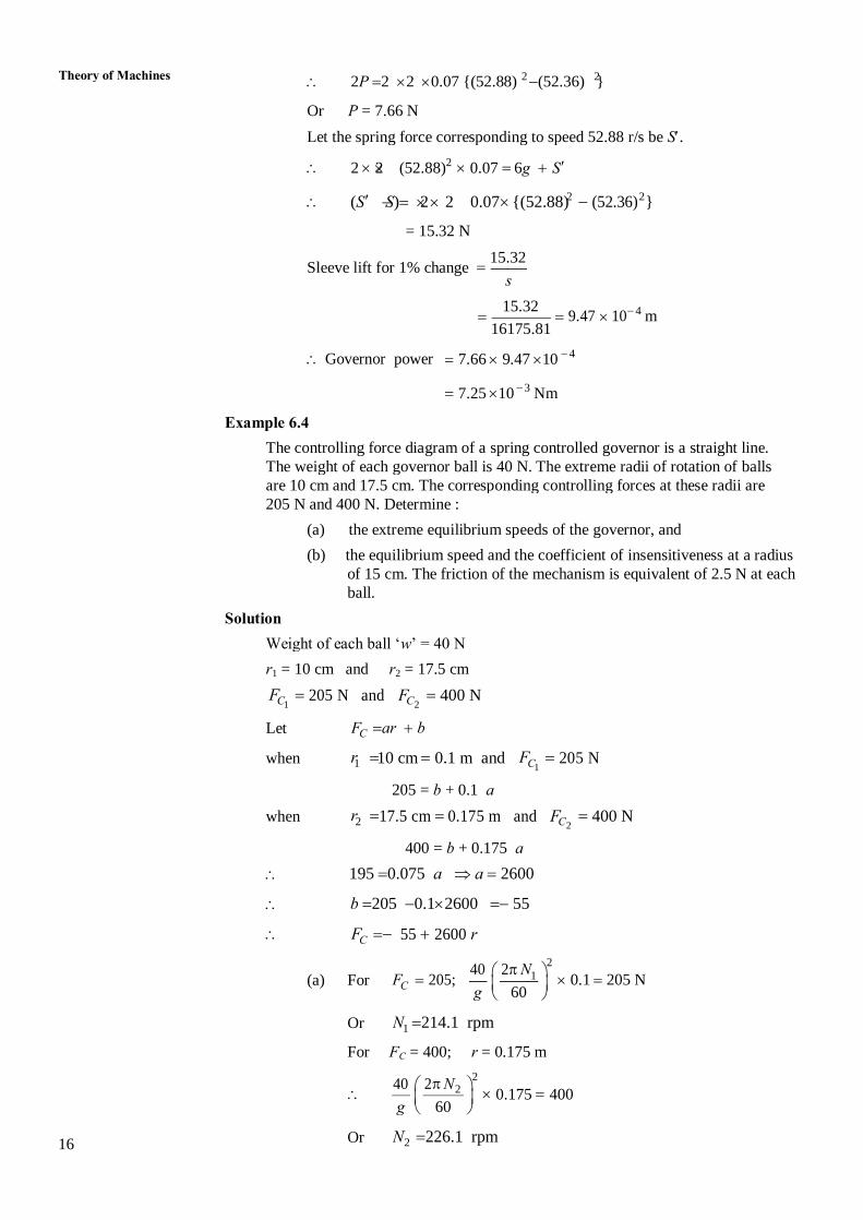
16 2 Or N 226.1 rpm
g 60 0.175 400 2 40 2 N
2
C For F = 400; r = 0.175 m
1 Or N 214.1 rpm
g 60 C (a) For F 205; 0.1 205 N 1 40 2 N
2
C F 55 2600 r
b 205 0.12600 55
195 0.075 a a 2600
400 = b + 0.175 a
2 2 C when r 17.5 cm 0.175 m and F 400 N
205 = b + 0.1 a
1 1 C when r 10 cm 0.1 m and F 205 N
C Let F ar b
1 2 C C F 205 N and F 400 N
1 2 r = 10 cm and r = 17.5 cm
Weight of each ball ‘w’ = 40 N
Solution
ball.
of 15 cm. The friction of the mechanism is equivalent of 2.5 N at each
(b) the equilibrium speed and the coefficient of insensitiveness at a radius
(a) the extreme equilibrium speeds of the governor, and
205 N and 400 N. Determine :
are 10 cm and 17.5 cm. The corresponding controlling forces at these radii are
The weight of each governor ball is 40 N. The extreme radii of rotation of balls
The controlling force diagram of a spring controlled governor is a straight line.
Example 6.4
7.25 10 Nm 3
Governor power 7.66 9.47 10 4
16175.81 9.47 10 m 4 15.32
s Sleeve lift for 1% change
15.32
= 15.32 N
(S S) 2 2 0.07 {(52.88) (52.36) } 2 2
2 2 (52.88) 0.07 6g S 2
Let the spring force corresponding to speed 52.88 r/s be S.
Or P = 7.66 N
2P 2 2 0.07 {(52.88) (52.36) } 2 2 Theory of Machines
at the sleeve and balls are mounted at the hinge. 17 Porter Governor : This is a type of governor which has dead weight
on the sleeve.
Watt Governor : It is a type of governor which does not have load
6.10 KEY WORDS
force diagram which should have intercept on the negative side of Y-axis.
The stability of a spring controlled governor can be determined by drawing controlling
as low as possible.
two speeds due to the friction. Therefore, it is most desirable that the friction should be
gives rise to the insensitiveness in the governor. At any particular radius, there shall be
governor is stable or isochronous or it is prone to hunting. The friction at the sleeve
categorize a governor the characteristics can be used. It can be determined whether a
whether a particular type of governor is suitable for a given situation or not. To
For comparing different type of governors, effort and power is used. They determine
Wilson-Hartnell governor and Hartung governor.
governor and Proell governor. The spring controlled governors are : Hartnel governor,
compared to the spring controlled governors. This type of governors are two, i.e. Porter
The gravity controlled type of governors are larger in size and require more space as
loaded type.
governors are classified into two main categories, gravity controlled type and spring
limited and in most of the cases centrifugal governors are used. The centrifugal
inertial governor and Pickering governor. The use of the two later governors is very
The governors are classified in three main categories that is centrifugal governors,
The speed control within the cycle is done by the flywheel.
prime mover changes. They have no control over the change is speed within the cycle.
control. Their basic function is to control the speed within limits when the load on the
The governors are control mechanisms and they work on the principle of feedback
6.9 SUMMARY
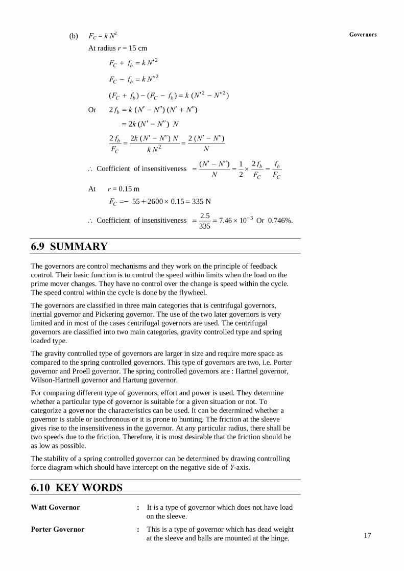
335 Coefficient of insensitiveness 7.46 10 Or 0.746%.
3 2.5
C F 55 2600 0.15 335 N
At r = 0.15 m
C C N 2 F F Coefficient of insensitiveness b b ( N N ) 1 2 f f
C k N F N 2 b 2 ( k N N ) N 2 ( N N ) 2 f
2k (N N ) N
b Or 2 f k N ( N ) ( N N )
C b C b ( F f ) ( F f ) k N ( N ) 2 2
C b F f k N 2
C b F f k N 2
At radius r = 15 cm
C (b) F = k N Governors 2
18
towards the axis.
movement of the ball and acts along the radial line
Controlling Force : It is the resultant external force which controls the
controlling it.
intensifies the speed variation instead of
oscillations of the governor. In that case governor
engine speed coincides the natural frequency of
Hunting of Governor : It can occur in governor when the fluctuations in
given change in speed.
Governor Power : It is defined as the work done at the sleeve for a
given change of speed.
Governor Effort : It is the mean force exerted on the sleeve during a
loaded by spring force.
are mounted on the bell crank lever and sleeve is
Hartnell Governor : It is a spring controlled governor in which balls Theory of Machines