chapter 1 ideal circuit elements and resistance lecturer
TRANSCRIPT

Chapter 1 Ideal Circuit Elements And Resistance Lecturer: Doctor Sarmad Fawzi
1
There are two types of elements found in electric circuits: passive elements and active elements. An active element is capable of generating energy while a passive element is not.
1-Passive elements
1.1 Resistance of the material:
The flow of charge through any material encounters an opposing force due to the collisions between electrons and between electrons and other atoms in the material, which converts electrical energy into another form of energy such as heat, is called the resistance of the material . The unit of measurement of resistance is the ohm, for which the symbol is (Ω) The circuit symbol for resistance appears in Fig. (1.1)
Fig. 1-1
Resistance symbol
Passive elements are:
1-Resistor المقاوم
2- Inductor اداة الحث
3- Capacitor مكثف
Active elements such as
1-Voltage source like batteries
2-Current source
3-Generators
4-Operational amplifier
Circuit elements are categorized into:

Chapter 1 Ideal Circuit Elements And Resistance Lecturer: Doctor Sarmad Fawzi
2
The resistance of any material with a uniform cross-sectional area is determined by the following four factors: 1. Material resistivity 2. Length 3. Cross-sectional area 4. Temperature
Conductors will have low resistance levels, while insulators will have high resistance characteristics.
At a fixed temperature of 20°C (room temperature), the resistance is related to the other three factors by:
1-2 ( a ) Temperature effect (T)
For good conductors, an increase in temperature will result in an increase in the resistance level. Consequently, conductors have a positive temperature coefficient. Fig (2-1-a) For semiconductor materials, an increase in temperature will result in a decrease in the resistance level. Consequently, semiconductors have negative temperature coefficients. Fig ( 2-1-b) As with semiconductors, an increase in temperature will result in a decrease in the resistance of an insulator. The result is a negative temperature coefficient.
____________(1.1)
Where ρ (Greek letter rho) is a characteristic of the material called the resistivity, l is the length of the sample, and A is the cross-sectional area of the sample.

Chapter 1 Ideal Circuit Elements And Resistance Lecturer: Doctor Sarmad Fawzi
3
Fig 1-2 (a) Positive temperature coefficient for conductors.
(b) Negative temperature coefficient for semiconductors and insulators.
1-2(b ) Inferred Absolute Temperature(درجة الحرارة المطلقة المستنتجة الصحیحة)
The proper inferred absolute temperature may be written as follows:
---------------------1.2) where |Ti| indicates that the inferred absolute temperature of the material involved is inserted as a positive value in the equation. In general, therefore, associate the sign only with T1 and T2. EXAMPLE 1-1 If the resistance of a copper wire is 50 Ω at 20°C, what is its resistance at 100°C (boiling point of water)? Note: Inferred absolute temperatures (Ti).of the copper is 234.5o
Solution:

Chapter 1 Ideal Circuit Elements And Resistance Lecturer: Doctor Sarmad Fawzi
4
EXAMPLE 1-2 If the resistance of aluminum wire at room temperature (20°C) is 100 mΩ(measured by a milliohm meter), at what temperature will its resistance increase to 120 mΩ?
Solution:
Ex. 1-3 if the resistance of a copper wire at freezing (0°C) is 30 Ω what is its resistance at -40°C? Sol.
1-3 CONDUCTANCE (G)
By finding the reciprocal of the resistance of a material, we have a measure of how well the material will conduct electricity. The quantity is called conductance, has the symbol G, and is measured in Siemens (S).
----------------- (1-3)
In equation form, the conductance is determined by:
------------------ (1-4)

Chapter 1 Ideal Circuit Elements And Resistance Lecturer: Doctor Sarmad Fawzi
5
1-4 Ohms law
Or
Or
Ex.1-4 Determine the current resulting from the application of a 9V battery across a network with a resistance of 2.2 Ω. Sol.
Ex. 1-5 Calculate the voltage that must be applied across the soldering iron of Fig. 1-4 to establish a current of 1.5 A through the iron if its internal resistance is 80 Ω.
Fig1-4 Sol.
Fig 1-3
Basic circuit

Chapter 1 Ideal Circuit Elements And Resistance Lecturer: Doctor Sarmad Fawzi
6
1-5 POWER power and energy calculations are important in circuit analysis. Power is an indication of how much work (the conversion of energy from one form to another) can be done in a specified amount of time, that is, a rate of doing work. For instance, a large motor has more Power than a small motor because it can convert more electrical energy into mechanical energy in the same period of time. Since converted energy is measured in joules (J) and time in seconds (s), power is measured in joules/second (J/s). The electrical unit of measurement for power is the watt (W),

Chapter 1 Ideal Circuit Elements And Resistance Lecturer: Doctor Sarmad Fawzi
7
The magnitude of the power delivered or absorbed by a battery is given by
With E the battery terminal voltage and I the current through the source
EXAMPLE 1-6 Find the power delivered to the dc motor of Fig 1-5:
Sol.

Chapter 1 Ideal Circuit Elements And Resistance Lecturer: Doctor Sarmad Fawzi
8
EXAMPLE 1-7 what is the power dissipated by a 5Ω resistor if the current is 4 A? Sol.
2- Active elements
2-1 Voltage source and current source
The most important active elements are voltage or current sources that generally deliver power to the circuit connected to them. There are two kinds of sources:
a. Independent sourses b. dependent sources
An independent voltage source delivers to the circuit whatever current is necessary to maintain its terminal voltage batteries and generators may be regarded as approximations to ideal voltage sources. Figure 2-1 shows the symbols for independent voltage sources.
Fig2-1 Symbols for independent voltage sources:
(a) Used for constant or time-varying voltage, (b) Used for constant voltage (dc).

Chapter 1 Ideal Circuit Elements And Resistance Lecturer: Doctor Sarmad Fawzi
9
An ideal independent current source is an active element that provides a specified current completely independent of the voltage across the source That is, the current source delivers to the circuit whatever voltage is necessary to maintain the designated current. The symbol for an independent current source is displayed in Fig. 2-2, where the arrow indicates the direction of current i.
Fig2-2 Symbol for independent current source.
Dependent sources are usually designated by diamond-shaped symbols, as shown in Fig. 2-3.
Fig 2-3 Symbols for:
(a) Dependent voltage source, (b) Dependent current source
Dependent sources are useful in modeling elements such as transistors, operational amplifiers and integrated circuits.

Chapter 1 Ideal Circuit Elements And Resistance Lecturer: Doctor Sarmad Fawzi
10
NOTE
1- The term (ideal source) means that the internal resistance (Rs) of the source (voltage source or current source) equal zero.
Fig 2-4
Ideal sources
2- The term (actual source) means that there is an internal resistance (Rs) of the source (voltage source or current source).
Fig 2-5
Actual sources

Chapter 1 Ideal Circuit Elements And Resistance Lecturer: Doctor Sarmad Fawzi
11
Please read and try understand in the first reference Chapter 1, 2, 3, and 4.
References:
1- Introductory Circuits Analysis, By Boylested, Tenth (10th) Edition.
2- Schaum’s Outline of Theory and Problems of Basic Circuit Analysis, By John O’Malley, Second (2nd) Edition.
3- Any reference that has Direct Current Circuits Analysis (DCCA).

Chapter 2 Network simplification
Lecturer: Doctor Sarmad Fawzi
1
2- Actual sources
Voltage and Current sources
For the voltage source, if Rs = 0 Ω or is so small compared to any series resistor that it can be ignored, then we have an “ideal” voltage source. For the current source, if Rs = ∞ or is large enough compared to other parallel elements that it can be ignored, and then we have an “ideal” current source. See fig (2-4). If the internal resistance is included with either source, then we have an “actual” voltage source or “actual” current source fig (2-5); then that source can be converted to the other type. Fig (2-6).
Fig (2-6)
Source conversion.
Voltage source to current source and vice versa
3- Network simplification
3-1 SERIES CIRCUITS
A circuit consists of any number of elements joined at terminal points, providing at least one closed path through which charge can flow. The circuit of Fig. 3-1 has three elements joined at three terminal points (a, b, and c) to provide a closed path for the current I.

Chapter 2 Network simplification
Lecturer: Doctor Sarmad Fawzi
2
In Fig.( 3-1) the resistors R1 and R2 are in series , the battery E and resistor R1 are in series, and the resistor R2 and the battery E are in series .Since all the elements are in series, the network is called a (series circuit.) Note
1- The total resistance of a series circuit is the sum of the resistance levels. RT= R1+R2 (ohm Ω )
2- The current is the same through each element and the current drawn from the source (Total current IT) of Fig. (3-1a) equal: I=IR1=IR2 =IT (Amp) IT can be determined using Ohm’s law. I= IT = 𝐸𝐸
𝑅𝑅𝑅𝑅 (Amp)
3- V1=IR1 V2=IR2 VT= V1+V2 (Volt) 4- The power delivered to each resistor can then be determined using any one of three
equations:
Fig(3-1)
(a) Series circuit R1and R2 and E
(b) R1 and R2 and R3 are not in series.

Chapter 2 Network simplification
Lecturer: Doctor Sarmad Fawzi
3
The total power delivered to a resistive circuit is equal to the total power dissipated by
the resistive elements.
EXAMPLE 1 a. Find the total resistance for the series circuit of Fig. 3-2 b. Calculate the source current Is. c. Determine the voltages V1, V2, and V3. d. Calculate the power dissipated by R1, R2, and R3. e. Determine the power delivered by the source, and compare it to the
sum of the power levels of part (d).
Fig (3-2)

Chapter 2 Network simplification
Lecturer: Doctor Sarmad Fawzi
4
EXAMPLE 2 Determine RT, I, and V2 for the circuit of Fig. 3-3
Fig 3-3

Chapter 2 Network simplification
Lecturer: Doctor Sarmad Fawzi
5
Solution. Note the current direction as established by the battery and the polarity of the voltage drops across R2 as determined by the current direction
RT=R1+R2+R3+R4
RT=7+4+7+7 =25 Ω
EXAMPLE 3 Given RT and I, calculate R1 and E for the circuit of Fig.3-4 .
Fig(3-4)
3-2 VOLTAGE SOURCES IN SERIES
ET = E1 + E2 + E3 = 10 V + 6 V +2 V = 18 V
and the polarity shown in the figure

Chapter 2 Network simplification
Lecturer: Doctor Sarmad Fawzi
6
ET= E2 +E3 -E1 = 9 V + 3 V - 4 V = 8 V
and the polarity shown in the figure
Fig3.5 ( a ,b ) Reducing series dc voltage sources to a single source.
3-3 KIRCHHOFF’S VOLTAGE LAW
Kirchhoff’s voltage law (KVL) states that the algebraic sum of the potential rises and drops around a closed loop (or path) is zero.
A closed loop is any continuous path that leaves a point in one direction and returns to that same point from another direction without leaving the circuit.
The clockwise (CW) direction will be used throughout the text for all applications of Kirchhoff’s voltage law. Be aware, however, that the same result will be obtained if the counterclockwise (CCW) direction is chosen and the law applied correctly. A plus sign is assigned to a potential rise (- to +), and a minus sign to a potential drop (+ to -). If we follow the current in Fig. (3-6 )rom point a, we first encounter a potential drop V1 (+ to -) across R1 and then another potential drop V2 across R2.
Continuing through the voltage source, we have a potential rise E (- to + ) before returning to point a. In symbolic form, where Σ represents (summation), the closed loop, and V the potential drops and rises, we have :

Chapter 2 Network simplification
Lecturer: Doctor Sarmad Fawzi
7
Which for the circuit of Fig. (3-6 ) yields (clockwise direction, following the current I and starting at point d):
Fig (3-6) Applying Kirchhoff’s voltage law to a series dc circuit.

Chapter 2 Network simplification
Lecturer: Doctor Sarmad Fawzi
8
Kirchhoff’s voltage law can also be stated in the following form:
EXAMPLE 4 Determine the unknown voltages for the networks of Fig. (3-7)
Fig3-7
Sol:
a-
Chapter 2 Network simplification
Lecturer: Doctor Sarmad Fawzi
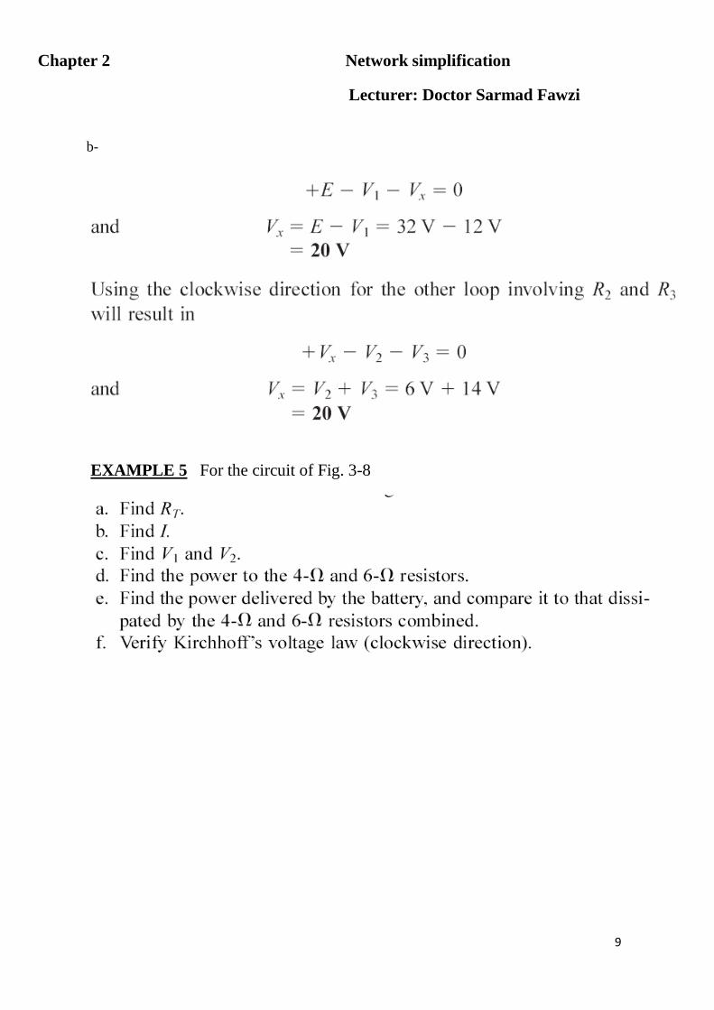
9
b-
EXAMPLE 5 For the circuit of Fig. 3-8

Chapter 2 Network simplification
Lecturer: Doctor Sarmad Fawzi
10
Fig 3-8

Chapter 2 Network simplification
Lecturer: Doctor Sarmad Fawzi
11
EXAMPLE 6 For the circuit of Fig. 3-9

Chapter 2 Network simplification
Lecturer: Doctor Sarmad Fawzi
12
Fig 3-9

Chapter 2 Network simplification
Lecturer: Doctor Sarmad Fawzi
13
3-4 INTERCHANGING SERIES ELEMENTS
The elements of a series circuit can be interchanged without affecting the total resistance, current, or power to each element. For instance, the network of Fig. (3-10) can be redrawn as shown in Fig.(3-11)
.
EXAMPLE 7 Determine I and the voltage across the 7Ω resistor for the network of Fig. 3-12
Fig 3-12
Fig. (3-11)
Circuit of
with R2and R3 interchanged.
Fig. (3-10)
Series dc circuit with
elements to be interchanged

Chapter 2 Network simplification
Lecturer: Doctor Sarmad Fawzi
14
Solution:
The network is redrawn in Fig. 3-13
Fig 3-13
3-5 VOLTAGE DIVIDER RULE (V.D.R.)
The voltage across a resistor in a series circuit is equal to the value of that resistor times the total impressed voltage across the series elements divided by the total resistance of the series elements.

Chapter 2 Network simplification
Lecturer: Doctor Sarmad Fawzi
15
EXAMPLE 8 Determine the voltage V1 for the network of Fig. 3-14
Fig (3-14)
Sol.
The circuit is simplified to fig (3-15)
Fig (3-15)

Chapter 2 Network simplification
Lecturer: Doctor Sarmad Fawzi
16
EXAMPLE 9 Using the voltage divider rule, determine the voltages V1 and V3 for the series circuit of Fig. 3-16
Fig 3-16

Chapter 2 Network simplification
Lecturer: Doctor Sarmad Fawzi
17
Note The rule can be extended to the voltage across two or more series elements.
EXAMPLE 10 Determine the voltage V′ in Fig.( 3-16 ) across resistors R1 and R2.
Please read and try understand in the first reference Chapter 5.
References:
1- Introductory Circuits Analysis, By Boylested, Tenth (10th) Edition.
2- Schaum’s Outline of Theory and Problems of Basic Circuit Analysis, By John O’Malley, Second (2nd) Edition.
3- Any reference that has Direct Current Circuits Analysis (DCCA).

Chapter 3 Voltage Sources And Notations 2017-2018 Lecturer: Doctor Sarmad Fawzi
1
Voltage Sources and Ground
The symbol for the ground connection appears in Fig. (1) With its defined
Fig(1)
Ground potential
If we take the circuit of fig (2)
Fig (2)
If Fig. (2) Is redrawn with a grounded supply, it might appear as shown in Fig. 3(a), (b), or (c). In any case, it is understood that the negative terminal of the battery and the bottom of the resistor R2 are at ground potential.
Fig (3) (a,b,c)
Three ways to sketch the same series dc circuit.

Chapter 3 Voltage Sources And Notations 2017-2018 Lecturer: Doctor Sarmad Fawzi
2
Example 1 Design a circuit by using the voltage divider rule of fig (4) such that (VR1 = 4VR2).
Fig (4)
Solution: The total resistance is defined by:
Voltage sources may be indicated as shown in Figs. 5(a) and 6(a) rather than as illustrated in Fig. 5(b) and 6(b).
Fig (5)

Chapter 3 Voltage Sources And Notations 2017-2018 Lecturer: Doctor Sarmad Fawzi
3
Replacing the special notation for a positive dc voltage source with the standard symbol
Fig (6)
Replacing the notation for a negative dc supply with the standard symbol.
Double-Subscript Notation
The double-subscript notation Vab specifies point (a) as the higher potential. If this is not the case, negative sign must be associated with the magnitude of Vab.
In other words,
The voltage Vab is the voltage at point (a) with respect to (w.r.t.) point (b).
Fig (7)
The fact that voltage is an across variable and exists between two points has resulted in a double-subscript notation that defines the first subscript as the higher potential. In Fig. 7(a), the two points that define the voltage across the resistor R are denoted by (a and b). Since (a) is the first subscript for Vab, point (a) must have a higher potential than point (b)if Vab is to have a positive value. If, point (b) is at a higher potential than point (a) ,Vab will have a negative value, as indicated in Fig. 7(b).

Chapter 3 Voltage Sources And Notations 2017-2018 Lecturer: Doctor Sarmad Fawzi
4
Single-Subscript Notation
The single-subscript notation (Va) specifies the voltage at point a with respect to ground (Zero volts).
In Fig. 8, Va is the voltage from point (a) to ground. In this case it is obviously 10 V since
It is right across the source voltage E. The voltage Vb is the voltage from point (b) to ground.
Because it is directly across the 4Ω resistor, Vb = 4 V.
The following relationship exists:
(1)
So from the equation (1):
EXAMPLE 2 Find the voltage Vab for the conditions of Fig. (9)
Fig (9)
Solution: Applying Eq. (1)
Fig. (8)
Defining the use of single-subscript notation

Chapter 3 Voltage Sources And Notations 2017-2018 Lecturer: Doctor Sarmad Fawzi
5
Vab =Va -Vb = 16 V - 20 V
= - 4 V
Note: the negative sign means that point (b) is at a higher potential than point (a).
EXAMPLE 3 Find the voltage Va for the configuration of Fig. (10)
Solution: Applying Eq. (1):
Fig(10)
Vab = Va - Vb
and Va = Vab + Vb = 5 V + 4 V
= 9 V
EXAMPLE 4 Find the voltage Vab for the configuration of Fig. (11)

Chapter 3 Voltage Sources And Notations 2017-2018 Lecturer: Doctor Sarmad Fawzi
6
Fig (11)
Solution: Applying Eq. (1):
Vab = Va - Vb = 20 V - (-15 V) = 20 V + 15 V
= 35 V
EXAMPLE 5 Find the voltages Vb, Vc, and Vac for the network of Fig (12).
Fig (12)
Solution: Starting at ground potential (zero volts), we proceed through a rise of 10 V to reach point (a) and then pass through( a) drop in potential of 4 V to point (b). The result is that the meter will read:
Vb = +10 V - 4 V = 6 V
Vc = Vb -20 V = 6 V - 20 V = -14 V
Vac = Va - Vc = 10 V - (-14 V)
= 24 V
EXAMPLE 6 Determine Vab, Vcb, and Vc for the network of Fig. (13)

Chapter 3 Voltage Sources And Notations 2017-2018 Lecturer: Doctor Sarmad Fawzi
7
Fig (13)
Fig (14)
EXAMPLE 7 Using the voltage divider rule, determine the voltagesV1 and V2 of Fig. (15).
Fig (15) fig (16)
Sol:
Redraw the network as shown in Fig. (14)
Redraw the network as shown in Fig. (16)
ET= 19+35= 54 V
RT = 20+25 =45

Chapter 3 Voltage Sources And Notations 2017-2018 Lecturer: Doctor Sarmad Fawzi
8
EXAMPLE 8 For the network of Fig. (17)
INTERNAL RESISTANCE OF VOLTAGE SOURCES
Every source of voltage, whether a generator, battery, or laboratory supply as shown in Fig. 17(a), will have some internal resistance. The equivalent circuit of any source of voltage will therefore appear as shown in Fig. 17(b).
Redraw the network as shown in Fig. (17 b)
a b
Fig (17)

Chapter 3 Voltage Sources And Notations 2017-2018 Lecturer: Doctor Sarmad Fawzi
9
Fig (17)
(a) Sources of dc voltage; (b) equivalent circuit.
The ideal voltage source has no internal resistance and an output voltage of E volts with
No load or full load. As shown in [fig18 (a)].
Fig (18)
In the practical case [Fig. 18(b)], where we consider the effects of the internal resistance, the output voltage will be E volts only when no-load (IL = 0) conditions exist.
Fig (18)

Chapter 3 Voltage Sources And Notations 2017-2018 Lecturer: Doctor Sarmad Fawzi
10
When a load is connected [fig 18c]
Fig (18)
By applying Kirchhoff’s voltage law around the indicated loop of Fig18(c), we obtain:
EXAMPLE 9 The battery of Fig. (19) has an internal resistance of 2 Ω. Find the voltage VL and the power lost to the internal resistance if the applied load is a 13Ω resistor.

Chapter 3 Voltage Sources And Notations 2017-2018 Lecturer: Doctor Sarmad Fawzi
11
Please read and try understand in the first reference Chapter 5. References: 1- Introductory Circuits Analysis, By Boylested, Tenth (10th) Edition. 2- Schaum’s Outline of Theory and Problems of Basic Circuit Analysis, By John O’Malley, Second (2nd) Edition. 3- Any reference that has Direct Current Circuits Analysis (DCCA).
Fig(19)
Chapter Four Parallel Circuits 2017-2018 Lecturer: Doctor Sarmad Fawzi
1
1.1 PARALLEL RESISTANCE
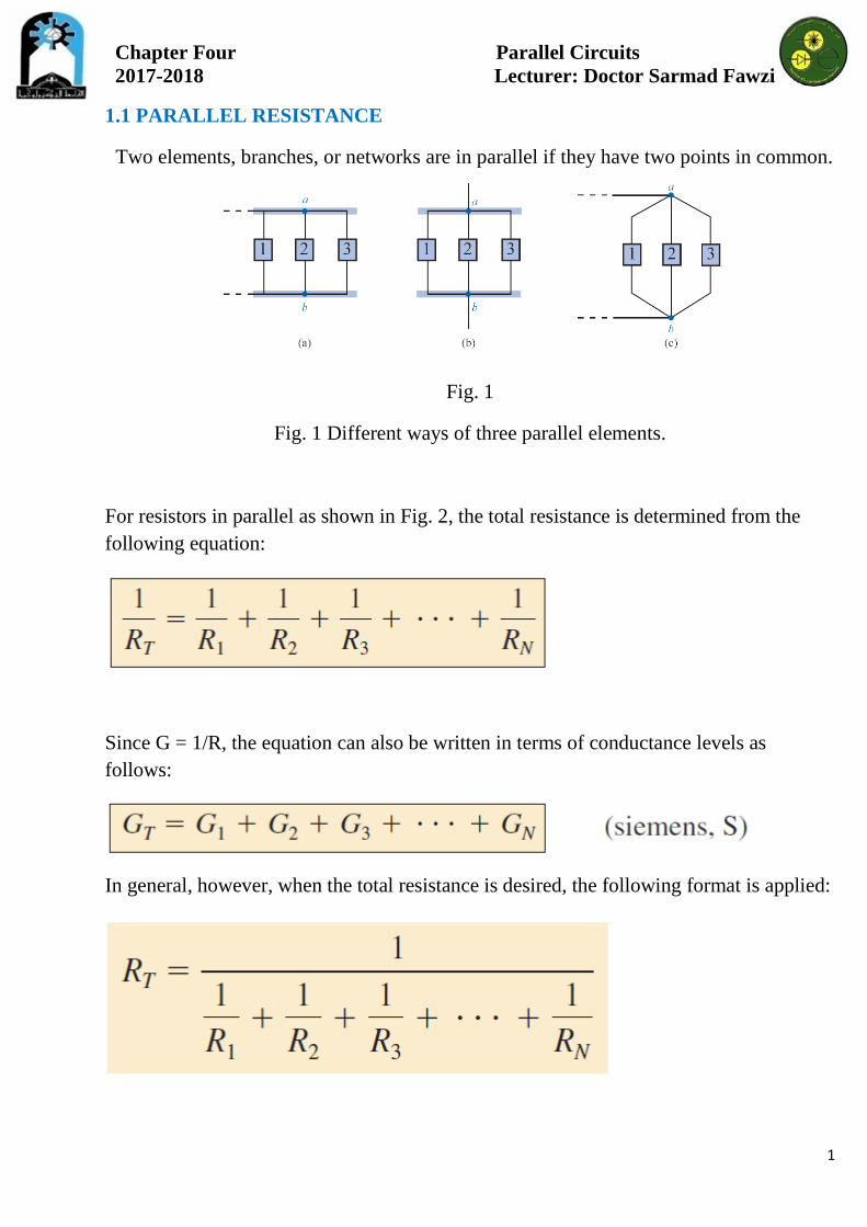
Two elements, branches, or networks are in parallel if they have two points in common.
Fig. 1
Fig. 1 Different ways of three parallel elements.
For resistors in parallel as shown in Fig. 2, the total resistance is determined from the following equation:
Since G = 1/R, the equation can also be written in terms of conductance levels as follows:
In general, however, when the total resistance is desired, the following format is applied:

Chapter Four Parallel Circuits 2017-2018 Lecturer: Doctor Sarmad Fawzi
2
Fig (2) Parallel combination of resistors.
EXAMPLE 1 Find the total resistance of the configuration in Fig. 3.
Fig. 3
Solution: First, the network is redrawn as shown in Fig. 4 to clearly demonstrate that all the resistors are in parallel.
Fig .4 Redrawing the network

Chapter Four Parallel Circuits 2017-2018 Lecturer: Doctor Sarmad Fawzi
3
Note: the total resistance of parallel resistors is always less than the value of the smallest resistor. For equal resistors in parallel, the equation for the total resistance becomes significantly easier to apply. For N equal resistors in parallel, the total resistance becomes:
In other words, the total resistance of N parallel resistors of equal value is the resistance of one resistor divided by the number (N) of parallel resistors. EXAMPLE 2 Find the total resistance of the parallel resistors in Fig. 5
Fig. 5 Three equal parallel resistors to be investigated.

Chapter Four Parallel Circuits 2017-2018 Lecturer: Doctor Sarmad Fawzi
4
EXAMPLE 3 Find the total resistance for the configuration in Fig. 6.
Fig. 6
Solution: Redrawing the network results in the parallel network in Fig. 7.
Fig. 7 Network in Fig. 6 redrawn.
Special Case: Two Parallel Resistors In the vast majority of cases, only two or three parallel resistors will have to be combined. With this in mind, an equation has been derived for two parallel resistors that is easy to apply and removes the need to continually worry about dividing into 1 and possibly misplacing a decimal point. For three parallel resistors, the equation to be derived here can be applied twice, or Equation of Total Resistance can be used. For two parallel resistors, the total resistance is determined:

Chapter Four Parallel Circuits 2017-2018 Lecturer: Doctor Sarmad Fawzi
5
Multiplying the top and bottom of each term of the right side of the equation by the other resistor results in
In words, the equation states that the total resistance of two parallel resistors is simply the product of their values divided by their sum. Note: Recall that series elements can be interchanged without affecting the magnitude of the total resistance. In parallel networks, parallel resistors can be interchanged without affecting the total resistance. EXAMPLE 4 Determine the total resistance of the parallel elements in Fig. 8.
Fig. 8.

Chapter Four Parallel Circuits 2017-2018 Lecturer: Doctor Sarmad Fawzi
6
Solution: The network is redrawn in Fig. 9.
Fig. 9 Redrawing the network
EXAMPLE 5 Determine the value of R2 in Fig. 10 to establish a total resistance of 9 kilo ohms.
Fig. 10

Chapter Four Parallel Circuits 2017-2018 Lecturer: Doctor Sarmad Fawzi
7
Solution:
EXAMPLE 6 Determine the values of R1, R2 and R3 in Fig. 11 if R2 = 2R1, R3 = 2R2, and the total resistance is 16 kilo ohms.
Fig. 11

Chapter Four Parallel Circuits 2017-2018 Lecturer: Doctor Sarmad Fawzi
8
1.2 PARALLEL CIRCUITS A parallel circuit can now be established by connecting a supply across a set of parallel resistors as shown in Fig.12. The positive terminal of the supply is directly connected to the top of each resistor, while the negative terminal is connected to the bottom of each resistor. Therefore, it should be quite clear that the applied voltage is the same across each resistor.
Fig. 12
In general,

Chapter Four Parallel Circuits 2017-2018 Lecturer: Doctor Sarmad Fawzi
9
the voltage is always the same across parallel elements. For the voltages of the circuit in Fig. 12, the result is that
Fig. 13
Replacing the parallel resistors in Fig. 13 with the equivalent total resistance. The source current can then be determined using Ohm’s law:
Since the voltage is the same across parallel elements, the current through each resistor can also be determined using Ohm’s law. That is,
The direction for the currents is dictated by the polarity of the voltage across the
resistors. Recall that for a resistor, current enters the positive side of a potential drop and leaves the negative. The result, as shown in Fig. 12, is that the source current enters point a, and currents I1 and I2 leave the same point.

Chapter Four Parallel Circuits 2017-2018 Lecturer: Doctor Sarmad Fawzi
10
An excellent analogy for describing the flow of charge through the network of Fig. 12 is the flow of water through the parallel pipes of Fig. 14.
Fig. 14
The larger pipe with less “resistance” to the flow of water will have a larger flow
of water through it. The thinner pipe with its increased “resistance” level will have less water through it. In any case, the total water entering the pipes at the top QT must equal that leaving at the bottom, with QT = Q1+ Q2.
The relationship between the source current and the parallel resistor currents can be derived by simply taking the equation for the total resistance in equation of total resistance.
The result reveals a very important property of parallel circuits:

Chapter Four Parallel Circuits 2017-2018 Lecturer: Doctor Sarmad Fawzi
11
For single-source parallel networks, the source current (Is) is always equal to the sum of the individual branch currents. The duality that exists between series and parallel circuits continues to surface as we proceed through the basic equations for electric circuits. for a parallel circuit, the source current equals the sum of the branch currents, while for a series circuit, the applied voltage equals the sum of the voltage drops.
Fig. 15 Demonstrating the duality that exists between series and parallel circuits.
EXAMPLE 7 For the parallel network in Fig. 16. a. Find the total resistance. b. Calculate the source current. c. Determine the current through each branch.
Fig. 16

Chapter Four Parallel Circuits 2017-2018 Lecturer: Doctor Sarmad Fawzi
12
a.
Note that the total resistance is less than the smallest parallel resistor. b. Using Ohm’s law:
c. Applying Ohm’s law:
for parallel resistors, the greatest current will exist in the branch with the least resistance. A more powerful statement is that current always seeks the path of least resistance.

Chapter Four Parallel Circuits 2017-2018 Lecturer: Doctor Sarmad Fawzi
13
1.3 POWER DISTRIBUTION IN A PARALLEL CIRCUIT for any network composed of resistive elements, the power applied by the battery will equal that dissipated by the resistive elements. For the parallel circuit in Fig. 17:
Fig. 17
Power flow in a dc parallel network.
which is exactly the same as obtained for the series combination. The power delivered by the source in the same:
as is the equation for the power to each resistor.
in a parallel resistive network, the larger the resistor, the less the power absorbed.

Chapter Four Parallel Circuits 2017-2018 Lecturer: Doctor Sarmad Fawzi
14
EXAMPLE 8 For the parallel network in Fig. 18 a. Determine the total resistance RT. b. Find the source current and the current through each resistor. c. Calculate the power delivered by the source. d. Determine the power absorbed by each parallel resistor. e. Verify the power applied by the battery will equal that dissipated by the resistive elements.
Fig. 18
Solutions: a.
b. Applying Ohm’s law:

Chapter Four Parallel Circuits 2017-2018 Lecturer: Doctor Sarmad Fawzi
15
c.
d. Applying each form of the power equation:
A review of the results clearly substantiates the fact that the larger the resistor, the less the power absorbed. e.
1.4 KIRCHHOFF’S CURRENT LAW (KCL) The algebraic sum of the currents entering and leaving a junction (or region) of a network is zero. The sum of the currents entering a junction (or region) of a network must equal the sum of the currents leaving the same junction (or region). In equation form, the above statement can be written as follows:
with Ii representing the current entering, or “in,” and Io representing the current leaving, or “out.”
Chapter Four Parallel Circuits 2017-2018 Lecturer: Doctor Sarmad Fawzi
16
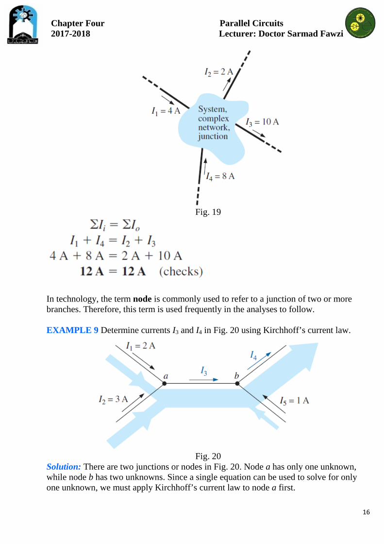
Fig. 19
In technology, the term node is commonly used to refer to a junction of two or more branches. Therefore, this term is used frequently in the analyses to follow. EXAMPLE 9 Determine currents I3 and I4 in Fig. 20 using Kirchhoff’s current law.
Fig. 20
Solution: There are two junctions or nodes in Fig. 20. Node a has only one unknown, while node b has two unknowns. Since a single equation can be used to solve for only one unknown, we must apply Kirchhoff’s current law to node a first.

Chapter Four Parallel Circuits 2017-2018 Lecturer: Doctor Sarmad Fawzi
17
At node a:
At node b, using the result just obtained:
Note that in Fig. 20, the width of the blue shaded regions matches the magnitude of the current in that region. EXAMPLE 10 Determine currents I1, I3, I4, and I5 for the network in Fig. 21. Solution: In this configuration, four nodes are defined. Nodes a and c have only one unknown current at the junction, so Kirchhoff’s current law can be applied at either junction.
Fig. 21 Four-node configuration for the Example.

Chapter Four Parallel Circuits 2017-2018 Lecturer: Doctor Sarmad Fawzi
18
At node a:
At node c:
Using the above results at the other junctions results in the following. At node b:
At node d:
1.5 CURRENT DIVIDER RULE (CDR)
For series circuits we have the powerful voltage divider rule for finding the voltage across a resistor in a series circuit. We now introduce the equally powerful current divider rule (CDR) for finding the current through a resistor in a parallel circuit.
For two parallel elements of equal value, the current will divide equally. For parallel elements with different values, the smaller the resistance, the greater the share of input current. For parallel elements of different values, the current will split with a ratio equal to the inverse of their resistor values.

Chapter Four Parallel Circuits 2017-2018 Lecturer: Doctor Sarmad Fawzi
19
EXAMPLE 11 a) Determine currents I1 and I3 for the network in Fig. 22. b) Find the source current Is.
Fig. 22
Solutions: a. Since R1 is twice R2, the current I1 must be one-half I2, and
Since R2 is three times R3, the current I3 must be three times I2, and
b. Applying Kirchhoff’s current law:

Chapter Four Parallel Circuits 2017-2018 Lecturer: Doctor Sarmad Fawzi
20
Fig. 23 Deriving the current divider rule: (a) parallel network of N parallel
resistors; (b) reduced equivalent of part (a).
Although the above discussions and examples allowed us to determine the relative magnitude of a current based on a known level, they do not provide the magnitude of a current through a branch of a parallel network if only the total entering current is known. The result is a need for the current divider rule which will be derived using the parallel configuration in Fig. 23(a). The current IT (using the subscript T to indicate the total entering current) splits between the N parallel resistors and then gathers itself together again at the bottom of the configuration. In Fig. 23(b), the parallel combination of resistors has been replaced by a single resistor equal to the total resistance of the parallel combination as determined in the previous sections. The current IT can then be determined using Ohm’s law:
Since the voltage V is the same across parallel elements, the following is true:
where the product IxRx refers to any combination in the series. Substituting for V in the above equation for IT, we have
Solving for Ix , the final result is the current divider rule:
Chapter Four Parallel Circuits 2017-2018 Lecturer: Doctor Sarmad Fawzi
21
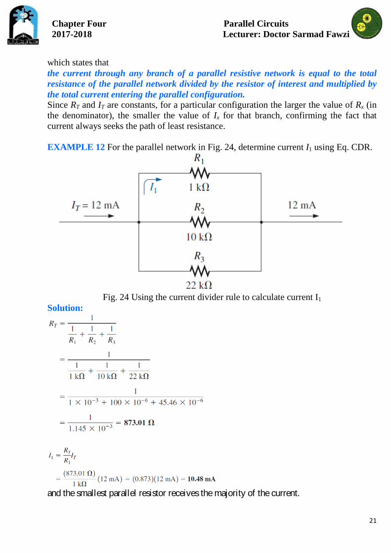
which states that the current through any branch of a parallel resistive network is equal to the total resistance of the parallel network divided by the resistor of interest and multiplied by the total current entering the parallel configuration. Since RT and IT are constants, for a particular configuration the larger the value of Rx (in the denominator), the smaller the value of Ix for that branch, confirming the fact that current always seeks the path of least resistance. EXAMPLE 12 For the parallel network in Fig. 24, determine current I1 using Eq. CDR.
Fig. 24 Using the current divider rule to calculate current I1
Solution:
and the smallest parallel resistor receives the majority of the current.

Chapter Four Parallel Circuits 2017-2018 Lecturer: Doctor Sarmad Fawzi
22
Special Case: Two Parallel Resistors For the case of two parallel resistors as shown in Fig 25, the total resistance is determined by
Fig. 25 Deriving the current divider rule for the special case of only two parallel
resistors.
Substituting RT into Eq. CDR for current I1 results in
And
Similarly, for I2,
Equation I1, I2 states that for two parallel resistors, the current through one is equal to the other resistor times the total entering current divided by the sum of the two resistors.

Chapter Four Parallel Circuits 2017-2018 Lecturer: Doctor Sarmad Fawzi
23
Since the combination of two parallel resistors is probably the most common parallel configuration, the simplicity of the format for Equation (I1, I2) suggests that it is worth memorizing. Take particular note, however, that the denominator of the equation is simply the sum, not the total resistance, of the combination. EXAMPLE 13 Determine current I2 for the network in Fig. 26 using the current divider rule.
Fig. 26
Solution:

Chapter Four Parallel Circuits 2017-2018 Lecturer: Doctor Sarmad Fawzi
24
EXAMPLE 14 Determine resistor R1 in Fig. 27 to implement the division of current shown.
Fig. 27 A design-type problem for two parallel resistors.
Solution: There are essentially two approaches to this type of problem. One involves the direct substitution of known values into the current divider rule equation followed by a mathematical analysis. The other is the sequential application of the basic laws of electric circuits. First we will use the latter approach.

Chapter Four Parallel Circuits 2017-2018 Lecturer: Doctor Sarmad Fawzi
25
In summary, therefore, remember that current always seeks the path of least resistance, and the ratio of the resistor values is the inverse of the resulting current levels, as shown in Fig 28. The thickness of the blue bands in Fig. 28 reflects the relative magnitude of the current in each branch.
Fig. 28 Demonstrating how current divides through equal and unequal parallel resistors.

Chapter Four Parallel Circuits 2017-2018 Lecturer: Doctor Sarmad Fawzi
26
1.6 OPEN AND SHORT CIRCUITS An open circuit is two isolated terminals not connected by an element of any
kind, as shown in Fig. 29(a). Since a path for conduction does not exist, the current associated with an open
circuit must always be zero. The voltage across the open circuit, however, can be any value, as determined by the system it is connected to. In summary, therefore, an open circuit can have a potential difference (voltage) across its terminals, but the current is always zero amperes.
Fig. 29-a
Fig. 29-b
In Fig. 29(b), an open circuit exists between terminals a and b. The voltage across the open-circuit terminals is the supply voltage, but the current is zero due to the absence of a complete circuit.

Chapter Four Parallel Circuits 2017-2018 Lecturer: Doctor Sarmad Fawzi
27
A short circuit is a very low resistance, direct connection between two terminals of a network, as shown in Fig. 30. The current through the short circuit can be any value, as determined by the system it is connected to, but the voltage across the short circuit is always zero volts because the resistance of the short circuit is assumed to be essentially zero ohms and
In summary, therefore, a short circuit can carry a current of a level determined by the external circuit, but the potential difference (voltage) across its terminals is always zero volts.
Fig. 30
EXAMPLE 15 Determine voltage Vab for the network in Fig. 31.
Fig. 31
Solution: The open circuit requires that I be zero amperes. The voltage drop across both resistors is therefore zero volts since
Applying Kirchhoff’s voltage law around the closed loop,

Chapter Four Parallel Circuits 2017-2018 Lecturer: Doctor Sarmad Fawzi
28
EXAMPLE 16 Determine voltages Vab and Vcd for the network in Fig. 32.
Fig. 32
Solution: The current through the system is zero amperes due to the open circuit, resulting in a 0 V drop across each resistor. Both resistors can therefore be replaced by short circuits, as shown in Fig. 33. Voltage Vab is then directly across the 10 V battery, and
Fig. 33 Circuit in Fig. 32 redrawn.

Chapter Four Parallel Circuits 2017-2018 Lecturer: Doctor Sarmad Fawzi
29
Voltage Vcd requires an application of Kirchhoff’s voltage law:
The negative sign in the solution indicates that the actual voltage Vcd has the opposite polarity of that appearing in Fig. 32. EXAMPLE 17 Determine V and I for the network in Fig. 34 if resistor R2 is shorted out.
Fig. 34
Solution: The redrawn network appears in Fig. 35.
Fig. 35 Network in Fig. 34 with R2 replaced by a jumper.

Chapter Four Parallel Circuits 2017-2018 Lecturer: Doctor Sarmad Fawzi
30
The current through the 3 ohm resistor is zero due to the open circuit, causing all the current I to pass through the jumper. Since
, the voltage V is directly across the short, and
1.7 SUMMARY TABLE
Now that the series and parallel configurations have been covered in detail, we will review the salient equations and characteristics of each. The equations for the two configurations have a number of similarities. In fact, the equations for one can often be obtained directly from the other by simply applying the duality principle.
TABLE 1 Summary table.
Chapter Four Parallel Circuits 2017-2018 Lecturer: Doctor Sarmad Fawzi
31
Please read and try understand in the first reference Chapter 6. References: 1- Introductory Circuits Analysis, By Boylested, Tenth (10th) Edition. 2- Schaum’s Outline of Theory and Problems of Basic Circuit Analysis, By John O’Malley, Second (2nd) Edition. 3- Any reference that has Direct Current Circuits Analysis (DCCA).

3/3/2018 Doctor Sarmad Fawzi 1

Direct Current Circuits Analysis (DCCA)
LE1042017-2018
Doctor Sarmad Fawzi
3/3/2018 2Doctor Sarmad Fawzi

Chapter 5SERIES-PARALLEL NETWORKS
3/3/2018 3Doctor Sarmad Fawzi

SERIES-PARALLEL NETWORKSA firm understanding of the basic principles associated with series and parallel circuits is a sufficient
background to begin an investigation of any single-source dc network having a combination of seriesand parallel elements or branches. Multisource networks are considered in detail in Chapters 8 and 9. Ingeneral,
Series-Parallel networks are networks that contain both series and parallel circuit configurations.
One can become proficient in the analysis of series-parallel networks only through:1) exposure, 2) practice, and 3) experience. In time the path to the desired unknown becomes moreobvious as one recalls similar configurations and the frustration resulting from choosing the wrongapproach. There are a few steps that can be helpful in getting started on the first few exercises, althoughthe value of each will become apparent only with experience.
3/3/2018 4Doctor Sarmad Fawzi

General Approach
1. Take a moment to study the problem “in total” and make a brief mental sketch of the overallapproach you plan to use. The result may be time- and energy-saving shortcuts.2. Next examine each region of the network independently before tying them together in series-parallel combinations. This will usually simplify the network and possibly reveal a direct approachtoward obtaining one or more desired unknowns. It also eliminates many of the errors that mightresult due to the lack of a systematic approach.3. Redraw the network as often as possible with the reduced branches and undisturbed unknownquantities to maintain clarity and provide the reduced networks for the trip back to unknownquantities from the source.4. When you have a solution, check that it is reasonable by considering the magnitudes of theenergy source and the elements in the network. If it does not seem reasonable, either solve the circuitusing another approach or check over your work very carefully.
3/3/2018 5Doctor Sarmad Fawzi

3/3/2018 6
Reduce and Return ApproachFor many single-source, series-parallel networks, the analysis is one that works back to the source,determines the source current, and then finds its way to the desired unknown.
In Fig. 1(a), for instance, the voltage V4 is desired. The absence of a single series or parallel path toV4 from the source immediately:
Doctor Sarmad Fawzi

3/3/2018 7
First, series and parallel elements must be combined to establish the reduced circuit of Fig. 1(b).
Second, series elements are combined to form the simplest of configurations in Fig. 1(c). Thesource current can now be determined using Ohm’s law,
Doctor Sarmad Fawzi

3/3/2018 8
Third, and we can proceed back through the network as shown in Fig. 1(d). The voltage V2 can bedetermined
Finally, and then the original network can be redrawn, as shown in Fig. 1(e). Since V2 is nowknown, the voltage divider rule (VDR) can be used to find the desired voltage V4.
Doctor Sarmad Fawzi

3/3/2018 9
Fig. 1Introducing the reduce and return approach.
Doctor Sarmad Fawzi

3/3/2018 10
Block Diagram Approach
The block diagram approach will be employed throughout to emphasize the fact that combinations ofelements, not simply single resistive elements, can be in series or parallel.
Fig. 2Introducing the block diagram approach.
Doctor Sarmad Fawzi

3/3/2018 11
1) In Fig. 2, blocks B and C are in parallel (points b and c in common),2) and the voltage source E is in series with block A (point a in common).3) The parallel combination of B and C is also in series with A and the voltage source E due to thecommon points b and c, respectively.
To ensure that the analysis to follow is as clear and uncluttered as possible,
For series resistors R1 and R2, a comma will be inserted between their subscript notations, as shownhere:R1, 2 =R1 + R2
For parallel resistors R1 and R2, the parallel symbol will be inserted between their subscriptnotations, as follows:
Doctor Sarmad Fawzi

3/3/2018 Doctor Sarmad Fawzi 12
Example 1: Calculate the source current (IS); (IB) ;( IC) for the cct. of fig (3):
Fig. (3)

3/3/2018 Doctor Sarmad Fawzi 13
Sol: The parallel combination of RB and RC results in
The equivalent resistance RB||C is then in series with RA, and the total resistance “seen” by thesource is
The result is an equivalent network, as shown in Fig. 4, permitting the determination of the source current Is.

3/3/2018 Doctor Sarmad Fawzi 14
Fig. (4)
We can then use the equivalent network of Fig. (5) to determine IB and IC using the current divider rule (CDR):

3/3/2018 Doctor Sarmad Fawzi 15
Fig. (5)
Note that in this solution, we worked back to the source to obtain the source current or total currentsupplied by the source.

3/3/2018 Doctor Sarmad Fawzi 16
Example 2: for the cct. of fig. (6) calculate: RA , RB , RC , RT , IT , IA , IB , IC , IR1 , IR2 , IR3 , IR4 , IR5
Fig.(6)

3/3/2018 Doctor Sarmad Fawzi 17
Sol. : By re-drawing the cct. of fig.(6) we get an equivalent cct. of fig(7):
Fig. (7)

3/3/2018 Doctor Sarmad Fawzi 18

3/3/2018 Doctor Sarmad Fawzi 19
Returning to the network of Fig. 6, we have:
Applying Kirchhoff’s voltage law for the loop indicated in Fig. (7), we obtain:

3/3/2018 Doctor Sarmad Fawzi 20
Example 3 : for the circuit in the fig(8) find: RT , RA , RB , RC , IS , IA , IB , IC , I1 , I2
Fig. (8)

3/3/2018 Doctor Sarmad Fawzi 21
SOL.
The network of Fig. ( 8) can then be redrawn in reduced form, as shown in Fig. (9).
Fig. (9)

3/3/2018 Doctor Sarmad Fawzi 22

3/3/2018 Doctor Sarmad Fawzi 23
Returning to the original network (Fig. 8) and applying the current divider rule:

3/3/2018 Doctor Sarmad Fawzi 24
EXAMPLE 4: Find the indicated currents and voltages for the network of Fig.(8)
Fig.(8) Block diagram for Figure (9)

3/3/2018 Doctor Sarmad Fawzi 25
The reduced form of Fig. ( 8 )will then appear as shown in Fig.(10) :
Fig.(10)

3/3/2018 Doctor Sarmad Fawzi 26

3/3/2018 Doctor Sarmad Fawzi 27
Example 5 : a. Find the voltages V1, V3, and Vab for the network of Fig. (11).b. Calculate the source current IS.
Fig.(11)

3/3/2018 Doctor Sarmad Fawzi 28
Sol: Since combining both sources will not affect the unknownsThe cct. is re-drawn as in fig(12):The net source voltage is the difference between the two with the polarity of the larger.
Fig.(12)

3/3/2018 Doctor Sarmad Fawzi 29
a.
The open-circuit voltage Vab is determined by applying Kirchhoff’s voltage law around the indicated loop of Fig.( 12) in the clockwise direction starting at terminal a.

3/3/2018 Doctor Sarmad Fawzi 30

3/3/2018 Doctor Sarmad Fawzi 31
Please read and try understand in the first reference Chapter 7.
References:
1- Introductory Circuits Analysis, By Boylested, Tenth (10th) Edition.
2- Schaum’s Outline of Theory and Problems of Basic Circuit Analysis, By John O’Malley, Second (2nd) Edition.
3- Any reference that has a Direct Current Circuits Analysis (DCCA).

3/3/2018 Doctor Sarmad Fawzi 32

Thank you for listening
3/3/2018 Doctor Sarmad Fawzi 33

3/3/2018 Doctor Sarmad Fawzi 34

C++ Computer Programming (Lab -7-)
51
Math. Functions
pow (real) <math.h>
Power function, x to the y
Declaration:
double pow(double x, double y);
Q) Write a program to calculate the cubic number for 4 different numbers #include <iostream.h>
#include <conio.h>
#include <math.h>
int main()
double n,c;
clrscr();
for (int i=1;i<=4;i=i+1)
cout <<"Number:=";
cin>> n;
c=pow(n,3);
cout <<"Cubic Number:="<<c;
cout << "\n\nHit any key to continue";
getch();
return 0;
cos, sin, tan (real) <math.h>
Cosine, sine, and tangent functions
Declaration:
double cos(double x);
double sin(double x);
double tan(double x);
Remarks:
cos compute the cosine of the input value
sin compute the sine of the input value
tan calculate the tangent of the input value
Angles are specified in radians.
#include <stdio.h>
#include <math.h>
int main(void)
double result, x;
x = 90;
result = sin(x*3.14/180);
cout <<"The sin of “<<x<<” is "<< result;
//the oputput is: The sin of 90.00 is 1.00
return 0;

C++ Computer Programming (Lab -7-)
52
acos, asin, atan, atan2 (real) <math.h>
Arc cosine, arc sine, and arc tangent functions
Declaration:
double acos(double x);
double asin(double x);
double atan(double x);
double atan2(double y, double x);
Remarks:
acos of a real value compute the arc cosine of that value
asin of a real value compute the arc sine of that value
atan calculate the arc tangent of the input value
atan2 also calculate the arc tangent of the input value
Real arguments to acos, and asin must be in the range -1 to 1.
#include <stdio.h>
#include <math.h>
int main(void)
double result;
double x = 1.00;
result = asin(x)/(3.14/180);
cout <<"The arc sin of “<<x<<” is "<< result;
//the oputput is: The arc sin of 1.00 is 90.00
return(0);
exp (real) <math.h>
Real exp calculates e to the xth power
Declaration:
double exp(double x);
Remarks:
exp calculates the exponential function e**x.
#include <stdio.h>
#include <math.h>
int main(void)
double result;
double x = 4.0;
result = exp(x);
cout <<" 'e' raised to the power of "<<x<<" (e ^ "<<x<<") = "<< result;
return 0;
The output is: 'e' raised to the power of 4.000000e^4.000000)=54.598150

C++ Computer Programming (Lab -7-)
53
sqrt (real) < math.h >
Calculates square root
Declaration:
Real: double sqrt(double x);
long double sqrtl(long double @E(x));
Remarks:
sqrt calculates the positive square root of the input value.
#include <math.h>
#include <iostream.h>
int main(void)
double x = 4.0, result;
result = sqrt(x);
cout <<"The square root of "<<x<<" is "<< result;
//the oputput is: The square root of 4.000000 is 2.000000
return 0;
abs <math.h, stdlib.h, complex.h>
fabs < math.h >
labs < math.h, stdlib.h >
abs (a macro) gets the absolute value of an integer
fabs calculate the absolute value of a floating-point number
labs calculates the absolute value of a long number
Declaration:
abs
int abs(int x);
double fabs(double x);
long int labs(long int x);
#include <iostream.h>
#include <math.h>
int main(void)
int number = -1234;
cout <<"number: "<<number<<" absolute value: " << abs(number);
//the oputput is: number: -1234 absolute value: 1234
return 0;

C++ Computer Programming (Lab -7-)
54
randomize <stdlib.h> Initializes random number generator. time.h must included
random < stdlib.h > Returns a random number: random(num);
random returns a random number between 0 and (num-1).
#include <stdlib.h>
#include <iostream.h>
#include <time.h>
/* prints a random number in the range 0 to 99 */
int main(void)
randomize();
cout <<"Random number in the 0-99 range: "<< random (100);
return 0;
Q) Write a program to solve the following equations, where Q in degree
𝑦 =
|tan 𝑄 − 𝑒𝑄| 𝑥 < 0
−𝑏 + √𝑏2 − 4𝑎𝑐
2𝑎 𝑥 ≥ 0
#include <iostream.h>
#include <conio.h>
#include <math.h>
int main()
double y,x,a,b,c,Q;
clrscr();
cout <<"x="; cin >>x;
if (x<0)
cout <<"Q="; cin >>Q;
y=fabs(tan(Q*3.14/180)-exp(Q));
else
cout <<"a="; cin >>a;
cout <<"b="; cin >>b;
cout <<"c="; cin >>c;
double bs=b*b-4*a*c;
if ((a) && (bs>0))
y=(-b+sqrt(bs))/2*a;
else
cout <<"Error illegal values";
getch();
return 1;
cout <<"y="<<y;
getch();
return 0;