centipede 1st printing.pdf
TRANSCRIPT

JI\. ATARr
TM-182 1st printing
Operation, Maintenance and Service Manual
Complete with Illustrated Parts Lists

GAME SERIAL NUMBER LOCATION Your game's serial number is stamped on a silver identification label. If your game is UL-listed, this label is located on the front of the game, underneath the coin door. Otherwise, the label is affixed to the rear panel of the game.
The same serial number is also stamped on the chassis of the monitor, Regulator/Audio II PCB, and the Centipede™ Game PCB. Please mention this number whenever calling your distributor for service.
GAME SERIAL NUMBER IDENTIFICATION TAG
REGULATOR/AUDIO 11 PCB
MONITOR
CEN E GAME PCB

Operation, Maintenance and Service Manual
Complete with Illustrated Parts Lists

Centipede TM
ii
Copyright © 1981 by Atari, Inc. All rights reserved.
No part of this publication may be reproduced by any mechanical, photographic, or electronic process, or in the form of a phonographic recording, nor may it be stored in a retrieval system, transmitted, or otherwise copied for public or private use, without permission from the publisher.
Published by: ATARI, INC. 1265 Borregas Avenue PO. Box 427 Sunnyvale, California 94086
Lithographed in the U.S.A. 6K
(
Notice Regarding Non-Atari Parts
WARNING Use of non-Atari parts or modifications of your Atari game circuitry may adversely affect the safety of your game, and may cause injury to you and your players.
Atari, lnc.'s warranty (prjnted on the inside back cover of this manual) may be voided, if you do any of the following:
1.) you substitute non-Atari parts in your coin-operated game, or
2.) you modify or alter any circuits in your Atari game by using kits or parts not supplied by Atari.
Not only may the use of any non-Atari parts void your warranty, but any such alteration may also adversely affect the safety of your game, and may cause injury to you and your players.
Centipede TM
iii
Centipede TM
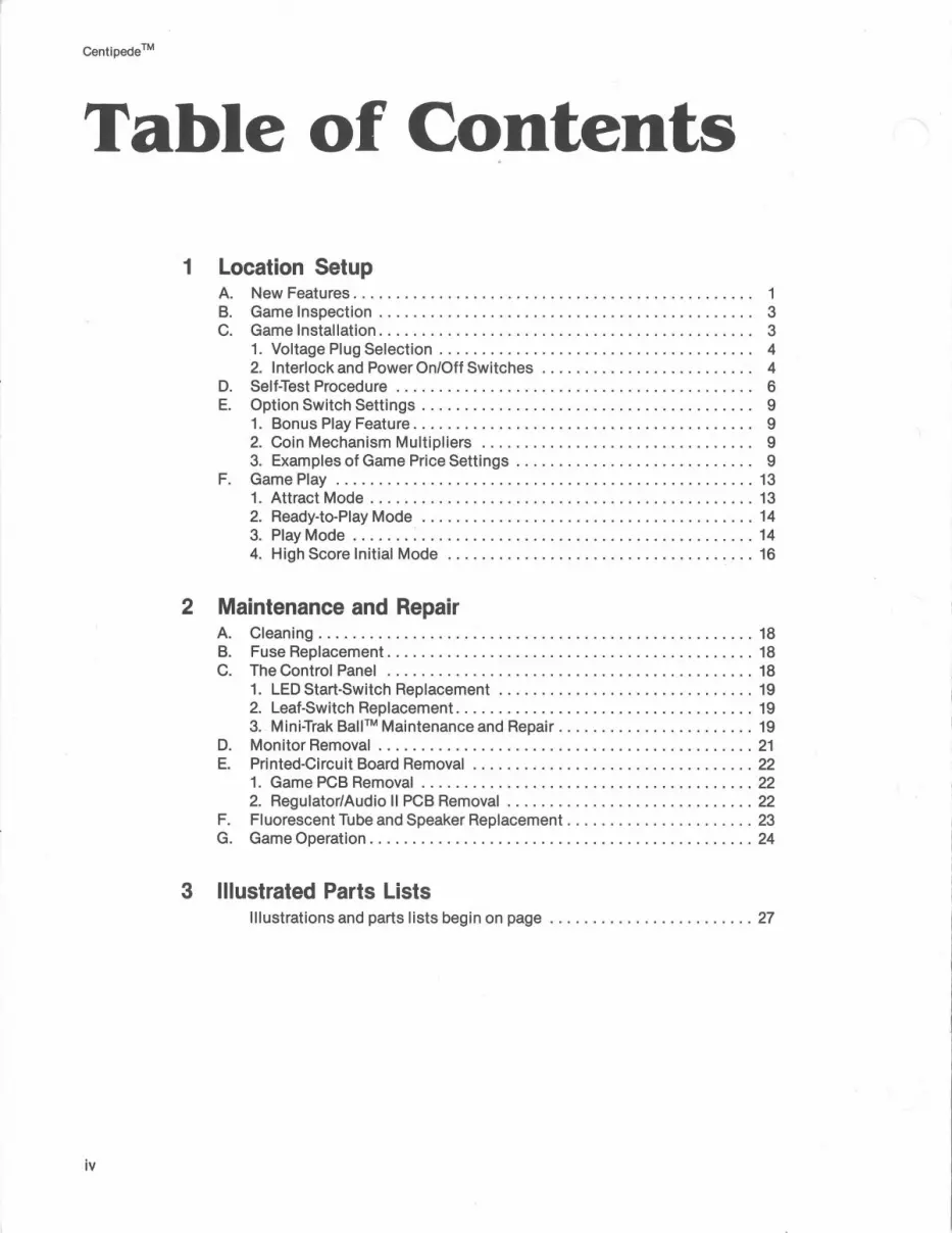
Table of Contents
1 Location Setup A. New Features . . . . . . . . . . . . . . . . . . . . . . . . . . . . . . . . . . . . . . . . . . . . . . . 1 B. Game Inspection . . . . . . . . . . . . . . . . . . . . . . . . . . . . . . . . . . . . . . . . . . . . 3 C. Game Installation............................................ 3
1. Voltage Plug Selection . . . . . . . . . . . . . . . . . . . . . . . . . . . . . . . . . . . . . 4 2. Interlock and Power On/Off Switches . . . . . . . . . . . . . . . . . . . . . . . . . 4
D. Self-Test Procedure . . . . . . . . . . . . . . . . . . . . . . . . . . . . . . . . . . . . . . . . . . 6 E. Option Switch Settings . . . . . . . . . . . . . . . . . . . . . . . . . . . . . . . . . . . . . . . 9
1. Bonus Play Feature. . . . . . . . . . . . . . . . . . . . . . . . . . . . . . . . . . . . . . . . 9 2. Coin Mechanism Multipliers . . . . . . . . . . . . . . . . . . . . . . . . . . . . . . . . 9 3. Examples of Game Price Settings . . . . . . . . . . . . . . . . . . . . . . . . . . . . 9
F. Game Play ................................................. 13 1. Attract Mode ............................................. 13 2. Ready-to-Play Mode ....................................... 14 3. Play Mode . . . . . . . . . . . . . . . . . . . . . . . . . . . . . . . . . . . . . . . . . . . . . . . 14 4. High Score Initial Mode .................................... 16
2 Maintenance and Repair A. Cleaning ................................................... 18 B. Fuse Replacement ........................................... 18 C. The Control Panel . . . . . . . . . . . . . . . . . . . . . . . . . . . . . . . . . . . . . . . . . . . 18
1. LED Start-Switch Replacement .............................. 19 2. Leaf-Switch Replacement ................................... 19 3. Mini-Trak Ball™ Maintenance and Repair ....................... 19
D. Monitor Removal ............................................ 21 E. Printed-Circuit Board Removal ................................. 22
1. Game PCB Removal ....................................... 22 2. Regulator/Audio II PCB Removal ............................. 22
F. Fluorescent Tube and Speaker Replacement ............ . ......... 23 G. Game Operation ............................................. 24
3 Illustrated Parts Lists Illustrations and parts lists begin on page ........................ 27
iv

(
)
Centipeae™
List of Illustrations
Figure 1 Figure 2 Figure 3 Figure 4
Figure 5 Figure 6 Figure 7 Figure 8
Figure 9 Figure 10 Figure 11 Figure 12
Figure 13 Figure 14 Figure 15 Figure 16
Figure 17 Figure 18 Figure 19 Figure 20
Figure 21 Figure 22 Figure 23 Figure 24 Figure 25
Overview of Game . . . . . . . . . . . . . . . . . . . . . . . . . . . . . . . . . . . . . . . . . . 2 Installation Requirements . . . . . . . . . . . . . . . . . . . . . . . . . . . . . . . . . . . . 3 International Voltage Plug Selection . . . . . . . . . . . . . . . . . . . . . . . . . . . . 4 Interlock and Power On/Off Switches . . . . . . . . . . . . . . . . . . . . . . . . . . . 5
Location of Self-Test Switch, Volume Control and Option Switches . . . 6 Self-Test Procedure. . . . . . . . . . . . . . . . . . . . . . . . . . . . . . . . . . . . . . . . . . 7 Game Option Settings ....................................... 10 Game Price Settings . . . . . . . . . . . . . . . . . . . . . . . . . . . . . . . . . . . . . . . . 11
Coin Counter Option Settings ................................. 13 Opening the Control Panel and Replacing Switches ............... 18 Mini-Trak Ball™ Maintenance and Repair ......................... 20 Monitor Removal ........................................... 21
Printed-Circuit Board Removal ................................ 22 Fluorescent Tube Replacement ................................ 23 Power Distribution .......................................... 25 Signal Distribution .......................................... 26
Illustrated Parts Lists: Cabinet-Mounted Assemblies ................................. 30 Control Panel Assembly ...................................... 31 Mini-Trak Ball Assembly ...................................... 32 Regulator/Audio II PCB Assembly .............................. 34
Centipede™ Game PCR Assembly ............................. 36 Power Supply Assembly ...................................... 40 Fluorescent Light and Speaker Assembly ........................ 42 American-Made Coin Door .................................... 44 British-Made Coin Door ...................................... 48
v
Centipede™
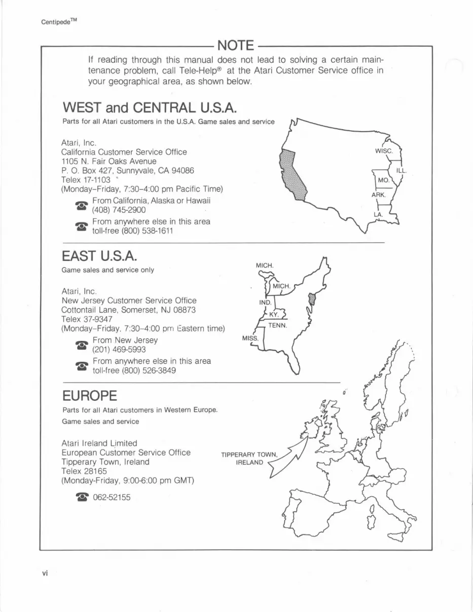
---------NOTE----------
vi
1t reading through this manual does not lead to solving a certain maintenance problem, call Tele-Help® at the Atari Customer Service office in your geographical area, as shown below.
WEST and CENTRAL U.S.A. Parts for all Atari customers in the U.S.A. Game sales and service
Atari, Inc. California Customer Service Office 1105 N. Fair Oaks Avenue P. 0. Box 427, Sunnyvale, CA 94086 Telex 17-1103 • (Monday-Friday, 7:30-4:00 pm Pacific Time)
-=- From California, Alaska or Hawaii .. (408) 745-2900 .
,._ From anywhere else in this area 8 toll-free (800) 538-1611
EAST U.S.A. Game sales and service only
Atari , Inc. New Jersey Customer Service Office Cottontail Lane, Somerset, NJ 08873 Telex 37-9347 (Monday-Friday, 7:30- 4:00 pm Eastern time)
-=- From New Jersey .. (201) 469-5993
,._ From anywhere else in this area 8 toll-free (800) 526-3849
EUROPE Parts for all Atari customers in Western Europe.
Game sales and service
Atari Ireland Limited European Customer Service Office Tipperary Town, Ireland Telex 28165 (Monday-Friday, 9:00-6:00 pm GMT)
w 062-52155

r Location Setup
this assembly are Underwriters Laboratories Listed and Canadian Standards Association Certified.
r"/.:.111111.-... • The addition of a foam pad on the rear access
A. New Features The Centipede™ game has several new parts.
Even if you are familiar with Atari games, you should note these important differences. The new parts are:
• Mini-Trak Ball™ Assembly. The widely used Trak Ball assembly has been redesigned. The basis for this compact, simplified design is a two-part molded plastic frame. Fewer parts in this control make servicing easier, and its very smooth action is designed for greater player accuracy.
• The circuitry has non-volatile memory for part of the high score table. This means that even if power is removed from the game, the three highest scores will permanently stay in memory. To erase these scores follow the instructions in Figure 6, Self-Test Procedure.
• To insure starting, the fluorescent light now includes a large grounded metal plate. In addition, the lampholder and ballast transformer used in
panel insures that the safety interlock switch will be completely closed when you lock this panel. Due to environmental factors, these panels can warp slightly, which could cause a switch to remain open.
• Additional Improvements: The wiring harness has been redesigned so that signal and power wiring are now separated to provide ease of maintenance and troubleshooting. Second, all monitors used are UL-Recognized and CSA-Certified, thus providing the most reliable and highest quality monitors available in the marketplace today.
In addition, the power supply chassis has been fitted with a metal bottom plate making it a totally self-contained unit.
Fourth, the attraction panel and monitor shield are now made of tempered glass to facilitate cleaning and improve visibility.

Cen
tiped
e T
M
FL
UO
RE
SC
EN
T L
IGH
T
CO
LOR
M
ON
ITO
R
CO
IN D
OO
R
2
INT
ER
LO
CK
SW
ITC
H
Fig
ure
1
Ove
rvie
w o
f G
ame
CE
NT
IPE
DE
™
GA
ME
PC
B
RE
GU
LAT
OR
/ A
UD
IO I
I P
CB
PO
WE
R S
UP
PLY

-----.i.a--- WARN I NG: SHOCK HAZARD
Connect this game only to a grounded 3-wire outlet. If you have only a 2-wire outlet, we recommend you hire a licensed electrician to install a grounded outlet. Players may receive an electric shock if this game is not properly grounded!
These new parts, as wel I as al I other major parts in the game, are illustrated in Figure 1. Throughout this manual, wherever one of these new parts is mentioned, you will see this symbol:
B. Game Inspection
This new game is ready to play upon removal from the shipping carton. However, your careful inspection is needed to supply the final touch of quality control. Please follow these steps to help us insure that your new game was delivered to you in good condition.
----------NOTE---------00 not plug the game in yet!
1. Examine the exterior of the game cabinet for dents, chips, or broken parts.
2. Remove the screws that were used as extra security to seal the rear access panel. Unlock and open this panel, as well as the coin door; inspect the interior of the game as follows:
• Check that all plug-in connectors (on the game harness) are firmly seated. Replug any connectors found unplugged. Don't force connectors together. The connectors are keyed so they only go on in the proper orientation. A reversed edge connector will dam· age a PCB and will void your warranty.
• Check that all plug-in integrated circuits on the game PCB are firmly seated in their sockets.
• Remove the tie-wrap that holds the coiled power cord on the inside cabinet wall. Check the cord for any cuts or dents in the insulation. Place the square black metal strainrelief plate in the wood slot at the bottom of the rear panel opening.
Centipede™
WARNING To avoid possible unpleasant electrical shock, do not touch internal parts of the monitor with your hands or metal objects held in your hands!
• Note the location of the game's serial number-it is printed on the special label on the outside of the game cabinet. Verify that the serial numbers also stamped on the Centipede™ Game PCB, Regulator/Audio II PCB and monitor are all identical. A drawing of the serial-numbered components is on the inside front cover of this manual. Please mention this number whenever you call your distributor for service.
• Check all major subassemblies such as the power supply, control panel and monitor for secure mounting.
c. Game Installation
Figure 2 Installation Requirements Power Temperature Humidity Space Required Game Height
130 watts Oto 38° C (32 to 100° F) Not over 95% relative 64 x 82 cm (251/4 x 321/4 in.) 181 cm (711/4 in:)
3

Centipede TM
1. Voltage Selection If you live outside the United States, your Centi
pede™ game has the "international" power supply with three colored plugs. Before plugging in your game, make sure that the voltage selection plug on the power supply (see Figure 3) is correct for your location's line voltage. Check the wire color on the plug and see if it is correct per Figure 3.
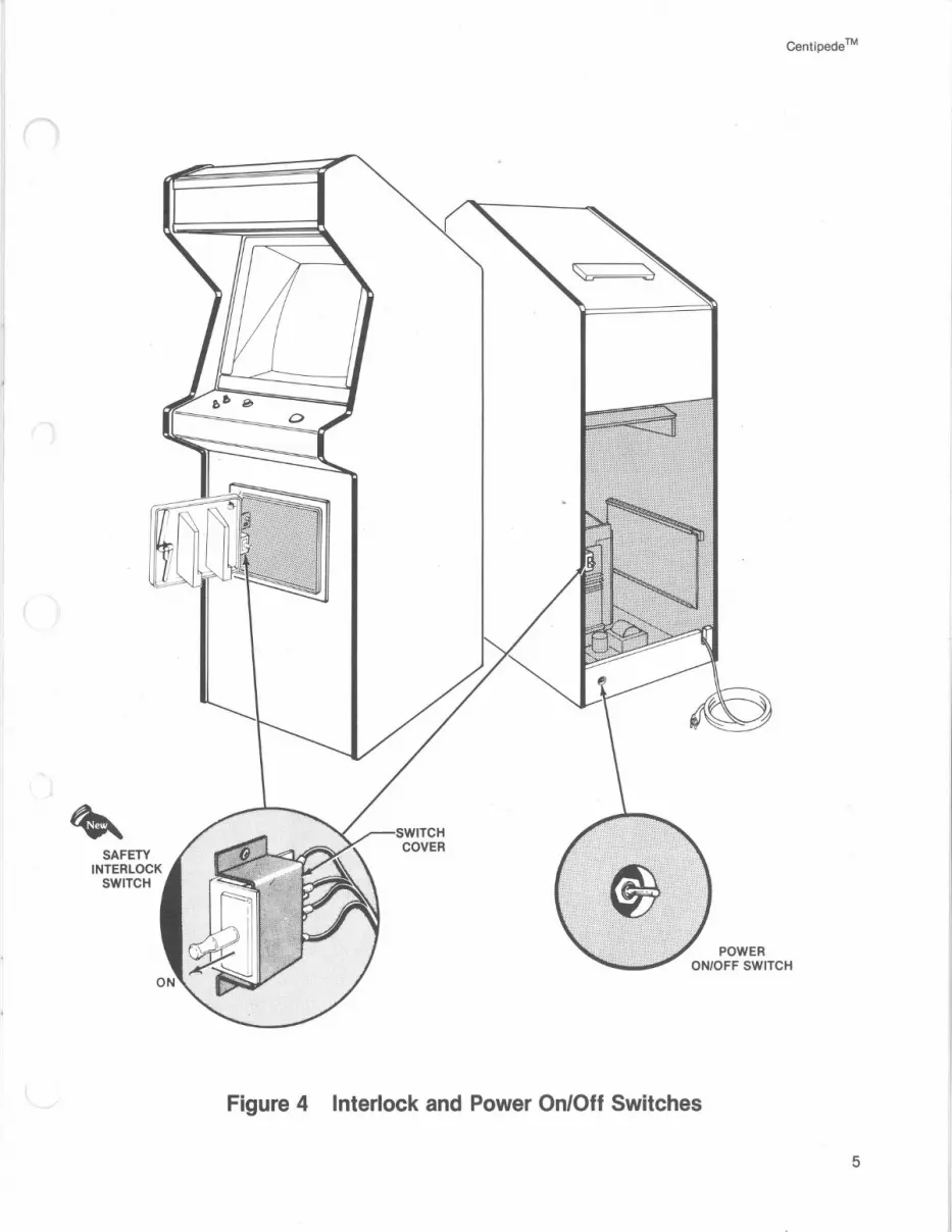
2. Interlock and Power On/Off ~ Switches
To minimize the hazard of electrical shock while working on the inside of the game cabinet, an interlock switch has been installed (see Figure 4). One is located behind the rear access panel and one is behind the coin door. These switches remove all AC line power from the game circuitry when a door is opened.
Line Voltage Range Voltage Selection Plug Color
90·110 VAC (100) Violet 105·135 VAC (120)* Yellow* 200·240 VAC (225) Blue 220·260 VAC (240) Brown
*This is the only plug provided on the U.S. power supply. The in· ternational power supply includes the other three plugs.
0
0
Check for proper operation of the interlock switches by performing the following steps:
• Be sure the access panel and the coin door are closed.
. • Plug the AC line power cord into an AC outlet.
• Set the power on/off switch to the on position. Within approximately 30 seconds the monitor should display a picture.
• Slowly open the rear access panel. The monitor picture should disappear when the panel is opened approximately 2V2 cm (1 inch). Close and lock the access panel and repeat this step with the coin door.
• If the results of the preceding step are satisfactory, the interlock switches are operating properly. If the monitor doesn't go off as described, check to see if the corresponding interlock switch is broken from its mounting or stuck in the on position.
WARNING Fuse cover must be in place during game operation.
~ m
0
0
Figure 3 International Voltage Plug Selection
4
SAFETY INTERLOCK
SWITCH
Centipede TM
POWER ON/OFF SWITCH
Figure 4 Interlock and Power On/Off Switches
5

Centipede™
D. Self ·Test Procedure
This game will test itself and provide data to demonstrate that the game's circuitry and controls are operating properly. The data is provided on the monitor, the light-emitting diodes in the start switches, and the game speaker; no additional equipment is necessary.
VOLUME CONTROL
Part of the self-test procedure includes a display of the operator-selectable game options. Therefore, we suggest you run the self-test procedure anytime you need to change the game's options.
To run the self-test, follow the instructions outlined in Figure 6.
CENTIPEDE™ GAME PCB
Figure 5 Location of Self-Test Switch, Volume Control and Option Switches
6

Figure 6
Instruction
1. Begin: Set self-test switch to on position (see Figure 5).
2. Trak Ball Test: Roll the Trak Ball control in all directions.
3. Switch Test: One after another, activate and release all 3 control-panel switches, the slam switch, and coin door switches.*
4. Audio 110 Chip Test: One after another, press and hold 2 of the control-panel switches and at least one of the coin-door switches.
5. Audio 110 Channel Test: Press 1-player start button four times.
6. Background Color Test: Press 1-player start button at least eight more times.
7. Object Color Test: Press 2-player start button at least 16 times.
8. Moving Object Test: Watch the screen, and move the Trak Ball around. Place the moving object in an open area of the screen. Press fire button several times.
9. Erasing the High Score Table (optional)
Centipede TM
Self-Test Procedure
Results if Test Passes (if results are not as indicated, see list of failures that follows)
The monitor displays the picture below. The game produces no sound at all. The two LEDs will stay on throughout self-test.
The centipede head moves around on the screen In directions corresponding to Trak Ball control.
As long as you activate (close) each switch, you'll hear a high beep.
Volume increases and pitch decreases with each additional switch that is activated.
You'll hear a high beep for each press of the button.
Background color changes with each press of the 1-player start button.
Objects on playfield change color.
Each press of the fire button changes the moving object to another moving object. At certain points in the series, the object will disappear. This is not a failure indication.
The current three highest scores are held in permanent memory, even if the game is unplugged. If you want to erase these scores, first check that the number 4 is not displayed in the far upper left corner of the screen. If this number is not displayed, then simultaneously press the start and fire buttons. The 4 FF message in the upper left corner of the screen will then be displayed. The average game time data will also be erased, but still displayed on the screen. If 4 is present, then the scores will be erased when you return to the attract mode.
10. End: When satisfied with test, set self-test switch to off position.
*Activate coin switches by inserting at least one coin in each coin slot. You will not trip the coin counters as long as you stay in self-test.
ENTIRE ~~~1---CHARACTER SET
ALL SWITCHES & TRAK·BALL INPUTS----11111'!!
C, R COIN MECH MULTIPLIERS
(L, R if you have a 2·mech coin door)
GAME DIFFICULTY SETTING
tt+~----~~=r---- NO. OF LIVES AT 111 START OF GAME _,_,
TOTAL NO. OF CREDITS PLAYED
AVG. GAME TIME (accurate to ± 3 secs.)
7

Centipede TM
Figure 6 Self-Test Procedure, continued
Results if Test Fails
1. Begin: RAM FAILURE is indicated by one to 10 beeps. Note the number of beeps and determine which RAM may be bad. To restart the test, press the reset pushbutton on the game PCB, or set the self· test switch to off, then again to the on position.
Number of Beeps Given 1 2 3 4 5
6 7 8 9 10
Possible Bad RAM Chip Location
H2 F2 K7 K5 L7
L5 M7 M5 N7 N5
Any bad RAM must be replaced before the computer can check the other RAMs, as well as continue with the self-test.
ROM/PROM FAILURE is indicated by two groups of numbers in the upper left corner of the screen. The number at the far left indicates the location of the failing PROM/ROM(s). Identify the bad ROM/PROM with the table below. If the screen displays "garbage," or the logic produces strange audio or randomly activates the coin counters, the chip at location J1 is probably bad.
Ignore the hexadecimal numbers just to the right of the chiplocation number.
Displayed Number 0 1 2
3 or "garbage" 4* 5
Failing ROM/PROM Chip Location
D1 E1
F/H141 J1 .
E5* B/C/D3
*If you replace or erase this ROM, the number 4 FF will be displayed throughout the self -test. The next time you enter self -test, the 4 disappears after a game is played. Otherwise the self -test will continue to display the numbers 4 FF.
8
2. Trak Ball Test: The character doesn't move in same direction as ball, jumps rather than moves smoothly, or doesn't move at all. One of the Coupler PCBs on Trak Ball control may be bad, harness wires or connector may be loose, Trak Ball reading circuitry on Game PCB may be bad, or Trak Ball bearings may need oiling.
3. Switch Test: Sound is constantly on, even though you are not activating any switch. Or, no beep is given for any switch, or LED is dark. Indicates a bad switch, loose harness wires, bad LED-driving circuitry, volume turned all the way down, or loose connector.
4. Audio 1/0 Chip Test: No increase in volume or decrease in pitch indicates bad custom audio 1/0 chip at location B/C/D3.
5. Audio 1/0 Channel Test: On one out of the four activations, no audio is produced. Indicates one channel is bad in the custom 1/0 audio chip at location B/C/03 (replace entire chip).
6. Background Color Test: Background doesn't change color, or doesn't display all 16 colors. Indicates bad color RAM chip. (RAM failure would have been indi-cated earlier with from 3 through 10 beeps.) ·
7. Object Color Test: Objects don't change color, or don't display all 16 colors. RAM failure.
8. Moving Object Test: Object doesn't change to another object. ROM/RAM failure.

E. Option Switch Settings
1. Bonus Play Feature Centipede™ offers a bonus play for certain com
binations of coins inserted. This bonus feature is operator-selectable, meaning you may choose to offer it or not.
For example, with your game set at 50¢ per play, players who deposit four successive quarters or a $1.00 coin, then press the start button, will receive a bonus coin. Therefore, players receive 3 plays for $1.00.
This bonus feature encourages players to insert more money than just the minimum 50¢ you could require for one game. Various other bonuses are available (see Figure 8).
2. Coin Mechanism Multipliers Available since early in 1980, Atari games have a
new coin door which has either two or three mechanisms. All recent Atari game PCBs identify the different mechanisms in a certain pattern.
The right coin mechs are all the same to the game's logic, regardless of whether you have two or three mechs in your door. In addition, the logic sees the left mech in a 2-mech door and the center mech in a 3-mech door as the same. Refer to the diagram below.
This pattern is important for you to know, so you can correctly set the "multipliers" for each mech. The multipliers determine how much each mechanism will be worth to the game's logic.
Centipede™
The basic unit of measurement is 25¢, which equals a multiplier of x 1. Therefore, if you have a 25¢/25¢/$1 coin door, you will probably want to set the center and right option-switch multipliers at _x 1/ x 4. (The left mech in a 3-mech door always has a value of x 1-you cannot change its value.)
You can set these multipliers with toggles 3 thru 5 on the Centipede Game PCB switch assembly at location N8. For exact settings of these toggles, refer to Figure 8.
3. Examples of Game Price Settings
Figure 8 explains the options, giving twelve examples of the most common U.S. situations. The toggles mentioned are all in the switch at location N8; they only relate to game price, coin mechanism multipliers, and bonus play. You should set the toggles relating to other functions as you see fit, although Figure 7, 8, and 9 provide"$" signs indicating Atari's recommendations.
9

Centipede™
Figure 7 Game Option Settings To change toggle positions on the switch assemblies, you need
not remove the game PCB. The switches, usually colored blue, are easily accessible when the Centipede Game PCB is mounted in place.
When changing the options, verify proper results on the monitor display by performing the self-test. Note that changing an option on any of the following eight toggles will not cause an immediate change on the monitor screen during the attract mode.
Toggle Settings of 8-Toggle Switch on Centipede Game PCB (at N9) (CENTER switch assembly when PCB is in game)
8 7 6 5 4 3 2
On Off
On Off
On On Off Off
On Off On Off
$ Manufacturer's suggested settings
On On Off Off
On Off On Off
*Refer to F. Game Play, for information on game difficulty.
10
On On Off Off
On Off On Off
Option
English $ German French Spanish
2 I ives per game 3 lives per game $ 4 lives per game 5 I iv es per game
Bonus life granted at every: 10,000 points 12,000 points $ 15,000 points 20,000 points
Hard game difficulty* Easy game difficulty*
1-credit minimum $ 2-credit minimum
~ $
For pricing for "credits," see Figure 8. Changing toggles 3-7 erases the high score table.

Centipede TM
Figure 8 Game Price Settings
The white block below contains Atari's suggested settings. All numbers 1 thru 8 are toggle settings on the 8-toggle switch at location N8, on the Centipede TM Game PCB (the LEFT switch assembly).
.. Circled numbers refer to game pricing labels you should use with each situation (labels are on the following page). Use the label no. 6 (indicated with@) only if you set toggle 8 at PCB switch assembly N9 to off.
50¢ PER CREDIT
Straight 25¢ Door
25¢/$1.00 Door or
25¢/25¢/$1.00 Door
No bonus Bonus
$1.00 = 3 credits
Bonus $.75 = 2 credits
$1.00 = 3 credits
25¢ PER CREDIT
Straight 25¢ Door
25¢/$1.00 Door or
25¢/25¢/$1.00 Door
® ©
No bonus
8 7 Off Off
4 3 Off Off
6 5 Off Off
2 1 On Off
Bonus $.50 = 3 credits
Bonus $1.00 = 5 credits
11

Centipede TM
Figure 8 Game Price Settings, continued The switch settings below relate to options for game price, coin
mechanism multipliers, and bonus play. This information is useful in case you need to temporarily set the Centipede TM game on free play, or if you have German coin mechanisms in your door.
8
On
On
On
On
Off
Off
Toggle Settings of 8-Toggle Switch on Centipede PCB (at NB). LEFT switch when PCB is in game
7 6 5 4 3 2
On
On
Off
Off
On
On
On
Off
On
Off
On
Off
On Off
On On Off Off
On Off On Off
On On Off Off
*In the U.S., a "coin" is defined as 25¢ In Germany a "coin" is 1 OM.
$ Manufacturer's suggested settings
Game Pricing Labels
8 JI\.. I I 2 coins = 1 play ATARI
e )I\. I 1 coin = 1 play ATARI
JI\.. 8 I I 2 coins = 1 play ATARI
I I I I 4 coins = 3 plays
12
To achieve bonus plays, all coins must be inserted before pressing the start button. The label no. 6 shown below should be used only if you set toggle 8 at PCB switch assembly N9 to off.
On Off On Off
Option
Free play 1 coin* for 2 credits 1 coin* for 1 credit $ 2 coins* for 1 credit
Right coin mech x 1 $ Right coin mech x 4 Right coin mech x 5 Right coin mech x 6
Left coin mech x 1 $ Left coin mech x 2
No bonus coins $
For every 2 coins* inserted, game logic adds 1 more coin*
For every 4 coins* inserted, game logic adds 1 more coin*
For every 4 coins* inserted, game logic adds 2 more coins*
For every 5 coins* inserted, game logic adds 1 more coin*
For every 3 coins* inserted, game logic adds 1 more coin*
JI\.. 8 I I 2 coins = 1 play ATARI I I I 3 coins = 2 plays
191 I 4 coins = 3 plays
e • • 2 coins = 1 play lrh I $1 coin = 3 plays
(Susan B. Anthony coin)
0 ""- I 1 coin = 1 play ATARI 2 play minimum
(2 coins = 2 plays)
•JI\. ATARI
(For operator use-write in the appropriate phrase. Use a permanent-ink water-resistant marker.)

Centipede™
Figure 9 Coin Counter Option Settings
[These toggles determine which coin mechanisms activate. which counters]
Toggle Settings of 4-Toggle Two coin acceptors and a push-Switch on Game PCB (N11) Two coin acceptors button utility coin switch in the Three coin acceptors
4 3 2 1 in the coin door: game: in the coin door:
On On Both acceptors activate all coin Do not use this setting. All 3 are same denomination and counters simultaneously. they activate all coin counters si-
multaneously.
On Off Both acceptors activate 2 count- Do not use this setting. Left and center acceptor activate ers separately. one coin counter; right acceptor ac-
"'O "'O tivates another coin counter. <1> <1> (/) (/)
::::> ::::> 0 0 Off On Both acceptors activate all coin Utility coin switch will. not acti- Left acceptor activates one coin ~ ~ counters simultaneously. vate a coin counter, if you do not counter; center and right acceptor
hook it up. Both acceptors acti- activate another coin counter. Not vate all coin counters simultane- for any currently designed 3-mech ously. coin door.
Off Off Both acceptors activate 2 count- Utility coin switch will not acti- Left, center and right acceptors acti-ers separately. $ vate a coin counter, if you do not vate 3 coin counters separately.
$ Manufacturer's suggested settings
F. Game Play Atari's Centipede™ game is a one- or two-player
game with a color raster-scan monitor. The fast-moving action includes a variety of creatures dropping down from the top of the screen or flying in from its sides, most of them to attack the player. The player's shooter is represented on the screen by a somewhat humanoid head.
The player's goal is to shoot at and destroy as many of these creatures and mushrooms as possible for a high point score, before the player's lives are used up. Players can maneuver their Trak Ball™ control anywhere within approximately the bottom fifth of the screen. However, they must move around mushrooms, since these are fixed, not "transparent", objects. A fire button shoots individual shots upwards, or fires a hail of shots if pressed constantly. (Only one shot appears on the screen at a time.)
The game has five possible modes of operation: attract, ready-to-play, play, high score initial, and self-test. Self-test is a special mode for checking the game switches and computer functions. You may enter this mode at any time. When entered, all game credits are cancelled. Wait at least eight seconds
hook it up. Left and right accep- $ tors activate 2 coin counters se-parately.
after a game has been played before entering selftest or turning off the power. Otherwise, you may erase the high score table.
1. Attract Mode The attract mode begins when power is applied to
the game, after a play or high score initial mode, or after self-test. This mode is continuous and is only interrupted when a game is paid for and accepted or when in self-test. In this mode, the monitor displays two pictures simultaneously.
One of the pictures is operator-selectable for one of four languages. Placed in the center of the screen, the picture shows the high score table, game price, and the bonus-life achievement level. If the operator sets the Centipede game for free play, the game will not display a game price message.
The high score table shows the eight highest scores and their matching initials. If you erase the ~ special "permanent" memory (see Figure 6, Self-~ Test Procedure), then this table will contain ficti-tious scores and initials. The table is redeveloped from subsequent games with scores of more than 12, 102 points. Subsection 4, High Score Initial Mode, explains this table in more detail.
13

Centipede TM
Operators may choose one- or two-credit minimums by selecting one of the option switch settings on the game PCB (see Figure 7, Game Option Settings).
If the game is set for a 2-credit minimum, that message will be displayed on the screen. (No special message appears if Centipede is set to the opposite setting, namely 1-credit minimum.)
The other picture surrounds the high score table, game price and bonus-life achievement level messages. That picture displays a typical game-play sequence, with a field of colorful mushrooms through which a centipede crawls. The spiders bounce in from the sides of the screen, and fleas occasionally drop down from the top. In addition, scorpions will cross the screen at almost any point.
In this mode, the action exactly duplicates a typical game played by a moderately ski I led player: the player's shooter moves freely within the limits of motion, shooting at spiders, centipedes, fleas and scorpions. Periodically the player is "destroyed" when a flea, spider or centipede head or body collides with the player's shooter.
All the colors on the screen change with each wave. A new wave occurs when the player shoots all centipede parts remaining on the screen. At this point, a new centipede starts snaking its way down from the top of the screen.
The attract mode differs from real game play in that no head figures are shown at the top of the screen to represent the number of lives remaining, no sounds are produced, no scores are incremented, and none of the four player controls work.
At any time when the game is powered up, if the coin-door slam switch is closed, you will hear a special alarm sound. This sound alerts location personnel that the game has been abused.
14
2. Ready-to-Play Mode This mode begins when sufficient coins are ac-
·cepted for a one- or two-player game. It ends when the 1-player start or 2-player start pushbutton is pressed. When this mode begins, the message CREDITS_ is displayed in the middle of the screen. The pictures are otherwise the same as those shown in the attract mode.
If you select the two-credit minimum and a player inserts enough money for only one credit, the message 2 CREDIT MINIMUM flashes on the screen until enough coins for the second credit are inserted.
In addition, CREDITS 0112 is displayed if you have selected the option of two coins per credit, and the player has inserted only one coin. A "credit" is defined as the cost for each player to play one game. In other words, two credits will pay for:
• one player playing two games, or • two players playing one game.
3. Play Mode The play mode begins when any flashing start
pushbutton is pressed. The mode ends when the player's last life is lost.
A player's shooter is enabled at the beginning of the play mode, and the audio starts. The appropriate LED start switch will then stay lighted until the end of the game. At this point it will flash if any credit remains.
The game begins with a playfield of randomly placed mushrooms. A centipede starts snaking its way across from the center top of the screen. The centipede changes direction when it runs into a mushroom or either the left or right boundaries of the playf ield.

When a centipede is shot, it breaks into two smaller ones, each with a head. Also, the part of the centipede that was shot leaves a mushroom in its place on the screen. When any centipedes reach the bottom of the screen, they start back up, but remain within the area of the player's shooter (the bottom fifth of the screen).
When a large centipede (that hasn't been shot yet) reaches the bottom, it releases its tail, and this part changes into a new head. Also to provide player challE)nge, if a centipede is still alive when it reaches the bottom, new heads will enter the screen almost at the bottom of the sides. More of these heads will appear as time progresses.
The randomly moving spiders also appear in the first wave. The spiders can destroy a player, as well as any mushrooms they move over. This eliminates many mushroom targets for a player.
The player's shooter is moved by rotating the Trak Ball™ control. The shooter can be moved in all directions, but only within the bottom fifth of the screen. Pressing the fire button causes the shooter to fire shots upwards, either singly or in rapid-fire mode, if held down constantly.
Centipede™
Mushrooms count 1 point when shot, and a player must fire four shots into a mushroom before it is destroyed and disappears. Centipede body parts count 10 points each, and the elusive heads (represented with small eyes on them) are worth 100 points each. Spiders are worth 300, 600 or 900 points, depending on how close they are to the player when stiot.
A bombardment of fleas starts in the second wave; as the fleas descend, they leave a trail of new mushrooms behind them.
In the second wave, the fleas appear when a certain number of mushrooms remains at the bottom of the screen. This number increases as the game progresses, meaning fleas appear more often later on in the game.
Fleas have a value of 200 points when shot, and players must hit them twice to destroy them (the first shot just speeds them up).
The scorpion enters from either side starting in the fourth wave; it moves at a relatively slow speed. Later it increases its speed. When shot, a scorpion counts 1000 points-the highest-value target of all.
15

Centipede TM
As it travels across the screen, it "poisons" the mushrooms that it moves over and changes their colors. These mushrooms cause any' centipedes that would collide with them to head straight towards the bottom of the screen, rather than continue snaking around. Players can stop a poisoned centipede by shooting its head.
In addition, these poisoned mushrooms as well as any partially shot mushrooms add 5 points to the player's score at the end of each life when the screen is resetting.
If the players are very ski I led and earn at least 60,000 points, two things happen to increase player challenge: the fleas descend at a faster speed and the spiders restrict their movement to a smaller area at the bottom of the screen.
~ An important new feature of this game is the operator option for easy/hard game difficulty. In the easy game, the spider moves slowly up to a 5,000-point score, and then bounces at a higher speed. It also changes direction less often throughout the game than at the hard setting.
In the hard setting, the spider moves slowly only for the first 1,000 points, and then speeds up. It also changes direction more often throughout the game. In either setting, the spider always moves at a 45-degree angle or straight up and down.
Another operator option is the number of lives per game, ranging from 2 to 5 (see Figure 7 for switch settings). This number is displayed as small shooters at the top of the screen. The number is de-
16
creased by one each time a player is destroyed. The number is increased by one each time the player scores multiples of 10, 12, 15 or 20 thousand points, depending on the operator selection.
4. High Score Initial Mode If a player's score exceeds the minimum on the
high score initial list, he or she may put up to three initials on this list at the end of the game. At the beginning of this mode, the characters A _ _ appear on the screen. The logic will also display the messages GREAT SCORE and ENTER YOUR INITIALS.
Players enter initials one character at a time, choosing from the characters A thru Z and a blank space. Pressing the fire button selects the letter, and rolling the Trak Ball control changes the letters on the screen.
After the fire button is pressed the third time, the initials and score are transferred to the table. This table contains eight scores and appears during the attract and ready-to-play mode.
All but the highest three scores are erased=.whenever you enter the self-test, or press the RESET button on the game PCB, or turn off the power. This resetting replaces the lowest five scores with ficti-tious scores and initials. . ~
If you erase the special "permanent" memory, the high score table is replaced with eight fictitious scores and initials. In other words, the table will always be displayed on the screen, possibly consisting of one or more realistic scores and players' initials.

(
Maintenance • • and Repair
All games require certain maintenance to keep them in good working order. Clean, properly maintained games will attract players and earn more profits.
The most important maintenance item is running the self-test every time you collect money from the ~ coin box. Just looking at a game will not tell you if~ Mini-Trak Ball™ control, leaf switch or light-emitting-diode (LED) switches are broken, or if LEDs have burned out. The self-test will inform you of any of these possible problems.
Second, you should regularly clean the outside of the game and the coin mechanisms. In addition, you will need to regularly lubricate the Mini-Trak Ball control: for details see this chapter.

Centipede™
To remove LED switch:
NORMALLY CLOSED (N.C.) CONTACT
NORMALLY OPEN ~ (N.O.) CONTACT
LIGHT-EMITTING-DIODE j (L.E.D.) CONTACTS
• Remove all wires from the faulty switch.
• Turn the switch counterclockwise while holding the black cone-shaped bushing on the outside of the control panel.
• Install a new switch using the reverse procedure.
• Reconnect the harness wires.
HORIZ.-MOTION PCB: BLUE, RED, BLACK & VIOLET WIRES
~·COMMON CONTACT
CAUTION Players may receive an electric shock if this control panel is not properly grounded! After servicing any parts on the panel, check that the ground wire is firmly attached to the metal tab on the inside of the control panel. Only then should you lock up the game.
GREEN
Figure 10 Opening the Control Panel and Replacing Switches
A. Cleaning The exterior of the game cabinet and the metal
and glass surfaces may be cleaned with any nonabrasive household cleaner. If desired, special coin machine cleaners that leave no residue can be obtained from your distributor.
The large monitor shield and the attraction panel are made of tempered glass and should be scratchresistant: if cleaned without abrasive substances, you should hardly ever have to replace them.
18
B. Fuse Replacement This game contains six fuses-all on the power ~
supply assembly (not including the monitor fuses). Replace fuses only with the same type as listed in Figure 22 of this manual. See the color monitor man-ual for the monitor fuse data.
C. The Control Panel Prior to repairing or replacing any switch or the
Mini-Trak Ball™ on the control panel, unplug the game. Then open the coin door.

Reach through the coin-door opening and open the luggage-style latch, located at each end on the underside of the control panel (see Figure 10). Lift up on the control panel at the topmost edge and tilt it towards you.
The edge of the control panel next to the monitor shield has foam tape applied to it. This tape acts as a cushion for the glass and prevents spilled liquids from entering the cabinet interior. Always make sure this tape is in good condition.
1. LED Switch Replacement The light-emitting diode (LED) switches on the
control panel have a very low failure rate. In case a switch should ever be suspect, first test it per the description that follows. To replace the switch, refer to Figure 10.
1. Remove the wires from the suspected switch.
2. Set multimeter to ohms scale. Set ohms scale to R x 1, then zero the meter.
3. Connect multimeter leads to appropriate LED switch contacts (see Figure 10 for designation of switch contacts).
4. Check contacts (push and release the switch button) for closed and open continuity.
5. If the contacts do not operate sharply or always remain closed or open, then replace the LED switch as outlined in the figure.
2. Leaf -Switch Replacement
The leaf switch on this game operates on 5 volts at a very low current. Therefore, pitting of the switch would be extremely rare. Probably the only reason that pitting would occur is that the game is in very high-humidity locations.
Centipede TM
Don't burnish the switch contacts. Burnishing them removes their plating, thus increasing the corrosion of the contacts. The best method of cleaning the switch contacts is to wipe them with a non·abra· sive surface. A business card works very well.
To replace the switch, remove both of its screws with a Phillips-head screwdriver.
If the white button itself needs to be replaced, turn the stamped nut with a wrench in a counterclockwise direction, as seen from the inside of the control panel. The white ring on the outside of the control panel should not spin, due to its design.
------NOTE------Adjust switch for a narrow gap. When a switch button is depressed, the resulting wiping action of the contacts provides a self-cleaning feature.
3. Mini-Trak BaWM Maintenance and Repair
To maintain this control, lubricate the bearings ,, approximately every 3 months or every 6,000 credits. The number of credits can be read off the coin counter, located on the coin door. Use only 2 drops of 3-in-One® oil in each of the ball bearings. (Each Mini-Trak Ball™ control has six bearings.)
For further instructions on how to replace the ball, either coupler PCB or either encoding wheel, see Figure 11.
19

Centipede™
~ ~~
20
Figure 11
Disassemble in the order indicated. (Circled numbers
match the steps described below.)
Ball Replacement
1. First remove the entire Mini·Trak Ball assembly from the con· trol panel as shown in Figure 11. Now locate the six "twin· lead" thread-forming screws in the black frames or plastic pieces; remove these six screws.
2. Lift off the top frame; remove and replace the ball.
Coupler PCB and Encoding Wheel Replacement
3. Lift the PCB out of its slot. Carefully unplug the red connec· tor on the coupler PCB.
4. To replace either encoding wheel, remove the PCB from its slot. Remove the socket-head machine screw, flat washer, and split lock washer that secure the encoding wheel. Remove the wheel.
Mini-Trak Ball™ Maintenance and Repair

D. Monitor Removal
The following procedure should only be performed by a qualified service technician.
,....---....-..--- WARNING Shock Hazard
High voltages may exist in any television or monitor, even with power disconnected. Use extreme caution and do not touch electrical parts of the yoke area with your hands or with metal objects in your hands!
Implosion Hazard If you drop the monitor and the picture
tube breaks, it will implode! Shattered glass and the yoke can fly 6 feet or more from the implosion. Use care when replacing any monitor.
;/ I
/
Disassemble in the order indicated. (Circled numbers
match the steps above.)
Centipede TM
To remove the color monitor, follow steps 1 thru 6 below. Refer to the accompanying Figure 12.
1. Be sure the game is unplugged from its wall outlet! Unlock and open the rear access panel, coin door, and control panel.
2. Remove the glass monitor shield. Carefully remove the four staples that secure the blue cardboard bezel. As an extra precaution, we highly recommend you discharge the high voltage from the picture tube.
3. Standing at the rear opening of the game, locate the 2-pin and 6-pin harness connectors for the monitor. Unplug both of these.
4. At the bottom rear of the monitor chassis is a wood screw that secures rear part of the chassis. Remove this screw.
5. From the front of the cabinet, locate the flat washers, and self-locking hex nuts (two sets underneath, and two sets above the monitor screen). This hardware attaches the monitor to the cabinet. Remove this hardware.
6. Carefully pull the monitor chassis out of the cabinet towards you.
Figure 12 Monitor Removal
21

Centipede TM
E. Printed-Circuit Board Removal
You may wish to remove the Centipede™ game printed circuit board (PCB) or the Regulator/Audio II PCB for service or inspection. To do this, refer to Figure 13 and proceed as follows:
1. Game PCB Removal • Unlock and open the rear access panel.
• Remove the 24-pin and 44-pin edge connectors from the right side of the game PCB.
• Locate the Phillips-head screw that extends through the PCB and into the two wood blocks (at the right side of the board). Remove and save this screw, as well as the fiber spacers.
• Remove the PCB from the cabinet by carefully sliding it straight out of the plastic PCB retainer. Be careful not to twist the board, as this may loosen connections or components. Replace or repair as necessary.
REGULATOR/ AUDIO 11 PCB
• After servicing, reinstall the PCB, making sure that the edge connectors are properly plugged in. Note that the connectors are keyed to fit on only one way, so if they don't slip on easily, don't force them ! A reversed connector will probably damage your PCB and will void the warranty.
• Check that the operation of the game is correct by performing the self-test. It is especially important to do the self-test with any game when you replace a PCB.
2. Regulator/Audio II PCB Removal • Unlock and open the rear access panel.
• Remove the five plug-in connectors on the Regulator/Audio II PCB. Note that all of these connectors are keyedfor proper orientation.
• Locate the two Phillips-head screws that extend through the PCB and into the wood behind the PCB. Remove and save these two screws and the two fiber spacers.
• Remove the PCB from the interior wall of the cabinet by lifting it up and out of the wood slot.
CENTIPEDE TM
GAME PCB
Figure 13 Printed-Circuit Board Removal
22

Centipede TM
-~·~ [ ] __ ,,,_~
.------
I
' Figure 14 Fluorescent Tube Replacement
F. Fluorescent Tube and Speaker Replacement
WARNING If you drop a fluorescent tube and it breaks it will implode! Shattered glass can fly 6 feet or more from the implosion. Use care when replacing any fluorescent tube.
To replace speaker or the white fluorescent tube behind the front graphics attraction panel, follow this procedure (see Figure 14).
1. Be sure the game is unplugged from its wall outlet. Remove the three Allen-head screws at the top of the game (they secure the black metal retainer for the attraction panel). Lift the attraction panel up and out of its lower retainer.
2. If you need to replace the speaker, remove the two Phillips screws that secure the light board to the cabinet, and slide out the whole assembly. The fluorescent light and speaker harness has extra length, so you can pull the assembly about one foot out of the game. Unplug the harness connector just behind the board.
23

Centipede TM
3. Remove the two plug-in connectors on the speaker. Remove the speaker from the wood board and replace it.
4. To replace the fluorescent tube, slightly rotate it up or down, and carefully remove it from the lampholders.
5. Replace with a new tube. Never force the tube into the lampholders-you may break it, causing an implosion!
·6. Also check that the green ground wire is secure~ ly attached to the large metal bracket and the l.Niil-- ballast transformer behind the wood panel. If the
lamp is not grounded, it may not start.
7. If you removed the light and speaker assembly, reconnect the harness connector; then reinstall the assembly. Replace the attraction panel on the front of the game.
G. Game Operation
With this manual you received two large sheets that contain the wiring and schematic diagrams for the Centipede™ (upright) game. Sheet 1, Side A, includes a "table of contents" that shows the arrangement of these diagrams. They explain the functions
24
of the circuits; the diagrams also define inputs and outputs.
Atari's Centipede™ is a microprocessor-con-"trolled game. The microprocessor is mounted on the game PCB. The game PCB receives switch inputs from the control panel and coin door. These inputs are processed by the game PCB and output to the monitor, Regulator/Audio II PCB, loudspeaker, and control panel.
The Regulator/Audio II PCB performs two functions: 1) it regulates the + 10 voe from the power supply to + 5 voe, and 2) it amplifies the audio output from the game PCB. The + 5 VOC from the Regulator/ Audio II PCB provides most logic power to the game PCB. The audio output from the Regulator/Audio II PCB directly drives the game speaker and is controlled by the volume control, mounted on the bracket inside the coin door. 4
The power supply is the source of all voltages in the game. These voltages are protected by three fuses (F3, F4 and F5) on the power supply chassis. The primary winding of the power supply transformer is protected by the fuses F1 and F2 on the power-supply chassis.
Figure 15 illustrates the distribution of power in this game. Figure 16 illustrates the distribution of signals.

FLUORESCENT TUBE
CONTROL PANEL
"""\ COIN DOOR ,
0 ~
~
0 ~ (')
cO
0 Q ~
co g
POWER ON/OFF SWITCH
Figure 15 Power Distribution ·
COLOR MONITOR
Centipede TM
GAME PCB
POWER SUPPLY
25

I\)
O>
.,, ce·
c ; .....
en
en
ce·
::1
e!. 2 tn .... ::::!.
CT c .... er ::1
~:D
Cm
C
C)
-c
or-
=~
.,,
;;...i
oO
m~
0 Q
z c 0 0 :D
C>
~
3:
m .,, 0 m
ST
AR
T1
LE
D
ST
AR
T1
ST
AR
T2
LE
D
ST
AR
T2
TR
AK
BA
LL
H D
IR &
CL
K
FIR
E
AU
DIO
OU
T
RE
D,
GR
EE
N,
BL
UE
CO
MP
SY
NC
<
0 r e 3:
m
0 0 z -4
:D
0 r-
0 0 z -4
:D
0 r- ~ z m
r-
0 0 r- 0 :D
3:
0 z =4
0 :D
)
en .,, ~ " m :D
0 <l> a ·O"
<l> a.
<l> -j s::

.,
Illustrated Parts Lists
:=~~~::::::::(~!:-=~--=~-• . . . . •.f5.•.·.·=-········=::~:·.'5.····· :::::::::::::::::::::::::$:::::::::::::::::. ·············································~ '•·······························································-·-·-······················· :;:;:;:;:;:;:;:;:: ~::::::::::::::::::: . ················· ,•:·:·:·:·:·:·:·:·:
··················,
This chapter provides you with the necessary in- · formation for ordering replacement parts for your Centipede™ game. Please note that, for simplicity, common hardware has been deleted from most of these parts lists. This includes screws, nuts, washers, bolts, etc.
The parts lists are arranged in alphanumeric order. For example, all "A-" prefix numbers come first. Following this are numbers in sequence evaluated up to the hyphen, namely 00- thru 99-, then 000598-thru approximately 190000-. .
When ordering parts from your distributor, give the part number, part name, applicable figure number of this manual, and serial number of your game. This will help to avoid confusion and mistakes in your order. We hope the results will be less downtime and more profit from your game.

Centipede TM
28
003053-01 (Lower Retnr.)
037443-01 (Mon. Bezel)
Control Panel Assy.see Figure 18
19-9032 (Vol. Ctrl.)
69-001 (Self-Test Sw.)
030168-01 (Bracket)
Coin Doorssee Figures 24, 25
036686-01 (Game Pricing Labels-
92·049 or 92-051 (Monitor)
not shown for clarity) ~
/~~
78-3201 (Leg)
Figure 17
036498-01 (Upper Retnr.) Fluor. Light & Spkr.
see Figure 23
~ 037427-01 (Foam Pad)
037413-01 (Mon. Shield)
4J Mini·Trak Ball-see Figure 19
037419·02 (Rear Panel)
036262-01 (Coin Bo~ Brkt.)
A035943·01, ·02 or ·03 (Coin Box)
035942-01 (Separator)
Cabinet-Mounted Assemblies A037397·XX A

,,
Schematics, Self-Test Label & Manualssee parts list on following page
037443·02
~(::7:::1} (Inter!. Sw./Brkt.)
007882-02 (Inter!. Sw. Cvr.)
Reg./Audio II PCBsee Figure 20
034536-02 (Vibra. Damper)
Power Supply Assy.-i ~ see Figure 22
~037243-01 (Plate)
A037 470·01 l (On/Off Sw./Mtg. Plate)
009992-01 (On/Off Sw. Cvr.)
Figure 17
Centipede TM
NOTICE TO ALL PERSONS RECEIVING THIS DRAWING CONFIDENTIAL: Reproduction forbidden without the specific written permission of Atari, Inc., Sunnyvale, CA. This drawing is only conditionally issued, and neither receipt nor possession thereof confers or transfers any right in, or license to use, the subject matter of the drawing or any de sign or technical information shown thereon, nor any right to reproduce this drawing or any part thereof. Except for manufacture by vendors of Atari, Inc., and for manufacture under the corporation's written license, no right to reproduce this drawing is granted or the subject matter thereof unless by written agreement with or written permission from the corporation.
178034-024 (T-Molding)
Cabinet-Mounted Assemblies A037397·xx A
29

Centipede TM
Part No.
A035943-01 A035943-02 A035943-03 A037433-01
A037450-01 A037453-01 A037454-01
A037455-01 A037456-01 A037470-01
DP-182-01 DP-182-02 ST-182 TM-160 TM-168 TM-182
19-9032 69-001 71-2110 75-07017
78-24012 78-3201 78-6900402 92-049
92-051 003053-01 007882-02 009992-01
030168-01
034536-02 034536-03 035745-02
035942-01 036262-01 036495-01 036498-01
036686-01 037243-01 037399-01 037411-01
037413-01 037419-02 037427-01 037443-01
037443-02 178013-001 178034-024
30
Figure 17 Cabinet-Mounted Assemblies, continued Parts List
Description
Deep-Well Coin Box Assembly (for all the same coins) Deep-Well Coin Box Assembly (for two different coin denominations-has one separator) Deep-Well Coin Box Assembly (for three different coin denominations-has two separators) Main Harness Assembly ~
Interlock Switch/Bracket Assembly (modified for safety) ,..,., Strain-Relief Power Cord · (U.S.) Strain-Relief Power Cord (Austria, Belgium, Chile, Denmark, Finland, France, Germany, Greece,
Indonesia, Italy, Netherlands, Norway, Spain, Sweden, and Uruguay)
Strain-Relief Power Cord (Australia and New Zealand) Power Harness Assembly Power On/Off Switch/Mounting Plate Assembly
The following six items are the technical information supplements to this game: Centipede TM (Upright) Schematic Drawings (Sheet 1) Centipede Schematic Drawings (Sheet 2) Centipede Label with Self-Test Procedure and Option Switch Settings Instruction and Service Manual for 19-lnch Electrohome Color Monitor, or Instruction and Service Manual for 19-lnch Wells-Gardner Color Monitor Centipede Operation, Maintenance and Service Manual
Volume Control DPDT Self-Test Switch (for British-made coin doors) Panel Cartridge Lock Mechanism (for rear access panel) Spacer for Mounting Printed Circuit Boards
5-lnch Beaded Nylon Tie Wrap (for game PCB edge connectors) Cabinet-Leveling Leg Vinyl Foam Single-Coated-Adhesive Tape, Ya-Inch Thick x 1/4-lnch Wide (2 x 24 in. req'd.) 19-lnch Electrohome Color Raster-Scan Monitor, or
19-lnch Wells-Gardner Color Raster-Scan Monitor Lower Attraction-Panel Retainer Interlock Switch Cover On/Off Switch Cover
Volume Control Mounting Bracket (also holds self-test switch in games with British-made coin doors)
Foam Vibration Damper (for Regulator/Audio II PCB) Foam Vibration Damper (for Centipede game PCB) 18-lnch Plastic PCB Retainer
Deep-Well Coin Box Separator Coin Box Bracket Speaker Grille Upper Attraction-Panel Retainer
Card of Game Pricing Labels 4J Metal Base Plate (located underneath power supply) Cabinet Assembly (includes legs and PCB retainers, but not the rear access panel) Attraction Panel with Graphics
Monitor Shield with Graphics Rear Access Panel (does not include lock) Rear Access Panel Foam Pad ~ Blue Cardboard Monitor Bezel _,
Cardboard Coin Deflector Spring Draw Latch %-Inch Black Plastic T-Molding

)
Mini·Trak Ball Assy.see Figure 19
78-6900402 (Foam Tape)
A037408·01 ------•"(Ctrl. Pnl.)
75·9910NO (Stamped Nut)
NOTICE TO ALL PERSONS RECEIVING THIS DRAWING CONFIDENTIAL: Reproduction forbidden without the spe· cific written permission of Atari, Inc., Sunnyvale, CA. This drawing is only conditionally issued, and neither receipt nor possession thereof confers or transfers any right in, or Ii· cense to use, the subject matter of the drawing or any de· sign or technical information shown thereon, nor any right to reproduce this drawing or any part thereof. Except for manufacture by vendors of Atari, Inc., and for manufacture under the corporation's written license, no right is granted to reproduce this drawing or the subject matter thereof, unless by written agreement with or written permission from the corporation.
Centipede TM
CAUTION Players may receive an electric shock if this control panel is not properly grounded! After servicing any parts on the panel, check that the ground wire is firmly attached to the metal tab on the inside of the control panel. Only then should you lock up the game.
62-039 (LED Switch)
75-9910WO (Stamped Nut)
033127-01 (Sw. Bushing)
NOTE: Graphics decal is not field-replaceable.
Figure 18 Control Panel Assembly
Part No.
A037408·01 A037435·01 62-039 75-9910NO 75·9910WO
78~6900402 033127-01 160013-001 178030-001
A037 409·01 · A
Description
Control Panel with Graphics Control-Panel Harness
Parts List
SPOT Momentary-Contact Pushbutton Start Switch with Red Light-Emitting Diode #%·11 Steel Stamped Nut #%·32 Steel Stamped Nut
Vinyl Foam Single-Coated-Adhesive Tape, 1/4-lnch wide x Ya ·Inch thick (24 in. required) Black Molded Switch Bushing Leaf Switch and Button Holder (leaf switch only is part no. 160012·001) Pushbutton Assembly
31

Centipede TM
176010-106 -----v (6 PLACES) I
(Screw) I
035938·01 (Wheel)
75·014S (2 PLACES)
(Washer)
0~192-01/ (Lower Frame)
32
034168-01 (Label-not
shown for clarity)
NOTICE TO ALL PERSONS RECEIVING THIS DRAWING CONFIDENTIAL: Reproduction forbidden without the specific written permission of Atari , Inc., Sunnyvale, CA. This drawing is only conditionally issued, and neither receipt nor possession thereof confers or transfers any right in, or license to use, the subject matter of the drawing or any design or technical information shown thereon, nor any right to reproduce this drawing or any part thereof. Except for maf"'ufacture by vendors of Atari , Inc. , and for manufacture under the corporation's written license, no right is granted to reproduce this drawing or the subject matter thereof, unless b~· written agreement with or written permission from the corporation.
,....,..,..,_ ____ 036191·01
(Upper Frame)
A036096·01 (Harness)
. ; ~A035220·01 (PCB)
Figure 19 Mini·Trak Ball™ Assembly A036190·01 A

Part No.
A035220-01 A036096-01 72-8406 75-014S
75-044S IJ 034168-01
035931-01 035936-01
035937-01 035938-01 036191-01 036192-01
036193-01 176010-106
Figure 19 Mini-Trak Ball™ Assembly Parts List
Description
Coupler PCB Assembly Harness Assembly #4-40 x %-Inch Hex Socket-Head Cap Alloy Steel Machine Screw #4 Flat Plain SAE-Standard Zinc-Plated Steel Washer
#4 Zinc-Plated Steel Split Lock Washer Label with Lubrication Instructions Roller Shaft (2 per assembly) Mini-Trak Ball™
Ball Bearing (6 per assembly) Etched Encoding Wheel Upper Black Plastic Frame Lower Black Plastic Frame
Idler Shaft (1 per assembly)
Centipede TM
#8 x %-Inch Cross-Recessed Pan-Head Thread-Forming Twin-Lead Zinc-Plated Steel Screw
33

(..)
~
"Tl ce·
c CiJ
I\)
c :::D
)>C
D
CC
C
w5
. CJ
1 D>
~ ..
..
(,,)
0 CJ
1 :::
t I
l>
Cc
I\
) 0.
. c:r
c.,
, 0 m
l>
en
en
CD 3 C'"
'<°
c:=
>
Q:AJ
I
3
I 3 Ae
l~ I
_J~ I
~'T,'CRI
L.:_
j r 1-J
.-'1
CO~
c=
)
~ c:
:::>
XI
RI
U1
m-t
~
0 N
lJ
I\)
:-\J
VJ
LM
uo -
N
~
,3?~
-N
l\
)o
30
5@
@ fl ;.:3
~n
~ R6
~.9t
c on~ n
Y..
Q(..
J-
R7
7·-
'"
:::0
°l:.
~
R2
9
io
I K
-fl-
. 8
I 3
C=
> ~
+
VJ
VIV
I()
c..n
OU>
<-
f IT c:
::>
VI
VlV
J ()
()
10
-<f
lo
,, +
I R
B
~~
~ ("
) ~ ~-
I t..
n~·o
ffil@
~@ ~~
~~
0 ~
~ ~
;o
0 +
R
28
0E
J
:i;::
N
Cl3
R2
71 I
)>
10
00
+
XJ
88'=
1~~~
-~
lf E
loN o
_ ;:
o~;:
o +
J,
JC)
~
1\.
)-
~
,--t
::.
~
~
~er~
-!
@CJ
D
o
-°'
\.)
};>
l3 ~
'@
0
CID
~
Cl7
0 ;JJ -~
!J " ~ 0
I I
NO
TIC
E T
O A
LL P
ER
SO
NS
RE
CE
IVIN
G T
HIS
DR
AW
ING
C
ON
FID
EN
TIA
L: R
ep
rod
uct
ion
for
bidd
en w
ith
ou
t th
e sp
eci
fic
wri
tte
n p
erm
issi
on
of
Ata
ri, I
nc.,
Sun
nyva
le,
CA
. T
his
dr
awin
g is
on
ly c
on
diti
on
ally
issu
ed, a
nd n
eith
er r
ecei
pt n
or
po
sse
ssio
n t
he
reo
f co
nfe
rs o
r tr
an
sfe
rs a
ny r
igh
t in
, o
r li
cens
e to
use
, th
e s
ub
ject
ma
tte
r o
f th
e d
raw
ing
or
any
de
sign
or
tech
nic
al
info
rma
tion
sho
wn
ther
eon,
no
r an
y ri
gh
t to
rep
rodu
ce t
his
dra
win
g o
r an
y pa
rt t
here
of.
Exc
ept
for
ma
nu
fact
ure
by
vend
ors
of
Ata
ri, I
nc.,
and
for
ma
nu
fact
ure
u
nd
er
the
corp
ora
tion
's w
ritt
en
lic
ense
, no
rig
ht
is g
rant
ed
to r
epro
duce
th
is d
raw
ing
or
the
sub
ject
ma
tte
r th
ereo
f, u
nle
ss b
y w
ritt
en
agr
eem
ent
with
or
wri
tte
n p
erm
issi
on
fro
m
the
co
rpo
ratio
n.
µio~
~.
N
no [
3
25 ~
viV
Jn
n8
CR
5 C
R6
~B (.
11
(.,J
_
~f~~~;
(.
JI
<8():
) ~
+
~rn
c:)
'8~8
®~
N
2®
c::::
> JIO
O> 0 ~ ®~
0
N
+
+
Ti
.,,
VJ
n~~
I\)
+
+
.~~ o~
~~ ~ R~
22
.fl>
IOW
c::
J
()
ct> ~
-o·
ct>
0.
ct> -t
~

•
Part No.
12-52P7 16-54PO 19-100P1015 19-315102
24-250108 24-250477 24-350226 24-350338
24-500105 29-088 31-1N4002 31-5401
33-TIP32 34-2N3055 37-LM305 37-7812
37-7905 72-1608C 75-F60405 75-99516
78-16008 78-16014 79-58306 79-58308
79-58346 79-58354 020670-01 034531-01
100015-103 110000-010 110000-100 110000-101
110000-102 110000-103 110000-271 110000-330
110000~392 110000-562 110000-752 110001-221
116000-220 122002-102 122004-224 137151-002
Figure 20 Regulator/Audio II PCB Assembly Parts List
Description (Reference Designations and Locations in Bold)
2.7 Ohm, ± 5%, 1W Resistor (RS) 4 Ohm, ± 5%, 5W Wirewound Resistor (R2S) .1 Ohm, ± 3%, 7W Wirewound Resistor (R24) 1 K Ohm Vertical PCB-Mounting Cermet Trimpot (RS)
1000 uf Aluminum Electrolytic Fixed Axial-Lead 25V Capacitor (C13) 470 uf Aluminum Electrolytic Fixed Axial-Lead 25V Capacitor (C1, 4, 12) 22 uf Aluminum Electrolytic Fixed Axial-Lead 35V Capacitor (C24, 31) 3300 uf Aluminum Electrolytic Fixed Axial-Lead 35V Capacitor (C9, 10, 1S, 19)
1 uf Aluminum Electrolytic Fixed Axial-Lead 50V Capacitor (C22, 23) .1 uf Ceramic-Disc 25V Radial-Lead Capacitor (C3, 11, 20, 21) 100V 1-Amp. Silicon Rectifier Type 1 N4002 Diode (CR1, 4-S) 100V 3-Amp. Silicon Rectifier Type 1 N5401 Diode (CR S-S)
PNP Power Transistor, Type TIP32 (Q2) NPN Silicon Transistor, Type 2N3055 (Q3) 5V Linear Voltage Regulator (Q1) + 12V Voltage Regulator, Type 7812 (QS)
-5V Voltage Regulator, Type 7905 (Q9) #6-32 x V2-lnch Cross-Recessed Pan-Head Corrosion-Resistant Steel Machine Screw #6-32 x 1/4-lnch Binder-Head Nylon Screw #6-32 Nut/Washer Assembly
Thermally Conductive Compound (Q3) Thermally Conductive Silicon Insulator (Q2, 9) 6-Position Connector Receptacle (J6, 9) 9-Position Connector Receptacle (J7)
12-Position Connector Receptacle (J10) 4-Position Connector Receptacle (JS) Test Point Heat Sink
.01 uf Ceramic-Disc 25V Radial-Lead Capacitor (CS, C14) 1 Ohm, ±5%, 1/4WResistor (R10,19) 10 Ohm, ± 5%, 1/4 W Resistor (R11, 20, 29, 30) 100 Ohm, ±5%, 1/4W Resistor (R4, 12, 22)
1 K Ohm, ± 5%, V4 W Resistor (R27, 2S) 10K Ohm, ± 5%, 1/4 W Resistor (R13, 14) 270 Ohm, ± 5%, 1/4 W Resistor (R1) 33 Ohm, ± 5%, 1/4 W Resistor (R3)
3.9K Ohm, ±5%, 1/4W Resistor (R6) 5.6K Ohm, ±5%, V4W Resistor (R32, 33) 7.5K Ohm, ±5%, 1/4W Resistor (R7) 220 Ohm, ± 5%, V2W Resistor (R9, 21)
22 Ohm, ± 5%, 10W Wirewound Resistor (R31) .001 uf Ceramic-Disc Minimum 25V Radial-Lead Capacitor (C2, 7, 16) .22 uf Ceramic-Disc 25V Capacitor (C6, S, 1S, 17) Type TDA2002A 8W Linear Audio Amplifier Integrated Circuit (QS, 7)
Centipede™
35

~
rQ)
"'O
Q)
a. ~ Q
) ()
p
N
M
L K
J H
F
E
D
c B
A
c.q p~
>' j0~8 I I ~008
"'1
I ~ ;.,L
I
-GD
k5.C.3A~ @
~1504-< ii~<t !\ o~:'i°"'°""
v\~tOQ"' ll'rtttr1
r1V
2>.J""°"'
~~
mes
ILSIG.3A.~
11...51<9~5 ill
I L<:AO~
0 ii rl ii
I ,._.O
T
J U
'=>
E.D
I
ko;,10{ ~ C
ll m
~
I ,----:i
~· ~
1 13G
..OO
I J
-zo
s
i
-GI:}
00
~
~
~
~
1L~s
ILS2A4 I
--(T
I-c.7
~
~
ill IL~l
~so --
2
R.'11'
C.1'5
-!BJ-
-GD
-
k.s~~<
1LSIC9~s
I ,_.,,745 C
.14
m
IL~105
I LS04S C
.15
m
IL5"32S
1L~s
IL'5t3:Z.~ C.I~
m
1Ls5:z.5
[] 3
NO
TIC
E TO
ALL P
ER
SO
NS
RE
CE
IVIN
G T
HIS
DR
AW
ING
C
ON
FID
EN
TIA
L: Re
pro
du
ction
forb
idd
en
with
ou
t the
specific w
ritten
pe
rmissio
n o
f Atari, Inc., S
unnyvale, CA
. This
drawing is o
nly co
nd
ition
ally issued, and n
eith
er re
ceip
t no
r p
osse
ssion
the
reo
f con
fers o
r tran
sfers any rig
ht in, o
r license to
use, the
sub
ject m
atte
r of th
e d
raw
ing
or any de
sign or tech
nica
l info
rma
tion sho
wn
thereon, no
r any righ
t to
reproduce this d
raw
ing
or any part th
ere
of. E
xcept for
ma
nu
factu
re by vendors o
f Atari, Inc., and fo
r ma
nu
factu
re
un
de
r the
corp
ora
tion
's writte
n lice
nse
, no righ
t is gra
nte
d
to reproduce th
is drawing o
r the
sub
ject m
atte
r the
reo
f, unless by w
ritten
agreement w
ith or w
ritten
permissio
n fro
m
the
corp
ora
tion
.
Cl?
m
~
~
ksn
s S
ll-'51755 c1
e
-ED
-
~
IL-.oe { Cl~
-GD
-
IL..S1"745
ILS'374 l rtl
-<till ii
ilii
@ @e
lL..'Sol7.55 C
.20
-G
D-
IL574{
1Ls13~s
l LS
:Z.7
3 ~
IL-s3:z.\ =1 m
4
.ffi IL~1s-rS @~
1:2
.IOIA
-2.l
12101A-:Z.l C
.23
-G
I:}
1;2.IOJA-2.l
1.2101A-.Zl C
:z.4
-GD
-
ILC:.'3735
lu:.:2.44~
~~~~~a @@~@@
I~~
&
~eeooe~ {Ig
} ... '31
k~32s
.GB
IL-~~~ rn-
~~ k-=-1~'3.A.s Ii~
C.:Z
.7 m
5
=
m
ko;,1s31
k~1s3<
I L.,,1s3\
I LC:,l':t3~
ks1s31
IL52.731 -GD-ILS83 5
GD
IL~3 s
l1.-S
17
4 5
C3
1
m
IL~17A5
l1...-s.1745
l.zw;,co\
~
C.3
2.
-ED
-
6
~ ~ ~~
I ;"11; ~liiiiG ~ OH~I
~ ~ l~-l~@~i~~ ~
12101A-2.~
1.2.IOIA-z~
C.3
4-G
D-
l.:Z.IOIA-2~
1:2..IOIA-Z.~
C.3
5-G
D-
~
~
11~1)
~
ks=~ c~
-GD
-
I L'S
IS7
~
IL-:0153~
1D,P5Ws
IL-'=>2575 C
AO
-G
D
~
ksrs7S
ksrs7~ C
A-I
-GD
IL5157 s
ko;,r-=>71
IL51'53~ C
A-2
. -G
D-
I L-'51'$75
le.2-szs\ m~
boeS I~~ I ~@@8 ~ @@~~
C.'3
7 ~
O" C
43
m~rn
ij\ -G
D-
~"' u"'
7 8
~
ffi d&ii&~
CA
3
l~s75 ~ I LSZ<OAS
1 @@@~~ :;0~
3
rn
"'Ltttl
~~
... 1,,.s kszs71
·~~~ I
&~~~@~ I I
~~~ffil8sst 1 ~~@@oo®~ ooef#S~ 85, ~~~~g~~
--
ILS2.575
I L'=>I"'-~ C
.45
-G
D-
I L"51<0G
.5
lsHS
::;_i@: ~· !@@~~i ~ ~ E
S
E5&48l y~~ i
15
74
~ I L-S257S ~
~
~~~/
~
8ij~8GG OO~Q88
~@~~~~Si ~ ~~l'f~~ ~ ~
~@~~@~8~~
~9~'''~ ~~ E
J ~
~? ::~ @ i @~@~8 ~~I
~-{B}--GIJ-dgQ~Q~b~
CS
I u
V lllf'flll Ill iY
rf
9 10
~U~
C.7
(,. •
~
~ ~:~2.~~~
Rl3
4
~ :
{]K
}-
•
~~~~ IL
'SJ
CJ
I ~ +
.,.
1'
~u~ g
~--.
11
>.
.c
E
Q)
"' "' <( m
0 o..m
Q)
E
cu CJ
'y
o
:::!! r-
I
Q)
'y-
"'C ~
Q) N
c."
·-
C")
... 0 i
<(
0 'y
N ! ::s
C)
u:
co ("
)

Part No.
C012294-01 24-250106 24-250107 24-500105
24-500106 29-088 31-1N914 31-1N4001
33-2N3906 34-2N3904 34-2N6044 37-LM324
37-45848 37-555 37-74LSOO 37-74LS04
37-74LS08 37-74LS10 37-74LS20 37-74LS32
37-74LS42 37-74LS74 37-74LS83 37-74LS86
37-74LS90 37-74LS139 37-74LS153 37-74LS157
37-74LS163A 37-74LS166 37-74LS174 37-74LS175
37-74LS191 37-74LS244 37-74LS245 37-74LS257
37-74LS259 37-74LS273 37-74LS373 37-74LS374
37-74S04 37-74S74 37-7407 37-7815
37-7915 38-MV5053
Figure 21 Centipede™ Game PCB Assembly, continued Parts List
Description (Reference Designations and Locations in Bold)
Audio 1/0 N-Channel MOS/LSI Custom Chip (C3) 10 uf Aluminum Electrolytic Fixed Axial-Lead 25V Capacitor (CS3) 100 uf Aluminum Electrolytic Fixed Axial-Lead 25V Capacitor (CS2, 7S) 1 mt Aluminum Electrolytic Fixed Axial-Lead 50V Capacitor (C79-S2, S4, S6)
10 uf Aluminum Electrolytic Fixed Axial-Lead 50V Capacitor (CSS) .1 uf Ceramic-Disc 25V Radial-Lead Capacitor (C3, S-37, 40-S1, S4-64, 66-77) 75V Type-1N914 Switching Diode (CR1, 2) 75V Type-1 N4001 Switching Diode (CR4, S)
Type-2N3906 PNP Switching and Amplifying Transistor (Q3) Type-2N3904 NPN Silicon Transistor (Q1, 2, 4, S) Type-2N6044 Darlington NPN Transistor (Q6-S) Type-LM324 Integrated Circuit (J10)
Type-45848 Integrated Circuit (F10, F11) Type-555 Timer Integrated Circuit (A11) Type-74LSOO Integrated Circuit (LS) Type-74LS04 Integrated Circuit (K3)
Type-74LS08 Integrated Circuit (87, K4) Type-74LS10 Integrated Circuit (L3, K2) Type-74LS20 Integrated Circuit (A7) Type-74LS32 Integrated Circuit (A4, CS, E3, F3, J3)
Type-74LS42 Integrated Circuit (H3) Type-74LS74 Integrated Circuit (04, 011, M3) Type-74LS83 Integrated Circuit (F6, H6) Type-74LS86 Integrated Circuit (E7)
Type-74LS90 Integrated Circuit (L2) Type-74LS139 Integrated Circuit (C4, J2) Type-74LS153 Integrated Circuit (C7, ES, K6, L6, M6, N6, P6) Type-74LS157 Integrated Circuit (07, OS, E11, FS, HS, JS, KS, PS)
Type-74LS163A Integrated Circuit (AS, 8S, M2, N2, N3, P2, P3) Type-74LS166 Integrated Circuit (H9, J9) . Type-74LS174 Integrated Circuit (C6, 06, E6, J4) Type-74LS175 Integrated Circuit (AS, E4, M4, N4)
Type-74LS191 Integrated Circuit (811, C11) Type-74LS244 Integrated Circuit (81, C1, HS) Type-74LS245 Integrated Circuit (E2) Type-74LS257 Integrated Circuit (09, E10, K9, L9, P7, MS, M9)
Type-74LS259 Integrated Circuit (M10) Type-74LS273 Integrated Circuit (84, J6) Type-74LS373 Integrated Circuit (JS) Type-74LS374 Integrated Circuit (H4)
Type-74S04 Integrated Circuit (N1) Type-74S74 Integrated Circuit (E9, F9) Type-7407 Integrated Circuit (A9, A/810) + 15V Voltage Regulator (VR2)
-15V Voltage Regulator (VR1) Type-MV5053 Light-Emitting Diode (CR3)
[Continued on next page]
Centipede TM
37

Centipede TM
Figure 21 Centipede1M Game PCB Assembly, continued Parts List
Part No.
41-3003 62-001 66-114P1T 66-118P1T
79-42C16 79-42C22 79-42C24 79-42C40
81-4302 90-102 90-6010 90-7005
90-7018 90-7033 020670-01 110000-102
110000-103 110000-104 110000-105 110000-152
110000-221 110000-222 110000-331 110000-332
110000-471 110000-560 110000-563 122002-102
122004-224 122005-103 128002-101 128002-221
128002-390 136001-201 or -211 136001-202 or -212 136001-203 or -207
136001-204 or -208 136001-205 or -209
~ 136001-206 or -210 ~ 136001-213
137161-001
137169-001 137170-001
38
Description (Reference Designations and Locations in Bold)
100 uH, ± 5%, Hot-Molded Plastic Fixed R.F. Choke (L 1-3) SPST Momentary Pushbutton Switch (Reset) 4-Station, Single-Throw, Dual-lnline-Package Bit Switch (N11) 8-Station, Single-Throw, Dual-lnline-Package Bit Switch (NS, N9)
16-Contact Medium-Insertion-Force Integrated Circuit Socket (P4) 22-Contact Medium-Insertion-Force Integrated Circuit Socket (ES) 24-Contact Medium-Insertion-Force Integrated Circuit Socket (F7, HIJ7, 01, E1, F/H1, J1) 40-Contact Medium-Insertion-Force Integrated Circuit Socket (C2, C3)
Nylon Snap-In Fastener 12.096, ± .005%, Crystal (Y1) Microprocessor (C2) Random-Access Memory (CS)
Random-Access Memory (KS, K7, LS, L7, MS, M7, NS, N7) Random-Access Memory (F2, H2) Test Point 1K Ohm, ±5%, 1/4W Resistor (R9-11, 13-16, 23-2S, 31-3S, SS-60, 67, 6S, 77, 79, SO, S7-S9, 94,
9S,99, 104, 109, 114-123, 134, 136-140)
10K Ohm, ±5%, 1/4W Resistor (R1, 2, 6-S, 12, 17-22, 29, 30, 39-S4, 70, 71, S3-S6, 130-133) 110K Ohm, ± 5%, 1/4 W Resistor (RS1, S2, 10S, 106) 100 MegOhm, ±5%, 1/4W Resistor (RS) 1.5K Ohm, ±5%, 1/4W Resistor (R10S)
220 Ohm, ± 5%, 1/4 W Resistor (R3, 62, 64, 66, 72, 74-76, 7S, 13S) 2.2K Ohm, ±5%, 1/4W Resistor (R107) 330 Ohm, ± 5%, 1/4 W Resistor (R61, 63, 6S, 73) 3.3K Ohm, ±5%, 1/4W Resistor (R69, 103)
470 Ohm, ±5%, 1/4W Resistor (R90-93, 96-9S, 100, 110-113, 124-129) 56 Ohm, ± 5%, 1/4 W Resistor (R101, 102) 56K Ohm, ±5%, 1/4W Resistor (R4) .001 uf Ceramic-Disc 50V Radial-Lead Capacitor (C4)
.22 uf Ceramic-Disc 25V Radial-Lead Capacitor (C6S)
.01 uf Ceramic-Disc 25V Radial-Lead Capacitor (CS3) 100 pf Radial-Lead Epoxy-Dipped 100V Mica Capacitor (C1) 220 pf Radial-Lead Epoxy-Dipped 100V Mica Capacitor (C3S, 39)
39 pf Radial-Lead Epoxy-Dipped 100V Mica Capacitor (C2) Read-Only Memory (F7) Read-Only Memory (H/J7) Read-Only Memory (01)
Read-Only Memory (E1) Read-Only Memory (F/H1) Read-Only Memory (J1) Programmable Read-Only Memory (P4)
Type-ER2055 Integrated Circuit (ES) Note: If you replace this part, you must erase this ROM before locking up the game. See Figure 6, Self-Test Procedure, in this manual for instructions.
Type-74LS107 Integrated Circuit (L4) Random-Access Memory (A6, 86) Acceptable substitute is part no. 90-7008 or 90-7035.

•

Centipede™
TOP VIEW
0
0
034482-02 (Chassis)
A035888-01 or ·02 (Transformer)
0
0
037639-01 (Label)
T1
A037479·01 (lnt'I. only)
(Voltage Plugs)
29-053 (Capacitor)
46-2014002 (Fuses)
~ m
037641-01 (Label)
0
79-3206 (Fuse Block)
A035891·01 (Fuse Harness)
78-2708 (Hole Bushing)
NOTICE TO ALL PERSONS RECEIVING THIS DRAWING CONFIDENTIAL: Reproduction forbidden without the specific written permission of Atari, Inc., Sunnyvale, CA. This drawing is only conditionally issued, and neither receipt nor possession thereof confers or transfers any right in, or li cense to use, the subject matter of the drawing or any design or technical information shown thereon, nor any right to reproduce this drawing or any part thereof. Except tor manufacture by vendors of Atari , Inc., and tor manufacture under the corporation 's written license, no right is granted to reproduce this drawing or the subject matter thereof, unless by written agreement with or written permission from the corporation.
BOTTOM VIEW
3A·MDA3501 (Rectifier)
A034630-01 (RFI Filter)
A035890·01 (Pwr. Harness)
A034629·01 (A.C. Harness)
79-15021001 (Term'I Block)
40
Figure 22 A037671 ·01 (U.S.) A
Power Supply Assembly I A037671 ·02 (International) A

•
•
Part No.
A021084-02 A034629-01 A034630-01 A035888-01 or -02
A035890-01 A035891-01 A037479-01 29-053
3A-MDA3501 46-2014002 46-2017002 46-301203
78-2708
78-70501SC 79-15021001 79-3206
79-4411001 034482-02 034544-01 037639-01 037641-01
Figure 22 Power Supply Assembly Parts List
Description (Reference Designations in Bold)
Voltage Plug (120V plug-for U.S. power supply only) A.C. Harness Assembly RFI Filter Assembly (FL 1) Transformer Assembly (T1)
Power Harness Assembly Fuse Harness Assembly Voltage Plug Assembly (100V, 220V and 240V plugs-international only) 27,000 uf 15 VDC Electrolytic Capacitor (C1)
Bridge Rectifier, Type MDA 3501 (CR1) 4-Amp. 250 V 3AG Slow-Blow Glass Cartridge-Type Fuse (F2, F4-F6) 7-Amp. 250 V 3AG Slow-Blow Glass Cartridge-Type Fuse (F1) 20-Amp. 32 V 3AG Slow-Blow Glass Cartridge-Type Fuse · (F3)
Nylon Type 616 Hole Bushing with %-Inch Inside Diameter x 57"64-lnch Outside Diameter x 1/4-lnch Thick
2-lnch Diameter Capacitor Mounting Bracket 2-Circuit Single-Row Terminal Block 5-Position 3AG Fuse Block with 1/4-lnch Quick-Disconnect Terminals
Panel-Mounting Non-Indicating 3AG Cartridge-Type Fuse Post Power Supply Chassis Fuse Block Cover Label for Fuse Value (F1) Label for Fuse Values (F2-F6)
Centipede TM
41

Centipede TM
Part No.
A037457-01 A037540-01 48-009 70-304
79-561816P 99-11003 99-11009 037469-01
142028-001 142028-002 179035-001
42
99·11003 (Starter)
99·11009 (Socket)
037469·01 (Bracket)
NOTE To ensure that the fluorescent tube starts, make sure the ground wire is firmly attached to both the ballast transformer and the steel lamp bracket.
142028·001 or ·002 (Transformer)
NOTICE TO ALL PERSONS RECEIVING THIS DRAWING CONFIDENTIAL: Reproduction forbidden without the specific written permission of Atari, Inc., Sunnyvale, CA. This drawing is only conditionally issued, and neither receipt nor possession thereof confers or transfers any right in, or license to use, the subject matter of the drawing or any design or technical information shown thereon, nor any right to reproduce this drawing or any part thereof. Except for manufacture by vendors of Atari, Inc., and for manufacture under the corporation's written license, no right is granted to reproduce this drawing or the subject matter thereof, unless by written agreement with or written permission from the corporation.
Figure 23 Fluorescent Light and Speaker Assembly A037417·01 and ·02 B
Parts List
Description
Light and Speaker Harness Ground Wire with Ring Lug 8-lnch High-Fidelity Speaker 18-lnch 15-Watt Cool White Fluorescent Tube
Spring-Connector Wire Nut for 16- to 18-Guage Wires Fluorescent Lamp Starter Starter Socket Steel Lamp Bracket
60-Hz 118-Volt Ballast Transformer 50-Hz 118-Volt Ballast Transformer 2-Pin Fluorescent Lampholder
(used on A037417-01 assembly) (used on A037417-02 assembly)

•

Centipede™
NOTICE TO ALL PERSONS RECEIVING THIS DRAWING CONFIDENTIAL: Reproduction forbidden without the specific written permission of Atari , Inc., Sunnyvale, CA. This drawing is only conditionally issued, and neither receipt nor possession thereof confers or transfers any right in, or license to use, the subject matter of the drawing or any design or technical information shown thereon, nor any right to reproduce this drawing or any part thereof. Except for manufacture by vendors of Atari, Inc ., and for manufacture under the corporation 's written license, no right to reproduce this drawing is granted or the subject matter thereof unless by written agreement with or written permission from the corporation.
71-12xxxx (Coin Mech.)
COIN RETURN CHUTE
99-10071 (Slam Sw.)
99-10096 75.9445
(Hex Nut)
l 99-10102
(Brkt Assy) 99-10065
(Return Box) 99-10068
(Coin Chute)
99-10042 thru 99-10045
(Coin Sw. Assy.)
<
Wire)
99·10008 (Retainer) 75-14125
(Screw)
75-9485 (Hex Nut)
99-10104 (Bar Retnr)
99-10095
99.1005~e~lf-Test Sw.)
(Lever) ,,/
/ 99-10073 ::.--- (Decal)
" , l
;~ L~~
75.9445 (Hex Nut)
72-96035 (Screw)
99-10047 (Lockt Coil)
31-1N4002-Part of 99-10047
99-10082 (Cover)
(Diode)
Figure 24 American-Made Coin Door 71-10.xxxx D
44

•
•
99-10012 thru 99-10022, and 99-10107 (Button Assy.)
99-10009 or 99-1001 O
(Door) ""
NOTICE TO ALL PERSONS RECEIVING THIS DRAWING CONFIDENTIAL: Reproduction forbidden without the specific written permission of Atari, Inc., Sunnyvale, CA. This drawing is only conditionally issued, and neither receipt nor possession thereof confers or transfers any right in, or license to use, the subject matter of the drawing or any design or technical information shown thereon, nor any right to reproduce this drawing or any part thereof. Except for manufacture by vendors of Atari, Inc., and for manufacture under the corporation's written license, no right to reproduce this drawing is granted or the subject matter thereof unless by written agreement with or written permission from the corporation.
71-102201 - U.S. 25¢/25¢ Coin Door 71-103202 - U.S. 25¢/25¢/25¢ Coin Door 71-103203....:.. U.S. 25¢/25¢/$1 Coin Door 71-102204 - German 2 DM/1 OM Coin Door 71-103205 - German 1/2/5 OM Coin Door
99-10055 thru 99· 10059 (Button Cover)
99-10070, 99· 10083 thru 99-10092, and 99·10108 (Price Plate)
99-10074 (Lock)
71-102206 - German 1 DM/5 OM Coin Door 71-102207 - Belgian 5 Fr/5 Fr Coin Door 71-102208 - Swiss 1 Fr/1 Fr Coin Door 71-102209 - Japanese 100Y/100Y Coin Door 71-102210 - British 10 P/10 P Coin Door
72·JA1405B (Screw)
99-10054 (Btn. Housing)
Centipede™
99·10048 (Harness-not
shown for clarity)
71-102211 - Australian 20¢/20¢ Coin Door 71-102212 - Italian 100 L/100 L Coin Door 71-102213 - U.S. 50¢/50¢ (2 x 25¢) Coin Door 71-103214 - U.S. 50¢/50¢/50¢ Coin Door 71-103215 - U.S. 50¢/50¢/$1 Coin Door
Figure 24 American-Made Coin Door 71·10xxxx D
45

Centipede TM
Part No.
31-1 N4002 65-441C 70-11-47 71-1201ADU 71-1201FCH
71-1201MG 71-1202MG 71-1205FB 71-1205MG 71-1210PE
71-1220CA 71-1225CU 71-12100LI 71-12100YJ 72-HA1404C
72-JA1405B 72-9406S 72-9603S 75-915S 75-918S
75-944S 75-948S 75-1408S 75-1412S 75-5520B
99-10008 99-10009 99-10010 99-10012 99-10013
99-10014 99-10015 99-10016 99-10017 99-10018
99-10019 99-10020 99-10021 99-10022 99-10040
99-10041 99-10042 99-10043 99-10044 99-10045
99-10047 99-10048
46
Figure 24 American-Made Coin Door, continued Parts List
Description
100V Silicon Rectifier 1 N4002 Diode General-Usage Low-Force Miniature Switch Miniature Bayonet-Base Incandescent Lamp, Type #47 U.S. $1.00 Coin Mechanism Swiss 1 Fr Coin Mechanism
German 1 DM Coin Mechanism German 2 DM Coin Mechanism Belgian 5 Fr Coin Mechanism German 5 DM Coin Mechanism U.K. 10 P Coin Mechanism
Australian 20¢ Coin Mechanism U.S. 25¢ Coin Mechanism Italian 100 Lire Coin Mechanism Japanese Y100 Coin Mechanism #4 x 1/4-lnch Slotted Pan-Head Thread-Rolling Tri-Fluted "Taptite" Cadmium-Plated Screw
#4 x ~6-lnch Slotted Pan-Head Thread-Rolling Tri-Fluted "Plastite" Black Screw #4-40 x %-Inch Slotted Truss-Head Steel Machine Screw #6-32 x Y,6-lnch Slotted Truss-Head Steel Machine Screw #1/4-20 Standard-Pattern Cadmium-Plated Steel Hex Nut #8-32 Standard-Pattern Cadmium-Plated Steel Hex Nut
#4-40 Polymer Self-Locking Steel Hex Nut #8-32 Polymer Self-Locking Steel Hex Nut #4-40 x 1/2-lnch Slotted Pan-Head Steel Machine Screw #4-40 x %-Inch Slotted Pan-Head Steel Machine Screw #1/4-20 x 11/4-lnch Round-Head Square-Neck Steel Bolt with Black Finish
Switch Wire Retainer 2-Mech Coin Door Only 3-Mech Coin Door Only U.S. 25¢ Coin Return Button Assembly U.S. $1.00 Coin Return Button Assembly
German 1 DM Coin Return Button Assembly German 2 DM Coin Return Button Assembly German 5 DM Coin Return Button Assembly Belgian 5 Fr Coin Return Button Assembly Swiss _1 Fr Coin Return Button Assembly
Japanese Y100 Coin Return Button Assembly U.K. 10 P Coin Return Button Assembly Australian 20¢ Coin Return Button Assembly Italian 100 Lire Coin Return Button Assembly Coin Inlet Chute Assembly
Coin Counter Assembly Coin Switch Assembly for U.S. 25¢ and Belgian 5 Fr Coins (silver wire) Coin Switch Assembly for German 1 DM, Swiss 1 Fr, and Japanese Y100 Coins (black wire) Coin Switch Assembly for U.S. $1.00, German 2 DM, and Italian 100 Lire Coins (gold wire) Coin Switch Assembly for German 5 DM, U.K. 10 P, and Australian 20¢ Coins (green wire)
Lockout Coin Assembly Coin Door Harness Assembly

Part No.
99-10049 99-10051 99-10052 99-10054 •99-10055
99-10056 99-10057 99-10058 99-10059 99-10061
99-10062 99-10063 99-10065 99-10066 99-10068
99-10070 99-10071 99-10073 99-10074 99-10075
99-10076 99-10077 99-10078 99-10080 99-10081
99-10082 99-10083 99-10084 99-10085 99-10086
99-10087 99-10088 99-10089 99-10090 99-10091
99-10092 99-10094 99-10095 99-10096 99-10097
99-10101 99-10102 99-10103 99-10104 99-10105
99-10107 99-10108
Figure 24 · American-Made Coin Door, continued Parts List
Description
Locking Arm Assembly Coin Door Frame Coin Return Lever Coin Button Housing Coin Return Button Cover for Japanese 100Y Coin
Coin Return Button Cover for German 1 OM and Swiss 1 Fr Coins Coin Return Button Cover for U.S. 25¢ and Belgian 5 Fr Coins Coin Return Button Cover for U.S. $1.00, German 2 OM, and Italian 100 Lire Coins Coin Return Button Cover for German 5 OM, U.K. 10 P, and Australian 20¢. Coins Coin Return Bezel
Coin Return Button Right Half of Coin Inlet Chute Coin Return Box Coin Return Cover Coin Chute
U.S. 25¢ Price Plate Slam Switch Assembly Test Switch Decal Lock Assembly Black Switch Wire for German 1 OM, Swiss 1 Fr and Japanese 100Y Coins
Silver Switch Wire for U.S. 25¢ and Belgian 5 Fr Coins Gold Switch Wire for U.S. $1.00, German 2 OM and Italian 100 Lire Coins Green Switch Wire for German 5 OM, U.K. 10 P and Australian 20¢ Coins Miniature Bayonet-Base Lamp Socket Wire Key Holder
Switch Cover U.S. $1.00 Price Plate German 1 OM Price Plate German 2 OM Price Plate German 5 OM Price Plate
Belgian 5 Fr Price Plate Swiss 1 Fr Price Plate Japanese Y100 Price Plate U.K. 10 P Price Plate Australian 20¢ Price Plate
Italian 100 Lire Price Plate Fish Paper Insulation Toggle Switch "U"-Type Fastener Fish Paper Insulation
Left Half of Coin Inlet Chute Switch and Lockout Coil Bracket Sub-Assembly Inner Panel with Levers Sub-Assembly Anti-Penny-Flip Bar Retainer Anti-Penny-Flip Bar
U.S. 50¢ Coin Return Button Assembly (for two quarters) U.S. 50¢ Price Plate (for two quarters)
Centipede TM
47

Centipede™
99·15056 (Screw for Bezel) ,.,
~ )@/ ~
99-15025 __ ...__
(Coin Inlet)
PART OF 99-15041
99-15055 . I\~ ~ (Retng. Screw) ~ ~~
99-15027 (Coin Ret. Box)
48
99-15001 thru 99-15012
99-15038 (Bezel for Button)
(Re~t. Button) ~;/?'
// / 99-15052 /
(Spring for Button) / y -\ ' '
'~/ / 99-15054
_,, (Pivot for Lever)
99-15056 (Screw for Bezel)
Figure 25 British-Made Coin Door 171001-xxx A
99-15039 (Bezel for Cover)
99-15036 (Cover)

>
99-15067 (Lock Assy.)
NOTICE TO ALL PERSONS RECEIVING THIS DRAWING CONFIDENTIAL. Reproduction forbidden without the spec1f1c written perm1ss1on of Alan, Inc , Sunnyvale, CA. This drawing 1s only cond1t1onally issued, and neither receipt nor possession thereof confers or transfers any right in, or license to use, the sub1ect matter of the drawing or any de sign or technical information shown thereon, nor any nght to reproduce this drawing or any part thereof. Except for manufacture by vendors of Atari, Inc., and for manufacture under the corporation's written license, no right to reproduce this drawing is granted or the subject matter thereof unless by written agreement with or written permission from the corporation.
171001-001 - British 10 P/10 P Coin Door 171001-002 - British 10 P/50 P Coin Door 171001-003 - British 20 P/50 P Coin Door 171001-004 - German 1 DM/1 OM Coin Door 171001-005 - German 2 DM/1 DM Coin Door
99-15061 (Dual Entry Frame)
/
171000-006 - German 2 DM/5 DM Coin Door 171001-007 - Belgian 5 Fr/5 Fr Coin Door 171001-008 - French 1 Fr/1 Fr Coin Door 171001-009 - French 2 Fr/1 Fr Coin Door 171001-010 - Swedish 1 Kr/1 Kr Coin Door
99-15067 (Lock Assy.)
99-15065 (Clamp)
Centipede TM
'1 99-15066 (Screw)
171000-011 - Hong Kong $1/$1 Coin Door 171001-012 - Canadian 25¢/25¢ Coin Door 171001-013 - U.S. 25¢/25¢ Coin Door 171001-014 - Spanish 25 Pts/25 Pts Coin Door 171001-015 - Swiss 1 Fr/1 Fr Coin Door
Figure 25 British-Made Coin Door 171001 ·xxx A
49

Centipede™
Part No.
47-1002 99-15001 99-15002 99-15003 99-15004
99-15005 99-15006 99-15007 99-15008 99-15009
99-15010 99-15011 99-15012 99-15025 99-15026
99-15027 99-15028 99-15029 99-15030 99-15036
99-15037 99-15038 99-15039 99-15040 99-15041
99-15042 99-15051 99-15052 99-15053 99-15054
99-15055 99-15056 99-15060 99-15061 99-15062
99-15063 99-15064 99-15065 99-15066 99-15067
50
Figure 25 British-Made Coin Door, continued 171001-xxx A
Description
Coin Counter Coin Return Button with U.S. 25¢ Price Plate Coin Return Button with U.S. $1 Price Plate Coin Return Button with German 1 DM Price Plate Coin Return Button with German 2 DM Price Plate
Coin Return Button with German 5 DM Price Plate Coin Return Button with Belgian 5 Fr Price Plate Coin Return Button with French 1 Fr Price Plate Coin Return Button with Japanese 100 Yen Price Plate Coin Return Button with British 10 Pence Price Plate
Coin Return Button with Australian 20¢ Price Plate Coin Return Button with Italian 100 Lire Price Plate Coin Return Button with U.S. 50¢ (2 x 25¢) Price Plate Left Half of Coin Inlet Right Half of Coin Inlet
Side Plate of Coin Return Box Base Plate of Coin Return Box Switch Bracket Flap for Lockout Coil (U.S. 25¢) Coin Return Cover
Switch Adjuster Bezel for Coin Return Button Bezel for Coin Return Cover Coin Return Lever Lockout Coil
Coin Switch for U.S. 25¢ Lamp Holder Spring for Coin Return Button Spring for Lockout Coil Pivot for Coin Return Lever
Retaining Screw Screw for Both Bezels Switch Cover Dual Entry F(ame Hinge
Screw for Hinge Coin Door Frame Clamp for Frame Screw for Frame Lock Assembly

)I I I I I I I
I
I I I
JI I I I I I I I I I I I
YOUR COMMENTS, PLEASE!
Your comments will assist Atari in improving the usefulness of our publications. They are an important part of preparing for revisions of manuals and parts catalogs. No postage stamp is necessary if mailed in the U.S.A.
If you have any technical questions about certain Atari or Kee Games products, or are requesting additional publications, we will .immediately forward your note to the appropriate person.
Page: Comments:
Fill in if you wish a reply :
Firm D Distributor
Address ____________________ _ D Operator
Centipede TM
1st printing
City ________ State ________ Zip ___ _ D Other _______ _
Area Code Phone ______________ _

First fold ---------· --------------------1
11111 No Postage I
BUSINESS REPLY MAIL FIRST CLASS PERMIT NO. 1004 SUNNYVALE, CA
POSTAGE WILL BE PAID BY ADDRESSEE
Atari, Inc. Attn.: Field Service/Coin-Op Division P. 0. Box 427 Sunnyvale, California 94086
Second fold
Necessary
theifU~i~~~ds~~tes I
:WOJ.::1
I I
~ I I I I I I I

' I


~mmmmmmmm~
I Seller warrants that its printed circuit ~~~~~s~reon are free from defects 1n material I I.
and workmanship under normal use and service for a period of ninety (90) days from date of 1· shipment. Seller warrants that its television monitors (in games supplied with monitors) are free from defects in material and workmanship under normal use and service for a period of thirty (30) days from date of shipment. None of the Seller's other products or parts thereof are war-ranted.
I If the products described in this manual fail to conform to this warranty, Sellers' sole liability I shall be, at its option, to repair, replace, or credit Buyer's account for such products which are
• returned to Seller during said warranty period, provided: ~
~. (a) Seller is promptly notified in writing upon discovery by Buyer that said products are defective; ~.·
~ (b) Such products are returned prepaid to Sellers' plant; and ~
I. (c) Seller's examination of said products discloses to Seller's satisfaction that such alleged 1·
defects existed and were not caused by accident, misuse, neglect, alteration, improper repair, installation or improper testing.
In no event shall Seller be liable for loss of profits, loss of use, incidental or consequential
I.. damages. 1·
Except for any express warranty set forth in a written contract between Seller and Buyer which contract supersedes the terms of this order, this warranty is expressed in lieu of all other warranties expressed or implied, including the implied warranties of merchantabil-
1 ity and fitness tor a particular purpose, and of all other obligations or liabilities on the I Seller's part, and it neither assumes nor authorizes any other person to assume for the
• Seller any other liabilities in connection with the sale of products under this order. •
J1mmmmmmmm1t The use of any non-Atari parts may void your warranty, according to the terms of the warranty. The use of any non-Atari parts may also adversely affect the safety of your game and cause injury to yourself and others. Be very cautious in using non-Atari-supplied components with our games, in order to insure your safety.
Atari distributors are independent, being privately owned and operated. In their judgment they may sell parts or accessories other than Atari parts or accessories. Atari cannot be responsible for the quality, suitability or safety of any non-Atari part or any modification including labor which is performed by such distributor.
This document is and contains confidential trade secret information of Atari, Inc.
This document is loaned under confidential custody for the sole purpose of operation, maintenance or repair of Atari equipment and may not be used by or disclosed to any person for any other purpose whatever, and remains the property of Atari, Inc.
Neither it nor the information it contains may be reproduced, used, or disclosed to persons not having a need to know consistent with the purpose of the loan, without written consent of Atari, Inc.

JI\_~ ATARI ' ATARI INC 1265 BORREGAS AVENUE P.O. BOX 427 SUNNYVALE, CALIFORNIA 94086 408/7 45-2000 • TELEX 35-7 488
0 A Warner Commun cations Company