catalogue cable reel and air-water hose reel
TRANSCRIPT

Made in Italy
No. E15/AE
CATALOGUE CABLE REEL andAir-Water HOSE REEL

Packaging contains, depending on the articles, one or more of the following materials; they must be recycled in accordance with current regulations in the country of use.
cardboard • polyethylene sack • polystyrene • paper • wood • nails • plastic strap • cellophane • clips • gummed paper
HELP THE NATURE

Made in Italy
OUR STRENGTHSThe widest range of cable reels and hose reels designed to meet all the needs of our clients, even the most specific.
The quality, reliability and design that have always distinguished the Ecodora brand in the global market.
The research and development as a flagship of our company to always offer cutting-edge solutions.
A technical service before and after sales to recommend the most suitable product according to the customer’s needs as well as to provide support to the end users.
OUR AIMSTo develop a long lasting cooperation with our customers by listening to their needs and their expectations.
To meet every user’s need by offering only high quality products.

OUR AIMSThe use of the best Technical and
project skills in order to offer to the customers, everywhere all over the
world, excellence products only.
www.ecodora.cominfo@ ecodora.com


page 9TECHNICAL CHARACTERISTICS
CABLE REEL Series 280
page 10USE OF ADJUSTABLE BRACKET
page 11ACCESSORIES
page 12ELECTRICAL CABLES
Series 280 - 230 V SINGLE-PHASEWithout Socket page 14
Series 280 - 400 V THREE-PHASEWithout Socket page 16
Series 280 - 230 V SINGLE-PHASEWith single socket and “shucko” - IP44With triple socket and “shucko” - IP44 page 18
Series 280 - Without transformerWith fluorescent portable lamp 11WSeries F230 - F12 - F24 page 20
Series 280 - Without transformerWith portable LED lampSeries L1224 page 22
Series 290 - With 230 V transformerWith portable LED lampSeries L1224 page 24
CABLE REEL Series 280 - 290 WITH LAMP
LAMPS
Portable lamp Series F230 - F12 - F24Equipped with fluorescent light bulb page 30
Portable lamp Series L1224Equipped with LED holder unit page 31
page 29TECHNICAL CHARACTERISTICS
EARTHING CABLE REEL Series 280 - 350
Enclosed cable reel Series 280 Earthing page 34
Earthing cable reel Series 350 page 36
page 33OPERATION
page 37TECHNICAL CHARACTERISTICS
ENCLOSED HOSE REEL Series 280
ENCLOSED HOSE REEL Series 280Air-Water 20 bar - 40 °C page 40
page 39TECHNICAL CHARACTERISTICS
Index
6

Cable reel presentation All ECODORA cable reels rewind automatically and are equipped with a spring tested for tens of thousands of cycles which ensure a constant force. They are sturdy, compact, easy to position and removable. They allow managing with extreme easeand safety electrical cables of various sizes and cross sections ensuring a tidy and safe work environment.
All models are equipped with:► Rewinding spring.► Cable stop rack work.► Protective shell in shockproof material.► Cable guide with rollers.► Fixing bracket.► System for the manual reset of electrical power (to prevent
damage from eventual overloads) with rewinded cable.► Inlet cable for connection to the mains.
AccessoriesEach model of ECODORA cable reel is customizable
with the following accessories:Fixing bracket with “bayonet” coupler,
protection cap, rewinding’ clutch.
ADVANTAGES► Electric collector designed for better performances also
with high currents. ► Thermal protector against overheating of the rewinded cable
mounted in all the models.► IP44 protection degree provided for all the electrical parts.► Spring tested for more than 10 working years with the possibility
to easily adjust the rewinding force.► Cable guide with rollers equipped with 4 rollers in each model
designed to save the work life of the cable.► Different options for different needs: rewinding clutch, bayonet bracket
and protection cap.

CABLE REEL
12 2 4 9 10
6
5
8
1
3
7
8

Technicalcharacteristics
ADJUSTABLE BRACKETAdjustable up to 90 ° per side, constructed with sturdy structure, with fixing slotted holes that facilitate wall mounting.
10
REWINDING CLUTCHOptional, devoid of complex and potentially wearing kinematic motions, allows the rewinding of the drum at a safe speed.
2
STOPPING RACKIt has an increased width and reinforcement ribs ensuring greater durability and sturdiness. It offers the possibility to block the cable every 0.5 m. allowing the unwinding of the desired length.
3
PAWL Easy to remove, of increased thickness with reinforcing ribs ensuring high stress resistance and durability.
4
STRUCTUREStrong and compact made in shockproof material of high mechanical resistance designed to withstand over time.
5
CABLE GUIDE WITH ROLLERSSturdy and resistant with reinforced steel interior. Wide width which allows guiding the cable properly for correctrewind. Equipped with 4 rollers, 2 arranged horizontally (above and below) and 2 arranged vertically (left and right) that reduce cable wear.
6
ELECTRIC COLLECTORReplaceable in one single piece, it has sliding contacts each provided with 3 sliding lines to reduce the electrical resistance and the heating during operation. Equipped with double earth contact.
7
THERMAL PROTECTORSafety system against overheating of the rewinded cable.
8
SIDE CLUTCHThe bracket is equipped with a special clutch which controls the rotation speed on the right and on the left of the cable reel.
9
BAYONET BRACKETA bracket with bayonet type quick coupling is available on request: it allows an easier movement of the cable reeler in the various workstations.
11
PROTECTION CAPIn NBR synthetic rubber, it protects the cable reel from accidental entrance of foreign bodies through the cable guide.
12
SPRINGRewinding spring totally protected from the external environment. The spring is subjected to a durability test of 20000 cycles (each cycle corresponds to the complete unwinding and rewinding of the cable) thus simulating an average life of over 10 years. Possibility to intervene to adjust the spring force increasing or decreasing the preload.
1
11
9

USE OF ADJUSTABLE BRACKET
The adjustable bracket of the cable reelmay assume various positions:
The position 1 is particularly suitable for “single” installation on the wall or ceiling.This position allows the rotation of the cable reel around the central axis supported by the bracket, allowing maximum flexibility to the operator in the use of the cable in all directions.
The position 2 issuitable for installationof the cable reel“in series” (ceilingwall / floor or bench) because the rotationis blocked by the bracketthat creates an interlockingwith the guards of the cable reel.
The position 3 is suitable for specific installation schemes, that is when the pulling and exit direction of the cable is parallel to the wall where the cable reel is installed.
In order to pass from an installation position to another it is necessary to remove the bracket.
pin
blockingsystem
usagehole
usagehole
usagehole
POSITION 1
POSITION 2
POSITION 3
10

ACCESSORIES
REWINDING CLUTCH
PROTECTION CAP
BAYONET BRACKET
P/N 0E728115The protection cap of the cable guide, made of flexible black rubber, prevents accidental entry of foreign bodies and ensures to the cable reeler the IP 45protection degree.On request it can be mounted on the cable reel you want to purchase using the appropriate customized code, see the following pages.
P/N 260/03A bracket with bayonet type quick coupling is available on request: (provided with wall bracket P/N 260/01), it allows an easier movement of the cable reel in the various workstations.
Cable reels Series 280 and Series 290can be equipped with a brakeacting while rewinding the cable.This accessory limits the maximum rotation speed making secure even accidental and uncontrolled rewinding.The version with the clutch,is distinguished from the
To prevent removal or theftof the cable reel it is possible to secure it with a bolt or a lock.
P/N 260/01Wall bracket, to be bought separately in case you wantto create multiple points for fitting the cable reel provided with bayonet bracket.
TO BE REQUESTEDWITH THE ORDER
“SPEED CONTROL” plate
11

ELECTRICAL CABLES
The denomination “electrical cable” indicates a conductor uniformly insulated or a set of insulated conductors, each from the others and towards the outside, combined into a single complex complete with protection covering.
CONDUCTOR
SHEATH
INSULATING MATERIAL
CORE
TECHNICAL TABLE READING GUIDENUMBER OF CONDUCTORS Number of conductors uniformly insulated that make up the cross section of the electrical cable.
CONDUCTOR’S CROSS SECTION Area (in mm2) of the cross section of each conductor.
TYPE OF INSULATING MATERIAL The type of material (e.g. PVC, natural rubber) acts as a protective covering to the conductor with mechanical or chemical protection function.
The following guidelines have been extracted from the Standard CEI 20-27
EXAMPLE OF POWER CABLE DESIGNATION
2 x 1 - H 05 V V - F
Number of conductors and conductor cross section (in mm2)2 x 1 3G x 14G x 15G x 1
2 Conductors cable, cross section 1 mm2
3 Conductors, cross section 1 mm2 each, one of them with yellow-green insulation4 Conductors, cross section 1 mm2 each, one of them with yellow-green insulation5 Conductors, cross section 1 mm2 each, one of them with yellow-green insulation
Reference StandardsHAxx - N
Cable conforming to Harmonized standards CENELEC (HD 22.4 S2)Cable of national type approved and listed in the supplements to the Harmonized standards CENELECOther type of national cable
Voltage rating0305071
Rated insulation voltage U0/U = 300/300VRated insulation voltage U0/U = 300/500VRated insulation voltage U0/U = 450/750VRated insulation voltage U0/U = 0,6/1KV
Insulation materialBB3JMNRSVX
Ethylene propylene rubberButyl rubberBraided fiberglassMineralPolychloroprene (or equivalent material)Natural rubber or styrene-butadiene rubberSilicone rubberPolyvinyl chloride (PVC) commonly usedCross-linked polyethylene
Non-metallic sheathBB3JMNRSVX
Ethylene propylene rubberButyl rubberBraided fiberglassMineralPolychloroprene (or equivalent material)Natural rubber or styrene-butadiene rubberSilicon rubberPolyvinyl chloride (PVC) commonly usedCross-linked polyethylene
Conductor formF
H
K
RSU
Flexible conductor of a flexiblecable for mobile serviceHighly flexible conductor of a flexiblecable for mobile serviceFlexible conductor of a cable for fixed installationRigid conductor, round, stringedRigid conductor, sectorial, stringedRigid conductor, round, single-wire
THE CABLE IS MADE OF SEVERAL PARTS:► The metallic part for conducting the current consists
of a single wire or several stranded wires and their conductor.► A layer of insulating material surrounds the conductor.► The set of the conductor and its isolation constitutes
the cable core; each cable may have more cores.► The sheath has a protective function of the cable cores.
The sheath in general is always in insulating material.
12

2 x 1 - H 05 V V - F
ECODORA has produced a wide range of industrial cable reels that can meet the most complex and demandingrequests for use fields such as industry, agriculture, petrochemical, mining, aeronautics, shipbuilding, fire departments, automotive, construction, etc.
CONSTRUCTION SITE
WINERIES AND WINE COMPANIES
Examplesof applicationsectors

Cable reel Series 280230 V SINGLE PHASE
without socket
2
3
EN 61242
2006/95/CE 2004/108/CE2011/65/UE
EN 61242
2006/95/CE 2004/108/CE2011/65/UE
Colour:
STANDARD RAL 7035
Structure: Shockproof plastic material Stop: Automatic through rackProtection degree of electrical part: IP44 without protection cap IP45 with protection capAttention: The system is downgraded dependingon the IP valve of the connected components.
Fixing bracket: Fixed / adjustableUsage environment temperature: -5°C / +40°C
CABLE REEL - 230 V SINGLE PHASE
Standard cablereel code
Number of conductors Cable type Cable
length (m)Cable
inlet (m)Max. power use (20°C) Thermal
protectorWound kW *Unwound kW0E728A0/A21171 2 2 x 1 - H05 VV-F 17 + 1 1,2 0,9 1,4 YES
0E728A0/B21121 2 2 x 1 - H07 RN-F 12 + 1 1,2 0,9 1,4 YES
0E728A0/A22151 2 2 x 1,5 - H05 VV-F 15 + 1 1,2 1,1 2,3 YES
0E728A0/A23101 2 2 x 2,5 - H05 VV-F 10 + 1 1,2 1,9 3,5 YES
0E728A0/A31141 3 3G x 1 - H05 VV-F 14 + 1 1,2 0,9 1,4 YES
0E728A0/B31101 3 3G x 1 - H07 RN-F 10 + 1 1,2 0,9 1,4 YES
0E728A0/A32141 3 3G x 1,5 - H05 VV-F 14 + 1 1,2 1,2 2,3 YES
0E728A0/B32091 3 3G x 1,5 - H07 RN-F 9 + 1 1,2 1,2 2,3 YES
0E728A0/A33091 3 3G x 2,5 - H05 VV-F 9 + 1 1,2 1,9 3,5 YES
0E728A0/B33071 3 3G x 2,5 - H07 RN-F 7 + 1 1,2 1,9 3,5 YES
The following codes are considered devoid of accessories: Rewinding clutch - Protection cap - Bayonet bracket.The values are intended with cable completely unwound.
14
230 V
230 V

P/N 0E728115 Protection cap, made of oil resistant rubber is usefulagainst the accidental entry ofwater or foreign objects inside the cable reel.
The version equipped with a clutch that allows rewinding thecable at a controlled rate, is characterized by the plate “SPEED CONTROL”
P/N 260/03Bayonet Bracket, it allows an easier movement of the cable reel in the various workstationsFor the use of the adjustable bracket see page 11.
TO BE REQUESTEDWITH THE ORDER
Overall dimensions (mm)
How to customize the cable reel
331
40
130
318
9494
492174387
242
20639
5
499174 132
165387
N°1 packing m3 0,043 from kg 6,4 to 8,2 N°1 packing m3 0,043 from kg 7,0 to 8,8
N°48 packages per pallet N°48 packages per pallet
NORMAL WITH BRACKET
All cable reel codes shown on the table on the opposite page are not provided with clutch, protection cover and bayonet bracket(see accessories description on page 11). To equip the cable reel with one or more of the above-mentioned
accessories you need to modify the code as described in the table below.
Example of standard code as indicated in the table on page 14
Accessories
NO YES NO NO YES YES NO YES
NO NO YES NO YES NO YES YES
NO NO NO YES NO YES YES YES
0 1 2 3 4 5 6 7
REWINDINGCLUTCH
0E728 A 0 A 2 1 17 1/
All other technical characteristics are not subject to customization
BAYONETBRACKET
Customizing the cable reel: for example, if you are interested to the cable reel 0E728A0/A21171 but equipped with clutch and protection cap you will have to put number 4 instead of 0 so that the final code of the cable reel will be 0E728A4/A21171
PROTECTIONCAP
15

Cable reel Series 280400 V THREE PHASE
without socket
EN 61242
2006/95/CE 2004/108/CE2011/65/UE
Colour:
STANDARD RAL 7035
The following codes are considered devoid of accessories: Rewinding clutch - Protection cap - Bayonet bracket.The values are intended with cable completely unwound.
16
CABLE REEL - 400 V THREE PHASE
Standard cablereel code
Number of conductors Cable type Cable
length (m)Cable
inlet (m)Max. power use (20°C) Thermal
protectorWound kW *Unwound kW0E728A0/A41111 4 4G x 1 - H05 VV-F 11 + 1 1,2 1,1 2,3 YES
0E728A0/A42101 4 4G x 1,5 - H05 VV-F 10 + 1 1,2 1,4 4 YES
0E728A0/B42081 4 4G x 1,5 - H07 RN-F 8 + 1 1,2 1,4 4 YES
0E728A0/A43081 4 4G x 2,5 - H05 VV-F 8 + 1 1,2 2 6 YES
0E728A0/B43051 4 4G x 2,5 - H07 RN-F 5 + 1 1,2 2 6 YES
0E728A0/A51111 5 5G x 1 - H05 VV-F 11 + 1 1,2 1 2,3 YES
0E728A0/A52081 5 5G x 1,5 - H05 VV-F 8 + 1 1,2 1,4 4 YES
0E728A0/B52071 5 5G x 1,5 - H07 RN-F 7 + 1 1,2 1,4 4 YES
400 V
400 V
Structure: Shockproof plastic material Stop: Automatic through rackProtection degree of electrical part: IP44 without protection cap IP45 with protection capAttention: The system is downgraded dependingon the IP valve of the connected components.
Fixing bracket: Fixed / adjustableUsage environment temperature: -5°C / +40°C

Overall dimensions (mm)
How to customize the cable reel
331
40
130
318
9494
492174387
242
20639
5
499174 132
165387
N°1 packing m3 0,043 from kg 6,4 to 8,4 N°1 packing m3 0,043 from kg 7,0 to 9,0
N°48 packages per pallet N°48 packages per pallet
NORMAL WITH BRACKET
All cable reel codes shown on the table on the opposite page are not provided with clutch, protection cover and bayonet bracket(see accessories description on page 11). To equip the cable reel with one or more of the above-mentioned
accessories you need to modify the code as described in the table below.
Example of standard code as indicated in the table on page 16
Accessories
NO YES NO NO YES YES NO YES
NO NO YES NO YES NO YES YES
NO NO NO YES NO YES YES YES
0 1 2 3 4 5 6 7
REWINDINGCLUTCH
0E728 A 0 A 4 1 11 1/
All other technical characteristics are not subject to customization
BAYONETBRACKET
Customizing the cable reel: for example, if you are interested to the cable reel 0E728A0/A41111 but equipped with clutch and protection cap you will have to put number 4 instead of 0 so that the final code of the cable reel will be 0E728A4/A41111
PROTECTIONCAP
17
P/N 0E728115 Protection cap, made of oil resistant rubber is usefulagainst the accidental entry ofwater or foreign objects inside the cable reel.
The version equipped with a clutch that allows rewinding thecable at a controlled rate, is characterized by the plate “SPEED CONTROL”
P/N 260/03Bayonet Bracket, it allows an easier movement of the cable reel in the various workstationsFor the use of the adjustable bracket see page 11.
TO BE REQUESTEDWITH THE ORDER

Cable reel Series 280230 V SINGLE PHASE
with socket and SCHUKO plug IP44
EN 61242
2006/95/CE 2004/108/CE2011/65/UE
The following codes are considered devoid of accessories: Rewinding clutch - Protection cap - Bayonet bracket.The values are intended with cable completely unwound.
18
CABLE REEL - 230 V SINGLE PHASE with socket and Schuko plug 1 SOCKET
Standard cablereel code
Number of
conductorsCable type Cable
length (m)Cable
inlet (m)Max. power use (20°C) Thermal
protectorWound kW *Unwound kW
0E728A0/A32142 3 3G x 1,5 - H05 VV-F 14 + 1 1,2 1,2 2,3 YES
CABLE REEL - 230 V SINGLE PHASE with triple socket and Schuko plug 3 SOCKET
Standard cablereel code
Number of
conductorsCable type Cable
length (m)Cable
inlet (m)Max. power use (20°C) Thermal
protectorWound kW *Unwound kW
0E728A0/A32143 3 3G x 1,5 - H05 VV-F 14 + 1 1,2 1,2 2,3 YES
extension with one socket and
universal Schuko plug IP44
extension with triple socketand Schuko plug IP44
Colour:
STANDARD RAL 7035
Structure: Shockproof plastic material Stop: Automatic through rackProtection degree of electrical part: IP44 without protection cap IP45 with protection capAttention: The system is downgraded dependingon the IP valve of the connected components.
Fixing bracket: Fixed / adjustableUsage environment temperature: -5°C / +40°C

Overall dimensions (mm)
How to customize the cable reel
331
40
130
318
9494
492174387
242
20639
5
499174 132
165387
N°1 packing m3 0,043 from kg 6,6 to 8,8 N°1 packing m3 0,043 from kg 7,2 to 9,4
N°48 packages per pallet N°48 packages per pallet
NORMAL WITH BRACKET
All cable reel codes shown on the table on the opposite page are not provided with clutch, protection cover and bayonet bracket(see accessories description on page 11). To equip the cable reel with one or more of the above-mentioned
accessories you need to modify the code as described in the table below.
Example of standard code as indicated in the table on page 18
Accessories
NO YES NO NO YES YES NO YES
NO NO YES NO YES NO YES YES
NO NO NO YES NO YES YES YES
0 1 2 3 4 5 6 7
REWINDINGCLUTCH
0E728 A 0 A 3 2 14 2/
All other technical characteristics are not subject to customization
BAYONETBRACKET
Customizing the cable reel: for example, if you are interested to the cable reel 0E728A0/A32142 but equipped with clutch and protection cap you will have to put number 4 instead of 0 so that the final code of the cable reel will be 0E728A4/A32142
PROTECTIONCAP
19
P/N 0E728115 Protection cap, made of oil resistant rubber is usefulagainst the accidental entry ofwater or foreign objects inside the cable reel.
The version equipped with a clutch that allows rewinding thecable at a controlled rate, is characterized by the plate “SPEED CONTROL”
P/N 260/03Bayonet Bracket, it allows an easier movement of the cable reel in the various workstationsFor the use of the adjustable bracket see page 11.
TO BE REQUESTEDWITH THE ORDER

Cable reel Series 280without transformer
with fluorescent portable lamp 11W S. F230-F12-F24
20
EN 61242 CEI.EN.60598
2006/95/CE 2004/108/CE2011/65/UE UE.874/2012
LAMP Series F230 - F12 - F24
Lamp power supply voltage
Lamp con-
nection
Maxpower
W
Lamp protection
degree
Light bulb supplied
230 V AC-50 Hz E27 11 IP65 P/N 0E728001
12 V DC E27 11 IP65 P/N 0E728002
24 V DC E27 11 IP65 P/N 0E728003
P/N 0E728001 Light bulb 11W 230 V AC-50 HzP/N 0E728002 Light bulb 11W 12 V DCP/N 0E728003 Light bulb 11W 24 V DC
The following codes are considered devoid of accessories: Rewinding clutch - Protection cap - Bayonet bracket.
CABLE REEL Series 280
Standard cablereel code
Number of
conduc-tors
Cable typeCable length
(m)
Cableinlet (m)
Inletvoltage
0E728A0/C21145 2 2 x 1 - H05 RN-F 14 + 1 1,2 230 V AC-50 Hz
0E728D0/C21145 2 2 x 1 - H05 RN-F 14 + 1 1,2 12 V DC
0E728E0/C21145 2 2 x 1 - H05 RN-F 14 + 1 1,2 24 V DC
All the models can be supplied with light bulbs belonging to energetic efficiency class B, A and A+ in accordance with European regulation UE.874/2012. Fluorescent light bulbs can be replaced only with same energetic efficiency class.
Light bulbs availableFeed the cable reel
exclusively withthe correct voltage
of the lamp. Using it withdifferent voltages irremediably
damages the lamp,and invalidate any warranty.
230 V AC-50 Hz12 V DC24 V DC
230 V AC-50 Hz12 V DC24 V DC
Colour:
STANDARD RAL 7035
Structure: Shockproof plastic material Stop: Automatic through rackProtection degree of electrical part: IP44 without protection cap IP45 with protection capAttention: The system is downgraded dependingon the IP valve of the connected components.
Fixing bracket: Fixed / adjustableUsage environment temperature: -5°C / +40°C
600 LUMEN6400°K
3,6 W 50 W11 W
Ø 4
4M
AX
IP 65 IK 09

Overall dimensions (mm)
How to customize the cable reel
331
40
130
318
9494
492174387
242
20639
5
499174 132
165387
N°1 packing m3 0,043 from kg 6,8 to 8,8 N°1 packing m3 0,043 from kg 7,3 to 9,3
N°48 packages per pallet N°48 packages per pallet
NORMAL WITH BRACKET
All cable reel codes shown on the table on the opposite page are not provided with clutch, protection cover and bayonet bracket(see accessories description on page 11). To equip the cable reel with one or more of the above-mentioned
accessories you need to modify the code as described in the table below.
Example of standard code as indicated in the table on page 20
Accessories
NO YES NO NO YES YES NO YES
NO NO YES NO YES NO YES YES
NO NO NO YES NO YES YES YES
0 1 2 3 4 5 6 7
REWINDINGCLUTCH
0E728 A 0 C 2 1 14 5/
All other technical characteristics are not subject to customization
BAYONETBRACKET
Customizing the cable reel: for example, if you are interested to the cable reel 0E728A0/C21145 but equipped with clutch and protection cap you will have to put number 4 instead of 0 so that the final code of the cable reel will be 0E728A4/C21145
PROTECTIONCAP
21
Light bulbs availableP/N 0E728115 Protection cap, made of oil resistant rubber is usefulagainst the accidental entry ofwater or foreign objects inside the cable reel.
The version equipped with a clutch that allows rewinding thecable at a controlled rate, is characterized by the plate “SPEED CONTROL”
P/N 260/03Bayonet Bracket, it allows an easier movement of the cable reel in the various workstationsFor the use of the adjustable bracket see page 11.
TO BE REQUESTEDWITH THE ORDER

Cable reel Series 280without transformer from 12 V to 24 V AC/DC
with led portable lamp Series L1224
22
2006/95/CE 2004/108/CE2011/65/UE UE.874/2012
EN 61242 CEI.EN.60598CEI.EN.62471
P/N 0E728005
LAMP Series L1224
Lamp power supply voltage
Ledholder
unitpower
W
Lamp protection
degree
Led holder unit
from 12 V to 24 V AC/DC 3,6 IP65 P/N 0E728005
The following codes are considered devoid of accessories: Rewinding clutch - Protection cap - Bayonet bracket.
CABLE REEL Series 280
Standard cablereel code
Number of
conductorsCable type Cable
length (m)Cable
inlet (m)Inlet
voltage
0E728F0/C21144 2 2 x 1 - H05 RN-F 14 + 1 1,2 from 12 V to 24 V AC/DC
Kit led holder unit,with 12 leds each of 0,3W.Led holder unit cannot be replacedby others available in the market.
All the models can be supplied with light bulbs belonging to energetic efficiency class A, A+ and A++ in accordance with European regulation UE.874/2012.
Led holder unit Feed the cable reelexclusively with
the correct voltageof the lamp. Using it with
different voltages irremediably damages the lamp,and
invalidate any warranty.
from 12 V to 24 V AC/DC
Colour:
STANDARD RAL 7035
Structure: Shockproof plastic material Stop: Automatic through rackProtection degree of electrical part: IP44 without protection cap IP45 with protection capAttention: The system is downgraded dependingon the IP valve of the connected components.
Fixing bracket: Fixed / adjustableUsage environment temperature: -5°C / +40°C
from 12 V to 24 V AC/DC360 LUMEN5000°K
3,6 W 11 W 50 W
IP 65 IK 09

Overall dimensions (mm)
How to customize the cable reel
331
40
130
318
9494
492174387
242
20639
5
499174 132
165387
N°1 packing m3 0,043 from kg 6,8 to 8,8 N°1 packing m3 0,043 from kg 7,3 to 9,3
N°48 packages per pallet N°48 packages per pallet
NORMAL WITH BRACKET
All cable reel codes shown on the table on the opposite page are not provided with clutch, protection cover and bayonet bracket(see accessories description on page 11). To equip the cable reel with one or more of the above-mentioned
accessories you need to modify the code as described in the table below.
Example of standard code as indicated in the table on page 22
Accessories
NO YES NO NO YES YES NO YES
NO NO YES NO YES NO YES YES
NO NO NO YES NO YES YES YES
0 1 2 3 4 5 6 7
REWINDINGCLUTCH
0E728 A 0 C 2 1 14 5/
All other technical characteristics are not subject to customization
BAYONETBRACKET
Customizing the cable reel: for example, if you are interested to the cable reel 0E728F0/C21144 but equipped with clutch and protection cap you will have to put number 4 instead of 0 so that the final code of the cable reel will be 0E728F4/C21144
PROTECTIONCAP
23
P/N 0E728115 Protection cap, made of oil resistant rubber is usefulagainst the accidental entry ofwater or foreign objects inside the cable reel.
The version equipped with a clutch that allows rewinding thecable at a controlled rate, is characterized by the plate “SPEED CONTROL”
P/N 260/03Bayonet Bracket, it allows an easier movement of the cable reel in the various workstationsFor the use of the adjustable bracket see page 11.
TO BE REQUESTEDWITH THE ORDER

Cable reel Series 290with transformer 230 V
with led portable lamp Series L1224
24
2006/95/CE 2004/108/CE2011/65/UE UE.874/2012
EN 61242 CEI.EN.60598CEI.EN.62471
LAMP Series L1224
Lamp power supply voltage
Ledholder
unitpower
W
Lamp protection
degree
Led holder unit
from 12 V to 24 V AC/DC 3,6 IP65 P/N 0E728005
The following codes are considered devoid of accessories: Rewinding clutch - Protection cap - Bayonet bracket.
CABLE REEL Series 280
Standard cablereel code
Number of
conductorsCable type
Cable length
(m)
Cableinlet (m)
Inletvoltage
0E729A0/C21144 2 2 x 1 - H05 RN-F 14 + 1 1,2 230 V AC-50 Hz
All the models can be supplied with light bulbs belonging to energetic efficiency class A, A+ and A++ in accordance with European regulation UE.874/2012.
Led holder unit Feed the cable reelexclusively with
the correct voltageof the lamp. Using it with
different voltages irremediably damages the lamp,and
invalidate any warranty.
230 V AC-50 Hz
P/N 0E728005 Kit led holder unit,with 12 leds each of 0,3W.Led holder unit cannot be replacedby others available in the market.
Colour:
STANDARD RAL 7035
Structure: Shockproof plastic material Stop: Automatic through rackProtection degree of electrical part: IP44 without protection cap IP45 with protection capAttention: The system is downgraded dependingon the IP valve of the connected components.
Fixing bracket: Fixed / adjustableUsage environment temperature: -5°C / +40°C
from 12 V to 24 V AC/DC
24 V AC50 Hz
360 LUMEN5000°K
3,6 W 11 W 50 W
IP 65 IK 09

Overall dimensions (mm)
How to customize the cable reel
N°1 packing m3 0,054 from kg 7,0 to 9,0 N°1 packing m3 0,054 from kg 8,0 to 10,0
N°40 packages per pallet N°40 packages per pallet
NORMAL WITH BRACKET
All cable reel codes shown on the table on the opposite page are not provided with clutch, protection cover and bayonet bracket(see accessories description on page 11). To equip the cable reel with one or more of the above-mentioned
accessories you need to modify the code as described in the table below.
Example of standard code as indicated in the table on page 24
Accessories
NO YES NO NO YES YES NO YES
NO NO YES NO YES NO YES YES
NO NO NO YES NO YES YES YES
0 1 2 3 4 5 6 7
REWINDINGCLUTCH
0E729 A 0 C 2 1 14 4/
All other technical characteristics are not subject to customization
BAYONETBRACKET
Customizing the cable reel: for example, if you are interested to the cable reel 0E729A0/C21144 but equipped with clutch and protection cap you will have to put number 4 instead of 0 so that the final code of the cable reel will be 0E729A4/C21144
PROTECTIONCAP
25
331
40
130
318
9494
492215387
242
20639
5
499132165
387 215
P/N 0E728115 Protection cap, made of oil resistant rubber is usefulagainst the accidental entry ofwater or foreign objects inside the cable reel.
The version equipped with a clutch that allows rewinding thecable at a controlled rate, is characterized by the plate “SPEED CONTROL”
P/N 260/03Bayonet Bracket, it allows an easier movement of the cable reel in the various workstationsFor the use of the adjustable bracket see page 11.
TO BE REQUESTEDWITH THE ORDER

LAMPS
Fluorescent lampSeries F230 - F12 - F24
Led lampSeries L1224

Lamps presentation
ADVANTAGES► Longer service life than a classic incandescent light bulb.► Increased light output.► Emits light at 5000° K, comparable with the sun light (led version).► Light diffusor to make uniform the led’s beam.► Lower heating.► Lower energy consumption.► Easy positioning thanks to the swivelling hook and the
magnetic support.► Switch protected from accidental actuation.► Bicomponent non-slip handgrip.
ECODORA, portable lamps are strong and ideal for use in many fields of application.The adjustable hook and magnetic support allow their correct positioning in any situation.Depending on the model, they emit yellow or white light without generating heat and guarantee a large area of uniform illumination that ensures a large visual field.
The model with fluorescent
lamp is suppliedwith light bulb.
Fluorescent portable lamp that fits only energy saving
light bulbs E27 max 11W.
27

LAMPS
1
2
3
9
5
6
7
8

Technicalcharacteristics
1
TRANSPARENT PROTECTION COVERIn high resistance polymer, it protects the lamp from accidental shocks and against entry of dust, dirt and liquids. Replaceable screen.
2
FLUORESCENT LIGHT BULB 11WFor voltages from 12 V DC - 24 V DC - 230 V AC-50 Hz.Series F280 - F12 - F24
3
LED HOLDER UNITFor voltages from 12 V AC/DC a 24 V AC/DC. It includes 12 white LEDS (5000 °K) for a total of 3,6 W.Easily replaceable. Series L1224.
4
MAGNETIC SUPPORTIntegrated in the handgrip, allows the adhesion of the lamp to any surface. This simple and practical device is useful when there are no holds for the hook of the lamp.
5
PROTECTED SWITCHIncorporated inside the handle grip, it is protected from accidental shocks and against entry of dust, dirt and liquids.
6
HANDGRIPIn anti-skidding bicomponent, it allows a rapid and safe grip of the lamp.
7
PROTECTION FUSE2 A, electrically protects the lamp from eventual short circuits.In the fluorescent lamp version is user replaceable.
8
PROTECTION DEGREE IP 65.
9
ADJUSTABLE HOOK360° rotating, with locking loop device, allows to securely hook the lamp to various types of supports.The innovative closed loop system ensures a safe hookingalso on moving equipment.
1
29
360°
4

Portable lamp Series F230 - F12 - F24supplied with fluorescent bulb of:
12 V DC - 24 V DC - 230 V AC
30
FLUORESCENT PORTABLE LAMP Series F230-F12-F24
Fluorescent lampcode
Power supply voltage
Light bulb coupling
Maxpower
W
Lamp protection
degree
Light bulb supplied
0E7F1/2301 230 V AC-50 Hz E27 11 IP65 P/N 0E728001
0E7F1/1201 12 V DC E27 11 IP65 P/N 0E728002
0E7F1/2401 24 V DC E27 11 IP65 P/N 0E728003
N°1 packing m3 0,0057
kg 0,35
P/N 0E728001 Light bulb 11W 230 V AC-50 HzP/N 0E728002 Light bulb 11W 12 V DCP/N 0E728003 Light bulb 11W 24 V DC
The above-mentioned codes refer to the lamp supplied without cable.
All the models can be supplied with light bulbs belonging to energetic efficiency class B, A and A+ in accordance with European regulation UE.874/2012. Fluorescent light bulbs can be replaced only with same energetic efficiency class.
Light bulbs availableFeed the lamp
exclusively with the correct voltage.
Using it with different voltages irremediably
damages the lamp, and invalidate any warranty.
390
62 61
F230
2006/95/CE 2004/108/CE2011/65/UE UE874/2012
F12 - F24
EN 60598-1 EN 60598-2-8
2006/95/CE 2004/108/CE2011/65/UE UE874/2012
Technical characteristics: Swivelling hook Magnetic supportTransparent replaceable protection coverFluorescent light bulb 11WProtection degree IP65Anti-skidding gripProtected switch
PROTECTED SWITCHSWIVELLING HOOK
360°
EN 60598-1 EN 60598-2-8
Ø 4
4M
AX
600 LUMEN6400°K
3,6 W 11 W 50 W IP 65 IK 09

Light bulbs available
Portable lamp Series L1224supplied with led holder unit:
from 12 V to 24 V AC/DC
N°1 packing m3 0,0057
kg 0,35
390
62 61
F230
2006/95/CE 2004/108/CE2011/65/UE UE874/2012
Technical characteristics: Swivelling hook Magnetic supportTransparent replaceable protection cover(12 leds) led holder unitProtection degree IP65Anti-skidding gripProtected switch
PROTECTED SWITCHSWIVELLING HOOK
360°
EN 60598-1 EN.60598-2-8CEI.EN.62471
LED PORTABLE LAMP Series L1224
Ledlamp code
Power supply voltage N° of leds
Ledholder
unitpower
W
Lamp protection
degree
Led holder unit
0E7L1/1301 12/24 V AC/DC 12 3,6 IP65 P/N 0E728005
All the models can be supplied with light bulbs belonging to energetic efficiency class A, A+ and A++ in accordance with European regulation UE.874/2012.
Led holder unit Feed the lamp exclusively with
the correct voltage.Using it with different
voltages irremediably damages the lamp, and invalidate
any warranty.
31
P/N 0E728005 Kit led holder unit,with 12 leds each of 0,3W.Led holder unit cannot be replacedby others available in the market.
360 LUMEN5000°K
3,6 W 11 W 50 W IP 65 IK 09

EARTHING CABLE REEL
32

33
Presentation
The cable reel easily meets the need to ground the tanks containing flammable liquids during the operations of transfer in order to avoid the accumulation of dangerous electrostatic charges.
Functioning: Alternative:
The assigned operator, before performing the transfer of the fluids, must connect the
clamp on the end of the cable to the proper connecting plate obligatorily foreseen on all portable tanks (fig. 1).
The cable reel can be installed on themobile tank and the pliers connected to the appropriate
ground plate (fig. 2).
Atex directive
The cable reel Series 350 is marked according to Atex directive, category 3 (zone 2). The anti-deflagration pliers, standard on some models, can be placed instead in a potentially explosive area (zone 1) as indicated in the relative marking.
APPLICATIONFIELDS
Deposits andrefineries,aviation,tank trucks,naval
1 2

Enclosed cable reel Series 280
earthing
34
10A ANTI-DEFLAGRATIONearthing pliers
earthing pliers50A P/N 0E735112
earthing pliers100A P/N 0E735111
EN 61242
2006/95/CE 2004/108/CE2011/65/UE
EARTHING CABLE REEL S. 280
Standardcable reel code
Number of conductors Cable type Cable (m)
length Cable (m)
inletConnectionflow in A Earthing pliers
0E728CO/E16151 1 1 x 6 - H05 V-F 15 + 1 1,2 50A without
0E728CO/E17101 1 1 x 16 - H05 V-F 10 + 1 1,2 100A without
0E728CO/E16157 1 1 x 6 - H05 V-F 15 + 1 1,2 50A
0E728CO/E17108 1 1 x 16 - H05 V-F 10 + 1 1,2 100A
0E728CO/G16146 1 1 x 6 - PUR 14,5 1,2 10A
Colour:
STANDARD RAL 7035
Structure: Shockproof plastic material Stop: Automatic through rackProtection degree of electrical part: IP44 without protection cap IP45 with protection capAttention: The system is downgraded dependingon the IP valve of the connected components.
Fixing bracket: Fixed / adjustableUsage environment temperature: -5°C / +40°C

Overall dimensions (mm)
How to customize the cable reel
N°1 packing m3 0,043 from kg 6,4 to 8,2 N°1 packing m3 0,043 from kg 7,0 to 8,8
N°48 packages per pallet N°48 packages per pallet
NORMAL WITH BRACKET
All cable reel codes shown on the table on the opposite page are not provided with clutch, protection cover and bayonet bracket(see accessories description on page 11). To equip the cable reel with one or more of the above-mentioned
accessories you need to modify the code as described in the table below.
Example of standard code as indicated in the table on page 34
Accessories
NO YES NO NO YES YES NO YES
NO NO YES NO YES NO YES YES
NO NO NO YES NO YES YES YES
0 1 2 3 4 5 6 7
REWINDINGCLUTCH
0E728 C 0 E 1 6 15 1/
All other technical characteristics are not subject to customization
BAYONETBRACKET
Customizing the cable reel: for example, if you are interested to the cable reel 0E728C0/E16151 but equipped with clutch and protection cap you will have to put number 4 instead of 0 so that the final code of the cable reel will be 0E728C4/E16151
PROTECTIONCAP
35
331
40
130
318
9494
492174387
242
20639
5
499174 132
165387
P/N 0E728115 Protection cap, made of oil resistant rubber is usefulagainst the accidental entry ofwater or foreign objects inside the cable reel.
The version equipped with a clutch that allows rewinding thecable at a controlled rate, is characterized by the plate “SPEED CONTROL”
P/N 260/03Bayonet Bracket, it allows an easier movement of the cable reel in the various workstationsFor the use of the adjustable bracket see page 11.
TO BE REQUESTEDWITH THE ORDER

Cable reel Series 350
earthing
Colour:
STANDARD RAL 7035
Structure: Painted steel Stop: Automatic through rackFixing bracket: FixedUsage environmenttemperature: -5°C / +40°C
10A ANTI-DEFLAGRATIONearthing pliers
earthing pliers50A P/N 0E735112
earthing pliers100A P/N 0E735111
EARTHING CABLE REEL Series 350
Standardcable reel code
Number of conductors Cable type Conducting cable
materialConducting cable
insulationCable (m)
length Earthing pliers
0E735000 1 without cable max cable capacity 30 m - cross section 16 mm2 without
0E735131/60141 1 1 x 6 Copper PUR 14,5 anti-deflagration 10A
0E735131/60261 1 1 x 6 Copper PUR 26 anti-deflagration 10A
0E735131/60152 1 1 x 6 Copper PUR 15 standard 50A
0E735131/60252 1 1 x 6 Copper PUR 25 standard 50A
0E735141/60152 1 1 x 7 Steel PVC 15 standard 50A
0E735141/60252 1 1 x 7 Steel PVC 25 standard 50A
II 3 GD
36

N°1 packing m3 0,036 from kg 10,3 to 11,5
N°36 packages per pallet
STOP RACKAllows the blocking of the cable to the wanted measure.
PAWLOf increased thickness with reinforcement ribs to ensure high resistance to stresses. Actuated by a spring in stainless steel.
MULTI POSITION ARMSTo facilitate the release of the cable according to the installation of the cable reel.
SELF-LUBRICATINGCABLE GUIDE ROLLERSWide omnidirectional nozzle.
CABLE CLAMP PADAdjustable.
EARTHING PLIERSTo eliminate the accumulationof electrostatic energy.
CABLE REEL DRUMSturdy and practical with ribs and rounded edges.
REWINDING SPRINGWith constant force fully closedand protected.
HOOKING BRACKETIt is provided with four slotted holes that allow easy and safe installation.
EARTHING CONNECTION
Overall dimensions (mm)
37
Technical characteristics
1
2
3
4
5
6
7
8
9
10
1
2
3
4
9
5
6
7
8
10
82
177
350
202
383
343
14888

HOSE REEL Air-Water 20 bar 40 °C
11
38
9 2
4
10
6
5
8
1
3
7

Technicalcharacteristics
SIDE CLUTCHThe bracket is equipped with a special clutch that controls the rotational speed on the right and on the left of the hose reel.
10
REWINDING CLUTCHOptional, devoid of complex and potentially wearing kinematic motions, allows the rewinding of the drum at a safe speed.
2
STOPPING RACKIt has an increased width and reinforcement ribs ensuring greater durability and sturdiness.
3
PAWL Of increased thickness with reinforcing ribs ensuring highstress resistance and durability.
4
STRUCTUREStrong and compact made of highly resistant shockproof material mechanical, designed to withstand over time.
5
HOSE GUIDE WITH ROLLERSSturdy and resistant with reinforced steel interior. Wide width which allows to guide properly the hose for correctrewind. Equipped with 4 rollers, 2 arranged horizontally (above and below) and 2 arranged vertically (left and right) that reduce hose wear.
6
FITTINGS AND CENTRAL PINBuilt in suitable material to withstand harsh products (Delrin®) and with passages dimensioned so as to avoid flow resistance.
7
ENTRY ARTICULATIONWith internal passage properly sized to the used pipes. The 90° fitting can be oriented in eight different positions, 45° equitably spaced to facilitate the connection of the inlet hose (supplied).
8
HOSEPolyurethane hose with hose stop pad and outlet articulation that ease the use of the pneumatic equipment (inflating guns, screwers, etc.) to which it is connected. Two metal coils positioned at either end of the hose are a safe reinforcement to its structure.
9
ADJUSTABLE BRACKETAdjustable up to 90° per side, of a sturdy structure with loop fixing holes that facilitate wall mounting.
11
BAYONET BRACKETThe bracket with bayonet type quick coupling is available on request and it allows an easier movement of the hose reel in the various workstations.
12
SPRINGRewinding spring totally protected from the external environment. The spring is subjected to a durability test of 20000 cycles (each cycle corresponds to the complete unwinding and rewinding of the hose thus simulating an average life of over 10 years. Possibility to intervene to adjust the spring force increasing or decreasing the preload.
1
39
12

Enclosed hose reel Series 280
Air-Water 20 bar / 40 °C
Colour:
STANDARD RAL 7035
Structure: Shockproof plastic material Stop: Automatic through rackFixing bracket: Fixed / adjustableUsage environment temperature: -5°C / +40°C
40
Swivel joint to facilitatethe use of pneumatic tools
Hose anti-foldingspring
- swivel joint pipe outbound- polyurethane hose (blue) with protection spring on fittings
- galvanized steel fittings- brass joint- seals in “viton”- length in entrance 1,5 m
EQUIPPED WITH: OUTPUT HOSE DETAIL
some examples of use
HOSE REEL Series 280
Standardhose reel code Hose length and ø
Couplinginlet outlet
42808/11 10 m - 8x12 (911/10) M 3/8”G M 1/4”G
42808/12 14 m - 8x12 (911/14) M 3/8”G M 1/4”G
42808/15 8 + 1 m - 10x14,5 (921/9) M 3/8”G M 3/8”G

The version equipped with a clutch that allows rewinding thecable at a controlled rate, is characterized by the plate “SPEED CONTROL”
P/N 260/01Wall bracket,to buyseparatelyin case you wantto create multiple points for fitting the hose reelprovided with bayonet bracket.
TO BE REQUESTEDWITH THE ORDER
Overall dimensions (mm)
How to customize the hose reel
N°1 packing m3 0,043 from kg 6,0 to 7,9 N°1 packing m3 0,043 from kg 6,0 to 7,9
N°48 packages per pallet N°48 packages per pallet
NORMAL WITH BRACKET
All hose reel codes shown on the table on the opposite page are not provided with clutch, protection cover and bayonet bracket(see accessories description on page 11). To equip the cable reel with one or more of the above-mentioned
accessories you need to modify the code as described in the table below.
Example of standard code as indicated in the table on page 40
All other technical characteristics are not subject to customization
Customizing the cable reel: for example, if you are interested to the cable reel 42808/11 but equipped with clutch you will have to put number 4 instead of 0 so that the final code of the cable reel will be 42848/11
41
331
40
130
318
9494
492174387
242
20639
5
499174 132
165387
P/N 260/03Bayonet Bracket, it allows an easier hose movement of the reel in the various workstationsFor the use of the adjustable bracket see page 11.
Accessories
NO NO YES YES
NO YES NO YES
0 1 4 5
428 0 8 1 1/
REWINDINGCLUTCH
BAYONETBRACKET

General sales conditions
For foreign marketsThe following general sales conditions regulate the sale of goods and services by the company ECODORA S.r.l. for customers residing outside the territory of the Italian State.
Art. 1 GOODS DELIVERY TERMSThe goods are delivered ex works ECODORA S.r.l..The subsequent transport/shipment must occur by, in the name and at the expense of the purchasing customer, even by means of carrier designated by the same. All risks arising from loading, subsequent custody and transport are borne entirely by the purchasing customer.
Art. 2 MINIMUM ORDERS Each order cannot be for less than €. 1,500.00, net of taxes, discounts and rebates. If, at the option of ECODORA S.r.l., orders for lower amounts are accepted, an extra charge of €. 155.00 shall be applied for order management administrative expenses.
Art. 3 ACCESSORIESAll the accessories given in the price list (rubber protection, clutch, swivelling bracket) are supplied exclusively for fitting to or combining with the items ECODORA S.r.l. produces.
Art. 4 COMPLAINTSAny defects immediately noticed after a brief inspection of the goods (damage, shortages or different product from that ordered) must be notified in writing to our company within 8 (eight) days of receipt the goods.Any defects in the product noticeable only during its use must be notified in writing to ECODORA S.r.l. within 8 (eight) days of being detected.Any returns of goods must be authorized in advance by ECODORA S.r.l. and freight charges are at the customer’s expenses.
Art. 5 DELIVERY TIMES/TERMSDelivery times and dates are only approximate and are subject to change. Any delays in delivery do not entitle the customer to cancel the order or claim compensation for damages caused by delay of delivery. Delivery times for urgent orders must be agreed directly by ECODORA S.r.l.. ECODORA S.r.l. has the right not to carry out the order and/or totally or partially carry it out, without this giving rise to reimbursement or claims for compensation for damage.
Art. 6 PACKS AND PACKAGINGPackaging costs are included in the price, except for special packing, which shall be charged at cost.
Art. 7 PRICESThe current Price list cancels and replaces the previous price list. In the event of changes to our price list and/or individual items, the goods shall be forwarded at the price in force on the day of delivery. The price list and/or the prices of individual items can be changed even without notice, according to the changes in market conditions or technical innovations/modifications made to the product. The prices are understood to be ex works ECODORA S.r.l..
Art. 8 PAYMENTSPayments must be made exclusively to ECODORA S.r.l. at the agreed conditions. Under no circumstances will deductions or roundings be accepted. In case of late payment with respect to the agreed conditions, ECODORA S.r.l. reserves the right to charge interest at the current rate, effective from the day after that agreed for payment, plus any additional expenses. Discounts conditional on the payment term and already credited shall be recharged.
Art. 9 WARRANTYECODORA S.r.l. provides each product with the communication of particular instructions for the installation, use and maintenance requirements and the need to carry out possible checks on the product. Incorrect installation, use or maintenance of the product shall void the warranty. The articles must be returned free to our Factory for checking and acceptance. All the technical information and data mentioned in the catalogue and in the price-list in force are not binding and can be changed without prior notice for the purpose of improving the quality of the products.All products in the present price list are manufactured by ECODORA S.r.l. and are guaranteed for a period of 1 (one) year.
Art. 10 RESPONSIBILITYECODORA S.r.l. is exempt from any responsibility and liability for accidents that may occur to persons and property, as a result of or during the use of the equipment, due to or depending on the same whenever the products have been damaged during transport, tampered with or modified, or improperly used, or stored, installed, protected and preserved without complying with the instructions of ECODORA S.r.l. as given in the installation, use and maintenance instruction manuals for each product. ECODORA S.r.l. is liable for the value for the supplied product and cannot be held responsible in any way for other possible costs or additional costs that the customer may bear.
Art. 11 COMPETENT LAW COURTAny disputes shall be settled by the Law Court of Vicenza, Italy.

La ditta costruttrice declina ogni responsabilità per le possibili inesattezze contenute nel presente catalogo imputabili ad errori di stampa o di trascrizione.Si riserva inoltre di apportare, senza preavviso, ed in totale libertà operativa, ogni e qualsiasi variante e miglioria d’ordine funzionale-tecnico ed estetica.
È vietata la pubblicazione e la riproduzione del presente listino prezzi.
The manufacturer declines any responsibility for possible inaccuracies contained in this catalogue, due to printing or transcription errors.
The manufacturer reserves the right to make any changes or improvements of a functional, technical or aesthetic nature without prior notice.
The Intellectual Property rights to the trademark ECODORA are exclusive and all rights to its use and reproduction are reserved. The ECODORA trademark is a protectedtrademark at an international level. No partof the ECODORA trademark and its logo may be utilized, copied and/or used in any form, time and space, even by means of improper alterations. The Intellectual Property rights on the images published in this catalogue are owned exclusively by ECODORA S.r.l. and any unauthorized reproduction is prohibited.
Any use in general of the assets protected by the Intellectual Property rights of the trademark ECODORA is prohibited and is subject to the prior written permission of ECODORA S.r.l..
The publication and the reprint of this price list is forbidden.

Ecodora S.r.l.Vicenza - Italytel. +39 0424 570891fax +39 0424 571354www.ecodora.cominfo@ ecodora.com
All
right
s re
serv
ed to
Eco
dora
s.r.
l.
Made in ItalyWECAVV2015-GB
GB

Made in Italy
HOSE REELS CATALOGUENo. E14/A1TECHNOLOGY FOR FLUIDYNAMICS

Packaging contains, depending on the articles, one or more of the following materials; they must be recycled in accordance with current regulations in the country of use.
cardboard • polyethylene sack • polystyrene • paper • wood • nails • plastic strap • cellophane • clips • gummed paper
HELP THE NATURE
The complete range of our products is presented in the specific catalogues:
• HOSE REELS CATALOGUE No. E14/A2• HOSE REELS CATALOGUE No. E14/A3• OIL CATALOGUE No. E14/LO• GREASE CATALOGUE No. E14/LG• DIAPHRAGM PUMPS CATALOGUE No. 2013/M• DIGITAL METER AND PULSER• FLUID CONTROL SYSTEM

OUR STRENGTHSThe widest range of hose reels designed to meet all the needs of our clients, even the most specific.
The quality, reliability and design that have always distinguished the Ecodora brand in the global market.
The research and development as a flagship of our company to always offer cutting-edge solutions.
A technical service before and after sales to recommend the most suitable product according to the customer’s needs as well as to provide support to the end users.
OUR GOALSTo develop a long lasting cooperation with our customers by listening to their needs and their expectations.
To meet every user’s need by offering only high quality products.
Made in Italy

Automatic hose reels with constant strength spring, open and enclosed, fixed and swivelling versions available, made in painted steel, stainless steel AISI 304, AISI 316 and in composite technopolymer materials.Others hose reels families with manual or motorized rewinding (with hydraulic, pneumatic or electric motor) are described in a proper catalogue.
Sturdy and compact, Ecodora hose reels allow to manage any kind of flexible hoses in a practical and safest way for transferring every type of fluids.
When in use, hose reels allow to unwind quickly and easily only the desired length of hose. After use, the unwound hose can be re-wound immediately by keeping an orderly workplace free of hindrances, thus improving functionality and safety, and safeguarding hoses against wear and breakage too.
Ecodora presents its wide range of hose reels for fluids
buildingagricultu
re
aviation
armed forc
es
foundries
marine
4

Hose Reels Applications
general in
dustr
ies
woodwork
ing
mining
service statio
ns
food industrie
s
oil-refiner y
Ecodora hose reels have an exc ellent ver-satility and can be used for most applications
including industries, workshops, service stations, garages, agriculture, building, and many others; with
their use you can transferring fluids such as: oil, air, wa-ter, grease, oxygen-acetylene, fuel, gas, etc.
5

Index for Series
HOSE REEL SERIES 4430 ABSPAINTED STEEL - STAINLESS STEEL AISI 304 from page 28 to 31
HOSE REEL SERIES 440 - 4440 ABSfrom page 24 to 27
HOSE REEL SERIES 560 PAINTED STEEL - STAINLESS STEEL AISI 304 from page 20 to 23
HOSE REEL SERIES 430-530-540-560 STAINLESS STEEL AISI 316 from page 16 to 19
HOSE REEL SERIES 430-530-540PAINTED STEEL - STAINLESS STEEL AISI 304 from page 12 to 15
HOSE REEL SERIES 270-300-350PAINTED STEEL - STAINLESS STEEL AISI 304 from page 8 to 11
6

Index for Fluid
AIR, WATER 20 bar page 32
AIR, WATER 10 bar Hygienic hose page 33
WATER MAX 130°C 100 bar page 34
WATER MAX 130°C 100 bar Hygienic hose page 35
WATER MAX 130°C 200 bar page 36
WATER MAX 130°C 200 bar Hygienic hose page 37
WATER MAX 130°C 400-700 bar page 38
WATER MAX 130°C 400 bar Hygienic hose page 39
OIL AND SIMILAR 50 - 100 - 150 bar page 40
GREASE 400-600 bar page 41
DIESEL FUEL 10 bar pag. 42
AD BLUE 10 bar page 42
WELDING 20 bar page 43
LPG - METHANE 10 bar page 44
WASTE OIL SUCTION page 44
DOUBLE INLET AND OUTLET page 45
WATER MAX 130°C 100-200-400 bar AISI 304 page 46
WATER MAX 130°C 100 bar AISI 316 page 47
ENCLOSED IN PAINTED STEEL OR ABS 20-150-400 bar page 48
OTHERS FLUIDS - COMPATIBILITY TABLE page
HOSEpage 51 to 58
ACCESSORIESpage 49 to 50
7
60

Series 270 - 300 - 350PAINTED STEEL Fixed - Swivelling
Fluid - PressurePAINTED STEEL STAINLESS STEEL AISI 304
Swivel joint Seals Central shaft Swivel joint Seals Central shaft
Air, Water 20 bar brass Viton galvanised steel brass Viton stainless steel
AISI 304
Water max 130°C 100 bar stainless steel AISI 304 Viton galvanised
steelstainless steel
AISI 304 Viton stainless steel AISI 304
Water max 130°C 200 bar stainless steel AISI 304 Viton galvanised
steelstainless steel
AISI 304 Viton stainless steel AISI 304
Water max 130°C 400 bar stainless steel AISI 304 Teflon galvanised
steelstainless steel
AISI 304 Teflon stainless steel AISI 304
Oil and similar 150 bar galvanised steel Polyurethane galvanised
steelstainless steel
AISI 304 Viton stainless steel AISI 304
Grease 400-600 bar galvanised steel Polyurethane galvanised
steelgalvanised
steel Polyurethane stainless steel AISI 304
GPL, Metano 20 bar brass Viton galvanised steel - - -
Series
Resistant with the corrosion: all the components are painted (painting with epoxy powder coating, thickness min. 80μ), or finished with a galvanic treatment, ideal to work externally. Easy to install everywhere, like for example on the wall, on the floor, on the ceiling and on the vehicles.
S. 270 S. 300 S. 350
USES
Attention: Series 270 is used only for Air, Water 20 bar
430-530-540
560
270-300-350
430-530540-560 Aisi 316
4430 ABS
440-4440 ABS
8

STAINLESS STEEL AISI 304 Fixed - Swivelling
Series 270 - 300 - 350
S. 270 S. 300 S. 350
9
Suggested for aggressive workplace or in application with use of water. The electrolytic polishing surface treatment helps the elimination of the surface impurities, increases the average life of the hose reel and improves its appearance.
Adjustable guide arms allows delivery hose going out at the desired location depending on hose reel installation.
The drum, in painted steel or in stainless steel AISI 304, is sturdy and practical, with beads to
reinforce the structure and rounded border.
Drum support bushingsin TENAXID®, self lubricating,
material resistant against corrosion.
Automatic with constant strength spring completely enclosed
protected and lubricated inside the reel. Tested to resist
more than 20000 cycles.*
Automatic block system built with material compliant with Atex legislation, it allows the
block of the hose at the desired measure.
Large and multidirectional roller guide with self lubricating hose guide rollers.
Adjustable hose stop.
Solid and compact fixed painted steel bracket with 4 slotted mounting holes for easy and safe installation.
Swivel joint with ideal internal dimensions to guarantee the most
possible flow. It is realized, depending on the model, in brass, galvanize steel and stainless steel AISI 304, with seals
in Polyurethane, Viton and Teflon.
* A cycle is composed by a number of rotations in one direction and the same in the opposite direction.The number of rotations depends on the spring model. This allows to simulate the rewinding and unwinding of a hose with its maximum length.
According to the model, they are compliant at the following Atex legislation:Atex 94/9 II 3GD c XAtex 94/9 II 3GD c (T5) T100°C X

Hose reel capacity
Hose reel outlet hose connection
Universal hose stop
The universal hose stop is just mounted in all models with hose. The models without hose come, together with the hose stop, with some adaptors for hoses of different sizes.Following table summarizes the internal diameters of the hose stop available for all the series.
Hose external diameterHose reel series
270 300 350ø 12 mm lenght max. 16 m lenght max. 18 m lenght max. 22 mø 14 mm lenght max. 14 m lenght max. 16 m lenght max. 20 mø 15 mm lenght max. 12 m lenght max. 14 m lenght max. 18 mø 16 mm lenght max. 10 m lenght max. 12 m lenght max. 18 mø 17 mm - lenght max. 12 m lenght max. 17 m
Series Inlet Outlet Inlet * Outlet *270 F 3/8” - F 1/2” F 3/8” - F 1/2” M 3/8” L-H M 3/8” L-H300 F 3/8” - F 1/2” F 3/8” - F 1/2” M 3/8” L-H M 3/8” L-H350 F 3/8” - F 1/2” F 3/8” - F 1/2” M 3/8” L-H M 3/8” L-H
* for LPG - Methane L-H: left hand thread
Fluid - Pressure Series 270ø (mm)
Series 300ø (mm)
Series 350ø (mm)
Air, Water 20 bar 12-14-16-19 12-14-16-19 12-14-16-19Water max 130°C 100 bar - 12-14-16-19 12-14-16-19Water max 130°C 200 bar - 12-14-16-19 12-14-16-19Water max 130°C 400 bar - 12-14-16-19 12-14-16-19Oil and similar 150 bar - 12-14-16-19 12-14-16-19Grease 400-600 bar - 12-14-16-19 12-14-16-19GPL, Metano 20 bar - 12-14-16-19 12-14-16-19
www.ecodora.com
The hose reel structure is designed also to facilitate the mounting and the disassembly of the hose.
10

Hose reel installation The adjustable arms can be easily repositioned according to needs
To switch from 1 to 2 configuration is necessary to follow this simple procedureStarting position Unlock fixing arms screws Arms rotation Final position
Standard wall installation Optional wall installation Bench installation Ceiling installation
2 3 41
Overall dimensions (mm)
Wall mounting
FIXED BRACKETOn request an additional bracket for a quick installation and dissassembly is available. Furthermore this bracket allows installing several hose reels in series. The P/N takes the suffix /SMFor example: 300/10 becomes 300/10/SM.
SWIVELLING BRACKETOn request a swivelling bracket to make the reel turning 40° to the right and 40° to the left is available.The P/N takes the suffix /SOFor example: 300/10 becomes 300/10/SO.
TEMPLATEThe solid and compact fixed bracket, included with the hose reel, is provided with four slotted mounting holes for easy and safe installation. Using the template supplied with the hose reel it’s easier to mark plugs holes for hose reel fixing.
Hose reel rotation of
180°
A
DC
B
E
L
H
GF
ISeries A B C D E F G H I L 1-m3 Kg*270 186 140 196 226 110 240 300 320 20 210 0,037 from10 to13300 186 140 196 226 110 280 350 365 20 215 0,045 from11to16350 186 140 196 226 110 280 390 410 20 215 0,068 from 13 to 19,5
* Packing is included in the weight
11

Series
Series 430 - 530 - 540
S. 430 S. 530 S. 540
PAINTED STEEL Fixed - Swivelling
Resistant with the corrosion: all the components are painted (painting with epoxy powder coating, thickness min. 80μ), or finished with a galvanic treatment, ideal to work externally. Easy to install everywhere, like for example on the wall, on the floor, on the ceiling and on the vehicles.
430-530-540
560
270-300-350
430-530540-560Aisi 316
4430 ABS
440-4440 ABS
12
Fluid - PressurePAINTED STEEL STAINLESS STEEL AISI 304
Swivel joint Seals Central shaft Swivel joint Seals Central shaft
Air, Water 10 bar - - - brass Viton stainless steel AISI 304
Air, Water 20 bar brass Viton galvanised steel brass Viton stainless steel
AISI 304
Water max 130°C 100 bar stainless steel AISI 304 Viton galvanised
steelstainless steel
AISI 304 Viton stainless steel AISI 304
Water max 130°C 200 bar stainless steel AISI 304 Viton galvanised
steelstainless steel
AISI 304 Viton stainless steel AISI 304
Water max 130°C 400 - 700 bar
stainless steel AISI 304 Teflon galvanised
steelstainless steel
AISI 304 Teflon stainless steel AISI 304
Oil and similar 50-100-150 bar
galvanised steel Polyurethane galvanised
steelstainless steel
AISI 304 Viton stainless steel AISI 304
Suction waste oil galvanised steel Polyurethane galvanised
steelstainless steel
AISI 304 Viton stainless steel AISI 304
Grease 400 bar galvanised steel Polyurethane galvanised
steelgalvanised
steel Polyurethane stainless steel AISI 304
Diesel fuel 10 bar brass Viton galvanised steel brass Viton stainless steel
AISI 304
Ad blue 10 bar stainless steel AISI 304-316L Viton stainless steel
AISI 304-316Lstainless steel AISI 304-316L Viton stainless steel
AISI 304-316L
GPL, Metano 20 bar brass Viton galvanised steel - - -
Welding 20 bar brass Viton galvanised steel - - -
Air, Water 20 bardouble inlet and outlet brass Viton galvanised
steel brass Viton stainless steel AISI 304
Oil, Water 200 bar double inlet and outlet
stainless steel AISI 304 Viton galvanised
steel - - -
Oil, Paint 200 bardouble inlet and outlet
galvanised steel Polyurethane galvanised
steel - - -
Oil and similar 400 bardouble inlet and outlet
galvanised steel Polyurethane galvanised
steelstainless steel
AISI 304 Viton stainless steel AISI 304

Series 430 - 530 - 540
S. 430 S. 530 S. 540
STAINLESS STEEL AISI 304 Fixed - Swivelling
Suggested for aggressive workplace or in application with use of water. The electrolytic polishing surface treatment helps the elimination of the surface impurities, increases the average life of the hose reel and improves its appearance.
13
Adjustable guide arms allows delivery hose going out at the desired location depending on hose reel installation.
Automatic with constant strength spring completely
enclosed protected and lubricated inside
the reel. Tested to resist from 15000 to 20000 cycles.*
Large and multidirectional roller guide with self lubricating hose guide rollers.
Adjustable hose stop.
Solid and compact fixed painted steel bracket with 4 slotted mounting holes for easy and safe installation.
Drum support bushings in TENAXID®, self lubricating,
material resistant against corrosion.
Automatic block system built with material compliant with Atex legislation, it allows the
block of the hose at the desired measure.
The drum, in painted steel or in stainless steel AISI 304, is sturdy and practical, with beads to
reinforce the structure and rounded border.
According to the model, they are compliant at the following Atex legislation:Atex 94/9 IIB 2GD c T4 T135°C XAtex 94/9 II 3GD c (T5) 100°C XAtex 94/9 II 3GD c X
Swivel joint with ideal internal dimensions to guarantee the most
possible flow. It is realized, depending on the model, in brass, galvanize steel and stainless steel AISI 304, with seals
in Polyurethane, Viton and Teflon.
* A cycle is composed by a number of rotations in one direction and the same in the opposite direction.The number of rotations depends on the spring model. This allows to simulate the rewinding and unwinding of a hose with its maximum length.

14
Hose external diameterHose reel series
430 530 540ø 17 mm lenght max. 21 m lenght max. 28 m -
ø 19,5 mm lenght max. 16 m lenght max. 26 m -ø 22 mm lenght max. 14 m lenght max. 24 m lenght max. 30 mø 28 mm - - lenght max. 22 mø 34 mm - - lenght max. 17 m
ø 13 + 13 mm lenght max. 13 m lenght max. 22 m lenght max. 37 mø 15 + 15 mm lenght max. 12 m lenght max. 20 m lenght max. 35 mø 16 + 16 mm lenght max. 10 m lenght max. 15 m lenght max. 27 m
Hose reel capacity
Hose reel outlet hose connectionFor hoses up to 1/2”
Series Inlet Outlet430 F 3/8”-1/2” F 1/2”430 * M 3/8” L-H M 3/8” L-H530 F 3/8”-1/2” F 1/2”530 * M 3/8” L-H M 3/8” L-H540 F 3/8”-1/2” F 1/2”540 * M 3/8” L-H M 3/8” L-H
* for LPG - Methane L-H: left hand thread
For double hoses
Series Inlet Outlet430 * M 3/8” M 3/8”430 ** F 3/8”-1/2” M 3/8”530 * M 3/8” M 3/8”530 ** F 3/8”-1/2” M 3/8”540 * M 3/8” M 3/8”540 ** F 3/8”-1/2” M 3/8”
* welding hose reel has the connection thread Left for acetylene and Right for oxygen
** for double inlet the thread is Right
For hoses from 3/4” to 1”
Series Inlet Outlet430 F 1” F 3/4”530 F 1” F 3/4” - 1”540 F 1” F 1”
For hoses from 3/4” to 5/8”
Series Inlet Outlet430 F 1/2” M 1/2”
Universal hose stop
The universal hose stop is just mounted in all models with hose. The models without hose come, together with the hose stop, with some adaptors for hoses of different sizes.Following table summarizes the internal diameters of the hose stop available for all the series.
Fluid - Pressure Series 430 (ø mm)for hoses up to 1/2”
Series 530 (ø mm)for hoses up to 1/2”
Series 530 (ø mm)for hoses from 3/4”to 1”
Series 540 (ø mm)for hoses up to 1/2”
Series 540 (ø mm)for hoses from 3/4”to 1”
Air, Water 10-20 bar 14-17-19-26 14-17-19-26 - 14-17-19-26 24,5-34Water max 130°C 100 bar 14-17-19-26 14-17-19-26 - 14-17-19-26 24,5-34Water max 130°C 200 bar 14-17-19-26 14-17-19-26 - 14-17-19-26 -Water max 130°C 400 bar 14-17-19-26 14-17-19-26 - 14-17-19-26 -Oil and similar 50-100-150 bar 14-17-19-26 14-17-19-26 24,5-34 14-17-19-26 24,5-34Suction waste oil 14-17-19-26 - - - -Grease 400 bar 14-17-19-26 14-17-19-26 - 14-17-19-26 -GPL, Metano 20 bar 12-14-16 12-14-16 12-14-16
Fluid - Pressure Series 430 (ø mm) for double hoses
Series 530 (ø mm) for double hoses
Series 540 (ø mm) for double hoses
Welding 20 bar 12-14-15-16 12-14-15-16 12-14-16Air, Water 20 bar 12-14-15-16 12-14-15-16 12-14-16Oil, Water 200 bar 12-14-15-16 12-14-15-16 -Oil, Paint 200 bar 12-14-15-16 12-14-15-16 -Oil and similar 400 bar 14-17-19 24,5-34 24,5-34
Fluid - Pressure Series 430 (ø mm)for hoses from 5/8” to 3/4”
Series 530 (ø mm)for hoses from 5/8” to 3/4”
Series 540 (ø mm)for hoses from 3/4” to 1”
Ad blue 10 bar 14-17,5-21-24,5-28-30-34 14-17,5-21-24,5-28-30-34 -
Diesel Fuel 10 bar 14-17-19-26 14-17-19-26 24,5-34

Hose reel installation The adjustable arms can be easily repositioned according to needs
To switch from 1 to 2 configuration is necessary to follow this simple procedureStarting position Unlock fixing arms screws Arms rotation Final position
Standard wall installation Optional wall installation Bench installation Ceiling installation
2 3 41
Overall dimensions (mm)
Wall mounting
FIXED BRACKETOn request an additional bracket for a quick installation and dissassembly is available. Furthermore this bracket allows installing several hose reels in series. The P/N takes the suffix /SMFor example: 430/10 becomes 430/10/SM.
SWIVELLING BRACKETOn request a swivelling bracket to make the reel turning 40° to the right and 40° to the left is available.The P/N takes the suffix /SOFor example: 430/10 becomes 430/10/SO.
TEMPLATEThe solid and compact fixed bracket, included with the hose reel, is provided with four slotted mounting holes for easy and safe installation. Using the template supplied with the hose reel it’s easier to mark plugs holes for hose reel fixing.
Hose reel rotation of
180°
A
DC
B
E
L
H
GF
ISeries A B C D E F G H I L 1-m3 Kg*430 186 140 196 226 115 261 420 460 20 215 0,098 from16 to 22,5530 203 153 220 258 115 328 510 560 20 230 0,120 from 22 to 31,5540 300 218 228 268 190 316 510 573 0 310 0,175 from 30 to 50
* Packing is included in the weight
15

Fluid - PressureSTAINLESS STEEL AISI 316
Swivel joint Seals Central shaft
Water max 130°C 100 bar stainless steel AISI 316 Viton stainless steel
AISI 316
For very aggressive workplace we suggest hose reel in stainless steel AISI 316, that guarantees greater resistance than other materials. The electrolytic polishing surface treatment helps the elimination of the surface impurities, increases the average life of the hose reel and improves its appearance.
Series
Series 430 - 530
S. 430 S. 530
STAINLESS STEEL AISI 316 Fixed
430-530540-560 Aisi 316
430-530-540
560
4430 ABS
270-300-350
440-4440 ABS
16
USES

Series 540 - 560
S. 540
STAINLESS STEEL AISI 316 Fixed
17
S. 560
Adjustable guide arms allows delivery hose going out at the desired location depending on hose reel installation. Automatic with constant
strength spring completely enclosed protected and
lubricated inside the reel. Tested to resist from 15000
to 20000 cycles.*
Large and multidirectional roller guide with self lubricating hose guide rollers.
Solid and compact fixed bracket with 4 slotted mounting holes for easy and safe installation.
Drum support bushings in TENAXID®, self lubricating,
material resistant against corrosion.
The drum in stainless steel AISI 316, is sturdy and practical, with beads to
reinforce the structure and rounded border.
According to the model, they are compliant at the following Atex legislation:Atex 94/9 IIB 2GD c T4 T135°C XAtex 94/9 II 3GD c X
Automatic block system built with material compliant with Atex legislation, it allows the
block of the hose at the desired measure.
Swivel joint with ideal internal dimensions to guarantee the most
possible flow. It is realized in stainless steel AISI 316,
with seals in Viton.
* A cycle is composed by a number of rotations in one direction and the same in the opposite direction.The number of rotations depends on the spring model. This allows to simulate the rewinding and unwinding of a hose with its maximum length.

Hose reel capacity
Hose reel outlet hose connection
Universal hose stop
www.ecodora.com
Hose external diameterHose reel series
430 530 540 560ø 17 mm lenght max. 21 m lenght max. 28 m lenght max. 30 m lenght max. 60 mø 20 mm lenght max. 16 m lenght max. 26 m lenght max. 30 m lenght max. 60 mø 22 mm lenght max. 14 m lenght max. 24 m lenght max. 30 m lenght max. 60 mø 28 mm - - lenght max. 22 m lenght max. 40 mø 34 mm - - lenght max. 17 m lenght max. 30 m
For hoses up to 1/2”
Series Inlet Outlet430 F 1/2” F 1/2”530 F 1/2” F 1/2”540 F 1/2” F 1/2”560 F 1/2” F 1/2”
For hoses from 3/4” to 1”
Series Inlet Outlet430 F 1” F 3/4”530 F 1” F 3/4” - 1”540 F 1” F 1”560 F 1” F 1”
Fluid - Pressure Series 430 (ø mm)for hoses from 1/2”
Series 530 (ø mm)for hoses from 1/2”
Series 540 (ø mm)for hoses from 1/2”
Series 540 (ø mm)for hoses from 1”
Series 560 (ø mm)for hoses from 1/2”
Series 560 (ø mm)for hoses from 1”
Water max 130°C 100 bar 14-17-19 14-17-19 14-17-19 25-34,5 14-17-19 25-34,5
The universal hose stop is just mounted in all models with hose. The models without hose come, together with the hose stop, with some adaptors for hoses of different sizes.Following table summarizes the internal diameters of the hose stop available for all the series.
18

Hose reel installation The adjustable arms can be easily repositioned according to needs
To switch from 1 to 2 configuration is necessary to follow this simple procedureStarting position Unlock fixing arms screws Arms rotation Final position
Standard wall installation Optional wall installation Bench installation Ceiling installation
2 3 41
Overall dimensions (mm)
Wall mounting
TEMPLATEThe solid and compact fixed bracket, included with the hose reel, is provided with four slotted mounting holes for easy and safe installation. Using the template supplied with the hose reel it’s easier to mark plugs holes for hose reel fixing.
Hose reel rotation of
180°
A
DC
B
E
L
H
GF
ISeries A B C D E F G H I L 1-m3 Kg*430 186 140 196 226 115 261 420 460 20 215 0,098 18530 203 153 220 258 115 328 510 560 20 230 0,120 21540 300 218 228 268 190 316 510 573 0 310 0,175 28,5560 488 399 238 272 368 316 510 578 0 475 0,310 48
* Packing is included in the weight
19

PAINTED STEEL Fixed
Fluid - PressurePAINTED STEEL STAINLESS STEEL AISI 304
Swivel joint Seals Central shaft Swivel joint Seals Central shaft
Air, Water 10-20 bar brass Viton galvanised steel brass Viton stainless steel
AISI 304
Water max 130°C 100 bar stainless steel AISI 304 Viton galvanised
steelstainless steel
AISI 304 Viton stainless steel AISI 304
Water max 130°C 200 bar stainless steel AISI 304 Viton galvanised
steelstainless steel
AISI 304 Viton stainless steel AISI 304
Water max 130°C 400 bar stainless steel AISI 304 Teflon galvanised
steelstainless steel
AISI 304 Teflon stainless steel AISI 304
Oil and similar 50-100-150 bar galvanised steel Polyurethane galvanised
steelstainless steel
AISI 304 Viton stainless steel AISI 304
Diesel fuel 10 bar brass Viton galvanised steel brass Viton stainless steel
AISI 304
Series
Series 560
USES
Resistant with the corrosion: all the components are painted (painting with epoxy powder coating, thickness min. 80μ), or finished with a galvanic treatment, ideal to work externally. Easy to install everywhere, like for example on the wall, on the floor, on the ceiling and on the vehicles.
430-530-540
560
270-300-350
430-530540-560 Aisi 316
4430 ABS
440-4440 ABS
20

Series 560STAINLESS STEEL AISI 304 Fixed
Suggested for aggressive workplace or in application with use of water. The electrolytic polishing surface treatment helps the elimination of the surface impurities, increases the average life of the hose reel and improves its appearance.
21
Adjustable guide arms allows delivery hose going out at the desired location depending on hose reel installation.
Double automatic with constant strength
spring completely enclosed protected and lubricated
inside the reel. Tested to resist from 15000 to 20000 cycles*.
Large and multidirectional roller guide with self lubricating hose guide rollers.
Adjustable hose stop.
Solid and compact fixed painted steel bracket with 4 slotted mounting holes for easy and safe installation.
Drum support bushings in TENAXID®,
self lubricating, material resistant against corrosion.
Automatic block system built with material compliant with Atex legislation, it allows the
block of the hose at the desired measure.
The drum, in painted steel or in stainless steel AISI 304, is sturdy and practical, with beads to
reinforce the structure and rounded border.
According to the model, they are compliant at the following Atex legislation:Atex 94/9 IIB 2GD c T4 T135°C XAtex 94/9 II 3GD c X
Swivel joint with ideal internal dimensions to guarantee the most
possible flow. It is realized, depending on the model, in brass, galvanize steel and stainless steel AISI 304, with seals
in Polyurethane, Viton and Teflon.
* A cycle is composed by a number of rotations in one direction and the same in the opposite direction.The number of rotations depends on the spring model. This allows to simulate the rewinding and unwinding of a hose with its maximum length.

Hose reel capacity
Hose reel outlet hose connection
Universal hose stop
www.ecodora.com
Hose external diameterHose reel series 560
With connection from 1/2” With connection from 1”ø 22 mm lenght max. 60 m -ø 28 mm - lenght max. 40 mø 34 mm - lenght max. 30 m
For hoses up to 1/2”
Series Inlet Outlet560 F 1/2” F 1/2”
For hoses from 3/4” to 1”
Series Inlet Outlet560 F 1” F 1”
Fluid - Pressure Series 560 (ø mm)for hoses from 1/2”
Series 560 (ø mm)for hoses from 1”
Air, Water 20 bar 14-17-19 25-34,5
Water max 130°C 100 bar 14-17-19 25-34,5
Water max 130°C 200 bar 14-17-19 -
Water max 130°C 400 bar 14-17-19 -
Oil and similar 50-100-150 bar 14-17-19 25-34,5
Diesel fuel 10 bar - 25-34,5
The universal hose stop is just mounted in all models with hose. The models without hose come, together with the hose stop, with some adaptors for hoses of different sizes.Following table summarizes the internal diameters of the hose stop available for all the series.
22
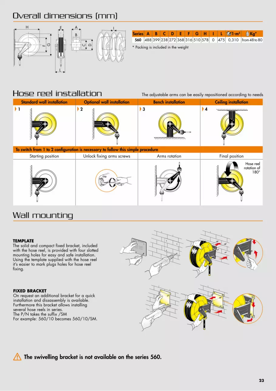
Hose reel installation The adjustable arms can be easily repositioned according to needs
To switch from 1 to 2 configuration is necessary to follow this simple procedureStarting position Unlock fixing arms screws Arms rotation Final position
Standard wall installation Optional wall installation Bench installation Ceiling installation
2 3 41
Overall dimensions (mm)
Wall mounting
FIXED BRACKETOn request an additional bracket for a quick installation and dissassembly is available. Furthermore this bracket allows installing several hose reels in series. The P/N takes the suffix /SMFor example: 560/10 becomes 560/10/SM.
TEMPLATEThe solid and compact fixed bracket, included with the hose reel, is provided with four slotted mounting holes for easy and safe installation. Using the template supplied with the hose reel it’s easier to mark plugs holes for hose reel fixing.
Hose reel rotation of
180°
The swivelling bracket is not available on the series 560.
A
DC
B
E
L
H
GF
ISeries A B C D E F G H I L 1-m3 Kg*560 488 399 238 272 368 316 510 578 0 475 0,310 from 48 to 80
* Packing is included in the weight
23

PAINTED STEEL Fixed - Swivelling
Series
Series 440
Fluid - PressurePAINTED STEEL
Swivel joint Seals Central shaft
Air, Water 20 bar brass Viton galvanised steel
Oil and similar 150 bar galvanised steel Polyurethane galvanised
steel
Grease 400 bar galvanised steel Polyurethane galvanised
steel
Suction waste oil galvanised steel Polyurethane galvanised
steel
USES
Resistant with the corrosion: all the components are painted (painting with epoxy powder coating, thickness min. 80μ), or finished with a galvanic treatment, ideal to work externally. Easy to install everywhere, like for example on the wall, on the floor, on the ceiling and on the vehicles.
430-530-540
270-300-350
430-530540-560Aisi 316
4430 ABS
440-4440 ABS
560
24

Series 4440 ABSPAINTED STEEL ABS Fixed - Swivelling
It has an internal drum in shockproof ABS. It is a valid alternative to the version with drum in painted steel, with less weight but with the same characteristics of sturdiness and reliability.
ABS shock proof internal drum
Cover and bracket in painted steel
25
Automatic with constant strength spring completely enclosed
protected and lubricated inside the reel. Tested to resist from
15000 to 20000 cycles.*
Large and multidirectional roller guide with self
lubricating hose guide rollers.
Adjustable hose stop.
Solid and compact fixed painted steel bracket with 4 slotted mounting holes for easy and safe installation.
Drum support bushings in TENAXID®, self lubricating, material resistant against corrosion.
Automatic block system built with material compliant with Atex legislation, it allows the
block of the hose at the desired measure.
Hose reel cover is in painted steel;
it is sturdy with beads and borders rounded.
Drum in painted steel or in shockproof ABS.
According to the model, they are compliant at the following Atex legislation:Atex 94/9 IIB 2GD c T4 T135°C XAtex 94/9 II 3GD c X
Swivel joint with ideal internal dimensions to guarantee the most possible flow. It is realized in brass, galvanize steel, with seals in Polyurethane, Viton.
* A cycle is composed by a number of rotations in one direction and the same in the opposite direction.The number of rotations depends on the spring model. This allows to simulate the rewinding and unwinding of a hose with its maximum length.

Hose reel capacity
Hose reel outlet hose connection
Universal hose stop
www.ecodora.com
For hoses up to 1/2”
Series Inlet Outlet440 F 1/2” F 1/2”
4440 ABS F 1/2” F 1/2”
Fluid - Pressure Series 440(ø mm)
Series 4440 ABS(ø mm)
Air - Water 20 bar 14-17-19-26 14-17-19-26
Oil and similar 150 bar 14-17-19-26 14-17-19-26
Grease 400 bar 14-17-19-26 14-17-19-26
Suction waste oil 14-17-19-26 -
Hose external diameter Hose reel series 440 - 4440 ABSø 17 mm lenght max. 21 m
ø 19,5 mm lenght max. 16 mø 22 mm lenght max. 14 m
The universal hose stop is just mounted in all models with hose. The models without hose come, together with the hose stop, with some adaptors for hoses of different sizes.Following table summarizes the internal diameters of the hose stop, available for all the series.
The hose reel structure is designed also to facilitate the mounting and the disassembly of the hose.
26

Hose reel installation The adjustable arms can be easily repositioned according to needs
Overall dimensions (mm)
Wall mounting
Standard wall installation Optional wall installation Bench installation Ceiling installation
21 3 4
FIXED SWIVELLING
FIXED BRACKETOn request an additional bracket for a quick installation and dissassembly is available. Furthermore this bracket allows installing several hose reels in series. The P/N takes the suffix /SMFor example: 440/10 becomes 440/10/SM.
SWIVELLING BRACKETOn request a swivelling bracket to make the reel turning 40° to the right and 40° to the left is available.The P/N takes the suffix /SOFor example: 440/10 becomes 440/10/SO.
TEMPLATEThe solid and compact fixed bracket, included with the hose reel, is provided with four slotted mounting holes for easy and safe installation. Using the template supplied with the hose reel it’s easier to mark plugs holes for hose reel fixing.
485500
140217
215
236
485
261
217177
236
180
485564
140208
164
485
208162
164
118
215
261
27
Series 1-m3 Kg*440 0,111 from 23 to 29
Series 1-m3 Kg*4440 ABS 0,111 from 19 to 25
* Packing is included in the weight * Packing is included in the weight

PAINTED STEEL Fixed - Swivelling
Series
Series 4430 ABS
ABS shock proof drum
Painted steelbracket
USES
It has a shockproof ABS drum and it is a valid alternative to the version with painted steel drum (pag. 12),with less weight but with the same characteristics of sturdiness and reliability.Easy to install everywhere, like for example on the wall, on the floor, on the ceiling and on the vehicles.
430-530-540
270-300-350
430-530540-560 Aisi 316
4430 ABS
440-4440 ABS
560
28
Fluid - PressurePAINTED STEEL STAINLESS STEEL AISI 304
Swivel joint Seals Central shaft Swivel joint Seals Central shaft
Air, Water 20 bar brass Viton galvanised steel brass Viton stainless steel
AISI 304
Water max 130°C 100 bar stainless steel AISI 304 Viton galvanised
steelstainless steel
AISI 304 Viton stainless steel AISI 304
Water max 130°C 200 bar stainless steel AISI 304 Viton galvanised
steelstainless steel
AISI 304 Viton stainless steel AISI 304
Oil and similar 150 bar galvanised steel Polyurethane galvanised
steelstainless steel
AISI 304 Viton stainless steel AISI 304
Grease 400 - 600 bar galvanised steel Polyurethane galvanised
steelstainless steel
AISI 304 Polyurethane stainless steel AISI 304
Diesel fuel 10 bar brass Viton galvanised steel - - -
Suction waste oil galvanised steel Polyurethane galvanised
steelstainless steel
AISI 304 Viton stainless steel AISI 304
AD Blue 10 bar stainless steel AISI 304-316L Viton stainless steel
AISI 304stainless steel AISI 304-316L Viton stainless steel
AISI 304

Series 4430 ABSSTAINLESS STEEL AISI 304 Fixed - Swivelling
Suggested for aggressive workplace or in application with use of water. It is a valid alternative to the versioncompletely in stainless steel. Easy to install everywhere, like for example on the wall, on the floor, on the ceiling and on the vehicles.
ABS shockproof drum
AISI 304 stainlesssteel bracket
29
Automatic with constant strength spring completely
enclosed protected and lubricated inside
the reel. Tested to resist from 15000 to 20000 cicli.*
Large and multidirectional roller guide with self lubricating hose guide rollers.
Adjustable hose stop.
Solid and compact fixed bracket in painted steel or in stainless steel AISI 304 with electrolytic polishing with 4 slotted mounting holes for easy and safe installation.
Drum support bushings in TENAXID®, self
lubricating, material resistant against corrosion.
Automatic block system built with material compliant with Atex legislation, it allows the
block of the hose at the desired measure.
Sturdy and practical drum in shockproof ABS.
Adjustable guide arms allows delivery hose going out at the desired location depending on hose reel installation.
Swivel joint with ideal internal dimensions to guarantee the most
possible flow. It is realized, depending on the model, in brass, galvanize steel and stainless steel AISI 304, with seals in Polyurethane, Viton.
* A cycle is composed by a number of rotations in one direction and the same in the opposite direction.The number of rotations depends on the spring model. This allows to simulate the rewinding and unwinding of a hose with its maximum length.
In accordance with directiveAtex 94/9 II 3GD c X

Hose reel capacity
Universal hose stop
www.ecodora.com
Hose external diameter Hose reel series 4430 ABSø 17 mm lenght max. 21 m
ø 19,5 mm lenght max. 16 mø 22 mm lenght max. 14 m
ø 22,5 mm lenght max. 10 mø 26 mm lenght max. 8 m
The universal hose stop is just mounted in all models with hose. The models without hose come, together with the hose stop, with some adaptors for hoses of different sizes.Following table summarizes the internal diameters of the hose stop available for all the series.
Hose reel outlet hose connectionSeries Inlet Outlet
4430 ABS F 1/2” F 1/2”
The hose reel structure is designed also to facilitate the mounting and the disassembly of the hose.
30
Fluid - Pressure Series 4430 (ø mm) for hoses from 1/2”
Air, Water 20 bar 14-17-19Water max 130°C 100 bar 14-17-19Water max 130°C 200 bar 14-17-19Oil and similar 150 bar 14-17-19Grease 400 bar - 600 bar 14-17-19Diesel fuel 10 bar 14-17-19-26Suction waste oil 14-17-19-26AD Blue 10 bar 14-17,5-21-24,5-28-30-34

Hose reel installation The adjustable arms can be easily repositioned according to needs
To switch from 1 to 2 configuration is necessary to follow this simple procedureStarting position Unlock fixing arms screws Arms rotation Final position
Standard wall installation Optional wall installation Bench installation Ceiling installation
2 3 41
Overall dimensions (mm)
Wall mounting
FIXED BRACKETOn request an additional bracket for a quick installation and dissassembly is available. Furthermore this bracket allows installing several hose reels in series.The P/N takes the suffix /SMFor example: 4430/10 becomes 4430/10/SM.
SWIVELLING BRACKETOn request a swivelling bracket to make the reel turning 40° to the right and 40° to the left is available.The P/N takes the suffix /SOFor example: 4430/10 becomes 4430/10/SO.
TEMPLATEThe solid and compact fixed bracket, included with the hose reel, is provided with four slotted mounting holes for easy and safe installation. Using the template supplied with the hose reel it’s easier to mark plugs holes for hose reel fixing.
Hose reel rotation of
180°
A
DC
B
E
L
H
GF
I
* Packing is included in the weight
Series A B C D E F G H I L 1-m3 Kg*4430 186 140 196 226 115 261 420 460 20 215 0,098 from 13 to 20
31

Air, Water max 70°C 20 bar
FIXED PAINTED STEEL FIXED S. STEEL AISI 304
P/N P/N Hose suppliedConnection
Inlet Outlet
S. 270 270/10 272/10 without hose F 3/8"G F 3/8"G270/11 272/11 10m 3/8” (952/10) F 3/8"G M 3/8"G270/14 272/14 15m 1/4” (932/15) F 3/8"G M 1/4"G
S. 300300/10 302/10 without hose F 3/8"G F 3/8"G
300/11 302/11 12m 3/8” (952/12) F 3/8"G M 3/8"G
S. 350350/10 352/10 without hose F 3/8"G F 3/8"G350/11 352/11 18m 3/8” (952/18) F 3/8"G M 3/8"G350/14 352/14 12m 3/8” (952/12) F 3/8"G M 3/8"G
S. 430
430/10 432/10 without hose F 1/2"G F 1/2"G430/11 432/11 15m 1/2” (962/15) F 1/2"G M 1/2"G430/12 432/12 12m 3/8” (952/13) F 1/2"G M 3/8"G430/13 432/13 18m 3/8” (952/19) F 1/2"G M 3/8"G430/14 432/14 10m 1/2” (962/10) F 1/2"G M 1/2"G
S. 4430ABS
4430/10 4432/10 without hose F 1/2"G F 1/2"G4430/11 4432/11 15m 1/2” (962/15) F 1/2"G M 1/2"G4430/12 4432/12 12m 3/8” (952/13) F 1/2"G M 3/8"G4430/13 4432/13 18m 3/8” (952/19) F 1/2"G M 3/8"G4430/14 4432/14 10m 1/2” (962/10) F 1/2"G M 1/2"G
S. 530530/10 532/10 without hose F 1/2"G F 1/2"G530/11 532/11 20m 1/2” (962/20) F 1/2"G M 1/2"G530/12 532/12 25m 1/2” (962/25) F 1/2"G M 1/2"G
S. 540
540/10 542/10 without hose F 1"G F 1"G540/11 542/11 15m 3/4” (972/15) F 1"G M 3/4"G540/12 542/12 20m 3/4” (972/20) F 1"G M 3/4"G540/13 542/13 15m 1” (982/15) F 1"G M 1"G540/15 542/15 without hose F 1/2"G F 1/2"G540/16 542/16 30m 1/2” (962/30) F 1/2"G M 1/2"G
S. 560
560/10 562/10 without hose F 1"G F 1"G560/11 562/11 30m 3/4” (972/30) F 1"G M 3/4"G560/12 562/12 35m 3/4” (972/35) F 1"G M 3/4"G560/13 562/13 40m 3/4” (972/40) F 1"G M 3/4"G560/14 562/14 20m 1” (982/20) F 1"G M 1"G560/15 562/15 30m 1” (982/30) F 1"G M 1"G560/16 562/16 without hose F 1/2"G F 1/2"G560/17 562/17 40m 1/2” (962/40) F 1/2"G M 1/2"G560/18 562/18 50m 1/2” (962/50) F 1/2"G M 1/2"G560/19 562/19 60m 1/2” (962/60) F 1/2"G M 1/2"G
Supplied with:- hose in black synthetic rubber with galvanized steel coupling - brass swivel joint - “Viton” seals- central shaft in galvanized steel or stainless steel AISI 304- inlet hose 0,6 m to connect the hose reel to the system (standard on the versions with hose)
For the SWIVELLING version add the suffix “/SO”at the P/N, except for the 560 series.For example:270/10/SO
32
Rubber handles, mounted on hose terminal part, are available for all the above series. For more information look at page 50.
II 3GD c XIIB 2GD c T4 T135°C X (only for series without hose 430-530-540-560)Atex 94/9

Air, Water max 70°C 10 bar Hygienic hose
FIXED S. STEEL AISI 304
P/N Hygienic hose supplied
ConnectionInlet Outlet
S. 300302/10 without hose* F 3/8"G F 3/8"G
303/11 12m 3/8” (950/12) F 3/8"G M 3/8"G
S. 430432/10 without hose* F 1/2"G F 1/2"G433/11 10m 1/2” (960/10) F 1/2"G M 1/2"G433/12 15m 1/2” (960/15) F 1/2"G M 1/2"G
S. 4430ABS
4432/10 without hose* F 1/2"G F 1/2"G4433/11 10m 1/2” (960/10) F 1/2"G M 1/2"G4433/12 15m 1/2” (960/15) F 1/2"G M 1/2"G
S. 530532/10 without hose* F 1/2"G F 1/2"G533/11 20m 1/2” (960/20) F 1/2"G M 1/2"G533/12 25m 1/2” (960/25) F 1/2"G M 1/2"G
S. 540
542/10 without hose* F 1"G F 1"G543/11 15m 3/4” (970/15) F 3/4"G M 3/4"G543/12 20m 3/4” (970/20) F 3/4"G M 3/4"G543/13 15m 1” (980/15) F 1"G M 1"G542/15 without hose* F 1/2"G F 1/2"G543/16 30m 1/2” (960/30) F 1/2"G M 1/2"G
S. 560
562/10 without hose* F 1"G F 1"G563/11 30m 3/4” (970/30) F 3/4"G M 3/4"G563/13 40m 3/4” (970/40) F 3/4"G M 3/4"G563/14 20m 1” (980/20) F 1"G M 1"G563/15 30m 1” (980/30) F 1"G M 1"G
Supplied with:- hose in synthetic rubber with blue hygienic covering and galvanized steel coupling, available for food workplace, compliant with the DIR 2007/19/EC - brass swivel joint - “Viton” seals- central shaft in stainless steel AISI 304 - inlet hose 0,6 m to connect the hose reel to the system (standard on the versions with hose)
For the SWIVELLING version add the suffix “/SO”at the P/N, except for the 560 series.For example:302/10/SO
33
Rubber handles, mounted on hose terminal part, are available for all the above series. For more information look at page 50.
II 3GD c XIIB 2GD c T4 T135°C X (only for series without hose 430-530-540-560)Atex 94/9
* For the version without hose the maximum work pressure is 20 bar

Water max 130°C 100 bar
FIXED PAINTED STEEL FIXED S. STEEL AISI 304
P/N P/N Hose suppliedConnection
Inlet Outlet
S. 300300/20 302/40 without hose* F 1/2"G F 3/8"- 1/2"G 300/21 302/21 12m 3/8” (953/13) F 1/2"G M 3/8"G300/22 302/22 8m 1/2” (963/8) F 1/2"G M 1/2"G
S. 350
350/20 352/40 without hose* F 1/2"G F 3/8"- 1/2"G350/21 352/21 17m 3/8” (953/18) F 1/2"G M 3/8"G350/22 352/22 12m 3/8” (953/13) F 1/2"G M 3/8"G350/23 352/23 10m 1/2” (963/9) F 1/2"G M 1/2"G
S. 430430/20 434/20 without hose* F 1/2"G F 1/2"G430/21 432/21 10m 1/2” (963/12) F 1/2"G M 1/2"G430/22 432/22 15m 1/2” (963/14) F 1/2"G M 1/2"G
S. 4430ABS
4430/20 4434/20 without hose* F 1/2"G F 1/2"G4430/21 4432/21 10m 1/2” (963/12) F 1/2"G M 1/2"G4430/22 4432/22 15m 1/2” (963/14) F 1/2"G M 1/2"G
S. 530530/20 534/20 without hose* F 1/2"G F 1/2"G530/21 532/21 20m 1/2” (963/19) F 1/2"G M 1/2"G530/22 532/22 25m 1/2” (963/24) F 1/2"G M 1/2"G
S. 540
540/20 544/20 without hose* F 1"G F 1"G540/21** 542/21** 15m 1” (983/15) F 1"G M 1"G540/22 542/22 15m 3/4” (973/14) F 1"G M 3/4"G540/23 542/23 20m 3/4” (973/19) F 1"G M 3/4"G540/25 544/25 without hose* F 1/2"G F 1/2"G540/26 542/26 30m 1/2” (963/29) F 1/2"G M 1/2"G
S. 560
560/20 564/20 without hose* F 1"G F 1"G560/21 562/21 30m 3/4” (973/29) F 1"G M 3/4"G560/22 562/22 35m 3/4” (973/34) F 1"G M 3/4"G560/23 562/23 40m 3/4” (973/39) F 1"G M 3/4"G
560/24** 562/24** 20m 1” (983/19) F 1"G M 1"G560/25** 562/25** 30m 1” (983/29) F 1"G M 1"G560/26 564/26 without hose* F 1/2"G F 1/2"G560/27 562/27 40m 1/2” (963/39) F 1/2"G M 1/2"G560/28 562/28 50m 1/2” (963/49) F 1/2"G M 1/2"G560/29 562/29 60m 1/2” (963/59) F 1/2"G M 1/2"G
Supplied with:- hose in black synthetic rubber with galvanized steel coupling - AISI 304 stainless steel swivel joint- “Viton” seals- central shaft in galvanized steel or stainless steel AISI 304- inlet hose 0,6 m to connect the hose reel to the system (standard on the versions with hose)
For the SWIVELLING version add the suffix “/SO”at the P/N, except for the 560 series.For example:300/20/SO
34
Rubber handles, mounted on hose terminal part, are available for all the above series. For more information look at page 50.
II 3GD c X (only for series 300-350-4430 ABS)IIB 2GD c T4 T135°C XAtex 94/9
** Work max pressure 50 bar, hose max working pressure 88 bar
* For the version without hose the maximum working pressure is 150 bar

Water max 130°C 100 bar Hygienic hose
FIXED S. STEEL AISI 304
P/N Hygienic hose supplied
ConnectionInlet Outlet
S. 300302/40 without hose* F 1/2"G F 3/8"-1/2"G303/21 8m 1/2” (964/8) F 1/2"G M 1/2"G303/22 12m 3/8” (954/13) F 1/2"G M 3/8"G
S. 350352/40 without hose* F 1/2"G F 3/8"- 1/2"G
353/22 12m 3/8” (954/13) F 1/2"G M 3/8"G
S. 430434/20 without hose* F 1/2"G F 1/2"G433/21 10m 1/2” (964/11) F 1/2"G M 1/2"G433/22 15m 1/2” (964/15) F 1/2"G M 1/2"G
S. 4430ABS
4434/20 without hose* F 1/2"G F 1/2"G4433/21 10m 1/2” (964/11) F 1/2"G M 1/2"G4433/22 15m 1/2” (964/15) F 1/2"G M 1/2"G
S. 530534/20 without hose* F 1/2"G F 1/2"G
533/22 25m 1/2” (964/25) F 1/2"G M 1/2"G
S. 540544/20 without hose* F 1"G F 1"G
543/22 20m 3/4” (974/20) F 1"G M 3/4"G
S. 560
564/20 without hose* F 1"G F 1"G563/21 30m 3/4” (974/30) F 1"G M 3/4"G563/23 40m 3/4” (974/40) F 1"G M 3/4"G
563/24** 20m 1” (984/20) F 1"G M 1"G563/25** 30m 1” (984/30) F 1"G M 1"G
Supplied with:- hose in synthetic rubber with blue hygienic covering with galvanized steel coupling- AISI 304 stainless steel swivel joint- “Viton” seals- central shaft in stainless steel AISI 304- inlet hose 0,6 m to connect the hose reel to the system (standard on the versions with hose)
For the SWIVELLING version add the suffix “/SO”at the P/N, except for the 560 series.For example:302/40/SO
35
** Work max pressure 50 bar, hose max pressione 88 bar
Rubber handles, mounted on hose terminal part, are available for all the above series. For more information look at page 50.
II 3GD c X (only for series 300-350-4430 ABS)IIB 2GD c T4 T135°C XAtex 94/9
* For the version without hose the maximum working pressure is 150 bar

Water max 130°C 200 bar
FIXED PAINTED STEEL FIXED S. STEEL AISI 304
P/N P/N Hose suppliedConnection
Inlet Outlet
S. 300300/30 302/30 without hose F 3/8"G F 3/8"G
300/31 302/31 12m 5/16” (943/12) F 3/8"G F 3/8"G
S. 350350/30 352/30 without hose F 3/8"G F 3/8"G350/31 352/31 12m 5/16” (943/12) F 3/8"G F 3/8"G350/32 352/32 17m 5/16” (943/17) F 3/8"G F 3/8"G
S. 430430/30 434/30 without hose F 3/8"G F 1/2"G430/31 432/31 12m 3/8” (955/12) F 3/8"G F 3/8"G430/32 432/32 18m 3/8” (955/18) F 3/8"G F 3/8"G
S. 4430ABS
4430/30 4434/30 without hose F 3/8"G F 1/2"G4430/31 4432/31 12m 3/8” (955/12) F 3/8"G F 3/8"G4430/32 4432/32 18m 3/8” (955/18) F 3/8"G F 3/8"G
S. 530530/30 534/30 without hose F 3/8"G F 1/2"G530/31 532/31 25m 3/8” (955/25) F 3/8"G F 3/8"G530/32 532/32 20m 3/8” (955/20) F 3/8"G F 3/8"G
S. 540540/30 544/30 without hose F 3/8"G F 1/2"G
540/31 542/31 30m 3/8” (955/30) F 3/8"G F 3/8"G
S. 560560/30 564/30 without hose F 3/8"G F 1/2"G560/31 562/31 40m 3/8” (955/40) F 3/8"G F 3/8"G560/32 562/32 50m 3/8” (955/50) F 3/8"G F 3/8"G
Supplied with:- hose in black synthetic rubber with galvanized steel coupling - AISI 304 stainless steel swivel joint- “Viton” seals- central shaft in galvanized steel or stainless steel AISI 304- inlet hose 0,6 m to connect the hose reel to the system (standard on the versions with hose)
USES
For the SWIVELLING version add the suffix “/SO”at the P/N, except for the 560 series.For example:300/30/SO
36
Rubber handles, mounted on hose terminal part, are available for all the above series. For more information look at page 50.
II 3GD c X (only for series 300-350-4430 ABS)IIB 2GD c T4 T135°C XAtex 94/9

Water max 130°C 200 bar Hygienic hose
FIXED S. STEEL AISI 304
P/N Hygienic hose supplied
ConnectionInlet Outlet
S. 300302/30 without hose F 3/8"G F 3/8"G
303/31 12m 5/16” (944/12) F 3/8"G F 3/8"G
S. 350352/30 without hose F 3/8"G F 3/8"G
353/31 12m 5/16” (944/12) F 3/8"G F 3/8"G
S. 430434/30 without hose F 3/8"G F 1/2"G433/31 12m 3/8” (956/12) F 3/8"G F 3/8"G433/32 18m 3/8” (956/18) F 3/8"G F 3/8"G
S. 4430ABS
4434/30 without hose F 3/8"G F 1/2"G4433/31 12m 3/8” (956/12) F 3/8"G F 3/8"G4433/32 18m 3/8” (956/18) F 3/8"G F 3/8"G
S. 530534/30 without hose F 3/8"G F 1/2"G
533/32 25m 3/8” (956/25) F 3/8"G F 3/8"G
S. 540544/30 without hose F 3/8"G F 1/2"G
543/31 30m 3/8” (956/30) F 3/8"G F 3/8"G
S. 560564/30 without hose F 3/8"G F 1/2"G
563/31 40m 3/8” (956/40) F 3/8"G F 3/8"G
Supplied with:- hose in black synthetic rubber with galvanized steel coupling - AISI 304 stainless steel swivel joint- “Viton” seals- central shaft in galvanized steel or stainless steel AISI 304- inlet hose 0,6 m to connect the hose reel to the system (standard on the versions with hose)
Supplied with:- hose in synthetic rubber with blue hygienic covering with galvanized steel coupling- AISI 304 stainless steel swivel joint- “Viton” seals- central shaft in stainless steel AISI 304- inlet hose 0,6 m to connect the hose reel to the system (standard on the versions with hose)
For the SWIVELLING version add the suffix “/SO”at the P/N, except for the 560 series.For example:302/30/SO
USES
37
Rubber handles, mounted on hose terminal part, are available for all the above series. For more information look at page 50.
II 3GD c X (only for series 300-350-4430 ABS)IIB 2GD c T4 T135°C XAtex 94/9

Water max 130°C 400-700 bar
FIXED PAINTED STEEL FIXED S. STEEL AISI 304
P/N P/N Hose suppliedConnection
Inlet Outlet
400 bar
S. 300300/35 302/35 without hose F 3/8"G F 3/8"G
300/36 302/36 12m 5/16” (945/12) F 3/8"G F 3/8"G
S. 350350/35 352/35 without hose F 3/8"G F 3/8"G350/36 352/36 12m 5/16” (945/12) F 3/8"G F 3/8"G350/37 352/37 17m 5/16” (945/17) F 3/8"G F 3/8"G
S. 430430/35 434/35 without hose F 3/8"G F 1/2"G430/38 432/38 10m 3/8” (907/10) F 3/8"G F 3/8"G430/39 432/39 15m 3/8” (907/15) F 3/8"G F 3/8"G
S. 4430ABS
- 4434/35 without hose F 3/8"G F 1/2"G- 4432/38 10m 3/8” (907/10) F 3/8"G F 3/8"G- 4432/39 15m 3/8” (907/15) F 3/8"G F 3/8"G
S. 530530/35 534/35 without hose F 3/8"G F 1/2"G530/36 532/36 20m 3/8” (907/20) F 3/8"G F 3/8"G530/37 532/37 25m 3/8” (907/25) F 3/8"G F 3/8"G
S. 540540/35 544/35 without hose F 3/8"G F 1/2"G
540/36 542/36 30m 3/8” (907/30) F 3/8"G F 3/8"G
S. 560560/35 564/35 without hose F 3/8"G F 1/2"G560/36 562/36 40m 3/8” (907/40) F 3/8"G F 3/8"G560/37 562/37 50m 3/8” (907/50) F 3/8"G F 3/8"G
700 bar
S. 530 530/550 534/550 without hose F 3/8”G F 1/2”G
S. 540 540/550 544/550 without hose F 3/8”G F 1/2”G
Supplied with:- hose in black synthetic rubber with galvanized steel coupling - AISI 304 stainless steel swivel joint- “Teflon” seals- central shaft in galvanized steel or stainless steel AISI 304- inlet hose 0,6 m to connect the hose reel to the system (standard on the versions with hose)
USES
For the SWIVELLING version add the suffix “/SO”at the P/N, except for the 560 series.For example:300/35/SO
38
Rubber handles, mounted on hose terminal part, are available for all the above series. For more information look at page 50.
II 3GD c X (only for series 300-350-4430 ABS)IIB 2GD c T4 T135°C XAtex 94/9

FIXED S. STEEL AISI 304
P/N Hygienic hose supplied
ConnectionInlet Outlet
S. 300302/35 without hose F 3/8"G F 3/8"G
303/36 12m 5/16” (946/12) F 3/8"G M 3/8"G
S. 350352/35 without hose F 3/8"G F 3/8"G
353/31 12m 5/16” (946/12) F 3/8"G M 3/8"G
S. 430434/35 without hose F 3/8"G F 1/2"G433/38 10m 3/8” (906/10) F 3/8"G F 3/8"G433/39 15m 3/8” (906/15) F 3/8”G F 3/8"G
S. 530534/35 without hose F 3/8"G F 1/2"G
533/37 25m 3/8” (906/25) F 3/8"G F 3/8"G
S. 560564/35 without hose F 3/8"G F 1/2"G
563/36 40m 3/8” (906/40) F 3/8"G F 3/8"G
Supplied with:- hose in synthetic rubber with blue hygienic covering with galvanized steel coupling- AISI 304 stainless steel swivel joint- “Teflon” seals- central shaft in stainless steel AISI 304- inlet hose 0,6 m to connect the hose reel to the system (standard on the versions with hose)
Water max 130°C 400 bar Hygienic hose
For the SWIVELLING version add the suffix “/SO”at the P/N, except for the 560 series.For example:302/35/SO
USES
39
Rubber handles, mounted on hose terminal part, are available for all the above series. For more information look at page 50.
II 3GD c X (only for series 300-350-4430 ABS)IIB 2GD c T4 T135°C XAtex 94/9
II 3GD c X (only for series 300-350-4430 ABS)IIB 2GD c T4 T135°C X

Oil and similar 50 - 100 - 150 bar
Supplied with:- hose in black synthetic rubber with galvanized steel coupling - swivel joint in galvanized steel or s. steel AISI 304- “Polyurethane” seals- central shaft in galvanized steel or stainless steel AISI 304- inlet hose 0,6 m to connect the hose reel to the system (standard on the versions with hose)
For the SWIVELLING version add the suffix “/SO”at the P/N, except for the 560 series.For example:300/40/SO
40
FIXED PAINTED STEEL FIXED S. STEEL AISI 304
P/N P/N Hose suppliedConnection
Inlet Outlet
150 bar
S. 300300/40 302/40 without hose F 1/2"G F 3/8" - 1/2"G300/41 302/41 8m 1/2” (963/8) F 1/2"G M 1/2"G300/42 302/42 12m 3/8” (953/12) F 1/2"G M 1/2"G
S. 350
350/40 352/40 without hose F 1/2"G F 3/8" - 1/2"G350/41 352/41 10m 1/2” (963/10) F 1/2"G M 1/2"G350/42 352/42 17m 3/8” (953/17) F 1/2"G M 1/2"G350/43 352/43 12m 3/8” (953/12) F 1/2"G M 1/2"G
S. 430430/40 434/20 without hose F 1/2"G F 1/2"G430/41 432/41 10m 1/2” (963/11) F 1/2"G M 1/2"G430/42 432/42 15m 1/2” (963/15) F 1/2"G M 1/2"G
S. 4430 ABS
4430/40 4434/20 without hose F 1/2"G F 1/2"G4430/41 4432/41 10m 1/2” (963/11) F 1/2"G M 1/2"G4430/42 4432/42 15m 1/2” (963/15) F 1/2"G M 1/2"G
S. 530530/40 534/20 without hose F 1/2"G F 1/2"G530/41 532/41 20m 1/2” (963/20) F 1/2"G M 1/2"G530/42 532/42 25m 1/2” (963/25) F 1/2"G M 1/2"G
S. 540540/45 544/25 without hose F 1/2"G F 1/2"G
540/46 542/46 30m 1/2” (963/30) F 1/2"G M 1/2"G
S. 560
560/46 564/26 without hose F 1/2"G F 1/2"G560/47 - 40m 1/2” (963/40) F 1/2"G M 1/2"G560/48 - 50m 1/2” (963/50) F 1/2"G M 1/2"G560/49 - 60m 1/2” (963/60) F 1/2"G M 1/2"G
100 bar
S. 430430/415 - without hose F 1/2"G M 1/2"G430/416 - 10m 5/8” (993/310) F 3/4"G M 3/4"G430/417 - 8m 3/4” (973/308) F 3/4"G M 3/4"G
S. 4430 ABS
4430/415 - without hose F 1/2"G M 1/2"G4430/416 - 10m 5/8” (993/310) F 3/4"G M 3/4"G4430/417 - 8m 3/4” (973/308) F 3/4"G M 3/4"G
S. 530530/415 - without hose F 1"G F 1"G
530/416 - 12m 3/4” (973/312) F 3/4"G M 3/4"G
S. 540540/40 544/20 without hose F 1"G F 1"G540/411 - 15m 3/4” (973/315) F 3/4"G M 3/4"G540/412 - 20m 3/4” (973/320) F 3/4"G M 3/4"G
S. 560560/40 564/20 without hose F 1"G F 1"G560/411 - 30m 3/4” (973/330) F 3/4"G M 3/4"G560/413 - 40m 3/4” (973/340) F 3/4"G M 3/4"G
50 bar
S. 540540/413 - 15m 1” (983/315) F 1"G M 1"G
540/414 - 10m 1” (983/310) F 1"G M 1"G
S. 560560/414 - 20m 1” (983/320) F 1"G M 1"G
560/415 - 30m 1” (983/330) F 1"G M 1"G
II 3GD c X (only for series 300-350-4430 ABS)IIB 2GD c T4 T135°C XAtex 94/9

Supplied with:- hose in black synthetic rubber with galvanized steel coupling- swivel joint in galvanized steel or s. steel AISI 304- “Polyurethane” seals- central shaft in galvanized steel or stainless steel AISI 304- inlet hose 0,6 m to connect the hose reel to the system (standard on the versions with hose)
For the SWIVELLING version add the suffix “/SO”at the P/N.For example:300/51/SO
Grease 400 - 600 bar
USES
41
FIXED PAINTED STEEL FIXED S. STEEL AISI 304
P/N P/N Hose suppliedConnection
Inlet Outlet
400 bar
S. 300300/50 302/50 without hose F 3/8"G F 3/8"G
300/51 302/51 12m 1/4” (935/12) F 3/8"G M 1/4"G
S. 350350/50 352/50 without hose F 3/8"G F 3/8"G350/51 352/51 12m 1/4” (935/12) F 3/8"G M 1/4"G350/52 352/52 16m 1/4” (935/16) F 3/8"G M 1/4"G
S. 430
430/50 432/50 without hose F 3/8"G F 1/2"G430/51 432/51 12m 1/4” (935/13) F 3/8"G M 1/4"G430/52 432/52 18m 1/4”(935/18) F 3/8"G M 1/4"G430/55 432/55 10m 3/8” (957/10) F 3/8"G M 1/4"G430/56 432/56 15m 3/8” (957/15) F 3/8"G M 1/4"G
4430/50 4432/50 without hose F 3/8"G F 1/2"G
S. 4430 ABS
4430/51 4432/51 12m 1/4” (935/13) F 3/8"G M 1/4"G4430/52 4432/52 18m 1/4”(935/18) F 3/8"G M 1/4"G4430/55 4432/55 10m 3/8” (957/10) F 3/8"G M 1/4"G4430/56 4432/56 15m 3/8” (957/15) F 3/8"G M 1/4"G
S. 530530/50 532/50 without hose F 3/8"G F 1/2"G530/51 532/51 20m 3/8” (957/20) F 3/8"G M 1/4"G530/52 532/52 25m 3/8” (957/25) F 3/8"G M 1/4"G
S. 540540/50 542/50 without hose F 3/8"G F 1/2"G
540/51 542/51 30m 3/8” (957/30) F 3/8"G M 1/4"G
II 3GD c X (only for series 300-350-4430 ABS)IIB 2GD c T4 T135°C XAtex 94/9

Diesel Fuel 10 bar
FIXED PAINTED STEEL FIXED S. STEEL AISI 304
P/N P/N Hose suppliedConnection
Inlet Outlet
S. 430430/60 - without hose* F 1/2"G M 1/2"G430/61 - 10m 5/8” (968/20) F 3/4"G M 3/4"G430/62 - 8m 3/4” (968/25) F 3/4"G M 3/4"G
S. 4430ABS
4430/60 - without hose* F 1/2"G M 1/2"G4430/61 - 10m 5/8” (968/20) F 3/4"G M 3/4"G4430/62 - 8m 3/4” (968/25) F 3/4"G M 3/4"G
S. 530530/60 - without hose* F 1"G F 1"G530/63 - 12m 19x27 (978/12) F 1"G M 3/4"G530/64 - 8m 25x35 (988/8) F 1"G M 1"G
S. 540
540/10 542/10 without hose* F 1"G F 1"G540/61 542/61 15m 19x27 (978/15) F 1"G M 3/4"G540/62 542/62 20m 19x27 (978/20) F 1"G M 3/4"G540/63 542/63 15m 25x35 (988/15) F 1"G M 1"G
S. 560
560/10 562/10 without hose* F 1"G F 1"G560/63 562/63 40m 19x27 (978/40) F 1"G M 3/4"G560/64 562/64 20m 25x35 (988/20) F 1"G M 1"G560/65 562/65 30m 25x35 (988/30) F 1"G M 1"G
Supplied with:- hose in antistatic EPDM black synthetic rubber with galvanized steel coupling- brass swivel joint- “Viton” seals- central shaft in galvanized steel or stainless steel- inlet hose 0,6 m to connect the hose reel to the system (standard on the versions with hose)
For the SWIVELLING version add the suffix “/SO”at the P/N, except for the 560 series.For example:430/60/SO
42
AD blue 10 barFIXED PAINTED STEEL FIXED S. STEEL AISI
P/N P/N Fluid contactparts Hose supplied
ConnectionInlet Outlet
S. 436 436/20 - AISI 316L without hose* F 1"G F 3/4"G
S. 436436/250 - AISI 304 without hose* F 3/4"G F 3/4"G436/251 - AISI 304 10m 19x27 (882/10) F 3/4"G M 3/4"G436/252 - AISI 304 15m 19x27 (882/15) F 3/4"G M 3/4"G
S. 4436 ABS
4436/20 - AISI 304 without hose* F 1/2"G F 1/2"G
4436/21 - AISI 304 8m 19x27 (882/8) F 3/4"G M 3/4"G
S. 537 - 537/20 AISI 316L without hose* F 1"G F 3/4"G
S. 537- 534/250 AISI 304 without hose* F 1"G F 1"G- 537/251 AISI 304 10m 19x27 (882/10) F 3/4"G M 3/4"G- 537/252 AISI 304 15m 19x27 (882/15) F 3/4"G M 3/4"G
Supplied with:- hose in antistatic EPDM rubber with AISI 304 stainless steel coupling- AISI 304 - 316L stainless steel swivel joint- “Viton” seals- central shaft in stainless steel AISI 304- inlet hose 0,6 m to connect the hose reel to the system (standard on the versions with hose)
For the SWIVELLING version add the suffix “/SO”at the P/N.For example:436/20/SO
II 3GD c X (per serie 4430 ABS)IIB 2GD c T4 T135°C XAtex 94/9
II 3GD c X (per serie 4430 ABS)IIB 2GD c T4 T135°C XAtex 94/9
* for the version without hose the maximum work pressure is 20 bar
* for the version without hose the maximum work pressure is 20 bar

Welding 20 bar
FIXED PAINTED STEEL
P/N Hose supplieddouble
ConnectionInlet Outlet
S. 430430/70 without hose M 3/8"G M 3/8"G430/71 13m 2x1/4”-2x6 (993/13) F 3/8"G F 3/8"G430/72 12m 2x5/16”-2x8 (994/12) F 3/8"G F 3/8"G
S. 530
530/70 without hose M 3/8"G M 3/8"G530/71 17m 2x1/4”-2x6 (993/17) F 3/8"G F 3/8"G530/72 20m 2x1/4”-2x6 (993/20) F 3/8"G F 3/8"G530/73 15m 2x5/16”-2x8 (994/15) F 3/8"G F 3/8"G530/74 20m 2x5/16”-2x8 (994/20) F 3/8"G F 3/8"G530/75 15m 2x3/8”-2x9 (995/15) F 3/8"G F 3/8"G
S. 540
540/70 without hose M 3/8"G M 3/8"G540/71 25m 2x1/4”-2x6 (993/25) F 3/8"G F 3/8"G540/72 30m 2x1/4”-2x6 (993/30) F 3/8"G F 3/8"G540/73 35m 2x1/4”-2x6 (993/35) F 3/8"G F 3/8"G540/74 25m 2x5/16”-2x8 (994/25) F 3/8"G F 3/8"G540/75 30m 2x5/16”-2x8 (994/30) F 3/8"G F 3/8"G540/76 35m 2x5/16”-2x8 (994/35) F 3/8"G F 3/8"G540/77 20m 2x3/8”-2x9 (995/20) F 3/8"G F 3/8"G540/78 25m 2x3/8”-2x9 (995/25) F 3/8"G F 3/8"G540/79 27m 2x3/8”-2x9 (995/27) F 3/8"G F 3/8"G
Supplied with:- double hose Standard EN559, hose SBR/EPDM rubber with brass coupling- brass swivel joint- “Viton” seals- central shaft in galvanized steel- inlet hose 1,5 m to connect the hose reel to the system (standard on the versions with hose)
USES
For the SWIVELLING version add the suffix “/SO”at the P/N.For example:430/70/SO
43
II 3GD c X (per serie 4430 ABS)IIB 2GD c T4 T135°C X
II 3GD c X (per serie 4430 ABS)IIB 2GD c T4 T135°C X
II 3GD c (T5) T100°C XAtex 94/9

LPG - Methane 20 bar
FIXED PAINTED STEEL
P/N Hose suppliedConnection
Inlet Outlet
S. 300300/80 without hose M 3/8"G L-H M 3/8"G L-H300/81 8m 8x15 (949/8) F 3/8"G L-H F 3/8"G L-H300/82 10m 10x17 (959/10) F 3/8"G L-H F 3/8"G L-H
S. 350350/80 without hose M 3/8"G L-H M 3/8"G L-H350/81 15m 8x15 (949/15) F 3/8"G L-H F 3/8"G L-H350/82 15m 10x17 (959/15) F 3/8"G L-H F 3/8"G L-H
S. 430430/80 without hose M 3/8"G L-H M 3/8"G L-H430/82 20m 8x15 (949/20) F 3/8"G L-H F 3/8"G L-H430/84 18m 10x17 (959/18) F 3/8"G L-H F 3/8"G L-H
S. 530530/80 without hose M 3/8"G L-H M 3/8"G L-H530/82 28m 8x15 (949/28) F 3/8"G L-H F 3/8"G L-H530/84 27m 10x17 (959/27) F 3/8"G L-H F 3/8"G L-H
S. 540540/80 without hose M 3/8"G L-H M 3/8"G L-H
540/82 30m 10x17 (959/30) F 3/8"G L-H F 3/8"G L-H
Supplied with:- NBR orange hose Standard EN559 with brass coupling- brass swivel joint- “Viton” seals- central shaft in galvanized steel- inlet hose 1,5 m to connect the hose reel to the system (standard on the versions with hose)
Suction waste oil
FIXED PAINTED STEEL FIXED PAINTED STEEL
P/N P/N Hose suppliedConnection
Inlet Outlet
S. 430430/40/AS - without hose F 1/2"G F 3/8"G430/41/AS - 10m 1/2” (963/11) F 1/2"G M 1/2"G430/415/AS - without hose F 1"G F 1"G
S. 4430 ABS 4430/40/AS - without hose F 1/2"G F 3/8"G
S. 440enclosed - 440/41/AS 10m 1/2” (963/11) F 1/2"G M 1/2"G
Supplied with:- hose in black synthetic rubber with galvanized steel coupling- brass swivel joint- “Viton” seals- inlet hose 2 m to connect the hose reel to the system (standard on the versions with hose)
For the SWIVELLING version add the suffix “/SO”at the P/N.For example:300/80/SO
For the SWIVELLING version add the suffix “/SO”at the P/N.For example:430/40/AS/SO
44
L-H: left hand thread
IIB 2GD c T4 T135°C XII 3GD c X (per serie 4430 ABS)Atex 94/9
II 3GD c (T5) T100°C XAtex 94/9

Supplied with:- hose with outlet coupling in brass or in stainless steel AISI 304- swivel joint in brass, galvanized steel or stainless steel AISI 304- “Viton” or “Polyurethane” seals- central shaft in galvanized steel
Double inlet and outlet
For the SWIVELLING version add the suffix “/SO”at the P/N.For example:430/100/SO
Atex 94/9 II 3 GD c X
45
FIXED PAINTED STEEL
P/NProvided with Connection
2 Swivels Seals Inlet Outlet
S. 430
Air-Water 20 bar 430/100 brass Viton F 1/2”G M 3/8”G
Oil-Water 200 bar 430/300 stainless steel
AISI 304 Viton F 3/8”G M 3/8”G
Oil-Paint 200 bar 430/400 galvanised steel Polyurethane F 1/2”G M 3/8”G
Oil 400 bar 430/500 galvanised steel Polyurethane F 3/8”G M 3/8”G
Water max 130°C400 bar 430/5500 stainless steel
AISI 304 Teflon F 3/8”G M 3/8”G
S. 530
Air-Water 20 bar 530/100 brass Viton F 1/2”G M 3/8”G
Oil-Water 200 bar 530/300 stainless steel
AISI 304 Viton F 3/8”G M 3/8”G
Oil-Paint 200 bar 530/400 galvanised steel Polyurethane F 1/2”G M 3/8”G
Oil 400 bar 530/500 galvanised steel Polyurethane F 3/8”G M 3/8”G
Water max 130°C400 bar 530/5500 stainless steel
AISI 304 Teflon F 3/8”G M 3/8”G
S. 540
Air-Water 20 bar 540/100 brass Polyurethane F 1/2”G M 3/8”G
Oil-Water 200 bar 540/300 stainless steel
AISI 304 Viton F 3/8”G M 3/8”G
Oil-Paint 200 bar 540/400 brass Viton F 1/2”G M 3/8”G
Oil 400 bar 540/500 brass Polyurethane F 3/8”G M 3/8”G
Water max 130°C400 bar 540/5500 stainless steel
AISI 304 Teflon F 3/8”G M 3/8”G
IIB 2GD c T4 T135°C XAtex 94/9
USES

FIXED S. STEEL AISI 304
P/N Hose suppliedConnection
Inlet Outlet
S. 430
Water max 130 °C 100 bar 434/20 without hose F 1/2"G F 1/2"G
Water max 130 °C 200 bar 434/30 without hose F 3/8"G F 1/2"G
Water max 130 °C 400 bar 434/35 without hose F 3/8"G F 1/2"G
S. 530
Water max 130 °C 100 bar
534/20 without hose F 1/2"G F 1/2"G534/250 without hose F 1"G F 1"G
Water max 130 °C 200 bar 534/30 without hose F 3/8”G F 1/2"G
Water max 130 °C 400 bar 534/35 without hose F 3/8”G F 1/2"G
Water max 130°C 700 bar 534/550 without hose F 3/8”G F 1/2"G
S. 540
Water max 130 °C 100 bar
544/20 without hose F 1"G F 1"G544/25 without hose F 1/2"G F 1/2"G
Water max 130 °C 200 bar 544/30 without hose F 3/8”G F 1/2"G
Water max 130 °C 400 bar 544/35 without hose F 3/8”G F 1/2"G
Water max 130°C 700 bar 544/550 without hose F 3/8”G F 1/2"G
S. 560
Water max 130 °C 100 bar
564/20 without hose F 1"G F 1"G564/26 F 1/2"G F 1/2"G
Water max 130 °C 200 bar 564/30 without hose F 3/8”G F 1/2"G
Water max 130 °C 400 bar 564/35 without hose F 3/8”G F 1/2"G
Supplied with:- AISI 304 stainless steel swivel joint- “Viton” or “Teflon” seals- central shaft in stainless steel AISI 304
Water max 130°C 100-200-400-700 bar AISI 304
For the SWIVELLING version add the suffix “/SO”at the P/N, except for the 560 series.For example:434/20/SO
USES
46
IIB 2GD c T4 T135°C XAtex 94/9

Supplied with:- AISI 316 stainless steel swivel joint- “Viton” seals- central shaft in stainless steel AISI 316
FIXED S. STEEL AISI 304
P/N Hose suppliedConnection
Inlet Outlet
S. 430 435/20 without hose F 1/2"G F 1/2"G
S. 530 535/20 without hose F 1/2"G F 1/2"G
S. 540545/20 without hose F 1"G F 1"G
545/25 without hose F 1/2"G F 1/2"G
S. 560565/20 without hose F 1"G F 1"G
565/26 without hose F 1/2"G F 1/2"G
Water max 130°C 100 bar AISI 316
USES
47
IIB 2GD c T4 T135°C XAtex 94/9

Enclosed painted steel
Supplied with:- hose in black synthetic rubber with galvanized steel coupling- swivel joint in brass or galvanized steel- “Viton” or “Polyurethane” seals- central shaft in galvanized steel- inlet hose from 0,6 m to 1m to connect the hose reel to the system (standard on the versions with hose)
USES
For the SWIVELLING version add the suffix “/SO”at the P/N.For example:440/10/SO
48
FIXED PAINTED STEEL
P/N Hose suppliedConnection
Inlet Outlet
S. 440 Air-Water 20 bar
440/10 without hose F 1/2"G F 1/2"G440/11 15m 1/2” (962/15) F 1/2"G M 1/2"G440/12 12m 3/8” (952/13) F 1/2"G M 3/8"G440/13 18m 3/8” (952/19) F 1/2"G M 3/8"G440/14 10m 1/2” (962/10) F 1/2"G M 1/2"G
S. 4440ABS Air-Water 20 bar
4440/10 without hose F 1/2"G F 1/2"G4440/11 15m 1/2” (962/15) F 1/2"G M 1/2"G4440/12 12m 3/8” (952/13) F 1/2"G M 3/8"G4440/13 18m 3/8” (952/19) F 1/2"G M 3/8"G4440/14 10m 1/2” (962/10) F 1/2"G M 1/2"G
S. 440 Oil 150 bar440/40 without hose F 1/2"G F 1/2"G440/41 10m 1/2” (963/11) F 1/2"G M 1/2"G440/42 15m 1/2” (963/15) F 1/2"G M 1/2"G
S. 4440ABS Oil 150 bar
4440/40 without hose F 1/2"G F 1/2"G4440/41 10m 1/2” (963/11) F 1/2"G M 1/2"G4440/42 15m 1/2” (963/15) F 1/2"G M 1/2"G
Grease 400 bar
440/50 without hose F 3/8"G F 1/2"G
S. 440
440/51 12m 1/4” (935/13) F 3/8"G M 1/4"G440/52 18m 1/4” (935/18) F 3/8"G M 1/4"G440/55 10m 3/8” (957/10) F 3/8"G M 1/4"G440/56 15m 3/8” (957/15) F 3/8"G M 1/4"G
Grease 400 bar
4440/50 without hose F 3/8"G F 1/2"G
S. 4440ABS
4440/51 12m 1/4” (935/13) F 3/8"G M 1/4"G4440/52 18m 1/4” (935/18) F 3/8"G M 1/4"G4440/55 10m 3/8” (957/10) F 3/8"G M 1/4"G4440/56 15m 3/8” (957/15) F 3/8"G M 1/4"G
II 3GD c X (only for S. 4440 ABS and S. 440 Air-Water 20 bar)IIB 2GD c T4 T135°C XAtex 94/9

A
DC
B
BA
DC
E
P/N A B C D
430/01 186 152 264 294430/02 186 152 264 294440/01 217 187 267 292530/01 203 160 302 338530/02 203 160 302 338540/01 300 220 300 340540/02 300 220 300 340
P/N A B C D E
430/05 162 208 118 165 94430/06 162 208 118 165 94440/05 162 208 118 165 94530/05 162 208 118 165 94530/06 162 208 118 165 94
Accessories
A
DC
B
P/N A B C D560/01 488 399 313 347
560/02 488 399 313 347
BA
DC
E
P/N A B C D E540/05 218 300 226 268 129
540/06 218 300 226 268 129
49
Art. 430/01Galvanized steel fixed bracket suitable for hose reels Series 270 - 300 - 350 - 4304430 ABS
Art. 430/02Stainless steel AISI 304 fixed bracket suitable for hose reels Series 270 - 300 - 350 - 4304430 ABS
Art. 440/01 Galvanized steel fixed bracket suitable for hose reels Series 440 - 4440 ABS
Art. 530/01 Galvanized steel fixed bracket suitable for hose reels Series 530
Art. 530/02 Stainless steel AISI 304 fixed bracket suitable for hose reels Series 530
Art. 540/01 Galvanized steel fixed bracket suitable for hose reels Series 540
Art. 540/02 Stainless steel AISI 304 fixed bracket suitable for hose reels Series 540
Art. 430/05Painted steel swivelling bracket suitable for hose reels Series 270 - 300 - 350 - 430 436 - 4436 ABS - 4430 ABS
Art. 430/06Stainless steel AISI 304 swivelling bracket suitable for hose reels Series 270 - 300 - 350430 - 4430 ABS
Art. 440/05 Painted steel swivelling bracket in steel suitable for hose reels Series 440 - 4440 ABS
Art. 530/05 Painted steel swivelling bracket in steel suitable for hose reels Series 530
Art. 530/06 Stainless steel AISI 304 swivelling bracket suitable for hose reels Series 530 - 537
Art. 560/01 Galvanized steel fixed bracket suitable for hose reels Series 560
Art. 560/02 Stainless steel AISI 304 fixed bracket suitable for hose reels Series 560
Art. 540/05 Painted steel swivelling bracket in steel suitable for hose reels Series 540
Art. 540/06 Stainless steel AISI 304 swivelling bracket suitable for hose reels Series 540

P/N 0E33105 Galvanized steel Nipple M 1” x M 1.1/4” GP/N 0E33114 Galvanized steel Nipple M 1” x M 1/2” GP/N 0E33116 Galvanized steel Nipple M 1” x M 1” GP/N 0E33117 Galvanized steel Nipple M 3/4” x M 3/4” GP/N 0E33118 Galvanized steel Nipple M 1/2” x M 3/4” GP/N 0E33119 Galvanized steel Nipple M 1” x M 3/4” GP/N 0E33270 Galvanized steel Nipple M 1.1/2” x M 3/4” GP/N 0E33271 Galvanized steel Nipple M 1.1/2” x M 1” GP/N 0E33272 Galvanized steel Nipple M 1.1/2” x M 1.1/4” GP/N 0E33273 Galvanized steel reduction M 1.1/2” x F 1.1/4” GP/N 0E33274 Galvanized steel reduction M 1” x F 1/2” GP/N 0E33275 Galvanized steel reduction F 3/4” x M 1/2” GP/N 0E33276 Galvanized steel reduction F 1” x M 3/4” GP/N 0E33277 Galvanized steel reduction M 3/4” x F 1/2” GP/N 0E38059 Galvanized steel Nipple M 1/4” x M 1/2” GP/N 0E38068 Galvanized steel Nipple M 3/8” x M 1/2” GP/N 0E38071 Galvanized steel Nipple M 1/2” x M 1/2” GP/N 0E38072 Galvanized steel Nipple M 1/2” x M 3/8” GP/N 0E38073 Galvanized steel Nipple M 3/8” x M 3/8” GP/N 0E38074 Galvanized steel Nipple M 1/2” x M 1/2” GP/N 0E66891 Galvanized steel Nipple M 1/4” x M 1/4” GP/N 0E66892 Galvanized steel Nipple M 1/4” x M 3/8” GP/N 0E66893 Galvanized steel Nipple M 1/2” x M 1/4” G
P/N 0E33128 Nipple Stainless steel AISI 304 M 1” x M 3/4” GP/N 0E33129 Nipple Stainless steel AISI 304 M 1” x M 1” GP/N 0E33130 Nipple Stainless steel AISI 304 M 3/4” x M 3/4” GP/N 0E33131 Nipple Stainless steel AISI 316 M 1” x M 3/4” GP/N 0E33132 Nipple Stainless steel AISI 316 M 1” x M 1” GP/N 0E33133 Nipple Stainless steel M 1” x M 3/4” GP/N 0E38120 Nipple Stainless steel AISI 304 M 1/2” x M 3/8” GP/N 0E38121 Nipple Stainless steel AISI 304 M 1/2” x M 1/2” GP/N 0E38123 Nipple Stainless steel AISI 304 M 1/2” G x M 3/8” GP/N 0E38124 Nipple Stainless steel AISI 304 M 1/2” G x M 1/2” G
Accessories
50
cylindrical/cylindrical thread tapared/cylindrical thread
cylindrical/cylindrical thread tapared/cylindrical thread
Modular drip-tray for hose reel:Equipped with gun hook and removable tray. Indispensable, applied under any hose-reel for holding the gun, and for keeping the wall and place clean and safe.
Latch mechanism protective cover rack side hose reels Series 430 - 436 - 437
Latch mechanism protective cover rack side hose reels Series 530 - 536 - 537 - 540 - 560
70
200 150
56
655
Art. 900
Art. 430/08
Art. 530/08
Special rubber protection mounted on hose end may are available on request for hose reels for air-water 20 bar, and for water up to 400 bar. This accessory help to protect the hands of the operator when water is hot, avoiding at the same time extreme hose bending. Available for hoses with 1/2” ID or smaller.To order the hose with this protection please add the suffix “/CM” at the P/N. For example 430/21 becomes 430/21/CM.

51
The range of hoses offered by ECODORA for its hose reels is in
line with company’s quality standards and guarantees excellent performance in
the applications with the pressures specified in the catalogue. For conditions different from those
recommended, ECODORA is available to appraise every aspect of the application context (compatibility
of the materials used with the fluid, temperature of use, working pressure, etc.) together with the customer for
identifying the right hose for each specific case.
The hoses mounted on the hose reels must support the max working pressure indicated on the label of each hose reels.
Hose specifications
51

Inlet connection hoses connecting hose reel to the system or to equipment
Connection hoses
52
L-H: left hand thread
P/N Length Pressure ø mmInside - Outside
ConnectionInlet Outlet Material
882/06 0,6 m 3/4” - rubber EPDM antistatic - 10 bar 19 x 27 F 3/4”G M 1”G s. steel AISI 304906/06 0,6 m 3/8” - hygienic - 400 bar 9,5 x 17,5 F 3/8”G M 3/8”G galvanized steel907/06 0,6 m 3/8” - black rubber - 400 bar 9,5 x 17,5 F 3/8”G M 3/8”G galvanized steel932/1 1 m 1/4” - black rubber - 20 bar 6,3 x 17,5 F 1/4”G M 1/4”G galvanized steel932/2 2 m 1/4” - black rubber - 20 bar 6,3 x 17,5 F 1/4”G M 1/4”G galvanized steel935/4 4 m 1/4” - black rubber - 400 bar 6,3 x 17,5 F 1/4”G M 1/4”G galvanized steel
952/06 0,6 m 3/8” - black rubber - 20 bar 9,5 x 16 F 3/8”G M 3/8”G galvanized steel955/06 0,6 m 3/8” - black rubber - 200 bar 9,5 x 17 F 3/8”G M 3/8”G galvanized steel956/06 0,6 m 3/8” - hygienic - 200 bar 9,5 x 17 F 3/8”G M 3/8”G galvanized steel957/06 0,6 m 3/8” - black rubber - 600 bar 9,5 x 18 F 3/8”G M 3/8”G galvanized steel959/2 1,5 m 3/8” - NBR-PVC - EN 559 - 20 bar 10 x 17 F 3/8”G-L-H F 3/8”G-L-H brass960/06 0,6 m 1/2” - hygienic - 20 bar 12,7 x 20 F 1/2”G M 1/2”G galvanized steel963/05 0,6 m 1/2” - black rubber - 100 bar 12,7 x 20 F 1/2”G M 1/2”G galvanized steel963/06 0,6 m 1/2” - black rubber - 150 bar 12,7 x 19 F 1/2”G M 1/2”G galvanized steel 963/1 1 m 1/2” - black rubber - 100 bar 12,7 x 18,5 F 1/2”G M 1/2”G galvanized steel 963/2 2 m 1/2” - black rubber - 100 bar 12,7 x 18,5 F 1/2”G M 1/2”G galvanized steel 963/4 4 m 1/2” - black rubber - 100 bar 12,7 x 18,5 F 1/2”G M 1/2”G galvanized steel964/06 0,6 m 1/2” - hygienic - 100 bar 12,7 x 20 F 1/2”G M 1/2”G galvanized steel973/305 5 m 3/4” - black rubber - 100 bar 19 x 26,5 F 3/4”G M 3/4”G galvanized steel973/306 0,6 m 3/4” - black rubber - 100 bar 19 x 26,5 F 3/4”G M 1/2”G galvanized steel980/06 0,6 m 1” - hygienic - 20 bar 25,4 x 33,5 F 1”G M 1”G galvanized steel983/05 0,6 m 1” - black rubber - 100 bar 25,4 x 33,5 F 1”G M 1”G galvanized steel983/301 1 m 1” - black rubber - 50 bar 25,4 x 35,5 F 1”G M 1”G galvanized steel983/302 2 m 1” - black rubber - 50 bar 25,4 x 35,5 F 1”G M 1”G galvanized steel983/306 0,6 m 1” - black rubber - 50 bar 25,4 x 35,5 F 1”G M 1”G galvanized steel984/06 0,6 m 1” - hygienic - 50 bar 25,4 x 33,5 F 1”G M 1”G galvanized steel988/06 0,6 m 1” - black rubber - 10 bar 25 x 35 F 1”G M 1”G galvanized steel995/2 1,5 m 2 x 3/8” - SBR-EPDM - EN 559 - 20 bar 9 + 9x16 F 3/8”G F 3/8”G brass

Air-Water 20 bar
P/N Length Characteristics - Pressure ø Inside - Outside
ConnectionInlet Outlet Material
932/1 1 m 1/4” - black rubber - 20 bar 6,3 x 17,5 F 1/4”G M 1/4”G galvanized steel932/2 2 m 1/4” - black rubber - 20 bar 6,3 x 17,5 F 1/4”G M 1/4”G galvanized steel932/15 15 m 1/4” - black rubber - 20 bar 6,3 x 17,5 M 1/4”G M 1/4”G galvanized steel952/06 0,6 m 3/8” - black rubber - 20 bar 9,5 x 16 F 3/8”G M 3/8”G galvanized steel952/10 10 m 3/8” - black rubber - 20 bar 9,5 x 16 M 3/8”G M 3/8”G galvanized steel952/12 12 m 3/8” - black rubber - 20 bar 9,5 x 16 M 3/8”G M 3/8”G galvanized steel952/13 12 m 3/8” - black rubber - 20 bar 9,5 x 16 F 3/8”G M 3/8”G galvanized steel952/18 18 m 3/8” - black rubber - 20 bar 9,5 x 16 M 3/8”G M 3/8”G galvanized steel952/19 18 m 3/8” - black rubber - 20 bar 9,5 x 16 F 3/8”G M 3/8”G galvanized steel962/10 10 m 1/2” - black rubber - 20 bar 12,7 x 20 F 1/2”G M 1/2”G galvanized steel962/15 15 m 1/2” - black rubber - 20 bar 12,7 x 20 F 1/2”G M 1/2”G galvanized steel962/20 20 m 1/2” - black rubber - 20 bar 12,7 x 20 F 1/2”G M 1/2”G galvanized steel962/25 25 m 1/2” - black rubber - 20 bar 12,7 x 20 F 1/2”G M 1/2”G galvanized steel962/30 30 m 1/2” - black rubber - 20 bar 12,7 x 20 F 1/2”G M 1/2”G galvanized steel962/40 40 m 1/2” - black rubber - 20 bar 12,7 x 20 F 1/2”G M 1/2”G galvanized steel962/50 50 m 1/2” - black rubber - 20 bar 12,7 x 20 F 1/2”G M 1/2”G galvanized steel962/60 60 m 1/2” - black rubber - 20 bar 12,7 x 20 F 1/2”G M 1/2”G galvanized steel972/15 15 m 3/4” - black rubber - 20 bar 19 x 26,5 F 3/4”G M 3/4”G galvanized steel972/20 20 m 3/4” - black rubber - 20 bar 19 x 26,5 F 3/4”G M 3/4”G galvanized steel972/30 30 m 3/4” - black rubber - 20 bar 19 x 26,5 F 3/4”G M 3/4”G galvanized steel972/35 35 m 3/4” - black rubber - 20 bar 19 x 26,5 F 3/4”G M 3/4”G galvanized steel972/40 40 m 3/4” - black rubber - 20 bar 19 x 26,5 F 3/4”G M 3/4”G galvanized steel982/15 15 m 1” - black rubber - 20 bar 25,4 x 32,5 F 1”G M 1”G galvanized steel982/20 20 m 1” - black rubber - 20 bar 25,4 x 32,5 F 1”G M 1”G galvanized steel982/30 30 m 1” - black rubber - 20 bar 25,4 x 32,5 F 1”G M 1”G galvanized steel
Black synthetic rubber hoses
53

Black synthetic rubber hoses
54
Water max 130°C 200 bar
P/N Length Characteristics - Pressure ø Inside - Outside
ConnectionInlet Outlet Material
943/12 12 m 5/16” - black rubber - 200 bar 8 x 15 M 3/8”G F 3/8”G galvanized steel943/17 17 m 5/16” - black rubber - 200 bar 8 x 15 M 3/8”G F 3/8”G galvanized steel955/06 0,6 m 3/8” - black rubber - 200 bar 9,5 x 17 F 3/8”G F 3/8”G galvanized steel955/12 12 m 3/8” - black rubber - 200 bar 9,5 x 17 F 3/8”G F 3/8”G galvanized steel955/18 18 m 3/8” - black rubber - 200 bar 9,5 x 17 F 3/8”G F 3/8”G galvanized steel955/20 20 m 3/8” - black rubber - 200 bar 9,5 x 17 F 3/8”G F 3/8”G galvanized steel955/25 25 m 3/8” - black rubber - 200 bar 9,5 x 17 F 3/8”G F 3/8”G galvanized steel955/30 30 m 3/8” - black rubber - 200 bar 9,5 x 17 F 3/8”G F 3/8”G galvanized steel955/40 40 m 3/8” - black rubber - 200 bar 9,5 x 17 F 3/8”G F 3/8”G galvanized steel955/50 50 m 3/8” - black rubber - 200 bar 9,5 x 17 F 3/8”G F 3/8”G galvanized steel
Water max 130°C 400 bar
P/N Length Characteristics - Pressure ø Inside - Outside
ConnectionInlet Outlet Material
945/12 12 m 5/16” - black rubber - 400 bar 8 x 16 M 3/8”G F 3/8”G galvanized steel945/17 17 m 5/16” - black rubber - 400 bar 8 x 16 M 3/8”G F 3/8”G galvanized steel907/06 0,6 m 3/8” - black rubber - 400 bar 9,5 x 17,5 F 3/8”G M 3/8”G galvanized steel907/10 10 m 3/8” - black rubber - 400 bar 9,5 x 17,5 F 3/8”G F 3/8”G galvanized steel907/15 15 m 3/8” - black rubber - 400 bar 9,5 x 17,5 F 3/8”G F 3/8”G galvanized steel907/20 20 m 3/8” - black rubber - 400 bar 9,5 x 17,5 F 3/8”G F 3/8”G galvanized steel907/25 25 m 3/8” - black rubber - 400 bar 9,5 x 17,5 F 3/8”G F 3/8”G galvanized steel907/30 30 m 3/8” - black rubber - 400 bar 9,5 x 17,5 F 3/8”G F 3/8”G galvanized steel907/40 40 m 3/8” - black rubber - 400 bar 9,5 x 17,5 F 3/8”G F 3/8”G galvanized steel907/50 50 m 3/8” - black rubber - 400 bar 9,5 x 17,5 F 3/8”G F 3/8”G galvanized steel
Water max 130°C 100 bar
P/N Length Characteristics - Pressure ø Inside - Outside
ConnectionInlet Outlet Material
953/13 12 m 3/8” - black rubber - 100 bar 9,5 x 15 M 3/8”G M 3/8”G galvanized steel953/18 17 m 3/8” - black rubber - 100 bar 9,5 x 15 M 3/8”G M 3/8”G galvanized steel 963/05 0,6 m 1/2” - black rubber - 100 bar 12,7 x 20 F 1/2”G M 1/2”G galvanized steel 963/06 0,6 m 1/2” - black rubber - 100 bar 12,7 x 18,5 F 1/2”G M 1/2”G galvanized steel 963/1 1 m 1/2” - black rubber - 100 bar 12,7 x 18,5 F 1/2”G M 1/2”G galvanized steel 963/2 2 m 1/2” - black rubber - 100 bar 12,7 x 18,5 F 1/2”G M 1/2”G galvanized steel 963/4 4 m 1/2” - black rubber - 100 bar 12,7 x 18,5 F 1/2”G M 1/2”G galvanized steel 963/9 10 m 1/2” - black rubber - 100 bar 12,7 x 18,5 M 1/2”G M 1/2”G galvanized steel963/12 10 m 1/2” - black rubber - 100 bar 12,7 x 18,5 F 1/2”G M 1/2”G galvanized steel963/14 15 m 1/2” - black rubber - 100 bar 12,7 x 18,5 F 1/2”G M 1/2”G galvanized steel963/19 20 m 1/2” - black rubber - 100 bar 12,7 x 18,5 F 1/2”G M 1/2”G galvanized steel963/24 25 m 1/2” - black rubber - 100 bar 12,7 x 18,5 F 1/2”G M 1/2”G galvanized steel963/29 30 m 1/2” - black rubber - 100 bar 12,7 x 18,5 F 1/2”G M 1/2”G galvanized steel963/39 40 m 1/2” - black rubber - 100 bar 12,7 x 18,5 F 1/2”G M 1/2”G galvanized steel963/49 50 m 1/2” - black rubber - 100 bar 12,7 x 18,5 F 1/2”G M 1/2”G galvanized steel963/59 60 m 1/2” - black rubber - 100 bar 12,7 x 18,5 F 1/2”G M 1/2”G galvanized steel973/14 15 m 3/4” - black rubber - 100 bar 19 x 25,5 F 3/4”G M 3/4”G galvanized steel973/19 20 m 3/4” - black rubber - 100 bar 19 x 25,5 F 3/4”G M 3/4”G galvanized steel973/29 30 m 3/4” - black rubber - 100 bar 19 x 25,5 F 3/4”G M 3/4”G galvanized steel973/34 35 m 3/4” - black rubber - 100 bar 19 x 25,5 F 3/4”G M 3/4”G galvanized steel973/39 40 m 3/4” - black rubber - 100 bar 19 x 25,5 F 3/4”G M 3/4”G galvanized steel983/05 0,6 m 1” - black rubber - 100 bar 25,4 x 33,5 F 1”G M 1”G galvanized steel983/15 15 m 1” - black rubber - 50 bar 25,4 x 31,5 F 1”G M 1”G galvanized steel983/19 20 m 1” - black rubber - 50 bar 25,4 x 31,5 F 1”G M 1”G galvanized steel983/29 30 m 1” - black rubber - 50 bar 25,4 x 31,5 F 1”G M 1”G galvanized steel

Hygienic synthetic rubber hoses
55
Hygienic hose for Air-Water 10 bar
P/N Length Characteristics - Pressure ø Inside - Outside
ConnectionInlet Outlet Material
950/06 0,6 m 3/8” - hygienic - 20 bar 10 x 17 F 3/8”G M 3/8”G galvanized steel950/12 12 m 3/8” - hygienic - 20 bar 10 x 17 M 3/8”G M 3/8”G galvanized steel960/06 0,6 m 1/2” - hygienic - 20 bar 13 x 20 F 1/2”G M 1/2”G galvanized steel960/10 10 m 1/2” - hygienic - 20 bar 13 x 20 F 1/2”G M 1/2”G galvanized steel960/15 15 m 1/2” - hygienic - 20 bar 13 x 20 F 1/2”G M 1/2”G galvanized steel960/20 20 m 1/2” - hygienic - 20 bar 13 x 20 F 1/2”G M 1/2”G galvanized steel960/25 25 m 1/2” - hygienic - 20 bar 13 x 20 F 1/2”G M 1/2”G galvanized steel960/30 30 m 1/2” - hygienic - 20 bar 13 x 20 F 1/2”G M 1/2”G galvanized steel970/15 15 m 3/4” - hygienic - 20 bar 19 x 27 F 3/4”G M 3/4”G galvanized steel970/20 20 m 3/4” - hygienic - 20 bar 19 x 27 F 3/4”G M 3/4”G galvanized steel970/30 30 m 3/4” - hygienic - 20 bar 19 x 27 F 3/4”G M 3/4”G galvanized steel970/40 40 m 3/4” - hygienic - 20 bar 19 x 27 F 3/4”G M 3/4”G galvanized steel980/06 0,6 m 1” - hygienic - 20 bar 25 x 35 F 1”G M 1”G galvanized steel980/15 15 m 1” - hygienic - 20 bar 25 x 35 F 1”G M 1”G galvanized steel980/20 20 m 1” - hygienic - 20 bar 25 x 35 F 1”G M 1”G galvanized steel980/30 30 m 1” - hygienic - 20 bar 25 x 35 F 1”G M 1”G galvanized steel
Hygienic hose for Water max 130°C 100 bar
P/N Length Characteristics - Pressure ø Inside - Outside
ConnectionInlet Outlet Material
954/13 12 m 3/8” - hygienic - 100 bar 9,5 x 17 M 3/8”G M 3/8”G galvanized steel964/8 8 m 1/2” - hygienic - 100 bar 12,7 x 20 M 1/2”G M 1/2”G galvanized steel
964/06 0,6 m 1/2” - hygienic - 100 bar 12,7 x 20 F 1/2”G M 1/2”G galvanized steel964/15 15 m 1/2” - hygienic - 100 bar 12,7 x 20 F 1/2”G M 1/2”G galvanized steel964/25 25 m 1/2” - hygienic - 100 bar 12,7 x 20 F 1/2”G M 1/2”G galvanized steel974/20 20 m 3/4” - hygienic - 100 bar 19 x 26 F 3/4”G M 3/4”G galvanized steel974/30 30 m 3/4” - hygienic - 100 bar 19 x 26 F 3/4”G M 3/4”G galvanized steel974/40 40m 3/4” - hygienic - 100 bar 19 x 26 F 3/4”G M 3/4”G galvanized steel984/06 0,6 m 1” - hygienic - 50 bar 25,4 x 33,5 F 1”G M 1”G galvanized steel984/20 20 m 1” - hygienic - 50 bar 25,4 x 33,5 F 1”G M 1”G galvanized steel984/30 30 m 1” - hygienic - 50 bar 25,4 x 33,5 F 1”G M 1”G galvanized steel
Hygienic hose for Water max 130°C 200 bar
P/N Length Characteristics - Pressure ø Inside - Outside
ConnectionInlet Outlet Material
944/12 12 m 5/16” - hygienic - 200 bar 8 x 15 M 3/8”G F 3/8”G galvanized steel956/06 0,6 m 3/8” - hygienic - 200 bar 9,5 x 17 F 3/8”G M 3/8”G galvanized steel956/12 12 m 3/8” - hygienic - 200 bar 9,5 x 17 F 3/8”G F 3/8”G galvanized steel956/18 18 m 3/8” - hygienic - 200 bar 9,5 x 17 F 3/8”G F 3/8”G galvanized steel956/25 25 m 3/8” - hygienic - 200 bar 9,5 x 17 F 3/8”G F 3/8”G galvanized steel956/30 30 m 3/8” - hygienic - 200 bar 9,5 x 17 F 3/8”G F 3/8”G galvanized steel956/40 40 m 3/8” - hygienic - 200 bar 9,5 x 17 F 3/8”G F 3/8”G galvanized steel
Hygienic hose for Water max 130°C 400 bar
P/N Length Characteristics - Pressure ø Inside - Outside
ConnectionInlet Outlet Material
946/12 12 m 5/16” - hygienic - 400 bar 8 x 16 M 3/8”G F 3/8”G galvanized steel906/06 0,6 m 3/8” - hygienic - 400 bar 9,5 x 17,5 F 3/8”G M 3/8”G galvanized steel906/10 10 m 3/8” - hygienic - 400 bar 9,5 x 17,5 F 3/8”G F 3/8”G galvanized steel906/15 15 m 3/8” - hygienic - 400 bar 9,5 x 17,5 F 3/8”G F 3/8”G galvanized steel906/25 25 m 3/8” - hygienic - 400 bar 9,5 x 17,5 F 3/8”G F 3/8”G galvanized steel906/40 40 m 3/8” - hygienic - 400 bar 9,5 x 17,5 F 3/8”G F 3/8”G galvanized steel

Black synthetic rubber hoses
56
Oil and similar 50 - 100 - 150 bar
P/N Length Characteristics - Pressure ø Inside - Outside
ConnectionInlet Outlet Material
953/1 1 m 3/8” - black rubber - 150 bar 9,5 x 17 M 3/8”G M 1/2”G galvanized steel953/12 12 m 3/8” - black rubber - 150 bar 9,5 x 17 M 3/8”G M 1/2”G galvanized steel953/17 17 m 3/8” - black rubber - 150 bar 9,5 x 17 M 3/8”G M 1/2”G galvanized steel963/06 0,6 m 1/2” - black rubber - 100 bar 12,7 x 18,5 F 1/2”G M 1/2”G galvanized steel963/1 1 m 1/2” - black rubber - 100 bar 12,7 x 18,5 F 1/2”G M 1/2”G galvanized steel963/2 2 m 1/2” - black rubber - 100 bar 12,7 x 18,5 F 1/2”G M 1/2”G galvanized steel963/4 4 m 1/2” - black rubber - 100 bar 12,7 x 18,5 F 1/2”G M 1/2”G galvanized steel963/7 6 m 1/2” - black rubber - 150 bar 12,7 x 19 F 1/2”G M 1/2”G galvanized steel963/8 8 m 1/2” - black rubber - 150 bar 12,7 x 19 M 1/2”G M 1/2”G galvanized steel
963/10 10 m 1/2” - black rubber - 150 bar 12,7 x 19 M 1/2”G M 1/2”G galvanized steel963/11 10 m 1/2” - black rubber - 150 bar 12,7 x 19 F 1/2”G M 1/2”G galvanized steel963/15 15 m 1/2” - black rubber - 150 bar 12,7 x 19 F 1/2”G M 1/2”G galvanized steel963/20 20 m 1/2” - black rubber - 150 bar 12,7 x 19 F 1/2”G M 1/2”G galvanized steel963/25 25 m 1/2” - black rubber - 150 bar 12,7 x 19 F 1/2”G M 1/2”G galvanized steel963/30 30 m 1/2” - black rubber - 150 bar 12,7 x 19 F 1/2”G M 1/2”G galvanized steel963/40 40 m 1/2” - black rubber - 150 bar 12,7 x 19 F 1/2”G M 1/2”G galvanized steel963/50 50 m 1/2” - black rubber - 150 bar 12,7 x 19 F 1/2”G M 1/2”G galvanized steel963/60 60 m 1/2” - black rubber - 150 bar 12,7 x 19 F 1/2”G M 1/2”G galvanized steel973/14 15 m 3/4” - black rubber - 100 bar 19 x 26,5 F 3/4”G M 3/4”G galvanized steel973/19 20 m 3/4” - black rubber - 100 bar 19 x 26,5 F 3/4”G M 3/4”G galvanized steel973/29 30 m 3/4” - black rubber - 100 bar 19 x 26,5 F 3/4”G M 3/4”G galvanized steel
973/305 5 m 3/4” - black rubber - 100 bar 19 x 26,5 F 3/4”G M 3/4”G galvanized steel973/306 0,6 m 3/4” - black rubber - 100 bar 19 x 26,5 F 3/4”G M 1/2”G galvanized steel973/308 8 m 3/4” - black rubber - 100 bar 19 x 26,5 F 1/2”G M 3/4”G galvanized steel973/312 12 m 3/4” - black rubber - 100 bar 19 x 26,5 F 3/4”G M 3/4”G galvanized steel973/315 15 m 3/4” - black rubber - 100 bar 19 x 26,5 F 3/4”G M 3/4”G galvanized steel973/320 20 m 3/4” - black rubber - 100 bar 19 x 26,5 F 3/4”G M 3/4”G galvanized steel973/330 30 m 3/4” - black rubber - 100 bar 19 x 26,5 F 3/4”G M 3/4”G galvanized steel973/340 40 m 3/4” - black rubber - 100 bar 19 x 26,5 F 3/4”G M 3/4”G galvanized steel983/301 1 m 1” - black rubber - 50 bar 25,4 x 35,5 F 1”G M 1”G galvanized steel983/302 2 m 1” - black rubber - 50 bar 25,4 x 35,5 F 1”G M 1”G galvanized steel983/306 0,6 m 1” - black rubber - 50 bar 25,4 x 35,5 F 1”G M 1”G galvanized steel983/310 10 m 1” - black rubber - 50 bar 25,4 x 35,5 F 1”G M 1”G galvanized steel983/315 15 m 1” - black rubber - 50 bar 25,4 x 35,5 F 1”G M 1”G galvanized steel983/320 20 m 1” - black rubber - 50 bar 25,4 x 35,5 F 1”G M 1”G galvanized steel983/330 30 m 1” - black rubber - 50 bar 25,4 x 35,5 F 1”G M 1”G galvanized steel993/310 10 m 5/8” - black rubber - 100 bar 16 x 23 F 1/2”G M 3/4”G galvanized steel

Black synthetic rubber hoses
57
Grease 400 bar
P/N Length Characteristics - Pressure ø Inside - Outside
ConnectionInlet Outlet Material
935/4 4 m 1/4” - black rubber - 400 bar 6,3 x 17,5 F 1/4”G M 1/4”G galvanized steel935/12 12 m 1/4” - black rubber - 400 bar 6,3 x 17,5 M 3/8”G M 1/4”G galvanized steel935/13 12 m 1/4” - black rubber - 400 bar 6,3 x 17,5 F 1/4”G M 1/4”G galvanized steel935/16 16 m 1/4” - black rubber - 400 bar 6,3 x 17,5 M 3/8”G M 1/4”G galvanized steel935/18 18 m 1/4” - black rubber - 400 bar 6,3 x 17,5 F 1/4”G M 1/4”G galvanized steel957/06 0,6 m 3/8” - black rubber - 400 bar 9,5 x 18 F 3/8”G M 3/8”G galvanized steel957/1 1 m 3/8” - black rubber - 400 bar 9,5 x 18 F 3/8”G M 3/8”G galvanized steel957/2 2 m 3/8” - black rubber - 400 bar 9,5 x 18 F 3/8”G M 3/8”G galvanized steel957/10 10 m 3/8” - black rubber - 400 bar 9,5 x 18 F 3/8”G M 1/4”G galvanized steel957/15 15 m 3/8” - black rubber - 400 bar 9,5 x 18 F 3/8”G M 1/4”G galvanized steel957/20 20 m 3/8” - black rubber - 400 bar 9,5 x 18 F 3/8”G M 1/4”G galvanized steel957/25 25 m 3/8” - black rubber - 400 bar 9,5 x 18 F 3/8”G M 1/4”G galvanized steel957/30 30 m 3/8” - black rubber - 400 bar 9,5 x 18 F 3/8”G M 1/4”G galvanized steel
Diesel fuel, Kerosene and Fuel oil 10 bar
P/N Length Characteristics - Pressure ø Inside - Outside
ConnectionInlet Outlet Material
978/06 0,6 m 3/4” - rubber NBR-EPDM antistatic - 10 bar 19 x 27 M 1/2”G F 3/4”G galvanized steel978/8 8 m 3/4” - rubber NBR-EPDM antistatic -10 bar 19 x 27 M 3/4”G F 1/2”G galvanized steel
978/12 12 m 3/4” - rubber NBR-EPDM antistatic - 10 bar 19 x 27 F 3/4”G M 3/4”G galvanized steel978/15 15 m 3/4” - rubber NBR-EPDM antistatic - 10 bar 19 x 27 F 3/4”G M 3/4”G galvanized steel978/20 20 m 3/4” - rubber NBR-EPDM antistatic - 10 bar 19 x 27 F 3/4”G M 3/4”G galvanized steel978/40 40 m 3/4” - rubber NBR-EPDM antistatic - 10 bar 19 x 27 F 3/4”G M 3/4”G galvanized steel988/06 0,6 m 1” - rubber NBR-EPDM antistatic - 10 bar 25 x 35 F 1”G M 1”G galvanized steel988/8 8 m 1” - rubber NBR-EPDM antistatic - 10 bar 25 x 35 F 1”G M 1”G galvanized steel988/15 15 m 1” - rubber NBR-EPDM antistatic - 10 bar 25 x 35 F 1”G M 1”G galvanized steel988/20 20 m 1” - rubber NBR-EPDM antistatic - 10 bar 25 x 35 F 1”G M 1”G galvanized steel988/30 30 m 1” - rubber NBR-EPDM antistatic - 10 bar 25 x 35 F 1”G M 1”G galvanized steel998/10 10 m 5/8” - rubber NBR-EPDM antistatic - 10 bar 16 x 23 F 1/2”G M 3/4”G galvanized steel
AdBlue 10 bar
P/N Length Characteristics - Pressure ø Inside - Outside
ConnectionInlet Outlet Material
882/05 0,6 m 3/4” - rubber EPDM antistatic - 10 bar 19 x 27 M 1/2”G F 3/4”G s. steel AISI 304882/06 0,6 m 3/4” - rubber EPDM antistatic - 10 bar 19 x 27 F 3/4”G M 1”G s. steel AISI 304882/8 8 m 3/4” - rubber EPDM antistatic - 10 bar 19 x 27 F 1/2”G M 3/4”G s. steel AISI 304
882/10 10 m 3/4” - rubber EPDM antistatic - 10 bar 19 x 27 F 3/4”G M 3/4”G s. steel AISI 304882/15 15 m 3/4” - rubber EPDM antistatic - 10 bar 19 x 27 F 3/4”G M 3/4”G s. steel AISI 304
Special antistatic hoses

Oxygen and Acetylene double hose 20 bar
P/N Length Characteristics - Pressure ø Inside - Outside
ConnectionInlet Outlet Material
993/13 13 m 2 x 1/4” - SBR-EPDM - EN 559 - 20 bar 6,3 + 6,3x13 F 3/8”G F 3/8”G brass993/17 17 m 2 x 1/4” - SBR-EPDM - EN 559 - 20 bar 6,3 + 6,3x13 F 3/8”G F 3/8”G brass993/20 20 m 2 x 1/4” - SBR-EPDM - EN 559 - 20 bar 6,3 + 6,3x13 F 3/8”G F 3/8”G brass993/25 25 m 2 x 1/4” - SBR-EPDM - EN 559 - 20 bar 6,3 + 6,3x13 F 3/8”G F 3/8”G brass993/30 30 m 2 x 1/4” - SBR-EPDM - EN 559 - 20 bar 6,3 + 6,3x13 F 3/8”G F 3/8”G brass993/35 35 m 2 x 1/4” - SBR-EPDM - EN 559 - 20 bar 6,3 + 6,3x13 F 3/8”G F 3/8”G brass994/12 12 m 2 x 5/16” - SBR-EPDM - EN 559 - 20 bar 8 + 8x15 F 3/8”G F 3/8”G brass994/15 15 m 2 x 5/16” - SBR-EPDM - EN 559 - 20 bar 8 + 8x15 F 3/8”G F 3/8”G brass994/20 20 m 2 x 5/16” - SBR-EPDM - EN 559 - 20 bar 8 + 8x15 F 3/8”G F 3/8”G brass994/25 25 m 2 x 5/16” - SBR-EPDM - EN 559 - 20 bar 8 + 8x15 F 3/8”G F 3/8”G brass994/30 30 m 2 x 5/16” - SBR-EPDM - EN 559 - 20 bar 8 + 8x15 F 3/8”G F 3/8”G brass994/35 35 m 2 x 5/16” - SBR-EPDM - EN 559 - 20 bar 8 + 8x15 F 3/8”G F 3/8”G brass995/2 1,5 m 2 x 3/8” - SBR-EPDM - EN 559 - 20 bar 9 + 9x16 F 3/8”G F 3/8”G brass995/15 15 m 2 x 3/8” - SBR-EPDM - EN 559 - 20 bar 9 + 9x16 F 3/8”G F 3/8”G brass995/20 20 m 2 x 3/8” - SBR-EPDM - EN 559 - 20 bar 9 + 9x16 F 3/8”G F 3/8”G brass995/25 25 m 2 x 3/8” - SBR-EPDM - EN 559 - 20 bar 9 + 9x16 F 3/8”G F 3/8”G brass995/27 27 m 2 x 3/8” - SBR-EPDM - EN 559 - 20 bar 9 + 9x16 F 3/8”G F 3/8”G brass
LPG, Methane and Natural gas 20 bar
P/N Length Characteristics - Pressure ø Inside - Outside
ConnectionInlet Outlet Material
949/8 8 m 5/16” - NBR-PVC - EN 559 - 20 bar 8 x 15 F 3/8”G - L-H F 3/8”G - L-H brass949/15 15 m 5/16” - NBR-PVC - EN 559 - 20 bar 8 x 15 F 3/8”G - L-H F 3/8”G - L-H brass949/20 20 m 5/16” - NBR-PVC - EN 559 - 20 bar 8 x 15 F 3/8”G - L-H F 3/8”G - L-H brass949/28 28 m 5/16” - NBR-PVC - EN 559 - 20 bar 8 x 15 F 3/8”G - L-H F 3/8”G - L-H brass959/2 1,5 m 3/8” - NBR-PVC - EN 559 - 20 bar 10 x 17 F 3/8”G - L-H F 3/8”G - L-H brass959/10 10 m 3/8” - NBR-PVC - EN 559 - 20 bar 10 x 17 F 3/8”G - L-H F 3/8”G - L-H brass959/15 15 m 3/8” - NBR-PVC - EN 559 - 20 bar 10 x 17 F 3/8”G - L-H F 3/8”G - L-H brass959/18 18 m 3/8” - NBR-PVC - EN 559 - 20 bar 10 x 17 F 3/8”G - L-H F 3/8”G - L-H brass959/27 27 m 3/8” - NBR-PVC - EN 559 - 20 bar 10 x 17 F 3/8”G - L-H F 3/8”G - L-H brass959/30 30 m 3/8” - NBR-PVC - EN 559 - 20 bar 10 x 17 F 3/8”G - L-H F 3/8”G - L-H brass
Special hoses EN 559
58
L-H: left hand thread

The information given in the following tables was obtained from
various sources which, for competence and technical knowledge, we deem
reliable. These data is not the result of tests carried out by us, but should be regarded
only as a guide to be used for determining the suitability of the various pump parts in contact with the
fluid.
ECODORA declines all liability for any inaccuracies contained in the following tables due to printing, transcription
or appraisal errors and, in case of no previous experience confirming suitability, recommends the practical testing of the
materials that will come into contact with the fluids to be pumped.
Chemical compatibility
59

FluidsMaterials
Galvanised steel
S. steel AISI 304
S. steel AISI 316 Brass Polyurethane Viton Teflon NBR
Acetate solvent - A A - D D A D
Acetic acid A A A D C C A C
Acetic acid, glacial A A A D C D A D
Acetone A A A D D D A D
Acetyl chloride (dry) - B B B D B A D
Acetylene A A A - D A A B
Adipic acid - B B - - A A B
Alcohols: ethyl A A A B D D A C
Alcohols: methyl A A A - D D A A
Ammonia (10%) - - A D D D A A
Ammonia, anhydrous - - A2 D D D A B
Ammonia, liquid - - A2 D B D A C
Ammonium bifluoride - - A - - A A A
Ammonium carbonate B B A - - B A B
Ammonium chloride D C C D A A A B
Ammonium nitrate D A A - D A A A
Ammonium oxalate A A A - - - - A
Ammonium persulfate A A A - D A A D
Ammonium phosphate dibasic - - A D - A A A
Ammonium phosphate monobasic A - A D - A A A
Ammonium phosphate tribasic A - A D - A A A
Ammonium sulfate C A A D A - A A
Ammonium thiosulfate - A A D - - A A
Antifreeze A A A A A A A A
Aqua regia (80% hci, 20% hno3) - - D - - B A A
Aromatic hydrocarbons - A C - D A A D
Arsenic acid D A A D C A A A
Beer - - A - D A A A
Benzene D A B A D A A D
Benzoic acid - B A B D A A D
Bitumen D - A - D A A D
Bleach D A A D D A A D
Bleaching liquors - - - - - A A D
Boric acid - A A D A A A A
Brake fluid A A A A D D A D
Butane - A A2 - A A A A
Butanol - A A1 - - A A2 A
Chemical compatibility table
A excellent compatibilityB good compatibility
C poor compatibility, not recommendedD no compatibility, not recommended
1 satisfactory up to 22°c2 satisfactory up to 48°c
- not available
60

FluidsMaterials
Galvanised steel
S. steelAISI 304
S. steelAISI 316 Brass Polyurethane Viton Teflon NBR
Butter - - A - A A A A
Buttermilk - A A - - A A A
Butyric acid - B A - - - A D
Calcium bisulfide - B B - A A A A
Calcium carbonate - A A D - A A A
Calcium chloride - C C D A A A A
Calcium hydroxide - A A C A A A A
Calcium hypochlorite - A A C D A A C
Calcium nitrate - B B - A A A B
Calcium sulfate - A A - - A A A
Cane juice - A A - D A A A
Carbolic acid (phenol) - A A C C A A D
Carbonated acid - - A - - A - A
Carbonic acid - B B C A A A B
Chlorine (anhydrous liquid) - D D - - A A D
Chlorine (dry) - D - - D A A D
Chlorine water - - C - - A A D
Chloroacetic acid - - - - - D D D
Chlorobenzene C B A B D A A D
Chlorobromomethane - B B - D A A D
Chlorosulfonic acid D D D D D D A D
Chocolate syrup - - A - - A A A
Chromic acid 5% - A A A D A A D
Chromic acid 50% - B B D D A A D
Cider - B A - - A A A
Citric acid D A A2 D A A A A
Coffee - A A - D A A A
Copper chloride - D D D A A A A
Copper nitrate - A A - - A A A
Cream - - A - - A A A
Cresylic acid - A A - D A A D
Cutting oil - - A - - A A A
Cyanic acid - A A - - - - C
Diesel fuel A A A1 A B A A A
Distilled water - - A - - A A A
Dyes - - A - - A - -
Engine oil A A A2 A A A A A
Chemical compatibility table
A excellent compatibilityB good compatibility
C poor compatibility, not recommendedD no compatibility, not recommended
1 satisfactory up to 22°c2 satisfactory up to 48°c
- not available
61

Ethyl acetate C A A A D D A D
Ethyl chloride D A A - C A A A
Ethyl sulfate - D D - - - A -
Fatty acids - - A - - A A B
Ferric chloride - D D D D A A A
Ferrous chloride - D D D - A A B
Fluoboric acid - B B D - A A B
Fluosilicic acid - B B D B - A A
Formic acid D A A D D B A D
Freon 113 - A A - B C A A
Freon 12 - A A A A B A A
Freon 22 - A A - D D A -
Freon tf - A A - A - A A
Fresh water D A A B A A A A
Fruit juice - - A - - A A A
Fuel oils - - A B - A B A
Gallic acid D B B - D A A C
Gasoline (high-aromatic) A A A A D A A C
Gasoline, leaded A A A2 A D A A A2
Gasoline, uleaded A A A2 A D A A A1
Gelatin - - A2 - - A A A
Glue (p.V.A.) A A A2 - A B A C
Glycerin - A A A A A A A
Glycolic acid - - - - - A A A
Grape juice - A A - - A A2 A
Grease A A A A A A A A
Honey - - A - - A A A
Hydraulic oil (petro) A A A A A A A A
Hydraulic oil (synthetic) A A A A A A A A
Hydrchloric acid (37% - cold) - D D D C A A C
Hydrobromic acid 100% D D D D D - A D
Hydrochloric acid (20%) - D D D B A A C
Hydrochloric acid (37% - hot) - D D D C A A D
Hydrofluoric acid 20% - D D D - A A D
Hydrofluoric acid 50% - D D D D A A D
Hydrofluoric acid 75% - D D D - - A D
Hydrofluoric acid concentrated - D D D D - A D
FluidsMaterials
Galvanised steel
S. steelAISI 304
S. steelAISI 316 Brass Polyurethane Viton Teflon NBR
Chemical compatibility table
A excellent compatibilityB good compatibility
C poor compatibility, not recommendedD no compatibility, not recommended
1 satisfactory up to 22°c2 satisfactory up to 48°c
- not available
62

Hydrofluosilicic acid - D D D B A A B
Hydrogen (gas) - - A D A A A A
Hydrogen peroxide D A A D C A A B
Hydroxyacetic acid - B - - - - A -
Ink - A C - - A A A
Isooctane - A - A B A A A
Jet fuel (jet a1) A A A A C A A A
Kerosene A A A A C A A A
Lacquer solvent - - A - D B A D
Lacquers - A A A - D A D
Lactic acid D A A B - A A B
Latex - A A2 - - A A A
Lime - - A - - A A1 A
Linoleic acid - A A - - B A B
Magneium nitrate - A A - - A A A
Magnesium carbonate - A A - - - A A
Magnesium chloride C D D - A A A A
Magnesium hydroxide B A A B A A A A
Magnesium oxide - A A - - A A A
Magnesium sulfate B A A - - A A A
Maleic acid B A A D - A A D
Malic acid - A A D - A A B
Mash - A A - - A - A
Mayonnaise - A A - - A A C
Mercury - A A D A A A A
Mercury chloride (dilute) - - D D - A A A
Mercury cyanide - B B D - A1 A A
Methane A A A B B A A A
Methanol - A A B D C A A
Methyl acetone A A A - - D A D
Methyl acrylate - A - B - D A D
Methyl bromide - A - - - A A B
Methyl chloride - A A - D B A D
Methyl dichloride - - - - D A A D
Methyl ethyl ketone - A A - D D A D
Methyl methacrylate - A - - - D A D
Milk - A A - - A A A1
FluidsMaterials
Galvanised steel
S. steelAISI 304
S. steelAISI 316 Brass Polyurethane Viton Teflon NBR
Chemical compatibility table
A excellent compatibilityB good compatibility
C poor compatibility, not recommendedD no compatibility, not recommended
1 satisfactory up to 22°c2 satisfactory up to 48°c
- not available
63

Chemical compatibility table
Mineral spirits - - A A - A A A
Molasses - A A - D A A A
Naphta - - A B C A A B
Naphtalene - - A B - A A D
Nitric acid (20%) D A A D C A A D
Nitric acid (50%) D A A D C A A D
Nitric acid (5-10%) D A A D C A A D
Nitric acid (concentrated) D A A D D A A D
Oils: aniline - - A - - C A D
Oils: anise - - A - - - - -
Oils: bay - - A - - A - -
Oils: bone - - A A - A A A
Oils: castor - A A - A A A B
Oils: cinnamon - - A - - A A -
Oils: clove - - A - - A A A
Oils: coconut - - A - - A A A
Oils: cod liver - - A - - A A A
Oils: corn - - A - - B A D
Oils: cottonseed - - A - - A A A
Oils: creosote - - B - - A A D
Oils: diesel fuel (20,30,40,50) - - A B - A A A
Oils: fuel (1, 2, 3, 5a, 5b, 6) - - A B - B A B
Oils: ginger - - D - - A A A
Oils: limon - - A - - A A -
Oils: linseed - - A B - A A A
Oils: mineral A A A A A A A A
Oils: olive - - A - - A A1 D
Oils: orange - - A - - A - A
Oils: palm - - A - - A A A
Oils: peanut - - A - - A A A
Oils: peppermint - - A - - A A D
Oils: pine - - A - - A A D
Oils: rapeseed - A A - B A A D
Oils: rosin - - A1 - - A A A
Oils: sesame seed - - A - - A A A
Oils: silicone - - A - - A A A
Oils: soybean D A A - - A A A
64
FluidsMaterials
Galvanised steel
S. steelAISI 304
S. steelAISI 316 Brass Polyurethane Viton Teflon NBR
A excellent compatibilityB good compatibility
C poor compatibility, not recommendedD no compatibility, not recommended
1 satisfactory up to 22°c2 satisfactory up to 48°c
- not available

Chemical compatibility table
Oils: sperm (whale) - - A - - A A A
Oils: tanning - - A - - A - A
Oils: transformer A A A - - A A A
Oils: turbine A A A - - A A B
Oleic acid C A A - B B A B
Palmitic acid - A A D A A A A
Perchloric acid - - - - D A A D
Petrolatum - A A - - A C A
Petroleum - A A A - A2 A2 A2
Phosphoric acid (<40%) - B B D B A A D
Phosphoric acid (>40%) - B B D C A A D
Photographic solutions - - - - - B1 A2 B
Picric acid - D D D B A A C
Potassium bicarbonate - B B - - A A A
Potassium bromide D A A - - A A A
Potassium chlorate - A A - - A A A
Potassium chloride B C C D A A A A
Potassium chromate - B B - - A A A
Potassium cyanide solutions B A A D A A A A
Potassium dichromate C A A D A A A A
Potassium hydroxide (caustic potash) - A A - B D A B
Potassium nitrate - B A B A A A A
Potassium permanganate - B B - - A A B
Potassium sulfate B B B B A A A A
Propane (liquefied) - A A A B A A A
Pyrogallic acid - A A - - A A D
Rosins D A A1 - - A A A2
Rum - A A - D A A A
Rust inhibitors - - A - - A - A
Salad dressings - - A - - A - A
Salt brine - A A2 - C B A C
Salt water - C B A A A A A
Sea water - C C A A A A A2
Sewage (black water) D A A - D A A A
Shellac (bleached) - A - - A A A2
Shellac (orange) - A A - - A A A
Silicone - - A - - A A A
65
FluidsMaterials
Galvanised steel
S. steelAISI 304
S. steelAISI 316 Brass Polyurethane Viton Teflon NBR
A excellent compatibilityB good compatibility
C poor compatibility, not recommendedD no compatibility, not recommended
1 satisfactory up to 22°c2 satisfactory up to 48°c
- not available

Chemical compatibility table
66
FluidsMaterials
Galvanised steel
S. steelAISI 304
S. steelAISI 316 Brass Polyurethane Viton Teflon NBR
A excellent compatibilityB good compatibility
C poor compatibility, not recommendedD no compatibility, not recommended
1 satisfactory up to 22°c2 satisfactory up to 48°c
- not available
Soap solutions - A A1 A A A A A
Soda ash (sodium carbonate) - - A D - A A A1
Sodium aluminate C A A - - A A A
Sodium bicarbonate C A A - - A A A
Sodium bisulfate D A A - - A A A
Sodium bisulfite - A A - - A A A
Sodium carbonate B A A B - A A A
Sodium chlorate C A A - - A A A
Sodium chloride C C C D A A A A
Sodium chromate B A - B - A A A
Sodium cyanide B A A D - A A A
Sodium hydroxide (20%) - A A - B A A A
Sodium hydroxide (50%) - B B - B A A D
Sodium hydroxide (80%) - D D - B B A D
Sodium hypochlorite (<20%) - C C D D C A D
Sodium metasilicate C A A - - A A A
Sodium nitrate B A A - - A A C
Sodium perborate B C C - - A A B
Sodium peroxide C B A D D A A C
Sodium silicate B B B - - A A A
Sodium sulfate B A A - A A A A
Sodium sulfide B A A D A A A A
Sodium tetraborate - A A - - A A A
Sodium thiosulfate - A A - A A A B
Soy sauce - A A - B A A A
Stannic chloride D D D D B A A A
Starch - A A - A A A A
Stoddard solvent A A A A A A A B
Sulfuric acid (<10%) - C C D D A A D
Sulfuric acid (10-75%) - C C D D A A D
Sulfuric acid (75-100%) - C C D D A A D
Sulfurous acid D B B D D - A D
Tannic acid C A A B A A A A
Tartaric acid D A A B A A A A
Toluene A A A A D B A D
Tomato juice - A A - - A A A
Trichloroacetic acid - D D - D D A D

Chemical compatibility table
Applications with special liquids
Antifreeze Hose reel air-water 20 bar (look at page)
Windshield washing liquid Hose reel air-water 20 bar (look at page)
Nitrogen(At room temperature) for tyre inflation, industrial application, hose reel air-water 20 bar
(look at page)
Argon Hoses with EN559 certification (look at page)
Propane Hoses with EN559 certification (look at page)
Natural gas Hoses with EN559 certification (look at page)
Oxygen Swivel joint with special grease not flammable (special hose for oxygen), ask our technical department for more information
Skydroll EPDM seals needed and stainless steel passages, ask our technical department for more information
Kind of liquid Kind of hose reel
67
FluidsMaterials
Galvanised steel
S. steelAISI 304
S. steelAISI 316 Brass Polyurethane Viton Teflon NBR
A excellent compatibilityB good compatibility
C poor compatibility, not recommendedD no compatibility, not recommended
1 satisfactory up to 22°c2 satisfactory up to 48°c
- not available
Turpentine B A A B D A A A
Urea - B B - - A A B
Urine - - A - - A1 A1 A1
Varnish - A A A - A A B
Varnish (xylene based) A A A A D D A D
Varnish diluted - A A A D A A D
Vegetable juice - A A - - A A A2
Vinegar - - A - - A A B
Water, acid, mine D A B B A A A A
Water, deionized - - A2 - - A1 A2 A1
Weed killers - - A - - A - A
Whiskey and wine - - A - - A A A

Each Hose Reel package contain User’s Instructions.
Attention: check carefully swivel joint and pressure indicated on the label to order the suitable gaskets depending on type of utilisation.
You can easily make your spare parts orders by consulting Ecodora Spare Parts Catalogue illustrating for each model of hose reel the exploded view of each item and spare parts guide.
The spare parts guide is subdiveded in 3 columns:
List of spare parts kit (code KR) : a KR includes a group of selected parts shown with the same colour in the exploded view; the spare parts componing the kit can’t be supplied separately except those with a proper code indicated in the exploded view.
List of spare parts that can be supplied separately.
Guide to ordering spare parts
Joints gaskets list shown on the exploded view.
68

GUIDA RICAMBI - SPARE PARTS GUIDE
KIT RICAMBIOGNI KIT SOTTO RIPORTATO COMPRENDE I RICAMBI EVIDENZIATI CON LO STESSO COLORE E LE RELATIVE GUARNIZIONI. QUESTI RICAMBI NON SONO FORNIBILI SEPARATAMENTE TRANNE QUELLI CODIFICATI.
SPARE PARTS KITSEACH KIT SHOWN WITH THE SAME COLOUR INCLUDES ALSO THE GASKETS. THE SPARE PARTS COMPONING THE KIT CAN’T BE SUPPLIED SEPARATELY EXCEPT THOSE SHOWN WITH A PROPER CODE.
ELENCO RICAMBI FORNIBILI SINGOLARMENTE
LIST OF SPARE PARTS WHICH CAN BE SUPPLIED SEPARATELYELENCO GUARNIZIONI SNODIJOINTS GASKETS LIST
tutti
i di
ritti
riser
vati
- all
right
s re
serv
ed
CODICECODE
DESCRIZIONEDESCRIPTION
Q.TÀQ.TY
KR8102 TAMPONE FERMATUBOHOSE STOP 1
KR8105 SET VITI AVVOLGITUBOHOSEREEL SCREWS KIT 1
KR8306 DENTE DI ARRESTODETENT 1
KR8307 KIT CREMAGLIERARACK KIT 1
KR8404 KIT PORTA RULLI AVVOLGITUBO ROLLERS HOLDING KIT FOR HOSEREEL 1
CODICECODE
DESCRIZIONEDESCRIPTION
Q.TÀQ.TY
F587 BRACCIO ORIENTABILEADJUSTABLE ARM 1
F589 BRACCIO ORIENTABILEADJUSTABLE ARM 1
I142 INSERTO FORO USCITA TUBOHOSE OUTLET PROTECTION 1
KC378 SUPPORTO AVVOLGITUBOHOSEREEL SUPPORT 1
KC390 TAMBURO AVVOLGITUBOHOSEREEL DRUM 1
KG166 CARTER MOLLACOVER SPRING GROUP 1
KG202 SNODO AVVOLGITUBOHOSEREEL JOINT 1
KG205 SNODO AVVOLGITUBOHOSEREEL JOINT 1
KG206 SNODO AVVOLGITUBOHOSEREEL JOINT 1
KG207 SNODO AVVOLGITUBOHOSEREEL JOINT 1
KG212 SNODO AVVOLGITUBOHOSEREEL JOINT 1
KG224 SNODO AVVOLGITUBOHOSEREEL JOINT 1
P051 BOCCOLA LATO CREMAGLIERARACK SIDE BUSH 1
P053 BOCCOLA LATO MOLLASPRING SIDE BUSH 1
CODICECODE
DESCRIZIONEDESCRIPTION
Q.TÀQ.TY
H160 O-RING 2093 1
H183 GUARNIZIONE GASKET 1
H242 GUARNIZIONE GASKET 1
H246 GUARNIZIONE GASKET 1
H267 GUARNIZIONE “VITON” 90SHGASKET “VITON” 90SH 1
H288 RONDELLA IN “PTFE”WASHER “PTFE” 1
H289 RONDELLA IN “PTFE”WASHER “PTFE” 1
H302 RONDELLA IN “PTFE”WASHER “PTFE” 1
H310 O-RING 112 “VITON” 1
H367 GUARNIZIONE GASKET 1
H368 RONDELLA IN “PTFE”WASHER “PTFE” 1
H370 O-RING 2062 “VITON” 1
H371 O-RING 2037 “VITON” 1
H393 RONDELLA IN “PTFE”WASHER “PTFE” 1
H394 RONDELLA IN “PTFE”WASHER “PTFE” 1
H395 RONDELLA IN “PTFE”WASHER “PTFE” 1
Art. 430/10 Mod. 430-20 barArt. 430/20 Mod. 430-100 bar
Art. 430/35 Mod. 430-400 barArt. 430/40 Mod. 430-150 barArt. 430/50 Mod. 430-600 barArt. 430/30 Mod. 430-200 bar
S. 430 industriale verniciata - S. 430 industrial painted
F587
F589
KG166
KC378
KC390
I142
P053
KR8306
KR8105
KR8404
KR8102
KR8307
H160
H160
H160
H160
H160
H160
P051
H395H370
H288H183
KG207(150BAR)
H246H289
H370H393
KG202(150BAR)
H242H302
H371H394
KG205(600BAR)
H395H370
H183
KG212(20BAR)
H367
H310H368
KG224(400BAR)
H371
H302H267
H394
KG206(200BAR)
Exploded view
Spare parts guide
First list:KR=spare parts kit
Second list:spare parts with a
proper code that it ispossible to order
separately
Third list:jonts gaskets
list on theexploded view
69

P/N P/N P/N
0E33105 500E33114 500E33116 500E33117 500E33118 500E33119 500E33128 500E33129 500E33130 500E33131 500E33132 500E33133 500E33270 500E33271 500E33272 500E33273 500E33274 500E33275 500E33276 500E33277 500E38059 500E38068 500E38071 500E38072 500E38073 500E38074 500E38120 500E38121 500E38123 500E38124 500E66891 500E66892 500E66893 50270/10 45270/11 32270/14 32272/10 32272/11 32272/14 32300/10 32300/11 32300/20 34300/21 34300/22 34300/30 36300/31 36300/35 38300/36 38300/40 40300/41 40300/42 40300/50 41300/51 41300/80 44300/81 44300/82 44302/10 32-33302/11 32302/21 34302/22 34302/30 36-37
302/31 36302/35 38-39302/36 38302/40 34-35-36302/41 40302/42 40302/50 41302/51 41303/11 33303/21 35303/22 35303/31 37303/36 39350/10 32350/11 32350/14 32350/20 34350/21 34350/22 34350/23 34350/30 36350/31 36350/32 36350/35 38350/36 38350/37 38350/40 40350/41 40350/42 40350/43 40350/50 41350/51 41350/52 41350/80 44350/81 44350/82 44352/10 32352/11 32352/14 32352/21 34352/22 34352/23 34352/30 36-37352/31 36352/32 36352/35 38-39352/36 38352/37 38352/40 34-35-40352/41 40352/42 40352/43 40352/50 41352/51 41352/52 41353/22 35353/31 37-39430/01 49430/02 49430/05 49430/06 49
430/08 50430/10 32430/100 45430/11 32430/12 32430/13 32430/14 32430/20 34430/21 34430/22 34430/30 36430/300 45430/31 36430/32 36430/35 38430/38 38430/39 38430/40 40
430/40/AS 44430/400 45430/41 40
430/41/AS 44430/415 40-44
430/415/AS 44430/416 40430/417 40430/42 40430/50 41430/500 45430/51 41430/52 41430/55 41
430/5500 45430/56 41430/60 42430/61 42430/62 42430/70 43430/71 43430/72 43430/80 44430/82 44430/84 44432/10 32-33432/11 32432/12 32432/13 32432/14 32432/21 34432/22 34432/31 36432/32 36432/38 38432/39 38432/41 40432/42 40432/50 41432/51 41432/52 41432/55 41432/56 41
page page page
Index P/N for fixed hose reels
70

P/N P/N P/N
433/11 33433/12 33433/21 35433/22 35433/31 37433/32 37433/38 39433/39 39434/20 34-35-40-46434/30 36-37-46434/35 38-39-46435/20 47436/20 42436/250 42436/251 42436/252 42440/01 49440/05 49440/10 48440/11 48440/12 48440/13 48440/14 48440/40 48440/41 48
440/41/AS 44440/42 48440/50 48440/51 48440/52 48440/55 48440/56 484430/10 324430/11 324430/12 324430/13 324430/14 324430/20 344430/21 344430/22 344430/30 364430/31 364430/32 364430/40 40
4430/40/AS 444430/41 40
4430/415 404430/416 404430/417 404430/42 404430/50 414430/51 414430/52 414430/55 414430/56 414430/60 424430/61 424430/62 424432/10 32-334432/11 324432/12 32
4432/13 324432/14 324432/21 344432/22 344432/31 364432/32 364432/38 384432/39 384432/41 404432/42 404432/50 414432/51 414432/52 414432/55 414432/56 414433/11 334433/12 334433/21 354433/22 354433/31 374433/32 374434/20 34-35-404434/30 36-374434/35 384436/20 424436/21 424440/10 484440/11 484440/12 484440/13 484440/14 484440/40 484440/41 484440/42 484440/50 484440/51 484440/52 484440/55 484440/56 48530/01 49530/02 49530/05 49530/06 49530/08 50530/10 32
530/100 45530/11 32530/12 32530/20 34530/21 34530/22 34530/30 36
530/300 45530/31 36530/32 36530/35 38530/36 38530/37 38530/40 40
530/400 45530/41 40
530/415 40530/416 40530/42 40530/50 41530/500 45530/51 41530/52 41530/550 38530/5500 45530/60 42530/63 42530/64 42530/70 43530/71 43530/72 43530/73 43530/74 43530/75 43530/80 44530/82 44530/84 44532/10 32-33532/11 32532/12 32532/21 34532/22 34532/31 36532/32 36532/36 38532/37 38532/41 40532/42 40532/50 41532/51 41532/52 41533/11 33533/12 33533/22 35533/32 37533/37 39534/20 34-35-40-46
534/250 42-46534/30 36-37-46534/35 38-39-46
534/550 38-46535/20 47537/20 42537/251 42537/252 42540/01 49540/02 49540/05 49540/06 49540/10 32-42540/100 45540/11 32540/12 32540/13 32540/15 32540/16 32540/20 34
page page page
71

P/N P/N P/Npage page page
540/21 34540/22 34540/23 34540/25 34540/26 34540/30 36540/300 45540/31 36540/35 38540/36 38540/40 40540/400 45540/411 40540/412 40540/413 40540/414 40540/45 40540/46 40540/50 41540/500 45540/51 41540/550 38
540/5500 45540/61 42540/62 42540/63 42540/70 43540/71 43540/72 43540/73 43540/74 43540/75 43540/76 43540/77 43540/78 43540/79 43540/80 44540/82 44542/10 32-33-42542/11 32542/12 32542/13 32542/15 32-33542/16 32542/21 34542/22 34542/23 34542/26 34542/31 36542/36 38542/46 40542/50 41542/51 41542/61 42542/62 42542/63 42543/11 33543/12 33543/13 33543/16 33543/22 35
543/31 37544/20 34-35-40-46544/25 34-40-46544/30 36-37-46544/35 38-46544/550 38545/20 47545/25 47560/01 49560/02 49560/10 32-42560/11 32560/12 32560/13 32560/14 32560/15 32560/16 32560/17 32560/18 32560/19 32560/20 34560/21 34560/22 34560/23 34560/24 34560/25 34560/26 34560/27 34560/28 34560/29 34560/30 36560/31 36560/32 36560/35 38560/36 38560/37 38560/40 40
560/411 40560/413 40560/414 40560/415 40560/46 40560/47 40560/48 40560/49 40560/63 42560/64 42560/65 42562/10 32-33-42562/11 32562/12 32562/13 32562/14 32562/15 32562/16 32562/17 32562/18 32562/19 32562/21 34562/22 34562/23 34
562/24 34562/25 34562/27 34562/28 34562/29 34562/31 36562/32 36562/36 38562/37 38562/63 42562/64 42562/65 42563/11 33563/13 33563/14 33563/15 33563/21 35563/23 35563/24 35563/25 35563/31 37563/36 39564/20 34-35-40-46564/26 34-40-46564/26 47564/30 36-37-46564/35 38-39-46565/20 47882/05 57882/06 52-57882/10 57882/15 57882/8 57900 50
906/06 52-55906/10 55906/15 55906/25 55906/40 55907/06 54-52907/10 54907/15 54907/20 54907/25 54907/30 54907/40 54907/50 54932/1 52-53
932/15 53932/2 52-53
935/12 57935/13 57935/16 57935/18 57935/4 52-57
943/12 54943/17 54944/12 55945/12 54945/17 54946/12 55
Index P/N for fixed hose reels
72

P/N P/N P/Npage page page
949/15 58949/20 58949/28 58949/8 58
950/06 55950/12 55952/06 52-53952/10 53952/12 53952/13 53952/18 53952/19 53953/12 56953/13 54953/17 56953/18 54954/13 55955/06 52-54955/12 54955/18 54955/20 54955/25 54955/30 54955/40 54955/50 54956/06 52-55956/12 55956/18 55956/25 55956/30 55956/40 55957/06 52-57957/1 57957/10 57957/15 57957/2 57
957/20 57957/25 57957/30 57959/10 58959/15 58959/18 58959/2 52-58
959/27 58959/30 58960/06 52-55960/10 55960/15 55960/20 55960/25 55960/30 55962/10 53962/15 53962/20 53962/25 53962/30 53962/40 53962/50 53962/60 53963/05 54963/06 52-54-56
963/1 52-54-56963/10 56963/11 56963/12 54963/14 54963/15 56963/19 54963/2 52-54-56963/20 56963/24 54963/25 56963/29 54963/30 56963/39 54963/4 52-54-56963/40 56963/49 54963/50 56963/59 54963/60 56963/7 56963/8 56963/9 54
964/06 52-55964/15 55964/25 55964/8 55
970/15 55970/20 55970/30 55970/40 55972/15 53972/20 53972/30 53972/35 53972/40 53973/14 54-56973/19 54-56973/29 54-56973/305 52-56973/306 52-56973/308 56973/312 56973/315 56973/320 56973/330 56973/34 54-56
973/340 56973/39 54974/20 55974/30 55974/40 55978/06 57978/12 57978/15 57978/20 57978/40 57978/8 57
983/05 54980/06 52-55980/15 55
980/20 55980/30 55982/15 53982/20 53982/30 53983/15 54983/19 54983/29 54983/301 52-56983/302 52-56983/306 52-56983/310 56983/315 56983/320 56983/330 56984/06 52-55984/20 55984/30 55988/06 52-57988/15 57988/20 57988/30 57988/8 57-65
993/13 58993/17 58993/20 58993/25 58993/30 58993/310 56993/35 58994/12 58994/15 58994/20 58994/25 58994/30 58994/35 58995/15 58995/2 52-58
995/20 58995/25 58995/27 58998/10 57
73

General sales conditions
For foreign marketsThe following general sales conditions regulate the sale of goods and services by the company ECODORA S.r.l. for customers residing outside the territory of the Italian State.
Art. 1 GOODS DELIVERY TERMSThe goods are delivered ex works ECODORA S.r.l..The subsequent transport/shipment must occur by, in the name and at the expense of the purchasing customer, even by means of carrier designated by the same. All risks arising from loading, subsequent custody and transport are borne entirely by the purchasing customer.
Art. 2 MINIMUM ORDERS Each order cannot be for less than €. 1,500.00, net of taxes, discounts and rebates. If, at the option of ECODORA S.r.l., orders for lower amounts are accepted, an extra charge of €. 155.00 shall be applied for order management administrative expenses.
Art. 3 ACCESSORIESAll the accessories given in the price list (plugs, oil bar taps, oil guns, grease guns, probes, etc.) are supplied exclusively for fitting to or combining with the items ECODORA S.r.l. produces.
Art. 4 COMPLAINTSAny defects immediately noticed after a brief inspection of the goods (damage, shortages or different product from that ordered) must be notified in writing to our company within 8 (eight) days of receipt the goods.Any defects in the product noticeable only during its use must be notified in writing to ECODORA S.r.l. within 8 (eight) days of being detected.Any returns of goods must be authorized in advance by ECODORA S.r.l. and freight charges are at the customer’s expenses.
Art. 5 DELIVERY TIMES/TERMSDelivery times and dates are only approximate and are subject to change. Any delays in delivery do not entitle the customer to cancel the order or claim compensation for damages caused by delay of delivery. Delivery times for urgent orders must be agreed directly by ECODORA S.r.l.. ECODORA S.r.l. has the right not to carry out the order and/or totally or partially carry it out, without this giving rise to reimbursement or claims for compensation for damage.
Art. 6 PACKS AND PACKAGINGPackaging costs are included in the price, except for special packing, which shall be charged at cost.
Art. 7 PRICESThe current Price list cancels and replaces the previous price list. In the event of changes to our price list and/or individual items, the goods shall be forwarded at the price in force on the day of delivery. The price list and/or the prices of individual items can be changed even without notice, according to the changes in market conditions or technical innovations/modifications made to the product. The prices are understood to be ex works ECODORA S.r.l..
Art. 8 PAYMENTSPayments must be made exclusively to ECODORA S.r.l. at the agreed conditions. Under no circumstances will deductions or roundings be accepted. In case of late payment with respect to the agreed conditions, ECODORA S.r.l. reserves the right to charge interest at the current rate, effective from the day after that agreed for payment, plus any additional expenses. Discounts conditional on the payment term and already credited shall be recharged.
Art. 9 WARRANTYECODORA S.r.l. provides each product with the communication of particular instructions for the installation, use and maintenance requirements and the need to carry out possible checks on the product. Incorrect installation, use or maintenance of the product shall void the warranty. The articles must be returned free to our Factory for checking and acceptance. All the technical information and data mentioned in the catalogue and in the price-list in force are not binding and can be changed without prior notice for the purpose of improving the quality of the products.All products manufactured by ECODORA S.r.l. are guaranteed for a period of 5 (five) years. The 5 (five) year guarantee does not apply to components which are subject to normal wear and tear (such as gaskets, membranes, O-rings, hoses, etc), electronic components and items that are sold but not manufactured by ECODORA S.r.l.(marked with an asterisk in the current product catalogue) which are guaranteed for 1(one) year.
Art. 10 RESPONSIBILITYECODORA S.r.l. is exempt from any responsibility and liability for accidents that may occur to persons and property, as a result of or during the use of the equipment, due to or depending on the same whenever the products have been damaged during transport, tampered with or modified, or improperly used, or stored, installed, protected and preserved without complying with the instructions of ECODORA S.r.l. as given in the installation, use and maintenance instruction manuals for each product. ECODORA S.r.l. is liable for the value for the supplied product and cannot be held responsible in any way for other possible costs or additional costs that the customer may bear.
Art. 11 COMPETENT LAW COURTAny disputes shall be settled by the Law Court of Vicenza, Italy.

The manufacturer declines any responsibility for possible inaccuracies contained in this catalogue, due to printing or transcription errors.
The manufacturer reserves the right to make any changes or improvements of a functional, technical or aesthetic nature without prior notice.
The Intellectual Property rights to the trademark ECODORA are exclusive and all rights to its use and reproduction are reserved. The ECODORA trademark is a protectedtrademark at an international level. No partof the ECODORA trademark and its logo may be utilized, copied and/or used in any form, time and space, even by means of improper alterations. The Intellectual Property rights on the images published in this catalogue are owned exclusively by ECODORA S.r.l. and any unauthorized reproduction is prohibited.
Any use in general of the assets protected by the Intellectual Property rights of the trademark ECODORA is prohibited and is subject to the prior written permission of ECODORA S.r.l..

Ecodora S.r.l.Vicenza - Italytel. +39 0424 570891fax +39 0424 571354www.ecodora.cominfo@ ecodora.com
All
right
s re
serv
ed to
Eco
dora
s.r.
l.
WECA2014A1/4-GB Made in ItalyGB