casimir microsphere diclusters and three-body effects in fluids
TRANSCRIPT
Casimir micro-sphere diclusters and three-body effects in fluids
Jaime Varela,1 Alejandro W. Rodriguez,2 Alexander P. McCauley,1 and Steven G. Johnson3
1Department of Physics, Massachusetts Institute of Technology, Cambridge, MA 021392School of Engineering and Applied Sciences, Harvard University, Cambridge, MA 02139
3Department of Mathematics, Massachusetts Institute of Technology, Cambridge, MA 02139
Our previous article [Phys. Rev. Lett. 104, 060401 (2010)] predicted that Casimir forces inducedby the material-dispersion properties of certain dielectrics can give rise to stable configurations ofobjects. This phenomenon was illustrated via a dicluster configuration of non-touching objectsconsisting of two spheres immersed in a fluid and suspended against gravity above a plate. Here, weexamine these predictions from the perspective of a practical experiment and consider the influenceof non-additive, three-body, and nonzero-temperature effects on the stability of the two spheres.We conclude that the presence of Brownian motion reduces the set of experimentally realizablesilicon/teflon spherical diclusters to those consisting of layered micro-spheres, such as the hollow-core (spherical shells) considered here.
PACS numbers:
I. INTRODUCTION
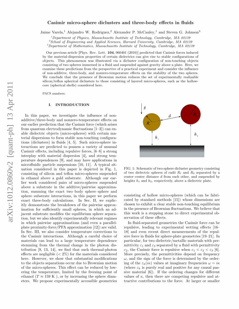
In this paper, we investigate the influence of non-additive/three-body and nonzero-temperature effects onour earlier prediction that the Casimir force (which arisesfrom quantum electrodynamic fluctuations [1–3]) can en-able dielectric objects (micro-spheres) with certain ma-terial dispersions to form stable non-touching configura-tions (diclusters) in fluids [4, 5]. Such micro-sphere in-teractions are predicted to possess a variety of unusualCasimir effects, including repulsive forces, [6–8] a stronginterplay with material dispersion [4], and strong tem-perature dependences [9], and may have applications inmicrofluidic particle suspensions [10, 11]. A typical sit-uation considered in this paper is depicted in Fig. 1,consisting of silicon and teflon micro-spheres suspendedin ethanol above a gold substrate. Although our ear-lier work considered pairs of micro-spheres suspendedabove a substrate in the additive/pairwise approxima-tion, summing the exact two–body sphere–sphere andsphere–substrate interactions, in this paper we performexact three-body calculations. In Sec. II, we explic-itly demonstrate the breakdown of the pairwise approx-imation for sufficiently small spheres, in which an ad-jacent substrate modifies the equilibrium sphere separa-tion, but we also identify experimentally relevant regimesin which pairwise approximations (and even a parallel-plate proximity-force/PFA approximation [12]) are valid.In Sec. III, we also consider temperature corrections tothe Casimir interactions. Although a careful choice ofmaterials can lead to a large temperature dependencestemming from the thermal change in the photon dis-tribution [9, 13, 14], we find that such thermal-photoneffects are negligible (< 2%) for the materials consideredhere. However, we show that substantial modificationsto the objects separations occur due to Brownian motionof the micro-spheres. This effect can be reduced by low-ering the temperature, limited by the freezing point ofethanol (T ≈ 159 K ), or by increasing the sphere diam-eters. We propose experimentally accessible geometries
R2
h 2h 1
R1
d
g
FIG. 1: Schematic of two-sphere dicluster geometry consistingof two dielectric spheres of radii R1 and R2 separated by acenter–center distance d from each other, and suspended byheights h1 and h2, respectively, above a dielectric plate.
consisting of hollow micro-spheres (which can be fabri-cated by standard methods [15]) whose dimensions arechosen to exhibit a clear stable non-touching equilibriumin the presence of Brownian fluctuations. We believe thatthis work is a stepping stone to direct experimental ob-servation of these effects.
In fluid-separated geometries the Casimir force can berepulsive, leading to experimental wetting effects [16–18] and even recent direct measurements of the repul-sive force in fluids for sphere-plate geometries [19–21]. Inparticular, for two dielectric/metallic materials with per-mittivity ε1 and ε3 separated by a fluid with permittivityε2, the Casimir force is repulsive when ε1 < ε2 < ε3 [6].More precisely, the permittivities depend on frequencyω, and the sign of the force is determined by the order-ing of the εk(iκ) values at imaginary frequencies ω = iκ(where εk is purely real and positive for any causal pas-sive material [6]). If the ordering changes for differentvalues of κ, then there are competing repulsive and at-tractive contributions to the force. At larger or smaller
arX
iv:1
012.
0860
v2 [
quan
t-ph
] 1
3 A
pr 2
011

2
separations, smaller or larger values of κ, respectively,dominate the contributions to the total force, and sothe force can change sign with separation. For exam-ple, if ε1 < ε2 < ε3 for large κ and ε1 < ε3 < ε2 forsmall κ, then the force may be repulsive for small sep-arations and attractive for large separations, leading toa stable equilibrium at an intermediate nonzero separa-tion. Alternatively, for a sphere–plate geometry in whichthe sphere is pulled downwards by gravity, a purely re-pulsive Casimir force (which dominates at small separa-tions) will also lead to a stable suspension. These ba-sic ideas were exploited in our previous work [4] to de-sign sphere–sphere and sphere–plate geometries exhibit-ing a stable non-touching configuration. The effects ofmaterial dispersion are further modified by an interplaywith geometric effects (which set additional length-scalesbeyond that of the separation), as well as by nonzero-temperature effects which set a Matsubara length-scale2πkT/~ [14] that can further interact with dispersion inorder to yield strong temperature corrections [9]. Ex-perimentally, stable suspensions are potentially appeal-ing in that one would be measuring static displacementsrather than force between micro-scale objects. The sta-ble configurations may be further modified, however, bythree-body effects in sphere–sphere–plate geometries andby Brownian motion of the particles within the potentialwell created by the Casimir interaction, and these effectsare studied in detail by the present paper.
Until the last few years, theoretical predictions ofCasimir forces were limited to a small set of simple ge-ometries (mainly planar geometries) amenable to analyti-cal solution, but a number of computational schemes haverecently been demonstrated that are capable of handlingcomplicated (and, in principle, arbitrary) geometries andmaterials [22–24]. Here, since the geometries consideredin this paper consist entirely of spheres and planes, we areable to adapt an existing technique [24] based on Fourier-like (“spectral”) expansions that semi-analytically ex-ploits the symmetries of this problem. This technique,formulated in terms of the scattering matrices of the ob-jects in a basis of spherical or plane waves, was developedin various forms by multiple authors [24–26], and we em-ploy the generalization of [24]. Although this processis described in detail elsewhere [24] and is reviewed forthe specific geometries of this paper in the appendix, thebasic idea of the calculation is as follows. The Casimirenergy can be expressed via path integrals as an integral∫∞
0log detA(κ)dκ over imaginary frequencies κ, where
A is a “T-matrix” related to the scattering matrix of thesystem. In particular, one needs to compute the scatter-ing matrices relating outgoing spherical waves from eachsphere (or planewaves from each plate) being reflectedinto outgoing spherical waves (or planewaves) from ev-ery other sphere (or plate), which can be expressed semi-analytically (as infinite series) by “translation matrices”that re-express a spherical wave (or planewave) with oneorigin in terms of spherical waves (or planewaves) aroundthe origin of the new object [24]. This formalism is exact
(no uncontrolled approximations) in the limit in whichan infinite number of spherical/plane waves is consid-ered. To obtain a finite matrix A, the number of spheri-cal waves (or spherical harmonics Y`m) is truncated to afinite order `. Because this expansion converges exponen-tially fast for spheres [24, 27], we find that ` ≤ 12 sufficesfor < 1% errors with the geometries in this paper. (Con-version from planewaves to spherical waves is performedby a semi-analytical formula [24] that involves integralsover all wavevectors, which was performed by a standardquadrature technique for semi-infinite integrals [28].) Al-though it is possible to differentiate log detA analyti-cally to obtain a trace expression for the force [23], inthis paper we use the simple expedient of computing theenergy and differentiating numerically via spline inter-polation. Previously, Ref. 29 employed the same for-malism in order to study a related geometry consistingof vacuum-separated perfect-metal spheres adjacent to aperfect-metal plate, where it was possible to employ themethod of images to reduce the computational complex-ity dramatically. That work found a three-body phe-nomenon in which the presence of a metallic plate re-sulted on a stronger attractive interaction between thespheres, and that this effect becomes more prominent atlarger separations [29], related to an earlier three-bodyeffect predicted for cylindrical shapes [30, 31]. Here, weexamine dielectric spheres and plate immersed in a fluidand therefore cannot exploit the method of images forsimplifying the calculation, which makes the calculationmuch more expensive because of the many oscillatoryintegrals that must be performed in order to convert be-tween planewaves (scattering off of the plate) and spher-ical waves (see appendix). We also obtain three-body ef-fects, in this case on the equilibrium separation distance,but find that the magnitude and sign of these effects de-pends strongly on the parameters of the problem.
II. THREE-BODY EFFECTS
To quantify the strength of three-body effects in thesphere–sphere–plate system of Fig. 1, we begin by com-puting how the zero–temperature equilibrium sphere–sphere separation d varies as a function of the sphere-plate separation h for two equal-radius spheres, as plottedin Fig. 2. To start with, we consider very small spheres,with radius R = 25 nm, for which the three-body effectsare substantial. The separation dh at a given h is normal-ized by d∞ (d as h→∞, i.e. in the absence of the plate).Several different material combinations are shown (whereX–Y –Z denotes spheres of materialsX and Y and a plateof material Z): polystyrene (PS), teflon (Tef), and sili-con (Si) spheres with gold (Au), teflon (Tef), and vacuum(air) plates (the latter corresponding to a fluid-gas inter-face). Depending on the material combinations, we findthat dh can either increase or decrease by as much as 15%as the plate is brought into proximity with the spheresfrom h = ∞ to h ≈ R. (We expect even larger devia-

3
0.5 1 1.5 2 2.5 3
0.5
0.6
0.7
0.8
0.9
1
1.1
1.2ed(∞
)ed(h
)/eq
uilib
rium
sepa
ratio
n
h
ed (h)
60 70 80 90 100 11070
74
78
82
86
90PS–Si–Au (R=57 nm)
ethanol
R R
ed(h
)nm
height h / ed (∞)
PS–Si–Au (R=25nm)Tef–Si–Au (R=25nm)
Tef–Si–Au (R=50nm)
PS–Si–Tef (R=25nm)
PS–Si–Au (R=25nm)
Tef–Si–Air (R=25nm)
FIG. 2: Equilibrium separation de(h)/de(∞) between twoR = 25nm spheres suspended in ethanol as a function of theirsurface–surface separation h from a plate (and normalized bythe equilibrium separation for the case of two isolated spheres,i.e. h = ∞). de is plotted for various material combinations,denoted by the designation sphere–sphere–plate, e.g. a PSand silicon sphere suspended above a gold plate is denoted asPS–Si–Au. Solid/dashed lines correspond to stable/unstableequilibria. (In the case of a gold plate, the spheres are chosento have R = 50nm.) The inset shows de (in units of nm) forthe case of two PS and silicon spheres (R = 57nm) above agold plate.
tions when h < R, but small separations are challengingfor this computational method [24] and our results forh ≥ R suffice here to characterize the general influenceof three-body effects.)
Interestingly, depending on the material combination,the dh can either increase or decrease as a function ofh: that is, the proximity of the plate can either in-crease or decrease the effective repulsion. This is quali-tatively similar to previous results for vacuum-separatedperfect-metal spheres/plates [29] in the following sense.Previously, the attractive interaction between a sphereand a plate was in general found to enhance the at-traction between two identical spheres as the plate be-came closer [29].(There are certain regimes, not presenthere, where the attractive interaction decreases) Here,we observe that the sphere–plate interaction changes thesphere–sphere interaction with the same sign as h be-comes smaller: if the sphere–plate interaction is repul-sive, the sphere–sphere interaction becomes more repul-sive (larger d), and vice-versa for an attractive sphere–plate interaction. Since the spheres are not identical, thethree-body effect is dominated by the sign of the strongersphere–plate interaction out of the two spheres. Thus,examining the signs and magnitudes of the pairwise in-teractions in all cases of Fig. 2 turns out to be sufficient topredict the sign of the three-body interaction, althoughwe have no proof that this is a general rule. (In contrast,for non-spherical objects such as cylinders, there can becompeting three-body effects that make the sign moredifficult to predict, even in vacuum-separated geometrieswhere all pairwise interactions are attractive, which caneven lead to a non-monotonic effect [30, 31].)
25 50 57 75 100 125
60
80
100
120
140
160
180
200
220
240
R RSi PS
de(∞)sepa
ratio
nd e(
∞)(
nm)
radius R (nm)
de(∞)R RSi Tef
0
Si-PS
Tef-SiR=57nmR=25nm
FIG. 3: Equilibrium separation de(∞) (units of nm) betweena Si sphere and either a teflon(Tef) or polystyrene(PS) sphereimmersed in ethanol as a function of their equivalent radii R.Solid/dashed lines denote stable/unstable equilibria.
Figure 2 also exhibits the interesting phenomenon ofbifurcations, in which stable equilibria (solid lines) andunstable equilibria (dashed lines) appear/disappear atsome critical h for certain materials and geometries,which is discussed in more detail in Sec. II A. As thesphere radius R increases, all of these three-body effectsrapidly decrease, eventually entering an additive regimein which three-body effects are negligible and in whicha parallel-plate/PFA approximation eventually becomesvalid, as described in Sec. II B.
A. Bifurcations
In the case of PS and Si spheres suspended above ei-ther a gold or teflon plate, one can observe the emer-gence or disappearance of a stable (solid) and unstable(dashed) pair of equilibria as h decreases from h = ∞,respectively, as evidenced by the blue curves in Fig. 2(teflon plate) and Fig. 2 (inset) (Au plate). This canbe qualitatively explained by the fact that the isolatedsphere–sphere interactions exhibit a natural bifurcationfor sufficiently-large spheres, in conjunction with the factthat the presence of the plate typically acts to either in-crease or decrease the sphere–sphere interaction, depend-ing on the sign of the dominant sphere–plate interaction,as explained above.
In particular, Fig. 3 shows the isolated Si–PS and Tef–Si sphere–sphere equilibrium separation de as a functionof the radius R of the spheres. As a consequence ofits material dispersion (similar to phenomena observedin [4]), the Si–PS combination exhibits a bifurcation atR ≈ 55 nm where the stable and unstable equilibria,such that there is no equilibrium for larger R (the in-teraction is purely attractive). The Tef–Si combinationexhibits no such bifurcation (even if we extend the plotto R = 300 nm), because it has no unstable equilibrium:the interaction is purely repulsive for small separationsand attractive for large separations. Therefore, if the Si–PS radius is above or below the 55 nm bifurcation, the

4
presence of the plate can shift this bifurcation and leadto a bifurcation as a function of h as in Fig. 2, whereasno such bifurcation with h appears for Tef–Si.
In the Si–PS–Au case of a gold plate with Si–PSspheres, the sphere–plate interactions turns out to beprimarily repulsive, which should push the bifurcationin Fig. 3 to the right (shrinking the attractive region)as h decreases. Correspondingly, if we choose a radiusR = 57 nm just to the right of isolated-sphere bifur-cation, then as h decreases the Si–PS–Au combinationshould push the bifurcation past R = 57 nm leading tothe creation of a stable/unstable pair for small h, andprecisely this behavior is observed in the inset of Fig. 2.Conversely, for the Si–PS–Tef case of a teflon plate withSi–PS spheres, the sphere–plate interaction is primarilyattractive, and the opposite behavior occurs: choosing aradius R = 25 nm to the left of the isolated-sphere bifur-cation, decreasing h increases the attraction and movesthe bifurcation to the left in Fig. 3, eventually causingthe disappearance of the stable/unstable equilibrium atR = 25 nm. Correspondingly, for the Si–PS–Tef curvein Fig. 2, we see the disappearance of a stable/unstablepair for sufficiently small h.
B. The additive regime
In general, three-body effects can expected to disap-pear in various regimes where key parameters of the in-teraction become small. First, for large radii, where h(the sphere–plate separation) and d (the sphere–sphereseparation) become small compared to R, eventually theCasimir interaction is dominated by nearest-surface in-teractions, or the proximity-force approximation (PFA),in which the force can be approximated by additivesurface–surface “parallel-plate” forces [12, 32, 33]. In or-der to damp the Brownian fluctuations as described inthe next section, we actually propose to use much larger(R > 5µm) spheres, and we quantify the accuracy ofPFA in this regime below. Second, as h becomes largecompared to d, the effect of the plate becomes negligi-ble and three-body effects disappear; this is apparent inFig. 2, where de → de(∞) when h de. Third, in thelimit where one of the spheres is much smaller than theother sphere, then the smaller sphere has a negligible ef-fect on the sphere–plate interaction of the larger sphere,and at least some of the three-body effect disappear asdescribed below. In fact, we find that even for a situa-tion in which one sphere is only a few times smaller thanthe other, the three-body effects tend to be negligible.For the sphere-radius regime considered in our previouswork, we argue below that equal-height suspension of thetwo spheres leads to a strong asymmetry in sphere radiithat tends to eliminate three-body effects.
To begin with, let us consider sphere radii on the orderof 102 nm, as in our previous work [4]. We wish to make abound dicluster, at some separation d, of two spheres (Siand teflon) that are suspended above a gold substrate
0 50 100 150 200 250 300 350 400100
200
300
400
500
600
radius R (nm)
equi
libri
umse
pera
tion
hor
L(n
m)
ee
Tef α = 1
Si α = 0.336
Si α = 0.7
Si α = 1
Au
Le he
R g
FIG. 4: Center–surface Le (solid lines) and surface–surface he
(dotted lines) equilibrium separation (units of nm) of a teflon(red) or Si hollowed sphere (shown on the inset) suspended inethanol above a gold plate, as a function of radius R (units ofnm). The equilibria are plotted for different values of the fill-fraction α, defined as the ratio of the spherical–shell thicknessover the radius of the sphere. Solid/dashed lines correspondto stable/unstable equilibria.
by Casimir repulsion in balance with gravity. Further-more, suppose that we wish to suspend both spheres atthe same equilibrium height he, and therefore choose theradii of the two spheres to equate their he values. InFig. 4, we plot he as a function of radius R for the iso-lated sphere–plate geometries (d → ∞). For example,with an Si sphere of radius R = 100 nm, the (stable)equilibrium height is he = 298.17 nm, whereas to ob-tain the same he value for teflon one needs a much largerteflon sphere of radius R = 217.2 nm, primarily becausethe Casimir repulsion is stronger for teflon. If, instead ofa pairwise calculation, we perform an exact three-bodycalculation of the he values for these radii at the equi-librium sphere–sphere separation de = 92.8 nm, we findthat the he values change by < 1%. Conversely, if wekeep he fixed and compute the three-body change in de(compared to h → ∞), again we find that the changeis < 1%. As mentioned above, the small size of theSi sphere makes it unsurprising that the Si sphere doesnot change the equilibrium he of the much larger teflonsphere. Furthermore, the sensitivity of the sphere–sphereforce Fd to the teflon h is equal to the sensitivity of theteflon sphere–plate force Fh to d, thanks to the equiva-lence ∂Fd/∂h = −∂2U/∂d∂h = ∂Fh/∂d where U is theenergy. Therefore, one would also not expect the finitevalue of he for the Si sphere to modify the equilibriumde. Size asymmetry alone, however, does not explainwhy the finite he of the teflon sphere does not affect thesphere-plate interactions of the Si sphere. Even if the Sisphere were of infinitesimal radius, the Casimir–Polderenergy the Si sphere would be determined by a Green’sfunction at the Si location [2], and if the Si sphere isat comparable distance de ∼ he from both the teflonplate and the sphere, one would in general expect the

5
response to a point-dipole source at the Si location (theGreen’s function) to depend non-additively on the teflonsphere and the plate even for an infinitesimal Si sphere.However, in the present case we do not observe any non-additive effect on the Si-sphere he, because the factorof three(approximately) difference between he and de isalready sufficient to eliminate three-body effects (as inFig. 2).
Figure 4 also exhibits a bifurcation of stable (solidlines) and unstable (dashed lines) equilibria that causesthe stable h equilibrium to vanish for Si at large radii.In order to utilize larger spheres to reduce the effects ofBrownian motion in the next section, one can consider in-stead a geometry of hollow air-filled spherical shells withouter radius R and shell thickness αR (so that α = 1gives a solid sphere). Such hollow microspheres are read-ily fabricated with a variety of materials [15]. As Fig. 4shows, decreasing the shell thickness α pushes the bi-furcation to larger R, and also increase he by makingthe sphere more buoyant. This modification allows usto consider R ≈ 10µm in the next section, where PFAshould be accurate. For only 3µm spheres and 500 nmseparations in fluids, we previously found that the cor-rection to PFA (which scales as d/R to lowest order [34–36]) was only about 15%. For the three times larger radiiand somewhat smaller separations in the next section thecorrections to PFA are typically < 5%, sufficient for ourcurrent purposes.
III. NONZERO TEMPERATURE ANDEXPERIMENTS
In this section, we address a number of questionsof consequence to an experimental realization of theteflon/silicon two-sphere dicluster of Fig. 1. In particu-lar, we consider several ways in which a nonzero temper-ature can disrupt the observation of stable equilibria. Anonzero temperature will manifest itself in at least twoimportant ways. First, there will be a change in theCasimir force between the objects due to the presenceof real (non-virtual) photons in the system. Second, theinclusion of nonzero temperature will cause the spheresto experience Brownian motion arising from the thermalagitations in the fluid [37]. We consider the influence ofboth of these effects on the observability of stable particleclusters and suspensions.
At zero temperature, the Casimir force F is determinedby an integral F =
∫∞0dξf(ξ) of a complicated integrand
f(ξ) evaluated at imaginary frequencies ξ [2]. At T > 0,the integral is replaced by a finite sum over Matsubarafrequencies ωn = 2πnkT/~, arising from the poles of thecoth photon distribution along the imaginary frequencyaxis [14, 38], leading to a force FT given by:
FT =2πkT
~
[f(0+)
2+
∞∑0
f
(2πkT
~n
)], (1)
Le
he
t=αR
g R
H
FIG. 5: Geometry of a hollow air–filled core sphere suspendedabove a layered plate with layer thicknessH. Explicitly shownis the thickness dimension as a function of α
which is exactly a trapezoidal-rule approximation to thezero-temperature force with a discretization error deter-mined by the Matsubara wavelength λT = 2πc/ξT =~/kT [39]. Because the integrand f(ξ) is smooth andtypically varies on a scale much slower than 1/λT , whereλT = 7.6µm at room temperature T = 300 K, the finite-T correction to the zero-temperature Casimir force isoften negligible [3]. However, in fluids, as is the casehere, larger temperature effects have been obtained [9]by dispersion-induced oscillations in f(ξ), and so we mustcheck our previous zero-temperature predictions againstfinite-T calculations. For the Tef–Si–Substrate case con-sidered here, we find that T > 0 corrections to the T = 0forces are no more than 2% over the entire range of sepa-rations considered here, and hence they can be neglected.
The presence of Brownian motion proves a much moredifficult experimental complication to overcome. First,Brownian motion will lead to random fluctuations in theposition of the spheres, making it hard to measure theirstable separations in an experiment [37]. Second, andmore importantly, sufficiently large fluctuations can drivethe Si sphere to “tunnel” past its unstable equilibriumposition with the gold plate, leading to stiction [37] sincethe Si–Au interaction is purely attractive for small sepa-rations. The remainder of this section will revolve aroundthe question of how and whether one can overcome bothof these difficulties to observe suspension in experiments.In particular, we consider observation of the average sep-aration of the spheres over a sufficiently long time, butnot so long that stiction occurs, and analyze the separa-tion statistics and the stiction timescale. First, however,we describe how the parameters are chosen so that Brow-nian fluctuations are not so severe.
The sphere geometry that we consider is depicted inFig. 5: a hollow spherical shell suspended by a surface–surface separation h above a layered substrate, consistingof a thin indium tin oxide (ITO) film of thickness H de-posited on a gold substrate, where the purpose of theITO layer is to eliminate the Si-sphere instability as ex-plained below. The thickness of the shell is denoted ast = αR, where α is a convenient fill-fraction parame-ter. We consider hollow spheres in order to increase R
6
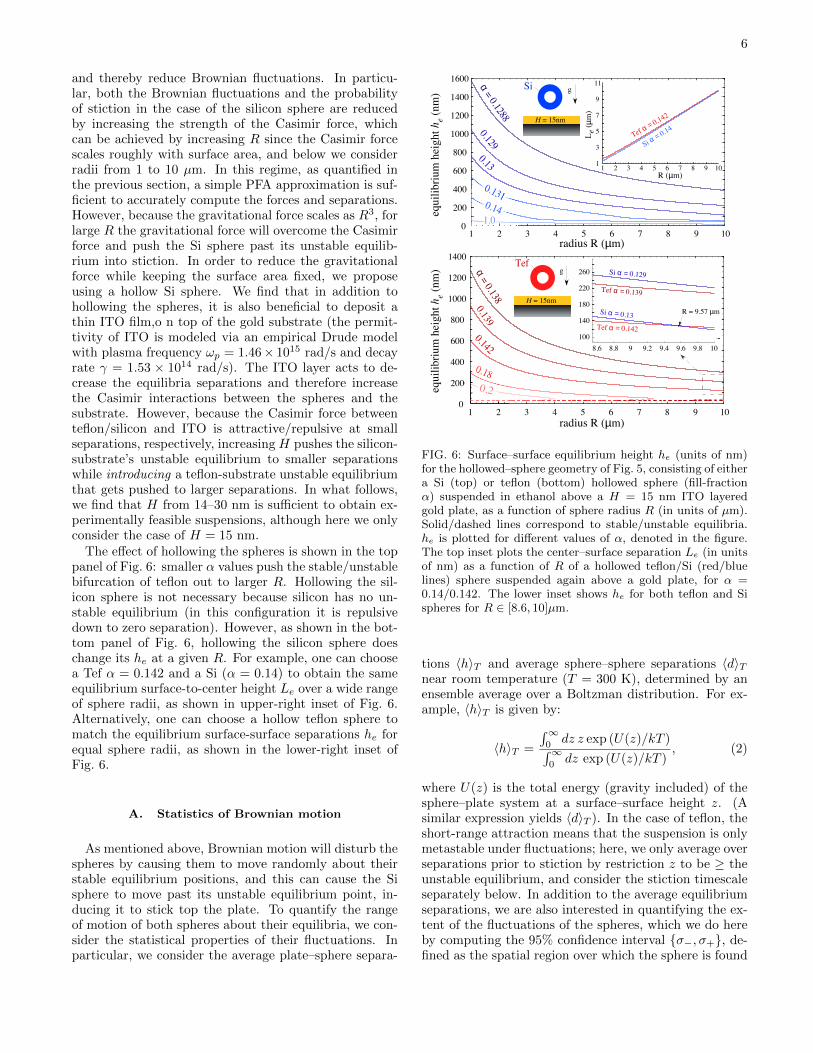
and thereby reduce Brownian fluctuations. In particu-lar, both the Brownian fluctuations and the probabilityof stiction in the case of the silicon sphere are reducedby increasing the strength of the Casimir force, whichcan be achieved by increasing R since the Casimir forcescales roughly with surface area, and below we considerradii from 1 to 10 µm. In this regime, as quantified inthe previous section, a simple PFA approximation is suf-ficient to accurately compute the forces and separations.However, because the gravitational force scales as R3, forlarge R the gravitational force will overcome the Casimirforce and push the Si sphere past its unstable equilib-rium into stiction. In order to reduce the gravitationalforce while keeping the surface area fixed, we proposeusing a hollow Si sphere. We find that in addition tohollowing the spheres, it is also beneficial to deposit athin ITO film,o n top of the gold substrate (the permit-tivity of ITO is modeled via an empirical Drude modelwith plasma frequency ωp = 1.46× 10¹⁵ rad/s and decayrate γ = 1.53 × 10¹⁴ rad/s). The ITO layer acts to de-crease the equilibria separations and therefore increasethe Casimir interactions between the spheres and thesubstrate. However, because the Casimir force betweenteflon/silicon and ITO is attractive/repulsive at smallseparations, respectively, increasing H pushes the silicon-substrate’s unstable equilibrium to smaller separationswhile introducing a teflon-substrate unstable equilibriumthat gets pushed to larger separations. In what follows,we find that H from 14–30 nm is sufficient to obtain ex-perimentally feasible suspensions, although here we onlyconsider the case of H = 15 nm.
The effect of hollowing the spheres is shown in the toppanel of Fig. 6: smaller α values push the stable/unstablebifurcation of teflon out to larger R. Hollowing the sil-icon sphere is not necessary because silicon has no un-stable equilibrium (in this configuration it is repulsivedown to zero separation). However, as shown in the bot-tom panel of Fig. 6, hollowing the silicon sphere doeschange its he at a given R. For example, one can choosea Tef α = 0.142 and a Si (α = 0.14) to obtain the sameequilibrium surface-to-center height Le over a wide rangeof sphere radii, as shown in upper-right inset of Fig. 6.Alternatively, one can choose a hollow teflon sphere tomatch the equilibrium surface-surface separations he forequal sphere radii, as shown in the lower-right inset ofFig. 6.
A. Statistics of Brownian motion
As mentioned above, Brownian motion will disturb thespheres by causing them to move randomly about theirstable equilibrium positions, and this can cause the Sisphere to move past its unstable equilibrium point, in-ducing it to stick top the plate. To quantify the rangeof motion of both spheres about their equilibria, we con-sider the statistical properties of their fluctuations. Inparticular, we consider the average plate–sphere separa-
0
200
400
600
800
1000
1200
1400
1 2 3 4 5 6 7 8 9 100
200
400
600
800
1000
1200
1400
1600
1 2 3 4 5 6 7 8 9 10
equi
libri
umhe
ight
h e(n
m)
equi
libri
umhe
ight
h e(n
m)
radius R (µm)
radius R (µm)
8.6 8.8 9 9.2 9.4 9.6 9.8 10
100
140
180
220
260
1 2 3 4 5 6 7 8 9 101
3
5
7
9
11
R (µm)
Le
(µm
)
Tefg
Si g
α=
0.138
0.1390.142
0.180.2
α=
0.1288
0.129
0.13
0.1310.141.0
Tef α = 0.139
Si α = 0.129
Tef α = 0.142
Tef α = 0.142
Si α = 0.14
Si α = 0.13 R = 9.57 µm
H = 15nm
H = 15nm
FIG. 6: Surface–surface equilibrium height he (units of nm)for the hollowed–sphere geometry of Fig. 5, consisting of eithera Si (top) or teflon (bottom) hollowed sphere (fill-fractionα) suspended in ethanol above a H = 15 nm ITO layeredgold plate, as a function of sphere radius R (in units of µm).Solid/dashed lines correspond to stable/unstable equilibria.he is plotted for different values of α, denoted in the figure.The top inset plots the center–surface separation Le (in unitsof nm) as a function of R of a hollowed teflon/Si (red/bluelines) sphere suspended again above a gold plate, for α =0.14/0.142. The lower inset shows he for both teflon and Sispheres for R ∈ [8.6, 10]µm.
tions 〈h〉T and average sphere–sphere separations 〈d〉Tnear room temperature (T = 300 K), determined by anensemble average over a Boltzman distribution. For ex-ample, 〈h〉T is given by:
〈h〉T =
∫∞0dz z exp (U(z)/kT )∫∞
0dz exp (U(z)/kT )
, (2)
where U(z) is the total energy (gravity included) of thesphere–plate system at a surface–surface height z. (Asimilar expression yields 〈d〉T ). In the case of teflon, theshort-range attraction means that the suspension is onlymetastable under fluctuations; here, we only average overseparations prior to stiction by restriction z to be ≥ theunstable equilibrium, and consider the stiction timescaleseparately below. In addition to the average equilibriumseparations, we are also interested in quantifying the ex-tent of the fluctuations of the spheres, which we do hereby computing the 95% confidence interval σ−, σ+, de-fined as the spatial region over which the sphere is found

7
2 3 4 5 6 7 8 9 101radius R (µm)
Si hSi he
Tefh
Tef he
RSi
1 2 3 4 5 6 7 8 9 100
100
200
300
400500600
700800
R (µm)
sepa
ratio
n(n
m)
de
equi
libri
umhe
ight
(nm
)
unstable0
250
750
1250
1750
2250
2750
he
RTef
he
RSi
RTef
de
d
FIG. 7: Average 〈h〉 (thick lines) and equilibrium he (thinlines) height (in units of nm) of a hollowed teflon/Si (blue/redlines) sphere suspended above a H = 15 nm ITO layeredgold plate, for α = 0.142/0.13, as a function of sphere ra-dius R (in units of µm). Solid/dashed lines correspond tostable/unstable equilibria. The red/blue shaded regions in-dicate positions where the teflon/Si spheres are found with95% probability. The inset shows 〈d〉 (thick line) and de (thinline) separations as a function of their radius for two equalradii teflon Si spheres. The gray shaded region indicate theseparations which the teflon and Si spheres are found with95% probability.
with 95% probability around the equilibria, where σ± de-notes the lower/upper bound of that interval. These re-sults are shown in Fig. 7 for h, with d shown in the inset,in which shaded regions indicate the confidence intervals,as a function of R where α is chosen to yield approxi-mately equal he (α = 0.142 for teflon and α = 0.13 forSi). (Note that the horizontal separation 〈d〉 is a purelyCasimir interaction and the difference here from α = 1 isnegligible in the PFA regime.) As predicted above, theBrownian fluctuations of the spheres vanish as R → ∞and are dramatically suppressed for R & 5µm, where onefinds 〈h〉 ≈ he. In addition, we find that the teflon spherecan safely avoid the unstable equilibrium and stiction inthe sense that the unstable equilibrium is far outside theconfidence interval; the timescale of the stiction processis quantified below. The asymmetrical nature of the con-fidence interval results from the fact that the Casimirenergy decreases as a function of z, and as a consequencethe Brownian excursions favor the +z direction. Thefluctuations in 〈d〉 are substantially larger than those in〈h〉 (nor is there any obvious reason why they should becomparable, given that the nature of the sphere–sphereequilibrium is completely different from the sphere–plateequilibrium), making the precise value of de potentiallyharder to observe.
Instead of considering the Brownian statistics as afunction of R, we can instead consider the statistics asa function of α for fixed radii ≈ 10µm (chosen to ob-tain nearly equal sphere-center heights Le), as shown inFig. 8. One key point is that there is a minimum allowedα: if α is too small, the buoyant force (assuming an air-
0.128 0.13 0.132 0.134 0.136 0.1380
50
100
150
200
250
300
0.14 0.145 0.15 0.155 0.160
50
100
150
200
250
300
Au
Si
ethanol
g
Au
teflon
ethanol
g
d = 152nmde = 87nm
fill-fraction α
fill-fraction α
Au
equi
libri
umse
para
tion
(nm
)eq
uilib
rium
sepa
ratio
n(n
m)
unstableforbidden
he
h
forbidden
he
h
FIG. 8: Average 〈h〉 (thick line) and equilibrium he (thinline) height (in units of nm) of a hollowed Si/teflon sphere(top/bottom) of radii R = 10/9.915µm suspended in ethanolabove a H = 15 nm ITO layered gold plate, as a function offill-fraction α (indicated in Fig. 5). Shaded regions indicateh positions where the Si/teflon spheres are found with 95%probability. Solid/dashed lines indicate stable/unstable equi-libria. For reference, we state the equilibrium de and average〈d〉 horizontal seperations between R = 10/9.915µm Si/Tefspheres in the top figure.
filled hollow sphere) will eventually become positive andthe sphere will float, although this limitation is removedif one could infiltrate the hollow sphere with the fluid.For the teflon sphere, there is also an upper limit to αfor a given R to avoid stiction as discussed previously.
B. Stiction and tunnelling rates
As mentioned above, the stable equilibrium for theteflon sphere is actually only metastable—because theCasimir force is attractive for small separations, given asufficiently long observation time τ the sphere will “tun-nel” (via Brownian fluctuations) past the energy barrier∆ posed by the unstable equilibrium, and stick to theplate (stiction). Given the energy barrier, the tempera-ture T , and the viscous drag on the particle, we can applystandard methods [37, 40, 41] to compute the timescale

8
1 2 3 4 5 6 7 8 9 100
10
20
30
40
50
60
70
Radius R (µm)
ener
gyba
rrie
r∆
/kT Tef α = 0.138
0.14
0.142
0.145
0.160.18Si α = 0.1288 (no ITO layer)
0 100 200 300 400
0
10
20
30
40
∆ / kTU
/kT
hu
he
h*
h (nm)
R = 10µmα = 0.142
FIG. 9: Energy barrier ∆/kT of a hollowed teflon spheresuspended in ethanol above a H = 15 nm ITO layered goldplate at T = 300 K, as a function of sphere radius R (inunits of µm) and for different values of fill-fraction α. Theinset shows the energy landscape U/kT as a function of thesurface–surface height h (units of nm) for a teflon sphere ofradius R = 10µm with a fill fraction of α = 0.142.
for stiction. This calculation, which is described in detailbelow, shows that for various values of the fill factor αthe expected time τ to stiction (which increases exponen-tially with ∆/kT ) can vary dramatically, but can easilybe made on the order of years.
The energy barrier ∆/kT is plotted versus the teflonsphere radius R for various α in Fig. 9, and can easilybe made > 10 to obtain a very long metastable lifetime.As we discussed earlier, the ∆ increases with R at firstbecause this increases the Casimir force, but has a max-imum at some R where gravity begins to dominate. De-creasing α decreases the gravitational force and thereforeincreases both the maximum ∆ and the corresponding R.A typical energy landscape U(z) is shown in the inset, ex-hibiting a local minimum at a height he and an unstableequilibrium (maximum) at hu. Also noted on the inset isthe “tunneling” height h∗ > he at which U(h∗) = U(hu).Figure 9 also shows the energy barrier ∆/kT of a sil-icon sphere (α = 0.1288 ≈ αc, R = 10 µm) in the ab-sence of the ITO layer (H = 0) to be significantly smallerthan that of teflon. Of course ∆/kT in this case couldbe made larger merely by choosing α ≈ αc, but we find(below) that achieving experimentally realizable lifetimesseverely limits the range of realizable α, i.e. requires thatthe Si thickness be known to within a few nanometers.
Because ∆ kT , the lifetime τ of a Brownian particletrapped around a local minimum of a potential U(z) canbe approximated by [40]:
τ = e∆/kT
[(1 +
γ
4ω2
)1/2
− γ
2ω
]−12π
Ωζ
(γS
kT
), (3)
where γ is the viscous drag coefficient (drag force =−γ velocity), ω and Ω characterize the curvature of U(z)at the energy maximum and minimum respectively [asdefined in Eq. (5)], ζ(δ) is a transcendental function de-fined in Eq. (6), and S is an integral of the potential
barrier defined by Eq. (4). Let m be the mass of thesphere. The drag coefficient for a sphere of radius R in afluid with viscosity η is γ = 6πRη/m [42], where a typicalviscosity is η ≈ 1.17 ± 0.06 mPas for ethanol [43]. Theother quantities are given by:
S = 2
∫ hc
hu
dz√−2mU(z) (4)
ω =
√U ′′(hu)
m; Ω =
√U ′′(he)
m(5)
ζ(δ) = exp
[− 2
π
∫ π/2
0
dz ln(
1− e−δ/4 cos2 z)]
. (6)
Combining these formulas and choosing different valuesof R and α to obtain different barriers ∆ and landscapesU(z) as in Fig. 9, the lifetime τ can be designed to takeon a wide range of values. The exponential dependenceon ∆ means that τ rapidly transitions from very shortto very long as α changes, but can easily be made large.For example, with R = 8.5µm and α < 0.15, one ob-tains τ > 40 days. (Conversely, for sufficiently large αone could design experiments where stiction occurs on anarbitrarily fast timescale, but in this ∆ ∼ kT regime theapproximations of Eq. (3) are no longer valid.)
Strictly speaking, this is a conservative estimate of thetimescale because the drag coefficient γ for a sphere abovea plate is larger than that of an isolated sphere. As thesphere approaches the plate, the drag is dominated bythe “lubrication” problem of the fluid squeezed betweenthe sphere and the plate, and the drag increases dramat-ically [44].
IV. CONCLUSION
Even including the thermal motion of the particles andthe finite lifetime of metastable suspensions, the stablesuspension and separation of particle diclusters appearsto be experimentally feasible. In the experimentally rel-evant regimes, these effects consist primarily of pairwisesphere–sphere and sphere–plate interactions; while three-body effects become significant for smaller spheres, theincreased Brownian fluctuations for small spheres makessuch an experiment challenging. Although the systemsconsidered here consisted of silicon and teflon spheresabove layered substrate in ethanol, many other materi-als combinations could potentially be explored to modifythese phenomena, including multi-material sphere sys-tems such as multi-layer spheres or patterned substratesthat could exhibit unusual effective dispersion phenom-ena. Although we considered hollow (air core) spheres,one could also use fluid-filled spheres or similar modifi-cations in order to modify the effect of gravity. Alter-natively, one could use non-spherical geometries such asdisks, which have a both surface area and volume propor-tional to R2 so that gravity does not dominate asymp-totically. We have recently demonstrated computational

9
methods capable of accurate modeling of such geome-tries, and find that the additional rotational degrees offreedom can lead to additional phenomena such as tran-sitions in the stable orientation with separation [45]. Ingeneral, the possibility of both repulsion and stable equi-libria in fluids (whereas the latter are not possible in vac-uum [46]but do exist in the critical casimir fluids [47, 48])opens the possibility of a rich and currently little exploredterritory for Casimir physics, and it is likely that manyeffects remain to be discovered.
Appendix
In what follows, we write down an expression for theCasimir energy of of the system in Fig. 1, in terms ofthe scattering and translation matrices of the individualobjects (spheres and plates) of the geometry. A simi-lar expression was derived in [29] in the case of perfect-metal vacuum-separated objects, for which an additionalsimplification, based on the method of images, was pos-sible [49]. Here, we consider the more general case offluid-separated dielectric objects.
The starting point of the Casimir-energy expressionis the well-known scattering-matrix formalism, derivedin [24, 25], in which the Casimir energy U between anarbitrary set of objects can be written as:
U =~c2π
∫ ∞0
dκ log detMM−1∞ , (7)
where M−1∞ = diag(F1,F2, ...) and the matrix M is given
by:
M =
F−11 X12 X13 ...
X21 F−12 X23 ...
... ... ... ...
, (8)
where Fi(κ) is the matrix of inside/outside scattering am-plitudes of the ith object, and Xij the translation matrixthat relates the scattering matrix of the ith and jth ob-jects, as described in [24]. Here, the plate is labeled bythe index i = 1 whereas the left and right spheres arelabeled as i = 2 and i = 3, respectively.
For computational convenience, the determinant inEq. (7) can be re-expressed in terms of standard oper-ations on the block matrices composing M, and in thiscase we find that:
detMM∞ = det(I −N (1)
)det(I −N (2)
)× det
(I −
(I−N (2)
)−1
A(I −N (1)
)−1
B),
where
N (2) = F3X31F1X13, A = F3X32 − F3X
31F1X12;
B = F2X23 − F2X
21F1X13, N (1) = F2X
21F1X12, (9)
where (I − N (1)) and (I − N (2)) yield the individualinteraction energies of the left and right spheres with theplate, respectively. Because of the logarithm in Eq. (7),it is possible to re-express the energy as:
U = E1(h1) + E2(h2) + Eint(h1, h2, d), (10)
where,
E1(h1) =~c2π
∫ ∞0
dκ log det(I −N (1)
)E2(h2) =
~c2π
∫ ∞0
dκ log det(I −N (2)
), (11)
are the individual interaction energies of the left (1) andright (2) spheres above a plate, in the absence of theother sphere, and Eint(h1, h2, d) is a three-body interac-tion term given by:
Eint =~c2π
∫dκ log det
[I −
(I−N (2)
)−1
× A(I −N (1)
)−1
B], (12)
Finally, for completeness, we write down simplified ex-pressions for the intermediate matrices N (i), A and B,in terms of appropriate and rapidly-converging multipoleand Fourier basis, as explained in [24]. The expressionfor E1,2 was derived in [24] and thus here we can simply
quote the result for the matrices N (1) and N (2). In par-ticular, [24] expresses the matrices in terms of a sphericalmultipole basis, indexed by the quantum numbers l, m,and P , corresponding to angular momentum, azithmutalangular momentum, and polarization [TE (P = E) orTM (P = M)]. The matrices N (i) are given by:
N (j)lmP,l′m′P ′ = δm,m′Fee(j)lmP,lmP
×∫ ∞
0
k⊥dk⊥2π
e−2hj
√k2⊥+κ2
2κ√k2⊥ + κ2
×∑Q
DlmP,k⊥QrQD†k⊥Q,l′m′P ′ (2δQ,P ′ − 1) ,
(13)
where k⊥ is the Fourier momentum parallel to the plate,
the Fee(j)lmP,lmP are the outside scattering amplitudes of
sphere j, rQ are the planar reflection coefficients (Fresnelreflection coefficients in the case of an isotropic plate),

10
and DlmP,k⊥mare conversion matrices:
DlmE,k⊥E = DlmM,k⊥M =
√4π(2l + 1)(l −m)!
l(l + 1)(l +m)!
× |k⊥|κ
e−imφk⊥P′ml
(√k2⊥ + κ2/κ
)DlmM,k⊥E = −DlmE,k⊥M = −im
√4π(2l + 1)(l −m)!
l(l + 1)(l +m)!
× κ
k⊥e−imφk⊥Pml
(√k2⊥ + κ2/κ
), (14)
given in terms of associated Legendre polynomials Pmland their derivatives with respect to their correspondingargument P
′ml .
Upon a number of algebraic manipulations, similar ex-pressions can be obtained for the matrices A and B, notfound in previous works, and in particular we find that:
−AlmP,l′m′P ′ = FeeR,lmP,lmPU23lmP,l′m′P ′
+ (−1)m′−m
im′−mFeeR,lmP,lmPβlmP,l′m′P ′
(15)
−BlmP,l′m′P ′ = FeeL,lmP,lmPU32lmP,l′m′P ′
+ im′−mFeeL,lmP,lmPβlmP.l′m′P ′ , (16)
where
βlmP,l′m′P ′ =
∫ ∞0
k⊥dk⊥(2π)
Jm′−m (Sk⊥)
× e−(h2+h3)√k2⊥+κ2
2κ√k2⊥ + κ2
×∑Q
DlmP,k⊥QrQD†k⊥Q,l′m′P ′ (2δQ,P ′ − 1) ,
(17)
and where the Jm(Sk⊥) is a Bessel function of the firstkind evaluated at different values of Sk⊥, where S is givenby the projection of the sphere center–center separationonto the plate axis:
S =√
(d+R1 +R2)2 − (h1 +R1 − h2 −R2)2 (18)
From a numerical perspective, all that remains in or-der to obtain the Casimir energy in Eq. (7) is to evalu-ate the various matrix entries and perform standard nu-merical operations, such as inversion and multiplication,which we perform using standard free software [50]. Forthe small matrices that we consider, most of the time isspent evaluating the various matrix elements, which canbe numerically expensive due to the integration of theoscillatory Bessel functions in A and B, although spe-cialized methods for oscillatory and Bessel integrals areavailable that may accelerate the calculation [51, 52].
[1] H. B. G. Casimir, Proc. K. Ned. Akad. Wet. 51, 793(1948).
[2] E. M. Lifshitz and L. P. Pitaevskii, Statistical Physics:Part 2 (Pergamon, Oxford, 1980).
[3] K. A. Milton, Journal of Physics A: Mathematical andGeneral 37, R209 (2004).
[4] A. W. Rodriguez, A. P. McCauley, D. Woolf, F. Capasso,J. D. Joannopoulos, and S. G. Johnson, Phys. Rev. Lett.104, 160402 (2010).
[5] A. W. Rodriguez, J. Munday, D. Davlit, F. Capasso, J. D.Joannopoulos, and S. G. Johnson, Phys. Rev. Lett. 101,190404 (2008).
[6] I. E. Dzyaloshinskiı, E. M. Lifshitz, and L. P. Pitaevskiı,Adv. Phys. 10, 165 (1961).
[7] J. Munday, F. Capasso, and V. A. Parsegia, Nature 457,170 (2009).
[8] O. Kenneth, I. Klich, A. Mann, and M. Revzen, Phys.Rev. Lett. 89, 033001 (2002).
[9] A. W. Rodriguez, D. Woolf, A. P. McCauley, F. Capasso,J. D. Joannopoulos, and S. G. Johnson, Phys. Rev. Lett.105, 060401 (2010).
[10] S. J. Rahi and S. Zaheer, arXiv:cond-mat/0909.4510v1(2009).
[11] A. P. McCauley, A. W. Rodriguez, J. D. Joannopoulos,and S. G. Johnson, Phys. Rev. A 81, 012119 (2010).
[12] B. V. Derjaguin, I. I. Abrikosova, and E. M. Lifshitz, Q.Rev. Chem. Soc. 10, 295 (1956), URL http://dx.doi.
org/10.1039/QR9561000295.[13] M. Bostrom and B. E. Sernelius, Phys. Rev. Lett. 84,
4757 (2000).[14] M. Bordag, B. Geyer, G. L. Klimchitskaya, and V. M.
Mostepanenko, Phys. Rev. Lett. 85, 503 (2000).[15] D. Wilcox, M. Berg, T. Bernat, D. Kellerman, and
J. Cochran, Hollow and Solid Spheres and Micro-spheres:Science and Technology Associated with TheirFabrication and Application, Vol 372 (Materials Re-

11
search Society, 1995).[16] D. Bonn, J. Eggers, J. Indekeu, J. Meunier, and E. Rolley,
Rev. Mod. Phys. 81, 739 (2009).[17] P.-G. d. Gennes, F. Brochard-Wyart, and D. Quere, Cap-
illarity and Wetting Phenomena: Drops, Bubbles, Pearls,Waves (Springer, 2004).
[18] J. N. Israelachvili, Intermolecular and Surface Forces (El-sevier, 2011).
[19] U. Mohideen and A. Roy, Phys. Rev. Lett. 81, 4549(1998).
[20] J. N. Munday and F. Capasso, Phys. Rev. A 75,060102(R) (2007).
[21] A. A. Feiler, L. Bergstrom, and M. W. Rut-land, Langmuir 24, 2274 (2008), pMID: 18278966,http://pubs.acs.org/doi/pdf/10.1021/la7036907, URLhttp://pubs.acs.org/doi/abs/10.1021/la7036907.
[22] A. Rodriguez, M. Ibanescu, D. Iannuzzi, J. D.Joannopoulos, and S. G. Johnson, Phys. Rev. A 76,032106 (2007).
[23] M. T. H. Reid, A. W. Rodriguez, J. White, and S. G.Johnson, Phys. Rev. Lett. 103, 040401 (2009).
[24] S. J. Rahi, T. Emig, R. L. Jaffe, and M. Kardar, Phys.Rev. D 80, 085021 (2009).
[25] T. Emig, N. Graham, R. L. Jaffe, and M. Kardar, Phys.Rev. Lett. 99, 170403 (2007).
[26] O. Kenneth and I. Klich, Phys. Rev. B 78, 014103 (2008).[27] A. Canaguier-Durand, P. A. Maia Neto, I. Cavero-Pelaez,
A. Lambrecht, and S. Reynaud, Phys. Rev. Lett. 102,230404 (2009).
[28] A. C. Genz and A. A. Malik, SIAM J. Numer. Anal. 20,580 (1983).
[29] P. Rodriguez-Lopez, S. J. Rahi, and T. Emig, Phys. Rev.A 80, 022519 (2009).
[30] S. J. Rahi, A. W. Rodriguez, T. Emig, R. L. Jaffe, S. G.Johnson, and M. Kardar, Phys. Rev. A 77, 030101(R)(2008).
[31] A. Rodriguez, M. Ibanescu, D. Iannuzzi, F. Capasso,J. D. Joannopoulos, and S. G. Johnson, Phys. Rev. Lett.99, 080401 (2007).
[32] M. Bordag, U. Mohideen, and V. M. Mostepanenko,Phys. Rep. 353, 1 (2001).
[33] H. Gies and K. Klingmuller, Phys. Rev. Lett. 96, 220401(2006).
[34] P. A. Maia Neto, A. Lambrecht, and S. Reynaud, Phys.
Rev. A 78, 012115 (2008).[35] M. Francisco D., L. Fernando C., and V. Paula I, Journal
of Physics: Conference Series 161, 012015 (2009).[36] H. Gies and K. Klingmuller, Phys. Rev. Lett. 96, 220401
(2006).[37] H. Risken, The Fokker-Plank Equation: Methods of Solu-
tion and Applications (Springer-Verlag, Heidelberg NewYork, 1996).
[38] J. Schwinger, L. L. DeRaad, and K. Milton, Ann. Phys.115, 1 (1978).
[39] J. P. Boyd, Chebychev and Fourier Spectral Methods(Dover, New York, 2001), 2nd ed.
[40] V. I. Mel’nikov, Physics Reports 209, 1 (1991),ISSN 0370-1573, URL http://www.sciencedirect.
com/science/article/B6TVP-46SXR6S-DN/2/
2738d111edbf3c995d7f494940a32cee.[41] S. Chandrasekhar, Rev. Mod. Phys. 15, 1 (1943).[42] L. D. Landau and E. M. Lifshitz, Fluid Mechanics (Perg-
amon Press, Elmsford, New York, 1987).[43] D. G. Friend and M. L. Huber, International Jour-
nal of Thermophysics 15, 1279 (1994), ISSN 0195-928X, 10.1007/BF01458836, URL http://dx.doi.org/
10.1007/BF01458836.[44] B. Hamrock, Fluid Film Lubrication (McGraw-Hill, New
York, 1994).[45] M. T. H. Reid, , J. White, and S. G. Johnson,
arXiv:1010.5539v1 (2010).[46] S. J. Rahi, M. Kardar, and T. Emig, Phys. Rev. Lett.
105, 070404 (2010).[47] M. Trondle, S. Kondrat, A. Gambassi, L. Harnau, and
S. Dietrich, J. Chem. Phys. 133, 074702 (2010).[48] T. F. Mohry, A. Macio lek, and S. Dietrich, Phys. Rev. E
81, 061117 (2010).[49] L. S. Brown and G. J. Maclay, Phys. Rev. 184, 1272
(1969).[50] R. K. S. Hankin, R News 6 (2006).[51] S. Xiang, J. Comput. Appl. Math. 206, 688 (2007), ISSN
0377-0427, URL http://portal.acm.org/citation.
cfm?id=1265610.1265788.[52] G. A. Evans and J. R. Webster, J. Comput. Appl. Math.
112, 55 (1999), ISSN 0377-0427, URL http://portal.
acm.org/citation.cfm?id=335447.335464.