cas-2700-24 sma modbus (rtu and tcp) / bacnet / html
TRANSCRIPT
©2014 Chipkin Automation Systems, 3381 Cambie St- Box 211, Vancouver, BC, Canada, V5Z 4R3
Tel: (866) 383-1657, Fax: (416) 915-4024
Email: [email protected] Website: www.chipkin.com
CAS-2700-24
SMA Gateway
Modbus / BACnet / HTML Gateway
CAS-2700-24
SMA
Modbus (RTU and TCP) / BACnet / HTML Gateway

2014© Chipkin Automation Systems, 3495 Cambie St. Unit211, Vancouver, BC, Canada, V5Z 4R3
Tel: (866) 383-1657, Fax: (416) 915-4024
Blank Page
CAS-2700-24 SMA Gateway Manual Page 3 of 62
2014© Chipkin Automation Systems, 3495 Cambie St. Unit211, Vancouver, BC, Canada, V5Z 4R3
Tel: (866) 383-1657, Fax: (416) 915-4024
TABLE OF CONTENTS
TABLE OF CONTENTS ..........................................................................................................................3
1. SMA Gateway Description ...........................................................................................................6
2. Connections ................................................................................................................................7
2.1. Block Diagram ................................................................................................................................. 7
2.2. Wiring / Connections ...................................................................................................................... 8
2.2.1. Modbus RTU Connections ....................................................................................................... 8
2.3. Limitations and Best Practices ........................................................................................................ 9
3. Configuration and Settings ........................................................................................................ 10
3.1. SMA Sunny Webbox Connection Settings .................................................................................... 10
3.2. SMA Sunny Webbox Configuration Options ................................................................................ 10
3.3. ModbusTCP Settings ..................................................................................................................... 11
3.4. ModbusRTU Settings .................................................................................................................... 11
3.5. BACnet IP Settings ........................................................................................................................ 12
3.6. Change Configuration Settings ..................................................................................................... 12
3.7. Adding SMA Devices ..................................................................................................................... 14
3.8. Configuration Tools ...................................................................................................................... 15
4. Reading Data using HTML / Web Browser .................................................................................. 16
5. Reading Modbus Data ............................................................................................................... 17
5.1. Modbus Function Supported (RTU and TCP) ................................................................................ 17
5.2. SMA Modbus Data Map ............................................................................................................... 17
CAS-2700-24 SMA Gateway Manual Page 4 of 62
2014© Chipkin Automation Systems, 3495 Cambie St. Unit211, Vancouver, BC, Canada, V5Z 4R3
Tel: (866) 383-1657, Fax: (416) 915-4024
5.3. Interpreting Modbus Data ............................................................................................................ 25
5.4. Test Procedure – Use CAS Modbus Scanner ................................................................................ 26
6. Reading BACnet Data ................................................................................................................ 29
6.1. Most Common BACnet Problem .................................................................................................. 29
6.2. Interpreting BACnet Data ............................................................................................................. 29
6.3. BACnet Objects ............................................................................................................................. 29
6.4. BACnet Test Procedure................................................................................................................. 38
7. Commissioning, Diagnostics and Trouble Shooting ..................................................................... 44
7.1. What to Take to Site for Commissioning ...................................................................................... 44
7.2. Gateway Status ............................................................................................................................. 48
7.3. Gateway Diagnostics .................................................................................................................... 48
7.4. Debug log. ..................................................................................................................................... 49
7.5. Veeder Device Connection ........................................................................................................... 51
7.6. Another Method for Changing the IP Address - DHCP ................................................................. 53
7.7. Discovering the Gateway .............................................................................................................. 54
7.8. Downloading New Firmware ........................................................................................................ 54
8. Specifications ............................................................................................................................ 56
9. SMA Enumerations .................................................................................................................... 57
9.1. SMA Invertor Data Enumerations ................................................................................................ 57
9.1.1. Mode ..................................................................................................................................... 57
9.1.2. Grid Type ............................................................................................................................... 57
9.1.3. Balancer................................................................................................................................. 57
CAS-2700-24 SMA Gateway Manual Page 5 of 62
2014© Chipkin Automation Systems, 3495 Cambie St. Unit211, Vancouver, BC, Canada, V5Z 4R3
Tel: (866) 383-1657, Fax: (416) 915-4024
9.1.4. Backup State .......................................................................................................................... 57
9.1.5. Error ....................................................................................................................................... 58
9.2. SMA Sunny Island Data Enumerations ......................................................................................... 59
9.2.1. Mode ..................................................................................................................................... 59
9.2.2. Invertor Operating State (InvOpStt) ...................................................................................... 59
9.2.3. Relay State (Rly1Stt, Rly2Stt) ................................................................................................. 59
9.2.4. Battery Charging Process (BatChrgOp) ................................................................................. 59
9.2.5. Absorption Phase (AptPhs) .................................................................................................... 59
9.2.6. GnDmdSrc .............................................................................................................................. 59
9.2.7. GnStatus ................................................................................................................................ 60
9.2.8. GnRnStatus ............................................................................................................................ 60
9.2.9. CHPStatus .............................................................................................................................. 60
9.2.10. Address (Adr) ..................................................................................................................... 60
9.2.11. Operating Status (OpStt) ................................................................................................... 60
9.2.12. Card Status (CardStt) ......................................................................................................... 61
9.2.13. Error ................................................................................................................................... 61
10. Revision History ..................................................................................................................... 62
CAS-2700-24 SMA Gateway Manual Page 6 of 62
2014© Chipkin Automation Systems, 3495 Cambie St. Unit211, Vancouver, BC, Canada, V5Z 4R3
Tel: (866) 383-1657, Fax: (416) 915-4024
1. SMA Gateway Description
The SMA Gateway connects to a SMA Sunny Webbox via an Ethernet (TCP/IP) connection. The SMA
Gateway can then be configured to poll for data values from a number of devices that are connected to
the Webbox. These devices can be Sunny Invertors, SensorBox, or Sunny Islands.
After configuration, the Gateway will poll and read the data from the SMA devices and stores it
internally. When a remote system requests data, this data is served in a form that is appropriate to the
requesting protocol (Modbus TCP/RTU or BACnet). In the event that the connection to the SMA
Webbox is lost, or data cannot be read, the gateway can signal this to the remote data clients by
changing all the values currently stored to a predefined default value.
The Gateway requires configuration that will be described later in this document.
CAS-2700-24 SMA Gateway Manual Page 7 of 62
2014© Chipkin Automation Systems, 3495 Cambie St. Unit211, Vancouver, BC, Canada, V5Z 4R3
Tel: (866) 383-1657, Fax: (416) 915-4024
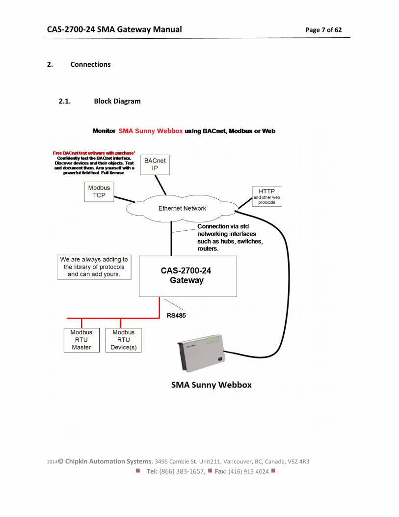
2. Connections
2.1. Block Diagram
CAS-2700-24 SMA Gateway Manual Page 8 of 62
2014© Chipkin Automation Systems, 3495 Cambie St. Unit211, Vancouver, BC, Canada, V5Z 4R3
Tel: (866) 383-1657, Fax: (416) 915-4024
2.2. Wiring / Connections
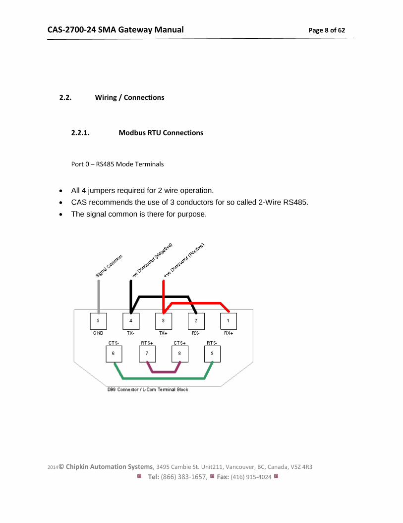
2.2.1. Modbus RTU Connections
Port 0 – RS485 Mode Terminals
All 4 jumpers required for 2 wire operation.
CAS recommends the use of 3 conductors for so called 2-Wire RS485.
The signal common is there for purpose.
CAS-2700-24 SMA Gateway Manual Page 9 of 62
2014© Chipkin Automation Systems, 3495 Cambie St. Unit211, Vancouver, BC, Canada, V5Z 4R3
Tel: (866) 383-1657, Fax: (416) 915-4024
2.3. Limitations and Best Practices
Maximum Number of SMA Sunny Webboxes per Gateway
Only 1 SMA Sunny Webbox can be connected to a single gateway.
RS232 Best Practices
We recommend a maximum of 30ft for the RS232 cable. A well-made cable in a clean environment
can easily run to 100ft and provide satisfactory performance.
CAS-2700-24 SMA Gateway Manual Page 10 of 62
2014© Chipkin Automation Systems, 3495 Cambie St. Unit211, Vancouver, BC, Canada, V5Z 4R3
Tel: (866) 383-1657, Fax: (416) 915-4024
3. Configuration and Settings
3.1. SMA Sunny Webbox Connection Settings
To poll for data from a Sunny Invertor, Sunny Island, or SensorBox all that is needed is the IP address
of the Sunny Webbox that these devices are connected to.
3.2. SMA Sunny Webbox Configuration Options
The following options are set to determine how the data from the SMA devices is handled.
- Night Data – SMA Invertors turn off at night. By enabling this option and selecting one of
the Night data methods, empty values will be replaced with either a zero value or the last
successfully polled value.
- Night Data Method
o Use Default Value – Uses the supplied default value to represent Invertor data at
night.
o Use Last Polled Values – Uses the last successfully polled Invertor data to represent
Invertor data at night. If no such data is available, the supplied default value is used.
- Default Value – The value that all points are set to initially and when the device is
disconnected or offline.
CAS-2700-24 SMA Gateway Manual Page 11 of 62
2014© Chipkin Automation Systems, 3495 Cambie St. Unit211, Vancouver, BC, Canada, V5Z 4R3
Tel: (866) 383-1657, Fax: (416) 915-4024
3.3. ModbusTCP Settings
To connect using ModbusTCP you need to know the IP address of the gateway and the Modbus
‘Station’ number (also known as ‘Device Address’ or ‘Node ID’) and the TCP Port for the
connection.
The following are the configurable parameters for this connection:
- Modbus Station Number (Default value is 1)
- Modbus TCP Port (Default value is 502)
Review section 7.6 Another Method for Changing the IP Address - DHCP to see the default IP
Address settings and how to change them.
3.4. ModbusRTU Settings
To connect using ModbusRTU you need to set the connection parameters correctly and the
Modbus ‘Station’ number (also known as ‘Device Address’ or ‘Node ID’)
- Modbus Station Number (Defaut value is 1)
- Connection Parameters:
o Baud Rate – 1200, 2400, 4800, 9600 (Default), 19200, 38400, 76800,
115200
o Data Bits – 8 (Default), 7
o Parity – None (Default), Odd, Even
o Stop Bits – 1 (Default), 2
CAS-2700-24 SMA Gateway Manual Page 12 of 62
2014© Chipkin Automation Systems, 3495 Cambie St. Unit211, Vancouver, BC, Canada, V5Z 4R3
Tel: (866) 383-1657, Fax: (416) 915-4024
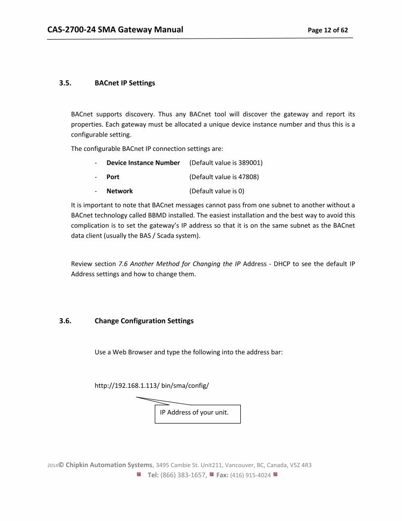
3.5. BACnet IP Settings
BACnet supports discovery. Thus any BACnet tool will discover the gateway and report its
properties. Each gateway must be allocated a unique device instance number and thus this is a
configurable setting.
The configurable BACnet IP connection settings are:
- Device Instance Number (Default value is 389001)
- Port (Default value is 47808)
- Network (Default value is 0)
It is important to note that BACnet messages cannot pass from one subnet to another without a
BACnet technology called BBMD installed. The easiest installation and the best way to avoid this
complication is to set the gateway’s IP address so that it is on the same subnet as the BACnet
data client (usually the BAS / Scada system).
Review section 7.6 Another Method for Changing the IP Address - DHCP to see the default IP
Address settings and how to change them.
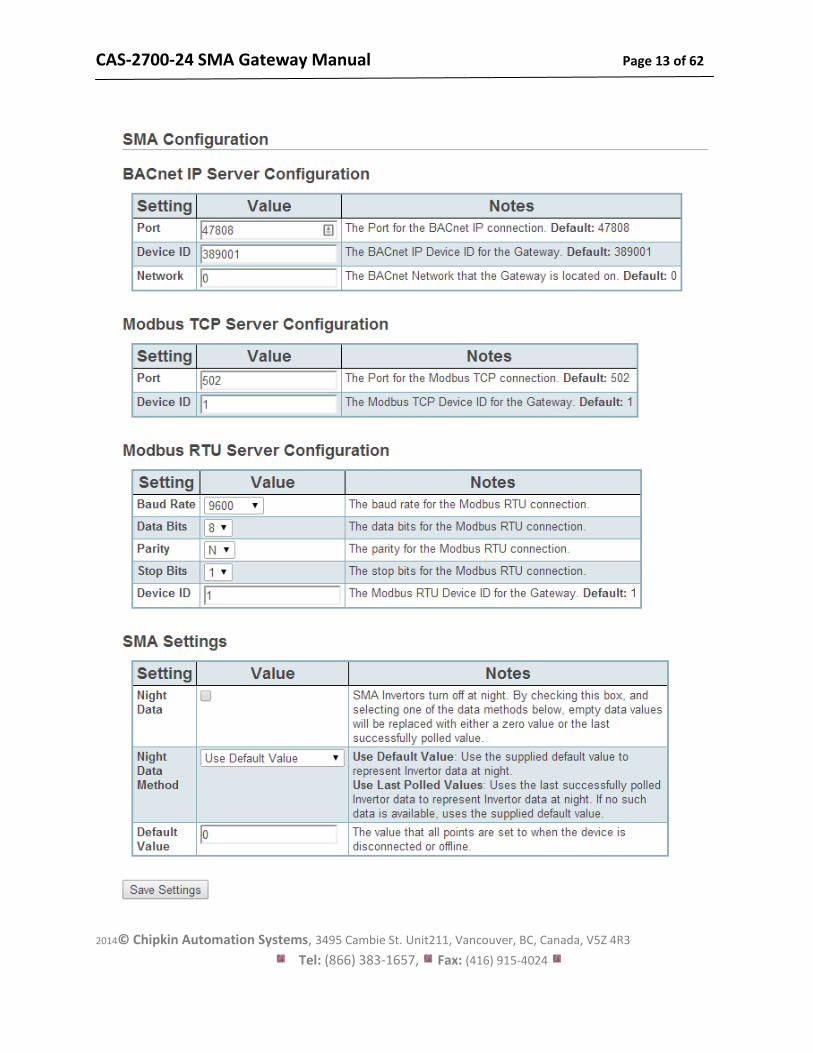
3.6. Change Configuration Settings
Use a Web Browser and type the following into the address bar:
http://192.168.1.113/ bin/sma/config/
IP Address of your unit.
CAS-2700-24 SMA Gateway Manual Page 13 of 62
2014© Chipkin Automation Systems, 3495 Cambie St. Unit211, Vancouver, BC, Canada, V5Z 4R3
Tel: (866) 383-1657, Fax: (416) 915-4024
CAS-2700-24 SMA Gateway Manual Page 14 of 62
2014© Chipkin Automation Systems, 3495 Cambie St. Unit211, Vancouver, BC, Canada, V5Z 4R3
Tel: (866) 383-1657, Fax: (416) 915-4024
Change the Settings and click Submit to save them. To cancel changes simply close the
page without submitting.
Note on IP Addresses: Another method is provided to change the Netmask and Gateway
address.
Changes do not take effect until the device restarts. Use the Reset button the web page
or recycle the power.
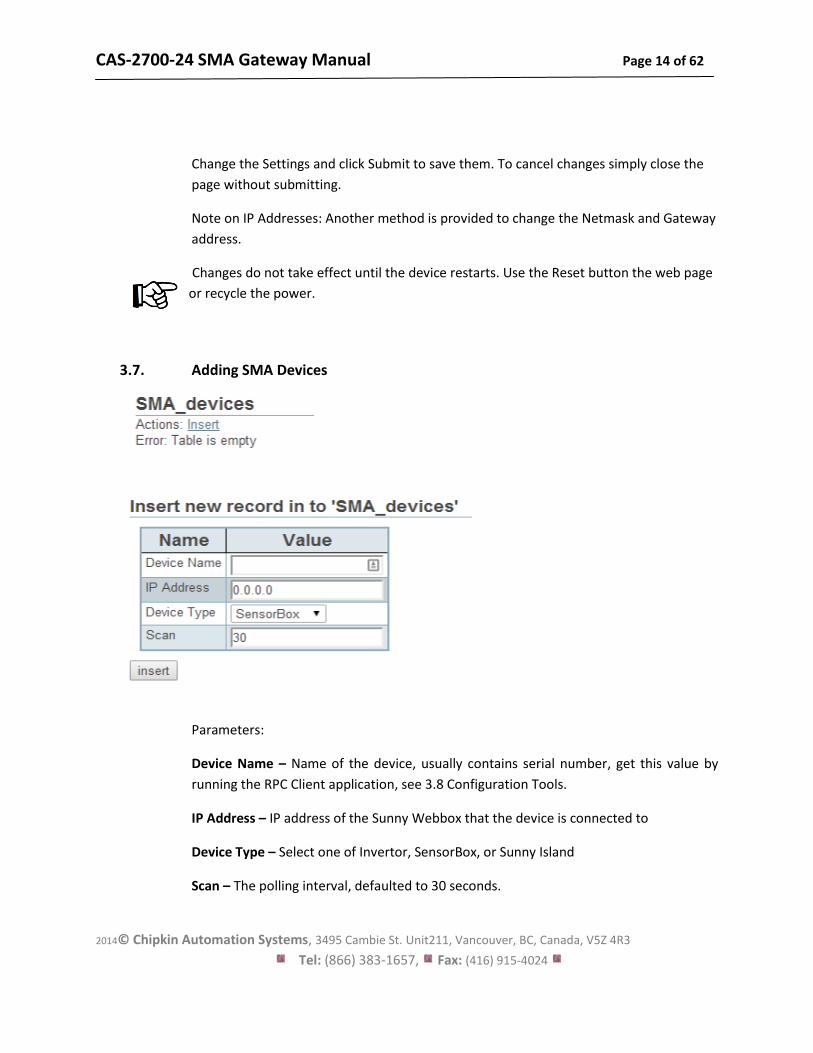
3.7. Adding SMA Devices
Parameters:
Device Name – Name of the device, usually contains serial number, get this value by
running the RPC Client application, see 3.8 Configuration Tools.
IP Address – IP address of the Sunny Webbox that the device is connected to
Device Type – Select one of Invertor, SensorBox, or Sunny Island
Scan – The polling interval, defaulted to 30 seconds.
CAS-2700-24 SMA Gateway Manual Page 15 of 62
2014© Chipkin Automation Systems, 3495 Cambie St. Unit211, Vancouver, BC, Canada, V5Z 4R3
Tel: (866) 383-1657, Fax: (416) 915-4024
3.8. Configuration Tools
In order to complete the configuration process, the names and serial numbers of the SMA devices
are needed.
There is a tool that is required to get this information called the RPC Client.
Please contact Chipkin Automation Systems to get access to this tool and for help with
configuration.
CAS-2700-24 SMA Gateway Manual Page 16 of 62
2014© Chipkin Automation Systems, 3495 Cambie St. Unit211, Vancouver, BC, Canada, V5Z 4R3
Tel: (866) 383-1657, Fax: (416) 915-4024
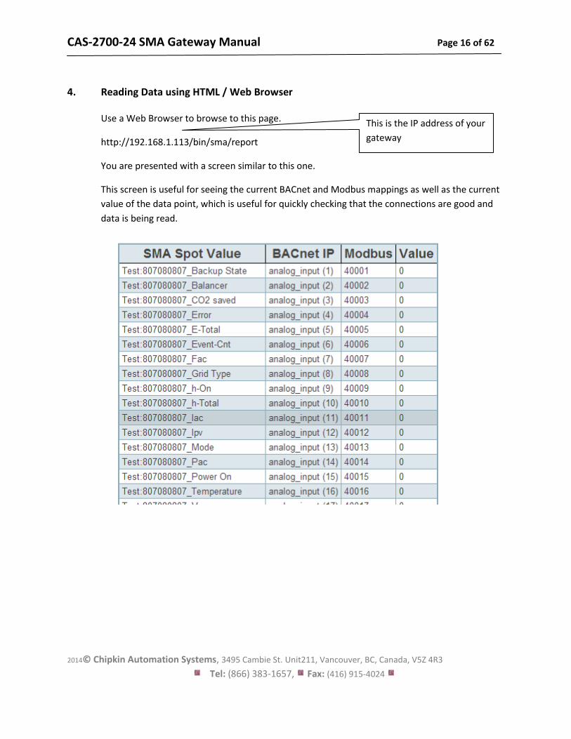
4. Reading Data using HTML / Web Browser
Use a Web Browser to browse to this page.
http://192.168.1.113/bin/sma/report
You are presented with a screen similar to this one.
This screen is useful for seeing the current BACnet and Modbus mappings as well as the current
value of the data point, which is useful for quickly checking that the connections are good and
data is being read.
This is the IP address of your
gateway
CAS-2700-24 SMA Gateway Manual Page 17 of 62
2014© Chipkin Automation Systems, 3495 Cambie St. Unit211, Vancouver, BC, Canada, V5Z 4R3
Tel: (866) 383-1657, Fax: (416) 915-4024
5. Reading Modbus Data
Need to know more about Modbus? Read this guide.
http://www.chipkin.com/september-2010-newsletter
5.1. Modbus Function Supported (RTU and TCP)
The Gateway supports functions 1, 2, 3, and 4. Most masters should be configured to use
function 3 (Read Holding Registers). However it will respond to polls that use the other functions
with offset equal to zero. You can read this data as 3xxxx, 1xxxx, 0xxxx or 4xxxx data.
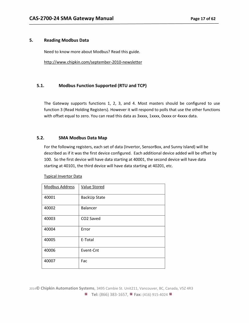
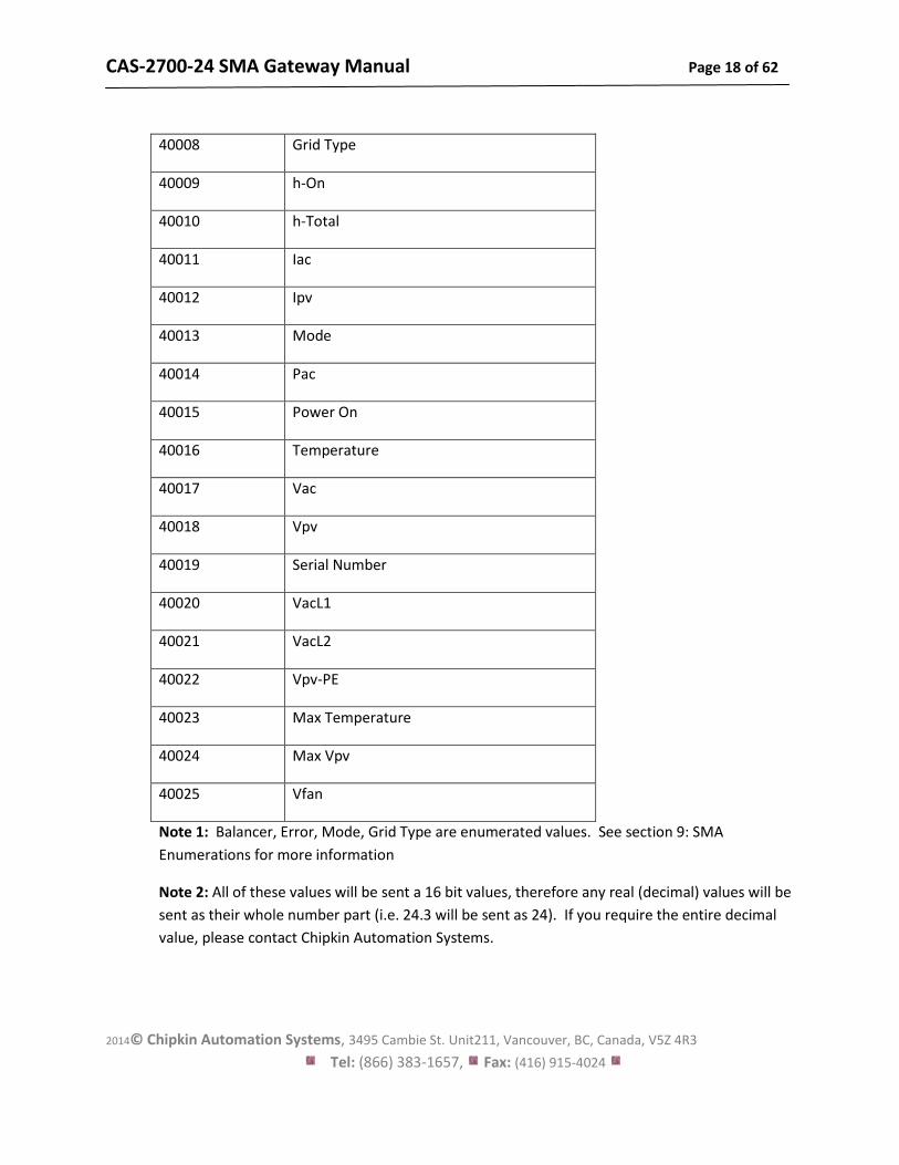
5.2. SMA Modbus Data Map
For the following registers, each set of data (Invertor, SensorBox, and Sunny Island) will be
described as if it was the first device configured. Each additional device added will be offset by
100. So the first device will have data starting at 40001, the second device will have data
starting at 40101, the third device will have data starting at 40201, etc.
Typical Invertor Data
Modbus Address Value Stored
40001 BackUp State
40002 Balancer
40003 CO2 Saved
40004 Error
40005 E-Total
40006 Event-Cnt
40007 Fac
CAS-2700-24 SMA Gateway Manual Page 18 of 62
2014© Chipkin Automation Systems, 3495 Cambie St. Unit211, Vancouver, BC, Canada, V5Z 4R3
Tel: (866) 383-1657, Fax: (416) 915-4024
40008 Grid Type
40009 h-On
40010 h-Total
40011 Iac
40012 Ipv
40013 Mode
40014 Pac
40015 Power On
40016 Temperature
40017 Vac
40018 Vpv
40019 Serial Number
40020 VacL1
40021 VacL2
40022 Vpv-PE
40023 Max Temperature
40024 Max Vpv
40025 Vfan
Note 1: Balancer, Error, Mode, Grid Type are enumerated values. See section 9: SMA
Enumerations for more information
Note 2: All of these values will be sent a 16 bit values, therefore any real (decimal) values will be
sent as their whole number part (i.e. 24.3 will be sent as 24). If you require the entire decimal
value, please contact Chipkin Automation Systems.
CAS-2700-24 SMA Gateway Manual Page 19 of 62
2014© Chipkin Automation Systems, 3495 Cambie St. Unit211, Vancouver, BC, Canada, V5Z 4R3
Tel: (866) 383-1657, Fax: (416) 915-4024
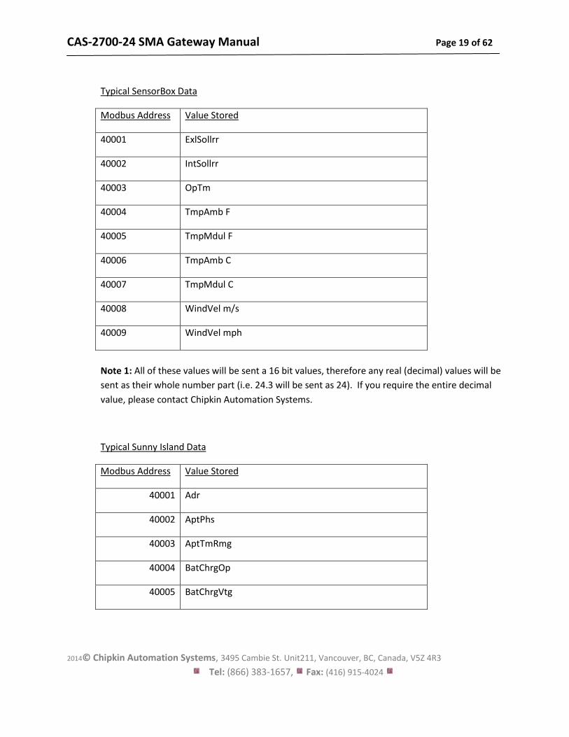
Typical SensorBox Data
Modbus Address Value Stored
40001 ExlSollrr
40002 IntSollrr
40003 OpTm
40004 TmpAmb F
40005 TmpMdul F
40006 TmpAmb C
40007 TmpMdul C
40008 WindVel m/s
40009 WindVel mph
Note 1: All of these values will be sent a 16 bit values, therefore any real (decimal) values will be
sent as their whole number part (i.e. 24.3 will be sent as 24). If you require the entire decimal
value, please contact Chipkin Automation Systems.
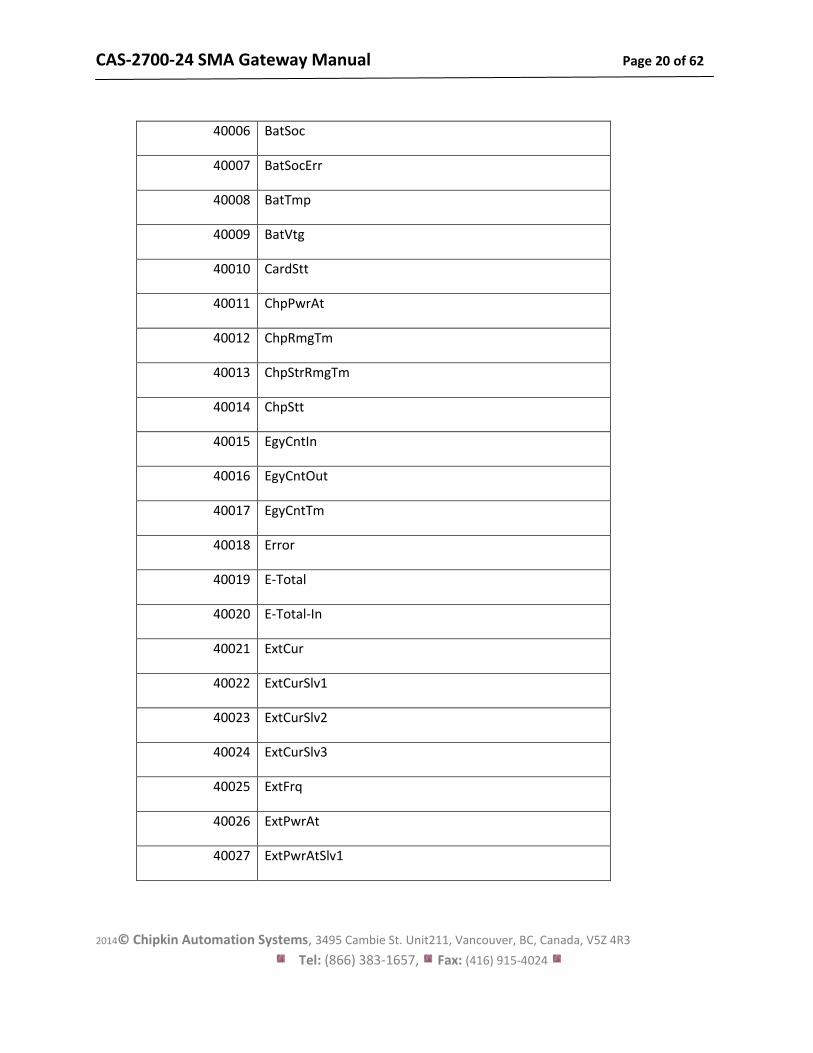
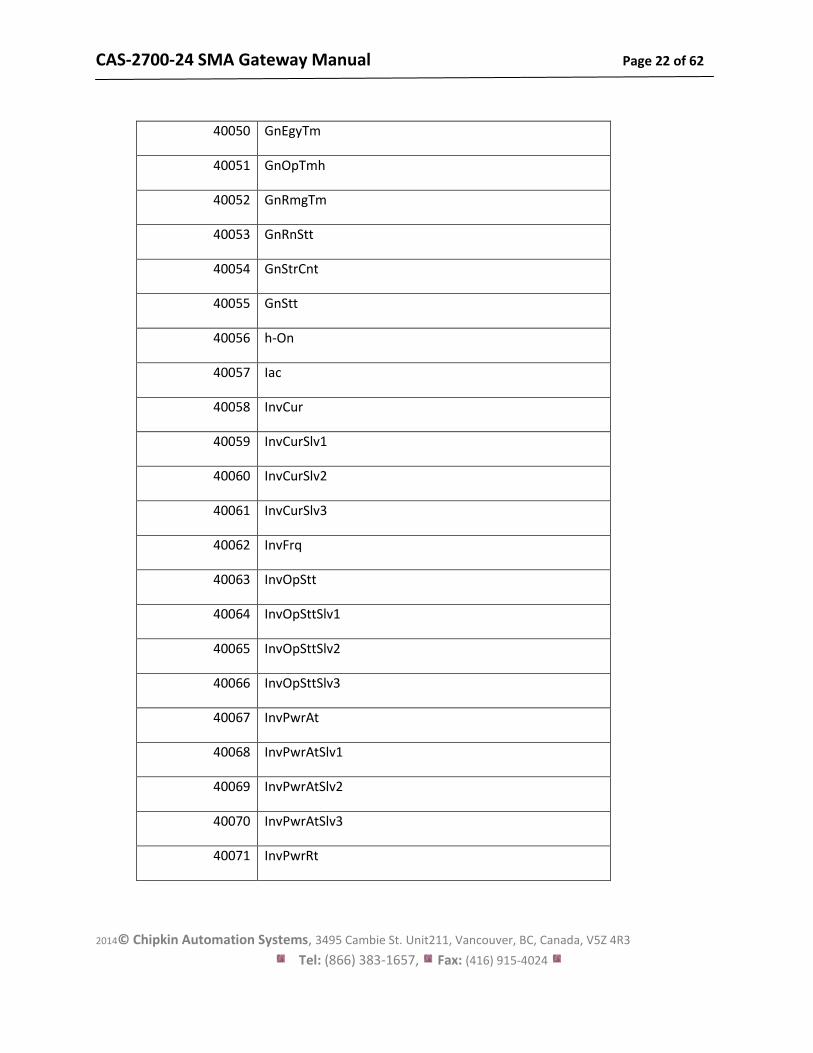
Typical Sunny Island Data
Modbus Address Value Stored
40001 Adr
40002 AptPhs
40003 AptTmRmg
40004 BatChrgOp
40005 BatChrgVtg
CAS-2700-24 SMA Gateway Manual Page 20 of 62
2014© Chipkin Automation Systems, 3495 Cambie St. Unit211, Vancouver, BC, Canada, V5Z 4R3
Tel: (866) 383-1657, Fax: (416) 915-4024
40006 BatSoc
40007 BatSocErr
40008 BatTmp
40009 BatVtg
40010 CardStt
40011 ChpPwrAt
40012 ChpRmgTm
40013 ChpStrRmgTm
40014 ChpStt
40015 EgyCntIn
40016 EgyCntOut
40017 EgyCntTm
40018 Error
40019 E-Total
40020 E-Total-In
40021 ExtCur
40022 ExtCurSlv1
40023 ExtCurSlv2
40024 ExtCurSlv3
40025 ExtFrq
40026 ExtPwrAt
40027 ExtPwrAtSlv1
CAS-2700-24 SMA Gateway Manual Page 21 of 62
2014© Chipkin Automation Systems, 3495 Cambie St. Unit211, Vancouver, BC, Canada, V5Z 4R3
Tel: (866) 383-1657, Fax: (416) 915-4024
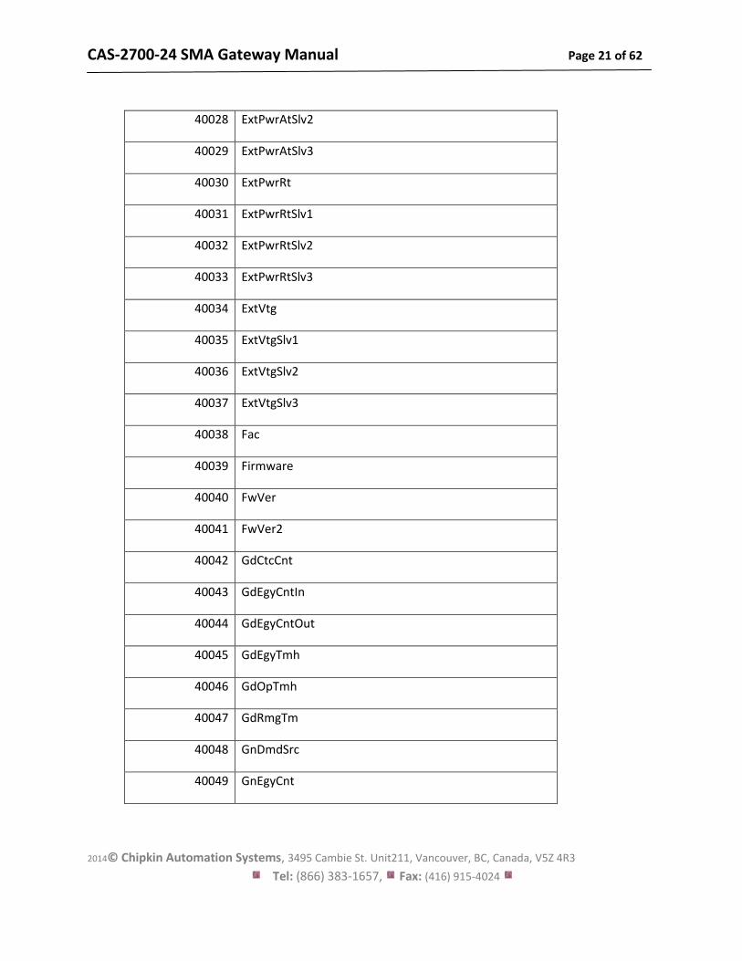
40028 ExtPwrAtSlv2
40029 ExtPwrAtSlv3
40030 ExtPwrRt
40031 ExtPwrRtSlv1
40032 ExtPwrRtSlv2
40033 ExtPwrRtSlv3
40034 ExtVtg
40035 ExtVtgSlv1
40036 ExtVtgSlv2
40037 ExtVtgSlv3
40038 Fac
40039 Firmware
40040 FwVer
40041 FwVer2
40042 GdCtcCnt
40043 GdEgyCntIn
40044 GdEgyCntOut
40045 GdEgyTmh
40046 GdOpTmh
40047 GdRmgTm
40048 GnDmdSrc
40049 GnEgyCnt
CAS-2700-24 SMA Gateway Manual Page 22 of 62
2014© Chipkin Automation Systems, 3495 Cambie St. Unit211, Vancouver, BC, Canada, V5Z 4R3
Tel: (866) 383-1657, Fax: (416) 915-4024
40050 GnEgyTm
40051 GnOpTmh
40052 GnRmgTm
40053 GnRnStt
40054 GnStrCnt
40055 GnStt
40056 h-On
40057 Iac
40058 InvCur
40059 InvCurSlv1
40060 InvCurSlv2
40061 InvCurSlv3
40062 InvFrq
40063 InvOpStt
40064 InvOpSttSlv1
40065 InvOpSttSlv2
40066 InvOpSttSlv3
40067 InvPwrAt
40068 InvPwrAtSlv1
40069 InvPwrAtSlv2
40070 InvPwrAtSlv3
40071 InvPwrRt
CAS-2700-24 SMA Gateway Manual Page 23 of 62
2014© Chipkin Automation Systems, 3495 Cambie St. Unit211, Vancouver, BC, Canada, V5Z 4R3
Tel: (866) 383-1657, Fax: (416) 915-4024
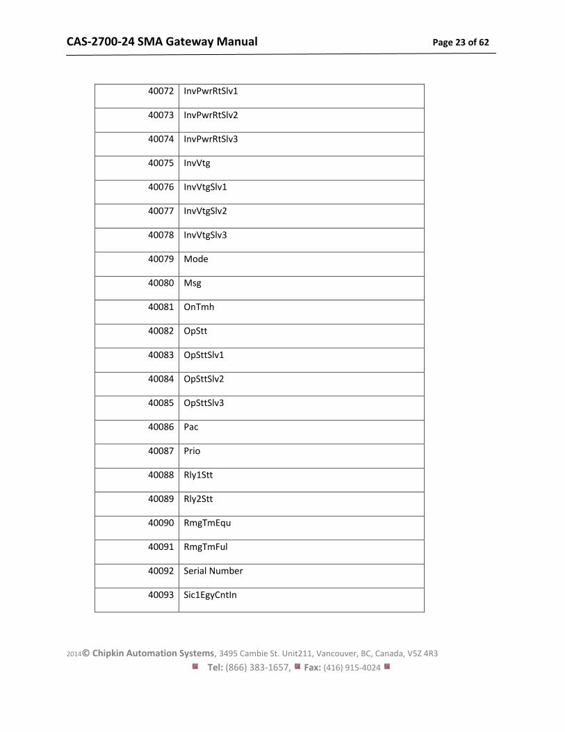
40072 InvPwrRtSlv1
40073 InvPwrRtSlv2
40074 InvPwrRtSlv3
40075 InvVtg
40076 InvVtgSlv1
40077 InvVtgSlv2
40078 InvVtgSlv3
40079 Mode
40080 Msg
40081 OnTmh
40082 OpStt
40083 OpSttSlv1
40084 OpSttSlv2
40085 OpSttSlv3
40086 Pac
40087 Prio
40088 Rly1Stt
40089 Rly2Stt
40090 RmgTmEqu
40091 RmgTmFul
40092 Serial Number
40093 Sic1EgyCntIn
CAS-2700-24 SMA Gateway Manual Page 24 of 62
2014© Chipkin Automation Systems, 3495 Cambie St. Unit211, Vancouver, BC, Canada, V5Z 4R3
Tel: (866) 383-1657, Fax: (416) 915-4024
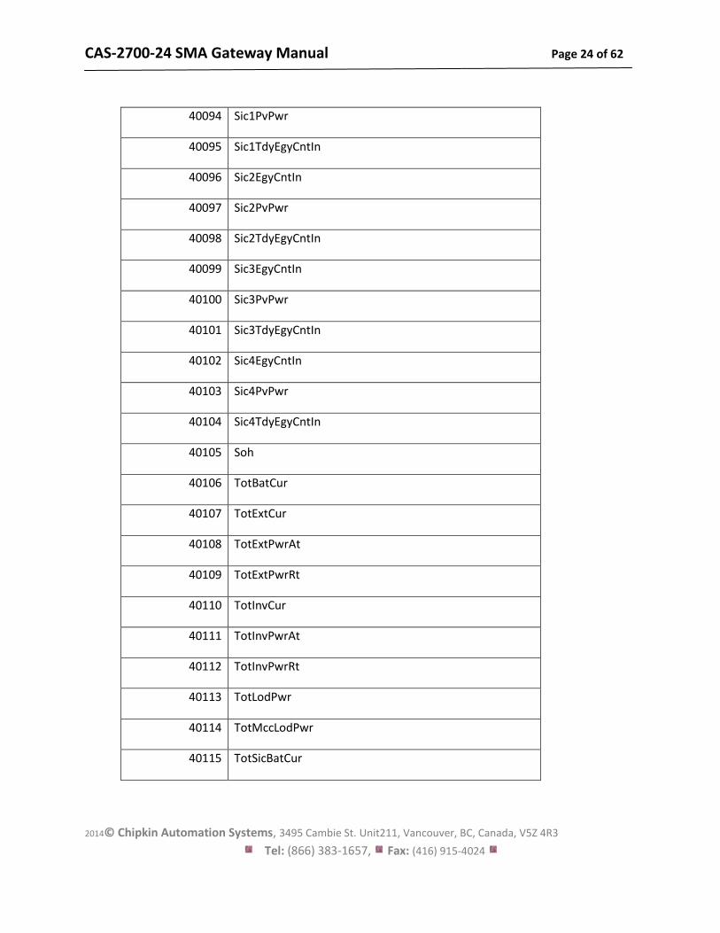
40094 Sic1PvPwr
40095 Sic1TdyEgyCntIn
40096 Sic2EgyCntIn
40097 Sic2PvPwr
40098 Sic2TdyEgyCntIn
40099 Sic3EgyCntIn
40100 Sic3PvPwr
40101 Sic3TdyEgyCntIn
40102 Sic4EgyCntIn
40103 Sic4PvPwr
40104 Sic4TdyEgyCntIn
40105 Soh
40106 TotBatCur
40107 TotExtCur
40108 TotExtPwrAt
40109 TotExtPwrRt
40110 TotInvCur
40111 TotInvPwrAt
40112 TotInvPwrRt
40113 TotLodPwr
40114 TotMccLodPwr
40115 TotSicBatCur
CAS-2700-24 SMA Gateway Manual Page 25 of 62
2014© Chipkin Automation Systems, 3495 Cambie St. Unit211, Vancouver, BC, Canada, V5Z 4R3
Tel: (866) 383-1657, Fax: (416) 915-4024
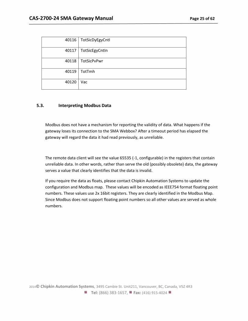
40116 TotSicDyEgyCntI
40117 TotSicEgyCntIn
40118 TotSicPvPwr
40119 TotTmh
40120 Vac
5.3. Interpreting Modbus Data
Modbus does not have a mechanism for reporting the validity of data. What happens if the
gateway loses its connection to the SMA Webbox? After a timeout period has elapsed the
gateway will regard the data it had read previously, as unreliable.
The remote data client will see the value 65535 (-1, configurable) in the registers that contain
unreliable data. In other words, rather than serve the old (possibly obsolete) data, the gateway
serves a value that clearly identifies that the data is invalid.
If you require the data as floats, please contact Chipkin Automation Systems to update the
configuration and Modbus map. These values will be encoded as IEEE754 format floating point
numbers. These values use 2x 16bit registers. They are clearly identified in the Modbus Map.
Since Modbus does not support floating point numbers so all other values are served as whole
numbers.
CAS-2700-24 SMA Gateway Manual Page 26 of 62
2014© Chipkin Automation Systems, 3495 Cambie St. Unit211, Vancouver, BC, Canada, V5Z 4R3
Tel: (866) 383-1657, Fax: (416) 915-4024
5.4. Test Procedure – Use CAS Modbus Scanner
You can test the ModbusTCP data using free test software provided by Chipkin
Automation Software.
This is a link to the download page. http://www.chipkin.com/cas-modbus-scanner
Configure the scanner as follows
1. Add a connection – specify the IP address of the gateway
2. Add a device to the connection. Set the device=1
3. Add a Request to the device: Read Holding register offset=1 Length=68
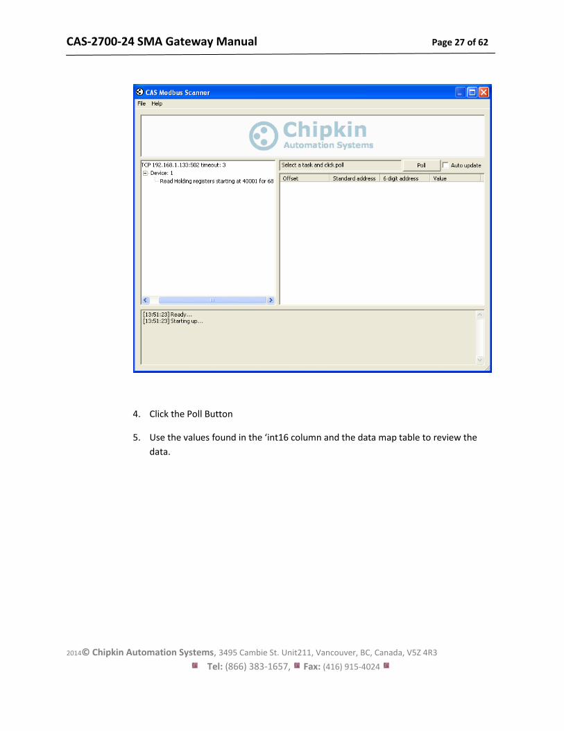
The result should be like this.
CAS-2700-24 SMA Gateway Manual Page 27 of 62
2014© Chipkin Automation Systems, 3495 Cambie St. Unit211, Vancouver, BC, Canada, V5Z 4R3
Tel: (866) 383-1657, Fax: (416) 915-4024
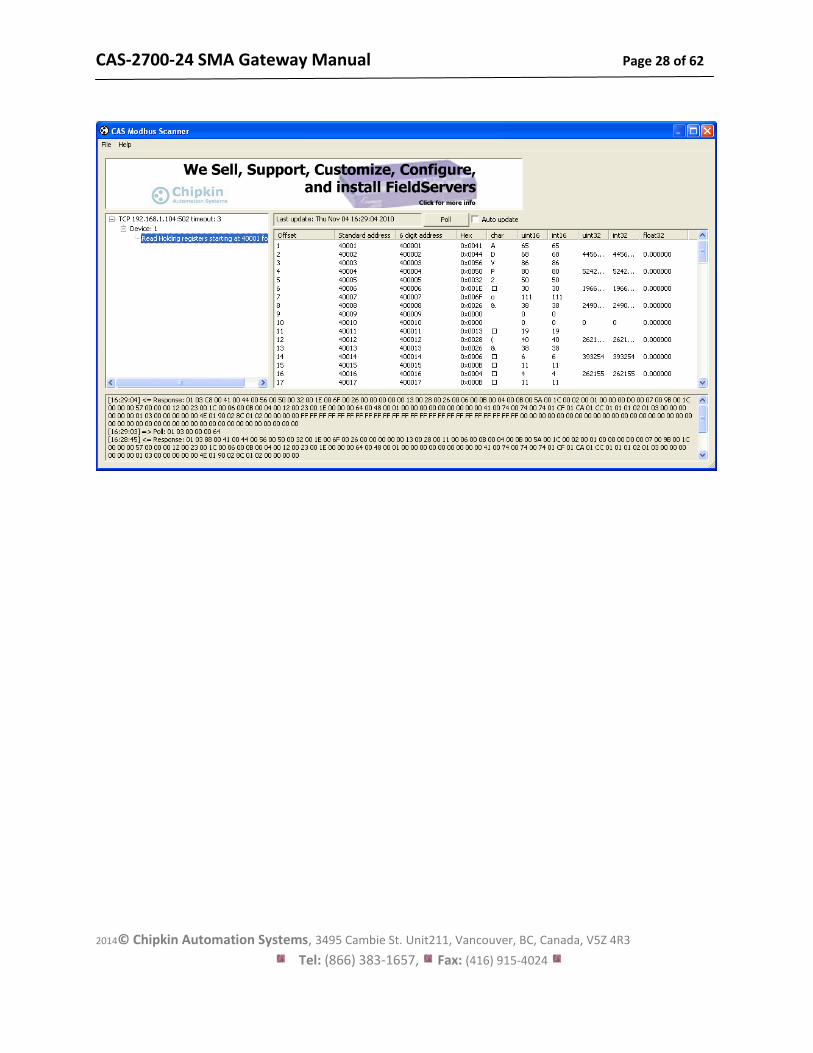
4. Click the Poll Button
5. Use the values found in the ‘int16 column and the data map table to review the
data.
CAS-2700-24 SMA Gateway Manual Page 28 of 62
2014© Chipkin Automation Systems, 3495 Cambie St. Unit211, Vancouver, BC, Canada, V5Z 4R3
Tel: (866) 383-1657, Fax: (416) 915-4024
CAS-2700-24 SMA Gateway Manual Page 29 of 62
2014© Chipkin Automation Systems, 3495 Cambie St. Unit211, Vancouver, BC, Canada, V5Z 4R3
Tel: (866) 383-1657, Fax: (416) 915-4024
6. Reading BACnet Data
BACnet supports discovery. When you discover the gateway, objects and properties you will find
appropriately named objects that report data from the SMA Devices. Because BACnet supports
discovery, usually knowledge of the BACnet Device Instance Number does not need to be known
in advance.
Each BACnet device (like the gateway) needs to have a unique instance number. Therefore it
may be necessary for you to change the instance number.
Need to learn some BACnet basics? Read this guide.
http://www.chipkin.com/bacnet-solutions
6.1. Most Common BACnet Problem
If the device or application that is reading the BACnet data is on another subnet then it will not
discover or be able to talk to the gateway. This can be resolved two ways. 1. Change the IP
address of the gateway to be on the same subnet – a simple task. 2. Install BBMD – a non trivial
task – but a task you can often pass the buck on – it is the responsibility of the company
installing the BAS system to provide BBMD. You can read more about it at this link.
http://www.chipkin.com/articles/bacnet-bbmd
6.2. Interpreting BACnet Data
If the gateway loses communications with the Veeder Root device or if a data point cannot be
read from the controller, the ‘Out of Service’ property of the data object is set true once the
timeout has expired. The value of the ‘Present Value’ property is not changed, thus the last
good value will be shown.
6.3. BACnet Objects
The following is a list of possible BACnet Objects. Note: This list only contains what is
configured with the default configuration (four tanks and system alarms).
CAS-2700-24 SMA Gateway Manual Page 30 of 62
2014© Chipkin Automation Systems, 3495 Cambie St. Unit211, Vancouver, BC, Canada, V5Z 4R3
Tel: (866) 383-1657, Fax: (416) 915-4024
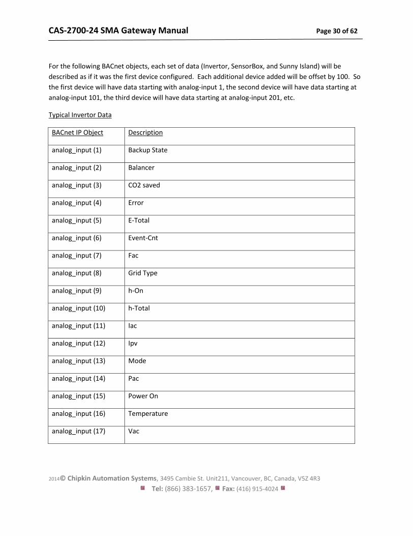
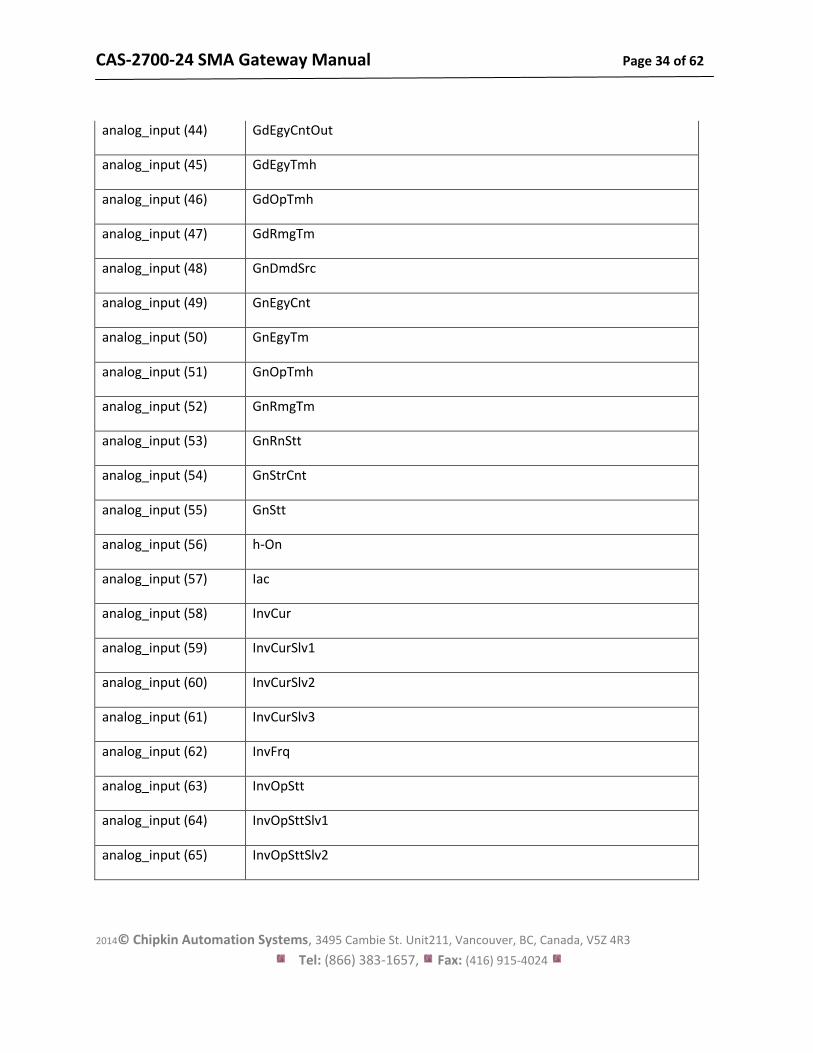
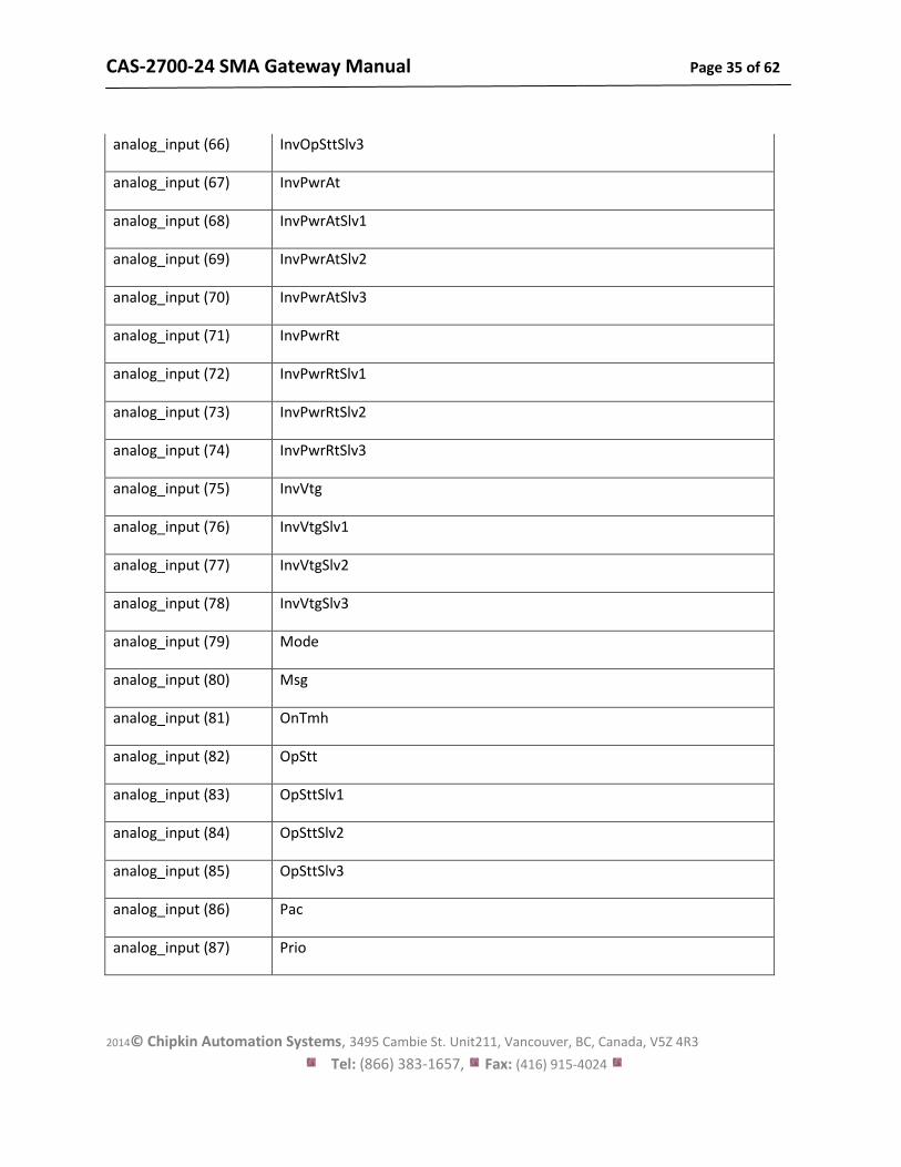
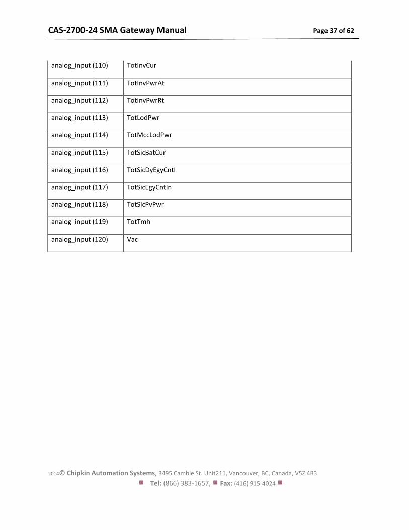
For the following BACnet objects, each set of data (Invertor, SensorBox, and Sunny Island) will be
described as if it was the first device configured. Each additional device added will be offset by 100. So
the first device will have data starting with analog-input 1, the second device will have data starting at
analog-input 101, the third device will have data starting at analog-input 201, etc.
Typical Invertor Data
BACnet IP Object Description
analog_input (1) Backup State
analog_input (2) Balancer
analog_input (3) CO2 saved
analog_input (4) Error
analog_input (5) E-Total
analog_input (6) Event-Cnt
analog_input (7) Fac
analog_input (8) Grid Type
analog_input (9) h-On
analog_input (10) h-Total
analog_input (11) Iac
analog_input (12) Ipv
analog_input (13) Mode
analog_input (14) Pac
analog_input (15) Power On
analog_input (16) Temperature
analog_input (17) Vac
CAS-2700-24 SMA Gateway Manual Page 31 of 62
2014© Chipkin Automation Systems, 3495 Cambie St. Unit211, Vancouver, BC, Canada, V5Z 4R3
Tel: (866) 383-1657, Fax: (416) 915-4024
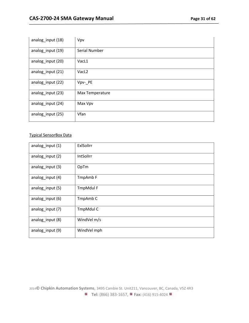
analog_input (18) Vpv
analog_input (19) Serial Number
analog_input (20) VacL1
analog_input (21) VacL2
analog_input (22) Vpv-_PE
analog_input (23) Max Temperature
analog_input (24) Max Vpv
analog_input (25) Vfan
Typical SensorBox Data
analog_input (1) ExlSolIrr
analog_input (2) IntSolIrr
analog_input (3) OpTm
analog_input (4) TmpAmb F
analog_input (5) TmpMdul F
analog_input (6) TmpAmb C
analog_input (7) TmpMdul C
analog_input (8) WindVel m/s
analog_input (9) WindVel mph
CAS-2700-24 SMA Gateway Manual Page 32 of 62
2014© Chipkin Automation Systems, 3495 Cambie St. Unit211, Vancouver, BC, Canada, V5Z 4R3
Tel: (866) 383-1657, Fax: (416) 915-4024
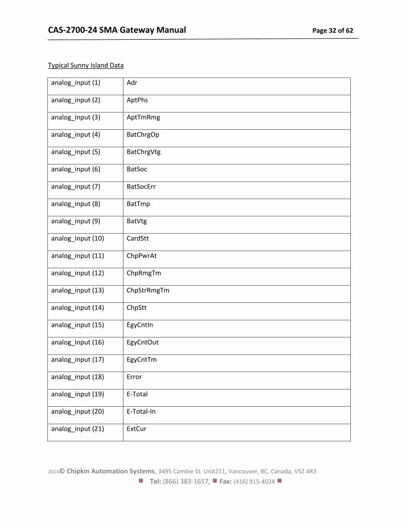
Typical Sunny Island Data
analog_input (1) Adr
analog_input (2) AptPhs
analog_input (3) AptTmRmg
analog_input (4) BatChrgOp
analog_input (5) BatChrgVtg
analog_input (6) BatSoc
analog_input (7) BatSocErr
analog_input (8) BatTmp
analog_input (9) BatVtg
analog_input (10) CardStt
analog_input (11) ChpPwrAt
analog_input (12) ChpRmgTm
analog_input (13) ChpStrRmgTm
analog_input (14) ChpStt
analog_input (15) EgyCntIn
analog_input (16) EgyCntOut
analog_input (17) EgyCntTm
analog_input (18) Error
analog_input (19) E-Total
analog_input (20) E-Total-In
analog_input (21) ExtCur
CAS-2700-24 SMA Gateway Manual Page 33 of 62
2014© Chipkin Automation Systems, 3495 Cambie St. Unit211, Vancouver, BC, Canada, V5Z 4R3
Tel: (866) 383-1657, Fax: (416) 915-4024
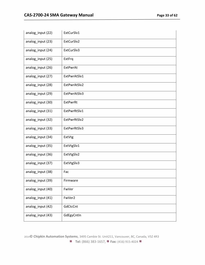
analog_input (22) ExtCurSlv1
analog_input (23) ExtCurSlv2
analog_input (24) ExtCurSlv3
analog_input (25) ExtFrq
analog_input (26) ExtPwrAt
analog_input (27) ExtPwrAtSlv1
analog_input (28) ExtPwrAtSlv2
analog_input (29) ExtPwrAtSlv3
analog_input (30) ExtPwrRt
analog_input (31) ExtPwrRtSlv1
analog_input (32) ExtPwrRtSlv2
analog_input (33) ExtPwrRtSlv3
analog_input (34) ExtVtg
analog_input (35) ExtVtgSlv1
analog_input (36) ExtVtgSlv2
analog_input (37) ExtVtgSlv3
analog_input (38) Fac
analog_input (39) Firmware
analog_input (40) FwVer
analog_input (41) FwVer2
analog_input (42) GdCtcCnt
analog_input (43) GdEgyCntIn
CAS-2700-24 SMA Gateway Manual Page 34 of 62
2014© Chipkin Automation Systems, 3495 Cambie St. Unit211, Vancouver, BC, Canada, V5Z 4R3
Tel: (866) 383-1657, Fax: (416) 915-4024
analog_input (44) GdEgyCntOut
analog_input (45) GdEgyTmh
analog_input (46) GdOpTmh
analog_input (47) GdRmgTm
analog_input (48) GnDmdSrc
analog_input (49) GnEgyCnt
analog_input (50) GnEgyTm
analog_input (51) GnOpTmh
analog_input (52) GnRmgTm
analog_input (53) GnRnStt
analog_input (54) GnStrCnt
analog_input (55) GnStt
analog_input (56) h-On
analog_input (57) Iac
analog_input (58) InvCur
analog_input (59) InvCurSlv1
analog_input (60) InvCurSlv2
analog_input (61) InvCurSlv3
analog_input (62) InvFrq
analog_input (63) InvOpStt
analog_input (64) InvOpSttSlv1
analog_input (65) InvOpSttSlv2
CAS-2700-24 SMA Gateway Manual Page 35 of 62
2014© Chipkin Automation Systems, 3495 Cambie St. Unit211, Vancouver, BC, Canada, V5Z 4R3
Tel: (866) 383-1657, Fax: (416) 915-4024
analog_input (66) InvOpSttSlv3
analog_input (67) InvPwrAt
analog_input (68) InvPwrAtSlv1
analog_input (69) InvPwrAtSlv2
analog_input (70) InvPwrAtSlv3
analog_input (71) InvPwrRt
analog_input (72) InvPwrRtSlv1
analog_input (73) InvPwrRtSlv2
analog_input (74) InvPwrRtSlv3
analog_input (75) InvVtg
analog_input (76) InvVtgSlv1
analog_input (77) InvVtgSlv2
analog_input (78) InvVtgSlv3
analog_input (79) Mode
analog_input (80) Msg
analog_input (81) OnTmh
analog_input (82) OpStt
analog_input (83) OpSttSlv1
analog_input (84) OpSttSlv2
analog_input (85) OpSttSlv3
analog_input (86) Pac
analog_input (87) Prio

CAS-2700-24 SMA Gateway Manual Page 36 of 62
2014© Chipkin Automation Systems, 3495 Cambie St. Unit211, Vancouver, BC, Canada, V5Z 4R3
Tel: (866) 383-1657, Fax: (416) 915-4024
analog_input (88) Rly1Stt
analog_input (89) Rly2Stt
analog_input (90) RmgTmEqu
analog_input (91) RmgTmFul
analog_input (92) Serial Number
analog_input (93) Sic1EgyCntIn
analog_input (94) Sic1PvPwr
analog_input (95) Sic1TdyEgyCntIn
analog_input (96) Sic2EgyCntIn
analog_input (97) Sic2PvPwr
analog_input (98) Sic2TdyEgyCntIn
analog_input (99) Sic3EgyCntIn
analog_input (100) Sic3PvPwr
analog_input (101) Sic3TdyEgyCntIn
analog_input (102) Sic4EgyCntIn
analog_input (103) Sic4PvPwr
analog_input (104) Sic4TdyEgyCntIn
analog_input (105) Soh
analog_input (106) TotBatCur
analog_input (107) TotExtCur
analog_input (108) TotExtPwrAt
analog_input (109) TotExtPwrRt
CAS-2700-24 SMA Gateway Manual Page 37 of 62
2014© Chipkin Automation Systems, 3495 Cambie St. Unit211, Vancouver, BC, Canada, V5Z 4R3
Tel: (866) 383-1657, Fax: (416) 915-4024
analog_input (110) TotInvCur
analog_input (111) TotInvPwrAt
analog_input (112) TotInvPwrRt
analog_input (113) TotLodPwr
analog_input (114) TotMccLodPwr
analog_input (115) TotSicBatCur
analog_input (116) TotSicDyEgyCntI
analog_input (117) TotSicEgyCntIn
analog_input (118) TotSicPvPwr
analog_input (119) TotTmh
analog_input (120) Vac
CAS-2700-24 SMA Gateway Manual Page 38 of 62
2014© Chipkin Automation Systems, 3495 Cambie St. Unit211, Vancouver, BC, Canada, V5Z 4R3
Tel: (866) 383-1657, Fax: (416) 915-4024
6.4. BACnet Test Procedure
You have been provided with a USB key to the CAS BACnet Explorer. This key activates the
software. It cannot run without it. If you don’t have your USB key, you can still activate the
application – it requires an internet connection. A video provides help.
http://www.chipkin.com/articles/cas-bacnet-explorer-software-activation-video
You might also want to refer to these articles.
http://www.chipkin.com/articles/cas-bacnet-explorer-usbsoftware-activation-problems
http://www.chipkin.com/cas-bacnet-explorer-licenses-faq
Install and activate the application. Download from here.
http://www.chipkin.com/cas-bacnet-explorer/
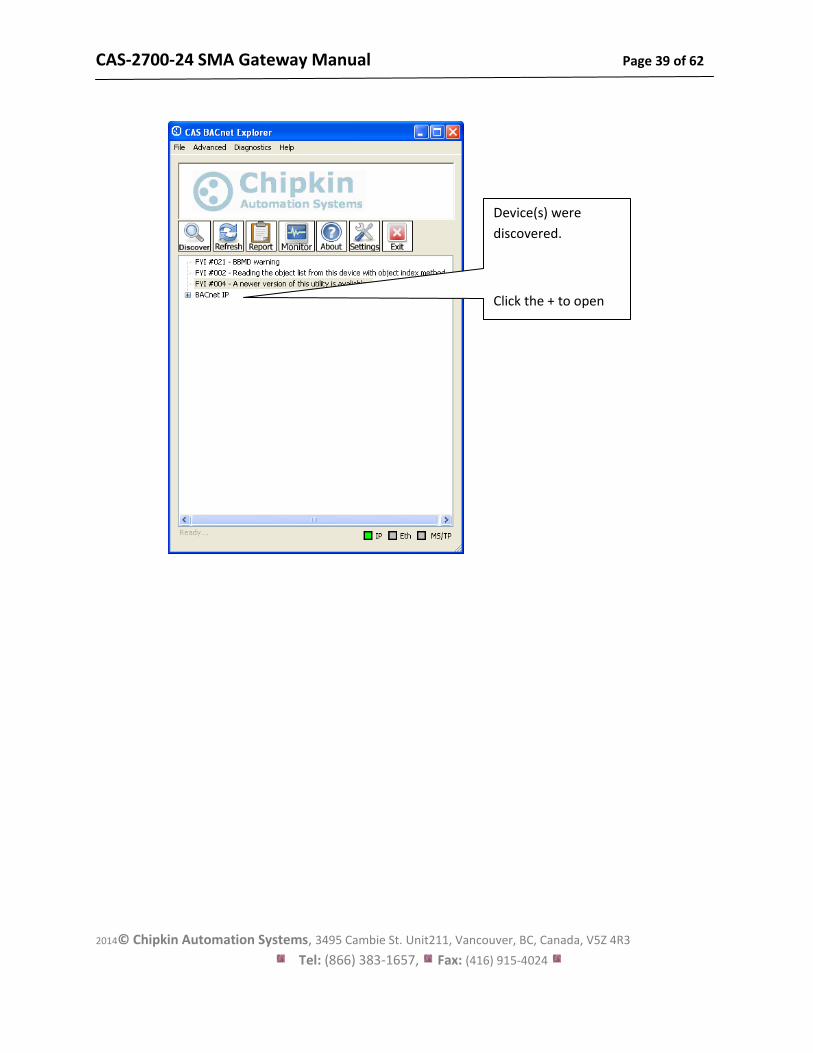
Procedure
1. Start the application
2. Click Settings
3. Check IP – uncheck MSTP and Ethernet
4. Click on the network card you will use.
5. Click Ok.
6. Now click discover
7. Click Send
CAS-2700-24 SMA Gateway Manual Page 39 of 62
2014© Chipkin Automation Systems, 3495 Cambie St. Unit211, Vancouver, BC, Canada, V5Z 4R3
Tel: (866) 383-1657, Fax: (416) 915-4024
Device(s) were
discovered.
Click the + to open
up.
CAS-2700-24 SMA Gateway Manual Page 40 of 62
2014© Chipkin Automation Systems, 3495 Cambie St. Unit211, Vancouver, BC, Canada, V5Z 4R3
Tel: (866) 383-1657, Fax: (416) 915-4024
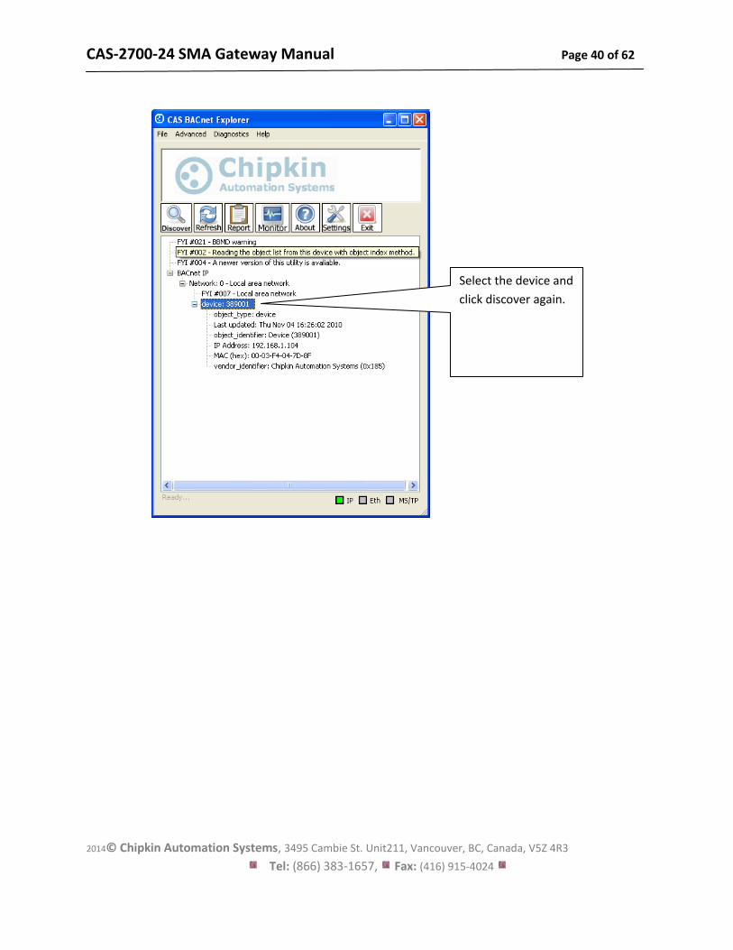
Select the device and
click discover again.
CAS-2700-24 SMA Gateway Manual Page 41 of 62
2014© Chipkin Automation Systems, 3495 Cambie St. Unit211, Vancouver, BC, Canada, V5Z 4R3
Tel: (866) 383-1657, Fax: (416) 915-4024
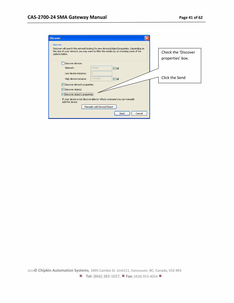
Check the ‘Discover
properties’ box.
Click the Send
button.
CAS-2700-24 SMA Gateway Manual Page 42 of 62
2014© Chipkin Automation Systems, 3495 Cambie St. Unit211, Vancouver, BC, Canada, V5Z 4R3
Tel: (866) 383-1657, Fax: (416) 915-4024
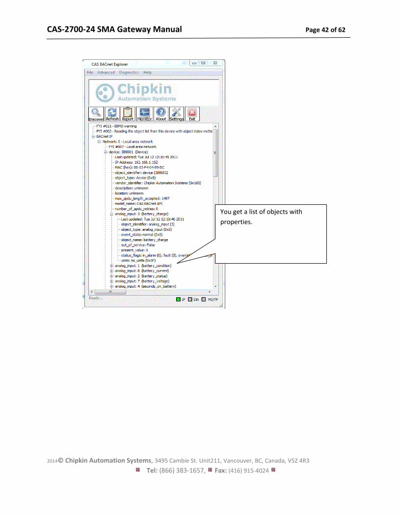
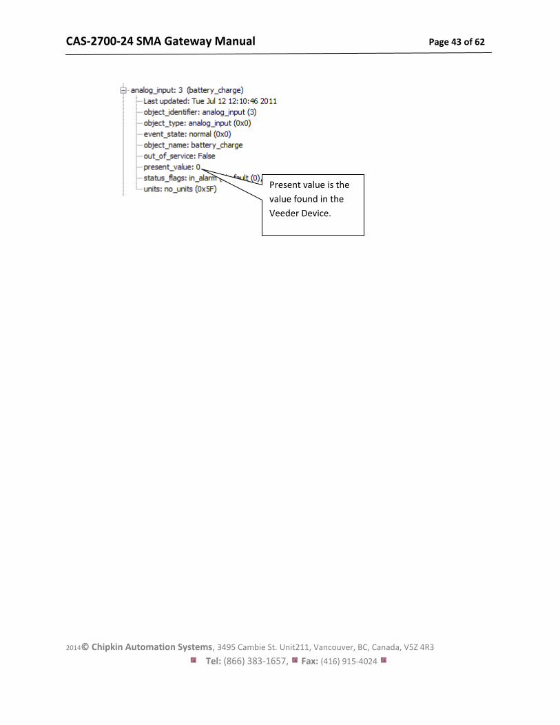
You get a list of objects with
properties.
CAS-2700-24 SMA Gateway Manual Page 43 of 62
2014© Chipkin Automation Systems, 3495 Cambie St. Unit211, Vancouver, BC, Canada, V5Z 4R3
Tel: (866) 383-1657, Fax: (416) 915-4024
Present value is the
value found in the
Veeder Device.
CAS-2700-24 SMA Gateway Manual Page 44 of 62
2014© Chipkin Automation Systems, 3495 Cambie St. Unit211, Vancouver, BC, Canada, V5Z 4R3
Tel: (866) 383-1657, Fax: (416) 915-4024
7. Commissioning, Diagnostics and Trouble Shooting
7.1. What to Take to Site for Commissioning
1. The gateway and other supplied components.
2. USB->485 Converter
Any will do. This will allow you run tests using the 485 serial connection for Modbus RTU. Connect to the device and find out which COM port is now available, use CAS Modbus Scanner to retrieve data.
3. Serial Cables
A Null Modem cable is used to connect to the gateway diagnostic port. Take one with you.
4. Laptop
5. Gateway IP Address Allocation Tool
Download from http://www.chipkin.com/articles/cas-gateway-ip-address-tool
6. Wireshark packet sniffer software – free download
http://www.wireshark.org/download.html
7. CAS Modbus Scanner – free download
CAS Modbus Scanner is a utility to retrieve coils, inputs, holding registers, and input
registers from a Modbus enabled device. Values retrieved from the device can be viewed in
many different formats including Binary, HEX, Uint16, Int16, Uint32, Int32, and Float32.
http://www.chipkin.com/cas-modbus-scanner
CAS-2700-24 SMA Gateway Manual Page 45 of 62
2014© Chipkin Automation Systems, 3495 Cambie St. Unit211, Vancouver, BC, Canada, V5Z 4R3
Tel: (866) 383-1657, Fax: (416) 915-4024
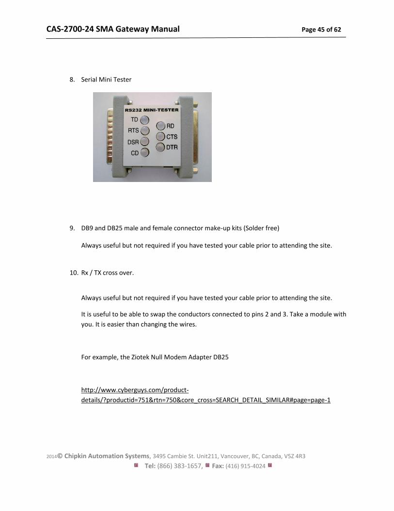
8. Serial Mini Tester
9. DB9 and DB25 male and female connector make-up kits (Solder free) Always useful but not required if you have tested your cable prior to attending the site.
10. Rx / TX cross over.
Always useful but not required if you have tested your cable prior to attending the site.
It is useful to be able to swap the conductors connected to pins 2 and 3. Take a module with
you. It is easier than changing the wires.
For example, the Ziotek Null Modem Adapter DB25
http://www.cyberguys.com/product-
details/?productid=751&rtn=750&core_cross=SEARCH_DETAIL_SIMILAR#page=page-1
CAS-2700-24 SMA Gateway Manual Page 46 of 62
2014© Chipkin Automation Systems, 3495 Cambie St. Unit211, Vancouver, BC, Canada, V5Z 4R3
Tel: (866) 383-1657, Fax: (416) 915-4024
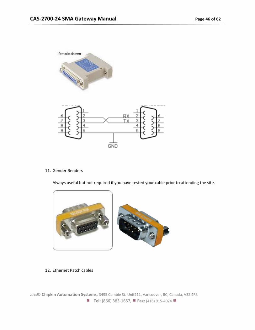
11. Gender Benders
Always useful but not required if you have tested your cable prior to attending the site.
12. Ethernet Patch cables
CAS-2700-24 SMA Gateway Manual Page 47 of 62
2014© Chipkin Automation Systems, 3495 Cambie St. Unit211, Vancouver, BC, Canada, V5Z 4R3
Tel: (866) 383-1657, Fax: (416) 915-4024
13. Hub
Used as a last resort if there are problems on Modbus or BACnet
A hub is not a switch. A hub can be used for trouble-shooting whereas only a ‘supervised’ switch can. Most switches are not supervised. http://www.chipkin.com/articles/hubs-vs-switches-using-wireshark-to-sniff-network-packets
CAS-2700-24 SMA Gateway Manual Page 48 of 62
2014© Chipkin Automation Systems, 3495 Cambie St. Unit211, Vancouver, BC, Canada, V5Z 4R3
Tel: (866) 383-1657, Fax: (416) 915-4024
7.2. Gateway Status
Browse to http://192.168.1.113/bin/sma/report and you will the present values of the
data points
If all of the data values are displayed as “-1” (or whatever the configured default value
is) then it could mean one of two things.
1) The Gateway has just been configured and has begun to poll for values.
Wait for a little while for the first couple of scan intervals to finish, and then
refresh the page. Current correct values should be displayed.
2) The Gateway is not connected to the Veeder Device. Either the Gateway
was never connected, or the Gateway got disconnected from the device.
After an amount of time has passed (as configured in the Disconnect Time
parameter of the configuration), the Gateway will set all values to the
default value.
You must manually refresh this page to get the updated values.
7.3. Gateway Diagnostics
Power Led: Green Solid = Normal Condition.
RJ45 LED: Green to show link.
CAS-2700-24 SMA Gateway Manual Page 49 of 62
2014© Chipkin Automation Systems, 3495 Cambie St. Unit211, Vancouver, BC, Canada, V5Z 4R3
Tel: (866) 383-1657, Fax: (416) 915-4024
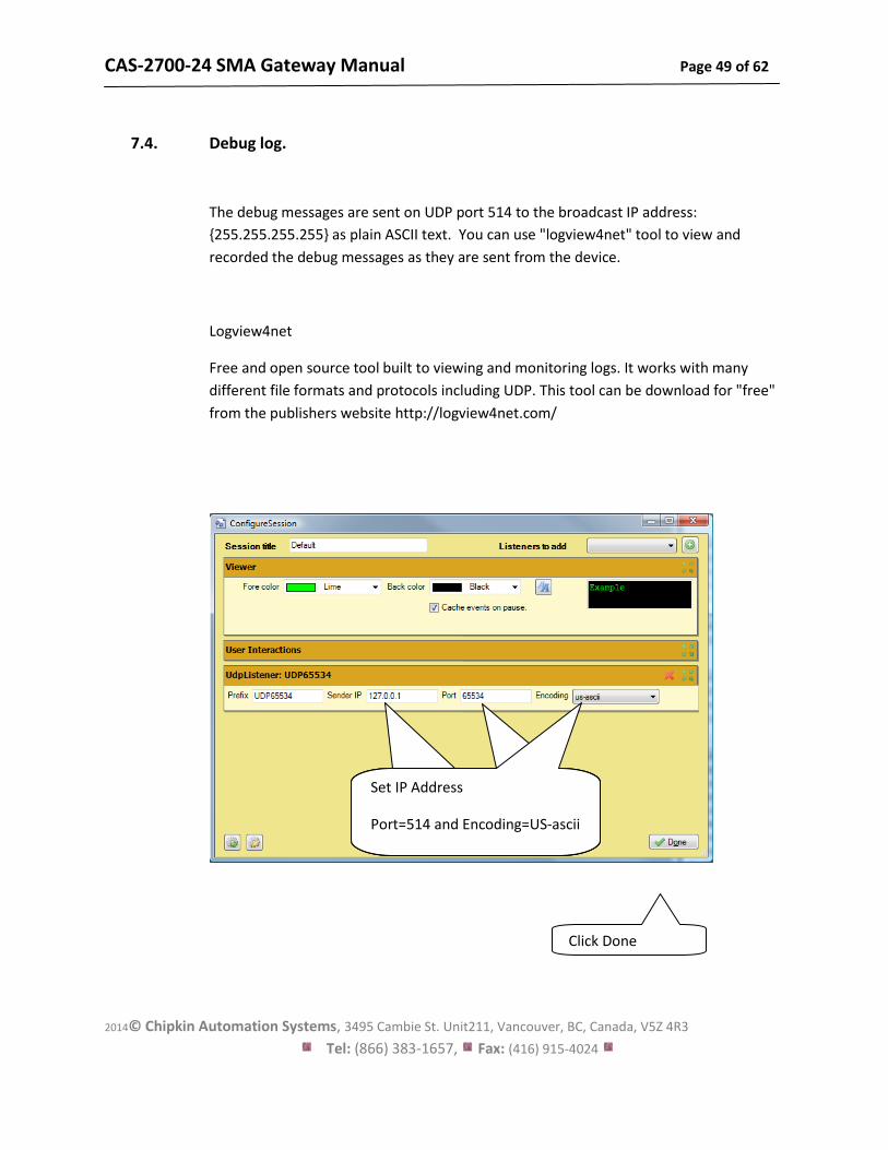
7.4. Debug log.
The debug messages are sent on UDP port 514 to the broadcast IP address:
{255.255.255.255} as plain ASCII text. You can use "logview4net" tool to view and
recorded the debug messages as they are sent from the device.
Logview4net
Free and open source tool built to viewing and monitoring logs. It works with many
different file formats and protocols including UDP. This tool can be download for "free"
from the publishers website http://logview4net.com/
Set IP Address
Port=65534 and Encoding=US-
ascii
Set IP Address
Port=65534 and Encoding=US-
ascii
Set IP Address
Port=514 and Encoding=US-ascii
Click Done
Port=65534 and
Encoding=US-ascii
CAS-2700-24 SMA Gateway Manual Page 50 of 62
2014© Chipkin Automation Systems, 3495 Cambie St. Unit211, Vancouver, BC, Canada, V5Z 4R3
Tel: (866) 383-1657, Fax: (416) 915-4024
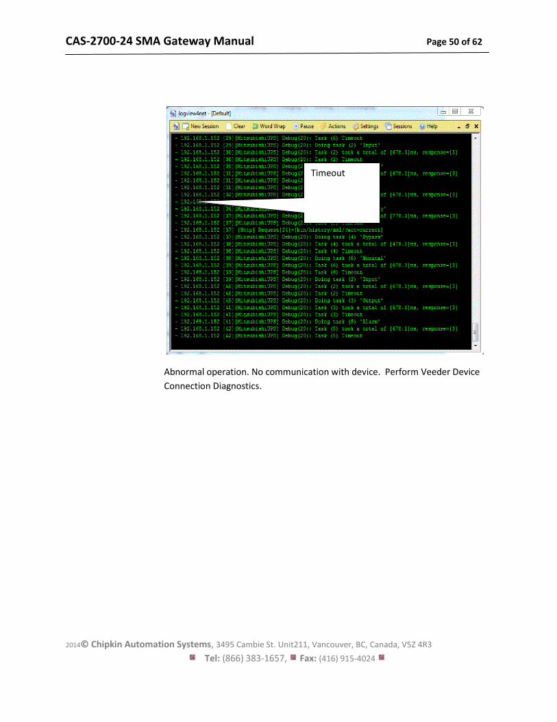
Abnormal operation. No communication with device. Perform Veeder Device
Connection Diagnostics.
Timeout
CAS-2700-24 SMA Gateway Manual Page 51 of 62
2014© Chipkin Automation Systems, 3495 Cambie St. Unit211, Vancouver, BC, Canada, V5Z 4R3
Tel: (866) 383-1657, Fax: (416) 915-4024
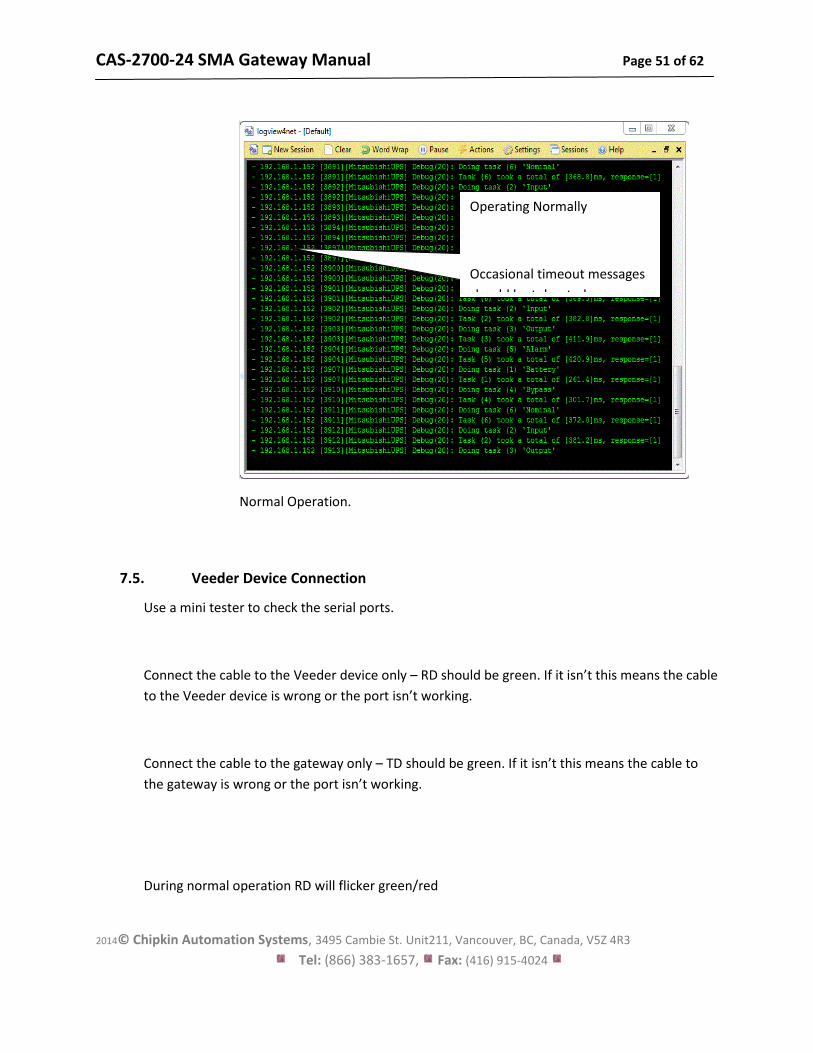
Normal Operation.
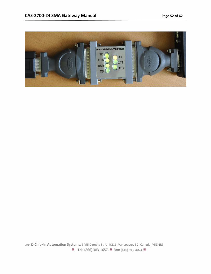
7.5. Veeder Device Connection
Use a mini tester to check the serial ports.
Connect the cable to the Veeder device only – RD should be green. If it isn’t this means the cable
to the Veeder device is wrong or the port isn’t working.
Connect the cable to the gateway only – TD should be green. If it isn’t this means the cable to
the gateway is wrong or the port isn’t working.
During normal operation RD will flicker green/red
Operating Normally
Occasional timeout messages
should be tolerated.
CAS-2700-24 SMA Gateway Manual Page 52 of 62
2014© Chipkin Automation Systems, 3495 Cambie St. Unit211, Vancouver, BC, Canada, V5Z 4R3
Tel: (866) 383-1657, Fax: (416) 915-4024

CAS-2700-24 SMA Gateway Manual Page 53 of 62
2014© Chipkin Automation Systems, 3495 Cambie St. Unit211, Vancouver, BC, Canada, V5Z 4R3
Tel: (866) 383-1657, Fax: (416) 915-4024
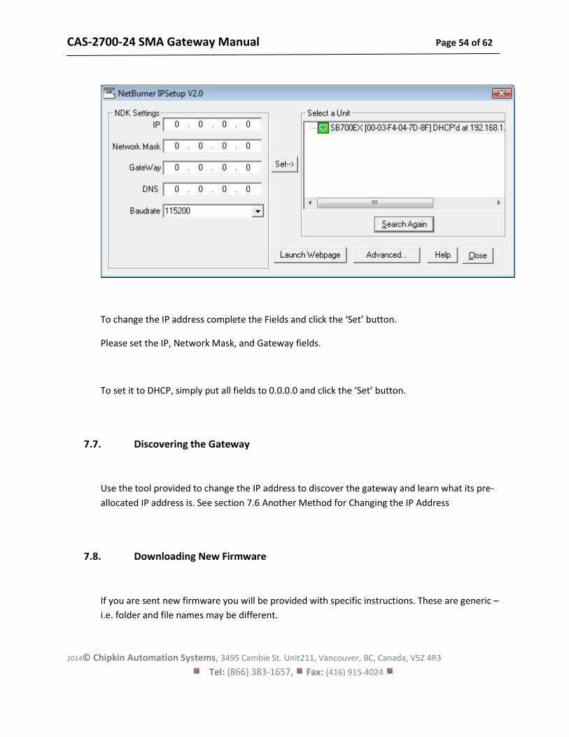
7.6. Another Method for Changing the IP Address - DHCP
This device supports DHCP and DHCP is disabled.
When shipped the device
IP = 192.168.1.113
Mask = 255.255.255.0
Gateway = 192.168.1.1
If you simply want to change the IP address then use the simpler method provided in section 3.6
Change Configuration Settings.
A tool is provided to change the IP address of the gateway. The tool can be downloaded from:
http://www.chipkin.com/articles/cas-gateway-ip-address-tool
When you start this tool it discovers gateways and list them in the right had side ‘Select a Unit’
area. If the area is blank then click the ‘Search Again’ button. If it remains blank check that the
Ethernet connection is made – is there a green link LED on the RJ45 and on the hub/switch you
are connected to.
CAS-2700-24 SMA Gateway Manual Page 54 of 62
2014© Chipkin Automation Systems, 3495 Cambie St. Unit211, Vancouver, BC, Canada, V5Z 4R3
Tel: (866) 383-1657, Fax: (416) 915-4024
To change the IP address complete the Fields and click the ‘Set’ button.
Please set the IP, Network Mask, and Gateway fields.
To set it to DHCP, simply put all fields to 0.0.0.0 and click the ‘Set’ button.
7.7. Discovering the Gateway
Use the tool provided to change the IP address to discover the gateway and learn what its pre-
allocated IP address is. See section 7.6 Another Method for Changing the IP Address
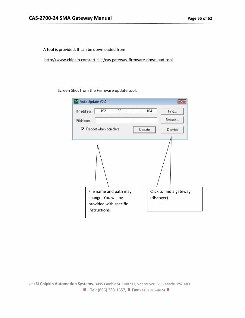
7.8. Downloading New Firmware
If you are sent new firmware you will be provided with specific instructions. These are generic –
i.e. folder and file names may be different.
CAS-2700-24 SMA Gateway Manual Page 55 of 62
2014© Chipkin Automation Systems, 3495 Cambie St. Unit211, Vancouver, BC, Canada, V5Z 4R3
Tel: (866) 383-1657, Fax: (416) 915-4024
A tool is provided. It can be downloaded from
http://www.chipkin.com/articles/cas-gateway-firmware-download-tool
Screen Shot from the Firmware update tool.
File name and path may
change. You will be
provided with specific
instructions.
Click to find a gateway
(discover)
CAS-2700-24 SMA Gateway Manual Page 56 of 62
2014© Chipkin Automation Systems, 3495 Cambie St. Unit211, Vancouver, BC, Canada, V5Z 4R3
Tel: (866) 383-1657, Fax: (416) 915-4024
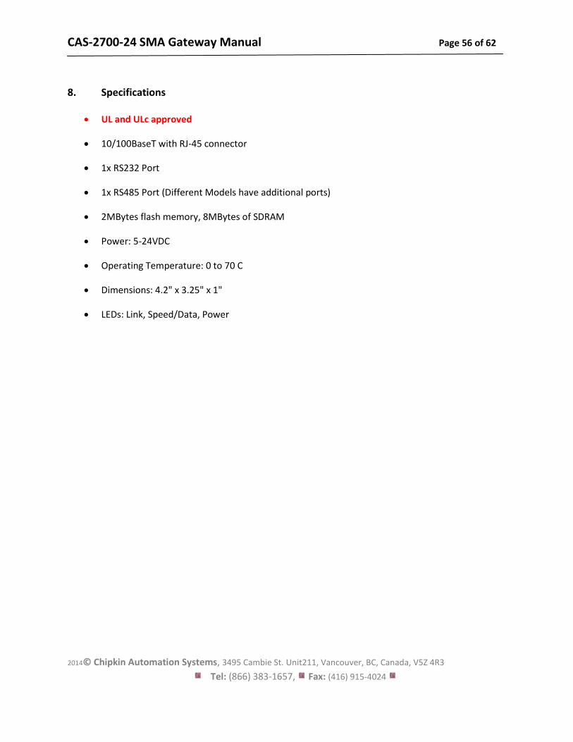
8. Specifications
UL and ULc approved
10/100BaseT with RJ-45 connector
1x RS232 Port
1x RS485 Port (Different Models have additional ports)
2MBytes flash memory, 8MBytes of SDRAM
Power: 5-24VDC
Operating Temperature: 0 to 70 C
Dimensions: 4.2" x 3.25" x 1"
LEDs: Link, Speed/Data, Power
CAS-2700-24 SMA Gateway Manual Page 57 of 62
2014© Chipkin Automation Systems, 3495 Cambie St. Unit211, Vancouver, BC, Canada, V5Z 4R3
Tel: (866) 383-1657, Fax: (416) 915-4024
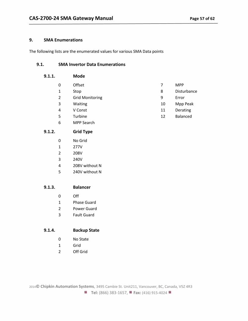
9. SMA Enumerations
The following lists are the enumerated values for various SMA Data points
9.1. SMA Invertor Data Enumerations
9.1.1. Mode
0 Offset
1 Stop
2 Grid Monitoring
3 Waiting
4 V Const
5 Turbine
6 MPP Search
7 MPP
8 Disturbance
9 Error
10 Mpp Peak
11 Derating
12 Balanced
9.1.2. Grid Type
0 No Grid
1 277V
2 208V
3 240V
4 208V without N
5 240V without N
9.1.3. Balancer
0 Off
1 Phase Guard
2 Power Guard
3 Fault Guard
9.1.4. Backup State
0 No State
1 Grid
2 Off Grid
CAS-2700-24 SMA Gateway Manual Page 58 of 62
2014© Chipkin Automation Systems, 3495 Cambie St. Unit211, Vancouver, BC, Canada, V5Z 4R3
Tel: (866) 383-1657, Fax: (416) 915-4024
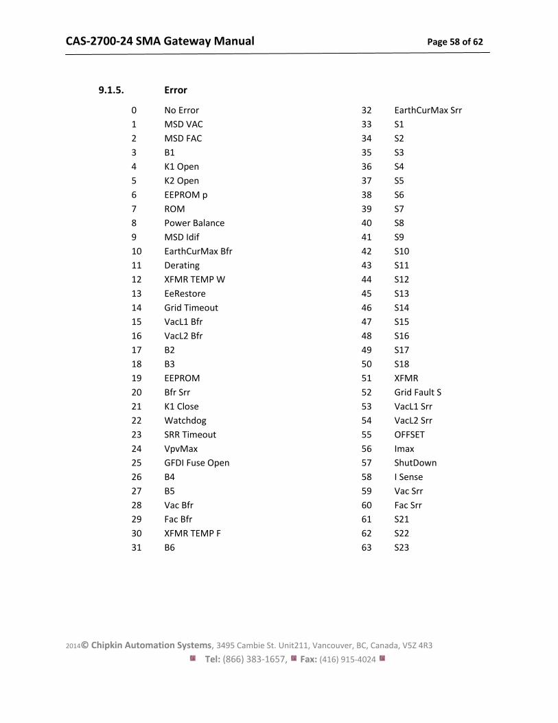
9.1.5. Error
0 No Error
1 MSD VAC
2 MSD FAC
3 B1
4 K1 Open
5 K2 Open
6 EEPROM p
7 ROM
8 Power Balance
9 MSD Idif
10 EarthCurMax Bfr
11 Derating
12 XFMR TEMP W
13 EeRestore
14 Grid Timeout
15 VacL1 Bfr
16 VacL2 Bfr
17 B2
18 B3
19 EEPROM
20 Bfr Srr
21 K1 Close
22 Watchdog
23 SRR Timeout
24 VpvMax
25 GFDI Fuse Open
26 B4
27 B5
28 Vac Bfr
29 Fac Bfr
30 XFMR TEMP F
31 B6
32 EarthCurMax Srr
33 S1
34 S2
35 S3
36 S4
37 S5
38 S6
39 S7
40 S8
41 S9
42 S10
43 S11
44 S12
45 S13
46 S14
47 S15
48 S16
49 S17
50 S18
51 XFMR
52 Grid Fault S
53 VacL1 Srr
54 VacL2 Srr
55 OFFSET
56 Imax
57 ShutDown
58 I Sense
59 Vac Srr
60 Fac Srr
61 S21
62 S22
63 S23
CAS-2700-24 SMA Gateway Manual Page 59 of 62
2014© Chipkin Automation Systems, 3495 Cambie St. Unit211, Vancouver, BC, Canada, V5Z 4R3
Tel: (866) 383-1657, Fax: (416) 915-4024
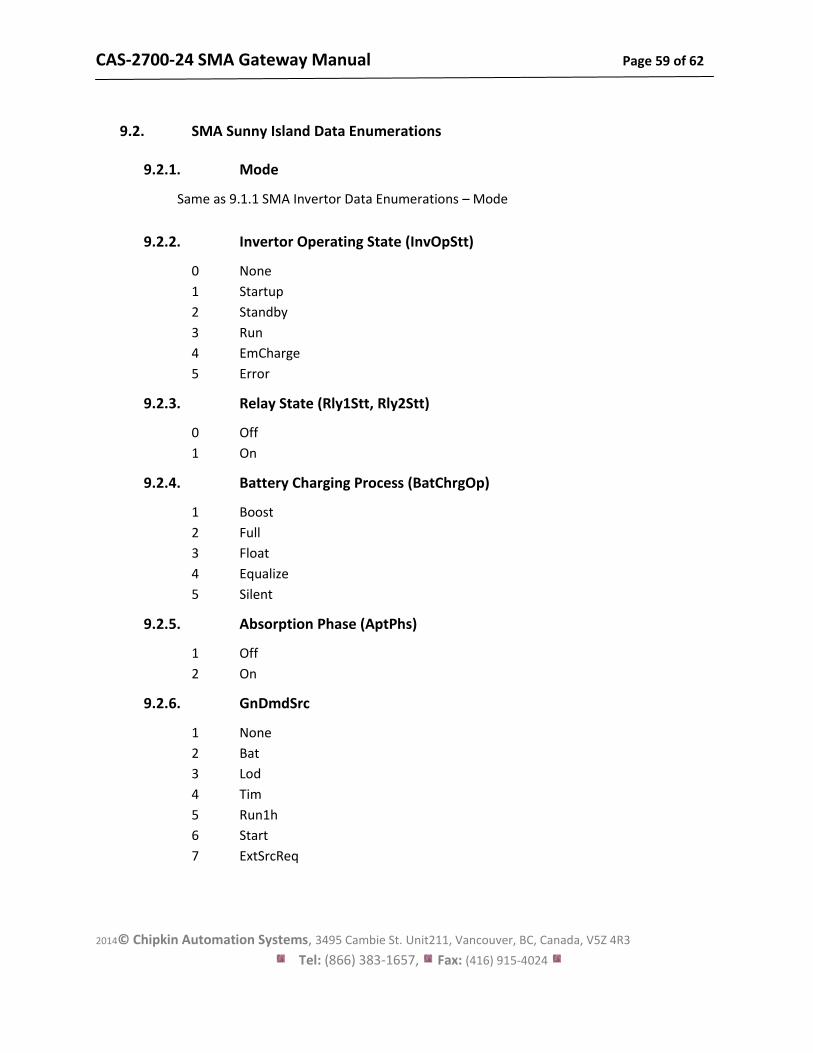
9.2. SMA Sunny Island Data Enumerations
9.2.1. Mode
Same as 9.1.1 SMA Invertor Data Enumerations – Mode
9.2.2. Invertor Operating State (InvOpStt)
0 None
1 Startup
2 Standby
3 Run
4 EmCharge
5 Error
9.2.3. Relay State (Rly1Stt, Rly2Stt)
0 Off
1 On
9.2.4. Battery Charging Process (BatChrgOp)
1 Boost
2 Full
3 Float
4 Equalize
5 Silent
9.2.5. Absorption Phase (AptPhs)
1 Off
2 On
9.2.6. GnDmdSrc
1 None
2 Bat
3 Lod
4 Tim
5 Run1h
6 Start
7 ExtSrcReq
CAS-2700-24 SMA Gateway Manual Page 60 of 62
2014© Chipkin Automation Systems, 3495 Cambie St. Unit211, Vancouver, BC, Canada, V5Z 4R3
Tel: (866) 383-1657, Fax: (416) 915-4024
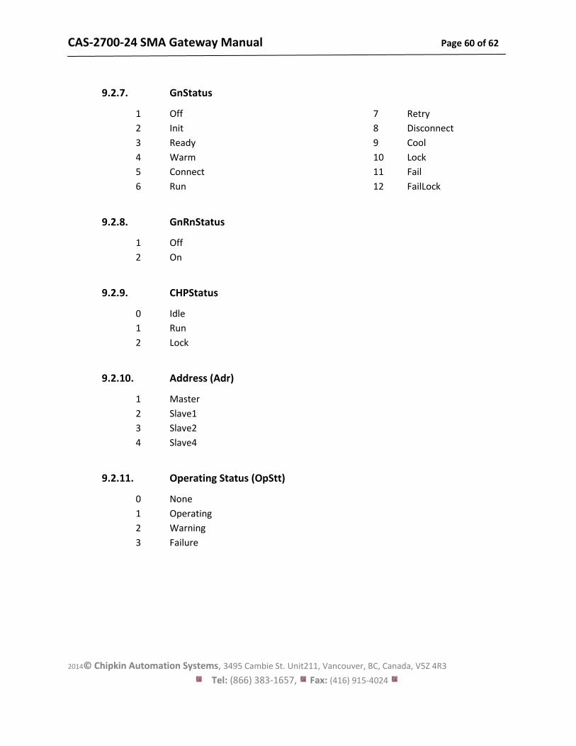
9.2.7. GnStatus
1 Off
2 Init
3 Ready
4 Warm
5 Connect
6 Run
7 Retry
8 Disconnect
9 Cool
10 Lock
11 Fail
12 FailLock
9.2.8. GnRnStatus
1 Off
2 On
9.2.9. CHPStatus
0 Idle
1 Run
2 Lock
9.2.10. Address (Adr)
1 Master
2 Slave1
3 Slave2
4 Slave4
9.2.11. Operating Status (OpStt)
0 None
1 Operating
2 Warning
3 Failure
CAS-2700-24 SMA Gateway Manual Page 61 of 62
2014© Chipkin Automation Systems, 3495 Cambie St. Unit211, Vancouver, BC, Canada, V5Z 4R3
Tel: (866) 383-1657, Fax: (416) 915-4024
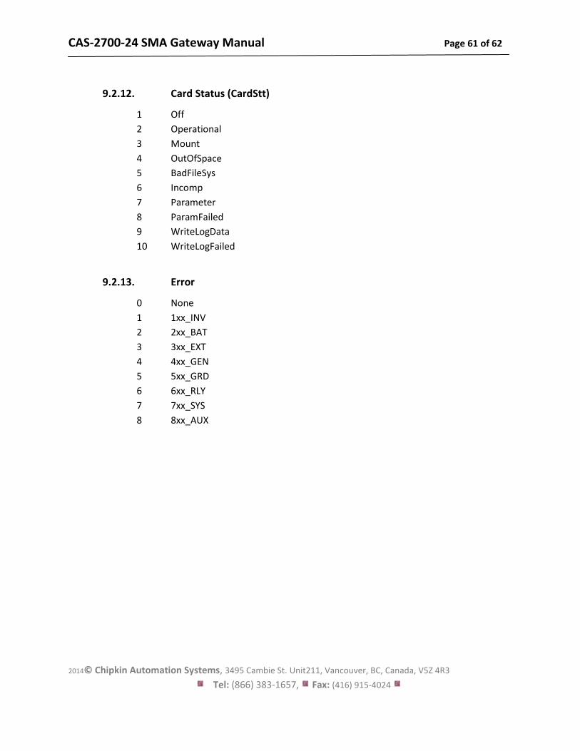
9.2.12. Card Status (CardStt)
1 Off
2 Operational
3 Mount
4 OutOfSpace
5 BadFileSys
6 Incomp
7 Parameter
8 ParamFailed
9 WriteLogData
10 WriteLogFailed
9.2.13. Error
0 None
1 1xx_INV
2 2xx_BAT
3 3xx_EXT
4 4xx_GEN
5 5xx_GRD
6 6xx_RLY
7 7xx_SYS
8 8xx_AUX
CAS-2700-24 SMA Gateway Manual Page 62 of 62
2014© Chipkin Automation Systems, 3495 Cambie St. Unit211, Vancouver, BC, Canada, V5Z 4R3
Tel: (866) 383-1657, Fax: (416) 915-4024
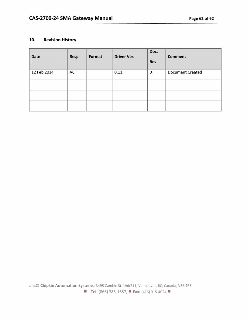
10. Revision History
Date Resp Format Driver Ver. Doc.
Rev. Comment
12 Feb 2014 ACF 0.11 0 Document Created