carbon nanotubes as optical antennae
TRANSCRIPT
DOI: 10.1002/adma.200601187
Carbon Nanotubes as Optical Antennae**
By Krzysztof Kempa,* Jakub Rybczynski, Zhongping Huang, Keith Gregorczyk, Andy Vidan,Brian Kimball, Joel Carlson, Glynda Benham, Yang Wang, Andrzej Herczynski, and Zhifeng Ren*
Light scattering from an array of aligned multiwall carbonnanotubes (MWCNTs) has previously been investigated,[1,2]
and shown to be consistent with that from an array of anten-nae. Two basic antenna effects have been demonstrated:1) the polarization effect, which suppresses the response of anantenna when the electric field of the incoming radiation ispolarized perpendicular to the dipole antenna axis, and 2) theantenna-length effect, which maximizes the antenna responsewhen the antenna length is a multiple of the radiation halfwavelength in the medium surrounding the antenna. In theseprevious experiments a random nanotube array was chosen toeliminate the intertube diffraction effects. In this communica-tion, we provide compelling evidence of the antenna action ofan MWCNT, by demonstrating that its directional radiationcharacteristics are in an excellent and quantitative agreementwith conventional radio antenna theory and simulations.
According to conventional radio antenna theory,[3–6] a sim-ple “thin” wire antenna (a metallic rod of diameter d andlength l >> d) maximizes its response to a wavelength k whenl = mk/2, where m is a positive integer. Thus, an antenna actsas a resonator of the external electromagnetic radiation. Anantenna is a complex boundary value problem; it is a resona-tor for both the external fields, and the currents at the anten-na surface. In a long radiating antenna, a periodic pattern ofcurrent distribution is excited along the antenna, synchro-nized with the pattern of fields outside. The current patternconsists of segments, with the current direction alternatingfrom segment to segment. Thus, a long antenna can be viewedas an antenna array consisting of smaller, coherently driven
antennae (segments) in series. Therefore, the resulting radia-tion pattern, as a function of the angle with respect to the an-tenna axis, consists of lobes of constructive interference, sepa-rated by radiation minima due to destructive interference.
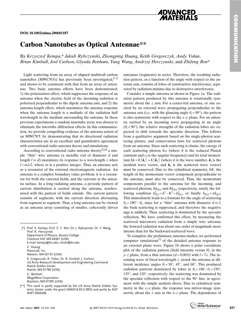
Consider a simple antenna as shown in Figure 1a. The radi-ation pattern produced by this antenna is rotationally sym-metric about the z axis. For a center-fed antenna, or one ex-cited by an external wave propagating perpendicular to theantenna axis (i.e., with the glancing angle hi = 90°), the patternis also symmetric with respect to the x–y plane. For an anten-na excited by an incoming wave propagating at an angle(hi < 90°), the relative strengths of the radiation lobes are ex-pected to shift towards the specular direction. This followsfrom a qualitative argument based on the single-photon scat-tering picture, and conservation laws for scattered photonsfrom an antenna. Since such scattering is elastic, the energy ofeach scattering photon �x (where � is the reduced Planckconstant and x is the angular frequency) and its total momen-tum �k = �ki = �ks (where k is the wave number, ki is theincident wave vector, and ks is the scattered wave vector)must be conserved. Due to the cylindrical symmetry, �K, thelength of the momentum vector component perpendicular tothe antenna, must also be conserved. Thus, the momentumcomponents parallel to the antenna for the incoming, andscattered photons, �k�(s) and �k�(i) respectively, satisfy the fol-lowing condition k2
�(i) = k2 – K2 = k2�(s), or finally k�(s) = ±k�(i).
This immediately leads to a formula for the angle of scatteringhs = 180° – hi, since for a “thin” antenna with diameter d << l,the back scattering is suppressed, and therefore the negativesign is unlikely. Thus, scattering is dominated by the specularreflection. We have confirmed this effect, by measuring thescattered microwave radiation from a simple wire antenna;the forward radiation was about one order of magnitude moreintense than for the backward scattered wave.
To complete the preliminary antenna studies, we performedcomputer simulations[7] of the detailed antenna response toan external plane wave. Figure 1b shows a polar coordinateplot of the radiation pattern (field intensity versus h), in they–z plane, from a thin antenna (d = 0.001l) with l = 7k. The in-coming wave of fixed wavelength k, struck the antenna at dif-ferent incidence angles hi = 30°, 45°, and 60°. This producedradiation patterns dominated by lobes at hs = 180 – hi = 150°,135°, and 120°, respectively: the scattering was dominated bythe specular reflection with respect to the 90° line, in agree-ment with the simple analysis above. Due to cylindrical sym-metry in the x–y plane, the response was mirror-image sym-metric about the z axis in the x–z plane. The dependence of
CO
MM
UN
ICATIO
N
Adv. Mater. 2007, 19, 421–426 © 2007 WILEY-VCH Verlag GmbH & Co. KGaA, Weinheim 421
–[*] Prof. K. Kempa, Prof. Z. F. Ren, Dr. J. Rybczynski, Dr. Y. Wang,
Prof. A. HerczynskiDepartment of Physics, Boston CollegeChestnut Hill, MA 02467 (USA)E-mail: [email protected]; [email protected]. HuangNanoLab, Inc.Newton, MA 02135 (USA)K. Gregorczyk, A. Vidan, Dr. B. Kimball, J. CarlsonUS Army Research Development and Engineering CommandNatick Soldier CenterNatick, MA 01760 (USA)G. BenhamMegaWave CorporationBoylston, MA 01505 (USA)
[**] This work is partly supported by the US Army Natick Soldier Sys-tems Center under the grant DAAD16-03-C-0052 and partly by NSFNIRT 0304506.
the radiation pattern on the antenna length is illustrated inFigure 1c. In this case, the incidence angle was kept constant(hi = 45°), but the antenna length was varied: l = k/2, k, 2k, and4k. The corresponding radiation patterns were displayed usinga decreasing line thickness (and decreasing darkness of shad-ing) with increasing antenna length (the dashed line is forl = 4k). They demonstrate the evolution towards the specularpattern as the antenna length increases, and the correspond-
ing suppression of the lobes for back-scattered waves. Notethat for l = k/2 (bold line), the radiation has a maximum in thex–y plane (i.e., no specular reflection). This is obvious, sinceonly one current segment was possible when the antenna wasone half wavelength long, and thus no interference could oc-cur to produce a specular enhancement.
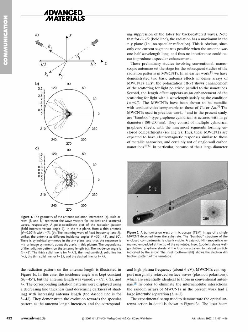
These preliminary studies involving conventional, macro-scopic antennae set the stage for the subsequent studies of theradiation patterns in MWCNTs. In an earlier work,[1] we havedemonstrated two basic antenna effects in dense arrays ofMWCNTs. First, the polarization effect shows enhancementof the scattering for light polarized parallel to the nanotubes.Second, the length effect appears as an enhancement of thescattering for light with a wavelength satisfying the conditionl = mk/2. The MWCNTs have been shown to be metallic,with conductivities comparable to those of Cu or Au.[1] TheMWCNTs used in previous work,[1] and in the present study,are “bamboo”-type graphene cylindrical structures, with largediameters (80–200 nm). They consist of multiple cylindricalgraphene sheets, with the innermost segments forming en-closed compartments (see Fig. 2). Thus, these MWCNTs areexpected to have electromagnetic responses similar to thoseof metallic nanowires, and certainly not of single-wall carbonnanotubes.[8–12] In particular, because of their large diameter
and high plasma frequency (about 6 eV), MWCNTs can sup-port marginally retarded surface waves (plasmon polaritons),which are essentially identical to those in conventional anten-nae.[8] In order to eliminate the internanotube interactions,the random arrays of MWCNTs in the present work had alarge intertube separation (L >> k).
The experimental setup used to demonstrate the optical an-tenna action in detail is shown in Figure 3a. The laser beam
CO
MM
UN
ICATI
ON
422 www.advmat.de © 2007 WILEY-VCH Verlag GmbH & Co. KGaA, Weinheim Adv. Mater. 2007, 19, 421–426
Figure 1. The geometry of the antenna-radiation interaction (a). Bold ar-rows (ki and ks) represent the wave vectors for incident and scatteredwaves, respectively. A polar-coordinate plot of the radiation pattern(field intensity versus angle h), in the y–z plane, from a thin antenna(d = 0.001l) with l = 7k (b). The incoming wave of fixed frequency (and k),strikes the antenna at different incidence angles hi = 30°, 45°, and 60°.There is cylindrical symmetry in the x–y plane, and thus the response ismirror-image symmetric about the z-axis in this picture. The dependenceof the radiation pattern on the antenna length (c). The incidence angle ishi = 45°. The thick solid line is for l = k/2, the medium-thick solid line forl = k, the thin solid line for l = 2k, and the dashed line for l = 4k.
Figure 2. A transmission electron microscopy (TEM) image of a singleMWCNT detached from the substrate. The “bamboo” structure of theenclosed compartments is clearly visible. A catalytic Ni nanoparticle re-mained embedded at the tip of the nanotube. Inset (top-left) shows well-graphitized graphene sheets at the location adjacent to catalyst particleindicated by the arrow. The inset (bottom-right) shows the electron dif-fraction pattern of the nanotube.
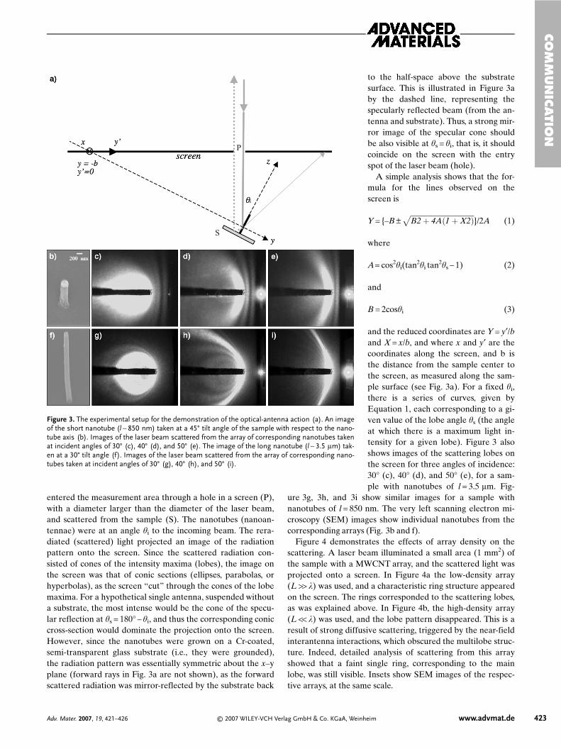
entered the measurement area through a hole in a screen (P),with a diameter larger than the diameter of the laser beam,and scattered from the sample (S). The nanotubes (nanoan-tennae) were at an angle hi to the incoming beam. The rera-diated (scattered) light projected an image of the radiationpattern onto the screen. Since the scattered radiation con-sisted of cones of the intensity maxima (lobes), the image onthe screen was that of conic sections (ellipses, parabolas, orhyperbolas), as the screen “cut” through the cones of the lobemaxima. For a hypothetical single antenna, suspended withouta substrate, the most intense would be the cone of the specu-lar reflection at hs = 180° – hi, and thus the corresponding coniccross-section would dominate the projection onto the screen.However, since the nanotubes were grown on a Cr-coated,semi-transparent glass substrate (i.e., they were grounded),the radiation pattern was essentially symmetric about the x–yplane (forward rays in Fig. 3a are not shown), as the forwardscattered radiation was mirror-reflected by the substrate back
to the half-space above the substratesurface. This is illustrated in Figure 3aby the dashed line, representing thespecularly reflected beam (from the an-tenna and substrate). Thus, a strong mir-ror image of the specular cone shouldbe also visible at hs = hi, that is, it shouldcoincide on the screen with the entryspot of the laser beam (hole).
A simple analysis shows that the for-mula for the lines observed on thescreen is
Y = {–B ±������������������������������������B2 � 4A�1 � X2��
}/2A (1)
where
A= cos2hi(tan2hi tan2hs – 1) (2)
and
B = 2coshi (3)
and the reduced coordinates are Y = y′/band X = x/b, and where x and y′ are thecoordinates along the screen, and b isthe distance from the sample center tothe screen, as measured along the sam-ple surface (see Fig. 3a). For a fixed hi,there is a series of curves, given byEquation 1, each corresponding to a gi-ven value of the lobe angle hs (the angleat which there is a maximum light in-tensity for a given lobe). Figure 3 alsoshows images of the scattering lobes onthe screen for three angles of incidence:30° (c), 40° (d), and 50° (e), for a sam-ple with nanotubes of l = 3.5 lm. Fig-
ure 3g, 3h, and 3i show similar images for a sample withnanotubes of l = 850 nm. The very left scanning electron mi-croscopy (SEM) images show individual nanotubes from thecorresponding arrays (Fig. 3b and f).
Figure 4 demonstrates the effects of array density on thescattering. A laser beam illuminated a small area (1 mm2) ofthe sample with a MWCNT array, and the scattered light wasprojected onto a screen. In Figure 4a the low-density array(L >> k) was used, and a characteristic ring structure appearedon the screen. The rings corresponded to the scattering lobes,as was explained above. In Figure 4b, the high-density array(L << k) was used, and the lobe pattern disappeared. This is aresult of strong diffusive scattering, triggered by the near-fieldinterantenna interactions, which obscured the multilobe struc-ture. Indeed, detailed analysis of scattering from this arrayshowed that a faint single ring, corresponding to the mainlobe, was still visible. Insets show SEM images of the respec-tive arrays, at the same scale.
CO
MM
UN
ICATIO
N
Adv. Mater. 2007, 19, 421–426 © 2007 WILEY-VCH Verlag GmbH & Co. KGaA, Weinheim www.advmat.de 423
P
S
Figure 3. The experimental setup for the demonstration of the optical-antenna action (a). An imageof the short nanotube (l ∼ 850 nm) taken at a 45° tilt angle of the sample with respect to the nano-tube axis (b). Images of the laser beam scattered from the array of corresponding nanotubes takenat incident angles of 30° (c), 40° (d), and 50° (e). The image of the long nanotube (l ∼ 3.5 lm) tak-en at a 30° tilt angle (f). Images of the laser beam scattered from the array of corresponding nano-tubes taken at incident angles of 30° (g), 40° (h), and 50° (i).
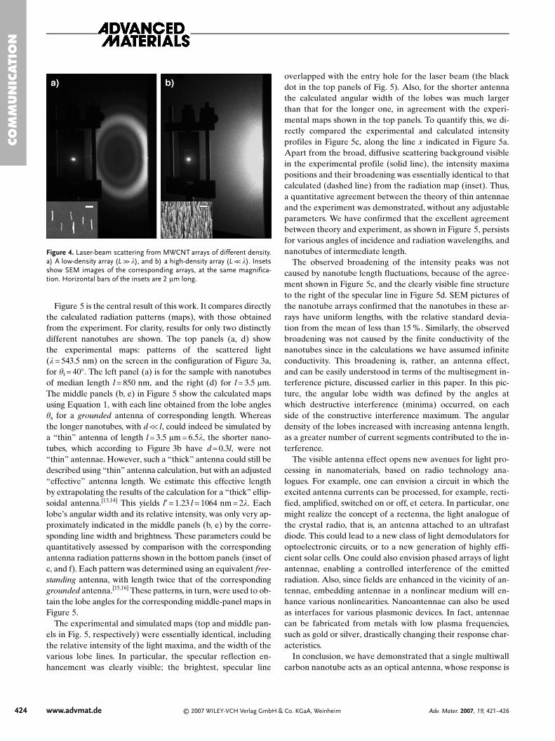
Figure 5 is the central result of this work. It compares directlythe calculated radiation patterns (maps), with those obtainedfrom the experiment. For clarity, results for only two distinctlydifferent nanotubes are shown. The top panels (a, d) showthe experimental maps: patterns of the scattered light(k = 543.5 nm) on the screen in the configuration of Figure 3a,for hi = 40°. The left panel (a) is for the sample with nanotubesof median length l = 850 nm, and the right (d) for l = 3.5 lm.The middle panels (b, e) in Figure 5 show the calculated mapsusing Equation 1, with each line obtained from the lobe angleshs for a grounded antenna of corresponding length. Whereasthe longer nanotubes, with d << l, could indeed be simulated bya “thin” antenna of length l = 3.5 lm = 6.5k, the shorter nano-tubes, which according to Figure 3b have d ≈ 0.3l, were not“thin” antennae. However, such a “thick” antenna could still bedescribed using “thin” antenna calculation, but with an adjusted“effective” antenna length. We estimate this effective lengthby extrapolating the results of the calculation for a “thick” ellip-soidal antenna.[13,14] This yields l′ = 1.23 l = 1064 nm = 2k. Eachlobe’s angular width and its relative intensity, was only very ap-proximately indicated in the middle panels (b, e) by the corre-sponding line width and brightness. These parameters could bequantitatively assessed by comparison with the correspondingantenna radiation patterns shown in the bottom panels (inset ofc, and f). Each pattern was determined using an equivalent free-standing antenna, with length twice that of the correspondinggrounded antenna.[15,16] These patterns, in turn, were used to ob-tain the lobe angles for the corresponding middle-panel maps inFigure 5.
The experimental and simulated maps (top and middle pan-els in Fig. 5, respectively) were essentially identical, includingthe relative intensity of the light maxima, and the width of thevarious lobe lines. In particular, the specular reflection en-hancement was clearly visible; the brightest, specular line
overlapped with the entry hole for the laser beam (the blackdot in the top panels of Fig. 5). Also, for the shorter antennathe calculated angular width of the lobes was much largerthan that for the longer one, in agreement with the experi-mental maps shown in the top panels. To quantify this, we di-rectly compared the experimental and calculated intensityprofiles in Figure 5c, along the line x indicated in Figure 5a.Apart from the broad, diffusive scattering background visiblein the experimental profile (solid line), the intensity maximapositions and their broadening was essentially identical to thatcalculated (dashed line) from the radiation map (inset). Thus,a quantitative agreement between the theory of thin antennaeand the experiment was demonstrated, without any adjustableparameters. We have confirmed that the excellent agreementbetween theory and experiment, as shown in Figure 5, persistsfor various angles of incidence and radiation wavelengths, andnanotubes of intermediate length.
The observed broadening of the intensity peaks was notcaused by nanotube length fluctuations, because of the agree-ment shown in Figure 5c, and the clearly visible fine structureto the right of the specular line in Figure 5d. SEM pictures ofthe nanotube arrays confirmed that the nanotubes in these ar-rays have uniform lengths, with the relative standard devia-tion from the mean of less than 15 %. Similarly, the observedbroadening was not caused by the finite conductivity of thenanotubes since in the calculations we have assumed infiniteconductivity. This broadening is, rather, an antenna effect,and can be easily understood in terms of the multisegment in-terference picture, discussed earlier in this paper. In this pic-ture, the angular lobe width was defined by the angles atwhich destructive interference (minima) occurred, on eachside of the constructive interference maximum. The angulardensity of the lobes increased with increasing antenna length,as a greater number of current segments contributed to the in-terference.
The visible antenna effect opens new avenues for light pro-cessing in nanomaterials, based on radio technology ana-logues. For example, one can envision a circuit in which theexcited antenna currents can be processed, for example, recti-fied, amplified, switched on or off, et cetera. In particular, onemight realize the concept of a rectenna, the light analogue ofthe crystal radio, that is, an antenna attached to an ultrafastdiode. This could lead to a new class of light demodulators foroptoelectronic circuits, or to a new generation of highly effi-cient solar cells. One could also envision phased arrays of lightantennae, enabling a controlled interference of the emittedradiation. Also, since fields are enhanced in the vicinity of an-tennae, embedding antennae in a nonlinear medium will en-hance various nonlinearities. Nanoantennae can also be usedas interfaces for various plasmonic devices. In fact, antennaecan be fabricated from metals with low plasma frequencies,such as gold or silver, drastically changing their response char-acteristics.
In conclusion, we have demonstrated that a single multiwallcarbon nanotube acts as an optical antenna, whose response is
CO
MM
UN
ICATI
ON
424 www.advmat.de © 2007 WILEY-VCH Verlag GmbH & Co. KGaA, Weinheim Adv. Mater. 2007, 19, 421–426
Figure 4. Laser-beam scattering from MWCNT arrays of different density.a) A low-density array (L >> k), and b) a high-density array (L << k). Insetsshow SEM images of the corresponding arrays, at the same magnifica-tion. Horizontal bars of the insets are 2 lm long.
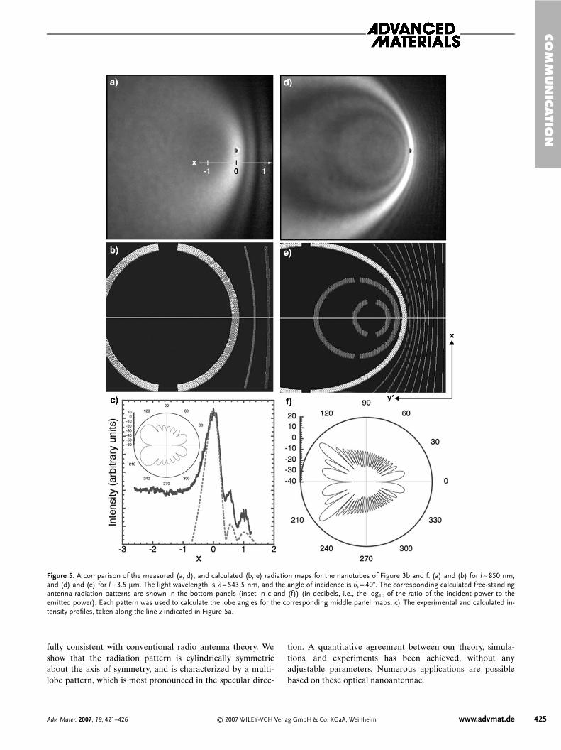
fully consistent with conventional radio antenna theory. Weshow that the radiation pattern is cylindrically symmetricabout the axis of symmetry, and is characterized by a multi-lobe pattern, which is most pronounced in the specular direc-
tion. A quantitative agreement between our theory, simula-tions, and experiments has been achieved, without anyadjustable parameters. Numerous applications are possiblebased on these optical nanoantennae.
CO
MM
UN
ICATIO
N
Adv. Mater. 2007, 19, 421–426 © 2007 WILEY-VCH Verlag GmbH & Co. KGaA, Weinheim www.advmat.de 425
Figure 5. A comparison of the measured (a, d), and calculated (b, e) radiation maps for the nanotubes of Figure 3b and f: (a) and (b) for l ∼ 850 nm,and (d) and (e) for l ∼ 3.5 lm. The light wavelength is k = 543.5 nm, and the angle of incidence is hi = 40°. The corresponding calculated free-standingantenna radiation patterns are shown in the bottom panels (inset in c and (f)) (in decibels, i.e., the log10 of the ratio of the incident power to theemitted power). Each pattern was used to calculate the lobe angles for the corresponding middle panel maps. c) The experimental and calculated in-tensity profiles, taken along the line x indicated in Figure 5a.

Experimental
MWCNTs were grown using the plasma enhanced chemical vapordeposition (PECVD) technique [17]. Corning 1737 aluminosilicateglass substrates, 25 mm× 25 mm, were first sputter-coated with a thinlayer of 15 nm Cr by magnetron sputtering, to obtain a conductivebut still transparent layer. The PECVD nanotubes were grown on ran-domly distributed Ni nanoparticles, which were deposited electro-chemically [18]. Briefly, the Cr-coated substrate was used as a cathodein an electrolytic bath, with an aqueous solution of 0.01 M NiSO4 and0.01 M H3BO4 as the electrolyte, and a graphite electrode as an anode.The deposition area was 15 mm× 15 mm, and the spacing between theelectrodes 15 mm. The optimal Ni particle dispersion was obtained at2 mA dc current, and 2.2 s deposition time. The nanotubes weregrown in a hot filament PECVD system. A base pressure of 10–6 torr(1 torr = 133.322 Pa) was obtained before introducing acetylene andammonia (40:160 sccm) into the system. The growth process was per-formed at 40 torr, for 8 min, yielding 5–6 lm long MWCNTs. Thesubstrate temperature was kept below 660 °C.
Received: May 31, 2006Revised: October 10, 2006
–[1] Y. Wang, K. Kempa, B. Kimball, J. B. Carlson, G. Benham, W. Z. Li,
T. Kempa, J. Rybczynski, A. Herczynski, Z. F. Ren, Appl. Phys. Lett.2004, 85, 2607.
[2] M. S. Dresselhaus, Nature 2004, 432, 959.[3] F. E. Terman, Radio Engineering, McGraw-Hill, NewYork 1947.
[4] J. A. Stratton, Electromagnetic Theory, McGraw-Hill, New York1941.
[5] C. A. Balanis, Antenna Theory: Analysis and Design, Wiley, NewYork 2005.
[6] K. Fujimoto, A. Henderson, K. Hirasawa, J. R. James, Small Anten-nae, Wiley, New York 1988.
[7] G. Burke, Numerical Electromagnetics Code, NEC-4.1D, LawrenceLivermore National Laboratory, http://www.nec2.org/ (accessed No-vember 2006).
[8] G. Y. Slepyan, S. A. Maksimenko, A. Lakhtakia, O. Yevtushenko,A. V. Gusakov, Phys. Rev. B 1999, 60, 17 136.
[9] G. W. Hanson, IEEE Trans. Antennas Propag. 2005, 53, 3426.[10] G. W. Hanson, IEEE Trans. Antennas Propag. 2006, 54, 76.[11] P. J. Burke, S. Li, Z. Yu, arXiv:cond-mat/0408418 .[12] G. Ya. Slepyan, M. V. Shuba, S. A. Maksimenko, A. Lakhtakia,
Phys. Rev. B 2006, 73, 195 416.[13] J. A. Stratton, L. J. Chu, J. Appl. Phys. 1941, 12, 230.[14] P. Moon, D. E. Spencer, Field Theory for Engineers, Van Nostrand
Reinhold, New York 1961.[15] J. D. Jackson, Classical Electrodynamics, 3rd ed., Wiley, New York
1998.[16] The mirror image effect occurs only if the response of the electrons
in the mirror is sufficiently fast, i.e., the working frequency is well be-low the plasma frequency of the mirror metal. This was the case inour experiment, since the plasma frequency of Cr is in UV.
[17] Z. F. Ren, Z. P. Huang, J. W. Xu, J. H Wang, P. Bush, M. P. Siegal,P. N. Provencio, Science 1998, 282, 1105.
[18] Y. Tu, Z. P. Huang, D. Z. Wang, J. G. Wen, Z. F. Ren, Appl. Phys.Lett. 2002, 80, 4018.
______________________
CO
MM
UN
ICATI
ON
426 www.advmat.de © 2007 WILEY-VCH Verlag GmbH & Co. KGaA, Weinheim Adv. Mater. 2007, 19, 421–426