calculation of evaporation rate of a droplets cluster and conceptual design of a structure utilizing...
TRANSCRIPT
1
Calculation of evaporation rate of adroplets cluster and conceptual designof a structure utilizing water droplets
for evaporationKang Zhou
Master of Science in Architecture, Department of Architecture, Collegeof Architecture, Planning and Landscape Architecture, University of Arizona
Abstract
It has been known that workers of a honey bee colony bring water droplets into their hive, spraying it on the frames and brood cells, and fanning their wings when ambient temperature rises higher than appropriate. And several species from Namibian beetles demonstrate unique water harvesting strategies from the morning fog via the bumps and troughs above their elytra, where water droplets will condense and grow into a size large enough that they will slide down from its back to be consumed afterwards. Interestingly, the dropwise evaporation can be far more effective in its cooling effect than swamp cooler prevalently used in arid regions. A group of parameters were selected as the boundary condition for calculating the evaporation rate of both a swamp cooler, and that a dropwise evaporative cooler, by using the Monte Carlo Simulation, Ranz and Marshall Correlation of heat and mass transfer analogy and modified drag force expressionfor discharged water droplets. The calculation shows under appreciable circumstances the dropwise evaporation can rival film evaporation. In consequence, the evaporative cooler system that is designed to utilize dropwise evaporation can be theoretically much more effective and efficient in water and energy use and easier to be regulated by humans than state of art evaporative coolers. The key parameters and some control strategies were pinpointed that can help raise the evaporation rate of a droplets cluster, shedding light on its further applications in industry and supporting human lives, like cooling tower of a power plant, and a fresh water harvesting net. Meanwhile, a conceptual design of an auxiliary structure, called hydro hair system, is proposed according to the
2
implication coming from Honey bees’ legs and hairs, and also the pattern of the surface of the elytra of Namibian Beetles.
Key Words: Hydro Hair · Evaporation rate · Dropwise evaporation · Film evaporation · Internal flow · Slip Velocity · Temperature
Outline of the article:
1. Introduction of evaporative cooling inside honey colony and water harvesting of Namibian beetles.
2. Monte Carlo simulation reveals the tendency that splitting of a water droplet into a cluster creates faster evaporation rate of the cluster than that of the original water droplet. For two clusters of water droplets, Monte Carlo simulation shows that thecluster with droplets of similar size gathers larger evaporation rate than the one comprising droplets with very different size (standard deviation of droplet’s diameters measures the extent ofdifference of size of water droplets).
3. Making a statement that Ranz and Marshall Correlation is selectedas a concise expression for solving problems of dropwise evaporation fitting into the equilibrium model, and for those droplets evaporation dominated by non-equilibrium effect, which have diameters less than 50 microns, they are not considered in this paper.
4. The effectiveness of evaporation of water droplets depends on itsdistribution, especially on a perpendicular direction. The sizesof water drops, and the velocity of air movement together determines the terminal velocity and trajectory of those water droplets. Thus according to the combined data of droplets drift, distance that a droplet with a certain size travels horizontally and perpendicularly and the normal size of an evaporative cooler,the terminal velocity of droplets having diameters in between [50
3
μm, 170 μm] and their trajectory after ejection is estimated. After then, the discharging velocity is assigned to the nozzle.
5. The horizontal velocity of air movement is determined by the medium value of desired air velocity for the human thermal comfort at the outlet of the evaporative cooler. With this velocity set the same for both swamp cooler and dropwise evaporative cooler, the total evaporation rate for the swamp cooler and the dropwise evaporative cooler is estimated. The air
movement inside the tubes of a swamp cooler pad is V/cos 15°
(estimated angle for the tubes inside a celdek with dimension of 2’ by 2’), and the air movement relative to a water droplet after
its immediate discharging is √V2+V20
. V0 is the initial
velocity right after discharging. In both cases, Reynolds Analogywas used to estimate the total evaporation rate.
6. Comparison was made between the evaporation rate of swamp cooler and that of the instant first stage evaporation of dropwise evaporative cooler using droplets with diameter of 50 μm, 60 μm and 70 μm, each of which has a ratio of number of 1: 1.1: 1. Governing equations are analyzed briefly and variation of key parameters, like the air velocity and diameter of water droplets show interesting results. The advantages of dropwise evaporative cooling in terms of evaporation rate relevant to the water and energy use were highlighted.
7. Second stage evaporation that relies on the evaporation of the residue of water droplets after their first stage evaporation andcondensed water droplets formed on the hydro hair micro structurewas proposed. The key factors influencing its design and materialwere discussed. Potential usages of the proposed micro scale net-like structure for water harvesting from humid air and fog and for evaporative cooling in cooling tower in a power plant, were mentioned, together with the possibility of applying self-cleaning to maintain its performance. After then the potential ofutilizing parametric design and relevant technology for its fabrication and production was described briefly.
8. Unsolved issues and Future Research.
4
Introduction:
It has been known for more than a century that workers of a honey bee colony conduct evaporative cooling to regulate their nest temperature,during hot summer days [1]. In order words, they bring water droplets back to their nest to cool the air temperature inside in order to prevent their nest from being overheated. Water can also be stored in workers’crop and brought back [2]. There are two types of evaporationthat contribute to the cooling process, namely, evaporation by unfolding and refolding their tongues and expose them to the air, which is termed as tongue lash; or evaporation via bringing in water droplets and spray/smear them on the frames and caps on the brood cells [3-4]. Interestingly, it worth noting that spraying splits waterinto smaller water droplets. It is also found that honey bee nest is made of wax, a type of material that that has low surface energy, allowing water to keep their spherical caps, and a relatively high contact angle. Furthermore, the hairs on the a worker’s leg that function as the carrier of water droplets are made from Chitin coveredwith wax-both of which is hydrophobic material. Several questions can be asked about the second type of cooling, which utilizes the water droplets to cooling their ambient temperature: Does spraying behavior,or the splitting of water droplet has an effect on the evaporation? 2)Does dropwise form, in which they are carried back to the hive, and are scattered on the comb surface and frames, play a special role in evaporation? 3) If evaporation of dropwise form will be unique in someaspects, could this uniqueness be maintained by applying certain material with certain geometric characteristics to build a structure that helps evaporation?
Recently, another interesting feature regarding water collection that appears on several species of genus Onymacris among Namib desert Darkling beetles reveals remarkable mechanisms of assembling water from nocturnal and early morning fogs [5-6]. More detailed observations reveal that that the array, or the distribution of hydrophobic and hydrophilic material in a certain pattern can result in decent water catching strategies in hot, arid regions with negligible rainfall. Research of the coating of their elytra reveals in addition to low surface energy and hierarchic structure-the key factors that make the elytra hydrophobic, the pattern formed from
5
hydrophilic bumps, and hydrophobic troughs also play an important rolein water harvesting-a geometric feature that cannot be grasped by simply looking at material itself. It further reminds us that while the sessile drops have been of the focus for scientists studying hydrophobic and superhydrophobic material [7-9], the inquiry and design of how to put such material to work purposefully, have seldom been touched. Further questions can be asked, however, by putting the thoughts of water capturing surface together with honey bee hairs thatbear water droplets: can the same pattern shown on the beetles’ back be emulated with hair based structure? Since hairs, can catch water droplets and maintain dropwise form, as has been shown by honey bees, and bundles, or nets constituted by hairs, provide enough hollowed, interconnected space for air to flow across easily, which precipitatesthe evaporation of water droplets sitting on hairs. In addition, hydrophilic hairs can be fabricated together with hydrophobic hairs, creating spatial array that mimics the water harvesting pattern, and its mechanism that is capable of gathering water from tiny, flying water droplets in fog. Could such a structure make a difference for evaporative cooling?
While it is reasonable to figure out feasibility of constructing such a structure, the value of such prototype should also be evaluated fromsomewhere else: Could dropwise evaporation be superior than evaporation of other types, such as film evaporation, when considered under certain conditions? The answers lies in various models built during the last century regarding evaporation of single water droplets, either freely flying, or sessile. Researchers in early days,like Ranz W.E., Marshall, W.R., Fuchs, N.A., and recent ones, like Y.O. Popov, H. Hu and R.G. Larson, R.D. Deegan, Shripad J Gokhale, WeiXu, Hanneke Gelderblom etc. have revealed regulations for the evaporation of single water droplets in various forms, which fit in calculation conducted under different circumstances, with different substrate material and solute. Dropwise evaporation has its diverse applications in engineering such as spray drying, fuel injection into combustion engines, medical care, controlling the deposition of particles on solid surfaces, rapid cooling by drop wise heat exchanges[10], and its cooling aspects can be described by existing mathematical expressions of heat and mass transfer, which further can be calculated either by known water vapor pressure, or Reynolds Analogy for heat and mass transfer. For evaporation of droplets
6
cluster, various models gave very similar results, when the evaporation rate is low, and the medium temperature or temperature of liquid drops is far less than the boiling point of liquid water [11]. Besides, large water droplets can be precisely described by equilibrium models, while smaller water droplets would exhibit non equilibrium effect which makes previous model invalid. For the evaporative cooling, the Ranz and Marshall Correlation is widely knownas a concise expression for equilibrium model for dropwise evaporation, and the heat and mass transfer analogy is suitable to be applied using this correlation. Evaporation with non-equilibrium effect exhibited by droplets with diameter falling below 50 μm can only be predicted precisely by models, like Herz-Knudson Law. As for turbulent flow, droplet dispersion may seem to be governed by classical D2 law-a diffusion dominated process described by Godsave andSpalding. The commonly operation for model spraying of droplets clusters includes the rapid mixing model (Stefan flow) and Abramzon-Sirignano Model. Among all the above-mentioned models, Ranz and Marshall Correlation is selected to conduct this research.
Methodology of the simulation:
Use Monte Carlo simulation to expose the underlying correlation between droplet’s size after split and evaporation rate, which was then generalized to offer background for the upcoming simulation.
Choose a group of basic parameters as the boundary condition for conducting the calculation of the evaporation rate, i.e. outside air temperature, tap water temperature, and a group of parameters that is pertinent to mass transfer is estimated at the atmospheric pressure, according to the weather data of Tucson.
Application of Stoke’s drag and Kishore’s modified drag force coefficient [12] to find out the terminal velocity for water droplets in the perpendicular direction. Estimation of the approximate terminalvelocity for droplets with diameter ranging from 50 µm to 170 µm is then referenced to determine the discharging velocity for the nozzle. On the other hand, the original velocity of horizontal air movement isassigned according to the research of human thermal comfort, which will represent the initial slip velocity of water droplets right afterthey leave the nozzle.
7
Using the above mentioned boundary condition and parameters to determine the evaporation rate of a swamp cooler.
Splitting the same amount of water that vaporizes in one second into acluster of water droplets, with given diameters and correspondent ratio of the number of each type, while referencing the terminal velocity and horizontal air velocity to computer the total evaporationrate for the cluster. The result will then be divided by the evaporation rate of the swamp cooler, in order for the comparison to be made.
Change parameters of both the celdek of the swamp cooler, and of the droplets in that cluster, to find out the key parameters that influence ratio. Change of the parameters each time will be regarded as one scheme, and the results of several schemes will be discussed briefly. Implication will be pointed out, and the correspondent applications will be mentioned.
8
Tendency of dropwise evaporation as seen from the Ranz and Marshall’s correlation:
The evaporation of a liquid drop is basically a simultaneous heat and mass transfer operation in which heat for evaporation is transferred by conduction and convection from warm air to drop surface from which the vapor is transferred by diffusion and convection back into the air[13]. And self-cooling of the drop surface is an important factor withwater when it is rapidly evaporating in a completely dry medium. All the below equations used to describe the evaporation of droplets sizedbetween [50μm, 170μm] in diameter neglect the mean free path of water
9
molecules as the radii of these droplets are significantly greater [14].The calculation for this research, aims at revealing the potential benefits and efficiency of applying dropwise evaporative cooling . The diameter of water droplets, relative velocity, or slip velocity between water droplets and gaseous medium, and other parameters affecting the fluid dynamics properties and transport properties are estimated according to the initial stage derived from established theory, engineering table, local climatic condition (Tucson) and assumptions. RH (relative humidity), temperature, and terminal velocity in perpendicular direction are estimated or determined under Atmospheric Pressure.
The Ranz and Marshall’s correlation for heat (left) and mass transfer (right) may be written as [15]
Nu=2+0.552Red1/2PrG1/3 ,
Sh=2+0.552Red1/2ScG1 /3 ;
(1)
The correlation of mass transfer coefficient and Average Sherwood Number may be written as
ShD=hmDDAB
;
(2)
ShD is the Average Sherwood Number over the whole surface of a single
water droplet, hm is the convection mass transfer coefficient (m/s) andDAB is the binary diffusion coefficient at one atmospheric pressure [16].
(3)
nA=AShm(ρA,s−ρA,∞)=ASnA''
(4)
Equation (4) tells that the total evaporation rate of a cluster is
determined by total effective surface area AS for evaporation, and the
nA''=hm(ρA,s−ρA,∞)
10
evaporation rate per unit surface area. If both parameters increase, then the total evaporation rate has to increase. It is also shown clearly that diameter of water droplets both affects the evaporation rate, and the surface area. Thus an examination of initial diameter ofdischarged water droplets will give us insights that assist our further discussion.
Theorem 1: Separation/split of spherical or spheroid water droplets into smaller water droplets always results in a larger surface area intotal for these smaller droplets, compared to the original larger water droplet.
Prove:
Monte Carlo simulation was conducted for 90 number in the range of [0, 1] were randomly generated by computer via Excel, and were assigned tobe diameters of water droplets after being split. The rule for separation can be expressed by one equation, which stands for the conservation of volume of water droplets before and after separation
43π(D02 )
3
=43π(D12 )
3
+43π(D22 )
3
(5)
Before separation the surface area Ai=4π(D0
2 )2
; After splitting the
surface area becomes Ae=4π(D12 )
2
+4π(D22 )2
(6)
D0 stands for the initial diameter of droplet, assuming equal to 1mm, while D1 , D2 represent the diameter of two water droplets after splitting. Splitting from one single droplet into two is presented here to show the the general features of splitting, i.e., the resultant total surface area of these two droplets is always larger than the original surface area, and the larger the difference of waterdroplets after splitting, the smaller the total surface area increase will be. The subsequent two droplets with their radii being equal givethe largest total surface area.
11
0
0.5
1
1.5
2
2.5
3
3.5
4
4.5
S1+S2radius differenceS0
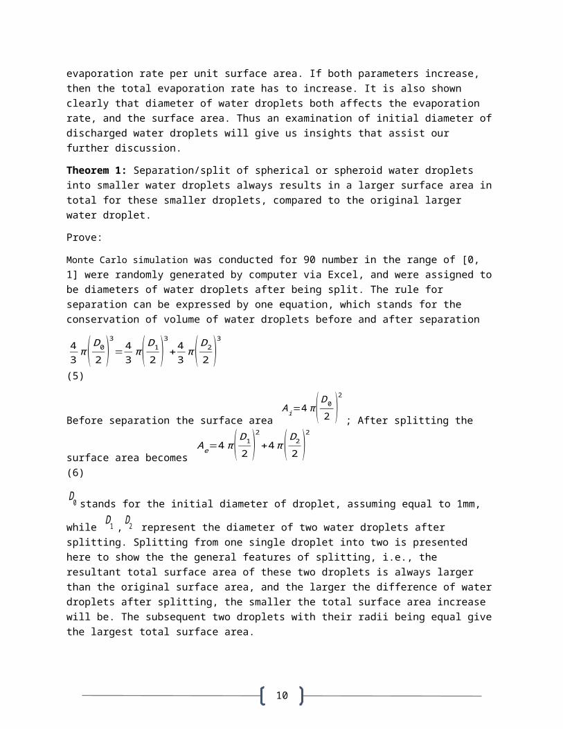
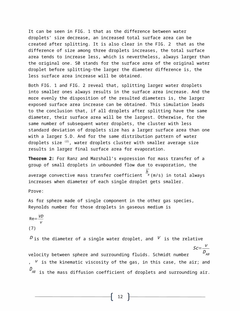
FIG. 2- plot of surface area of water droplets before and after
splitting into 3 droplets; D0=1 mm. And its surface area is represented by S0. S1+S2+S3 represents the total surface area after separation. Two droplets have their diameter (mm) as random numbers between 0 and
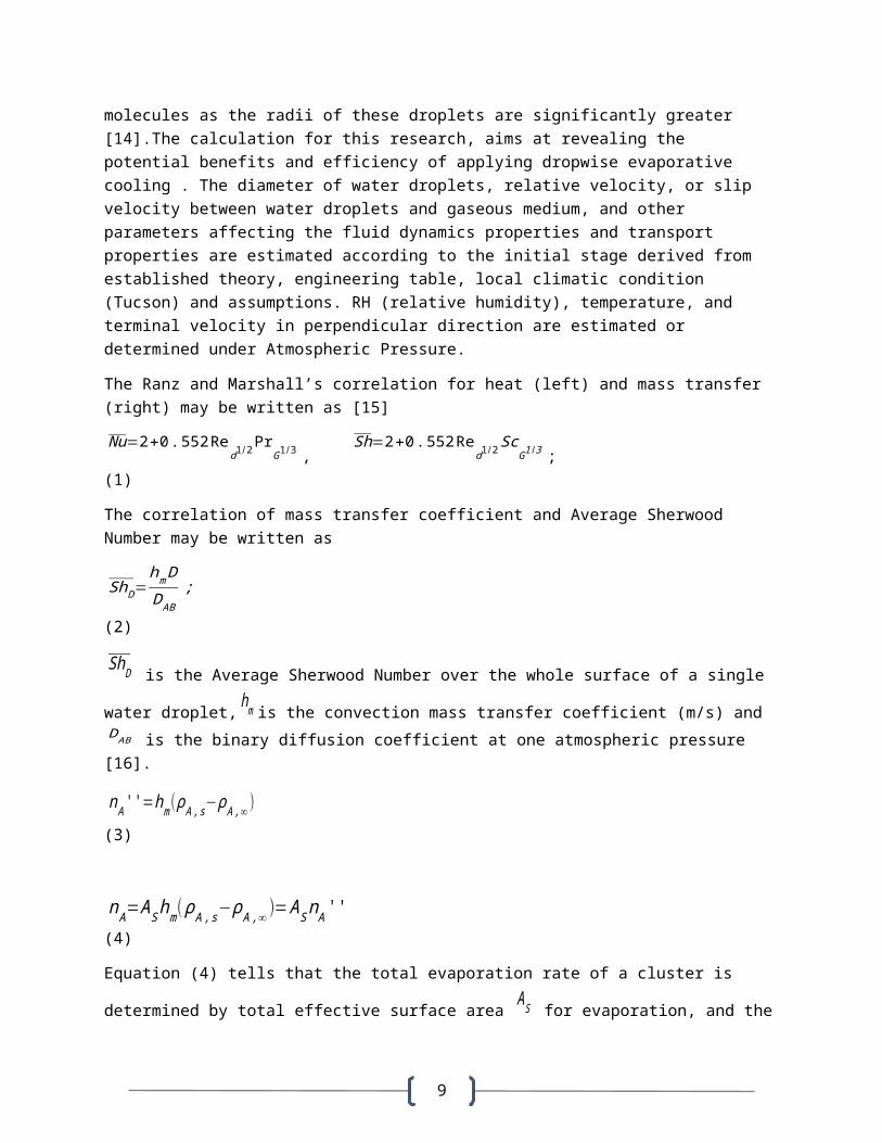
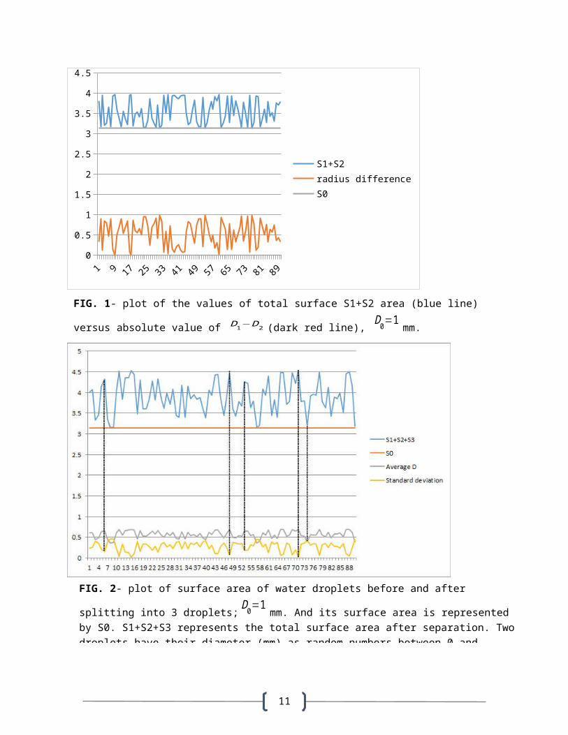
FIG. 1- plot of the values of total surface S1+S2 area (blue line)
versus absolute value of D1−D2 (dark red line), D0=1 mm.
12
It can be seen in FIG. 1 that as the difference between water droplets’ size decrease, an increased total surface area can be created after splitting. It is also clear in the FIG. 2 that as the difference of size among three droplets increases, the total surface area tends to increase less, which is nevertheless, always larger thanthe original one. S0 stands for the surface area of the original waterdroplet before splitting-the larger the diameter difference is, the less surface area increase will be obtained.
Both FIG. 1 and FIG. 2 reveal that, splitting larger water droplets into smaller ones always results in the surface area increase. And themore evenly the disposition of the resulted diameters is, the larger exposed surface area increase can be obtained. This simulation leads to the conclusion that, if all droplets after splitting have the same diameter, their surface area will be the largest. Otherwise, for the same number of subsequent water droplets, the cluster with less standard deviation of droplets size has a larger surface area than onewith a larger S.D. And for the same distribution pattern of water droplets size (2), water droplets cluster with smaller average size results in larger final surface area for evaporation.
Theorem 2: For Ranz and Marshall’s expression for mass transfer of a group of small droplets in unbounded flow due to evaporation, the
average convective mass transfer coefficient hm (m/s) in total always increases when diameter of each single droplet gets smaller.
Prove:
As for sphere made of single component in the other gas species, Reynolds number for those droplets in gaseous medium is
Re=VDν
(7)
D is the diameter of a single water droplet, and V is the relative
velocity between sphere and surrounding fluids. Schmidt number Sc= ν
DAB, ν is the kinematic viscosity of the gas, in this case, the air; andDAB is the mass diffusion coefficient of droplets and surrounding air.
13
Substituting the expression for Reynolds number and Schmidt number into the expression of Sherwood number, one gets
Sh=2+0.552Red1/2ScG1 /3
=2+0.552 V1 /2D1/2
ν1 /6DAB1/3 ;
Since hm=
Sh×DABD , by substituting the expression of Sherwood number
into convection mass transfer coefficient, one gets
hm=2×DABD
+0.522×V1 /2D
AB2/3
ν1 /6D1/2 (8)
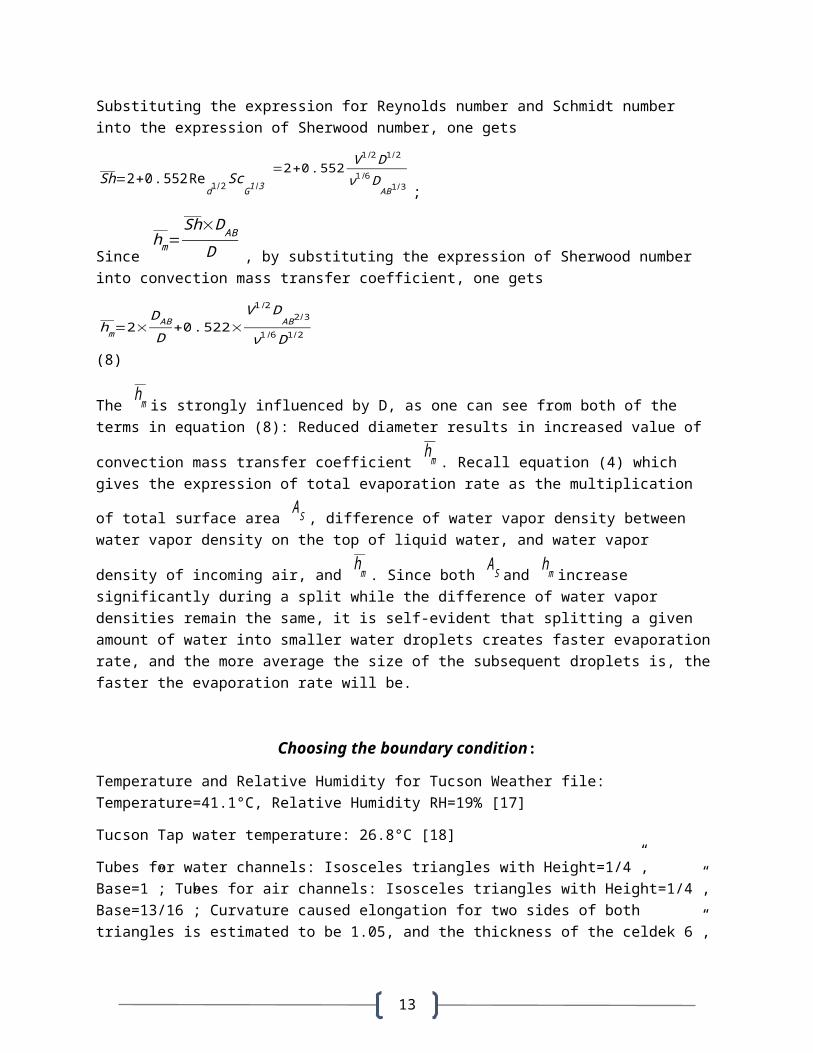
The hm is strongly influenced by D, as one can see from both of the terms in equation (8): Reduced diameter results in increased value of
convection mass transfer coefficient hm . Recall equation (4) which gives the expression of total evaporation rate as the multiplication
of total surface area AS , difference of water vapor density between water vapor density on the top of liquid water, and water vapor
density of incoming air, and hm . Since both AS and hm increase significantly during a split while the difference of water vapor densities remain the same, it is self-evident that splitting a given amount of water into smaller water droplets creates faster evaporationrate, and the more average the size of the subsequent droplets is, thefaster the evaporation rate will be.
Choosing the boundary condition:
Temperature and Relative Humidity for Tucson Weather file: Temperature=41.1°C, Relative Humidity RH=19% [17]
Tucson Tap water temperature: 26.8°C [18]
Tubes for water channels: Isosceles triangles with Height=1/4”, Base=1”; Tubes for air channels: Isosceles triangles with Height=1/4”,Base=13/16”; Curvature caused elongation for two sides of both triangles is estimated to be 1.05, and the thickness of the celdek 6”,
14
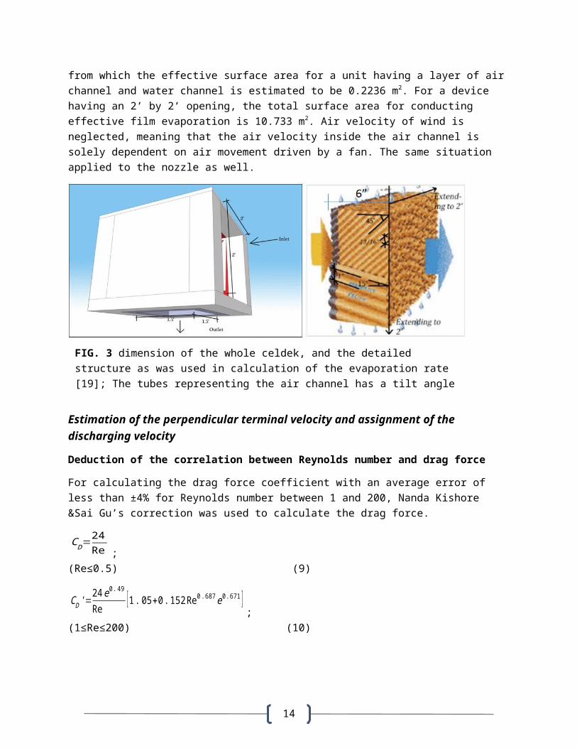
from which the effective surface area for a unit having a layer of airchannel and water channel is estimated to be 0.2236 m2. For a device having an 2’ by 2’ opening, the total surface area for conducting effective film evaporation is 10.733 m2. Air velocity of wind is neglected, meaning that the air velocity inside the air channel is solely dependent on air movement driven by a fan. The same situation applied to the nozzle as well.
Estimation of the perpendicular terminal velocity and assignment of the discharging velocity
Deduction of the correlation between Reynolds number and drag force
For calculating the drag force coefficient with an average error of less than ±4% for Reynolds number between 1 and 200, Nanda Kishore &Sai Gu’s correction was used to calculate the drag force.
CD=24Re ;
(Re≤0.5) (9)
CD'=24e0.49Re
[1.05+0.152Re0.687e0.671 ];
(1≤Re≤200) (10)
FIG. 3 dimension of the whole celdek, and the detailed structure as was used in calculation of the evaporation rate [19]; The tubes representing the air channel has a tilt angle of 15°, while the tilt angle for the water channels is -45°.
15
CD'=24Re
[1.05+0.152Re0.687]=25.2Re
+3.648Re−0.313
when e=1 ; (1≤Re≤200) (11)
Expression (11) will be suitable to address the drag force of water droplets that appear in this research, since they are usually very small and safe to be regarded as perfect spheres. In order to find out that if the expression given by Whitaker is suitable when 0.5≤Re≤1, or some other expression will be more helpful to evaluate the drag force coefficient, this research further considered the extent of deviation from drag force coefficient (9) and (11), creating an approximation for drag force coefficient when 0.5≤Re≤1 .
Reorganize that (11) which is the modified drag force coefficient can
also be rewritten asCD'=1.05CD+1.3491 C
D0.313 . Then the deviation of CD'
from original drag force CD equals
(CD'−CD )/CD=(1.05CD+1.3491 CD0.313−CD )/CD = 0.05+1.3491CD−0.687 ;
(12)
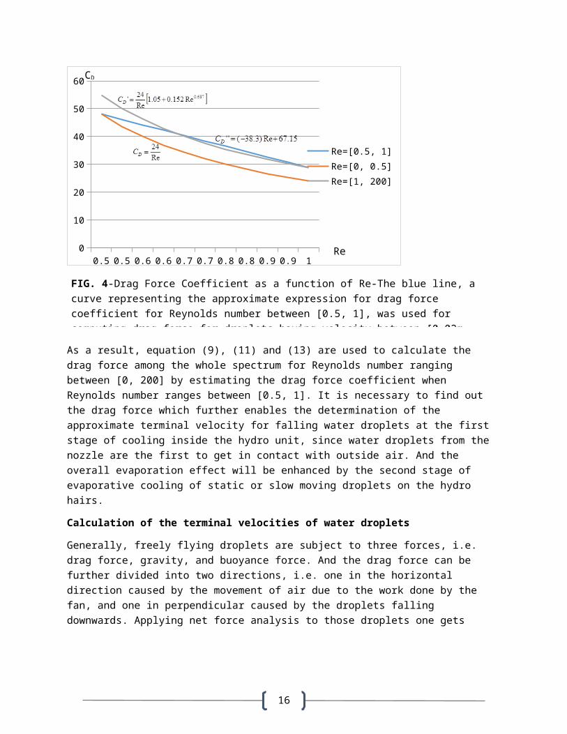
As Reynolds number varies between [0.5, 1], CD ranges within [24, 48] while CD' varies within [28.85, 54.93]. When CD=24, CD’=28.5 as Re=1; when CD=48, CD’=54.93 as Re=0.5. It further shows that CD and CD’ do not have any intersection for Re between [0.5, 1]. Since the Reynolds number in between this range will appear in our calculation, it is wise to find out the approximate expression of drag force coefficient for Reynolds number varies in this interval. The approximation was obtained by regarding the curve in this range as a function linearly changing with Re. By using the value of two end points, i.e., [0.5, 48] and [1, 28.85], the function can be written as
CD''=(−38.3)Re+67.15 (13)
Stokes’ ?
16
0.5 0.5 0.6 0.6 0.7 0.7 0.8 0.8 0.9 0.9 10
10
20
30
40
50
60
Re=[0.5, 1]Re=[0, 0.5]Re=[1, 200]
As a result, equation (9), (11) and (13) are used to calculate the drag force among the whole spectrum for Reynolds number ranging between [0, 200] by estimating the drag force coefficient when Reynolds number ranges between [0.5, 1]. It is necessary to find out the drag force which further enables the determination of the approximate terminal velocity for falling water droplets at the first stage of cooling inside the hydro unit, since water droplets from the nozzle are the first to get in contact with outside air. And the overall evaporation effect will be enhanced by the second stage of evaporative cooling of static or slow moving droplets on the hydro hairs.
Calculation of the terminal velocities of water droplets
Generally, freely flying droplets are subject to three forces, i.e. drag force, gravity, and buoyance force. And the drag force can be further divided into two directions, i.e. one in the horizontal direction caused by the movement of air due to the work done by the fan, and one in perpendicular caused by the droplets falling downwards. Applying net force analysis to those droplets one gets
FIG. 4-Drag Force Coefficient as a function of Re-The blue line, acurve representing the approximate expression for drag force coefficient for Reynolds number between [0.5, 1], was used for computing drag force for droplets having velocity between [0.02m,
Re
CD
17
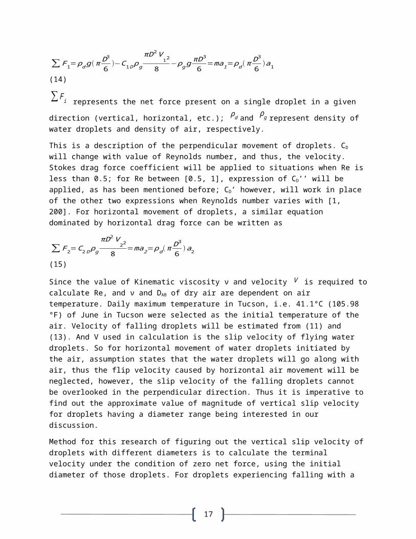
∑F1=ρdg(π D3
6)−C1Dρg
πD2V12
8−ρgg
πD3
6=ma1=ρd(π
D36
)a1 (14)
∑Fi represents the net force present on a single droplet in a given direction (vertical, horizontal, etc.); ρd and ρg represent density of water droplets and density of air, respectively.
This is a description of the perpendicular movement of droplets. CD will change with value of Reynolds number, and thus, the velocity. Stokes drag force coefficient will be applied to situations when Re isless than 0.5; for Re between [0.5, 1], expression of CD’’ will be applied, as has been mentioned before; CD’ however, will work in place of the other two expressions when Reynolds number varies with [1, 200]. For horizontal movement of droplets, a similar equation dominated by horizontal drag force can be written as
∑F2=C2DρgπD2V
22
8=ma2=ρd(π
D36
)a2 (15)
Since the value of Kinematic viscosity ν and velocity V is required tocalculate Re, and ν and DAB of dry air are dependent on air temperature. Daily maximum temperature in Tucson, i.e. 41.1°C (105.98 °F) of June in Tucson were selected as the initial temperature of the air. Velocity of falling droplets will be estimated from (11) and (13). And V used in calculation is the slip velocity of flying water droplets. So for horizontal movement of water droplets initiated by the air, assumption states that the water droplets will go along with air, thus the flip velocity caused by horizontal air movement will be neglected, however, the slip velocity of the falling droplets cannot be overlooked in the perpendicular direction. Thus it is imperative tofind out the approximate value of magnitude of vertical slip velocity for droplets having a diameter range being interested in our discussion.
Method for this research of figuring out the vertical slip velocity ofdroplets with different diameters is to calculate the terminal velocity under the condition of zero net force, using the initial diameter of those droplets. For droplets experiencing falling with a
18
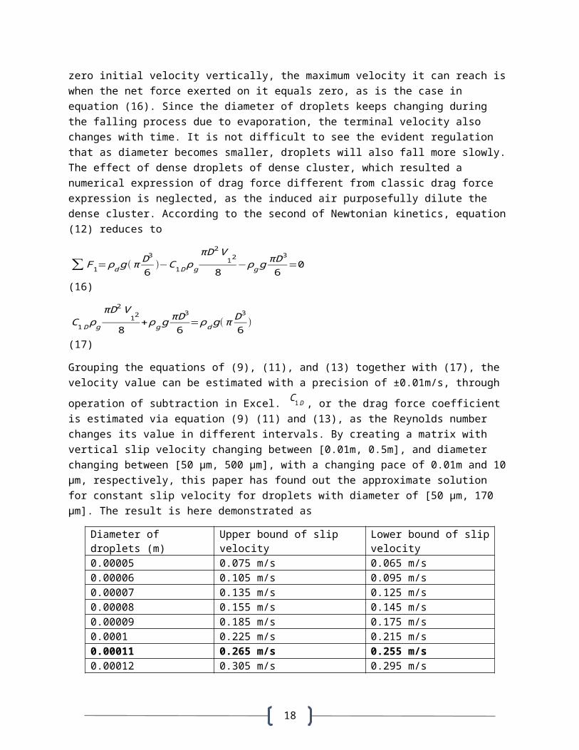
zero initial velocity vertically, the maximum velocity it can reach iswhen the net force exerted on it equals zero, as is the case in equation (16). Since the diameter of droplets keeps changing during the falling process due to evaporation, the terminal velocity also changes with time. It is not difficult to see the evident regulation that as diameter becomes smaller, droplets will also fall more slowly.The effect of dense droplets of dense cluster, which resulted a numerical expression of drag force different from classic drag force expression is neglected, as the induced air purposefully dilute the dense cluster. According to the second of Newtonian kinetics, equation(12) reduces to
∑F1=ρdg(π D3
6)−C1Dρg
πD2V12
8−ρgg
πD3
6=0
(16)
C1DρgπD2V
12
8+ρgg
πD36
=ρdg(π D3
6)
(17)
Grouping the equations of (9), (11), and (13) together with (17), the velocity value can be estimated with a precision of ±0.01m/s, through operation of subtraction in Excel. C1D , or the drag force coefficient is estimated via equation (9) (11) and (13), as the Reynolds number changes its value in different intervals. By creating a matrix with vertical slip velocity changing between [0.01m, 0.5m], and diameter changing between [50 µm, 500 µm], with a changing pace of 0.01m and 10µm, respectively, this paper has found out the approximate solution for constant slip velocity for droplets with diameter of [50 µm, 170 µm]. The result is here demonstrated as
Diameter of droplets (m)
Upper bound of slip velocity
Lower bound of slipvelocity
0.00005 0.075 m/s 0.065 m/s0.00006 0.105 m/s 0.095 m/s0.00007 0.135 m/s 0.125 m/s0.00008 0.155 m/s 0.145 m/s0.00009 0.185 m/s 0.175 m/s0.0001 0.225 m/s 0.215 m/s0.00011 0.265 m/s 0.255 m/s0.00012 0.305 m/s 0.295 m/s
19
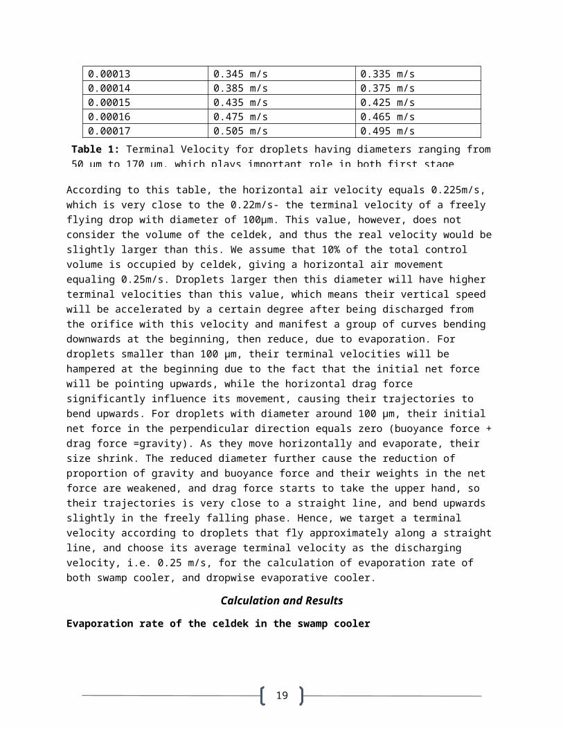
0.00013 0.345 m/s 0.335 m/s0.00014 0.385 m/s 0.375 m/s0.00015 0.435 m/s 0.425 m/s0.00016 0.475 m/s 0.465 m/s0.00017 0.505 m/s 0.495 m/s
According to this table, the horizontal air velocity equals 0.225m/s, which is very close to the 0.22m/s- the terminal velocity of a freely flying drop with diameter of 100µm. This value, however, does not consider the volume of the celdek, and thus the real velocity would beslightly larger than this. We assume that 10% of the total control volume is occupied by celdek, giving a horizontal air movement equaling 0.25m/s. Droplets larger then this diameter will have higher terminal velocities than this value, which means their vertical speed will be accelerated by a certain degree after being discharged from the orifice with this velocity and manifest a group of curves bending downwards at the beginning, then reduce, due to evaporation. For droplets smaller than 100 µm, their terminal velocities will be hampered at the beginning due to the fact that the initial net force will be pointing upwards, while the horizontal drag force significantly influence its movement, causing their trajectories to bend upwards. For droplets with diameter around 100 µm, their initial net force in the perpendicular direction equals zero (buoyance force +drag force =gravity). As they move horizontally and evaporate, their size shrink. The reduced diameter further cause the reduction of proportion of gravity and buoyance force and their weights in the net force are weakened, and drag force starts to take the upper hand, so their trajectories is very close to a straight line, and bend upwards slightly in the freely falling phase. Hence, we target a terminal velocity according to droplets that fly approximately along a straightline, and choose its average terminal velocity as the discharging velocity, i.e. 0.25 m/s, for the calculation of evaporation rate of both swamp cooler, and dropwise evaporative cooler.
Calculation and Results
Evaporation rate of the celdek in the swamp cooler
Table 1: Terminal Velocity for droplets having diameters ranging from50 µm to 170 µm, which plays important role in both first stage
20
The evaporation of the water film above the surface inside a celdek ismodelled as internal flow inside a pipe. The velocity inside each tubeequals V/cos15° . When V =0.25 m/s, mean velocity inside the air channelis regarded as 0.259 m/s. The Reynolds number for a near-isosceles triangle tube, is calculated via equation (7), in which all the
variables remain the same except that D will be replaced by Dh , which
is termed as hydraulic diameter. Dh=
4AcP , Ac is cross section area of
the tube, and P is the wetted parameter. The resulted Reynolds number is around 100, convincing us that laminar flow is formed as air travels through it. And thus the entry length, and its Sherwood number, was calculated accordingly. The hydraulic entry length turns out to be 0.0264 m, followed by fully developed laminar flow, whose Sherwood number is assigned with an arbitrary constant 2.7-a value between 3.11 and 2.47 for triangular shaped tubes [20]. Sherwood number is then used to calculate the mean convection mass transfer
coefficient inside the tubes, termed as hm . For the effective surface area for evaporation, please refer back to “Boundary condition” part. The water vapor density difference between water vapor present above
water film, termed as ρA,s , and water vapor in the air medium at largeρA,∞ , are determined via engineering table. Wet bulb temperature for the air equaling to 22.3°C, as was shown in the psychometric chart,
was selected so as to estimate the ρA,s . The selection of this temperature is controversial, and can cause significant difference forthe calculating results, which will be discussed shortly in the following sessions.
The result for this calculation yields evaporation rate of 0.00138 kg/s.
If the evaporation of a celdek occurs with 100% efficiency, meaning that all the water supply will undergo vaporization. Thus the evaporation rate we’ve calculated, represents some kind of inherent properties of film evaporation. The same amount of water that represents the evaporation rate of a celdek, will then be split into water droplets with a given size distribution. A similar calculation is performed for this cluster, yielding yet another evaporation rate, which will be compared with the original evaporation rate.
21
Evaporation rate of a droplets cluster:
Original evaporation rate:
If, the water evaporated equals the water that supplied, then this amount of water will be used again for the calculation of dropwise evaporative cooling-the size of water droplets are 50 μm, 60 μm and 70μm, respectively, and the number of each size of water droplet goes with a proportion of 1: 1.1: 1. All other boundary conditions were kept the same, except that the velocity of air movement will be combined with the velocity that all of the droplets carried when they
were discharged, that is to say, √V2+V20 . V0 had a value of 0.25 m/s,which was the initial velocity right after discharging . A droplets cluster comprising droplets of these types, have a final evaporation rate of 0.00150 kg/s, which is 8.3% larger than the evaporation rate rising from a water film being equal to 0.00138 kg/s.
Scheme 1: Increase horizontal air movement from 0.25 m/s to 0.3 m/s, with the ejection velocity of the nozzle changing simultaneously to 0.3 m/s
Increase of the horizontal velocity results in a slight increase of entry length for tubes in the celdek, and thus the overall Sherwood number, which gives a total evaporation rate 0.00139 kg/s. On the other hand, water droplets cluster can reach an evaporation rate of 0.00153 kg/s, being 10.4% larger than that of the swamp cooler.
Scheme 2: Change the temperature of saturated air right above the water surface from 22.3 ˚C to 24.6 ˚C
24.6°C is the arithmetic mean value of the wetbulb temperature of the air medium (22.3°C) and the temperature of the water (26.8°C). If the temperature of the saturated air right above the surface of water is lifted from 22.3°C to 24.6°C, the water density will rise from 0.0198 kg/m3 to 0.0227 kg/m3, creating a large difference for the performanceof swamp cooler and dropwise evaporative cooler: simulation shows thatinstantaneous evaporation rate for dropwise evaporative cooler can be 41% larger than that of the swamp cooler, as the water vapor density increases.
Scheme 3: Change the Sherwood number of fully developed internal laminar flow inside the tubes of a celdek from 2.7 to 2.8
22
The increase of the Sherwood number does raise the total evaporation rate for the celdek, which goes from 0.00138 kg/s to 0.00143 kg/s. However, the ratio of the evaporation rate of the droplets cluster to that of the celdek shows no difference, as the evaporation rate of thecluster climbs up from 0.00150 kg/s to 0.0155 kg/s simultaneously.
Scheme 4: Change the hydraulic diameter Dh of the tubes inside the celdek from 0.00584m to 0.006m
The increase of the hydraulic diameter for the tubes of a celdek makesno difference on the subsequent ratio. The evaporation rate of a swampcooler drops from 0.00138 kg/s to 0.00135 kg/s, while the same value for droplets cluster drops from 0.00150 kg/s to 0.00146 kg/s, thus making the ratio remain the same.
Scheme 5: Change the diameter of water droplets from 50μm, 60μm and 70μm to 50μm, 55μm and 60μm, while keeping the ratio of the number of each droplets the same, i.e. 1: 1.1: 1
The diameter change for droplets cluster increases its evaporation rate appreciably. Simulation shows that the evaporation rate for droplets cluster increases from 0.00150 kg/s to 0.00183 kg/s, resulting in an increased ratio of 32.4 % when compared with the evaporation rate of a swamp cooler having an evaporation rate of 0.00138 kg/s.
Discussion and identification of key parameters
By changing the value of Sherwood number (from 2.7 to 2.8), or the hydraulic diameter (from 0.00584m to 0.006m), the results do not change.
It seems that the evaporation rate of droplets cluster right after thedischarging of water droplets will not increase, if any change is madeto increase or decrease the evaporation rate for a celdek, i.e. increasing the Sherwood number, increasing the surface area of the celdek, and reduce the hydraulic diameter of tubes inside the celdek etc. It appears that the ratio of increased evaporation rate is an inherent property of droplets cluster evaporating in unbounded air flow-without simultaneous change of air velocity that blows into the dropwise evaporative cooler, or air temperature on the top of water
23
surface, or droplets diameter, this ratio remains a constant, which inour case, equals 8.3%.
By lifting the air temperature right above the surface of water droplets, a significant increase of evaporation rate can be achieved as we replace the film evaporation by dropwise evaporation.
The performance of evaporation rate of droplets in the first stage is strongly related to temperature of saturated air right above the watersurface. Considering the air-water interface for both cases: the infinite thin layer of air right above the water has a temperature influenced immediately by the conduction heat transfer from the water,and mixture of air above it. If the temperature of that layer of air equals exactly with the temperature of the water at its wet bulb temperature (The lowest possible temperature), the evaporation rate for the swamp cooler will be much smaller than what we would expect. In the most extreme condition, the temperature of water drops to 13.2˚C, and if it is the same for saturated air right above water surface, the evaporation rate of swamp cooler is much larger than evaporation rate from water droplets obtained by splitting the same amount of water. Applying Ranz and Marshall correlation, one can compute this value to get the result of 88.76% decrease of the evaporation rate by conducting the same operation as the original case. Interestingly, the temperature rise of that saturated air will soon lift the performance of droplets cluster to get an upper hand. At22.3 ˚C, 8.3% increase has been recorded from the simulation. Another 2.1 ˚C increase will soon make the ratio soar to 41%. Thus, the simulation results reveal that applying air medium, or other gaseous medium with higher temperature, raise the evaporation rate effectively. It also implies that effective mixing of the high temperature air with water droplets creates efficiency evaporation andevaporative cooling. It further gives rise to a series of applicationsthat may benefit from dropwise evaporative cooling, such as the evaporation inside a cooling tower of a power plant. In contrast, the dropwise evaporation works much more poorly, when the difference between water vapor density above the liquid surface, and the one of the gaseous medium at large is small.
By controlling the nozzle discharging, which regulates the diameter ofwater droplets, a higher evaporation rate can be achieved if the totalnumber of water droplets’s size proportionally shift to their smaller size.
24
In other words, the smaller the water droplets are, the faster evaporation rate will be. And the more average the diameter of water droplets or the narrower their range of size, the faster evaporation can be accomplished. For example, droplets having diameter centered at55 µm, rather than 60 µm, and the spectrum of water droplets ranges from [50 µm, 60 µm] instead of [50 µm, 70 µm] can achieve about 32.4 %increase of evaporation rate if the water for steady state film evaporation inside a celdek is split into water droplets. Since higherpressures yield smaller drops and lower flow rate of nozzles yield smaller drops, the size of droplets can be controlled by selecting theright type of product, and by regulating the flow rate of tap water during operation.
What does it mean to have a higher evaporation rate for droplets cluster?
A higher evaporation rate for the same amount of water means it takes less time for that amount of water to vaporize, which also means more intense cooling rate. It is also known that for the same amount of water, the faster the vaporization leaves less residual water. It is not clear, however, that flying droplets will necessarily produce larger evaporation rate than a water film during its drying process since the calculation appeared in this research only consider the instantaneous evaporation rate of droplets right after they were discharged. The evolution of droplets’ size during their “flight” are intimately related to their evaporation rate, which is also influencedby slip velocity of droplets, and the vapor density on their surfaces and of their surrounding air medium. A dynamic simulation with multiple variables is required in order to depict such process, which is beyond the scope of this research. However, if there is a micro structure being capable of capturing residual water and allow them to condense, without consuming these condensed water drops through their own absorption, then these water drops can continue evaporating and thus contribute to the cooling effect, creating an ideal scenario as if all the water can be used for evaporation. Hence, the total evaporation rate after a time contains two parts, namely, the first stage evaporation from droplets during their flight, and the second stage evaporation from the condensed drops on the micro structure. Whenever there is enough water on the micro structure which generates sufficiently intense evaporation, the nozzle can cease to work, and restart again when evaporation rate of the second stage droplets below
25
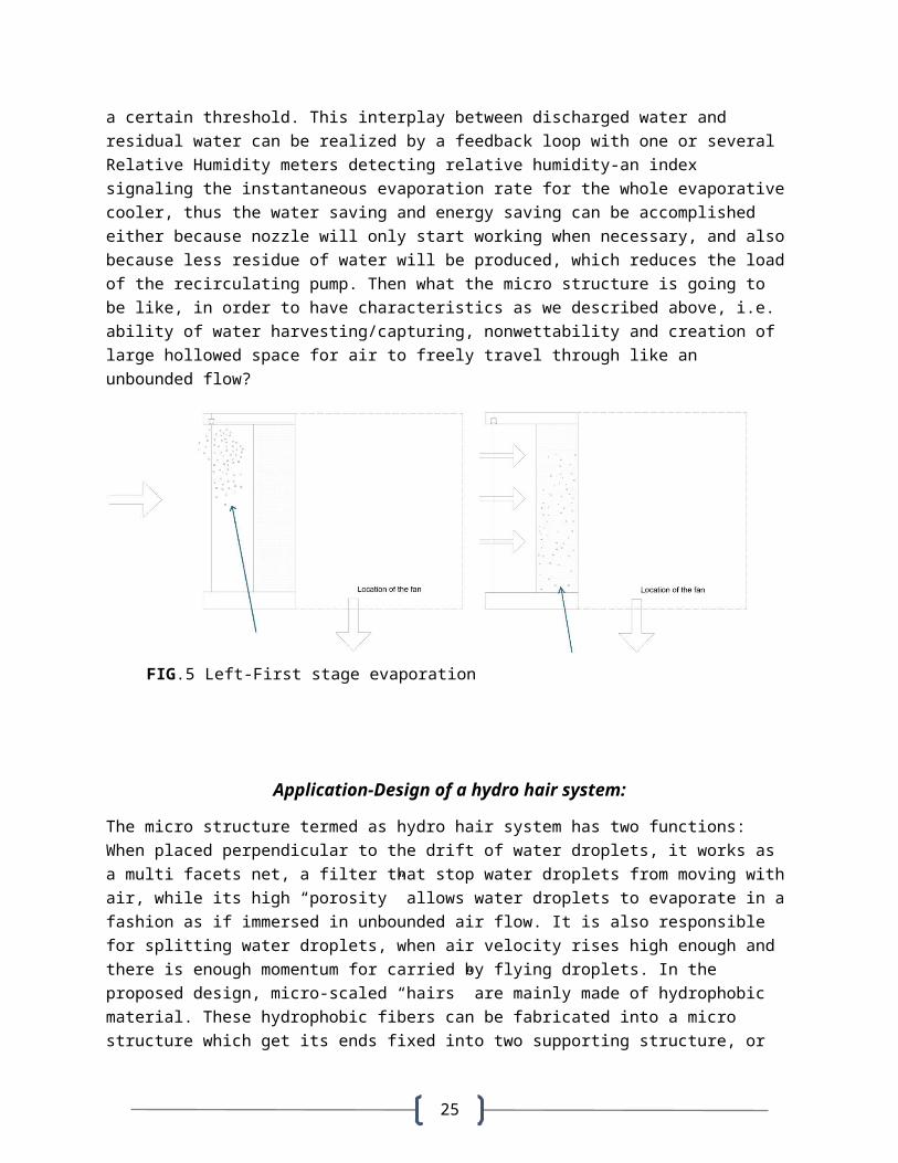
a certain threshold. This interplay between discharged water and residual water can be realized by a feedback loop with one or several Relative Humidity meters detecting relative humidity-an index signaling the instantaneous evaporation rate for the whole evaporativecooler, thus the water saving and energy saving can be accomplished either because nozzle will only start working when necessary, and alsobecause less residue of water will be produced, which reduces the loadof the recirculating pump. Then what the micro structure is going to be like, in order to have characteristics as we described above, i.e. ability of water harvesting/capturing, nonwettability and creation of large hollowed space for air to freely travel through like an unbounded flow?
Application-Design of a hydro hair system:
The micro structure termed as hydro hair system has two functions: When placed perpendicular to the drift of water droplets, it works as a multi facets net, a filter that stop water droplets from moving withair, while its high “porosity” allows water droplets to evaporate in afashion as if immersed in unbounded air flow. It is also responsible for splitting water droplets, when air velocity rises high enough and there is enough momentum for carried by flying droplets. In the proposed design, micro-scaled “hairs” are mainly made of hydrophobic material. These hydrophobic fibers can be fabricated into a micro structure which get its ends fixed into two supporting structure, or
FIG.5 Left-First stage evaporation Right-Second stage evaporation

26
pecks, through the micro fiber textile technology. A small fraction ofhydrophilic knots will be added to link these hydrophobic fibers into a 2-D net, which enable the production of landing spots for tiny water droplets, while keeping the spherical or spheroid shape of thosewater droplets approximately intact, as they mix with other flying tiny droplets and grow in size. The key point for precipitating the evaporation, however, lies within the idea of creating a way of catching, suspending or holding small drops as if water liquid sits not on a solid substrate-as is the case for so many evaporation experiments done with sessile drops, but a number of numerous hollowedmicro surfaces through which air can freely flow, similar to a situation as if droplets are surrounded by unbounded flow, while the whole hydro unit embedded with hydro hairs works in a similar fashion to a Packed Bed systems .
Hydrophobic String
Hydrophilic String
Residue of water droplet condenseson the hydrophilic knots, which willprobably grow as it evaporates simultaneously, FIG.6 A single unit of the hydro
hair system
27
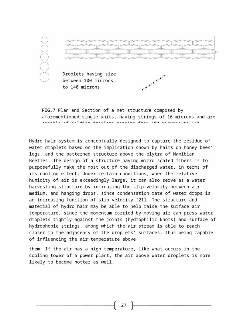
Hydro hair system is conceptually designed to capture the residue of water droplets based on the implication shown by hairs on honey bees’ legs, and the patterned structure above the elytra of Namibian Beetles. The design of a structure having micro scaled fibers is to purposefully make the most out of the discharged water, in terms of its cooling effect. Under certain conditions, when the relative humidity of air is exceedingly large, it can also serve as a water harvesting structure by increasing the slip velocity between air medium, and hanging drops, since condensation rate of water drops is an increasing function of slip velocity [21]. The structure and material of hydro hair may be able to help raise the surface air temperature, since the momentum carried by moving air can press water droplets tightly against the joints (hydrophilic knots) and surface ofhydrophobic strings, among which the air stream is able to reach closer to the adjacency of the droplets’ surfaces, thus being capable of influencing the air temperature above
them. If the air has a high temperature, like what occurs in the cooling tower of a power plant, the air above water droplets is more likely to become hotter as well.
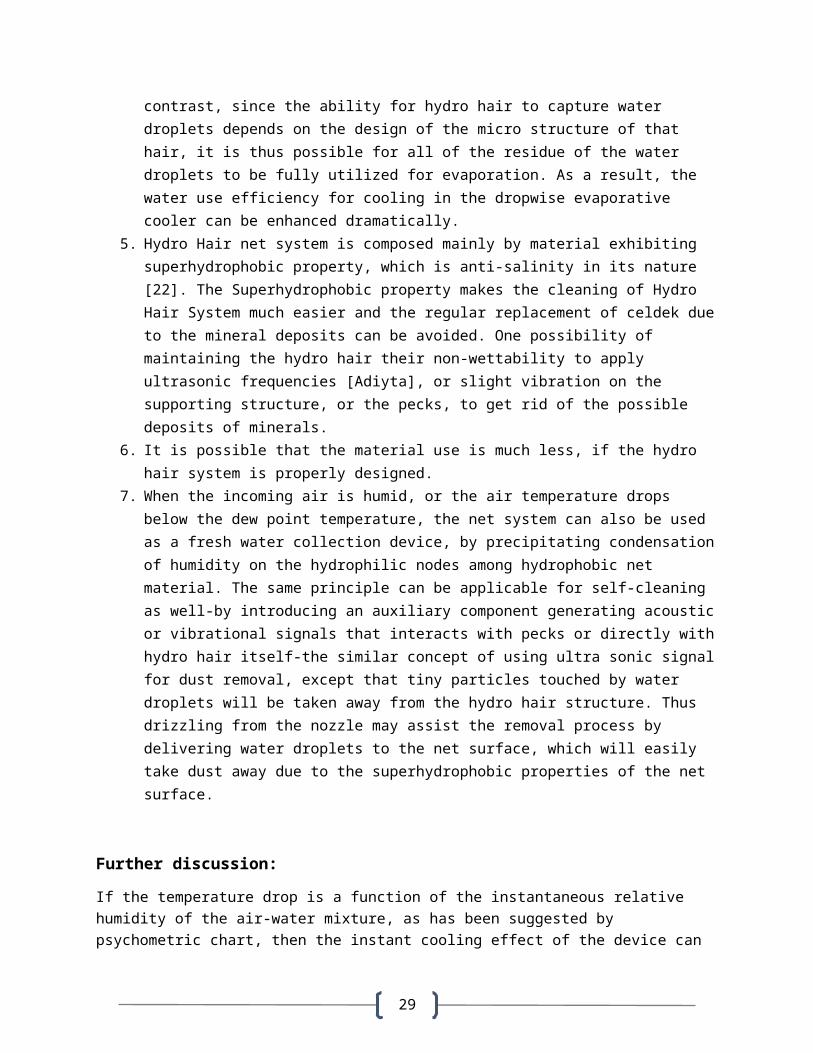
FIG.7 Plan and Section of a net structure composed by aforementioned single units, having strings of 16 microns and arecapable of holding droplets ranging from 100 microns to 140
Droplets having size between 100 microns to 140 microns
28
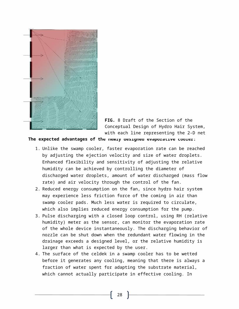
The expected advantages of the newly designed evaporative cooler:
1. Unlike the swamp cooler, faster evaporation rate can be reached by adjusting the ejection velocity and size of water droplets. Enhanced flexibility and sensitivity of adjusting the relative humidity can be achieved by controlling the diameter of discharged water droplets, amount of water discharged (mass flow rate) and air velocity through the control of the fan.
2. Reduced energy consumption on the fan, since hydro hair system may experience less friction force of the coming in air than swamp cooler pads. Much less water is required to circulate, which also implies reduced energy consumption for the pump.
3. Pulse discharging with a closed loop control, using RH (relative humidity) meter as the sensor, can monitor the evaporation rate of the whole device instantaneously. The discharging behavior of nozzle can be shut down when the redundant water flowing in the drainage exceeds a designed level, or the relative humidity is larger than what is expected by the user.
4. The surface of the celdek in a swamp cooler has to be wetted before it generates any cooling, meaning that there is always a fraction of water spent for adapting the substrate material, which cannot actually participate in effective cooling. In
FIG. 8 Draft of the Section of the Conceptual Design of Hydro Hair System, with each line representing the 2-D net shown in FIG. 7; Arrows represent the
29
contrast, since the ability for hydro hair to capture water droplets depends on the design of the micro structure of that hair, it is thus possible for all of the residue of the water droplets to be fully utilized for evaporation. As a result, the water use efficiency for cooling in the dropwise evaporative cooler can be enhanced dramatically.
5. Hydro Hair net system is composed mainly by material exhibiting superhydrophobic property, which is anti-salinity in its nature [22]. The Superhydrophobic property makes the cleaning of Hydro Hair System much easier and the regular replacement of celdek dueto the mineral deposits can be avoided. One possibility of maintaining the hydro hair their non-wettability to apply ultrasonic frequencies [Adiyta], or slight vibration on the supporting structure, or the pecks, to get rid of the possible deposits of minerals.
6. It is possible that the material use is much less, if the hydro hair system is properly designed.
7. When the incoming air is humid, or the air temperature drops below the dew point temperature, the net system can also be used as a fresh water collection device, by precipitating condensationof humidity on the hydrophilic nodes among hydrophobic net material. The same principle can be applicable for self-cleaning as well-by introducing an auxiliary component generating acousticor vibrational signals that interacts with pecks or directly withhydro hair itself-the similar concept of using ultra sonic signalfor dust removal, except that tiny particles touched by water droplets will be taken away from the hydro hair structure. Thus drizzling from the nozzle may assist the removal process by delivering water droplets to the net surface, which will easily take dust away due to the superhydrophobic properties of the net surface.
Further discussion:
If the temperature drop is a function of the instantaneous relative humidity of the air-water mixture, as has been suggested by psychometric chart, then the instant cooling effect of the device can
30
be detected, thus controlled by a humidity sensor embedded in the device. And whether or not there is enough evaporation in total can betold by a threshold RH value designating the minimum amount of evaporation. For a type of evaporative cooler product with a given parameters and performance indices, the minimum RH can be evaluated inadvance, which also serves as a design parameter.
Referring back to the discharging behavior of the nozzle. If we dividea process representing a cluster of water droplets being discharged inone second by a very small time segment, so short that in such time period, the water coming from the nozzle can be treated as a singular water parcel, coming into existence as a quantized unit, occupying a discrete unit of time, then according to the same Ranz and Marshall Correlation, this quantized “water bit” may contain several micron sized droplets, each of which has its evaporation rate represented by an expression:
m0¿
=2πD⋅DAB+0.552πD⋅DAB⋅(VDν )1/2
( νDAB )
1/3
(19)
m0¿
stands for the evaporation rate for a single droplet in that parcel.V is the relative velocity between water droplets and the air flow. AndD is the diameter of that droplet. Recast the equation one yields:
m0¿
=2πD⋅DAB+0.552π⋅D3/2⋅V1/2⋅D
AB2/3ν−1/6
(20)
The interpretation of this formula states that as relative velocity between water droplets and air get smaller, or as the diameter of water droplets gets smaller, the evaporation rate of a single droplet becomes more dominated by the first term, which makes its evaporation rate reduce in a more linearized fashion as its diameter decreases, asfar as the inhibition of evaporation by increased water vapor density of air medium was not considered. However, our simulation shows that the reduced difference of water vapor densities cause much more trouble for dropwise evaporation than film evaporation, thus the
31
function of hydro hair system can be critical to make the dropwise evaporative cooler truly work. The contribution of residual water on the hydro hairs to the entire evaporation rate of the device, relies heavily on factors such as the number of water droplets present on thehydro hair, the ratio of their surface area exposed to the air flow, relative humidity of the air, air temperature right above the surface of liquid water, air velocity, and size of the each of single droplet on the hydro hair surface.
In addition to evaporation cooling, the same concept can be applied tothe design of cooling tower for several types of power plant. As one can tell from the calculation the water droplets evaporation turns outto be much more sensitive to the temperature of air present right above the surface of the liquid water, and the increase of the temperature will cause a significant ascension of the evaporation rate. The magnitude of change of evaporation rate owing to the rising temperature of the air above the surface of a water droplet, is significant larger than the one owing to the rising temperature above a water film. This also means that, if water droplets are discharged against hot air, which will raise the saturated air temperature aroundthe water droplets, more water will turn into vapor in a certain period of time. Thus both the time required for cooling the same amount of gas or air, and the amount of water required to circulate inside the cooling tower can be significantly reduced. Moreover, the proposed hydro hair can be mounted on the path in which the water is delivered to sewer, and the residue of water droplets can be used to further produce cooling and increase the efficiency of water use.
Many types of material coming from nature that exhibits superhydrophobic properties can be potentially available to construct the hydro hair. Diatomaceous Earth technology developed by oak ridge national laboratory can be one of the options of material making the superhydrophobic coatings for the hydro hair [23]. Another decent choice by making use of the cellulose comes from the recent technologyof combining the electrospining of nano scaled fibers with plasma treatment over the surface of nano scaled cellulose fibers which will wrap around a micro scaled fiber, increasing the equilibrium contact angle for sessile drops and the mechanical intensity of the micro fibers [24]. And the supporting structures, whose surfaces also exhibit remarkable nonwettability, can be made from Teflon and Sandpapers in an inexpensive way [25].
32
The methods for producing the micro scaled fibers include polymer based fabrication, electrospinning, etc. And the nonwettability of thecoating can be achieved by electrospining process of material like cellulose fibers treated with fluorine plasma. Or, applying tweezers to place glass microfibers in a defined pattern onto an elastomeric (PDMS) hydrophobic film, which is then manually pressed onto a hydrophobic silicon wafer, causing it to adhere to the silicon wafer and form a liquid tight seal around the fiber [26]. Although it seems inevitable that this hair like substrate for evaporative cooling takesmore complicated procedures and expenses to produce at the beginning, we argue that the benefits inherent to this evaporation prototype regarding the smart use of water, energy and material will outstand its minor difficulties in production and maintenance. The design of hydro hair proposed in this paper is simply a conceptual design, creative industrial designers, engineers and even architects can add more talents and details to its actual formation and structure, creating the secondary even the tertiary structure for organizing the basic net-like units discussed in this paper. The tilt angle, diameterof the superhydrophobic and hydrophilic strings, the size of one unit,and the 3-D shape and tilt angle of a single net surface, can be designed, simulated, fabricated using parametric design software, likeRhino+Grasshopper.
On the other hand, control strategies applied by bee castes that incorporate principles like self-organization and task specialization have several analogies to human group in a building, or of an organization. If an archetype of human assisted feedback loop which allows humans to actually “talk” to the evaporative cooling system, sending commends to regulate its operational parameters and optimize its performance, it is possible to let it interact with users, while performing with an increased order and enhanced stability of for less energy and water use [27].
Problems that need to be solved in future:
Saturated air layer is formed on the top of the water drops, impartinga layer of saturated air shielding the surface of water droplets away from the surrounding air medium. If, rather than what had been observed by Kinzer and Gunn which states that the surface temperature of the freely falling drops having their diameters ranging from 10 to
33
140 µm are very close to the wet bulb temperature of the ventilated medium [28], the water vapor density of a water film may get higher than the one appeared in our calculation. Higher water vapor density leads faster evaporation rate, which can reconcile, even reverse the ratio we just calculated. Further details need to be addressed to pinpoint the air temperature above a water film and air temperature onthe top of a water droplet. However, mathematically speaking, the comparatively steep increase of evaporation rate with rise of saturated air temperature right above the droplets’ surface still holds true for dropwsie evaporation.
And it is not clear if hydrophobic properties can be maintained long, being economic to support an annual running of a swamp cooler or a large scale cooling in a power plant. Another problem regarding the nozzle is that will water droplets make the discharging nozzle get clogged? The development of superhydrophobic nozzle plate may be the solution to this unsolved issue, and it may further be utilized in Golf countries where people literally do not have access to fresh water coming from nature. What is the potential to make salty water, or sea water work in this proposed design? How does the hydro hair system respond to solution with various solutes? The design of the size, geometric patterns, and structural features together with feasibility of hydro hair system, and its materiality corresponding todifferent contexts, and its flexibility of being incorporated into multi-steps evaporative cooling system will be discussed with more detail in the next paper.
Acknowledgement:
Larry Sobel, Adjunct Professor, Department of Aero Space and Mechanical Engineering, The University of Arizona. James J. Riley, Associate Professor, Soil, Water and Environmental Science Department,The University of Arizona (retired). Susannah Dickinson, Assistant Professor, College of Architecture, Planning and Landscape Architecture, The University of Arizona. Aditya Peri, Graduate Student, Department of Aero Space and Mechanical Engineering, The University of Arizona.
Reference:
34
1. Water Collection Cools Hive: Honey Bee. Ask Nature Biomimicry 3.8 http://www.asknature.org/strategy/a342605f58d48907bc44e37b33a0c253#.U3OqXPldXVI
2. Helmut Kovac, et al. Thermoregulation of water foraging honeybees- Balancing of endothermic activity with radiative heat gain and functional requirements. Journal of Insect physiology 56(2010) 1834-1845
3. Fredi Kronenberg, H. Craig Heller, Colonial thermoregulation in honey bees (Apis mellifera). Journal of comparative physiology1982, Volume 148, Issue 1, pp 65-76
4. Andrew R. Parker, Chris R. Lawrence, Water Capture by a DesertBeetle, Brief Communication, Nature 414, November 1st, 2001, doi:10.1038/35102108
5. Julia C. Jones, Benjamin P. Oldroyd Nest Thermoregulation in Social Insects. Volume 33, 2006, Pages 153–191, http://dx.doi.org/10.1016/S0065-2806(06)33003-2
6. Thomas Nørgaard and Marie Dacke, Fog Basking Behavior and Water Collection Efficiency in Namib Desert Darkling Beetles. Frontiers in Zoology 2010, 7:23, doi:10.1186/1742-9994-7-23
7. Hanneke Gelderblom, Álvaro G. Marín, Hrudya Nair, Arie van Houselt, Leon Lefferts, Jacco H. Snoeijer, and Detlef Lohse , Howwater droplets evaporate on a superhydrophobic substrate. Phys. Rev. E 83, 026306
8. Wei Xu, Rajesh Leeladhar, Yong Tae Kang, and Chang-Hwan Choi, Evaporation Kinetics of Sessile Water Drops on Micropillared Superhydrophobic Surfaces. Langmuir, 2013, 29 (20), pp 6032–6041,DOI: 10.1021/la400452e
9. K. S. Birdi , D. T. Vu , A. Winter, A study of the evaporationrates of small water drops placed on a solid surface. J. Phys. Chem., 1989, 93 (9), pp 3702–3703 DOI: 10.1021/j100346a065
35
10, 13-14, 28. H. Yildirim Erbil. Evaporation of pure liquid sessile and spherical suspended drops: A Review. Advances in Colloid and Interface Science 170 (2012) 67-86
11, 15. R.S. Miller, K. Harstad and J. Bellan. Evaluation of Equilibrium and Non-equilibrium Evaporation Models for Many-Droplet Gas-Liquid Flow Simulations. International Journal of Multiphase Flow 24, 1998, 1025-1055
12. Nanda Kishore and Sai Gu, Momentum and heat transfer phenomena of spheroid particles at moderate Reynolds and Prandtl numbers. Southampton, United Kingdom. International Journal of Heat and Mass Transfer 54 (2011) 2595-2601
16, 20. Frank P. Incropera, Theodore L. Bergman, Adrienne S. Lavine and David P. Dewitt, Fundamentals of Heat and Mass Transfer, 7th Edition. John Wiley and Sons (2012) ISBN 13: 9780470501979
17. Energy Plus energy simulation software, Weather Data, Tucson,722740 (TMY2), http://apps1.eere.energy.gov/buildings/energyplus/cfm/weather_data3.cfm/region=4_north_and_central_america_wmo_region_4/country=1_usa/cname=USA
18. City of Tucson, official website Water Quality Summary of Main distribution System. http://www.tucsonaz.gov/tucsonwater/clearwater?output=allTabular
19. Gothic Arc Green Houses, Evaporative Cooling Pads. http://www.gothicarchgreenhouses.com/greenhouse_cooling_pads.htm
21. Mohammad J. Kermania, John M. Stockieb, The effect of slip velocity on saturation for multiphase condensing mixtures in a PEM fuel cell. International Journal of Hydrogen Energy, Volume 36, Issue 20, October 2011, Pages 13235-13240
22, 23. John T. Simpson, Alex DeTrana and Shawn Carson, Superhydrophobic Materials, Oak Ridge National Laboratories. www.ornl.gov/File%20Library/Main%20Nav/ORNL/Partnerships/Events/B
36
ridging%20The%20Gap%202011/06-Superhydrophobic_Materials.pdf superhydrophobic materials
24. Anna Thorvaldsson, Petra Edvinsson, Alexandra Glantz, Katia Rodriguez, Pernilla Walkenström, Paul Gatenholm, Superhydrophobicbehaviour of plasma modified electrospun cellulose nanofiber-coated microfibers. Cellulose October 2012, Volume 19, Issue 5, pp 1743-1748
25. Michael A Nilsson, Robert J Daniello and Jonathan P Rothstein, A novel and inexpensive technique for creating superhydrophobic surfaces using Teflon and sandpaper. Michael A Nilsson et al 2010 J. Phys. D: Appl. Phys. 43 045301 doi:10.1088/0022-3727/43/4/04530126. Tom T. Huang, David G Taylor, Miroslav Dedlak, Nathan S. Mosier and Michael R. Ladisch. Microfiber-Directed Boundary Flow in Press-Fit Microdevices Fabricated from Self-Adhesive Hydrophobic Surfaces. Anal. Chem. 2005, 77, 3671-3675
27. Benjamin P. Oldroyd and Jennifer, H, Fewell, Genetic Diversity Promotes Homeostasis in Insect Colonies. Trends Ecol Evol. 2007 Aug; 22(8):408-13
(Concentrated one for journal like Sicence)Honey bees are able to bring water droplets back for cooling their nest via evaporation, while Namibian beetles collect water drops from morning fog by their elytra patterned with bumps and troughs respectively made from hydrophilic and hydrophobic surfaces. By calculating theoretically the evaporation rate of water films above the pad’s surface of a swamp cooler, and the evaporation rate of droplets right after their discharging from the nozzle, results showed that dropwise evaporation can be more effective in its higher evaporation rate, and controllable parameters capable of lifting such rate and water use efficiency. Following the comparison, a conceptual design that utilizes the dropwise evaporation is proposed afterwards, revealing its potential of efficiency of water use, energy use and material.

37