c.a 1900 - chauvin-arnoux.fi
TRANSCRIPT
1
EN - User’s manual
C.A 1900
Thermal camera for body temperature measurement
2
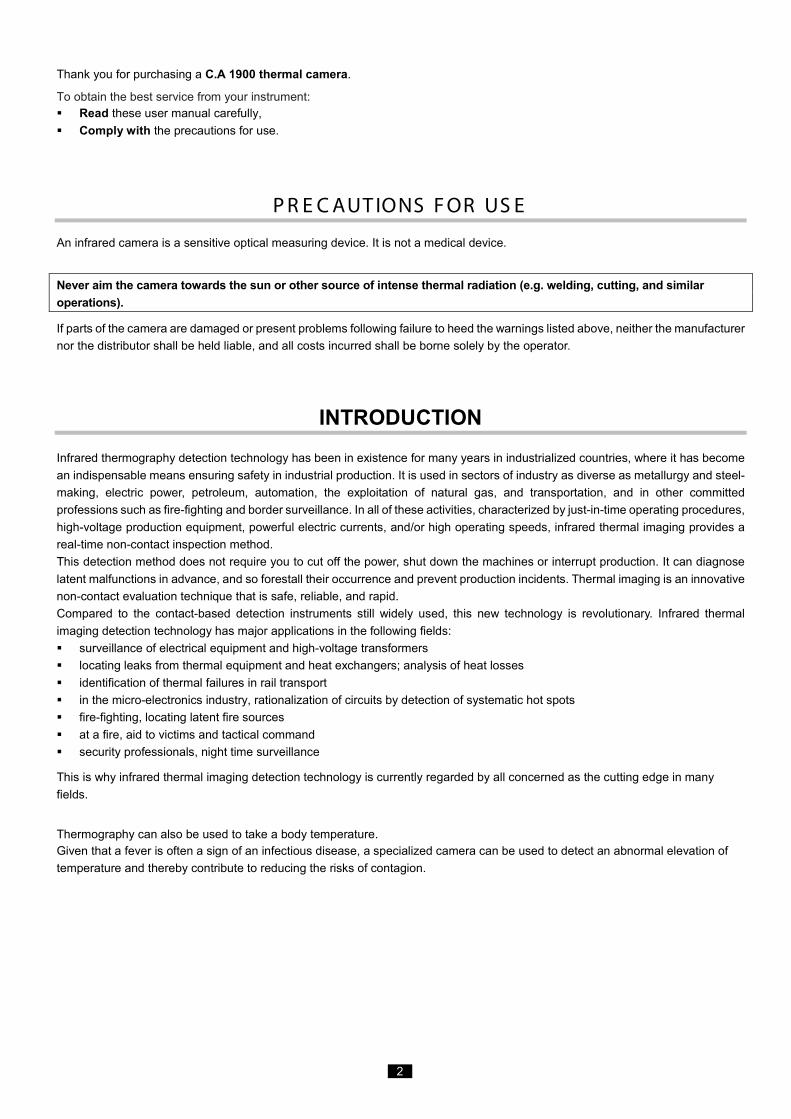
Thank you for purchasing a C.A 1900 thermal camera.
To obtain the best service from your instrument: Read these user manual carefully, Comply with the precautions for use.
P R E C AUT IONS F OR US E
An infrared camera is a sensitive optical measuring device. It is not a medical device.
Never aim the camera towards the sun or other source of intense thermal radiation (e.g. welding, cutting, and similar operations).
If parts of the camera are damaged or present problems following failure to heed the warnings listed above, neither the manufacturer nor the distributor shall be held liable, and all costs incurred shall be borne solely by the operator.
INTRODUCTION Infrared thermography detection technology has been in existence for many years in industrialized countries, where it has become an indispensable means ensuring safety in industrial production. It is used in sectors of industry as diverse as metallurgy and steel-making, electric power, petroleum, automation, the exploitation of natural gas, and transportation, and in other committed professions such as fire-fighting and border surveillance. In all of these activities, characterized by just-in-time operating procedures, high-voltage production equipment, powerful electric currents, and/or high operating speeds, infrared thermal imaging provides a real-time non-contact inspection method. This detection method does not require you to cut off the power, shut down the machines or interrupt production. It can diagnose latent malfunctions in advance, and so forestall their occurrence and prevent production incidents. Thermal imaging is an innovative non-contact evaluation technique that is safe, reliable, and rapid. Compared to the contact-based detection instruments still widely used, this new technology is revolutionary. Infrared thermal imaging detection technology has major applications in the following fields: surveillance of electrical equipment and high-voltage transformers locating leaks from thermal equipment and heat exchangers; analysis of heat losses identification of thermal failures in rail transport in the micro-electronics industry, rationalization of circuits by detection of systematic hot spots fire-fighting, locating latent fire sources at a fire, aid to victims and tactical command security professionals, night time surveillance
This is why infrared thermal imaging detection technology is currently regarded by all concerned as the cutting edge in many fields.
Thermography can also be used to take a body temperature. Given that a fever is often a sign of an infectious disease, a specialized camera can be used to detect an abnormal elevation of temperature and thereby contribute to reducing the risks of contagion.

3
Meanings of the symbols used on the device:
The CE marking indicates conformity with European LVD and EMC directives.
The rubbish bin with a line through it means that in the European Union, the product must undergo selective disposal in compliance with Directive WEEE 2012/19/EU.
The product is declared recyclable following a life cycle analysis in accordance with standard ISO 14040.
4
CONTENTS
1. GETTING STARTED ....................................................................................................................................................... 6 1.1. Elementary precautions........................................................................................................................................... 6
1.1.1. Never aim the camera towards the sun or other source of intense thermal radiation ............................ 6 1.1.2. Avoid exposing to dust with the lens flap open ...................................................................................... 6 1.1.3. Do not touch the lens with your fingers. ................................................................................................ 6 1.1.4. Avoid jolting or dropping the camera. .................................................................................................... 6
1.2. Powering the camera .............................................................................................................................................. 7 1.3. Inserting the micro SD memory card ....................................................................................................................... 8 1.4. Organization of the display ...................................................................................................................................... 8
1.4.1. Battery management ...................................................................................................................................... 8 1.4.2. Main screen ......................................................................................................................................... 10 1.4.3. Displaying the menus .......................................................................................................................... 13
1.5. Configuring the camera ......................................................................................................................................... 13 1.5.1. Changing the language of the camera ................................................................................................ 13 1.5.2. Changing the camera's date and time ................................................................................................. 13 1.5.3. Changing the units of temperature and of distance ............................................................................. 14 1.5.4. Changing the function associated with the trigger of the camera ........................................................ 14 1.5.5. Setting the time before automatic shutdown of the camera................................................................. 14 1.5.6. Adjusting the brightness of the screen ................................................................................................ 14 1.5.7. Changing the image backup location .................................................................................................. 15 1.5.8. Changing the colours used in the images ........................................................................................... 15 1.5.9. Compensate the difference between the internal body temperature and the skin temperature........... 16
2. MEASUREMENT CAMPAIGN ....................................................................................................................................... 17 2.1. Estimating the temperature of an object without a cursor ..................................................................................... 17 2.2. Trigger an alarm when the measured temperature exceeds some limit ................................................................ 17 2.3. Locating the cold and hot spots in the image ........................................................................................................ 19 2.4. Measuring the temperature of a point in the image ............................................................................................... 19 2.5. Determining the characteristics of a zone on the screen ....................................................................................... 19 2.6. Displaying the temperature profile of a line in the image ....................................................................................... 19 2.7. Displaying points at the same temperature in the image ....................................................................................... 19 2.8. Freezing the colours representing the temperatures ............................................................................................. 19
3. MORE PRECISE MEASUREMENT CAMPAIGN ........................................................................................................... 21 3.1. Good practices ...................................................................................................................................................... 21 3.2. Use influencing parameters consistent with the conditions of measurement ........................................................ 21 3.3. Using a tripod ........................................................................................................................................................ 22
4. SAVING AND RECALLING IMAGES ............................................................................................................................. 23 4.1. How are the image files named? ........................................................................................................................... 23 4.2. Saving an image ................................................................................................................................................... 23 4.3. Where are the images saved? .............................................................................................................................. 24 4.4. Adding a vocal remark ........................................................................................................................................... 24 4.5. Changing the vocal remark on an existing image .................................................................................................. 24 4.6. Recalling an image ................................................................................................................................................ 25 4.7. Playing back a vocal remark ................................................................................................................................. 26 4.8. Deleting an image ................................................................................................................................................. 26 4.9. Transferring an image to a PC .............................................................................................................................. 26
4.9.1. With the micro SD memory card ......................................................................................................... 26 4.9.2. Via the USB cable ............................................................................................................................... 27
4.10 Creating an operating report including images from the camera .......................................................................... 27 5. BACKUP AND RECALL OF USER CONFIGURATIONS ............................................................................................... 28
5.1. Where are the configurations saved? .................................................................................................................... 28 5.2. Saving the current setup of the camera ................................................................................................................ 28 5.3. Recalling a saved setup ........................................................................................................................................ 28 5.4. Deleting a saved setup .......................................................................................................................................... 29 5.5. Returning to the default setup of the camera ........................................................................................................ 29
6. BLUETOOTH FUNCTION ............................................................................................................................................. 30 6.1. Activating/Deactivating the Bluetooth function ....................................................................................................... 30
6.1.1. Activating Bluetooth ............................................................................................................................ 30 6.1.2. Deactivating Bluetooth ........................................................................................................................ 30
6.2. Using the headset or a Bluetooth speaker ............................................................................................................ 30 6.2.1. How many headsets can be connected at a time? .............................................................................. 30 6.2.2. Connecting a headset ......................................................................................................................... 30 6.2.3. Disconnecting a headset ..................................................................................................................... 31 6.2.4. Changing headsets ............................................................................................................................. 31
6.3. Using Bluetooth measurement peripherals ........................................................................................................... 32 6.3.1. How many peripherals can be connected? ......................................................................................... 32 6.3.2. How many measurements can be recovered from a peripheral? ........................................................ 32 6.3.3. What peripherals does the camera recognize? ................................................................................... 32 6.3.4. Connecting a Bluetooth measurement peripheral ............................................................................... 32 6.3.5. How are the Bluetooth peripherals chosen? ........................................................................................ 32
5
6.3.6. Replacing one peripheral with another ................................................................................................ 33 6.3.7. Changing the frequency of reading of a Bluetooth peripheral ............................................................. 33 6.3.8. Displaying the measurements of the various Bluetooth peripherals .................................................... 33 6.3.9. Using a Bluetooth measurement as an influencing parameter ............................................................ 35 6.3.10. Displaying the Bluetooth measurements on the main screen .............................................................. 36 6.3.11. Can the Bluetooth measurements be saved at the same time as an image? ...................................... 36
7. UPDATING THE FIRMWARE OF THE CAMERA .......................................................................................................... 37 7.1. Where can the firmware version of the camera be read? ...................................................................................... 37 7.2. How update the firmware? .................................................................................................................................... 37
8. ARE YOU HAVING DIFFICULTIES? .............................................................................................................................. 38 8.1. The IR image I obtain is solid-colour ..................................................................................................................... 38
8.1.1. The palette of colours is frozen ........................................................................................................... 38 8.1.2. Inconsistent "user" influencing parameters ......................................................................................... 38
8.2. The contrast of my IR image is wrong ................................................................................................................... 38 8.3. I am unable to save the current image .................................................................................................................. 38 8.4. The file manager takes a very long time to respond .............................................................................................. 38 8.5. I cannot connect my headset ................................................................................................................................ 38 8.6. I cannot connect my Bluetooth peripheral ............................................................................................................. 38 8.7. My Bluetooth measurements are not displayed or are not refreshed in the measurements manager ................... 39
9. SERVICING AND MAINTENANCE ................................................................................................................................ 40 9.1 Cleaning the housing and screen of the camera .................................................................................................... 40 9.2 Cleaning the infrared optics.................................................................................................................................... 40 9.3 Unpacking, re-packing............................................................................................................................................ 40
10. WARRANTY ................................................................................................................................................................ 41 11. DELIVERY CONDITION .............................................................................................................................................. 42
11.1 Accessories and spares ........................................................................................................................................ 42 Appendix I – Menu tree ...................................................................................................................................................... 43 Appendix II – Technical specifications ............................................................................................................................... 46
6
1. GETTING STARTED
1.1. Elementary precautions
1.1.1. Never aim the camera towards the sun or other source of intense thermal radiation
Direct exposure to sunlight or other strong thermal radiation can impair the operation of the camera and make the infrared sensor
partially or totally inoperative for as long as several months.
We therefore recommend closing the lens flap when the camera is not in use, to avoid any accidental exposure.
1.1.2. Avoid exposing to dust with the lens flap open
Even though it is rated IP54 (dust and splash protected), it is best not to use the camera in a dusty environment: dust deposited on
the lens can not only perturb the measurements (absorption of part of the thermal flux and spurious diffusion) but also impair the
sharpness of the images.
To clean your lens, refer to §9.2 Cleaning the infrared optics.
1.1.3. Do not touch the lens with your fingers.
Finger marks must be carefully avoided, because acids from the skin attack the coatings and the glass of the lens; they can leave
indelible traces. Refer to §9.2 Cleaning the infrared optics.
1.1.4. Avoid jolting or dropping the camera.
The camera is rugged, but even so it is a delicate precision instrument which should not be jolted or dropped.
7
1.2. Powering the camera
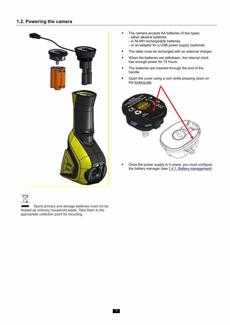
Spent primary and storage batteries must not be treated as ordinary household waste. Take them to the appropriate collection point for recycling.
The camera accepts AA batteries of two types: - either alkaline batteries - or Ni-MH rechargeable batteries. - or an adapter for a USB power supply (optional).
The latter must be recharged with an external charger.
When the batteries are withdrawn, the internal clock has enough power for 15 hours.
The batteries are inserted through the end of the handle.
Open the cover using a coin while pressing down on the locking tab:
Once the power supply is in place, you must configure
the battery manager (see 1.4.1. Battery management)
8
1.3. Inserting the micro SD memory card
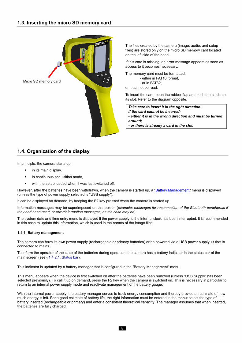
The files created by the camera (image, audio, and setup files) are stored only on the micro SD memory card located on the left side of the head.
If this card is missing, an error message appears as soon as access to it becomes necessary.
The memory card must be formatted: - either in FAT16 format, - or in FAT32, or it cannot be read.
To insert the card, open the rubber flap and push the card into its slot. Refer to the diagram opposite.
Take care to insert it in the right direction. If the card cannot be inserted: - either it is in the wrong direction and must be turned around; - or there is already a card in the slot.
1.4. Organization of the display
In principle, the camera starts up:
in its main display,
in continuous acquisition mode,
with the setup loaded when it was last switched off.
However, after the batteries have been withdrawn, when the camera is started up, a "Battery Management" menu is displayed (unless the type of power supply selected is "USB supply").
It can be displayed on demand, by keeping the F2 key pressed when the camera is started up.
Information messages may be superimposed on this screen (example: messages for reconnection of the Bluetooth peripherals if they had been used, or error/information messages, as the case may be).
The system date and time entry menu is displayed if the power supply to the internal clock has been interrupted. It is recommended in this case to update this information, which is used in the names of the image files.
1.4.1. Battery management
The camera can have its own power supply (rechargeable or primary batteries) or be powered via a USB power supply kit that is connected to mains.
To inform the operator of the state of the batteries during operation, the camera has a battery indicator in the status bar of the main screen (see §1.4.2.1. Status bar).
This indicator is updated by a battery manager that is configured in the "Battery Management" menu.
This menu appears when the device is first switched on after the batteries have been removed (unless "USB Supply" has been selected previously). To call it up on demand, press the F2 key when the camera is switched on. This is necessary in particular to return to an internal power supply mode and reactivate management of the battery gauge.
With the internal power supply, the battery manager serves to track energy consumption and thereby provide an estimate of how much energy is left. For a good estimate of battery life, the right information must be entered in the menu: select the type of battery inserted (rechargeable or primary) and enter a consistent theoretical capacity. The manager assumes that when inserted, the batteries are fully charged.
Micro SD memory card
9
With the USB adapter, the manager is no longer actuated and the batteries will always appear as fully charged in the status bar. The camera will remain on until switched off by the user or by the auto-off system. It may be useful in this mode to deactivate the instrument's auto-off function so that the camera remains on at all times (see 1.5.5. Setting the time before automatic shutdown of the camera).
Warning: Like all the other parameters entered by the user, these values are stored in lasting form when the camera is switched off by the i/o key of the keypad (the information is lost if there is a power outage).
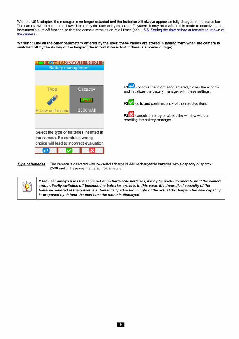
F1 confirms the information entered, closes the window and initializes the battery manager with these settings.
F2 edits and confirms entry of the selected item.
F3 cancels an entry or closes the window without resetting the battery manager.
Type of batteries: The camera is delivered with low-self-discharge Ni-MH rechargeable batteries with a capacity of approx. 2500 mAh. These are the default parameters.
If the user always uses the same set of rechargeable batteries, it may be useful to operate until the camera automatically switches off because the batteries are low. In this case, the theoretical capacity of the batteries entered at the outset is automatically adjusted in light of the actual discharge. This new capacity is proposed by default the next time the menu is displayed.
10
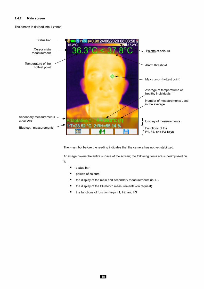
1.4.2. Main screen
The screen is divided into 4 zones:
Status bar
Cursor main
measurement
Temperature of the hottest point
Secondary measurements at cursors
Bluetooth measurements
Palette of colours Alarm threshold Max cursor (hottest point) Average of temperatures of healthy individuals Number of measurements used in the average
Display of measurements Functions of the F1, F2, and F3 keys
The ~ symbol before the reading indicates that the camera has not yet stabilized.
An image covers the entire surface of the screen; the following items are superimposed on
it:
status bar
palette of colours
the display of the main and secondary measurements (in IR)
the display of the Bluetooth measurements (on request)
the functions of function keys F1, F2, and F3
11
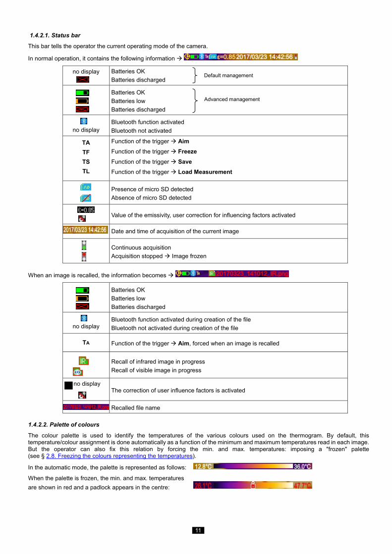
1.4.2.1. Status bar
This bar tells the operator the current operating mode of the camera.
In normal operation, it contains the following information
no display
Batteries OK Batteries discharged
Batteries OK Batteries low Batteries discharged
no display
Bluetooth function activated Bluetooth not activated
TA TF TS TL
Function of the trigger Aim
Function of the trigger Freeze
Function of the trigger Save Function of the trigger Load Measurement
Presence of micro SD detected Absence of micro SD detected
Value of the emissivity, user correction for influencing factors activated
Date and time of acquisition of the current image
Continuous acquisition
Acquisition stopped Image frozen
When an image is recalled, the information becomes
Batteries OK Batteries low Batteries discharged
no display
Bluetooth function activated during creation of the file Bluetooth not activated during creation of the file
TA Function of the trigger Aim, forced when an image is recalled
Recall of infrared image in progress Recall of visible image in progress
no display The correction of user influence factors is activated
Recalled file name
1.4.2.2. Palette of colours
The colour palette is used to identify the temperatures of the various colours used on the thermogram. By default, this temperature/colour assignment is done automatically as a function of the minimum and maximum temperatures read in each image. But the operator can also fix this relation by forcing the min. and max. temperatures: imposing a "frozen" palette (see § 2.8. Freezing the colours representing the temperatures).
In the automatic mode, the palette is represented as follows:
When the palette is frozen, the min. and max. temperatures are shown in red and a padlock appears in the centre:
Default management
Advanced management
12
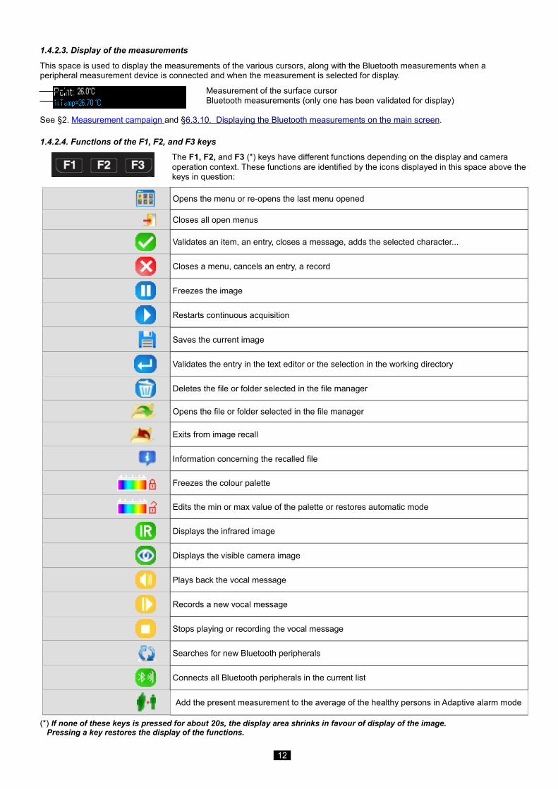
1.4.2.3. Display of the measurements
This space is used to display the measurements of the various cursors, along with the Bluetooth measurements when a peripheral measurement device is connected and when the measurement is selected for display.
Measurement of the surface cursor Bluetooth measurements (only one has been validated for display)
See §2. Measurement campaign and §6.3.10. Displaying the Bluetooth measurements on the main screen.
1.4.2.4. Functions of the F1, F2, and F3 keys
The F1, F2, and F3 (*) keys have different functions depending on the display and camera operation context. These functions are identified by the icons displayed in this space above the keys in question:
Opens the menu or re-opens the last menu opened
Closes all open menus
Validates an item, an entry, closes a message, adds the selected character...
Closes a menu, cancels an entry, a record
Freezes the image
Restarts continuous acquisition
Saves the current image
Validates the entry in the text editor or the selection in the working directory
Deletes the file or folder selected in the file manager
Opens the file or folder selected in the file manager
Exits from image recall
Information concerning the recalled file
Freezes the colour palette
Edits the min or max value of the palette or restores automatic mode
Displays the infrared image
Displays the visible camera image
Plays back the vocal message
Records a new vocal message
Stops playing or recording the vocal message
Searches for new Bluetooth peripherals
Connects all Bluetooth peripherals in the current list
Add the present measurement to the average of the healthy persons in Adaptive alarm mode
(*) If none of these keys is pressed for about 20s, the display area shrinks in favour of display of the image. Pressing a key restores the display of the functions.
13
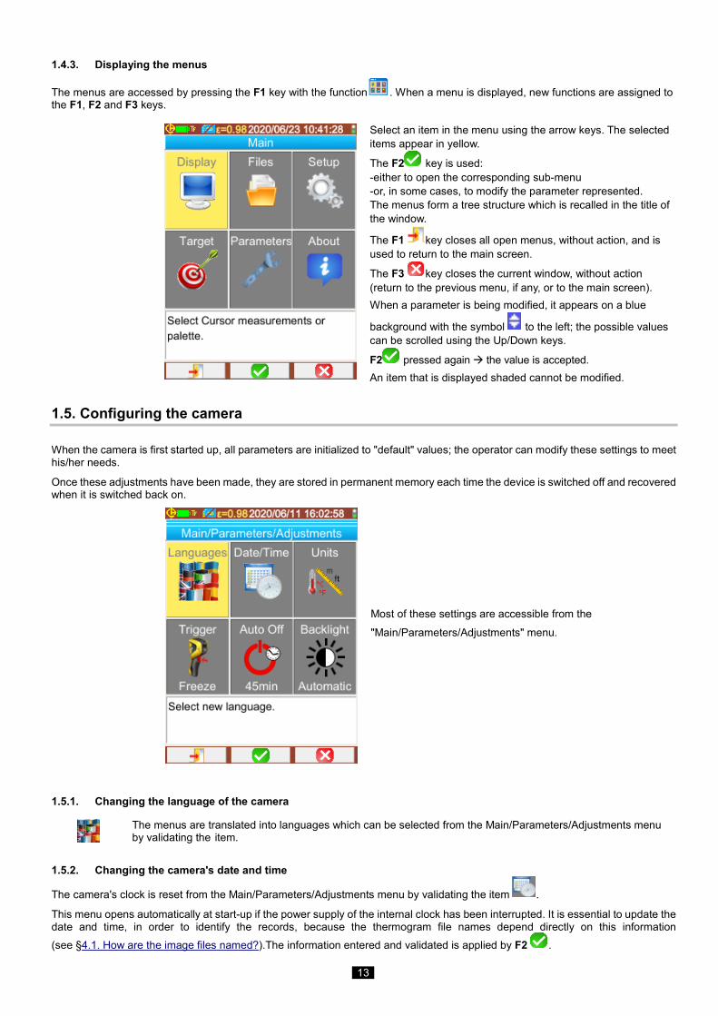
1.4.3. Displaying the menus
The menus are accessed by pressing the F1 key with the function . When a menu is displayed, new functions are assigned to the F1, F2 and F3 keys.
Select an item in the menu using the arrow keys. The selected items appear in yellow.
The F2 key is used: -either to open the corresponding sub-menu -or, in some cases, to modify the parameter represented. The menus form a tree structure which is recalled in the title of the window.
The F1 key closes all open menus, without action, and is used to return to the main screen.
The F3 key closes the current window, without action (return to the previous menu, if any, or to the main screen). When a parameter is being modified, it appears on a blue
background with the symbol to the left; the possible values can be scrolled using the Up/Down keys.
F2 pressed again the value is accepted. An item that is displayed shaded cannot be modified.
1.5. Configuring the camera
When the camera is first started up, all parameters are initialized to "default" values; the operator can modify these settings to meet his/her needs.
Once these adjustments have been made, they are stored in permanent memory each time the device is switched off and recovered when it is switched back on.
Most of these settings are accessible from the
"Main/Parameters/Adjustments" menu.
1.5.1. Changing the language of the camera
The menus are translated into languages which can be selected from the Main/Parameters/Adjustments menu by validating the item.
1.5.2. Changing the camera's date and time
The camera's clock is reset from the Main/Parameters/Adjustments menu by validating the item .
This menu opens automatically at start-up if the power supply of the internal clock has been interrupted. It is essential to update the date and time, in order to identify the records, because the thermogram file names depend directly on this information (see §4.1. How are the image files named?).The information entered and validated is applied by F2 .
14
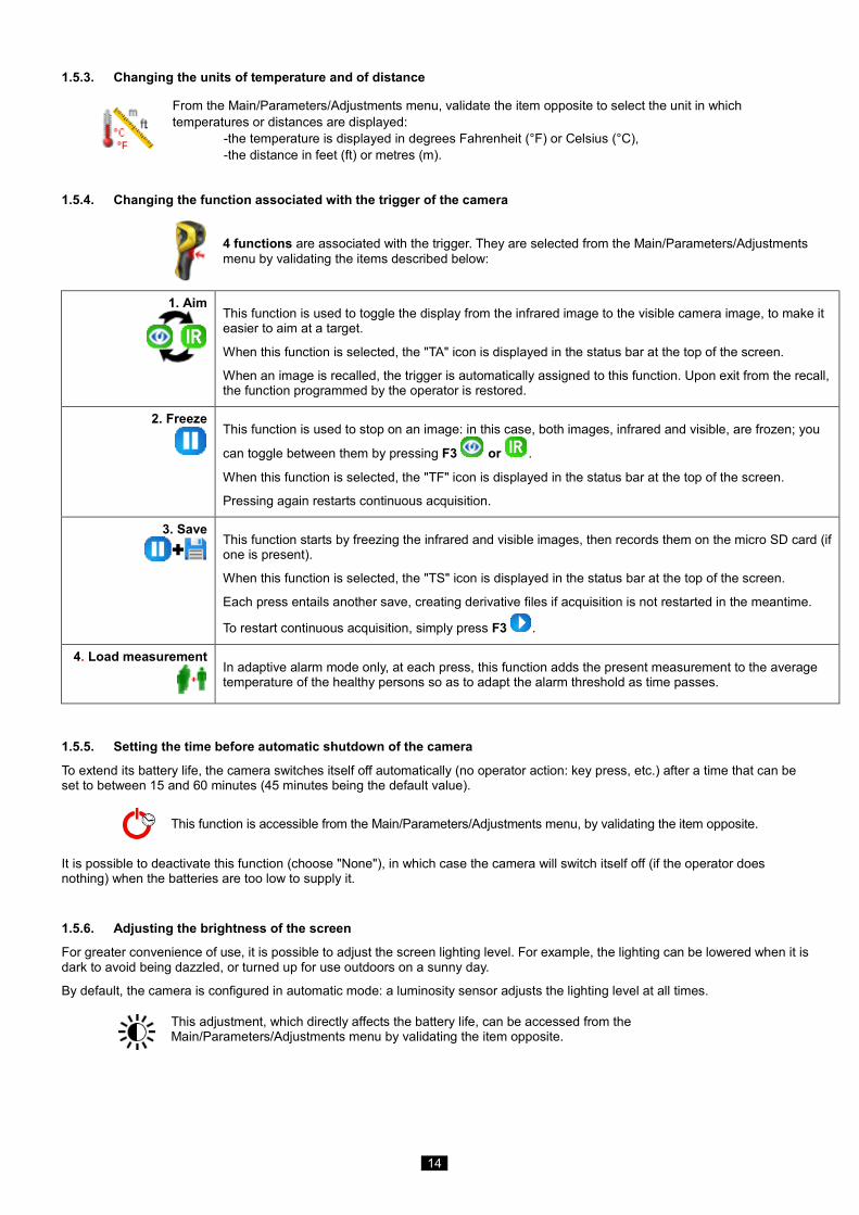
1.5.3. Changing the units of temperature and of distance
From the Main/Parameters/Adjustments menu, validate the item opposite to select the unit in which temperatures or distances are displayed: -the temperature is displayed in degrees Fahrenheit (°F) or Celsius (°C), -the distance in feet (ft) or metres (m).
1.5.4. Changing the function associated with the trigger of the camera
4 functions are associated with the trigger. They are selected from the Main/Parameters/Adjustments menu by validating the items described below:
1. Aim
This function is used to toggle the display from the infrared image to the visible camera image, to make it easier to aim at a target.
When this function is selected, the "TA" icon is displayed in the status bar at the top of the screen.
When an image is recalled, the trigger is automatically assigned to this function. Upon exit from the recall, the function programmed by the operator is restored.
2. Freeze
This function is used to stop on an image: in this case, both images, infrared and visible, are frozen; you
can toggle between them by pressing F3 or .
When this function is selected, the "TF" icon is displayed in the status bar at the top of the screen.
Pressing again restarts continuous acquisition.
3. Save
This function starts by freezing the infrared and visible images, then records them on the micro SD card (if one is present).
When this function is selected, the "TS" icon is displayed in the status bar at the top of the screen.
Each press entails another save, creating derivative files if acquisition is not restarted in the meantime.
To restart continuous acquisition, simply press F3 .
4. Load measurement
In adaptive alarm mode only, at each press, this function adds the present measurement to the average temperature of the healthy persons so as to adapt the alarm threshold as time passes.
1.5.5. Setting the time before automatic shutdown of the camera
To extend its battery life, the camera switches itself off automatically (no operator action: key press, etc.) after a time that can be set to between 15 and 60 minutes (45 minutes being the default value).
This function is accessible from the Main/Parameters/Adjustments menu, by validating the item opposite.
It is possible to deactivate this function (choose "None"), in which case the camera will switch itself off (if the operator does nothing) when the batteries are too low to supply it.
1.5.6. Adjusting the brightness of the screen
For greater convenience of use, it is possible to adjust the screen lighting level. For example, the lighting can be lowered when it is dark to avoid being dazzled, or turned up for use outdoors on a sunny day.
By default, the camera is configured in automatic mode: a luminosity sensor adjusts the lighting level at all times.
This adjustment, which directly affects the battery life, can be accessed from the Main/Parameters/Adjustments menu by validating the item opposite.
15
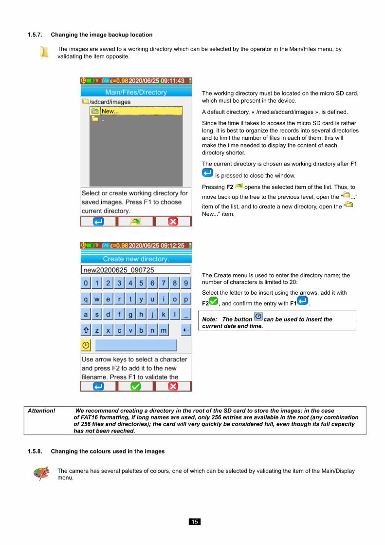
1.5.7. Changing the image backup location
The images are saved to a working directory which can be selected by the operator in the Main/Files menu, by validating the item opposite.
The working directory must be located on the micro SD card, which must be present in the device.
A default directory, « /media/sdcard/images », is defined.
Since the time it takes to access the micro SD card is rather long, it is best to organize the records into several directories and to limit the number of files in each of them; this will make the time needed to display the content of each directory shorter.
The current directory is chosen as working directory after F1
is pressed to close the window.
Pressing F2 opens the selected item of the list. Thus, to move back up the tree to the previous level, open the " ..." item of the list, and to create a new directory, open the " New..." item.
The Create menu is used to enter the directory name; the number of characters is limited to 20:
Select the letter to be insert using the arrows, add it with
F2 , and confirm the entry with F1 .
Note: The button can be used to insert the current date and time.
Attention! We recommend creating a directory in the root of the SD card to store the images: in the case of FAT16 formatting, if long names are used, only 256 entries are available in the root (any combination of 256 files and directories); the card will very quickly be considered full, even though its full capacity has not been reached.
1.5.8. Changing the colours used in the images
The camera has several palettes of colours, one of which can be selected by validating the item of the Main/Display menu.

16
1.5.9. Compensate the difference between the internal body temperature and the skin temperature
As default (offset = 0°C), the temperature measured on an individual is the skin temperature, which is approximately 2°C lower than the internal temperature. So the temperature measured on a healthy person will be close to 35°C rather than the 37°C that would be indicated by a medical thermometer (which generally makes this correction). The possibility of adding a general offset to all measurements made by the camera is therefore provided, to compensate this temperature difference and display the person's internal temperature directly. The adjustment is made in the Main/Target menu; an offset of up to +/-10°C in 0.1°C steps can be entered.
Attention: remember to remove the offset for measurements that are not of body temperatures.
17
2. MEASUREMENT CAMPAIGN
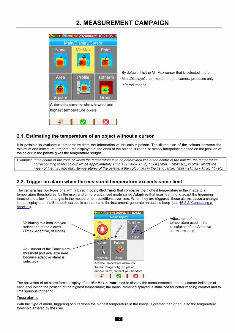
By default, it is the MinMax cursor that is selected in the
Main/Display/Cursor menu, and the camera produces only
infrared images.
2.1. Estimating the temperature of an object without a cursor It is possible to evaluate a temperature from the information of the colour palette. The distribution of the colours between the minimum and maximum temperatures displayed at the ends of the palette is linear, so simply interpolating based on the position of the colour in the palette gives the temperature sought.
Example: if the colour of the zone of which the temperature is to be determined lies at the centre of the palette, the temperature corresponding to this colour will be approximately Tmin + (Tmax – Tmin) * ½ = (Tmin + Tmax )/ 2, in other words the mean of the min. and max. temperatures of the palette; if the colour lies in the 1st quartile, Tmin + (Tmax - Tmin) * ¼ etc.
2.2. Trigger an alarm when the measured temperature exceeds some limit The camera has two types of alarm, a basic mode called Tmax that compares the highest temperature in the image to a temperature threshold set by the user, and a more advanced mode called Adaptive that uses learning to adapt the triggering threshold to allow for changes in the measurement conditions over time. When they are triggered, these alarms cause a change in the display and, if a Bluetooth earbud is connected to the instrument, generate an audible beep (see §6.2.2. Connecting a headset).
The activation of an alarm forces display of the MinMax cursor used to display the measurements, the max cursor indicates at each acquisition the position of the highest temperature; the measurement displayed is stabilized for better reading comfort and to limit spurious triggering.
Tmax alarm:
With this type of alarm, triggering occurs when the highest temperature in the image is greater than or equal to the temperature threshold entered by the user.
Validating this item lets you select one of the alarms (Tmax, Adaptive, or None)
Adjustment of the Tmax alarm threshold (not available here because adaptive alarm is selected)
Adjustment of the temperature used in the calculation of the Adaptive alarm threshold
18
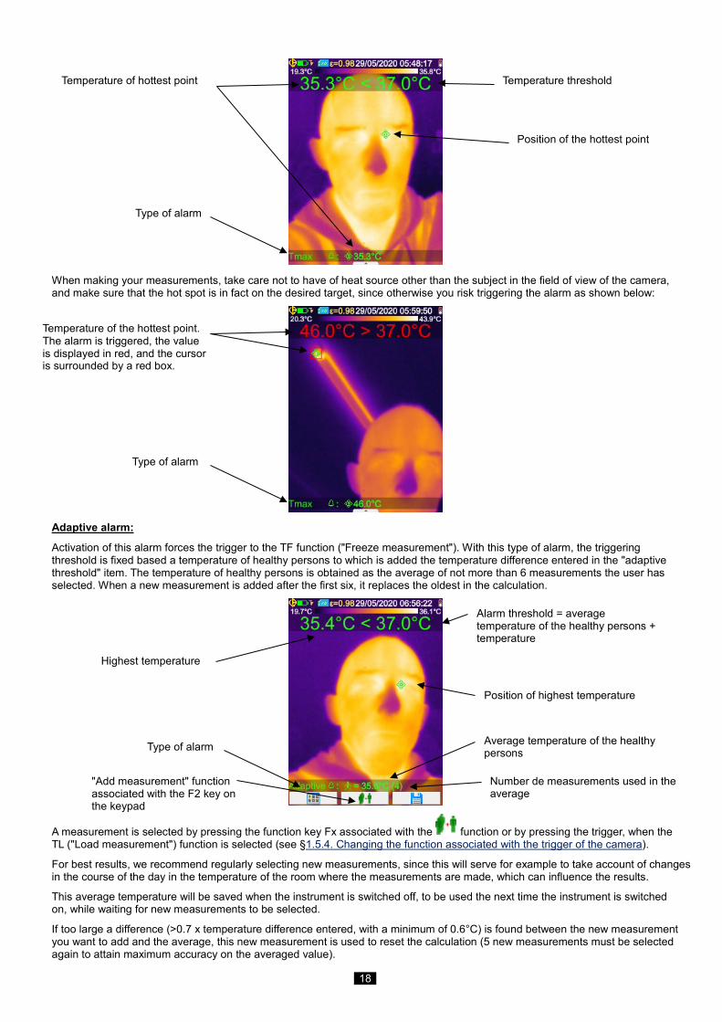
When making your measurements, take care not to have of heat source other than the subject in the field of view of the camera, and make sure that the hot spot is in fact on the desired target, since otherwise you risk triggering the alarm as shown below:
Adaptive alarm:
Activation of this alarm forces the trigger to the TF function ("Freeze measurement"). With this type of alarm, the triggering threshold is fixed based a temperature of healthy persons to which is added the temperature difference entered in the "adaptive threshold" item. The temperature of healthy persons is obtained as the average of not more than 6 measurements the user has selected. When a new measurement is added after the first six, it replaces the oldest in the calculation.
A measurement is selected by pressing the function key Fx associated with the function or by pressing the trigger, when the TL ("Load measurement") function is selected (see §1.5.4. Changing the function associated with the trigger of the camera).
For best results, we recommend regularly selecting new measurements, since this will serve for example to take account of changes in the course of the day in the temperature of the room where the measurements are made, which can influence the results.
This average temperature will be saved when the instrument is switched off, to be used the next time the instrument is switched on, while waiting for new measurements to be selected.
If too large a difference (>0.7 x temperature difference entered, with a minimum of 0.6°C) is found between the new measurement you want to add and the average, this new measurement is used to reset the calculation (5 new measurements must be selected again to attain maximum accuracy on the averaged value).
Type of alarm
Temperature threshold
Position of the hottest point
Temperature of hottest point
Type of alarm
Position of highest temperature
Alarm threshold = average temperature of the healthy persons + temperature
Average temperature of the healthy persons
Number de measurements used in the average
Highest temperature
"Add measurement" function associated with the F2 key on the keypad
Type of alarm
Temperature of the hottest point. The alarm is triggered, the value is displayed in red, and the cursor is surrounded by a red box.
19
Note that the temperatures accepted for this average must lie in the interval [30°C, 45°C]; if not, the measurement will be ignored.
Note: as default, the camera measures the skin temperature of the person aimed at; this external temperature is approximately 2°C lower than the body's internal temperature. You can correct this difference to have a direct reading by entering a general offset value that compensates the difference (see §1.5.9. Compensate the difference between the internal body temperature and the skin temperature).
2.3. Locating the cold and hot spots in the image
In the Main/Display/Cursor menu, choose the Min/Max cursors they represent the minimum and maximum temperatures in the image and display their values.
2.4. Measuring the temperature of a point in the image
In the Main/Display/Cursor menu, choose the Point cursor it gives the temperature of a point. It can be moved on the image using the arrow keys. Place the cursor in the centre of the screen and aim so as to shift the point to the centre.
2.5. Determining the characteristics of a zone on the screen
In the Main/Display/Cursor menu, choose the Surface cursor it indicates the mean, minimum, and maximum temperatures of a square or rectangular area (the rectangular area has the same aspect ratio as the screen), identified by the cursor. Place the area in the centre of the screen, then aim so as to shift the target zone into this area.
Move this area using the arrow keys or adjust its size using the following combinations of keys: Up + Left to reduce it and Down + Right to enlarge it.
2.6. Displaying the temperature profile of a line in the image
In the Main/Display/Cursor menu, choose the Profile cursor ; it highlights a horizontal line in the image (Up/Down keys) and shows its profile. This cursor also identifies a point on this line (Left/Right keys) and indicates its temperature.
2.7. Displaying points at the same temperature in the image
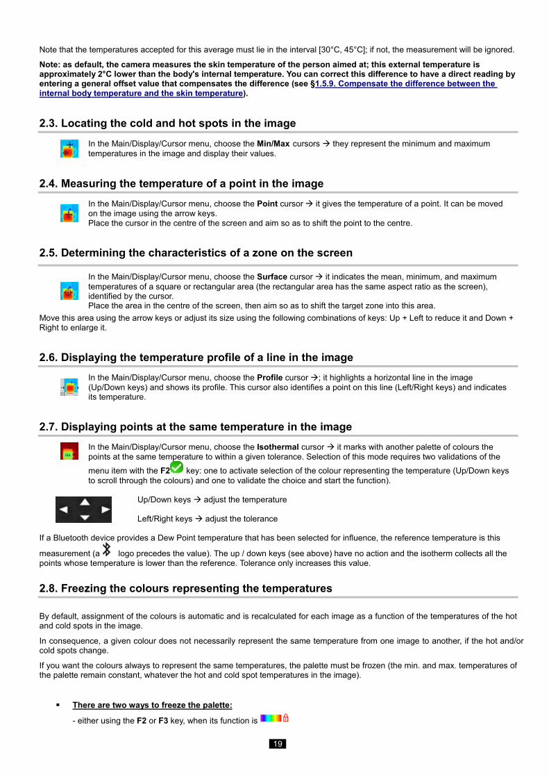
In the Main/Display/Cursor menu, choose the Isothermal cursor it marks with another palette of colours the points at the same temperature to within a given tolerance. Selection of this mode requires two validations of the menu item with the F2 key: one to activate selection of the colour representing the temperature (Up/Down keys to scroll through the colours) and one to validate the choice and start the function).
Up/Down keys adjust the temperature Left/Right keys adjust the tolerance If a Bluetooth device provides a Dew Point temperature that has been selected for influence, the reference temperature is this
measurement (a logo precedes the value). The up / down keys (see above) have no action and the isotherm collects all the points whose temperature is lower than the reference. Tolerance only increases this value.
2.8. Freezing the colours representing the temperatures
By default, assignment of the colours is automatic and is recalculated for each image as a function of the temperatures of the hot and cold spots in the image.
In consequence, a given colour does not necessarily represent the same temperature from one image to another, if the hot and/or cold spots change.
If you want the colours always to represent the same temperatures, the palette must be frozen (the min. and max. temperatures of the palette remain constant, whatever the hot and cold spot temperatures in the image).
There are two ways to freeze the palette:
- either using the F2 or F3 key, when its function is
20
- or from the Main/Parameters menu, by validating the item with the F2 key to change its value to "Manual" (Up/Down keys).
When the palette is frozen, a red padlock appears on the palette; the min and max values are also red.
When the mode is entered, the minimum changes to edit mode for a few seconds (on a blue ground with the symbol ) so that its value can be changed (Up/Down keys).
To modify the max., a simple press on Right (when min. is in edit mode) edits the value. If there is no action on the keypad for a few seconds, the edit mode disappears.
To re-edit a value, another press on the F2 or F3 key with the function , or another validation of the item in the Main/Parameters menu, returns the min. value to edit mode.
To exit from the frozen palette mode, the following steps are necessary:
- if not in edit mode two successive presses on F2 or F3 having the function
- if in edit mode a single press from the edit mode or, from the Main/Parameters menu, by editing the item of the Main/Parameters menu to restore the value "Automatic".
21
3. MORE PRECISE MEASUREMENT CAMPAIGN
3.1. Good practices
Make the measurement in the central zone of the screen.
Aim head on, not at an angle.
Measure scenes that are large enough. Avoid point-like scenes.
Following a variation of ambient temperature, wait for the camera to stabilize.
If the storage batteries have warmed up during charging, wait before putting them back in the camera.
3.2. Use influencing parameters consistent with the conditions of measurement
The flux received by the camera depends:
on the emissivity of the object observed,
on the temperature of the environment,
on the distance to the target,
on the relative humidity of the air.
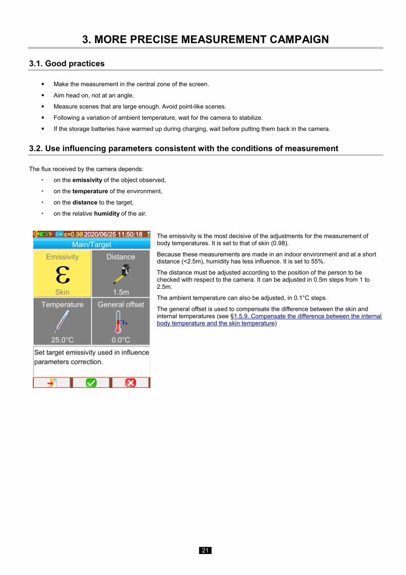
The emissivity is the most decisive of the adjustments for the measurement of body temperatures. It is set to that of skin (0.98).
Because these measurements are made in an indoor environment and at a short distance (<2.5m), humidity has less influence. It is set to 55%.
The distance must be adjusted according to the position of the person to be checked with respect to the camera. It can be adjusted in 0.5m steps from 1 to 2.5m.
The ambient temperature can also be adjusted, in 0.1°C steps
The general offset is used to compensate the difference between the skin and internal temperatures (see §1.5.9. Compensate the difference between the internal body temperature and the skin temperature)
22
3.3. Using a tripod
To improve the sharpness of the images and therefore the accuracy of the measurements, it is possible to use a support that prevents extraneous movements.
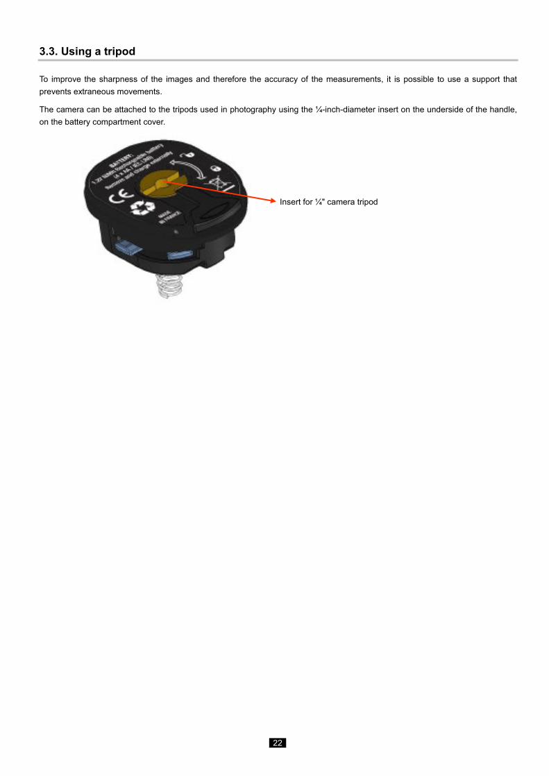
The camera can be attached to the tripods used in photography using the ¼-inch-diameter insert on the underside of the handle, on the battery compartment cover.
Insert for ¼" camera tripod
23
4. SAVING AND RECALLING IMAGES
If there is a micro SD memory card in the drive, it is possible to store, then recall the current image and measurements displayed.
4.1. How are the image files named?
The camera has two objectives, one for infrared images, the other for entering a photograph in the visible domain. In consequence, when an image is recorded, two files are created, one for the infrared image, named "yyyymmdd_hhmmss_IR.PNG", the other for the visible image, having the same name but without the IR extension ("yyyymmdd_hhmmss.PNG"), where yyyymmdd_hhmmss is the date and time of acquisition of the image (the operator must take care to reset the system date and time in advance, see §1.5.2. Changing the camera's date and time).
A third file may be added to the other two if a Bluetooth headset is connected to the camera and the operator accepts the proposal to create a vocal message (see §4.4. Adding a vocal remark). This file will be given the same name as the associated IR image, with the extension .WAV instead of .PNG (e.g. yyyymmdd_hhmmss_IR.WAV).
When the image is frozen, it is possible to make several backups of the same image (addition of cursors, change of palette, etc.). These are referred to as "derived" images: to differentiate these infrared images, which have the same date of acquisition, an index from "a" to "z" is added after the date (e.g. 20141020_131254a_IR.PNG). When all indexes from "a" to "z" have been used, the index "z" is re-used and the file that already bears this name is overwritten by the new one.
As for the visible image, it does not change and so is not duplicated. A single visible image can therefore be associated with several infrared images (when erasing visible images other than via the camera's file manager, take care not to create orphan IR images). Here again it is possible to add a vocal message, which will have the same name as the IR image (e.g. 20141020_131254a_IR.WAV).
4.2. Saving an image It is possible to save an image when there is a micro SD memory card in the drive.
In normal operation if the function associated with the trigger is Aim or Freeze (see §1.5.4. Changing the function associated with the camera's trigger), it is first necessary to stop acquisition (if this has not already been done, press F2 ) to freeze the image.
Either the F2 or the F3 key then takes on the function , allowing backup of the current image in the working directory. If the trigger is assigned to the Save function, each press freezes the image (if it is not already frozen) and records the frozen image in memory. If acquisition is stopped, each further press creates a new "derived" image (same date of acquisition), differentiated by the addition to its name of an index (see §4.1. How are the image files named?)
If an image is recalled it is possible to create a new image (derived, because from the same acquisition) by
selecting the item in the Recall menu; a new index (see §4.1. How are the image files named?) will be used, since the date of acquisition is unchanged.
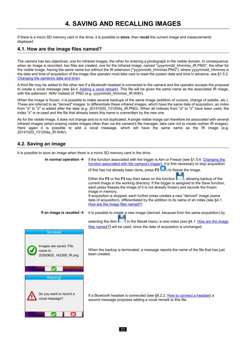
When the backup is terminated, a message reports the name of the file that has just been created.
If a Bluetooth headset is connected (see §6.2.2. How to connect a headset) a second message proposes adding a vocal remark to this file.
24
As the case may be, 1, 2, or 3 files are saved:
1 file for a derived image (same date of acquisition) with no headset connected (the visible image already exists, only the IR file is created)
2 files for the creation of an image from a new acquisition (new date of acquisition) with no headset connected (the IR and visible image files are created)
3 files for the creation of an image from a new acquisition with a vocal file
4.3. Where are the images saved?
The images are saved in the working directory selected by the operator in the Main/Files/Directory menu (see §1.5.7. Changing the image backup location). The working directory must be located on the micro SD card present in the device; if it is missing, an error message informs the operator.
4.4. Adding a vocal remark
The vocal functions are performed by means of a Bluetooth headset, which must be connected to the camera (see §6.2.2. How to connect a headset).
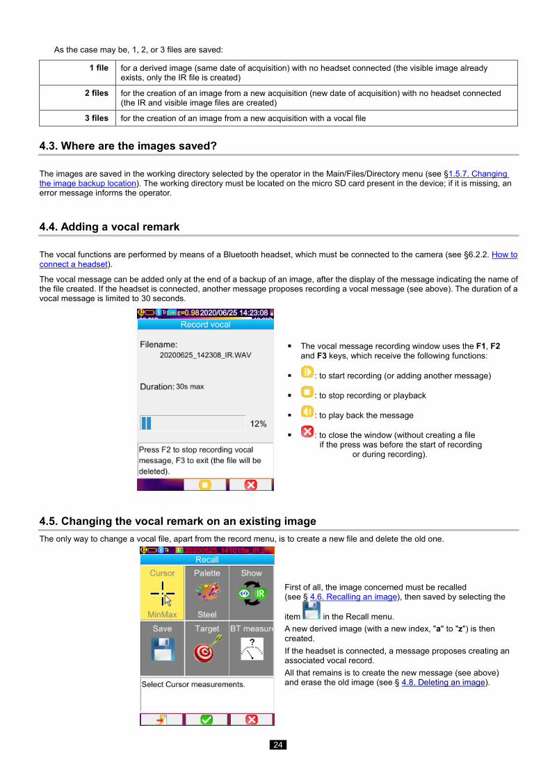
The vocal message can be added only at the end of a backup of an image, after the display of the message indicating the name of the file created. If the headset is connected, another message proposes recording a vocal message (see above). The duration of a vocal message is limited to 30 seconds.
The vocal message recording window uses the F1, F2 and F3 keys, which receive the following functions:
: to start recording (or adding another message)
: to stop recording or playback
: to play back the message
: to close the window (without creating a file if the press was before the start of recording or during recording).
4.5. Changing the vocal remark on an existing image The only way to change a vocal file, apart from the record menu, is to create a new file and delete the old one.
First of all, the image concerned must be recalled (see § 4.6. Recalling an image), then saved by selecting the
item in the Recall menu. A new derived image (with a new index, "a" to "z") is then created. If the headset is connected, a message proposes creating an associated vocal record. All that remains is to create the new message (see above) and erase the old image (see § 4.8. Deleting an image).
25
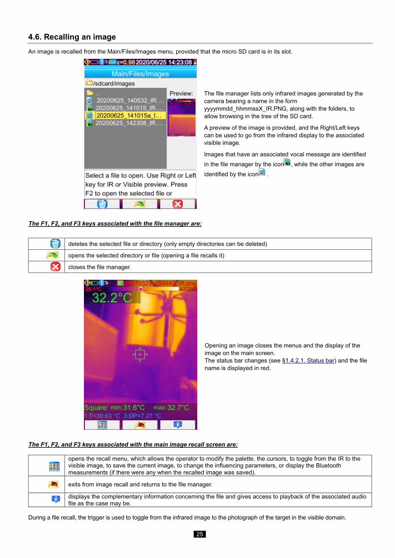
4.6. Recalling an image An image is recalled from the Main/Files/Images menu, provided that the micro SD card is in its slot.
The file manager lists only infrared images generated by the camera bearing a name in the form yyyymmdd_hhmmssX_IR.PNG, along with the folders, to allow browsing in the tree of the SD card.
A preview of the image is provided, and the Right/Left keys can be used to go from the infrared display to the associated visible image.
Images that have an associated vocal message are identified in the file manager by the icon , while the other images are identified by the icon .
The F1, F2, and F3 keys associated with the file manager are:
deletes the selected file or directory (only empty directories can be deleted)
opens the selected directory or file (opening a file recalls it)
closes the file manager.
Opening an image closes the menus and the display of the image on the main screen. The status bar changes (see §1.4.2.1. Status bar) and the file name is displayed in red.
The F1, F2, and F3 keys associated with the main image recall screen are:
opens the recall menu, which allows the operator to modify the palette, the cursors, to toggle from the IR to the visible image, to save the current image, to change the influencing parameters, or display the Bluetooth measurements (if there were any when the recalled image was saved).
exits from image recall and returns to the file manager.
displays the complementary information concerning the file and gives access to playback of the associated audio file as the case may be.
During a file recall, the trigger is used to toggle from the infrared image to the photograph of the target in the visible domain.
26
4.7. Playing back a vocal remark
A vocal message is played back using the Bluetooth headset, which must be connected to the camera (see §6.2.2. Connecting a headset).
To play back the vocal message associated with an image, the image must be recalled (see §4.6. Recalling an image
4.6. Recalling an image) and the F3 key used to open the window of information on the file.
The F2 key then takes on the following functions : to play
back the vocal message or to stop playing it back .
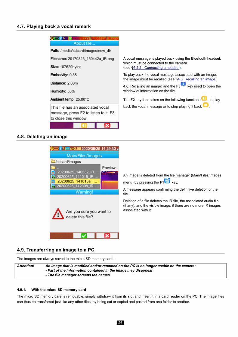
4.8. Deleting an image
An image is deleted from the file manager (Main/Files/Images
menu) by pressing the F1 key.
A message appears confirming the definitive deletion of the file.
Deletion of a file deletes the IR file, the associated audio file (if any), and the visible image, if there are no more IR images associated with it.
4.9. Transferring an image to a PC The images are always saved to the micro SD memory card.
Attention! An image that is modified and/or renamed on the PC is no longer usable on the camera: - Part of the information contained in the image may disappear - The file manager screens the names.
4.9.1. With the micro SD memory card
The micro SD memory care is removable; simply withdraw it from its slot and insert it in a card reader on the PC. The image files can thus be transferred just like any other files, by being cut or copied and pasted from one folder to another.
27
4.9.2. Via the USB cable
• The camera, in normal operation, has a USB port of the type used for mass storage: when the camera is connected to the
PC by the USB cord, the content of the micro SD memory card can be accessed directly by the PC; the image is transferred
by cut or copy and paste from one folder to another.
• If the camera's file manager is open and the PC modifies the content of the SD card, the file manager must be reopened
or the camera rebooted for the camera to apply the changes.
• Conversely, any modification from the camera requires disconnection/reconnection of the USB cable to force an update of
the file manager of the PC.
4.10 Creating an operating report including images from the camera
The instrument is delivered with an application CamReport allowing post-processing of the images taken with the camera and
automatic generation of reports.
To use an image, simply transfer the image files from the SD card (infrared image, visible image, and audio file) to the PC and open
it with the application (see the documentation of the software).
28
5. BACKUP AND RECALL OF USER CONFIGURATIONS
The setup files contain a complete backup of the current parameters of the camera, enabling the operator to return to an operating mode defined earlier (user setup) or to a predefined setup (factory setup). The setup stores the list of Bluetooth peripherals connected and their statuses, to allow their re-use.
5.1. Where are the configurations saved? Like the images, the setup files are saved in the micro SD card. The files are stored in a single directory named « /media/sdcard/config/ » placed in the root of the memory card.
Their names are entered by the operator at the time of the backup and have the extension ".CFG".
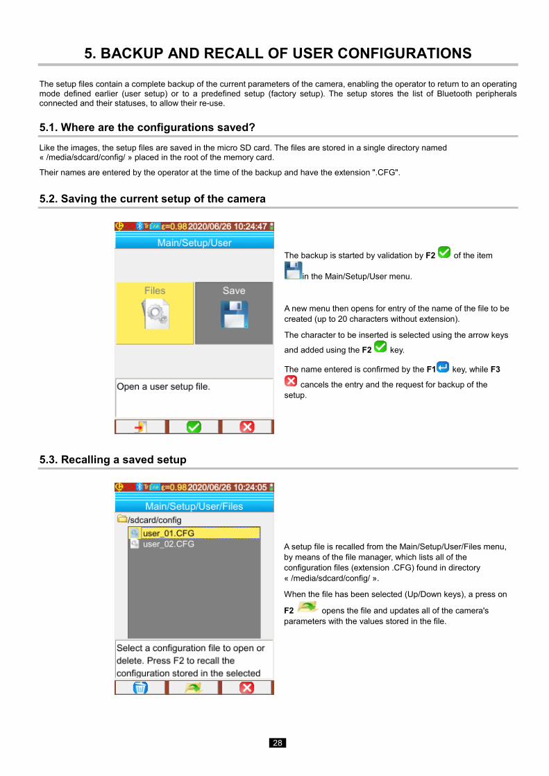
5.2. Saving the current setup of the camera
The backup is started by validation by F2 of the item
in the Main/Setup/User menu.
A new menu then opens for entry of the name of the file to be created (up to 20 characters without extension).
The character to be inserted is selected using the arrow keys
and added using the F2 key.
The name entered is confirmed by the F1 key, while F3
cancels the entry and the request for backup of the setup.
5.3. Recalling a saved setup
A setup file is recalled from the Main/Setup/User/Files menu, by means of the file manager, which lists all of the configuration files (extension .CFG) found in directory « /media/sdcard/config/ ».
When the file has been selected (Up/Down keys), a press on
F2 opens the file and updates all of the camera's parameters with the values stored in the file.
29
5.4. Deleting a saved setup A configuration file is deleted from the Main/Setup/User/Files menu, by means of the file manager, which lists all of the configuration files (extension .CFG) found in directory « /media/sdcard/config/ ».
When the file has been selected (Up/Down keys), a press on F1 activates the deletion. A message requesting confirmation appears and must be accepted for definitive deletion of the file to take place.
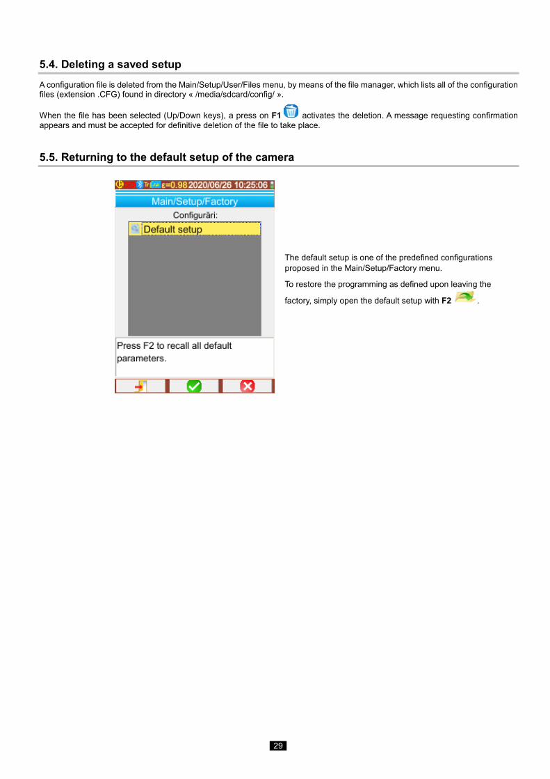
5.5. Returning to the default setup of the camera
The default setup is one of the predefined configurations proposed in the Main/Setup/Factory menu.
To restore the programming as defined upon leaving the
factory, simply open the default setup with F2 .
30
6. BLUETOOTH FUNCTION
6.1. Activating/Deactivating the Bluetooth function
6.1.1. Activating Bluetooth
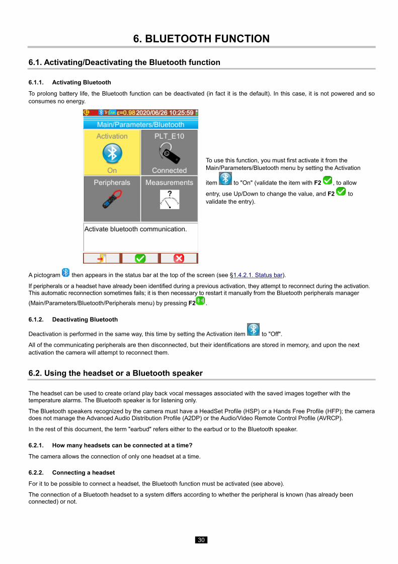
To prolong battery life, the Bluetooth function can be deactivated (in fact it is the default). In this case, it is not powered and so consumes no energy.
To use this function, you must first activate it from the Main/Parameters/Bluetooth menu by setting the Activation
item to "On" (validate the item with F2 , to allow
entry, use Up/Down to change the value, and F2 to validate the entry).
A pictogram then appears in the status bar at the top of the screen (see §1.4.2.1. Status bar).
If peripherals or a headset have already been identified during a previous activation, they attempt to reconnect during the activation. This automatic reconnection sometimes fails; it is then necessary to restart it manually from the Bluetooth peripherals manager (Main/Parameters/Bluetooth/Peripherals menu) by pressing F2 .
6.1.2. Deactivating Bluetooth
Deactivation is performed in the same way, this time by setting the Activation item to "Off".
All of the communicating peripherals are then disconnected, but their identifications are stored in memory, and upon the next activation the camera will attempt to reconnect them.
6.2. Using the headset or a Bluetooth speaker
The headset can be used to create or/and play back vocal messages associated with the saved images together with the temperature alarms. The Bluetooth speaker is for listening only.
The Bluetooth speakers recognized by the camera must have a HeadSet Profile (HSP) or a Hands Free Profile (HFP); the camera does not manage the Advanced Audio Distribution Profile (A2DP) or the Audio/Video Remote Control Profile (AVRCP).
In the rest of this document, the term "earbud" refers either to the earbud or to the Bluetooth speaker.
6.2.1. How many headsets can be connected at a time?
The camera allows the connection of only one headset at a time.
6.2.2. Connecting a headset
For it to be possible to connect a headset, the Bluetooth function must be activated (see above).
The connection of a Bluetooth headset to a system differs according to whether the peripheral is known (has already been connected) or not.
31
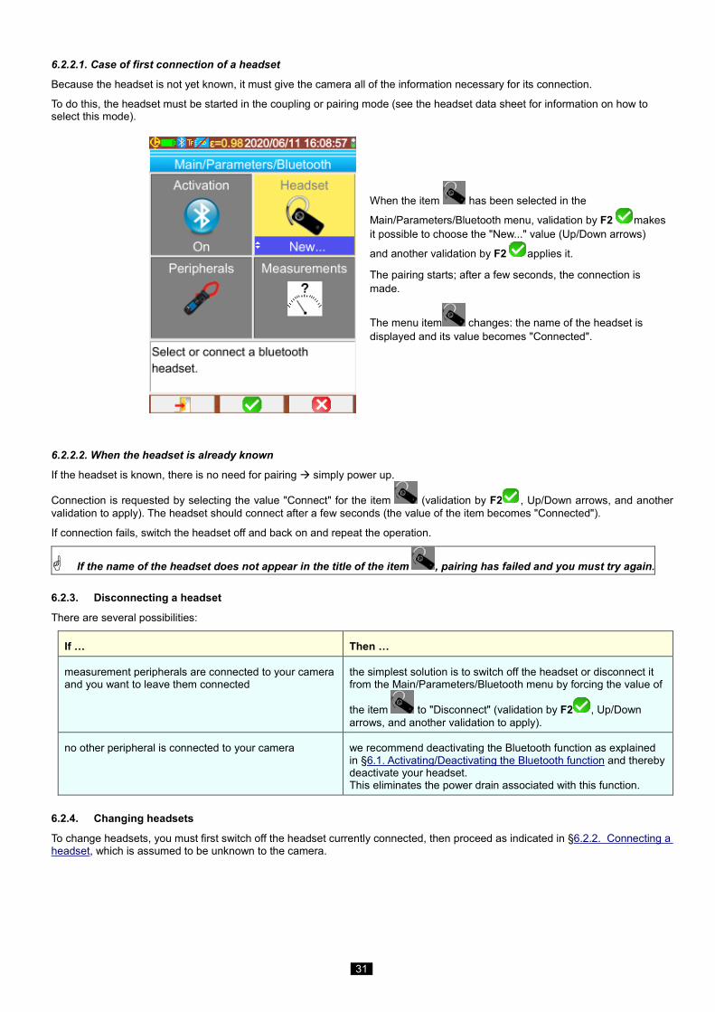
6.2.2.1. Case of first connection of a headset
Because the headset is not yet known, it must give the camera all of the information necessary for its connection.
To do this, the headset must be started in the coupling or pairing mode (see the headset data sheet for information on how to select this mode).
When the item has been selected in the
Main/Parameters/Bluetooth menu, validation by F2 makes it possible to choose the "New..." value (Up/Down arrows)
and another validation by F2 applies it.
The pairing starts; after a few seconds, the connection is made.
The menu item changes: the name of the headset is displayed and its value becomes "Connected".
6.2.2.2. When the headset is already known
If the headset is known, there is no need for pairing simply power up.
Connection is requested by selecting the value "Connect" for the item (validation by F2 , Up/Down arrows, and another validation to apply). The headset should connect after a few seconds (the value of the item becomes "Connected").
If connection fails, switch the headset off and back on and repeat the operation.
If the name of the headset does not appear in the title of the item , pairing has failed and you must try again.
6.2.3. Disconnecting a headset
There are several possibilities:
If … Then …
measurement peripherals are connected to your camera and you want to leave them connected
the simplest solution is to switch off the headset or disconnect it from the Main/Parameters/Bluetooth menu by forcing the value of
the item to "Disconnect" (validation by F2 , Up/Down arrows, and another validation to apply).
no other peripheral is connected to your camera we recommend deactivating the Bluetooth function as explained in §6.1. Activating/Deactivating the Bluetooth function and thereby deactivate your headset. This eliminates the power drain associated with this function.
6.2.4. Changing headsets
To change headsets, you must first switch off the headset currently connected, then proceed as indicated in §6.2.2. Connecting a headset, which is assumed to be unknown to the camera.
32
6.3. Using Bluetooth measurement peripherals
6.3.1. How many peripherals can be connected?
The camera allows the simultaneous connection of 3 measurement peripherals and one headset (classic Bluetooth or low-energy).
6.3.2. How many measurements can be recovered from a peripheral?
Three measurements for the clamps and one measurement for the ASYC IV multimeter can be read on each of the measurement peripherals, for a maximum of 9 measurements if 3 clamps are connected.
6.3.3. What peripherals does the camera recognize?
In the current version, the camera recognizes the following instruments: ASYC IV multimeters: MTX 3292/3BT, MTX3292/3B-BT, C.A 5292/3-BT (1 measurement read) current clamps: F607 (3 measurements read) current clamps: F407 (3 measurements read) Chauvin Arnoux BLE instruments: C.A 1246, C.A 1821 …
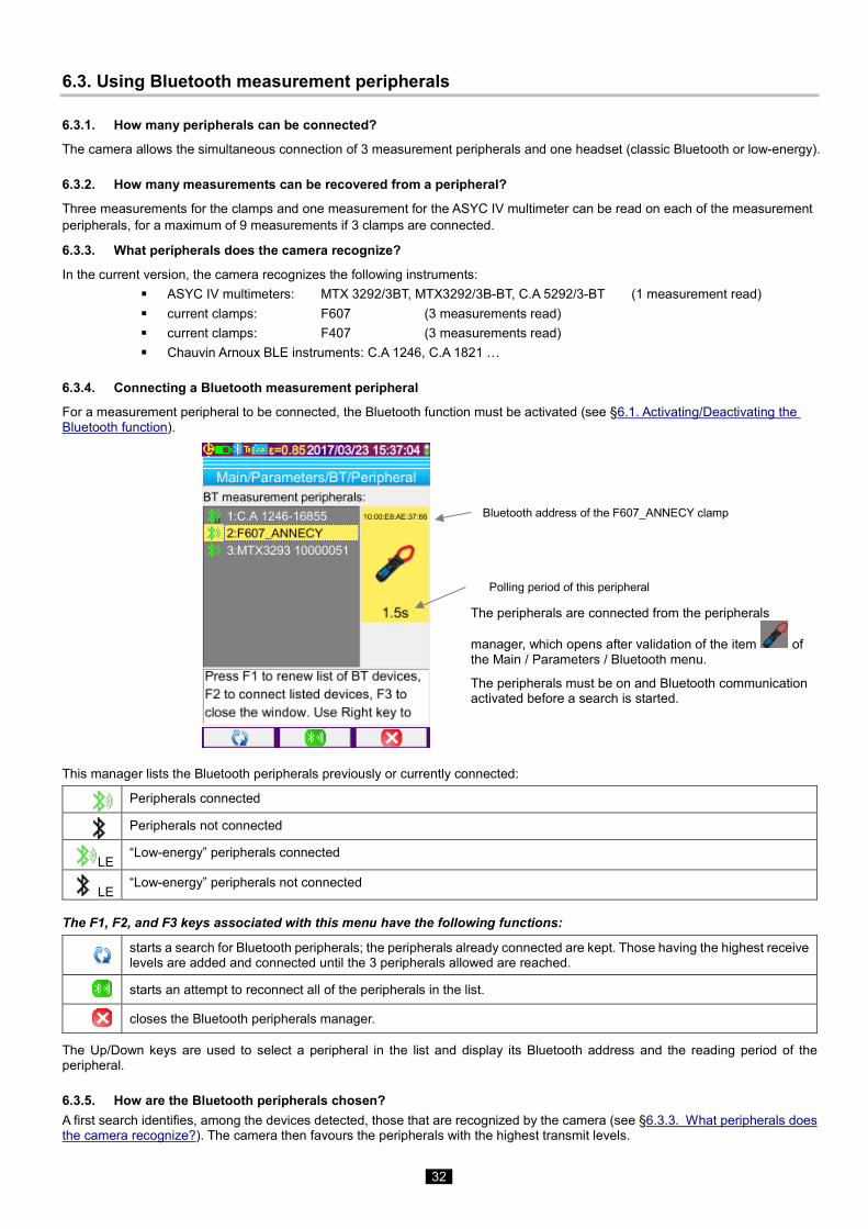
6.3.4. Connecting a Bluetooth measurement peripheral
For a measurement peripheral to be connected, the Bluetooth function must be activated (see §6.1. Activating/Deactivating the Bluetooth function).
The peripherals are connected from the peripherals
manager, which opens after validation of the item of the Main / Parameters / Bluetooth menu.
The peripherals must be on and Bluetooth communication activated before a search is started.
This manager lists the Bluetooth peripherals previously or currently connected:
Peripherals connected
Peripherals not connected
LE “Low-energy” peripherals connected
LE “Low-energy” peripherals not connected
The F1, F2, and F3 keys associated with this menu have the following functions:
starts a search for Bluetooth peripherals; the peripherals already connected are kept. Those having the highest receive levels are added and connected until the 3 peripherals allowed are reached.
starts an attempt to reconnect all of the peripherals in the list.
closes the Bluetooth peripherals manager.
The Up/Down keys are used to select a peripheral in the list and display its Bluetooth address and the reading period of the peripheral.
6.3.5. How are the Bluetooth peripherals chosen? A first search identifies, among the devices detected, those that are recognized by the camera (see §6.3.3. What peripherals does the camera recognize?). The camera then favours the peripherals with the highest transmit levels.
Bluetooth address of the F607_ANNECY clamp
Polling period of this peripheral
33
If peripherals are already connected to the camera when the search is started, they will be kept. The list will be completed up to the 3 peripherals allowed, using those found previously.
6.3.6. Replacing one peripheral with another
1. Disconnect the peripheral to be removed by switching it off.
2. Wait until the disconnection takes effect on the camera (appearance of a message).
3. Switch on the new peripheral to be connected. 4. Start a new search (F1 key) from the peripherals manager (Main/Parameters/Bluetooth/Peripherals menu), which will
overwrite the current list (the peripherals which are connected are kept) and lead to addition of the new instrument.
6.3.7. Changing the frequency of reading of a Bluetooth peripheral
From the peripherals manager (above), it is possible to change the reading period of the selected peripheral:
the Right arrow is used to start the entry of a new reading period. The period is displayed on a blue ground with the symbol indicating that the Up/Down arrows can now be used to change its value. The F2 key is then used to validate the entry, while
the F3 key or the Left arrow cancels it. The reading period can be set to 50 minutes.
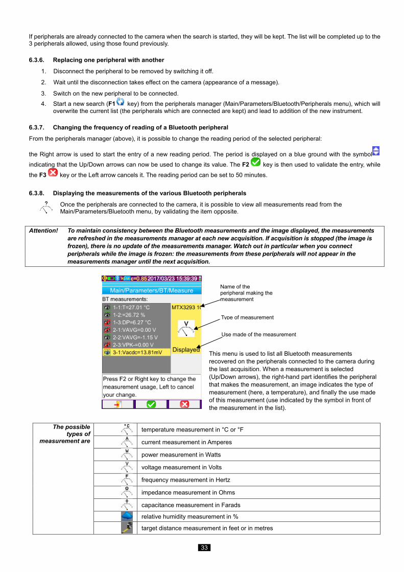
6.3.8. Displaying the measurements of the various Bluetooth peripherals
Once the peripherals are connected to the camera, it is possible to view all measurements read from the Main/Parameters/Bluetooth menu, by validating the item opposite.
Attention! To maintain consistency between the Bluetooth measurements and the image displayed, the measurements are refreshed in the measurements manager at each new acquisition. If acquisition is stopped (the image is frozen), there is no update of the measurements manager. Watch out in particular when you connect peripherals while the image is frozen: the measurements from these peripherals will not appear in the measurements manager until the next acquisition.
This menu is used to list all Bluetooth measurements recovered on the peripherals connected to the camera during the last acquisition. When a measurement is selected (Up/Down arrows), the right-hand part identifies the peripheral that makes the measurement, an image indicates the type of measurement (here, a temperature), and finally the use made of this measurement (use indicated by the symbol in front of the measurement in the list).
The possible
types of measurement are
temperature measurement in °C or °F
current measurement in Amperes
power measurement in Watts
voltage measurement in Volts
frequency measurement in Hertz
impedance measurement in Ohms
capacitance measurement in Farads
relative humidity measurement in %
target distance measurement in feet or in metres
Name of the peripheral making the measurement
Use made of the measurement
Type of measurement

34
other measurement
35
Several uses are possible
hidden The measurement does not appear among the Bluetooth measurements displayed at the bottom of the main screen.
displayed
The measurement is added to the list of Bluetooth measurements displayed at the bottom of the main screen (unless the Profile cursor is selected)
influence The measurement is added to the list of measurements displayed at the bottom of the main screen and can be used in the correction for the influencing factors or isotherm cursor (see §6.3.9. Using a Bluetooth measurement as an influencing parameter).
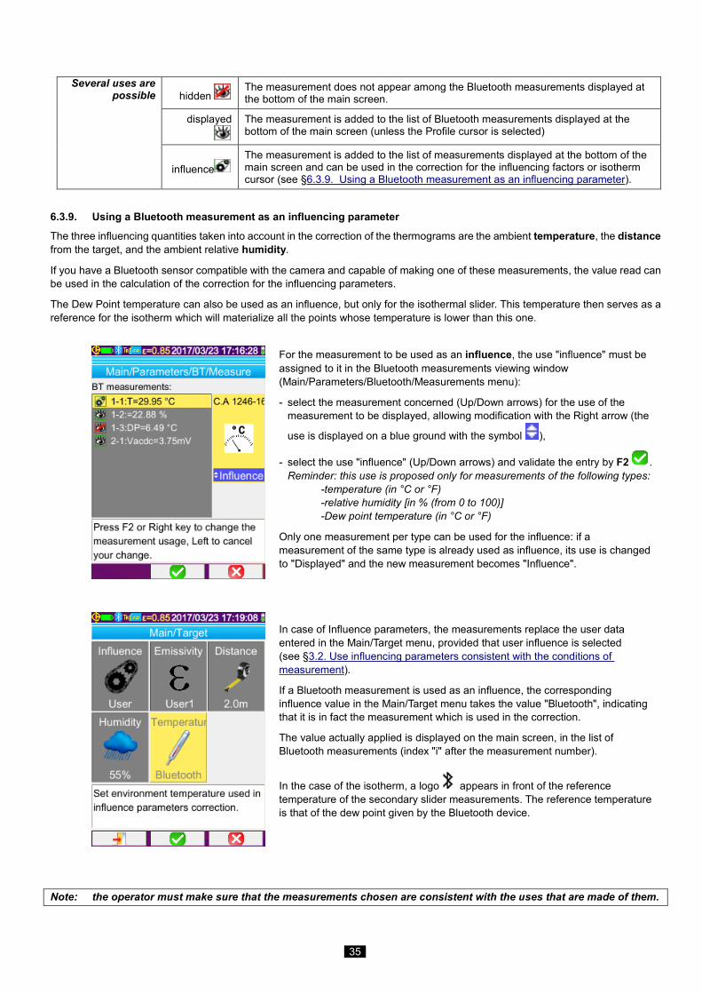
6.3.9. Using a Bluetooth measurement as an influencing parameter
The three influencing quantities taken into account in the correction of the thermograms are the ambient temperature, the distance from the target, and the ambient relative humidity.
If you have a Bluetooth sensor compatible with the camera and capable of making one of these measurements, the value read can be used in the calculation of the correction for the influencing parameters.
The Dew Point temperature can also be used as an influence, but only for the isothermal slider. This temperature then serves as a reference for the isotherm which will materialize all the points whose temperature is lower than this one.
For the measurement to be used as an influence, the use "influence" must be assigned to it in the Bluetooth measurements viewing window (Main/Parameters/Bluetooth/Measurements menu):
- select the measurement concerned (Up/Down arrows) for the use of the measurement to be displayed, allowing modification with the Right arrow (the
use is displayed on a blue ground with the symbol ),
- select the use "influence" (Up/Down arrows) and validate the entry by F2 . Reminder: this use is proposed only for measurements of the following types: -temperature (in °C or °F) -relative humidity [in % (from 0 to 100)] -Dew point temperature (in °C or °F)
Only one measurement per type can be used for the influence: if a measurement of the same type is already used as influence, its use is changed to "Displayed" and the new measurement becomes "Influence".
In case of Influence parameters, the measurements replace the user data entered in the Main/Target menu, provided that user influence is selected (see §3.2. Use influencing parameters consistent with the conditions of measurement).
If a Bluetooth measurement is used as an influence, the corresponding influence value in the Main/Target menu takes the value "Bluetooth", indicating that it is in fact the measurement which is used in the correction.
The value actually applied is displayed on the main screen, in the list of Bluetooth measurements (index "i" after the measurement number).
In the case of the isotherm, a logo appears in front of the reference temperature of the secondary slider measurements. The reference temperature is that of the dew point given by the Bluetooth device.
Note: the operator must make sure that the measurements chosen are consistent with the uses that are made of them.
36
6.3.10. Displaying the Bluetooth measurements on the main screen
As described above, it is possible to assign a use to measurements. If a measurement is "Displayed" or "Influence", it will appear in blue on the last line of the measurement zone of the screen (unless the profile cursor is activated, because of lack of space). If the number of measurements is too large, they are not all visible in continuous acquisition. However, if the image is frozen, all Bluetooth measurements corresponding to the acquisition scroll along the line. For each measurement, the measurement number is displayed as it appears in the Bluetooth measurements window, possibly followed by an "i" if the measurement is used as an influence, followed by the separator ":", the name of the measurement, and its value. Measurements are separated by 2 spaces. If the setup of the Bluetooth peripheral is modified (change to another measurement function), then the use of all measurements from this peripheral are forced to "hidden" on the camera and they disappear from the main screen. The operator must return to the Main/Parameters/Bluetooth/Measurements menu to request display once again.
6.3.11. Can the Bluetooth measurements be saved at the same time as an image?
Yes, the Bluetooth measurements are recorded when an image is saved.
They can be viewed when the file is recalled (see §4.6. Recalling an image) by validating the item in the Recall menu.
37
7. UPDATING THE FIRMWARE OF THE CAMERA
7.1. Where can the firmware version of the camera be read?
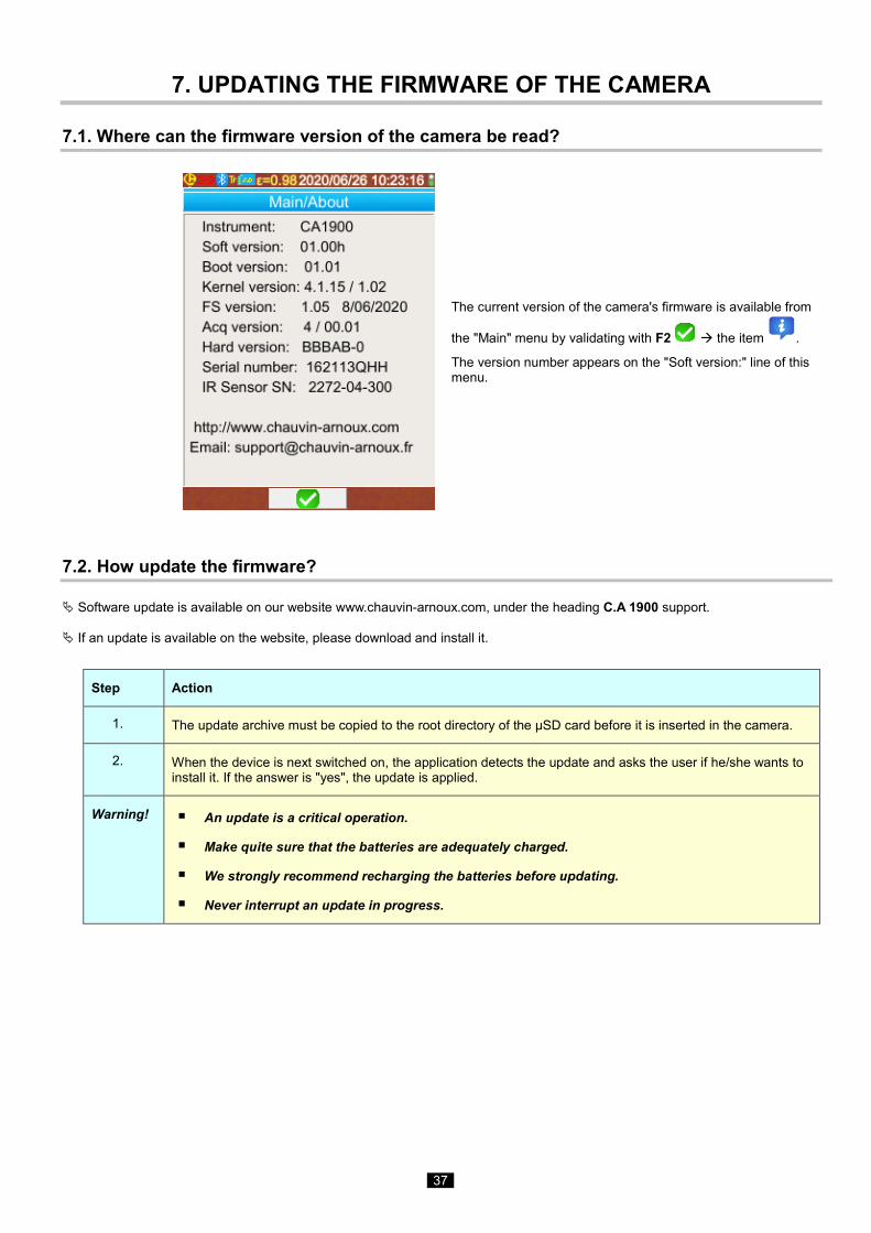
The current version of the camera's firmware is available from
the "Main" menu by validating with F2 the item .
The version number appears on the "Soft version:" line of this menu.
7.2. How update the firmware?
Software update is available on our website www.chauvin-arnoux.com, under the heading C.A 1900 support. If an update is available on the website, please download and install it.
Step Action
1. The update archive must be copied to the root directory of the µSD card before it is inserted in the camera.
2. When the device is next switched on, the application detects the update and asks the user if he/she wants to install it. If the answer is "yes", the update is applied.
Warning! An update is a critical operation.
Make quite sure that the batteries are adequately charged.
We strongly recommend recharging the batteries before updating.
Never interrupt an update in progress.
38
8. ARE YOU HAVING DIFFICULTIES?
8.1. The IR image I obtain is solid-colour
8.1.1. The palette of colours is frozen
Make sure that the low and high temperature limits of your palette are consistent with the temperature range of your scene. To check this, unlock the palette (see §2.8. Freezing the colours representing the temperatures).
8.1.2. Inconsistent "user" influencing parameters
The entry of an incorrect emissivity value can lead to measurement errors of this type. Check your influencing parameters in the "Main/Target" menu. If there is any doubt, restore the "default" influencing parameters.
8.2. The contrast of my IR image is wrong Make sure that isothermal measurement is not activated.
If the palette is frozen, make sure that the low and high temperature limits of your palette are consistent with the temperature range of your scene. If there is any doubt, unlock the palette (see §2.8. Freezing the colours representing the temperatures).
The temperature range of the image is very large (hot and cold points very far apart), so the linear distribution of the colours between the minimum and maximum temperatures is in larger steps, impairing the contrast of the image.
Several solutions are possible: -either freeze the palette and set the limits according to the range of temperatures that interest you, -or arrange to keep the hot or cold point which does not interest you outside the field of view of the camera, so as to reduce the temperature range of the image.
8.3. I am unable to save the current image Make sure that the micro SD card is correctly inserted in its slot and displayed as being present in the status bar of
the main screen (see §1.4.2.1. Status bar).
Make sure that your micro SD card is not full (with FAT16 formatting, watch out for the number of entries in the root; see §1.5.7. Changing the image backup location).
Make sure that your micro SD card is not corrupted and that you can read/modify its content on a PC via the USB cable or a card reader.
8.4. The file manager takes a very long time to respond The access time to the SD is relatively long. To make it shorter, favour the creation of new directories to store your images and limit the number of files per directory. We suggest regularly uploading your images to a host PC via the USB cable or a card reader.
8.5. I cannot connect my headset Make sure that your headset is correctly powered and that it is not automatically connected to another instrument with
which you have already paired it.
Switch off your headset and repeat the operation as described in §6.2.2. Connecting a headset.
If the problem persists, deactivate the Bluetooth function on the camera (see §6.1. Activating/Deactivating the Bluetooth function), re-activate it and then make another attempt to connect.
8.6. I cannot connect my Bluetooth peripheral Make sure that your peripheral is correctly powered, configured in Bluetooth mode, and not already used by another
instrument.
Switch off your peripheral and repeat the operation described in §6.3.4. Connecting a Bluetooth measurement peripheral.
If the problem persists, deactivate the Bluetooth function on the camera (see §6.1. Activating/Deactivating the Bluetooth function), re-activate it, then make another attempt to connect.
39
8.7. My Bluetooth measurements are not displayed or are not refreshed in the measurements manager
Make sure that acquisition has not been stopped. To preserve consistency between the image displayed and the
Bluetooth measurements read on the peripherals at the time of acquisition, the measurements are refreshed only
when there is a new acquisition. If a peripheral is connected, but acquisition has been stopped, its measurements will
not be displayed until there has been another acquisition.
Following an incorrect reading, the measurement read and the measurement expected may not be consistent. This
can prevent refreshing. To eliminate the ambiguity, change the measurement function on the peripheral (rotary switch
on clamps) and return to the initial position.
If the problem persists:
1. Switch off the Bluetooth peripheral.
2. Wait until this disconnection is detected on the camera.
3. Switch your peripheral back on (Bluetooth mode activated).
4. Press F2 to try again to connect the instrument from the Bluetooth peripherals manager
(Main/Parameters/Bluetooth/Peripherals menu).
If continuous acquisition is activated, your measurements must appear in the Bluetooth measurements
manager (Main/Parameters/Bluetooth/Measurements menu).
40
9. SERVICING AND MAINTENANCE
9.1 Cleaning the housing and screen of the camera
Cleaning the housing: to avoid any spattering on the lens, you must close the camera's lens protection flap. Use a cloth moistened with soapy water or with alcohol.
Cleaning the screen: to avoid scratching, use a soft, lint-free cloth.
WARNING! The camera is not immersion-proof.
9.2 Cleaning the infrared optics
The infrared lens has a very fragile coating.
For this reason, great care must be taken to avoid leaving fingerprints. Insofar as possible, any rubbing of the lens will be avoided. If there is a dust deposit on the lens, favour non-contact methods, such as compressed dry nitrogen, an air bulb, etc., so as not to damage the lens coating.
If you must wipe the lens, always start by blowing away any dust as explained above, to avoid scratching by dust wiped across the surface, then use a special soft, absorbent, lint-free optical lens cleaning paper (such as KIMWIPE).
9.3 Unpacking, re-packing
The mechanical and electrical condition of all of the equipment was checked before dispatching.
When you receive it, carry out a quick check for damage that may have occurred in transit. Should there be any, contact our sales department immediately and declare your reservations to the carrier.
For reshipping, it is best to use the original packaging.

41
10. WARRANTY
Our warranty applies, except as otherwise stated, for two years after the date of availability of the equipment.
Extract from our General Terms of Sale, communicated on request.
The warranty does not apply in the following cases:
Inappropriate use of the equipment or use with incompatible equipment
Modifications made to the equipment without the explicit permission of the manufacturer’s technical staff
Work done on the device by a person not approved by the manufacturer
Adaptation for a particular application not anticipated in the definition of the equipment or not indicated in the user’s manual
Damage caused by shocks, falls, or floods.
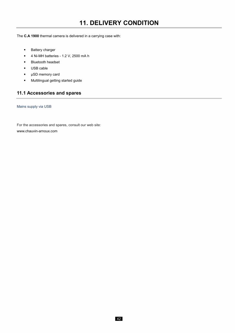
42
11. DELIVERY CONDITION
The C.A 1900 thermal camera is delivered in a carrying case with:
Battery charger
4 Ni-MH batteries - 1.2 V, 2500 mA h
Bluetooth headset
USB cable
µSD memory card
Multilingual getting started guide
11.1 Accessories and spares
Mains supply via USB
For the accessories and spares, consult our web site:
www.chauvin-arnoux.com
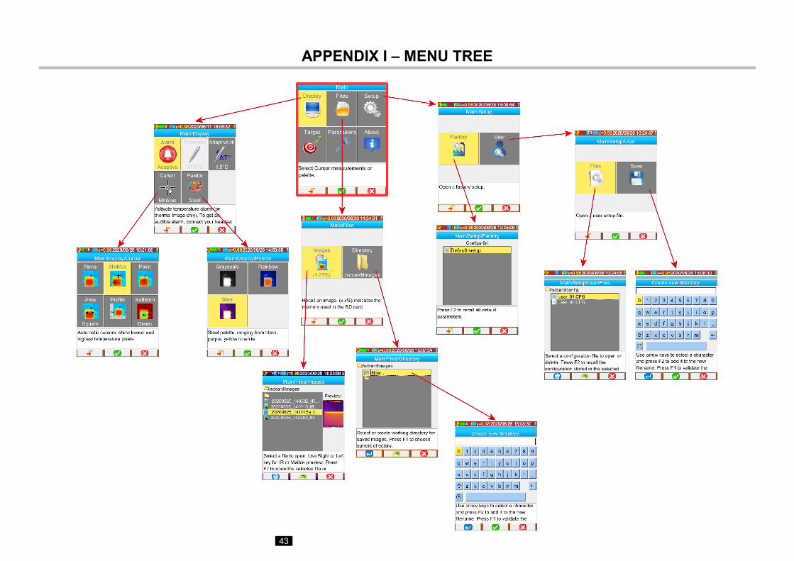
43
APPENDIX I – MENU TREE
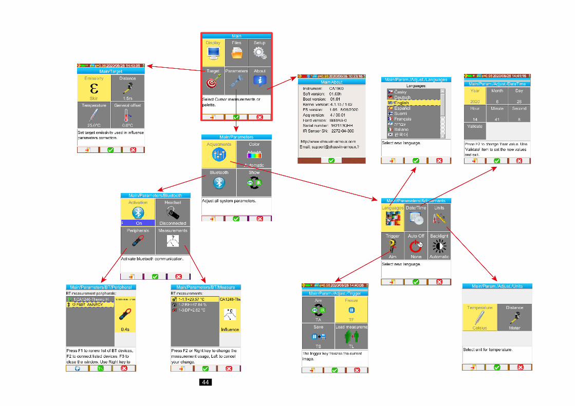
44
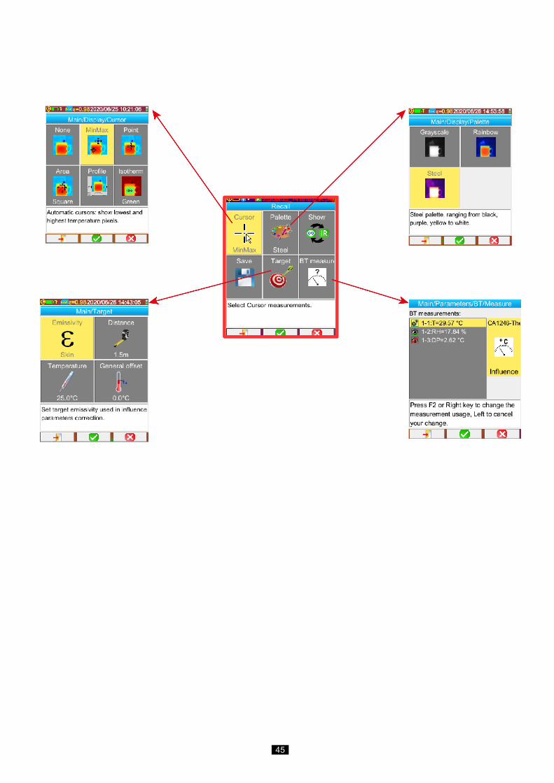
45
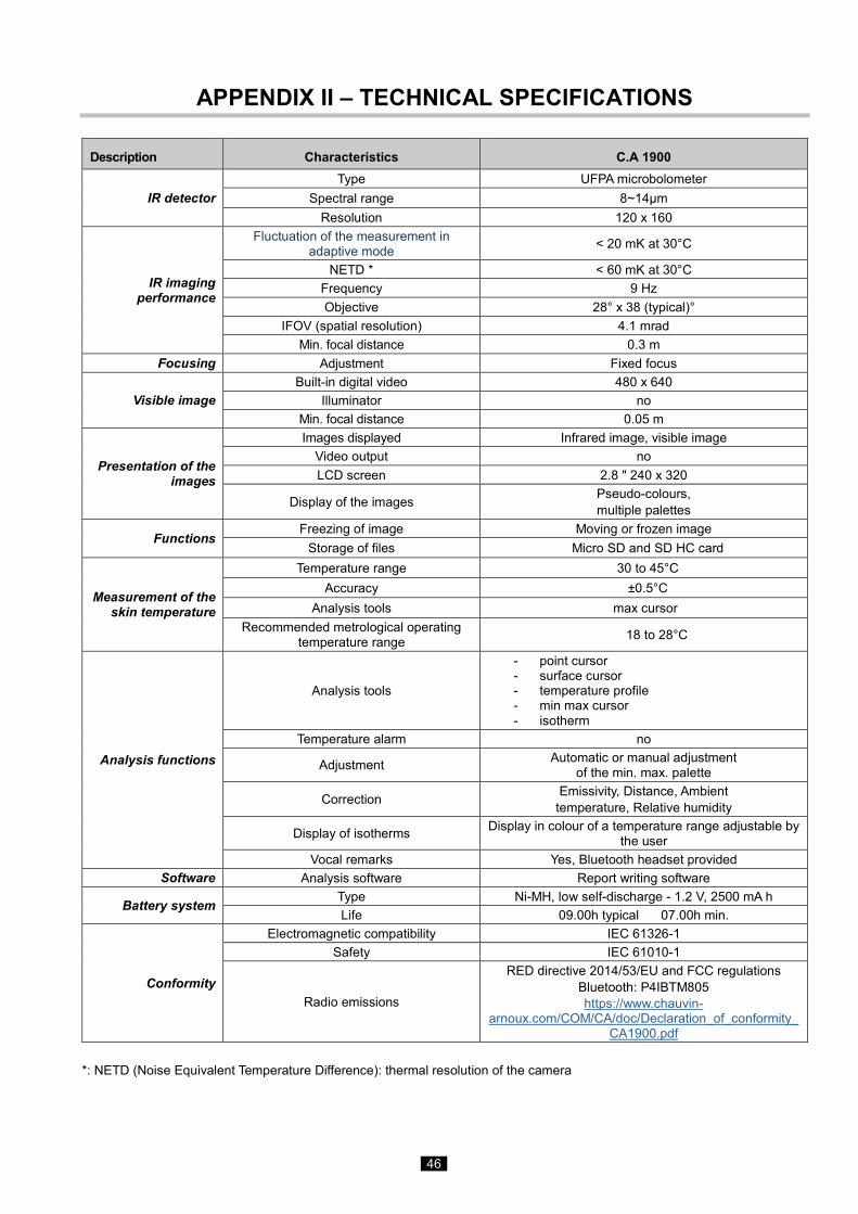
46
APPENDIX II – TECHNICAL SPECIFICATIONS
Description Characteristics C.A 1900
IR detector Type UFPA microbolometer
Spectral range 8~14µm Resolution 120 x 160
IR imaging performance
Fluctuation of the measurement in adaptive mode < 20 mK at 30°C
NETD * < 60 mK at 30°C Frequency 9 Hz Objective 28° x 38 (typical)°
IFOV (spatial resolution) 4.1 mrad Min. focal distance 0.3 m
Focusing Adjustment Fixed focus
Visible image Built-in digital video 480 x 640
Illuminator no Min. focal distance 0.05 m
Presentation of the images
Images displayed Infrared image, visible image Video output no LCD screen 2.8 " 240 x 320
Display of the images Pseudo-colours, multiple palettes
Functions Freezing of image Moving or frozen image
Storage of files Micro SD and SD HC card
Measurement of the skin temperature
Temperature range 30 to 45°C Accuracy ±0.5°C
Analysis tools max cursor Recommended metrological operating
temperature range 18 to 28°C
Analysis functions
Analysis tools
- point cursor - surface cursor - temperature profile - min max cursor - isotherm
Temperature alarm no
Adjustment Automatic or manual adjustment of the min. max. palette
Correction Emissivity, Distance, Ambient temperature, Relative humidity
Display of isotherms Display in colour of a temperature range adjustable by the user
Vocal remarks Yes, Bluetooth headset provided Software Analysis software Report writing software
Battery system Type Ni-MH, low self-discharge - 1.2 V, 2500 mA h Life 09.00h typical 07.00h min.
Conformity
Electromagnetic compatibility IEC 61326-1 Safety IEC 61010-1
Radio emissions
RED directive 2014/53/EU and FCC regulations Bluetooth: P4IBTM805 https://www.chauvin-
arnoux.com/COM/CA/doc/Declaration_of_conformity_CA1900.pdf
*: NETD (Noise Equivalent Temperature Difference): thermal resolution of the camera

47
Description Characteristics C.A 1900
Environmental specification
Temperature range of operation for other than body measurements -15 to +50°C (-4 to +122°F)
Temperature range, storage -40 to +70°C (-40 to +158°F) Humidity 10 to 95 % Altitude < 2000 m and 10000 m in storage
Pollution degree 2 For use indoors and outdoors.
Mechanical characteristics
Mass Approximately 720 g with batteries Dimensions 225 x 125 x 83 mm
Drop resistance 2 m on all sides Impact resistance 25G
Vibration resistance 2G Protection IP54

48

49
X050
31A0
2 - E
d. 1
– 0
7/20
20