bytube - engineering.com
TRANSCRIPT

BYTUBEOperating instructions
Issued on: 10.2003
2003 Bystronic Laser AG, Switzerland
Tit.BYTUBE.BA.V02.EN.fm 0 - 1

Product identificationThese operating instructions apply to the laser cutting system- BYTUBEThese operating instructions are intended for owners and operators of the machine and for maintenance and repair personnel. They must be freely accessible to these persons. The laser cutting machine is CE compliant.
Other documentationThe Bytube operating manual is part of the complete set of documentation for the laser cutting machine, They comprise the following documents:
• Bytube operating manual
• Laser operating manual
• Spare parts catalogue
• Diagrams
• Supplier documents
• Machine documentation
• Machine logbook
Online Help facilityThe Online Help facility is part of the controller and programming software of the laser cutting machine. It provides more detailed information not included in the operating instructions.
Document identification
Please always quote the order number and version number of this operating manual when reordering.
Please notify us of any errors or any suggestions for changes, at:Bystronic Laser AGDept.: DocumentationIndustriestrasse 21CH -3362 NiederönzTel.: +4162-9563333Fax.:+4162-9563380
Order No.: BYTUBE_BA_V02_DE
0 - 2 Tit.BYTUBE.BA.V02.EN.fm

Contents of operating manual
* = not included in this operating manual
Copyright:All rights reserved, in particular the right to duplication, dissemination and translation. No part of this document may be reproduced, or stored, processed, duplicated or disseminated by means of electronic systems, in any form without written permission from Bystronic Laser AG.Copyright for this issue 2003 Bystronic Laser AG, SwitzerlandBystronic Laser AG reserves the right to make technical changes without informing the recipients of this documentation/data.BYSTRONIC Laser AG is not liable for errors in this documentation. Liability for indirect and direct damage caused in connection with delivery or use of this documentation is excluded to the extent permissible under the law.
Chapter 1 Product specification
Chapter 2 Safety regulations
Chapter 3 Design and operation
Chapter 4 Operating and display elements, operating modes
Chapter 5 Commissioning *
Chapter 6 Operation
Chapter 7 Maintenance
Chapter 8 Repair
Chapter 9 Decommissioning the system *
Chapter 10 Packaging and transport *
Chapter 11 Disposal
Chapter 12 Cutting technology
This operating manual must be kept readily accessible for
everyone at the machine.
Tit.BYTUBE.BA.V02.EN.fm 0 - 3

SwitzerlandBYSTRONIC LASER AGIndustriestrasse 21CH-3362 NiederönzTel.: +41 956 33 33Fax: +41 956 33 86mail: [email protected]
ArgentinaFERROSTAL ARGENTINA S.A.Talcahuano 26AR-C1013AAB Buenos AiresTel.: +54 11 50 31 53 00Fax: +54 11 50 31 53 01mail: [email protected]
AustraliaLMC LASER SERVICE PTY. LTD1/8 Kylie PlaceAUS-3192 Cheltenham, VictoriaTel.: +61 3 9555 5525Fax: +61 3 9555 2970
BrazilBYSTRONIC DO BRASIL Ltda.Rua Arapongas, 285São Cristóvão 83040-200São José dos Pinhais ParanáTel.: +55 41 398 2000Fax: +55 41 398 1789mail: [email protected]
ChinaBYSTRONIC CO LTDWaigaoqiao FTZ PudongCN-200131 ShanghaiTel.: +86 21 58 68 0478Fax: +86 21 58 68 0481mail: [email protected]
EnglandPULLMAX LIMITEDLowfields AvenueGB-LS12 6HH LeedsTel.: +44 113 277 8112Fax: +44 113 271 9862mail: [email protected]
FranceBYSTRONIC FRANCE SA2, BurospaceF- 91571 Bievres CedexTel.: +33 1 69 41 99 84Fax: +33 1 69 41 99 51mail: [email protected]
GermanyBYSTRONIC LASER GMBHMollenbachstrasse 33-35D-71229 LeonbergTel.: +49 (0)7152 60 90-0 Fax: +49 (0)7152 60 90 20mail: [email protected]
IsraelKATZENSTEIN MACHINE TOOLS6 Meitav St.IL-67898 Tel AvivTel.: 972-3-5626266Fax: 972-3-5626299mail: [email protected]
ItalyBYSTRONIC ITALIA SRLVia del Lavoro 30I-20030 Bovisio Masciago (MI)Tel.: +39 0362 5710 46/47Fax: +39 0362 59 41 35mail: [email protected]
NetherlandsBYSTRONIC BENELUX BVStek 8NL-3371 KG Hardinxveld-GiessendamTel.: +31 (181) 611 020Fax: +31 (184) 617 774
SingaporeBYSTRONIC PTE. LTD.61 Alexandra Terrace#06-11 Harbour LinkSingapore 119936Tel.: +65 278 66 78Fax: +65 272 59 78mail: [email protected]
South AfricaFOREST ENGINEERINGPF169ZA-1600 IsandoTel.: +27 11 397 4050Fax: +27 11 397 4210mail: [email protected]
South KoreaHAN KWANG CO. LTD.Yanggam-MyunKR-445-932 Hwasung-Si, Kyonggi-DoTel.: +82 313 50 2900Fax: +82 313 50 2992
SpainBYSTRONIC IBERICA, S.A.Avenida de los Pirineos, 9E-28700 San Sebastian de los ReyesTel.: +34 91 654 44 96Fax: +34 91 652 49 83mail: [email protected]
SwedenBYSTRONIC ABSöderbyvägen 1CSE-195 60 MärstaTel.: +46 (0)8 594 41551/52Fax: +46 (0)8 594 41555mail: [email protected]
TurkeyLASERPRESS LTD.Göksu Eveleri B-253/ATR-81260 Anadoluhisari-BeykozIstanbulTel.: +90 216 465 13 00Fax: +90 216 465 12 90
USABYSTRONIC INC.30 Commerce DriveHauppauge, NY 11788Tel.: 1 516 231 12 12Fax: 1 516 231 10 40mail: [email protected]
0 - 4 Tit.BYTUBE.BA.V02.EN.fm

Table of Content
1. Product specification . . . . . . . . . . . . . . . . . . . . . . . . 1
1.1 Introduction . . . . . . . . . . . . . . . . . . . . . . . . . . . . . . . . . . . . . . .3
1.2 Product data . . . . . . . . . . . . . . . . . . . . . . . . . . . . . . . . . . . . . .14
1.3 Equipment. . . . . . . . . . . . . . . . . . . . . . . . . . . . . . . . . . . . . . . .16
2. Safety regulations. . . . . . . . . . . . . . . . . . . . . . . . . . . 1
2.1 Warning signs and symbols . . . . . . . . . . . . . . . . . . . . . . . . . .3
2.2 Product safety . . . . . . . . . . . . . . . . . . . . . . . . . . . . . . . . . . . . .4
2.3 Danger zones . . . . . . . . . . . . . . . . . . . . . . . . . . . . . . . . . . . . . .5
2.4 Organization, personnel . . . . . . . . . . . . . . . . . . . . . . . . . . . . .7
2.5 Product-specific hazards. . . . . . . . . . . . . . . . . . . . . . . . . . . . .9
2.6 Additional hazards . . . . . . . . . . . . . . . . . . . . . . . . . . . . . . . .12
2.7 Information for emergencies. . . . . . . . . . . . . . . . . . . . . . . . .12
3. Design and operation . . . . . . . . . . . . . . . . . . . . . . . . 1
3.1 Introduction . . . . . . . . . . . . . . . . . . . . . . . . . . . . . . . . . . . . . . .4
3.2 Safety and monitoring devices . . . . . . . . . . . . . . . . . . . . . . . .5
3.3 Control cabinets. . . . . . . . . . . . . . . . . . . . . . . . . . . . . . . . . . . .8
3.4 Tube loader. . . . . . . . . . . . . . . . . . . . . . . . . . . . . . . . . . . . . . .10
3.5 Machining area . . . . . . . . . . . . . . . . . . . . . . . . . . . . . . . . . . . .22
3.6 Laser . . . . . . . . . . . . . . . . . . . . . . . . . . . . . . . . . . . . . . . . . . . .35
3.7 Beam guidance. . . . . . . . . . . . . . . . . . . . . . . . . . . . . . . . . . . .36
3.8 Cutting bridge. . . . . . . . . . . . . . . . . . . . . . . . . . . . . . . . . . . . .40
3.9 Cut Control (option) . . . . . . . . . . . . . . . . . . . . . . . . . . . . . . . .54
BYTUBE_BA_V02_ENTOC.fm 0 – 5

3.10 Crossjet (optional) . . . . . . . . . . . . . . . . . . . . . . . . . . . . . . . . 57
3.11 Bypos (option) . . . . . . . . . . . . . . . . . . . . . . . . . . . . . . . . . . . 59
4. Operating and display elements,operating modes. . . . . . . . . . . . . . . . . . . . . . . . . . . . 1
4.1 Introduction. . . . . . . . . . . . . . . . . . . . . . . . . . . . . . . . . . . . . . . 3
4.2 Warning signals . . . . . . . . . . . . . . . . . . . . . . . . . . . . . . . . . . . 3
4.3 Operating and display elements . . . . . . . . . . . . . . . . . . . . . . 4
4.4 Operating modes . . . . . . . . . . . . . . . . . . . . . . . . . . . . . . . . . 12
5. Commissioning. . . . . . . . . . . . . . . . . . . . . . . . . . . . . 1
6. Operation. . . . . . . . . . . . . . . . . . . . . . . . . . . . . . . . . . 1
6.1 Introduction. . . . . . . . . . . . . . . . . . . . . . . . . . . . . . . . . . . . . . . 6
6.2 Operation of the system . . . . . . . . . . . . . . . . . . . . . . . . . . . . 7
6.3 Using the Panel PC. . . . . . . . . . . . . . . . . . . . . . . . . . . . . . . . 13
6.4 Layout of the MMC Online Help facility . . . . . . . . . . . . . . . 34
6.5 Assist gases . . . . . . . . . . . . . . . . . . . . . . . . . . . . . . . . . . . . . 37
6.6 Setting up and adjustment . . . . . . . . . . . . . . . . . . . . . . . . . 44
6.7 Process parameter make-up . . . . . . . . . . . . . . . . . . . . . . . . 52
6.8 Adjusting process parameters . . . . . . . . . . . . . . . . . . . . . . 61
6.9 Process parameters . . . . . . . . . . . . . . . . . . . . . . . . . . . . . . . 67
6.10 Hand-held controller . . . . . . . . . . . . . . . . . . . . . . . . . . . . . . 72
6.11 Special functions . . . . . . . . . . . . . . . . . . . . . . . . . . . . . . . . . 75
6.12 Parameter setup . . . . . . . . . . . . . . . . . . . . . . . . . . . . . . . . . . 89
6.13 DATA menu. . . . . . . . . . . . . . . . . . . . . . . . . . . . . . . . . . . . . 110
0 – 6 BYTUBE_BA_V02_ENTOC.fm

6.14 Fault, error and system messages . . . . . . . . . . . . . . . . . . .122
7. Maintenance . . . . . . . . . . . . . . . . . . . . . . . . . . . . . . . 1
7.1 Introduction . . . . . . . . . . . . . . . . . . . . . . . . . . . . . . . . . . . . . . .3
7.2 Maintenance schedule. . . . . . . . . . . . . . . . . . . . . . . . . . . . . . .6
7.3 Maintenance tasks . . . . . . . . . . . . . . . . . . . . . . . . . . . . . . . . .11
8. Repair. . . . . . . . . . . . . . . . . . . . . . . . . . . . . . . . . . . . . 1
8.1 Introduction . . . . . . . . . . . . . . . . . . . . . . . . . . . . . . . . . . . . . . .3
8.2 Troubleshooting. . . . . . . . . . . . . . . . . . . . . . . . . . . . . . . . . . . .5
8.3 Repair . . . . . . . . . . . . . . . . . . . . . . . . . . . . . . . . . . . . . . . . . . . .6
8.4 Converting a Bypos mirror to a flat mirror . . . . . . . . . . . . .18
8.5 Alignment . . . . . . . . . . . . . . . . . . . . . . . . . . . . . . . . . . . . . . . .22
8.6 Circuit diagrams, drawings . . . . . . . . . . . . . . . . . . . . . . . . . .28
8.7 Repair service information . . . . . . . . . . . . . . . . . . . . . . . . . .28
9. Decommissioning the system . . . . . . . . . . . . . . . . . 1
10. Packaging, transport . . . . . . . . . . . . . . . . . . . . . . . . 1
11. Disposal . . . . . . . . . . . . . . . . . . . . . . . . . . . . . . . . . . . 1
11.1 Introduction . . . . . . . . . . . . . . . . . . . . . . . . . . . . . . . . . . . . . . .3
11.2 Disposal . . . . . . . . . . . . . . . . . . . . . . . . . . . . . . . . . . . . . . . . . .3
11.3 Components suitable for disposal . . . . . . . . . . . . . . . . . . . . .4
11.4 Disposal centers, authorities . . . . . . . . . . . . . . . . . . . . . . . . .5
BYTUBE_BA_V02_ENTOC.fm 0 – 7

12. Cutting technology. . . . . . . . . . . . . . . . . . . . . . . . . . 1
12.1 Cutting with Bytube . . . . . . . . . . . . . . . . . . . . . . . . . . . . . . . . 5
12.2 The laser cutting process . . . . . . . . . . . . . . . . . . . . . . . . . . . 8
12.3 Materials . . . . . . . . . . . . . . . . . . . . . . . . . . . . . . . . . . . . . . . . 12
12.4 Production. . . . . . . . . . . . . . . . . . . . . . . . . . . . . . . . . . . . . . . 19
12.5 Programming . . . . . . . . . . . . . . . . . . . . . . . . . . . . . . . . . . . . 22
12.6 Definitions and limits . . . . . . . . . . . . . . . . . . . . . . . . . . . . . . 40
12.7 Cutting process . . . . . . . . . . . . . . . . . . . . . . . . . . . . . . . . . . 49
12.8 Cut evaluation. . . . . . . . . . . . . . . . . . . . . . . . . . . . . . . . . . . . 62
12.9 Troubleshooting . . . . . . . . . . . . . . . . . . . . . . . . . . . . . . . . . . 68
0 – 8 BYTUBE_BA_V02_ENTOC.fm

HAPTER1
1. Product specification
The «Product specification» chapter contains general information on the laser cutting machine, its purpose of use, safety precautions, danger areas, work stations, etc. It also contains specification data and information on the equipment fitted.
Kap01.BYTUBE.BA.V02.EN.fm 1
Product specification
Table of contents
1. Product specification
1.1 Introduction. . . . . . . . . . . . . . . . . . . . . . . . . . . . . . . . . . . . . . . 31.1.1 Overall view . . . . . . . . . . . . . . . . . . . . . . . . . . . . . . . . . . . . . . . . . . . . . . . 31.1.2 Machine components. . . . . . . . . . . . . . . . . . . . . . . . . . . . . . . . . . . . . . . . 41.1.2.1 Base frame. . . . . . . . . . . . . . . . . . . . . . . . . . . . . . . . . . . . . . . . . . . . . . . . . . . . 41.1.2.2 Machining unit . . . . . . . . . . . . . . . . . . . . . . . . . . . . . . . . . . . . . . . . . . . . . . . . . 41.1.2.3 Cutting bridge. . . . . . . . . . . . . . . . . . . . . . . . . . . . . . . . . . . . . . . . . . . . . . . . . . 41.1.2.4 Cutting carriage . . . . . . . . . . . . . . . . . . . . . . . . . . . . . . . . . . . . . . . . . . . . . . . . 41.1.2.5 Cutting head. . . . . . . . . . . . . . . . . . . . . . . . . . . . . . . . . . . . . . . . . . . . . . . . . . . 41.1.2.6 Detection . . . . . . . . . . . . . . . . . . . . . . . . . . . . . . . . . . . . . . . . . . . . . . . . . . . . . 51.1.2.7 Travel unit . . . . . . . . . . . . . . . . . . . . . . . . . . . . . . . . . . . . . . . . . . . . . . . . . . . . 51.1.2.8 Rotary axis . . . . . . . . . . . . . . . . . . . . . . . . . . . . . . . . . . . . . . . . . . . . . . . . . . . . 51.1.2.9 Tube loader . . . . . . . . . . . . . . . . . . . . . . . . . . . . . . . . . . . . . . . . . . . . . . . . . . . 61.1.2.10 Control cabinet . . . . . . . . . . . . . . . . . . . . . . . . . . . . . . . . . . . . . . . . . . . . . . . . . 61.1.2.11 Operating terminal . . . . . . . . . . . . . . . . . . . . . . . . . . . . . . . . . . . . . . . . . . . . . . 61.1.2.12 Laser control cabinet . . . . . . . . . . . . . . . . . . . . . . . . . . . . . . . . . . . . . . . . . . . . 61.1.2.13 Laser module . . . . . . . . . . . . . . . . . . . . . . . . . . . . . . . . . . . . . . . . . . . . . . . . . . 71.1.2.14 Cooling unit . . . . . . . . . . . . . . . . . . . . . . . . . . . . . . . . . . . . . . . . . . . . . . . . . . . 71.1.2.15 Operator protection . . . . . . . . . . . . . . . . . . . . . . . . . . . . . . . . . . . . . . . . . . . . . 71.1.2.16 BYPOS adaptive optics . . . . . . . . . . . . . . . . . . . . . . . . . . . . . . . . . . . . . . . . . . 71.1.2.17 Crossjet . . . . . . . . . . . . . . . . . . . . . . . . . . . . . . . . . . . . . . . . . . . . . . . . . . . . . . 71.1.2.18 Bysoft programming software . . . . . . . . . . . . . . . . . . . . . . . . . . . . . . . . . . . . . 81.1.3 Power supply and resources . . . . . . . . . . . . . . . . . . . . . . . . . . . . . . . . . . 81.1.3.1 Pneumatic system . . . . . . . . . . . . . . . . . . . . . . . . . . . . . . . . . . . . . . . . . . . . . . 81.1.3.2 Cooling water . . . . . . . . . . . . . . . . . . . . . . . . . . . . . . . . . . . . . . . . . . . . . . . . . . 81.1.3.3 Electrical supply . . . . . . . . . . . . . . . . . . . . . . . . . . . . . . . . . . . . . . . . . . . . . . . . 81.1.3.4 Gases. . . . . . . . . . . . . . . . . . . . . . . . . . . . . . . . . . . . . . . . . . . . . . . . . . . . . . . . 81.1.3.5 Tools . . . . . . . . . . . . . . . . . . . . . . . . . . . . . . . . . . . . . . . . . . . . . . . . . . . . . . . . 91.1.4 Purpose of use and cutting range . . . . . . . . . . . . . . . . . . . . . . . . . . . . . 101.1.4.1 Cross-section . . . . . . . . . . . . . . . . . . . . . . . . . . . . . . . . . . . . . . . . . . . . . . . . . 101.1.4.2 Tube length on delivery . . . . . . . . . . . . . . . . . . . . . . . . . . . . . . . . . . . . . . . . . 101.1.4.3 Materials. . . . . . . . . . . . . . . . . . . . . . . . . . . . . . . . . . . . . . . . . . . . . . . . . . . . . 101.1.5 Safety precautions . . . . . . . . . . . . . . . . . . . . . . . . . . . . . . . . . . . . . . . . . 111.1.6 Danger zones. . . . . . . . . . . . . . . . . . . . . . . . . . . . . . . . . . . . . . . . . . . . . 121.1.7 Conformance . . . . . . . . . . . . . . . . . . . . . . . . . . . . . . . . . . . . . . . . . . . . . 121.1.8 Product labeling . . . . . . . . . . . . . . . . . . . . . . . . . . . . . . . . . . . . . . . . . . . 13
1.2 Product data . . . . . . . . . . . . . . . . . . . . . . . . . . . . . . . . . . . . . 141.2.0.1 BYTUBE 3204/6504 machine data . . . . . . . . . . . . . . . . . . . . . . . . . . . . . . . . 141.2.0.2 Assist gas. . . . . . . . . . . . . . . . . . . . . . . . . . . . . . . . . . . . . . . . . . . . . . . . . . . . 141.2.0.3 Laser gas . . . . . . . . . . . . . . . . . . . . . . . . . . . . . . . . . . . . . . . . . . . . . . . . . . . . 141.2.0.4 Compressed air values . . . . . . . . . . . . . . . . . . . . . . . . . . . . . . . . . . . . . . . . . 151.2.0.5 Machine . . . . . . . . . . . . . . . . . . . . . . . . . . . . . . . . . . . . . . . . . . . . . . . . . . . . . 151.2.0.6 Dust removal unit . . . . . . . . . . . . . . . . . . . . . . . . . . . . . . . . . . . . . . . . . . . . . . 151.2.0.7 Electrical connections . . . . . . . . . . . . . . . . . . . . . . . . . . . . . . . . . . . . . . . . . . 161.2.1 Environmental conditions. . . . . . . . . . . . . . . . . . . . . . . . . . . . . . . . . . . . 16
1.3 Equipment . . . . . . . . . . . . . . . . . . . . . . . . . . . . . . . . . . . . . . . 161.3.1 Model versions. . . . . . . . . . . . . . . . . . . . . . . . . . . . . . . . . . . . . . . . . . . . 16
1 – 2 Kap01.BYTUBE.BA.V02.EN.fm

Product specification
1.1 Introduction
1.1.1 Overall view
Fig. 1.1 -1 Overall view of Bytube machine
The machine consists of the following components:
1. Laser cutting machine
2. Tube loader
3. Laser module
4. Control cabinets
5. Cooling unit
6. Exhaust air filter
7. Operating terminal
12 45 6 7 3
Kap01.BYTUBE.BA.V02.EN.fm 1 – 3

Product specification
Fig. 1.1 -2 BYTUBE laser cutting machine
1.1.2 Machine components
1.1.2.1 Base frameThe base frame of the laser cutting machine bears the machining unit and the beam guidance system
1.1.2.2 Machining unitThe machining unit consists of the cutting bridge and cutting carriage.
1.1.2.3 Cutting bridgeThe cutting bridge moves along the X-axis, longitudinal to the work piece.The cutting bridge bears the carriage.A mirror in the cutting bridge deflects the laser beam into the cutting carriage.
1.1.2.4 Cutting carriageThe cutting carriage moves along the Y axis.A mirror in the cutting carriage deflects the laser beam in a vertical direction down towards the cutting head.
1.1.2.5 Cutting headIn order to cut, the cutting head is lowered along the Z-axis until there is a small gap between nozzle and work piece.During breaks in cutting, this gap is increased by the cutting head moving back a suitable distance.When cutting sections, the gap is held constant using a sensing device.
1 – 4 Kap01.BYTUBE.BA.V02.EN.fm

Product specification
The cutting head is the final element of the beam guidance system. The built-in lens focuses the laser beam to the required power density. The basic kit includes 2 cutting heads with focal lengths of 5" and 7½".Assist gas is supplied in the cutting head:
• During cutting the gas drives molten material out of the cut gap and prevents the focusing lens from being damaged by splashes of slag.
• The flow of assist gas is shaped by the nozzle so that the greatest possible percentage of the gas flows through the cut gap.
1.1.2.6 DetectionThe nozzle must be at a constant distance from the work piece in order to achieve optimum machining quality. There are two options for measuring the distance between the nozzle and the work piece:
– Capacitive detection is normally used, where the electrical capacitance between nozzle and work piece is measured. Capacitive detection can only be used for electrically conductive materials.
– Tactile detection, which works by making contact with the work piece, can be used to sense all types of material. Tactile sensing is used primarily for non-conductive materials.
The distance between nozzle and work piece is adjusted to a predefined value by measuring the nozzle clearance and moving the Z-axis accordingly.
1.1.2.7 Travel unitThe guide, which is mounted on the base frame, carries a travel unit, which can take a lance, tray or support. The travel unit is referred to as the A-axis.For manual loading ("conventional" operating mode) the guide can carry a tailstock.
1.1.2.8 Rotary axisThe rotational axis (U2) is supported by a plate on the base frame. A steady rest for circular-tubes and one for hollow rectangular tubes are provided for machining various cross-sections. A four-jaw chuck cannot be fitted in the "conventional" operating mode. The driven steady rest runs synchronously with the U-axis of the tube loader.
Kap01.BYTUBE.BA.V02.EN.fm 1 – 5

Product specification
1.1.2.9 Tube loaderAutomatic loading is performed by a tube loader. Tubes and hollow sections are held in a tube magazine. A feed unit (X2-axis) pushes the tubes into the machining area. The rotational axis U provides the tube rotation.
1.1.2.10 Control cabinetThe control box contains:
• Power switch• Supply• Power distribution system• Safety circuits• Programmable logic controller (PLC)• CNC controller• Drive modules for the main axes
The programmable controller controls the safety functions and the safety gate. It can also control optional components such as the lance, support or tailstock.The CNC controller converts cutting plans (nested parts geometries) and process parameters into axis movements. It controls the path of the laser beam by a combination of movements of the cutting bridge, carriage, work piece and rotational axis. It automatically adjusts the cutting speed, assist gas, pressure and laser power to suit the contours of the parts geometry.The machine works through the programs independently of when program input is made.The CNC controller communicates with the operator by means of the MMC software. The MMC spftware is installed on the PC in the operating terminal. The hot keys <Shift> and <F1> can be used to open a software Help facility from the MMC Software.
1.1.2.11 Operating terminalThe operator terminal is the interface between operator and machine. The PC in the operator terminal is available for creating and editing geometries while the machine is in the process of executing a program.The CNC hand-held controller is mounted on the side of the terminal. An Emergency Stop button is provided for rapid shutdown of the machine in emergencies. Buttons for operating the safety gate are also provided here.
1.1.2.12 Laser control cabinetThe laser control cabinet contains:
• Gas controller• Laser controller• High-voltage supply for laser excitation
1 – 6 Kap01.BYTUBE.BA.V02.EN.fm

Product specification
In the gas controller, the laser gases are reduced to the correct pressure, mixed and fed to the laser. The laser controller starts the laser automatically on in manual steps. It controls and monitors the laser functions and, via the text display, provides information on the system pressure, power, discharge-path current, any faults and the operating status of the laser.
1.1.2.13 Laser moduleThe resonator, which generates the laser beam, is the heart of the laser module. The laser gas consists of a mixture of carbon dioxide, nitrogen and helium. The turboblower generates a rapid flow of gas in the axial direction of the resonator. The gas is cooled in pre- and post-coolers to ensure optimum power transfer from the applied high voltage to the laser gas. The laser is described in a separate operating manual.
1.1.2.14 Cooling unitA large proportion of the electrical power consumed is converted into heat by the laser. This heat is removed via the cooling unit.
1.1.2.15 Operator protectionOperator protection includes the safety gate, light barriers and fixed barriers.The safety gate is locked during cutting. It protects against:
• direct laser radiation• reflected laser radiation• splashes of material• crushing risk
A safety light barrier provides protection against crushing in the tube magazine.
1.1.2.16 BYPOS adaptive opticsIn machines with flying optics, the focal position changes. The greater the distance between the output coupler and the lens, the lower the focal point. The reason for this is the natural divergence of the laser beam. This results in a varying cutting quality over large work areas.The adaptive optics system (BYPOS) is used to keep the focal parameters constant, irrespective of external influences such as a variable distance between the focusing lens and the laser source in machines using "flying optics", or even to adjust these focal parameters according to the process and work piece being used.
1.1.2.17 CrossjetCrossjet prevents too much heat from building up during start-of-cut piercing. A thin oil film is applied to the work piece from a jet. If working without oil, compressed air can be used to blow away splashes of metal.Crossjet can also be operated with water in order to cool the work piece.
Kap01.BYTUBE.BA.V02.EN.fm 1 – 7

Product specification
1.1.2.18 Bysoft programming softwareThe Bysoft software module can be used to create parts geometries and to generate cutting plans. The software can be used either on an operator terminal or on an external workstation. The Bysoft programming software is described in a separate operating manual or in an Online Help in the application.
1.1.3 Power supply and resources
The wiring, gas, pneumatic and cooling-water diagrams are held in the "Diagrams" folder.
1.1.3.1 Pneumatic system
– The supply unit provides a treated supply of compressed air.
– Filtered air is blown into the beam path, setting up an excess pressure that prevents moisture and dirt penetrating.
– The exhaust air filter and tube loader have a separate compressed-air supply.
1.1.3.2 Cooling waterCooling is used to achieve a constant operating temperature in the laser. A preset temperature is necessary for optimum power transfer. The laser control cabinet, CNC control cabinet, machine mirror and cutting head are also cooled.
1.1.3.3 Electrical supplyThe machine has a central supply point. The exhaust filter has a separate mains supply.
1.1.3.4 GasesThe gases are stored in gas bottles, sets of gas cylinders or sometimes in tanks.Assist gases affect the machining quality. The laser gases are a critical factor in the laser operating performance. You must therefore comply with the specified gas qualities.
1 – 8 Kap01.BYTUBE.BA.V02.EN.fm

Product specification
1.1.3.5 Tools
Tailstock Centering cone for circular tubes 20-120 mmCentering cone for circular tubes 115-320 mmNose piece for rectangular tubes, diagonal length20-320 mm
Lance Lance unit, internal diameter up to 100 mmmax. parts length up to 500 mm
Support Rest for circular tubes 20-170mmRest for rectangular tubes according to customer specification(max. external diameter 170 mm)
Mounting plate Plate for mounting on the guides of the travel unit
Table A cutting table is available for cutting flat parts
Kap01.BYTUBE.BA.V02.EN.fm 1 – 9

Product specification
1.1.4 Purpose of use and cutting range
The Bytube laser cutting machine has been designed to machine• circular tubes• square hollow sections• rectangular hollow sections• flat parts up to a sheet width of 400 mm can be cut.
The primary machining technology is cutting by means of a laser.Auxiliary functions are engraving and setting of weld points.
1.1.4.1 Cross-section
Fig. 1.1 -3 Cross-section from the tube loader / in manual operation
1.1.4.2 Tube length on delivery
Special length using right-hand end stop: 2000 mm
1.1.4.3 MaterialsThe laser cutting machine and its exhaust-air filter system are designed for the cutting of
• steel,• aluminum
Flex mode Hybrid modeBYTUBE 3204 3000 mm 6500 mmBYTUBE 6504 6000 mm 6500 mm
1 – 10 Kap01.BYTUBE.BA.V02.EN.fm

Product specification
• titanium,• brass,• tubes and sheets covered by protective foil
NOTE
The machine has a state-of-the-art design. The safety standards specified in the EC Machinery Directive have been implemented. Nevertheless, the machine still represents a risk to life and limb if it is not used properly and in accordance with regulations.
• The operating, maintenance and servicing instructions described in the operating manual must be followed.
• The machine must only be operated, maintained and repaired by persons trained in this work and instructed as to risks.
• The relevant accident prevention regulations and other generally recognized industrial health and safety rules must be observed.
NOTE
1.1.5 Safety precautions
Only those materials permitted for this machine must be machined. For further information please see the order confirmation.Danger to life and limb and damage to the machine can occur if it is used or operated improperly!For this reason the following are forbidden:
• Transportation of persons,
• Unauthorized modifications or additions,
• Machining of materials not permitted for the machine,
• Remaining inside the danger zone.
No liability will be accepted for any damage resulting from improperly executed repair or maintenance work.
Materials that produce toxic vaporization gases require additional filters in the extraction unit or special extraction units. Please obtain the relevant information from the manufacturer of the material concerned.
Any change in the agreed purpose and/or the agreed basic conditions without written approval by the manufacturer is at your own risk!
Kap01.BYTUBE.BA.V02.EN.fm 1 – 11

Product specification
1.1.6 Danger zones
The workstation must be arranged so that the operator is not at risk from, or hindered by, the transportation of work pieces to and from the machine. Open access to the Emergency stop buttons on the PPC must be guaranteed.
1.1.7 Conformance
The machine meets the relevant basic health and safety requirements of the EC Machinery Directive.
DANGERNo-one it permitted to remain inside the machining area or within the light barrier whilst the machine is in operation. There is acute danger to life!
CAUTIONRisk of crushing when loading the tube loader. Wear protective gloves! When loading the tube loader, ensure that there is no one in the danger zone.
!
!
1 – 12 Kap01.BYTUBE.BA.V02.EN.fm

Product specification
1.1.8 Product labeling
The machine type plates are located on the machine frame, on the cutting bridge and on the side wall of the CNC cabinet.
Type plate Position
On the machine frame
On the cutting bridge
On the CNC cabinet
A. Machine name G. CE conformance markB. Job number H. Mains voltageC. Total weight of machine in kg I. Mains frequencyD. Date of manufacture J. PowerE. Machine serial no. K. Peak currentF. Max. weight of the material in kg/m 2 L. Rated current
AB
C
DE
F
G
AB
C
DE
H I J KL
G
Kap01.BYTUBE.BA.V02.EN.fm 1 – 13

Product specification
1.2 Product data
1.2.0.1 BYTUBE 3204/6504 machine data
1.2.0.2 Assist gasThe level of consumption depends on the material and wall thickness of the hollow section.Supply values
1.2.0.3 Laser gasSupply values
Max. tube length at delivery mm 6500 (7700)Tube storage: number of tubes on support Qty 6Work areaX-axis mm 3250 / 6500Y-axis mm 400Z axis mm 170Tube outer diameterFrom tube feed mm 20 - 170Special section tubes min. mm 20x20Special section tubes, max. diagonal length mm 170Placed manually in the cutting areaCircular tubes max. mm 320Rectangular tubes, max. diagonal length mm 320Tolerances in the length mm / m ± 0.1
N2 dynamic 25 bar (1600 l/min.)N2 static max. 30 barO2 dynamic 18 bar (500 l/min.)O2 static 30 barO2 dynamic 10 bar (300 l/min.)O2 static 30 barMachine connection (diameter): 12 mmAssist-gas pressure in nozzle: 0.1 bar to 20 bar
Helium (min. purity: 99.996%) 5 bar (27 l/h.)Nitrogen (min. purity: 99.999%) 5 bar (12 l/h.)Carbon dioxide (min. purity: 99.995%) 5 bar (2 l/h.)
1 – 14 Kap01.BYTUBE.BA.V02.EN.fm

Product specification
1.2.0.4 Compressed air values
NOTE
1.2.0.5 Machine
1.2.0.6 Dust removal unit
NOTE
Air taken in by the compressor must not contain any solvent vapors or aerosols. An oil-free screw compressor with a downstream compressed air treatment system (air drier) is required in order to ensure that there is no risk of contamination from the compressor. The air distribution network must be free from contamination and must not contain any oils. If the above requirements cannot be met, a supply of compressed air or nitrogen must be connected from a bottle or a tank for ventilating the output-coupler and beam path. Likewise, a separate screw compressor with a compressed-air treatment system (air drier) can be used for ventilation.
Minimum inlet pressure 6 barConnection G ½Maximum consumption 50 Nm3 / hMinimum compressed air quality at machine input ISO 8573-1Maximum particle diameter (Class 4 or better) 5 µmMaximum particle density (Class 4 or better) 5 mg/m3
Maximum residual oil content (Class 3 or better) 0.1 mg/m3Compressed-air dew point 3° CMax. temperature of compressed air on entering maintenance unit.
40° C
The compressed air admitted must be clean and dry and must contain minimal oil. Where necessary, oil and/or water filters should be fitted as close as possible to the filter unit.
Minimum inlet pressure 5.5 barConnection G 1/2Maximum consumption 27 Nm3 / hResidual oil content of the compressed air < 5 mg/ m3
Supply connection: 3 phase & PEMains frequency: 50Hz /60HzSupply voltage: 3x400V / 3x480VMaximum voltage tolerance: +6% / -10%Fuse: 25 ATConnected load: 6.7 kWcos (ϕ) 0.91
Kap01.BYTUBE.BA.V02.EN.fm 1 – 15

Product specification
1.2.0.7 Electrical connections
NOTE
1.2.1 Environmental conditions
The temperature in the factory hall must lie between 15 °C and 35 °C. No parts of the system should be exposed to direct sunlight.If operated in tropical climates or workshop temperatures exceeding 35 °C, an air-conditioned room is required.The dew point of the surrounding air must be below 10 °C in order to prevent condensation on the cooled parts of the system.The machine must be placed on a low-vibration base in order to achieve a constantly good cutting result.Fumes, e.g. from paint sprayers or solvents, can absorb the laser light and thus impair the machine performance. Moreover, such fumes constitute a severe risk of explosion in combination with the laser beam.
1.3 Equipment
1.3.1 Model versions
The machine described in the operating manual has a cutting area of length 3250 mm for machine type 3204, and of length 6500 mm for the 6504 version. Optional attachments are available. Please refer to your confirmation of order for more details.
The power supply must not be subject to frequent voltage fluctuations, or voltage spikes or dips outside the full mains tolerance range, such as can be eberated by spot-welding machines etc.Equipment and machinery operated on the same mains must comply with the relevant EMC standards.
Supply connection: 3 phase & PEMains frequency: 50Hz 60HzSupply voltage: 3x400V 3x480VMaximum voltage tolerance: +6% / -10% +5% / -10%Fuse: 100ATConnected load: 54kVAcos (ϕ) 0.87
1 – 16 Kap01.BYTUBE.BA.V02.EN.fm

HAPTER2
2. Safety regulations
Please read the “Safety regulations” chapter before you start working on the machine. This chapter describes important safety precautions for the protection of personnel and machine.
Kap02.BYTUBE.BA.V02.EN.fm 1

Safety regulations
Table of contents
2. Safety regulations . . . . . . . . . . . . . . . . . . . . . . . . . . 1
2.1 Warning signs and symbols . . . . . . . . . . . . . . . . . . . . . . . . . 3
2.2 Product safety. . . . . . . . . . . . . . . . . . . . . . . . . . . . . . . . . . . . . 4
2.3 Danger zones . . . . . . . . . . . . . . . . . . . . . . . . . . . . . . . . . . . . . 52.3.1 Workplaces, danger zones . . . . . . . . . . . . . . . . . . . . . . . . . . . . . . . . . . . 52.3.2 Safety and monitoring devices. . . . . . . . . . . . . . . . . . . . . . . . . . . . . . . . . 52.3.3 Warning signals . . . . . . . . . . . . . . . . . . . . . . . . . . . . . . . . . . . . . . . . . . . . 52.3.4 Warning and advice labels. . . . . . . . . . . . . . . . . . . . . . . . . . . . . . . . . . . . 6
2.4 Organization, personnel . . . . . . . . . . . . . . . . . . . . . . . . . . . . 72.4.1 User classification . . . . . . . . . . . . . . . . . . . . . . . . . . . . . . . . . . . . . . . . . . 72.4.1.1 Owner 72.4.1.2 Operator 72.4.1.3 Mechanic 72.4.2 Qualifications . . . . . . . . . . . . . . . . . . . . . . . . . . . . . . . . . . . . . . . . . . . . . . 72.4.3 Responsibility. . . . . . . . . . . . . . . . . . . . . . . . . . . . . . . . . . . . . . . . . . . . . . 72.4.4 Protective clothing . . . . . . . . . . . . . . . . . . . . . . . . . . . . . . . . . . . . . . . . . . 82.4.5 Obligation to report faults. . . . . . . . . . . . . . . . . . . . . . . . . . . . . . . . . . . . . 82.4.6 Modifications and alterations . . . . . . . . . . . . . . . . . . . . . . . . . . . . . . . . . . 82.4.7 Safety-conscious working . . . . . . . . . . . . . . . . . . . . . . . . . . . . . . . . . . . . 8
2.5 Product-specific hazards. . . . . . . . . . . . . . . . . . . . . . . . . . . . 92.5.1 Laser radiation hazards . . . . . . . . . . . . . . . . . . . . . . . . . . . . . . . . . . . . . . 92.5.1.1 Normal mode 92.5.1.2 Service mode 92.5.1.3 Direct laser beam 92.5.1.4 Reflected and stray radiation 102.5.2 Electrical power hazards . . . . . . . . . . . . . . . . . . . . . . . . . . . . . . . . . . . . 102.5.3 Pneumatic power hazards . . . . . . . . . . . . . . . . . . . . . . . . . . . . . . . . . . . 112.5.4 Hazards due to gas, dust, smoke . . . . . . . . . . . . . . . . . . . . . . . . . . . . . 112.5.5 Hazards associated with handling the optical system . . . . . . . . . . . . . . 112.5.5.1 General information 112.5.5.2 Warnings in case of fire or accident 112.5.5.3 Notes on health protection 12
2.6 Additional hazards . . . . . . . . . . . . . . . . . . . . . . . . . . . . . . . 12
2.7 Information for emergencies . . . . . . . . . . . . . . . . . . . . . . . . 12
2 – 2 Kap02.BYTUBE.BA.V02.EN.fm

Safety regulations
2.1 Warning signs and symbols
HINWEIS
TIP
1. Explains handling or the steps involved in an activity.
2.
3.
– This symbol describes actions or settings that must be made.–
DANGERImmediate risk of severe injuries or death.
WARNINGPotentially dangerous situation leading to severe inju-ries or death
CAUTIONPotentially dangerous situation leading to minor injuries or damage to property
!
!
!
Indicates technical features of the machine or control unit that the operating and mainte-nance staff must be aware of.
Indicates useful tips on specific topics.
Kap02.BYTUBE.BA.V02.EN.fm 2 – 3

Safety regulations
2.2 Product safety
The machine has a state-of-the-art design. It conforms to recognized safety regula-tions and the EU Machinery Directive. Nevertheless, the machine still represents a risk to life and limb if it is not used pro-perly and in accordance with regulations. Safe working is guaranteed provided:
– you follow the Operating Instructions
– you are trained in the use of the machine
– you keep unauthorized persons away from the work area
– you refrain from any mode of work that impairs safety
– faults which impair safety are immediately rectified
– maintenance intervals are complied with.
The machine is used for the industrial cutting and engraving of sheets.The extraction system is designed for steel, aluminum, titanium and brass.Materials that produce toxic vaporization gases require special extraction units or additional filters. Please consult Bystronic before machining such materials.Any change in the agreed purpose and/or the agreed basic conditions without written approval by the manufacturer is at your own risk.
Operate the system only in a proper state.
2 – 4 Kap02.BYTUBE.BA.V02.EN.fm

Safety regulations
2.3 Danger zones
2.3.1 Workplaces, danger zones
For detailed information concerning this machine please see Chapter 1, "Product description".
2.3.2 Safety and monitoring devices
These devices are for your safety and must not be dismantled, bridged or bypassed.The machine components are driven automatically by electrical and pneumatic drives. It can be dangerous to life and limb to remain inside the safety devices whilst the machine is in operation. For this reason:
Never remove orswitch off safety devices!
Further information can be found in Chapter 3, "Design and operation".
2.3.3 Warning signals
Information on the functioning of the «EMERGENCY STOP» devices can be found in Chapter 3, "Design and operation".Chapter 4, "Operating and display elements", modes contains information on the location and meaning of the warning signals.
Kap02.BYTUBE.BA.V02.EN.fm 2 – 5

Safety regulations
2.3.4 Warning and advice labels
Signs must be permanently affixed and legible. Do not change the position of labels when replacing them.
Symbol Description Position
High voltage warning Guard plate in MCS cabinet
Protective cover on resona-tor
Laser radiation warning On the machine cutting head
On the resonator
Focal length of cutting head in inches
On the machine cutting head
Electrical voltage warning On the control cabinets of the machine
Wear a light breathing mask
Dust removal unit
Warning notice Dust removal unit
Hand injury warning
8841135
Hochspannung
Alta tensione Attenzione
Haute tension
High voltage
Vorsicht Lebensgefahr
Pericolo di morte
Attension-Danger de mort
Attention danger to life
5,0”
Nichtwährend des
Betriebs öffnen
Do not openduring operation
Ne pas ouvir pendant la marche
Proibito aprire quando funziona
2 – 6 Kap02.BYTUBE.BA.V02.EN.fm

Safety regulations
2.4 Organization, personnel
2.4.1 User classification
We refer to all people who work with or on the machine as users.Requirements placed on users vary depending on the actions they must perform. We therefore classify users according to the following roles:
2.4.1.1 OwnerThe term "owner" is used to describe the signatory to the agreement with the manu-facturer, or their representative. The owner is authorized as legally-binding signatory to agreements. He/she procures the machine and provides the conditions for its pro-per use.
2.4.1.2 OperatorThe term "operator" refers to a person trained to operate the machine. The operator operates and looks after the machine in normal operation.
2.4.1.3 MechanicThe term "mechanic" refers to a skilled person with training in mechanical or electri-cal engineering. The mechanic maintains the system, services it and carries out repairs as necessary.
2.4.2 Qualifications
Only persons trained and instructed to do so by the owner may work on the machine. Personnel are responsible for third persons in the work area.Training of the operator includes participation in a training course at the manufactu-rer's premises or at the site of use of the machine.Personnel still requiring training, instruction or teaching are only allowed to operate the machine under constant supervision by an experienced person.
2.4.3 Responsibility
Responsibility for the various activities on the machine must be laid down and follo-wed. Undefined responsibilities are a safety risk.The owner must provide the operator and mechanic with access to the operating manual, and ensure that it has been read and understood.
Kap02.BYTUBE.BA.V02.EN.fm 2 – 7

Safety regulations
2.4.4 Protective clothing
Where necessary, provide personal protection equipment (safety boots, protective gloves, etc.) and instruct personnel in its use.
2.4.5 Obligation to report faults
Any faults in the machine must be reported to the immediate supervisor.
2.4.6 Modifications and alterations
Structural modifications to the machine are prohibited for safety reasons.
2.4.7 Safety-conscious working
Work on mechanical or electrical equipment must be carried out solely by qualified staff or under their supervision.Staff responsibility for operation, set-up, maintenance and repair must be clearly defi-ned. Ensure that only authorized personnel operate the machine.Work on electrical equipment must be performed solely by trained electricians accor-ding to electrical engineering regulations.Work on technical gas fittings must be performed solely by trained personnel.
2 – 8 Kap02.BYTUBE.BA.V02.EN.fm

Safety regulations
2.5 Product-specific hazards
2.5.1 Laser radiation hazards
2.5.1.1 Normal modeIn normal operating mode the machine corresponds to Laser Class 1 (fully screened laser radiation). All covers must be fitted. Do not bypass any interlocksThe safety gate protects you from reflected and stray radiation. It is not necessary to wear safety goggles to protect yourself from reflected and stray radiation. However, wear goggles with an antidazzle filter if you observe the cutting beam for a prolonged period!
2.5.1.2 Service modeIn service mode the machine corresponds to Laser Class 4. The direct laser beam, as well as reflected or stray radiation, is dangerous for eyes and skin. Fence off the laser zone. Cover or remove any reflective objects. Remove any combustible objects and prevent generation of explosive solvent fumes.Please refer to Chapter 4, "Operating and display elements", operating modes for a precise description of the operating modes.
2.5.1.3 Direct laser beam
Therefore, observe the following points when working with laser radiation:
• Never intentionally expose yourself to direct laser radiation.
• Never change the way optical elements are mounted.
• Follow the instructions in the operating manual in order to protect yourself from direct laser radiation.
WARNINGLaser Class 4
The direct laser beam can cause life-threatening injuries to the whole body
!
Kap02.BYTUBE.BA.V02.EN.fm 2 – 9

Safety regulations
2.5.1.4 Reflected and stray radiationAvoid radiation in eyes and on skin due to reflected and leakage radiation.Special laser safety glasses must be worn without fail for alignment and setup work in the optical area when the laser module is switched on. These glasses must be labeled as complying with regulations EN207:1998 stage 5 (also referred to as D5).The safety glasses provide adequate protection from reflected and stray radiation from the CO2 laser; they can also withstand the effect of the direct beam for up to ten seconds.These safety glasses can be obtained from specialist stores or from the manufactu-rer.
2.5.2 Electrical power hazards
Work on electrical systems or equipment must be performed solely by trained electricians or under their guidance.
Observe the following points when working on electrical installations or equipment:
• Only use original fuses with the prescribed amperage. Switch the machine off immediately in the event of a fault in the electrical supply.
• Parts on which you are performing maintenance work must be powered down unless otherwise specified. First, check that exposed parts are de-energized, then ground and short-circuit them, and insulate any adjacent live parts.
• Inspect electrical equipment regularly. Faults such as loose connections or charred cables must be remedied immediately.
• When working on live parts, another person must be involved who can operate the Emergency Stop or power switch in an emergency. Block off the work area with a red and white safety chain and a warning sign. Always use insulated tools.
• When working with high voltage components, connect the supply cable to ground after switching off the power supply, and short circuit components, for example capacitors, with a grounding rod (MCS cabinet).
WARNINGWork on electrical installations and equipment can cause life-threatening physical injuries.
!
2 – 10 Kap02.BYTUBE.BA.V02.EN.fm

Safety regulations
2.5.3 Pneumatic power hazards
Inspect loads, valves, hoses regularly for leaks. Depressurize sections of systems to be opened before starting maintenance and repair work.Do not perform any assembly or disassembly work, or unscrew or tighten any screw connections, while the system is under pressure. There is a risk of injury from flying parts and escaping air.
2.5.4 Hazards due to gas, dust, smoke
If there are leaks in the gas supply, escaping oxygen can combine with a naked flame to cause deflagrations. Check the lines on the gas supply are connected correctly.Please see the «Laser Operating Manual» for further information on the gas supply and its attendant hazards.The gases given off when cutting are filtered by an extraction system. Check that the extraction system is working properly if any smells are noticed during cutting.Observe the maintenance intervals specified in the maintenance schedule to avoid the risk of inadequate gas extraction.Ensure that there is sufficient ventilation when working in confined spaces. Observe national regulations where necessary.
2.5.5 Hazards associated with handling the optical system
2.5.5.1 General informationThe output coupler for the laser beam, and the lens in the cutting head are made of zinc selenide (ZnSe). When intact, the lenses pose no danger. However, toxic fumes are generated if thermal decomposition of a lens occurs. In addition, damage to the coating allows the escape of thorium fluoride, which is slightly radioactive.
2.5.5.2 Warnings in case of fire or accidentZnSe is not combustible. Thermal decomposition sets in at temperatures above 400°C, releasing toxic fumes and dust particles. In the event of an accident, it is imperative to ventilate the working environment thoroughly. Wait until dust has sett-led before starting cleaning work. Avoid stirring up dust at all costs. Breathing mask and gloves must be worn during cleaning without fail. Defective lenses must be retur-ned to the manufacturer in a sealed container.ZnSe is not a water contaminant. Avoid spreading dust.
Kap02.BYTUBE.BA.V02.EN.fm 2 – 11

Safety regulations
2.5.5.3 Notes on health protectionNature of effect and toxicity: ZnSe has low acute toxicity. ZnSe vapors can cause breathlessness. ZnSe dust can cause irritation to the eyes and respiratory passages. Skin irritation is possible after prolonged and repeated contact.First aid: if inhaled, remove the victim from the hazard area. Provide sufficient fresh air. Call doctor in event of breathlessness.For further information, please refer to the safety data sheets on zinc selenide and thorium contained in the "Supplier Documents" folder.
2.6 Additional hazards
Unauthorized structural modifications to the machine are prohibited for safety rea-sons. When replacing defective parts, only use original spare parts or standard parts approved by the manufacturer.Do not modify programmable control systems (software).Laser machines must not be integrated into existing systems without the knowledge and consent of the manufacturer.Always observe the manufacturer’s safety instructions when handling working mate-rials, particularly oil and grease. Relevant information can be found in the «Supplier Documentation» manual.
2.7 Information for emergencies
For personal injury:
– take first-aid measures
– notify a doctor
– inform immediate supervisor
– observe national and company regulations
2 – 12 Kap02.BYTUBE.BA.V02.EN.fm

HAPTER3
3. Design and operation
This chapter provides information on the design of each of the equipment modules in the laser cutting machine.Operation of the equipment is dealt with under the module concerned.
Kap03.BYTUBE.BA.V02.EN.fm 1

Design and operation
Table of contents
3. Design and operation
3.1 Introduction. . . . . . . . . . . . . . . . . . . . . . . . . . . . . . . . . . . . . . . 4
3.2 Safety and monitoring devices . . . . . . . . . . . . . . . . . . . . . . . 53.2.1 Safety light barrier . . . . . . . . . . . . . . . . . . . . . . . . . . . . . . . . . . . . . . . . . . 53.2.2 Safety gate. . . . . . . . . . . . . . . . . . . . . . . . . . . . . . . . . . . . . . . . . . . . . . . . 63.2.3 Safety covers on tube loader . . . . . . . . . . . . . . . . . . . . . . . . . . . . . . . . . . 7
3.3 Control cabinets . . . . . . . . . . . . . . . . . . . . . . . . . . . . . . . . . . . 83.3.1 CNC cabinet. . . . . . . . . . . . . . . . . . . . . . . . . . . . . . . . . . . . . . . . . . . . . . . 83.3.2 STL cabinet . . . . . . . . . . . . . . . . . . . . . . . . . . . . . . . . . . . . . . . . . . . . . . . 83.3.3 Supply unit . . . . . . . . . . . . . . . . . . . . . . . . . . . . . . . . . . . . . . . . . . . . . . . . 8
3.4 Tube loader . . . . . . . . . . . . . . . . . . . . . . . . . . . . . . . . . . . . . . 103.4.1 Axis labeling. . . . . . . . . . . . . . . . . . . . . . . . . . . . . . . . . . . . . . . . . . . . . . 103.4.2 Tube magazine . . . . . . . . . . . . . . . . . . . . . . . . . . . . . . . . . . . . . . . . . . . 113.4.2.1 Pillar rests . . . . . . . . . . . . . . . . . . . . . . . . . . . . . . . . . . . . . . . . . . . . . . . . . . . 123.4.2.2 Support plates . . . . . . . . . . . . . . . . . . . . . . . . . . . . . . . . . . . . . . . . . . . . . . . . 123.4.2.3 Lifting-height adjustment device. . . . . . . . . . . . . . . . . . . . . . . . . . . . . . . . . . . 143.4.2.4 Centering mechanism for rectangular hollow sections. . . . . . . . . . . . . . . . . . 153.4.3 Feed unit drive (X2-axis / CNC) . . . . . . . . . . . . . . . . . . . . . . . . . . . . . . . 153.4.4 Rotary drive (U-axis) . . . . . . . . . . . . . . . . . . . . . . . . . . . . . . . . . . . . . . . 163.4.4.1 Gripper . . . . . . . . . . . . . . . . . . . . . . . . . . . . . . . . . . . . . . . . . . . . . . . . . . . . . . 163.4.4.2 Foot pedal for gripper. . . . . . . . . . . . . . . . . . . . . . . . . . . . . . . . . . . . . . . . . . . 173.4.4.3 Clamping the gripper . . . . . . . . . . . . . . . . . . . . . . . . . . . . . . . . . . . . . . . . . . . 173.4.4.4 Releasing the gripper . . . . . . . . . . . . . . . . . . . . . . . . . . . . . . . . . . . . . . . . . . . 173.4.5 Ventilation of the cutting tubes (extraction back-up) . . . . . . . . . . . . . . . 183.4.6 Weld detection . . . . . . . . . . . . . . . . . . . . . . . . . . . . . . . . . . . . . . . . . . . . 203.4.7 Light barrier for length measurement . . . . . . . . . . . . . . . . . . . . . . . . . . . 21
3.5 Machining area . . . . . . . . . . . . . . . . . . . . . . . . . . . . . . . . . . . 223.5.1 Axis labeling. . . . . . . . . . . . . . . . . . . . . . . . . . . . . . . . . . . . . . . . . . . . . . 223.5.2 Rotary axis U2 . . . . . . . . . . . . . . . . . . . . . . . . . . . . . . . . . . . . . . . . . . . . 233.5.3 Four-jaw chuck for conventional operation (flex mode) . . . . . . . . . . . . . 243.5.4 Tailstock. . . . . . . . . . . . . . . . . . . . . . . . . . . . . . . . . . . . . . . . . . . . . . . . . 243.5.4.1 Foot pedal for operating the tailstock . . . . . . . . . . . . . . . . . . . . . . . . . . . . . . . 263.5.5 Steady rests . . . . . . . . . . . . . . . . . . . . . . . . . . . . . . . . . . . . . . . . . . . . . . 273.5.5.1 Adjustable clamping force . . . . . . . . . . . . . . . . . . . . . . . . . . . . . . . . . . . . . . . 273.5.5.2 Driven steady rest for rectangular tubes . . . . . . . . . . . . . . . . . . . . . . . . . . . . 273.5.5.3 Steady rest for circular tubes . . . . . . . . . . . . . . . . . . . . . . . . . . . . . . . . . . . . . 283.5.6 Travel unit (A-axis) . . . . . . . . . . . . . . . . . . . . . . . . . . . . . . . . . . . . . . . . . 293.5.6.1 Lance unit. . . . . . . . . . . . . . . . . . . . . . . . . . . . . . . . . . . . . . . . . . . . . . . . . . . . 293.5.6.2 Lances . . . . . . . . . . . . . . . . . . . . . . . . . . . . . . . . . . . . . . . . . . . . . . . . . . . . . . 303.5.6.3 Selecting lance dimensions . . . . . . . . . . . . . . . . . . . . . . . . . . . . . . . . . . . . . . 313.5.6.4 Support. . . . . . . . . . . . . . . . . . . . . . . . . . . . . . . . . . . . . . . . . . . . . . . . . . . . . . 323.5.6.5 Collecting tray . . . . . . . . . . . . . . . . . . . . . . . . . . . . . . . . . . . . . . . . . . . . . . . . 333.5.7 Table . . . . . . . . . . . . . . . . . . . . . . . . . . . . . . . . . . . . . . . . . . . . . . . . . . . 343.5.8 Tray . . . . . . . . . . . . . . . . . . . . . . . . . . . . . . . . . . . . . . . . . . . . . . . . . . . . 34
3 – 2 Kap03.BYTUBE.BA.V02.EN.fm

Design and operation
3.6 Laser . . . . . . . . . . . . . . . . . . . . . . . . . . . . . . . . . . . . . . . . . . . .353.6.1 Laser cabinet . . . . . . . . . . . . . . . . . . . . . . . . . . . . . . . . . . . . . . . . . . . . . 35
3.7 Beam guidance. . . . . . . . . . . . . . . . . . . . . . . . . . . . . . . . . . . .363.7.1 Labeling . . . . . . . . . . . . . . . . . . . . . . . . . . . . . . . . . . . . . . . . . . . . . . . . . 373.7.2 Deflecting mirror . . . . . . . . . . . . . . . . . . . . . . . . . . . . . . . . . . . . . . . . . . . 38
3.8 Cutting bridge. . . . . . . . . . . . . . . . . . . . . . . . . . . . . . . . . . . . .403.8.1 Cutting carriage. . . . . . . . . . . . . . . . . . . . . . . . . . . . . . . . . . . . . . . . . . . . 413.8.1.1 Connection box . . . . . . . . . . . . . . . . . . . . . . . . . . . . . . . . . . . . . . . . . . . . . . . 413.8.2 Z axis . . . . . . . . . . . . . . . . . . . . . . . . . . . . . . . . . . . . . . . . . . . . . . . . . . . 423.8.2.1 Cutting head . . . . . . . . . . . . . . . . . . . . . . . . . . . . . . . . . . . . . . . . . . . . . . . . . . 433.8.2.2 Cutting head applications . . . . . . . . . . . . . . . . . . . . . . . . . . . . . . . . . . . . . . . . 443.8.2.3 Effect of the focal length. . . . . . . . . . . . . . . . . . . . . . . . . . . . . . . . . . . . . . . . . 453.8.3 Nozzles . . . . . . . . . . . . . . . . . . . . . . . . . . . . . . . . . . . . . . . . . . . . . . . . . . 463.8.3.1 Nozzle shape and area of application . . . . . . . . . . . . . . . . . . . . . . . . . . . . . . 473.8.3.2 Labeling of nozzles . . . . . . . . . . . . . . . . . . . . . . . . . . . . . . . . . . . . . . . . . . . . 483.8.3.3 Nozzle cleaning . . . . . . . . . . . . . . . . . . . . . . . . . . . . . . . . . . . . . . . . . . . . . . . 493.8.3.4 Application . . . . . . . . . . . . . . . . . . . . . . . . . . . . . . . . . . . . . . . . . . . . . . . . . . . 503.8.3.5 Replacement . . . . . . . . . . . . . . . . . . . . . . . . . . . . . . . . . . . . . . . . . . . . . . . . . 503.8.4 Detection. . . . . . . . . . . . . . . . . . . . . . . . . . . . . . . . . . . . . . . . . . . . . . . . . 503.8.5 Capacitive detection . . . . . . . . . . . . . . . . . . . . . . . . . . . . . . . . . . . . . . . . 513.8.5.1 Assembly . . . . . . . . . . . . . . . . . . . . . . . . . . . . . . . . . . . . . . . . . . . . . . . . . . . . 513.8.5.2 Referencing . . . . . . . . . . . . . . . . . . . . . . . . . . . . . . . . . . . . . . . . . . . . . . . . . . 513.8.6 Tactile detection (optional) . . . . . . . . . . . . . . . . . . . . . . . . . . . . . . . . . . . 513.8.6.1 Referencing . . . . . . . . . . . . . . . . . . . . . . . . . . . . . . . . . . . . . . . . . . . . . . . . . . 523.8.6.2 Blind plug . . . . . . . . . . . . . . . . . . . . . . . . . . . . . . . . . . . . . . . . . . . . . . . . . . . . 53
3.9 Cut Control (option) . . . . . . . . . . . . . . . . . . . . . . . . . . . . . . . .543.9.1 Feed-rate reduction function . . . . . . . . . . . . . . . . . . . . . . . . . . . . . . . . . . 553.9.2 Stop feed-rate function . . . . . . . . . . . . . . . . . . . . . . . . . . . . . . . . . . . . . . 56
3.10 Crossjet (optional) . . . . . . . . . . . . . . . . . . . . . . . . . . . . . . . . .573.10.1 Applications. . . . . . . . . . . . . . . . . . . . . . . . . . . . . . . . . . . . . . . . . . . . . . . 573.10.2 How it works . . . . . . . . . . . . . . . . . . . . . . . . . . . . . . . . . . . . . . . . . . . . . . 583.10.3 Cross blow . . . . . . . . . . . . . . . . . . . . . . . . . . . . . . . . . . . . . . . . . . . . . . . 583.10.4 Water jet spray (optional) . . . . . . . . . . . . . . . . . . . . . . . . . . . . . . . . . . . . 58
3.11 Bypos (option) . . . . . . . . . . . . . . . . . . . . . . . . . . . . . . . . . . . .593.11.1 Cutting properties without Bypos . . . . . . . . . . . . . . . . . . . . . . . . . . . . . . 593.11.2 Cutting properties with Bypos . . . . . . . . . . . . . . . . . . . . . . . . . . . . . . . . 603.11.3 Operating Mode 0 . . . . . . . . . . . . . . . . . . . . . . . . . . . . . . . . . . . . . . . . . . 613.11.3.1 Parameters for operating mode 0. . . . . . . . . . . . . . . . . . . . . . . . . . . . . . . . . . 613.11.4 Operating mode 1 . . . . . . . . . . . . . . . . . . . . . . . . . . . . . . . . . . . . . . . . . . 623.11.4.1 Parameters for operating mode 1. . . . . . . . . . . . . . . . . . . . . . . . . . . . . . . . . . 623.11.4.2 Measuring the curve. . . . . . . . . . . . . . . . . . . . . . . . . . . . . . . . . . . . . . . . . . . . 643.11.4.3 Centering the characteristic curve . . . . . . . . . . . . . . . . . . . . . . . . . . . . . . . . . 653.11.4.4 Distribution of beam-length points . . . . . . . . . . . . . . . . . . . . . . . . . . . . . . . . . 663.11.4.5 Test piece bypos_t.lcc . . . . . . . . . . . . . . . . . . . . . . . . . . . . . . . . . . . . . . . . . . 673.11.5 Operating mode 2 (default mode) . . . . . . . . . . . . . . . . . . . . . . . . . . . . . 683.11.5.1 Working in operating mode 2 . . . . . . . . . . . . . . . . . . . . . . . . . . . . . . . . . . . . . 693.11.6 Bypos error messages . . . . . . . . . . . . . . . . . . . . . . . . . . . . . . . . . . . . . . 69
Kap03.BYTUBE.BA.V02.EN.fm 3 – 3

Design and operation
3.1 Introduction
A Bytube laser cutting machine contains the following equipment modules:
• Tube loader containing
• Tube magazine• Pillar rests• Gripper
• Machining area containing
• Cutting bridge• Cutting carriage• Cutting head• Steady rests /Chuck• Travel unit
• Laser module
• Laser cabinet
• Control cabinets
• Supply unit
• Safety gate
• Operating terminal
• Hand-held controller
The laser module and laser cabinet are described in a separate operating manual, while the operating terminal and hand-held controller are dealt with in the next chapter.Operation of the equipment is dealt with under the module concerned.
3 – 4 Kap03.BYTUBE.BA.V02.EN.fm

Design and operation
3.2 Safety and monitoring devices
Protective measures have been put in place at danger spots according to the safety regulations that apply to the machine.It is the owner's responsibility to install the appropriate barriers and to check them regularly for proper functioning.Protective and safety devices may only be removed, modified or put out of operation if this is absolutely essential for transportation and repair work, and if, for this work, appropriate measures have been taken to prevent risk to life and health of persons, and to prevent damage and breakage of structural parts.Before putting the system into operation, it must be ensured that all protective devices are in place and that all danger zones are protected according to local safety regulations.The following are included in the safety devices of the laser machine:
• «Emergency stop» button (described in chapter 4)
• Safety covers on tube loader
• Safety light barrier (tube loader)
• Laser machine safety gate
3.2.1 Safety light barrier
The light barrier protects against access to the danger area of the tube loader. As soon as the light beam is interrupted, the drives of the transport systems in question are switched off. The controller stores the last program step. The following states are indicated by the illuminated reset button on the operating terminal:Button flashing:The light barrier circuit has been interrupted. Controller unit prompts to press the Reset button.Button permanently on:The light barrier circuit is in working order and active.
Kap03.BYTUBE.BA.V02.EN.fm 3 – 5

Design and operation
3.2.2 Safety gate
The safety gate can be opened and closed by pressing the buttons on the edge of the operator panel.
The safety gate can be opened to an intermediate position by pressing the button briefly. Pressing the button for longer than one second moves the gate to its limit of travel.
The button must be held down continuously to close the safety gate.
The gate moves at two speeds: normal and slow. The gate slows down shortly before reaching the limit of travel.
The safety gate is driven by a motor located at the back on a bracket on the safety cover. For the safety gate to be closed, both the limit switch at the lower of the guide and the switching tab in the top horizontal area of the guide must be actuated.
If the safety gate is open, the drives are de-energized and the U-axis / U2-axis is locked by a holding brake. This prevents any risk to the operator from uncontrolled movements of the axis.
Fig. 3.2 -1 Safety door closed
3 – 6 Kap03.BYTUBE.BA.V02.EN.fm

Design and operation
3.2.3 Safety covers on tube loader
The drive axes are de-energized when the safety covers are open (e.g. for adjsutment tasks) so that they do not endanger the operator. Thus the safety covers on the automatic tube loader are monitored by non-contacting safety sensors. If the safety covers are opened during operation, then an "Emergency Stop CNC" occurs (equivalent to the "Emergency stop" mushroom-head button). The covers can only be opened once the safety gate on the cutting machine has been opened. After closing the covers and the safety gate, work can continue according to the cutting plan by pressing "CONT".
Fig. 3.2 -2 Tube loader safety cover with safety sensor
Kap03.BYTUBE.BA.V02.EN.fm 3 – 7

Design and operation
3.3 Control cabinets
3.3.1 CNC cabinet
The CNC controller (CNC = Computer-Numeric-Control) is housed in the CNC cabinet.The CNC controller converts plans and process parameters into axis movements. It controls the path of the laser beam by a combination of movements of the cutting bridge, the cutting carriage and the Z-axis. It automatically adjusts the travel speed and the laser power to the contours of the parts geometry.The machine works through the programs independently of program input. The operating terminal is available for creating and editing geometries while the machine is in the process of executing a program.
3.3.2 STL cabinet
The controller and the safety functions are located in the SRL cabinet (SRL = Laser controller, tubes).
3.3.3 Supply unit
Fig. 3.3 -1 Supply unit
1. Compressed-air connection
2. Water filter
3. Fine filter
4. Manometer
3 – 8 Kap03.BYTUBE.BA.V02.EN.fm

Design and operation
5. Compressed-air valve
6. Pressure regulator 6 bar
7. Compressed-air valve
8. Pressure switch 0.5 - 10 bar
9. Pressure regulator 2 bar (beam-path ventilation)
10. Pressure vessel, Crossjet oil
11. Stop valve (Crossjet)
12. Activated charcoal filter
13. Pressure regulator cutting gas N2/O2
14. Cutting gas connection 12mm
15. Opening for error display Ultrapac-filter
16. Connector electrical control
The containers for the drying-agent cartridges and the pre- and post-filters are located at the rear of the supply unit.
Kap03.BYTUBE.BA.V02.EN.fm 3 – 9

Design and operation
3.4 Tube loader
3.4.1 Axis labeling
Fig. 3.4 -1 Axis labeling on tube loader
X2, U• Feed unit X2 axis• with rotary axis U• with gripper
S• Weld detection
L• Light barrier for length measurement
3 – 10 Kap03.BYTUBE.BA.V02.EN.fm

Design and operation
3.4.2 Tube magazine
Fig. 3.4 -2 The tube magazine can hold 6 or 12 tubes.
The tubes must be placed in the gaps between pusher tabs. Tubes can lie at an angle within the pusher pieces on the chain. Rectangular tubes must lie on their broad side. They must also touch the left stop. Tubes of length up to 2 m must lie against the right stop. "Short tubes" operating mode must be set to use this loading option. Longer tubes are detected by a switch and cannot be handled in the "short tubes" operating mode.
The tube magazine continues to cycle through the positioning steps until the switching tab in the limit switch "Tube in position" is actuated. The number of steps until the feed process is stopped can be defined in RS-View. The first tube to be machined must never be placed after the limit switch, otherwise the chain pushers will press against the rests. The stalled chain drive trips the motor safety switch.
Kap03.BYTUBE.BA.V02.EN.fm 3 – 11

Design and operation
3.4.2.1 Pillar restsTubes lying on pillar rests are raised until their longitudinal axis is aligned with that of the gripper.
Fig. 3.4 -3 Tube loader with raised pillar rests
3.4.2.2 Support platesEach pillar rest is fitted with a support plate or support roller whose form depends on the cross-section of the tube.
Fig. 3.4 -4 First pillar rest with support plate.
The first pillar rest takes only support plates (no support rollers, or vees fitted with ball bearings).
Support plate for square and rectangular sections Support plates for circular tubes
The tubular sections must be able to rotate in the U-shaped recess.
The V-shaped recess ensures that the tubes are centered.
3 – 12 Kap03.BYTUBE.BA.V02.EN.fm

Design and operation
Fig. 3.4 -5 Support roller for rectangular tubes
Support rollers make it easier to feed the square and rectangular hollow sections forward. They prevent scratching of the work piece surface.
Fig. 3.4 -6 Vee fitted with ball bearings for circular tubes
Kap03.BYTUBE.BA.V02.EN.fm 3 – 13

Design and operation
3.4.2.3 Lifting-height adjustment deviceThe level to which the pillar rests need to lift a hollow section depends on its cross-section. The appropriate lifting height is achieved using a lever mechanism actuated by an electric motor.
Fig. 3.4 -7 View of lifting unit
1 Pillar-rests lever
2 Actuating motor with lever
3 Synchronizing shaft
3 – 14 Kap03.BYTUBE.BA.V02.EN.fm

Design and operation
3.4.2.4 Centering mechanism for rectangular hollow sectionsSquare and rectangular tubes lying within the pusher tabs are placed precisely over the pillar rests by means of the centering mechanism, before being raised by the pillars with the appropriate inserts.
Fig. 3.4 -8 View of tube centering mechanism
Circular tubes are centered by the wedge-shaped inserts when the pillar rests are raised (see Fig.«3.4 -6 »).
3.4.3 Feed unit drive (X2-axis / CNC)
The feed unit (X2-axis) pushes the tube into the machining area.Watch maximum possible tube dimensions.
Fig. 3.4 -9 Feed unit with small parts hopper
Kap03.BYTUBE.BA.V02.EN.fm 3 – 15

Design and operation
3.4.4 Rotary drive (U-axis)
The rotary drive of the gripper is driven by a servo motor.
Fig. 3.4 -10 Gripper rotary drive
When the safety gate is open or the safety covers on the tube loader are open then all drives are de-energized. In order to prevent the axis rotating unintentionally when clamping a work piece, the axis is fitted with a holding brake that operates in the de-energized state, i.e. the axis cannot rotate with the safety gate open. To turn the axis, the safety gate must be closed and the axis moved with the hand controller.
3.4.4.1 GripperThe gripper jaws are operated pneumatically. The clamping force of the jaws can be varied.
Fig. 3.4 -11 Gripper
In the Setup menu, you can define whether the gripper is meant to clamp tubes from the inside or outside.
3 – 16 Kap03.BYTUBE.BA.V02.EN.fm

Design and operation
The tube is pushed gently in front of the gripper to ensure it hits the end.
3.4.4.2 Foot pedal for gripperThe gripper can be operated using the foot pedal or from the operating terminal.
Fig. 3.4 -12 Foot pedal for gripper
3.4.4.3 Clamping the gripperJaws move towards the center.
- release work pieces held from inside
- clamp work pieces held from outside
3.4.4.4 Releasing the gripperJaws move outwards.
- clamp work pieces held from inside
- release work pieces held from outside
The clamping force of the gripper can be varied by means of a pressure-reducing valve (min. 2 bar). The necessary clamping force depends on the diameter of the tube and the wall thickness of the work piece.
Rectangular tubes:The adjustable parts of the jaws must all be set symmetrically with respect to the cross-sectional geometry (width and height of rectangular tube).
Square sections / circular tubes:
The adjustable parts of the jaws must all be set symmetrically.
DangerThere is a risk of being crushed between the individual jaws and between the jaws and the work piece. Do not hold the work piece from the front. During setup work, do not lean against the jaws.
!
Kap03.BYTUBE.BA.V02.EN.fm 3 – 17

Design and operation
3.4.5 Ventilation of the cutting tubes (extraction back-up)
In order to cool small-diameter tubes and clear them of smoke, the tube can be ventilated from behind. To save air, ventilation is only active during the cutting process.
Instead of blowing in air, one can also extract air through the gripper towards the rear. In this case the air-supply valve must be completely closed.
Fig. 3.4 -13 Tube ventilation valve
NOTEThe dust produced during the machining process is also deposited inside the gripper, increasing friction and wear considerably. Thus if there is a loss of grip on the work piece, do not simply increase the pneumatic power but clean the gripper.
3 – 18 Kap03.BYTUBE.BA.V02.EN.fm

Design and operation
Fig. 3.4 -14 Emptying the small parts hopper
A small parts hopper is positioned at the end of the gripper to prevent the pipe being blocked by small waste parts that have been sucked backwards. The small parts hopper is always emptied whenever the X2 axis is referenced.
Fig. 3.4 -15 Slide valves
Slide valves in the suction piping (in the extraction unit) allow selective distribution and adjustment of the suction power (e.g. to extract air from behind the cutting head and through the gripper, the "tube ventilation" control valve must be closed).
Kap03.BYTUBE.BA.V02.EN.fm 3 – 19

Design and operation
3.4.6 Weld detection
Weld detection can be enabled / disabled in the Setup menu. Fluorescent adhesive tape must be applied to identify the weld seam.
Approx. 60 mm of adhesive tape must be applied about 120 mm from the end of the tube. The feed unit pushes the tube towards the machining area until it reaches the light barrier for measuring the length.
During the detection process, circular tubes are rotated through 360°. If the position of the weld seam is not detected, the detection process can be repeated with the "Cont" button. Square or rectangular hollow sections are rotated in steps of 90 ° between searches for the mark, the sensor being moved out of the way during each rotation.
The position of the weld seam is defined by saving the relevant angle of rotation.
The detection process can be interrupted using the "Abort" button. The cutting plan display disappears from the screen at this instant. Pressing the "CONT" button resumes cutting from the cutting plan (although the screen remains blank).
Fig. 3.4 -16 Weld detection
3 – 20 Kap03.BYTUBE.BA.V02.EN.fm

Design and operation
3.4.7 Light barrier for length measurement
When the hollow section is pushed towards the machining unit, the tubular section passes a light barrier. This is used to measure the length of the hollow section.The cutting plan can be optimized using this information. For instance the cutting sequence can be altered or another suitable work piece inserted in the cutting plan in order to minimize the length of tube left over.
Fig. 3.4 -17 Measuring the tube length
Kap03.BYTUBE.BA.V02.EN.fm 3 – 21

Design and operation
3.5 Machining area
3.5.1 Axis labeling
Fig. 3.5 -1 Axis labeling on the laser cutting machine
U2– Support plate with U2 rotary axis
• with steady rest for rectangular tubes or chuck for Byflex operating mode• or with steady rest for circular tubes
X, Y, Z– Machining unit X-axis
• with cutting bridge Y-axis• with cutting head Z-axis
P– Mounting plate
• with guide for unstable tubes• or with tailstock
A– Travel unit A-axis
• with lance• or with support
3 – 22 Kap03.BYTUBE.BA.V02.EN.fm

Design and operation
3.5.2 Rotary axis U2
Fig. 3.5 -2 Rotary Axis
Depending on the operating mode, the rotary axis U2 can be operated with a
• Rotary chuck or
• driven steady rest .
When the safety gate is open or the safety covers on the tube loader are open then all drives are de-energized. In order to prevent the axis rotating unintentionally when clamping a work piece, the axis is fitted with a holding brake that operates in the de-energized state. i.e. the axis cannot rotate with the safety gate open. To turn the axis, the safety gate must be closed and the axis moved with the hand controller.
Fig. 3.5 -3 Rotary axis U2 with holding brake
Kap03.BYTUBE.BA.V02.EN.fm 3 – 23

Design and operation
3.5.3 Four-jaw chuck for conventional operation (flex mode)
For conventional use, i.e. manual loading, machining is performed with a four-jaw chuck and a tailstock.
Fig. 3.5 -4 Manual loading with four-jaw chuck and tailstock
Mounting the four-jaw chuck:
- remove the automatic steady rest (using the 3 screws on the mount)
- Fit chuckMake sure its positioned correctly
3.5.4 Tailstock
The tailstock is fitted on a mounting plate. The mounting plate is suspended on two bearing rollers on the guide rail. Two catches ensure that the mounting plate can be positioned securely at any point along the guide rail.
Fig. 3.5 -5 Tailstock
3 – 24 Kap03.BYTUBE.BA.V02.EN.fm

Design and operation
Fig. 3.5 -6 Travel unit with tailstock
To set up the tailstock, the travel unit must be moved as close as necessary to connect the air supply and controller cable.
Fig. 3.5 -7 Tailstock
The continuous piston rod of the pneumatic clamping cylinder consists of a tube. The tube takes various nose pieces and allows smoke extraction. Conical nose pieces with smoke-extraction hole are used for clamping circular tubes and square hollow sections.Rectangular sections require individual nose pieces, which do not include a smoke-extraction hole.2 conical nose pieces with a hole of 8 mm and 30 mm respectively are included in the delivered parts.
Clamping a hollow section:
• Clamp the hollow section in the four-jaw chuck.
• Push mounting plate and attached tailstock into the required position, and lock in place.
• Connect power cable plus compressed-air and smoke extraction pipes.
Kap03.BYTUBE.BA.V02.EN.fm 3 – 25

Design and operation
• Adjust clamping force using pressure reducing valve.The clamping force of the pneumatically operated tailstock can be varied using the pressure reducing valve to avoid buckling narrow hollow sections. The following graph shows the relationship between weight of the hollow section and the necessary pressure.
Work pieces weighing more than 150 kg must be supported with an additional support (rolling friction).The max. tube weight in Flex mode is limited to 400 kg.
• Clamp hollow section by operating the foot pedal.
Use suitable lifting gear when handling heavy tubes.
3.5.4.1 Foot pedal for operating the tailstock
Fig. 3.5 -8 Foot pedal
Risk of crushing from accidental clamping or releasing of tailstock
If possible, set up the machining head before clamping the work piece or after releasing it.If possible, clamp or release the work piece with the safety gate closed.
Cla
mpi
ng c
ylin
der,
nom
inal
pre
ssur
e [b
ar] Support required
Weight of hollow section [kg]
3 – 26 Kap03.BYTUBE.BA.V02.EN.fm

Design and operation
3.5.5 Steady rests
3.5.5.1 Adjustable clamping forceThe force that the steady rest exerts on the work piece can be varied. It depends on the wall thickness, cross-section and weight of the tube.
Fig. 3.5 -9
3.5.5.2 Driven steady rest for rectangular tubesThe steady rest is used for centering, clamping and rotating square and rectangular hollow sections. The pneumatically applied clamping force can be adjusted using a pressure reducing valve.Standard pressure: 6 barPressure for tubes susceptible to deformation: according to judgementA servomotor drives the rotary drive synchronously with the rotary drive of the tube-loader chuck (gripper).Four jaws fitted with rollers transfer the torque to the tube.The jaws are removable. There are 4 different jaws available for use depending on the tube dimension.The relevant combination is shown in Drawing number 0-11781.The steady rest is also suitable for machining circular tubes.Tubes are handled with more protection than in the steady rest for circular tubes, resulting in fewer slipping marks. More of the tube is wasted however.
Kap03.BYTUBE.BA.V02.EN.fm 3 – 27

Design and operation
Fig. 3.5 -10 Driven steady rest (rotary axis U2 lowered)
Once the rotary axis U2 (A) has been raised, circular tubes can be supported using the steady rest (B)
3.5.5.3 Steady rest for circular tubesThe rotary chuck must be raised using the operating terminal in order to work with the steady rest for circular tubes.
Fig. 3.5 -11 Steady rest (rotary axis U2 raised)
A) Driven steady restB) Steady rest for circular tubes.
Different adapters need to be used according to the tube diameter. There are 3 different sets available.
A
B
3 – 28 Kap03.BYTUBE.BA.V02.EN.fm

Design and operation
3.5.6 Travel unit (A-axis)
The travel unit carries either the lance unit, the support or a tray.
Fig. 3.5 -12 Travel unit
3.5.6.1 Lance unit
Fig. 3.5 -13 Lance unit
The lance unit is a device that can be used to guide a lance into a tube in order to support the inner face of the tube during cutting. Cut parts can drop off by withdrawing the lance. The lance unit is fixed onto the travel unit. It is positioned using two centering pins and attached with four screws, the two lower screws being inserted in the bottom row of holes in the travel unit plate. The three connectors X2A1, +SRL and X2E2 must be inserted in the correspondingly labeled and coded sockets, and the air ducts connected together. The lance can be pushed back and forth along the guide by hand by releasing the motor coupling using the attached pin and then moving the lance manually. If the support for the lance tube is positioned in the center of the rail, then a hole on the front face of the support provides access to two grease nipples.The smoke is extracted via a flexible pipe connected to the travel unit.
Kap03.BYTUBE.BA.V02.EN.fm 3 – 29

Design and operation
3.5.6.2 LancesThe outer diameter of a lance should be about 5 mm smaller than the internal diameter of the tube.
Lances with a diameter of less than 35 mm are subject to heavy wear.
Fig. 3.5 -14 Various sizes of lances
To change a lance:
• Remove connector X2A1
• Remove wiper (4 screws)
• Undo holder (6 screws)
• Replace lance tube together with intermediate ring
• Tighten holder (4 screws)
• Fit wiper (4 screws)
• Check alignment of wiper. Move lance manually with the brake released
• Plug in connector X2A1
A Lance tube
B Wiper
C Intermediate ring
A B C
3 – 30 Kap03.BYTUBE.BA.V02.EN.fm

Design and operation
Fig. 3.5 -15 Front view of lance unit
A baffle plate records when a cut part is dropped off.
The lance length, lance position and lance offset must be entered in the Setup menu of the MMC.
3.5.6.3 Selecting lance dimensions
Recommended values [mm]
Max. lance length = 825
Max. length of parts = 550 (collision limits)
Lance length = Length of parts + 175
Length of parts = Lance length - 175
Max. lance travel = 660
Diameter [mm] …20 …40 …60 …80 …100
Length [mm] …200 …350 …500 …500 …500
Design rules for selecting the lance dimensions
Tube inner diameter < 70 mm Tube inner diameter – Lance outer diameter >= 5 mm
Tube inner diameter > 70 mm Tube inner diameter – Lance outer diameter >= 10 mm
Reliable operation only for tube inner diameters > 40 mm
Max. length of parts for reliable operation is 500 mm (dependent on diameter and wall thickness (=weight))
Select as large a wall thickness as possible for the lance (heating, weight of parts)
Kap03.BYTUBE.BA.V02.EN.fm 3 – 31

Design and operation
3.5.6.4 Support This device is used when machining long hollow sections. The support can be fitted with a solid vee for supporting circular tubes, or with rollers for supporting hollow sections.The support platforms must be set to the correct height for the section to be machined by turning the hand wheel.Before the support can perform its task, it must first be lowered by 50mm while the hollow section is being fed into the machining area, in order to avoid collision with the support platforms.
Fig. 3.5 -16 Travel unit with tube support for tubular profiles
After cutting, the travel unit with mounted support retreats out of the cutting area, with the part held in position by a clamp.During unloading, the clamp releases and the support platforms are tipped pneumatically together with the part through an angle of 90°. The part falls Das onto the conveyor belt and the support platforms rotate back into their working position.
The appropriate rollers must be used to suit the various rectangular dimensions.
Minimize Tube inner diameter – Lance outer diameter
better protection of inside of tube
High-quality tube interior required: Tube inner diameter – Lance outer diameter, small
High-quality tube interior not required: Tube inner diameter – Lance outer diameter, large
Design rules for selecting the lance dimensions
3 – 32 Kap03.BYTUBE.BA.V02.EN.fm

Design and operation
Fig. 3.5 -17 Travel unit with tube support for tubular profiles
3.5.6.5 Collecting trayWhen cutting small parts, instead of the support platforms the support unit can take a collecting tray for holding cut parts.Cutting is carried out near the rectangular hole, which is closed by a replaceable wear plate.
Fig. 3.5 -18 Collecting tray
Kap03.BYTUBE.BA.V02.EN.fm 3 – 33

Design and operation
3.5.7 Table
A table can be fitted for flat cutting of small sheets. The table has dimensions 990 x 740 x 515 mm.
Fig. 3.5 -19 Table for flat-part cutting
3.5.8 Tray
A tray can be placed at the end of the hinged-plate conveyor for collecting the parts.
Fig. 3.5 -20 Tray
3 – 34 Kap03.BYTUBE.BA.V02.EN.fm

Design and operation
3.6 Laser
Fig. 3.6 -1 Laser
The laser beam is generated in the upper section of the laser (resonator). The compressor, vacuum pump, gas preparation system, water distributor for the cooling system and part of the control system are located in the lower section. Please refer to the «Laser» operating manual for further details on the laser.
3.6.1 Laser cabinet
Fig. 3.6 -2 Laser cabinet
The laser cabinet contains the electrical power supply, the laser gas mix unit and the microprocessor controller (MCS). Please refer to the «Laser» operating manual for further details on the laser cabinet.
Kap03.BYTUBE.BA.V02.EN.fm 3 – 35

Design and operation
3.7 Beam guidance
The laser beam is directed from the resonator output coupler via polarizing mirrors, deflecting mirrors and focusing lens to the work piece.The route taken by the laser beam from the output of the laser source to the cutting head is called the beam path.The bridge and carriage move during cutting, together with the deflecting mirrors mounted on them. This alters the length of the beam path. This principle of laser beam guidance is called “Flying optics“.
Radiation protection
The beam path is totally sealed by structural parts, bellows and protective covers. Bellows and protective covers protect persons near the machine from stray radiation and from contact with the laser beam. At the same time they protect the optical system from outside influences.
Components that define the beam path are described in more detail below.
WARNINGRisk of fire and explosion
The laser beam can cause flammable and explosive fluids and vapors to ignite. Foreign bodies, liquids and gases can have an adverse effect on the beam quality. Cleaning agents and solvents and their vapors should therefore be kept away from the beam path!
DANGERInvisible laser radiation.
The beam path protective covers must never be removed or modified! So not mechanically stress the beam protection tube between the laser and the machine! This can result in danger to life and limb, because any bending of the tube may mean that the laser beam exits without protection or damages the tube.
!
!
3 – 36 Kap03.BYTUBE.BA.V02.EN.fm

Design and operation
3.7.1 Labeling
Fig. 3.7 -1 Beam guidance
A. Laser E. Cutting bridgeB. Deflecting mirror F. Beam deflection BYPOS mirrorC. Beam protection tube G. Cutting carriageD. Bellows H. Z axis / cutting head
BCD AE
H
F
G
C
B
Kap03.BYTUBE.BA.V02.EN.fm 3 – 37

Design and operation
3.7.2 Deflecting mirror
Fig. 3.7 -2 Deflecting mirror module
Deflecting mirrors are used to deflect the laser beam along the line of the machine axes. The mirrors are flat. The beam quality (the parallelism, for example) is maintained with flat mirrors.The angle of incidence and angle of reflection are measured with respect to the normal line. The angles of incidence and reflection are equal.If the deflecting mirror is rotated by a certain angle then the direction of the reflected beam alters by twice that angle.
Fig. 3.7 -3 Angle of reflection of a deflecting mirror
Legend:
A. Cover fixing screw E. Mirror fixing screwB. Cover for coarse adjustment F. Fine adjustment screwC. Cooling water connections G. Mirror mountD. Mirror support H. Deflection vee
B
A
C
D
E
F
G
H
A. α Angle of incidenceB. β Angle of reflectionC. Laser beamD. CoatingE. Base materialF. Normal line
α βA BCDEF
3 – 38 Kap03.BYTUBE.BA.V02.EN.fm

Design and operation
NOTE
Defelction mirrors are held in a mirror holder with a locking ring. The mirror holder can be adjusted by rotating it horizontally and vertically using set screws. The adjustment screws for setting the beam path are set at commissioning and do not require any further adjustment.
When replacing deflecting mirrors, take care to use replacement mirrors of the correct description. In particualr note the difference between folding, deflection, telescopic and polarization mirrors! (See Spare Parts catalog)
Kap03.BYTUBE.BA.V02.EN.fm 3 – 39

Design and operation
3.8 Cutting bridge
Fig. 3.8 -1 Cutting bridge
The cutting bridge moves along the X-axis. It carries the cutting carriage, which moves along the Y-axis.The mirror mounted on the cutting bridge deflects the laser beam from the X-axis onto the Y-axis.
A. Cutting bridge / X-axisB. Cutting bridge / Y-axis
B
A
3 – 40 Kap03.BYTUBE.BA.V02.EN.fm

Design and operation
3.8.1 Cutting carriage
Fig. 3.8 -2 Cutting carriage
The cutting carriage carries the Z-axis with cutting head, the connection boxes with the assist-gas valves and the Crossjet (option).
3.8.1.1 Connection box
Fig. 3.8 -3 Open connection box
All the lines and connections for the cutting carriage and the Z-axis are housed in the connection box, which is attached to the cutting carriage.
A. Cutting carriageB. Z axisC. Crossjet
A
C
B
Kap03.BYTUBE.BA.V02.EN.fm 3 – 41

Design and operation
3.8.2 Z axis
Fig. 3.8 -4 Z-axis design
The Z-axis is the final section of the beam guidance system. The laser beam is focused in the cutting head to achieve the power density required for cutting.The Z-axis moves the cutting head in a vertical direction. It raises the cutting head above the work piece to allow positioning between different figures, and ensures that the nozzle clearance remains constant even when there is unevenness in the work piece.The Bypos mirror deflects the laser beam from the Y-axis onto the Z-axis.The assist gas is supplied in the cutting head. During the cutting process this drives molten material out of the cut gap and prevents the focusing lens from being damaged by splashes of slag. The stream of gas is shaped by the nozzle so that the greatest possible percentage of the gas flows through the cut gap.The nozzle is centered using a knurled screw.
A. Cover for tactile detection connection (optional)B. Focal length in inchesC. Cutting headD. Jet
A
C
B
D
3 – 42 Kap03.BYTUBE.BA.V02.EN.fm

Design and operation
3.8.2.1 Cutting head
Fig. 3.8 -5 5“ cutting head, dismantled
The various cutting heads differ in the focal length of the lens.
A. Millimeter scale for reading the focal point position
F. Scale of tenths on the setting ring
B. Effective focal position G. Pin for the device for pressing on the Z axis
C. Focal length H. Anti-rotation elementD. Centering screws for horizontal
movement of the nozzleI. Nozzle, shapes the stream of
assist gas, laser beam exitE. Setting ring for setting the focal
point position
0 , 04F=
BYSTRONIC
E
F
G
H
I
A
C
D
B
Kap03.BYTUBE.BA.V02.EN.fm 3 – 43

Design and operation
3.8.2.2 Cutting head applicationsCutting heads with different focal lengths are available in order to provide optimum cutting results. The following focal lengths are available:
A. 5,0“
B. 7,5“The focal length affects the use of the cutting head.All lenses have the diameter 1,5” = 38 mm.Depending on the material the focal point during cutting is either on (1), in (2) or below (3) the work piece.
Fig. 3.8 -6 Focal point of the laser beam
* If one were to cut with a focal length of 7.5“, the opposite wall would be damaged.
1 2 3
Focal length of lens
Focus diameter
Focus length Application
(Inches) (µm) (mm) MaterialThick-ness (mm)
GasGas
pressure (bar)
5.0“ 130 0.6 Structural steel (St 37)
Galvanized structural steel
Stainless steel (1.4301)
Aluminum alloy
≤ 3 *
≤ 4
≤ 3 *
≤ 4
O2
N2
N2
N2
≤ 5
≤ 12
8 - 16
8 - 16
7.5“ 190 1.4 Structural steel (St 37)
Stainless steel (1.4301)
Aluminum alloy
≤ 20
≤ 15
≤ 8
O2
N2
N2
≤ 0.5
8 - 20
8 - 20
3 – 44 Kap03.BYTUBE.BA.V02.EN.fm

Design and operation
3.8.2.3 Effect of the focal length
NOTE
Short focal length (5"): Large focal length (7.5"):– small focus diameter – larger focus diameter– higher intensity at focal point – lower intensity at focal point– higher cutting speed with thin sheets – slower cutting speed with thin sheets– Thick sheets cannot be cut – higher cutting speed with thick sheets– small depth of focus – large depth of focus– Focal position sensitive – Focal position not sensitive– narrow cut gap – wider cut gap– lens closer to work piece (soiling) – lens further away from work piece
The replacement of a cutting head is described in Chapter 6 "Fitting / removing the cutting head".
Kap03.BYTUBE.BA.V02.EN.fm 3 – 45

Design and operation
3.8.3 Nozzles
Fig. 3.8 -7 Attachment of nozzle to the Z-axis
The shape and diameter of the nozzle (A) depend on the:
• Focal length
• Focal position
• Gas pressure
• Volume flow rate
• Gas-jet shape
• Type of detection
• Scope of application
The Bystronic nozzles are the result of optimizing these factors.
A
3 – 46 Kap03.BYTUBE.BA.V02.EN.fm

Design and operation
3.8.3.1 Nozzle shape and area of application
Nozzle shape Area of application Identifi-cation Part no.
Normal pressure
Tactile detection
All applications for gas cutting (O2)
Structural sheet steel up to 20 mm thick
08 3-0427110 3-0189412 3-0189515 3-0189617 3-0189720 3-0189825 3-04272
High pressure
Tactile detection
All applications for fusion cutting (N2)
Aluminum and Chromium steelsheets up to 10 mm thick
H08 3-04275H10 3-01899H12 3-01900H15 3-01901H17 3-01902H20 3-01903H25 3-04276
Normal pressure
Capacitive detection
All applications for gas cutting (O2)
Structural sheet steel from 0.5 mm to 25 mm thick
K08 3-04273K10 3-01905K12 3-01906K15 3-01907K17 3-01908K20 3-01909K25 3-04274
High pressure
Capacitive detection
Universal nozzles for all applications
Steel up to 25 mm (O2 and N2)Stainless steel up to 12 mm (N2)Aluminum up to 8 mm (N2)various materials (O2 and N2)
HK08 3-04277HK10 3-01910HK12 3-01911HK15 3-01912HK17 3-01913HK20 3-01914HK25 3-03584HK30 3-06112
Kap03.BYTUBE.BA.V02.EN.fm 3 – 47

Design and operation
NOTE
3.8.3.2 Labeling of nozzles
Double nozzle
Capacitive detection
not suitable forCut Control
Structural sheet steel 4 - 5 mm (O2)
NK10-15 3-16058
Structural sheet steel 6 - 8 mm (O2)
NK12-15 3-16059
Structural sheet steel 10 - 12 mm (O2)
NK15-15 3-16060
Structural sheet steel 15 mm (O2) NK17-15 3-14317Structural sheet steel 16 - 18 mm (O2)
NK20-15 3-14318
Structural sheet steel 20 mm (O2) NK25-15 3-14319Aluminum 5 - 8 mm (N2) NK25-20 3-16256Structural sheet steel 25 mm (O2) NK30-17 3-16061Aluminum 10 - 12 mm (N2) NK30-20 3-16257
Nozzle shape Area of application Identifi-cation Part no.
The nozzle actually to be used can be found from the relevant parameter set ( see “Process parameters” chapter).
no letters = Normal pressure (1 – 10 bar)
H = High pressure (8 – 20 bar)
N = Double nozzles
K = Capacitive detection
08 = Nozzle diameter 0.8 mm
10 = Nozzle diameter 1.0 mm
12 = Nozzle diameter 1.2 mm
15 = Nozzle diameter 1.5 mm
17 = Nozzle diameter 1.7 mm
20 = Nozzle diameter 2.0 mm
25 = Nozzle diameter 2.5 mm
30 = Nozzle diameter 3.0 mm
3 – 48 Kap03.BYTUBE.BA.V02.EN.fm

Design and operation
Example 1 (standard nozzles):
Example 2 (double nozzles):
Example 3 (special nozzles):
NOTE
3.8.3.3 Nozzle cleaning
Fig. 3.8 -8 Cleaning brush
Nozzles are cleaned using a brass brush attached to the base frame. This brush is an important tool for ensuring that work is trouble-free.
H K 17
High pressure Nozzle diameter 1.7 mm
Capacitive detection
N K 15-10
Double nozzle Nozzle diameter 1.5 mm (outer section)
Capacitive detection
Nozzle diameter 1.0 mm (Inner section)
01 20
Serial no. Nozzle diameter 2.0 mm
How to change and center a nozzle is explained in chapter 6 "Changing the nozzle and centering the laser beam".
Kap03.BYTUBE.BA.V02.EN.fm 3 – 49

Design and operation
3.8.3.4 ApplicationIn the course of use the nozzle head becomes coated with splashes. Moving the nozzle head over the brush cleans it.Nozzle cleaning is suitable for the following materials:
• Structural steel (all thicknesses)
• Stainless steel (all thicknesses) especially for stainless steel with protective foil
• Aluminum up to 3 mm
When cutting aluminum, the splashes stick too firmly to the nozzle. They can only be removed with a brush by hand. Nozzle cleaning is performed automatically after each work process, or manually via the MC Hand menu. Further details can be found in the «Nozzle Cleaning Set-Up Values» chapter of the «MMC Introductory Training» manual.
3.8.3.5 ReplacementThe brush no longer cleans effectively once it is full of splashes of metal. Please contact the Bystronic Replacement Parts Service to order a new brush.
3.8.4 Detection
Optimal cutting quality is obtained if the separation of nozzle from work piece is constant. The nozzle clearance is set using the cutting parameters.There are two options available for measuring the distance between the nozzle and the work piece:
• capacitive detection (default)
• tactile detection (optional)
Capacitive detection can be used to regulate the nozzle clearance for electrically conductive work pieces. For all other materials, the nozzle clearance can be regulated by means of tactile detection.The distance between nozzle and work piece is adjusted to a defined value by moving the cutting head in the Z direction.
NOTE It is not possible to use both sensors simultaneously. The tactile sensor should be removed after use
3 – 50 Kap03.BYTUBE.BA.V02.EN.fm

Design and operation
3.8.5 Capacitive detection
In capacitive detection, the electrical capacity between nozzle and work piece is measured. Capacitive detection can, therefore, only be used for electrically conductive materials. It is permanently integrated into the Z-axis.The nozzle and work piece form the two plates of a variable capacitor. This capacitor is connected to the controller via a cable. The controller compares the capacitive charge with the target value, which corresponds to the nozzle distance selected.
3.8.5.1 AssemblyThe capacitive detection device is mounted on the rear side of the cutting head.This must not be fiddled with!
3.8.5.2 ReferencingWhen the cutting process is started, the distance is adjusted automatically at the reference point. Further details of referencing can be found in the "Laser machine" operating manual.
3.8.6 Tactile detection (optional)
Fig. 3.8 -9 Tactile detection
The sensor makes contact with the surface of the work piece, thereby closing a circuit. The nozzle clearance is set relative to the sensor. The referencing process is performed on the same basis at the reference position.
A. Fixing screwsB. HousingC. Ring sensor
A
B
C
Kap03.BYTUBE.BA.V02.EN.fm 3 – 51
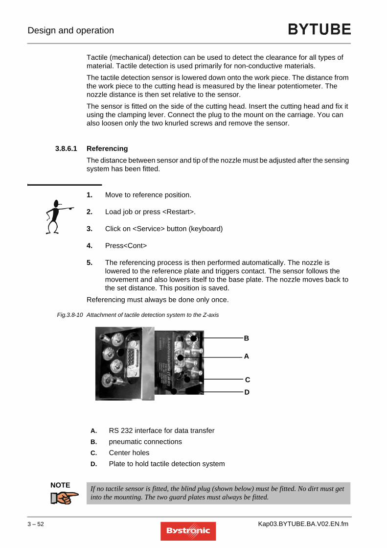
Design and operation
Tactile (mechanical) detection can be used to detect the clearance for all types of material. Tactile detection is used primarily for non-conductive materials.The tactile detection sensor is lowered down onto the work piece. The distance from the work piece to the cutting head is measured by the linear potentiometer. The nozzle distance is then set relative to the sensor.The sensor is fitted on the side of the cutting head. Insert the cutting head and fix it using the clamping lever. Connect the plug to the mount on the carriage. You can also loosen only the two knurled screws and remove the sensor.
3.8.6.1 ReferencingThe distance between sensor and tip of the nozzle must be adjusted after the sensing system has been fitted.
1. Move to reference position.
2. Load job or press <Restart>.
3. Click on <Service> button (keyboard)
4. Press<Cont>
5. The referencing process is then performed automatically. The nozzle is lowered to the reference plate and triggers contact. The sensor follows the movement and also lowers itself to the base plate. The nozzle moves back to the set distance. This position is saved.
Referencing must always be done only once.
Fig. 3.8 -10 Attachment of tactile detection system to the Z-axis
NOTE
A. RS 232 interface for data transferB. pneumatic connectionsC. Center holesD. Plate to hold tactile detection system
A
B
CD
If no tactile sensor is fitted, the blind plug (shown below) must be fitted. No dirt must get into the mounting. The two guard plates must always be fitted.
3 – 52 Kap03.BYTUBE.BA.V02.EN.fm

Design and operation
3.8.6.2 Blind plugKeep the blind plug with the accessories.
Fig. 3.8 -11 Blind plug
NOTE The assembly and calibration of a tactile detection device is described in Chapter 6 «Fitting /removing the tactile detection system» .
Kap03.BYTUBE.BA.V02.EN.fm 3 – 53

Design and operation
3.9 Cut Control (option)
Cut Control monitors the cutting process during fusion cutting of stainless steel. The process monitoring system uses light reflected from the work piece and regulates the feed or interrupts the cutting process.
NOTE
Fig. 3.9 -1 Section diagram of machining head with Cut Control
The cutting head with the Cut Control option only differs externally from a conventional cutting head only by its Cut Control sticker. The Cut Control cutting head (5” and 7.5”) can be fitted and operated instead of the conventional cutting head. It is still handled and adjusted in the same way (e.g. nozzle changing, centering, focal point position etc). The “Cut Control” function can only be activated with machines that are equipped with the necessary hardware and software. The CNC software version for this corresponds to P6110 or higher. Older machines can be retrofitted with Cut Control. Please talk to Bystronic Customer Services.
CutControl cannot be used with an NK nozzle
A. PhotodiodeB. Deflecting mirrorC. Cutting headD. Light reflected from work pieceE. Work piece
A B
C
D
E
3 – 54 Kap03.BYTUBE.BA.V02.EN.fm

Design and operation
Fig. 3.9 -2
The measurement signals from the photodiodes are converted on the «SENSOS circuit board» (integrated in the Z-axis) and passed on to the «PROMON Card» in the CNC rack. The CNC controller processes this signal and monitors the cutting process. Piercing, pulsing and engraving are now monitored. Cut control is not activated until after the starting cut acceleration. If the quality of the cutting process starts to deteriorate, this is recognized by the change in the signal and is then regulated by the following control functions.
3.9.1 Feed-rate reduction function
If the signal reaches the alarm or plasma threshold then the feed rate is reduced in steps to a predefined percentage level. This reduction continues until the signal falls below the alarm or plasma threshold or until the maximum reduction has been made. The reduced feed rate then remains constant during the «Reduced feed rate period». When the alarm has stopped or the plasma extinguished, acceleration back to the set feed rate (value in cutting parameters) takes place.
Kap03.BYTUBE.BA.V02.EN.fm 3 – 55

Design and operation
3.9.2 Stop feed-rate function
If the signal no longer drops below the alarm or plasma threshold or if the stop threshold is exceeded, the feed is stopped and piercing completed. After stopping and completion of the piercing a resetting by a defined amount (up to the last piercing as a maximum) takes place to repeat the cut. The resetting is limited to a maximum number of repetitions per contour section and after that a normal STOP function is triggered. This prevents endless repetition under faulty cutting conditions.
3 – 56 Kap03.BYTUBE.BA.V02.EN.fm

Design and operation
3.10 Crossjet (optional)
The Crossjet prevents too much heat from building up during the piercing process by spraying with a mixture of air and oil. It is located to the side of the cutting head. Weld protection oil is used. This can be procured from Bystronic.Only fit the Crossjet in the machining position when you want to use it. This prevents unnecessary soiling of the Crossjet.The Crossjet should be kept in the park position when not in use.Note! If the CrossJet is fitted on the cutting head, and if tubes are machined using the steady rest for circular tubes, then the higher tension rollers on the driven steady rest must be removed without fail (see. Fig. «3.5 -2 » Rotary axis).
Fig. 3.10 -1 Crossjet on the Z-axis
Move the crossjet against the nubs, and fix with the screw
3.10.1 Applications
The Crossjet should be used for steel and aluminum with a thickness of 6 mm upwards. With these thicknesses, the oil mist prevents molten material from sticking to the surface of the work piece. The Crossjet is activated by pressing the [Sf2] button on the keyboard in the «Work» menu.
WARNINGOil vapors can ignite spontaneously in the laser beam or on the hot work piece. Use only the correct oil. Further information can be found under “Supplier documentation”.
!
Kap03.BYTUBE.BA.V02.EN.fm 3 – 57

Design and operation
3.10.2 How it works
The Crossjet is fitted with air and oil connections. A mist of oil and air is sprayed onto the work piece before piercing. The film of oil on the surface of the work piece reduces the adhesion of the slack that escapes upwards during piercing. The thickness of the oil film depends on the flow rate, the nozzle diameter and the duration of the spraying process.
3.10.3 Cross blow
After piercing, a jet of compressed air blows away sideways the material coming off the top surface, thereby reducing its adhesion to the work piece and nozzle. «Cross blowing after piercing» is activated by pressing the [Sf2] button on the membrane keyboard in the «Work» menu.
3.10.4 Water jet spray (optional)
This is attached to the tactile detection device and is used for cooling the material.
3 – 58 Kap03.BYTUBE.BA.V02.EN.fm

Design and operation
3.11 Bypos (option)
Fig. 3.11 -1 BYPOS mirror with mount
In machines with flying optics, the focal point varies over the working area of the machine. The greater the distance between the output coupler in the laser and the lens in the cutting head, the lower the focal point. The reason for this is the natural divergence of the laser beam. This results in different cutting qualities over large work areas.An adaptive optics system (BYPOS) can be used to keep the focal parameters constant irrespective of outside influences such as the variable distance between focusing lens and laser in machines with “flying optics”, or even to control these parameters according to the respective processes and work pieces.Bystronic uses a deformable mirror as its adaptive optics system, designed so that the mirror surface ensures constant optical properties during long-term use. The deformable mirror provides a 90° deflection along the Z-axis. The mirror surface is deformed by cooling-water pressure. A pressure booster station connected into the cooling circuit increases the water pressure to 14 bar. The electronic control system controls and monitors the pressure of the flowing cooling water in the mirror via a proportional (solenoid) control valve and a pressure sensor on the mirror.The pressure booster station is fitted with a heater that can set the temperature of the BYPOS circuit in laser cutting machines having two cooling circuits. In machines with just one circuit the heater must be switched off.
3.11.1 Cutting properties without Bypos
Over the cutting area, the focal position moves down as a function of the beam length between laser and lens.
A. ApertureB. Pressure transducerC. Water circulationD. Deformation of the mirrorE. BYPOS mirror
A
B
C
D
E
Kap03.BYTUBE.BA.V02.EN.fm 3 – 59

Design and operation
Fig. 3.11 -2 Cutting properties without BYPOS
3.11.2 Cutting properties with Bypos
The focal position remains constant over the entire cutting area.
Fig. 3.11 -3 Cutting properties with BYPOS
Cutting area
BA C D
E
F
G
A. Laser module F. LensB. Curved wave front G. Work pieceC. Flat mirror H. Distorted mirrorD. Beam I. Flat wave frontE. Variable wave front
Cutting area
BA H D
E
F
G
3 – 60 Kap03.BYTUBE.BA.V02.EN.fm

Design and operation
3.11.3 Operating Mode 0
Fig. 3.11 -4 Operating mode 0
Legend:
The defined mirror deformation remains constant over the entire cutting area irrespective of the beam length. The focal position is not automatically corrected in this operating mode. The correction must be done manually at the cutting head. The setting for the focal position must be found from the relevant cutting parameters.For a mirror deformation of 0µm, the adaptive mirror is flat. The technically feasible adjustment range lies between -40 µm and +40µm. This means that the focal point can be moved by about 20mm.If the operating mode is tested by firing into a Plexiglas cube, the mirror deformation must definitely be set to 0µm.
3.11.3.1 Parameters for operating mode 0The following parameters must be entered under "Setup values Adaptive optics 1" in the “Setup” menu:
Fig. 3.11 -5
A. Mirror deformationB. Beam length
B
A
Operating mode (constant)=0Fixed mirror deformation= XµmThe fixed mirror deformation is normally set to 0.
Other values have no effect in this operating mode.
Kap03.BYTUBE.BA.V02.EN.fm 3 – 61

Design and operation
3.11.4 Operating mode 1
The mirror deformation is varied as a function of the beam length. This relationship is fixed by a characteristic curve. The characteristic curve is defined by 5 mirror deformations at 5 different points along the length of the beam path. These mirror deformations are measured in cutting tests at the corresponding beam path lengths, and saved as parameters in “Setup”. The 7.5”cutting head and 8mm stainless steel sheet should be used for these cutting tests.In operating mode 1, the focal position for different types and thicknesses of sheet is not set automatically. This is possible in operating mode 2.
Fig. 3.11 -6 Operating mode 1
Legend:
3.11.4.1 Parameters for operating mode 1The following parameters apply to operating mode 1:
A. Mirror deformationB. Beam length
B
A
3 – 62 Kap03.BYTUBE.BA.V02.EN.fm

Design and operation
Fig. 3.11 -7
A valid characteristic curve must exist before operating mode 1 can be used.The total deformation is computed from the position-dependent characteristic value (characteristic curve) plus an OFFSET dependent on the characteristic data. The calculation is performed automatically.
Operating Mode = 1(In this operating mode, the value “Fixed mirror deformation” is irrelevant)
The data for defining the characteristic curve (5 interpolation-point pairs: beam length / mirror deformation) are set at the factory. After changing a lens or Bypos mirror, it may be necessary to measure the cutting-test values again using the following procedure.
For correct calculation of the beam length, the machine must first move to the reference point.
The current beam length and the mirror deformation calculated from this (set value) can be followed in the “Hand” menu as the cutting head moves.
Kap03.BYTUBE.BA.V02.EN.fm 3 – 63

Design and operation
3.11.4.2 Measuring the curveThe following requirements must be met before it is possible to measure the characteristic curve:
• The optical components and beam guidance system must be in perfect condition
• Material: stainless steel 8mm (preferably: 1.4301)
• 7.5" cutting head
• Test piece bypos_t.lcc (is saved under C:\Abnahme\BTL ….) If this file is not present, this part must be produced on site according to the supplement bypos_t.lcc.
1. Select operating mode 0 and deformation 0 (flat mirror)
2. Moving to reference position
3. Move to curve point 1 (minimum beam length – see table below)
4. Cut test piece and correct focal point at cutting head until an optimum cut is obtained. One should aim for the lowest possible focal position for which there is still no hard burr.
5. Move to curve point 5 (maximum beam length)
6. Cut the same test piece without adjusting the focal length at the cutting head. Instead correct the focal length by changing the parameter "Fixed mirror deformation for operating mode 0". Larger negative deformations result in a higher focal position, and vice versa. Adjust parameter until an optimum cut is obtained.
7. Joining these two corner points gives a straight line as the characteristic curve. The deformation values for the intermediate points are interpolated and saved in the “Setup” menu Characteristic curve: beam length/mirror deformation 1-5. Calculation is as follows: the deformation determined at point 5 is divided by the number of intermediate points, in this case five.
8. Select operating mode 1. (Instead of the fixed mirror deformation, the CNC now imports the deformation calculated from the characteristic curve, which can be checked under Mirror deformation in the “Hand” menu.)
9. By making test cuts at the intermediate points, the characteristic curve in operating mode 1 can be checked and improved if necessary (by correcting the deformation of the corresponding point to adjust the focal position).
The beam length defines the position in which the test cut must be made. The beam length alone is not enough to specify the position on the cutting table. Thus the sheet for the test cut does not have to lie exactly on the table diagonal. The test cuts can be made on the table diagonals or in other positions by shifting the sheets, as
3 – 64 Kap03.BYTUBE.BA.V02.EN.fm

Design and operation
illustrated in the diagram below. The current length of the beam path can be read in the “Hand” menu.
3.11.4.3 Centering the characteristic curveIn a very few cases it is necessary to center the characteristic curve. This should be done when the mirror deformation at point 5 amounts to more than ¼ of the total mirror deformation.By changing the deformation value of each characteristic-curve point by the same amount, the curve can undergo a parallel shift. This means the characteristic curve can be centered around the zero value for large deformation variations. However, this correction must be compensated for at the cutting head. The conversion factors necessary for this can be found in the “Setup” menu, “Setup values adaptive optics 1”.The characteristic curve is measured with the cutting head. For a different head (e.g. 5”), or after a lens change, one only needs to re-determine the focus zero position and the focal position for the relevant sheet thickness.
NOTE
The beam lengths are then listed for the various machine sizes for which the mirror deformations can be measured.
TIP
The characteristic curve may need to be modified after a lens change in the resonator (especially the output coupler).
Beam input - left Beam input - right
Beam input - lower left Beam input - lower right
5
4
3
2
1
23 4
Cutting table1
5
2
34
2
3
4
Cutting table
Cutting table5
4
3
2
123
4
Cutting table
The curve that is derived is valid for all focal lengths.
The values measured can vary from machine to machine because of differing beam-path ventilation.
Kap03.BYTUBE.BA.V02.EN.fm 3 – 65

Design and operation
3.11.4.4 Distribution of beam-length points
Machine size Characteristic curve points 1 2 3 4 5
2512 Beam length (mm) 600 1200 2000 2800 36003015 Beam length (mm) 600 1400 2400 3400 44003204 Beam length (mm) 600 1450 2300 3150 40004015 Beam length (mm) 600 1700 3000 4300 56004020 Beam length (mm) 600 1800 3200 4600 60004025 Beam length (mm) 600 2300 3800 5200 68006504 Beam length (mm) 600 2250 3900 5550 72006520 Beam length (mm) 600 2600 4600 6600 86006525 Beam length (mm) 600 2700 4800 6900 90006530 Beam length (mm) 600 2800 5000 7200 9400
3 – 66 Kap03.BYTUBE.BA.V02.EN.fm

Design and operation
3.11.4.5 Test piece bypos_t.lcc
Fig. 3.11 -8 Bypos test piece
bypos_tGezeichnet
Geändert
Datum Name25.05.99
25.05.99
bbe
bbe
Masseinheit : mm
Material :
Dicke : 8.00
Bezeichnung
bypos_tZeichnungs Nr.
Common Cut : NeinFüllteil : NeinDrehwinkel : 0Dateiname : 00000154.BPDBearbeitungsfolge ok : JaAnz. bearb. Konturen : 2
Dimension X : 95.00Dimension Y : 80.00Fläche effektiv : 5121.90Fläche Rechteck : 7600.00
Nichtrost. Stahl X5CrNi18 9 1.4301Material Code:
LaserschneidenTechnologie :Kunde :
Bystronic Laser AG
Kap03.BYTUBE.BA.V02.EN.fm 3 – 67

Design and operation
3.11.5 Operating mode 2 (default mode)
Fig. 3.11 -9
The presence of a valid characteristic curve for operating mode 1 is a requirement for operating mode 2. In operating mode 2 the focal position, which is otherwise only for information purposes in the cutting parameters, is adopted as a parameter. In this mode, the focal position no longer needs to be adjusted manually at the cutting head when the work piece is changed, but is adjusted automatically by the adaptive optics. The total deformation is computed from the position-dependent characteristic value (characteristic curve from operating mode 1) plus an OFFSET dependent on the characteristic data. The OFFSET is calculated automatically as:OFFSET = [Deformation/Change in focal length] - (Focal length + Nozzle clearance – [Focal length cutting head])The two machine parameters dependent on the focal length:– Deformation/Change in focal point– Focal position Cutting headare factory set and saved in the “Setup” menu.
NOTE
A. Mirror deformationB. Characteristic curveC. Beam length
C
AB
These values must not be changed without careful consideration.
Operating Mode = 2
Do not adjust these values!
3 – 68 Kap03.BYTUBE.BA.V02.EN.fm

Design and operation
3.11.5.1 Working in operating mode 2Follow the procedure below to work in operating mode 2:– It is assumed that the reference focal length is known for the cutting head. If
not it must be found.– Select operating mode 2 (as described above).– Set “Focal position Cutting head optics 7.5” / 5” (from Setup) on the cutting
head. Once the cutting heads are correctly set, no further changes need to be made to them.
– Import the cutting plan and the cutting parameters. Here it is essential that the focal length in the cutting parameters tallies with that for the cutting head, otherwise the focal point is calculated incorrectly.
– Check or replace the cutting nozzle. If several jobs need to be processed automatically one after the other, then the largest of the specified nozzles must be used. Additional parameter adjustments may consequently be necessary. For example, when widely differing sheet thicknesses are cut in automatic mode.
– Center the cutting nozzle, then start the cutting process.
3.11.6 Bypos error messages
When the machine is ready for operation, the sensor and control monitoring system provides four error bits for diagnosing possible faults.
Error no. Description Cause
11Control loop error:
Actual value < target value
• Flow controller or output stage faulty
• Proportional valve not being actuated
• Inlet value for the controlled variable too low for the set value.
• Sensor is faulty or not connected
• Can arise with Error 13.
12 Control loop error:
Actual value > target value
• Flow controller or output stage faulty
• Proportional valve fully open
• Faulty sensor
• Can arise with Error 14.
13 Pressure sensor error:
sensor signal <3 mA
• Faulty sensor
• Break in wiring to sensor
Kap03.BYTUBE.BA.V02.EN.fm 3 – 69

Design and operation
As of CNC P6104, Bypos error messages are displayed according to the following system:
Errors are displayed with a 1 at the appropriate position (error code 10000 means normal functioning, i.e. no error). Several errors at once can be indicated with this coding scheme.
14 Pressure sensor error:
sensor signal >25 mA
• Faulty sensor
• Signal and supply line for sensor shorted together
• Sensor overloaded by the control variable.
Control circuit error actual value < target value
Control circuit error actual value > target value
Pressure sensor error: sensor signal <3 mA
Pressure sensor error: sensor signal >25 mA
Mirror (control loop) number
Error no. Description Cause
1 0 0 0 0
3 – 70 Kap03.BYTUBE.BA.V02.EN.fm

HAPTER4
4. Operating and display elements,operating modes
In this chapter you will learn more about the operating and display elements on the laser machine. An overview gives a brief description of the various buttons and keys. The different modes that can be used for operating the laser machine are also explained.
Kap04.BYTUBE.BA.V02.EN.fm 1

Operating and display elements, operating modes
Table of contents
4. Operating and display elements,operating modes
4.1 Introduction. . . . . . . . . . . . . . . . . . . . . . . . . . . . . . . . . . . . . . . 3
4.2 Warning signals . . . . . . . . . . . . . . . . . . . . . . . . . . . . . . . . . . . 34.2.1 Warning and indicator lamps . . . . . . . . . . . . . . . . . . . . . . . . . . . . . . . . . . 34.2.1.1 Red warning lamp . . . . . . . . . . . . . . . . . . . . . . . . . . . . . . . . . . . . . . . . . . . . . . 34.2.1.2 Orange warning lamp. . . . . . . . . . . . . . . . . . . . . . . . . . . . . . . . . . . . . . . . . . . . 34.2.1.3 White indicator lamp. . . . . . . . . . . . . . . . . . . . . . . . . . . . . . . . . . . . . . . . . . . . . 3
4.3 Operating and display elements . . . . . . . . . . . . . . . . . . . . . . 44.3.1 Emergency stop button . . . . . . . . . . . . . . . . . . . . . . . . . . . . . . . . . . . . . . 44.3.2 PPC operating terminal . . . . . . . . . . . . . . . . . . . . . . . . . . . . . . . . . . . . . . 54.3.2.1 Switching status of buttons . . . . . . . . . . . . . . . . . . . . . . . . . . . . . . . . . . . . . . . 54.3.2.2 Automatic activation of functions. . . . . . . . . . . . . . . . . . . . . . . . . . . . . . . . . . . 64.3.2.3 Self-locking operation. . . . . . . . . . . . . . . . . . . . . . . . . . . . . . . . . . . . . . . . . . . . 64.3.2.4 Key groups . . . . . . . . . . . . . . . . . . . . . . . . . . . . . . . . . . . . . . . . . . . . . . . . . . . 64.3.2.5 Summary of the PPC machine keyboard . . . . . . . . . . . . . . . . . . . . . . . . . . . . . 74.3.3 Additional operating buttons . . . . . . . . . . . . . . . . . . . . . . . . . . . . . . . . . . 94.3.4 Hand-held controller. . . . . . . . . . . . . . . . . . . . . . . . . . . . . . . . . . . . . . . . . 94.3.5 MCS cabinet . . . . . . . . . . . . . . . . . . . . . . . . . . . . . . . . . . . . . . . . . . . . . 114.3.6 Fault messages . . . . . . . . . . . . . . . . . . . . . . . . . . . . . . . . . . . . . . . . . . . 11
4.4 Operating modes . . . . . . . . . . . . . . . . . . . . . . . . . . . . . . . . . 124.4.1 HYBRID operating mode . . . . . . . . . . . . . . . . . . . . . . . . . . . . . . . . . . . . 124.4.2 CONVENTIONAL operating mode (Byflex) . . . . . . . . . . . . . . . . . . . . . . 134.4.3 FLAT operating mode . . . . . . . . . . . . . . . . . . . . . . . . . . . . . . . . . . . . . . 144.4.4 Service mode . . . . . . . . . . . . . . . . . . . . . . . . . . . . . . . . . . . . . . . . . . . . . 15
4 – 2 Kap04.BYTUBE.BA.V02.EN.fm

Operating and display elements, operating modes
4.1 Introduction
This chapter describes the warning signals and operating elements on the machine.
4.2 Warning signals
4.2.1 Warning and indicator lamps
The warning lamps are mounted on the MCS cabinet. They show at a glance the current operating status of the laser.
Fig. 4.2 -1 Warning and indicator lamp
4.2.1.1 Red warning lampIf the red warning lamp is illuminated, the shutter is open and the laser beam is being emitted from the laser. If the lamp is off then the shutter is closed.If the red warning lamp is flashing, the laser is in Service mode (laser class 4). Service mode is in force when the laser cover is open. Service mode tasks are described in the chapter «4.4 Operating modes».
4.2.1.2 Orange warning lampIf the orange warning lamp is illuminated, the high voltage to the laser is switched on and the laser is operating.
4.2.1.3 White indicator lampThe white indicator lamp indicates low pressure in the gas supply. This indicator enables the gas supply to be swapped to the reserve bottle before machining is stopped automatically by the controller because of insufficient gas supply. The gas controller (MCS cabinet) indicates which gas caused the white lamp to come on. (The green operating indicator light for the gas concerned is off).
Red warning lamp
Orange warning lamp
White indicator lamp
Kap04.BYTUBE.BA.V02.EN.fm 4 – 3

Operating and display elements, operating modes
4.3 Operating and display elements
4.3.1 Emergency stop button
There are 3 «Emergency stop» buttons on the laser machine enabling the machine to be switched off in the event of danger.
1. PPC operating terminal
Fig. 4.3 -1 Emergency stop on operating terminal
2. Hand-held controller
Fig. 4.3 -2 Hand-held controller Emergency Stop
3. MCS cabinet
Fig. 4.3 -3 Emergency stop on MCS cabinet
After an “Emergency stop” all reset buttons on the PPC and on the MCS cabinet go out. The following messages are displayed:
The way in which an «Emergency stop» operates, and the procedure for restarting the machine, is described in the "Emergency stop" section of Chapter 3.
MMC Work menu MCS cabinet display Handling Operation1. «Wait for Abort»
2. press after «Abort»
3. «External Emergency stop»
«Emergency Stop» «Emergency stop active: deactivate»
4 – 4 Kap04.BYTUBE.BA.V02.EN.fm

Operating and display elements, operating modes
4.3.2 PPC operating terminal
Fig. 4.3 -4 Operating terminal user interface
The operating terminal comprises:
• Emergency Stop and Reset button (A)
• TFT screen (B)
• Membrane keyboard area (PC functions) (C)
• Membrane keyboard area (machine functions) (D)
• Optical PC mouse (E)
• PC keyboard (F)
The latter has a ”touch screen” design, Each program interface can be operated by touching the corresponding button or menu display on the TFT screen. The screen resolution must be at least 800 x 600 pixels.
4.3.2.1 Switching status of buttonsWhen a button is illuminated, its command is activated.
B
C
E
F
A
D
Kap04.BYTUBE.BA.V02.EN.fm 4 – 5

Operating and display elements, operating modes
4.3.2.2 Automatic activation of functionsThe following buttons are automatically activated when a cutting plan is started:
• <DWELL>
• <STOP SEL>
• <SENS OFF > (only if active during last job)
• <STOP CYCL>
When starting up the MMC, the relevant function keys SF1 to SF4 will be activated depending on what equipment the machine has (e.g. Crossjet) and on the setting in the SETUP configuration menu.
4.3.2.3 Self-locking operationIf you activate the buttons <AUTO> to <HEAD>, then the relevant function will remain active until you press the button again in order to deactivate it.
• If you deactivate one of the buttons, then the relevant function will remain deactivated until you press the button again in order to activate it.
• Active buttons are deactivated automatically after all jobs have been processed and the axes are back in the reference position.
4.3.2.4 Key groupsCommon features of the buttons <HALT CNC>, <STOP CYCL>, <STOP PART>, <STOP WORK> und <STOP SEL> are summarized under the heading <STOP>.
4 – 6 Kap04.BYTUBE.BA.V02.EN.fm

Operating and display elements, operating modes
4.3.2.5 Summary of the PPC machine keyboardSome of the buttons are assigned different meanings for individual functions. The standard functions are listed in the table below.
Button Description<f1> F1 - F8 function keys for operating the machine software
<AUTO> Automatic import of cutting plans and process parameters
<DNC> Activate connection to a higher-level PPS
<INHB> Move to programmed reference point (see < INHIBIT REF> )
<INV> Work through cutting plan in reverse order
<DWELL> Enable braking and acceleration during cutting
<REPT> Work through engraving parameters first and then process parameters (e.g. to remove protective foils from sheet)
<MOD OFF>
Switch off modulation
<SENS OFF>
Switch off detection inside the < Sensor OFF> field
<SERV> Press once = Move to service position
Press twice = Automatic nozzle cleaning performed and then the cutting plan is completed
<TEST> Work through cutting plan with cutting head raised and without laser beam
<STOP CYCL>
Stop before processing a new cutting plan. The automatic tube loader does not load a new tube
<STOP PART>
Stop before the next part
<STOP WORK>
Stop before and after a contour (before and after raising the cutting head)
<HALT CNC>
Stop the machining process
<SNGL STEP>
Work through plan in single steps (geometry element)
<STOP SEL>
Programmed stop to machining sequence (M01)
<SF1> SF1 - SF4 Function keys (assignment depends on MMC Menu)
<MAIN> MMC Main menu
<MANUAL>
Manual operation and diagnosis
<WORK> Work through cutting plan
<SETUP> Machine setup values
<DATA> Editor for cutting plans and process parameters
<PARA> Edit active parameters in the < Work> menu
<TASK> not assigned
<PLC> not assigned
Kap04.BYTUBE.BA.V02.EN.fm 4 – 7

Operating and display elements, operating modes
<HALT PLC>
not assigned
<OPEN DOOR>
not assigned
<PLC1> not assigned
<HEAD> not assigned
<ESC> Exit a dialog window without accepting the data
<BS> (Back Space) Delete last character entered
<ENTER> (Carriage Return) Acknowledge input
<PGDN> Next screen page / Jump to end of block
<PGUP> Previous screen page / Jump to start of block
<BACK> Back to previous menu screen
<TAB> Switch between the various dialog boxes using TAB key
Cursor keys Move selection on screen in corresponding direction
Button Description
4 – 8 Kap04.BYTUBE.BA.V02.EN.fm

Operating and display elements, operating modes
4.3.3 Additional operating buttons
4.3.4 Hand-held controller
The hand-held controller is used for setup and adjustment tasks and for test cuts to determine parameters.
To activate the hand-held controller, select <HAND>, "Manual operation" or "Auto. setup".
The emergency stop buttons < STOP> and <CONT> are always enabled, regardless of whether or not you are in the <Hand> menu.
Brief description of buttons on the hand-held controller.
Acknowledge dropped work piecewhen cutting using lance
Stop tube magazine feed
Close safety gate
Open safety gate
Safety light barrier
Button Description<BURN> opens shutter and holds open whilst pressed down <CONT> Acknowledge button (continue)<CROSSJET> Crossjet functions<MANUAL ADJUST> Holding down this button enables fine positioning using
thumb-wheel<PULS> Single pulse: Open shutter for selected period of time<STOP> Software stop: Stops all axis drives. Not an Emergency
stop!
Kap04.BYTUBE.BA.V02.EN.fm 4 – 9

Operating and display elements, operating modes
Fig. 4.3 -5
Button Description<F1> Additional button (2nd) up<F2> Additional button (2nd) down<U1+> Rotates rotary axis counterclockwise,
manual feed<U1-> Rotates rotary axis clockwise, manual feed<U2+> Rotates rotary axis (steady rest) counterclockwise,
manual feed<U2-> Rotates rotary axis (on steady rest) clockwise, manual feed<X+> Moves away from zero point in X-direction, manual feed<X-> Moves towards zero point in X-direction, manual feed<X2+> Moves the feed unit away from zero point in X-direction,
manual feed<X2-> Moves the feed unit towards zero point in X-direction,
manual feed<Y+> Moves away from zero point in Y-direction, manual feed<Y-> Moves towards zero point in Y-direction, manual feed<TOOL> activated (LED on)<Z +> Raises tool, capacitive sensing enabled, and closes assist-gas valve<Z -> Lowers tool, capacitive sensing enabled, and opens assist-gas valve<TOOL> deactivated (LED off)
4 – 10 Kap04.BYTUBE.BA.V02.EN.fm

Operating and display elements, operating modes
4.3.5 MCS cabinet
The MCS cabinet controls are described in Chapter 4 of the «BYLASER 3000» Operating Manual.
4.3.6 Fault messages
System and fault messages are displayed in the «MMC» and «Handling Operation» program in the yellow status-and error-message bars.
<Z +> Raises tool, capacitive sensing disabled<Z -> Lowers tool, capacitive sensing disabledThumb-wheel Fine positioning of the axes
Button Description
Kap04.BYTUBE.BA.V02.EN.fm 4 – 11

Operating and display elements, operating modes
4.4 Operating modes
There are three operating modes that can be used when working with BYTUBE in Normal mode.
- Hybrid
- Conventional (Byflex)
- FlatThe machine is in Normal mode when
• the machine is correctly assembled,
• all covers and protective fences have been correctly fitted,
• the machine is switched on,
• all safety devices are reset,
• cutting plans and parameters have been imported,
• and the machining process has been started.
One can switch from one operating mode to another in the Setup menu. Hybrid operating mode = 1, Conventional operating mode = 0. Flat operating mode is enabled/disabled in FMS Handling.
The following axes and labels are relevant for operation and practical work.
4.4.1 HYBRID operating mode
Tubular sections with maximum external diameter of 170 mm can be cut in the HYBRID operating mode.Bytube works with the tube loader. The U- and U2-axes are in use.The cutting head moves in the Y- and Z-direction. The work piece moves along the X2-axis.
Axis Description
A Travel unit with lance or support
X,Y,Z Machining unit
U2 Plate holding rotary unit (steady rest) and four-jaw chuck
X2,
U
Feed unit with gripper
with rotary axis
4 – 12 Kap04.BYTUBE.BA.V02.EN.fm

Operating and display elements, operating modes
When cutting square and rectangular tubular sections, the X2-, Y- and Z-axes are active. When cutting circular tubes, the X2- and Z-axes are active.The U2 rotary axis is fitted with the driven steady rest for cutting square and rectangular tubular sections. Different cross-sections require suitably sized clamping jaws (steady rest) plus matching support plates and/or support rollers (located on tube-loader pillar rests). Tubes are supported by a steady rest consisting of two solid vees able to move in opposing directions. Various sizes of vees are available.
NOTE
4.4.2 CONVENTIONAL operating mode (Byflex)
In the Conventional operating mode (Byflex), the tube or the section is clamped in the four-jaw chuck in the lifting plate (U2) and a tailstock, i.e. the tube is placed directly in the machining area.
Tube magazine, pillar controller, steady rest and travel unit are not in use.
Fig. 4.4 -1 Four-jaw chuck in Conventional operating mode
Tubular sections with a maximum external diameter of 320mm and a maximum weight of 400kg can be cut.
The cutting head moves along the three axes X, Y and Z.
It is not possible to repeat an aborted cutting plan in Hybrid mode. This command key has therefore been disabled in the software.
Kap04.BYTUBE.BA.V02.EN.fm 4 – 13

Operating and display elements, operating modes
Fig. 4.4 -2 Tailstock nose piece with clamped tube
The tailstock is fixed mechanically in the required position. The travel unit is positioned as close as possible to the travel unit in manual operation, so that the compressed-air supply to the tailstock can be connected. The tube is clamped pneumatically via a foot pedal.Tubular sections weighing more than 150 kg must be supported on rollers in a steady rest.
4.4.3 FLAT operating mode
Bytube also has a limited capability for cutting flat sheets. For this mode, a table is placed on the base frame, and the sheets placed on the table grating.
In order to prevent the cutting head from colliding with the calibration plate or cleaning brush, the table must not be placed too far forward.
For Flat operation, "Conventional mode" must be selected in Setup, and "Flat cutting" selected under Setup in the Main menu.
4 – 14 Kap04.BYTUBE.BA.V02.EN.fm

Operating and display elements, operating modes
4.4.4 Service mode
The machine is in Service mode when the machining sequence in Normal mode has been interrupted by the operator or by a third party. The reason for the stop makes no difference, whether for adjustment and checking tasks, loading and unloading or cleaning and maintenance work.The machine enters Service mode at the moment when non-contact safety devices (e.g. light barriers) are crossed, the safety gate is opened or permanent safety devices are removed.Normal mode is restored when the machine is once more ready for use, the safety devices are reset and the process is started up.
Kap04.BYTUBE.BA.V02.EN.fm 4 – 15

Operating and display elements, operating modes
4 – 16 Kap04.BYTUBE.BA.V02.EN.fm

HAPTER5
5. Commissioning
Installation and commissioning are performed by Bystronic personnel or under the supervision of Bystronic. For this reason the “Commissioning” chapter is not included in the Operating Manual.
Kap05.BYTUBE.BA.V01.EN.fm 1

Commissioning
Table of contents
5. Commissioning. . . . . . . . . . . . . . . . . . . . . . . . . . . . . 1
5 – 2 Kap05.BYTUBE.BA.V01.EN.fm

HAPTER6
6. Operation
This chapter describes the operation of the laser cutting machine, and how to operate it safely. It also provides information on setting up and adjusting the laser cutting machine, as well as its various functions. The most important parameters for optimizing cutting are also explained.
Kap06.BYTUBE.BA.V02.EN.fm 1

Operation
Table of contents
6. Operation. . . . . . . . . . . . . . . . . . . . . . . . . . . . . . . . . . 1
6.1 Introduction. . . . . . . . . . . . . . . . . . . . . . . . . . . . . . . . . . . . . . . 66.1.1 Safety regulations . . . . . . . . . . . . . . . . . . . . . . . . . . . . . . . . . . . . . . . . . . 66.1.2 Requirements to be met by personnel performing the disposal. . . . . . . . 6
6.2 Operation of the system . . . . . . . . . . . . . . . . . . . . . . . . . . . . 76.2.1 Checks before switching on . . . . . . . . . . . . . . . . . . . . . . . . . . . . . . . . . . . 76.2.2 Starting up the machine . . . . . . . . . . . . . . . . . . . . . . . . . . . . . . . . . . . . . . 86.2.2.1 Opening the gas supply . . . . . . . . . . . . . . . . . . . . . . . . . . . . . . . . . . . . . . . . . . 86.2.2.2 Switching on the power supply to the resonator and machine. . . . . . . . . . . . . 86.2.2.3 Pressing the Reset button on the PPC . . . . . . . . . . . . . . . . . . . . . . . . . . . . . . 86.2.2.4 Switching on the resonator manually . . . . . . . . . . . . . . . . . . . . . . . . . . . . . . . . 86.2.2.5 Peripheral equipment . . . . . . . . . . . . . . . . . . . . . . . . . . . . . . . . . . . . . . . . . . . . 96.2.3 Shutting down the machine manually . . . . . . . . . . . . . . . . . . . . . . . . . . 106.2.4 Shutting down the machine automatically . . . . . . . . . . . . . . . . . . . . . . . 106.2.4.1 Shutting down after a defined time. . . . . . . . . . . . . . . . . . . . . . . . . . . . . . . . . 116.2.4.2 Shutting down after a fault . . . . . . . . . . . . . . . . . . . . . . . . . . . . . . . . . . . . . . . 116.2.5 Start-up after automatic shutdown . . . . . . . . . . . . . . . . . . . . . . . . . . . . . 11
6.3 Using the Panel PC. . . . . . . . . . . . . . . . . . . . . . . . . . . . . . . . 136.3.1 Starting the software . . . . . . . . . . . . . . . . . . . . . . . . . . . . . . . . . . . . . . . 136.3.2 General information . . . . . . . . . . . . . . . . . . . . . . . . . . . . . . . . . . . . . . . . 136.3.2.1 Summary of the MMC menus . . . . . . . . . . . . . . . . . . . . . . . . . . . . . . . . . . . . 136.3.3 Layout of MMC screen. . . . . . . . . . . . . . . . . . . . . . . . . . . . . . . . . . . . . . 146.3.4 Manual cutting process . . . . . . . . . . . . . . . . . . . . . . . . . . . . . . . . . . . . . 156.3.4.1 Reading in cutting plan . . . . . . . . . . . . . . . . . . . . . . . . . . . . . . . . . . . . . . . . . 156.3.4.2 Assigning cutting parameters to a job . . . . . . . . . . . . . . . . . . . . . . . . . . . . . . 156.3.4.3 Starting the cutting process . . . . . . . . . . . . . . . . . . . . . . . . . . . . . . . . . . . . . . 166.3.4.4 Starting the cutting process, "Hybrid" mode. . . . . . . . . . . . . . . . . . . . . . . . . . 166.3.4.5 Starting the cutting process, "Conventional / Byflex" mode . . . . . . . . . . . . . . 166.3.4.6 Starting the cutting process, "Conventional / Flat" mode . . . . . . . . . . . . . . . . 176.3.5 MMC menus. . . . . . . . . . . . . . . . . . . . . . . . . . . . . . . . . . . . . . . . . . . . . . 186.3.5.1 Main . . . . . . . . . . . . . . . . . . . . . . . . . . . . . . . . . . . . . . . . . . . . . . . . . . . . . . . . 186.3.5.2 WORK . . . . . . . . . . . . . . . . . . . . . . . . . . . . . . . . . . . . . . . . . . . . . . . . . . . . . . 186.3.5.3 MANUAL . . . . . . . . . . . . . . . . . . . . . . . . . . . . . . . . . . . . . . . . . . . . . . . . . . . . 186.3.5.4 PARAM . . . . . . . . . . . . . . . . . . . . . . . . . . . . . . . . . . . . . . . . . . . . . . . . . . . . . 206.3.5.5 DATA . . . . . . . . . . . . . . . . . . . . . . . . . . . . . . . . . . . . . . . . . . . . . . . . . . . . . . . 216.3.5.6 SETUP . . . . . . . . . . . . . . . . . . . . . . . . . . . . . . . . . . . . . . . . . . . . . . . . . . . . . . 216.3.5.7 Bytube setup values. . . . . . . . . . . . . . . . . . . . . . . . . . . . . . . . . . . . . . . . . . . . 226.3.5.8 Bytube settings. . . . . . . . . . . . . . . . . . . . . . . . . . . . . . . . . . . . . . . . . . . . . . . . 226.3.5.9 A-axis . . . . . . . . . . . . . . . . . . . . . . . . . . . . . . . . . . . . . . . . . . . . . . . . . . . . . . . 246.3.6 PLC - Handling Operation . . . . . . . . . . . . . . . . . . . . . . . . . . . . . . . . . . . 266.3.6.1 Hand/Manual menu . . . . . . . . . . . . . . . . . . . . . . . . . . . . . . . . . . . . . . . . . . . . 276.3.6.2 “Configuration” menu . . . . . . . . . . . . . . . . . . . . . . . . . . . . . . . . . . . . . . . . . . . 296.3.6.3 “Setup” menu . . . . . . . . . . . . . . . . . . . . . . . . . . . . . . . . . . . . . . . . . . . . . . . . . 306.3.7 “Emergency Stop” alarm messages. . . . . . . . . . . . . . . . . . . . . . . . . . . . 316.3.8 Status fields . . . . . . . . . . . . . . . . . . . . . . . . . . . . . . . . . . . . . . . . . . . . . . 326.3.8.1 Machine messages . . . . . . . . . . . . . . . . . . . . . . . . . . . . . . . . . . . . . . . . . . . . 326.3.8.2 Alarm messages . . . . . . . . . . . . . . . . . . . . . . . . . . . . . . . . . . . . . . . . . . . . . . 32
6 – 2 Kap06.BYTUBE.BA.V02.EN.fm

Operation
6.4 Layout of the MMC Online Help facility . . . . . . . . . . . . . . . .346.4.1 Opening the Help facility . . . . . . . . . . . . . . . . . . . . . . . . . . . . . . . . . . . . . 346.4.2 User guidance. . . . . . . . . . . . . . . . . . . . . . . . . . . . . . . . . . . . . . . . . . . . . 356.4.3 System messages. . . . . . . . . . . . . . . . . . . . . . . . . . . . . . . . . . . . . . . . . . 356.4.4 Search for terms . . . . . . . . . . . . . . . . . . . . . . . . . . . . . . . . . . . . . . . . . . . 366.4.5 Note function of the Online Help facility . . . . . . . . . . . . . . . . . . . . . . . . . 366.4.6 Limitation in the "DIN-EDITOR" menu page . . . . . . . . . . . . . . . . . . . . . . 36
6.5 Assist gases . . . . . . . . . . . . . . . . . . . . . . . . . . . . . . . . . . . . . .376.5.1 Assist gas quality . . . . . . . . . . . . . . . . . . . . . . . . . . . . . . . . . . . . . . . . . . 376.5.2 Gas consumption . . . . . . . . . . . . . . . . . . . . . . . . . . . . . . . . . . . . . . . . . . 386.5.3 Bottle replacement . . . . . . . . . . . . . . . . . . . . . . . . . . . . . . . . . . . . . . . . . 426.5.4 Assist gas fittings . . . . . . . . . . . . . . . . . . . . . . . . . . . . . . . . . . . . . . . . . . 43
6.6 Setting up and adjustment . . . . . . . . . . . . . . . . . . . . . . . . . .446.6.1 Cutting head . . . . . . . . . . . . . . . . . . . . . . . . . . . . . . . . . . . . . . . . . . . . . . 446.6.1.1 Remove the cutting head . . . . . . . . . . . . . . . . . . . . . . . . . . . . . . . . . . . . . . . . 446.6.1.2 Fitting the cutting head . . . . . . . . . . . . . . . . . . . . . . . . . . . . . . . . . . . . . . . . . . 446.6.2 Changing the nozzle . . . . . . . . . . . . . . . . . . . . . . . . . . . . . . . . . . . . . . . . 446.6.3 Fine adjustment of nozzle centering . . . . . . . . . . . . . . . . . . . . . . . . . . . . 456.6.4 Nozzle cooling. . . . . . . . . . . . . . . . . . . . . . . . . . . . . . . . . . . . . . . . . . . . . 466.6.5 Adjust jet clearance. . . . . . . . . . . . . . . . . . . . . . . . . . . . . . . . . . . . . . . . . 476.6.6 Adjusting the focal position . . . . . . . . . . . . . . . . . . . . . . . . . . . . . . . . . . . 476.6.7 Setting the reference points on the Bytube CNC . . . . . . . . . . . . . . . . . . 486.6.7.1 X-axis reference . . . . . . . . . . . . . . . . . . . . . . . . . . . . . . . . . . . . . . . . . . . . . . . 486.6.7.2 X2-axis reference . . . . . . . . . . . . . . . . . . . . . . . . . . . . . . . . . . . . . . . . . . . . . . 486.6.7.3 Reference A-axis . . . . . . . . . . . . . . . . . . . . . . . . . . . . . . . . . . . . . . . . . . . . . . 496.6.7.4 Collision limits X2-axis . . . . . . . . . . . . . . . . . . . . . . . . . . . . . . . . . . . . . . . . . . 506.6.7.5 Tray on the A-axis . . . . . . . . . . . . . . . . . . . . . . . . . . . . . . . . . . . . . . . . . . . . . 506.6.7.6 Lance on the A-axis . . . . . . . . . . . . . . . . . . . . . . . . . . . . . . . . . . . . . . . . . . . . 51
6.7 Process parameter make-up . . . . . . . . . . . . . . . . . . . . . . . . .526.7.1 File naming conventions . . . . . . . . . . . . . . . . . . . . . . . . . . . . . . . . . . . . . 536.7.1.1 Material ID in compliance with DIN standard . . . . . . . . . . . . . . . . . . . . . . . . . 536.7.1.2 Principal material groups . . . . . . . . . . . . . . . . . . . . . . . . . . . . . . . . . . . . . . . . 536.7.1.3 Type numbers . . . . . . . . . . . . . . . . . . . . . . . . . . . . . . . . . . . . . . . . . . . . . . . . 536.7.1.4 Suffixes. . . . . . . . . . . . . . . . . . . . . . . . . . . . . . . . . . . . . . . . . . . . . . . . . . . . . . 546.7.2 BYSTRONIC material ID based on DIN standard. . . . . . . . . . . . . . . . . . 546.7.2.1 Principal group 1: Steel and cast steel . . . . . . . . . . . . . . . . . . . . . . . . . . . . . . 546.7.2.2 Principal group 2: Non-ferrous metals . . . . . . . . . . . . . . . . . . . . . . . . . . . . . . 556.7.2.3 Principal group 3: Light metals and their alloys . . . . . . . . . . . . . . . . . . . . . . . 556.7.3 Material thickness . . . . . . . . . . . . . . . . . . . . . . . . . . . . . . . . . . . . . . . . . . 566.7.4 Machine type, work-piece support, laser type. . . . . . . . . . . . . . . . . . . . . 566.7.5 Lens . . . . . . . . . . . . . . . . . . . . . . . . . . . . . . . . . . . . . . . . . . . . . . . . . . . . 576.7.6 Process and assist gases . . . . . . . . . . . . . . . . . . . . . . . . . . . . . . . . . . . . 576.7.7 Coding of process parameter file names . . . . . . . . . . . . . . . . . . . . . . . . 586.7.8 Constraints . . . . . . . . . . . . . . . . . . . . . . . . . . . . . . . . . . . . . . . . . . . . . . . 596.7.8.1 Influence of contour geometry . . . . . . . . . . . . . . . . . . . . . . . . . . . . . . . . . . . . 596.7.8.2 Optimizing parameters . . . . . . . . . . . . . . . . . . . . . . . . . . . . . . . . . . . . . . . . . . 596.7.9 Parameter storage system . . . . . . . . . . . . . . . . . . . . . . . . . . . . . . . . . . . 60
6.8 Adjusting process parameters . . . . . . . . . . . . . . . . . . . . . . .616.8.1 General information . . . . . . . . . . . . . . . . . . . . . . . . . . . . . . . . . . . . . . . . 616.8.2 Reasons for adjusting parameters . . . . . . . . . . . . . . . . . . . . . . . . . . . . . 616.8.3 Requirements for adjusting parameters . . . . . . . . . . . . . . . . . . . . . . . . . 62
Kap06.BYTUBE.BA.V02.EN.fm 6 – 3

Operation
6.8.4 Procedure for optimizing cutting parameters . . . . . . . . . . . . . . . . . . . . . 636.8.5 Focus position . . . . . . . . . . . . . . . . . . . . . . . . . . . . . . . . . . . . . . . . . . . . 646.8.6 Gas pressure . . . . . . . . . . . . . . . . . . . . . . . . . . . . . . . . . . . . . . . . . . . . . 656.8.7 Laser power . . . . . . . . . . . . . . . . . . . . . . . . . . . . . . . . . . . . . . . . . . . . . . 656.8.8 Feed. . . . . . . . . . . . . . . . . . . . . . . . . . . . . . . . . . . . . . . . . . . . . . . . . . . . 656.8.9 Nozzle distance . . . . . . . . . . . . . . . . . . . . . . . . . . . . . . . . . . . . . . . . . . . 66
6.9 Process parameters . . . . . . . . . . . . . . . . . . . . . . . . . . . . . . . 676.9.1 Focal length: 5.0 / 7.5 . . . . . . . . . . . . . . . . . . . . . . . . . . . . . . . . . . . . . . 676.9.2 Type of nozzle . . . . . . . . . . . . . . . . . . . . . . . . . . . . . . . . . . . . . . . . . . . . 676.9.3 Focal position. . . . . . . . . . . . . . . . . . . . . . . . . . . . . . . . . . . . . . . . . . . . . 676.9.4 Gas channel cutting . . . . . . . . . . . . . . . . . . . . . . . . . . . . . . . . . . . . . . . . 676.9.5 CW piercing mode . . . . . . . . . . . . . . . . . . . . . . . . . . . . . . . . . . . . . . . . . 676.9.6 Laser power piercing . . . . . . . . . . . . . . . . . . . . . . . . . . . . . . . . . . . . . . . 696.9.7 Nozzle distance, piercing . . . . . . . . . . . . . . . . . . . . . . . . . . . . . . . . . . . . 696.9.8 Gas pressure CW piercing. . . . . . . . . . . . . . . . . . . . . . . . . . . . . . . . . . . 696.9.9 Nozzle distance, cutting . . . . . . . . . . . . . . . . . . . . . . . . . . . . . . . . . . . . . 696.9.10 Laser power cutting . . . . . . . . . . . . . . . . . . . . . . . . . . . . . . . . . . . . . . . . 696.9.11 Acceleration factor, lead-in . . . . . . . . . . . . . . . . . . . . . . . . . . . . . . . . . . 696.9.12 Gas ramp piercing / cutting . . . . . . . . . . . . . . . . . . . . . . . . . . . . . . . . . . 706.9.13 Gas pressure CW cutting. . . . . . . . . . . . . . . . . . . . . . . . . . . . . . . . . . . . 706.9.14 Feed, continuous wave mode . . . . . . . . . . . . . . . . . . . . . . . . . . . . . . . . 706.9.15 Dynamic Factor . . . . . . . . . . . . . . . . . . . . . . . . . . . . . . . . . . . . . . . . . . . 706.9.16 Modulation . . . . . . . . . . . . . . . . . . . . . . . . . . . . . . . . . . . . . . . . . . . . . . . 716.9.17 Tool radius . . . . . . . . . . . . . . . . . . . . . . . . . . . . . . . . . . . . . . . . . . . . . . . 71
6.10 Hand-held controller . . . . . . . . . . . . . . . . . . . . . . . . . . . . . . 726.10.1 Separating cuts . . . . . . . . . . . . . . . . . . . . . . . . . . . . . . . . . . . . . . . . . . . 726.10.2 Shifting the origin of the cutting plan . . . . . . . . . . . . . . . . . . . . . . . . . . . 73
6.11 Special functions . . . . . . . . . . . . . . . . . . . . . . . . . . . . . . . . . 756.11.1 Crossjet . . . . . . . . . . . . . . . . . . . . . . . . . . . . . . . . . . . . . . . . . . . . . . . . . 756.11.1.1 Registering the crossjet . . . . . . . . . . . . . . . . . . . . . . . . . . . . . . . . . . . . . . . . . 766.11.1.2 Oil mist . . . . . . . . . . . . . . . . . . . . . . . . . . . . . . . . . . . . . . . . . . . . . . . . . . . . . . 766.11.1.3 Transverse blowing . . . . . . . . . . . . . . . . . . . . . . . . . . . . . . . . . . . . . . . . . . . . 776.11.1.4 Manual controller . . . . . . . . . . . . . . . . . . . . . . . . . . . . . . . . . . . . . . . . . . . . . . 776.11.2 Edge detection . . . . . . . . . . . . . . . . . . . . . . . . . . . . . . . . . . . . . . . . . . . . 786.11.2.1 Edge detection types . . . . . . . . . . . . . . . . . . . . . . . . . . . . . . . . . . . . . . . . . . . 786.11.2.2 Edge detection with CutControl . . . . . . . . . . . . . . . . . . . . . . . . . . . . . . . . . . . 796.11.3 Service functions . . . . . . . . . . . . . . . . . . . . . . . . . . . . . . . . . . . . . . . . . . 806.11.3.1 Move to service point . . . . . . . . . . . . . . . . . . . . . . . . . . . . . . . . . . . . . . . . . . . 806.11.3.2 Nozzle cleaning . . . . . . . . . . . . . . . . . . . . . . . . . . . . . . . . . . . . . . . . . . . . . . . 806.11.3.3 Calibration . . . . . . . . . . . . . . . . . . . . . . . . . . . . . . . . . . . . . . . . . . . . . . . . . . . 806.11.4 CutControl . . . . . . . . . . . . . . . . . . . . . . . . . . . . . . . . . . . . . . . . . . . . . . . 816.11.4.1 Working with CutControl . . . . . . . . . . . . . . . . . . . . . . . . . . . . . . . . . . . . . . . . 816.11.4.2 Measuring the calibration threshold . . . . . . . . . . . . . . . . . . . . . . . . . . . . . . . . 826.11.4.3 Guideline values for Calibration thresholds . . . . . . . . . . . . . . . . . . . . . . . . . . 836.11.4.4 CutControl functional check . . . . . . . . . . . . . . . . . . . . . . . . . . . . . . . . . . . . . . 836.11.5 Microjoints . . . . . . . . . . . . . . . . . . . . . . . . . . . . . . . . . . . . . . . . . . . . . . . 856.11.5.1 Automatic microjoints . . . . . . . . . . . . . . . . . . . . . . . . . . . . . . . . . . . . . . . . . . . 856.11.5.2 Programmed microjoints . . . . . . . . . . . . . . . . . . . . . . . . . . . . . . . . . . . . . . . . 856.11.5.3 Weld-joints . . . . . . . . . . . . . . . . . . . . . . . . . . . . . . . . . . . . . . . . . . . . . . . . . . . 866.11.6 Restart Work . . . . . . . . . . . . . . . . . . . . . . . . . . . . . . . . . . . . . . . . . . . . . 876.11.6.1 Restart selection . . . . . . . . . . . . . . . . . . . . . . . . . . . . . . . . . . . . . . . . . . . . . . 876.11.6.2 Limitations . . . . . . . . . . . . . . . . . . . . . . . . . . . . . . . . . . . . . . . . . . . . . . . . . . . 88
6 – 4 Kap06.BYTUBE.BA.V02.EN.fm

Operation
6.12 Parameter setup . . . . . . . . . . . . . . . . . . . . . . . . . . . . . . . . . . .896.12.1 Machine setup values . . . . . . . . . . . . . . . . . . . . . . . . . . . . . . . . . . . . . . . 896.12.2 Setup value, auto shutdown . . . . . . . . . . . . . . . . . . . . . . . . . . . . . . . . . . 926.12.3 Laser setup values . . . . . . . . . . . . . . . . . . . . . . . . . . . . . . . . . . . . . . . . . 926.12.4 Purge gas setup values . . . . . . . . . . . . . . . . . . . . . . . . . . . . . . . . . . . . . 946.12.5 Edge detection setup values. . . . . . . . . . . . . . . . . . . . . . . . . . . . . . . . . . 946.12.6 Set-up values microbars . . . . . . . . . . . . . . . . . . . . . . . . . . . . . . . . . . . . . 996.12.7 Setup values, Weld joint . . . . . . . . . . . . . . . . . . . . . . . . . . . . . . . . . . . . 1016.12.8 Nozzle cleaning setup values . . . . . . . . . . . . . . . . . . . . . . . . . . . . . . . . 1036.12.9 Setup values, adaptive optics 1 . . . . . . . . . . . . . . . . . . . . . . . . . . . . . . 1046.12.10 Cut Control setup values. . . . . . . . . . . . . . . . . . . . . . . . . . . . . . . . . . . . 1076.12.11 Setup values for edge detection with CutControl . . . . . . . . . . . . . . . . . 109
6.13 DATA menu. . . . . . . . . . . . . . . . . . . . . . . . . . . . . . . . . . . . . .1106.13.1 Editor (DinEdit) . . . . . . . . . . . . . . . . . . . . . . . . . . . . . . . . . . . . . . . . . . . 1106.13.1.1 DATA graphic . . . . . . . . . . . . . . . . . . . . . . . . . . . . . . . . . . . . . . . . . . . . . . . . 1116.13.1.2 DATA Editor . . . . . . . . . . . . . . . . . . . . . . . . . . . . . . . . . . . . . . . . . . . . . . . . . 1126.13.1.3 Table of defined addresses . . . . . . . . . . . . . . . . . . . . . . . . . . . . . . . . . . . . . 1156.13.1.4 G functions . . . . . . . . . . . . . . . . . . . . . . . . . . . . . . . . . . . . . . . . . . . . . . . . . . 1166.13.1.5 Table of G functions . . . . . . . . . . . . . . . . . . . . . . . . . . . . . . . . . . . . . . . . . . . 1176.13.1.6 M functions . . . . . . . . . . . . . . . . . . . . . . . . . . . . . . . . . . . . . . . . . . . . . . . . . . 1196.13.1.7 Validity of M functions . . . . . . . . . . . . . . . . . . . . . . . . . . . . . . . . . . . . . . . . . 1206.13.2 Explorer (Windows Explorer) . . . . . . . . . . . . . . . . . . . . . . . . . . . . . . . . 1216.13.3 Param. (Parameter Editor) . . . . . . . . . . . . . . . . . . . . . . . . . . . . . . . . . . 121
6.14 Fault, error and system messages . . . . . . . . . . . . . . . . . . .1226.14.1 System error status. . . . . . . . . . . . . . . . . . . . . . . . . . . . . . . . . . . . . . . . 1226.14.2 System warnings. . . . . . . . . . . . . . . . . . . . . . . . . . . . . . . . . . . . . . . . . . 1226.14.3 Waiting states . . . . . . . . . . . . . . . . . . . . . . . . . . . . . . . . . . . . . . . . . . . . 1246.14.4 Interruptions (Stop) . . . . . . . . . . . . . . . . . . . . . . . . . . . . . . . . . . . . . . . . 1256.14.5 Confirmations . . . . . . . . . . . . . . . . . . . . . . . . . . . . . . . . . . . . . . . . . . . . 1266.14.6 Emergency stop . . . . . . . . . . . . . . . . . . . . . . . . . . . . . . . . . . . . . . . . . . 1266.14.7 Aborting a cutting process . . . . . . . . . . . . . . . . . . . . . . . . . . . . . . . . . . 1306.14.8 Adaptive lens error . . . . . . . . . . . . . . . . . . . . . . . . . . . . . . . . . . . . . . . . 1316.14.9 Transport system error . . . . . . . . . . . . . . . . . . . . . . . . . . . . . . . . . . . . . 1326.14.10 MMC DNC error message . . . . . . . . . . . . . . . . . . . . . . . . . . . . . . . . . . 1326.14.11 MMC supplementary text to DNC error messages . . . . . . . . . . . . . . . . 1336.14.12 Laser status . . . . . . . . . . . . . . . . . . . . . . . . . . . . . . . . . . . . . . . . . . . . . 1336.14.13 Laser errors. . . . . . . . . . . . . . . . . . . . . . . . . . . . . . . . . . . . . . . . . . . . . . 134
Kap06.BYTUBE.BA.V02.EN.fm 6 – 5

Operation
6.1 Introduction
6.1.1 Safety regulations
The Owner, operator and works mechanic must know the contents of Chapter 2 "Safety regulations" in order to avoid personal injury or damage to property when working with the Bytube machine.
6.1.2 Requirements to be met by personnel performing the disposal
Relevant training of the operator includes participation in a training course by Bystronic Laser AG. The machine owner is responsible for ensuring the operator has the correct level of training.The owner and operator shall ensure that no one is put at risk by the use of the Bytube laser cutting machine. The operator is responsible in particular for the following points:
• Operation in Normal mode
• Cleaning and inspection
• Responding immediately to faults in accordance with regulations
• Keeping third parties out of the machine danger zone.
6 – 6 Kap06.BYTUBE.BA.V02.EN.fm

Operation
6.2 Operation of the system
6.2.1 Checks before switching on
Check the following points before starting the laser cutting machine:
• Safety equipment and emergency-stop devices are fitted and in working order.
• All emergency stop buttons are reset.
• The machine and its components show no signs of external damage or faults.
• Compressed air is connected, pressure and quality meet technical specification.
• Laser gas bottles are connected and reducing valves are open, pressure and quality meet technical specification.
• Assist-gas bottle is connected and the reducing valve is open. As long as no assist gas is ready at the gas control, the high voltage stays locked during start-up.
• The key-operated switch on the MCS cabinet is set to «POWER» .
• The cooling unit and extraction-system power switches are on.
• There is no 3 ½ inch floppy disk in the A drive of the PPC (PPC cannot boot automatically if there is a disk in the drive).
Operating elements relevant to personal safety are:- EMERGENCY STOP - Enable light barrier- Open safety gate- Close safety gate- Stop Tubemagazine and chuck
Kap06.BYTUBE.BA.V02.EN.fm 6 – 7

Operation
6.2.2 Starting up the machine
Follow the four steps below to start the machine:1. Open the gas supply2. Open the compressed-air supply3. Switch on the power supply4. Press the Reset button on the PPC
6.2.2.1 Opening the gas supplyOpen the reducing valves on the bottles containing assist gas (O2, N2), on the bottles containing laser gas (He, CO2, N2) and on the compressed-air supply.
6.2.2.2 Switching on the power supply to the resonator and machineThe power supply to the whole system is switched on using the machine main power switch on the left side wall of the control cabinet. This switch can be locked in the <OFF> position, and must be switched to the <ON> position to start up the machine.
Fig. 6.2 -1
6.2.2.3 Pressing the Reset button on the PPCThe resonator is started automatically.
6.2.2.4 Switching on the resonator manuallyIn order to start the resonator, the key-operated switch on the MCS cabinet (laser) must be set to <ON> (position 1). The following prompt appears on the display..- >RESET.
(The text BTL ... and P..-0.. varies according to the type of laser and program version used by the cusomter).
Now press the reset button above the key-operated switch. The <RESET> function sets the safety circuits to a defined state. Keep the reset button depressed for at least
XXXXXX LASER DC BTL 3000 XXXXXX
XX BYSTRONIC AG P02-03B XX RESET
6 – 8 Kap06.BYTUBE.BA.V02.EN.fm

Operation
three seconds to allow the control system to check all safety functions. The prompt <VACUUM ON?> appears in the display as the start-up message after the restart.
The resonator can be started up in step mode or automatically. To start the resonator up automatically, press the <ON> button on the keypad. The <Step> button must be disabled. The resonator is then started up automatically. The following message appears on the display once start-up is complete
NOTE
6.2.2.5 Peripheral equipment
• The cooling unit is also connected via the main power switch.
• The exhaust-air filter unit has a separate supply
• If the orange light on the laser cabinet is on, the machine is ready for use.
CURRENT 0 POWER 0 PRESS 1000
VACUUM ON? SHUTTER UNLOCKED
CURRENT 14 POWER 400 PRESS 160 LASER READY SHUTTER UNLOCKED
The laser must reach the operating temperature before you start cutting. The operating temperature is reached when the power display stays permanently at the set power.
Kap06.BYTUBE.BA.V02.EN.fm 6 – 9

Operation
6.2.3 Shutting down the machine manually
1. Shutting down the resonator
Press the <OFF> button on the keypad of the MCS cabinet (laser). This switches off the high voltage, turboblower and vacuum pump. The system is flooded with nitrogen to approximately ambient atmospheric pressure.
Flooding takes several minutes. After flooding has finished, the following display appears:
Only continue with the shutdown procedure once this display appears. (A new start-up cycle would also be possible now).
Turn the key to the left to position 0. Take out the key. All displays go out. The complete laser is powered down.
2. Shutting down the Panel PC
In the MMC, use the <MAIN> key on the MMC keypad to go to the start page of the MMC software, and press <Shut down> in the lower menu field to shut down the MMC and the computer.
Do not switch off the power supply to the Panel PC until the following message appears on the screen: "You can switch off the computer now".
3. Switching off the peripheral equipment
- Switch off the main power switch on the left of the control cabinet
- Close the compressed air supply
- Close the reducing valve on the assist-gas and laser-gas supply
6.2.4 Shutting down the machine automatically
The relevant setting can be made in Setup under the heading "Set-up Laser". See “Setup Parameters” chapter.If the appropriate value has been entered, the software on the PPC can be closed. If the resonator is flooded, the machine can be shut down using the main power switch.
There are two other options for shutting down the machine automatically.
1. Shutting down after a defined time (parameter: "Switching off after:" in the MMC Setup)
2. Shutting down after a fault
CURRENT 0 POWER 0 PRESS 155
RUNNING FLOOD SHUTTER UNLOCKED
CURRENT 0 POWER 0 PRESS 990
VACUUM ON? SHUTTER UNLOCKED
6 – 10 Kap06.BYTUBE.BA.V02.EN.fm

Operation
6.2.4.1 Shutting down after a defined timeThe machine is shut down:
- once the job list has been worked through
- once the cutting head has moved to the reference position
- and once the shutdown time specified in the MMC Setup has elapsed.
The STL controller switches the following components off in the order shown:
6.2.4.2 Shutting down after a faultThe machine is shut down automatically after the following faults:
- Machine fault
- System error
- Incomplete loading process
- Incomplete removal process
- Light barrier interrupted
The STL controller shuts down the machine automatically after 60 minutes have elapsed. Shutdown can be prevented if the fault is rectified within this period. The shutdown procedure follows the sequence given in "Shutting down after a defined time"
6.2.5 Start-up after automatic shutdown
NOTE
After an automatic shutdown, the resonator must be re-started manually.
In order to re-start the resonator, press the reset button above the key-operated switch. The <RESET> function sets the safety circuits to a defined state. Keep the reset button depressed for at least three seconds to allow the control system to check all safety functions. The prompt <VACUUM ON?> appears in the display as the start-up message after the restart.
immediately: − Laser high voltage off
− Laser blower off
− Laser system flooded with nitrogen
after 1 minute: − Exhaust air filter switched off
after 5 minutes: − Cutting gases switched off− Compressed air switched off
after 10 minutes: − Cooling unit compressor switched off− Cooling unit fan switched off
Before starting up the machine, the time parameter in the MMC_Setup must be reset to zero.
Kap06.BYTUBE.BA.V02.EN.fm 6 – 11

Operation
The resonator can be started up in step mode or automatically. To start the resonator up automatically, press the <ON> button on the keypad. The <Step> button must be disabled. The resonator is then started up automatically. The following message appears on the display once start-up is complete
NOTE
CURRENT 0 POWER 0 PRESS 1000
VACUUM ON? SHUTTER UNLOCKED
CURRENT 14 POWER 400 PRESS 160
LASER READY SHUTTER UNLOCKED
The laser must reach the operating temperature before you start cutting. The operating temperature is reached when the power display stays permanently at the set power.
6 – 12 Kap06.BYTUBE.BA.V02.EN.fm

Operation
6.3 Using the Panel PC
6.3.1 Starting the software
The software is started as follows:
1. Switch main switch on
2. This starts Windows NT
3. RS-View together with the Transport project and the MMC are started up automatically.
4. The root menu "Main" appears on the screen
5. You can switch back and forth between the RS-View and MMC programs by pressing the [Alt] and [Tab] keys together.
6.3.2 General information
The MMC software controls the cutting process of the laser machine, The MMC is a program with which the CNC controller can be displayed and changed.The laser machine is operated via the following six main menus, which can be selected on the PPC operator terminal using the buttons with the same names.
6.3.2.1 Summary of the MMC menus
MAIN Main screen at MMC start-up User logon and logoff, Windows NT4 operating system shutdown, machine configuration.
WORK In this menu NC programs are selected, cutting parameters loaded and cutting plans executed; it also displays system messages.
MANUAL It is possible to operate the machine manually in this menu. The diagnosis of any pending errors is also implemented here.
PARAM Active process parameters are loaded in this menu. Changes can be made here and the data saved under the same or a new name.
DATA An NC program can be created, edited and displayed graphically in the DIN Editor in this menu.
SETUP Setup value settings are made in this menu. Access to these data is only possible on the < EXPERT> access level.
Kap06.BYTUBE.BA.V02.EN.fm 6 – 13

Operation
6.3.3 Layout of MMC screen
The MMC screen interface contains the following elements:
Fig. 6.3 -1 Layout of MMC screen
1. Menu This field shows which menu you are in. Labels match machine keyboard: <MAIN>, <WORK>, <MANUAL>, <PARAM>, <DATA>, <SETUP>
2. CNC operating mode Displays current operating state of the machine (e.g. individual job, automatic mode, manual mode, test mode, etc.)
3. Information on material
Name and dimensions of current material
4. NC program File name of current cutting plan
5. Parameter file File name of current process parameters
6. Application window different displays according to menu
7. LED function keys Designation of LED function keys SF1 – SF4 on the machine keyboard; enabled in WORK and MANUAL
8. Comment line NC program comments are displayed as information for the operator.
9. System messages Status and error messages for the machine.
10. Function keys Designation of the function keys S1 – S8 on the machine keyboard, differnt assignments depending on the menu.
11. Date Displays today's date
12. Time Displays the current time
BYSTRONIC - MMC P6010
6
1 2 3 4 5
7
89
10 11 12
6 – 14 Kap06.BYTUBE.BA.V02.EN.fm

Operation
6.3.4 Manual cutting process
The manual cutting process is the usual way of starting a cutting process.
6.3.4.1 Reading in cutting plan
1. Press the <WORK> button on the terminal.
2. In the «Work» menu press the [f1] key or the «Job List» button.
3. In the «Job List» sub-menu press the [f1] key or the «Job/SPL» button. The «Add NC program» dialog window appears.
4. In this dialog box you can select the jobs that you want to import. Follow the instructions below:• Select the drive (1st column)• Select the directory in which the jobs are located (2nd column)• Select the jobs/files that you want to cut (3rd column)
(Multiple selection possible using the «Shift» or «Ctrl» keys).
5. Confirm the selection by clicking on «OK». All the selected jobs will be entered in the «Job List».
6. If the Job List contains more than one job, then you can change the order in which they are performed using the "Prioritize" button. The jobs in the Job List are processed from top to bottom.
NOTE
6.3.4.2 Assigning cutting parameters to a job
1. In the «Job List» sub-menu select the first job that has not yet been assigned a parameter file.
2. Press the [f2] key or the «Select param.» Button. The «Load parameter file» dialog window appears.
3. You can select the cutting parameters for the job in this dialog. To do this proceed as in Point 4. Only one parameter can be assigned to each job. When selecting the parameter take into account which laser is being used and which version of the CNC controller is present.
4. Confirm the selection by clicking on «OK». The parameter is assigned to the selected job. Jobs with “default” next to them in the «Parameter file» column use the parameter file that was assigned to the job before them.
For further information on the “Add NC program” dialog and on the “Job List” sub-menu please see the MMC Online Help.
Kap06.BYTUBE.BA.V02.EN.fm 6 – 15

Operation
6.3.4.3 Starting the cutting process
1. Use the >BACK> button to switch back to the «Work» menu. In the “Work” menu the job to be cut is displayed in the graphic window.
2. Press the [f6] key or the «Start work» button. The current job with the parameter assigned to it is read into the CNC. The status message «STOP Cycle - Wait for <CONT>/<ABORT>» appears.
NOTE
3. What you do next depends on the operating mode:
6.3.4.4 Starting the cutting process, "Hybrid" mode
• Insert the support rollers or vees on the pillar rests of the tube loader
• Grippers must be adjusted to suit the tubular section.
• Select the correct steady rest and adjust accordingly
• Select the "Auto" function in RS-View "Manual". Tube loading then proceeds automatically.
• In the MMC Setup, define whether cutting is being performed with the lance or tray
• Select the "Hybrid" operating mode in the MMC Setup
6.3.4.5 Starting the cutting process, "Conventional / Byflex" mode
• Insert the mechanical chuck
• Fit the tailstock
• For heavy, long tubes insert additional support
• Select the "Conventional" operating mode in the MMC Setup
Press the [F4] key or the «Info» button in the «Work» menu to check that the cutting data such as focal length of cutting head, nozzle type, material thickness, etc. are correct.
6 – 16 Kap06.BYTUBE.BA.V02.EN.fm

Operation
6.3.4.6 Starting the cutting process, "Conventional / Flat" mode
• Fit the table or support surface (a maximum width of 400 mm can be cut)
• Select "Flat cutting" in RS-View Setup
• Select the "Conventional" operating mode in the MMC Setup
Press the [f5] key or the «CONT» button to start the cutting process.Depending on which stop buttons are selected (>STOP CYCL>, <STOP PART>, <STOP WORK> , <HALT CNC>, <STOP SEL>), you are prompted to enter the appropriate confirmation in the status bar with «<CONT>/<ABORT>» to continue with the next program step. The stop keys are used for checking the cutting process before or after certain program steps. An explanation of the individual stop functions can be found in the MMC Online Help.
Kap06.BYTUBE.BA.V02.EN.fm 6 – 17

Operation
6.3.5 MMC menus
You can find basic information on the MMC in the "MMC Introductory Training" manual. This chapter describes any differences that apply specifically to the BYTUBE application.
6.3.5.1 MainMain screen at MMC start-up User logon and logoff, Windows NT operating system shutdown, machine configuration.
6.3.5.2 WORKIn this menu NC programs are selected, cutting parameters loaded and plans processed; display of system messages.
Fig. 6.3 -2 Potentiometer values
The values assigned in SETUP to the four potentiometers can be read here.
6.3.5.3 MANUALIt is possible to operate the machine manually in this menu. It also includes a fault diagnosis facility for any outstanding faults.
6 – 18 Kap06.BYTUBE.BA.V02.EN.fm

Operation
Fig. 6.3 -3 Positions of axes
When used in production, the positions can be monitored using the display above. which shows the following axes:X: Machining unit X-axis (longitudinal direction)X2: Feed unit X2-axis (longitudinal direction)Y: Cutting carriage (sideways)Z: Cutting head (vertical)U: Rotary axis of the gripper (feed unit)U2: Rotary axis on the lifting plate (steady rest/chuck)A: Position of the travel unit
The buttons at the bottom of the window are provided for manual operation of the tube loader and steady rest.
Buttons Explanation
Pillar rests reference Move all pillar rests to the reference point
Pillar rests down All pillar rests are lowered
Pillar rests up All pillar rests are raised
X pillar rest up Each pillar rest is raised individually
X pillar rest down Each pillar rest is lowered individually
Pillar rests radius Move the pillar rests to the REQUIRED position
Open steady rest The steady rest is opened
Kap06.BYTUBE.BA.V02.EN.fm 6 – 19

Operation
6.3.5.4 PARAMActive process parameters are loaded in this menu. In addition, changes can be made and the data saved under the same or a new name. Potentiometers can be assigned to four parameters, which can be displayed and varied.
Assign pot 1
Assign pot 2
Assign pot 3
Assign pot 4
Select Param
Save Param.
The individual windows in which the parameters can be set are documented in the "MMC Introductory Training" manual. These are:
Material / Tool data
Parameters, Continuous mode
Special parameters
Pulse mode parameters
Engraving mode parameters
CW macro parameters 1 / 2
Cutcontrol parameters
Additional information
Close steady rest The steady rest is closed
Raise chuck Lifting plate moves up into top limit of travel
Lower chuck Lifting plate moves down into bottom limit of travel
6 – 20 Kap06.BYTUBE.BA.V02.EN.fm

Operation
6.3.5.5 DATAAn NC program can be created, edited and displayed graphically in the DIN Editor in this menu. You can also edit the parameters in the Parameter Editor or create new ones.
TAB
Edit
Graphic
Entry in Job List
Select NC prog.
Save NC prog.
BACK
Please refer to the Online Help for more information.
6.3.5.6 SETUPSetup value settings are made in this menu. Access to this data is only possible at the < EXPERT> level.
TAB
Setup values
Process macros
Process setup
BACK
Fig. 6.3 -4 Setup values
Kap06.BYTUBE.BA.V02.EN.fm 6 – 21

Operation
6.3.5.7 Bytube setup values
6.3.5.8 Bytube settings
X-axis: Working position, Hybrid mode
Distance of nozzle from reference point
X2 chuck width If a chuck with relatively long jaws is fitted, this dimension must be entered
Light barrier distance
Distance from the zero point to the light barrier (virtual light-barrier distance). The distance that the tube moves forwards depends on the value entered here. For instance, if a value 100 mm larger is set, then the first waste part is longer This is particularly important for parts cut at an angle.
Open limit of end support (position)
Position of work piece at which the steady rest is opened. This value applies to the machining of circular tubes.
Collision limit tubular section /Collision limit circular tube
Distance from zero point back to collision limit. Applies when cutting tubes, typical value 270mm. The distance must always be set so that one cannot drive into the steady rest with the X2 axis.
X2 Disposal position tubular section / X2 Disposal position circular tube
After cutting the last piece, the chuck moves close enough to the steady rest to allow a leftover piece to be pushed out. This disposal position can be defined here. The value for circular tubes can be reduced, but is 250 mm for rectangular tubes.
Raise chuck / Lower chuck
The lifting plate is now controlled by the CNC. Inorder to raise the plate, the machien must be in Hybrid mode and the X2-axis sittingin the reference position. The command is performed in the second Shift menu using "Raise chuck" / "Lower chuck".
Light barrier fitted [0/1]
Enable or disable light barrier for detecting tube. Tube length must match that in cutting plan.
Chuck clamping: [0=external, 1=internal]
For large tube diameters the tube is clamped from inside. The direction of the clamping action of the jaws can be set here.
With lance [0/1] A 1 must be entered here if a lance is being used
6 – 22 Kap06.BYTUBE.BA.V02.EN.fm

Operation
With tray [0=off, 1=on, 2=end pos. 3= cutting pos.]
0: Entering a 0 means that no tray is being used.
1: The tray moves into the parked position and waits until the material is present. Then the tray (in lowered position) moves to the center (of gravity) of the work piece to be cut, is raised again and stops. The first cut/severance cut drops down onto the conveyor. (The tray tips up without material.) As soon as the part has finished being cut, it is taken by the gripper and discarded in the disposal position.
2: The tray moves into the parked position and waits until the material is present. Then the tray (in lowered position) moves to the center (of gravity) of the work piece to be cut and waits until the first cut piece has dropped off. Then the tray moves under the tube and stops. Before the last cut (part finished), the tray returns to the center of gravity. Once the part has finished being cut, it is taken by the gripper and discarded in the disposal position.
3: The tray moves with the center of gravity.
With tailstock [0=off, 1=on]
A 1 must be entered here if a tailstock is being used
Loading short tubes [0/1]
If tubes of length 2m are placed in the tube loader, then they must be placed against the right end stops. This is set with a 1.
X2 axis: Chuck speed to clamping pos.
Defines the speed at which the chuck moves to the specified position.
X2 axis Chuck clamping position
Defines the position at which the chuck clamps a long tube.
X2 axis Chuck clamping position short
Defines the position at which the chuck clamps a short tube that has been placed against the right-hand end stop of the tube loader.
X2 axis: Pillar rests down, forward
Defines the distance between chuck and pillar rest at which the pillar rest is lowered when the chuck moves forward.
Steady-rest height offset
The offset can be used to adjust the steady-rest height to the ideal axis height according to the tube diameter.
Kap06.BYTUBE.BA.V02.EN.fm 6 – 23

Operation
6.3.5.9 A-axis
Fig. 6.3 -5 A-axis setup values
Tray length The length of the tray mounted on the travel unit. The tray is used for collecting the work piece or the waste.
Tray position This value specifies the position of the tray. The position is measured from the front edge of the travel unit to the front edge of the tray.
Tray offset Tray position compensation. Distance from start of tray to rotary axis
Lance length Length of the lance. Measured from the front edge of the travel unit to the lance mount.
Lance position Position of the lance.
Lance offset Lance position compensation. Distance from lance tip to rotary axis
Disposal positions for lance and trayStation positions This position is the starting point for the travel unit or the
intermediate position during operation.
Disposal positions 1 - 4
The 4 disposal positions can be used to define points at which parts or waste can be discarded.
6 – 24 Kap06.BYTUBE.BA.V02.EN.fm

Operation
Tray spec.Tray speed The tray speed is the speed at which the travel unit moves
back with the tray. The speed must be selected to ensure that a work piece does not fall off when the travel unit accelerates.
Bytube operating modeTip tray [0=off, 1=on]
Tipping of the tray can be enabled or disabled.
Operating modeConventional=0, Hybrid=1
The operating modes must be defined. 0 is selected for manual loading and conventionally clamped work piece. Hybrid operating mode (1) is selected for automated loading by the tube loader.
Steady rest U2 closed for tube changeover
This function is enabled to prevent a leftover tube being tipped up at tube changeover. The next tube pushes the leftover tube along with the steady rest closed. This prevents a leftover tube from tipping up and colliding with a new tube pushing it along.
This function must be enabled during machining of the first tube, otherwise the tube moves into the closed steady rest at the start.
Kap06.BYTUBE.BA.V02.EN.fm 6 – 25

Operation
6.3.6 PLC - Handling Operation
The main window is the entry point into the tube handling software.
Fig. 6.3 -6 Main window
The submenus are accessed from the Main menu. Some of the menus are access protected with a login procedure. It is possible to switch between different cell modules within the submenus.
The "Info" window provides information on the software and version.
Fig. 6.3 -7 Program Info
6 – 26 Kap06.BYTUBE.BA.V02.EN.fm

Operation
6.3.6.1 Hand/Manual menuThe tube loader is operated using the "Manual" menu.
<Next> scrolls to the next page. <Alarm> signals a triggered alarm.<Home> takes you back to the start page.
Fig. 6.3 -8 Hand/Manual menu
As the buttons indicate, various functions of the tube loader and tools can be enabled.
• The tube-loader chain moves forward.
• The tube-loader chain is put into reverse.
Main Root screen which opens when the software is started.
Hand / Manuall Manual operation of the various tube-handling elements
Setup Settings fro the configured components
Configuration Configuration of the modules fitted
Login/Logout Entry to / exit from password-protected areas of the software
Exit Exits the software
Alarm Alarm-message handling
Home Back to start page
Kap06.BYTUBE.BA.V02.EN.fm 6 – 27

Operation
• Tray can be raised or lowered.
• Tray can be placed in a tipped or level position.
• Square and rectangular sections can be centered.
• The clamping brackets are closed / released.
• The lance is moved forwards or backwards.
• If the machine does not automatically detect a part being discarded, this can be confirmed manually.
• The <Auto> button is used to initiate the loading process.
Fig. 6.3 -9 Hand / Manual menu, 2nd page
In this menu one can
• raise or lower the chuck.
If the machine is set up for the "Conventional" operating mode, one can
• clamp or release the tailstock.
The small-parts conveyor is
• moved forwards and backwards. The time displayed on the "small-parts conveyor forward" button indicates how long the small-parts conveyor continues running after cutting.
6 – 28 Kap06.BYTUBE.BA.V02.EN.fm

Operation
6.3.6.2 “Configuration” menu
Fig. 6.3 -10 Configuration menu
In the "Configuration" menu one can select whether
• a tube magazine is in use
• the safety gate is electrically connected
• the small-parts conveyor is fitted
• and whether the small-parts conveyor is running counter-clockwise.
Kap06.BYTUBE.BA.V02.EN.fm 6 – 29
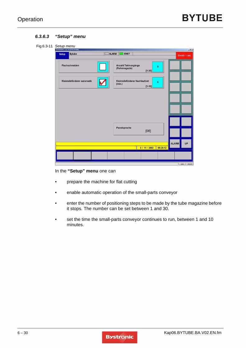
Operation
6.3.6.3 “Setup” menu
Fig. 6.3 -11 Setup menu
In the “Setup” menu one can
• prepare the machine for flat cutting
• enable automatic operation of the small-parts conveyor
• enter the number of positioning steps to be made by the tube magazine before it stops. The number can be set between 1 and 30.
• set the time the small-parts conveyor continues to run, between 1 and 10 minutes.
6 – 30 Kap06.BYTUBE.BA.V02.EN.fm

Operation
6.3.7 “Emergency Stop” alarm messages
Activating the [Emergency stop] button disconnects all electrical loads from the power supply. This does not apply to the controller or the dust extraction system (filter) if fitted.
The "Emergency Stop" alarm message appears on the screen.
In order to bring the system back into a defined status after an emergency stop, proceed as follows:
1. Rectify the problem
2. Reset the Emergency stop button
3. Switch off laser controller (MCS)
4. Press the Reset button on the STL control cabinet (button must light up).
5. Switch on the laser controller (LCS); see “Laser Operating Manual”
6. Start up the laser and begin the machining process
Enable light barrier
The light barrier protects against access to the danger area of the tube loader. If the light beam is interrupted, the drives of the transport systems in question are disconnected from the supply. The programmable controller stores the last program step.
The following states are indicated by the lamp coming on:
Lamp flashing:The light barrier circuit has been interrupted. Controller issues prompt to press the enable button.
Lamp lit:
The light barrier circuit is in working order and active.
Kap06.BYTUBE.BA.V02.EN.fm 6 – 31

Operation
6.3.8 Status fields
Alarm and machine messages are treated differently.
6.3.8.1 Machine messages
The messages provide information about the instantaneous status of the machining process. Information concerning the commands that follow immediately thereafter are displayed for further processing. The current machine status is displayed in field (3) and the current machining process in field (4).
6.3.8.2 Alarm messages
Fig. 6.3 -12 Alarm message
Any faults are shown on the display (1) in plain text . Pressing the [ALARM] button displays the list of all errors.
Fig. 6.3 -13 List of alarm messages
If there are several errors, they can be shown in a list and deleted using the button [ACK ALARMS] (2).
Alarm messages (1) are triggered by an erroneous controller state.
Different colors for the error messaging are used to indicate the severity of the cause.
6 – 32 Kap06.BYTUBE.BA.V02.EN.fm

Operation
Tab. 6.3-1
If a fault occurs, then it triggers an alarm message. All automatic processes and manual operation in the relevant module are stopped. After the problem is fixed and the alarm has been acknowledged, operation can continue.
Alarm messaging color Meaning
red current, active alarm message which shuts down the machine.
violet acknowledged alarm message that is still active and is stopping machine operation
blue unacknowledged alarm message that does not cause an immediate break in machine operation.
Kap06.BYTUBE.BA.V02.EN.fm 6 – 33

Operation
6.4 Layout of the MMC Online Help facility
General informationAn OnlineHelp facility is installed with the MMC software. The Help facility contains the description of each of the MMC functions. It is installed in the same language as that used in the MMC. The Help files are located in the MMC root directory. The file name is "HELPLCC_*.hlp", where the * stands for the language version.
6.4.1 Opening the Help facility
Fig. 6.4 -1 Help dialog in the «Main» menu.
You can open the Help facility from the MMC user interface using the «SHIFT-F1» hotkeys. The Help facility is context sensitive; «SHIFT-F1» retrieves the Help topic relating to whichever menu page or dialog window is open in the MMC. A screenshot appears with Help text. If the displayed text or screenshot is larger than the displayed area of the screen, then you can scroll using the scrollbars on the right and bottom of the window. You can also open the Help facility by selecting the Help file in the Windows user interface.
6 – 34 Kap06.BYTUBE.BA.V02.EN.fm

Operation
6.4.2 User guidance
Fig. 6.4 -2 Graphic with hot-spot symbol
Most graphics have hidden hotspots. A "hotspot" refers to an active element in this screen. If you move the mouse cursor over an area containing a background "hotspot", the mouse cursor becomes a hand. Clicking with the mouse then opens the associated Help text or jumps to the relevant Help page.
Fig. 6.4 -3 Text as hotspot
If a screen text is displayed in green then it contains a cross-reference or "hotspot".Clicking on the «Related topics» option opens a dialog box containing similar or related terms.
6.4.3 System messages
Fig. 6.4 -4 System messages display
You can display explanations of «System and error messages» that appear in the MMC status line by pressing the «System messages» button in the six main menus of the Online Help. This opens a glossary of the messages. Clicking on the message opens the associated explanation.
Hand as symbol for hotspot graphics
Hand as symbol for hotspot text
Kap06.BYTUBE.BA.V02.EN.fm 6 – 35

Operation
6.4.4 Search for terms
There are 3 options for searching for specific topics or terms within the Help facility. Clicking on the «Help topics» button opens a dialog window containing the tabs "Contents, Index, Search".Contents:The «Contents» page is the same as a table of contents. Clicking on the main topics opens a sub-list from which you can jump to the Help topics.Index:The Help topic being sought is accessed by entering the search term in the top input line and clicking on the entry that appears in the search result.Search:The «Search» function can be used to find words or terms anywhere in the Help facility.
6.4.5 Note function of the Online Help facility
Fig. 6.4 -5 Note function of the Online Help facility
The Online Help facility includes an option for saving additional information or personal notes on specific entries. To do this, open the Help window to which you want to add certain notes. Right-click in this window to open a dialog box. Click on the «Notes» option. This opens a dialog box in which you can add personal notes or comments to the selected Help dialog box. Save the note you have made. A green paperclip appears above the Help topic to indicate that there is a note attached to this topic.
6.4.6 Limitation in the "DIN-EDITOR" menu page
Using the «SHIFT-F1» hotkeys to open the Help facility is only possible in the MMC software. The DIN-EDITOR should be considered as a separate program, however, so the Help facility cannot be opened from here using «SHIFT-F1». The quickest way of accessing the DIN-EDITOR Help topic is to click on the «EDITOR» button in the «DATA menu» Help topic.
Dialog box for notes
green paperclips indicate notes on the Help text
6 – 36 Kap06.BYTUBE.BA.V02.EN.fm

Operation
6.5 Assist gases
Nitrogen (N2) and oxygen (O2) are used for laser cutting.
6.5.1 Assist gas quality
The gas quality has a crucial impact on the cut quality. Nitrogen affects the quality of the cut surface. The following table shows the relationship between quality grade and oxide formation on the cut surface.
*Values recommended by Bystronic
Gas type Quality Purity
[Vol. %]
Proportion nitrogen + argon
(N2+Ar) / [ppm]
Proportion of water
(H2O) / [ppm]
Cut surface
Oxygen O2 3.5* ≥ 99.95 ≤ 500 ≤ 5 Oxide formationProportion of oxygen
(O2) / [ppm]
Proportion of water
(H2O) / [ppm]Nitrogen N2 2.8 ≥ 99.8 ≤ 500 ≤ 20 oxide free, slightly
yellowNitrogen N2 3.5* ≥ 99.95 ≤ 100 ≤ 10 oxide-free, not
guaranteed shinyNitrogen N2 4.5 ≥ 99,995 ≤ 10 ≤ 5 oxide-free, guaranteed
shinyNitrogen N2 5.0 ≥ 99,999 ≤ 3 ≤ 5 absolutely oxide-free,
guaranteed shiny
Kap06.BYTUBE.BA.V02.EN.fm 6 – 37

Operation
6.5.2 Gas consumption
The gas consumption is heavily dependent on the pressure and the nozzle used.
Oxygen with K-nozzles (low-pressure cutting)
Fig. 6.5 -1 O2 with K-nozzles, Resolution 0-6 bar
Fig. 6.5 -2 O2 with K-nozzles, Resolution 0-20 bar
0
5
10
15
20
25
0 1 2 3 4 5 6
[m3/h]
3 mm
2.5 mm
2 mm
1.75 mm
1.5 mm1.25 mm
1 mm0.8 mm
[bar]
Gas consumption
Gas pressure
[m3/h]
[bar]0
10
20
30
40
50
60
70
0 4 8 12 16 20
3 mm
2.5 mm
2 mm
1.75 mm
1.5 mm
1.25 mm1 mm
0.8 mm
Gas consumption
Gas pressure
6 – 38 Kap06.BYTUBE.BA.V02.EN.fm

Operation
Nitrogen with HK-nozzles (high-pressure cutting)
Fig. 6.5 -3 O2 with HK-nozzles, Resolution 0-6 bar
Fig. 6.5 -4 O2 with HK-nozzles, Resolution 0-25 bar
0
5
10
15
20
25
0 1 2 3 4 5 6
[m3/h]3 mm
2.5 mm
2 mm
1.75 mm
1.5 mm
1.25 mm1 mm
0.8 mm
[bar]
Gas consumption
Gas pressure
0
10
20
30
40
50
60
70
0 4 8 12 16 20
[m 3/h]3 mm
2.5 mm
2 mm
1.75 mm
1.5 mm
1.25 mm1 mm
0.8 mm
[bar]
Gas consumption
Gas pressure
Kap06.BYTUBE.BA.V02.EN.fm 6 – 39

Operation
Nitrogen with K-nozzles (low-pressure cutting)
Fig. 6.5 -5 N2 with K-nozzles, Resolution 0-6 bar
Fig. 6.5 -6 N2 with K-nozzles, Resolution 0-20 bar
0
5
10
15
20
25
0 1 2 3 4 5 6
[m 3/h]3 mm
2.5 mm
2 mm
1.75 mm
1.5 mm
1.25 mm1 mm
0.8 mm
[bar]
Gas consumption
Gas pressure
[m3/h]
[bar]0
10
20
30
40
50
60
70
0 4 8 12 16 20
3 mm
2.5 mm
2 mm
1.75 mm
1.5 mm
1.25 mm1 mm
0.8 mm
Gas consumption
Gas pressure
6 – 40 Kap06.BYTUBE.BA.V02.EN.fm

Operation
Nitrogen with HK-nozzles (high-pressure cutting)
Fig. 6.5 -7 N2 with HK-nozzles, Resolution 0-6 bar
Fig. 6.5 -8 N2 with HK-nozzles, Resolution 0-25 bar
0
5
10
15
20
25
0 1 2 3 4 5 6
[m3/h]3 mm
2.5 mm
2 mm
1.75 mm
1.5 mm
1.25 mm1 mm
0.8 mm
[bar]
Gas consumption
Gas pressure
0
10
20
30
40
50
60
70
0 4 8 12 16 20
[m 3/h]3 mm
2.5 mm
2 mm
1.75 mm
1.5 mm
1.25 mm1 mm
0.8 mm
[bar]
Gas consumption
Gas pressure
Kap06.BYTUBE.BA.V02.EN.fm 6 – 41

Operation
6.5.3 Bottle replacement
The assist-gas bottles can be replaced during operation. Make sure that you replace bottles carefully and cleanly to avoid dirt entering the gas pipeline.
General notes
• Never empty the bottles completely. Always return the bottles with a residual pressure of at least 1 atmosphere above atmospheric pressure.
• When changing bottles, make sure that you use the correct gas quality. Never use a lower gas quality than specified.
• The machine stops if the assist gas runs low. The MMC displays the error message «GAS JET ERROR».
• The machine stops if the laser gas runs low, and the laser excitation is switched off. The MMC displays the error message «GAS MIX ERROR» (in the MCS controller) or "Gas error" (in LaserView).
• Use «Reset» (laser controller) or «Abort» (CNC controller) to clear the error messages on the laser controller once the cause of the error has been removed.
CAUTIONSecure gas bottles in place. Put safety caps on unconnected bottles.
!
6 – 42 Kap06.BYTUBE.BA.V02.EN.fm

Operation
6.5.4 Assist gas fittings
Fig. 6.5 -9 Fitting for assist-gas connection
Replacing assist-gas bottles during operation
1. Check that the stop valve (C) (full bottle) is closed.
2. Close the reducing valve (B). Counter-clockwise, 0 bar)
3. Slowly open the bottle valve (full bottle).
4. Close the stop valve (C) (empty bottle) and open the stop valve (C) (full bottle).
5. Set reducing valve (B) to 15 bar (for oxygen) or 25 bar (oxide-free cutting). (max 28 bar)
6. Close bottle valve (empty bottle).
7. Remove empty bottle from the cabinet and fit with safety cap. Insert new bottle and secure in place.
8. Open bottle valve to the new bottle briefly to blow out any accumulated dirt. Caution: Pressure 200 bar! (Protect eyes) Connect bottle.
NOTE
A. ManometerB. Reducing valveC. Stop valveD. Gas controller base pipe connectionE. Bottle connection
A
B
C
D
E
The bottle valves should be closed if the system is to be out of operation for a prolonged period (> 8 hours). Otherwise, if gas leaks through valve faces, pressure builds up that can destroy the pressure control valve in the cutting carriage.
Kap06.BYTUBE.BA.V02.EN.fm 6 – 43

Operation
6.6 Setting up and adjustment
6.6.1 Cutting head
6.6.1.1 Remove the cutting headThe head needs to be removed
- if the work-piece material or thickness requires a suitable focal length.
- if the nozzle and lens need to be checked because of declining machining quality.
1. Move the axes until you can reach the cutting head comfortably.
2. Open the safety door.
3. Hold the cutting head in one hand and undo the two clamping levers with the other.
4. Turn the cutting head over to prevent dust reaching the lens. Put the cover over the aperture. (If the aperture is not covered, dirt can get on the lens. This dirt may then be heated by the laser beam once the head has been refitted, causing damage to the lens). Store the cutting head either with the nozzle pointing downwards or horizontally.
6.6.1.2 Fitting the cutting headTake the cover off the cutting head. Use one hand to place the cutting head in the retaining ring. Press it evenly against the holder until you have fixed it with the clamping levers.
6.6.2 Changing the nozzle
The nozzle needs to be changed
- if another nozzle is required according to the parameter set.
- if because of declining machining quality the nozzle has been found to be damaged.
1. Clean the nozzle and nozzle body externally.
2. Unscrew the nozzle by hand in a counter-clockwise direction If the nozzle is too tight to move, use a ring spanner.
3. Screw in the nozzle required. Only tighten the nozzle by hand.
4. Fine adjustment of the nozzle centering must be performed whenever a nozzle is changed.
6 – 44 Kap06.BYTUBE.BA.V02.EN.fm

Operation
6.6.3 Fine adjustment of nozzle centering
Fine adjustment of the centering is necessary after
• poor cutting results (whiskering on one side of the work piece)
• coarse adjustment
• changing a nozzle
If the selected material requires a change in the focal position, then the focal point must be moved before fine adjustment of the centering.
1. On the MMC, select "Setup", ”Setup Laser”.
2. Enter 1% for "Laser power single pulse"
3. Enter a ”Pulse length” of about 20-100 ms
4. Enter a "Delay time, shutter open/closed" of 400 ms
5. Affix a strip of transparent adhesive tape onto the nozzle of the cutting head.
6. Switch to <Manual> "manual operation"
7. Close safety gate
8. Select <PULS> on the hand-held controller
9. Open safety door
10. Using a mirror held under the nozzle, check whether the hole burnt into the adhesive tape is positioned exactly in the center of the nozzle aperture
11. If necessary, center the nozzle in the relevant direction using the centering screws
12. Repeat steps 5-10 until the laser beam is fired exactly through the center of the nozzle
WARNINGLaser class 4.Invisible laser radiation. Avoid exposing eyes or skin to direct or stray radiation. Wear protective glasses.
!
Kap06.BYTUBE.BA.V02.EN.fm 6 – 45

Operation
Fig. 6.6 -1 Nozzle with centering screws
NOTE
NOTE
12. Exit Manual operation, close safety gate.
6.6.4 Nozzle cooling
When machining reflective materials (aluminum, stainless steel), the nozzle is heated by the reflection. This also applies to steel of thickness 6mm or more. This can have a negative effect on the capacitive detection (nozzle clearance distance changes).The nozzle can be cooled with air. You can set the pressure using an adjustment knob. The blue adjustment knob is located on the front of the carriage.
Nozzle cooling also prevents fumes soiling the cutting head when cutting steel.
centered
Nozzle aperture laser burn hole
Centering required
Correction: Move nozzle to right
The centering screws move the nozzle, not the burn hole. The screws have right-hand threads, i.e. turning clockwise moves the nozzle towards the screw, while turning counter-clockwise moves it away from the screw.
Optimum cutting quality is to a large extent dependent on a properly centered nozzle. If the nozzle is off-center, the laser beam can hit the nozzle and be deflected. For this reason care should be taken to center the nozzle accurately.
6 – 46 Kap06.BYTUBE.BA.V02.EN.fm

Operation
6.6.5 Adjust jet clearance
Determining the parameters
A suitable nozzle clearance and focal position are required for different materials and work-piece thicknesses. A set of parameters for the most frequently used materials is included in the machine. When determining the nozzle clearance and focal position for other materials, use the parameter set for a similar material as starting point.
If you have changed the lens, carry out a calibration before setting the nozzle clearance and focal position.
For a focal position of 0, the focus lies on the work-piece surface. Focal positions above the work-piece surface are given a negative sign, while focal positions below the work-piece surface (in the work piece or below the work piece) have a positive sign.
6.6.6 Adjusting the focal position
One turn of the tenths scale corresponds to a 6 mm height adjustment, i.e. one sub-division equals 2/10 mm.
1. Turn the focus adjustment ring until the slide piece is right at the top. The zero mark is now visible on the millimeter scale and the adjustment ring. This corresponds to the maximum top focal position.
2. Turn the focus adjustment ring in the positive direction until the zero mark appears again. This corresponds to position 0 on the adjustment ring and 6 on the millimeter scale. Another complete turn of the focus adjustment ring produces another 6mm adjustment, i.e. 12mm in total, which can be read off on the millimeter scale again. Another turn goes to 18mm.
3. Read off the intermediate values on the tenths scale. For example the figure 0-40 means that, starting from the position 0 and turning downwards, 40 must appear on the tenths scale on the adjustment ring.
4. Find the required nozzle clearance from the "Work", "Info" menu (for example nozzle clearance 0.7mm). Start from the focal position noted on the label on the head (e.g. 0-40). Add the required nozzle clearance to the value on the label (e.g. 40 + 7 = 47) and set this value on the adjustment ring.
5. Find the required focal position for the work piece from the "Work", "Info" menu (e.g. focal position 5 mm, i.e. 5mm in the material).
6. Add this value to the value on the adjustment ring (e.g. 47 + 50 = 97). The value of 97 means we are in the 2nd range, i.e. between 6 and 12mm. The focus adjustment ring is therefore turned beyond the 2nd zero mark (6mm) to the difference of 3.7 mm, i.e. to subdivision 37.
Kap06.BYTUBE.BA.V02.EN.fm 6 – 47

Operation
6.6.7 Setting the reference points on the Bytube CNC
Certain rules need to be followed for the settings. These basically relate to setting the reference points X, X2 and A axes. It is important to know here, that all reference dimensions, and hence all dimensions derived from the reference points, depend on the X (default X) axis. For example, if the reference dimension for the X-axis is changed, then the position values for the A- and X2-axes are no longer correct. Thus it is imperative to make the X-axis settings first.
6.6.7.1 X-axis referenceThe reference dimension for the X-axis must be set so that when X = 0.00 mm the machine stands 275 mm from the outer edge of the first plate screwed onto the machine frame. This value must be optimized between the risk of collision and material wear and the length of leftover tubes.
6.6.7.2 X2-axis reference The reference dimension for the X2 axis must be set so that the head of the gripper lies directly under the nozzle of the cutting head when both axes display 0.00. This position is only theoretically possible however. Thus the X2-axis should be positioned at 1000mm and the X-axis at 0.00mm(on the display). It must be possible to measure this distance of 1000mm, i.e. distance and displayed value must match (displayed in Hand / Hybrid X2). The distance is measured from the front face of the gripper base without jaws fitted.
This value can be set in the menu Main / Config HW / X2-axis reference
A. Cutting head at X = 0.00B. Machine frame
A
B
6 – 48 Kap06.BYTUBE.BA.V02.EN.fm

Operation
6.6.7.3 Reference A-axisThe reference dimension of the A-axis must be placed at the zero point of the X-axis. To do this the A-axis can be positioned at 1000mm and the X-axis at 0.00mm(on the display). It must be possible to measure this distance of 1000mm.
This can be changed in Main / Config HW / A-axis: Reference
A. Cutting head at X = 0.00B. Machine frameC. X2-axis with gripper
A
B
C
A. Cutting head at X = 0.00B. Machine frameC. A-axis
A
B
C
Kap06.BYTUBE.BA.V02.EN.fm 6 – 49

Operation
6.6.7.4 Collision limits X2-axisThe collision limits of the X2-axis for circular, square and rectangular hollowsections depend on the components that are fitted, such as clamping jaws, steadyrest and chuck. The collision limits must be found on the machine, with the aim ofgenerating minimum waste while ensuring collision-free operation.Can be set in Setup / Hybrid.
6.6.7.5 Tray on the A-axisThe sketch below illustrates the tray Setup. The offset value is used for making slight corrections.
This value can be set in Setup / Hybrid / A-axis.
A. TrayB. Tray lengthC. A-axisD. Zero point A-axisE. Tray position
B
A
D C
E
6 – 50 Kap06.BYTUBE.BA.V02.EN.fm

Operation
6.6.7.6 Lance on the A-axisThe sketch below illustrates the lance Setup. The offset value is used for making slight corrections.
A. LanceB. Lance lengthC. A-axisD. Zero point A-axisE. Lance position
A
B
CD
E
Kap06.BYTUBE.BA.V02.EN.fm 6 – 51

Operation
6.7 Process parameter make-up
The required cutting quality can only be achieved with optimized process parameters.Process parameters for the most frequently cut materials are supplied on the hard disk of the machine controller or on diskette. When the machine is delivered, the latest parameter files for your controller version are copied to the panel PC. The process parameters for a specific operating mode are grouped in a file with a characteristic file name.To load process parameters:
• press the key
• select the «Job List» function or press the [f1] key
• selecting the «Select param» function or pressing the [f2] key.
• Select the desired parameter file and load it by selecting the «Open» function.
NOTE The parameters provided by BYSTRONIC are guides. The conditions required for achieving optimum cutting results are summarized in chapter 12, Cutting technology.
6 – 52 Kap06.BYTUBE.BA.V02.EN.fm

Operation
6.7.1 File naming conventions
File names contain five parameters:
1. Material number using DIN convention
2. Material thickness + surface treatment
3. Machine type
4. Lens (focal length)
5. Process or assist gas
6.7.1.1 Material ID in compliance with DIN standardSystematic numeric identification of materials according to DIN 17007.The seven-digit material number consists of:– Principal material group– Type number– Suffix
6.7.1.2 Principal material groups0 = iron, iron alloys, cast iron1 = steel and cast steel2 = heavy metals excluding iron3 = light (non-heavy) metals4 – 8 = non-metal materials9 = unassigned code
6.7.1.3 Type numbersFor the type numbers of principal groups 0 and 1, the first two digits indicate the type categories. The next two digits of the type numbers are counters. Type numbers are essentially formed on the basis of their chemical composition of the materials or their origin.
WWWWWSSS.B5P
54321
Kap06.BYTUBE.BA.V02.EN.fm 6 – 53

Operation
6.7.1.4 SuffixesThe suffixes stand for special characteristics such as type of melt or cast, heat treatment and cold forming.It was not possible to take the suffix into account in the BYSTRONIC file names. Only the first five digits are used for the material identifier.
6.7.2 BYSTRONIC material ID based on DIN standard
6.7.2.1 Principal group 1: Steel and cast steelThis group covers all steels including cast steel. The first two digits in the type numbers indicate the type categories. The next two digits are counters, which bear no relation to the carbon or alloy content.
WWWWWSSS.B5P
The letters ”WWWWW” stand for the first five digits of the DIN material designation.
Ordinary steels and quality steels1.00 Commercial and ordinary grades1.01-1.02 General structural steels1.03-1.07 Quality steels, unalloyed1.08, 1.09 Quality steels, alloyed1.90-1.99 Special grades
Unalloyed high grade steels1.10 Steels with special physical characteristics1.11-1.12 Structural steels1.15-1.18 Tool steels
Alloyed high grade steels1.20-1.28 Tool steels1.32,1.33 High-speed steels1.34 Wear-resistant steels1.35 Roller bearing steels1.36-1.39 Ferrous materials with special physical
characteristics1.40-1.45 Stainless steels1.47, 1.48 Heat-resistant steels1.49 High temperature materials1.50-1.84 Structural steels
6 – 54 Kap06.BYTUBE.BA.V02.EN.fm

Operation
6.7.2.2 Principal group 2: Non-ferrous metals
6.7.2.3 Principal group 3: Light metals and their alloys
In principal groups 2 and 3, the four-digit type numbers indicate the composition, classified according to base metals, type and amount of the alloy constituents.
1.85 Nitriding steels1.88 Hard alloys
Alloyed high grade steels
2.000-2.1799 Copper and copper alloys
3.0000-2.4999 Aluminum and alloys3.5000-3.5999 Magnesium and alloys3.7000-3.7999 Titanium and alloys
Kap06.BYTUBE.BA.V02.EN.fm 6 – 55
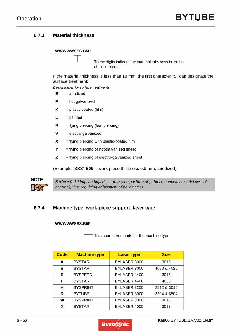
Operation
6.7.3 Material thickness
If the material thickness is less than 10 mm, the first character “S” can designate the surface treatment:Designations for surface treatments
(Example ”SSS” E09 = work-piece thickness 0.9 mm, anodized).
NOTE
6.7.4 Machine type, work-piece support, laser type
E = anodized
F = hot galvanized
K = plastic coated (film)
L = painted
R = flying piercing (fast piercing)
V = electro-galvanized
X = flying piercing with plastic-coated film
Y = flying piercing of hot-galvanized sheet
Z = flying piercing of electro-galvanized sheet
WWWWWSSS.B5P
These digits indicate the material thickness in tenths of millimeters.
Surface finishing can impede cutting (composition of paint components or thickness of coating), thus requiring adjustment of parameters.
Code Machine type Laser type SizeA BYSTAR BYLASER 3000 3015B BYSTAR BYLASER 3000 4020 & 4025E BYSPEED BYLASER 4400 3015F BYSTAR BYLASER 4400 4020H BYSPRINT BYLASER 2200 2512 & 3015R BYTUBE BYLASER 3000 3204 & 6504W BYSPRINT BYLASER 3000 3015X BYSTAR BYLASER 4000 3015
WWWWWSSS.B5P
This character stands for the machine type.
6 – 56 Kap06.BYTUBE.BA.V02.EN.fm

Operation
6.7.5 Lens
6.7.6 Process and assist gases
Y BYSTAR BYLASER 4000 4020 & 4025Z BYSPEED BYLASER 40S 3015
Code Machine type Laser type Size
Code Focal length5 5"7 7.5"
WWWWWSSS.B5P
This character stands for the lens used.
Code ProcessO Cutting with oxygenA Cutting with nitrogenA Cutting with argonL Cutting with compressed airP Pulsed cutting
WWWWWSSS.B5P
This character stands for the process and the assist gas
Kap06.BYTUBE.BA.V02.EN.fm 6 – 57

Operation
6.7.7 Coding of process parameter file names
Example:Code for process parameter file name
1 0 3 3 2 X 5 0 . A 5 O
Assist gas: O = oxygen N = nitrogen P = pulsed cuttingL = compressed air A = argon
Cutting head: 5 = 5" 7 = 7.5
Laser machine:A = BYSTAR 3015 BYLASER 3000B = BYSTAR 4020, 4025 BYLASER 3000E = BYSPEED 3015 BYLASER 4400F = BYSTAR 4020 BYLASER 4400H = BYSPRINT 2512, 3015 BYLASER 2200R = BYTUBE 3204, 6504 BYLASER 3000W = BYSPRINT 3015 BYLASER 3000X = BYSTAR 3015 BYLASER 4000Y = BYSTAR 4020, 4025 BYLASER 4000Z = BYSPEED 3015 BYLASER 40S
Sheet thickness: Sheet thickness in 1/10 mm (e.g. 150 = 15 mm)
Surface finish & machining type:E = anodizedF = hot galvanized (smooth finish)K = plastic coated (film)L = paintedR = flying piercing (fast piercing)V = electro-galvanizedX = flying piercing with plastic-coated filmY = flying piercing of hot-galvanized sheetZ = flying piercing of electro-galvanized sheet
Sheets less than 10 mm thick: one letter specifies the surface treatment and the machining type.
Material: DIN number of material
6 – 58 Kap06.BYTUBE.BA.V02.EN.fm

Operation
6.7.8 Constraints
Transferability of parameters between different machines of the same typeConditions for transferring the parameters calculated by BYSTRONIC:– machine properly calibrated– beam quality as at first start-up– focal length and nozzle as per parameter list– machine and focusing lens in perfect condition– laser gas quality as per specifications– sheet surface free of scale (pickled, etched or polished)
6.7.8.1 Influence of contour geometryThe parameters apply to shapes whose contour elements are larger than twice the sheet thickness (example: for a sheet thickness of 3 mm, parameters apply at and above 6 mm hole diameter, tooth length, etc.).Various parameters need to be adjusted for complicated and tight contours. Recognizing the key parameters for adjustment requires experience on the part of the machine operator.
6.7.8.2 Optimizing parametersThe parameters provided by BYSTRONIC are for recommended values. Materials with the same designation still differ in terms of composition within certain tolerances. Other differences are due to the type of casting and melt, heat treatment and cold forming.The parameters have been selected so as to allow these materials to be cut despite these differences. If material quality and ambient conditions are constant, it may be possible to optimize these parameters still further. Optimization can increase the quality and economic efficiency of the machining process.
Kap06.BYTUBE.BA.V02.EN.fm 6 – 59
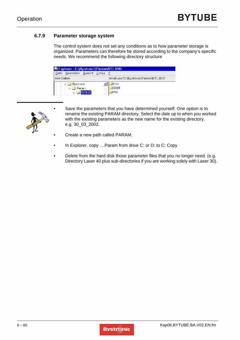
Operation
6.7.9 Parameter storage system
The control system does not set any conditions as to how parameter storage is organized. Parameters can therefore be stored according to the company’s specific needs. We recommend the following directory structure
• Save the parameters that you have determined yourself. One option is to rename the existing PARAM directory. Select the date up to when you worked with the existing parameters as the new name for the existing directory. e.g. 30_03_2002.
• Create a new path called PARAM.
• In Explorer, copy ....Param from drive C: or D: to C: Copy
• Delete from the hard disk those parameter files that you no longer need. (e.g. Directory Laser 40 plus sub-directories if you are working solely with Laser 30).
6 – 60 Kap06.BYTUBE.BA.V02.EN.fm

Operation
6.8 Adjusting process parameters
Process parameters are parameters that have a direct effect on the cutting process. These production parameters are not optimized for maximum cutting rate but for process reliability.The parameters supplied by Bystronic are optimized for cutting particular materials. Nevertheless, it can be the case that these parameters result in unsatisfactory cutting results. The requirements and procedure to be followed in order to improve the cutting result in such a situation are described below.
6.8.1 General information
There are numerous laser cutting parameters, some of which are mutually dependent. We only list here the 5 main parameters that can be used to optimize cutting quality:
• Focal position
• Laser power
• Gas pressure
• Feedrate
• Nozzle distance
The adjustments to parameters described here only apply to simple contours such as straight lines.
NOTE
6.8.2 Reasons for adjusting parameters
– Differences in alloys– Tolerance variation in the sheet thickness– Different qualities of surface finish– Different composition of material– Large temperature differences in the material used
(Reference temperature = +20°C)
The cutting quality is only evaluated for a straight cut in the X+, X-, Y+, Y- axis direction. Interpolated cut directions such as radii, diagonal cuts or initial cuts are not included.How to modify parameters for complex contours such as sharp corners, radii, small contours, initial and final cuts and holes is explained in Chapter 12, Cutting Technology.
Kap06.BYTUBE.BA.V02.EN.fm 6 – 61

Operation
6.8.3 Requirements for adjusting parameters
The following conditions must be met in order to obtain a good cut quality by adjusting the main parameters:
• Laser machine and laser must be in perfect condition.
• The lens in the cutting head must be in perfect condition (see Chapter 7, Maintenance).
• The cutting head and nozzle must match the specifications in the parameter file.
Preliminary stepsBefore you start adjusting parameters for the material to be cut, we recommend that you create a directory for modified parameters. The parameters supplied by Bystronic are saved in the directory «C:\Param». Follow the instructions below:
1. Save the modified parameters in a second directory containing the sub-directories.
Fig. 6.8 -1 Example directory for modified production parameters
2. Save the parameters that you want to change in the directory for the material concerned.
TIP
Directory containing Bystronic parameters
New parameter directory for your own production parameters
Once you have adjusted the parameters, we recommend printing them out using the «Paramview» program from the «Bysoft 6 Toolbox», and keeping them in a folder. We also recommend keeping the test piece.
6 – 62 Kap06.BYTUBE.BA.V02.EN.fm

Operation
6.8.4 Procedure for optimizing cutting parameters
Before cutting new material, carry out a cutting test. If problems arise with the cutting quality, these can be rectified by adjusting the Bystronic parameters. Bystronic provides dedicated cutting plans for adjusting and testing cutting parameters (except for BYTUBE). These are held on the PPC in the «Handover» folder under the Laser type concerned. Use the "Test_large.lcc" cutting plan. This part includes all four cuts in the X and Y direction.To optimize the cutting quality:
1. Place the material that you want to cut on the shuttle table and move this into the machining area.
2. Import the cutting plan "Test_large.lcc" into the «Job List» menu and assign to this cutting plan the relevant material parameter file that you want to use for cutting. (See Chapter 6, Operation). Use the parameter file that you saved for this purpose in the directory for personal parameters (see chapter «6.8.3 Requirements for adjusting parameters»).
NOTE
Order in which to adjust the cutting parameters
3. Only cut one part from the cutting plan for each cutting test. To do this, press the button on the PPC operating terminal. The program stops after cutting a part. Press «Cont» to cut further parts, «Abort» to terminate.
4. Repeat the cutting tests with the amended parameters until you achieve a good cutting result.
5. Save the amended parameter in the menu «Param» with key [f8]. Make sure that you save the modified parameter file in its own directory (see "Preliminary steps" in chapter «6.8.3 Requirements for adjusting parameters»).
Use the guidance in Chapter 12, Cutting Technology to assess the cut made in your part having below-par cut quality. Find out what cut-optimization steps are needed from the list of possible causes and suitable remedial action. If more than one option is given, follow the order below.
Cutting with O2 Cutting with N2
1 Focal position Focal position2 Laser power Gas pressure3 Gas pressure Feed ± 10% OK4 Feed ± 10% OK Laser power5 Nozzle distance Nozzle distance
Kap06.BYTUBE.BA.V02.EN.fm 6 – 63

Operation
6.8.5 Focus position
The focal position refers to the position of the cutting point at which the diameter of the laser beam is at its minimum and thus there is maximum power density. The focusing of the laser beam is generated by the lens in the cutting head. Depending on the material, the focal point during cutting is either on (1), in (2) or below (3) the work piece.
Fig. 6.8 -2 Focal position of the laser beam
The focal position depends essentially on the cutting gas used.
* For information on the laser cutting types please see Chapter 12, Cutting technology.
To change the focal position, proceed as follows:
1. Press the key. Mark the parameter «Focal position» on the page «Characteristics Material / Tool».
2. Enter the new value on the numeric block of the PC keyboard. A higher value moves the focal position down, a lower value moves it up. The value “0” corresponds to the material surface.
Fig. 6.8 -3 Change of focal position
3. Confirm by clicking on OK.
Gas type *Laser cutting type Focal position
O2 Burn cutting Focal position in upper area of materialN2 Laser cutting Focal position in lower area of materialNo gas Sublimation cutting Focal position depends on material thickness and
beam quality
1 2 3
Work piece surface-5
+5
0
6 – 64 Kap06.BYTUBE.BA.V02.EN.fm

Operation
6.8.6 Gas pressure
To change the gas pressure, proceed as follows:
1. Press the key. Mark the parameter «Gas pressure CW cutting» on the page «Parameters continuous operation».
2. Enter the new value on the numeric block of the PC keyboard. With oxygen, a higher value results in a higher cutting temperature and a rougher cut surface. For nitrogen, the material is blown out more strongly and cooled more.
3. Confirm by clicking on OK.
6.8.7 Laser power
To change the laser power, proceed as follows:
1. Press the key. Select the parameter «Laser power cutting» on the page «Parameters continuous mode».
2. Enter the new value on the numeric block of the PC keyboard.
3. Confirm by clicking on OK.
6.8.8 Feed
To change the feed, proceed as follows:
1. Press the key. Select the parameter «Feed cont. operation» on the page «Parameters continuous operation».
2. Enter the new value on the numeric block of the PC keyboard.
3. Confirm by clicking on OK.
Kap06.BYTUBE.BA.V02.EN.fm 6 – 65

Operation
6.8.9 Nozzle distance
To change the nozzle clearance, proceed as follows:
1. Press the key. Mark the parameter «Nozzle distance cutting» on the page «Parameters continuous operation».
2. Enter the new value on the numeric block of the PC keyboard.– Nozzle distance < 1mm
• Nozzle wear and soiling increase– Nozzle distance > 1mm
• Cutting quality decreases• Lower nozzle heating with plasma cutting
3. Confirm by clicking on OK.
6 – 66 Kap06.BYTUBE.BA.V02.EN.fm

Operation
6.9 Process parameters
Prior to machining, a cutting plan file and a process parameter file are imported into the CNC. The «Param» menu only provides access to the process parameters present in the CNC.This chapter describes the most important process parameters. Additional process parameters are described in the MMC Online Help.
6.9.1 Focal length: 5.0 / 7.5
Focal length of the focusing lens (inches)
6.9.2 Type of nozzle
Nozzle specification (e.g. HK 10)
6.9.3 Focal position
Position of the focal point in the material (mm)
6.9.4 Gas channel cutting
Selection of gas type for the «Cutting» process.
6.9.5 CW piercing mode
1 = TactileThis piercing mode is mainly used with thin sheets (steel/stainless steel). Advantage: Nozzle & lens protection, short piercing timeDisadvantage: Piercing holes are slightly larger than from «Nozzle distance piercing»The laser power is increased from 0% to «Laser power piercing» as soon as the signal «sensor on sheet» (15mm above surface of sheet) is generated. At the same time, the speed is adjusted to «Piercing speed» (5000mm/min). With the «Piercing tactile» option, highly reflective materials may set up reflections that will destroy the adaptive mirror (option).
Kap06.BYTUBE.BA.V02.EN.fm 6 – 67

Operation
2 = Z dimensionThis piercing mode is mainly used for thick sheets (steel > 6mm).Advantage: Nozzle and lens protection, flat piercing cups and short piercing time. The incident laser beam, not being 100% focused, results in considerable heating of the sheet surface. This causes increased absorption of the laser beam. The «lifting height, nozzle» should be at least 40 mm.Special application: Piercing in film-coated sheets. The foil at the piercing point is melted away or melted on and can therefore no longer bubble up. The «Lifting height, nozzle» should be at least 40 mm.The laser power is increased as soon as the head begins to descend from the Z-dimension height. If the current position does not lie at the height given by the Z dimension, the Z-axis moves to the Z dimension (define the Z dimension in «Special parameters», «Lifting height, nozzle»).With «Piercing from Z dimension», highly reflective materials may set up reflections that will destroy the optical components.
3 = NozzleThe laser power is not increased until the «Nozzle distance, piercing» is reached.
4 = Circular piercing
Fig. 6.9 -1
After piercing, a circle of diameter 2 mm is cut around the piercing point and back to the center, at half the speed of the «Feed cutting» feed rate. The hole created makes the subsequent initial cut easier. Circular piercing can only be enabled in CW mode. Set the piercing time to zero if necessary.
Fig. 6.9 -2
The circle and subsequent initial cut into the contour are cut in the relevant operating mode. The position within the cut hole is not suitable for readjustment of the nozzle clearance. Avoid readjustment of the clearance by selecting the same nozzle distance in the parameters for piercing and cutting. If you select different operating modes for the circular piercing and for the contour, ensure that both parameter records contain the same nozzle distance settings.
6 – 68 Kap06.BYTUBE.BA.V02.EN.fm

Operation
6.9.6 Laser power piercing
Laser power during the piercing time (as a percentage of the rated power of the laser) (%) .
6.9.7 Nozzle distance, piercing
Distance between the nozzle and the work piece during piercing (mm).
6.9.8 Gas pressure CW piercing
Gas pressure during piercing. A pressure higher than 10 bar for the low-pressure gas channel 1 results in «Warning ! parameter error» (bar).
6.9.9 Nozzle distance, cutting
Distance between the nozzle and the work piece during machining (mm).
6.9.10 Laser power cutting
Laser power (as a percentage of the rated power of the laser) when cutting in normal operating mode with the standard feed rate (%).
6.9.11 Acceleration factor, lead-in
In the event of difficult lead-in conditions after piercing, this parameter can achieve higher process reliability. If the lead-in (initial cut) acceleration is less than 0.1 and below the «Acceleration factor, contour», the initial cut is made without modulation (m/s2).
• enabled for standard piercing
• disabled for engraving, welding, pre-burning, Common Cut (M18) and also when a value of 0 is set for «piercing time»
Kap06.BYTUBE.BA.V02.EN.fm 6 – 69

Operation
6.9.12 Gas ramp piercing / cutting
Ramp from piercing pressure to cutting pressure during lead-in. This parameter is used in oxide-free cutting. The correct pressure depends on the cutting feed rate, and is increased linearly after normal or circular piercing (s).The gas ramp is only applied if
• the value for the piercing time is > 0
• both piercing and cutting is in CW mode
• the same gas has been selected for piercing and cutting
• the piercing pressure is lower than the cutting pressure
6.9.13 Gas pressure CW cutting
Gas pressure for the «Cutting» process. Pressures higher than 10 bar in gas channel 1 are not permitted and result in «Parameter error» (bar).
6.9.14 Feed, continuous wave mode
Standard feed rate for CW mode (active between machine functions M4 and M5). When a plan is copied from the MMC to the CNC, the value of the "F" address is copied from this parameter (if present, this value must appear in block G29, otherwise this value is not active) (mm/min).
6.9.15 Dynamic Factor
The maximum feed rate when cutting radii is calculated by the controller using the formula below. This value is compared with the standard feed rate. The smaller value of the two is chosen as the actual feed rate.
• V (max. dyn. feed rate) = [mm]
• Df:dynamic factor [-]
• R :radius [mm]
• ∆S:chordal deviation [mm]/1000
If you are cutting small-radius contours, the dynamic factor should be optimized using trial cuts. The table indiates the smallest radius that can be cut at the standard feed rate. (Chordal deviation 10µm). For smaller radii, the feed rate is reduced accordingly.
900 Df R ∆S×××
6 – 70 Kap06.BYTUBE.BA.V02.EN.fm

Operation
Radius table
6.9.16 Modulation
Adjustment of the laser power to suit reduced feed rate (acceleration, braking and reduction of the feed rate in radii, corners and initial cuts). The percentage defines the speed (as a percentage of the standard feed rate) at which (linear) reduction of the power is to commence (%).
6.9.17 Tool radius
The tool radius equals half the width of the cutting gap. Measure the width of the cutting gap in test cuts. As the sides of the cutting gap are not exactly parallel in the vertical direction, the depth of measurement must be defined for larger sheet thicknesses. The value can be entered to 2 decimal places. This parameter is active if the G functions G41 / G42 (tool compensation left / right) are contained in the plan (mm).
Feed rate Dynamic factor
[mm/min] 0.3 0.4 0.5 0.6 0.7 0.8 0.9 1.0 1.1 1.2 1.31000 1.37 0.77 0.49 0.34 0.25 0.19 0.15 0.12 0.10 0.09 0.072000 5.49 3.09 1.98 1.37 1.01 0.77 0.61 0.49 0.41 0.34 0.293000 12.35 6.94 4.44 3.09 2.27 1.74 1.37 1.11 0.92 0.77 0.664000 21.95 12.35 7.90 5.49 4.03 3.09 2.44 1.98 1.63 1.37 1.175000 34.29 19.29 12.35 8.57 6.30 4.82 3.81 3.09 2.55 2.14 1.836000 49.38 27.78 17.78 12.35 9.07 6.94 5.49 4.44 3.67 3.09 2.637000 67.22 37.81 24.20 16.80 12.35 9.45 7.47 6.05 5.00 4.20 3.588000 87.79 49.38 31.60 21.95 16.12 12.35 9.75 7.90 6.53 5.49 4.689000 111.11 62.50 40.00 27.78 20.41 15.63 12.35 10.00 8.26 6.94 5.92
10000 137.17 77.16 49.38 34.29 25.20 19.29 15.24 12.35 10.20 8.57 7.3111000 165.98 93.36 59.75 41.50 30.49 23.34 18.44 14.94 12.35 10.37 8.8412000 197.53 111.11 71.11 49.38 36.28 27.78 21.95 17.78 14.69 12.35 10.52
CAUTIONThe minimum gas pressure must never fall below 1.5 - 2 bar (protection of lens). An excessively high gas pressure results in unnecessary gas loss on the positioning paths
!
Kap06.BYTUBE.BA.V02.EN.fm 6 – 71

Operation
6.10 Hand-held controller
The hand-held controller is a flexible extension to the PPC operator terminal. It is connected to the CNC controller by a cable. The two functions most commonly performed with the hand-held controller are described below.
6.10.1 Separating cuts
Severance cuts made with the hand-held controller are used for removing off-cuts or leftover tube sections.
NOTE
To perform a separating cut using the hand-held controller:
1. In the MMC go to the «Hand» menu. Press the «Manual operation» button or the <f3> key. The hand-held controller is enabled and the <TOOL> button illuminated.
2. Move the cutting head to the reference position by pressing the «Move to reference» button. Calibrate the sensing mechanism on the calibration plate using the hand-held controller.
3. Press and hold the <Z-> button to calibrate. Wait until the cutting head has lowered itself onto the calibration plate for the second time and you can hear cutting gas escaping.
4. Release the <Z-> button. The cutting head remains lowered.
5. Press the <Z+> button to raise the cutting head.
6. Use the X and Y buttons to move the cutting head to the position on the sheet where the separating cut is required.
7. Press the <Z-> button to lower the cutting head. Wait until the cutting head has lowered itself to the nozzle clearance distance and then release the button.
8. Switch the laser on by pressing the <BURN> button. The laser remains on as long as the <BURN> button remains pressed. Use the U or Y buttons to move immediately in the required direction for separating the tube or tubular section.
Always make separating cuts using the parameter belonging to the material to be cut.
6 – 72 Kap06.BYTUBE.BA.V02.EN.fm

Operation
9. After separating the off-cut, release the <BURN> button immediately to switch off the laser, then press the <Z+> button to raise the cutting head.
6.10.2 Shifting the origin of the cutting plan
The origin of the cutting plan is offset in order to be able to cut parts at any position in the machining area. The main applications are:
• Use of leftover sheets
• Cutting without edge detection
• Material not located at the machine origin.
NOTE
CAUTIONMake sure that the cutting head is always lowered during cutting, otherwise strong reflections can arise that may damage the cutting nozzle.Always move the cutting head immediately after pressing the <BURN> button, otherwise the laser may damage the lower tube wall or machine components.
!
Only use the origin-offset function for cutting single parts, not for whole cutting plans. There is a risk that the machine would move beyond the existing sheet or into the end-stops if the cutting plan extended beyond the sheet as a result of shifting the origin.
Kap06.BYTUBE.BA.V02.EN.fm 6 – 73

Operation
To offset the origin of the cutting plan:
1. Load the cutting program and run using «Start work». The <STOP PART> and <HALT CNC> buttons must be activated (yellow LED must light up).
2. In the Work menu, use the «Cont» button to confirm the messages in the yellow status line until the message «Stop at origin – wait for <Cont>/<Abort>» appears. The cutting head moves to the machine origin (zero point).
3. Switch to the Hand menu and press the «Manual operation» button.
4. Use the X and Y buttons on the hand-held controller to move the cutting head to the required position.
5. Switch to the «Work» menu and press the «Cont» button to start the cutting process.
6 – 74 Kap06.BYTUBE.BA.V02.EN.fm

Operation
6.11 Special functions
General informationSpecial functions are tools which make working with the laser cutting machine easier in certain situations.
6.11.1 Crossjet
Crossjet prevents slag generated when the laser beam pierces the material from adhering to the surface of the work piece.
The base position for the Crossjet is the parked position.
Fig. 6.11 -1 Crossjet in parked position.
Fig. 6.11 -2 Crossjet in machining position
1 Move in the Crossjet on the nubs, and fix with screw
Only fit the Crossjet in the machining position when you want to use it. This prevents unnecessary soiling.
1
1
Kap06.BYTUBE.BA.V02.EN.fm 6 – 75

Operation
6.11.1.1 Registering the crossjetIf a Crossjet is mounted on the Z-axis, this must be registered in the MMC menu «Main», «Service», «Config. CNC» MMC menu by activating the «Crossjet» checkbox.Crossjet is enabled by pressing the [SF2] button on the keyboard in the «Work» menu.
NOTE
The Crossjet has the following operating modes:
• Oil mist
• Cross blow.
6.11.1.2 Oil mistThe oil mist consists of oil and air, and is sprayed onto the work piece before piercing. The film of oil on the surface of the work piece reduces the adhesion of the slack that escapes upwards during piercing.
The length of the spraying process is set in the MMC in the «Param», «Special Param» menu using the «Oil mist before piercing» parameter.The oil mist is not active before piercing in pulse operation or before piercing after “Lowered positioning”.
The thickness of the oil film depends on the flow rate, the nozzle diameter and the length of the spraying process.
Fig. 6.11 -3
Crossjet can only be enabled with the [SF2] button if the parameter «Oil-mist time before piercing» has a value greater than zero.
CAUTIONRisk of fire
Oil vapors can ignite spontaneously on the laser beam or on the hot surface of the work piece. Only use the correct oil and only in the dosage required for the job.
!
1
2
3
6 – 76 Kap06.BYTUBE.BA.V02.EN.fm

Operation
You can regulate the flow rate using the set-screw. First undo the retaining screw. The flow rate is set to "fully open" in the factory setting.
6.11.1.3 Transverse blowingTransverse blowing can be switched on and off in the MMC using the «Transverse blowing after piercing» parameter in the «Work» menu, «active param.», «Special parameters». To control the duration of the cross-blowing, use the «Delay time before processing» parameter in the «Work», «Active param.», «Laser parameters CW mode» menu.
6.11.1.4 Manual controllerTake Crossjet from the parked position to the machining position.Move to the reference point. In the “HAND” menu, choose “Auto. setup”. The machine then moves to the zero point.Activate the hand-held controller and press <Z->to lower the head.Use SF2 or SF3 (Oil, Blow) to select Crossjet functions, which are enabled in manual operation and during automatic setup using the <CROSSJET> button on the hand-held controller. Settings and operating modes.
NOTE
1.) Retaining screw2.) Set-screw3.) Jet
If Crossjet is fitted, note that the distance between cutting head and chuck must be changed by the size of the fitted Crossjet attachment.Collision risk!
Kap06.BYTUBE.BA.V02.EN.fm 6 – 77
Operation
6.11.2 Edge detection
Edge detection is used when the sheet is not lying on the machine zero point when cutting flat parts (operating mode Conventional / Flat). Edge detection enables better use of the sheet. Process reliability is higher. The zero point and angle of the sheet are measured by edge detection.
NOTE
The sheet (work piece) is only detected in the Y-direction. The X-direction is blocked to prevent a collision with the clamping jaws, which means that not all the options are available.
NOTE
Select edge detection
1. MMC «Setup» menu, «Edge detection setup values».
2. «Detection 0=off, 1=X, 2=X/Y, 3=X/Y/angle» parameters
3. Select 2, to detect the sheet once in the Y direction. Use this option if the sheet is located correctly in the X direction and at the correct angle.
4. Select 3 to detect the sheet twice in the Y-direction. The two measurements are used to determine the position and the angle of the sheet in the Y-direction. Use this option if the sheet is located correctly in the X direction.
6.11.2.1 Edge detection typesThe detection modes have the following meaning:0 = offNo edge detection1 = XDetection of the origin in the X-direction. Fastest detection mode. Use if the sheet has been pushed correctly into the stops in the Y direction.2 = X/YDetection of the origin in the X- and Y-direction. Used if the sheet is already positioned squarely with respect to the axes.3 = X/Y/AngleDetection of the origin in the X- and Y-direction and computation of the skew angle α. Used if the position and angle of the sheet need to be found.
Edge detection is possible with both capacitive detection and CutControl.
For edge detection to work with BYTUBE, "flat-part machining" mode must be enabled.
6 – 78 Kap06.BYTUBE.BA.V02.EN.fm

Operation
6.11.2.2 Edge detection with CutControlDetection using CutControl is more accurate than detection using capacitive sensing.
• During capacitive sensing, the cutting head moves approx. 5 mm beyond the edge of the sheet.
• The cutting head moves rearwards until the laser beam touches the edge of the sheet.
• The next sensing section is moved to.
Select Edge detection with Cut Control:
1. MMC «Setup» menu, «Edge detection with CutControl set up values»
2. Parameter «Detection with CutControl: 0=off, 1=on»
3. Select 1 to enable edge detection with CutControl.
Kap06.BYTUBE.BA.V02.EN.fm 6 – 79

Operation
6.11.3 Service functions
Service functions are functions for checking and servicing the machine before or during the cutting process. The service functions are only active if the <SERV> button has been enabled.The following service functions are available:
• Move to service point
• Nozzle cleaning
• Calibration
6.11.3.1 Move to service pointPress the button to move to the service point. The machine moves to the service point when next told to Stop or Halt.This function makes the cutting head move to a defined position in the machining area. The position of the service point can be fixed in the «Setup» menu, «Machine setup values», «X/Y axis: Service point». The service point can be used for maintenance work in the machining area and for replacing the cutting head.
6.11.3.2 Nozzle cleaningThe «Nozzle cleaning» function is a sub-function of «Move to service point» and is executed by pressing the < sfl> key or the <Clean> button in the «Work» menu.This function causes the nozzle on the Z-axis to be passed repeatedly across the brush on the shuttle table. Nozzle cleaning removes dirt, deposits and splashes of metal that have become attached to the nozzle as a result of the cutting process. You can set the number of cleaning actions using the parameter «Number of cleaning passes» in the menu «Setup», «Nozzle cleaning set-up values».You can also specify in this menu whether automatic nozzle cleaning should be performed at the end of the cutting plan and after a certain number of cuts into the sheet. The sensing mechanism is re-calibrated after nozzle cleaning.
6.11.3.3 CalibrationThe «Calibration» function is a sub-function of «Move to service point» and is also executed by pressing the < SENS OFF> button twice.
6 – 80 Kap06.BYTUBE.BA.V02.EN.fm

Operation
6.11.4 CutControl
Chapter 3.9 «Cut Control (option)» describes the «CutControl» design and operation.
NOTE
6.11.4.1 Working with CutControlBefore using CutControl, the system must be in a fault-free condition.. The cut quality and parameters must be correct. (see chapter «6.8.4 Procedure for optimizing cutting parameters»).
Cutting using CutControl:
– In the «Setup» menu parameters, set «CutControl 0=off/1=on» to 1.
– The calibration threshold for the material to be cut is needed. From CNC software version P6110 onwards, calibration thresholds are determined and saved in the cutting parameters. Cutting can proceed immediately with these values without needing to find the thresholds manually. During production, you should measure the calibration threshold as a check, and make a change to the cutting parameter file if necessary.
– CutControl is ready for use. The cutting plan can be started.
– CutControl stays enabled until the parameter «CutControl 0=off/1=on» is set to 0 in the Setup menu, or the calibration value is set to 0 in the cutting parameters. In principle, CutControl can be switched on in Setup and switched on and off using cutting parameters. This means that CutControl can be switched on and off in automatic mode.When cutting materials that are not monitored by CutControl, the CutControl must be switched off.
CutControl cannot be used with an NK nozzle
Kap06.BYTUBE.BA.V02.EN.fm 6 – 81

Operation
6.11.4.2 Measuring the calibration thresholdThe calibration threshold is measured during a good cut in cutting or manual operation. In the cutting mode, the calibration threshold can be determined using the “Cutcontr.LCC” cutting program. This cutting program is stored on the PPC in the directory "C:\Abnahmen\Lasertyp\....".
Measure the calibration threshold as follows:
– Load and run the "Cutcontr.LCC" cutting plan
– During the cutting of the contour elements 1-5, the parameter «Calibration during cutting: 0=off; 1=on» must be set to 1 in Setup. This activates the calibration process. After about 2 seconds, the mean value is displayed on the bottom line to the right. This is the calibration threshold.
Fig. 6.11 -4 Cutting plan "Cutcontr.lcc"
The contour elements are cut as follows:
The calibration thresholds will be different in each cutting direction (see table in chapter «6.11.4.3 Guideline values for Calibration thresholds»). The mean value should be formed from the values for the contour elements 2-5. in order to take into account the directional dependence. The mean value must be entered in the parameter «Calibration threshold Gas channel 2» and saved.This calculated value normally does not vary significantly under identical optical conditions, and so only needs to be checked occasionally during the course of production. The calibration threshold can vary sharply if cutting parameters change, or lenses become splashed or mirrors soiled. CutControl can still operate correctly over a very broad tolerance range (See table in chapter «6.11.4.3 Guideline values for Calibration thresholds»).
Contour element Cut direction1 X+2 X+3 X-4 Y+5 Y-
Contour element 5
Contour element 2
Contour element 3
Contour element 4
Contour element 1
X
Y
6 – 82 Kap06.BYTUBE.BA.V02.EN.fm

Operation
CutControl operation can be checked during cutting of the star shapes (see chapter «6.11.4.4 CutControl functional check»).If a different material or a known sheet with a different surface finish is being cut, a new calibration value must be determined.After calibration, or if cutting is stopped prematurely, the setup value is automatically reset (=0).If the calibration is performed with a cutting head without CutControl, a calibration threshold <10 appears. Values <10 are ignored by the CNC controller, and thus handled as for disabled CutControl
6.11.4.3 Guideline values for Calibration thresholds
6.11.4.4 CutControl functional checkThe functioning of the CutControl can be checked by using the “Cutcontr.LCC” test program. This cutting program is stored on the PPC in the directory "C:\Abnahmen\Lasertyp\....". Perform the following steps to check the operation of CutControl:
1. Load a stainless-steel sheet, 10mm thick, onto the machine (BYLASER 3000)
2. Enable CutControl in the «Setup» menu.
3. Load the cutting plan "Cutcontr.LCC"
4. Load the cutting parameters
5. Perform a test cut by hand to check the cut quality
6. Start the cutting plan "Cutcontr.LCC"
7. The calibration threshold can be checked using the first five contour elements (see chapter «6.11.4.2 Measuring the calibration threshold»)
Material thickness [mm]
Focal length
Stainless steelN2
NozzleStructural steelN2
Nozzle
1 5“ 250-450 Hk15 250-450 Hk152 5“ 250-450 Hk15 250-450 Hk153 5“ 250-450 Hk17 250-450 Hk174 7.5“ 200-450 Hk17 350-450 Hk205 7.5“ 250-500 Hk20 400-700 Hk256 7.5“ 350-500 Hk25 450-1000 Hk258 7.5“ 600-1100 Hk25 1100-1400 Hk3010 7.5“ 850-1150 Hk30 - -12 7.5“ 700-900 Hk30 - -
Kap06.BYTUBE.BA.V02.EN.fm 6 – 83

Operation
CutControl operation can be checked during cutting of the star shapes. If CutControl is functioning correctly, the system reacts in the following way at the points of the stars:
• If the laser beam fails to cuts through (welding), the cutting head stops, moves back and cuts slowly over the welding bead and then accelerates back to the original speed.
• If only the blue plasma flame is produced (it is still cutting through), the speed of the cutting head reduces until the plasma flame goes out and it then accelerates to the normal cutting speed.
Both types can be repeated or combined. Where slow cutting is being carried out, a burr is produced. If the machine reacts during plasma formation of when the beam breaks away, CutControl does not then function. An error is present.
6 – 84 Kap06.BYTUBE.BA.V02.EN.fm

Operation
6.11.5 Microjoints
Microjoints prevent cut parts from tilting or falling down (see chapter 12.7.5 «Microjoints»).
NOTE
The following types of microjoints are possible:
• Automatic microjoints (enabled at the laser machine)
• Programmed microjoints (programmed in Bysoft and enabled at the laser machine)
• Weld joints (programmed in Bysoft and enabled at the laser machine)
6.11.5.1 Automatic microjointsYou can set automatic microjoints in your cutting plan.To set microjoints:
1. In the menu «Setup», «Set-up values microbars», select the function «2= automatic».
2. Use the values for “Critical parts...” to specify the minimum and maximum range at which a microjoint is set automatically. These functions are only enabled for «2=automatic». This function also takes into account the microjoints programmed in Bysoft. Further information on «Microjoint setup values» can be found in the MMC Online Help.
3. Switch to the «Work» menu and press the «SF4»button. This enables the «Microjoints» function.
6.11.5.2 Programmed microjointsProgrammed microjoints are programmed as «Microjoints» in Bysoft and are already included in the LCC file (M80). To enable the microjoints:
1. In the menu «Setup», «Set-up values microbars», select the function «1=on». All microjoints programmed in Bysoft are enabled. Further information on programming microjoints in Bysoft can be found in the Bysoft Online Help.
2. Switch to the «Work» menu and press the «SF4»button. This enables the «Microjoints» function.
With BYTUBE, the microjoint functions are only available for circular-tube machining (rectangular-tube machining with microjoints is not provided).
Kap06.BYTUBE.BA.V02.EN.fm 6 – 85

Operation
6.11.5.3 Weld-jointsWelding frames are programmed in Bysoft as «Microjoint» and are already included in the LLC file (M80). Unlike the microjoint, the weld joint must be programmed as close as possible to the center of the contour, as the weld joint is placed on the cutting clearance of a previously cut contour. Weld-joints are used mainly when cutting sheets greater than 4mm in thickness, where the thickness of the material makes it difficult or impossible to break out the part. To enable weld-joints:
1. In the menu «Setup», «Set-up values microbars», select the function "3=weld joint". Further information on «Weld-joint setup values» can be found in the MMC Online Help.
2. Switch to the «Work» menu and press the «SF4»button. This enables the «Weld-joint» function.
6 – 86 Kap06.BYTUBE.BA.V02.EN.fm

Operation
6.11.6 Restart Work
<RESTART WORK> allows you to continue processing the aborted cutting plan at any position you choose. Examples of abort situations:
• Scheduled interruption• Power failure• Stop because of error message (see chapter «6.14 Fault, error and
system messages»
NOTE
6.11.6.1 Restart selectionVarious restart types are possible depending on the abort condition.
Fig. 6.11 -5 Restart mode selection window
A <Restart Work> can be issued after every<Stop Part>, <Stop Work>, <Abort> or <Halt>. Then instead of moving to the reference position, the machine positions itself directly at the restart point.The status of all function keys on the machine keyboard prior to the abort is restored with a Restart. Exceptions are <AUTO>, <DNC>, <SERVICE> and <HALT>, which remain disabled for safety reasons, and must be selectively set again after the Restart.
Restart WORK is not available in the "Hybrid" operating mode.
Selecting restart mode Description
next shape Start machining from the next figurenext piercing Start machining from the next piercingat stop point Start machining from the abort positionmm before stop point
Start machining 1-999mm before the abort position. All the program steps needed to machine this path may no longer be held in the internal memory. If this is the case then machinng restarts at the first program step still stored. If 0 is entered for the distance then this is equiavlent to "Restart at stop point". If the machine stops during withdrawal at the end of the cut, withdrawal is repeated (even if unnecessary).
at last piercing Start machining at the last piercing point without piercing action. The piercing time is not taken into account
from start Start machining from the beginning of the cutting plan (G51)
Kap06.BYTUBE.BA.V02.EN.fm 6 – 87

Operation
6.11.6.2 LimitationsAll restart options:
• A restart is only practical up to the last cutting plan displacement of a figure. For figures prior to this displacement an offset results or the wrong restart point or no restart point is found.
• A restart is only possible in the same cutting process; it cannot extend into another process. Thus for instance a restart can only be performed within the Cutting or Preburning process. It is not possible to switch to preburn from cutting using a restart function.
Contour lock-on:
• When restarting in the contour, the <Sensor off> field around the withdrawal point is ignored
• <On-the-fly cut start and end> is only possible again from the next contour onwards.
• The computing time to pick the contour can be considerable in the case of large cutting plans or imprecise restart positions.
MP block / SP block By entering the block number within the main program and sub program the restart can take place at any point in the cutting plan This means it is possible to skip contours, contour sections or even complete figures that have not yet been cut.
n piercing points back
Start machining at the given number of piercing points before the abort point.
Contour lock-on Start machining after positioning the cutting head in manual mode. On selecting the <Contour lock-on> option the machine moves into the waiting position. The operator must then position the cutting head in manual mode as close as possible to the required restart point for resumption of cutting After acknowledgement with <Cont>, the controller moves at right angles to the next contour and continues working through the cutting plan from this point onwards.
Selecting restart mode Description
6 – 88 Kap06.BYTUBE.BA.V02.EN.fm

Operation
6.12 Parameter setup
This menu is displayed by pressing the «Setup» button. The «SETUP» menu contains the setup values for the machine, laser, edge detection, microjoints and any other options. The menu contains several pages which can be scrolled through using the «Page Up» and «Page Dn» keys.
6.12.1 Machine setup values
Feed with manual operation, head up:(mm/min)Feed rate for rough positioning in manual mode, head in reference position.
Feed with manual operation, head down:(mm/min)Advance for fine positioning and for machining in manual mode, head lowered. Active while you press «Z-». If you also press «BURN», the rate automatically switches to the value for «Feed, continuous wave mode» from the process parameters.
Feed reference:(mm/min)Advance rate for moving to reference position. This feed rate is limited to 30 m/min in order to minimize the stress on the guides when stopping.
Feed positioning:(mm/min)Advance rate when positioning, during automatic setup and when moving to zero point. This feed rate is limited to 130 m/min by the drive. This feed rate is not active in manual operation.
Positioning acceleration:(mm/s2)This value applies to the X- and Y-axes within the displayed value range.
Dimensional units, plan:2 = MMUnits in mm3 = INCHESUnits in inches. A plan dimensioned in inches is converted to mm for machining (the display is still in inches however). In extreme cases this conversion can cause rounding errors.
Kap06.BYTUBE.BA.V02.EN.fm 6 – 89
Operation
Type of calibration1 = 1. piercingCalibration at first piercing point in plan2 = referenceCalibration at reference point3 = specific positionCalibration at defined position
X-axis: Specific position:(mm)X-dimension for defining the specific calibration position
Y-axis: Specific position:(mm)Y-dimension for defining the specific calibration position
X-axis: Setup points:(mm)Separation of setup points in X-direction. This value is required for aligning the laser beam (auto. setup).
Y-axis: Setup points:(mm)Separation of setup points in Y-direction. This value is required for aligning the laser beam (auto. setup).
X-axis: Service point:(mm)Distance of the service point from the machine zero point.
Y-axis: Service point:(mm)Distance of the service point from the machine zero point.
X-axis: Start coordinate:(mm)Distance of the cutting plan origin from the machine zero point. If the plan contains a G51 address, "X-axis: start coordinate" is ignored.
Y-axis: Start coordinate:(mm)Distance of the cutting plan origin from the machine zero point. If the plan contains a G51 address, «X-axis: start coordinate» is ignored.
6 – 90 Kap06.BYTUBE.BA.V02.EN.fm

Operation
Tube radius:(mm)Default value for tube radius for rotary axis cutting. The controller reads the actual tube radius from the cutting plan in order to compute the Y coordinate in rotary movements.
Minimum lifting-off height between figures:(mm)This setup value defines the lift-off height when positioning between two figures. This improves process reliability.
Max. positioning distance at low lifting height:(mm)This value limits the positioning distance with no or only low lift-off height. If the value «Max. positioning distance at low lifting height» is exceeded, then the head is raised to the «Minimum lifting-off height between figures» at the exit cut. The limit only applies to cutting flat parts but not to tubes. Lowered positioning is disabled for this distance. For flying end-of-cut, the head is raised to the lift-off height between shapes during positioning. This also applies to the flying start-of-cut, with the proviso that the initial cut is long enough for lowering the head. The parameter is static, and is read only at the start of an NC program. Any change during cutting has no effect.
Detection:0 = offCutting without height detection. The tool is positioned to the absolute height required. The height is calculated from the current parameters: abs. height = material thickness + nozzle distance1 = onCutting with height detection
Kap06.BYTUBE.BA.V02.EN.fm 6 – 91
Operation
6.12.2 Setup value, auto shutdown
Switching off after:0=offThe auto shutdown system is enabled as soon as a value greater than zero is entered.Condition
• all cutting plans finished
• cutting head in reference position
NOTE
Unload:0 = off1 = onOnly enabled if a loading/unloading device is fitted.
6.12.3 Laser setup values
Laser:0 = offSwitches the laser off and remembers the previous switch setting (1-3)1 = standbyFollow cutting plan but without laser, e.g. for test purposes2 = onLaser powered up manually3 = automaticWith this setting the laser is powered up automatically after switching on the main switch on the machine.
Pulse width, single pulse:(ms)Pulse length of a single pulse. This value is required when measuring the focal position and centering the nozzle.
Laser power single pulse:(%)Laser power of a single pulse. This value is required when measuring the focal position and centering the nozzle.
Before starting up the machine, the parameter must be reset to zero.
6 – 92 Kap06.BYTUBE.BA.V02.EN.fm

Operation
Delay time, shutter open/closed (BYSTAR / BYSPRINT / BYTUBE):(ms)Delay between the shutter opening and the laser power being increased from the base power to the specified value (piercing, cutting, pulse). This delay is needed for opening / closing the shutter. It depends on the air pressure present. Find out for your machine the minimum value for this parameter by increasing it in steps at low pulse power and comparing the burn hole at each step. Maximum burn hole indicates the shutter is fully open (See nozzle centering).
Delay time before lowered positioning:(ms)Delay between exit cut and positioning action. This is needed when positioning without raising the head. The laser power is reduced during this time to a level where an engraving mark is no longer left during positioning.
Öffnungszeit Shutter 200-999 ms
Pause 40 ms
Schliesszeit Shutter 200-999 ms
Shutter offen
Shutter geschlossen
Laserleistung Einzelimpuls
Simmerleistung Standbyleistung
Wartezeit vor Shutter auf Pulsbreite Wartezeit vor Shutter auf
Kap06.BYTUBE.BA.V02.EN.fm 6 – 93

Operation
6.12.4 Purge gas setup values
Minimum purging pressure after change of gas type:(bar)If the gas channel is changed in the various process steps, the gas pressure of the purge gas can be set. The purging process is also performed after a change in cutting gas initiated by a process macro.
Minimum purging time after change of gas type:(s)If the gas channel is changed in the various process steps, the purge time for the purge gas can be set. The purging process is also performed after a change in cutting gas initiated by a process macro.
Gas depressurization waiting time after purging:(s)For a purging process after changing the gas type, a delay can be set as the «Gas depressurization waiting time after purging» in the «Setup» menu to allow the gas pressure to drop after purging.
Pre-purging time after interruption:(ms)A pre-purging operation can be performed after any interruption in cutting, to protect the lens. The gas type and pressure are the same as those for the subsequent piercing action.
6.12.5 Edge detection setup values
Determining the position of the work piece when cutting flat parts by detecting the edge of the work piece:
• No need to align sheet with the positioning stops
• Lower wear on the support grating for heavy sheets
• No scratch marks on the sheet
It is assumed that the size of the sheet is at least as big as the plan dimensions (G29).The start of the detection path is set by a distance given in the «Sensor allowance» parameter (see diagram). The controller uses the detected edge points to work out the sheet origin, and, depending on the value of the «Detection» parameter, also the angle of the sheet with respect to the axes. It places the corner point of the cutting plan (G51) on the computed origin of the sheet, and rotates the plan ready for machining if the angle has been computed.The «X- and Y-axis start coordinate» parameters from «Set-up Machine» are ignored, as is any origin offset given with the address G51 in the cutting plan.
6 – 94 Kap06.BYTUBE.BA.V02.EN.fm

Operation
Detection process
1. Moving to reference position
2. Calibrate the detection system
3. Detect edges
4. Move to plan originIf high detection accuracy is required, then ensure that sheets are used with edges that are as vertical as possible. If «INHIBIT» is enabled then the origin is only found for the first sheet. The angle and the origin offset are retained.
Detection:0 = offNo edge detection1 = XDetection of the left edge only in the X-direction. Fastest detection mode. Used when loading from the sheet table, assuming that the sheets are pushed against the end stops.2 = X/YDetection of the origin in the X- and Y-direction. Use if the sheet is already correctly located at the correct angle relative to the axes.3 = X/Y/AngleDetection of the origin in the X- and Y-direction and computation of the skew angle. Used if the position and angle of the sheet need to be found.
Sheet loading (BYSPEED / BYSTAR / BYSPRINT):A configuration value for Material request to transport system (PLC) results in material data for placing a new sheet being forwarded from the MMC via the CNC.When a Material request to transport system (PLC) is enabled, an X- and Y- start coordinate must be added as a G51 block. With edge detection enabled, the coordinates are calculated from the setup and the configuration (PLC) according to the type of sheet loading. The Sheet store and Material request to PLC configurations can only be selected if the CNC is fitted with the necessary 2nd DIOCOM.With edge detection enabled, a sheet can be placed in any corner or in the middle of the cutting table. The lower left corner of the sheet is always detected.
Kap06.BYTUBE.BA.V02.EN.fm 6 – 95

Operation
Cutting table
Sensor allowance:(mm)Detection starts over the work piece and moves towards the edge (sensing path). The sensor allowance z includes the positioning tolerance of the sheet stack and the loading tolerance. The value must be less than the plan dimension G29.
Number Loading Number Loading1 front left 6 center right2 front center 7 rear left3 front right 8 rear center4 center left 9 rear right5 center center
7
4
8
2
6
9
31
5
Sheet
Cutting plan
6 – 96 Kap06.BYTUBE.BA.V02.EN.fm

Operation
X-distance, scanning device:(mm)Since at the edge of the work piece only half the nozzle is lying over metal, the capacitance changes. This parameter contains this offset that arises when detecting the edge (see handover report for default value).This parameter can also be used instead of an edge distance if the cutting plan does not include an edge offset (in address G52).
Y-distance, scanning device(mm)Analogous to X offset above.
Scanning feed:(mm/min)Maximum permitted speed during detection. The lower the speed the higher the detection accuracy.
Detection step length:(mm)Length of steps between which capacitive detection readjusts the nozzle clearance. Readjustment allows sheets with down-turned edges to be detected. The special case of "No readjustment" is assigned to the value 0.
For efficient production, the sensor allowance should be as small as possible, the detection feed rate (scanning feed) as high as possible and the detection step length as long as possible. Carry out tests to find optimum values.
Sampling tolerance (0= no check points):(mm)Edge detection with check points is enabled by the Setup value«Sampling tolerance (0=no check points)».An additional point in both the X- and Y-direction is then detected and compared with the measured edge taking into account the position. If one of the check points deviates by more than the detection (sampling) tolerance then the detection process is repeated with the detection positions shifted slightly.After 3 failed attempts, detection is terminated with «Warning:. inaccurate detection». After displaying the warning for 5 seconds, the cutting plan is worked through using the most accurate detection.
Höhe Düsenspitze
Kap06.BYTUBE.BA.V02.EN.fm 6 – 97

Operation
This procedure applies to detection of the origin as well as detection of shapes.
If edge detection is performed near an end stop on the cutting table then there is a risk of the cutting head colliding with the end stop. Therefore make sure when performing an edge detection that the sheet is at least 20 mm from the stop. This makes sure that the cutting head does not collide with the stop during edge detection.
CAUTIONDanger when using edge detection with thin sheets
!
Collision risk
Distance (20 mm min.)
6 – 98 Kap06.BYTUBE.BA.V02.EN.fm

Operation
6.12.6 Set-up values microbars
Microjoints (microbars) prevent:
• cut figures tilting or falling out during automatic sheet removal.
• cut figures tilting during lowered positioning
• melting loss at the exit cut when cutting stainless steel
Function:0 = offNo microjoints. Any microjoints programmed in the cutting plan are ignored.1 = onMicrojoint only as auxiliary function in cutting plan: M80 before M5 at any point between two geometry elements. This means more than one microjoint is possible per contour. The geometry element before M80 is cut shorter by an amount given by the joint width b (see diagram).
2 = automaticThe controller automatically sets exactly one microjoint per cut for shapes where the X-dimension lies between «X-dimension minimum» and «X-dimension maximum»: the controller generates one microjoint before each exit cut by terminating the cutting action prematurely.3 = Weld jointA weld joint is set instead of a microjoint. This parameter must be enabled before starting on the cutting plan. The «weld joint» function is primarily designed for thick sheet steel, where the thickness means that these parts cannot be removed, or only with difficulty, if microjoints are used.
Critical parts: X-dimension max..:(mm)Only enabled for "2 = automatic". If you are setting microjoints merely to prevent tilting, then microjoints for X-dimensions greater than twice the spacing of two grating bars are superfluous. The value 0 means that the direction is still not taken into account.
Kap06.BYTUBE.BA.V02.EN.fm 6 – 99

Operation
Critical parts: X-dimension min.(mm)Only enabled for "2 = automatic". Parts smaller than «X-dimension minimum» count as small parts (cut-outs) that will not be machined further and are therefore to be removed by the small-parts conveyor.If you want to prevent the small parts from tipping up or being left in place, then the value must be less than the spacing of two grating bars.
Critical parts: Y-dimension max.(mm)Only enabled for "2 = automatic". The value 0 means that the direction is still not taken into account.
Critical parts: Y-dimension min.:(mm)Only enabled for "2 = automatic". Parts smaller than «Y-dimension minimum» count as small parts (cut-outs) that will not be machined further and are therefore to be removed by the small-parts conveyor.The material-dependent parameters of the microjoint function («microjoint width», «piercing mode after microjoint») are described in the «Special parameters» menu.
6 – 100 Kap06.BYTUBE.BA.V02.EN.fm
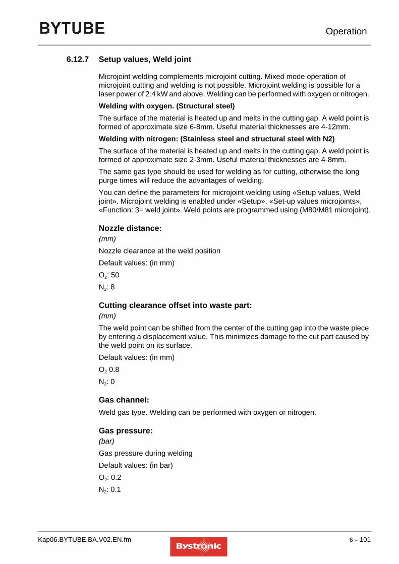
Operation
6.12.7 Setup values, Weld joint
Microjoint welding complements microjoint cutting. Mixed mode operation of microjoint cutting and welding is not possible. Microjoint welding is possible for a laser power of 2.4 kW and above. Welding can be performed with oxygen or nitrogen. Welding with oxygen. (Structural steel)The surface of the material is heated up and melts in the cutting gap. A weld point is formed of approximate size 6-8mm. Useful material thicknesses are 4-12mm.Welding with nitrogen: (Stainless steel and structural steel with N2)The surface of the material is heated up and melts in the cutting gap. A weld point is formed of approximate size 2-3mm. Useful material thicknesses are 4-8mm.The same gas type should be used for welding as for cutting, otherwise the long purge times will reduce the advantages of welding.You can define the parameters for microjoint welding using «Setup values, Weld joint». Microjoint welding is enabled under «Setup», «Set-up values microjoints», «Function: 3= weld joint». Weld points are programmed using (M80/M81 microjoint).
Nozzle distance:(mm)Nozzle clearance at the weld positionDefault values: (in mm)O2: 50N2: 8
Cutting clearance offset into waste part:(mm)The weld point can be shifted from the center of the cutting gap into the waste piece by entering a displacement value. This minimizes damage to the cut part caused by the weld point on its surface.Default values: (in mm)O2 0.8N2: 0
Gas channel:Weld gas type. Welding can be performed with oxygen or nitrogen.
Gas pressure:(bar)Gas pressure during weldingDefault values: (in bar)O2: 0.2N2: 0.1
Kap06.BYTUBE.BA.V02.EN.fm 6 – 101

Operation
Laser power:(%)Laser power during weldingDefault values: (in %)
Weld time:(s)Time spent by the laser beam making the weld point on the materialDefault values: (in s)
Overcut:(mm)The overcut is the cutting distance traveled beyond the programmed weld joint before the laser makes the weld joint.Default values: (in mm)O2: 25N2: 6
Reset distance before interrupt:(mm)Restart point before welding interruptionDefault values: (in mm)O2: 0N2: 0
Acceleration factor:(m/s2)Acceleration factor when starting up in the cutting gapDefault values: (in m/s2)O2: 3N2: 3
Laser: 2.4 3.0 4.0O2: 100 85 60N2: 45 35 25
Laser: 2.4 3.0 4.0O2: 0.5 0.4 0.4N2: 1 1 1
6 – 102 Kap06.BYTUBE.BA.V02.EN.fm

Operation
CW gas ramp:(s)CW gas ramp when starting up in cutting gapDefault values: (in s)O2 0N2: 0
6.12.8 Nozzle cleaning setup values
Manual initiation of nozzle cleaningEnable «Service» and if applicable «Halt» to initiate this function. Once the service position has been reached, the cleaning process can be started by selecting the «Service» function again.
Number of cleaning passesThe nozzle is cleaned by traveling x number of times over the brass brush. The cutting gas is shut off during the cleaning process. The nozzle is recalibrated on the calibration plate after cleaning.
Clean at end of cutting plan:0 = offThe nozzle is not cleaned at the end of the cutting plan.1 = onThe nozzle is cleaned at the end of the cutting plan, before moving to the reference position.
Clean after x pierces:0=offThe nozzle is not cleaned while working through a cutting plan.»0=onThe nozzle is cleaned after performing the number of piercing actions specified in the parameter.
Distance Z-reference - cleaning height:(mm)This value is used to define how far the cutting head is lowered from the reference position in order to clean the nozzle.
Kap06.BYTUBE.BA.V02.EN.fm 6 – 103

Operation
6.12.9 Setup values, adaptive optics 1
Operating mode (BYSPEED):0=Fixed: (Service mode BYSPEED)
Fig. 6.12 -1 Operating mode 0
The defined mirror deformation remains constant over the entire cutting range irrespective of the beam length. The focal position is not automatically re-corrected in this operating mode. A mirror deformation of 0µm for the adaptive mirror corresponds to a flat mirror. The technically feasible adjustment range of -40µm to +40µm moves the focal point by about 20mm.If the operating mode is tested by firing into a Plexiglas cube, the mirror deformation must definitely be set to 0µm.1=Focus correction+Focal position: (Default mode BYSPEED)
Fig. 6.12 -2 Operating mode 1
A valid characteristic curve must exist before operating mode 1 can be used. In operating mode 1, the focal position, which normally appears in the cutting parameters merely for information purposes, is adopted as a parameter. In this mode, the focal position no longer needs to be adjusted manually at the cutting head when the material is changed, but is adjusted automatically by the adaptive optics. The total deformation is calculated from the position-dependent characteristic-curve value (characteristic curve) plus an OFFSET. This offset is a function of the characteristic values for focal length, focal position and nozzle distance, which are obtained from the given cutting parameter file. The calculation is performed automatically.
A. Mirror deformationB. Characteristic curveC. Beam length
C
A
B
A. Mirror deformationB. Characteristic curveC. Beam length
C
AB
6 – 104 Kap06.BYTUBE.BA.V02.EN.fm

Operation
Operating mode (BYSTAR / BYSPRINT / BYTUBE):0 = FixedThe mirror deformation specified by the parameter «Fixed mirror lift for operating mode= 0» is adopted.
Fig. 6.12 -3 Operating mode 0
Legend:
NOTE
1 = Focus correctionIn operating mode 1, mirror deformation correction is used to compensate over the cutting range for the variation in focal position as a function of beam length. These mirror deformations are saved in the five characteristic curve points.Operating mode 1
Legend:
NOTE
2 = Focus correction + focal positionIn operating mode 2, the «cutting head focal position» (focal length) parameter (dependent on cutting head) given in the «Adaptive Optics set-up values» (Setup) merely needs to be added manually to the focal point reference position (focal position at nozzle tip) at the cutting head. All necessary settings and corrections are then performed by the CNC.
A. Mirror deformationB. Characteristic curveC. Beam length
C
A
B
No characteristic curve is followed.
A. Mirror deformationB. Beam length
A
B
Follows the characteristic curve
Kap06.BYTUBE.BA.V02.EN.fm 6 – 105

Operation
The CNC takes into account the following values:
• «Focal length» from the cutting head characteristic data?(Param menu)
• «Focal position» from the cutting head characteristic data?(Param menu)
• «Nozzle distance» from the currently enabled parameter set (Param menu)
• «Deformation/focus change» lens ... (Setup menu)
• «Cutting head focal position» lens... (Setup menu)
• Mirror deformation to be generated online from characteristic curve (Setup menu)
Fig. 6.12 -4 Operating mode 1
Legend:
NOTE
Fixed mirror deformation for operating mode = 0:This value is used to define the fixed mirror deformation for operating mode 0, for servicing purposes. A negative deformation (< 0mm) produces a concave mirror, a mirror deformation of 0mm generates a flat mirror and a positive deformation (> 0mm) creates a convex mirror.
Characteristic curve:The characteristic curve is used to compensate for variations in the position of the focal point (dependent on the beam property) over the whole cutting range. The Maintenance folder contains more precise details on how to calibrate this compensation curve. The beam length begins 400 mm outside the effective cutting range. Five points on the characteristic curve are taken at regular intervals along the whole beam path. Points 2, 3, 4 and 5 are obtained by applying mirror deformation correction to the focal position characteristic of point 1.
Focal length default setting (BYSPEED):(mm)In order to be able to generate the whole range of focus positions required (dependent on the focal length) using mirror deformation, the negative mirror deformation range must also be included. The «Focal length default setting» is only relevant in operating mode 1.
A. Mirror deformationB. Characteristic curveC. Beam length
C
AB
Follows characteristic curve + focal point corrected
6 – 106 Kap06.BYTUBE.BA.V02.EN.fm

Operation
Lift/Focus change (BYSTAR / BYSPRINT / BYTUBE):(µm/mm)This parameter is defined by the type of adaptive mirror used and by the focal length chosen. It is used by the CNC in operating mode 2, to convert all values dependent on the focal position (mm) into a deformation in mm.
Focal position cutting head (BYSTAR / BYSPRINT / BYTUBE):(mm)In order to be able to generate the whole range of focus positions required (dependent on the focal length) using the mirror deformation, the negative mirror deformation range must also be included. This is done by adding this value to the cutting head reference position. The CNC compensates for this by less deformation. The «Focal position cutting head» parameter is only effective in operating mode 2.
6.12.10 Cut Control setup values
Process monitoring:CutControl monitors the cutting process in CW normal mode. Piercing, pulsing, engraving, pre-burning and macros are not monitored. Monitoring starts after the initial cut and/or after start-up following a «HALT», and ends before the exit cut. Cutting-process parameters such as modulation, corner feed rate etc. are not taken into account. Any change in a CutControl value is only enabled at the next monitoring cycle, which can be forced by «HALT» or a calibration process.Process monitoring is based on the light emitted from the work piece. The emitted light is detected via a mirror by three detectors. The mirror and the detectors are mounted in the sliding piece of the cutting head. The cutting heads are labeled with a CutControl label.CutControl applicationsCutControl is used for the following materials and thicknesses:– Stainless steel 1-12mm thick– Steel 1-6mm thickMeasuring the calibration thresholdThe calibration process is initiated during a good cut in cutting or manual operation by setting the parameter «Calibration during cut» in the «Setup» menu to 1. During calibration, a signal is detected every 20ms and summed to obtain an average value. After a short time (about 2 seconds), the controller displays the average value on the right of the same line. This is the calibration threshold for the material concerned. The value can be measured several times for checking purposes. This value must then be entered manually in the parameter «Calibration threshold Gas channel 2» in the «Param» menu. This calculated value normally does not vary significantly, and so only needs to be checked occasionally.If a different material or a different surface finish is being cut, then a new calibration value must be measured.After calibration, or if cutting is interrupted, the setup value is automatically reset (=0).
Kap06.BYTUBE.BA.V02.EN.fm 6 – 107

Operation
NOTE
CutControl: 0=off, 1=on:Cutting with/without CutControl
Calibration during cutting: 0=off, 1=enable:Measuring the base signal for a good cut in cutting or manual operation.
Guideline values for Calibration thresholds for Bystar, Bysprint und Bytube
Calibration threshold gas channel 1 ( O2 ), and 2 ( N2 ) (display only):Measured base signal of a good cut with gas channel 1 / 2 . Calibration thresholds cannot be overwritten. They are used for displaying the values found from calibration. These values must be entered manually in the parameters and saved.
CutControl cannot be used with an NK nozzle
Material thickness [mm]
Focal length
Stainless steelN2
NozzleStructural steelN2
Nozzle
1 5“ 250-450 Hk15 250-450 Hk152 5“ 250-450 Hk15 250-450 Hk153 5“ 250-450 Hk17 250-450 Hk174 7.5“ 200-450 Hk17 350-450 Hk205 7.5“ 250-500 Hk20 400-700 Hk256 7.5“ 350-500 Hk25 450-1000 Hk258 7.5“ 600-1100 Hk25 1100-1400 Hk3010 7.5“ 850-1150 Hk30 - -12 7.5“ 700-900 Hk30 - -
6 – 108 Kap06.BYTUBE.BA.V02.EN.fm

Operation
6.12.11 Setup values for edge detection with CutControl
More accurate edge detection is achieved by using CutControl. When CutControl is employed, the following steps are performed in addition to capacitive edge detection:
• After capacitive edge detection the machine moves approximately 5 mm beyond the edge of the sheet.
• The laser is switched on with «Detection laser power» and «Detection gas pressure»
• The laser is moved backwards until the laser beam touches the sheet edge
• The machine stops in this position and saves the detected reading found using Cut Control
• The machine travels to the next edge detection location
Detection with CutControl:(0 = off, 1 = on)Edge detection with Cut Control on/off
Detection feed rate:(mm/min)Feed rate during detection
Detection nozzle distance:(mm)Optimum nozzle distance for an accurate signal
Detection Gas channel:Gas type for detection
Detection Gas pressure:(bar)Gas pressure during detection
Detection Laser power:(%)Percentage laser power during detection
Detection level:Minimum signal level for sheet detection. An error can arise if the detection point lies on a support grating.
Kap06.BYTUBE.BA.V02.EN.fm 6 – 109

Operation
6.13 DATA menu
This menu is displayed by pressing the <Data> button
6.13.1 Editor (DinEdit)
The <S1> button opens the <DinEdit> program, a standalone editing program. To highlight that this program is not the MMC, its start-up screen displays a graphic with the label "DinEdit". A cutting plan can be displayed graphically or as NC code.
Pressing the <Editor> button opens the Editor program DinEdit.
Pressing the <Data> button opens the Parameter Editor. This tool allows you to import a process parameter file, edit process parameters or create a personal process parameter file. Pressing the <Explorer> button opens Windows Explorer.
6 – 110 Kap06.BYTUBE.BA.V02.EN.fm

Operation
6.13.1.1 DATA graphic
The cutting plan currently selected or being edited is displayed graphically. The <Graphic> application displays the cutting plan in full.Simulation(Not enabled yet)Select contour(Not enabled yet)Zoom functionThe zoom functions <Zoom in>, <Zoom out> and <Zoom 100%> are displayed in the toolbar when the DinEdit program is started The size of the graphic can also be changed from the PC or machine keyboard using the <+>/<-> buttons.Zoom inEnlarges the screen contents currently displayed. Zoom outReduces in size the screen contents currently displayed.Zoom 100%The screen contents are set to the default size.Move
The on-screen graphic can be moved both horizontally and vertically using the arrow keys on the machine or PC keyboard.
Entry in Job ListA modified cutting plan must be saved. After saving, the <Entry in Job List> button is enabled in the toolbar. Pressing this button inserts the cutting plan directly in the Job List.
Kap06.BYTUBE.BA.V02.EN.fm 6 – 111

Operation
New NC prog.This function opens an empty editing window for creating a new cutting plan.
Select NC prog.A dialog box opens in which you can browse through all the drives, directories and files, optionally selected by file extensions, in order to select an NC program for editing.
Save NC prog.NC programs, with any modifications, can be saved under the same name or a new name.
6.13.1.2 DATA Editor
The Editor allows you to edit and create values, comments and, if applicable, parameter file details in the NC program via the CNC or PC keyboard. The Editor works as a standalone program and can only be started when the MMC is running. It is divided into six address columns.
6 – 112 Kap06.BYTUBE.BA.V02.EN.fm

Operation
AddressesThe editor works on the basis of the code blocks.The G functions are preparatory functions.Columns X and Y contain coordinates. Column R is reserved for radii.When you close the editor, the plausibility is checked automatically. You yourself, however, must check whether the data entered can also be worked through in practice. Look out in particular for– typing errors in the numbers for the M functions and G functions– modified positioning data that causes the axes to hit the end stops.Check the edited plan using <GRAPHIC>, to highlight any obvious (typing) errors in the graphic."N" addressConsecutive line numbering. The lines are renumbered if a line is inserted. "G" addressThe table below shows the authorized numbers and their meaning. The numbers can be overwritten and deleted. Missing address numbers are inherited."X" and "Y" addressCoordinates or dimensions. These values can be overwritten, deleted or inherited."R" addressCircle, corner or tube radius. These values can be overwritten, deleted or inherited."I" and "J" addressCenter of circular arcs. The values can be overwritten, deleted or inherited. The program only jumps to these columns if a radius or circular arc has not been specified."+" addressAuxiliary functions. A number of different auxiliary functions are possible depending on the G functions. These appear in one line in the order entered and in the same column, with letter and value. These values can be overwritten, deleted or inherited.
Kap06.BYTUBE.BA.V02.EN.fm 6 – 113

Operation
Go to NThis function is used to jump to a specified N address number.ModifyThe data in the currently selected field can be changed.Marking(Not enabled yet)Copy(Not enabled yet)Insert a new data recordEditing function for inserting a block.Inserts an empty block at the required position.DeleteEditing function for deleting a block.The blocks from line number Nxxxx to Nzzzz are deleted.DiversThis function contains the zoom functions and a function for updating the line numbers.Zoom 100%The screen contents are set to the default size.Zoom inEnlarges the screen contents currently displayed. Zoom outReduces in size the screen contents currently displayed.Updating of the N-CodeThe line numbers of a modified NC program are listed in ascending order.
6 – 114 Kap06.BYTUBE.BA.V02.EN.fm

Operation
6.13.1.3 Table of defined addresses
NOTE
Address contents not included in the table are not defined and are ignored by the controller. Thus unexpected results can occur with typing mistakes.No practical applications for the address Q are currently known of for the Bystronic machines.
Code Meaning Format Units
A Job number 05
C Angle of rotation of figure in degrees +0320 (degrees)
F Feed rate during interpolation 05 (mm/min)
G Preparatory function (G address or G function) 02
H Number of program passes 05
I X coordinate of circle center point + 0520 (mm)
J Y coordinate of circle center point + 0520 (mm)
L Subprogram number 03
M Auxiliary function 02
N Block number 06
O Rotation code (0=0°, 1=90°, 2=180°, 3=270°; only after G52)
03
P Program number (main prog.) / Figure number (subprog.)
05
Q Piercing time different from parameter 0210 (s)
R Radius 0520 (mm)
S Macro no.
U Rotation coordinate + 0320 (degrees)
X X coordinate (main prog.) / X dimension (subprog.)
+ 0520 (mm)
Y Y coordinate (main prog.) / Y dimension (subprog.)
+ 0520 (mm)
Z Z lift-off height different from parameter 0520 (mm)
If you have selected Inches for the dimensional units under <SETUP>, <Machine setup values>, the format for addresses I, J, R and X, Y, Z (+) reads 0430 inches.
Kap06.BYTUBE.BA.V02.EN.fm 6 – 115

Operation
The Bytube software module in Bysoft calculates Z for the additional lift-off height prior to tube rotation. The calculated Z dimension depends on the tube dimensions.
6.13.1.4 G functions– For those assigned addresses enclosed in brackets, the controller adopts the
default value if you have not entered any numerical values from the keyboard.– For all other assigned addresses, numerical values must be entered from the
keyboard, otherwise machining may be terminated in some circumstances (Error message "memory error").
– Entering the address M is optional.
Notes on the individual functionsFor address G0, the controller takes the feed rate from the <Positioning speed> parameter.For addresses G1 to G3, the controller takes the feed rate from the Cutting, Engraving or Welding parameters depending on the machining mode (G10 – G12).It computes the actual feed rate from this set value, taking into account– <Acceleration factor>– <Dynamic factor> and <Corner tolerance>, if these parameters are enabledFor address G11 (Engrave) and M16 (Reduced power), the controller uses fixed values for the following special parameters, irrespective of the defined values:
Address O with rotation code Address C with amount in degrees
YO
XO
Y
X
O1
XC
YC
Y
X
C57.27
Critical angle dwell time 175
Corner tolerance 0.08
Acceleration factor 1
Acceleration factor, lead-in 1
6 – 116 Kap06.BYTUBE.BA.V02.EN.fm

Operation
Summary of G functionsThe following list summarizes the G functions.
6.13.1.5 Table of G functions
Code Assigned addresses Description
0 XY (U)(Z) Positioning
1 XYM Straight path
2 XYRM Circular arc, clockwise (start, end and radius)
3 XYRM Circular arc, counterclockwise (start, end and radius)
2 XYIJM Circular arc, clockwise (start, end and center)
3 XYIJM Circular arc, counterclockwise (start, end, center)
4 M Machine command without moving the axes (e.g. G0 X50 Y100 G4 M1)
(10) S Cutting (default value, only include in program when switching back from engraving or welding). A process macro is enabled when G10 is used with S1 or S2.
11 Engraving
12 Welding
(17) Machining of work pieces in the XY plane (default value, only include in program when switching back from rotary axis)
20 Machining circular tubes using the rotary axis
23 Machining rectangular tubes using the rotary axis
28 XYL(P) Start of subprogram for single figure
29 XY(P)H(A)(F)(Q) Start of main program (X and Y are required for edge detection)
40 Tool-radius compensation off
41 Tool-radius compensation left
42 Tool-radius compensation right
51 XY(R)(U)(Z) Coordinate of main program origin
52 XY(R)(Z)LO(T)C Coordinate of subprogram origin (referred to the origin of the main program), O and C are mutually exclusive
85 XYRU U-axis, corners, no X movement or proportional movement
(R is the calculated rounding radius, U is the destination plane)
Kap06.BYTUBE.BA.V02.EN.fm 6 – 117

Operation
86 XYRU U-axis, corners, approaching at an angle, leaving straight
(R is the calculated rounding radius, U is the destination plane)
87 XYRU U-axis, corners, approaching straight, leaving at an angle
(R is the calculated rounding radius, U is the destination plane)
98 End of subprogram
99 End of main program
Code Assigned addresses Description
6 – 118 Kap06.BYTUBE.BA.V02.EN.fm

Operation
6.13.1.6 M functions
Code Meaning Validity Action before or after G function
1 Scheduled interrupt if <STOP SELECT> is enabled
block after
4 Machining on global before
5 Machining off global after
6 Lowered positioning on global before
7 Lowered positioning off global after
8 Cooling water on global / on the fly
before
9 Cooling water off global / on the fly
after
10 Sensing off global before
11 Sensing on global after
12 Pulsed mode, cutting on global before
13 Pulsed mode, cutting off global after
14 Pulsed mode, piercing on global before
15 Pulsed mode, piercing off global after
16 Reduced power M4 to M5 before
17 Dwell block before
18 Piercing without piercing time, taking into account the parameter <Gas ramp, CW piercing/cutting> and <Acceleration factor, lead-in>
block before
19 Interrupt auxiliary signal on block before
20 Interrupt auxiliary signal on block after
21-28 Bysmart deposit locations
30,32 User functions, enable block / on the fly
before
31, 33 User functions, enable block / on the fly
after
40, 42 User functions, acknowledgement block before
41, 43 User functions, acknowledgement block after
50, 52 User functions, acknowledgement / <CONT> block before
51, 53 User functions, acknowledgement / <CONT> block after
80 Microjoint after
Kap06.BYTUBE.BA.V02.EN.fm 6 – 119

Operation
6.13.1.7 Validity of M functionsBlockThe function is active for the block containing the function.global The function is active from the block containing the "On" command up to the block containing the "Off" command.on the flyThe function is coupled to an external signal that can also be received while a G address is being executed (see next section "User functions" for an example).User functionsThe user functions are provided for coordinating customized processes and devices with laser machine operation.Numerous different applications are conceivable, but just a few examples are given below as illustration:enableThese functions work in a similar way to the functions "Cooling water on/off"(M8 and M9)– In combination with blocks G1 to G3, these M functions work on the fly. M
numbers that are even work before the block, odd numbers after the block.– Before M4, after M5 and in combination with G4, these M commands work
statically.Example of the use of an on-the-fly M function: A clamping device for a welding task is fitted with proximity switches in order to prevent collisions with the machining head. If the head approaches, the clamping device is released, if it moves away again, clamping is applied.AcknowledgementThese functions work in a similar way to "Interrupt auxiliary signal".They always cause an interrupt in the machining process. Machining is resumed once the acknowledgement signal is received. If necessary during cutting, the cut is interrupted and the head raised. M42/43 cause the tool to be raised first to the maximum Z-dimension.Example of the use of an M function with acknowledgement: External drill. The drill outputs the acknowledgement signal on completing the drilling action.Acknowledgement or <CONT>These functions work in a similar way to "optional stop", but are dependent on <STOP SELECT>.They always cause an interrupt in the machining process. Machining is resumed once the acknowledgement signal is received or if you press the Acknowledge button. If necessary during cutting, the cut is interrupted and the head raised. M52/53 cause the tool to be raised first to the maximum Z-dimension.Example of the use of an M function with acknowledge or <CONT>: External quality control of unattended machining using temperature measurement. If the maximum temperature is exceeded, machining is interrupted until you press acknowledge.
6 – 120 Kap06.BYTUBE.BA.V02.EN.fm

Operation
6.13.2 Explorer (Windows Explorer)
The Windows 95 Explorer is started from this toolbar. It is used in particular for copying, moving, renaming, locating and deleting files. Familiarity with Windows is assumed.
6.13.3 Param. (Parameter Editor)
Parameters can be created, edited and saved using this tool. These do not have any effect on the cutting process in hand, however. This data is not sent to the CNC.
Kap06.BYTUBE.BA.V02.EN.fm 6 – 121

Operation
6.14 Fault, error and system messages
6.14.1 System error status
The system error status indicates faults or system errors; the system is not ready for operation.
6.14.2 System warnings
The system warnings indicate faults or system errors; the system is ready for restricted operation.
WARNINGIn accordance with electrical engineering regulations, work must only be undertaken on the machine’s electrical equipment by specialist electricians.
!
System message Cause ProcedureController not ready Intermediate circuit voltage
can no longer be switched on.Check fuse switch F2
Reset CPUDrives not ready Servo failure. Turn off machine and turn it
back on.Emergency off external
One of the < EMERGENCY STOP> buttons has been activated
The machine safety circuit is open
Turn the mushroom-head button to release it, switch the resonator control off with the key-operated switch and press < RESET> on the PPC
Drives locked Safety gate open
Key-operated switch turned to left
Close safety gate
Turn key-operated switch to the right
System message Cause ProcedureLubricant container empty
The central lubrication container is empty. No lubrication cycle taking place.
Fill lubricant container
Lubricating cycle timeout Lubrication cycle taking too long.
Test drive and reset CNC
Delay motor temperature too high
Motor protection. <STOP WORK> is set automatically or after a while <Halt>. 'Stop before...' cannot be cleared with <CONT>.
Wait until motor cools down and continue by pressing <CONT> or cancel by pressing <ABORT> and move to reference.
6 – 122 Kap06.BYTUBE.BA.V02.EN.fm

Operation
Warning: Bypos error An adaptive lens error in Mode 0=Fix only causes this warning and no Emergency stop.
Emergency operation. After correcting the Bypos error activate Mode 1 or 2.
Warning: inaccurate sampling
The required accuracy was not achieved in edge detection with check points. In subsequent machining the values with the smallest deviation are used.
Machining is automatically resumed after a 5 second pause. The process can be terminated during this interval if the required tolerance is not achieved.
Gas warning Difference between existing and required gas pressure is less than 1 bar.
Check gas supply and replace gas bottle concerned.
W-axis warning:frequency outside tolerance
The free-running frequency of the capacitive W axis control does not lie in the expected frequency range before calibration.
Call Bystronic Customer Services
Warning: park crossjet The crossjet is in its operating position, although not currently in use.
Park crossjet
CutControl: plasma formation
The CutControl has detected plasma
Adapt parameters (not essential)
CutControl: cutting problems
The CutControl has detected cutting problems (plasma).
Adapt parameters, clean head (not essential)
PLC transport fault Operating with sheet store: The PLC (SPS) transport system is reporting an error with transportation of sheets to and from the store
Correct the transport system fault.
System message Cause Procedure
Kap06.BYTUBE.BA.V02.EN.fm 6 – 123

Operation
6.14.3 Waiting states
Waiting states either terminate themselves, are terminated by the PLC signal or can be ended by pressing < CONT> .
System message Cause ProcedureWaiting for stops Mechanical stops (where
they exist) are being retracted.
Waiting for material Continuing with machining without automatic table interchange
Continue machining by pressing < CONT>
Cancel machining by pressing < ABORT>
Press < MatPos> on the console
Waiting for stacking Operating with BYSORT, stacking plan is being transferred.
In the case of repeated transfer errors the process can be cancelled by pressing < ABORT> .
Waiting for cutting data Controller is waiting for the NC program.
Move to reference Machine moving to reference
In manual mode this message appears as a warning before the machine moves to reference.
Start the movement by pressing < CONT>
Cancel the procedure with < ABORT> .
Move to zero point Machine is moving to zero point.
In manual mode this message appears as a warning before the machine moves to zero point.
Start the movement by pressing < CONT>
Cancel the procedure with < ABORT> .
Optional stop M01 The machine is standing at a stop that has been scheduled using M1, if the < STOP SELECT> function is activated.
Continue machining by pressing < CONT>
Cancel machining by pressing < ABORT>
Waiting for additional signal M19/M20
The machine is standing at a scheduled stop. (M19/20,M40 - M53)
Clear via PLC or manually.
Continue machining by pressing < CONT>
Cancel machining by pressing < ABORT>
Restart seam detection Tube handler is trying to detect seam.
only with optional tube handler
Wait for upper seam detector
Seam detector is being raised only with optional tube handler
Wait for end of laser manual operation
The laser is still in manual mode at Start Work, or when enabling CNC manual operation
Switch laser to CNC operation using laser controller.
6 – 124 Kap06.BYTUBE.BA.V02.EN.fm

Operation
6.14.4 Interruptions (Stop)
Interruptions, stops are triggered using the machine keyboard and must always be cleared by pressing <CONT>, external <CONT> or <ABORT>
Wait for laser to be ready The laser is still powering up at Start Work, or when enabling CNC manual operation
Wait or terminate Start Work with <ABORT>. Manual operation is not possible without laser functions
System message Cause Procedure
System message Cause ProcedureStop service This message appears when
the axes are standing in the service position.
<CONT>to continue or <ABORT> to terminate
Interruption stop This message appears when the axes are standing still due to a <HALT>.
<CONT>to continue or <ABORT> to terminate
Stop cycle This message appears before each sheet in the reference position.
<CONT>to continue or <ABORT> to terminate
Stop part This message appears when the axes are standing at the zero point of the next part.
<CONT>to continue or <ABORT> to terminate
Stop work This message appears when the axes are standing still before or after the next step in the work.
<CONT>to continue or <ABORT> to terminate
Stop at zero point This message appears if < HALT> was initiated during < Stop Cycle>. The axes stop at the zero reference point of the cutting plan.
The zero reference point can be offset in manual operation.
<CONT>to continue or <ABORT> to terminate
Stop at contour lock-on This message appears after a restart with contour lock-on, as a prompt to move to the restart point manually.
After selecting the restart point:
<CONT>to continue or <ABORT> to terminate
Single step This message appears when the program is being worked through in single steps (program line by line)
<CONT>to continue or <ABORT> to terminate
Kap06.BYTUBE.BA.V02.EN.fm 6 – 125

Operation
6.14.5 Confirmations
Confirmations are protective measures for man and machine and must always be cleared by pressing <CONT>, external <CONT> or <ABORT>.
6.14.6 Emergency stop
Emergency stops terminate cutting and manual mode. They have to be cleared by pressing < ABORT> . A Restart is possible in certain cases.
System message Cause ProcedureForced continue Confirmation by pressing <
CONT> of:
Waiting for material
Optional stop M01
Waiting for additional signal M19/M20
<CONT>to continue or <ABORT> to terminate
Inverse work not possible
If the entire plan has been created as a single figure then the INVERS key cannot be used.
Program individual figure segments as sub-programs
Axis movement OK? Confirmation of movements in manual mode:
Moving to reference position
Moving to zero point
Axis movements in auto. Configuration
<CONT>to continue or <ABORT> to terminate
System message Cause ProcedureEmergency off internal <STOP> has been activated
the machine’s safety circuit has tripped
Press <ABORT> on the MMC.
Emergency off external one of the <EMERGENCY STOP> buttons has been activated
the machine’s safety circuit has tripped
Turn the mushroom-head button to release it, switch the resonator control off with the key-operated switch and press <RESET> on the PPC.
Stop, point of aim beyond cutting zone
The target of the positioning process displayed is outside the cutting range. (e.g. manual movement)
Cancel and Restart from the beginning.
6 – 126 Kap06.BYTUBE.BA.V02.EN.fm

Operation
Stop by laser Laser not ready Resonator pressure switch has triggered
Cooling water flow rate too low
Wait for «Laser Ready» on the laser controller display or, if you do not need the laser, switch it off using the key.
Check compressed air supply
Check cooling systemStop by crash There has been contact
between the nozzle and the sheet, or the nozzle is dirty
The tactile ring sensor has come off.
Check the nozzle distance, clean the nozzle.
Replace the ring sensor.
Stop by limit switch X+ Limit switch X+ has been overshot, machining aborted (e.g. due to coordinates outside work surface)
Clear with <ABORT>, restart not possible. Move away from the limit switch in manual mode.
Stop by limit switch X- Limit switch X- has been overshot, machining aborted (e.g. due to coordinates outside work surface)
Clear with <ABORT>, restart not possible. Move away from the limit switch in manual mode.
Stop by limit switch Y+ Limit switch Y+ has been overshot, machining aborted (e.g. due to coordinates outside work surface)
Clear with <ABORT>, restart not possible. Move away from the limit switch in manual mode.
Stop by limit switch Y- Limit switch Y- has been overshot, machining aborted (e.g. due to coordinates outside work surface)
Clear with <ABORT>, restart not possible. Move away from the limit switch in manual mode.
Stop by limit switch Z+ Limit switch Z+ has been overshot, machining aborted (e.g. due to position outside work surface)
Clear with <ABORT>, restart not possible. Move away from the limit switch in manual mode.
Stop by limit switch Z- Limit switch Z- has been overshot, machining aborted (e.g. due to position outside work surface)
Clear with <ABORT>, restart not possible. Move away from the limit switch in manual mode.
Stop by axis limitation, bridge
The bridge has crashed and interrupted the safety circuit.
Move the bridge by hand out of the limit position (mechanical knob-operated switch). Then reset the CPU and bridge servo.
Stop by axis limitation, carriage
The carriage has crashed and interrupted the safety circuit.
Move the carriage by hand out of the limit position (mechanical knob-operated switch) Then reset the CPU and carriage servo.
System message Cause Procedure
Kap06.BYTUBE.BA.V02.EN.fm 6 – 127

Operation
Stop by gas jet error The existing gas pressure is lower than required
Clear with <ABORT> and change the gas bottle concerned.
Stop since crossjet not in position
The crossjet has been torn off Clear with <ABORT> and change the crossjet..
Stop due to W-axis frequency error
The frequency of the capacitive W axis control is too low. The lowering operation has been terminated.
Clear with <ABORT> and check the cutting head for moisture in particular.
Stop because controller not ready
PLC (CNC) is no longer ready (fault)
Clear with <ABORT>
Stop because drives not ready
Servo failure. Turn off machine and turn it back on.
Stop by safety cirquit failure
Safety gate open
Key-operated switch turned to left
Clear with <ABORT> and check the safety gates and the key-operated switch.
Stop by Watchdog, stop - fail
An axis is moving or was moved when safety circuit open.
Turn off machine and turn it back on.
Stop by Watchdog, CNC - fail
A software error caused CNC to crash.
Turn off machine and turn it back on.
NC-Stop: error at switching over to virtuel machine 01 - 03:
The switchover to another virtual machine is only possible at the reference and outside cutting or manual mode.
Clear with <ABORT> and move the machine to reference.
01 = CNC at cutting02 = CNC in manual mode03 = CNC not in reference pos.Stop by plausibilitytest …
During machining the actual and target values of the position of the axes are compared before each movement. If the current position deviates by more than 5 mm from the coordinates of the plan then machining is aborted. A faulty sensor, card or software could be the cause.
The axis/axes responsible and the location are also given.
Check the cutting plan
Call Bystronic Customer Services. A restart is only possible under certain circumstances.
… in X at approaching reference… in Y at approaching reference… in X/Y at approaching reference… in X at zero point… in Y at zero point
System message Cause Procedure
6 – 128 Kap06.BYTUBE.BA.V02.EN.fm

Operation
… in X/Y at zero point… in X at piercing in… in Y at piercing in… in X/Y at piercing in… in X at piercing out… in Y at piercing out… X/Y at piercing outStop by plausibility test in Z, sensor off inadequate
An attempt has been made to cut rectangular tubes with < Sensor off> .
Start from the beginning with sensor activated (Setup).
Stop by plausibility test in Z, not calibrated
Lowered without previous calibration.
System error!
Recalibrate
Call Bystronic Customer Services
Stop by plausibility test in Z, stopping distance too little
The calculated braking distance is greater than tne current lifting height Causes:
Axis is incorrectly configured
Detection frequency fault
Call Bystronic Customer Services to check the configuration.
In general operation is no longer possible.
Stop by plausibility test in Z, material detected at reference
Detection frequency fault. Causes:
mechanical damage to cutting head
poor assembly
Moisture in the plug connections
Call Bystronic Customer Services
Stop from CutControl: no sheet edge detected
When using Cut Control for accurate edge detection, no edge could be detected in the area of previous capacitive detection.
Check Cut Control head and detection setup, and repeat procedure.
System message Cause Procedure
Kap06.BYTUBE.BA.V02.EN.fm 6 – 129

Operation
6.14.7 Aborting a cutting process
Cutting process cancellations have to be cleared by pressing <ABORT>. A restart is never possible.
System message Cause ProcedureNo beginning of cutting plan
Faulty plan Correct the cutting plan in BYSOFT or in the data editor
Read in the plan againNo end of cutting plan Faulty plan Correct the cutting plan in
BYSOFT or in the data editor
Read in the plan againInvalid subprogram number
Faulty plan Correct the cutting plan in BYSOFT or in the data editor
Read in the plan againCutting plan dimensions too large
Faulty plan Correct the cutting plan in BYSOFT or in the data editor
Read in the plan againConverted cutting plan too large
LCC file too large Divide the cutting plan up and read it in again
Faulty cutting plan structure
Error in precalculation of the processing sequence due to a reading error or a data error in the plan.
Correct the cutting plan in BYSOFT or in the data editor
Read in the plan again
Incremental buffer overflow
Software fault Inform Bystronic Customer Services
Flat cut: chuck in working position
A plan for flat machining was started, although the chuck is still installed. The operation is interrupted.
Terminate the start procedure with <ABORT>.
Tube cut: chuck swivelled away
A plan for rotary machining was started, although the chuck is not yet installed. The operation is interrupted.
Terminate the start procedure with <ABORT>.
Sheet count = 0 The value for the letter H in plan is 0.
Machining is interrupted.
Modify the number of runs in <Job Detail> under <Job List> and send the program to the CNC again (modification also possible using the "H" code under <DATA>or BYSOFT).
Shuttle table active During machining the < Waiting for material> position was skipped either intentionally with <CONT> or as a signal error. However the release test showed that the <Shuttle table active> signal is still displayed.
Terminate machining with <CONT> or <ABORT> and start machining process again. A restart is not possible.
6 – 130 Kap06.BYTUBE.BA.V02.EN.fm

Operation
6.14.8 Adaptive lens error
Adaptive lens errors terminate cutting and manual mode. They have to be cleared by pressing <ABORT> . A Restart is possible in certain cases.
System message Cause ProcedureBypos: Timeout during transmission
The BYPOS is not switched on
The serial link is broken
The SERCOM is not adjusted to the adaptive lens
Switch the adaptive lens on
Check the serial link
Call Bystronic Customer Services
Bypos: UART parity error
There is a fault with the serial link
Check the serial link
Call Bystronic Customer Services
Bypos: Protocol error Poor serial link (a message has been wrongly communicated three times)
CNC and adaptive lens have gone out of phase
Check the serial link
Faulty manipulation, start the process again from the beginning
Error of the Bypos control
Internal error in the adaptive lens. Transfer or status errors of the adaptive lens bring about an Emergency stop
Clear this error message with <ABORT>. A detailed error message then appears so that conclusions can be drawn about the exact cause.
Call Bystronic Customer Services
Bypos voltage 1/2 not ready
The Bystronic Bypos device is not ready or has failed
Call Bystronic Customer Services
Kap06.BYTUBE.BA.V02.EN.fm 6 – 131

Operation
6.14.9 Transport system error
Transport system errors can occur when operating with sheet store connected. They lead to termination of the cutting operation. They usually have to be cleared by pressing <ABORT> . A restart is never possible.
6.14.10 MMC DNC error message
Some of the DNC messages have a modular structure. Two text blocks may appear one after the other in the system line. First there is a supplementary text (if one exists). The DNC error always comes at the end.
System message Cause ProcedurePLC transport fault, serial number
The transport system is signaling a general fault.
Check the transport system.
PLC transport sequence error, serial number
The transport system is acknowledging a «transport to» with an incorrect sequence number.
Unload the shuttle tables and start the cutting operation again.
System message CauseTime-Out During communication the time limit for receiving a character
was reached.EOT During communication the EOT control character was
received unexpectedly.File error The MMC cannot create, read or write temporary file, which
the MMC needs to do for temporary data storage.Unknown DNC-Error An unknown error occurred during communication.DNC interface in use The requested COM port is already in use for another DNC
communication application.PGM aborted Data transfer/upload terminated by the MMC with EOT.No answer Receiver (e.g. CNC) not responding to the ENQ call.Wrong answer received The first six characters of the response from the receiver (e.g.
CNC) do not match the response format.Wrong character received
Unexpected characters were received during DNC protocol (e.g. wrong control character during protocol)
Wrong Block Check number
The calculated block checksum does not equal the received checksum.
Wrong block assign Assignment of block size, number of blocks and start block for program download is wrong. Calculated start point in file is larger than the file itself.
DNC connection retention. --> <CTRL+F9> to continue
The MMC could not establish a connection with the CNC at start up, and is now running OFFLINE. No data transfer with the CNC is possible. If the CNC is re-enabled, communication with the CNC can be resumed using the key combination < CTRL+F9> . An MMC restart is recommended.
6 – 132 Kap06.BYTUBE.BA.V02.EN.fm

Operation
6.14.11 MMC supplementary text to DNC error messages
The supplementary texts are optional and solely indicate the activity for which the error arose. The supplementary texts are generated and managed by the MMC.
6.14.12 Laser status
Actual laser status during laser power up, operation and flooding
System message CauseDelete NC-Programm Delete error for NcProgram command.Material Request to PLC Error when sending the material request to the stock system
(PLC)Material Request to CNC
Error when sending the material request to the CNC
Error when sending NC program
Error when sending an NC program to the CNC.
Parameterfile Error when sending the parameter file to the CNC.Store For a laser machine with stock system: Error when reading the
stock status from the stock system (PLC).
LCS/LASCON3 status MCS/SSI status CauseLaser status: Reset ok
Laser status: apply vacuum
Laser status: fill with gas
Laser status: start turbine
Laser status: switch on energizing
Laser status: LASER OFF
Laser status: RUNNING VACUUM
Laser status: RUNNING GAS
Laser status: RUNNING BLOWER
Status information when powering up the laser (progress display)
Laser status: hand mode Laser status: LOCAL Laser being controlled manually
Laser status: flood Laser status: RUNNING FLOOD
Additional information during switch-off
Kap06.BYTUBE.BA.V02.EN.fm 6 – 133

Operation
6.14.13 Laser errors
The status conditions below only lead to an emergency stop during cutting and if there is a collective error
LCS/LASCON3 status MCS/SSI status CauseLaser error: compressed air, water
Laser error: vacuum punp
Laser error: inverter, turbine
Laser error: energizing
Laser error: gas warning
Laser error: gas error
Laser error: service error
Laser error: WATER/AIR ERROR
Laser error: OVER CURRENT
Laser error: TUBE OUT
Laser error: GAS WARNING
Laser error: GAS MIX ERROR
Laser error: ERROR HV DESK
The error is acknowledged on the laser controller concerned.
Refer to the laser controller specification for error details
6 – 134 Kap06.BYTUBE.BA.V02.EN.fm

Operation
Kap06.BYTUBE.BA.V02.EN.fm 6 – 135

Operation
6 – 136 Kap06.BYTUBE.BA.V02.EN.fm

HAPTER7
7. Maintenance
This chapter describes all the regular inspection and maintenance work on the machine that you can perform yourself after you have participated in a Bystronic Introductory Training Course. A maintenance table and logbook are provided to help you plan and perform this work.
Kap07.BYTUBE.BA.V02.EN.fm 1

Maintenance
Table of contents
7. Maintenance
7.1 Introduction. . . . . . . . . . . . . . . . . . . . . . . . . . . . . . . . . . . . . . . 37.1.1 Safety regulations . . . . . . . . . . . . . . . . . . . . . . . . . . . . . . . . . . . . . . . . . . 37.1.2 Requirements to be met by personnel . . . . . . . . . . . . . . . . . . . . . . . . . . . 47.1.2.1 Operator . . . . . . . . . . . . . . . . . . . . . . . . . . . . . . . . . . . . . . . . . . . . . . . . . . . . . . 47.1.2.2 Technical staff . . . . . . . . . . . . . . . . . . . . . . . . . . . . . . . . . . . . . . . . . . . . . . . . . 47.1.2.3 Maintenance personnel . . . . . . . . . . . . . . . . . . . . . . . . . . . . . . . . . . . . . . . . . . 4
7.2 Maintenance schedule . . . . . . . . . . . . . . . . . . . . . . . . . . . . . . 67.2.1 Tasks to be performed daily. . . . . . . . . . . . . . . . . . . . . . . . . . . . . . . . . . . 67.2.2 Tasks to be performed weekly . . . . . . . . . . . . . . . . . . . . . . . . . . . . . . . . . 67.2.3 Tasks to be performed monthly . . . . . . . . . . . . . . . . . . . . . . . . . . . . . . . . 77.2.4 Tasks to be carried out after 500 hours . . . . . . . . . . . . . . . . . . . . . . . . . . 87.2.5 All tasks to be carried out after 500 hours . . . . . . . . . . . . . . . . . . . . . . . . 87.2.6 All tasks to be carried out after 1000 hours . . . . . . . . . . . . . . . . . . . . . . . 87.2.7 All tasks to be carried out after 2000 hours . . . . . . . . . . . . . . . . . . . . . . . 97.2.8 All maintenance tasks to be carried out every 3000 hours . . . . . . . . . . . 97.2.9 All tasks to be carried out after 7500 hours . . . . . . . . . . . . . . . . . . . . . . 107.2.10 Tasks to be carried out as necessary . . . . . . . . . . . . . . . . . . . . . . . . . . 10
7.3 Maintenance tasks . . . . . . . . . . . . . . . . . . . . . . . . . . . . . . . . 117.3.1 Safety devices . . . . . . . . . . . . . . . . . . . . . . . . . . . . . . . . . . . . . . . . . . . . 117.3.2 Machining axes . . . . . . . . . . . . . . . . . . . . . . . . . . . . . . . . . . . . . . . . . . . 127.3.3 Carriage linear guide . . . . . . . . . . . . . . . . . . . . . . . . . . . . . . . . . . . . . . . 127.3.4 Rack-and-pinion. . . . . . . . . . . . . . . . . . . . . . . . . . . . . . . . . . . . . . . . . . . 137.3.5 Tools . . . . . . . . . . . . . . . . . . . . . . . . . . . . . . . . . . . . . . . . . . . . . . . . . . . 147.3.6 Tube loader . . . . . . . . . . . . . . . . . . . . . . . . . . . . . . . . . . . . . . . . . . . . . . 147.3.7 Cutting head. . . . . . . . . . . . . . . . . . . . . . . . . . . . . . . . . . . . . . . . . . . . . . 147.3.8 Mirror types . . . . . . . . . . . . . . . . . . . . . . . . . . . . . . . . . . . . . . . . . . . . . . 157.3.9 Cleaning the deflecting mirrors and lenses. . . . . . . . . . . . . . . . . . . . . . 157.3.10 Conveyor . . . . . . . . . . . . . . . . . . . . . . . . . . . . . . . . . . . . . . . . . . . . . . . . 18
7 – 2 Kap07.BYTUBE.BA.V02.EN.fm

Maintenance
7.1 Introduction
7.1.1 Safety regulations
This documentation forms the basis for the maintenance of the laser machine.
NOTE
Always power down the machine for performing maintenance work. Protect the main switch with a padlock and store the key in a place inaccessible to unauthorized persons.
• Always power down all electrical or electronic components on which work is being carried out, to avoid danger of electrocution.
• Do not carry out work on gear units until components have cooled down, as there is a risk of burns.
• Always observe the manufacturer’s safety instructions when handling operating resources, particularly gear oil, solvents and grease.
ImportantDo not carry out any maintenance work on the machine until you have read the relevant chapter (incl. Safety)!
WARNINGDanger zone – keep away!Switch off the entire system before performing any inspection or maintenance work. Make sure that all components are disconnected from the power supply. Safeguard machine against unauthorized start-up.
!
Kap07.BYTUBE.BA.V02.EN.fm 7 – 3

Maintenance
7.1.2 Requirements to be met by personnel
Personnel charged with maintaining the machine must have basic training. Maintenance personnel must be able to perform the following work:
• Operation of the machine control system
• Replacement and alignment of mechanical components
• Adjustments to mechanical and electrical equipment
The requirements of the maintenance personnel are differentiated into three levels.
7.1.2.1 OperatorThe operator is responsible for daily cleaning and inspection work on the machine or system.
7.1.2.2 Technical staffTechnical staff are responsible for simple maintenance and inspection work on the machine or system. Work must be performed by trained personnel having attended Bystronic Laser AG’s «Introductory operator training».
7.1.2.3 Maintenance personnelMaintenance personnel must have basic professional training as electricians, mechanics etc.. The requirements to be met by maintenance personnel are high for safety reasons.Maintenance can be performed either by BYSTRONIC’s service personnel or the customer’s own specially trained personnel. BYSTRONIC Laser AG offers special maintenance training for the customer’s own maintenance staff.
7 – 4 Kap07.BYTUBE.BA.V02.EN.fm

Maintenance
Checks and maintenance tasks must be carried out at the intervals specified to ensure that the machine functions perfectly.
Damage occurring to the machine or system as a result of non-observance of the maintenance schedule is excluded from the provisions of the warranty.
TIP
WARNINGFailing to observe the safety instructions in the operating manual may lead to danger to life and limb and damage to the machine.
!
Regular maintenance protects your machine from premature wear and increases its life. The result is maximum availability of your machine and minimal costs for wearing parts.
Kap07.BYTUBE.BA.V02.EN.fm 7 – 5

Maintenance
7.2 Maintenance schedule
7.2.1 Tasks to be performed daily
Tab. 7.2-1
7.2.2 Tasks to be performed weekly
Tab. 7.2-2
Tasks Manual
Laser module:check for mechanical damage. Check warning lamp operating correctly.
See "Laser" Operating manual
Laser controller:check laser power and laser operating pressure See "Laser" Operating manual
Laser cabinet:Check that warning lights are operating correctly
Check "Shutter open" function
Check "Laser ready" function
See "Laser" Operating manual
Cooling unit:check correct cooling-water temperature Supplier documentation HYFRA PEDIA HT
Cutting head:Check lens for soiling, and possibly clean or replace
Check that there are no leaks in the couplings
Check cutting nozzle
Clean cutting head (outside)
Check that sensor working correctly (option)
See "Cutting head" section
Tasks Manual
Laser upper section: inspect for soiling, corrosion and water leaks See "Laser" Operating manual
Laser module: vacuum test See "Laser" Operating manual
Laser lower section, Deltech filter: check for discoloration and possible replacement of filter
See "Laser" Operating manual
Laser lower section, ultra-fine filter: check for clogging, change if necessary
See "Laser" Operating manual
Laser cabinet:Check surge voltage protector viewing window
See "Laser" Operating manual
Crossjet: check oil level in the supply unit See "Supply unit" section
7 – 6 Kap07.BYTUBE.BA.V02.EN.fm

Maintenance
7.2.3 Tasks to be performed monthly
Tab. 7.2-3
HERDING exhaust air filter:Monitor cleaning compartment via rubber cap
Acoustic and visual check of the blow off pulses
Check operation of filter controller
Empty dust collectors
HERDING supplier documentation
Cooling unit:Check air filter, clean or replace if necessary
Clean air-cooled condensers
See "Laser" Operating manual
Supplier documentation HYFRA PEDIA HT
Collecting trays: empty and clean trays -
Pre-coating unit: check for correct operation HERDING supplier documentation
Ultrapac FILTER SYSTEM: check LED display to see if filter change required
See "Supply unit" section
ULTRAPAC supplier documentation
Supply unit: Check differential pressure display (pre-filter)
Empty filter
See "Supply unit" section
Tasks Manual
Control cabinet and laser:all labels in place and legible Operation
Lower section of laser, turboblower (LEYBOLD): check oil level See "Laser" Operating manual
Laser lower section, vacuum pump (SOGEVAC): check oil level See "Laser" Operating manual
Laser lower section, Becker turbine:Check temperature of turboblower bearings during operation
Check LED display on BTC electronic monitoring panel(green range up to 60% O.K.)
See "Laser" Operating manual
Laser: Check contact pin of protective switch on shutter connection tube.
See "Laser" Operating manual
Cooling unit: Check water level in tank See "Laser" Operating manual
Supplier documentation HYFRA PEDIA HT
Kap07.BYTUBE.BA.V02.EN.fm 7 – 7

Maintenance
7.2.4 Tasks to be carried out after 500 hours
Tab. 7.2-4
7.2.5 All tasks to be carried out after 500 hours
Tab. 7.2-5
7.2.6 All tasks to be carried out after 1000 hours
Tab. 7.2-6
Cooling unit / MINISTIL De-ionization unit : check resin cartridge and change if necessary
See "Laser" Operating manual
MINISTIL supplier documentation
Beam path: check machine optics, clean and adjust if necessary, check for leaks (bellows, seals)
See "Optics" section
Carriage, bridge and Z-axis: check limit and emergency switches working correctly
Design and operation
Conveyor: clean and lubricate the hinged-plate conveyor and sprocket
See "Conveyor" section
"Simalube" grease cartridges: check grease level See "Tube loader" section
Base frame: check exhaust-air sector flaps are working correctly -
Tasks Manual
Laser lower section, vacuum pump:first oil change See "Laser" Operating manual
Tasks Manual
Cooling unit: Check air filter, clean or replace if necessary
See "Laser" Operating manual
Supplier documentation HYFRA PEDIA HT
Linear guides: clean and lubricate -
Chain drive on safety gate:clean and lubricate; check tension. -
Tasks Manual
Laser lower section: replace active charcoal filter See "Laser" Operating manual
7 – 8 Kap07.BYTUBE.BA.V02.EN.fm

Maintenance
7.2.7 All tasks to be carried out after 2000 hours
Tab. 7.2-7
7.2.8 All maintenance tasks to be carried out every 3000 hours
Tab. 7.2-8
Supply unit: Replace active charcoal filter
Replace pre-filter
See "Laser" Operating manual
Cooling unit: clean air-cooled condensers See "Laser" Operating manual
Supplier documentation Hyfra Pedia HT
Cooling circuit: clean secondary flow filter See "Laser" Operating manual
Tube loader: grease nipples See "Tube loader" section
Carriage, bridge, Z-axis, base frame:Inspect bellows for damage, replace if necessary
Linear guides and rack-and-pinion: clean and lubricate
See "Linear carriage guide" section
See "Rack-and-pinion" section
Tools: check, clean and grease if necessary See "Tools" section
HERDING exhaust air filter:Check filter elements, deflector, walls of housing for wear
Clean measurement line filter in the unfiltered gas and filtered gas compartment
HERDING supplier documentation
Lance: lubricate guides and spindle
Tasks Manual
Slack in chains: tighten chains if necessary See "Tube loader" section
Laser lower section, vacuum pump: change oil See "Laser" Operating manual
Tasks Manual
Linear guide and drive wheel: grease with Molikote See "Tube loader" section
Cross-rod: grease with Molikote See "Tools" section
Kap07.BYTUBE.BA.V02.EN.fm 7 – 9

Maintenance
7.2.9 All tasks to be carried out after 7500 hours
Tab. 7.2-9
7.2.10 Tasks to be carried out as necessary
Tab. 7.2-10
Cooling unit: change cooling water See "Laser" Operating manual
Supplier documentation Hyfra Pedia HT
Laser lower section, vacuum pump (SOGEVAC): Change exhaust filter
See "Laser" Operating manual
Laser lower section, turboblower (LEYBOLD): Oil change See "Laser" Operating manual
Tasks Manual
Conveyor, gear motor: change oil See "Conveyor" section
Ultrapac FILTER SYSTEM: Change drying agent cartridge as indicated by LED display or after 7500 hrs
Change pre- and post-filter as indicated by LED display or after 7500 hrs
See "Laser" Operating manual
ULTRAPAC supplier documentation
Tasks Manual
Control cabinet, Laser controller: Check vacuum seal See "Laser" Operating manual
Beam path: check machine optics, clean and adjust if necessary See section "Replacing the deflecting mirrors" and "Cleaning the deflecting mirrors and lenses in the cutting head"
Conveyor: clean the hinged-plate conveyor and sprocket, check wiper See "Conveyor" section
Carriage, bridge, Z-axis and base frame:Inspect bellows for damage, replace if necessary
Clean and lubricate rack-and-pinions and guides
See "Linear carriage guide" section
See "Rack-and-pinion" section
Carriage and bridge, Z-axis, limit and emergency switches: check operating correctly
Operation
Lance: clean
Collecting tray: dispose of contents of collecting tray See "Conveyor" section
7 – 10 Kap07.BYTUBE.BA.V02.EN.fm

Maintenance
7.3 Maintenance tasks
7.3.1 Safety devices– Check the resonator daily for mechanical damage, and that the orange LASER
READY warning lamp is working properly.– Check the SERVICE MODE warning lamp whenever the machine is switched to
service mode.– Check monthly that the labels are in place and legible. The types of labels and
their position are listed in the operating manual.
Position of the safety devicesThe laser includes the following safety devices, all of which must be fitted and serviceable.
Fig. 7.3 -1 View of laser module and HV cabinet
After maintenance work, refit all covers that you have removed. Lock the folding doors on the resonator upper section and remove the key.
Please refer to the Laser operating manual for more detailed information.
1. Rear doors of laser cabinet
2. Two fixed covers on laser cabinet (right-hand side identical)
3. Warning lamps
4. Front doors of laser cabinet
5. Six service covers on laser lower section with sound insulation liners (rear side of laser identical)
6. Two folding doors on resonator upper section, lockable with key (rear side of laser identical)
Kap07.BYTUBE.BA.V02.EN.fm 7 – 11

Maintenance
7.3.2 Machining axes
InspectionCheck the bellows at least every 1000 hours for burn marks or other damage. Replace if necessary.
Check the level of the "Simalube" grease cartridges monthly. Replace the empty grease cartridges.
MaintenanceService the rack-and-pinion and the linear guide every 1000 hours.
Environmental protection in waste disposalReplaced parts such as seals, solvents and oil must be disposed of according to the local waste disposal regulations and the environmental protection laws that apply in the country of use.
The mineral oils suggested by Bystronic can be reprocessed, depending on their degree of contamination and degradation. See also the manufacturer’s specification.
7.3.3 Carriage linear guideFig. 7.3 -2
Required material– Grease gun– Motorex 190 EP grease (Bystronic order number 197 1661)
7 – 12 Kap07.BYTUBE.BA.V02.EN.fm

Maintenance
Procedure
1. Move to the zero point.
2. Disconnect machine from the power supply (switch off main power switch). Move the carriage by hand to the center of the bridge.
3. Start with any grease nipple. Each grease nipple must be lubricated with three shots of grease. During lubrication, the carriage must be moved 10 cm in each case (distributing the grease).
4. Move the carriage to and fro by hand.
5. Switch on the machine.
6. Check that the limit switches are working correctly: in manual mode, use the hand-held controller to move to all limit switches.
7.3.4 Rack-and-pinion(Rack-and-pinion and linear unit beneath bellows)
1. Move to the zero point.
2. Disconnect machine from the power supply (switch off main power switch). Move the carriage by hand to the center of the bridge.
3. On the cutting-carriage side, loosen the four bellows. Undo the guard plates. Move the bellows away from the center of the bridge.
4. Remove any emergent grease and dirt with a clean cloth.
5. Clean the rack-and-pinion with petrol.
6. Clean the rack-and-pinion with a dry cloth.
7. Grease the rack-and-pinion with Molikote DX Paste (Bystronic order number 197 3609). Refer to the Supplier documentation in the maintenance manual for instructions for use and the safety datasheet.
8. Fit bellows and guard plates.
9. Move the bridge to and fro by hand. Check that working properly.
10. Switch on the machine.
11. Check that the limit and emergency switches are working correctly: in manual mode, use the hand-held controller to move to all limit switches.
The rack-and-pinions and linear guides of the tube loader must also be cleaned and greased.
Kap07.BYTUBE.BA.V02.EN.fm 7 – 13

Maintenance
7.3.5 Tools
MaintenanceGrease the nipples on the U2-axis plate, the steady rest and the A-axis travel unit every 1000 hrs. Undo the covers on the A-axis travel unit. Apply three shots of grease with the grease gun.
Grease the cross-rod for the U2 plate with Molikote DX Paste (Bystronic order number 197 3609) every 3000 hrs.
7.3.6 Tube loader
InspectionCheck the chains of the tube loader for slack every 2000 hrs. The chains should have a maximum slack of 1 cm.
Check the level of the "Simalube" grease cartridges monthly. Replace the empty grease cartridges.
MaintenanceCheck the grease nipples on the pillar rests every 1000 hrs. Move the carriage to reference position and activate the command "All pillar rests up". Apply three shots of grease with the grease gun.
Grease the linear guide and the drive wheel of the chuck with Molikote DX Paste (Bystronic order number 197 3609) every 3000 hrs.
Fig. 7.3 -3 "Simalube" grease cartridge
7.3.7 Cutting head
InspectionCheck the lens daily or as necessary for soiling, metal splashes or scratched surface; clean or replace the lens if necessary.
Close the input aperture with a cover to prevent dirt penetrating.
7 – 14 Kap07.BYTUBE.BA.V02.EN.fm

Maintenance
Check the cutting head daily for soiling.
Check the cutting nozzle daily for burn marks, splashes of material and circular nozzle hole.
7.3.8 Mirror typesVarious mirrors, which seem identical externally, are used in Bystronic laser cutting machines. The type and properties of the mirrors can only be identified by the order number.
7.3.9 Cleaning the deflecting mirrors and lenses
The lenses and mirrors have specially coated surfaces, so you need to store, clean and fit the optical parts with care. Damage to the vapor-deposited coating causes a reduction in beam quality.
Damage can occur in the following ways:– by dirt being burnt on by the laser beam– by dirt leaving scratches on the surface during cleaning
Aids required for cleaning:Cleaning set part no. 4-09163 comprising:– Lens cleaner (acetone) 100ml– Lens polish 50ml– Lens cleaning paper, 2 packs– 1 bag cotton buds– 1 bag cotton-wool pads– Disposable gloves
CAUTIONHandling optical components and parts.Optical components and parts are soiled or damaged by improper handling.Always wear disposable gloves when cleaning, replacing or checking the optical system. Make sure that the work place is clean.
!
Kap07.BYTUBE.BA.V02.EN.fm 7 – 15

Maintenance
Cleaning after light soiling (stage 1)
1. Remove the particles of dirt by blowing them off or use a new soft paintbrush.
2. Place a lens cleaning paper on the lens or mirror and add 2-3 drops of acetone using the pipette.
3. Wipe the lens cleaning paper slowly over the lens or mirror, avoiding smears and leaving a dry clean surface.
Fig. 7.3 -4
NOTE– Never clean the mirror surface when it is dry.– Never use compressed air to blow dirt off the optical parts
as impurities in the compressed air will be shot into the mirror.
– Only use the lens cleaning cloths and cotton buds once, and keep them free from dust when storing.
– Keep the bottle of acetone clean, and always replace the lid.
– Wear gloves. Fingerprints left when inserting the optical components shorten their life.
– Set up the work place away from the laser so that no solvent vapors can get into the laser gas circuit.
– Check the labeling on the edge of the mirror and lenses. If the labeling has disintegrated then it must be reapplied.
– Replace the clean mirror immediately. Caution: observe mounting direction
7 – 16 Kap07.BYTUBE.BA.V02.EN.fm

Maintenance
Cleaning after heavier soiling (stage 2)
1. Blow off the particles of dirt and make sure that all the particles are removed so that the surface is not scratched.
2. Using a fresh cotton bud dipped in lens cleaner, perform circular movements from the center outwards. Turn the cotton bud round once evenly in the process. Only apply light pressure, and if necessary repeat the process more than once with a fresh cotton bud each time.
3. When finished, clean the lens or mirror again with acetone and lens cleaning paper to remove any smears.
Fig. 7.3 -5
Cleaning off stubborn dirt (stage 3)If the lens is not clean enough after using the cleaning methods described above, the lens polish cleaning agent can be used.
1. Put some lens polish on a cotton-wool pad and polish the lens or mirror with circular movements from the center outwards.
2. Leave the polish to dry.
3. Take a new cotton-wool pad and remove the polish residues.
4. Then clean the lens or mirror with acetone and lens cleaning paper as described above. Inspect the lens or mirror carefully. No residues must be visible.
5. If the lens or mirror cannot be cleaned even by this method, or if you discover burns or damage to the coating, the element must be replaced.
NOTE– The lens polish is abrasive and not only removes dirt but
also acts on the coating. If you polish for too long, too often or with too high a pressure, the coating can be removed and the optical characteristics changed!
Kap07.BYTUBE.BA.V02.EN.fm 7 – 17

Maintenance
7.3.10 Conveyor
The conveyor is also called the hinged-plate conveyor.
InspectionWhenever the collecting tray is emptied, check the wiper for damage and that the tension spring is applying enough contact pressure.
MaintenanceClean the chains monthly or as necessary and treat them with WKS chain spray (Bystronic order number 1972800).
Working with added cooling water:
Clean daily and oil with Anticorit BW 366 (Bystronic order number 1974615).
Working without added cooling water:
Clean at least monthly and oil with Anticorit BW 366
Change oil in gear motor according to supplier’s instructions. Use only gear oil GEARSYNT 220 (Bystronic order number 1974002).
7 – 18 Kap07.BYTUBE.BA.V02.EN.fm

HAPTER8
8. Repair
The «Repair» chapter helps you to identify the causes of faults and to remedy them. It gives you advice on how to carry out the repairs.
Kap08.BYTUBE.BA.V02.EN.fm 1

Repair
Table of contents
8. Repair
8.1 Introduction. . . . . . . . . . . . . . . . . . . . . . . . . . . . . . . . . . . . . . . 38.1.1 Safety regulations . . . . . . . . . . . . . . . . . . . . . . . . . . . . . . . . . . . . . . . . . . 38.1.2 Requirements to be met by personnel performing the disposal. . . . . . . . 4
8.2 Troubleshooting . . . . . . . . . . . . . . . . . . . . . . . . . . . . . . . . . . . 58.2.1 Troubleshooting schedule... . . . . . . . . . . . . . . . . . . . . . . . . . . . . . . . . . . . 5
8.3 Repair . . . . . . . . . . . . . . . . . . . . . . . . . . . . . . . . . . . . . . . . . . . 68.3.1 Chain tension . . . . . . . . . . . . . . . . . . . . . . . . . . . . . . . . . . . . . . . . . . . . . . 68.3.2 Tactile detection. . . . . . . . . . . . . . . . . . . . . . . . . . . . . . . . . . . . . . . . . . . . 68.3.3 Cutting head. . . . . . . . . . . . . . . . . . . . . . . . . . . . . . . . . . . . . . . . . . . . . . . 98.3.3.1 Replacing the lens . . . . . . . . . . . . . . . . . . . . . . . . . . . . . . . . . . . . . . . . . . . . . . 98.3.3.2 Tools required . . . . . . . . . . . . . . . . . . . . . . . . . . . . . . . . . . . . . . . . . . . . . . . . 108.3.3.3 Lens key and plastic rod . . . . . . . . . . . . . . . . . . . . . . . . . . . . . . . . . . . . . . . . 108.3.3.4 Calibration of the focal position . . . . . . . . . . . . . . . . . . . . . . . . . . . . . . . . . . . 128.3.4 Beam guidance optical system . . . . . . . . . . . . . . . . . . . . . . . . . . . . . . . 15
8.4 Converting a Bypos mirror to a flat mirror. . . . . . . . . . . . . 188.4.1 Conversion procedure . . . . . . . . . . . . . . . . . . . . . . . . . . . . . . . . . . . . . . 198.4.2 Commissioning after conversion carried out . . . . . . . . . . . . . . . . . . . . . 198.4.2.1 Conversion when pressure booster station intact . . . . . . . . . . . . . . . . . . . . . 208.4.2.2 Conversion when pressure booster station faulty . . . . . . . . . . . . . . . . . . . . . 20
8.5 Alignment . . . . . . . . . . . . . . . . . . . . . . . . . . . . . . . . . . . . . . . 228.5.1 Alignment tools . . . . . . . . . . . . . . . . . . . . . . . . . . . . . . . . . . . . . . . . . . . 228.5.2 Alignment procedure . . . . . . . . . . . . . . . . . . . . . . . . . . . . . . . . . . . . . . . 238.5.3 Alignment in beam divergence system . . . . . . . . . . . . . . . . . . . . . . . . . 248.5.4 Alignment at deflecting mirror . . . . . . . . . . . . . . . . . . . . . . . . . . . . . . . . 248.5.5 Alignment at Bypos-W . . . . . . . . . . . . . . . . . . . . . . . . . . . . . . . . . . . . . . 268.5.6 Alignment at cutting head . . . . . . . . . . . . . . . . . . . . . . . . . . . . . . . . . . . 27
8.6 Circuit diagrams, drawings . . . . . . . . . . . . . . . . . . . . . . . . . 27
8.7 Repair service information . . . . . . . . . . . . . . . . . . . . . . . . . 28
8 – 2 Kap08.BYTUBE.BA.V02.EN.fm

Repair
8.1 Introduction
8.1.1 Safety regulations
NOTE
Always power down the machine when performing repair work. Protect the main switch with a padlock and keep its key in a place inaccessible to unauthorized persons.– Always power down all electrical or electronic components on which work is
being performed– Work on gear units may not be carried out until they have cooled down. as
there is a risk of burns.– Always observe the manufacturer’s safety instructions when handling
operating resources, particularly gear oil, solvents and grease.
Observe the following points concerning repair of the machine:
• Only the work described may be performed. Any work on the machine beyond these specified tasks is prohibited.
• Use only the tools and test equipment listed.
• Use only original BYSTRONIC spare parts.
ImportantNever perform any repair work on the machine without having read the relevant chapters (including safety section).
WARNINGIt is not permitted to stay in the danger zone. Secure the system against unauthorized switchon.
WARNINGFailing to observe the safety regulations may lead to danger to life and limb and damage to the machine.
!
!
Kap08.BYTUBE.BA.V02.EN.fm 8 – 3

Repair
8.1.2 Requirements to be met by personnel performing the disposal
Personnel charged with repairing the machine must have appropriate basic training. Repair personnel must be capable of the following tasks:
• Operation of the machine
• Repair to pneumatic and hydraulic systems
• Replacement and repair of mechanical components
• Adjustments to mechanical and electrical equipment
8 – 4 Kap08.BYTUBE.BA.V02.EN.fm
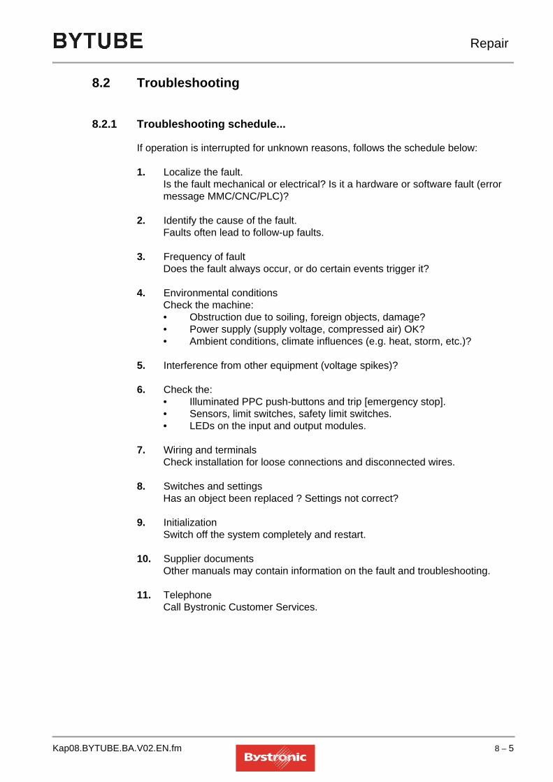
Repair
8.2 Troubleshooting
8.2.1 Troubleshooting schedule...
If operation is interrupted for unknown reasons, follows the schedule below:
1. Localize the fault. Is the fault mechanical or electrical? Is it a hardware or software fault (error message MMC/CNC/PLC)?
2. Identify the cause of the fault. Faults often lead to follow-up faults.
3. Frequency of faultDoes the fault always occur, or do certain events trigger it?
4. Environmental conditionsCheck the machine:• Obstruction due to soiling, foreign objects, damage?• Power supply (supply voltage, compressed air) OK?• Ambient conditions, climate influences (e.g. heat, storm, etc.)?
5. Interference from other equipment (voltage spikes)?
6. Check the:• Illuminated PPC push-buttons and trip [emergency stop].• Sensors, limit switches, safety limit switches. • LEDs on the input and output modules.
7. Wiring and terminalsCheck installation for loose connections and disconnected wires.
8. Switches and settingsHas an object been replaced ? Settings not correct?
9. InitializationSwitch off the system completely and restart.
10. Supplier documentsOther manuals may contain information on the fault and troubleshooting.
11. TelephoneCall Bystronic Customer Services.
Kap08.BYTUBE.BA.V02.EN.fm 8 – 5

Repair
8.3 Repair
8.3.1 Chain tension
Overtightened chains load the drive unnecessarily and create increased wear. Chains that are too loose tend to skip teeth.Check the chain tension monthly and re-tension as necessary.
8.3.2 Tactile detection
Break in tactile sensorThe sensor is positioned using the pin and fastened with the fastening screw. If the sensor breaks, either the pin or the fastening screw has broken off.
Fig. 8.3 -1 Tactile sensor with fastening screw
Remedying a sensor break
1. Interrupt the process by pressing <Abort>.
2. Go into the manual menu and raise the head with <Z+>.
3. Use the hand-held controller to move the bridge close to the safety gate.
4. Shut down machine and open safety gate.
5. Place the new sensor with the fastening screw on a clean table. Put the cutting head beside it.
6. Depressurize the pneumatic cylinder by briefly pressing the Allen key onto the top of the coupling.
A. PinB. Ring sensorC. Fastening screw with predetermined breaking point
C
B
A
8 – 6 Kap08.BYTUBE.BA.V02.EN.fm

Repair
Fig. 8.3 -2
7. Pull the head forward until the Allen screw becomes visible. Loosen both screws.
8. Undo both cheese-head screws and remove the head from the guide by hand
9. Remove head carefully from the guide. Head section can only be pulled forward 5 cm, as it is joined to the connection tube to the detection unit.
10. The rear side of the head is visible, and the broken-off part of the pin or fastening screw can be pushed or screwed out. For better access, the connection tube can be detached by turning the head and holding the connection tube.
11. Fit the connection tube again, and push the head into the guide. Retighten the four screws.
12. Check whether the head can move without touching the housing.
13. Fit sensor and tighten the fastening screw.
14. Check whether the sensor is in the center of the nozzle (visual check only). Turn the clip to the right side.
Kap08.BYTUBE.BA.V02.EN.fm 8 – 7

Repair
15. Refit cutting head and connect electrical cables.
16. Switch on machine and reference the tactile detection system (see Beam guidance system operating manual).
8 – 8 Kap08.BYTUBE.BA.V02.EN.fm

Repair
8.3.3 Cutting head
8.3.3.1 Replacing the lens
NOTE
CAUTIONHandling optical components and parts.Optical components and parts are soiled or damaged by improper handling.Always wear disposable gloves when cleaning, replacing or checking the optical system. Make sure that the work place is clean.
!
WARNINGToxic fumes can be emitted by thermal damage to a lens or severe scratching of a lens. In addition, slightly radioactive thorium fluoride is released.
Always wear a breathing mask and gloves when performing cleaning work.
Avoid stirring up dust.
Material that has come into contact with the broken lens or lens dust must be cleaned thoroughly or disposed of as hazardous waste.
Damaged lenses must be returned to Bystronic.
After cleaning, wash your hands thoroughly under running water.
Further information can be found in the safety datasheets in the supplier documentation.
!
The lens casing and clamping ring are adapted to suit the focal length of the lens. Note the labeling (5", 7.5") when assembling.The clamping ring must be pre-tensioned, otherwise the lens will move when subject to thermal stress. Pre-tensioning the clamping ring too tightly may damage the lens. Therefore, make sure that you tighten the clamping ring with only slight pressure.
Kap08.BYTUBE.BA.V02.EN.fm 8 – 9

Repair
8.3.3.2 Tools required
• Lens key
• Plastic rod
• Lubrication set
• Cleaning set
8.3.3.3 Lens key and plastic rod
Fig. 8.3 -3 Cutting head
A. O-ring “b” D. O-ring “a” (do not grease)B. Nut E. Lens casingC. Clamping ring F. O-ring “b”
8 – 10 Kap08.BYTUBE.BA.V02.EN.fm

Repair
1. Lay the cutting head on a clean surface with the Bystronic labeling facing up and with the nozzle to the back.
2. Undo the screws holding the lens mount in the cutting head.
3. Remove the lens casing from the cutting head using the lens key and place it on a clean surface with the clamping ring facing up.
4. Remove O-rings (F) and check for damage.
NOTE
5. Clean lens key with compressed air.
6. Unscrew the nuts (B) with the lens key. The lens key is in two parts. The long end fits the 7.5” cutting head, and the short end the 5” head.
7. Turn lens casing through 90 o and carefully lift off the lens casing. If the lens does not come away from the lens casing, press the lens down lightly from above with a cleaning swab inserted in the slide.
8. Clean lens according to the instructions in Chapter 7.4.2 «Lubrication, maintenance and cleaning tasks».
9. Check O-ring (D), replace if damaged.Caution: Do not grease this O-ring. Place clamping ring with fitted O-ring on the correct side on a clean surface.
10. Place lens on the O-ring. Make sure that the lens is placed on the O-ring with the curvature facing up.
11. Pull lens casing over the lens key and turn it all upside down.
12. Screw nut into the lens casing and tighten with the lens key, holding the lens casing with one hand and tightening firmly with the other hand on the key shaft in one action.
NOTE
13. Insert the assembled lens casing into the cutting head using the lens key. Observe the correct direction of installation.
14. Reinsert the assembled lens casing into the cutting head and tighten the six screws evenly. Don’t use an offset Allen key, as the applied torque can be too great.
If a damaged O-ring (F) has to be replaced by a new one, this must be lightly greased with “Syntheso Proba 270” (Bystronic order number: 1971659) before fitting. No residual grease should be visible.
If the clamping ring is properly pre-tensioned, the four slits in the middle are closed.
Kap08.BYTUBE.BA.V02.EN.fm 8 – 11

Repair
15. Insert the cutting head on the «Z-axis» and center the laser beam in the cutting nozzle (see chapter 6 «Changing the nozzle and centering the laser beam»).
16. Determine the focal position of the cutting head (only necessary after a change of lens, but not after lens cleaning).
8.3.3.4 Calibration of the focal positionDetermine the focal position after each lens change.Each cutting head has a specific focal position. The value found should be recorded on the cutting head.
Fig. 8.3 -4
There are two different ways of finding the focal position:
First option: (Cutting)
1. After a lens change, the old focal point can be set using the adjusting ring. Now perform fine-adjustment of nozzle centering (see Beam guidance system operating manual)
2. Place sheet (stainless steel >= 3mm) on table. Set up machine for oxide free (N2) cutting.
3. Do cutting tests and adjust the adjustment ring until the cutting quality is back to the original state. The optimum focal position can be found in this way.
8 – 12 Kap08.BYTUBE.BA.V02.EN.fm

Repair
4. Do not select too complicated a contour for the cutting test. Example:
Fig. 8.3 -5
5. If a new focal position is obtained, this must be recorded on the cutting head.
Second option: (Single pulse)Get a pad of self-stick post-it notes. (3M Post-it 76x76mm)
1. Set the adjustment ring to the old value for the focal position.
2. Insert new nozzle (e.g.: HK20) and center it.
3. Use the adjustment ring to set a focal position 3mm higher.
4. Now stick a Post-it note directly over the nozzle aperture.
5. At the MMC controller, select <Setup>, and then “Set-up Laser”. Now enter a “Laser power, single pulse” of 1%, and a “Pulse length” of 20-100ms.
6. Now switch to the <Hand> menu and send a pulse using the hand-held controller. Make sure that the alignment hole is clean. If not, the pulse duration must be corrected.
7. Move Post-it note and repeat action 6, after turning the adjustment ring 0.5 millimeters lower.
Kap08.BYTUBE.BA.V02.EN.fm 8 – 13

Repair
Fig. 8.3 -6
The focal position is at 0-45
8. Repeat this operation a number of times, until the smallest possible hole is found. It is advisable to use smaller steps, e.g. 0.2 millimeters, for the final optimization.
9. Write the focal position found on the head. (e.g. F= 6-10)
8 – 14 Kap08.BYTUBE.BA.V02.EN.fm

Repair
8.3.4 Beam guidance optical system
TIP
Replacing the deflection mirror
NOTE
Fig. 8.3 -7 Deflecting mirror cross-section
CAUTIONHandling optical components and parts.Optical components and parts are soiled or damaged by improper handling.Always wear disposable gloves when cleaning, replacing or checking the optical system. Make sure that the work place is clean.
!
Bystronic laser cutting machines have various mirrors, which appear identical externally. The type and properties of the mirrors can only be identified by the order number.
On no account adjust the setting screws. Cooling water tubes must not be detached.
A. Mirror support F. CoolerB. Set screw G. Pressure springC. Deflecting mirror H. Mirror screws (x 4)D. O-ring I. Mirror mountE. Cooler connection J. Deflection vee
A
D
C
B
E
J
H
F
G
I
Kap08.BYTUBE.BA.V02.EN.fm 8 – 15

Repair
1. Switch machine off at main power switch, and safeguard against being switched on again.
2. Remove beam-path cover.
3. Unscrew four fastening screws on the mirror mounting (H) without detaching the coolant tubes.
4. Remove the mirror mounting (H) from the vee and turn it upside down so that the mirror faces up.
5. Press the mirror out of its mounting and out of the O-ring by pressing the cooler (F) upwards.
6. You can now hold the mirror on the side and remove it from the mounting.
7. Replace new or cleaned mirror. See chapter 7 «Lubrication, maintenance and cleaning tasks» for a description of how to clean the mirrors.
NOTE
8. Make sure that the mirror holder is absolutely clean before inserting the mirror mounting.
9. Position the mirror mounting correctly in the mirror holder. Tighten the fastening screws evenly.
10. Fit covers and switch on machine.
11. Before continuing work, a test shot must be fired to ensure that the beam deflection has not been changed.
12. To do this, insert the alignment tool for the Z-axis and fire at corner 4 on a cardboard plate.
13. Check centricity of the burn point.
14. If this is OK, you can commence cutting. For poor centricity, check the beam path.
15. After replacing or cleaning the deflecting mirror, the laser beam must always be re-centered in the nozzle (see chapter 6 «Changing the nozzle and centering the laser beam»).
TIP
Hold the mirror from the side without soiling it with your fingers and insert it into the mounting. Use Kodak paper to press the mirror into the O-ring.
When you replace a machine mirror, note down the position, date and hours of operation of the machine on the back of the mirror.
8 – 16 Kap08.BYTUBE.BA.V02.EN.fm

Repair
NOTE
Schematic diagram of Bytube beam path
If the machine is fitted with Bypos, an adaptive mirror Bypos W is fitted in detail B, otherwise a deflecting mirror.
Repair work exceeding the scope of work described in the ”Repair” chapter may only be performed by specially trained Bystronic experts. Contact our Customer Services department (see chapter "Repair service information").
m) Deflecting mirrorl) 90o deflection o), p) Lenses as per customer requirements
Kap08.BYTUBE.BA.V02.EN.fm 8 – 17

Repair
8.4 Converting a Bypos mirror to a flat mirror
The flat mirror needs to be used if one of the following components fails:
• Bypos mirror
• Pressure sensor
• Proportional valve
• Pressure booster station
• Prescon card
Cutting can continue using the flat mirror as a temporary solution. If the Bypos mirror or the sensor fails then the whole mirror unit (including sensor) must be replaced.
Fig. 8.4 -1 Bypos mirror and flat mirror
CAUTIONHandling optical components and parts.Optical components and parts are soiled or damaged by improper handling.Always wear disposable gloves when cleaning, replacing or checking the optical system. Make sure that the work place is clean.
!
A. Bypos mirror E. Protective capB. Cooling water return F. Flat mirrorC. Fixing screws (4 off) G. Cooling water supplyD. Pressure sensor H. Sensor cable connector
B C
G
HA
D
E
F
8 – 18 Kap08.BYTUBE.BA.V02.EN.fm

Repair
8.4.1 Conversion procedure
1. Shut down and switch off the complete system (resonator, machine, cooling unit).
2. Disconnect the sensor cable (H) in the cutting carriage.
3. Disconnect the cooling water supply (G) and return pipes (B) from the Bypos mirror.
4. Unscrew the fixing screws (C) (4 off).
5. Remove the Bypos mirror (A) and affix the protective cap.
6. Fit the flat mirror (F) and connect the cooling water supply and return pipes.
NOTE
• To convert the cooling-water circuit when the pressure booster station is intact, please see «8.4.2.1 Conversion when pressure booster station intact»
• To convert the cooling-water circuit when the pressure booster station is faulty, please see «8.4.2.2 Conversion when pressure booster station faulty»
7. Call in the site electrician, and switch off the motor safety switch labeled "Pressure booster in Bypos circuit" in the cooling-unit control box (see diagram in supplier documentation).
8. Close the cover of the cutting carriage.
8.4.2 Commissioning after conversion carried out
1. Start up laser cutting machine.
2. Check the position of the flat mirror using the alignment gauge, and align if necessary.
3. In the "Setup" menu, switch the Bypos operating mode to "0". Ignore any error message that may appear.
4. Before starting cutting, adjust the focal point manually (see «8.3.3.4 Calibration of the focal position»).
Once the flat mirror has been fitted, the cooling-water circuit needs to be converted to suit the new circumstances.
Kap08.BYTUBE.BA.V02.EN.fm 8 – 19

Repair
8.4.2.1 Conversion when pressure booster station intactIf the pressure booster station is not faulty, once the flat mirror has been fitted the cooling-water circuit must be reconnected by bypassing the proportional valve (A).
Fig. 8.4 -2 Bypassing the proportional valve
8.4.2.2 Conversion when pressure booster station faultyIf the pressure booster station fails, the cooling-water return from the cutting head (Z-axis) must be fed into the cooling-water circuit for the flat mirror.
Fig. 8.4 -3 Converted cooling-water circuit
A
Return
Supply
A B
D
C
Water Out(Return)
Water Out(Z axis)
8 – 20 Kap08.BYTUBE.BA.V02.EN.fm

Repair
1. Disconnect the cooling water return (Z-axis – return from cutting head) at the coupling and connect to the plug-in connector (A) downstream of the proportional valve.
For model with tank heater: connect to the plug-in connector (E) downstream of the Bypass valve.
Fig. 8.4 -4 Converted cooling-water circuit for model with tank heater
2. Disconnect cooling-water return at Y-connector (B) .
3. Connect Y-connector to cooling water return (Z-axis – return from cutting head) using extension tube.
4. Disconnect the cooling-water supply (C) upstream of the proportional valve and blank it off using couplings with blanking plugs.
5. Also seal the cooling-water return pipe (D) with a coupling and plug.
Water Out(Return)
Water Out(Z axis)
E
Kap08.BYTUBE.BA.V02.EN.fm 8 – 21

Repair
8.5 Alignment
8.5.1 Alignment tools
Fig. 8.5 -1Description Applications
Alignment device for setting up optical beam expansion system
Alignment device for setting up the mirror on the bridge axis.(3. deflecting mirror)
Alignment device for setting up the mirror on the Z-axis (Bypos)
8 – 22 Kap08.BYTUBE.BA.V02.EN.fm

Repair
Fig. 8.5 -2
8.5.2 Alignment procedure
To obtain an optimum level of efficiency in laser cutting, all deflecting mirrors must be aligned and adjusted when commissioning the system for the first time. The deflecting mirrors also need to be aligned after changing an optical component, or if the cutting result is unsatisfactory.
When aligning, ensure that the laser beam is always in the center F of the alignment gauge. Use the screws E to make the adjustment. Fire with reduced power onto the plaster plate or paper strip.
Fig. 8.5 -3
TIP
Alignment device for deflecting and adaptive mirrors
A. Alignment gauge B. Adapter ringC. Bracket D. Protective cap
Description Applications
DA B C
F
E
E
Optical components must be cleaned before assembly.
Kap08.BYTUBE.BA.V02.EN.fm 8 – 23

Repair
8.5.3 Alignment in beam divergence system
NOTE
Fig. 8.5 -4
1. Remove mirror holder A, take it out of the mirror mounting and let it hang down
2. Fix alignment gauge without adapter in the mirror mounting C using two screws B.
NOTE
3. Fire a pulse of appropriate power
Only adjusted when there is extreme deviation along X beam path.
B
C
B
A
Direction of laser beam
During alignment, protect deflecting mirror from soiling with cap and masking tape.
8 – 24 Kap08.BYTUBE.BA.V02.EN.fm

Repair
8.5.4 Alignment at deflecting mirror
The system must be re-aligned whenever the deflecting mirror is changed. The deflecting mirror in the X beam path is aligned using the targeting device on the bridge axis (3rd deflecting mirror).
Fig. 8.5 -5
1. Undo the four screws B on the mirror holder A
2. Take mirror holder A out of the mirror mounting and let it hang down
3. Attach protective cap
NOTE
Fig. 8.5 -6
4. Fix alignment gauge C to mirror mounting D using the three screws B
5. Fire a pulse of appropriate power
B A
During alignment, protect deflecting mirror from soiling with cap and masking tape.
B
CBBD
Direction of laser beam
Kap08.BYTUBE.BA.V02.EN.fm 8 – 25

Repair
8.5.5 Alignment at Bypos-W
Fig. 8.5 -7
1. Remove screws B of the mirror mounting
Fig. 8.5 -8
2. Fix bracket E onto the cutting bridge using the knurled screws D
3. Fit cap F on mirror
4. Fix mirror mounting C onto bracket using screw B
B
A
B
C
DEF
8 – 26 Kap08.BYTUBE.BA.V02.EN.fm

Repair
Fig. 8.5 -9
5. Fit alignment gauge G in the mirror holder H and fasten with three screws B
TIP
6. Fire a pulse of appropriate power
8.5.6 Alignment at cutting head
Fig. 8.5 -10
1. Remove cutting head
2. Mount alignment gauge for cutting head A using the two clamping levers B.If necessary lower using the Z-axis to enable simpler and more precise alignment.
3. Fire a pulse of appropriate power
4. Adjust mirror if necessary
B
G
B
Direction of laser beam
H
If the vee is fitted incorrectly, the gauge stands up on the pin of the mirror holder and corrupts the result
B
A
Direction of laser beam
Kap08.BYTUBE.BA.V02.EN.fm 8 – 27

Repair
8.6 Circuit diagrams, drawings
Circuit diagrams and drawings can be found in the spare parts catalogue and the «Equipment Diagram» folder.
8.7 Repair service information
Our Customer Service department is at your disposal in the event of problems. Please have the following information ready before you call:– Company / Address– Contact person– Job numberFor the contact address please refer to the details of BYSTRONIC Customer Support on page 4 at the beginning of this operating manual.
8 – 28 Kap08.BYTUBE.BA.V02.EN.fm

HAPTER9
9. Decommissioning the system
The chapter «Decommissioning the system» is not yet included in the operating manual.
Kap09.BYTUBE.BA.V01.EN.fm 1

Decommissioning the system
Table of contents
9. Decommissioning the system. . . . . . . . . . . . . . . . . 1
9 – 2 Kap09.BYTUBE.BA.V01.EN.fm

HAPTER10
10. Packaging, transport
The chapter «Packaging, transport» is not available in the operating instructions. All work connected with packaging and transporting the machine or system is performed by the manufacturer’s personnel.
Kap10.BYTUBE.BA.V01.EN.fm 1

Packaging, transport
Table of contents
10. Packaging, transport . . . . . . . . . . . . . . . . . . . . . . . . 1
10 – 2 Kap10.BYTUBE.BA.V01.EN.fm

HAPTER11
11. Disposal
The «Disposal» chapter provides information on disposal of the machine and its operating resources in accordance with environmental regulations. It also includes information on how to deal with spare components (e.g. replacement parts).
Kap11.BYTUBE.BA.V01.EN.fm 1

Disposal
Table of contents
11. Disposal. . . . . . . . . . . . . . . . . . . . . . . . . . . . . . . . . . . 1
11.1 Introduction. . . . . . . . . . . . . . . . . . . . . . . . . . . . . . . . . . . . . . . 311.1.1 Safety regulations . . . . . . . . . . . . . . . . . . . . . . . . . . . . . . . . . . . . . . . . . . 311.1.2 Requirements to be met by operating personnel . . . . . . . . . . . . . . . . . . . 3
11.2 Disposal. . . . . . . . . . . . . . . . . . . . . . . . . . . . . . . . . . . . . . . . . . 311.2.1 Packaging . . . . . . . . . . . . . . . . . . . . . . . . . . . . . . . . . . . . . . . . . . . . . . . . 311.2.2 Operating resources . . . . . . . . . . . . . . . . . . . . . . . . . . . . . . . . . . . . . . . . 3
11.3 Components suitable for disposal . . . . . . . . . . . . . . . . . . . . 411.3.1 Material groups . . . . . . . . . . . . . . . . . . . . . . . . . . . . . . . . . . . . . . . . . . . . 4
11.4 Disposal centers, authorities . . . . . . . . . . . . . . . . . . . . . . . . 511.4.1 Return to manufacturer . . . . . . . . . . . . . . . . . . . . . . . . . . . . . . . . . . . . . . 511.4.2 Notification to authorities and manufacturer . . . . . . . . . . . . . . . . . . . . . . 5
11 – 2 Kap11.BYTUBE.BA.V01.EN.fm

Disposal
11.1 Introduction
11.1.1 Safety regulations
Always observe national regulations and standards for all components to be disposed of.Also observe the manufacturer’s regulations for operating resources and cleaning agents.
11.1.2 Requirements to be met by operating personnel
Proper disposal must be performed by specially trained personnel.
11.2 Disposal
11.2.1 Packaging
Dispose of packaging material used for delivery in accordance with national regulations and standards.
11.2.2 Operating resources
NOTE
Gear oil and lubricants must be sent to a suitable treatment plant or disposed of as hazardous waste. For all operating resources, observe the manufacturer’s regulations. For further details please refer to the safety data sheets in the «Supplier Documents» folder in your machine documentation.
Dispose of all operating resources in accordance with national regulations and standards.
Kap11.BYTUBE.BA.V01.EN.fm 11 – 3

Disposal
11.3 Components suitable for disposal
11.3.1 Material groups
NOTE
Metals and plastics must be separated and taken for recycling or disposal.The machine and electrical control system must be taken apart and the component properly disposed of.The machine contains the following materials:
• Steel castings
• Steel
• Nonferrous heavy metals (aluminum, copper)
• Rubber
• Plastics
The electrical control system contains the following materials and parts:
• Steel
• Plastics
• Nonferrous heavy metals (aluminum, copper)
• Protective varnish on circuit boards
• Electrical and electronic components
• Battery
Dispose of all materials in accordance with national regulations and standards.
11 – 4 Kap11.BYTUBE.BA.V01.EN.fm

Disposal
11.4 Disposal centers, authorities
11.4.1 Return to manufacturer
The manufacturer takes back various components. This applies particularly to components replaced by repaired parts during the machine’s service life.
11.4.2 Notification to authorities and manufacturer
The manufacturer should be informed when you decommission the system.
Kap11.BYTUBE.BA.V01.EN.fm 11 – 5

Disposal
11 – 6 Kap11.BYTUBE.BA.V01.EN.fm

HAPTER12
12. Cutting technology
The «Cutting technology» chapter provides information on cutting with the Bystar laser machine. It includes basic advice on machining the raw material, and also provides information on special applications, coatings and alloys.
Kap12.BYTUBE.BA.V02.EN.fm 1

Cutting technology
Table of contents
12. Cutting technology. . . . . . . . . . . . . . . . . . . . . . . . . . 1
12.1 Cutting with Bytube . . . . . . . . . . . . . . . . . . . . . . . . . . . . . . . . 512.1.1 Adapting flat-sheet parameters to tube parameters. . . . . . . . . . . . . . . . . 512.1.1.1 For large circular tubes: . . . . . . . . . . . . . . . . . . . . . . . . . . . . . . . . . . . . . . . . . . 512.1.1.2 For small circular tubes: . . . . . . . . . . . . . . . . . . . . . . . . . . . . . . . . . . . . . . . . . . 512.1.1.3 For large rectangular tubes: . . . . . . . . . . . . . . . . . . . . . . . . . . . . . . . . . . . . . . . 612.1.1.4 For small rectangular tubes:. . . . . . . . . . . . . . . . . . . . . . . . . . . . . . . . . . . . . . . 612.1.1.5 Performance with sand-blasted surfaces . . . . . . . . . . . . . . . . . . . . . . . . . . . . . 612.1.2 Recommendations for machining tubes and sections . . . . . . . . . . . . . . . 612.1.2.1 General rules . . . . . . . . . . . . . . . . . . . . . . . . . . . . . . . . . . . . . . . . . . . . . . . . . . 612.1.2.2 Cutting in conventional mode (Byflex) . . . . . . . . . . . . . . . . . . . . . . . . . . . . . . . 612.1.2.3 Cutting in Hybrid mode. . . . . . . . . . . . . . . . . . . . . . . . . . . . . . . . . . . . . . . . . . . 7
12.2 The laser cutting process . . . . . . . . . . . . . . . . . . . . . . . . . . . 812.2.1 Inert gas fusion laser cutting . . . . . . . . . . . . . . . . . . . . . . . . . . . . . . . . . . 812.2.2 Oxygen laser cutting . . . . . . . . . . . . . . . . . . . . . . . . . . . . . . . . . . . . . . . . 812.2.3 Laser sublimation cutting . . . . . . . . . . . . . . . . . . . . . . . . . . . . . . . . . . . . . 912.2.4 Cutting process . . . . . . . . . . . . . . . . . . . . . . . . . . . . . . . . . . . . . . . . . . . 1012.2.5 Laser modes . . . . . . . . . . . . . . . . . . . . . . . . . . . . . . . . . . . . . . . . . . . . . 1112.2.6 Gas parameters . . . . . . . . . . . . . . . . . . . . . . . . . . . . . . . . . . . . . . . . . . . 11
12.3 Materials . . . . . . . . . . . . . . . . . . . . . . . . . . . . . . . . . . . . . . . . 1212.3.1 Material properties . . . . . . . . . . . . . . . . . . . . . . . . . . . . . . . . . . . . . . . . . 1212.3.1.1 Alloy components. . . . . . . . . . . . . . . . . . . . . . . . . . . . . . . . . . . . . . . . . . . . . . 1212.3.1.2 Microstructure . . . . . . . . . . . . . . . . . . . . . . . . . . . . . . . . . . . . . . . . . . . . . . . . 1212.3.1.3 Surface quality and surface roughness . . . . . . . . . . . . . . . . . . . . . . . . . . . . . 1212.3.1.4 Surface treatment. . . . . . . . . . . . . . . . . . . . . . . . . . . . . . . . . . . . . . . . . . . . . . 1312.3.1.5 Beam reflection . . . . . . . . . . . . . . . . . . . . . . . . . . . . . . . . . . . . . . . . . . . . . . . 1312.3.1.6 Thermal conductivity . . . . . . . . . . . . . . . . . . . . . . . . . . . . . . . . . . . . . . . . . . . 1312.3.1.7 Heat affected zone . . . . . . . . . . . . . . . . . . . . . . . . . . . . . . . . . . . . . . . . . . . . . 1312.3.2 Machining a range of materials . . . . . . . . . . . . . . . . . . . . . . . . . . . . . . . 1512.3.2.1 Structural steel . . . . . . . . . . . . . . . . . . . . . . . . . . . . . . . . . . . . . . . . . . . . . . . . 1512.3.2.2 Stainless steel . . . . . . . . . . . . . . . . . . . . . . . . . . . . . . . . . . . . . . . . . . . . . . . . 1612.3.2.3 Titanium . . . . . . . . . . . . . . . . . . . . . . . . . . . . . . . . . . . . . . . . . . . . . . . . . . . . . 1712.3.2.4 Copper and brass. . . . . . . . . . . . . . . . . . . . . . . . . . . . . . . . . . . . . . . . . . . . . . 1712.3.2.5 Plastics. . . . . . . . . . . . . . . . . . . . . . . . . . . . . . . . . . . . . . . . . . . . . . . . . . . . . . 1712.3.2.6 Organic materials . . . . . . . . . . . . . . . . . . . . . . . . . . . . . . . . . . . . . . . . . . . . . . 1812.3.2.7 Other materials. . . . . . . . . . . . . . . . . . . . . . . . . . . . . . . . . . . . . . . . . . . . . . . . 18
12.4 Production. . . . . . . . . . . . . . . . . . . . . . . . . . . . . . . . . . . . . . . 1912.4.1 Sheets . . . . . . . . . . . . . . . . . . . . . . . . . . . . . . . . . . . . . . . . . . . . . . . . . . 1912.4.2 Material surface . . . . . . . . . . . . . . . . . . . . . . . . . . . . . . . . . . . . . . . . . . . 1912.4.3 Stresses . . . . . . . . . . . . . . . . . . . . . . . . . . . . . . . . . . . . . . . . . . . . . . . . . 2012.4.4 Primers, varnishes, protective paints, zinc coatings . . . . . . . . . . . . . . . 2012.4.5 Alloy elements . . . . . . . . . . . . . . . . . . . . . . . . . . . . . . . . . . . . . . . . . . . . 2112.4.6 Oiling . . . . . . . . . . . . . . . . . . . . . . . . . . . . . . . . . . . . . . . . . . . . . . . . . . . 2112.4.7 Radii . . . . . . . . . . . . . . . . . . . . . . . . . . . . . . . . . . . . . . . . . . . . . . . . . . . . 21
12 – 2 Kap12.BYTUBE.BA.V02.EN.fm

Cutting technology
12.5 Programming . . . . . . . . . . . . . . . . . . . . . . . . . . . . . . . . . . . . .2212.5.1 Piercing and initial cuts . . . . . . . . . . . . . . . . . . . . . . . . . . . . . . . . . . . . . . 2212.5.2 Piercing . . . . . . . . . . . . . . . . . . . . . . . . . . . . . . . . . . . . . . . . . . . . . . . . . . 2212.5.2.1 Continuous wave piercing . . . . . . . . . . . . . . . . . . . . . . . . . . . . . . . . . . . . . . . 2212.5.2.2 Pulsed mode piercing. . . . . . . . . . . . . . . . . . . . . . . . . . . . . . . . . . . . . . . . . . . 2212.5.2.3 On-the-fly piercing during lowered positioning . . . . . . . . . . . . . . . . . . . . . . . . 2212.5.2.4 Piercing with circular pierce in stainless steel and aluminum. . . . . . . . . . . . . 2312.5.2.5 Pulsed piercing on the contour . . . . . . . . . . . . . . . . . . . . . . . . . . . . . . . . . . . . 2312.5.3 Special piercing cuts in thick sheets . . . . . . . . . . . . . . . . . . . . . . . . . . . . 2412.5.3.1 Applications . . . . . . . . . . . . . . . . . . . . . . . . . . . . . . . . . . . . . . . . . . . . . . . . . . 2412.5.3.2 Programming . . . . . . . . . . . . . . . . . . . . . . . . . . . . . . . . . . . . . . . . . . . . . . . . . 2412.5.3.3 Cutting . . . . . . . . . . . . . . . . . . . . . . . . . . . . . . . . . . . . . . . . . . . . . . . . . . . . . . 2512.5.4 Initial cutting pane and end cutting pane for steel. . . . . . . . . . . . . . . . . . 2612.5.4.1 Outer contour . . . . . . . . . . . . . . . . . . . . . . . . . . . . . . . . . . . . . . . . . . . . . . . . . 2612.5.4.2 Inside contour (cut-outs). . . . . . . . . . . . . . . . . . . . . . . . . . . . . . . . . . . . . . . . . 2612.5.5 Initial cutting pane and end cutting pane for stainless steel and aluminum2812.5.5.1 Outer contour . . . . . . . . . . . . . . . . . . . . . . . . . . . . . . . . . . . . . . . . . . . . . . . . . 2812.5.5.2 Inside contour (cut-outs). . . . . . . . . . . . . . . . . . . . . . . . . . . . . . . . . . . . . . . . . 2812.5.5.3 Initial cut length for cut-outs . . . . . . . . . . . . . . . . . . . . . . . . . . . . . . . . . . . . . . 2912.5.6 Microjoints. . . . . . . . . . . . . . . . . . . . . . . . . . . . . . . . . . . . . . . . . . . . . . . . 3012.5.7 Corners . . . . . . . . . . . . . . . . . . . . . . . . . . . . . . . . . . . . . . . . . . . . . . . . . . 3112.5.7.1 Cutting obtuse corners with radii . . . . . . . . . . . . . . . . . . . . . . . . . . . . . . . . . . 3112.5.7.2 Cutting obtuse corners with «corner tolerance». . . . . . . . . . . . . . . . . . . . . . . 3112.5.7.3 Acute corners in thin sheet with loops . . . . . . . . . . . . . . . . . . . . . . . . . . . . . . 3212.5.7.4 Acute corners in thick sheet with the «dwell time» parameter . . . . . . . . . . . . 3212.5.8 Pre-piercing. . . . . . . . . . . . . . . . . . . . . . . . . . . . . . . . . . . . . . . . . . . . . . . 3312.5.9 Cutting small parts . . . . . . . . . . . . . . . . . . . . . . . . . . . . . . . . . . . . . . . . . 3412.5.9.1 with normal thickness . . . . . . . . . . . . . . . . . . . . . . . . . . . . . . . . . . . . . . . . . . . 3412.5.9.2 With limit thickness. . . . . . . . . . . . . . . . . . . . . . . . . . . . . . . . . . . . . . . . . . . . . 3712.5.10 Pulsed mode cutting . . . . . . . . . . . . . . . . . . . . . . . . . . . . . . . . . . . . . . . . 39
12.6 Definitions and limits . . . . . . . . . . . . . . . . . . . . . . . . . . . . . . .4012.6.1 Definition of limit thickness / normal thickness . . . . . . . . . . . . . . . . . . . . 4012.6.2 Definition of part area A . . . . . . . . . . . . . . . . . . . . . . . . . . . . . . . . . . . . . 4212.6.3 Definition of part size . . . . . . . . . . . . . . . . . . . . . . . . . . . . . . . . . . . . . . . 4312.6.4 Definition of web width and minimum web width . . . . . . . . . . . . . . . . . . 4412.6.5 Part spacing . . . . . . . . . . . . . . . . . . . . . . . . . . . . . . . . . . . . . . . . . . . . . . 4512.6.6 Master gauges . . . . . . . . . . . . . . . . . . . . . . . . . . . . . . . . . . . . . . . . . . . . 4612.6.7 Achievable parts accuracy . . . . . . . . . . . . . . . . . . . . . . . . . . . . . . . . . . . 4712.6.8 Unsuitable parts for production . . . . . . . . . . . . . . . . . . . . . . . . . . . . . . . . 48
12.7 Cutting process . . . . . . . . . . . . . . . . . . . . . . . . . . . . . . . . . . .4912.7.1 Cutting structural steel . . . . . . . . . . . . . . . . . . . . . . . . . . . . . . . . . . . . . . 4912.7.1.1 Initial cuts for holes. . . . . . . . . . . . . . . . . . . . . . . . . . . . . . . . . . . . . . . . . . . . . 5012.7.1.2 Hole roundness . . . . . . . . . . . . . . . . . . . . . . . . . . . . . . . . . . . . . . . . . . . . . . . 5012.7.1.3 Guidelines for the dynamic factor . . . . . . . . . . . . . . . . . . . . . . . . . . . . . . . . . . 5012.7.1.4 Obtuse corners with «corner tolerance» parameter (quality cuts) . . . . . . . . . 5112.7.1.5 Corner tolerance guides [mm] . . . . . . . . . . . . . . . . . . . . . . . . . . . . . . . . . . . . 5112.7.1.6 Cutting acute corners in thin sheet with loops . . . . . . . . . . . . . . . . . . . . . . . . 5112.7.1.7 Acute corners in thick sheet with the «dwell time» parameter . . . . . . . . . . . . 5112.7.1.8 Cutting thick sheet . . . . . . . . . . . . . . . . . . . . . . . . . . . . . . . . . . . . . . . . . . . . . 5112.7.1.9 Piercing . . . . . . . . . . . . . . . . . . . . . . . . . . . . . . . . . . . . . . . . . . . . . . . . . . . . . 5212.7.1.10 Cutting . . . . . . . . . . . . . . . . . . . . . . . . . . . . . . . . . . . . . . . . . . . . . . . . . . . . . . 5212.7.2 Oxide-free cutting of stainless steel . . . . . . . . . . . . . . . . . . . . . . . . . . . . 5312.7.2.1 Start of cutting after piercing . . . . . . . . . . . . . . . . . . . . . . . . . . . . . . . . . . . . . 5312.7.2.2 Bylaser 2200 . . . . . . . . . . . . . . . . . . . . . . . . . . . . . . . . . . . . . . . . . . . . . . . . . 5312.7.2.3 Bylaser 3000/4000/40s. . . . . . . . . . . . . . . . . . . . . . . . . . . . . . . . . . . . . . . . . . 5312.7.2.4 Initial cut for hole . . . . . . . . . . . . . . . . . . . . . . . . . . . . . . . . . . . . . . . . . . . . . . 54
Kap12.BYTUBE.BA.V02.EN.fm 12 – 3

Cutting technology
12.7.2.5 Hole roundness . . . . . . . . . . . . . . . . . . . . . . . . . . . . . . . . . . . . . . . . . . . . . . . 5412.7.2.6 Corner tolerance (quality cuts) . . . . . . . . . . . . . . . . . . . . . . . . . . . . . . . . . . . . 5412.7.2.7 Processing with loops . . . . . . . . . . . . . . . . . . . . . . . . . . . . . . . . . . . . . . . . . . 5412.7.2.8 Inside contours (cut-outs). . . . . . . . . . . . . . . . . . . . . . . . . . . . . . . . . . . . . . . . 5512.7.3 Oxide-free cutting of aluminum alloys . . . . . . . . . . . . . . . . . . . . . . . . . . 5612.7.3.1 Start of cutting after piercing . . . . . . . . . . . . . . . . . . . . . . . . . . . . . . . . . . . . . 5612.7.3.2 Bylaser 2200 . . . . . . . . . . . . . . . . . . . . . . . . . . . . . . . . . . . . . . . . . . . . . . . . . 5612.7.3.3 Bylaser 3000/4000/40s . . . . . . . . . . . . . . . . . . . . . . . . . . . . . . . . . . . . . . . . . 5612.7.3.4 Initial cut for hole . . . . . . . . . . . . . . . . . . . . . . . . . . . . . . . . . . . . . . . . . . . . . . 5612.7.3.5 Hole roundness . . . . . . . . . . . . . . . . . . . . . . . . . . . . . . . . . . . . . . . . . . . . . . . 5712.7.3.6 Corner tolerance (quality cuts) . . . . . . . . . . . . . . . . . . . . . . . . . . . . . . . . . . . . 5712.7.3.7 Processing with loops . . . . . . . . . . . . . . . . . . . . . . . . . . . . . . . . . . . . . . . . . . 5712.7.4 Pulsed operation . . . . . . . . . . . . . . . . . . . . . . . . . . . . . . . . . . . . . . . . . . 5812.7.4.1 Pulsed cutting. . . . . . . . . . . . . . . . . . . . . . . . . . . . . . . . . . . . . . . . . . . . . . . . . 5812.7.4.2 Pulsed piercing. . . . . . . . . . . . . . . . . . . . . . . . . . . . . . . . . . . . . . . . . . . . . . . . 5812.7.4.3 Programming . . . . . . . . . . . . . . . . . . . . . . . . . . . . . . . . . . . . . . . . . . . . . . . . . 5812.7.4.4 Adjusting the pulse parameters in cutting mode . . . . . . . . . . . . . . . . . . . . . . 5912.7.4.5 Adjusting the pulse parameters in piercing mode . . . . . . . . . . . . . . . . . . . . . 5912.7.4.6 Further influencing factors in pulsed mode . . . . . . . . . . . . . . . . . . . . . . . . . . 5912.7.4.7 Alternatives to pulsed cutting . . . . . . . . . . . . . . . . . . . . . . . . . . . . . . . . . . . . . 5912.7.5 Engraving. . . . . . . . . . . . . . . . . . . . . . . . . . . . . . . . . . . . . . . . . . . . . . . . 6012.7.5.1 General information . . . . . . . . . . . . . . . . . . . . . . . . . . . . . . . . . . . . . . . . . . . . 6012.7.5.2 Vaporization of films. . . . . . . . . . . . . . . . . . . . . . . . . . . . . . . . . . . . . . . . . . . . 6012.7.5.3 Assessment of engraving quality . . . . . . . . . . . . . . . . . . . . . . . . . . . . . . . . . . 6012.7.6 Support grids . . . . . . . . . . . . . . . . . . . . . . . . . . . . . . . . . . . . . . . . . . . . . 61
12.8 Cut evaluation. . . . . . . . . . . . . . . . . . . . . . . . . . . . . . . . . . . . 6212.8.1 Waiting time before cutting in continuous wave. . . . . . . . . . . . . . . . . . . 6212.8.2 Machining holes . . . . . . . . . . . . . . . . . . . . . . . . . . . . . . . . . . . . . . . . . . . 6212.8.2.1 Burring with holes. . . . . . . . . . . . . . . . . . . . . . . . . . . . . . . . . . . . . . . . . . . . . . 6212.8.3 Structural steel: Cutting with O2 . . . . . . . . . . . . . . . . . . . . . . . . . . . . . . 6312.8.4 Stainless steel: High-pressure cutting with N2. . . . . . . . . . . . . . . . . . . . 6512.8.5 Aluminum alloys: High-pressure cutting with N2 . . . . . . . . . . . . . . . . . . 67
12.9 Troubleshooting . . . . . . . . . . . . . . . . . . . . . . . . . . . . . . . . . . 6812.9.1 Parameters . . . . . . . . . . . . . . . . . . . . . . . . . . . . . . . . . . . . . . . . . . . . . . 6812.9.2 Cutting head. . . . . . . . . . . . . . . . . . . . . . . . . . . . . . . . . . . . . . . . . . . . . . 6812.9.3 Beam guidance . . . . . . . . . . . . . . . . . . . . . . . . . . . . . . . . . . . . . . . . . . . 6912.9.4 Resonator . . . . . . . . . . . . . . . . . . . . . . . . . . . . . . . . . . . . . . . . . . . . . . . 69
12 – 4 Kap12.BYTUBE.BA.V02.EN.fm

Cutting technology
12.1 Cutting with Bytube
This chapter contains general advice on laser cutting, detailed in the sections from "Laser cutting procedure" onwards.The following points should be considered in particular in order to make optimum use of Bytube:
• Programming of parts
• Cutting parameters
• Production
When cutting tubes and sections, there are a larger range of variables to consider than when cutting flat sheets.There are so many different possible values for tube dimensions, wall thicknesses, surface finishes and qualities that Bystronic cannot issue general cutting parameters.A number of points need to be considered when adopting cutting parameters from flat-sheet cutting.
12.1.1 Adapting flat-sheet parameters to tube parameters
The tube thickness should be the same as the sheet thickness in question.
12.1.1.1 For large circular tubes:• Reduce the piercing power (the power can be reduced to as low as 60%)• Set Nozzle distance, cutting to 1.2 mm• Adjust focal position (when cutting tubes, the focal point needs to be
slightly lower in practice)
12.1.1.2 For small circular tubes:• Reduce the piercing power (the power can be reduced by up to 60%), or
pulsed piercing• Minimize the 'Delay time before processing' or set to zero• Set Nozzle distance, cutting to 1.2 mm• Adjust focal position (when cutting tubes, the focal point needs to be
slightly lower in practice than for cutting flat sheets)• Reduce feed rate by 30…60%• Reduce power by 50…80%• Reduce gas pressure when cutting with O2 (depends on material and
surface finish of tube)
Kap12.BYTUBE.BA.V02.EN.fm 12 – 5
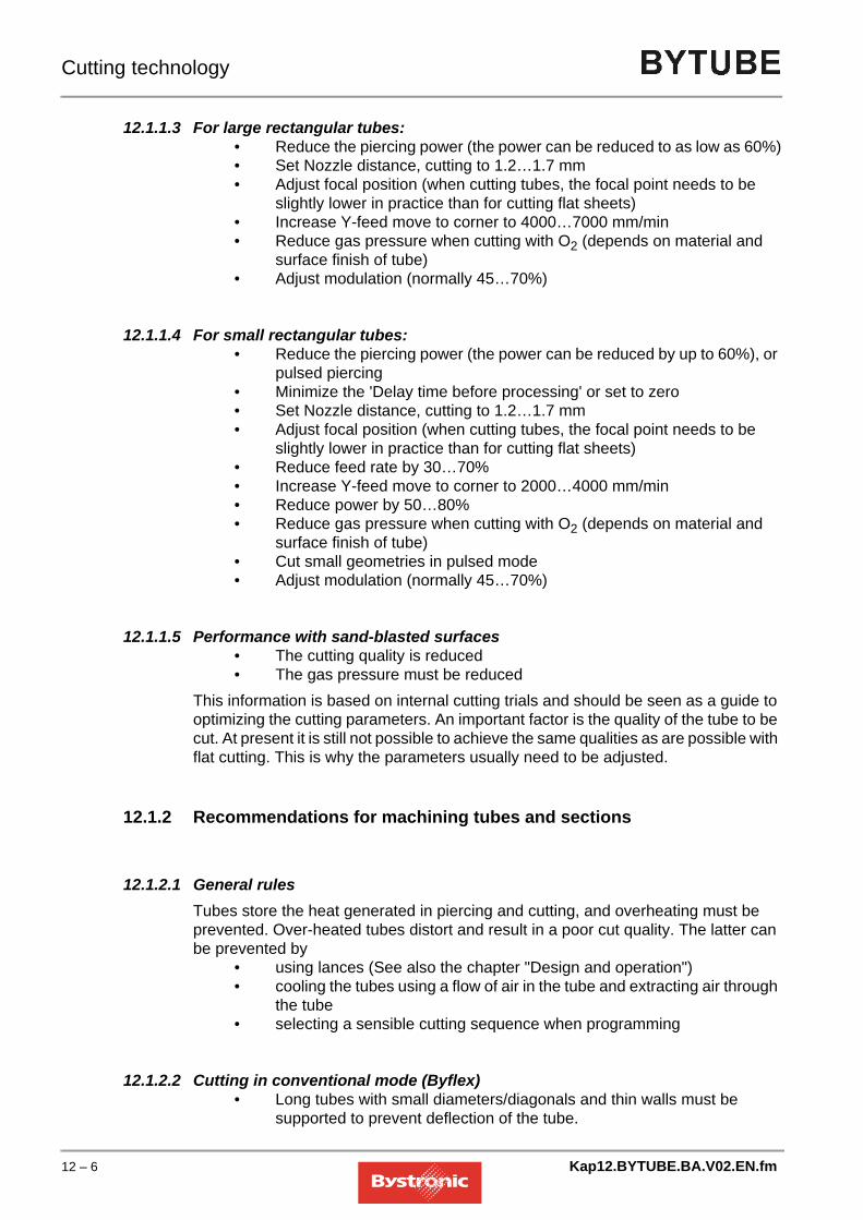
Cutting technology
12.1.1.3 For large rectangular tubes:• Reduce the piercing power (the power can be reduced to as low as 60%)• Set Nozzle distance, cutting to 1.2…1.7 mm• Adjust focal position (when cutting tubes, the focal point needs to be
slightly lower in practice than for cutting flat sheets)• Increase Y-feed move to corner to 4000…7000 mm/min• Reduce gas pressure when cutting with O2 (depends on material and
surface finish of tube)• Adjust modulation (normally 45…70%)
12.1.1.4 For small rectangular tubes:• Reduce the piercing power (the power can be reduced by up to 60%), or
pulsed piercing• Minimize the 'Delay time before processing' or set to zero• Set Nozzle distance, cutting to 1.2…1.7 mm• Adjust focal position (when cutting tubes, the focal point needs to be
slightly lower in practice than for cutting flat sheets)• Reduce feed rate by 30…70%• Increase Y-feed move to corner to 2000…4000 mm/min• Reduce power by 50…80%• Reduce gas pressure when cutting with O2 (depends on material and
surface finish of tube)• Cut small geometries in pulsed mode• Adjust modulation (normally 45…70%)
12.1.1.5 Performance with sand-blasted surfaces• The cutting quality is reduced• The gas pressure must be reduced
This information is based on internal cutting trials and should be seen as a guide to optimizing the cutting parameters. An important factor is the quality of the tube to be cut. At present it is still not possible to achieve the same qualities as are possible with flat cutting. This is why the parameters usually need to be adjusted.
12.1.2 Recommendations for machining tubes and sections
12.1.2.1 General rulesTubes store the heat generated in piercing and cutting, and overheating must be prevented. Over-heated tubes distort and result in a poor cut quality. The latter can be prevented by
• using lances (See also the chapter "Design and operation")• cooling the tubes using a flow of air in the tube and extracting air through
the tube• selecting a sensible cutting sequence when programming
12.1.2.2 Cutting in conventional mode (Byflex)• Long tubes with small diameters/diagonals and thin walls must be
supported to prevent deflection of the tube.
12 – 6 Kap12.BYTUBE.BA.V02.EN.fm

Cutting technology
• The maximum diameter is 320 mm• Long tubes with a large diameter/diagonal and thick walls require support
as soon as end cuts are set. The axial tensioning of the tailstock is not sufficient to prevent the tube dropping down. Another option is to set programmed microjoints. This only works with circular tubes.
Options• Microjoints
The microjoints prevent the tube dropping down when making severance cuts.
• Weld-jointsWeld joints can be programmed in Bysoft.The values required in Setup for making the weld joints can be taken from flat machining.The advantage of the weld joint over the conventional microjoint is that it is not the same thickness as the wall of the tube being cut, but simply results in a weld point on the material surface. This property means it is easier to separate the tube later. If the weld joints are not sufficient, the tube must be supported.
12.1.2.3 Cutting in Hybrid mode• In Hybrid mode the tubes are loaded automatically via the feed unit. The
tubes can be up to 6500mm depending on the machine type (max. 12500 mm).
• Circular tubes can be cut using the circular-tube steady rest or using the driven four-jaw steady rest. The surface of the tubes is damaged less by the driven four-jaw steady rest. This applies particularly to aluminum tubes and tubes with surface treatments.
• Rectangular or square sections can only be cut using the driven four-jaw steady rest.
• The length of the leftover tube equals- for the driven four-jaw steady rest 300 mm- for the circular tube steady rest 170 mm
• The maximum diameter or longest diagonal that can be cut is 170 mm.
Kap12.BYTUBE.BA.V02.EN.fm 12 – 7

Cutting technology
12.2 The laser cutting process
Basically, we can divide laser cutting into three areas:
12.2.1 Inert gas fusion laser cutting
In the fusion cutting process the work piece is melted locally and the melt is blown out by a gas jet (nitrogen N2). The material is only transported in the liquid phase, which is why the process is also called melt shearing. The laser beam is admixed with a high-purity assist gas that blows the melted material out of the kerf but is not involved in the actual cutting process.
• Fusion cutting achieves greater cutting speeds than oxygen cutting or sublimation cutting. The evaporation energy required is generally far greater than the energy required to melt the material. In fusion cutting only a small part of the laser beam is absorbed.
• Maximum cutting speed rises with increasing laser power and decreases almost inversely proportionally to sheet thickness and fusion heat of the material. If laser power is sufficient, limiting factors are gas pressure in the cut and heat conduction.
• Fusion cutting is suitable for making oxide-free cuts in ferrous materials and titanium.
• The range of power flux density achieved by melting without causing evaporation is between 104 W/cm2 and 105 W/cm2 for steel.
12.2.2 Oxygen laser cutting
Oxygen laser cutting differs from fusion cutting in the use of oxygen as assist gas. The interaction of oxygen with the heated metal causes a reaction that heats up the material even more. As a result of this effect, depending on sheet thickness and laser power, this method of cutting can cut structural steel at speeds far greater than fusion cutting. However, this process can lead to diminished cut quality compared to fusion cutting. The result may be wider cuts, increased surface roughness, deeper heat affected zones and diminished cut edge quality.
Laser cutting.
LaserLaser cutting
LaserGas cutting
LaserSublimation cutting
12 – 8 Kap12.BYTUBE.BA.V02.EN.fm

Cutting technology
• Oxygen cutting is critical when cutting fine contours and acute geometries (risk of burn-off). However, the amount of heat input can be limited by pulsing.
• The laser power determines speed of cutting. If laser power is sufficient, limiting factors are available oxygen and heat conduction.
12.2.3 Laser sublimation cutting
In laser sublimation cutting, the material is evaporated in the cut. This requires very strong laser power. Sheet thickness must not substantially exceed the diameter of the beam otherwise the vapor created at the cut wall will condense and close the cut again. Therefore, this method is only suitable for applications where you must prevent the melt from being blown out. There are currently only a few applications for ferrous metals. Exceptions are materials such as wood or special ceramics without a molten phase so that no recondensation of the material vapor can occur. It is also possible to cut much greater thicknesses of these materials.
• In laser sublimation cutting, optimum focusing depends on sheet thickness and beam quality.
• Laser power and evaporation heat only have little effect on the optimum focal position.
• Maximum cutting speed for a given material thickness is inversely proportional to the evaporation heat of the material.
• The necessary power density must be greater than 108 Watt/cm2 (Bystronic laser maximum 1.5x10⁷ Watt/cm2) and depends on the material, the depth of cut and the focal position of the laser beam.
• Maximum cutting speed for a given material thickness and sufficient laser power is limited by the gas jet speed.
Kap12.BYTUBE.BA.V02.EN.fm 12 – 9

Cutting technology
12.2.4 Cutting process
The cutting process means the interaction of the laser beam, the assist gas and the work piece.
The zone in which this process takes place is referred to as the cutting front or cut front. The laser power applied at the cutting front must heat up the material to the temperature required for phase transition of the material to melt and vapor.The cutting front is a practically perpendicular surface heated and melted by the absorbed laser beam.
• In oxygen laser cutting, this melt zone is heated up further by the flow of oxygen blown into the kerf and reaches temperatures close to the melting point of the material. This causes strong vaporization and ablation of the material. At the same time, the assist gas jet blows out liquid material underneath the work piece.
• In fusion cutting the gas blows out the liquid material and protects the kerf from oxidization.
The molten zone continues to move in the direction of cutting. This ensures a continuous kerf.Many important processes in laser cutting occur in this zone. Analyzing these processes provides important information on laser cutting. For example, it is possible to estimate cutting speed and explain the formation of characteristic striation marks.
Process parametersfor
Material Laser Assist gas Axis movement
12 – 10 Kap12.BYTUBE.BA.V02.EN.fm

Cutting technology
12.2.5 Laser modes
12.2.6 Gas parameters
• Gas type
• Gas pressure
• Nozzle diameter
• Nozzle geometry
Gas pressure and nozzle geometry affect the roughness of the cut edge and the creation of whiskers.The amount of assist gas consumed depends on nozzle diameter and gas pressure.
• For low-pressure cutting applications gas pressure is up to 5 bar and up to 20 bar in the high-pressure range.
• The conventional cutting nozzle has a circular, conical aperture.
• Make sure that the distance between the nozzle aperture and surface of the material is as small as possible. The smaller the distance, the greater the volume of gas actually entering the kerf. Clearance distances typically range from 0.5 to 1.5 mm.
Operating mode Applications ExampleContinuous wave (CW) Low-pressure cutting
Normal cutting
High-pressure cutting
Structural steel with O2
Aluminum with N2
Stainless steel with N2
Continuous cutting produces a relatively fine cutModulation (MOD) Cutting corners
Acceleration and deceleration
With modulation activated, the laser output is adjusted to the axis speed. This prevents corners from getting burnt off.
Normal pulsed (NP) Piercing
Tight contours
Mild steel example:Small piercing point on contour (after microjoint)
Small holes with minimum Ø ½ material thickness
Fine contours
Kap12.BYTUBE.BA.V02.EN.fm 12 – 11

Cutting technology
12.3 Materials
12.3.1 Material properties
The result of cutting the work piece can be a clean cut or a frayed cut edge with a burr.The main factors influencing cut quality are:
• Alloy components
• Microstructure
• Surface quality
• Surface roughness
• Surface treatment
• Beam reflection
• Thermal conductivity
• Melting point
• Fusion heat
• Evaporation temperature
12.3.1.1 Alloy componentsThese properties have a considerable influence on the materials’ strength, specific weight, weldability, resistance to oxides and acids. Some major alloy elements of ferrous materials are: carbon, chrome, nickel, magnesium and zinc.The higher the content of carbon, the less well the material can be cut (critical limit approx. 0.8% carbon). The following carbon steels can be cut well with the laser:St 37-2, StW 22, DIN 1.203
12.3.1.2 MicrostructureGenerally speaking, the finer the grain of the material structure, the better the quality of the cut edge.
12.3.1.3 Surface quality and surface roughnessIf the surface has rusty spots or scales, the cut will be irregular and have many chips.When cutting checker plate, select cutting parameters for the maximum thickness of the material. The checkers must always face down (reflection).
12 – 12 Kap12.BYTUBE.BA.V02.EN.fm

Cutting technology
12.3.1.4 Surface treatmentCommon surface treatments include zinc-coating, hot-galvanizing, varnishing, anodizing or foil coating.
• Depending on sheet thickness, zinc-coated sheets tend to form droplets below the cut.
• With varnished sheets, cut quality depends on the composition of the paint components.
Procedure for processing varnished sheets:
• Activate <REPEAT> on the CNC control unit
• For the first pass (G11) select a parameter set with reduced performance (etching) in order to pre-burn the surface treatment.
• For the second pass (G10) select the parameter set that corresponds to the material to be cut.
Foil-coated sheets are well suited to laser cutting. In order for the capacity scan to work smoothly and ensure optimal foil adhesion (avoiding bubbles), the foil-coated side should always face up on the work piece.
12.3.1.5 Beam reflectionBeam reflection of work piece surfaces depends on the base material, surface roughness and surface treatment. Some aluminum alloys are highly reflective (e.g. Anticorodal), as are copper, brass and stainless steel sheet.
12.3.1.6 Thermal conductivityMaterials with low thermal conductivity require less energy to melt than materials with high thermal conductivity.For example, the energy required for stainless steel is less than for structural steel despite lower absorption at cutting temperature.On the other hand, copper, aluminum and brass, for example, conduct a large amount of the heat generated by absorption of the laser beam. The heat is quickly conducted away from the focal point of the laser beam, thus making it harder to melt the material at this spot.
12.3.1.7 Heat affected zoneDuring laser cutting and laser welding changes may occur in the edge zones of the material being cut.
Kap12.BYTUBE.BA.V02.EN.fm 12 – 13

Cutting technology
The following table contains guidelines for the size of the heat affected zone depending on the base material and its thickness.
• In low-carbon steel and stainless steel there is little increase in hardness in the heat affected zone.
• In high-carbon steel (e.g. Ck60) hardening occurs in the edge zones.
• In hard-rolled aluminum alloys, the heat affected zone is slightly softer than the rest of the material.
Material thickness [mm]
Heat affected zone [mm]
St 37 Stainless steel Aluminum1 0.05 0.05 0.102 0.10 0.10 0.203 0.15 0.15 0.304 0.20 0.25 0.405 0.25 0.34 0.506 0.30 0.55 0.608 0.40 0.75 0.7010 0.50 0.85 -12 0.60 - -
12 – 14 Kap12.BYTUBE.BA.V02.EN.fm

Cutting technology
12.3.2 Machining a range of materials
12.3.2.1 Structural steelThis material can be cut with oxygen to produce good quality cuts. The laser is operated in CW mode. If the control changes the feed rate in tight contours, laser power is adjusted to axis feed rate by means of modulation.When using oxygen as the assist gas, the cut edge is slightly oxidized. For sheet thicknesses up to 6 mm, high-pressure cutting with nitrogen as assist gas may also be used. In this case the cut edges are oxide-free.Cut difficult contours and holes (Ø less than thickness of the material) in pulsed mode. This prevents sharp corners and thin joints from being burnt off.
• The greater the content of carbon in the steel, the more the cut edge will solidify and the greater the chance that sharp corners will be burnt off.
• Sheets with high alloy contents are more difficult to cut than sheets with low alloy content.
• An oxidized or sand-blasted surface will produce a far poorer cut quality.
• Color markings on the surface of the sheet have a negative effect on the cutting result.
• For sheet thicknesses of 12 mm and above, good results are achieved with laser sheet (e.g. Raex) and an oiled work-piece surface. The oil film reduces slag adhesion on the surface and considerably assists cooling. The oil film does not impair cutting results.
• Whenever possible, cut only fully killed steel. Contaminants in un-killed steel significantly impairs the cutting result. Dressing rollers and internal stress also affect suitability for cutting.
For smaller contours in sheet thicknesses of 15 and 20 mm we recommend fine-grain steel (e.g.: "Raex-250-Laser" from the Rautaruukki steel works, Raahe. This steel is made from a special melt with a maximum silicon content of 0.03% and a maximum carbon content of 0.012%. Tensile strength is 360-440 N/mm2. The ReH upper yield point equals at least 250 N/mm2. This steel has the following special features:
• no slag formation in laser cutting
• no warping of cut parts
• optimum edge behavior
• low spring-back
Kap12.BYTUBE.BA.V02.EN.fm 12 – 15

Cutting technology
• good suitability for welding
• This steel is available in thicknesses of up to 30 mm
Cutting results with St 52-3 are inferior as it tends to chip and burr due to the viscous slag.Observe the following guidelines in order to cut structural steel with a clean surface:
NOTE
12.3.2.2 Stainless steelCut this material:
• With oxygen if one can tolerate oxidization of the cut edge
• With nitrogen in order to achieve oxide-free, burr-free cut edges that do not require clean-up.
• Depending on sheet thickness, high-pressure cutting with nitrogen at high laser power achieves comparable or even greater speeds than oxygen cutting.
• In order to be able to achieve burr-free cutting with nitrogen of stainless steel of thickness 5 mm or more over the entire table area, it is necessary to readjust the focal position. By averaging out the focal position and reducing speed it is possible to cut clean cuts, albeit with slight burring.
• With the BYPOS option it is not necessary to adjust the focal position manually.
• An oiled sheet surface improves piercing without reducing cut quality.
For stainless steels select:
• When cutting with oxygen: pulsed mode with reduced feed rate for sheet thicknesses of 5 mm and above.
• A much larger nozzle clearance distance for piercing than for cutting. A large nozzle clearance distance helps prevent splashes on the lens.
NOTE
Si ≤ 0.04%: preferable; cuts well with laser
Si < 0.25%: possibly slightly reduced cutting properties
Si > 0.25%: steel of limited suitability for laser cutting and thus inferior or irregular cutting results.
Tolerance as per DIN for steels up to St 52, Si is ≤ 0.55%. These figures are too imprecise for laser cutting.
Only cut aluminum if the machine has a suitable device for absorbing reflections. Otherwise reflections can destroy the optical elements.
12 – 16 Kap12.BYTUBE.BA.V02.EN.fm

Cutting technology
12.3.2.3 TitaniumCut titanium sheets with nitrogen or argon assist gas. Cutting parameters are stored on the panel PC.When cutting with oxygen, the cutting edge oxidizes and has a brown discoloration. A burr also forms on the underside of the sheet.Cutting with argon achieves an oxide-free, clean cut edge without burr.
12.3.2.4 Copper and brass
• Both materials are highly reflective and have high thermal conductivity.
• Brass can be cut with nitrogen up to 3 mm.
• Copper can be cut up to a sheet thickness of 3 mm; assist gas must be oxygen.
NOTE
12.3.2.5 Plastics
Only cut copper and brass if the machine has a suitable device for absorbing reflections. Otherwise reflections can destroy the optical elements.
WARNINGPlastics must not be cut on BYSTRONIC laser cutting machines! The fumes given off on combustion are highly toxic. They cannot be completely removed by the extraction system.
!
Kap12.BYTUBE.BA.V02.EN.fm 12 – 17

Cutting technology
12.3.2.6 Organic materials
Wood, leather, cardboard and paper can be cut with the laser. The cut edge is charred (brown discoloration). The greater the feed rate, the less charring occurs. A clean cut cannot be guaranteed for glued wood because the glue layer breaks down in different ways depending on the type of glue.
12.3.2.7 Other materialsBystronic Customer Services can supply information on other materials.
DANGERThere is a risk of fire when cutting organic materials (use nitrogen as assist gas).
!
12 – 18 Kap12.BYTUBE.BA.V02.EN.fm

Cutting technology
12.4 Production
In order to maximize safety in production, we recommend testing parts separately with a greatly reduced cutting and positioning speed and by means of simulation in BYSOFT. Observe the following:
• Never position above a contour that is already cut.
• Observe direction of rotation during cutting and positioning
• No parts that rise up.
• Machine from right to left
12.4.1 Sheets
When machining sheets of thickness 0.5-3 mm, special care must be taken to ensure that the sheets are good quality and are transported with care. Sheets should be flat and not warped. During storage, handling and transport, keep sheets flat and do not bend.
12.4.2 Material surface
Material surface has a very significant influence on cutting results and cut quality.
Negative influences Positive influences
• Loose rolling skin
• Rust
• Scale
• Uneven surface with troughs and irregularities
• General soiling
• Steel stamping, scrap marks
• Color markings
• Fine, even surfaces with microscale
• Sheet lightly oiled
• Pickled sheets
• Hot-rolled oiled sheets
• Sandblasted and shot-blasted surfaces are only suitable to a limited extent but still better than rusty surfaces.
Example: cheap ST52 sheet exposed to weathering.
Example: RAEX series sheets recommended by Bystronic.
Kap12.BYTUBE.BA.V02.EN.fm 12 – 19

Cutting technology
12.4.3 Stresses
Cheap sheets generally have greater internal stress, and warp correspondingly in laser cutting. This stress is created during sheet manufacture.Higher quality sheets have less internal stress. Often, stress may vary within one sheet. The greatest stress can be seen in the edge zones as a result of faster cooling. By means of careful nesting it is possible to achieve additional production reliability.
Area 1: Little stress in the sheet. Parts subject to severe warping should be nested in this area. (e.g. long. thin strips)Area 2: More stress in the sheet. Uncomplicated parts not susceptible to warping should be positioned here.
12.4.4 Primers, varnishes, protective paints, zinc coatings
All these and similar surface treatments usually have a negative influence on cutting results. Oxygen and e.g. paint react in the kerf during cutting. This results in a very rough, frayed cut. Another problem is the difference in layer thickness in one sheet. Different thicknesses of protective coating cause errors in the capacitive detection.Solutions:
NOTE
1
2
2
22
Thicknesses up to 4 mm: Cut with nitrogen
Thicknesses > 4 mm: Etch off protective layer in the first pass.
Zinc-coated sheets are not suitable for pre-etching!
12 – 20 Kap12.BYTUBE.BA.V02.EN.fm

Cutting technology
12.4.5 Alloy elements
Cutting quality and cutting performance depend on alloy elements. In steel, a greater content of Si creates a rough cut edge and increases slag formation and burring. Carbon contents > 0.16% can lead to poor results on sharp edges and small holes.Bystronic recommends laser sheets having controlled alloying constituents when working at the extreme sheet-thickness range.
12.4.6 Oiling
Piercing splashes adhere less strongly on oiled sheets. This means that capacitate scanning is disrupted less. You can oil sheets in two ways.
• Working with Crossjet
• Buy oiled sheets
• Oil dry sheets manually
12.4.7 Radii
Always avoid acute contours in laser cutting. It is much easier for the machine to cut a radius of e.g. 1…2 mm at all changes in direction. This has the following advantages:
• corners do not burn
• time gain thanks to continuous process
• clean laser part
• less risk of injury on the part
C content Si content
RAEX 250 0,12% 0,01%
RAEX 420 0,13% 0,01%
CAUTIONDo not use combustible oil. Always use welding protection oil (MOTOREX PROWELD 264 Bystronic order no. 8861850).
!
Kap12.BYTUBE.BA.V02.EN.fm 12 – 21

Cutting technology
12.5 Programming
12.5.1 Piercing and initial cuts
Piercing causes the sheet to heat up very strongly. Careful positioning of piercing points and adequate length of initial cuts can help prevent heat build-up.Limit thickness sheet always requires a radius initial cut in order to ensure that the cutting process is as constant as possible.
12.5.2 Piercing
Parameter values for the piercing process differ from cutting values.
12.5.2.1 Continuous wave piercingAdvantage: fast piercing Disadvantage: piercing crater.
12.5.2.2 Pulsed mode piercingAdvantage: small piercing hole. Disadvantage: piercing takes a long time.
12.5.2.3 On-the-fly piercing during lowered positioningUse the parameters for «Flying start of cutting». These parameters ensure that the lens is protected against splashing.
Poorly located initial cuts Well located initial cuts with additional radius initial cut
R = 2 mm
12 – 22 Kap12.BYTUBE.BA.V02.EN.fm

Cutting technology
12.5.2.4 Piercing with circular pierce in stainless steel and aluminum
The hole is required in order to blow out the melt created during the approach and to initiate the cutting process.
12.5.2.5 Pulsed piercing on the contourPulsed piercing is used if piercing needs to be performed on the contour, or if the contour is very small and the piercing crater would impair the contour.
NOTE
If you need the cut-out part and the cut-out itself use «Pulsed mode piercing» (M14/15) directly on the contour.
1. After piercing, the machine cuts a 2 mm diameter circle with laser power.
2. Lowered positioning and approaching the contour through the start hole.
Sheet thickness in mm corresponds approximately to piercing time in seconds.
Kap12.BYTUBE.BA.V02.EN.fm 12 – 23

Cutting technology
12.5.3 Special piercing cuts in thick sheets
As laser powers increase it is possible to cut ever thicker materials. As a means of achieving optimum process reliability, the piercing procedure described below can be used to both increase reliabilty and reduce the minimum diameter that can be cut. Version 6 and above of the Technology Wizard supports special piercing cuts.
12.5.3.1 Applications
• if the hole is < sheet thickness
• tight, complex inner contours
• if the sheet is too hot and the cut quality gets bad
12.5.3.2 Programming
1. Select the sheet thickness in the Technology wizard and set the technology automatically. Add macro 1 for small bores or contours depending on size.
2. For difficult contours, position the initial cut so as to maximize initial cut length.
Equipment Thickness Bylaser
Steel 18…25 mm 4000
Steel 18…20 mm 3000
Stainless 15…20 mm 4000
12 – 24 Kap12.BYTUBE.BA.V02.EN.fm

Cutting technology
3. Program a start hole at the end of an initial cut (for an inner contour).• Start hole radius in stainless steel = 1.25 mm• Start hole radius in Steel = 1.6 mm
4. Set technology automatically again. The start hole is pierced in pulsed mode and cut with macro 2.
5. Copy the start hole with technology to all ends of initial cuts where you want special piercing.
6. Delete the cutting sequence for the entire part.
7. Select cutting sequence manually.Recommendation for steel: first cut all start holes, then cut the most difficult or the smallest contours (reduces the heat).
12.5.3.3 Cutting
1. Load program and cutting parameters.
2. Cut the cutting plan.
Kap12.BYTUBE.BA.V02.EN.fm 12 – 25

Cutting technology
12.5.4 Initial cutting pane and end cutting pane for steel
The technology wizard as of BYSOFT 6.2 greatly facilitates setting the initial cutting pane. The length and geometry of the initial cut are set automatically.
12.5.4.1 Outer contourPiercing is usually done in CW mode. This form of piercing is fast but makes a larger pierce than in pulsed mode. Therefore the pierce is usually located outside the contour (Figs. 2 and 3). The connecting line between the pierce and the contour is referred to as the initial cutting pane or initial cut for short.A change in direction of the laser beam between the end of the initial cut and the contour appears as an irregularity on the work piece (Fig. 2). Therefore, if possible program the initial cut of the outside contour in the extension of a geometry element (Fig. 3).However, program the initial cut perpendicular to a geometry element (Fig. 2) if you want to use the automatic round-off function or if you program a small inside contour in a sheet thickness greater than 10 mm (heat not carried away from initial cut when the cut is finished).
Program the initial cut as a stand-alone geometry element.
12.5.4.2 Inside contour (cut-outs)With small inside contours it is important that the heat input during piercing can flow off before cutting begins. Do not program the initial cutting pane in confined areas and at as large as possible an angle to the contour. This allows the heat to flow away more easily.
Parts requiring finishing
Small inside contours in thick sheet, corners
with radiiThin sheet, corners
without radii
CW pierce on contour:
Corner damaged
CW pierce outside contour
Corner damaged
CW pierce outside contour.
Move into contour in a line.
No markings on the part
Fig. 1 Fig. 2 Fig. 3
12 – 26 Kap12.BYTUBE.BA.V02.EN.fm

Cutting technology
Fig. 12.5 -1 small inside contours
The length of the initial cut depends on sheet thickness and the diameter of the hole.
Fig. 12.5 -2 Hole diameter
not suitable suitable
Sheet thickness [mm]
Hole diameter «d» [mm]
Initial cut length «a» [mm]
1…6d < 10 from hole center (d/2)
d > 10 5
8…12d < 20 from hole center (d/2)
d > 20 10
15…25d < 30 from hole center (d/2)
d > 30 15
Work pieceHole
Kap12.BYTUBE.BA.V02.EN.fm 12 – 27

Cutting technology
12.5.5 Initial cutting pane and end cutting pane for stainless steel and aluminum
Piercing is usually done with oxide-free cutting in CW mode. In oxide-free cutting, the acceleration and deceleration paths must be outside the contour in order to avoid whiskers.
12.5.5.1 Outer contour
12.5.5.2 Inside contour (cut-outs)
NOTE
Fig. 12.5 -3 Inside contour cut-out
poor OK good
– CW pierce on contour
– Corner damaged
– CW pierce outside contour
– Point of cut-in and cut-out visible on contour
– CW pierce outside contour
– Move into contour in a line
– Markings on the part
Part Part Part
For holes and other cut-outs it is an advantage to program the transition from the initial cutting pane to the contour with a radius.
Work piece
SectionRadius
12 – 28 Kap12.BYTUBE.BA.V02.EN.fm

Cutting technology
12.5.5.3 Initial cut length for cut-outs
Piercing in center of hole up to 30 mm hole diameter
Length of initial cut depends on sheet thickness as of a hole diameter of 30 mm
Kap12.BYTUBE.BA.V02.EN.fm 12 – 29

Cutting technology
12.5.6 Microjoints
Without microjoints, a cut-out is completely cut, i.e. when the cut is completed the laser joins the start of the cut again. However, separation of the material occurs before the geometric end of the cut by at least the width of the kerf (d):
Fig. 12.5 -4 Part cut-out microjoint
At this point the cut-out part already tilts and the laser beam hits the side of the tilting part causing heat erosion. The melt of this burn-out reflects the laser beam and causes more burn-out in the cut-out itself.Use microjoints to avoid this burn-out. The CNC system has an automatic microjoint function. Adding a microjoint causes the laser beam to switch off by distance (b) before the geometric end of the cut-out. The cut-out stays connected to the part and does not tilt off. Press the cut-out out of the part after cutting the plan or remove the cut-out with a rod magnet when the protective door is open. Set web width (b) at least as large as kerf width (d).
Fig. 12.5 -5 Microjoint
d
Initial cutLaser beam at separation
Laser beam at start and end of cut
b
Work pieceSection
12 – 30 Kap12.BYTUBE.BA.V02.EN.fm

Cutting technology
12.5.7 Corners
12.5.7.1 Cutting obtuse corners with radiiAvoid corners without radii wherever possible. Advantages of corners with radii over corner without radii:
• Axes are moved more dynamically
• smaller heat affected zone
• less burring
• time gain
• lower risk of damaging contour
Optimum rounding off radius:R optimum = sheet thickness in mm divided by 10, but not less than 1 mm.Maximum radius, if a sharp corner is needed on the inner contour:R edge = half cut widthThis radius creates a sharp corner but the axes already move dynamically:
Fig. 12.5 -6 Radii in contours
12.5.7.2 Cutting obtuse corners with «corner tolerance»If you need a sharp corner on the outside contour for further processing, program the corner without a rounding-off radius.
NOTE
Outside contour with radius
Inside contour with corner
Focus diameter
Cut width
Rounding-off radius
rmax = 0,1 mm
If corner tolerance is too high, overshooting can occur.
Kap12.BYTUBE.BA.V02.EN.fm 12 – 31

Cutting technology
Fig. 12.5 -7 Corner tolerance
12.5.7.3 Acute corners in thin sheet with loops
Fig. 12.5 -8 Corner with loops
Cutting corners in thin sheet at high speed requires looping. This procedure has the following advantages:
• the axes travel over a sharp corner with continuous change of direction
• the part itself is cut at constant speed
• prevents axis overshoot and additional burring
• reduces heat effect in the corner
12.5.7.4 Acute corners in thick sheet with the «dwell time» parameterCutting thick sheet with loops creates too much heat on the work piece. Therefore, use the «dwell time» parameter for thick sheet when cutting acute corners.The machine moves into the corner and waits for the set «dwell time» before leaving the corner.
Fig. 12.5 -9 Critical angle dwell time
If you enter a value for the «dwell time» parameter, the machine decelerates and waits at every critical angle greater than the «critical angle dwell time» parameter set in the CNC.
too large correct
Radius R
Loop
Part
Change of direction angle
12 – 32 Kap12.BYTUBE.BA.V02.EN.fm

Cutting technology
NOTE
12.5.8 Pre-piercing
If you are cutting parts with lots of holes and openings or if small parts are tightly nested, Bystronic recommends pre-piercing.
– Use the BYSOFT 5.3 ByADD or Bysoft 6.0 Bywork software to add the pre-piercing functions to the LCC plan
– Pre-pierce whole sheet– Clean off piercing splashes from sheet– Let the sheet cool down if necessary– Cut
TIP
NOTE
Solution:Reduce size of cutting area by dividing a large cutting plan (e.g. 1x2 m) into two small (e.g. 1x1 m) plans.The thermal expansion problem means that you should only use multiple cuts to cut individual parts that have no tolerances.
Where the angle on the wanted part is too small, the machine will automatically follow a small radius; thus the dwell time is no longer active.
Use a smaller nozzle for pre-percing than for cutting. (e.g. K12 instead of K17). The piercing pressure must be doubled in order to prevent splashes on the lens. Pre-piercing considerably reduces the amount of heat introduced into the sheet. It also reduces the size of piercing holes.After pre-piercing all the holes, the machine automatically moves to the zero point. Here you can conveniently change the nozzle.Reset the «Gas pressure, pre-piercing» back to the original value and reduce the piercing time to 0. This procedure allows you to cut holes and openings of 0.8 to 1.0 times the sheet thickness in normal thickness sheet without pulsing.
If the sheet heats up severely during cutting it expands. This can cause pre-punched holes to shift.
Kap12.BYTUBE.BA.V02.EN.fm 12 – 33

Cutting technology
12.5.9 Cutting small parts
12.5.9.1 with normal thicknessIn order to be able to cut such parts with adequate process safety in production, observe the following guidelines:
• Use a radius (R) for all acute contours. R= 1/10 x sheet thickness, but at least 1 mm.
• Smallest openings (holes, slits) 1,2…1,5 x sheet thickness.
• Minimum web width 1,2…1,5 x sheet thickness.
• Minimum part spacing 1.0…1.5 x sheet thickness, but at least 10 mm in order to ensure reliable capacitive detection
• When cutting with tactile detection, parts spacing min. ½ ring diameter.
• Initial cut length 1 x sheet thickness, but at least 10 mm.
• Careful programming (cutting sequence in DIN part) in order to ensure optimum heat distribution in the part.
• Well thought-out nesting (cutting sequence of individual parts in the cutting plan). This ensures good distribution of heat in the cutting plan.
– The numbers indicate the cutting sequence.Exceeding guidelines may cause sheet overheating. First signs of overheating are indicated by rough cut surfaces, burnt contour cuts and melt not blown out.
Fig. individual part Fig. cutting plan
12 – 34 Kap12.BYTUBE.BA.V02.EN.fm

Cutting technology
Example 1: Cutting in 2 passesRaex 250, thickness 15 mm
The complete cutting plan is divided into two new cutting plans. Only every second part is cut in the first plan (cut 1). Now you have to interrupt cutting until the temperature of the sheet drops below 40 °C. Only then can you cut the remaining parts (cut 2).
Example 2: Cutting in 3 passesRaex 250, thickness 12 mm
Sheet dimension x = 675 mm
y = 689 mm
Parts dimension x = 100 mm
y = 80 mm
Shape spacing x = -18 mm
y = 17 mm
All 1. section 2. section
Sheet dimension x = 477 mm
y = 485 mm
Parts dimension x = 62 mm
y = 30 mm
Shape spacing x = 20 mm
y = 20 mm
Kap12.BYTUBE.BA.V02.EN.fm 12 – 35

Cutting technology
The same procedure as with two passes only that every third part is cut in the first pass (cut 1). Now you have to interrupt cutting until the temperature of the sheet drops below 40 °C. Only then can you cut the second groups of parts (cut 2). The third cut is cut the same way as the second cut.
All 1. section
2. section 3. section
12 – 36 Kap12.BYTUBE.BA.V02.EN.fm

Cutting technology
12.5.9.2 With limit thicknessObserve the following guidelines:
• Use a radius (R) for all acute contours. Rmin = 1 mm
• Radius initial cut, Rmin = 1,0…3,0 mm
• Smallest openings (holes, slits) 1,5…2,5 x sheet thickness
• Minimum web width 1,5…2,5 x sheet thickness
• Minimum part spacing 1,5…2 x sheet thickness, but at least 15 mm
• Initial cut length 1 x sheet thickness, but at least 15 mm
• Careful programming (cutting sequence in DIN part, see example Fig. individual part) in order to ensure optimum heat distribution in the part
• Well thought-out nesting (cutting sequence of individual parts in the cutting plan, see example Fig. cutting plan). This ensures good distribution of heat in the cutting plan
• Possibly with etching
Kap12.BYTUBE.BA.V02.EN.fm 12 – 37

Cutting technology
Example 3: Cutting in 2 passesRaex 250, thickness 18 mm
Only cut 1 and 2 when sheet temperature is less than 40 degrees.
Despite the suggested measures, the necessary process reliability when cutting small parts may not be achieved in production at the limits of sheet thickness. Although the parts can be cut, they can only be cut as individual parts but not as a nested cutting plan. The operator’s experience will decide where the limit is.
Sheet dimension x = 485 mm
y = 960 mm
Parts dimension x = 122 mm
y = 110 mm
Shape spacing x = -1 mm
y = 30 mm
All 1. section 2. section
12 – 38 Kap12.BYTUBE.BA.V02.EN.fm

Cutting technology
12.5.10 Pulsed mode cutting
Use laser cutting in pulsed mode for critical contours.
• Sheet thickness range 1 to 5 mm
• Cutting speed is approx. 5 to 10 x less than with CW laser cutting
• Sheets of thickness 1 to 6 mm are well suited to pulsed machining
• Sheets of thickness 8 to 5 mm can only be cut in pulsed mode if machine settings are optimum and laser power is sufficient. Rough grooves form and the "cutting" feed rate is low.
• Do not cut whole parts in pulsed mode.
• Set the switchover point from pulsed to CW cutting so that switchover takes place in a corner.
• Do not switch on straight lines or large contours as switching from one mode to another causes a small chip:
Fig. 12.5 -10 Cutting in CW and pulsed mode
Legend:
NOTE
unsuitable suitable
A. Switchover pointB. CW cuttingC. Pulsed cutting
A
A
B
B
B B
C
C
A
A
B
B
B B
C
C
If possible switch pulsing on after CW cutting and not vice-versa. This improves transitions on the cut edge from CW cutting to pulsing.
Kap12.BYTUBE.BA.V02.EN.fm 12 – 39

Cutting technology
12.6 Definitions and limits
Cutting steel causes very high temperatures in the sheet. These are due to
• the laser beam
• the carbon (C) in the material assisting the melting process
• the assist gas (O2) supporting melting.
• other alloy components in the sheet
Applying heat and heat generation are therefore physical processes.The heat applied can get so high that cut quality gets so poor that the melt is no longer blown out. The cut parts are useless.These problems occur in different material thicknesses, part sizes, holes shapes and laser types.These cutting instructions are intended to highlight potential cutting problems before they occur, and to show what is and is not possible.The following definitions are required.
12.6.1 Definition of limit thickness / normal thickness
When cutting materials whose thickness lies in the limit-thickness region, the following points are crucial to maintaining constant results:
• Quality of material and gas
• Condition of lens and system
• Overall constancy of laser system
Limit thicknesses are material thicknesses at the limit of the cutting performance of the laser. All value below these limit thicknesses are normal thicknesses.By taking account of these cutting instructions, materials can be cut on Bystronic laser cutting machines up to the following maximum limit thicknesses:
12 – 40 Kap12.BYTUBE.BA.V02.EN.fm

Cutting technology
Max.sheet thickness in
Bylaser
2200 3000 4000 4400
Structural steel 12 mm 20 mm 20 mm 25 mm
Stainless steel 6 mm 10 mm 12 mm 20 mm
Aluminum 4 mm 8 mm 8 mm 12 mm
Smallesthole in
Bylaser
2200 3000 4000 4400
Structural steel with pulsed piercing
…10 mm:0.8…1 x sheet
thickness
…10 mm:0.8…1 x sheet
thickness
…15 mm:0.6…1 x sheet
thickness
…15 mm:0.6…1 x sheet
thickness
Structural steel with pulsed piercing/
cutting
…10 mm:0.5…0.8 x sheet
thickness
…10mm:0.5…0.8 x sheet
thickness
…15 mm:0.5…0.8 x sheet
thickness
…15 mm:0.5…0.8 x sheet
thickness
Stainless steel with macro
0.5…2 x sheet thickness
0.5…2 x sheet thickness
0.5…2 x sheet thickness
0.5…2 x sheet thickness
Aluminum with macro
0.5…2 x sheet thickness
0.5…2 x sheet thickness
0.5…2 x sheet thickness
0.5…2 x sheet thickness
Various materials with macro
0.5…2 x sheet thickness
0.5…2 x sheet thickness
0.5…2 x sheet thickness
0.5…2 x sheet thickness
Stainless steel with CW
>2 x sheet thickness
>2 x sheet thickness
>2 x sheet thickness
>2 x sheet thickness
Aluminum with CW >2 x sheet thickness
>2 x sheet thickness
>2 x sheet thickness
>2 x sheet thickness
Various materials with CW
>2 x sheet thickness
>2 x sheet thickness
>2 x sheet thickness
>2 x sheet thickness
Flying piercing inBylaser
2200 3000 4000 4400
Steel (sheet thickness)
3 mm 3 mm 3 mm 3 mm
Stainless steel 3 mm 3 mm 3 mm 3 mm
Aluminum 3 mm 3 mm 3 mm 3 mm
Various materials 3 mm 3 mm 3 mm 3 mm
Kap12.BYTUBE.BA.V02.EN.fm 12 – 41

Cutting technology
12.6.2 Definition of part area A
Bystronic defines the area of a geometric part according to the following criteria.
Fig. 12.6 -1 Example:
Part area A = area inside an enclosed outside contour. Bore holes, slits and openings are subtracted.
Square = 100 cm2
2 bore holes = - 6.3 cm2
1 slot = -22 cm2
Part areas = 71 cm2
A
12 – 42 Kap12.BYTUBE.BA.V02.EN.fm

Cutting technology
12.6.3 Definition of part size
Severe heat accumulation (build-up) above all occurs at limit thicknesses and with small parts. Allocation of part size depends on sheet thickness.Definition of part size as dependent on sheet thickness
Table applies to BYSTRONIC laser series.If heat problems occur when cutting small part sizes up to max. 4 mm sheet thickness, you can cut with nitrogen (N2) instead of with oxygen (O2).Advantages:
• Nitrogen greatly cools the cut edge and the part
• Bright-finished metallic surface
• Very small heat-affected zone
Cutting parameters are similar to stainless steel sheets of the same thickness. Only feed rate needs to be reduced by 10 to 20%.
Thickness in mm small parts medium parts large parts
15,0…20,0 A = 150 150 = A = 1350 1350 = A12,0…14,9 A = 100 100 = A = 900 900 = A8,0…11,9 A = 75 75 = A = 675 675 = A4,0…7,9 A = 40 40 = A = 360 360 = A2,0…3,9 A = 20 20 = A = 180 180 = A0,5…1,9 A = 10 10 = A = 90 90 = A
Kap12.BYTUBE.BA.V02.EN.fm 12 – 43

Cutting technology
12.6.4 Definition of web width and minimum web width
Hole separations, hole-to-outside-contour distance, and distances between contours are generally referred to as web width. The smallest distance inside a part is referred to as minimum web width.
Fig. 12.6 -2 Example A
Fig. 12.6 -3 Example B
Fig. 12.6 -4 Example C
minimum web width
web
wid
th
web width
web width
minimum web width
minimum web width
12 – 44 Kap12.BYTUBE.BA.V02.EN.fm

Cutting technology
12.6.5 Part spacing
Part spacing is the minimum distance between two parts. Initial cuts outside the part belong to the part.
Fig. 12.6 -5 Example A
Fig. 12.6 -6 Example B
Part
spac
ing
in Y
dire
ctio
n
Part spacing in X direction
Part
spac
ing
in Y
dire
ctio
n
Part spacing in X direction
Kap12.BYTUBE.BA.V02.EN.fm 12 – 45

Cutting technology
12.6.6 Master gauges
Large parts can also overheat partially if you are cutting narrow master gauges. Master gauges are subject to the same rules and definitions as individual parts.
Fig. 12.6 -7 Example B
The same rules and definitions apply as to individual parts.
12 – 46 Kap12.BYTUBE.BA.V02.EN.fm

Cutting technology
12.6.7 Achievable parts accuracy
The tables shown are based on the DIN standard 2310 "Thermal Cutting", but have been extended to cover the Bystronic Laser AG laser machines. The specified tolerances are values obtained from practical experience of laser gas cutting and fuson cutting.
The following conditions must be met in order to achieve the tolerances above:
• Optimized cutting results, especially tool compensation (normally the Bystronic lens carrier parameters).
• The sheets must not heat up more than 20°C during laser cutting.
• When parts are measured, the flatness of the parts must be identical to the flatness of the cutting position.
• Internal stress of the sheets is not taken into consideration in the tables. Warps have a negative effect on the results.
• The superficial roughness must not influence the measurement.
• Measurements must not be performed on the contour at the starting point.
• Relevant measurements must only be performed on parts with bare edges.
• Good system conditions including all lenses.
• Measurement and analysis processes according to VDI/DGQ 3441
Thickness t[mm]
Part length L [mm]
0 < L < 10 10 < L < 100 100 < L < 300 300 < L < 1000 1000 < L < 2000 2000< L < 3000
0,5 < t < 3 [+/-] 0,1 [+/-] 0,1 [+/-] 0,2 [+/-] 0,25 [+/-] 0,3 [+/-] 0,4
3 < t < 6 [+/-] 0,2 [+/-] 0,2 [+/-] 0,2 [+/-] 0,25 [+/-] 0,4 [+/-] 0,5
6 < t < 10 [+/-] 0,2 [+/-] 0,2 [+/-] 0,2 [+/-] 0,3 [+/-] 0,4 [+/-] 0,5
10 < t < 15 [+/-] 0,25 [+/-] 0,25 [+/-] 0,3 [+/-] 0,3 [+/-] 0,4 [+/-] 0,6
15 < t < 20 [+/-] 0,3 [+/-] 0,3 [+/-] 0,3 [+/-] 0,3 [+/-] 0,5 [+/-] 0,6
Kap12.BYTUBE.BA.V02.EN.fm 12 – 47

Cutting technology
12.6.8 Unsuitable parts for production
These are usually small parts in limit thicknesses, although special geometries in normal thicknesses can cause problems.
Example 4Raex 250, thickness 20 mm
• Shape 1 without radii cannot be cut this way
• Shape 2 with R= 2 mm can be cut as an individual part on certain conditions
• Parts of this size in limit thickness are unsuitable for production
Sheet dimension x = 88 mm
y = 83 mm
Parts dimension x = 25 mm
y = 17 mm
12 – 48 Kap12.BYTUBE.BA.V02.EN.fm

Cutting technology
12.7 Cutting process
12.7.1 Cutting structural steel
Start of cutting after piercing in continuous wave.The following table lists guidelines for waiting time before cutting and for the acceleration factor to start cutting in continuous wave. During the set waiting time before cutting the heat created by piercing can dissipate in the work piece. This prevents large chips when the laser starts moving.
NOTE
* These thicknesses cannot be cut with «Bylaser 2200».
For holes with a diameter smaller than sheet thickness, increase waiting time before cutting based on the following guidelines or pierce in pulsed mode.
Sheet strength Focal length Waiting time before
cuttingAcceleration
factorShape >
sheet thickness
Shape < sheet
thickness
Start-up
[mm] [Inch] [s] [s]1 5“ 0,1 0,1 12 5“ 0,2 0,2 13 5“ 0,2 0,2 14 7,5“ 0,3 0,3 15 7,5“ 0,3 0,3 16 7,5“ 0,4 0,8 18 7,5“ 0,5 1,2 1
10 7,5“ 0,8 1,5 112 7,5“ 0,8 2,0 1*15 7,5“ 0,8 2,5 1*20 7,5“ 1,0 3,0 1
Kap12.BYTUBE.BA.V02.EN.fm 12 – 49

Cutting technology
12.7.1.1 Initial cuts for holes
Fig. 12.7 -1 Hole diameter
Also refer to the technology wizard in the BYSOFT programming software.
12.7.1.2 Hole roundnessYou can influence hole roundness by changing the dynamic factor. If holes are cut out of round, set a smaller dynamic factor.The dynamic factor depends on the type of machine, cutting feed and the laser.
12.7.1.3 Guidelines for the dynamic factor
For general information on programming initial cuts please see chapter «Initial cutting pane and end cutting pane for steel», while the chapter «Machining holes» contains tips on cutting holes.
Sheet thickness
[mm]Hole diameter «d»
[mm]Initial cut length «a»
[mm]
1…6d < 10 from hole center
d > 10 5
8…12d < 20 from hole center
d > 20 10
15…25d < 30 from hole center
d > 30 15
Work pieceHole
Sheet strength
[mm]Bysprint Bystar 3015 Bystar 4020/25 Byspeed Bytube
1…3 1,0 0,8 0,5 1,8 0,84…0 0,8 0,8 0,8 1,5 0,5
12 – 50 Kap12.BYTUBE.BA.V02.EN.fm

Cutting technology
12.7.1.4 Obtuse corners with «corner tolerance» parameter (quality cuts)The following table contains recommended values for the «corner tolerance» parameter according to the laser machine. General information on cutting corners can be found in the chapter «Machining corners».
12.7.1.5 Corner tolerance guides [mm]
12.7.1.6 Cutting acute corners in thin sheet with loops
12.7.1.7 Acute corners in thick sheet with the «dwell time» parameterThe following table contains guides for the «dwell time» parameter depending on sheet thickness. General information on cutting corners in thin sheets can be found in the chapter «Machining corners».
12.7.1.8 Cutting thick sheetGeneral notes:
• Use the serrated grid; for critical parts consider shimming the sheet off the support grid.
• Spacing a of individual parts in the cutting plan: a = double sheet thickness.
Sheet strength
[mm]Bysprint Bystar 3015 Bystar 4020/25 Byspeed Bytube
1…2 0,15 0,10 0,05 0,25 0,103…4 0,10 0,10 0,07 0,25 0,105…10 0,10 0,10 0,10 0,25 0,10
Sheet strength[mm]
Loop radius[mm]
1…5 36…10 412…20 5
Sheet strength[mm]
Dwell time[ms]
1…12 10013…15 20016…20 500
Kap12.BYTUBE.BA.V02.EN.fm 12 – 51

Cutting technology
12.7.1.9 Piercing
• Oil the sheets. Oiling prevents piercing splashes from sticking on the surface of the sheet and does not have any negative effect on the cutting process.
• The Crossjet allows you to spray an oil mist. The oil mist is a mixture of air and oil. The oil mist cools the piercing point. The Crossjet function can be used to blow off piercing splashes. This prevents piercing splashes from sticking to the sheet.
Use the «Bywork» module of the BYSOFT programming software to specify the sequence of piercing thick sheet with numerous pierces (etching).
• All piercing is done before cutting the contours. This greatly reduces and distributes more evenly the heat input into the work piece.
• For etching, for example, you can also use a cutting head with an older lens. However, use a cutting head with an intact lens to cut the contours!
• After completion of the etching program, wipe any splashes off and continue cutting.
12.7.1.10 CuttingMake sure that the sheet temperature does not exceed 40°C otherwise cut edges may “chip”.
• Wait before starting to cut small holes until the pierce has cooled down («dwell time before cutting» parameter) or even use the etching program for sheet thicknesses 15…20 mm.
• Note geometric conditions when specifying the cutting sequence. Cut small holes and complicated contours before other contours.
• In a first pass, only cut every other part and then the remaining parts in a second pass.
• Interrupt cutting until the sheet has cooled down to less than 40°C if it still heats up to more than 40°C despite these measures.
12 – 52 Kap12.BYTUBE.BA.V02.EN.fm

Cutting technology
12.7.2 Oxide-free cutting of stainless steel
NOTE
12.7.2.1 Start of cutting after piercingAfter the set piercing time has expired, the machine starts moving at the set acceleration factor. Sheet thicknesses for which the entry “yes” is indicated in the “Circular piercing required” column additionally require a start hole.
12.7.2.2 Bylaser 2200
12.7.2.3 Bylaser 3000/4000/40s
**Only for Bylaser 4000
Assist gas is nitrogen!
Sheet strength[mm]
Acceleration factorStart-up [-]
Circular piercing required
1…1,5 1 No2…2,5 0,7 No
3 0,3 No4 0,05 No5 0,02 No
Sheet thickness [mm]
Acceleration factor start-up [-]
Circular piercing required
1 1 no2 0,8 no3 0,5 no4 0,4 no5 0,1 no6 0,02 no
8…12 0,001 Yes**15 0,001 Yes
Kap12.BYTUBE.BA.V02.EN.fm 12 – 53

Cutting technology
12.7.2.4 Initial cut for holeThe length of the initial cut depends on sheet thickness and the diameter of the hole:
Fig. 12.7 -2 Hole diameter
12.7.2.5 Hole roundnessThe same values apply to roundness of holes and the dynamic factor as for structural steel. See chapter «Cutting structural steel».
12.7.2.6 Corner tolerance (quality cuts)The same values apply to corner tolerance as for structural steel. See chapter «Cutting structural steel».
12.7.2.7 Processing with loopsLoop size guides
Sheet thickness [mm]
Hole diameter «d» [mm]
Initial cut length «a» [mm]
1…6d < 20 from hole center (d/2)
d > 20 10
8…12d < 30 from hole center (d/2)
d > 30 15
Work pieceHole
Sheet strength[mm]
Loop radius[mm]
1…4 45 56 68 810 1012 12
12 – 54 Kap12.BYTUBE.BA.V02.EN.fm
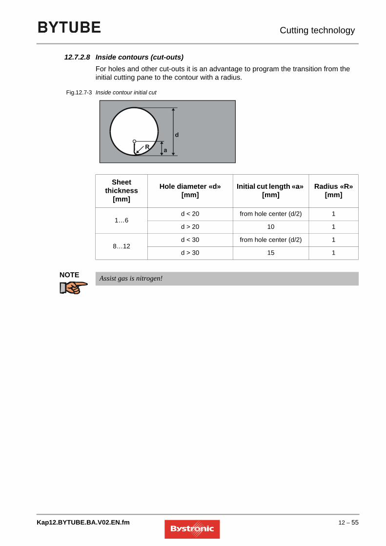
Cutting technology
12.7.2.8 Inside contours (cut-outs)For holes and other cut-outs it is an advantage to program the transition from the initial cutting pane to the contour with a radius.
Fig. 12.7 -3 Inside contour initial cut
NOTE
Sheet thickness
[mm]Hole diameter «d»
[mm]Initial cut length «a»
[mm]Radius «R»
[mm]
1…6d < 20 from hole center (d/2) 1
d > 20 10 1
8…12d < 30 from hole center (d/2) 1
d > 30 15 1
Assist gas is nitrogen!
Kap12.BYTUBE.BA.V02.EN.fm 12 – 55

Cutting technology
12.7.3 Oxide-free cutting of aluminum alloys
12.7.3.1 Start of cutting after piercingAfter the set piercing time has expired, the machine starts moving at the set acceleration factor. Sheet thicknesses for which the entry “yes” is indicated in the “Circular piercing required” column additionally require a start hole.
12.7.3.2 Bylaser 2200
12.7.3.3 Bylaser 3000/4000/40s
12.7.3.4 Initial cut for holeThe length of the initial cut depends on sheet thickness and the diameter of the hole:
Fig. 12.7 -4 Hole diameter
Sheet strength
[mm]
Acceleration factorStart-up [-]
Circular piercing required
1 1 No2…3 0,3 No
4 0,03 Yes
Sheet thickness
[mm]Acceleration factor start-
up [-]Circular piercing
required
1 1 no2 0,8 no3 0,5 no4 0,1 no5 0,01 no
6…8 0,001 Yes
Work pieceHole
12 – 56 Kap12.BYTUBE.BA.V02.EN.fm

Cutting technology
12.7.3.5 Hole roundnessThe same values apply to roundness of holes and the dynamic factor as for structural steel. See chapter «Cutting structural steel».
12.7.3.6 Corner tolerance (quality cuts)The same values apply to corner tolerance as for structural steel. See chapter «Cutting structural steel».Corner tolerance guides:
12.7.3.7 Processing with loopsLoop size guides
Sheet thickness [mm]
Hole diameter «d» [mm]
Initial cut length «a» [mm]
1…6d < 20 from hole center (d/2)
d > 20 10
8…12d < 30 from hole center (d/2)
d > 30 15
Sheet strength[mm]
Corner tolerance[mm]
1…5 0,16 0,088 0,06
10 0,04
Sheet strength[mm]
Loop radius[mm]
1…4 25…6 38…10 4
Kap12.BYTUBE.BA.V02.EN.fm 12 – 57

Cutting technology
12.7.4 Pulsed operation
In pulsed cutting,the laser power is always switched from "base power" to "cutting power" at a defined frequency. The energy introduced into the material causes heating and rapid metling of the material. A coaxial flow of gas assists the cutting process, removing the material from the cut gap.The advantage of pulsed operation is that the necessary pulse peak power is present, but less heat overall is introduced into the material. This allows smaller holes and openings, plus difficult contours, to be cut with a better quality.The ratio between pulse and pulse interval has a direct impact on the piercing time and the cutting feed rate. The cutting speed can be up to 10 times lower in pulsed mode than in CW mode. The piercing time in pulsed mode can be up to 10 times longer than in CW mode.
12.7.4.1 Pulsed cutting
• The values for the default pulse parameters are found for holes whose diameters are half the material thickness maximum.
• Cutting sharp ends and corners without radii
12.7.4.2 Pulsed piercing
• Piercing with lower heat input
• Piercing with minimum piercing craters.
• Piercing on the contour, so that both inner and outer part can be used
12.7.4.3 ProgrammingParts programming has a major impact on the results that can be achieved.Use the Bysoft software to define the full machining technology. There are two ways of defining whether pulsed mode is used to cut/pierce contours:
• Manual: the programmer assigns the required process type to the individual contours.
• Automatic: using the Technology wizard. This contains the most important rules on how to machine which contour. This has the added advantage of reducing the programming time.
If only sections of a contour are to be cut in pulsed mode, then programming must ensure the minimum number of changeover points (pulsed mode/cutting mode).Select the cutting sequence so that the difficult contours on a part are always cut first, i.e. the smallest contours, which are usually those cut in pulsed mode
12 – 58 Kap12.BYTUBE.BA.V02.EN.fm

Cutting technology
12.7.4.4 Adjusting the pulse parameters in cutting mode1. Reduce feed rate2. Reduce pulse frequency3. Vary pulse width
12.7.4.5 Adjusting the pulse parameters in piercing mode1. Increase piercing time2. Reduce the initial/end pulse frequency = reduction in applied heat.3. Increase the laser power4. Vary pulse width
12.7.4.6 Further influencing factors in pulsed mode
• Sheet quality and surface finish
• Parts geometryThe hotter the sheet becomes, the harder it is to achieve a good quality. If a set of pulse parameters is working reliably in a hot sheet, then these parameters are good and have a lot in reserve.
12.7.4.7 Alternatives to pulsed cuttingUp to sheet thicknesses of 6 mm, cutting using nitrogen can often be employed instead of pulsed cutting.This has the following advantages:
• The nitrogen cools the material, avoiding burn marks
• machining is much quicker and hence more economic
• no oxide formation
Kap12.BYTUBE.BA.V02.EN.fm 12 – 59

Cutting technology
12.7.5 Engraving
12.7.5.1 General informationEngraving is available as standard on every machine and is a support function for e.g. the following tasks:
• Labeling parts
• Marking positions (guide cross for drill holes)
• Marking bending edges
• Applying optical marks and IDs
• Pre-positioning of sheets or parts
• Vaporizing off films, dyes, paints or other coatings
Engraving is mainly used on stainless steel and steel. It is possible to engrave using nitrogen or oxygen The same gas should be used for engraving as for cutting. to avoid the need for purging.Highly reflective materials such as aluminum, copper, brass or polished surfaces are not suitable for engraving.The cutting parameters supplied by Bystronic include engraving data.Engraving is easy to program in Bysoft.
12.7.5.2 Vaporization of filmsFor films with poor adhesion, machining can be performed in two steps:1. Vaporization of film2. Cutting of sheet
• Start vaporization using the "REPEAT" button (immediately after "START WORK") on the MMC. This vaporizes the film using the "Engraving mode Parameters" at all those points where the sheet will subsequently be cut. For this application, the "Feed, engraving" parameter can be increased to 20000 mm/min". The "Laser power, engraving" also needs to be increased for thicker films. The sheet should be visible after vaporization.
• Working with the nozzle-cleaning option is recommended for vaporization because the nozzle can be soiled with particles of plastic. Where soiling is heavy, the "Nozzle distance, engraving" parameter can also be increased up to 6 mm.
12.7.5.3 Assessment of engraving qualityThe depth and quality of the engraving is partly determined by the set parameters, partly by the sheet surface finish. In addition, everyone assesses the quality of an
12 – 60 Kap12.BYTUBE.BA.V02.EN.fm

Cutting technology
engraving in different ways. Thus the saved parameters should be considered simply as guidelines that can be used as a basis for creating one's own optimum engraving results.
12.7.6 Support grids
The strips can be made from various metals. Copper strips have the longest service life in terms of heat resistance. Slag is easy to remove. The high reflectivity of copper can impact negatively on thin sheets when cutting small holes (holes are imprecise) or in oxide-free cutting (plasma formation, beam break). Steel and V2A strips have least impact on the cutting process.You can cut steel and V2A strips yourself. The appropriate cutting plans are on the PPC’s hard disk. The service life of these strips depends on laser power used for cutting.
TIP
Steel: Economic, low reflection, short creep stability
V2A: Splashes from this grid cannot oxidize on stainless materials
Copper: High reflection, long creep stability
Cutting the grid strips with O2 saves costs.
Kap12.BYTUBE.BA.V02.EN.fm 12 – 61

Cutting technology
12.8 Cut evaluation
12.8.1 Waiting time before cutting in continuous wave
Enter a value for the «Waiting time before cutting» parameter if you are piercing in continuous wave. During this waiting time, some of the heat flows away around the piercing hole which ensures good cut quality already when the laser moves away. Select the higher value for «Waiting time for cutting» in the “material-specific details” section in the tables if you want to cut holes with a diameter smaller than the sheet thickness.
12.8.2 Machining holes
12.8.2.1 Burring with holesBurring is a sign that the hole was cut too fast. Correction: choose a smaller dynamic factor.If you reduce the dynamic factor too much, there will be burring on the contour. Correction: cut the hole in pulsed mode.You can influence cutting speed in holes with the aid of the dynamic factor, proportional to feed cutting. If the dynamic factor in thin sheet is too high, holes will be out of round. If the factor is too small, the contours of the holes will burn. If the dynamic factor in thick sheet is too high the result will be burring and the cut will not go right through. If the factor is too small, the cut may resolidify and close and form burrs. Reason: The material gets too hot, absorption increases.
12 – 62 Kap12.BYTUBE.BA.V02.EN.fm

Cutting technology
12.8.3 Structural steel: Cutting with O2
Fault Possible causes RemedyNo burring, striation marks regular Good performance
Good speedSevere deflection of striation marks at the bottom, kerf wider at the bottom
Speed too high
Laser power too low
Gas pressure too low
Focal position too high
Reduce speed
Increase laser power
Increase gas pressure
Set focus lower
Burring on the side at the bottom, slag-like, even drop-shaped, easy to remove
Speed too high
Gas pressure too low
Focal position too high
Laser power too low
Reduce speed
Increase gas pressure
Set focus lower
Metallic burring, contiguous, easy to remove in one piece
Focal position too high Set focus lower
Burring on the side at the bottom, metallic, hard to remove
Speed too high
Gas pressure too low
Gas soiling
Focal position too high
Reduce speed
Increase gas pressure
Use purer gas
Set focus lower
Burring on one side only Nozzle inadequately centered
Nozzle aperture defective
Center nozzle replace nozzle
Cleared material on top Power too low
Speed too high
Increase power
Reduce speed
Kap12.BYTUBE.BA.V02.EN.fm 12 – 63

Cutting technology
Angled cuts
2 sides OK, 2 sides poor
Wrong polarization mirror, incorrectly mounted or defective
Mount polarization mirror instead of deflection mirror
Check polarization mirror
Check deflection mirror
Blue plasma light, work piece not cut through completely
wrong gas (N2)Speed too high
Power too low
Use oxygen as assist gas
Reduce speed
Increase power
Rough cut surface Gas pressure too high
Nozzle damaged
Nozzle diameter too large
Inferior material
Set gas pressure lower
Replace nozzle
Install correct nozzle
Material with fine and regular surface
No burring, striation marks curved back
Cut narrower towards the bottom
Speed too high Reduce speed
Craters Gas pressure too high
Speed to slow
Focus too high
Scale on sheet surface
Work piece overheating
Inclusions in material
Reduce gas pressure
Increase speed
Set focus lower
Use better material
Very rough wrinkling Focal position too high
Gas pressure too high
Speed to slow
Material too hot
Set focus lower
Reduce gas pressure
Increase speed
Cool material
Fault Possible causes Remedy
12 – 64 Kap12.BYTUBE.BA.V02.EN.fm

Cutting technology
12.8.4 Stainless steel: High-pressure cutting with N2
Fault Possible causes RemedyFine, regular whiskery burring Focus too low
Speed too high
Set focus higher
Reduce speed
Long coarse whiskers on both sides, whiskers oxidized,
on large contours
Focal position too high
Speed too low
Gas pressure too low
Material too hot
Set focus lower
Increase speed
Increase gas pressure
Cool material
Long, coarse whiskers on one cut edge side only
Nozzle not centered
Focal position too high
Gas pressure too low
Speed too low
Center nozzle
Set focus lower
Increase gas pressure
Increase speed
Yellowish cut edge Nitrogen with oxygen soiling Use better quality of nitrogenPlasma on straight lines Speed too high
Power too low
Focus too low
Reduce speed
Increase power
Set focus higher
Beam cuts off Speed too high
Power too low
Focus too low
Reduce speed
Increase power
Set focus higherPlasma in corners Corner tolerance too high
Modulation too high
Acceleration too high
Reduce corner tolerance
Reduce modulation or acceleration
Beam cuts off when movement starts Start-up acceleration too high
Focus too low
Molten material cannot be blown out
Reduce start-up acceleration
Set focus higher
Make a start hole
Use a gas ramp
Kap12.BYTUBE.BA.V02.EN.fm 12 – 65

Cutting technology
Rough cut Nozzle damaged
Lens soiled
Gas pressure too high
Changing the nozzle
Clean lens (replace if necessary)
Cleared material on top Inadequate power
Feed too large
Gas pressure much too high
Increase power
Reduce feed
Reduce gas pressure
Fault Possible causes Remedy
12 – 66 Kap12.BYTUBE.BA.V02.EN.fm

Cutting technology
12.8.5 Aluminum alloys: High-pressure cutting with N2
Fault Possible causes RemedyLong coarse whiskers on both sides, whiskery, hard to remove
Focal position too high
Gas pressure too low
Speed too low
Set focus lower
Increase gas pressure
Increase speed
Long coarse whiskers on both sides, can be removed by hand
Speed too low
valid up to 4.0 mm
5.0 mm upwards normal
Increase speed
Rough cut Nozzle diameter too large
Nozzle damaged
Gas pressure too high
Nozzle damaged
Install correct nozzle
Replace nozzle
Reduce gas pressure
Changing the nozzleRegular burring, hard to remove Focus too low
Speed too high
Set focus higher
Reduce speed
strong plasma formation on straight lines
Speed too high Reduce speed
Beam cuts off Speed too high Reduce speedPlasma in corners Corner tolerance too high
Modulation too high
Acceleration too high
Reduce corner tolerance
Reduce modulation or acceleration
program radiusBeam cuts off when movement starts Start-up acceleration too high
Focus too low
Reduce start-up acceleration
Set focus higherCleared material on top Inadequate power
Feed too large
Increase power
Reduce feed
Kap12.BYTUBE.BA.V02.EN.fm 12 – 67

Cutting technology
12.9 Troubleshooting
Optimum cut quality can only be achieved if the following conditions are met:
• precise adjustment of the machine
• maintenance as per maintenance plan
• operating resources corresponding to demands
• work piece surface free of rust and scale (pickled or polished)
• suitable parameters for given material and sheet thickness
• parameters harmonized to each other
Check the following if cut quality deteriorates compared to previous results:
1. Parameter
2. Cutting head
3. Beam guidance
4. Resonator
12.9.1 Parameters
Never overwrite the default parameters supplied with the machine.Create a new directory for your optimized parameters.If cut quality deteriorates, check whether the parameters stored in the machine have been changed significantly compared to your optimized parameters.
12.9.2 Cutting head
• Nozzle distance according to parameters
• Nozzle shape according to parameters
• Focal length according to parameters
• Scanner free of slag
• Focal point (with Bypos); Focal position (without Bypos)
• Nozzle centered accurately
• Lens clean
12 – 68 Kap12.BYTUBE.BA.V02.EN.fm

Cutting technology
• Lens mounted correctly and fixed in place
• Check water cooling on the cutting head
• Check cutting head guides
12.9.3 Beam guidance
• Solvent in ambient air
• Excess pressure in beam channel and lens hood followers
• Adequate air quality for beam channel ventilation
• Deflection mirror (cleanliness, fit, cooling)
• Laser mode on test plates
• 4 alignment points on cutting table
• Vertical incidence of laser beam on lens
12.9.4 Resonator
• Visual impression of gas discharge
• Power check
• Tube current
• Excess pressure at output coupler
• Deflecting mirror
• Polarizing mirror
• Beam divergence system
• Laser seal
• Output coupler (Service)
• End mirror (Service)
Kap12.BYTUBE.BA.V02.EN.fm 12 – 69

Cutting technology
12 – 70 Kap12.BYTUBE.BA.V02.EN.fm