bridging the sense-reasoning gap using the knowledge processing middleware dyknow
TRANSCRIPT

Bridging the Sense-Reasoning Gap using the KnowledgeProcessing Middleware DyKnow
Fredrik Heintz, Piotr Rudol, and Patrick Doherty
Department of Computer and Information ScienceLinkopings universitet, Sweden
{frehe, pioru, patdo }@ida.liu.se
Abstract. To achieve sophisticated missions an autonomous UAV operating in acomplex and dynamic environments must create and maintain situational aware-ness. It is achieved by continually gathering information from many sources, se-lecting the relevant information for the current task, and deriving models aboutthe environment and the UAV itself. Often models close to the sensor data, suit-able for traditional control, are not sufficient for deliberative services. More ab-stract models are required to bridge the sense-reasoning gap. This paper presentshow DyKnow, a knowledge processing middleware, can bridge the gap in a con-crete UAV traffic monitoring application. In the presented example sequences ofcolor and thermal images are used to construct and maintain qualitative objectstructures modeling the parts of the environment necessary to recognize the traf-fic behavior of the tracked vehicles in realtime. The system has been implementedand tested both in simulation and on data collected during test flights.1
1 Introduction
Unmanned aerial vehicles (UAVs) are becoming more and more commonly used in bothcivil and military applications. Especially missions which are considered dull, dirty anddangerous could benefit from being more or less automated. One important applicationdomain for UAVs is different types of surveillance missions. Such missions may in-volve flying over unknown areas to build terrain models, to quickly get an overview ofa disaster area including helping the rescue services to find injured people and delivermedical supplies, or to help law enforcement agencies to monitor areas or people for on-going or potential criminal activity. To achieve these complex missions an autonomousUAV must continually gather information from many different sources, including sen-sors, databases, other UAVs, and human operators, select the relevant information forthe current task, and derive higher-level knowledge about the environment and the UAVitself in order to understand what is happening and to make the appropriate decisions.In other words, the UAV must create and maintain situational awareness.
To become situationally aware the UAV needs to build models of the environmentand use them to reason about what is going on. These models should be constructedfrom the information gathered from the distributed sources as close as possible to re-altime in order to capture the latest developments and be up to date. Since there are
1 This work is supported in part by the National Aeronautics Research Program NFFP04 S4203and the Swedish Foundation for Strategic Research (SSF) Strategic Research Center MOVIII.

infinitely many models that could be built and the UAV has limited resources it is im-portant that the appropriate models are constructed for the particular task at hand. Whenthe task changes the models should reflect this change as well. What is an appropriatemodel will depend on what properties of the world which are relevant, what reason-ing is needed to make decisions to achieve the task, and the context within which thereasoning is made. One important problem is therefore to construct models with differ-ent properties from information collected by various sensors that can be used to reasonabout the environment and the UAV in realtime. Traditionally this problem has beenseparated in two different approaches, the “sensor” approach constructing quantitativemodels based on sensor signals and the “reasoning” approach constructing qualitativemodels using formal languages based on common sense reasoning. Not only have themodels been different, but also the purpose of the models have been radically differ-ent. For example, while the “reasoning” approach has mainly focused on building gen-eral and global domain models the “sensor” approach has worked on building localmodels based on specific sensors and assumptions. The problem with the “reasoning”approach is that the models are very difficult to implement in uncertain and dynamicenvironments, while the “sensor” approaches are designed to handle these cases butfail to reason about events on a more global scale and to build overview models usingencoded background knowledge. The gap between these two approaches is called thesense-reasoning gap. The goal is to close this gap by constructing high-level models ofthe environment using the information collected by sensors. The purpose of this paperis to present an approach which tries to bridge this gap in order to provide a solutionwhich integrates the large amount of work done in both communities.
The application is implemented and has been tested both in simulation and on datacollected during test flights.
2 Traffic Monitoring
Imagine a human operator trying to maintain situational awareness about the traffic sit-uation in an urban area using UAVs looking for accidents, reckless driving, or other rel-evant activities. One approach would be for one or more UAVs to relay videos and otherdata to the operator for human inspection. Another, more scalable approach, would befor the UAVs to monitor the traffic situations which arise and only report back the highlevel events observed, such as cars turning in intersections and doing overtakes, to re-duce the amount of information and help the operator focus her attention. This paperdescribes such a traffic monitoring application where cars are tracked by a UAV plat-form and streams of observations are fused with a model of the road system in order todraw conclusions about the behavior of the cars in the environment. The input consistsof images taken by the color and thermal cameras on the UAV which are fused andgeolocated to a single world position. This stream of positions is then correlated witha geographical information system (GIS) in order to know where in a road system theobject is located. Based on this information high level behaviors such as turning in in-tersections and overtaking are recognized in realtime as they develop using a chroniclerecognition system.
Color camera
Thermal camera
Heli state estimation
Chroniclerecognition
Temporal logic
Reasoning Engines
GIS
Databases
Image processing DyKnowSensors
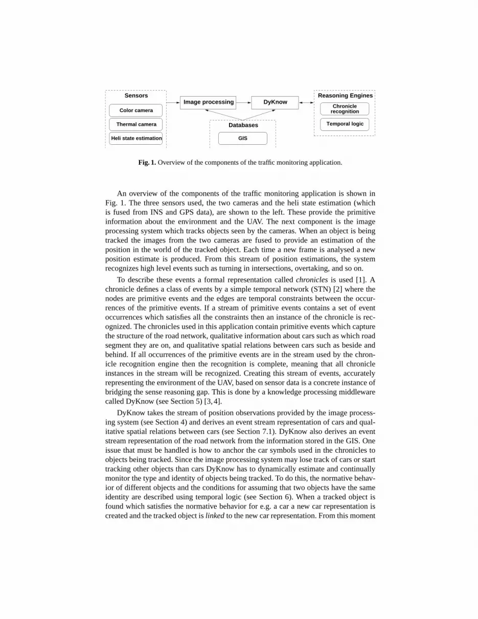
Fig. 1.Overview of the components of the traffic monitoring application.
An overview of the components of the traffic monitoring application is shown inFig. 1. The three sensors used, the two cameras and the heli state estimation (whichis fused from INS and GPS data), are shown to the left. These provide the primitiveinformation about the environment and the UAV. The next component is the imageprocessing system which tracks objects seen by the cameras. When an object is beingtracked the images from the two cameras are fused to provide an estimation of theposition in the world of the tracked object. Each time a new frame is analysed a newposition estimate is produced. From this stream of position estimations, the systemrecognizes high level events such as turning in intersections, overtaking, and so on.
To describe these events a formal representation calledchroniclesis used [1]. Achronicle defines a class of events by a simple temporal network (STN) [2] where thenodes are primitive events and the edges are temporal constraints between the occur-rences of the primitive events. If a stream of primitive events contains a set of eventoccurrences which satisfies all the constraints then an instance of the chronicle is rec-ognized. The chronicles used in this application contain primitive events which capturethe structure of the road network, qualitative information about cars such as which roadsegment they are on, and qualitative spatial relations between cars such as beside andbehind. If all occurrences of the primitive events are in the stream used by the chron-icle recognition engine then the recognition is complete, meaning that all chronicleinstances in the stream will be recognized. Creating this stream of events, accuratelyrepresenting the environment of the UAV, based on sensor data is a concrete instance ofbridging the sense reasoning gap. This is done by a knowledge processing middlewarecalled DyKnow (see Section 5) [3,4].
DyKnow takes the stream of position observations provided by the image process-ing system (see Section 4) and derives an event stream representation of cars and qual-itative spatial relations between cars (see Section 7.1). DyKnow also derives an eventstream representation of the road network from the information stored in the GIS. Oneissue that must be handled is how to anchor the car symbols used in the chronicles toobjects being tracked. Since the image processing system may lose track of cars or starttracking other objects than cars DyKnow has to dynamically estimate and continuallymonitor the type and identity of objects being tracked. To do this, the normative behav-ior of different objects and the conditions for assuming that two objects have the sameidentity are described using temporal logic (see Section 6). When a tracked object isfound which satisfies the normative behavior for e.g. a car a new car representation iscreated and the tracked object islinkedto the new car representation. From this moment

the car representation will be updated each time the tracked object is updated. Sincelinks only represent hypotheses, they are always subject to becoming invalid given ad-ditional observations, and therefore the UAV continually has to verify the validity ofthe links. This is done by monitoring that the normative behavior of the assumed objecttype is not violated. For example, an object assumed to be a car must not violate thenormative constraints on cars, e.g. leaving the road. If it does violate the correspondinglink is removed, in other words the object is no longer assumed to be a car. To evalu-ate temporal logical formulas DyKnow has to derive temporal models representing thevalue of the variables used in the formulas. Since these models are derived from thesensor data it is another concrete example of how DyKnow can be used to bridge thesense reasoning gap.
3 The Hardware Platform
The WITAS UAV platform [5] is a slightly modified Yamaha RMAX helicopter (Fig. 2),equipped with a more efficient power generator and a taller landing gear. Its total lengthis 3.6 m, including the main rotor, and it is powered by a 21 horse power two-strokeengine. The maximum takeoff weight of the platform is 95 kg and it can stay in the airup to one hour. The onboard avionics system is enclosed in an easily detachable boxmounted on the side of the UAV.
Fig. 2. The WITAS RMAX autonomous heli-copter.
Fig. 3. The onboard color and thermal camerasmounted on a pan-tilt unit.
The onboard computer system contains three PC104 embedded computers. The pri-mary flight control (PFC) system runs on a Pentium-III (700MHz) and is responsible forsensor fusion required for basic helicopter control and for sequentializing control modes(i.e. takeoff, hover, 3D path following, landing, vehicle following etc.). PFC interfaceswith the RMAX helicopter through YAS (Yamaha Attitude Sensor) and YACS (YamahaAttitude Control System) and receives data from the GPS receiver and a barometricaltitude sensor. The deliberative/reactive control (DRC) system runs on a Pentium-M(1.4GHz) and executes deliberative functionalities such as planning, execution moni-toring, and scenario recognition.

The image processing (IPC) system runs on a Pentium-III (700MHz) embeddedcomputer. The camera platform suspended under the UAV fuselage is vibration iso-lated by a system of springs. The platform consists of a Sony color CCD block cameraFCB-780P and a ThermalEye-3600AS miniature infrared camera mounted rigidly on apan-tilt unit (Fig. 3). Both cameras delivers analogue PAL signals with the frame size768x576 pixels at a rate of 25Hz.
Network communication between the onboard computers is physically realized withserial lines (RS232C point-to-point realtime communication) and Ethernet (non-realtimecommunication). Finally, the onboard system contains two miniDV video recorderscontrolled by software through a Control-L (LANC) interface. The live video is alsosent to the ground and presented to the UAV operator. The recorded video is synchro-nized with the log data (i.e. complete UAV state) allowing off-line processing.
4 Image Processing
The task of image processing in this work is to calculate world coordinates of vehiclestracked in video sequences. First, an object tracker is used to find pixel coordinates ofthe vehicle of interest based on color and thermal input images. Second, the geograph-ical location of the object is calculated and expressed as world coordinates. The objecttracker developed for the purpose of this work can be initialized automatically or man-ually. The automatic mode chooses the warmest object on a road segment (descriptionfetched from the GIS database) within the thermal camera view and within a certaindistance from the UAV (the process of calculating the distance to a tracked object is ex-plained below). The area around the initial point is checked for homogeneity in thermaland color images. The object is used to initialize the tracker if its area is consistent withthe size of a car signature. This initialization method works with satisfactory results fordistances up to around 50m from the tracked object.
If the tracker is initialized incorrectly the user can choose the object of interestmanually by clicking on a frame of the color or thermal video. The corresponding pixelposition (for color and thermal images) is calculated knowing the parameters of thecameras, the UAV’s position and attitude and the model of the ground elevation. Afterinitialization, tracking of an object is performed independently in color and thermalvideo streams. Tracking in the thermal image is achieved by finding the extreme value,the warmest or coldest spot, within a small window, i.e. 5 percent of the image size,around the previous result. Object tracking in color video sequences is also performedwithin such a small window and is done by finding the center of mass of the colorblob in the HSI color space. The thresholding parameters are updated to compensate forillumination changes. Tracking in both images is performed at full frame rate (i.e. 25Hz)which allows for compensating for moderate illumination changes and moderate speedsof relative motion between the UAV and the tracked object. The problem of automaticreinitialization in case of loss of tracking is not addressed in this work. The result fromthe thermal image tracking is preferred if the trackers do not agree on the trackingsolution.
In order to find the distance to the tracked object as well as corresponding regionsin both images, the cameras have been calibrated to find their intrinsic and extrinsic

parameters. The color camera has been calibrated using the Matlab Camera Calibra-tion Toolkit [6]. The same toolkit could not be used for finding optical parameters ofthe thermal camera because it was infeasible to obtain sharp images of the chessboardcalibration pattern. To find focal length, principal point and the lens distortion parame-ters, a custom calibration pattern and the calibration toolkit by Wengert et. al. has beenused [7]. The extrinsic parameters of the cameras were found by minimizing the errorbetween the calculated corresponding pixel positions for several video sequences.
Finding pixel correspondences between the two cameras can not be achieved byfeature matching commonly used in stereo vision algorithms since objects generallyappear different in color and thermal images. Because of this, the distance to an ob-ject whose projection lies in a given pixel must be determined. Knowing the cameraintrinsic and extrinsic parameters, helicopter attitude and position, and the ground ele-vation model, the distance to an object can easily be calculated as the distance from thecamera center to the intersection between the ground plane and the ray going throughthe pixel belonging to the object of interest. For the environment in which the flighttests were performed the error introduced by the flat world assumption is neglectable.Finally, calculating pixel correspondences between the two cameras can be achievedby performing pixel geolocalization using intrinsic and extrinsic parameters of one ofthe cameras followed by applying inverse procedure (i.e. projection of geographicallocation) using the other camera parameters.
A B
Fig. 4. A. Two frames from video sequence with the UAV hovering close to a road segmentobserving two cars performing overtaking maneuver.B. Three frames from video sequence withthe UAV following a driving car passing road crossings. Top row contains color images andbottom row contains corresponding thermal images.
Using the described object tracker several data series of world coordinates of trackedvehicles were generated. Two kinds of video sequences were used as data sources. In thefirst kind (Fig. 4A) the UAV is stationary at altitudes of 50 and 60 meters and observestwo vehicles as they drive on a nearby road. In the second kind (Fig. 4B) both the carand the UAV are moving. The ground vehicle drives several hundreds meters on theroad system passing through two crossings and the UAV follows the car at altitudes

between 25 and 50 meters. For sequences containing two cars, the tracker was executedtwice to track both vehicles independently.
A precise measure of the error of the computed world location of the tracked objectis not known because the true location of the cars was not registered during the flighttests. The accuracy of the computation is influenced by several factors, such as errorin the UAV position and the springs in the camera platform suspension, but the trackerin general delivers world coordinates with enough accuracy to determine which side ofthe road a car is driving on. Thus the maximum error can be estimated to be below 4-5meters for distances to the object of around 80 meters.
5 DyKnow
To facilitate the development of general traffic scenario recognition application a knowl-edge processing middleware called DyKnow is used [3, 4]. The main purpose of Dy-Know is to provide generic and well-structured software support for the processes in-volved in generating state, object, and event abstractions about the environments ofcomplex systems. The generation is done at many levels of abstraction beginning withlow level quantitative sensor data and resulting in qualitative data structures which aregrounded in the world and can be interpreted as knowledge by the system. To producethese structures the system supports operations on data and event streams at many dif-ferent levels of abstraction. For the result to be useful, the processing must be donein a timely manner so that the UAV can react in time to changes in the environment.The resulting structures are used by various functionalities in a deliberative/reactive ar-chitecture for control, situation awareness and assessment, monitoring, and planning toachieve mission goals. In the current application it is used to derive high level infor-mation about the objects being tracked. DyKnow provides a declarative language forspecifying the structures needed by the different subsystems. Based on this specifica-tion it creates representations of the external world and the internal state of a UAV basedon observations and a priori knowledge, such as facts stored in databases.
Conceptually, a knowledge processing middleware processes streams generated bydifferent components in a distributed system. These streams may be viewed as rep-resentations of time-series data and may start as continuous streams from sensors orsequences of queries to databases. Eventually, they will contribute to definitions ofmore refined, composite, knowledge structures. Knowledge producing processes com-bine such streams by computing, synchronizing, filtering and approximating to derivehigher level abstractions. A knowledge producing process has different quality of ser-vice properties such as maximum delay, trade-off between quality and delay, how tocalculate missing values and so on, which together define the semantics of the knowl-edge derived by the process. It is important to realize that knowledge is not static, butis a continually evolving collection of structures which are updated as new informa-tion becomes available from sensors and other sources. Therefore, the emphasis is onthe continuous and ongoing knowledge derivation process, which can be monitoredand influenced at runtime. The same streams of data may be processed differently bydifferent parts of the architecture by tailoring the knowledge processes relative to theneeds and constraints associated with the tasks at hand. This allows DyKnow to support

easy integration of existing sensors, databases, reasoning engines and other knowledgeproducing services.
5.1 Fluent Streams
For modelling purposes, the environment of the UAV is viewed as consisting of physi-cal and non-physicalobjects, propertiesassociated with these objects, andrelationsbe-tween these objects. The properties and relations associated with objects will be calledfeatures, which may be static or dynamic. Due to the potentially dynamic nature of afeature, that is, its ability to change values through time, a total function from time tovalue called afluent is associated with each feature. It is this fluent, representing thevalue over time of a feature, which is being modelled.
A fluent streamis a partial representation of a fluent, where a stream ofsamplesofthe value of the feature at specific time-points is seen as an approximation of the fluent.A sample can either come from an observation of the feature or a computation whichresults in an estimation of the value at the particular time-point, called thevalid time. Ifthe samples are ordered by the time they become available to the fluent stream, then theresult is a stream of samples representing the value of the feature over time, that is, anapproximation of its fluent. The time-point when a sample is made available or added toa fluent stream is called theadd time. To be able to totally order the samples in a fluentstream a requirement that the add time is unique is imposed, i.e. at most one samplemay be added to a fluent stream at any given time-point. A fluent stream has certainproperties such as start and end time, maximum size, i.e. number of samples in thestream, sample rate and maximum delay. These properties are specified by a declarativepolicywhich describes the constraints placed on the fluent stream.
For example, the position of a car would be an example of a feature. The true posi-tion of the car at each time-point during its existence would be its fluent, and a particularsequence of observations of its position would be a fluent stream. There can be manyfluent streams all approximating the same fluent.
5.2 Computational Units
A computational unitencapsulates a computation on one or more fluent streams. Acomputational unit takes a number of fluent streams as input and computes a new fluentstream as output. The encapsulated function can do anything, including calling externalservices.
Examples of computational units are filters, such as Kalman filters, and other sensorprocessing and fusion algorithms. Several other examples of computational units willbe presented later.
6 Object Linkage Structures
One problem that has to be dealt with is recognizing that the object being tracked by theUAV platform is actually a car, that is, to anchoring the symbolic representation of a carwith the stream of positions extracted by the image processing system. This is called

the anchoring problem [8]. Our approach is based on using temporal logic to describethe normative behavior of different types of entities and based on the behavior of anobserved entity hypothesize its type. For example, in the traffic monitoring domain theobject being tracked is assumed to be a physical object in the world, called aworldobject. Then, if the position of this world object is consistently on the road system thenit is hypothesized to be aroad object, i.e. an object moving within the road system. Byfurther monitoring the behavior and other characteristics such as speed and size of theroad object it could be hypothesized whether it is a car, a truck, a motorcycle, or anothertype of vehicle.
An object or an aspect of an object is represented by anentity structure. The termentity is used to indicate that it is more general than an object. An entity structureconsists of a type, a name and a set of features representing the properties of the entity.The name is supposed to be unique and is used to identify the entity. All entity structureswith the same type are assumed to have the same features. Anentity frameis a datastructure representing a snapshot of an entity. It consists of the type and name of anentity structure and a value for each of the features of the entity. An entity structure isimplemented in DyKnow as a fluent stream where the values are entity frames. Eachentity frame represents the state of an entity at a particular time-point and the fluentstream represents the evolution of the entity over time.
Each object is represented by an entity structure and relations between the entitiesare represented bylinks. The description of a class of links from entities of type A toentities of type B consists of three constraints, theestablish, reestablish, andmaintainconstraints, and a computational unit for computing B entity structures from A entitystructures.
The establish constraint describes when a new instance of type B should be createdand linked to. For example, if the position of a world object is on the road for morethan 30 seconds then a road object is created together with a link between them. Aroad object could contain more abstract and qualitative attributes such as which roadsegment it is on, which makes it possible to reason qualitatively about its position inthe world relative to the road, other vehicles on the road, and building structures in thevicinity of the road. At this point, streams of data are being generated and computedfor the features in the linked object structures at many levels of abstraction as the UAVtracks the road objects.
The reestablish constraint describes when two existing entities of the appropriatetypes which are not already linked should be linked. This is used when the tracking of aroad object is lost and the tracker finds a new world object which may or may not be thesame object as before. If the reestablish constraint is satisfied then it is hypothesized thatthe new world object is in fact the same road object as was previously tracked. Sincelinks only represent hypotheses, they are always subject to becoming invalid given ad-ditional data, so the UAV continually has to verify the validity of the links. This is doneby monitoring that the maintenance constraint is not violated.
A maintenance constraint could compare the behavior of the new entity, which isthe combination of the two representations, with the normative behavior of this type ofentity and, if available, the predicted behavior of the previous entity. In the road objectexample the condition is that the world object is continually on the road maybe with
shorter periods when it is outside. If this condition is violated then the link is removedand the road object is no longer updated since the hypothesis can not be maintained.
One purpose of the object linkage structures is to maintain an explicit representationof all the levels of abstraction used to derive the representation of an object. It is believedthat this will make the anchoring problem easier since sensor data, such as images,does not have to be directly connected to a car representation but can be anchored andtransformed in many small steps. Another benefit is that if the tracking is lost only thelink between the world object and the road object is lost, if the road object is linked toa car object then this link can still persists and the car will be updated once the roadobject has been linked to a new world object. Another usage of the linkage structurescould be to replace the world object which is lost with a simulated world object whichsimulates or predicts the development of the previous world object based on its history.
7 Scenario Recognition
In many applications it is crucial to describe and recognize complex events and scenar-ios. Chronicles [1] is one formalism used to represent complex occurrences of activitiesdescribed in terms of temporally constrained events. In this context, an event is definedas a change in the value of a feature. For example, in the traffic monitoring application,a UAV might fly to an intersection and try to identify how many vehicles turn left, rightor drive straight through a specific intersection. In another scenario, the UAV may beinterested in identifying vehicles overtaking. Each of these complex activities can bedefined in terms of one or more chronicles. In our project, we use the C.R.S. chroniclerecognition system developed by France Telecom [9].
A chronicle is a description of a generic scenario whose instances should be rec-ognized. A chronicle is represented by a set of events and a set of temporal constraintsbetween these events with respect to a context [1]. An event represents a change inthe value of a feature. The online recognition algorithm takes a stream of time-stampedevent instances and finds all matching chronicle instances. To do this C.R.S. keeps trackof all possible developments in a tractable and efficient manner by using simple tempo-ral networks [2]. A chronicle instance is matched if all the events in the chronicle modelare present in the stream and the time-stamps of the event instances satisfies the tem-poral constraints. Recognized instances of a chronicle can be used as events in anotherchronicle, thereby enabling recursive chronicles.
In order to use chronicle recognition to recognize event occurrences the event mustbe expressed in the chronicle formalism and a stream of primitive events must be avail-able. The only requirement on the stream is that the primitive events arrive ordered byoccurrence time. The reason is that all the information for a specific time-point has to beavailable before the temporal network can be updated with the new information. Thismeans that whenever a new event arrives with the occurrence timet all partial chronicleinstances are updated up to the time-pointt− 1 and then the new information is added.If an event arrives out of order it will be ignored. The integration using DyKnow is donein two steps, integration of chronicles and integration of events.
The first step is when a chronicle is registered for recognition. To integrate a newchronicle DyKnow goes through each of the features in the chronicle and subscribes to

the corresponding fluent stream. The name of each feature is required to be a referenceto a fluent stream containing discrete values. To make sure that the chronicle recogni-tion engine is aware of all the changes in the fluent stream a policy is constructed whichsubscribes to all changes in the fluent stream and makes sure that the changes are or-dered by valid time by use of a monotone order constraint. When subscriptions for allfluent streams are set up the recognition engine is ready to recognize chronicles.
The second step is when a sample arrives to the chronicle recognition engine. Tointegrate a sample it must be transformed into an event, i.e. a change in the featurerepresented by the fluent stream. To do this the recognition engine keeps track of thelast value for each of the features and creates an event if the feature changed valuescompared to the stored value. The first value is a special case where the value changesfrom an unknown value to the new value. When the chronicle recognition engine isstarted events representing the initial state must be added. Since it is assumed that theevents arrive in order the recognition engine updates the internal clock to the time-pointbefore the valid time of the new sample. Thus the chronicle engine can prune all partialchronicles which are inconsistent with the current knowledge of what events have takenplace. When a chronicle instance is recognized this is announced by an event.
7.1 Recognizing Overtakes
One instance of the traffic monitoring application involves the UAV observing a roadsegment and collecting information about the behavior of the vehicles passing by. Theexample used is recognizing overtakes, but the approach is general.
An overtake is considered to have occurred when two cars are driving on the sameroad and when one of the cars has caught up with and passed the other car. This is thesame as saying that an overtake occurs if a car is first behind another car, and then laterin front of the same car while both cars are on the same road. A requirement that the carsare beside each other at some time-point in between could be added to strengthen thedefinition. The overtake event can be formalized by the following overtake chronicle:
chronicle overtake[?car1, ?car2] {event(same_road[?car1, ?car2]:(?, true), t0)event(behind[?car1, ?car2]:(?, true), t1)event(behind[?car1, ?car2]:(true, false), t2)event(in_front[?car1, ?car2]:(false, true), t3)
noevent(behind[?car1, ?car2]:(true, false), (t1, t2-1))noevent(behind[?car1, ?car2]:(false, true), (t2, t3-1))noevent(in_front[?car1, ?car2]:(false, true), (t1, t3-1))noevent(same_road[?car1, ?car2]:(true, false), (t0, t3-1))
t0 < t2t1 < t2t1 < t3 }
An event(A[?x]:(v1, v2), t) statement says that the featureA of the objectassigned to the variable?x changed values fromv1 to v2 at time-pointt. The valuecan be? which works as a wildcard and represents that the actual value is not impor-tant. Each? represents a new variable. Anoevent(A:(v1, v2), (t1, t2))

statement says that an event, where the featureA changes values fromv1 to v2 , shouldnot occur in the interval[t1, t2]. The temporal constraints at the end of the chronicle canbe any metric constraint on pairs of time-points. The constraintt0 < t2 could alsobe writtent2-t0 in [1, oo] . Thenoevent statement is used to make sure thata value does not change within an interval. For example, to say thatA should be trueover the interval[b, e] the following statements could be used:
event(A:(?, true), a)noevent(A:(true, false), (b, e))a <= b
The recognition has been tested both on simulated cars driving in a road system andon real data captured during flight tests. One example of the latter is shown in Fig. 5.
Fig. 5.An example overtake situation recorded during a test flight.
To recognize overtakes using the above chronicle a stream of qualitative spatialrelations between pairs of cars, such as behind and beside, must be computed. Thismight sound like a very simple task, but does in fact require a number of steps. First,the set of cars that are actually being tracked must be extracted from the stream ofcar observations using the object linkage structures described in the previous section.Second, the set of pairs of active cars can be computed from the set of cars. Third, foreach pair of car names a stream of synchronized pairs of car entity structures have to becreated. Since they are synchronized both car entities in the pair are valid at the sametime-point, which is required to compute the relation between the two cars. Fourth, fromthis stream of car pairs the qualitative spatial relations must be computed. Finally, thisstream of car relations can be used to detect overtakes and other driving patterns usingthe chronicle recognition engine. All these functions are implemented as computationalunits. The complete setup is shown in Fig. 6. A more detailed description follows.
To extract the active cars a computational unit is created which keeps track of thenames of all cars that have been updated the last minute. This means that if no ob-servation of a car has been made in more than 60 seconds it will be removed fromthe set of active cars. For example, assuming the stream of car observations lookslike: 〈〈car1, . . .〉, . . . 〈car2, . . .〉, . . . 〈car3, . . .〉, . . .〉 then the stream of sets of active carswould be〈{car1}, {car1, car2}, {car1, car2, car3}〉. Since the qualitative spatial rela-tions are computed on pairs of cars where the cars are different and the order of the two

TrackingSource
CarDomain
CU
CarRelation
CU
CarPairsCU
CarRelations
CU
cars Cars CarPairs car_pairs car_relations
Fig. 6.The DyKnow setup used in the overtake monitoring application.
cars are not important the computational unit that extracts pairs of car names only com-putes one pair for each combination of distinct car names. To continue the example, thestream of set of pairs would be〈{}, {〈car1, car2〉}, {〈car1, car2〉, 〈car1, car3〉, 〈car2, car3〉}〉.The stream of sets of pairs is calledCarPairs and is updated when a car is added orremoved from the set of active car names, calledCars. This stream of car name pairsis then used as input together with the stream of car entities to a state extraction com-putational unit which for each pair synchronizes the streams of car entities as shown inFig. 7. The figure shows that for each of pair of car names in theCarPairs stream anew state synchronization unit is created where only updates to those car entities withthe specified names are sent. Each time one of the state synchronization units derives anew state it is added to the fluent stream defined by the computational unit.
state sync
state synccar2, car3 <car2, car3>
state sync
cars, CarPairs car1, car3 <car1, car3>
car1, car2 <car1, car2>
car_pairs
Fig. 7.The synchronization of car pairs.
in front of
right
behind
left
Fig. 8.The qualitative spatialrelations used.
Finally the car pair entities are used as input in the car relation computational unitwhich computes the qualitative spatial relation between the two cars by comparing theforward direction ofcar1 with the direction fromcar2 to car1 , as shown in Fig. 8.The forward direction of the car is assumed to be either along the current road segmentor against it. To compute which, the current driving direction of the car is compared tothe forward direction of the road segment. Since the estimated driving direction of thecar is very noisy this provides a much better estimate.
Each time the car relations are computed the chronicle recognition engine is noti-fied, since it subscribes to that fluent stream, and the chronicles instance are updatedwith the new information. In the next section some experimental results are presented.
8 Experimental Results
The traffic monitoring application has been test both in simulation and on images col-lected from flight tests. The only difference between the two cases is who creates theworld objects. One of the trajectories collected at a flight test is shown in Fig. 5.

The robustness to noise in the position estimation was tested in simulation by addingrandom error to the true position of the cars. The error has a uniform distribution witha known maximum value and is added independently to the x and y coordinates. If themaximum error is 2 meters, then the observed position is within a 2x2 meter squarecentered on the true position. Two variables were varied, the speed of the car and thesample period of the position. For each combination 10 simulations were run were acar overtook another. If the overtake was recognized the run was considered successful.The results are shown in Table 1.
Speed Sample 0m 1m 2m 3m 4m 5m 7mperiod error error error error error error error
15 m/s 200 ms 100% 100% 70% 60% 50% 40% 20%20 m/s 200 ms 100% 90% 60% 70% 50% 50% 20%25 m/s 200 ms 100% 100% 100% 50% 40% 10% 0%15 m/s 100 ms - - 60% 90% 60% 90% 0%20 m/s 100 ms - - 90% 90% 90% 80% 20%25 m/s 100 ms - - 90% 80% 70% 80% 0%Table 1.The results from varying the speed of the cars and the sample period.
The conclusions from these experiments are that the speed of the car is not signif-icant but the sample period is. The more noise in the position the more samples areneeded in order to detect the overtake. The reason for the very poor performance whenthe error is 7 meters is due to the fact that most observations are outside the road andthose observations are filtered out. Since the estimated error from the image processingis 4-5 meters the system should reliably detect overtakes.
9 Related Work
There is a great amount of related work which is relevant for each of the components,but the focus will be on integrated systems. There are a number of systems for mon-itoring traffic by interpreting video sequences, for example [10–15]. Of these, almostall work on sequences collected by static surveillance cameras. The exception is [12]which analyses sequences collected by a Predator UAV. Of these none combine theinput from both color and thermal images. Another major difference is how the scenar-ios are described and recognized. The approaches used include fuzzy metric-temporallogic [11], state transition networks [13], belief networks [15], and Petri-nets [10, 14]neither of which have the same expressivety when it comes to temporal constraints asthe chronicle recognition approach. Another difference is the ad-hoc nature of how thecomponents of the system and the data flows are connected. In our solution the basisis a declarative description of the properties of the different data streams which is thenimplemented by the DyKnow knowledge processing middleware. This makes it veryeasy to change the application to e.g. add new features or to change the parameters. Thedeclarative specification could also be used to reason about the system itself.

10 Conclusions
A traffic monitoring application which is an instance of a general approach to creat-ing high-level situation awareness applications is presented. The implemented systemtakes as input sequences of color and thermal images used to construct and maintainqualitative object structures and recognize the traffic behavior of the tracked vehiclesin realtime. The system is tested both in simulation and on data collected during testflights. It is believed that this type of system where streams of data are generated atmany levels of abstraction using both top-down and bottom-up reasoning handles manyof the issues related to closing the sense-reasoning gap. A reason is that the informationderived at each level is available for inspection and use. This means that the subsystemshave access to the appropriate abstraction while it is being continually updated withnew information and used to derived even more abstract structures. High-level informa-tion, such as the type of vehicle, can then be used to constrain and refine the processingof lower level information. The result is a very powerful and flexible system capable ofachieving and maintaining high-level situation awareness.
References
1. Ghallab, M.: On chronicles: Representation, on-line recognition and learning. In: Proceed-ings of the Fifth Intl Conf on Principles of Knowledge Representation and Reasoning. (1996)
2. Dechter, R., Meiri, I., Pearl, J.: Temporal constraint networks. AIJ49 (1991)3. Heintz, F., Doherty, P.: DyKnow: An approach to middleware for knowledge processing.
Journal of Intelligent and Fuzzy Systems15(1) (2004) 3–134. Heintz, F., Doherty, P.: A knowledge processing middleware framework and its relation to
the JDL data fusion model. Journal of Intelligent and Fuzzy Systems17(4) (2006) 335–3515. Doherty, P., Haslum, P., Heintz, F., Merz, T., Nyblom, P., Persson, T., Wingman, B.: A
distributed architecture for autonomous unmanned aerial vehicle experimentation. In: Pro-ceedings of the 7th Intl Symposium on Distributed Autonomous Robotic Systems. (2004)
6. Bouguet, J.: Matlab camera calibration toolbox (2000)7. Wengert, C., Reeff, M., Cattin, P.C., Szekely, G.: Fully automatic endoscope calibration for
intraoperative use. In: Bildverarbeitung fur die Medizin, Springer-Verlag (2006) 419–238. Coradeschi, S., Saffiotti, A.: An introduction to the anchoring problem. Robotics and Au-
tonomous Systems43(2-3) (2003) 85–969. Telecom, F.: C.R.S. website (2007) Retrieved March 22, 2007, from http://crs.elibel.tm.fr/en.
10. Ghanem, N., DeMenthon, D., Doermann, D., Davis, L.: Representation and recognition ofevents in surveillance video using petri nets. In: Proceedings of Conference on ComputerVision and Pattern Recognition Workshops CVPRW. (2004)
11. Nagel, H., Gerber, R., Schreiber, H.: Deriving textual descriptions of road traffic queuesfrom video sequences. In: Proc. 15th European Conference on Artificial Intelligence. (2002)
12. Medioni, G., Cohen, I., Bremond, F., Hongeng, S., Nevatia, R.: Event detection and analysisfrom video streams. IEEE Trans. Pattern Anal. Mach. Intell.23(8) (2001) 873–889
13. Fernyhough, J., Cohn, A., Hogg, D.: Building qualitative event models automatically fromvisual input. In: Proceedings of the International Conference on Computer Vision. (1998)
14. Chaudron, L., Cossart, C., Maille, N., Tessier, C.: A purely symbolic model for dynamicscene interpretation. International Journal on Artificial Intelligence Tools6(4) (1997)
15. Huang, T., Koller, D., Malik, J., Ogasawara, G., Rao, B., Russell, S., Weber, J.: Automaticsymbolic traffic scene analysis using belief networks. In: AAAI’94: Proceedings of thetwelfth national conference on Artificial intelligence (vol. 2). (1994) 966–972