brickwork support systems - specifiedby
TRANSCRIPT
HAZ-BS-EN / 08.14
Brick Support SystemsTechnical CatalogueHAZ-BS-EN/04.20
Your Fixing Systems Specialist
Brickwork Support Systems Technical Product Catalogue
HAZ-BS-EN/04.20

Company Profile
Brickwork Support Systems Overview
Brickwork Support Systems Design Principles
FIX Brickwork Support Brackets Introduction
Brickwork Support System Product Range
FIX Brickwork Support Brackets Product Details
FIX Brickwork Support Bracket Load Table
FIX Brickwork Support Bracket Application Guide
FIX Brickwork Support Bracket Technical Details
Brickwork Support Systems - Application Examples
ISO-FIX Brickwork Support Brackets Introduction
FIX Adjustable Plate Introduction
HMCS Continuous Brickwork Support Introduction
HMCS Continuous Supports Product Details
1
3
5
9
10
11
12
13
19
31
33
34
35
36
Contents
HMS-AV & AVS Angled Brackets
HMS-ES & GS Prefabricated Component Inserts
HMS-AW Special Restraint Channel
HWP Wind Post Restraints Introduction
HLS Brickwork Lintel Supports Introduction
HMP Brickwork Wall Tie Channels
HWT-M Brickwork Wall Ties
HRST Restraining Ties
CMWT Brickwork Wall Ties Product Details
HMHR Brickwork Head Restraints
Connections Methods to Concrete
Scaffholding Anchors Product Details
References
39
41
42
43
45
49
50
51
52
55
57
58
59
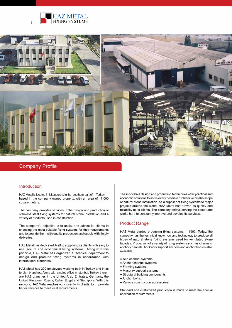
Bosmos Flats, Switzerland
Contents
HAZ Metal Sanayi ve Ticaret A.S. All rights reserved. April 2020. Reproduction and distribution of the information contained in this catalog is forbidden without prior written consent. HAZ Copyright. R
1
Introduction
HAZ Metal is located in Iskenderun, in the southern part of Turkey, based in the company owned property, with an area of 17.000 square meters.
The company provides services in the design and production of stainless steel fixing systems for natural stone installation and a variety of products used in construction.
The company’s objective is to assist and advise its clients in choosing the most suitable fixing systems for their requirements and to provide them with quality production and supply with timely deliveries.
HAZ Metal has dedicated itself to supplying its clients with easy to use, secure and economical fixing systems. Along with this principle, HAZ Metal has organized a technical department to design and produce fixing systems in accordance with international standards.
HAZ Metal has 200 employees working both in Turkey and in its foreign branches. Along with a sales office in Istanbul, Turkey, there are HAZ branches in the United Arab Emirates, Germany, the United Kingdom, Russia, Qatar, Egypt and Singapore. With this network, HAZ Metal reaches out closer to its clients, to provide better services to meet local requirements.
The innovative design and production techniques offer practical and economic solutions to solve every possible problem within the scope of natural stone installation. As a supplier of fixing systems to major projects around the world, HAZ Metal has proven its quality and reliability to its clients. The company enjoys serving the sector and works hard to constantly improve and develop its services.
Product Range
HAZ Metal started producing fixing systems in 1993. Today, the company has the technical know how and technology to produce all types of natural stone fixing systems used for ventilated stone facades. Production of a variety of fixing systems such as channels, anchor channels, brickwork support anchors and anchor bolts is also available.
● Sub channel systems● Anchor channel systems● Framing systems● Masonry support systems● Structural building components.● Anchor bolts. ● Various construction accessories.
Standard and customized production is made to meet the special application requirements.
Company Profile
| 2Your Fixing Systems Specialist
Production Capacity
HAZ Metal has the capacity to produce over 300 tons of materials every month with over 100 production units and work stations. The production plant boast a series of high grade machinery ranging from a slitting line to eccentric presses and 6 meter press brakes.
There is well equipped welding unit with proper welding benches and a welding robot that does precision welding. Two automated welding units are also available for the fast and economic process. All of the operators in the welding unit are certified and carry licenses from Lloyds quality assurance institute. Technical Know-How
HAZ Metal’s technical staff, each with more than 10 years experience, has an outstanding technical knowledge in the field of stainless steel production.
The maintenance of the machines and the preparation of moulds for production are done in the company’s workshop. This ensures higher efficiency and productivity in production, increasing the quality of services with competitive prices.
Welding processes are well understood and controlled by the experienced and responsible staff. In ensuring high quality welding of steel and stainless steel, highly skilled, certified operators are certified are recruited for the welding unit. Appropriate machines and welding techniques are in use to offer the structural integrity of the welded products.
Quality Standards
HAZ Metal implements EN and ASTM standards in the production of channels. Production is strictly controlled within the tolerances of these standards.
All products are produced by its personnel, applying the latest production methods with advanced machinery. The quality control team, under the supervision of a mechanical engineer, is selected from long serving and experienced foremen.
Production is checked during each production step and is compared with production drawings and specifications. The company is strictly bound to the concept of ISO 9001:2008 and “Total Quality Management” system. A quality assurance system is set up and is running to cover the control of each process in manufacturing. The control checks are documented and recorded.
The application of this management system is maintained and is a part of day to day operations. HAZ Metal gives great emphasis in keeping the high level quality of manufacturing and strides to improve its processes to meet the increasing demands of the construction industry.
Your Fixing Systems SpecialistHAZ Metal is certified with integrated management
systems by TUV SUD for ISO 9001:2008, ISO 14001:2004& OHSAS 18001:2007 standards
3
FIX Brickwork Support Systems - Overview
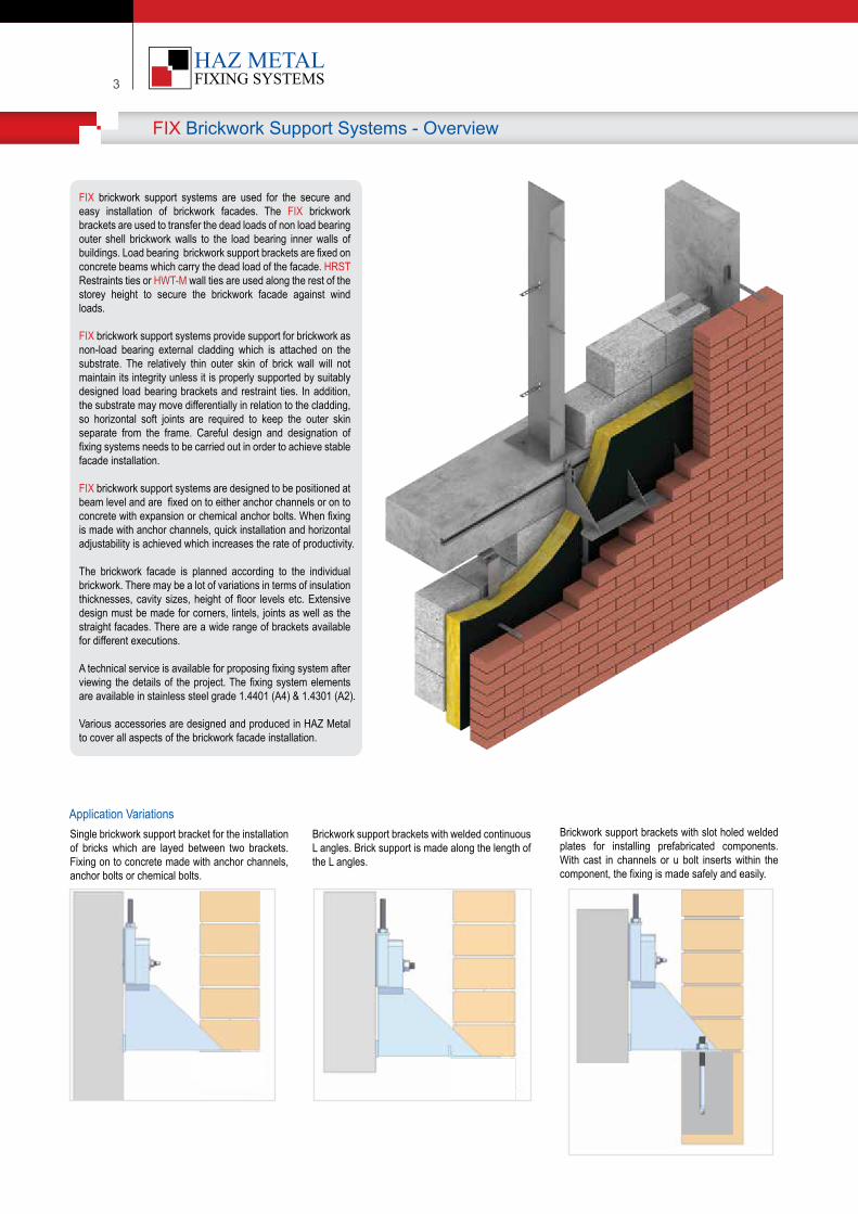
FIX brickwork support systems are used for the secure and easy installation of brickwork facades. The FIX brickwork brackets are used to transfer the dead loads of non load bearing outer shell brickwork walls to the load bearing inner walls of buildings. Load bearing brickwork support brackets are fixed on concrete beams which carry the dead load of the facade. HRST Restraints ties or HWT-M wall ties are used along the rest of the storey height to secure the brickwork facade against wind loads.
FIX brickwork support systems provide support for brickwork as non-load bearing external cladding which is attached on the substrate. The relatively thin outer skin of brick wall will not maintain its integrity unless it is properly supported by suitably designed load bearing brackets and restraint ties. In addition, the substrate may move differentially in relation to the cladding, so horizontal soft joints are required to keep the outer skin separate from the frame. Careful design and designation of fixing systems needs to be carried out in order to achieve stable facade installation.
FIX brickwork support systems are designed to be positioned at beam level and are fixed on to either anchor channels or on to concrete with expansion or chemical anchor bolts. When fixing is made with anchor channels, quick installation and horizontal adjustability is achieved which increases the rate of productivity.
The brickwork facade is planned according to the individual brickwork. There may be a lot of variations in terms of insulation thicknesses, cavity sizes, height of floor levels etc. Extensive design must be made for corners, lintels, joints as well as the straight facades. There are a wide range of brackets available for different executions.
A technical service is available for proposing fixing system after viewing the details of the project. The fixing system elements are available in stainless steel grade 1.4401 (A4) & 1.4301 (A2).
Various accessories are designed and produced in HAZ Metal to cover all aspects of the brickwork facade installation.
Appl�cat�on Var�at�onsSingle brickwork support bracket for the installation of bricks which are layed between two brackets. Fixing on to concrete made with anchor channels, anchor bolts or chemical bolts.
Br�ckwork support brackets w�th welded cont�nuous L angles. Br�ck support �s made along the length of the L angles.
Br�ckwork support brackets w�th slot holed welded plates for �nstall�ng prefabr�cated components. W�th cast �n channels or u bolt �nserts w�th�n the component, the f�x�ng �s made safely and eas�ly.
| 4Your Fixing Systems Specialist
Brickwork Support Systems - Overview
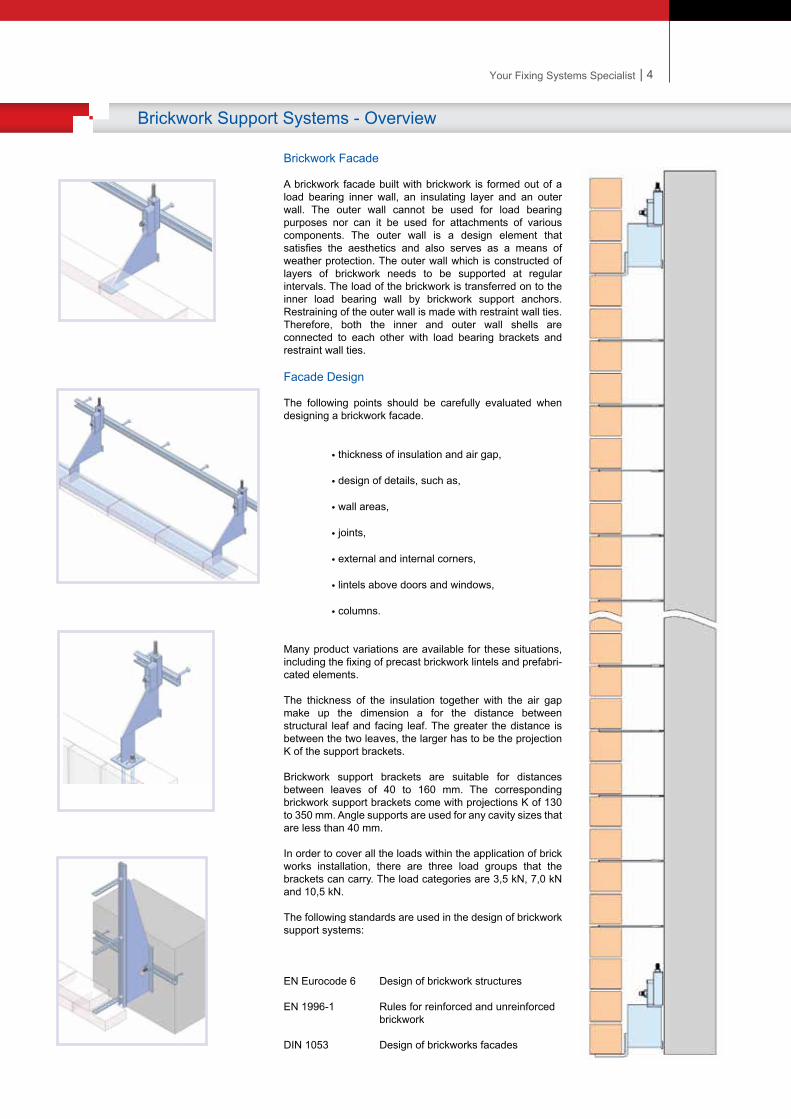
Brickwork Facade
A brickwork facade built with brickwork is formed out of a load bearing inner wall, an insulating layer and an outer wall. The outer wall cannot be used for load bearing purposes nor can it be used for attachments of various components. The outer wall is a design element that satisfies the aesthetics and also serves as a means of weather protection. The outer wall which is constructed of layers of brickwork needs to be supported at regular intervals. The load of the brickwork is transferred on to the inner load bearing wall by brickwork support anchors. Restraining of the outer wall is made with restraint wall ties. Therefore, both the inner and outer wall shells are connected to each other with load bearing brackets and restraint wall ties.
Facade Design
The following points should be carefully evaluated when designing a brickwork facade.
• thickness of insulation and air gap,
• design of details, such as,
• wall areas,
• joints,
• external and internal corners,
• lintels above doors and windows,
• columns.
Many product variations are available for these situations, including the fixing of precast brickwork lintels and prefabri-cated elements.
The thickness of the insulation together with the air gap make up the dimension a for the distance between structural leaf and facing leaf. The greater the distance is between the two leaves, the larger has to be the projection K of the support brackets.
Brickwork support brackets are suitable for distances between leaves of 40 to 160 mm. The corresponding brickwork support brackets come with projections K of 130 to 350 mm. Angle supports are used for any cavity sizes that are less than 40 mm.
In order to cover all the loads within the application of brick works installation, there are three load groups that the brackets can carry. The load categories are 3,5 kN, 7,0 kN and 10,5 kN.
The following standards are used in the design of brickwork support systems:
EN Eurocode 6 Design of brickwork structures
EN 1996-1 Rules for reinforced and unreinforced brickwork
DIN 1053 Design of brickworks facades
3
FIX Brickwork Support Systems - Overview
FIX brickwork support systems are used for the secure and easy installation of brickwork facades. The FIX brickwork brackets are used to transfer the dead loads of non load bearing outer shell brickwork walls to the load bearing inner walls of buildings. Load bearing brickwork support brackets are fixed on concrete beams which carry the dead load of the facade. HRST Restraints ties or HWT-M wall ties are used along the rest of the storey height to secure the brickwork facade against wind loads.
FIX brickwork support systems provide support for brickwork as non-load bearing external cladding which is attached on the substrate. The relatively thin outer skin of brick wall will not maintain its integrity unless it is properly supported by suitably designed load bearing brackets and restraint ties. In addition, the substrate may move differentially in relation to the cladding, so horizontal soft joints are required to keep the outer skin separate from the frame. Careful design and designation of fixing systems needs to be carried out in order to achieve stable facade installation.
FIX brickwork support systems are designed to be positioned at beam level and are fixed on to either anchor channels or on to concrete with expansion or chemical anchor bolts. When fixing is made with anchor channels, quick installation and horizontal adjustability is achieved which increases the rate of productivity.
The brickwork facade is planned according to the individual brickwork. There may be a lot of variations in terms of insulation thicknesses, cavity sizes, height of floor levels etc. Extensive design must be made for corners, lintels, joints as well as the straight facades. There are a wide range of brackets available for different executions.
A technical service is available for proposing fixing system after viewing the details of the project. The fixing system elements are available in stainless steel grade 1.4401 (A4) & 1.4301 (A2).
Various accessories are designed and produced in HAZ Metal to cover all aspects of the brickwork facade installation.
Appl�cat�on Var�at�onsSingle brickwork support bracket for the installation of bricks which are layed between two brackets. Fixing on to concrete made with anchor channels, anchor bolts or chemical bolts.
Br�ckwork support brackets w�th welded cont�nuous L angles. Br�ck support �s made along the length of the L angles.
Br�ckwork support brackets w�th slot holed welded plates for �nstall�ng prefabr�cated components. W�th cast �n channels or u bolt �nserts w�th�n the component, the f�x�ng �s made safely and eas�ly.
| 4Your Fixing Systems Specialist
Brickwork Support Systems - Overview
Brickwork Facade
A brickwork facade built with brickwork is formed out of a load bearing inner wall, an insulating layer and an outer wall. The outer wall cannot be used for load bearing purposes nor can it be used for attachments of various components. The outer wall is a design element that satisfies the aesthetics and also serves as a means of weather protection. The outer wall which is constructed of layers of brickwork needs to be supported at regular intervals. The load of the brickwork is transferred on to the inner load bearing wall by brickwork support anchors. Restraining of the outer wall is made with restraint wall ties. Therefore, both the inner and outer wall shells are connected to each other with load bearing brackets and restraint wall ties.
Facade Design
The following points should be carefully evaluated when designing a brickwork facade.
• thickness of insulation and air gap,
• design of details, such as,
• wall areas,
• joints,
• external and internal corners,
• lintels above doors and windows,
• columns.
Many product variations are available for these situations, including the fixing of precast brickwork lintels and prefabri-cated elements.
The thickness of the insulation together with the air gap make up the dimension a for the distance between structural leaf and facing leaf. The greater the distance is between the two leaves, the larger has to be the projection K of the support brackets.
Brickwork support brackets are suitable for distances between leaves of 40 to 160 mm. The corresponding brickwork support brackets come with projections K of 130 to 350 mm. Angle supports are used for any cavity sizes that are less than 40 mm.
In order to cover all the loads within the application of brick works installation, there are three load groups that the brackets can carry. The load categories are 3,5 kN, 7,0 kN and 10,5 kN.
The following standards are used in the design of brickwork support systems:
EN Eurocode 6 Design of brickwork structures
EN 1996-1 Rules for reinforced and unreinforced brickwork
DIN 1053 Design of brickworks facades
| 6Your Fixing Systems Specialist
cs cs
FIX Brickwork Support Systems - Design Principles
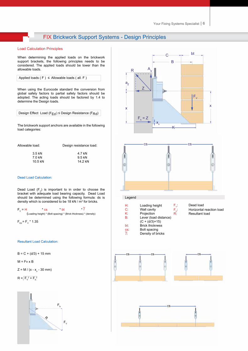
Load Calculation Principles
When determining the applied loads on the brickwork support brackets, the following principles needs to be considered. The applied loads should be lower than the allowable loads.
When using the Eurocode standard the conversion from global safety factors to partial safety factors should be adopted. The acting loads should be factored by 1.4 to determine the Design loads.
The brickwork support anchors are available in the following load categories:
Allowable load: Design resistance load:
3.5 kN 4.7 kN 7.0 kN 9.5 kN 10.5 kN 14.2 kN
Dead Load Calculation:
Dead Load (FV) is important to in order to choose the bracket with adequate load bearing capacity. Dead Load should be determined using the following formula: ds is density which is considered to be 18 kN / m3 for bricks.
FV = H * cs * bt * (Loading height) * (Bolt spacing) * (Brick thickness) * (density)
FEd = FV * 1.35
Resultant Load Calculation:
B = C + (d/3) + 15 mm
M = Fv x B
Z = M / (x - xu - 30 mm)
R = FV2 + Fh
2
Applied loads ( F ) ≤ Allowable loads ( all. F )
Legend
H: Loading heightC: Wall cavityK: ProjectionB: Lever (load distance) (C + (d/3)+15) bt: Brick thicknesscs: Bolt spacing : Density of bricks
FV: Dead loadFh: Horizontal reaction load R: Resultant load
ar
bC
R Av
K
cs cs cs
x
Z
Fh = Z
x
B
bt
Design Effect Load ( ) ≤ Design Resistance ( ) FEd FRd
xu
cs
R
Fh
FV
FV
5
FIX Brickwork Support Systems - Design Principles
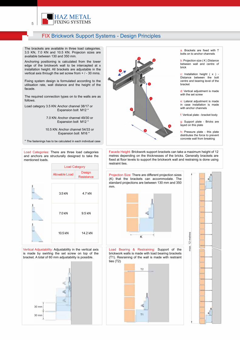
a. Brackets are f�xed w�th T bolts on to anchor channels
b: Project�on s�ze ( K ) D�stance between wall and centre of br�ck
c: Installat�on he�ght ( x ) - D�stance between the bolt centre and bear�ng level of the bracket
d: Vert�cal adjustment �s made w�th the set screw
e: Lateral adjustment �s made �n case �nstallat�on �s made w�th anchor channels
f: Vert�cal plate - bracket body
g: Support plate - Br�cks are layed on th�s plate
h: Pressure plate - th�s plate d�str�butes the force to prevent concrete wall from break�ng
The brackets are ava�lable �n three load categor�es. 3.5 KN, 7.0 KN and 10.5 KN. Projec�on s�zes are ava�lable between 130 and 350 mm.Anchor�ng pos�t�on�ng �s calculated from the lower edge of the br�ckwork wall to be �ntercepted at x �nstallat�on he�ght. All brackets are adjustable �n the vert�cal ax�s through the set screw from + / - 30 mms.
F�x�ng system des�gn �s formulated accord�ng to the ut�l�sat�on rate, wall d�stance and the he�ght of the facade.
The requ�red connect�on types on to the walls are as follows.
Load category 3.5 KN: Anchor channel 38/17 or Expans�on bolt M12 * 7.0 KN: Anchor channel 49/30 or Expans�on bolt M12 *
10.5 KN: Anchor channel 54/33 or Expans�on bolt M16 *
* The fasten�ngs has to be calculated �n each �nd�v�dual case
Load Categor�es: There are three load categor�es and anchors are structurally des�gned to take the ment�oned loads.
Facade He�ght: Br�ckwork support brackets can take a max�mum he�ght of 12 metres depend�ng on the th�cknesses of the br�cks. Generally brackets are f�xed at floor levels to support the br�ckwork wall and restra�n�g �s done us�ng restra�nt t�es.
c
Vert�cal Adjustab�l�ty: Adjustab�l�ty �n the ver�tcal ax�s �s made by sw�rl�ng the set screw on top of the bracket. A total of 60 mm adjustab�l�ty �s poss�ble.
Load Bear�ng & Restra�n�ng: Support of the br�ckwork walls �s made w�th load bear�ng brackets (T1). Resra�n�ng of the wall �s made w�th restra�nt t�es (T2)
Project�on S�ze: There are d�fferent project�on s�zes (K) that the brackets can accommodate. The standard project�ons are between 130 mm and 350 mm.
Allowable Load Design Resistance
3.5 kN 4.7 kN
7.0 kN 9.5 kN
10.5 kN 14.2 kN
Load Category
K
max
. 12
met
res
T2
T1
30 mm
30 mm
a
c
b
g
h
e
d
f
| 6Your Fixing Systems Specialist
cs cs
FIX Brickwork Support Systems - Design Principles
Load Calculation Principles
When determining the applied loads on the brickwork support brackets, the following principles needs to be considered. The applied loads should be lower than the allowable loads.
When using the Eurocode standard the conversion from global safety factors to partial safety factors should be adopted. The acting loads should be factored by 1.4 to determine the Design loads.
The brickwork support anchors are available in the following load categories:
Allowable load: Design resistance load:
3.5 kN 4.7 kN 7.0 kN 9.5 kN 10.5 kN 14.2 kN
Dead Load Calculation:
Dead Load (FV) is important to in order to choose the bracket with adequate load bearing capacity. Dead Load should be determined using the following formula: ds is density which is considered to be 18 kN / m3 for bricks.
FV = H * cs * bt * (Loading height) * (Bolt spacing) * (Brick thickness) * (density)
FEd = FV * 1.35
Resultant Load Calculation:
B = C + (d/3) + 15 mm
M = Fv x B
Z = M / (x - xu - 30 mm)
R = FV2 + Fh
2
Applied loads ( F ) ≤ Allowable loads ( all. F )
Legend
H: Loading heightC: Wall cavityK: ProjectionB: Lever (load distance) (C + (d/3)+15) bt: Brick thicknesscs: Bolt spacing : Density of bricks
FV: Dead loadFh: Horizontal reaction load R: Resultant load
ar
bC
R Av
K
cs cs cs
x
Z
Fh = Z
x
B
bt
Design Effect Load ( ) ≤ Design Resistance ( ) FEd FRd
xu
cs
R
Fh
FV
FV
5
FIX Brickwork Support Systems - Design Principles
a. Brackets are f�xed w�th T bolts on to anchor channels
b: Project�on s�ze ( K ) D�stance between wall and centre of br�ck
c: Installat�on he�ght ( x ) - D�stance between the bolt centre and bear�ng level of the bracket
d: Vert�cal adjustment �s made w�th the set screw
e: Lateral adjustment �s made �n case �nstallat�on �s made w�th anchor channels
f: Vert�cal plate - bracket body
g: Support plate - Br�cks are layed on th�s plate
h: Pressure plate - th�s plate d�str�butes the force to prevent concrete wall from break�ng
The brackets are ava�lable �n three load categor�es. 3.5 KN, 7.0 KN and 10.5 KN. Projec�on s�zes are ava�lable between 130 and 350 mm.Anchor�ng pos�t�on�ng �s calculated from the lower edge of the br�ckwork wall to be �ntercepted at x �nstallat�on he�ght. All brackets are adjustable �n the vert�cal ax�s through the set screw from + / - 30 mms.
F�x�ng system des�gn �s formulated accord�ng to the ut�l�sat�on rate, wall d�stance and the he�ght of the facade.
The requ�red connect�on types on to the walls are as follows.
Load category 3.5 KN: Anchor channel 38/17 or Expans�on bolt M12 * 7.0 KN: Anchor channel 49/30 or Expans�on bolt M12 *
10.5 KN: Anchor channel 54/33 or Expans�on bolt M16 *
* The fasten�ngs has to be calculated �n each �nd�v�dual case
Load Categor�es: There are three load categor�es and anchors are structurally des�gned to take the ment�oned loads.
Facade He�ght: Br�ckwork support brackets can take a max�mum he�ght of 12 metres depend�ng on the th�cknesses of the br�cks. Generally brackets are f�xed at floor levels to support the br�ckwork wall and restra�n�g �s done us�ng restra�nt t�es.
c
Vert�cal Adjustab�l�ty: Adjustab�l�ty �n the ver�tcal ax�s �s made by sw�rl�ng the set screw on top of the bracket. A total of 60 mm adjustab�l�ty �s poss�ble.
Load Bear�ng & Restra�n�ng: Support of the br�ckwork walls �s made w�th load bear�ng brackets (T1). Resra�n�ng of the wall �s made w�th restra�nt t�es (T2)
Project�on S�ze: There are d�fferent project�on s�zes (K) that the brackets can accommodate. The standard project�ons are between 130 mm and 350 mm.
Allowable Load Design Resistance
3.5 kN 4.7 kN
7.0 kN 9.5 kN
10.5 kN 14.2 kN
Load Category
K
max
. 12
met
res
T2
T1
30 mm
30 mm
a
c
b
g
h
e
d
f
7
HMS Brickwork Support System - Design Principles
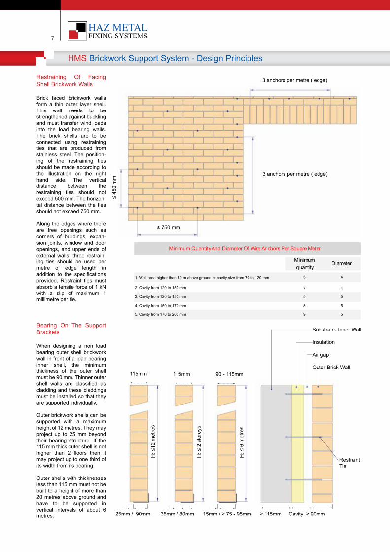
Restraining Of Facing Shell Brickwork Walls
Brick faced brickwork walls form a thin outer layer shell. This wall needs to be strengthened against buckling and must transfer wind loads into the load bearing walls. The brick shells are to be connected using restraining ties that are produced from stainless steel. The position-ing of the restraining ties should be made according to the illustration on the right hand side. The vertical distance between the restraining ties should not exceed 500 mm. The horizon-tal distance between the ties should not exceed 750 mm.
Along the edges where there are free openings such as corners of buildings, expan-sion joints, window and door openings, and upper ends of external walls; three restrain-ing ties should be used per metre of edge length in addition to the specifications provided. Restraint ties must absorb a tensile force of 1 kN with a slip of maximum 1 millimetre per tie.
Bearing On The Support Brackets
When designing a non load bearing outer shell brickwork wall in front of a load bearing inner shell, the minimum thickness of the outer shell must be 90 mm. Thinner outer shell walls are classified as cladding and these claddings must be installed so that they are supported individually.
Outer brickwork shells can be supported with a maximum height of 12 metres. They may project up to 25 mm beyond their bearing structure. If the 115 mm thick outer shell is not higher than 2 floors then it may project up to one third of its width from its bearing.
Outer shells with thicknesses less than 115 mm must not be built to a height of more than 20 metres above ground and have to be supported in vertical intervals of about 6 metres.
Minimum quantity
Diameter
1. Wall area higher than 12 m above ground or cavity size from 70 to 120 mm 5 41. Wall area higher than 12 m above ground or distance between brickwork shells between 70 and 120 mm
5 4
2. Cavity from 120 to 150 mm 7 4
Minimum Quantity And Diameter Of Wire Anchors Per Square Meter
3 anchors per metre ( edge)
3 anchors per metre ( edge)
≤ 750 mm
≤ 45
0 m
m
115mm 115mm 90 - 115mm
25mm / 90mm 35mm / 80mm 15mm / ≥ 75 - 95mm ≥ 115mm Cavity ≥ 90mm
Substrate- Inner Wall
Insulation
Air gap
Outer Brick Wall
RestraintTie
H: ≤
12 m
etre
s
H: ≤
2 s
tore
ys
H: ≤
6 m
etre
s
3. Cavity from 120 to 150 mm 5 5
4. Cavity from 150 to 170 mm 8 5
5. Cavity from 170 to 200 mm 9 5
| 8Your Fixing Systems Specialist
HMS Brickwork Support Systems - Design Principles
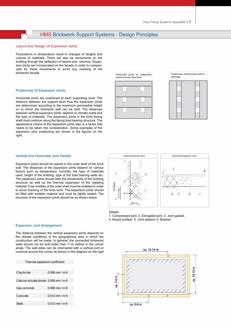
Details: 1. Compressed joint. 2. Elongated joint. 3. Joint gasket. 4. Keyed surface. 5. Joint sealant. 6. Bracket.
Vertical And Horizontal Joint Details:
Expansion joints should be placed in the outer shell of the brick wall. The distances of the expansion joints depend on various factors such as temperature, humidity, the type of materials used, height of the building, type of the load bearing walls etc. The expansion joints should take the movements of the building structure as well as the thermal expansion of the cladding material. Free mobility of the outer shell must be enabled in order to avoid cracking of the brick work. The expansion joints should be filled with suitable material and must be tightly sealed. The structure of the expansion joints should be as shown below:
Vertical Expansion joint Horizontal Expansion Joint
Layout And Design Of Expansion Joints
Fluctuations in temperature result in changes of lengths and volume of materials. There will also be movements on the building through the deflection of beams and columns. Expan-sion joints are incorporated on the facade in order to compen-sate for these movements to avoid any cracking of the brickwork facade.
Positioning Of Expansion Joints:
Horizontal joints are positioned at each supporting level. The distance between the support level thus the expansion joints are determined according to the maximum permissible height on to which the brickwork wall can be built. The distances between vertical expansion joints depend on climatic loads and the type of materials. The expansion joints in the brick facing shell must continue along the facing load bearing structure. The appearance choice of the expansion joints also is a factor that needs to be taken into consideration. Some examples of the expansion joint positioning are shown in the figures on the right.
Continuous vertical joints next to openings
Horizontal joints on supporting levels at every floor level
Expansion Joint Arrangement:
The distance between the vertical expansion joints depends on the climate conditions of the geographical area in which the construction will be made. In general, the connected brickwork walls should not be built wider than 7-14 metres in the corner areas. The wall slabs can be interrupted with a vertical joint or continue around the corner as shown in the diagram on the right.
Clay bricks 0.006 mm / m K
Calcium silicate blocks 0.008 mm / m K
Gas concrete 0.008 mm / m K
Concrete 0.012 mm / m K
Steel 0.012 mm / m K
Thermal expansion coefficient
| 8Your Fixing Systems Specialist
HMS Brickwork Support Systems - Design Principles
Details: 1. Compressed joint. 2. Elongated joint. 3. Joint gasket. 4. Keyed surface. 5. Joint sealant. 6. Bracket.
Vertical And Horizontal Joint Details:
Expansion joints should be placed in the outer shell of the brick wall. The distances of the expansion joints depend on various factors such as temperature, humidity, the type of materials used, height of the building, type of the load bearing walls etc. The expansion joints should take the movements of the building structure as well as the thermal expansion of the cladding material. Free mobility of the outer shell must be enabled in order to avoid cracking of the brick work. The expansion joints should be filled with suitable material and must be tightly sealed. The structure of the expansion joints should be as shown below:
Vertical Expansion joint Horizontal Expansion Joint
Layout And Design Of Expansion Joints
Fluctuations in temperature result in changes of lengths and volume of materials. There will also be movements on the building through the deflection of beams and columns. Expan-sion joints are incorporated on the facade in order to compen-sate for these movements to avoid any cracking of the brickwork facade.
Positioning Of Expansion Joints:
Horizontal joints are positioned at each supporting level. The distance between the support level thus the expansion joints are determined according to the maximum permissible height on to which the brickwork wall can be built. The distances between vertical expansion joints depend on climatic loads and the type of materials. The expansion joints in the brick facing shell must continue along the facing load bearing structure. The appearance choice of the expansion joints also is a factor that needs to be taken into consideration. Some examples of the expansion joint positioning are shown in the figures on the right.
Continuous vertical joints next to openings
Horizontal joints on supporting levels at every floor level
Expansion Joint Arrangement:
The distance between the vertical expansion joints depends on the climate conditions of the geographical area in which the construction will be made. In general, the connected brickwork walls should not be built wider than 7-14 metres in the corner areas. The wall slabs can be interrupted with a vertical joint or continue around the corner as shown in the diagram on the right.
Clay bricks 0.006 mm / m K
Calcium silicate blocks 0.008 mm / m K
Gas concrete 0.008 mm / m K
Concrete 0.012 mm / m K
Steel 0.012 mm / m K
Thermal expansion coefficient
Restraining tie
Insulation
Brick facing (Outer wall shell)
Fixing bolt into concrete
Brickwork bracket
Substrate (Inner wall shell)
9
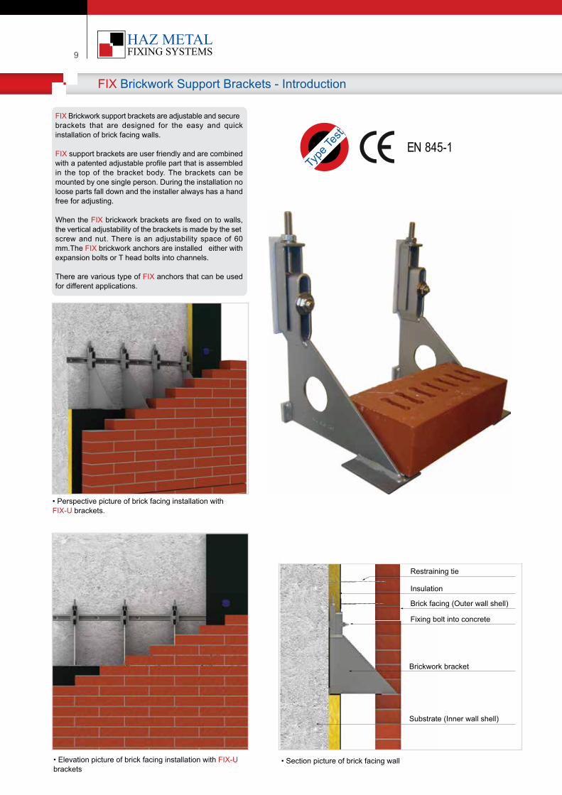
FIX Brickwork support brackets are adjustable and secure brackets that are designed for the easy and quick installation of brick facing walls.
FIX support brackets are user friendly and are combined with a patented adjustable profile part that is assembled in the top of the bracket body. The brackets can be mounted by one single person. During the installation no loose parts fall down and the installer always has a hand free for adjusting.
When the FIX brickwork brackets are fixed on to walls, the vertical adjustability of the brackets is made by the set screw and nut. There is an adjustability space of 60 mm.The FIX brickwork anchors are installed either with expansion bolts or T head bolts into channels.
There are various type of FIX anchors that can be used for different applications.
FIX Brickwork Support Brackets - Introduction
• Perspective picture of brick facing installation with FIX-U brackets.
• Elevation picture of brick facing installation with FIX-U brackets
• Section picture of brick facing wall
Type
Test
EN 845-1
| 10Your Fixing Systems Specialist
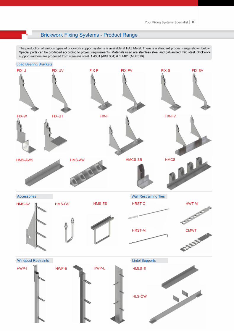
Brickwork Fixing Systems - Product Range
The production of various types of brickwork support systems is available at HAZ Metal. There is a standard product range shown below. Special parts can be produced according to project requirements. Materials used are stainless steel and galvanized mild steel. Brickwork support anchors are produced from stainless steel 1.4301 (AISI 304) & 1.4401 (AISI 316).
FIX-U FIX-UV FIX-P FIX-PV FIX-S FIX-SV
HMS-AWHMS-AWS
HMS-GS
FIX-W FIX-UT FIX-F
HMS-ESHMS-AV
HMCS
Load Bearing Brackets
Accessories
HRST-C HWT-M
CMWT
Windpost Restraints Lintel Supports
HWP-E HWP-LHWP-I HMLS-E
HLS-OW
HRST-M
HMCS-SB
FIX-FV
Wall Restraining Ties
Restraining tie
Insulation
Brick facing (Outer wall shell)
Fixing bolt into concrete
Brickwork bracket
Substrate (Inner wall shell)
9
FIX Brickwork support brackets are adjustable and secure brackets that are designed for the easy and quick installation of brick facing walls.
FIX support brackets are user friendly and are combined with a patented adjustable profile part that is assembled in the top of the bracket body. The brackets can be mounted by one single person. During the installation no loose parts fall down and the installer always has a hand free for adjusting.
When the FIX brickwork brackets are fixed on to walls, the vertical adjustability of the brackets is made by the set screw and nut. There is an adjustability space of 60 mm.The FIX brickwork anchors are installed either with expansion bolts or T head bolts into channels.
There are various type of FIX anchors that can be used for different applications.
FIX Brickwork Support Brackets - Introduction
• Perspective picture of brick facing installation with FIX-U brackets.
• Elevation picture of brick facing installation with FIX-U brackets
• Section picture of brick facing wall
Type
Test
EN 845-1
| 10Your Fixing Systems Specialist
Brickwork Fixing Systems - Product Range
The production of various types of brickwork support systems is available at HAZ Metal. There is a standard product range shown below. Special parts can be produced according to project requirements. Materials used are stainless steel and galvanized mild steel. Brickwork support anchors are produced from stainless steel 1.4301 (AISI 304) & 1.4401 (AISI 316).
FIX-U FIX-UV FIX-P FIX-PV FIX-S FIX-SV
HMS-AWHMS-AWS
HMS-GS
FIX-W FIX-UT FIX-F
HMS-ESHMS-AV
HMCS
Load Bearing Brackets
Accessories
HRST-C HWT-M
CMWT
Windpost Restraints Lintel Supports
HWP-E HWP-LHWP-I HMLS-E
HLS-OW
HRST-M
HMCS-SB
FIX-FV
Wall Restraining Ties
11
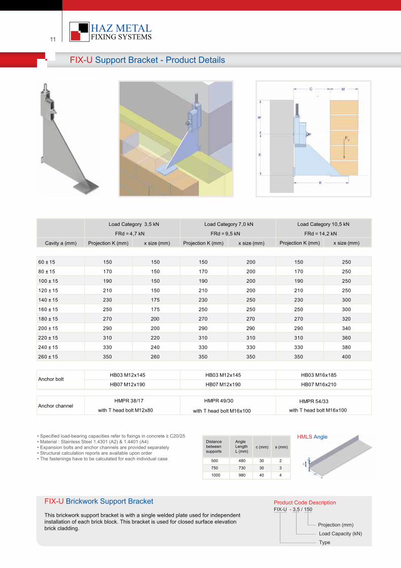
FIX-U Support Bracket - Product Details
:
:
:
Product Code Descr�pt�onFIX-U - 3,5 / 150
Load Capac�ty (kN)
Project�on (mm)
Type
FIX-U Br�ckwork Support Bracket
Th�s br�ckwork support bracket �s w�th a s�ngle welded plate used for �ndependent �nstallat�on of each br�ck block. Th�s bracket �s used for closed surface elevat�onbr�ck cladd�ng.
• Spec�f�ed load-bear�ng capac�t�es refer to f�x�ngs �n concrete ≥ C20/25• Mater�al : Sta�nless Steel 1.4301 (A2) & 1.4401 (A4)• Expans�on bolts and anchor channels are prov�ded separately• Structural calculat�on reports are ava�lable upon order• The fasten�ngs have to be calculated for each �nd�v�dual case
Cavity a (mm) Projection K (mm) x size (mm)
60 ± 15 150 150 150 200 150 250
80 ± 15 170 150 170 200 170 250
100 ± 15 190 150 190 200 190 250
120 ± 15 210 150 210 200 210 250
140 ± 15 230 175 230 250 230 300
160 ± 15 250 175 250 250 250 300
180 ± 15 270 200 270 270 270 320
200 ± 15 290 200 290 290 290 340
220 ± 15 310 220 310 310 310 360
240 ± 15 330 240 330 330 330 380
260 ± 15 350 260 350 350 350 400
Anchor bolt
with T head bolt M16x100Anchor channel
HB03 M12x145 HB03 M12x145 HB03 M16x185
HMPR 49/30
with T head bolt M16x100
HMPR 38/17
with T head bolt M12x80
HMPR 54/33
Load Category 3,5 kN
FRd = 4,7 kN
Load Category 7,0 kN
FRd = 9,5 kN
Load Category 10,5 kN
FRd = 14,2 kN
Projection K (mm) x size (mm) Projection K (mm) x size (mm)
Distance betweensupports
AngleLengthL (mm)
c (mm)
500
750
1000
480
730
980
30
30
40
2
3
4
s (mm)
HMLS Angle
sc
95
FV
HB07 M12x190 HB07 M12x190 HB07 M16x210
| 12Your Fixing Systems Specialist
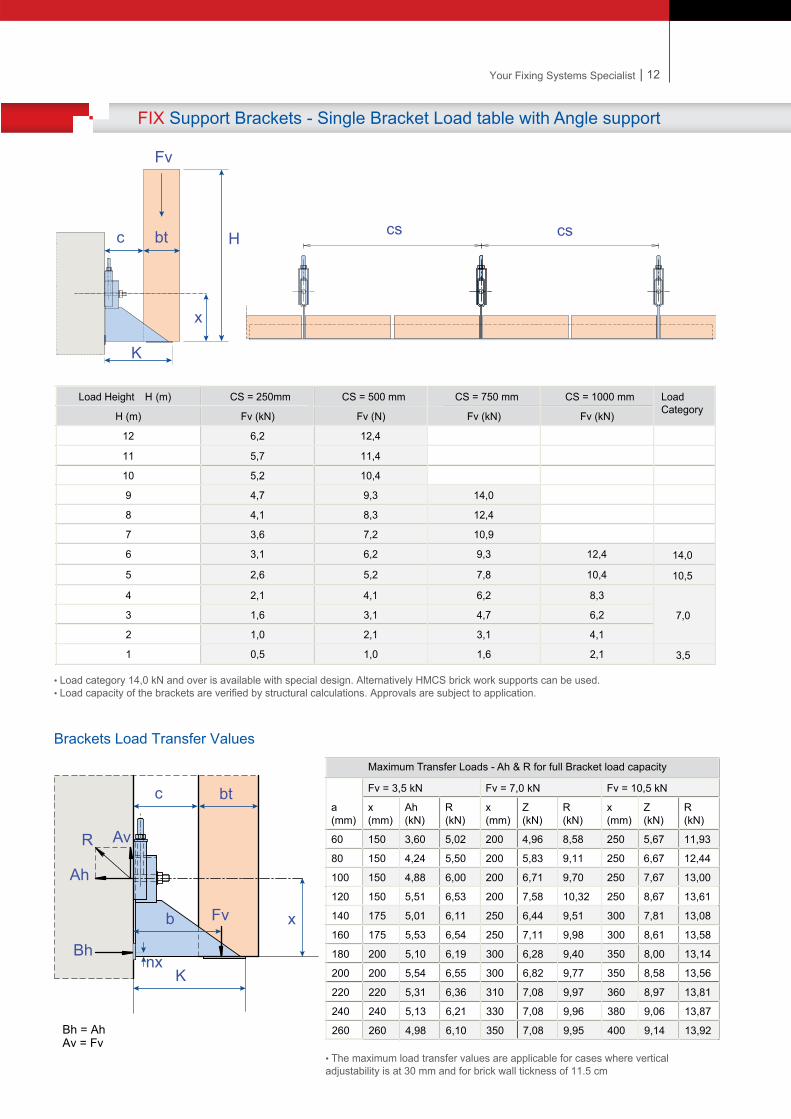
FIX Support Brackets - Single Bracket Load table with Angle support
:
Brackets Load Transfer Values
Bh = AhAv = Fv
cs csc
K
x
Hbt
Fv
• Load category 14,0 kN and over �s ava�lable w�th spec�al des�gn. Alternat�vely HMCS br�ck work supports can be used.• Load capac�ty of the brackets are ver�f�ed by structural calculat�ons. Approvals are subject to appl�cat�on.
Load He�ght H (m) CS = 250mm CS = 500 mm CS = 750 mm CS = 1000 mm Load CategoryH (m) Fv (kN) Fv (N) Fv (kN) Fv (kN)
12 6,2 12,4
11 5,7 11,4
10 5,2 10,4
9 4,7 9,3 14,0
8 4,1 8,3 12,4
7 3,6 7,2 10,9
6 3,1 6,2 9,3 12,4 14,0
5 2,6 5,2 7,8 10,4 10,5
4 2,1 4,1 6,2 8,3
7,03 1,6 3,1 4,7 6,2
2 1,0 2,1 3,1 4,1
1 0,5 1,0 1,6 2,1 3,5
a (mm)
Fv = 3,5 kN Fv = 7,0 kN Fv = 10,5 kN
x (mm)
Ah (kN)
R (kN)
x(mm)
Z (kN)
R (kN)
x(mm)
Z (kN)
R (kN)
60 150 3,60 5,02 200 4,96 8,58 250 5,67 11,93
80 150 4,24 5,50 200 5,83 9,11 250 6,67 12,44
100 150 4,88 6,00 200 6,71 9,70 250 7,67 13,00
120 150 5,51 6,53 200 7,58 10,32 250 8,67 13,61
140 175 5,01 6,11 250 6,44 9,51 300 7,81 13,08
160 175 5,53 6,54 250 7,11 9,98 300 8,61 13,58
180 200 5,10 6,19 300 6,28 9,40 350 8,00 13,14
200 200 5,54 6,55 300 6,82 9,77 350 8,58 13,56
220 220 5,31 6,36 310 7,08 9,97 360 8,97 13,81
240 240 5,13 6,21 330 7,08 9,96 380 9,06 13,87
260 260 4,98 6,10 350 7,08 9,95 400 9,14 13,92
c bt
K
xFvb
nx
Av
Ah
R
Bh
Maximum Transfer Loads - Ah & R for full Bracket load capacity
• The max�mum load transfer values are appl�cable for cases where vert�cal adjustab�l�ty �s at 30 mm and for br�ck wall t�ckness of 11.5 cm
13
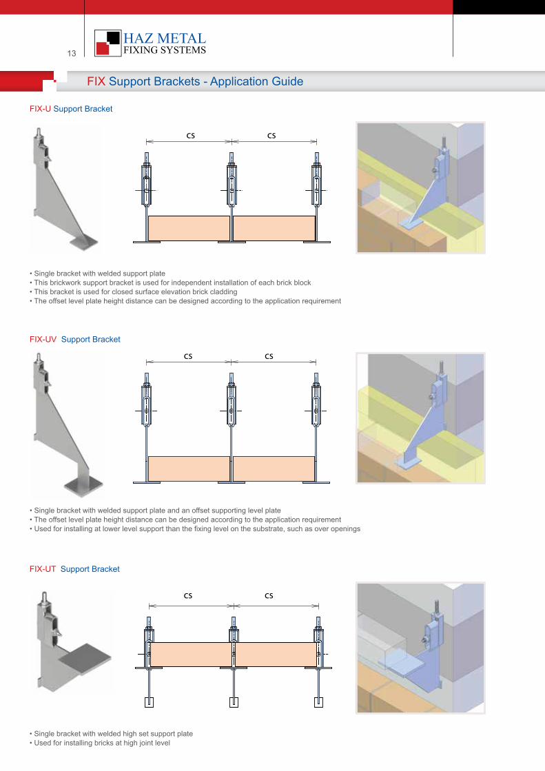
FIX Support Brackets - Application Guide
:
• Single bracket with welded support plate• This brickwork support bracket is used for independent installation of each brick block • This bracket is used for closed surface elevation brick cladding • The offset level plate height distance can be designed according to the application requirement
FIX-U Support Bracket
cs cs
• Single bracket with welded support plate and an offset supporting level plate• The offset level plate height distance can be designed according to the application requirement • Used for installing at lower level support than the fixing level on the substrate, such as over openings
FIX-UV Support Bracket
cs cs
• Single bracket with welded high set support plate• Used for installing bricks at high joint level
FIX-UT Support Bracket
cs cs
| 14Your Fixing Systems Specialist
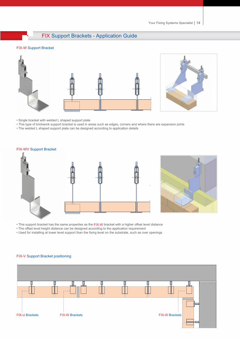
FIX Support Brackets - Application Guide
:
• Single bracket with welded L shaped support plate• This type of brickwork support bracket is used in areas such as edges, corners and where there are expansion joints• The welded L shaped support plate can be designed according to application details
FIX-W Support Bracket
• This support bracket has the same properties as the FIX-W bracket with a higher offset level distance• The offset level height distance can be designed according to the application requirement• Used for installing at lower level support than the fixing level on the substrate, such as over openings
FIX-WV Support Bracket
FIX-V Support Bracket positioning
FIX-U Brackets FIX-W Brackets FIX-W Brackets
FIX Support Brackets - Application Guide
:
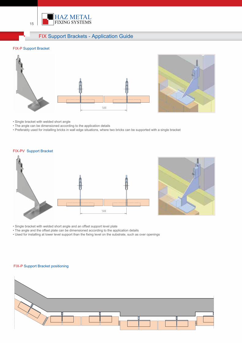
• Single bracket with welded short angle• The angle can be dimensioned according to the application details • Preferably used for installing bricks in wall edge situations, where two bricks can be supported with a single bracket
FIX-P Support Bracket
• Single bracket with welded short angle and an offset support level plate• The angle and the offset plate can be dimensioned according to the application details • Used for installing at lower level support than the fixing level on the substrate, such as over openings
FIX-PV Support Bracket
15
FIX-P Support Bracket positioning
| 16Your Fixing Systems Specialist
FIX Support Brackets - Application Guide
:
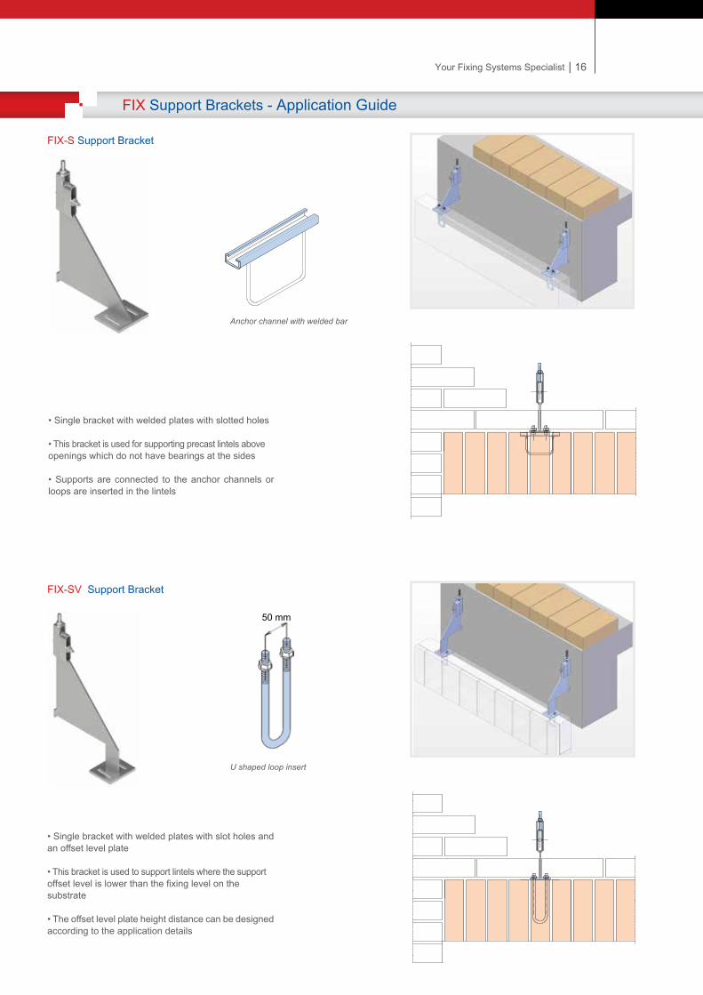
• Single bracket with welded plates with slotted holes
• This bracket is used for supporting precast lintels above openings which do not have bearings at the sides
• Supports are connected to the anchor channels or loops are inserted in the lintels
FIX-S Support Bracket
• Single bracket with welded plates with slot holes and an offset level plate
• This bracket is used to support lintels where the support offset level is lower than the fixing level on the substrate • The offset level plate height distance can be designed according to the application details
FIX-SV Support Bracket
50 mm
Anchor channel with welded bar
U shaped loop insert
| 16Your Fixing Systems Specialist
FIX Support Brackets - Application Guide
:
• Single bracket with welded plates with slotted holes
• This bracket is used for supporting precast lintels above openings which do not have bearings at the sides
• Supports are connected to the anchor channels or loops are inserted in the lintels
FIX-S Support Bracket
• Single bracket with welded plates with slot holes and an offset level plate
• This bracket is used to support lintels where the support offset level is lower than the fixing level on the substrate • The offset level plate height distance can be designed according to the application details
FIX-SV Support Bracket
50 mm
Anchor channel with welded bar
U shaped loop insert
FIX Support Brackets - Product Information
:
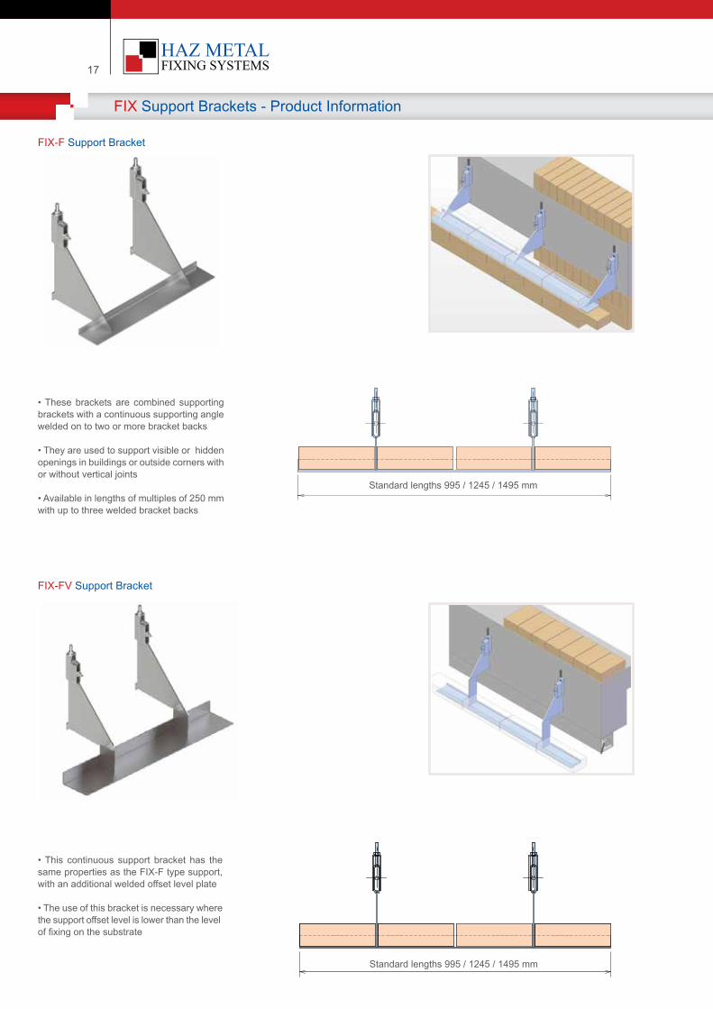
• These brackets are combined supporting brackets with a continuous supporting angle welded on to two or more bracket backs
• They are used to support visible or hidden openings in buildings or outside corners with or without vertical joints • Available in lengths of multiples of 250 mm with up to three welded bracket backs
FIX-F Support Bracket
• This continuous support bracket has the same properties as the FIX-F type support, with an additional welded offset level plate
• The use of this bracket is necessary where the support offset level is lower than the level of fixing on the substrate
FIX-FV Support Bracket
17
Standard lengths 995 / 1245 / 1495 mm
Standard lengths 995 / 1245 / 1495 mm
| 18Your Fixing Systems Specialist
FIX Support Brackets - Product Information
:
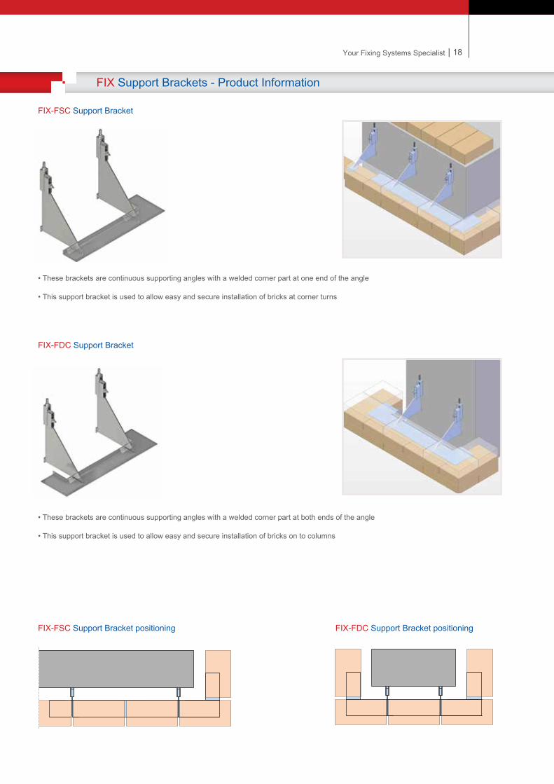
• These brackets are continuous supporting angles with a welded corner part at one end of the angle
• This support bracket is used to allow easy and secure installation of bricks at corner turns
FIX-FSC Support Bracket
• These brackets are continuous supporting angles with a welded corner part at both ends of the angle
• This support bracket is used to allow easy and secure installation of bricks on to columns
FIX-FDC Support Bracket
FIX-FSC Support Bracket positioning FIX-FDC Support Bracket positioning
| 18Your Fixing Systems Specialist
FIX Support Brackets - Product Information
:
• These brackets are continuous supporting angles with a welded corner part at one end of the angle
• This support bracket is used to allow easy and secure installation of bricks at corner turns
FIX-FSC Support Bracket
• These brackets are continuous supporting angles with a welded corner part at both ends of the angle
• This support bracket is used to allow easy and secure installation of bricks on to columns
FIX-FDC Support Bracket
FIX-FSC Support Bracket positioning FIX-FDC Support Bracket positioning
19
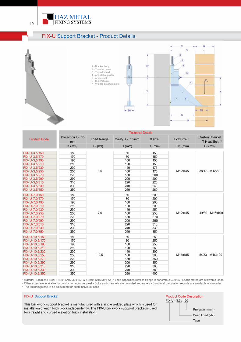
FIX-U Support Bracket - Product Details
:
Product Code Descr�pt�onFIX-U - 3,5 / 150
Project�on (mm)
Dead Load (kN)
Type
FIX-U Support Bracket
Th�s br�ckwork support bracket �s manufactured w�th a s�ngle welded plate wh�ch �s used for �nstallat�on of each br�ck block �ndependently. The FIX-U br�ckwork suppport bracket �s used for stra�ght and curved elevat�on br�ck �nstallat�on.
• Mater�al : Sta�nless Steel 1.4301 (AISI 304-A2) & 1.4401 (AISI 316-A4) • Load capac�t�es refer to f�x�ngs �n concrete ≥ C20/25 • Loads stated are allowable loads • Other s�zes are ava�lable for product�on upon request • Bolts and channels are prov�ded separately • Structural calculat�on reports are ava�lable upon order• The fasten�ngs has to be calculated for each �nd�v�dual case
K (mm) Fv (kN) C (mm) X (mm) E.b. (mm) CI (mm)
FIX-U-3,5/150 150 60 150FIX-U-3,5/170 170 80 150FIX-U-3,5/190 190 100 150FIX-U-3,5/210 210 120 150FIX-U-3,5/230 230 140 175FIX-U-3,5/250 250 160 175FIX-U-3,5/270 270 180 200FIX-U-3,5/290 290 200 200FIX-U-3,5/310 310 220 220FIX-U-3,5/330 330 240 240FIX-U-3,5/350 350 260 260FIX-U-7,0/150 150 60 200FIX-U-7,0/170 170 80 200FIX-U-7,0/190 190 100 200FIX-U-7,0/210 210 120 200FIX-U-7,0/230 230 140 250FIX-U-7,0/250 250 160 250FIX-U-7,0/270 270 180 270FIX-U-7,0/290 290 200 290FIX-U-7,0/310 310 220 310FIX-U-7,0/330 330 240 330FIX-U-7,0/350 350 260 350FIX-U-10,5/150 150 60 250FIX-U-10,5/170 170 80 250FIX-U-10,5/190 190 100 250FIX-U-10,5/210 210 120 250FIX-U-10,5/230 230 140 300FIX-U-10,5/250 250 160 300FIX-U-10,5/270 270 180 350FIX-U-10,5/290 290 200 350FIX-U-10,5/310 310 220 360FIX-U-10,5/330 330 240 380FIX-U-10,5/350 350 260 400
7,0 M12x145 49/30 - M16x100
10,5 M16x185 54/33 - M16x100
3,5 M12x145 38/17 - M12x80
Product Code Projection +/- 15 mm
Load Range Cavity +/- 15 mm Cast-in Channel T Head Bolt 1)
Bolt Size 1)X size
Technical Details
1 - Bracket body2 - Thermal break3 - Threaded rod4 - Adjustable prof�le5 - Anchor bolt6 - Support plate7 - Welded pressure plate
FV
x
| 20Your Fixing Systems Specialist
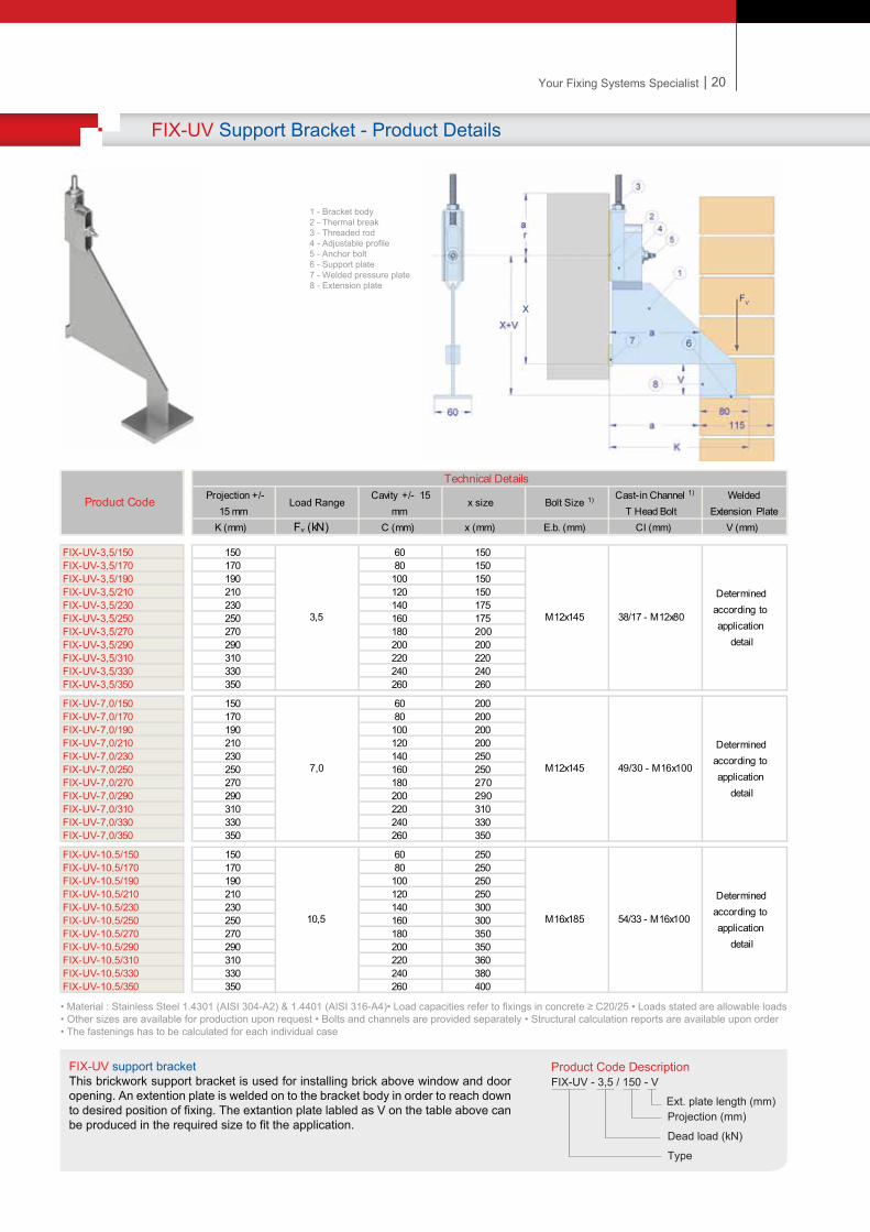
FIX-UV Support Bracket - Product Details
:
Product Code Descr�pt�onFIX-UV - 3,5 / 150 - V
Project�on (mm)
Dead load (kN)
Type
Ext. plate length (mm)
FIX-UV support bracketTh�s br�ckwork support bracket �s used for �nstall�ng br�ck above w�ndow and door open�ng. An extent�on plate �s welded on to the bracket body �n order to reach down to des�red pos�t�on of f�x�ng. The extant�on plate labled as V on the table above can be produced �n the requ�red s�ze to f�t the appl�cat�on.
• Mater�al : Sta�nless Steel 1.4301 (AISI 304-A2) & 1.4401 (AISI 316-A4)• Load capac�t�es refer to f�x�ngs �n concrete ≥ C20/25 • Loads stated are allowable loads • Other s�zes are ava�lable for product�on upon request • Bolts and channels are prov�ded separately • Structural calculat�on reports are ava�lable upon order• The fasten�ngs has to be calculated for each �nd�v�dual case
K (mm) Fv (kN) C (mm) x (mm) E.b. (mm) CI (mm) V (mm)
FIX-UV-3,5/150 150 60 150FIX-UV-3,5/170 170 80 150FIX-UV-3,5/190 190 100 150FIX-UV-3,5/210 210 120 150FIX-UV-3,5/230 230 140 175FIX-UV-3,5/250 250 160 175FIX-UV-3,5/270 270 180 200FIX-UV-3,5/290 290 200 200FIX-UV-3,5/310 310 220 220FIX-UV-3,5/330 330 240 240FIX-UV-3,5/350 350 260 260
FIX-UV-7,0/150 150 60 200FIX-UV-7,0/170 170 80 200FIX-UV-7,0/190 190 100 200FIX-UV-7,0/210 210 120 200FIX-UV-7,0/230 230 140 250FIX-UV-7,0/250 250 160 250FIX-UV-7,0/270 270 180 270FIX-UV-7,0/290 290 200 290FIX-UV-7,0/310 310 220 310FIX-UV-7,0/330 330 240 330FIX-UV-7,0/350 350 260 350
FIX-UV-10,5/150 150 60 250FIX-UV-10,5/170 170 80 250FIX-UV-10,5/190 190 100 250FIX-UV-10,5/210 210 120 250FIX-UV-10,5/230 230 140 300FIX-UV-10,5/250 250 160 300FIX-UV-10,5/270 270 180 350FIX-UV-10,5/290 290 200 350FIX-UV-10,5/310 310 220 360FIX-UV-10,5/330 330 240 380FIX-UV-10,5/350 350 260 400
10,5 M16x185
Determined according to application
detail
Cast-in Channel 1)
T Head Bolt
38/17 - M12x80
49/30 - M16x100
54/33 - M16x100
3,5 M12x145
Determined according to application
detail
7,0 M12x145
Determined according to application
detail
Product Code
Technical DetailsProjection +/-
15 mm Load Range
Cavity +/- 15 mm
x size Bolt Size 1) Welded Extension Plate
1 - Bracket body2 - Thermal break3 - Threaded rod4 - Adjustable prof�le5 - Anchor bolt6 - Support plate7 - Welded pressure plate8 - Extens�on plate FVx
| 20Your Fixing Systems Specialist
FIX-UV Support Bracket - Product Details
:
Product Code Descr�pt�onFIX-UV - 3,5 / 150 - V
Project�on (mm)
Dead load (kN)
Type
Ext. plate length (mm)
FIX-UV support bracketTh�s br�ckwork support bracket �s used for �nstall�ng br�ck above w�ndow and door open�ng. An extent�on plate �s welded on to the bracket body �n order to reach down to des�red pos�t�on of f�x�ng. The extant�on plate labled as V on the table above can be produced �n the requ�red s�ze to f�t the appl�cat�on.
• Mater�al : Sta�nless Steel 1.4301 (AISI 304-A2) & 1.4401 (AISI 316-A4)• Load capac�t�es refer to f�x�ngs �n concrete ≥ C20/25 • Loads stated are allowable loads • Other s�zes are ava�lable for product�on upon request • Bolts and channels are prov�ded separately • Structural calculat�on reports are ava�lable upon order• The fasten�ngs has to be calculated for each �nd�v�dual case
K (mm) Fv (kN) C (mm) x (mm) E.b. (mm) CI (mm) V (mm)
FIX-UV-3,5/150 150 60 150FIX-UV-3,5/170 170 80 150FIX-UV-3,5/190 190 100 150FIX-UV-3,5/210 210 120 150FIX-UV-3,5/230 230 140 175FIX-UV-3,5/250 250 160 175FIX-UV-3,5/270 270 180 200FIX-UV-3,5/290 290 200 200FIX-UV-3,5/310 310 220 220FIX-UV-3,5/330 330 240 240FIX-UV-3,5/350 350 260 260
FIX-UV-7,0/150 150 60 200FIX-UV-7,0/170 170 80 200FIX-UV-7,0/190 190 100 200FIX-UV-7,0/210 210 120 200FIX-UV-7,0/230 230 140 250FIX-UV-7,0/250 250 160 250FIX-UV-7,0/270 270 180 270FIX-UV-7,0/290 290 200 290FIX-UV-7,0/310 310 220 310FIX-UV-7,0/330 330 240 330FIX-UV-7,0/350 350 260 350
FIX-UV-10,5/150 150 60 250FIX-UV-10,5/170 170 80 250FIX-UV-10,5/190 190 100 250FIX-UV-10,5/210 210 120 250FIX-UV-10,5/230 230 140 300FIX-UV-10,5/250 250 160 300FIX-UV-10,5/270 270 180 350FIX-UV-10,5/290 290 200 350FIX-UV-10,5/310 310 220 360FIX-UV-10,5/330 330 240 380FIX-UV-10,5/350 350 260 400
10,5 M16x185
Determined according to application
detail
Cast-in Channel 1)
T Head Bolt
38/17 - M12x80
49/30 - M16x100
54/33 - M16x100
3,5 M12x145
Determined according to application
detail
7,0 M12x145
Determined according to application
detail
Product Code
Technical DetailsProjection +/-
15 mm Load Range
Cavity +/- 15 mm
x size Bolt Size 1) Welded Extension Plate
1 - Bracket body2 - Thermal break3 - Threaded rod4 - Adjustable prof�le5 - Anchor bolt6 - Support plate7 - Welded pressure plate8 - Extens�on plate FVx
21
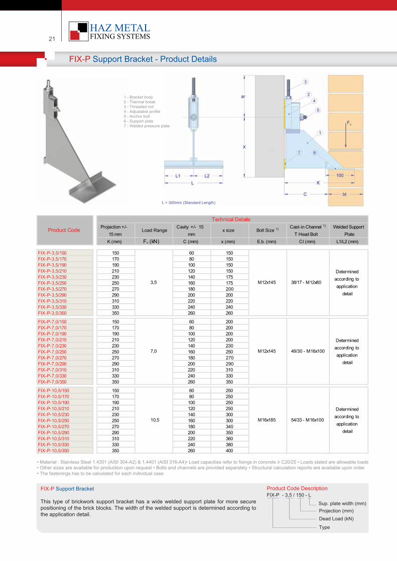
Product Code Descr�pt�onFIX-P - 3,5 / 150 - L
Project�on (mm)Dead Load (kN)
Type
Sup. plate w�dth (mm)
FIX-P Support Bracket
Th�s type of br�ckwork support bracket has a w�de welded support plate for more secure pos�t�on�ng of the br�ck blocks. The w�dth of the welded support �s determ�ned accord�ng to the appl�cat�on deta�l.
FIX-P Support Bracket - Product Details
:
• Mater�al : Sta�nless Steel 1.4301 (AISI 304-A2) & 1.4401 (AISI 316-A4)• Load capac�t�es refer to f�x�ngs �n concrete ≥ C20/25 • Loads stated are allowable loads • Other s�zes are ava�lable for product�on upon request • Bolts and channels are prov�ded separately • Structural calculat�on reports are ava�lable upon order• The fasten�ngs has to be calculated for each �nd�v�dual case
K (mm) Fv (kN) C (mm) x (mm) E.b. (mm) CI (mm) L1/L2 (mm)
FIX-P-3,5/150 150 60 150FIX-P-3,5/170 170 80 150FIX-P-3,5/190 190 100 150FIX-P-3,5/210 210 120 150FIX-P-3,5/230 230 140 175FIX-P-3,5/250 250 160 175FIX-P-3,5/270 270 180 200FIX-P-3,5/290 290 200 200FIX-P-3,5/310 310 220 220FIX-P-3,5/330 330 240 240FIX-P-3,5/350 350 260 260
FIX-P-7,0/150 150 60 200FIX-P-7,0/170 170 80 200FIX-P-7,0/190 190 100 200FIX-P-7,0/210 210 120 200FIX-P-7,0/230 230 140 230FIX-P-7,0/250 250 160 250FIX-P-7,0/270 270 180 270FIX-P-7,0/290 290 200 290FIX-P-7,0/310 310 220 310FIX-P-7,0/330 330 240 330FIX-P-7,0/350 350 260 350
FIX-P-10,5/150 150 60 250FIX-P-10,5/170 170 80 250FIX-P-10,5/190 190 100 250FIX-P-10,5/210 210 120 250FIX-P-10,5/230 230 140 300FIX-P-10,5/250 250 160 300FIX-P-10,5/270 270 180 340FIX-P-10,5/290 290 200 350FIX-P-10,5/310 310 220 360FIX-P-10,5/330 330 240 380FIX-P-10,5/350 350 260 400
10,5 M16x185 54/33 - M16x100
Determined according to application
detail
3,5 M12x145 38/17 - M12x80
Determined according to application
detail
7,0 M12x145 49/30 - M16x100
Determined according to application
detail
Product Code
Technical DetailsProjection +/-
15 mm Load Range
Cavity +/- 15 mm
x size Bolt Size 1) Cast-in Channel 1)
T Head BoltWelded Support
Plate
FV
1 - Bracket body2 - Thermal break3 - Threaded rod4 - Adjustable prof�le5 - Anchor bolt6 - Support plate7 - Welded pressure plate
L = 300mm (Standard Length)
x
| 22Your Fixing Systems Specialist
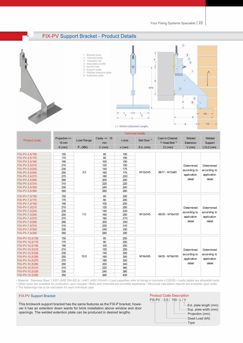
FIX-PV Support Bracket - Product Details
:
Product Code Descr�pt�onFIX-PV - 3,5 / 150 - L / V
Project�on (mm)Dead Load (kN)Type
Sup. plate w�dth (mm)Ext. plate length (mm)
FIX-PV Support Bracket
Th�s br�ckwork support bracket has the same features as the FIX-P bracket, howe-ver �t has an extent�on down wards for br�ck �nstallat�on above w�ndow and door open�ngs. The welded extent�on plate can be produced �n des�red lengths.
• Mater�al : Sta�nless Steel 1.4301 (AISI 304-A2) & 1.4401 (AISI 316-A4) • Load capac�t�es refer to f�x�ngs �n concrete ≥ C20/25 • Loads stated are allowable loads • Other s�zes are ava�lable for product�on upon request • Bolts and channels are prov�ded separately • Structural calculat�on reports are ava�lable upon order• The fasten�ngs has to be calculated for each �nd�v�dual case
K (mm) Fv (kN) C (mm) x (mm) E.b. (mm) CI (mm) V (mm) L1/L2 (mm)
FIX-PV-3,5/150 150 60 150FIX-PV-3,5/170 170 80 150FIX-PV-3,5/190 190 100 150FIX-PV-3,5/210 210 120 150FIX-PV-3,5/230 230 140 175FIX-PV-3,5/250 250 160 175FIX-PV-3,5/270 270 180 200FIX-PV-3,5/290 290 200 200FIX-PV-3,5/310 310 220 220FIX-PV-3,5/330 330 240 240FIX-PV-3,5/350 350 260 260
FIX-PV-7,0/150 150 60 200FIX-PV-7,0/170 170 80 200FIX-PV-7,0/190 190 100 200FIX-PV-7,0/210 210 120 200FIX-PV-7,0/230 230 140 230FIX-PV-7,0/250 250 160 250FIX-PV-7,0/270 270 180 270FIX-PV-7,0/290 290 200 290FIX-PV-7,0/310 310 220 310FIX-PV-7,0/330 330 240 330FIX-PV-7,0/350 350 260 350
FIX-PV-10,5/150 150 60 250FIX-PV-10,5/170 170 80 250FIX-PV-10,5/190 190 100 250FIX-PV-10,5/210 210 120 250FIX-PV-10,5/230 230 140 300FIX-PV-10,5/250 250 160 300FIX-PV-10,5/270 270 180 320FIX-PV-10,5/290 290 200 340FIX-PV-10,5/310 310 220 360FIX-PV-10,5/330 330 240 380FIX-PV-10,5/350 350 260 400
10,5 M16x185 54/33 - M16x100
Determined according to application
detail
Welded Extension
Determined according to application
detail
Determined according to application
detail
Determined according to application
detail
3,5 M12x145 38/17 - M12x80
Determined according to application
detail
7,0 M12x145 49/30 - M16x100
Determined according to application
detail
Product Code
Technical Details
Projection +/- 15 mm
Load RangeCavity +/- 15
mmx size Bolt Size 1) Cast-in Channel
T Head Bolt 1)
Welded Support
FV
1 - Bracket body2 - Thermal break3 - Threaded rod4 - Adjustable prof�le5 - Anchor bolt6 - Support plate7 - Welded pressure plate8 - Extens�on plate
L = 300mm (Standard Length)
x
21
Product Code Descr�pt�onFIX-P - 3,5 / 150 - L
Project�on (mm)Dead Load (kN)
Type
Sup. plate w�dth (mm)
FIX-P Support Bracket
Th�s type of br�ckwork support bracket has a w�de welded support plate for more secure pos�t�on�ng of the br�ck blocks. The w�dth of the welded support �s determ�ned accord�ng to the appl�cat�on deta�l.
FIX-P Support Bracket - Product Details
:
• Mater�al : Sta�nless Steel 1.4301 (AISI 304-A2) & 1.4401 (AISI 316-A4)• Load capac�t�es refer to f�x�ngs �n concrete ≥ C20/25 • Loads stated are allowable loads • Other s�zes are ava�lable for product�on upon request • Bolts and channels are prov�ded separately • Structural calculat�on reports are ava�lable upon order• The fasten�ngs has to be calculated for each �nd�v�dual case
K (mm) Fv (kN) C (mm) x (mm) E.b. (mm) CI (mm) L1/L2 (mm)
FIX-P-3,5/150 150 60 150FIX-P-3,5/170 170 80 150FIX-P-3,5/190 190 100 150FIX-P-3,5/210 210 120 150FIX-P-3,5/230 230 140 175FIX-P-3,5/250 250 160 175FIX-P-3,5/270 270 180 200FIX-P-3,5/290 290 200 200FIX-P-3,5/310 310 220 220FIX-P-3,5/330 330 240 240FIX-P-3,5/350 350 260 260
FIX-P-7,0/150 150 60 200FIX-P-7,0/170 170 80 200FIX-P-7,0/190 190 100 200FIX-P-7,0/210 210 120 200FIX-P-7,0/230 230 140 230FIX-P-7,0/250 250 160 250FIX-P-7,0/270 270 180 270FIX-P-7,0/290 290 200 290FIX-P-7,0/310 310 220 310FIX-P-7,0/330 330 240 330FIX-P-7,0/350 350 260 350
FIX-P-10,5/150 150 60 250FIX-P-10,5/170 170 80 250FIX-P-10,5/190 190 100 250FIX-P-10,5/210 210 120 250FIX-P-10,5/230 230 140 300FIX-P-10,5/250 250 160 300FIX-P-10,5/270 270 180 340FIX-P-10,5/290 290 200 350FIX-P-10,5/310 310 220 360FIX-P-10,5/330 330 240 380FIX-P-10,5/350 350 260 400
10,5 M16x185 54/33 - M16x100
Determined according to application
detail
3,5 M12x145 38/17 - M12x80
Determined according to application
detail
7,0 M12x145 49/30 - M16x100
Determined according to application
detail
Product Code
Technical DetailsProjection +/-
15 mm Load Range
Cavity +/- 15 mm
x size Bolt Size 1) Cast-in Channel 1)
T Head BoltWelded Support
Plate
FV
1 - Bracket body2 - Thermal break3 - Threaded rod4 - Adjustable prof�le5 - Anchor bolt6 - Support plate7 - Welded pressure plate
L = 300mm (Standard Length)
x
| 22Your Fixing Systems Specialist
FIX-PV Support Bracket - Product Details
:
Product Code Descr�pt�onFIX-PV - 3,5 / 150 - L / V
Project�on (mm)Dead Load (kN)Type
Sup. plate w�dth (mm)Ext. plate length (mm)
FIX-PV Support Bracket
Th�s br�ckwork support bracket has the same features as the FIX-P bracket, howe-ver �t has an extent�on down wards for br�ck �nstallat�on above w�ndow and door open�ngs. The welded extent�on plate can be produced �n des�red lengths.
• Mater�al : Sta�nless Steel 1.4301 (AISI 304-A2) & 1.4401 (AISI 316-A4) • Load capac�t�es refer to f�x�ngs �n concrete ≥ C20/25 • Loads stated are allowable loads • Other s�zes are ava�lable for product�on upon request • Bolts and channels are prov�ded separately • Structural calculat�on reports are ava�lable upon order• The fasten�ngs has to be calculated for each �nd�v�dual case
K (mm) Fv (kN) C (mm) x (mm) E.b. (mm) CI (mm) V (mm) L1/L2 (mm)
FIX-PV-3,5/150 150 60 150FIX-PV-3,5/170 170 80 150FIX-PV-3,5/190 190 100 150FIX-PV-3,5/210 210 120 150FIX-PV-3,5/230 230 140 175FIX-PV-3,5/250 250 160 175FIX-PV-3,5/270 270 180 200FIX-PV-3,5/290 290 200 200FIX-PV-3,5/310 310 220 220FIX-PV-3,5/330 330 240 240FIX-PV-3,5/350 350 260 260
FIX-PV-7,0/150 150 60 200FIX-PV-7,0/170 170 80 200FIX-PV-7,0/190 190 100 200FIX-PV-7,0/210 210 120 200FIX-PV-7,0/230 230 140 230FIX-PV-7,0/250 250 160 250FIX-PV-7,0/270 270 180 270FIX-PV-7,0/290 290 200 290FIX-PV-7,0/310 310 220 310FIX-PV-7,0/330 330 240 330FIX-PV-7,0/350 350 260 350
FIX-PV-10,5/150 150 60 250FIX-PV-10,5/170 170 80 250FIX-PV-10,5/190 190 100 250FIX-PV-10,5/210 210 120 250FIX-PV-10,5/230 230 140 300FIX-PV-10,5/250 250 160 300FIX-PV-10,5/270 270 180 320FIX-PV-10,5/290 290 200 340FIX-PV-10,5/310 310 220 360FIX-PV-10,5/330 330 240 380FIX-PV-10,5/350 350 260 400
10,5 M16x185 54/33 - M16x100
Determined according to application
detail
Welded Extension
Determined according to application
detail
Determined according to application
detail
Determined according to application
detail
3,5 M12x145 38/17 - M12x80
Determined according to application
detail
7,0 M12x145 49/30 - M16x100
Determined according to application
detail
Product Code
Technical Details
Projection +/- 15 mm
Load RangeCavity +/- 15
mmx size Bolt Size 1) Cast-in Channel
T Head Bolt 1)
Welded Support
FV
1 - Bracket body2 - Thermal break3 - Threaded rod4 - Adjustable prof�le5 - Anchor bolt6 - Support plate7 - Welded pressure plate8 - Extens�on plate
L = 300mm (Standard Length)
x
23
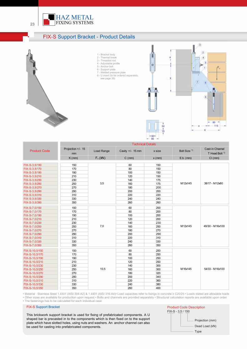
FIX-S Support Bracket - Product Details
::
Product Code Descr�pt�onFIX-S - 3,5 / 150
Project�on (mm)
Dead Load (kN)
Type
FIX-S Support Bracket
Th�s br�ckwork support bracket �s used for f�x�ng of prefabr�cated components. A U shaped bar �s precasted �n to the components wh�ch �s then f�xed on to the support plate wh�ch have slotted holes, us�ng nuts and washers. An anchor channel can also be used for cast�ng �nto prefabr�cated components.
• Mater�al : Sta�nless Steel 1.4301 (AISI 304-A2) & 1.4401 (AISI 316-A4)• Load capac�t�es refer to f�x�ngs �n concrete ≥ C20/25 • Loads stated are allowable loads • Other s�zes are ava�lable for product�on upon request • Bolts and channels are prov�ded separately • Structural calculat�on reports are ava�lable upon order• The fasten�ngs has to be calculated for each �nd�v�dual case
K (mm) Fv (kN) C (mm) x (mm) E.b. (mm) CI (mm)
FIX-S-3,5/150 150 60 150FIX-S-3,5/170 170 80 150FIX-S-3,5/190 190 100 150FIX-S-3,5/210 210 120 150FIX-S-3,5/230 230 140 175FIX-S-3,5/250 250 160 175FIX-S-3,5/270 270 180 200FIX-S-3,5/290 290 200 200FIX-S-3,5/310 310 220 220FIX-S-3,5/330 330 240 240FIX-S-3,5/350 350 260 260
FIX-S-7,0/150 150 60 200FIX-S-7,0/170 170 80 200FIX-S-7,0/190 190 100 200FIX-S-7,0/210 210 120 200FIX-S-7,0/230 230 140 230FIX-S-7,0/250 250 160 250FIX-S-7,0/270 270 180 270FIX-S-7,0/290 290 200 290FIX-S-7,0/310 310 220 310FIX-S-7,0/330 330 240 330FIX-S-7,0/350 350 260 350
FIX-S-10,5/150 150 60 250FIX-S-10,5/170 170 80 250FIX-S-10,5/190 190 100 250FIX-S-10,5/210 210 120 250FIX-S-10,5/230 230 140 300FIX-S-10,5/250 250 160 300FIX-S-10,5/270 270 180 320FIX-S-10,5/290 290 200 340FIX-S-10,5/310 310 220 360FIX-S-10,5/330 330 240 380FIX-S-10,5/350 350 260 400
10,5 M16x145 54/33 - M16x100
3,5 M12x145 38/17 - M12x80
7,0 M12x145 49/30 - M16x100
Product Code
Technical DetailsProjection +/- 15
mm Load Range Cavity +/- 15 mm x size Bolt Size 1) Cast-in Channel
T Head Bolt 1)
1 - Bracket body2 - Thermal break3 - Threaded rod4 - Adjustable prof�le5 - Anchor bolt6 - Support plate7 - Welded pressure plate8 - U �nsert (to be ordered separately, see page 39)
FV
x
| 24Your Fixing Systems Specialist
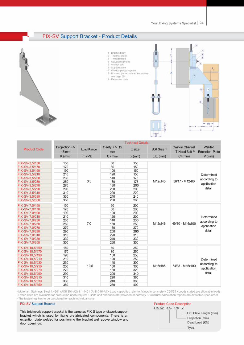
FIX-SV Support Bracket - Product Details
:
Product Code Descr�pt�onFIX-SV - 3,5 / 150 - V
Project�on (mm)Dead Load (KN)
Type
Ext. Plate Length (mm)
FIX-SV Support Bracket
Th�s br�ckwork support bracket �s the same as FIX-S type br�ckwork support bracket wh�ch �s used for f�x�ng prefabr�cated components. There �s an extent�on plate welded for pos�t�on�ng the bracket well above w�ndow and door open�ngs.
• Mater�al : Sta�nless Steel 1.4301 (AISI 304-A2) & 1.4401 (AISI 316-A4)• Load capac�t�es refer to f�x�ngs �n concrete ≥ C20/25 • Loads stated are allowable loads • Other s�zes are ava�lable for product�on upon request • Bolts and channels are prov�ded separately • Structural calculat�on reports are ava�lable upon order• The fasten�ngs has to be calculated for each �nd�v�dual case
K (mm) Fv (kN) C (mm) x (mm) E.b. (mm) CI (mm) V (mm)
FIX-SV-3,5/150 150 60 150FIX-SV-3,5/170 170 80 150FIX-SV-3,5/190 190 100 150FIX-SV-3,5/210 210 120 150FIX-SV-3,5/230 230 140 175FIX-SV-3,5/250 250 160 175FIX-SV-3,5/270 270 180 200FIX-SV-3,5/290 290 200 200FIX-SV-3,5/310 310 220 220FIX-SV-3,5/330 330 240 240FIX-SV-3,5/350 350 260 260FIX-SV-7,0/150 150 60 200FIX-SV-7,0/170 170 80 200FIX-SV-7,0/190 190 100 200FIX-SV-7,0/210 210 120 200FIX-SV-7,0/230 230 140 230FIX-SV-7,0/250 250 160 250FIX-SV-7,0/270 270 180 270FIX-SV-7,0/290 290 200 290FIX-SV-7,0/310 310 220 310FIX-SV-7,0/330 330 240 330FIX-SV-7,0/350 350 260 350FIX-SV-10,5/150 150 60 250FIX-SV-10,5/170 170 80 250FIX-SV-10,5/190 190 100 250FIX-SV-10,5/210 210 120 250FIX-SV-10,5/230 230 140 300FIX-SV-10,5/250 250 160 300FIX-SV-10,5/270 270 180 320FIX-SV-10,5/290 290 200 340FIX-SV-10,5/310 310 220 360FIX-SV-10,5/330 330 240 380FIX-SV-10,5/350 350 260 400
10,5 M16x185 54/33 - M16x100
Determined according to application
detail
3,5 M12x145 38/17 - M12x80
Determined according to application
detail
7,0 M12x145 49/30 - M16x100
Determined according to application
detail
Product Code
Technical DetailsProjection +/-
15 mm Load Range
Cavity +/- 15 mm
x size Bolt Size 1) Cast-in Channel T Head Bolt 1)
Welded Extension Plate
1 - Bracket body2 - Thermal break3 - Threaded rod4 - Adjustable prof�le5 - Anchor bolt6 - Support plate7 - Welded pressure plate8 - U �nsert (to be ordered separately, see page 39)9 - Extens�on plate
9
FV
x
23
FIX-S Support Bracket - Product Details
::
Product Code Descr�pt�onFIX-S - 3,5 / 150
Project�on (mm)
Dead Load (kN)
Type
FIX-S Support Bracket
Th�s br�ckwork support bracket �s used for f�x�ng of prefabr�cated components. A U shaped bar �s precasted �n to the components wh�ch �s then f�xed on to the support plate wh�ch have slotted holes, us�ng nuts and washers. An anchor channel can also be used for cast�ng �nto prefabr�cated components.
• Mater�al : Sta�nless Steel 1.4301 (AISI 304-A2) & 1.4401 (AISI 316-A4)• Load capac�t�es refer to f�x�ngs �n concrete ≥ C20/25 • Loads stated are allowable loads • Other s�zes are ava�lable for product�on upon request • Bolts and channels are prov�ded separately • Structural calculat�on reports are ava�lable upon order• The fasten�ngs has to be calculated for each �nd�v�dual case
K (mm) Fv (kN) C (mm) x (mm) E.b. (mm) CI (mm)
FIX-S-3,5/150 150 60 150FIX-S-3,5/170 170 80 150FIX-S-3,5/190 190 100 150FIX-S-3,5/210 210 120 150FIX-S-3,5/230 230 140 175FIX-S-3,5/250 250 160 175FIX-S-3,5/270 270 180 200FIX-S-3,5/290 290 200 200FIX-S-3,5/310 310 220 220FIX-S-3,5/330 330 240 240FIX-S-3,5/350 350 260 260
FIX-S-7,0/150 150 60 200FIX-S-7,0/170 170 80 200FIX-S-7,0/190 190 100 200FIX-S-7,0/210 210 120 200FIX-S-7,0/230 230 140 230FIX-S-7,0/250 250 160 250FIX-S-7,0/270 270 180 270FIX-S-7,0/290 290 200 290FIX-S-7,0/310 310 220 310FIX-S-7,0/330 330 240 330FIX-S-7,0/350 350 260 350
FIX-S-10,5/150 150 60 250FIX-S-10,5/170 170 80 250FIX-S-10,5/190 190 100 250FIX-S-10,5/210 210 120 250FIX-S-10,5/230 230 140 300FIX-S-10,5/250 250 160 300FIX-S-10,5/270 270 180 320FIX-S-10,5/290 290 200 340FIX-S-10,5/310 310 220 360FIX-S-10,5/330 330 240 380FIX-S-10,5/350 350 260 400
10,5 M16x145 54/33 - M16x100
3,5 M12x145 38/17 - M12x80
7,0 M12x145 49/30 - M16x100
Product Code
Technical DetailsProjection +/- 15
mm Load Range Cavity +/- 15 mm x size Bolt Size 1) Cast-in Channel
T Head Bolt 1)
1 - Bracket body2 - Thermal break3 - Threaded rod4 - Adjustable prof�le5 - Anchor bolt6 - Support plate7 - Welded pressure plate8 - U �nsert (to be ordered separately, see page 39)
FV
x
| 24Your Fixing Systems Specialist
FIX-SV Support Bracket - Product Details
:
Product Code Descr�pt�onFIX-SV - 3,5 / 150 - V
Project�on (mm)Dead Load (KN)
Type
Ext. Plate Length (mm)
FIX-SV Support Bracket
Th�s br�ckwork support bracket �s the same as FIX-S type br�ckwork support bracket wh�ch �s used for f�x�ng prefabr�cated components. There �s an extent�on plate welded for pos�t�on�ng the bracket well above w�ndow and door open�ngs.
• Mater�al : Sta�nless Steel 1.4301 (AISI 304-A2) & 1.4401 (AISI 316-A4)• Load capac�t�es refer to f�x�ngs �n concrete ≥ C20/25 • Loads stated are allowable loads • Other s�zes are ava�lable for product�on upon request • Bolts and channels are prov�ded separately • Structural calculat�on reports are ava�lable upon order• The fasten�ngs has to be calculated for each �nd�v�dual case
K (mm) Fv (kN) C (mm) x (mm) E.b. (mm) CI (mm) V (mm)
FIX-SV-3,5/150 150 60 150FIX-SV-3,5/170 170 80 150FIX-SV-3,5/190 190 100 150FIX-SV-3,5/210 210 120 150FIX-SV-3,5/230 230 140 175FIX-SV-3,5/250 250 160 175FIX-SV-3,5/270 270 180 200FIX-SV-3,5/290 290 200 200FIX-SV-3,5/310 310 220 220FIX-SV-3,5/330 330 240 240FIX-SV-3,5/350 350 260 260FIX-SV-7,0/150 150 60 200FIX-SV-7,0/170 170 80 200FIX-SV-7,0/190 190 100 200FIX-SV-7,0/210 210 120 200FIX-SV-7,0/230 230 140 230FIX-SV-7,0/250 250 160 250FIX-SV-7,0/270 270 180 270FIX-SV-7,0/290 290 200 290FIX-SV-7,0/310 310 220 310FIX-SV-7,0/330 330 240 330FIX-SV-7,0/350 350 260 350FIX-SV-10,5/150 150 60 250FIX-SV-10,5/170 170 80 250FIX-SV-10,5/190 190 100 250FIX-SV-10,5/210 210 120 250FIX-SV-10,5/230 230 140 300FIX-SV-10,5/250 250 160 300FIX-SV-10,5/270 270 180 320FIX-SV-10,5/290 290 200 340FIX-SV-10,5/310 310 220 360FIX-SV-10,5/330 330 240 380FIX-SV-10,5/350 350 260 400
10,5 M16x185 54/33 - M16x100
Determined according to application
detail
3,5 M12x145 38/17 - M12x80
Determined according to application
detail
7,0 M12x145 49/30 - M16x100
Determined according to application
detail
Product Code
Technical DetailsProjection +/-
15 mm Load Range
Cavity +/- 15 mm
x size Bolt Size 1) Cast-in Channel T Head Bolt 1)
Welded Extension Plate
1 - Bracket body2 - Thermal break3 - Threaded rod4 - Adjustable prof�le5 - Anchor bolt6 - Support plate7 - Welded pressure plate8 - U �nsert (to be ordered separately, see page 39)9 - Extens�on plate
9
FV
x
25
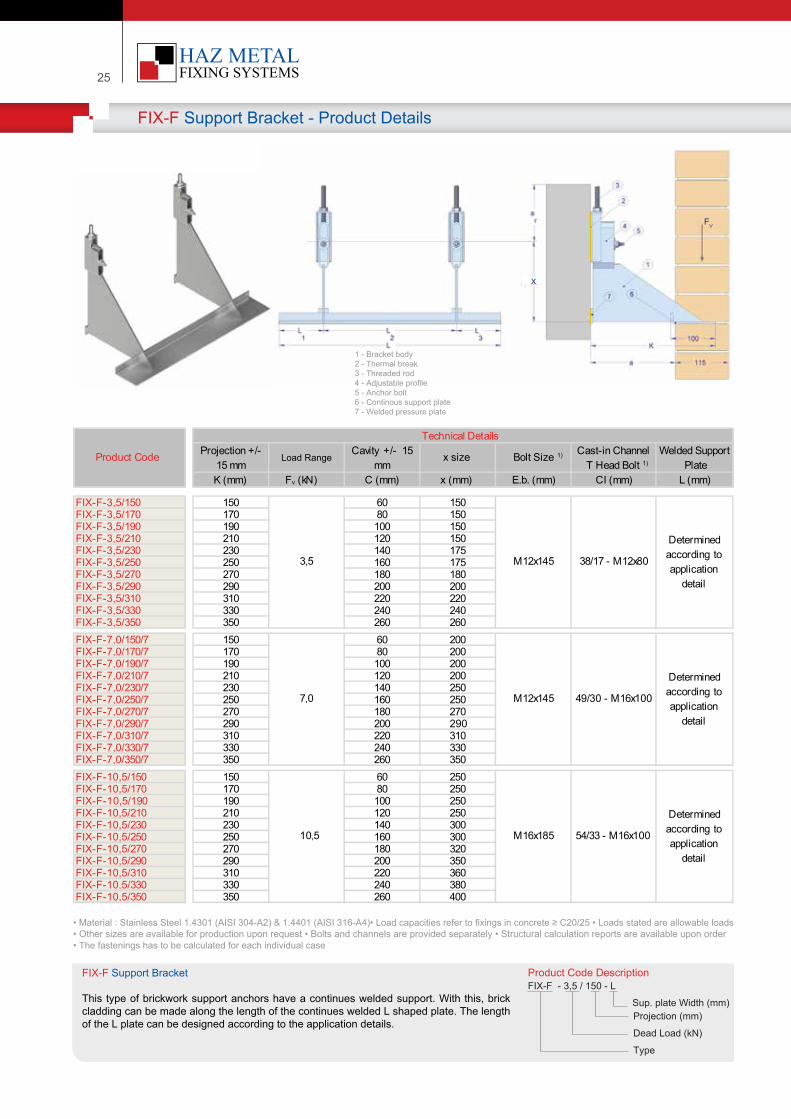
FIX-F Support Bracket - Product Details
:
:
Product Code Descr�pt�onFIX-F - 3,5 / 150 - L
Project�on (mm)
Dead Load (kN)
Type
Sup. plate W�dth (mm)
FIX-F Support Bracket
Th�s type of br�ckwork support anchors have a cont�nues welded support. W�th th�s, br�ck cladd�ng can be made along the length of the cont�nues welded L shaped plate. The length of the L plate can be des�gned accord�ng to the appl�cat�on deta�ls.
• Mater�al : Sta�nless Steel 1.4301 (AISI 304-A2) & 1.4401 (AISI 316-A4)• Load capac�t�es refer to f�x�ngs �n concrete ≥ C20/25 • Loads stated are allowable loads • Other s�zes are ava�lable for product�on upon request • Bolts and channels are prov�ded separately • Structural calculat�on reports are ava�lable upon order• The fasten�ngs has to be calculated for each �nd�v�dual case
K (mm) Fv (kN) C (mm) x (mm) E.b. (mm) CI (mm) L (mm)
FIX-F-3,5/150 150 60 150FIX-F-3,5/170 170 80 150FIX-F-3,5/190 190 100 150FIX-F-3,5/210 210 120 150FIX-F-3,5/230 230 140 175FIX-F-3,5/250 250 160 175FIX-F-3,5/270 270 180 180FIX-F-3,5/290 290 200 200FIX-F-3,5/310 310 220 220FIX-F-3,5/330 330 240 240FIX-F-3,5/350 350 260 260FIX-F-7,0/150/7 150 60 200FIX-F-7,0/170/7 170 80 200FIX-F-7,0/190/7 190 100 200FIX-F-7,0/210/7 210 120 200FIX-F-7,0/230/7 230 140 250FIX-F-7,0/250/7 250 160 250FIX-F-7,0/270/7 270 180 270FIX-F-7,0/290/7 290 200 290FIX-F-7,0/310/7 310 220 310FIX-F-7,0/330/7 330 240 330FIX-F-7,0/350/7 350 260 350FIX-F-10,5/150 150 60 250FIX-F-10,5/170 170 80 250FIX-F-10,5/190 190 100 250FIX-F-10,5/210 210 120 250FIX-F-10,5/230 230 140 300FIX-F-10,5/250 250 160 300FIX-F-10,5/270 270 180 320FIX-F-10,5/290 290 200 350FIX-F-10,5/310 310 220 360FIX-F-10,5/330 330 240 380FIX-F-10,5/350 350 260 400
10,5 M16x185 54/33 - M16x100
Determined according to application
detail
3,5 M12x145 38/17 - M12x80
Determined according to application
detail
7,0 M12x145 49/30 - M16x100
Determined according to application
detail
Product Code
Technical DetailsProjection +/-
15 mm Load Range
Cavity +/- 15 mm
x size Bolt Size 1) Cast-in Channel T Head Bolt 1)
Welded Support Plate
1 - Bracket body2 - Thermal break3 - Threaded rod4 - Adjustable prof�le5 - Anchor bolt6 - Cont�nous support plate7 - Welded pressure plate
FV
x
| 26Your Fixing Systems Specialist
:
Product Code Descr�pt�onFIX-FV - 3,5 / 150 - L / V
Project�on (mm)Dead Load (kN)Type
Sup. plate w�dth (mm)Ext. plate length (mm)
FIX-FV Support Bracket
Th�s type of br�ckwork support bracket has the same propert�es as the FIX-F type support bracket. The d�ffernece �s that �t has a down word extent�on plate for br�ck cladd�ng above w�ndow and door open�ngs.
• Mater�al : Sta�nless Steel 1.4301 (AISI 304-A2) & 1.4401 (AISI 316-A4)• Load capac�t�es refer to f�x�ngs �n concrete ≥ C20/25 • Loads stated are allowable loads • Other s�zes are ava�lable for product�on upon request • Bolts and channels are prov�ded separately • Structural calculat�on reports are ava�lable upon order• The fasten�ngs has to be calculated for each �nd�v�dual case
1 - Anchor body2 - Thermal brake3 - Threaded rod4 - Adjustable prof�le5 - Anchor bolt6 - Extens�on plate7 - Welded pressure plate8- Support plate
FIX-FV Support Bracket - Product Details
K (mm) Fv (kN) C (mm) x (mm) E.b. (mm) CI (mm) V (mm) L (mm)
FIX-FV-3,5/150 150 60 150FIX-FV-3,5/170 170 80 150FIX-FV-3,5/190 190 100 150FIX-FV-3,5/210 210 120 150FIX-FV-3,5/230 230 140 175FIX-FV-3,5/250 250 160 175FIX-FV-3,5/270 270 180 180FIX-FV-3,5/290 290 200 200FIX-FV-3,5/310 310 220 220FIX-FV-3,5/330 330 240 240FIX-FV-3,5/350 350 260 260
FIX-FV-7,0/150 150 60 200FIX-FV-7,0/170 170 80 200FIX-FV-7,0/190 190 100 200FIX-FV-7,0/210 210 120 200FIX-FV-7,0/230 230 140 250FIX-FV-7,0/250 250 160 250FIX-FV-7,0/270 270 180 270FIX-FV-7,0/290 290 200 290FIX-FV-7,0/310 310 220 310FIX-FV-7,0/330 330 240 330FIX-FV-7,0/350 350 260 350
FIX-FV-10,5/150 150 60 250FIX-FV-10,5/170 170 80 250FIX-FV-10,5/190 190 100 250FIX-FV-10,5/210 210 120 250FIX-FV-10,5/230 230 140 300FIX-FV-10,5/250 250 160 300FIX-FV-10,5/270 270 180 320FIX-FV-10,5/290 290 200 350FIX-FV-10,5/310 310 220 360FIX-FV-10,5/330 330 240 380FIX-FV-10,5/350 350 260 400
10,5 M16x145 54/33 - M16x80
Determined according to application
detail
Determined according to application
detail
3,5 M12x135 38/17 - M12x70
Determined according to application
detail
Determined according to application
detail
7,0 M12x135 49/30 - M16x80
Determined according to application
detail
Determined according to application
detail
Product Code
Technical DetailsProjection +/-
15 mm Load Range
Cavity +/- 15 mm
x size Bolt Size 1) Cast-in Channel T Head Bolt 1)
Welded Extension
Welded Support
FV
x
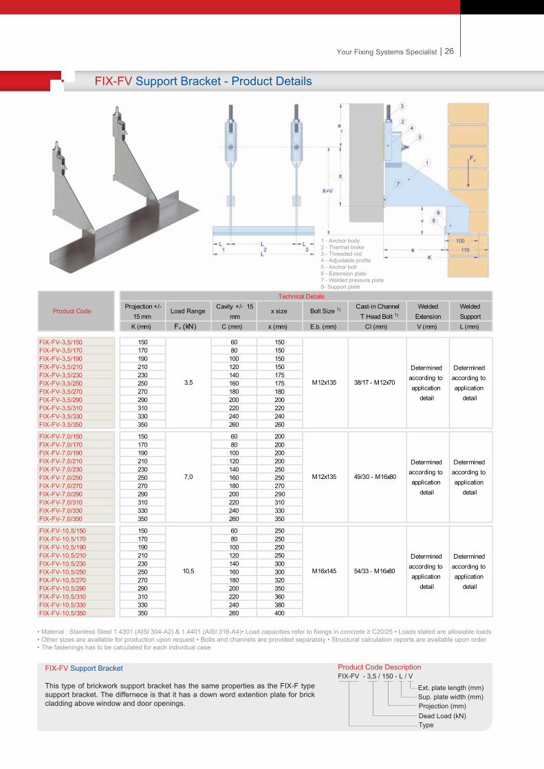
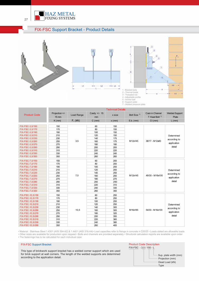
27
FIX-FSC Support Bracket - Product Details
:
:
:
Product Code Descr�pt�onFIX-FSC - 3,5 / 150 - L
Project�on (mm)Dead Load (kN)Type
Sup. plate w�dth (mm)
FIX-FSC Support Bracket
Th�s type of br�ckwork support bracket has a welded corner support wh�ch are used for br�ck support at wall corners. The length of the welded supports are determ�ned accord�ng to the appl�cat�on deta�l.
• Mater�al : Sta�nless Steel 1.4301 (AISI 304-A2) & 1.4401 (AISI 316-A4)• Load capac�t�es refer to f�x�ngs �n concrete ≥ C20/25 • Loads stated are allowable loads • Other s�zes are ava�lable for product�on upon request • Bolts and channels are prov�ded separately • Structural calculat�on reports are ava�lable upon order• The fasten�ngs has to be calculated for each �nd�v�dual case
K (mm) Fv (kN) C (mm) x (mm) E.b. (mm) CI (mm) L (mm)
150 60 150170 80 150190 100 150210 120 150230 140 175250 160 175270 180 180290 200 200310 220 220330 240 240350 260 260
150 60 200170 80 200190 100 200210 120 200230 140 250250 160 250270 180 270290 200 290310 220 310330 240 330350 260 350
150 60 250170 80 250190 100 250210 120 250230 140 300250 160 300270 180 320290 200 350310 220 360330 240 380350 260 400
10,5 M16x185 54/33 - M16x100
Determined according to application
detail
3,5 M12x145 38/17 - M12x80
Determined according to application
detail
7,0 M12x145 49/30 - M16x100
Determined according to application
detail
Product Code
Technical DetailsProjection +/-
15 mm Load Range
Cavity +/- 15 mm
x size Bolt Size 1) Cast-in ChannelT Head Bolt 1)
Welded Support Plate
1 - Bracket body2 - Thermal break3 - Threaded rod4 - Adjustable prof�le5 - Anchor bolt6 - Support plate7 - Welded pressure plate
FIX-FSC-3,5/150FIX-FSC-3,5/170FIX-FSC-3,5/190FIX-FSC-3,5/210FIX-FSC-3,5/230FIX-FSC-3,5/250FIX-FSC-3,5/270FIX-FSC-3,5/290FIX-FSC-3,5/310FIX-FSC-3,5/330FIX-FSC-3,5/350
FIX-FSC-7,0/150FIX-FSC-7,0/170FIX-FSC-7,0/190FIX-FSC-7,0/210FIX-FSC-7,0/230FIX-FSC-7,0/250FIX-FSC-7,0/270FIX-FSC-7,0/290FIX-FSC-7,0/310FIX-FSC-7,0/330FIX-FSC-7,0/350
FIX-FSC-10,5/150FIX-FSC-10,5/170FIX-FSC-10,5/190FIX-FSC-10,5/210FIX-FSC-10,5/230FIX-FSC-10,5/250FIX-FSC-10,5/270FIX-FSC-10,5/290FIX-FSC-10,5/310FIX-FSC-10,5/330FIX-FSC-10,5/350
FV
x
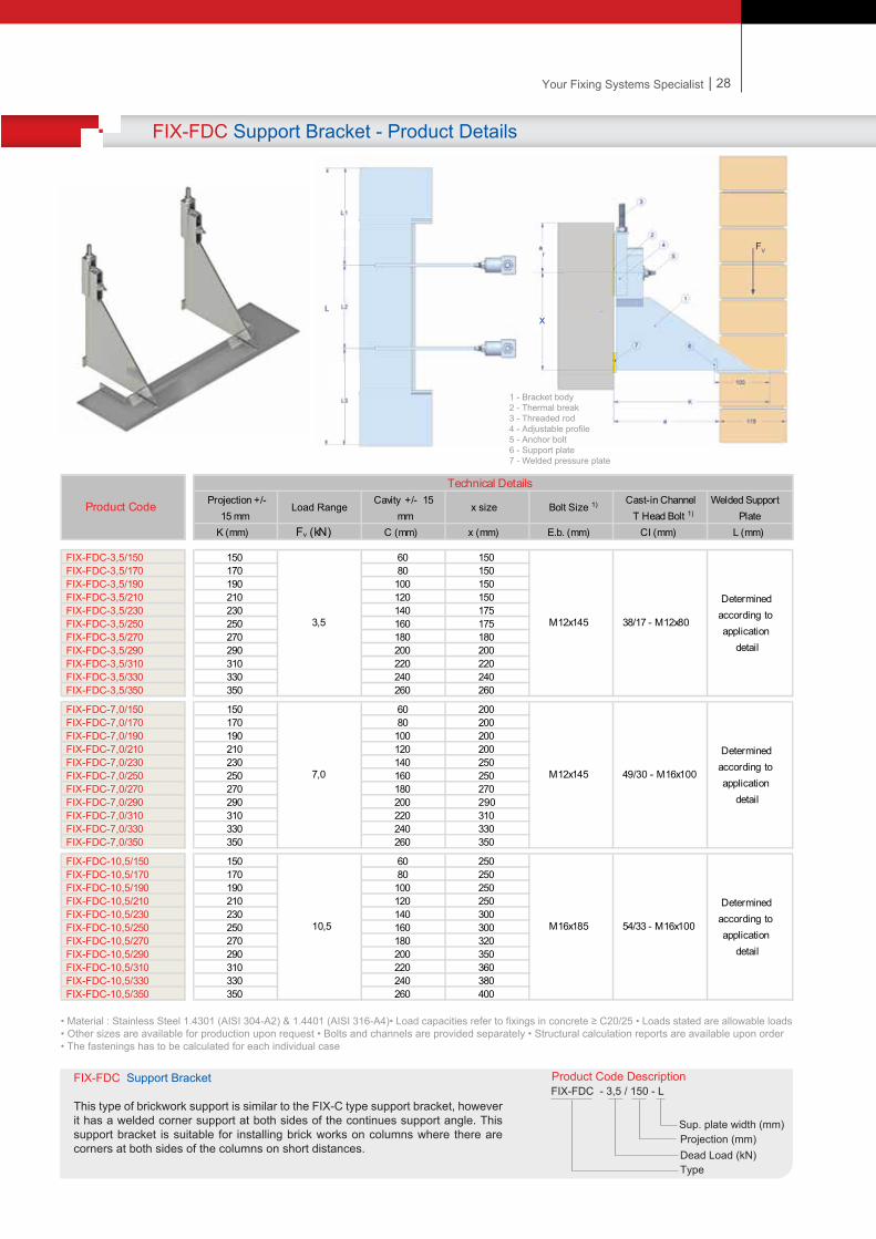
27
FIX-FSC Support Bracket - Product Details
:
:
:
Product Code Descr�pt�onFIX-FSC - 3,5 / 150 - L
Project�on (mm)Dead Load (kN)Type
Sup. plate w�dth (mm)
FIX-FSC Support Bracket
Th�s type of br�ckwork support bracket has a welded corner support wh�ch are used for br�ck support at wall corners. The length of the welded supports are determ�ned accord�ng to the appl�cat�on deta�l.
• Mater�al : Sta�nless Steel 1.4301 (AISI 304-A2) & 1.4401 (AISI 316-A4)• Load capac�t�es refer to f�x�ngs �n concrete ≥ C20/25 • Loads stated are allowable loads • Other s�zes are ava�lable for product�on upon request • Bolts and channels are prov�ded separately • Structural calculat�on reports are ava�lable upon order• The fasten�ngs has to be calculated for each �nd�v�dual case
K (mm) Fv (kN) C (mm) x (mm) E.b. (mm) CI (mm) L (mm)
150 60 150170 80 150190 100 150210 120 150230 140 175250 160 175270 180 180290 200 200310 220 220330 240 240350 260 260
150 60 200170 80 200190 100 200210 120 200230 140 250250 160 250270 180 270290 200 290310 220 310330 240 330350 260 350
150 60 250170 80 250190 100 250210 120 250230 140 300250 160 300270 180 320290 200 350310 220 360330 240 380350 260 400
10,5 M16x185 54/33 - M16x100
Determined according to application
detail
3,5 M12x145 38/17 - M12x80
Determined according to application
detail
7,0 M12x145 49/30 - M16x100
Determined according to application
detail
Product Code
Technical DetailsProjection +/-
15 mm Load Range
Cavity +/- 15 mm
x size Bolt Size 1) Cast-in ChannelT Head Bolt 1)
Welded Support Plate
1 - Bracket body2 - Thermal break3 - Threaded rod4 - Adjustable prof�le5 - Anchor bolt6 - Support plate7 - Welded pressure plate
FIX-FSC-3,5/150FIX-FSC-3,5/170FIX-FSC-3,5/190FIX-FSC-3,5/210FIX-FSC-3,5/230FIX-FSC-3,5/250FIX-FSC-3,5/270FIX-FSC-3,5/290FIX-FSC-3,5/310FIX-FSC-3,5/330FIX-FSC-3,5/350
FIX-FSC-7,0/150FIX-FSC-7,0/170FIX-FSC-7,0/190FIX-FSC-7,0/210FIX-FSC-7,0/230FIX-FSC-7,0/250FIX-FSC-7,0/270FIX-FSC-7,0/290FIX-FSC-7,0/310FIX-FSC-7,0/330FIX-FSC-7,0/350
FIX-FSC-10,5/150FIX-FSC-10,5/170FIX-FSC-10,5/190FIX-FSC-10,5/210FIX-FSC-10,5/230FIX-FSC-10,5/250FIX-FSC-10,5/270FIX-FSC-10,5/290FIX-FSC-10,5/310FIX-FSC-10,5/330FIX-FSC-10,5/350
FV
x
| 28Your Fixing Systems Specialist
FIX-FDC Support Bracket - Product Details
Product Code Descr�pt�onFIX-FDC - 3,5 / 150 - L
Project�on (mm)Dead Load (kN)Type
Sup. plate w�dth (mm)
• Mater�al : Sta�nless Steel 1.4301 (AISI 304-A2) & 1.4401 (AISI 316-A4)• Load capac�t�es refer to f�x�ngs �n concrete ≥ C20/25 • Loads stated are allowable loads • Other s�zes are ava�lable for product�on upon request • Bolts and channels are prov�ded separately • Structural calculat�on reports are ava�lable upon order• The fasten�ngs has to be calculated for each �nd�v�dual case
K (mm) Fv (kN) C (mm) x (mm) E.b. (mm) CI (mm) L (mm)
150 60 150170 80 150190 100 150210 120 150230 140 175250 160 175270 180 180290 200 200310 220 220330 240 240350 260 260
150 60 200170 80 200190 100 200210 120 200230 140 250250 160 250270 180 270290 200 290310 220 310330 240 330350 260 350
150 60 250170 80 250190 100 250210 120 250230 140 300250 160 300270 180 320290 200 350310 220 360330 240 380350 260 400
10,5 M16x185 54/33 - M16x100
Determined according to application
detail
3,5 M12x145 38/17 - M12x80
Determined according to application
detail
7,0 M12x145 49/30 - M16x100
Determined according to application
detail
Product Code
Technical DetailsProjection +/-
15 mm Load Range
Cavity +/- 15 mm
x size Bolt Size 1) Cast-in Channel T Head Bolt 1)
Welded Support Plate
FIX-FDC-3,5/150FIX-FDC-3,5/170FIX-FDC-3,5/190FIX-FDC-3,5/210FIX-FDC-3,5/230FIX-FDC-3,5/250FIX-FDC-3,5/270FIX-FDC-3,5/290FIX-FDC-3,5/310FIX-FDC-3,5/330FIX-FDC-3,5/350
FIX-FDC-7,0/150FIX-FDC-7,0/170FIX-FDC-7,0/190FIX-FDC-7,0/210FIX-FDC-7,0/230FIX-FDC-7,0/250FIX-FDC-7,0/270FIX-FDC-7,0/290FIX-FDC-7,0/310FIX-FDC-7,0/330FIX-FDC-7,0/350
FIX-FDC-10,5/150FIX-FDC-10,5/170FIX-FDC-10,5/190FIX-FDC-10,5/210FIX-FDC-10,5/230FIX-FDC-10,5/250FIX-FDC-10,5/270FIX-FDC-10,5/290FIX-FDC-10,5/310FIX-FDC-10,5/330FIX-FDC-10,5/350
:
FV
x
1 - Bracket body2 - Thermal break3 - Threaded rod4 - Adjustable prof�le5 - Anchor bolt6 - Support plate7 - Welded pressure plate
FIX-FDC Support Bracket
Th�s type of br�ckwork support �s s�m�lar to the FIX-C type support bracket, however �t has a welded corner support at both s�des of the cont�nues support angle. Th�s support bracket �s su�table for �nstall�ng br�ck works on columns where there are corners at both s�des of the columns on short d�stances.
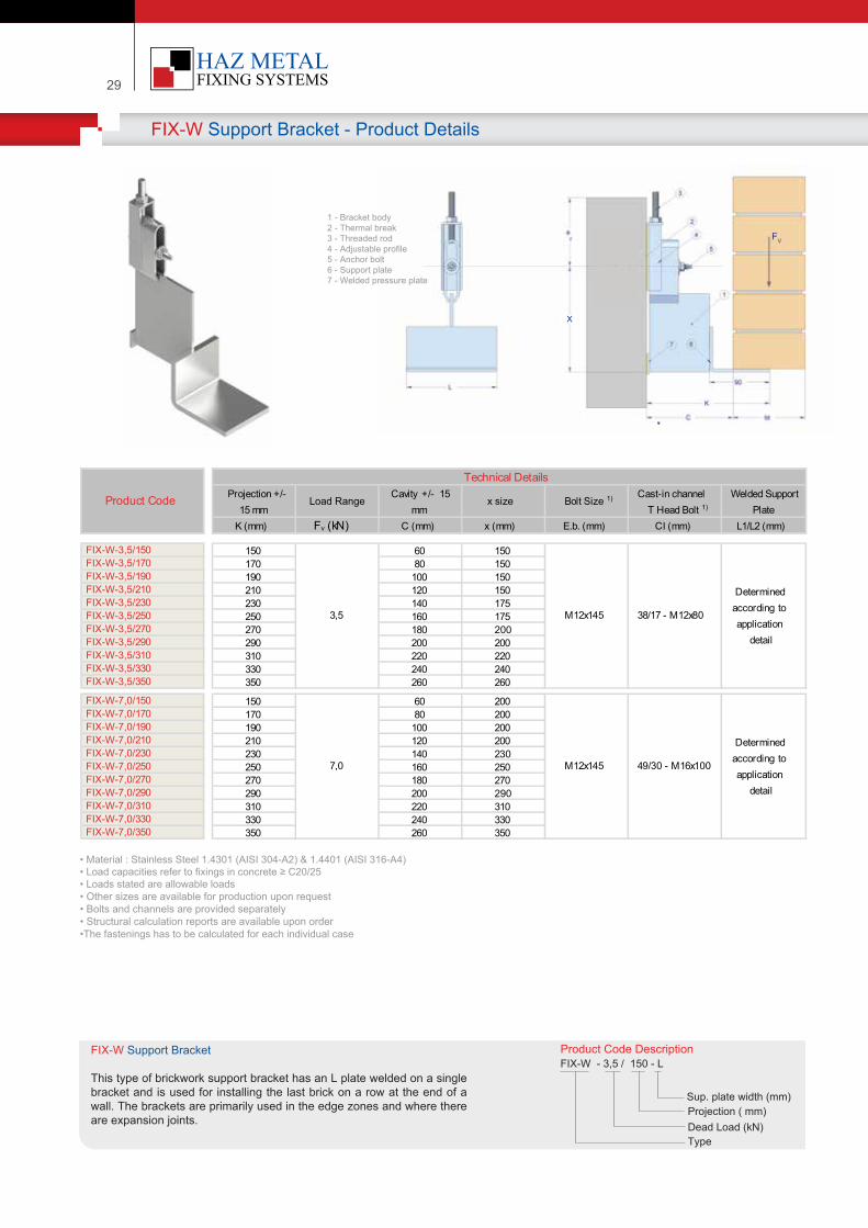
29
FIX-W Support Bracket - Product Details
::
Product Code Descr�pt�onFIX-W - 3,5 / 150 - L
Project�on ( mm)Dead Load (kN)Type
Sup. plate w�dth (mm)
FIX-W Support Bracket
Th�s type of br�ckwork support bracket has an L plate welded on a s�ngle bracket and �s used for �nstall�ng the last br�ck on a row at the end of a wall. The brackets are pr�mar�ly used �n the edge zones and where there are expans�on jo�nts.
• Mater�al : Sta�nless Steel 1.4301 (AISI 304-A2) & 1.4401 (AISI 316-A4)• Load capac�t�es refer to f�x�ngs �n concrete ≥ C20/25 • Loads stated are allowable loads • Other s�zes are ava�lable for product�on upon request • Bolts and channels are prov�ded separately • Structural calculat�on reports are ava�lable upon order•The fasten�ngs has to be calculated for each �nd�v�dual case
K (mm) Fv (kN) C (mm) x (mm) E.b. (mm) CI (mm) L1/L2 (mm)
150 60 150170 80 150190 100 150210 120 150230 140 175250 160 175270 180 200290 200 200310 220 220330 240 240350 260 260
150 60 200170 80 200190 100 200210 120 200230 140 230250 160 250270 180 270290 200 290310 220 310330 240 330350 260 350
3,5 M12x145 38/17 - M12x80
Determined according to application
detail
7,0 M12x145 49/30 - M16x100
Determined according to application
detail
Product Code
Technical DetailsProjection +/-
15 mm Load Range
Cavity +/- 15 mm
x size Bolt Size 1) Cast-in channel T Head Bolt 1)
Welded Support Plate
1 - Bracket body2 - Thermal break3 - Threaded rod4 - Adjustable prof�le5 - Anchor bolt6 - Support plate7 - Welded pressure plate
FIX-W-3,5/150FIX-W-3,5/170FIX-W-3,5/190FIX-W-3,5/210FIX-W-3,5/230FIX-W-3,5/250FIX-W-3,5/270FIX-W-3,5/290FIX-W-3,5/310FIX-W-3,5/330FIX-W-3,5/350
FIX-W-7,0/150FIX-W-7,0/170FIX-W-7,0/190FIX-W-7,0/210FIX-W-7,0/230FIX-W-7,0/250FIX-W-7,0/270FIX-W-7,0/290FIX-W-7,0/310FIX-W-7,0/330FIX-W-7,0/350
FV
x
| 30Your Fixing Systems Specialist
FIX-UT Support Bracket - Product Details
:
Product Code Descr�pt�onFIX-UT - 3,5 / 150
Project�on ( mm)Dead Load (KN)Type
FIX-UT Support Bracket
Th�s type of br�ckwork support bracket �s used for br�ck �nstallat�on where the support levels are h�gher than the FIX-UT type support bracket. The support level �s �n the same level as the f�x�ng po�nt ont he wall.
• Mater�al : Sta�nless Steel 1.4301 (AISI 304-A2) & 1.4401 (AISI 316-A4)• Load capac�t�es refer to f�x�ngs �n concrete ≥ C20/25 • Loads stated are allowable loads • Other s�zes are ava�lable for product�on upon request • Bolts and channels are prov�ded separately • Structural calculat�on reports are ava�lable upon order1) The fasten�ngs has to be calculated for each �nd�v�dual case
K (mm) Fv (kN) C (mm) x (mm) E.b. (mm) CI (mm)
FIX-UT-3,5/150 150 60 150FIX-UT-3,5/170 170 80 150FIX-UT-3,5/190 190 100 150FIX-UT-3,5/210 210 120 150FIX-UT-3,5/230 230 140 175FIX-UT-3,5/250 250 160 175FIX-UT-3,5/270 270 180 200FIX-UT-3,5/290 290 200 200FIX-UT-3,5/310 310 220 220FIX-UT-3,5/330 330 240 240FIX-UT-3,5/350 350 260 260
FIX-UT-7,0/150 150 60 200FIX-UT-7,0/170 170 80 200FIX-UT-7,0/190 190 100 200FIX-UT-7,0/210 210 120 200FIX-UT-7,0/230 230 140 250FIX-UT-7,0/250 250 160 250FIX-UT-7,0/270 270 180 270FIX-UT-7,0/290 290 200 290FIX-UT-7,0/310 310 220 310FIX-UT-7,0/330 330 240 330FIX-UT-7,0/350 350 260 350
FIX-UT-10,5/150 150 60 250FIX-UT-10,5/170 170 80 250FIX-UT-10,5/190 190 100 250FIX-UT-10,5/210 210 120 250FIX-UT-10,5/230 230 140 300FIX-UT-10,5/250 250 160 300FIX-UT-10,5/270 270 180 350FIX-UT-10,5/290 290 200 350FIX-UT-10,5/310 310 220 360FIX-UT-10,5/330 330 240 380FIX-UT-10,5/350 350 260 400
10,5 M16x185 54/33 - M16x100
3,5 M12x145 38/17 - M12x80
7,0 M12x145 49/30 - M16x100
Product Code
Technical DetailsProjection +/- 15
mm Load Range Cavity +/- 15 mm x size Bolt Size 1) Cast-in channel
T-Head Bolt 1)
1 - Bracket body2 - Thermal break3 - Threaded rod4 - Adjustable prof�le5 - Anchor bolt6 - Welded pressure plate7 - Support plate
7
FV
x
54/33 - M16x100
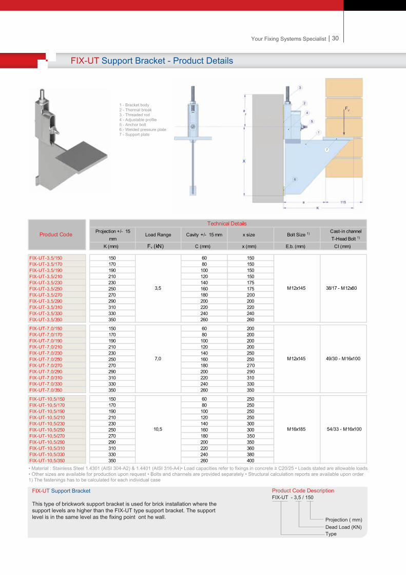

31
Brickwork Support Brackets - Application Examples
FIX brickwork support brackets can be custom designed to accommodate the special application requirements. Below are some examples of what could be designed and produced to cover the design requirements. Custom design is made in our technical department and project drawings are prepared and submitted for approval.
Fixing On Thin Inner WallsBrackets are bolted on to specially designed elements that allow bolting on to concrete beam upper surface
Lateral AdjustabilityIn circumstances where adjustability of the projection size is required, an adjusting screw is welded on the brackets
Fixing When Close To Wall EdgesA tie strap can be used for fixing the brackets on the side of the wall
Low Height Brick Work InstallationSpecial bracket design can be made for installation bricks positioned on edges where there is a low installation height
Fixing Of Prefabricated ComponentsBrackets can be supplied with pins for supporting the prefabricated components. Anchor channels and wall ties can be used for restraining purposes
Fixing Of Prefabricated LintelsBrackets can be supplied with an additional plate where threaded rods can be connected for supporting the load of the prefabricated component
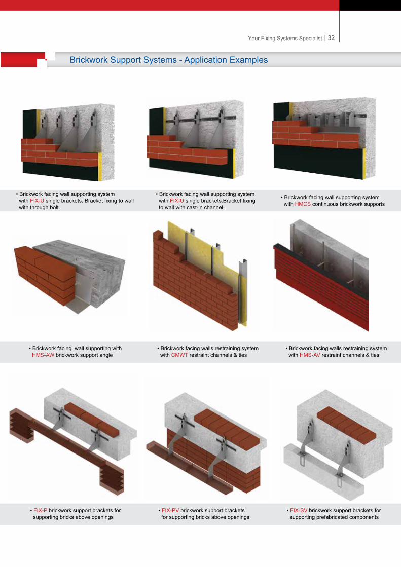
| 32Your Fixing Systems Specialist
Brickwork Support Systems - Application Examples
• FIX-P brickwork support brackets for supporting bricks above openings
• FIX-PV brickwork support brackets for supporting bricks above openings
• FIX-SV brickwork support brackets for supporting prefabricated components
• Brickwork facing wall supporting with HMS-AW brickwork support angle
• Brickwork facing walls restraining system with CMWT restraint channels & ties
• Brickwork facing walls restraining system with HMS-AV restraint channels & ties
• Brickwork facing wall supporting system with FIX-U single brackets. Bracket fixing to wall with through bolt.
• Brickwork facing wall supporting system with FIX-U single brackets.Bracket fixing to wall with cast-in channel.
• Brickwork facing wall supporting system with HMCS continuous brickwork supports
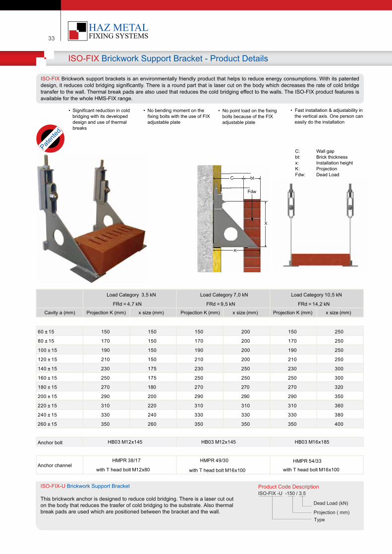
33
ISO-FIX Brickwork Support Bracket - Product Details
ISO-FIX Brickwork support brackets is an environmentally friendly product that helps to reduce energy consumptions. With its patented design, it reduces cold bridging significantly. There is a round part that is laser cut on the body which decreases the rate of cold bridge transfer to the wall. Thermal break pads are also used that reduces the cold bridging effect to the walls. The ISO-FIX product features is available for the whole HMS-FIX range.
Cavity a (mm) Projection K (mm) x size (mm)
60 ± 15 150 150 150 200 150 250
80 ± 15 170 150 170 200 170 250
100 ± 15 190 150 190 200 190 250
120 ± 15 210 150 210 200 210 250
140 ± 15 230 175 230 250 230 300
160 ± 15 250 175 250 250 250 300
180 ± 15 270 180 270 270 270 320
200 ± 15 290 200 290 290 290 350
220 ± 15 310 220 310 310 310 360
240 ± 15 330 240 330 330 330 380
260 ± 15 350 260 350 350 350 400
Anchor bolt
with T head bolt M16x100Anchor channel
HB03 M12x145 HB03 M12x145 HB03 M16x185
HMPR 49/30
with T head bolt M16x100
HMPR 38/17
with T head bolt M12x80
HMPR 54/33
Load Category 3,5 kN
FRd = 4,7 kN
Load Category 7,0 kN
FRd = 9,5 kN
Load Category 10,5 kN
FRd = 14,2 kN
• No bending moment on the fixing bolts with the use of FIX adjustable plate
• No point load on the fixing bolts because of the FIX adjustable plate
• Fast installation & adjustability in the vertical axis. One person can easily do the installation
Projection K (mm) x size (mm) Projection K (mm) x size (mm)
Product Code Descr�pt�onISO-FIX -U -150 / 3.5
Dead Load (kN)
Project�on ( mm)Type
ISO-FIX-U Br�ckwork Support Bracket
Th�s br�ckwork anchor �s des�gned to reduce cold br�dg�ng. There �s a laser cut out on the body that reduces the trasfer of cold br�dg�ng to the substrate. Also thermalbreak pads are used wh�ch are pos�t�oned between the bracket and the wall.
C: Wall gapbt: Brick thicknessx: Installation heightK: ProjectionFdw: Dead Load
Patente
d
• Significant reduction in cold bridging with its developed design and use of thermal breaks
C
Fdw
X
K
bt
| 34Your Fixing Systems Specialist
FIX-AP Adjustable Profile - Product Information
FIX Brickwork Support Bracket - Product Range
FIX-U FIX-UV FIX-P FIX-PV FIX-S FIX-SV
FIX-W FIX-UT FIX-F FIX-FV
The FIX brackets are available for the complete range of the FIX Brickwork support brackets. The patented special adjustable profile is compatible with all the FIX type brackets. The adjustable profile and a threaded rod is used instead of a set screw and nut in order to regulate the vertical adjustment.
The FIX-AP adjustable profile is a patented product that is used as a complementary product with the FIX brackets.
The adjustable profile enables quick and secure adjustability in the vertical axis. Unlike the traditional set screw, using the adjustable profile offers the installer adjustment the brackets without the need for a second hand assistance.
The primary advantage of the adjustable profile is that it eliminates offset moment loads on the bolts, therefore the requirement for bending moment testing on bolts is not necessary.
• Adjustability of the bracket is made by the adjustable profile and the threaded bar that is fixed on the profile with a nut. The bar is inserted in the tabbed hole on the upper part of the bracket.
60 mm adjustability
FIX-AP Adjustable Profile
Patente
d
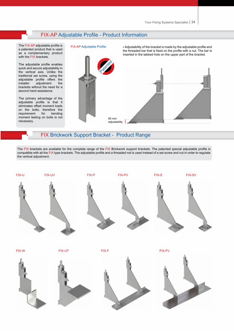
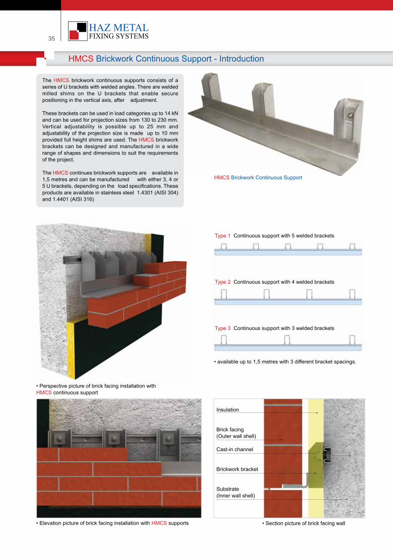
35
HMCS Brickwork Continuous Support - Introduction
The HMCS brickwork continuous supports consists of a series of U brackets with welded angles. There are welded milled shims on the U brackets that enable secure positioning in the vertical axis, after adjustment.
These brackets can be used in load categories up to 14 kN and can be used for projection sizes from 130 to 230 mm. Vertical adjustability is possible up to 25 mm and adjustability of the projection size is made up to 10 mm provided full height shims are used. The HMCS brickwork brackets can be designed and manufactured in a wide range of shapes and dimensions to suit the requirements of the project.
The HMCS continues brickwork supports are available in 1,5 metres and can be manufactured with either 3, 4 or 5 U brackets, depending on the load specifications. These products are available in stainless steel 1.4301 (AISI 304) and 1.4401 (AISI 316)
• Perspective picture of brick facing installation with HMCS continuous support
• Elevation picture of brick facing installation with HMCS supports • Section picture of brick facing wall
Insulation
Brick facing(Outer wall shell)
Cast-in channel
Brickwork bracket
Substrate(Inner wall shell)
HMCS Brickwork Continuous Support
• available up to 1,5 metres with 3 different bracket spacings.
Type 1 Continuous support with 5 welded brackets
Type 2 Continuous support with 4 welded brackets
Type 3 Continuous support with 3 welded brackets
| 36Your Fixing Systems Specialist
Support set elements:
1 - U Shaped bracket w�th vert�cal slot hole
2 - Welded serrated washer
3 - Welded support plate
4 - Anchor channel for attachments
HMCS Brickwork Continues Support Bracket - Product Details
Product Code Descr�pt�onHMCS - 130 / 3.5 - 1500
Dead Load (kN)
Project�on ( mm)
Type
Lenght
HMCS Br�ckwork Cont�nuous Support
The cont�nuous br�ckwork supports are ava�lable �n 1.5 metres as a standard length and can be spec�ally des�gned to meet the appl�cat�on requ�rements. Adjustab�l�ty �n the vert�cal ax�s �s made w�th m�lled serrated washers and a mx�mum of 10 mm lateral adjustab�lty poss�ble w�th full he�ght sh�ms
K (mm) Fdw (kN) C (mm) X (mm) E.b. (mm) SC CI (mm)
HMCS-130/3.5 130 60HMCS-150/3.5 150 80HMCS-170/3.5 170 100HMCS-190/3.5 190 120HMCS-210/3.5 210 140HMCS-230/3.5 230 160
HMCS-130/7 130 60HMCS-150/7 150 80HMCS-170/7 170 100HMCS-190/7 190 120HMCS-210/7 210 140HMCS-230/7 230 160
HMCS-130/10.5 130 60HMCS-150/10.5 150 80HMCS-170/10.5 170 100HMCS-190/10.5 190 120HMCS-210/10.5 210 140HMCS-230/10.5 230 160
HMCS-130/14 130 60HMCS-150/14 150 80HMCS-170/14 170 100HMCS-190/14 190 120HMCS-210/14 210 140HMCS-230/14 230 160
HMCS-130/18 130 60HMCS-150/18 150 80HMCS-170/18 170 100HMCS-190/18 190 120HMCS-210/18 210 140HMCS-230/18 230 160
18.00 150 M16x130 300 49/30
49/30
400
40/25
49/30
14.00 M16x130 350
10.50 M12x110135
150
38/17
28/15
370
115
115
38/17
40/25
3.50 M10x90
7.00 M12x110
460
Product Code
Technical Details
Projection Dead Load Cavity Bolt Height Bolt Size AnchorChannel
Bolt Spacing
bt
ar
y±30
1
2
3
4
• Mater�al : Sta�nless Steel 1.4301 (AISI 304-A2) & 1.4401 (AISI 316-A4)• Load capac�t�es refer to f�x�ngs �n concrete ≥ C20/25 • Loads stated are allowable loads • Other s�zes are ava�lable for product�on upon request • Bolts and channels are prov�ded separately • Structural calculat�on reports are ava�lable upon order
FV
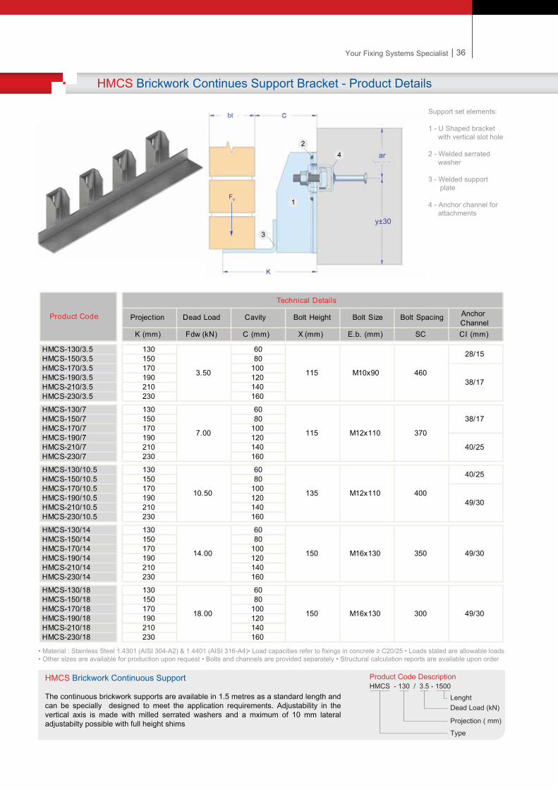
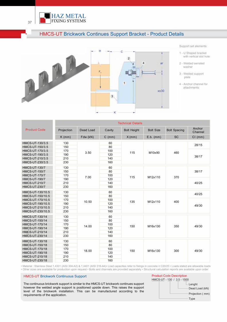
37
K (mm) Fdw (kN) C (mm) X (mm) E.b. (mm) SC CI (mm)
HMCS-UT-130/3.5 130 60HMCS-UT-150/3.5 150 80HMCS-UT-170/3.5 170 100HMCS-UT-190/3.5 190 120HMCS-UT-210/3.5 210 140HMCS-UT-230/3.5 230 160
HMCS-UT-130/7 130 60HMCS-UT-150/7 150 80HMCS-UT-170/7 170 100HMCS-UT-190/7 190 120HMCS-UT-210/7 210 140HMCS-UT-230/7 230 160
HMCS-UT-130/10.5 130 60HMCS-UT-150/10.5 150 80HMCS-UT-170/10.5 170 100HMCS-UT-190/10.5 190 120HMCS-UT-210/10.5 210 140HMCS-UT-230/10.5 230 160
HMCS-UT-130/14 130 60HMCS-UT-150/14 150 80HMCS-UT-170/14 170 100HMCS-UT-190/14 190 120HMCS-UT-210/14 210 140HMCS-UT-230/14 230 160
HMCS-UT-130/18 130 60HMCS-UT-150/18 150 80HMCS-UT-170/18 170 100HMCS-UT-190/18 190 120HMCS-UT-210/18 210 140HMCS-UT-230/18 230 160
18.00 150 M16x130 300 49/30
49/30
400
40/25
49/30
14.00 M16x130 350
10.50 M12x110135
150
38/17
28/15
370
115
115
38/17
40/25
3.50 M10x90
7.00 M12x110
460
Product Code
Technical Details
Projection Dead Load Cavity Bolt Height Bolt Size Anchor ChannelBolt Spacing
HMCS-UT Brickwork Continues Support Bracket - Product Details
Product Code Descr�pt�onHMCS-UT - 130 / 3.5 - 1500
Dead Load (kN)
Project�on ( mm)
Type
Lenght
HMCS-UT Br�ckwork Cont�nuous Support
The cont�nuous br�ckwork support �s s�m�lar to the HMCS-UT br�ckwork cont�nues support however the welded angle support �s pos�t�oned ups�de down. Th�s ra�ses the support level of the br�ckwork �nstallat�on. Th�s can be manufactured accord�ng to the requ�rements of the appl�cat�on.
Support set elements:
1 - U Shaped bracket w�th vert�cal slot hole
2 - Welded serrated washer
3 - Welded support plate
4 - Anchor channel for attachments
Fdw
bt
ar
x±30
1
2
3
4
• Mater�al : Sta�nless Steel 1.4301 (AISI 304-A2) & 1.4401 (AISI 316-A4)• Load capac�t�es refer to f�x�ngs �n concrete ≥ C20/25 • Loads stated are allowable loads • Other s�zes are ava�lable for product�on upon request • Bolts and channels are prov�ded separately • Structural calculat�on reports are ava�lable upon order
FV
| 38Your Fixing Systems Specialist
HMS-SB Brickwork Support Bracket - Product Details
Product Code Descr�pt�onHMCS-SB - 130 / 3.5
Dead Load (kN)
Project�on ( mm)
Type
HMCS-SB Brickwork Support Bracket
The brickwork support bracket is an angle with a single bracket that is used for the installation of bricks and stone blocks on tot straight and curves walls. This brick support bracket can be supplied with welded pins and an angle with various degress used for installting stone blocks from the rear surface.
K (mm) Fdw (kN) C (mm) X (mm) E.b. (mm) SC CI (mm)
HMCS-SB-130/3.5 130 60HMCS-SB-150/3.5 150 80HMCS-SB-170/3.5 170 100HMCS-SB-190/3.5 190 120HMCS-SB-210/3.5 210 140HMCS-SB-230/3.5 230 160
HMCS-SB-130/7 130 60HMCS-SB-150/7 150 80HMCS-SB-170/7 170 100HMCS-SB-190/7 190 120HMCS-SB-210/7 210 140HMCS-SB-230/7 230 160
HMCS-SB-130/10.5 130 60HMCS-SB-150/10.5 150 80HMCS-SB-170/10.5 170 100HMCS-SB-190/10.5 190 120HMCS-SB-210/10.5 210 140HMCS-SB-230/10.5 230 160
HMCS-SB-130/14 130 60HMCS-SB-150/14 150 80HMCS-SB-170/14 170 100HMCS-SB-190/14 190 120HMCS-SB-210/14 210 140HMCS-SB-230/14 230 160
HMCS-SB-130/18 130 60HMCS-SB-150/18 150 80HMCS-SB-170/18 170 100HMCS-SB-190/18 190 120HMCS-SB-210/18 210 140HMCS-SB-230/18 230 160
18.00 150 M16x130 300 49/30
49/30
400
40/25
49/30
14.00 M16x130 350
10.50 M12x110135
150
38/17
28/15
370
115
115
38/17
40/25
3.50 M10x90
7.00 M12x110
460
Product Code
Technical Details
Projection Dead Load Cavity Bolt Height Bolt Size AnchorChannel
Bolt Spacing
Support set elements:
1 - U Shaped bracket w�th vert�cal slot hole
2 - Welded serrated washer
3 - Welded support plate
4 - Anchor channel for attachments
Fdw
bt
ar
x±30
1
2
3
4
• Mater�al : Sta�nless Steel 1.4301 (AISI 304-A2) & 1.4401 (AISI 316-A4)• Load capac�t�es refer to f�x�ngs �n concrete ≥ C20/25 • Loads stated are allowable loads • Other s�zes are ava�lable for product�on upon request • Bolts and channels are prov�ded separately • Structural calculat�on reports are ava�lable upon order
FV
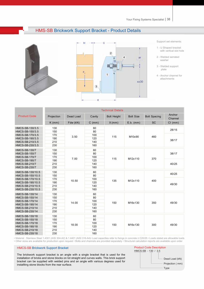
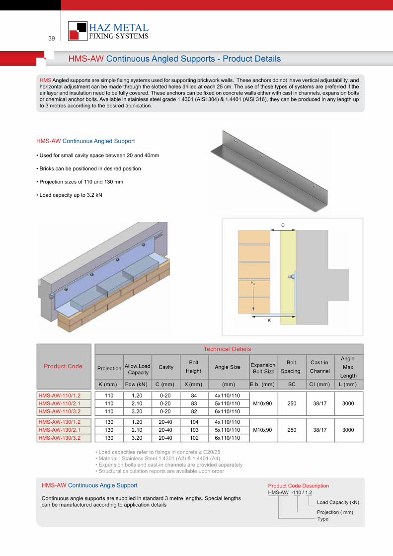
39
HMS-AW Continuous Angled Supports - Product Details
HMS-AW Continuous Angled Support
HMS Angled supports are simple fixing systems used for supporting brickwork walls. These anchors do not have vertical adjustability, and horizontal adjustment can be made through the slotted holes drilled at each 25 cm. The use of these types of systems are preferred if the air layer and insulation need to be fully covered. These anchors can be fixed on concrete walls either with cast in channels, expansion bolts or chemical anchor bolts. Available in stainless steel grade 1.4301 (AISI 304) & 1.4401 (AISI 316), they can be produced in any length up to 3 metres according to the desired application.
• Used for small cavity space between 20 and 40mm
• Bricks can be positioned in desired position • Projection sizes of 110 and 130 mm
• Load capacity up to 3.2 kN
K (mm) Fdw (kN) C (mm) X (mm) (mm) E.b. (mm) SC CI (mm) L (mm)
HMS-AW-110/1.2 110 1.20 0-20 84 4x110/110HMS-AW-110/2.1 110 2.10 0-20 83 5x110/110HMS-AW-110/3.2 110 3.20 0-20 82 6x110/110
HMS-AW-130/1.2 130 1.20 20-40 104 4x110/110HMS-AW-130/2.1 130 2.10 20-40 103 5x110/110HMS-AW-130/3.2 130 3.20 20-40 102 6x110/110
Angle Size
38/17
38/17M10x90 250 3000
M10x90 250 3000
Product Code
Technical Details
Projection CavityBolt
HeightExpansion Bolt Size
Bolt Spacing
Cast-in Channel
Angle Max
Length
Product Code Descr�pt�onHMS-AW -110 / 1.2
Load Capac�ty (kN)
Project�on ( mm)Type
• Load capac�t�es refer to f�x�ngs �n concrete ≥ C20/25• Mater�al : Sta�nless Steel 1.4301 (A2) & 1.4401 (A4)• Expans�on bolts and cast-�n channels are prov�ded separately • Structural calculat�on reports are ava�lable upon order
Allow.Load Capacity
HMS-AW Cont�nuous Angle Support
Cont�nuous angle supports are suppl�ed �n standard 3 metre lengths. Spec�al lengths can be manufactured accord�ng to appl�cat�on deta�ls
K
C
FdwFV
| 40Your Fixing Systems Specialist
HMS-AWS Continuous Angle Supports - Product Details
HMS-AWS Continuous Angle Support
• Used for cavity spaces between 40 and 240mm
• Welded support plates for loading at high projections • Projection sizes of 130 to 330 mm
• Load capacity up to 3.2 kN
K (mm) Fdw (kN) C (mm) X (mm) (mm) E.b. (mm) SC CI (mm) L (mm)
HMS-AWS-130/1.5 1.50 105 4x110/110HMS-AWS-130/3.2 3.20 103 5x110/110
HMS-AWS-150/1.5 1.50 125 4x110/110HMS-AWS-150/3.2 3.20 123 5x110/110
HMS-AWS-170/1.5 1.50 145 4x110/110HMS-AWS-170/3.2 3.20 143 5x110/110
HMS-AWS-190/1.5 1.50 165 4x110/110HMS-AWS-190/3.2 3.20 163 5x110/110
HMS-AWS-210/1.5 1.50 185 4x110/110HMS-AWS-210/3.2 3.20 183 5x110/110
HMS-AWS-230/1.5 1.50 205 4x110/110HMS-AWS-230/3.2 3.20 203 5x110/110
HMS-AWS-250/1.5 1.50 84 4x110/110HMS-AWS-250/3.2 3.20 83 5x110/110
HMS-AWS-270/1.5 1.50 84 4x110/110HMS-AWS-270/3.2 3.20 83 5x110/110
HMS-AWS-290/1.5 1.50 84 4x110/110HMS-AWS-290/3.2 3.20 83 5x110/110
HMS-AWS-310/1.5 1.50 84 4x110/110HMS-AWS-310/3.2 3.20 83 5x110/110
HMS-AWS-330/1.5 1.50 84 4x110/110HMS-AWS-330/3.2 3.20 83 5x110/110
180
200
220
240
290
310
330
40
60
80
100
120
140
160
38/17 3000
130
150
170
190
210
230
250
270
M10x90 250 38/17 3000
M10x90 250
M10x90 250 38/17 3000
M10x90 250 38/17 3000
M10x90 250 38/17 3000
M10x90 250 38/17 3000
M10x90 250 38/17 3000
M10x90 250 38/17 3000
M10x90 250 38/17 3000
M10x90 250 38/17 3000
max Length
M10x90 250 38/17 3000
Product Code
Technical Details
ProjectionDead Load
CavityBolt
HeightAngle Size Bolt Size
Bolt Spacing
Cast-in Channel
Product Code Descr�pt�onHMS -AWS -150 / 1.5
Load capac�ty (kN)
Project�on ( mm)Type
K
C
Fdw
• Load capac�t�es refer to f�x�ngs �n concrete ≥ C20/25• Mater�al : Sta�nless Steel 1.4301 (A2) & 1.4401 (A4)
• Expans�on bolts and cast-�n channels are prov�ded separately • Structural calculat�on reports are ava�lable upon order
HMS-AWS Cont�nuous Angle Support
Cont�nuous angle supports w�th welded belts are suppl�ed �n standard 3 metre lengths. Spec�al lengths can be manufactured accord�ng to appl�cat�on deta�ls
FV
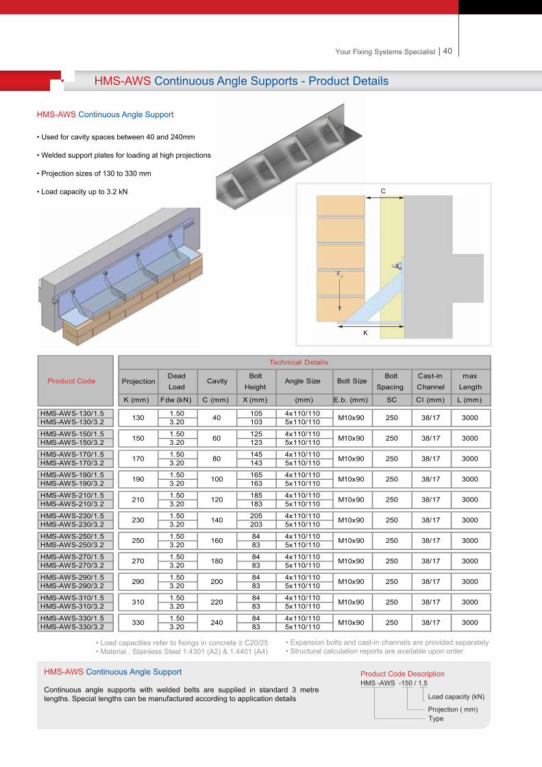
39
HMS-AW Continuous Angled Supports - Product Details
HMS-AW Continuous Angled Support
HMS Angled supports are simple fixing systems used for supporting brickwork walls. These anchors do not have vertical adjustability, and horizontal adjustment can be made through the slotted holes drilled at each 25 cm. The use of these types of systems are preferred if the air layer and insulation need to be fully covered. These anchors can be fixed on concrete walls either with cast in channels, expansion bolts or chemical anchor bolts. Available in stainless steel grade 1.4301 (AISI 304) & 1.4401 (AISI 316), they can be produced in any length up to 3 metres according to the desired application.
• Used for small cavity space between 20 and 40mm
• Bricks can be positioned in desired position • Projection sizes of 110 and 130 mm
• Load capacity up to 3.2 kN
K (mm) Fdw (kN) C (mm) X (mm) (mm) E.b. (mm) SC CI (mm) L (mm)
HMS-AW-110/1.2 110 1.20 0-20 84 4x110/110HMS-AW-110/2.1 110 2.10 0-20 83 5x110/110HMS-AW-110/3.2 110 3.20 0-20 82 6x110/110
HMS-AW-130/1.2 130 1.20 20-40 104 4x110/110HMS-AW-130/2.1 130 2.10 20-40 103 5x110/110HMS-AW-130/3.2 130 3.20 20-40 102 6x110/110
Angle Size
38/17
38/17M10x90 250 3000
M10x90 250 3000
Product Code
Technical Details
Projection CavityBolt
HeightExpansion Bolt Size
Bolt Spacing
Cast-in Channel
Angle Max
Length
Product Code Descr�pt�onHMS-AW -110 / 1.2
Load Capac�ty (kN)
Project�on ( mm)Type
• Load capac�t�es refer to f�x�ngs �n concrete ≥ C20/25• Mater�al : Sta�nless Steel 1.4301 (A2) & 1.4401 (A4)• Expans�on bolts and cast-�n channels are prov�ded separately • Structural calculat�on reports are ava�lable upon order
Allow.Load Capacity
HMS-AW Cont�nuous Angle Support
Cont�nuous angle supports are suppl�ed �n standard 3 metre lengths. Spec�al lengths can be manufactured accord�ng to appl�cat�on deta�ls
K
C
FdwFV
| 40Your Fixing Systems Specialist
HMS-AWS Continuous Angle Supports - Product Details
HMS-AWS Continuous Angle Support
• Used for cavity spaces between 40 and 240mm
• Welded support plates for loading at high projections • Projection sizes of 130 to 330 mm
• Load capacity up to 3.2 kN
K (mm) Fdw (kN) C (mm) X (mm) (mm) E.b. (mm) SC CI (mm) L (mm)
HMS-AWS-130/1.5 1.50 105 4x110/110HMS-AWS-130/3.2 3.20 103 5x110/110
HMS-AWS-150/1.5 1.50 125 4x110/110HMS-AWS-150/3.2 3.20 123 5x110/110
HMS-AWS-170/1.5 1.50 145 4x110/110HMS-AWS-170/3.2 3.20 143 5x110/110
HMS-AWS-190/1.5 1.50 165 4x110/110HMS-AWS-190/3.2 3.20 163 5x110/110
HMS-AWS-210/1.5 1.50 185 4x110/110HMS-AWS-210/3.2 3.20 183 5x110/110
HMS-AWS-230/1.5 1.50 205 4x110/110HMS-AWS-230/3.2 3.20 203 5x110/110
HMS-AWS-250/1.5 1.50 84 4x110/110HMS-AWS-250/3.2 3.20 83 5x110/110
HMS-AWS-270/1.5 1.50 84 4x110/110HMS-AWS-270/3.2 3.20 83 5x110/110
HMS-AWS-290/1.5 1.50 84 4x110/110HMS-AWS-290/3.2 3.20 83 5x110/110
HMS-AWS-310/1.5 1.50 84 4x110/110HMS-AWS-310/3.2 3.20 83 5x110/110
HMS-AWS-330/1.5 1.50 84 4x110/110HMS-AWS-330/3.2 3.20 83 5x110/110
180
200
220
240
290
310
330
40
60
80
100
120
140
160
38/17 3000
130
150
170
190
210
230
250
270
M10x90 250 38/17 3000
M10x90 250
M10x90 250 38/17 3000
M10x90 250 38/17 3000
M10x90 250 38/17 3000
M10x90 250 38/17 3000
M10x90 250 38/17 3000
M10x90 250 38/17 3000
M10x90 250 38/17 3000
M10x90 250 38/17 3000
max Length
M10x90 250 38/17 3000
Product Code
Technical Details
ProjectionDead Load
CavityBolt
HeightAngle Size Bolt Size
Bolt Spacing
Cast-in Channel
Product Code Descr�pt�onHMS -AWS -150 / 1.5
Load capac�ty (kN)
Project�on ( mm)Type
K
C
Fdw
• Load capac�t�es refer to f�x�ngs �n concrete ≥ C20/25• Mater�al : Sta�nless Steel 1.4301 (A2) & 1.4401 (A4)
• Expans�on bolts and cast-�n channels are prov�ded separately • Structural calculat�on reports are ava�lable upon order
HMS-AWS Cont�nuous Angle Support
Cont�nuous angle supports w�th welded belts are suppl�ed �n standard 3 metre lengths. Spec�al lengths can be manufactured accord�ng to appl�cat�on deta�ls
FV
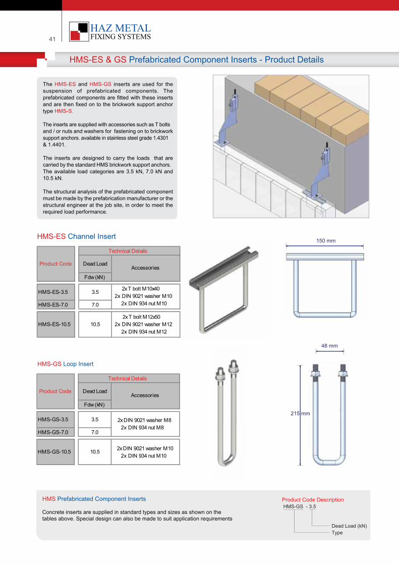
41
HMS-ES & GS Prefabricated Component Inserts - Product Details
HMS-ES Channel Insert
HMS-GS Loop Insert
The HMS-ES and HMS-GS inserts are used for the suspension of prefabricated components. The prefabricated components are fitted with these inserts and are then fixed on to the brickwork support anchor type HMS-S.
The inserts are supplied with accessories such as T bolts and / or nuts and washers for fastening on to brickwork support anchors. available in stainless steel grade 1.4301 & 1.4401.
The inserts are designed to carry the loads that are carried by the standard HMS brickwork support anchors. The available load categories are 3.5 kN, 7.0 kN and 10.5 kN.
The structural analysis of the prefabricated component must be made by the prefabrication manufacturer or the structural engineer at the job site, in order to meet the required load performance.
Fdw (kN)
HMS-ES-3.5 3.5
HMS-ES-7.0 7.0
HMS-ES-10.5 10.52x T bolt M12x50
2x DIN 9021 washer M12 2x DIN 934 nut M12
Technical Details
2x T bolt M10x40 2x DIN 9021 washer M10
2x DIN 934 nut M10
AccessoriesProduct Code Dead Load
Fdw (kN)
HMS-GS-3.5 3.5
HMS-GS-7.0 7.0
HMS-GS-10.5 10.5 2x DIN 9021 washer M102x DIN 934 nut M10
Product Code
Technical Details
Dead LoadAccessories
2x DIN 9021 washer M8 2x DIN 934 nut M8
Product Code Descr�pt�onHMS-GS - 3.5
Dead Load (kN)Type
HMS Prefabr�cated Component Inserts
Concrete �nserts are suppl�ed �n standard types and s�zes as shown on thetables above. Spec�al des�gn can also be made to su�t appl�cat�on requ�rements
150 mm
215 mm
48 mm
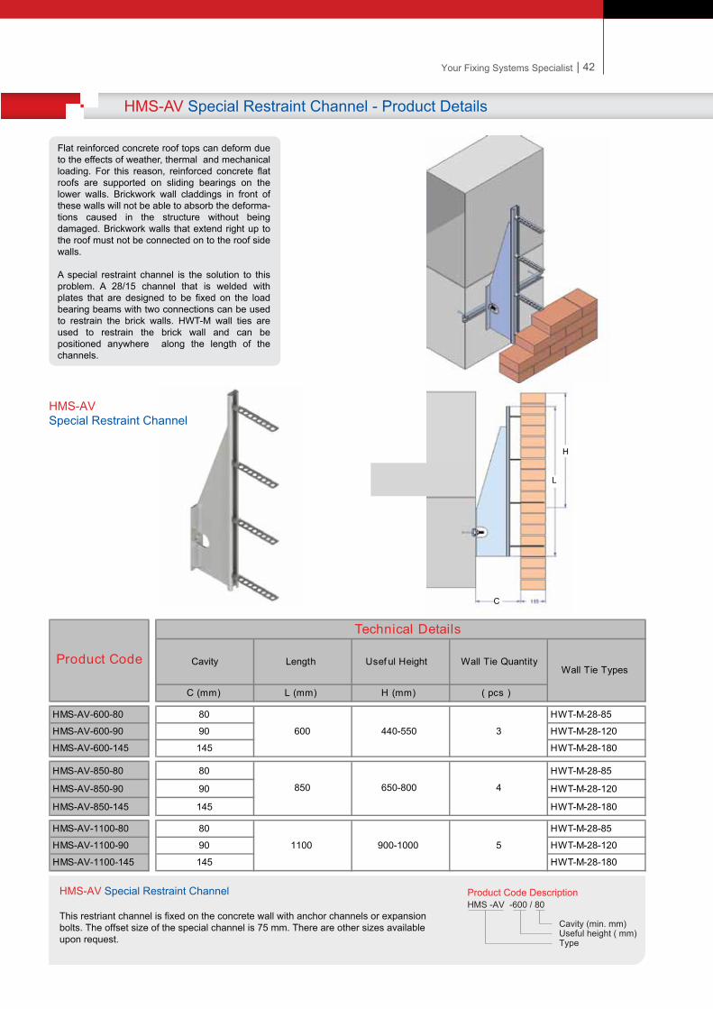
| 42Your Fixing Systems Specialist
HMS-AV Special Restraint Channel - Product Details
:
Flat reinforced concrete roof tops can deform due to the effects of weather, thermal and mechanical loading. For this reason, reinforced concrete flat roofs are supported on sliding bearings on the lower walls. Brickwork wall claddings in front of these walls will not be able to absorb the deforma-tions caused in the structure without being damaged. Brickwork walls that extend right up to the roof must not be connected on to the roof side walls.
A special restraint channel is the solution to this problem. A 28/15 channel that is welded with plates that are designed to be fixed on the load bearing beams with two connections can be used to restrain the brick walls. HWT-M wall ties are used to restrain the brick wall and can be positioned anywhere along the length of the channels.
C (mm) L (mm) H (mm) ( pcs )
HMS-AV-600-80 80 HWT-M-28-85
HMS-AV-600-90 90 HWT-M-28-120
HMS-AV-600-145 145 HWT-M-28-180
HMS-AV-850-80 80 HWT-M-28-85
HMS-AV-850-90 90 HWT-M-28-120
HMS-AV-850-145 145 HWT-M-28-180
HMS-AV-1100-80 80 HWT-M-28-85
HMS-AV-1100-90 90 HWT-M-28-120
HMS-AV-1100-145 145 HWT-M-28-180
1100 900-1000 5
600 3440-550
Wall Tie Types
850 650-800 4
Product Code
Technical Details
Cavity Length Usef ul Height Wall Tie Quantity
Product Code Descr�pt�onHMS -AV -600 / 80
Cav�ty (m�n. mm)Useful he�ght ( mm)Type
HMS-AV Spec�al Restra�nt Channel
Th�s restr�ant channel �s f�xed on the concrete wall w�th anchor channels or expans�onbolts. The offset s�ze of the spec�al channel �s 75 mm. There are other s�zes ava�lable upon request.
C
L
H
HMS-AV Spec�al Restra�nt Channel
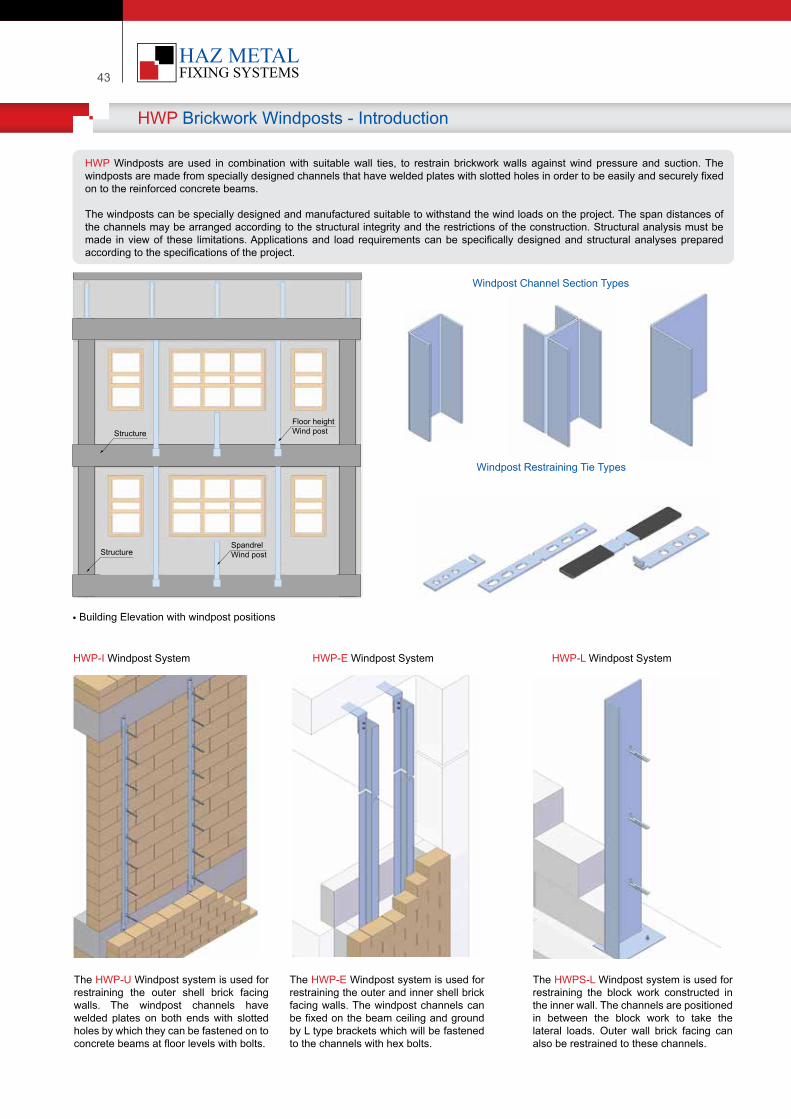
43
HWP Brickwork Windposts - Introduction
HWP Windposts are used in combination with suitable wall ties, to restrain brickwork walls against wind pressure and suction. The windposts are made from specially designed channels that have welded plates with slotted holes in order to be easily and securely fixed on to the reinforced concrete beams.
The windposts can be specially designed and manufactured suitable to withstand the wind loads on the project. The span distances of the channels may be arranged according to the structural integrity and the restrictions of the construction. Structural analysis must be made in view of these limitations. Applications and load requirements can be specifically designed and structural analyses prepared according to the specifications of the project.
• Building Elevation with windpost positions
Windpost Channel Section Types
Windpost Restraining Tie Types
HWP-I Windpost System HWP-E Windpost System HWP-L Windpost System
The HWP-U Windpost system is used for restraining the outer shell brick facing walls. The windpost channels have welded plates on both ends with slotted holes by which they can be fastened on to concrete beams at floor levels with bolts.
The HWP-E Windpost system is used for restraining the outer and inner shell brick facing walls. The windpost channels can be fixed on the beam ceiling and ground by L type brackets which will be fastened to the channels with hex bolts.
The HWPS-L Windpost system is used for restraining the block work constructed in the inner wall. The channels are positioned in between the block work to take the lateral loads. Outer wall brick facing can also be restrained to these channels.
Structure
Structure
Floor heightWind post
Spandrel Wind post
| 44Your Fixing Systems Specialist
HWP Brickwork Windpost Channels - Product Information
HWP-I Windpost Channel• Channels span between floor beams and are fixed to the concrete load bearing beams with expansion bolts. Can also be installed on to cast in channels
• Corresponding wall ties are used to restrain the outer brick facing wall on to the channels. The wall ties slide through the slotted hole on the channels and lock after a 90 degree twist • Designed wind loads are taken into consideration to determine the dimensions of the channels. Can be used for cavities between 70 - 205 mm
Cha
nnel
Set
ting
Len
gth
HWP-E Windpost Channel• Channels span between floor beams and are fixed on to concrete beams with expansion bolts
• Corresponding wall ties with a loop are hooked on the channel lips for restraining the walls. The slotted hole version can also be manufactured to suit normal wall ties
• L angles are manufactured from 4 and 5 mm thick plates. Channels are manufactured on a project basis and any dimension is possible
HWP-L Windpost Channel• Channels are manufactured with welded plates at the ends of the channels. The channels are fixed on to the beam flooring with expansion bolts.
• Corresponding wall ties with a loop are hooked on the channel lips for restraining the walls. The slotted hole version can also be manufactured to suit the normal wall ties
• Channels are manufactured on a project basis and any dimension is possible
Channel Span Distance
Channel Span Distance
Cha
nnel
Set
ting
Len
gth
Channel Span Distance
Cha
nnel
Set
ting
Len
gth
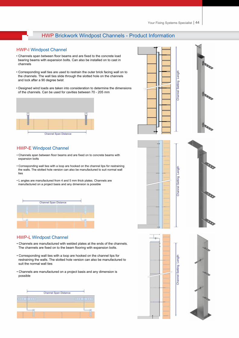
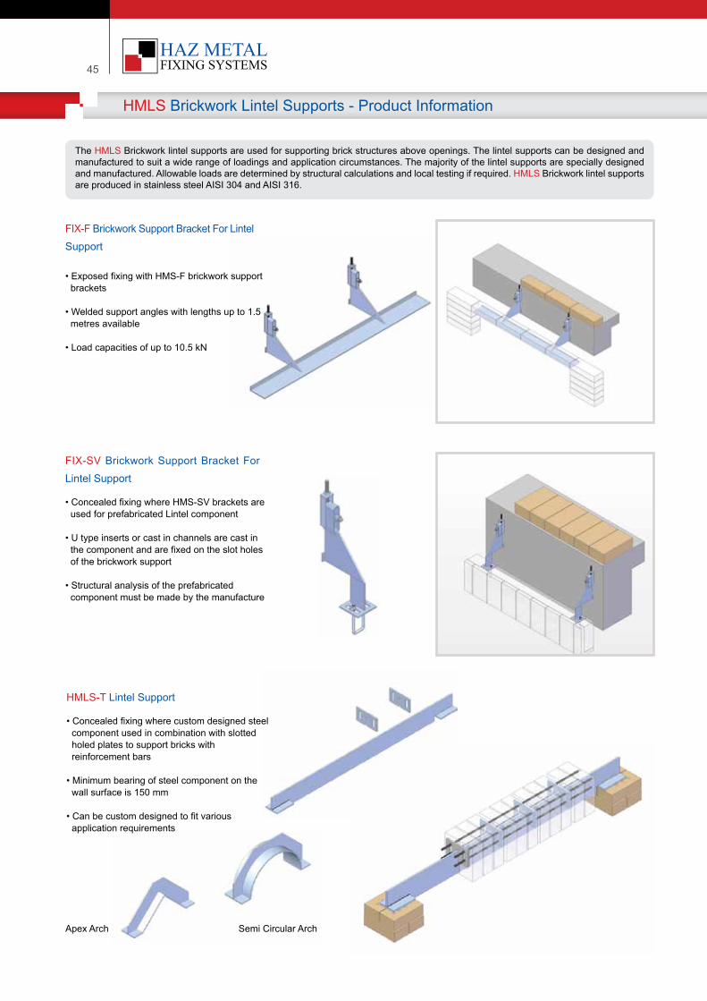
45
HMLS Brickwork Lintel Supports - Product Information
The HMLS Brickwork lintel supports are used for supporting brick structures above openings. The lintel supports can be designed and manufactured to suit a wide range of loadings and application circumstances. The majority of the lintel supports are specially designed and manufactured. Allowable loads are determined by structural calculations and local testing if required. HMLS Brickwork lintel supports are produced in stainless steel AISI 304 and AISI 316.
Apex Arch Semi Circular Arch
FIX-F Brickwork Support Bracket For Lintel Support
• Exposed fixing with HMS-F brickwork support brackets
• Welded support angles with lengths up to 1.5 metres available
• Load capacities of up to 10.5 kN
FIX-SV Brickwork Support Bracket For Lintel Support
• Concealed fixing where HMS-SV brackets are used for prefabricated Lintel component
• U type inserts or cast in channels are cast in the component and are fixed on the slot holes of the brickwork support
• Structural analysis of the prefabricated component must be made by the manufacture
HMLS-T Lintel Support
• Concealed fixing where custom designed steel component used in combination with slotted holed plates to support bricks with reinforcement bars
• Minimum bearing of steel component on the wall surface is 150 mm
• Can be custom designed to fit various application requirements
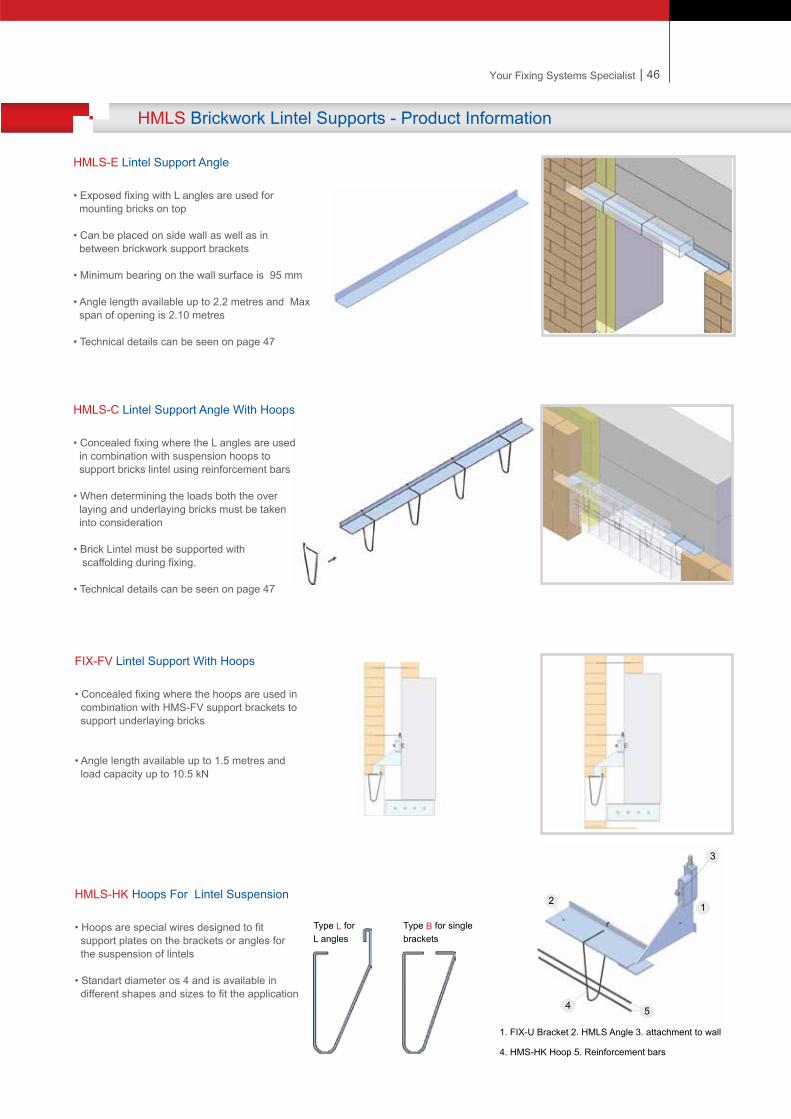
| 46Your Fixing Systems Specialist
HMLS Brickwork Lintel Supports - Product Information
HMLS-E Lintel Support Angle
• Exposed fixing with L angles are used for mounting bricks on top
• Can be placed on side wall as well as in between brickwork support brackets
• Minimum bearing on the wall surface is 95 mm
• Angle length available up to 2.2 metres and Max span of opening is 2.10 metres
• Technical details can be seen on page 47
HMLS-C Lintel Support Angle With Hoops
• Concealed fixing where the L angles are used in combination with suspension hoops to support bricks lintel using reinforcement bars
• When determining the loads both the over laying and underlaying bricks must be taken into consideration • Brick Lintel must be supported with scaffolding during fixing.
• Technical details can be seen on page 47
FIX-FV Lintel Support With Hoops
• Concealed fixing where the hoops are used in combination with HMS-FV support brackets to support underlaying bricks
• Angle length available up to 1.5 metres and load capacity up to 10.5 kN
HMLS-HK Hoops For Lintel Suspension
• Hoops are special wires designed to fit support plates on the brackets or angles for the suspension of lintels
• Standart diameter os 4 and is available in different shapes and sizes to fit the application
Type L for L angles
Type B for single brackets
1. FIX-U Bracket 2. HMLS Angle 3. attachment to wall
4. HMS-HK Hoop 5. Reinforcement bars
2
54
3
1
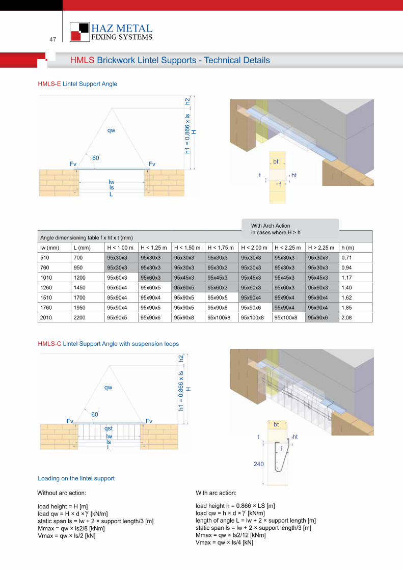
47
HMLS Brickwork Lintel Supports - Technical Details
Angle d�mens�on�ng table f x ht x t (mm)
lw (mm) L (mm) H < 1,00 m H < 1,25 m H < 1,50 m H < 1,75 m H < 2,00 m H < 2,25 m H > 2,25 m h (m)
510 700 95x30x3 95x30x3 95x30x3 95x30x3 95x30x3 95x30x3 95x30x3 0,71
760 950 95x30x3 95x30x3 95x30x3 95x30x3 95x30x3 95x30x3 95x30x3 0,94
1010 1200 95x60x3 95x60x3 95x45x3 95x45x3 95x45x3 95x45x3 95x45x3 1,17
1260 1450 95x60x4 95x60x5 95x60x5 95x60x3 95x60x3 95x60x3 95x60x3 1,40
1510 1700 95x90x4 95x90x4 95x90x5 95x90x5 95x90x4 95x90x4 95x90x4 1,62
1760 1950 95x90x4 95x90x5 95x90x5 95x90x6 95x90x6 95x90x4 95x90x4 1,85
2010 2200 95x90x5 95x90x6 95x90x8 95x100x8 95x100x8 95x100x8 95x90x6 2,08
M�tW�th Arch Act�on�n cases where H > h
HMLS-E Lintel Support Angle
HMLS-C Lintel Support Angle with suspension loops
load he�ght = H [m]load qw = H × d × [kN/m]stat�c span ls = lw + 2 × support length/3 [m]Mmax = qw × ls2/8 [kNm]Vmax = qw × ls/2 [kN]
load he�ght h = 0.866 × LS [m]load qw = h × d × [kN/m]length of angle L = lw + 2 × support length [m]stat�c span ls = lw + 2 × support length/3 [m]Mmax = qw × ls2/12 [kNm]Vmax = qw × ls/4 [kN]
Loading on the lintel support
W�thout arc act�on: W�th arc act�on:
lslw
FvFv
qw Hh1
= 0
,866
x ls
h2
60
L
t
bt
htf
t
bt
ht
f
240
lslw
FvFvqst
qw Hh1
= 0
,866
x ls
h2
60
L
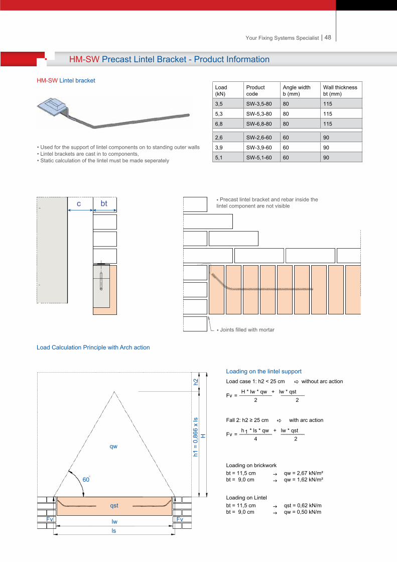
| 48Your Fixing Systems Specialist
HM-SW Precast Lintel Bracket - Product Information
Load case 1: h2 < 25 cm w�thout arc act�on H * lw * qw + lw * qstFv = ___________ ________ 2 2
Fall 2: h2 ≥ 25 cm w�th arc act�on h1 * ls * qw + lw * qstFv = ___________ ________ 4 2
Load�ng on br�ckworkbt = 11,5 cm qw = 2,67 kN/m²bt = 9,0 cm qw = 1,62 kN/m²
Load�ng on L�ntelbt = 11,5 cm qst = 0,62 kN/mbt = 9,0 cm qw = 0,50 kN/m
Loading on the lintel support
c bt • Precast lintel bracket and rebar inside the lintel component are not visible
• Joints filled with mortar
Load (kN)
Productcode
Angle w�dth b (mm)
Wall th�cknessbt (mm)
3,5 SW-3,5-80 80 115
5,3 SW-5,3-80 80 115
6,8 SW-6,8-80 80 115
2,6 SW-2,6-60 60 90
3,9 SW-3,9-60 60 90
5,1 SW-5,1-60 60 90
HM-SW Lintel bracket
• Used for the support of lintel components on to standing outer walls• Lintel brackets are cast in to components, • Static calculation of the lintel must be made seperately
Load Calculation Principle with Arch action
lslw FvFv
qst
qw
Hh1
= 0
,866
x ls
h2
60
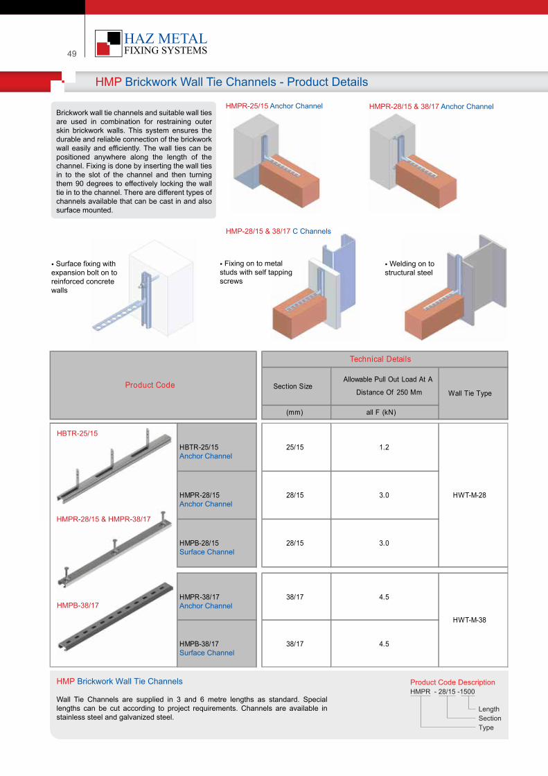
49
HMP Brickwork Wall Tie Channels - Product Details
Brickwork wall tie channels and suitable wall ties are used in combination for restraining outer skin brickwork walls. This system ensures the durable and reliable connection of the brickwork wall easily and efficiently. The wall ties can be positioned anywhere along the length of the channel. Fixing is done by inserting the wall ties in to the slot of the channel and then turning them 90 degrees to effectively locking the wall tie in to the channel. There are different types of channels available that can be cast in and also surface mounted.
Product Code Descr�pt�onHMPR - 28/15 -1500
Length Sect�onType
HMPR-25/15 Anchor Channel HMPR-28/15 & 38/17 Anchor Channel
HMP-28/15 & 38/17 C Channels
• Surface fixing with expansion bolt on toreinforced concretewalls
• Fixing on to metal studs with self tappingscrews
• Welding on to structural steel
(mm) all F (kN)
HBTR-25/15Anchor Channel
25/15 1.2
HMPR-28/15Anchor Channel
28/15 3.0
HMPB-28/15Surface Channel
28/15 3.0
HMPR-38/17Anchor Channel
38/17 4.5
HMPB-38/17Surface Channel
38/17 4.5
Wall Tie Type
HWT-M-28
HWT-M-38
Technical Details
Section SizeAllowable Pull Out Load At A
Distance Of 250 MmProduct Code
HMP Br�ckwork Wall T�e Channels
Wall Tie Channels are supplied in 3 and 6 metre lengths as standard. Special lengths can be cut according to project requirements. Channels are available in stainless steel and galvanized steel.
HBTR-25/15
HMPR-28/15 & HMPR-38/17
HMPB-38/17
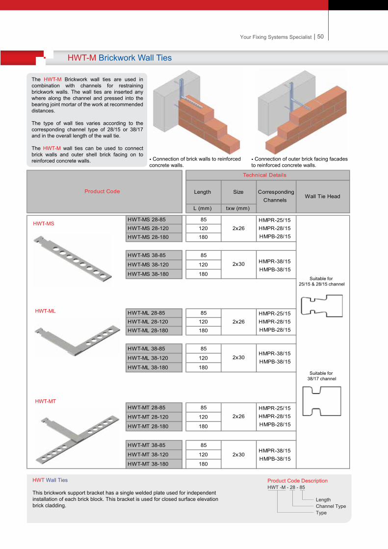
| 50Your Fixing Systems Specialist
HWT-M Brickwork Wall Ties
The HWT-M Brickwork wall ties are used in combination with channels for restraining brickwork walls. The wall ties are inserted any where along the channel and pressed into the bearing joint mortar of the work at recommended distances.
The type of wall ties varies according to the corresponding channel type of 28/15 or 38/17 and in the overall length of the wall tie.
The HWT-M wall ties can be used to connect brick walls and outer shell brick facing on to reinforced concrete walls.
L (mm) txw (mm)
HWT-MS 28-85 85HWT-MS 28-120 120HWT-MS 28-180 180
HWT-MS 38-85 85
HWT-MS 38-120 120
HWT-MS 38-180 180
HWT-ML 28-85 85HWT-ML 28-120 120HWT-ML 28-180 180
HWT-ML 38-85 85
HWT-ML 38-120 120
HWT-ML 38-180 180
HWT-MT 28-85 85
HWT-MT 28-120 120
HWT-MT 28-180 180
HWT-MT 38-85 85
HWT-MT 38-120 120
HWT-MT 38-180 180
2x26HMPR-25/15 HMPR-28/15 HMPB-28/15
2x30
HMPR-38/15 HMPB-38/15
2x26HMPR-25/15 HMPR-28/15 HMPB-28/15
2x30
HMPR-38/15 HMPB-38/15
Product Code
2x26
Corresponding Channels
HMPR-25/15 HMPR-28/15 HMPB-28/15
2x30
HMPR-38/15 HMPB-38/15
Technical Details
Length SizeWall Tie Head
• Connection of brick walls to reinforced concrete walls.
• Connection of outer brick facing facades to reinforced concrete walls.
Product Code Descr�pt�onHWT -M - 28 - 85
Length Channel TypeType
HWT Wall T�es
Th�s br�ckwork support bracket has a s�ngle welded plate used for �ndependent �nstallat�on of each br�ck block. Th�s bracket �s used for closed surface elevat�onbr�ck cladd�ng.
Suitable for 25/15 & 28/15 channel
Suitable for 38/17 channel
HWT-MS
HWT-ML
HWT-MT
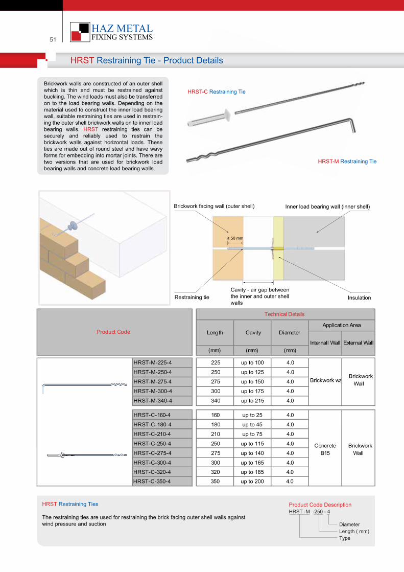
51
HRST Restraining Tie - Product Details
Brickwork walls are constructed of an outer shell which is thin and must be restrained against buckling. The wind loads must also be transferred on to the load bearing walls. Depending on the material used to construct the inner load bearing wall, suitable restraining ties are used in restrain-ing the outer shell brickwork walls on to inner load bearing walls. HRST restraining ties can be securely and reliably used to restrain the brickwork walls against horizontal loads. These ties are made out of round steel and have wavy forms for embedding into mortar joints. There are two versions that are used for brickwork load bearing walls and concrete load bearing walls.
(mm) (mm) (mm)
HRST-M-225-4 225 up to 100 4.0
HRST-M-250-4 250 up to 125 4.0
HRST-M-275-4 275 up to 150 4.0
HRST-M-300-4 300 up to 175 4.0
HRST-M-340-4 340 up to 215 4.0
HRST-C-160-4 160 up to 25 4.0
HRST-C-180-4 180 up to 45 4.0
HRST-C-210-4 210 up to 75 4.0
HRST-C-250-4 250 up to 115 4.0
HRST-C-275-4 275 up to 140 4.0
HRST-C-300-4 300 up to 165 4.0
HRST-C-320-4 320 up to 185 4.0
HRST-C-350-4 350 up to 200 4.0
Product Code
Technical Details
Length Diameter
Brickwork Wall
CavityApplication Area
Internall Wall External Wall
Brickwork wall
Concrete B15
Brickwork Wall
Product Code Descr�pt�onHRST -M -250 - 4
D�ameter Length ( mm)Type
HRST Restra�n�ng T�es
The restra�n�ng t�es are used for restra�n�ng the br�ck fac�ng outer shell walls aga�nstw�nd pressure and suct�on
HRST-C Restraining Tie
HRST-M Restraining Tie
Brickwork facing wall (outer shell) Inner load bearing wall (inner shell)
Restraining tie Insulation
≥ 50 mm
Cavity - air gap between the inner and outer shell walls
| 52Your Fixing Systems Specialist
CWMT-D Brickwork Wall Tie
• Corrugated tir provides multiple drips to prevent moisture bridging cavity• Provides lateral restraint for wind pressure & suction on brick work without transferring loads on to insulation • Fixed on to 38/17 cast-in or surface fixed channels• Positioning any where along the length of the channels • Available in lengths between 75 and 250 mm• Tensile loading is 0.7 kN per 600 mm screw centres
CWMT-D wall ties fixed on surface mounted C channels
• Self tapping screws with drill adaptor used for quick and easy fixing of surface channels on to metal studs
≥ 90
Product Code Length
CMWT-D-75 75CMWT-D-100 100CMWT-D-125 125CMWT-D-150 150CMWT-D-200 200CMWT-D-225 225CMWT-D-250 250
Pr o d uct Co d e D imensio ns D escr ip t io n Insulat io n
T hickness
For steel sections 1.5-6 mm thicknessHJT-3-70 5.5x70 20-50HJT-3-90 5.5x90 40-70HJT-3-110 5.5x110 60-90HJT3-130 5.5x130 80-110For steel sections 1.5-6 mm thicknessHJT2-120 6x120 55-105HJT2-140 6x140 75-125HJT2-160 6x160 95-145
Washered
Un-washered
c
b
d
e
f
a
a. Brick workb. Insulation ( Any kind )c. Steel sectiond. HJT Self tabbing screwse. HMPC-38/17 Surface channelf. CMWT-D Corrugated wall tie
HJT Self Tabbing Screw
HMLN-38DIN 934-6
CWMT Brickwork Corrugated Wall Ties - Product Information
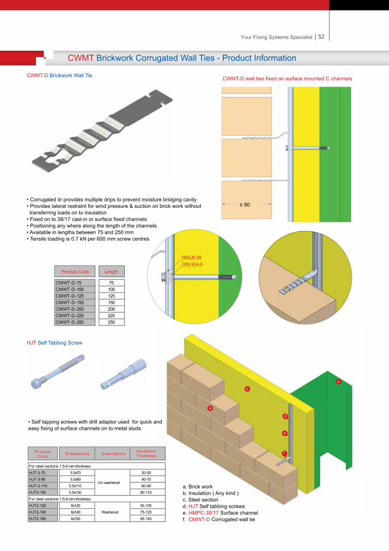
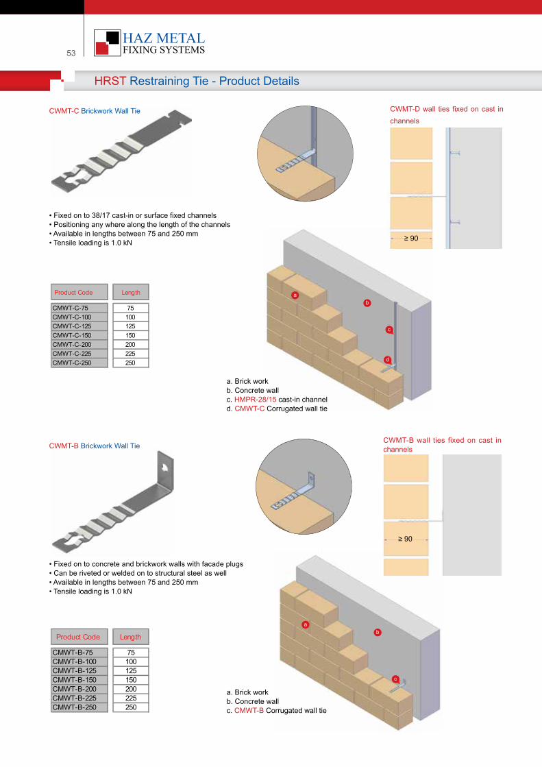
53
CWMT-C Brickwork Wall Tie
• Fixed on to 38/17 cast-in or surface fixed channels• Positioning any where along the length of the channels • Available in lengths between 75 and 250 mm• Tensile loading is 1.0 kN
CWMT-B Brickwork Wall Tie
• Fixed on to concrete and brickwork walls with facade plugs• Can be riveted or welded on to structural steel as well• Available in lengths between 75 and 250 mm• Tensile loading is 1.0 kN
CWMT-D wall ties fixed on cast in channels
CWMT-B wall ties fixed on cast in channels
HRST Restraining Tie - Product Details
≥ 90
≥ 90
Product Code Length
CMWT-C-75 75CMWT-C-100 100CMWT-C-125 125CMWT-C-150 150CMWT-C-200 200CMWT-C-225 225CMWT-C-250 250
Product Code Length
CMWT-B-75 75CMWT-B-100 100CMWT-B-125 125CMWT-B-150 150CMWT-B-200 200CMWT-B-225 225CMWT-B-250 250
b
c
a
d
a. Brick workb. Concrete wallc. HMPR-28/15 cast-in channeld. CMWT-C Corrugated wall tie
a. Brick workb. Concrete wallc. CMWT-B Corrugated wall tie
b
c
a
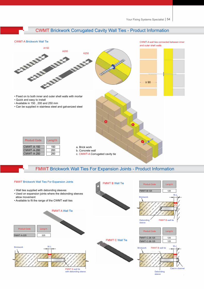
| 54Your Fixing Systems Specialist
CWMT Brickwork Corrugated Cavity Wall Ties - Product Information
CWMT-A Brickwork Wall Tie
• Fixed on to both inner and outer shell walls with mortar• Quick and easy to install• Available in 150 , 200 and 250 mm• Can be supplied in stainless steel and galvanized steel
CWMT-A wall ties connected between inner and outer shell walls
A150A200
A250
Product Code Leng t h
CMWT-A-150 150CMWT-A-200 200CMWT-A-250 250
FMWT Brickwork Wall Ties For Expansion Joints - Product Information
≥ 90
a. Brick workb. Concrete wallc. CMWT-A Corrugated cavity tie
b
c
a
FMWT Brickwork Wall Ties For Expansion Joints
• Wall ties supplied with debonding sleeves • Used on expansion joints where the debonding sleeves allow movement• Available to fit the range of the CWMT wall ties
Product Code Leng t h
FMWT-C-28-125 125125FMWT-C-38-125
Product Code Leng t h
FMWT-A-225 225
Brickwork M.J.
FMWT A wall tie with debonding sleeve
Brickwork
FMWT B wall tieDebonding sleeve
Product Code Leng t h
FMWT-B-125 125
M.J.
Brickwork FMWT B wall tieM.J.
Debonding sleeve
Cast-in channel
FMWT A Wall Tie
FMWT B Wall Tie
FMWT C Wall Tie
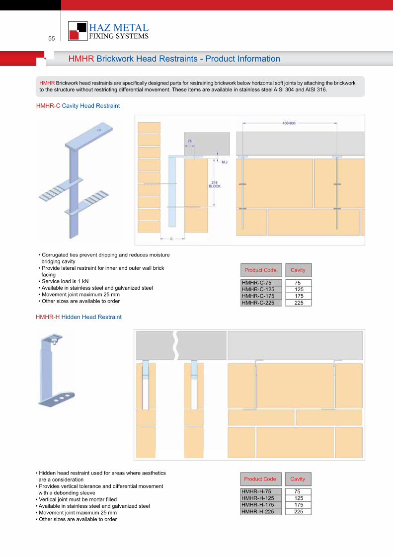
55
HMHR Brickwork Head Restraints - Product Information
HMHR-H Hidden Head Restraint
HMHR-C Cavity Head Restraint
HMHR Brickwork head restraints are specifically designed parts for restraining brickwork below horizontal soft joints by attaching the brickwork to the structure without restricting differential movement. These items are available in stainless steel AISI 304 and AISI 316.
• Corrugated ties prevent dripping and reduces moisture bridging cavity• Provide lateral restraint for inner and outer wall brick facing• Service load is 1 kN• Available in stainless steel and galvanized steel• Movement joint maximum 25 mm• Other sizes are available to order
• Hidden head restraint used for areas where aesthetics are a consideration• Provides vertical tolerance and differential movement with a debonding sleeve• Vertical joint must be mortar filled• Available in stainless steel and galvanized steel• Movement joint maximum 25 mm• Other sizes are available to order
Product Code Cavity
HMHR-C-75 75HMHR-C-125 125HMHR-C-175 175HMHR-C-225 225
Product Code Cavity
HMHR-H-75 75HMHR-H-125 125HMHR-H-175 175HMHR-H-225 225
| 56Your Fixing Systems Specialist
HMHR Brickwork Head Restraints - Product Information
HMHR-E Exposed Head Restraint
• Exposed head restraint for inner wall• Provides vertical tolerance and differential movement with a debonding sleeve• Vertical joint must be mortar filled
Product Code Cavity
HMHR-E-75 75HMHR-E-125 125HMHR-E-175 175HMHR-E-225 225HMHR-E Exposed Head Restraint
• Exposed head restraint for inner wall• Provides vertical tolerance and differential movement with a debonding sleeve• Vertical joint must be mortar filled
Product Code Cavity
HMHR-E-75 75HMHR-E-125 125HMHR-E-175 175HMHR-E-225 225
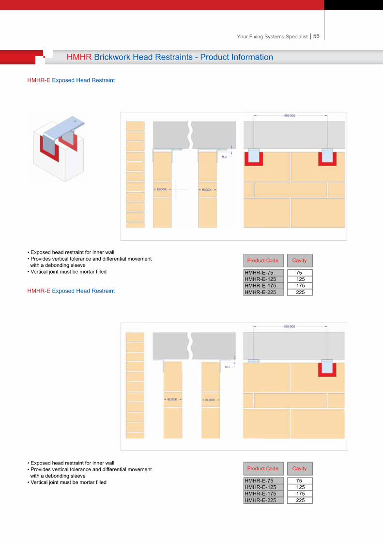
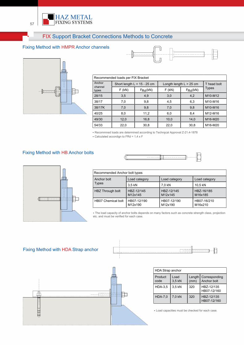
57
FIX Support Bracket Connections Methods to Concrete
Anchorchanneltypes
Short length L = 15 - 25 cm Longth length L > 25 cm T head boltTypesF (kN) FRd (kN) F (kN) FRd (kN)
28/15 3,5 4,9 3,0 4,2 M10-M12
38/17 7,0 9,8 4,5 6,3 M10-M16
38/17K 7,0 9,8 7,0 9,8 M10-M16
40/25 8,0 11,2 6,0 8,4 M12-M16
49/30 12,0 16,8 10,0 14,0 M16-M20
54/33 22,0 30,8 22,0 30,8 M16-M20
Anchor boltTypes
Load category Load category Load category
3,5 kN 7,0 kN 10,5 kN
HBZ Through bolt HBZ-12/145M12x145
HBZ-12/145M12x145
HBZ-16/185M16x185
HB07 Chem�cal bolt HB07-12/190M12x190
HB07-12/190M12x190
HB07-16/210M16x210
Load3,5 kN
Length(mm)
Correspond�ngAnchor bolt
HDA-3,5 3,5 kN 320 HBZ-12/135HB07-12/160
HDA-7,0 7,0 kN 320 HBZ-12/135HB07-12/160
Fixing Method with HMPR Anchor channels
Fixing Method with HB Anchor bolts
Fixing Method with HDA Strap anchor
HDA Strap anchor
Product code
Recommended loads per FIX Bracket
• Recommned loads are determ�ned accord�ng to Technşcal Approval Z-21.4-1878• Calculated accord�gn to FRd = 1,4 x F
Recommended Anchor bolt types
• The load capac�ty of anchor bolts depends on many factors such as concrete strength class, project�on etc. and must be ver�f�ed for each case.
• Load capac�t�es must be checked for each case.
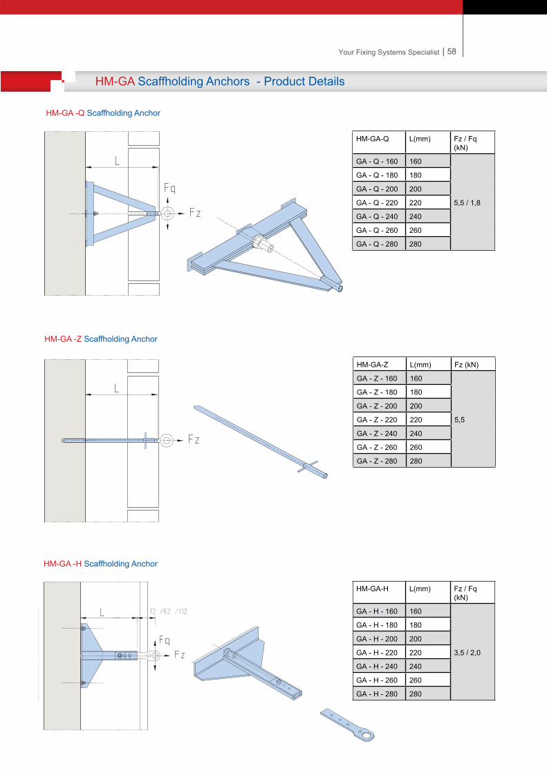
| 58Your Fixing Systems Specialist
HM-GA Scaffholding Anchors - Product Details
HM-GA-Q L(mm) Fz / Fq(kN)
GA - Q - 160 160
5,5 / 1,8
GA - Q - 180 180
GA - Q - 200 200
GA - Q - 220 220
GA - Q - 240 240
GA - Q - 260 260
GA - Q - 280 280
HM-GA-Z L(mm) Fz (kN)
GA - Z - 160 160
5,5
GA - Z - 180 180
GA - Z - 200 200
GA - Z - 220 220
GA - Z - 240 240
GA - Z - 260 260
GA - Z - 280 280
HM-GA-H L(mm) Fz / Fq(kN)
GA - H - 160 160
3,5 / 2,0
GA - H - 180 180
GA - H - 200 200
GA - H - 220 220
GA - H - 240 240
GA - H - 260 260
GA - H - 280 280
HM-GA -Q Scaffholding Anchor
HM-GA -Z Scaffholding Anchor
HM-GA -H Scaffholding Anchor
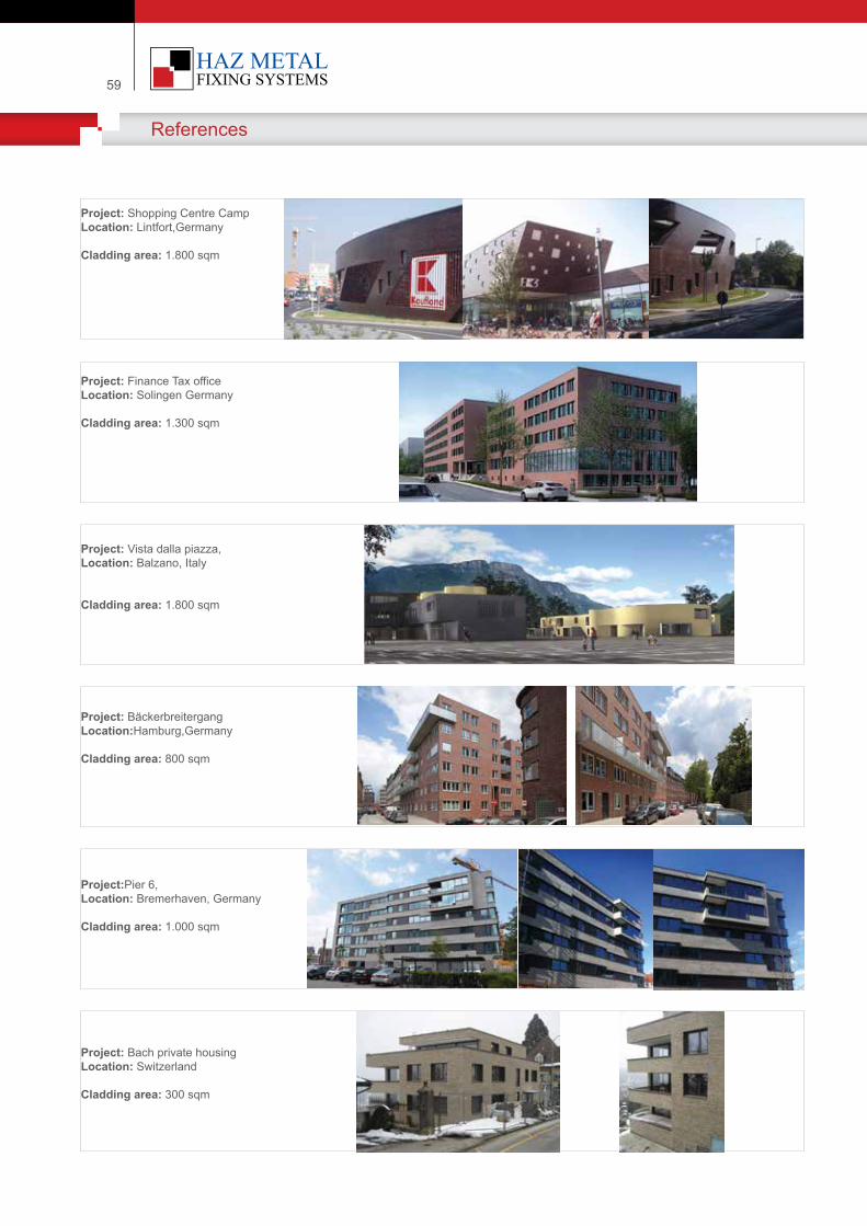
59
References
Project: Shopping Centre Camp Location: Lintfort,Germany
Cladding area: 1.800 sqm
Project: Finance Tax office Location: Solingen Germany
Cladding area: 1.300 sqm
Project: Vista dalla piazza, Location: Balzano, Italy
Cladding area: 1.800 sqm
Project: Bäckerbreitergang Location:Hamburg,Germany
Cladding area: 800 sqm
Project:Pier 6, Location: Bremerhaven, Germany
Cladding area: 1.000 sqm
Project: Bach private housingLocation: Switzerland
Cladding area: 300 sqm
| 60Your Fixing Systems Specialist
References
Project: Bosmos office flatsLocation: Switzwerland
Claddiing area: 2.250 sqm
Project: Wardalls Grove Location: United Kingdom
Project: Rochester RiversideLocation: United Kingdom
Project: Rublevo Housing projectLocation: Moscow, Russia
Project: Marinat Residence Location: United Arab Emirates
Project: Sabanci UniversityLocation: Istanbul, Turkey
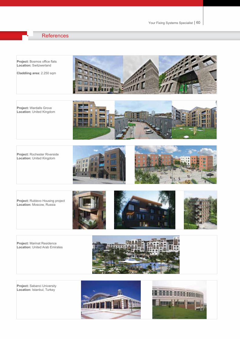

Notes
Your Fixing Systems Specialist
Notes
Notes
Your Fixing Systems Specialist
Notes
Notes

Notes
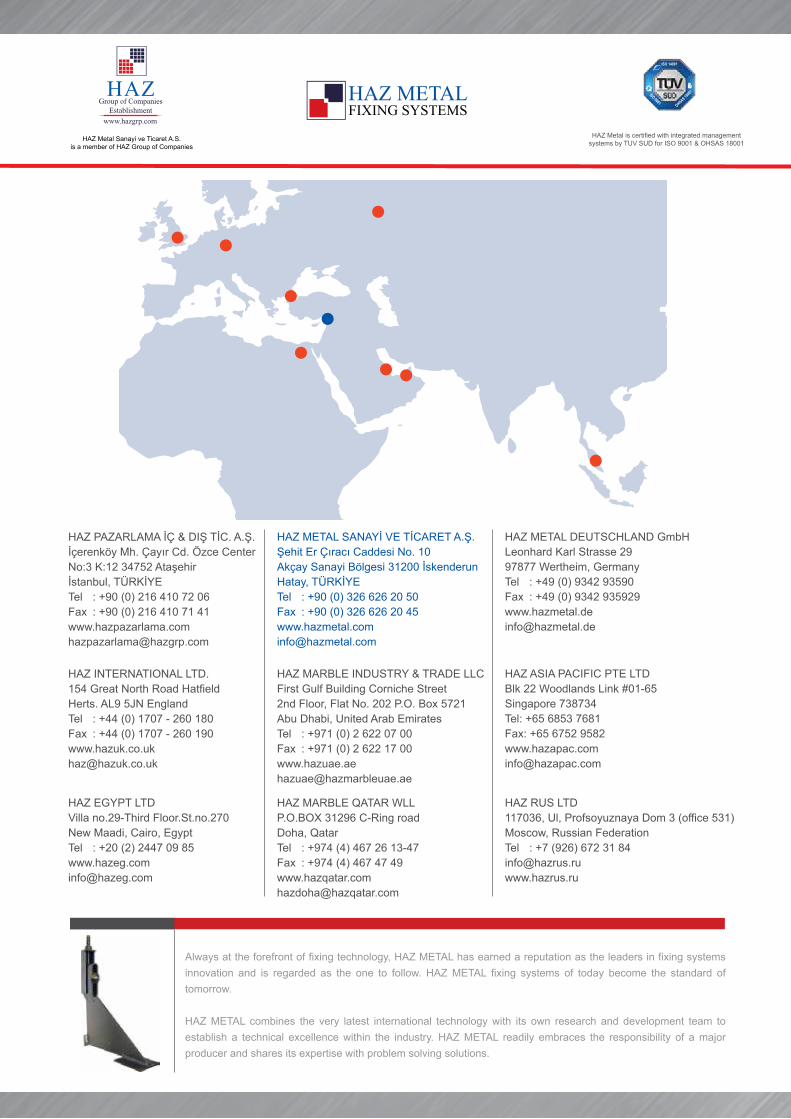
HAZ MARBLE QATAR WLLP.O.BOX 31296 C-Ring roadDoha, QatarTel : +974 (4) 467 26 13-47Fax : +974 (4) 467 47 [email protected]
HAZ RUS LTD117036, Ul, Profsoyuznaya Dom 3 (office 531)Moscow, Russian FederationTel : +7 (926) 672 31 84 [email protected]
HAZ EGYPT LTDVilla no.29-Third Floor.St.no.270New Maadi, Cairo, EgyptTel : +20 (2) 2447 09 [email protected]
Always at the forefront of fixing technology, HAZ METAL has earned a reputation as the leaders in fixing systems innovation and is regarded as the one to follow. HAZ METAL fixing systems of today become the standard of tomorrow.
HAZ METAL combines the very latest international technology with its own research and development team to establish a technical excellence within the industry. HAZ METAL readily embraces the responsibility of a major producer and shares its expertise with problem solving solutions.
HAZ Metal is certified with integrated managementsystems by TUV SUD for ISO 9001 & OHSAS 18001
HAZ PAZARLAMA İÇ & DIŞ TİC. A.Ş.İçerenköy Mh. Çayır Cd. Özce CenterNo:3 K:12 34752 Ataşehirİstanbul, TÜRKİYETel : +90 (0) 216 410 72 06Fax : +90 (0) 216 410 71 [email protected]
HAZ INTERNATIONAL LTD.154 Great North Road HatfieldHerts. AL9 5JN EnglandTel : +44 (0) 1707 - 260 180Fax : +44 (0) 1707 - 260 [email protected]
HAZ METAL SANAYİ VE TİCARET A.Ş.Şehit Er Çıracı Caddesi No. 10Akçay Sanayi Bölgesi 31200 İskenderunHatay, TÜRKİYETel : +90 (0) 326 626 20 50Fax : +90 (0) 326 626 20 [email protected]
HAZ MARBLE INDUSTRY & TRADE LLCFirst Gulf Building Corniche Street2nd Floor, Flat No. 202 P.O. Box 5721Abu Dhabi, United Arab EmiratesTel : +971 (0) 2 622 07 00Fax : +971 (0) 2 622 17 [email protected]
HAZ METAL DEUTSCHLAND GmbHLeonhard Karl Strasse 2997877 Wertheim, GermanyTel : +49 (0) 9342 93590Fax : +49 (0) 9342 [email protected]
HAZ ASIA PACIFIC PTE LTDBlk 22 Woodlands Link #01-65 Singapore 738734Tel: +65 6853 7681Fax: +65 6752 [email protected]
HAZ Metal Sanayi ve Ticaret A.S.is a member of HAZ Group of Companies