bock residential oil-fired water heaters - torrco
TRANSCRIPT
TO THE CONSUMER:Read these and all com-ponent instructions.Please keep for futurereference. Please re-member to return theregistration card.Waranty, registrationcard & parts list included.
TO THE INSTALLER:Please attach these in-structions next to thewater heater.
BOCK RESIDENTIAL OIL-FIREDWATER HEATERS
Model numbers: 20e, 20pp, 32E, 32EC, 32PP,32PPC, 33E, 33PP, 40E, 40PP, 50ES, 50ESC,51E, 51EC, 51PP, 51PPC, 71E, 120E
WARNING:Improper installation, adjustment, alteration, serviceor maintenance can cause serious injury or prop-erty damage. Refer to this manual. For assistanceor additional information, consult a qualified installeror service agency.
WARNING:If the information in these instructions is not fol-lowed exactly, fire or explosion may result and cancause property damage, personal injury or death.
WARNING:Follow minimum combustible clearance as notedon water heater label. Do not install on combustibleflooring (see Figure 2, Page 3). Install in accor-dance with all local codes. In the absence of localcodes, refer to NFPA 31 or ANSI Z21.10.1.
CAUTION:The recommended temperature for normal residen-tial use is 120°F. The dial on the aquastat does notalways reflect the outcoming water temperature,which could occasionally exceed 120°F. The varia-tion in outcoming temperature could be based onfactors including but not limited to usage patternsand type of installation. Test your water at the tapnearest to the water heater. (See page 5 for mea-suring the outcoming water temperature).
WARNING:Hotter water increases the risk of scald injury. Be-fore changing the temperature setting, read theinstruction manual. Temperatures at which injury oc-curs vary with the individual’s age and length ofexposure.
The slower reaction times of children, elderly andphysically or mentally impaired persons increasesthe scalding hazard to them. It is recommended lowerwater temperatures be used where these situationsexist.Households with small children or invalids may re-quire a temperature setting less than 120°F to preventaccidental contact with hot water.To lower water temperature use point-of-use tem-perature limiting devices.
WARNING:Flammable vapors may be drawn to this water heat-er from other areas of the structure by air currents.
Do not store or use any flammable liquids in thevicinity of this heater.
WARNING:Water heater blankets may restrict air flow to theheater and cause fire, asphyxiation, personal injuryor death.
Bock Water Heaters, Inc.110 South Dickinson Street • P.O. Box 8632 • Madison, WI 53708-8632Phone: 608/257-2225 • Fax: 608/257-5304 • www.bockwaterheaters.com
INSTALLATION, OPERATION &MAINTENANCE INSTRUCTIONS
#23420 Rev 7 (7/11)
23420.qxp:23420 Res Oil Water Bro 8/3/11 8:39 AM Page 1

23420.qxp:23420 Res Oil Water Bro 8/3/11 8:39 AM Page 2
– 2 –
THIS MANUAL HAS BEEN PREPARED TOACQUAINT YOUWITH THE INSTAL-LATION, OPERATION, AND MAINTENANCE OF YOUR WATER HEATER ANDTO PROVIDE IMPORTANT SAFETY INFORMATION.
Read all instructions thoroughly before attempting installation or operation of thewater heater. Keep these and all component instructions for future reference.
The manufacturer of this water heater will not be liable for any damages causedby failure to comply with the installation and operating instructions outlined on thefollowing pages. These instructions are a guide for the correct installation of thewater heater.
If the installer lacks the necessary skills or has difficulty following thedirections, do not proceed but get help from a qualified person for that part of theinstallation that is not understood.
Local plumbing and electrical codes must be followed in the installation of thiswater heater. In the absence of a local code use the UNIFORM PLUMBINGCODE and the NFPACode. Local codes may supersede instructions in this instal-lation manual.
When two or more burners are used, each unit should have a separatesupply line to the fuel pump to prevent nuisance lockouts caused by one or bothpumps starving for oil. If this is not possible, the use of a prioritycontrol is recommended.
Check new equipment to see if all components are in good condition.The water heater and oil burner may be shipped as separate units. The aquastatand immersion well may be packed with the oil burner.
The new water heater requires fuel (#I or #2 heating oil), electricity and should beclose to the chimney and water supply. Locate the heater near a floor drain if pos-sible for easy maintenance and protection if trouble should occur. Allow amplespace around the heater for servicing (see combustible clearance warning, page1). Adequate air for combustion must be available. NOTE: Locate the heater so itis not subject to physical damage by moving vehicles or possible flooding.
CONSUMERRESPONSIBILITIES
MULTIPLE BURNERINSTALLATION
SELECT THE RIGHTLOCATION
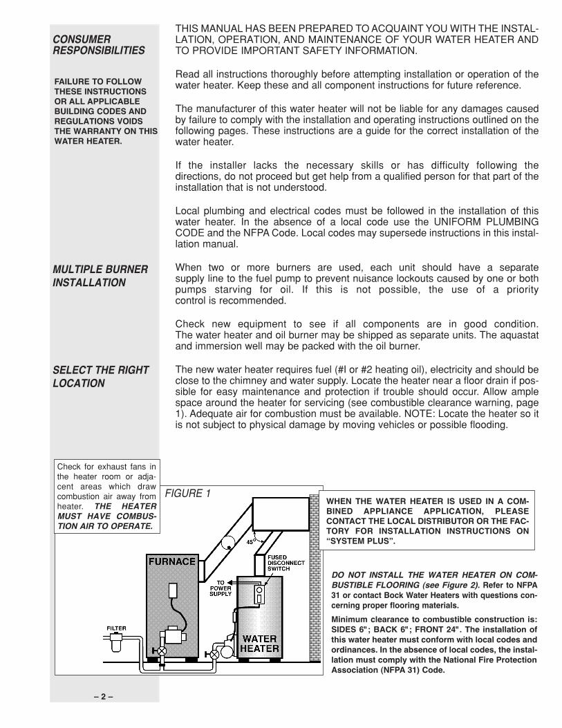
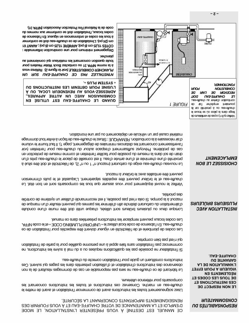
FIGURE 1
Check for exhaust fans inthe heater room or adja-cent areas which drawcombustion air away fromheater. THE HEATERMUST HAVE COMBUS-TION AIR TO OPERATE.
WHEN THE WATER HEATER IS USED IN A COM-BINED APPLIANCE APPLICATION, PLEASECONTACT THE LOCAL DISTRIBUTOR OR THE FAC-TORY FOR INSTALLATION INSTRUCTIONS ON“SYSTEM PLUS”.
DO NOT INSTALL THE WATER HEATER ON COM-BUSTIBLE FLOORING (see Figure 2). Refer to NFPA31 or contact Bock Water Heaters with questions con-cerning proper flooring materials.Minimum clearance to combustible construction is:SIDES 6"; BACK 6"; FRONT 24". The installation ofthis water heater must conform with local codes andordinances. In the absence of local codes, the instal-lation must comply with the National Fire ProtectionAssociation (NFPA 31) Code.
FAILURE TO FOLLOWTHESE INSTRUCTIONSOR ALL APPLICABLEBUILDING CODES ANDREGULATIONS VOIDSTHE WARRANTY ON THISWATER HEATER.
23420.qxp:23420 Res Oil Water Bro 8/3/11 8:39 AM Page 3
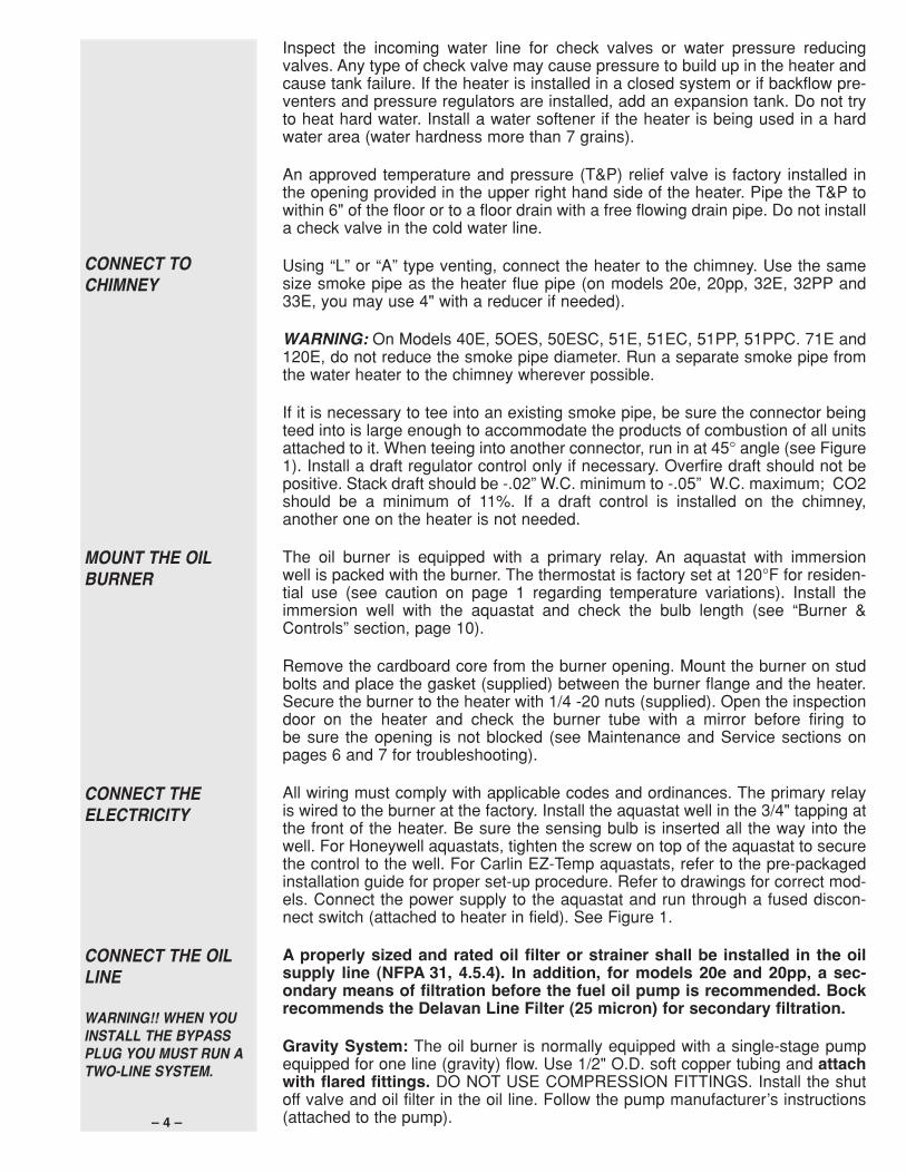
The drain valve fitting may be used asan alternate cold water inlet on heatersequipped with a dip tube, as shown inFigure 3. By plumbing a “T” into the drainfitting, the cold water inlet can berelocated to this point. The dip tubemust be removed and its fitting plugged.Figure 3 also shows a copper loop heattrap installed on the hot water outlet toreduce standby losses.
Note: When converting to this configu-ration on an existing heater, visuallyinspect the heater and make certain itdoes not have scale buildup on the
bottom of the tank. Scale can restrict the flowof water into the tank.CAUTION!! Scalding injury and/or waterdamage can occur from either the manuallifting of the lever or the normal operation of theT&P valve if it is not piped to a proper drain. Ifthe valve fails to flow water or reseat, calla plumber.
– 3 –
FIGURE 3FIGURE 2
CONNECT WATERPIPING
Hot water outlet(“HOT”) is on tanktop. Cold water inletis on right frontbottom of 33E and40E. On all othermodels, cold waterinlet is on tank top.
Connect the water piping, being careful not to apply heat to the heaternipples. Install dielectric unions and shut off valves on both hot and cold waterlines.
The 40E and all “C” models (example: 32EC, 51PPC) have a 1” NPT tapping locat-ed on the front left side of the tank. This is an alternate outlet for use with combinedappliance applications. If this fitting is not used, plug it with a fitting suitable forpotable water.
A 1” NPT fitting is also located behind the drain valve on the 40E and all“C” models. This is for use as an alternate inlet or a combined appliance return.Your heater is shipped with a reducer in this location to mountthe drain valve.
The drain valve fitting may be used as an alternate cold water inlet on heatersequipped with a dip tube, as shown in Figure 3. By plumbing a “T” into the drainfitting, the cold water inlet can be relocated to this point. The dip tube must beremoved and its fitting plugged. Figure 3 also shows a copper loop heat trapinstalled on the hot water outlet to reduce standby losses.
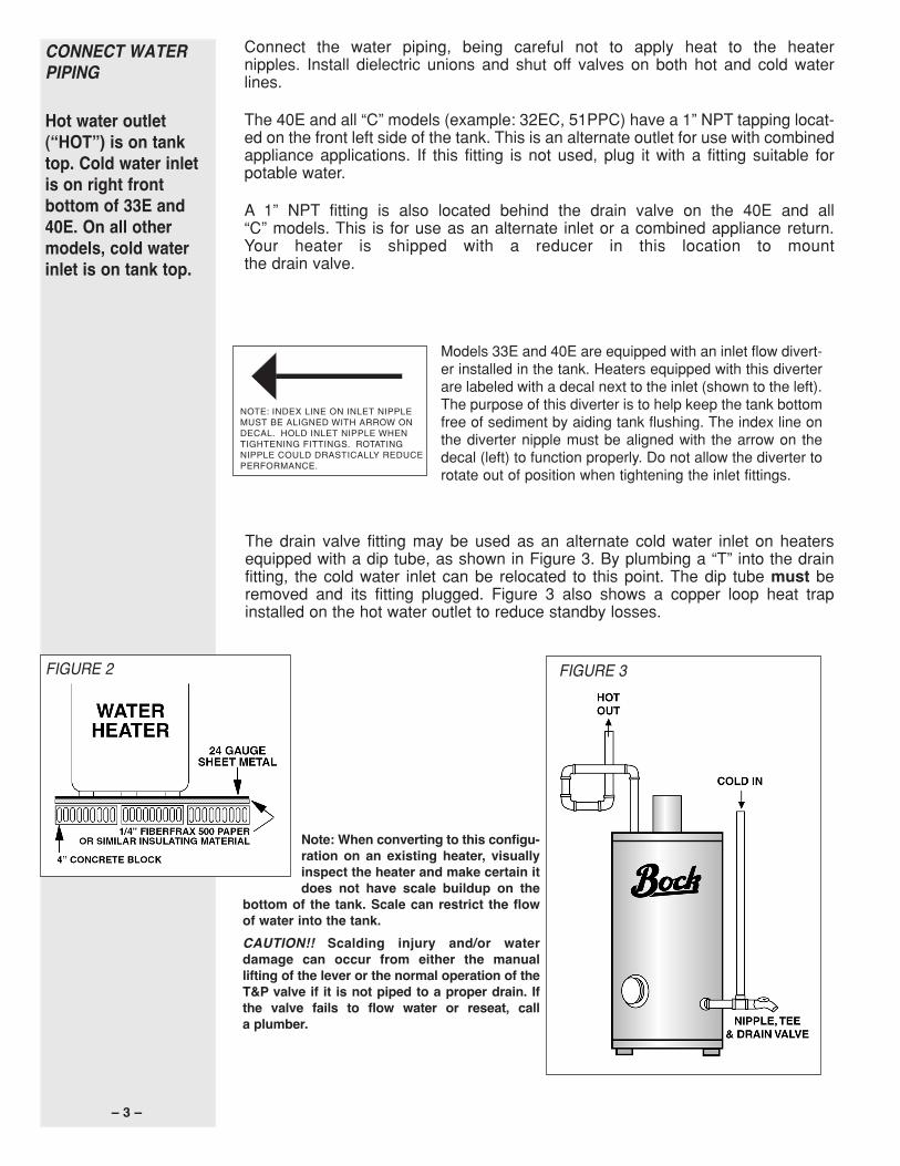
Models 33E and 40E are equipped with an inlet flow divert-er installed in the tank. Heaters equipped with this diverterare labeled with a decal next to the inlet (shown to the left).The purpose of this diverter is to help keep the tank bottomfree of sediment by aiding tank flushing. The index line onthe diverter nipple must be aligned with the arrow on thedecal (left) to function properly. Do not allow the diverter torotate out of position when tightening the inlet fittings.
NOTE: INDEX LINE ON INLET NIPPLE MUST BE ALIGNED WITH ARROW ONDECAL. HOLD INLET NIPPLE WHEN TIGHTENING FITTINGS. ROTATINGNIPPLE COULD DRASTICALLY REDUCEPERFORMANCE.
23420.qxp:23420 Res Oil Water Bro 8/3/11 8:39 AM Page 4
– 4 –
Inspect the incoming water line for check valves or water pressure reducingvalves. Any type of check valve may cause pressure to build up in the heater andcause tank failure. If the heater is installed in a closed system or if backflow pre-venters and pressure regulators are installed, add an expansion tank. Do not tryto heat hard water. Install a water softener if the heater is being used in a hardwater area (water hardness more than 7 grains).
An approved temperature and pressure (T&P) relief valve is factory installed inthe opening provided in the upper right hand side of the heater. Pipe the T&P towithin 6" of the floor or to a floor drain with a free flowing drain pipe. Do not installa check valve in the cold water line.
Using “L” or “A” type venting, connect the heater to the chimney. Use the samesize smoke pipe as the heater flue pipe (on models 20e, 20pp, 32E, 32PP and33E, you may use 4" with a reducer if needed).
WARNING: On Models 40E, 5OES, 50ESC, 51E, 51EC, 51PP, 51PPC. 71E and120E, do not reduce the smoke pipe diameter. Run a separate smoke pipe fromthe water heater to the chimney wherever possible.
If it is necessary to tee into an existing smoke pipe, be sure the connector beingteed into is large enough to accommodate the products of combustion of all unitsattached to it. When teeing into another connector, run in at 45° angle (see Figure1). Install a draft regulator control only if necessary. Overfire draft should not bepositive. Stack draft should be -.02” W.C. minimum to -.05” W.C. maximum; CO2should be a minimum of 11%. If a draft control is installed on the chimney,another one on the heater is not needed.
The oil burner is equipped with a primary relay. An aquastat with immersionwell is packed with the burner. The thermostat is factory set at 120°F for residen-tial use (see caution on page 1 regarding temperature variations). Install theimmersion well with the aquastat and check the bulb length (see “Burner &Controls” section, page 10).
Remove the cardboard core from the burner opening. Mount the burner on studbolts and place the gasket (supplied) between the burner flange and the heater.Secure the burner to the heater with 1/4 -20 nuts (supplied). Open the inspectiondoor on the heater and check the burner tube with a mirror before firing tobe sure the opening is not blocked (see Maintenance and Service sections onpages 6 and 7 for troubleshooting).
All wiring must comply with applicable codes and ordinances. The primary relayis wired to the burner at the factory. Install the aquastat well in the 3/4" tapping atthe front of the heater. Be sure the sensing bulb is inserted all the way into thewell. For Honeywell aquastats, tighten the screw on top of the aquastat to securethe control to the well. For Carlin EZ-Temp aquastats, refer to the pre-packagedinstallation guide for proper set-up procedure. Refer to drawings for correct mod-els. Connect the power supply to the aquastat and run through a fused discon-nect switch (attached to heater in field). See Figure 1.
A properly sized and rated oil filter or strainer shall be installed in the oilsupply line (NFPA 31, 4.5.4). In addition, for models 20e and 20pp, a sec-ondary means of filtration before the fuel oil pump is recommended. Bockrecommends the Delavan Line Filter (25 micron) for secondary filtration.
Gravity System: The oil burner is normally equipped with a single-stage pumpequipped for one line (gravity) flow. Use 1/2" O.D. soft copper tubing and attachwith flared fittings. DO NOT USE COMPRESSION FITTINGS. Install the shutoff valve and oil filter in the oil line. Follow the pump manufacturer’s instructions(attached to the pump).
CONNECT THE OILLINE
WARNING!! WHEN YOUINSTALL THE BYPASSPLUG YOU MUST RUN ATWO-LINE SYSTEM.
CONNECT THEELECTRICITY
MOUNT THE OILBURNER
CONNECT TOCHIMNEY
23420.qxp:23420 Res Oil Water Bro 8/3/11 8:39 AM Page 5
– 5 –
PLACE THEWATERSYSTEM INOPERATION
Warning: Handholecover may loosenduring shipping –check for tightnessbefore putting heaterin operation.
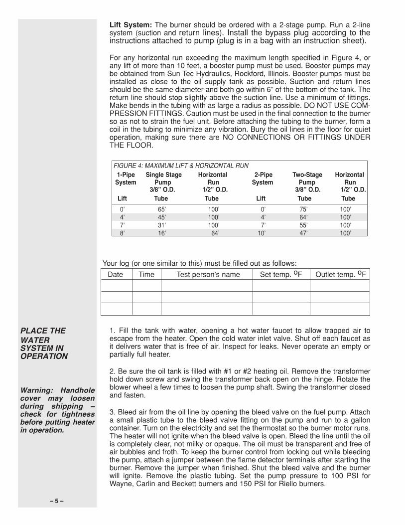
Lift System: The burner should be ordered with a 2-stage pump. Run a 2-linesystem (suction and return lines). Install the bypass plug according to theinstructions attached to pump (plug is in a bag with an instruction sheet).
For any horizontal run exceeding the maximum length specified in Figure 4, orany lift of more than 10 feet, a booster pump must be used. Booster pumps maybe obtained from Sun Tec Hydraulics, Rockford, Illinois. Booster pumps must beinstalled as close to the oil supply tank as possible. Suction and return linesshould be the same diameter and both go within 6” of the bottom of the tank. Thereturn line should stop slightly above the suction line. Use a minimum of fittings.Make bends in the tubing with as large a radius as possible. DO NOT USE COM-PRESSION FITTINGS. Caution must be used in the final connection to the burnerso as not to strain the fuel unit. Before attaching the tubing to the burner, form acoil in the tubing to minimize any vibration. Bury the oil lines in the floor for quietoperation, making sure there are NO CONNECTIONS OR FITTINGS UNDERTHE FLOOR.
1. Fill the tank with water, opening a hot water faucet to allow trapped air toescape from the heater. Open the cold water inlet valve. Shut off each faucet asit delivers water that is free of air. Inspect for leaks. Never operate an empty orpartially full heater.
2. Be sure the oil tank is filled with #1 or #2 heating oil. Remove the transformerhold down screw and swing the transformer back open on the hinge. Rotate theblower wheel a few times to loosen the pump shaft. Swing the transformer closedand fasten.
3. Bleed air from the oil line by opening the bleed valve on the fuel pump. Attacha small plastic tube to the bleed valve fitting on the pump and run to a galloncontainer. Turn on the electricity and set the thermostat so the burner motor runs.The heater will not ignite when the bleed valve is open. Bleed the line until the oilis completely clear, not milky or opaque. The oil must be transparent and free ofair bubbles and froth. To keep the burner control from locking out while bleedingthe pump, attach a jumper between the flame detector terminals after starting theburner. Remove the jumper when finished. Shut the bleed valve and the burnerwill ignite. Remove the plastic tubing. Set the pump pressure to 100 PSI forWayne, Carlin and Beckett burners and 150 PSI for Riello burners.
Your log (or one similar to this) must be filled out as follows:
Date Time Test person’s name Set temp. oF Outlet temp. oF
FIGURE 4: MAXIMUM LIFT & HORIZONTAL RUN1-Pipe Single Stage Horizontal 2-Pipe Two-Stage HorizontalSystem Pump Run System Pump Run
3/8” O.D. 1/2” O.D. 3/8” O.D. 1/2” O.D.Lift Tube Tube Lift Tube Tube0’ 65’ 100’ 0’ 75’ 100’4’ 45’ 100’ 4’ 64’ 100’7’ 31’ 100’ 7’ 55’ 100’8’ 16’ 64’ 10’ 47’ 100’
23420.qxp:23420 Res Oil Water Bro 8/3/11 8:39 AM Page 6
– 6 –
4. Adjust the burner combustion air in accordance with the burner manufacturer’sinstructions. Using combustion instruments, check the C02 and smoke. The C02should be at least 10 1/2% minimum with 0-to-trace smoke on the Bacharachscale.
5. While the burner is operating, disconnect one of the yellow cad cell wires.Check to see that the burner control locks out in the time specified on the control.Reattach the wire and reset the control. The burner should restart. Note: You mayhave to wait a minute before resetting the control.
6. The thermostat is factory set at 120°F for residential use. (See caution onpage 1 regarding temperature variations. It is the responsibility of the homeown-er and installer to verify that the installer follows the recommended quantitativetesting for measuring the outcoming water temperature. To make sure that thesystem works properly after installation and in the future, it is recommended thatthe heater’s performance be measured and monitored. Run water out of the tapnearest the heater until it comes out warm. Using a calibrated thermometer, takea measurement. If the water is not at a suitable temperature for the installation,have a qualified service person adjust the aquastat. Contact Bock for furtherinformation on the thermometer if needed.
WARNING: Hydrogen gas can be produced in a hot water system served bya heater that has not been used for a long period of time (generally twoweeks or more.) Hydrogen gas is extremely flammable. To reduce the riskof injury, open the hot water faucet at the highest location in the house forseveral minutes before using any electrical appliance connected to the hotwater system. If hydrogen is present, there may be an unusual sound suchas air escaping through the pipe as the water begins to flow. Do not smokeor allow an open flame near the faucet at the time it is open.
1. Oil the burner motor (5-10 drops) with #10 SAE motor oil (if applicable).
2. Install a new burner nozzle of the correct rate and angle. (See Chart A, page 11).
3. Clean and adjust the electrodes and inspect for cracks in the porcelain. Checkfor corrosion on the buss bars and ignitor terminals.
4. Change the fuel oil filter and have the oil tank checked for sediment. Clean thetank if necessary.
5. Keep the oil tank full to prevent water vapor from collecting inside the tank,especially during the summer.
6. Check the smoke pipe and chimney. Clean and repair if necessary.
7. EVERY SIX to 12 MONTHS. Drain water from the heater tank and inspect forsediment or lime accumulation. Flush out if necessary. If lime has accumulated,remove with a commercial compound for dissolving lime or by scraping throughthe hand hole opening (if supplied). Check water softening equipment if lime isfound in the tank. DO NOT ATTEMPT TO HEAT HARD WATER. (See mainte-nance label on heater.)
8. Change the magnesium anode rods every six to 12 months or when theyare reduced to 3/8” diameter (see maintenance label on heater). We recom-mend the installer use PermaBond LH-050. Teflon tape should not be used wheninstalling magnesium or aluminum anode rods.
9. Open the relief valve test lever to flush out the tank. Make sure it reseats itself.
10. If the heater is to be shut off in cold weather, drain the tank to prevent freezing.
MAINTENANCE
MEASURING THEOUTCOMINGWATERTEMPERATURE
Have the oil burnerserviced once eachyear by a qualifiedoil burner serviceperson. Serviceshould comply withthe burner manufac-turerʼs recommenda-tions and include:
23420.qxp:23420 Res Oil Water Bro 8/3/11 8:39 AM Page 7
– 7 –
SERVICE 1. Check the fuel supply, electrical wiring and fuses, and make sure temperaturecontrol is calling for heat.
2. If the motor runs but there is no flame, remove the electrode assembly, clean,readjust to the burner manufacturer’s specifications, check the electrode porce-lain for cracks and replace if necessary. Check the transformer to see if it is pro-ducing a strong spark. (Use extreme CAUTION: The transformer has a 10,000volt output). Check that the coupling between the motor and pump shaft is notslipping. Check the set screw on the blower wheel for tightness. Clean or replacethe nozzle with the correct size and spray angle (see Chart A, page 11).
3. Bleed the pump and check for clear, air-free oil. If the oil is milky or frothy, checkthe line for air leaks at fittings. Tighten all fittings again. Check the filter gasketsand make sure cartridge is clean.
4. If the burner motor does not run, check the motor thermal overload button (redbutton on end of motor). Reset the primary control by pushing the reset button onthe control. If the burner motor still does not run after resetting the control, turn offthe electricity and replace the flame detector (with the same make) located in theburner compartment. Reset the primary control. If the motor stilldoes not run, replace the control.
5. If the burner ignites and runs a short time (30-40 seconds), then goes out onsafety, replace the flame detector. If the burner still runs only a short time, replacethe control.
6. If there is a smell of oil or combustion products, remove and clean the electrodeassembly (see No. 2 above). Check the draft in the stack above the heater. Stackdraft (pull in) should be -.02” W.C. minimum to -.05” W.C. maximum.
Check for exhaust fans in the heater room or adjacent areas which draw com-bustion air away from heater. THE HEATER MUST HAVE COMBUSTION AIR TOOPERATE.
For more information, contact your installer, the nearest Bock distributor, or write,call or fax:
BOCK WATER HEATERS, INC.110 South Dickinson Street, Madison, WI 53703Phone: 608/257-2225 • Fax: 608/257-5304
23420.qxp:23420 Res Oil Water Bro 8/3/11 8:39 AM Page 8
L4080B
L4006A
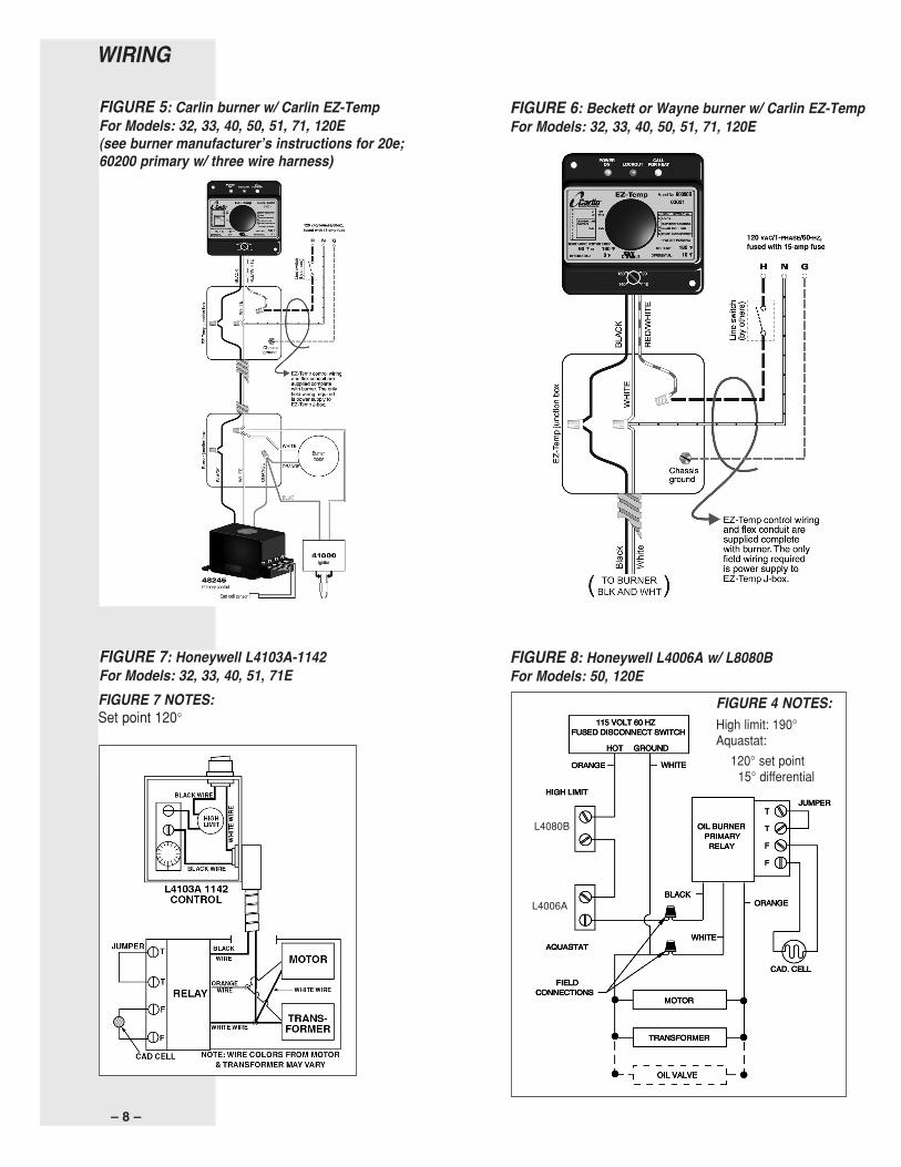
FIGURE 8: Honeywell L4006A w/ L8080BFor Models: 50, 120E
FIGURE 6: Beckett or Wayne burner w/ Carlin EZ-TempFor Models: 32, 33, 40, 50, 51, 71, 120E
FIGURE 7: Honeywell L4103A-1142For Models: 32, 33, 40, 51, 71EFIGURE 7 NOTES:Set point 120°
FIGURE 4 NOTES:High limit: 190°Aquastat:
120° set point15° differential
– 8 –
WIRING
FIGURE 5: Carlin burner w/ Carlin EZ-TempFor Models: 32, 33, 40, 50, 51, 71, 120E(see burner manufacturerʼs instructions for 20e;60200 primary w/ three wire harness)
23420.qxp:23420 Res Oil Water Bro 8/3/11 8:39 AM Page 9
– 9 –
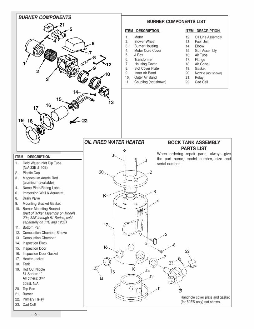
ITEM DESCRIPTION1. Cold Water Inlet Dip Tube
(N/A 33E & 40E)2. Plastic Cap3. Magnesium Anode Rod
(aluminum avaliable)4. Name Plate/Rating Label6. Immersion Well & Aquastat8. Drain Valve9. Mounting Bracket Gasket10. Burner Mounting Bracket
(part of jacket assembly on Models20e, 32E through 51 Series; soldseparately on 71E and 120E)
11. Bottom Pan12. Combustion Chamber Sleeve13. Combustion Chamber14. Inspection Block15. Inspection Door16. Inspection Door Gasket17. Heater Jacket18. Tank19. Hot Out Nipple
51 Series: 1”AlI others: 3/4”50ES: N/A
20. Top Pan21. Burner22. Primary Relay23. Cad Cell
ITEM DESCRIPTION1. Motor2. Blower Wheel3. Burner Housing4. Motor Cord Cover5. J-Box6. Transformer7. Housing Cover8. Slot Cover Plate9. Inner Air Band10. Outer Air Band11. Coupling (not shown)
BURNER COMPONENTS LISTBURNER COMPONENTS
ITEM DESCRIPTION12. Oil Line Assembly13. Fuel Unit14. Elbow15. Gun Assembly16. Air Tube17. Flange18. Air Cone19. Gasket20. Nozzle (not shown)21. Relay22. Cad Cell
OIL FIRED WATER HEATER BOCK TANK ASSEMBLYPARTS LIST
When ordering repair parts, always givethe part name, model number, size andserial number.
Handhole cover plate and gasket(for 50ES only) not shown.
23420.qxp:23420 Res Oil Water Bro 8/3/11 8:39 AM Page 10
– 10 –
LIMITED WARRANTY
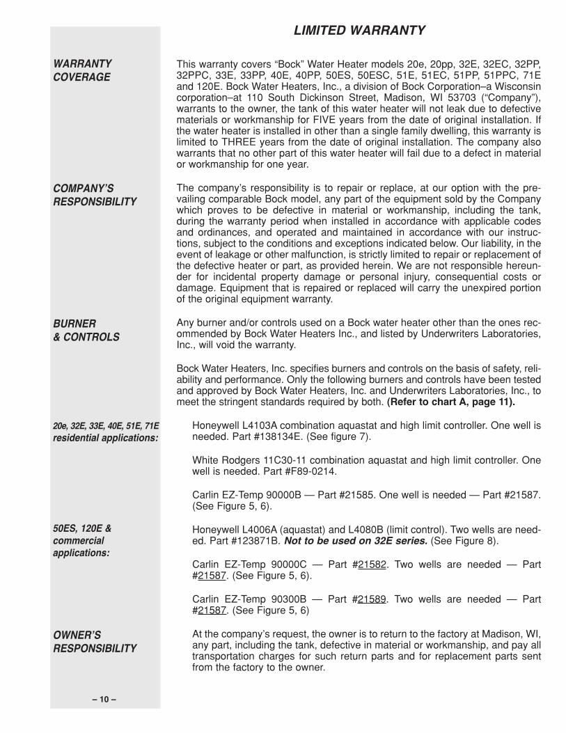
This warranty covers “Bock” Water Heater models 20e, 20pp, 32E, 32EC, 32PP,32PPC, 33E, 33PP, 40E, 40PP, 50ES, 50ESC, 51E, 51EC, 51PP, 51PPC, 71Eand 120E. Bock Water Heaters, Inc., a division of Bock Corporation–a Wisconsincorporation–at 110 South Dickinson Street, Madison, WI 53703 (“Company”),warrants to the owner, the tank of this water heater will not leak due to defectivematerials or workmanship for FIVE years from the date of original installation. Ifthe water heater is installed in other than a single family dwelling, this warranty islimited to THREE years from the date of original installation. The company alsowarrants that no other part of this water heater will fail due to a defect in materialor workmanship for one year.
The company’s responsibility is to repair or replace, at our option with the pre-vailing comparable Bock model, any part of the equipment sold by the Companywhich proves to be defective in material or workmanship, including the tank,during the warranty period when installed in accordance with applicable codesand ordinances, and operated and maintained in accordance with our instruc-tions, subject to the conditions and exceptions indicated below. Our liability, in theevent of leakage or other malfunction, is strictly limited to repair or replacement ofthe defective heater or part, as provided herein. We are not responsible hereun-der for incidental property damage or personal injury, consequential costs ordamage. Equipment that is repaired or replaced will carry the unexpired portionof the original equipment warranty.
Any burner and/or controls used on a Bock water heater other than the ones rec-ommended by Bock Water Heaters Inc., and listed by Underwriters Laboratories,Inc., will void the warranty.
Bock Water Heaters, Inc. specifies burners and controls on the basis of safety, reli-ability and performance. Only the following burners and controls have been testedand approved by Bock Water Heaters, Inc. and Underwriters Laboratories, Inc., tomeet the stringent standards required by both. (Refer to chart A, page 11).
Honeywell L4103A combination aquastat and high limit controller. One well isneeded. Part #138134E. (See figure 7).
White Rodgers 11C30-11 combination aquastat and high limit controller. Onewell is needed. Part #F89-0214.
Carlin EZ-Temp 90000B — Part #21585. One well is needed — Part #21587.(See Figure 5, 6).
Honeywell L4006A (aquastat) and L4080B (limit control). Two wells are need-ed. Part #123871B. Not to be used on 32E series. (See Figure 8).
Carlin EZ-Temp 90000C — Part #21582. Two wells are needed — Part#21587. (See Figure 5, 6).
Carlin EZ-Temp 90300B — Part #21589. Two wells are needed — Part#21587. (See Figure 5, 6)
At the company’s request, the owner is to return to the factory at Madison, WI,any part, including the tank, defective in material or workmanship, and pay alltransportation charges for such return parts and for replacement parts sentfrom the factory to the owner.
20e, 32E, 33E, 40E, 51E, 71Eresidential applications:
WARRANTYCOVERAGE
COMPANYʼSRESPONSIBILITY
BURNER& CONTROLS
50ES, 120E &commercialapplications:
OWNERʼSRESPONSIBILITY
23420_EN.qxp:23420 Res Oil Water Bro 8/3/11 9:33 AM Page 11
BOCK BURNER MODEL/ MAX MODEL MAXMODEL (OIL) MFR. OEM # INPUT OEM # INPUT32E, 32EC, 33E WAYNE MSR/371-001B 0.75 X 80A32PP, 32PPC WAYNE HS/371-009HS 0.75 X 80A40E WAYNE MSR/371-030B 0.90 X 70A5IE, 51EC WAYNE MSR/371-003B 1.10 X 80A50ES, 120E WAYNE MSR/371-029B 1.10 X 80A51PP, 51PPC WAYNE HS/371-011HS 1.10 X 80A71E WAYNE MSR/371-017B 1.25 X 70B32E, 32EC, 33E BECKETT AF/BK3 0.75 X 80A32PP, 32PPC BECKETT AF/BK3 0.75 X 80A40E BECKETT AF/BK4 0.85 X 80A51E, 51EC BECKETT AF/BK5 1.00 X 80A50ES, 120E BECKETT AF/BK5 1.00 X 80A51PP, 51PPC BECKETT AF/BK5 1.00 X 80A71E BECKETT AF/BK7 1.25 X 80B32E, 32EC, 33E RIELLO R35.3/C8511221 0.60 X 60B 40F5/C8512180 0.60 X 60B32PP, 32PPC RIELLO R35.3/C8511221 0.60 X 60B 40F5/C8512180 0.60 X 60B51E, 51EC RIELLO R35.3/C8511223 1.10 X 80A 40F5/C8512181 0.90 X 60B50ES RIELLO R35.3/C8511222 0.85 X 60B 40F5/C8512181 0.90 X 60B51PP, 51PPC RIELLO R35.3/C8511223 1.10 X 80A 40F5/C8512181 0.90 X 60B120E RIELLO R35.3/C8511223 1.00 X 60B 40F5/C8512181 0.90 X 60B71E RIELLO R35.5/C8512220 1.00 X 60B 40F5/C8512182 1.00 X 60B20e, 20pp CARLIN EZ-LF/997843CT 0.40 X 60A32E, 32EC, 33E CARLIN EZ-1/96828-32E 0.75 X 70A32PP, 32PPC CARLIN EZ-1/96828-32PP(C) 0.75 X 70A51E, 51EC CARLIN EZ-1/96828-51E 1.10 X 70A50ES CARLIN EZ-1/96828-50ES 1.00 X 70A51PP, 51PPC CARLIN EZ-1/96828-51PP(C) 1.10 X 70A120E CARLIN EZ-1/968280A120E 1.10 X 70A71E CARLIN EZ-1/96828-71E 1.25 X 60A
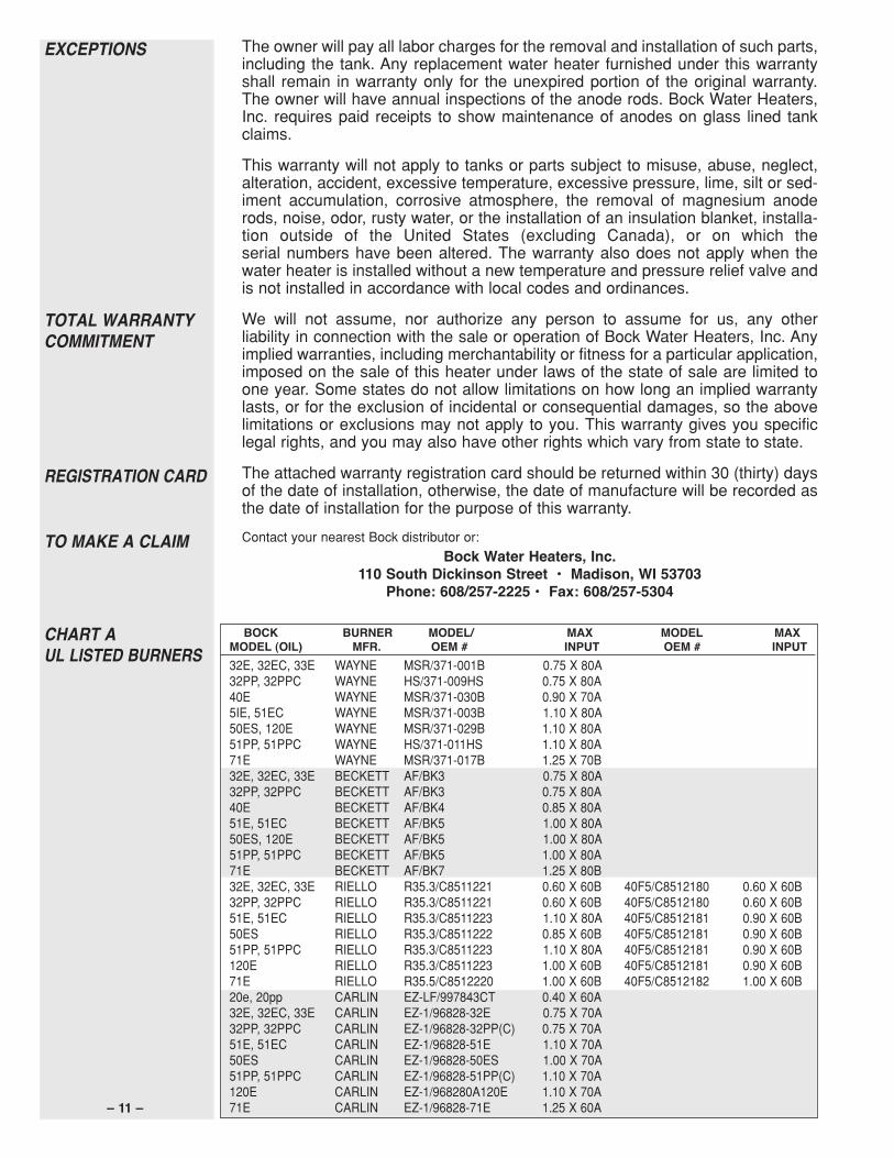
The owner will pay all labor charges for the removal and installation of such parts,including the tank. Any replacement water heater furnished under this warrantyshall remain in warranty only for the unexpired portion of the original warranty.The owner will have annual inspections of the anode rods. Bock Water Heaters,Inc. requires paid receipts to show maintenance of anodes on glass lined tankclaims.
This warranty will not apply to tanks or parts subject to misuse, abuse, neglect,alteration, accident, excessive temperature, excessive pressure, lime, silt or sed-iment accumulation, corrosive atmosphere, the removal of magnesium anoderods, noise, odor, rusty water, or the installation of an insulation blanket, installa-tion outside of the United States (excluding Canada), or on which theserial numbers have been altered. The warranty also does not apply when thewater heater is installed without a new temperature and pressure relief valve andis not installed in accordance with local codes and ordinances.
We will not assume, nor authorize any person to assume for us, any otherliability in connection with the sale or operation of Bock Water Heaters, Inc. Anyimplied warranties, including merchantability or fitness for a particular application,imposed on the sale of this heater under laws of the state of sale are limited toone year. Some states do not allow limitations on how long an implied warrantylasts, or for the exclusion of incidental or consequential damages, so the abovelimitations or exclusions may not apply to you. This warranty gives you specificlegal rights, and you may also have other rights which vary from state to state.
The attached warranty registration card should be returned within 30 (thirty) daysof the date of installation, otherwise, the date of manufacture will be recorded asthe date of installation for the purpose of this warranty.
Contact your nearest Bock distributor or:
Bock Water Heaters, Inc.110 South Dickinson Street • Madison, WI 53703
Phone: 608/257-2225 • Fax: 608/257-5304
TOTAL WARRANTYCOMMITMENT
REGISTRATION CARD
TO MAKE A CLAIM
CHART AUL LISTED BURNERS
EXCEPTIONS
– 11 –
23420.qxp:23420 Res Oil Water Bro 8/3/11 8:39 AM Page 12

–11–
MODÈLEFABRICANTMODÈLE/ENTRÉEMODÈLE/ENTRÉEBOCK(MAZOUT)BRÛLEURNºOEMMAXNºOEMMAX
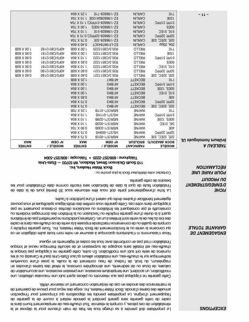
32E,32EC,33EWAYNEMSR/371-001B0.75X80A32PP,32PPCWAYNEHS/371-009HS0.75X80A40EWAYNEMSR/371-030B0.90X70A5IE,51ECWAYNEMSR/371-003B1.10X80A50ES,120EWAYNEMSR/371-029B1.10X80A51PP,51PPCWAYNEHS/371-011HS1.10X80A71EWAYNEMSR/371-017B1.25X70B32E,32EC,33EBECKETTAF/BK30.75X80A32PP,32PPCBECKETTAF/BK30.75X80A40EBECKETTAF/BK40.85X80A51E,51ECBECKETTAF/BK51.00X80A50ES,120EBECKETTAF/BK51.00X80A51PP,51PPCBECKETTAF/BK51.00X80A71EBECKETTAF/BK71.25X80B32E,32EC,33ERIELLOR35.3/C85112210.60X60B40F5/C85121800.60X60B32PP,32PPCRIELLOR35.3/C85112210.60X60B40F5/C85121800.60X60B51E,51ECRIELLOR35.3/C85112231.10X80A40F5/C85121810.90X60B50ESRIELLOR35.3/C85112220.85X60B40F5/C85121810.90X60B51PP,51PPCRIELLOR35.3/C85112231.10X80A40F5/C85121810.90X60B120ERIELLOR35.3/C85112231.00X60B40F5/C85121810.90X60B71ERIELLOR35.5/C85122201.00X60B40F5/C85121821.00X60B20e,20ppCARLINEZ-LF/997843CT0.40X60A32E,32EC,33ECARLINEZ-1/96828-32E0.75X70A32PP,32PPCCARLINEZ-1/96828-32PP(C)0.75X70A51E,51ECCARLINEZ-1/96828-51E1.10X70A50ESCARLINEZ-1/96828-50ES1.00X70A51PP,51PPCCARLINEZ-1/96828-51PP(C)1.10X70A120ECARLINEZ-1/968280A120E1.10X70A71ECARLINEZ-1/96828-71E1.25X60A
Lepropriétairedoitprendreàsachargetouslesfraisdemaind’œuvrepourladéposeetlaréinstallationdecespièces,ycomprisleréservoir.Toutchauffe-eauderemplacementfournidanslecadredecettegarantieseragarantipendantlapérioderestantàcouvrirdelagarantiedel’équipementd’origine.Lepropriétaireprendralesdispositionsquis’imposentpourl’inspectionannuelledesbarresd’anode.BockWaterHeaters,Inc.exigedesreçuspourpreuvedepaiementdelamaintenancedesanodesencasderéclamationconcernantunréservoirvitrifié.
Cettegarantienes’appliquepasauxréservoirsoupiècesayantsubiunemauvaiseutilisation,unemodification,unaccident,unetempératureexcessive,unepressionexcessive,uneaccumulationdecalcaire,deboueoudesédiments,uneatmosphèrecorrosive,leretraitdesbarresd’anodesenmagnésium,dubruit,del'odeur,del'eaucontenantdelarouille,laposed’unecouvertureisothermiquesurlechauffe-eau,uneinstallationailleursqu’auxÉtats-Unis(saufleCanada)ousilesnumérosdesérieontsubiunemodification.Enoutre,cettegarantienes’appliquepaslorsquelechauffe-eauestinstallésanssoupapedesurpressionetdesécuritéthermiqueneuveetlorsquel'installationn'estpasenconformitéavectouslescodesetrèglementsenvigueur.
Nousn’assumonsnin’autorisonsquiconqueàassumerennotrenomtouteautreobligationencequiconcernelaventeoulefonctionnementdeBockWaterHeaters,Inc.Toutegarantieimpliciteycomprisdequalitéoudeconvenancemarchandeimposéeàlaventedecechauffeeaudanslecadredesloisdulieudelaventesontlimitéesàunan.Certainesjuridictionsnepermettentpasdelimitationsquantàladuréed'unegarantieimpliciteoul'exclusionoulalimitationdesdommagesincidentsouconsécutifsetparconséquentleslimitationsouexclusionsdécritesci-dessuspourraientnepass'appliquerdansvotrecas.Cettegarantievousconfèredesdroitslégauxspécifiquesetvouspouvezégalementbénéficierd’autresdroitsquivarientd’unejuridictionàl’autre.
Lafiched’enregistrementjointedoitnousêtreretournéesous30(trente)joursdeladatedel’installationfautedequoiladatedefabricationserainscritecommedated’installationpourlesbesoinsdecettegarantie.
ContactezvotredistributeurBockleplusprocheou:
BockWaterHeaters,Inc.110SouthDicknsonStreet,Madison,WI53703—États-UnisTéléphone:608/257-2225•Télécopie:608/257-5304
ENGAGEMENTDEGARANTIETOTALE
FICHED’ENREGISTREMENTDUPRODUIT
POURFAIREUNERÉCLAMATION
TABLEAUAbrûleurshomologuésUL
EXCEPTIONS
–10–
GARANTIELIMITÉE
Cettegarantierecouvreleschauffe-eau«Bock»modèles20e,20pp,32E,32EC,32PP,32PPC,33E,33PP,40E,40PP,50ES,50ESC,51E,51EC,51PP,51PPC,71Eet120E.BockWaterHeaters,Inc.,unefilialedeBockCorporation–incorporéeauxÉtats-Unisd’AmériquedansleWisconsin–110SouthDickinsonStreet,Madison,WI53703(la«Compagnie»),garantitaupropriétairequeleréservoirdechauffe-eauneprésenterapasdefuitesduesàundéfautdematérieloudemaind’œuvrependantCINQansàpartirdeladated’installationoriginale.Silechauffe-eauestinstalléailleursquedansunehabitationpouruneseulefamille,cettegarantieestlimitéeàTROISansàpartirdeladated’installationoriginale.Lacompagniegarantitaussiqu’aucuneautrepartiedecechauffe-eaunecesseradefonctionnerenraisond’undéfautmatérieloudemaind’œuvrependantunan.
Laresponsabilitédelacompagnieconsisteàréparerouremplacer,ànotrediscrétionparlemodèleBockactuelcomparable,toutepartiedel’équipementvenduparlaCompagniequiprésenteundéfautdematérieloudemaind’œuvre,ycomprisleréservoir,pendantlapériodedegarantielorsquel’installationestconformeàtouslescodesetrèglementslocauxenvigueuretutiliséetentretenuconformémentànosinstructionssousréservedesconditionsetexceptionsindiquéesci-dessous.Notreresponsabilité,encasdefuiteoud’autredéfautdefonctionnement,eststrictementlimitéeàlaréparationouauremplacementduchauffe-eaudéfectueuxoudelapiècedéfectueuse,ainsiqu’ilestindiquéauxprésentes.Nousnesommespasresponsablesdesdommagesconsécutifsqu’ilssoientmatérielsoucorporels,nidesfraisoudesdommagesindirects.Toutéquipementréparéouremplacéseragarantipendantlapérioderestantàcouvrirdelagarantiedel’équipementd’origine.
Touteutilisationsurunchauffe-eauBockd’unbrûleuret/oud’undispositifdecontrôleautrequeceuxrecommandésparBockWaterHeatersInc.ethomologuésparUnderwritersLaboratories,Inc.annuleracettegarantie.
BockWaterHeaters,Inc.prescritlesbrûleursetlesdispositifsdecontrôlepourleursécurité,leurfiabilitéetleurperformance.Nousindiquonsci-dessouslesseulsbrûleursetdispositifsdecontrôlevérifiésetapprouvésparBockWaterHeaters,Inc.etUnderwritersLaboratories,Inc.conformesauxnormesrigoureusesexigéesparcesdeuxorganismes.(VoirletableauA,page11).
HoneywellL4103A:combinaisond’unaquastatetd’uncontrôleurdelimitehaute.Ilfautunpuits.Nºdepièce138134E.(VoirFigure7)
WhiteRodgers11C30-11:combinaisond’unaquastatetd’uncontrôleurdelimitehaute.Ilfautunpuits.NºdepièceF89-0214.
CarlinEZ-Temp90000B—Nºdepièce21585.Ilfautunpuits.—Nºdepièce21587.(VoirFigure5,6).
HoneywellL4006A(aquastat)etL4080B(contrôleurdelimite).Ilfautdeuxpuits.Nºdepièce123871B.Nes’utilisepassurlesséries32E.(VoirFigure8).
CarlinEZ-Temp90000C—Nºdepièce21582.Ilfautdeuxpuits—Nºdepièce21587.(VoirFigure5,6).
CarlinEZ-Temp90300B—Nºdepièce21589.Ilfautdeuxpuits—Nºdepièce21587.(VoirFigure5,6).
Àlademandedelacompagnie,lepropriétairedoitrenvoyeràl’usinedeMadison,WI,É-U.toutepièce,ycomprisleréservoirquiprésenteundéfautdematérieloudemaind’œuvreetpayerlesfraisdetransportpourlespiècesrenvoyéesetpourlespiècesderechangeenvoyéesenretourparl’usineaupropriétaire.
20e,32E,33E,40E,51E,71Epourlesapplicationsrésidentielles:
GARANTIE
RESPONSABILITÉDUFABRICANT
BRÛLEURETCONTRÔLES
50ES,120E&pourlesapplicationscommerciales:
RESPONSABILITÉDUPROPRIÉTAIRE
–9–
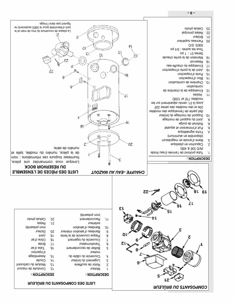
DESCRIPTION:
1.Tubeprofonddel’arrivéed’eaufroide(N/D33E&40E)
2.Capuchonenplastique3.Barred’anodeenmagnésium
(disponibleenaluminium)4.Fichesignalétique6.Puitd’immersionetaquatat8.Robinetdepurge9.Jointdusupportdemontage10.Supportdemontagedubrûleur
(faitpartiedel’enveloppedesmodèles20eetdesmodèlesdesséries32Ejusqu’à51;venduséparémentsurlesmodèles71Eet120E)
11.Assise12.Enveloppedelachambrede
combustion13.Chambredecombustion14.Blocd’inspection15.Ported’inspection16.Jointdelaported’inspection17.Enveloppeduchauffe-eau18.Réservoir19.Mamelondelasortiechaude
Séries51:1poTouslesautres:3/4po50ES:S/O
20.Panneausupérieur21.Brûleur22.Relaisprincipal23.Cellulephoto
DESCRIPTION:
1.Moteur2.Rotordesoufflerie3.Logementdubrûleur4.Couvercleducâbledu
moteur5.Boîtierderaccordement6.Transformateur7.Couvercledulogement8.Plaquecouvercledelafente9.Bandeaud’aérationintérieur10.Bandeaud’aération
extérieur11.Raccordement
(nonprésenté)
LISTEDESCOMPOSANTSDUBRÛLEURCOMPOSANTSDUBRÛLEUR
DESCRIPTION:
12.Conduitedemazout13.Moduleducarburant14.Coude15.Assemblage
d’injection16.Tubed’air17.Bride18.Côned’air19.Joint20.Gicleur
(nonprésenté)21.Relais22.Cellulephoto
CHAUFFE–EAUAUMAZOUTLISTEDESPIÈCESDEL’ENSEMBLEDURÉSERVOIRBOCK
Lorsquevouscommandezunepièce,fournisseztoujourscesinformations:nomdelapièce,numérodumodèle,tailleetnumérodesérie.
Laplaquedecouverturedutroudemainetlejointd’étanchéité(pourle50ESseulement)nefigurentpasdansl'image.
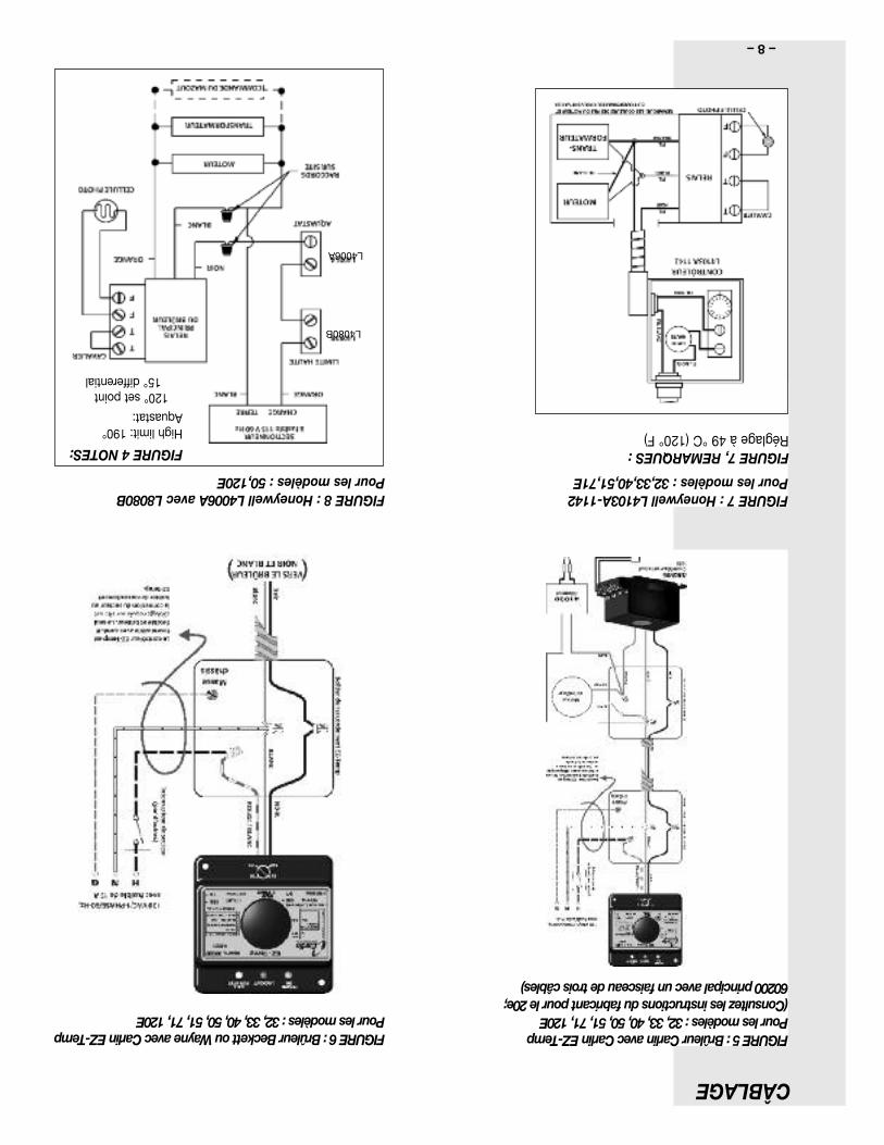
L4080B
L4006A
FIGURE8:HoneywellL4006AavecL8080BPourlesmodèles:50,120E
FIGURE6:BrûleurBeckettouWayneavecCarlinEZ-TempPourlesmodèles:32,33,40,50,51,71,120E
FIGURE7:HoneywellL4103A-1142Pourlesmodèles:32,33,40,51,71E
FIGURE7,REMARQUES:Réglageà49°C(120°F)
FIGURE4NOTES:Highlimit:190°Aquastat:
120°setpoint15°differential
–8–
CÂBLAGE
FIGURE5:BrûleurCarlinavecCarlinEZ-TempPourlesmodèles:32,33,40,50,51,71,120E(Consultezlesinstructionsdufabricantpourle20e;60200principalavecunfaisceaudetroiscâbles)
–7–
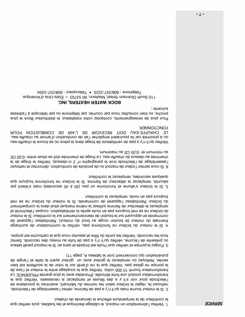
SERVICE1.Vérifiezl’alimentationenmazout,lecâblageélectriqueetlesfusibles,puisvérifiezquelecontrôleurdelatempératureeffectuelademandedechaleur.
2.Silemoteurtournemaisqu’iln’yapasdeflamme,retirezl’assemblagedel’électrode,nettoyez-le,réglezlebrûleurselonlesnormesdufabricant,examinezlaporcelainedel’électrodepourvoirs’ilyadesfêluresetremplacezsinécessaire.Vérifiezqueletransformateurproduituneforteétincelle.(ProcédezaveclaplusgrandePRUDENCE:Letransformateurfournit10000volts).Vérifiezquelecouplageentrelemoteuretl’axedelapompeneglissepas.Vérifiezquelavisd’arrêtsurlerotordelasoufflerieestbienserrée.Nettoyezouremplacezlegicleuravecungicleurayantlatailleetl’angledepulvérisationquiconviennent(voirletableauA,page11)
3.Purgezlapompeetvérifiezquel’huileestlimpideetsansair.Silemazoutparaîtlaiteuxouprésentedel’écume,vérifiezqu’iln’yapasdefuiteauniveaudesraccords.Serreztouslesraccords.Vérifiezlesjointsdufiltreetassurez-vousquelacartoucheestpropre.
4.Silemoteurdubrûleurnefonctionnepas,vérifiezlecommutateurdesurchargethermaledumoteur(leboutonrougeauboutdumoteur).Réinitialisezl’appareildecommandeenappuyantsurleboutonderéenclenchementsurlecontrôleur.Silemoteurdubrûleurnesemettoujourspasenrouteaprèslaréinitialisation,coupezl’électricitéetremplacezledétecteurdeflamme(utilisezlamêmemarque)situédanslecompartimentdubrûleur.Réinitialisezl’appareildecommande.Silemoteurdubrûleurnesemettoujourspasenroute,remplacezlecontrôleur.
5.Silebrûleurs’allumeetfonctionneunpeu(30à40secondes)maiss’éteintparsécurité,remplacezledétecteurdeflamme.Silebrûleurnefonctionnetoujoursquequelquessecondes,remplacezlecontrôleur.
6.Sivoussentezl’odeurdemazoutoudeproduitsdecombustion,démontezetnettoyezl’assemblagedel’électrode(voirleparagraphenº2ci-dessus).Vérifiezletiragedelacheminéeau-dessusduchauffe-eau.Letiragedecheminéedoitsesituerentre-0,02CEauminimumet-0,05CEaumaximum.
Vérifiezqu’iln’yapasdeventilateursdetiragedanslapièceoùsetrouvelechauffe-eauouàproximitécarilspourraientempêcherl’airdecombustiond’arriverauchauffe-eau.LECHAUFFE-EAUDOITRECEVOIRDEL’AIRDECOMBUSTIONPOURFONCTIONNER.
Pourplusderenseignements,contactezvotreinstallateur,ledistributeurBockleplusproche,oubienconsulteznousparcourrier,partéléphoneoupartélécopieàl’adressesuivante:
BOCKWATERHEATERS,INC.110SouthDicknsonStreet,Madison,WI53703—États-Unisd’Amérique
Téléphone:608/257-2225•Télécopieur:608/257-5304
–6–
4.Leréglagedel’airdecombustiondubrûleurdoitsefaireconformémentauxinstructionsdufabricant.L’utilisationd’appareilsd’analysedelacombustionpourvérifierleCO2etlafumée.LateneurenC02doitêtred’aumoins10,5%avecunindicedenoircissementde0surl’échelledeBacharach.
5.Pendantlefonctionnementdubrûleur,débranchezundesfilsjaunesdelacelluleausulfuredecadmium(cellulephoto).Vérifiezquelecontrôleurdubrûleurfermelesystèmeauboutdutempsprécisésurlacommande.Lebrûleurdevraitredémarrer.Remarque:Ilpeutêtrenécessaired’attendreuneminuteavantderéenclencherlecontrôleur.
6.Lethermostatestrégléenusineà49°C(120°F)pouruneutilisationrésidentielle.(Voirlamention«miseengarde»àlapage1encequiconcernelesvariationsdetempérature).Ilestdelaresponsabilitédupropriétairedudomicileetdel’installateurdevérifierquel’installateursuittouslestestsdevérificationrecommandéspourlamesuredelatempératuredel’eau.Pourvérifierquelesystèmefonctionnenormalementaprèsl’installationetparlasuite,ilestrecommandédevérifieretdesuivrelaperformanceduchauffe-eau.Faitescoulerl’eaudurobinetleplusprocheduchauffe-eaujusqu’àcequ’ellesoitchaude.Mesurezlatempératuredel’eauàl’aided’unthermomètrecalibré.Silatempératuredel’eauneconvientpasàl’installation,demandezàuntechnicienqualifiéderéglerl’aquastat.ContactezBockpourplusderenseignementsàproposduthermomètreencasdebesoin.
AVERTISSEMENT:del’hydrogènepeutêtregénérédansunsystèmed'eauchaudealimentéparunchauffe-eauquin’apasfonctionnépendantunelonguepériode(engénéraldeuxsemainesouplus).L’hydrogèneestungazextrêmementinflammable.Afinderéduirelesrisquesdeblessures,ouvrezlerobinetd'eauchaudesituéauplushautdelamaisonpendantplusieursminutesavantd'utiliserunappareilélectriqueconnectéauréseaud'alimentationeneauchaudeLaprésenced'hydrogènedanslescanalisationspeutsemanifesterparunsoninhabituelcommeceluidel'airquis’échappelelongdestuyauxquandl'eaucommenceàcouler.Nefumezpasetveillezàcequ'iln'yaitaucuneflammeàproximitédurobinetlorsqu’ilestouvert.
1.Huilezlemoteurdubrûleur(5à10gouttes)avecunehuilemoteurSAE10(lecaséchéant).
2.Installezunnouveaugicleurdebrûleurayantlescaractéristiquesquiconviennent.(VoirletableauA,page11).
3.Nettoyezetréglezlesélectrodesetvérifiezquelaporcelainen’estpasendommagée.Vérifiezquelesbarresomnibusetlesbornessontexemptesdecorrosion.
4.Remplacezlefiltreàhuileetexaminezleréservoirdestockagedumazoutpourvoirs’ilyadesdépôtssédimentaires.Nettoyezceréservoirsinécessaire.
5.Veillezàcequeleréservoirdestockagedumazoutsoittoujourspleinpouréviterl’accumulationdevapeursdansleréservoir,surtoutenété.
6.Vérifiezletuyaudefuméeetlacheminée.Nettoyezetréparezcesélémentssinécessaire.
7.TOUSLESSIXÀDOUZEMOIS:Videzl’eauduréservoirduchauffe-eauetinspectez-lepourvoirs’ilyadesdépôtsdesédimentsoudecalcaire.Rincezsinécessaire.S’ilyauneaccumulationdecalcaire,utilisezunproduitcommercialpourledissoudreougrattez-leàtraversletroudemain(lecaséchéant).Encasdeprésencededépôtscalcaires,vérifiezlesystèmedel’adoucisseurd’eau.N’ESSAYEZPASDECHAUFFERDEL’EAUDURE.(Voirl’étiquettedeservicesurlechauffe-eau.)
8.Remplacezlesbarresd’anodeenmagnésiumtouslessixàdouzemoisoulorsqu’ellessontréduitesà10mm(3/8po)dediamètre(voirl’étiquettedeservicesurlechauffe-eau).Nousrecommandonsàl’installateurd’utiliserPermaBondLH-050.Ilestconseilléd’utiliserdurubanpourjointsfiletéslorsdel’installationdebarresd’anodeenmagnésiumouenaluminium.
9.Ouvrezlelevierdevérificationdelasoupapedesûretépourvidangerleréservoir.Vérifierquelasoupapeserefermebien.
10.Silechauffe-eaudoitêtrefermépartempsfroid,videzleréservoirpouréviterlegel.
MAINTENANCE
MESUREDELATEMPÉRATUREDEL’EAUFOURNIE
Havetheoilburnerservicedonceeachyearbyaqualifiedoilburnerserviceperson.Serviceshouldcomplywiththeburnermanu-facturer’srecommen-dationsandinclude:
–5–
METTEZENROUTELECIRCUITD’EAU
Miseengarde:Lepanneaudutroudemainpeutsedesserrerpendantletransport:vérifiezqu’ilestbienserréavantdemettrelechauffe-eauenroute.
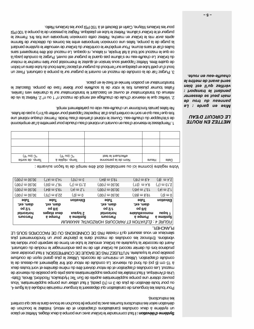
Systèmed’élévation:ilfautcommanderlebrûleuravecunepompeàdeuxétages.Mettezenplaceunsystèmeàdeuxconduites(canalisationsd’aspirationetderetour).Installezlebouchondedérivationselonlesinstructionsfourniesaveclapompe(lebouchonsetrouvedanslesacquicontientlesinstructions).
Pourtoutesleslongueursdecanalisationquidépassentlalongueurmaximaleindiquéeàlafigure4,oupourtouteélévationdeplusde3m(10pieds),ilfaututiliserunepompesupplémentaire.VouspouvezobtenirunepompesupplémentaireauprèsdeSunTecHydraulics,Rockford,Illinois,États-Unisd’Amérique.Ilfautinstallerlespompessupplémentairesaussiprèsquepossibleduréservoirdemazout.Lesconduitesd’aspirationetderetourdoiventêtredumêmediamètreetvonttoutesdeuxà15cm(6po)dufondduréservoir.Laconduitederetourdoitfinirlégèrementau-dessusdelaconduited’aspiration.Utilisezunminimumderaccords.Utilisezleplusgrandrayondecourburepossiblepourlatuyauterie.N’UTILISEZPASDEBAGUEDECOMPRESSION.Ilfautprocéderavecprudencelorsdudernierraccordaubrûleurafindenepasendommagerlemoduleducarburant.Avantderaccorderlatuyauterieaubrûleur,enroulezletubeenformedeserpentinpourréduirelesvibrations.Enfoncezlesconduitesdemazoutdansleplancherpourunfonctionnementplussilencieuxenvousassurantqu’iln’existePASDECONNEXIONSOUDERACCORDSSOUSLEPLANCHER..
1.Remplissezleréservoird’eauenouvrantunrobinetd’eauchaudepourpermettreàl’airemprisonnédes’échapperduchauffe-eau.Ouvrezlerobinetd’arrivéed’eaufroide.Fermezchaquerobinetunefoisquel’eauquiensortnecontientplusd’air.Inspectezl’appareilpourvérifierqu’iln’yapasdefuites.Nefaitesjamaisfonctionnerunchauffe-eauvideoupartiellementrempli.
2.Vérifiezqueleréservoird’huiledechauffageestremplidemazoutnº1ounº2.Retirezlavisderetenuedutransformateuretouvrezenbasculantletransformateursurlacharnièreversl’arrière.Faitestournerplusieursfoislerotordelasouffleriepourlibérerl’axedepompe.Basculezletransformateurenpositionferméeetfixez-leenplace.
3.Purgezl’airdelaconduitedemazoutenouvrantlepurgeursurlapompeàcarburant.Fixezunboutd’unpetittubeenplastiquesurl’emboutdupurgeuretplacezl’autreboutdutubedansunbidondequatrelitres.Mettezl’appareilsoustensionetajustezlethermostatpourfairemarcherlemoteurdubrûleur.Lechauffe-eaunes’allumepasquandlepurgeurestouvert.Purgezlaconduitejusqu’àcequelemazoutsoittoutàfaitlimpide,nilaiteux,niopaque.Lemazoutdoitêtretransparentsansbullesd’airetsansécume.Pourempêcherlecontrôleurdubrûleurdeverrouillerlesystèmependantlapurgedelapompe,faitesuneconnexiontemporaireentrelesbornesdudétecteurdeflammeaprèsavoirmislebrûleurenmarche.Retirezcetteconnexiontemporaireunefoisfini.Fermezlepurgeuretlebrûleurs’allume.Retirezletubeenplastique.Réglezlapressiondelapompeà100PSIpourlesbrûleursWayne,CarlinetBeckettetà150PSIpourlesbrûleursRiello.
Votreregistre(commeiciousemblable)doitêtreremplidelafaçonsuivante:
DateHeureNomdelapersonneTemp.régléeàTemp.desortieeffectuantletestºC(ouºF)ºC(ouºF)
FIGURE4:ÉLÉVATIONETPARCOURSHORIZONTALMAXIMUMSystèmeàPompeàParcoursSystèmeàPompeàParcours1tuyaumonocellulairehorizontal2tuyauxdeuxétageshorizontal
3/8po1/2po3/8po1/2podiam.ext.diam.ext.diam.ext.diam.ext.
ÉlévationTubeTubeÉlévationTubeTube0m(0’)19,8m(65’)30,50m(100’)0m(0’)22,9m(75’)30,50m(100’)1,2m(4’)13,7m(45’)30,50m(100’)1,2m(4’)19,5m(64’)30,50m(100’)2,13m(7’)9,4m(31’)30,50m(100’)2,13m(7’)16,7m(55’)30,50m(100’)2,4m(8’)4,9m(16’)19,5m(64’)3m(10’)14,3m(47’)30,50m(100’)
–4–
Examinezlaconduited’arrivéed’eaupourvoirs’ilexistedesclapetsdenon-retouroudesréducteursdepression.Touttypedeclapetdenon-retourrisqued’entraîneruneaugmentationdelapressionàl’intérieurduchauffe-eauetparconséquentunepanne.Silechauffe-eauestinstallésuruncircuitferméous’ilexisteundispositifanti-refoulementouunrégulateurdepression,ilfautrajouterunréservoirdedétente.N’essayezpasdechaufferdel’eaudure.Installezunadoucisseursilechauffe-eauestinstallédansunezoned'eaudure(plusde120mg/litre[7grains]dedureté).
Unesoupapedesurpressionetdesécuritéthermique(T&P)homologuéeestinstalléeàl’usinedansl’ouverturesituéeenhautetàdroiteduchauffe-eau.CanalisezlasoupapeT&Pjusqu’à15cm(6po)dusolouàundraind’évacuationavecunetuyauteriedevidange.N’installezpasdeclapetanti-retoursurlaconduited’eaufroide.
Effectuezlesraccordsdeventilationduchauffe-eauàlacheminéeavecdesdispositifsdetype«L»ou«A».Utilisezuntuyauàfuméedelamêmetaillequelecarneauduchauffe-eau(avecunréducteurencasdebesoinsurlesmodèles20e,20pp,32E,32PPet33E).
AVERTISSEMENT:Surlesmodèles40E,5OES,50ESC,51E,51EC,51PP,51PPC,71Eet120E,neréduisezpaslediamètredutuyaudefumée.Sipossible,installezuntuyaudefuméedistinctduchauffe-eauàlacheminée.
S’ilestnécessaired'installeruntédansuntuyaudefuméedéjàenplace,assurez-vousqueleraccordsoitfaitsurunélémentsuffisammentgrandpourévacuertouslesproduitsdecombustiondel’ensembledesappareilsraccordés.Lorsdel’installationd’untédansunautreraccord,utilisezunanglede45°(voirlafigure1).Saufencasdenécessité,n’installezpasderégulateurdetirage.L’emballementdetiragenedevraitpasêtrepositif.Letiragedecheminéedoitsesituerentre-0,02CEet-0,05CEmaximum;leCO2doitsesitueràunminimumde11%.Siunrégulateurdetirageestinstallésurlacheminée,iln'estpasnécessaired'eninstallerunautresurlechauffe-eau.
Lebrûleurdemazoutestmunid’unrelaisprimaire.L’aquastatetlepuitsd’immersionsontemballésaveclebrûleur.Lethermostatestrégléàl’usineà49°C(120°F)pouruneutilisationrésidentielle(voirlamention«miseengarde»àlapage1encequiconcernelesvariationsdetempérature).Installezlepuitsd’immersionetl’aquastatetvérifiezlalongueurdel’ampoule(voirleparagraphe«BrûleuretContrôles»,page10).
Retirezleblocdecartondel’ouverturedubrûleur.Installezlebrûleursurdesboulonsd’ancrageetplacezlejoint(fourni)entrelabridedubrûleuretlechauffe-eau.Fixezlebrûleurauchauffe-eauaveclesécrousde1/4-20(fournis).Ouvrezlepanneaud’accèsduchauffe-eaupourexaminerletubedubrûleuretvérifiezavecunmiroirquerienn’enbouchel'ouverture(voir«Maintenanceetservice»pages6et7pourledépannage).
Toutlecâblagedoitêtreconformeauxcodesdubâtimentetauxrèglementslocauxenvigueur.Lerelaisprimaireestcâbléaubrûleuràl’usine.Installezlepuitsdel’aquastatdansleraccordde3/4posituéàl’avantduchauffe-eau.Assurez-vousquel’ampoulesensibleestbienenfoncéejusqu’aufonddupuits.AvecunaquastatdeHoneywell,serrezlavisenhautdel'aquastatpourfixerlecontrôleuraupuit.AvecunaquastatCarlinEZ-Temp,référez-vousauguided’installationinsérédansl’emballagepourlamiseenplacecorrecte.Référez-vousauxillustrationspourlesmodèlescorrects.Raccordezl’alimentationélectriqueàl’aquastatenpassantparunsectionneuràfusible(reliéauchampélectriqueduchauffe-eau).VoirlaFigure1.
Ilfautinstallerunfiltreàhuiledelabonnetailleetdelabonnecapacitédanslaconduitedemazout(NFPA31,4.5.4).Enoutre,pourlesmodèles20eet20pp,ilconvientd’installerunsecondfiltreavantlapompeàmazout.BockrecommandelefiltredeconduiteDelavan(25micromètres)pourlesecondfiltre.
Réseaugravitaire:lebrûleurdemazoutestgénéralementmunid’unepompemonocellulaireéquipéepourundébit(pargravité)suruneseuleconduite.Utilisezuntubeencuivresouplede1/2podediamètreextérieuretfaitesdesraccordementsàcolletrepoussé.N’UTILISEZPASDEBAGUEDECOMPRESSION.Installezlerobinetd’arrêtetlefiltreàhuiledanslaconduited’huile.Suivezlesinstructionsdufabriquantdelapompe(attachéesàlapompe).
RACCORDEZLACONDUITEDUMAZOUT
AVERTISSEMENT!!L’INSTALLATIOND’UNBOUCHONSURLADÉRIVATIONEXIGEL’UTILISATIOND’UNSYSTÈMEÀDEUXCONDUITES.
FAITESLESRACCORDSÉLECTRIQUES
MONTEZLEBRÛLEURÀMAZOUT
RACCORDEZÀLACHEMINÉE
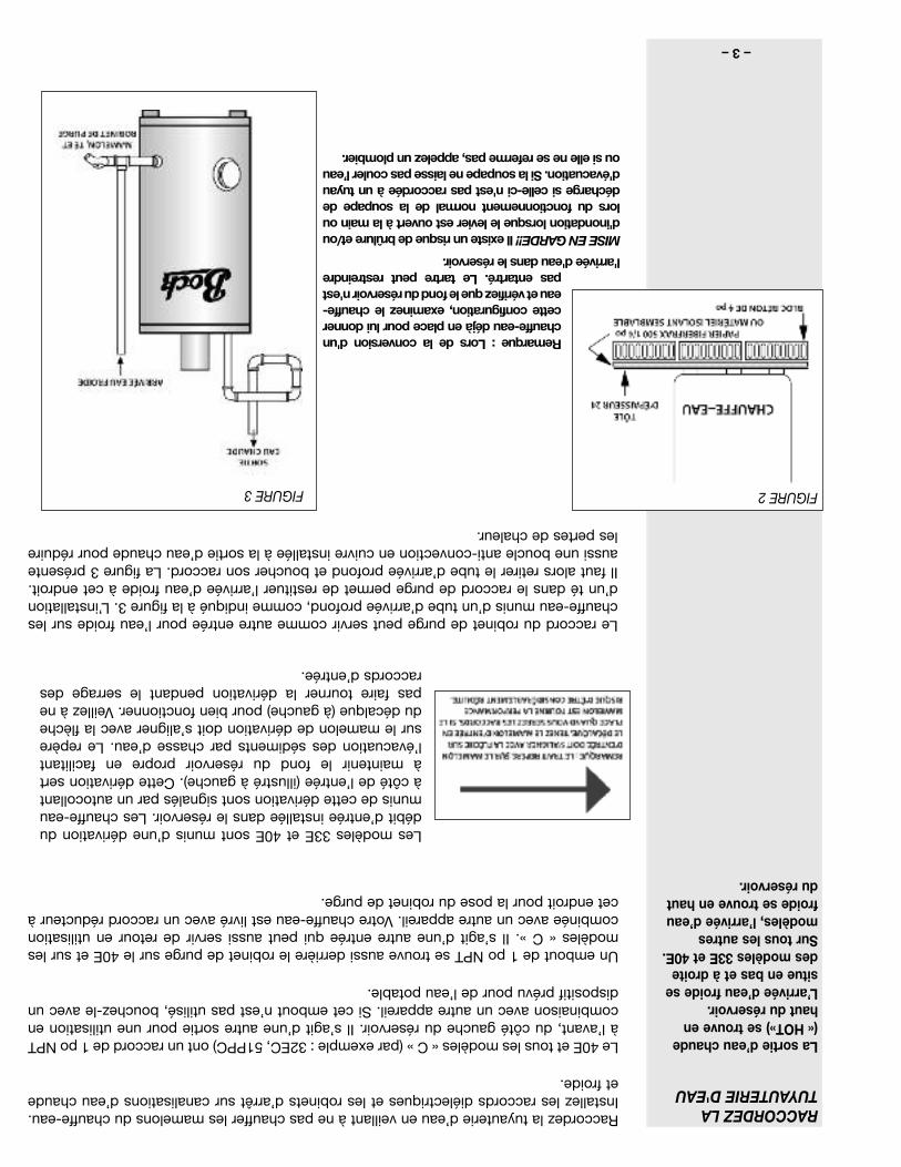
Thedrainvalvefittingmaybeusedasanalternatecoldwaterinletonheatersequippedwithadiptube,asshowninFigure3.Byplumbinga“T”intothedrainfitting,thecoldwaterinletcanberelocatedtothispoint.Thediptubemustberemovedanditsfittingplugged.Figure3alsoshowsacopperloopheattrapinstalledonthehotwateroutlettoreducestandbylosses.
Remarque:Lorsdelaconversiond'unchauffe-eaudéjàenplacepourluidonnercetteconfiguration,examinezlechauffe-eauetvérifiezquelefondduréservoirn'estpasentartré.Letartrepeutrestreindre
l'arrivéed'eaudansleréservoir.
MISEENGARDE!!Ilexisteunrisquedebrûlureet/oud'inondationlorsquelelevierestouvertàlamainoulorsdufonctionnementnormaldelasoupapededéchargesicelle-cin'estpasraccordéeàuntuyaud'évacuation.Silasoupapenelaissepascoulerl’eauousielleneserefermepas,appelezunplombier.
–3–
FIGURE3 FIGURE2
RACCORDEZLATUYAUTERIED'EAU
Lasortied’eauchaude(«HOT»)setrouveenhautduréservoir.L’arrivéed’eaufroidesesitueenbasetàdroitedesmodèles33Eet40E.Surtouslesautresmodèles,l’arrivéed’eaufroidesetrouveenhautduréservoir.
Raccordezlatuyauteried’eauenveillantànepaschaufferlesmamelonsduchauffe-eau.Installezlesraccordsdiélectriquesetlesrobinetsd’arrêtsurcanalisationsd’eauchaudeetfroide.
Le40Eettouslesmodèles«C»(parexemple:32EC,51PPC)ontunraccordde1poNPTàl’avant,ducôtégaucheduréservoir.Ils’agitd’uneautresortiepouruneutilisationencombinaisonavecunautreappareil.Sicetemboutn’estpasutilisé,bouchez-leavecundispositifprévupourdel’eaupotable.
Unemboutde1poNPTsetrouveaussiderrièrelerobinetdepurgesurle40Eetsurlesmodèles«C».Ils’agitd’uneautreentréequipeutaussiservirderetourenutilisationcombinéeavecunautreappareil.Votrechauffe-eauestlivréavecunraccordréducteuràcetendroitpourlaposedurobinetdepurge.
Leraccorddurobinetdepurgepeutservircommeautreentréepourl’eaufroidesurleschauffe-eaumunisd’untubed’arrivéeprofond,commeindiquéàlafigure3.L’installationd’untédansleraccorddepurgepermetderestituerl’arrivéed’eaufroideàcetendroit.Ilfautalorsretirerletubed’arrivéeprofondetbouchersonraccord.Lafigure3présenteaussiuneboucleanti-convectionencuivreinstalléeàlasortied’eauchaudepourréduirelespertesdechaleur.
Lesmodèles33Eet40Esontmunisd’unedérivationdudébitd’entréeinstalléedansleréservoir.Leschauffe-eaumunisdecettedérivationsontsignalésparunautocollantàcôtédel’entrée(illustréàgauche).Cettedérivationsertàmaintenirlefondduréservoirpropreenfacilitantl’évacuationdessédimentsparchassed’eau.Lerepèresurlemamelondedérivationdoits’aligneraveclaflèchedudécalque(àgauche)pourbienfonctionner.Veillezànepasfairetournerladérivationpendantleserragedesraccordsd’entrée.
–2–
CEMANUELESTDESTINÉÀVOUSPRÉSENTERL’INSTALLATION,LEMODED’EMPLOIETLAMAINTENANCEDEVOTRECHAUFFE-EAUETÀVOUSFOURNIRDESRENSEIGNEMENTSIMPORTANTSCONCERNANTLASÉCURITÉ.
Lisezsoigneusementtouteslesinstructionsavantdecommencerl’installationetavantdemettrelechauffe-eauenmarche.Conservezcesinstructionsettouteslesinstructionsconcernantlescomposantspourréférenceultérieure.
Lefabricantdecechauffe-eauneserapasresponsableencasdedommagesrésultantdelanonobservancedesinstructionsd'installationetd’utilisationprésentésdanslespagesquisuivent.Cesinstructionsconstituentunguidepourl'installationcorrecteduchauffe-eau.
Sil’installateurnepossèdepaslesqualificationsrequisesouadumalàsuivrelesinstructions,necommencezpasl’installationsansfaireappelàunepersonnequalifiéepourlapartiedel'installationquin'estpasbiencomprise.
Lescodesdeplomberieetdel’électricitéenvigueurdoiventêtrerespectéspourl'installationdecechauffe-eau.Enl’absencedecodelocalutilisezle«UNIFORMPLUMBINGCODE»etlecodeNFPA.Lescodeslocauxpeuventremplacerlesinstructionsprésentéesdanscemanuel.
Lorsquedeuxouplusieursbrûleurssontutilisés,chaqueunitédoitêtremunied’uneconduited’alimentationducarburantdistincteafind’éliminerlespannesquipeuventrésulterd’unmanquedemazoutàlapompe.Sicelan’estpaspossible,ilestrecommandéd’utiliserunsystèmedecontrôledespriorités.
Vérifiezlenouveléquipementpourvousassurerquetouslescomposantssontenbonétat.Lechauffe-eauetlebrûleurpeuventêtreexpédiésséparément.L’aquastatetlepuitsd’immersionpeuventêtreemballésaveclebrûleuràmazout.
Lenouveauchauffe-eauexigeducarburant(mazoutnº1ounº2),del’électricitéetdoitêtresituéàproximitéd’unecheminéeetd’unearrivéed’eau.Ilestconseillédeplacerlechauffe-eauprèsd’undraindesoldanslamesuredupossiblepourfaciliterl’entretienetcommemesuredeprotectionencasdeproblème.Prévoyezsuffisammentd'espaceautourduchauffe-eaupourl'entretien(voirl’avertissementconcernantlesdistancesminimalesdedégagement,page1).Ilfautfournirlevolumed'airnécessaireàlacombustion.REMARQUE:Situezlechauffe-eaudefaçonàévitertoutdommagematérielcauséparunvéhiculeendéplacementouparuneinondation.
RESPONSABILITÉSDUCONSOMMATEUR
INSTALLATIONAVECPLUSIEURSBRÛLEURS
CHOISISSEZLEBONEMPLACEMENT
FIGURE1
Vérifiezqu’iln’yapasdeventilateursdetiragedanslapièceoùsetrouvelechauffe-eauouàproximitécarilspourraientempêcherl’airdecombustiond’arriverauchauffe-eau.LECHAUFFE-EAUDOITRECEVOIRDEL’AIRDECOMBUSTIONPOURFONCTIONNER.
QUANDLECHAUFFE-EAUESTUTILISÉENCOMBINAISONAVECUNAUTREAPPAREIL,ADRESSEZ-VOUSAUREVENDEURLOCALOUÀL’USINEPOUROBTENIRLESINSTRUCTIONSDU«SYSTEMPLUS».
N’INSTALLEZPASCECHAUFFE-EAUSURUNPLANCHERCOMBUSTIBLE(voirlafigure2).Référez-vousàlanormeNFPA31oucontactezBockWaterHeaterspourtoutequestionconcernantlesmatériauxquiconviennentauplancher.
Dégagementminimumpouruneconstructioninflammable:CÔTÉS15,25cm(6po);ARRIÈRE15,25cm(6po);AVANT61cm(24po).L’installationdecechauffe-eaudoitseconformeràtouslescodesetordonnancesenvigueur.Enl’absencedecodeslocaux,l’installationdoitseconformerauxnormesducodedelaNationalFireProtectionAssociation(NFPA31).
LENONRESPECTDECESINSTRUCTIONSETDETOUSLESCODESETRÉGLEMENTSENVIGUEURAPOUREFFETL’ANNULATIONDELAGARANTIEDUCHAUFFE-EAU.
–1–
AUCONSOMMATEUR
Lisezl'ensembledesinstructionsconcernantceproduitetlescomposants.Veuillezconservercesdocumentspourréférenceultérieure.N’oubliezpasdenousrenvoyerlafiched’enregistrement.
Piècesincluses:garantie,fiched’enregistrementduproduitetlistedespièces.
ÀINSTALLATEUR
Veuillezfixercesinstructionsprèsduchauffe-eau.
CHAUFFE-EAURÉSIDENTIELSBOCKAUMAZOUT
Numérosdemodèle:20e,20pp,32E,32EC,32PP,32PPC,33E,33PP,40E,40PP,50ES,50ESC,51E,51EC,51PP,51PPC,71E,120E
AVERTISSEMENT:Uneinstallation,unréglage,unemodification,unentretienouunemaintenanceimpropredusystèmepeuvententraînerdesdommagescorporelsoumatérielsgraves.Consultezcemanuel.Pourobtenirdel’aideouplusderenseignements,consultezuneentrepriseouuninstallateurqualifiés.
AVERTISSEMENT:Lefaitdenepasrespectercesinstructionsàlalettrepeutprovoquerunincendieouuneexplosionetentraînerdesdommagesmatérielsetdesblessurescorporellesquipeuventêtremortelles.
AVERTISSEMENT:Respectezlesinstructionsconcernantlesdistancesminimalesdedégagementindiquéessurlafichesignalétiqueduchauffe-eau.N’installezpasceproduitsurunplanchercombustible(voirlafigure2,page3).L’installationdoitrespectertouslescodesenvigueur.Enl’absencedecodeslocaux,suivezlesdirectivessuivantes:NFPA31ouANSIZ21.10.1.
MISEENGARDE:Latempératurerecommandéepouruneutilisationrésidentiellenormaleestde49°C(120°F).Lecadrandel’aquastatnecorrespondpastoujoursàlatempératureréelledel’eaufourniequipeutparfoisdépasserles49°C(120°F).Lesécartsdetempératuredel’eaufourniepeuventêtrelerésultatdedifférentsfacteursdontnotamment,maisnonexclusivement,lestypesd’utilisationetd’installation.Vérifiezlatempératuredel’eauaurobinetleplusprocheduchauffe-eau.(Consultezlapage5pourévaluerlatempératuredel’eaufournie).
AVERTISSEMENT:Lerisquedebrûlureaugmenteaveclatempératuredel’eau.Avantdechangerleréglagedelatempérature,consultezlemanuel.Latempératurerequisepourprovoquerdesblessuresdépenddel’âgedel’individuetdeladuréedel’exposition.
Lesenfants,lespersonnesâgéesetlespersonnesquisouffrentd’unhandicapmentalouphysiqueréagissentmoinsviteetsontplussusceptiblesdes’ébouillanter.L'utilisationdetempératuresmoinsélevéesestrecommandéedansuntelcontexte.
Lorsquedejeunesenfantsoudespersonneshandicapéessontprésents,ilestconseilléderéglerlatempératureàmoinsde49°C(120°F)afind’évitertoutrisquedecontactaccidentelavecdel'eaubrûlante.
Pourabaisserlatempérature,utilisezdesdispositifsrégulateursdetempératureauxpointsd'utilisation.
AVERTISSEMENT:Desvapeursinflammablesprovenantd’uneautrepartiedubâtimentpeuventêtretransportéesverscechauffe-eaupardescourantsd’air.
N’entreposezpasetn’utilisezpasdeliquidesinflammablesàproximitédecetappareil.
AVERTISSEMENT:Lescouverturesdechauffe-eaupeuventlimiterl'arrivéed'airàl’appareiletprovoquerunincendie,l'asphyxie,desblessuresoulamort.
BockWaterHeaters,Inc.110SouthDickinsonStreet•P.O.Box8632•Madison,WI53708-8632–États-UnisTél:608/257-2225•Télécopieur:608/257-5304•www.bockwaterheaters.com
INSTRUCTIONSDEPOSE,D’UTILISATIONETDEMAINTENANCE