bgp case studies - philip smith's internet development site
TRANSCRIPT
BGP Case StudiesISP Workshops
1Last updated 28th September 2020
These materials are licensed under the Creative Commons Attribution-NonCommercial 4.0 International license(http://creativecommons.org/licenses/by-nc/4.0/)
Acknowledgementsp This material was developed by Philip Smith with the support of
the Network Startup Resource Center
p Use of these materials is encouraged as long as the source is fully acknowledged and this notice remains in place
p Bug fixes and improvements are welcomedn Please email workshop (at) bgp4all.com
2Philip Smith
Topics Coveredp Peering Prioritiesp Transit Provider Peering at an IXPp Customer Multihomed between two IXP membersp Traffic Engineering for an ISP connected to two IXesp Traffic Engineering for an ISP with two interfaces on one
IX LANp Traffic Engineering and CDNsp Multihoming with Partial Routes: propagating the default
using the IGP3
Peering Priorities for a Network Operator
4
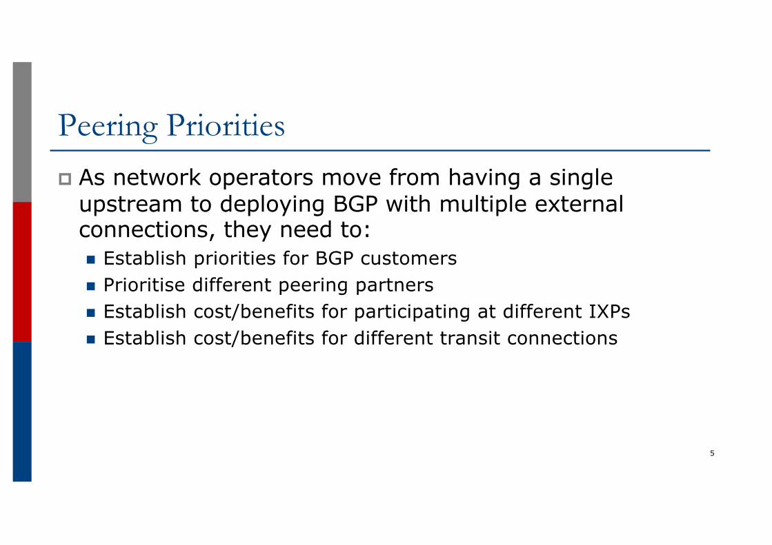
Peering Prioritiesp As network operators move from having a single
upstream to deploying BGP with multiple external connections, they need to:n Establish priorities for BGP customersn Prioritise different peering partnersn Establish cost/benefits for participating at different IXPsn Establish cost/benefits for different transit connections
5
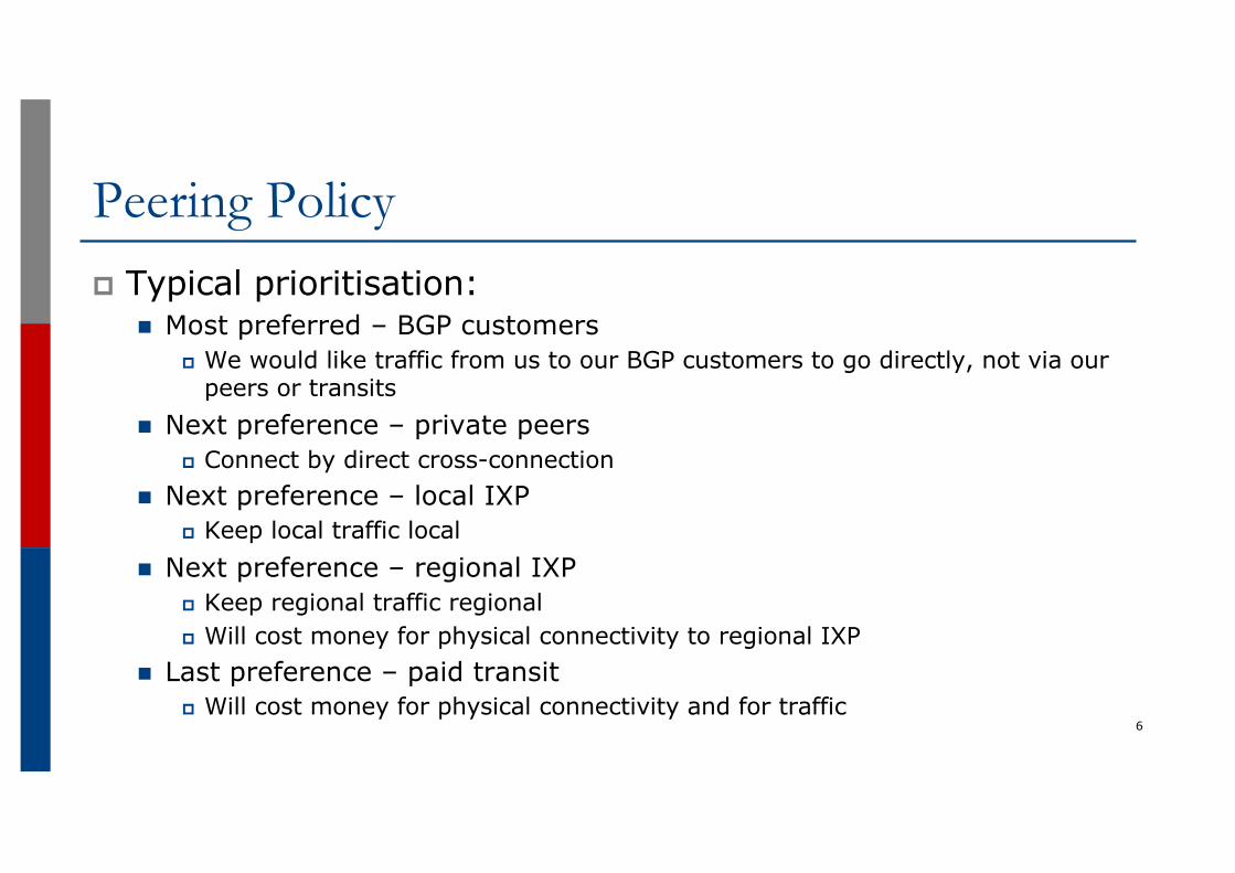
Peering Policyp Typical prioritisation:
n Most preferred – BGP customersp We would like traffic from us to our BGP customers to go directly, not via our
peers or transitsn Next preference – private peers
p Connect by direct cross-connectionn Next preference – local IXP
p Keep local traffic localn Next preference – regional IXP
p Keep regional traffic regionalp Will cost money for physical connectivity to regional IXP
n Last preference – paid transitp Will cost money for physical connectivity and for traffic
6
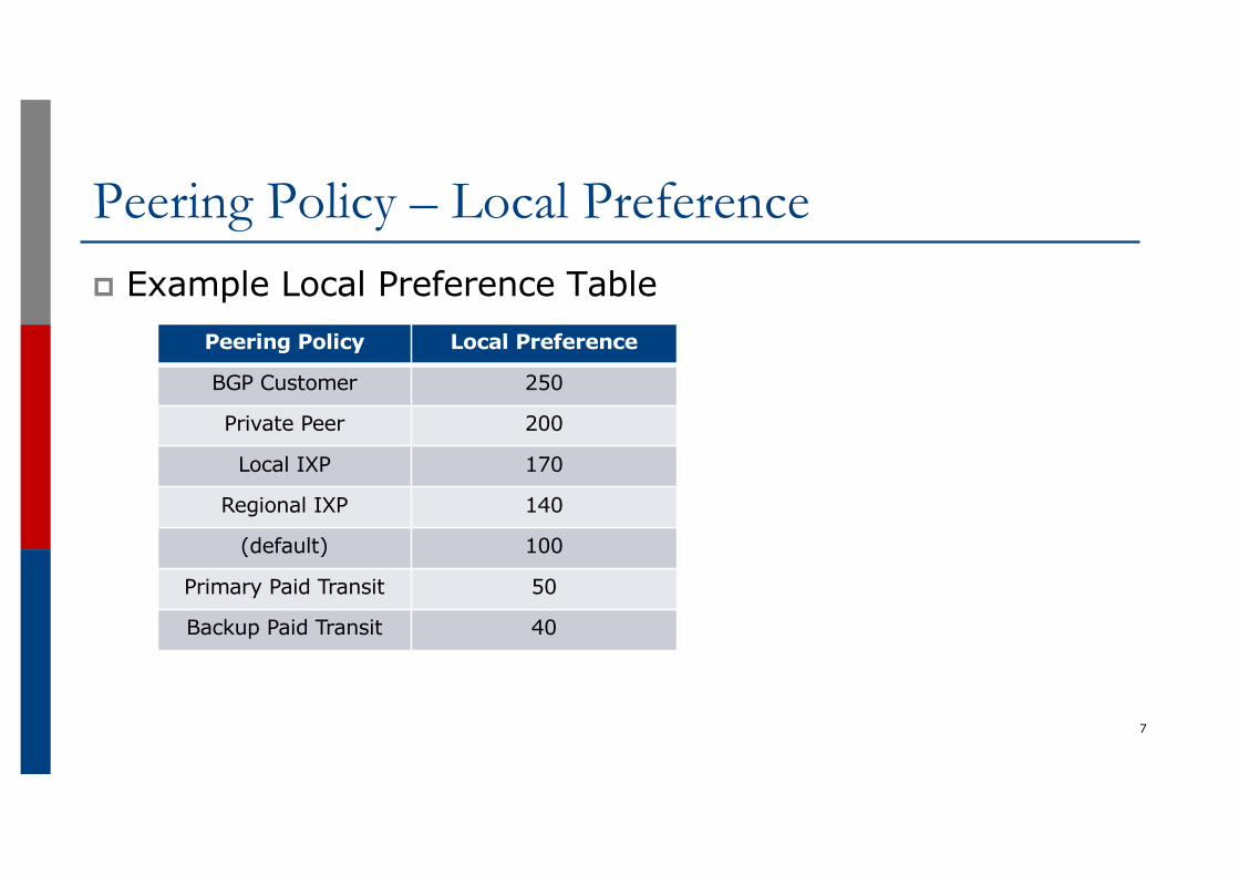
Peering Policy – Local Preferencep Example Local Preference Table
7
Peering Policy Local Preference
BGP Customer 250
Private Peer 200
Local IXP 170
Regional IXP 140
(default) 100
Primary Paid Transit 50
Backup Paid Transit 40
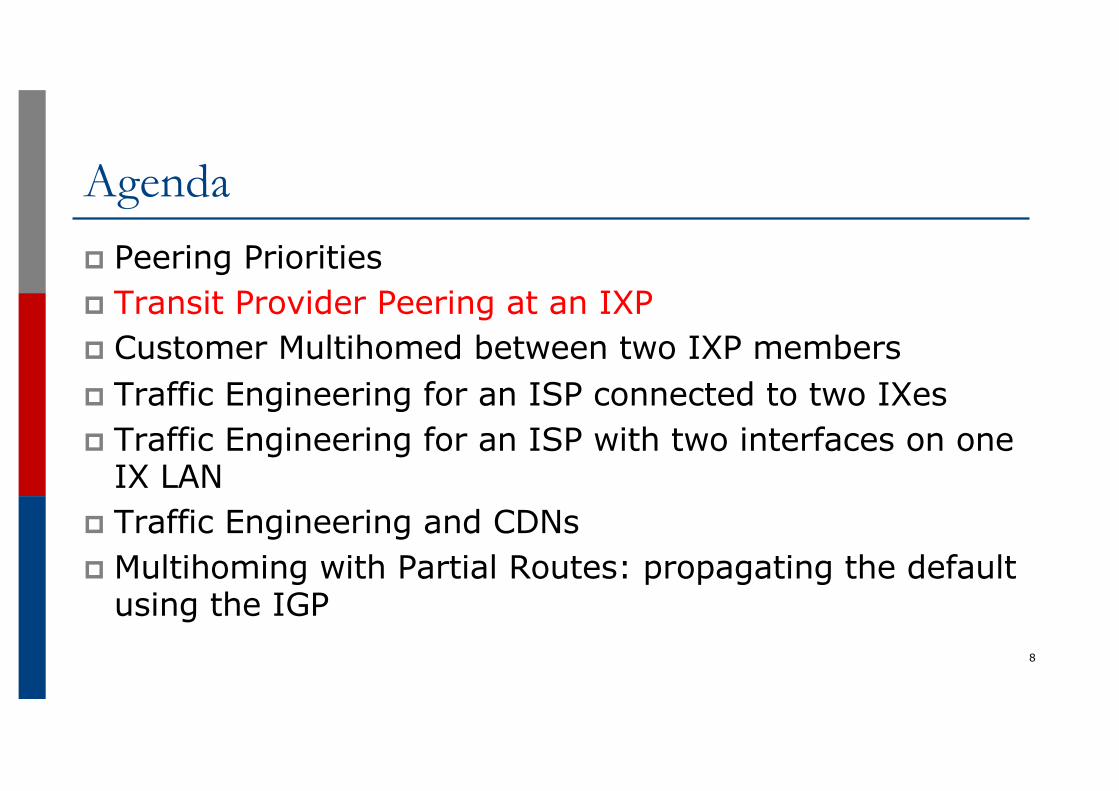
Agendap Peering Prioritiesp Transit Provider Peering at an IXPp Customer Multihomed between two IXP membersp Traffic Engineering for an ISP connected to two IXesp Traffic Engineering for an ISP with two interfaces on one
IX LANp Traffic Engineering and CDNsp Multihoming with Partial Routes: propagating the default
using the IGP8
IXP Peering: When a Transit Provider is Also a Peer
9
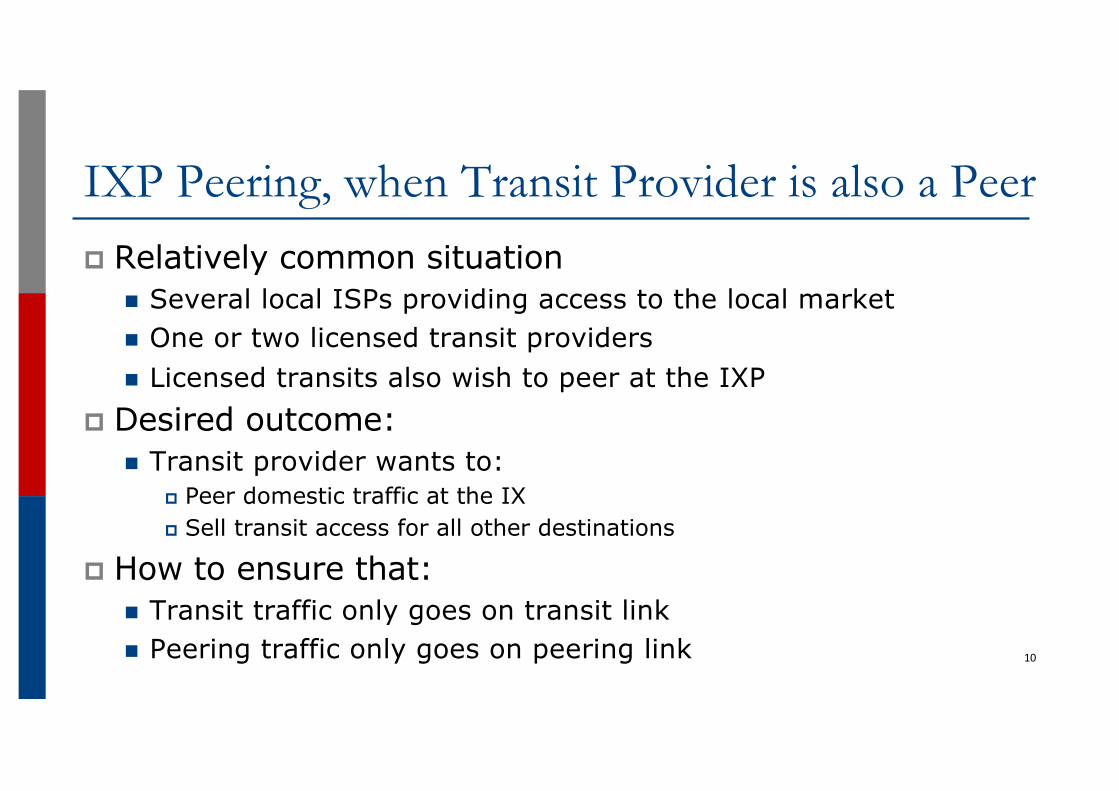
IXP Peering, when Transit Provider is also a Peerp Relatively common situation
n Several local ISPs providing access to the local marketn One or two licensed transit providersn Licensed transits also wish to peer at the IXP
p Desired outcome:n Transit provider wants to:
p Peer domestic traffic at the IXp Sell transit access for all other destinations
p How to ensure that:n Transit traffic only goes on transit linkn Peering traffic only goes on peering link 10
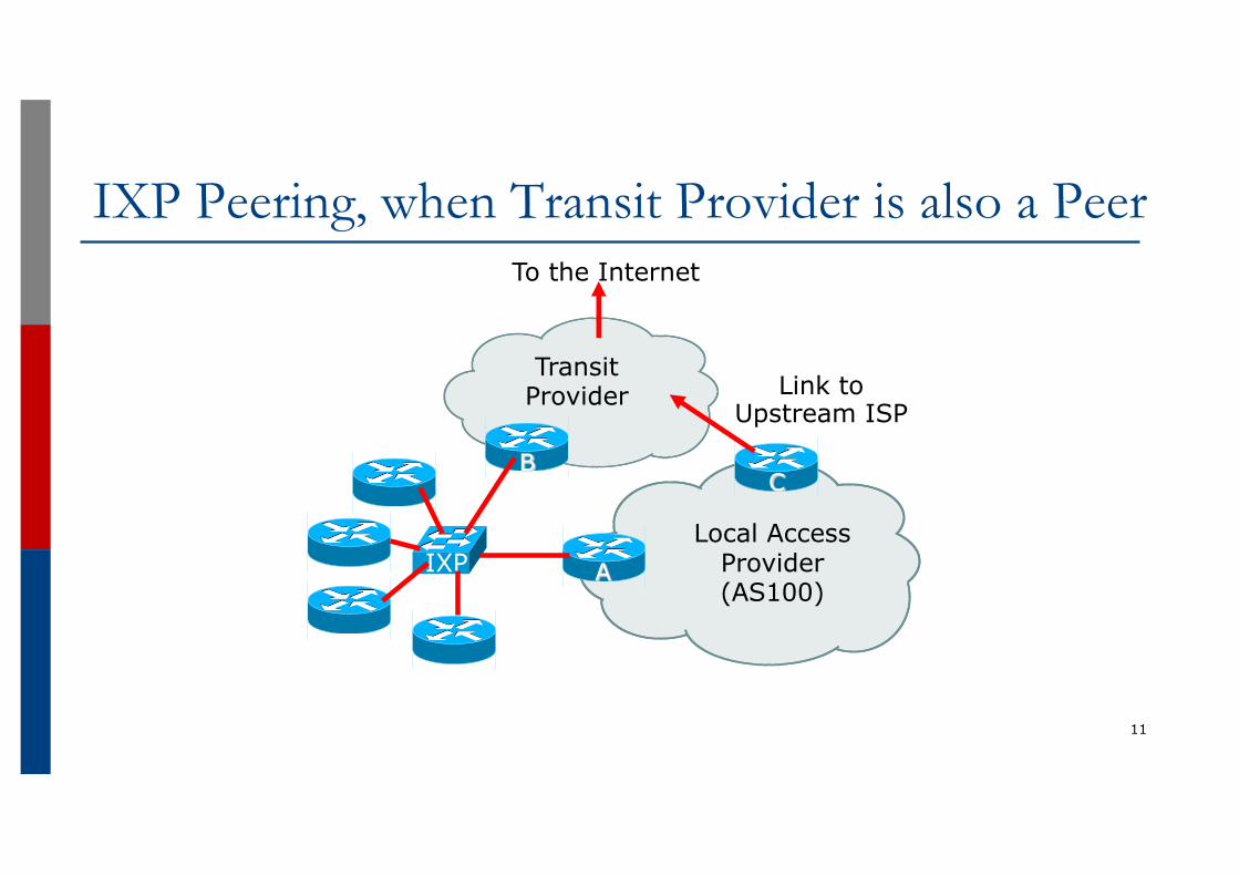
IXP Peering, when Transit Provider is also a Peer
11
C
A
Link to Upstream ISP
IXP
To the Internet
Transit Provider
B
Local Access Provider (AS100)
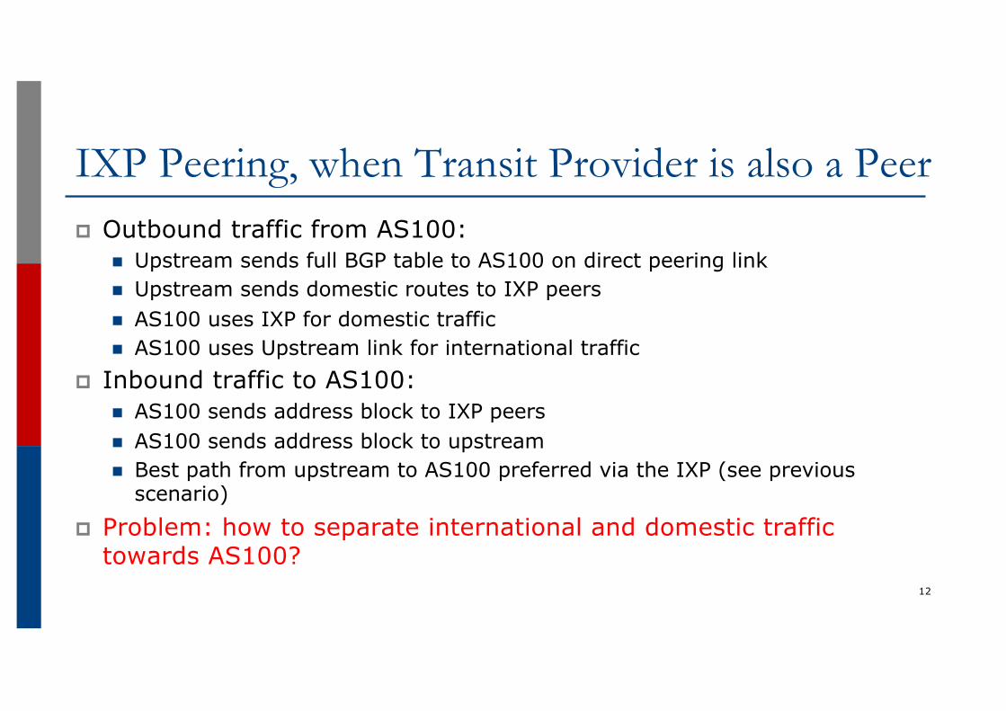
IXP Peering, when Transit Provider is also a Peerp Outbound traffic from AS100:
n Upstream sends full BGP table to AS100 on direct peering linkn Upstream sends domestic routes to IXP peersn AS100 uses IXP for domestic trafficn AS100 uses Upstream link for international traffic
p Inbound traffic to AS100:n AS100 sends address block to IXP peersn AS100 sends address block to upstreamn Best path from upstream to AS100 preferred via the IXP (see previous
scenario)
p Problem: how to separate international and domestic traffic towards AS100?
12
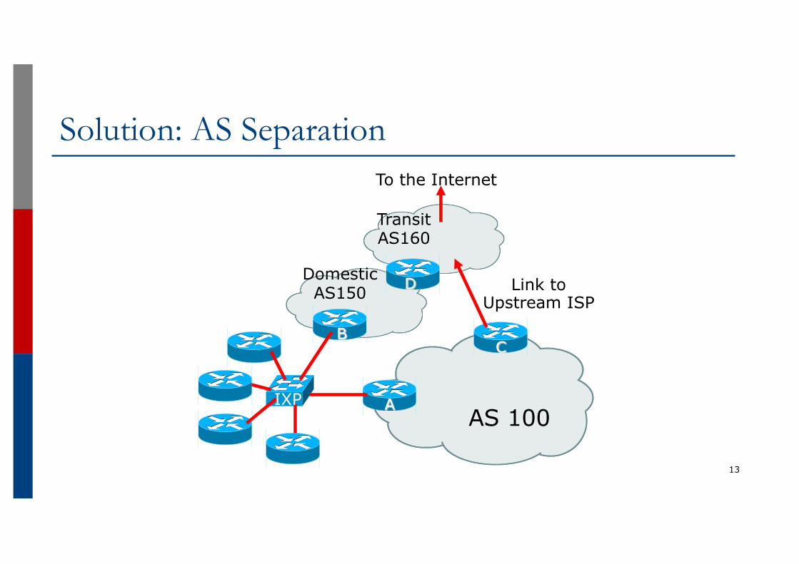
Solution: AS Separation
13
AS 100
C
A
Link to Upstream ISP
B
To the Internet
Domestic AS150
Transit AS160
D
IXP
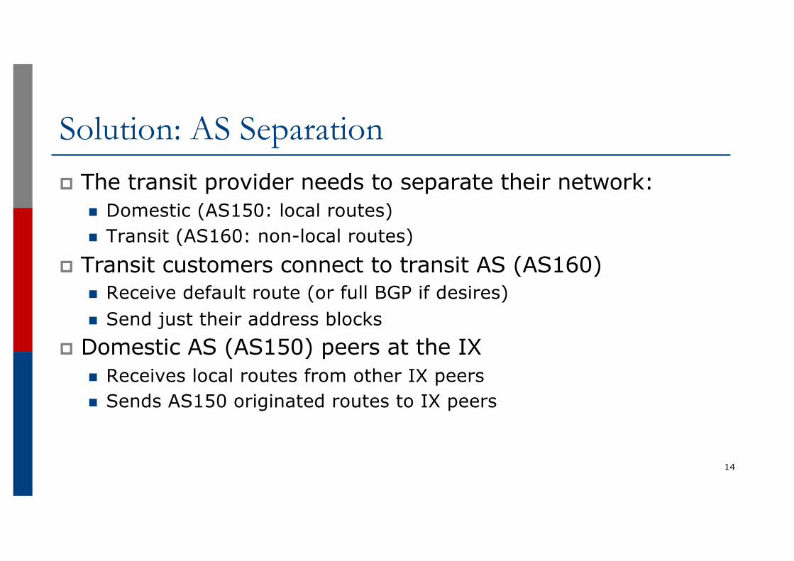
Solution: AS Separationp The transit provider needs to separate their network:
n Domestic (AS150: local routes)n Transit (AS160: non-local routes)
p Transit customers connect to transit AS (AS160)n Receive default route (or full BGP if desires)n Send just their address blocks
p Domestic AS (AS150) peers at the IXn Receives local routes from other IX peersn Sends AS150 originated routes to IX peers
14
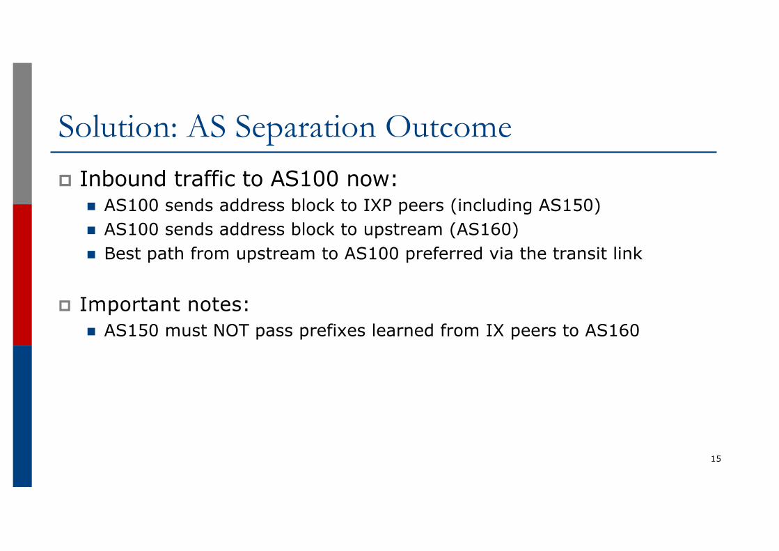
Solution: AS Separation Outcomep Inbound traffic to AS100 now:
n AS100 sends address block to IXP peers (including AS150)n AS100 sends address block to upstream (AS160)n Best path from upstream to AS100 preferred via the transit link
p Important notes:n AS150 must NOT pass prefixes learned from IX peers to AS160
15
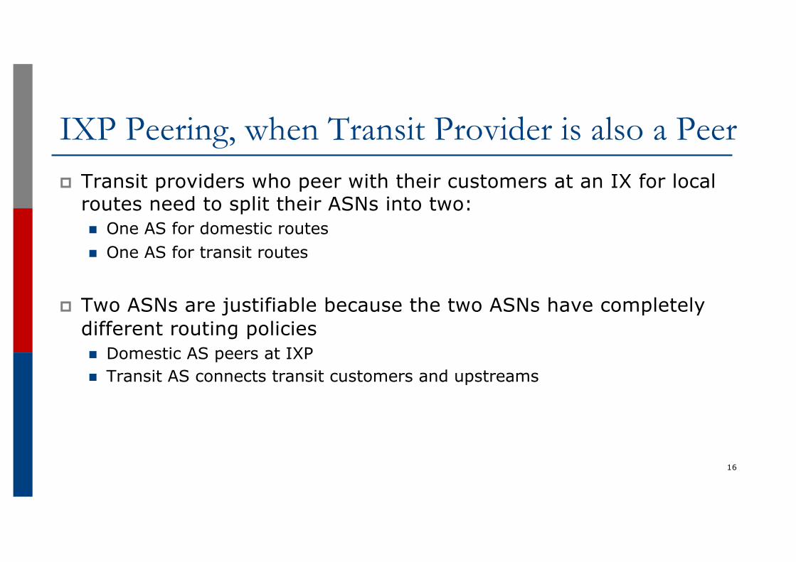
IXP Peering, when Transit Provider is also a Peerp Transit providers who peer with their customers at an IX for local
routes need to split their ASNs into two:n One AS for domestic routesn One AS for transit routes
p Two ASNs are justifiable because the two ASNs have completely different routing policiesn Domestic AS peers at IXPn Transit AS connects transit customers and upstreams
16
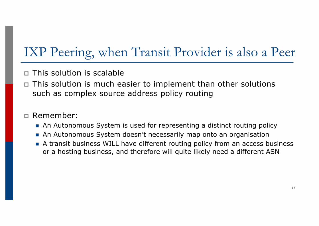
IXP Peering, when Transit Provider is also a Peerp This solution is scalablep This solution is much easier to implement than other solutions
such as complex source address policy routing
p Remember: n An Autonomous System is used for representing a distinct routing policyn An Autonomous System doesn’t necessarily map onto an organisationn A transit business WILL have different routing policy from an access business
or a hosting business, and therefore will quite likely need a different ASN
17
Agendap Peering Prioritiesp Transit Provider Peering at an IXPp Customer Multihomed between two IXP membersp Traffic Engineering for an ISP over two routers on one IX
LANp Traffic Engineering for an ISP connected to two IXesp Traffic Engineering and CDNsp Multihoming with Partial Routes: propagating the default
using the IGP18
Customer multihomed between two IXP members
19
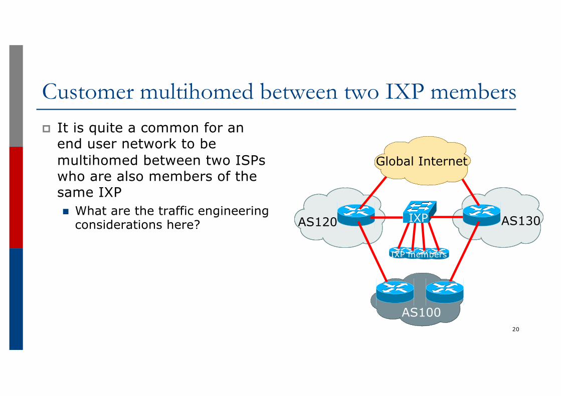
Customer multihomed between two IXP membersp It is quite a common for an
end user network to be multihomed between two ISPs who are also members of the same IXPn What are the traffic engineering
considerations here?
20
AS120 AS130
AS100
Global Internet
IXP
IXP members
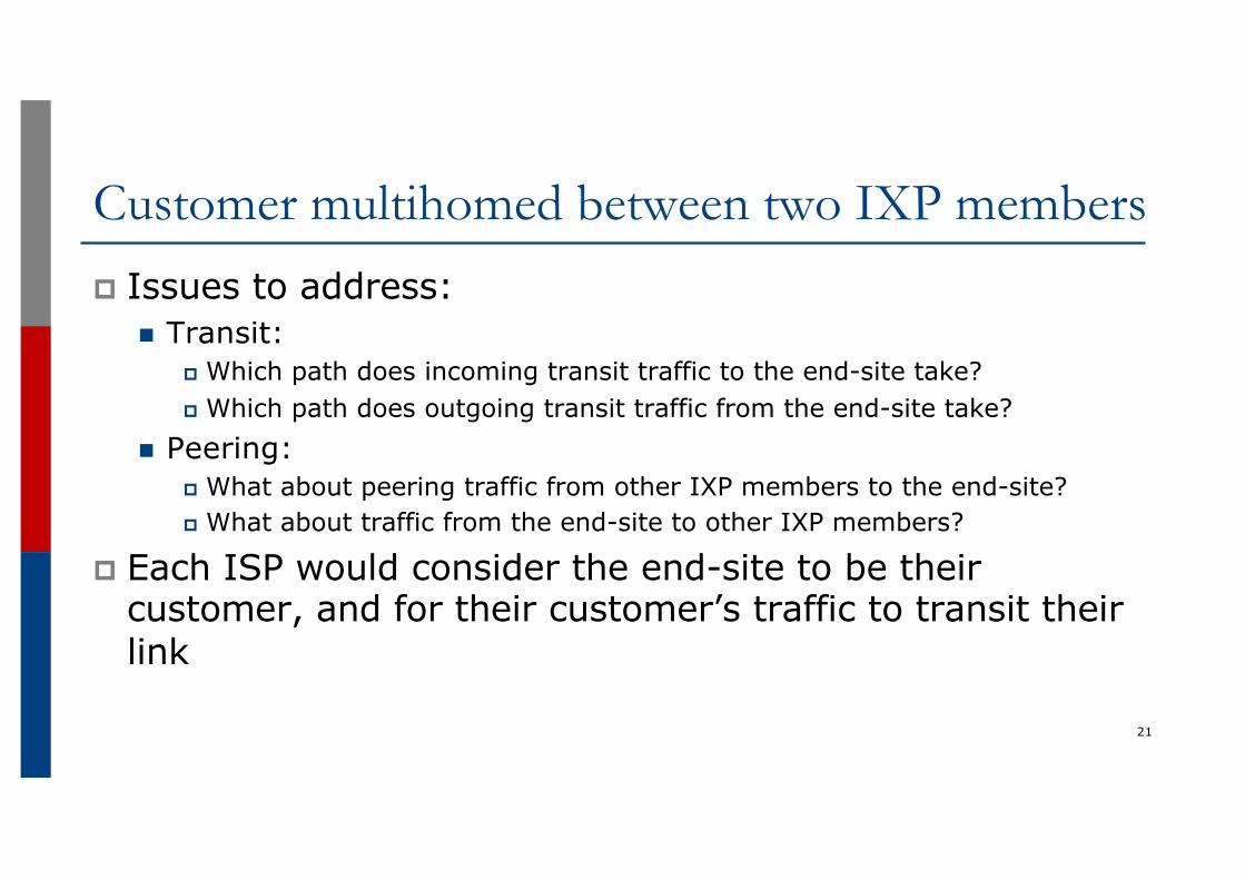
Customer multihomed between two IXP membersp Issues to address:
n Transit:p Which path does incoming transit traffic to the end-site take?p Which path does outgoing transit traffic from the end-site take?
n Peering:p What about peering traffic from other IXP members to the end-site?p What about traffic from the end-site to other IXP members?
p Each ISP would consider the end-site to be their customer, and for their customer’s traffic to transit their link
21
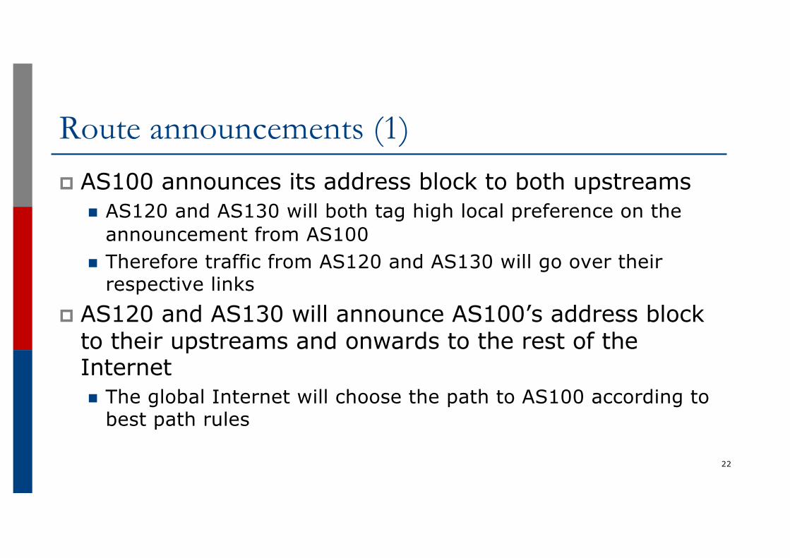
Route announcements (1)p AS100 announces its address block to both upstreams
n AS120 and AS130 will both tag high local preference on the announcement from AS100
n Therefore traffic from AS120 and AS130 will go over their respective links
p AS120 and AS130 will announce AS100’s address block to their upstreams and onwards to the rest of the Internetn The global Internet will choose the path to AS100 according to
best path rules
22
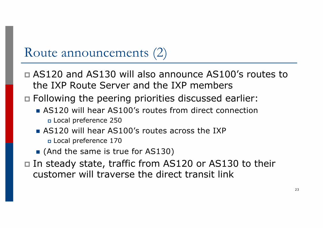
Route announcements (2)p AS120 and AS130 will also announce AS100’s routes to
the IXP Route Server and the IXP membersp Following the peering priorities discussed earlier:
n AS120 will hear AS100’s routes from direct connectionp Local preference 250
n AS120 will hear AS100’s routes across the IXPp Local preference 170
n (And the same is true for AS130)p In steady state, traffic from AS120 or AS130 to their
customer will traverse the direct transit link23
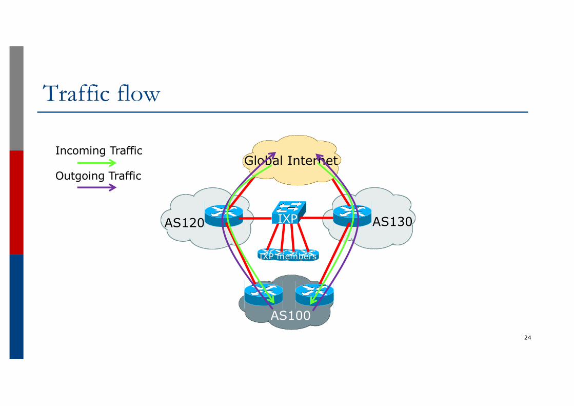
Traffic flow
24
AS120 AS130
AS100
Global Internet
IXP
Incoming Traffic
Outgoing Traffic
IXP members
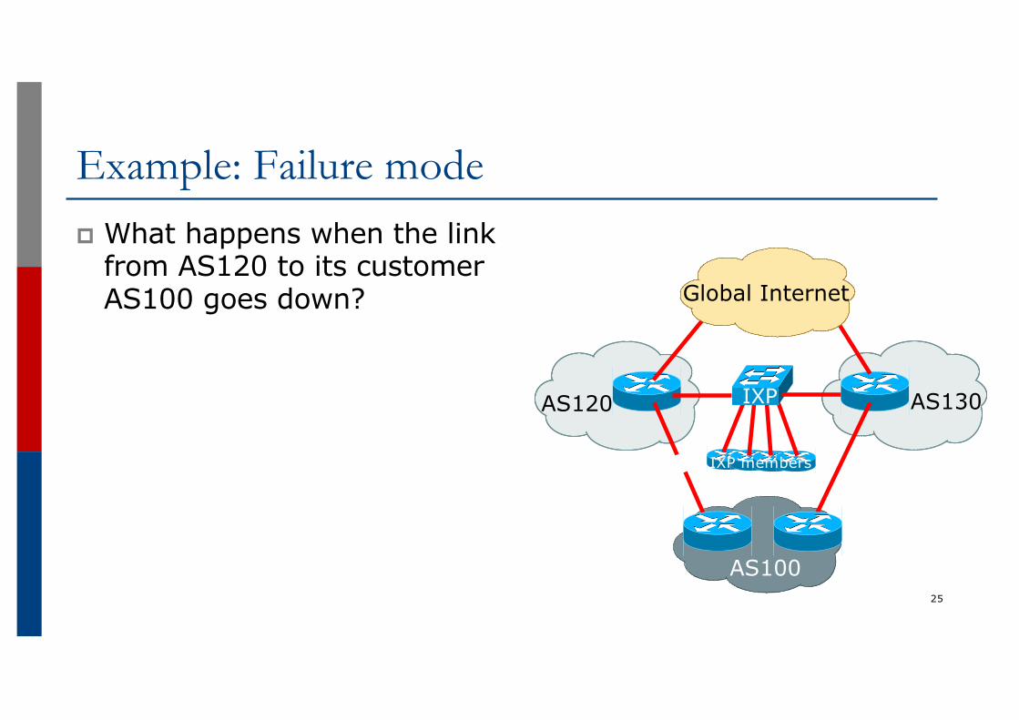
Example: Failure modep What happens when the link
from AS120 to its customer AS100 goes down?
25
AS120 AS130
AS100
Global Internet
IXP
IXP members
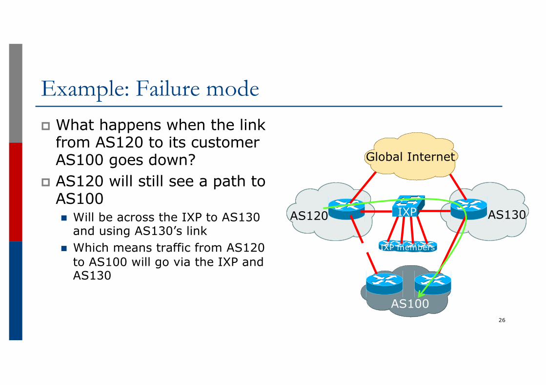
Example: Failure modep What happens when the link
from AS120 to its customer AS100 goes down?
p AS120 will still see a path to AS100n Will be across the IXP to AS130
and using AS130’s linkn Which means traffic from AS120
to AS100 will go via the IXP and AS130
26
AS120 AS130
AS100
Global Internet
IXP
IXP members
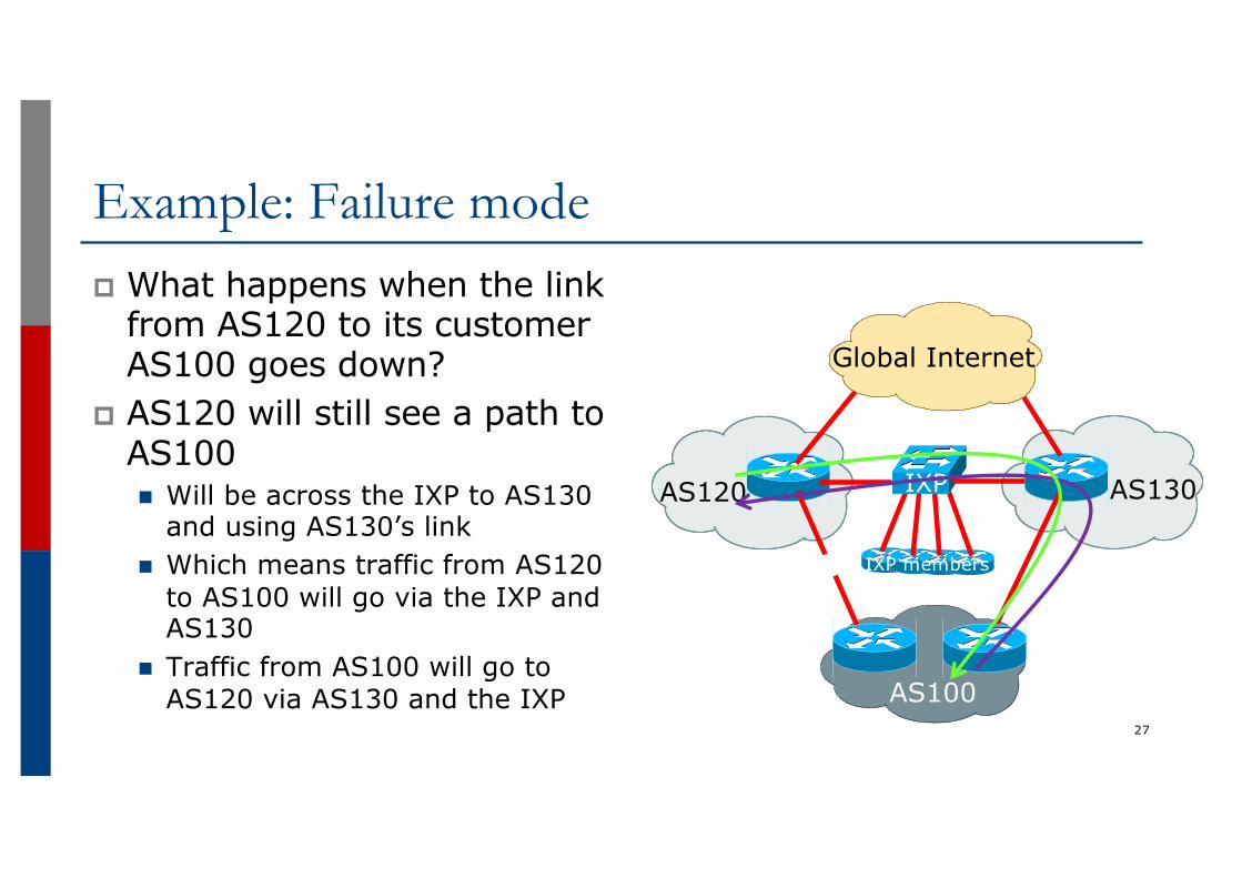
Example: Failure modep What happens when the link
from AS120 to its customer AS100 goes down?
p AS120 will still see a path to AS100n Will be across the IXP to AS130
and using AS130’s linkn Which means traffic from AS120
to AS100 will go via the IXP and AS130
n Traffic from AS100 will go to AS120 via AS130 and the IXP
27
AS120 AS130
AS100
Global Internet
IXP
IXP members
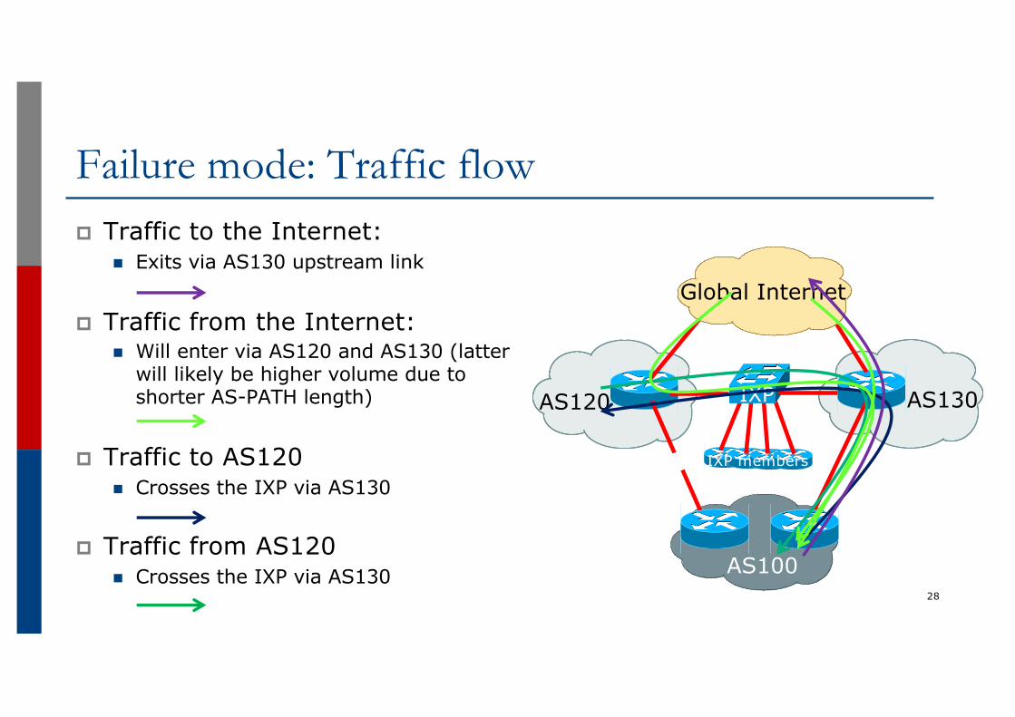
Failure mode: Traffic flowp Traffic to the Internet:
n Exits via AS130 upstream link
p Traffic from the Internet:n Will enter via AS120 and AS130 (latter
will likely be higher volume due to shorter AS-PATH length)
p Traffic to AS120n Crosses the IXP via AS130
p Traffic from AS120n Crosses the IXP via AS130
28
AS120 AS130
AS100
Global Internet
IXP
IXP members
Failure mode observationsp If AS130 implements packet filtering by source address
on the peering link:n Incoming traffic from the Internet via AS120 and the IXP to
AS100 will be dropped, affecting connectivity for AS100p Multihomed customers of IXP members will result in this
”unusual” traffic flown This is a side-effect of the customer having redundant
connections – nothing wrong with itn And one reason why it is very important for a network operator
to set higher local preference on routes heard directly from a BGP customer versus the same routes heard via peering or transit links 29
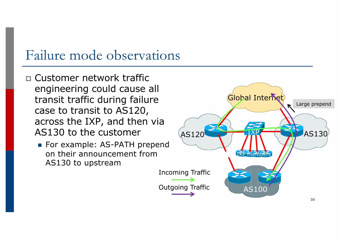
Failure mode observationsp Customer network traffic
engineering could cause all transit traffic during failure case to transit to AS120, across the IXP, and then via AS130 to the customern For example: AS-PATH prepend
on their announcement from AS130 to upstream
30
AS120 AS130
AS100
Global Internet
IXP
IXP members
Incoming Traffic
Outgoing Traffic
Large prepend
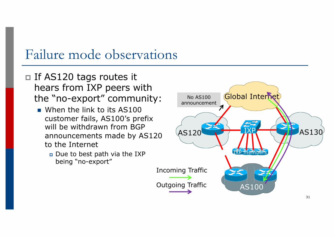
Failure mode observationsp If AS120 tags routes it
hears from IXP peers with the “no-export” community:n When the link to its AS100
customer fails, AS100’s prefix will be withdrawn from BGP announcements made by AS120 to the Internet
p Due to best path via the IXP being “no-export”
31
AS120 AS130
AS100
Global Internet
IXP
IXP members
Incoming Traffic
Outgoing Traffic
No AS100 announcement
Summaryp This is a common scenario for when a customer is
multihomed on to members of an IXPp Steady state works as expectedp If either customer transit link fails, then incoming transit
traffic will cross the IXPn This is not unusual, nor is it a problem
p To avoid having transit traffic crossing the IXPn Tag routes heard from the IXP with “no-export”n Direct customer routes only announced to transits when direct
link to customer is active32
Agendap Peering Prioritiesp Transit Provider Peering at an IXPp Customer Multihomed between two IXP membersp Traffic Engineering for an ISP over two routers on one IX
LANp Traffic Engineering for an ISP connected to two IXesp Traffic Engineering and CDNsp Multihoming with Partial Routes: propagating the default
using the IGP33
Traffic Engineering over two routers on one IX LAN
34
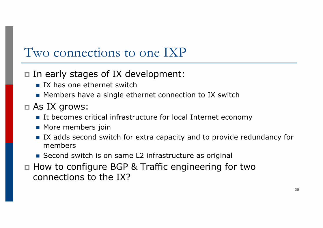
Two connections to one IXPp In early stages of IX development:
n IX has one ethernet switchn Members have a single ethernet connection to IX switch
p As IX grows:n It becomes critical infrastructure for local Internet economyn More members joinn IX adds second switch for extra capacity and to provide redundancy for
membersn Second switch is on same L2 infrastructure as original
p How to configure BGP & Traffic engineering for two connections to the IX?
35
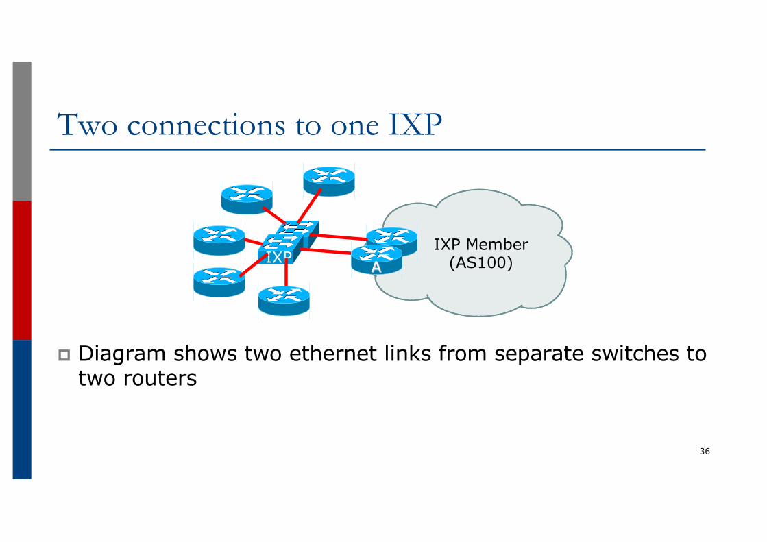
p Diagram shows two ethernet links from separate switches to two routers
Two connections to one IXP
36
IXPIXP Member
(AS100)A
Two connections to one IXPp IXP LAN configuration:
n Second connection is on same subnet on IXPn Member receives another IP address from the same subnet
p BGP configuration:n Second EBGP session is established
p With the IXP Route Server (if present)p With the other IXP members (with their second router, if they have one)p With IXP services infrastructure (if applicable)
37
Two connections to one IXPp Outbound Traffic Engineering configuration:
n By default, the link chosen will follow BGP best path rulesp In the absence of any other member policy (e.g. MEDs), best path will be
lowest neighbour IP addressp Which most likely means that one link carries all the traffic; the other link
remains relatively emptyn AS100 could load balance over the two physical links by:
p Setting local preferences on particular announcements from peersp Using any BGP community policy implemented by other members
38
Two connections to one IXPp Inbound Traffic Engineering configuration:
n By default, the link chosen will follow BGP best path rulesp In the absence of any local policy (e.g. MEDs), best path will be lowest IP
address on the IX LANn AS100 could load balance over the two physical links by:
p Setting MEDs on particular announcements to peers§ Half the peers could have announcements of MED 10 on one link and MED 20 on the
other link§ And the other half of the peers have the MED values reversed§ Which assumes that peers even respect MEDs
p Implementing a BGP community policy available for other members to use§ Sometimes IXPs recommend what a community policy might be
p Using AS-PATH prepends (care needed so the IX path doesn’t have longer AS path than via paid transit links)
39
Two connections to one IXPp Bonding two ethernet connections
n In some circumstances, the IXP may offer the facility of creating an aggregated link (LAG – Link Aggregation Group)
n This provides redundancy at L2p For example, two GigabitEthernet links will effectively present as 2Gbps on a single
connection on the routerp The BGP session is established over the LAG rather than on individual linksp Load balancing is at L2, contained within the LAG itself
p Note: this is only possible if the member only provisions one router for the IXP connectionn And not desirable if the IXP provisions the two links on separate
switches (assuming the switch vendor supports creating a LAG shared over two switches)
40
Agendap Peering Prioritiesp Transit Provider Peering at an IXPp Customer Multihomed between two IXP membersp Traffic Engineering for an ISP with two interfaces on one
IX LANp Traffic Engineering for an ISP connected to two IXesp Traffic Engineering and CDNsp Multihoming with Partial Routes: propagating the default
using the IGP41
Traffic Engineering when connected to two IXPs
42
Traffic Engineering when connected to two IXPsp Several variations possible on this theme
n Peering at two local IXPsp Shouldn’t really happen as an IXP is intended to be a collaborative effort
between members/participants to peer local trafficp Two IXPs serving the same local market doubles the costs for all operators
and makes the traffic engineering more challenging
n Peering at local IXP and regional IXPp Very common where an ISP participates in the local IXP and also turns up
at one or more regional IXPs for greater peering opportunitiesn Peering at two regional IXPs
p Occurs in the absence of a local IXP
43
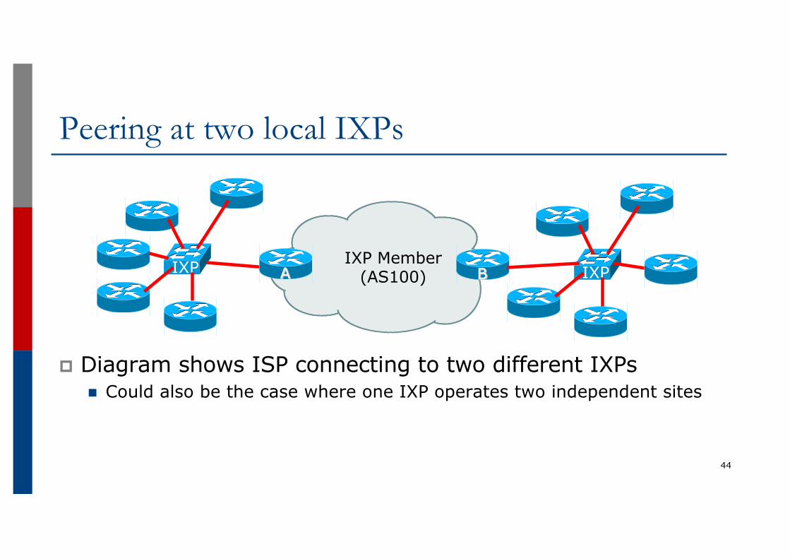
p Diagram shows ISP connecting to two different IXPsn Could also be the case where one IXP operates two independent sites
Peering at two local IXPs
44
IXP IXP Member (AS100)A IXPB
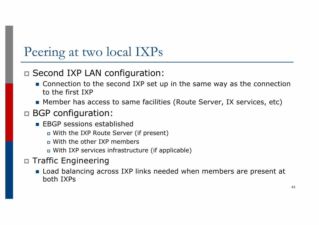
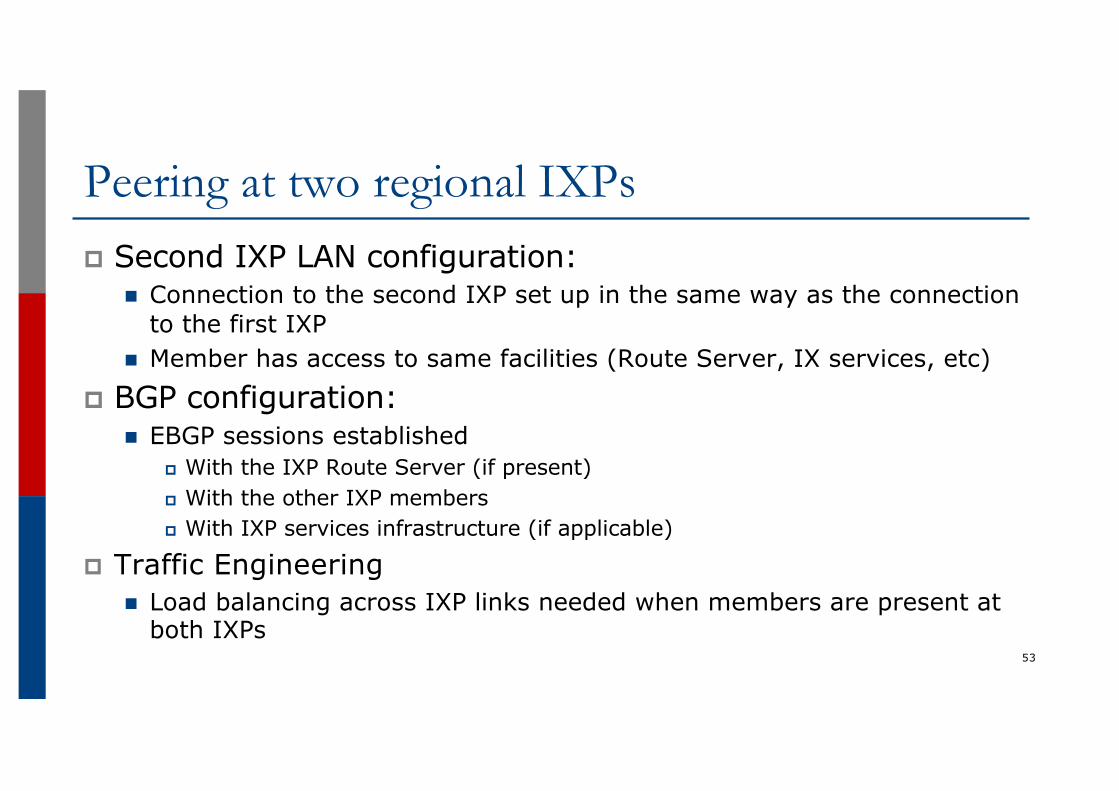
Peering at two local IXPsp Second IXP LAN configuration:
n Connection to the second IXP set up in the same way as the connection to the first IXP
n Member has access to same facilities (Route Server, IX services, etc)
p BGP configuration:n EBGP sessions established
p With the IXP Route Server (if present)p With the other IXP membersp With IXP services infrastructure (if applicable)
p Traffic Engineeringn Load balancing across IXP links needed when members are present at
both IXPs45
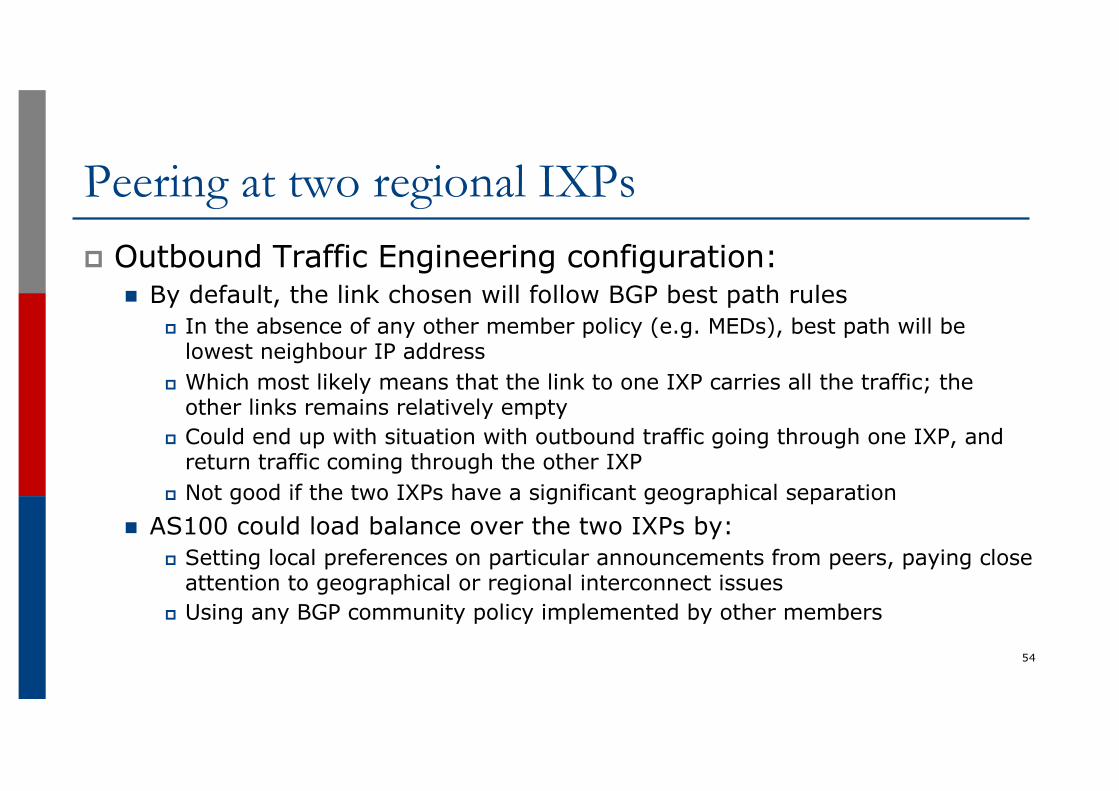
Peering at two local IXPsp Outbound Traffic Engineering configuration:
n By default, the link chosen will follow BGP best path rulesp In the absence of any other member policy (e.g. MEDs), best path will be
lowest neighbour IP addressp Which most likely means that the link to one IXP carries all the traffic; the
other link remains relatively emptyp Could end up with situation with outbound traffic going through one IXP, and
return traffic coming through the other IXPn AS100 could load balance over the two IXPs by:
p Setting local preferences on particular announcements from peersp Using any BGP community policy implemented by other members
46
Peering at two local IXPsp Inbound Traffic Engineering configuration:
n By default, the link chosen will follow BGP best path rulesp In the absence of any local policy (e.g. MEDs), best path will be lowest
neighbour IP address (i.e. entirely dependent on the address block the IX has received from the RIR)
n AS100 could load balance over the two IXP links to other members by:p Setting MEDs on particular announcements to peers
§ Half the peers could have announcements of MED 10 on one link and MED 20 on the other link
§ And the other half of the peers have the MED values reversed§ Which assumes that peers even respect MEDs
p Implementing a BGP community policy available for other members to use§ Sometimes IXPs recommend what a community policy might be
p Using AS-PATH prepends (care needed so the IX path doesn’t have longer AS path than via paid transit links) 47
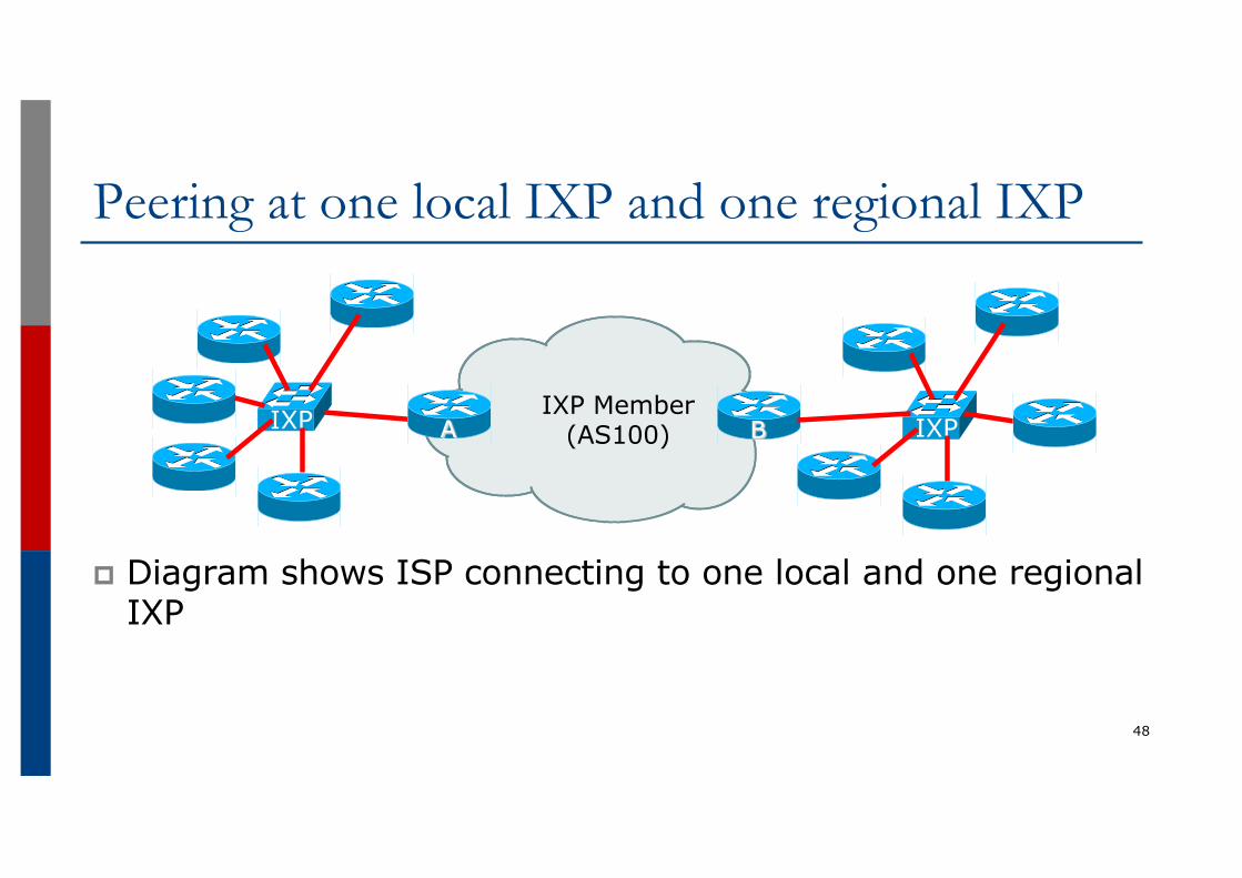
p Diagram shows ISP connecting to one local and one regional IXP
Peering at one local IXP and one regional IXP
48
IXP IXP Member (AS100)A IXPB
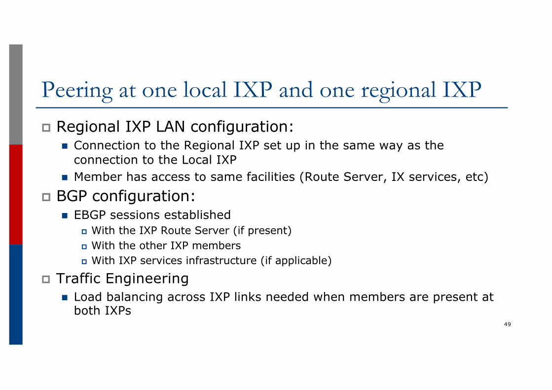
Peering at one local IXP and one regional IXPp Regional IXP LAN configuration:
n Connection to the Regional IXP set up in the same way as the connection to the Local IXP
n Member has access to same facilities (Route Server, IX services, etc)
p BGP configuration:n EBGP sessions established
p With the IXP Route Server (if present)p With the other IXP membersp With IXP services infrastructure (if applicable)
p Traffic Engineeringn Load balancing across IXP links needed when members are present at
both IXPs49
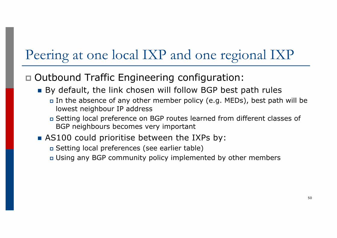
Peering at one local IXP and one regional IXPp Outbound Traffic Engineering configuration:
n By default, the link chosen will follow BGP best path rulesp In the absence of any other member policy (e.g. MEDs), best path will be
lowest neighbour IP addressp Setting local preference on BGP routes learned from different classes of
BGP neighbours becomes very important
n AS100 could prioritise between the IXPs by:p Setting local preferences (see earlier table)p Using any BGP community policy implemented by other members
50
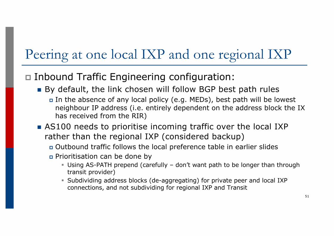
Peering at one local IXP and one regional IXPp Inbound Traffic Engineering configuration:
n By default, the link chosen will follow BGP best path rulesp In the absence of any local policy (e.g. MEDs), best path will be lowest
neighbour IP address (i.e. entirely dependent on the address block the IX has received from the RIR)
n AS100 needs to prioritise incoming traffic over the local IXP rather than the regional IXP (considered backup)
p Outbound traffic follows the local preference table in earlier slidesp Prioritisation can be done by
§ Using AS-PATH prepend (carefully – don’t want path to be longer than through transit provider)
§ Subdividing address blocks (de-aggregating) for private peer and local IXP connections, and not subdividing for regional IXP and Transit
51
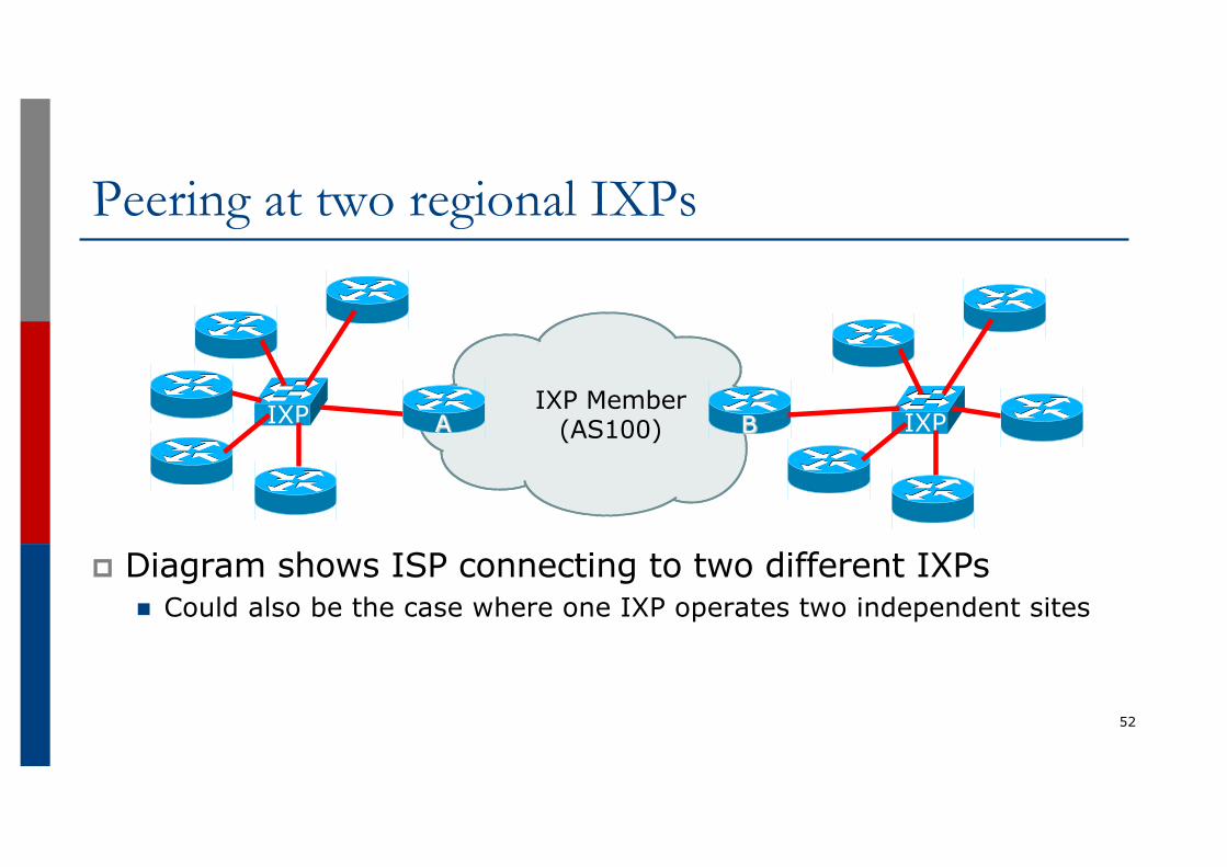
p Diagram shows ISP connecting to two different IXPsn Could also be the case where one IXP operates two independent sites
Peering at two regional IXPs
52
IXP IXP Member (AS100)A IXPB
Peering at two regional IXPsp Second IXP LAN configuration:
n Connection to the second IXP set up in the same way as the connection to the first IXP
n Member has access to same facilities (Route Server, IX services, etc)
p BGP configuration:n EBGP sessions established
p With the IXP Route Server (if present)p With the other IXP membersp With IXP services infrastructure (if applicable)
p Traffic Engineeringn Load balancing across IXP links needed when members are present at
both IXPs53
Peering at two regional IXPsp Outbound Traffic Engineering configuration:
n By default, the link chosen will follow BGP best path rulesp In the absence of any other member policy (e.g. MEDs), best path will be
lowest neighbour IP addressp Which most likely means that the link to one IXP carries all the traffic; the
other links remains relatively emptyp Could end up with situation with outbound traffic going through one IXP, and
return traffic coming through the other IXPp Not good if the two IXPs have a significant geographical separation
n AS100 could load balance over the two IXPs by:p Setting local preferences on particular announcements from peers, paying close
attention to geographical or regional interconnect issuesp Using any BGP community policy implemented by other members
54
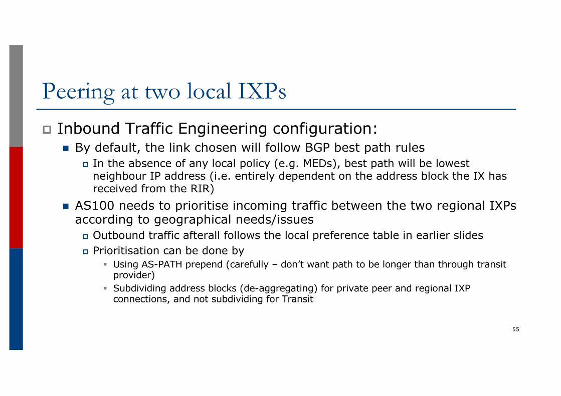
Peering at two local IXPsp Inbound Traffic Engineering configuration:
n By default, the link chosen will follow BGP best path rulesp In the absence of any local policy (e.g. MEDs), best path will be lowest
neighbour IP address (i.e. entirely dependent on the address block the IX has received from the RIR)
n AS100 needs to prioritise incoming traffic between the two regional IXPs according to geographical needs/issues
p Outbound traffic afterall follows the local preference table in earlier slidesp Prioritisation can be done by
§ Using AS-PATH prepend (carefully – don’t want path to be longer than through transit provider)
§ Subdividing address blocks (de-aggregating) for private peer and regional IXP connections, and not subdividing for Transit
55
Agendap Peering Prioritiesp Transit Provider Peering at an IXPp Customer Multihomed between two IXP membersp Traffic Engineering for an ISP with two interfaces on one
IX LANp Traffic Engineering for an ISP connected to two IXesp Traffic Engineering and CDNsp Multihoming with Partial Routes: propagating the default
using the IGP56

Traffic Engineering and CDNs
57
Traffic Engineering and CDNsp Each CDN has its own configuration recommendations
n These slides are only a guideline – it is best to consult directly with the CDN in question about their operational and traffic engineering policies
p CDN implementations:n Present at IXP via the IXP Services Infrastructure
p Transit (backhaul/cache-fill) via one of the IX members or a transit provider or their own infrastructure
n Peering directly at the IXPn Hosted at IX member, and made available to other IX members
58
CDN at an IXP – on Services LAN
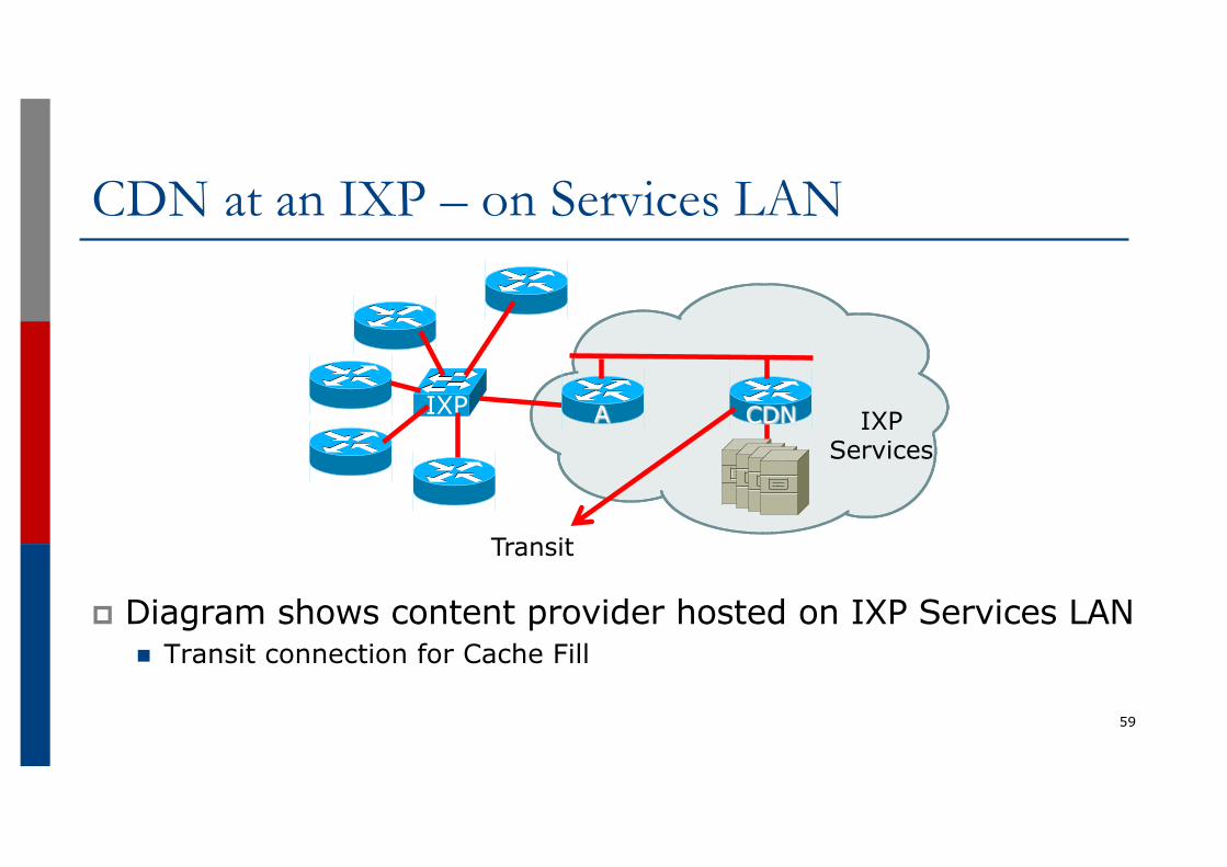
p Diagram shows content provider hosted on IXP Services LANn Transit connection for Cache Fill
59
IXP IXP Services
A CDN
Transit
CDN at an IXP – on Services LANp BGP configuration:
n IXP members peer with IXP Services Router (Router A)n Receive the routes originated by the CDNn IXP Services announces routes to be served to the CDNn CDN has its own transit arrangements
p Either via IXP member or separate infrastructure
60
CDN at an IXP – on Services LANp CDNs usually serve content to operators based on a
combination of:n Lowest round trip time (latency)
p End users expect “instant access”n BGP announcements of the peer
p Following most specific announcementsp AS-path lengthp BGP MED
p Operators need to:n Talk to CDN operator about BGP policy!n Watch the bandwidth to the CDNn Pay attention to BGP announcements
61
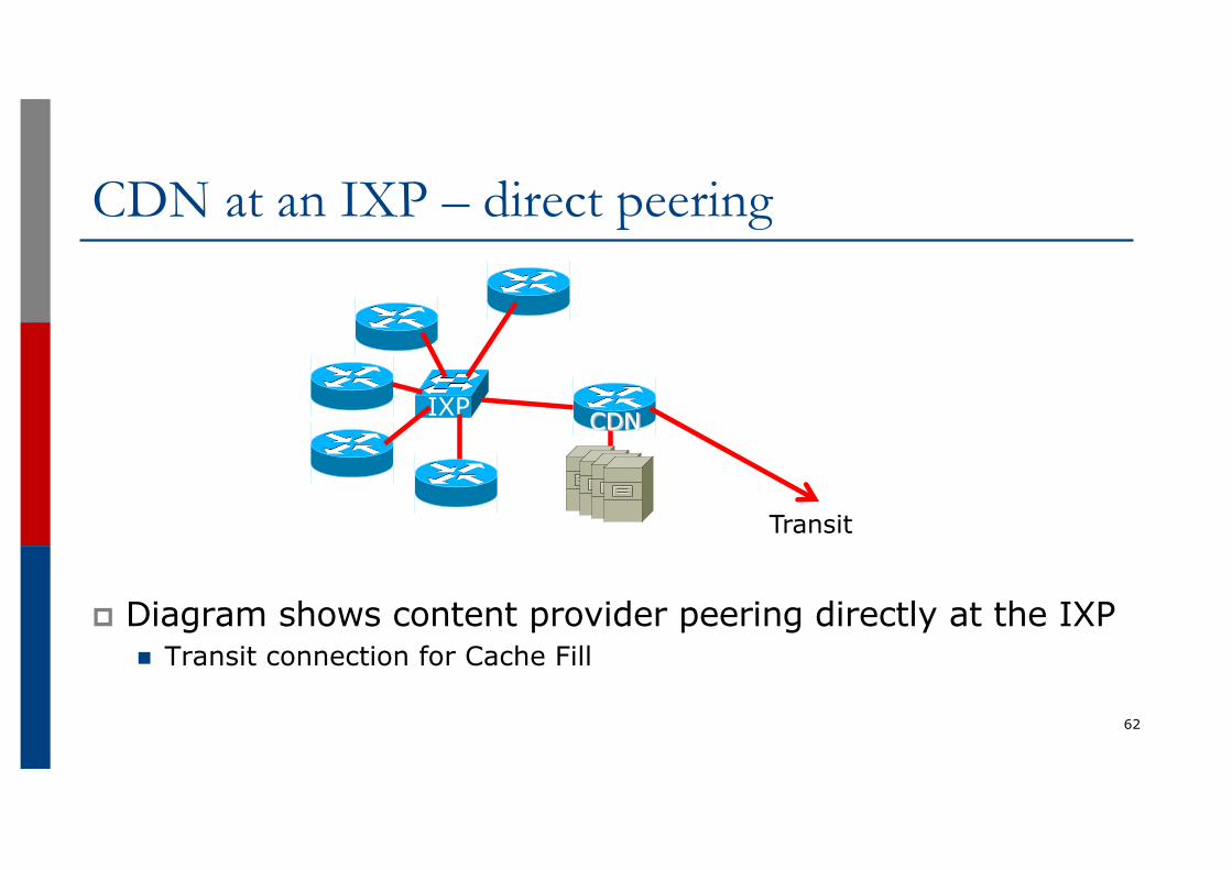
CDN at an IXP – direct peering
p Diagram shows content provider peering directly at the IXPn Transit connection for Cache Fill
62
IXP CDN
Transit
CDN at an IXP – direct peeringp BGP configuration:
n IXP members peer with CDN Routern IXP members receive the routes originated by the CDNn CDN has its own transit arrangements
p Either via IXP member or separate infrastructure
p Operations:n Same as for the previous example
63
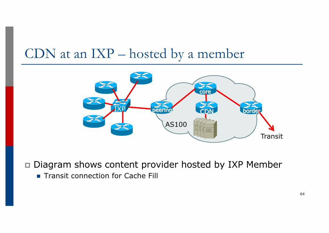
CDN at an IXP – hosted by a member
p Diagram shows content provider hosted by IXP Membern Transit connection for Cache Fill
64
IXP
AS100
CDN
Transit
core
borderpeering
CDN at an IXP – hosted by a memberp BGP configuration:
n IXP members peer with AS100 (Peering Router A)n IXP members receive the routes originated by the CDN (as well
as those originated by AS100)n AS100 announces routes to be served to the CDN
p This could depend on AS100’s agreement with each of its peering partners§ AS100 may charge for access to the CDN content (they have to pay for the
backhaul)§ AS100 may limit access to the CDN content to certain peering partners
65
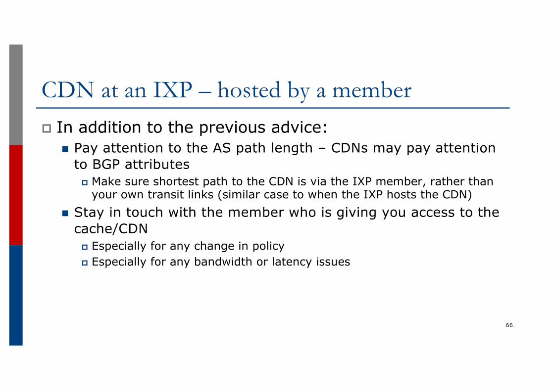
CDN at an IXP – hosted by a memberp In addition to the previous advice:
n Pay attention to the AS path length – CDNs may pay attention to BGP attributes
p Make sure shortest path to the CDN is via the IXP member, rather than your own transit links (similar case to when the IXP hosts the CDN)
n Stay in touch with the member who is giving you access to the cache/CDN
p Especially for any change in policyp Especially for any bandwidth or latency issues
66
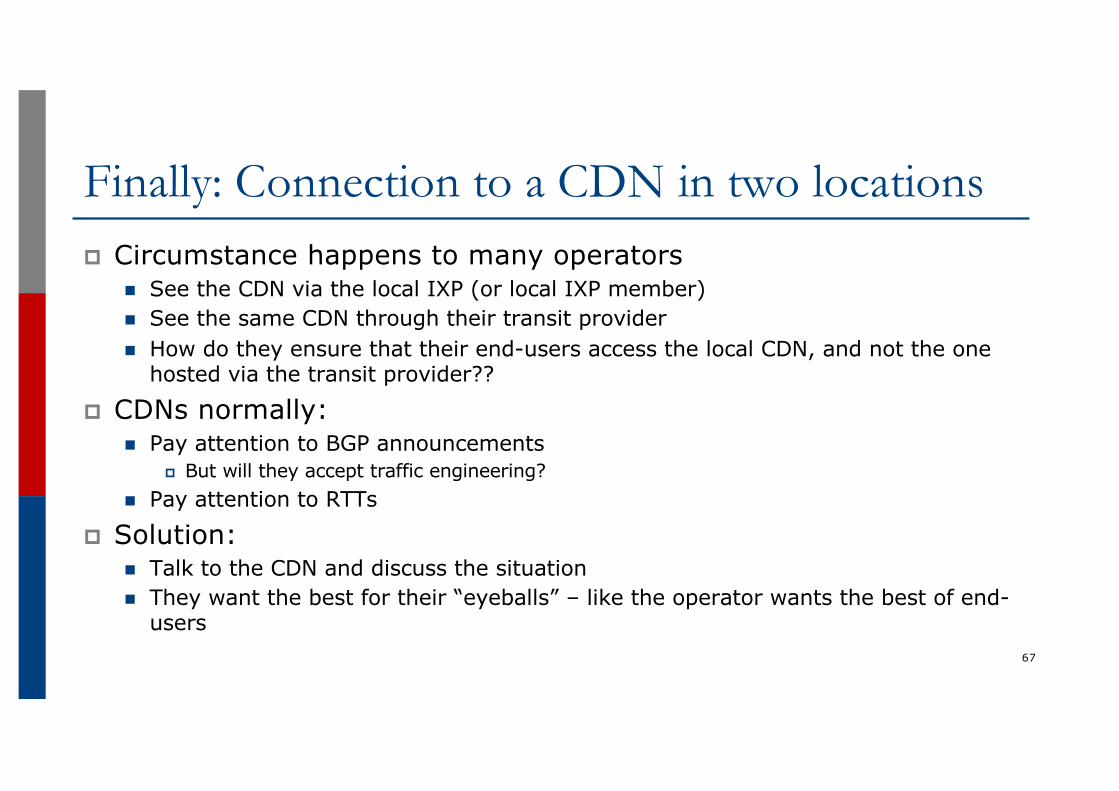
Finally: Connection to a CDN in two locationsp Circumstance happens to many operators
n See the CDN via the local IXP (or local IXP member)n See the same CDN through their transit providern How do they ensure that their end-users access the local CDN, and not the one
hosted via the transit provider??
p CDNs normally:n Pay attention to BGP announcements
p But will they accept traffic engineering?n Pay attention to RTTs
p Solution:n Talk to the CDN and discuss the situationn They want the best for their “eyeballs” – like the operator wants the best of end-
users67
Agendap Peering Prioritiesp Transit Provider Peering at an IXPp Customer Multihomed between two IXP membersp Traffic Engineering for an ISP with two interfaces on one
IX LANp Traffic Engineering for an ISP connected to two IXesp Traffic Engineering and CDNsp Multihoming with Partial Routes: propagating the default
using the IGP68
Multihoming with Partial Routes: default route propagation using IS-IS
69
Default routes in IS-ISp When using BGP for multihoming, and using only partial
routes from upstream providers, it is desirable to propagate a default route across the internal network using IS-ISn There isn’t a need to carry default in BGP unless providing
transit to other operatorsp And in this case you’d opt for full routes in the default free zone
n A default route in IBGP means only one of the multihoming exit paths is used, whereas operators may want to load balance exit traffic based on “nearest exit” derived from the IGP
70
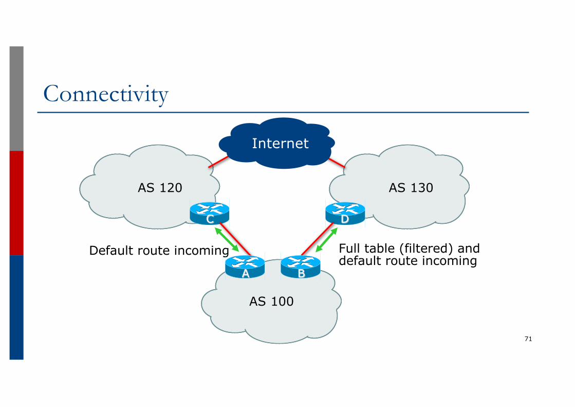
Connectivity
71
AS 120 AS 130
AS 100
C D
Full table (filtered) and default route incoming
Default route incoming
BA
Internet
Partial Routesp AS120 sends just a default routep AS130 sends the full BGP table and a default routep As described in the “Multihoming: Outbound Traffic
Engineering” presentationn Sufficient routes from AS130 are accepted so as to ensure
p Close to symmetric inbound/outbound traffic flowp Close to equal outbound link loading
n For the remaining destinations, default route is via AS120, propagated by IBGP
p And if AS120 link fails totally, then AS130 link takes the entire load
72
Handling the default routep With IBGP, the default route is the BGP best path
n Failure of one path will inevitably result in the default route disappearing from the IBGP while updates propagate from the other Border Router
p Operators may also wish to balance the default route by nearest exit
p Propagating the default route in the IGP:n Works around the “disappearing default” failure moden Allows default by nearest exit, if desired
73
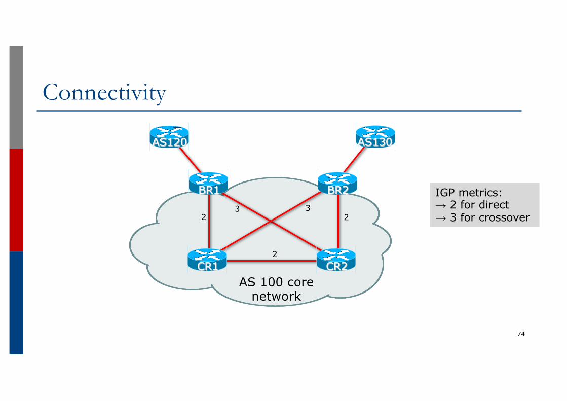
Connectivity
74
AS 100 core network
AS120 AS130
BR2BR1
CR2CR1
2 2
2
3 3
IGP metrics:→ 2 for direct→ 3 for crossover
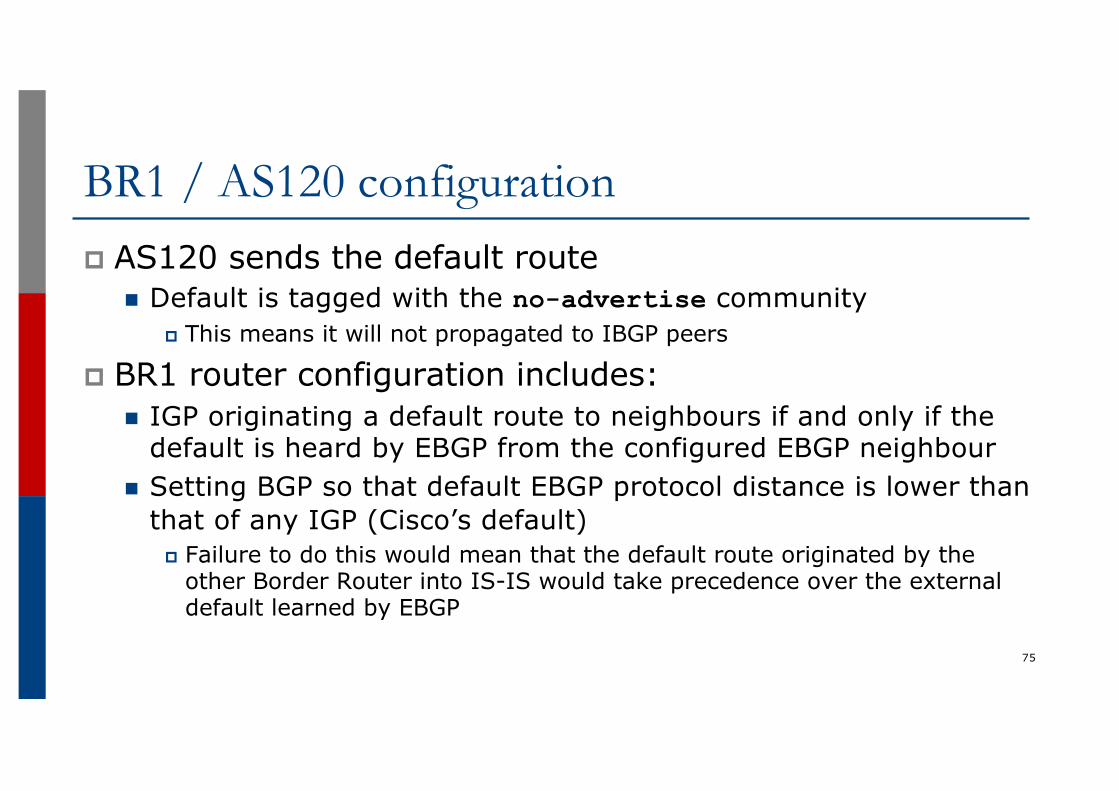
BR1 / AS120 configurationp AS120 sends the default route
n Default is tagged with the no-advertise communityp This means it will not propagated to IBGP peers
p BR1 router configuration includes:n IGP originating a default route to neighbours if and only if the
default is heard by EBGP from the configured EBGP neighbourn Setting BGP so that default EBGP protocol distance is lower than
that of any IGP (Cisco’s default)p Failure to do this would mean that the default route originated by the
other Border Router into IS-IS would take precedence over the external default learned by EBGP
75
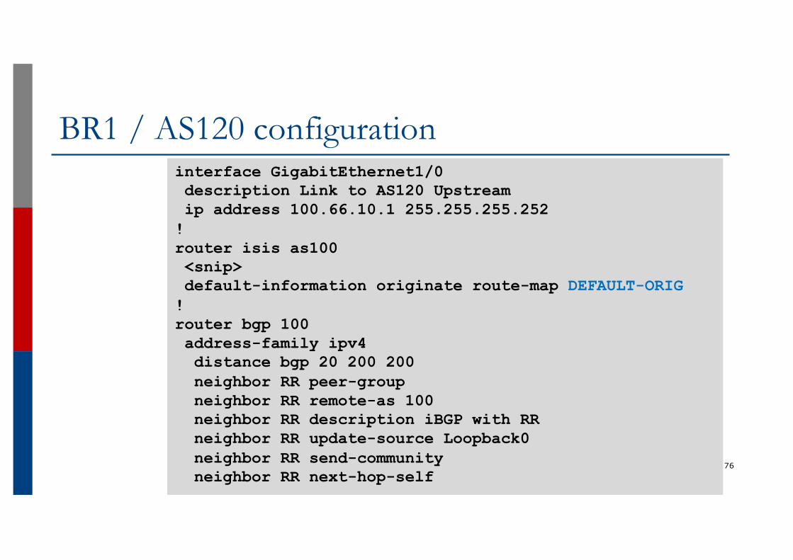
BR1 / AS120 configuration
76
interface GigabitEthernet1/0description Link to AS120 Upstreamip address 100.66.10.1 255.255.255.252!router isis as100<snip>default-information originate route-map DEFAULT-ORIG!router bgp 100address-family ipv4distance bgp 20 200 200neighbor RR peer-groupneighbor RR remote-as 100neighbor RR description iBGP with RRneighbor RR update-source Loopback0neighbor RR send-communityneighbor RR next-hop-self
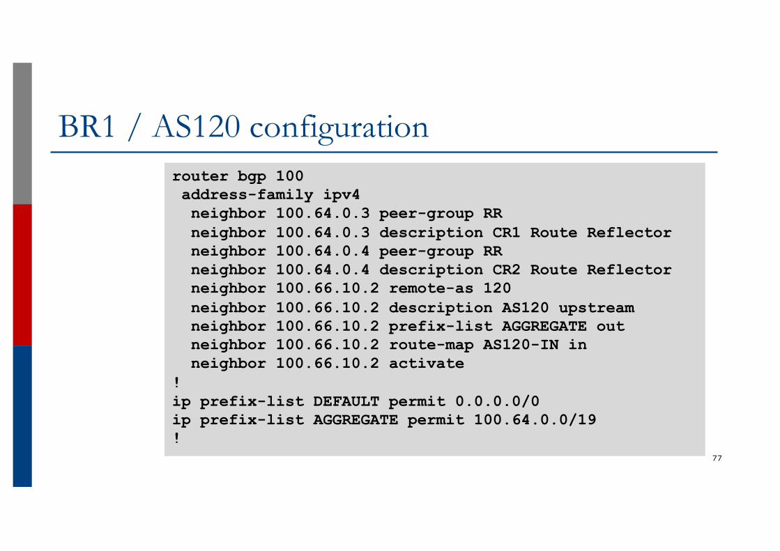
BR1 / AS120 configuration
77
router bgp 100address-family ipv4neighbor 100.64.0.3 peer-group RRneighbor 100.64.0.3 description CR1 Route Reflectorneighbor 100.64.0.4 peer-group RRneighbor 100.64.0.4 description CR2 Route Reflectorneighbor 100.66.10.2 remote-as 120neighbor 100.66.10.2 description AS120 upstreamneighbor 100.66.10.2 prefix-list AGGREGATE outneighbor 100.66.10.2 route-map AS120-IN inneighbor 100.66.10.2 activate
!ip prefix-list DEFAULT permit 0.0.0.0/0ip prefix-list AGGREGATE permit 100.64.0.0/19!
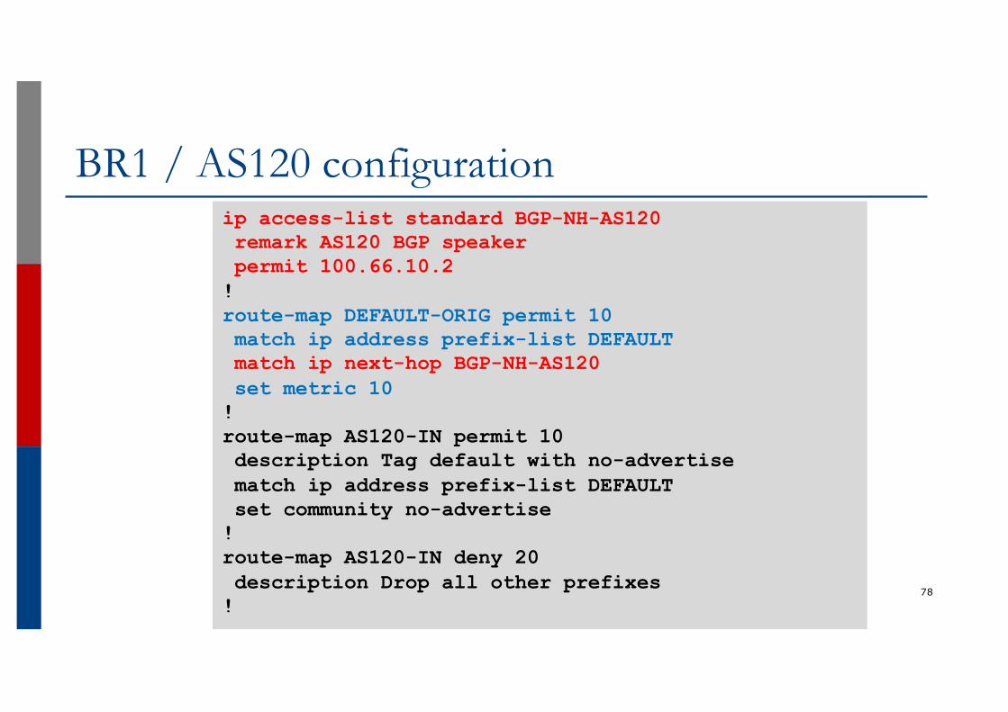
BR1 / AS120 configuration
78
ip access-list standard BGP-NH-AS120remark AS120 BGP speakerpermit 100.66.10.2!route-map DEFAULT-ORIG permit 10match ip address prefix-list DEFAULTmatch ip next-hop BGP-NH-AS120set metric 10!route-map AS120-IN permit 10description Tag default with no-advertisematch ip address prefix-list DEFAULTset community no-advertise!route-map AS120-IN deny 20description Drop all other prefixes!
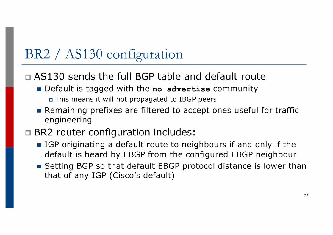
BR2 / AS130 configurationp AS130 sends the full BGP table and default route
n Default is tagged with the no-advertise communityp This means it will not propagated to IBGP peers
n Remaining prefixes are filtered to accept ones useful for traffic engineering
p BR2 router configuration includes:n IGP originating a default route to neighbours if and only if the
default is heard by EBGP from the configured EBGP neighbourn Setting BGP so that default EBGP protocol distance is lower than
that of any IGP (Cisco’s default)
79

BR2 / AS130 configuration
80
interface GigabitEthernet1/0description Link to AS130 Upstreamip address 100.67.3.2 255.255.255.252!router isis as100<snip>default-information originate route-map DEFAULT-ORIG!router bgp 100address-family ipv4distance bgp 20 200 200neighbor RR peer-groupneighbor RR remote-as 100neighbor RR description IBGP with RRneighbor RR update-source Loopback0neighbor RR send-communityneighbor RR next-hop-self
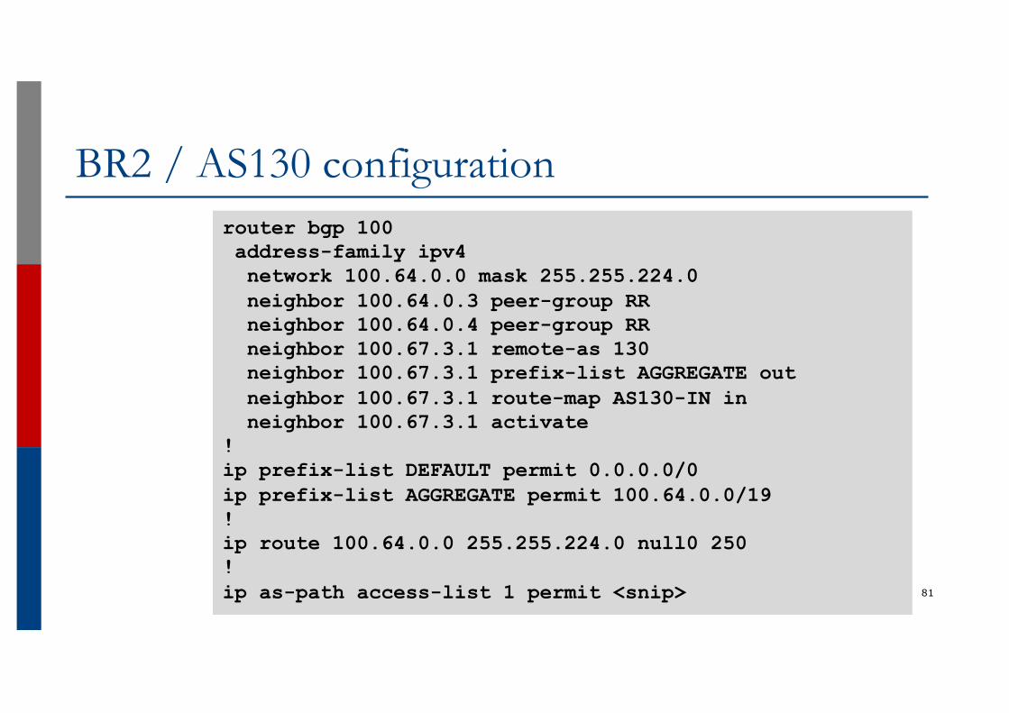
BR2 / AS130 configuration
81
router bgp 100address-family ipv4network 100.64.0.0 mask 255.255.224.0neighbor 100.64.0.3 peer-group RRneighbor 100.64.0.4 peer-group RRneighbor 100.67.3.1 remote-as 130neighbor 100.67.3.1 prefix-list AGGREGATE outneighbor 100.67.3.1 route-map AS130-IN inneighbor 100.67.3.1 activate
!ip prefix-list DEFAULT permit 0.0.0.0/0ip prefix-list AGGREGATE permit 100.64.0.0/19!ip route 100.64.0.0 255.255.224.0 null0 250!ip as-path access-list 1 permit <snip>
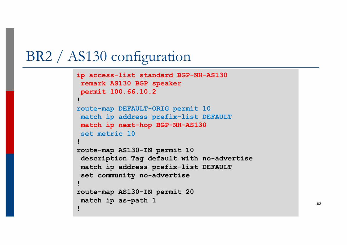
BR2 / AS130 configuration
82
ip access-list standard BGP-NH-AS130remark AS130 BGP speakerpermit 100.66.10.2!route-map DEFAULT-ORIG permit 10match ip address prefix-list DEFAULTmatch ip next-hop BGP-NH-AS130set metric 10!route-map AS130-IN permit 10description Tag default with no-advertisematch ip address prefix-list DEFAULTset community no-advertise!route-map AS130-IN permit 20match ip as-path 1!
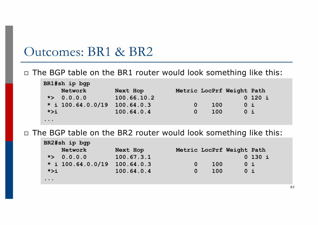
Outcomes: BR1 & BR2p The BGP table on the BR1 router would look something like this:
p The BGP table on the BR2 router would look something like this:
83
BR1#sh ip bgpNetwork Next Hop Metric LocPrf Weight Path
*> 0.0.0.0 100.66.10.2 0 120 i* i 100.64.0.0/19 100.64.0.3 0 100 0 i*>i 100.64.0.4 0 100 0 i...
BR2#sh ip bgpNetwork Next Hop Metric LocPrf Weight Path
*> 0.0.0.0 100.67.3.1 0 130 i* i 100.64.0.0/19 100.64.0.3 0 100 0 i*>i 100.64.0.4 0 100 0 i...
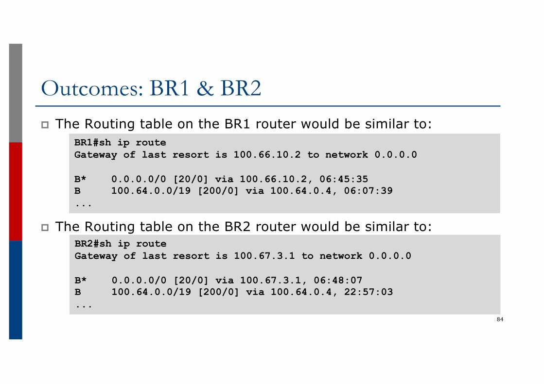
Outcomes: BR1 & BR2p The Routing table on the BR1 router would be similar to:
p The Routing table on the BR2 router would be similar to:
84
BR1#sh ip routeGateway of last resort is 100.66.10.2 to network 0.0.0.0
B* 0.0.0.0/0 [20/0] via 100.66.10.2, 06:45:35B 100.64.0.0/19 [200/0] via 100.64.0.4, 06:07:39...
BR2#sh ip routeGateway of last resort is 100.67.3.1 to network 0.0.0.0
B* 0.0.0.0/0 [20/0] via 100.67.3.1, 06:48:07B 100.64.0.0/19 [200/0] via 100.64.0.4, 22:57:03...
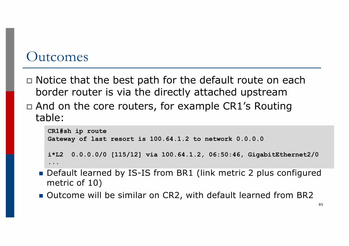
Outcomesp Notice that the best path for the default route on each
border router is via the directly attached upstreamp And on the core routers, for example CR1’s Routing
table:
n Default learned by IS-IS from BR1 (link metric 2 plus configured metric of 10)
n Outcome will be similar on CR2, with default learned from BR285
CR1#sh ip routeGateway of last resort is 100.64.1.2 to network 0.0.0.0
i*L2 0.0.0.0/0 [115/12] via 100.64.1.2, 06:50:46, GigabitEthernet2/0...
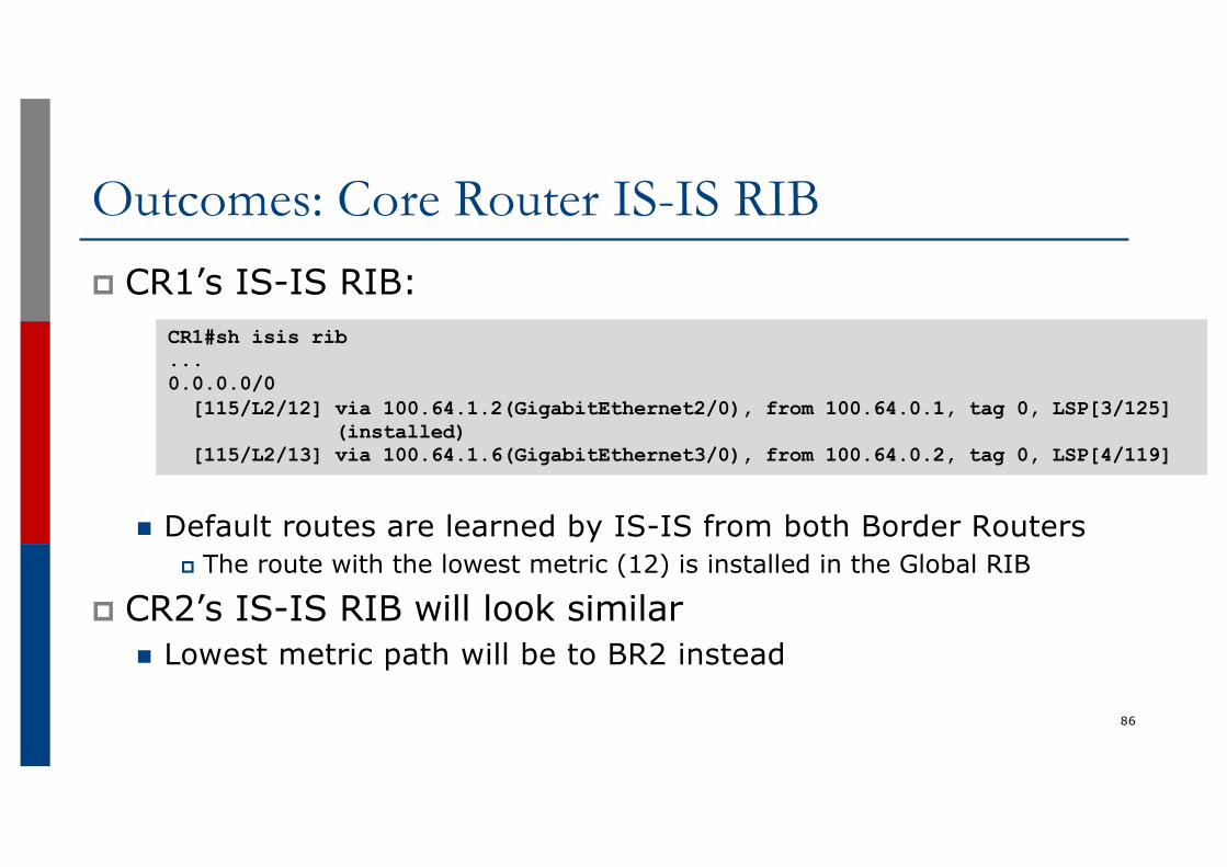
Outcomes: Core Router IS-IS RIBp CR1’s IS-IS RIB:
n Default routes are learned by IS-IS from both Border Routersp The route with the lowest metric (12) is installed in the Global RIB
p CR2’s IS-IS RIB will look similarn Lowest metric path will be to BR2 instead
86
CR1#sh isis rib...0.0.0.0/0[115/L2/12] via 100.64.1.2(GigabitEthernet2/0), from 100.64.0.1, tag 0, LSP[3/125]
(installed)[115/L2/13] via 100.64.1.6(GigabitEthernet3/0), from 100.64.0.2, tag 0, LSP[4/119]
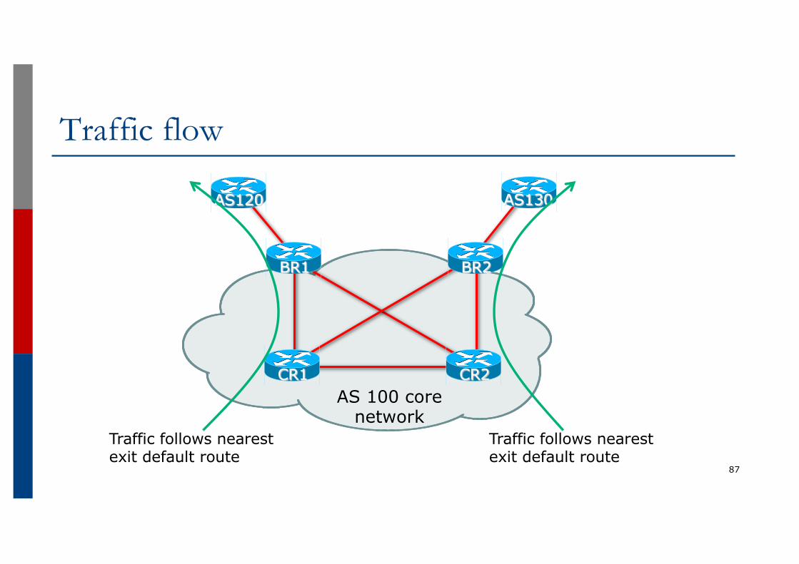
Traffic flow
87
AS 100 core network
AS120 AS130
BR2BR1
CR2CR1
Traffic follows nearestexit default route
Traffic follows nearestexit default route
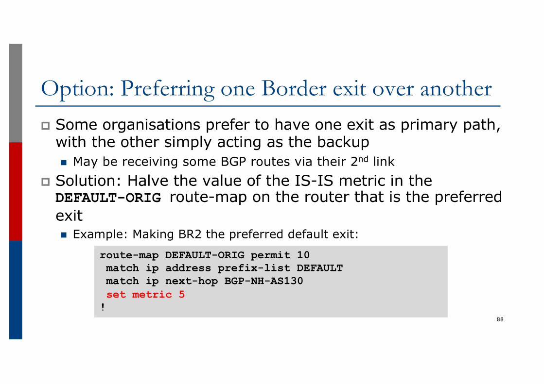
Option: Preferring one Border exit over anotherp Some organisations prefer to have one exit as primary path,
with the other simply acting as the backupn May be receiving some BGP routes via their 2nd link
p Solution: Halve the value of the IS-IS metric in theDEFAULT-ORIG route-map on the router that is the preferredexitn Example: Making BR2 the preferred default exit:
88
route-map DEFAULT-ORIG permit 10match ip address prefix-list DEFAULTmatch ip next-hop BGP-NH-AS130set metric 5!
Deployment Scenariosp Configuration described here are suitable for and have
been deployed at many different organisations:n Small ISPs carrying defaults and partial BGP table from their
upstream providersn Enterprises multihoming between two ISPsn Research & Education institutions multihoming between their
R&E provider and their commodity Internet provider
89
Summaryp Propagation of the default via IGP allows for:
n Swift failover if either external BGP session dropsn Sending traffic to nearest exit if this is desired
p Much more effective than propagating default by IBGPn Note the Cisco IOS specific requirements:
p EBGP route distance needs to be lower than any IGP on border routerp IS-IS needs a route-map to conditionally propagate the default route
90
BGP Case StudiesISP Workshops
91