behavior-based architecture conformance checking
TRANSCRIPT
Ana-Maria-Cristina Nicolaescu
Ana
-Mar
ia-C
ristin
a N
icol
aesc
uB
ehav
ior-
Bas
ed A
rchi
tect
ure
Con
form
ance
Che
ckin
g
Band 37
Ban
d 37
Behavior-Based Architecture Conformance Checking
Aachener Informatik-Berichte,Software Engineering
Hrsg: Prof. Dr. rer. nat. Bernhard Rumpe Prof. Dr. rer. nat. Horst Lichter
Behavior-Based Architecture ConformanceChecking
Von der Fakultät für Mathematik, Informatik und Naturwissenschaften der RWTH AachenUniversity zur Erlangung des akademischen Grades einer Doktorin der Naturwissenschaften
genehmigte Dissertation
vorgelegt von
Ana-Maria-Cristina Nicolaescu, M.Sc.aus Bukarest, Rumänien
Berichter: Universitätsprofessor Dr. rer. nat. Horst LichterUniversitätsprofessor Dr. rer. nat. Claus Lewerentz
Tag der mündlichen Prüfung: 13. September 2018
Diese Dissertation ist auf den Internetseiten der Universitätsbibliothek online verfügbar.
[Nic18] A. Nicolaescu: Behavior-Based Architecture Conformance Checking. Shaker Verlag, ISBN 978-3-8440-6415-5. Aachener Informatik-Berichte, Software Engineering, Band 37. Dezember 2018. www.se-rwth.de/publications/

Shaker VerlagAachen 2018
Aachener Informatik-Berichte, Software Engineering
herausgegeben vonProf. Dr. rer. nat. Bernhard Rumpe
Software EngineeringRWTH Aachen University
Band 37
Ana-Maria-Cristina NicolaescuRWTH Aachen University
Behavior-Based ArchitectureConformance Checking
WICHTIG: D 82 überprüfen !!!

Bibliographic information published by the Deutsche NationalbibliothekThe Deutsche Nationalbibliothek lists this publication in the DeutscheNationalbibliografie; detailed bibliographic data are available in the Internet athttp://dnb.d-nb.de.
Zugl.: D 82 (Diss. RWTH Aachen University, 2018)
Copyright Shaker Verlag 2018All rights reserved. No part of this publication may be reproduced, stored in aretrieval system, or transmitted, in any form or by any means, electronic,mechanical, photocopying, recording or otherwise, without the prior permissionof the publishers.
Printed in Germany.
ISBN 978-3-8440-6415-5ISSN 1869-9170
Shaker Verlag GmbH • P.O. BOX 101818 • D-52018 AachenPhone: 0049/2407/9596-0 • Telefax: 0049/2407/9596-9Internet: www.shaker.de • e-mail: [email protected]
AcknowledgementLooking back to my PhD years, I become overwhelmed with happiness: it has been an incrediblejourney and a privilege.
First of all, I would like to express my most sincere gratitude to my doctoral father and mentor,Prof. Dr. rer. nat. Horst Lichter, who has enabled me to conduct my doctoral studies in theResearch Group for Software Construction. I couldn’t have concluded this work without hiscontinuous support, careful guidance and precious advice. Throughout the years, I had thehonor to know him not only as the absolute professional and perfectionist, but also as a personthat became for me a constant source of inspiration and a model.
At the same time, I would like to thank Prof. Dr. rer. nat. Claus Lewerentz for havingaccepted to overtake the second supervision and having guided me with useful comments andimprovement suggestions in the last phase of my PhD.
Dorin Moraru, my math teacher, is one of the persons that hugely impacted my life. I learnedfrom him what true passion for one’s work is. He has constantly pushed his students to becomethe better versions of themselves, to never settle with less and to constantly learn something new.
My grandparents Anica and Gheorghe gave me wings to fly. Grandma Anica, always veryloving and gentle, made one particular issue very clear: she had big dreams for me and wasnot willing to accept anything less than perfect. Grandpa Gheorghe made everything humanlypossible to awake in me the joy of learning and the thirst for knowledge. I wish I could showhim my PhD thesis and dance with him our "dance of joy" that we invented in my childhood.They will be both forever dearly missed.
My mother is the person that supported me the most through all these years. She is my numberone advocate, my model and the lighthouse towards which I turn to when I don’t know further.Thank you for always having been there for me! I couldn’t have finished my work without yourunconditional help and love.
My father constantly reminded me that knowledge trumps possessions and my grandparentsGicu and Jeni always believed in my abilities.
Georgeta’s ambition and perfectionism astonished and inspired me. Her personal example,belief in me, motherly affection contributed significantly to my becoming. I think of her everyday with love and respect.
Petre has always supported and encouraged me very affectionately. Cici, Dinu, Irina, Iulian,Diana and Robert constantly cheered for me and stood by my side, ready to listen and offer goodadvice.
My friends Ioana, Anna, Vicktor, Marina, Miguel, Göckhan, Zied, Dejan, Alexandra, Yiwei,Sten, Dominik, Peter and Adeline made my days cheerful and also invested time to listen andgive me good advice when help was needed. Ralf Klamma slowly shifted from my first chefto a great friend and a constant source of inspiration. Cornelia, Carl and Ruth helped us settlein Germany and have offered constant guidance. Last but not least, Marion, Ina and Nele madeAachen feel like home and surrounded us with love and care.
Furthermore, I would like to express my deepest gratitude to all my colleagues from theresearch group: Simona, Veit, Andreas, Matthias, Firdaus, Andrej, Andy, Simon, Konrad andPeter. It was a pleasure to work with you and constantly learn from you! I am very grateful for

your support and friendship!I would like to thank my long-term industrial cooperation partner Generali Deutschland In-
formatik Services for having financed my PhD, involved me in real-world projects and evaluatedmy results. Furthermore, the company Kisters helped me to extend the scope of the evaluationand contributed significantly to the overall quality of my work.
All of my internship, master and bachelor students contributed to the completion of my PhDand I am thankful to each and every one of them. However, the happiest time of my PhD isassociated with my small "ARAMIS Core Team": Artjom Göringer, Dung Le, Jan Thomas,Peter Alexander and Alexandru Sabau, who have contributed with valuable ideas and activelydeveloped the ARAMIS Toolbox.
To end with, none of what happened in the last 13 years would have been possible withoutmy best friend, soul-mate and husband, Petru, who accompanied me in so many adventures andhappy moments and always found the right words and actions to help me out when life was notrunning as expected. The long discussions with him always brought me forward and gave menew insights. Petru, it is a privilege to spend my life with you, thank you for everything you are!
Last, I would like to thank our little son, Erik George. His arrival in our lives brought ustremendous happiness! Despite generously contributing to our overall sleep deprivation in thelast PhD phases, Erik has showed us what life really is about and completed us as persons. Mydear child, you are still so young, yet so inspiring with your pure joy and fierce ambition toachieve your goals!
Thank you!
AbstractIn this dissertation we present ARAMIS: a concept and corresponding tool support for behavior-based architecture conformance checking of software systems.
In the past years several approaches for static-based architecture conformance checking wereproposed. These pose important limitations when considering modern systems, typically com-posed of several interacting processes. Ever since the advent of object orientation and due tothe shift from monolith architectures to componentized ones, the complexity of software sys-tems has moved from structure to behavior. This is typically out of the scope of static-basedconformance approaches, which face an impossibility in assessing if the system under analysisis behaving as foreseen by its architects.
ARAMIS is our solution to alleviating the above-mentioned problem. First, the intendedarchitecture description of the system under analysis is expressed using an ARAMIS-specificmeta-model. This encompasses the architecture units constituting the system and the commu-nication rules governing these. To increase acceptance, model-engineering techniques are alsoproposed to enable the reuse of intended architecture descriptions elaborated using differentmeta-models than that of ARAMIS. Next, interactions are extracted during the system’s exe-cution using third party monitoring tools. Given that a holistic analysis of the behavior of asystem is impossible in general, we proposed several indicators to assess whether the capturedinteractions represent an adequate basis for checking the conformance of the system as a whole.The interactions are consequently elevated to depict communication between the units definedin the system’s intended architecture description and validated to check their conformance to theformulated communication rules. The results constitute a description of the implemented archi-tecture of the system, characterized by its drift from the intended one. This can subsequentlybe explored using several mechanisms such as user-defined architecture views and perspectivesor dedicated visualizations. Last but not least, processes for guiding the activities involved inbehavior-based conformance checking were developed and described.
The ARAMIS concept and the developed toolbox were evaluated in three case studies, the lasttwo being conducted in industrial settings. The results were very positive. The evaluation provedthat the ARAMIS approach can be utilized by organizations when attempting to understandand evaluate the current state of implemented architectures and as a starting point for futureevolution.

KurzfassungIn dieser Arbeit stellen wir ARAMIS vor: einen neuen, innovativen Ansatz und eine dazu
gehörende Werkezugumgebung, um auf Basis von Laufzeitinformationen verhaltensbasiert dieKonformität von Softwarearchitekturen zu überprüfen.
In den letzten Jahren wurden einige Ansätze für eine statisch-basierte Architekturkonformität-süberprüfung von Softwaresystemen vorgeschlagen. Diese haben jedoch erhebliche Nachteile,insbesondere dann, wenn damit moderne, technologisch heterogene und verteilte Softwaresys-temen analysiert werden sollen. Etablierte Technologien wie die Objektorientierung aber auchder Übergang von monolithischen zu komponentenbasierten Systemen haben die Komplexitätvon Softwaresystemen von deren Struktur zum Systemverhalten verschoben. Eine Prüfungder Architekturkonformität solcher Systeme kann häufig nicht mit statisch-basierten Verfahrendurchgeführt werden, da diese nicht immer feststellen können, ob sich ein System so verhält,wie dies von der Architektur vorgesehen wurde. In dieser Arbeit stellen wir ARAMIS vor, einenneuen Ansatz zur Prüfung der Architekturkonformität, der dieses Problem löst.
In einem ersten Schritt wird dabei die vorgesehene Architekturbeschreibung des zu analysieren-den Softwaresystems mittels eines ARAMIS-spezifischen Metamodells erfasst. Diese Beschrei-bung besteht im Wesentlichen aus den Architektureinheiten des Systems und ihren Kommu-nikationsregeln. Um die Akzeptanz des Ansatzes zu erhöhen, werden darüber hinaus Technikendes Modell-Engineerings genutzt. Dabei wird das Ziel verfolgt, schon existierende Architek-turbeschreibungen verarbeiten zu können, die nicht dem ARAMIS-Metamodell entsprechen. ImAnschluss daran werden die Interaktionen innerhalb einer ausgeführten Software aufgezeich-net, wobei vorhandene Monitoring-Systeme verwendet werden. Im Gegensatz zu den statisch-basierten Ansätzen, ist eine vollständige Analyse eines nicht trivialen Softwaresystems jedochunmöglich. Um dem entgegenzuwirken, werden eine Reihe von Indikatoren eingeführt, dieHinweise bezüglich der Angemessenheit des analysierten Verhaltens, im Verhältnis zu einer sys-temweiten Konformitätsüberprüfung, liefern. Die Interaktionen innerhalb des Systems werdenim nächsten Schritt analysiert. Dabei wird die Kommunikation den definierten Architekturein-heiten zugewiesen und anschlies̈send gegen die definierten Kommunikationsregeln geprüft. DiesesErgebnis liefert die implementierte Architektur des Softwaresystems, die insbesondere auch dieAbweichungen von der vorgesehenen Architekturbeschreibung definiert. Die implementierteArchitektur kann vielfältig analysiert werden, so können zum Beispiel benutzerdefinierte Ar-chitektursichten und Perspektiven definiert oder dedizierte Visualisierungen genutzt werden.Abschlies̈send werden Prozesse vorgeschlagen, die einen Leitfaden für eine verhaltensbasierteArchitekturkonformitätsüberprüfung darstellen.
Der ARAMIS-Ansatz wurde durch drei Fallstudien evaluiert, zwei davon im industriellenKontext. Die Ergebnisse sind sehr positiv. Die Evaluierungen haben gezeigt, dass ARAMIS ef-fektiv genutzt werden kann, um eine implementierte Architektur im Bezug zu ihrer vorgesehenenArchitekturbeschreibung zu verstehen und zu evaluieren. Dies ist ein wichtiger Ausgangspunktfür eine gezielte Softwareevolution.

Contents
I. Introduction and Foundations 1
1. Introduction 31.1. Thesis Context . . . . . . . . . . . . . . . . . . . . . . . . . . . . . . . . . . 31.2. Thesis Statement . . . . . . . . . . . . . . . . . . . . . . . . . . . . . . . . . 4
1.2.1. Contribution . . . . . . . . . . . . . . . . . . . . . . . . . . . . . . . 51.3. Research Questions . . . . . . . . . . . . . . . . . . . . . . . . . . . . . . . . 71.4. Dissertation Outline . . . . . . . . . . . . . . . . . . . . . . . . . . . . . . . . 8
2. Foundations 112.1. Software Architecture and Software Architecture Description . . . . . . . . . . 11
2.1.1. Software Architecture . . . . . . . . . . . . . . . . . . . . . . . . . . 112.1.2. Software Architecture Description . . . . . . . . . . . . . . . . . . . . 13
2.2. Architecture Degeneration . . . . . . . . . . . . . . . . . . . . . . . . . . . . 182.3. Architecture Reconstruction . . . . . . . . . . . . . . . . . . . . . . . . . . . 23
II. ARAMIS 25
3. ARAMIS - The Big Picture 27
4. ARAMIS Monitoring Concepts 354.1. Scenario Sources Overview . . . . . . . . . . . . . . . . . . . . . . . . . . . . 37
4.1.1. Use Cases . . . . . . . . . . . . . . . . . . . . . . . . . . . . . . . . . 374.1.2. Test Cases . . . . . . . . . . . . . . . . . . . . . . . . . . . . . . . . . 484.1.3. Stakeholders’ Narratives . . . . . . . . . . . . . . . . . . . . . . . . . 50
5. Describing Extracted Interactions in ARAMIS 515.1. The ARAMIS Interactions Description Language . . . . . . . . . . . . . . . . 515.2. Enabling Kieker-Based Monitoring . . . . . . . . . . . . . . . . . . . . . . . . 535.3. Enabling Dynatrace-Based Monitoring . . . . . . . . . . . . . . . . . . . . . . 55
6. Behavior-based Architecture Conformance Checking in ARAMIS 596.1. Conformance Checking Techniques Employed in ARAMIS . . . . . . . . . . . 596.2. Meta-Model of ARAMIS Architecture Descriptions . . . . . . . . . . . . . . . 626.3. The ARAMIS Communication Rules Language - A Taxonomical Perspective . 68
6.3.1. Predefined Default Rules . . . . . . . . . . . . . . . . . . . . . . . . . 72
6.4. Concepts for Rules Prioritization and the ARAMIS Conformance Checking Phases 746.4.1. The Non-Aggregating Phase . . . . . . . . . . . . . . . . . . . . . . . 756.4.2. The Aggregating Phase . . . . . . . . . . . . . . . . . . . . . . . . . . 86
6.5. Focusing the Conformance Checking Results . . . . . . . . . . . . . . . . . . 876.5.1. The ARAMIS Results Exploration Language . . . . . . . . . . . . . . 88
7. The Meta-Model Incompatibility Problem 937.1. The Architecture Description Transformation Process . . . . . . . . . . . . . . 97
8. Adequate Monitoring 1098.1. White-Box Indicators for Adequate Monitoring . . . . . . . . . . . . . . . . . 1108.2. Black-Box Indicator for Adequate Monitoring . . . . . . . . . . . . . . . . . . 1218.3. Related Work . . . . . . . . . . . . . . . . . . . . . . . . . . . . . . . . . . . 125
9. Conducting Behavior-Based Conformance Checks 1279.1. Static- vs. Behavior-Based Conformance Checks . . . . . . . . . . . . . . . . 1279.2. Towards a Behavior-Based Conformance Checking Process . . . . . . . . . . . 134
10. Tooling for Architecture Conformance Checking 13910.1. The ARAMIS Toolbox . . . . . . . . . . . . . . . . . . . . . . . . . . . . . . 139
10.1.1. Capabilities Overview . . . . . . . . . . . . . . . . . . . . . . . . . . 13910.1.2. Architecture and Implementation . . . . . . . . . . . . . . . . . . . . 141
10.2. Related Work . . . . . . . . . . . . . . . . . . . . . . . . . . . . . . . . . . . 145
III. Evaluation 151
11. Evaluation Overview 15311.1. Evaluation Goals . . . . . . . . . . . . . . . . . . . . . . . . . . . . . . . . . 15311.2. Methodology . . . . . . . . . . . . . . . . . . . . . . . . . . . . . . . . . . . 155
12. Case Study I 15712.1. Case Study Design . . . . . . . . . . . . . . . . . . . . . . . . . . . . . . . . 15712.2. Results . . . . . . . . . . . . . . . . . . . . . . . . . . . . . . . . . . . . . . . 15912.3. Discussion . . . . . . . . . . . . . . . . . . . . . . . . . . . . . . . . . . . . . 165
13. Case Study II 16713.1. Case Study Design . . . . . . . . . . . . . . . . . . . . . . . . . . . . . . . . 16713.2. Results . . . . . . . . . . . . . . . . . . . . . . . . . . . . . . . . . . . . . . . 16813.3. Discussion . . . . . . . . . . . . . . . . . . . . . . . . . . . . . . . . . . . . . 177
14. Case Study III 17914.1. Case Study Design . . . . . . . . . . . . . . . . . . . . . . . . . . . . . . . . 17914.2. Results . . . . . . . . . . . . . . . . . . . . . . . . . . . . . . . . . . . . . . . 18114.3. Discussion . . . . . . . . . . . . . . . . . . . . . . . . . . . . . . . . . . . . . 190
15. Evaluation Summary 193
16. Related Case Studies on Architecture Conformance Checking 197
IV. Conclusions, Summary and Future Work 201
17. Conclusions 203
18. Summary 205
19. Future Work 207
V. Appendixes 209
A. Monitoring Anomalies 211A.1. The Polymorphism Anomaly . . . . . . . . . . . . . . . . . . . . . . . . . . . 211A.2. The Partial Trace Anomaly . . . . . . . . . . . . . . . . . . . . . . . . . . . . 214
B. Case Study III- Results Overview 221B.1. Behavior-Based Conformance Checking of TADD . . . . . . . . . . . . . . . . 221B.2. Static Conformance Checking of TADD . . . . . . . . . . . . . . . . . . . . . 222
C. Monitoring Sessions Conducted in the Presented Case Studies 227C.1. Monitoring Session Employed in Case Study I . . . . . . . . . . . . . . . . . . 227C.2. Scenarios Employed in Case Study II . . . . . . . . . . . . . . . . . . . . . . 228
D. Grammar of the ARAMIS DSL for Views and Perspectives (Excerpt) 231
Refereed Publications 235
Glossary 239
Acronyms 247
List of Figures 249
Listings 251
List of Tables 253
Bibliography 255


Part I.
Introduction and Foundations

Chapter 1.
Introduction
1.1. Thesis Context
The paramount importance of software architecture has long been acknowledged. Among oth-ers, it has been described to have a decisive role in the communication with stakeholders andact as a manifestation of the early design decisions. Furthermore a good architecture is claimedto benefit the employing organization beyond the boundaries of a single system as it representsan "architecturally graspable model [...] transferable across systems" [BCK12]. Moreover, asFairbanks underlined, "when you choose [architecture] deliberately, you reduce your risks andchances of failure" [Fai10]. As suggested by Fairbanks’ statement, given a functional require-ments specification, there are more architecture variants that might be employed to developthese. In fact, "with enough effort you probably could build any system using any architecture,but developers will struggle when the architecture is unsuitable" [Fai10]. To decrease devel-opment effort and meaningfully achieve not only the functional but also the system’s qualityrequirements, architects work towards defining the most suitable architecture for a given con-text. This is all the more important in the case of complex systems expected to be in use for alonger time span than a mere prototype: "you don’t need architecture to build a dog kennel, butyou’d better have some for a skyscraper" [Boo00]. The architecture is documented in the so-called architecture description of the system and its role is to guide development, maintenanceand evolution activities.
Bass et al. formulated a set of process and product recommendations to consider when sys-tematically working with software architectures as a means to reduce risks. One of the centralprocess-oriented recommendations is that the architecture description "should be well docu-mented, with at least one static and one dynamic view using an agreed-on notation that all stake-holders can understand with a minimum of effort" [BCK12]. Furthermore, according to theirrole as blueprints, architecture descriptions should place constraints on the freedom degree offuture implementations, because "constraints impose organization on chaos" [Fai10]. To empha-size their role as blueprints architecture descriptions are often referred to as being (as-)intended,(as-)designed or prescriptive.
However, despite initial efforts invested in creating intended architecture descriptions, soft-ware systems are often developed under acute time and cost pressure and their implementationstypically violate initial architectural decisions and constraints in the favor of, e.g., less rigorousbut on the short term easier implementable solutions [GKMM13], [dSB12]. These situationsmight be acceptable in an initial phase to secure momentum and agility towards ever changingrequirements. However, if corrective actions are not undertaken, the system quickly evolves very
4 Chapter 1. Introduction
differently than prescribed [PW92], [LV95] and a new architecture emerges - often referred toas the (as-)implemented architecture. The drift of the implemented architecture away from theintended one, inherently renders the description of the latter useless or even harmful for support-ing the understanding of the system on a more abstract, conceptual level. In such situations, adescription of the implemented architecture can prove beneficial to understand the status of thesystem and support evolution decisions. To this end, the research field of software architecturereconstruction has emerged. Architecture reconstruction is defined as an "interpretive, interac-tive and iterative process [...] in which the as-built architecture [description] of an implementedsystem is obtained from an existing system" [BCK12]. Architecture reconstruction can be em-ployed to serve a variety of purposes ranging from (re-)documentation and dependency analysisto evolution planning. In this dissertation we focus on architecture reconstruction as a meansto support conformance evaluations between the implemented architecture of a system and theinitially intended one. Through the identification of violated architectural constraints, we aidthe architects in planning future evolution activities to reduce the resulted drift thus enabling therealization of required system qualities.
While a plethora of approaches for extracting and checking the conformance of the imple-mented architectures exist, the wide majority of these focus on structural aspects alone. How-ever, with the widespread use of object oriented programming languages and new architecturalstyles such as microservices ([mfm], [Sam15]), the complexity often lies in the interplay of thedifferent parts of the systems, rather than in their mere structure [SBB+10]. To this date, most ofthe tools that analyze the run-time of systems focus on performance diagnosis-related aspects.In this dissertation we present ARAMIS (the Architectural Analysis and Monitoring Infrastruc-ture), our approach for analyzing the behavior of a system on various architectural abstractionlevels thus scaffolding understanding, architectural reasoning and conformance checking. Thus,ARAMIS builds on the formerly mentioned monitoring tools specialized in information extrac-tion from running systems and adds an additional layer that enables architectural conformancechecking and analysis.
1.2. Thesis Statement
In this section we first present our overall thesis statement. This will then be analyzed accordingto its constituent elements to emphasize the contributions brought forward by this dissertation.
Thesis Statement We assist software architects to analyze and evaluate the architecturaldrift of software systems or landscapes thereof by employing architectural conformance checkingon information extracted during run-time. Thus, we provide (a) a means to leverage existingmonitoring tools to fit the purpose of conformance checking, (b) a set of concepts to investigatethe adequacy of the monitored behavior towards assessing the drift of the system as a whole, (c)support for the definition or reuse of intended architecture descriptions including an extensiblelanguage to express applicable communication rules, and last but not least (d) a process to guidestakeholders towards achieving the formulated goal.
1.2. Thesis Statement 5
1.2.1. Contribution
We break the thesis statement into its constituent pieces and explain them more closely, to pro-vide an overview of our contributions as presented in this thesis.
We assist software architects to analyze and evaluate the architectural drift of software sys-tems or landscapes thereof by employing architectural conformance checking on informationextracted during run-time.
Due to the phenomenon of architecture drift, the implemented architecture is rarely docu-mented and typically inconsistent with the intended architecture description. However, the sus-tainable evolution of large software systems can only take place if the implemented architec-ture is understood and documented for constant reference. Typically, architecture reconstruc-tion tools address this issue and extract up-to-date structural views of the considered systemby holistically examining its source code. However, to fully understand a system, its behaviorhas to be comprehended as well. Important architectural aspects, such as details regarding thecommunication among involved processes are out of the scope of static conformance checkingapproaches. However, considering the size of industrial software systems, it cannot be real-istically expected that a complete understanding of all occurring low-level interactions can beachieved. Our claim is that we can facilitate the understanding of the behavior view of soft-ware systems by employing an adaptation of the hierarchical reflexion modeling technique: wecreate a description of the implemented architecture by mapping interactions extracted from therunning system on structures depicted in its intended architecture description. The resultingimplemented architecture description can then be used to analyze and understand the softwaresystem and evaluate the emerged drift.
We provide (a) a means to leverage existing monitoring tools to fit the purpose of conformancechecking.
Tools capable of extracting run-time information from heterogeneous running systems arealready available. However, their focus is not on supporting conformance checking but ratherperformance analysis and diagnosis. To support reuse and reduce complexity, we create a flex-ible solution to enable the easy docking of monitoring tools as data sources for the proposedbehavior-based conformance checking process. This problematic is addressed in detail in Chap-ter 5.
We propose (b) a set of concepts to investigate the adequacy of the monitored behavior to-wards assessing the drift of the system as a whole.
Behavior-based conformance checking gives deep insights into the run-time of the systemunder analysis. However, it can only be representative for the system as a whole if "enough"behavior is captured and analyzed. This problematic is well-known, but it was only shallowlyaddressed in our related work. In this research, we propose the use of semantic and technicalindicators for assessing the adequacy of the monitored behavior from two different but comple-menting perspectives. This problematic is detailed in Chapter 8.
We provide (c) support for the definition or reuse of intended architecture descriptions includ-ing an extensible language to express applicable communication rules.
Due to the popularity of reflexion modeling, most state-of-the-art software architecture recon-struction tools rely on intended architecture descriptions as input. These are then enriched withinformation gained during conformance checking to depict the differences between the intended
6 Chapter 1. Introduction
architecture and the implemented one. However, the language to express the intended architec-ture is typically tool-specific. It is implicitly expected that an architect who intends to use aconformance checking tool must define the intended architecture using the architecture descrip-tion language employed by the tool itself. Also in our approach, we provide a specific meansfor describing the architectural structure of the system under analysis, as depicted in Chapter 6.However, very often intended architecture descriptions already exist prior to making the deci-sion to undergo a conformance checking process. Unfortunately, these are typically expressedin some other language than the one required by the conformance checking tool as input, sinceno architecture description language managed to impose itself as a generally accepted standard.The fact that existing architecture descriptions (e.g., boxes and lines, company specific UMLdiagrams) cannot be reused and must first be transformed to adhere to a given tool’s languageis perceived as frustrating and leads to acceptance problems (“I do not agree with the resultsbecause our system was not supposed to be a layered one!”). This situation was also revealed bysome of the case studies that we conducted in the industry [DHL14]. In our research, we intro-duced the term “meta-model incompatibility problem” to express the discordance between thelanguages used by the architects when creating architecture descriptions, on the one hand, andthe languages employed by the various tools to depict intended and/or implemented architec-tures, on the other hand. Our solution towards alleviating the meta-model incompatibly problemby means of model engineering techniques is detailed in Chapter 7.
Furthermore, we address the problematic of formulating architectural rules governing thecommunication of the architectural structures encompassed in the intended architecture descrip-tion. Some of these rules can be automatically derived from the intended architecture descrip-tions themselves. However, the more complex the analyzed system is, the more complex theserules can also be. Consequently, many rules are only hinted at in textual architecture documentsor implicitly imposed by the architects. We propose a flexible XML-based language for ex-pressing these rules in order to support the automatic conformance checking against them (seeChapter 6).
We propose (d) a process to guide stakeholders towards meaningfully employing behavior-based conformance checking.
Behavior-based conformance checking while insightful, is not straight-forward to conduct andrequires more resources than static-based approaches. Consequently, the differences between thebehavior- and static-based solutions must be understood prior to commencing the conformancechecking process, to meaningfully use the available resources. Once the decision for behavior-based conformance checking has been made, we propose a process to control the complexityassociated therewith. This problematic is addressed in detail in Chapter 9.
All in all, based on the formulated thesis statement, we presented four main aspects (a-d) underlying the research presented in this thesis. The next section derives associated re-search questions that underlaid the work presented in this dissertation. Their answers, as pre-sented in the chapters of Part II, are subsumed to a conceptual and tool-supported approachtowards behavior-based conformance checking, called ARAMIS: the Architecture Analysis andMonitoring Infrastructure.
1.3. Research Questions 7
1.3. Research Questions
Given the thesis statement presented in Section 1.2 and explained in Section 1.2.1, we derive aset of five research questions addressed by this dissertation:
Research Question 1 (Universal Language for Interaction Descriptions) How to de-scribe the interactions occurring in a running software system independently of the monitoringtools employed to extract these?
To answer this question, we propose a universal language for describing interactions thatenables a monitoring tool-independent reconstruction of implemented architecture descriptions.The approach is presented in Chapter 5 and has been intrinsically evaluated by including twodifferent monitors as data sources for ARAMIS.
Research Question 2 (Behavior-based Architecture Conformance Checking) How tomodel the intended architecture of a system and perform behavior-based architecture confor-mance checking based thereupon?
Chapter 6 presents the ARAMIS approach towards defining intended architecture descrip-tions and corresponding communication rules governing them. Furthermore, it presents thealgorithms that ARAMIS employs when checking behavior conformance. All presented casestudies (Chapters 12, 13, 14) are evaluating various facets of the answers that we provide forthis central research question.
Research Question 3 (Addressing Meta-Model Incompatibility) How can we enable ar-bitrary intended architecture descriptions as input for the ARAMIS analysis and present theoutput so that it boosts understanding and recognition effects?
Our contribution towards answering this research question is discussed in Chapter 7. In thecase study presented in Chapter 12, we defined the intended architecture description of ARAMISusing the ARAMIS meta-model. Consequently, no meta-model incompatibility needed to beaddressed. However, both industrial case studies exhibited this problem. In the Industrial CaseStudy 1 (Chapter 13) the architecture description was available in a boxes and lines format.Contrastingly, in the Industrial Case Study 2 we received instead a multi-level UML componentdiagram. We used both case studies to evaluate our approach towards alleviating the meta-modelincompatibility problem.
Research Question 4 (Monitoring Relevance) How to ensure that the monitored behaviorrepresents a sound basis for an architectural conformance check?
Chapter 8 presents our contribution towards a set of technical and semantic indicators to as-sess the adequacy of monitored behavior for supporting overall evaluations regarding the ar-chitectural drift of a system as a whole. We applied the developed semantic indicators in theARAMIS-based case study (Chapter 12) and the Industrial Case Study 1 (Chapter 13). Due tolack of documentation, only technical indicators could be employed in the Industrial Case Study2 (Chapter 14).
8 Chapter 1. Introduction
Research Question 5 (Behavior-based Conformance Checking Process) When andhow to conduct behavior-based architecture conformance checks?
This research question is addressed in Chapter 9. First we present a theoretical compari-son between static and behavior conformance checking approaches to understand their relativestrengths and weaknesses and offer guidance if a choice between the two should be made. Giventhat behavior-based approaches are more intricate than static ones, we then provide a process thatsupports the systematic applicability of ARAMIS by highlighting the main activities that shouldbe performed in a behavior-based conformance checking context. Tailorings of the presentedprocess were then employed in all three presented case studies (Chapters 12, 13, 14).
1.4. Dissertation Outline
In the following we give a brief overview of the structure of this thesis.
Chapter 1 introduced the reader to the context of this research. Next, we formulated ourthesis statement, briefly presented our contribution and extracted the research questions that lieat the basis of our research. Next, Chapter 2 gives an overview of important concepts usedthroughout this dissertation. First, we present well-known definitions of software architectureand software architecture descriptions. Then, we discuss the architecture degeneration processthat typically occurs during the evolution of software systems and results in an architectural driftthat can threaten key qualities of the system such as maintainability and understandability. Inthis context, we present various synonym concepts used throughout related literature to refer toarchitectural drift in general and discuss possible semantic differences between these. Finally,we approach the important topic of architecture reconstruction and conformance checking.
The second part of this dissertation is dedicated exclusively to presenting ARAMIS - ourcontribution for supporting the formulated thesis statement. A high-level overview of the pro-posed approach is presented in Chapter 3. A set of important monitoring concepts and termi-nology associated therewith is depicted in Chapter 4. The following chapters approach one byone the research questions formulated in Section 1.3. Chapter 5 presents a universal languagefor describing interactions that we proposed to enable the flexible accommodation of arbitrarymonitoring tools as data sources for the ARAMIS-based conformance checking process. Next,Chapter 6 details the ARAMIS-specific approach to modeling intended architecture descriptions.We first present the meta-model of ARAMIS-specific architecture descriptions. We then elabo-rate on the taxonomy of ARAMIS architectural communication rules and consequently presentthe algorithms guiding the ARAMIS behavior conformance checks. Chapter 6 is rounded upwith a discussion regarding the focusing of conformance checking results using an ARAMIS-specific extension of the well-known concepts of views and perspectives. Chapter 7 approachesthe meta-model incompatibility problem and proposes a model-engineering based process forsupporting the reuse of existing intended architecture descriptions as input for ARAMIS andtheir subsequent augmentation with the conformance checking results to leverage understandingbased on recognition effects. Chapter 8 approaches the problematic of adequacy of the moni-tored behavior towards supporting system-level evaluations of the identified architectural drift.An overall comparison of static vs. behavior conformance checking approaches is presented inChapter 9 and aims to guide architects towards choosing the right approach considering the over-
1.4. Dissertation Outline 9
all scope of their endeavor and the available resources. The chapter concludes with a processaimed to guide architects while performing behavior conformance checks. Chapter 10.1 givesan overview of the toolbox developed to showcase the most important concepts presented in thispart.
The third part of the dissertation concerns the evaluation of ARAMIS. To this end we presentthree conducted case-studies. First, in Chapter 12, we evaluate the architecture drift of an excerptof the ARAMIS Toolbox by employing ARAMIS itself. Next, in Chapter 13 we evaluate a pureJ2EE system developed in an industrial context. Last but not least, we performed a third, morecomprehensive case study in the industry on a large-scale OSGI-based system whose resultsare presented in Chapter 14. The corroborated results of all the conducted case studies arediscussed in Chapter 11. We end this part with an overview of published experiences regardingthe applicability and evaluation of further conformance checking approaches in the industry.
The fourth part summarizes the presented research. Chapter 17 discusses the conclusions andlimitations of our work and Chapter 18 sketches a summary thereof. Possible directions forfuture work are elaborated upon in the concluding Chapter 19.

Chapter 2.
Foundations
In this chapter we explore some important aspects that lie at the basis of this research. To beginwith, we explore the concepts of software architecture and software architecture description.We then further define the terms view, viewpoint and perspective and exemplify some well-known viewpoint models of software architecture. Finally, we discuss the process of softwarearchitecture degradation and the various types in which this can be encountered in softwaresystems.
2.1. Software Architecture and Software ArchitectureDescription
2.1.1. Software Architecture
The software architecture influences to a great extent most of a software system’s non-functionalcharacteristics [CBB+10], [CK16], [Mar17], such as maintainability, understandability, perfor-mance, etc. Fairbanks [Fai10] described the architecture as the backbone or skeleton of a system.The more appropriate for its intended purpose and the more robust the skeleton, the better thequalities of the sustained system is. Furthermore, he highlighted the fact that while severalsystems with different architectures can achieve the same functional requirements, their qualityas perceived by the stakeholders might dramatically differ based on their employed architec-ture. Therefore, the choice of architecture is crucial, especially in the case of large, long-livedand/or commercial systems. In the case of large landscapes of inter-related software systems,the architecture plays an even more crucial role as changes to one system can easily lead to thepropagation of possibly undesirable effects throughout the landscape.
Because of such rationales, the importance of software architecture has been long acknowl-edged by the research and industrial communities [GS94], [SG96], [CKK01], [Hoh03], [SC06].Representing only an abstraction of the overall system, it allows reasoning about a system’scurrent state, sustains high-level evaluations and decisions about evolution at an intellectuallymanageable level. Consequently, “software architecture can provide a vehicle for communica-tion between the various stakeholders” [RM06], such as users (interested e.g., in the performanceof the system), managers (e.g., for dividing and assigning tasks), coders (e.g., when assemblingthe components of a system) and testers (e.g., when planning integration tests). Additionally,being the skeleton of the application, the architecture emerges very soon in the software devel-opment life-cycle and is largely affected by the decisions taken in the incipient phases. However,
12 Chapter 2. Foundations
as stated by Barry Boehm more than 30 years ago, these early decisions, when wrong, can causeenormous change costs if identified in late project phases [Boe81]. Although with the adventof extreme programming and lean development the curve of these costs has arguably flattened,changing the architecture of a system is still potentially very costly as it can easily affect thestructure and organization of the system in its entirety. Finally, the importance of software ar-chitecture also lies in its role as a “transferable abstraction” [BCK12]. If an architecture provesitself to successfully respond to its stakeholders’ requirements, reusing it in similar projects isof course desirable, leading to faster development time, better quality resulted from leveragingpast experiences and possibly cost reduction.
Despite its importance, there is no standard definition of the “software architecture” concept.For example, a listing of possible definitions as collected by the Software Engineering Institute(SEI) can be analyzed in [seib]. In the next paragraph we give an overview of some of the mostwell known and cited definitions thereof.
Taylor et al. [TMD10] define software architecture as simply “the set of principal designdecisions made about the system”. This decisions-centric definition has been criticized, howeveron the grounds that architecture, while comprising decisions and their rationale, goes muchfurther beyond these, also encompassing, e.g., the most important software elements and theirform [BCK12].
Therefore, for the purpose of this research, we consider that the following definitions of soft-ware architecture are more accurate.
The software architecture is
• the “fundamental concepts or properties of a system in its environment em-bodied in its elements, relationships, and in the principles of its design andevolution” [420] (The ISO/IEC/IEEE 42010 standard).
• the "set of structures needed to reason about the system, which comprise soft-ware elements, relations among them, and properties of both” [BCK12].
The above definition explicitly stipulates the existence of more than one structure of the sys-tem (e.g., organizational structure - how the system is organized in implementation units de-veloped by the developers, interaction structure - how the elements should access each other atrun-time, threading issues, etc.) and emphasizes that the architecture is an abstraction, becauseonly those structures that are large or important enough to actually support reasoning about thesystem are architectural.
The above definitions have in common the fact that the architecture is not something extrinsicto a system, but intrinsic to it. The architecture of a system exists also if it is not documentedanywhere and thus no architecture description is available. As Rozanski and Woods also em-phasize, “although every system has an architecture, not every system has an architecture that iseffectively communicated via an architectural description” [RW11]. However, given the impor-tance of software architecture and the effort that should otherwise be invested to understand asoftware architecture if its documentation were not available, researchers and practitioners alikestrongly petition for elaborating and periodically updating suitable architecture descriptions.
2.1. Software Architecture and Software Architecture Description 13
2.1.2. Software Architecture Description
The ISO/IEC/IEEE 42010 standard, centered around the concept of architecture description,defines a software architecture description as follows:
"A software architecture description is an artifact that expresses an Architectureof some System of Interest" [420].
Acording to the 42010 standard, the purpose of an architecture description is to help stake-holders to “understand, analyze and compare architectures” and/or to serve as a “blueprint forplanning and construction”.
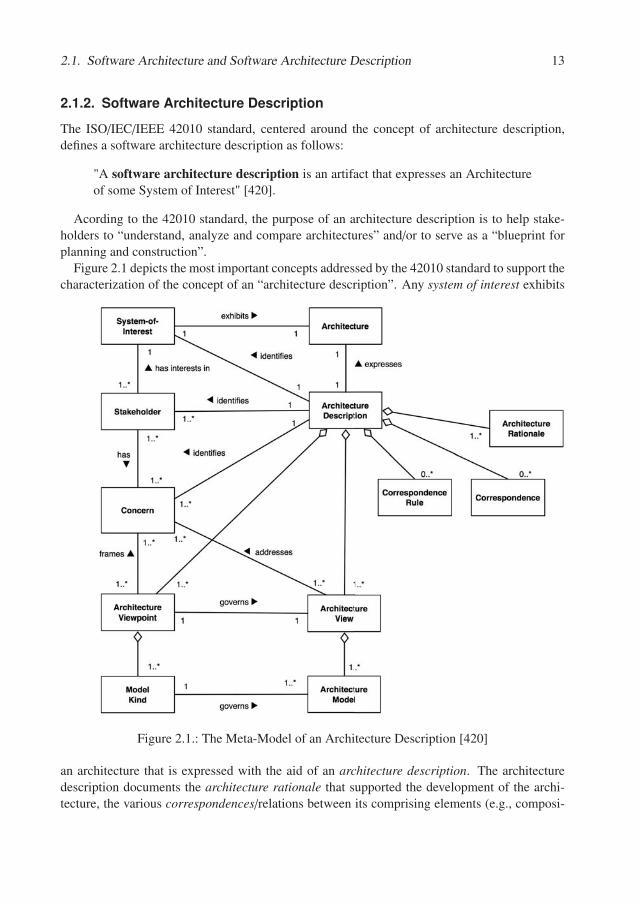
Figure 2.1 depicts the most important concepts addressed by the 42010 standard to support thecharacterization of the concept of an “architecture description”. Any system of interest exhibits
Figure 2.1.: The Meta-Model of an Architecture Description [420]
an architecture that is expressed with the aid of an architecture description. The architecturedescription documents the architecture rationale that supported the development of the archi-tecture, the various correspondences/relations between its comprising elements (e.g., composi-
14 Chapter 2. Foundations
tion, dependency, etc.) and the rules governing them, while focusing on the various concernsof the system’s stakeholders. Given that there is a large variety of aspects that could and shouldbe documented, architecture descriptions can get quite cluttered and very complex to developand understand if treated as monoliths and not properly structured. According to Rozanski andWoods, “it is not possible to capture the functional features and quality properties of a softwaresystem in a single, comprehensible model that is understandable by, and of value to, its stake-holders” [RW11]. In this context, the 42010 standards introduces two very important concepts:architecture views and architecture viewpoints.
An architecture view “expresses the Architecture of the System of Interest fromthe perspective of one or more Stakeholders to address specific Concerns, using theconventions established by its viewpoint” [420].
A view is expressed by means of various architecture models. The models adhere to corre-sponding model kinds that are framed by architecture viewpoints.
An architecture viewpoint is
• “a set of conventions for constructing, interpreting, using and analyzing onetype of Architecture View” [420].
• “a collection of standardized definitions of view concepts, content, and activ-ities” [RW11].
Viewpoint sets. For the sake of standardization and limiting the effort of creating architecturedescriptions by offering guidance regarding the views that should be created, several viewpointsets have been proposed.
A viewpoint set is a collection of predefined viewpoints that architects should con-sider when developing the architecture views of a system of interest.
One of the first proposed viewpoint sets was Kruchten’s 4+1 model [Kru95]. The containedviewpoints are:
• Logical Viewpoint - gives an overview of the functional structure of the system, i.e., thevarious software elements comprising it, with their structures and responsibilities. In thiscontext, Kruchten mentioned class diagrams (for OO systems) to be some of the mostappropriate means to create the logical view.
• Process Viewpoint - depicts concurrency and distribution aspects of the considered system
• Development Viewpoint - considers the various modules of the software developmentenvironment and their organization (e.g., the Eclipse projects that were created for a givensoftware system)
• Physical Viewpoint - is concerned with the actual deployment of the various elementscomprising the system on physical hardware nodes
2.1. Software Architecture and Software Architecture Description 15
• Scenarios Viewpoint - depicts instances of important use cases and a demonstration ofhow the other views cooperate with each other to support them.
Rozanski and Woods [RW11] proposed an alternative viewpoint set, extending the ones pro-posed by Kruchten:
• Context - depicts the software system in its environment and is concerned with the inter-actions with the users, third party systems, etc.
• Functional - corresponds to Kruchten’s logical view
• Information - is concerned with the data flow, storage and management within the system
• Concurrency - corresponds to Kruchten’s process view
• Development - corresponds to Kruchten’s development view
• Deployment - corresponds to Kruchten’s deployment view
• Operational - describes details about operational and administration tasks that must beundergone when the system will run in its operational environment.
Further viewpoint sets have also been proposed, such as the Siemens model [HNS00], whichhas emerged from the industry and encompasses knowledge and best practices that resultedfrom analyzing and documenting architecture descriptions at Siemens. However, a definitiveviewpoint set has not yet been proposed and it is also not likely to ever exist, because differentsystems and/or system landscapes, while often addressing similar concerns, are also likely toexpose specific peculiarities that must be addressed using customized viewpoints.
Additionally, to the concepts defined in the 42010 standard, Rozanski and Woods also intro-duce the notion of perspective to further enable a concerns-based structuring of the architecturedescription.
An architectural perspective is “a collection of architectural activities, tactics, andguidelines that are used to ensure that a system exhibits a particular set of qualityproperties that require consideration across a number of the system’s architecturalviews” [RW11].
Perspectives are therefore cross-cutting the boundaries of viewpoints and aspects that con-tribute to them can consequently be encountered over a multitude of views. Examples of per-spectives include security, availability, performance, etc. These are recommended to be used inexploring the various views of the architecture to ensure that it exposes a certain quality attributeof interest.
16 Chapter 2. Foundations
Relevance for Our Work Our research is concerned with the architecture conformanceof the behavior of software systems. Given Kruchten’s 4+1 model, the logical view-point is of particular importance, because an intended architecture description encom-passing the logical structures of the system is required as an input to ARAMIS. Given thatARAMIS pursues a behavior-based analysis, Kruchten’s process viewpoint and Rozanskiand Woods’ context viewpoint are also playing a central role, framing a common con-cern: the architectural conformance of the system’s behavior. Furthermore, we adapt theterms view and perspective to further refine the results of ARAMIS.
Architecture modeling means. Viewpoint sets aid the creation of architecture descriptionsby suggesting what concerns should be addressed and how these should be structured. Given aset of viewpoints, the architects can employ various architecture modeling means to create thecorresponding views.
Architecture descriptions are often written in informal, textual notations. Consequently, or-ganizations often face situations where most architectural knowledge is scattered throughoutvarious textual documents and/or PowerPoint presentations. In our experience with industrialpartners, we encountered massive documents containing more than 120 pages of summarizedarchitecture decisions taken in the scope of a given software project. In these cases, most archi-tectural models were elaborated as boxes and lines diagrams [DLB14].
When more formality is required, UML and/or ADL-based descriptions are elaborated.
UML became popular in the 1990s and “brought an end to the Babylonian language confusionin the notations in the object oriented community” [VACK11]. While it was deemed unsuitablefor creating architecture descriptions in its initial form (due to, e.g., the lack of explicit softwareconnectors) [MRRR02], it rapidly gained acceptance in the practitioners community. The sit-uation has improved with the advent of UML 2.0 in 2004 and its applicability in architecturedescriptions was exemplified in high-impact literature addressing this topic (e.g., [CBB+10])and UML was even included in the curricula of various courses such as “Documenting SoftwareArchitectures” [seia] offered by the renowned Software Engineering Institute.
However, despite its popularity, UML remains a general-purpose modeling language, not ded-icated to the domain of software architectures. Therefore, the level of architecture-specific for-malization and analysis possibilities is also correspondingly limited. Consequently, dedicatedarchitecture description languages (ADLs) have emerged. As early as 1996, Clements has de-scribed ADLs as follows:
ADLs are “viable tools for formally representing architectures of systems” [Cle96].
Furthermore, Clements also enumerated a set of common important features that ADLs shouldexpose:
• an ADL should support the formal description of an architecture. Completeness and con-sistency checks should be applicable to a given architecture description to check its adher-ence to a given ADL;
2.1. Software Architecture and Software Architecture Description 17
• an ADL should support the use of common architectural styles;
• an ADL should primarily allow the description of high-level abstractions and can be com-pletely non-implementation specific;
• if the ADL does permit the specification of implementation details, then this should bepossible in a very flexible fashion, taking into consideration the fact that several differentconcrete implementations can adhere to the same architecture description;
• an ADL should support architecture-specific analyses (e.g., performance simulations, se-curity checks, data-flow simulations, etc.) and/or possibly be usable as input for codegeneration.
Moreover, Medvidovic and Taylor [MT00], pointed out that most ADLs are structured around4 core concepts:
• components - units of computations or data storage
• connectors - the glue that links components together and the rules governing the inter-component communication
• configurations - the actual structure of an architecture, depicting the components and theconnectors linking them
Given their potential benefits, ADLs have long been researched into, and a considerable num-ber of proposals have emerged. For example, Wright [AG94], developed at the Carnegie MellonUniversity, and Rapide [LKA+95], developed at Stanford University, are both centered aroundthe specification of behavior on an architectural level, but while Wright only enables a staticanalysis of specification correctness, Rapide also allows simulations of the described behavior.Industry-originated ADLs also exist. For example, Koala [vOvdLKM00], developed by Philips,is an ADL and associated component model for the development of product families of con-sumer electronics. Efforts for defining exchangeable ADL formats were also pursued. A notableexample is ACME, developed at the Carnegie Melon University that “permits subsets of ADLtools to share architectural information that is jointly understood, while tolerating the presenceof information that falls outside their common vocabulary” [GMW97].
Nowadays, there are more than 100 published architecture languages available for use. Anoverview of the most popular ones is depicted in [Mal]. However, ADLs have mainly remainedan academic topic and were not widely adopted by the industry [VACK11]. While ADLs offermeans to formally represent architecture descriptions, the industry opted for more pragmatic so-lutions, that ranked practicality higher than rigor. Consequently, informal descriptions such asboxes and lines diagrams, or mere text, are still quite often employed. Furthermore, since UMLcomponent diagrams offer the syntactic means to define components, connectors and configura-tions, these are often employed when more rigor is required [VACK11].
All in all, although the research and industry community have been discussing the architecturemodeling topic for more than 2 decades, no definitive consensus has been reached and architec-ture descriptions are still elaborated using a relative wide variety of modeling means.
18 Chapter 2. Foundations
Relevance for Our Work In our research, we explore the viability of seamlessly work-ing with intended architecture descriptions realized with arbitrary means of modeling.Next, in order to produce recognition effects and support the understanding of the results,we aim to present the retrieved implemented architecture description using the same mod-eling means as the one employed for its intended counterpart. We elaborate this in detailin Chapter 7.
2.2. Architecture Degeneration
Even though, as previously highlighted, the importance of software architectures is widelyacknowledged and various modeling means are available to support its description, completeand/or up-to-date architecture descriptions rarely exist [RH08].
According to the generally accepted Lehman’s Law of Continuing Change [Leh80], a sys-tem used in production will probably have to undergo several changes in order to continue tosatisfy its users. Performing the changes in the architecture description first, can be regardedas hindering immediate productivity, since time and schedule constraints often require changesto be implemented in a very timely manner. On the other hand, once the changes have beenperformed in the actual code, post-documentation may be seen as an additional hurdle and isoften ignored. The causes thereof are not rooted in developer sloppiness or bad intentions: this“happens neither because software engineers have poor intentions nor because they are lazy, butrather because it is time-consuming, difficult, and rarely the highest priority to maintain logicalbut implicit relationships among documents” [MNS01]. Therefore, even if they initially adhereto their software architecture description, software systems tend to evolve independently. Thissituation is particularly undesirable, since according to the law of Lehman’s Increasing Com-plexity and Decreasing Quality [Leh80], over time the complexity of a system increases andits quality tends to diminish if corrective actions are not performed. To avoid this, importantdecisions should be taken at an architectural level. To control complexity and maintain/increasequality the architect should employ a reasonable, controlled evolution of the software architec-ture. An important premise for this is the availability of an up-to-date architecture description[KMN06], whether written or simply available in the minds of the architects.
Intended vs. Implemented Architecture. The discrepancy between the actually imple-mented architecture and the envisioned one has long been discussed in the literature, whichexposes a plethora of terms used to differentiate between these concepts.
Tran and Holt [TH99], and Ducasse and Pollet [DP09] differentiate between the conceptualand the concrete architecture. Contrastingly, for the same semantic concepts, other authorsuse different terms: Tran and Holt also use the terms “as-designed” and “as-built” architecture[TH99], Kazman and Carrière opted for “as-designed” vs. “as-implemented” [KC99], whileHarris et al. preferred the terms “idealized” vs. “as-built” architectures [HRY95]. Further-more, Medvidovic and Jakobak differentiated between the “logical” and “physical” architectures[MJ06], while Carrière and Kazman opted for “intended” vs “realized” architectures [CK98].
2.2. Architecture Degeneration 19
Relevance for Our Work Given that no consensus has been achieved in the researchcommunity regarding the correct terminology to be used, in this research we use theterms intended vs. implemented architecture to refer to the discrepancy between theenvisioned architecture and the actually developed one.
The intended architecture is the “architecture that exists in human minds or in thesoftware documentation” [DP09]. The intended architecture is a vision and reflectsthe ideal outcome of a system’s development, according to its architects.
The implemented architecture is the one exposed by an implemented system.
Intended vs. Implemented Architecture Description. The wide spectrum of terms usedfor the concepts of an intended vs. an implemented architecture, mirrors itself with respect totheir descriptions.
Relevance for Our Work For consistency reasons, we use the terms intended vs. im-plemented architecture description to refer to the descriptions of the intended architectureand the implemented architecture respectively.
Architectural Gap. Similarly as in the cases above, several terms are used in the literatureto refer to the discrepancy between the intended and implemented architecture, such as the “ar-chitectural gap” or “architectural degradation”. In the literature, these are also referred to as the“gap between high level architectural models and the implementation” [dSB12], the “gap be-tween design and implementation” [MNS01], the lack of “architecture compliance” [vHRH+09]or the “lack of conformance” [LV95], [RLBA08].
The architectural gap encompasses the differences between the implemented andintended architectures of a system.
The architectural gap is further differentiated by some authors (e.g., Perry and Wolf [PW92]and Medvidovic and Taylor [TMD10]) in two different types: architectural drift and architecturalerosion.
The architectural drift is the “introduction of principal design decisions into asystem’s descriptive architecture that (a) are not included in, encompassed by, orimplied by the prescriptive architecture, but which (b) do not violate any of theprescriptive architecture’s design decisions” [TMD10].
According to this definition, a drift is introduced by changes that are not explicitly prohibitedto occur, but which are also not necessarily harmless or desirable. According to the authors,the drift, although not necessarily causing violations, “reflects the engineers’ insensitivity to thesystem’s architecture and can lead to a loss of clarity of form and system understanding”. Incontrast, the architectural erosion is directly associated with the existence of explicit violations.
20 Chapter 2. Foundations
Architectural erosion represents “the introduction of architectural design decisionsinto a system’s descriptive architecture that violate its prescriptive architecture”[TMD10].
The violations mentioned in the definition of architectural erosion are typically more harmfulthan “just” reducing clarity but can “lead to an increase in problems in the system and contributeto the increasing brittleness of a system” [PW92].
However, not all authors differentiate semantically between architectural drift and architec-tural erosion [DP09], [MNS01], [dSB12]. For example, Vogel et al. [VACK11] only mentionerosion, and describe it to be a phenomenon in which the architecture deviates from its descrip-tion. Contrastingly, Rosik et al. define drift as the situation in which “implementations divergefrom their intended architectures” and use most of the previously mentioned terms as synonyms:“such discrepancies between the designed and implemented architecture are collectively referredto as architectural drift, architecture degeneration, or system degeneration” [RLB+10].
Furthermore, other less popular terms are also used in literature as synonyms of drift anderosion, e.g.:
• rotting design [Mar00]: “over time as the rotting continues, the ugly festering sores andboils accumulate until they dominate the design of the application”
• architectural decay [RSN09]: “the phenomenon when concrete (as-built) architecture of asoftware system deviates from its conceptual (as-planned) architecture where it no longerspecifies the key quality attributes that led to its construction or when architecture of asoftware system allows no more changes to it due to changes introduced in the systemover time and renders it un-maintainable”
• architectural mismatch [GAO95]: the “architectural mismatch stems from mismatchedassumptions a reusable part makes about the structure of the system it is to be part of”
• chasm [Riv04]: “the architectural designs are unlikely to conform with the actual imple-mentation. This yields to a chasm between the conceptual (or intended) software archi-tecture that exists in the minds of the developers and the concrete (or as-implemented)architecture that is hidden in the implementation”.
Relevance for Our Work Because the above mentioned terms are often used inter-changeably in the literature, in this research we also opt to treat them as synonyms. Werefer to the discrepancy between the intended and implemented architectures using thenouns (architectural) gap or (architectural) drift. We use the verb drift to refer to theprocess of creating an (architectural) drift. A degraded/drifted implemented architec-ture is an implemented architecture affected by architectural drift.
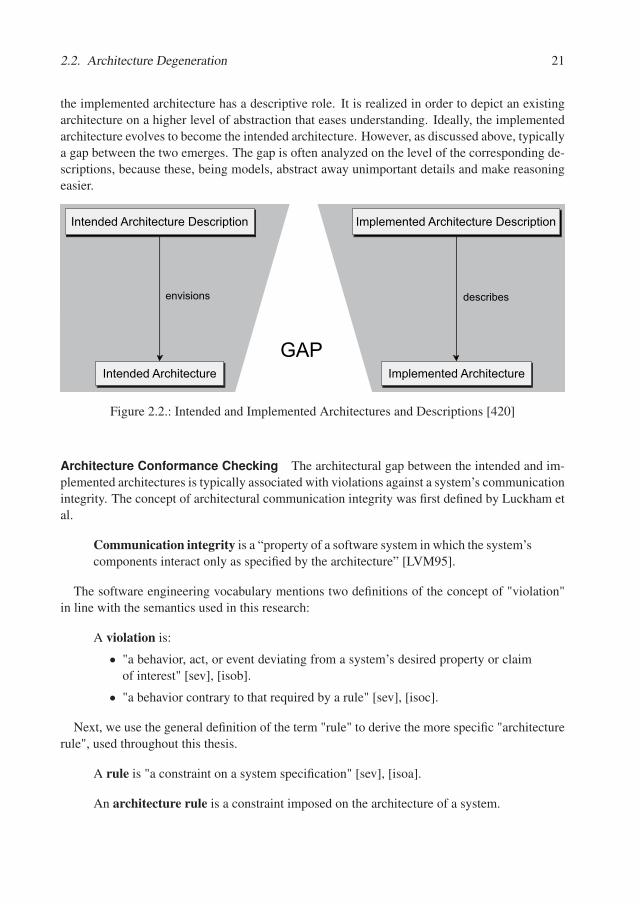
Figure 2.2 visually depicts the relation between the concepts introduced above. Furthermore,it emphasizes the different roles of the intended and the implemented architecture descriptions.The intended architecture description has a prescriptive role; it envisions an intended architec-ture nonexistent at the time the description is realized, but is aimed towards. On the other hand,
2.2. Architecture Degeneration 21
the implemented architecture has a descriptive role. It is realized in order to depict an existingarchitecture on a higher level of abstraction that eases understanding. Ideally, the implementedarchitecture evolves to become the intended architecture. However, as discussed above, typicallya gap between the two emerges. The gap is often analyzed on the level of the corresponding de-scriptions, because these, being models, abstract away unimportant details and make reasoningeasier.
Intended Architecture
Intended Architecture Description
Implemented Architecture
Implemented Architecture Description
GAP
envisions describes
Figure 2.2.: Intended and Implemented Architectures and Descriptions [420]
Architecture Conformance Checking The architectural gap between the intended and im-plemented architectures is typically associated with violations against a system’s communicationintegrity. The concept of architectural communication integrity was first defined by Luckham etal.
Communication integrity is a “property of a software system in which the system’scomponents interact only as specified by the architecture” [LVM95].
The software engineering vocabulary mentions two definitions of the concept of "violation"in line with the semantics used in this research:
A violation is:
• "a behavior, act, or event deviating from a system’s desired property or claimof interest" [sev], [isob].
• "a behavior contrary to that required by a rule" [sev], [isoc].
Next, we use the general definition of the term "rule" to derive the more specific "architecturerule", used throughout this thesis.
A rule is "a constraint on a system specification" [sev], [isoa].
An architecture rule is a constraint imposed on the architecture of a system.
22 Chapter 2. Foundations
Relevance for Our Work As in this research we propose a behavior-based approach toidentify the (architectural) gap between the implemented and intended architectures, asrevealed by their descriptions. We achieve this by extracting the implemented architec-ture description of the system and identifying the violations it exhibits. If no violationsare identified, we conclude that the implemented architecture is "conforming" to the in-tended one. The process of identifying violations is referred to in this thesis using theterm "architecture conformance checking", as defined next.
An implemented architecture is conforming to the intended one if it adheres to therules formulated in the latter. Equivalently, an implemented architecture is conformif it exposes communication integrity.
We define architecture conformance checking to be the process of establishing ifan implemented architecture fulfills the rules formulated in its intended architecturedescription.
As we will discuss in Chapter 6, several approaches to architecture conformance checkingexist.
We define static-based architecture conformance checking to be the process ofestablishing if an implemented architecture fulfills the rules formulated in its in-tended architecture description based exclusively on system configuration files andsource code artifacts.
We define behavior-based architecture conformance checking to be the processof establishing if an implemented architecture fulfills the rules formulated in itsintended architecture description based on the system’s behavior as extracted duringrun-time.
Relevance for Our Work In this dissertation we present an approach to behavior-basedconformance checking. The architecture rules of interest are thus mostly concerning thecommunication of architecture structures. We refer to these as communication rules, asdefined next.
The term communication defines an abstraction of all types of possible interac-tions, be them local or distributed (e.g., direct calls, REST calls, message passingthrough queuing systems, etc.).
A communication rule is an architecture rule that places constraints on the com-munication of architectural structures as defined in the intended architecture de-scription of a system.
2.3. Architecture Reconstruction 23
2.3. Architecture Reconstruction
It has long been acknowledged that understanding and changing an existing system are muchmore time-consuming activities than the initial development of the system. In a study conductedin 1990, Nosek and Palvia even claimed that the understanding and changing of a system eachtake up to 40% of the time spent on a system, thus brutally contrasting with the actual devel-opment that occupies only 20% [NP90]. Considering this, one could have reasonably expectedfurther developments in software engineering practices to focus on avoiding architectural driftand preserving and/or evolving initial design towards easing the first two mentioned activities.However, a recent CAST CRASH Report [cas] draws attention to the fact that, after analyzing aset of 1316 applications from 212 different organizations, with respect to their structural qualityduring production, it was discovered that most of them exposed above-average scores for qual-ity attributes such as performance, robustness and scalability but lower ones for changeabilityand transferability. According to this report, a possible explanation for this situation is that theviolations occurred in the architecture that affect these latter attributes are perceived mostly as“cost-related”, while the violations against former ones tend to be fixed prior to production asthey are more visible to end-users and are thus considered to be “operational risk factors”.
Consequently, “in practice, unfortunately, relatively little value is placed on measures to im-prove architecture” [VACK11]. Thus, although “understanding and updating a system’s softwarearchitecture is arguably the most critical activity” in a system’s life-cycle [GKMM13], the imple-mented architecture degenerates rapidly, becomes ever harder to comprehend, and the intendedarchitecture description gradually becomes useless or even dangerously misleading when usedto analyze the corresponding system. Considering the “cost-related” factors mentioned earlier, itis also unrealistic to assume that “system’s engineers will be able or willing to take considerabletime away from their daily obligations” [GKMM13] in order to re-document the architectureand create a better, up-to-date basis for understanding it. Consequently, degraded implementedarchitectures that have little left in common with their corresponding intended descriptions area very frequent sight in the industry: "it is common that the resulting implementation does notexactly correspond to the designed architecture. This results in a situation where the existingarchitectural documentation is of less use or possibly even harmful" [RLBA08].
To address this stringent problem, both the industry and academia have invested considerableefforts in developing automatic and semi-automatic approaches for aiding software architecturereconstruction.
Software architecture reconstruction was defined as:
• “a reverse engineering approach that aims at reconstructing viable architec-tural views of a software application” [DP09].
• "the effort of redetermining architectural decisions, given only the result ofthese decisions in the actual artifacts" [BCK12].
A comprehensive and referential, yet not complete, listing of software architecture reconstruc-tion approaches has been performed by Ducasse and Pollet and is available in [DP09]. Theycategorize the selected reconstruction approaches according to the following important criteria:
24 Chapter 2. Foundations
• the goals of architecture reconstruction can be: re-documentation, discovering reuse can-didates, checking the conformance of the implemented architecture to the intended one,supporting co-evolution of multiple architecture descriptions, enabling analysis of variousquality attributes and aiding future evolution
• according to the employed processes, the reconstructions tools can be: bottom-up (startwith analyzing low-level information such as source code and progressively create ab-stractions thereof to reach a high-level architectural view), top-down (based on high-levelartifacts such as architecture descriptions, formulate various mapping hypotheses and cre-ate a mapping to low-level entities from the source code) or hybrid (start with consider-ing both high-level and low-level abstractions and continue by simultaneously applyingbottom-up and top-down processes until a mapping is achieved)
• inputs: architectural vs non-architectural. The architectural inputs are further classified instyles (e.g., the knowledge that a system is built using pipes and filters, layers, etc.) andviewpoints (in order to guide the reconstruction process to only extract information rele-vant to the involved stakeholders). The non-architectural inputs can be the source code,textual information, dynamic information (e.g., execution traces), the physical organiza-tion of the source code (constituent files, folders and their hierarchy, etc.), human orga-nization (e.g., the communication structures between the developers involved in the sameproject), historical information (e.g., the changes reflected by the analysis of the commitsin the version control systems and/or issue tracking systems) and human expertise
• outputs: visual (e.g., graph-based views of the package structure), architecture (e.g., ADL-based representations of the reconstructed architecture), conformance (of the implementedarchitecture to the intended one) and further analyses (e.g., high-level statistics, metrics,etc.)
• employed techniques: quasi-manual (most of the steps are manual and support is mostlygiven to visualize the results), semiautomatic (instructions for the code to architecturemapping are manually provided but are applied automatically), quasi-automatic (reducemanual input to a minimum by applying various techniques, e.g., clustering, concepts-analysis algorithms, etc.)
Relevance for Our Work In our work we present a behavior-based architecture con-formance checking approach called ARAMIS. According to the taxonomy proposed byDucasse and Polet, ARAMIS proposes a hybrid process that requires an intended ar-chitecture description as input and produces a behavior-based implemented architecturedescription as output, by employing exploration-based quasi-manual and semiautomatictechniques.
This concludes the first part of this dissertation. In the next part we present in detail ourconcept and associated toolbox.
Part II.
ARAMIS

Chapter 3.
ARAMIS - The Big Picture
In the following we present an overview of ARAMIS - the approach towards behavioral-basedarchitecture conformance checking developed and evaluated within this dissertation.
The central stakeholder of ARAMIS is the software architect, who models the intended archi-tecture description of a system as a blueprint for its implementation. During the implementationphase, some of the imposed architectural constraints are disregarded in order to meet time andbudget requirements or simply because these are unrealistic or technically impossible to realize.The thus resulted architectural drift causes gradual decay in the suitability of the intended archi-tecture description to guide the understandability of the system under analysis and its evolution.The main goal of ARAMIS is to extract a description of the implemented architecture, with aconcrete focus on behavioral aspects.
The ARAMIS Conformance Checking Process (ACC-Proc), presented in Chapter 9 offersguidance to the architects regarding how to meaningfully undergo conformance checks based onextracted interactions occurring during run-time.
ARAMIS is built around an adaptation of the concept of hierarchical reflexion modeling[KS03], i.e., it requires as input an intended architecture description of the system under analysisand produces, based thereupon, a description of the implemented architecture.
ARAMIS enables the architect to model the intended architecture of a system using an ARAMIS-specific meta-model. However, acknowledging the wide range of existing and employed archi-tecture modeling means, ARAMIS also encompasses the so-called ARAMIS Architecture De-scription Transformation Process (AADT-Proc) that offers guidance on how to employ modelengineering techniques to automatically transform already existing descriptions to ARAMISspecific ones. This aspect will be discussed in detail in Chapter 7. The AADT-Proc is defined asa standalone process that can also be adapted for other conformance checking approaches thanARAMIS. However, in the scope of this disseration the AADT-Proc details one of the activitiesencompassed in the ACC-Proc.
Given that ARAMIS is a behavior-based approach, support is needed for the extraction ofinteractions from the running system under analysis. ARAMIS builds on top of existing moni-toring tools which already serve this purpose and supports the normalization of extracted interac-tions to a monitoring-tool-independent format using the AID-Lang - the ARAMIS InteractionsDescription Language. The details thereof are discussed in Chapter 5. Additionally, as pre-sented in Chapter 8, ARAMIS addresses the well-known incompleteness problem of behavior-based approaches, and offers guidance for inspecting whether the captured behavior is adequatefor supporting conformance checking analyses. To achieve this, ARAMIS proposes the use ofseveral metrics for inspecting and reasoning adequacy from a semantic and technical point of
28 Chapter 3. ARAMIS - The Big Picture
view.Furthermore, ARAMIS enables the architect to express applicable communication rules, that
are only implicitly available and not documented in the intended architecture descriptions, dueto, e.g., commodity reasons. To this end, ARAMIS employs a flexible and powerful XML-based rules language, called the ARAMIS Communication Rules Language (ACR-Lang). ACR-Lang is the main constituent of the above mentioned ARAMIS meta-model for architecturedescription.
Having extracted interactions from the system under analysis, transformed or created fromscratch an ARAMIS intended architecture description and enriched it with additional commu-nication rules to be checked against, the ACC-Proc proceeds to create a corresponding descrip-tion of the implemented architecture. To boost understanding, this can result by augmentingthe intended architecture description with the conformance results of the ACC-Proc. Further-more, ARAMIS also offers dedicated ARAMIS-specific visualizations as well as the possibilityto focus the conformance results by applying specific views and perspectives, defined using adedicated ARAMIS Results Exploration Language (ARE-Lang).
Most of the concepts introduced in this dissertation are included in the ARAMIS Toolboxdeveloped in the scope of this dissertation and briefly presented in Chapter 10.1.
All in all, as depicted in Figure 3.1, ARAMIS consists of three main important aspects:
• processes to guide the reuse of existing intended architectures (AADT-Proc) and supportthe behavior-based conformance checking of software systems (ACC-Proc);
• languages to support the tool-independent description of extracted interactions (AID-Lang), the definition of communication rules (ACR-Lang) and the exploration of the con-formance results (ARE-Lang);
• tool support to enable and automatize the above.
The rest of this chapter presents a motivating example for employing ARAMIS in a softwaredevelopment organization.
Motivating Example To illustrate the quintessence of the ARAMIS approach developed inthis dissertation, we illustrate a representative usage example, which - although fictitious - isadapted from one of the case studies underlying our evaluation, as we will present in Part III.
The company ABC has been developing and evolving TADA - an industrial task automa-tion and data distribution system for over 10 years. Being a relatively long-living system itsarchitecture was re-factored several times. Currently, TADA is developed as a component-basedapplication, consisting of five intercommunicating processes.
Architecture erosion was a big problem in TADA’s past evolution making the code highly un-maintainable and not understandable. Therefore, when the decision was made to evolve TADAto a component-based, multi-process solution, a team of architects elaborated an intended ar-chitecture description of the system, to serve as the communication basis and implementationblueprint for the developers. The architects used the well known Enterprise Architect mod-eling tool to document the elaborated architecture description. Because they had experiencewith using UML component diagrams from previous projects, they expressed TADA’s intended
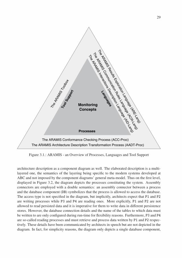
29
Figure 3.1.: ARAMIS - an Overview of Processes, Languages and Tool Support
architecture description as a component diagram as well. The elaborated description is a multi-layered one, the semantics of the layering being specific to the modern systems developed atABC and not imposed by the component diagrams’ general meta-model. Thus on the first level,displayed in Figure 3.2, the diagram depicts the processes constituting the system. Assemblyconnectors are employed with a double semantics: an assembly connector between a processand the database component (DB) symbolizes that the process is allowed to access the database.The access type is not specified in the diagram, but implicitly, architects expect that P1 and P2are writing processes while P3 and P4 are reading ones. More explicitly, P1 and P2 are notallowed to read persisted data and it is imperative for them to write data in different persistencestores. However, the database connection details and the name of the tables to which data mustbe written to are only configured during run-time for flexibility reasons. Furthermore, P3 and P4are so-called reading processes and must retrieve and process data written by P1 and P2 respec-tively. These details have been communicated by architects in speech but are not depicted in thediagram. In fact, for simplicity reasons, the diagram only depicts a single database component,
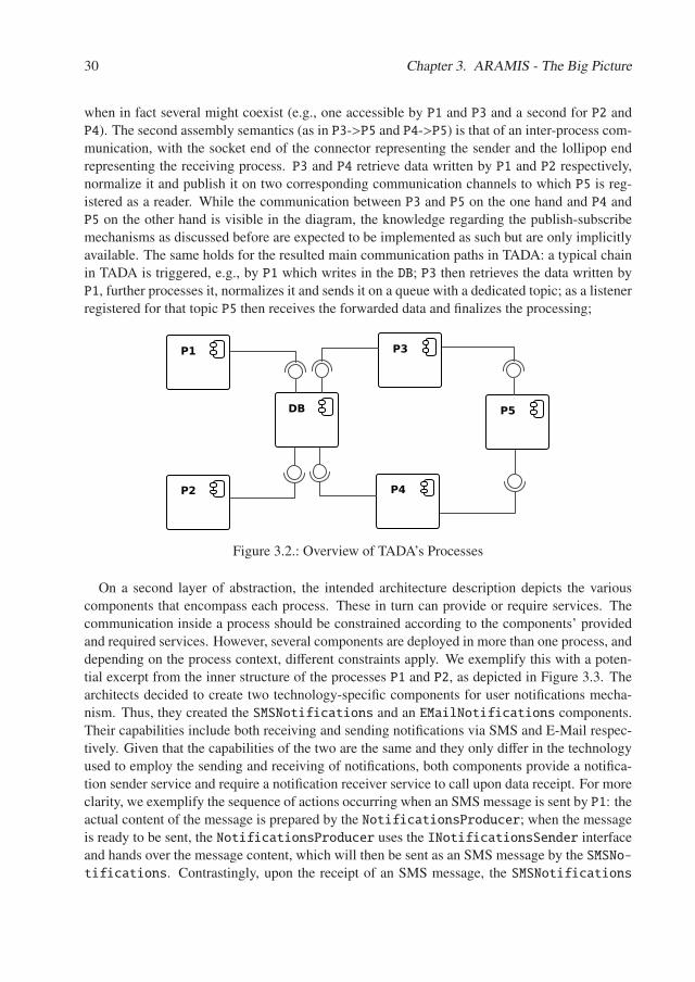
30 Chapter 3. ARAMIS - The Big Picture
when in fact several might coexist (e.g., one accessible by P1 and P3 and a second for P2 andP4). The second assembly semantics (as in P3->P5 and P4->P5) is that of an inter-process com-munication, with the socket end of the connector representing the sender and the lollipop endrepresenting the receiving process. P3 and P4 retrieve data written by P1 and P2 respectively,normalize it and publish it on two corresponding communication channels to which P5 is reg-istered as a reader. While the communication between P3 and P5 on the one hand and P4 andP5 on the other hand is visible in the diagram, the knowledge regarding the publish-subscribemechanisms as discussed before are expected to be implemented as such but are only implicitlyavailable. The same holds for the resulted main communication paths in TADA: a typical chainin TADA is triggered, e.g., by P1 which writes in the DB; P3 then retrieves the data written byP1, further processes it, normalizes it and sends it on a queue with a dedicated topic; as a listenerregistered for that topic P5 then receives the forwarded data and finalizes the processing;
P1
P2
P3
P4
DB P5
Figure 3.2.: Overview of TADA’s Processes
On a second layer of abstraction, the intended architecture description depicts the variouscomponents that encompass each process. These in turn can provide or require services. Thecommunication inside a process should be constrained according to the components’ providedand required services. However, several components are deployed in more than one process, anddepending on the process context, different constraints apply. We exemplify this with a poten-tial excerpt from the inner structure of the processes P1 and P2, as depicted in Figure 3.3. Thearchitects decided to create two technology-specific components for user notifications mecha-nism. Thus, they created the SMSNotifications and an EMailNotifications components.Their capabilities include both receiving and sending notifications via SMS and E-Mail respec-tively. Given that the capabilities of the two are the same and they only differ in the technologyused to employ the sending and receiving of notifications, both components provide a notifica-tion sender service and require a notification receiver service to call upon data receipt. For moreclarity, we exemplify the sequence of actions occurring when an SMS message is sent by P1: theactual content of the message is prepared by the NotificationsProducer; when the messageis ready to be sent, the NotificationsProducer uses the INotificationsSender interfaceand hands over the message content, which will then be sent as an SMS message by the SMSNo-tifications. Contrastingly, upon the receipt of an SMS message, the SMSNotifications
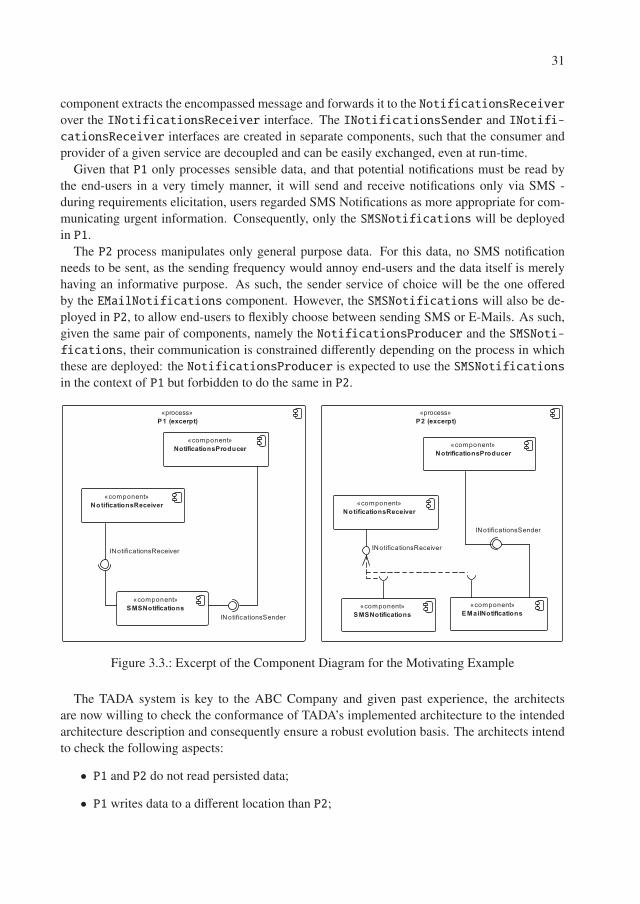
31
component extracts the encompassed message and forwards it to the NotificationsReceiverover the INotificationsReceiver interface. The INotificationsSender and INotifi-cationsReceiver interfaces are created in separate components, such that the consumer andprovider of a given service are decoupled and can be easily exchanged, even at run-time.
Given that P1 only processes sensible data, and that potential notifications must be read bythe end-users in a very timely manner, it will send and receive notifications only via SMS -during requirements elicitation, users regarded SMS Notifications as more appropriate for com-municating urgent information. Consequently, only the SMSNotifications will be deployedin P1.
The P2 process manipulates only general purpose data. For this data, no SMS notificationneeds to be sent, as the sending frequency would annoy end-users and the data itself is merelyhaving an informative purpose. As such, the sender service of choice will be the one offeredby the EMailNotifications component. However, the SMSNotifications will also be de-ployed in P2, to allow end-users to flexibly choose between sending SMS or E-Mails. As such,given the same pair of components, namely the NotificationsProducer and the SMSNoti-fications, their communication is constrained differently depending on the process in whichthese are deployed: the NotificationsProducer is expected to use the SMSNotificationsin the context of P1 but forbidden to do the same in P2.
������������������
��������� ��������
����������������������������
�������������������������
����������������������������
�������������������������
���������������������������
����������������������������� ���������
��������������������
���������������������
�������������������
�������������������
���������������������
Figure 3.3.: Excerpt of the Component Diagram for the Motivating Example
The TADA system is key to the ABC Company and given past experience, the architectsare now willing to check the conformance of TADA’s implemented architecture to the intendedarchitecture description and consequently ensure a robust evolution basis. The architects intendto check the following aspects:
• P1 and P2 do not read persisted data;
• P1 writes data to a different location than P2;
32 Chapter 3. ARAMIS - The Big Picture
• P3 reads data previously written by P1;
• P4 reads data previously written by P2;
• P3 and P4 publish data on different messaging channels to which P5 has subscribed for;
• two general control flow chains are to be observed in the application: First, P1 writes datato a location, from which P3 later reads, then P3 publishes data to a dedicated channel andis then processed by P5. The second chain is very similar, involving the processes P2, P4and P5;
• in the context of the process P1, the NotificationsProducer component must use theSMSNotifications component at run-time;
• in the context of the process P2, the NotificationsProducer is denied to use the SM-SNotifications as an implementation of the INotificationSender interface. In-stead, it should use the EMailNotifications component.
Many of the concerns listed above cannot be checked using static-based conformance check-ing solutions, due to three main reasons:
• as mentioned when presenting TADA’s architecture, most of the details regarding per-sistence are configurable; depending on the structure and location of these configurations,these might be out of the scope of static analysis, which often simply inspects the system’ssource code;
• timing related constraints (e.g., P3 reads data after P1 writes) and communication chainsare not in the scope of static analysis;
• static analyses check dependencies to interfaces rather than implementations. However, inthe case depicted before, in which the same pair of components had different communica-tion permissions depending on the process in which these were deployed, a mere check oninterface-level dependencies is not sufficient. The NotifocationsProducer depends inboth cases on the INotificationsSender interface. However, in P1 it must use the SM-SNotifications implementation of this interface and in P2 the EMailNotificationsinstead. These checks are also out of the scope of static analyses.
Consequently, the architects decide to employ a behavior-based conformance checking so-lution on TADA. More precisely, they choose to employ ARAMIS because of the followingarguments:
• the architects can employ tools with which they are already familiar with (e.g., Dynatracefor performance monitoring) to extract interactions during the execution;
• ARAMIS offers guidance to analyze the adequacy of the captured behavior and processesthat meaningfully guide the architects in their conformance checking endeavor;
33
• the architecture description of TADA can be reused and communication rules can auto-matically be derived based thereupon; further rules can easily be defined using a dedicatedlanguage;
The resulting implemented architecture description depicts that TADA was almost entirely im-plemented according to the intended architecture description. However, P3 and P4 use the sametopic and queue for publishing data and they use a flagging mechanism to differentiate it. Fur-thermore, while at the beginning of the monitoring, P2’s NotificationsProducer correctlyused the EmailNotifications implementation of INotificationREceiver, the architectsobserved that after a certain period of time this changed and the SMSNotifications was usedinstead, causing architectural violations. Further inspections, showed that the EMailNotifi-cations became unavailable during the execution and the implementation was thus swappedautomatically. The architects consequently discuss with the involved developers and plan forfuture improvements.
As planning for future evolutions is in itself a related, but different research topic , the scopeof ARAMIS and our motivating example ends here. As discussed before, the next chapters willintroduce one by one the various features of ARAMIS and the developed toolbox.

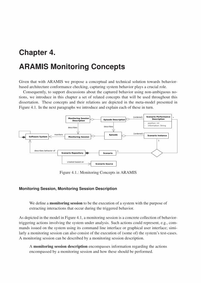
Chapter 4.
ARAMIS Monitoring Concepts
Given that with ARAMIS we propose a conceptual and technical solution towards behavior-based architecture conformance checking, capturing system behavior plays a crucial role.
Consequently, to support discussions about the captured behavior using non-ambiguous no-tions, we introduce in this chapter a set of related concepts that will be used throughout thisdissertation. These concepts and their relations are depicted in the meta-model presented inFigure 4.1. In the next paragraphs we introduce and explain each of these in turn.
Monitoring Session Description Episode Description
EpisodeMonitoring SessionSoftware System
Scenario Repository Scenario
Scenario Instance
Scenario Performance Description
- position: int- information: String
Scenario Sourcecreated based on
{ordered}monitors
1
describes
*
describes behavior of
describes
1
{ordered}
Figure 4.1.: Monitoring Concepts in ARAMIS
Monitoring Session, Monitoring Session Description
We define a monitoring session to be the execution of a system with the purpose ofextracting interactions that occur during the triggered behavior.
As depicted in the model in Figure 4.1, a monitoring session is a concrete collection of behavior-triggering actions involving the system under analysis. Such actions could represent, e.g., com-mands issued on the system using its command line interface or graphical user interface; simi-larly a monitoring session can also consist of the execution of (some of) the system’s test-cases.A monitoring session can be described by a monitoring session description.
A monitoring session description encompasses information regarding the actionsencompassed by a monitoring session and how these should be performed.
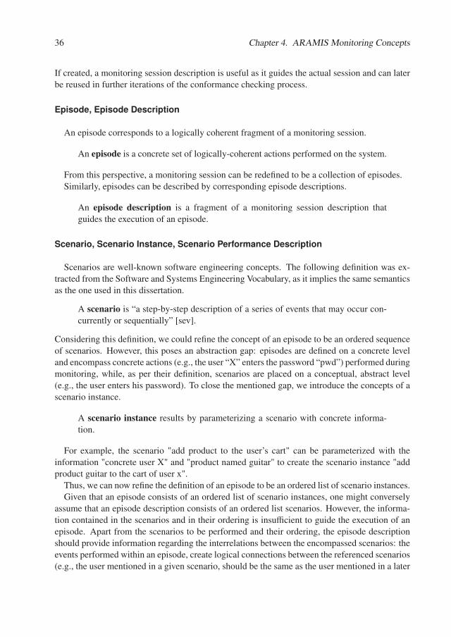
36 Chapter 4. ARAMIS Monitoring Concepts
If created, a monitoring session description is useful as it guides the actual session and can laterbe reused in further iterations of the conformance checking process.
Episode, Episode Description
An episode corresponds to a logically coherent fragment of a monitoring session.
An episode is a concrete set of logically-coherent actions performed on the system.
From this perspective, a monitoring session can be redefined to be a collection of episodes.Similarly, episodes can be described by corresponding episode descriptions.
An episode description is a fragment of a monitoring session description thatguides the execution of an episode.
Scenario, Scenario Instance, Scenario Performance Description
Scenarios are well-known software engineering concepts. The following definition was ex-tracted from the Software and Systems Engineering Vocabulary, as it implies the same semanticsas the one used in this dissertation.
A scenario is “a step-by-step description of a series of events that may occur con-currently or sequentially” [sev].
Considering this definition, we could refine the concept of an episode to be an ordered sequenceof scenarios. However, this poses an abstraction gap: episodes are defined on a concrete leveland encompass concrete actions (e.g., the user “X” enters the password “pwd”) performed duringmonitoring, while, as per their definition, scenarios are placed on a conceptual, abstract level(e.g., the user enters his password). To close the mentioned gap, we introduce the concepts of ascenario instance.
A scenario instance results by parameterizing a scenario with concrete informa-tion.
For example, the scenario "add product to the user’s cart" can be parameterized with theinformation "concrete user X" and "product named guitar" to create the scenario instance "addproduct guitar to the cart of user x".
Thus, we can now refine the definition of an episode to be an ordered list of scenario instances.Given that an episode consists of an ordered list of scenario instances, one might conversely
assume that an episode description consists of an ordered list scenarios. However, the informa-tion contained in the scenarios and in their ordering is insufficient to guide the execution of anepisode. Apart from the scenarios to be performed and their ordering, the episode descriptionshould provide information regarding the interrelations between the encompassed scenarios: theevents performed within an episode, create logical connections between the referenced scenarios(e.g., the user mentioned in a given scenario, should be the same as the user mentioned in a later
4.1. Scenario Sources Overview 37
scenario). The scenarios that are occurring prior to a considered one, create its context (e.g., aproduct is added to a user’s cart in a context in which the user had already logged in and chosea profile). Thus, we introduce the concept of scenario performance to refine the definition of anepisode description as follows: an episode description is an ordered list of scenario performancedescriptions.
A scenario performance description is a triple consisting of (1) its position inthe episode description, (2) the actual scenario that it is referring to and (3) someadditional textual information that should give clarification regarding the context inwhich the scenario should occur in.
Consequently, when executing an episode based on its description, a scenario performance de-scription will specify constrains for the actual scenario instances that are included in the givenepisode.
An explanatory example that illustrates the above introduced concepts is depicted in Figure4.2 (see next page).
Scenario RepositoryWhen defining a monitoring session description, one of the central questions that arises is whatepisode descriptions it should consist of. To this end, we propose the investigation of alreadyexisting scenario sources (such as the system’s use case descriptions, the system’s narratives,etc.) to create a central, so-called scenario repository. The within documented scenarios shouldbe relevant for showcasing the architecturally relevant interactions within the system.
A system’s scenario repository is a collection of all its identified scenarios.
Because the choice of episodes that constitute a monitoring session is crucial for the qualityof the subsequent behavior-based conformance check, in the next section we proceed by givinga more detailed insight of three of the most common sources of system scenarios.
4.1. Scenario Sources Overview
In this section we will highlight the three, in our opinion, most important sources of scenarios.Each source has its own specificity and corresponding notions. Consequently, for each sourcewe will make explicit the correspondences between its specific notions and the concepts definedpreviously in this chapter.
4.1.1. Use Cases
Use-cases were defined by Ivar Jacobson as early as 1987.
Use cases are “a special sequence of transactions, performed by a user and a systemin a dialogue” [Jac87].

38 Chapter 4. ARAMIS Monitoring Concepts
Use�the�GU
I�of�a�test�version�of�system
�ABC�to�monitor�user�
actions;�Ensure�that�in�the�initial�state�discounted�products�exist�but�no�users�are�defined;
New
�user�buys�a�discounted�product
2,�User�brow
ses�products,�same�user�as�in�1
3,�User�selects�product,�sam
e�user�as�in�1�&
�product�is�discounted�
4,�User�buys�product,�sam
e�product�as�in�3��������������������������������&
�same�user�as�in�1
1,�New
�user�creates�log�in
User�Alice�buys�discounted�bike
Create�new�login�for�Alice
User�Alice�brow
ses�for�products
User�Alice�selects�discounted�bike�w
ith�ref.�no.�123
User�Alice�buys�bike�w
ith �ref.�no.�123
The�person�performing�the�
monitoring�identifies�a�test�version�
of�the�system.�She�then�introduces�
three�discounted�bikes�in�the�system�
and�deletes�all�existing�users.
Create�log�in
Browse�for�products
Select�product
Buy�product
Monitoring�Session�Description
Episode�DescriptionsScenario�Perform
ance�Descriptions
……
Monitoring�Session
EpisodesScenario�Instances
Scenarios
Figure
4.2.:M
onitoringC
onceptsin
AR
AM
IS-
Exam
ple
4.1. Scenario Sources Overview 39
As the following definition extracted from the software engineering vocabulary indicates,scenarios are often defined as use case instances: "a use case defines a set of use case instancesor scenarios" [sev]. Consequently, the definition of a scenario can be extended to that of a flowexposed by a use case narrative:
A flow/scenario is "a description of some full or partial path through a use-casenarrative. There is always at least a basic flow and there may be alternative flows"[JSB11].
Ever since their introduction, use cases have proven themselves to be a very useful techniquefor capturing the functional requirements of a system and have often been applied in the indus-try [WHL09]. Thus, provided that they are available, use cases provide a good initial insightregarding the scenarios that the system exhibits.
Because of their popularity and suitability to document functional requirements, use caseshave been used as an input for various other research purposes. For example, Hoffman andLichter [HL10], proposed a simulation-based environment to showcase the behavior of a soft-ware system, based on the information provided in its narrative use-cases, with the purpose ofevaluating the captured requirements and/or aid in their refinement. Additionally, Nebut et al.[NFLJ06] have shown how the generation of test cases can be automated based on use-casesenhanced with boolean contracts to express their pre- and postconditions.
The preconditions of a use case represent the conditions that should hold true tomake the occurrence of a use case possible. These can be expressed as a set ofpredicates combined using logical operators.
The postconditions of a use case represent the conditions that consequently holdtrue after the use-case occurs. As in the case of pre-conditions, these can also beexpressed as a set of predicates combined using logical operators.
The contract of a use case consists of the use case’s pre- and postconditions.
Similarly as use cases can provide a suitable input for the automatic generation of test cases,scenarios enhanced with pre and postconditions may be used in ARAMIS to automatically deriveepisode descriptions.
We define the episode description(s) derivation process to be the process of defin-ing relevant episode descriptions to guide the choice of episodes to be monitored onthe analyzed running system(s).
In the remainder of this Subsection, we propose an adaptation of the solution proposed byNebut et al. [NFLJ06] to automatize the above defined episode description derivation process.
Since use-cases consist of scenarios, we consider that defining predicates for the pre- andpostconditions at the use-case level is, in practical situations, not meaningful. The scenariosencompassed in a use case typically occur under different circumstances and create differenteffects. Thus, we further refine the concept of contracts to designate the pre- and postconditionsassociated to each and every scenario. The contracts are then used, to derive all possible validsequences of scenarios that can occur in the context of the analyzed system.
40 Chapter 4. ARAMIS Monitoring Concepts
The preconditions of a scenario represent the conditions that should hold true tomake the occurrence of the scenario possible.
The postconditions of a scenario represent the conditions that consequently holdtrue after the scenario occured.
The contract of a scenario consists of its pre- and postconditions.
The Roundtrips Set Derivation AlgorithmGiven its relevance for our work, we present an adaption of the algorithm of Nebut et al. namedthe roundtrips set derivation algorithm that supports the generation of scenario sequences havingthe roundtrip property, as will be defined later in this section.
We define a system predicate, to be a first-order logic predicate whose variablesare given by system actors (e.g., student) and/or main system concepts (e.g., classroom, exam), as depicted from the analysis of the system use-cases.
An example of a system predicate is connected(user:u); the connected predicate is true iff theuser u is logged into the system and false otherwise.
We define a system state to be the set of all system predicates that hold true at agiven moment in time.
Let S T s be the set of all possible system states of a system s. Let is ∈ S T s denote the initialstate of the system s.
Let UCs and S Cs be the sets of all use cases and scenarios of a system s respectively.A use case uc ∈ UCs is a set of scenarios depicting its basic and alternative flows:∀uc ∈ UCs ⇐⇒ ∃sc1, ..., scn ∈ S Cs s.t. uc = sc1, ..., scn
A very important assumption that we make throughout our formalism is that performing ascenario when the system is in a given state is a deterministic action, i.e., that the system willalways consequently transition in the same target state.
Given a scenario sc and a system state st, we define prest(sc) to be a predicate that expressesif the logical expression denoting the precondition of the scenario sc is true or f alse in a givensystem state st.
Similarly, we define postst(sc) to be a predicate that expresses if the logical expression denot-ing the postcondition of the scenario sc is true or f alse in a given system state st.
To formalize the effect that the occurrence of a given scenario in a given state produces, wedefine the functions trans f _state and apply_scen:
trans f _state : S Cs × S T s �→ S T s
trans f _state is a function that changes a given state only to the extent needed to satisfy thepostcondition of the applied scenario.
apply_scen : S Cs × S T s �→ S T s
apply_scen(sc, st) =
⎧⎪⎪⎨⎪⎪⎩
st, if prest(sc) = f alsest′|st′ = trans f _state(sc, st), if prest(sc) = true ∧ postst’(sc) = true
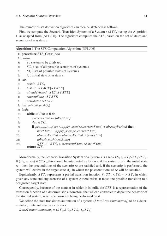
4.1. Scenario Sources Overview 41
The roundtrips set derivation algorithm can then be sketched as follows:
First we compute the Scenario Transition System of a System s (S TS s) using the Algorithm1, as adapted from [NFLJ06]. The algorithm computes the STSs based on the set of states andscenarios of a system s.
Algorithm 1 The STS Computation Algorithm [NFLJ06]
1: procedure STS_Comp_Alg2: param:3: s : system to be analyzed4: SCs : set of all possible scenarios of system s5: STs : set of possible states of system s6: is : initial state of system s7: var:8: result : S TS s
9: toVisit : S T ACK[S T AT E]10: alreadyVisited : S ET [S T AT E]11: currentState : S T AT E12: newState : S T AT E13: init: toVisit.push(is)14: body:15: while toVisit � ∅ do16: currentS tate← toVisit.pop17: ∀sc ∈ S Cs
18: if precurrentState(sc) ∧ apply_scen(sc, currentS tate) � alreadyVisited then19: newS tate← apply_scen(sc, currentS tate)20: alreadyVisited = alreadyVisited ∪ {newS tate}21: toVisit.push(newS tate)22: S TS s ← S TS s ∪ {(currentS tate, sc, newS tate)}
return STSs
More formally, the Scenario Transition System of a System s is a set S TS s ⊆ S T s×S Cs×S T s.If (st1, sc, st2) ∈ S TS s, this should be interpreted as follows: if the system s is in the initial statest1, then the preconditions of the scenario sc are satisfied and, if the scenario is performed, thesystem will evolve in the target state st2, in which the postconditions of sc will be satisfied.
Equivalently, S TS s represents a partial transition function f : S T s × S Cs− > S T s in whichgiven any state and any scenario of a system s there exists at most one possible transition to adesignated target state.
Consequently, because of the manner in which it is built, the S TS is a representation of thetransition function of a deterministic automaton, that we can construct to depict the behavior ofthe studied system, when scenarios are being performed on it.
We define the state transitions automaton of a system (S tateTransAutomatons) to be a deter-ministic, finite automaton as follows:
S tateTransAutomatons = (S T s, S Cs, S TS s, is, S T s)
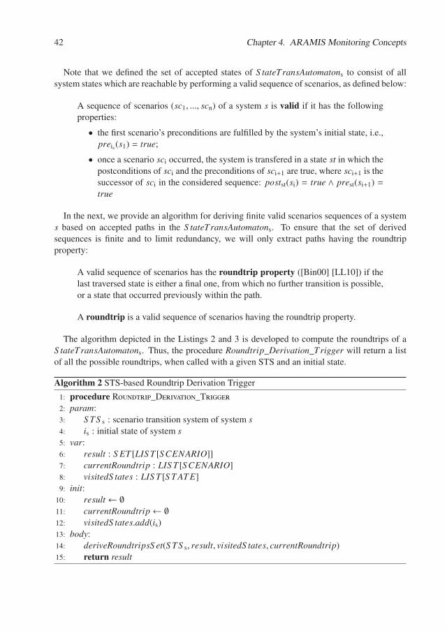
42 Chapter 4. ARAMIS Monitoring Concepts
Note that we defined the set of accepted states of S tateTransAutomatons to consist of allsystem states which are reachable by performing a valid sequence of scenarios, as defined below:
A sequence of scenarios (sc1, ..., scn) of a system s is valid if it has the followingproperties:
• the first scenario’s preconditions are fulfilled by the system’s initial state, i.e.,preis (s1) = true;
• once a scenario sci occurred, the system is transfered in a state st in which thepostconditions of sci and the preconditions of sci+1 are true, where sci+1 is thesuccessor of sci in the considered sequence: postst(si) = true ∧ prest(si+1) =true
In the next, we provide an algorithm for deriving finite valid scenarios sequences of a systems based on accepted paths in the S tateTransAutomatons. To ensure that the set of derivedsequences is finite and to limit redundancy, we will only extract paths having the roundtripproperty:
A valid sequence of scenarios has the roundtrip property ([Bin00] [LL10]) if thelast traversed state is either a final one, from which no further transition is possible,or a state that occurred previously within the path.
A roundtrip is a valid sequence of scenarios having the roundtrip property.
The algorithm depicted in the Listings 2 and 3 is developed to compute the roundtrips of aS tateTransAutomatons. Thus, the procedure Roundtrip_Derivation_Trigger will return a listof all the possible roundtrips, when called with a given STS and an initial state.
Algorithm 2 STS-based Roundtrip Derivation Trigger
1: procedure Roundtrip_Derivation_Trigger2: param:3: S TS s : scenario transition system of system s4: is : initial state of system s5: var:6: result : S ET [LIS T [S CENARIO]]7: currentRoundtrip : LIS T [S CENARIO]8: visitedS tates : LIS T [S T AT E]9: init:
10: result ← ∅11: currentRoundtrip← ∅12: visitedS tates.add(is)13: body:14: deriveRoundtripsS et(S TS s, result, visitedS tates, currentRoundtrip)15: return result
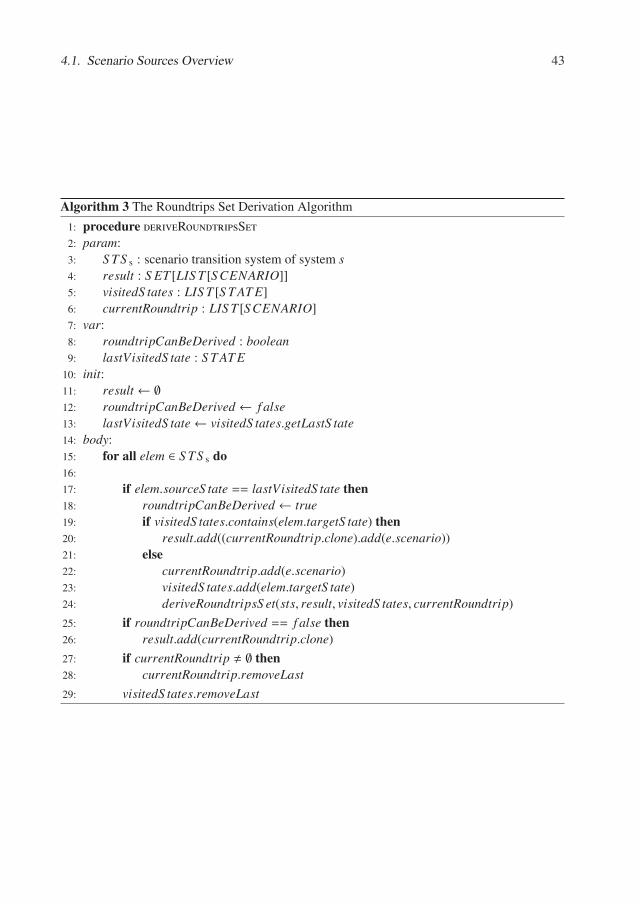
4.1. Scenario Sources Overview 43
Algorithm 3 The Roundtrips Set Derivation Algorithm
1: procedure deriveRoundtripsSet2: param:3: S TS s : scenario transition system of system s4: result : S ET [LIS T [S CENARIO]]5: visitedS tates : LIS T [S T AT E]6: currentRoundtrip : LIS T [S CENARIO]7: var:8: roundtripCanBeDerived : boolean9: lastVisitedS tate : S T AT E
10: init:11: result ← ∅12: roundtripCanBeDerived ← f alse13: lastVisitedS tate← visitedS tates.getLastS tate14: body:15: for all elem ∈ S TS s do16:
17: if elem.sourceS tate == lastVisitedS tate then18: roundtripCanBeDerived ← true19: if visitedS tates.contains(elem.targetS tate) then20: result.add((currentRoundtrip.clone).add(e.scenario))21: else22: currentRoundtrip.add(e.scenario)23: visitedS tates.add(elem.targetS tate)24: deriveRoundtripsS et(sts, result, visitedS tates, currentRoundtrip)
25: if roundtripCanBeDerived == f alse then26: result.add(currentRoundtrip.clone)
27: if currentRoundtrip � ∅ then28: currentRoundtrip.removeLast29: visitedS tates.removeLast
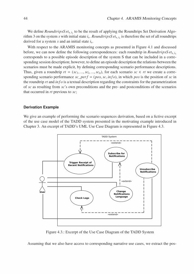
44 Chapter 4. ARAMIS Monitoring Concepts
We define RoundtripsS ets, is to be the result of applying the Roundtrips Set Derivation Algo-rithm 3 on the system s with initial state is. RoundtripsS ets, is is therefore the set of all roundtripsderived for a system s and an initial state is.
With respect to the ARAMIS monitoring concepts as presented in Figure 4.1 and discussedbefore, we can now define the following correspondences: each roundtrip in RoundtripsS ets, is
corresponds to a possible episode description of the system S that can be included in a corre-sponding session description; however, to define an episode description the relations between thescenarios must be made explicit, by defining corresponding scenario performance descriptions.Thus, given a roundtrip rt = (sc1, ..., sci, ..., scn), for each scenario sc ∈ rt we create a corre-sponding scenario performance sc_per f = (pos, sc, in f o), in which pos is the position of sc inthe roundtrip rt and in f o is a textual description regarding the constraints for the parametrizationof sc as resulting from sc’s own preconditions and the pre- and postconditions of the scenariosthat occurred in rt previous to sc;
Derivation Example
We give an example of performing the scenario sequences derivation, based on a fictive excerptof the use case model of the TADD system presented in the motivating example introduced inChapter 3. An excerpt of TADD’s UML Use Case Diagram is represented in Figure 4.3.
TADD System
User
Trigger Receipt of Recent Noti�cations
Check Logs
Subscribe for Noti�cations
Change Noti�cations
Language
Unsubscribe Noti�cations
«extend»
«extend»
«extend»
Figure 4.3.: Excerpt of the Use Case Diagram of the TADD System
Assuming that we also have access to corresponding narrative use cases, we extract the pos-
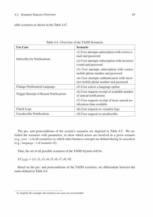
4.1. Scenario Sources Overview 45
sible scenarios as shown in the Table 4.41.
Table 4.4.: Overview of the TADD Scenarios
Use Case Scenario
Subscribe for Notifications
s1) User attempts subscription with correct e-mail and password
s2) User attempts subscription with incorrecte-mail and password
s3) User attempts subscription with correctmobile phone number and password
s4) User attempts authentication with incor-rect mobile phone number and password
Change Notification Language s5) User selects a language option
Trigger Receipt of Recent Notificationss6) User requests receipt of available numberof unread notifications
s7) User requests receipt of more unread no-tifications than available
Check Logs s8) User requests to visualize logs
Unsubscribe Notifications s9) User requests to unsubscribe
The pre- and postconditions of the system’s scenarios are depicted in Table 4.5. We en-riched the scenarios with parameters, to show which actors are involved in a given scenario(e.g., user : u in all scenarios) or, which other business concepts are defined during its execution(e.g., language : l of scenario s5).
Thus, the set of all possible scenarios of the TADD System will be:
S CTADD = {s1, s2, s3, s4, s5, s6, s7, s8, s9}
Based on the pre- and postconditions of the TADD scenarios, we differentiate between thestates defined in Table 4.6.
1to simplify the example, the narrative use cases are not included
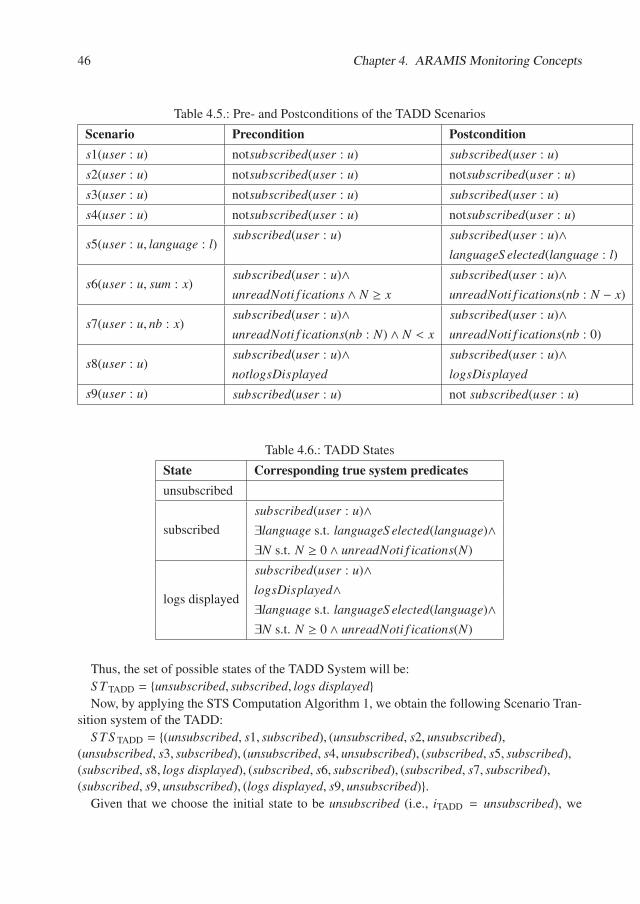
46 Chapter 4. ARAMIS Monitoring Concepts
Table 4.5.: Pre- and Postconditions of the TADD Scenarios
Scenario Precondition Postconditions1(user : u) notsubscribed(user : u) subscribed(user : u)
s2(user : u) notsubscribed(user : u) notsubscribed(user : u)
s3(user : u) notsubscribed(user : u) subscribed(user : u)
s4(user : u) notsubscribed(user : u) notsubscribed(user : u)
s5(user : u, language : l)subscribed(user : u) subscribed(user : u)∧
languageS elected(language : l)
s6(user : u, sum : x)subscribed(user : u)∧ subscribed(user : u)∧unreadNoti f ications ∧ N ≥ x unreadNoti f ications(nb : N − x)
s7(user : u, nb : x)subscribed(user : u)∧ subscribed(user : u)∧unreadNoti f ications(nb : N) ∧ N < x unreadNoti f ications(nb : 0)
s8(user : u)subscribed(user : u)∧ subscribed(user : u)∧notlogsDisplayed logsDisplayed
s9(user : u) subscribed(user : u) not subscribed(user : u)
Table 4.6.: TADD States
State Corresponding true system predicatesunsubscribed
subscribed
subscribed(user : u)∧∃language s.t. languageS elected(language)∧∃N s.t. N ≥ 0 ∧ unreadNoti f ications(N)
logs displayed
subscribed(user : u)∧logsDisplayed∧∃language s.t. languageS elected(language)∧∃N s.t. N ≥ 0 ∧ unreadNoti f ications(N)
Thus, the set of possible states of the TADD System will be:
S T TADD = {unsubscribed, subscribed, logs displayed}Now, by applying the STS Computation Algorithm 1, we obtain the following Scenario Tran-
sition system of the TADD:
S TS TADD = {(unsubscribed, s1, subscribed), (unsubscribed, s2, unsubscribed),(unsubscribed, s3, subscribed), (unsubscribed, s4, unsubscribed), (subscribed, s5, subscribed),(subscribed, s8, logs displayed), (subscribed, s6, subscribed), (subscribed, s7, subscribed),(subscribed, s9, unsubscribed), (logs displayed, s9, unsubscribed)}.
Given that we choose the initial state to be unsubscribed (i.e., iTADD = unsubscribed), we
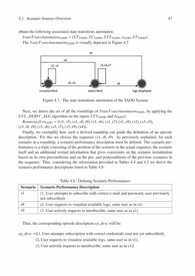
4.1. Scenario Sources Overview 47
obtain the following associated state transitions automaton:
S tateTransAutomatonTADD = (S T TADD, S CTADD, S TS TADD, iTADD, S T TADD).
The S tateTransAutomatonTADD is visually depicted in Figure 4.7.
Figure 4.7.: The state transitions automaton of the TADD System
Next, we derive the set of all the roundtrips of S tateTransAutomatonTADD, by applying theS TS _DERIV_ALG algorithm on the inputs S TS TADD and ITADD):
RountripsS etTADD = {(s1, s5), (s1, s8, s9), (s1, s6), (s1, s7), (s1, s9), (s2), (s3, s5),(s3, s8, s9), (s3, s6), (s3, s7), (s3, s9), (s4)}.
Finally, we exemplify how such a derived roundtrip can guide the definition of an episodedescription. For this we choose the sequence (s1, s8, s9). As previously explained, for eachscenario in a roundtrip, a scenario performance description must be defined. The scenario per-formance is a triple consisting of the position of the scenario in the actual sequence, the scenarioitself and an additional textual information that gives constraints on the scenario instantiationbased on its own preconditions and on the pre- and postconditions of the previous scenarios inthe sequence. Thus, considering the information provided in Tables 4.4 and 4.5 we derive thescenario performance descriptions listed in Table 4.8:
Table 4.8.: Defining Scenario Performances
Scenario Scenario Performance Descriptions1 (1, User attempts to subscribe with correct e-mail and password, user previously
not subscribed)
s8 (2, User requests to visualize available logs, same user as in s1)
s9 (3, User actively requests to unsubscribe, same user as in s1)
Thus, the corresponding episode description ep_desc will be:
ep_desc ={(1,User attempts subscription with correct credentials, user not yet subscribed),
(2,User requests to visualize available logs, same user as in s1),
(3,User actively requests to unsubscribe, same user as in s1)}
48 Chapter 4. ARAMIS Monitoring Concepts
Discussion
In the previous subsections we demonstrated how appropriate scenario sequences can be derivedsystematically based on use cases enhanced with pre- and postconditions for their normative andexceptional scenarios. The derived scenario sequences can then be easily used to create corre-sponding episode descriptions. This systematic, repeatable approach ensures that all possiblesequences, having the presented roundtrip property, are considered. Hence, if using this ap-proach to define episode descriptions, one can then define a comprehensive monitoring sessiondescription that ensures that all corresponding monitoring sessions are semantically adequatefor supporting a behavior-based architecture conformance check, as we will describe later inSection 8.2. However, this is only valid if the use case description used as the input is accurateand complete. In the next paragraphs we present some of the shortcomings of this approach andexplain, why this is often not appropriate.
In a software development project, use cases are often used as a blueprint to support dis-cussions regarding the requirements and, possibly, for the assignment of the initial tasks andcreation of the initial tests. However, practitioners often complain that, as the analysis evolves,use cases rapidly become cluttered and unreadable, especially in the cases when multiple sce-narios emerge [WHL09]. In addition, others question their suitability even in the case of simplercases [WHL09]. Enhancing use cases with pre- and postconditions for each depicted scenariowould add further considerable effort. Consequently, the proposed approach, while systematic,poses a high acceptance risk. Furthermore, as predicted by Lehman’s Law of Continuing Change[Leh80], in the case of non-trivial systems, requirements are often changed and/or new ones areidentified and included during further development of the project or later, in the maintenancephase. However, unlike test cases which are typically enriched to reflect the introduction of newrequirements, the use cases are often not updated accordingly. Instead, the newly introducedfunctionality is documented in a scattered manner, e.g., in tickets described in the issue man-agement system, in the product and sprint backlogs in the case of Scrum development processes[scr], or even in e-mails and chat messages. This natural evolution process gradually renders theuse cases and initial requirements specifications incomplete.
In conclusion, although use cases can offer a good premises for systematically deriving sce-nario sequences, these are often incomplete and/or inaccurate and, additionally, are often re-garded as difficult to work with by practitioners. Consequently, as depicted in the next section,we argue that in general, test cases represent a better source of episode derivation.
4.1.2. Test Cases
As explained in the previous section, the system’s test cases are more likely than the documenteduse cases to reflect the current state of the system. Additionally, most of the systems developedin the industry and meant for production, typically expose up-to-date test cases.
According to the Software and Systems Engineering Vocabulary, a test case is a “set of testinputs, execution conditions, and expected results developed for a particular objective, such asto exercise a particular program path or to verify compliance with a specific requirement” [sev].
Good testing practices dictate that test cases should be developed with the goal of testinga single aspect (or as few aspects as possible), at a given time. Furthermore, best practices
4.1. Scenario Sources Overview 49
impose that test cases should not have dependencies on one another [MG07] 2. Consequently,we can conclude that a test case (including its fixture and tear down) corresponds to an episodedescription. The episode description is in this case technical, depicting the various low-levelinteractions to be performed on the system under test. Thus the various scenario performancedescriptions are only implicitly present. The selection of a set of test cases corresponds to thecreation of a monitoring session description; their actual execution corresponds in turn to amonitoring session.
Considering the aspects mentioned above, the episode description derivation is, in the caseof test cases, a trivial task, since the episode descriptions have a one-to-one correspondenceto the test cases. However, a difficulty that arises also in this context, is the selection of asubset of episodes that constitute a monitoring session that is as small in extent as possible butcomprehensive enough to reflect the overall system behavior. Such a situation occurs in casesin which the execution of the complete test suite requires a considerable amount of resourcesthat should be minimized. In the case of behavior-based conformance checks the resourcesconsumption becomes even more important considering that the instrumentation of the systemfor monitoring purposes causes additional overhead and that the overhead of the conformancecheck itself grows with the number of captured interactions.
Next, based on the classification criteria presented by Ludewig and Lichter [LL10], we signalwhich are the most suitable test types to be used as episodes:
According to the basis of the tests, there exist three main test classes: black-box testing (basedon the system specification), glass-box testing (based on the inner structure of the tested system)and error guessing based testing. All three classes can serve as episodes. On the one hand,the black-box and error guessing-based tests are important to reflect the usage of the system.Such tests are useful for exhibiting the success and exceptional scenarios that a system shouldsupport. On the other hand, glass-box tests can be used as well, since they are formulatedwith an intrinsic knowledge regarding the way a system is structurally constructed. Therefore,some glass-box tests can be especially interesting from an architectural standpoint as they canintentionally trigger several architectural interactions of interest.
According to the invested effort, the tests can be classified in run trials, throw-away testsand systematic tests. From an architectural monitoring stand-point, the most useful test typesare the systematically derived ones. In order to achieve relevant results, the tests should becarefully derived to ensure a high coverage while clearly defining the general test setup, theexpected test results and rules to which the architecture must adhere and the obtained results.In particular, if additionally to the traditional test results, the architectural conformance resultsare also persisted, the architects can later analyze the past evolution of the considered systemsregarding their conformance to the predefined architectural rules. Based on these results, bestpractices and guidelines can be formulated to limit the extent of future architectural drift.
Regarding the classification of tests based on the complexity of the tested entity, one can dif-ferentiate between unit, module, integration and system tests. From an architectural standpointthe system and integration tests are the most suitable ones, since their goal is to test the sys-tem in a more holistic manner. Consequently, these levels are also the most suitable ones forperforming architectural conformance checks.
2in [MG07] this situation is referred to as “interacting tests”
50 Chapter 4. ARAMIS Monitoring Concepts
Based on the tested property, the tests can be classified in functional, (re-)installation, avail-ability, load, stress and regression tests. The functional and regression tests are relevant from abehavior-based conformance checking standpoint as they have the potential to reveal if the func-tionality is implemented as specified in the intended architecture description. Load and stresstests can also prove relevant as the system might exhibit architectural violations when dealingwith such exceptional situations.
Last but not least, based on the involved roles the tests can be classified in alpha and betatests vs. acceptance tests. Since the architectural conformance aspect should be a continuousconcern throughout the development process, all these three types of tests are relevant. However,since the customer, unless a software company itself, is probably not directly interested in thearchitectural conformance results, these checks can be skipped during acceptance testing.
4.1.3. Stakeholders’ Narratives
If the system’s use cases, requirements specification and test cases are not available, one canresort instead to the know-how of the stakeholders actively involved in the software project, moreprominently the architects and developers. Because the architects’ role often involves mediatingbetween requirements analysts and developers and additionally have a good understanding of thearchitectural rules that should be checked, they can be especially reliable to interview in orderto determine which scenarios are best for being included in the episodes, to ensure relevance.
Typically, the know-how of architects and developers regarding system scenarios and episodedescriptions can be extracted in the form of narratives that emerge during dedicated meetings anddiscussions in the planning phase of a monitoring session, when a monitoring session descriptionemerges. Based on their knowledge of the system and its composition, the architects can makeassumptions regarding events that can be triggered on it in order to most effectively illustratehow the architecture is built. In doing this, they might imply partial parameterizations andorderings of scenarios (“if you try to log-in with the user abc after you delete his account,an exception should be thrown by the system component E”), thus aiding in the definition ofscenario performance descriptions and episode descriptions. Because narratives are informal,we cannot make very strong assumptions regarding their content. Therefore, a narrative cancontain one or more episode descriptions or even only a central part of an episode descriptionthat must then be completed with some implicit knowledge (e.g., for the set-up of the episodedescription).
Finally, it must be mentioned that the know-how of architects and developers can and shouldbe leveraged even when test cases and/or use cases are available. Architects are in this senseentitled to guide the selection of the scenarios, their instantiation and composition in episodedescriptions through corresponding scenario performance descriptions. To this end, the archi-tect might be able to use the information provided in the system’s use cases or test cases todefine monitoring sessions descriptions that reduce the amount of data being collected duringmonitoring while still preserving relevance.
In order to demonstrate how ARAMIS supports the research questions formulated in ChapterI we organize the remainder of this part in corresponding chapters that each address one researchquestion, clearly depicting what concepts have been developed in order to offer pertinent answersto it.
Chapter 5.
Describing Extracted Interactions inARAMIS
Having presented a big picture of the ARAMIS approach, a motivating example and a set ofimportant monitoring concepts to be used throughout this thesis, we now address one by one theresearch questions formulated in Chapter I.
The research question approached in this Chapter is depicted below.
How to describe the interactions occurring in a running software system independentlyof the monitoring tools employed to extract these?
MotivationBoth open-source (e.g., Kieker [HWH+12]) and commercial monitoring tools (e.g., Nagios[nag], Dynatrace [dyn]) were introduced over time to support the analysis of running systems.Most of these monitoring tools are developed with performance analysis and diagnostics as theirmain concern, and are often used in the industry for this purpose. However, the information thatthey extract can also be used for behavior-based architecture conformance checks.
Consequently, to reduce unnecessary complexity, we decided to reuse within ARAMIS thedata captured by such tools. However, different monitoring tools describe the extracted inter-actions using proprietary languages. Our concern was to create a solution for reusing extractedinteractions without making ARAMIS conceptually or technically dependent on a single moni-toring tool.
This chapter is structured as follows. In Section 5.1, we present the ARAMIS Interactions De-scription Language (AID-Lang) - our solution towards achieving the above-mentioned desiredmonitoring tool decoupling. Next, we discuss how interactions are described by two popularmonitoring tools and, as a proof of concept, depict how these can be expressed using the AID-Lang.
5.1. The ARAMIS Interactions Description Language
To decouple ARAMIS from the monitoring tools leveraged to extract interactions from runningsystems, we defined the ARAMIS Interactions Description Language (AID-Lang). When em-ploying ARAMIS, any extracted interactions must first be expressed using the AID-Lang andonly subsequently processed further. Thus we pose no conditions on the monitoring tool to em-ploy, so its choice can be driven by criteria such as its monitoring capabilities or whether the
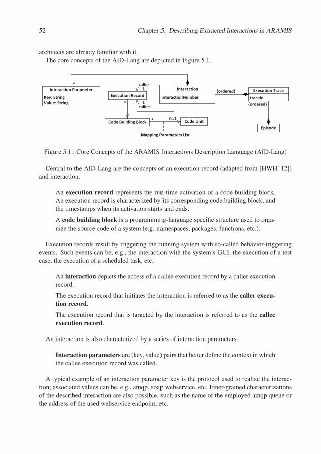
52 Chapter 5. Describing Extracted Interactions in ARAMIS
architects are already familiar with it.The core concepts of the AID-Lang are depicted in Figure 5.1.
Mapping�Parameters�List
Code�Building�Block
interactionNumber
Interaction
traceId
Execution�Trace
Code�Unit
caller
Execution�RecordKey:�StringValue:�String
Interaction�Parameter
callee
Episode
{ordered}
0..1*
*
*1
1
{ordered}
Figure 5.1.: Core Concepts of the ARAMIS Interactions Description Language (AID-Lang)
Central to the AID-Lang are the concepts of an execution record (adapted from [HWH+12])and interaction.
An execution record represents the run-time activation of a code building block.An execution record is characterized by its corresponding code building block, andthe timestamps when its activation starts and ends.
A code building block is a programming-language specific structure used to orga-nize the source code of a system (e.g. namespaces, packages, functions, etc.).
Execution records result by triggering the running system with so-called behavior-triggeringevents. Such events can be, e.g., the interaction with the system’s GUI, the execution of a testcase, the execution of a scheduled task, etc.
An interaction depicts the access of a callee execution record by a caller executionrecord.
The execution record that initiates the interaction is referred to as the caller execu-tion record.
The execution record that is targeted by the interaction is referred to as the calleeexecution record.
An interaction is also characterized by a series of interaction parameters.
Interaction parameters are (key, value) pairs that better define the context in whichthe callee execution record was called.
A typical example of an interaction parameter key is the protocol used to realize the interac-tion; associated values can be, e.g., amqp, soap webservice, etc. Finer-grained characterizationsof the described interaction are also possible, such as the name of the employed amqp queue orthe address of the used webservice endpoint, etc.
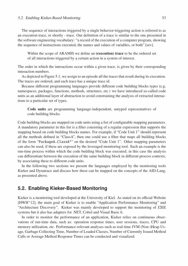
5.2. Enabling Kieker-Based Monitoring 53
The sequence of interactions triggered by a single behavior-triggering action is referred to asan execution trace, or shortly - trace. Our definition of a trace is similar to the one presented inthe software engineering vocabulary: “a record of the execution of a computer program, showingthe sequence of instructions executed, the names and values of variables, or both” [sev].
Within the scope of ARAMIS we define an (execution) trace to be the ordered setof all interactions triggered by a certain action in a system of interest.
The order in which the interactions occur within a given trace, is given by their correspondinginteraction numbers.
As depicted in Figure 5.1, we assign to an episode all the traces that result during its execution.The traces are ordered, and each trace has a unique trace id.
Because different programming languages provide different code building blocks types (e.g.namespaces, packages, functions, methods, structures, etc.) we have introduced so-called codeunits as an additional layer of abstraction to avoid constraining the analysis of extracted interac-tions to a particular set of types.
Code units are programming language-independent, untyped representatives ofcode building blocks.
Code building blocks are mapped on code units using a list of configurable mapping parameters.A mandatory parameter in this list is a filter consisting of a regular expression that supports themapping based on code building blocks names. For example, if “Code Unit 1” should representall the methods defined in “ClassA”, then one could use a filter that maps all building blocksof the form “PackageA.ClassA*” on the desired “Code Unit 1”. Other mapping parameterscan also be used, if these are exposed by the leveraged monitoring tool. Such an example is therun-time process within which the code building block was executed; in this case the analysiscan differentiate between the execution of the same building block in different process contexts,by associating these to different code units.
In the following two sections we present the languages employed by the monitoring toolsKieker and Dynatrace and discuss how these can be mapped on the concepts of the AID-Lang,as presented above.
5.2. Enabling Kieker-Based Monitoring
Kieker is a monitoring tool developed at the University of Kiel. As stated on its official Website[HWH+12], the main goal of Kieker is to enable “Application Performance Monitoring” and“Architecture Discovery”. Kieker was mainly developed to support the monitoring of J2EEsystems but it also has adapters for .NET, Cobol and Visual Basic 6.
In order to monitor the performance of an application, Kieker relies on continuous obser-vations of run-time data, such as: operation response times, user sessions, traces, CPU andmemory utilization, etc. Performance-relevant analyses such as real-time JVM (Non-)Heap Us-age, Garbage Collecting Time, Number of Loaded Classes, Number of Currently Issued MethodCalls or Average Method Response Times can be conducted and visualized.
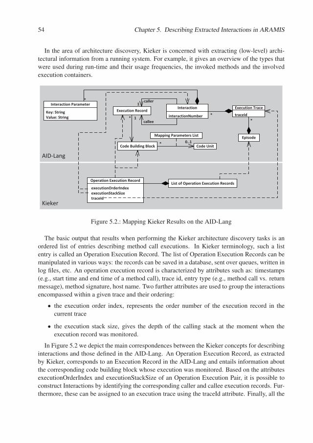
54 Chapter 5. Describing Extracted Interactions in ARAMIS
In the area of architecture discovery, Kieker is concerned with extracting (low-level) archi-tectural information from a running system. For example, it gives an overview of the types thatwere used during run-time and their usage frequencies, the invoked methods and the involvedexecution containers.
Kieker
AID�Lang
*
Mapping�Parameters�List
Code�Building�Block
interactionNumber
Interaction
traceId
Execution�Trace
Code�Unit
caller
Execution�RecordKey:�StringValue:�String
Interaction�Parameter
callee
Episode
*
0..1*
*
*1
1
List�of�Operation�Execution�Records��executionOrderIndex��executionStackSize��traceId
Operation�Execution�Record
Figure 5.2.: Mapping Kieker Results on the AID-Lang
The basic output that results when performing the Kieker architecture discovery tasks is anordered list of entries describing method call executions. In Kieker terminology, such a listentry is called an Operation Execution Record. The list of Operation Execution Records can bemanipulated in various ways: the records can be saved in a database, sent over queues, written inlog files, etc. An operation execution record is characterized by attributes such as: timestamps(e.g., start time and end time of a method call), trace id, entry type (e.g., method call vs. returnmessage), method signature, host name. Two further attributes are used to group the interactionsencompassed within a given trace and their ordering:
• the execution order index, represents the order number of the execution record in thecurrent trace
• the execution stack size, gives the depth of the calling stack at the moment when theexecution record was monitored.
In Figure 5.2 we depict the main correspondences between the Kieker concepts for describinginteractions and those defined in the AID-Lang. An Operation Execution Record, as extractedby Kieker, corresponds to an Execution Record in the AID-Lang and entails information aboutthe corresponding code building block whose execution was monitored. Based on the attributesexecutionOrderIndex and executionStackSize of an Operation Execution Pair, it is possible toconstruct Interactions by identifying the corresponding caller and callee execution records. Fur-thermore, these can be assigned to an execution trace using the traceId attribute. Finally, all the
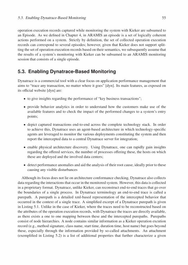
5.3. Enabling Dynatrace-Based Monitoring 55
operation execution records captured while monitoring the system with Kieker are subsumed toan Episode. As we defined in Chapter 4, in ARAMIS an episode is a set of logically coherentactions performed on a system. Strictly by definition, the set of collected operation executionrecords can correspond to several episodes; however, given that Kieker does not support split-ting the set of operation execution records based on their semantics, we subsequently assume thatthe results of a system’s monitoring with Kieker can be subsumed to an ARAMIS monitoringsession that consists of a single episode.
5.3. Enabling Dynatrace-Based Monitoring
Dynatrace is a commercial tool with a clear focus on application performance management thataims to “trace any transaction, no matter where it goes” [dyn]. Its main features, as exposed onits official website [dyn] are:
• to give insights regarding the performance of “key business transactions";
• provide behavior analytics in order to understand how the customers make use of theavailable features and to check the impact of the performed changes to a system’s entrypoints;
• depict captured transactions end-to-end across the complete technology stack. In orderto achieve this, Dynatrace uses an agent-based architecture in which technology-specificagents are leveraged to monitor the various deployments constituting the system and thenreport the intercepted data to a central Dynatrace server for integration;
• enable physical architecture discovery. Using Dynatrace, one can rapidly gain insightsregarding the offered services, the number of processes offering these, the hosts on whichthese are deployed and the involved data centers;
• detect performance anomalies and aid the analysis of their root cause, ideally prior to thesecausing any visible disturbances
Although its focus does not lie on architecture conformance checking, Dynatrace also collectsdata regarding the interactions that occur in the monitored system. However, this data is collectedin a proprietary format. Dynatrace, unlike Kieker, can reconstruct end-to-end traces that go overthe boundaries of a single process. In Dynatrace terminology an end-to-end trace is called apurepath. A purepath is a detailed xml-based representation of the intercepted behavior thatoccurred in the context of a single trace. A simplified excerpt of a Dynatrace purepath is givenin Listing 5.1. Unlike in the case of Kieker, where the traces need to be reconstructed based onthe attributes of the operation execution records, with Dynatrace the traces are directly available,as there exists a one to one mapping between these and the intercepted purepaths. Purepathsconsist of node hierarchies. A node contains similar information as a Kieker operation excutionrecord (e.g., method signature, class name, start time, duration time, host name) but goes beyondthese, especially through the information provided by so-called attachments. An attachment(exemplified in Listing 5.2) is a list of additional properties that further characterize a given
56 Chapter 5. Describing Extracted Interactions in ARAMIS
node. In the provided example, the attachment provides additional information for an initiatedREST service call: URI, query parameters, request type and response code.
Listing 5.1: Excerpt of Simplified Dynatrace Purepath
1 <p u r e p a t h name=" {$ purePathName } ">2 <node method=" {$ methodName1} " c l a s s=" {$ className1 } " a g e n t=" {$ agentName } ">3 < a t t a c h m e n t> . . . < / a t t a c h m e n t>4 <node method=" {$ methodName2} " c l a s s=" {$ className2 } "> < / node>5 <node method=" {$ methodName3} " c l a s s=" {$ className3 } "> < / node>6 < / node>7 < / p u r e p a t h>
Listing 5.2: Excerpt of a Dynatrace Node Attachement
1 < a t t a c h m e n t t y p e=" C l i e n t S i d e W e b r e q u e s t N o d e A t t a c h m e n t ">2 <p r o p e r t y key=" u r i " v a l u e=" h t t p : / / 1 2 7 . 0 . 0 . 1 :8020 / r e s t / management / d a s h b o a r d
/ SpringREST " / >3 <p r o p e r t y key=" que ry " v a l u e=" p u r e P a t h D e t a i l s=ALL" / >4 <p r o p e r t y key=" r e q u e s t m e t h o d " v a l u e="GET" / >5 <p r o p e r t y key=" r e s p o n s e c o d e " v a l u e=" 200 " / >6 < / a t t a c h m e n t>
While Dynatrace is capable of monitoring end-to-end cross-processes transactions, it is im-portant to note that without a preliminary normalization of the resulted purepaths, a consequentanalysis would entail large amounts of irrelevant nodes, mostly introduced by the leveragedframeworks within the system. During the mentioned normalization process, these irrelevantnodes must be removed and purepaths drastically simplified.
Dynatrace
AID�Lang
*
Mapping�Parameters�List
Code�Building�Block
interactionNumber
Interaction
traceId
Execution�Trace
Code�Unit
caller
Execution�RecordKey:�StringValue:�String
Interaction�Parameter
callee
Episode
*
0..1*
*
*1
1
Purepaths�DashletPurepathNodeAttachement *0...1 *
is�child�of0..1*
Figure 5.3.: Mapping Dynatrace Results on the AID-Lang
In Figure 5.3 we depict the main correspondences between the Dynatrace concepts for de-scribing interactions and those included in the AID-Lang. Similar to the Kieker operation ex-
5.3. Enabling Dynatrace-Based Monitoring 57
ecution records, a Dynatrace node can be associated with an AID-Lang execution record and acorresponding code building block. Furthermore, nodes contain information regarding the pro-cess in which the node was monitored. This information can be associated with an entry in anAID-Lang mapping parameters list. Furthermore, as previously suggested, a purepath is logi-cally corresponding to an execution trace. The interactions included in a trace can be identifiedbased on the hierarchy of the nodes in its corresponding purepath: a direct "parent to child" rela-tion between two nodes corresponds to an interaction whose caller and callee execution recordsare associated to the parent and child nodes respectively. Moreover, the attachment of a Dyna-trace child node contains information regarding the way this node was activated by its parent;consequently, several interaction parameters characterizing the associated AID-Lang interactioncan be extracted based thereupon. Last but not least, when monitoring a system with Dynatraceone can define so-called dashlets by selecting the purepaths to be included within. Supposingthat the selection is made such that the purepaths correspond to a logically coherent behaviorsnippet of the system, we can conclude that a dashlet can be subsumed to an episode in theAID-Lang.
Discussion
The main goal of the AID-Lang is to decouple ARAMIS from the underlying employed moni-toring tools, by expressing the extracted interactions in a tool-independent format.
However, at a semantic level, a perfect decoupling is not completely possible, as some level ofknowledge regarding how the interactions are extracted is necessary in order to perform correctarchitecture conformance checks. As also pointed out by Bass et al. "data extraction tools areimperfect: they often return incomplete results or false positives" [BCK12]. In this context animportant concept used throughout this dissertation must be introduced:
A monitoring tool exposes a monitoring anomaly if, in some situations, the ex-tracted interactions do not correctly reflect the execution of the system under anal-ysis.
A behavior-based conformance checking performed on interactions extracted with a moni-toring tool that exposes monitoring anomalies can be erroneous, if anomalies-specific countermeasures are not taken. In our practical experiments with monitoring tools we encountered twomain classes of monitoring anomalies: polymorphism- and partial trace anomalies. These arediscussed and exemplified in Appendix A.

Chapter 6.
Behavior-based Architecture ConformanceChecking in ARAMIS
In the previous chapters we introduced a series of concepts regarding the monitoring of a soft-ware system and discussed how the interactions extracted in this context can be described inARAMIS using the ARAMIS Interactions Description Language.
In this chapter we discuss how intended architecture descriptions can be modeled in ARAMISand how behavior-based architecture conformance checks can be conducted based thereupon.This chapter addresses the following research question, as formulated in Section 1.3:
How to model the intended architecture of a system and perform behavior-based ar-chitecture conformance checks based thereupon?
This chapter is structured as follows: first, in Section 6.1, we give an overview of the con-formance checking techniques employed in ARAMIS in adapted fashions. Next, in Section 6.2we discuss the meta-model of architecture descriptions used by ARAMIS and in Section 6.3 wepresent a taxonomy of the architectural communication rules that can be expressed using ourapproach. Last but not least, in Section 6.4.1 we present how ARAMIS conducts architectureconformance checks to inquire the adherence to the previously formulated communication rules.
6.1. Conformance Checking Techniques Employed in ARAMIS
A sketch of a general process to support architecture reconstruction and conformance checkingwas proposed by Bass et al.: "when a system is initially developed, its high-level design/ar-chitectural elements are mapped to implementation elements. Therefore, when we reconstructthose elements, we need to apply the inverse of mappings" [BCK12]. Furthermore, Knodel andPopescu [KP07], have identified three main techniques that can be employed to perform ar-chitecture conformance checks: reflexion models, relation conformance rules and conformanceaccess rules.
In the next paragraphs we give an overview of the three techniques mentioned above and thendiscuss how we accommodated these in ARAMIS.
Reflexion ModelingAmong the existing techniques, reflexion modeling [MNS95] has prominently differentiateditself as the one adopted by most of the conformance checking tools and the one with the highestindustry acceptance [HEB+15].
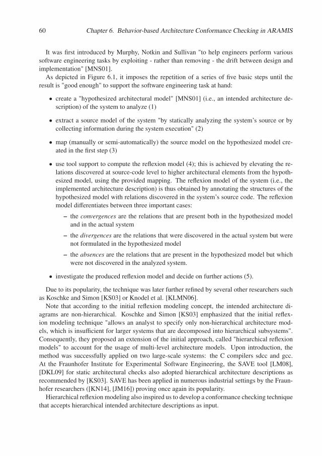
60 Chapter 6. Behavior-based Architecture Conformance Checking in ARAMIS
It was first introduced by Murphy, Notkin and Sullivan "to help engineers perform varioussoftware engineering tasks by exploiting - rather than removing - the drift between design andimplementation" [MNS01].
As depicted in Figure 6.1, it imposes the repetition of a series of five basic steps until theresult is "good enough" to support the software engineering task at hand:
• create a "hypothesized architectural model" [MNS01] (i.e., an intended architecture de-scription) of the system to analyze (1)
• extract a source model of the system "by statically analyzing the system’s source or bycollecting information during the system execution" (2)
• map (manually or semi-automatically) the source model on the hypothesized model cre-ated in the first step (3)
• use tool support to compute the reflexion model (4); this is achieved by elevating the re-lations discovered at source-code level to higher architectural elements from the hypoth-esized model, using the provided mapping. The reflexion model of the system (i.e., theimplemented architecture description) is thus obtained by annotating the structures of thehypothesized model with relations discovered in the system’s source code. The reflexionmodel differentiates between three important cases:
– the convergences are the relations that are present both in the hypothesized modeland in the actual system
– the divergences are the relations that were discovered in the actual system but werenot formulated in the hypothesized model
– the absences are the relations that are present in the hypothesized model but whichwere not discovered in the analyzed system.
• investigate the produced reflexion model and decide on further actions (5).
Due to its popularity, the technique was later further refined by several other researchers suchas Koschke and Simon [KS03] or Knodel et al. [KLMN06].
Note that according to the initial reflexion modeling concept, the intended architecture di-agrams are non-hierarchical. Koschke and Simon [KS03] emphasized that the initial reflex-ion modeling technique "allows an analyst to specify only non-hierarchical architecture mod-els, which is insufficient for larger systems that are decomposed into hierarchical subsystems".Consequently, they proposed an extension of the initial approach, called "hierarchical reflexionmodels" to account for the usage of multi-level architecture models. Upon introduction, themethod was successfully applied on two large-scale systems: the C compilers sdcc and gcc.At the Fraunhofer Institute for Experimental Software Engineering, the SAVE tool [LM08],[DKL09] for static architectural checks also adopted hierarchical architecture descriptions asrecommended by [KS03]. SAVE has been applied in numerous industrial settings by the Fraun-hofer researchers ([KN14], [JM16]) proving once again its popularity.
Hierarchical reflexion modeling also inspired us to develop a conformance checking techniquethat accepts hierarchical intended architecture descriptions as input.
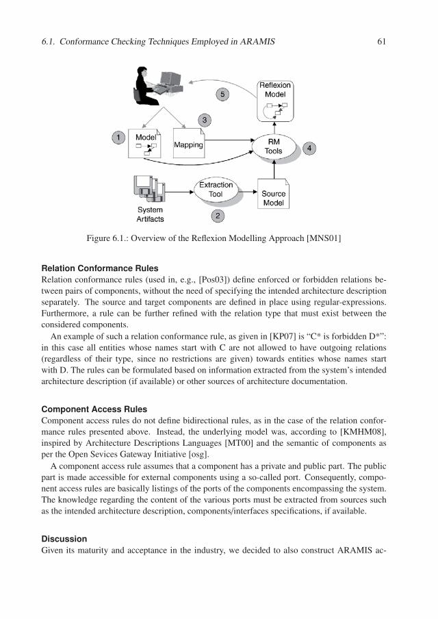
6.1. Conformance Checking Techniques Employed in ARAMIS 61
Figure 6.1.: Overview of the Reflexion Modelling Approach [MNS01]
Relation Conformance RulesRelation conformance rules (used in, e.g., [Pos03]) define enforced or forbidden relations be-tween pairs of components, without the need of specifying the intended architecture descriptionseparately. The source and target components are defined in place using regular-expressions.Furthermore, a rule can be further refined with the relation type that must exist between theconsidered components.
An example of such a relation conformance rule, as given in [KP07] is “C* is forbidden D*”:in this case all entities whose names start with C are not allowed to have outgoing relations(regardless of their type, since no restrictions are given) towards entities whose names startwith D. The rules can be formulated based on information extracted from the system’s intendedarchitecture description (if available) or other sources of architecture documentation.
Component Access RulesComponent access rules do not define bidirectional rules, as in the case of the relation confor-mance rules presented above. Instead, the underlying model was, according to [KMHM08],inspired by Architecture Descriptions Languages [MT00] and the semantic of components asper the Open Sevices Gateway Initiative [osg].
A component access rule assumes that a component has a private and public part. The publicpart is made accessible for external components using a so-called port. Consequently, compo-nent access rules are basically listings of the ports of the components encompassing the system.The knowledge regarding the content of the various ports must be extracted from sources suchas the intended architecture description, components/interfaces specifications, if available.
DiscussionGiven its maturity and acceptance in the industry, we decided to also construct ARAMIS ac-
62 Chapter 6. Behavior-based Architecture Conformance Checking in ARAMIS
Figure 6.2.: Architecture Descriptions in ARAMIS
cording to the reflexion model, while also allowing, however, hierarchical intended architecturedescriptions as input. Consequently, to employ ARAMIS an intended architecture descriptionof the system under analysis needs to exist or to be created. Then, mappings between the sys-tem’s code building blocks and the created intended architecture description must be specified.Next, because ARAMIS employs a behavior-based analysis, the system must be monitored andthe occurring interactions must be intercepted, as they depict the relations of interest betweenthe system’s code building blocks. According to the reflexion model, these extracted relationsare consequently elevated on the elements of the intended architecture description and thus theconvergences, divergences and absences are identified.
Furthermore, inspired by the expressiveness of relation conformance rules, we employ a richtaxonomy of communication rules that can be expressed as part of the system’s intended archi-tecture description. For example, unlike in the case of pure reflexion modeling, with ARAMISone can also specify enforcing and denying rules, because "what a system does not do is as im-portant as what it does. To ensure that a system possesses certain qualities, you must constrainit so that you know what it will not do" [Fai10].
The meta-model of ARAMIS architecture descriptions imposes very few semantic restric-tions. Although the meta-model itself does not contain a port concept, this can be simulatedusing the existing elements. Consequently, rules equivalent to the above mentioned componentaccess rules can also be formulated within ARAMIS.
6.2. Meta-Model of ARAMIS Architecture Descriptions
When we created the meta-model of ARAMIS architecture descriptions, we considered the fol-lowing characterization of software architecture, as formulated by Reekie and McAdam [RM06]:(1) the whole consists of smaller parts; (2) the parts have relations to each other; (3) when puttogether, the parts form a whole that has some designed purpose and fills a specific need. In thenext paragraphs we introduce the meta-model of ARAMIS architecture descriptions and, whereneccessary, we explain how this meets Reekie and McAdam’s characterization given above.
As shown in the meta-model depicted in Figure 6.2, an architecture description has either aprescriptive or descriptive role depending on its relation with the software system of interest. Inits prescriptive role, in which it poses constraints to be obeyed during development, the descrip-tion is referred to as the system’s intended architecture description. Conversely, in its descriptiverole, in which it mainly depicts how the system is actually built, the description is referred to as
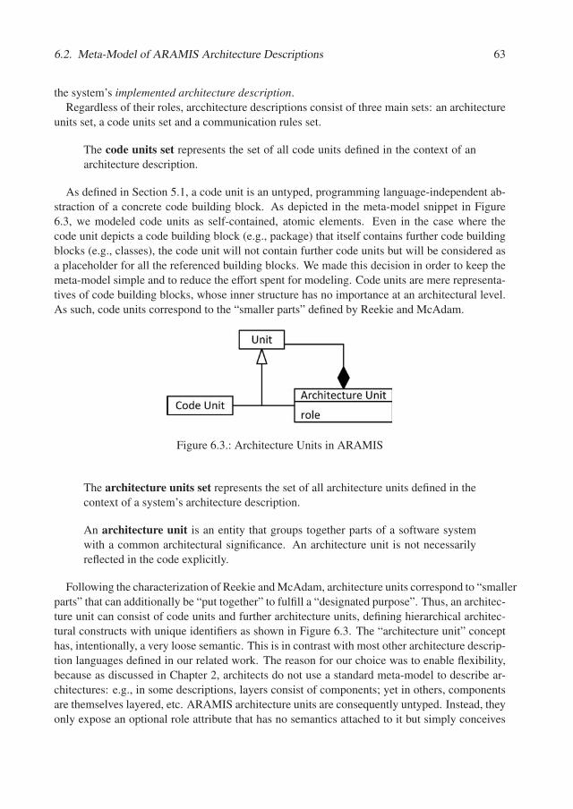
6.2. Meta-Model of ARAMIS Architecture Descriptions 63
the system’s implemented architecture description.Regardless of their roles, arcchitecture descriptions consist of three main sets: an architecture
units set, a code units set and a communication rules set.
The code units set represents the set of all code units defined in the context of anarchitecture description.
As defined in Section 5.1, a code unit is an untyped, programming language-independent ab-straction of a concrete code building block. As depicted in the meta-model snippet in Figure6.3, we modeled code units as self-contained, atomic elements. Even in the case where thecode unit depicts a code building block (e.g., package) that itself contains further code buildingblocks (e.g., classes), the code unit will not contain further code units but will be considered asa placeholder for all the referenced building blocks. We made this decision in order to keep themeta-model simple and to reduce the effort spent for modeling. Code units are mere representa-tives of code building blocks, whose inner structure has no importance at an architectural level.As such, code units correspond to the “smaller parts” defined by Reekie and McAdam.
Figure 6.3.: Architecture Units in ARAMIS
The architecture units set represents the set of all architecture units defined in thecontext of a system’s architecture description.
An architecture unit is an entity that groups together parts of a software systemwith a common architectural significance. An architecture unit is not necessarilyreflected in the code explicitly.
Following the characterization of Reekie and McAdam, architecture units correspond to “smallerparts” that can additionally be “put together” to fulfill a “designated purpose”. Thus, an architec-ture unit can consist of code units and further architecture units, defining hierarchical architec-tural constructs with unique identifiers as shown in Figure 6.3. The “architecture unit” concepthas, intentionally, a very loose semantic. This is in contrast with most other architecture descrip-tion languages defined in our related work. The reason for our choice was to enable flexibility,because as discussed in Chapter 2, architects do not use a standard meta-model to describe ar-chitectures: e.g., in some descriptions, layers consist of components; yet in others, componentsare themselves layered, etc. ARAMIS architecture units are consequently untyped. Instead, theyonly expose an optional role attribute that has no semantics attached to it but simply conceives
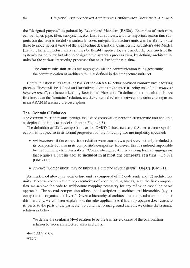
64 Chapter 6. Behavior-based Architecture Conformance Checking in ARAMIS
the “designed purpose” as pointed by Reekie and McAdam [RM06]. Examples of such rolescan be: layer, pipe, filter, subsystems, etc. Last but not least, another important reason that sup-ports our decision to model semantically loose, untyped architecture units was the ability to usethese to model several views of the architecture description. Considering Kruchten’s 4+1 Model,[Kru95], the architecture units can thus be flexibly applied to, e.g., model the constructs of thesystem’s logical view but also to designate the system’s process view, by defining architecturalunits for the various interacting processes that exist during the run-time.
The communication rules set aggregates all the communication rules governingthe communication of architecture units defined in the architecture units set.
Communication rules are at the basis of the ARAMIS behavior-based conformance checkingprocess. These will be defined and formalized later in this chapter, as being one of the “relationsbetween parts”, as characterized my Reekie and McAdam. To define communication rules wefirst introduce the "contains" relation, another essential relation between the units encompassedin an ARAMIS architecture description.
The "Contains" RelationThe contains relation results through the use of composition between architecture unit and unit,as depicted in the meta-model snippet in Figure 6.3).
The definition of UML composition, as per OMG’s Infrastructure and Superstructure specifi-cations is not precise in its formal properties, but the following two are implicitly specified:
• not transitive: if the composition relation were transitive, a part were not only included inits composite but also in its composite’s composite. However, this is rendered impossibleby the following characterization: "Composite aggregation is a strong form of aggregationthat requires a part instance be included in at most one composite at a time" [Obj09],[OMG11];
• acyclic: "Compositions may be linked in a directed acyclic graph" [Obj09], [OMG11].
As mentioned above, an architecture unit is composed of (1) code units and (2) architectureunits. Because code units are representatives of code building blocks, with the first composi-tion we achieve the code to architecture mapping necessary for any reflexion modeling-basedapproach. The second composition allows the description of architectural hierarchies (e.g., acomponent is organized in layers). Given a hierarchy of architecture units, and a certain unit inthis hierarchy, we will later explain how the rules applicable to this unit propagate downwards toits parts, to the parts of the parts, etc. To build the formal ground thereof, we define the containsrelation as below:
We define the contains (�→) relation to be the transitive closure of the compositionrelation between architecture units and units.
�→⊂ AUS × US
where,
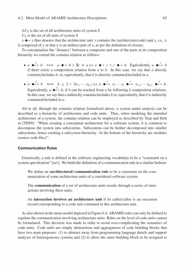
6.2. Meta-Model of ARAMIS Architecture Descriptions 65
AUS is the set of all architecture units of system SUS is the set of all units of system Sx �→ y thus denotes that the architecture unit x contains the (architecture/code) unit y, i.e., x
is composed of y or that y is an indirect part of x, as per the definition of closure.To conceptualize the "distance" between a composite and one of the parts in its composition
hierarchy we extend the contains relation as follows:
• a �1−−→ b ⇐⇒ a �→ b ∧ �c � a s.t. a �→ c ∧ c �→ b. Equivalently, a �
1−−→ bif there exists a composition relation from a to b. In this case, we say that a directlycontains/includes b, or, equivalently, that b is directly contained/included in a.
• a �k−−→ b ⇐⇒ k ≥ 2 ∧ ∃x1, · · · ,xk-1 s.t. a �
1−−→ x1 · · · xi �1−−→ xi+1 · · · xk-1 �
1−−→ b.
Equivalently, a �k−−→ b, if b can be reached from a by following k composition relations.
In this case, we say that a indirectly contains/includes b or, equivalently, that b is indirectlycontained/included in a.
All in all, through the contains relation formalized above, a system under analysis can bedescribed as a hierarchy of architecture and code units. Thus, when modeling the intendedarchitecture of a system, the contains relation can be employed as described by Tran and Holtin [TH99]: “When creating a conceptual architecture for a software system, it is common todecompose the system into subsystems. Subsystems can be further decomposed into smallersubsystems, hence creating a subsystem hierarchy. At the bottom of the hierarchy are modules(source code files)”.
Communication Rules
Generically, a rule is defined in the software engineering vocabulary to be a “constraint on asystem specification” [sev]. We build the definition of a communication rule in a similar fashion:
We define an (architectural) communication rule to be a constraint on the com-munication of some architecture units of a considered software system.
The communication of a set of architecture units results through a series of inter-actions involving these units.
An interaction involves an architecture unit if its caller/callee is an executionrecord corresponding to a code unit contained in this architecture unit.
As also shown in the meta-model depicted in Figure 6.4, ARAMIS rules can only be defined toregulate the communication involving architecture units. Rules on the level of code units cannotbe formulated. This decision was made in order to avoid over-complicating the semantics ofcode units. Code units are simply abstractions and aggregations of code building blocks thathave two main purposes: (1) to abstract away from programming language details and supportanalyses of heterogeneous systems and (2) to allow the same building block to be assigned to
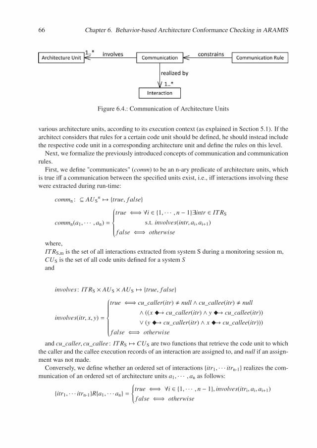
66 Chapter 6. Behavior-based Architecture Conformance Checking in ARAMIS
Figure 6.4.: Communication of Architecture Units
various architecture units, according to its execution context (as explained in Section 5.1). If thearchitect considers that rules for a certain code unit should be defined, he should instead includethe respective code unit in a corresponding architecture unit and define the rules on this level.
Next, we formalize the previously introduced concepts of communication and communicationrules.
First, we define "communicates" (comm) to be an n-ary predicate of architecture units, whichis true iff a communication between the specified units exist, i.e., iff interactions involving thesewere extracted during run-time:
commn : ⊆ AUSn �→ {true, f alse}
commn(a1, · · · , an) =
⎧⎪⎪⎪⎪⎪⎨⎪⎪⎪⎪⎪⎩
true ⇐⇒ ∀i ∈ {1, · · · , n − 1}∃intr ∈ ITRS
s.t. involves(intr, ai, ai+1)
f alse ⇐⇒ otherwise
where,ITRS,m is the set of all interactions extracted from system S during a monitoring session m,CUS is the set of all code units defined for a system Sand
involves : ITRS × AUS × AUS �→ {true, f alse}
involves(itr, x, y) =
⎧⎪⎪⎪⎪⎪⎪⎪⎪⎨⎪⎪⎪⎪⎪⎪⎪⎪⎩
true ⇐⇒ cu_caller(itr) � null ∧ cu_callee(itr) � null
∧ ((x �→ cu_caller(itr) ∧ y �→ cu_callee(itr))
∨ (y �→ cu_caller(itr) ∧ x �→ cu_callee(itr)))
f alse ⇐⇒ otherwise
and cu_caller, cu_callee : ITRS �→ CUS are two functions that retrieve the code unit to whichthe caller and the callee execution records of an interaction are assigned to, and null if an assign-ment was not made.
Conversely, we define whether an ordered set of interactions {itr1, · · · itrn-1} realizes the com-munication of an ordered set of architecture units a1, · · · , an as follows:
{itr1, · · · itrn-1}R{a1, · · · an} =⎧⎪⎪⎨⎪⎪⎩
true ⇐⇒ ∀i ∈ {1, · · · , n − 1}, involves(itri, ai, ai+1)
f alse ⇐⇒ otherwise
6.2. Meta-Model of ARAMIS Architecture Descriptions 67
Communication rules constrain the communication of architecture units. A communicationrule of order n is a tuple as follows:
commRulen = (a1, · · · , an,Cond, permission)
where:
• permission ∈ {denied, allowed, en f orced} is a parameter that depicts whether the de-picted communication is respectively forbidden, permitted or necessary to occur
• Cond is a set of conditions that better define how the the involved architecture units shouldcommunicate. More precisely, Cond represents a set of predicates involving the parame-ters of interactions realizing the communication of involved units.
We use the following notation to express that a set of interactions {itr1, . . . itrn-1} realizes thecommunication of an ordered set of architecture units a1, · · · , an under a given set of conditionsCond:
{itr1, . . . itrn-1}R{a1, . . . an}|Cond = true
Next, given a software system S , its associated set CRS of communication rules and the setITRS,m of monitored interactions, we define the conformance to an n-ary rule as follows:
con f ormanceToRuleITRS : CRS �→ {true, f alse}
con f ormanceToRuleITRS,m(rl) =
⎧⎪⎪⎪⎪⎪⎪⎪⎪⎪⎪⎪⎪⎪⎪⎪⎪⎪⎪⎨⎪⎪⎪⎪⎪⎪⎪⎪⎪⎪⎪⎪⎪⎪⎪⎪⎪⎪⎩
f alse ⇐⇒ (∃itr1 · · · itrn-1 ∈ ITRS,ms.t.
{itr1, · · · itrn-1}R{a1, · · · an}|Cond = true
∧ permission = denied)∨(�itr1 · · · itrn-1 ∈ ITRS,ms.t.
{itr1, · · · itrn-1}R{a1, · · · an}|Cond = true
∧ permission = en f orced)
true ⇐⇒ otherwise
where rl = (a1, · · · , an,Cond, permission)
As defined above, there are two situations when, given a set of interactions, a ruleis not being conformed to, or equivalently, a rule is violated:
• if the rule’s permission is denied, but there exist an ordered set of interactionsthat realizes the communication of the specified architecture units under thespecified conditions;
• if the rule’s permission is enforced, but there exist no set of ordered interac-tions that realizes the communication under the specified conditions.
In the next section, we present the taxonomy of the architectural communication rules thatcan be expressed and checked against in ARAMIS.
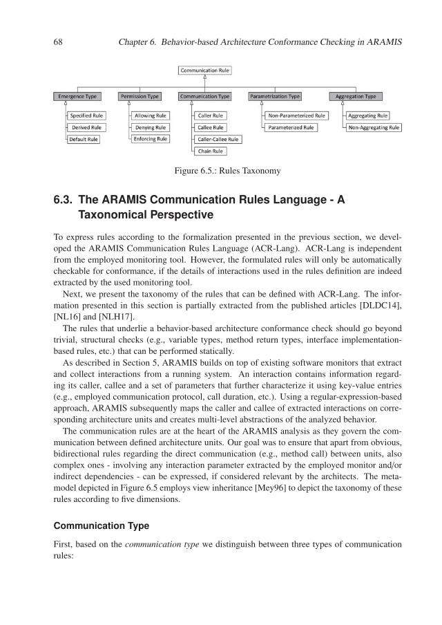
68 Chapter 6. Behavior-based Architecture Conformance Checking in ARAMIS
Figure 6.5.: Rules Taxonomy
6.3. The ARAMIS Communication Rules Language - ATaxonomical Perspective
To express rules according to the formalization presented in the previous section, we devel-oped the ARAMIS Communication Rules Language (ACR-Lang). ACR-Lang is independentfrom the employed monitoring tool. However, the formulated rules will only be automaticallycheckable for conformance, if the details of interactions used in the rules definition are indeedextracted by the used monitoring tool.
Next, we present the taxonomy of the rules that can be defined with ACR-Lang. The infor-mation presented in this section is partially extracted from the published articles [DLDC14],[NL16] and [NLH17].
The rules that underlie a behavior-based architecture conformance check should go beyondtrivial, structural checks (e.g., variable types, method return types, interface implementation-based rules, etc.) that can be performed statically.
As described in Section 5, ARAMIS builds on top of existing software monitors that extractand collect interactions from a running system. An interaction contains information regard-ing its caller, callee and a set of parameters that further characterize it using key-value entries(e.g., employed communication protocol, call duration, etc.). Using a regular-expression-basedapproach, ARAMIS subsequently maps the caller and callee of extracted interactions on corre-sponding architecture units and creates multi-level abstractions of the analyzed behavior.
The communication rules are at the heart of the ARAMIS analysis as they govern the com-munication between defined architecture units. Our goal was to ensure that apart from obvious,bidirectional rules regarding the direct communication (e.g., method call) between units, alsocomplex ones - involving any interaction parameter extracted by the employed monitor and/orindirect dependencies - can be expressed, if considered relevant by the architects. The meta-model depicted in Figure 6.5 employs view inheritance [Mey96] to depict the taxonomy of theserules according to five dimensions.
Communication Type
First, based on the communication type we distinguish between three types of communicationrules:
6.3. The ARAMIS Communication Rules Language - A Taxonomical Perspective 69
• caller rule: concerns the communication emerging from a given caller unit to all otherarchitecture units (e.g., “utility layer” is not allowed to issue calls towards any other ar-chitecture units).
• callee rule: concerns the communication emerging from all other architecture units to-wards a given callee unit (e.g., “facade layer” can be called from all other architectureunits).
• caller-callee rule: concerns the directed communication between a pair of specified callerand callee architecture units (e.g., “layer A” must not access “layer B”).
• chain rule: concerns the directed communication between a sequence of three or morespecified caller and callee architecture units (e.g., “layer A” calls “layer B” which dele-gates the call to “layer C”).
Permission Type
Second, according to its permission type, a rule can allow (equivalently permit), deny (equiv-alently disallow or prohibit) or enforce a communication. Equivalently we refer to the rule asrespectively being allowing, denying or enforcing. The semantics of an enforced communicationis similar to that of an allowed one, but stronger. As in the case of an allowed communication,the occurrence of an enforced communication does not produce a violation. However, in addi-tion to this, an enforced communication must occur, or else the intended architecture descriptionis violated; contrastingly, an allowed communication is only to some extent expected: if an al-lowed communication does not occur at run-time, this will result in an absence according to thereflexion model; if, in turn, an enforced communication does not occur, this will represent anactual divergence or, equivalently, a violation.
In the case of enforcing rules, it is important to distinguish between the permission of a ruleand the permission that it confers to realizing interactions, if applicable. An enforcing rule im-poses the occurrence of a given communication. While the communication itself is enforced, theindividual realizing interactions sets are not. In fact, these are - according to the enforcing rule- merely allowed. It suffices for one realizing set of interactions to exist, for the communicationto be identified and for the conformance to the rule to be confirmed. Further details regardingthis difference and an explanatory situation will be given in Section 6.4.
Emergence Type
Third, according to its emergence type, a rule can be specified, derived or default. Specified rulesare those rules that are explicitly formulated by the architect when creating the intended archi-tecture description of a system (e.g. “Layer A is denied to access Layer B”). In contrast, derivedrules are only implicitly suggested by the created intended architecture description, i.e., they arejust implied by existing specified rules. An example of a derived rule can be: “C1 should notaccess C2 because they are included in further architecture units that are explicitly not allowedto access each other according to a specified rule”. In the given example, the architect did notexplicitly formulate a rule for disallowing the communication between C1 and C2. However this
70 Chapter 6. Behavior-based Architecture Conformance Checking in ARAMIS
rule is implied by another, explicitly formulated one, namely that the encompassing architectureunits are disallowed to communicate. Finally, default rules exist to ease the creation of rule sets,in that they regulate the communication for the cases where no specified or derived rule apply.A set of predefined default rules to be used in ARAMIS intended architecture descriptions willbe presented later Section 6.3.1.
Parametrization Type
Forth, according to their parametrization type, the rules can be either non-parametrized orparametrized. Non-parametrized rules regulate the direct communication between architectureunits (e.g., through method invocation). In turn, the parametrized rules, whose meta-model isdepicted in Figure 6.6 regulate more complex communication, based on the interaction parame-ters of their realizing interactions. Interaction parameters are expressed through key-value pairs.Such keys can be, e.g., the interaction type (possible values can be: queue, soap webservice,etc.) or, more fine-grained, type-specific information (e.g., queue name, name of the calledweb service operation, etc.). Moreover, the rules can allow or deny a certain communicationby considering several parameters connected by logical operators such as “and”, “not” or “or”(e.g., the communication between two units is allowed only if the first one accesses the secondover a restful webservice (<key: type, value: restful webservice>) and uses the operation get(<key: operation, value: get>) to retrieve a resource whose name matches the regular expres-sion tom123* (<key: resource name, value: matches(tom123*)>). To enable the specification ofsuch rules we created an expression-based language that consists of three types of expressions:
Terminal expressions are directly constraining retrieved interaction parameters. The “matches”and “equals” expressions can be used to allow/deny a certain communication if realized by aninteraction exposing a parameter (e.g., “queue name”) that matches a given regular expression(e.g., <key: queue name, value: matches(queueData*)>) or has a precise value (e.g., <key:queue name, value: equals(queueDataTransfer)>), respectively. The “has” expression is used toallow/deny a communication based on whether the interaction realizing it exposes a parameterwith a given key (e.g., allow the communication, only if the corresponding execution recordsexhibit the “queue name” parameter key).
N-ary and unary expressions can be further used to express conditions using logical operators.The unary not expression can be applied to an expression, to reverse its boolean value. For ex-ample, the not expression used in combination with an equals expression can be used to identifycommunication in which the value of a parameter is different than a specified one (e.g., allow thecommunication only if its “type” is not “messaging”: <key: type, value: not(equals(messaging))>).Furthermore, using an n-ary expression, one can constrain a communication if several expression-based conditions apply simultaneously (and expressions - e.g., the type should be “soap web-service” and the endpoint name should match the regexp “getData*”) - or only if some of themhold (or expressions - e.g., the communication is allowed if the type of the communication is“soap webservice” or “restful webservice”).
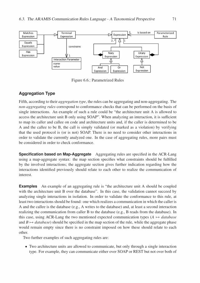
6.3. The ARAMIS Communication Rules Language - A Taxonomical Perspective 71
Figure 6.6.: Parametrized Rules
Aggregation Type
Fifth, according to their aggregation type, the rules can be aggregating and non-aggregating. Thenon-aggregating rules correspond to conformance checks that can be performed on the basis ofsingle interactions. An example of such a rule could be “the architecture unit A is allowed toaccess the architecture unit B only using SOAP”. When analyzing an interaction, it is sufficientto map its caller and callee on code and architecture units and, if the caller is determined to beA and the callee to be B, the call is simply validated (or marked as a violation) by verifyingthat the used protocol is (or is not) SOAP. There is no need to consider other interactions inorder to validate the currently analyzed one. In the case of aggregating rules, more pairs mustbe considered in order to check conformance.
Specification based on Map-Aggregate Aggregating rules are specified in the ACR-Langusing a map-aggregate syntax: the map section specifies what constraints should be fulfilledby the involved interactions; the aggregate section gives further indication regarding how theinteractions identified previously should relate to each other to realize the communication ofinterest.
Examples An example of an aggregating rule is “the architecture unit A should be coupledwith the architecture unit B over the database”. In this case, the validation cannot succeed byanalyzing single interactions in isolation. In order to validate the conformance to this rule, atleast two interactions should be found: one which realizes a communication in which the caller isA and the callee is the database (e.g., A writes to the database) and, at least a second interactionrealizing the communication from caller B to the database (e.g., B reads from the database). Inthis case, using ACR-Lang the two mentioned expected communication types (A �→ databaseand B �→ database) should be specified in the map section of the rule, while the aggregate phasewould remain empty since there is no constraint imposed on how these should relate to eachother.
Two further examples of such aggregating rules are:
• Two architecture units are allowed to communicate, but only through a single interactiontype. For example, they can communicate either over SOAP or REST but not over both of
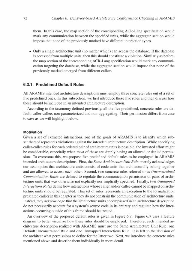
72 Chapter 6. Behavior-based Architecture Conformance Checking in ARAMIS
them. In this case, the map section of the corresponding ACR-Lang specification wouldmark any communication between the specified units, while the aggregate section wouldimpose that none of the previously marked have different interaction types.
• Only a single architecture unit (no matter which) can access the database. If the databaseis accessed from multiple units, then this should constitute a violation. Similarly as before,the map section of the corresponding ACR-Lang specification would mark any communi-cation targeting the database, while the aggregate section would impose that none of thepreviously marked emerged from different callers.
6.3.1. Predefined Default Rules
All ARAMIS intended architecture descriptions must employ three concrete rules out of a set offive predefined ones. In this subsection, we first introduce these five rules and then discuss howthese should be included in an intended architecture description.
According to the taxonomy defined previously, all the five predefined, concrete rules are de-fault, caller-callee, non-parameterized and non-aggregating. Their permission differs from caseto case as we will highlight below.
MotivationGiven a set of extracted interactions, one of the goals of ARAMIS is to identify which sub-set thereof represents violations against the intended architecture description. While specifyingcaller-callee rules for each ordered pair of architecture units is possible, the invested effort mightbe considerable, especially when most of these are simply having an allowed or denied permis-sion. To overcome this, we propose five predefined default rules to be employed in ARAMISintended architecture descriptions. First, the Same Architecture Unit Rule, merely acknowledgesour assumption that architecture units consist of code units that architecturally belong togetherand are allowed to access each other. Second, two concrete rules referred to as UnconstrainedCommunication Rules are defined to regulate the communication permission of pairs of archi-tecture units that was otherwise not explicitly nor implicitly specified. Finally, two UnmappedInteractions Rules define how interactions whose caller and/or callee cannot be mapped on archi-tecture units should be regulated. This set of rules represents an exception to the formalizationpresented earlier in this chapter as they do not constrain the communication of architecture units.Instead, they acknowledge that the architecture units encompassed in an architecture descriptiondo not necessarily account for a system’s source code in its entirety and regulate how the inter-actions occurring outside of this frame should be treated.
An overview of the proposed default rules is given in Figure 6.7. Figure 6.7 uses a featurediagram to better visualize how these rules should be employed. Therefore, each intended ar-chitecture description realized with ARAMIS must use the Same Architecture Unit Rule, oneDefault Unconstrained Rule and one Unmapped Interactions Rule. It is left to the decision ofthe architect what permissions to define for the latter two. Next, we introduce the concrete rulesmentioned above and describe them individually in more detail.
6.3. The ARAMIS Communication Rules Language - A Taxonomical Perspective 73
Deny Unconstrained Rule Deny Unmapped Interactions Rule Allow Unmapped Interactions Rule
Legend:
Mandatory
Alternative
Default Rules in ARAMIS Architecture Description
Same Architecture Unit Rule Default Unconstrained Rule Unmapped Interactions Rule
Allow Unconstrained Rule
Figure 6.7.: Overview of Predefined Default Rules in ARAMIS
Same Architecture Unit Rule This rule is mandatory to be included in any ARAMIS in-tended architecture description. It prescribes that the bidirectional communication realized byinteractions whose corresponding caller and callee code units are directly included in the samearchitecture unit is always permitted. The reasoning supporting this rule is that the code unitsthat were directly included in an architecture unit form together a coherent logical abstractionrepresented by the encompassing unit itself. If the communication of some of these code unitswere to be denied, then these would be directly included in different abstractions, i.e., in differentarchitecture units. It should be noted that this rule only refers to the communication of directlyincluded code units, and not to that employing architecture units directly or indirectly includedin a considered architecture unit. Two different architecture units represent two logically distinctabstractions, and thus it should be possible for the architect to regulate the permission type oftheir communication, regardless of whether these are included in a common architecture unit ornot.
Rules for Unconstrained Communication
Each ARAMIS intended architecture description must employ one of the following two rules forunconstrained communication. These regulate the communication involving two architectureunits for which no specified or derived rule applies. Depending on the chosen rule, the intendedarchitecture description can be specified on a white-list or black-list basis:
Allow Unconstrained Communication Rule This rule foresees that, if no other specifiedor derived caller-callee rule applies, then the communication involving two distinct architectureunits is allowed. Consequently, a black-list-based specification of the intended architecture de-scription is enabled. The architect can consequently specify only what communication should bedenied and enforced. The enforced communication needs to be extra specified, even if the con-cerned communication is not prohibited, because the semantics of “enforced” is stronger thanthe simple “allowed”: not only that it is not disallowed that a communication occurs (i.e., thecommunication is allowed), but the communication must occur or otherwise the conformancecheck fails.
Deny Unconstrained Communication Rule This rule specifies that, if no other specifiedor derived caller-callee rule applies, then the communication involving two distinct architectureunits is disallowed. Consequently, a white-list-based specification of the intended architecturedescription is enabled. In this case, the architect can specify only which communication shouldbe allowed and enforced.
74 Chapter 6. Behavior-based Architecture Conformance Checking in ARAMIS
Rules for Unmapped Interactions
Very often, only parts of the system under analysis are of interest for a conformance check. Onthe one hand, it is often the case that only a subset of the code building blocks encompassing thesystem are assigned to code and architecture units. On the other hand, even when all the codebuilding blocks of the system are considered architecturally relevant by the architect and ex-haustive mappings to code and architecture units are performed in an initial phase, it is possiblefor new code building blocks to be added along the evolution of the analyzed software system.Thus, interactions can be encountered whose either caller, callee or even both cannot be mappedon units from the code and architecture sets. The communication permission of such interac-tions is governed by the Allow Unmapped Rule and the Deny Unmapped Rule. Each ARAMISintended description must include one of these two rules.
Allow Unmapped Interactions Rule If the Allow Unmapped Interactions Rule is used, theinteractions that cannot be mapped on the system’s intended architecture description are consid-ered valid. This can be interpreted as: “anything not architecturally significant is allowed”.
Deny Unmapped Interactions Rule If this rule is employed, the interactions whose callerand/or callee cannot be mapped on architecture units, are considered violations. A situation inwhich this default rule is useful is when the architect considers that the specified code to archi-tecture mapping is exhaustive and possibly also foresees mappings of code building blocks notyet implemented in the actual system. Thus, in this case the intended architecture descriptionrepresents a precise blueprint of the analyzed system. In such a case any communication be-tween code building blocks not assigned through code units to architectural units is considereddisallowed.
6.4. Concepts for Rules Prioritization and the ARAMISConformance Checking Phases
Prior to performing the actual behavior-based conformance checking, the set of communicationrules to be employed can be examined to identify and eliminate a series of inconsistencies. Forexample, it can be checked whether identical rules or rules with different permission types butotherwise identical were defined. These inconsistencies can be discovered and eliminated in theinitial phases of creating an intended architecture description. Consequently, it is reasonable toassume that at the actual time of conformance checking the intended architecture descriptionis free of such inconsistencies. However, due to the property of specified rules to propagatethemselves as derived rules down in the inclusion hierarchy of architecture units, it is possi-ble that given one communication, more than one rule applies. The applicable rules can havethe same permission type or contradicting ones. Especially for the latter case, it needs to bedetermined which of the applicable rules should be used to check the conformance of a givencommunication. Equivalently, a method must be developed to prioritize the applicable rules.
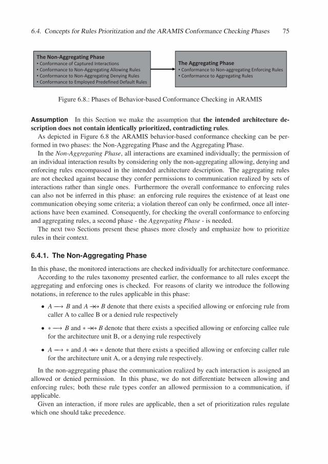
6.4. Concepts for Rules Prioritization and the ARAMIS Conformance Checking Phases 75
The�Non�Aggregating�Phase• Conformance�of�Captured�Interactions• Conformance�to�Non�Aggregating�Allowing�Rules• Conformance�to�Non�Aggregating�Denying�Rules• Conformance�to�Employed�Predefined�Default�Rules
The�Aggregating�Phase• Conformance�to�Non�aggregating�Enforcing�Rules• Conformance�to�Aggregating�Rules
Figure 6.8.: Phases of Behavior-based Conformance Checking in ARAMIS
Assumption In this Section we make the assumption that the intended architecture de-scription does not contain identically prioritized, contradicting rules.
As depicted in Figure 6.8 the ARAMIS behavior-based conformance checking can be per-formed in two phases: the Non-Aggregating Phase and the Aggregating Phase.
In the Non-Aggregating Phase, all interactions are examined individually; the permission ofan individual interaction results by considering only the non-aggregating allowing, denying andenforcing rules encompassed in the intended architecture description. The aggregating rulesare not checked against because they confer permissions to communication realized by sets ofinteractions rather than single ones. Furthermore the overall conformance to enforcing rulescan also not be inferred in this phase: an enforcing rule requires the existence of at least onecommunication obeying some criteria; a violation thereof can only be confirmed, once all inter-actions have been examined. Consequently, for checking the overall conformance to enforcingand aggregating rules, a second phase - the Aggregating Phase - is needed.
The next two Sections present these phases more closely and emphasize how to prioritizerules in their context.
6.4.1. The Non-Aggregating Phase
In this phase, the monitored interactions are checked individually for architecture conformance.According to the rules taxonomy presented earlier, the conformance to all rules except the
aggregating and enforcing ones is checked. For reasons of clarity we introduce the followingnotations, in reference to the rules applicable in this phase:
• A −−→ B and A −−→× B denote that there exists a specified allowing or enforcing rule fromcaller A to callee B or a denied rule respectively
• ∗ −−→ B and ∗ −−→× B denote that there exists a specified allowing or enforcing callee rulefor the architecture unit B, or a denying rule respectively
• A −−→ ∗ and A −−→× ∗ denote that there exists a specified allowing or enforcing caller rulefor the architecture unit A, or a denying rule respectively.
In the non-aggregating phase the communication realized by each interaction is assigned anallowed or denied permission. In this phase, we do not differentiate between allowing andenforcing rules; both these rule types confer an allowed permission to a communication, ifapplicable.
Given an interaction, if more rules are applicable, then a set of prioritization rules regulatewhich one should take precedence.
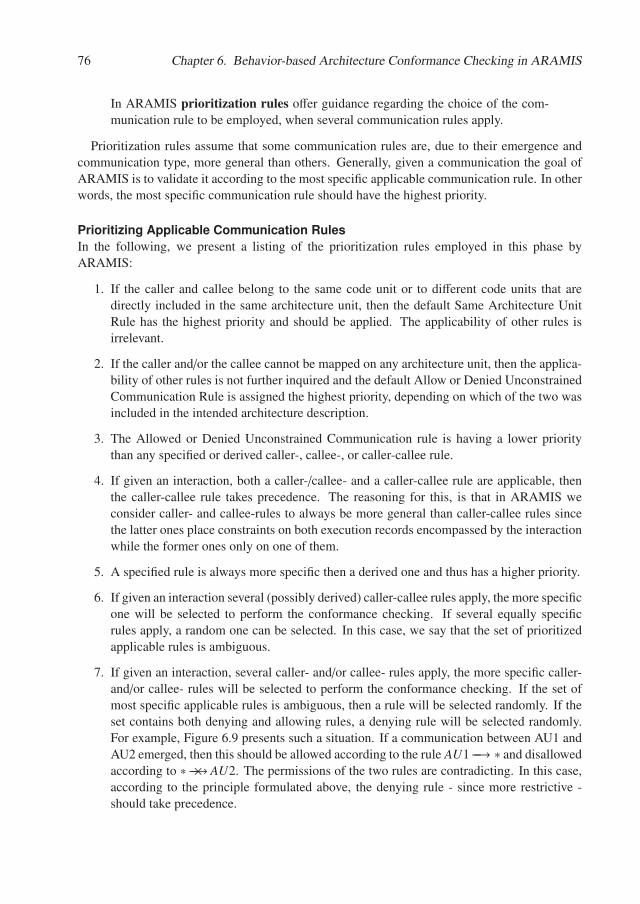
76 Chapter 6. Behavior-based Architecture Conformance Checking in ARAMIS
In ARAMIS prioritization rules offer guidance regarding the choice of the com-munication rule to be employed, when several communication rules apply.
Prioritization rules assume that some communication rules are, due to their emergence andcommunication type, more general than others. Generally, given a communication the goal ofARAMIS is to validate it according to the most specific applicable communication rule. In otherwords, the most specific communication rule should have the highest priority.
Prioritizing Applicable Communication RulesIn the following, we present a listing of the prioritization rules employed in this phase byARAMIS:
1. If the caller and callee belong to the same code unit or to different code units that aredirectly included in the same architecture unit, then the default Same Architecture UnitRule has the highest priority and should be applied. The applicability of other rules isirrelevant.
2. If the caller and/or the callee cannot be mapped on any architecture unit, then the applica-bility of other rules is not further inquired and the default Allow or Denied UnconstrainedCommunication Rule is assigned the highest priority, depending on which of the two wasincluded in the intended architecture description.
3. The Allowed or Denied Unconstrained Communication rule is having a lower prioritythan any specified or derived caller-, callee-, or caller-callee rule.
4. If given an interaction, both a caller-/callee- and a caller-callee rule are applicable, thenthe caller-callee rule takes precedence. The reasoning for this, is that in ARAMIS weconsider caller- and callee-rules to always be more general than caller-callee rules sincethe latter ones place constraints on both execution records encompassed by the interactionwhile the former ones only on one of them.
5. A specified rule is always more specific then a derived one and thus has a higher priority.
6. If given an interaction several (possibly derived) caller-callee rules apply, the more specificone will be selected to perform the conformance checking. If several equally specificrules apply, a random one can be selected. In this case, we say that the set of prioritizedapplicable rules is ambiguous.
7. If given an interaction, several caller- and/or callee- rules apply, the more specific caller-and/or callee- rules will be selected to perform the conformance checking. If the set ofmost specific applicable rules is ambiguous, then a rule will be selected randomly. If theset contains both denying and allowing rules, a denying rule will be selected randomly.For example, Figure 6.9 presents such a situation. If a communication between AU1 andAU2 emerged, then this should be allowed according to the rule AU1 −−→ ∗ and disallowedaccording to ∗ −−→× AU2. The permissions of the two rules are contradicting. In this case,according to the principle formulated above, the denying rule - since more restrictive -should take precedence.
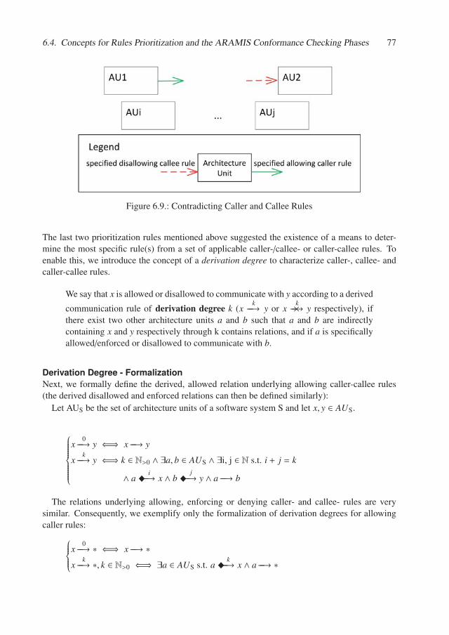
6.4. Concepts for Rules Prioritization and the ARAMIS Conformance Checking Phases 77
Figure 6.9.: Contradicting Caller and Callee Rules
The last two prioritization rules mentioned above suggested the existence of a means to deter-mine the most specific rule(s) from a set of applicable caller-/callee- or caller-callee rules. Toenable this, we introduce the concept of a derivation degree to characterize caller-, callee- andcaller-callee rules.
We say that x is allowed or disallowed to communicate with y according to a derived
communication rule of derivation degree k (xk−−→ y or x
k−−→× y respectively), ifthere exist two other architecture units a and b such that a and b are indirectlycontaining x and y respectively through k contains relations, and if a is specificallyallowed/enforced or disallowed to communicate with b.
Derivation Degree - FormalizationNext, we formally define the derived, allowed relation underlying allowing caller-callee rules(the derived disallowed and enforced relations can then be defined similarly):
Let AUS be the set of architecture units of a software system S and let x, y ∈ AUS.
⎧⎪⎪⎪⎪⎪⎪⎪⎨⎪⎪⎪⎪⎪⎪⎪⎩
x0−−→ y ⇐⇒ x −−→ y
xk−−→ y ⇐⇒ k ∈ N>0 ∧ ∃a, b ∈ AUS ∧ ∃i, j ∈ N s.t. i + j = k
∧ a �i−−→ x ∧ b �
j−−→ y ∧ a −−→ b
The relations underlying allowing, enforcing or denying caller- and callee- rules are verysimilar. Consequently, we exemplify only the formalization of derivation degrees for allowingcaller rules:
⎧⎪⎪⎪⎨⎪⎪⎪⎩
x0−−→ ∗ ⇐⇒ x −−→ ∗
xk−−→ ∗, k ∈ N>0 ⇐⇒ ∃a ∈ AUS s.t. a �
k−−→ x ∧ a −−→ ∗
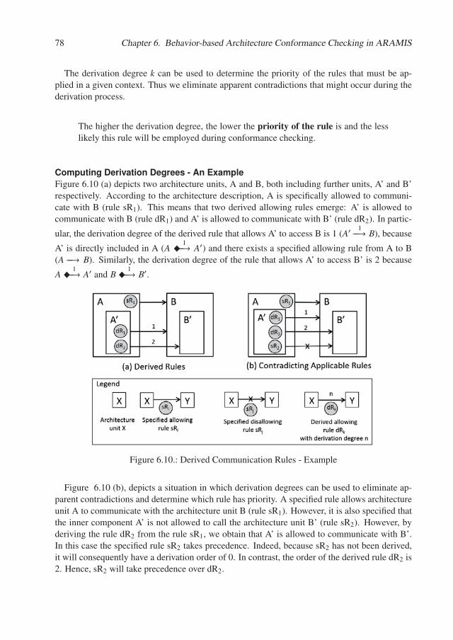
78 Chapter 6. Behavior-based Architecture Conformance Checking in ARAMIS
The derivation degree k can be used to determine the priority of the rules that must be ap-plied in a given context. Thus we eliminate apparent contradictions that might occur during thederivation process.
The higher the derivation degree, the lower the priority of the rule is and the lesslikely this rule will be employed during conformance checking.
Computing Derivation Degrees - An ExampleFigure 6.10 (a) depicts two architecture units, A and B, both including further units, A’ and B’respectively. According to the architecture description, A is specifically allowed to communi-cate with B (rule sR1). This means that two derived allowing rules emerge: A’ is allowed tocommunicate with B (rule dR1) and A’ is allowed to communicate with B’ (rule dR2). In partic-
ular, the derivation degree of the derived rule that allows A’ to access B is 1 (A′1−−→ B), because
A’ is directly included in A (A �1−−→ A′) and there exists a specified allowing rule from A to B
(A −−→ B). Similarly, the derivation degree of the rule that allows A’ to access B’ is 2 because
A �1−−→ A′ and B �
1−−→ B′.
Figure 6.10.: Derived Communication Rules - Example
Figure 6.10 (b), depicts a situation in which derivation degrees can be used to eliminate ap-parent contradictions and determine which rule has priority. A specified rule allows architectureunit A to communicate with the architecture unit B (rule sR1). However, it is also specified thatthe inner component A’ is not allowed to call the architecture unit B’ (rule sR2). However, byderiving the rule dR2 from the rule sR1, we obtain that A’ is allowed to communicate with B’.In this case the specified rule sR2 takes precedence. Indeed, because sR2 has not been derived,it will consequently have a derivation order of 0. In contrast, the order of the derived rule dR2 is2. Hence, sR2 will take precedence over dR2.
6.4. Concepts for Rules Prioritization and the ARAMIS Conformance Checking Phases 79
Algorithms for Conformance Checking in the Non-Aggregating Phase
In the last sections, we introduced the taxonomy of rules supported by the ACR-Lang and dis-cussed how these can be prioritized in the non-aggregating phase.
In this section we present two algorithms that support conformance checking based on thepriorization rules introduced earlier.
First, we give an overview of rule systems and discuss their similarities with ARAMIS. Weconclude that we can adapt the forward chaining mechanism of rule systems to ARAMIS andfinally propose two algorithms based thereupon: the conformance checking based on on-demandrule derivation and conformance checking based on eager rule derivation algorithms.
Rule Systems. Given that ARAMIS relies on specified and derived rules to derive knowl-edge about a system under analysis, several important parallels with rule systems can be drawn.Rule systems are frequently employed in the artificial intelligence domain to persist and manip-ulate expert knowledge. In the case of ARAMIS, the expert knowledge is available explicitlyin the system’s intended architecture description. To this end, a parallel can be made between asystem’s set of communication rules and the rule base of a rule system.
A rule-based system “is a way of encoding a human expert’s knowledge in a fairlynarrow area into an automated system” [GA11] and consists of three basic elements:
• a set of facts, on which the rules will operate. In the case of ARAMIS theset of facts is given by the set of interactions captured during a monitoringsession;
• a set of rules to be applied on the facts. In the case of ARAMIS these corre-spond to the set of communication rules applicable for a given system;
• a termination criterion to ensure that the rule system will eventually stopand that no infinite loop emerges. In the case of ARAMIS, if no specified orderived rule can be applied, then the default rules are employed instead. Thederivation of specified rules is also a finite process, given that the hierarchy ofarchitecture units is finite and non-cyclic.
Types of Rules in Rule Systems. The literature on rule systems differentiates betweenthree main types of rules: deductive, reactive and normative rules. When applied, deductiverules produce new knowledge based on that already existing (e.g.: “if the temperature is neg-ative and it snows, then it is winter”). Normative rules are used to check integrity constraintson the data (e.g.: “each address must have an assigned postal code”). Last but not least, reac-tive rules specify actions to be taken, if a set of logically related conditions hold (e.g., “if thetemperature drops below the limit, turn the heat on”). According to this schema, the ARAMISrules can be considered to be deductive or reactive, depending on their interpretation. As re-active rules, these can be formulated as follows: if the conditions imposed by a rule are met,then the communication realized by the corresponding interaction is marked to be allowed ordisallowed depending on the rule’s permission type. Contrastingly, the ARAMIS rules can also
80 Chapter 6. Behavior-based Architecture Conformance Checking in ARAMIS
be formulated as deductive ones: if the rule conditions are met for a given interaction, then thecorresponding communication is allowed/disallowed.
Forward vs. Backward Chaining. Furthermore, depending on the manner in which therules are applied, there are two main types of rule systems: forward and backward chainingsystems. With backward chaining, the rule system takes as input a goal to be proven and thensearches for rules whose conclusions support the currently set goal. Supposing that a set ofsuch rules is identified, the system then sequentially chooses a rule from this set and attemptsto prove that its preconditions are true. Contrastingly, in the case of forward chaining all thefacts are loaded in the memory and the system attempts to apply rules on facts that match theirprecondition. If the rule is a deductive one and produces a new fact, then the set of facts isupdated and the chain continues until no new facts can be inferred. Typically, in the case offorward chaining, the rule engine that underlies the rule system leverages a three-phased match-select-execute cycle [GA11], as explained below. In the match phase the preconditions of allthe rules in the rule base are checked against all the available facts. Thus the result of the matchphase is a list of all the rules that are applicable given the facts. If more than one rule can beapplied, a decision is made regarding which one to apply first during the select phase. In theexecution phase, the previously selected rule is applied, possibly resulting in new facts that willbe added to the fact base for future consideration. The cycle then resumes or, alternatively,terminates if the conclusion was reached or if the termination criterion is fulfilled.
The literature generally recommends (e.g., [GA11]) that when most of the facts are alreadyavailable in the problem statement and there are many conclusions that must be proved/dis-proved, a forward chaining mechanism is preferable to backward chaining. Transferring thisknowledge to the domain of ARAMIS:
• most of the facts are available a priori in the problem statement, in the form of interactions.
• the pursued conclusion is whether system behaves according to the intended architec-ture description. This results by analyzing a set of sub-conclusions, in which each sub-conclusion denotes whether the communication of a given interaction is allowed or not.
Given the arguments mentioned above, we propose two algorithms that mimic the forwardchaining mechanism to perform conformance checking in the non-aggregating phase. Thesediffer from two points of view:
• the "Conformance Checking based on On-Demand Rule Derivation" (CCORD) relies onthe on-demand derivation of rules. Thus, when the conformance of a communicationneeds to be checked, the possibly applicable derived rules are determined and added to alist of matching rules provided this doesn’t already contain a rule of higher priority.
• the "Conformance Checking based on Eager Rule Derivation" (CCERD) algorithm em-ploys a different strategy: all derived rules are computed a priori to any conformancecheck. Only after all rules have been derived, the matching ones will be determined. How-ever, because in this case all the rules are already available during conformance checking,these can be ordered in descending order according to their priority and thus the list ofmatching rules can be optimized to contain only the highest prioritized ones.
6.4. Concepts for Rules Prioritization and the ARAMIS Conformance Checking Phases 81
In the next two subsections we present the two previously mentioned algorithms and discusstheir mapping on the match-select-execute cycle.
Conformance Checking based on On-Demand Rule Derivation
In the case of CCORD, the match phase consists of determining for each interaction the listof matching communication rules, i.e., the rules applicable for checking the conformance ofthe realized communication. The corresponding pseudocode for determining matching rulesis depicted in the Algorithm Listing 4. To simplify the pseudocode we do not differentiatehere between the default allow vs deny unmapped interactions rules and the default allow/denyunconstrained rules but refer to the employed ones as the default unmapped interaction rule andthe default unsconstrained rule.
Initially (Line 11), we extract the caller and callee execution records from the analyzed in-teraction. Then, we map these, using the associated mapping parameter list of each, on codeunits from the intended architecture description, as discussed in Section 5.1. Next, as depictedin the Lines 15 and 16 we compute for both the caller and callee the hierarchy of architectureunits in which the corresponding code units are directly and indirectly included. The resultedlists are sorted along the inclusion hierarchy of architecture units from the "closest" architectureunit, which has a direct inclusion relationship with the corresponding code unit, to the most"distant" one. If at least one of the mappings of the caller or callee to code units was not pos-sible and/or one of the respective computed hierarchies is empty, then the interaction must bevalidated according to the employed default unmapped interaction rule (Line 17 - 19) and thealgorithm ends. Otherwise, if the interaction’s caller and callee code units are directly includedin the same architecture unit, then the default same architecture rule applies (Lines 20 - 22) andthe algorithm exits. If this is not the case, the algorithm first attempts to identify applicablecaller-callee rules (Lines 23 - 34) to validate the considered interaction. The algorithm’s goal isto retrieve only the matching rules with lowest derivation degrees, i.e., highest priority. To thisend, it inquires if rules with ascending derivation degree (Line 24) match; if this is the case, thenthese are added to the list of matching rules (Line 31). Notably, the list of matching rules willcontain the applicable rules with maximum priority. If no caller-callee rule can be identified, thealgorithm searches further (Lines 35 - 38) whether applicable caller (Line 38 - 41) or callee rules(Line 39 - 42) can be identified. The search for applicable caller and callee rules iterates throughthe list of architecture units enclosing the caller and callee execution records respectively. Sincethe list is sorted upwards the inclusion hierarchy, the first rules that will be identified will be themost specific ones (Line 37 and Line 41 respectively). Consequently, the list of matching ruleswill contain the most specific caller and callee rules respectively. If such rules exist and the listof matching rules is not empty, the algorithm terminates (Lines 43 - 44). Otherwise if the list ofapplicable rules is still empty, it is inferred that no matching rule exists and the interaction willbe validated using the default unconstrained rule (Lines 45-46).
The pseudocode corresponding to the entire adapted match-select-execute cycle is depicted inthe Algorithm Listing 5. The cycle is executed for all interactions extracted during monitoring(Lines 9 - 31).
Given an interaction, we first determine all rules that match it and have the lowest derivationdegree possible (Line 11). The minimality of the derivation degree is ensured by the algorithm
82 Chapter 6. Behavior-based Architecture Conformance Checking in ARAMIS
Discover_Matching_Rules presented in the Algorithm Listing 4.The select phase is straightforward. If the match phase identified the same architecture unit
rule, then this rule will be selected and the pair will be assigned an allowed permission. Ifinstead one of the default allow/denny unmapped interaction rules was matched (Line 15 orLine 17), then the communication will also be assigned an allowed/denied permission (Line16, Line 18). Similarly, if one of the default allow/deny unconstrained interaction rules wasmatched (Line 19 or Line 21), then the communication will also be assigned an allowed/ deniedpermission respectively (Line 20, Line 22). Furthermore, if only one or several caller-calleewere matched (Lines 23, 24) then any of the matching rules will be selected and the permissionassignment will be performed accordingly. Note that if several matching caller-callee ruleswith the same derivation degree and permission are identified (Lines 23, 24) the selection phasesimply selects the first rule in the list, as the exact selected rule does not impact in any formthe assigned permission. Finally, if no caller-callee rules matched, but a set of caller or calleerules were identified instead by the matching phase (Lines 25 - 29), the selection will followthe rules discussed in Section 6.4: if any of the identified rules is denying, then one of therules with denied permission will be randomly selected (Lines 26, 27) to validate the consideredinteraction. Otherwise, a random caller or callee rule with allowed permission will be selectedinstead (Lines 28, 29).
In the execute phase the interaction’s permission is assigned as determined by the selectionphase. Again, note that in this case it can be considered that the execution phase indeed producesa new fact but the latter addition of this fact to the fact base cannot trigger any further rules tomatch, as these are applicable only for interactions that were not yet checked for conformance.
While, as discussed above, the CCORD algorithm resembles a match-select-execute cycle of atypical forward chaining mechanism, the resemblance is in essence only apparent, as there existvery important differences as well. Unlike in the classical cycle, the match, select and executephases are executed for each interaction in turn. In the classical cycle, the rules are typicallyformulated declaratively. This strongly contrasts with our imperative approach presented abovein which the algorithm iterated through the facts and performed rule matching for each of thefacts in turn. In classical matching, the identified rules are not applicable to a single fact, butto any of the facts in the fact base. Even more, the match phase, as presented in the AlgorithmListing 4, includes some activities specific to a classical select phase, e.g., if caller-callee rulesare applicable then the ones with the lowest derivation degree are selected or, if applicable caller-callee rules are identified, then the caller and callee rules are automatically disregarded.
Conformance Checking Based On Eager Rule Derivation
As explained previously, the main difference exposed by CCERD is that the derived communi-cation rules are computed a priori to the match phase. For reasons of brevity, we do not presentthe pseudocode for rules derivation but only sketch the two basic principles that lie at the basisthereof as presented in Section 6.3:
• in the case of a caller rule, the rule will propagate down in the inclusion hierarchy of thecaller. This means that all architecture units included directly or indirectly in the unit listedas the caller of the rule, will be allowed/denied to call all other architecture units defined
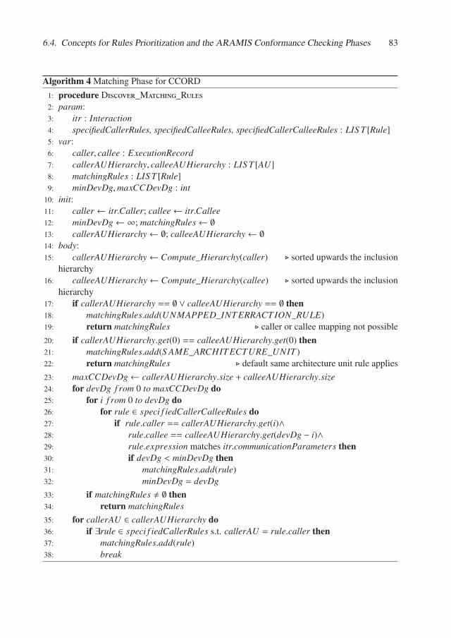
6.4. Concepts for Rules Prioritization and the ARAMIS Conformance Checking Phases 83
Algorithm 4 Matching Phase for CCORD
1: procedure Discover_Matching_Rules2: param:3: itr : Interaction4: specifiedCallerRules, specifiedCalleeRules, specifiedCallerCalleeRules : LIS T [Rule]5: var:6: caller, callee : ExecutionRecord7: callerAUHierarchy, calleeAUHierarchy : LIS T [AU]8: matchingRules : LIS T [Rule]9: minDevDg,maxCCDevDg : int
10: init:11: caller ← itr.Caller; callee← itr.Callee12: minDevDg← ∞; matchingRules← ∅13: callerAUHierarchy← ∅; calleeAUHierarchy← ∅14: body:15: callerAUHierarchy← Compute_Hierarchy(caller) � sorted upwards the inclusion
hierarchy16: calleeAUHierarchy← Compute_Hierarchy(callee) � sorted upwards the inclusion
hierarchy17: if callerAUHierarchy == ∅ ∨ calleeAUHierarchy == ∅ then18: matchingRules.add(UNMAPPED_INT ERRACT ION_RULE)19: return matchingRules � caller or callee mapping not possible
20: if callerAUHierarchy.get(0) == calleeAUHierarchy.get(0) then21: matchingRules.add(S AME_ARCHIT ECTURE_UNIT )22: return matchingRules � default same architecture unit rule applies
23: maxCCDevDg← callerAUHierarchy.size + calleeAUHierarchy.size24: for devDg f rom 0 to maxCCDevDg do25: for i f rom 0 to devDg do26: for rule ∈ speci f iedCallerCalleeRules do27: if rule.caller == callerAUHierarchy.get(i)∧28: rule.callee == calleeAUHierarchy.get(devDg − i)∧29: rule.expression matches itr.communicationParameters then30: if devDg < minDevDg then31: matchingRules.add(rule)32: minDevDg = devDg33: if matchingRules � ∅ then34: return matchingRules35: for callerAU ∈ callerAUHierarchy do36: if ∃rule ∈ speci f iedCallerRules s.t. callerAU = rule.caller then37: matchingRules.add(rule)38: break

84 Chapter 6. Behavior-based Architecture Conformance Checking in ARAMIS
Matching Phase for CCORD - Part 2
39: for calleeAU ∈ calleeAUHierarchy do40: if ∃rule ∈ speci f iedCalleeRules s.t. calleeAU = rule.callee then41: matchingRules.add(rule)42: break43: if matchingRules � ∅ then44: return matchingRules45: matchingRules.add(DEFAULT_UNCONS TRAINED_RULE)46: return matchingRules � no specified or derived rule applicable
Algorithm 5 Adaptation of the Match-Select-Execute Cycle in CCORD
1: procedure Execute_Conformance_Check2: param:3: itrs : LIS T [Interaction]4: specifiedCallerRules, specifiedCalleeRules, specifiedCallerCalleeRules : LIS T [Rule]5: var:6: assignedPermission : Permission7: init:8: body:9: for itr ∈ itrs do
10: � match phase:11: itr.matchingRules← Discover_Matching_Rules(itr)12: � select phase:13: if S AME_ARCHIT ECTURE_UNIT ∈ itr.matchingRules then14: assignedPermission← ALLOWED15: else if ALLOW_UNMAPPED_INT ERACT ION_RULE ∈ itr.matchingRules then16: assignedPermission← ALLOWED17: else if DENY_UNMAPPED_INT ERACT ION_RULE ∈ itr.matchingRules then18: assignedPermission← DENIED19: else if ALLOW_UNCONS TRAINED_RULE ∈ itr.matchingRules then20: assignedPermission← ALLOWED21: else if DENY_UNCONS TRAINED_RULE ∈ itr.matchingRules then22: assignedPermission← DENIED23: else if itr.matchingRules contains caller-callee rules then24: assignedPermission← itr.matchingRules.get(0).permission25: else � caller and/or callee rules were identified26: if ∃rule ∈ itr.matchingRules s.t. rule.permission == DENIED then27: assignedPermission← DENIED28: else29: assignedPermission← ALLOWED30: � execute phase:31: itr.permission← assignedPermission
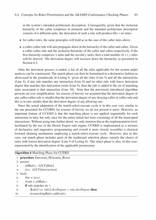
6.4. Concepts for Rules Prioritization and the ARAMIS Conformance Checking Phases 85
in the system’s intended architecture description. Consequently, given that the inclusionhierarchy of the caller comprises m elements and the intended architecture descriptionconsists of n different units, the derivation of such a rule will produce O(n ∗ m) rules.
• for callee rules, the same principles will hold as in the case of the caller rules above
• a caller-callee rule will also propagate down in the hierarchy of the caller and callee. Givena caller-callee rule and the inclusion hierarchy of the caller and callee respectively, if thefirst hierarchy comprises x units and the second y units, then a total number of x ∗ y ruleswill be derived. The derivation degree will increase down the hierarchy, as presented inSection 6.3.
After the derivation process is ended, a list of all the rules applicable for the system underanalysis can be constructed. The match phase can then be formulated in a declarative fashion asshowcased in the pseudocode in Listing 6: given all the rules (Line 3) and all the interactions(Line 4), if any rule matches any interaction (Line 8) and no other rule with lower derivationdegree that matches this interaction exists (Line 9), then the rule is added to the set of matchingrules associated to that interaction (Line 10). Note that the previously introduced algorithmpresents an over simplification: for reasons of brevity we assumed that the derivation degree ofany caller-callee rule is smaller that the derivation degree of any denying caller or callee rule andthis is in turn smaller than the derivation degree of any allowing one.
Since the actual adaptation of the match-select-execute cycle is in this case very similar tothe one presented for CCORD, for reasons of brevity we do not present it anew. However, animportant feature of CCERD is that the matching phase is not applied sequentially for eachinteraction in turn, but only once for the entire initial fact base consisting of all the interceptedinteractions. Without going into further detail, we only mention that at the implementation level,facilitated by the use of the Drools Expert rule engine, CCERD is implemented as a mixtureof declarative and imperative programming and overall it more closely resembles a classicalforward chaining mechanism employing a match-select-execute cycle. However, also in thiscase, our match phase includes parts of the traditional selection phase, namely the choice ofrules with lowest derivation degree (Line 9 of Listing 6). The select phase is also, in this case,represented by the identification of the applicable permissions.
Algorithm 6 Matching Phase for CCERD
1: procedure Discover_Matching_Rules2: param:3: allRules : LIS T [Rule]4: itrs : LIS T [Interaction]5: body:6: ∀itr ∈ itrs∧7: ∀rule ∈ allRules :8: if rule matches itr ∧9: �rule2 s.t. rule2.derDegree < rule.derDegree then
10: itr.matchingRules.add(rule)
86 Chapter 6. Behavior-based Architecture Conformance Checking in ARAMIS
This ends our presentation of the non-aggregating phase of ARAMIS. To summarize, in thissection we presented how the communication realized by single interactions can be checked forconformance to the rules of the intended architecture description. Furthermore, we presentedseven rules for prioritizing the communication rules, if several are applicable for a given a com-munication.
Next, we present the second phase of the ARAMIS conformance checking process, namelythe aggregating phase.
6.4.2. The Aggregating Phase
In this phase we differentiate between the conformance of the system to (1) caller-, callee- orcaller-callee enforcing rules, on the one hand, and (2) aggregating rules, on the other.
Conformance to Non-Aggregating Enforcing Rules
While caller-, callee and caller-callee enforcing rules can be used to validate the conformanceof communication in the non-aggregating phase, they have an aggregating nature as well, in thesense that their violation can only be confirmed if by the end of the non-aggregation phase therewas no interaction realizing the imposed communication. Checking the conformance to theserules mainly consists of a selection performed on the results of the non-aggregating phase todiscover if at least one interaction has been architecturally mapped as foreseen by the rule. If nosuch interaction is identified, then a violation emerges.
Conformance to Aggregating Rules
Aggregating rules constrain communication realized by several interactions.
The result of the non-aggregating phase can be seen as a list of the monitored interactionsenhanced with information regarding the communication they realize and the status (allowed,disallowed) of their conformance to the rules checked against in the non-aggregating phase.Given that the interactions are already mapped on caller and callee code- and architecture units,checking the conformance to aggregating rules consists of performing corresponding selectionsusing the criteria enlisted in the map and aggregate sections of their ACR-Lang specification.
Need for Prioritization Rules?In the non-aggregating phase, prioritization rules to guide the selection of rules to apply for theconformance checking of a communication were necessary. The monitored interactions wereconsidered individually: given an interaction, the set of applicable rules was identified and thesewere prioritized accordingly. Doing the same in the case of the aggregating rules would implyconsidering all possible subsets of interactions and check which aggegating rules apply. Thiswould dramatically increase complexity without providing real practical benefits, as case studies[TNL17], [NLH17] reflect that w.r.t. non-aggregating rules comparatively few aggregating rulesare formulated by architects. Instead we propose to apply all rules, and build a so-called evidenceset for each of these, as defined below:
6.5. Focusing the Conformance Checking Results 87
The evidence set of an allowing or enforcing aggregating rule is the set of all setsof interactions that realize the communication allowed/enforced by the given rule.Similarly, the evidence set of a denying rule is the set of all sets of interactionsthat realize communication constituting a violation of the corresponding rule.
Next, the sets of interactions that were added both in the evidence set of an allowing or enforc-ing rule and in that of a denying rule should be can be analyzed by the architect to decide onthe interpretation and future actions. However, our assumption is that rules that might lead tosuch situations are only rarely formulated: aggregating rules are, by design and purpose, morecomplex and are defined based on very specific conformance-checking intents. Consequently, noprioritization rules are formulated in this context. The aggregating phase ends after each rule hasan assigned (possibly empty) evidence set and once the architect decided on their interpretation.
Having presented the two phases of the ARAMIS conformance checking process, we nowmove on and give an overview of how the obtained conformance checking results can be ex-plored.
6.5. Focusing the Conformance Checking Results
This section is based on the results published in [ANL15] and [Ale15].In the previous sections we presented how intended architecture descriptions can be elaborated
and what algorithms can be used to support the ARAMIS-based conformance checking. Theresult of the ARAMIS conformance checking is the implemented architecture description ofthe considered system. This contains information regarding the occurred communication, itsfrequency and validation status.
The implemented architecture description can be explored holistically, by analyzing the ex-tracted and validated communication, on various abstraction levels. While out of the scope ofthis dissertation, an overview of the visualizations that we developed to support the explorationof the caller-callee communication instances was published in [NLG+15]. Dedicated visualiza-tions for the results associated with the aggregated rules were not developed but easily-readableJSON representations of these are produced instead.
However, especially considering the extent of real-life software systems, the implemented ar-chitecture description is difficult to explore in its entirety, even if multiple abstraction levels areavailable. This problem is not specific to ARAMIS and has, in fact, been investigated before ona broader problem scope: the software architecture description with all its behavioral, deploy-ment, structural and logical aspects. To enable a more focused analysis, the concepts of view andviewpoint have been introduced and adopted by the major architecture description standards, asdepicted in Section 2.1.2. To briefly recapitulate, a viewpoint encapsulates common concerns,applicable for software systems in general. Contrastingly, a view is specific to a system anddepicts several aspects of interest; a view results by applying a viewpoint to a specific system.Furthermore, as also defined in Section 2.1.2, Rozanski and Woods proposed architectural per-spectives as views-crosscutting concerns used to ensure that the system exposes certain qualitiesof interest.
The implemented architecture description as produced by ARAMIS can be considered abehavior-oriented view of the system under analysis. This view adheres to an ARAMIS-specific
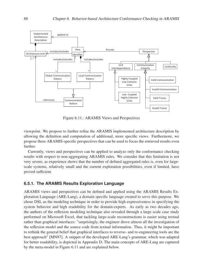
88 Chapter 6. Behavior-based Architecture Conformance Checking in ARAMIS
Communication�Integrity
identifier
ViewPerspective
focuses
Cardinality
Global�Communication�Pattern
applied�onImplemented�Architecture�Description
*
Architecture�Unit
2..*
Highly�Coupled�Low�Cohesive�
Units
Low��Coupled�Highly�Cohesive�
Units
Unit�Interdependence
Valid�Communication
Invalid�Communication
Valid�Traces
Invalid�Traces
includes/excludes*
Local�Communication�Pattern
includes/excludesincludes/excludes
Communication�Pattern
references
*
Figure 6.11.: ARAMIS Views and Perspectives
viewpoint. We propose to further refine the ARAMIS implemented architecture description byallowing the definition and computation of additional, more specific views. Furthermore, wepropose three ARAMIS-specific perspectives that can be used to focus the retrieved results evenfurther.
Currently, views and perspectives can be applied to analyze only the conformance checkingresults with respect to non-aggregating ARAMIS rules. We consider that this limitation is notvery severe, as experience shows that the number of defined aggregated rules is, even for large-scale systems, relatively small and the current exploration possibilities, even if limited, haveproved sufficient.
6.5.1. The ARAMIS Results Exploration Language
ARAMIS views and perspectives can be defined and applied using the ARAMIS Results Ex-ploration Language (ARE-Lang), a domain specific language created to serve this purpose. Wechose DSL as the modeling technique in order to provide high expressiveness in specifying thesystem behavior and high readability for the domain-experts. As early as two decades ago,the authors of the reflexion modeling technique also revealed through a large scale case studyperformed on Microsoft Excel, that tackling large-scale reconstructions is easier using textualrather than graphical interfaces: "surprisingly, the engineer drove almost all the investigation ofthe reflexion model and the source code from textual information. Thus, it might be importantto rethink the general belief that graphical interfaces to reverse- and re-engineering tools are thebest approach" [MN97]. A snippet of the developed ARE-Lang’s grammar, which was adaptedfor better readability, is depicted in Appendix D. The main concepts of ARE-Lang are capturedby the meta-model in Figure 6.11 and are explained below.
6.5. Focusing the Conformance Checking Results 89
ARAMIS Views
A view can be applied on the implemented architecture of a system, as reflected by a set ofmonitored episodes, to retrieve only a subset of the conformance checking results. To this end,a view can explicitly include or exclude several architecture units. Excluding an architectureunit causes all the conformance-checked interactions involving this unit to be removed from thecreated view. In turn, including a unit has the opposite effect. Furthermore, the architect cancreate views that retrieve architecturally mapped and conformance-checked traces of interac-tions that explicitly expose or not a given communication pattern. For this, he can define localcommunication patterns (usable only in the scope of the current view) or reuse global ones. Alocal communication pattern specifies the communication chain between a random number ofarchitecture units. If the name of intermediate units involved in the communication from a givensource to a given destination are not known or are not important, a placeholder unit named "any"can be used instead. Multiplicities can also be assigned to units or to the "any" placeholder,to refine the expectation regarding how many times these should occur in the retrieved trace.For simplicity, the admitted multiplicities are "+" (at least one unit) and "*" (zero or more). Topromote reuse across views and system boundaries, global communication patterns can also bedefined. While a view is specific for a given system, the overall structure of some communi-cation patterns of interest can be very similar regardless of the actual system under analysis:e.g., architects are often interested in the cyclic communication of certain pairs of units. Globalcommunication patterns can be reused within several views and systems by parameterizing theseaccordingly.
The local and global patterns are powerful constructs to depict the structure of communicationchains of interest. Currently these are used as a querying mechanism only, but future work canintegrate the ARE-Lang with the ACR-Lang to allow the easier and more flexible definition ofrules.
ARAMIS Perspectives
Once a view has been defined, several built-in ARAMIS Perspectives can be applied on it. Wegrouped the ARAMIS Perspectives in three main categories according to their concern: unitinterdependence, communication integrity, and cardinality.
The Unit Interdependence Perspective. The unit interdependence perspective focuseson identifying architecture units depending on the relationship between their coupling vs. theircohesion, as exposed at run-time. Two concrete sub-perspectives can be applied in this context:the highly coupled, low cohesive and the low coupled, highly cohesive perspectives.
As such, the highly coupled, low cohesive perspective retrieves only those architecture unitsthat communicate extensively with other external architecture units, but that do not expose avery coherent internal behavior. It is useful to study architecture units exposing such a behavior,when planning refactoring activities. While sometimes the architecture units are per designbehaving in a highly coupled and low cohesive manner, e.g., in the case of Facade units, in othercases this situation might be the result of degeneration. Retrieving the list of such architectureunits that are encompassed in a given view can support such a focused analysis. In contrast, the
90 Chapter 6. Behavior-based Architecture Conformance Checking in ARAMIS
low coupled, highly cohesive perspective retrieves only those units of a given view, that behaveaccording to the well known "low coupling, high cohesion" design principle.
The definition of the metrics that underlie the computation of an architecture unit’s run-timecoupling and cohesion, along with the characterization of its behavior according to various cou-pling/cohesion classes (highly coupled low cohesive, medium coupled medium cohesive andlow coupled high cohesive) have been presented in detail in [DLDC14].
The Communication Integrity Perspective. The communication integrity perspectivemainly focuses on listing the violations of the non-aggregating ARAMIS rules. The architectcan choose to retrieve the violations one by one or on a per-trace basis, using two concrete sub-perspectives: disallowed communication and disallowed traces. In the first case, a list will beretrieved containing all interactions realizing communication with a denied permission. In thesecond case, a list of traces is retrieved, having the property that each trace in the listing con-tains at least one interaction realizing a communication with denied permission. Thus, using thesecond per-trace perspective, the context in which the violations occurred can be further investi-gated. For symmetry reasons, perspectives for retrieving the list of allowed communication andtraces (i.e., traces containing no interactions realizing communication with denied permission)can be defined, but we consider that most of the time, architects are interested in identifyingviolations rather then valid communication.
The Cardinality Perspective. Last but not least, the cardinality perspective focuses onquantifying the set of retrieved results obtained by applying a view and/or several perspectiveson an implemented architecture description. The perspective concept, as introduced by Rozanskiand Woods refers to quality attributes of the system under analysis. Consequently, introducinga cardinality perspective in ARAMIS might appear inappropriate as cardinality is per definitiona mere quantitative indicator. However, we considered that given the behavioral nature of theARAMIS analysis, cardinality does play a very important role, that can give important infor-mation regarding the scale of the detected drift and can later guide the prioritization of actionsplanned for reducing it. Furthermore, the cardinality of the retrieved interactions or traces canbe considered as a crosscutting concern and can be applied to quantify the created views. Con-sequently, we opted to treat cardinality as an additional ARAMIS perspective.
Applying ARE-Lang - Examples
Listing 6.1 depicts a view definition created to explore the implemented architecture descrip-tion of ARAMIS itself. The view "aramisCommunicationChainView" determines the numberof all traces in the monitored episode "aramisEpisode" (Line 14) that contain a communicationchain as declared in the local communication pattern defined on line 11: the communicationchain should emerge in the Dynatrace Adapter and be redirected to the Architecture Mapper;the Architecture Mapper, after some potential inner communication (as suggested by the "+"multiplicity of its corresponding variable) further redirects to the Conformance Checker thateventually accesses the MongoDB Manager to persist the mapping and validation results. Asvisible on line 15, we applied the cardinality perspective on the created view to determine the
6.5. Focusing the Conformance Checking Results 91
number of traces that expose the defined pattern. It is important to notice that many elementsof the view definition are versioned: the code unit, architecture unit and rules sets, as well asthe episode on which the analysis is performed. While out of the scope of the current research,the versioning can enable the study of past and future architectural evolution. We briefly detailthis using the exemplified view. We assume that the first application of the "aramisCommunica-tionChainView" occurred on an initial version of ARAMIS in which the communication patternof interest was not yet implemented. Assuming that the code evolved, at a later point in time,the architect can decide to re-monitor the "aramisEpisode" thus creating the "aramisEpisode"version 2. Assuming that this episode was monitored on the final, fully-functional version ofARAMIS several occurrences of this chain will be identified and the architect will be able toconclude that the implemented architecture correctly evolved and is now exhibiting the chain ofinterest. Similarly, instead of evolving the code, the architect can decide to change the code toarchitecture mapping, the structure of architecture units or the rules used for the actual confor-mance checking, thus respectively affecting and increasing the version of the considered codeunit, architecture unit or rules sets; consequently, the architect can experiment how the imple-mented architecture description would change if a different version of its intended counterpartwere used instead.
Listing 6.1: View to Retrieve the Cardinality of a Given Communication Chain
1 a n a l y z e sys tem a r a m i s2 c o n s t r u c t view aramisCommunica t ionChainView3 wi th4 code u n i t s s e t v e r s i o n 15 a r c h i t e c t u r e u n i t s s e t v e r s i o n 16 {7 Adap te r := a r c h i t e c t u r e u n i t w i th name D y n a t r a c e A d a p t e r8 Mapper := a r c h i t e c t u r e u n i t w i th name A r c h i t e c t u r e M a p p e r9 CC := a r c h i t e c t u r e u n i t w i th name ConformanceChecker
10 Mongo := a r c h i t e c t u r e u n i t w i th name MongoDBManager11 i n c l u d e ( Adap te r ) −>(Mapper+)−>(CC+)−>(Mongo )12 }13 r u l e s s e t v e r s i o n 114 on e p i s o d e ’ a r a m i s E p i s o d e ’ v e r s i o n 115 c o n s i d e r c a r d i n a l i t y o f t r a c e s
Listing 6.2 depicts a second example of a view definition. In this case the view employsa global communication pattern, named "CyclicCommunicationPattern" (defined on Lines 1,2). The "CyclicCommunicationPattern" accepts two generic unit parameters as input and de-fines the structure that would represent a cyclic communication between these. The pattern canthen be reused in any view and in any system, using any two units of interest. Next, the view"aramisMapperCheckerCycles" (Lines 3-13) will initiate the identification of all cycles occur-ring between the Architecture Mapper and the Conformance Checker, by making use of thepreviously defined "CyclicCommunicationPattern".
All in all, the ARE-Lang allows the definition of system-specific views, by including/exclud-ing units and communication patterns of interest. The obtained views can then be refined byapplying several types of patterns that retrieve information regarding the interdependence of the
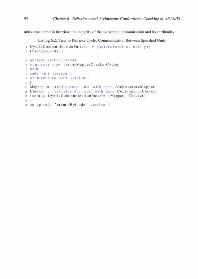
92 Chapter 6. Behavior-based Architecture Conformance Checking in ARAMIS
units considered in the view, the integrity of the extracted communication and its cardinality.
Listing 6.2: View to Retrieve Cyclic Communication Between Specified Units
1 C y c l i c C o m m u n i c a t i o n P a t t e r n := p a t t e r n ( u n i t x , u n i t y ) {2 ( x ) −>(y+)−>(x ) }
4 a n a l y z e sys tem a r a m i s5 c o n s t r u c t view aramisMappe rChecke rCyc le s6 w i th7 code u n i t v e r s i o n 18 a r c h i t e c t u r e u n i t v e r s i o n 19 {
10 Mapper := a r c h i t e c t u r e u n i t w i th name A r c h i t e c t u r e M a p p e r11 Checker := a r c h i t e c t u r e u n i t w i th name ConformanceChecker12 i n c l u d e C y c l i c C o m m u n i c a t i o n P a t t e r n ( Mapper , Checker )13 }14 on e p i s o d e ’ a r a m i s E p i s o d e ’ v e r s i o n 1
Chapter 7.
The Meta-Model Incompatibility Problem
In the previous chapters, we first discussed how interactions extracted with various monitors canbe described in ARAMIS. These represent the evidence based on which the implemented archi-tecture is checked against its intended architecture description. In the last chapter we presentedthe meta-model of ARAMIS architecture descriptions and discussed the taxonomy of rules thatcan be formulated using the ARE-Lang language. Next, we discussed how these can be checkedagainst during two conformance checking phases and lastly, how the obtained results can beexplored.
In this chapter we discuss how intended architecture descriptions that were not elaboratedusing the ARAMIS meta-model can be re-used and how the results of the conformance check-ing can be presented as augmentations of these. This chapter addresses the following researchquestion, as formulated in Section 1.3:
How can we support arbitrary intended architecture descriptions as input for theARAMIS analysis and present the output to boost understanding and recognition ef-fects?
This chapter is based on the results published in [LNL15].
Motivation
Conformance checking approaches that, as ARAMIS, are built as adaptations of the reflexionmodeling technique, require as input an intended architecture description of the system underanalysis as well as a mapping between the architectural elements encompassed in it and evidencefrom the actual system, such as source code and configuration files.
On the one hand, the problem that arises is that the architects have a huge variety of possibil-ities to express the architecture descriptions and this is being reflected in the existence of a widespectrum of methods, tools, languages and standards that serve this purpose. In fact, nowadaysthere are more than 100 published architecture description languages (ADLs) available for useby the architects to express their intended architectures [Mal]. While most of the existing ADLshave not found acceptance in the industry [VACK11], the large variety of possibilities is stillreflected in the nature of intended architecture descriptions formulated in real world scenarios.Architects often use informal boxes and lines augmented with further semantic information, tex-tual descriptions of expected behavior, overall architectural guidelines, etc. As also depictedin Section 2.1.2, when more rigor is needed, then slightly more formal specifications such asUML component or class diagrams are elaborated. Furthermore, even for intended architec-ture descriptions created within the same software development project and elaborated using the
94 Chapter 7. The Meta-Model Incompatibility Problem
same language, the composing elements can be used with a different semantics. In fact, somelanguages even embrace this semantical ambiguity, as the following excerpt form the UML Su-perstructure reveals: “The Components package supports the specification of both logical com-ponents (e.g., business components, process components) and physical components (e.g., EJBcomponents, CORBA components, COM+ and .NET components, WSDL components, etc.),along with the artifacts that implement them and the nodes on which they are deployed and ex-ecuted. It is anticipated that profiles based around components will be developed for specificcomponent technologies and associated hardware and software environments” [OMG11].
All in all, a consensus regarding a single, universal language for expressing intended archi-tecture descriptions does not exist and, as underlined by Malavolta, such a universal languagewould probably not even gain popularity, if it were available [MLM+13].
On the other hand, the variety of possibilities to express architecture descriptions is alsoreflected by the available conformance checking tools. These also employ proprietary meta-models, often not extendable and with a stiff semantic. To exemplify, the well-known Struc-ture101 Studio [str], specialized in agile architecture development, supports the creation of lay-ered intended architecture descriptions. By default, these have a relaxed layers semantics butexceptions to this general rule can be defined by the architect. However, describing non-layeredarchitectures as such, can lead to confusions. For example, Figure 7.1 depicts the intended ar-chitecture description of the Ant tool for build process automation, as constructed by a team ofresearchers intending to evaluate and compare the support offered by Structure101 and Sonar-graph Architect in the detection and repair of architectural drift [FRZ+16]. The diagram wasconstructed using the architecture modeler of Structure101, based on knowledge extracted bythe authors from the Ant documentation: “For Ant, architectural documentation is very scarce.In the documentation, allowed and disallowed dependencies are not defined. The only informa-tion available is the division of packages in modules.” Exceptions to the relaxed layers archi-tecture are represented by continuous arrows; the discovered violations are drawn using dashedarrows. As the authors of [FRZ+16] state, a clear statement regarding the layered nature of Antwas missing in the documentation but, because of the meta-model imposed by Structure101, theauthors’ only choice was to model the system using the imposed relaxed layers pattern. How-ever, this choice seems unnatural given that exceptions had to be defined that allow all the fourbottom layers (taskdefs, types, util and Others) to access the highest one (ant).
Similarly, the Sonargraph Architect [son] versions up to 7 also supported the definition ofrelaxed layered architecture descriptions exclusively. Similarly, as mentioned in Section 6.2 thiscaused acceptance problems when presenting conformance results to practitioners.
Starting with version 9, Sonargraph Architect is employing a new architecture definition lan-guage revolving around the concept of an architectural artifact. An architectural artifact consistsof components which represent mappings to source files. Artifacts can be composed hierar-chically and the inter-dependencies between them can be represented by linking correspondingincoming and outgoing ports of pairs of artifacts. If the authors of [FRZ+16] were to repeattheir experiment with this new version of Sonargraph Architect, reusing the previously modeledintended architecture description wouldn’t be possible, because the meta-model of architecturedescriptions has changed and contains syntactically and semantically different elements. Ona considerably lower scale, this situation reflects the problem that practitioners in the industry
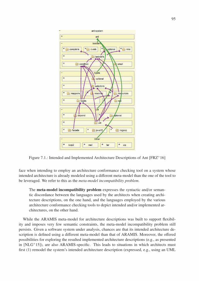
95
Figure 7.1.: Intended and Implemented Architecture Descriptions of Ant [FRZ+16]
face when intending to employ an architecture conformance checking tool on a system whoseintended architecture is already modeled using a different meta-model than the one of the tool tobe leveraged. We refer to this as the meta-model incompatibility problem.
The meta-model incompatibility problem expresses the syntactic and/or seman-tic discordance between the languages used by the architects when creating archi-tecture descriptions, on the one hand, and the languages employed by the variousarchitecture conformance checking tools to depict intended and/or implemented ar-chitectures, on the other hand.
While the ARAMIS meta-model for architecture descriptions was built to support flexibil-ity and imposes very few semantic constraints, the meta-model incompatibility problem stillpersists. Given a software system under analysis, chances are that its intended architecture de-scription is defined using a different meta-model than that of ARAMIS. Moreover, the offeredpossibilities for exploring the resulted implemented architecture descriptions (e.g., as presentedin [NLG+15]), are also ARAMIS-specific. This leads to situations in which architects mustfirst (1) remodel the system’s intended architecture description (expressed, e.g., using an UML
96 Chapter 7. The Meta-Model Incompatibility Problem
component diagram) using the ARAMIS meta-model and then (2) interpret the result as pre-sented by ARAMIS using a specific visualization that has no traceability links with the intendeddescription from step (1).
Manual vs. Automatic Model to Model Transformation.
In general, there are two main possibilities to accomplish the first step mentioned above: eithermanually re-model the intended architecture description using the new meta-model, or employan automatic transformation process. These two approaches differ in terms of level of detail andinvested effort, as detailed next.
If a manual transformation is applied, the architect can make use of all the modeling possibil-ities offered by the target meta-model, potentially being enabled to create a semantically richerintended architecture description. For example, in the case of ARAMIS, with its rich rules tax-onomy, the architect can enrich the communication rules expressed in the original descriptionwith implicitly available information regarding the modeled communication. Contrastingly, ifthe target meta-model is less expressive than that of the original one, it is left to the architectto explore if a workaround can be employed to express the knowledge captured in the originaldescription
In contrast, an automatic transformation is less flexible. Given that no additional informa-tion is provided to the transformation process, the transformed description can only encompassmaximum as many details as available in the original description. Therefore, in the case ofan automatic transformation the quality of the transformed description largely depends on thequality of the original one and the capabilities of the transformation process itself.
From the point of view of the effort invested, the manual transformation is feasible in the caseof small-scale systems with not very extensive original architecture descriptions. In the caseof large scale systems with extensive architecture descriptions manual transformations becomecumbersome. In this case, although defining and employing an automatic transformation pro-cess can be costly, the invested effort soon pays off. Despite the initial effort needed to invest inthe transformation itself, a manual process implies consequent changes every time the originalintended architecture description evolves. Contrastingly, once an automatic transformation isavailable, accommodating changes is simply achieved by re-triggering the transformation, withlittle or no extra effort. Even more, if further systems should be checked for conformance andthese are elaborated using the same original meta-model, then cross-system reuse of the auto-matic transformation process can reduce the invested effort by several orders of magnitude.
Addressing the Meta-Model Incompatibility Problem in ARAMIS
In order to loosen the limitation posed by the meta-model incompatibility problem in the contextof ARAMIS and increase its acceptability, we developed a process that supports the transforma-tion of original intended descriptions to ARAMIS-specific ones. We refer to this as the ARAMISArchitecture Description Transformation Process (AADT-Proc). The AADT-Proc process canserve to guide the architect in the case of a manual transformation or to support the developmentof automatic transformations. In the case of automatic transformations, it aims to enable flexibleformats for the intended architecture description (i.e., the process input) and the corresponding
7.1. The Architecture Description Transformation Process 97
implemented architecture description (i.e., the process output). Accordingly, after an initiallyinvested effort to define the automatic transformation, the architect would provide an intendedarchitecture description adhering to a non-ARAMIS meta-model and receive as output the samediagram, augmented with the conformance checking results of ARAMIS (e.g., occurred viola-tions and their frequency). The AADT-Proc is presented in more detail in the following section.
7.1. The Architecture Description Transformation Process
As briefly mentioned previously, the main goals of AADT-Proc are:
• to guide the transformation process of non-ARAMIS intended architecture descriptions todescriptions that adhere to the ARAMIS meta-model (ARAMIS-MM) (G1).
• in the case of automatic transformations, to boost the understanding of implemented archi-tecture descriptions created by ARAMIS by presenting them as instantiations of the samemeta-model as the corresponding intended architecture descriptions, possibly by merelyaugmenting the latter with the obtained conformance checking results (G2).
If the intended architecture description (IAD) of the system under test does not exist, thenthe AADT-Proc process is not relevant, since the description must be elaborated by the architectfrom scratch. To this end, given that the reason behind the elaboration of the description isto conduct an architectural conformance check with ARAMIS, it is reasonable to assume thatthe description will adhere to the ARAMIS-MM and, consequently the AADT-Proc is renderedobsolete. Therefore, in the remainder of this section we will assume that when the decision toleverage ARAMIS is made, an IAD of the system is already available, but this is elaboratedusing a different meta-model than the ARAMIS-MM and thus the meta-model incompatibilityproblem arises. The meta-model of the IAD will be referred to as the IAD-MM.
Convention. While an ARAMIS intended architecture description per se is, by definition,an intended architecture description (IAD), to avoid confusion, when using the acronym IAD inthis section we will refer to a description elaborated with a meta-model other than the ARAMIS-MM.
The AADT-Proc consists of four main phases, as depicted in Figure 7.2. In the next para-graphs we illustrate the details of each of these.
The Preprocessing Phase
The goal of the preprocessing phase is to achieve a clear understanding of the meta-model em-ployed in the intended architecture description and, if an automatic transformation is pursued, torepresent it and the description itself in a structured, automatically processable format. There-fore, this phase commences with the formalization of the IAD-MM.
If the intended architecture description is documented using some informal notations (e.g.,boxes and lines), formalizing the underlying meta-model is a necessary step, even if an au-tomatic transformation is not pursued, in order to support the understanding of the depicted
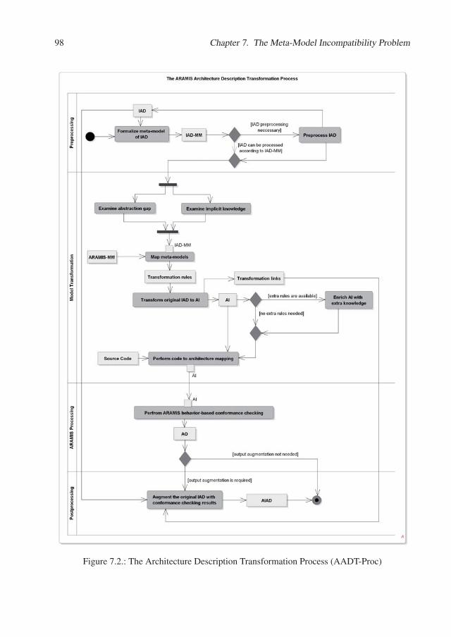
98 Chapter 7. The Meta-Model Incompatibility Problem
Figure 7.2.: The Architecture Description Transformation Process (AADT-Proc)
7.1. The Architecture Description Transformation Process 99
architectural elements and the analysis of correspondences between the intended meta-modeland the ARAMIS-MM in the next phase.
In extreme cases, such as when the description is simply a drawing realized with pen andpaper, if an automatic transformation is aimed towards, the description will first need to be ex-pressed in a structured, processable format. To this end, several solutions are available. Thehighest level of automation can be achieved if image recognition techniques were employed andstructured descriptions were elaborated based thereupon. In fact, given that very often archi-tectural documentation is available in pictures, solutions for automatically transforming these tostructured diagrams were proposed and are an open research endeavor [KC13]. Another, lessautomated but possibly more realistic, option is to create an editor for IAD-MM instances thatoffers export functionality to a structured format. Such editors can for example be elaboratedusing Eclipse Ecore [eco]. Creating such an editor and re-elaborating the intended descriptionusing it can be seen as wasteful. One can argue that the involved effort does not pay off andmilitate towards abandoning an automatic solution. A definitive statement regarding effort min-imization is not possible, since this depends on the quality of the intended architecture descrip-tions to transform and the model engineering expertize of the involved stakeholders. However,“simply” modeling the exact same model with a dedicated editor is, in general, less error pronethan transforming it manually to a new meta-model. Furthermore, if a manual transformationis employed, its quality will depend on the skills of the modeler. In the case study presented inSection 13, we have developed an Ecore-based editor for boxes and lines diagrams to express ina processable format the informal boxes and lines diagram received from the architects.
The above mentioned situations imposed the renewed modeling of the IAD because this wasnot available in a format that allows its exploration. This must not always be the case. TheIAD can be elaborated using a dedicated editor but its exploration can be regarded as over-complicated. Consequently, in such situations it can be useful to first pre-process the IAD toensure an easier meta-model-based exploration. We encountered such a situation in the casestudy presented in Chapter 14.
All in all, the preprocessing step of the AADT-Proc consists of the formalization of the IAD-MM and of consequent possible refinements of the IAD to enable its easier exploration.
The Model Transformation Phase
Once the original IAD and the IAD-MM are available, we can continue with the actual modeltransformation phase. The goal of this phase is to produce an intended architecture descriptionthat conforms to the ARAMIS-MM.
In this section, we will refer to this as the ARAMIS input (AI).
An ARAMIS input (AI) is an intended architecture description expressed using theARAMIS meta-model.
To realize a meaningful transformation, the abstraction gap involved in the transformationand, if applicable, the implicitly encoded knowledge in the IAD and the IAD-MM should bestudied.
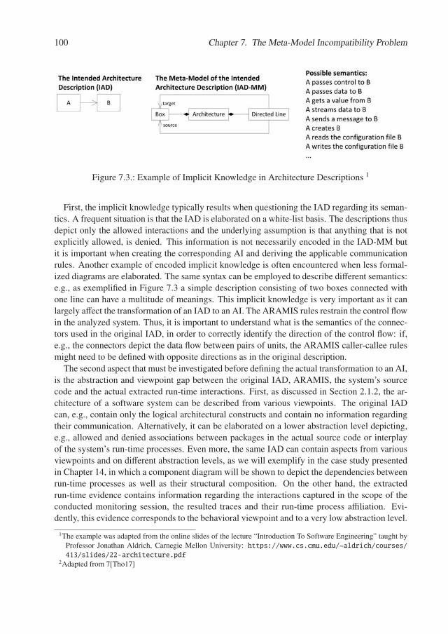
100 Chapter 7. The Meta-Model Incompatibility Problem
Figure 7.3.: Example of Implicit Knowledge in Architecture Descriptions 1
First, the implicit knowledge typically results when questioning the IAD regarding its seman-tics. A frequent situation is that the IAD is elaborated on a white-list basis. The descriptions thusdepict only the allowed interactions and the underlying assumption is that anything that is notexplicitly allowed, is denied. This information is not necessarily encoded in the IAD-MM butit is important when creating the corresponding AI and deriving the applicable communicationrules. Another example of encoded implicit knowledge is often encountered when less formal-ized diagrams are elaborated. The same syntax can be employed to describe different semantics:e.g., as exemplified in Figure 7.3 a simple description consisting of two boxes connected withone line can have a multitude of meanings. This implicit knowledge is very important as it canlargely affect the transformation of an IAD to an AI. The ARAMIS rules restrain the control flowin the analyzed system. Thus, it is important to understand what is the semantics of the connec-tors used in the original IAD, in order to correctly identify the direction of the control flow: if,e.g., the connectors depict the data flow between pairs of units, the ARAMIS caller-callee rulesmight need to be defined with opposite directions as in the original description.
The second aspect that must be investigated before defining the actual transformation to an AI,is the abstraction and viewpoint gap between the original IAD, ARAMIS, the system’s sourcecode and the actual extracted run-time interactions. First, as discussed in Section 2.1.2, the ar-chitecture of a software system can be described from various viewpoints. The original IADcan, e.g., contain only the logical architectural constructs and contain no information regardingtheir communication. Alternatively, it can be elaborated on a lower abstraction level depicting,e.g., allowed and denied associations between packages in the actual source code or interplayof the system’s run-time processes. Even more, the same IAD can contain aspects from variousviewpoints and on different abstraction levels, as we will exemplify in the case study presentedin Chapter 14, in which a component diagram will be shown to depict the dependencies betweenrun-time processes as well as their structural composition. On the other hand, the extractedrun-time evidence contains information regarding the interactions captured in the scope of theconducted monitoring session, the resulted traces and their run-time process affiliation. Evi-dently, this evidence corresponds to the behavioral viewpoint and to a very low abstraction level.
1The example was adapted from the online slides of the lecture “Introduction To Software Engineering” taught byProfessor Jonathan Aldrich, Carnegie Mellon University: https://www.cs.cmu.edu/~aldrich/courses/413/slides/22-architecture.pdf
2Adapted from 7[Tho17]
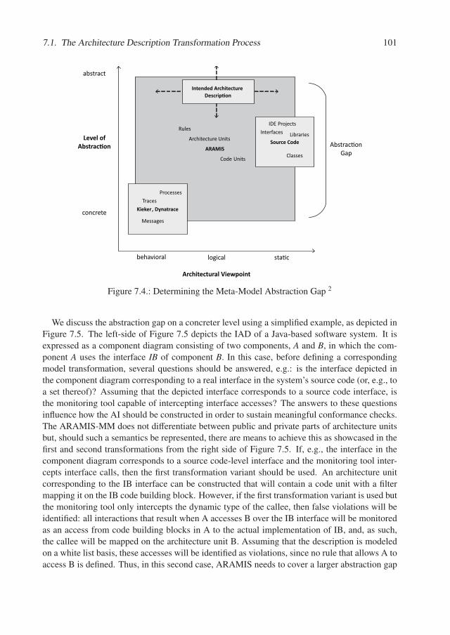
7.1. The Architecture Description Transformation Process 101
ARAMIS
Level of Abstrac�on
Architectural Viewpoint
behavioral logical sta�c
abstract
concrete Kieker, Dynatrace
Source Code Abstrac�onGap
Processes
Messages
Classes
InterfacesArchitecture Units
Code Units
Rules
Traces
IDE Projects
Libraries
Intended Architecture Descrip�on
Figure 7.4.: Determining the Meta-Model Abstraction Gap 2
We discuss the abstraction gap on a concreter level using a simplified example, as depicted inFigure 7.5. The left-side of Figure 7.5 depicts the IAD of a Java-based software system. It isexpressed as a component diagram consisting of two components, A and B, in which the com-ponent A uses the interface IB of component B. In this case, before defining a correspondingmodel transformation, several questions should be answered, e.g.: is the interface depicted inthe component diagram corresponding to a real interface in the system’s source code (or, e.g., toa set thereof)? Assuming that the depicted interface corresponds to a source code interface, isthe monitoring tool capable of intercepting interface accesses? The answers to these questionsinfluence how the AI should be constructed in order to sustain meaningful conformance checks.The ARAMIS-MM does not differentiate between public and private parts of architecture unitsbut, should such a semantics be represented, there are means to achieve this as showcased in thefirst and second transformations from the right side of Figure 7.5. If, e.g., the interface in thecomponent diagram corresponds to a source code-level interface and the monitoring tool inter-cepts interface calls, then the first transformation variant should be used. An architecture unitcorresponding to the IB interface can be constructed that will contain a code unit with a filtermapping it on the IB code building block. However, if the first transformation variant is used butthe monitoring tool only intercepts the dynamic type of the callee, then false violations will beidentified: all interactions that result when A accesses B over the IB interface will be monitoredas an access from code building blocks in A to the actual implementation of IB, and, as such,the callee will be mapped on the architecture unit B. Assuming that the description is modeledon a white list basis, these accesses will be identified as violations, since no rule that allows A toaccess B is defined. Thus, in this second case, ARAMIS needs to cover a larger abstraction gap
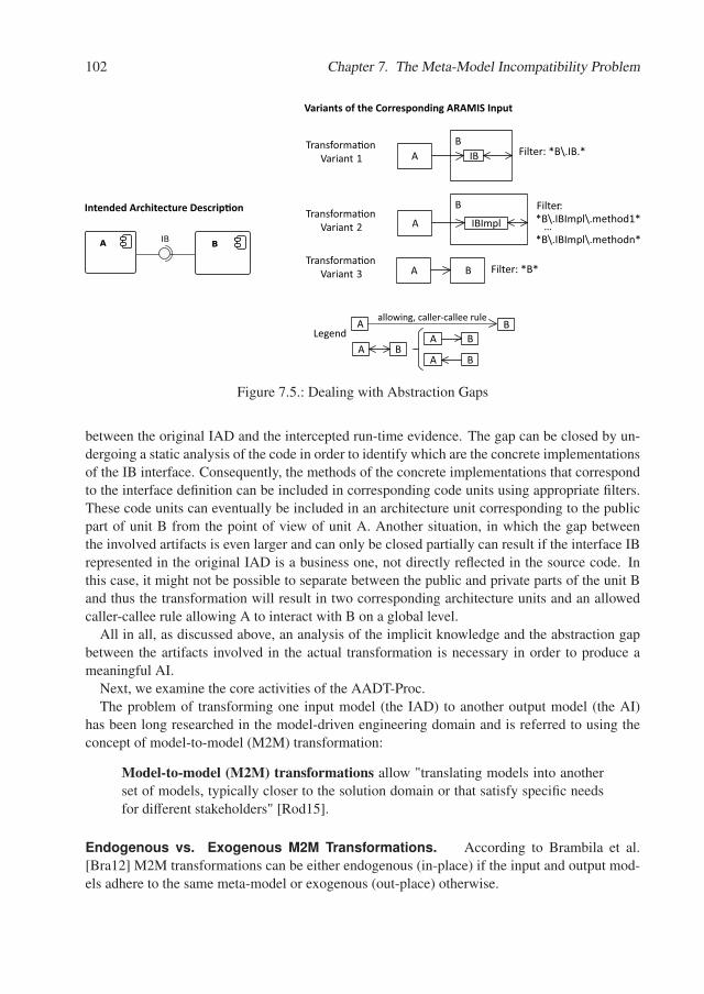
102 Chapter 7. The Meta-Model Incompatibility Problem
BA IB
A B
AB
IB
A
B
IBImpl
Transforma�on Variant 1
Transforma�on Variant 2
Legendallowing, caller-callee rule
A BA B
A B
Filter: *B\.IB.*
Filter:: *B\.IBImpl\.method1*
…*B\.IBImpl\.methodn*
A BTransforma�on
Variant 3 Filter: *B*
Intended Architecture Descrip�on
Variants of the Corresponding ARAMIS Input
Figure 7.5.: Dealing with Abstraction Gaps
between the original IAD and the intercepted run-time evidence. The gap can be closed by un-dergoing a static analysis of the code in order to identify which are the concrete implementationsof the IB interface. Consequently, the methods of the concrete implementations that correspondto the interface definition can be included in corresponding code units using appropriate filters.These code units can eventually be included in an architecture unit corresponding to the publicpart of unit B from the point of view of unit A. Another situation, in which the gap betweenthe involved artifacts is even larger and can only be closed partially can result if the interface IBrepresented in the original IAD is a business one, not directly reflected in the source code. Inthis case, it might not be possible to separate between the public and private parts of the unit Band thus the transformation will result in two corresponding architecture units and an allowedcaller-callee rule allowing A to interact with B on a global level.
All in all, as discussed above, an analysis of the implicit knowledge and the abstraction gapbetween the artifacts involved in the actual transformation is necessary in order to produce ameaningful AI.
Next, we examine the core activities of the AADT-Proc.The problem of transforming one input model (the IAD) to another output model (the AI)
has been long researched in the model-driven engineering domain and is referred to using theconcept of model-to-model (M2M) transformation:
Model-to-model (M2M) transformations allow "translating models into anotherset of models, typically closer to the solution domain or that satisfy specific needsfor different stakeholders" [Rod15].
Endogenous vs. Exogenous M2M Transformations. According to Brambila et al.[Bra12] M2M transformations can be either endogenous (in-place) if the input and output mod-els adhere to the same meta-model or exogenous (out-place) otherwise.
7.1. The Architecture Description Transformation Process 103
Evidently, the transformation of an original IAD to an AI is an exogenous transformation.To enable the transformation, a so-called transformation definition consisting of transformationrules must be created. The transformation rules are specified at meta-model level and prescribehow one or more elements from the output model must be produced based on one or moreelements from the input model. When the rules are applied and the transformation is performed,information regarding what exact input(s) element was transformed to what output element(s)can be persisted in the form of so-called transformation links.
Typically, if the transformation rules are bidirectional a M2M transformation can be executedin both directions. This means that the input model can be transformed to the output model,the output model can be changed as a result of some subsequent processing and, lastly theoutput (as long as its meta-model didn’t change) can be re-transformed to express the results inthe same meta-model as the original input. On a first analysis, a bidirectional transformationmight seem ideal to achieve both goals formulated above, namely to transform the original IADto an ARAMIS input and to present the results by simply augmenting the original description7.1. However, given that the ARAMIS-MM is very general, with few semantic constraints,we assume that the probability that more elements from the IAD-MM (e.g., box, component)must be transformed to the same ARAMIS-MM element (e.g., architecture unit) is relativelyhigh. In such a scenario, defining bidirectional transformation rules can be complex. Instead,we expect that unidirectional transformations are in most cases better suited than bidirectionalones. However, in order to enable the architects to analyze the result on their own architecturedescription, we propose to store the concrete links resulted during the transformation and reusethem after the ARAMIS conformance checking results are available in order to augment theseon the IAD. Eventually, this leads to the same effect as the bidirectional transformation.
Transformation Rules - An Example. An example of the transformation rules resultedfrom the meta-model mapping of the boxes and lines meta-model exemplified in Figure 7.3and the relevant excerpt of the ARAMIS-MM is depicted in Figure 7.6: when a boxes andlines architecture must be transformed into an ARAMIS input, a new ARAMIS architecturedescription consisting of corresponding sets for architecture units, communication rules andcode units and a corresponding set of default rules is initially created. For simplicity reasons, notall the default rules are depicted in the ARAMIS meta-model. The implicit knowledge acquiredin the previous steps can be reflected in constraints expressed for the transformation itself. Inthis case, assuming that we previously identified that a boxes and lines diagram is built on awhite-list basis, this will be reflected in the usage of the ARAMIS Deny Unconstrained Rule inthe created ARAMIS input. Next, for each box in the boxes and lines diagram, a correspondingarchitecture unit is added to the ARAMIS architecture units set. A line in the boxes and linesdiagram corresponds to an allowing caller-callee rule in the ARAMIS input and the referencedcaller and callee architecture units are determined based on the source and target of the line inthe original diagram. An example of an actual transformation conducted with the transformationrules resulted from the presented meta-model mapping is depicted on the left side of Figure 7.7.The resulted (simplified view of the) transformation links is presented on the right side of Figure7.7.
Once the transformation was performed, the ARAMIS input expresses the communication
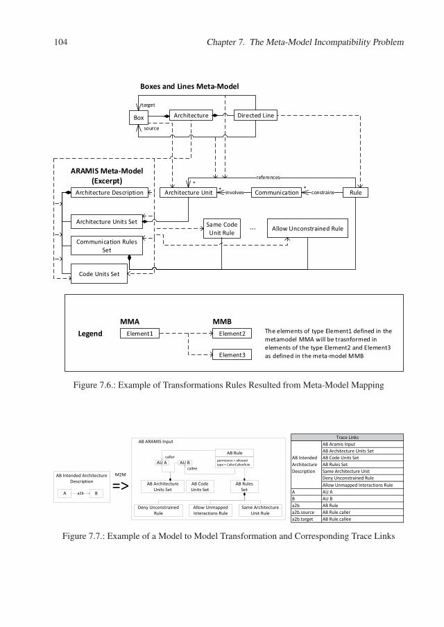
104 Chapter 7. The Meta-Model Incompatibility Problem
ArchitectureBox Directed Line
source
target
Boxes and Lines Meta-Model
Architecture Description Architecture Unit RuleCommunication
Communication RulesSet
Architecture Units Set
Code Units Set
* involves*
references
*constrains
ARAMIS Meta-Model(Excerpt)
Element1 Element2
Element3
LegendMMA MMB
The elements of type Element1 defined in themetamodel MMA will be trasnformed inelements of the type Element2 and Element3as defined in the meta-model MMB
Same CodeUnit Rule
Allow Unconstrained Rule...
Figure 7.6.: Example of Transformations Rules Resulted from Meta-Model Mapping
AU A AU Bcaller
callee
permission = allowedtype = CallerCalleeRule
AB Rule
AB ARAMIS Input
AB Architecture Units Set
AB Rules Set
AB Code Units Set
A Ba2b
AB Intended Architecture Description
M2M
=>Deny Unconstrained
RuleSame Architecture
Unit RuleAllow UnmappedInteractions Rule
AB Aramis InputAB Architecture Units SetAB Code Units SetAB Rules SetSame Architecture UnitDeny Unconstrained RuleAllow Unmapped Interactions Rule
A AU AB AU Ba2b AB Rulea2b.source AB Rule.callera2b.target AB Rule.callee
Trace Links
AB Intended Architecture Description
Figure 7.7.: Example of a Model to Model Transformation and Corresponding Trace Links
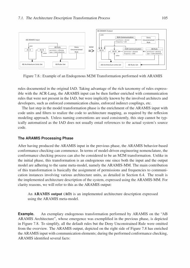
7.1. The Architecture Description Transformation Process 105
AU�A AU�B
caller
callee
permission�=�allowingtype�=�CallerCalleeRule
AB�Rule
AB�ARAMIS�Input
AB�Architecture�Units�Set AB�Rules�Set
M2M
=> AU�A AU�B
caller
callee
AB�ARAMIS�Output
AB�Architecture�Units�Set AB�Rules�Set
permission�=�allowedfrequency�=�1000
A2B�Communication
permission�=�deniedfrequency�=�100
B2A�Communication Deny�Unconstrained�
Rule
Deny�Unconstrained�
Rule permission�=�allowingtype�=�CallerCalleeRule
AB�Rule
Figure 7.8.: Example of an Endogenous M2M Transformation performed with ARAMIS
rules documented in the original IAD. Taking advantage of the rich taxonomy of rules express-ible with the ACR-Lang, the ARAMIS input can be then further enriched with communicationrules that were not present in the IAD, but were implicitly known by the involved architects anddevelopers, such as enforced communication chains, enforced indirect couplings, etc.
The last step in the model transformation phase is the enrichment of the ARAMIS input withcode units and filters to realize the code to architecture mapping, as required by the reflexionmodeling approach. Unless naming conventions are used consistently, this step cannot be typ-ically automatized as the IAD does not usually entail references to the actual system’s sourcecode.
The ARAMIS Processing Phase
After having produced the ARAMIS input in the previous phase, the ARAMIS behavior-basedconformance checking can commence. In terms of model-driven engineering nomenclature, theconformance checking process can also be considered to be an M2M transformation. Unlike inthe initial phase, this transformation is an endogenous one since both the input and the outputmodel are adhering to the same meta-model, namely the ARAMIS-MM. The main contributionof this transformation is basically the assignment of permissions and frequencies to communi-cation instances involving various architecture units, as detailed in Section 6.4. The result isthe implemented architecture description of the system, expressed using the ARAMIS-MM. Forclarity reasons, we will refer to this as the ARAMIS output:
An ARAMIS output (AO) is an implemented architecture description expressedusing the ARAMIS meta-model.
Example. An exemplary endogenous transformation performed by ARAMIS on the “ABARAMIS Architecture”, whose emergence was exemplified in the previous phase, is depictedin Figure 7.8. To simplify, all the default rules but the Deny Unconstrained Rule were omittedfrom the overview. The ARAMIS output, depicted on the right side of Figure 7.8 has enrichedthe ARAMIS input with communication elements; during the performed conformance checking,ARAMIS identified several facts:
106 Chapter 7. The Meta-Model Incompatibility Problem
• unit A accessed unit B 1000 times. This communication could be validated by “Rule AB”
• unit B also accessed unit A 100 times. No other rule but the default Deny UnconstrainedRule could be applied and consequently the communication was marked as denied andrepresents a violation.
The Postprocessing Phase
The last phase in the AADT-Proc is designed to fulfill the second formulated goal, namely toexpress the results of the ARAMIS behavior-based conformance checking by augmenting theoriginal IAD, in order to boost understanding based on recognition effects.
Typically architecture description languages do not contain elements for depicting the resultsof architecture conformance checks. The abstraction gap discussed above and the nature of theARAMIS-MM, oriented towards constraining the behavior view of the analyzed system, furthercontribute to yet another possible incompatibility between the IAD-MM and the ARAMIS-MM.ARAMIS assigns to the communication of two architecture units a frequency and a conformancevalidation result, possibly marking it as a violation. The IAD-MM however, might not dispose ofmeans to represent this information. Two possible solutions are possible in such a situation. Onesolution is to reuse general purpose elements with a loose semantic from the input meta-modelif these are available. For example, in UML one can append the conformance checking resultsusing UML comments, because “a comment adds no semantics to the annotated elements, butmay represent information useful to the reader of the model” [OMG11]. Alternatively, if theIAD-MM does not expose such elements, one can extend it with additional suitable elements.If we consider, e.g., the meta-model of boxes and lines diagrams depicted in Figure 7.3, it con-tains no means to specify weather a line represents a violation and how often is the depictedrelation occurring during run-time. To this end, we can extend the meta-model and add a “com-ment” element or “frequency” and “is allowed” attributes to the already existing “directed line”element.
Yet another problem arises if the ARAMIS behavior-based conformance checking processleads to the emergence of elements that are not linked with the original IAD. For example,ARAMIS might discover that the caller of some interactions cannot be mapped on any archi-tecture unit from the ARAMIS input. Consequently, it will map the caller of all these pairs ona newly created “Unknown” architecture unit and validate them according to the employed de-fault Unmapped Rule. However, no transformation link exists that connects this newly createdunit with an element of the IAD. Continuing the example depicted in Figure 7.7, should such asituation occur, the IAD could be enriched with a new box called "Unknown" that correspondsto the newly created ARAMIS "Unknown" architecture unit.
The default rules pose a similar, yet less intuitive problem: namely there exist traceabilitylinks that target them, but these links typically trace back to the architecture itself, as we dis-cussed when presenting the second phase of the ADT process and exemplified in Figure 7.7.We discuss this based on the exemplary situation depicted in Figures 7.7 and 7.8. The defaultDeny Unconstrained Rule resulted when transforming the “AB Intended Architecture Descrip-tion”. Next, according to this rule the communication “B2A Communication” from B to A wasidentified as a violation. When specifying how the conformance checking results should be
7.1. The Architecture Description Transformation Process 107
augmented on the original diagram, several options might be considered.
1. Given that the transformation links depicted on the right side of Figure 7.7, depict theDeny Unconstrained Rule as the target of the “AB Intended Architecture Description”itself, a summary of all the communication instances validated or invalidated using thisrule could be attached as a general comment in the original architecture, considering thatsuch comments can be created according to the (possibly extended) IAD-MM. In a sim-ilar fashion, the summary of the communication instances validated using the employedUnmapped Interactions Rule can be added to the diagram as an additional comment.
2. Given that the boxes and lines meta-model describes bidirectional communication andconsidering that the ARAMIS default rules are also applicable for bidirectional commu-nication, one can conclude to include additional lines in the original diagram that cor-respond to the identified pairs that were invalidated using the Deny Unconstrained Ruleand attach to them a comment to depict their frequency and validation status. We cantreat the employed Unmapped Interactions Rule similarly. Considering that that we addan "Unknown" box to the IAD, to correspond to the ARAMIS "Unknown" architectureunit, commented lines emerging from or targeting this box can also be added to depict thecommunication validated using this rule.
Considering the options listed above and the extension of the boxes and lines meta-model toattach comments to the architecture itself but also to any of its elements, two possible augmen-tations of the original “AB Intended Architecture Description” with the results of the ARAMISoutput as depicted on the right side of Figure 7.8 are presented in Figure 7.9. In the first aug-mentation option, we only used comments to depict the ARAMIS results. The “AB Rule” wasthe target of a traceability link emerging from the “a2b” line in the initial M2M transformation.This was used to validate the “A2B Communication”. Thus, we extract the information in the“A2B Communication” to augment the “a2b” line with a corresponding comment. Similarly, the“Deny Unconstrained Rule” is linked to the “AB Intended Architecture Description” througha traceability link resulted in the M2M transformation. Since this rule was used to invalidatethe “B2A Communication” we extract the relevant information from this communication (in-volved architecture units, permission, frequency) to attach a corresponding comment to the “ABIntended Architecture Description”.
Last but not least, the conformance checking results that emerged by applying the rules withwhich the ARAMIS input was enriched after the transformation of the IAD, will also have nocorresponding trace links. Typically, these were not originally captured in the IAD as the IAD-MM lacked the necessary expressiveness or convenience. Extending the IAD-MM to make theirvalidation results visible, might prove challenging if a solution beyond mere comments is strivenfor. In this case, it should be questioned if the results outweigh the invested effort. We considerthat in most of the cases, it suffices to resume the corresponding conformance checking resultsby simply attaching comments to the IAD itself.
All in all, the postprocessing phase consists of the augmentation of the conformance resultsobtained during the ARAMIS processing phase onto the original IAD. As discussed and ex-emplified, several challenges can be encountered in this phase and the cost of creating optimalaugmentations should always be considered in relation to the invested effort.
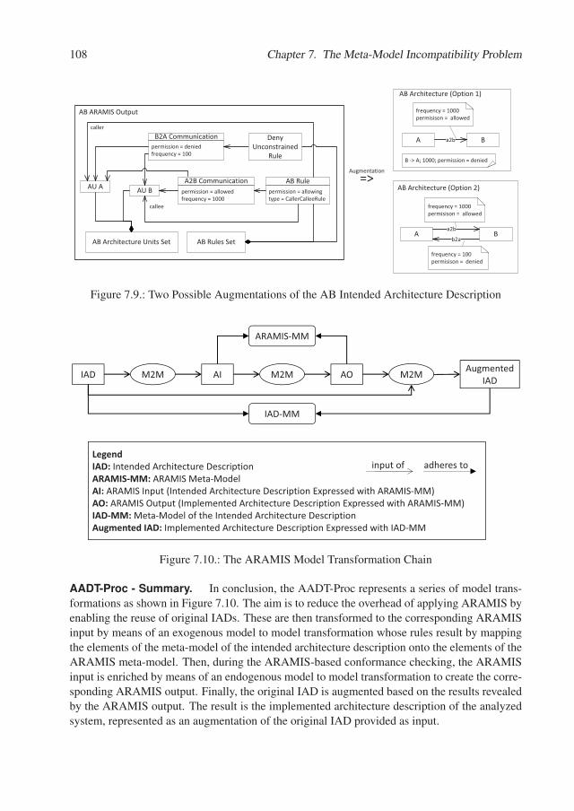
108 Chapter 7. The Meta-Model Incompatibility Problem
A Ba2b
AB�Architecture�(Option�1)
B��>�A;�1000;�permission�=�denied
A Ba2b
AB�Architecture�(Option�2)
b2a
Augmentation=>
AU�A AU�B
caller
callee
AB�ARAMIS�Output
AB�Architecture�Units�Set AB�Rules�Set
permission�=�allowedfrequency�=�1000
A2B�Communication
permission�=�deniedfrequency�=�100
B2A�Communication Deny�Unconstrained�
Rule
permission�=�allowingtype�=�CallerCalleeRule
AB�Rule
frequency�=�1000permisison�=��allowed
frequency�=�1000permisison�=��allowed
frequency�=�100permisison�=��denied
Figure 7.9.: Two Possible Augmentations of the AB Intended Architecture Description
IAD AI AO Augmented�IADM2M M2M M2M
ARAMIS�MM
IAD�MM
LegendIAD:�Intended Architecture�DescriptionARAMIS�MM:�ARAMIS�Meta�ModelAI: ARAMIS�Input�(Intended�Architecture�Description�Expressed�with�ARAMIS�MM)AO: ARAMIS�Output�(Implemented�Architecture�Description�Expressed�with�ARAMIS�MM)IAD�MM:�Meta�Model�of�the�Intended�Architecture�DescriptionAugmented�IAD: Implemented�Architecture�Description�Expressed�with�IAD�MM
input�of adheres�to
Figure 7.10.: The ARAMIS Model Transformation Chain
AADT-Proc - Summary. In conclusion, the AADT-Proc represents a series of model trans-formations as shown in Figure 7.10. The aim is to reduce the overhead of applying ARAMIS byenabling the reuse of original IADs. These are then transformed to the corresponding ARAMISinput by means of an exogenous model to model transformation whose rules result by mappingthe elements of the meta-model of the intended architecture description onto the elements of theARAMIS meta-model. Then, during the ARAMIS-based conformance checking, the ARAMISinput is enriched by means of an endogenous model to model transformation to create the corre-sponding ARAMIS output. Finally, the original IAD is augmented based on the results revealedby the ARAMIS output. The result is the implemented architecture description of the analyzedsystem, represented as an augmentation of the original IAD provided as input.
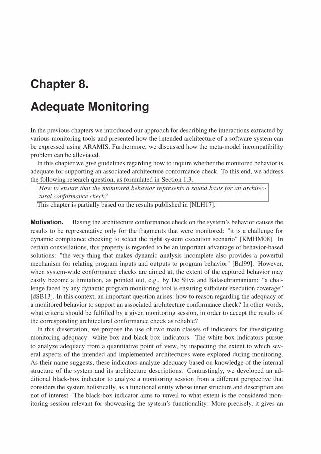
Chapter 8.
Adequate Monitoring
In the previous chapters we introduced our approach for describing the interactions extracted byvarious monitoring tools and presented how the intended architecture of a software system canbe expressed using ARAMIS. Furthermore, we discussed how the meta-model incompatibilityproblem can be alleviated.
In this chapter we give guidelines regarding how to inquire whether the monitored behavior isadequate for supporting an associated architecture conformance check. To this end, we addressthe following research question, as formulated in Section 1.3.
How to ensure that the monitored behavior represents a sound basis for an architec-tural conformance check?
This chapter is partially based on the results published in [NLH17].
Motivation. Basing the architecture conformance check on the system’s behavior causes theresults to be representative only for the fragments that were monitored: "it is a challenge fordynamic compliance checking to select the right system execution scenario" [KMHM08]. Incertain constellations, this property is regarded to be an important advantage of behavior-basedsolutions: "the very thing that makes dynamic analysis incomplete also provides a powerfulmechanism for relating program inputs and outputs to program behavior" [Bal99]. However,when system-wide conformance checks are aimed at, the extent of the captured behavior mayeasily become a limitation, as pointed out, e.g., by De Silva and Balasubramaniam: “a chal-lenge faced by any dynamic program monitoring tool is ensuring sufficient execution coverage”[dSB13]. In this context, an important question arises: how to reason regarding the adequacy ofa monitored behavior to support an associated architecture conformance check? In other words,what criteria should be fulfilled by a given monitoring session, in order to accept the results ofthe corresponding architectural conformance check as reliable?
In this dissertation, we propose the use of two main classes of indicators for investigatingmonitoring adequacy: white-box and black-box indicators. The white-box indicators pursueto analyze adequacy from a quantitative point of view, by inspecting the extent to which sev-eral aspects of the intended and implemented architectures were explored during monitoring.As their name suggests, these indicators analyze adequacy based on knowledge of the internalstructure of the system and its architecture descriptions. Contrastingly, we developed an ad-ditional black-box indicator to analyze a monitoring session from a different perspective thatconsiders the system holistically, as a functional entity whose inner structure and description arenot of interest. The black-box indicator aims to unveil to what extent is the considered mon-itoring session relevant for showcasing the system’s functionality. More precisely, it gives an

110 Chapter 8. Adequate Monitoring
estimation whether the most important scenarios of the considered system were monitored andwhether these were executed in a contextual-rich manner. In the next sections, we give moredetails regarding these two types of indicators.
8.1. White-Box Indicators for Adequate Monitoring
From the point of view of completeness, behavioral-based approaches are strongly contrastingwith static ones. During static architecture conformance checks, the entire code-base of a systemis considered. Thus, given that the code base does not evolve, the results of static conformancechecks are stable, in the sense that these cannot be influenced by the choice of scenarios to bemonitored, as in the case of behavioral-based checks. On the other hand, behavior-based checkscan be more accurate and reveal dependencies that are not visible during mere static analyses.
The white-box indicators pursue to give an estimation regarding the extent towhich a system was investigated during monitoring from the point of view of itsintended and implemented architectures.
“The extracted architectural facts are as good as the code coverage” [GKN08]. Consequently,from the point of view of the intended architecture description, any "known" code coveragemeasure (statement coverage, branch coverage, term coverage, etc.) can be used to estimate theextent to which a system was explored. However, given that ARAMIS performs conformancechecks based on a system’s intended architecture description, coverage metrics on this levelshould also be considered. These can be used as an extra indicator to determine which parts ofthe system’s intended architecture description were not or were only insufficiently considered.Two possible scenarios in which white-box indicators could be employed are sketched below.Based thereupon, we consequently extract four questions that these should answer.
Applications of the White-box Indicators
In the next, we assume that an architect is interested to determine the adequacy of some behavior-based architecture conformance checking results with respect to the overall extent to which theconsidered system was investigated. We sketch two possible scenarios how the architect couldproceed. These are by no means exhaustive but they ae useful to determine a set of questions tobe answered during such an endeavor.
First, if a small known code coverage (e.g. instructions coverage) is obtained, the architectis probably reluctant regarding the adequacy of the performed monitoring. By exploring theintended architecture in a top-down fashion he could then identify, if there are any architectureunits that were not covered during monitoring. A top-down traversal of the hierarchy of ar-chitecture units could reveal high-level excluded architecture units first. Upon discovery of anuncovered or poorly covered architecture unit, the architect might be able to formulate assump-tions regarding why this unit was not (properly) involved in the system’s monitored behavior.Possibly, he can identify scenarios aimed to increase its involvement. Furthermore, to gathermore information, the architect can refine his assumptions by analyzing into more detail thecoverage of several architecture units of his interest. To this end he could explore whether all the
8.1. White-Box Indicators for Adequate Monitoring 111
code units encompassed therein were used during monitoring. If necessary, by investigating theactual code coverage of the code units he can achieve a more technical understanding regardingthe motoring’s extent.
Alternatively, the architect can start with investigating which code units were used when mon-itoring the system. If some of these were not employed, their inclusion hierarchy might offerhints regarding what other scenarios should be added to the monitoring session. If instead, theanalysis reveals that all code units were involved, the architect could investigate the adequacyat a more detailed level, inquiring fo some traditional measures such as its statement coverage.A low value thereof would in this case signal that while the system as a whole was triggeredto a reasonable extent, its constituting elements were not investigated to their full extent. Thearchitect can then decide whether a more extensive monitoring is necessary in this case.
At any point in the two scenarios presented above, the architect can also investigate which ar-chitecture conformance rules were employed during architecture conformance checking. Thesecould additionally aid the identification of potential communication paths that were not triggeredduring monitoring and, being formulated on a higher abstraction level, could give important hintsregarding scenarios that could enhance the adequacy.
Proposed White-box Indicators
Based on the applications presented above, we derive a set of four questions to address whenstudying the adequacy of a performed monitoring from the point of view of its intended andimplemented architectures.
Q1. To what extent is the system as a whole covered?
Q2. Are there units that were not used during system monitoring although defined in the in-tended architecture description?
Q3. Given that a particular unit was used during monitoring, to what extent was it covered?
Q4. To what extent was the foreseen communication, as depicted in the system’s intendedarchitecture description, triggered during monitoring?
To satisfy the information needs unveiled by the questions formulated above, we propose theuse of the following types of white-box indicators, as depicted in Table 8.1:
In the next subsections we detail one by one the above proposed indicators, along with theirformalization, when needed.
Known Code Coverage Metrics
The known code coverage measures are extensively discussed in the software engineering liter-ature (e.g., [LL10]). The most popular ones are the statement/instruction, branch, term and pathcoverage. These are widely known and used metrics that give an estimate regarding the extentto which the system was explored during codeSizeing. Due to their popularity, we refrain from

112 Chapter 8. Adequate Monitoring
Table 8.1.: Overview of Proposed White-box Indicators
Addressed Question Proposed IndicatorsQ1 known code coverage metrics, to measure the coverage of the vari-
ous building blocks encompassed by a considered system;
Q2 a hierarchical code unit coverage metric, that depicts the percent-age of code units that were active in a given monitoring session, re-gardless of their inner code coverage;
Q3 adaptations of known coverage metrics, to determine the coverageof units defined in the intended architecture description;
Q4 several rule coverage characterizations, whose main purpose is toexpose absences, i.e., communication that did not occur during mon-itoring, although it would have been allowed
a further presentation thereof. Within the scope of our work, we promote their use in order toexplore how thoroughly was the considered system monitored in its entirety.
The Hierarchical Code Unit Coverage Metric
As presented in [LL10], the known coverage measures can be extended to coarser granularentities of a software system. For example, the same principles used to measure instructionscoverage can be applied to measure method coverage. A method will thus be considered to becovered if it is called during the execution. The extent to which the source code encompassedby a given method is covered can be ignored. Similarly, we introduce the so-called hierarchicalcode unit coverage of a unit, as the percentage of code units included in this unit, that wereinvolved in a given monitoring session. We formalize this metric as depicted below.
Auxiliary Notations, Functions and Predicates. First, we introduce a set of preliminarynotations and auxiliary functions to be used in the actual metric definition.
Let:
S be an arbitrary software system;
MONS be the set of all possible monitoring sessions of a system S and let m ∈ MONS be anarbitrary monitoring session;
AUS be the set of all architecture units of S and let au ∈ AUS be an arbitrary architecture unit;
CUS be the set of all code units of S and let cu ∈ CUS be an arbitrary code unit;
US = AUS ∪CUS be the set of all units of a system S ;
inCU : AUS �→ P(CUS) be a function that retrieves the set of all code units contained (directlyor indirectly) in an a given architecture unit, where P(CUS) represents the set of sets of CUS;
dinCU : AUS �→ P(CUS) be a function that retrieves the set of all code units directly con-tained in a given architecture unit;
ERS, m be the set of all execution records captured during the monitoring session m of thesystem S;
8.1. White-Box Indicators for Adequate Monitoring 113
mapOnCU : ERS, m × CUS �→ {true, f alse} be a predicate that is true if an execution recorder is mapped on a code unit cu and false otherwise;
ITRS,m be the set of all interactions extracted from system S during the monitoring session m;getCaller : ITRS,m �→ ERS, m be a function that retrieves the caller execution record of a given
interaction;getCallee : ITRS,m �→ ERS, m be a function that retrieves the callee execution record of a given
interaction;isCuInvolved : ITRS,m × CUS �→ {true, f alse}; isCuInvolved(itr, cu) is a predicate that re-
trieves true only if the caller or the callee of itr is mapped on the code unit cu.
Definition. Given the notations and auxiliary functions and predicates introduced above,we now define the hierarchical code unit coverage metric of a system S during the monitoringsession m as follows.
To measure the code coverage of a code or architecture unit u within the monitoring sessionM of a given system S , we define the following function:
cuCov : US × MONS �→ [0, 1]
cuCov(u,m) =
⎧⎪⎪⎪⎪⎪⎪⎪⎨⎪⎪⎪⎪⎪⎪⎪⎩
1, if u ∈ CUS ∧ ∃itr ∈ ITRS,m ∧ isCuInvolved(itr, u) = true∑
cu∈inCU(u) cuCov(cu,m)
|inCU(u)| , if u ∈ AUS ∧ inCU(u) � ∅0, otherwise
Note that according to the definition above the code coverage of an architecture unit thatdoesn’t contain any code units is 0. Indeed such an architecture unit can never be covered duringthe monitoring of a system’s behavior, since it doesn’t contain any corresponding code buildingblocks.
Interpretation. All in all, the cuCov metric is built on a rational scale, and its values rangebetween 0 and 1. According to the metric model, the cuCov value can be interpreted as follows:in the case of a code unit, the value 1 indicates that the unit was active during the system’smonitoring while 0 indicates that the unit was not used; in the case of an architecture unit, thehigher the number of covered code units included in the considered unit, the better the includingunit is considered to be covered during monitoring and thus, the higher the value of its cuCovis. When the cuCov of an architecture unit is 1, all of its included code units were active duringmonitoring; if none of these were active, or if the architecture unit is a mere placeholder thatdoesn’t contain any code units, then its cuCov will be 0.
Example. An example of the computation of the cuCov is depicted in Figure 8.2. Theexemplified system consists of only two architecture units and four code units. All the code unitsbut the Math Utilities CU were employed in the exemplified monitoring session, and thus theircoverage is 1. Next, given that all the code units included in the Low-level Utilities architectureunit were active during the session, its coverage will be 1 as well. When considering the Utilities

114 Chapter 8. Adequate Monitoring
architecture unit, only 3 of its 4 included code units were active; as such its coverage will beonly 0.75.
Figure 8.2.: Computation of Code Unit Coverage
Adaptation of Known Code Coverage Metrics
As mentioned above, any known code coverage measure can be used to check the extent towhich the system as a whole was explored. However, given that ARAMIS operates on an archi-tectural level, it is not necessary to strive for a very strong coverage type. The input of ARAMIS,as extracted by arbitrary monitors, consists of trace-ordered interactions. In a simplified view,in which we only consider direct, non-parametrized communication, an interaction simply de-picts the execution of a statement in the system’s code. We can thus infer that if a monitoringsession achieves a 100% statement coverage, then the corresponding architecture conformancecheck is complete with respect to the formulated rules regarding direct communication. Conse-quently, although in the case of codeSizeing the statement coverage is a weak criterion, it is nev-ertheless sufficient in the case of architecture conformance checking against non-parametrized,non-aggregating rules. A stronger coverage (e.g., branch or minimal term coverage) does notprovide different conformance check results and should be aimed towards only for codeSizeingpurposes.
However, ARAMIS enables - through the use of parametrized rules - more complex archi-tectural checks whose completion cannot be guaranteed by simply achieving maximum or veryhigh values of the known code coverage metrics. Such rules can, e.g., allow or disallow a di-rect communication based on the used method arguments, based on the duration of the call, etc.Moreover, rules regarding the communication through web services, messaging mechanisms orthe indirect coupling of units can be formulated. Similarly, in this case the known coveragemetrics can be used only as a heuristic and not as a guarantee.
Moreover, as a system analyzed with ARAMIS can consist of further sub-systems, it is pos-sible for architecture units, as logical aggregations, to be crosscutting subsystems boundaries.
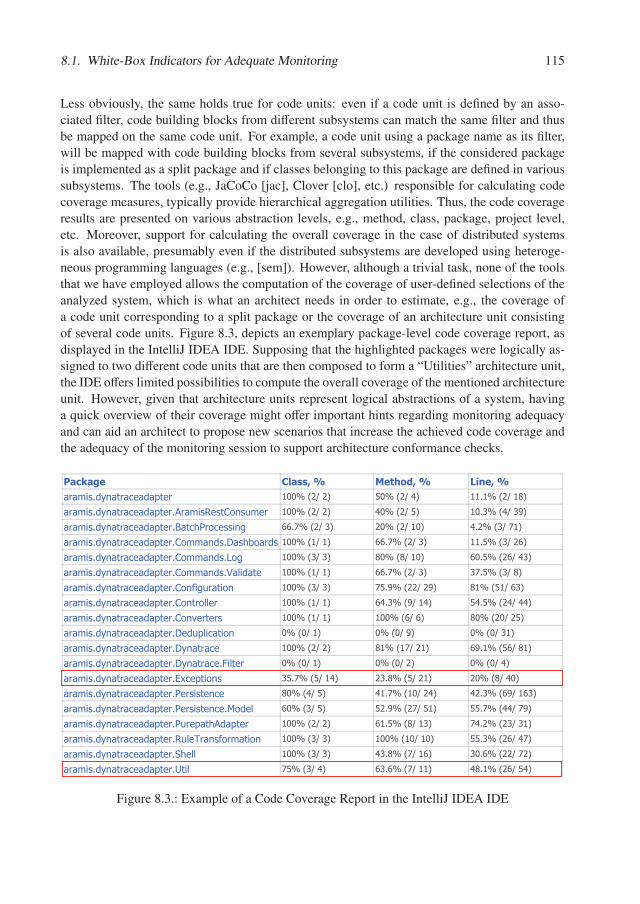
8.1. White-Box Indicators for Adequate Monitoring 115
Less obviously, the same holds true for code units: even if a code unit is defined by an asso-ciated filter, code building blocks from different subsystems can match the same filter and thusbe mapped on the same code unit. For example, a code unit using a package name as its filter,will be mapped with code building blocks from several subsystems, if the considered packageis implemented as a split package and if classes belonging to this package are defined in varioussubsystems. The tools (e.g., JaCoCo [jac], Clover [clo], etc.) responsible for calculating codecoverage measures, typically provide hierarchical aggregation utilities. Thus, the code coverageresults are presented on various abstraction levels, e.g., method, class, package, project level,etc. Moreover, support for calculating the overall coverage in the case of distributed systemsis also available, presumably even if the distributed subsystems are developed using heteroge-neous programming languages (e.g., [sem]). However, although a trivial task, none of the toolsthat we have employed allows the computation of the coverage of user-defined selections of theanalyzed system, which is what an architect needs in order to estimate, e.g., the coverage ofa code unit corresponding to a split package or the coverage of an architecture unit consistingof several code units. Figure 8.3, depicts an exemplary package-level code coverage report, asdisplayed in the IntelliJ IDEA IDE. Supposing that the highlighted packages were logically as-signed to two different code units that are then composed to form a “Utilities” architecture unit,the IDE offers limited possibilities to compute the overall coverage of the mentioned architectureunit. However, given that architecture units represent logical abstractions of a system, havinga quick overview of their coverage might offer important hints regarding monitoring adequacyand can aid an architect to propose new scenarios that increase the achieved code coverage andthe adequacy of the monitoring session to support architecture conformance checks.
������� ����� ������� ������
��������������� ���!� � "##$�%&'�&( )#$�%&'�*( ""�"$�%&'�"+(
��������������� ���!� ��,�����- ��./��0� � "##$�%&'�&( *#$�%&'�)( "#�1$�%*'�12(
��������������� ���!� ��3���45�/� ����6 77�8$�%&'�1( &#$�%&'�"#( *�&$�%1'�8"(
��������������� ���!� ��./�������9��4:/����"##$�%"'�"( 77�8$�%&'�1( ""�)$�%1'�&7(
��������������� ���!� ��./�������;/6 "##$�%1'�1( +#$�%+'�"#( 7#�)$�%&7'�*1(
��������������� ���!� ��./�������<�=���� "##$�%"'�"( 77�8$�%&'�1( 18�)$�%1'�+(
��������������� ���!� ��./�>�60����/� "##$�%1'�1( 8)�2$�%&&'�&2( +"$�%)"'�71(
��������������� ���!� ��./���/== � "##$�%"'�"( 7*�1$�%2'�"*( )*�)$�%&*'�**(
��������������� ���!� ��./�? �� �� "##$�%"'�"( "##$�%7'�7( +#$�%&#'�&)(
��������������� ���!� ��9 �0!=�����/� #$�%#'�"( #$�%#'�2( #$�%#'�1"(
��������������� ���!� ��9������� "##$�%&'�&( +"$�%"8'�&"( 72�"$�%)7'�+"(
��������������� ���!� ��9������� �@�=� � #$�%#'�"( #$�%#'�&( #$�%#'�*(
��������������� ���!� ��AB� !��/�� 1)�8$�%)'�"*( &1�+$�%)'�&"( &#$�%+'�*#(
��������������� ���!� ��5 ����� �� +#$�%*'�)( *"�8$�%"#'�&*( *&�1$�%72'�"71(
��������������� ���!� ��5 ����� �� �C/� = 7#$�%1'�)( )&�2$�%&8'�)"( ))�8$�%**'�82(
��������������� ���!� ��50� !��4,��!� � "##$�%&'�&( 7"�)$�%+'�"1( 8*�&$�%&1'�1"(
��������������� ���!� ��-0= D����>/�����/� "##$�%1'�1( "##$�%"#'�"#( ))�1$�%&7'�*8(
��������������� ���!� ��E4 == "##$�%1'�1( *1�+$�%8'�"7( 1#�7$�%&&'�8&(
��������������� ���!� ��F��= 8)$�%1'�*( 71�7$�%8'�""( *+�"$�%&7'�)*(
Figure 8.3.: Example of a Code Coverage Report in the IntelliJ IDEA IDE

116 Chapter 8. Adequate Monitoring
Therefore, we propose to augment the hierarchy of code and architecture units that consti-tute the architecture of a system, with aggregated code coverage measures originating from thesystem’s code building blocks.
Formalization. As in the case of the hierarchical aggregations performed by code coveragetools, in order to aggregate the measures of various code building blocks to code units and toarchitecture units, a size measure thereof (e.g., “total number of instructions” in the case ofinstructions coverage) is necessary, in order for the result to correctly reflect the size relationsbetween the various units. The size measure itself, depends on the considered coverage: totalnumber of statements in the case of statement coverage, total number of branches in the caseof branch coverage, etc. The size measure of a unit in the architecture hierarchy is computedrecursively:
size : US �→ N
size(u) =
⎧⎪⎪⎨⎪⎪⎩
∑cb∈setCBB(u) codeS ize(cb), ⇐⇒ u ∈ CUS∑
cu∈inCU(u) size(u), ⇐⇒ u ∈ AUS
Where, setCBB is a function that retrieves the set of all code building blocks that were mappedon a code unit, and the codeS ize is a function that retrieves a size dimension of a code buildingblock (e.g., total number of statements) that we are interested in.
Now, having selected a known code coverage metric and an associated size measure, we canrecursively compute the code coverage of code and architecture units:
codeCoverage : US × MONS �→ [0, 1]
codeCoverage(u,m) =
⎧⎪⎪⎪⎪⎪⎪⎪⎨⎪⎪⎪⎪⎪⎪⎪⎩
∑cb∈setCBB(u) codeS ize(cb) × codeCoverage(cb,m)
∑cb∈setCBB(u) codeS ize(cb)
, if u ∈ CUS
∑cu∈inCU(u) size(cu) × codeCoverage(cu,m)
∑cu∈inCU(u) size(u)
, if u ∈ AUS
The codeCoverage of a code building block cb achieved during a given monitoring sessionm, is simply its known code coverage measure of interest as provided by the employed coveragemeasurement tool. An important observation is that, for the above formula to retrieve correct re-sults, the codeSize and the codeCoverage must use the same measurement unit (e.g., statements,instructions, lines of code, etc.). E.g., if the codeCoverage retrieves the statement coverage ofa building block, than the codeSize should retrieve the number of statements of that buildingblock.
Example. Figure 8.4 uses the total number of instructions as the codeSize of the packages thatconstitute the code building blocks of a hypothetical architecture description 1. The considered
1Some code coverage measurement tools (e.g., Jacoco) operate on bytecode level. Consequently they providemeasures of the instructions coverage instead of that of the statement coverage.
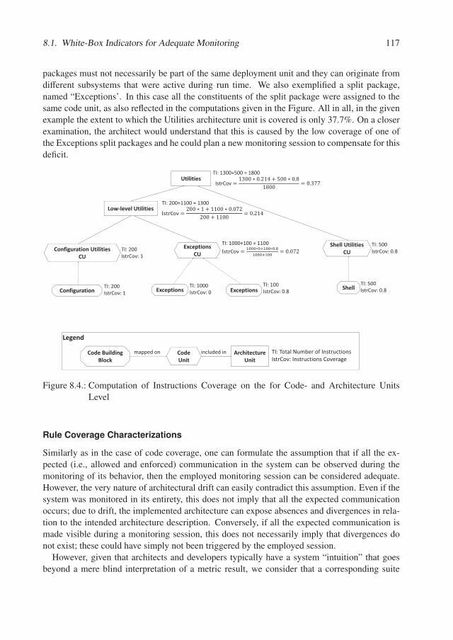
8.1. White-Box Indicators for Adequate Monitoring 117
packages must not necessarily be part of the same deployment unit and they can originate fromdifferent subsystems that were active during run time. We also exemplified a split package,named “Exceptions’. In this case all the constituents of the split package were assigned to thesame code unit, as also reflected in the computations given in the Figure. All in all, in the givenexample the extent to which the Utilities architecture unit is covered is only 37.7%. On a closerexamination, the architect would understand that this is caused by the low coverage of one ofthe Exceptions split packages and he could plan a new monitoring session to compensate for thisdeficit.
Legend
Configuration Exceptions Shell
Configuration�Utilities�CU
Exceptions
Exceptions�CU
Shell�Utilities��CU
Low�level�Utilities
Utilities
TI:�200IstrCov:�1
TI:�1000IstrCov:�0
TI:�100IstrCov:�0.8
TI:�500IstrCov:�0.8
TI:�200IstrCov:�1
TI:�1000+100�=�1100��Cov
TI:�500IstrCov:�0.8
TI:�200+1100�=�1300
Cov
TI:�1300+500�=�1800
IstrCov
Code�Building�Block
Code�Unit
Architecture�Unit
TI:�Total�Number�of�InstructionsIstrCov:�Instructions�Coverage
mapped�on included�in
Figure 8.4.: Computation of Instructions Coverage on the for Code- and Architecture UnitsLevel
Rule Coverage Characterizations
Similarly as in the case of code coverage, one can formulate the assumption that if all the ex-pected (i.e., allowed and enforced) communication in the system can be observed during themonitoring of its behavior, then the employed monitoring session can be considered adequate.However, the very nature of architectural drift can easily contradict this assumption. Even if thesystem was monitored in its entirety, this does not imply that all the expected communicationoccurs; due to drift, the implemented architecture can expose absences and divergences in rela-tion to the intended architecture description. Conversely, if all the expected communication ismade visible during a monitoring session, this does not necessarily imply that divergences donot exist; these could have simply not been triggered by the employed session.
However, given that architects and developers typically have a system “intuition” that goesbeyond a mere blind interpretation of a metric result, we consider that a corresponding suite
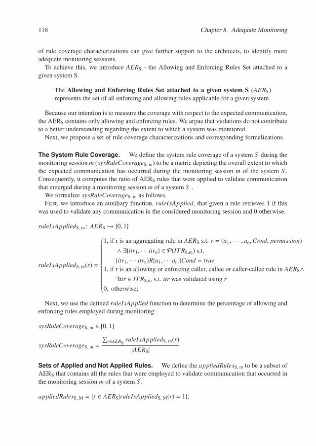
118 Chapter 8. Adequate Monitoring
of rule coverage characterizations can give further support to the architects, to identify moreadequate monitoring sessions.
To achieve this, we introduce AERS - the Allowing and Enforcing Rules Set attached to agiven system S.
The Allowing and Enforcing Rules Set attached to a given system S (AERS)represents the set of all enforcing and allowing rules applicable for a given system.
Because our intention is to measure the coverage with respect to the expected communication,the AERS contains only allowing and enforcing rules. We argue that violations do not contributeto a better understanding regarding the extent to which a system was monitored.
Next, we propose a set of rule coverage characterizations and corresponding formalizations.
The System Rule Coverage. We define the system rule coverage of a system S during themonitoring session m (sysRuleCoverageS, m) to be a metric depicting the overall extent to whichthe expected communication has occurred during the monitoring session m of the system S .Consequently, it computes the ratio of AERS rules that were applied to validate communicationthat emerged during a monitoring session m of a system S .
We formalize sysRuleCoverageS, m as follows.First, we introduce an auxiliary function, ruleIsApplied, that given a rule retrieves 1 if this
was used to validate any communication in the considered monitoring session and 0 otherwise.
ruleIsAppliedS, m : AERS �→ {0, 1}
ruleIsAppliedS, m(r) =
⎧⎪⎪⎪⎪⎪⎪⎪⎪⎪⎪⎪⎪⎪⎪⎨⎪⎪⎪⎪⎪⎪⎪⎪⎪⎪⎪⎪⎪⎪⎩
1, if r is an aggregating rule in AERS s.t. r = (a1, · · · , an,Cond, permission)
∧ ∃{itr1, · · · itrn} ∈ P(ITRS,m) s.t.
{itr1, · · · itrn}R{a1, · · · an}|Cond = true1, if r is an allowing or enforcing caller, callee or caller-callee rule in AERS∧∃itr ∈ ITRS,m s.t. itr was validated using r
0, otherwise;
Next, we use the defined ruleIsApplied function to determine the percentage of allowing andenforcing rules employed during monitoring:
sysRuleCoverageS, m ∈ [0, 1]
sysRuleCoverageS, m =
∑r∈AERS
ruleIsAppliedS, m(r)
|AERS|
Sets of Applied and Not Applied Rules. We define the appliedRulesS, m to be a subset ofAERS that contains all the rules that were employed to validate communication that occurred inthe monitoring session m of a system S .
appliedRulesS, M = {r ∈ AERS|ruleIsAppliedS, M(r) = 1};
8.1. White-Box Indicators for Adequate Monitoring 119
Conversely, we define notAppliedRulesS, M to be a subset of AERS that contains all the rulesthat were not employed to validate any communication during the monitoring session m of asystem S .
notAppliedRulesS, M = AERS \ appliedRulesS, M;
Example. We exemplify the rule coverage characterizations defined above on the intendedand implemented architecture descriptions depicted in Figures 8.5 and 8.6. First, we construct
Legend
MB
NA C D E
U
Intended�Architecture�Description�of�TestSys
YXAllowing�rule�between�X�and�Y
YXDenying�rule�between�X�and�Y
YXEnforcing�rule�between�X�and�Y
XAllowing�Callee Rule
XDenying�Caller�Rule
Deny�Unconstrained
Figure 8.5.: Intended Architecture Description Example
the Allowing and Enforcing Rules Set of the system depicted in Figure 8.5. We will refer tothis system with the id “TestSys”. Since we have no chain rule in the system “TestSys”, theAERTestSys will contain only allowing and enforcing caller-, callee- and caller-callee rules. Forsimplicity we depict a rule as a triple of the type (a, b, permission), where a and b are the callerand callee architecture units respectively and permission ∈ {allowed, en f orced}. If the rule is acaller or callee one, then a or b will respectively be absent.
AERTestSys ={(M,N, allowed), (A, B, allowed), (C,D, allowed), (D, E, en f orced), (,U, allowed)}
Having determined the AERTestSys set, we now consider the actual communication that oc-curred during a fictive monitoring session (in the next, denoted by the identifier “codeSizeMon”)as depicted in Figure 8.6.
First, we identify the set appliedRulesTestSys, codeSizeMon - which consists of all the rules inAERTestSys which were used to validate actual communication in the monitoring session codeS izeMon.
appliedRulesTestSys, codeSizeMon ={(M,N, allowed), (A, B, allowed), (C,D, allowed),
(,U, allowed)}
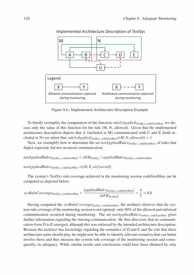
120 Chapter 8. Adequate Monitoring
M N
BA C D E
U
Implemented�Architecture�Description�of�TestSys
Legend
YXAllowed�communication�captured
during�monitoring
YXDisallowed�communication�captured
during�monitoring
Figure 8.6.: Implemented Architecture Description Example
To briefly exemplify the computation of the function ruleIsAppliedTestSys, codeSizeMon, we dis-cuss only the value of this function for the rule (M, N, allowed). Given that the implementedarchitecture description depicts that A (included in M) communicated with C and E (both in-cluded in N) we infere that ruleIsAppliedTestSys, codeSizeMon((M,N, allowed)) = 1.
Next, we exemplify how to determine the set notAppliedRulesTestSys, codeSizeMon, of rules thatdepict expected, but not occurred communication.
notAppliedRulesTestSys, codeSizeMon = AERTestSys \ appliedRulesTestSys, codeSizeMon
notAppliedRulesTestSys, codeSizeMon ={(D, E, en f orced)}
The system’s TestSys rule coverage achieved in the monitoring session codeSizeMon can becomputed as depicted below:
sysRuleCoverageTestSys, codeSizeMon =|appliedRulesTestSys, codeSizeMon|
|AERTestSys| =4
5� 0.8
Having computed the sysRuleCoverageTestSys, codeSizeMon, the architect observes that the sys-tem rule coverage of the monitoring session is not optimal: only 80% of the allowed and enforcedcommunication occurred during monitoring. The set notAppliedRulesTestSys, codeSizeMon givesfurther information regarding the missing communication. He thus discovers that no communi-cation from D to E emerged, although this was enforced by the intended architecture description.Because the architect has knowledge regarding the semantics of D and E and the role that thesearchitecture units should play, he might now be able to identify relevant scenarios that can betterinvolve these and thus increase the system rule coverage of the monitoring session and conse-quently, its adequacy. While similar results and conclusions could have been obtained by only
8.2. Black-Box Indicator for Adequate Monitoring 121
inspecting the code coverage, considering the rules indicators can be beneficial on large-scalesystems, due to their higher abstraction level.
Wrapping up, the white-box indicators presented in this section can be used to investigatethe technical extent to which a system was monitored and to identify its underrepresented areas.Two possible applications thereof were discussed at the beginning of this section, but their usageis not limited to these: it is left to the involved architects to decide how these can be applied inconcrete set-ups.
8.2. Black-Box Indicator for Adequate Monitoring
In the previous section, we elucidated how white-box indicators can be used to reason aboutthe adequacy of a monitoring session to support a behavior-based architecture conformancechecking. However, while valuable, typically available and relatively facile to compute, weconsider that these are not enough when studying adequacy. Black-box indicators should beinvestigated as well to increase confidence that the monitored behavior is indeed representative.
Black-box indicators attempt to give an estimation regarding the extent to which asystem was investigated in terms of its specification.
We consider black-box indicators useful to reason about the adequacy of architecture confor-mance checks because of the very nature of software development and evolution. For example,in situations where the defensive programming style is used extensively, achieving a good cov-erage can be problematic. Furthermore, due to evolution, it is often the case that not the entirecode base is relevant from an architecture conformance checking viewpoint. The source codecan contain dead code or code that is not executed (as often) anymore due to the requirements-driven system evolution that can render certain implemented functionality outdated. While ar-chitectural drift can well reside in such areas of the source code, we claim that these are lessimportant to be fixed. In the case of dead code, simply removing it from the system’s sourcecode is a more efficient and desirable outcome than investing additional effort to increase itsconformance with the intended architecture description. In the case of code corresponding torarely used functionality, we assume the following:
• the probability of evolving this code is rather low. The developers are more likely toevolve the parts of the system that correspond to currently used functionality, as new orchanging requirements are often triggered by constant usage.
• due to economical and time constraints, achieving perfect conformance is unrealistic. De-viations, if not critical, can be accepted. Especially deviations corresponding to barelyused and unimportant functionality are likely to be ignored. The goal of ensuring a goodarchitectural conformance is to support the understanding and evolution of a system. Theneed for understanding and evolution of those parts of the system which are not used orunimportant is low and consequently so is the need for ensuring their conformance.
Because of the aspects exposed above, architecture conformance results can easily be renderedinappropriate or even erroneous if they are based, e.g., only on the monitoring of non-important
122 Chapter 8. Adequate Monitoring
or obsolete scenarios that rarely occur in normal practice. To ensure that the system’s nature iscorrectly reflected by the analysis, its most important scenarios must be taken into consideration.Furthermore, as shown in Section 4.1.1, a scenario can be performed within different scenariosequences that create its context. Technically, these different executions can cause different com-munication paths in the system. Thus, an adequate monitoring should ensure that the importantscenarios are also executed in an as large a variety of contexts as possible.
To offer a view regarding the extent to which a given monitoring session is adequate for show-casing the system’s most relevant functionality in an as rich a variety of contexts as possible, wepropose a black-box indicator, called the scenario coverage. The black-box nature of this indica-tor is given by the fact that no knowledge regarding the inner structure of the system is necessaryin order to compute and interpret it.
Next, we detail and formalize the newly introduced, scenario coverage metric.
Scenario Coverage
In this subsection, we first define several important concepts revolving around the scenario cov-erage indicator and then formalize its computation, present an example and discuss its interpre-tation.
We define the scenario coverage of a monitoring session to be the percentage ofscenarios whose instances are executed within the session’s episodes, pondered bytheir relevance and variance.
We define the relevance of a scenario to be a ranking given by experts to express thepotential of a the scenario to reveal useful facts regarding the system’s conformanceto its intended architecture description.
We define the variance of a scenario to be the percentage of different, possiblecontexts in which the scenario was executed in the given session.
The context of a scenario is determined by the sequence of scenarios that wereperformed previously in the considered monitoring session, after a clean systemstart.
The context set of a scenario encompasses all defined contexts in which a scenariocould occur.
In the following we introduce the metric step by step. The monitoring concepts used inARAMIS were presented in Chapter 4. Accordingly, the formalization presented in this sec-tion is based thereupon.
Let S CS, be the set of all scenarios of a system S . Due to the abstract, conceptual natureof scenarios, this set is finite. Conversely, as discussed in Chapter 4, the number of possiblescenario instances is generally infinite and consequently exhaustive monitoring is not possible,closely resembling the problematic incurred during codeSizeing.
As introduced in Chapter 4, an episode description is an ordered set of scenario performancedescriptions defined by triples of type (possc, sc, in f osc) where sc ∈ S CS, possc ∈ N repre-sents its position in the episode, and in f osc represents some textual information. If not empty,
8.2. Black-Box Indicator for Adequate Monitoring 123
in f osc gives additional information regarding the context in which the scenario sc must be in-stantiated during the actual episode and can reference previous scenario performances by theirpos and place conditions thereupon. The same scenario can be referenced by different scenarioperformance descriptions, conferring an episode description a so-called “screenplay character”.Consequently, an episode description can showcase various contexts of the same scenario.
Next, we formalize the definition of a scenario’s variance within an episode description. Forthat, let Es be the (infinite) set of all possible episode descriptions to be performed on a systemS. Then the variance of a scenario sc within an episode description e of a system S can beformalized as follows:
var : S Cs × Es �→ [0, 1]
var(sc,e) =contexts(sc, e)
|CT Xsc| ⇐⇒ CT Xsc � ∅
where, contexts(sc, e) returns the number of contexts of sc in the epispde description e andCT Xsc represents its given context set. As context sets are not always defined and we want tomake the metric robust, we simply consider that the default context set of a scenario is givenby the scenario itself, and thus, in this case |CT Xsc| = 1 and var(sc, e) = 1,∀e ∈ ES wherecontexts(sc, e) = 1.
Furthermore, the relevance of a scenario is the second factor influencing its coverage. To keepthe metric simple and applicable, we propose the following four relevance classes to which ascenario can be assigned to: VR (very relevant), R (relevant), N (neutral), NR (not relevant).
Thus, given an episode e we define its scenario coverage as:
Let sccov : Es �→ [0, 1]
sccov(e) =
⎧⎪⎪⎪⎪⎨⎪⎪⎪⎪⎩
0, if VR ∪ R ∪ N = ∅∑
sc∈e contexts(sc, e) · relv(sc)∑
sc∈S Cs |CT Xsc| · relv(sc), otherwise
where,
relv(sc) =
⎧⎪⎪⎪⎪⎪⎪⎪⎪⎨⎪⎪⎪⎪⎪⎪⎪⎪⎩
3 ⇐⇒ sc ∈ VR2 ⇐⇒ sc ∈ R1 ⇐⇒ sc ∈ N0 ⇐⇒ sc ∈ NR
Based on this definition, the scenario coverage of any episode description containing only notrelevant scenarios is 0, because their analysis will also be prone to irrelevance. Furthermore,we designed the sccov metric such that its value increases the most when all relevant scenariosare considered in as many contexts as possible (high variance), preferably in all their associatedcontexts (i.e., having variance 1). Also, the value of the metric decreases rapidly when relevantscenarios that have large context sets are monitored only with a low variance.
124 Chapter 8. Adequate Monitoring
To sum up, the proposed scenario coverage metric is intended to give an estimation regardingthe adequacy of a given episode description (and consequently of all corresponding episodes)with respect to addressing the relevant scenarios of the system in as many different contexts aspossible.
To compute the overall scenario coverage of a monitoring session consisting of multipleepisodes we concatenate the corresponding episode descriptions using a concatenation functionsuch as below:
concat : P(Es) �→ Es
The concat function simply returns an episode description containing of all concatenated sce-nario performance descriptions of the input episode descriptions.
Let MS = {e1, ..., en} denote a monitoring session of system S, defined by an ordered list ofepisodes. Then, its scenario coverage is defined as:
sccov(Ms) = sccov(concat(e1, ..., en))
Example. Next we exemplify the concepts introduced before.Given a fictive scenario “log in with nonexistent user”, its possible contexts could be: {per-
form scenario on system start, perform scenario after deleting the user}. Similarly the possiblecontexts of a scenario “create new user” could be: {perform scenario on system start, performscenario after deleting a previously existing user with the same user name}.
An episode description that reflects the log in of a nonexistent user, the creation of a new user,the logging in of an existing user with the same user name as the previous one, the deletion ofthis user and its new creation can be represented by the following list of scenario performances(sp):
LoginEpisode={
(1, log in with nonexistent user),
(2, create new user),
(3, log in with existing user, same user as in sp 2),
(4, delete existing user, same user as in sp 2),
(5, log in with nonexistent user, same user as in sp 2),
(6, create new user, same user name as in sp 2)}
Given the introduced scenario contexts and the presented LoginEpisode, we can make thefollowing observations: the "log in with nonexistent user" occurs in both of its defined contexts,while "create new user" only occurs in one of them as it was not performed directly after systemstart. Therefore, given the episode description LoginEpisode and considering the definition ofvariance, as formulated previously, the variance of the scenario “log in with nonexistent user”is 1 while that of “create new user” is only 0.5 as it was performed in only half of its definedcontexts.
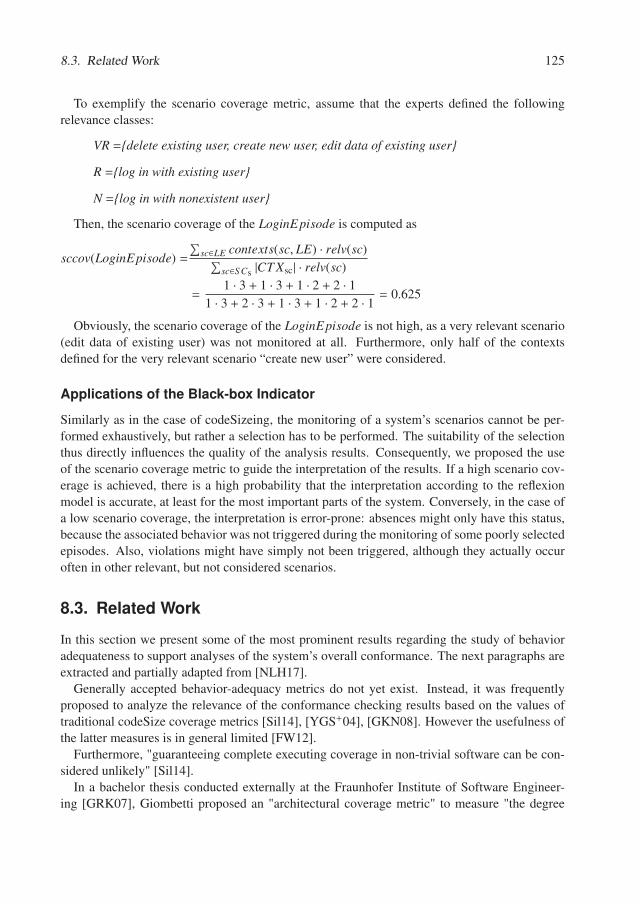
8.3. Related Work 125
To exemplify the scenario coverage metric, assume that the experts defined the followingrelevance classes:
VR ={delete existing user, create new user, edit data of existing user}
R ={log in with existing user}
N ={log in with nonexistent user}
Then, the scenario coverage of the LoginEpisode is computed as
sccov(LoginEpisode) =
∑sc∈LE contexts(sc, LE) · relv(sc)∑
sc∈S Cs |CT Xsc| · relv(sc)
=1 · 3 + 1 · 3 + 1 · 2 + 2 · 1
1 · 3 + 2 · 3 + 1 · 3 + 1 · 2 + 2 · 1 = 0.625
Obviously, the scenario coverage of the LoginEpisode is not high, as a very relevant scenario(edit data of existing user) was not monitored at all. Furthermore, only half of the contextsdefined for the very relevant scenario “create new user” were considered.
Applications of the Black-box Indicator
Similarly as in the case of codeSizeing, the monitoring of a system’s scenarios cannot be per-formed exhaustively, but rather a selection has to be performed. The suitability of the selectionthus directly influences the quality of the analysis results. Consequently, we proposed the useof the scenario coverage metric to guide the interpretation of the results. If a high scenario cov-erage is achieved, there is a high probability that the interpretation according to the reflexionmodel is accurate, at least for the most important parts of the system. Conversely, in the case ofa low scenario coverage, the interpretation is error-prone: absences might only have this status,because the associated behavior was not triggered during the monitoring of some poorly selectedepisodes. Also, violations might have simply not been triggered, although they actually occuroften in other relevant, but not considered scenarios.
8.3. Related Work
In this section we present some of the most prominent results regarding the study of behavioradequateness to support analyses of the system’s overall conformance. The next paragraphs areextracted and partially adapted from [NLH17].
Generally accepted behavior-adequacy metrics do not yet exist. Instead, it was frequentlyproposed to analyze the relevance of the conformance checking results based on the values oftraditional codeSize coverage metrics [Sil14], [YGS+04], [GKN08]. However the usefulness ofthe latter measures is in general limited [FW12].
Furthermore, "guaranteeing complete executing coverage in non-trivial software can be con-sidered unlikely" [Sil14].
In a bachelor thesis conducted externally at the Fraunhofer Institute of Software Engineer-ing [GRK07], Giombetti proposed an "architectural coverage metric" to measure "the degree
126 Chapter 8. Adequate Monitoring
to which elements in recorded runtime behavior [...] capture elements of the static structure ofthe software system’s architecture". He then differentiates between common and variable cov-erage, by computing the percentage of components that were active in all retrieved traces andthe percentage of components that were active in at least two of the traces respectively. The pre-sented work in [GRK07] is in an initial stage and its evaluation is lacking relevance. However,it acknowledges the need for more relevant adequacy measures for behavior-based conformancechecking.
In contrast, the black-box indicator proposed in this dissertation is computed based on in-formation extrinsic to the system, such as the relevance of the considered scenarios and theircontextual richness. Furthermore, it complements the white-box indicators to enable reasoningabout the adequacy of a captured behavior from various, orthogonal perspectives.
Chapter 9.
Conducting Behavior-Based ConformanceChecks
In the previous chapters we first introduced our approach for describing interactions extractedduring the execution of a software system and how these can be used together with an intendedarchitecture description to create an overview of the system’s implemented architecture andcheck its conformance to the communication rules formulated by its architects. Given that ar-chitecture descriptions can be created using several meta-models, we then discussed how theso-called meta-model incompatibility problem can be alleviated. Next, we investigated the ade-quacy issue posed by all behavior-based approaches: in order to ensure the quality of the confor-mance checking result, the analyzed behavior should be "adequate"; consequently, we proposeda set of white-box and black-box indicators to explore this aspect.
In this chapter, we move one step further. First, in Section 9.1, we analyze the relativestrengths and weaknesses of behavior-based conformance checking approaches as opposed tostatic ones. Next, in Section 9.2, we systematize and organize the concepts introduced in theprevious chapters to create a process for guiding behavior-based conformance checks performedwith ARAMIS.
To this end, we address the following research question, as formulated in Section 1.3.
When and how to conduct behavior-based architecture conformance checks?
9.1. Static- vs. Behavior-Based Conformance Checks
With the shift towards object orientation and modular architectural styles such as microservices,the nature of system complexity evolved from purely structural towards behavioral. This sit-uation has been acknowledged very early, as the following quote from 1997 proves: " object-oriented concepts [...] tend to make the actual designs in which they are used more difficultto comprehend [...] For example, the dynamics of polymorphism and inheritance make it vir-tually impossible to produce a control flow graph of manageable size" [LN97]. Consequently,researchers started focusing very early on extracting behavior-based information alongside thepurely statical one. The trade-offs between the two were also addressed early in the process.In 1999 Bal [Bal99] compared static and behavior-oriented approaches from three dimensions,namely completeness, scope and precision and militated for the advantages posed by the second.His arguments are summarized in Table 9.1.
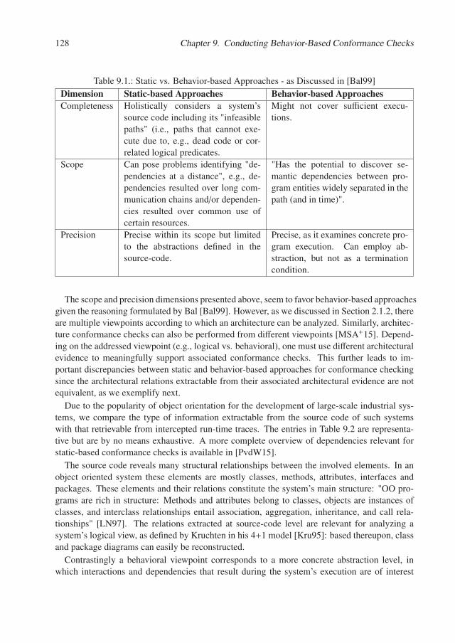
128 Chapter 9. Conducting Behavior-Based Conformance Checks
Table 9.1.: Static vs. Behavior-based Approaches - as Discussed in [Bal99]
Dimension Static-based Approaches Behavior-based ApproachesCompleteness Holistically considers a system’s
source code including its "infeasiblepaths" (i.e., paths that cannot exe-cute due to, e.g., dead code or cor-related logical predicates.
Might not cover sufficient execu-tions.
Scope Can pose problems identifying "de-pendencies at a distance", e.g., de-pendencies resulted over long com-munication chains and/or dependen-cies resulted over common use ofcertain resources.
"Has the potential to discover se-mantic dependencies between pro-gram entities widely separated in thepath (and in time)".
Precision Precise within its scope but limitedto the abstractions defined in thesource-code.
Precise, as it examines concrete pro-gram execution. Can employ ab-straction, but not as a terminationcondition.
The scope and precision dimensions presented above, seem to favor behavior-based approachesgiven the reasoning formulated by Bal [Bal99]. However, as we discussed in Section 2.1.2, thereare multiple viewpoints according to which an architecture can be analyzed. Similarly, architec-ture conformance checks can also be performed from different viewpoints [MSA+15]. Depend-ing on the addressed viewpoint (e.g., logical vs. behavioral), one must use different architecturalevidence to meaningfully support associated conformance checks. This further leads to im-portant discrepancies between static and behavior-based approaches for conformance checkingsince the architectural relations extractable from their associated architectural evidence are notequivalent, as we exemplify next.
Due to the popularity of object orientation for the development of large-scale industrial sys-tems, we compare the type of information extractable from the source code of such systemswith that retrievable from intercepted run-time traces. The entries in Table 9.2 are representa-tive but are by no means exhaustive. A more complete overview of dependencies relevant forstatic-based conformance checks is available in [PvdW15].
The source code reveals many structural relationships between the involved elements. In anobject oriented system these elements are mostly classes, methods, attributes, interfaces andpackages. These elements and their relations constitute the system’s main structure: "OO pro-grams are rich in structure: Methods and attributes belong to classes, objects are instances ofclasses, and interclass relationships entail association, aggregation, inheritance, and call rela-tionships" [LN97]. The relations extracted at source-code level are relevant for analyzing asystem’s logical view, as defined by Kruchten in his 4+1 model [Kru95]: based thereupon, classand package diagrams can easily be reconstructed.
Contrastingly a behavioral viewpoint corresponds to a more concrete abstraction level, inwhich interactions and dependencies that result during the system’s execution are of interest
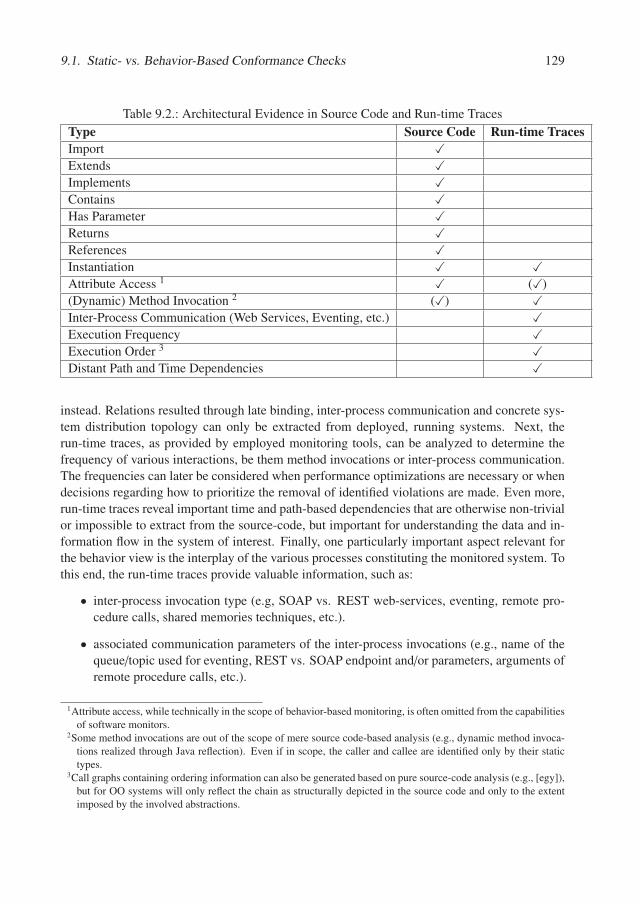
9.1. Static- vs. Behavior-Based Conformance Checks 129
Table 9.2.: Architectural Evidence in Source Code and Run-time Traces
Type Source Code Run-time TracesImport �Extends �Implements �Contains �Has Parameter �Returns �References �Instantiation � �Attribute Access 1 � (�)
(Dynamic) Method Invocation 2 (�) �Inter-Process Communication (Web Services, Eventing, etc.) �Execution Frequency �Execution Order 3 �Distant Path and Time Dependencies �
instead. Relations resulted through late binding, inter-process communication and concrete sys-tem distribution topology can only be extracted from deployed, running systems. Next, therun-time traces, as provided by employed monitoring tools, can be analyzed to determine thefrequency of various interactions, be them method invocations or inter-process communication.The frequencies can later be considered when performance optimizations are necessary or whendecisions regarding how to prioritize the removal of identified violations are made. Even more,run-time traces reveal important time and path-based dependencies that are otherwise non-trivialor impossible to extract from the source-code, but important for understanding the data and in-formation flow in the system of interest. Finally, one particularly important aspect relevant forthe behavior view is the interplay of the various processes constituting the monitored system. Tothis end, the run-time traces provide valuable information, such as:
• inter-process invocation type (e.g, SOAP vs. REST web-services, eventing, remote pro-cedure calls, shared memories techniques, etc.).
• associated communication parameters of the inter-process invocations (e.g., name of thequeue/topic used for eventing, REST vs. SOAP endpoint and/or parameters, arguments ofremote procedure calls, etc.).
1Attribute access, while technically in the scope of behavior-based monitoring, is often omitted from the capabilitiesof software monitors.
2Some method invocations are out of the scope of mere source code-based analysis (e.g., dynamic method invoca-tions realized through Java reflection). Even if in scope, the caller and callee are identified only by their statictypes.
3Call graphs containing ordering information can also be generated based on pure source-code analysis (e.g., [egy]),but for OO systems will only reflect the chain as structurally depicted in the source code and only to the extentimposed by the involved abstractions.
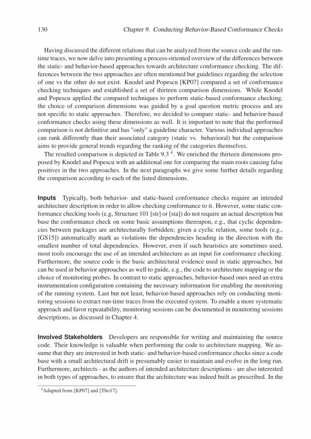
130 Chapter 9. Conducting Behavior-Based Conformance Checks
Having discussed the different relations that can be analyzed from the source code and the run-time traces, we now delve into presenting a process-oriented overview of the differences betweenthe static- and behavior-based approaches towards architecture conformance checking. The dif-ferences between the two approaches are often mentioned but guidelines regarding the selectionof one vs the other do not exist. Knodel and Popescu [KP07] compared a set of conformancechecking techniques and established a set of thirteen comparison dimensions. While Knodeland Popescu applied the compared techniques to perform static-based conformance checking,the choice of comparison dimensions was guided by a goal question metric process and arenot specific to static approaches. Therefore, we decided to compare static- and behavior-basedconformance checks using these dimensions as well. It is important to note that the performedcomparison is not definitive and has "only" a guideline character. Various individual approachescan rank differently than their associated category (static vs. behavioral) but the comparisonaims to provide general trends regarding the ranking of the categories themselves.
The resulted comparison is depicted in Table 9.3 4. We enriched the thirteen dimensions pro-posed by Knodel and Popescu with an additional one for comparing the main roots causing falsepositives in the two approaches. In the next paragraphs we give some further details regardingthe comparison according to each of the listed dimensions.
Inputs Typically, both behavior- and static-based conformance checks require an intendedarchitecture description in order to allow checking conformance to it. However, some static con-formance checking tools (e.g, Structure 101 [str] or [sta]) do not require an actual description butbase the conformance check on some basic assumptions thereupon, e.g., that cyclic dependen-cies between packages are architecturally forbidden; given a cyclic relation, some tools (e.g.,[GS15]) automatically mark as violations the dependencies heading in the direction with thesmallest number of total dependencies. However, even if such heuristics are sometimes used,most tools encourage the use of an intended architecture as an input for conformance checking.Furthermore, the source code is the basic architectural evidence used in static approaches, butcan be used in behavior approaches as well to guide, e.g., the code to architecture mapping or thechoice of monitoring probes. In contrast to static approaches, behavior-based ones need an extrainstrumentation configuration containing the necessary information for enabling the monitoringof the running system. Last but not least, behavior-based approaches rely on conducting moni-toring sessions to extract run-time traces from the executed system. To enable a more systematicapproach and favor repeatability, monitoring sessions can be documented in monitoring sessionsdescriptions, as discussed in Chapter 4.
Involved Stakeholders Developers are responsible for writing and maintaining the sourcecode. Their knowledge is valuable when performing the code to architecture mapping. We as-sume that they are interested in both static- and behavior-based conformance checks since a codebase with a small architectural drift is presumably easier to maintain and evolve in the long run.Furthermore, architects - as the authors of intended architecture descriptions - are also interestedin both types of approaches, to ensure that the architecture was indeed built as prescribed. In the
4Adapted from [KP07] and [Tho17].
9.1. Static- vs. Behavior-Based Conformance Checks 131T
able
9.3.
:C
ompa
riso
nof
Beh
avio
r-an
dS
tati
c-B
ased
Arc
hite
ctur
eC
onfo
rman
ceC
heck
s
Beha
vior
�Bas
ed�A
rchi
tect
ure�
Conf
orm
ance
�Che
cks
Stat
ic�B
ased
�Arc
hite
ctur
e�Co
nfor
man
ce�C
heck
s
Inpu
ts
•�in
tend
ed�a
rchi
tect
ure�
desc
riptio
n•�
(sou
rce�
code
)�•�
(mon
itorin
g�se
ssio
n�de
scrip
tion)
•�m
onito
ring�
inst
rum
enta
tion�
conf
igur
atio
n•�
mon
itora
ble,
�exe
cuta
ble�
syst
em
•�(in
tend
ed�a
rchi
tect
ure�
desc
riptio
n)•�
sour
ce�c
ode�
Invo
lved
�Sta
keho
lder
s•�
arch
itect
s•�
deve
lope
rs•�
(sys
tem
�inte
grat
ion�
engi
neer
s/te
st�e
ngin
eers
)
•�ar
chite
cts
•�de
velo
pers
Man
ual�S
teps
•�tr
igge
r�aut
omat
ic�a
rchi
tect
ure�
desc
riptio
n �tr
ansf
orm
atio
n/m
anua
lly�c
reat
e�to
ol�sp
ecifi
c�ar
chite
ctur
e�de
scrip
tion
•�co
nfig
ure�
syst
em�in
stru
men
tatio
n•�
cond
uct�m
onito
ring�
sess
ion
•�tr
igge
r�con
form
ance
�che
ck•�
inte
rpre
t�res
ults
•�tr
igge
r�aut
omat
ic�a
rchi
tect
ure�
desc
riptio
n�tr
ansf
orm
atio
n/m
anua
lly�c
reat
e�to
ol�sp
ecifi
c�ar
chite
ctur
e�de
scrip
tion
•�tr
igge
r�con
form
ance
�che
ck•�
inte
rpre
t�res
ults
Eval
uatio
n�Pe
rfor
man
ce•�
(pos
sibly
)�lon
g�ru
nnin
g�pr
oces
s•�
(alm
ost)
�inst
ant�c
onfo
rman
ce�c
heck
ing�
resu
lts
Defe
ct�T
ypes
•�de
fect
s� in�
hete
roge
neou
s�sys
tem
s�•�
scop
e�is�
give
n�by
�rela
tions
�as�i
n�Ta
ble�
8.2
•�on
ly�d
efec
ts�in
�hom
ogen
eous
�syst
ems�
•�sc
ope�
is�gi
ven�
by�re
latio
ns�a
s�in�
Tabl
e�8.
2Pr
obab
ility
�of�F
alse
�Pos
itive
s•�
med
ium
�(mon
itorin
g�an
omal
ies)
•�no
�false
�pos
itive
sCa
use�
of�F
alse
�Pos
itive
s•�
false
�inte
rpre
tatio
ns�d
ue�to
�mon
itorin
g�an
omal
ies
•�no
t�app
licab
leCo
mpl
eten
ss•�
depe
nds �o
n�th
e�m
onito
ring�
adeq
uacy
�•�
com
plet
e�w
ithin
�its�s
cope
Mai
ntai
nabi
lity�
(w.r.
t.�Co
de�E
volu
tion�
&�
Arch
itect
ure�
Desc
riptio
n�Ev
olut
ion)
•�th
e�to
ol�s
peci
fic�a
rchi
tect
ure�
desc
riptio
n�sh
ould
�be�
upda
ted
�(pos
sibly
�by�
reru
nnin
g�th
e�au
tom
atic
�tran
sfor
mat
ion)
•�th
e�co
nfor
man
ce�c
heck
�shou
d�be
�re�t
rigge
red
•�th
e�re
sults
�nee
d�to
�be�
rein
terp
rete
d•�
poss
ible
�cha
nges
�in�sy
stem
�inst
rum
enta
tion �
mig
ht�b
e�ne
cess
ary
•�th
e�m
onito
ring�
sess
ion�
mig
ht�n
eed�
to�b
e�co
nduc
ted�
agai
n�an
d�its
�de
scrip
tion�
poss
ibly
�upd
ated
•�th
e�to
ol�s
peci
fic�a
rchi
tect
ure�
desc
riptio
n�sh
ould
�be�
upda
ted
�(pos
sibly
�by�
reru
nnin
g�th
e�au
tom
atic
�tran
sfor
mat
ion)
•�th
e�co
nfor
man
ce�c
heck
�shou
d�be
�re�t
rigge
red
•�th
e�re
sults
�nee
d�to
�be�
rein
terp
rete
d
Tran
sfer
abili
ty•�
auto
mat
ic�a
rchi
tect
ure�
desc
riptio
n�tr
ansf
orm
atio
n�(if
�the�
sam
e�m
eta�
mod
el�is
�use
d�fo
r�the
�inte
nded
�des
crip
tion)
•�(p
arts
�of)�
syst
em�in
stru
men
tatio
n�co
nfig
urat
ion�
(if�a
pplic
able
)
•�au
tom
atic
�arc
hite
ctur
e�de
scrip
tion�
tran
sfor
mat
ion�
(if�th
e�sa
me�
met
a�m
odel
�is�u
sed�
for�t
he�in
tend
ed�d
escr
iptio
n)
Scal
abili
ty•�
inst
rum
enta
tion�
over
head
•�hi
gh�re
sour
ce�u
sage
•�sc
ales
�eas
ily
Ease
�of�A
pplic
atio
n•�
high
�com
plex
ity•�
triv
ial
Mul
tiple
�Vie
w�S
uppo
rt•�
yes�(
depe
ndin
g�on
�the�
empl
oyed
�tool
)•�
yes�(
depe
ndin
g�on
�the�
empl
oyed
�tool
)Re
stru
ctur
ing�
Scen
ario
s•�
alth
ough
�pos
sible
,�not
�supp
orte
d�by
�exi
stin
g�to
ols
•�so
me�
tool
s�offe
r�ref
acto
ring�
simul
atio
nsAr
chite
ctur
al�D
ecisi
on�S
uppo
rt•�
not�a
vaila
ble
•�no
t�ava
ilabl
e
Dim
ensi
onAp
proa
ch
132 Chapter 9. Conducting Behavior-Based Conformance Checks
case of behavioral approaches, a third stakeholder-type, namely the system integration or testengineers might be responsible for maintaining the artifacts necessary when conducting moni-toring sessions, for example the utilized test suite, the actual monitoring infrastructure and itsconfiguration, etc.
Manual Steps Static based approaches are less intricate to apply than behavioral ones: first,an intended architecture description needs to be elaborated, manually or by transformationmeans as described in 7; the code-to-architecture mapping is then conducted and the confor-mance checking is triggered; consequently the results must be reviewed and interpreted. Con-trastingly, behavioral approaches include at least two additional, possibly time-consuming steps:first, the monitoring tool must be configured to enable the capturing of behavior informationfrom the system under analysis. Finally, the monitoring session needs to be conducted on theinstrumented system by, e.g., running several selected test cases, interacting with the system’sGUI, etc.
Evaluation Performance Static approaches rely only on the analysis of the system’s sourcecode. Therefore, their performance is typically much better than that of behavioral approaches.First, the monitoring sessions might be long-running processes themselves. Second, there mightbe millions of interactions collected during monitoring. While the instrumentation itself canadd considerable overhead and slow down the system under analysis, the further processing andconformance checking poses also additional challenges with respect to, e.g., scalability.
Defect Types Table 9.2 already gave an overview regarding the scopes of static vs. behavioralapproaches. In addition to this, it is important to note that while software monitors (e.g., Nagios[nag] and Dynatrace [dyn]) are capable of monitoring the interactions of heterogeneous systems,static approaches are, to the best of our knowledge, limited to homogeneous systems since theanalysis is always restricted to a single programming language at a time.
Probability and Cause of False Positives With respect to architecture conformance check-ing, we define a false positive to be a wrongly identified violation that actually corresponds to avalid interaction between the involved architecture units. Static approaches use the source codeas their architectural evidence. Detected relations are not determined based on heuristics butextracted from the code itself. Consequently the probability for false positives is 0. Behaviorapproaches can instead be affected by false positives. As mentioned in Chapter 5, monitoringtools can be affected by so-called monitoring anomalies. Examples thereof are given in theAppendix A. In this context, it is important to acknowledge that anomalies can lead to falselyidentified violations.
Completeness The completeness dimension represents a pivotal difference between the staticand dynamic approaches. Static approaches consider the source code of a given system in itsentirety. To this end, it also considers dead or unreachable code. On the other hand, behaviorapproaches can only be as good as the monitored behavior itself. In Chapter 8 we presented a
9.1. Static- vs. Behavior-Based Conformance Checks 133
set of white-box and black-box indicators to increase the probability of a monitored behavior tobe adequate for supporting an attached conformance check. However, as in the case of softwaretesting, because of its nature, any behavior approach is incomplete, for all but very few, trivialsystems.
Maintainability Knodel and Popescu discuss maintainability only with respect to source codeevolution. We extend the discussion to architecture description evolution as well. Depending onthe actual technique applied (reflexion modeling, component access rules, relation conformancerules or variants thereof) the approaches can differ to a great extent regardless whether they arestatic or behavioral in nature. In the case of static approaches, if the intended architecture ofthe system changes, then the changes must be reflected also in its description. If the tool usesa version of the description resulted through model to model transformation, then the changesshould be propagated accordingly. Also, the conformance check itself should be re-triggered.Next, the conformance checking results should be re-interpreted, if necessary. In contrast, thebehavioral approach comes with some additional challenges: due to the system’s evolution themonitoring configuration might require updates; additionally, the system might need to be re-monitored using a possibly enhanced monitoring session that accounts for the changes resultedduring the system’s evolution.
Transferability When deciding for an approach and a corresponding tool to apply for a givensystem under analysis, it is important to have an estimate regarding how much of the investedeffort can be reused when further systems need to be analyzed using the same approach and tool.With this respect, if an automatic architecture description transformation process is in place tosupport the transformation of the original intended description to a tool-specific one, this canbe reused for further systems as well, as long as the architects employ the same meta-model.Furthermore, depending on the processes and components constituting the new system, parts ofthe instrumentation configuration can be reused in the case of behavior-based approaches.
Scalability Static approaches typically scale well, providing the results in seconds, even forlarge-scale systems. To this end, some static conformance analysis tools (e.g., Sonargraph Archi-tect [son]) even include IDE integration. Behavior-based approaches pose in contrast importantscalability problems caused by the instrumentation overhead and high resource usage. As such,they are not suitable for IDE integration but could be employed on a regular basis as well, whenmore resources are available and the analysis duration is not critical, e.g., during periodic nightlybuilds.
Ease of Application Given that in the case of behavioral approaches there are more (manual)tasks that need to be performed, the static approaches rank better in terms of application ease.
Multiple View Support A general comparison between static and behavioral approaches withrespect to this dimension cannot be formulated. Multiple views can be created for the results ofboth approaches. The static or behavior nature of the approach does not influence this dimension,but rather the capabilities of the employed tool.
134 Chapter 9. Conducting Behavior-Based Conformance Checks
Restructuring Scenarios and Support for Architectural Decisions Conformance check-ing is rarely a goal by itself. Unless no drift is revealed by the performed conformance check,the involved stakeholders typically use the results to plan future drift-amelioration activities. Inprinciple, both the static and behavioral approaches can support the system’s evolution by en-abling the definition and comparison of restructuring scenarios. Some static-based tools alreadysupport this (e.g., Sonargraph Architect [son]) and a first promising attempt based on ARAMISwas explored as well [Gör16]. Contrastingly, support for architectural decisions is very limitedwith current tools regardless if using a static or a dynamic approach. As Knodel and Popescualso mentioned: "The reasoning of the architects is dependent on their interpretation and deci-sions are not derived by the evaluation results only but use a significant amount of additionalcontext information and rationales" [KP07].
All in all, there are important differences between static and behavioral approaches to archi-tectural conformance checking. While static approaches are often available out of the box withvirtually no extra cost, the behavior-based approaches give a concrete overview of a system’sexecution enabling more complex discussions regarding inter-process communication, resultedcommunication chains, etc. Unfortunately, these imply additional overhead, since more re-sources are required and more activities need to be performed when applying behavior-basedapproaches.
The next section presents a process to support behavior-based conformance checking, usingthe example of ARAMIS.
9.2. Towards a Behavior-Based Conformance Checking Process
As already visible from the comparisons drawn in the previous section, the behavior-based con-formance checking approaches have advantages conferred especially by their scope but also poselimitations when it comes down to the involved resources and required activities. One approachto dealing with complexity is through organization and systematization.
In this section we present a process for conducting ARAMIS behavior-based conformancechecks. A visual depiction thereof is given in Figure 9.4.
Process Description
As discussed in Chapter 5, when deciding to perform a behavior-based architecture conformancecheck it is of paramount importance to choose a suitable monitoring tool (A1). With ARAMIS,we experimented with Kieker [HWH+12] and Dynatrace [dyn], and laid the premises to allowthe integration of further monitors, if needed.
Next, two sets of actions can take place in parallel. On the one hand, an intended architecturedescription expressed as an instance of the ARAMIS Meta-Model (ARAMIS-MM) must bemade available for the next phases of the process. If no intended architecture description ispreviously available, one must be elaborated "from scratch" using the ARAMIS-MM (A2). Ifa description is available but it is not an instance of the ARAMIS-MM, we are faced with theMeta-Model Incompatibility Problem, adressed in Chapter 7. As per the ARAMIS ArchitectureDescription Transformation Process (AADT-Proc) introduced previously, one can reuse it and
9.2. Towards a Behavior-Based Conformance Checking Process 135
manually or automatically transform it to an ARAMIS-MM instance (A3). On the other hand, inparallel with the previous activities, one can search for scenarios and episodes to be included inthe monitoring session to be performed (A4). An overview of possible scenario sources that canbe considered was given in Section 4.1. The identified scenarios must then be assigned contextsets and are ranked according to their importance (A5). The resulted scenario list can then beused to guide the elaboration of a monitoring session description (A6).
Next, to ensure that the proposed monitoring session is adequate to support a behavioral-basedconformance check, we apply the concepts introduced in Chapter 8. Consequently, we computethe defined black-box and white-box indicators. These computations can also be parallelized. Onthe one hand, based on the defined monitoring session, one can easily compute the associatedscenario coverage (A7). On the other hand, the white-box indicators can be computed whileexecuting the system under analysis and harvesting its run-time traces (A8). From a technicalperspective, it can be necessary to execute the system twice with two different agents: once forcollecting data regarding the coverage and once for gathering run-time traces. This is however,mostly a technical detail, which was, for the sake of clarity, omitted on purpose from Figure9.4. Next, given the values of the white-box and black-box indicators, one can corroborate theseto analyze if the extracted behavior is adequate for supporting a subsequent behavior-basedconformance check. If this is not the case, an enhanced monitoring session should instead bedefined and executed. If the behavior is adequate, the process can continue as follows.
To improve the performance of the following steps, it might need to be investigated whetherthe resulted traces can be trimmed to reduce their size while preserving their adequacy to sup-port conformance checking. If possible, such size-reduction steps (A9) should be performedeven earlier in the process (e.g., when performing the system instrumentation and the monitor-ing tool configuration). While losing some information regarding the frequency of the removedinteractions, the performance gain resulted from a so-called trace deduplication might pose animportant advantage, potentially reducing the conformance checking time by several orders ofmagnitude. What exactly can be trimmed, is however very system-specific and should be de-termined by the involved architects and developers. Popular examples are frequent, repetitiveactions, such as those initiated in control loops involved in processing large input data, periodic,scheduled actions such as regular database-polling, etc. One decision that can be taken in sucha context is to preserve only a single repetition and trim out all the rest. Naturally, the repetitiveactions that are known not to cause any violations are especially suitable for deduplication.
Having the definitive set of extracted run-time traces, one can describe these using the ARAMISInteractions Description Language (A10). Next, based on the intended architecture descriptionand the normalized traces, the actual architectural mapping and conformance checking can betriggered (A11). The result of the process is a description of the system’s implemented archi-tecture. This can be further focused using the concepts of behavioral views and perspectives asintroduced in Section 6.5. Furthermore, as mentioned in Chapter 5, it must be investigated if theresults contain errors caused by anomalies of the employed monitoring tools. An overview ofsuch anomalies is given in Appendix A. As a consequence thereof, the obtained results shouldbe refined (A12).
It is important to stress that upon refinement, errors or false assumptions in the intended ar-chitecture description can also be discovered. This experience is also related by Rick Kazman:
136 Chapter 9. Conducting Behavior-Based Conformance Checks
"your initial guess as to the structure of the architecture may be wrong. You may be requiredto iterate a number of times before you get something that approaches a rational looking struc-ture". Consequently, during refinements not only the implemented architecture description mightchange, but also the intended one.
The process ends when a consensus regarding the system’s intended and implemented archi-tecture descriptions is reached by the involved architects. However, it is of utmost importanceto note that conformance checking should not be a goal by itself. Ideally, the results will conse-quently be used in follow-up processes that aim to plan future evolution and eventually reducethe identified drift.
All in all, this chapter addressed two important aspects: first, we analyzed the relative strengthsand weaknesses of static- vs. behavior-based architecture conformance checks. We concludedthat the latter cannot be substituted by the former but are considerably more expensive in termsof overall effort and computation power. Consequently, we presented the ACC-Proc as a meansto systematize and organize the actions involved when performing behavior-based conformancechecks using ARAMIS.
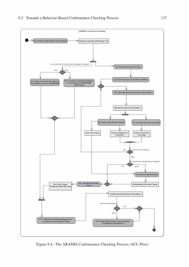
9.2. Towards a Behavior-Based Conformance Checking Process 137
������������ ������!��"��#
� $�%�����������������#�&�������� ��' %���������#����#���������#�&���
�($���������������������
�)$����"��������������%��������������
�*$��� �����������������#�
��������������������
��$��������������������!��������%���������+���#��!��������,��
����� ��������� ������������������������������ ���
�-$�&����� ����������%���������������������������������,����
���%&,����
�.$����/�������������#���������%��������
�0$����� ���������#��������
��������#���������%��������
1���������2���",/������������
1���������������������#�
�3$����� �%�����������
� 4$�&����� ����,�� ��&����
� $����� ���!�������������#���������� ������!��"��#����&����
� �� ��������!��������%��������
�������������������������!���� ���
%��������������,�� ��&����
� �$��������� �� ���������5�������������!��������%�����������
�����������������
���,&� ��&����
���,&� ��&�������������6��!���%,7��#
"��#
"��#
"��#
"$��#
"$��#
"$��#
"��#
"$��#
Figure 9.4.: The ARAMIS Conformance Checking Process (ACC-Proc)


Chapter 10.
Tooling for Architecture ConformanceChecking
In this chapter we first present the ARAMIS Toolbox in terms of capabilities, employed tech-nologies and architecture. Next, we give an overview of the most relevant related work in thearea of architecture conformance tooling and discuss how the ARAMIS Toolbox differentiatesitself from these alternatives.
10.1. The ARAMIS Toolbox
The ARAMIS Toolbox consists of a set of tools developed to automatize several activities of theARAMIS Conformance Checking Process (ACC-Proc) introduced in Chapter 9.
10.1.1. Capabilities Overview
An overview of the use-cases of the ARAMIS Toolbox is given in the Use Case Diagram inFigure 10.1.
An architect can use the Toolbox to get a dashboard-overview of the systems that werechecked for architectural conformance using ARAMIS. Several monitoring sessions can be con-ducted for a single system. An overview of these is available when a given system is selected.
Next, the architect can use the ARAMIS Toolbox to import behavior extracted with externalmonitoring tools. The associated interactions are normalized and described using the ARAMISInteractions Description Language (AID-Lang), introduced in Chapter 4.
The intended architecture of a system to be analyzed can be elaborated either as an xml filethat can be then imported using the ARAMIS Protype, or using a graphical editor instead. Inboth of these cases, the intended architecture description is internally represented as an instanceof the ARAMIS Meta-Model (ARAMIS-MM). Alternatively, if an intended architecture descrip-tion is already available but expressed using a different meta-model than the ARAMIS-MM anautomated transformation can be undergone. This later option depends however, on whether toolsupport for this type of model to model transformation was added to the ARAMIS Toolbox.
Having imported run-time traces and defined an associated intended architecture description,the architect can then trigger the conformance checking of the system. Accordingly, the ex-tracted interactions will be automatically mapped on architecture units defined in the intendedarchitecture description and then checked for conformance to the specified communication rules.
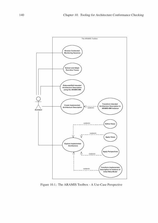
140 Chapter 10. Tooling for Architecture Conformance Checking
The ARAMIS Toolbox
Architect
Browse Conducted Monitoring Sessions
Extract and Adapt Run-time Traces
Elaborate/Edit Intended Architecture Description
using the ARAMIS-MM
Transform Intended Architecture Description to
ARAMIS-MM Instance
Create Implemented Architecture Description
Explore Implemented Architecture
Define Views
Apply Perspectives
Apply Views
Transform Implemented Description to Instance of
Initial Meta-Model
«extend»
«extend»
«extend»
«extend»
«extend»
Figure 10.1.: The ARAMIS Toolbox - A Use-Case Perspective
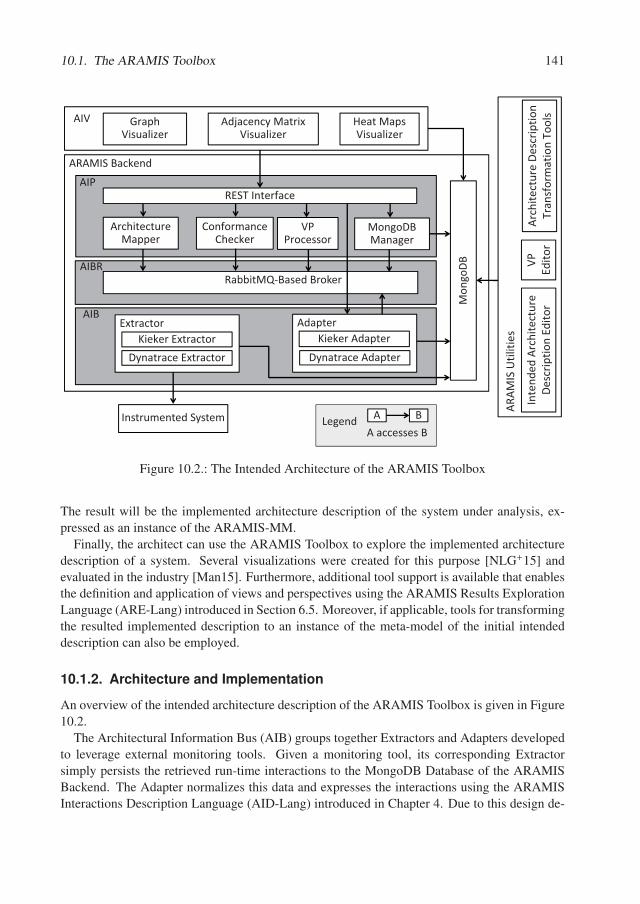
10.1. The ARAMIS Toolbox 141
ARAMIS�Backend
MongoDB�Manager
ArchitectureMapper
Instrumented�System
RabbitMQ�Based�Broker
AIB
AIBR
AIP
ConformanceChecker
Mon
goDB
ExtractorKieker Extractor
Dynatrace Extractor
AdapterKieker Adapter
Dynatrace Adapter
REST�Interface
GraphVisualizer
Adjacency MatrixVisualizer
Heat MapsVisualizer
AIV
VP�Processor
ARAM
IS�U
tiliti
es
VP�
Edito
rIn
tend
edAr
chite
ctur
eDe
scrip
tion�
Edito
rAr
chite
ctur
eDe
scrip
tion�
Tran
sfor
mat
ion�
Tool
s
A BA�accesses�B
Legend
Figure 10.2.: The Intended Architecture of the ARAMIS Toolbox
The result will be the implemented architecture description of the system under analysis, ex-pressed as an instance of the ARAMIS-MM.
Finally, the architect can use the ARAMIS Toolbox to explore the implemented architecturedescription of a system. Several visualizations were created for this purpose [NLG+15] andevaluated in the industry [Man15]. Furthermore, additional tool support is available that enablesthe definition and application of views and perspectives using the ARAMIS Results ExplorationLanguage (ARE-Lang) introduced in Section 6.5. Moreover, if applicable, tools for transformingthe resulted implemented description to an instance of the meta-model of the initial intendeddescription can also be employed.
10.1.2. Architecture and Implementation
An overview of the intended architecture description of the ARAMIS Toolbox is given in Figure10.2.
The Architectural Information Bus (AIB) groups together Extractors and Adapters developedto leverage external monitoring tools. Given a monitoring tool, its corresponding Extractorsimply persists the retrieved run-time interactions to the MongoDB Database of the ARAMISBackend. The Adapter normalizes this data and expresses the interactions using the ARAMISInteractions Description Language (AID-Lang) introduced in Chapter 4. Due to this design de-
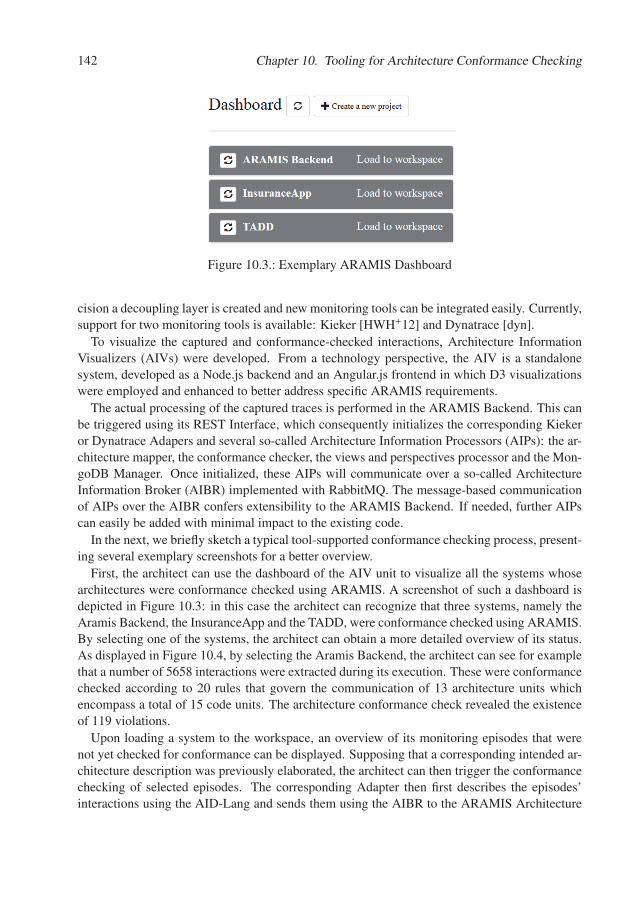
142 Chapter 10. Tooling for Architecture Conformance Checking
Figure 10.3.: Exemplary ARAMIS Dashboard
cision a decoupling layer is created and new monitoring tools can be integrated easily. Currently,support for two monitoring tools is available: Kieker [HWH+12] and Dynatrace [dyn].
To visualize the captured and conformance-checked interactions, Architecture InformationVisualizers (AIVs) were developed. From a technology perspective, the AIV is a standalonesystem, developed as a Node.js backend and an Angular.js frontend in which D3 visualizationswere employed and enhanced to better address specific ARAMIS requirements.
The actual processing of the captured traces is performed in the ARAMIS Backend. This canbe triggered using its REST Interface, which consequently initializes the corresponding Kiekeror Dynatrace Adapers and several so-called Architecture Information Processors (AIPs): the ar-chitecture mapper, the conformance checker, the views and perspectives processor and the Mon-goDB Manager. Once initialized, these AIPs will communicate over a so-called ArchitectureInformation Broker (AIBR) implemented with RabbitMQ. The message-based communicationof AIPs over the AIBR confers extensibility to the ARAMIS Backend. If needed, further AIPscan easily be added with minimal impact to the existing code.
In the next, we briefly sketch a typical tool-supported conformance checking process, present-ing several exemplary screenshots for a better overview.
First, the architect can use the dashboard of the AIV unit to visualize all the systems whosearchitectures were conformance checked using ARAMIS. A screenshot of such a dashboard isdepicted in Figure 10.3: in this case the architect can recognize that three systems, namely theAramis Backend, the InsuranceApp and the TADD, were conformance checked using ARAMIS.By selecting one of the systems, the architect can obtain a more detailed overview of its status.As displayed in Figure 10.4, by selecting the Aramis Backend, the architect can see for examplethat a number of 5658 interactions were extracted during its execution. These were conformancechecked according to 20 rules that govern the communication of 13 architecture units whichencompass a total of 15 code units. The architecture conformance check revealed the existenceof 119 violations.
Upon loading a system to the workspace, an overview of its monitoring episodes that werenot yet checked for conformance can be displayed. Supposing that a corresponding intended ar-chitecture description was previously elaborated, the architect can then trigger the conformancechecking of selected episodes. The corresponding Adapter then first describes the episodes’interactions using the AID-Lang and sends them using the AIBR to the ARAMIS Architecture
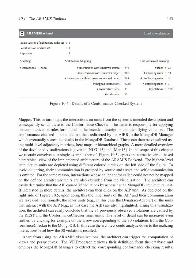
10.1. The ARAMIS Toolbox 143
Figure 10.4.: Details of a Conformance-Checked System
Mapper. This in turn maps the interactions on units from the system’s intended description andconsequently sends these to the Conformance Checker. The latter is responsible for applyingthe communication rules formulated in the intended description and identifying violations. Theconformance-checked interactions are then redirected by the AIBR to the MongoDB Managerwhich eventually stores the results in the MongoDB Database. These can then be visualized us-ing multi-level adjacency matrices, heat maps or hierarchical graphs. A more detailed overviewof the developed visualizations is given in [NLG+15] and [Man15]. In the scope of this chapterwe restrain ourselves to a single example thereof. Figure 10.5 depicts an interactive circle-basedhierarchical view of the implemented architecture of the ARAMIS Backend. The highest-levelarchitecture units are depicted using different colored circles on the left side of the figure. Toavoid cluttering, their communication is grouped by source and target and self-communicationis omitted. For the same reason, interactions whose caller and/or callee could not not be mappedon the defined architecture units are also excluded from the visualization. The architect caneasily determine that the AIP caused 75 violations by accessing the MongoDB architecture unit.If interested in more details, the architect can then click on the AIP unit. As depicted on theright side of Figure 10.5, upon doing this the inner units of the AIP and their communicationare revealed; additionally, the inner units (e.g., in this case the DynatraceAdapter) of the unitsthat interact with the AIP (e.g., in this case the AIB) are also highlighted. Using this visualiza-tion, the architect can easily conclude that the 75 previously observed violations are caused bythe REST and the ConformanceChecker inner units. The level of detail can be increased evenfurther, by clicking for example on the arrow corresponding to the 30 violations from the Con-formanceChecker to the MongoDB. In this case the architect could analyze down to the realizinginteractions level how the 30 violations resulted.
Apart from using the ARAMIS visualizations, the architect can trigger the computation ofviews and perspectives. The VP Processor retrieves their definition form the database andemploys the MongoDB Manager to extract the corresponding conformance checking results.
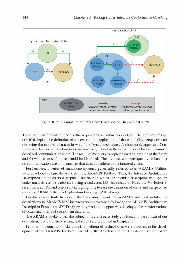
144 Chapter 10. Tooling for Architecture Conformance Checking
AIP MongoDB
AIB
AIP
AIP
ArchitectureMapper REST
ConformanceChecker
MongoDBManager
751
60
Highest�Level� Architecture�Units
After�Selection�of�AIP
LegendArchitecture
Unit
x
Allowed�communication�that�occurred�x�times�
x
Disallowed�communication�that�occurred�x�times�
60 44
MongoDB45
30
AIB
DynatraceAdapter
60
Figure 10.5.: Example of an Interactive Circle-based Hierarchical View
These are then filtered to produce the required view and/or perspective. The left side of Fig-ure 10.6 depicts the definition of a view and the application of the cardinality perspective forretrieving the number of traces in which the DynatraceAdapter, ArchitectureMapper and Con-formanceChecker architecture units are involved, but not in the order imposed by the previouslydescribed communication chain. The result of the query is depicted on the right side of the figureand shows that no such traces could be identified. The architect can consequently deduce thatno communication was implemented that does not adhere to the imposed chain.
Furthermore, a series of standalone systems, generically referred to as ARAMIS Utilitieswere developed to ease the work with the ARAMIS Toolbox. Thus, the Intended ArchitectureDescription Editor offers a graphical interface in which the intended description of a systemunder analysis can be elaborated using a dedicated D3 visualization. Next, the VP Editor isresembling an IDE and offers syntax highlighting to ease the definition of views and perspectivesusing the ARAMIS Results Exploration Language (ARE-Lang).
Finally, several tools to support the transformation of non-ARAMIS intended architecturedescriptions to ARAMIS-MM instances were developed following the ARAMIS ArchitectureDescription Process (AADT-Proc): prototypical tool-support was developed for transformationsof boxes and lines and component diagrams.
The ARAMIS backend was the subject of the first case study conducted in the context of ourevaluation. The case study setting and results are presented in Chapter 12.
From an implementation standpoint, a plethora of technologies were involved in the devel-opment of the ARAMIS Toolbox. The AIPs, the Adapters and the Dynatrace Extractor were
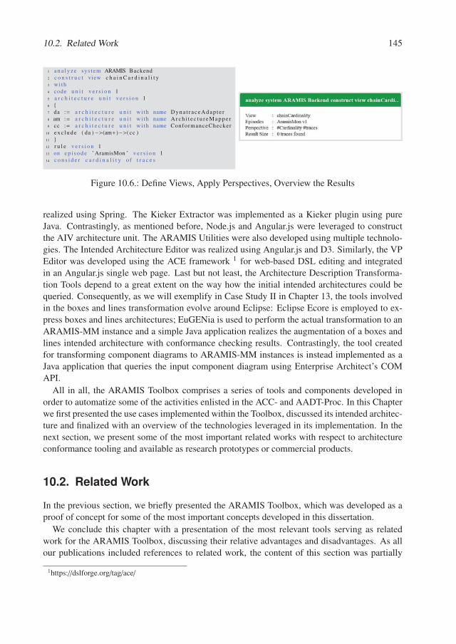
10.2. Related Work 145
Figure 10.6.: Define Views, Apply Perspectives, Overview the Results
realized using Spring. The Kieker Extractor was implemented as a Kieker plugin using pureJava. Contrastingly, as mentioned before, Node.js and Angular.js were leveraged to constructthe AIV architecture unit. The ARAMIS Utilities were also developed using multiple technolo-gies. The Intended Architecture Editor was realized using Angular.js and D3. Similarly, the VPEditor was developed using the ACE framework 1 for web-based DSL editing and integratedin an Angular.js single web page. Last but not least, the Architecture Description Transforma-tion Tools depend to a great extent on the way how the initial intended architectures could bequeried. Consequently, as we will exemplify in Case Study II in Chapter 13, the tools involvedin the boxes and lines transformation evolve around Eclipse: Eclipse Ecore is employed to ex-press boxes and lines architectures; EuGENia is used to perform the actual transformation to anARAMIS-MM instance and a simple Java application realizes the augmentation of a boxes andlines intended architecture with conformance checking results. Contrastingly, the tool createdfor transforming component diagrams to ARAMIS-MM instances is instead implemented as aJava application that queries the input component diagram using Enterprise Architect’s COMAPI.
All in all, the ARAMIS Toolbox comprises a series of tools and components developed inorder to automatize some of the activities enlisted in the ACC- and AADT-Proc. In this Chapterwe first presented the use cases implemented within the Toolbox, discussed its intended architec-ture and finalized with an overview of the technologies leveraged in its implementation. In thenext section, we present some of the most important related works with respect to architectureconformance tooling and available as research prototypes or commercial products.
10.2. Related Work
In the previous section, we briefly presented the ARAMIS Toolbox, which was developed as aproof of concept for some of the most important concepts developed in this dissertation.
We conclude this chapter with a presentation of the most relevant tools serving as relatedwork for the ARAMIS Toolbox, discussing their relative advantages and disadvantages. As allour publications included references to related work, the content of this section was partially
1https://dslforge.org/tag/ace/
146 Chapter 10. Tooling for Architecture Conformance Checking
extracted from these sources.
In 2006, Shaw and Clements, discussed the "phenomenal growth of software architecture asa discipline" but also identified several potential areas to be explored by future research, amongwhich approaches for architecture conformance checking and enforcement were also mentioned:"Lack of conformance dooms an architecture to irrelevance as the code sets out on its ownindependent trajectory. [...] Early work exists [...] but solutions are incomplete, especially inrecovery and enforcement of runtime views and architectural rules that go beyond structure"[SC06]. More than a decade later, the landscape of tool support is lager but behavior-basedapproaches are still underrepresented. In the following, we first give an overview of some ofthe most popular static-based solutions. Next, we discuss the status of the behavior-based ones.We continue with a discussion regarding the relevance of immediate feedback in the context ofconformance checking. Finally, we approach the stringent issue of lack of industry adoption.
Static-Based Approaches. A multitude of tools for static-based architecture reconstructionand/or conformance checking are available. They require little to no set-up effort and some caneven be integrated in the automated build pipelines.
For example, ArchUnit [arc] is a Java library developed specifically for writing architecturaltests to assert if predefined static architectural rules are obeyed within a system under analy-sis. These tests can then be easily executed on-demand or periodically by integration servers.Similarly, the commercial tool Understand [und], while closer to the code than architecturalreconstruction tools, offers support for test-alike definition of rules regarding naming conven-tions, metric thresholds, and other configurable parameters. Furthermore, the popular VisualStudio IDE [vis] recently included support for the definition of layered intended architecturedescriptions; the checking of the system’s conformance to them can be triggered manually orautomatically from the IDE itself. Likewise, with Sonargraph Architect [son] the architects cancreate an intended architecture description of a system comprising rules similar to the ARAMISnon-aggregated ones. The conformance check can be performed on-demand or included in thesystem’s automatic build pipeline, given that Maven, Gradle and Jenkins plugins are availableout of the box. Similarly, Structure101 [str] is a popular alternative to Sonargraph Architect. In[FRZ+16], Fontana, Roveda and Zanoni reported their experiences from a case study employingthese two tools. While intended architecture descriptions were more easily created using Sonar-graph, Structure101 was more advantageous when an intended description was not available. Assuch, Structure101 offered more adequate means to inspect the current state of the architecture,instead of limiting itself to conformance checking alone.
At a different side of the spectrum, various approaches focus on inspecting the evolution of asoftware system and its current state, rather than its conformance to a possibly out-dated intendeddescription. A relevant example is given here by the use of city metaphors to visualize the stateof a software system and its history. Steinbrückner and Lewerentz [SL10], [SL13] introduced thevisualization tool CrocoCosmos as a tool-support for the Evo-Streets approach: "a three-staged[solution] adopted from cartography for the systematic visualization of large software systems"[SL10]. With Evo-Streets, landscape elevations are employed to represent evolution-relatedinformation. An intended description of the system can be visualized as well, and the result willdepict how the various units contained therein can be represented with Evo-Steets. However, the
10.2. Related Work 147
major goal of this approach is to enable the analysis and understanding of the status quo ratherthan revealing the drift between intended and implemented. A similar approach is representedby the well known Code City tool [WL08], [WLR11], primarily developed by Richard Wettel.
Other approaches, such as the STAN project [sta] or the one presented by Goldstein andSegall [GS15] emoploy heuristics to identify possible violations without the need for previouslyformulating any intended description. The identified violations typically correspond to low-levelcode-level dependencies.
A further solution to static-based conformance checking that, as ARAMIS, embraces the factthat the intended architecture description can be expressed with a variety of meta-models, wasintroduced by Bennicke and Lewerentz [BL10]. They propose the use of ontologies and rule-systems to define the intended architecture and its meta-model, on the one hand, and the thedevelopment platform and its meta-model along with and a corresponding model of the sys-tem under test, on the other hand. Ontologies offer out-of-the-box consistency and satisfiabilitychecking. Description-logic-safe rules add further expressiveness, without compromising de-cidability. The architecture to code consistency can then be undergone by merely employingontologies-specific operations. Consequently, the implemented architecture description can bededuced based on the findings of the leveraged reasoner. The limitations of the approach, de-rive from those of ontologies and ontologies-integrated rule systems in general. For example,unlike in the case of ARAMIS, the open world assumption prohibits the definition of denyingrules. While allowing rules can instead be leveraged to exhaustively define what is permitted,this limits conciseness and future extensibility. Furthermore, hierarchical concepts and prop-agation of properties, as in the case of derived rules, are not trivial: "Unfortunately, the useof transitive roles badly interacts with other description logic constructs and therefore furtherlimits expressiveness"[BL10]. All in all, the proposed ontology-centric approach exposes bothimportant benefits and limitations. Contrastingly, ARAMIS has a stiff intended architecture-and platform-meta-model. Model-to-model transformations should be performed, as foreseenby the AADT-Proc, to reduce a possible meta-model incompatibility problem. Also, the confor-mance checking is not offered out-of-the-box but instead implemented using self-defined algo-rithms. We claim that the rules taxonomy offered by ARAMIS is better adapted to the domainof software architecture and that the limitations exposed by the ontology-centric alternative areavoided.
Finally, lower-level approaches such as "Points-to" employ "static program analysis that com-putes precise object reference information by tracking the flow of objects from one part of aprogram to another" [LL12]. In general, "points-to" leverages context-independent or context-dependent analyses to identify reference information within a system. E.g., in the case of Java,the main goal is "to determine the set of objects pointed to by a reference variable or a refer-ence object field" [MRR02]. Consequently, "points-to" analyses are useful for a variety of usecases, ranging from compilers optimization to computation of coupling and cohesion metrics atan object level. While the technique seemingly combines the benefits of static- and behavior-based approaches, it is conducted on a very low abstraction level and is limited to single-processsystems.
148 Chapter 10. Tooling for Architecture Conformance Checking
Behavior-Based Approaches. Architecture reconstruction solutions based on the analy-sis of run-time data are less numerous. Typically, run-time monitoring is employed to supportthe diagnosis of performance-related problems. For example, profiler tools such as VisualVM2 and JProfiler 3 are often employed to analyze the performance of Java-based systems. Simi-larly, other solutions such as the Rainbow framework [GCH+04] employ monitoring in order tosupport self-adaptation to different deployment conditions.
In [HlL04], Hamou-Lhadj and Lethbridge present a survey of 8 trace exploration tools. Theauthors underline the importance of analyzing execution traces, reasoning that "polymorphismand dynamic binding pose serious limitations to static analysis". They criticize that a commonframework for trace analysis is missing, leading to undesired heterogeneity: "it is also verycommon to have two different tools implement the same techniques using different terminol-ogy". The surveyed tools, out of which none is still being actively developed or used, are thefollowing: Shimba [SKM01], ISVis [JR97], Ovation [DLVW98], Jinsight [PJM+02], ProgramExplorer [LN97], AVID [WMFB+98], Scene [KM96] and The Collaboration Browser [RD02].The survey revealed that, at that time, only AVID permitted the aggregation of interactions toarchitectural units, the others often presenting the extracted information only on object- andclass-level. Furthermore, the survey raised an important issue: the need for analysis techniquesthat reduce the amount of information presented to the user: "A key element for a successfuldynamic analysis tool consists of implementing efficient techniques for reducing the amount ofinformation that exists in the traces". As we will discuss in Case Study III presented in Chap-ter 14, this scalability issue was also encountered when employing ARAMIS and extractingdata from a medium-scale industrial software system. To reduce the amount of data to pro-cess, deduplication techniques were employed to eliminate redundant interactions that have alow-probability to be architecturally significant.
Currently, two commercial tools that are often employed are Dynatrace [dyn] and Nagios[nag]. Central to these tools is the monitoring of CPU consumption or the detection of perfor-mance bottlenecks. A residual product of such tools is the information regarding the interactionswithin the analyzed systems. For example, Dynatrace employs the so-called Purepath technol-ogy to “capture timing and code level context for all transactions, end-to-end, from user click,across all tiers, to the database of record and back” [dyn]. ARAMIS is developed in a modularmanner, to allow the easy “docking” of such monitoring tools to facilitate data extraction andvalidate it according to pre-specified intended architecture descriptions. A Dynatrace adapterfor ARAMIS is already available and it was employed in all the case studies presented in theEvaluation part of this dissertation.
Furthermore, Zipkin [zip] is an open-source project, inspired by Google Dapper [SBB+10],that aims to support engineers to identify and troubleshoot latency problems in a distributed,microservices environment.
Kieker [HWH+12] is a university project that also addresses the run-time analysis of systems.Unlike its commercial counterparts, Kieker is not suitable for analyzing multi-processes systems.Furthermore, despite focusing on performance management, several architectural analyses arepossible (e.g., call tree views). However, unlike ARAMIS, the specification of rules on an
2the VisualVM home page: https://visualvm.github.io/3the JProfiler home page: https://www.ej-technologies.com/products/jprofiler/features.html
10.2. Related Work 149
architectural level is not possible.Contrastingly, ExplorViz [FSH14] analyzes run-time data and creates scalable visualizations
that aid results exploration.DiscoTect [YGS+04], [SAG+06], [SGY05], a pioneer of run-time monitoring, employed the
Java Platform Debugger Architecture, to extract traces from a Java-based system and enabledtheir filter-based exploration to create architecturally-relevant state-machines.
None of the behavior-based approaches presented up to this point foresee the definition ofcommunication rules and the checking of conformance to them.
In [SSL+14], Saadatmand et al. present an example of checking low-level behavior consis-tency based on pre-specified expected state transitions for monitoring software. Contrastingly,ARAMIS has a richer rules taxonomy that enables conformance assessments on higher, moreabstract architectural levels.
In [dSB13], de Silva and Balasubramaniam introduce PANDArch, their solution for dynamicconformance checking, designed to be "automated, customizable, non-intrusive and pluggable".Similarly to Dynatrace, PANDArch employs a Java Agent that injects optimized probes in thebytecode of the system under analysis and asynchronously sends messages to the PANDArchframework. According to the authors, the evaluation revealed significant improvements fromprevious JDI-based 4 versions for extracting interactions but still added a 31% overhead to themonitored system. While the framework is presumably extensible, at the time of publishingit was only available for Java-based systems described using the self-developed Grasp ADL[DB11]. Consequently, only rules regarding the direct and interface-based access were checkedagainst.
Industry Adoption. Despite the fact that architectural drift is generally accepted as poten-tially harmful and in need to be investigated and possibly repaired, "architectural inconsistencyseems prevalent in the software industry worldwide" [ARB12], [CLN14]. Furthermore, auto-mated architecture conformance checking techniques and tools are still not well adopted by theindustry [CLN14], [MSSV16]. Consequently, there is a growing need to raise awareness regard-ing the benefits of conformance checking in general and militate for its inclusion in the standardsoftware development processes.
4the Java Debug Interface


Part III.
Evaluation

Chapter 11.
Evaluation Overview
In the previous chapters we described ARAMIS - our approach towards behavior-based archi-tecture conformance checking. This Part presents three case studies that serve as the empiricalevaluation of ARAMIS.
Section 11.1 presents the goals pursued during the evaluation phase of this dissertation. Next,Section 11.2 gives an overview of the employed evaluation methodology. The next three chapterspresent in detail each of the conducted case studies focusing on the respective case study designand achieved results. Furthermore, Chapter 15 presents a summary of the conducted evaluationand its outcomes as well as an overview regarding its limitations. Finally, Chapter 16 discussesseveral similar case studies encountered in our related work that focus on the evaluation ofconformance checking approaches and tooling.
11.1. Evaluation Goals
This evaluation assesses the following aspects of ARAMIS: (1) the expressiveness of the ARAMISCommunication Rules Language to define relevant communication rules for the architectures ofthe considered systems, (2) the suitability of the developed white-box and black-box indica-tors to reason about the adequacy of the extracted behavior, (3) the usefulness of the developedprocesses to offer guidance when conducting behavioral-based conformance checking and deal-ing with the Meta-Model Incompatibility Problem and (4) the support offered by the ARAMISToolbox to conduct automatic conformance checks.
Next, we address each of the above aspects and formulate the hypotheses tested during theconducted case studies.
Expressiveness of the ACR-Lang
We hypothesize that the ARAMIS Communication Rules Languages (ACR-Lang) can be em-ployed to formulate all the communication rules envisioned by the architects of the analyzedsoftware systems.
H1: All the communication rules applicable for the intended architecture descriptionsof the studied systems can be expressed using the ACR-Lang.
154 Chapter 11. Evaluation Overview
Suitability of the Adequacy Indicators
We hypothesize that the ARAMIS white-box and black-box indicators can offer guidance forreasoning regarding the adequacy of the captured behavior to support an associated architectureconformance checking process.
H2: The proposed white-box and black-box indicators can be used and corroboratedto investigate the adequacy of captured behavior to support behavioral-based archi-tecture conformance checks.
H2a The proposed white-box indicators can be used to investigate the adequacy ofthe captured behavior to support behavioral-based architecture conformancechecks.
H2b The proposed black-box indicator can be used to investigate the adequacy ofthe captured behavior to support behavioral-based architecture conformancechecks.
H2c The proposed white-box and black-box indicators can be corroborated and en-able a better understanding of the adequacy of the captured behavior to supportbehavioral-based architecture conformance checks.
Usefulness of the ACC-Proc and AADT-Proc
We hypothesize that the ARAMIS Conformance Checking (ACC-Proc) and the ARAMIS Ar-chitecture Description Transformation Processes (AADT-Proc) can be applied in a variety ofcontexts and offer guidance when conducting behavioral-based conformance checking and deal-ing with the Meta-Model Incompatibility Problem.
H3: The ACC-Proc and AADT-Proc processes offer guidance in a variety of differentconformance-checking contexts.
H3a The ACC-Proc offers guidance when conducting behavior-based architectureconformance checks.
H3b The AADT-Proc supports the development of solutions to alleviate the Meta-Model Incompatibility Problem.
Applicability of the ARAMIS Toolbox
We hypothesize that the developed ARAMIS Toolbox can be applied in a variety of contexts toautomatize the conformance checking task.
H4: The developed ARAMIS Toolbox supports the definition of intended architecturedescriptions and can be used to automatically process extracted interactions and checkfor the conformance of the resulted communication to the formulated communicationrules.
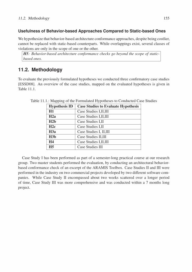
11.2. Methodology 155
Usefulness of Behavior-based Approaches Compared to Static-based Ones
We hypothesize that behavior-based architecture conformance approaches, despite being costlier,cannot be replaced with static-based counterparts. While overlappings exist, several classes ofviolations are only in the scope of one or the other.
H5: Behavior-based architecture conformance checks go beyond the scope of static-based ones.
11.2. Methodology
To evaluate the previously formulated hypotheses we conducted three confirmatory case studies[ESSD08]. An overview of the case studies, mapped on the evaluated hypotheses is given inTable 11.1.
Table 11.1.: Mapping of the Formulated Hypotheses to Conducted Case Studies
Hypothesis ID Case Studies to Evaluate HypothesisH1 Case Studies I,II,III
H2a Case Studies I,II,III
H2b Case Studies I,II
H2c Case Studies I,II
H3a Case Studies I, II,III
H3b Case Studies II,III
H4 Case Studies I,II,III
H5 Case Studies III
Case Study I has been performed as part of a semester-long practical course at our researchgroup. Two master students performed the evaluation, by conducting an architectural behavior-based conformance check of an excerpt of the ARAMIS Toolbox. Case Studies II and III wereperformed in the industry on two commercial projects developed by two different software com-panies. While Case Study II encompassed about two weeks scattered over a longer periodof time, Case Study III was more comprehensive and was conducted within a 7 months longproject.

Chapter 12.
Case Study I
In this case study we describe the applicability of the ARAMIS concepts and toolbox to conducta behavior-based architecture conformance check of an excerpt of the ARAMIS Toolbox itself.This chapter is based on the results published in [NLH17].
The choice of the ARAMIS Toolbox as the unit of analysis of this case study is motivated asfollows:
• the ARAMIS Toolbox is complex enough to support the definition of a wide category ofrules, as per the taxonomy of ARAMIS rules presented in Chapter 6;
• our familiarity with the ARAMIS Toolbox enables us to reliably assess the adequacy of thecaptured behavior towards supporting an associated behavior-based architecture confor-mance check. Consequently, we can reason whether the results provided by the developedadequacy indicators indeed reflect the reality.
In this case study we evaluated whether the developed ARAMIS Communication Rules Lan-guage (ACR-Lang) is expressive enough to support the definition of communication rules gov-erning the architecture of the ARAMIS Toolbox. Moreover, we investigated if the developed in-dicators are useful for inquiring the adequacy of captured behavior to support associated confor-mance checks. Finally, we evaluated whether the developed ARAMIS Toolbox can be employedto automate the conformance checking of the captured behavior and whether the ARAMIS Con-formance Checking Process (ACC-Proc) offers sufficient guidance to novices.
Section 12.1 describes the case study design; we briefly present the environment and casestudy context as well as the participants. Section 12.2 emphasizes the obtained results andSection 12.3 wraps up this chapter with a discussion of the findings.
12.1. Case Study Design
This section presents the participants involved in the case study, the general environment andinitial setup.
Participants
The evaluation presented in this case study involved two master students with a strong but gen-eral background in computer science and with varying levels of experience in various domainssuch as back-end and web programming. The master students were guided by the author of
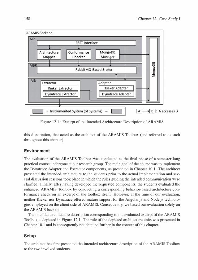
158 Chapter 12. Case Study I
Figure 12.1.: Excerpt of the Intended Architecture Description of ARAMIS
this dissertation, that acted as the architect of the ARAMIS Toolbox (and referred to as suchthroughout this chapter).
Environment
The evaluation of the ARAMIS Toolbox was conducted as the final phase of a semester-longpractical course undergone at our research group. The main goal of the course was to implementthe Dynatrace Adapter and Extractor components, as presented in Chapter 10.1. The architectpresented the intended architecture to the students prior to the actual implementation and sev-eral discussion sessions took place in which the rules guiding the intended communication wereclarified. Finally, after having developed the requested components, the students evaluated theenhanced ARAMIS Toolbox by conducting a corresponding behavior-based architecture con-formance check on an excerpt of the toolbox itself. However, at the time of our evaluation,neither Kieker nor Dynatrace offered mature support for the Angular.js and Node.js technolo-gies employed on the client side of ARAMIS. Consequently, we based our evaluation solely onthe ARAMIS backend.
The intended architecture description corresponding to the evaluated excerpt of the ARAMISToolbox is depicted in Figure 12.1. The role of the depicted architecture units was presented inChapter 10.1 and is consequently not detailed further in the context of this chapter.
Setup
The architect has first presented the intended architecture description of the ARAMIS Toolboxto the two involved students.
12.2. Results 159
Next, the students were asked to accordingly implement the Dynatrace Extractor and Adapterunits. Once the implementation phase ended, the ACC-Proc was introduced to the students, toguide the final phase of the practical course, namely the conformance checking of the ARAMISToolbox.
The architect elaborated scenarios for the ARAMIS Toolbox and assigned them to relevanceclasses. These are available in Appendix C.1 and, for brevity and clarity reasons, are not furtherdiscussed here.
12.2. Results
When defining the episode to be monitored, the students chose only scenarios that did not involvethe Kieker Extractor and Adapter architecture units. The reasoning behind this decision was, onthe one hand, their lack of familiarity therewith and, on the other, the fact that the capabilities ofthe Dynatrace units included and exceeded those of their Kieker correspondents.
Having decided on the monitoring session to perform - referred to as the AramisMon and de-picted in Appendix C.1 - , the students proceeded to extract data by executing the ARAMIS Tool-box accordingly. Dynatrace purepaths were extracted using a previously configured Dynatraceagent and instructions coverage measurements were performed using JaCoCo. The purepathsare publicly available under [araa].
The extracted purepaths and the elaborated intended architecture then served as the basis ofthe subsequent behavior-based conformance checking.
Expressiveness of ACR-Lang
Using ACR-Lang it was possible to formulate all the architecturally relevant rules applicable inthe case of the ARAMIS backend and depicted in Table 12.2.
To this end, 20 communication rules were formulated.
To specify the non-aggregating rules on a whitelist basis, we used the default DenyUncon-strainedRule. However, to explore the expression capability of the ACR-Lang, some redundantrules were also specified to explicitly deny several communication types. If such a communica-tion existed, a violation would have been nonetheless identified, due to the whitelist characterof the rules set. However, having also defined a non-default rule, if such a communication hadoccurred, we expected instead the additional, explicitly defined rule to be listed as its cause.
The created xml-based intended architecture description of ARAMIS is publicly available[arab].
For clarity reasons, we present here one of the aggregating rules defined in this context toexemplify how this could be expressed using the ACR-Lang. Listing 12.1 depicts the rule“AramisChainRule” that enforces the communication chain Adapter - Architecture Mapper -Conformance Checker. In the map phase (Lines 2-17), we search for two types of interactions.First, we search for interactions over a queue (Line 6) whose names match the string value“aramis.adapter.result” (Lines 7, 8), and that showcase the Adapter as a caller (Line 4) and theArchitecture Mapper as a callee (Line 5). These are marked with the identifier “e” (Line 3) forfuture reference in the aggregate phase. Next, we similarly search for queue-based interactions
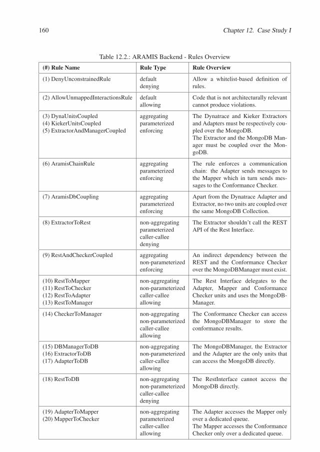
160 Chapter 12. Case Study I
Table 12.2.: ARAMIS Backend - Rules Overview
(#) Rule Name Rule Type Rule Overview
(1) DenyUnconstrainedRule defaultdenying
Allow a whitelist-based definition ofrules.
(2) AllowUnmappedInteractionsRule defaultallowing
Code that is not architecturally relevantcannot produce violations.
(3) DynaUnitsCoupled(4) KiekerUnitsCoupled(5) ExtractorAndManagerCoupled
aggregatingparameterizedenforcing
The Dynatrace and Kieker Extractorsand Adapters must be respectively cou-pled over the MongoDB.The Extractor and the MongoDB Man-ager must be coupled over the Mon-goDB.
(6) AramisChainRule aggregatingparameterizedenforcing
The rule enforces a communicationchain: the Adapter sends messages tothe Mapper which in turn sends mes-sages to the Conformance Checker.
(7) AramisDbCoupling aggregatingparameterizedenforcing
Apart from the Dynatrace Adapter andExtractor, no two units are coupled overthe same MongoDB Collection.
(8) ExtractorToRest non-aggregatingparameterizedcaller-calleedenying
The Extractor shouldn’t call the RESTAPI of the Rest Interface.
(9) RestAndCheckerCoupled aggregatingnon-parameterizedenforcing
An indirect dependency between theREST and the Conformance Checkerover the MongoDBManager must exist.
(10) RestToMapper(11) RestToChecker(12) RestToAdapter(13) RestToManager
non-aggregatingnon-parameterizedcaller-calleeallowing
The Rest Interface delegates to theAdapter, Mapper and ConformanceChecker units and uses the MongoDB-Manager.
(14) CheckerToManager non-aggregatingnon-parameterizedcaller-calleeallowing
The Conformance Checker can accessthe MongoDBManager to store theconformance results.
(15) DBManagerToDB(16) ExtractorToDB(17) AdapterToDB
non-aggregatingnon-parameterizedcaller-calleeallowing
The MongoDBManager, the Extractorand the Adapter are the only units thatcan access the MongoDB directly.
(18) RestToDB non-aggregatingnon-parameterizedcaller-calleedenying
The RestInterface cannot access theMongoDB directly.
(19) AdapterToMapper(20) MapperToChecker
non-aggregatingparameterizedcaller-calleeallowing
The Adapter accesses the Mapper onlyover a dedicated queue.The Mapper accesses the ConformanceChecker only over a dedicated queue.
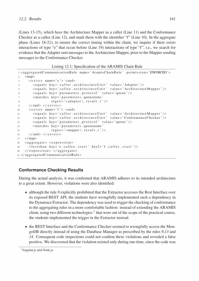
12.2. Results 161
(Lines 13-15), which have the Architecture Mapper as a caller (Line 11) and the ConformanceChecker as a callee (Line 12), and mark them with the identifier “f” (Line 10). In the aggregatephase (Lines 18-21), to ensure the correct timing within the chain, we inquire if there existsinteractions of type “e” that occur before (Line 19) interactions of type “f”, i.e., we search forevidence that the Adapter sent messages to the Architecture Mapper, prior to the Mapper sendingmessages to the Conformance Checker.
Listing 12.1: Specification of the ARAMIS Chain Rule
1 <agg rega t edCommunica t i onRu le name= ’ AramisChainRule ’ p e r m i s s i o n= ’ENFORCED’>2 <map>3 < e x i s t s name= ’ e ’> <and>4 < e q u a l s key= ’ c a l l e r . a r c h i t e c t u r e U n i t ’ v a l u e= ’ Adap te r ’ / >5 < e q u a l s key= ’ c a l l e e . a r c h i t e c t u r e U n i t ’ v a l u e= ’ A r c h i t e c t u r e M a p p e r ’ / >6 < e q u a l s key= ’ p a r a m e t e r s . p r o t o c o l ’ v a l u e= ’ queue ’ / >7 <matches key= ’ p a r a m e t e r s . queuename ’8 r e g e x= ’ ∗ a d a p t e r \ . r e s u l t . ∗ ’ / >9 < / and> < / e x i s t s>
10 < e x i s t s name= ’ f ’> <and>11 < e q u a l s key= ’ c a l l e r . a r c h i t e c t u r e U n i t ’ v a l u e= ’ A r c h i t e c t u r e M a p p e r ’ / >12 < e q u a l s key= ’ c a l l e e . a r c h i t e c t u r e U n i t ’ v a l u e= ’ ConformanceChecker ’ / >13 < e q u a l s key= ’ p a r a m e t e r s . p r o t o c o l ’ v a l u e= ’ queue ’ / >14 <matches key= ’ p a r a m e t e r s . queuename ’15 r e g e x= ’ ∗mapper \ . r e s u l t . ∗ ’ / >16 < / and> < / e x i s t s>17 < /map>18 < a g g r e g a t e> < e x p r e s s i o n>19 < l e s s t h a n key= ’ e . c a l l e e . s t a r t ’ key2= ’ f . c a l l e r . s t a r t ’ / >20 < / e x p r e s s i o n> < / a g g r e g a t e>21 < / agg rega t edCommunica t i onRu le>
Conformance Checking Results
During the actual analysis, it was confirmed that ARAMIS adheres to its intended architectureto a great extent. However, violations were also identified:
• although the rule 8 explicitly prohibited that the Extractor accesses the Rest Interface overits exposed REST API, the students have wrongfully implemented such a dependency inthe Dynatrace Extractor. The dependency was used to trigger the checking of conformanceto the aggregating rules in a more comfortable fashion: instead of extending the ARAMISclient, using two different technologies 1 that were out of the scope of the practical course,the students implemented the trigger in the Extractor instead.
• the REST Interface and the Conformance Checker seemed to wrongfully access the Mon-goDB directly instead of using the Database Manager as prescribed by the rules 9,13 and14. Consequent code inspections could not confirm these violations and revealed a falsepositive. We discovered that the violation existed only during run-time, since the code was
1Angular.js and Node.js
162 Chapter 12. Case Study I
silently modified by the used Spring Data mechanisms. Spring Data leverages dynamicproxies causing the emergence of classes with non-deterministic names whose instancesare used at run-time. These will cause violations, because they cannot be assigned toan architectural unit. Indeed, the intended architecture is violated during the executionof the system but the violation is not introduced by the developers but by the employedframework.
Upon analyzing the results, we took the decision to refactor the Dynatrace Extractor andremove its dependency on the Rest Interface. We chose not to pursue the correction of theviolation introduced by the Spring framework and accept it as a side effect of using a frameworkthat highly reduces the development effort but that potentially introduces some unwanted effectsin the architecture.
Monitoring Adequacy
The adequacy of the extracted behavior was investigated using white-box and black-box indica-tors as depicted below.
Instruction Coverage. For computing the well-known code coverage measures, we em-ployed the Jacoco library. Consequently, given that Jacoco operates at bytecode level, we fur-ther considered the instructions coverage of the monitored episode. The instruction coveragewas subsequently computed on the level of the defined architecture units, according to the for-mula for the adaptation of known code coverage metrics presented in Chapter 8. The results aredepicted in Table 12.3.
As expected, because none of the scenarios involving Kieker were monitored, the coverageof the Kieker Adapter and Extractor is 0%, contributing to a low overall coverage of the AIBarchiture unit (38%). Furthermore, the overall coverage of the AIP unit was also computed to beonly 56%, because of three main reasons:
• not all the ARAMIS rule types were employed in the evaluation. However, given ourdeep understanding of the code, we consider that these were sufficient for supporting anadequate conformance checking of ARAMIS;
• most of the exceptions were not fired during monitoring, so most of the code for handlingthese was not executed;
• due to the evolution of the ARAMIS Toolbox, parts of the code became obsolete and werenot executed any longer.
Consequently, given the coverage of the AIB and AIP architecture units, the overall instruc-tions coverage of the ARAMIS Backend was only 51%.
Code Unit Coverage. In the intended architecture description, the architect defined 15 codeunits which were assigned to 9 architecture units. Out of these, only 3 code units, namely thoseencompassed by the Kieker Adapter and Extractor, were not covered by the monitored episode.
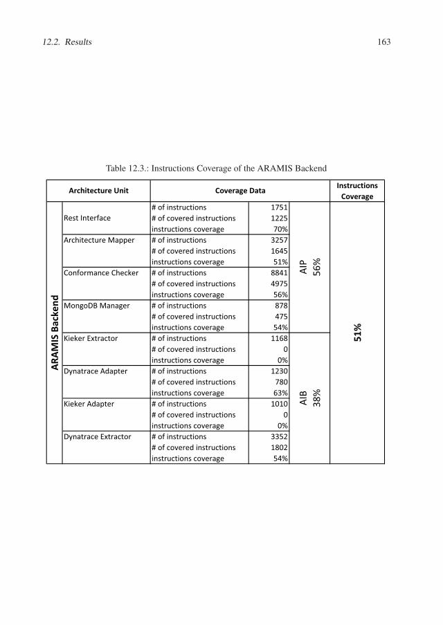
12.2. Results 163
Table 12.3.: Instructions Coverage of the ARAMIS Backend
Instructions Coverage
# of instructions 1751# of covered instructions 1225instructions coverage 70%
Architecture Mapper # of instructions 3257# of covered instructions 1645instructions coverage 51%
Conformance Checker # of instructions 8841# of covered instructions 4975instructions coverage 56%
MongoDB Manager # of instructions 878# of covered instructions 475instructions coverage 54%
Kieker Extractor # of instructions 1168# of covered instructions 0instructions coverage 0%
Dynatrace Adapter # of instructions 1230# of covered instructions 780instructions coverage 63%
Kieker Adapter # of instructions 1010# of covered instructions 0instructions coverage 0%
Dynatrace Extractor # of instructions 3352# of covered instructions 1802instructions coverage 54%
Architecture Unit
Rest Interface
Coverage Data
51%
ARAM
IS B
acke
nd
AIB
38%
AIP
56%
164 Chapter 12. Case Study I
Next, we applied the formula defined in Chapter 8 for the computation of the system’s code unitcoverage.
cuCov(ARAMIS _Backend, AramisMon) =15 − 3
15� 0.8
Given that despite the low instructions coverage approximately 80% of all the code unitswere involved during the execution of the considered episode, our confidence in its adequacyincreased accordingly.
Rule Coverage To further inquire the adequacy of the monitored behavior, we also computedthe achieved rule coverage, as defined in Chapter 8.
To this end, as introduced in Chapter 8, we first identified the set of allowing and enforcingrules corresponding to ARAMIS:
AERARAMIS ={DynaUnitsCoupled,KiekerUnitsCoupled, ExtractorAndManagerCoupled,
AramisChainRule, AramisDbCoupling,RestAndCheckerCoupled,
RestToMapper,RestToChecker,RestToAdapter,RestToManager,
CheckerToManager,DBManagerToDB, ExtractorToDB, AdapterToDB,
AdapterToMapper,MapperToChecker}
Because the Kieker units were not involved in the conducted monitoring session, the followingsubset of rules was not used during conformance checking:
notAppliedRulesARAMIS,AramisMon = {KiekerUnitsCoupled}
Due to the fact that the Spring framework shadowed the use of some of the defined rules 2 theset notAppliedRulesARAMIS,AramisMon was initially larger. However, manual inspections provedthat all rules involving the MongoDBManager were in fact used and thus these were eliminatedfrom the notAppliedRulesARAMIS,AramisMon set.
Consequently, the rule coverage was computed as follows:
sysRuleCoverageARAMIS,AramisMon =|appliedRulesARAMIS,AramisMon|
|AERARAMIS| =
=|AERARAMIS| − |notAppliedRulesARAMIS,AramisMon|
|AERARAMIS| =
=15
16� 0.94
The high value of the achieved rule coverage additionally increased our confidence, that thecaptured behavior was indeed adequate to support an associated conformance checking, despitethe low instructions coverage measured earlier.
2ExtractorAndManagerCoupled, RestAndCheckerCoupled, RestToManager, CheckerToManager andDBManagerToDB

12.3. Discussion 165
Scenario Coverage As explained above, when deciding which scenarios to include in theconducted monitoring session, the students chose only those that did not involve the KiekerExtractor and Adapter architecture units. Details regarding the resulted episode, referred toas the AramisMon, and the actual computation of the scenario coverage are available in theAppendix C.1. Despite omitting two architecture units, a scenario coverage of 0.9 was achieved.This indicated that the most important functionality of the ARAMIS system was indeed triggeredduring the conducted monitoring session, thus further increasing the confidence in the extractedbehavior.
Corroborating White- and Black-box Indicators Having computed several black-box andwhite-box indicators of adequacy for the AramisMon episode, we then corroborated the results.If we had considered the instructions coverage in isolation, its very low value would have leadus to the conclusion that the considered episode is not adequate for supporting a system-widebehavior-based conformance check. However, this contradicted our architectural knowledgeregarding the ARAMIS Backend. Indeed, the code unit coverage confirmed that the majority ofthe code units were active during the execution. Even more, 90% of all scenarios enlisted bythe system’s architect were considered. Given that additionally to this, 94% of the allowed andenforced communication occured during execution, we concluded that the performed analysis isrelevant for the system as a whole and that there is a high chance that the ARAMIS backend isindeed adhering to its indended architecture to a significant extent.
12.3. Discussion
Using the ACR-Lang we could express all the applicable communication rules of interest andthe conformance to them could be checked with the developed ARAMIS Toolbox.
Furthermore, the proposed white-box and black-box indicators were useful to reason regard-ing the adequacy of the employed monitoring session. Despite the low instructions coverage,the rules, code unit and scenario coverages expose higher values. Consequently, we argued thatalthough the actual instructions coverage was low, the session itself is adequate for checking theconformance of the system from the point of view of its most important scenarios.
Last but not least, the ACC-Proc was useful to guide the activities of the students, providingorientation regarding what tasks should be performed during conformance checking.
The intended architecture description was elaborated by the architect using the ARAMISmeta-model presented in Chapter 6.2. Consequently, the ARAMIS Architecture DescriptionTransformation Process (AADT-Proc) was rendered unnecessary, as the elaborated descriptioncould be used in its initial form. Applications of the AADT-Proc will be presented in the follow-ing two case studies.
Threats To Validity
Despite the positive results and the fact that we could conveniently profit from our architecturalknowledge regarding the ARAMIS Backend, this case study also poses important threats to va-lidity. The most important one is given by the identity of the architect. The intended architecture

166 Chapter 12. Case Study I
description was already available and published at the time of this evaluation. However a biascannot be ruled out: it is possible that the author unwillingly defined the architecture in a waythat ensures that the rules governing the communication of the architecture units will later beexpressible using the created ACR-Lang. In reverse, it cannot be rendered impossible that theACR-Lang itself was created to be able to express the already existing intended architecture ofthe ARAMIS Backend. Either of these cases would minimize or even nullify the positive resultthat we obtained regarding the expressiveness of the ACR-Lang. Furthermore, the students in-volved in the evaluation were familiar with the main goal of ARAMIS; also, they were awarethat the final task of the practical course will be the conformance checking of the developed so-lution itself. Consequently, their whole implementation process could have been influenced bythis knowledge thus minimizing the number of produced violations. In a more realistic set-up itcan easily occur that the developers question the quality of the intended architecture descriptionand possibly propose alternative solutions. Given the current situation, it is possible that thestudents refrained from doing so, to reduce the risk of not being able to express the alternativecommunication rules. Last but not least, the ranking of the scenarios was also performed by theauthor of the thesis. All the performed case studies confirmed the superiority of Dynatrace overKieker with respect to our conformance checking purpose. This indeed supports the author’sdecision to rank the Dynatrace-related scenarios as more important. However, this choice couldhave also been influenced by the desire to obtain overall positive evaluation results. While theauthor constantly motivated and questioned her actions in order to reduce bias, self-evaluationis, as always, prone to a certain level of subjectivity.

Chapter 13.
Case Study II
In this case study we investigated the applicability of ARAMIS to conduct a behavior-basedarchitecture conformance check of a commercial software system for managing insurances pro-vided by one of our industry partners. The names of the partner and of the investigated systemitself are obfuscated due to confidentiality reasons. Within the frame of this evaluation we referto this system as being the InsuranceApp System. This chapter is based on the results publishedin [NLH17].
In this case study we evaluated whether the ARAMIS Communication Rules Language (ACR-Lang) is suitable to express the communication rules formulated by one of the architects of theInsuranceApp. We further inquired if the developed white-box and black-box indicators are use-ful to investigate the adequacy of the captured behavior and whether the ARAMIS Toolbox canbe used to automate the actual conformance check, when provided with an intended architecturedescription and extracted interactions. Last but not least, we inquired whether the developed pro-cesses offer enough guidance when preparing and conducting the actual conformance checkingin general (the ARAMIS Conformance Checking Process - ACC-Proc), and when seeking forsolutions to the Meta-Model Incompatibility Problem (the ARAMIS Architecture DescriptionTransformation Process - AADT-Proc) in particular.
13.1. Case Study Design
This section presents the participants involved in the case study, the general environment andinitial setup.
Participants
This case study involved two persons: the author of this dissertation and one of the architectsresponsible for the InsuranceApp.
Environment
The evaluation of the InsuranceApp was conducted over a timespan of approximately two weeks,scattered over a longer period of time, depending on the availability of the two involved partici-pants.
The core of the InsuranceApp was developed externally as a commercial, highly customiz-able J2EE-based framework for defining and managing insurance products. Its purpose is to

168 Chapter 13. Case Study II
allow customers to define customized products on top of the underlying framework, with spe-cific parameters and attached, definable life-cycles. At the time of the evaluation (February2016), the InsuranceApp framework was evaluated by our industry partner for its suitability toreplace a long-living system in the company. Consequently, a project was undergone with thepurpose to experiment with the development of system-support for insurance products specificto our industry partner on top of the InsuranceApp framework. We refer to the resulted sys-tem, as the InsuranceApp System, or shortly, the InsuranceApp. A quantitative overview of theInsuranceApp is given in Table 13.1.
Table 13.1.: Quantitative Overview of the InsuranceApp
Estimated Number of Person Days 5000
Number of Lines of Code 2491227
Number of Classes 7523
Number of Database tables 271
Setup
To be able to perform the evaluation with minimum impact on the day to day business of ourindustry partner, we were handed in a virtual machine containing the source code and an instal-lation of the InsuranceApp system. Technically, the InsuranceApp is simply an EAR deployedon a Oracle Weblogic 11g Server. The interaction with the application was possible through itsJSF-based WEB interface.
As prescribed by the ACC-Proc, we investigated as part of the overall setup what monitoringtool is better fitted to employ on the InsuranceApp. Given that the system was a technicallyhomogeneous J2EE system, we first decided to employ the apparently easier solution and in-strument with Kieker the Weblogic server on which the corresponding InsuranceApp EAR filewas deployed. Being an academic product, Kieker has a less restrictive usage model guided bythe popular Apache License. Furthermore, Kieker assumes no additional installation of soft-ware. However, after several failed attempts to perform the instrumentation, we decided to usethe more mature Dynatrace monitor instead. Dynatrace requires installation, but this additional,more time-consuming step could be undergone by us, given that we performed the monitoringon a virtual machine on which we were granted full control.
13.2. Results
In this section we first discuss our AADT-Proc-driven solution to alleviating the Meta-ModelIncompatibility Problem resulted from the fact that the initially provided intended architecturedescription of the InsuranceApp was not an instance of the ARAMIS Meta-Model (ARAMIS-MM). Next we discuss whether the ACR-Lang was expressive enough to formulate the rulesapplicable in the case of the InsuranceApp. We continue with an overview of the obtainedconformance checking results and then inquire about their relevance by inspecting the adequacyof the captured behavior using the developed white- and black-box indicators.
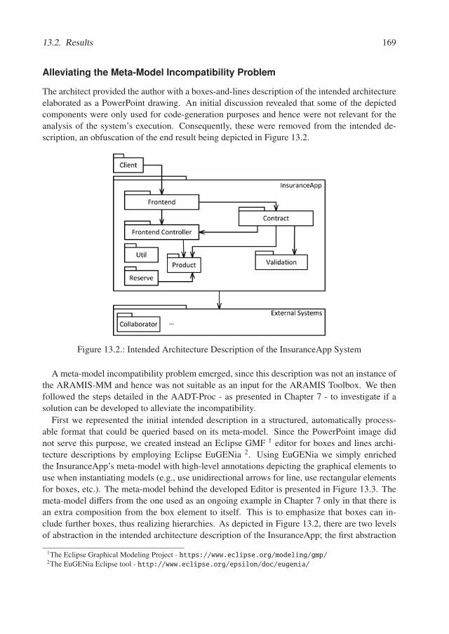
13.2. Results 169
Alleviating the Meta-Model Incompatibility Problem
The architect provided the author with a boxes-and-lines description of the intended architectureelaborated as a PowerPoint drawing. An initial discussion revealed that some of the depictedcomponents were only used for code-generation purposes and hence were not relevant for theanalysis of the system’s execution. Consequently, these were removed from the intended de-scription, an obfuscation of the end result being depicted in Figure 13.2.
Figure 13.2.: Intended Architecture Description of the InsuranceApp System
A meta-model incompatibility problem emerged, since this description was not an instance ofthe ARAMIS-MM and hence was not suitable as an input for the ARAMIS Toolbox. We thenfollowed the steps detailed in the AADT-Proc - as presented in Chapter 7 - to investigate if asolution can be developed to alleviate the incompatibility.
First we represented the initial intended description in a structured, automatically process-able format that could be queried based on its meta-model. Since the PowerPoint image didnot serve this purpose, we created instead an Eclipse GMF 1 editor for boxes and lines archi-tecture descriptions by employing Eclipse EuGENia 2. Using EuGENia we simply enrichedthe InsuranceApp’s meta-model with high-level annotations depicting the graphical elements touse when instantiating models (e.g., use unidirectional arrows for line, use rectangular elementsfor boxes, etc.). The meta-model behind the developed Editor is presented in Figure 13.3. Themeta-model differs from the one used as an ongoing example in Chapter 7 only in that there isan extra composition from the box element to itself. This is to emphasize that boxes can in-clude further boxes, thus realizing hierarchies. As depicted in Figure 13.2, there are two levelsof abstraction in the intended architecture description of the InsuranceApp; the first abstraction
1The Eclipse Graphical Modeling Project - https://www.eclipse.org/modeling/gmp/2The EuGENia Eclipse tool - http://www.eclipse.org/epsilon/doc/eugenia/
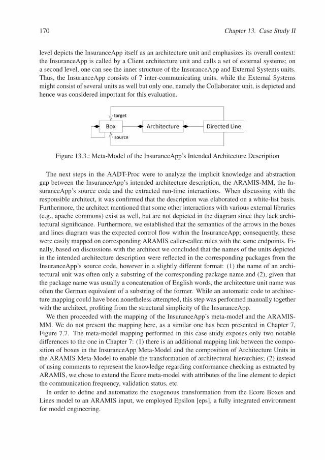
170 Chapter 13. Case Study II
level depicts the InsuranceApp itself as an architecture unit and emphasizes its overall context:the InsuranceApp is called by a Client architecture unit and calls a set of external systems; ona second level, one can see the inner structure of the InsuranceApp and External Systems units.Thus, the InsuranceApp consists of 7 inter-communicating units, while the External Systemsmight consist of several units as well but only one, namely the Collaborator unit, is depicted andhence was considered important for this evaluation.
Figure 13.3.: Meta-Model of the InsuranceApp’s Intended Architecture Description
The next steps in the AADT-Proc were to analyze the implicit knowledge and abstractiongap between the InsuranceApp’s intended architecture description, the ARAMIS-MM, the In-suranceApp’s source code and the extracted run-time interactions. When discussing with theresponsible architect, it was confirmed that the description was elaborated on a white-list basis.Furthermore, the architect mentioned that some other interactions with various external libraries(e.g., apache commons) exist as well, but are not depicted in the diagram since they lack archi-tectural significance. Furthermore, we established that the semantics of the arrows in the boxesand lines diagram was the expected control flow within the InsuranceApp; consequently, thesewere easily mapped on corresponding ARAMIS caller-callee rules with the same endpoints. Fi-nally, based on discussions with the architect we concluded that the names of the units depictedin the intended architecture description were reflected in the corresponding packages from theInsuranceApp’s source code, however in a slightly different format: (1) the name of an archi-tectural unit was often only a substring of the corresponding package name and (2), given thatthe package name was usually a concatenation of English words, the architecture unit name wasoften the German equivalent of a substring of the former. While an automatic code to architec-ture mapping could have been nonetheless attempted, this step was performed manually togetherwith the architect, profiting from the structural simplicity of the InsuranceApp.
We then proceeded with the mapping of the InsuranceApp’s meta-model and the ARAMIS-MM. We do not present the mapping here, as a similar one has been presented in Chapter 7,Figure 7.7. The meta-model mapping performed in this case study exposes only two notabledifferences to the one in Chapter 7: (1) there is an additional mapping link between the compo-sition of boxes in the InsuranceApp Meta-Model and the composition of Architecture Units inthe ARAMIS Meta-Model to enable the transformation of architectural hierarchies; (2) insteadof using comments to represent the knowledge regarding conformance checking as extracted byARAMIS, we chose to extend the Ecore meta-model with attributes of the line element to depictthe communication frequency, validation status, etc.
In order to define and automatize the exogenous transformation from the Ecore Boxes andLines model to an ARAMIS input, we employed Epsilon [eps], a fully integrated environmentfor model engineering.
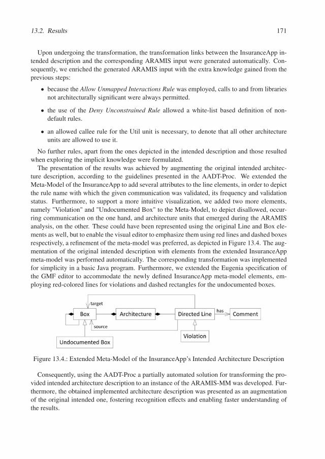
13.2. Results 171
Upon undergoing the transformation, the transformation links between the InsuranceApp in-tended description and the corresponding ARAMIS input were generated automatically. Con-sequently, we enriched the generated ARAMIS input with the extra knowledge gained from theprevious steps:
• because the Allow Unmapped Interactions Rule was employed, calls to and from librariesnot architecturally significant were always permitted.
• the use of the Deny Unconstrained Rule allowed a white-list based definition of non-default rules.
• an allowed callee rule for the Util unit is necessary, to denote that all other architectureunits are allowed to use it.
No further rules, apart from the ones depicted in the intended description and those resultedwhen exploring the implicit knowledge were formulated.
The presentation of the results was achieved by augmenting the original intended architec-ture description, according to the guidelines presented in the AADT-Proc. We extended theMeta-Model of the InsuranceApp to add several attributes to the line elements, in order to depictthe rule name with which the given communication was validated, its frequency and validationstatus. Furthermore, to support a more intuitive visualization, we added two more elements,namely "Violation" and "Undocumented Box" to the Meta-Model, to depict disallowed, occur-ring communication on the one hand, and architecture units that emerged during the ARAMISanalysis, on the other. These could have been represented using the original Line and Box ele-ments as well, but to enable the visual editor to emphasize them using red lines and dashed boxesrespectively, a refinement of the meta-model was preferred, as depicted in Figure 13.4. The aug-mentation of the original intended description with elements from the extended InsuranceAppmeta-model was performed automatically. The corresponding transformation was implementedfor simplicity in a basic Java program. Furthermore, we extended the Eugenia specification ofthe GMF editor to accommodate the newly defined InsuranceApp meta-model elements, em-ploying red-colored lines for violations and dashed rectangles for the undocumented boxes.
Figure 13.4.: Extended Meta-Model of the InsuranceApp’s Intended Architecture Description
Consequently, using the AADT-Proc a partially automated solution for transforming the pro-vided intended architecture description to an instance of the ARAMIS-MM was developed. Fur-thermore, the obtained implemented architecture description was presented as an augmentationof the original intended one, fostering recognition effects and enabling faster understanding ofthe results.
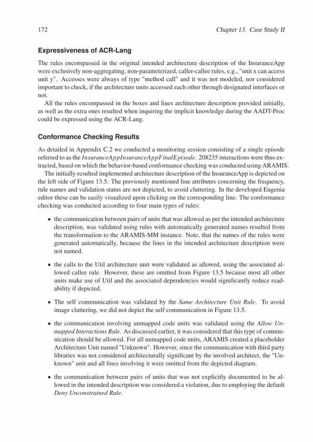
172 Chapter 13. Case Study II
Expressiveness of ACR-Lang
The rules encompassed in the original intended architecture description of the InsuranceAppwere exclusively non-aggregating, non-parameterized, caller-callee rules, e.g., "unit x can accessunit y". Accesses were always of type "method call" and it was not modeled, nor consideredimportant to check, if the architecture units accessed each other through designated interfaces ornot.
All the rules encompassed in the boxes and lines architecture description provided initially,as well as the extra ones resulted when inquiring the implicit knowledge during the AADT-Proccould be expressed using the ACR-Lang.
Conformance Checking Results
As detailed in Appendix C.2 we conducted a monitoring session consisting of a single episodereferred to as the InsuranceAppInsuranceAppFinalEpisode. 208235 interactions were thus ex-tracted, based on which the behavior-based conformance checking was conducted using ARAMIS.
The initially resulted implemented architecture description of the InsuranceApp is depicted onthe left side of Figure 13.5. The previously mentioned line attributes concerning the frequency,rule names and validation status are not depicted, to avoid cluttering. In the developed Eugeniaeditor these can be easily visualized upon clicking on the corresponding line. The conformancechecking was conducted according to four main types of rules:
• the communication between pairs of units that was allowed as per the intended architecturedescription, was validated using rules with automatically generated names resulted fromthe transformation to the ARAMIS-MM instance. Note, that the names of the rules weregenerated automatically, because the lines in the intended architecture description werenot named.
• the calls to the Util architecture unit were validated as allowed, using the associated al-lowed callee rule. However, these are omitted from Figure 13.5 because most all otherunits make use of Util and the associated dependencies would significantly reduce read-ability if depicted.
• The self communication was validated by the Same Architecture Unit Rule. To avoidimage cluttering, we did not depict the self communication in Figure 13.5.
• the communication involving unmapped code units was validated using the Allow Un-mapped Interactions Rule. As discussed earlier, it was considered that this type of commu-nication should be allowed. For all unmapped code units, ARAMIS created a placeholderArchitecture Unit named "Unknown". However, since the communication with third partylibraries was not considered architecturally significant by the involved architect, the "Un-known" unit and all lines involving it were omitted from the depicted diagram.
• the communication between pairs of units that was not explicitly documented to be al-lowed in the intended description was considered a violation, due to employing the defaultDeny Unconstrained Rule.
13.2. Results 173
Client
InsuranceApp
Frontend
Frontend Controller
Contract
Product Validation
External SystemsCollaborator …
Util
Reserve
Client
InsuranceApp
Frontend
Frontend Controller
Contract
Product Validation
External SystemsCollaborator …
Platform
Reserve
Util
First Version of Implemented Architecture Description Refined Implemented Architecture Description
Architecture Unit Architecture UnitRightfully Accessed
Caused A Violation by AccessingLegend
Figure 13.5.: Implemented Architecture Description of the InsuranceApp
Using ARAMIS, we detected multiple violations involving calls to the Product architectureunit. Upon analyzing these, the Architect acknowledged that the initial intended architecturedescription lacks an important piece of information: the product architecture unit consists ofmany domain objects which are also used for transferring information between the units. Con-sequently, a new rule was formulated, namely that the Product architecture unit can be called byany other unit in the InsuranceApp’s architecture. Next, the architect examined the calls that theUtil unit issues towards the Frontend, Frontend Controller, Product and Contract. Although thedetails are out of the scope of this paper, using the ARAMIS visualizations it was easily possibleto check from which packages, classes and methods in the source code did the calls originate andwhich exact methods were called by these. In doing so, the architect realized that we initiallyperformed a wrong code to architecture mapping and, additionally, that the intended architecturedescription should be enriched with a new architecture unit, generically named Platform. Thus,given that all the violations caused by Util originated from two packages, these were extractedfrom Util and added to the newly created architecture unit Platform. According to the archi-tect, Platform is a unit responsible for various initializations and code injection capabilities. Anew caller rule was formulated, namely that Platform is allowed to call all other units of Insur-anceApp. Furthermore, after a thorough analysis of the dependencies between the Client and theFrontend Controller, the architect concluded that an additional allowed caller-callee rule shouldbe added to the intended architecture description (Client �→ Frontend Controller).
Having performed these refinements, the architect eventually confirmed the existence of 5violations in the implemented architecture of InsuranceApp that need further analysis and refac-toring: Product �→ Frontend Controller, Product �→ Fronted, Product �→ Validation, Product �→Contract and Fronted �→ Client.
174 Chapter 13. Case Study II
Another important finding, resulted through the inspection of the allowed dependency be-tween the InsuranceApp and the ExternalSystems. The intended architecture description sug-gests in this case, by means of a derived rule, that any architecture unit encompassed in the In-suranceApp is allowed to call the Colaborator External System. An analysis of this dependencyrevealed that the Collaborator was accessed by three InsuranceApp architecture units: Fron-tend, Contract and Product. Upon acknowledging this, the architect recognized a fault in theintended architecture description: this has been formulated in a too permissive manner. Futurerefactorings should ensure a single dependency to Collaborator, preferably from the Frontendarchitecture unit.
The final implemented architecture description of the InsuranceApp system is depicted on theright side of Figure 13.5.
Monitoring Adequacy
The adequacy of the extracted behavior was investigated using white-box and black-box indica-tors as depicted below.
Instruction Coverage. Using a JaCoCo agent we instrumented the Weblogic Server onwhich the InsuranceApp was running to compute the instructions coverage of the InsuranceApp-FinalEpisode. Using JaCoCo’s reporting capabilities we extracted the instructions coverage ofthe packages encompassed by the InsuranceApp which we then aggregated hierarchically tocompute the coverage of the encompassed code units, architecture units and eventually of theInsuranceApp as a whole, using the formula for the adaptation of known code coverage metricspresented in Section 8.1. The resulted values for the instructions coverage are displayed in Table13.6.
The reason for the low value of the instructions coverage can be the integration level on whichwe have measured it. Good code coverage can be (relatively) easily obtained at the level of unittesting. However, the InsuranceAppFinalEpisode positions itself very high in the integrationhierarchy, namely on the system level. At this level of integration, achieving a good overallcoverage is sometimes very challenging.
Code Unit Coverage. For computing the code unit coverage, as defined Section 8.1, we onlyconsidered the architecture units encompassed in the InsuranceApp system. We considered thatthe coverage of the Client and Collaborator units is not important in this context, since we are notinterested if these were used in their entirety but whether they interacted properly with the Insur-anceApp system. In Table 13.7 we give an overview of the code unit coverage of all architectureunits encompassed in the InsuranceApp. Given that all architecture units encompassed in theInsuranceApp exposed a 100% code unit coverage, it follows that the InsuranceApp itself alsohas a perfect 100% coverage, meaning that all defined code units were involved in performingthe behavior associated to the InsuranceAppFinalEpisode.
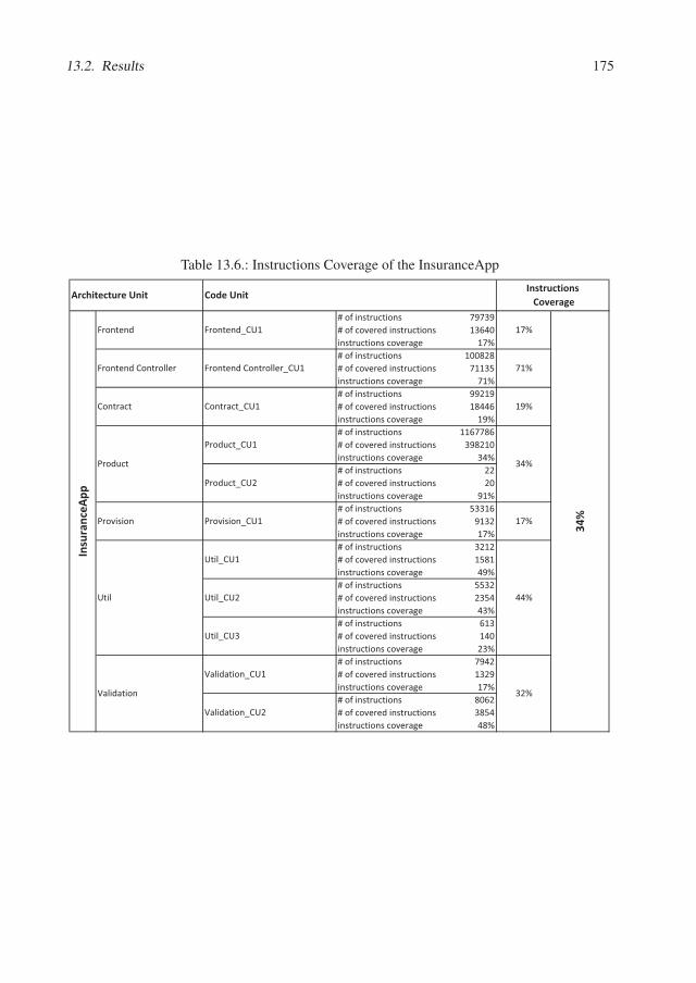
13.2. Results 175
Table 13.6.: Instructions Coverage of the InsuranceApp
#�of�instructions 79739#�of�covered�instructions 13640instructions�coverage 17%#�of�instructions 100828#�of�covered�instructions 71135instructions�coverage 71%#�of�instructions 99219#�of�covered�instructions 18446instructions�coverage 19%#�of�instructions 1167786#�of�covered�instructions 398210instructions�coverage 34%#�of�instructions 22#�of�covered�instructions 20instructions�coverage 91%#�of�instructions 53316#�of�covered�instructions 9132instructions�coverage 17%#�of�instructions 3212#�of�covered�instructions 1581instructions�coverage 49%#�of�instructions 5532#�of�covered�instructions 2354instructions�coverage 43%#�of�instructions 613#�of�covered�instructions 140instructions�coverage 23%#�of�instructions 7942#�of�covered�instructions 1329instructions�coverage 17%#�of�instructions 8062#�of�covered�instructions 3854instructions�coverage 48%
Validation_CU1
Validation_CU2
Code�UnitInstructions�Coverage
34%
32%
Frontend_CU1
Frontend�Controller_CU1
Contract_CU1
Product_CU1
Product_CU2
Provision_CU1
Util_CU1
Util_CU2
Util_CU3
Provision
Util
Validation
Insu
ranc
eApp
17%
71%
19%
34%
17%
44%
Architecture�Unit
Frontend
Frontend�Controller
Contract
Product
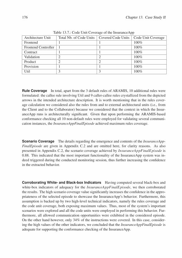
176 Chapter 13. Case Study II
Table 13.7.: Code Unit Coverage of the InsuranceApp
Architecture Unit Total Nb. of Code Units Covered Code Units Code Unit Coverage
Frontend 1 1 100%
Frontend Controller 1 1 100%
Contract 1 1 100%
Validation 2 2 100%
Product 2 2 100%
Provision 1 1 100%
Util 3 3 100%
Rule Coverage In total, apart from the 3 default rules of ARAMIS, 10 additional rules wereformulated: the callee rule involving Util and 9 caller-callee rules crystallized from the depictedarrows in the intended architecture description. It is worth mentioning that in the rules cover-age calculation we considered also the rules from and to external architectural units (i.e., fromthe Client and to the Collaborator) because we considered that the context in which the Insur-anceApp runs is architecturally significant. Given that upon performing the ARAMIS-basedconformance checking all 10 non-default rules were employed for validating several communi-cation instances, the InsuranceAppFinalEpisode achieved maximum rules coverage.
Scenario Coverage The details regarding the emergence and contents of the InsuranceApp-FinalEpisode are given in Appendix C.2 and are omitted here, for clarity reasons. As alsopresented in Appendix C.2, the scenario coverage achieved by InsuranceAppFinalEpisode is0.88. This indicated that the most important functionality of the InsuranceApp system was in-deed triggered during the conducted monitoring session, thus further increasing the confidencein the extracted behavior.
Corroborating White- and Black-box Indicators Having computed several black-box andwhite-box indicators of adequacy for the InsuranceAppFinalEpisode, we then corroboratedthe results. The high scenario coverage value significantly increases the confidence in the appro-priateness of the selected episode to showcase the InsuranceApp’s behavior. Furthermore, thisassumption is backed up by two high-level technical indicators, namely the rules coverage andthe code unit coverage, both exposing maximum values. Thus, most of the system’s importantscenarios were explored and all the code units were employed in performing this behavior. Fur-thermore, all allowed communication opportunities were exhibited in the considered episode.On the other hand however, only 34% of the instructions were covered. In this case, consider-ing the high values of the other indicators, we concluded that the InsuranceAppFinalEpisode isadequate for supporting the conformance checking of the InsuranceApp.
13.3. Discussion 177
13.3. Discussion
The main goal of this case study was to investigate the applicability of ARAMIS in a non-trivial,realistic context.
Using the ACR-Lang we could express all the communication rules of interest. The confor-mance thereto was checked automatically using the ARAMIS Toolbox.
Because the intended architecture description was not an instance of the ARAMIS-MM, theAADT-Proc offered guidance in alleviating the Meta-Model Incompatibility Problem. Further-more, the ACC-Proc provided orientation for the activities specific to behavior-based confor-mance checking in general.
Furthermore, we employed the proposed white-box indicator as well a subset of the developedblack-box indicators to investigate the adequacy of the monitored episode for supporting an as-sociated behavior-based architecture conformance check. The high values of the rules and codeunit coverage were corroborated with the results of the scenario coverage metric to increases theconfidence in the obtained results despite the low value of the overall instructions coverage.
This case study is also useful as an example regarding the effort needed to invest for checkingthe conformance of a technologically homogeneous, middle-sized software system with a doc-umented intended architecture description: half of a working day from the architect’s time andtwo additional days to conduct the analysis and prepare the presentation of the results 3.
All in all, the results were regarded by the involved architect as useful and relevant and thedeveloped processes offered us enough guidance during the evaluation itself. However, gener-alizations regarding the applicability of ARAMIS in industrial contexts are not possible basedthereupon. Due to its inherent nature, a single case-study is only relevant for the analyzed sys-tem and its context alone. Therefore, in order to strengthen our results we performed a secondindustrial case study, this time with a larger scope and on a more complex, large-scale system,as we will present in the next chapter.
Threats to Validity
The Case Study II was performed on a third-party system provided by one of our industry part-ners. Consequently, the limitations faced in the Case Study I were thus avoided. However, adifferent threat of validity emerges from the nature of the InsuranceApp: being a monolith ap-plication, developed using a homogeneous technology stack, it does not represent the best can-didate to evaluate an approach for behavior-based architecture conformance checking. It can bequestioned that the positive results regarding the capability to express the communication rulesusing ACR-Lang are misleading, given the simplicity of the rules themselves. Furthermore, con-sidering that the author of the thesis was the one following the ACC-Proc and the AADT-Proc, itremains unknown whether these processes are feasible to guide novices with no prior experiencein behavior-based conformance checking. The results regarding their usefulness are thereforealso not directly transferable.
3the artifacts that served the model to model transformation and augmentation were available from previous exper-iments

Chapter 14.
Case Study III
In this case study we explored the applicability of ARAMIS to conduct a further behavior-based architecture conformance check of a commercial software system developed with anotherindustry partner of our research group. The names of the industry partner and of the investigatedsystem itself are obfuscated due to confidentiality reasons. Given that the main capabilities ofthe analyzed system are task automation and data distribution, in the context of this evaluationwe will refer to it as being the TADD System. This chapter is based on the results published in[TNL17].
In this case study we evaluated whether the ARAMIS Communication Rules Language (ACR-Lang) is suitable to express the communication rules formulated by several stakeholders em-ployed by our industry partner and/or depicted in the presented intended architecture descrip-tion. Also in this case, we aimed towards investigating whether the developed ARAMIS Toolboxcan be employed to automate the conformance checking against the defined rules. We furtherinquired if the developed white-box and black-box indicators are useful to investigate the ade-quacy of the captured behavior and to indicate the extent to which the conformance checkingresults can be relied upon. Last but not least, we inquired weather the developed processes offerenough guidance when preparing and conducting the actual conformance checking in general(the ARAMIS Conformance Checking Process - ACC-Proc), and when seeking for solutionsto the Meta-Model Incompatibility Problem (the ARAMIS Architecture Description Transfor-mation Process - AADT-Proc) in particular. Finally, we compared the capabilities of ARAMISwith those of a static-based conformance checking solution with the intent to analyze its relativestrengths and weaknesses in a real-world context.
14.1. Case Study Design
This section presents the participants involved in the case study, the general environment andinitial setup.
Participants
The case study was organized within the context of a master thesis project [Tho17] and wasconducted over a period of seven months. The involved master thesis student was supervisedboth by us and by our industry partners to ensure that both parties’ goals are met. Furthermore,the student was deeply involved in the day to day business of our industry partner, was offered a
180 Chapter 14. Case Study III
permanent working place at their premises and discussed the obtained results on a weekly basiswith several stakeholders.
Environment
The evaluation’s scope exceeded by far that of the Case Studies I and II in almost all aspects,most notably in terms of invested time and resources, evaluation objectives, involvement of theindustry partner and complexity of the explored system.
TADD has been developed and constantly evolved since 2008 and is a business critical com-ponent for many of the software solutions offered by our industry partner. Due to its importance,features were constantly added to it to keep up with the customers’ changing requirements.Furthermore, to ensure the preservation of its nonfunctional requirements, several architecturalrefactorings have been undergone, such that TADD has evolved to a multi-process, OSGI-basedsystem. TADD consists of 5 OSGi processes: the Public Proxy (PP) provides the API for theTADD’s rich client application; the Task Manager (TM) uses finite states machines to managethe lifecycle of TADD tasks and provides a fail-over and retry management, to handle possibletask execution failures; the schedule of recurrent and timed tasks is calculated by the Sched-uler (S); the Executor (E) executes tasks by starting and stopping local processes or servicesand triggering data transfer jobs as well as remote services; finally, the Data Distributor (DD)distributes, filters and converts data across different locations.
A quantitative overview of TADD is give in Table 14.1. From a pure quantitative perspec-tive, TADD is significantly smaller than the InsuranceApp analyzed in the first industrial CaseStudy in Chapter 13, comprising significantly fewer lines of code. However, from a process-oriented perspective, TADD is by far more complex. Unlike the InsuranceApp, which was amere monolith, homogeneous application running in a single process, TADD consists of fiveOSGI processes, each responsible for a well-defined functional aspect. Each process hosts sev-eral OSGI bundles and some of the bundles (e.g., the Data Access Layer) are deployed in morethan one process. The bundles communicate with each-other through provided and requiredOSGI services. Furthermore, the bundles make use of several .jar artifacts to which they havedirect dependencies. Being a data distribution system, TADD also employs several commu-nication protocols (e.g., FTP, IMAP) to redirect or extract data to and from external systems.For persistence, TADD uses a traditional relational database management system but also a fairamount of local files to which all processes have access to. The processes communicate witheach-other through two main mechanisms:
• all processes use a message bus on a publish-subscribe basis;
• all processes are constantly polling the persistence layer to detect state changes caused bythe other processes.
Setup
As prescribed by the ACC-Proc, we investigated as part of the overall setup what monitoringtool is better fitted to employ on the TADD. Considering that TADD is a multi-process system,
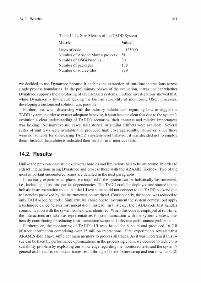
14.2. Results 181
Table 14.1.: Size Metrics of the TADD System
Metric Value
Lines of code ∼ 125000Number of Apache Maven projects 51Number of OSGi bundles 30Number of packages 138Number of source files 879
we decided to use Dynatrace because it enables the extraction of run-time interactions acrosssingle process boundaries. In the preliminary phases of the evaluation, it was unclear whetherDynatrace supports the monitoring of OSGI-based systems. Further investigations showed that,while Dynatrace is by-default lacking the built-in capability of monitoring OSGI processes,developing a customized solution was possible.
Furthermore, when discussing with the industry stakeholders regarding how to trigger theTADD system in order to extract adequate behavior, it soon became clear that due to the system’sevolution a clear understanding of TADD’s scenarios, their contexts and relative importanceswas lacking. No narrative use cases, user stories, or similar artifacts were available. Severalsuites of unit tests were available that produced high coverage results. However, since thesewere not suitable for showcasing TADD’s system-level behavior, it was decided not to employthem. Instead, the architects indicated their suite of user interface tests.
14.2. Results
Unlike the previous case studies, several hurdles and limitations had to be overcome, in order toextract interactions using Dynatrace and process these with the ARAMIS Toolbox. Two of themost important encountered issues are detailed in the next paragraphs.
In an early experimental phase, we inquired if the system can be holistically instrumented,i.e., including all its third parties dependencies. The TADD could be deployed and started in thisholistic instrumentation mode, but the UI test suite could not connect to the TADD backend dueto latencies provoked by the instrumentation overhead. Consequently, the scope was reduced toonly TADD-specific code. Similarly, we chose not to instrument the system context, but applya technique called "driver instrumentation" instead. In this case, the TADD code that handlescommunication with the system context was identified. When this code is employed at run-time,the interactions are taken as representatives for communication with the system context, thusheavily contributing to reducing instrumentation scope and alleviate performance problems.
Furthermore, the monitoring of TADD’s UI tests lasted for 6 hours and produced 16 GBof trace information comprising over 35 million interactions. First experiments revealed thatARAMIS didn’t have sufficient main memory to process all traces. As it was uncertain if this is-sue can be fixed by performance optimizations in the processing chain, we decided to tackle thisscalability problem by exploiting our knowledge regarding the monitored tests and the system’sgeneral architecture: redundant traces result through (1) test fixture setup and tear down and (2)
182 Chapter 14. Case Study III
periodic polling employed by the processes. We discarded these duplicate traces by utilizingheuristic-based data deduplication techniques. Heuristics were preferred to exact comparisonsin order to avoid long processing times. This strategy enabled us to analyze the captured tracesin ARAMIS. However, in general, when employing such an input reduction technique, archi-tects must be aware of the fact that deduplication based on heuristics might affect the results intwo ways. First, discarding traces can change the frequency of detected violations. This mightlead to misinterpretation of performance critical violations. Second, if traces that contain uniquearchitectural violations are removed, the behavior-based approach will fail to identify them. Inour case, our decision was backed up by the architectural knowledge of the architects and ourown analyses of the source code. The validity of the choice was confirmed by comparing theresults with those resulted when processing the complete input. After an initial analysis of theresults obtained using deduplication techniques, ARAMIS underwent several performance op-timizations and eventually succeeded to process the full set of traces. A close comparison ofthe resulted conformance reports revealed no important differences, as extensively discussed in[Tho17]. However, a very significant performance difference differentiated the analysis of thededuplicated vs. complete monitoring sessions: while the processing and conformance checkingof the deduplicated session lasted for 13 hours, an increase of 154% (33 hours) was determinedin the case of the complete session. However, it is important to note that the low performance,is also due to the prototype character of the ARAMIS Toolbox, developed as a proof of conceptrather than as a performance-optimized, readily applicable software solution. Future optimiza-tions, such as the parallelization of the conformance checking process, could further drasticallyimprove the analysis time. However, the present evaluation has clearly shown the radical positiveeffect that deduplication can play when performing behavior-based conformance checking.
In the remainder of this section we first discuss our AADT-Proc-driven solution to alleviat-ing the Meta-Model Incompatibility problem resulted from the fact that the initially providedintended architecture description of the TADD was not an instance of the ARAMIS Meta-Model(ARAMIS-MM) but, instead, a multi-level UML component diagram. Next we discuss whetherthe ACR-Lang was expressive enough to express the rules applicable in the case of TADD andcontinue with an overview of the obtained conformance checking results. The relevance of theseresults to give an overview regarding the conformance of TADD as a whole is then investigatedusing a subset of the developed white- and black-box indicators.
Alleviating the Meta-Model Incompatibility Problem
The provided intended architecture description of the TADD system was not an ARAMIS-MMinstance. It was instead realized as a multi-level component diagram elaborated using the Enter-prise Architect modeling tool [ent]. Apart from the inherent semantics of an UML componentdiagram, the diagram was elaborated on the basis of a more concrete meta-model, as definedby our industry partners for their OSGI-based systems. The employed meta-model is depictedin Figure 14.2. Although component diagrams typically depict structural aspects, TADD’s in-tended architecture description encompasses a series of both structural and run-time, process-based information. Consequently, from a viewpoint perspective, TADD’s intended architecturedescription is crosscutting two different viewpoints namely the logical and the process ones, asdefined, e.g., by Kruchten [Kru95]. Furthermore, the diagram was realized on several levels of
14.2. Results 183
abstraction that can be analyzed individually. We differentiate between three main abstractionlevels, as discussed next. On Level 0, the diagram depicts the TADD system in its context. Themain information extractable at this level, concerns the interactions of TADD with various othersystems, by employing communication and file exchange protocols such as SMTP, IMAP, FTP,etc. Another important information depicted at Level 0 is that TADD can be accessed by itsclient using a customized RPC protocol. Next, on Level 1, the diagram is enriched with run-time information regarding TADD’s 5 run-time processes and the message broker used for theirinter-communication. First, the information available at Level 0 is further detailed. Therefore,at Level 1 one can see which of the TADD processes exposes the customized RPC interfaceintroduced at Level 0 and also what process uses the previously enlisted protocols to communi-cate with other systems in TADD’s context. By choosing a given process at this level, one cansee further associated Level 2 information. The most important information available at Level2 is what OSGI bundles are included in a selected process. Communication between bundles ismainly realized and depicted through provided and required services. In OSGI terminology, abundle provides a service if it implements a specific service interface. Similarly, other bundlescan require implementations of this interface to be available and accordingly injected for useduring run-time. The process-specific wiring of bundles through required and provided servicesis symbolized on Level 2 using associated assembly connectors named according to the sourcecode-level interface defined for the service in question. An implicit but very important pieceof TADD-specific knowledge is that all the service interfaces are defined in a separate bundlethat acts as the glue between two bundles communicating over a provided and required service.Another dependency type between the bundles depicted at Level 2 is given by imported andexported packages. Using OSGI a bundle can expose packages in their entirety. These can thenbe imported and used by other bundles. The diagram depicts this type of usage using simple de-pendencies from the importing to the exporting bundle. Finally, a third, non-OSGI dependencytype results through the loading of third party or in-house developed jar artifacts in some of thesystem’s bundles.
Furthermore, the type of a certain model element is signaled not only by the level on whichit is defined but also by dedicated stereotypes («OSGI Bundle», «System», «Process», «JAR»etc.). The meta-model of the intended architecture description of TADD is represented in Figure14.2.
Furthermore, we investigated the implicit knowledge encompassed in the TADD’s intendedarchitecture description. Through discussions with the architects, it became clear that the TADDintended description was also realized on a white-list basis. Furthermore, the employed assem-bly connectors were representing the control flow from the requiring to the providing counter-parts. An important implicit knowledge, results from the OSGI semantics in particular. Throughthe use of implemented services and exported packages, an OSGI bundle is inherently split into apublic and a private part. While the private part cannot access or be accessed by other bundles, itis allowed for these to interact with the public part. However, this knowledge is not explicitly de-picted in the architecture description of the component itself, as showcased on the Level 2 of theTADD architecture description. Another important piece of implicit information was suggestedby the name of one bundle, deployed in each of the 5 TADD processes: as its name suggests, theAccessLayer is responsible for realizing the communication with a third party, in this case with
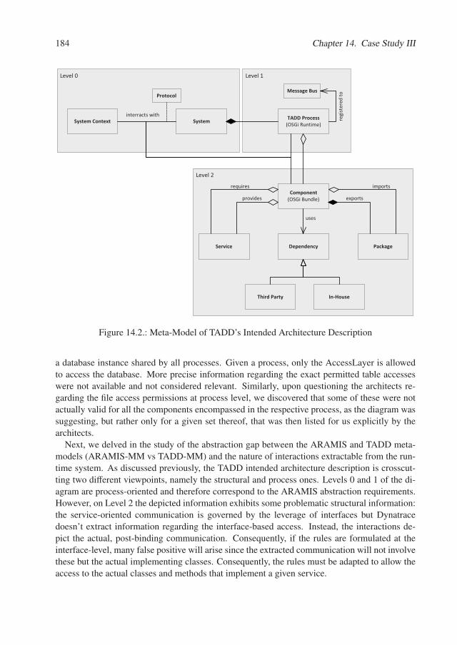
184 Chapter 14. Case Study III
Level�2
Level�1Level�0
System TADD�Process(OSGi�Runtime)
Component(OSGi�Bundle)
Dependency
Third�Party In�House
PackageService
uses
exports
imports
provides
requires
System�Contextinterracts�with
ProtocolMessage�Bus
regi
ster
ed�to
Figure 14.2.: Meta-Model of TADD’s Intended Architecture Description
a database instance shared by all processes. Given a process, only the AccessLayer is allowedto access the database. More precise information regarding the exact permitted table accesseswere not available and not considered relevant. Similarly, upon questioning the architects re-garding the file access permissions at process level, we discovered that some of these were notactually valid for all the components encompassed in the respective process, as the diagram wassuggesting, but rather only for a given set thereof, that was then listed for us explicitly by thearchitects.
Next, we delved in the study of the abstraction gap between the ARAMIS and TADD meta-models (ARAMIS-MM vs TADD-MM) and the nature of interactions extractable from the run-time system. As discussed previously, the TADD intended architecture description is crosscut-ting two different viewpoints, namely the structural and process ones. Levels 0 and 1 of the di-agram are process-oriented and therefore correspond to the ARAMIS abstraction requirements.However, on Level 2 the depicted information exhibits some problematic structural information:the service-oriented communication is governed by the leverage of interfaces but Dynatracedoesn’t extract information regarding the interface-based access. Instead, the interactions de-pict the actual, post-binding communication. Consequently, if the rules are formulated at theinterface-level, many false positive will arise since the extracted communication will not involvethese but the actual implementing classes. Consequently, the rules must be adapted to allow theaccess to the actual classes and methods that implement a given service.
14.2. Results 185
Following the AADT-Proc, we continued with the meta-model mapping phase. The meta-model of ARAMIS is more simplistic than that of the TADD. Consequently, many differentelements of the TADD-MM were mapped on the same element of the ARAMIS-MM, as clearlyvisible in the excerpt of the realized meta-model mapping presented in Figure 14.3.
An OSGI system was mapped on an ARAMIS architecture unit. This unit encompassed,directly or indirectly, all other units resulted from the transformation of processes, components,services, packages and dependencies. In this context, we discussed whether units correspondingto third party dependencies should be indeed included in this unit. We decided to do so, becauseaccording to the TADD-MM everything considered architecturally external, is assigned to thesystem context element.
Given that processes and encompassed components are central architectural entities of theTADD-MM, these were mapped on ARAMIS architecture units. The aggregation between aprocess and its components is reflected by the composition of corresponding architecture units.The correspondence between an aggregation relation in the TADD-MM and a composition re-lation in the ARAMIS-MM can be explained as follows: structurally the aggregation betweenthe process and component elements suggests that processes consists of components and thatthe same component can be deployed in several processes, as, e.g., the case with the previouslymentioned AccessLayer. However, within ARAMIS we associate the behavior of concrete unitsto the behavior of more abstract ones. To achieve this, a composition relation is required, inwhich the concrete unit can only be included in a single, more abstract one. To achieve this,we take advantage of the fact that the various monitors often extract information regarding theclass loader or process in which a given behavior takes place. Therefore, if a given component isdeployed in x distinct processes, then we create x distinct, associated architecture units. Givenan execution record, we can then associate it to the corresponding architecture unit based on itsname qualifier and process id.
Furthermore, as explained before, with services we encountered an abstraction gap betweenthe two meta-models. During the transformation, we approached this gap as follows: For allarchitecture units transformed from components that provided a given service, we created aninner architecture unit encompassing the methods realizing the corresponding service interface.Consequently, we created allowing caller-callee rules from the architecture units requiring thisservice to the newly created architecture units that encompass its implementation.
Next, the TADD-MM dependencies, regardless whether third party or in-house, were trans-formed to architecture units directly included in the unit corresponding to the overall system, i.e.,with no intermediary parent units. The "uses" association between a component and a depen-dency was consequently transformed to an allowing caller-callee rule between the correspondingunits.
Similarly, a high-level architecture unit was created for the system context. We mapped the"interacts with" relationship with an allowing caller-callee rule between the units correspondingto the system and the system context. When a precise protocol (e.g, SMTP, HTTP) was spec-ified for the interaction, a parameterized rule was created with corresponding communicationparameters to characterize the referred protocol.
Our initial assumption was that, as in the case of ARAMIS, rules created between TADD-MM elements propagate downwards in their hierarchy. However, this is not always intended.
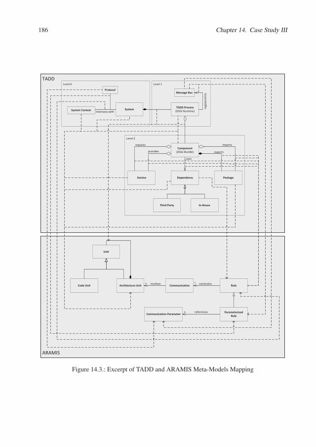
186 Chapter 14. Case Study III
ARAMIS
TADD
Level�2
Level�1Level�0
System TADD�Process(OSGi�Runtime)
Component(OSGi�Bundle)
Dependency
Third�Party In�House
PackageService
�������������uses
exports
imports
provides
requires
System�Context interracts�with
ProtocolMessage�Bus
regi
ster
ed�to
Architecture�UnitCode�Unit
Unit
Communication Rule* constrains* involves
Parameterized�RuleCommunication�Parameter * references
Figure 14.3.: Excerpt of TADD and ARAMIS Meta-Models Mapping
14.2. Results 187
As a TADD-MM diagram is represented on multiple levels of abstraction, a dependency on ahigher level, e.g, on process level, can just mean that inside the process, there is a bundle, or aset thereof, that has this dependency 1. In this case the relation defined on the higher level, e.g.,process does not transitively apply to all the included elements (e.g., bundles). Consequently,we refined our transformation process as follows: if a given relation is not further refined onlower levels, then we consider it transitive and transform it as such. Otherwise, we define therule only for the most specific corresponding unit, i.e. the unit corresponding to the element onthe last level of abstraction that exhibited this relation.
Next, TADD-MM exported packages were not mapped to high-level architecture units. In-stead given a package exported by a given component, this was transformed to an inner archi-tecture unit of the unit corresponding to the exporting component. The same package cannot beexported by more than a single component, so the mapping to a composition relation is indeedpossible.
Last but not least, the TADD diagram depicted "registered to" relations between the TADDprocesses and a message bus element. As confirmed by the architects, the semantics of thisrelation was that the processes that registered to the bus, were allowed to communicate witheach-other by transmitting messages. More details regarding the employed queues were notavailable and the architects didn’t formulate any other related rules beyond this. Consequently,for each process connected to the message bus, a corresponding set of parameterized allowingcaller and callee rules were created, in which communication parameters were used to charac-terize the message-driven character of the communication.
Having explained the most significant transformation rules in the model to model mapping,we move on to the next step in the AADT-Proc, namely the actual transformation of the in-tended architecture description to an ARAMIS-MM instance. Given that the TADD model wasdescribed as a component diagram elaborated with the Enterprise Architect Modeling Tool, wecould use Enterprise Architect’s Java API to write a Java-based model to model transformation.As approached in Chapter 7, the Enterprise Architect’s Java API assumes the model’s traversalusing a specific, more general meta-model than that of TADD. Consequently, before realizing theactual transformation, an intermediary one was performed that enabled us to access the TADDmodel based on the presented meta-model 2.
In the next step, the architects had the opportunity to enrich the resulted set of rules with newones, not encompassed in the TADD diagram but implicitly applicable. However, the architectsconsidered that the already defined rules are sufficient to express the constraints that TADDshould adhere to and, consequently, this process step produced no changes to the resulted in-tended description.
The next step of performing the code to architecture mapping was semi-automatized, giventhat the names of some of the elements in the TADD model (e.g., the component names, thepackage names) were designating the names of the actual source-code packages included within.Consequently, we parsed TADD’s source code and employed the Java Reflection API to realizethe code to architecture mapping. To increase efficiency and account for small typos in the
1To avoid cluttering, the "interacts with" relations originating from processes and components were omitted inFigure 14.3.
2for brevity reasons the details thereof are omitted
188 Chapter 14. Case Study III
architecture diagram, several heuristics were employed as well (e.g., recognition based on theLevenstein distance between the name of a component and a given source code package name).Furthermore, to account for the abstraction level gap caused by the use of interfaces in the initialTADD intended architecture description, we used the Java Reflection API to determine the actualclasses implementing the specified interfaces and created corresponding filters and code units.Finally, to remove possible errors, we asked the TADD developers to analyze and correct therealized mapping.
All in all, by following the AADT-Proc we developed a solution for transforming the providedintended architecture description to a suitable ARAMIS-MM instance. A presentation of theconformance checking results as annotations of the initial intended architecture description wasnot considered necessary. Instead, our industry stakeholders preferred tabular presentations ofthe results instead.
Expressiveness of ACR-Lang
As in the previous case studies, all the identified communication rules could be expressed usingthe ACR-Lang.
Conformance Checking Results
The ARAMIS architecture conformance check revealed 20 types of architectural violations.An overview thereof is given in Appendix B.1 and in [Tho17]. Through code inspections anddiscussions with architects and developers, we further classified these into defects in the intendedvs. implemented architecture descriptions and false positives that resulted due to anomaliesexposed by Dynatrace. Anomalies, defined in Chapter 5 and detailed in Appendix A, wereresponsible for almost one third of the violations. The majority of the rest were traced back toinaccuracies and errors in the intended architecture description. This was consequently updatedin order to better reflect the architectural vision of TADD.
Comparison with a Static Tool
Once the behavior-based conformance checking with ARAMIS was concluded, we addressedthe last goal formulated for this industrial case study: the comparison of the capabilities ofARAMIS with those of a static-based conformance checking solution.
To this end, we employed Sonargraph Architect [son], a mature, industrial static analysis toolfor which our industry partner had previously acquired a license and performed first evaluationsthereof. Sonargraph-Architect provides a textual domain-specific language to define a system’sarchitecture. Consequently, we reapplied the first part of the AADT-Proc once again, in orderto transform TADD’s intended architecture description in a Sonargraph Architect input havingthe same degree of detail as the ARAMIS-MM instance and a similar quality, because of beingproduced by the same process. For reasons of brevity the details regarding this transformationare omitted, but are available in [Tho17].
Because scalability was in this case not an issue, using Sonargraph Architect we could also
14.2. Results 189
instrument third party dependencies and consequently covered undocumented external depen-dencies.
All in all, using Sonagraph Architect we identified 15 types of architectural violations. Anoverview thereof is given in Appendix B.2. Only three of these types were detected by bothARAMIS and Sonargraph Architect, underlining also on a practical level the different charac-ter of the two approaches. Sonargraph Architect detected four architectural violations, whichalthough in the scope of ARAMIS, were not detected in our behavior-based analysis due to theinsufficient coverage of the employed monitoring session. In contrast, ARAMIS was able touncover file system related violations which were not in the scope of Sonargraph Architect. Inaddition, with ARAMIS, we identified several performance critical violations by analyzing theexecution frequency captured at run-time. These valuable run-time insights highlight the uniquecapabilities of the dynamic approach.
On a quantitative note, unlike ARAMIS, in which the automatic conformance checking posedimportant performance problems and required between 13 (deduplicated monitoring session)and 33 (complete monitoring sessions) hours to complete, Sonargraph Architect provided (al-most) instant feedback. Furthermore, no coverage needed to be measured in order to investigatethe accuracy of the conformance checking analysis: as typical for static-based approaches, thesource code of TADD was holistically analyzed.
All in all, we conclude that static based analyses should be applied as often as possible, asthey expose a very good performance and can even be included in the automatic build process.Behavior-based approaches are more resource-demanding but reveal more details, in the case ofrun-time wired systems like TADD. Furthermore, using behavior-based approaches, the reduc-tion of the identified drift can be driven by a performance-oriented rationale.
Monitoring Adequacy
White-Box Indicators . The overall system-level instructions coverage of TADD was ini-tially computed to be only 32%, as measured using the JaCoCo agent. This was computeddirectly on system level, and not hierarchically, as we proposed in Chapter 8 using the formulafor the adaptation of known code coverage metrics. However, the TADD system precisely ex-poses the disadvantages of the non-hierarchical coverage computation, as discussed in Chapter8: several components are deployed in more processes. Consequently, on system level, a state-ment is marked as covered, if it is covered within at least one process. There is no guarantee thata covered statement was indeed covered in all the processes in which its encompassing com-ponent was deployed. Hence, it is expected that the reported code coverage, although small, iseven an overestimate. To investigate this, we computed the code coverage on process level, aswell. The results are depicted in Figure 14.4. Indeed, the individual coverages of the 5 TADDprocesses range between 12% and 23%, which strongly contrasts with the suggested average of32%. When hierarchically computing the TADD’s system coverage, we contrastingly obtain amuch smaller value, namely 17%.
Given the high integration level of UI tests, achieving a high coverage is in general a difficulttask. Moreover, much of TADD’s code deals with error and exception handling, which con-tributes further to difficulties in achieving high coverage values. Adding new tests to the TADDUI tests suite was out of the scope of our evaluation. Consequently, in the monitoring session to
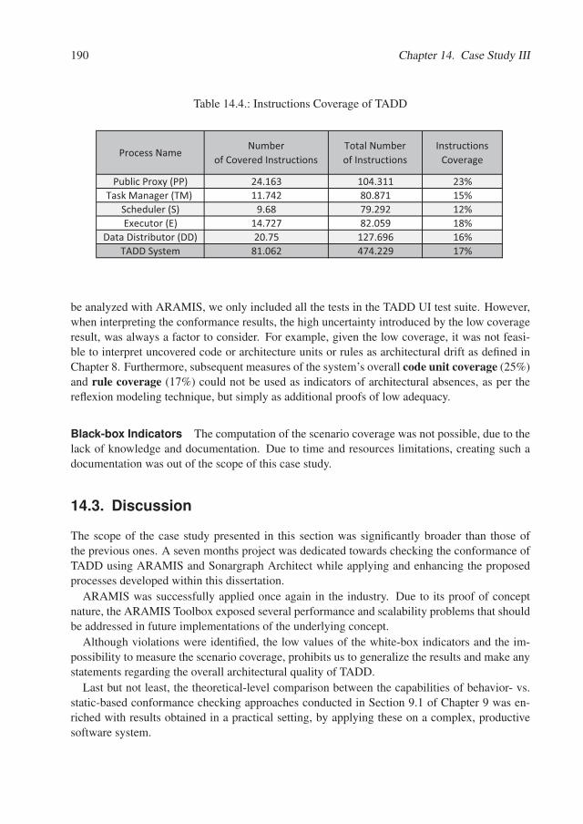
190 Chapter 14. Case Study III
Table 14.4.: Instructions Coverage of TADD
Process�NameNumber�
of�Covered�InstructionsTotal�Numberof�Instructions
Instructions�Coverage
Public�Proxy�(PP) 24.163 104.311 23%Task�Manager�(TM)� 11.742 80.871 15%
Scheduler�(S) 9.68 79.292 12%Executor�(E) 14.727 82.059 18%
Data�Distributor�(DD) 20.75 127.696 16%TADD�System 81.062 474.229 17%
be analyzed with ARAMIS, we only included all the tests in the TADD UI test suite. However,when interpreting the conformance results, the high uncertainty introduced by the low coverageresult, was always a factor to consider. For example, given the low coverage, it was not feasi-ble to interpret uncovered code or architecture units or rules as architectural drift as defined inChapter 8. Furthermore, subsequent measures of the system’s overall code unit coverage (25%)and rule coverage (17%) could not be used as indicators of architectural absences, as per thereflexion modeling technique, but simply as additional proofs of low adequacy.
Black-box Indicators The computation of the scenario coverage was not possible, due to thelack of knowledge and documentation. Due to time and resources limitations, creating such adocumentation was out of the scope of this case study.
14.3. Discussion
The scope of the case study presented in this section was significantly broader than those ofthe previous ones. A seven months project was dedicated towards checking the conformance ofTADD using ARAMIS and Sonargraph Architect while applying and enhancing the proposedprocesses developed within this dissertation.
ARAMIS was successfully applied once again in the industry. Due to its proof of conceptnature, the ARAMIS Toolbox exposed several performance and scalability problems that shouldbe addressed in future implementations of the underlying concept.
Although violations were identified, the low values of the white-box indicators and the im-possibility to measure the scenario coverage, prohibits us to generalize the results and make anystatements regarding the overall architectural quality of TADD.
Last but not least, the theoretical-level comparison between the capabilities of behavior- vs.static-based conformance checking approaches conducted in Section 9.1 of Chapter 9 was en-riched with results obtained in a practical setting, by applying these on a complex, productivesoftware system.
14.3. Discussion 191
Threats to Validity
The Case Study III was also conducted using a system developed by an industry partner. Noprior connection existed before between the author of the thesis and the master thesis student onthe one hand and the research group’s industry partner on the other hand. The master studentand the author were not familiar with the TADD system and thus the case study correctly sim-ulated the situation in which a novice tries to architecturally understand a previously unknownsystem and compare its implementation to an intended architecture description. However, somelimitations still exist. First, the master student was one of the participants in the practical courseorganized in the context of Case Study I. Consequently, given his experience with ARAMIS, theresults regarding the usefulness of the ACC-Proc are also not directly transferable. In the caseof the AADT-Proc the situation is different, as the master student didn’t work with this aspect ofARAMIS previously. Consequently the results regarding the usefulness of the AADT-Proc areless questionable that those of the ACC-Proc in the context of this Case Study. Last but not least,even though TADD is a multi-process system, the expressiveness of the ACR-Lang was still notexplored in its entirety, given that the architects didn’t define any aggregating communicationrules to be checked against.

Chapter 15.
Evaluation Summary
The results of the three conducted case studies are summarized in Table 15.1. The table lists eachof the formulated hypotheses formulated in chapter 11 and depicts whether this was rejected,partially supported or supported by the results of the case studies.
All formulated hypotheses were supported by the results of the conducted case studies. UsingACR-Lang, we could express all the communication rules applicable in the systems under anal-ysis (H1). Furthermore, the developed white- and black-box adequacy indicators proved to beuseful to investigate the extent to which the system was explored during monitoring and whetherthe extracted behavior represents a good basis for conformance checking (H2). As demonstratedin the Case Studies I and II, when both indicator types are available these can be corroborated toobtain better insights regarding the extracted behavior (H2c). However, while the computationof the white-box indicators is often straight forward and was easily conducted in all the per-formed case studies (H2a), the black-box cannot always be computed, as revealed by the CaseStudy III.
Furthermore, while conducting the case studies, we implicitly confirmed that the developedAADT-Proc (H3b) and ACC-Proc (H3a) proccesses were useful and provided sufficient guid-ance. While the general ACC-Proc was applicable during all the three studies, the meta-modelincompatibility had to be overcome only in Case Studies II and III. Consequently, the AADT-Proc was applied in its fully extent in Case Study II and only partially in Case Study III, as anaugmentation of the results on the initial intended description was not desired by the stakehold-ers.
The ARAMIS Toolbox has also served its purpose and could be successfully applied in allthe case studies (H4). However, as revealed by the Case Study III, performance problems canquickly hinder its applicability and future research should be invested in alleviating this short-coming.
Finally, Case Study III has clearly shown that static- and behavior-based approaches cannotsubstitute, but complement each other (H5). While static-based approaches can be applied withless effort and provide results almost instantly, behavior-based approaches can be subsequentlyuse to determine violations occurring at run-time and set the scene for more complex analysesregarding performance, inter-process communication, resulted communication chains, etc.
In the next Section we give an overview of the most important threats to validity posed by theconducted case studies.
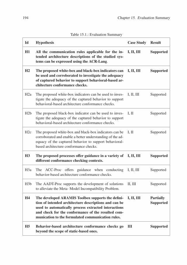
194 Chapter 15. Evaluation Summary
Table 15.1.: Evaluation Summary
Id Hypothesis Case Study Result
H1 All the communication rules applicable for the in-tended architecture descriptions of the studied sys-tems can be expressed using the ACR-Lang.
I, II, III Supported
H2 The proposed white-box and black-box indicators canbe used and corroborated to investigate the adequacyof captured behavior to support behavioral-based ar-chitecture conformance checks.
I, II, III Supported
H2a The proposed white-box indicators can be used to inves-tigate the adequacy of the captured behavior to supportbehavioral-based architecture conformance checks.
I, II, III Supported
H2b The proposed black-box indicator can be used to inves-tigate the adequacy of the captured behavior to supportbehavioral-based architecture conformance checks.
I, II Supported
H2c The proposed white-box and black-box indicators can becorroborated and enable a better understanding of the ad-equacy of the captured behavior to support behavioral-based architecture conformance checks.
I, II Supported
H3 The proposed processes offer guidance in a variety ofdifferent conformance checking contexts.
I, II, III Supported
H3a The ACC-Proc offers guidance when conductingbehavior-based architecture conformance checks.
I, II, III Supported
H3b The AADT-Proc supports the development of solutionsto alleviate the Meta- Model Incompatibility Problem.
II, III Supported
H4 The developed ARAMIS Toolbox supports the defini-tion of intended architecture descriptions and can beused to automatically process extracted interactionsand check for the conformance of the resulted com-munication to the formulated communication rules.
I, II, III PartiallySupported
H5 Behavior-based architecture conformance checks gobeyond the scope of static-based ones.
III Supported
195
Threats to Validity - Summary
The following limitations should be taken into account when considering the results of our eval-uation.
Case Study I was conducted within the evaluation phase of a practical course offered by ourresearch group and supervised by the author of this dissertation. The author played the role of thearchitect of the ARAMIS Toolbox, defined the applicable scenarios and contexts and formulatedthe communication rules that should govern its execution. Consequently, despite the fact that theintended architecture description of the ARAMIS Toolbox was already available and publishedin several articles (e.g., [DLDC14], [NLG+15], [NL16]) at the time of the evaluation, a certainbias to define only rules that indeed can be checked with ARAMIS and to assign the importanceof scenarios such that to achieve a higher scenario coverage cannot be completely ruled out.
Case Study II was important because it was the first one conducted in a real-world softwareorganization. The ARAMIS concepts and toolbox were applied using real-world constraintsand in a less familiar setting than before. However, the system under analysis was itself notarchitecturally complex. The formulated rules were all non-parameterized and non-aggregating.A different setting could have produced different results; however, this limitation is intrinsicto case-study-based evaluations. They cannot provide definitive answers regarding the level towhich the formulated hypothesis are supported in general. While Case Studies II and III providedetailed analyses of two particular industrial systems, the results need to be replicated in morecontexts to ensure generality.

Chapter 16.
Related Case Studies on ArchitectureConformance Checking
Initial large-scale case studies involving the extraction of structural information that reflects thearchitecture of software systems were performed even more than two decades ago; however, theypursued a different goal than conformance checking, namely architecture re-documentation. Forexample, as early as 1995, Wong et al. [WTMS95] presented their results when applying theRigi [MK89] [MTW93] methodology and tool support. Rigi is an "environment which focuseson the architectural aspects of program understanding that [...] supports a method for identifying,building, and documenting layered subsvstem hierarchies". The authors have extracted severalarchitectural views from the SQL/DS 1 system developed at IBM and comprising more than 2MLOC. The focus of the case study was exclusively the documentation of inter-module depen-dencies in order to create an accurate description of the legacy system under analysis. Initially,the authors generated a complete call graph of SQL/DS that was rejected by the IBM stake-holders, as the presented abstractions did not correspond to their mental model of the system.Consequently, abstractions based on composition guidelines provided by the developers werecreated, presented and accepted as a proper, accurate description of the system. Further decom-positions of subsystems were also performed and documented. Checking for conformance topredefined architecture rules, was at that time, not a priority. Instead, the authors emphasized theimportance of extracting up-to-date documentation by regularly analyzing the system’s sourcecode.
In [MN97], an early large-scale case study is presented, in which reflexion modeling is ap-plied by an experienced Microsoft Engineer, to understand and evolve Microsoft Excel - whichthen comprised more than 1.2 million LOC. At the time of the case study, the engineer wasinvolved in an "experimental reengineering of Microsoft Excel". The case study revealed that,despite several encountered hurdles, the use of reflexion modeling might contribute to tacklingthe complexity involved when reconstructing and/or understanding large-scale architectures, asit favors an incremental and iterative process. Following the technique’s guidelines, the engineerfirst started with the highest level architectural units and their connections and only subsequentlydelved into increasingly higher levels of detail. The engineer’s evaluation underlined the impor-tance of identifying not only the actual structure of the system, but also the deviations fromthe originally envisioned intended architecture. To this end, the engineer assessed that reflexion
1the Structured Query Language/Data System is a long-lived large database management system developed at theIBM Almaden Research Center in the 1970s and constantly evolved until the time of publishing of the presentedcase study
198 Chapter 16. Related Case Studies on Architecture Conformance Checking
modeling straightforwardly "allowed [...] to pinpoint deviations".Several large-scale case studies were also conducted at the Fraunhofer Institute for Experi-
mental Software Engineering. For example, in [KMHM08], a report on conformance checkingactivities concerning 15 instances of a product line is presented. The 15 products were eval-uated regularly over a time span of more than two years. Initially, the conformance checkingwas performed off-line by the authors, at major project checkpoints. Later on, this activity wasovertaken by the industrial partner and was conducted on site and on demand. The employedtool was the SAVE [LM08] tool for "static architecture compliance checking", developed atFraunhofer. Apart from reflexion modeling, SAVE also leverages two other techniques, namelythe relation conformance rules and the component access rules. Nonetheless, reflexion model-ing was the preferred technique within this case study, underlining once again its importance.The case study is remarkable because it shows that the rate of divergences decreased with therepetition of the workshops and eventually comprised less than 5% . Therefore, the case studysupports the hypothesis that the drift can be kept under control, if regular conformance checkingis performed and results are discussed. To counteract reluctance towards applying conformancechecking, the authors recommend 5 aspects:
• make explicit the contribution of the conformance checking towards achieving organiza-tional goals;
• proceed incrementally; the authors first conducted the conformance checking themselves,prior to completely handing over the task to the involved industry partners;
• adapt the conformance checking process to the needs of the employing organization, tar-geting high automation and ease of use;
• raise architecture awareness of the developers; conformance checking should go beyondpresenting a set of conformance results; the developers should be trained to think withinthe scope of the intended constraints and encouraged to document and motivate deviations;
• provide measurable evidence that repeated conformance checking adds additional valueto the organization.
In another early study, Tran et al. discussed the stringent problem of architectural drift inopen-source systems, "where many developers work in isolation on distinct features with lit-tle co-ordination" [TGLH00]. Consequently, they presented their experiences with repairingthe architectures of the Linux kernel and of the VIM editor. The first undergone step was tocompare their intended architecture descriptions with the implemented ones. In doing so, theyused the PBS tools for static code analysis 2, to extract the implemented architecture descriptionof the system. The intended architecture description was created by Tran et al. by analyzingexisting documentation, interviewing developers, analyzing the source code, etc. The authorsdo not mention how the differences between the intended and implemented architectures wereidentified and the reader is left to assume that the process was a manual one. Next, the au-thors used forward and reverse architecture repairing techniques to fix the discovered anomalies
2The PBS Tools are described in Krickhaar’s PHD Thesis: "SoftwareArchitecture Reconstruction", University ofAmsterdam, 1999
199
and reported positive results in reconciling the implemented architectures with their intendedcounterparts.
In 2005 Gorton and Zhu [GZ05], assessed "the capabilities of [5] software reverse engineeringand architecture reconstruction tools to support just-in-time architecture reconstruction". Theanalysis subject was a Java subsystem responsible for producing and presenting financial data.The subsystem comprised 50K LOC and 296 classes and interfaces scattered within 27 packages.The authors chose 5 reconstruction tools, not in order to compare them with each other but ratherto combine their benefits, as "there is no single silver bullet tool that can solve all the needs ofan architecture reconstruction effort". The actual reconstruction effort comprised 3 person days.Using the 5 tools (the then latest versions of Understand for Java [und], JDepend [jde], SA4J[saj], ARMIN [OSL05] and Enterprise Architect [ent]) the authors could provide "numerousarchitectural views and identify problematic components from a modifiability perspective".
Ganesan et al. [GKN08] used a dynamic approach in an industrial context. Based on theirexperience, they recommend to apply dynamic approaches iteratively and in close cooperationwith architects. Moreover, similarly as De Silva [Sil14] and Yan et al. [YGS+04], they militatefor the use of code coverage metrics to ensure that all relevant architectural components werecovered at run-time.
In [RLBA08], Rosik et al. present their two-years-long experience with applying static confor-mance checking in an industrial context. They underline the importance of a "reversed" versionof reflexion modeling, which stands for applying the technique periodically, at short time inter-vals throughout the development process, rather than only on the finished system. Furthermore,they emphasize that the reconciliation of the intended and implemented architectures could alsobe performed, by only updating the former one, if the discovered differences can be architec-turally motivated. Furthermore, the authors questioned the evaluations of previously publishedcase studies, which tended to measure success by the number of identified violations; based ontheir observations, merely identifying the violations didn’t imply their consequent removal. Anextended version of these findings was published 2 years later in [RLB+10].
Vierhauser et al. [VRG+14] present an experiment for extracting and visualizing interactionswithin a system of systems developed at Siemens. Unlike in ARAMIS, the focus is not onconformance checking but on documenting and understanding the communication occurring onthe various abstraction levels.
All in all, several related case studies were conducted and published. Most of these involvedstatic-based approaches and their goal was often architecture re-documentation instead of con-formance checking. To the best of our knowledge, comparative case studies of behavior- vs.static- based approaches were not conducted. Instead the similarities and differences betweenthe two were discussed only on a theoretical level.

Part IV.
Conclusions, Summary and FutureWork

Chapter 17.
Conclusions
We finalize this dissertation by first presenting in this chapter an overview of the conclusionsand limitations of our work. Next, Chapter 18 presents a summary of this thesis. Last but notleast, some of our suggestions for future work are elaborated in Chapter 19.
In this conclusion, we reflect on the lessons learned throughout the process leading to thisdissertation.
Behavior-based architecture conformance checking is typically more expensive than its static-based counterpart as it imposes the extraction of interactions from running systems and theirsubsequent analysis. In this dissertation we argued that despite this limitation, behavior-basedarchitecture conformance checking can prove useful in the case of modern, multi-process sys-tems. This aspect was discussed extensively, both on a theoretical (see Section 9.1) and a prac-tical level (see Chapter 14).
In the process of our research, we learned that the overall complexity of behavior-based ar-chitecture conformance checking can be reduced if the employed approach builds on top ofwell-known performance monitoring systems which are already capable of extracting executiondata from a variety of systems.
Furthermore, we investigated what types of rules should be expressible to characterize theexpected behavior of a given system on an architectural level. The proposed taxonomy wassufficient to support the definition of all the communication rules identified in the performedcase studies. Probably one of the most important aspects learned in this context, was to avoidstiff solutions. Consequently, using our parameterized rules, constraints can be imposed on anyinteraction parameter extracted during monitoring.
Another important lesson learned is that communication plays an important role in under-standing and accepting the results of conformance checking. By proposing model engineeringtechniques, we intended to increase the acceptance of our approach by enabling the architects toreuse intended architecture descriptions and by presenting the implemented architecture descrip-tions in a fashion that fosters recognition effects. Within Case Study III the architects rejectedour initial plan to create an implemented architecture description by augmenting the intendedone accordingly. They argued that the augmentation would only create clutter and a simple tab-ular presentation of the results would instead be more advantageous. Communicating with thestakeholders and understanding their needs can significantly reduce the effort to be invested.
Last but not least, we learned that the commonly used argument that the code coverage repre-sents a good estimate of the adequacy of the captured behavior does not necessarily hold in ourcontext. In the conducted case studies we have shown that even if the measured code coverageis low, the extracted behavior can still be adequate to support system-wide, behavior-based con-
204 Chapter 17. Conclusions
formance checking. This can be investigated by corroborating a series of proposed white-boxand black-box indicators that go beyond the scope of simple code coverage.
Limitations
Although some important results were achieved and demonstrated in this dissertation, severallimitations also exist. This section offers an overview of the most important limitations of ourwork.
ARAMIS builds on top of existing monitors but these are not optimized for its pur-pose. One of the goals of ARAMIS was to reuse already existing work in systems monitor-ing. However, this is also a limitation. While most of the monitors are optimized for identifyingperformance issues, the same does not hold for generating efficient instrumentations to sup-port conformance checking. Consequently, as in the case of Case Study III (Chapter 14) largeamounts of data are extracted, leading to important performance issues during analysis. Instead,customized instrumentations generated based on the systems’ intended architecture descriptionscould alleviate this issue to a great extent.
ARAMIS identifies architectural violations but does not automatically prioritize them.Understanding the nature of interactions between the architectural structures of a system andidentifying occurring violations are important activities that scaffold architectural evaluationand evolution. However, a large number of discovered violations can lead to demoralization andreluctance to improve the system. Currently, all violations are treated by ARAMIS as "equal".An automatic prioritization thereof based on flexible criteria, such as performance impact oraffected architectural level, might further motivate the involved architects and developers toreduce the identified architectural drift on a step-by-step basis.
ARAMIS was evaluated only using case studies and only twice in real-world industrialcontexts. While case studies are often employed to evaluate approaches emerged in the soft-ware engineering domain, these typically have limited generalization potential. "A case studyis not generalizable in the same sense that a study based on statistical sampling is generaliz-able. [...] In a case study, the goal is not statistical generalizability, but instead some notion oftransferability or analytic generalizability" [Bar13]. Currently, despite the predominantly posi-tive results, it is unclear to what extent can the findings be transfered to other contexts. Futurework should address this important limitation. First the user friendliness and performance of ourARAMIS Toolbox should be improved to better support future case studies. Second, a largervariety of industrial case studies should be conducted and results should be documented andcritically compared to gain more in-depth insight regarding the usefulness of the approach.
Chapter 18.
Summary
In this dissertation we presented ARAMIS (the Architectural Analysis and Monitoring Infras-tructure), our approach towards behavior-based architecture conformance checking.
ARAMIS encompasses our answers to the research questions formulated in Section 1.3 andserves as a proof for the formulated thesis statement introduced in Section 1.2:
We can support software architects to analyze and evaluate the architectural drift ofsoftware systems by employing conformance checking on information extracted duringrun-time. Thus, we provide a means to leverage existing monitoring tools, a set of con-cepts to investigate the adequacy of the monitored behavior towards assessing the driftof the system as a whole, support for the definition or reuse of intended architecturedescriptions including an extensible language to express applicable communicationrules, and, last but not least, processes to guide stakeholders towards achieving theformulated goals.
To this end, we first presented how ARAMIS can build on top of existing monitoring toolsand reuse the extracted interactions for the purpose of architecture conformance checking byinitially describing them with the monitoring-tool-independent ARAMIS Interactions Descrip-tion Language (AID-Lang). The architecture of the ARAMIS Toolbox enabled the reuse of twoexisting monitors, namely Dynatrace and Kieker, and is easily extendible to allow the additionof others.
Furthermore, we discussed how to ensure that the behavior extracted by means of externalmonitors is adequate for supporting meaningful conformance checks. While static-based alter-natives holistically analyze a system’s code base, the analysis corresponding to a behavior-basedsolution depends on the quality of the extracted behavior. Consequently, we investigated a se-ries of white-box and black-box indicators to be used when investigating the adequacy of theextracted behavior.
Next, we approached the problematic of defining or reusing existing intended architecturedescriptions to be employed as a blueprint in the developed conformance checking approach.We developed an ARAMIS Meta-Model for defining the architectural structures of the systemsunder analysis and the rules governing their communication. Moreover, we proposed a modelengineering-based solution to address the meta-model incompatibility problem, an issue arisingwhen the intended architecture of the system is not expressed using the meta-model requiredby ARAMIS. The ARAMIS Architecture Description Transformation Process was proposed toguide the development of solutions for re-using intended architecture descriptions elaboratedwith different meta-models and consequently to express the results in a similar fashion, boostingunderstanding and recognition effects .

206 Chapter 18. Summary
Finally, acknowledging that behavior-based architecture conformance checking is generallymore expensive than its static-based counterpart, we investigated their relative strengths andweaknesses to offer guidance for the architects in choosing the appropriate solution given aconcrete situation. Additionally, we defined the ARAMIS Conformance Checking Process, tosupport the architects in identifying and performing the intricate tasks imposed by behavioral-based architecture conformance checking.
Chapter 19.
Future Work
A long road can lie ahead of ARAMIS. The limitations discussed in Section 17, have alreadygiven guidance for potential future work. This section presents several other topics that mightbe addressed in the future.
Inclusion in Build Pipelines. When conducting the Industrial Case Study II (Chapter 14),the developers were enthusiastic about including ARAMIS in an automatic build pipeline. How-ever, the current status of the ARAMIS Toolbox and the low degree of automation of theARAMIS conformance checking process did not permit this. However, to increase industrialacceptance and ease future case studies, this requirement is a "must" that needs to be addressedby future work. The need of continuous and early feedback, together with the necessity ofcustomized tool chain inclusion, is also militated for by the research community.
Incremental Conformance Checking. When discussing some of the limitations of our work,we mentioned the need of prioritizing identified violations to better guide the effort of tacklingthem. Another strategy to follow, could be the incremental application of conformance rules,starting with critical ones, continuing with ever less important ones and ending with "nice tohaves". Consequently, a system of rules classification should be developed. Once in place, theapplication of rules can resemble a build pipeline in itself, consisting of quality gates that imposewhat is acceptable and to what extent.
Support for Evolution. Conformance checking is never a goal by itself. Instead, it shouldsupport the meaningful evolution of software systems. Software architecture evolution is cur-rently an important research area by itself [Bar13], [MKM11], [JB04]. Analyzing past andfuture evolution on an architectural level carries important advantages: it supports discussionson higher level concerns (such as integration), it is more scalable and it "grants [...] a kindof generality that is usually not available to code-level approaches" [Bar13]. However, analysesthat are centered on architectural descriptions can suffer from lack of relevance, if the descriptionis outdated. By retrieving an up-to-date description of the architecture of a system, ARAMISbuilds the premise of supporting evolution analysis on an architectural level, without risking thatthe underlying architectural model is not reflecting the way the system under analysis is actuallybuilt. First attempts of modeling future evolution scenarios in ARAMIS and analyzing theirtrade-offs were already made [Gör16] and can be extended in the future.
208 Chapter 19. Future Work
Integration with Static Approaches and Support for Architecture Discovery. One ofthe preconditions of effectively applying ARAMIS is to create or reuse an intended architecturedescription of the system. However, more often than not, such a description is not available.To this end, integration with static reconstruction approaches could be beneficial. The intendedarchitecture description could thus be discovered incrementally and semi-automatically, basedon source code analysis results and visualizations thereof. Furthermore, clustering approachescould be applied to create first views of the implemented architecture without any intended archi-tecture description as an input. First steps towards applying clustering techniques in ARAMISwere also conducted [Lan15].
IDE and Source Code Integration. ARAMIS could also benefit from an appropriate IDEand source code integration. The possibility to trigger behavioral-based conformance checksdirectly from the IDE during the development and test phases could aid developers to quicklyoverview the effects produced by their code. To this end, specifying architectural test cases totrigger certain system behavior can also be a part of future research. Last but not least, onceviolations are identified by ARAMIS, it could be beneficial to be able to seamlessly navigate tothe actual source code sections where the violations emerged and thus offer better support forviolations analysis and, if necessary, removal. Even more, future research could investigate ifproposals for automatic violation removal can be made. A straightforward improvement wouldbe the possibility to manually update the intended architecture description while analyzing theconformance results; for example some identified violations could be marked as permitted andthe intended architecture description would be updated accordingly. More complex proposalscan be made regarding how the source code itself could be changed to remove the violationswhile potentially preserving the behavior.
Part V.
Appendixes

Appendix A.
Monitoring Anomalies
The main goal of the introduced ARAMIS Interactions Description Language (AID-Lang) wasto decouple ARAMIS from the employed monitoring tools used for the extraction of run-timeinterations. From a syntactical perspective, this goal was achieved. However, at a semanticlevel, a perfect decoupling is not completely possible, as some level of knowledge regarding howthe interactions are extracted is necessary in order to perform correct architecture conformancechecks.
The term "monitoring anomaly", introduced in Chapter 5, was used throughout this disserta-tion to refer to situations in which the extracted interactions do not correctly reflect the executionof the system under analysis.
In our practical experiments with monitoring tools we encountered two main classes of mon-itoring anomalies: polymorphism- and partial trace anomalies. These are detailed and exempli-fied in the following two sections.
A.1. The Polymorphism Anomaly
Universal polymorphism is one of the key concepts of the object oriented paradigm. A universalpolymorphic operation is thus “applicable to a potentially infinite number of different types”1. Itis the task of the run-time system to “bind the right operation implementation to the message”.
Given that with ARAMIS we intend to perform behavior-based architecture conformancechecks, and that the information is extracted during run-time, one might assume that the ex-tracted communication reflects the actual message passing between the system’s objects as re-flected after the dynamic types of the involved variables have been assigned and the operationswere bound accordingly.
However, the above assumption does not always hold. We will demonstrate this with anexample and discuss the various ways in which the same interactions can be monitored. Thecorresponding class diagram of the exemplary situation is depicted in Figure A.1 and the codeto be monitored is listed in Listing A.1.
As depicted in line 9 of the Listing A.1, we declare a variable of static type ClassB whichwill eventually have a dynamic type ClassA. Consequently, the expected sequence diagram ofthe behavior enclosed within the triggerCalls() method is depicted on the left side of the FigureA.2. Instead, if we reconstruct the corresponding behavior based on the information extractedby Kieker and Dynatrace, we obtain a different Sequence Diagram, as exposed on the right side
1as presented in the Object Oriented Software Construction lecture, RWTH Aachen University
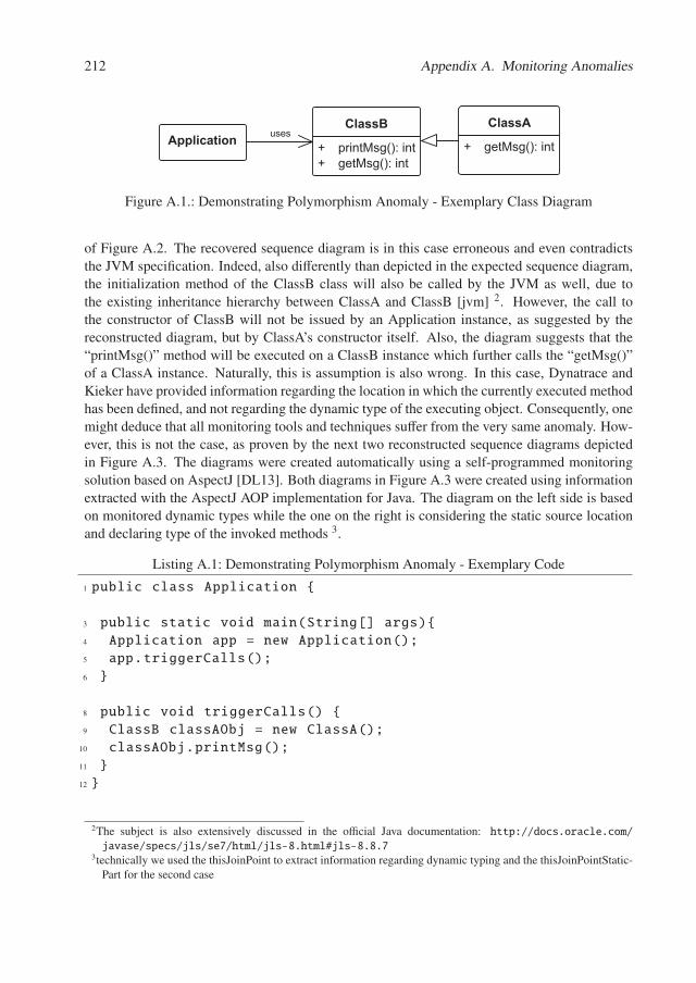
212 Appendix A. Monitoring Anomalies
ApplicationClassA
+ getMsg(): int
ClassB
+ printMsg(): int+ getMsg(): int
uses
Figure A.1.: Demonstrating Polymorphism Anomaly - Exemplary Class Diagram
of Figure A.2. The recovered sequence diagram is in this case erroneous and even contradictsthe JVM specification. Indeed, also differently than depicted in the expected sequence diagram,the initialization method of the ClassB class will also be called by the JVM as well, due tothe existing inheritance hierarchy between ClassA and ClassB [jvm] 2. However, the call tothe constructor of ClassB will not be issued by an Application instance, as suggested by thereconstructed diagram, but by ClassA’s constructor itself. Also, the diagram suggests that the“printMsg()” method will be executed on a ClassB instance which further calls the “getMsg()”of a ClassA instance. Naturally, this is assumption is also wrong. In this case, Dynatrace andKieker have provided information regarding the location in which the currently executed methodhas been defined, and not regarding the dynamic type of the executing object. Consequently, onemight deduce that all monitoring tools and techniques suffer from the very same anomaly. How-ever, this is not the case, as proven by the next two reconstructed sequence diagrams depictedin Figure A.3. The diagrams were created automatically using a self-programmed monitoringsolution based on AspectJ [DL13]. Both diagrams in Figure A.3 were created using informationextracted with the AspectJ AOP implementation for Java. The diagram on the left side is basedon monitored dynamic types while the one on the right is considering the static source locationand declaring type of the invoked methods 3.
Listing A.1: Demonstrating Polymorphism Anomaly - Exemplary Code
1 public class Application {
3 public static void main(String[] args){4 Application app = new Application();5 app.triggerCalls();6 }
8 public void triggerCalls() {9 ClassB classAObj = new ClassA();
10 classAObj.printMsg();11 }12 }
2The subject is also extensively discussed in the official Java documentation: http://docs.oracle.com/javase/specs/jls/se7/html/jls-8.html#jls-8.8.7
3technically we used the thisJoinPoint to extract information regarding dynamic typing and the thisJoinPointStatic-Part for the second case
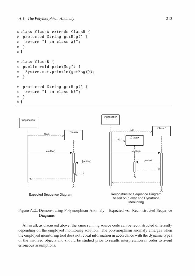
A.1. The Polymorphism Anomaly 213
14 class ClassA extends ClassB {15 protected String getMsg() {16 return "I am class a!";17 }18 }
20 class ClassB {21 public void printMsg() {22 System.out.println(getMsg());23 }
25 protected String getMsg() {26 return "I am class b!";27 }28 }
:Application
:ClassANew()
printMsg()
getMsg()
:Application
:ClassA
:Class B
getMsg()
init()
printMsg()
init()
������������ ��������� ���� ������������ ��������������� ������� ��� ������
�� ����� �
Figure A.2.: Demonstrating Polymorphism Anomaly - Expected vs. Reconstructed SequenceDiagrams
All in all, as discussed above, the same running source code can be reconstructed differentlydepending on the employed monitoring solution. The polymorphism anomaly emerges whenthe employed monitoring tool does not reveal information in accordance with the dynamic typesof the involved objects and should be studied prior to results interpretation in order to avoiderroneous assumptions.
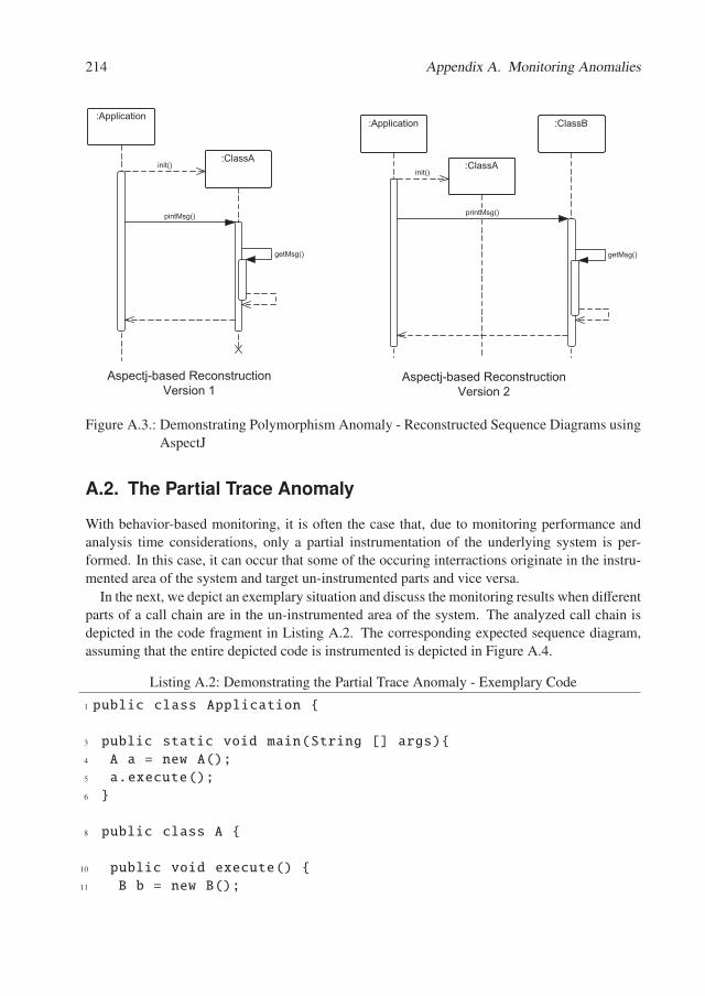
214 Appendix A. Monitoring Anomalies
:Application
:ClassA
getMsg()
init()
pintMsg()
:Application
:ClassA
:ClassB
init()
getMsg()
printMsg()
����������������� �������� ������ !
����������������� �������� ������ "
Figure A.3.: Demonstrating Polymorphism Anomaly - Reconstructed Sequence Diagrams usingAspectJ
A.2. The Partial Trace Anomaly
With behavior-based monitoring, it is often the case that, due to monitoring performance andanalysis time considerations, only a partial instrumentation of the underlying system is per-formed. In this case, it can occur that some of the occuring interractions originate in the instru-mented area of the system and target un-instrumented parts and vice versa.
In the next, we depict an exemplary situation and discuss the monitoring results when differentparts of a call chain are in the un-instrumented area of the system. The analyzed call chain isdepicted in the code fragment in Listing A.2. The corresponding expected sequence diagram,assuming that the entire depicted code is instrumented is depicted in Figure A.4.
Listing A.2: Demonstrating the Partial Trace Anomaly - Exemplary Code
1 public class Application {
3 public static void main(String [] args){4 A a = new A();5 a.execute();6 }
8 public class A {
10 public void execute() {11 B b = new B();
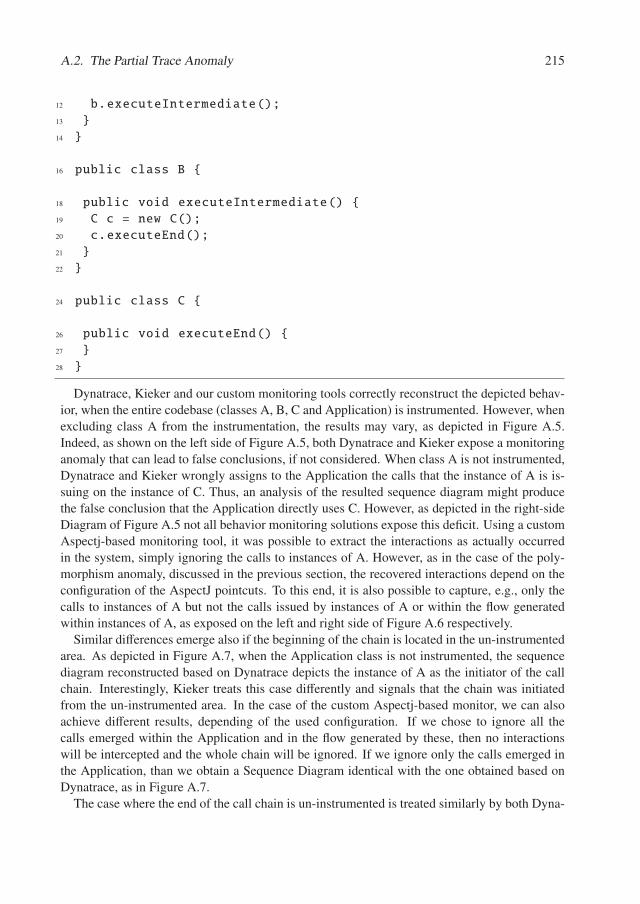
A.2. The Partial Trace Anomaly 215
12 b.executeIntermediate();13 }14 }
16 public class B {
18 public void executeIntermediate() {19 C c = new C();20 c.executeEnd();21 }22 }
24 public class C {
26 public void executeEnd() {27 }28 }
Dynatrace, Kieker and our custom monitoring tools correctly reconstruct the depicted behav-ior, when the entire codebase (classes A, B, C and Application) is instrumented. However, whenexcluding class A from the instrumentation, the results may vary, as depicted in Figure A.5.Indeed, as shown on the left side of Figure A.5, both Dynatrace and Kieker expose a monitoringanomaly that can lead to false conclusions, if not considered. When class A is not instrumented,Dynatrace and Kieker wrongly assigns to the Application the calls that the instance of A is is-suing on the instance of C. Thus, an analysis of the resulted sequence diagram might producethe false conclusion that the Application directly uses C. However, as depicted in the right-sideDiagram of Figure A.5 not all behavior monitoring solutions expose this deficit. Using a customAspectj-based monitoring tool, it was possible to extract the interactions as actually occurredin the system, simply ignoring the calls to instances of A. However, as in the case of the poly-morphism anomaly, discussed in the previous section, the recovered interactions depend on theconfiguration of the AspectJ pointcuts. To this end, it is also possible to capture, e.g., only thecalls to instances of A but not the calls issued by instances of A or within the flow generatedwithin instances of A, as exposed on the left and right side of Figure A.6 respectively.
Similar differences emerge also if the beginning of the chain is located in the un-instrumentedarea. As depicted in Figure A.7, when the Application class is not instrumented, the sequencediagram reconstructed based on Dynatrace depicts the instance of A as the initiator of the callchain. Interestingly, Kieker treats this case differently and signals that the chain was initiatedfrom the un-instrumented area. In the case of the custom Aspectj-based monitor, we can alsoachieve different results, depending of the used configuration. If we chose to ignore all thecalls emerged within the Application and in the flow generated by these, then no interactionswill be intercepted and the whole chain will be ignored. If we ignore only the calls emerged inthe Application, than we obtain a Sequence Diagram identical with the one obtained based onDynatrace, as in Figure A.7.
The case where the end of the call chain is un-instrumented is treated similarly by both Dyna-
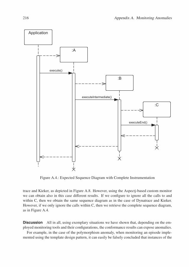
216 Appendix A. Monitoring Anomalies
Application
:A
:B
:C
executeEnd()
executeIntermediate()
execute()
Figure A.4.: Expected Sequence Diagram with Complete Instrumentation
trace and Kieker, as depicted in Figure A.8. However, using the Aspectj-based custom monitorwe can obtain also in this case different results. If we configure to ignore all the calls to andwithin C, then we obtain the same sequence diagram as in the case of Dynatrace and Kieker.However, if we only ignore the calls within C, then we retrieve the complete sequence diagram,as in Figure A.4.
Discussion All in all, using exemplary situations we have shown that, depending on the em-ployed monitoring tools and their configurations, the conformance results can expose anomalies.
For example, in the case of the polymorphism anomaly, when monitoring an episode imple-mented using the template design pattern, it can easily be falsely concluded that instances of the
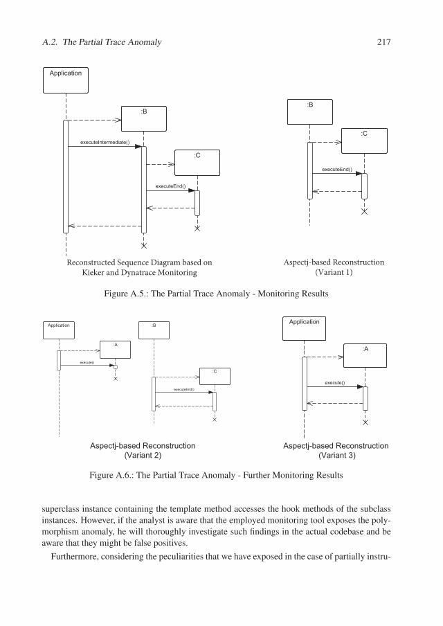
A.2. The Partial Trace Anomaly 217
Application
:B
:C
executeEnd()
executeIntermediate()
:B
:C
executeEnd()
Figure A.5.: The Partial Trace Anomaly - Monitoring Results
Application
:A
:B
:C
executeEnd()
execute()
Application
:A
execute()
����������������� �������� #����� �"$
����������������� �������� #����� �%$
Figure A.6.: The Partial Trace Anomaly - Further Monitoring Results
superclass instance containing the template method accesses the hook methods of the subclassinstances. However, if the analyst is aware that the employed monitoring tool exposes the poly-morphism anomaly, he will thoroughly investigate such findings in the actual codebase and beaware that they might be false positives.
Furthermore, considering the peculiarities that we have exposed in the case of partially instru-
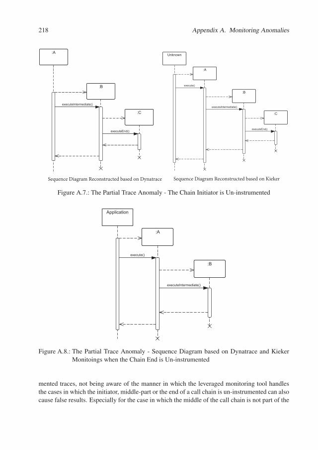
218 Appendix A. Monitoring Anomalies
:A
:B
:C
executeEnd()
executeIntermediate()
Unknown
:A
:B
:C
executeIntermediate()
execute()
executeEnd()
Figure A.7.: The Partial Trace Anomaly - The Chain Initiator is Un-instrumented
Application
:A
:B
executeIntermediate()
execute()
Figure A.8.: The Partial Trace Anomaly - Sequence Diagram based on Dynatrace and KiekerMonitoings when the Chain End is Un-instrumented
mented traces, not being aware of the manner in which the leveraged monitoring tool handlesthe cases in which the initiator, middle-part or the end of a call chain is un-instrumented can alsocause false results. Especially for the case in which the middle of the call chain is not part of the
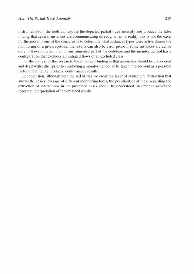
A.2. The Partial Trace Anomaly 219
instrumentation, the tools can expose the depicted partial trace anomaly and produce the falsefinding that several instances are communicating directly, when in reality this is not the case.Furthermore, if one of the concerns is to determine what instances types were active during themonitoring of a given episode, the results can also be error prone if some instances are activeonly in flows initiated in an un-instrumented part of the codebase and the monitoring tool has aconfiguration that excludes all initiated flows of an excluded class.
For the context of this research, the important finding is that anomalies should be consideredand dealt with either prior to employing a monitoring tool or be taken into account as a possiblefactor affecting the produced conformance results.
In conclusion, although with the AID-Lang we created a layer of syntactical abstraction thatallows the easier leverage of different monitoring tools, the peculiarities of these regarding theextraction of interactions in the presented cases should be understood, in order to avoid theincorrect interpretation of the obtained results.

Appendix B.
Case Study III- Results Overview
In this appendix we first present, in Section B.1 the results of the conducted behavior-basedarchitecture conformance checking of theTADD system. Next, in Section B.2, we present theresults obtained during the static-based conformance checking of this system.
B.1. Behavior-Based Conformance Checking of TADD
Using ARAMIS, we identified 20 types of architecture violations in the TADD system. Theseare summarized in Table B.1. These were investigated by inspecting the corresponding sourcecode, the TADD intended architecture diagram and through discussions with the architects.
In the following paragraphs, an overview thereof is given.
According to the violations B1, B2 and B3 the ICryptologyService OSGi service was wrong-fully accessed by the common bundle. While the common bundle was deployed in all the 5 pro-cesses, only 3 of these accessed the ICryptologyService, emphasizing the process-aware natureof ARAMIS. When consulted, the architects argued that the intended architecture descriptionwas too restrictive and updated it such that to allow this access.
B4 indicates that the datadistributor bundle wrongly accessed access-shared. Indeed, thisaccess is a violation of the TADD intended architecture. The access is possible, because access-shared is a dependency of a bundle on which datadistributor in turn depends. Consequently, theaccess was possible due to transitivity. The architects recognized this as an error in the intendedarchitecture description, and updated it to allow the communication between the two. Further-more, the descriptor of the datadistributor bundle was also updated, and hence the implementedarchitecture of TADD evolved as well, in order to enlist access-shared as an explicit dependency.
B5 and B6 are false positives and resulted as a consequence of the Dynatrace polymorphismanomalies. For example, in the case of B5, Dynatrace falsely identified a call’s callee to be theclass in which an inherited method was defined although the run-time object was an instance ofa subclass thereof.
The remaining violations are related to accesses to the file system and hence the callee isalways designated to be a file or directory.
B7, B10 and B13 denote violations caused by accesses issued in the accesslayer bundle in 3of the 5 five processes in which this was deployed to. The violations involving the conf direc-tory were caused by defects in the intended architecture description of TADD, which was, toorestrictive. Instead of simply allowing the access of accesslayer to any file or directory underconf, the architects tried to exhaustively specify the name of these files. With the evolution of
222 Appendix B. Case Study III- Results Overview
TADD several other files and directories were created under conf, resulting in many apparent vi-olations. Consequently, the intended architecture description of TADD was refined accordingly.However, the high frequencies in B7 and B10 signaled a defect in the implemented architectureas well. In total the file system was accessed approximately 370000 times within six hours ofcapturing the traces. These accesses were mostly caused by re-reading configuration properties.Accordingly, the architects proposed to implement a caching layer to reduce the amount of I/Ooperations and alleviate system performance.
Another violation listed under B7 (and repeated in B10 and B13) resulted as a consequenceof the partial trace anomaly, which Dynatrace exposes. The accesslayer does not access thejre/lib/xerces.properties file, but uses a third party dependency that does so. Since third partydependencies are excluded from monitoring, Dynatrace erroneously identified correspondingaccesses.
Next, B8, B14, B18 represent violations caused by the configurationfile bundle in 3 of the 5processes they were deployed in. The architects had previously corrected an over-generalizationin the intended architecture description: while initially the access to the conf directory wasgranted to all processes, and hence to all bundles deployed within, they have restricted the accessto conf only the accesslayer, prior to the transformation of the intended architecture descriptionto the ARAMIS input. Hence the accesses caused by the configurationfile bundle were classifiedas a violation. Upon analyzing this, the architects decided to architecturally allow these calls aswell, and modify the intended architecture description accordingly. Similar as in the previouscases, the high frequency of the file accesses revealed performance shortcomings in the TADDimplemented architecture and triggered the architects to plan the implementation of cachingmechanisms in TADD.
According to the intended architecture description, the authadapter bundle seemed to be com-pletely decoupled from the file system. This was contradicted by B9. The architects acknowl-edged the legitimacy of the call and consequently updated the intended architecture description.The same course of action was followed for B11, B17 and B20 in which the bundles executor,common and datadistrshared were identified to access random files in the file system. Upona consequent analysis, it was confirmed that the user is able to define arbitrary directories onthe host system as so-called locations for data transfer purpose. Consequently, the intended ar-chitecture description was updated to denote that these bundles are allowed access within thecomplete file system.
Last but not least, the violations listed under B12, B15, B16 and B19 are false positives,caused by the partial trace anomaly.
B.2. Static Conformance Checking of TADD
Using Sonargraph Architect, we identified 15 types of architecture violations in the TADD sys-tem. These are summarized in Table B.2. These were investigated by inspecting the corre-sponding source code, TADD intended architecture description and through discussions withthe architects.
The violation S1 corresponds to B1, B2 and B3 in the behavior-based conformance checkingresults (see Appendix B.1). The commons bundle wrongfully accesses the ICryptologyService.
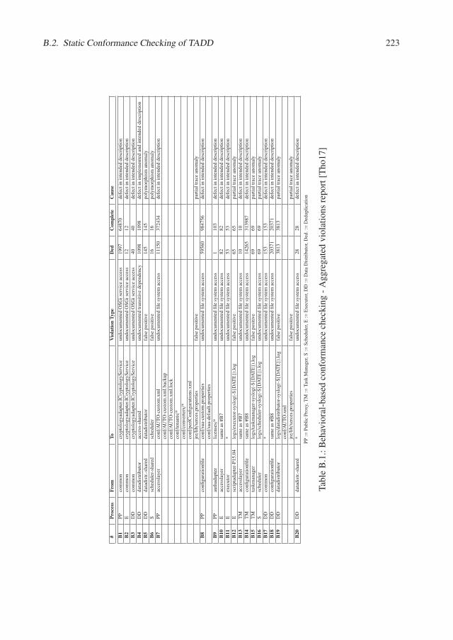
B.2. Static Conformance Checking of TADD 223
#Pr
oces
sFr
omTo
Vio
latio
nTy
peD
edC
ompl
ete
Cau
se
B1
PP
com
mon
cryp
tolo
gyad
apte
r.IC
rypt
olog
ySer
vice
undo
cum
ente
dO
SG
ise
rvic
eac
cess
1997
6487
0de
fect
inin
tend
edde
scri
ptio
nB
2E
com
mon
cryp
tolo
gyad
apte
r.IC
rypt
olog
ySer
vice
undo
cum
ente
dO
SG
ise
rvic
eac
cess
1212
defe
ctin
inte
nded
desc
ript
ion
B3
DD
com
mon
cryp
tolo
gyad
apte
r.IC
rypt
olog
ySer
vice
undo
cum
ente
dO
SG
ise
rvic
eac
cess
4040
defe
ctin
inte
nded
desc
ript
ion
B4
DD
data
dist
ribu
tor
acce
ss-s
hare
dun
docu
men
ted
tran
siti
vede
pend
ency
1098
1098
defe
ctin
impl
emen
ted
and
inte
nded
desc
ript
ion
B5
DD
data
dist
r.-s
hare
dda
tadi
stri
buto
rfa
lse
posi
tive
145
145
poly
mor
phis
man
omal
yB
6S
sche
dule
r-sh
ared
sche
dule
rfa
lse
posi
tive
1616
poly
mor
phis
man
omal
yB
7P
Pac
cess
laye
rco
nf/A
UT
O-c
usto
m.x
ml
undo
cum
ente
dfi
lesy
stem
acce
ss11
150
3724
34de
fect
inin
tend
edde
scri
ptio
nco
nf/A
UT
O-c
usto
m.x
ml.
back
upco
nf/A
UT
O-c
usto
m.x
ml.
lock
conf/t
enan
ts/*
conf/c
onve
rter
s/*
conf/p
erlC
onfi
gura
tion
s.xm
ljr
e/li
b/xe
rces
.pro
pert
ies
fals
epo
siti
vepa
rtia
ltr
ace
anom
aly
B8
PP
confi
gura
tion
file
conf/s
ua-c
usto
m.p
rope
rtie
sun
docu
men
ted
file
syst
emac
cess
5956
098
4756
defe
ctin
inte
nded
desc
ript
ion
conf/s
ua-d
efau
lt.p
rope
rtie
sB
9P
Pau
thad
apte
rli
cens
es/*
undo
cum
ente
dfi
lesy
stem
acce
ss1
103
defe
ctin
inte
nded
desc
ript
ion
B10
Eac
cess
laye
rsa
me
as#B
7un
docu
men
ted
file
syst
emac
cess
8282
defe
ctin
inte
nded
desc
ript
ion
B11
Eex
ecut
or*
undo
cum
ente
dfi
lesy
stem
acce
ss53
53de
fect
inin
tend
edde
scri
ptio
nB
12E
scri
ptad
apte
r-P
15.0
4lo
gs/e
xecu
tor-
sysl
og(-
${D
AT
E})
.log
fals
epo
siti
ve65
65pa
rtia
ltr
ace
anom
aly
B13
TM
acce
ssla
yer
sam
eas
#B7
undo
cum
ente
dfi
lesy
stem
acce
ss10
10de
fect
inin
tend
edde
scri
ptio
nB
14T
Mco
nfigu
rati
onfi
lesa
me
as#B
8un
docu
men
ted
file
syst
emac
cess
1426
531
3987
defe
ctin
inte
nded
desc
ript
ion
B15
TM
task
man
ager
logs/t
askm
anag
er-s
yslo
g(-$
{DA
TE
}).l
ogfa
lse
posi
tive
6969
part
ial
trac
ean
omal
yB
16S
sche
dule
rlo
gs/s
ched
uler
-sys
log(
-${D
AT
E})
.log
undo
cum
ente
dfi
lesy
stem
acce
ss69
69pa
rtia
ltr
ace
anom
aly
B17
DD
com
mon
*un
docu
men
ted
file
syst
emac
cess
153
153
defe
ctin
inte
nded
desc
ript
ion
B18
DD
confi
gura
tion
file
sam
eas
#B8
undo
cum
ente
dfi
lesy
stem
acce
ss20
371
2037
1de
fect
inin
tend
edde
scri
ptio
nB
19D
Dda
tadi
stri
buto
rlo
gs/d
atad
istr
ibut
or-s
yslo
g(-$
{DA
TE
}).l
ogfa
lse
posi
tive
3813
3813
part
ial
trac
ean
omal
yco
nf/A
UT
O.x
ml
jre/
lib/
xerc
es.p
rope
rtie
sfa
lse
posi
tive
part
ial
trac
ean
omal
yB
20D
Dda
tadi
str.
-sha
red
*un
docu
men
ted
file
syst
emac
cess
2828
defe
ctin
inte
nded
desc
ript
ion
PP
:=P
ubli
cP
roxy
,TM
:=T
ask
Man
ager
,S:=
Sch
edul
er,E
:=E
xecu
tor,
DD
:=D
ata
Dis
trib
utor
,Ded
.:=
Ded
upli
cati
on
Tab
leB
.1.:
Beh
avio
ral-
base
dco
nfor
man
cech
ecki
ng-
Agg
rega
ted
viol
atio
nsre
port
[Tho
17]
224 Appendix B. Case Study III- Results Overview
The behavior-based results are in this sense more accurate, clearly depicting in which processeswas this access actually used during monitoring. As per B1, B2 and B3, S1 was identified to becaused by a defect in the intended architecture description.
Similarly, S2, S3 and S4 denote forbidden service accesses. These were not identified byARAMIS, although theoretically in its scope, because of the low coverage of the employedmonitoring session. In the case of S2 and S3, the architects chose to accept these accesses asvalid and correct instead the intended architecture description. Instead, S4 was confirmed to be adefect in the actual implementation of TADD, and decided to fix this issue in future refactorings.
S5 corresponds to the B4 violation identified in the behavior-based conformance results. Itis caused by the use of a transitive dependency. The architects chose to make the transitivedependency explicit, both in the bundle’s descriptor and in the intended architecture description.
S6 and S7 could not be confirmed by neither source code inspections nor discussions withthe architects and developers. Initially it was suspected that the automatically performed codeto architecture mapping, realized through the use of Java relexion techniques. A closer anal-ysis revealed that classes which were defined in the caller unit were in both cases mistakenlymapped to the callee unit. However, contrary to our first assumption, this violation was notcaused by a bug in the static pre-analysis that included the automatic code to architecture map-ping, but instead it was caused by the way how the utilized build tool (Apache Maven) handlessplit packages. Although a known anti-pattern for OSGi development, split packages are em-ployed quite often in the TADD architecture. If a package is implemented partly in an OSGibundle and partly in another bundle or in on/several of its dependencies, the build tool inlinesall class files of the split package in all the affected bundles and dependency artifacts. As thestatic pre-analysis is based on the inlined class files, the utilized algorithm has two ambiguousmapping choices because a single class file is physically located in at least two different units.In this two cases, the ambiguity was resolved by mapping the callee on the wrong code unitand hence on the wrong architecture unit. We exemplify this with the concrete example of S6in which the datadistributor-shared seems to access the datadistributor unit. In reality, an objectin the datadistributor-shared accessed another object, which was an instance of a class definedin a package of datadistributor-shared. However, this package is split, and the datadistributoritslef also implements several classes belonging to this package. Although in the case of S6 thecallee class is implemented only in datadistributor-shared, Maven inlines it in datadistributor aswell. When performing the automatic code to architecture mapping, this ambiguity was resolvedby erroneously assigning the class in question to the datadistributor-shared, leading to the erro-neously identified violation S6. Architects recognized the negative impact of split packages onmaintainability in general. Consequently, a decision to enforce the removal of split packageswas made.
False negatives due to split packages were also identified in S11-S14, although these involvethird party libraries as callees. In all these cases, the actual caller was a different architectureunit than the one identified during conformance checking. In this cases, the real caller and theidentified caller contained split packages; while the real caller was architecturally allowed to callthe callee, the identified caller was not. Given that the caller was erroneously identified, falsepositives have emerged.
S8 depicts a usage realized through a static method call in the commons.net artifact by the
B.2. Static Conformance Checking of TADD 225
accesslayer bundle. The experts identified this as a defect in the as-intended model. Hence, theTADD intended architecture description was updated accordingly.
In S9 we identified an undocumented third party library dependency which was accordinglymarked as an architectural violation: The interfaces bundle uses the xtext library. A follow-up analysis revealed that the xtext class in the interfaces bundle is auto generated by the xtendframework. The dependency between the interfaces bundle and the xtend framework is docu-mented in the architecture of TADD, but the architects were not aware of the dependency onxtext, which resulted transitively. During further discussions, the architects considered it impor-tant, to make these implicit dependencies explicit in their diagrams.
Violation S10 depicts the usage of the cluster.common bundle by the iosys.adapter bundle.The usage results because the cluster.common bundle exports a package through the OSGi mech-anisms, which is then imported by the iosys.adapter bundle. The experts pointed out that staticaccess to an OSGi bundle’s exported packages is not yet modeled thoroughly in the architecturediagram. However, an exported package should not generally be used by any other bundle in thearchitecture. Consequently, rules regarding this accesses should be formulated and included inTADD’s architecture.
Finally, S15 subsumes various 74 apparently prohibited usage relations from datadistributor-shared to configuration. The usage itself is multifaceted: the datadistributor-shared declaresvariables of types declared in the configuration, uses configuration types as method parame-ters, calls methods from the configuration, etc. When discussing with the architects, they havecategorized these as inaccuracies of the intended architecture and rejected their violation status.
To sum up, the evaluation performed by employing Sonargraph Architect produced severalimportant findings. Analogously to the behavioral analysis the majority of the violations iscaused by defects and imprecise information in the intended architecture description. Later dis-cussions with the architects revealed that the intended architecture description was, in fact, notused as a blueprint, but recreated based on manual explorations of the source code. This findingis important, because it proves that even in this case, in which the intended architecture descrip-tion is actually created such that to mirror the implemented one, inconsistencies and errors caneasily be introduced. Furthermore, our evaluation revealed that the usage of exported packagesis not constrained in the intended architecture description, although the architects strongly con-sider that this should be the case. In addition, the architects need to consider that using autogeneration frameworks may introduce additional dependencies in the generated source code.Moreover, split packages led to many falsely identified violations. While split packages are ingeneral considered to be a bad practice and are known to negatively effect maintainability, ourfinding clearly shows how these can lead to the belief that the architecture contains violations,reducing trust in its quality.
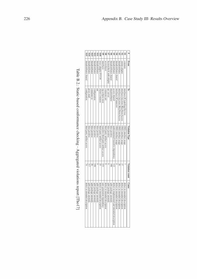
226 Appendix B. Case Study III- Results Overview
#From
ToV
iolationType
Violation
countC
ause
S1com
mon
interfaces.ICryptologyS
erviceO
SG
iinterface
usage7
defectin
intendeddescription
S2sm
ime.adapter
interfaces.keystore.IKeyS
toreAccess
OS
Gi
interfaceusage
17defect
inintended
descriptionS3
datadistributorinterfaces.keystore.IK
eyStoreA
ccessO
SG
iinterface
usage20
defectin
intendeddescription
S4datadistributor-shared
interfaces.IConnector
OS
Gi
interfaceusage
4defect
inintended
descriptionS5
datadistributoraccess-shared
undocumented
transitivedependency
112defect
inim
plemented
andintended
descriptionS6
datadistributor-shareddatadistributor
falsepositive
198split
packageanom
alyS7
licensecheck.auth.adapterrpc-server
falsepositive
6split
packageanom
alyS8
accesslayercom
mons.net
thirdparty
artifactaccess
8defect
inintended
descriptionS9
interfacesorg.eclipse.xtext
transitivethird
partyartifact
access233
autogeneration
dependencyS10
iosys.adapter-P15.04
cluster.comm
onthird
partyartifact
access25
defectin
intendeddescription
S11datadistributor
antfalse
positive9
splitpackage
anomaly
S12datadistributor
configuration
falsepositive
228split
packageanom
alyS13
datadistributorcom
mons-io
falsepositive
20split
packageanom
alyS14
datadistributorjavax-m
ailfalse
positive317
splitpackage
anomaly
S15datadistributor-shared
configuration
thirdparty
artifactaccess
74defect
inintended
description
Table
B.2.:
Static-based
conformance
checking-
Aggregated
violationsreport
[Tho17]
Appendix C.
Monitoring Sessions Conducted in thePresented Case Studies
In this appendix we give more details regarding the episodes and sessions employed in the CaseStudies I (Section C.1) and II (Section C.2).
C.1. Monitoring Session Employed in Case Study I
In this section, we present how the monitoring session conducted on an excerpt of the ARAMISToolbox emerged and what its scenario coverage is.
Considering that the capabilities of Dynatrace represent a superset of those of Kieker, weclassified the ARAMIS scenarios in relevance classes as follows:
VR ={“extract data with Dynatrace”,“trigger conformance checking of data collected withDynatrace”, “define architecture and code units", "define non-parameterized non-aggregatedrules", "define parameterized non-aggregated rules", "define aggregated rules"}
N ={“extract data with Kieker”, “trigger the processing of Kieker data”}Due to the simplicity exhibited by the considered scenarios, defining contexts was not neces-
sary.
Given the relevance classes depicted above and considering that the main task of the practicalcourse was to develop the Dynatrace Extractor and Adapter units, the students then designed amonitoring session consisting of a single episode, as follows:
AramisMon= {(1,“extract data with Dynatrace ”,“”), (2,“define architecture and code units”,“forthe same system as in 1”), (3,“define non-parameterized non-aggregated rules”,“involving thearchitecture units defined in 2”), (4,“define parameterized non-aggregated rules”,“involvingthe architecture units defined in 2”), (5,“define aggregated rules”,“involving the architectureunits defined in 2”),(6, “trigger conformance checking of data collected with Dynatrace”, “thedata extracted in 1”)}.
Thus, the scenario coverage was computed as follows:
sccov(AramisMon) = 3∗61∗2+3∗6 = 0.90
All in all, the AramisMon session, exhibiting a scenario coverage of 0.9 was employed toextract interactions from the ARAMIS Toolbox.
228 Appendix C. Monitoring Sessions Conducted in the Presented Case Studies
C.2. Scenarios Employed in Case Study II
In this section, we present how the monitoring session conducted for the InsuranceApp systememerged and what its scenario coverage is.
To reduce the overhead of the responsible architect, we defined a monitoring session based onour own exploration of the InsuranceApp system. By skipping the initial definition and rankingof scenarios and the documentation of scenario contexts of interest, we intended to speed up theconformance checking process and reduce involvement on our partner’s side. Consequently, wefirst defined and subsequently monitored and checked for conformance a session consisting ofthe following episode:
InsuranceAppIniEpisode={ (1, create a new insurance), (2, parametrize insurance, same in-surance as in 1), (3, assign insurance to customer, same insurance as in 1 and already existingcustomer), (4, save current progress), (5, list insurances of customer, same customer as in 3)}
We presented the initial analysis results to the architect. These revealed that the architectureunits Contract and Validation were not used in performing the InsuranceAppIniEpisode leadingto 4 absent but expected communication instances as formulated in the system’s intended ar-chitecture description. The absences suggested that either the initially monitored episode wasnot relevant or that (some of) the communication possibilities foreseen by the intended architec-ture description were not taken into consideration when building the system. Since a scenariorepository was not available, the architect defined himself the following relevance classes andscenario contexts, in order to estimate the coverage of the initial episode and possibly supportthe definition of a more comprehensive one:
R ={sc1:“create a new insurance”, sc2:“parametrize insurance”, sc3:“assign insurance tocustomer”, sc4:“save current progress”, sc5:“list insurances of customer”}
VR ={sc6:“trigger computation of monthly rate”}.
The last scenario was considered more relevant than the others because it has a more globalarchitectural effect. Furthermore the architect specified the following context set for scenario 5:
CTXsc5 ={ ctx1: list insurances of customer on system start), (cxt2: list insurances of cus-tomer after creating a new insurance (sc1), parametrizing it (sc2), assigning it to the customer(sc3), and saving the progress (sc4)), (ctx3: list insurances of customer after creating a newinsurance (sc1), parametrizing it (sc2), assigning it to the customer (sc3), triggering the calcu-lation of the monthly rate (sc6), and saving the progress (sc4))}
Given that in the InsuranceAppIniEpisode we only considered the scenarios sc1 - sc5 and onlythe context ctx2 for sc5, the scenario coverage was low:
sccov(InsuranceAppIniEpisode) = 1·2+1·2+1·2+1·2+1·21·2+1·2+1·2+1·2+3·2+1·3 ≈ 0.58.
To better cover the scenarios, the architect recorded, using Selenium, a more comprehensiveepisode that consisted of 120 different actions performed in the web-based user interface of theapplication. The episode is detailed below:
InsuranceAppFinalEpisode={ (1, list insurances of customer, ), (2, create a new life insurance,), (3, parametrize insurance, same insurance as in 1), (4, assign insurance to customer, samecustomer as in 1 and same insurance as in 2), (5, trigger computation of monthly rate, sameinsurance as in 2), (6, save current progress, s), (7, list insurances of customer, same customeras in 3)}

C.2. Scenarios Employed in Case Study II 229
InsuranceAppFinalEpisode thus covered all the scenarios (sc1 - sc6) of the system and two ofthe defined contexts (ctx1, ctx3). Therefore, the scenario coverage of the FinalEpisode (≈ 0.88)was higher and the architect considered it sufficient to support the architecture conformancecheck.
In conclusion, to monitor the InsuranceApp, we conducted a monitoring session consisting ofthe episode InsuranceAppFinalEpisode and achieved a scenario coverage of 0.88.

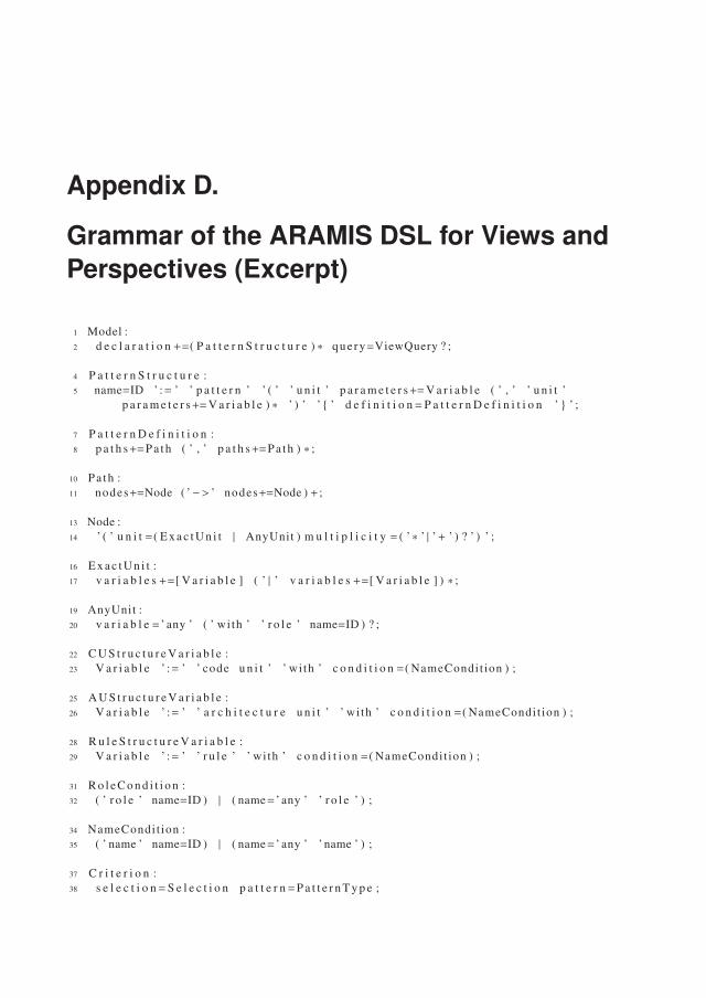
Appendix D.
Grammar of the ARAMIS DSL for Views andPerspectives (Excerpt)
1 Model :2 d e c l a r a t i o n +=( P a t t e r n S t r u c t u r e ) ∗ query=ViewQuery ? ;
4 P a t t e r n S t r u c t u r e :5 name=ID ’ := ’ ’ p a t t e r n ’ ’ ( ’ ’ u n i t ’ p a r a m e t e r s+=V a r i a b l e ( ’ , ’ ’ u n i t ’
p a r a m e t e r s+=V a r i a b l e ) ∗ ’ ) ’ ’{ ’ d e f i n i t i o n=P a t t e r n D e f i n i t i o n ’ } ’ ;
7 P a t t e r n D e f i n i t i o n :8 p a t h s+=Pa th ( ’ , ’ p a t h s+=Pa th ) ∗ ;
10 Pa th :11 nodes+=Node ( ’−> ’ nodes+=Node ) + ;
13 Node :14 ’ ( ’ u n i t =( E x a c t U n i t | AnyUnit ) m u l t i p l i c i t y = ( ’∗ ’ | ’+ ’ ) ? ’ ) ’ ;
16 E x a c t U n i t :17 v a r i a b l e s +=[ V a r i a b l e ] ( ’ | ’ v a r i a b l e s +=[ V a r i a b l e ] ) ∗ ;
19 AnyUnit :20 v a r i a b l e = ’ any ’ ( ’ wi th ’ ’ r o l e ’ name=ID ) ? ;
22 C U S t r u c t u r e V a r i a b l e :23 V a r i a b l e ’ := ’ ’ code u n i t ’ ’ wi th ’ c o n d i t i o n =( NameCondit ion ) ;
25 A U S t r u c t u r e V a r i a b l e :26 V a r i a b l e ’ := ’ ’ a r c h i t e c t u r e u n i t ’ ’ wi th ’ c o n d i t i o n =( NameCondit ion ) ;
28 R u l e S t r u c t u r e V a r i a b l e :29 V a r i a b l e ’ := ’ ’ r u l e ’ ’ wi th ’ c o n d i t i o n =( NameCondit ion ) ;
31 R o l e C o n d i t i o n :32 ( ’ r o l e ’ name=ID ) | ( name= ’ any ’ ’ r o l e ’ ) ;
34 NameCondit ion :35 ( ’ name ’ name=ID ) | ( name= ’ any ’ ’ name ’ ) ;
37 C r i t e r i o n :38 s e l e c t i o n=S e l e c t i o n p a t t e r n=P a t t e r n T y p e ;
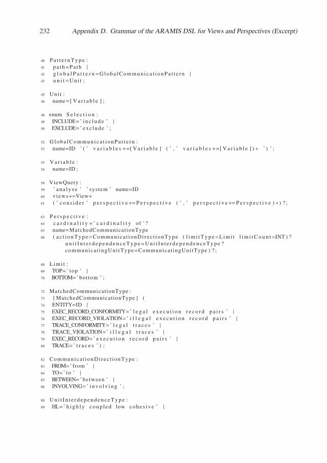
232 Appendix D. Grammar of the ARAMIS DSL for Views and Perspectives (Excerpt)
40 P a t t e r n T y p e :41 p a t h=Pa th |
42 g l o b a l P a t t e r n=G l o b a l C o m m u n i c a t i o n P a t t e r n |
43 u n i t=Uni t ;
45 Un i t :46 name=[ V a r i a b l e ] ;
48 enum S e l e c t i o n :49 INCLUDE= ’ i n c l u d e ’ |50 EXCLUDE= ’ exc lude ’ ;
52 G l o b a l C o m m u n i c a t i o n P a t t e r n :53 name=ID ’ ( ’ v a r i a b l e s +=[ V a r i a b l e ] ( ’ , ’ v a r i a b l e s +=[ V a r i a b l e ] ) ∗ ’ ) ’ ;
55 V a r i a b l e :56 name=ID ;
58 ViewQuery :59 ’ a n a l y z e ’ ’ system ’ name=ID60 v iews+=View+61 ( ’ c o n s i d e r ’ p e r s p e c t i v e+=P e r s p e c t i v e ( ’ , ’ p e r s p e c t i v e+=P e r s p e c t i v e ) ∗ ) ? ;
63 P e r s p e c t i v e :64 c a r d i n a l i t y = ’ c a r d i n a l i t y of ’ ?65 name=MatchedCommunicat ionType66 ( a c t i o n T y p e=Communica t i onDi rec t i onType ( l i m i t T y p e=L i m i t l i m i t C o u n t=INT ) ?
u n i t I n t e r d e p e n d e n c e T y p e=U n i t I n t e r d e p e n d e n c e T y p e ?communica t ingUni tType=Communicat ingUni tType ) ? ;
68 L i m i t :69 TOP= ’ top ’ |70 BOTTOM= ’ bottom ’ ;
72 MatchedCommunicat ionType :73 { MatchedCommunicat ionType } (74 ENTITY=ID |
75 EXEC_RECORD_CONFORMITY= ’ l e g a l e x e c u t i o n r e c o r d p a i r s ’ |76 EXEC_RECORD_VIOLATION= ’ i l l e g a l e x e c u t i o n r e c o r d p a i r s ’ |77 TRACE_CONFORMITY= ’ l e g a l t r a c e s ’ |78 TRACE_VIOLATION= ’ i l l e g a l t r a c e s ’ |79 EXEC_RECORD= ’ e x e c u t i o n r e c o r d p a i r s ’ |80 TRACE= ’ t r a c e s ’ ) ;
82 Communica t i onDi rec t i onType :83 FROM= ’ from ’ |84 TO= ’ to ’ |85 BETWEEN= ’ between ’ |86 INVOLVING= ’ i n v o l v i n g ’ ;
88 U n i t I n t e r d e p e n d e n c e T y p e :89 HL= ’ h i g h l y c o u p l e d low c o h e s i v e ’ |
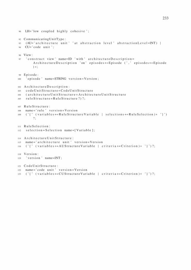
233
90 LH= ’ low c o u p l e d h i g h l y c o h e s i v e ’ ;
92 Communicat ingUni tType :93 (AU= ’ a r c h i t e c t u r e u n i t ’ ’ a t a b s t r a c t i o n l e v e l ’ a b s t r a c t i o n L e v e l=INT ) |94 CU= ’ code u n i t ’ ;
96 View :97 ’ c o n s t r u c t view ’ name=ID ’ with ’ a r c h i t e c t u r e D e s c r i p t i o n=
A r c h i t e c t u r e D e s c r i p t i o n ’ on ’ e p i s o d e s+=Epi sode ( ’ , ’ e p i s o d e s+=Epi sode) ∗ ;
99 Ep i sode :100 ’ e p i s o d e ’ name=STRING v e r s i o n=V e r s i o n ;
102 A r c h i t e c t u r e D e s c r i p t i o n :103 c o d e U n i t S t r u c t u r e=C o d e U n i t S t r u c t u r e104 ( a r c h i t e c t u r e U n i t S t r u c t u r e=A r c h i t e c t u r e U n i t S t r u c t u r e105 r u l e S t r u c t u r e=R u l e S t r u c t u r e ? ) ? ;
107 R u l e S t r u c t u r e :108 name= ’ r u l e ’ v e r s i o n=V e r s i o n109 ( ’ { ’ ( v a r i a b l e s+=R u l e S t r u c t u r e V a r i a b l e | s e l e c t i o n s+=R u l e S e l e c t i o n ) ∗ ’ } ’ )
? ;
111 R u l e S e l e c t i o n :112 s e l e c t i o n=S e l e c t i o n name=[ V a r i a b l e ] ;
114 A r c h i t e c t u r e U n i t S t r u c t u r e :115 name= ’ a r c h i t e c t u r e u n i t ’ v e r s i o n=V e r s i o n116 ( ’ { ’ ( v a r i a b l e s+=A U S t r u c t u r e V a r i a b l e | c r i t e r i a +=C r i t e r i o n ) ∗ ’ } ’ ) ? ;
118 V e r s i o n :119 ’ v e r s i o n ’ name=INT ;
121 C o d e U n i t S t r u c t u r e :122 name= ’ code u n i t ’ v e r s i o n=V e r s i o n123 ( ’ { ’ ( v a r i a b l e s+=C U S t r u c t u r e V a r i a b l e | c r i t e r i a +=C r i t e r i o n ) ∗ ’ } ’ ) ? ;

Refereed Publications
[1] Ana Dragomir and Horst Lichter. Model-Based Software Architecture Evolution and Eval-uation. In Proceedings of the 19th Asia-Pacific Software Engineering Conference (APSEC),pages 697–700, Hong Kong, China, December 2012. IEEE.
[2] Ana Dragomir and Horst Lichter. Run-time Monitoring and Real-time Visualization ofSoftware Architectures. In Proceedings of the 20th Asia-Pacific Software EngineeringConference (APSEC), pages 396–403, Bangkok, Thailand, December 2013. IEEE.
[3] Ana Dragomir, M. Firdaus Harun, and Horst Lichter. On Bridging the Gap Between Prac-tice and Vision for Software Architecture Reconstruction and Evolution: A Toolbox Per-spective. In Proceedings of the Working IEEE/IFIP Conference on Software Architec-ture (WICSA) 2014 Companion Volume, pages 10:1–10:4, Sydney, Australia, April 2014.ACM.
[4] Ana Dragomir, Horst Lichter, and Tiberiu Budau. Systematic Architectural Decision Man-agement, A Process-Based Approach. In Proceedings of the 11th IEEE/IFIP Conferenceon Software Architecture (WICSA), pages 255–258. IEEE, 2014.
[5] Ana Dragomir, M. F. Harun, and Horst Lichter. An architecture for toolbox-based softwarearchitecture reconstruction solutions. Modelbased and Modeldriven Software Modernisa-tion (in German), Workshop 2014, Vienna, Austria, March, 2014.
[6] Ana Dragomir, Horst Lichter, Johannes Dohmen, and Hongyu Chen. Run-TimeMonitoring-Based Evaluation and Communication Integrity Validation of Software Ar-chitectures. In Proceedings of the 21st Asia-Pacific Software Engineering Conference(APSEC), pages 191–198, Jeju, South Korea, 2014. IEEE.
[7] Ana Dragomir and Horst Lichter. Towards an Architecture Quality Index for the Behaviorof Software Systems. In Proceedings of the 2nd International Workshop on QuantitativeApproaches to Software Quality (QuASoC), in conjunction with 21th Asia-Pacific SoftwareEngineering Conference (APSEC), pages 75–82. IEEE, 2014.
[8] Ana Nicolaescu, Horst Lichter, Artjom Göringer, Peter Alexander, and Dung Le. TheARAMIS Workbench for Monitoring, Analysis and Visualization of Architectures basedon Run-time Interactions. In Proceedings of the 9th European Conference on SoftwareArchitecture Workshops (ECSAW ), pages 1–7, Dubrovnik/Cavtat, Croatia, 2015. ACMPress.
[9] Ana Nicolaescu, Horst Lichter, and Yi Xu. Evolution of Object Oriented Coupling Metrics:A Sampling of 25 Years of Research. In Proceedings of the 2nd International Workshop
236 Refereed Publications
on Software Architecture and Metrics (SAM) associated with the 37th International Con-ference on Software Engineering (ICSE), pages 48–54. IEEE, 2015.
[10] Dung Le, Ana Nicolaescu, and Horst Lichter. Adapting Heterogeneous ADLs for SoftwareArchitecture Reconstruction Tools. In Proceedings of the 10th International Conferenceon Software Engineering Advances (ICSEA), pages 52–55, Barcelona, Spain, 2015. IARIAXPS Press.
[11] Peter Alexander, Ana Nicolaescu, and Horst Lichter. Model-Based Evaluation and Simula-tion of Software Architecture Evolution. In Proceedings of 10th International Conferenceon Software Engineering Advances (ICSEA), pages 153–156, Barcelona, Spain, 2015.
[12] Ana Nicolaescu and Horst Lichter. Behavior-Based Architecture Reconstruction and Con-formance Checking. In Proceedings of the 13th Working IEEE/IFIP Conference on Soft-ware Architecture (WICSA), pages 152–157. IEEE, 2016.
[13] Jan Thomas, Ana Nicolaescu, and Horst Lichter. Static and Dynamic Architecture Confor-mance Checking : A Systematic , Case Study-Based Analysis on Tradeoffs and Synergies.In Proceedings of the 5th International Workshop on Quantitative Approaches to SoftwareQuality (QuASoQ), pages 6–13, Nanjing, China, 2017. CEUR-WS.org.
[14] Ana Nicolaescu, Horst Lichter, and Veit Hoffman. On Adequate Behavior-Based Archi-tecture Conformance Checks. In Proceedings of 24th Asia-Pacific Software EngineeringConference (APSEC), Nanjing, China, 2017. IEEE.

Refereed Publications 237

Glossary
Adaptation of Known Code Coverage Metric The adaptation of a known code coverage met-ric extends its definition to allow the coverage computation also for the units defined in asystem’s intended architecture description.
Aggregating Rule A non-aggregating rule results in conformance checks that are performedon the basis of several, related interactions.
Allow Unconstrained Rule The allow unconstrained rule specifies that, if no other specifiedor derived caller-callee rule applies, then the communication involving two distinct archi-tecture units is allowed.
Allow Unmapped Interactions Rule According to the allow unmapped interactions rule, theinteractions that cannot be mapped on the system’s intended architecture description arepermitted.
Allowing Rule An allowing rule permits the occurrence a specified communication.
Allowing and Enforcing Rules Set The Allowing and Enforcing Rules Set attached to a givensystem S represents the set of all enforcing and allowing rules applicable for a given sys-tem.
ARAMIS Toolbox The ARAMIS Toolbox consists of a set of tools developed to automatizeseveral activities of the ARAMIS Conformance Checking Process and to further enablethe understanding and exploration of the conformance checking results.
ARAMIS Conformance Checking Process The ACC-Proc guides the behavior-based con-formance checking of software systems.
ARAMIS Results Exploration Language The ARE-Lang is a language used to define viewsand communication patters for focusing the conformance results produced by ARAMIS.
ARAMIS Communication Rules Language The ACR-Lang is a language that supports thedefinition of communication rules according to the ARAMIS taxonomy.
ARAMIS Interactions Description Language The AID-Lang is employed to normalize theinteractions extracted with arbitrary monitoring tools to a monitoring-tool-independentformat.
ARAMIS Architecture Description Transformation Process The AADT-Proc offers guid-ance how to employ model engineering techniques to automatically transform alreadyexisting descriptions to ARAMIS specific ones.
240 Glossary
ARAMIS Meta-Model The ARAMIS Meta-Model is the meta-model that must be used to in-stantiate intended architecture descriptions that can be analyzed using ARAMIS.
ARAMIS Output An ARAMIS output is an implemented architecture description expressedusing the ARAMIS meta-model.
ARAMIS Input An ARAMIS input is an intended architecture description expressed using theARAMIS meta-model.
Architectural Erosion Architectural erosion represents “the introduction of architectural de-sign decisions into a system’s descriptive architecture that violate its prescriptive architec-ture” [TMD10].
Architectural Drift The architectural drift is the “introduction of principal design decisionsinto a system’s descriptive architecture that (a) are not included in, encompassed by, orimplied by the prescriptive architecture, but which (b) do not violate any of the prescriptivearchitecture’s design decisions” [TMD10].
Architectural Gap The architectural gap encompasses the differences between the implementedand intended architectures of a system.
Architectural Perspective An architectural perspective is “a collection of architectural activi-ties, tactics, and guidelines that are used to ensure that a system exhibits a particular set ofquality properties that require consideration across a number of the system’s architecturalviews” [RW11].
Architecture Unit Set The architecture units set represents the set of all architecture units de-fined in the context of a system’s architecture description.
Architecture Unit An architecture unit is an entity that groups together parts of a softwaresystem with a common architectural significance. An architecture unit is not necessarilyreflected in the code explicitly.
Architecture Rule An architecture rule is a constraint imposed on the architecture of a systemand typically documented in the system’s intended architecture description.
Architecture Description Language An architecture description language is a “viable toolfor formally representing architectures of systems” [Cle96].
Architecture Viewpoint An architecture viewpoint is “a set of conventions for constructing,interpreting, using and analyzing one type of Architecture View” [420].
Architecture View An architecture view “expresses the Architecture of the System of Interestfrom the perspective of one or more Stakeholders to address specific Concerns, using theconventions established by its viewpoint” [420].
Glossary 241
Behavior-based Architecture Conformance Checking Behavior-based architecture confor-mance checking is the process of establishing if an implemented architecture fulfills therules formulated in its intended architecture description based on the system’s behavior asextracted during run-time.
Black-box Indicators Black-box indicators attempt to give an estimation regarding the extentto which a system was investigated in terms of its specification.
Callee Rule A callee rule concerns the communication emerging from all other architectureunits towards a given callee unit.
Callee Execution Record A callee execution record is the target of an interaction.
Caller-Callee Rule A caller-callee rule concerns the directed communication between a pairof specified caller and callee architecture units.
Caller Rule A caller rule concerns the communication emerging from a given caller unit to allother architecture units.
Caller Execution Record A caller execution record is the initiator of an interaction.
Chain Rule A chain concerns the directed communication between a sequence of three or morespecified caller and callee architecture units.
Code Units Set The code units set represents the set of all code units defined in the context ofan architecture description.
Code Unit A code unit is a programming language-independent, untyped representative of acode building block or a set thereof.
Code Building Block A code building block is a programming-language specific structureused to organize the source code of a system (e.g. namespaces, packages, functions, etc.).
Communication The communication of a set of architecture units results through a series ofinteractions involving these units. Communication is realized by different types of interac-tions, be them local or distributed (e.g., direct calls, REST calls, message passing throughqueuing systems, etc.).
Communication Rule A communication rule is an architecture rule that places constraintson the communication of architectural structures as defined in the intended architecturedescription of a system.
Communication Integrity Communication integrity is a “property of a software system inwhich the system’s components interact only as specified by the architecture” [LVM95].
Communications Rule Set The communication rules set aggregates all the communicationrules governing the communication of architecture units defined in the architecture unitsset.
242 Glossary
Context Set of a Scenario The context set of a scenario encompasses all defined contexts inwhich a scenario could occur.
Default Rule Default rules exist to ease the creation of rule sets, in that they regulate the com-munication for the cases where no specified or derived rule apply.
Deny Unconstrained Rule The deny unconstrained rule specifies that, if no other specified orderived caller-callee rule applies, then the communication involving two distinct architec-ture units is disallowed.
Deny Unmapped Interactions Rule According to the deny unmapped interactions rule, theinteractions that cannot be mapped on the system’s intended architecture description aredisallowed and considered violations.
Denying Rule A denying rule prohibits the occurrence a specified communication.
Derivation Degree We say that the architecture unit x is allowed or disallowed to communicatewith y according to a derived communication rule of derivation degree k, if there exist twoother architecture units a and b such that these are indirectly containing x and y respec-tively through k contain relations, and if a is specifically allowed/enforced or disallowedto communicate with b.
Derived Rule A derived rule is only implicitly suggested by the created intended architecturedescription as a consequence of a specified rule.
Enforcing Rule An enforcing rule states that a specified communication must occur.
Episode An episode is a concrete set of logically-coherent actions performed on the system.
Episode Description Derivation (Process) Episode description(s) derivation is the processof defining relevant episode descriptions to guide the choice of episodes to be monitoredon the analyzed running system(s).
Episode Description An episode description is a fragment of a monitoring session descriptionthat guides the execution of an episode.
Evidence Set of a Rule The evidence set of an allowing or enforcing aggregating rule is theset of all sets of interactions that realize the communication allowed/enforced by the givenrule. Similarly, the evidence set of a denying rule is the set of all sets of interactions thatrealize communication constituting a violation of the corresponding rule.
Execution Trace In ARAMIS, an (execution) trace represents the ordered set of all interactionstriggered by a certain behavior-triggering action in a system of interest.
Execution Record An execution record represents the run-time activation of a code buildingblock. An execution record is characterized by its corresponding code building block, andthe timestamps when its activation starts and ends.
Glossary 243
Hierarchical Code Unit Coverage Metric The hierarchical code unit coverage of a unit rep-resents the percentage of code units included in this unit, that were involved in a givenmonitoring sessions.
Implemented Architecture The implemented architecture of a system is intrinsically encom-passed in the actual outcome of a system’s development.
Intended Architecture The intended architecture of a system is a vision and reflects the idealoutcome of a system’s development, according to its architects.
Interaction An interaction depicts the access of a callee execution record by a caller executionrecord.
Interaction Parameter An interaction parameters is a (key, value) pair that better defines thecontext in which the callee execution record was called. A typical example of an interac-tion parameter key is the protocol used to realize the interaction; associated values can be,e.g., amqp, soap webservice, etc.
Meta-model Incompatibility Problem The meta-model incompatibility problem expresses thesyntactic and/or semantic discordance between the languages used by the architects whencreating architecture descriptions, on the one hand, and the languages employed by thevarious architecture conformance checking tools to depict intended and/or implementedarchitectures, on the other hand.
Model-To-Model Transformations Model-to-model transformations allow translating mod-els into another set of models, typically closer to the solution domain or that satisfy spe-cific needs for different stakeholders” [Rod15].
Monitoring Tool A monitoring tool supports the extraction and analysis of information ex-tracted from running systems.
Monitoring Anomaly A monitoring tool exposes a monitoring anomaly if, in some situations,the extracted interactions do not correctly reflect the execution of the system under analy-sis.
Monitoring Session Description A monitoring session description encompasses informa-tion regarding the actions encompassed by a monitoring session and how these shouldbe performed.
Monitoring Session A monitoring session represents the execution of a system with the pur-pose of extracting interactions that occur during the triggered behavior.
Non-aggregating Rule A non-aggregating rule results in conformance checks that are per-formed on the basis of single interactions.
Non-Parameterized Rule A non-parametrized rule regulates the direct communication be-tween architecture units. .
244 Glossary
Overall System Rule Coverage The overall system rule coverage is a metric that depicts theoverall extent to which the expected communication has occurred during a monitoringsession of a system.
Parameterized Rule A parametrized rule regulates communication based on the interactionparameters exposed by its realizing interactions.
Prioritization Rule A prioritization rule offers guidance regarding the choice of the communi-cation rule to be employed, when several communication rules apply.
Relevance Class A relevance class consists of all the scenarios that were assigned the samerelevance.
Same Architecture Unit Rule The same architecture unit rule prescribes that the bidirectionalcommunication realized by interactions whose corresponding caller and callee code unitsare directly included in the same architecture unit is always permitted.
Scenario A scenario is “a step-by-step description of a series of events that may occur concur-rently or sequentially”.
Scenario Context The context of a scenario is determined by the sequence of scenarios thatwere performed previously in the considered monitoring session, after a clean systemstart.
Scenario Variance The variance of a scenario is the percentage of different, possible contextsin which the scenario was executed in the given session.
Scenario Relevance The relevance of a scenario is a ranking given by experts to express thepotential of a the scenario to reveal useful facts regarding the system’s conformance to itsintended architecture description.
Scenario Coverage The scenario coverage of a monitoring session is the percentage of sce-narios whose instances are executed within the session’s episodes, pondered by their rele-vance and variance.
Scenario Repository A system’s scenario repository is a collection of all its identified scenar-ios.
Scenario Performance Description A scenario performance description is a triple consistingof (1) its position in the episode description, (2) the actual scenario that it is referring toand (3) some additional textual information that should give clarification regarding thecontext in which the scenario should occur in.
Scenario Instance A scenario instance results by parameterizing a scenario with concrete in-formation.
Glossary 245
Set of Not Applied Rules The set of not applied rules is a subset of the allowing and enforcingrules set that contains all the rules that were not employed to validate any communicationduring conformance checking to.
Set of Applied Rules The set of applied rules is a subset of the allowing and enforcing rulesset that contains all the rules that were employed to validate communication during con-formance checking to.
Software Architecture Reconstruction Software architecture reconstruction is a “reverseengineering approach that aims at reconstructing viable architectural views of a softwareapplication” [DP09].
Software Architecture Description A software architecture description is "an artifact thatexpresses an Architecture of some System Of Interest" [420].
Software Architecture Software architecture is the "fundamental concepts or properties of asystem in its environment embodied in its elements, relationships, and in the principles ofits design and evolution” [420].
Specified Rule A specified rule is explicitly formulated by the architect when creating theintended architecture description of a system.
Static-based Architecture Conformance Checking Static-based architecture conformancechecking is the process of establishing if an implemented architecture fulfills the rules for-mulated in its intended architecture description based exclusively on system configurationfiles and source code artifacts.
Viewpoint Set A viewpoint set is a collection of predefined viewpoints that architects shouldconsider when developing the architecture views of a system of interest.
Violation A violation is a behavior that realizes a communication contrary to that required bya rule.
White-box Indicators White-box indicators pursue to give an estimation regarding the extentto which a system was investigated during monitoring from the point of view of its in-tended and implemented architectures.

Acronyms
AADT-Proc ARAMIS Architecture Description Transformation Process.
ACC-Proc ARAMIS Conformance Checking Process.
ACR-Lang ARAMIS Communication Rules Language.
ADL Architecture Description Language.
AI ARAMIS Input.
AID-Lang ARAMIS Interactions Description Language.
ARAMIS The Architecture Analysis and Monitoring Infrastructure.
ARAMIS-MM The ARAMIS Meta-Model.
ARE-Lang ARAMIS Results Exploration Language.
CCERD Conformance Checking Based On Eager Rule Derivation.
CCORD Conformance Checking based on On-Demand Rule Derivation.
IAD Intended Architecture Description.
IAD-MM Intended Architecture Description Meta-Model.
M2M Model to Model Transformation.
TADD The Task Automation and Data Distribution System.
TADD-MM The Meta-Model of the Intended Architecture Description of TADD.

List of Figures
2.1. The Meta-Model of an Architecture Description [420] . . . . . . . . . . . . . . 132.2. Intended and Implemented Architectures and Descriptions [420] . . . . . . . . 21
3.1. ARAMIS - an Overview of Processes, Languages and Tool Support . . . . . . 293.2. Overview of TADA’s Processes . . . . . . . . . . . . . . . . . . . . . . . . . . 303.3. Excerpt of the Component Diagram for the Motivating Example . . . . . . . . 31
4.1. Monitoring Concepts in ARAMIS . . . . . . . . . . . . . . . . . . . . . . . . 354.2. Monitoring Concepts in ARAMIS - Example . . . . . . . . . . . . . . . . . . 384.3. Excerpt of the Use Case Diagram of the TADD System . . . . . . . . . . . . . 444.7. The state transitions automaton of the TADD System . . . . . . . . . . . . . . 47
5.1. Core Concepts of the ARAMIS Interactions Description Language (AID-Lang) 525.2. Mapping Kieker Results on the AID-Lang . . . . . . . . . . . . . . . . . . . . 545.3. Mapping Dynatrace Results on the AID-Lang . . . . . . . . . . . . . . . . . . 56
6.1. Overview of the Reflexion Modelling Approach [MNS01] . . . . . . . . . . . 616.2. Architecture Descriptions in ARAMIS . . . . . . . . . . . . . . . . . . . . . . 626.3. Architecture Units in ARAMIS . . . . . . . . . . . . . . . . . . . . . . . . . . 636.4. Communication of Architecture Units . . . . . . . . . . . . . . . . . . . . . . 666.5. Rules Taxonomy . . . . . . . . . . . . . . . . . . . . . . . . . . . . . . . . . 686.6. Parametrized Rules . . . . . . . . . . . . . . . . . . . . . . . . . . . . . . . . 716.7. Overview of Predefined Default Rules in ARAMIS . . . . . . . . . . . . . . . 736.8. Phases of Behavior-based Conformance Checking in ARAMIS . . . . . . . . . 756.9. Contradicting Caller and Callee Rules . . . . . . . . . . . . . . . . . . . . . . 776.10. Derived Communication Rules - Example . . . . . . . . . . . . . . . . . . . . 786.11. ARAMIS Views and Perspectives . . . . . . . . . . . . . . . . . . . . . . . . 88
7.1. Intended and Implemented Architecture Descriptions of Ant [FRZ+16] . . . . . 957.2. The Architecture Description Transformation Process (AADT-Proc) . . . . . . 987.10. The ARAMIS Model Transformation Chain . . . . . . . . . . . . . . . . . . . 108
8.2. Computation of Code Unit Coverage . . . . . . . . . . . . . . . . . . . . . . . 1148.3. Example of a Code Coverage Report in the IntelliJ IDEA IDE . . . . . . . . . 1158.4. Computation of Instructions Coverage on the for Code- and Architecture Units
Level . . . . . . . . . . . . . . . . . . . . . . . . . . . . . . . . . . . . . . . 1178.5. Intended Architecture Description Example . . . . . . . . . . . . . . . . . . . 1198.6. Implemented Architecture Description Example . . . . . . . . . . . . . . . . . 120
250 List of Figures
9.4. The ARAMIS Conformance Checking Process (ACC-Proc) . . . . . . . . . . . 137
10.1. The ARAMIS Toolbox - A Use-Case Perspective . . . . . . . . . . . . . . . . 14010.2. The Intended Architecture of the ARAMIS Toolbox . . . . . . . . . . . . . . . 14110.3. Exemplary ARAMIS Dashboard . . . . . . . . . . . . . . . . . . . . . . . . . 14210.4. Details of a Conformance-Checked System . . . . . . . . . . . . . . . . . . . 14310.5. Example of an Interactive Circle-based Hierarchical View . . . . . . . . . . . . 14410.6. Define Views, Apply Perspectives, Overview the Results . . . . . . . . . . . . 145
12.1. Excerpt of the Intended Architecture Description of ARAMIS . . . . . . . . . 158
13.2. Intended Architecture Description of the InsuranceApp System . . . . . . . . . 16913.3. Meta-Model of the InsuranceApp’s Intended Architecture Description . . . . . 17013.4. Extended Meta-Model of the InsuranceApp’s Intended Architecture Description 17113.5. Implemented Architecture Description of the InsuranceApp . . . . . . . . . . . 173
14.2. Meta-Model of TADD’s Intended Architecture Description . . . . . . . . . . . 18414.3. Excerpt of TADD and ARAMIS Meta-Models Mapping . . . . . . . . . . . . 186
A.1. Demonstrating Polymorphism Anomaly - Exemplary Class Diagram . . . . . . 212A.2. Demonstrating Polymorphism Anomaly - Expected vs. Reconstructed Sequence
Diagrams . . . . . . . . . . . . . . . . . . . . . . . . . . . . . . . . . . . . . 213A.3. Demonstrating Polymorphism Anomaly - Reconstructed Sequence Diagrams
using AspectJ . . . . . . . . . . . . . . . . . . . . . . . . . . . . . . . . . . . 214A.4. Expected Sequence Diagram with Complete Instrumentation . . . . . . . . . . 216A.5. The Partial Trace Anomaly - Monitoring Results . . . . . . . . . . . . . . . . 217A.6. The Partial Trace Anomaly - Further Monitoring Results . . . . . . . . . . . . 217A.7. The Partial Trace Anomaly - The Chain Initiator is Un-instrumented . . . . . . 218A.8. The Partial Trace Anomaly - Sequence Diagram based on Dynatrace and Kieker
Monitoings when the Chain End is Un-instrumented . . . . . . . . . . . . . . . 218
Listings
5.1. Excerpt of Simplified Dynatrace Purepath . . . . . . . . . . . . . . . . . . . . 565.2. Excerpt of a Dynatrace Node Attachement . . . . . . . . . . . . . . . . . . . . 56
6.1. View to Retrieve the Cardinality of a Given Communication Chain . . . . . . . 916.2. View to Retrieve Cyclic Communication Between Specified Units . . . . . . . 92
12.1. Specification of the ARAMIS Chain Rule . . . . . . . . . . . . . . . . . . . . 161
A.1. Demonstrating Polymorphism Anomaly - Exemplary Code . . . . . . . . . . . 212A.2. Demonstrating the Partial Trace Anomaly - Exemplary Code . . . . . . . . . . 214

List of Tables
4.4. Overview of the TADD Scenarios . . . . . . . . . . . . . . . . . . . . . . . . 454.5. Pre- and Postconditions of the TADD Scenarios . . . . . . . . . . . . . . . . . 464.6. TADD States . . . . . . . . . . . . . . . . . . . . . . . . . . . . . . . . . . . 464.8. Defining Scenario Performances . . . . . . . . . . . . . . . . . . . . . . . . . 47
8.1. Overview of Proposed White-box Indicators . . . . . . . . . . . . . . . . . . . 112
9.1. Static vs. Behavior-based Approaches - as Discussed in [Bal99] . . . . . . . . 1289.2. Architectural Evidence in Source Code and Run-time Traces . . . . . . . . . . 1299.3. Comparison of Behavior- and Static-Based Architecture Conformance Checks . 131
11.1. Mapping of the Formulated Hypotheses to Conducted Case Studies . . . . . . . 155
12.2. ARAMIS Backend - Rules Overview . . . . . . . . . . . . . . . . . . . . . . . 16012.3. Instructions Coverage of the ARAMIS Backend . . . . . . . . . . . . . . . . . 163
13.1. Quantitative Overview of the InsuranceApp . . . . . . . . . . . . . . . . . . . 16813.6. Instructions Coverage of the InsuranceApp . . . . . . . . . . . . . . . . . . . . 17513.7. Code Unit Coverage of the InsuranceApp . . . . . . . . . . . . . . . . . . . . 176
14.1. Size Metrics of the TADD System . . . . . . . . . . . . . . . . . . . . . . . . 18114.4. Instructions Coverage of TADD . . . . . . . . . . . . . . . . . . . . . . . . . 190
15.1. Evaluation Summary . . . . . . . . . . . . . . . . . . . . . . . . . . . . . . . 194
B.1. Behavioral-based conformance checking - Aggregated violations report [Tho17] 223B.2. Static-based conformance checking - Aggregated violations report [Tho17] . . 226

Bibliography
[420] The ISO/IEC/IEEE 42010 Standard for Architecture Description. http://www.iso-architecture.org/ieee-1471/index.html. Accessed on Oc-tober, 19th, 2015. (Cited on pages 12, 13, 14, 21, 240, 245, 249, 56, 61, and 65.)
[AG94] Robert Allen and David Garlan. Formalizing architectural connection. In Pro-ceedings of the 16th International Conference on Software Engineering (ICSE),pages 71–80, Los Alamitos, CA, USA, 1994. IEEE. (Cited on page 17.)
[Ale15] Peter Alexander. Model-Based Viewpoints Specification in the Context ofARAMIS Spezifikation von Modelbasierten Standpunkten im Kontext von. Mas-ter thesis, RWTH Aachen University, 2015. (Cited on page 87.)
[ANL15] Peter Alexander, Ana Nicolaescu, and Horst Lichter. Model-Based Evaluationand Simulation of Software Architecture Evolution. In Proceedings of 10thInternational Conference on Software Engineering Advances (ICSEA), pages153–156, Barcelona, Spain, 2015. (Cited on page 87.)
[araa] Extracted ARAMIS Purepaths. https://rwth-aachen.sciebo.de/index.php/s/SybSuySpCw6V8HC. (Cited on page 159.)
[arab] Intended Architecture Description of an Excerpt of the ARAMIS Tool-box. https://rwth-aachen.sciebo.de/s/mqTEH8fkNGXCSnJ. (Cited onpage 159.)
[ARB12] Nour Ali, Jacek Rosik, and Jim Buckley. Characterizing Real-Time Reflexion-Based Architecture Recovery. In Proceedings of the 8th International ACMSIGSOFT Conference on Quality of Software Architectures (QoSA), pages 23–32, Bertinoro, Italy, 2012. ACM Press. (Cited on page 149.)
[arc] The ArchUnit Open Source Library. https://github.com/TNG/ArchUnit.Accessed on 2017-08-21. (Cited on page 146.)
[Bal99] Thomas Ball. The Concept of Dynamic Analysis. In Proceedings of the 7thEuropean Software Engineering Conference (ESEC), volume 24, pages 216–234, Toulouse, France, 1999. ACM. (Cited on pages 109, 127, 128, and 253.)
[Bar13] Jeffrey M. Barnes. Software Architecture Evolution. Phd thesis, Carnegie Mel-lon University, 2013. (Cited on pages 204 and 207.)
256 Bibliography
[BCK12] Len Bass, Paul Clements, and Rick Kazman. Software Architecture in Practice.Addison-Wesley Professional, 3rd edition, 2012. (Cited on pages 3, 4, 12, 23,57, and 59.)
[Bin00] Robert Binder. Testing Object-Oriented Systems : Models, Patterns, and Tools.Addison-Wesley, 2000. (Cited on page 42.)
[BL10] Marcel Bennicke and Claus Lewerentz. Towards Managing Software Architec-tures with Ontologies. In Graph Transformations and Model-Driven Engineer-ing - Essays Dedicated to Manfred Nagl on the Occasion of his 65th Birthday,volume 5765, pages 274–308, 2010. (Cited on page 147.)
[Boe81] Barry W. Boehm. Software Engineering Economics. Prentice Hall PTR, 1stedition, 1981. (Cited on page 12.)
[Boo00] Grady Booch. The future of software (abstract of invited presentation). In Pro-ceedings of International Conference of Software Engineering (ICSE), page 3,2000. (Cited on page 3.)
[Bra12] Manuel Brambilla, Marco and Cabot, Jordi and Wimmer. Model-Driven Soft-ware Engineering in Practice. Morgan & Claypool Publishers, 2012. (Cited onpage 102.)
[cas] The CRASH Report - 2014. http://www.sei.cmu.edu/architecture/start/glossary/community.cfm. Accessed on December, 8th, 2015. (Citedon page 23.)
[CBB+10] Paul Clements, Felix Bachmann, Len Bass, David Garlan, James Ivers, ReedLittle, Paulo Merson, Robert Nord, and Judith Stafford. Documenting Soft-ware Architectures: Views and Beyond. SEI Series in Software Engineering.Addison-Wesley, Upper Saddle River, NJ, 2010. (Cited on pages 11 and 16.)
[CK98] S. Jeromy Carrière and Rick Kazman. The Perils of Reconstructing Architec-tures. In Proceedings of the 3rd International Workshop on Software Archi-tecture (ISAW), pages 13–16, New York, NY, USA, 1998. ACM. (Cited onpage 18.)
[CK16] Humberto Cervantes and Rick Kazman. Designing Software Architectures:A Practical Approach. SEI Series in Software Engineering. Addison-Wesley,Boston, 2016. (Cited on page 11.)
[CKK01] Paul Clements, Rick Kazman, and Mark Klein. Evaluating Software Archi-tectures: Methods and Case Studies. SEI Series in Software Engineering.Addison-Wesley, Boston, MA, 2001. (Cited on page 11.)
[Cle96] Paul C. Clements. A Survey of Architecture Description Languages. In Pro-ceedings of the 8th International Workshop on Software Specification and De-sign (IWSSD), pages 16–25, Washington, DC, USA, 1996. IEEE Computer So-ciety. (Cited on pages 16, 240, and 56.)
Bibliography 257
[CLN14] Andrea Caracciolo, Mircea Filip Lungu, and Oscar Nierstrasz. How Do Soft-ware Architects Specify and Validate Quality Requirements? In Software Ar-chitecture, pages 374–389. Springer International Publishing, 2014. (Cited onpage 149.)
[clo] Clover Code Coverage. https://www.atlassian.com/software/clover.Accessed on 2017-02-07. (Cited on page 115.)
[DB11] Lakshitha De Silva and Dharini Balasubramaniam. A Model for SpecifyingRationale Using an Architecture Description Language. In Proceedings of the5th European Conference on Software Architecture (ECSA), pages 319–327,Essen, Germany, 2011. Springer-Verlag GmbH Berlin Heidelberg. (Cited onpage 149.)
[DHL14] Ana Dragomir, M. Firdaus Harun, and Horst Lichter. On Bridging the Gap Be-tween Practice and Vision for Software Architecture Reconstruction and Evolu-tion: A Toolbox Perspective. In Proceedings of the Working IEEE/IFIP Confer-ence on Software Architecture (WICSA) 2014 Companion Volume, pages 10:1–10:4, Sydney, Australia, April 2014. ACM. (Cited on page 6.)
[DKL09] Slawomir Duszynski, Jens Knodel, and Mikael Lindvall. SAVE: Software Ar-chitecture Visualization and Evaluation. In Proceedings of the 13th EuropeanConference on Software Maintenance and Reengineering (CSMR), pages 323–324, Kaiserslautern, Germany, 2009. IEEE. (Cited on page 60.)
[DL13] Ana Dragomir and Horst Lichter. Run-time Monitoring and Real-time Visual-ization of Software Architectures. In Proceedings of the 20th Asia-Pacific Soft-ware Engineering Conference (APSEC), pages 396–403, Bangkok, Thailand,December 2013. IEEE. (Cited on pages 212 and 28.)
[DLB14] Ana Dragomir, Horst Lichter, and Tiberiu Budau. Systematic ArchitecturalDecision Management, A Process-Based Approach. In Proceedings of the11th IEEE/IFIP Conference on Software Architecture (WICSA), pages 255–258,2014. (Cited on page 16.)
[DLDC14] Ana Dragomir, Horst Lichter, Johannes Dohmen, and Hongyu Chen. Run-TimeMonitoring-Based Evaluation and Communication Integrity Validation of Soft-ware Architectures. In Proceedings of the 21st Asia-Pacific Software Engineer-ing Conference (APSEC), pages 191–198, Jeju, South Korea, dec 2014. IEEE.(Cited on pages 68, 90, and 195.)
[DLVW98] Wim De Pauw, David Lorenz, John Vlissides, and Mark Wegman. ExecutionPatterns in Object-oriented Visualization. In Proceedings of the 4th conferenceon Object-Oriented Technologies and Systems, pages 16–16. USENIX Associ-ation, 1998. (Cited on page 148.)
258 Bibliography
[DP09] Stephane Ducasse and Damien Pollet. Software architecture reconstruction:A process-oriented taxonomy. IEEE Transactions on Software Engineering,35(4):573–591, 2009. (Cited on pages 18, 19, 20, 23, 245, and 61.)
[dSB12] Lakshitha de Silva and Dharini Balasubramaniam. Controlling Software Archi-tecture Erosion: A Survey. Journal of Systems and Software, 85(1):132–151,January 2012. (Cited on pages 3, 19, and 20.)
[dSB13] Lakshitha de Silva and Dharini Balasubramaniam. PANDArch: A PluggableAutomated Non-Intrusive Dynamic Architecture Conformance Checker. InProceedings of the 7th European Conference on Software Engineering (ECSA),pages 240–248, Montpellier, France, 2013. Springer Berlin Heidelberg. (Citedon pages 109 and 149.)
[dyn] Dynatrace: Digital Performance and Application Performance Monitoring.https://www.dynatrace.com/. Accessed on 2015-12-08. (Cited onpages 51, 55, 132, 134, 142, and 148.)
[eco] The Eclipse Ecore Meta-Model. https://wiki.eclipse.org/Ecore. Ac-cessed on April, 27th, 2016. (Cited on page 99.)
[egy] The Egypt tool for Call Graphs Generation. http://www.gson.org/egypt/egypt.html. (Cited on page 129.)
[ent] The Enterprise Architect Website. http://www.sparxsystems.com/products/ea/. Accessed on April, 28th, 2016. (Cited on pages 182 and 199.)
[eps] The Epsilon Tool for Model Engineering. http://www.eclipse.org/epsilon/. Accessed on 2015-10-01. (Cited on page 170.)
[ESSD08] Steve Easterbrook, Janice Singer, Margaret-Anne Storey, and Daniela Damian.Selecting Empirical Methods for Software Engineering Research. In ForrestShull, , Janice Singer, , and Dag I. K. Sj{\o}berg, editors, Guide to Ad-vanced Empirical Software Engineering, pages 285–311. Springer London,2008. (Cited on page 155.)
[Fai10] George Fairbanks. Just enough software architecture: a risk-driven approach.Marshall & Brainerd, 2010. (Cited on pages 3, 11, and 62.)
[FRZ+16] Francesca Arcelli Fontana, Riccardo Roveda, Marco Zanoni, Claudia Raibulet,and Rafael Capilla. An Experience Report on Detecting and Repairing SoftwareArchitecture Erosion. In Proceedings of the 13th Working IEEE/IFIP Con-ference on Software Architecture (WICSA), pages 21–30, Venice, Italy, 2016.IEEE. (Cited on pages 94, 95, 146, and 249.)
[FSH14] Florian Fittkau, Phil Stelzer, and Wilhelm Hasselbring. Live Visualization ofLarge Software Landscapes for Ensuring Architecture Conformance. In Pro-ceedings of the 8th European Conference on Software Architecture Workshops(ECSAW ), pages 1–4, Vienna, Austria, 2014. ACM Press. (Cited on page 149.)
Bibliography 259
[FW12] Gordon Fraser and Neil Walkinshaw. Behaviourally Adequate Software Test-ing. In Proceedings of the 5th International Conference on Software Testing,Verification and Validation (ICST), pages 300–309, Montreal, Canada, 2012.IEEE. (Cited on page 125.)
[GA11] Crina Grosan and Ajith Abraham. Intelligent Systems: A Modern Approach.Springer Berlin Heidelberg, 2011. (Cited on pages 79 and 80.)
[GAO95] David Garlan, Robert Allen, and John Ockerbloom. Architectural Mismatch:Why Reuse Is So Hard. IEEE Software, 12(6):17–26, November 1995. (Citedon page 20.)
[GCH+04] D. Garlan, S.-W. Cheng, A.-C. Huang, B. Schmerl, and P. Steenkiste. Rainbow:Architecture-Based Self-adaptation with Reusable Infrastructure. Computer,37:46–54, oct 2004. (Cited on page 148.)
[GKMM13] Joshua Garcia, Ivo Krka, Chris Mattmann, and Nenad Medvidovic. ObtainingGround-truth Software Architectures. In Proceedings of the 2013 InternationalConference on Software Engineering, ICSE ’13, pages 901–910, Piscataway,NJ, USA, 2013. IEEE Press. (Cited on pages 3 and 23.)
[GKN08] Dharmalingam Ganesan, Thorsten Keuler, and Yutaro Nishimura. ArchitectureCompliance Checking at Runtime: An Industry Experience Report. In Pro-ceedings of the 8th International Conference on Quality Software (QSIC), pages347–356, Oxford, UK, aug 2008. IEEE. (Cited on pages 110, 125, and 199.)
[GMW97] David Garlan, Robert Monroe, and David Wile. Acme: An Architecture De-scription Interchange Language. In Proceedings of the Conference of the Centrefor Advanced Studies on Collaborative Research (CASCON), pages 7–22. IBMPress, 1997. (Cited on page 17.)
[Gör16] Artjom Göringer. Simulation of Software Architecture Evolution in ARAMIS.Master thesis, RWTH Aachen University, 2016. (Cited on pages 134 and 207.)
[GRK07] Marc Giombetti, Dieter Rombach, and Jens Knodel. Evaluating the Archi-tectural Coverage of Runtime Traces. Bachelor thesis, Technische UniversitätKaiserslautern, 2007. (Cited on pages 125 and 126.)
[GS94] David Garlan and Mary Shaw. An Introduction to Software Architecture. Tech-nical report, 1994. (Cited on page 11.)
[GS15] Maayan Goldstein and Itai Segall. Automatic and Continuous Software Archi-tecture Validation. In 37th IEEE International Conference on Software Engi-neering (ICSE), pages 59–68. IEEE, may 2015. (Cited on pages 130 and 147.)
[GZ05] Ian Gorton and Liming Zhu. Tool Support for Just-in-Time Architecture Recon-struction and Evaluation : An Experience Report. In Proceedings of the 27th
260 Bibliography
International Conference on Software Engineering (ICSE), pages 514–523, St.Louis, USA, 2005. ACM. (Cited on page 199.)
[HEB+15] Sebastian Herold, Michael English, Jim Buckley, Steve Counsell, and Mel OCinneide. Detection of Violation Causes in Reflexion Models. In Proceed-ings of the 22nd International Conference on Software Analysis, Evolution, andReengineering (SANER), pages 565–569. IEEE, mar 2015. (Cited on page 59.)
[HL10] Veit Hoffmann and Horst Lichter. A Model-based Narrative Use Case. In Pro-ceedings of the 5th International Conference on Software and Data Technolo-gies, pages 63–72, Athens, Greece, 2010. (Cited on page 39.)
[HlL04] Abdelwahab Hamou-lhadj and Timothy C Lethbridge. A Survey of Trace Ex-ploration Tools and Techniques. In Proceedings of the Conference of the Cen-tre for Advanced Studies on Collaborative Research (CASCON), pages 42–55,Markham, Canada, 2004. IBM Press. (Cited on page 148.)
[HNS00] Christine Hofmeister, Robert Nord, and Dilip Soni. Applied Software Architec-ture. Addison-Wesley Longman Publishing Co., Inc., Boston, MA, USA, 2000.(Cited on page 15.)
[Hoh03] Luke Hohmann. Beyond Software Architecture: Creating and Sustaining Win-ning Solutions. The Addison-Wesley signature series. Addison-Wesley, 2003.(Cited on page 11.)
[HRY95] David R. Harris, Howard B. Reubenstein, and Alexander S. Yeh. Reverse En-gineering to the Architectural Level. In Proceedings of the 17th InternationalConference on Software Engineering, ICSE ’95, pages 186–195, New York,NY, USA, 1995. ACM. (Cited on page 18.)
[HWH+12] André Van Hoorn, Jan Waller, Wilhelm Hasselbring, Software EngineeringGroup, and Christian-albrechts-university Kiel. Kieker : A Framework for Ap-plication Performance Monitoring and Dynamic Software Analysis. In Pro-ceedings of the 3rd joint ACM/SPEC International Conference on PerformanceEngineering (ICPE), pages 247–248, Boston, USA, 2012. ACM. (Cited onpages 51, 52, 53, 134, 142, and 148.)
[isoa] The ISO/IEC 10746-2:2009 Standard. Information technology – Open dis-tributed processing – Reference model: Foundations. https://www.iso.org/standard/55723.html. Accessed on October, 21st, 2017. (Cited onpage 21.)
[isob] The ISO/IEC 15026-1:2013 Standard. Systems and software engineering – Sys-tems and software assurance – Part 1: Concepts and vocabulary. https://www.iso.org/standard/62526.html. Accessed on October, 21st, 2017.(Cited on page 21.)
Bibliography 261
[isoc] The ISO/IEC 15414:2015 Standard. Information technology – Open distributedprocessing – Reference model – Enterprise language. https://www.iso.org/standard/68642.html. Accessed on October, 21st, 2017. (Cited onpage 21.)
[jac] EclEmma - JaCoCo Java Code Coverage Library. http://www.eclemma.org/jacoco/. Accessed on 2015-08-21. (Cited on page 115.)
[Jac87] Ivar Jacobson. Object-Oriented Development in an Industrial Environment.In Proceedings of the Object-Oriented Programming Systems, Languages andApplications (OOPSLA), volume 22, pages 183–191, Orlando, Florida, USA,1987. ACM Press. (Cited on page 37.)
[JB04] Anton Jansen and Jan Bosch. Evaluation of Tool Support for Architectural Evo-lution. In Proceedings of the 19th IEEE International Conference on AutomatedSoftware Engineering (ASE), pages 375–378, Linz, Austria, 2004. IEEE. (Citedon page 207.)
[jde] The JDepend Tool. http://clarkware.com/software/JDepend.html.Accessed on 2015-08-21. (Cited on page 199.)
[JM16] Jens Knodel and Mathias Naab. Pragmatic Evaluation of Software Architec-tures. Springer Publishing Company, Incorporated, 1st edition, 2016. (Cited onpage 60.)
[JR97] Dean Jerding and Spencer Rugaber. Using Visualization for Architectural Lo-calization and Extraction. In Proceedings of the Fourth Working Conference onReverse Engineering (WCRE), pages 56–65. IEEE, 1997. (Cited on page 148.)
[JSB11] Ivar Jacobson, Ian Spence, and Kurt Bittner. Use-Case 2.0 The Guide to Suc-ceeding with Use Cases. Ivar Jacobson International, 2011. (Cited on page 39.)
[jvm] Java Virtual Machine Structure. http://docs.oracle.com/javase/specs/jvms/se7/html/jvms-2.html. Accessed on 2017-03-03. (Cited onpages 212 and 28.)
[KC99] Rick Kazman and S. Jeromy Carrière. Playing Detective: Reconstructing Soft-ware Architecture from Available Evidence. Automated Software Engineering,6(2):107–138, April 1999. (Cited on page 18.)
[KC13] Bilal Karasneh and Michel R.V. Chaudron. Extracting UML Models from Im-ages. In Proceedings of the 5th International Conference on Computer Sci-ence and Information Technology (CSIT), pages 169–178, Amman, Jordan, mar2013. IEEE. (Cited on page 99.)
[KLMN06] Jens Knodel, Mikael Lindvall, Dirk Muthig, and Matthias Naab. Static Eval-uation of Software Architectures. In Proceedings of the 10th Conference on
262 Bibliography
Software Maintenance and Reengineering (CSMR), pages 279–294, Bari, Italy,2006. IEEE. (Cited on page 60.)
[KM96] Kai Koskimies and Hanspeter Mössenböck. Scene: Using Scenario Diagramsand Active Text for Illustrating Object-oriented Programs. In Proceedings of the18th international conference on Software engineering (ICSE), pages 366–375,Berlin, Germany, 1996. IEEE Computer Society Press. (Cited on page 148.)
[KMHM08] Jens Knodel, Dirk Muthig, Uwe Haury, and Gerald Meier. Architecture Compli-ance Checking - Experiences from Successful Technology Transfer to Industry.In Proceedings of the 12th European Conference on Software Maintenance andReengineering (CSMR), pages 43–52. IEEE, 2008. (Cited on pages 61, 109,and 198.)
[KMN06] Jens Knodel, Dirk Muthig, and Matthias Naab. Understanding Software Archi-tectures by Visualization-An Experiment with Graphical Elements. In Proceed-ings of the 13th Working Conference on Reverse Engineering (WCRE), pages39–50, October 2006. (Cited on page 18.)
[KN14] Jens Knodel and Matthias Naab. Software Architecture Evaluation in Practice:Retrospective on More Than 50 Architecture Evaluations in Industry. In Pro-ceedings of IEEE/IFIP Conference on Software Architecture (WICSA), pages115–124, Sydney, Australia, 2014. IEEE. (Cited on page 60.)
[KP07] Jens Knodel and Daniel Popescu. A Comparison of Static Architecture Com-pliance Checking Approaches. In 2007 Working IEEE/IFIP Conference onSoftware Architecture (WICSA’07). IEEE, 2007. (Cited on pages 59, 61, 130,and 134.)
[Kru95] Philippe Kruchten. The 4+1 view model of architecture. IEEE Software,12(6):42–50, November 1995. (Cited on pages 14, 64, 128, and 182.)
[KS03] Rainer Koschke and Daniel Simon. Hierarchical Reflexion Models. In Proceed-ings of the 10th Working Conference on Reverse Engineering (WCRE), pages36–45. IEEE, 2003. (Cited on pages 27 and 60.)
[Lan15] Lidia Lang. Extracting Up-to-Date Architecture Models based on Clusteringof Run-time Information Clustering. Master thesis, RWTH Aachen University,2015. (Cited on page 208.)
[Leh80] Meir M. Lehman. Programs, Life Cycles, and Laws of Software Evolution.Proceedings of the IEEE, 68(9):1060–1076, 1980. (Cited on pages 18 and 48.)
[LKA+95] David C. Luckham, John J. Kenney, Larry M. Augustin, James Vera, DougBryan, and Walter Mann. Specification and analysis of system architecture us-ing rapide. IEEE Transactions on Software Engineering, 21(4):336–355, April1995. (Cited on page 17.)
Bibliography 263
[LL10] Jochen Ludewig and Horst Lichter. Software Engineering : Fundamentals,People, Processes and Techniques (in German). dpunkt.verlag, 2nd edition,2010. (Cited on pages 42, 49, 111, and 112.)
[LL12] Jonas Lundberg and Welf Löwe. Points-to Analysis: A Fine-Grained Evalua-tion. Journal of Universal Computer Science, 18(20):2851–2878, 2012. (Citedon page 147.)
[LM08] Mikael Lindvall and Dirk Muthig. Bridging the Software Architecture Gap.Computer, 41:98–101, 2008. (Cited on pages 60 and 198.)
[LN97] Danny B. Lange and Yuichi Nakamura. Object-Oriented Program Tracing andVisualization. Computer, 30(5):63–70, may 1997. (Cited on pages 127, 128,and 148.)
[LNL15] Dung Le, Ana Nicolaescu, and Horst Lichter. Adapting Heterogeneous ADLsfor Software Architecture Reconstruction Tools. In Proceedings of the 10thInternational Conference on Software Engineering Advances (ICSEA), pages52–55, Barcelona, Spain, 2015. IARIA XPS Press. (Cited on page 93.)
[LV95] David C. Luckham and James Vera. An Event-Based Architecture Defini-tion Language. IEEE Transactions on Software Engineering, 21(9):717–734,September 1995. (Cited on pages 4 and 19.)
[LVM95] David C. Luckham, James Vera, and Sigurd Meldal. Three Concepts of Sys-tem Architecture. In Technical Report, Stanford University, 1995. (Cited onpages 21, 241, and 57.)
[Mal] Malavolta, Ivano and Lago, Patricia and Muccini, Henry and Pelliccione, Pa-trizio and Tang, Antony. The up-to-date list of currently existing architecturallanguages. http://www.di.univaq.it/malavolta/al/. Accessed on October, 27th,2015. (Cited on pages 17 and 93.)
[Man15] Claude Mangen. Composing Interactive Views for Software Behavior Compre-hension Based on its Architecture Description. Master thesis, RWTH AachenUniversity, 2015. (Cited on pages 141 and 143.)
[Mar00] Robert C. Martin. Design Principles and Design Patterns (Techni-cal report). http://www.objectmentor.com/resources/articles/Principles_and_Patterns.PDF, 2000. (Cited on page 20.)
[Mar17] Robert C Martin. Clean Architecture: A Craftsman’s Guide to Software Struc-ture and Design. Pearson Education, 2017. (Cited on page 11.)
[Mey96] Bertrand Meyer. The Many Faces of Inheritance: A Taxonomy of Taxonomy.Computer, 29(5):105–108, 1996. (Cited on page 68.)
264 Bibliography
[mfm] Overview of Microsoervices. https://martinfowler.com/articles/microservices.html. Accessed on 2016-12-15. (Cited on page 4.)
[MG07] Gerard. Meszaros and Gerard. XUnit test patterns : refactoring test code.Addison-Wesley, 2007. (Cited on page 49.)
[MJ06] Nenad Medvidovic and Vladimir Jakobac. Using Software Evolution to Fo-cus Architectural Recovery. Automated Software Engg., 13(2):225–256, April2006. (Cited on page 18.)
[MK89] Hausi A. Müller and Karl Klashinsky. Rigi- A System for Programming-in-the-Large. In Proceedings of the 10th International Conference on SoftwareEngineering (ICSE), pages 80–86, Singapore, 1989. IEEE. (Cited on page 197.)
[MKM11] Andrew McVeigh, Jeff Kramer, and Jeff Magee. Evolve: Tool Support forArchitecture Evolution. In Proceedings of the 33rd international conference onSoftware engineering (ICSE ), pages 1040–1042, Waikiki, USA, 2011. ACMPress. (Cited on page 207.)
[MLM+13] Ivano Malavolta, Patricia Lago, Henry Muccini, Patrizio Pelliccione, andAntony Tang. What Industry Needs from Architectural Languages: A Survey.IEEE Transactions on Software Engineering, 39(6):869–891, jun 2013. (Citedon page 94.)
[MN97] Gail C. Murphy and David Notkin. Reengineering with Reflexion Models: ACase Study. Computer, 30(8):29–36, 1997. (Cited on pages 88 and 197.)
[MNS95] Gail C. Murphy, David Notkin, and Kevin Sullivan. Software Reflexion Models:Bridging the Gap between Source and High-Level Models. In Proceedings ofthe 3rd ACM SIGSOFT Symposium on Foundations of Software Engineering,volume 20, pages 18–28, Washington, USA, 1995. ACM. (Cited on page 59.)
[MNS01] Gail C. Murphy, David Notkin, and Kevin J. Sullivan. Software Reflexion Mod-els: Bridging the Gap Between Design and Implementation. IEEE Transactionson Software Engineering, 27(4):364–380, apr 2001. (Cited on pages 18, 19, 20,60, 61, and 249.)
[MRR02] Ana Milanova, Barbara G Ryder, and B G Ryder. Parameterized Object Sensi-tivity for Points-to Analysis for Java. ACM Transactions on Software Engineer-ing and Methodology, 14(1):1–11, 2002. (Cited on page 147.)
[MRRR02] Nenad Medvidovic, David S. Rosenblum, David F. Redmiles, and Jason E. Rob-bins. Modeling software architectures in the unified modeling language. ACMTransactions on Software Engineering and Methodologies, 11(1):2–57, January2002. (Cited on page 16.)
Bibliography 265
[MSA+15] Ivan Mistrik, Richard Soley, Nour Ali, John Grundy, and Bedir Tekinerdogan.Software Quality Assurance: In Large Scale and Complex Software-IntensiveSystems. Morgan Kaufmann Publishers Inc., 1st edition, 2015. (Cited onpage 128.)
[MSSV16] Izabela Melo, Gustavo Santos, Dalton Dario Serey, and Marco Tulio Valente.Perceptions of 395 Developers on Software Architecture’s Documentation andConformance (in Portuguese). In Brazilian Symposium on Software Compo-nents, Architectures and Reuse (SBCARS), pages 81–90, Maringá, Brazil, 2016.(Cited on page 149.)
[MT00] Nenad Medvidovic and Richard N. Taylor. A Classification and ComparisonFramework for Software Architecture Description Languages. IEEE Transac-tions on Software Engineering, 26(1):70–93, 2000. (Cited on pages 17 and 61.)
[MTW93] Hausi A. Müller, Scott R. Tilley, and Kenny Wong. Understanding SoftwareSystems Using Reverse Engineering Technology Perspectives from the RigiProject, 1993. (Cited on page 197.)
[nag] Nagios - The Industry Standard In IT Infrastructure Monitoring. https://www.nagios.org/. Accessed on 2017-02-19. (Cited on pages 51, 132,and 148.)
[NFLJ06] Clémentine Nebut, Franck Fleurey, Yves Le Traon, and Jean-Marc Jézéquel.Automatic Test Generation: A use Case Driven Approach. IEEE Transactionson Software Engineering, 32(3):140–155, 2006. (Cited on pages 39 and 41.)
[NL16] Ana Nicolaescu and Horst Lichter. Behavior-Based Architecture Reconstruc-tion and Conformance Checking. In Proceedings of the 13th Working IEEE/I-FIP Conference on Software Architecture (WICSA), pages 152–157. IEEE, apr2016. (Cited on pages 68 and 195.)
[NLG+15] Ana Nicolaescu, Horst Lichter, Artjom Göringer, Peter Alexander, and DungLe. The ARAMIS Workbench for Monitoring, Analysis and Visualization ofArchitectures based on Run-time Interactions. In Proceedings of the 9th Eu-ropean Conference on Software Architecture Workshops (ECSAW ), pages 1–7,Dubrovnik/Cavtat, Croatia, 2015. ACM Press. (Cited on pages 87, 95, 141,143, and 195.)
[NLH17] Ana Nicolaescu, Horst Lichter, and Veit Hoffman. On Adequate Behavior-Based Architecture Conformance Checks. In Proceedings of 24th Asia-PacificSoftware Engineering Conference (APSEC), Nanjing, China, 2017. (Cited onpages 68, 86, 109, 125, 157, and 167.)
[NP90] John Teofil Nosek and Prashant Palvia. Software Maintenance Management:Changes in the Last Decade. Journal of Software Maintenance, 2(3):157–174,September 1990. (Cited on page 23.)
266 Bibliography
[Obj09] Object Management Group. OMG Unified Modeling Language Infrastructure.2009. (Cited on page 64.)
[OMG11] OMG. OMG Unified Modeling Language (OMG UML), Superstructure, Ver-sion 2.4.1. August 2011. (Cited on pages 64, 94, and 106.)
[osg] The Open Services Gateway Initiative. https://www.osgi.org/. Accessedon 2017-14-08. (Cited on page 61.)
[OSL05] Liam O’Brien, Dennis Smith, and Grace Lewis. Supporting Migration to Ser-vices using Software Architecture Reconstruction. In Proceedings of the 13thIEEE International Workshop on Software Technology and Engineering Prac-tice (STEP), pages 81–91. IEEE, 2005. (Cited on page 199.)
[PJM+02] Wim De Pauw, Erik Jensen, Nick Mitchell, Gary Sevitsky, John M. Vlissides,and Jeaha Yang. Visualizing the Execution of Java Programs. In SoftwareVisualization: International Seminar, pages 151–162. Springer, 2002. (Citedon page 148.)
[Pos03] André Postma. A Method for Module Architecture Verification and its Appli-cation on a Large Component-Based System. Information and Software Tech-nology, 45(4):171–194, mar 2003. (Cited on page 61.)
[PvdW15] Leo Pruijt and Jan Martijn E. M. van der Werf. Dependency Types and Sub-types in the Context of Architecture Reconstruction and Compliance Check-ing. In Proceedings of the 9th European Conference on Software Architec-ture Workshops (ECSAW), pages 1–7, Dubrovnik, Cavtat, Croatia, 2015. ACMPress. (Cited on page 128.)
[PW92] Dewayne E. Perry and Alexander L. Wolf. Foundations for the Study of Soft-ware Architecture. SIGSOFT Software Engineering Notes, 17(4):40–52, Octo-ber 1992. (Cited on pages 4, 19, and 20.)
[RD02] Tamar Richner and Stéphane Ducasse. Using Dynamic Information for theIterative Recovery of Collaborations and Roles. In Proceedings of InternationalConference on Software Maintenance (ICSM), pages 34–43, Montreal, Canada,2002. IEEE. (Cited on page 148.)
[RH08] Ralf Reussner and Wilhelm Hasselbring, editors. Software Architecture Hand-book (in German). dpunkt, Heidelberg, 2 edition, 2008. (Cited on page 18.)
[Riv04] Claudio Riva. View-based Software Architecture Reconstruction. Phd thesis,Vienna University of Technology, October 2004. (Cited on page 20.)
[RLB+10] Jacek Rosik, Andrew Le Gear, Jim Buckley, Muhammad Ali Babar, and DaveConnolly. Assessing Architectural Drift in Commercial Software Development:a Case Study. Software: Practice and Experience, 41(1):63–86, jan 2010.(Cited on pages 20 and 199.)
Bibliography 267
[RLBA08] Jacek Rosik, Andrew Le Gear, Jim Buckley, and Muhammad Ali Babar. AnIndustrial Case Study of Architecture Conformance. In Proceedings of the Sec-ond ACM-IEEE International Symposium on Empirical software engineeringand measurement (ESEM), pages 80–89, Kaiserslautern, Germany, 2008. ACMPress. (Cited on pages 19, 23, and 199.)
[RM06] John Reekie and Rohan McAdam. A Software Architecture Primer. AngophoraPress, 2006. (Cited on pages 11, 62, and 64.)
[Rod15] Alberto Rodrigues Da Silva. Model-Driven Engineering. Computer Languages,Systems and Structures, 43:139–155, 2015. (Cited on pages 102, 243, and 59.)
[RSN09] Mehwish Riaz, Muhammad Sulayman, and Husnain Naqvi. Architectural De-cay during Continuous Software Evolution and Impact of ’Design for Change’on Software Architecture. In Advances in Software Engineering, volume 59,pages 119–126. Springer Berlin Heidelberg, 2009. (Cited on page 20.)
[RW11] Nick Rozanski and Eóin Woods. Software Systems Architecture: Working withStakeholders Using Viewpoints and Perspectives. Addison-Wesley, 2nd edition,2011. (Cited on pages 12, 14, 15, 240, and 56.)
[SAG+06] Bradley Schmerl, Jonathan Aldrich, David Garlan, Rick Kazman, and HongYan. DiscoTect : A System for Discovering the Architectures of Running Pro-grams Using Colored Petri Nets. Technical report, Carnegie Mellon University,Pittsburgh, PA, USA, 2006. (Cited on page 149.)
[saj] IBM SA4J - Structural Analysis for Java, 2004. (Cited on page 199.)
[Sam15] Sam Newman. Building Microservices. O’Reilly and Associates, 2015. (Citedon page 4.)
[SBB+10] Benjamin H. Sigelman, Luiz André Barroso, Mike Burrows, Pat Stephenson,Manoj Plakal, Donald Beaver, Saul Jaspan, and Chandan Shanbhag. Dapper,a Large-Scale Distributed Systems Tracing Infrastructure. Technical report,Google, Inc., 2010. (Cited on pages 4 and 148.)
[SC06] Mary Shaw and Paul Clements. The Golden Age of Software Architecture.IEEE Software, 23:31–39, 2006. (Cited on pages 11 and 146.)
[scr] The Scrum Alliance Website. https://www.scrumalliance.org/. Ac-cessed on 2017-11-14. (Cited on page 48.)
[seia] SEI Course on Documenting Software Architectures. http://www.sei.cmu.edu/training/P33.cfm. Accessed on October, 22nd, 2015. (Cited onpage 16.)
[seib] SEI Listing of Community Architecture Definitions. http://www.sei.cmu.edu/architecture/start/glossary/community.cfm. Accessed on Oc-tober, 19th, 2015. (Cited on page 12.)
268 Bibliography
[sem] Semantic Designs: Test Coverage. http://www.semanticdesigns.com/Products/TestCoverage/index.html?Home=Main. Accessed on 2017-02-07. (Cited on page 115.)
[sev] The Software and Systems Engineering Vocabulary. https://pascal.computer.org. Accessed on 2016-08-15. (Cited on pages 21, 36, 39, 48,53, and 65.)
[SG96] Mary Shaw and David Garlan. Software Architecture: Perspectives on anEmerging Discipline. An Alan R. Apt book. Prentice Hall, 1996. (Cited onpage 11.)
[SGY05] Bradley Schmerl, David Garlan, and Hong Yan. Dynamically Discovering Ar-chitectures with DiscoTect. In Proceedings of the 10th European software engi-neering conference held jointly with 13th ACM SIGSOFT international sympo-sium on Foundations of software engineering - ESEC/FSE-13, volume 30, pages103–106, Lisbon, Portugal, 2005. ACM Press. (Cited on page 149.)
[Sil14] Lakshitha De Silva. Towards Controlling Software Architecture ErosionThrough Runtime Conformance Monitoring. Phd, University of St Andrews,2014. (Cited on pages 125 and 199.)
[SKM01] Tarja Systä, Kai Koskimies, and Hausi Müller. Shimba - an Environment forReverse Engineering Java Software Systems. Software: Practice and Experi-ence, 31:371–394, apr 2001. (Cited on page 148.)
[SL10] Frank Steinbrückner and Claus Lewerentz. Representing Development Historyin Software Cities. In Proceedings of the 5th International Symposium on Soft-ware Visualization, SOFTVIS ’10, pages 193–202, Salt Lake City, Utah, USA,2010. ACM. (Cited on page 146.)
[SL13] Frank Steinbrückner and Claus Lewerentz. Understanding Software Evolutionwith Software Cities. Information Visualization, 12(2):200–216, 2013. (Citedon page 146.)
[son] The Sonargraph Architect Website. (Cited on pages 94, 133, 134, 146, and 188.)
[SSL+14] Mehrdad Saadatmand, Detlef Scholle, Cheuk Wing Leung, Sebastian Ullström,and Joanna Fredriksson Larsson. Runtime Verification of State Machines andDefect Localization Applying Model-Based Testing. In Proceedings of theWorking IEEE/IFIP Conference on Software Architecture (WICSA) Compan-ion Volume, pages 1–8, Sydney, Australia, apr 2014. ACM Press. (Cited onpage 149.)
[sta] The STAN Project. http://stan4j.com. Accessed on 2016-12-19. (Cited onpages 130 and 147.)
Bibliography 269
[str] The Structure101 Project. http://structure101.com/. Accessed on 2016-12-19. (Cited on pages 94, 130, and 146.)
[TGLH00] John B. Tran, Michael W. Godfrey, Eric H.S. Lee, and Richard C. Holt. Ar-chitectural Repair of Open Source Software. In Proceedings of the 8th Inter-national Workshop on Program Comprehension (IWPC), pages 48–59. IEEE,2000. (Cited on page 198.)
[TH99] John B. Tran and Richard C. Holt. Forward and Reverse Repair of Software Ar-chitecture. In Proceedings of the Conference of the Centre for Advanced Stud-ies on Collaborative research (CASCON ), pages 12–21, Mississauga, Canada,1999. IBM Press. (Cited on pages 18 and 65.)
[Tho17] Jan Thomas. Software Architecture Conformance Analysis - A Large-Scale In-dustrial Case Study. Master thesis, RWTH Aachen University, 2017. (Cited onpages 100, 130, 179, 182, 188, 223, 226, 253, 39, 42, and 69.)
[TMD10] Richard N. Taylor, Nenad Medvidovic, and Eric M. Dashofy. Software Archi-tecture - Foundations, Theory, and Practice. Wiley, 2010. (Cited on pages 12,19, 20, 240, and 56.)
[TNL17] Jan Thomas, Ana Nicolaescu, and Horst Lichter. Static and Dynamic Archi-tecture Conformance Checking : A Systematic , Case Study-Based Analysis onTradeoffs and Synergies. In Proceedings of the 5th International Workshop onQuantitative Approaches to Software Quality (QuASoQ), pages 6–13, Nanjing,China, 2017. CEUR-WS.org. (Cited on pages 86 and 179.)
[und] The Understand Tool. https://scitools.com/features/. Accessed on2017-08-21. (Cited on pages 146 and 199.)
[VACK11] Oliver Vogel, Ingo Arnold, Arif Chughtai, and Timo Kehrer. Software Archi-tecture - A Comprehensive Framework and Guide for Practitioners. Springer,2011. (Cited on pages 16, 17, 20, 23, and 93.)
[vHRH+09] André van Hoorn, Matthias Rohr, Wilhelm Hasselbring, Jan Waller, Jens Ehlers,Sören Frey, and Dennis Kieselhorst. Continuous Monitoring of Software Ser-vices: Design and Application of the Kieker Framework. Technical report,Department of Computer Science, University of Kiel, Germany, 2009. (Citedon page 19.)
[vis] Layer Diagrams in Visual Studio. https://msdn.microsoft.com/en-us/library/dd409462.aspx. Accessed on 2016-08-15. (Cited on page 146.)
[vOvdLKM00] Rob van Ommering, Frank van der Linden, Jeff Kramer, and Jeff Magee.The Koala Component Model for Consumer Electronics Software. Computer,33(3):78–85, 2000. (Cited on page 17.)
270 Bibliography
[VRG+14] Michael Vierhauser, Rick Rabiser, Paul Grunbacher, Christian Danner, StefanWallner, and Helmut Zeisel. A Flexible Framework for Runtime Monitoring ofSystem-of-Systems Architectures. In Proceedings of the 11th Working IEEE/I-FIP Conference on Software Architecture (WICSA), pages 57–66, Sydney, Aus-tralia, 2014. IEEE. (Cited on page 199.)
[WHL09] Christoph Weidmann, Veit Hoffmann, and Horst Lichter. Aplicationsand Usages of Use Cases: Results of an Empirical Study (in German).Softwaretechnik-Trends, 29(2):62–67, 2009. (Cited on pages 39 and 48.)
[WL08] Richard Wettel and Michele Lanza. Visual Exploration of Large-Scale SystemEvolution. In Proceedings of Working Conference on Reverse Engineering,pages 219–228. IEEE, 2008. (Cited on page 147.)
[WLR11] Richard Wettel, Michele Lanza, and Romain Robbes. Software Systems asCities. In Proceeding of the 33rd International Conference on Software Engi-neering (ICSE), pages 551–560, New York, New York, USA, 2011. ACM Press.(Cited on page 147.)
[WMFB+98] Robert J. Walker, Gail C. Murphy, Bjorn Freeman-Benson, Darin Wright, DarinSwanson, Jeremy Isaak, Robert J. Walker, Gail C. Murphy, Bjorn Freeman-Benson, Darin Wright, Darin Swanson, and Jeremy Isaak. Visualizing DynamicSoftware System Information through High-level Models. In Proceedings ofthe 13th ACM SIGPLAN conference on Object-oriented programming, systems,languages, and applications (OOPSLA), pages 271–283, Vancouver, Canada,1998. ACM Press. (Cited on page 148.)
[WTMS95] K. Wong, S.R. Tilley, H.A. Muller, and M.-A.D. Storey. Structural Redocumen-tation: a Case Study. IEEE Software, 12(1):46–54, 1995. (Cited on page 197.)
[YGS+04] Hong Yan, D. Garlan, B. Schmerl, J. Aldrich, and R. Kazman. DiscoTect: ASystem for Discovering Architectures from Running Systems. In Proceedingsof the 26th International Conference on Software Engineering (ICSE), numberMay, pages 470–479. IEEE, 2004. (Cited on pages 125, 149, and 199.)
[zip] The Zipkin Project. http://zipkin.io/. Accessed on 2016-12-19. (Citedon page 148.)
Related Work from the SE Group, RWTH Aachen
Agile Model Based Software Engineering
Agility and modeling in the same project? This question was raised in [Rum04]: “Using an executable,yet abstract and multi-view modeling language for modeling, designing and programming still allows touse an agile development process.” Modeling will be used in development projects much more, if thebenefits become evident early, e.g with executable UML [Rum02] and tests [Rum03]. In [GKRS06], forexample, we concentrate on the integration of models and ordinary programming code. In [Rum12] and[Rum16], the UML/P, a variant of the UML especially designed for programming, refactoring and evolu-tion, is defined. The language workbench MontiCore [GKR+06, GKR+08] is used to realize the UML/P[Sch12]. Links to further research, e.g., include a general discussion of how to manage and evolve models[LRSS10], a precise definition for model composition as well as model languages [HKR+09] and refac-toring in various modeling and programming languages [PR03]. In [FHR08] we describe a set of generalrequirements for model quality. Finally [KRV06] discusses the additional roles and activities necessaryin a DSL-based software development project. In [CEG+14] we discuss how to improve reliability ofadaptivity through models at runtime, which will allow developers to delay design decisions to runtimeadaptation.
Generative Software Engineering
The UML/P language family [Rum12, Rum11, Rum16] is a simplified and semantically sound derivativeof the UML designed for product and test code generation. [Sch12] describes a flexible generator forthe UML/P based on the MontiCore language workbench [KRV10, GKR+06, GKR+08]. In [KRV06],we discuss additional roles necessary in a model-based software development project. In [GKRS06] wediscuss mechanisms to keep generated and handwritten code separated. In [Wei12] demonstrate howto systematically derive a transformation language in concrete syntax. To understand the implicationsof executability for UML, we discuss needs and advantages of executable modeling with UML in agileprojects in [Rum04], how to apply UML for testing in [Rum03] and the advantages and perils of usingmodeling languages for programming in [Rum02].
Unified Modeling Language (UML)
Starting with an early identification of challenges for the standardization of the UML in [KER99] manyof our contributions build on the UML/P variant, which is described in the two books [Rum16] and[Rum12] implemented in [Sch12]. Semantic variation points of the UML are discussed in [GR11]. Wediscuss formal semantics for UML [BHP+98] and describe UML semantics using the “System Model”[BCGR09a], [BCGR09b], [BCR07b] and [BCR07a]. Semantic variation points have, e.g., been applied todefine class diagram semantics [CGR08]. A precisely defined semantics for variations is applied, whenchecking variants of class diagrams [MRR11c] and objects diagrams [MRR11d] or the consistency ofboth kinds of diagrams [MRR11e]. We also apply these concepts to activity diagrams [MRR11b] whichallows us to check for semantic differences of activity diagrams [MRR11a]. The basic semantics for ADsand their semantic variation points is given in [GRR10]. We also discuss how to ensure and identifymodel quality [FHR08], how models, views and the system under development correlate to each other[BGH+98] and how to use modeling in agile development projects [Rum04], [Rum02]. The question howto adapt and extend the UML is discussed in [PFR02] describing product line annotations for UML andmore general discussions and insights on how to use meta-modeling for defining and adapting the UMLare included in [EFLR99], [FELR98] and [SRVK10].
272 Related Work from the SE Group, RWTH Aachen
Domain Specific Languages (DSLs)
Computer science is about languages. Domain Specific Languages (DSLs) are better to use, but needappropriate tooling. The MontiCore language workbench [GKR+06, KRV10, Kra10, GKR+08] allowsthe specification of an integrated abstract and concrete syntax format [KRV07b] for easy development.New languages and tools can be defined in modular forms [KRV08, GKR+07, Völ11] and can, thus, easilybe reused. [Wei12] presents a tool that allows to create transformation rules tailored to an underlyingDSL. Variability in DSL definitions has been examined in [GR11]. A successful application has beencarried out in the Air Traffic Management domain [ZPK+11]. Based on the concepts described above,meta modeling, model analyses and model evolution have been discussed in [LRSS10] and [SRVK10].DSL quality [FHR08], instructions for defining views [GHK+07], guidelines to define DSLs [KKP+09]and Eclipse-based tooling for DSLs [KRV07a] complete the collection.
Software Language Engineering
For a systematic definition of languages using composition of reusable and adaptable language com-ponents, we adopt an engineering viewpoint on these techniques. General ideas on how to engineer alanguage can be found in the GeMoC initiative [CBCR15, CCF+15]. As said, the MontiCore languageworkbench provides techniques for an integrated definition of languages [KRV07b, Kra10, KRV10]. In[SRVK10] we discuss the possibilities and the challenges using metamodels for language definition.Modular composition, however, is a core concept to reuse language components like in MontiCore forthe frontend [Völ11, KRV08] and the backend [RRRW15]]. Language derivation is to our believe apromising technique to develop new languages for a specific purpose that rely on existing basic lan-guages. How to automatically derive such a transformation language using concrete syntax of the baselanguage is described in [HRW15, Wei12] and successfully applied to various DSLs. We also applied thelanguage derivation technique to tagging languages that decorate a base language [GLRR15] and deltalanguages [HHK+15a, HHK+13], where a delta language is derived from a base language to be able toconstructively describe differences between model variants usable to build feature sets.
Modeling Software Architecture & the MontiArc Tool
Distributed interactive systems communicate via messages on a bus, discrete event signals, streams oftelephone or video data, method invocation, or data structures passed between software services. Weuse streams, statemachines and components [BR07] as well as expressive forms of composition and re-finement [PR99] for semantics. Furthermore, we built a concrete tooling infrastructure called MontiArc[HRR12] for architecture design and extensions for states [RRW13b]. MontiArc was extended to de-scribe variability [HRR+11] using deltas [HRRS11, ?] and evolution on deltas [HRRS12]. [GHK+07]and [GHK+08] close the gap between the requirements and the logical architecture and [GKPR08] ex-tends it to model variants. [MRR14] provides a precise technique to verify consistency of architecturalviews [Rin14, MRR13] against a complete architecture in order to increase reusability. Co-evolutionof architecture is discussed in [MMR10] and a modeling technique to describe dynamic architectures isshown in [HRR98].
Compositionality & Modularity of Models
[HKR+09] motivates the basic mechanisms for modularity and compositionality for modeling. The mech-anisms for distributed systems are shown in [BR07] and algebraically underpinned in [HKR+07]. Seman-tic and methodical aspects of model composition [KRV08] led to the language workbench MontiCore[KRV10] that can even be used to develop modeling tools in a compositional form. A set of DSL design
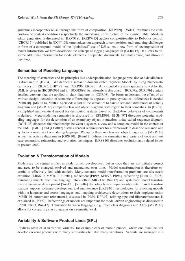
Related Work from the SE Group, RWTH Aachen 273
guidelines incorporates reuse through this form of composition [KKP+09]. [Völ11] examines the com-position of context conditions respectively the underlying infrastructure of the symbol table. Modulareditor generation is discussed in [KRV07a]. [RRRW15] applies compositionality to Robotics control.[CBCR15] (published in [CCF+15]) summarizes our approach to composition and remaining challengesin form of a conceptual model of the “globalized” use of DSLs. As a new form of decomposition ofmodel information we have developed the concept of tagging languages in [GLRR15]. It allows to de-scribe additional information for model elements in separated documents, facilitates reuse, and allows totype tags.
Semantics of Modeling Languages
The meaning of semantics and its principles like underspecification, language precision and detailednessis discussed in [HR04]. We defined a semantic domain called “System Model” by using mathemati-cal theory in [RKB95, BHP+98] and [GKR96, KRB96]. An extended version especially suited for theUML is given in [BCGR09b] and in [BCGR09a] its rationale is discussed. [BCR07a, BCR07b] containdetailed versions that are applied to class diagrams in [CGR08]. To better understand the effect of anevolved design, detection of semantic differencing as opposed to pure syntactical differences is needed[MRR10]. [MRR11a, MRR11b] encode a part of the semantics to handle semantic differences of activitydiagrams and [MRR11e] compares class and object diagrams with regard to their semantics. In [BR07],a simplified mathematical model for distributed systems based on black-box behaviors of componentsis defined. Meta-modeling semantics is discussed in [EFLR99]. [BGH+97] discusses potential mod-eling languages for the description of an exemplary object interaction, today called sequence diagram.[BGH+98] discusses the relationships between a system, a view and a complete model in the context ofthe UML. [GR11] and [CGR09] discuss general requirements for a framework to describe semantic andsyntactic variations of a modeling language. We apply these on class and object diagrams in [MRR11e]as well as activity diagrams in [GRR10]. [Rum12] defines the semantics in a variety of code and testcase generation, refactoring and evolution techniques. [LRSS10] discusses evolution and related issuesin greater detail.
Evolution & Transformation of Models
Models are the central artifact in model driven development, but as code they are not initially correctand need to be changed, evolved and maintained over time. Model transformation is therefore es-sential to effectively deal with models. Many concrete model transformation problems are discussed:evolution [LRSS10, MMR10, Rum04], refinement [PR99, KPR97, PR94], refactoring [Rum12, PR03],translating models from one language into another [MRR11c, Rum12] and systematic model transfor-mation language development [Wei12]. [Rum04] describes how comprehensible sets of such transfor-mations support software development and maintenance [LRSS10], technologies for evolving modelswithin a language and across languages, and mapping architecture descriptions to their implementation[MMR10]. Automaton refinement is discussed in [PR94, KPR97], refining pipe-and-filter architectures isexplained in [PR99]. Refactorings of models are important for model driven engineering as discussed in[PR01, PR03, Rum12]. Translation between languages, e.g., from class diagrams into Alloy [MRR11c]allows for comparing class diagrams on a semantic level.
Variability & Software Product Lines (SPL)
Products often exist in various variants, for example cars or mobile phones, where one manufacturerdevelops several products with many similarities but also many variations. Variants are managed in a
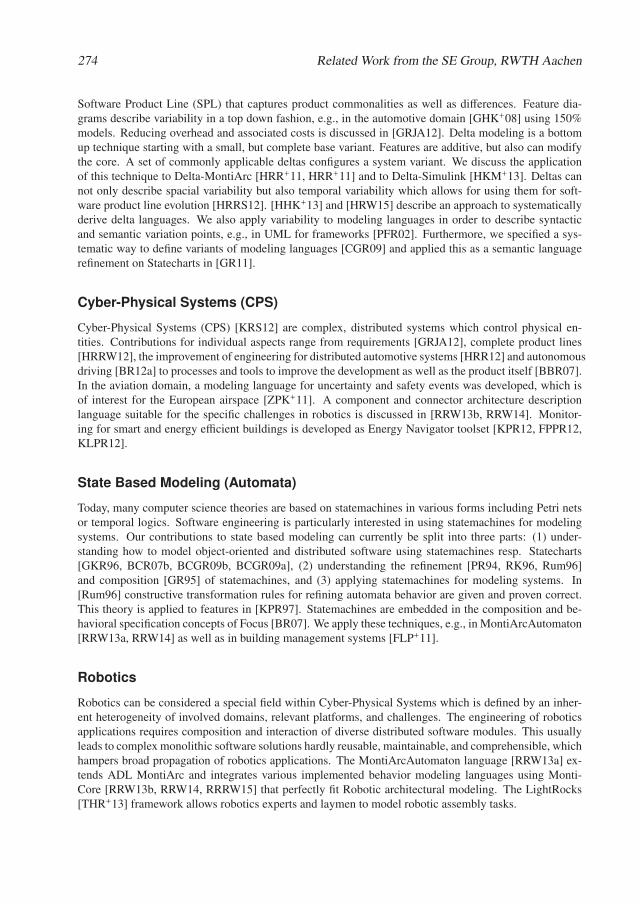
274 Related Work from the SE Group, RWTH Aachen
Software Product Line (SPL) that captures product commonalities as well as differences. Feature dia-grams describe variability in a top down fashion, e.g., in the automotive domain [GHK+08] using 150%models. Reducing overhead and associated costs is discussed in [GRJA12]. Delta modeling is a bottomup technique starting with a small, but complete base variant. Features are additive, but also can modifythe core. A set of commonly applicable deltas configures a system variant. We discuss the applicationof this technique to Delta-MontiArc [HRR+11, HRR+11] and to Delta-Simulink [HKM+13]. Deltas cannot only describe spacial variability but also temporal variability which allows for using them for soft-ware product line evolution [HRRS12]. [HHK+13] and [HRW15] describe an approach to systematicallyderive delta languages. We also apply variability to modeling languages in order to describe syntacticand semantic variation points, e.g., in UML for frameworks [PFR02]. Furthermore, we specified a sys-tematic way to define variants of modeling languages [CGR09] and applied this as a semantic languagerefinement on Statecharts in [GR11].
Cyber-Physical Systems (CPS)
Cyber-Physical Systems (CPS) [KRS12] are complex, distributed systems which control physical en-tities. Contributions for individual aspects range from requirements [GRJA12], complete product lines[HRRW12], the improvement of engineering for distributed automotive systems [HRR12] and autonomousdriving [BR12a] to processes and tools to improve the development as well as the product itself [BBR07].In the aviation domain, a modeling language for uncertainty and safety events was developed, which isof interest for the European airspace [ZPK+11]. A component and connector architecture descriptionlanguage suitable for the specific challenges in robotics is discussed in [RRW13b, RRW14]. Monitor-ing for smart and energy efficient buildings is developed as Energy Navigator toolset [KPR12, FPPR12,KLPR12].
State Based Modeling (Automata)
Today, many computer science theories are based on statemachines in various forms including Petri netsor temporal logics. Software engineering is particularly interested in using statemachines for modelingsystems. Our contributions to state based modeling can currently be split into three parts: (1) under-standing how to model object-oriented and distributed software using statemachines resp. Statecharts[GKR96, BCR07b, BCGR09b, BCGR09a], (2) understanding the refinement [PR94, RK96, Rum96]and composition [GR95] of statemachines, and (3) applying statemachines for modeling systems. In[Rum96] constructive transformation rules for refining automata behavior are given and proven correct.This theory is applied to features in [KPR97]. Statemachines are embedded in the composition and be-havioral specification concepts of Focus [BR07]. We apply these techniques, e.g., in MontiArcAutomaton[RRW13a, RRW14] as well as in building management systems [FLP+11].
Robotics
Robotics can be considered a special field within Cyber-Physical Systems which is defined by an inher-ent heterogeneity of involved domains, relevant platforms, and challenges. The engineering of roboticsapplications requires composition and interaction of diverse distributed software modules. This usuallyleads to complex monolithic software solutions hardly reusable, maintainable, and comprehensible, whichhampers broad propagation of robotics applications. The MontiArcAutomaton language [RRW13a] ex-tends ADL MontiArc and integrates various implemented behavior modeling languages using Monti-Core [RRW13b, RRW14, RRRW15] that perfectly fit Robotic architectural modeling. The LightRocks[THR+13] framework allows robotics experts and laymen to model robotic assembly tasks.
Related Work from the SE Group, RWTH Aachen 275
Automotive, Autonomic Driving & Intelligent Driver Assistance
Introducing and connecting sophisticated driver assistance, infotainment and communication systemsas well as advanced active and passive safety-systems result in complex embedded systems. As thesefeature-driven subsystems may be arbitrarily combined by the customer, a huge amount of distinct vari-ants needs to be managed, developed and tested. A consistent requirements management that con-nects requirements with features in all phases of the development for the automotive domain is de-scribed in [GRJA12]. The conceptual gap between requirements and the logical architecture of a car isclosed in [GHK+07, GHK+08]. [HKM+13] describes a tool for delta modeling for Simulink [HKM+13].[HRRW12] discusses means to extract a well-defined Software Product Line from a set of copy andpaste variants. [RSW+15] describes an approach to use model checking techniques to identify behavioraldifferences of Simulink models. Quality assurance, especially of safety-related functions, is a highlyimportant task. In the Carolo project [BR12a, BR12b], we developed a rigorous test infrastructure forintelligent, sensor-based functions through fully-automatic simulation [BBR07]. This technique allows adramatic speedup in development and evolution of autonomous car functionality, and thus enables us todevelop software in an agile way [BR12a]. [MMR10] gives an overview of the current state-of-the-art indevelopment and evolution on a more general level by considering any kind of critical system that relieson architectural descriptions. As tooling infrastructure, the SSELab storage, versioning and managementservices [HKR12] are essential for many projects.
Energy Management
In the past years, it became more and more evident that saving energy and reducing CO2 emissions isan important challenge. Thus, energy management in buildings as well as in neighborhoods becomesequally important to efficiently use the generated energy. Within several research projects, we developedmethodologies and solutions for integrating heterogeneous systems at different scales. During the designphase, the Energy Navigators Active Functional Specification (AFS) [FPPR12, KPR12] is used for tech-nical specification of building services already. We adapted the well-known concept of statemachines tobe able to describe different states of a facility and to validate it against the monitored values [FLP+11].We show how our data model, the constraint rules and the evaluation approach to compare sensor datacan be applied [KLPR12].
Cloud Computing & Enterprise Information Systems
The paradigm of Cloud Computing is arising out of a convergence of existing technologies for web-based application and service architectures with high complexity, criticality and new application do-mains. It promises to enable new business models, to lower the barrier for web-based innovations andto increase the efficiency and cost-effectiveness of web development [KRR14]. Application classes likeCyber-Physical Systems and their privacy [HHK+14, HHK+15b], Big Data, App and Service Ecosystemsbring attention to aspects like responsiveness, privacy and open platforms. Regardless of the applica-tion domain, developers of such systems are in need for robust methods and efficient, easy-to-use lan-guages and tools [KRS12]. We tackle these challenges by perusing a model-based, generative approach[NPR13]. The core of this approach are different modeling languages that describe different aspects of acloud-based system in a concise and technology-agnostic way. Software architecture and infrastructuremodels describe the system and its physical distribution on a large scale. We apply cloud technology forthe services we develop, e.g., the SSELab [HKR12] and the Energy Navigator [FPPR12, KPR12] but alsofor our tool demonstrators and our own development platforms. New services, e.g., collecting data fromtemperature, cars etc. can now easily be developed.

Bibliography
[BBR07] Christian Basarke, Christian Berger, and Bernhard Rumpe. Software & Systems Engineer-ing Process and Tools for the Development of Autonomous Driving Intelligence. Journal ofAerospace Computing, Information, and Communication (JACIC), 4(12):1158–1174, 2007.(Cited on pages 274 and 275.)
[BCGR09a] Manfred Broy, María Victoria Cengarle, Hans Grönniger, and Bernhard Rumpe. Consider-ations and Rationale for a UML System Model. In K. Lano, editor, UML 2 Semantics andApplications, pages 43–61. John Wiley & Sons, November 2009. (Cited on pages 271, 273,and 274.)
[BCGR09b] Manfred Broy, María Victoria Cengarle, Hans Grönniger, and Bernhard Rumpe. Definitionof the UML System Model. In K. Lano, editor, UML 2 Semantics and Applications, pages63–93. John Wiley & Sons, November 2009. (Cited on pages 271, 273, and 274.)
[BCR07a] Manfred Broy, María Victoria Cengarle, and Bernhard Rumpe. Towards a System Modelfor UML. Part 2: The Control Model. Technical Report TUM-I0710, TU Munich, Germany,February 2007. (Cited on pages 271 and 273.)
[BCR07b] Manfred Broy, María Victoria Cengarle, and Bernhard Rumpe. Towards a System Modelfor UML. Part 3: The State Machine Model. Technical Report TUM-I0711, TU Munich,Germany, February 2007. (Cited on pages 271, 273, and 274.)
[BGH+97] Ruth Breu, Radu Grosu, Christoph Hofmann, Franz Huber, Ingolf Krüger, Bernhard Rumpe,Monika Schmidt, and Wolfgang Schwerin. Exemplary and Complete Object InteractionDescriptions. In Object-oriented Behavioral Semantics Workshop (OOPSLA’97), TechnicalReport TUM-I9737, Germany, 1997. TU Munich. (Cited on page 273.)
[BGH+98] Ruth Breu, Radu Grosu, Franz Huber, Bernhard Rumpe, and Wolfgang Schwerin. Systems,Views and Models of UML. In Proceedings of the Unified Modeling Language, Techni-cal Aspects and Applications, pages 93–109. Physica Verlag, Heidelberg, Germany, 1998.(Cited on pages 271 and 273.)
[BHP+98] Manfred Broy, Franz Huber, Barbara Paech, Bernhard Rumpe, and Katharina Spies. Soft-ware and System Modeling Based on a Unified Formal Semantics. In Workshop on Require-ments Targeting Software and Systems Engineering (RTSE’97), LNCS 1526, pages 43–68.Springer, 1998. (Cited on pages 271 and 273.)
[BR07] Manfred Broy and Bernhard Rumpe. Modulare hierarchische Modellierung als Grundlageder Software- und Systementwicklung. Informatik-Spektrum, 30(1):3–18, Februar 2007.(Cited on pages 272, 273, and 274.)
[BR12a] Christian Berger and Bernhard Rumpe. Autonomous Driving - 5 Years after the UrbanChallenge: The Anticipatory Vehicle as a Cyber-Physical System. In Automotive SoftwareEngineering Workshop (ASE’12), pages 789–798, 2012. (Cited on pages 274 and 275.)
[BR12b] Christian Berger and Bernhard Rumpe. Engineering Autonomous Driving Software. InC. Rouff and M. Hinchey, editors, Experience from the DARPA Urban Challenge, pages243–271. Springer, Germany, 2012. (Cited on page 275.)
278 Related Work from the SE Group, RWTH Aachen
[CBCR15] Tony Clark, Mark van den Brand, Benoit Combemale, and Bernhard Rumpe. Concep-tual Model of the Globalization for Domain-Specific Languages. In Globalizing Domain-Specific Languages, LNCS 9400, pages 7–20. Springer, 2015. (Cited on pages 272 and 273.)
[CCF+15] Betty H. C. Cheng, Benoit Combemale, Robert B. France, Jean-Marc Jézéquel, and Bern-hard Rumpe, editors. Globalizing Domain-Specific Languages, LNCS 9400. Springer, 2015.(Cited on pages 272 and 273.)
[CEG+14] Betty Cheng, Kerstin Eder, Martin Gogolla, Lars Grunske, Marin Litoiu, Hausi Müller,Patrizio Pelliccione, Anna Perini, Nauman Qureshi, Bernhard Rumpe, Daniel Schneider,Frank Trollmann, and Norha Villegas. Using Models at Runtime to Address Assurancefor Self-Adaptive Systems. In [email protected], LNCS 8378, pages 101–136. Springer,Germany, 2014. (Cited on page 271.)
[CGR08] María Victoria Cengarle, Hans Grönniger, and Bernhard Rumpe. System Model Semanticsof Class Diagrams. Informatik-Bericht 2008-05, TU Braunschweig, Germany, 2008. (Citedon pages 271 and 273.)
[CGR09] María Victoria Cengarle, Hans Grönniger, and Bernhard Rumpe. Variability within Mod-eling Language Definitions. In Conference on Model Driven Engineering Languages andSystems (MODELS’09), LNCS 5795, pages 670–684. Springer, 2009. (Cited on pages 273and 274.)
[EFLR99] Andy Evans, Robert France, Kevin Lano, and Bernhard Rumpe. Meta-Modelling Semanticsof UML. In H. Kilov, B. Rumpe, and I. Simmonds, editors, Behavioral Specificationsof Businesses and Systems, pages 45–60. Kluver Academic Publisher, 1999. (Cited onpages 271 and 273.)
[FELR98] Robert France, Andy Evans, Kevin Lano, and Bernhard Rumpe. The UML as a formalmodeling notation. Computer Standards & Interfaces, 19(7):325–334, November 1998.(Cited on page 271.)
[FHR08] Florian Fieber, Michaela Huhn, and Bernhard Rumpe. Modellqualität als Indikator fürSoftwarequalität: eine Taxonomie. Informatik-Spektrum, 31(5):408–424, Oktober 2008.(Cited on pages 271 and 272.)
[FLP+11] M. Norbert Fisch, Markus Look, Claas Pinkernell, Stefan Plesser, and Bernhard Rumpe.State-based Modeling of Buildings and Facilities. In Enhanced Building Operations Con-ference (ICEBO’11), 2011. (Cited on pages 274 and 275.)
[FPPR12] M. Norbert Fisch, Claas Pinkernell, Stefan Plesser, and Bernhard Rumpe. The EnergyNavigator - A Web-Platform for Performance Design and Management. In Energy Efficiencyin Commercial Buildings Conference(IEECB’12), 2012. (Cited on pages 274 and 275.)
[GHK+07] Hans Grönniger, Jochen Hartmann, Holger Krahn, Stefan Kriebel, and Bernhard Rumpe.View-based Modeling of Function Nets. In Object-oriented Modelling of Embedded Real-Time Systems Workshop (OMER4’07), 2007. (Cited on pages 272 and 275.)
[GHK+08] Hans Grönniger, Jochen Hartmann, Holger Krahn, Stefan Kriebel, Lutz Rothhardt, andBernhard Rumpe. Modelling Automotive Function Nets with Views for Features, Vari-ants, and Modes. In Proceedings of 4th European Congress ERTS - Embedded Real TimeSoftware, 2008. (Cited on pages 272, 274, and 275.)
Related Work from the SE Group, RWTH Aachen 279
[GKPR08] Hans Grönniger, Holger Krahn, Claas Pinkernell, and Bernhard Rumpe. Modeling Variantsof Automotive Systems using Views. In Modellbasierte Entwicklung von eingebettetenFahrzeugfunktionen, Informatik Bericht 2008-01, pages 76–89. TU Braunschweig, 2008.(Cited on page 272.)
[GKR96] Radu Grosu, Cornel Klein, and Bernhard Rumpe. Enhancing the SysLab System Modelwith State. Technical Report TUM-I9631, TU Munich, Germany, July 1996. (Cited onpages 273 and 274.)
[GKR+06] Hans Grönniger, Holger Krahn, Bernhard Rumpe, Martin Schindler, and Steven Völkel.MontiCore 1.0 - Ein Framework zur Erstellung und Verarbeitung domänspezifischerSprachen. Informatik-Bericht 2006-04, CFG-Fakultät, TU Braunschweig, August 2006.(Cited on pages 271 and 272.)
[GKR+07] Hans Grönniger, Holger Krahn, Bernhard Rumpe, Martin Schindler, and Steven Völkel.Textbased Modeling. In 4th International Workshop on Software Language Engineering,Nashville, Informatik-Bericht 4/2007. Johannes-Gutenberg-Universität Mainz, 2007. (Citedon page 272.)
[GKR+08] Hans Grönniger, Holger Krahn, Bernhard Rumpe, Martin Schindler, and Steven Völkel.MontiCore: A Framework for the Development of Textual Domain Specific Languages.In 30th International Conference on Software Engineering (ICSE 2008), Leipzig, Germany,May 10-18, 2008, Companion Volume, pages 925–926, 2008. (Cited on pages 271 and 272.)
[GKRS06] Hans Grönniger, Holger Krahn, Bernhard Rumpe, and Martin Schindler. Integration vonModellen in einen codebasierten Softwareentwicklungsprozess. In Modellierung 2006 Con-ference, LNI 82, Seiten 67–81, 2006. (Cited on page 271.)
[GLRR15] Timo Greifenberg, Markus Look, Sebastian Roidl, and Bernhard Rumpe. Engineering Tag-ging Languages for DSLs. In Conference on Model Driven Engineering Languages andSystems (MODELS’15), pages 34–43. ACM/IEEE, 2015. (Cited on pages 272 and 273.)
[GR95] Radu Grosu and Bernhard Rumpe. Concurrent Timed Port Automata. Technical ReportTUM-I9533, TU Munich, Germany, October 1995. (Cited on page 274.)
[GR11] Hans Grönniger and Bernhard Rumpe. Modeling Language Variability. In Workshop onModeling, Development and Verification of Adaptive Systems, LNCS 6662, pages 17–32.Springer, 2011. (Cited on pages 271, 272, 273, and 274.)
[GRJA12] Tim Gülke, Bernhard Rumpe, Martin Jansen, and Joachim Axmann. High-Level Require-ments Management and Complexity Costs in Automotive Development Projects: A ProblemStatement. In Requirements Engineering: Foundation for Software Quality (REFSQ’12),2012. (Cited on pages 274 and 275.)
[GRR10] Hans Grönniger, Dirk Reiß, and Bernhard Rumpe. Towards a Semantics of Activity Dia-grams with Semantic Variation Points. In Conference on Model Driven Engineering Lan-guages and Systems (MODELS’10), LNCS 6394, pages 331–345. Springer, 2010. (Cited onpages 271 and 273.)
[HHK+13] Arne Haber, Katrin Hölldobler, Carsten Kolassa, Markus Look, Klaus Müller, BernhardRumpe, and Ina Schaefer. Engineering Delta Modeling Languages. In Software ProductLine Conference (SPLC’13), pages 22–31. ACM, 2013. (Cited on pages 272 and 274.)
280 Related Work from the SE Group, RWTH Aachen
[HHK+14] Martin Henze, Lars Hermerschmidt, Daniel Kerpen, Roger Häußling, Bernhard Rumpe, andKlaus Wehrle. User-driven Privacy Enforcement for Cloud-based Services in the Internet ofThings. In Conference on Future Internet of Things and Cloud (FiCloud’14). IEEE, 2014.(Cited on page 275.)
[HHK+15a] Arne Haber, Katrin Hölldobler, Carsten Kolassa, Markus Look, Klaus Müller, BernhardRumpe, Ina Schaefer, and Christoph Schulze. Systematic Synthesis of Delta ModelingLanguages. Journal on Software Tools for Technology Transfer (STTT), 17(5):601–626,October 2015. (Cited on page 272.)
[HHK+15b] Martin Henze, Lars Hermerschmidt, Daniel Kerpen, Roger Häußling, Bernhard Rumpe, andKlaus Wehrle. A comprehensive approach to privacy in the cloud-based Internet of Things.Future Generation Computer Systems, 56:701–718, 2015. (Cited on page 275.)
[HKM+13] Arne Haber, Carsten Kolassa, Peter Manhart, Pedram Mir Seyed Nazari, Bernhard Rumpe,and Ina Schaefer. First-Class Variability Modeling in Matlab/Simulink. In VariabilityModelling of Software-intensive Systems Workshop (VaMoS’13), pages 11–18. ACM, 2013.(Cited on pages 274 and 275.)
[HKR+07] Christoph Herrmann, Holger Krahn, Bernhard Rumpe, Martin Schindler, and Steven Völkel.An Algebraic View on the Semantics of Model Composition. In Conference on ModelDriven Architecture - Foundations and Applications (ECMDA-FA’07), LNCS 4530, pages99–113. Springer, Germany, 2007. (Cited on page 272.)
[HKR+09] Christoph Herrmann, Holger Krahn, Bernhard Rumpe, Martin Schindler, and Steven Völkel.Scaling-Up Model-Based-Development for Large Heterogeneous Systems with Compo-sitional Modeling. In Conference on Software Engineeering in Research and Practice(SERP’09), pages 172–176, July 2009. (Cited on pages 271 and 272.)
[HKR+11] Arne Haber, Thomas Kutz, Holger Rendel, Bernhard Rumpe, and Ina Schaefer. Delta-oriented Architectural Variability Using MontiCore. In Software Architecture Conference(ECSA’11), pages 6:1–6:10. ACM, 2011.
[HKR12] Christoph Herrmann, Thomas Kurpick, and Bernhard Rumpe. SSELab: A Plug-In-BasedFramework for Web-Based Project Portals. In Developing Tools as Plug-Ins Workshop(TOPI’12), pages 61–66. IEEE, 2012. (Cited on page 275.)
[HR04] David Harel and Bernhard Rumpe. Meaningful Modeling: What’s the Semantics of ”Se-mantics”? IEEE Computer, 37(10):64–72, October 2004. (Cited on page 273.)
[HRR98] Franz Huber, Andreas Rausch, and Bernhard Rumpe. Modeling Dynamic Component Inter-faces. In Technology of Object-Oriented Languages and Systems (TOOLS 26), pages 58–70.IEEE, 1998. (Cited on page 272.)
[HRR+11] Arne Haber, Holger Rendel, Bernhard Rumpe, Ina Schaefer, and Frank van der Linden.Hierarchical Variability Modeling for Software Architectures. In Software Product LinesConference (SPLC’11), pages 150–159. IEEE, 2011. (Cited on pages 272 and 274.)
[HRR12] Arne Haber, Jan Oliver Ringert, and Bernhard Rumpe. MontiArc - Architectural Modelingof Interactive Distributed and Cyber-Physical Systems. Technical Report AIB-2012-03,RWTH Aachen University, February 2012. (Cited on pages 272 and 274.)
[HRRS11] Arne Haber, Holger Rendel, Bernhard Rumpe, and Ina Schaefer. Delta Modeling for Soft-ware Architectures. In Tagungsband des Dagstuhl-Workshop MBEES: Modellbasierte En-twicklung eingebetteterSysteme VII, pages 1 – 10. fortiss GmbH, 2011. (Cited on page 272.)
Related Work from the SE Group, RWTH Aachen 281
[HRRS12] Arne Haber, Holger Rendel, Bernhard Rumpe, and Ina Schaefer. Evolving Delta-orientedSoftware Product Line Architectures. In Large-Scale Complex IT Systems. Development,Operation and Management, 17th Monterey Workshop 2012, LNCS 7539, pages 183–208.Springer, 2012. (Cited on pages 272 and 274.)
[HRRW12] Christian Hopp, Holger Rendel, Bernhard Rumpe, and Fabian Wolf. Einführung eines Pro-duktlinienansatzes in die automotive Softwareentwicklung am Beispiel von Steuergeräte-software. In Software Engineering Conference (SE’12), LNI 198, Seiten 181–192, 2012.(Cited on pages 274 and 275.)
[HRW15] Katrin Hölldobler, Bernhard Rumpe, and Ingo Weisemöller. Systematically DerivingDomain-Specific Transformation Languages. In Conference on Model Driven Engineer-ing Languages and Systems (MODELS’15), pages 136–145. ACM/IEEE, 2015. (Cited onpages 272 and 274.)
[KER99] Stuart Kent, Andy Evans, and Bernhard Rumpe. UML Semantics FAQ. In A. Moreira andS. Demeyer, editors, Object-Oriented Technology, ECOOP’99 Workshop Reader, LNCS1743, Berlin, 1999. Springer Verlag. (Cited on page 271.)
[KKP+09] Gabor Karsai, Holger Krahn, Claas Pinkernell, Bernhard Rumpe, Martin Schindler, andSteven Völkel. Design Guidelines for Domain Specific Languages. In Domain-SpecificModeling Workshop (DSM’09), Techreport B-108, pages 7–13. Helsinki School of Eco-nomics, October 2009. (Cited on pages 272 and 273.)
[KLPR12] Thomas Kurpick, Markus Look, Claas Pinkernell, and Bernhard Rumpe. Modeling Cyber-Physical Systems: Model-Driven Specification of Energy Efficient Buildings. In Modellingof the Physical World Workshop (MOTPW’12), pages 2:1–2:6. ACM, October 2012. (Citedon pages 274 and 275.)
[KPR97] Cornel Klein, Christian Prehofer, and Bernhard Rumpe. Feature Specification and Refine-ment with State Transition Diagrams. In Workshop on Feature Interactions in Telecommu-nications Networks and Distributed Systems, pages 284–297. IOS-Press, 1997. (Cited onpages 273 and 274.)
[KPR12] Thomas Kurpick, Claas Pinkernell, and Bernhard Rumpe. Der Energie Navigator. InH. Lichter and B. Rumpe, Editoren, Entwicklung und Evolution von Forschungssoftware.Tagungsband, Rolduc, 10.-11.11.2011, Aachener Informatik-Berichte, Software Engineer-ing, Band 14. Shaker Verlag, Aachen, Deutschland, 2012. (Cited on pages 274 and 275.)
[Kra10] Holger Krahn. MontiCore: Agile Entwicklung von domänenspezifischen Sprachen imSoftware-Engineering. Aachener Informatik-Berichte, Software Engineering, Band 1.Shaker Verlag, März 2010. (Cited on page 272.)
[KRB96] Cornel Klein, Bernhard Rumpe, and Manfred Broy. A stream-based mathematical model fordistributed information processing systems - SysLab system model. In Workshop on FormalMethods for Open Object-based Distributed Systems, IFIP Advances in Information andCommunication Technology, pages 323–338. Chapmann & Hall, 1996. (Cited on page 273.)
[KRR14] Helmut Krcmar, Ralf Reussner, and Bernhard Rumpe. Trusted Cloud Computing. Springer,Schweiz, December 2014. (Cited on page 275.)
[KRS12] Stefan Kowalewski, Bernhard Rumpe, and Andre Stollenwerk. Cyber-Physical Systems- eine Herausforderung für die Automatisierungstechnik? In Proceedings of Automation2012, VDI Berichte 2012, Seiten 113–116. VDI Verlag, 2012. (Cited on pages 274 and 275.)
282 Related Work from the SE Group, RWTH Aachen
[KRV06] Holger Krahn, Bernhard Rumpe, and Steven Völkel. Roles in Software Development usingDomain Specific Modelling Languages. In Domain-Specific Modeling Workshop (DSM’06),Technical Report TR-37, pages 150–158. Jyväskylä University, Finland, 2006. (Cited onpage 271.)
[KRV07a] Holger Krahn, Bernhard Rumpe, and Steven Völkel. Efficient Editor Generation for Com-positional DSLs in Eclipse. In Domain-Specific Modeling Workshop (DSM’07), TechnicalReports TR-38. Jyväskylä University, Finland, 2007. (Cited on pages 272 and 273.)
[KRV07b] Holger Krahn, Bernhard Rumpe, and Steven Völkel. Integrated Definition of Abstract andConcrete Syntax for Textual Languages. In Conference on Model Driven Engineering Lan-guages and Systems (MODELS’07), LNCS 4735, pages 286–300. Springer, 2007. (Cited onpage 272.)
[KRV08] Holger Krahn, Bernhard Rumpe, and Steven Völkel. Monticore: Modular Development ofTextual Domain Specific Languages. In Conference on Objects, Models, Components, Pat-terns (TOOLS-Europe’08), LNBIP 11, pages 297–315. Springer, 2008. (Cited on page 272.)
[KRV10] Holger Krahn, Bernhard Rumpe, and Stefen Völkel. MontiCore: a Framework for Com-positional Development of Domain Specific Languages. International Journal on SoftwareTools for Technology Transfer (STTT), 12(5):353–372, September 2010. (Cited on pages 271and 272.)
[LRSS10] Tihamer Levendovszky, Bernhard Rumpe, Bernhard Schätz, and Jonathan Sprinkle. ModelEvolution and Management. In Model-Based Engineering of Embedded Real-Time Sys-tems Workshop (MBEERTS’10), LNCS 6100, pages 241–270. Springer, 2010. (Cited onpages 271, 272, and 273.)
[MMR10] Tom Mens, JeffMagee, and Bernhard Rumpe. Evolving Software Architecture Descriptionsof Critical Systems. IEEE Computer, 43(5):42–48, May 2010. (Cited on pages 272, 273,and 275.)
[MRR10] Shahar Maoz, Jan Oliver Ringert, and Bernhard Rumpe. A Manifesto for Semantic ModelDifferencing. In Proceedings Int. Workshop on Models and Evolution (ME’10), LNCS 6627,pages 194–203. Springer, 2010. (Cited on page 273.)
[MRR11a] Shahar Maoz, Jan Oliver Ringert, and Bernhard Rumpe. ADDiff: Semantic Differencingfor Activity Diagrams. In Conference on Foundations of Software Engineering (ESEC/FSE’11), pages 179–189. ACM, 2011. (Cited on pages 271 and 273.)
[MRR11b] Shahar Maoz, Jan Oliver Ringert, and Bernhard Rumpe. An Operational Semantics forActivity Diagrams using SMV. Technical Report AIB-2011-07, RWTH Aachen University,Aachen, Germany, July 2011. (Cited on pages 271 and 273.)
[MRR11c] Shahar Maoz, Jan Oliver Ringert, and Bernhard Rumpe. CD2Alloy: Class Diagrams Anal-ysis Using Alloy Revisited. In Conference on Model Driven Engineering Languages andSystems (MODELS’11), LNCS 6981, pages 592–607. Springer, 2011. (Cited on pages 271and 273.)
[MRR11d] Shahar Maoz, Jan Oliver Ringert, and Bernhard Rumpe. Modal Object Diagrams. In Object-Oriented Programming Conference (ECOOP’11), LNCS 6813, pages 281–305. Springer,2011. (Cited on page 271.)
Related Work from the SE Group, RWTH Aachen 283
[MRR11e] Shahar Maoz, Jan Oliver Ringert, and Bernhard Rumpe. Semantically Configurable Consis-tency Analysis for Class and Object Diagrams. In Conference on Model Driven Engineer-ing Languages and Systems (MODELS’11), LNCS 6981, pages 153–167. Springer, 2011.(Cited on pages 271 and 273.)
[MRR13] Shahar Maoz, Jan Oliver Ringert, and Bernhard Rumpe. Synthesis of Component and Con-nector Models from Crosscutting Structural Views. In Meyer, B. and Baresi, L. and Mezini,M., editor, Joint Meeting of the European Software Engineering Conference and the ACMSIGSOFT Symposium on the Foundations of Software Engineering (ESEC/FSE’13), pages444–454. ACM New York, 2013. (Cited on page 272.)
[MRR14] Shahar Maoz, Jan Oliver Ringert, and Bernhard Rumpe. Verifying Component and Con-nector Models against Crosscutting Structural Views. In Software Engineering Conference(ICSE’14), pages 95–105. ACM, 2014. (Cited on page 272.)
[NPR13] Antonio Navarro Pérez and Bernhard Rumpe. Modeling Cloud Architectures as Interac-tive Systems. In Model-Driven Engineering for High Performance and Cloud ComputingWorkshop, CEUR Workshop Proceedings 1118, pages 15–24, 2013. (Cited on page 275.)
[PFR02] Wolfgang Pree, Marcus Fontoura, and Bernhard Rumpe. Product Line Annotations withUML-F. In Software Product Lines Conference (SPLC’02), LNCS 2379, pages 188–197.Springer, 2002. (Cited on pages 271 and 274.)
[PR94] Barbara Paech and Bernhard Rumpe. A new Concept of Refinement used for BehaviourModelling with Automata. In Proceedings of the Industrial Benefit of Formal Methods(FME’94), LNCS 873, pages 154–174. Springer, 1994. (Cited on pages 273 and 274.)
[PR99] Jan Philipps and Bernhard Rumpe. Refinement of Pipe-and-Filter Architectures. InCongress on Formal Methods in the Development of Computing System (FM’99), LNCS1708, pages 96–115. Springer, 1999. (Cited on pages 272 and 273.)
[PR01] Jan Philipps and Bernhard Rumpe. Roots of Refactoring. In Kilov, H. and Baclavski,K., editor, Tenth OOPSLA Workshop on Behavioral Semantics. Tampa Bay, Florida, USA,October 15. Northeastern University, 2001. (Cited on page 273.)
[PR03] Jan Philipps and Bernhard Rumpe. Refactoring of Programs and Specifications. In Kilov,H. and Baclavski, K., editor, Practical Foundations of Business and System Specifications,pages 281–297. Kluwer Academic Publishers, 2003. (Cited on pages 271 and 273.)
[Rin14] Jan Oliver Ringert. Analysis and Synthesis of Interactive Component and Connector Sys-tems. Aachener Informatik-Berichte, Software Engineering, Band 19. Shaker Verlag, 2014.(Cited on page 272.)
[RK96] Bernhard Rumpe and Cornel Klein. Automata Describing Object Behavior. In B. Harveyand H. Kilov, editors, Object-Oriented Behavioral Specifications, pages 265–286. KluwerAcademic Publishers, 1996. (Cited on page 274.)
[RKB95] Bernhard Rumpe, Cornel Klein, and Manfred Broy. Ein strombasiertes mathematischesModell verteilter informationsverarbeitender Systeme - Syslab-Systemmodell. TechnischerBericht TUM-I9510, TU München, Deutschland, März 1995. (Cited on page 273.)
[RRRW15] Jan Oliver Ringert, Alexander Roth, Bernhard Rumpe, and Andreas Wortmann. Languageand Code Generator Composition for Model-Driven Engineering of Robotics Component& Connector Systems. Journal of Software Engineering for Robotics (JOSER), 6(1):33–57,2015. (Cited on pages 272, 273, and 274.)
284 Related Work from the SE Group, RWTH Aachen
[RRW13a] Jan Oliver Ringert, Bernhard Rumpe, and Andreas Wortmann. From Software Architec-ture Structure and Behavior Modeling to Implementations of Cyber-Physical Systems. InSoftware Engineering Workshopband (SE’13), LNI 215, pages 155–170, 2013. (Cited onpage 274.)
[RRW13b] Jan Oliver Ringert, Bernhard Rumpe, and Andreas Wortmann. MontiArcAutomaton: Mod-eling Architecture and Behavior of Robotic Systems. In Conference on Robotics and Au-tomation (ICRA’13), pages 10–12. IEEE, 2013. (Cited on pages 272 and 274.)
[RRW14] Jan Oliver Ringert, Bernhard Rumpe, and Andreas Wortmann. Architecture and Behav-ior Modeling of Cyber-Physical Systems with MontiArcAutomaton. Aachener Informatik-Berichte, Software Engineering, Band 20. Shaker Verlag, December 2014. (Cited onpage 274.)
[RSW+15] Bernhard Rumpe, Christoph Schulze, Michael von Wenckstern, Jan Oliver Ringert, andPeter Manhart. Behavioral Compatibility of Simulink Models for Product Line Maintenanceand Evolution. In Software Product Line Conference (SPLC’15), pages 141–150. ACM,2015. (Cited on page 275.)
[Rum96] Bernhard Rumpe. Formale Methodik des Entwurfs verteilter objektorientierter Systeme.Herbert Utz Verlag Wissenschaft, München, Deutschland, 1996. (Cited on page 274.)
[Rum02] Bernhard Rumpe. Executable Modeling with UML - A Vision or a Nightmare? In T. Clarkand J. Warmer, editors, Issues& Trends of Information Technology Management in Contem-porary Associations, Seattle, pages 697–701. Idea Group Publishing, London, 2002. (Citedon page 271.)
[Rum03] Bernhard Rumpe. Model-Based Testing of Object-Oriented Systems. In Symposium onFormal Methods for Components and Objects (FMCO’02), LNCS 2852, pages 380–402.Springer, November 2003. (Cited on page 271.)
[Rum04] Bernhard Rumpe. Agile Modeling with the UML. In Workshop on Radical Innovations ofSoftware and Systems Engineering in the Future (RISSEF’02), LNCS 2941, pages 297–309.Springer, October 2004. (Cited on pages 271 and 273.)
[Rum11] Bernhard Rumpe. Modellierung mit UML, 2te Auflage. Springer Berlin, September 2011.(Cited on page 271.)
[Rum12] Bernhard Rumpe. Agile Modellierung mit UML: Codegenerierung, Testfälle, Refactoring,2te Auflage. Springer Berlin, Juni 2012. (Cited on pages 271 and 273.)
[Rum16] Bernhard Rumpe. Modeling with UML: Language, Concepts, Methods. Springer Interna-tional, July 2016. (Cited on page 271.)
[Sch12] Martin Schindler. Eine Werkzeuginfrastruktur zur agilen Entwicklung mit der UML/P.Aachener Informatik-Berichte, Software Engineering, Band 11. Shaker Verlag, 2012. (Citedon page 271.)
[SRVK10] Jonathan Sprinkle, Bernhard Rumpe, Hans Vangheluwe, and Gabor Karsai. Metamodelling:State of the Art and Research Challenges. In Model-Based Engineering of Embedded Real-Time Systems Workshop (MBEERTS’10), LNCS 6100, pages 57–76. Springer, 2010. (Citedon pages 271 and 272.)
[THR+13] Ulrike Thomas, Gerd Hirzinger, Bernhard Rumpe, Christoph Schulze, and Andreas Wort-mann. A New Skill Based Robot Programming Language Using UML/P Statecharts. InConference on Robotics and Automation (ICRA’13), pages 461–466. IEEE, 2013. (Cited onpage 274.)

Related Work from the SE Group, RWTH Aachen 285
[Völ11] Steven Völkel. Kompositionale Entwicklung domänenspezifischer Sprachen. AachenerInformatik-Berichte, Software Engineering, Band 9. Shaker Verlag, 2011. (Cited onpages 272 and 273.)
[Wei12] Ingo Weisemöller. Generierung domänenspezifischer Transformationssprachen. Aach-ener Informatik-Berichte, Software Engineering, Band 12. Shaker Verlag, 2012. (Citedon pages 271, 272, and 273.)
[ZPK+11] Massimiliano Zanin, David Perez, Dimitrios S Kolovos, Richard F Paige, Kumardev Chat-terjee, Andreas Horst, and Bernhard Rumpe. On Demand Data Analysis and Filtering forInaccurate Flight Trajectories. In Proceedings of the SESAR Innovation Days. EUROCON-TROL, 2011. (Cited on pages 272 and 274.)

Ana-Maria-Cristina Nicolaescu
Ana
-Mar
ia-C
ristin
a N
icol
aesc
uB
ehav
ior-
Bas
ed A
rchi
tect
ure
Con
form
ance
Che
ckin
g
Band 37
Ban
d 37
Behavior-Based Architecture Conformance Checking
Aachener Informatik-Berichte,Software Engineering
Hrsg: Prof. Dr. rer. nat. Bernhard Rumpe Prof. Dr. rer. nat. Horst Lichter