bearings - aws
TRANSCRIPT
Boston Gear 800-825-6544 135P-1930-BG 9/17
FFF
Bearings
BOST-BRONZ (OIL-IMPREGNATED SINTERED BRONZE)
General Description .............................................................................................................136–137
Catalog Number Selections/Dimensions ..........................................................................138–144
BEAR-N-BRONZ (660 CAST BRONZE)
General Description .....................................................................................................................145
Catalog Number Selections/Dimensions ..........................................................................146–153
BRONZE BEARING EMERGENCY BANK
BOST-BRONZ & BEAR-N-BRONZ ..............................................................................................154
BOStonE F-1 (GLASS FILLED TEFLON)
General Description/Engineering ...............................................................................................155
Catalog Number Selections/Dimensions ..........................................................................156–157
RULON® 641 BEARINGS
General Description .....................................................................................................................158
Catalog Number Selections/Dimensions ..................................................................................159
BOStonE MOLDED PLASTIC
General Description/Engineering ...............................................................................................160
Catalog Number Selections/Dimensions ..........................................................................161–171
BOStonE MOLDED NYLON
Catalog Number Selections/Dimensions ..........................................................................172–173
Engineering Information ......................................................................................................174–182
ANTI-FRICTION (BALL BEARINGS)
General Description .............................................................................................................183–184
Catalog Number Selections/Dimensions ..........................................................................185–197
SELF-ALIGNING (ROD END & SPHERICAL BEARINGS)
Catalog Number Selections/Dimensions ..........................................................................198–206
Engineering Information ......................................................................................................207–211
MOUNTED BEARINGS
General Description .....................................................................................................................212
Replacement Bearings & Locking Collars .........................................................................213–214
Pillow Blocks .......................................................................................................................215–222
Flanged Units .......................................................................................................................223–230
Shaft Supports .............................................................................................................................231
Take-Up Frames ..........................................................................................................................232
Stainless Steel Pillow Blocks with Setscrew Locking ..............................................................233
Stainless Steel Pillow Blocks with Eccentric Locking Collar ..................................................234
Stainless Steel 2 Bolt Flange ......................................................................................................235
Stainless Steel 4 Bolt Flange ......................................................................................................236
Stainless Steel 3 Bolt Flange Bracket ........................................................................................237
Stainless Steel Take Up Units ....................................................................................................238
ENGINEERING INFORMATION ............................................................................................... 239-245
Section Contents
136 Boston Gear 800-825-6544 P-1930-BG 9/17
FFF
BOST-BRONZ Oil-Impregnated Sintered Bronze Bearings
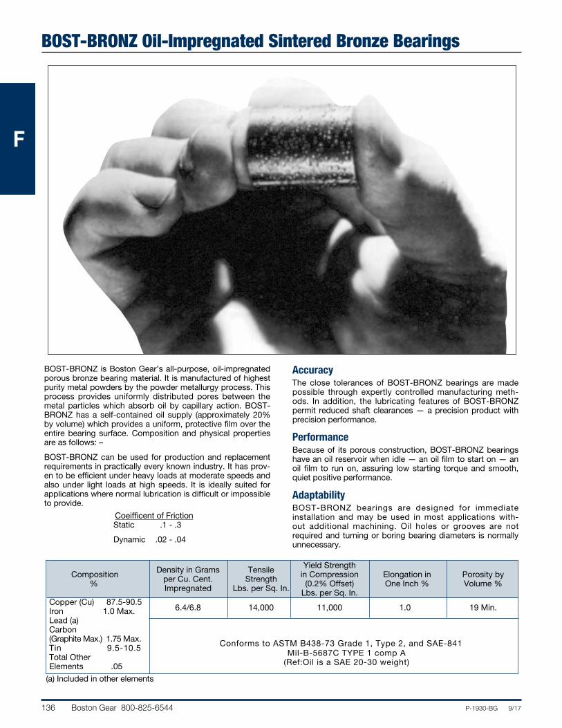
BOST-BRONZ is Boston Gear’s all-purpose, oil-impregnated porous bronze bearing material. It is manufactured of highest purity metal powders by the powder metallurgy process. This process provides uniformly distributed pores between the metal particles which absorb oil by capillary action. BOST-BRONZ has a self-contained oil supply (approximately 20% by volume) which provides a uniform, protective film over the entire bearing surface. Composition and physical properties are as follows: –
BOST-BRONZ can be used for production and replacement requirements in practically every known industry. It has prov-en to be efficient under heavy loads at moderate speeds and also under light loads at high speeds. It is ideally suited for applications where normal lubrication is difficult or impossible to provide.
AccuracyThe close tolerances of BOST-BRONZ bearings are made possible through expertly controlled manufacturing meth-ods. In addition, the lubricating features of BOST-BRONZ permit reduced shaft clearances — a precision product with precision performance.
PerformanceBecause of its porous construction, BOST-BRONZ bearings have an oil reservoir when idle — an oil film to start on — an oil film to run on, assuring low starting torque and smooth, quiet positive performance.
AdaptabilityBOST-BRONZ bearings are designed for immediate installation and may be used in most applications with-out additional machining. Oil holes or grooves are not required and turning or boring bearing diameters is normally unnecessary.
Density in Grams Tensile Yield Strength Composition per Cu. Cent. Strength in Compression Elongation in Porosity by % Impregnated Lbs. per Sq. In. (0.2% Offset) One Inch % Volume % Lbs. per Sq. In.Copper (Cu) 87.5-90.5
6.4/6.8 14,000 11,000 1.0 19 Min.
Iron 1.0 Max.Lead (a) Carbon (Graphite Max.) 1.75 Max. Conforms to ASTM B438-73 Grade 1, Type 2, and SAE-841Tin 9.5-10.5 Total OtherElements .05
(a) Included in other elements
Coeifficent of Friction Static .1 - .3
Dynamic .02 - .04
Mil-B-5687C TYPE 1 comp A(Ref:Oil is a SAE 20-30 weight)
Boston Gear 800-825-6544 137P-1930-BG 9/17
FFF
BOST-BRONZ Oil-Impregnated Sintered Bronze BearingsNon-Listed SizesThe stock sizes of BOST-BRONZ bearings listed in this catalog will satisfy the majority of industrial applications. Tooling is available for many metric and additional inch sizes. Where tooling is not available, special sizes can be made to order.
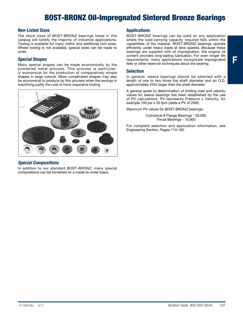
Special ShapesMany special shapes can be made economically by the powdered metal process. This process is particular-ly economical for the production of comparatively simple shapes in large volume. More complicated shapes may also be economical to produce by this process when the savings in machining justify the cost of more expensive tooling.
Special CompositionsIn addition to our standard BOST-BRONZ, many special compositions can be furnished on a made-to-order basis.
ApplicationsBOST-BRONZ bearings can be used on any application where the load-carrying capacity required falls within the capabilities of the material. BOST-BRONZ bearings operate efficiently under heavy loads at slow speeds. Because these bearings are supplied with oil impreg na tion, the original oil content provides long-lasting lubrication. For even longer life requirements, many applications incorporate impregnated felts or other reservoir techniques about the bearing.
SelectionIn general, sleeve bearings should be selected with a length of one to two times the shaft diameter and an O.D. approximately 25% larger than the shaft diameter.
A general guide to determination of limiting load and velocity values for sleeve bearings has been estab lished by the use of PV calculations. PV represents Pressure x Velocity, for example 100 psi x 20 fpm yields a PV of 2000.
Maximum PV values for BOST-BRONZ bearings:
Cylindrical & Flange Bearings - 50,000 Thrust Bearings - 10,000
For complete selection and application information, see Engineering Section, Pages 174-182.
138 Boston Gear 800-825-6544 P-1930-BG 9/17
FFF
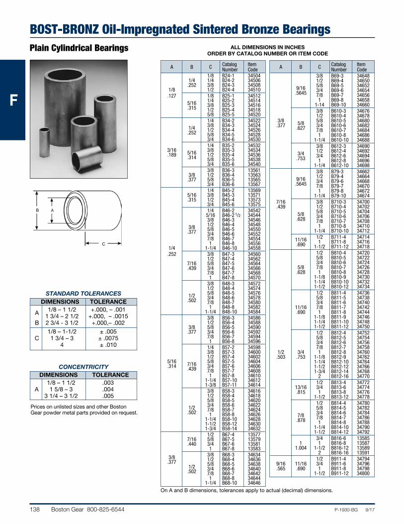
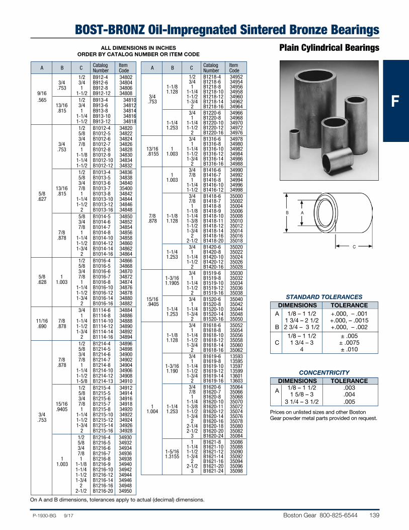
BOST-BRONZ Oil-Impregnated Sintered Bronze BearingsPlain Cylindrical Bearings ALL DIMENSIONS IN INCHES
ORDER BY CATALOG NUMBER OR ITEM CODE
Catalog Item A B C Number Code 1/8 B24-1 34504 1/4 1/4 B24-2 34506 .252 3/8 B24-3 34508 1/8 1/2 B24-4 34510 .127 1/8 B25-1 34512 5/16 1/4 B25-2 34514 .315 3/8 B25-3 34516 1/2 B25-4 34518 5/8 B25-5 34520 1/4 B34-2 34522 1/4 3/8 B34-3 34524 .252 1/2 B34-4 34526 5/8 B34-5 34528 3/4 B34-6 34530 1/4 B35-2 34532 3/16 5/16 3/8 B35-3 34534 .189 .314 1/2 B35-4 34536 5/8 B35-5 34538 3/4 B35-6 34540 3/8 B36-3 13561 3/8 1/2 B36-4 13563 .377 5/8 B36-5 13565 3/4 B36-6 13567 1/4 B45-2 13569 5/16 3/8 B45-3 13571 .315 1/2 B45-4 13573 3/4 B45-6 13575 1/4 B46-2 34542 5/16 B46-2 1/2 34544 3/8 B46-3 34546 3/8 1/2 B46-4 34548 .377 5/8 B46-5 34550 3/4 B46-6 34552 7/8 B46-7 34554 1 B46-8 34556 1/4 1-1/4 B46-10 34558 .252 3/8 B47-3 34560 1/2 B47-4 34562 7/16 5/8 B47-5 34564 .439 3/4 B47-6 34566 7/8 B47-7 34568 1 B47-8 34570 3/8 B48-3 34572 1/2 B48-4 34574 1/2 5/8 B48-5 34576 .502 3/4 B48-6 34578 7/8 B48-7 34580 1 B48-8 34582 1-1/4 B48-10 34584 3/8 B56-3 34586 1/2 B56-4 34588 3/8 5/8 B56-5 34590 .377 3/4 B56-6 34592 7/8 B56-7 34594 1 B56-8 34596 1/4 B57-2 34598 3/8 B57-3 34600 1/2 B57-4 34602 5/16 7/16 5/8 B57-5 34604 .314 .439 3/4 B57-6 34606 7/8 B57-7 34608 1 B57-8 34610 1-1/4 B57-10 34612 1-3/8 B57-11 34614 3/8 B58-3 34616 1/2 B58-4 34618 5/8 B58-5 34620 1/2 3/4 B58-6 34622 .502 7/8 B58-7 34624 1 B58-8 34626 1-1/4 B58-10 34628 1-1/2 B58-12 34630 1-3/4 B58-14 34632 1/2 B67-4 13577 7/16 5/8 B67-5 13579 .440 3/4 B67-6 13581 1 B67-8 13583 3/8 3/8 B68-3 34634 .377 1/2 B68-4 34636 1/2 5/8 B68-5 34638 .502 3/4 B68-6 34640 7/8 B68-7 34642 1 B68-8 34644 1-1/4 B68-10 34646
Catalog Item A B C Number Code 3/8 B69-3 34648 1/2 B69-4 34650 9/16 5/8 B69-5 34652 .5645 3/4 B69-6 34654 7/8 B69-7 34656 1 B69-8 34658 1-14 B69-10 34660 3/8 B610-3 34676 1/2 B610-4 34678 3/8 5/8 5/8 B610-5 34680 .377 .627 3/4 B610-6 34682 7/8 B610-7 34684 1 B610-8 34686 1-1/4 B610-10 34688 3/8 B612-3 34690 3/4 1/2 B612-4 34692 .753 3/4 B612-6 34694 1 B612-8 34696 1-1/4 B612-10 34698 3/8 B79-3 34662 9/16 1/2 B79-4 34664 .5645 3/4 B79-6 34668 7/8 B79-7 34670 1 B79-8 34672 1-1/4 B79-10 34674 7/16 3/8 B710-3 34700 .439 1/2 B710-4 34702 5/8 5/8 B710-5 34704 .628 3/4 B710-6 34706 7/8 B710-7 34708 1 B710-8 34710 1-1/4 B710-10 34712 11/16 1/2 B711-4 34714 .690 1 B711-8 34716 1-1/2 B711-12 34718 1/2 B810-4 34720 5/8 B810-5 34722 3/4 B810-6 34724 5/8 7/8 B810-7 34726 .628 1 B810-8 34728 1-1/8 B810-9 34730 1-1/4 B810-10 34732 1-1/2 B810-12 34734 1/2 B811-4 34736 5/8 B811-5 34738 3/4 B811-6 34740 11/16 7/8 B811-7 34742 .690 1 B811-8 34744 1-1/8 B811-9 34746 1-1/4 B811-10 34748 1-1/2 B811-12 34750 1/2 B812-4 34752 5/8 B812-5 34754 3/4 B812-6 34756 7/8 B812-7 34758 1/2 3/4 1 B812-8 34760 .503 .753 1-1/8 B812-9 34762 1-1/4 B812-10 34764 1-1/2 B812-12 34766 1-3/4 B812-14 34768 2 B812-16 34770 1/2 B813-4 34772 13/16 3/4 B813-6 34774 .815 1 B813-8 34776 1-1/2 B813-12 34778 1/2 B814-4 34780 5/8 B814-5 34782 7/8 3/4 B814-6 34784 .878 7/8 B814-7 34786 1 B814-8 34788 1-1/4 B814-10 34790 1-1/2 B814-12 34792 3/4 B816-6 13585 1 1 B816-8 13587 1.004 1-1/2 B816-12 13589 2 B816-16 13591 1/2 B911-4 34794 9/16 11/16 3/4 B911-6 34796 .565 .690 1 B911-8 34798 1-1/2 B911-12 34800
On A and B dimensions, tolerances apply to actual (decimal) dimensions.
STANDARD TOLERANCES DIMENSIONS TOLERANCE 1/8 – 1 1/2 +.000, – .001 A 1 3/4 – 2 1/2 +.000, – .0015 B 2 3/4 - 3 1/2 +.000,– .002
1/8 – 1-1/2 ± .005 C 1 3/4 – 3 ± .0075 4 ± .010
CONCENTRICITY DIMENSIONS TOLERANCE 1/8 – 1 1/2 .003 A 1 5/8 – 3 .004 3 1/4 – 3 1/2 .005
Prices on unlisted sizes and other Boston Gear powder metal parts provided on request.
Boston Gear 800-825-6544 139P-1930-BG 9/17
FFF
BOST-BRONZ Oil-Impregnated Sintered Bronze BearingsPlain Cylindrical Bearings ALL DIMENSIONS IN INCHES
ORDER BY CATALOG NUMBER OR ITEM CODE
Catalog Item A B C Number Code 1/2 B912-4 34802 3/4 3/4 B912-6 34804 .753 1 B912-8 34806 9/16 1-1/2 B912-12 34808 .565 1/2 B913-4 34810 13/16 3/4 B913-6 34812 .815 1 B913-8 34814 1-1/4 B913-10 34816 1-1/2 B913-12 34818 1/2 B1012-4 34820 5/8 B1012-5 34822 3/4 B1012-6 34824 3/4 7/8 B1012-7 34826 .753 1 B1012-8 34828 1-1/8 B1012-9 34830 1-1/4 B1012-10 34834 1-1/2 B1012-12 34832 1/2 B1013-4 34836 5/8 B1013-5 34838 3/4 B1013-6 34840 13/16 7/8 B1013-7 35400 5/8 .815 1 B1013-8 34842 .627 1-1/4 B1013-10 34844 1-1/2 B1013-12 34846 2 B1013-16 34848 5/8 B1014-5 34850 3/4 B1014-6 34852 7/8 B1014-7 34854 7/8 1 B1014-8 34856 .878 1-1/4 B1014-10 34858 1-1/2 B1014-12 34860 1-3/4 B1014-14 34862 2 B1014-16 34864 1/2 B1016-4 34866 5/8 B1016-5 34868 3/4 B1016-6 34870 5/8 1 7/8 B1016-7 34872 .628 1.003 1 B1016-8 34874 1-1/4 B1016-10 34876 1-1/2 B1016-12 34878 1-3/4 B1016-14 34880 2 B1016-16 34882 3/4 B1114-6 34884 1 B1114-8 34886 11/16 7/8 1-1/4 B1114-10 34888 .690 .878 1-1/2 B1114-12 34890 1-3/4 B1114-14 34892 2 B1114-16 34894 1/2 B1214-4 34896 5/8 B1214-5 34898 3/4 B1214-6 34900 7/8 7/8 B1214-7 34902 .878 1 B1214-8 34904 1-1/4 B1214-10 34906 1-1/2 B1214-12 34908 1-5/8 B1214-13 34910 1/2 B1215-4 34912 5/8 B1215-5 34914 3/4 B1215-6 34916 15/16 7/8 B1215-7 34918 .9405 1 B1215-8 34920 3/4 1-1/4 B1215-10 34922 .753 1-1/2 B1215-12 34924 1-3/4 B1215-14 34926 2 B1215-16 34928 1/2 B1216-4 34930 5/8 B1216-5 34932 3/4 B1216-6 34934 7/8 B1216-7 34936 1 1 B1216-8 34938 1.003 1-1/8 B1216-9 34940 1-1/4 B1216-10 34942 1-1/2 B1216-12 34944 1-3/4 B1216-14 34946 2 B1216-16 34948 2-1/2 B1216-20 34950
Catalog Item A B C Number Code 1/2 B1218-4 34952 3/4 B1218-6 34954 1-1/8 1 B1218-8 34956 1.128 1-1/4 B1218-10 34958 3/4 1-1/2 B1218-12 34960 .753 1-3/4 B1218-14 34962 2 B1218-16 34964 3/4 B1220-6 34966 1 B1220-8 34968 1-1/4 1-1/4 B1220-10 34970 1.253 1-1/2 B1220-12 34972 2 B1220-16 34976 3/4 B1316-6 34978 1 B1316-8 34980 13/16 1 1-1/4 B1316-10 34982 .8155 1.003 1-1/2 B1316-12 34984 1-3/4 B1316-14 34986 2 B1316-16 34988 3/4 B1416-6 34990 1 7/8 B1416-7 34992 1.003 1 B1416-8 34994 1-1/4 B1416-10 34996 1-1/2 B1416-12 34998 3/4 B1418-6 35000 7/8 B1418-7 35002 1 B1418-8 35004 1-1/8 B1418-9 35006 7/8 1-1/8 1-1/4 B1418-10 35008 .878 1.128 1-3/8 B1418-11 35010 1-1/2 B1418-12 35012 1-3/4 B1418-14 35014 2 B1418-16 35016 2-1/2 B1418-20 35018 3/4 B1420-6 35020 1-1/4 1 B1420-8 35022 1.253 1-1/4 B1420-10 35024 1-1/2 B1420-12 35026 2 B1420-16 35028 3/4 B1519-6 35030 1-3/16 1 B1519-8 35032 1.1905 1-1/4 B1519-10 35034 1-1/2 B1519-12 35036 2 B1519-16 35038 15/16 3/4 B1520-6 35040 .9405 1 B1520-8 35042 1-1/4 1-1/4 B1520-10 35044 1.253 1-3/4 B1520-14 35048 2 B1520-16 35050 3/4 B1618-6 35052 1 B1618-8 35054 1-1/8 1-1/4 B1618-10 35056 1.128 1-1/2 B1618-12 35058 1-3/4 B1618-14 35060 2 B1618-16 35062 3/4 B1619-6 13593 1 B1619-8 13595 1-3/16 1-1/4 B1619-10 13597 1.190 1-1/2 B1619-12 13599 1-3/4 B1619-14 13601 2 B1619-16 13603 3/4 B1620-6 35064 7/8 B1620-7 35066 1 B1620-8 35068 1-1/4 B1620-10 35070 1 1-1/4 1-3/8 B1620-11 35072 1.004 1.253 1-1/2 B1620-12 35074 1-3/4 B1620-14 35076 2 B1620-16 35078 2-1/4 B1620-18 35080 2-1/2 B1620-20 35082 3 B1620-24 35084 1 B1621-8 35086 1-1/4 B1621-10 35088 1-5/16 1-1/2 B1621-12 35090 1.3155 1-3/4 B1621-14 35092 2 B1621-16 35094 2-1/2 B1621-20 35096 3 B1621-24 35098
On A and B dimensions, tolerances apply to actual (decimal) dimensions.
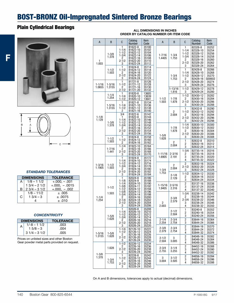
STANDARD TOLERANCES DIMENSIONS TOLERANCE A 1/8 – 1 1/2 +.000, – .001 1 3/4 – 2 1/2 +.000, – .0015 B 2 3/4 – 3 1/2 +.000, – .002
1/8 – 1 1/2 ± .005 C 1 3/4 – 3 ± .0075 4 ± .010
CONCENTRICITY DIMENSIONS TOLERANCE A 1/8 – 1 1/2 .003 1 5/8 – 3 .004 3 1/4 – 3 1/2 .005
Prices on unlisted sizes and other Boston Gear powder metal parts provided on request.
140 Boston Gear 800-825-6544 P-1930-BG 9/17
FFF
BOST-BRONZ Oil-Impregnated Sintered Bronze BearingsPlain Cylindrical Bearings
ALL DIMENSIONS IN INCHES ORDER BY CATALOG NUMBER OR ITEM CODE
Catalog Item A B C Number Code 1 B1622-8 35100 1-1/4 B1622-10 35102 1-3/8 1-1/2 B1622-12 35104 1.378 1-3/4 B1622-14 35106 2 B1622-16 35108 1 2-1/2 B1622-20 35110 1.003 3 B1622-24 35112 1 B1624-8 35114 1-1/2 1-1/2 B1624-12 35118 1.503 2 B1624-16 35120 2-1/2 B1624-20 35122 3 B1624-24 35124 1 B1721-8 35126 1-1/16 1-5/16 1-1/2 B1721-12 35128 1.0655 1.3155 2 B1721-16 35130 2-1/2 B1721-20 35132 1-1/4 1 B1820-8 13605 1.254 1-1/4 B1820-10 13639 1-1/2 B1820-12 13641 1 B1821-8 35134 1-5/16 1-1/4 B1821-10 35136 1.3155 1-1/2 B1821-12 35138 2 B1821-16 35140 3/4 B1822-6 35142 1-1/8 1 B1822-8 35144 1.129 1-1/4 B1822-10 35146 1-3/8 1-1/2 B1822-12 35148 1.378 1-3/4 B1822-14 35150 2 B1822-16 35152 2-1/2 B1822-20 35154 3 B1822-24 35156 1-1/2 1 B1824-8 35158 1.503 1-1/2 B1824-12 35160 2 B1824-16 35162 1-1/4 B1923-10 35164 1-7/16 2 B1923-16 35166 1.441 2-1/2 B1923-20 35168 3 B1923-24 35170 1 B1924-8 35172 1-1/4 B1924-10 35174 1-3/16 1-1/2 1-1/2 B1924-12 35716 1.1905 1.503 1-3/4 B1924-14 35178 2 B1924-16 35180 2-1/2 B1924-20 35182 3 B1924-24 35184 1 B2024-8 35186 1-1/8 B2024-9 35188 1-1/4 B2024-10 35190 1-3/8 B2024-11 35192 1-1/2 1-1/2 B2024-12 35194 1.503 1-5/8 B2024-13 35196 1-3/4 B2024-14 35198 1-1/4 2 B2024-16 35200 1.254 2-1/4 B2024-18 35202 2-1/2 B2024-20 35204 3 B2024-24 35206 1 B2026-8 35208 1-1/4 B2026-10 35210 1-5/8 1-1/2 B2026-12 35212 1.628 1-3/4 B2026-14 35214 2 B2026-16 35216 2-1/2 B2026-20 35218 3 B2026-24 35220 1-1/4 B2126-10 35222 1-5/16 1-5/8 1-1/2 B2126-12 35224 1.3155 1.628 2 B2126-16 35226 2-1/2 B2126-20 35228 3 B2126-24 35230 1-1/2 B2226-12 35234 1.628 2 B2226-16 35236 2-1/2 B2226-20 35238 3 B2226-24 35240 1-3/8 1 B2228-8 35242 1.378 1-3/4 1-1/2 B2228-12 35244 1.753 2 B2228-16 35246 2-1/2 B2228-20 35248 3 B2228-24 35250
Catalog Item A B C Number Code 1 B2328-8 35252 1-1/4 B2328-10 35254 1-7/16 1-3/4 1-1/2 B2328-12 35256 1.4405 1.753 1-3/4 B2328-14 35258 2 B2328-16 35260 2-1/2 B2328-20 35262 3 B2328-24 35264 1 B2428-8 35266 1-1/4 B2428-10 35268 1-3/4 1-1/2 B2428-12 35270 1.753 2 B2428-16 G00602 2-1/2 B2428-20 35274 3 B2428-24 35276 1-13/16 1-1/2 B2429-12 35278 1.816 3 B2429-24 35280 1-1/2 B2430-12 35282 1-1/2 1-7/8 2 B2430-16 35284 1.503 1.878 2-1/2 B2430-20 35286 3 B2430-24 35288 1 B2432-8 35290 2 1-1/2 B2432-12 35292 2.004 2 B2432-16 35294 2-1/2 B2432-20 35296 3 B2432-24 35298 1-1/4 B2630-10 35300 1-7/8 1-1/2 B2630-12 35302 1.878 2 B2630-16 35304 1-5/8 2-1/2 B2630-20 35306 1.628 3 B2630-24 35308 2 1 B2632-8 35310 2.004 2 B2632-16 35312 3 B2632-24 35314 1-3/4 B2735-14 35316 1-11/16 2-3/16 2 B2735-16 35318 1.6905 2.191 3 B2735-24 35320 4 B2735-32 35322 2 2 B2832-16 35324 2.004 2-1/2 B2832-20 35326 1-3/4 3 B2832-24 35328 1.753 2-1/8 1-1/2 B2834-12 35330 2.129 2 B2834-16 35332 3 B2834-24 35334 1-15/16 2-5/16 2 B3137-16 35336 1.9405 2.316 3 B3137-24 35338 4 B3137-32 35340 1-3/4 B3238-14 35342 2-3/8 2 B3238-16 35344 2.379 2-3/4 B3238-22 35346 2 3 B3238-24 35348 2.003 4 B3238-32 35350 2-1/2 1 B3240-8 35352 2.504 2 B3240-16 35354 3 B3240-24 35356 2-1/4 2-3/4 2 B3644-16 35364 2.254 2.754 3 B3644-24 35366 2-3/8 2-3/4 2 B3844-16 35370 2.379 2.754 3 B3844-24 35372 4 B3844-32 35374 2-1/2 3 2 B4048-16 35382 2.504 3.005 3 B4048-24 35384 4 B4048-32 35386 2-3/4 3-1/4 2 B4452-16 35388 2.755 3.255 3 B4452-24 35390 4 B4452-32 35392 3 3-1/2 2 B4856-16 35394 3.004 3.505 3 B4856-24 35396 4 B4856-32 35398
On A and B dimensions, tolerances apply to actual (decimal) dimensions.
STANDARD TOLERANCES
DIMENSIONS TOLERANCE A 1/8 – 1 1/2 +.000, – .001 1 3/4 – 2 1/2 +.000, – .0015 B 2 3/4 – 3 1/2 +.000, – .002 1/8 – 11/2 ± .005 C 1 3/4 – 3 ± .0075 4 ± .010
CONCENTRICITY
DIMENSIONS TOLERANCE A 1/-8 – 1 1/2 .003 1 5/8 – 3 .004 3 1/4 – 3 1/2 .005
Prices on unlisted sizes and other Boston Gear powder metal parts provided on request.
Boston Gear 800-825-6544 141P-1930-BG 9/17
FFF
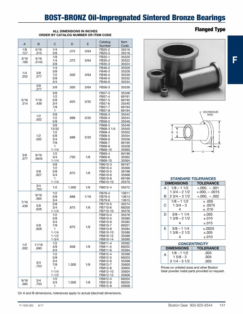
BOST-BRONZ Oil-Impregnated Sintered Bronze BearingsFlanged Type
Catalog Item A B C D E Number Code 1/8 5/16 1/4 .375 3/64 FB25-2 35516 .127 .315 3/8 FB25-3 35518 3/16 5/16 1/8 FB35-1 35520 .189 .3145 1/4 .375 3/64 FB35-2 35522 3/8 FB35-3 35524 1/4 FB46-2 35526 1/4 3/8 3/8 FB46-3 35528 .252 .377 1/2 .500 3/64 FB46-4 35530 5/8 FB46-5 35532 3/4 FB46-6 35534 3/8 3/8 .500 3/64 FB56-3 35536 .377 3/8 FB57-3 35538 1/2 FB57-4 69191 5/16 7/16 5/8 .625 3/32 FB57-5 69192 .314 .439 3/4 FB57-6 35540 7/8 FB57-7 69193 1 FB57-8 69194 1/2 3/8 FB58-3 35542 .502 1/2 .688 3/32 FB58-4 35544 5/8 FB58-5 35546 3/8 FB68-3 35548 13/32 FB68-3 1/4 35550 1/2 FB68-4 35552 1/2 5/8 .688 3/32 FB68-5 35554 .502 3/4 FB68-6 35556 7/8 FB68-7 69195 1 FB68-8 35558 1-1/4 FB68-10 35560 3/8 9/16 1/2 FB69-4 69196 .377 .5645 3/4 .750 1/8 FB69-6 35562 1-1/4 FB69-10 35564 3/8 FB610-3 69197 1/2 FB610-4 35566 5/8 5/8 .875 1/8 FB610-5 39198 .627 3/4 FB610-6 35568 1 FB610-8 69199 1-1/4 FB610-10 35570 3/4 1/2 1.000 1/8 FB612-4 35572 .753
9/16 1/2 FB79-4 13611
.565
5/8 .688 1/16 FB79-5 13613
7/16 3/4 FB79-6 13615
.439
5/8 5/8 FB710-5 35574 .628 3/4 .875 1/8 FB710-6 69200 1-1/4 FB710-10 35576 1/2 FB810-4 35578 5/8 FB810-5 35580 3/4 FB810-6 35582 5/8 7/8 .875 1/8 FB810-7 69201 .628 1 FB810-8 35584 1-1/4 FB810-10 35586 1-1/2 FB810-12 35588 1-3/4 FB810-14 35590 1/2 11/16 1/2 FB811-4 35592 .502 .690 5/8 .938 1/8 FB811-5 69202 3/4 FB811-6 35594 1/2 FB812-4 35596 5/8 FB812-5 69203 3/4 3/4 FB812-6 35598 .753 7/8 1.000 1/8 FB812-7 35600 1 FB812-8 35602 1-1/4 FB812-10 35604 1-1/2 FB812-12 35606 9/16 3/4 1/2 FB912-4 69204 .565 .753 3/4 1.000 1/8 FB912-6 69205 1 FB912-8 35608
ALL DIMENSIONS IN INCHES ORDER BY CATALOG NUMBER OR ITEM CODE
On A and B dimensions, tolerances apply to actual (decimal) dimensions.
STANDARD TOLERANCES DIMENSIONS TOLERANCE A 1/8 – 1 1/2 +.000, – .001 1 3/4 – 2 1/2 +.000, – .0015 B 2 3/4 – 3 1/2 +.000, – .002 1/8 – 1 1/2 ± .005 C 1 3/4 – 3 ± .0075 4 ± .010 D 3/8 – 1 1/4 ±.005 1 3/8 – 2 1/2 ±.010 4 ±.015
E 3/8 – 1 1/4 ±.0025 1 3/8 – 2 1/2 ±.005 4 ±.010
CONCENTRICITY DIMENSIONS TOLERANCE A 1/8 - 1 1/2 .003 1 5/8 - 3 .004 3 1/4 - 3 1/2 .005
Prices on unlisted sizes and other Boston Gear powder metal parts provided on request.
142 Boston Gear 800-825-6544 P-1930-BG 9/17
FFF
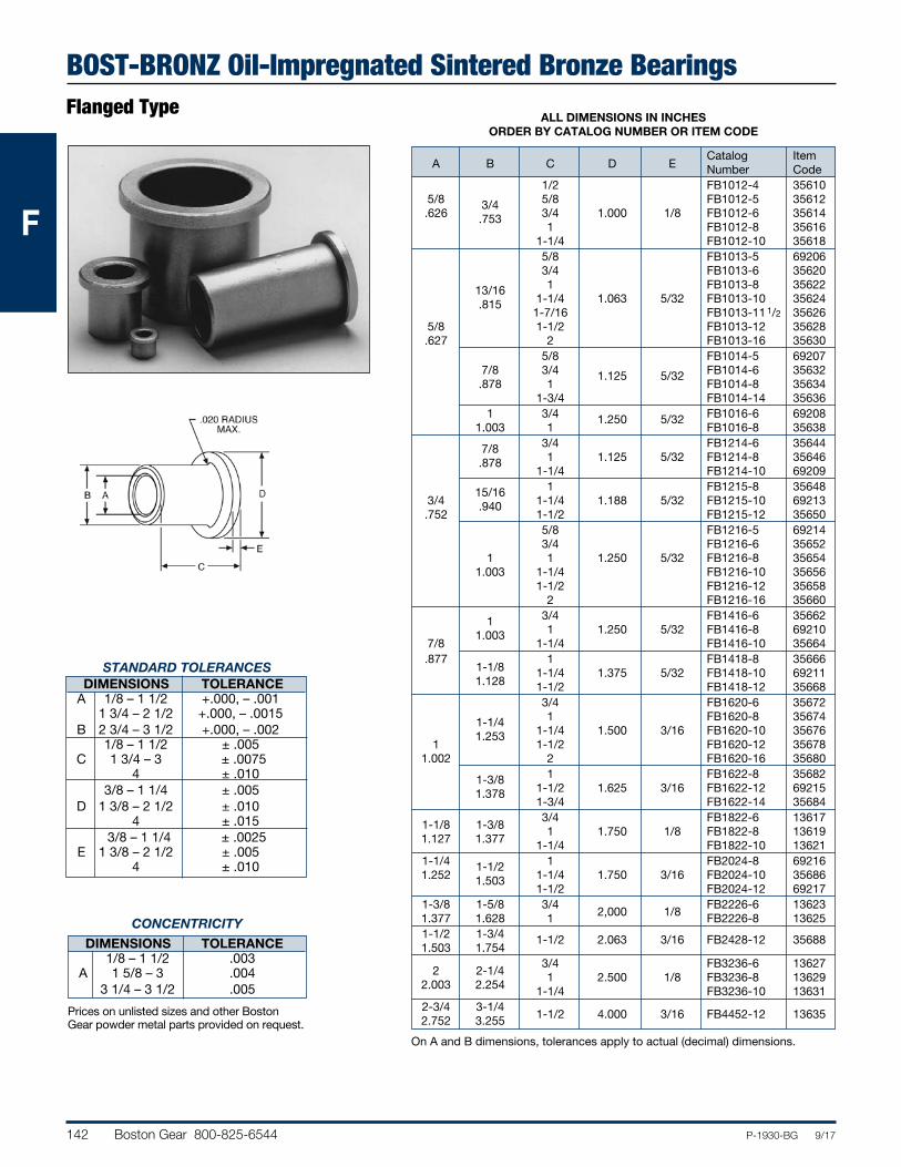
BOST-BRONZ Oil-Impregnated Sintered Bronze BearingsFlanged Type
Catalog Item A B C D E Number Code 1/2 FB1012-4 35610 5/8 3/4 5/8 FB1012-5 35612 .626 .753 3/4 1.000 1/8 FB1012-6 35614 1 FB1012-8 35616 1-1/4 FB1012-10 35618 5/8 FB1013-5 69206 3/4 FB1013-6 35620 13/16 1 FB1013-8 35622 .815 1-1/4 1.063 5/32 FB1013-10 35624 1-7/16 FB1013-11 1/2 35626 5/8 1-1/2 FB1013-12 35628 .627 2 FB1013-16 35630 5/8 FB1014-5 69207 7/8 3/4 1.125 5/32 FB1014-6 35632 .878 1 FB1014-8 35634 1-3/4 FB1014-14 35636 1 3/4 1.250 5/32 FB1016-6 69208 1.003 1 FB1016-8 35638 7/8 3/4 FB1214-6 35644 .878 1 1.125 5/32 FB1214-8 35646 1-1/4 FB1214-10 69209 15/16 1 FB1215-8 35648 3/4 .940 1-1/4 1.188 5/32 FB1215-10 69213 .752 1-1/2 FB1215-12 35650 5/8 FB1216-5 69214 3/4 FB1216-6 35652 1 1 1.250 5/32 FB1216-8 35654 1.003 1-1/4 FB1216-10 35656 1-1/2 FB1216-12 35658 2 FB1216-16 35660 1 3/4 FB1416-6 35662 1.003 1 1.250 5/32 FB1416-8 69210 7/8 1-1/4 FB1416-10 35664 .877 1 FB1418-8 35666 1-1/8 1-1/4 1.375 5/32 FB1418-10 69211 1.128 1-1/2 FB1418-12 35668 3/4 FB1620-6 35672 1-1/4 1 FB1620-8 35674 1.253 1-1/4 1.500 3/16 FB1620-10 35676 1 1-1/2 FB1620-12 35678 1.002 2 FB1620-16 35680 1-3/8 1 FB1622-8 35682 1.378 1-1/2 1.625 3/16 FB1622-12 69215 1-3/4 FB1622-14 35684
1-1/8 1-3/8 3/4 FB1822-6 13617
1.127 1.377
1 1.750 1/8 FB1822-8 13619 1-1/4 FB1822-10 13621 1-1/4 1-1/2 1 FB2024-8 69216 1.252 1.503 1-1/4 1.750 3/16 FB2024-10 35686 1-1/2 FB2024-12 69217 1-3/8 1-5/8 3/4
2,000 1/8 FB2226-6 13623
1.377 1.628 1 FB2226-8 13625 1-1/2 1-3/4 1-1/2 2.063 3/16 FB2428-12 35688 1.503 1.754
2
2-1/4 3/4 FB3236-6 13627
2.003
2.254
1 2.500 1/8 FB3236-8 13629 1-1/4 FB3236-10 13631 2-3/4 3-1/4
1-1/2 4.000 3/16 FB4452-12 13635
2.752 3.255
ALL DIMENSIONS IN INCHES ORDER BY CATALOG NUMBER OR ITEM CODE
On A and B dimensions, tolerances apply to actual (decimal) dimensions.
STANDARD TOLERANCES DIMENSIONS TOLERANCE A 1/8 – 1 1/2 +.000, – .001 1 3/4 – 2 1/2 +.000, – .0015 B 2 3/4 – 3 1/2 +.000, – .002 1/8 – 1 1/2 ± .005 C 1 3/4 – 3 ± .0075 4 ± .010 3/8 – 1 1/4 ± .005 D 1 3/8 – 2 1/2 ± .010 4 ± .015 3/8 – 1 1/4 ± .0025 E 1 3/8 – 2 1/2 ± .005 4 ± .010
CONCENTRICITY
DIMENSIONS TOLERANCE 1/8 – 1 1/2 .003 A 1 5/8 – 3 .004 3 1/4 – 3 1/2 .005
Prices on unlisted sizes and other Boston Gear powder metal parts provided on request.
Boston Gear 800-825-6544 143P-1930-BG 9/17
FFF
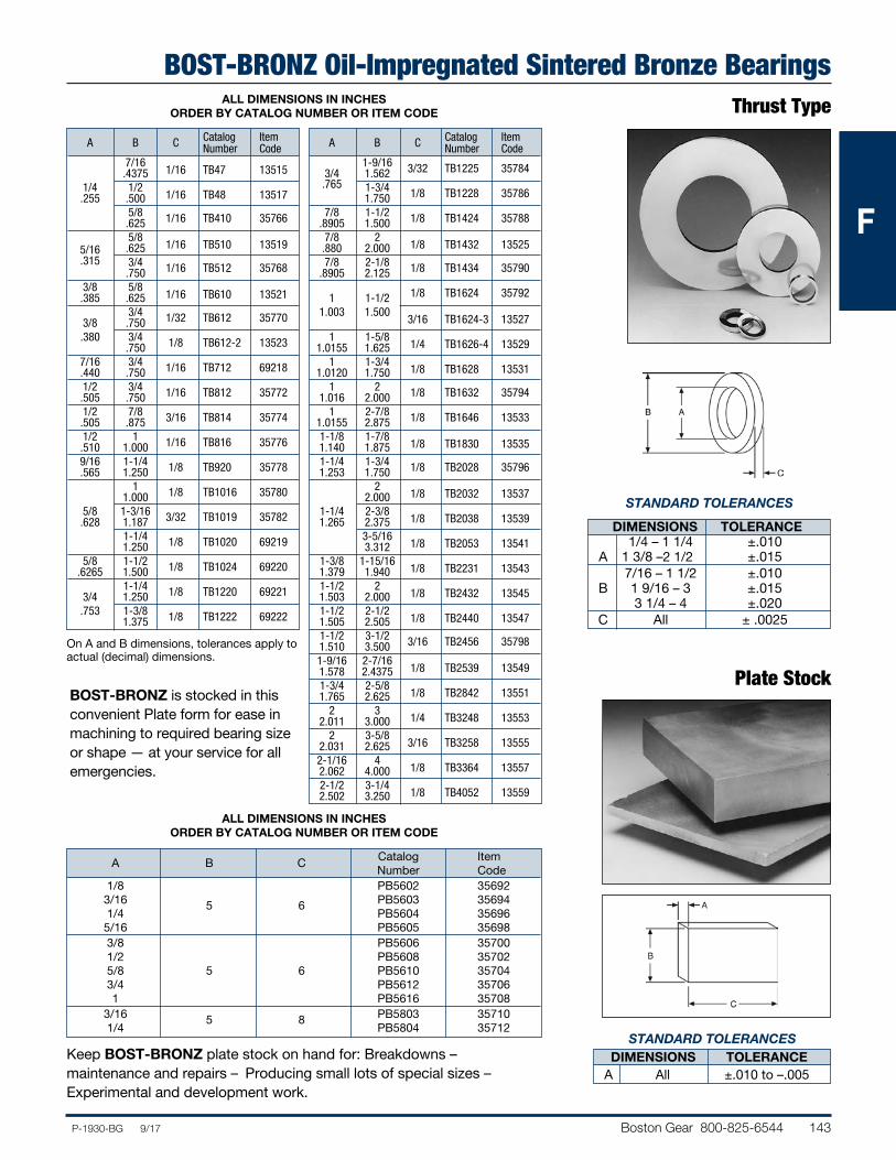
BOST-BRONZ Oil-Impregnated Sintered Bronze BearingsThrust Type
Plate Stock
Catalog Item
A B C Number Code
1/8 PB5602 35692 3/16 5 6 PB5603 35694 1/4 PB5604 35696 5/16 PB5605 35698 3/8 PB5606 35700 1/2 PB5608 35702 5/8 5 6 PB5610 35704 3/4 PB5612 35706 1 PB5616 35708 3/16 5 8 PB5803 35710 1/4 PB5804 35712
STANDARD TOLERANCES
DIMENSIONS TOLERANCE 1/4 – 1 1/4 ±.010 A 1 3/8 –2 1/2 ±.015 7/16 – 1 1/2 ±.010 B 1 9/16 – 3 ±.015 3 1/4 – 4 ±.020 C All ± .0025
STANDARD TOLERANCES DIMENSIONS TOLERANCE A All ±.010 to –.005
Catalog Item A B C Number Code 7/16
1/16 TB47 13515
.4375 1/4 1/2
1/16 TB48 13517
.255 .500 5/8 1/16 TB410 35766 .625 5/8
1/16 TB510 13519
5/16 .625 .315 3/4 1/16 TB512 35768 .750 3/8 5/8
1/16 TB610 13521
.385 .625 3/4 1/32 TB612 35770 3/8 .750 .380 3/4 1/8 TB612-2 13523 .750 7/16 3/4 1/16 TB712 69218 .440 .750 1/2 3/4 1/16 TB812 35772 .505 .750 1/2 7/8 3/16 TB814 35774 .505 .875 1/2 1 1/16 TB816 35776 .510 1.000 9/16 1-1/4 1/8 TB920 35778 .565 1.250 1 1/8 TB1016 35780 1.000 5/8 1-3/16 3/32 TB1019 35782 .628 1.187 1-1/4 1/8 TB1020 69219 1.250 5/8 1-1/2 1/8 TB1024 69220 .6265 1.500 1-1/4 1/8 TB1220 69221 3/4 1.250 .753 1-3/8 1/8 TB1222 69222 1.375
BOST-BRONZ is stocked in this convenient Plate form for ease in machining to required bearing size or shape — at your service for all emergencies.
ALL DIMENSIONS IN INCHES ORDER BY CATALOG NUMBER OR ITEM CODE
Catalog Item A B C Number Code 1-9/16 3/32 TB1225 35784 3/4 1.562 .765 1-3/4 1/8 TB1228 35786 1.750 7/8 1-1/2 1/8 TB1424 35788 .8905 1.500 7/8 2
1/8 TB1432 13525
.880 2.000 7/8 2-1/8 1/8 TB1434 35790 .8905 2.125 1/8 TB1624 35792 1 1-1/2 1.003 1.500
3/16 TB1624-3 13527
1 1-5/8
1/4 TB1626-4 13529
1.0155 1.625 1 1-3/4
1/8 TB1628 13531
1.0120 1.750 1 2 1/8 TB1632 35794 1.016 2.000 1 2-7/8 1/8 TB1646 13533 1.0155 2.875 1-1/8 1-7/8
1/8 TB1830 13535
1.140 1.875 1-1/4 1-3/4 1/8 TB2028 35796 1.253 1.750 2
1/8 TB2032 13537
2.000 1-1/4 2-3/8
1/8 TB2038 13539
1.265 2.375 3-5/16
1/8 TB2053 13541
3.312 1-3/8 1-15/16
1/8 TB2231 13543
1.379 1.940 1-1/2 2
1/8 TB2432 13545
1.503 2.000 1-1/2 2-1/2
1/8 TB2440 13547
1.505 2.505 1-1/2 3-1/2 3/16 TB2456 35798 1.510 3.500 1-9/16 2-7/16
1/8 TB2539 13549
1.578 2.4375 1-3/4 2-5/8
1/8 TB2842 13551
1.765 2.625 2 3
1/4 TB3248 13553
2.011 3.000 2 3-5/8
3/16 TB3258 13555
2.031 2.625 2-1/16 4
1/8 TB3364 13557
2.062 4.000 2-1/2 3-1/4
1/8 TB4052 13559
2.502 3.250
On A and B dimensions, tolerances apply to actual (decimal) dimensions.
Keep BOST-BRONZ plate stock on hand for: Breakdowns – maintenance and repairs – Producing small lots of special sizes – Experimental and development work.
ALL DIMENSIONS IN INCHES ORDER BY CATALOG NUMBER OR ITEM CODE
144 Boston Gear 800-825-6544 P-1930-BG 9/17
FFF
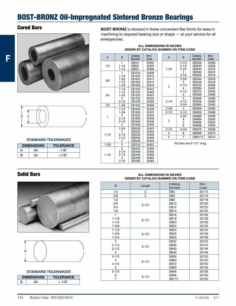
BOST-BRONZ Oil-Impregnated Sintered Bronze BearingsCored Bars
Solid Bars
ALL DIMENSIONS IN INCHES ORDER BY CATALOG NUMBER OR ITEM CODE
Catalog Item A B Number Code 1 CB816 35402 1/2 1-1/4 CB820 35404 1-1/2 CB824 35406 1 CB1016 35408 1-1/4 CB1020 35410 5/8 1-3/8 CB1022 35412 1-1/2 CB1024 35414 1-3/4 CB1028 35416 1-1/4 CB1220 35418 1-1/2 CB1224 35420 3/4 1-3/4 CB1228 35422 2 CB1232 35424 2-1/2 CB1240 35426 7/8 1-3/8 CB1422 35428 1-1/2 CB1624 35430 1-3/4 CB1628 35432 1 2 CB1632 35434 2-1/4 CB1636 35436 2-1/2 CB1640 35438 3 CB1648 35440 1-3/4 CB2028 35442 2 CB2032 35444 1-1/4 2-1/4 CB2036 35446 2-1/2 CB2040 35448 3 CB2048 35450 1-3/8 2 CB2232 35452 2 CB2432 35456 2-1/4 CB2436 35458 1-1/2 2-1/2 CB2440 35460 3 CB2448 35462 3-1/2 CB2456 35464
Catalog Item A B Number Code 2-1/4 CB2836 35466 2-1/2 CB2840 35468 1-3/4 2-3/4 CB2844 35470 3 CB2848 35472 3-1/2 CB2856 35474 2-3/4 CB3244 35476 3 CB3248 35478 2 3-1/4 CB3252 35480 4 CB3264 35482 4-1/2 CB3272 35484 5 CB3280 35486 3 CB3648 35488 2-1/4 3-1/2 CB3656 35490 3-3/4 CB3660 35492 2-3/8 3 CB3848 35494 2-1/2 3-1/2 CB4056 35496 3-3/4 CB4860 35498 3 4 CB4864 35500 5 CB4880 35502 6 CB4896 35504 3-1/2 4-3/4 CB5676 35506 4 6 CB6496 35512 5 7 CB80112 35514
All bars are 6 1/2” long.
Catalog Item
B Length Number Code
1/4 2 SB4 35714 3/8 3 SB6 35716 1/2 SB8 35718 5/8 6-1/2 SB10 35720 3/4 SB12 35722 7/8 SB14 35724 1 SB16 35726 1-1/8 6-1/2 SB18 35728 1-1/4 SB20 35730 1-3/8 SB22 35732 1-1/2 SB24 35734 1-5/8 6-1/2 SB26 35736 1-3/4 SB28 35738 2 SB32 35742 2-1/4 6-1/2 SB36 35744 2-1/2 SB40 35746 3 SB48 35748 3-1/2 SB56 35750 4 6-1/2 SB64 35752 4-1/2 SB72 35754 5 SB80 35756 5-1/2 SB88 35758 6 6-1/2 SB96 35760 7 SB112 35762
ALL DIMENSIONS IN INCHES ORDER BY CATALOG NUMBER OR ITEM CODE
BOST-BRONZ is stocked in these convenient Bar forms for ease in machining to required bearing size or shape — at your service for all emergencies.
STANDARD TOLERANCES
DIMENSIONS TOLERANCE A All –1/8” B All +1/8”
STANDARD TOLERANCES
DIMENSIONS TOLERANCE B All + 1/8”
Boston Gear 800-825-6544 145P-1930-BG 9/17
FFF
BEAR-N-BRONZE 660 Cast Bronze Bearings
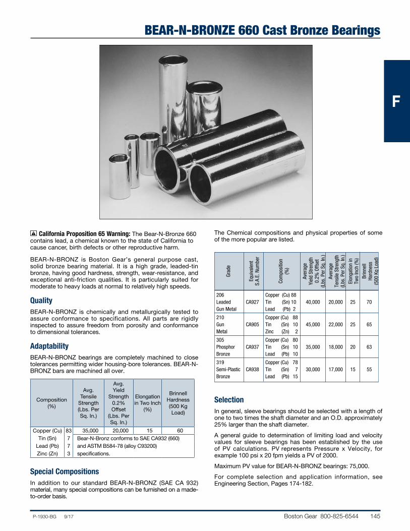
BEAR-N-BRONZ is Boston Gear’s general purpose cast, solid bronze bearing material. It is a high grade, leaded-tin bronze, having good hardness, strength, wear-resistance, and exceptional anti-friction qualities. It is particularly suited for moderate to heavy loads at normal to relatively high speeds.
QualityBEAR-N-BRONZ is chemically and metallurgically tested to assure conformance to specifications. All parts are rigidly inspected to assure freedom from porosity and conformance to dimensional tolerances.
AdaptabilityBEAR-N-BRONZ bearings are completely machined to close tolerances permitting wider housing-bore tol er ances. BEAR-N-BRONZ bars are machined all over.
Composition (%)
Avg. Tensile
Strength (Lbs. Per Sq. In.)
Avg. Yield
Strength 0.2% Offset
(Lbs. Per Sq. In.)
Elongation in Two Inch
(%)
Brinnell Hardness (500 Kg Load)
Copper (Cu) 83 35,000 20,000 15 60Tin (Sn) 7 Bear-N-Bronz conforms to SAE CA932 (660)
Lead (Pb) 7 and ASTM B584-78 (alloy C93200)Zinc (Zn) 3 specifications.
Special CompositionsIn addition to our standard BEAR-N-BRONZ (SAE CA 932) material, many special compositions can be furnished on a made-to-order basis.
The Chemical compositions and physical properties of some of the more popular are listed.
206 Copper (Cu) 88 Leaded CA927 Tin (Sn) 10 40,000 20,000 25 70 Gun Metal Lead (Pb) 2
210 Copper (Cu) 88 Gun CA905 Tin (Sn) 10 45,000 22,000 25 65 Metal Zinc (Zn) 2
305 Copper (Cu) 80 Phosphor CA937 Tin (Sn) 10 35,000 18,000 20 63 Bronze Lead (Pb) 10
319 Copper (Cu) 78 Semi-Plastic CA938 Tin (Sn) 7 30,000 17,000 15 55 Bronze Lead (Pb) 15
SelectionIn general, sleeve bearings should be selected with a length of one to two times the shaft diameter and an O.D. approximately 25% larger than the shaft diameter.
A general guide to determination of limiting load and velocity values for sleeve bearings has been estab lished by the use of PV calculations. PV represents Pressure x Velocity, for example 100 psi x 20 fpm yields a PV of 2000.
Maximum PV value for BEAR-N-BRONZ bearings: 75,000.
For complete selection and application information, see Engineering Section, Pages 174-182.
Grad
e
Equi
vale
nt
S.A.
E. N
umbe
r
Com
posi
tion
(%)
Aver
age
Yiel
d St
reng
th
0.2%
Offs
et
(Lbs
. Per
Sq.
In.)
Aver
age
Tens
ile S
treng
th
(Lbs
. Per
Sq.
In.)
Elon
gatio
n in
Tw
o In
ch (%
)
Brin
nell
Hard
ness
(5
00 K
g Lo
ad)
California Proposition 65 Warning: The Bear-N-Bronze 660 contains lead, a chemical known to the state of California to cause cancer, birth defects or other reproductive harm.
146 Boston Gear 800-825-6544 P-1930-BG 9/17
FFF
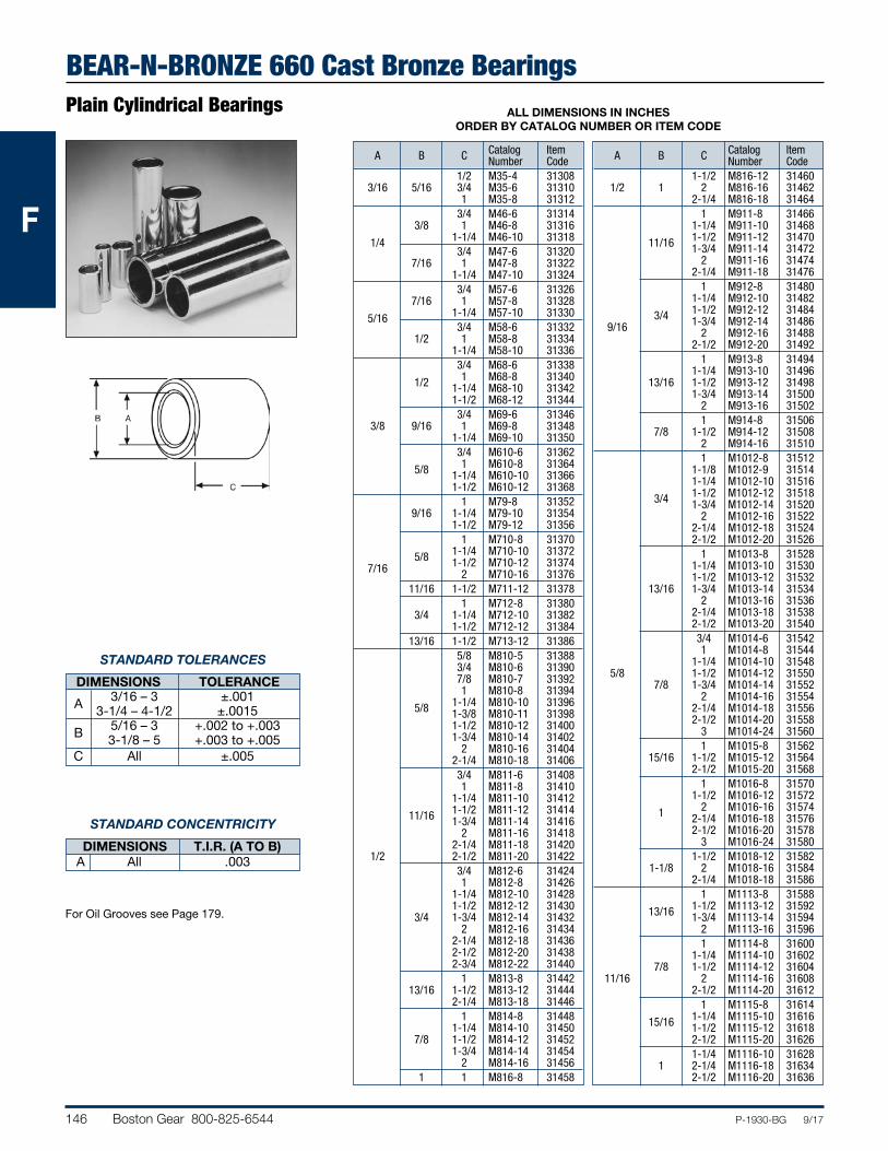
BEAR-N-BRONZE 660 Cast Bronze BearingsPlain Cylindrical Bearings ALL DIMENSIONS IN INCHES
ORDER BY CATALOG NUMBER OR ITEM CODE
Catalog Item A B C Number Code 1/2 M35-4 31308 3/16 5/16 3/4 M35-6 31310 1 M35-8 31312 3/4 M46-6 31314 3/8 1 M46-8 31316 1/4 1-1/4 M46-10 31318 3/4 M47-6 31320 7/16 1 M47-8 31322 1-1/4 M47-10 31324 3/4 M57-6 31326 7/16 1 M57-8 31328 5/16 1-1/4 M57-10 31330 3/4 M58-6 31332 1/2 1 M58-8 31334 1-1/4 M58-10 31336 3/4 M68-6 31338 1/2 1 M68-8 31340 1-1/4 M68-10 31342 1-1/2 M68-12 31344 3/4 M69-6 31346 3/8 9/16 1 M69-8 31348 1-1/4 M69-10 31350 3/4 M610-6 31362 5/8 1 M610-8 31364 1-1/4 M610-10 31366 1-1/2 M610-12 31368 1 M79-8 31352 9/16 1-1/4 M79-10 31354 1-1/2 M79-12 31356 1 M710-8 31370 5/8 1-1/4 M710-10 31372 7/16 1-1/2 M710-12 31374 2 M710-16 31376 11/16 1-1/2 M711-12 31378 1 M712-8 31380 3/4 1-1/4 M712-10 31382 1-1/2 M712-12 31384 13/16 1-1/2 M713-12 31386 5/8 M810-5 31388 3/4 M810-6 31390 7/8 M810-7 31392 1 M810-8 31394 5/8 1-1/4 M810-10 31396 1-3/8 M810-11 31398 1-1/2 M810-12 31400 1-3/4 M810-14 31402 2 M810-16 31404 2-1/4 M810-18 31406 3/4 M811-6 31408 1 M811-8 31410 1-1/4 M811-10 31412 11/16 1-1/2 M811-12 31414 1-3/4 M811-14 31416 2 M811-16 31418 2-1/4 M811-18 31420 1/2 2-1/2 M811-20 31422 3/4 M812-6 31424 1 M812-8 31426 1-1/4 M812-10 31428 1-1/2 M812-12 31430 3/4 1-3/4 M812-14 31432 2 M812-16 31434 2-1/4 M812-18 31436 2-1/2 M812-20 31438 2-3/4 M812-22 31440 1 M813-8 31442 13/16 1-1/2 M813-12 31444 2-1/4 M813-18 31446 1 M814-8 31448 1-1/4 M814-10 31450 7/8 1-1/2 M814-12 31452 1-3/4 M814-14 31454 2 M814-16 31456 1 1 M816-8 31458
Catalog Item A B C Number Code 1-1/2 M816-12 31460 1/2 1 2 M816-16 31462 2-1/4 M816-18 31464 1 M911-8 31466 1-1/4 M911-10 31468 11/16 1-1/2 M911-12 31470 1-3/4 M911-14 31472 2 M911-16 31474 2-1/4 M911-18 31476 1 M912-8 31480 1-1/4 M912-10 31482 3/4 1-1/2 M912-12 31484 9/16 1-3/4 M912-14 31486 2 M912-16 31488 2-1/2 M912-20 31492 1 M913-8 31494 1-1/4 M913-10 31496 13/16 1-1/2 M913-12 31498 1-3/4 M913-14 31500 2 M913-16 31502 1 M914-8 31506 7/8 1-1/2 M914-12 31508 2 M914-16 31510 1 M1012-8 31512 1-1/8 M1012-9 31514 1-1/4 M1012-10 31516 3/4 1-1/2 M1012-12 31518 1-3/4 M1012-14 31520 2 M1012-16 31522 2-1/4 M1012-18 31524 2-1/2 M1012-20 31526 1 M1013-8 31528 1-1/4 M1013-10 31530 1-1/2 M1013-12 31532 13/16 1-3/4 M1013-14 31534 2 M1013-16 31536 2-1/4 M1013-18 31538 2-1/2 M1013-20 31540 3/4 M1014-6 31542 1 M1014-8 31544 1-1/4 M1014-10 31548 5/8 1-1/2 M1014-12 31550 7/8 1-3/4 M1014-14 31552 2 M1014-16 31554 2-1/4 M1014-18 31556 2-1/2 M1014-20 31558 3 M1014-24 31560 1 M1015-8 31562 15/16 1-1/2 M1015-12 31564 2-1/2 M1015-20 31568 1 M1016-8 31570 1-1/2 M1016-12 31572 1 2 M1016-16 31574 2-1/4 M1016-18 31576 2-1/2 M1016-20 31578 3 M1016-24 31580 1-1/2 M1018-12 31582 1-1/8 2 M1018-16 31584 2-1/4 M1018-18 31586 1 M1113-8 31588 13/16 1-1/2 M1113-12 31592 1-3/4 M1113-14 31594 2 M1113-16 31596 1 M1114-8 31600 1-1/4 M1114-10 31602 7/8 1-1/2 M1114-12 31604 11/16 2 M1114-16 31608 2-1/2 M1114-20 31612 1 M1115-8 31614 15/16 1-1/4 M1115-10 31616 1-1/2 M1115-12 31618 2-1/2 M1115-20 31626 1-1/4 M1116-10 31628 1 2-1/4 M1116-18 31634 2-1/2 M1116-20 31636
STANDARD TOLERANCES
DIMENSIONS TOLERANCE 3/16 – 3 ±.001 A 3-1/4 – 4-1/2 ±.0015 5/16 – 3 +.002 to +.003 B 3-1/8 – 5 +.003 to +.005 C All ±.005
STANDARD CONCENTRICITY
DIMENSIONS T.I.R. (A TO B) A All .003
For Oil Grooves see Page 179.

Boston Gear 800-825-6544 147P-1930-BG 9/17
FFF
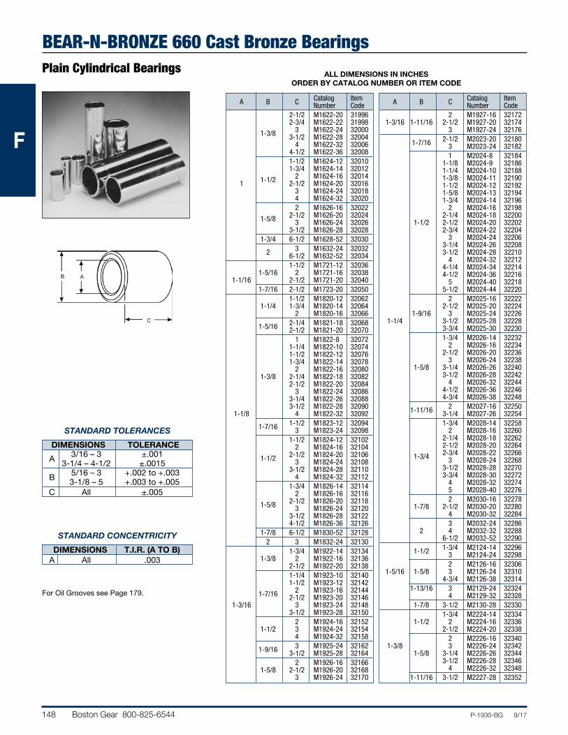
BEAR-N-BRONZE 660 Cast Bronze BearingsPlain Cylindrical BearingsALL DIMENSIONS IN INCHES
ORDER BY CATALOG NUMBER OR ITEM CODE
Catalog Item A B C Number Code 3/4 M1214-6 31640 1 M1214-8 31642 1-1/4 M1214-10 31644 7/8 1-1/2 M1214-12 31646 1-3/4 M1214-14 31648 2 M1214-16 31650 2-1/4 M1214-18 31652 2-1/2 M1214-20 31654 1 M1215-8 31656 1-1/4 M1215-10 31658 1-1/2 M1215-12 31662 15/16 1-3/4 M1215-14 31664 2 M1215-16 31666 2-1/4 M1215-18 31668 2-1/2 M1215-20 31670 3 M1215-24 31674 3/4 M1216-6 31676 1 M1216-8 31678 1-1/8 M1216-9 31680 1-1/4 M1216-10 31682 1-3/8 M1216-11 31684 1-1/2 M1216-12 31686 1 1-3/4 M1216-14 31688 3/4 2 M1216-16 31690 2-1/8 M1216-17 31692 2-1/4 M1216-18 31694 2-1/2 M1216-20 31696 2-3/4 M1216-22 31698 3 M1216-24 31700 3-1/2 M1216-28 31702 1 M1217-8 31704 1-1/16 1-1/2 M1217-12 31706 2 M1217-16 31708 3 M1217-24 31714 1 M1218-8 31716 1-1/2 M1218-12 31718 1-1/8 2 M1218-16 31720 2-1/2 M1218-20 31724 3 M1218-24 31726 1-3/16 1-1/2 M1219-12 31728 2 M1219-16 31730 1-3/4 M1220-14 31734 1-1/4 2 M1220-16 31736 2-1/2 M1220-20 31740 3 M1220-24 31742 1 M1315-8 31744 15/16 1-1/2 M1315-12 31748 2 M1315-16 31750 1-1/2 M1316-12 31752 1 2 M1316-16 31756 13/16 2-1/2 M1316-20 31758 1-1/2 M1317-12 31760 1-1/16 2 M1317-16 31762 2-3/4 M1317-22 31766 1-1/8 1-1/2 M1318-12 31770 2 M1318-16 31772 1 M1416-8 31788 1-1/4 M1416-10 31790 1 1-3/8 M1416-11 31792 1-1/2 M1416-12 31794 1-5/8 M1416-13 31796 2 M1416-16 31798 1 M1417-8 31800 1-1/4 M1417-10 31802 1-1/2 M1417-12 31804 7/8 1-1/16 1-3/4 M1417-14 31806 2 M1417-16 31808 2-1/4 M1417-18 31810 2-1/2 M1417-20 31812 3 M1417-24 31816 3/4 M1418-6 31818 1-1/8 1 M1418-8 31820 1-1/4 M1418-10 31822 1-3/8 M1418-11 31824
Catalog Item A B C Number Code 1-1/2 M1418-12 31826 1-3/4 M1418-14 31828 2 M1418-16 31830 1-1/8 2-1/4 M1418-18 31832 2-1/2 M1418-20 31834 3 M1418-24 31836 3-1/4 M1418-26 31838 3-1/2 M1418-28 31840 7/8 1-3/16 1 M1419-8 31842 3 M1419-24 31852 1-1/2 M1420-12 31854 1-3/4 M1420-14 31856 2 M1420-16 31858 1-1/4 2-1/4 M1420-18 31860 2-1/2 M1420-20 31862 3 M1420-24 31864 3-1/2 M1420-28 31866 1-1/2 M1422-12 31868 1-3/8 2 M1422-16 31872 2-1/2 M1422-20 31874 3 M1422-24 31876 1-1/8 1-1/2 M1518-12 31878 2 M1518-16 31880 1-1/4 M1519-10 31884 1-3/16 1-1/2 M1519-12 31886 2 M1519-16 31888 15/16 3 M1519-24 31894 1 M1520-8 31896 1-1/2 M1520-12 31898 1-1/4 2 M1520-16 31900 2-1/2 M1520-20 31902 2-3/4 M1520-22 31904 1-5/16 1-1/2 M1521-12 31906 2 M1521-16 31910 1-3/8 M1618-11 31916 1-1/2 M1618-12 31918 1-1/8 1-3/4 M1618-14 31920 2 M1618-16 31922 2-1/2 M1618-20 31924 7/8 M1619-7 31926 1-1/4 M1619-10 31928 1-3/16 1-1/2 M1619-12 31930 1-3/4 M1619-14 31932 2 M1619-16 31934 2-1/2 M1619-20 31936 3/4 M1620-6 31938 1 M1620-8 31940 1-1/8 M1620-9 31942 1-1/4 M1620-10 31944 1-3/8 M1620-11 31946 1-1/2 M1620-12 31948 1-5/8 M1620-13 31950 1 1-1/4 1-3/4 M1620-14 31952 2 M1620-16 31954 2-1/4 M1620-18 31956 2-1/2 M1620-20 31958 2-3/4 M1620-22 31960 3 M1620-24 31962 4 M1620-32 31968 4-1/2 M1620-36 31970 1-1/2 M1621-12 31972 2 M1621-16 31974 1-5/16 2-1/4 M1621-18 31976 2-1/2 M1621-20 31978 3 M1621-24 31980 3-1/2 M1621-28 31982 1-1/4 M1622-10 31988 1-3/8 1-1/2 M1622-12 31990 1-3/4 M1622-14 31992 2 M1622-16 31994
STANDARD TOLERANCES
DIMENSIONS TOLERANCE 3/16 – 3 ±.001 A 3-1/4 – 4-1/2 ±.0015 5/16 – 3 +.002 to +.003 B 3-1/8 – 5 +.003 to +.005 C All ±.005
STANDARD CONCENTRICITY
DIMENSIONS T.I.R. (A TO B) A All .003
For Oil Grooves see Page 179.
148 Boston Gear 800-825-6544 P-1930-BG 9/17
FFF
BEAR-N-BRONZE 660 Cast Bronze BearingsPlain Cylindrical Bearings ALL DIMENSIONS IN INCHES
ORDER BY CATALOG NUMBER OR ITEM CODE
Catalog Item A B C Number Code 2-1/2 M1622-20 31996 2-3/4 M1622-22 31998 1-3/8 3 M1622-24 32000 3-1/2 M1622-28 32004 4 M1622-32 32006 4-1/2 M1622-36 32008 1-1/2 M1624-12 32010 1-3/4 M1624-14 32012 1-1/2 2 M1624-16 32014 1 2-1/2 M1624-20 32016 3 M1624-24 32018 4 M1624-32 32020 2 M1626-16 32022 1-5/8 2-1/2 M1626-20 32024 3 M1626-24 32026 3-1/2 M1626-28 32028 1-3/4 6-1/2 M1628-52 32030 2 3 M1632-24 32032 6-1/2 M1632-52 32034 1-1/2 M1721-12 32036 1-5/16 2 M1721-16 32038 1-1/16 2-1/2 M1721-20 32040 1-7/16 2-1/2 M1723-20 32050 1-1/2 M1820-12 32062 1-1/4 1-3/4 M1820-14 32064 2 M1820-16 32066 1-5/16 2-1/4 M1821-18 32068 2-1/2 M1821-20 32070 1 M1822-8 32072 1-1/4 M1822-10 32074 1-1/2 M1822-12 32076 1-3/4 M1822-14 32078 2 M1822-16 32080 1-3/8 2-1/4 M1822-18 32082 2-1/2 M1822-20 32084 3 M1822-24 32086 3-1/4 M1822-26 32088 3-1/2 M1822-28 32090 1-1/8 4 M1822-32 32092 1-7/16 1-1/2 M1823-12 32094 3 M1823-24 32098 1-1/2 M1824-12 32102 2 M1824-16 32104 1-1/2 2-1/2 M1824-20 32106 3 M1824-24 32108 3-1/2 M1824-28 32110 4 M1824-32 32112 1-3/4 M1826-14 32114 2 M1826-16 32116 1-5/8 2-1/2 M1826-20 32118 3 M1826-24 32120 3-1/2 M1826-28 32122 4-1/2 M1826-36 32126 1-7/8 6-1/2 M1830-52 32128 2 3 M1832-24 32130 1-3/4 M1922-14 32134 1-3/8 2 M1922-16 32136 2-1/2 M1922-20 32138 1-1/4 M1923-10 32140 1-1/2 M1923-12 32142 1-7/16 2 M1923-16 32144 2-1/2 M1923-20 32146 1-3/16 3 M1923-24 32148 3-1/2 M1923-28 32150 2 M1924-16 32152 1-1/2 3 M1924-24 32154 4 M1924-32 32158 1-9/16 3 M1925-24 32162 3-1/2 M1925-28 32164 2 M1926-16 32166 1-5/8 2-1/2 M1926-20 32168 3 M1926-24 32170
Catalog Item A B C Number Code 2 M1927-16 32172 1-3/16 1-11/16 2-1/2 M1927-20 32174 3 M1927-24 32176 1-7/16 2-1/2 M2023-20 32180 3 M2023-24 32182 1 M2024-8 32184 1-1/8 M2024-9 32186 1-1/4 M2024-10 32188 1-3/8 M2024-11 32190 1-1/2 M2024-12 32192 1-5/8 M2024-13 32194 1-3/4 M2024-14 32196 2 M2024-16 32198 2-1/4 M2024-18 32200 1-1/2 2-1/2 M2024-20 32202 2-3/4 M2024-22 32204 3 M2024-24 32206 3-1/4 M2024-26 32208 3-1/2 M2024-28 32210 4 M2024-32 32212 4-1/4 M2024-34 32214 4-1/2 M2024-36 32216 5 M2024-40 32218 5-1/2 M2024-44 32220 2 M2025-16 32222 2-1/2 M2025-20 32224 1-9/16 3 M2025-24 32226 1-1/4 3-1/2 M2025-28 32228 3-3/4 M2025-30 32230 1-3/4 M2026-14 32232 2 M2026-16 32234 2-1/2 M2026-20 32236 3 M2026-24 32238 1-5/8 3-1/4 M2026-26 32240 3-1/2 M2026-28 32242 4 M2026-32 32244 4-1/2 M2026-36 32246 4-3/4 M2026-38 32248 1-11/16 2 M2027-16 32250 3-1/4 M2027-26 32254 1-3/4 M2028-14 32258 2 M2028-16 32260 2-1/4 M2028-18 32262 2-1/2 M2028-20 32264 1-3/4 2-3/4 M2028-22 32266 3 M2028-24 32268 3-1/2 M2028-28 32270 3-3/4 M2028-30 32272 4 M2028-32 32274 5 M2028-40 32276 2 M2030-16 32278 1-7/8 2-1/2 M2030-20 32280 4 M2030-32 32284 3 M2032-24 32286 2 4 M2032-32 32288 6-1/2 M2032-52 32290 1-1/2 1-3/4 M2124-14 32296 3 M2124-24 32298 2 M2126-16 32306 1-5/16 1-5/8 3 M2126-24 32310 4-3/4 M2126-38 32314 1-13/16 3 M2129-24 32324 4 M2129-32 32328 1-7/8 3-1/2 M2130-28 32330 1-3/4 M2224-14 32334 1-1/2 2 M2224-16 32336 2-1/2 M2224-20 32338 2 M2226-16 32340 1-3/8 3 M2226-24 32342 1-5/8 3-1/4 M2226-26 32344 3-1/2 M2226-28 32346 4 M2226-32 32348 1-11/16 3-1/2 M2227-28 32352
STANDARD TOLERANCES
DIMENSIONS TOLERANCE 3/16 – 3 ±.001 A 3-1/4 – 4-1/2 ±.0015 5/16 – 3 +.002 to +.003 B 3-1/8 – 5 +.003 to +.005 C All ±.005
STANDARD CONCENTRICITY
DIMENSIONS T.I.R. (A TO B) A All .003
For Oil Grooves see Page 179.
Boston Gear 800-825-6544 149P-1930-BG 9/17
FFF
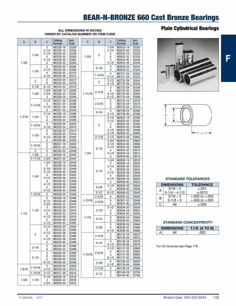
BEAR-N-BRONZE 660 Cast Bronze BearingsPlain Cylindrical BearingsALL DIMENSIONS IN INCHES
ORDER BY CATALOG NUMBER OR ITEM CODE
Catalog Item A B C Number Code 2 M2228-16 32354 2-1/4 M2228-18 32356 1-3/4 2-1/2 M2228-20 32358 3 M2228-24 32360 3-1/2 M2228-28 32362 1-3/8 4 M2228-32 32364 3 M2230-24 32366 1-7/8 3-1/2 M2230-28 32368 4 M2230-32 32370 4-1/2 M2230-36 32372 2 3 M2232-24 32374 4 M2232-32 32376 2-1/8 6-1/2 M2234-52 32378 1-3/4 M2326-14 32380 1-5/8 2-3/4 M2326-22 32382 3 M2326-24 32384 2-1/2 M2327-20 32386 1-11/16 3 M2327-24 32388 3-1/2 M2327-28 32390 4 M2327-32 32392 2-1/4 M2328-18 32396 1-7/16 1-3/4 3 M2328-24 32398 4 M2328-32 32400 1-13/16 3 M2329-24 32402 4-1/4 M2329-34 32410 3 M2330-24 32414 1-7/8 4 M2330-32 32416 4-1/2 M2330-36 32420 5 M2330-40 32422 1-15/16 2 M2331-16 32424 3 M2331-24 32426 2 4 M2332-32 32438 1-5/8 2 M2426-16 32440 1-11/16 2-3/4 M2427-22 32442 1-3/4 M2428-14 32444 2 M2428-16 32446 2-1/4 M2428-18 32448 2-1/2 M2428-20 32450 1-3/4 3 M2428-24 32452 3-1/2 M2428-28 32454 4 M2428-32 32456 4-1/2 M2428-36 32458 5 M2428-40 32460 5-1/2 M2428-44 32462 1-13/16 3 M2429-24 32464 2 M2430-16 32466 2-1/2 M2430-20 32468 2-3/4 M2430-22 32470 3 M2430-24 32472 1-7/8 3-1/2 M2430-28 32474 1-1/2 4 M2430-32 32476 4-1/2 M2430-36 32478 5 M2430-40 32480 5-1/2 M2430-44 32482 2-1/2 M2432-20 32484 3 M2432-24 32486 2 3-1/2 M2432-28 32488 4 M2432-32 32490 4-1/2 M2432-36 32492 5 M2432-40 32494 2-1/8 3 M2434-24 32496 4 M2434-32 32498 3 M2436-24 32500 2-1/4 4 M2436-32 32502 5 M2436-40 32504 6-1/2 M2436-52 32506 1-13/16 3 M2529-24 32508 1-9/16 3-1/2 M2529-28 32510 1-15/16 3-1/2 M2531-28 32514 2-1/4 M2630-18 32518 1-5/8 1-7/8 3 M2630-24 32520 3-3/4 M2630-30 32522
Catalog Item A B C Number Code 1-3/4 M2632-14 32526 2-1/2 M2632-20 32528 2 2 M2632-24 32530 1-5/8 4 M2632-32 32534 5 M2632-40 32538 5-1/2 M2632-44 32540 2-1/8 3 M2634-24 32542 4 M2634-32 32544 1-15/16 3 M2731-24 32550 3-1/2 M2731-28 32552 2 3-1/2 M2732-28 32554 4-1/2 M2732-36 32556 3 M2733-24 32558 2-1/16 4 M2733-32 32562 1-11/16 4-1/2 M2733-36 32564 5-1/2 M2733-44 32568 2 M2735-16 32570 2-3/16 3 M2735-24 32574 4 M2735-32 32578 2-1/4 3 M2736-24 32586 4-1/2 M2736-36 32588 2-1/4 M2832-18 32590 2-1/2 M2832-20 32592 2 3 M2832-24 32594 4 M2832-32 32596 4-1/2 M2832-36 32598 5-1/4 M2832-42 32600 2-1/16 3-1/2 M2833-28 32602 2-3/4 M2834-22 32604 3-1/4 M2834-26 32606 2-1/8 3-1/2 M2834-28 32608 4 M2834-32 32610 1-3/4 4-1/4 M2834-34 32612 5 M2834-40 32614 1-3/4 M2836-14 32618 2 M2836-16 32620 2-1/2 M2836-20 32622 2-1/4 3 M2836-24 32624 3-1/2 M2836-28 32626 4 M2836-32 32628 4-1/4 M2836-34 32630 5 M2836-40 32632 2-3/8 3-1/2 M2838-28 32634 5 M2838-40 32638 2-1/2 6-1/2 M2840-52 32640 2-3/16 4 M2935-32 32642 1-13/16 2-5/16 4 M2937-32 32646 5 M2937-40 32648 2-1/2 M3034-20 32650 2-1/8 3 M3034-24 32652 4 M3034-32 32654 1-7/8 2-1/4 3 M3036-24 32656 5 M3036-40 32662 3 M3038-24 32664 2-3/8 4 M3038-32 32666 5-1/4 M3038-42 32668 2-3/16 2 M3135-16 32670 3 M3135-24 32672 2-1/4 3 M3136-24 32676 4-1/2 M3136-36 32678 3-1/2 M3137-28 32680 2-5/16 4 M3137-32 32682 1-15/16 5 M3137-40 32684 6-1/4 M3137-50 32688 2-3/8 4 M3138-32 32692 5-1/2 M3138-44 32694 2-7/16 3 M3139-24 32696 2-1/2 3 M3140-24 32704 5 M3140-40 32706
STANDARD TOLERANCES
DIMENSIONS TOLERANCE 3/16 – 3 ±.001 A 3-1/4 – 4-1/2 ±.0015 5/16 – 3 +.002 to +.003 B 3-1/8 – 5 +.003 to +.005 C All ±.005
STANDARD CONCENTRICITY
DIMENSIONS T.I.R. (A TO B) A All .003
For Oil Grooves see Page 179.
150 Boston Gear 800-825-6544 P-1930-BG 9/17
FFF
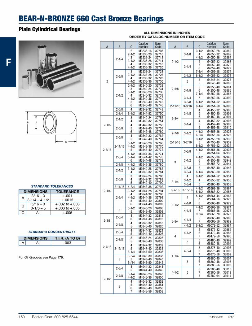
BEAR-N-BRONZE 660 Cast Bronze BearingsPlain Cylindrical Bearings
ALL DIMENSIONS IN INCHES ORDER BY CATALOG NUMBER OR ITEM CODE
Catalog Item A B C Number Code 2 M3236-16 32708 2-1/2 M3236-20 32710 2-1/4 3 M3236-24 32712 3-1/2 M3236-28 32714 4 M3236-32 32718 4-1/2 M3236-36 32720 3 M3238-24 32724 2-3/8 3-1/2 M3238-28 32726 4 M3238-32 32728 2 4-1/2 M3238-36 32730 2-1/2 M3240-20 32732 3 M3240-24 32734 3-1/2 M3240-28 32736 2-1/2 4 M3240-32 32738 4-1/2 M3240-36 32740 5 M3240-40 32742 6 M3240-48 32746 2-5/8 4 M3242-32 32748 2-3/4 6-1/2 M3244-52 32750 2-1/2 3 M3440-24 32752 4 M3440-32 32754 2-1/8 4 M3442-32 32756 2-5/8 5 M3442-40 32758 6 M3442-48 32760 2-5/8 4 M3542-32 32762 5 M3542-40 32764 3-1/2 M3543-28 32766 2-11/16 4-1/2 M3543-36 32770 2-3/16 5 M3543-40 32772 4-1/2 M3544-36 32774 2-3/4 5-1/4 M3544-42 32776 6 M3544-48 32778 2-7/8 4-1/2 M3546-36 32780 2-1/2 3-1/2 M3640-28 32782 4 M3640-32 32784 3 M3642-24 32786 2-5/8 4 M3642-32 32788 5 M3642-40 32790 2-11/16 4-3/4 M3643-38 32792 2-1/4 3-1/2 M3644-28 32794 4 M3644-32 32796 2-3/4 4-1/2 M3644-36 32798 5 M3644-40 32800 6 M3644-48 32802 3 3-1/2 M3648-28 32806 5 M3648-40 32808 2-3/4 4 M3844-32 32812 2-3/8 6 M3844-48 32816 2-7/8 4 M3846-32 32818 5 M3846-40 32820 2-3/4 4 M3944-32 32824 5 M3944-40 32826 2-7/8 3 M3946-24 32828 5 M3946-40 32830 2-7/16 4 M3947-32 32832 2-15/16 5 M3947-40 32834 6-1/4 M3947-50 32836 3-3/4 M3948-30 32838 3 5 M3948-40 32840 6-/14 M3948-50 32842 2-3/4 4 M4044-32 32844 5 M4044-40 32846 2-7/8 3-1/4 M4046-26 32848 2-1/2 4-1/2 M4046-36 32850 4 M4048-32 32852 3 5 M4048-40 32854 6 M4048-48 32856 7 M4048-56 32858
Catalog Item A B C Number Code 3-1/2 M4050-28 32860 3-1/8 4 M4050-32 32862 4-1/2 M4050-36 32864 2-1/2 4 M4052-32 32868 3-1/4 5 M4052-40 32870 6 M4052-48 32872 7-1/4 M4052-58 32874 3-1/2 6-1/2 M4056-52 32876 3 3 M4248-24 32878 5 M4248-40 32882 2-5/8 5 M4250-40 32884 3-1/8 6 M4250-48 32886 7-1/4 M4250-58 32888 3-1/4 7 M4252-56 32890 3-3/8 6-1/2 M4254-52 32892 2-11/16 3-3/16 6-1/4 M4351-50 32898 4 M4450-32 32900 3-1/8 5 M4450-40 32902 2-3/4 6 M4450-48 32904 4 M4452-32 32906 3-1/4 5 M4452-40 32908 6 M4452-48 32910 2-7/8 3-1/2 4-1/2 M4656-36 32926 6-3/4 M4656-54 32928 3-1/2 M4755-28 32930 2-15/16 3-7/16 5 M4755-40 32932 6-1/2 M4755-52 32934 3-3/8 4-1/2 M4854-36 32936 8 M4854-64 32938 4-1/2 M4856-36 32940 3 3-1/2 6 M4856-48 32942 9 M4856-72 32944 3-5/8 5 M4858-40 32946 3-3/4 6-1/4 M4860-50 32952 4 6-1/2 M4864-52 32954 3-1/4 3-1/2 4 M5256-32 32956 3-3/4 5 M5260-40 32958 3-7/16 3-15/16 4-1/2 M5563-36 32964 6-1/2 M5563-52 32966 4 5-1/2 M5664-44 32968 7 M5664-56 32970 3-1/2 4-1/8 6 M5666-48 32972 4-1/2 M5668-36 32974 4-1/4 7 M5668-56 32976 9-3/4 M5668-78 32978 4-1/4 5 M6068-40 32980 3-3/4 7 M6068-56 32982 4-1/2 6-1/2 M6072-52 32984 4 M6472-32 32986 4-1/2 6 M6472-48 32988 4 7 M6472-56 32990 5 5 M6480-40 32992 6 M6480-48 32994 5 M6876-40 32998 4-3/4 6 M6876-48 33000 4-1/4 7 M6876-56 33002 5 M6880-40 33004 5 6 M6880-48 33006 7 M6880-56 33008 6 M7280-48 33010 4-1/2 5 7 M7280-56 33012 8 M7280-64 33014
STANDARD TOLERANCES
DIMENSIONS TOLERANCE 3/16 – 3 ±.001 A 3-1/4 – 4-1/2 ±.0015 5/16 – 3 +.002 to +.003 B 3-1/8 – 5 +.003 to +.005 C All ±.005
STANDARD CONCENTRICITY
DIMENSIONS T.I.R. (A TO B) A All .003
For Oil Grooves see Page 179.
Boston Gear 800-825-6544 151P-1930-BG 9/17
FFF
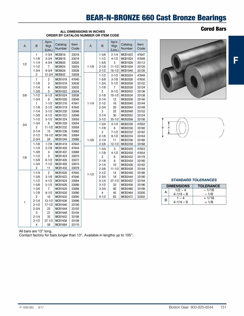
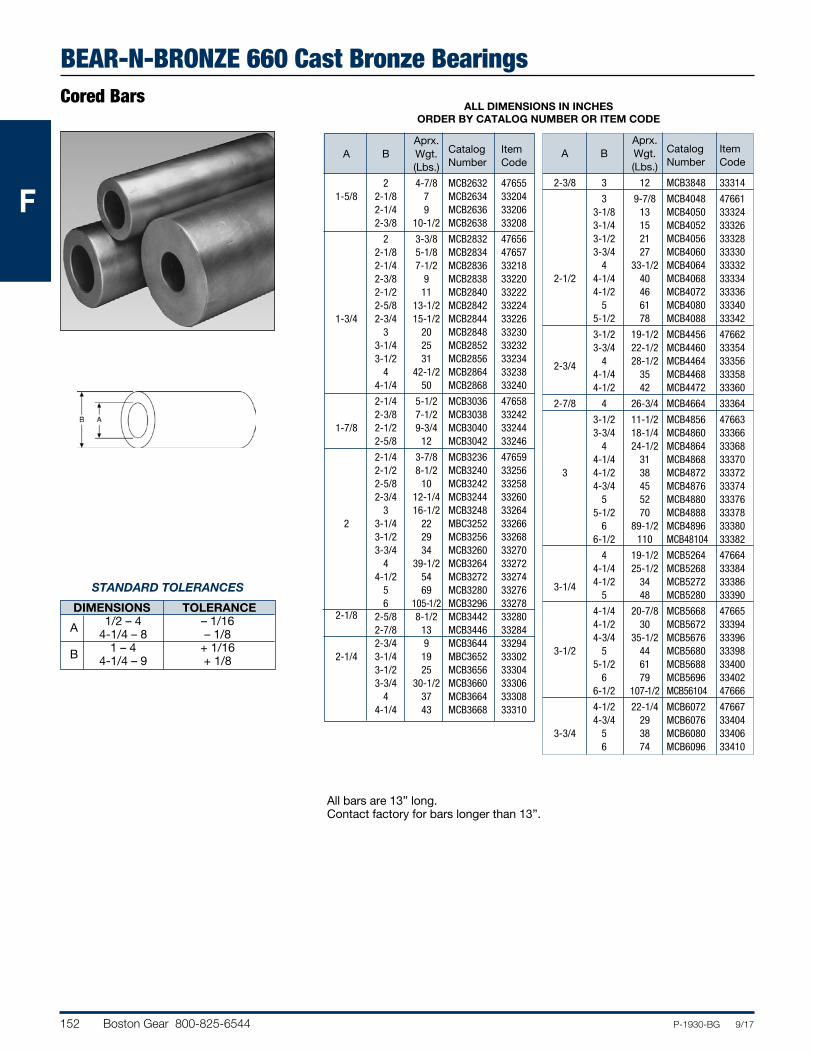
BEAR-N-BRONZE 660 Cast Bronze BearingsCored Bars
STANDARD TOLERANCES
DIMENSIONS TOLERANCE 1/2 – 4 – 1/16 A 4-1/4 – 8 – 1/8 1 – 4 + 1/16 B 4-1/4 – 9 + 1/8
ALL DIMENSIONS IN INCHES ORDER BY CATALOG NUMBER OR ITEM CODE
Aprx. A B Wgt. Catalog Item (Lbs.) Number Code
1 2-3/4 MCB816 33016 1-1/8 3-3/4 MCB818 33018 1/2 1-1/4 4-3/4 MCB820 33020 1-1/2 7 MCB824 33024 1-3/4 9-3/4 MCB828 33026 2 12-3/4 MCB832 33028
1 2 MCB1016 47640 1-1/8 3 MCB1018 33030 1-1/4 4 MCB1020 33032 1-3/8 5 MCB1022 33034 5/8 1-1/2 6-1/2 MCB1024 33036 1-3/4 9 MCB1028 33040 1 1-1/2 MCB1216 47641 1-1/8 2-1/2 MCB1218 47642 1-1/4 3-1/2 MCB1220 33046 1-3/8 4-1/2 MCB1222 33048 1-1/2 5-1/2 MCB1224 33050 3/4 1-3/4 8 MCB1228 33054 2 11-1/2 MCB1232 33058 2-1/4 15 MCB1236 33062 2-1/2 19-1/2 MCB1240 33064 2-3/4 24 MCB1244 33066
1-1/8 1-7/8 MCB1418 47643 1-1/4 2-7/8 MCB1420 47644 1-3/8 4 MCB1422 33068 7/8 1-1/2 5 MCB1424 33070 1-5/8 6-1/2 MCB1426 33072 1-3/4 7-1/2 MCB1428 33074 2 11 MCB1432 33078
1-1/4 2 MCB1620 47645 1-3/8 3-1/8 MCB1622 47646 1-1/2 4-1/2 MCB1624 33084 1-5/8 5-1/2 MCB1626 33086 1-3/4 7 MCB1628 33088 1-7/8 8-1/2 MCB1630 33090 2 10 MCB1632 33092 1 2-1/4 13-1/2 MCB1636 33096 2-1/2 17-1/2 MCB1640 33100 2-3/4 22 MCB1644 33102 3 27 MCB1648 33104 2-1/4 32 MCB1652 33106 3-1/2 37-1/2 MCB1656 33108 4 50 MCB1664 33110
Aprx. A B Wgt. Catalog Item (Lbs.) Number Code
1-3/8 2-1/4 MCB1822 47647 1-1/2 4-1/2 MCB1824 47648 1-5/8 5 MCB1826 33112 1-1/8 2-1/8 11-1/2 MCB1834 33120 2-1/2 16-1/2 MCB1840 33126
1-1/2 2-1/2 MCB2024 47649 1-5/8 3-7/8 MCB2026 47650 1-3/4 5-1/2 MCB2028 33132 1-7/8 7 MCB2030 33134 2 8-1/2 MCB2032 33136 2-1/8 10-1/2 MCB2034 33138 2-1/4 12 MCB2036 33140 1-1/4 2-1/2 16 MCB2040 33144 2-3/4 20 MCB2044 33148 3 25 MCB2048 33152 3-1/4 30 MCB2052 33154 3-1/2 35-1/2 MCB2056 33156
1-3/4 4-1/4 MCB2228 47652 1-7/8 6 MCB2230 33160 2 7-1/2 MCB2232 33162 2-1/8 9-1/2 MCB2234 33164 1-3/8 2-1/4 11 MCB2236 33166 2-3/8 12-1/2 MCB2238 33168
1-3/4 3 MCB2428 47653 1-7/8 4-1/2 MCB2430 47654 2 6 MCB2432 33178 2-1/8 8 MCB2434 33180 2-1/4 10 MCB2436 33182 2-3/8 11-1/2 MCB2438 33184 1-1/2 2-1/2 14 MCB2440 33186 2-3/4 18 MCB2444 33190 3-1/4 27-1/2 MCB2452 33194 3-1/2 33 MCB2456 33196 3-3/4 40 MCB2460 33198 4 45 MCB2464 33200 4-1/2 62 MCB2472 33202
All bars are 13” long.Contact factory for bars longer than 13”. Available in lengths up to 105”.
152 Boston Gear 800-825-6544 P-1930-BG 9/17
FFF
BEAR-N-BRONZE 660 Cast Bronze BearingsCored Bars
ALL DIMENSIONS IN INCHES ORDER BY CATALOG NUMBER OR ITEM CODE
Aprx. A B Wgt. Catalog Item (Lbs.) Number Code
2 4-7/8 MCB2632 47655 1-5/8 2-1/8 7 MCB2634 33204 2-1/4 9 MCB2636 33206 2-3/8 10-1/2 MCB2638 33208
2 3-3/8 MCB2832 47656 2-1/8 5-1/8 MCB2834 47657 2-1/4 7-1/2 MCB2836 33218 2-3/8 9 MCB2838 33220 2-1/2 11 MCB2840 33222 2-5/8 13-1/2 MCB2842 33224 1-3/4 2-3/4 15-1/2 MCB2844 33226 3 20 MCB2848 33230 3-1/4 25 MCB2852 33232 3-1/2 31 MCB2856 33234 4 42-1/2 MCB2864 33238 4-1/4 50 MCB2868 33240
2-1/4 5-1/2 MCB3036 47658 2-3/8 7-1/2 MCB3038 33242 1-7/8 2-1/2 9-3/4 MCB3040 33244 2-5/8 12 MCB3042 33246
2-1/4 3-7/8 MCB3236 47659 2-1/2 8-1/2 MCB3240 33256 2-5/8 10 MCB3242 33258 2-3/4 12-1/4 MCB3244 33260 3 16-1/2 MCB3248 33264 2 3-1/4 22 MBC3252 33266 3-1/2 29 MCB3256 33268 3-3/4 34 MCB3260 33270 4 39-1/2 MCB3264 33272 4-1/2 54 MCB3272 33274 5 69 MCB3280 33276 6 105-1/2 MCB3296 33278 2-1/8 2-5/8 8-1/2 MCB3442 33280 2-7/8 13 MCB3446 33284 2-3/4 9 MCB3644 33294 2-1/4 3-1/4 19 MBC3652 33302 3-1/2 25 MCB3656 33304 3-3/4 30-1/2 MCB3660 33306 4 37 MCB3664 33308 4-1/4 43 MCB3668 33310
Aprx. A B Wgt. Catalog Item (Lbs.) Number Code
2-3/8 3 12 MCB3848 33314
3 9-7/8 MCB4048 47661 3-1/8 13 MCB4050 33324 3-1/4 15 MCB4052 33326 3-1/2 21 MCB4056 33328 3-3/4 27 MCB4060 33330 4 33-1/2 MCB4064 33332 2-1/2 4-1/4 40 MCB4068 33334 4-1/2 46 MCB4072 33336 5 61 MCB4080 33340 5-1/2 78 MCB4088 33342
3-1/2 19-1/2 MCB4456 47662 3-3/4 22-1/2 MCB4460 33354 2-3/4 4 28-1/2 MCB4464 33356 4-1/4 35 MCB4468 33358 4-1/2 42 MCB4472 33360
2-7/8 4 26-3/4 MCB4664 33364
3-1/2 11-1/2 MCB4856 47663 3-3/4 18-1/4 MCB4860 33366 4 24-1/2 MCB4864 33368 4-1/4 31 MCB4868 33370 3 4-1/2 38 MCB4872 33372 4-3/4 45 MCB4876 33374 5 52 MCB4880 33376 5-1/2 70 MCB4888 33378 6 89-1/2 MCB4896 33380 6-1/2 110 MCB48104 33382
4 19-1/2 MCB5264 47664 4-1/4 25-1/2 MCB5268 33384 3-1/4 4-1/2 34 MCB5272 33386 5 48 MCB5280 33390
4-1/4 20-7/8 MCB5668 47665 4-1/2 30 MCB5672 33394 4-3/4 35-1/2 MCB5676 33396 3-1/2 5 44 MCB5680 33398 5-1/2 61 MCB5688 33400 6 79 MCB5696 33402 6-1/2 107-1/2 MCB56104 47666
4-1/2 22-1/4 MCB6072 47667 4-3/4 29 MCB6076 33404 3-3/4 5 38 MCB6080 33406 6 74 MCB6096 33410
All bars are 13” long.Contact factory for bars longer than 13”.
STANDARD TOLERANCES
DIMENSIONS TOLERANCE 1/2 – 4 – 1/16 A 4-1/4 – 8 – 1/8 1 – 4 + 1/16 B 4-1/4 – 9 + 1/8
Boston Gear 800-825-6544 153P-1930-BG 9/17
FFF
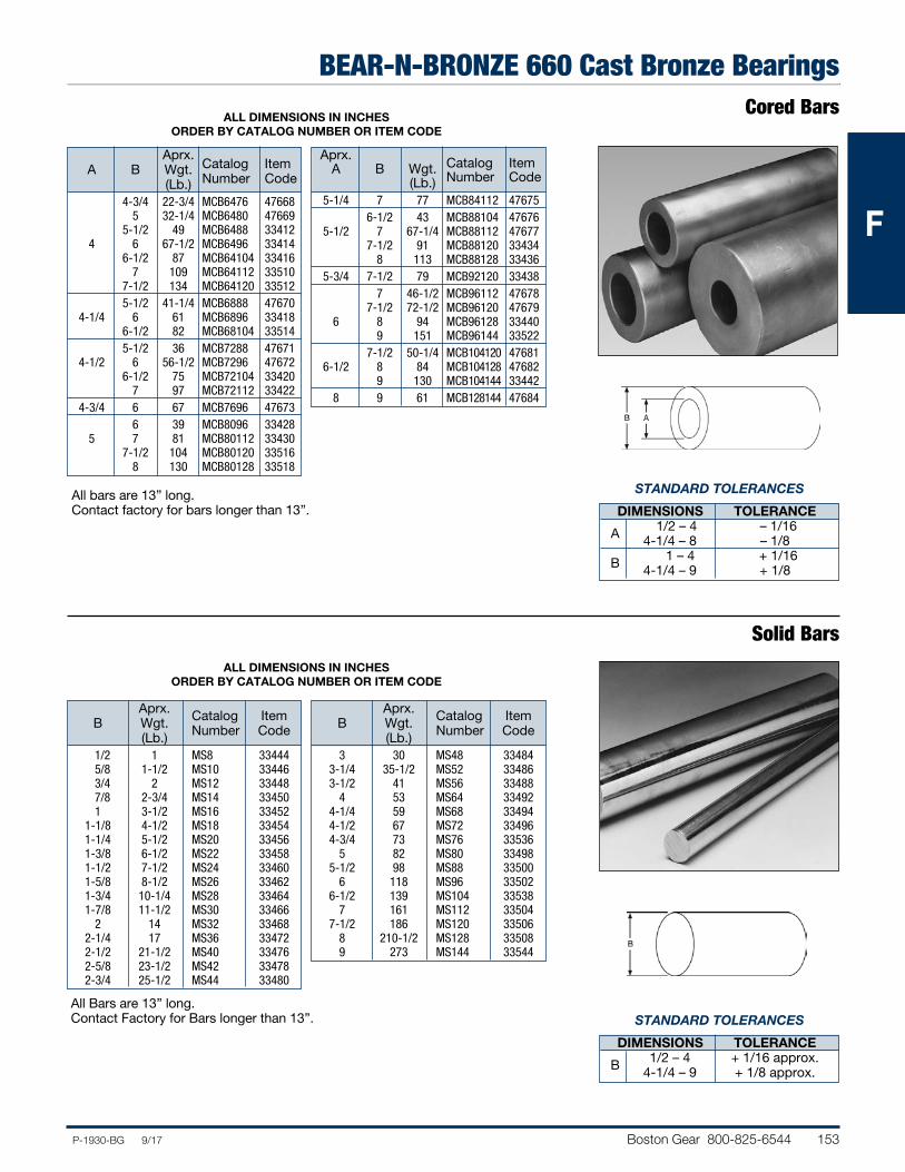
BEAR-N-BRONZE 660 Cast Bronze BearingsCored Bars
ALL DIMENSIONS IN INCHES ORDER BY CATALOG NUMBER OR ITEM CODE
Solid Bars
Aprx. A B Wgt. Catalog Item (Lb.) Number Code
4-3/4 22-3/4 MCB6476 47668 5 32-1/4 MCB6480 47669 5-1/2 49 MCB6488 33412 4 6 67-1/2 MCB6496 33414 6-1/2 87 MCB64104 33416 7 109 MCB64112 33510 7-1/2 134 MCB64120 33512 5-1/2 41-1/4 MCB6888 47670 4-1/4 6 61 MCB6896 33418 6-1/2 82 MCB68104 33514 5-1/2 36 MCB7288 47671 4-1/2 6 56-1/2 MCB7296 47672 6-1/2 75 MCB72104 33420 7 97 MCB72112 33422 4-3/4 6 67 MCB7696 47673 6 39 MCB8096 33428 5 7 81 MCB80112 33430 7-1/2 104 MCB80120 33516 8 130 MCB80128 33518
Aprx. A B Wgt. Catalog Item (Lb.) Number Code
5-1/4 7 77 MCB84112 47675 6-1/2 43 MCB88104 47676 5-1/2 7 67-1/4 MCB88112 47677 7-1/2 91 MCB88120 33434 8 113 MCB88128 33436 5-3/4 7-1/2 79 MCB92120 33438 7 46-1/2 MCB96112 47678 7-1/2 72-1/2 MCB96120 47679 6 8 94 MCB96128 33440 9 151 MCB96144 33522 7-1/2 50-1/4 MCB104120 47681 6-1/2 8 84 MCB104128 47682 9 130 MCB104144 33442 8 9 61 MCB128144 47684
All bars are 13” long.Contact factory for bars longer than 13”.
ALL DIMENSIONS IN INCHES ORDER BY CATALOG NUMBER OR ITEM CODE
Aprx. B Wgt. Catalog Item (Lb.) Number Code
1/2 1 MS8 33444 5/8 1-1/2 MS10 33446 3/4 2 MS12 33448 7/8 2-3/4 MS14 33450 1 3-1/2 MS16 33452 1-1/8 4-1/2 MS18 33454 1-1/4 5-1/2 MS20 33456 1-3/8 6-1/2 MS22 33458 1-1/2 7-1/2 MS24 33460 1-5/8 8-1/2 MS26 33462 1-3/4 10-1/4 MS28 33464 1-7/8 11-1/2 MS30 33466 2 14 MS32 33468 2-1/4 17 MS36 33472 2-1/2 21-1/2 MS40 33476 2-5/8 23-1/2 MS42 33478 2-3/4 25-1/2 MS44 33480
Aprx. B Wgt. Catalog Item (Lb.) Number Code
3 30 MS48 33484 3-1/4 35-1/2 MS52 33486 3-1/2 41 MS56 33488 4 53 MS64 33492 4-1/4 59 MS68 33494 4-1/2 67 MS72 33496 4-3/4 73 MS76 33536 5 82 MS80 33498 5-1/2 98 MS88 33500 6 118 MS96 33502 6-1/2 139 MS104 33538 7 161 MS112 33504 7-1/2 186 MS120 33506 8 210-1/2 MS128 33508 9 273 MS144 33544
All Bars are 13” long.Contact Factory for Bars longer than 13”.
STANDARD TOLERANCES
DIMENSIONS TOLERANCE 1/2 – 4 – 1/16 A 4-1/4 – 8 – 1/8 1 – 4 + 1/16 B 4-1/4 – 9 + 1/8
STANDARD TOLERANCES
DIMENSIONS TOLERANCE 1/2 – 4 + 1/16 approx. B 4-1/4 – 9 + 1/8 approx.
154 Boston Gear 800-825-6544 P-1930-BG 9/17
FFF
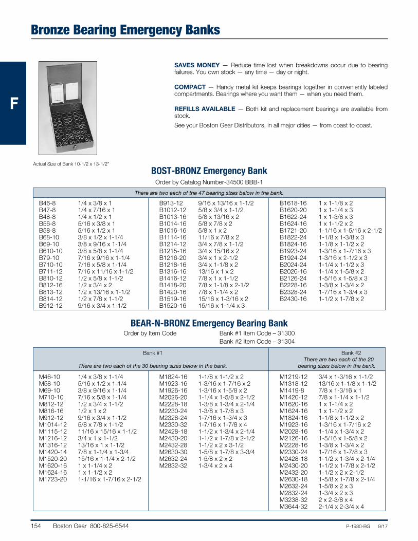
Bronze Bearing Emergency Banks
SAVES MONEY — Reduce time lost when breakdowns occur due to bearing failures. You own stock — any time — day or night.
COMPACT — Handy metal kit keeps bearings together in conveniently labeled compartments. Bearings where you want them — when you need them.
REFILLS AVAILABLE — Both kit and replacement bearings are available from stock.See your Boston Gear Distributors, in all major cities — from coast to coast.
Actual Size of Bank 10-1/2 x 13-1/2”
There are two each of the 47 bearing sizes below in the bank.
BOST-BRONZ Emergency BankOrder by Catalog Number-34500 BBB-1
B46-8 1/4 x 3/8 x 1 B47-8 1/4 x 7/16 x 1 B48-8 1/4 x 1/2 x 1 B56-8 5/16 x 3/8 x 1 B58-8 5/16 x 1/2 x 1 B68-10 3/8 x 1/2 x 1-1/4 B69-10 3/8 x 9/16 x 1-1/4 B610-10 3/8 x 5/8 x 1-1/4 B79-10 7/16 x 9/16 x 1-1/4 B710-10 7/16 x 5/8 x 1-1/4 B711-12 7/16 x 11/16 x 1-1/2 B810-12 1/2 x 5/8 x 1-1/2 B812-16 1/2 x 3/4 x 2 B813-12 1/2 x 13/16 x 1-1/2 B814-12 1/2 x 7/8 x 1-1/2 B912-12 9/16 x 3/4 x 1-1/2
B913-12 9/16 x 13/16 x 1-1/2 B1012-12 5/8 x 3/4 x 1-1/2 B1013-16 5/8 x 13/16 x 2 B1014-16 5/8 x 7/8 x 2 B1016-16 5/8 x 1 x 2 B1114-16 11/16 x 7/8 x 2 B1214-12 3/4 x 7/8 x 1-1/2 B1215-16 3/4 x 15/16 x 2 B1216-20 3/4 x 1 x 2-1/2 B1218-16 3/4 x 1-1/8 x 2 B1316-16 13/16 x 1 x 2 B1416-12 7/8 x 1 x 1-1/2 B1418-20 7/8 x 1-1/8 x 2-1/2 B1420-16 7/8 x 1-1/4 x 2 B1519-16 15/16 x 1-3/16 x 2 B1520-16 15/16 x 1-1/4 x 3
B1618-16 1 x 1-1/8 x 2 B1620-20 1 x 1-1/4 x 3 B1622-24 1 x 1-3/8 x 3 B1624-16 1 x 1-1/2 x 2 B1721-20 1-1/16 x 1-5/16 x 2-1/2 B1822-24 1-1/8 x 1-3/8 x 3 B1824-16 1-1/8 x 1-1/2 x 2 B1923-24 1-3/16 x 1-7/16 x 3 B1924-24 1-3/16 x 1-1/2 x 3 B2024-24 1-1/4 x 1-1/2 x 3 B2026-16 1-1/4 x 1-5/8 x 2 B2126-24 1-5/16 x 1-5/8 x 3 B2228-16 1-3/8 x 1-3/4 x 2 B2328-24 1-7/16 x 1-3/4 x 3 B2430-16 1-1/2 x 1-7/8 x 2
Bank #1 Bank #2 There are two each of the 20 There are two each of the 30 bearing sizes below in the bank. bearing sizes below in the bank.
BEAR-N-BRONZ Emergency Bearing Bank Order by Item Code Bank #1 Item Code – 31300 Bank #2 Item Code – 31304
M46-10 1/4 x 3/8 x 1-1/4 M58-10 5/16 x 1/2 x 1-1/4 M69-10 3/8 x 9/16 x 1-1/4 M710-10 7/16 x 5/8 x 1-1/4 M812-12 1/2 x 3/4 x 1-1/2 M816-16 1/2 x 1 x 2 M912-12 9/16 x 3/4 x 1-1/2 M1014-12 5/8 x 7/8 x 1-1/2 M1115-12 11/16 x 15/16 x 1-1/2 M1216-12 3/4 x 1 x 1-1/2 M1316-12 13/16 x 1 x 1-1/2 M1420-14 7/8 x 1-1/4 x 1-3/4 M1520-20 15/16 x 1-1/4 x 2-1/2 M1620-16 1 x 1-1/4 x 2 M1624-16 1 x 1-1/2 x 2 M1723-20 1-1/16 x 1-7/16 x 2-1/2
M1824-16 1-1/8 x 1-1/2 x 2 M1923-16 1-3/16 x 1-7/16 x 2 M1926-16 1-3/16 x 1-5/8 x 2 M2026-20 1-1/4 x 1-5/8 x 2-1/2 M2228-18 1-3/8 x 1-3/4 x 2-1/4 M2230-24 1-3/8 x 1-7/8 x 3 M2328-24 1-7/16 x 1-3/4 x 3 M2330-32 1-7/16 x 1-7/8 x 4 M2428-18 1-1/2 x 1-3/4 x 2-1/4 M2430-20 1-1/2 x 1-7/8 x 2-1/2 M2432-28 1-1/2 x 2 x 3-1/2 M2630-30 1-5/8 x 1-7/8 x 3-3/4 M2632-24 1-5/8 x 2 x 2 M2832-32 1-3/4 x 2 x 4
M1219-12 3/4 x 1-3/16 x 1-1/2 M1318-12 13/16 x 1-1/8 x 1-1/2 M1419-8 7/8 x 1-3/16 x 1 M1420-12 7/8 x 1-1/4 x 1-1/2 M1620-16 1 x 1-1/4 x 2 M1624-16 1 x 1-1/2 x 2 M1824-16 1-1/8 x 1-1/2 x 2 M1923-16 1-3/16 x 1-7/16 x 2 M2028-16 1-1/4 x 1-3/4 x 2 M2126-16 1-5/16 x 1-5/8 x 2 M2228-16 1-3/8 x 1-3/4 x 2 M2330-24 1-7/16 x 1-7/8 x 3 M2428-18 1-1/2 x 1-3/4 x 2-1/4 M2430-20 1-1/2 x 1-7/8 x 2-1/2 M2432-20 1-1/2 x 2 x 2-1/2 M2630-18 1-5/8 x 1-7/8 x 2-1/4 M2632-24 1-5/8 x 2 x 3 M2832-24 1-3/4 x 2 x 3 M3238-32 2 x 2-3/8 x 4 M3644-32 2-1/4 x 2-3/4 x 4
Boston Gear 800-825-6544 155P-1930-BG 9/17
FFF
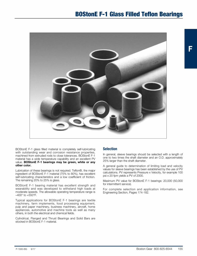
BOStonE F-1 Glass Filled Teflon Bearings
BOStonE F-1 glass filled material is completely self-lubricating with outstanding wear and corrosion resistance properties, machined from extruded rods to close tolerances. BOStonE F-1 material has a wide temperature capability and an excellent PV value. BOStonE F-1 bearings may be green, white or any other color.Lubrication of these bearings is not required. Teflon®, the major ingredient of BOStonE F-1 material (75% to 80%), has excellent self-lubricating characteristics and a low coefficient of friction. The remaining 20% to 25% is glass.BOStonE F-1 bearing material has excellent strength and wearability and was developed to withstand high loads at moderate speeds. The allowable operating temperature range is –400° to +550°F.Typical applications for BOStonE F-1 bearings are textile machinery, farm implements, food processing equipment, pulp and paper machinery, business machinery, aircraft, home appliances, automotive and machine tools as well as many others, in both the electrical and chemical fields.Cylindrical, Flanged and Thrust Bearings and Solid Bars are stocked in BOStonE F-1 material.
SelectionIn general, sleeve bearings should be selected with a length of one to two times the shaft diameter and an O.D. approximately 25% larger than the shaft diameter.A general guide to determination of limiting load and velocity values for sleeve bearings has been established by the use of PV calculations. PV represents Pressure x Velocity, for example 100 psi x 20 fpm yields a PV of 2000.Maximum PV value for BOStonE F-1 bearings: 20,000 (50,000 for intermittent service).For complete selection and application information, see Engineering Section, Pages 174-182.
156 Boston Gear 800-825-6544 P-1930-BG 9/17
FFF
ALL DIMENSIONS IN INCHES ORDER BY CATALOG NUMBER OR ITEM CODE
ALL DIMENSIONS IN INCHES ORDER BY CATALOG NUMBER OR ITEM CODE
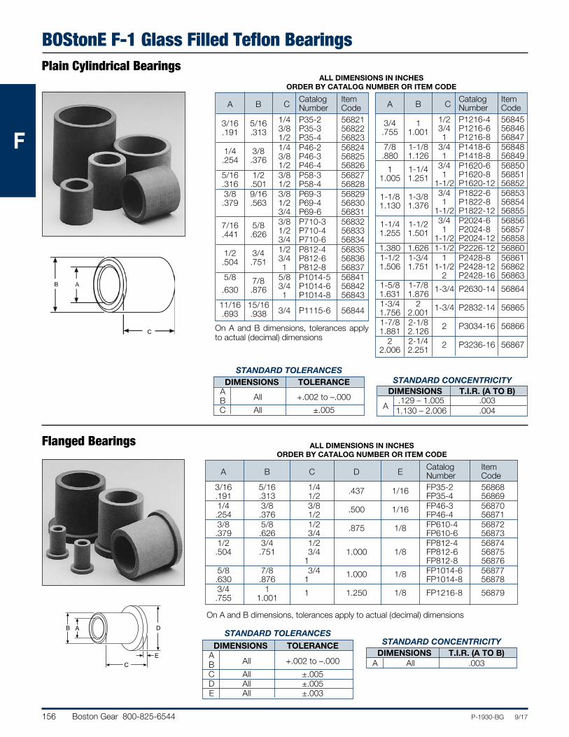
BOStonE F-1 Glass Filled Teflon BearingsPlain Cylindrical Bearings
Catalog Item A B C Number Code 3/16 5/16 1/4 P35-2 56821 .191 .313 3/8 P35-3 56822 1/2 P35-4 56823 1/4 3/8 1/4 P46-2 56824 .254 .376 3/8 P46-3 56825 1/2 P46-4 56826 5/16 1/2 3/8 P58-3 56827 .316 .501 1/2 P58-4 56828 3/8 9/16 3/8 P69-3 56829 .379 .563 1/2 P69-4 56830 3/4 P69-6 56831 7/16 5/8 3/8 P710-3 56832 .441 .626 1/2 P710-4 56833 3/4 P710-6 56834 1/2 3/4 1/2 P812-4 56835 .504 .751 3/4 P812-6 56836 1 P812-8 56837 5/8 7/8 5/8 P1014-5 56841 .630 .876 3/4 P1014-6 56842 1 P1014-8 56843 11/16 15/16 3/4 P1115-6 56844 .693 .938
Catalog Item A B C Number Code 3/4 1 1/2 P1216-4 56845 .755 1.001 3/4 P1216-6 56846 1 P1216-8 56847 7/8 1-1/8 3/4 P1418-6 56848 .880 1.126 1 P1418-8 56849 1 1-1/4 3/4 P1620-6 56850 1.005 1.251 1 P1620-8 56851 1-1/2 P1620-12 56852 1-1/8 1-3/8 3/4 P1822-6 56853 1.130 1.376 1 P1822-8 56854 1-1/2 P1822-12 56855 1-1/4 1-1/2 3/4 P2024-6 56856 1.255 1.501 1 P2024-8 56857 1-1/2 P2024-12 56858 1.380 1.626 1-1/2 P2226-12 56860 1-1/2 1-3/4 1 P2428-8 56861 1.506 1.751 1-1/2 P2428-12 56862 2 P2428-16 56863 1-5/8 1-7/8 1-3/4 P2630-14 56864 1.631 1.876 1-3/4 2 1-3/4 P2832-14 56865 1.756 2.001 1-7/8 2-1/8 2 P3034-16 56866 1.881 2.126 2 2-1/4 2 P3236-16 56867 2.006 2.251
On A and B dimensions, tolerances apply to actual (decimal) dimensions
On A and B dimensions, tolerances apply to actual (decimal) dimensions
Flanged Bearings
B A
C
D
E
Catalog Item A B C D E Number Code 3/16 5/16 1/4 .437 1/16 FP35-2 56868 .191 .313 1/2 FP35-4 56869 1/4 3/8 3/8 .500 1/16 FP46-3 56870 .254 .376 1/2 FP46-4 56871 3/8 5/8 1/2 .875 1/8 FP610-4 56872 .379 .626 3/4 FP610-6 56873 1/2 3/4 1/2 FP812-4 56874 .504 .751 3/4 1.000 1/8 FP812-6 56875 1 FP812-8 56876 5/8 7/8 3/4 1.000 1/8 FP1014-6 56877 .630 .876 1 FP1014-8 56878 3/4 1 1 1.250 1/8 FP1216-8 56879 .755 1.001
STANDARD CONCENTRICITY DIMENSIONS T.I.R. (A TO B) A .129 – 1.005 .003 1.130 – 2.006 .004
STANDARD TOLERANCES DIMENSIONS TOLERANCE A B All +.002 to –.000 C All ±.005
STANDARD TOLERANCES DIMENSIONS TOLERANCE A B All +.002 to –.000 C All ±.005 D All ±.005 E All ±.003
STANDARD CONCENTRICITY DIMENSIONS T.I.R. (A TO B) A All .003
Boston Gear 800-825-6544 157P-1930-BG 9/17
FFF
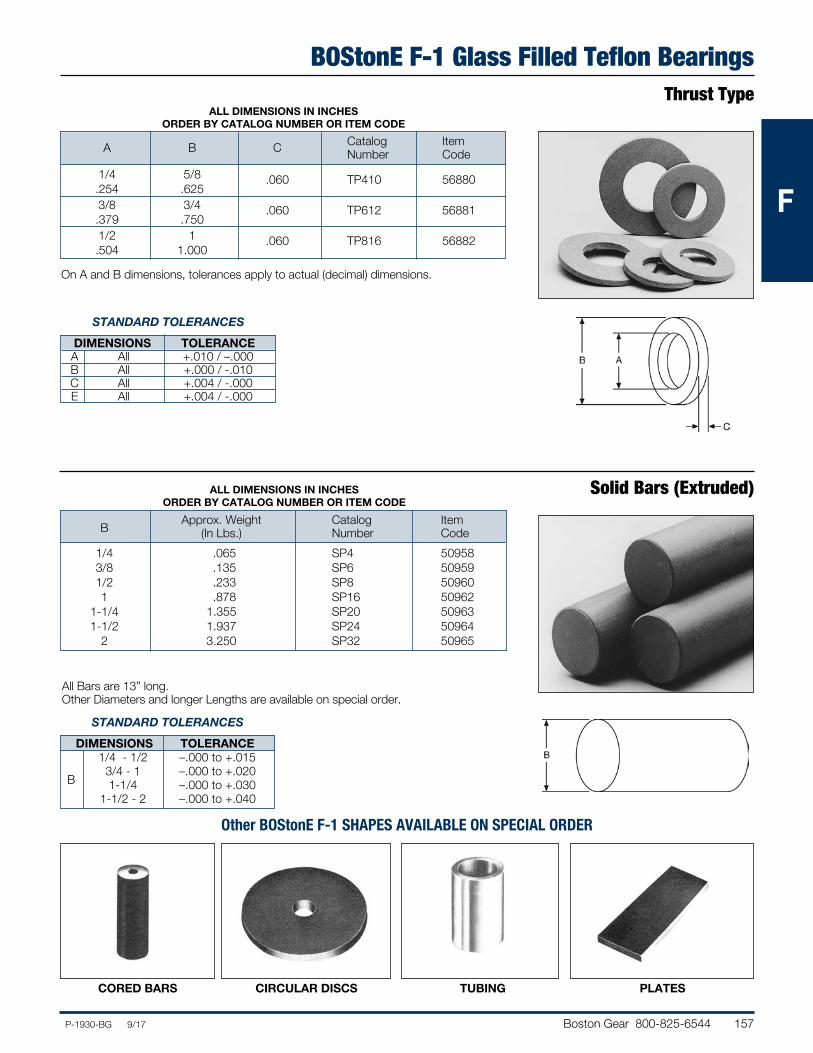
BOStonE F-1 Glass Filled Teflon BearingsThrust Type
ALL DIMENSIONS IN INCHES ORDER BY CATALOG NUMBER OR ITEM CODE
Catalog Item A B C Number Code 1/4 5/8 .060 TP410 56880 .254 .625 3/8 3/4 .060 TP612 56881 .379 .750 1/2 1 .060 TP816 56882 .504 1.000
On A and B dimensions, tolerances apply to actual (decimal) dimensions.
Solid Bars (Extruded)ALL DIMENSIONS IN INCHES ORDER BY CATALOG NUMBER OR ITEM CODE
Approx. Weight Catalog Item B (In Lbs.) Number Code 1/4 .065 SP4 50958 3/8 .135 SP6 50959 1/2 .233 SP8 50960 1 .878 SP16 50962 1-1/4 1.355 SP20 50963 1-1/2 1.937 SP24 50964 2 3.250 SP32 50965
All Bars are 13” long.Other Diameters and longer Lengths are available on special order.
Other BOStonE F-1 SHAPES AVAILABLE ON SPECIAL ORDER
CORED BARS CIRCULAR DISCS TUBING PLATES
STANDARD TOLERANCES
DIMENSIONS TOLERANCE A All +.010 / –.000 B All +.000 / -.010 C All +.004 / -.000 E All +.004 / -.000
STANDARD TOLERANCES
DIMENSIONS TOLERANCE 1/4 - 1/2 –.000 to +.015 3/4 - 1 –.000 to +.020 B 1-1/4 –.000 to +.030 1-1/2 - 2 –.000 to +.040
158 Boston Gear 800-825-6544 P-1930-BG 9/17
FFF
RULON® 641 Bearings
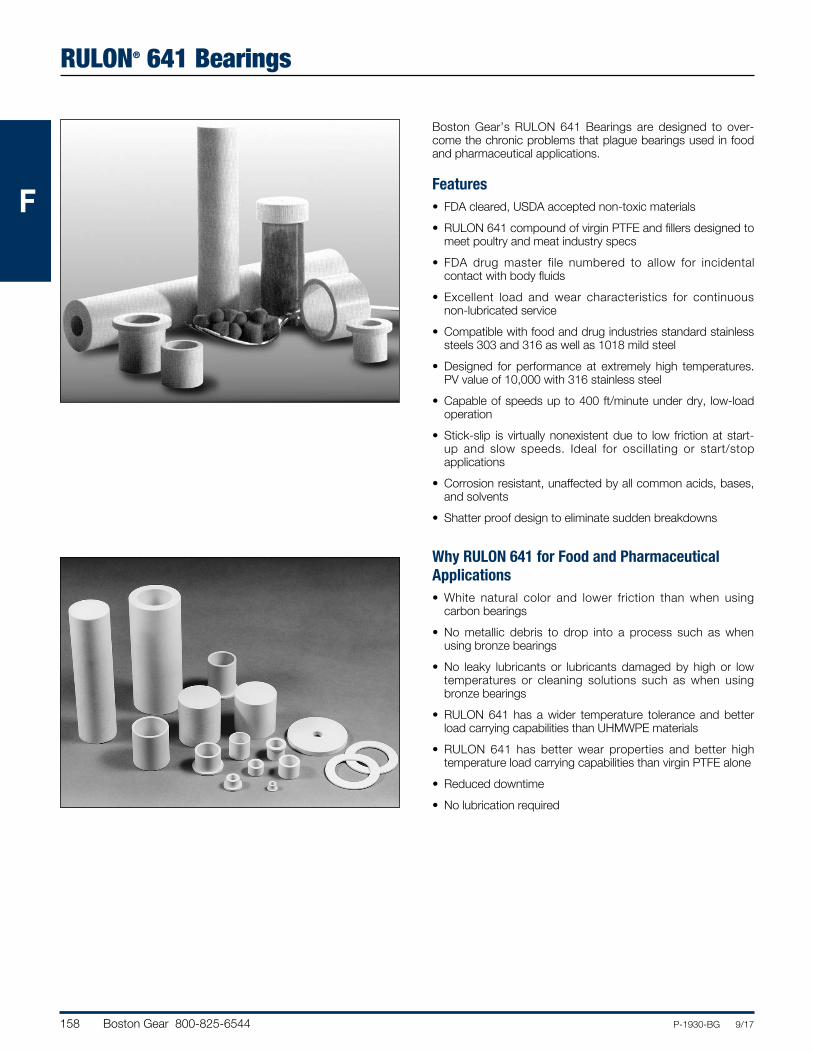
Boston Gear’s RULON 641 Bearings are designed to over-come the chronic problems that plague bearings used in food and pharmaceutical applications.
Features• FDA cleared, USDA accepted non-toxic materials• RULON 641 compound of virgin PTFE and fillers designed to
meet poultry and meat industry specs• FDA drug master file numbered to allow for incidental
contact with body fluids• Excellent load and wear characteristics for continuous
non-lubricated service• Compatible with food and drug industries standard stainless
steels 303 and 316 as well as 1018 mild steel• Designed for performance at extremely high temperatures.
PV value of 10,000 with 316 stainless steel• Capable of speeds up to 400 ft/minute under dry, low-load
operation• Stick-slip is virtually nonexistent due to low friction at start-
up and slow speeds. Ideal for oscillating or start/stop applications
• Corrosion resistant, unaffected by all common acids, bases, and solvents
• Shatter proof design to eliminate sudden breakdowns
Why RULON 641 for Food and Pharmaceutical Applications• White natural color and lower friction than when using
carbon bearings• No metallic debris to drop into a process such as when
using bronze bearings• No leaky lubricants or lubricants damaged by high or low
temperatures or cleaning solutions such as when using bronze bearings
• RULON 641 has a wider temperature tolerance and better load carrying capabilities than UHMWPE materials
• RULON 641 has better wear properties and better high temperature load carrying capabilities than virgin PTFE alone
• Reduced downtime• No lubrication required
Boston Gear 800-825-6544 159P-1930-BG 9/17
FFF
RULON 641 Bearings
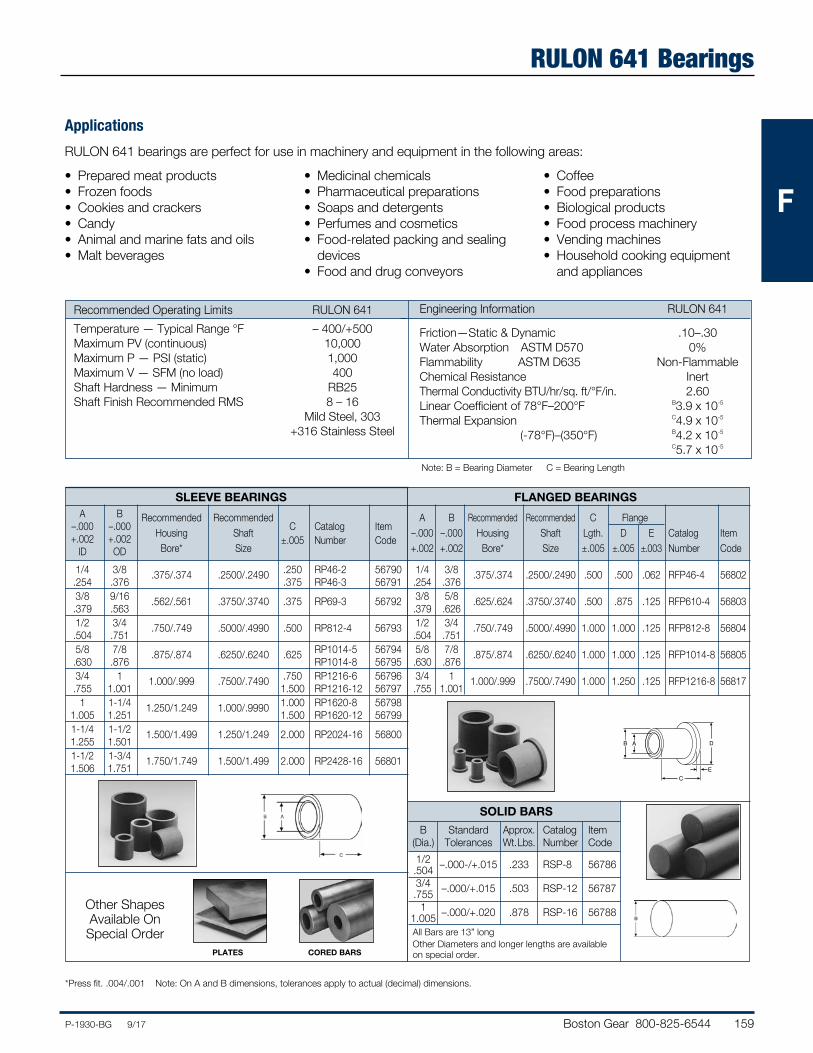
Recommended Operating Limits RULON 641 Temperature — Typical Range °F – 400/+500 Maximum PV (continuous) 10,000 Maximum P — PSI (static) 1,000 Maximum V — SFM (no load) 400 Shaft Hardness — Minimum RB25 Shaft Finish Recommended RMS 8 – 16 Mild Steel, 303 +316 Stainless Steel
Engineering Information RULON 641
Friction—Static & Dynamic .10–.30Water Absorption ASTM D570 0%Flammability ASTM D635 Non-FlammableChemical Resistance InertThermal Conductivity BTU/hr/sq. ft/°F/in. 2.60Linear Coefficient of 78°F–200°F B3.9 x 10-5
Thermal Expansion C4.9 x 10-5
(-78°F)–(350°F) B4.2 x 10-5
C5.7 x 10-5
Applications
RULON 641 bearings are perfect for use in machinery and equipment in the following areas:
• Prepared meat products• Frozen foods• Cookies and crackers• Candy• Animal and marine fats and oils• Malt beverages
• Medicinal chemicals• Pharmaceutical preparations• Soaps and detergents• Perfumes and cosmetics• Food-related packing and sealing
devices• Food and drug conveyors
• Coffee• Food preparations• Biological products• Food process machinery• Vending machines• Household cooking equipment
and appliances
Note: B = Bearing Diameter C = Bearing Length
SLEEVE BEARINGS FLANGED BEARINGS A B Recommended Recommended –.000 –.000 Housing Shaft C Catalog Item +.002 +.002
Bore* Size ±.005 Number Code
ID OD 1/4 3/8 .375/.374 .2500/.2490 .250 RP46-2 56790 .254 .376 .375 RP46-3 56791 3/8 9/16 .562/.561 .3750/.3740 .375 RP69-3 56792 .379 .563 1/2 3/4 .750/.749 .5000/.4990 .500 RP812-4 56793 .504 .751 5/8 7/8 .875/.874 .6250/.6240 .625 RP1014-5 56794 .630 .876 RP1014-8 56795 3/4 1 1.000/.999 .7500/.7490 .750 RP1216-6 56796 .755 1.001 1.500 RP1216-12 56797 1 1-1/4 1.250/1.249 1.000/.9990 1.000 RP1620-8 56798 1.005 1.251 1.500 RP1620-12 56799 1-1/4 1-1/2 1.500/1.499 1.250/1.249 2.000 RP2024-16 56800 1.255 1.501 1-1/2 1-3/4 1.750/1.749 1.500/1.499 2.000 RP2428-16 56801 1.506 1.751
Other Shapes Available On Special Order
A B Recommended Recommended C Flange –.000 –.000 Housing Shaft Lgth. D E Catalog Item +.002 +.002 Bore* Size ±.005 ±.005 ±.003
Number Code
1/4 3/8 .375/.374 .2500/.2490 .500 .500 .062 RFP46-4 56802 .254 .376 3/8 5/8 .625/.624 .3750/.3740 .500 .875 .125 RFP610-4 56803 .379 .626 1/2 3/4 .750/.749 .5000/.4990 1.000 1.000 .125 RFP812-8 56804 .504 .751 5/8 7/8 .875/.874 .6250/.6240 1.000 1.000 .125 RFP1014-8 56805 .630 .876 3/4 1 1.000/.999 .7500/.7490 1.000 1.250 .125 RFP1216-8 56817 .755 1.001
B A
C
D
E
SOLID BARS
B Standard Approx. Catalog Item (Dia.) Tolerances Wt. Lbs. Number Code 1/2 –.000-/+.015 .233 RSP-8 56786 .504 3/4 –.000/+.015 .503 RSP-12 56787 .755 1 –.000/+.020 .878 RSP-16 56788 1.005All Bars are 13” longOther Diameters and longer lengths are available on special order.
*Press fit. .004/.001 Note: On A and B dimensions, tolerances apply to actual (decimal) dimensions.
PLATES CORED BARS
160 Boston Gear 800-825-6544 P-1930-BG 9/17
FFF
BOStonE Molded Plastic Bearings
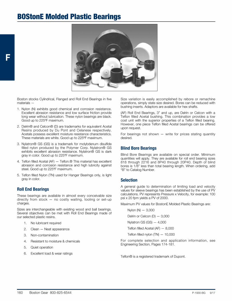
Boston stocks Cylindrical, Flanged and Roll End Bearings in five materials —1. Nylon (N) exhibits good chemical and corrosion resistance.
Excellent abrasion resistance and low surface friction provide long wear without lubrication. These nylon bearings are black. Good up to 225ºF maximum.
2. Delrin® and Celcon® (D) are trademarks for equivalent Acetal Resins produced by Du Pont and Celanese respectively. Acetals possess excellent moisture resistance characteristics. These materials are white. Good up to 225ºF maximum.
3. Nylatron® GS (GS) is a trademark for molybdenum disulfide filled nylon produced by the Polymer Corp. Nylatron® GS exhibits excellent abrasion resistance. Nylatron® GS is dark gray in color. Good up to 225ºF maximum.
4. Teflon filled Acetal (AF) — Teflon.® This material has excellent abrasion and corrosion resistance and high lubricity against steel. Good up to 225ºF maximum.
5. Teflon filled Nylon (TN) used for Hanger Bearings only, is light gray in color.
Roll End BearingsThese bearings are available in almost every conceivable size directly from stock — no costly waiting, tooling or set-up charges. Sizes are interchangeable with existing wood and ball bearings. Several objectives can be met with Roll End Bearings made of our selected plastic resins. 1. No lubricant required 2. Clean — Neat appearance 3. Non-contamination 4. Resistant to moisture & chemicals 5. Quiet operation 6. Excellent load & wear ratings
Size variation is easily accomplished by rebore or remachine operations, simply state size desired. Bores can be reduced with bushing inserts. Adaptors are available for hex shafts.(AF) Roll End Bearings, 3” and up, are Delrin or Celcon with a Teflon filled Acetal bushing. This combination provides a low cost unit with the superior properties of a Teflon filled bearing. However, one piece Teflon filled Acetal bearings can be offered upon request.For bearings not shown — write for prices stating quantity desired.
Blind Bore BearingsBlind Bore Bearings are available on special order. Minimum quantities will apply. They are available for roll end bearing sizes 818 through 2216 and 8P40 through 20P40. Depth of blind bores is 1/8” less than total bearing length. When ordering, add “B” to Catalog Number.
SelectionA general guide to determination of limiting load and velocity values for sleeve bearings has been established by the use of PV calculations. PV represents Pressure x Velocity, for example: 100 psi x 20 fpm yields a PV of 2000.Maximum PV values for BostonE Molded Plastic Bearings are: Nylon (N) — 3,000 Delrin or Celcon (D) — 3,000 Nylatron GS (GS) — 4,000 Teflon filled Acetal (AF) — 8,000 Teflon filled nylon (TN) — 10,000For complete selection and application information, see Engineering Section, Pages 174-181.
Teflon® is a registered trademark of Dupont.
Boston Gear 800-825-6544 161P-1930-BG 9/17
FFF
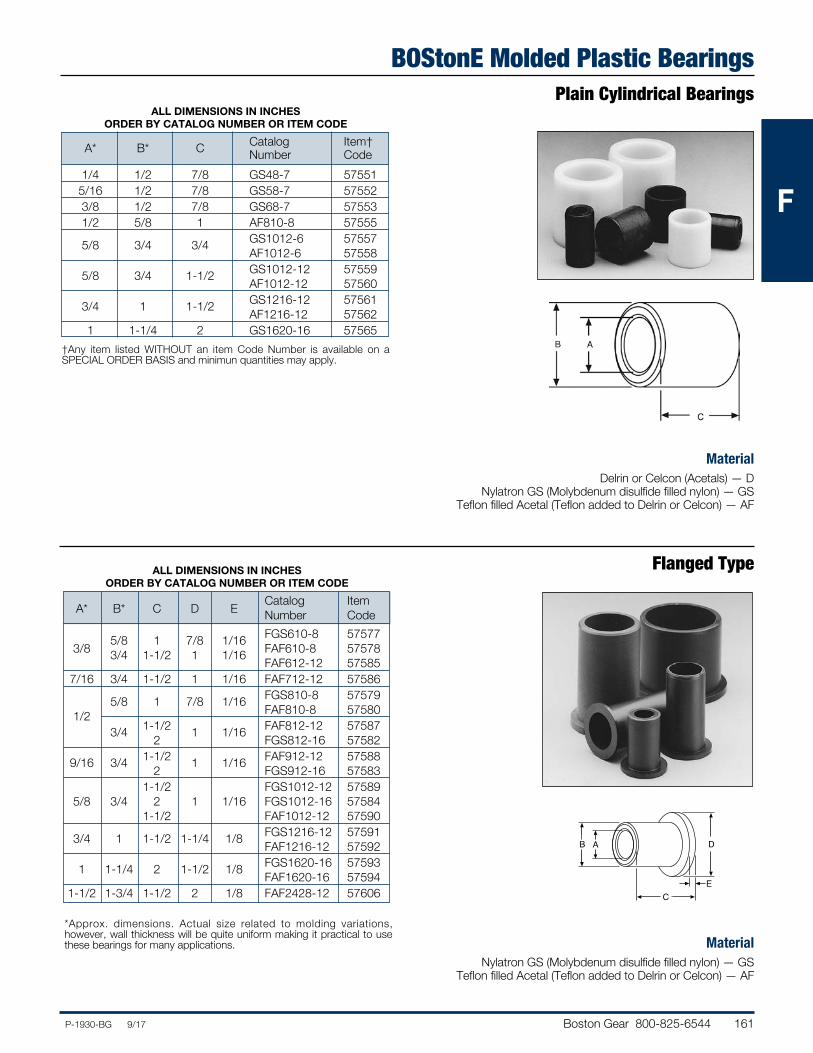
BOStonE Molded Plastic BearingsPlain Cylindrical Bearings
MaterialDelrin or Celcon (Acetals) — D
Nylatron GS (Molybdenum disulfide filled nylon) — GSTeflon filled Acetal (Teflon added to Delrin or Celcon) — AF
ALL DIMENSIONS IN INCHES ORDER BY CATALOG NUMBER OR ITEM CODE
Catalog Item† A* B* C Number Code 1/4 1/2 7/8 GS48-7 57551 5/16 1/2 7/8 GS58-7 57552 3/8 1/2 7/8 GS68-7 57553 1/2 5/8 1 AF810-8 57555 5/8 3/4 3/4 GS1012-6 57557 AF1012-6 57558 5/8 3/4 1-1/2 GS1012-12 57559 AF1012-12 57560 3/4 1 1-1/2 GS1216-12 57561 AF1216-12 57562 1 1-1/4 2 GS1620-16 57565
Flanged Type
MaterialNylatron GS (Molybdenum disulfide filled nylon) — GS
Teflon filled Acetal (Teflon added to Delrin or Celcon) — AF
*Approx. dimensions. Actual size related to molding variations, however, wall thickness will be quite uniform making it practical to use these bearings for many applications.
ALL DIMENSIONS IN INCHES ORDER BY CATALOG NUMBER OR ITEM CODE
Catalog Item A* B* C D E Number Code 5/8 1 7/8 1/16 FGS610-8 57577 3/8 3/4 1-1/2 1 1/16 FAF610-8 57578 FAF612-12 57585 7/16 3/4 1-1/2 1 1/16 FAF712-12 57586 5/8 1 7/8 1/16 FGS810-8 57579 1/2 FAF810-8 57580 3/4 1-1/2 1 1/16 FAF812-12 57587 2 FGS812-16 57582 9/16 3/4 1-1/2 1 1/16 FAF912-12 57588 2 FGS912-16 57583 1-1/2 FGS1012-12 57589 5/8 3/4 2 1 1/16 FGS1012-16 57584 1-1/2 FAF1012-12 57590 3/4 1 1-1/2 1-1/4 1/8 FGS1216-12 57591 FAF1216-12 57592 1 1-1/4 2 1-1/2 1/8 FGS1620-16 57593 FAF1620-16 57594 1-1/2 1-3/4 1-1/2 2 1/8 FAF2428-12 57606
B A
C
D
E
†Any item listed WITHOUT an item Code Number is available on a SPECIAL ORDER BASIS and minimun quantities may apply.
162 Boston Gear 800-825-6544 P-1930-BG 9/17
FFF
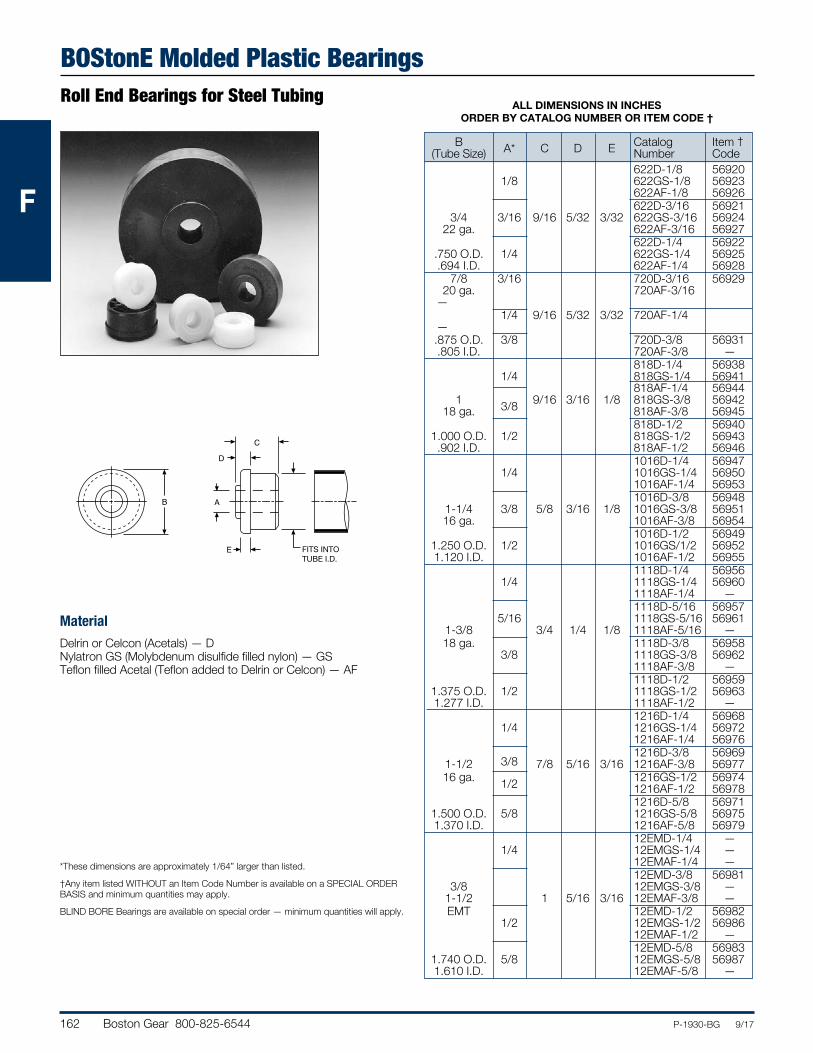
BOStonE Molded Plastic BearingsRoll End Bearings for Steel Tubing
MaterialDelrin or Celcon (Acetals) — DNylatron GS (Molybdenum disulfide filled nylon) — GSTeflon filled Acetal (Teflon added to Delrin or Celcon) — AF
*These dimensions are approximately 1/64” larger than listed.
†Any item listed WITHOUT an Item Code Number is available on a SPECIAL ORDER BASIS and minimum quantities may apply.
BLIND BORE Bearings are available on special order — minimum quantities will apply.
ALL DIMENSIONS IN INCHES ORDER BY CATALOG NUMBER OR ITEM CODE †
B Catalog Item † (Tube Size) A* C D E Number Code 622D-1/8 56920 1/8 622GS-1/8 56923 622AF-1/8 56926 622D-3/16 56921 3/4 3/16 9/16 5/32 3/32 622GS-3/16 56924 22 ga. 622AF-3/16 56927 622D-1/4 56922 .750 O.D. 1/4 622GS-1/4 56925 .694 I.D. 622AF-1/4 56928 7/8 3/16 720D-3/16 56929 20 ga. 720AF-3/16 — 1/4 9/16 5/32 3/32 720AF-1/4 — .875 O.D. 3/8 720D-3/8 56931 .805 I.D. 720AF-3/8 — 818D-1/4 56938 1/4 818GS-1/4 56941 818AF-1/4 56944 1 3/8 9/16 3/16 1/8 818GS-3/8 56942 18 ga. 818AF-3/8 56945 818D-1/2 56940 1.000 O.D. 1/2 818GS-1/2 56943 .902 I.D. 818AF-1/2 56946 1016D-1/4 56947 1/4 1016GS-1/4 56950 1016AF-1/4 56953 1016D-3/8 56948 1-1/4 3/8 5/8 3/16 1/8 1016GS-3/8 56951 16 ga. 1016AF-3/8 56954 1016D-1/2 56949 1.250 O.D. 1/2 1016GS/1/2 56952 1.120 I.D. 1016AF-1/2 56955 1118D-1/4 56956 1/4 1118GS-1/4 56960 1118AF-1/4 — 1118D-5/16 56957 5/16 1118GS-5/16 56961 1-3/8 3/4 1/4 1/8 1118AF-5/16 — 18 ga. 1118D-3/8 56958 3/8 1118GS-3/8 56962 1118AF-3/8 — 1118D-1/2 56959 1.375 O.D. 1/2 1118GS-1/2 56963 1.277 I.D. 1118AF-1/2 — 1216D-1/4 56968 1/4 1216GS-1/4 56972 1216AF-1/4 56976 1216D-3/8 56969 1-1/2 3/8 7/8 5/16 3/16 1216AF-3/8 56977 16 ga. 1/2 1216GS-1/2 56974 1216AF-1/2 56978 1216D-5/8 56971 1.500 O.D. 5/8 1216GS-5/8 56975 1.370 I.D. 1216AF-5/8 56979 12EMD-1/4 — 1/4 12EMGS-1/4 — 12EMAF-1/4 — 12EMD-3/8 56981 3/8 12EMGS-3/8 — 1-1/2 1 5/16 3/16 12EMAF-3/8 — EMT 12EMD-1/2 56982 1/2 12EMGS-1/2 56986 12EMAF-1/2 — 12EMD-5/8 56983 1.740 O.D. 5/8 12EMGS-5/8 56987 1.610 I.D. 12EMAF-5/8 —
B A
E
D
C
PRESSFIT INTO
ROLL SIZE
FITS INTO TUBE I.D.
Boston Gear 800-825-6544 163P-1930-BG 9/17
FFF
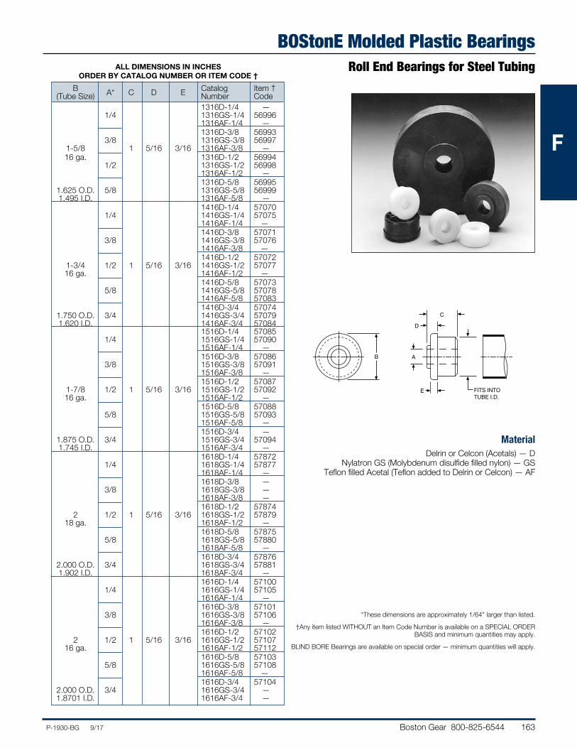
BOStonE Molded Plastic BearingsRoll End Bearings for Steel Tubing
MaterialDelrin or Celcon (Acetals) — D
Nylatron GS (Molybdenum disulfide filled nylon) — GSTeflon filled Acetal (Teflon added to Delrin or Celcon) — AF
*These dimensions are approximately 1/64” larger than listed.
†Any item listed WITHOUT an Item Code Number is available on a SPECIAL ORDER BASIS and minimum quantities may apply.
BLIND BORE Bearings are available on special order — minimum quantities will apply.
ALL DIMENSIONS IN INCHES ORDER BY CATALOG NUMBER OR ITEM CODE †
B Catalog Item † (Tube Size) A* C D E Number Code 1316D-1/4 — 1/4 1316GS-1/4 56996 1316AF-1/4 — 1316D-3/8 56993 3/8 1316GS-3/8 56997 1-5/8 1 5/16 3/16 1316AF-3/8 — 16 ga. 1316D-1/2 56994 1/2 1316GS-1/2 56998 1316AF-1/2 — 1316D-5/8 56995 1.625 O.D. 5/8 1316GS-5/8 56999 1.495 I.D. 1316AF-5/8 — 1416D-1/4 57070 1/4 1416GS-1/4 57075 1416AF-1/4 — 1416D-3/8 57071 3/8 1416GS-3/8 57076 1416AF-3/8 — 1416D-1/2 57072 1-3/4 1/2 1 5/16 3/16 1416GS-1/2 57077 16 ga. 1416AF-1/2 — 1416D-5/8 57073 5/8 1416GS-5/8 57078 1416AF-5/8 57083 1416D-3/4 57074 1.750 O.D. 3/4 1416GS-3/4 57079 1.620 I.D. 1416AF-3/4 57084 1516D-1/4 57085 1/4 1516GS-1/4 57090 1516AF-1/4 — 1516D-3/8 57086 3/8 1516GS-3/8 57091 1516AF-3/8 — 1516D-1/2 57087 1-7/8 1/2 1 5/16 3/16 1516GS-1/2 57092 16 ga. 1516AF-1/2 — 1516D-5/8 57088 5/8 1516GS-5/8 57093 1516AF-5/8 — 1516D-3/4 — 1.875 O.D. 3/4 1516GS-3/4 57094 1.745 I.D. 1516AF-3/4 — 1618D-1/4 57872 1/4 1618GS-1/4 57877 1618AF-1/4 — 1618D-3/8 — 3/8 1618GS-3/8 — 1618AF-3/8 — 1618D-1/2 57874 2 1/2 1 5/16 3/16 1618GS-1/2 57879 18 ga. 1618AF-1/2 — 1618D-5/8 57875 5/8 1618GS-5/8 57880 1618AF-5/8 — 1618D-3/4 57876 2.000 O.D. 3/4 1618GS-3/4 57881 1.902 I.D. 1618AF-3/4 — 1616D-1/4 57100 1/4 1616GS-1/4 57105 1616AF-1/4 — 1616D-3/8 57101 3/8 1616GS-3/8 57106 1616AF-3/8 — 1616D-1/2 57102 2 1/2 1 5/16 3/16 1616GS-1/2 57107 16 ga. 1616AF-1/2 57112 1616D-5/8 57103 5/8 1616GS-5/8 57108 1616AF-5/8 — 1616D-3/4 57104 2.000 O.D. 3/4 1616GS-3/4 — 1.8701 I.D. 1616AF-3/4 —
B A
E
D
C
PRESSFIT INTO
ROLL SIZE
FITS INTO TUBE I.D.
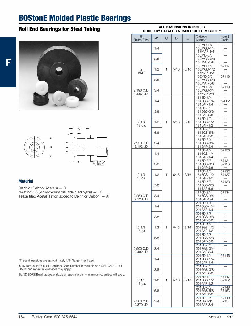
164 Boston Gear 800-825-6544 P-1930-BG 9/17
FFF
BOStonE Molded Plastic BearingsRoll End Bearings for Steel Tubing
MaterialDelrin or Celcon (Acetals) — DNylatron GS (Molybdenum disulfide filled nylon) — GSTeflon filled Acetal (Teflon added to Delrin or Celcon) — AF
*These dimensions are approximately 1/64” larger than listed.
†Any item listed WITHOUT an Item Code Number is available on a SPECIAL ORDER BASIS and minimum quantities may apply.
BLIND BORE Bearings are available on special order — minimum quantities will apply.
ALL DIMENSIONS IN INCHES ORDER BY CATALOG NUMBER OR ITEM CODE †
B Catalog Item † (Tube Size) A* C D E Number Code 16EMD-1/4 — 1/4 16EMGS-1/4 — 16EMAF-1/4 — 16EMD-3/8 — 3/8 16EMGS-3/8 — 16EMAF-3/8 — 16EMD-1/2 57117 2 1/2 1 5/16 3/16 16EMGS-1/2 — EMT 16EMAF-1/2 — 16EMD-5/8 57118 5/8 16EMGS-5/8 — 16EMAF-5/8 — 16EMD-3/4 57119 2.190 O.D. 3/4 16EMGS-3/4 — 2.067 I.D. 16EMAF-3/4 — 1818D-1/4 — 1/4 1818GS-1/4 57862 1818AF-1/4 — 1818D-3/8 — 3/8 1818GS-3/8 — 1818AF-3/8 — 1818D-1/2 — 2-1/4 1/2 1 5/16 3/16 1818GS-1/2 — 18 ga. 1818AF-1/2 — 1818D-5/8 — 5/8 1818GS-5/8 — 1818AF-5/8 — 1818D-3/4 — 2.250 O.D. 3/4 1818GS-3/4 — 2.152 I.D. 1818AF-3/4 — 1816D-1/4 57130 1/4 1816GS-1/4 — 1816AF-1/4 — 1816D-3/8 57131 3/8 1816GS-3/8 57136 1816AF-3/8 — 1816D-1/2 57132 2-1/4 1/2 1 5/16 3/16 1816GS-1/2 57137 16 ga. 1816AF-1/2 — 1816D-5/8 57133 5/8 1816GS-5/8 — 1816AF-5/8 — 1816D-3/4 57134 2.250 O.D. 3/4 1816GS-3/4 — 2.120 I.D. 1816AF-3/4 — 2018D-1/4 — 1/4 2018GS-1/4 — 2018AF-1/4 — 2018D-3/8 — 3/8 2018GS-3/8 — 2018AF-3/8 — 2018D-1/2 — 2-1/2 1/2 1 5/16 3/16 2018GS-1/2 — 18 ga. 2018AF-1/2 — 2018D-5/8 — 5/8 2018GS-5/8 — 2018AF-5/8 — 2018D-3/4 — 2.500 O.D. 3/4 2018GS-3/4 — 2.402 I.D. 2018AF-3/4 — 2016D-1/4 57145 1/4 2016GS-1/4 — 2016AF-1/4 — 2016D-3/8 — 3/8 2016GS-3/8 — 2016AF-3/8 — 2016D-1/2 57147 2-1/2 1/2 1 5/16 3/16 2016GS-1/2 57152 16 ga. 2016AF-1/2 — 2016D-5/8 57148 5/8 2016GS-5/8 57153 2016AF-5/8 — 2016D-3/4 57149 2.500 O.D. 3/4 2016GS-3/4 57154 2.370 I.D. 2016AF-3/4 —
B A
E
D
C
PRESSFIT INTO
ROLL SIZE
FITS INTO TUBE I.D.
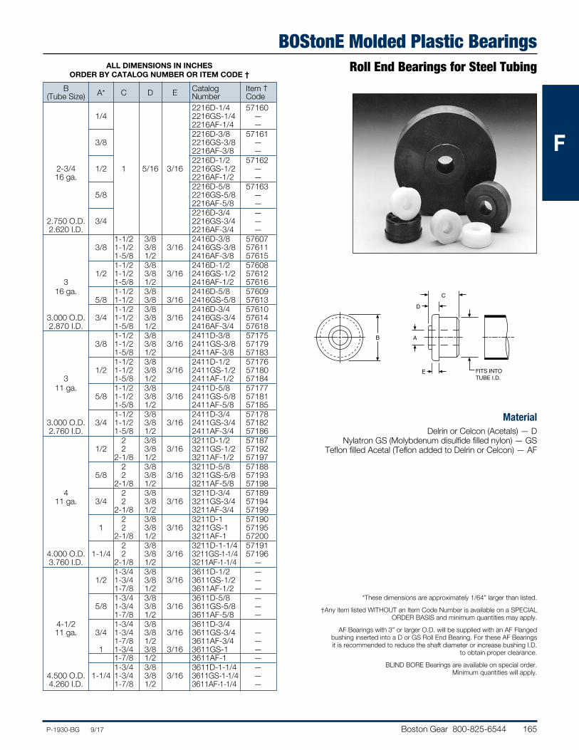
Boston Gear 800-825-6544 165P-1930-BG 9/17
FFF
BOStonE Molded Plastic BearingsRoll End Bearings for Steel Tubing
MaterialDelrin or Celcon (Acetals) — D
Nylatron GS (Molybdenum disulfide filled nylon) — GSTeflon filled Acetal (Teflon added to Delrin or Celcon) — AF
*These dimensions are approximately 1/64” larger than listed.
†Any item listed WITHOUT an Item Code Number is available on a SPECIAL ORDER BASIS and minimum quantities may apply.
AF Bearings with 3” or larger O.D. will be supplied with an AF Flanged bushing inserted into a D or GS Roll End Bearing. For these AF Bearings it is recommended to reduce the shaft diameter or increase bushing I.D.
to obtain proper clearance.
BLIND BORE Bearings are available on special order. Minimum quantities will apply.
ALL DIMENSIONS IN INCHES ORDER BY CATALOG NUMBER OR ITEM CODE †
B Catalog Item † (Tube Size) A* C D E Number Code 2216D-1/4 57160 1/4 2216GS-1/4 — 2216AF-1/4 — 2216D-3/8 57161 3/8 2216GS-3/8 — 2216AF-3/8 — 2216D-1/2 57162 2-3/4 1/2 1 5/16 3/16 2216GS-1/2 — 16 ga. 2216AF-1/2 — 2216D-5/8 57163 5/8 2216GS-5/8 — 2216AF-5/8 — 2216D-3/4 — 2.750 O.D. 3/4 2216GS-3/4 — 2.620 I.D. 2216AF-3/4 — 1-1/2 3/8 2416D-3/8 57607 3/8 1-1/2 3/8 3/16 2416GS-3/8 57611 1-5/8 1/2 2416AF-3/8 57615 1-1/2 3/8 2416D-1/2 57608 1/2 1-1/2 3/8 3/16 2416GS-1/2 57612 3 1-5/8 1/2 2416AF-1/2 57616 16 ga. 1-1/2 3/8 2416D-5/8 57609 5/8 1-1/2 3/8 3/16 2416GS-5/8 57613 1-1/2 3/8 2416D-3/4 57610 3.000 O.D. 3/4 1-1/2 3/8 3/16 2416GS-3/4 57614 2.870 I.D. 1-5/8 1/2 2416AF-3/4 57618 1-1/2 3/8 2411D-3/8 57175 3/8 1-1/2 3/8 3/16 2411GS-3/8 57179 1-5/8 1/2 2411AF-3/8 57183 1-1/2 3/8 2411D-1/2 57176 1/2 1-1/2 3/8 3/16 2411GS-1/2 57180 3 1-5/8 1/2 2411AF-1/2 57184 11 ga. 1-1/2 3/8 2411D-5/8 57177 5/8 1-1/2 3/8 3/16 2411GS-5/8 57181 1-5/8 1/2 2411AF-5/8 57185 1-1/2 3/8 2411D-3/4 57178 3.000 O.D. 3/4 1-1/2 3/8 3/16 2411GS-3/4 57182 2.760 I.D. 1-5/8 1/2 2411AF-3/4 57186 2 3/8 3211D-1/2 57187 1/2 2 3/8 3/16 3211GS-1/2 57192 2-1/8 1/2 3211AF-1/2 57197 2 3/8 3211D-5/8 57188 5/8 2 3/8 3/16 3211GS-5/8 57193 2-1/8 1/2 3211AF-5/8 57198 4 2 3/8 3211D-3/4 57189 11 ga. 3/4 2 3/8 3/16 3211GS-3/4 57194 2-1/8 1/2 3211AF-3/4 57199 2 3/8 3211D-1 57190 1 2 3/8 3/16 3211GS-1 57195 2-1/8 1/2 3211AF-1 57200 2 3/8 3211D-1-1/4 57191 4.000 O.D. 1-1/4 2 3/8 3/16 3211GS-1-1/4 57196 3.760 I.D. 2-1/8 1/2 3211AF-1-1/4 — 1-3/4 3/8 3611D-1/2 — 1/2 1-3/4 3/8 3/16 3611GS-1/2 — 1-7/8 1/2 3611AF-1/2 — 1-3/4 3/8 3611D-5/8 — 5/8 1-3/4 3/8 3/16 3611GS-5/8 — 1-7/8 1/2 3611AF-5/8 — 4-1/2 1-3/4 3/8 3611D-3/4 11 ga. 3/4 1-3/4 3/8 3/16 3611GS-3/4 — 1-7/8 1/2 3611AF-3/4 — 1 1-3/4 3/8 3/16 3611GS-1 — 1-7/8 1/2 3611AF-1 — 1-3/4 3/8 3611D-1-1/4 — 4.500 O.D. 1-1/4 1-3/4 3/8 3/16 3611GS-1-1/4 — 4.260 I.D. 1-7/8 1/2 3611AF-1-1/4 —
B A
E
D
C
PRESSFIT INTO
ROLL SIZE
FITS INTO TUBE I.D.
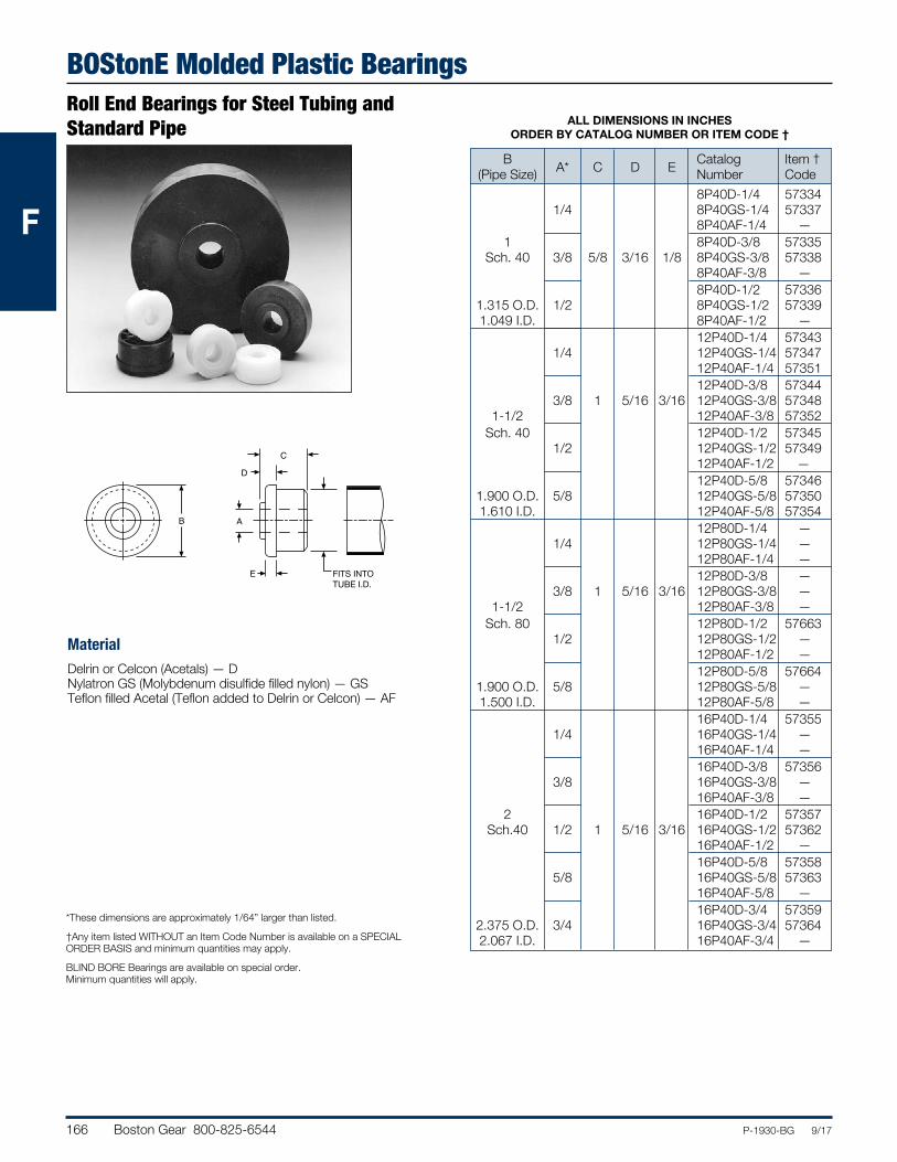
166 Boston Gear 800-825-6544 P-1930-BG 9/17
FFF
BOStonE Molded Plastic BearingsRoll End Bearings for Steel Tubing and Standard Pipe
MaterialDelrin or Celcon (Acetals) — DNylatron GS (Molybdenum disulfide filled nylon) — GSTeflon filled Acetal (Teflon added to Delrin or Celcon) — AF
*These dimensions are approximately 1/64” larger than listed.
†Any item listed WITHOUT an Item Code Number is available on a SPECIAL ORDER BASIS and minimum quantities may apply.
BLIND BORE Bearings are available on special order. Minimum quantities will apply.
ALL DIMENSIONS IN INCHES ORDER BY CATALOG NUMBER OR ITEM CODE †
B Catalog Item † (Pipe Size) A* C D E Number Code 8P40D-1/4 57334 1/4 8P40GS-1/4 57337 8P40AF-1/4 — 1 8P40D-3/8 57335 Sch. 40 3/8 5/8 3/16 1/8 8P40GS-3/8 57338 8P40AF-3/8 — 8P40D-1/2 57336 1.315 O.D. 1/2 8P40GS-1/2 57339 1.049 I.D. 8P40AF-1/2 — 12P40D-1/4 57343 1/4 12P40GS-1/4 57347 12P40AF-1/4 57351 12P40D-3/8 57344 3/8 1 5/16 3/16 12P40GS-3/8 57348 1-1/2 12P40AF-3/8 57352 Sch. 40 12P40D-1/2 57345 1/2 12P40GS-1/2 57349 12P40AF-1/2 — 12P40D-5/8 57346 1.900 O.D. 5/8 12P40GS-5/8 57350 1.610 I.D. 12P40AF-5/8 57354 12P80D-1/4 — 1/4 12P80GS-1/4 — 12P80AF-1/4 — 12P80D-3/8 — 3/8 1 5/16 3/16 12P80GS-3/8 — 1-1/2 12P80AF-3/8 — Sch. 80 12P80D-1/2 57663 1/2 12P80GS-1/2 — 12P80AF-1/2 — 12P80D-5/8 57664 1.900 O.D. 5/8 12P80GS-5/8 — 1.500 I.D. 12P80AF-5/8 — 16P40D-1/4 57355 1/4 16P40GS-1/4 — 16P40AF-1/4 — 16P40D-3/8 57356 3/8 16P40GS-3/8 — 16P40AF-3/8 — 2 16P40D-1/2 57357 Sch.40 1/2 1 5/16 3/16 16P40GS-1/2 57362 16P40AF-1/2 — 16P40D-5/8 57358 5/8 16P40GS-5/8 57363 16P40AF-5/8 — 16P40D-3/4 57359 2.375 O.D. 3/4 16P40GS-3/4 57364 2.067 I.D. 16P40AF-3/4 —
B A
E
D
C
PRESSFIT INTO
ROLL SIZE
FITS INTO TUBE I.D.
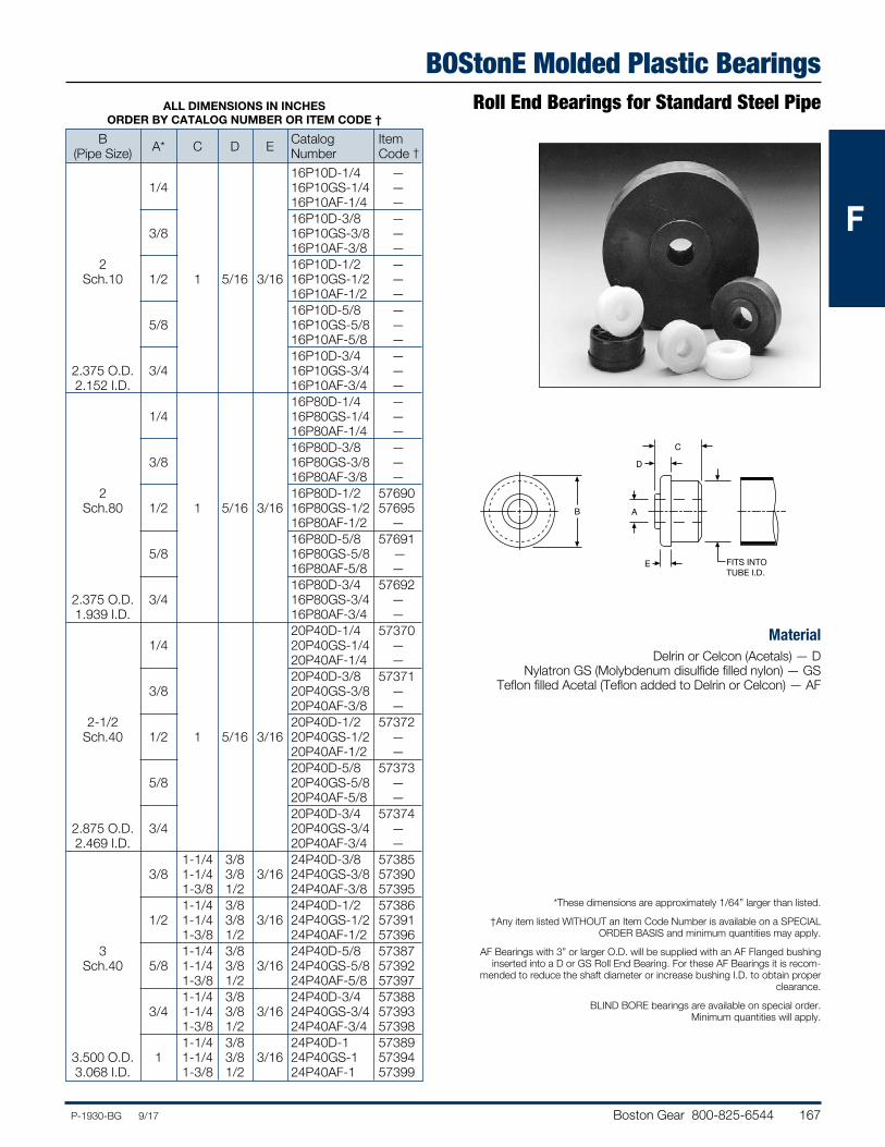
Boston Gear 800-825-6544 167P-1930-BG 9/17
FFF
BOStonE Molded Plastic BearingsRoll End Bearings for Standard Steel Pipe
MaterialDelrin or Celcon (Acetals) — D
Nylatron GS (Molybdenum disulfide filled nylon) — GSTeflon filled Acetal (Teflon added to Delrin or Celcon) — AF
*These dimensions are approximately 1/64” larger than listed.
†Any item listed WITHOUT an Item Code Number is available on a SPECIAL ORDER BASIS and minimum quantities may apply.
AF Bearings with 3” or larger O.D. will be supplied with an AF Flanged bushing inserted into a D or GS Roll End Bearing. For these AF Bearings it is recom-
mended to reduce the shaft diameter or increase bushing I.D. to obtain proper clearance.
BLIND BORE bearings are available on special order. Minimum quantities will apply.
ALL DIMENSIONS IN INCHES ORDER BY CATALOG NUMBER OR ITEM CODE †
B Catalog Item (Pipe Size) A* C D E Number Code † 16P10D-1/4 — 1/4 16P10GS-1/4 — 16P10AF-1/4 — 16P10D-3/8 — 3/8 16P10GS-3/8 — 16P10AF-3/8 — 2 16P10D-1/2 — Sch.10 1/2 1 5/16 3/16 16P10GS-1/2 — 16P10AF-1/2 — 16P10D-5/8 — 5/8 16P10GS-5/8 — 16P10AF-5/8 — 16P10D-3/4 — 2.375 O.D. 3/4 16P10GS-3/4 — 2.152 I.D. 16P10AF-3/4 — 16P80D-1/4 — 1/4 16P80GS-1/4 — 16P80AF-1/4 — 16P80D-3/8 — 3/8 16P80GS-3/8 — 16P80AF-3/8 — 2 16P80D-1/2 57690 Sch.80 1/2 1 5/16 3/16 16P80GS-1/2 57695 16P80AF-1/2 — 16P80D-5/8 57691 5/8 16P80GS-5/8 — 16P80AF-5/8 — 16P80D-3/4 57692 2.375 O.D. 3/4 16P80GS-3/4 — 1.939 I.D. 16P80AF-3/4 — 20P40D-1/4 57370 1/4 20P40GS-1/4 — 20P40AF-1/4 — 20P40D-3/8 57371 3/8 20P40GS-3/8 — 20P40AF-3/8 — 2-1/2 20P40D-1/2 57372 Sch.40 1/2 1 5/16 3/16 20P40GS-1/2 — 20P40AF-1/2 — 20P40D-5/8 57373 5/8 20P40GS-5/8 — 20P40AF-5/8 — 20P40D-3/4 57374 2.875 O.D. 3/4 20P40GS-3/4 — 2.469 I.D. 20P40AF-3/4 — 1-1/4 3/8 24P40D-3/8 57385 3/8 1-1/4 3/8 3/16 24P40GS-3/8 57390 1-3/8 1/2 24P40AF-3/8 57395 1-1/4 3/8 24P40D-1/2 57386 1/2 1-1/4 3/8 3/16 24P40GS-1/2 57391 1-3/8 1/2 24P40AF-1/2 57396 3 1-1/4 3/8 24P40D-5/8 57387 Sch.40 5/8 1-1/4 3/8 3/16 24P40GS-5/8 57392 1-3/8 1/2 24P40AF-5/8 57397 1-1/4 3/8 24P40D-3/4 57388 3/4 1-1/4 3/8 3/16 24P40GS-3/4 57393 1-3/8 1/2 24P40AF-3/4 57398 1-1/4 3/8 24P40D-1 57389 3.500 O.D. 1 1-1/4 3/8 3/16 24P40GS-1 57394 3.068 I.D. 1-3/8 1/2 24P40AF-1 57399
B A
E
D
C
PRESSFIT INTO
ROLL SIZE
FITS INTO TUBE I.D.
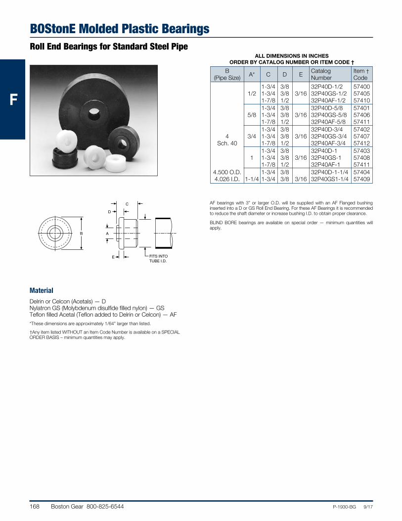
168 Boston Gear 800-825-6544 P-1930-BG 9/17
FFFF
BOStonE Molded Plastic BearingsRoll End Bearings for Standard Steel Pipe
MaterialDelrin or Celcon (Acetals) — DNylatron GS (Molybdenum disulfide filled nylon) — GSTeflon filled Acetal (Teflon added to Delrin or Celcon) — AF*These dimensions are approximately 1/64” larger than listed.
†Any item listed WITHOUT an Item Code Number is available on a SPECIAL ORDER BASIS – minimum quantities may apply.
ALL DIMENSIONS IN INCHES ORDER BY CATALOG NUMBER OR ITEM CODE †
B Catalog Item † (Pipe Size) A* C D E Number Code 1-3/4 3/8 32P40D-1/2 57400 1/2 1-3/4 3/8 3/16 32P40GS-1/2 57405 1-7/8 1/2 32P40AF-1/2 57410 1-3/4 3/8 32P40D-5/8 57401 5/8 1-3/4 3/8 3/16 32P40GS-5/8 57406 1-7/8 1/2 32P40AF-5/8 57411 1-3/4 3/8 32P40D-3/4 57402 4 3/4 1-3/4 3/8 3/16 32P40GS-3/4 57407 Sch. 40 1-7/8 1/2 32P40AF-3/4 57412 1-3/4 3/8 32P40D-1 57403 1 1-3/4 3/8 3/16 32P40GS-1 57408 1-7/8 1/2 32P40AF-1 57411 4.500 O.D. 1-3/4 3/8 32P40D-1-1/4 57404 4.026 I.D. 1-1/4 1-3/4 3/8 3/16 32P40GS1-1/4 57409
AF bearings with 3” or larger O.D. will be supplied with an AF Flanged bushing inserted into a D or GS Roll End Bearing. For these AF Bearings it is recommended to reduce the shaft diameter or increase bushing I.D. to obtain proper clearance.
BLIND BORE bearings are available on special order — minimum quantities will apply.
B A
E
D
C
PRESSFIT INTO
ROLL SIZE
F
FITS INTO TUBE I.D.
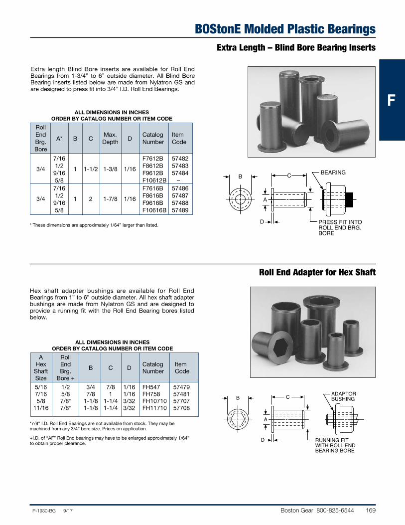
Boston Gear 800-825-6544 169P-1930-BG 9/17
FFFF
BOStonE Molded Plastic BearingsExtra Length – Blind Bore Bearing Inserts
* These dimensions are approximately 1/64” larger than listed.
ALL DIMENSIONS IN INCHES ORDER BY CATALOG NUMBER OR ITEM CODE
Roll End Max. Catalog Item Brg. A* B C Depth D Number Code Bore 7/16 F7612B 57482 3/4 1/2 1 1-1/2 1-3/8 1/16 F8612B 57483 9/16 F9612B 57484 5/8 F10612B – 7/16 F7616B 57486 3/4 1/2 1 2 1-7/8 1/16 F8616B 57487 9/16 F9616B 57488 5/8 F10616B 57489
C
A
B
PRESS FIT INTOROLL END BRG.BORE
BEARING
D
*7/8” I.D. Roll End Bearings are not available from stock. They may be machined from any 3/4” bore size. Prices on application.
+I.D. of “AF” Roll End bearings may have to be enlarged approximately 1/64” to obtain proper clearance.
ALL DIMENSIONS IN INCHES ORDER BY CATALOG NUMBER OR ITEM CODE
A Roll Hex End Catalog Item Shaft Brg. B C D Number Code Size Bore + 5/16 1/2 3/4 7/8 1/16 FH547 57479 7/16 5/8 7/8 1 1/16 FH758 57481 5/8 7/8* 1-1/8 1-1/4 3/32 FH10710 57707 11/16 7/8* 1-1/8 1-1/4 3/32 FH11710 57708
Roll End Adapter for Hex Shaft
Extra length Blind Bore inserts are available for Roll End Bearings from 1-3/4” to 6” outside diameter. All Blind Bore Bearing inserts listed below are made from Nylatron GS and are designed to press fit into 3/4” I.D. Roll End Bearings.
Hex shaft adapter bushings are available for Roll End Bearings from 1” to 6” outside diameter. All hex shaft adapter bushings are made from Nylatron GS and are designed to provide a running fit with the Roll End Bearing bores listed below.
C
A
B
RUNNING FITWITH ROLL ENDBEARING BORE
ADAPTORBUSHING
D
F
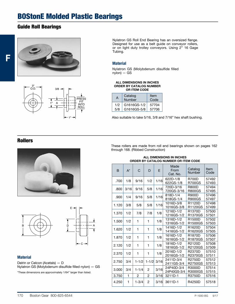
170 Boston Gear 800-825-6544 P-1930-BG 9/17
FFFF
BOStonE Molded Plastic BearingsGuide Roll Bearings
Nylatron GS Roll End Bearing has an oversized flange. Designed for use as a belt guide on conveyor rollers, or on light duty trolley conveyors. Using 2” 16 Gage Tubing.
Also suitable to take 5/16, 3/8 and 7/16” hex shaft bushing.
These rollers are made from roll end bearings shown on pages 162 through 168. (Ribbed Construction)
D
C
E
B A
Rollers
MaterialNylatron GS (Molybdenum disulfide filled nylon) — GS
MaterialDelrin or Celcon (Acetals) — DNylatron GS (Molybdenum disulfide filled nylon) — GS*These dimensions are approximately 1/64” larger than listed.
ALL DIMENSIONS IN INCHES ORDER BY CATALOG NUMBER OR ITEM CODE
Made From Catalog Item
B A* C D E Cat. No. Number Code
.700 1/8 9/16 1/2 1/16 622D-1/8 R700D 57492 622GS-1/8 R700GS 57493 .800 3/16 9/16 5/8 1/16 720D-3/16 R800D 57494 720GS-3/16 R800GS 57495 .900 1/4 9/16 5/8 1/16 818D-1/4 R900D 57496 818GS-1/4 R900GS 57497 1.120 3/8 5/8 5/8 1/16 1016D-3/8 R1120D 57498 1016GS-3/8 R1120GS 57499 1.370 1/2 7/8 7/8 1/8 1216D-1/2 R1370D 57500 1216GS-1/2 R1370GS 57501 1.500 1/2 1 1 1/8 1316D-1/2 R1500D 57502 1316GS-1/2 R1500GS 57503 1.620 1/2 1 1 1/8 1416D-1/2 R1620D 57504 1416GS-1/2 R1620GS 57505 1.870 1/2 1 1 1/8 1616D-1/2 R1870D 57506 1616GS-1/2 R1870GS 57507 2.120 1/2 1 1 1/8 1816D-1/2 R2120D 57508 1816GS-1/2 R2120GS 57509 2.370 1/2 1 1 1/8 2016D-1/2 R2370D 57510 2016GS-1/2 R2370GS 57511 2.750 3/4 1-1/2 1-1/2 3/16 2411D-3/4 R2750D 57512 2411GS-3/4 R2750GS 57513 3.000 3/4 1-1/4 2 3/16 24P40D-3/4 R3000D 57514 24P40GS-3/4 R3000GS 57515 3.750 1 2 2 3/16 3211D-1 R3750D 57516 4.250 1 1-3/4 2 3/16 3611D-1 R4250D 57518
1"
3"O.D.
A
3/8
1"
PRESSFIT
INTOROLL
ALL DIMENSIONS IN INCHES ORDER BY CATALOG NUMBER
OR ITEM CODE
Catalog Item A Number Code 1/2 G1616GS-1/2 57704 5/8 G1616GS-5/8 57706
F
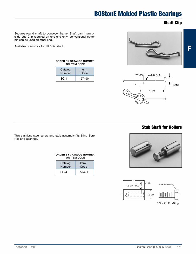
Boston Gear 800-825-6544 171P-1930-BG 9/17
FFFF
BOStonE Molded Plastic BearingsShaft Clip
Stub Shaft for Rollers
Secures round shaft to conveyor frame. Shaft can’t turn or slide out. Clip required on one end only, conventional cotter pin can be used on other end.
Available from stock for 1/2” dia. shaft.
ORDER BY CATALOG NUMBER
OR ITEM CODE
Catalog Item Number Code
SC-4 574901/8 DIA.
5/16
1 1/4
This stainless steel screw and stub assembly fits Blind Bore Roll End Bearings.
ORDER BY CATALOG NUMBER
OR ITEM CODE
Catalog Item Number Code
SS-4 57491
1/2 DIA.
1"1/8
1/8 DIA. HOLE CAP SCREW
1/4 - 20 X 5/8 Lg
F
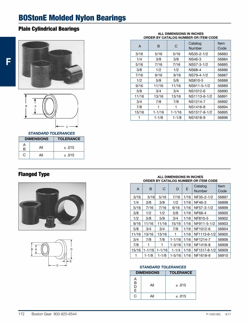
172 Boston Gear 800-825-6544 P-1930-BG 9/17
FFF
BOStonE Molded Nylon BearingsPlain Cylindrical Bearings
ALL DIMENSIONS IN INCHES ORDER BY CATALOG NUMBER OR ITEM CODE
Flanged Type
STANDARD TOLERANCES
DIMENSIONS TOLERANCE
A All ± .015 B C All ± .015
STANDARD TOLERANCES DIMENSIONS TOLERANCE
A B All ± .015 D E C All ± .015
Catalog Item A B C Number Code 3/16 5/16 5/16 NS35-2-1/2 56883 1/4 3/8 3/8 NS46-3 56884 5/16 7/16 7/16 NS57-3-1/2 56885 3/8 1/2 1/2 NS68-4 56886 7/16 9/16 9/16 NS79-4-1/2 56887 1/2 5/8 5/8 NS810-5 56888 9/16 11/16 11/16 NS911-5-1/2 56889 5/8 3/4 3/4 NS1012-6 56890 11/16 13/16 13/16 NS1113-6-1/2 56891 3/4 7/8 7/8 NS1214-7 56892 7/8 1 1 NS1416-8 56894 15/16 1-1/16 1-1/16 NS1517-8-1/2 56895 1 1-1/8 1-1/8 NS1618-9 56896
ALL DIMENSIONS IN INCHES ORDER BY CATALOG NUMBER OR ITEM CODE
Catalog Item A B C D E Number Code 3/16 5/16 5/16 7/16 1/16 NF35-2-1/2 56897 1/4 3/8 3/8 1/2 1/16 NF46-3 56898 5/16 7/16 7/16 9/16 1/16 NF57-3-1/2 56899 3/8 1/2 1/2 5/8 1/16 NF68-4 56900 1/2 5/8 5/8 3/4 1/16 NF810-5 56902 9/16 11/16 11/16 15/16 1/16 NF911-5-1/2 56903 5/8 3/4 3/4 7/8 1/16 NF1012-6 56904 11/16 13/16 13/16 1 1/16 NF1113-6-1/2 56905 3/4 7/8 7/8 1-1/16 1/16 NF1214-7 56906 7/8 1 1 1-3/16 1/16 NF1416-8 56908 15/16 1-1/16 1-1/16 1-1/4 1/16 NF1517-8-1/2 56909 1 1-1/8 1-1/8 1-5/16 1/16 NF1618-9 56910
B A
C
D
E
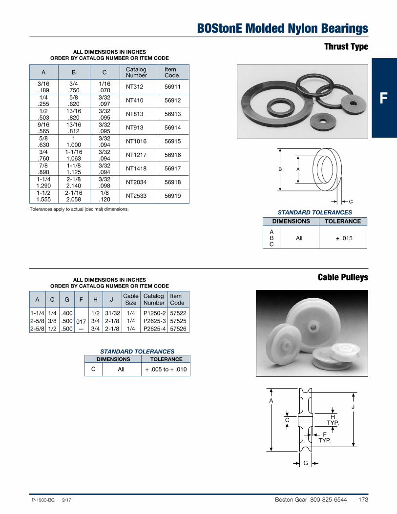
Boston Gear 800-825-6544 173P-1930-BG 9/17
FFF
BOStonE Molded Nylon BearingsThrust Type
ALL DIMENSIONS IN INCHES ORDER BY CATALOG NUMBER OR ITEM CODE
Cable Pulleys
STANDARD TOLERANCES
DIMENSIONS TOLERANCE
A B All ± .015 C
A
C HTYP.
J
G
FTYP.
STANDARD TOLERANCES DIMENSIONS TOLERANCE
C All + .005 to + .010
ALL DIMENSIONS IN INCHES ORDER BY CATALOG NUMBER OR ITEM CODE
Catalog Item A B C Number Code 3/16 3/4 1/16 NT312 56911 .189 .750 .070 1/4 5/8 3/32 NT410 56912 .255 .620 .097 1/2 13/16 3/32 NT813 56913 .503 .820 .095 9/16 13/16 3/32 NT913 56914 .565 .812 .095 5/8 1 3/32 NT1016 56915 .630 1.000 .094 3/4 1-1/16 3/32 NT1217 56916 .760 1.063 .094 7/8 1-1/8 3/32 NT1418 56917 .890 1.125 .094 1-1/4 2-1/8 3/32 NT2034 56918 1.290 2.140 .098 1-1/2 2-1/16 1/8 NT2533 56919 1.555 2.058 .120
Cable Catalog Item A C G F H J Size Number Code 1-1/4 1/4 .400
017 1/2 31/32 1/4 P1250-2 57522
2-5/8 3/8 .500 3/4 2-1/8 1/4 P2625-3 57525 2-5/8 1/2 .500 — 3/4 2-1/8 1/4 P2625-4 57526
Tolerances apply to actual (decimal) dimensions.
174 Boston Gear 800-825-6544 P-1930-BG 9/17
FFF
Engineering InformationSleeve Bearing Selection
The performance of a bearing is influenced by the condi-tions of speed, mating materials, clearances, temperature, lubrication, type of loading, etc. Of primary importance, is the maintenance of an oil film between the bearing surfaces to reduce friction, dissipate heat and retard wear by minimizing metal to metal contact. The most critical periods of operation are during starting and stopping, when the load may cause the bearing surfaces to come into contact with each other. For these reasons it is not practical to predict the wear rate of bronze bearings.The selection of the best bearing for an application can be a very complicated problem because the combined influence of the many factors affecting the operation is difficult to predict.The following information may be used as a guide for selecting a Bronze sleeve bearing which should satisfy the requirements.For practical reasons, the length of the bearing should normally be between one and two times the shaft diame-ter and the O.D. approximately 25% larger than the shaft diameter.Starting and Stopping/Oscillatory Motion/Cyclical Overload conditions mean a full film of oil cannot be maintained. When this happens, met-al-to-metal contact occurs and causes bearing wear. Because of the continual interruption of the oil film, a larger safety factor is required when designing bearings for applications of this type. A lower permissible PV factor must be considered.Speed/Oil Viscosity must also be considered. The prop-er viscosity oil must be selected for each particular speed application, to achieve optimum bearing operation.For high speed applications, a light oil (150 SUS at 100°F) is required to keep internal oil friction at a minimum and assure proper metering of the oil to the bearing/shaft surface.For moderate speeds, a medium-viscosity oil (400 SUS at 100°F) is required.For very low shaft speeds under moderate or heavy loads, a heavier oil with an extreme pressure additive may be required to prevent complete oil film rupture and give sufficient lubrication for proper operation.
Shaft Consideration is extremely important in bearing applications. For optimum operation the shaft must be of proper material, hardness, surface finish, roundness and dimensions. Experience indicates that carbon steels, and pref-erably C1137, offer the best operating results. If stainless steel shafts are to be used, 400 Series is recommended. Austenitic 300 Series stainless steel tends to gall, which results in extreme wear and shortened life. If 300 Series stainless is required for its non-magnetic qualities, it is strongly recom-mended that shafts be work-hardened or chrome-plated for satisfactory operation.For best results, a shaft surface finish of 4 to 12 RMS is recommended. Nicks, gouges, and burrs should be avoided because they rupture the oil film and cause metal-to-metal contact.Shaft roundness and dimensions also contribute greatly to bearing life. The more round the shaft, the less the bearing and shaft wear, with longer life resulting. Dimensions also play an important role in operation and should always be in accord with the recommended bearing clearance charts.As stated, for practical reasons the bearing length should normally be between one and two times the shaft diame-ter. However, the recommended practice is by using the PV factor. PV is a means of measuring the performance capabilities of bearings. P is expressed as pressure or pounds per square inch on the projected area of the bearing. V is velocity in feet per minute of the wear surface (surface feet per minute).“PV” is expressed by the following:
PV = W x πdn = πWn = .262Wn
__ ____ ____ ______ Ld 12 12L L
P = W
_________________
A (Brg. I.D. x Length)
V = Surface velocity of the shaft, ft./min. (.262 x RPM x Shaft Dia.)
W = Bearing load in pounds
L = Bearing length in inches
d = I.D. of bearing in inches (cancels out of formula)
n = Shaft speed, RPM
Boston Gear 800-825-6544 175P-1930-BG 9/17
FFF
Engineering InformationSleeve Bearing Selection (Continued)
Each material has a specific maximum PV rating, as shown in the following Table. In addition, it also has a maximum pressure (P) and velocity (V) limitation. These values should not be exceeded. At no time can all maximum values be utilized.
All values based on 72°F ambient temperature and standard lubricant, when required.NOTE: Above figures should be considered maximum and
not to be exceeded.EXAMPLE
Select a BOST-BRONZ (oil impregnated) bearing to satisfy the following conditions.Known—
5/8” Shaft Diameter
n = 500 RPM
W1 = Load Bearing I = L I = 52.5 Lbs.
W2 = Load Bearing II = L II = 157.5 Lbs.
L = Length of Bearing
For Bearing I—
PV = .262 x W1 x n L (In. of Lgth)
= .262 x 52.5 x 500 1 = 6877
For Bearing II—
PV = .262 x W2 x n L (In. of Lgth.)
= .262 x 157.5 x 500 1 = 20632
With the calculated PV of 6877, Bearing I, and 20,632, Bearing II, it can be seen from the Table, that a BOST-BRONZ bearing, one inch long, will not exceed Maximum PV.NOTE: An increase in L will decrease the value of PV;
conversely, a shortening of L increases the value of PV.
A check of PV calculations should now be performed to assure that Max. “P” and Max. “V” is not exceeded.PV Max. = P Max. x V Max. V = .262 x Shaft Dia. x n = .262 x .625 x 500 = 81.9
Bearing I P = PV = 6877 = 83.9 V 81.9
Bearing II P = PV = 20632 = 251.9 V 81.9As can be seen, we have not exceeded any maximum values. We can now select an actual Bost-Bronz bearing.Knowing:Shaft Dia. 5/8” = Bearing I.D. 5/8”Bearing O.D. should be approximately 25% larger than I.D.Bearing O.D. = .625 x 1.25 = .781”Referring to Bost-Bronz listings, Page 12, we find 5/8” I.D. bearings listed with O.D.’s from 3/4 to 1” and lengths from 1/2 to 2”.From this selection of bearings, we may choose a bearing to fit the requirements.Since Bearing I is lightly loaded, for practical reasons, we select a bearing length of one times bearing I.D. We select a B1013-5 (5/8” I.D. x 13/16 O.D. x 5/8” long).
Material Max. PV Max. P Max. V BEAR-N-BRONZ 75,000 3,000 750 BOST-BRONZ 50,000 2,000 1,200 BOST-BRONZ (Thrust Washers) 10,000 2,000 1,200 F1 20,000 1,000 400 TN 10,000 800 300 AF 8,000 750 300 GS 4,000 500 300 D 3,000 480 300 N 3,000 480 300 UHMW-PE 2,300 1,400 100 Nyloil 16,000 2,000 400 UHMW-PE with Internal Wear Strip 4,000 1,400 100 Nyloil with Internal Wear Strip 16,000 2,000 400
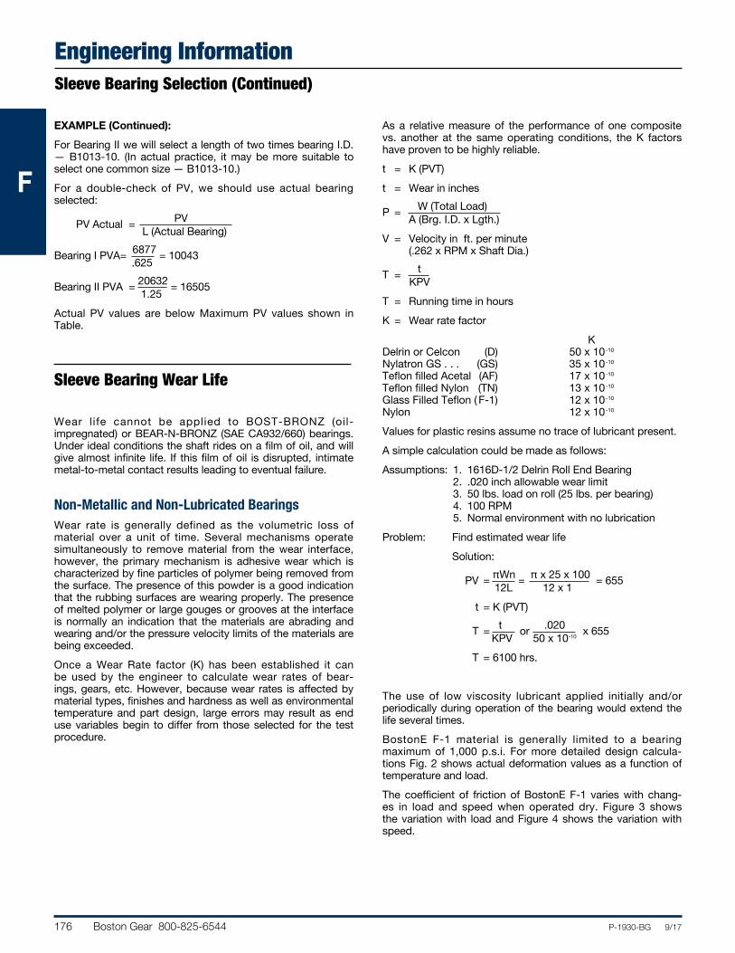
176 Boston Gear 800-825-6544 P-1930-BG 9/17
FFF
Engineering InformationSleeve Bearing Selection (Continued)
EXAMPLE (Continued):
For Bearing II we will select a length of two times bearing I.D. — B1013-10. (In actual practice, it may be more suitable to select one common size — B1013-10.)For a double-check of PV, we should use actual bearing selected:
PV Actual = PV L (Actual Bearing)
Bearing I PVA = 6877 = 10043 .625
Bearing II PVA = 20632 = 16505 1.25Actual PV values are below Maximum PV values shown in Table.
Wear l ife cannot be applied to BOST-BRONZ (oil- impregnated) or BEAR-N-BRONZ (SAE CA932/660) bearings. Under ideal conditions the shaft rides on a film of oil, and will give almost infinite life. If this film of oil is disrupted, intimate metal-to-metal contact results leading to eventual failure.
Non-Metallic and Non-Lubricated BearingsWear rate is generally defined as the volumetric loss of material over a unit of time. Several mechanisms operate simultaneously to remove material from the wear interface, however, the primary mechanism is adhesive wear which is characterized by fine particles of polymer being removed from the surface. The presence of this powder is a good indication that the rubbing surfaces are wearing properly. The presence of melted polymer or large gouges or grooves at the interface is normally an indication that the materials are abrading and wearing and/or the pressure velocity limits of the materials are being exceeded.Once a Wear Rate factor (K) has been established it can be used by the engineer to calculate wear rates of bear-ings, gears, etc. However, because wear rates is affected by material types, finishes and hardness as well as environmental temperature and part design, large errors may result as end use variables begin to differ from those selected for the test procedure.
As a relative measure of the performance of one composite vs. another at the same operating conditions, the K factors have proven to be highly reliable.t = K (PVT)t = Wear in inches
P = W (Total Load) A (Brg. I.D. x Lgth.)V = Velocity in ft. per minute (.262 x RPM x Shaft Dia.)
T = t KPVT = Running time in hoursK = Wear rate factor KDelrin or Celcon (D) 50 x 10-10
Nylatron GS . . . (GS) 35 x 10-10
Teflon filled Acetal (AF) 17 x 10-10
Teflon filled Nylon (TN) 13 x 10-10
Glass Filled Teflon ( F-1) 12 x 10-10
Nylon 12 x 10-10
Values for plastic resins assume no trace of lubricant present.A simple calculation could be made as follows:Assumptions: 1. 1616D-1/2 Delrin Roll End Bearing
2. .020 inch allowable wear limit 3. 50 lbs. load on roll (25 lbs. per bearing) 4. 100 RPM 5. Normal environment with no lubrication
Problem: Find estimated wear life Solution:
PV = πWn = πx25x100 = 655 12L 12 x 1 t = K (PVT)
T = t or .020 x 655 KPV 50 x 10-10
T = 6100 hrs.
The use of low viscosity lubricant applied initially and/or periodically during operation of the bearing would extend the life several times.BostonE F-1 material is generally limited to a bearing maximum of 1,000 p.s.i. For more detailed design calcula-tions Fig. 2 shows actual deformation values as a function of temperature and load.The coefficient of friction of BostonE F-1 varies with chang-es in load and speed when operated dry. Figure 3 shows the variation with load and Figure 4 shows the variation with speed.
Sleeve Bearing Wear Life
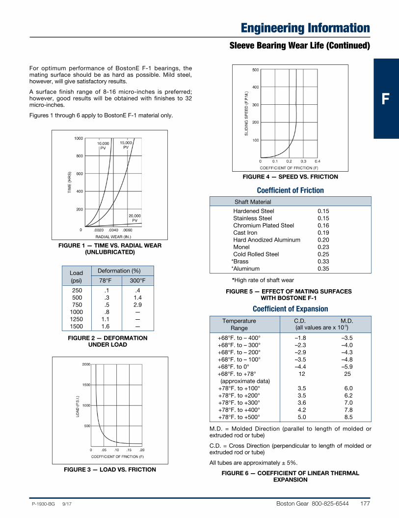
Boston Gear 800-825-6544 177P-1930-BG 9/17
FFF
Engineering InformationSleeve Bearing Wear Life (Continued)
For optimum performance of BostonE F-1 bearings, the mating surface should be as hard as possible. Mild steel, however, will give satisfactory results.A surface finish range of 8-16 micro-inches is preferred; however, good results will be obtained with finishes to 32 micro-inches.Figures 1 through 6 apply to BostonE F-1 material only.
FIGURE 1 — TIME VS. RADIAL WEAR (UNLUBRICATED)
FIGURE 2 — DEFORMATION UNDER LOAD
FIGURE 3 — LOAD VS. FRICTION
FIGURE 4 — SPEED VS. FRICTION
Load Deformation (%) (psi) 78°F 300°F 250 .1 .4 500 .3 1.4 750 .5 2.9 1000 .8 — 1250 1.1 — 1500 1.6 —
Coefficient of Friction
M.D. = Molded Direction (parallel to length of molded or extruded rod or tube)C.D. = Cross Direction (perpendicular to length of molded or extruded rod or tube)All tubes are approximately ± 5%.
FIGURE 6 — COEFFICIENT OF LINEAR THERMAL EXPANSION
*High rate of shaft wear
FIGURE 5 — EFFECT OF MATING SURFACES WITH BOSTONE F-1
Coefficient of Expansion Temperature C.D. M.D. Range (all values are x 10-5)
+68°F. to – 400° –1.8 –3.5 +68°F. to – 300° –2.3 –4.0 +68°F. to – 200° –2.9 –4.3 +68°F. to – 100° –3.5 –4.8+68°F. to 0° –4.4 –5.9+68°F. to +78° 12 25 (approximate data) +78°F. to +100° 3.5 6.0 +78°F. to +200° 3.5 6.2 +78°F. to +300° 3.6 7.0 +78°F. to +400° 4.2 7.8 +78°F. to +500° 5.0 8.5
Shaft MaterialHardened Steel 0.15Stainless Steel 0.15Chromium Plated Steel 0.16Cast Iron 0.19Hard Anodized Aluminum 0.20Monel 0.23Cold Rolled Steel 0.25
*Brass 0.33*Aluminum 0.35
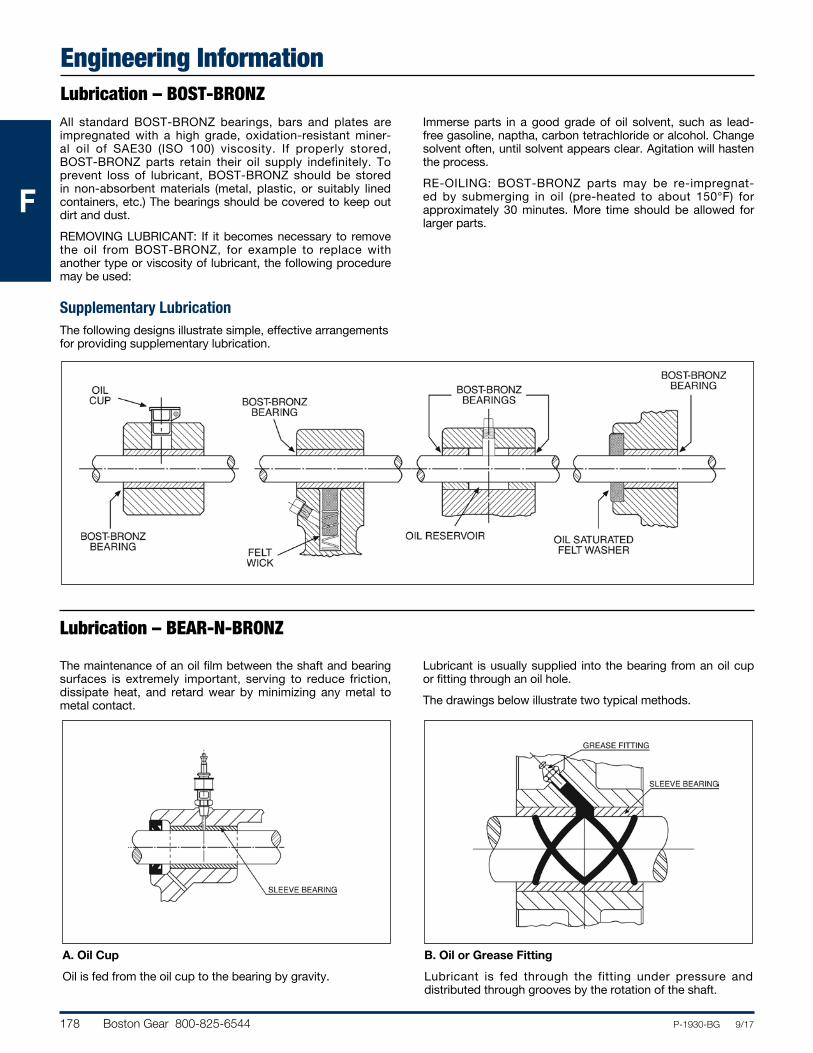
178 Boston Gear 800-825-6544 P-1930-BG 9/17
FFF
Engineering InformationLubrication – BOST-BRONZ
Lubrication – BEAR-N-BRONZ
All standard BOST-BRONZ bearings, bars and plates are impregnated with a high grade, oxidation-resistant miner-al oil of SAE30 (ISO 100) viscosity. If properly stored, BOST-BRONZ parts retain their oil supply indefinitely. To prevent loss of lubricant, BOST-BRONZ should be stored in non-absorbent materials (metal, plastic, or suitably lined containers, etc.) The bearings should be covered to keep out dirt and dust.REMOVING LUBRICANT: If it becomes necessary to remove the oil from BOST-BRONZ, for example to replace with another type or viscosity of lubricant, the following procedure may be used:
Immerse parts in a good grade of oil solvent, such as lead-free gasoline, naptha, carbon tetrachloride or alcohol. Change solvent often, until solvent appears clear. Agitation will hasten the process.RE-OILING: BOST-BRONZ parts may be re-impregnat-ed by submerging in oil (pre-heated to about 150°F) for approximately 30 minutes. More time should be allowed for larger parts.
Supplementary LubricationThe following designs illustrate simple, effective arrangements for providing supplementary lubrication.
The maintenance of an oil film between the shaft and bearing surfaces is extremely important, serving to reduce friction, dissipate heat, and retard wear by minimizing any metal to metal contact.
Lubricant is usually supplied into the bearing from an oil cup or fitting through an oil hole.The drawings below illustrate two typical methods.
A. Oil Cup
Oil is fed from the oil cup to the bearing by gravity.B. Oil or Grease Fitting
Lubricant is fed through the fitting under pressure and distributed through grooves by the rotation of the shaft.
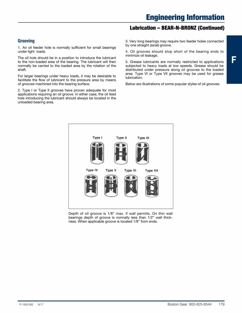
Boston Gear 800-825-6544 179P-1930-BG 9/17
FFF
Engineering InformationLubrication – BEAR-N-BRONZ (Continued)
Grooving1. An oil feeder hole is normally sufficient for small bearings under light loads.The oil hole should be in a position to introduce the lubricant to the non-loaded area of the bearing. The lubricant will then normally be carried to the loaded area by the rotation of the shaft.For larger bearings under heavy loads, it may be desirable to facilitate the flow of lubricant to the pressure area by means of grooves machined into the bearing surface.2. Type I or Type II grooves have proven adequate for most applications requiring an oil groove. In either case, the oil feed hole introducing the lubricant should always be located in the unloaded bearing area.
3. Very long bearings may require two feeder holes connected by one straight (axial) groove.4. Oil grooves should stop short of the bearing ends to minimize oil leakage.5. Grease lubricants are normally restricted to applications subjected to heavy loads at low speeds. Grease should be distributed under pressure along oil grooves to the loaded area. Type VI or Type VII grooves may be used for grease lubrication.Below are illustrations of some popular styles of oil grooves:
Depth of oil groove is 1/8” max. if wall permits. On thin wall bearings depth of groove is normally less than 1/2” wall thick-ness. When applicable groove is located 1/8” from ends.

180 Boston Gear 800-825-6544 P-1930-BG 9/17
FFF
Engineering InformationShaft Clearances
The following graphs may be used as a guide to determine shaft clearance for proper running fit.
BOST-BRONZ BEAR-N-BRONZ
Plastics
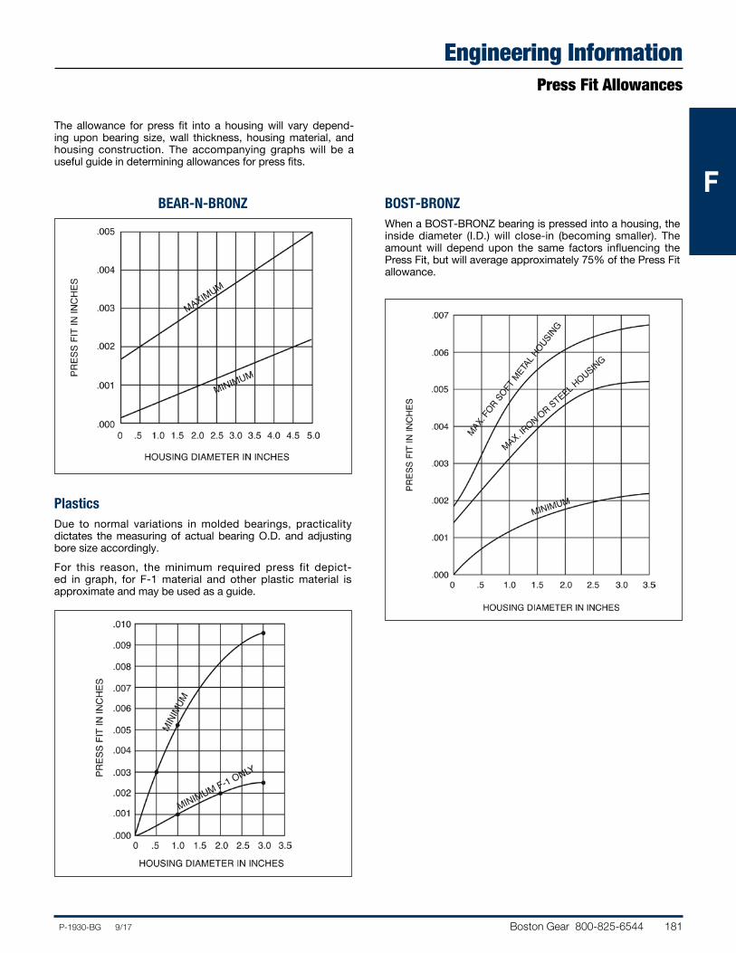
Boston Gear 800-825-6544 181P-1930-BG 9/17
FFF
Engineering InformationPress Fit Allowances
The allowance for press fit into a housing will vary depend-ing upon bearing size, wall thickness, housing material, and housing construction. The accompanying graphs will be a useful guide in determining allowances for press fits.
BEAR-N-BRONZ BOST-BRONZWhen a BOST-BRONZ bearing is pressed into a housing, the inside diameter (I.D.) will close-in (becoming smaller). The amount will depend upon the same factors influencing the Press Fit, but will average approximately 75% of the Press Fit allowance.
PlasticsDue to normal variations in molded bearings, practicality dictates the measuring of actual bearing O.D. and adjusting bore size accordingly.For this reason, the minimum required press fit depict-ed in graph, for F-1 material and other plastic material is approximate and may be used as a guide.
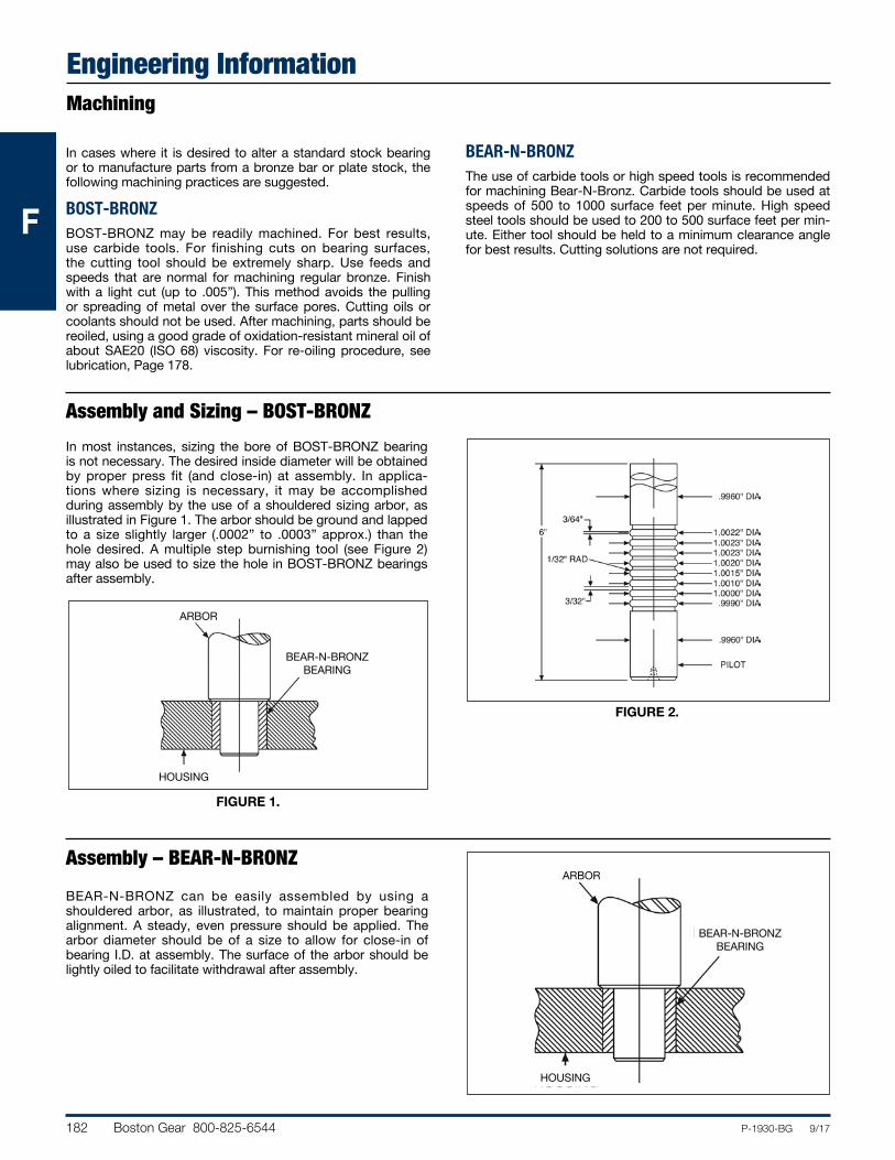
182 Boston Gear 800-825-6544 P-1930-BG 9/17
FFF
Engineering InformationMachining
Assembly – BEAR-N-BRONZ
In cases where it is desired to alter a standard stock bearing or to manufacture parts from a bronze bar or plate stock, the following machining practices are suggested.
BOST-BRONZBOST-BRONZ may be readily machined. For best results, use carbide tools. For finishing cuts on bearing surfaces, the cutting tool should be extremely sharp. Use feeds and speeds that are normal for machining regular bronze. Finish with a light cut (up to .005”). This method avoids the pulling or spreading of metal over the surface pores. Cutting oils or coolants should not be used. After machining, parts should be reoiled, using a good grade of oxidation-resistant mineral oil of about SAE20 (ISO 68) viscosity. For re-oiling procedure, see lubrication, Page 178.
BEAR-N-BRONZThe use of carbide tools or high speed tools is recommended for machining Bear-N-Bronz. Carbide tools should be used at speeds of 500 to 1000 surface feet per minute. High speed steel tools should be used to 200 to 500 surface feet per min-ute. Either tool should be held to a minimum clearance angle for best results. Cutting solutions are not required.
BEAR-N-BRONZBEARING
HOUSING
ARBOR
BEAR-N-BRONZBEARING
HOUSING
ARBOR
Assembly and Sizing – BOST-BRONZ
FIGURE 1.
FIGURE 2.
In most instances, sizing the bore of BOST-BRONZ bearing is not necessary. The desired inside diameter will be obtained by proper press fit (and close-in) at assembly. In applica-tions where sizing is necessary, it may be accomplished during assembly by the use of a shouldered sizing arbor, as illustrated in Figure 1. The arbor should be ground and lapped to a size slightly larger (.0002” to .0003” approx.) than the hole desired. A multiple step burnishing tool (see Figure 2) may also be used to size the hole in BOST-BRONZ bearings after assembly.
BEAR-N-BRONZ can be easily assembled by using a shouldered arbor, as illustrated, to maintain proper bearing alignment. A steady, even pressure should be applied. The arbor diameter should be of a size to allow for close-in of bearing I.D. at assembly. The surface of the arbor should be lightly oiled to facilitate withdrawal after assembly.
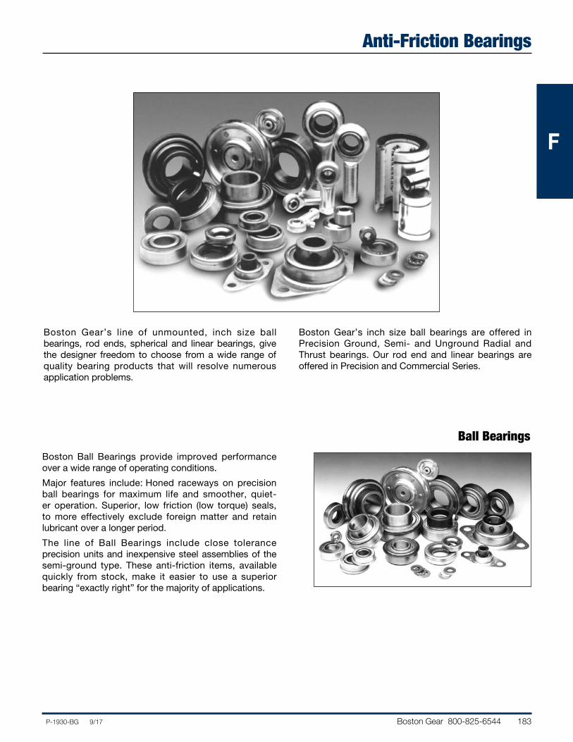
Boston Gear 800-825-6544 183P-1930-BG 9/17
FFF
Anti-Friction Bearings
Boston Gear’s line of unmounted, inch size ball bearings, rod ends, spherical and linear bearings, give the designer freedom to choose from a wide range of quality bearing products that will resolve numerous application problems.
Boston Gear’s inch size ball bearings are offered in Precision Ground, Semi- and Unground Radial and Thrust bearings. Our rod end and linear bearings are offered in Precision and Commercial Series.
Ball BearingsBoston Ball Bearings provide improved performance over a wide range of operating conditions.
Major features include: Honed raceways on precision ball bearings for maximum life and smoother, quiet-er operation. Superior, low friction (low torque) seals, to more effectively exclude foreign matter and retain lubricant over a longer period.
The line of Ball Bearings include close tolerance precision units and inexpensive steel assemblies of the semi-ground type. These anti-friction items, available quickly from stock, make it easier to use a superior bearing “exactly right” for the majority of applications.
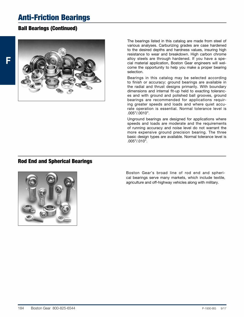
184 Boston Gear 800-825-6544 P-1930-BG 9/17
FFF
Anti-Friction BearingsBall Bearings (Continued)
Rod End and Spherical Bearings
The bearings listed in this catalog are made from steel of various analyses. Carburizing grades are case hardened to the desired depths and hardness values, insuring high resistance to wear and breakdown. High carbon chrome alloy steels are through hardened. If you have a spe-cial material application, Boston Gear engineers will wel-come the opportunity to help you make a proper bearing selection.
Bearings in this catalog may be selected according to finish or accuracy: ground bearings are available in the radial and thrust designs primarily. With boundary dimensions and internal fit-up held to exacting toleranc-es and with ground and polished ball grooves, ground bearings are recommended for applications requir-ing greater speeds and loads and where quiet accu-rate operation is essential. Normal tolerance level is .005”/.0010”.
Unground bearings are designed for applications where speeds and loads are moderate and the requirements of running accuracy and noise level do not warrant the more expensive ground precision bearing. The three basic design types are available. Normal tolerance level is .005”/.010”.
Boston Gear’s broad line of rod end and spheri-cal bearings serve many markets, which include textile, agriculture and off-highway vehicles along with military.
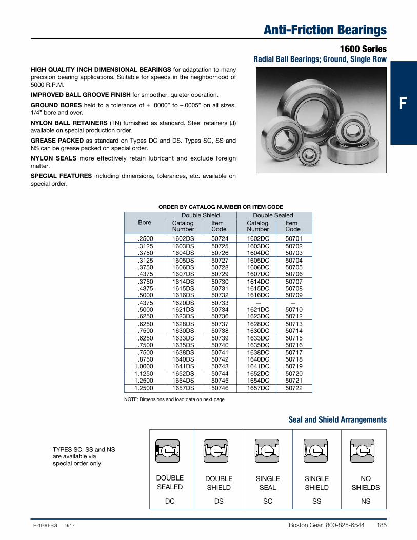
Boston Gear 800-825-6544 185P-1930-BG 9/17
FFF
Anti-Friction Bearings1600 Series
Radial Ball Bearings; Ground, Single RowHIGH QUALITY INCH DIMENSIONAL BEARINGS for adaptation to many precision bearing applications. Suitable for speeds in the neighborhood of 5000 R.P.M.
IMPROVED BALL GROOVE FINISH for smoother, quieter operation.
GROUND BORES held to a tolerance of + .0000” to –.0005” on all sizes, 1/4” bore and over.
NYLON BALL RETAINERS (TN) furnished as standard. Steel retainers (J) available on special production order.
GREASE PACKED as standard on Types DC and DS. Types SC, SS and NS can be grease packed on special order.
NYLON SEALS more effectively retain lubricant and exclude foreign matter.
SPECIAL FEATURES including dimensions, tolerances, etc. available on special order.
ORDER BY CATALOG NUMBER OR ITEM CODE
Double Shield Double Sealed Catalog Item Catalog Item
Bore Number Code Number Code
.2500 1602DS 50724 1602DC 50701 .3125 1603DS 50725 1603DC 50702 .3750 1604DS 50726 1604DC 50703 .3125 1605DS 50727 1605DC 50704 .3750 1606DS 50728 1606DC 50705 .4375 1607DS 50729 1607DC 50706 .3750 1614DS 50730 1614DC 50707 .4375 1615DS 50731 1615DC 50708 .5000 1616DS 50732 1616DC 50709 .4375 1620DS 50733 — — .5000 1621DS 50734 1621DC 50710 .6250 1623DS 50736 1623DC 50712 .6250 1628DS 50737 1628DC 50713 .7500 1630DS 50738 1630DC 50714 .6250 1633DS 50739 1633DC 50715 .7500 1635DS 50740 1635DC 50716 .7500 1638DS 50741 1638DC 50717 .8750 1640DS 50742 1640DC 50718 1.0000 1641DS 50743 1641DC 50719 1.1250 1652DS 50744 1652DC 50720 1.2500 1654DS 50745 1654DC 50721 1.2500 1657DS 50746 1657DC 50722
NOTE: Dimensions and load data on next page.
Seal and Shield Arrangements
DOUBLE SEALED
DC
DOUBLE SHIELD
DS
SINGLE SEAL
SC
SINGLE SHIELD
SS
NO SHIELDS
NS
TYPES SC, SS and NSare available viaspecial order only
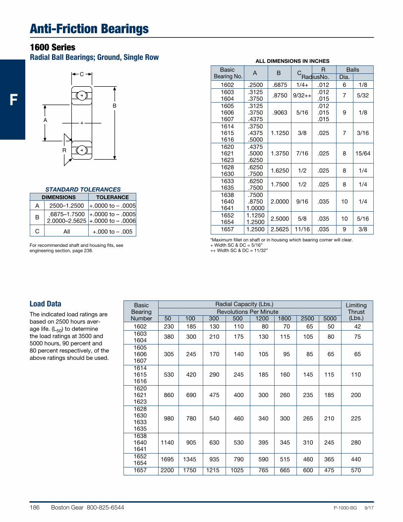
186 Boston Gear 800-825-6544 P-1930-BG 9/17
FFF
Anti-Friction Bearings1600 SeriesRadial Ball Bearings; Ground, Single Row
A
C
R
B
STANDARD TOLERANCES DIMENSIONS TOLERANCE
A 2500–1.2500 +.0000 to – .0005
B .6875–1.7500 +.0000 to – .0005 2.0000–2.5625 +.0000 to – .0006
C All +.000 to – .005
ALL DIMENSIONS IN INCHES
Basic R Balls Bearing No. A B C Radius No. Dia. 1602 .2500 .6875 1/4+ .012 6 1/8 1603 .3125 .8750 9/32++ .012 7 5/32 1604 .3750 .015 1605 .3125 .012 1606 .3750 .9063 5/16 .015 9 1/8 1607 .4375 .015 1614 .3750 1615 .4375 1.1250 3/8 .025 7 3/16 1616 .5000 1620 .4375 1621 .5000 1.3750 7/16 .025 8 15/64 1623 .6250 1628 .6250 1.6250 1/2 .025 8 1/4 1630 .7500 1633 .6250 1.7500 1/2 .025 8 1/4 1635 .7500 1638 .7500 1640 .8750 2.0000 9/16 .035 10 1/4 1641 1.0000 1652 1.1250 2.5000 5/8 .035 10 5/16 1654 1.2500 1657 1.2500 2.5625 11/16 .035 9 3/8
*Maximum fillet on shaft or in housing which bearing corner will clear.+ Width SC & DC = 5/16”++ Width SC & DC = 11/32”
For recommended shaft and housing fits, see engineering section, page 238.
Load DataThe indicated load ratings are based on 2500 hours aver-age life. (L50) to determine the load ratings at 3500 and 5000 hours, 90 percent and 80 percent respectively, of the above ratings should be used.
Basic Radial Capacity (Lbs.) Limiting Bearing Revolutions Per Minute Thrust Number 50 100 300 500 1200 1800 2500 5000 (Lbs.) 1602 230 185 130 110 80 70 65 50 42 1603 380 300 210 175 130 115 105 80 75 1604 1605 1606 305 245 170 140 105 95 85 65 65 1607 1614 1615 530 420 290 245 185 160 145 115 110 1616 1620 1621 860 690 475 400 300 260 235 185 200 1623 1628 1630 980 780 540 460 340 300 265 210 225 1633 1635 1638 1640 1140 905 630 530 395 345 310 245 280 1641 1652 1695 1345 935 790 590 515 460 365 440 1654 1657 2200 1750 1215 1025 765 665 600 475 570
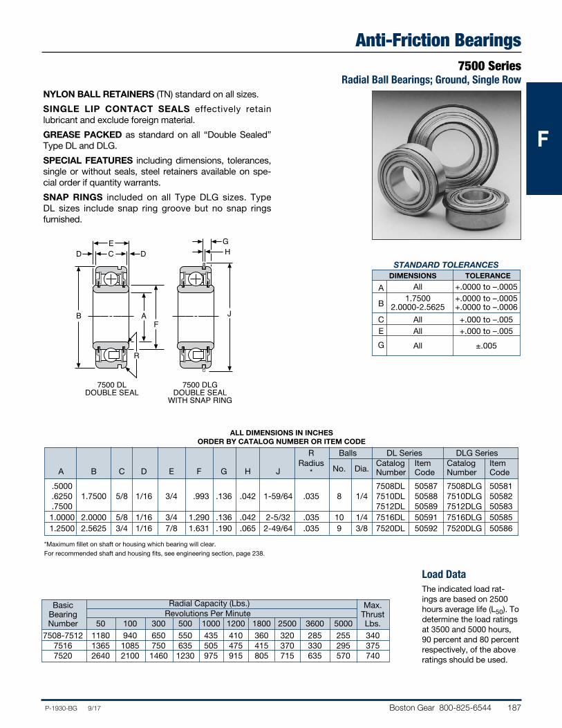
Boston Gear 800-825-6544 187P-1930-BG 9/17
FFF
Anti-Friction Bearings7500 Series
Radial Ball Bearings; Ground, Single RowNYLON BALL RETAINERS (TN) standard on all sizes.
SINGLE LIP CONTACT SEALS effectively retain lubricant and exclude foreign material.
GREASE PACKED as standard on all “Double Sealed” Type DL and DLG.
SPECIAL FEATURES including dimensions, tolerances, single or without seals, steel retainers available on spe-cial order if quantity warrants.
SNAP RINGS included on all Type DLG sizes. Type DL sizes include snap ring groove but no snap rings furnished.
B
E
J
HG
A
CD D
F
R
7500 DLDOUBLE SEAL
7500 DLGDOUBLE SEAL
WITH SNAP RING
STANDARD TOLERANCES DIMENSIONS TOLERANCE
A All +.0000 to –.0005
B 1.7500 +.0000 to –.0005 2.0000-2.5625 +.0000 to –.0006
C All +.000 to –.005 E All +.000 to –.005 G All ±.005
Load DataThe indicated load rat-ings are based on 2500 hours average life (L50). To determine the load ratings at 3500 and 5000 hours, 90 percent and 80 percent respectively, of the above ratings should be used.
ALL DIMENSIONS IN INCHES ORDER BY CATALOG NUMBER OR ITEM CODE
R Balls DL Series DLG Series Radius Catalog Item Catalog Item A B C D E F G H J * No. Dia. Number Code Number Code
.5000 7508DL 50587 7508DLG 50581 .6250 1.7500 5/8 1/16 3/4 .993 .136 .042 1-59/64 .035 8 1/4 7510DL 50588 7510DLG 50582 .7500 7512DL 50589 7512DLG 50583 1.0000 2.0000 5/8 1/16 3/4 1.290 .136 .042 2-5/32 .035 10 1/4 7516DL 50591 7516DLG 50585 1.2500 2.5625 3/4 1/16 7/8 1.631 .190 .065 2-49/64 .035 9 3/8 7520DL 50592 7520DLG 50586
*Maximum fillet on shaft or housing which bearing will clear.For recommended shaft and housing fits, see engineering section, page 238.
Basic Radial Capacity (Lbs.) Max. Bearing Revolutions Per Minute Thrust Number 50 100 300 500 1000 1200 1800 2500 3600 5000 Lbs. 7508-7512 1180 940 650 550 435 410 360 320 285 255 340 7516 1365 1085 750 635 505 475 415 370 330 295 375 7520 2640 2100 1460 1230 975 915 805 715 635 570 740
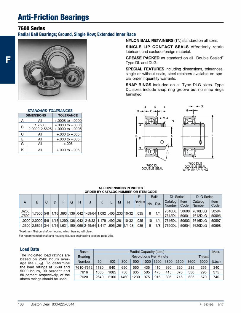
188 Boston Gear 800-825-6544 P-1930-BG 9/17
FFF
Anti-Friction Bearings7600 SeriesRadial Ball Bearings; Ground, Single Row; Extended Inner Race
NYLON BALL RETAINERS (TN) standard on all sizes.
SINGLE LIP CONTACT SEALS effectively retain lubricant and exclude foreign material.
GREASE PACKED as standard on all “Double Sealed” Type DL and DLG.
SPECIAL FEATURES including dimensions, tolerances, single or without seals, steel retainers available on spe-cial order if quantity warrants.
SNAP RINGS included on all Type DLG sizes. Type DL sizes include snap ring groove but no snap rings furnished.
STANDARD TOLERANCES DIMENSIONS TOLERANCE
A All +.0008 to –.0000 B 1.7500 +.0000 to –.0005 2.0000-2.5625 +.0000 to –.0006
C All +.000 to –.005 E All +.000 to –.005 G All ±.005
K All +.000 to –.005
Load DataThe indicated load ratings are based on 2500 hours aver-age life (L50). To determine the load ratings at 3500 and 5000 hours, 90 percent and 80 percent respectively, of the above ratings should be used.
*Maximum fillet on shaft or housing which bearing will clear.
For recommended shaft and housing fits, see engineering section, page 238.
ALL DIMENSIONS IN INCHES ORDER BY CATALOG NUMBER OR ITEM CODE
R* Balls DL Series DLG Series Radius Catalog Item Catalog Item
A B C D F G H J K L M N *
No. Dia. Number Code Number Code
.6250 1.7500 5/8 1/16 .993 .136 .042 1-59/64 1.092 .405 .233 10-32 .035 8 1/4
7610DL 50600 7610DLG 50594 .7500 7612DL 50601 7612DLG 50595 1.0000 2.0000 5/8 1/16 1.290 .136 .042 2-5/32 1.179 .492 .261 10-32 .035 10 1/4 7616DL 50603 7616DLG 50597 1.2500 2.5625 3/4 1/16 1.631 .190 .065 2-49/64 1.417 .605 .261 1/4-28 .035 9 3/8 7620DL 50604 7620DLG 50598
Basic Radial Capacity (Lbs.) Max. Bearing Revolutions Per Minute Thrust Number 50 100 300 500 1000 1200 1800 2500 3600 5000 (Lbs.)
7610-7612 1180 940 650 550 435 410 360 320 285 255 340 7616 1365 1085 750 635 505 475 415 370 330 295 375 7620 2640 2100 1460 1230 975 915 805 715 635 570 740
B
K
J
HG
A
CD
F
R
7600 DLDOUBLE SEAL
7600 DLGDOUBLE SEAL
WITH SNAP RING
L
MN
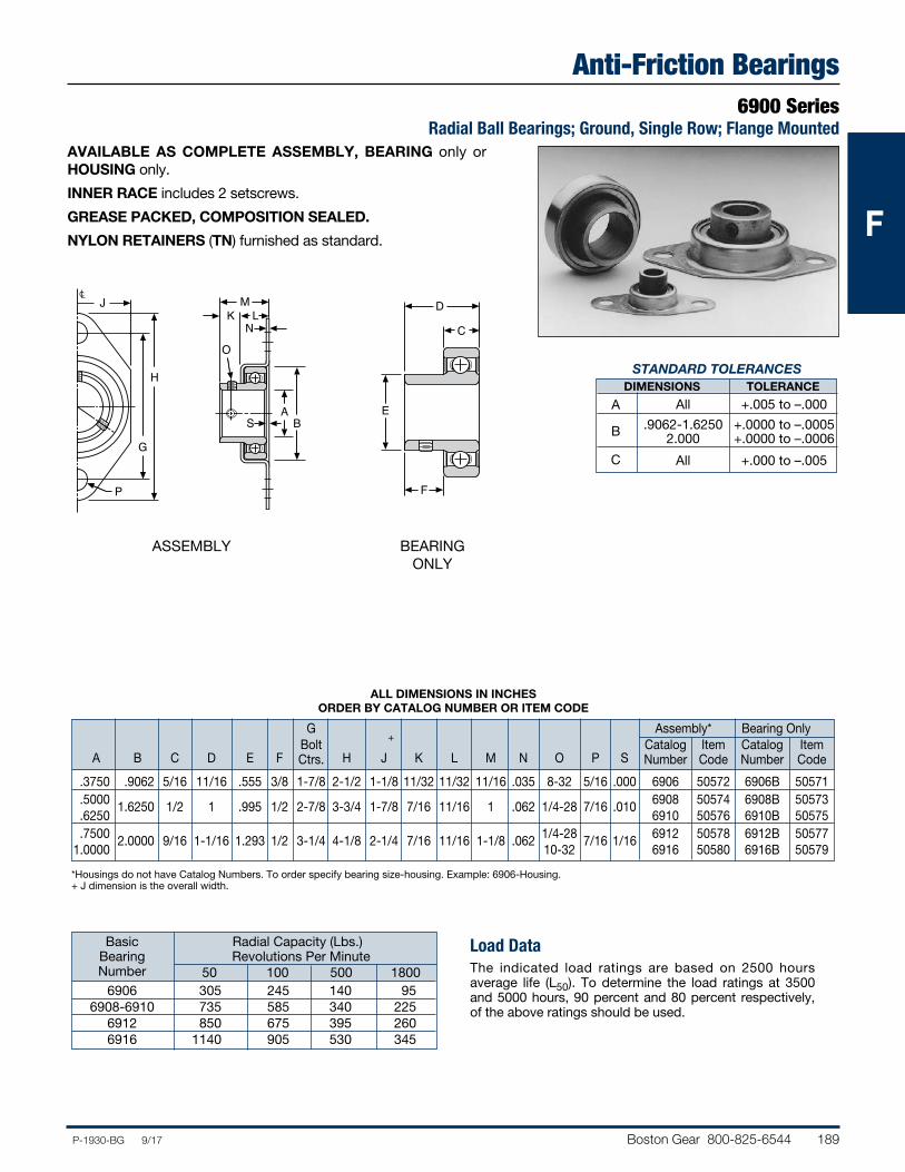
Boston Gear 800-825-6544 189P-1930-BG 9/17
FFF
Anti-Friction Bearings6900 Series
Radial Ball Bearings; Ground, Single Row; Flange MountedAVAILABLE AS COMPLETE ASSEMBLY, BEARING only or HOUSING only.
INNER RACE includes 2 setscrews.
GREASE PACKED, COMPOSITION SEALED.
NYLON RETAINERS (TN) furnished as standard.
H
BA
MLK
N
O
SG
JC
P
STANDARD TOLERANCES DIMENSIONS TOLERANCE
A All +.005 to –.000
B .9062-1.6250 +.0000 to –.0005 2.000 +.0000 to –.0006
C All +.000 to –.005
ALL DIMENSIONS IN INCHES ORDER BY CATALOG NUMBER OR ITEM CODE
G Assembly* Bearing Only Bolt Catalog Item Catalog Item A B C D E F Ctrs. H J K L M N O P S Number Code Number Code
.3750 .9062 5/16 11/16 .555 3/8 1-7/8 2-1/2 1-1/8 11/32 11/32 11/16 .035 8-32 5/16 .000 6906 50572 6906B 50571 .5000 1.6250 1/2 1 .995 1/2 2-7/8 3-3/4 1-7/8 7/16 11/16 1 .062 1/4-28 7/16 .010 6908 50574 6908B 50573 .6250 6910 50576 6910B 50575 .7500 2.0000 9/16 1-1/16 1.293 1/2 3-1/4 4-1/8 2-1/4 7/16 11/16 1-1/8 .062 1/4-28 7/16 1/16 6912 50578 6912B 50577 1.0000 10-32 6916 50580 6916B 50579
Load DataThe indicated load ratings are based on 2500 hours average life (L50). To determine the load ratings at 3500 and 5000 hours, 90 percent and 80 percent respectively, of the above ratings should be used.
*Housings do not have Catalog Numbers. To order specify bearing size-housing. Example: 6906-Housing.+ J dimension is the overall width.
Basic Radial Capacity (Lbs.) Bearing Revolutions Per Minute Number 50 100 500 1800 6906 305 245 140 95 6908-6910 735 585 340 225 6912 850 675 395 260 6916 1140 905 530 345
H
BA
MLK
N
O
SG
JC
P F
E
C
D
ASSEMBLY BEARING ONLY
+
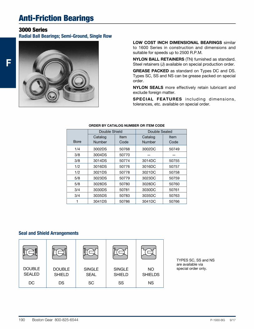
190 Boston Gear 800-825-6544 P-1930-BG 9/17
FFF
Anti-Friction Bearings3000 SeriesRadial Ball Bearings; Semi-Ground, Single Row
DOUBLE SEALED
DC
DOUBLE SHIELD
DS
SINGLE SEAL
SC
SINGLE SHIELD
SS
NO SHIELDS
NS
LOW COST INCH DIMENSIONAL BEARINGS similar to 1600 Series in construction and dimensions and suitable for speeds up to 2500 R.P.M.
NYLON BALL RETAINERS (TN) furnished as standard. Steel retainers (J) available on special production order.
GREASE PACKED as standard on Types DC and DS. Types SC, SS and NS can be grease packed on special order.
NYLON SEALS more effectively retain lubricant and exclude foreign matter.
SPECIAL FEATURES including dimensions, tolerances, etc. available on special order.
ORDER BY CATALOG NUMBER OR ITEM CODE
Double Shield Double Sealed Catalog Item Catalog Item Bore Number Code Number Code
1/4 3002DS 50768 3002DC 50749
3/8 3004DS 50770 — —
3/8 3014DS 50774 3014DC 50755
1/2 3016DS 50776 3016DC 50757
1/2 3021DS 50778 3021DC 50758
5/8 3023DS 50779 3023DC 50759
5/8 3028DS 50780 3028DC 50760
3/4 3030DS 50781 3030DC 50761
3/4 3035DS 50783 3035DC 50763
1 3041DS 50786 3041DC 50766
Seal and Shield Arrangements
TYPES SC, SS and NSare available viaspecial order only.
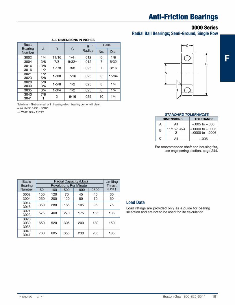
Boston Gear 800-825-6544 191P-1930-BG 9/17
FFF
Anti-Friction Bearings3000 Series
Radial Ball Bearings; Semi-Ground, Single Row
A
C
R
B
STANDARD TOLERANCES DIMENSIONS TOLERANCE
A All +.005 to –.000 B 11/16-1-3/4 +.0000 to –.0005 2 +.0000 to –.0006 C All ±.005
ALL DIMENSIONS IN INCHES
Basic Bearing A B C R * Balls
Number Radius No. Dia.
3002 1/4 11/16 1/4+ .012 6 1/8 3004 3/8 7/8 9/32++ .012 7 5/32 3014 3/8
1-1/8 3/8 .025 7 3/16
3016 1/2 3021 1/2
1-3/8 7/16 .025 8 15/64
3023 5/8 3028 5/8
1-5/8 1/2 .025 8 1/4 3030 3/4 3035 3/4 1-3/4 1/2 .025 8 1/4 3040 7/8
2 9/16 .035 10 1/4
3041 1
*Maximum fillet on shaft or in housing which bearing corner will clear.+ Width SC & DC = 5/16”++ Width SC = 11/32”
For recommended shaft and housing fits, see engineering section, page 244.
Load DataLoad ratings are provided only as a guide for bearing selection and are not to be used for life calculation.
Basic Radial Capacity (Lbs.) Limiting Bearing Revolutions Per Minute Thrust Number 50 100 500 1800 2500 (Lbs.)
3002 150 120 70 45 40 30 3004 250 200 120 80 70 50 3014
350 280 165 105 95 75
3016 3021
575 460 270 175 155 135
3023 3028 3030 650 520 305 200 180 150 3035 3040
760 605 355 230 205 185
3041
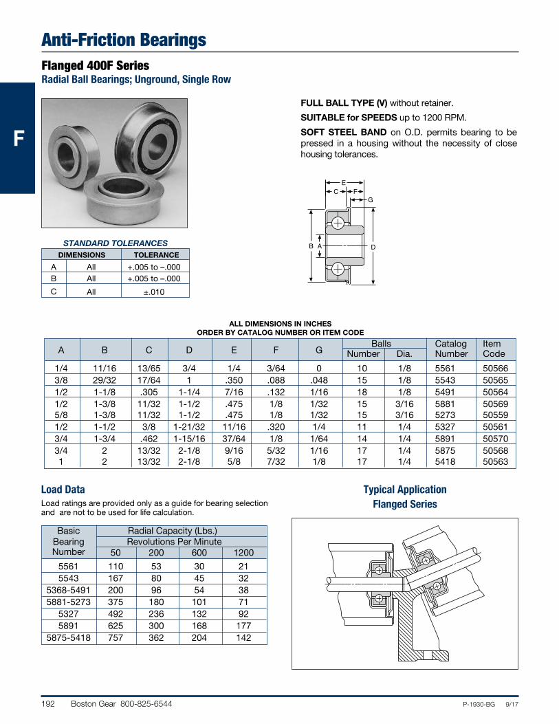
192 Boston Gear 800-825-6544 P-1930-BG 9/17
FFF
Anti-Friction BearingsFlanged 400F SeriesRadial Ball Bearings; Unground, Single Row
FULL BALL TYPE (V) without retainer.
SUITABLE for SPEEDS up to 1200 RPM.
SOFT STEEL BAND on O.D. permits bearing to be pressed in a housing without the necessity of close housing tolerances.
B
E
D
C FG
A
ALL DIMENSIONS IN INCHES ORDER BY CATALOG NUMBER OR ITEM CODE
Balls Catalog Item A B C D E F G Number Dia. Number Code
1/4 11/16 13/65 3/4 1/4 3/64 0 10 1/8 5561 50566 3/8 29/32 17/64 1 .350 .088 .048 15 1/8 5543 50565 1/2 1-1/8 .305 1-1/4 7/16 .132 1/16 18 1/8 5491 50564 1/2 1-3/8 11/32 1-1/2 .475 1/8 1/32 15 3/16 5881 50569 5/8 1-3/8 11/32 1-1/2 .475 1/8 1/32 15 3/16 5273 50559 1/2 1-1/2 3/8 1-21/32 11/16 .320 1/4 11 1/4 5327 50561 3/4 1-3/4 .462 1-15/16 37/64 1/8 1/64 14 1/4 5891 50570 3/4 2 13/32 2-1/8 9/16 5/32 1/16 17 1/4 5875 50568 1 2 13/32 2-1/8 5/8 7/32 1/8 17 1/4 5418 50563
Load DataLoad ratings are provided only as a guide for bearing selection and are not to be used for life calculation.
Basic Radial Capacity (Lbs.) Bearing Revolutions Per Minute Number 50 200 600 1200
5561 110 53 30 21 5543 167 80 45 32 5368-5491 200 96 54 38 5881-5273 375 180 101 71 5327 492 236 132 92 5891 625 300 168 177 5875-5418 757 362 204 142
Typical ApplicationFlanged Series
STANDARD TOLERANCES DIMENSIONS TOLERANCE
A All +.005 to –.000 B All +.005 to –.000
C All ±.010
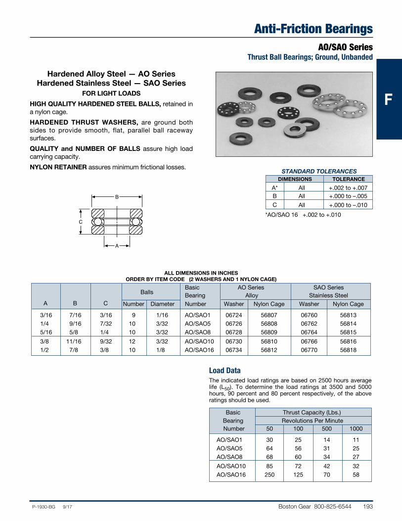
Boston Gear 800-825-6544 193P-1930-BG 9/17
FFF
Anti-Friction BearingsAO/SAO Series
Thrust Ball Bearings; Ground, Unbanded
Hardened Alloy Steel — AO Series Hardened Stainless Steel — SAO Series
FOR LIGHT LOADS
HIGH QUALITY HARDENED STEEL BALLS, retained in a nylon cage.
HARDENED THRUST WASHERS, are ground both sides to provide smooth, flat, parallel ball raceway surfaces.
QUALITY and NUMBER OF BALLS assure high load carrying capacity.
NYLON RETAINER assures minimum frictional losses.
C
B
A
STANDARD TOLERANCES DIMENSIONS TOLERANCE
A* All +.002 to +.007 B All +.000 to –.005 C All +.000 to –.010
Load DataThe indicated load ratings are based on 2500 hours average life (L50). To determine the load ratings at 3500 and 5000 hours, 90 percent and 80 percent respectively, of the above ratings should be used.
Basic Thrust Capacity (Lbs.) Bearing Revolutions Per Minute Number 50 100 500 1000
AO/SAO1 30 25 14 11 AO/SAO5 64 56 31 25 AO/SAO8 68 60 34 27
AO/SAO10 85 72 42 32 AO/SAO16 250 125 70 58
ALL DIMENSIONS IN INCHES ORDER BY ITEM CODE (2 WASHERS AND 1 NYLON CAGE)
Basic AO Series SAO Series Balls Bearing Alloy Stainless Steel A B C Number Diameter Number Washer Nylon Cage Washer Nylon Cage
3/16 7/16 3/16 9 1/16 AO/SAO1 06724 56807 06760 56813 1/4 9/16 7/32 10 3/32 AO/SAO5 06726 56808 06762 56814 5/16 5/8 1/4 10 3/32 AO/SAO8 06728 56809 06764 56815
3/8 11/16 9/32 12 3/32 AO/SAO10 06730 56810 06766 56816 1/2 7/8 3/8 10 1/8 AO/SAO16 06734 56812 06770 56818
*AO/SAO 16 +.002 to +.010
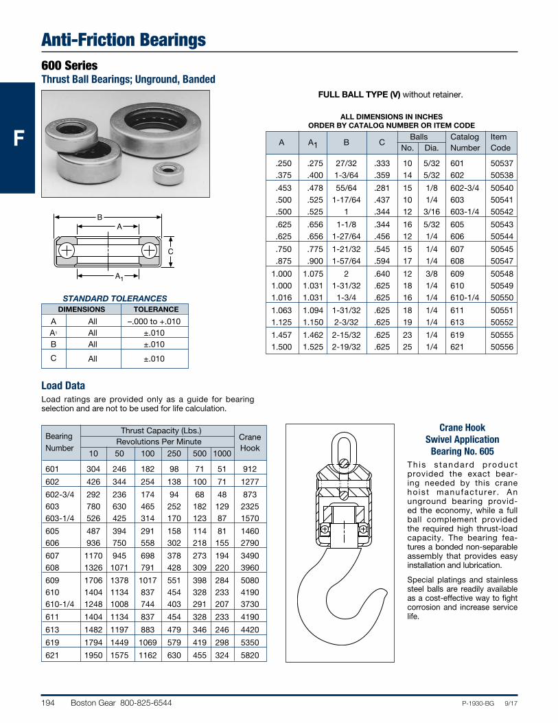
194 Boston Gear 800-825-6544 P-1930-BG 9/17
FFF
Anti-Friction Bearings600 SeriesThrust Ball Bearings; Unground, Banded
C
BA
A1
STANDARD TOLERANCES DIMENSIONS TOLERANCE
A All –.000 to +.010 A1 All ±.010 B All ±.010
C All ±.010
Load DataLoad ratings are provided only as a guide for bearing selection and are not to be used for life calculation.
FULL BALL TYPE (V) without retainer.
ALL DIMENSIONS IN INCHES ORDER BY CATALOG NUMBER OR ITEM CODE
Balls Catalog Item
A A1 B C No. Dia. Number Code
.250 .275 27/32 .333 10 5/32 601 50537 .375 .400 1-3/64 .359 14 5/32 602 50538
.453 .478 55/64 .281 15 1/8 602-3/4 50540 .500 .525 1-17/64 .437 10 1/4 603 50541 .500 .525 1 .344 12 3/16 603-1/4 50542
.625 .656 1-1/8 .344 16 5/32 605 50543 .625 .656 1-27/64 .456 12 1/4 606 50544
.750 .775 1-21/32 .545 15 1/4 607 50545 .875 .900 1-57/64 .594 17 1/4 608 50547
1.000 1.075 2 .640 12 3/8 609 50548 1.000 1.031 1-31/32 .625 18 1/4 610 50549 1.016 1.031 1-3/4 .625 16 1/4 610-1/4 50550
1.063 1.094 1-31/32 .625 18 1/4 611 50551 1.125 1.150 2-3/32 .625 19 1/4 613 50552
1.457 1.462 2-15/32 .625 23 1/4 619 50555 1.500 1.525 2-19/32 .625 25 1/4 621 50556
Thrust Capacity (Lbs.) Bearing
Revolutions Per Minute Crane Number
10 50 100 250 500 1000 Hook
601 304 246 182 98 71 51 912
602 426 344 254 138 100 71 1277
602-3/4 292 236 174 94 68 48 873 603 780 630 465 252 182 129 2325 603-1/4 526 425 314 170 123 87 1570
605 487 394 291 158 114 81 1460 606 936 750 558 302 218 155 2790
607 1170 945 698 378 273 194 3490 608 1326 1071 791 428 309 220 3960
609 1706 1378 1017 551 398 284 5080 610 1404 1134 837 454 328 233 4190 610-1/4 1248 1008 744 403 291 207 3730
611 1404 1134 837 454 328 233 4190
613 1482 1197 883 479 346 246 4420
619 1794 1449 1069 579 419 298 5350
621 1950 1575 1162 630 455 324 5820
Crane Hook Swivel Application
Bearing No. 605Th is s tandard p roduc t provided the exact bear-ing needed by this crane ho is t manufacturer . An unground bearing provid-ed the economy, while a full ball complement provided the required high thrust-load capacity. The bearing fea-tures a bonded non-separable assembly that provides easy installation and lubrication.
Special platings and stainless steel balls are readily available as a cost-effective way to fight corrosion and increase service life.
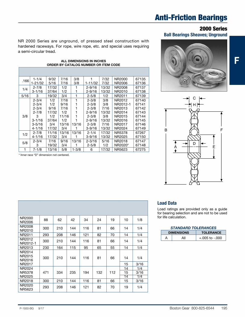
Boston Gear 800-825-6544 195P-1930-BG 9/17
FFF
Anti-Friction Bearings2000 Series
Ball Bearings Sheaves; Unground
Radial Load Capacity (Lbs.) Balls Sheave Revolutions Per Minute
Number 50 100 200 300 600 900 No. Diam.
NR2000 88 62 42 34 24 19 10 1/8 NR2006 NR2008 300 210 144 116 81 66 14 1/4 NR2010 NR2011 293 208 146 121 82 70 14 1/4 NR2012 300 210 144 116 81 66 14 1/4 NR2012-1 NR2013 230 164 115 95 65 55 14 1/4 NR2014 NR2015 300 210 144 116 81 66 14 1/4 NR2016 NR2017 15 3/16 NR2024 14 1/4 NR5378 471 334 235 194 132 112 15 3/16 NR2025 14 1/4 NR2018 300 210 144 116 81 66 15 3/16 NR2020 293 208 146 121 82 70 19 1/4 NR5623
Load DataLoad ratings are provided only as a guide for bearing selection and are not to be used for life calculation.
ALL DIMENSIONS IN INCHES ORDER BY CATALOG NUMBER OR ITEM CODE
Catalog Item A B C D E F H Number Code
.166 1-1/4 9/32 7/16 3/8 1 7/32 NR2000 67135 1-21/32 5/16 7/16 3/8 1-11/32 7/32 NR2006 67136 1/4 2-7/8 17/32 1/2 1 2-9/16 13/32 NR2008 67137 3-1/16 37/64 1/2 1 2-9/16 13/32 NR2010 67138 5/16 3 19/32 3/4 1 2-5/8 1/2 NR2011 67139 2-3/4 1/2 7/16 1 2-3/8 3/8 NR2012 67140 2-3/4 1/2 9/16 1 2-3/8 3/8 NR2012-1 67141 2-3/4 9/16 7/16 1 2-3/8 7/16 NR2013 67142 2-7/8 17/32 1/2 1 2-9/16 13/32 NR2014 67143 3/8 3 1/2 11/16 1 2-3/8 3/8 NR2015 67144 3-1/16 37/64 1/2 1 2-9/16 13/32 NR2016 67145 3-5/16 3/4 13/16 13/16 2-3/8 7/16 NR2017 67146 4-1/16 17/32 3/4 1 3-9/16 13/32 NR2024 67149 1/2 2-7/8 11/16 13/16 13/16 2-1/4 17/32 NR5378 67267 4-1/16 17/32 3/4 1 3-9/16 13/32 NR2025 67150 5/8 2-3/4 7/16 9/16 13/16 2-3/16 5/16 NR2018 67147 3 19/32 3/4 1 2-5/8 1/2 NR2020* 67148 1 7-1/8 13/16 5/8 1-3/8 6 17/32 NR5623 67275
NR 2000 Series are unground, of pressed steel construction with hardened raceways. For rope, wire rope, etc. and special uses requiring a semi-circular tread.
* Inner race “D” dimension not centered.
B
C
AD
E
F
H
STANDARD TOLERANCES DIMENSIONS TOLERANCE
A All +.005 to -.000
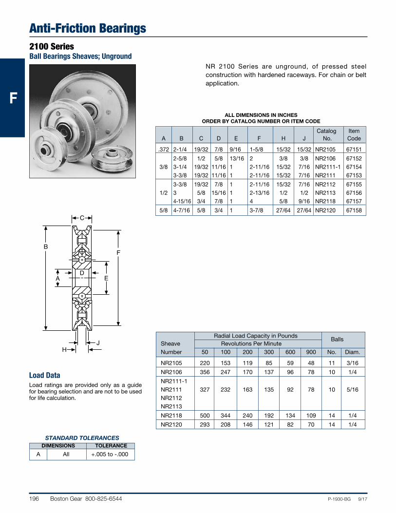
196 Boston Gear 800-825-6544 P-1930-BG 9/17
FFF
Anti-Friction Bearings2100 SeriesBall Bearings Sheaves; Unground
Load DataLoad ratings are provided only as a guide for bearing selection and are not to be used for life calculation.
H
B
AD
F
E
C
J
STANDARD TOLERANCES DIMENSIONS TOLERANCE
A All +.005 to -.000
Radial Load Capacity in Pounds Balls
Sheave Revolutions Per Minute Number 50 100 200 300 600 900 No. Diam.
NR2105 220 153 119 85 59 48 11 3/16
NR2106 356 247 170 137 96 78 10 1/4
NR2111-1 NR2111 327 232 163 135 92 78 10 5/16 NR2112 NR2113
NR2118 500 344 240 192 134 109 14 1/4
NR2120 293 208 146 121 82 70 14 1/4
NR 2100 Series are unground, of pressed steel construction with hardened raceways. For chain or belt application.
ALL DIMENSIONS IN INCHES ORDER BY CATALOG NUMBER OR ITEM CODE
Catalog Item A B C D E F H J No. Code
.372 2-1/4 19/32 7/8 9/16 1-5/8 15/32 15/32 NR2105 67151
2-5/8 1/2 5/8 13/16 2 3/8 3/8 NR2106 67152 3/8 3-1/4 19/32 11/16 1 2-11/16 15/32 7/16 NR2111-1 67154 3-3/8 19/32 11/16 1 2-11/16 15/32 7/16 NR2111 67153
3-3/8 19/32 7/8 1 2-11/16 15/32 7/16 NR2112 67155 1/2 3 5/8 15/16 1 2-13/16 1/2 1/2 NR2113 67156 4-15/16 3/4 7/8 1 4 5/8 9/16 NR2118 67157
5/8 4-7/16 5/8 3/4 1 3-7/8 27/64 27/64 NR2120 67158
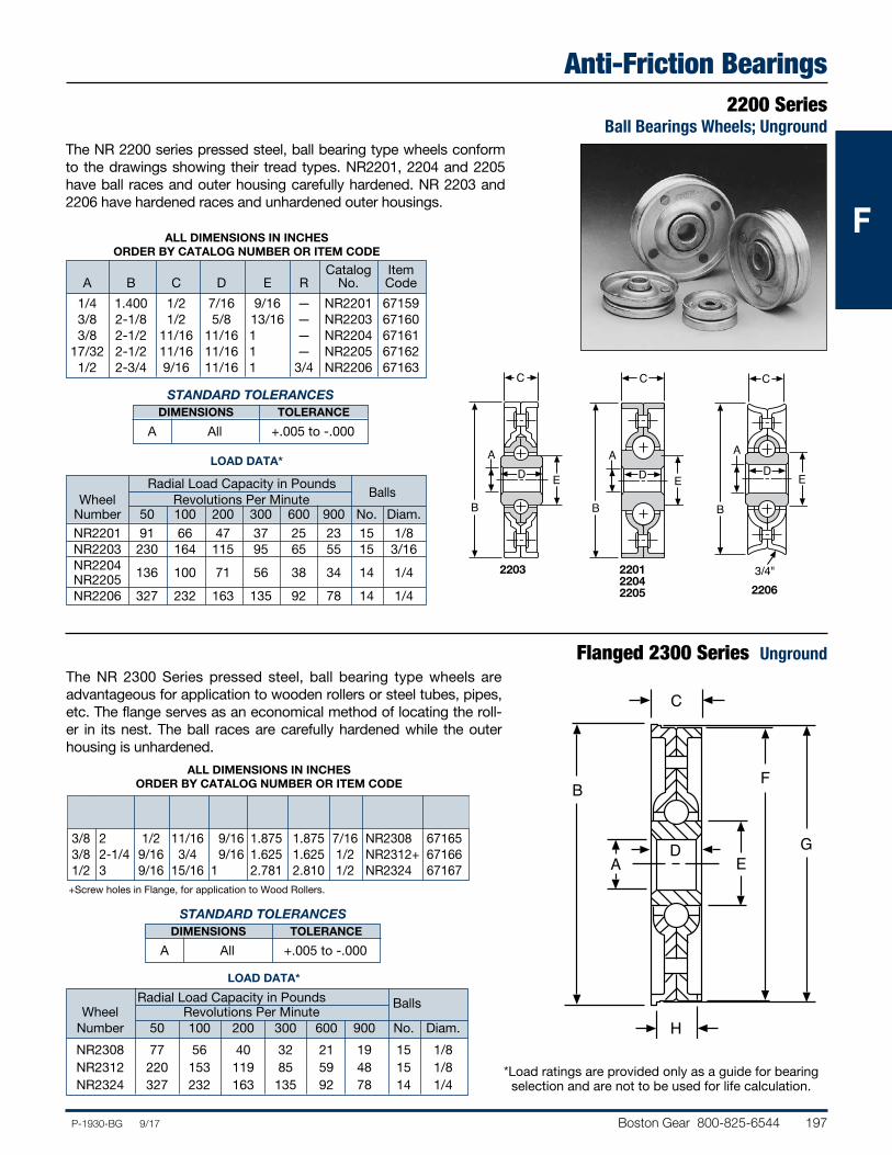
Boston Gear 800-825-6544 197P-1930-BG 9/17
FFF
Anti-Friction Bearings2200 Series
Ball Bearings Wheels; UngroundThe NR 2200 series pressed steel, ball bearing type wheels conform to the drawings showing their tread types. NR2201, 2204 and 2205 have ball races and outer housing carefully hardened. NR 2203 and 2206 have hardened races and unhardened outer housings.
LOAD DATA*
Radial Load Capacity in Pounds Balls
Wheel Revolutions Per Minute Number 50 100 200 300 600 900 No. Diam. NR2201 91 66 47 37 25 23 15 1/8 NR2203 230 164 115 95 65 55 15 3/16 NR2204 136 100 71 56 38 34 14 1/4 NR2205 NR2206 327 232 163 135 92 78 14 1/4
Flanged 2300 Series Unground
D
H
A
B
C
F
EG
The NR 2300 Series pressed steel, ball bearing type wheels are advantageous for application to wooden rollers or steel tubes, pipes, etc. The flange serves as an economical method of locating the roll-er in its nest. The ball races are carefully hardened while the outer housing is unhardened.
Radial Load Capacity in Pounds Balls Wheel Revolutions Per Minute Number 50 100 200 300 600 900 No. Diam.
NR2308 77 56 40 32 21 19 15 1/8 NR2312 220 153 119 85 59 48 15 1/8 NR2324 327 232 163 135 92 78 14 1/4
ALL DIMENSIONS IN INCHES ORDER BY CATALOG NUMBER OR ITEM CODE
Catalog Item A B C D E R No. Code
1/4 1.400 1/2 7/16 9/16 — NR2201 67159 3/8 2-1/8 1/2 5/8 13/16 — NR2203 67160 3/8 2-1/2 11/16 11/16 1 — NR2204 67161 17/32 2-1/2 11/16 11/16 1 — NR2205 67162 1/2 2-3/4 9/16 11/16 1 3/4 NR2206 67163
ALL DIMENSIONS IN INCHES ORDER BY CATALOG NUMBER OR ITEM CODE
Catalog Item A B C D E F G H No. Code
3/8 2 1/2 11/16 9/16 1.875 1.875 7/16 NR2308 67165 3/8 2-1/4 9/16 3/4 9/16 1.625 1.625 1/2 NR2312+ 67166 1/2 3 9/16 15/16 1 2.781 2.810 1/2 NR2324 67167
*Load ratings are provided only as a guide for bearing selection and are not to be used for life calculation.
+Screw holes in Flange, for application to Wood Rollers.
B
C
AD E
B
C
AD E
A
D
3/4"
B
C
E
LOAD DATA*
STANDARD TOLERANCES DIMENSIONS TOLERANCE
A All +.005 to -.000
STANDARD TOLERANCES DIMENSIONS TOLERANCE
A All +.005 to -.000
2203 220122042205 2206
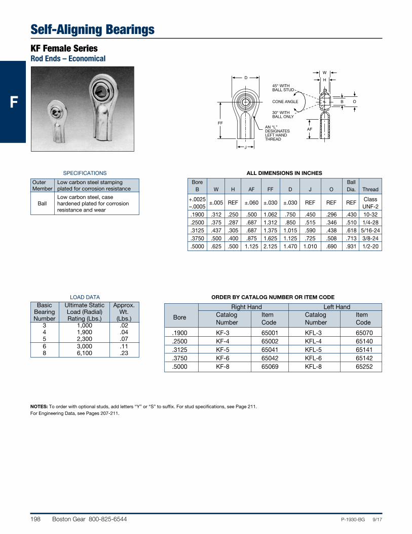
198 Boston Gear 800-825-6544 P-1930-BG 9/17
FFF
Self-Aligning BearingsKF Female SeriesRod Ends – Economical
ORDER BY CATALOG NUMBER OR ITEM CODE
ALL DIMENSIONS IN INCHES
Bore Ball B W H AF FF D J O Dia. Thread
+.0025 ±.005 REF ±.060 ±.030 ±.030 REF REF REF
Class –.0005 UNF-2 .1900 .312 .250 .500 1.062 .750 .450 .296 .430 10-32 .2500 .375 .287 .687 1.312 .850 .515 .346 .510 1/4-28 .3125 .437 .305 .687 1.375 1.015 .590 .438 .618 5/16-24 .3750 .500 .400 .875 1.625 1.125 .725 .508 .713 3/8-24 .5000 .625 .500 1.125 2.125 1.470 1.010 .690 .931 1/2-20
LOAD DATA
Basic Ultimate Static Approx. Bearing Load (Radial) Wt. Number Rating (Lbs.) (Lbs.) 3 1,000 .02 4 1,900 .04 5 2,300 .07 6 3,000 .11 8 6,100 .23
SPECIFICATIONS
Outer Low carbon steel stamping Member plated for corrosion resistance
Low carbon steel, case Ball hardened plated for corrosion resistance and wear
NOTES: To order with optional studs, add letters “Y” or “S” to suffix. For stud specifications, see Page 211. For Engineering Data, see Pages 207-211.
Right Hand Left Hand Bore Catalog Item Catalog Item Number Code Number Code
.1900 KF-3 65001 KFL-3 65070 .2500 KF-4 65002 KFL-4 65140 .3125 KF-5 65041 KFL-5 65141 .3750 KF-6 65042 KFL-6 65142 .5000 KF-8 65069 KFL-8 65252
WH
B O
AF
J
D
FF
45° WITHBALL STUD
30° WITHBALL ONLY
CONE ANGLE
AN “L”DESIGNATESLEFT HANDTHREAD
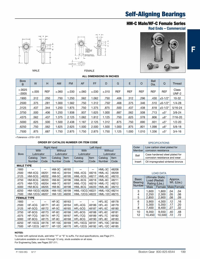
Boston Gear 800-825-6544 199P-1930-BG 9/17
FFF
Self-Aligning BearingsHM-C Male/HF-C Female Series
Rod Ends – Commercial
LOAD DATA Ultimate Static Basic Load (Radial) Approx. Bearing Rating (Lbs.) Wt. (Lbs.) Number Male Female Male Female
3 1,600 1,800 .04 .04 4 2,250 2,300 .05 .06 5 2,850 2,900 .08 .09 6 3,900 4,300 .12 .16 7 5,300 5,350 .17 .20 8 7,400 8,400 .27 .32 10 9,350 9,550 .40 .48 12 10,450 10,500 .72 .72
+Tolerance +.015/–.010
NOTES:To order with optional studs, add letter “Y” or “S” to suffix. For stud specifications, see Page 211. Lubricators available on sizes 4 through 12 only, studs available on all sizes.For Engineering Data, see Pages 207-211.
ORDER BY CATALOG NUMBER OR ITEM CODE
Right Hand Left Hand With Without With Without Bore Lubricator Lubricator Lubricator Lubricator Catalog Item Catalog Item Catalog Item Catalog Item Number Code Number Code Number Code Number Code
MALE TYPE .1900 — — HM-3C 48193 — — HML-3C 48208 .2500 HM-4CG 48201 HM-4C 48194 HML-4CG 48216 HML-4C 48209 .3125 HM-5CG 48202 HM-5C 48195 HML-5CG 48217 HML-5C 48210 .3750 HM-6CG 48203 HM-6C 48196 HML-6CG 48218 HML-6C 48211 .4375 HM-7CG 48204 HM-7C 48197 HML-7CG 48219 HML-7C 48212 .5000 HM-8CG 48205 HM-8C 48198 HML-8CG 48220 HML-8C 48213 .6250 HM-10CG 48206 HM-10C 48199 HML-10CG 48221 HML-10C 48214 .7500 HM-12CG 48207 HM-12C 48200 HML-12CG 48222 HML-12C 48215 FEMALE TYPE .1900 — — HF-3C 48163 — — HFL-3C 48178 .2500 HF-4CG 48171 HF-4C 48164 HFL-4CG 48186 HFL-4C 48179 .3125 HF-5CG 48172 HF-5C 48165 HFL-5CG 48187 HFL-5C 48180 .3750 HF-6CG 48173 HF-6C 48166 HFL-6CG 48188 HFL-6C 48181 .4375 HF-7CG 48174 HF-7C 48167 HFL-7CG 48189 HFL-7C 48182 .5000 HF-8CG 48175 HF-8C 48168 HFL-8CG 48190 HFL-8C 48183 .6250 HF-10CG 48176 HF-10C 48169 HFL-10CG 48191 HFL-10C 48184 .7500 HF-12CG 48177 HF-12C 48170 HFL-12CG 48192 HFL-12C 48185
ALL DIMENSIONS IN INCHES
Bore Ball B W H AM FM AF FF D G E O Dia. Q Thread
+.0025 ±.005 REF ±.060 ±.030 ±.060 ±.030 ±.010 REF REF REF REF
REF
Class -.0005 UNF-2
.1900 .312 .250 .750 1.250 .562 1.062 .750 .406 .312 .296 .430 ±5-1/2° 10-32
.2500 .375 .281 1.000 1.562 .750 1.312 .7501 .468 .375 .346 .510 ±6-1/2° 1/4-28
.3125 .437 .344 1.250 1.875 .750 1.375 .875 .500 .437 .438 .618 ±5-1/2° 5/16-24
.3750 .500 .406 1.250 1.938 .937 1.625 1.000 .687 .562 .508 .713 ±5° 3/8-24
.4375 .562 .437 1.375 2.125 1.062 1.812 1.125 .750 .625 .578 .806 ±6° 7/16-20
.5000 .625 .500 1.500 2.438 1.187 2.125 1.312 .875 .750 .690 .931 ±5° 1/2-20
.6250 .750 .562 1.625 2.625 1.500 2.500 1.500 1.000 .875 .801 1.098 ±6° 5/8-18
.7500 .875 .687 1.750 2.875 1.750 2.875 1.750 1.125 1.000 1.010 1.336 ±5° 3/4-16
W
H
B O
AM
D
FM
Q
MALE
W
H
B O
AF
GDIA
D
FF
EACROSS FLATS
Q
APPROX.LOCATION OFLUBRICATORIF REQD.
GROOVE DEPICTSLEFT HAND THREAD
FEMALE
SPECIFICATIONS
Outer Low carbon steel plated for Member corrosion resistance
Ball Case hardened steel plated for corrosion resistance and wear
Insert Oil impregnated sintered bronze
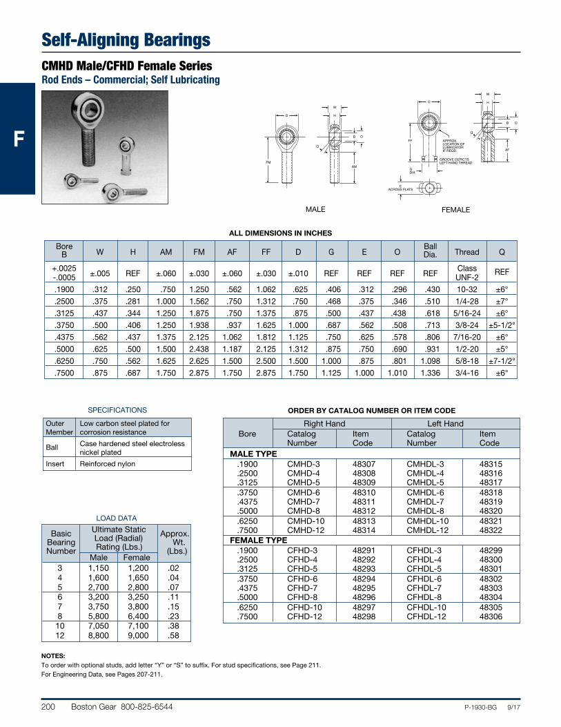
200 Boston Gear 800-825-6544 P-1930-BG 9/17
FFF
Self-Aligning BearingsCMHD Male/CFHD Female SeriesRod Ends – Commercial; Self Lubricating
SPECIFICATIONS
Outer Low carbon steel plated for Member corrosion resistance
Ball Case hardened steel electroless nickel plated
Insert Reinforced nylon
NOTES:To order with optional studs, add letter “Y” or “S” to suffix. For stud specifications, see Page 211.For Engineering Data, see Pages 207-211.
ORDER BY CATALOG NUMBER OR ITEM CODE
Right Hand Left Hand Bore Catalog Item Catalog Item Number Code Number Code MALE TYPE .1900 CMHD-3 48307 CMHDL-3 48315 .2500 CMHD-4 48308 CMHDL-4 48316 .3125 CMHD-5 48309 CMHDL-5 48317 .3750 CMHD-6 48310 CMHDL-6 48318 .4375 CMHD-7 48311 CMHDL-7 48319 .5000 CMHD-8 48312 CMHDL-8 48320 .6250 CMHD-10 48313 CMHDL-10 48321 .7500 CMHD-12 48314 CMHDL-12 48322 FEMALE TYPE .1900 CFHD-3 48291 CFHDL-3 48299 .2500 CFHD-4 48292 CFHDL-4 48300 .3125 CFHD-5 48293 CFHDL-5 48301 .3750 CFHD-6 48294 CFHDL-6 48302 .4375 CFHD-7 48295 CFHDL-7 48303 .5000 CFHD-8 48296 CFHDL-8 48304 .6250 CFHD-10 48297 CFHDL-10 48305 .7500 CFHD-12 48298 CFHDL-12 48306
LOAD DATA
Ultimate Static Basic Load (Radial) Approx. Bearing Rating (Lbs.) Wt. Number Male Female (Lbs.)
3 1,150 1,200 .02 4 1,600 1,650 .04 5 2,700 2,800 .07 6 3,200 3,250 .11 7 3,750 3,800 .15 8 5,800 6,400 .23 10 7,050 7,100 .38 12 8,800 9,000 .58
ALL DIMENSIONS IN INCHES
Bore Ball B W H AM FM AF FF D G E O Dia. Thread Q
+.0025 ±.005 REF ±.060 ±.030 ±.060 ±.030 ±.010 REF REF REF REF
Class -.0005 UNF-2
REF
.1900 .312 .250 .750 1.250 .562 1.062 .625 .406 .312 .296 .430 10-32 ±6° .2500 .375 .281 1.000 1.562 .750 1.312 .750 .468 .375 .346 .510 1/4-28 ±7° .3125 .437 .344 1.250 1.875 .750 1.375 .875 .500 .437 .438 .618 5/16-24 ±6° .3750 .500 .406 1.250 1.938 .937 1.625 1.000 .687 .562 .508 .713 3/8-24 ±5-1/2° .4375 .562 .437 1.375 2.125 1.062 1.812 1.125 .750 .625 .578 .806 7/16-20 ±6° .5000 .625 .500 1.500 2.438 1.187 2.125 1.312 .875 .750 .690 .931 1/2-20 ±5° .6250 .750 .562 1.625 2.625 1.500 2.500 1.500 1.000 .875 .801 1.098 5/8-18 ±7-1/2° .7500 .875 .687 1.750 2.875 1.750 2.875 1.750 1.125 1.000 1.010 1.336 3/4-16 ±6°
W
H
B O
AM
D
FM
Q
MALE
W
H
B O
AF
GDIA
D
FF
EACROSS FLATS
Q
APPROX.LOCATION OFLUBRICATORIF REQD.
GROOVE DEPICTSLEFT HAND THREAD
FEMALE
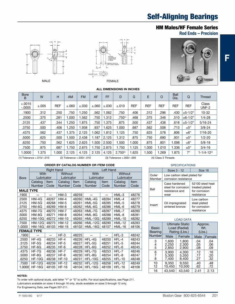
Boston Gear 800-825-6544 201P-1930-BG 9/17
FFF
Self-Aligning BearingsHM Males/HF Female Series
Rod Ends – Precision
W
H
B O
AM
D
FM
Q
W
H
B O
AF
GDIA
D
FF
EACROSS FLATS
Q
APPROX.LOCATION OFLUBRICATORIF REQD.
GROOVE DEPICTSLEFT HAND THREAD
NOTES:To order with optional studs, add letter “Y” or “S” to suffix. For stud specifications, see Page 211. Lubricators available on sizes 4 through 16 only, studs available on sizes 3 through 12 only.For Engineering Data, see Pages 207-211.
ORDER BY CATALOG NUMBER OR ITEM CODE
Right Hand Left Hand With Without With Without Bore Lubricator Lubricator Lubricator Lubricator Catalog Item Catalog Item Catalog Item Catalog Item Number Code Number Code Number Code Number Code
MALE TYPE .1900 — — HM-3 48259 — — HML-3 48276 .2500 HM-4G 48267 HM-4 48260 HML-4G 48284 HML-4 48277 .3125 HM-5G 48268 HM-5 48261 HML-5G 48285 HML-5 48278 .3750 HM-6G 48269 HM-6 48262 HML-6G 48286 HML-6 48279 .4375 HM-7G 48270 HM-7 48263 HML-7G 48287 HML-7 48280 .5000 HM-8G 48271 HM-8 48264 HML-8G 48288 HML-8 48281 .6250 HM-10G 48272 HM-10 48265 HML-10G 48289 HML-10 48282 .7500 HM-12G 48273 HM-12 48266 HML-12G 48290 HML-12 48283 1.0000 HM-16G 48103 HM-16 48102 HML-16G 48107 HML-16 48106 FEMALE TYPE .1900 — — HF-3 48225 — — HFL-3 48242 .2500 HF-4G 48233 HF-4 48226 HFL-4G 48250 HFL-4 48243 .3125 HF-5G 48234 HF-5 48227 HFL-5G 48251 HFL-5 48244 .3750 HF-6G 48235 HF-6 48228 HFL-6G 48252 HFL-6 48245 .4375 HF-7G 48236 HF-7 48229 HFL-7G 48253 HFL-7 48246 .5000 HF-8G 48237 HF-8 48230 HFL-8G 48254 HFL-8 48247 .6250 HF-10G 48238 HF-10 48231 HFL-10G 48255 HFL-10 48248 .7500 HF-12G 48239 HF-12 48232 HFL-12G 48256 HFL-12 48249 1.0000 HF-16G 48105 HF-16 48104 HFL-16G 48109 HFL-16 48108
SPECIFICATIONS
Sizes 3 - 12 Size 16
Outer Low carbon steel plated for Member corrosion resistance
Case hardened 52100 steel heat Ball
steel for corrosion treated plated resistance and for corrosion wear resistance
Low carbon Insert
Oil impregnated steel plated sintered bronze for corrosion resistance
LOAD DATA
Ultimate Static Approx. Basic Load (Radial) Wt. Bearing Rating (Lbs.) (Lbs.) Number Male Female Male Female 3 1,600 1,800 .04 .04 4 2,250 2,300 .05 .06 5 2,850 2,900 .08 .09 6 3,900 4,300 .12 .16 7 5,300 5,350 .17 .20 8 7,400 8,400 .27 .32 10 9,350 9,550 .40 .48 12 10,450 10,500 .62 .72 16 43,540 43,540 2.41 2.13
ALL DIMENSIONS IN INCHES
Bore Ball B W H AM FM AF FF D G E O Dia. Q Thread
+.0015 ±.005 REF ±.060 ±.030 ±.060 ±.030 ±.010 REF REF REF REF
REF
Class -.0005 UNF-2 .1900 .312 .250 .750 1.250 .562 1.062 .750 .406 .312 .296 .430 ±5-1/2° 10-32 .2500 .375 .281 1.000 1.562 .750 1.312 .750(1) .468 .375 .346 .510 ±6-1/2° 1/4-28 .3125 .437 .344 1.250 1.875 .750 1.375 .875 .500 .437 .438 .618 ±5-1/2° 5/16-24 .3750 .500 .406 1.250 1.938 .937 1.625 1.000 .687 .562 .508 .713 ±5° 3/8-24 .4375 .562 .437 1.375 2.125 1.062 1.812 1.125 .750 .625 .578 .806 ±6° 7/16-20 .5000 .625 .500 1.500 2.438 1.187 2.125 1.312 .875 .750 .690 .931 ±5° 1/2-20 .6250 .750 .562 1.625 2.625 1.500 2.500 1.500 1.000 .875 .801 1.098 ±6° 5/8-18 .7500 .875 .687 1.750 2.875 1.750 2.875 1.750 1.125 1.000 1.010 1.336 ±5° 3/4-16 1.0000 1.375 1.000 2.125 4.125 2.125 4.125 2.750(2) 1.625 1.500 1.269 1.875 7° 1-1/4-12(4)
(1) Tolerance +.015/–.010 (2) Tolerance +.030/–.010 (3) Tolerance +.000/–.005 (4) Class 3 Threads
MALE FEMALE
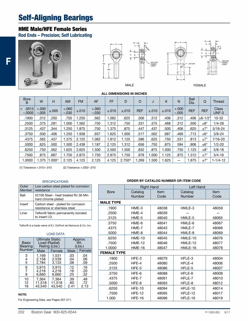
202 Boston Gear 800-825-6544 P-1930-BG 9/17
FFF
Self-Aligning BearingsHME Male/HFE Female SeriesRod Ends – Precision; Self Lubricating
NOTE:
For Engineering Data, see Pages 207-211.
ORDER BY CATALOG NUMBER OR ITEM CODE
Right Hand Left Hand Bore Catalog Item Catalog Item Number Code Number Code
MALE TYPE
.1900 HME-3 48038 HMLE-3 48059 .2500 HME-4 48039 — — .3125 HME-5 48040 HMLE-5 48065 .3750 HME-6 48041 HMLE-6 48067 .4375 HME-7 48043 HMLE-7 48068 .5000 HME-8 48044 HMLE-8 48069 .6250 HME-10 48045 HMLE-10 48076 .7500 HME-12 48046 HMLE-12 48077 1.0000 HME-16 48047 HMLE-16 48078 FEMALE TYPE
.1900 HFE-3 48079 HFLE-3 48004 .2500 HFE-4 48080 HFLE-4 48006 .3125 HFE-5 48086 HFLE-5 48007 .3750 HFE-6 48088 HFLE-6 48008 .4375 HFE-7 48091 HFLE-7 48010 .5000 HFE-8 48093 HFLE-8 48012 .6250 HFE-10 48094 HFLE-10 48014 .7500 HFE-12 48095 HFLE-12 46017 1.000 HFE-16 48096 HFLE-16 48019
ALL DIMENSIONS IN INCHES
Bore Ball B W H AM FM AF FF D O J K N Dia. Q Thread
+ .0015 +.000 ±.005 +.060 ±.010 +.060 ±.010 ±.010 REF ±.010 ±.010 +.000 REF REF Class –.0005 –.005 –.030 –.030 –.005 UNF-3 .1900 .312 .250 .750 1.250 .562 1.062 .625 .306 .312 .406 .312 .406 ±6-1/2° 10-32 .2500 .375 .281 1.000 1.562 .750 1.312 .750 .331 .375 .468 .312 .500 ±8° 1/4-28 .3125 .437 .344 1.250 1.875 .750 1.375 .875 .447 .437 .500 .406 .625 ±7° 5/16-24 .3750 .500 .406 1.250 1.938 .937 1.625 1.000 .517 .562 .687 .469 .713 ±6° 3/8-24 .4375 .562 .437 1.375 2.125 1.062 1.812 1.125 .586 .625 .750 .531 .813 ±7° 7/16-20 .5000 .625 .500 1.500 2.438 1.187 2.125 1.312 .656 .750 .875 594 .906 ±6° 1/2-20 .6250 .750 .562 1.625 2.625 1.500 2.500 1.500 .832 .875 1.000 .750 1.125 ±8° 5/8-18 .7500 .875 .687 1.750 2.875 1.750 2.875 1.750 .978 1.000 1.125 .875 1.312 ±7° 3/4-16 1.0000 1.375 1.000(1) 2.125 4.125 2.125 4.125 2.750(2) 1.269 1.500 1.625 — 1.875 ±7° 1-1/4-12
(1) Tolerance +.015/–.010 (2) Tolerance +.030/–.010
Teflon® is a trade name of E.I. DuPont de Nemours & Co. Inc.
LOAD DATA
Ultimate Static Approx. Basic Load (Radial) Wt. Bearing Rating (Lbs.) (Lbs.) Number Male Female Male Female 3 1,169 1,531 .03 .04 4 2,158 2,539 .04 .06 5 2,784 3,133 .08 .09 6 3,915 3,915 .12 .16 7 4,218 4,218 .16 .20 8 6,660 6,660 .25 .32 10 7,364 7,364 .39 .48 12 11,518 11,518 .60 .72 16 43,540 43,540 2.41 2.13
SPECIFICATIONS Outer Low carbon steel plated for corrosion Member resistance
Ball 52100 Steel - heat treated Rc 56 Min hard chrome plated
Insert Carbon steel - plated for corrosion resistance or stainless steel
Liner Teflon® fabric permanently bonded to insert I.D.
WH
BO
D
FM
Q
TEFLON®
FABRICLINER
AM
MALE
WH
BO
AF
D
FF
Q
J
K
N
.070 DIATEFLON®
FABRICLINER
FEMALE
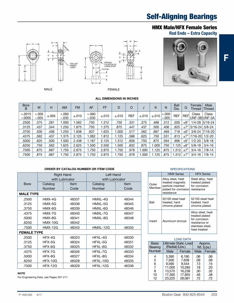
Boston Gear 800-825-6544 203P-1930-BG 9/17
FFF
Self-Aligning BearingsHMX Male/HFX Female Series
Rod Ends – Extra Capacity
WH
BO
D
FM
Q
TEFLON®
FABRICLINER
AM
W
H
BO
AF
K
D
FF
Q
APPROX.LOCATION OFLUBRICATOR
.070 DIA.J
N
NOTEFor Engineering Data, see Pages 207-211.
LOAD DATA Basic Ultimate Static Load Approx. Bearing (Radial) (Lbs.) Wt. (Lbs.) Number Male Female Male Female
4 5,390 6,190 .06 .06 5 7,500 7,639 .09 .09 6 9,590 9,544 .13 .15 7 11,000 10,285 .18 .20 8 13,575 16,238 .30 .32 10 17,300 17,955 .46 .48 12 23,225 28,081 .72 .72
ORDER BY CATALOG NUMBER OR ITEM CODE
Right Hand Left Hand with Lubricator with Lubricator Bore Catalog Item Catalog Item Number Code Number Code
MALE TYPE
.2500 HMX-4G 48337 HMXL-4G 48344 .3125 HMX-5G 48338 HMXL-5G 48345 .3750 HMX-6G 48339 HMXL-6G 48346 .4375 HMX-7G 48340 HMXL-7G 48347 .5000 HMX-8G 48341 HMXL-8G 48348 .6250 HMX-10G 48342 .7500 HMX-12G 48343 HMXL-12G 48350 FEMALE TYPE .2500 HFX-4G 48323 HFXL-4G 48330 .3125 HFX-5G 48324 HFXL-5G 48331 .3750 HFX-6G 48325 HFXL-6G 48332 .4375 HFX-7G 48326 HFXL-7G 48333 .5000 HFX-8G 48327 HFXL-8G 48334 .6250 HFX-10G 48328 HFXL-10G 48335 .7500 HFX-12G 48329 HFXL-12G 46336
SPECIFICATIONS
HMX Series HFX Series
Alloy steel, heat Steel alloy, heat Outer
treated magnetic treated plated Member
particle inserted for corrosion plated for corrosion resistance resistance
52100 steel heat 52100 steel heat Ball treated, hard treated, hard
chrome plated chrome plated
Alloy steel, heat treated plated Insert Aluminum bronze
for corrosion resistance or stainless steel, heat treated
ALL DIMENSIONS IN INCHES
Bore Ball Female Male B W H AM FM AF FF D O J K N Dia. Q Thread Thread
+.0015 +.000 ±.005 +.060 ±.010 +.060 ±.010 ±.010 REF ±.010 ±.010 +.000 REF REF Class Class –.0005 –.005 –.030 –.030 –.005 UNF-3B UNF-3A .2500 .375 .281 1.000 1.562 .750 1.312 .750 .331 .375 .468 .312 .500 ±8° 1/4-28 5/16-24 .3125 .437 .344 1.250 1.875 .750 1.375 .875 .447 .437 .500 .406 .625 ±7° 5/16-24 3/8-24 .3750 .500 .406 1.250 1.938 .937 1.625 1.000 .517 .562 .687 .469 .718 ±6° 3/8-24 7/16-20 .4375 .562 .437 1.375 2.125 1.062 1.812 1.125 .586 .625 .750 .531 .813 ±7° 7/16-20 1/2-20 .5000 .625 .500 1.500 2.438 1.187 2.125 1.312 .656 .750 .875 .594 .906 ±6° 1/2-20 5/8-18 .6250 .750 .562 1.625 2.625 1.500 2.500 1.500 .832 .875 1.000 .750 1.125 ±8° 5/8-18 3/4-16 .7500 .875 .687 1.750 2.875 1.750 2.875 1.750 .978 1.000 1.125 .875 1.312 ±7° 3/4-16 7/8-14 .7500 .875 .687 1.750 2.875 1.750 2.875 1.750 .978 1.000 1.125 .875 1.312 ±7° 3/4-16 7/8-14
MALE FEMALE
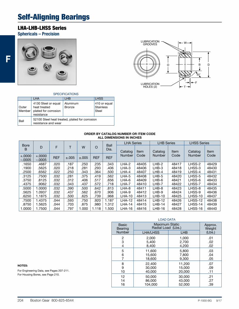
204 Boston Gear 800-825-6544 P-1930-BG 9/17
FFF
Self-Aligning BearingsLHA-LHB-LHSS SeriesSphericals – Precision
W
BO D
LUBRICATIONGROOVES
LUBRICATIONHOLES (2)
FT
45˚
SPECIFICATIONS LHA LHB LHSS
4130 Steel or equal Aluminum 410 or equal Outer heat treated Bronze Stainless Member plated for corrosion Steel resistance
Ball 52100 Steel heat treated, plated for corrosion resistance and wear
NOTES:
For Engineering Data, see Pages 207-211.For Housing Bores, see Page 210.
LOAD DATA
Basic Maximum Static Approx. Bearing Radial Load (Lbs.) Weight Number LHA/LHSS LHB (Lbs.)
2 2,000 1,000 .01 3 5,400 2,700 .02 4 8,400 4,200 .02 5 11,600 5,800 .03 6 15,600 7,800 .04 7 18,600 9,300 .05 8 22,400 11,200 .07 9 30,000 15,000 .09 10 40,000 20,000 .11 12 50,000 30,000 .21 14 86,000 43,000 .27 16 104,000 52,000 .39
ORDER BY CATALOG NUMBER OR ITEM CODE ALL DIMENSIONS IN INCHES
LHA Series LHB Series LHSS Series Bore Ball
Catalog
Item
Catalog
Item
Catalog
Item
B D F T W O
Dia. Number
Code
Number
Code
Number
Code +.0000 +.0000 REF ±.005 ±.005 REF REF
–.0005 –.0005 .1650 .4687 .020 .187 .250 .235 .343 LHA-2 48405 LHB-2 48417 LHSS-2 48429 .1900 .5625 .020 .218 .281 .293 .406 LHA-3 48406 LHB-3 48418 LHSS-3 48430 .2500 .6562 .022 .250 .343 .364 .500 LHA-4 48407 LHB-4 48419 LHSS-4 48431 .3125 .7500 .032 .281 .375 .419 .562 LHA-5 48408 LHB-5 48420 LHSS-5 48432 .3750 .8125 .032 .312 .406 .517 .656 LHA-6 48409 LHB-6 48421 LHSS-6 48433 .4375 .9062 .032 .343 .437 .572 .718 LHA-7 48410 LHB-7 48422 LHSS-7 48434 .5000 1.0000 .032 .390 .500 .642 .813 LHA-8 48411 LHB-8 48423 LHSS-8 48435 .5625 1.0937 .032 .437 .562 .670 .906 LHA-9 48412 LHB-9 48424 LHSS-9 48436 .6250 1.1875 .032 .500 .625 .739 .968 LHA-10 48413 LHB-10 48425 LHSS-10 48437 .7500 1.4375 .044 .593 .750 .920 1.187 LHA-12 48414 LHB-12 48426 LHSS-12 48438 .8750 1.5625 .044 .703 .875 .980 1.312 LHA-14 48415 LHB-14 48427 LHSS-14 48439 1.0000 1.7500 .044 .797 1.000 1.118 1.500 LHA-16 48416 LHB-16 48428 LHSS-16 48440
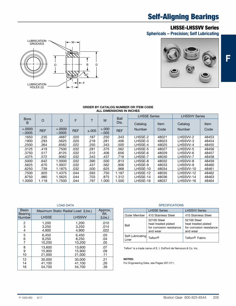
Boston Gear 800-825-6544 205P-1930-BG 9/17
FFF
Self-Aligning BearingsLHSSE-LHSSVV Series
Sphericals – Precision; Self Lubricating
W
BO D
LUBRICATIONGROOVES
LUBRICATIONHOLES (2)
FT
45˚
SPECIFICATIONS
LHSSE Series LHSSVV Series
Outer Member 410 Stainless Steel 410 Stainless Steel
52100 Steel 52100 Steel Ball heat treated plated heat treated plated for corrosion resistance for corrosion resistance and wear and wear
Self Lubricating Teflon® Teflon® Fabric
Liner
NOTES:For Engineering Data, see Pages 207-211.
LOAD DATA
Basic Maximum Static Radial Load (Lbs.) Approx. Bearing
LHSSE LHSSVV Wt.
Number (Lbs.)
2 1,200 1,200 .010 3 3,250 3,250 .014 4 4,900 4,900 .022 5 6,450 6,450 .03 6 8,250 8,250 .04 7 10,200 10,200 .05 8 13,600 13,600 .07 9 15,900 15,900 .09 10 21,000 21,000 .11 12 30,000 30,000 .21 14 41,100 41,100 .26 16 54,700 54,700 .39
ORDER BY CATALOG NUMBER OR ITEM CODE ALL DIMENSIONS IN INCHES
LHSSE Series LHSSVV Series Bore Ball B
O D F T W Dia. Catalog Item Catalog Item
+.0000 REF +.0000 REF ±.005 +.000 REF Number Code Number Code –.0005 – .0005 –.005 .1650 .235 .4687 .020 .187 .250 .343 LHSSE-2 48021 LHSSVV-2 48453 .1900 .293 .5625 .020 .218 .281 .406 LHSSE-3 48023 LHSSVV-3 48454 .2500 .364 .6562 .022 .250 .343 .500 LHSSE-4 48025 LHSSVV-4 48455 .3125 .419 .7500 .032 .281 .375 .562 LHSSE-5 48027 LHSSVV-5 48456 .3750 .517 .8125 .032 .312 .406 .656 LHSSE-6 48029 LHSSVV-6 48457 .4375 .572 .9062 .032 .343 .437 .718 LHSSE-7 48030 LHSSVV-7 48458 .5000 .642 1.0000 .032 .390 .500 .813 LHSSE-8 48032 LHSSVV-8 48459 .5625 .670 1.0937 .032 .437 .562 .906 LHSSE-9 48033 LHSSVV-9 48460 .6250 .739 1.1875 .032 .500 .625 .968 LHSSE-10 48034 LHSSVV-10 48461 .7500 .920 1.4375 .044 .593 .750 1.187 LHSSE-12 48035 LHSSVV-12 48462 .8750 .980 1.5625 .044 .703 .875 1.312 LHSSE-14 48036 LHSSVV-14 48463 1.0000 1.118 1.7500 .044 .797 1.000 1.500 LHSSE-16 48037 LHSSVV-16 48464
Teflon® is a trade name of E. I. DuPont de Nemours & Co. Inc.
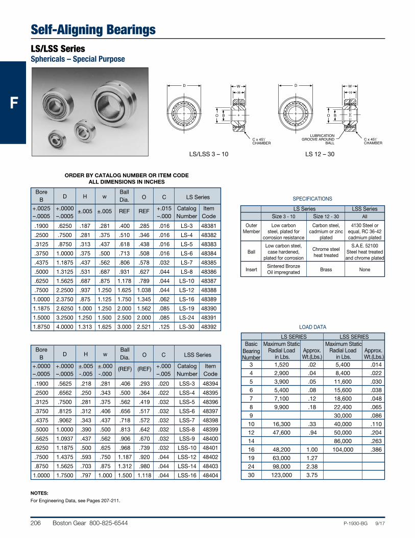
206 Boston Gear 800-825-6544 P-1930-BG 9/17
FFF
Self-Aligning BearingsLS/LSS SeriesSphericals – Special Purpose
ORDER BY CATALOG NUMBER OR ITEM CODE ALL DIMENSIONS IN INCHES
Bore Ball B D H w Dia. O C LS Series
+.0025 +.0000 ±.005 ±.005 REF REF +.015 Catalog Item –.0005 –.0005 –.000 Number Code
.1900 .6250 .187 .281 .400 .285 .016 LS-3 48381
.2500 .7500 .281 .375 .510 .346 .016 LS-4 48382
.3125 .8750 .313 .437 .618 .438 .016 LS-5 48383
.3750 1.0000 .375 .500 .713 .508 .016 LS-6 48384
.4375 1.1875 .437 .562 .806 .578 .032 LS-7 48385
.5000 1.3125 .531 .687 .931 .627 .044 LS-8 48386
.6250 1.5625 .687 .875 1.178 .789 .044 LS-10 48387
.7500 2.2500 .937 1.250 1.625 1.038 .044 LS-12 48388
1.0000 2.3750 .875 1.125 1.750 1.345 .062 LS-16 48389
1.1875 2.6250 1.000 1.250 2.000 1.562 .085 LS-19 48390
1.5000 3.2500 1.250 1.500 2.500 2.000 .085 LS-24 48391
1.8750 4.0000 1.313 1.625 3.000 2.521 .125 LS-30 48392
Bore Ball B D H w Dia. O C LSS Series
+.0000 +.0000 ±.005 ±.000 (REF) (REF) +.000 Catalog Item –.0005 –.0005 -.005 -.000 –.005 Number Code
.1900 .5625 .218 .281 .406 .293 .020 LSS-3 48394
.2500 .6562 .250 .343 .500 .364 .022 LSS-4 48395
.3125 .7500 .281 .375 .562 .419 .032 LSS-5 48396
.3750 .8125 .312 .406 .656 .517 .032 LSS-6 48397
.4375 .9062 .343 .437 .718 .572 .032 LSS-7 48398
.5000 1.0000 .390 .500 .813 .642 .032 LSS-8 48399
.5625 1.0937 .437 .562 .906 .670 .032 LSS-9 48400
.6250 1.1875 .500 .625 .968 .739 .032 LSS-10 48401
.7500 1.4375 .593 .750 1.187 .920 .044 LSS-12 48402
.8750 1.5625 .703 .875 1.312 .980 .044 LSS-14 48403
1.0000 1.7500 .797 1.000 1.500 1.118 .044 LSS-16 48404
WH
BO
D
C x 45ϒCHAMBER
LUBRICATIONGROOVE AROUND
BALL
WH
BO
D
C x 45ϒCHAMBER
NOTES:
For Engineering Data, see Pages 207-211.
LOAD DATA
LS SERIES LSS SERIES
Basic Maximum Static Maximum Static Bearing Radial Load Approx. Radial Load Approx. Number in Lbs. Wt.(Lbs.) in Lbs. Wt.(Lbs.) 3 1,520 .02 5,400 .014
4 2,900 .04 8,400 .022
5 3,900 .05 11,600 .030
6 5,400 .08 15,600 .038
7 7,100 .12 18,600 .048
8 9,900 .18 22,400 .065
9 30,000 .086
10 16,300 .33 40,000 .110
12 47,600 .94 50,000 .204
14 86,000 .263
16 48,200 1.00 104,000 .386
19 63,000 1.27
24 98,000 2.38
30 123,000 3.75
SPECIFICATIONS
LS Series LSS Series Size 3 - 10 Size 12 - 30 All
Outer Low carbon Carbon steel, 4130 Steel or Member steel, plated for cadmium or zinc equal, RC 36-42 corrosion resistance plated cadmium plated
Ball
Low carbon steel, Chrome steel
S.A.E. 52100 case hardened,
heat treated Steel heat treated
plated for corrosion and chrome plated
Insert
Sintered Bronze Brass None
Oil impregnated
LS/LSS 3 – 10 LS 12 – 30
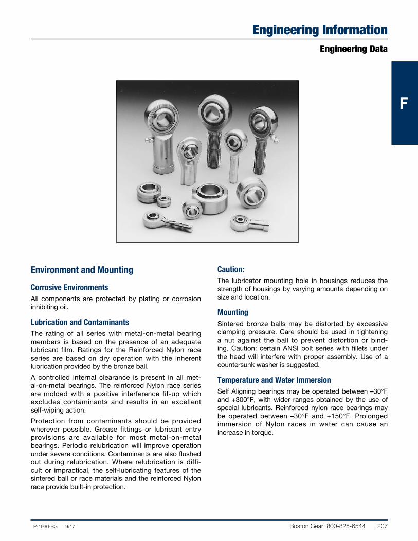
Boston Gear 800-825-6544 207P-1930-BG 9/17
FFF
Engineering InformationEngineering Data
Environment and Mounting
Corrosive EnvironmentsAll components are protected by plating or corrosion inhibiting oil.
Lubrication and ContaminantsThe rating of all series with metal-on-metal bearing members is based on the presence of an adequate lubricant film. Ratings for the Reinforced Nylon race series are based on dry operation with the inherent lubrication provided by the bronze ball.
A controlled internal clearance is present in all met-al-on-metal bearings. The reinforced Nylon race series are molded with a positive interference fit-up which excludes contaminants and results in an excellent self-wiping action.
Protection from contaminants should be provided wherever possible. Grease fittings or lubricant entry provisions are available for most metal-on-metal bearings. Periodic relubrication will improve operation under severe conditions. Contaminants are also flushed out during relubrication. Where relubrication is diffi-cult or impractical, the self-lubricating features of the sintered ball or race materials and the reinforced Nylon race provide built-in protection.
Caution:The lubricator mounting hole in housings reduces the strength of housings by varying amounts depending on size and location.
MountingSintered bronze balls may be distorted by excessive clamping pressure. Care should be used in tight ening a nut against the ball to prevent distortion or bind-ing. Caution: certain ANSI bolt series with fillets under the head will interfere with proper assembly. Use of a countersunk washer is suggested.
Temperature and Water ImmersionSelf Aligning bearings may be operated between –30°F and +300°F, with wider ranges obtained by the use of special lubricants. Reinforced nylon race bearings may be operated between –30°F and +150°F. Prolonged immersion of Nylon races in water can cause an increase in torque.
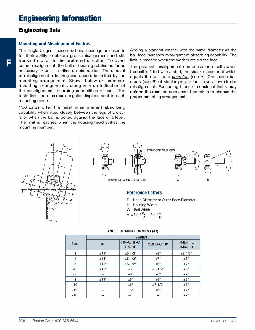
208 Boston Gear 800-825-6544 P-1930-BG 9/17
FFF
Engineering InformationEngineering Data
Mounting and Misalignment FactorsThe single biggest reason rod end bearings are used is for their ability to absorb gross misalignment and still transmit motion in the preferred direction. To over-come misalignment, the ball or housing rotates as far as necessary or until it strikes an obstruction. The amount of misalignment a bearing can absorb is limited by the mounting arrangement. Shown below are common mounting arrangements, along with an indication of the misalignment absorbing capabilities of each. The table lists the maximum angular displacement in each mounting mode.
Rod Ends offer the least misalignment absorbing capability when fitted closely between the legs of a clev-is or when the ball is bolted against the face of a lever. The limit is reached when the housing head strikes the mounting member.
Adding a standoff washer with the same diameter as the ball face increases misalignment absorbing capability. The limit is reached when the washer strikes the face.
The greatest misalignment compensation results when the ball is fitted with a stud, the shank diameter of which equals the ball bore chamfer, (see A). One piece ball studs (see B) of similar proportions also allow similar misalignment. Exceeding these dimensional limits may deform the race, so care should be taken to choose the proper mounting arrangement.
STANDOFF WASHERS
MOUNTING ARRANGEMENTS
A B
C
BA
C
a1
a1
Reference LettersD – Head Diameter or Outer Race DiameterH – Housing WidthW – Ball WidthA1=Sin–1 W − Sin–1 H
ANGLE OF MISALIGNMENT (A1)
SERIES Size
KF HM-C/HF-C
CMHD/CFHD HME/HFE
HM/HF HMX/HFX
-3 ±15° ±5-1/2° ±6° ±6-1/2°
-4 ±15° ±6-1/2° ±7° ±8°
-5 ±15° ±5-1/2° ±6° ±7°
-6 ±15° ±5° ±5-1/2° ±6°
-7 — ±6° ±6° ±7°
-8 ±15° ±5° ±5° ±6°
-10 — ±6° ±7-1/2° ±8°
-12 — ±5° ±6° ±7°
-16 — ±7° — ±7°
D D
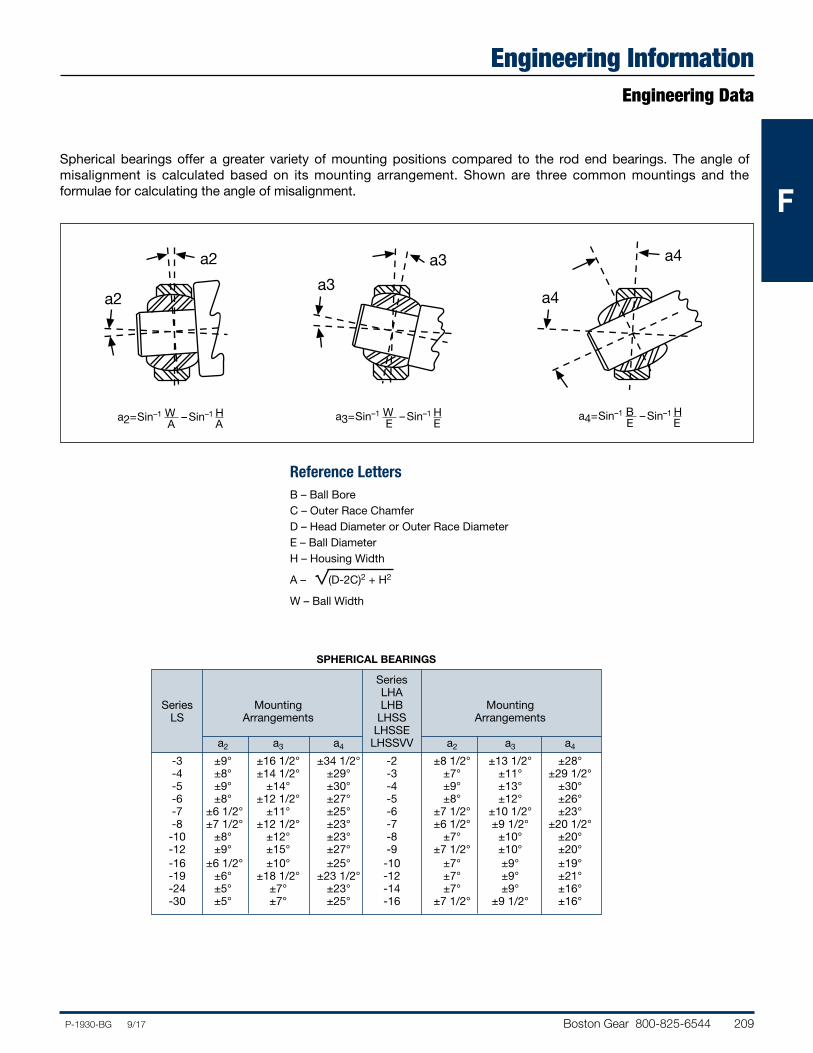
Boston Gear 800-825-6544 209P-1930-BG 9/17
FFF
Engineering InformationEngineering Data
Spherical bearings offer a greater variety of mounting positions compared to the rod end bearings. The angle of misalignment is calculated based on its mounting arrangement. Shown are three common mountings and the formulae for calculating the angle of misalignment.
SPHERICAL BEARINGS
Series LHA Series Mounting LHB Mounting LS Arrangements LHSS Arrangements LHSSE a2 a3 a4 LHSSVV a2 a3 a4
-3 ±9° ±16 1/2° ±34 1/2° -2 ±8 1/2° ±13 1/2° ±28° -4 ±8° ±14 1/2° ±29° -3 ±7° ±11° ±29 1/2° -5 ±9° ±14° ±30° -4 ±9° ±13° ±30° -6 ±8° ±12 1/2° ±27° -5 ±8° ±12° ±26° -7 ±6 1/2° ±11° ±25° -6 ±7 1/2° ±10 1/2° ±23° -8 ±7 1/2° ±12 1/2° ±23° -7 ±6 1/2° ±9 1/2° ±20 1/2° -10 ±8° ±12° ±23° -8 ±7° ±10° ±20° -12 ±9° ±15° ±27° -9 ±7 1/2° ±10° ±20° -16 ±6 1/2° ±10° ±25° -10 ±7° ±9° ±19° -19 ±6° ±18 1/2° ±23 1/2° -12 ±7° ±9° ±21° -24 ±5° ±7° ±23° -14 ±7° ±9° ±16° -30 ±5° ±7° ±25° -16 ±7 1/2° ±9 1/2° ±16°
a2
a2
a3
a3
a4
a4
Reference LettersB – Ball BoreC – Outer Race ChamferD – Head Diameter or Outer Race DiameterE – Ball DiameterH – Housing Width
A – (D-2C)2 + H2
W – Ball Width
a2=Sin–1 W – Sin–1 HA A
a3=Sin–1 W – Sin–1 HE E
a4=Sin–1 B – Sin–1 HE E
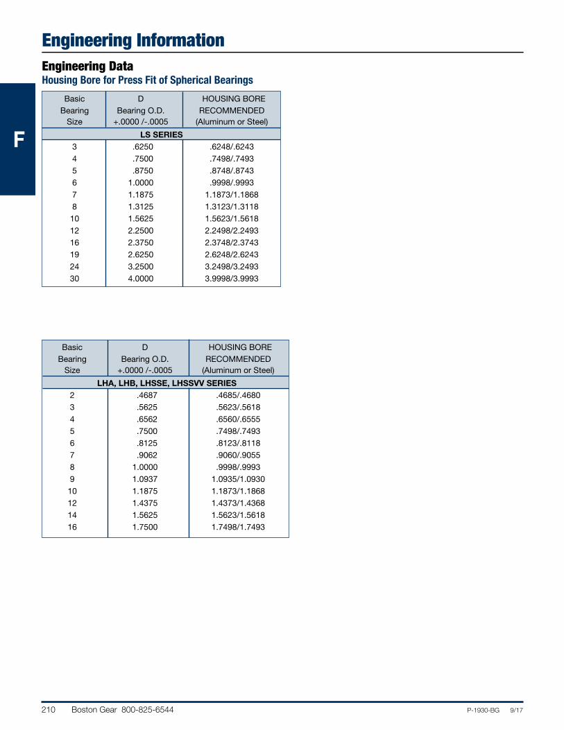
210 Boston Gear 800-825-6544 P-1930-BG 9/17
FFF
Engineering InformationEngineering DataHousing Bore for Press Fit of Spherical Bearings
Basic D HOUSING BORE Bearing Bearing O.D. RECOMMENDED Size +.0000 /-.0005 (Aluminum or Steel)
LS SERIES 3 .6250 .6248/.6243 4 .7500 .7498/.7493 5 .8750 .8748/.8743 6 1.0000 .9998/.9993 7 1.1875 1.1873/1.1868 8 1.3125 1.3123/1.3118 10 1.5625 1.5623/1.5618 12 2.2500 2.2498/2.2493 16 2.3750 2.3748/2.3743 19 2.6250 2.6248/2.6243 24 3.2500 3.2498/3.2493 30 4.0000 3.9998/3.9993
Basic D HOUSING BORE Bearing Bearing O.D. RECOMMENDED Size +.0000 /-.0005 (Aluminum or Steel)
LHA, LHB, LHSSE, LHSSVV SERIES 2 .4687 .4685/.4680 3 .5625 .5623/.5618 4 .6562 .6560/.6555 5 .7500 .7498/.7493 6 .8125 .8123/.8118 7 .9062 .9060/.9055 8 1.0000 .9998/.9993 9 1.0937 1.0935/1.0930 10 1.1875 1.1873/1.1868 12 1.4375 1.4373/1.4368 14 1.5625 1.5623/1.5618 16 1.7500 1.7498/1.7493
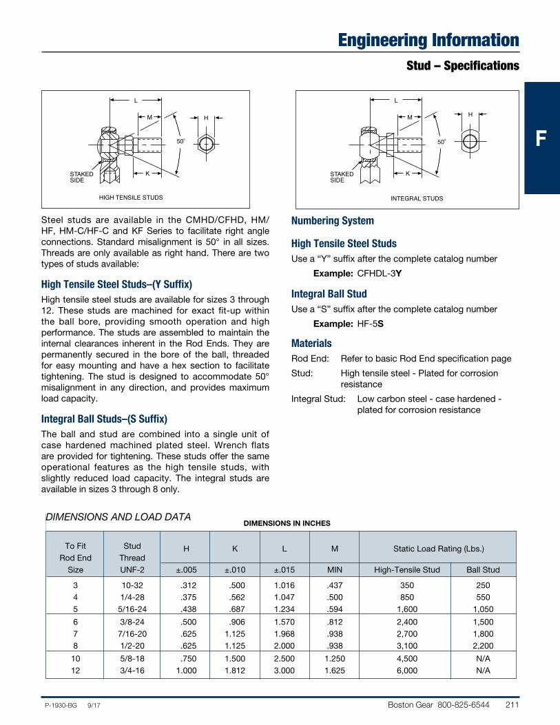
Boston Gear 800-825-6544 211P-1930-BG 9/17
FFF
Engineering InformationStud – Specifications
Steel studs are available in the CMHD/CFHD, HM/HF, HM-C/HF-C and KF Series to facilitate right angle connections. Standard misalignment is 50° in all sizes. Threads are only available as right hand. There are two types of studs available:
High Tensile Steel Studs–(Y Suffix) High tensile steel studs are available for sizes 3 through 12. These studs are machined for exact fit-up within the ball bore, providing smooth operation and high performance. The studs are assembled to maintain the internal clearances inherent in the Rod Ends. They are permanently secured in the bore of the ball, threaded for easy mounting and have a hex section to facilitate tightening. The stud is designed to accommodate 50° misalignment in any direction, and provides maximum load capacity.
Integral Ball Studs–(S Suffix)The ball and stud are combined into a single unit of case hardened machined plated steel. Wrench flats are provided for tightening. These studs offer the same operational features as the high tensile studs, with slightly reduced load capacity. The integral studs are available in sizes 3 through 8 only.
Numbering System
High Tensile Steel StudsUse a “Y” suffix after the complete catalog number
Example: CFHDL-3Y
Integral Ball StudUse a “S” suffix after the complete catalog number
Example: HF-5S
MaterialsRod End: Refer to basic Rod End specification page
Stud: High tensile steel - Plated for corrosion resistance
Integral Stud: Low carbon steel - case hardened - plated for corrosion resistance
L
M
K
H
HIGH TENSILE STUDS
STAKEDSIDE
50˚
INTEGRAL STUDS
L
M
K
H
STAKEDSIDE
50˚
To Fit Stud Rod End Thread
H K L M Static Load Rating (Lbs.)
Size UNF-2 ±.005 ±.010 ±.015 MIN High-Tensile Stud Ball Stud
3 10-32 .312 .500 1.016 .437 350 250 4 1/4-28 .375 .562 1.047 .500 850 550 5 5/16-24 .438 .687 1.234 .594 1,600 1,050
6 3/8-24 .500 .906 1.570 .812 2,400 1,500 7 7/16-20 .625 1.125 1.968 .938 2,700 1,800 8 1/2-20 .625 1.125 2.000 .938 3,100 2,200
10 5/8-18 .750 1.500 2.500 1.250 4,500 N/A 12 3/4-16 1.000 1.812 3.000 1.625 6,000 N/A
DIMENSIONS AND LOAD DATA DIMENSIONS IN INCHES
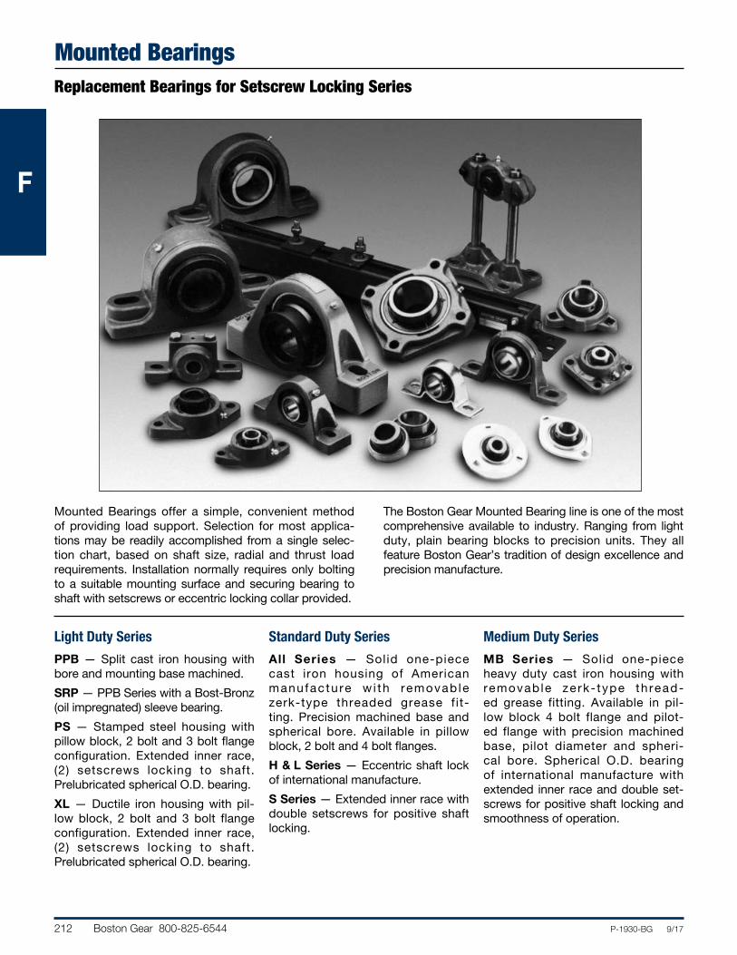
212 Boston Gear 800-825-6544 P-1930-BG 9/17
FFF
Mounted BearingsReplacement Bearings for Setscrew Locking Series
Mounted Bearings offer a simple, convenient method of providing load support. Selection for most applica-tions may be readily accomplished from a single selec-tion chart, based on shaft size, radial and thrust load requirements. Installation normally requires only bolting to a suitable mounting surface and securing bearing to shaft with setscrews or eccentric locking collar provided.
The Boston Gear Mounted Bearing line is one of the most comprehensive available to industry. Ranging from light duty, plain bearing blocks to precision units. They all feature Boston Gear’s tradition of design excellence and precision manufacture.
Light Duty Series
PPB — Split cast iron housing with bore and mounting base machined.
SRP — PPB Series with a Bost-Bronz (oil impregnated) sleeve bearing.
PS — Stamped steel housing with pillow block, 2 bolt and 3 bolt flange configuration. Extended inner race, (2) setscrews locking to shaft. Prelubricated spherical O.D. bearing.
XL — Ductile iron housing with pil-low block, 2 bolt and 3 bolt flange configuration. Extended inner race, (2) setscrews locking to shaft. Pre lub ricated spherical O.D. bearing.
Standard Duty Series
All Series — Solid one-piece cast iron housing of American manufacture w i th removab le zerk-type threaded grease fit-ting. Precision machined base and spherical bore. Available in pillow block, 2 bolt and 4 bolt flanges.
H & L Series — Eccentric shaft lock of international manufacture.
S Series — Extended inner race with double setscrews for positive shaft locking.
Medium Duty Series
MB Series — Solid one-piece heavy duty cast iron housing with removable zerk- type thread-ed grease fitting. Available in pil-low block 4 bolt flange and pilot-ed flange with precision machined base, pilot diameter and spheri-cal bore. Spherical O.D. bearing of international manufacture with extended inner race and double set-screws for positive shaft locking and smoothness of operation.
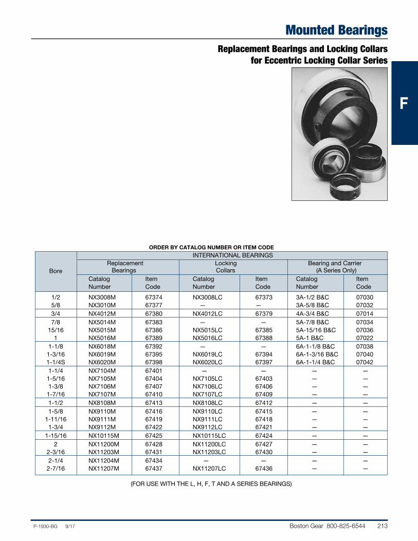
Boston Gear 800-825-6544 213P-1930-BG 9/17
FFF
Replacement Bearings and Locking Collars for Eccentric Locking Collar Series
Mounted Bearings
ORDER BY CATALOG NUMBER OR ITEM CODE
INTERNATIONAL BEARINGS Replacement Locking Bearing and Carrier Bore Bearings Collars (A Series Only) Catalog Item Catalog Item Catalog Item Number Code Number Code Number Code
1/2 NX3008M 67374 NX3008LC 67373 3A-1/2 B&C 07030 5/8 NX3010M 67377 — — 3A-5/8 B&C 07032 3/4 NX4012M 67380 NX4012LC 67379 4A-3/4 B&C 07014 7/8 NX5014M 67383 — — 5A-7/8 B&C 07034 15/16 NX5015M 67386 NX5015LC 67385 5A-15/16 B&C 07036 1 NX5016M 67389 NX5016LC 67388 5A-1 B&C 07022 1-1/8 NX6018M 67392 — — 6A-1-1/8 B&C 07038 1-3/16 NX6019M 67395 NX6019LC 67394 6A-1-3/16 B&C 07040 1-1/4S NX6020M 67398 NX6020LC 67397 6A-1-1/4 B&C 07042 1-1/4 NX7104M 67401 — — — — 1-5/16 NX7105M 67404 NX7105LC 67403 — — 1-3/8 NX7106M 67407 NX7106LC 67406 — — 1-7/16 NX7107M 67410 NX7107LC 67409 — — 1-1/2 NX8108M 67413 NX8108LC 67412 — — 1-5/8 NX9110M 67416 NX9110LC 67415 — — 1-11/16 NX9111M 67419 NX9111LC 67418 — — 1-3/4 NX9112M 67422 NX9112LC 67421 — — 1-15/16 NX10115M 67425 NX10115LC 67424 — — 2 NX11200M 67428 NX11200LC 67427 — — 2-3/16 NX11203M 67431 NX11203LC 67430 — — 2-1/4 NX11204M 67434 — — — — 2-7/16 NX11207M 67437 NX11207LC 67436 — —
(FOR USE WITH THE L, H, F, T AND A SERIES BEARINGS)
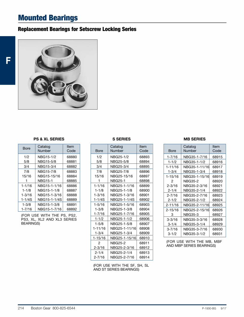
214 Boston Gear 800-825-6544 P-1930-BG 9/17
FFF
Mounted BearingsReplacement Bearings for Setscrew Locking Series
PS & XL SERIES
Catalog Item
Bore Number Code
1/2 NBG15-1/2 68880 5/8 NBG15-5/8 68881 3/4 NBG15-3/4 68882 7/8 NBG15-7/8 68883 15/16 NBG15-15/16 68884 1 NBG15-1 68885 1-1/16 NBG15-1-1/16 68886 1-1/8 NBG15-1-1/8 68887 1-3/16 NBG15-1-3/16 68888 1-1/4S NBG15-1-1/4S 68889 1-3/8 NBG15-1-3/8 68891 1-7/16 NBG15-1-7/16 68892
S SERIES
Catalog Item Bore Number Code
1/2 NBG25-1/2 68893 5/8 NBG25-5/8 68894 3/4 NBG25-3/4 68895 7/8 NBG25-7/8 68896 15/16 NBG25-15/16 68897 1 NBG25-1 68898 1-1/16 NBG25-1-1/16 68899 1-1/8 NBG25-1-1/8 68900 1-3/16 NBG25-1-3/16 68901 1-1/4S NBG25-1-1/4S 68902 1-5/16 NBG25-1-5/16 68903 1-3/8 NBG25-1-3/8 68904 1-7/16 NBG25-1-7/16 68905 1-1/2 NBG25-1-1/2 68906 1-5/8 NBG25-1-5/8 68907 1-11/16 NBG25-1-11/16 68908 1-3/4 NBG25-1-3/4 68909 1-15/16 NBG25-1-15/16 68910 2 NBG25-2 68911 2-3/16 NBG25-2-3/16 68912 2-1/4 NBG25-2-1/4 68913 2-7/16 NBG25-2-7/16 68914
MB SERIES
Catalog Item Bore Number Code
1-7/16 NBG35-1-7/16 68915 1-1/2 NBG35-1-1/2 68916 1-11/16 NBG35-1-11/16 68917 1-3/4 NBG35-1-3/4 68918 1-15/16 NBG35-1-15/16 68919 2 NBG35-2 68920 2-3/16 NBG35-2-3/16 68921 2-1/4 NBG35-2-1/4 68922 2-7/16 NBG35-2-7/16 68923 2-1/2 NBG35-2-1/2 68924 2-11/16 NBG35-2-11/16 68925 2-15/16 NBG25-2-15/16 68926 3 NBG35-3 68927 3-3/16 NBG35-3-3/16 68928 3-1/4 NBG35-3-1/4 68929 3-7/16 NBG35-3-7/16 68930 3-1/2 NBG35-3-1/2 68931
(FOR USE WITH THE PS, PS2, PS3, XL, XL2 AND XL3 SERIES BEARINGS)
(FOR USE WITH THE SF, SH, SL AND ST SERIES BEARINGS)
(FOR USE WITH THE MB, MBF AND MBP SERIES BEARINGS)
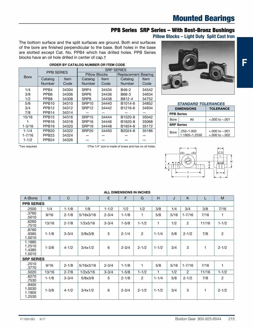
Boston Gear 800-825-6544 215P-1930-BG 9/17
FFF
Mounted BearingsPPB Series SRP Series – With Bost-Bronz Bushings
Pillow Blocks – Light Duty Split Cast Iron
STANDARD TOLERANCES DIMENSIONS TOLERANCE
PPB Series
Bore All +.000 to –.001
SRP Series
Bore .252–1.003 +.000 to –.001 1.1905–1.2530 +.000 to –.002
ORDER BY CATALOG NUMBER OR ITEM CODE
SRP SERIES PPB SERIES Pillow Blocks Replacement Bearing Bore Catalog Item Catalog Item Catalog Item Number Code Number Code Number Code
1/4 PPB4 34304 SRP4 34434 B46-2 34542 3/8 PPB6 34306 SRP6 34436 B68-3 34634 1/2 PPB8 34308 SRP8 34438 B812-4 34752 5/8 PPB10 34310 SRP10 34440 B1014-6 34852 3/4 PPB12 34312 SRP12 34442 B1216-6 34934 7/8 PPB14 34314 — — — — 15/16 PPB15 34316 SRP15 34444 B1520-8 35042 1 PPB16 34318 SRP16 34446 B1620-8 35068 1-3/16 PPB19 34320 SRP19 34448 B1924-8 35172 1-1/4 PPB20 34322 SRP20 34450 B2024-8 35186 1-7/16 PPB23 34324 — — — — 1-1/2 PPB24 34326 — — — —
The bottom surface and the split surfaces are ground. Both end surfaces of the bore are finished perpendicular to the base. Bolt holes in the base are slotted except Cat. No. PPB4 which has drilled holes. PPB Series blocks have an oil hole drilled in center of cap.†
*Two required. †The 1/4” size is made of brass and has no oil holes.K
F
JD
C
E G
H
DB
L
MA
ALL DIMENSIONS IN INCHES
A (Bore) B C D E F G H J K L M
PPB SERIES .2500 1/4 1-1/8 1/8 1-1/2 1/2 1/2 3/8 1/4 3/4 3/8 7/16 .3760 9/16 2-1/8 5/16x3/16 2-3/4 1-1/8 1 5/8 5/16 1-7/16 7/16 1 .5010 .6260 13/16 2-7/8 1/2x5/16 3-3/4 1-5/8 1-1/2 1 1/2 2 11/16 1-1/2 .7510 .8760 .9385 1-1/8 3-3/4 5/8x3/8 5 2-1/4 2 1-1/4 5/8 2-1/2 7/8 2 1.0010 1.1885 1.2510 1-3/8 4-1/2 3/4x1/2 6 2-3/4 2-1/2 1-1/2 3/4 3 1 2-1/2 1.4385 1.5010 SRP SERIES .2510 9/16 2-1/8 5/16x3/16 2-3/4 1-1/8 1 5/8 5/16 1-7/16 7/16 1 .3770 .5020 13/16 2-7/8 1/2x5/16 3-3/4 1-5/8 1-1/2 1 1/2 2 11/16 1-1/2 .6270 1-1/8 3-3/4 5/8x3/8 5 2-1/8 2 1-1/4 5/8 2-1/2 7/8 2 .7530 .9405 1.0030 1-3/8 4-1/2 3/4x1/2 6 2-3/4 2-1/2 1-1/2 3/4 3 1 2-1/2 1.1905 1.2530
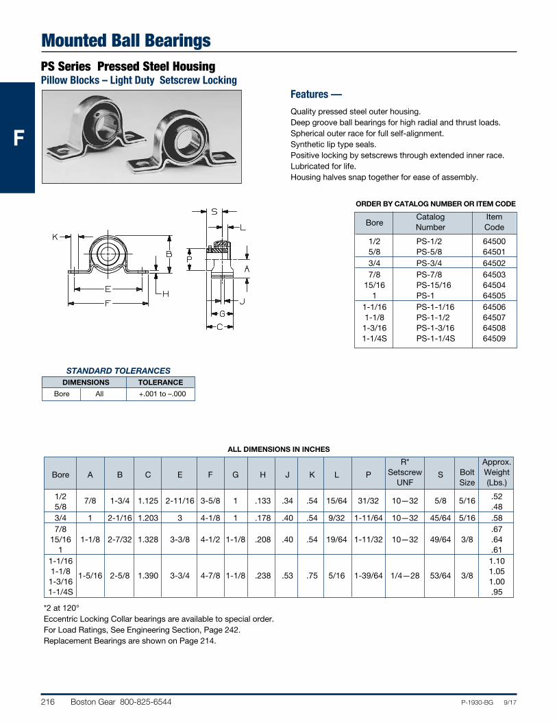
216 Boston Gear 800-825-6544 P-1930-BG 9/17
FFF
Mounted Ball BearingsPS Series Pressed Steel HousingPillow Blocks – Light Duty Setscrew Locking
STANDARD TOLERANCES DIMENSIONS TOLERANCE
Bore All +.001 to –.000
Features —
Quality pressed steel outer housing.Deep groove ball bearings for high radial and thrust loads.Spherical outer race for full self-alignment.Synthetic lip type seals.Positive locking by setscrews through extended inner race.Lubricated for life.Housing halves snap together for ease of assembly.
ORDER BY CATALOG NUMBER OR ITEM CODE
Catalog Item Bore Number Code
1/2 PS-1/2 64500 5/8 PS-5/8 64501 3/4 PS-3/4 64502 7/8 PS-7/8 64503 15/16 PS-15/16 64504 1 PS-1 64505 1-1/16 PS-1-1/16 64506 1-1/8 PS-1-1/2 64507 1-3/16 PS-1-3/16 64508 1-1/4S PS-1-1/4S 64509
*2 at 120°Eccentric Locking Collar bearings are available to special order.For Load Ratings, See Engineering Section, Page 242.Replacement Bearings are shown on Page 214.
ALL DIMENSIONS IN INCHES
R* Approx. Setscrew Bolt Weight Bore A B C E F G H J K L P
UNF S
Size (Lbs.)
1/2 7/8 1-3/4 1.125 2-11/16 3-5/8 1 .133 .34 .54 15/64 31/32 10—32 5/8 5/16 .52 5/8 .48 3/4 1 2-1/16 1.203 3 4-1/8 1 .178 .40 .54 9/32 1-11/64 10—32 45/64 5/16 .58 7/8 .67 15/16 1-1/8 2-7/32 1.328 3-3/8 4-1/2 1-1/8 .208 .40 .54 19/64 1-11/32 10—32 49/64 3/8 .64 1 .61 1-1/16 1.10 1-1/8 1-5/16 2-5/8 1.390 3-3/4 4-7/8 1-1/8 .238 .53 .75 5/16 1-39/64 1/4—28 53/64 3/8 1.05 1-3/16 1.00 1-1/4S .95
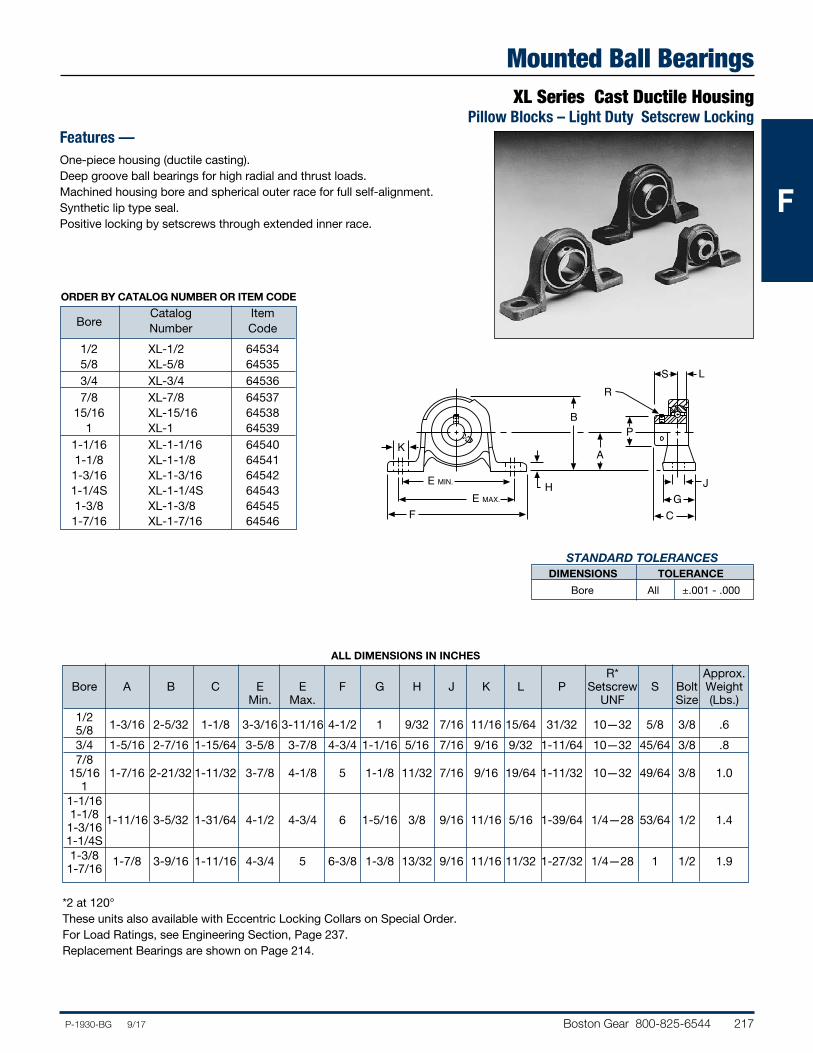
Boston Gear 800-825-6544 217P-1930-BG 9/17
FFF
Mounted Ball BearingsXL Series Cast Ductile Housing
Pillow Blocks – Light Duty Setscrew LockingFeatures —One-piece housing (ductile casting).Deep groove ball bearings for high radial and thrust loads.Machined housing bore and spherical outer race for full self-alignment.Synthetic lip type seal.Positive locking by setscrews through extended inner race.
ORDER BY CATALOG NUMBER OR ITEM CODE
Catalog Item Bore Number Code
1/2 XL-1/2 64534 5/8 XL-5/8 64535 3/4 XL-3/4 64536 7/8 XL-7/8 64537 15/16 XL-15/16 64538 1 XL-1 64539 1-1/16 XL-1-1/16 64540 1-1/8 XL-1-1/8 64541 1-3/16 XL-1-3/16 64542 1-1/4S XL-1-1/4S 64543 1-3/8 XL-1-3/8 64545 1-7/16 XL-1-7/16 64546
PB
RS L
GC
E MIN.
F
HE MAX.
AK
J
ALL DIMENSIONS IN INCHES
R* Approx. Bore A B C E E F G H J K L P Setscrew S Bolt Weight Min. Max. UNF Size (Lbs.) 1/2
1-3/16 2-5/32 1-1/8 3-3/16 3-11/16 4-1/2 1 9/32 7/16 11/16 15/64 31/32 10—32 5/8 3/8 .6
5/8 3/4 1-5/16 2-7/16 1-15/64 3-5/8 3-7/8 4-3/4 1-1/16 5/16 7/16 9/16 9/32 1-11/64 10—32 45/64 3/8 .8 7/8 15/16 1-7/16 2-21/32 1-11/32 3-7/8 4-1/8 5 1-1/8 11/32 7/16 9/16 19/64 1-11/32 10—32 49/64 3/8 1.0 1 1-1/16 1-1/8 1-3/16
1-11/16 3-5/32 1-31/64 4-1/2 4-3/4 6 1-5/16 3/8 9/16 11/16 5/16 1-39/64 1/4—28 53/64 1/2 1.4
1-1/4S 1-3/8 1-7/16
1-7/8 3-9/16 1-11/16 4-3/4 5 6-3/8 1-3/8 13/32 9/16 11/16 11/32 1-27/32 1/4—28 1 1/2 1.9
STANDARD TOLERANCES DIMENSIONS TOLERANCE
Bore All ±.001 - .000
*2 at 120°These units also available with Eccentric Locking Collars on Special Order.For Load Ratings, see Engineering Section, Page 237.Replacement Bearings are shown on Page 214.
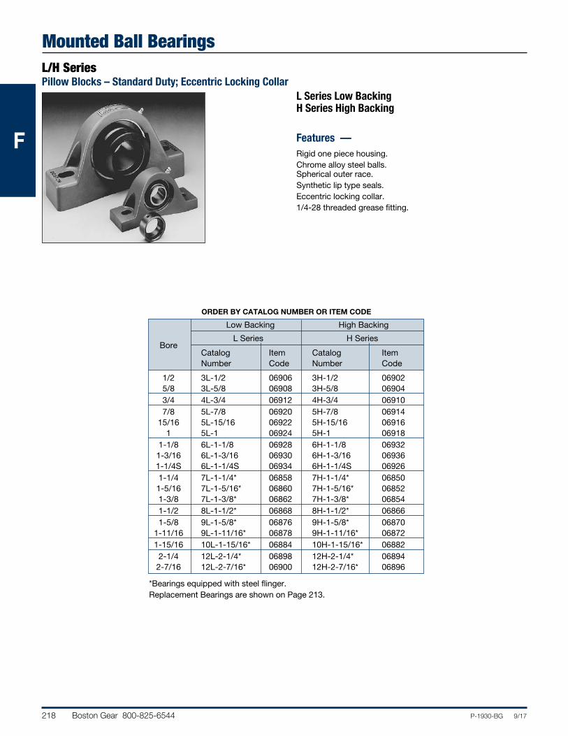
218 Boston Gear 800-825-6544 P-1930-BG 9/17
FFF
Mounted Ball BearingsL/H SeriesPillow Blocks – Standard Duty; Eccentric Locking Collar
L Series Low BackingH Series High Backing
Features — Rigid one piece housing.Chrome alloy steel balls. Spherical outer race.Synthetic lip type seals.Eccentric locking collar.1/4-28 threaded grease fitting.
ORDER BY CATALOG NUMBER OR ITEM CODE
Low Backing High Backing
L Series H Series
Bore
Catalog Item Catalog Item Number Code Number Code
1/2 3L-1/2 06906 3H-1/2 06902 5/8 3L-5/8 06908 3H-5/8 06904 3/4 4L-3/4 06912 4H-3/4 06910 7/8 5L-7/8 06920 5H-7/8 06914 15/16 5L-15/16 06922 5H-15/16 06916 1 5L-1 06924 5H-1 06918 1-1/8 6L-1-1/8 06928 6H-1-1/8 06932 1-3/16 6L-1-3/16 06930 6H-1-3/16 06936 1-1/4S 6L-1-1/4S 06934 6H-1-1/4S 06926 1-1/4 7L-1-1/4* 06858 7H-1-1/4* 06850 1-5/16 7L-1-5/16* 06860 7H-1-5/16* 06852 1-3/8 7L-1-3/8* 06862 7H-1-3/8* 06854 1-1/2 8L-1-1/2* 06868 8H-1-1/2* 06866 1-5/8 9L-1-5/8* 06876 9H-1-5/8* 06870 1-11/16 9L-1-11/16* 06878 9H-1-11/16* 06872 1-15/16 10L-1-15/16* 06884 10H-1-15/16* 06882 2-1/4 12L-2-1/4* 06898 12H-2-1/4* 06894 2-7/16 12L-2-7/16* 06900 12H-2-7/16* 06896
*Bearings equipped with steel flinger.Replacement Bearings are shown on Page 213.
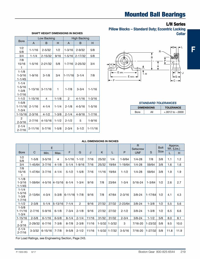
Boston Gear 800-825-6544 219P-1930-BG 9/17
FFF
Mounted Ball BearingsL/H Series
Pillow Blocks – Standard Duty; Eccentric Locking Collar
STANDARD TOLERANCES
DIMENSIONS TOLERANCE
Bore All +.0012 to –.0000
PB
RS L
GC
E MIN.
F
HE MAX.
AK
J
SHAFT HEIGHT DIMENSIONS IN INCHES
Low Backing High Backing
Bore
A B H A B H
1/2 5/8
1-1/16 2-5/32 1/2 1-3/16 2-9/32 5/8
3/4 1-1/4 2-15/32 9/16 1-5/16 2-17/32 5/8 7/8 15/16 1-5/16 2-21/32 5/8 1-7/16 2-25/32 3/4 1 1-1/8 1-3/16 1-9/16 3-1/8 3/4 1-11/16 3-1/4 7/8 1-1/4S 1-1/4 1-5/16 1-3/8 1-13/16 3-11/16 1 1-7/8 3-3/4 1-1/16 1-7/16 1-1/2 1-15/16 4 1-1/8 2 4-1/16 1-3/16 1-5/8 1-11/16 2-1/16 4-1/4 1-1/4 2-1/8 4-5/16 1-5/16 1-3/4 1-15/16 2-3/16 4-1/2 1-3/8 2-1/4 4-9/16 1-7/16 2 2-3/16 2-7/16 4-15/16 1-1/2 2-1/2 5 1-9/16
2-1/4 2-7/16 2-11/16 5-7/16 1-5/8 2-3/4 5-1/2 1-11/16
ALL DIMENSIONS IN INCHES
R Approx. E Setscrew Bolt Wt. (Lbs.) Bore C Min. Max. F G J K L P UNF S Size L H
1/2 5/8 1-5/8 3-5/16 4 5-1/16 1-1/2 7/16 25/32 1/4 1-9/64 1/4-28 7/8 3/8 1.1 1.2
3/4 1-45/64 3-7/16 4-1/8 5-1/4 1-9/16 7/16 25/32 19/64 1-19/64 1/4-28 59/64 3/8 1.6 1.6 7/8 15/16 1-47/64 3-7/16 4-1/4 5-1/2 1-5/8 7/16 11/16 19/64 1-1/2 1/4-28 59/64 3/8 1.9 1.9 1 1-1/8 1-3/16 1-59/64 4-5/16 4-15/16 6-1/4 1-3/4 9/16 7/8 23/64 1-3/4 5/16-24 1-3/64 1/2 2.6 2.7 1-1/4S 1-1/4 1-5/16 2-13/64 4-3/4 5-3/8 6-11/16 1-7/8 9/16 7/8 47/64 2-3/16 3/8-24 1-17/64 1/2 4.1 4.3 1-3/8 1-7/16 1-1/2 2-3/8 5-1/4 5-13/16 7-1/4 2 9/16 27/32 27/32 2-23/64 3/8-24 1-3/8 1/2 5.5 5.6 1-5/8 1-11/16 2-7/16 5-9/16 6-1/8 7-3/4 2-1/8 9/16 27/32 27/32 2-1/2 3/8-24 1-3/8 1/2 6.5 6.6 1-3/4 1-15/16 2-5/8 6-1/16 6-5/8 8-1/4 2-1/4 11/16 31/32 31/32 2-3/4 3/8-24 1-1/2 5/8 8.0 8.1 2 2-29/32 6-7/16 7-3/8 8-7/8 2-3/8 11/16 1-5/32 1-3/32 3 7/16-20 1-23/32 5/8 9.5 10.0 2-3/16 2-1/4 3-3/32 6-15/16 7-7/8 9-5/8 2-1/2 11/16 1-5/32 1-7/32 3-5/16 7/16-20 1-27/32 5/8 11.8 11.9 2-7/16
For Load Ratings, see Engineering Section, Page 243.
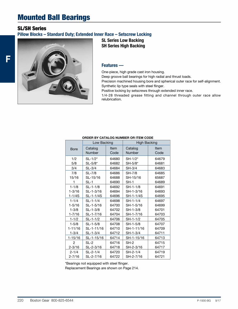
220 Boston Gear 800-825-6544 P-1930-BG 9/17
FFF
Mounted Ball BearingsSL/SH SeriesPillow Blocks – Standard Duty; Extended Inner Race – Setscrew Locking
SL Series Low Backing SH Series High Backing
Features —One-piece, high grade cast iron housing.Deep groove ball bearings for high radial and thrust loads.Precision machined housing bore and spherical outer race for self-alignment.Synthetic lip type seals with steel flinger.Positive locking by setscrews through extended inner race.1/4-28 threaded grease fitting and channel through outer race allow relubrication.
*Bearings not equipped with steel flinger.Replacement Bearings are shown on Page 214.
ORDER BY CATALOG NUMBER OR ITEM CODE
Low Backing High Backing
Catalog Item Catalog Item
Bore Number Code Number Code
1/2 SL-1/2* 64680 SH-1/2* 64679 5/8 SL-5/8* 64682 SH-5/8* 64681 3/4 SL-3/4 64684 SH-3/4 64683 7/8 SL-7/8 64686 SH-7/8 64685 15/16 SL-15/16 64688 SH-15/16 65687 1 SL-1 64690 SH-1 64689 1-1/8 SL-1-1/8 64692 SH-1-1/8 64691 1-3/16 SL-1-3/16 64694 SH-1-3/16 64693 1-1/4S SL-1-1/4S 64696 SH-1-1/4S 64695 1-1/4 SL-1-1/4 64698 SH-1-1/4 64697 1-5/16 SL-1-5/16 64700 SH-1-5/16 64699 1-3/8 SL-1-3/8 64702 SH-1-3/8 64701 1-7/16 SL-1-7/16 64704 SH-1-7/16 64703 1-1/2 SL-1-1/2 64706 SH-1-1/2 64705 1-5/8 SL-1-5/8 64708 SH-1-5/8 64707 1-11/16 SL-1-11/16 64710 SH-1-11/16 64709 1-3/4 SL-1-3/4 64712 SH-1-3/4 64711 1-15/16 SL-1-15/16 64714 SH-1-15/16 64713 2 SL-2 64716 SH-2 64715 2-3/16 SL-2-3/16 64718 SH-2-3/16 64717 2-1/4 SL-2-1/4 64720 SH-2-1/4 64719 2-7/16 SL-2-7/16 64722 SH-2-7/16 64721
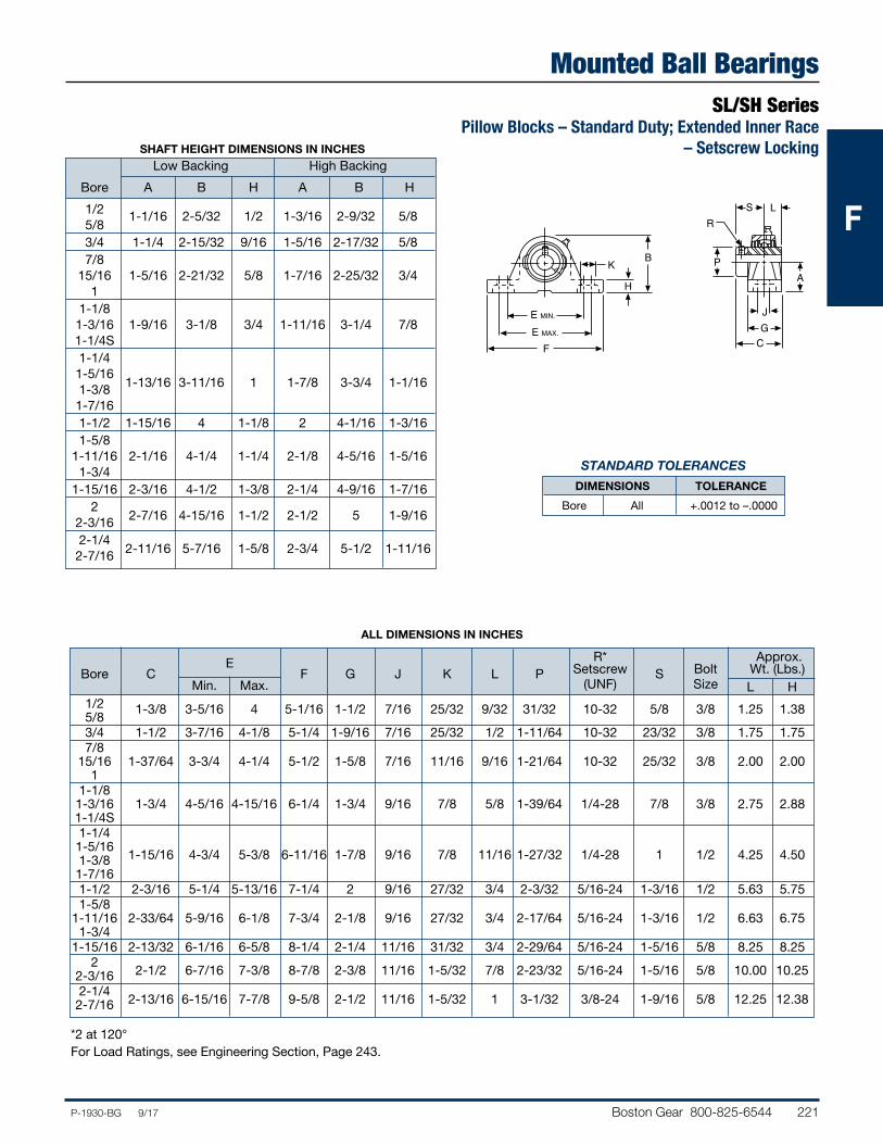
Boston Gear 800-825-6544 221P-1930-BG 9/17
FFF
Mounted Ball BearingsSL/SH Series
Pillow Blocks – Standard Duty; Extended Inner Race – Setscrew Locking
PB
RS L
GC
E MIN.
F
H
E MAX.
K
J
A
SHAFT HEIGHT DIMENSIONS IN INCHES
Low Backing High Backing
Bore A B H A B H
1/2 5/8
1-1/16 2-5/32 1/2 1-3/16 2-9/32 5/8
3/4 1-1/4 2-15/32 9/16 1-5/16 2-17/32 5/8 7/8 15/16 1-5/16 2-21/32 5/8 1-7/16 2-25/32 3/4 1 1-1/8 1-3/16 1-9/16 3-1/8 3/4 1-11/16 3-1/4 7/8 1-1/4S 1-1/4 1-5/16 1-3/8 1-13/16 3-11/16 1 1-7/8 3-3/4 1-1/16 1-7/16 1-1/2 1-15/16 4 1-1/8 2 4-1/16 1-3/16 1-5/8 1-11/16 2-1/16 4-1/4 1-1/4 2-1/8 4-5/16 1-5/16 1-3/4 1-15/16 2-3/16 4-1/2 1-3/8 2-1/4 4-9/16 1-7/16 2 2-3/16 2-7/16 4-15/16 1-1/2 2-1/2 5 1-9/16
2-1/4 2-7/16 2-11/16 5-7/16 1-5/8 2-3/4 5-1/2 1-11/16
ALL DIMENSIONS IN INCHES
R* Approx. E Setscrew Bolt Wt. (Lbs.)
Bore C Min. Max.
F G J K L P (UNF)
S Size L H
1/2 5/8
1-3/8 3-5/16 4 5-1/16 1-1/2 7/16 25/32 9/32 31/32 10-32 5/8 3/8 1.25 1.38
3/4 1-1/2 3-7/16 4-1/8 5-1/4 1-9/16 7/16 25/32 1/2 1-11/64 10-32 23/32 3/8 1.75 1.75 7/8 15/16 1-37/64 3-3/4 4-1/4 5-1/2 1-5/8 7/16 11/16 9/16 1-21/64 10-32 25/32 3/8 2.00 2.00 1 1-1/8 1-3/16 1-3/4 4-5/16 4-15/16 6-1/4 1-3/4 9/16 7/8 5/8 1-39/64 1/4-28 7/8 3/8 2.75 2.88 1-1/4S 1-1/4 1-5/16
1-15/16 4-3/4 5-3/8 6-11/16 1-7/8 9/16 7/8 11/16 1-27/32 1/4-28 1 1/2 4.25 4.50
1-3/8 1-7/16 1-1/2 2-3/16 5-1/4 5-13/16 7-1/4 2 9/16 27/32 3/4 2-3/32 5/16-24 1-3/16 1/2 5.63 5.75 1-5/8 1-11/16 2-33/64 5-9/16 6-1/8 7-3/4 2-1/8 9/16 27/32 3/4 2-17/64 5/16-24 1-3/16 1/2 6.63 6.75 1-3/4 1-15/16 2-13/32 6-1/16 6-5/8 8-1/4 2-1/4 11/16 31/32 3/4 2-29/64 5/16-24 1-5/16 5/8 8.25 8.25 2
2-1/2 6-7/16 7-3/8 8-7/8 2-3/8 11/16 1-5/32 7/8 2-23/32 5/16-24 1-5/16 5/8 10.00 10.25
2-3/16 2-1/4
2-13/16 6-15/16 7-7/8 9-5/8 2-1/2 11/16 1-5/32 1 3-1/32 3/8-24 1-9/16 5/8 12.25 12.38
2-7/16
*2 at 120°For Load Ratings, see Engineering Section, Page 243.
STANDARD TOLERANCES
DIMENSIONS TOLERANCE
Bore All +.0012 to –.0000
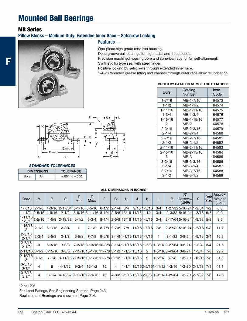
222 Boston Gear 800-825-6544 P-1930-BG 9/17
FFF
Mounted Ball BearingsMB SeriesPillow Blocks – Medium Duty; Extended Inner Race – Setscrew Locking
STANDARD TOLERANCES DIMENSIONS TOLERANCE
Bore All +.001 to –.000
Features —One-piece high grade cast iron housing.Deep groove ball bearings for high radial and thrust loads.Precision machined housing bore and spherical race for full self-alignment.Synthetic lip type seal with steel flinger.Positive locking by setscrews through extended inner race.1/4-28 threaded grease fitting and channel through outer race allow relubrication.
ORDER BY CATALOG NUMBER OR ITEM CODE
Catalog Item Bore Number Code
1-7/16 MB-1-7/16 64573 1-1/2 MB-1-1/2 64574 1-11/16 MB-1-11/16 64575 1-3/4 MB-1-3/4 64576 1-15/16 MB-1-15/16 64577 2 MB-2 64578 2-3/16 MB-2-3/16 64579 2-1/4 MB-2-1/4 64580 2-7/16 MB-2-7/16 64581 2-1/2 MB-2-1/2 64582 2-11/16 MB-2-11/16 64583 2-15/16 MB-2-15/16 64584 3 MB-3 64585 3-3/16 MB-3-3/16 64586 3-1/4 MB-3-1/4 64587 3-7/16 MB-3-7/16 64588 3-1/2 MB-3-1/2 64589
PB
R S L
GC
E MIN.
F
H
E MAX.
A
K
J
*2 at 120°For Load Ratings, See Engineering Section, Page 243.Replacement Bearings are shown on Page 214.
ALL DIMENSIONS IN INCHES
R* Approx. Bore A B C E E F G H J K L P Setscrew S Bolt Weight Min. Max. (UNF) Size (Lbs.)
1-7/16 2-1/8 4-3/16 2-17/64 5-1/16 6-5/16 6-1/2 2-1/4 3/4 9/16 1-3/16 3/4 1-27/32 5/16-24 1-9/64 1/2 6.8 1-1/2 2-5/16 4-9/16 2-1/2 5-9/16 6-11/16 8-1/4 2-5/8 13/16 11/16 1-1/4 3/4 2-3/32 5/16-24 1-3/16 5/8 9.0 1-11/16
2-5/16 4-5/8 2-19/32 5-1/2 6-3/4 8-1/4 2-5/8 13/16 11/16 1-5/16 3/4 2-17/64 5/16-24 1-9/32 5/8 9.5
1-3/4 1-15/16
2-1/2 5-1/16 2-3/4 6 7-1/2 8-7/8 2-7/8 7/8 11/16 1-7/16 7/8 2-23/32 5/16-24 1-5/16 5/8 11.7 2 2-3/16
2-3/4 5-5/8 3-1/8 6-5/8 7-7/8 9-5/8 3-1/8 1-1/16 13/16 1-7/16 1 3-1/32 3/8-24 1-9/16 3/4 16.2 2-1/4 2-7/16
3 6-3/16 3-3/8 7-3/16 8-13/16 10-3/8 3-1/4 1-1/16 13/16 1-5/8 1-3/16 3-27/64 3/8-24 1-3/4 3/4 21.5
2-1/2 2-11/16 3-1/2 6-15/16 3-3/8 7-15/16 10-1/16 11-7/8 3-1/2 1-1/8 15/16 2 1-5/16 3-43/64 3/8-24 1-3/4 7/8 29.2 2-15/16
3-1/2 7-1/8 3-11/16 7-15/16 10-1/16 11-7/8 3-1/2 1-1/4 15/16 2 1-5/16 3-7/8 1/2-20 1-15/16 7/8 31.5
3 3-3/16
4 8 4-1/32 9-3/4 12-1/2 15 4 1-1/4 15/16 2-5/16 1-11/32 4-3/16 1/2-20 2-1/32 7/8 41.1
3-1/4 3-7/16
4 8-1/4 4-13/32 9-11/16 12-9/16 15 4-3/8 1-5/16 15/16 2-3/8 1-9/16 4-25/64 1/2-20 2-7/32 7/8 47.8 3-1/2
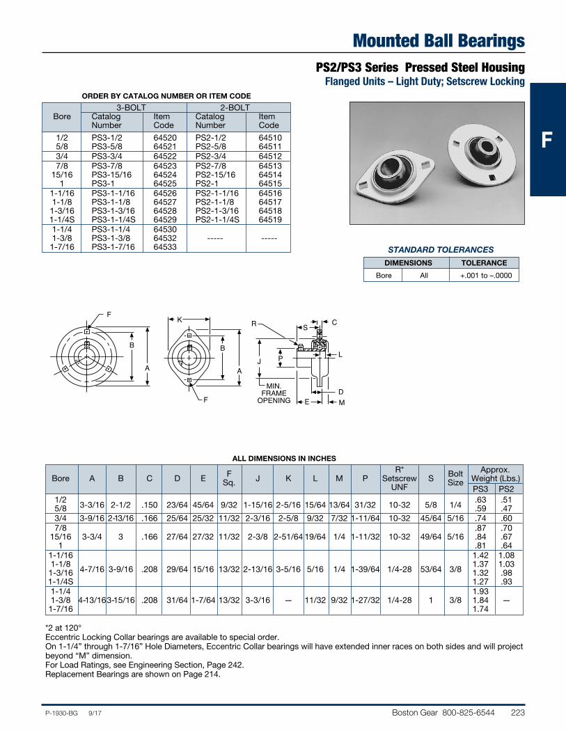
Boston Gear 800-825-6544 223P-1930-BG 9/17
FFF
Mounted Ball BearingsPS2/PS3 Series Pressed Steel Housing
Flanged Units – Light Duty; Setscrew Locking
B
A
FR
PJA
B
SK C
L
DMEF
MIN.FRAME
OPENING
*2 at 120°Eccentric Locking Collar bearings are available to special order. On 1-1/4” through 1-7/16” Hole Diameters, Eccentric Collar bearings will have extended inner races on both sides and will project beyond “M” dimension.For Load Ratings, see Engineering Section, Page 242.Replacement Bearings are shown on Page 214.
ALL DIMENSIONS IN INCHES
R* Approx. Bore A B C D E F J K L M P Setscrew S Bolt Weight (Lbs.) Sq. UNF Size PS3 PS2 1/2
3-3/16 2-1/2 .150 23/64 45/64 9/32 1-15/16 2-5/16 15/64 13/64 31/32 10-32 5/8 1/4 .63 .51
5/8 .59 .47 3/4 3-9/16 2-13/16 .166 25/64 25/32 11/32 2-3/16 2-5/8 9/32 7/32 1-11/64 10-32 45/64 5/16 .74 .60 7/8 .87 .70 15/16 3-3/4 3 .166 27/64 27/32 11/32 2-3/8 2-51/64 19/64 1/4 1-11/32 10-32 49/64 5/16 .84 .67 1 .81 .64 1-1/16 1.42 1.08 1-1/8
4-7/16 3-9/16 .208 29/64 15/16 13/32 2-13/16 3-5/16 5/16 1/4 1-39/64 1/4-28 53/64 3/8 1.37 1.03
1-3/16 1.32 .98 1-1/4S 1.27 .93 1-1/4 1.93 1-3/8 4-13/16 3-15/16 .208 31/64 1-7/64 13/32 3-3/16 — 11/32 9/32 1-27/32 1/4-28 1 3/8 1.84 — 1-7/16 1.74
ORDER BY CATALOG NUMBER OR ITEM CODE
3-BOLT 2-BOLT Bore Catalog Item Catalog Item Number Code Number Code
1/2 PS3-1/2 64520 PS2-1/2 64510 5/8 PS3-5/8 64521 PS2-5/8 64511 3/4 PS3-3/4 64522 PS2-3/4 64512 7/8 PS3-7/8 64523 PS2-7/8 64513 15/16 PS3-15/16 64524 PS2-15/16 64514 1 PS3-1 64525 PS2-1 64515 1-1/16 PS3-1-1/16 64526 PS2-1-1/16 64516 1-1/8 PS3-1-1/8 64527 PS2-1-1/8 64517 1-3/16 PS3-1-3/16 64528 PS2-1-3/16 64518 1-1/4S PS3-1-1/4S 64529 PS2-1-1/4S 64519 1-1/4 PS3-1-1/4 64530 1-3/8 PS3-1-3/8 64532 ----- ----- 1-7/16 PS3-1-7/16 64533
STANDARD TOLERANCES
DIMENSIONS TOLERANCE
Bore All +.001 to –.0000
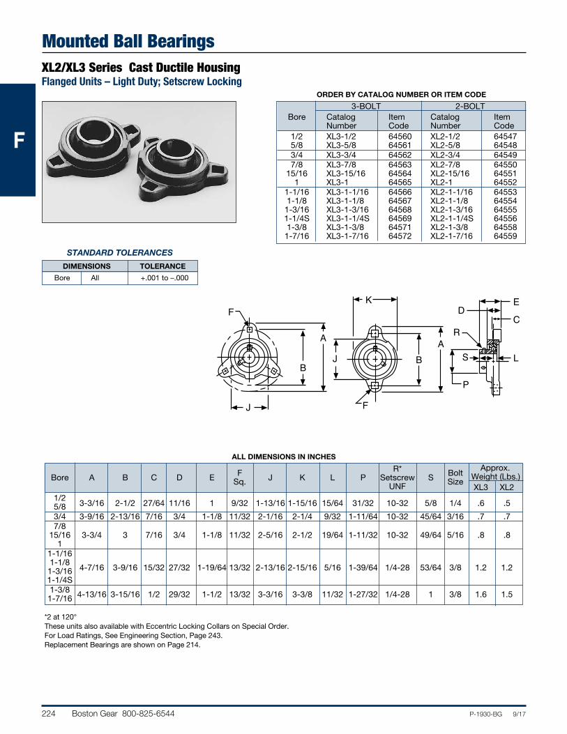
224 Boston Gear 800-825-6544 P-1930-BG 9/17
FFF
Mounted Ball BearingsXL2/XL3 Series Cast Ductile HousingFlanged Units – Light Duty; Setscrew Locking
STANDARD TOLERANCES
DIMENSIONS TOLERANCE
Bore All +.001 to –.000
ORDER BY CATALOG NUMBER OR ITEM CODE
3-BOLT 2-BOLT Bore Catalog Item Catalog Item Number Code Number Code 1/2 XL3-1/2 64560 XL2-1/2 64547 5/8 XL3-5/8 64561 XL2-5/8 64548 3/4 XL3-3/4 64562 XL2-3/4 64549 7/8 XL3-7/8 64563 XL2-7/8 64550 15/16 XL3-15/16 64564 XL2-15/16 64551 1 XL3-1 64565 XL2-1 64552 1-1/16 XL3-1-1/16 64566 XL2-1-1/16 64553 1-1/8 XL3-1-1/8 64567 XL2-1-1/8 64554 1-3/16 XL3-1-3/16 64568 XL2-1-3/16 64555 1-1/4S XL3-1-1/4S 64569 XL2-1-1/4S 64556 1-3/8 XL3-1-3/8 64571 XL2-1-3/8 64558 1-7/16 XL3-1-7/16 64572 XL2-1-7/16 64559
B
A
F
R
P
AB S
K
L
DE
FJ
J
C
ALL DIMENSIONS IN INCHES
R* Approx. Bore A B C D E F J K L P Setscrew S Bolt Weight (Lbs.) Sq. UNF Size XL3 XL2 1/2
3-3/16 2-1/2 27/64 11/16 1 9/32 1-13/16 1-15/16 15/64 31/32 10-32 5/8 1/4 .6 .5
5/8 3/4 3-9/16 2-13/16 7/16 3/4 1-1/8 11/32 2-1/16 2-1/4 9/32 1-11/64 10-32 45/64 3/16 .7 .7 7/8 15/16 3-3/4 3 7/16 3/4 1-1/8 11/32 2-5/16 2-1/2 19/64 1-11/32 10-32 49/64 5/16 .8 .8 1 1-1/16 1-1/8
4-7/16 3-9/16 15/32 27/32 1-19/64 13/32 2-13/16 2-15/16 5/16 1-39/64 1/4-28 53/64 3/8 1.2 1.2
1-3/16 1-1/4S 1-3/8 4-13/16 3-15/16 1/2 29/32 1-1/2 13/32 3-3/16 3-3/8 11/32 1-27/32 1/4-28 1 3/8 1.6 1.5 1-7/16
*2 at 120°These units also available with Eccentric Locking Collars on Special Order.For Load Ratings, See Engineering Section, Page 243.Replacement Bearings are shown on Page 214.
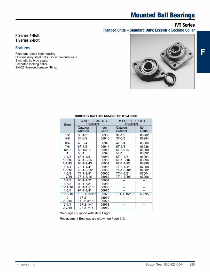
Boston Gear 800-825-6544 225P-1930-BG 9/17
FFF
Mounted Ball BearingsF/T Series
Flanged Units – Standard Duty; Eccentric Locking CollarF Series 4-Bolt T Series 2-Bolt
Features —Rigid one-piece high housing.Chrome alloy steel balls. Spherical outer race.Synthetic lip type seals.Eccentric locking collar.1/4-28 threaded grease fitting.
ORDER BY CATALOG NUMBER OR ITEM CODE
4-BOLT FLANGES 2-BOLT FLANGES Bore F SERIES T SERIES Catalog Item Catalog Item Number Code Number Code 1/2 3F-1/2 06938 3T-1/2 06982 5/8 3F-5/8 06940 3T-5/8 06984
3/4 4F-3/4 06942 4T-3/4 06986 7/8 5F-7/8 06944 5T-7/8 06988 15/16 5F-15/16 06946 5T-15/16 06990 1 5F-1 06948 5T-1 06992 1-1/8 6F-1-1/8 06950 6T-1-1/8 06994 1-3/16 6F-1-3/16 06952 6T-1-3/16 06996 1-1/4S 6F-1-1/4S 06954 6T-1-1/4S 06998 1-1/4 7F-1-1/4* 06956 7T-1-1/4* 07000 1-5/16 7F-1-5/16* 06958 7T-1-5/16* 07002 1-3/8 7F-1-3/8* 06960 7T-1-3/8* 07004 1-7/16 7F-1-7/16* 06962 7T-1-7/16* 07006 1-1/2 8F-1-1/2* 06964 — — 1-5/8 9F-1-5/8* 06966 — — 1-11/16 9F-1-11/16* 06968 — — 1-3/4 9F-1-3/4* 06970 — — 1-15/16 10F-1-15/16* 06972 10T-1-15/16* 50695 2 11F-2* 06974 — — 2-3/16 11F-2-3/16* 06976 — — 2-1/4 12F-2-1/4* 06978 — — 2-7/16 12F-2-7/16* 06980 — —
*Bearings equipped with steel flinger.
Replacement Bearings are shown on Page 213.
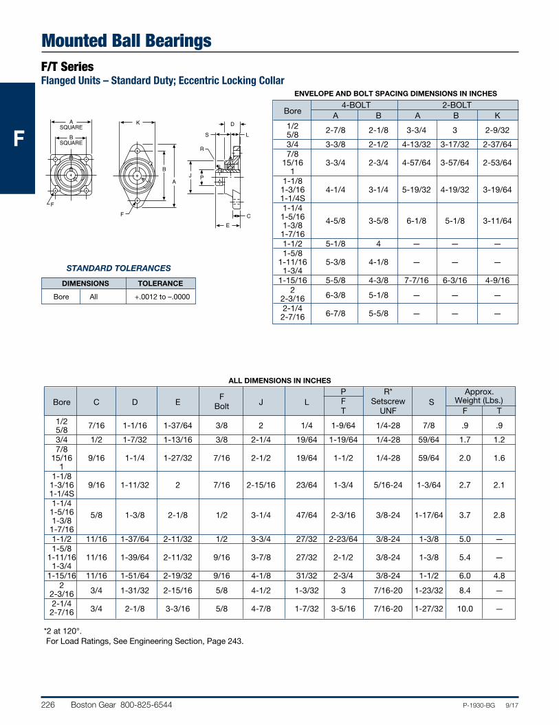
226 Boston Gear 800-825-6544 P-1930-BG 9/17
FFF
Mounted Ball BearingsF/T SeriesFlanged Units – Standard Duty; Eccentric Locking Collar
B
A
F
K
R
C
PJ
E
D
S L
ASQUARE
BSQUARE
F
STANDARD TOLERANCES
DIMENSIONS TOLERANCE
Bore All +.0012 to –.0000
*2 at 120°. For Load Ratings, See Engineering Section, Page 243.
ENVELOPE AND BOLT SPACING DIMENSIONS IN INCHES
4-BOLT 2-BOLT Bore A B A B K 1/2 2-7/8 2-1/8 3-3/4 3 2-9/32 5/8 3/4 3-3/8 2-1/2 4-13/32 3-17/32 2-37/64 7/8 15/16 3-3/4 2-3/4 4-57/64 3-57/64 2-53/64 1 1-1/8 1-3/16 4-1/4 3-1/4 5-19/32 4-19/32 3-19/64 1-1/4S 1-1/4 1-5/16 4-5/8 3-5/8 6-1/8 5-1/8 3-11/64 1-3/8 1-7/16 1-1/2 5-1/8 4 — — — 1-5/8 1-11/16 5-3/8 4-1/8 — — — 1-3/4 1-15/16 5-5/8 4-3/8 7-7/16 6-3/16 4-9/16 2
6-3/8 5-1/8 — — —
2-3/16 2-1/4
6-7/8 5-5/8 — — —
2-7/16
ALL DIMENSIONS IN INCHES
P R* Approx. Bore C D E F J L F Setscrew S Weight (Lbs.) Bolt T UNF F T 1/2 7/16 1-1/16 1-37/64 3/8 2 1/4 1-9/64 1/4-28 7/8 .9 .9 5/8 3/4 1/2 1-7/32 1-13/16 3/8 2-1/4 19/64 1-19/64 1/4-28 59/64 1.7 1.2 7/8 15/16 9/16 1-1/4 1-27/32 7/16 2-1/2 19/64 1-1/2 1/4-28 59/64 2.0 1.6 1 1-1/8 1-3/16 9/16 1-11/32 2 7/16 2-15/16 23/64 1-3/4 5/16-24 1-3/64 2.7 2.1 1-1/4S 1-1/4 1-5/16 5/8 1-3/8 2-1/8 1/2 3-1/4 47/64 2-3/16 3/8-24 1-17/64 3.7 2.8 1-3/8 1-7/16 1-1/2 11/16 1-37/64 2-11/32 1/2 3-3/4 27/32 2-23/64 3/8-24 1-3/8 5.0 — 1-5/8 1-11/16 11/16 1-39/64 2-11/32 9/16 3-7/8 27/32 2-1/2 3/8-24 1-3/8 5.4 — 1-3/4 1-15/16 11/16 1-51/64 2-19/32 9/16 4-1/8 31/32 2-3/4 3/8-24 1-1/2 6.0 4.8 2
3/4 1-31/32 2-15/16 5/8 4-1/2 1-3/32 3 7/16-20 1-23/32 8.4 —
2-3/16 2-1/4
3/4 2-1/8 3-3/16 5/8 4-7/8 1-7/32 3-5/16 7/16-20 1-27/32 10.0 —
2-7/16
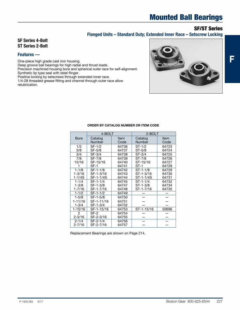
Boston Gear 800-825-6544 227P-1930-BG 9/17
FFF
Mounted Ball BearingsSF/ST Series
Flanged Units – Standard Duty; Extended Inner Race – Setscrew LockingSF Series 4-Bolt ST Series 2-Bolt
Features —One-piece high grade cast iron housing.Deep groove ball bearings for high radial and thrust loads.Precision machined housing bore and spherical outer race for self-alignment.Synthetic lip type seal with steel flinger.Positive locking by setscrews through extended inner race.1/4-28 threaded grease fitting and channel through outer race allow relubrication.
ORDER BY CATALOG NUMBER OR ITEM CODE
4-BOLT 2-BOLT Bore Catalog Item Catalog Item Number Code Number Code 1/2 SF-1/2 64736 ST-1/2 64723 5/8 SF-5/8 64737 ST-5/8 64724 3/4 SF-3/4 64738 ST-3/4 64725 7/8 SF-7/8 64739 ST-7/8 64726 15/16 SF-15/16 64740 ST-15/16 64727 1 SF-1 64741 ST-1 64728 1-1/8 SF-1-1/8 64742 ST-1-1/8 64729 1-3/16 SF-1-3/16 64743 ST-1-3/16 64730 1-1/4S SF-1-1/4S 64744 ST-1-1/4S 64731 1-1/4 SF-1-1/4 64745 ST-1-1/4 64732 1-3/8 SF-1-3/8 64747 ST-1-3/8 64734 1-7/16 SF-1-7/16 64748 ST-1-7/16 64735 1-1/2 SF-1-1/2 64749 — — 1-5/8 SF-1-5/8 64750 — — 1-11/16 SF-1-11/16 64751 — — 1-3/4 SF-1-3/4 64752 — — 1-15/16 SF-1-15/16 64753 ST-1-15/16 50696 2 SF-2 64754 — — 2-3/16 SF-2-3/16 64755 — — 2-1/4 SF-2-1/4 64756 — — 2-7/16 SF-2-7/16 64757 — —
Replacement Bearings are shown on Page 214.
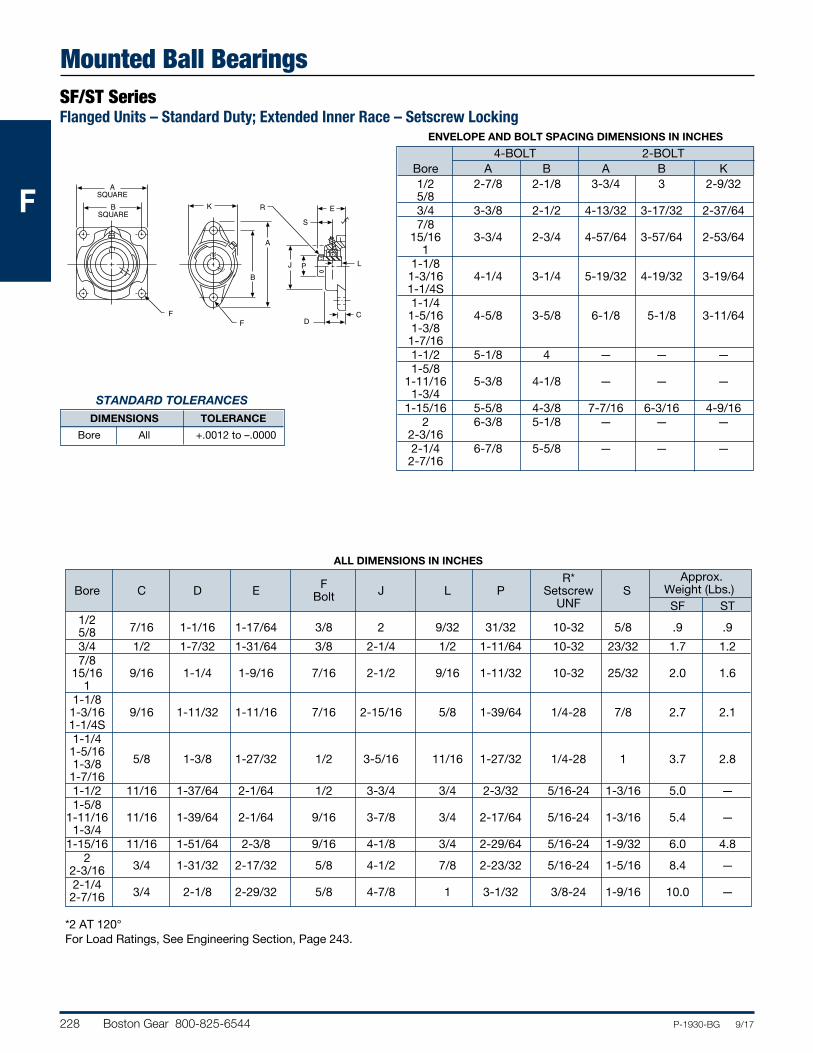
228 Boston Gear 800-825-6544 P-1930-BG 9/17
FFF
Mounted Ball BearingsSF/ST SeriesFlanged Units – Standard Duty; Extended Inner Race – Setscrew Locking
B
A
F
K R
C
PJ
D
E
S
L
ASQUARE
BSQUARE
F
STANDARD TOLERANCES
DIMENSIONS TOLERANCE
Bore All +.0012 to –.0000
*2 AT 120°For Load Ratings, See Engineering Section, Page 243.
ENVELOPE AND BOLT SPACING DIMENSIONS IN INCHES
4-BOLT 2-BOLT Bore A B A B K 1/2 2-7/8 2-1/8 3-3/4 3 2-9/32 5/8 3/4 3-3/8 2-1/2 4-13/32 3-17/32 2-37/64 7/8 15/16 3-3/4 2-3/4 4-57/64 3-57/64 2-53/64 1 1-1/8 1-3/16 4-1/4 3-1/4 5-19/32 4-19/32 3-19/64 1-1/4S 1-1/4 1-5/16 4-5/8 3-5/8 6-1/8 5-1/8 3-11/64 1-3/8 1-7/16 1-1/2 5-1/8 4 — — — 1-5/8 1-11/16 5-3/8 4-1/8 — — — 1-3/4 1-15/16 5-5/8 4-3/8 7-7/16 6-3/16 4-9/16 2 6-3/8 5-1/8 — — — 2-3/16 2-1/4 6-7/8 5-5/8 — — — 2-7/16
ALL DIMENSIONS IN INCHES
R* Approx. Bore C D E F J L P Setscrew S Weight (Lbs.) Bolt UNF SF ST 1/2
7/16 1-1/16 1-17/64 3/8 2 9/32 31/32 10-32 5/8 .9 .9
5/8 3/4 1/2 1-7/32 1-31/64 3/8 2-1/4 1/2 1-11/64 10-32 23/32 1.7 1.2 7/8 15/16 9/16 1-1/4 1-9/16 7/16 2-1/2 9/16 1-11/32 10-32 25/32 2.0 1.6 1 1-1/8 1-3/16 9/16 1-11/32 1-11/16 7/16 2-15/16 5/8 1-39/64 1/4-28 7/8 2.7 2.1 1-1/4S 1-1/4 1-5/16
5/8 1-3/8 1-27/32 1/2 3-5/16 11/16 1-27/32 1/4-28 1 3.7 2.8
1-3/8 1-7/16 1-1/2 11/16 1-37/64 2-1/64 1/2 3-3/4 3/4 2-3/32 5/16-24 1-3/16 5.0 — 1-5/8 1-11/16 11/16 1-39/64 2-1/64 9/16 3-7/8 3/4 2-17/64 5/16-24 1-3/16 5.4 — 1-3/4 1-15/16 11/16 1-51/64 2-3/8 9/16 4-1/8 3/4 2-29/64 5/16-24 1-9/32 6.0 4.8 2
3/4 1-31/32 2-17/32 5/8 4-1/2 7/8 2-23/32 5/16-24 1-5/16 8.4 —
2-3/16 2-1/4
3/4 2-1/8 2-29/32 5/8 4-7/8 1 3-1/32 3/8-24 1-9/16 10.0 —
2-7/16
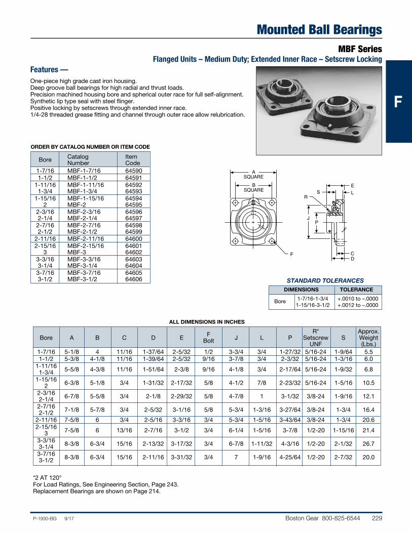
Boston Gear 800-825-6544 229P-1930-BG 9/17
FFF
Mounted Ball BearingsMBF Series
Flanged Units – Medium Duty; Extended Inner Race – Setscrew Locking
STANDARD TOLERANCES
DIMENSIONS TOLERANCE
Bore 1-7/16-1-3/4 +.0010 to –.0000 1-15/16-3-1/2 +.0012 to –.0000
ALL DIMENSIONS IN INCHES
R* Approx. Bore A B C D E F J L P Setscrew S Weight Bolt UNF (Lbs.) 1-7/16 5-1/8 4 11/16 1-37/64 2-5/32 1/2 3-3/4 3/4 1-27/32 5/16-24 1-9/64 5.5 1-1/2 5-3/8 4-1/8 11/16 1-39/64 2-5/32 9/16 3-7/8 3/4 2-3/32 5/16-24 1-3/16 6.0 1-11/16 5-5/8 4-3/8 11/16 1-51/64 2-3/8 9/16 4-1/8 3/4 2-17/64 5/16-24 1-9/32 6.8 1-3/4 1-15/16 6-3/8 5-1/8 3/4 1-31/32 2-17/32 5/8 4-1/2 7/8 2-23/32 5/16-24 1-5/16 10.5 2 2-3/16 6-7/8 5-5/8 3/4 2-1/8 2-29/32 5/8 4-7/8 1 3-1/32 3/8-24 1-9/16 12.1 2-1/4 2-7/16 7-1/8 5-7/8 3/4 2-5/32 3-1/16 5/8 5-3/4 1-3/16 3-27/64 3/8-24 1-3/4 16.4 2-1/2 2-11/16 7-5/8 6 3/4 2-5/16 3-3/16 3/4 5-3/4 1-5/16 3-43/64 3/8-24 1-3/4 20.6 2-15/16 7-5/8 6 13/16 2-7/16 3-1/2 3/4 6-1/4 1-5/16 3-7/8 1/2-20 1-15/16 21.4 3 3-3/16 8-3/8 6-3/4 15/16 2-13/32 3-17/32 3/4 6-7/8 1-11/32 4-3/16 1/2-20 2-1/32 26.7 3-1/4 3-7/16 8-3/8 6-3/4 15/16 2-11/16 3-31/32 3/4 7 1-9/16 4-25/64 1/2-20 2-7/32 20.0 3-1/2
*2 AT 120°For Load Ratings, See Engineering Section, Page 243.Replacement Bearings are shown on Page 214.
ORDER BY CATALOG NUMBER OR ITEM CODE
Catalog Item Bore Number Code 1-7/16 MBF-1-7/16 64590 1-1/2 MBF-1-1/2 64591 1-11/16 MBF-1-11/16 64592 1-3/4 MBF-1-3/4 64593 1-15/16 MBF-1-15/16 64594 2 MBF-2 64595 2-3/16 MBF-2-3/16 64596 2-1/4 MBF-2-1/4 64597 2-7/16 MBF-2-7/16 64598 2-1/2 MBF-2-1/2 64599 2-11/16 MBF-2-11/16 64600 2-15/16 MBF-2-15/16 64601 3 MBF-3 64602 3-3/16 MBF-3-3/16 64603 3-1/4 MBF-3-1/4 64604 3-7/16 MBF-3-7/16 64605 3-1/2 MBF-3-1/2 64606
Features —One-piece high grade cast iron housing.Deep groove ball bearings for high radial and thrust loads.Precision machined housing bore and spherical outer race for full self-alignment.Synthetic lip type seal with steel flinger.Positive locking by setscrews through extended inner race.1/4-28 threaded grease fitting and channel through outer race allow relubrication.
R
C
PJ
D
ES L
ASQUARE
BSQUARE
F
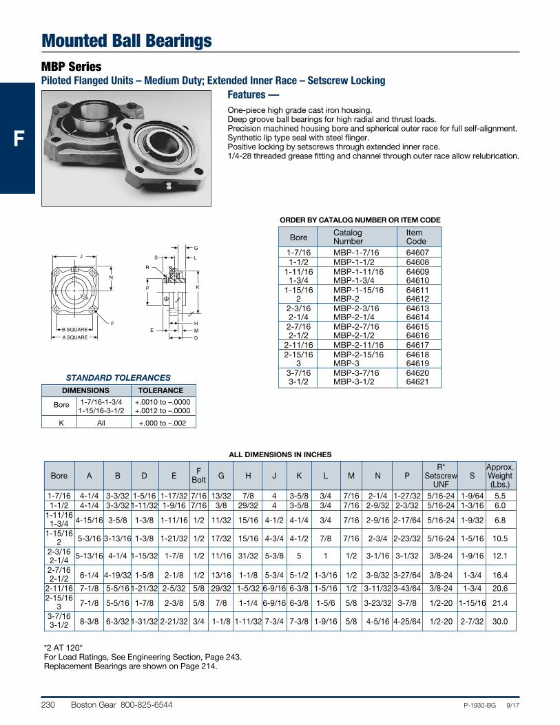
230 Boston Gear 800-825-6544 P-1930-BG 9/17
FFF
Mounted Ball BearingsMBP SeriesPiloted Flanged Units – Medium Duty; Extended Inner Race – Setscrew Locking
STANDARD TOLERANCES
DIMENSIONS TOLERANCE
Bore 1-7/16-1-3/4 +.0010 to –.0000 1-15/16-3-1/2 +.0012 to –.0000 K All +.000 to –.002
ALL DIMENSIONS IN INCHES
R* Approx. Bore A B D E F G H J K L M N P Setscrew S Weight Bolt UNF (Lbs.) 1-7/16 4-1/4 3-3/32 1-5/16 1-17/32 7/16 13/32 7/8 4 3-5/8 3/4 7/16 2-1/4 1-27/32 5/16-24 1-9/64 5.5 1-1/2 4-1/4 3-3/32 1-11/32 1-9/16 7/16 3/8 29/32 4 3-5/8 3/4 7/16 2-9/32 2-3/32 5/16-24 1-3/16 6.0 1-11/16
4-15/16 3-5/8 1-3/8 1-11/16 1/2 11/32 15/16 4-1/2 4-1/4 3/4 7/16 2-9/16 2-17/64 5/16-24 1-9/32 6.8
1-3/4 1-15/16
5-3/16 3-13/16 1-3/8 1-21/32 1/2 17/32 15/16 4-3/4 4-1/2 7/8 7/16 2-3/4 2-23/32 5/16-24 1-5/16 10.5
2 2-3/16 5-13/16 4-1/4 1-15/32 1-7/8 1/2 11/16 31/32 5-3/8 5 1 1/2 3-1/16 3-1/32 3/8-24 1-9/16 12.1 2-1/4 2-7/16
6-1/4 4-19/32 1-5/8 2-1/8 1/2 13/16 1-1/8 5-3/4 5-1/2 1-3/16 1/2 3-9/32 3-27/64 3/8-24 1-3/4 16.4
2-1/2 2-11/16 7-1/8 5-5/16 1-21/32 2-5/32 5/8 29/32 1-5/32 6-9/16 6-3/8 1-5/16 1/2 3-11/32 3-43/64 3/8-24 1-3/4 20.6 2-15/16
7-1/8 5-5/16 1-7/8 2-3/8 5/8 7/8 1-1/4 6-9/16 6-3/8 1-5/6 5/8 3-23/32 3-7/8 1/2-20 1-15/16 21.4
3 3-7/16
8-3/8 6-3/32 1-31/32 2-21/32 3/4 1-1/8 1-11/32 7-3/4 7-3/8 1-9/16 5/8 4-5/16 4-25/64 1/2-20 2-7/32 30.0
3-1/2
*2 AT 120°For Load Ratings, See Engineering Section, Page 243.Replacement Bearings are shown on Page 214.
ORDER BY CATALOG NUMBER OR ITEM CODE
Catalog Item Bore Number Code 1-7/16 MBP-1-7/16 64607 1-1/2 MBP-1-1/2 64608 1-11/16 MBP-1-11/16 64609 1-3/4 MBP-1-3/4 64610 1-15/16 MBP-1-15/16 64611 2 MBP-2 64612 2-3/16 MBP-2-3/16 64613 2-1/4 MBP-2-1/4 64614 2-7/16 MBP-2-7/16 64615 2-1/2 MBP-2-1/2 64616 2-11/16 MBP-2-11/16 64617 2-15/16 MBP-2-15/16 64618 3 MBP-3 64619 3-7/16 MBP-3-7/16 64620 3-1/2 MBP-3-1/2 64621
Features —One-piece high grade cast iron housing.Deep groove ball bearings for high radial and thrust loads.Precision machined housing bore and spherical outer race for full self-alignment.Synthetic lip type seal with steel flinger.Positive locking by setscrews through extended inner race.1/4-28 threaded grease fitting and channel through outer race allow relubrication.
R
P K
DE
S L
F
N
B SQUAREA SQUARE
G
MH
J
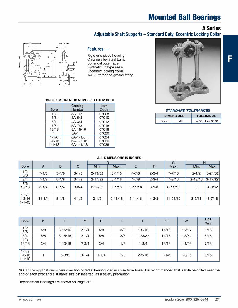
Boston Gear 800-825-6544 231P-1930-BG 9/17
FFF
Mounted Ball BearingsA Series
Adjustable Shaft Supports – Standard Duty; Eccentric Locking Collar
Bolt Bore K L M N O R S W Size 1/2 5/8 3-15/16 2-1/4 5/8 3/8 1-9/16 11/16 15/16 5/16 5/8 3/4 5/8 3-15/16 2-1/4 5/8 3/8 1-23/32 11/16 1-3/64 5/16 7/8 15/16 3/4 4-13/16 2-3/4 3/4 1/2 1-3/4 15/16 1-1/16 7/16 1 1-1/8 1-3/16 1 6-3/8 3-1/4 1-1/4 5/8 2-5/16 1-1/8 1-3/16 9/16 1-1/4S
NOTE: For applications where direction of radial bearing load is away from base, it is recommended that a hole be drilled near the end of each post and a suitable size pin inserted, as a safety precaution.
Replacement Bearings are shown on Page 213.
ORDER BY CATALOG NUMBER OR ITEM CODE
Catalog Item Bore Number Code 1/2 3A-1/2 07008 5/8 3A-5/8 07010 3/4 4A-3/4 07012 7/8 5A-7/8 07016 15/16 5A-15/16 07018 1 5A-1 07020 1-1/8 6A-1-1/8 07024 1-3/16 6A-1-3/16 07026 1-1/4S 6A-1-1/4S 07028
Features —Rigid one piece housing.Chrome alloy steel balls.Spherical outer race.Synthetic lip type seals.Eccentric locking collar.1/4-28 threaded grease fitting.
ALL DIMENSIONS IN INCHES
D G H Bore A B C Min. Max. E F Max. Min. Max.
1/2 7-1/8 5-1/8 3-1/8 2-13/32 6-1/16 4-7/8 2-3/4 7-7/16 2-1/2 3-21/32 5/8 3/4 7-1/8 5-1/8 3-1/8 2-17/32 6-1/16 4-7/8 2-3/4 7-9/16 2-13/16 3-17.32’ 7/8 15/16 8-1/4 6-1/4 3-3/4 2-25/32 7-1/16 5-11/16 3-1/8 8-11/16 3 4-9/32 1 1-1/8 1-3/16 11-1/4 8-1/8 4-1/2 3-1/2 9-15/16 7-11/16 4-3/8 11-25/32 3-7/16 6-7/16 1-1/4S
LB
EF
DMIN.
DMAX.
AG
H
O
SN
R
W
MC
K
STANDARD TOLERANCES
DIMENSIONS TOLERANCE
Bore All +.001 to –.0000
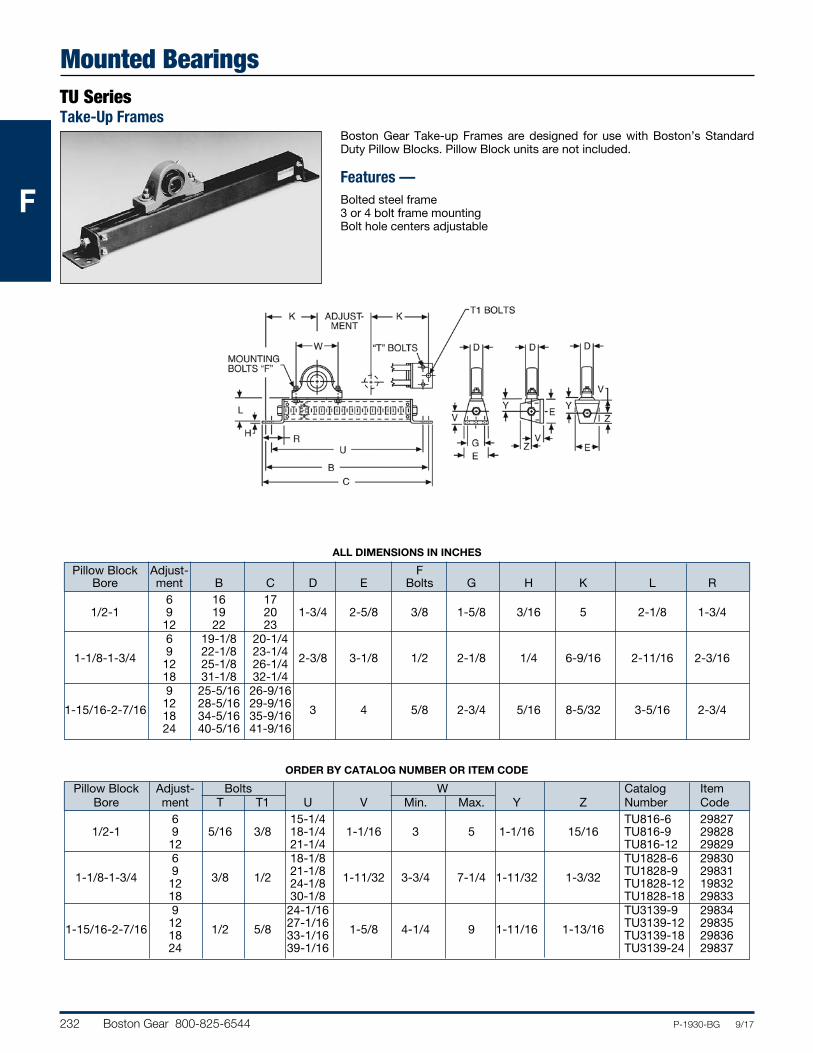
232 Boston Gear 800-825-6544 P-1930-BG 9/17
FFF
Mounted BearingsTU SeriesTake-Up Frames
ALL DIMENSIONS IN INCHES
Pillow Block Adjust- F Bore ment B C D E Bolts G H K L R 6 16 17 1/2-1 9 19 20 1-3/4 2-5/8 3/8 1-5/8 3/16 5 2-1/8 1-3/4 12 22 23 6 19-1/8 20-1/4 1-1/8-1-3/4 9 22-1/8 23-1/4 2-3/8 3-1/8 1/2 2-1/8 1/4 6-9/16 2-11/16 2-3/16 12 25-1/8 26-1/4 18 31-1/8 32-1/4 9 25-5/16 26-9/16 1-15/16-2-7/16 12 28-5/16 29-9/16 3 4 5/8 2-3/4 5/16 8-5/32 3-5/16 2-3/4 18 34-5/16 35-9/16 24 40-5/16 41-9/16
Pillow Block Adjust- Bolts W Catalog Item Bore ment T T1 U V Min. Max. Y Z Number Code 6 15-1/4 TU816-6 29827 1/2-1 9 5/16 3/8 18-1/4 1-1/16 3 5 1-1/16 15/16 TU816-9 29828 12 21-1/4 TU816-12 29829 6 18-1/8 TU1828-6 29830 1-1/8-1-3/4 9 3/8 1/2 21-1/8 1-11/32 3-3/4 7-1/4 1-11/32 1-3/32 TU1828-9 29831 12 24-1/8 TU1828-12 19832 18 30-1/8 TU1828-18 29833 9 24-1/16 TU3139-9 29834 1-15/16-2-7/16 12 1/2 5/8 27-1/16 1-5/8 4-1/4 9 1-11/16 1-13/16 TU3139-12 29835 18 33-1/16 TU3139-18 29836 24 39-1/16 TU3139-24 29837
Boston Gear Take-up Frames are designed for use with Boston’s Standard Duty Pillow Blocks. Pillow Block units are not included.
Features —Bolted steel frame3 or 4 bolt frame mountingBolt hole centers adjustable
ORDER BY CATALOG NUMBER OR ITEM CODE
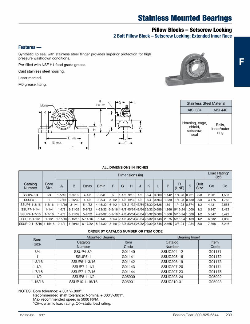
Boston Gear 800-825-6544 233P-1930-BG 9/17
FFF
Stainless Mounted BearingsPillow Blocks – Setscrew Locking
2 Bolt Pillow Block – Setscrew Locking; Extended Inner Race
Features —Synthetic lip seal with stainless steel flinger provides superior protection for high pressure washdown conditions.
Pre-filled with NSF H1 food grade grease.
Cast stainless steel housing.
Laser marked.
M6 grease fitting.
BP
S L
GE MIN.
F
H
E MAX.
A
K
Bore
J
R (2 @ 120º)
Dimensions (in) Load Rating* (lbf)
Catalog Number
Bore Size A B Emax Emin F G H J K L P R
(UNF) S Bolt Size CR CO
SSUP4-3/4 3/4 1-5/16 2-9/16 4-1/8 3-3/8 5 1-1/2 9/16 1/2 3/4 0.500 1.142 1/4-28 0.721 3/8 2,901 1,507
SSUP5-1 1 1-7/16 2-25/32 4-1/2 3-3/4 5-1/2 1-1/2 19/32 1/2 3/4 0.563 1.339 1/4-28 0.780 3/8 3,175 1,782
SSUP6-1-3/16 1-3/16 1-11/16 3-1/4 5-1/32 4-15/32 6-1/2 1-7/8 21/32 43/64 25/32 0.626 1.591 1/4-28 0.874 1/2 4,431 2,558
SSUP7-1-1/4 1-1/4 1-7/8 3-21/32 5-9/32 4-23/32 6-9/16 1-7/8 45/64 43/64 25/32 0.689 1.866 5/16-24 1.000 1/2 5,847 3,472
SSUP7-1-7/16 1-7/16 1-7/8 3-21/32 5-9/32 4-23/32 6-9/16 1-7/8 45/64 43/64 25/32 0.689 1.866 5/16-24 1.000 1/2 5,847 3,472
SSUP8-1-1/2 1-1/2 1-15/16 3-15/16 5-11/16 5-1/8 7-1/4 2-1/8 45/64 43/64 25/32 0.748 2.075 5/16-24 1.189 1/2 6,632 4,069
SSUP10-1-15/16 1-15/16 2-1/4 4-29/64 6-17/32 5-31/32 8-1/8 2-3/8 53/64 25/32 29/32 0.748 2.465 3/8-24 1.284 5/8 7,868 5,216
Bore Size
Mounted Bearing Bearing InsertCatalog Number
Item Code
Catalog Number
Item Code
3/4 SSUP4- 3/4 G01140 SSUC204- 12 G011711 SSUP5- 1 G01141 SSUC205- 16 G01172
1- 3/16 SSUP6- 1- 3/16 G01142 SSUC206- 19 G011731- 1/4 SSUP7- 1- 1/4 G01143 SSUC207- 20 G011741- 7/16 SSUP7- 1- 7/16 G01144 SSUC207- 23 G011751-1/2 SSUP8-1-1/2 G05900 SSUC208-24 G05922
1-15/16 SSUP10-1-15/16 G05901 SSUC210-31 G05923
Stainless Steel Material
AISI 304 AISI 440
Housing, cage, shield,
setscrew, seal
Balls, inner/outer
ring
NOTES: Bore tolerance: +.001”/-.000”. Recommended shaft tolerance: Nominal +.000”/-.001”. Max recommended speed is 5000 RPM. *CR=dynamic load rating, CO=static load rating.
ALL DIMENSIONS IN INCHES
ORDER BY CATALOG NUMBER OR ITEM CODE
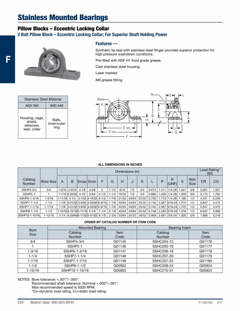
234 Boston Gear 800-825-6544 P-1930-BG 9/17
FFF
Stainless Mounted BearingsPillow Blocks – Eccentric Locking Collar2 Bolt Pillow Block – Eccentric Locking Collar; For Superior Shaft Holding Power
Features —Synthetic lip seal with stainless steel flinger provides superior protection for high pressure washdown conditions.
Pre-filled with NSF H1 food grade grease.
Cast stainless steel housing.
Laser marked.
M6 grease fitting.
P
B
S L
GE MIN.
F
H
E MAX.
A
K
J
BoreR
Dimensions (in) Load Rating* (lbf)
Catalog Number
Bore Size A B Emax Emin F G H J K L PR
(UNF)S
Bolt Size
CR CO
SSHP4-3/4 3/4 1-5/16 2-9/16 4-1/8 3-3/8 5 1-1/2 9/16 1/2 3/4 0.673 1.311 1/4-28 1.047 3/8 2,901 1,507 SSHP5-1 1 1-7/16 2-25/32 4-1/2 3-3/4 5-1/2 1-1/2 19/32 1/2 3/4 0.689 1.500 1/4-28 1.059 3/8 3,175 1,782
SSHP6-1-3/16 1-3/16 1-11/16 3-1/4 5-1/32 4-15/32 6-1/2 1-7/8 21/32 43/64 25/32 0.720 1.713 1/4-28 1.186 1/2 4,431 2,558 SSHP7-1-1/4 1-1/4 1-7/8 3-21/32 5-9/32 4-23/32 6-9/16 1-7/8 45/64 43/64 25/32 0.740 2.087 5/16-24 1.272 1/2 5,847 3,472 SSHP7-1-7/16 1-7/16 1-7/8 3-21/32 5-9/32 4-23/32 6-9/16 1-7/8 45/64 43/64 25/32 0.740 2.087 5/16-24 1.272 1/2 5,847 3,472 SSHP8-1-1/2 1-1/2 1-15/16 3-15/16 5-11/16 5-1/8 7-1/4 2-1/8 45/64 43/64 25/32 0.748 2.283 5/16-24 1.378 1/2 6,632 4,069
SSHP10-1-15/16 1-15/16 2-1/4 4-29/64 6-17/32 5-31/32 8-1/8 2-3/8 53/64 25/32 29/32 0.969 2.697 3/8-24 1.500 5/8 7,868 5,216
Bore Size
Mounted Bearing Bearing InsertCatalog Number
Item Code
Catalog Number
Item Code
3/4 SSHP4-3/4 G01145 SSHC204-12 G011761 SSHP5-1 G01146 SSHC205-16 G01177
1-3/16 SSHP6-1-3/16 G01147 SSHC206-19 G011781-1/4 SSHP7-1-1/4 G01148 SSHC207-20 G011791-7/16 SSHP7-1-7/16 G01149 SSHC207-23 G011801-1/2 SSHP8-1-1/2 G05902 SSHC208-24 G05924
1-15/16 SSHP10-1-15/16 G05903 SSHC210-31 G05925
NOTES: Bore tolerance: +.001”/-.000”. Recommended shaft tolerance: Nominal +.000”/-.001”. Max recommended speed is 5000 RPM. *CR=dynamic load rating, CO=static load rating.
Stainless Steel Material
AISI 304 AISI 440
Housing, cage, shield,
setscrew, seal, collar
Balls, inner/outer
ring
ALL DIMENSIONS IN INCHES
ORDER BY CATALOG NUMBER OR ITEM CODE
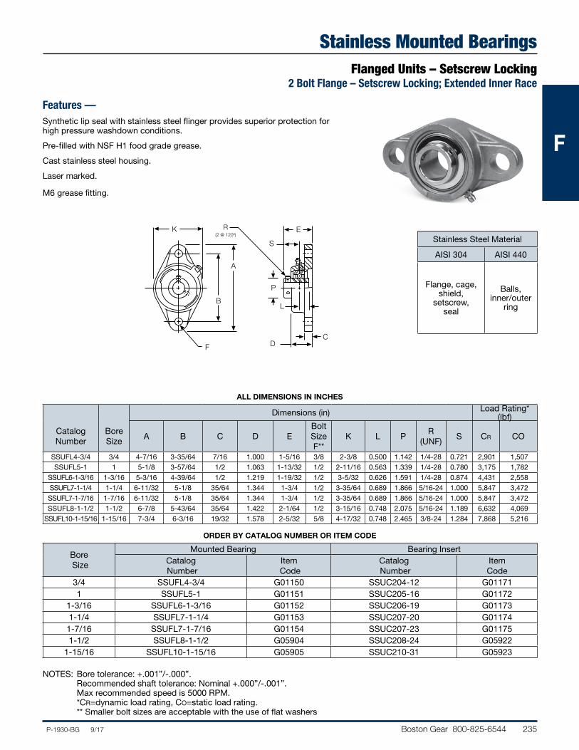
Boston Gear 800-825-6544 235P-1930-BG 9/17
FFF
Stainless Mounted BearingsFlanged Units – Setscrew Locking
2 Bolt Flange – Setscrew Locking; Extended Inner Race
Features —Synthetic lip seal with stainless steel flinger provides superior protection for high pressure washdown conditions.
Pre-filled with NSF H1 food grade grease.
Cast stainless steel housing.
Laser marked.
M6 grease fitting.
Stainless Steel Material
AISI 304 AISI 440
Flange, cage, shield,
setscrew, seal
Balls, inner/outer
ringB
A
F
R(2 @ 120º)
CD
E
S
L
K
P
Dimensions (in) Load Rating* (lbf)
Catalog Number
Bore Size
A B C D EBolt Size F**
K L PR
(UNF)S CR CO
SSUFL4-3/4 3/4 4-7/16 3-35/64 7/16 1.000 1-5/16 3/8 2-3/8 0.500 1.142 1/4-28 0.721 2,901 1,507 SSUFL5-1 1 5-1/8 3-57/64 1/2 1.063 1-13/32 1/2 2-11/16 0.563 1.339 1/4-28 0.780 3,175 1,782
SSUFL6-1-3/16 1-3/16 5-3/16 4-39/64 1/2 1.219 1-19/32 1/2 3-5/32 0.626 1.591 1/4-28 0.874 4,431 2,558 SSUFL7-1-1/4 1-1/4 6-11/32 5-1/8 35/64 1.344 1-3/4 1/2 3-35/64 0.689 1.866 5/16-24 1.000 5,847 3,472 SSUFL7-1-7/16 1-7/16 6-11/32 5-1/8 35/64 1.344 1-3/4 1/2 3-35/64 0.689 1.866 5/16-24 1.000 5,847 3,472 SSUFL8-1-1/2 1-1/2 6-7/8 5-43/64 35/64 1.422 2-1/64 1/2 3-15/16 0.748 2.075 5/16-24 1.189 6,632 4,069
SSUFL10-1-15/16 1-15/16 7-3/4 6-3/16 19/32 1.578 2-5/32 5/8 4-17/32 0.748 2.465 3/8-24 1.284 7,868 5,216
Bore Size
Mounted Bearing Bearing InsertCatalog Number
Item Code
Catalog Number
Item Code
3/4 SSUFL4-3/4 G01150 SSUC204-12 G011711 SSUFL5-1 G01151 SSUC205-16 G01172
1-3/16 SSUFL6-1-3/16 G01152 SSUC206-19 G011731-1/4 SSUFL7-1-1/4 G01153 SSUC207-20 G011741-7/16 SSUFL7-1-7/16 G01154 SSUC207-23 G011751-1/2 SSUFL8-1-1/2 G05904 SSUC208-24 G05922
1-15/16 SSUFL10-1-15/16 G05905 SSUC210-31 G05923
NOTES: Bore tolerance: +.001”/-.000”. Recommended shaft tolerance: Nominal +.000”/-.001”. Max recommended speed is 5000 RPM. *CR=dynamic load rating, CO=static load rating. ** Smaller bolt sizes are acceptable with the use of flat washers
ALL DIMENSIONS IN INCHES
ORDER BY CATALOG NUMBER OR ITEM CODE
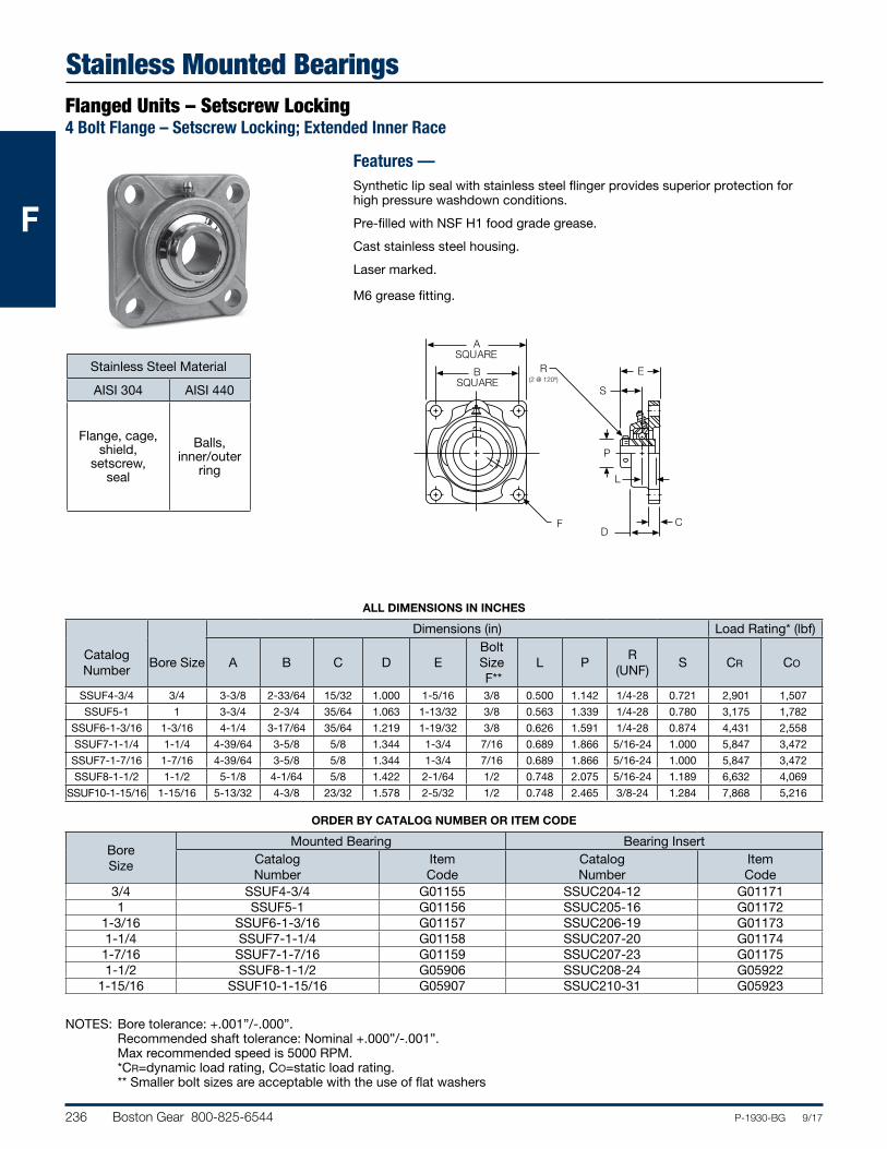
236 Boston Gear 800-825-6544 P-1930-BG 9/17
FFF
R(2 @ 120º)
CD
E
S
L
ASQUARE
BSQUARE
F
P
Dimensions (in) Load Rating* (lbf)
Catalog Number
Bore Size A B C D EBolt Size F**
L PR
(UNF)S CR CO
SSUF4-3/4 3/4 3-3/8 2-33/64 15/32 1.000 1-5/16 3/8 0.500 1.142 1/4-28 0.721 2,901 1,507
SSUF5-1 1 3-3/4 2-3/4 35/64 1.063 1-13/32 3/8 0.563 1.339 1/4-28 0.780 3,175 1,782
SSUF6-1-3/16 1-3/16 4-1/4 3-17/64 35/64 1.219 1-19/32 3/8 0.626 1.591 1/4-28 0.874 4,431 2,558
SSUF7-1-1/4 1-1/4 4-39/64 3-5/8 5/8 1.344 1-3/4 7/16 0.689 1.866 5/16-24 1.000 5,847 3,472
SSUF7-1-7/16 1-7/16 4-39/64 3-5/8 5/8 1.344 1-3/4 7/16 0.689 1.866 5/16-24 1.000 5,847 3,472
SSUF8-1-1/2 1-1/2 5-1/8 4-1/64 5/8 1.422 2-1/64 1/2 0.748 2.075 5/16-24 1.189 6,632 4,069
SSUF10-1-15/16 1-15/16 5-13/32 4-3/8 23/32 1.578 2-5/32 1/2 0.748 2.465 3/8-24 1.284 7,868 5,216
NOTES: Bore tolerance: +.001”/-.000”. Recommended shaft tolerance: Nominal +.000”/-.001”. Max recommended speed is 5000 RPM. *CR=dynamic load rating, CO=static load rating. ** Smaller bolt sizes are acceptable with the use of flat washers
Stainless Mounted BearingsFlanged Units – Setscrew Locking4 Bolt Flange – Setscrew Locking; Extended Inner Race
Features —Synthetic lip seal with stainless steel flinger provides superior protection for high pressure washdown conditions.
Pre-filled with NSF H1 food grade grease.
Cast stainless steel housing.
Laser marked.
M6 grease fitting.
Bore Size
Mounted Bearing Bearing InsertCatalog Number
Item Code
Catalog Number
Item Code
3/4 SSUF4-3/4 G01155 SSUC204-12 G011711 SSUF5-1 G01156 SSUC205-16 G01172
1-3/16 SSUF6-1-3/16 G01157 SSUC206-19 G011731-1/4 SSUF7-1-1/4 G01158 SSUC207-20 G011741-7/16 SSUF7-1-7/16 G01159 SSUC207-23 G011751-1/2 SSUF8-1-1/2 G05906 SSUC208-24 G05922
1-15/16 SSUF10-1-15/16 G05907 SSUC210-31 G05923
Stainless Steel Material
AISI 304 AISI 440
Flange, cage, shield,
setscrew, seal
Balls, inner/outer
ring
ALL DIMENSIONS IN INCHES
ORDER BY CATALOG NUMBER OR ITEM CODE
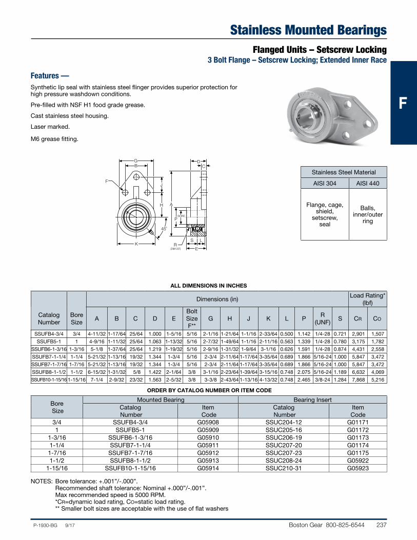
Boston Gear 800-825-6544 237P-1930-BG 9/17
FFF
45˚
H
JF
BG
K R
P
A
CD
BORE
(2@120˚)
S
E
L
Dimensions (in)Load Rating*
(lbf)
Catalog Number
Bore Size
A B C D EBolt Size F**
G H J K L PR
(UNF)S CR CO
SSUFB4-3/4 3/4 4-11/32 1-17/64 25/64 1.000 1-5/16 5/16 2-1/16 1-21/64 1-1/16 2-33/64 0.500 1.142 1/4-28 0.721 2,901 1,507
SSUFB5-1 1 4-9/16 1-11/32 25/64 1.063 1-13/32 5/16 2-7/32 1-49/64 1-1/16 2-11/16 0.563 1.339 1/4-28 0.780 3,175 1,782
SSUFB6-1-3/16 1-3/16 5-1/8 1-37/64 25/64 1.219 1-19/32 5/16 2-9/16 1-31/32 1-9/64 3-1/16 0.626 1.591 1/4-28 0.874 4,431 2,558
SSUFB7-1-1/4 1-1/4 5-21/32 1-13/16 19/32 1.344 1-3/4 5/16 2-3/4 2-11/64 1-17/64 3-35/64 0.689 1.866 5/16-24 1.000 5,847 3,472
SSUFB7-1-7/16 1-7/16 5-21/32 1-13/16 19/32 1.344 1-3/4 5/16 2-3/4 2-11/64 1-17/64 3-35/64 0.689 1.866 5/16-24 1.000 5,847 3,472
SSUFB8-1-1/2 1-1/2 6-15/32 1-31/32 5/8 1.422 2-1/64 3/8 3-1/16 2-23/64 1-39/64 3-15/16 0.748 2.075 5/16-24 1.189 6,632 4,069
SSUFB10-1-15/16 1-15/16 7-1/4 2-9/32 23/32 1.563 2-5/32 3/8 3-3/8 2-43/64 1-13/16 4-13/32 0.748 2.465 3/8-24 1.284 7,868 5,216
ALL DIMENSIONS IN INCHES
Stainless Mounted BearingsFlanged Units – Setscrew Locking
3 Bolt Flange – Setscrew Locking; Extended Inner Race
Features —Synthetic lip seal with stainless steel flinger provides superior protection for high pressure washdown conditions.
Pre-filled with NSF H1 food grade grease.
Cast stainless steel housing.
Laser marked.
M6 grease fitting.
Stainless Steel Material
AISI 304 AISI 440
Flange, cage, shield,
setscrew, seal
Balls, inner/outer
ring
Bore Size
Mounted Bearing Bearing InsertCatalog Number
Item Code
Catalog Number
Item Code
3/4 SSUFB4-3/4 G05908 SSUC204-12 G011711 SSUFB5-1 G05909 SSUC205-16 G01172
1-3/16 SSUFB6-1-3/16 G05910 SSUC206-19 G011731-1/4 SSUFB7-1-1/4 G05911 SSUC207-20 G011741-7/16 SSUFB7-1-7/16 G05912 SSUC207-23 G011751-1/2 SSUFB8-1-1/2 G05913 SSUC208-24 G05922
1-15/16 SSUFB10-1-15/16 G05914 SSUC210-31 G05923
NOTES: Bore tolerance: +.001”/-.000”. Recommended shaft tolerance: Nominal +.000”/-.001”. Max recommended speed is 5000 RPM. *CR=dynamic load rating, CO=static load rating. ** Smaller bolt sizes are acceptable with the use of flat washers
ORDER BY CATALOG NUMBER OR ITEM CODE
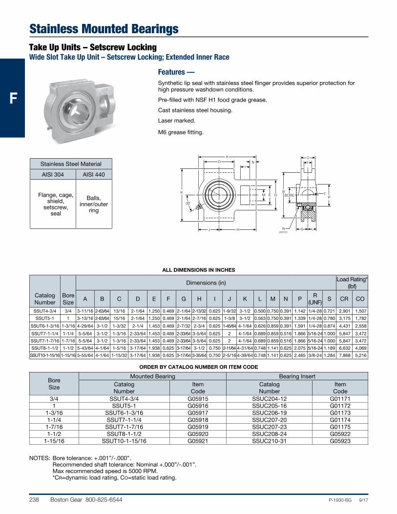
238 Boston Gear 800-825-6544 P-1930-BG 9/17
FFF
BOREB
LSRH
TP
CF
(2@120˚)J
A
N
GEM
ID
K
30˚
Dimensions (in)Load Rating*
(lbf)
Catalog Number
Bore Size
A B C D E F G H I J K L M N PR
(UNF)S CR CO
SSUT4-3/4 3/4 3-11/16 2-63/64 13/16 2-1/64 1.250 0.469 2-1/64 2-13/32 0.625 1-9/32 3-1/2 0.500 0.750 0.391 1.142 1/4-28 0.721 2,901 1,507
SSUT5-1 1 3-13/16 2-63/64 15/16 2-1/64 1.250 0.469 2-1/64 2-7/16 0.625 1-3/8 3-1/2 0.563 0.750 0.391 1.339 1/4-28 0.780 3,175 1,782
SSUT6-1-3/16 1-3/16 4-29/64 3-1/2 1-3/32 2-1/4 1.453 0.469 2-7/32 2-3/4 0.625 1-45/64 4-1/64 0.626 0.859 0.391 1.591 1/4-28 0.874 4,431 2,558
SSUT7-1-1/4 1-1/4 5-5/64 3-1/2 1-3/16 2-33/64 1.453 0.469 2-33/64 3-5/64 0.625 2 4-1/64 0.689 0.859 0.516 1.866 5/16-24 1.000 5,847 3,472
SSUT7-1-7/16 1-7/16 5-5/64 3-1/2 1-3/16 2-33/64 1.453 0.469 2-33/64 3-5/64 0.625 2 4-1/64 0.689 0.859 0.516 1.866 5/16-24 1.000 5,847 3,472
SSUT8-1-1/2 1-1/2 5-43/64 4-1/64 1-5/16 3-17/64 1.938 0.625 3-17/64 3-1/2 0.750 2-11/64 4-31/64 0.748 1.141 0.625 2.075 5/16-24 1.189 6,632 4,069
SSUT10-1-15/16 1-15/16 5-55/64 4-1/64 1-15/32 3-17/64 1.938 0.625 3-17/64 3-35/64 0.750 2-5/16 4-39/64 0.748 1.141 0.625 2.465 3/8-24 1.284 7,868 5,216
NOTES: Bore tolerance: +.001”/-.000”. Recommended shaft tolerance: Nominal +.000”/-.001”. Max recommended speed is 5000 RPM. *CR=dynamic load rating, CO=static load rating.
Stainless Mounted BearingsTake Up Units – Setscrew LockingWide Slot Take Up Unit – Setscrew Locking; Extended Inner Race
Features —Synthetic lip seal with stainless steel flinger provides superior protection for high pressure washdown conditions.
Pre-filled with NSF H1 food grade grease.
Cast stainless steel housing.
Laser marked.
M6 grease fitting.
Bore Size
Mounted Bearing Bearing InsertCatalog Number
Item Code
Catalog Number
Item Code
3/4 SSUT4-3/4 G05915 SSUC204-12 G011711 SSUT5-1 G05916 SSUC205-16 G01172
1-3/16 SSUT6-1-3/16 G05917 SSUC206-19 G011731-1/4 SSUT7-1-1/4 G05918 SSUC207-20 G011741-7/16 SSUT7-1-7/16 G05919 SSUC207-23 G011751-1/2 SSUT8-1-1/2 G05920 SSUC208-24 G05922
1-15/16 SSUT10-1-15/16 G05921 SSUC210-31 G05923
Stainless Steel Material
AISI 304 AISI 440
Flange, cage, shield,
setscrew, seal
Balls, inner/outer
ring
ALL DIMENSIONS IN INCHES
ORDER BY CATALOG NUMBER OR ITEM CODE
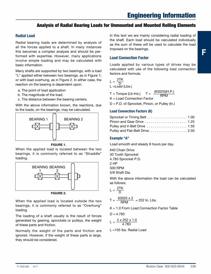
Boston Gear 800-825-6544 239P-1930-BG 9/17
FFF
Engineering InformationAnalysis of Radial Bearing Loads for Unmounted and Mounted Rolling Elements
Radial Load
Radial bearing loads are determined by analysis of all the forces applied to a shaft. In many instances this becomes a complex analysis and should be per-formed with expertise. However, many applications involve simple loading and may be calculated with basic information.
Many shafts are supported by two bearings, with a load “L” applied either between two bearings, as in Figure 1; or with load overhung, as in Figure 2. In either case, the reaction on the bearing is dependent upon:
a. The point of load application b. The magnitude of the load. c. The distance between the bearing centers.
With the above information known, the reactions, due to the loads, on the bearings, may be calculated.
FIGURE 1.When the applied load is located between the two bearings, it is commonly referred to as “Straddle” loading.
FIGURE 2.
When the applied load is located outside the two bearings, it is commonly referred to as “Overhung” loading.
The loading of a shaft usually is the result of forces generated by gearing, sprockets or pulleys, the weight of these parts and friction.
Normally the weight of the parts and friction are ignored. However, if the weight of these parts is large, they should be considered.
In this text we are mainly considering radial loading of the shaft. Each load should be calculated individually as the sum of these will be used to calculate the load imposed on the bearings.
Load Connection Factor
Loads applied by various types of drives may be calculated with use of the following load connection factors and formula:
2TKL = DL = Load (Lbs.)
(63025)(H.P.)T = Torque (Lb-Ins.) T = RPMK = Load Connection Factor
D = P.D. of Sprocket, Pinion, or Pulley (In.)
Load Connection Factors (K)
Sprocket or Timing Belt . . . . . . . . . . . . . . . . . . . . . 1.00Pinion and Gear Drive . . . . . . . . . . . . . . . . . . . . . . 1.25Pulley and V-Belt Drive . . . . . . . . . . . . . . . . . . . . . 1.50Pulley and Flat-Belt Drive. . . . . . . . . . . . . . . . . . . . 2.50
Example “A”
Load smooth and steady 8 hours per day.
#40 Chain Drive 30 Tooth Sprocket 4.783 Sprocket P.D. 2 HP 500 RPM 5/8 Shaft Dia.
With the above information the load can be calculated as follows:
2TKL = D
63025 x 2T = = 252 In. Lbs. RPM
K = 1.0 From Load Connection Factor Table
D = 4.783
2 x 252 x 1.0L = 4.783
L = 105 lbs. Radial Load
BEARING1
BEARING2
BEARING 1 BEARING 2
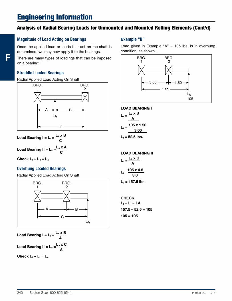
240 Boston Gear 800-825-6544 P-1930-BG 9/17
FFF
Engineering InformationAnalysis of Radial Bearing Loads for Unmounted and Mounted Rolling Elements (Cont’d)
Magnitude of Load Acting on Bearings
Once the applied load or loads that act on the shaft is determined, we may now apply it to the bearings.
There are many types of loadings that can be imposed on a bearing:
Straddle Loaded BearingsRadial Applied Load Acting On Shaft
LA x BLoad Bearing I = LI = C
LA x ALoad Bearing II = LII = C
Check LI + LII = LA
Overhung Loaded BearingsRadial Applied Load Acting On Shaft
LA x BLoad Bearing I = LI = A
LA x CLoad Bearing II = LII = A
Check LII – LI = LA
Example “B”Load given in Example “A” = 105 lbs. is in overhung condition, as shown.
LOAD BEARING I LA x BLI = A
105 x 1.50LI = 3.00
LI = 52.5 lbs.
LOAD BEARING II LA x CL2 = A
105 x 4.5L2 = 3.0
L2 = 157.5 lbs.
CHECKLII – LI = LA
157.5 – 52.5 = 105
105 = 105
BRG.1
BRG.2
4.50
1.503.00
AL105
BRG.1
BRG.2
C
BA
AL
BRG.1
BRG.2
C
BA
AL
Boston Gear 800-825-6544 241P-1930-BG 9/17
FFF
Engineering InformationBall and Mounted Ball Bearing Selection
Bearing selection for the majority of applications can be made directly from the Load Rating Tables. Mounted bearings are listed individually on each page. The mounted bearings tables are located on Pages 108-109.
The following procedure may be followed:
1. Determine the actual radial load to be supported by the bearing. For applications involving heavy shock loads or severe vibration, actual load should be multiplied by a service factor from 1.1 to 1.5 depending on the severity of these conditions.
2. Select a bearing from the table that has a radial load rating equal to or greater than the actual radial load determined in Step 1, for the life desired at the required operating speed.
Ball bearing rating tables are based on an “Average” bearing life of 2500 hours. Average or medium life (L50) is the life that may be expected from 50% or more of a given group of bearings operating under an identical steady load condition. The minimum life (L10) is the life expectancy of at least 90% of a group of bearings and is approxi-mately 1/5 average.
Example “C”
Using loading from Example “B,” select a mounted bearing suitable to give an average life (L50) of 15,000 hours.
Known—
Load Bearing I = 52.5Load Bearing II = 157.5 Shaft Diameter 5/8 (From Example “A”)Service Factor 1 (From Example “A”)500 RPM (From Example “A”)
From the Rating Table, Page 243, as shown, a standard duty bearing (either eccentric collar or extended set screw inner race) may be selected.
Service Factor
Operating Conditions
.8 Uniform — not more than 15 minutes in 2 hours. 1.0 Moderate Shock — not more than 15 minutes in 2 hours.
Uniform — not more than 10 hours per day 1.25 Moderate Shock — not more than 10 hours per day.
Uniform — more than 10 hours per day. 1.50 Heavy Shock — not more than 15 minutes in 2 hours.
Moderate Shock — more than 10 hours per day. 1.75 Heavy Shock — not more than 10 hours per day. 2.0 Heavy Shock — more than 10 hours per day.
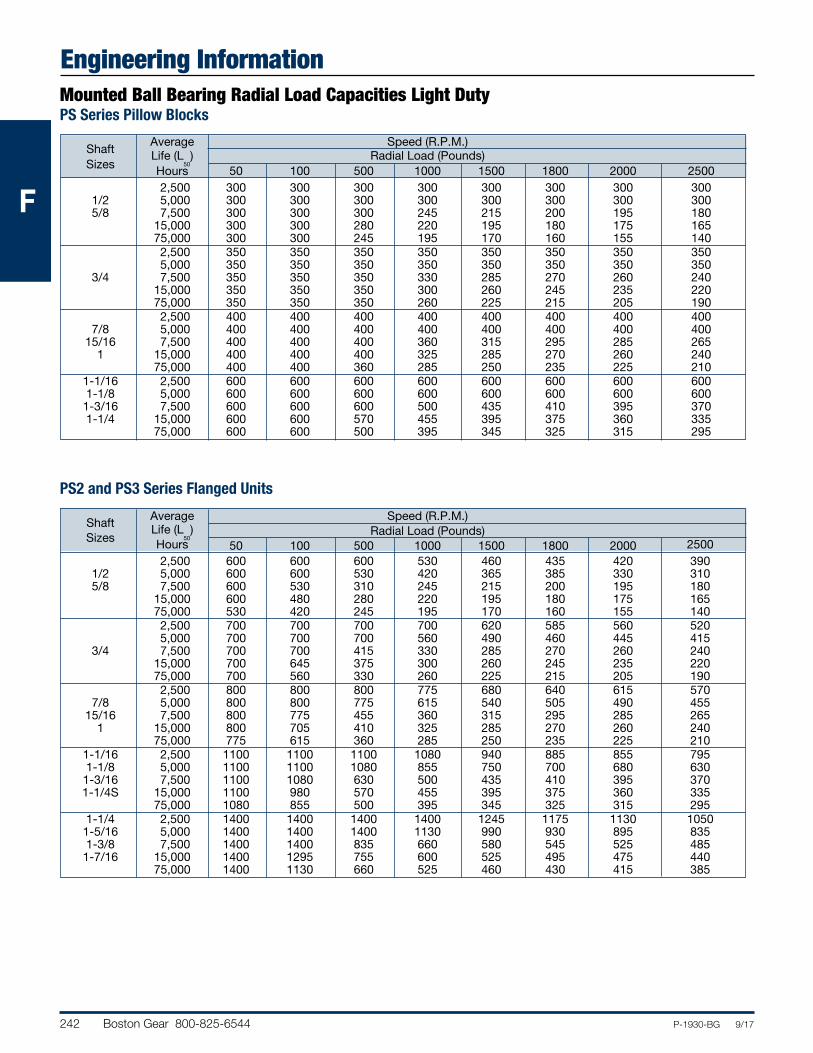
242 Boston Gear 800-825-6544 P-1930-BG 9/17
FFF
Engineering Information
Average Speed (R.P.M.) Shaft Life (L
50) Radial Load (Pounds)
Sizes Hours 50 100 500 1000 1500 1800 2000 2500 2,500 600 600 600 530 460 435 420 390 1/2 5,000 600 600 530 420 365 385 330 310 5/8 7,500 600 530 310 245 215 200 195 180 15,000 600 480 280 220 195 180 175 165 75,000 530 420 245 195 170 160 155 140 2,500 700 700 700 700 620 585 560 520 5,000 700 700 700 560 490 460 445 415 3/4 7,500 700 700 415 330 285 270 260 240 15,000 700 645 375 300 260 245 235 220 75,000 700 560 330 260 225 215 205 190 2,500 800 800 800 775 680 640 615 570 7/8 5,000 800 800 775 615 540 505 490 455 15/16 7,500 800 775 455 360 315 295 285 265 1 15,000 800 705 410 325 285 270 260 240 75,000 775 615 360 285 250 235 225 210 1-1/16 2,500 1100 1100 1100 1080 940 885 855 795 1-1/8 5,000 1100 1100 1080 855 750 700 680 630 1-3/16 7,500 1100 1080 630 500 435 410 395 370 1-1/4S 15,000 1100 980 570 455 395 375 360 335 75,000 1080 855 500 395 345 325 315 295 1-1/4 2,500 1400 1400 1400 1400 1245 1175 1130 1050 1-5/16 5,000 1400 1400 1400 1130 990 930 895 835 1-3/8 7,500 1400 1400 835 660 580 545 525 485 1-7/16 15,000 1400 1295 755 600 525 495 475 440 75,000 1400 1130 660 525 460 430 415 385
PS2 and PS3 Series Flanged Units
Average Speed (R.P.M.) Shaft Life (L
50) Radial Load (Pounds)
Sizes Hours 50 100 500 1000 1500 1800 2000 2500 2,500 300 300 300 300 300 300 300 300 1/2 5,000 300 300 300 300 300 300 300 300 5/8 7,500 300 300 300 245 215 200 195 180 15,000 300 300 280 220 195 180 175 165 75,000 300 300 245 195 170 160 155 140 2,500 350 350 350 350 350 350 350 350 5,000 350 350 350 350 350 350 350 350 3/4 7,500 350 350 350 330 285 270 260 240 15,000 350 350 350 300 260 245 235 220 75,000 350 350 350 260 225 215 205 190 2,500 400 400 400 400 400 400 400 400 7/8 5,000 400 400 400 400 400 400 400 400 15/16 7,500 400 400 400 360 315 295 285 265 1 15,000 400 400 400 325 285 270 260 240 75,000 400 400 360 285 250 235 225 210 1-1/16 2,500 600 600 600 600 600 600 600 600 1-1/8 5,000 600 600 600 600 600 600 600 600 1-3/16 7,500 600 600 600 500 435 410 395 370 1-1/4 15,000 600 600 570 455 395 375 360 335 75,000 600 600 500 395 345 325 315 295
Mounted Ball Bearing Radial Load Capacities Light DutyPS Series Pillow Blocks
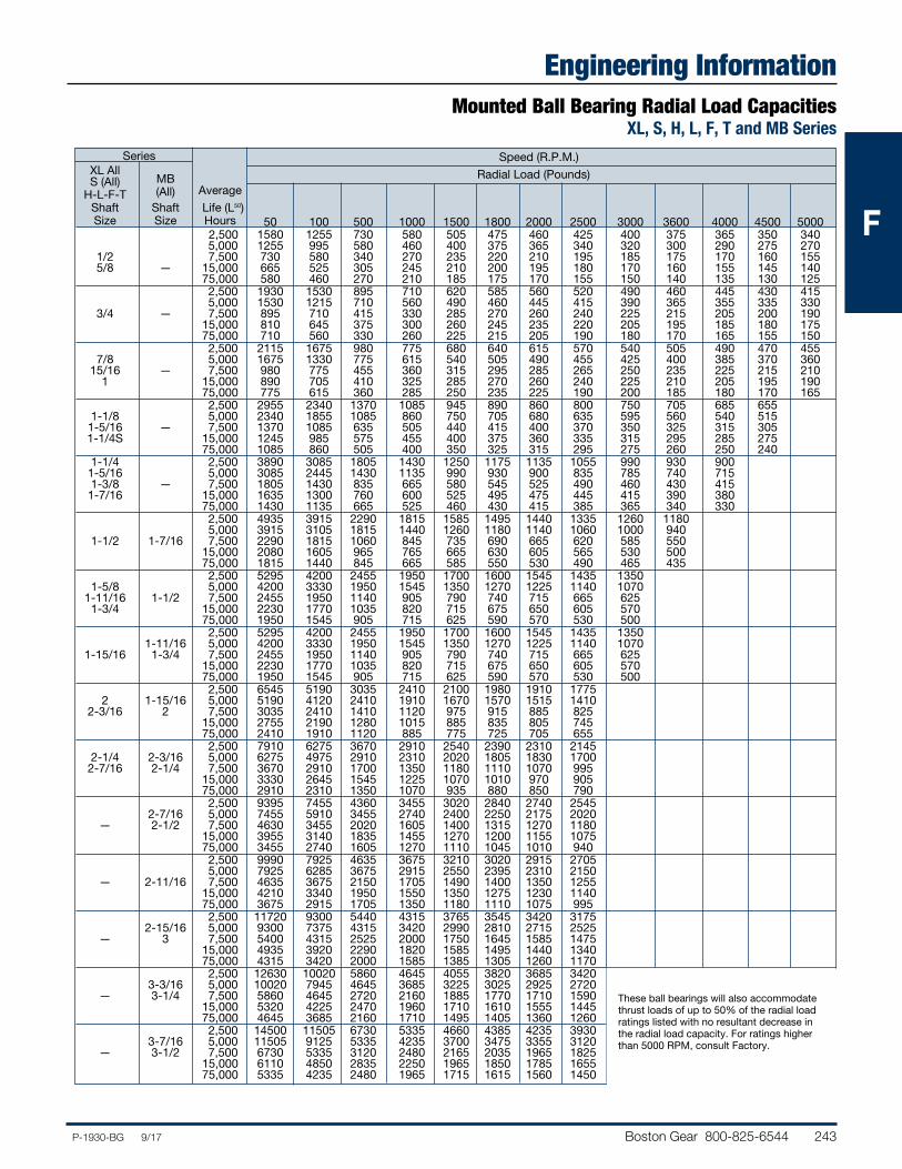
Boston Gear 800-825-6544 243P-1930-BG 9/17
FFF
Engineering InformationMounted Ball Bearing Radial Load Capacities
XL, S, H, L, F, T and MB Series Series XL All
Speed (R.P.M.)
S (All) MB Radial Load (Pounds) H-L-F-T (All) Average Shaft Shaft Life (L50) Size Size Hours 50 100 500 1000 1500 1800 2000 2500 3000 3600 4000 4500 5000 2,500 1580 1255 730 580 505 475 460 425 400 375 365 350 340 5,000 1255 995 580 460 400 375 365 340 320 300 290 275 270 1/2 7,500 730 580 340 270 235 220 210 195 185 175 170 160 155 5/8 — 15,000 665 525 305 245 210 200 195 180 170 160 155 145 140 75,000 580 460 270 210 185 175 170 155 150 140 135 130 125 2,500 1930 1530 895 710 620 585 560 520 490 460 445 430 415 5,000 1530 1215 710 560 490 460 445 415 390 365 355 335 330 3/4 — 7,500 895 710 415 330 285 270 260 240 225 215 205 200 190 15,000 810 645 375 300 260 245 235 220 205 195 185 180 175 75,000 710 560 330 260 225 215 205 190 180 170 165 155 150 2,500 2115 1675 980 775 680 640 615 570 540 505 490 470 455 7/8 5,000 1675 1330 775 615 540 505 490 455 425 400 385 370 360 15/16 — 7,500 980 775 455 360 315 295 285 265 250 235 225 215 210 1 15,000 890 705 410 325 285 270 260 240 225 210 205 195 190 75,000 775 615 360 285 250 235 225 190 200 185 180 170 165 2,500 2955 2340 1370 1085 945 890 860 800 750 705 685 655 1-1/8 5,000 2340 1855 1085 860 750 705 680 635 595 560 540 515 1-5/16 — 7,500 1370 1085 635 505 440 415 400 370 350 325 315 305 1-1/4S 15,000 1245 985 575 455 400 375 360 335 315 295 285 275 75,000 1085 860 505 400 350 325 315 295 275 260 250 240 1-1/4 2,500 3890 3085 1805 1430 1250 1175 1135 1055 990 930 900 1-5/16 5,000 3085 2445 1430 1135 990 930 900 835 785 740 715 1-3/8 — 7,500 1805 1430 835 665 580 545 525 490 460 430 415 1-7/16 15,000 1635 1300 760 600 525 495 475 445 415 390 380 75,000 1430 1135 665 525 460 430 415 385 365 340 330 2,500 4935 3915 2290 1815 1585 1495 1440 1335 1260 1180 5,000 3915 3105 1815 1440 1260 1180 1140 1060 1000 940 1-1/2 1-7/16 7,500 2290 1815 1060 845 735 690 665 620 585 550 15,000 2080 1605 965 765 665 630 605 565 530 500 75,000 1815 1440 845 665 585 550 530 490 465 435 2,500 5295 4200 2455 1950 1700 1600 1545 1435 1350 1-5/8 5,000 4200 3330 1950 1545 1350 1270 1225 1140 1070 1-11/16 1-1/2 7,500 2455 1950 1140 905 790 740 715 665 625 1-3/4 15,000 2230 1770 1035 820 715 675 650 605 570 75,000 1950 1545 905 715 625 590 570 530 500 2,500 5295 4200 2455 1950 1700 1600 1545 1435 1350 1-11/16 5,000 4200 3330 1950 1545 1350 1270 1225 1140 1070 1-15/16 1-3/4 7,500 2455 1950 1140 905 790 740 715 665 625 15,000 2230 1770 1035 820 715 675 650 605 570 75,000 1950 1545 905 715 625 590 570 530 500 2,500 6545 5190 3035 2410 2100 1980 1910 1775 2 1-15/16 5,000 5190 4120 2410 1910 1670 1570 1515 1410 2-3/16 2 7,500 3035 2410 1410 1120 975 915 885 825 15,000 2755 2190 1280 1015 885 835 805 745 75,000 2410 1910 1120 885 775 725 705 655 2,500 7910 6275 3670 2910 2540 2390 2310 2145 2-1/4 2-3/16 5,000 6275 4975 2910 2310 2020 1805 1830 1700 2-7/16 2-1/4 7,500 3670 2910 1700 1350 1180 1110 1070 995 15,000 3330 2645 1545 1225 1070 1010 970 905 75,000 2910 2310 1350 1070 935 880 850 790 2,500 9395 7455 4360 3455 3020 2840 2740 2545 2-7/16 5,000 7455 5910 3455 2740 2400 2250 2175 2020 — 2-1/2 7,500 4630 3455 2020 1605 1400 1315 1270 1180 15,000 3955 3140 1835 1455 1270 1200 1155 1075 75,000 3455 2740 1605 1270 1110 1045 1010 940 2,500 9990 7925 4635 3675 3210 3020 2915 2705 5,000 7925 6285 3675 2915 2550 2395 2310 2150 — 2-11/16 7,500 4635 3675 2150 1705 1490 1400 1350 1255 15,000 4210 3340 1950 1550 1350 1275 1230 1140 75,000 3675 2915 1705 1350 1180 1110 1075 995 2,500 11720 9300 5440 4315 3765 3545 3420 3175 2-15/16 5,000 9300 7375 4315 3420 2990 2810 2715 2525 — 3 7,500 5400 4315 2525 2000 1750 1645 1585 1475 15,000 4935 3920 2290 1820 1585 1495 1440 1340 75,000 4315 3420 2000 1585 1385 1305 1260 1170 2,500 12630 10020 5860 4645 4055 3820 3685 3420 3-3/16 5,000 10020 7945 4645 3685 3225 3025 2925 2720 — 3-1/4 7,500 5860 4645 2720 2160 1885 1770 1710 1590 15,000 5320 4225 2470 1960 1710 1610 1555 1445 75,000 4645 3685 2160 1710 1495 1405 1360 1260 2,500 14500 11505 6730 5335 4660 4385 4235 3930 3-7/16 5,000 11505 9125 5335 4235 3700 3475 3355 3120 — 3-1/2 7,500 6730 5335 3120 2480 2165 2035 1965 1825 15,000 6110 4850 2835 2250 1965 1850 1785 1655 75,000 5335 4235 2480 1965 1715 1615 1560 1450
These ball bearings will also accommodate thrust loads of up to 50% of the radial load ratings listed with no resultant decrease in the radial load capacity. For ratings higher than 5000 RPM, consult Factory.
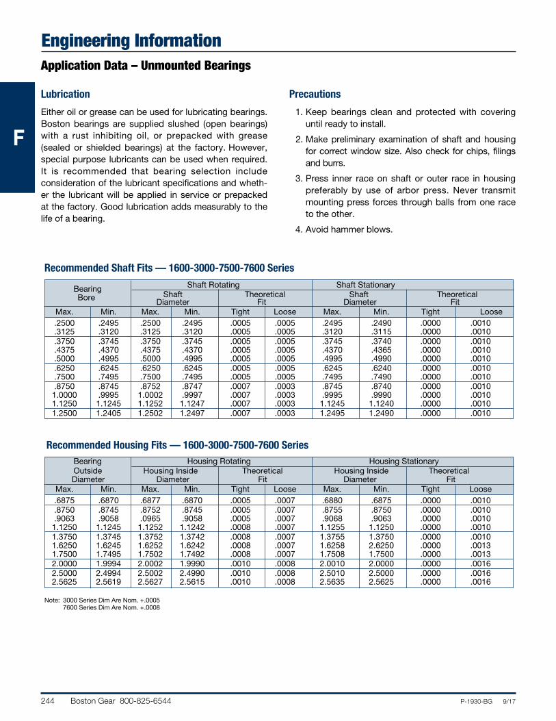
244 Boston Gear 800-825-6544 P-1930-BG 9/17
FFF
Engineering InformationApplication Data – Unmounted Bearings
Lubrication
Either oil or grease can be used for lubricating bearings. Boston bearings are supplied slushed (open bearings) with a rust inhibiting oil, or prepacked with grease (sealed or shielded bearings) at the factory. However, special purpose lubricants can be used when required. It is recommended that bearing selection include consideration of the lubricant specifications and wheth-er the lubricant will be applied in service or prepacked at the factory. Good lubrication adds measurably to the life of a bearing.
Precautions
1. Keep bearings clean and protected with covering until ready to install.
2. Make preliminary examination of shaft and housing for correct window size. Also check for chips, filings and burrs.
3. Press inner race on shaft or outer race in housing preferably by use of arbor press. Never transmit mounting press forces through balls from one race to the other.
4. Avoid hammer blows.
Shaft Rotating Shaft Stationary Bearing Shaft Theoretical Shaft Theoretical Bore Diameter Fit Diameter Fit Max. Min. Max. Min. Tight Loose Max. Min. Tight Loose .2500 .2495 .2500 .2495 .0005 .0005 .2495 .2490 .0000 .0010 .3125 .3120 .3125 .3120 .0005 .0005 .3120 .3115 .0000 .0010 .3750 .3745 .3750 .3745 .0005 .0005 .3745 .3740 .0000 .0010 .4375 .4370 .4375 .4370 .0005 .0005 .4370 .4365 .0000 .0010 .5000 .4995 .5000 .4995 .0005 .0005 .4995 .4990 .0000 .0010 .6250 .6245 .6250 .6245 .0005 .0005 .6245 .6240 .0000 .0010 .7500 .7495 .7500 .7495 .0005 .0005 .7495 .7490 .0000 .0010 .8750 .8745 .8752 .8747 .0007 .0003 .8745 .8740 .0000 .0010 1.0000 .9995 1.0002 .9997 .0007 .0003 .9995 .9990 .0000 .0010 1.1250 1.1245 1.1252 1.1247 .0007 .0003 1.1245 1.1240 .0000 .0010 1.2500 1.2405 1.2502 1.2497 .0007 .0003 1.2495 1.2490 .0000 .0010
Bearing Housing Rotating Housing Stationary Outside Housing Inside Theoretical Housing Inside Theoretical Diameter Diameter Fit Diameter Fit Max. Min. Max. Min. Tight Loose Max. Min. Tight Loose .6875 .6870 .6877 .6870 .0005 .0007 .6880 .6875 .0000 .0010 .8750 .8745 .8752 .8745 .0005 .0007 .8755 .8750 .0000 .0010 .9063 .9058 .0965 .9058 .0005 .0007 .9068 .9063 .0000 .0010 1.1250 1.1245 1.1252 1.1242 .0008 .0007 1.1255 1.1250 .0000 .0010 1.3750 1.3745 1.3752 1.3742 .0008 .0007 1.3755 1.3750 .0000 .0010 1.6250 1.6245 1.6252 1.6242 .0008 .0007 1.6258 2.6250 .0000 .0013 1.7500 1.7495 1.7502 1.7492 .0008 .0007 1.7508 1.7500 .0000 .0013 2.0000 1.9994 2.0002 1.9990 .0010 .0008 2.0010 2.0000 .0000 .0016 2.5000 2.4994 2.5002 2.4990 .0010 .0008 2.5010 2.5000 .0000 .0016 2.5625 2.5619 2.5627 2.5615 .0010 .0008 2.5635 2.5625 .0000 .0016
Note: 3000 Series Dim Are Nom. +.0005 7600 Series Dim Are Nom. +.0008
Recommended Housing Fits — 1600-3000-7500-7600 Series
Recommended Shaft Fits — 1600-3000-7500-7600 Series
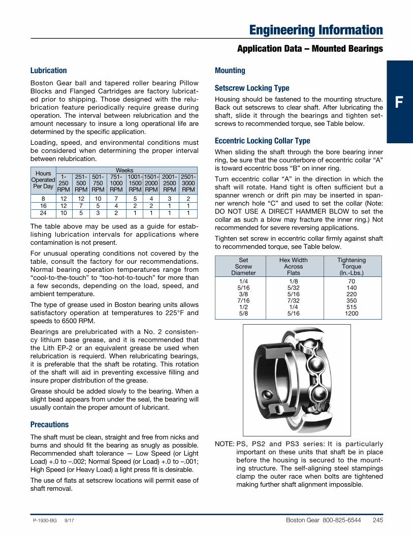
Boston Gear 800-825-6544 245P-1930-BG 9/17
FFF
Engineering InformationApplication Data – Mounted Bearings
Lubrication
Boston Gear ball and tapered roller bearing Pillow Blocks and Flanged Cartridges are factory lubricat-ed prior to shipping. Those designed with the relu-brication feature periodically require grease during operation. The interval between relubrication and the amount necessary to insure a long operational life are determined by the specific application.
Loading, speed, and environmental conditions must be considered when determining the proper interval between relubrication.
The table above may be used as a guide for estab-lishing lubrication intervals for applications where contamination is not present.
For unusual operating conditions not covered by the table, consult the factory for our recom men da tions. Normal bearing operation temperatures range from “cool-to-the-touch” to “too-hot-to-touch” for more than a few seconds, depending on the load, speed, and ambient temperature.
The type of grease used in Boston bearing units allows satisfactory operation at temperatures to 225°F and speeds to 6500 RPM.
Bearings are prelubricated with a No. 2 consisten-cy lithium base grease, and it is recommended that the Lith EP-2 or an equivalent grease be used when relubrication is requierd. When relubricating bearings, it is preferable that the shaft be rotating. This rotation of the shaft will aid in preventing excessive filling and insure proper distribution of the grease.
Grease should be added slowly to the bearing. When a slight bead appears from under the seal, the bearing will usually contain the proper amount of lubricant.
Precautions
The shaft must be clean, straight and free from nicks and burns and should fit the bearing as snugly as possible. Recommended shaft tolerance — Low Speed (or Light Load) +.0 to –.002; Normal Speed (or Load) +.0 to –.001; High Speed (or Heavy Load) a light press fit is desirable.
The use of flats at setscrew locations will permit ease of shaft removal.
Mounting
Setscrew Locking TypeHousing should be fastened to the mounting structure. Back out setscrews to clear shaft. After lubricating the shaft, slide it through the bearings and tighten set-screws to recommended torque, see Table below.
Eccentric Locking Collar TypeWhen sliding the shaft through the bore bearing inner ring, be sure that the counterbore of eccentric collar “A” is toward eccentric boss “B” on inner ring.
Turn eccentric collar “A” in the direction in which the shaft will rotate. Hand tight is often sufficient but a spanner wrench or drift pin may be inserted in span-ner wrench hole “C” and used to set the collar (Note: DO NOT USE A DIRECT HAMMER BLOW to set the collar as such a blow may fracture the inner ring.) Not recommended for severe reversing applications.
Tighten set screw in eccentric collar firmly against shaft to recommended torque, see Table below.
NOTE: PS, PS2 and PS3 series: It is particularly important on these units that shaft be in place before the housing is secured to the mount-ing structure. The self-aligning steel stampings clamp the outer race when bolts are tightened making further shaft alignment impossible.
Set Hex Width Tightening Screw Across Torque Diameter Flats (In.-Lbs.) 1/4 1/8 70 5/16 5/32 140 3/8 5/16 220 7/16 7/32 350 1/2 1/4 515 5/8 5/16 1200
Weeks Hours 1- 251- 501- 751- 1001- 1501- 2001- 2501- Operated 250 500 750 1000 1500 2000 2500 3000 Per Day RPM RPM RPM RPM RPM RPM RPM RPM
8 12 12 10 7 5 4 3 2 16 12 7 5 4 2 2 1 1 24 10 5 3 2 1 1 1 1