beam dynamics newsletter
TRANSCRIPT
International Committee for Future Accelerators Sponsored by the Particles and Fields Commission of IUPAP
Beam Dynamics Newsletter
No. 46
Issue Editor: M. A. Furman
Editor in Chief:
W. Chou
August 2008

3
Contents
1 FOREWORD..........................................................................................................9
1.1 FROM THE CHAIRMAN...............................................................................................9
1.2 FROM THE EDITOR ..................................................................................................10
2 INTERNATIONAL LINEAR COLLIDER (ILC)............................................12
2.1 THIRD INTERNATIONAL ACCELERATOR SCHOOL FOR LINEAR COLLIDERS..............12
3 THEME SECTION: ELECTRON GUNS.........................................................14
3.1 LOW EMITTANCE PHOTOCATHODE RF GUN STUDIES AT TSINGHUA UNIVERSITY ..14
3.1.1 Introduction ..................................................................................................14 3.1.2 Theoretical Studies of Low Emittance RF Gun ...........................................15
3.1.2.1 Emittance Evolution of Relativistic Space-charge Dominated Beams ….........................................................................................15
3.1.2.2 Thermal Emittance of Metal Cathode in Photocathode Gun .........19 3.1.3 Highlights of the RF Gun Design.................................................................20
3.1.3.1 RF-Asymmetry in Photo-Injector ..................................................20 3.1.3.2 Waveguide Post’s Influence on RF Gun ........................................21
3.1.4 Experimental Study of Low Emittance RF Gun ..........................................22 3.1.4.1 RF Measurement of the RF Gun.....................................................22 3.1.4.2 Compact Solenoid without Bucking Coil........................................23 3.1.4.3 Laser System...................................................................................24 3.1.4.4 Beam Experiments of RF Gun ........................................................24
3.1.5 Ongoing Work ..............................................................................................28 3.1.6 References ....................................................................................................29
3.2 THE ELBE SUPERCONDUCTING PHOTOINJECTOR ...................................................30
3.2.1 Introduction ..................................................................................................30 3.2.2 History and Other Projects ...........................................................................33 3.2.3 SRF Gun Design Parameter..........................................................................34 3.2.4 Niobium Cavity ............................................................................................34 3.2.5 Cryomodule ..................................................................................................38 3.2.6 Photo Cathodes .............................................................................................39 3.2.7 UV Drive Laser ............................................................................................41 3.2.8 Diagnostic Beamline ....................................................................................42 3.2.9 Installation and Commissioning ...................................................................42 3.2.10 First Operation Result ....................................................................43 3.2.11 Summary and Outlook....................................................................46 3.2.12 Acknowledgement..........................................................................46 3.2.13 References ......................................................................................47
4
3.3 EXPERIMENTAL BEAM DYNAMICS WITH THE SPARC HIGH BRIGHTNESS PHOTOINJECTOR......................................................................................................49
3.3.1 Introduction...................................................................................................49 3.3.2 The SPARC Facility .....................................................................................51 3.3.3 Emittance Meter Experimental Results ........................................................52 3.3.4 Invariant Envelope and Velocity Bunching Experiments.............................54 3.3.5 References.....................................................................................................57
3.4 OVERVIEW OF PHOTOINJECTOR R&D IN THE EUROFEL COLLABORATION ...........58
3.4.1 Introduction...................................................................................................58 3.4.2 Motivations ...................................................................................................59 3.4.3 Laser System.................................................................................................60 3.4.4 Cathode Materials .........................................................................................63 3.4.5 RF Guns and Injectors ..................................................................................64 3.4.6 Diagnostic Techniques..................................................................................66 3.4.7 Reliability Studies.........................................................................................69 3.4.8 Conclusions...................................................................................................70 3.4.9 References.....................................................................................................71
3.5 ELECTRON GUN DEVELOPMENT AT ARGONNE NATIONAL LABORATORY ...............73
3.5.1 Introduction...................................................................................................73 3.5.2 APS Thermionic Cathode RF Guns..............................................................73 3.5.3 Operational High-Brightness Photocathode Guns........................................74
3.5.3.1 AWA High-Charge Photocathode Guns .........................................74 3.5.3.2 AWA High Brightness Photocathode Gun......................................75 3.5.3.3 APS Photocathode RF Gun ............................................................76
3.5.4 Research Guns & Related Technologies – Experimental.............................77 3.5.4.1 APS BBC gun..................................................................................77 3.5.4.2 Ballistic bunching & THz generation.............................................78 3.5.4.3 Photothermal Cathode Studies .......................................................78 3.5.4.4 AWA Arc Testing Gun.....................................................................78 3.5.4.5 GaN Cathodes.................................................................................79 3.5.4.6 AWA Cs2Te Cathode Fabrication & Testing..................................79
3.5.5 Research Guns & Related Technologies – Simulation.................................80 3.5.5.1 Higher-Order Mode Injector ..........................................................80 3.5.5.2 Planar-Focusing Cathode ..............................................................81 3.5.5.3 Gated Field Emitter RF Gun ..........................................................82 3.5.5.4 Ion Tracking in Photocathode RF Guns.........................................83
3.5.6 The Argonne Department of Defense Project Office ...................................83 3.5.7 The Argonne-NIU Beam Laboratory............................................................84 3.5.8 Conclusions...................................................................................................84 3.5.9 References.....................................................................................................84
3.6 LOW-FREQUENCY, HIGH-REPETITION RATE PHOTOINJECTORS FOR FEL AND ERL APPLICATIONS.........................................................................................................86
3.6.1 Introduction...................................................................................................86 3.6.2 A 106 MHz RF Gun Design Example ..........................................................87 3.6.3 201 and 350 MHz Designs ...........................................................................92
5
3.6.4 Beam Dynamics Simulations .......................................................................93 3.6.5 Conclusions ..................................................................................................95 3.6.6 References ....................................................................................................96
3.7 HIGH VOLTAGE DC PHOTOEMISSION ELECTRON GUNS – CURRENT STATUS AND TECHNICAL CHALLENGES .......................................................................................97
3.7.1 Introduction ..................................................................................................97 3.7.2 DC Electron Gun Structures .........................................................................99 3.7.3 Technical Challenges..................................................................................104
3.7.3.1 Field Emission and Voltage Holdoff of the Cathode-Anode Gap 104 3.7.3.2 Ceramic Insulators .......................................................................107 3.7.3.3 Cathode Choices and Issues.........................................................108 3.7.3.4 Laser Systems ...............................................................................113 3.7.3.5 Ultrahigh and Extreme High Vacuum..........................................115
3.7.4 Conclusions ................................................................................................117 3.7.5 References ..................................................................................................118
3.8 THE HIGH BRIGHTNESS ELECTRON BEAM PHYSICS AND PHOTOINJECTOR TECHNOLOGY PROGRAM AT UCLA......................................................................119
3.8.1 Introduction ................................................................................................119 3.8.2 Photoinjectors at UCLA: Prehistory...........................................................121 3.8.3 The BNL/SLAC/UCLA 1.6 Cell RF Photocathode Gun ...........................123 3.8.4 Dynamically Optimized Photoelectron Beams...........................................130 3.8.5 Measurements in the Blowout Regime at SPARC .....................................131 3.8.6 Definitive Demonstration of the Blowout Regime at Pegasus ...................134 3.8.7 Ultrafast Relativistic Electron Diffraction..................................................137 3.8.8 Recent Photoinjectors: FERMI and FINDER ............................................139 3.8.9 Hybrid Standing Wave/Traveling Wave Photoinjector..............................143 3.8.10 Future Directions..........................................................................148 3.8.11 Acknowledgements ......................................................................149 3.8.12 References ....................................................................................149
3.9 HIGH-CURRENT RF PHOTOINJECTOR DEVELOPMENT FOR FREE ELECTRON LASERS151
3.9.1 Introduction ................................................................................................151 3.9.2 RF Photoinjector Development ..................................................................151 3.9.3 High Average-Current RF Injectors ...........................................................156 3.9.4 Conclusions ................................................................................................160 3.9.5 References ..................................................................................................160
3.10 THE DEVELOPMENT OF THE LINAC COHERENT LIGHT SOURCE RF GUN...............162
3.10.1 Introduction ..................................................................................162 3.10.2 The History and Characteristics of the BNL/SLAC/UCLA S-Band
Gun III and the Gun Test Facility (GTF) at SLAC ......................163 3.10.3 Experimental Studies of the GTF Gun III ....................................165
3.10.3.1 Longitudinal Phase Space Studies ...............................................165 3.10.3.2 RF Measurements of 0-π Mode Beating.......................................167 3.10.3.3 Studies of the GTF Gun Solenoid .................................................169 3.10.3.4 Impact of GTF Work on the LCLS Gun Design ...........................170
3.10.4 Final Design Characteristics of the LCLS Gun............................170
6
3.10.5 RF Modeling and Design..............................................................172 3.10.5.1 Numerical Simulations .................................................................172 3.10.5.2 1.6-cell Gun 2D Shape Optimization............................................172 3.10.5.3 1.6-cell Gun Coupler Design........................................................172 3.10.5.4 Pulsed Heating .............................................................................173 3.10.5.5 Quadrupole RF Fields ..................................................................174 3.10.5.6 Laser and RF Probe Ports ............................................................174 3.10.5.7 The Final LCLS Gun RF Design and Comparison with Gun III..175
3.10.6 Electron Beam Simulations ..........................................................176 3.10.7 The Emittance Compensation Solenoid .......................................177 3.10.8 Thermo-Mechanical Engineering of the LCLS Gun ....................181
3.10.8.1 Overview of the LCLS Gun Design...............................................181 3.10.8.2 ANSYS Simulations .......................................................................182 3.10.8.3 Design, Cooling and Fabrication of the LCLS Gun.....................184 3.10.8.4 Cathode Design ............................................................................185 3.10.8.5 Tuner Tests ...................................................................................186 3.10.8.6 Cathode Seal Tests........................................................................187 3.10.8.7 Integration of the LCLS Gun with the Emittance Compensation
Solenoid….....................................................................................187 3.10.9 The Cold and Hot RF Testing.......................................................187
3.10.9.1 RF Cold Tests and Tuning the Gun ..............................................187 3.10.9.2 RF Hot Tests of the LCLS Guns....................................................189
3.10.10 Summary and Conclusions ...........................................................190 3.10.11 Acknowledgements ......................................................................191 3.10.12 References ....................................................................................192
4 ACTIVITY REPORTS......................................................................................193
4.1 AN INTRODUCTION TO THE SUPERB ACCELERATOR PROJECT ...............................193
4.1.1 Introduction.................................................................................................193 4.1.2 The SuperB Process ....................................................................................194 4.1.3 Project Overview ........................................................................................195
4.1.3.1 A Novel Collision Scheme.............................................................195 4.1.3.2 Beam Parameters .........................................................................196 4.1.3.3 Rings Design.................................................................................198
4.1.4 Synergy with the ILC..................................................................................200 4.1.5 Conclusions.................................................................................................200 4.1.6 References...................................................................................................200
5 WORKSHOP AND CONFERENCE REPORTS ...........................................201 5.1 SUMMARY OF THE 43RD ICFA ADVANCED BEAM DYNAMICS WORKSHOP
NANOBEAM2008 ....................................................................................................201
5.1.1 Introduction.................................................................................................201 5.1.2 Linear Collider Related Topics...................................................................202 5.1.3 Accelerator Technology..............................................................................202 5.1.4 References...................................................................................................202
6 RECENT DOCTORAL THESES ....................................................................203
7
6.1 LINEAR BEAM DYNAMICS AND AMPERE CLASS SUPERCONDUCTING RF CAVITIES AT RHIC ...............................................................................................................203
6.2 DIAGNOSTICS OF THE FERMILAB TEVATRON USING AN AC DIPOLE .....................204
7 FORTHCOMING BEAM DYNAMICS EVENTS .........................................204
7.1 44TH ICFA ADVANCED BEAM DYNAMICS WORKSHOP: X-BAND RF STRUCTURE AND BEAM DYNAMICS....................................................................................................204
7.2 2009 INTERNATIONAL COMPUTATIONAL ACCELERATOR PHYSICS CONFERENCE .205
7.3 FFAG'08...............................................................................................................205
7.4 ICFA BEAM DYNAMICS MINI-WORKSHOP: 2ND WORKSHOP ON SHORT BUNCHES IN STORAGE RINGS .....................................................................................................206
8 ANNOUNCEMENTS OF THE BEAM DYNAMICS PANEL......................206 8.1 ICFA BEAM DYNAMICS NEWSLETTER..................................................................206
8.1.1 Aim of the Newsletter ................................................................................206 8.1.2 How to Prepare a Manuscript .....................................................................207 8.1.3 Distribution.................................................................................................208 8.1.4 Regular Correspondents .............................................................................208
8.2 ICFA BEAM DYNAMICS PANEL MEMBERS ...........................................................209

9
1 Foreword
1.1 From the Chairman
Weiren Chou, Fermilab Mail to: [email protected]
The International Committee for Future Accelerators (ICFA) met on August 2, 2008
at the University of Pennsylvania, Philadelphia, U.S.A. during the ICHEP08 Conference. Albrecht Wagner gave a brief report on the ILCSC and FALC. A document titled “Memorandum of Understanding for the Establishment of a Technical Design Phase of the Global Design Effort concerning the International Linear Collider” was prepared by the ILCSC and is expected to be signed by a number of major HEP laboratories around the world. The ILCSC has set up a Project Advisory Committee (PAC) to review ILC accelerator and detector activities; for the first year it is chaired by Jean-Eudes Augustin. An ILCSC subgroup will study site selection procedures. The FALC hopes that solid LHC results by 2012 will allow a statement on the energy range for a future linear collider; by that date also the ILC Technical Design Phase (TDP) should be completed, the feasibility of CLIC technology should be known, and the XFEL should be nearing completion. The FALC elected Pierre Coulombe, President of the National Research Council Canada, as its new chair. A major topic at this ICFA meeting was the agenda for the upcoming ICFA Seminar, which will take place from October 28 to 31, 2008 at SLAC. David MacFarlane on behalf of the Local Organizing Committee gave a status report. The seminar is by invitation only. Each country has a coordinator responsible for assigning delegates. A total of 150 people from all over the world will attend, including representatives from various funding agencies. The presentations will cover a wide range of topics: from the LHC to the intensity frontier facilities, from TeV-scale lepton colliders to dark matter and dark energy, from globalization to collaboration issues in HEP. There will also be talks on accelerator applications such as light sources, FEL, as well as medical and industrial applications.
One of the ICFA panels, the IHEPCCC Panel, is temporarily suspended because of duplication of its mission with the Worldwide LHC Computing Grid (WLCG), which is a new global organization for HEP computing. ICFA will review the mandate of the IHEPCCC and decide if this panel will be reactivated.
ICFA approved the 44th ICFA Advanced Beam Dynamics Workshop: X-band RF Structure and Beam Dynamics, which will take place from December 1 to 3, 2008 at the Cockcroft Institute, U.K. ICFA also approved the 45th ICFA Advanced Beam Dynamics Workshop: ERL2009, a continuation of the ERL workshop series. This workshop will take place from June 8 to 12, 2009 at Cornell University, Ithaca, New York, U.S.A.
The Third International Accelerator School for Linear Colliders, which will be held from October 19 to 29, 2008 at the Oak Brook Hills Marriott Hotel near Chicago, U.S.A., received 245 applications from 37 countries. Through a rigorous selection process, the Curriculum Committee admitted 57 students from 14 countries. The curriculum has been designed and all lecturers have been confirmed. More information
10
about this school can be found in Section 2.1 of this issue as well as on the school web site: http://www.linearcollider.org/school/2008/.
David Rice from Cornell University has resigned from the panel. He is a long time panel member and has made important contributions including editing the Newsletter and chairing the Remote Accelerator Physics Experiment Working Group. On behalf of the panel, I want to thank him for his great service in the past years.
The editor of this issue is Dr. Miguel Furman, a panel member and a scientist from LBL, U.S.A. Dr. Furman collected 10 comprehensive and well-written articles in the theme section “Electron guns.” There is also a nice article on the Super-B factory, an HEP project of high priority in Europe as well as in Asia. This newsletter has over 200 pages and contains valuable scientific information. Miguel spent a significant amount of time on editing. I want to express my sincere thanks to him for producing a fine newsletter.
1.2 From the Editor
Miguel A. Furman, LBNL http://www.lbl.gov/ Mail to: [email protected]
As they say, "when it rains it pours." After considering a couple of other topics for the Theme Section, I settled on
electron guns, a topic of great current interest for future light sources and FELs, and not yet covered in previous issues of this Newsletter. Even though I didn't get started particularly early in soliciting articles from potential authors, the response was enthusiastic and generous. One author, in fact, contributed a second unsolicited article. And, despite the fact that a couple of potential authors regretfully declined, for understandable reasons, to contribute, the page length of this issue is close to a record.
I am grateful to all the authors, who generously contributed to this issue despite their busy schedules, work commitments and summer vacation plans. Their articles provide an important service to our community, helping to educate the non-experts and to counteract the unfortunate (but perhaps necessary) specialization most of us fall into. Though I tried to be as careful as possible, I apologize in advance to all authors if I messed up the contents of the articles (especially symbols) during the editing process.
In the Theme Section, Chuanxiang Tang and colleagues describe the program on RF guns at Tsinghua University, organized in response to the present high demand for bright electron sources in China. Jochen Teichert and colleagues write about the ELBE superconducting photoinjector, in operation for several years now at Rosendorff. Massimo Ferrario, on behalf of the SPARC team, writes about experimental beam dynamics with the SPARC photoinjector, now in its final commissioning stages at Frascati. Massimo kindly contributed a second article, by H. Duerr et al, on photoinjector R&D for the EUROFEL collaboration. This 3-year effort, whose funding recently came to an end, involved 16 European institutions and was triggered by the FP6 programme of the European Commission. John Lewellen and John Power then write about electron gun developments at Argonne. The goal of this effort is to support applications in wakefield acceleration as well as next-generation light sources and high-power energy-recovery linac-based FELs. My colleagues at LBNL, led by Fernando Sannibale, write about recent efforts here at the Lab to design a cavity in the 30-300 MHz frequency range capable to operate in CW mode for future light-source
11
applications. Charlie Sinclair provides a historical review, along with a state of the art discussion, of high-voltage DC photoemission electron guns. It was apparent to me that his extensive experience at Cornell affords him a unique and broad perspective in the field; I found his article especially informative. Jamie Rosenzweig provides an extensive overview of the UCLA program on high-brightness electron beam physics and photoinjector technology, involving both in-house applications as well as collaborative efforts with laboratories worldwide. Dinh Nguyen (LANL) provides a historical overview of RF photoinjectors, leading to high-average-current RF photoinjectors for FELs. Last but not least, Dave Dowell and his colleagues at SLAC write about the design and commissioning of the LCLS photoinjector, perhaps the most significant recent programmatic development in the area of electron guns in the US.
I am grateful to Marica Biagini (Frascati) for writing, on behalf of the SuperB Accelerator Team, a thoroughly informative overview of the SuperB project, a collaboration designing a B factory capable of a luminosity some two orders of magnitude higher than the records achieved at the KEKB and PEP-II e+-e– colliders. I am also grateful to Nikolay Vinokurov (BINP) for an informative summary of the "Nanobeam 2008" ICFA Workshop, which took place in May 2008 at the Novosibirsk Scientific Center.
I am indebted to Sasha Zholents, John Byrd, Bob Rimmer, Matt Poelker, Steve Lidia and Ilan Ben-Zvi for suggestions on possible Theme Section topics. Their recommendations made my job a lot easier.
Finally, I would like to say that editing the Beam Dynamics Newsletter takes real time and is real work, most of which (probably 90%) would be unnecessary if the authors would truly use the templates provided and truly follow the style conventions, as explained in the website for this Newsletter. I beg of future authors to: 1) not use automatic referencing (i.e., "insert endnote/footnote" command), but rather generate the reference numbering and bibliography by hand; 2) not use "paste special" to insert figures; and 3) use "insert picture," not "insert object," when inserting a picture. Future editors will be grateful, I assure you. As for future editors, I can strongly recommend to them, with the benefit of 20-20 hindsight, to edit each individual contribution separately first, and combine all contributions into a single document at the very end of the editing process.
We will all be happier, or at least much less stressed out. Trust me.
12
2 International Linear Collider (ILC)
2.1 Third International Accelerator School for Linear Colliders
Barry Barish, Director, ILC GDE, Enzo Iarocci, Chair, ILCSC, Shin-ichi Kurokawa, KEK
Weiren Chou, Chair, ICFA BD Panel http://www.linearcollider.org/school/2008/
The Third International Accelerator School for Linear Colliders will take place at
the Oak Brook Hills Marriott Hotel near Chicago, Illinois, U.S.A. from October 19 – 29, 2008. The announcement and curriculum can be found in the last issue (No. 45) of this newsletter.
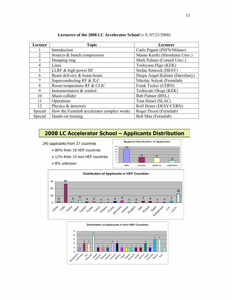
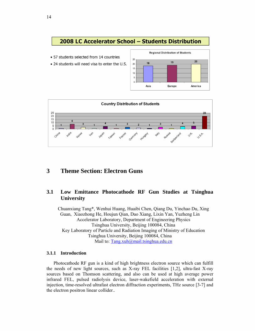
The school received 245 applications from 37 countries. Each applicant was required to submit a CV and a letter of recommendation from his or her supervisor. The Curriculum Committee, which is responsible for student selection, met in early June in the three regions respectively and admitted 57 students from 14 countries: 20 from North and South America, 19 from Europe and Africa, 18 from Asia and Oceania. The geographic distribution of applicants and students is shown in the figures. This is a talented and highly motivated group of young people. They are the future of our field. We believe that in one or two decades, some of them will play leadership roles and make important contributions to the accelerator field.
Financial support for all the students to attend the school has been confirmed. This year’s sponsors include: KEK, CERN, DESY, IN2P3, INFN, Oxford Univ., Univ. of Manchester, Univ. of Bonn, U.S. DOE, U.S. NSF, Fermilab, FRA, SLAC and ILC GDE.
The lecturers are listed in the table. These are well-known experts in their respective fields. The students will receive good training and great education from these instructors.
One important issue for this year’s school is visas. Out of the fifty-seven students, twenty-four will require a visa to enter the United States. In some cases, this can be a long and complicated process. We are fully aware of this problem. Fortunately, we received a great deal of help from the Fermilab Visa Office, the Conference Office and the Visa Office in the National Academies of Sciences. These people are very experienced in the visa business. At this moment, we have sent each of the 24 students detailed step-by-step instructions for the visa application and all required supporting documents. It is our goal to bring every admitted student to the school.
13
Lecturers of the 2008 LC Accelerator School (v.9, 07/23/2008)
Lecture Topic Lecturer 1 Introduction Carlo Pagani (INFN/Milano) 2 Sources & bunch compressors Masao Kuriki (Hiroshima Univ.) 3 Damping ring Mark Palmer (Cornell Univ.) 4 Linac Toshiyasu Higo (KEK) 5 LLRF & high power RF Stefan Simrock (DESY) 6 Beam delivery & beam-beam Deepa Angal-Kalinin (Daresbury) 7 Superconducting RF & ILC Nikolay Solyak (Fermilab) 8 Room temperature RF & CLIC Frank Tecker (CERN) 9 Instrumentation & control Toshiyuki Okugi (KEK) 10 Muon collider Bob Palmer (BNL) 11 Operations Tom Himel (SLAC) 12 Physics & detectors Rolf Heuer (DESY/CERN)
Special How the Fermilab accelerator complex works Roger Dixon (Fermilab) Special Hands-on training Bob Mau (Fermilab)
14
3 Theme Section: Electron Guns
3.1 Low Emittance Photocathode RF Gun Studies at Tsinghua University
Chuanxiang Tang*, Wenhui Huang, Huaibi Chen, Qiang Du, Yinchao Du, Xing Guan, Xiaozhong He, Houjun Qian, Dao Xiang, Lixin Yan, Yuzheng Lin
Accelerator Laboratory, Department of Engineering Physics Tsinghua University, Beijing 100084, China
Key Laboratory of Particle and Radiation Imaging of Ministry of Education Tsinghua University, Beijing 100084, China
Mail to: [email protected]
3.1.1 Introduction
Photocathode RF gun is a kind of high brightness electron source which can fulfill the needs of new light sources, such as X-ray FEL facilities [1,2], ultra-fast X-ray sources based on Thomson scattering, and also can be used at high average power infrared FEL, pulsed radiolysis device, laser-wakefield acceleration with external injection, time-resolved ultrafast electron diffraction experiments, THz source [3-7] and the electron positron linear collider..
15
Recently, there are urgent demands on high brightness electron bunch emerge in China. A hard X-ray source based on Thomson scattering between TW laser and relativistic electron bunch will be built in Tsinghua University [8]. Shanghai DUV FEL is carrying out. The proposal of Soft X-ray FEL test facility in China (SXFEL) is released by SINP, IHEP, Tsinghua University and Peking University. All the above projects plan to adopt S band photocathode RF gun as high brightness electron source. Based on the demands, the research related to photocathode RF gun is carried out at Tsinghua University since 2001. The analytical and simulation studies of the emittance, the RF gun design and experiment results will be introduced in this paper.
3.1.2 Theoretical Studies of Low Emittance RF Gun
The normalized emittance of RF photoinjector has significant impact both on the saturation length XFEL facility and on the peak-brilliance of ultra-fast X-ray source based on Thomson scattering. One part of our work is dedicated to lower the normalized emittance of the beam analytically.
3.1.2.1 Emittance Evolution of Relativistic Space-charge Dominated Beams [12]
Slice emittance is very important for FEL facilities. A transverse cross-section of the beam is called a slice, and the emittance of a slice is called slice emittance. Slice emittance consists of two parts: one is the thermal emittance, the other is the emittance induced by nonlinear space-charge force. In this section, only the latter one is studied. For simplification, we just call it slice emittance. If a slice can be seen as a series of rings in radial direction, slice emittance can be considered to be due to the correlation between the phase space angle and the radial position of rings. Similar to correlated emittance, slice emittance grows rapidly in the vicinity of cathode and varies relatively slowly in subsequent beam lines. The relationship between the evolution of slice emittance and correlated emittance in a general photoinjector beam line was deduced here.
First, the correlated emittance of a cylindrical relativistic beam was studied with first-order approximation. Each slice in the beam with longitudinal position s can be described by four parameters: rms sizeσ r s( ), rms divergence ′σ r s( ), Lorentz factor
γ s( ) and the current
I s( ). Here we introduce the average slice, and any slice can be
represented by adding perturbations to it:
σ r s( )= σ ra s( ) 1+ Δ1 s( )⎡⎣ ⎤⎦ , ′σ r s( )
σ r s( )=′σ ra
σ ra
1+ Δ2 s( )⎡⎣ ⎤⎦
βγ s( )= βaγ a s( ) 1+ Δ3 s( )⎡⎣ ⎤⎦ , I s( )= Ia s( ) 1+ Δ4 s( )⎡⎣ ⎤⎦
(1)
where σ ra , ′σ ra , γ a , Ia is the rms size, rms divergence, Lorentz factor, current of the average slice respectively. Then, with first-order approximation,
0=Δi , 1<<Δi , 41L=i (2)
16
The correlated emittance in radial direction of the electron beam can be expressed as
232
2222 )()()( Δ+Δ′=′−′= raraaarrrrnr σσγβσβγσσβγσε (3)
If energy spread is neglected, the correlated emittance thus becomes
εnr = βaγ aσ ra ′σ ra Δ22 = βaγ aσ ra
2 RMS( ′σ r σ r ) (4)
where RMS( ′σ r σ r ) means the root mean square deviation of the phase space angle ′σ r σ r .
Now we deal with the slice emittance in first-order approximation. An ideal circular slice with uniform distribution, zero energy spread and zero emittance can be expressed by four parameters: the radius Ru , the divergence at the radial edge ′Ru , the Lorentz factor γ u and the charge of the slice Qu . A slice can be partitioned into small rings in radial direction. For an arbitrary ring the charge it encloses is qu ; we define the relative
radial position of the ring λ = qu Qu . In the ideal slice mentioned above, the radius of
the ring ru and its divergence ′ru can be expressed as
ru = λRu , ′ru = λ ′Ru (5)
Then we add a small perturbation to the arbitrary ring while keeping the relative radial position λ unchanged,
r λ( )= ru 1+ δ1 λ( )⎡⎣ ⎤⎦ , ′r r λ( )= ′Ru Ru 1+ δ2 λ( )⎡⎣ ⎤⎦βγ λ( )= βuγ u s( ) 1+ δ3⎡⎣ ⎤⎦
(6)
If the first-order approximation holds,
31 ,1 ,02 L=<<= iii δδλ (7)
and if the intrinsic small energy spread within the slice is neglected, the slice emittance can be written as
εnr = βuγ u σ r
2 ′σ r2 − σ r ′σ r( )
2= βuγ u Ru
2 ′rr
−′Ru
Ru
⎛
⎝⎜⎞
⎠⎟λ3dλ
0
1
∫ (8)
Comparing Eqs. (4) and (8), one can find that the expressions for the two kinds of emittances have similar forms.
In space-charge dominated beams in photoinjectors with cigar-like shape, the transverse motion of slices can be regarded as independent of each other [9]. If the emittance term is neglected, the rms envelope equation of an arbitrary slice can be written as [9,10]
17
′′σ r + kβ
2 +η ′γ 2
8γ 2
⎛
⎝⎜⎞
⎠⎟σ r +
′γ ′σ r
β 2γ=
κ 2
2σ r
(9)
where κ2 = 2I I Aβ 3γ 3 is the normalized perveance, kβ = eBz 2mecβγ( ) where Bz is
the strength of external focusing solenoid, η represents the strength of RF focusing in the accelerating structure; η is a factor between 0 and 1 [9,11]. Defining the normalized
beam envelope σ nr = 2σ r κ , the envelope equation becomes
′′σ nr + kβ
2 +η ′γ 2
8γ 2
⎛
⎝⎜⎞
⎠⎟σ nr +
′γ ′σ nr
β 2γ=
1σ nr
(10)
Neglecting the energy spread of the beam, we can expand the phase space angle of an arbitrary slice ′σ nr σ nr in first order of the two variables: one is the difference between the initial normalized rms transverse size of the arbitrary slice
σ nr ,0 and the
initial normalized rms transverse size of the average slice σ nra ,0 , the other is the
difference between the initial normalized rms divergence of the arbitrary slice
′σ nr ,0 and
the initial normalized rms divergence of the average slice ′σ nra,0 ,
′σ nr
σ nr
z,σ nra,0 , ′σ nra,0( )=′σ nra
σ nra
z,σ nra,0 , ′σ nra,0( )
+∂ ′σ nra σ nra( )
∂σ nra,0
Δσ nr ,0 s( )
+∂ ′σ nra σ nra( )
∂ ′σ nra,0
Δ ′σ nr ,0 s( )
(11)
where z is the propagating distance, Δσ nr ,0 s( )= σ nr ,0 s( )− σ nra,0 s( ) and
Δ ′σ nr ,0 s( )= ′σ nr ,0 s( )− ′σ nra,0 s( ). Substituting Eq. (11) to Eq. (4), we get the correlated emittance
εnr = βaγ aσ ra
2 c12 Δσ nr ,0
2 + c22 Δ ′σ nr ,0
2 + 2c1c2Δσ nr ,0Δ ′σ nr ,0 (12)
where c1 = ∂ ′σ nra σ nra( ) ∂σ nra,0 and c2 = ∂ ′σ nra σ nra( ) ∂ ′σ nra,0 .
For slice emittance, if phase space wave breaking does not occur, the relative radial
position λ of each ring within the slice remains constant, and the differential equation of an arbitrary ring’s normalized radius rn is,
18
′′rn + kβ2 +
η ′γ 2
8γ 2
⎛
⎝⎜⎞
⎠⎟rn +
′γ ′rn
β 2γ=
1rn
(13)
where rn = r κ , and r is the radius of the ring. The slice can be represented by adding a perturbation to a uniformly distributed cold
slice with radius Ru and divergence ′Ru . Neglecting the intrinsic small energy spread, we can expand the phase angle of an arbitrary ring ′rn rn in first order of the two variables: one is the difference between the ring’s initial normalized radius
rn,0 and its
corresponding normalized radius in the uniform distributed cold slice λRnu , the other is the difference between the ring’s initial normalized divergence
′rn,0 and its
corresponding normalized divergence λ ′Rnu ,
′rn
rn
z,λ, Rnu ,0 , ′Rnu,0( )=′Rnu
Rnu
z, Rnu,0 , ′Rnu ,0( )
+∂ ′Rnu Rnu( )
∂Rnu,0
Δrn,0 λ( )
+∂ ′Rnu Rnu( )
∂ ′Rnu,0
Δ ′rn,0 λ( )
(14)
where Δrn,0 λ( )= rn,0 s( )− λRnu ,0 and Δ ′rn,0 λ( )= ′rn,0 s( )− λ ′Rnu ,0 . Thus, the slice
emittance can be written as
εnr = βuγ u Ru
2 c32g Δrn,0
2( )+ c42g Δ ′rn,0
2( )+ 2c3c4g Δrn,0Δ ′rn,0( ) (15)
where c3 = ∂ ′Rnu Rnu( ) ∂Rnu,0 and c4 = ∂ ′Rnu Rnu( ) ∂ ′Rnu,0 and
g f λ( )( )= f λ( )λ3dλ
0
1
∫ .
Eqs. (12) and (15) have similar forms, which implies that correlated emittance and slice emittance have similar behavior in the approximations used to derive these equations. In fact, σ nra and Rnu obey the same differential equation, and if the correlated emittance and slice emittance are of the same beam, their initial values are approximately equal for nearly uniformly distributed beams. So c3 and c4 in Eq. (15)
are equal to c1 and c2 in Eq. (12), respectively, and Ru in Eq. (15) is 2 times of σ ra in Eq. (12). When the following constraints on initial phase space are fulfilled,
Δσ nr ,02
g Δrn,02( )=
Δ ′σ nr ,02
g Δ ′rn,02( )=
Δσ nr ,0Δ ′σ nr ,0
g Δrn,0Δ ′rn,0( ) (16)
19
Therefore, the correlated emittance and slice emittance have the same dependence on the propagating distance z . Δσ nr ,0 s( )= Δrn,0 λ( )= 0 and Δ ′σ nr ,0 s( )= Δ ′rn,0 λ( )= 0 are two special cases which fulfil the constraints.
The first-order analytical investigation in this part shows that, if the beam is a quasilaminar space-charge dominated relativistic cylindrical beam in which phase space wave breaking does not happen, and the energy spread is neglected, the slice emittance due to the nonlinear space-charge force and the projected emittance due to phase space misalignment between slices behave similarly in a general photoinjector beam line, and they have the same dependence on propagating distance for specific initial phase space. Results of Parmela simulations are in good agreement to this analysis [12].
3.1.2.2 Thermal Emittance of Metal Cathode in Photocathode Gun
The thermal emittance is the uncorrelated emittance of the beam that produced at the cathode, it sets the lower limit of emittance that RF gun can reach. Several groups give the theoretical analysis of the thermal emittance of ideal flat metal cathode [17-20]. In fact, the roughness of cathode surface also contributes to the thermal emittance. This contribution consists of two parts, one is caused by the momentum transfer from longitudinal direction to transverse direction, the other is caused by the stray electric field of rough surface. The latter one results in more increasing of thermal emittance.
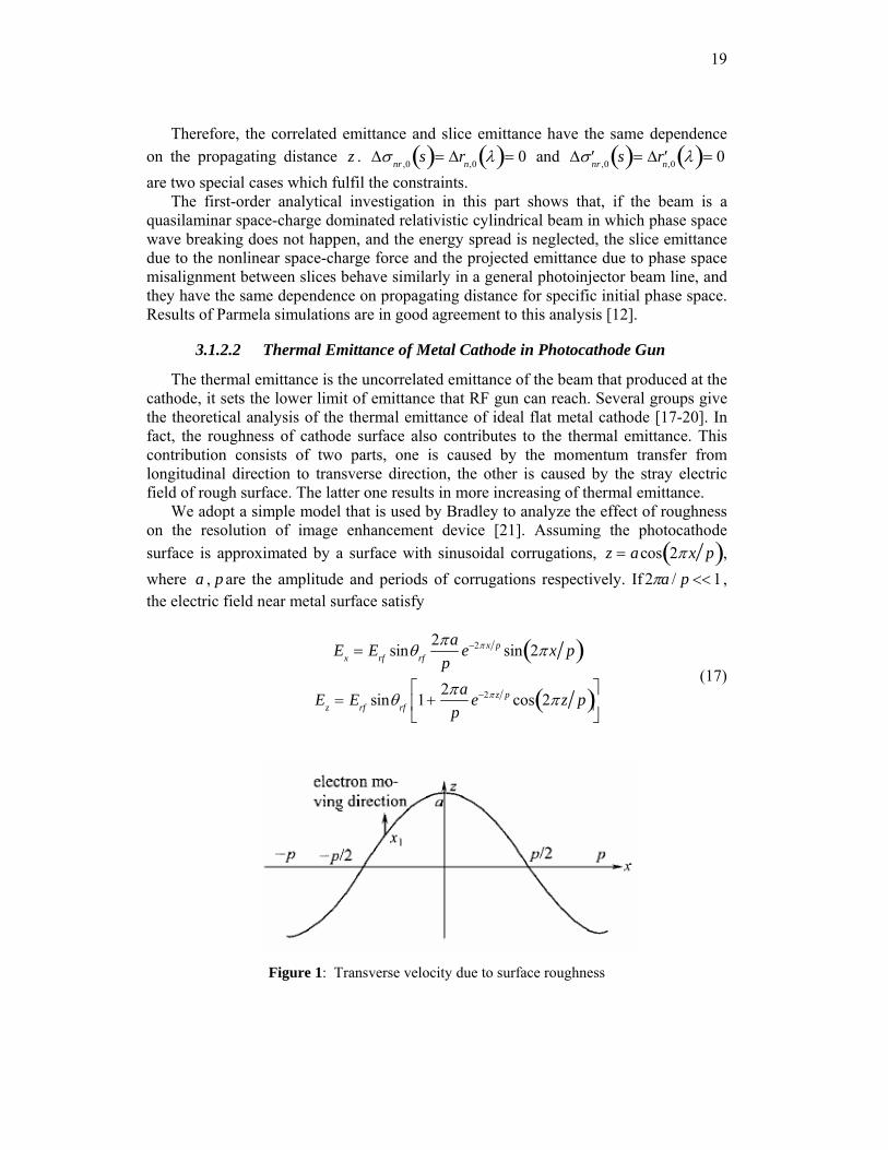
We adopt a simple model that is used by Bradley to analyze the effect of roughness on the resolution of image enhancement device [21]. Assuming the photocathode surface is approximated by a surface with sinusoidal corrugations, z = acos 2π x p( ), where a , p are the amplitude and periods of corrugations respectively. If 1/2 <<paπ , the electric field near metal surface satisfy
Ex = Erf sinθrf
2πap
e−2π x p sin 2π x p( )
Ez = Erf sinθrf 1+2πa
pe−2π z p cos 2π z p( )⎡
⎣⎢
⎤
⎦⎥
(17)
Figure 1: Transverse velocity due to surface roughness
20
As shown in Figure 1, the electron will move along the z direction approximately after it is emitted from x = x1 . The transverse velocity of electron due to Ex is
ve =
2πap
sin 2π x1 p( ) eErf sinθrf p 4m0( )1 2 (18)
The thermal emittance can be estimated by [22]
εn,rms = x22 Ekin,x
m0c2 (19)
Then thermal emittance due to surface roughness is
εn,rms,rough =R2
π 2ea2 Erf sinθrf
2m0c2 p
(20)
The surface profile of the samples after diamond cutting or diamond polishing have been measured by white light interferometers and atomic force microscope. The amplitude and periods of surface corrugations is about 10 − 80 nm and 3− 8 μm . Take
a = 70 nm , p = 3 μm , RF field amplitude Erf = 100 MV/m and phase θrf = 30o , radius
of laser R = 1 mm , the thermal emittance due to surface roughness is about 0.44 mm mrad. This will be one of main source of thermal emittance. So the surface of cathode should be handled carefully.
3.1.3 Highlights of the RF Gun Design
3.1.3.1 RF-Asymmetry in Photo-Injector [13]
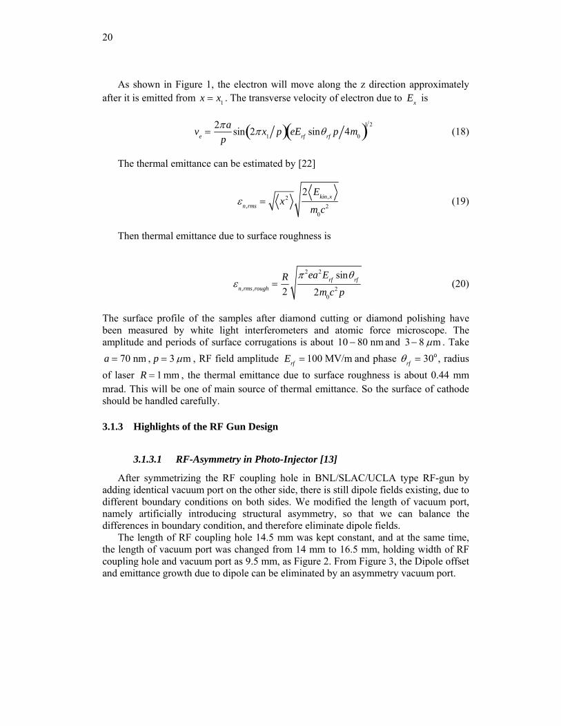
After symmetrizing the RF coupling hole in BNL/SLAC/UCLA type RF-gun by adding identical vacuum port on the other side, there is still dipole fields existing, due to different boundary conditions on both sides. We modified the length of vacuum port, namely artificially introducing structural asymmetry, so that we can balance the differences in boundary condition, and therefore eliminate dipole fields.
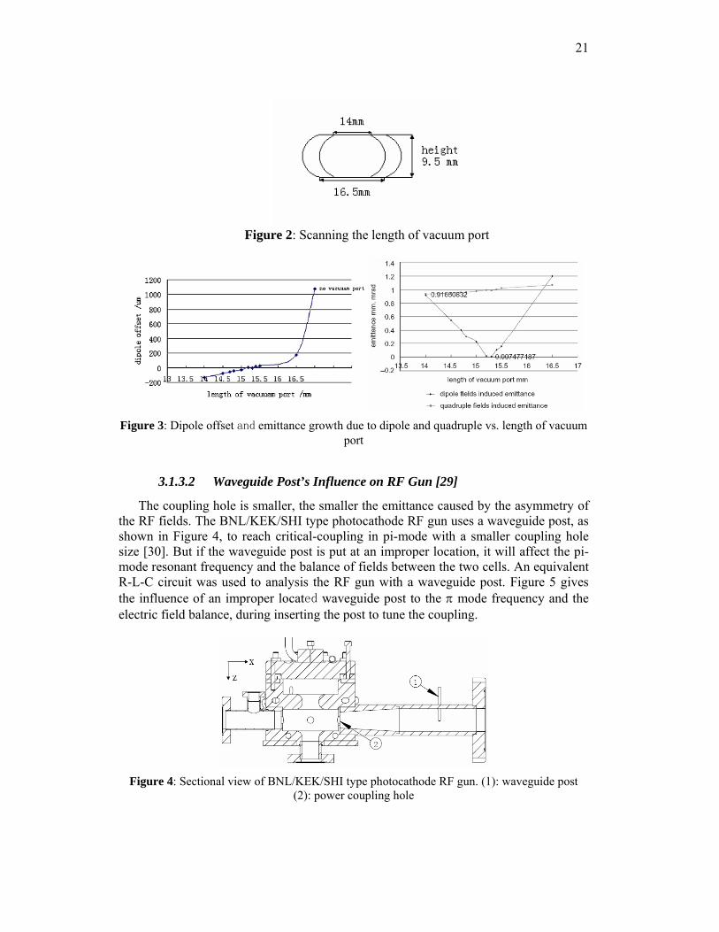
The length of RF coupling hole 14.5 mm was kept constant, and at the same time, the length of vacuum port was changed from 14 mm to 16.5 mm, holding width of RF coupling hole and vacuum port as 9.5 mm, as Figure 2. From Figure 3, the Dipole offset and emittance growth due to dipole can be eliminated by an asymmetry vacuum port.
21
Figure 2: Scanning the length of vacuum port
Figure 3: Dipole offset and emittance growth due to dipole and quadruple vs. length of vacuum
port
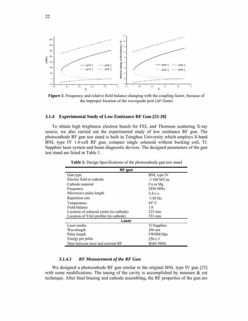
3.1.3.2 Waveguide Post’s Influence on RF Gun [29]
The coupling hole is smaller, the smaller the emittance caused by the asymmetry of the RF fields. The BNL/KEK/SHI type photocathode RF gun uses a waveguide post, as shown in Figure 4, to reach critical-coupling in pi-mode with a smaller coupling hole size [30]. But if the waveguide post is put at an improper location, it will affect the pi-mode resonant frequency and the balance of fields between the two cells. An equivalent R-L-C circuit was used to analysis the RF gun with a waveguide post. Figure 5 gives the influence of an improper located waveguide post to the π mode frequency and the electric field balance, during inserting the post to tune the coupling.
Figure 4: Sectional view of BNL/KEK/SHI type photocathode RF gun. (1): waveguide post
(2): power coupling hole
22
Figure 5: Frequency and relative field balance changing with the coupling factor, because of
the improper location of the waveguide post (Δl=2mm)
3.1.4 Experimental Study of Low Emittance RF Gun [25-28]
To obtain high brightness electron bunch for FEL and Thomson scattering X-ray source, we also carried out the experimental study of low emittance RF gun. The photocathode RF gun test stand is built in Tsinghua University which employs S-band BNL type IV 1.6-cell RF gun, compact single solenoid without bucking coil, Ti: Sapphire laser system and beam diagnostic devices. The designed parameters of the gun test stand are listed in Table 1.
Table 1: Design Specifications of the photocathode gun test stand
RF gun Gun type BNL type IV Electric field at cathode ≥100 MV/m Cathode material Cu or Mg Frequency 2856 MHz Microwave pulse length 2-4μs Repetition rate ≤50 Hz Temperature 45o C Field balance 1.0 Location of solenoid center (to cathode) 223 mm Location of YAG profiler (to cathode) 531 mm
Laser Laser media Ti:Sapphire Wavelength 266 nm Pulse length FWHM10ps Energy per pulse 250μJ Jitter between laser and external RF RMS 500fs
3.1.4.1 RF Measurement of the RF Gun
We designed a photocathode RF gun similar to the original BNL type IV gun [23] with some modifications. The tuning of the cavity is accomplished by measure & cut technique. After final brazing and cathode assembling, the RF properties of the gun are
23
measured by vector network analyzer 8720B. The measured data of the RF gun and their computed values by SuperFish are listed in Table 2.
Table 2: Measurement result of the 1.6-Cell RF gun
Measured Computed fπ–f
0 (MHz) 3.234 3.230
Ehalf / Efull NA 1.08 fπ in vacuum (MHz) 2857.37 @ 23o C 2856 @ 45o C
Q0 of π mode 10327 10863
β of π mode 1.19 1.28 Q
0 of 0 mode 9503 9629
β of 0 mode 0.78 0.77
Recently we have developed other three BNL type IV RF guns for Shanghai Institute of Applied Physics, Brookhaven National Laboratory, and National Synchrotron Radiation Laboratory (Hefei).
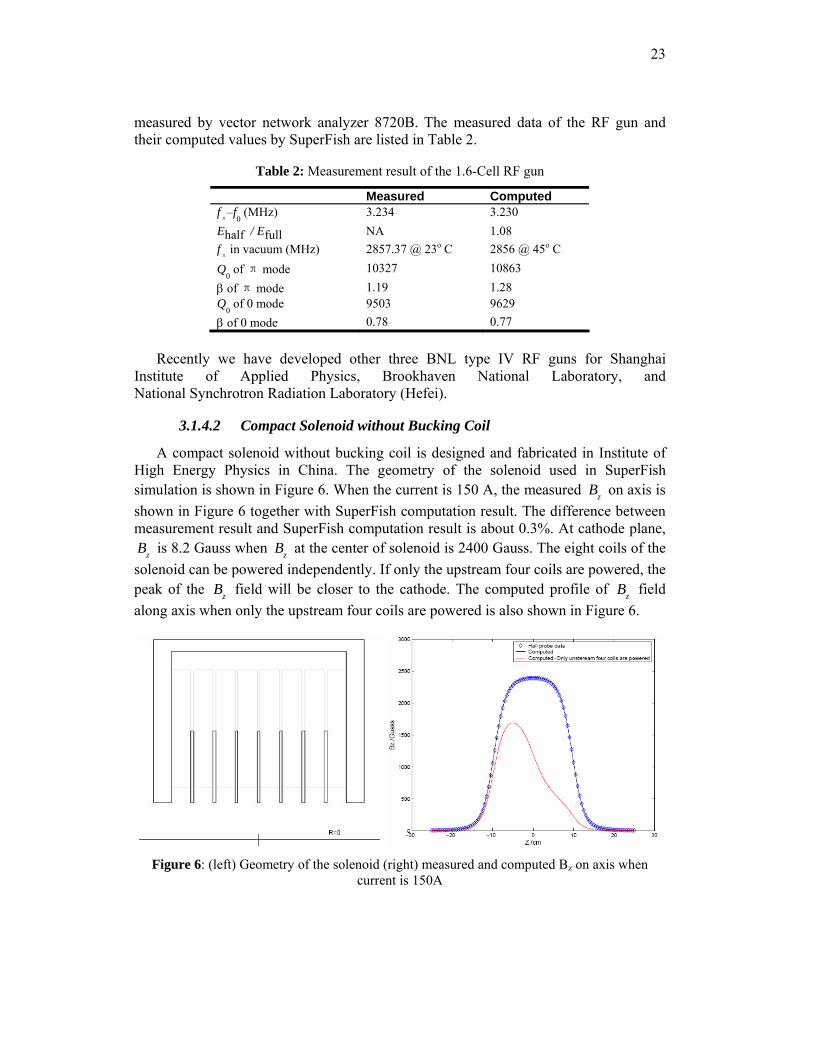
3.1.4.2 Compact Solenoid without Bucking Coil
A compact solenoid without bucking coil is designed and fabricated in Institute of High Energy Physics in China. The geometry of the solenoid used in SuperFish simulation is shown in Figure 6. When the current is 150 A, the measured Bz on axis is shown in Figure 6 together with SuperFish computation result. The difference between measurement result and SuperFish computation result is about 0.3%. At cathode plane,
Bz is 8.2 Gauss when Bz at the center of solenoid is 2400 Gauss. The eight coils of the solenoid can be powered independently. If only the upstream four coils are powered, the peak of the Bz field will be closer to the cathode. The computed profile of Bz field along axis when only the upstream four coils are powered is also shown in Figure 6.
Figure 6: (left) Geometry of the solenoid (right) measured and computed Bz on axis when
current is 150A
24
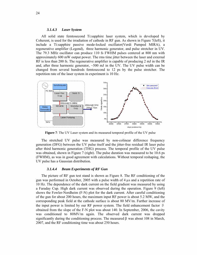
3.1.4.3 Laser System
All solid state femtosecond Ti:sapphire laser system, which is developed by Coherent, is used for the irradiation of cathode in RF gun. As shown in Figure 7(left), it include a Ti:sapphire passive mode-locked oscillator(Verdi Pumped MIRA), a regenerative amplifier (Legend), three harmonic generator, and pulse stretcher in UV. The 79.3 MHz oscillator can produce 110 fs FWHM pulses centered at 800 nm with approximately 600 mW output power. The rms time jitter between the laser and external RF is less than 200 fs. The regenerative amplifier is capable of producing 2 mJ in the IR and, after three harmonic generator, ~500 mJ in the UV. The UV pulse width can be changed from several hundreds femtosecond to 12 ps by the pulse stretcher. The repetition rate of the laser system in experiment is 10 Hz.
Figure 7: The UV Laser system and its measured temporal profile of the UV pulse
The stretched UV pulse was measured by non-colinear difference frequency generation (DFG) between the UV pulse itself and the jitter-free residual IR laser pulse after third harmonic generation (THG) process. The temporal profile of the UV pulse was obtained, shown in Figure 7 (right). The pulse duration was measured to be 10.6 ps (FWHM), as was in good agreement with calculations. Without temporal reshaping, the UV pulse has a Gaussian distribution.
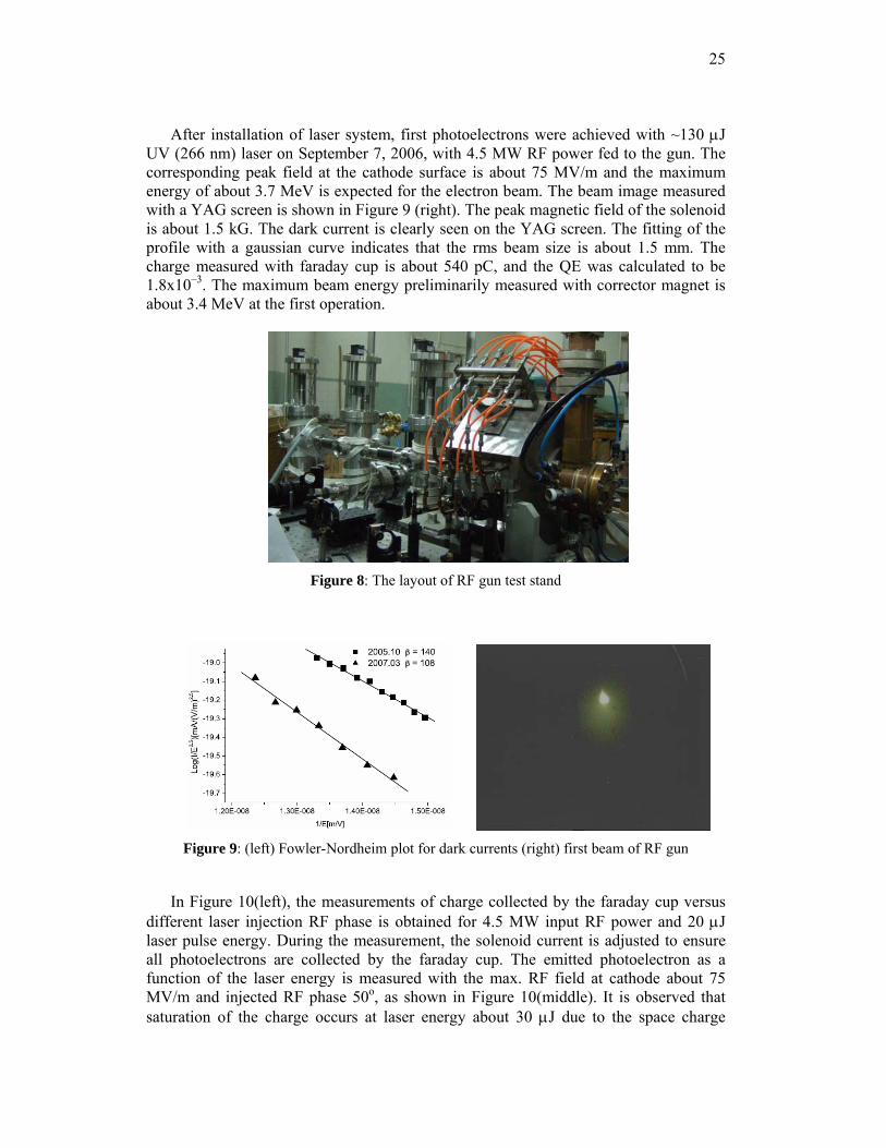
3.1.4.4 Beam Experiments of RF Gun
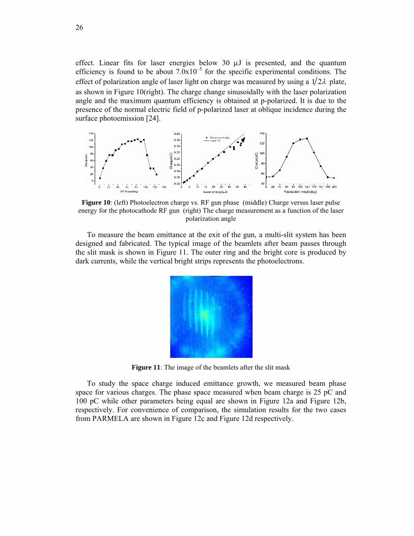
The picture of RF gun test stand is shown as Figure 8. The RF conditioning of the gun was performed in October, 2005 with a pulse width of 4 μs and a repetition rate of 10 Hz. The dependence of the dark current on the field gradient was measured by using a Faraday Cup. High dark current was observed during the operation. Figure 9 (left) shows the Fowler-Nordheim (F-N) plot for the dark current. After careful conditioning of the gun for about 200 hours, the maximum input RF power is about 5.2 MW, and the corresponding peak field at the cathode surface is about 80 MV/m. Further increase of the input power is limited by our RF power system. The field enhancement factor β obtained from the slope of the F-N plot was about 140. In September, 2006, the cavity was conditioned to 80MV/m again. The observed dark current was dropped significantly during the conditioning process. The measured β was about 108 in March, 2007, and the RF conditioning time was about 250 hours.
25
After installation of laser system, first photoelectrons were achieved with ~130 μJ UV (266 nm) laser on September 7, 2006, with 4.5 MW RF power fed to the gun. The corresponding peak field at the cathode surface is about 75 MV/m and the maximum energy of about 3.7 MeV is expected for the electron beam. The beam image measured with a YAG screen is shown in Figure 9 (right). The peak magnetic field of the solenoid is about 1.5 kG. The dark current is clearly seen on the YAG screen. The fitting of the profile with a gaussian curve indicates that the rms beam size is about 1.5 mm. The charge measured with faraday cup is about 540 pC, and the QE was calculated to be 1.8x10⁻³. The maximum beam energy preliminarily measured with corrector magnet is about 3.4 MeV at the first operation.
Figure 8: The layout of RF gun test stand
Figure 9: (left) Fowler-Nordheim plot for dark currents (right) first beam of RF gun
In Figure 10(left), the measurements of charge collected by the faraday cup versus
different laser injection RF phase is obtained for 4.5 MW input RF power and 20 μJ laser pulse energy. During the measurement, the solenoid current is adjusted to ensure all photoelectrons are collected by the faraday cup. The emitted photoelectron as a function of the laser energy is measured with the max. RF field at cathode about 75 MV/m and injected RF phase 50o, as shown in Figure 10(middle). It is observed that saturation of the charge occurs at laser energy about 30 μJ due to the space charge
26
effect. Linear fits for laser energies below 30 μJ is presented, and the quantum efficiency is found to be about 7.0x10⁻⁵ for the specific experimental conditions. The effect of polarization angle of laser light on charge was measured by using a 1 2λ plate, as shown in Figure 10(right). The charge change sinusoidally with the laser polarization angle and the maximum quantum efficiency is obtained at p-polarized. It is due to the presence of the normal electric field of p-polarized laser at oblique incidence during the surface photoemission [24].
Figure 10: (left) Photoelectron charge vs. RF gun phase (middle) Charge versus laser pulse
energy for the photocathode RF gun (right) The charge measurement as a function of the laser polarization angle
To measure the beam emittance at the exit of the gun, a multi-slit system has been designed and fabricated. The typical image of the beamlets after beam passes through the slit mask is shown in Figure 11. The outer ring and the bright core is produced by dark currents, while the vertical bright strips represents the photoelectrons.
Figure 11: The image of the beamlets after the slit mask
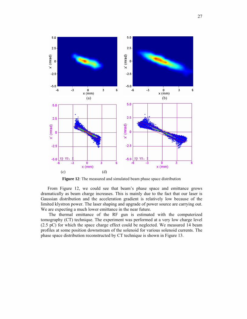
To study the space charge induced emittance growth, we measured beam phase space for various charges. The phase space measured when beam charge is 25 pC and 100 pC while other parameters being equal are shown in Figure 12a and Figure 12b, respectively. For convenience of comparison, the simulation results for the two cases from PARMELA are shown in Figure 12c and Figure 12d respectively.
27
(a) (b)
(c) (d)
Figure 12: The measured and simulated beam phase space distribution
From Figure 12, we could see that beam’s phase space and emittance grows dramatically as beam charge increases. This is mainly due to the fact that our laser is Gaussian distribution and the acceleration gradient is relatively low because of the limited klystron power. The laser shaping and upgrade of power source are carrying out. We are expecting a much lower emittance in the near future.
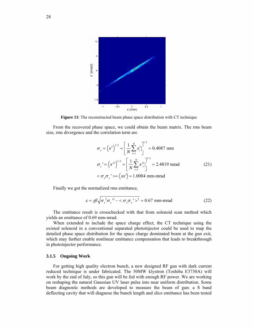
The thermal emittance of the RF gun is estimated with the computerized tomography (CT) technique. The experiment was performed at a very low charge level (2.5 pC) for which the space charge effect could be neglected. We measured 14 beam profiles at some position downstream of the solenoid for various solenoid currents. The phase space distribution reconstructed by CT technique is shown in Figure 13.
28
Figure 13: The reconstructed beam phase space distribution with CT technique
From the recovered phase space, we could obtain the beam matrix. The rms beam size, rms divergence and the correlation term are
σ x = x2 1/ 2=
1N
xi2
i=1
N
∑⎡
⎣⎢
⎤
⎦⎥
1/ 2
= 0.4087 mm
σ x ' = x '21/ 2
=1N
x 'i2
i=1
N
∑⎡
⎣⎢
⎤
⎦⎥
1/ 2
= 2.4819 mrad
< σ xσ x ' >= xx ' = 1.0084 mm-mrad
(21)
Finally we got the normalized rms emittance,
ε = γβ σ x2σ x '2 − < σ xσ x ' >2 = 0.67 mm-mrad (22)
The emittance result is crosschecked with that from solenoid scan method which yields an emittance of 0.69 mm-mrad.
When extended to include the space charge effect, the CT technique using the existed solenoid in a conventional separated photoinjector could be used to map the detailed phase space distribution for the space charge dominated beam at the gun exit, which may further enable nonlinear emittance compensation that leads to breakthrough in photoinjector performance.
3.1.5 Ongoing Work
For getting high quality electron bunch, a new designed RF gun with dark current reduced technique is under fabricated. The 50MW klystron (Toshiba E3730A) will work by the end of July, so this gun will be fed with enough RF power. We are working on reshaping the natural Gaussian UV laser pulse into near uniform distribution. Some beam diagnostic methods are developed to measure the beam of gun: a S band deflecting cavity that will diagnose the bunch length and slice emittance has been tested
29
off-line and installed on the beam line; the crystal, detector and chamber for EO method which will measure the bunch length and electron bunch arrival time jitter are preparing. Ultrafast MeV electron diffraction has been simulated and will begin to experimental research at the next half year of 2008. A 3 TW laser system is commissioning, and Thomson scattering experiment is expected at the beginning of next year. So lots of works, including creating, measurement and application of high brightness electron bunch based on low emittance RF guns are being carried out at the Accelerator Lab of Tsinghua University.
3.1.6 References
1. LCLS Conceptual Design Report. [R]. Tech. rep., SLAC, http://www-ssrl.slac.stanford.edu/lcls/cdr/, 2001
2. TESLA TDR Part V [R]. Tech. rep., DESY, http://tesla.desy.de/new pages/TDR CD/PartV/fel.html, 2001
3. G. R. Neil, C. L. Bohn, S. V. Benson, et al. "Sustained Kilowatt Lasing in a Free-Electron Laser with Same-Cell Energy Recovery". Phys. Rev. Lett. 2000, 84:662
4. James. F. Wishart, Andrew. R. Cook, John. R. Miller, "The LEAF picosecond pulse radiolysis facility at Brookhaven National Laboratory," Rev. Sci Inst. 2004, 75:4359
5. W. J. Brown, S. G. Anderson, C. P. Barty, et al. "Generation of high brightness x-rays with the pleiades Thomson x-ray source," Proc. PAC2003.
6. M. E. Conde, W. Gai, R. Konecny, et al. "A high-charge high-brightness l-band photocathode rf gun" Proc. ICFA99
7. G. L. Carr, Michael. C. Martin, Wayne. R. McKinney, et al. "Very high power THz radiation at Jefferson Lab". Phys Med. Biol. 2002, 47:3761.
8. Wenhui Huang, Xiaozhong He, Gang Huang et al, "Preliminary Study of X-Ray Source Based on Thomson Scattering," High Energy Physics and Nuclear Physics-Chinese Edition 28 (4): 446-450 April 2004
9. L. Serafini, J. B. Rosenzweig, Phys. Rev. E. 55 (1997) 7565. 10. J. D. Lawson, "The Physics of Charged Particle Beams," 2nd ed., Oxford University
Press, New York, 1988. 11. S. C. Hartman, J. B. Rosenzweig, Phys. Rev. E 47 (1993) 2031. 12. X. Zh. He, Ch. X. Tang, et al., NIMPR A 560 (2006), p. 197–203. 13. X. Guan, Ch. X. Tang, et al., NIMPR A 574 (2007), p. 17–21. 14. D. T. Palmer, PhD thesis, "The Next Generation Photo-injector," 1998, pp. 64. 15. J. B. Rosenzweig et al., "The Effects of RF Asymmetries on Photo-injector Beam
Quality," PAC 1999, New York City, USA. 16. D. T. Palmer et al., "Microwave Measurements of the BNL/SLAC/UCLA 1.6 Cell
Photocathode RF Gun," PAC 1995, Dallas, TX, USA. 17. J. E. Clendenin, G. A. Mulhollan, "High Quantum Yield, Low Emittance Electron
Sources." SLAC-PUB-7760, 1998. 18. D. T. Palmer, "The Next Generation Photoinjector." PhD Thesis, 1998 19. X. J. Wang, M. Babzien, R. Malone et al, "Mg Cathode and Its Thermal Emittance."
LINAC 2002. 20. W. S. Graves, L. F. DiMauro, R. Heese et al, "Thermal Emittance Measurement of
Copper Cathode," PAC 2001 21. D. J. Bradley et al., "The Transverse Energy of Electrons Emitted from GaAs
Photocathodes." J. Phys. D: Appl. Phys., 1997, 10: 111-125. 22. Xiaozhong He et al., "Researches on Thermal Emittance of Metal Cathode in
Photoinjectors," High Energy Physics and Nuclear Physics-Chinese Edition 28 (9): 1007-1012, September 2004
30
23. J. Rose, W. Graves, R. Heese, “Modeling and measurements of the DUV FEL photoinjector cavity rf properties”, PAC01, Chicago, 2001, p. 2221.
24. Dao Xiang, Sung-Ju Park, Jang-Ho Park, Yong-Woon Parc, X. J. Wang, NIMPR A 562 (2006) 48-52.
25. X. Zh. He, Ch. X. Tang et al. "Status of the photocathode RF gun research at Tsinghua University," EPAC 2006
26. Lixin Yan et al., "Measurements of laser temporal profile and polarization-dependent quantum efficiency," PAC07.
27. Du Ying-Chao, Yan Li-Xin, Du Qiang et al. "First beam measurements of the S-band photocathode radio-frequency gun at Tsinghua University," Chinese Physics Letters 24 Issue 7:1876-8, July 2007
28. Yan Li-Xin, Du Ying-Chao, Xiang Dao et al., "Multislit-based emittance measurement of electron beam from a photocathode radio-frequency gun," Chinese Physics Letters 25 Issue 5: 1640-3, May 2008
29. H. J. Qian, Ch. X. Tang et al, "Analysis and experiments of a waveguide post’s influence on photocathode RF gun," NIMPR A, to be published.
30. D. T. Palmer. The Next Generation Photoinjector. Ph.D. Thesis. Stanford University, 1998.
3.2 The ELBE Superconducting Photoinjector
Jochen Teichert, André Arnold, Dietmar Janssen, Petr Murcek, Friedrich Staufenbiel, Rong Xiang
Forschungszentrum Dresden-Rossendorf, P.O. Box 510119, 01314 Dresden, Germany
Thorsten Kamps BESSY, Albert-Einstein-Str. 15, 12489 Berlin, Germany
Guido Klemz, Ingo Will Max-Born-Institut, Max-Born-Str. 2A, 12489 Berlin, Germany
Mail to: [email protected]
3.2.1 Introduction
Since several years the Radiation Source ELBE has been operated at Forschungszentrum Dresden-Rossendorf (FZD). The basis of the facility is an electron linear accelerator with up to 40 MeV electron energy and 1 mA average current. This linac uses superconducting accelerating cavities and allows continuous wave (CW) operation. After commissioning of the accelerator in 2002 [1, 2], successively beamlines for the production of different radiation and application have been put into operation. The first user beamline which was finished generates gamma rays by means of a Bremsstrahlung radiator for applications in nuclear physics [3]. Then a beam line with a target station was installed for monochromatic x-rays generated by electron channelling in a crystal. Beside x-ray production this target station is now in use for direct electron beam irradiation. Most important are two free electron lasers (FELs) completed in 2004 and 2006 [4]. The first FEL (U27) with an undulator period of 27.3 mm and adjustable k parameter between 0.2 and 0.68 produces infrared (IR) light with wavelengths from 4 to 22 µm. The second FEL (U100) has an undulator period of 100 mm, a k-range of 0.3 - 2.7 and covers the far IR range from 20 to 215 µm. The average radiation power is up to 70 W. Besides in-house users the IR beams are
31
available to external users in the FELBE (FEL@ELBE) program which is part of the EU funded integrated activity on synchrotron and FEL science. Worldwide unique is the combination of IR radiation and high magnetic fields as it is realized by an optical transport line [5] which guides the IR light to the high magnetic field laboratory [6] nearby the ELBE hall. The studies with pulsed magnetic fields require FEL pulse trains of 10 ms or even longer with high amplitude stability. The CW operation of ELBE is particularly suitable. Last year two new production targets for neutrons [7] were completed. At present, the installation of the position production facility [8] is being carried out. In the future, experiments are planned which will combine the ELBE electron beam with the terra watt laser commissioned this year.
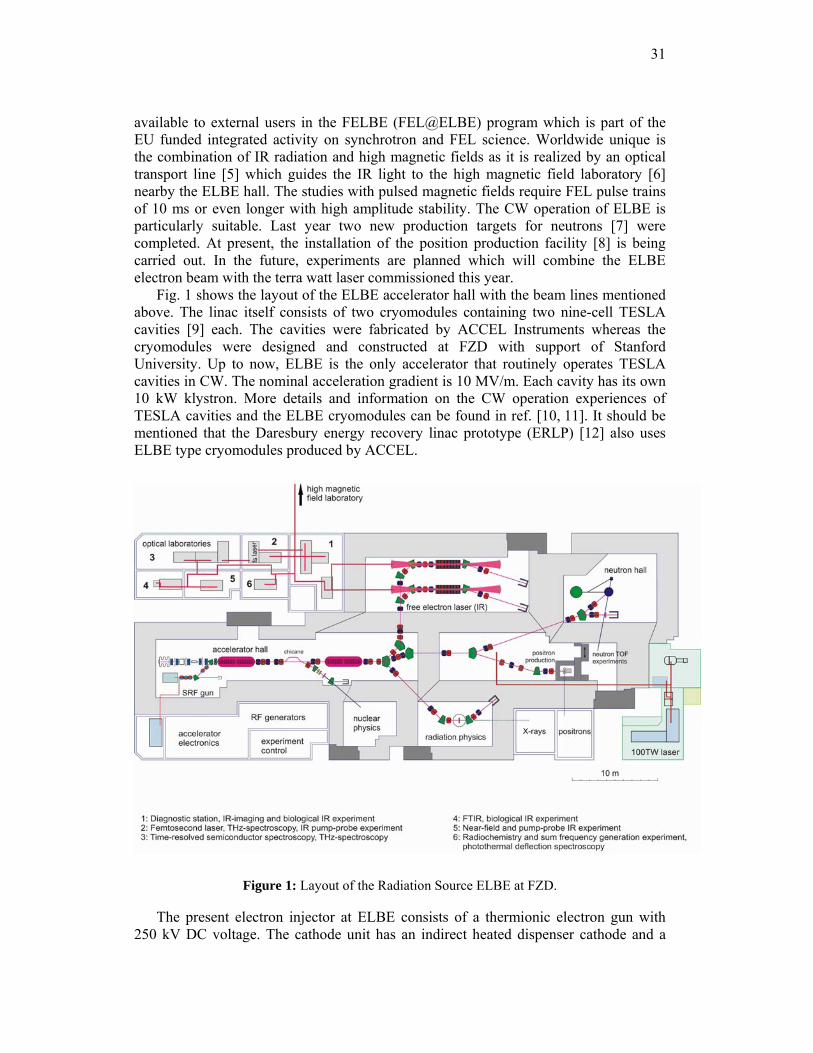
Fig. 1 shows the layout of the ELBE accelerator hall with the beam lines mentioned above. The linac itself consists of two cryomodules containing two nine-cell TESLA cavities [9] each. The cavities were fabricated by ACCEL Instruments whereas the cryomodules were designed and constructed at FZD with support of Stanford University. Up to now, ELBE is the only accelerator that routinely operates TESLA cavities in CW. The nominal acceleration gradient is 10 MV/m. Each cavity has its own 10 kW klystron. More details and information on the CW operation experiences of TESLA cavities and the ELBE cryomodules can be found in ref. [10, 11]. It should be mentioned that the Daresbury energy recovery linac prototype (ERLP) [12] also uses ELBE type cryomodules produced by ACCEL.
Figure 1: Layout of the Radiation Source ELBE at FZD.
The present electron injector at ELBE consists of a thermionic electron gun with 250 kV DC voltage. The cathode unit has an indirect heated dispenser cathode and a
32
pulse grid. The electronic pulsing unit allows the generation of about 500 ps long electron pulses with a maximum peak current of 150 mA (77 pC bunch charge). Two RF bunchers with 260 MHz and 1.3 GHz frequency shorten the bunch length to about 10 ps at the entrance of the first accelerator module. The thermal emittance of the cathode is about 2 mm mrad. With increasing bunch charge the emittance growths up to about 10 mm mrad due to the electric field deformation caused be the pulse grid of the cathode unit.
In order to overcome the mentioned drawbacks of the thermionic injector, the development of a superconducting radio-frequency photo injector (SRF Gun) was started at FZD. In a first phase, a proof-of-principle experiment with a half-cell cavity was carried out [13]. The results were very successful and the first beam of a SRF gun could be produced in 2002 [14]. The objective of the second phase is now the development and installation of a SRF photo injector for ELBE with a 3-1/2 cell cavity. This R&D project has been performed in collaboration with ACCEL Instruments, BESSY, Budker Institute, DESY, Max Born Institute (MBI) and TU Dresden.
Beside the beam parameter improvement at ELBE, the successful development of a SRF photoinjector and the demonstration of its routine operation are of great importance for the community. Future accelerator projects like next generation light sources and energy recovery linacs require electron sources with high-brightness beams as well as high average currents. State-of-the-art RF photoinjectors with (normal conducting) copper cavity are capable to produce electron beams of highest brightness and large peak current. They are the preferred injector for SASE FELs. But in general their average currents are low because they produce single pulses with low repetition rates or short pulse trains and their RF is pulsed with a low duty factor. Here the SRF gun, i.e. the replacement of the copper cavity by a superconducting one is the most elegant solution for CW operation and for high average currents. But this approach is connected with new challenges and uncertainties as will be discussed later.
Another way towards high average-current is to increase the duty factor in normal conducting rf gun towards CW. Up to now, the record is the Boing gun [15, 16] designed in 1992 and operated at a duty factor of 25% with a macropulse current of 132 mA. A CW mode normal-conducting RF photo-injector for 100 mA is under development in collaboration of LANL and Advanced Energy Systems (AES) [17]. The CW mode operation causes serious cooling problems in a normal conducting cavity. Therefore the field gradient is low (e.g. 7 MV/m in the LANL/AES project) with the consequences of an increasing transverse emittance. A high-duty cycle, high repetition rate gun [18] was designed and tested for the BESSY FEL project, and a new design for a CW mode NC photoinjector was presented by BNL [19].
In a DC photo-injector the extraction of the electrons from the photo cathode happens in a high electric DC field. The present DC gun of the Jefferson Lab FEL operates at 350 kV [20]. In CW operation, this gun delivers 74.85 MHz pulses at over 9 mA average current, corresponding to 135 pC per bunch. An upgrade of the DC gun for 500 kV and 100 mA average current together with a new closely coupled SRF booster cryomodule is being realized [21, 22]. For the Daresbury ERL test facility a DC gun similar to the JLab 350 kV injector has be installed [12]. The DC photo gun is suitable for the production of high average current electron beams. But the comparably low acceleration field strength at the cathode limits the bunch charge and a medium transverse emittance can be obtained only. Higher bunch charges or/and lower transverse emittance can be obtained by increasing the high voltage of these guns. The
33
Cornell energy recovery linac based synchrotron light source will utilize a 750 kV DC photo gun [23] with excellent transverse emittance at 77 pC bunch charge and 100 mA average current (1.3 GHz repetition rate).
3.2.2 History and Other Projects
The use of a superconducting resonator in a RF photo-injector was proposed at the University of Wuppertal [24] and a first experimental set-up was installed [25, 26]. The experiments by Michalke [26] were carried out with an elliptical half-cell of niobium operating at 3 GHz. The cathode stem was also made of Nb and was cooled down together with the cavity in order to be superconducting. The quarter wave band pass filter prevented RF power losses through the coaxial gap between cavity and cathode stem. The photoemission layer of Cs3Sb was irradiated with 543 nm laser light. Photoemission could be obtained at 4.5 K but the gradient achieved in the cavity was too low to produce an electron beam.
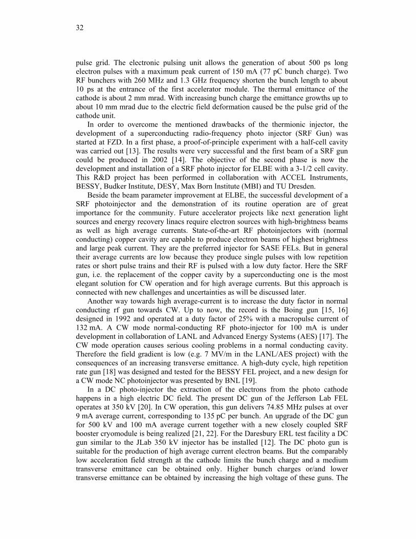
Later, at the FZD a SRF photo-injector project was launched [13, 27]. The cavity was a 1.3 GHz TESLA type half-cell closed by a shallow cone with an opening for the cathode and an additional superconducting choke flange filter [28]. A photograph of the Nb cavity is shown in Fig. 2. Similar to the Wuppertal solution, the filter was necessary because the coaxial gap between cavity and photocathode acts as a RF drain. But a normal-conducting photocathode with a Cs2Te photo layer was used. A special support structure insulated the cathode thermally and electrically from the surrounding cavity and held it at liquid nitrogen temperature. The cavity was mounted in a test cryostat. An RF system, a CW driver laser with 262 nm wavelength and 1 W power, a diagnostic beam line and control system were installed. Photo cathodes were prepared in an attached preparation system. After several tests, the gun was cooled down to 4.2 K and was in operation during a period of seven weeks (approximately five hours per day) [14]. During the whole period of operation, no change of the quality factor of Q = 2.5x10⁸ of the cavity was measured. The electron energy was 900 keV and the maximum bunch charge obtained was 20 pC, which corresponds to an average current of 520 μA in the CW mode. It was limited by average power and repetition rate of the laser and by the small quantum efficiency of the photo cathode.
Figure 2: Half-cell cavity of the first operating SRF gun at Rossendorf [27].
34
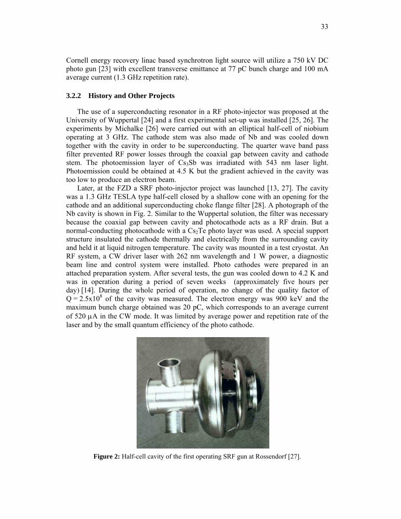
Currently, four projects are running: the 3-1/2 cell SRF photoinjector project for ELBE at FZD, the DC-SC photoinjector at Peking University, the SRF gun project with superconducting Pb photo cathode (BNL, DESY, JLab, and the high-current SRF gun (AES, BNL). A summary of the main design parameters is given in table 1.
3.2.3 SRF Gun Design Parameter
Table 2 gives an overview of the design parameters and planned operation modes of the 3-1/2 cell SRF gun at ELBE. The gun will reduce the pulse length and the transverse emittance for the standard FEL operation mode with 77 pC bunch charge and 13 MHz pulse repetition rate compared to the existing thermionic electron injector. A second operation mode is planned at ELBE with bunch charges up to 1 nC and a repetition rate of 500 kHz. This operation mode will be used for neutron and positron generation. For both applications a high average current and a repetition rate below 1 MHz (time of flight measurements) are essential. Furthermore, it is envisaged to characterize the gun at high bunch charges up to 2.5 nC which is especially important for future application of the SRF gun in the BESSY FEL [29].
Table 1: Overview of running SRF photo injector projects.
Project
RF frequency
(MHz)
Pulse frequency
(MHz)
Energy (MeV)
cells photo cathode
Bunch Charge
(nC)
Current
(mA)
Ref.
ELBE SRF gun,
FZD
1300
13 / 0.5
9.5
3-1/2
Cs2Te
0.077 /
1
1 / 0.5
[30]
DC-SC Photo
Injector, Peking
University
1300
81.25
5
3-1/2
Cs2Te
0.1
1 – 5
[31]
Pb SRF gun
BNL, DESY, JLab
1300
1
6.5
1.6
Pb
1
1
[32]
High-Current
SRF Gun AES, BNL
703.75
351.88
2
1/2
CsK2Sb
1.4
500
[33]
3.2.4 Niobium Cavity
The SRF gun cavity consists of three full cells, a specially designed half-cell and the choke filter. The three full cells have TESLA shapes [9]. The back wall of the half-cell has a slightly conical shape and a centered hole for the photocathode. The photocathode consists of a normal-conducting copper stem with a Cs2Te layer on the top surface. A circular vacuum gap prevents the heat transport from the photocathode to the cavity. Therefore the heat loaded in the cathode does not burden the helium bath. The cathode is separately cooled with liquid nitrogen. On the other hand, to prevent RF power losses through the coaxial line formed by this geometry, an additional choke filter cell is

35
attached. The cavity has an RF power coupler, a pick-up and two higher-order mode couplers adopted from the TESLA cavity [9], and one extra pick-up in the choke filter to measure the field in the half-cell. The half-cell was designed on the basis of RF field calculations as well as particle tracking simulations.
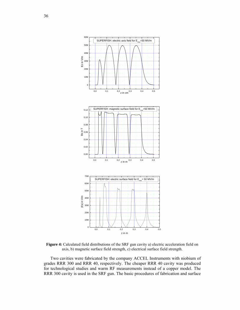
The basis for the cavity design was the TESLA 500 specification, developed at DESY for Eacc = 25 MV/m with corresponding maximum surface peak fields of 110 mT and 50 MV/m. In order to obtain optimal performance, i.e. the same maximum electric and magnetic surface field strengths in all cells of the SRF gun cavity, the electrical peak field on axis had to be reduced to 64% in the half-cell compared to the TESLA cells as shown in Fig. 4a. The maximum electrical peak field on axis in the TESLA cells is 50 MV/m, the geometry constant is 240 Ω and R/Q is 165 Ω. For Q0 = 1x10¹⁰ and the gradient mentioned above a RF power dissipation of 26 W (without cathode) is expected. Details of the geometrical design and the RF parameters of the cavity are published elsewhere [30].
Table 2: SRF gun design parameters and expected values for the planned operation modes.
Parameter ELBE mode
high charge mode
BESSY-FEL
RF frequency 1.3 GHz beam energy 9.5 MeV operation CW drive laser wave length 262 nm Photocathode Cs2Te quantum efficiency >1 % >2.5 % average current 1 mA 0.5 mA 2.5 µA pulse length 5 ps 15 ps 40 ps Repetition rate 13 MHz 500 kHz 1 kHz bunch charge 77 pC 1 nC 2.5 nC transverse emittance 1 µm 2.5 µm 3 µm+)
+) flat top laser
Figure 3: 3-D view of the cavity design with liquid He vessel, photocathode, cathode cooler, liquid N2 reservoir and transfer rod.
36
0,0 0,1 0,2 0,3 0,4 0,5
0
10M
20M
30M
40M
50M
60M
SUPERFISH: electric axis field for Emax=50 MV/m
Ez
in V
/m
z in cm
0,0 0,1 0,2 0,3 0,4 0,5
0,00
0,02
0,04
0,06
0,08
0,10
0,12
SUPERFISH: magnetic surface field for Emax=50 MV/m
Bs in
T
z in m
0,0 0,1 0,2 0,3 0,4 0,50
10M
20M
30M
40M
50M
60M
70MSUPERFISH: electric surface field for Emax= 50 MV/m
|Es|
in V
/m
z in m
Figure 4: Calculated field distributions of the SRF gun cavity a) electric acceleration field on axis, b) magnetic surface field strength, c) electrical surface field strength.
Two cavities were fabricated by the company ACCEL Instruments with niobium of grades RRR 300 and RRR 40, respectively. The cheaper RRR 40 cavity was produced for technological studies and warm RF measurements instead of a copper model. The RRR 300 cavity is used in the SRF gun. The basic procedures of fabrication and surface
37
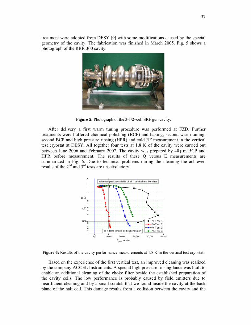
treatment were adopted from DESY [9] with some modifications caused by the special geometry of the cavity. The fabrication was finished in March 2005. Fig. 5 shows a photograph of the RRR 300 cavity.
Figure 5: Photograph of the 3-1/2–cell SRF gun cavity.
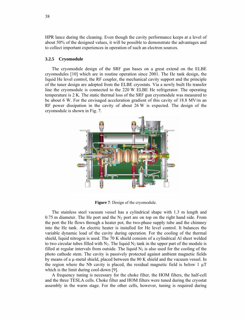
After delivery a first warm tuning procedure was performed at FZD. Further treatments were buffered chemical polishing (BCP) and baking, second warm tuning, second BCP and high pressure rinsing (HPR) and cold RF measurement in the vertical test cryostat at DESY. All together four tests at 1.8 K of the cavity were carried out between June 2006 and February 2007. The cavity was prepared by 40 μm BCP and HPR before measurement. The results of these Q versus E measurements are summarized in Fig. 6. Due to technical problems during the cleaning the achieved results of the 2nd and 3rd tests are unsatisfactory.
0,0 10,0M 20,0M 30,0M 40,0M 50,0M
1E9
1E10
Q0
Epeak
in V/m
V-Test 1 V-Test 2 V-Test 3 V-Test 4all 4 tests limited by field emission
achieved peak axis fields of all 4 vertical test benches
Figure 6: Results of the cavity performance measurements at 1.8 K in the vertical test cryostat.
Based on the experience of the first vertical test, an improved cleaning was realized by the company ACCEL Instruments. A special high pressure rinsing lance was built to enable an additional cleaning of the choke filter beside the established preparation of the cavity cells. The low performance is probably caused by field emitters due to insufficient cleaning and by a small scratch that we found inside the cavity at the back plane of the half cell. This damage results from a collision between the cavity and the
38
HPR lance during the cleaning. Even though the cavity performance keeps at a level of about 50% of the designed values, it will be possible to demonstrate the advantages and to collect important experiences in operation of such an electron sources.
3.2.5 Cryomodule
The cryomodule design of the SRF gun bases on a great extend on the ELBE cryomodules [10] which are in routine operation since 2001. The He tank design, the liquid He level control, the RF coupler, the mechanical cavity support and the principle of the tuner design are adopted from the ELBE cryostats. Via a newly built He transfer line the cryomodule is connected to the 220 W ELBE He refrigerator. The operating temperature is 2 K. The static thermal loss of the SRF gun cryomodule was measured to be about 6 W. For the envisaged acceleration gradient of this cavity of 18.8 MV/m an RF power dissipation in the cavity of about 26 W is expected. The design of the cryomodule is shown in Fig. 7.
Figure 7: Design of the cryomodule.
The stainless steel vacuum vessel has a cylindrical shape with 1.3 m length and 0.75 m diameter. The He port and the N2 port are on top on the right hand side. From the port the He flows through a heater pot, the two-phase supply tube and the chimney into the He tank. An electric heater is installed for He level control. It balances the variable dynamic load of the cavity during operation. For the cooling of the thermal shield, liquid nitrogen is used. The 70 K shield consists of a cylindrical Al sheet welded to two circular tubes filled with N2. The liquid N2 tank in the upper part of the module is filled at regular intervals from outside. The liquid N2 is also used for the cooling of the photo cathode stem. The cavity is passively protected against ambient magnetic fields by means of a µ-metal shield, placed between the 80 K shield and the vacuum vessel. In the region where the Nb cavity is placed, the residual magnetic field is below 1 µT which is the limit during cool-down [9].
A frequency tuning is necessary for the choke filter, the HOM filters, the half-cell and the three TESLA cells. Choke filter and HOM filters were tuned during the cryostat assembly in the warm stage. For the other cells, however, tuning is required during
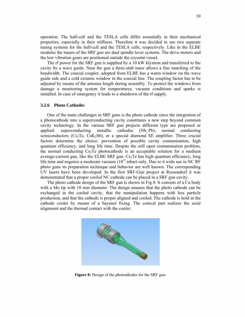
39
operation. The half-cell and the TESLA cells differ essentially in their mechanical properties, especially in their stiffness. Therefore it was decided to use two separate tuning systems for the half-cell and the TESLA cells, respectively. Like in the ELBE modules the tuners of the SRF gun are dual spindle lever systems. The drive motors and the low vibration gears are positioned outside the cryostat vessel.
The rf power for the SRF gun is supplied by a 10 kW klystron and transferred to the cavity by a wave guide. Near the gun a three-stub tuner allows a fine matching of the bandwidth. The coaxial coupler, adopted from ELBE has a warm window on the wave guide side and a cold ceramic window in the coaxial line. The coupling factor has to be adjusted by means of the antenna length during assembly. To protect the windows from damage a monitoring system for temperatures, vacuum conditions and sparks is installed. In case of emergency it leads to a shutdown of the rf supply.
3.2.6 Photo Cathodes
One of the main challenges in SRF guns is the photo cathode since the integration of a photocathode into a superconducting cavity constitutes a new step beyond common cavity technology. In the various SRF gun projects different type are proposed or applied: superconducting metallic cathodes (Nb, Pb), normal conducting semiconductors (Cs2Te, CsK2Sb), or a special diamond SE amplifier. Three crucial factors determine the choice: prevention of possible cavity contamination, high quantum efficiency, and long life time. Despite the still open contamination problem, the normal conducting Cs2Te photocathode is an acceptable solution for a medium average-current gun, like the ELBE SRF gun. Cs2Te has high quantum efficiency, long life time and requires a moderate vacuum (10-9 mbar) only. Due to it wide use in NC RF photo guns its preparation technique und behavior are well known. The corresponding UV lasers have been developed. In the first SRF-Gun project at Rossendorf it was demonstrated that a proper cooled NC cathode can be placed in a SRF gun cavity.
The photo cathode design of the SRF gun is shown in Fig 8. It consists of a Cu body with a Mo tip with 10 mm diameter. The design ensures that the photo cathode can be exchanged in the cooled cavity, that the manipulation happens with less particle production, and that the cathode is proper aligned and cooled. The cathode is hold in the cathode cooler by means of a bayonet fixing. The conical part realizes the axial alignment and the thermal contact with the cooler.
Figure 8: Design of the photoathodes for the SRF gun.
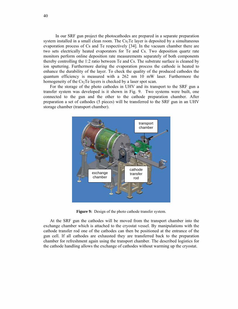
40
In our SRF gun project the photocathodes are prepared in a separate preparation system installed in a small clean room. The Cs2Te layer is deposited by a simultaneous evaporation process of Cs and Te respectively [34]. In the vacuum chamber there are two sets electrically heated evaporators for Te and Cs. Two deposition quartz rate monitors perform online deposition rate measurements separately of both components thereby controlling the 1:2 ratio between Te and Cs. The substrate surface is cleaned by ion sputtering. Furthermore during the evaporation process the cathode is heated to enhance the durability of the layer. To check the quality of the produced cathodes the quantum efficiency is measured with a 262 nm 10 mW laser. Furthermore the homogeneity of the Cs2Te layers is checked by a laser spot scan.
For the storage of the photo cathodes in UHV and its transport to the SRF gun a transfer system was developed is it shown in Fig. 9. Two systems were built, one connected to the gun and the other to the cathode preparation chamber. After preparation a set of cathodes (5 pieces) will be transferred to the SRF gun in an UHV storage chamber (transport chamber).
Figure 9: Design of the photo cathode transfer system.
At the SRF gun the cathodes will be moved from the transport chamber into the exchange chamber which is attached to the cryostat vessel. By manipulations with the cathode transfer rod one of the cathodes can then be positioned at the entrance of the gun cell. If all cathodes are exhausted they are transferred back to the preparation chamber for refreshment again using the transport chamber. The described logistics for the cathode handling allows the exchange of cathodes without warming up the cryostat.
exchange chamber
transport chamber
cathode transfer
rod
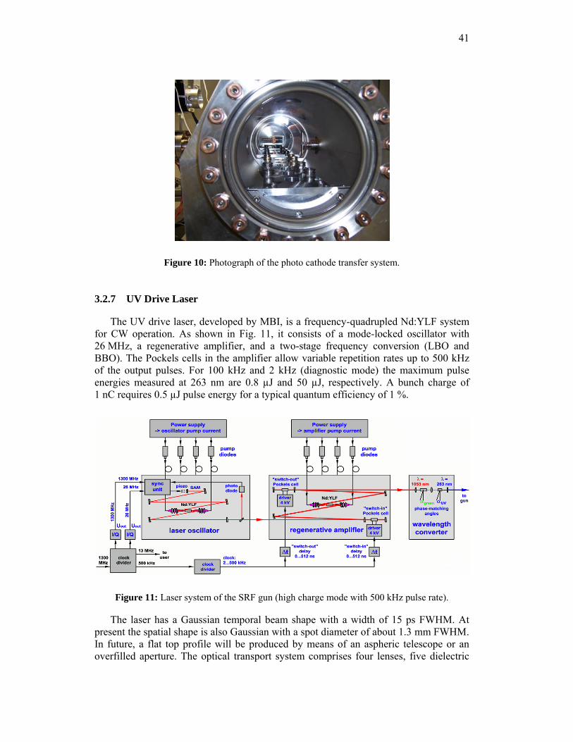
41
Figure 10: Photograph of the photo cathode transfer system.
3.2.7 UV Drive Laser
The UV drive laser, developed by MBI, is a frequency-quadrupled Nd:YLF system for CW operation. As shown in Fig. 11, it consists of a mode-locked oscillator with 26 MHz, a regenerative amplifier, and a two-stage frequency conversion (LBO and BBO). The Pockels cells in the amplifier allow variable repetition rates up to 500 kHz of the output pulses. For 100 kHz and 2 kHz (diagnostic mode) the maximum pulse energies measured at 263 nm are 0.8 µJ and 50 µJ, respectively. A bunch charge of 1 nC requires 0.5 µJ pulse energy for a typical quantum efficiency of 1 %.
Figure 11: Laser system of the SRF gun (high charge mode with 500 kHz pulse rate).
The laser has a Gaussian temporal beam shape with a width of 15 ps FWHM. At present the spatial shape is also Gaussian with a spot diameter of about 1.3 mm FWHM. In future, a flat top profile will be produced by means of an aspheric telescope or an overfilled aperture. The optical transport system comprises four lenses, five dielectric
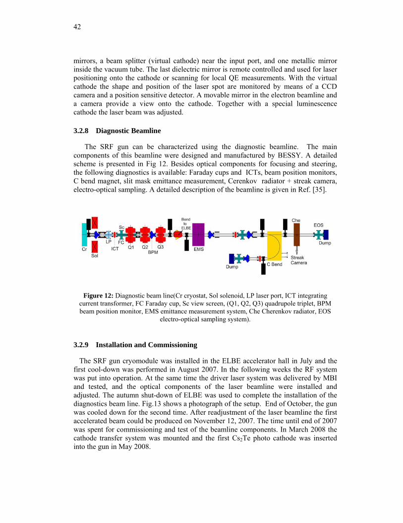
42
mirrors, a beam splitter (virtual cathode) near the input port, and one metallic mirror inside the vacuum tube. The last dielectric mirror is remote controlled and used for laser positioning onto the cathode or scanning for local QE measurements. With the virtual cathode the shape and position of the laser spot are monitored by means of a CCD camera and a position sensitive detector. A movable mirror in the electron beamline and a camera provide a view onto the cathode. Together with a special luminescence cathode the laser beam was adjusted.
3.2.8 Diagnostic Beamline
The SRF gun can be characterized using the diagnostic beamline. The main components of this beamline were designed and manufactured by BESSY. A detailed scheme is presented in Fig 12. Besides optical components for focusing and steering, the following diagnostics is available: Faraday cups and ICTs, beam position monitors, C bend magnet, slit mask emittance measurement, Cerenkov radiator + streak camera, electro-optical sampling. A detailed description of the beamline is given in Ref. [35].
Figure 12: Diagnostic beam line(Cr cryostat, Sol solenoid, LP laser port, ICT integrating current transformer, FC Faraday cup, Sc view screen, (Q1, Q2, Q3) quadrupole triplet, BPM beam position monitor, EMS emittance measurement system, Che Cherenkov radiator, EOS
electro-optical sampling system).
3.2.9 Installation and Commissioning
The SRF gun cryomodule was installed in the ELBE accelerator hall in July and the first cool-down was performed in August 2007. In the following weeks the RF system was put into operation. At the same time the driver laser system was delivered by MBI and tested, and the optical components of the laser beamline were installed and adjusted. The autumn shut-down of ELBE was used to complete the installation of the diagnostics beam line. Fig.13 shows a photograph of the setup. End of October, the gun was cooled down for the second time. After readjustment of the laser beamline the first accelerated beam could be produced on November 12, 2007. The time until end of 2007 was spent for commissioning and test of the beamline components. In March 2008 the cathode transfer system was mounted and the first Cs2Te photo cathode was inserted into the gun in May 2008.
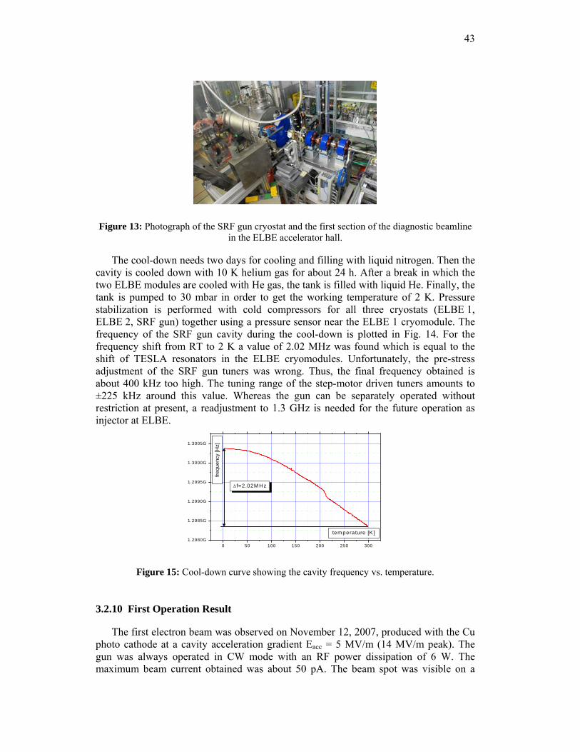
43
Figure 13: Photograph of the SRF gun cryostat and the first section of the diagnostic beamline in the ELBE accelerator hall.
The cool-down needs two days for cooling and filling with liquid nitrogen. Then the cavity is cooled down with 10 K helium gas for about 24 h. After a break in which the two ELBE modules are cooled with He gas, the tank is filled with liquid He. Finally, the tank is pumped to 30 mbar in order to get the working temperature of 2 K. Pressure stabilization is performed with cold compressors for all three cryostats (ELBE 1, ELBE 2, SRF gun) together using a pressure sensor near the ELBE 1 cryomodule. The frequency of the SRF gun cavity during the cool-down is plotted in Fig. 14. For the frequency shift from RT to 2 K a value of 2.02 MHz was found which is equal to the shift of TESLA resonators in the ELBE cryomodules. Unfortunately, the pre-stress adjustment of the SRF gun tuners was wrong. Thus, the final frequency obtained is about 400 kHz too high. The tuning range of the step-motor driven tuners amounts to ±225 kHz around this value. Whereas the gun can be separately operated without restriction at present, a readjustment to 1.3 GHz is needed for the future operation as injector at ELBE.
0 50 100 150 200 250 3001.2980G
1.2985G
1.2990G
1.2995G
1.3000G
1.3005G
frequ
ency
[Hz]
tem perature [K ]
Δ f=2.02M Hz
Figure 15: Cool-down curve showing the cavity frequency vs. temperature.
3.2.10 First Operation Result
The first electron beam was observed on November 12, 2007, produced with the Cu photo cathode at a cavity acceleration gradient Eacc = 5 MV/m (14 MV/m peak). The gun was always operated in CW mode with an RF power dissipation of 6 W. The maximum beam current obtained was about 50 pA. The beam spot was visible on a
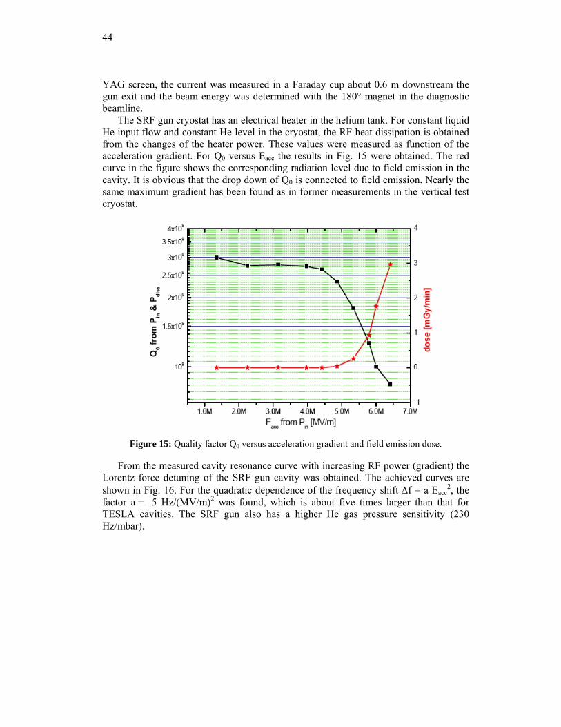
44
YAG screen, the current was measured in a Faraday cup about 0.6 m downstream the gun exit and the beam energy was determined with the 180° magnet in the diagnostic beamline.
The SRF gun cryostat has an electrical heater in the helium tank. For constant liquid He input flow and constant He level in the cryostat, the RF heat dissipation is obtained from the changes of the heater power. These values were measured as function of the acceleration gradient. For Q0 versus Eacc the results in Fig. 15 were obtained. The red curve in the figure shows the corresponding radiation level due to field emission in the cavity. It is obvious that the drop down of Q0 is connected to field emission. Nearly the same maximum gradient has been found as in former measurements in the vertical test cryostat.
Figure 15: Quality factor Q0 versus acceleration gradient and field emission dose.
From the measured cavity resonance curve with increasing RF power (gradient) the Lorentz force detuning of the SRF gun cavity was obtained. The achieved curves are shown in Fig. 16. For the quadratic dependence of the frequency shift Δf = a Eacc
2, the factor a = –5 Hz/(MV/m)2 was found, which is about five times larger than that for TESLA cavities. The SRF gun also has a higher He gas pressure sensitivity (230 Hz/mbar).
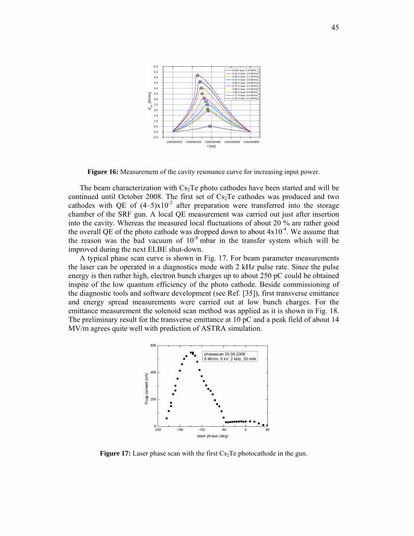
45
1300383000 1300383200 1300383400 1300383600 1300383800-0.5
0.0
0.5
1.0
1.5
2.0
2.5
3.0
3.5
4.0
4.5
5.0
5.5
6.0
E acc [
MV
/m]
f [Hz]
0,04V bzw. 0.5 MV/m 0.42 V bzw. 1.9 MV/m 0.48 V bzw. 2,1 MV/m 0.57 V bzw. 2.5 MV/m 0.66 V bzw. 2.8 MV/m 0.76 V bzw. 3.1 MV/m 0.86 V bzw. 3.5 MV/m 1.00 V bzw. 4.0 MV/m 1.17 V bzw. 4.6 MV/m 1.33 V bzw. 5.2 MV/m
Figure 16: Measurement of the cavity resonance curve for increasing input power.
The beam characterization with Cs2Te photo cathodes have been started and will be continued until October 2008. The first set of Cs2Te cathodes was produced and two cathodes with QE of (4–5)x10-2 after preparation were transferred into the storage chamber of the SRF gun. A local QE measurement was carried out just after insertion into the cavity. Whereas the measured local fluctuations of about 20 % are rather good the overall QE of the photo cathode was dropped down to about 4x10⁻⁴. We assume that the reason was the bad vacuum of 10-8 mbar in the transfer system which will be improved during the next ELBE shut-down.
A typical phase scan curve is shown in Fig. 17. For beam parameter measurements the laser can be operated in a diagnostics mode with 2 kHz pulse rate. Since the pulse energy is then rather high, electron bunch charges up to about 250 pC could be obtained inspite of the low quantum efficiency of the photo cathode. Beside commissioning of the diagnostic tools and software development (see Ref. [35]), first transverse emittance and energy spread measurements were carried out at low bunch charges. For the emittance measurement the solenoid scan method was applied as it is shown in Fig. 18. The preliminary result for the transverse emittance at 10 pC and a peak field of about 14 MV/m agrees quite well with prediction of ASTRA simulation.
Figure 17: Laser phase scan with the first Cs2Te photocathode in the gun.
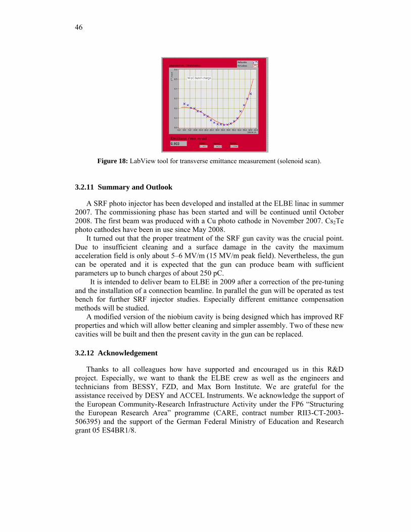
46
Figure 18: LabView tool for transverse emittance measurement (solenoid scan).
3.2.11 Summary and Outlook
A SRF photo injector has been developed and installed at the ELBE linac in summer 2007. The commissioning phase has been started and will be continued until October 2008. The first beam was produced with a Cu photo cathode in November 2007. Cs2Te photo cathodes have been in use since May 2008.
It turned out that the proper treatment of the SRF gun cavity was the crucial point. Due to insufficient cleaning and a surface damage in the cavity the maximum acceleration field is only about 5–6 MV/m (15 MV/m peak field). Nevertheless, the gun can be operated and it is expected that the gun can produce beam with sufficient parameters up to bunch charges of about 250 pC.
It is intended to deliver beam to ELBE in 2009 after a correction of the pre-tuning and the installation of a connection beamline. In parallel the gun will be operated as test bench for further SRF injector studies. Especially different emittance compensation methods will be studied.
A modified version of the niobium cavity is being designed which has improved RF properties and which will allow better cleaning and simpler assembly. Two of these new cavities will be built and then the present cavity in the gun can be replaced.
3.2.12 Acknowledgement
Thanks to all colleagues how have supported and encouraged us in this R&D project. Especially, we want to thank the ELBE crew as well as the engineers and technicians from BESSY, FZD, and Max Born Institute. We are grateful for the assistance received by DESY and ACCEL Instruments. We acknowledge the support of the European Community-Research Infrastructure Activity under the FP6 “Structuring the European Research Area” programme (CARE, contract number RII3-CT-2003-506395) and the support of the German Federal Ministry of Education and Research grant 05 ES4BR1/8.
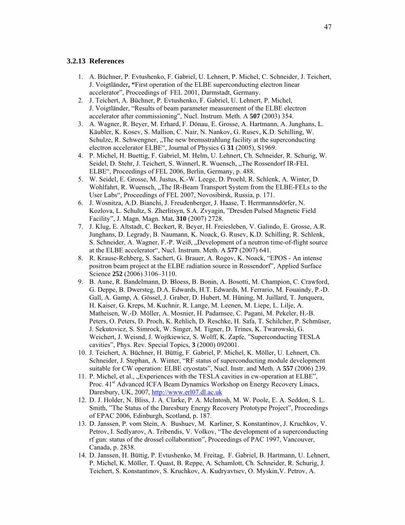
47
3.2.13 References
1. A. Büchner, P. Evtushenko, F. Gabriel, U. Lehnert, P. Michel, C. Schneider, J. Teichert, J. Voigtländer, “First operation of the ELBE superconducting electron linear accelerator”, Proceedings of FEL 2001, Darmstadt, Germany.
2. J. Teichert, A. Büchner, P. Evtushenko, F. Gabriel, U. Lehnert, P. Michel, J. Voigtländer, “Results of beam parameter measurement of the ELBE electron accelerator after commissioning”, Nucl. Instrum. Meth. A 507 (2003) 354.
3. A. Wagner, R. Beyer, M. Erhard, F. Dönau, E. Grosse, A. Hartmann, A. Junghans, L. Käubler, K. Kosev, S. Mallion, C. Nair, N. Nankov, G. Rusev, K.D. Schilling, W. Schulze, R. Schwengner, „The new bremsstrahlung facility at the superconducting electron accelerator ELBE“, Journal of Physics G 31 (2005), S1969.
4. P. Michel, H. Buettig, F. Gabriel, M. Helm, U. Lehnert, Ch. Schneider, R. Schurig, W. Seidel, D. Stehr, J. Teichert, S. Winnerl, R. Wuensch, „The Rossendorf IR-FEL ELBE“, Proceedings of FEL 2006, Berlin, Germany, p. 488.
5. W. Seidel, E. Grosse, M. Justus, K.-W. Leege, D. Proehl, R. Schlenk, A. Winter, D. Wohlfahrt, R. Wuensch, „The IR-Beam Transport System from the ELBE-FELs to the User Labs“, Proceedings of FEL 2007, Novosibirsk, Russia, p. 171.
6. J. Wosnitza, A.D. Bianchi, J. Freudenberger, J. Haase, T. Herrmannsdörfer, N. Kozlova, L. Schultz, S. Zherlitsyn, S.A. Zvyagin, ”Dresden Pulsed Magnetic Field Facility”, J. Magn. Magn. Mat. 310 (2007) 2728.
7. J. Klug, E. Altstadt, C. Beckert, R. Beyer, H. Freiesleben, V. Galindo, E. Grosse, A.R. Junghans, D. Legrady, B. Naumann, K. Noack, G. Rusev, K.D. Schilling, R. Schlenk, S. Schneider, A. Wagner, F.-P. Weiß, „Development of a neutron time-of-flight source at the ELBE accelerator“, Nucl. Instrum. Meth. A 577 (2007) 641.
8. R. Krause-Rehberg, S. Sachert, G. Brauer, A. Rogov, K. Noack, “EPOS - An intense positron beam project at the ELBE radiation source in Rossendorf”, Applied Surface Science 252 (2006) 3106–3110.
9. B. Aune, R. Bandelmann, D. Bloess, B. Bonin, A. Bosotti, M. Champion, C. Crawford, G. Deppe, B. Dwersteg, D.A. Edwards, H.T. Edwards, M. Ferrario, M. Fouaindy, P.-D. Gall, A. Gamp, A. Gössel, J. Graber, D. Hubert, M. Hüning, M. Juillard, T. Junquera, H. Kaiser, G. Kreps, M. Kuchnir, R. Lange, M. Leenen, M. Liepe, L. Lilje, A. Matheisen, W.-D. Möller, A. Mosnier, H. Padamsee, C. Pagani, M. Pekeler, H.-B. Peters, O. Peters, D. Proch, K. Rehlich, D. Reschke, H. Safa, T. Schilcher, P. Schmüser, J. Sekutovicz, S. Simrock, W. Singer, M. Tigner, D. Trines, K. Twarowski, G. Weichert, J. Weisnd, J. Wojtkiewicz, S. Wolff, K. Zapfe, ”Superconducting TESLA cavities”, Phys. Rev. Special Topics, 3 (2000) 092001.
10. J. Teichert, A. Büchner, H. Büttig, F. Gabriel, P. Michel, K. Möller, U. Lehnert, Ch. Schneider, J. Stephan, A. Winter, “RF status of superconducting module development suitable for CW operation: ELBE cryostats”, Nucl. Instr. and Meth. A 557 (2006) 239.
11. P. Michel, et al., „Experiences with the TESLA cavities in cw-operation at ELBE”, Proc. 41st Advanced ICFA Beam Dynamics Workshop on Energy Recovery Linacs, Daresbury, UK, 2007, http://www.erl07.dl.ac.uk
12. D. J. Holder, N. Bliss, J. A. Clarke, P. A. McIntosh, M. W. Poole, E. A. Seddon, S. L. Smith, ”The Status of the Daresbury Energy Recovery Prototype Project”, Proceedings of EPAC 2006, Edinburgh, Scotland, p. 187.
13. D. Janssen, P. vom Stein, A. Bushuev, M. Karliner, S. Konstantinov, J. Kruchkov, V. Petrov, I. Sedlyarov, A. Tribendis, V. Volkov, “The development of a superconducting rf gun: status of the drossel collaboration”, Proceedings of PAC 1997, Vancouver, Canada, p. 2838.
14. D. Janssen, H. Büttig, P. Evtushenko, M. Freitag, F. Gabriel, B. Hartmann, U. Lehnert, P. Michel, K. Möller, T. Quast, B. Reppe, A. Schamlott, Ch. Schneider, R. Schurig, J. Teichert, S. Konstantinov, S. Kruchkov, A. Kudryavtsev, O. Myskin,V. Petrov, A.
48
Tribendis, V. Volkov, W. Sandner, I. Will, A. Matheisen, W. Moeller, M. Pekeler, P. vom Stein, Ch. Haberstroh, “First operation of a superconducting RF gun”, Nucl. Instr. and Meth. A 507 (2003) 314.
15. D. H. Dowell, S. Z. Bethel, K. D. Friddell, “Results from the average power laser experiment photocathode injector test”, Nucl. Instr. and Meth. A 356 (1995) 167.
16. D. H. Dowell, K. J. Davis, K. D. Friddell, E. L. Tyson, C. A. Lancaster, L. Milliman, R. E. Rodenburg, T. Aas, M. Bemes, S. Z. Bethel, P. E. Johnson, K. Murphy, C. Whelen, G. E. Busch, D. K. Remelius, “ First operation of a photocathode radio frequency gun injector at high duty factor”, Appl. Phys. Lett. 63 (1993) 2035.
17. D. C. Nguyen, P. L. Colestock, S. S. Kurennoy, D. E. Rees, A. H. Regan, S. Russell, D. L. Schrage, R. L. Wood, L. M. Young, T. Schultheiss, V. Christina, M. Cole, J. Rathke, J. Shaw, C. Eddy, R. Holm, R. Henry, J. Yater, “ Overview of the 100 mA average-current RF photoinjector”, Nucl. Instrum. Meth. A 528 (2004), 71-77.
18. F. Marhauser, “High Power Tests of a High Duty Cycle, High Repetition Rate RF Photoinjector Gun for the BESSY FEL”, Proc. of EPAC 2006, Edinburgh, Scotland, p. 68.
19. X. Chang, I. Ben-Zvi, J. Kewisch, C.-I. Pai, “High Average Current Low Emittance Beam Employing CW Normal Conducting Gun”, Proc. of PAC07, Albuquerque, New Mexico, USA, p. 2547.
20. C. Hernandez-Garcia, K. Beard, S. Benson, G. Biallas, D. Bullard, D. Douglas, H.F. Dylla, R. Evans, A. Grippo, J. Gubeli, K. Jordan, G. Neil, M. Shinn, T. Siggins, R. Walker, B. Yunn, S. Zhang, “Performance and Modeling of the JLab IR FEL Upgrade Injector”, Proc. of the 2004 FEL Conference, Trieste, Italy, 2004, p. 558.
21. C. K. Sinclair, “A 500 kV photoemission electron gun for the CEBAF FEL” Nucl. Instr. and Meth. A 318 (1992) 410.
22. A. Todd, “State-of-the-art electron guns and injector designs for energy recovery linacs (ERL)”, Nucl. Instr. and Meth. A 557 (2006) 36.
23. B.M. Dunham, C.K. Sinclair, I.V. Bazarov, Y. Li, K.W. Smolenski, “Performance of a Very High Voltage Photoemission Electron Gun for a High Brightness, High Average Current ERL Injector”, Proceedings of PAC07, Albuquerque, New Mexico, USA, p. 1224.
24. H. Piel et al., Proceedings of FEL 1988, Jerusalem, Israel, 1988. 25. A. Michalke, H. Piel, C.K. Sinclair, P. Michelato, “First Operation of High-Quantum
Efficiency Photocathodes Inside Superconducting Cavities”, Proceedings of EPAC 1992, Berlin, Germany, p. 1014.
26. A. Michalke, “Photocathodes inside a Super-conducting Cavity”, PhD thesis, University of Wuppertal, 1993, WUB-DIS 92-5.
27. P. vom Stein, “Hochfrequenz Elektroneninjektoren für cw-Beschleuniger”, PhD thesis, Dresden University of Technology , 1998, Report FZR-227.
28. E. Barthels, H. Büttig, F. Gabriel, E. Grosse, D. Janssen, A. Bushuev, M. Karliner, S. Konstantinov, S. Kruchkov, O. Myshkin, V. Petrov, I. Sedlyarrov, A. Tribendis, V. Volkov, W. Sandner, I. Will, P. vom Stein, H. Vogel, A. Matheisen, M. Pekeler, Ch. Haberstroh, A. Thiel,”On the way to a superconducting RF gun: first measurments with the gun cavity”, Nucl. Instr. and Meth. A 445 (2000) 408.
29. “The BESSY Soft X-ray Free Electron Laser”, TDR BESSY March 2004, eds.: D.Krämer, E. Jaeschke, W. Eberhardt, ISBN 3-9809534-0-8, Berlin (2004).
30. A. Arnold, H. Büttig, D. Janssen, U. Lehnert, P. Michel, K. Möller, P. Murcek, Ch. Schneider, R. Schurig, F. Staufenbiel, J. Teichert, R. Xiang, T. Kamps, D. Lipka F. Marhauser, W.-D. Lehmann, J. Stephan, V. Volkov, I. Will, G. Klemz, „Development of a superconducting radio frequency photo injector”, Nucl. Instr. and Meth. A 577 (2007) 440.
31. Lu Xiangyang, “Progress of SRF and ERL at Peking University”, BILCW07, IHEP, Beijing, China, 2007, http://bilcw07.ihep.ac.cn
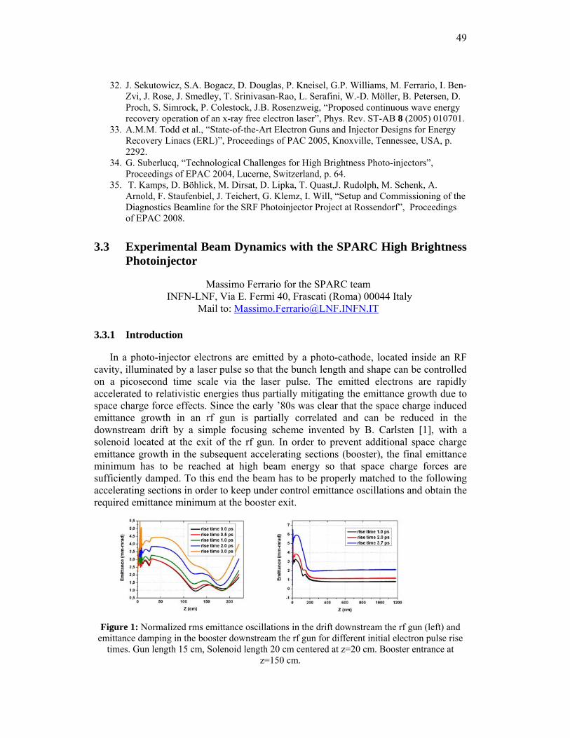
49
32. J. Sekutowicz, S.A. Bogacz, D. Douglas, P. Kneisel, G.P. Williams, M. Ferrario, I. Ben-Zvi, J. Rose, J. Smedley, T. Srinivasan-Rao, L. Serafini, W.-D. Möller, B. Petersen, D. Proch, S. Simrock, P. Colestock, J.B. Rosenzweig, “Proposed continuous wave energy recovery operation of an x-ray free electron laser”, Phys. Rev. ST-AB 8 (2005) 010701.
33. A.M.M. Todd et al., “State-of-the-Art Electron Guns and Injector Designs for Energy Recovery Linacs (ERL)”, Proceedings of PAC 2005, Knoxville, Tennessee, USA, p. 2292.
34. G. Suberlucq, “Technological Challenges for High Brightness Photo-injectors”, Proceedings of EPAC 2004, Lucerne, Switzerland, p. 64.
35. T. Kamps, D. Böhlick, M. Dirsat, D. Lipka, T. Quast,J. Rudolph, M. Schenk, A. Arnold, F. Staufenbiel, J. Teichert, G. Klemz, I. Will, “Setup and Commissioning of the Diagnostics Beamline for the SRF Photoinjector Project at Rossendorf”, Proceedings of EPAC 2008.
3.3 Experimental Beam Dynamics with the SPARC High Brightness Photoinjector
Massimo Ferrario for the SPARC team INFN-LNF, Via E. Fermi 40, Frascati (Roma) 00044 Italy
Mail to: [email protected]
3.3.1 Introduction
In a photo-injector electrons are emitted by a photo-cathode, located inside an RF cavity, illuminated by a laser pulse so that the bunch length and shape can be controlled on a picosecond time scale via the laser pulse. The emitted electrons are rapidly accelerated to relativistic energies thus partially mitigating the emittance growth due to space charge force effects. Since the early ’80s was clear that the space charge induced emittance growth in an rf gun is partially correlated and can be reduced in the downstream drift by a simple focusing scheme invented by B. Carlsten [1], with a solenoid located at the exit of the rf gun. In order to prevent additional space charge emittance growth in the subsequent accelerating sections (booster), the final emittance minimum has to be reached at high beam energy so that space charge forces are sufficiently damped. To this end the beam has to be properly matched to the following accelerating sections in order to keep under control emittance oscillations and obtain the required emittance minimum at the booster exit.
Figure 1: Normalized rms emittance oscillations in the drift downstream the rf gun (left) and
emittance damping in the booster downstream the rf gun for different initial electron pulse rise times. Gun length 15 cm, Solenoid length 20 cm centered at z=20 cm. Booster entrance at
z=150 cm.
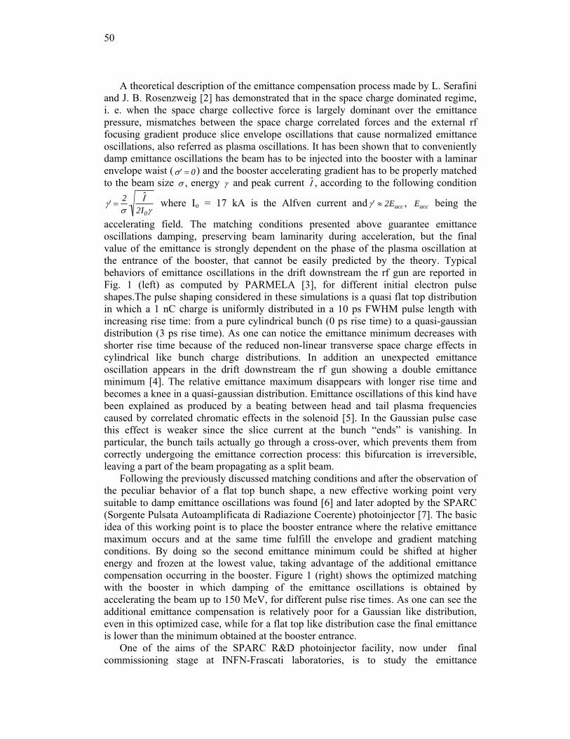
50
A theoretical description of the emittance compensation process made by L. Serafini and J. B. Rosenzweig [2] has demonstrated that in the space charge dominated regime, i. e. when the space charge collective force is largely dominant over the emittance pressure, mismatches between the space charge correlated forces and the external rf focusing gradient produce slice envelope oscillations that cause normalized emittance oscillations, also referred as plasma oscillations. It has been shown that to conveniently damp emittance oscillations the beam has to be injected into the booster with a laminar envelope waist ( ′ σ = 0) and the booster accelerating gradient has to be properly matched to the beam size σ , energy γ and peak current ˆ Ι , according to the following condition
′ γ =2σ
ˆ Ι 2I0γ
where Io = 17 kA is the Alfven current and ′ γ ≈ 2Eacc , Eacc being the
accelerating field. The matching conditions presented above guarantee emittance oscillations damping, preserving beam laminarity during acceleration, but the final value of the emittance is strongly dependent on the phase of the plasma oscillation at the entrance of the booster, that cannot be easily predicted by the theory. Typical behaviors of emittance oscillations in the drift downstream the rf gun are reported in Fig. 1 (left) as computed by PARMELA [3], for different initial electron pulse shapes.The pulse shaping considered in these simulations is a quasi flat top distribution in which a 1 nC charge is uniformly distributed in a 10 ps FWHM pulse length with increasing rise time: from a pure cylindrical bunch (0 ps rise time) to a quasi-gaussian distribution (3 ps rise time). As one can notice the emittance minimum decreases with shorter rise time because of the reduced non-linear transverse space charge effects in cylindrical like bunch charge distributions. In addition an unexpected emittance oscillation appears in the drift downstream the rf gun showing a double emittance minimum [4]. The relative emittance maximum disappears with longer rise time and becomes a knee in a quasi-gaussian distribution. Emittance oscillations of this kind have been explained as produced by a beating between head and tail plasma frequencies caused by correlated chromatic effects in the solenoid [5]. In the Gaussian pulse case this effect is weaker since the slice current at the bunch “ends” is vanishing. In particular, the bunch tails actually go through a cross-over, which prevents them from correctly undergoing the emittance correction process: this bifurcation is irreversible, leaving a part of the beam propagating as a split beam.
Following the previously discussed matching conditions and after the observation of the peculiar behavior of a flat top bunch shape, a new effective working point very suitable to damp emittance oscillations was found [6] and later adopted by the SPARC (Sorgente Pulsata Autoamplificata di Radiazione Coerente) photoinjector [7]. The basic idea of this working point is to place the booster entrance where the relative emittance maximum occurs and at the same time fulfill the envelope and gradient matching conditions. By doing so the second emittance minimum could be shifted at higher energy and frozen at the lowest value, taking advantage of the additional emittance compensation occurring in the booster. Figure 1 (right) shows the optimized matching with the booster in which damping of the emittance oscillations is obtained by accelerating the beam up to 150 MeV, for different pulse rise times. As one can see the additional emittance compensation is relatively poor for a Gaussian like distribution, even in this optimized case, while for a flat top like distribution case the final emittance is lower than the minimum obtained at the booster entrance.
One of the aims of the SPARC R&D photoinjector facility, now under final commissioning stage at INFN-Frascati laboratories, is to study the emittance
51
compensation process through accurate comparison between measurements and simulations, as will be described in the next sections. More advanced application, like the Single Spike SASE FEL mode and the Laser Comb scheme are described in [20,21].
3.3.2 The SPARC Facility
The SPARC project comprises an R&D photo-injector facility devoted to the production of high brightness electron beams to drive a SASE-FEL experiment in the visible light and SASE@Seeding HHG tests [8] at 266, 160, 114 nm. The SPARC schematic layout is shown in Fig. 2.It is also the test prototype of the injector of the recently approved SPARX Project [9] aiming to generate radiation in the range of 13.5-4 nm and 6-1 nm, at 1.5 and 2.4 GeV respectively. The first phase of the SPARC project, that is now concluded, consisted in characterizing the electron beam out of the photoinjector, a 1.6 cell S-band RF gun, at low energy (~5.6 MeV with 120 MV/m peak field on the cathode), before the installation of the 3 S-band accelerating sections, located after a drift downstream the rf gun (the so called split configuration), which now boost the beam energy up to 150-200 MeV. In order to study the first few meters of beam propagation a new sophisticated diagnostic tool has been installed and commissioned: the movable emittance-meter described in [10]. This device has allowed measuring the evolution of beam sizes, energy spread, rms transverse emittances and transverse phase space at different locations along the beamline, the so called Z-scan, in the range 1 m to 2.1 m from the cathode location [11]. The SPARC laser is composed by a Ti:Sa oscillator generating 100 fs long pulses with a repetition rate of 79.3 MHz and an energy of 10 nJ, as described in [12]. An acousto-optic programmable dispersive filter called “DAZZLER” [13] used to modify the spectral amplitude and phase function, is placed between the oscillator and the amplifier to obtain the target temporal profile, thus allowing us to study beam dynamics with different pulse shapes.
Figure 2: Schematic SPARC layout
In the second phase of the SPARC commissioning the emittance meter has been removed and three SLAC-type traveling waves sections has been installed, accelerating the beam up to 150-200 MeV a 1-nC–10-ps beam with a nominal projected emittance ≤ 2 mm-mrad and a slice emittance ≤ 1 mm-mrad.. The first two accelerating sections are embedded in a 3 m long solenoid field in order to keep under control the beam envelope matching with the linac and the emittance, in particular during “velocity bunching” experiments.
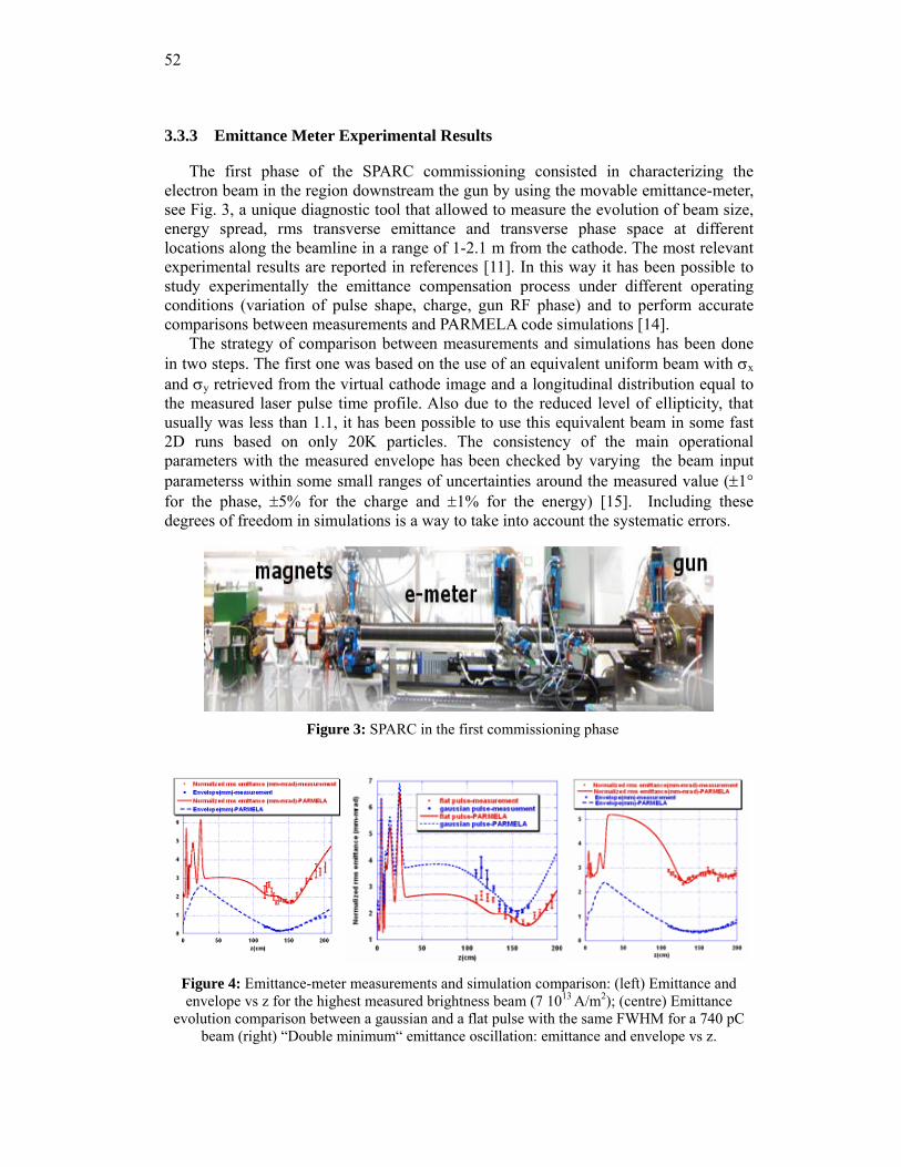
52
3.3.3 Emittance Meter Experimental Results
The first phase of the SPARC commissioning consisted in characterizing the electron beam in the region downstream the gun by using the movable emittance-meter, see Fig. 3, a unique diagnostic tool that allowed to measure the evolution of beam size, energy spread, rms transverse emittance and transverse phase space at different locations along the beamline in a range of 1-2.1 m from the cathode. The most relevant experimental results are reported in references [11]. In this way it has been possible to study experimentally the emittance compensation process under different operating conditions (variation of pulse shape, charge, gun RF phase) and to perform accurate comparisons between measurements and PARMELA code simulations [14].
The strategy of comparison between measurements and simulations has been done in two steps. The first one was based on the use of an equivalent uniform beam with σx and σy retrieved from the virtual cathode image and a longitudinal distribution equal to the measured laser pulse time profile. Also due to the reduced level of ellipticity, that usually was less than 1.1, it has been possible to use this equivalent beam in some fast 2D runs based on only 20K particles. The consistency of the main operational parameters with the measured envelope has been checked by varying the beam input parameterss within some small ranges of uncertainties around the measured value (±1° for the phase, ±5% for the charge and ±1% for the energy) [15]. Including these degrees of freedom in simulations is a way to take into account the systematic errors.
Figure 3: SPARC in the first commissioning phase
Figure 4: Emittance-meter measurements and simulation comparison: (left) Emittance and envelope vs z for the highest measured brightness beam (7 1013 A/m2); (centre) Emittance
evolution comparison between a gaussian and a flat pulse with the same FWHM for a 740 pC beam (right) “Double minimum“ emittance oscillation: emittance and envelope vs z.
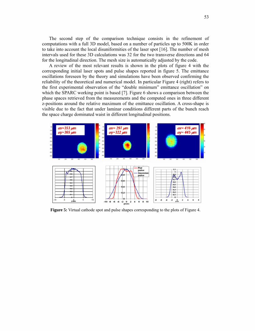
53
The second step of the comparison technique consists in the refinement of computations with a full 3D model, based on a number of particles up to 500K in order to take into account the local disuniformities of the laser spot [16]. The number of mesh intervals used for these 3D calculations was 32 for the two transverse directions and 64 for the longitudinal direction. The mesh size is automatically adjusted by the code.
A review of the most relevant results is shown in the plots of figure 4 with the corresponding initial laser spots and pulse shapes reported in figure 5. The emittance oscillations foreseen by the theory and simulations have been observed confirming the reliability of the theoretical and numerical model. In particular Figure 4 (right) refers to the first experimental observation of the “double minimum” emittance oscillation” on which the SPARC working point is based [7]. Figure 6 shows a comparison between the phase spaces retrieved from the measurements and the computed ones in three different z-positions around the relative maximum of the emittance oscillation. A cross-shape is visible due to the fact that under laminar conditions different parts of the bunch reach the space charge dominated waist in different longitudinal positions.
Figure 5: Virtual cathode spot and pulse shapes corresponding to the plots of Figure 4.
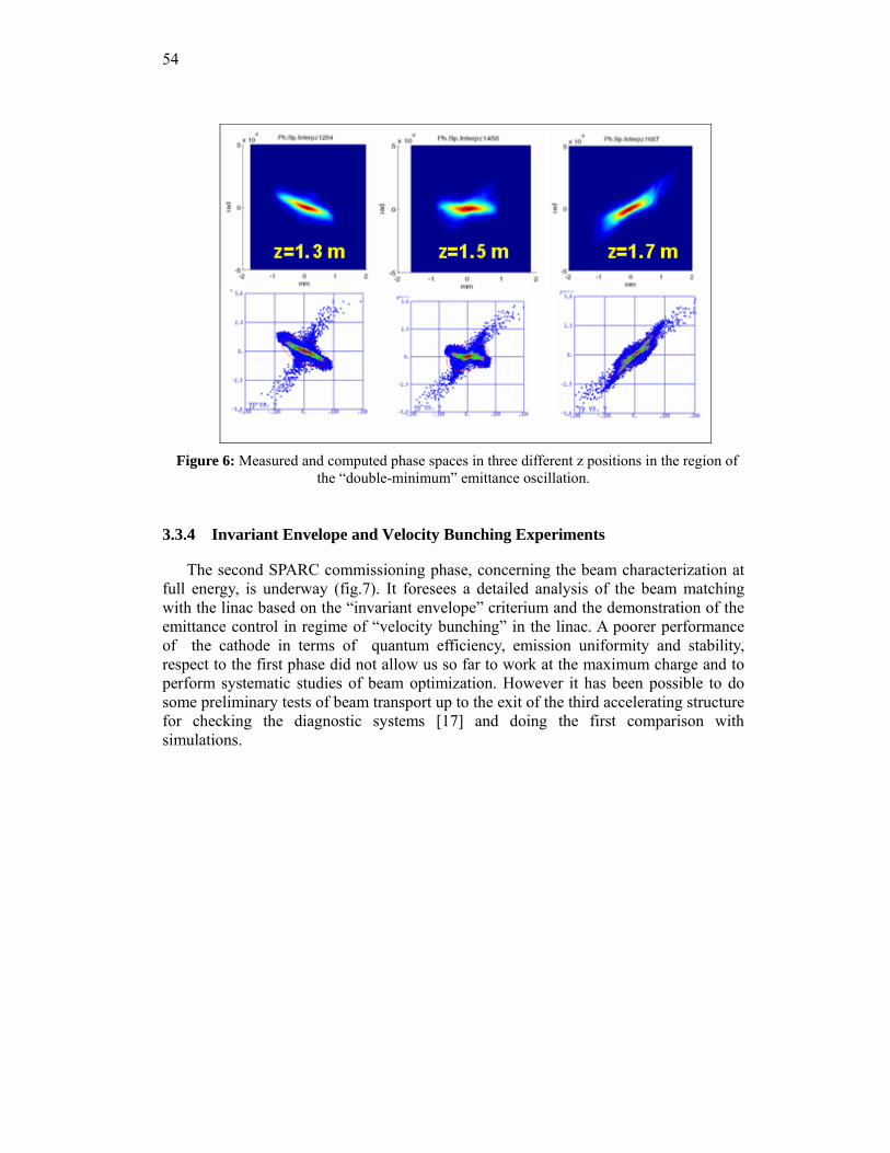
54
Figure 6: Measured and computed phase spaces in three different z positions in the region of
the “double-minimum” emittance oscillation.
3.3.4 Invariant Envelope and Velocity Bunching Experiments
The second SPARC commissioning phase, concerning the beam characterization at full energy, is underway (fig.7). It foresees a detailed analysis of the beam matching with the linac based on the “invariant envelope” criterium and the demonstration of the emittance control in regime of “velocity bunching” in the linac. A poorer performance of the cathode in terms of quantum efficiency, emission uniformity and stability, respect to the first phase did not allow us so far to work at the maximum charge and to perform systematic studies of beam optimization. However it has been possible to do some preliminary tests of beam transport up to the exit of the third accelerating structure for checking the diagnostic systems [17] and doing the first comparison with simulations.
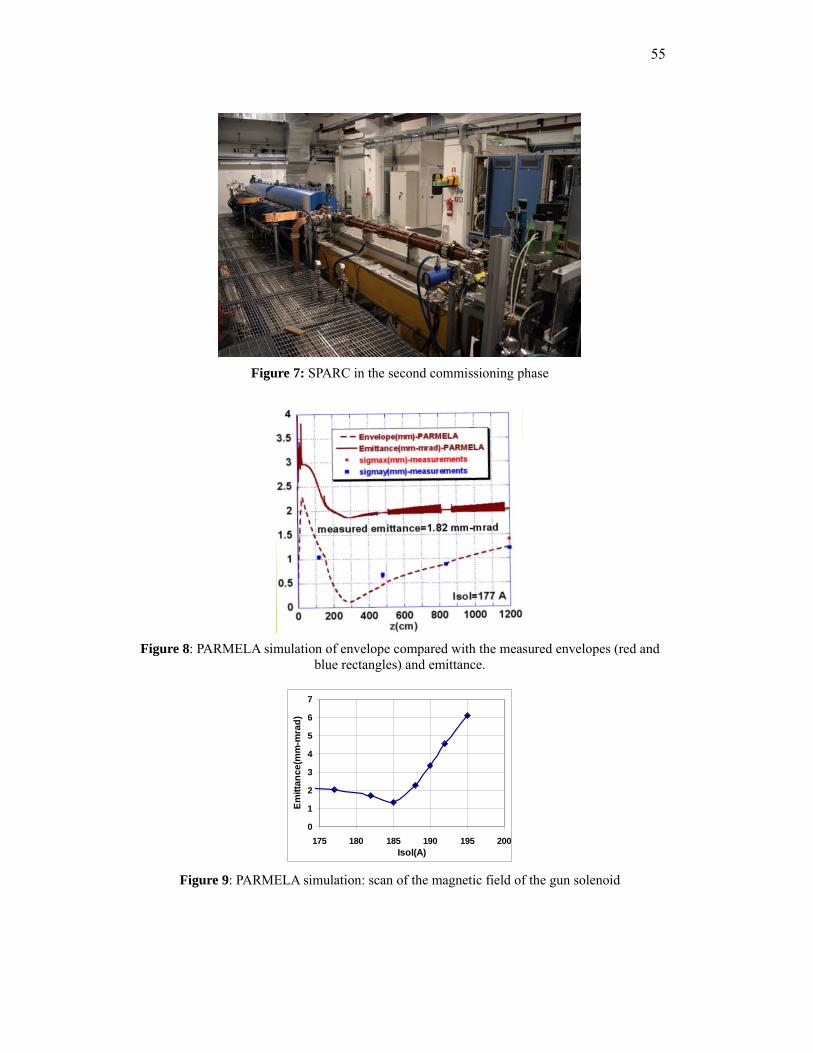
55
Figure 7: SPARC in the second commissioning phase
Figure 8: PARMELA simulation of envelope compared with the measured envelopes (red and
blue rectangles) and emittance.
0
1
2
3
4
5
6
7
175 180 185 190 195 200Isol(A)
Emitt
ance
(mm
-mra
d)
Figure 9: PARMELA simulation: scan of the magnetic field of the gun solenoid
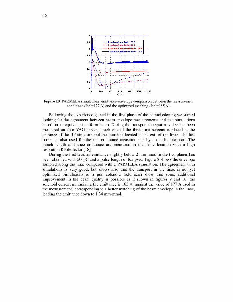
56
Figure 10: PARMELA simulations: emittance-envelope comparison between the measurement
conditions (Isol=177 A) and the optimized maching (Isol=185 A).
Following the experience gained in the first phase of the commissioning we started looking for the agreement between beam envelope measurements and fast simulations based on an equivalent uniform beam. During the transport the spot rms size has been measured on four YAG screens: each one of the three first screens is placed at the entrance of the RF structure and the fourth is located at the exit of the linac. The last screen is also used for the rms emittance measurements by a quadrupole scan. The bunch length and slice emittance are measured in the same location with a high resolution RF deflector [18].
During the first tests an emittance slightly below 2 mm-mrad in the two planes has been obtained with 500pC and a pulse length of 8.5 psec. Figure 8 shows the envelope sampled along the linac compared with a PARMELA simulation. The agreement with simulations is very good, but shows also that the transport in the linac is not yet optimized Simulations of a gun solenoid field scan show that some additional improvement in the beam quality is possible as it shown in figures 9 and 10: the solenoid current minimizing the emittance is 185 A (against the value of 177 A used in the measurement) corresponding to a better matching of the beam envelope in the linac, leading the emittance down to 1.34 mm-mrad.
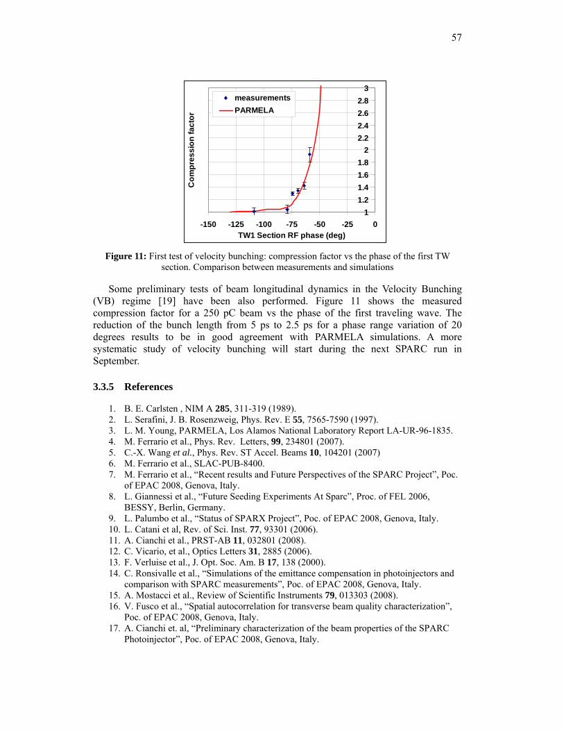
57
11.21.41.61.8
22.22.42.62.8
3
-150 -125 -100 -75 -50 -25 0TW1 Section RF phase (deg)
Com
pres
sion
fact
or
measurementsPARMELA
Figure 11: First test of velocity bunching: compression factor vs the phase of the first TW
section. Comparison between measurements and simulations
Some preliminary tests of beam longitudinal dynamics in the Velocity Bunching (VB) regime [19] have been also performed. Figure 11 shows the measured compression factor for a 250 pC beam vs the phase of the first traveling wave. The reduction of the bunch length from 5 ps to 2.5 ps for a phase range variation of 20 degrees results to be in good agreement with PARMELA simulations. A more systematic study of velocity bunching will start during the next SPARC run in September.
3.3.5 References
1. B. E. Carlsten , NIM A 285, 311-319 (1989). 2. L. Serafini, J. B. Rosenzweig, Phys. Rev. E 55, 7565-7590 (1997). 3. L. M. Young, PARMELA, Los Alamos National Laboratory Report LA-UR-96-1835. 4. M. Ferrario et al., Phys. Rev. Letters, 99, 234801 (2007). 5. C.-X. Wang et al., Phys. Rev. ST Accel. Beams 10, 104201 (2007) 6. M. Ferrario et al., SLAC-PUB-8400. 7. M. Ferrario et al., “Recent results and Future Perspectives of the SPARC Project”, Poc.
of EPAC 2008, Genova, Italy. 8. L. Giannessi et al., “Future Seeding Experiments At Sparc”, Proc. of FEL 2006,
BESSY, Berlin, Germany. 9. L. Palumbo et al., “Status of SPARX Project”, Poc. of EPAC 2008, Genova, Italy. 10. L. Catani et al, Rev. of Sci. Inst. 77, 93301 (2006). 11. A. Cianchi et al., PRST-AB 11, 032801 (2008). 12. C. Vicario, et al., Optics Letters 31, 2885 (2006). 13. F. Verluise et al., J. Opt. Soc. Am. B 17, 138 (2000). 14. C. Ronsivalle et al., “Simulations of the emittance compensation in photoinjectors and
comparison with SPARC measurements”, Poc. of EPAC 2008, Genova, Italy. 15. A. Mostacci et al., Review of Scientific Instruments 79, 013303 (2008). 16. V. Fusco et al., “Spatial autocorrelation for transverse beam quality characterization”,
Poc. of EPAC 2008, Genova, Italy. 17. A. Cianchi et. al, “Preliminary characterization of the beam properties of the SPARC
Photoinjector”, Poc. of EPAC 2008, Genova, Italy.
58
18. C. Vaccarezza, “Slice emittance measurements at SPARC Photoinjector with a RF deflector”, Poc. of EPAC 2008, Genova, Italy.
19. L. Serafini and M. Ferrario, AIP Conference Proceedings 581, 87, (2001) 20. V. Petrillo et al., “Single spike operation in the SPARC SASE-FEL”, Proc. EPAC 2008,
Genova, Italy. 21. M. Boscolo et al., “A possible THz radiation source with a train of short pulses in the
SPARC high brightness photoinjector”, Proc. EPAC 2008, Genova, Italy.
3.4 Overview of Photoinjector R&D in the EUROFEL Collaboration
H. Duerr, F. Marhauser, BESSY, D. Garzella, G. Petite, CEA, H. Monard, U. Schmidhammer, CNRS, C. Boulware, F Stephan, DESY-Berlin, J. Feldhaus, U. Krell,
DESY-Hamburg, M. B. Danailov, R. Ivanov, ELETTRA, M. Quattromini, C. Ronsivalle, ENEA, M. Ferrario, L. Palumbo, INFN, G. Klemz, I. Will, MBI, D. J.
Holder, B. Muratori, STFC, W. F. O. Muller, TEMF, M. Migliorati, URLS. INFN-LNF, Via E. Fermi 40, Frascati (Roma) 00044 Italy
Mail to: [email protected]
3.4.1 Introduction
During the last few years Europe has made enormous progress towards free electron laser (FEL) based research infrastructures. The FLASH facility [1] at DESY in Hamburg, Germany, has been in user operation since summer 2005, and several other FEL projects are being prepared in France, Germany, Italy, Poland, Sweden, Switzerland and the UK. Triggered by the funding programme of the European Commission (EC) for the development of new research infrastructures, 16 European institutions [2] have joined their forces to develop key technologies required for the design and construction of next generation free electron laser sources in Europe. This coordinated European effort has been supported as a Design Study - the European FEL Design Study EUROFEL [3,4], - by the EC’s 6th Framework Programme (Contract N. 011935) for a period of three years, ended December 2007.
Figure 1: Logo of the EUROFEL collaboration
The EUROFEL project focused on electron injectors (DS1), beam dynamics (DS2), synchronization (DS3), seeding and harmonic generation (DS4), high duty-cycle superconducting accelerators (DS5), and technology transfer to industry for the production of complete superconducting accelerator modules (DS6). Almost 200 person-years were spent on this work, 115 of which were funded by the EC giving many young scientists the opportunity to participate in exciting fore-front research in an international collaboration. The present article reviews the objectives and main results of the DS1 EUROFEL work packages devoted to photoinjectors R&D.
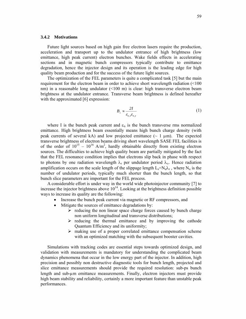
59
3.4.2 Motivations
Future light sources based on high gain free electron lasers require the production, acceleration and transport up to the undulator entrance of high brightness (low emittance, high peak current) electron bunches. Wake fields effects in accelerating sections and in magnetic bunch compressors typically contribute to emittance degradation, hence the injector design and its operation is the leading edge for high quality beam production and for the success of the future light sources.
The optimization of the FEL parameters is quite a complicated task [5] but the main requirement for the electron beam in order to achieve short wavelength radiation (<100 nm) in a reasonable long undulator (<100 m) is clear: high transverse electron beam brightness at the undulator entrance. Transverse beam brightness is defined hereafter with the approximated [6] expression:
B⊥ ≈2I
εn,xεn,y
(1)
where I is the bunch peak current and εn is the bunch transverse rms normalized emittance. High brightness beam essentially means high bunch charge density (with peak currents of several kA) and low projected emittance (~ 1 μm). The expected transverse brightness of electron beams driving short wavelength SASE FEL facilities is of the order of 1015 – 1016 A/m2, hardly obtainable directly from existing electron sources. The difficulties to achieve high quality beam are partially mitigated by the fact that the FEL resonance condition implies that electrons slip back in phase with respect to photons by one radiation wavelength λr per undulator period λυ. Hence radiation amplification occurs on the scale length of the slippage length Ls=Nuλr , where Nu is the number of undulator periods, typically much shorter than the bunch length, so that bunch slice parameters are important for the FEL process.
A considerable effort is under way in the world wide photoinjector community [7] to increase the injector brightness above 1014. Looking at the brightness definition possible ways to increase its quality are the following:
• Increase the bunch peak current via magnetic or RF compressors, and • Mitigate the sources of emittance degradations by:
reducing the non linear space charge forces caused by bunch charge non uniform longitudinal and transverse distributions;
reducing the thermal emittance and by improving the cathode Quantum Efficiency and its uniformity;
making use of a proper correlated emittance compensation scheme with an optimized matching with the subsequent booster cavities.
Simulations with tracking codes are essential steps towards optimized design, and
validation with measurements is mandatory for understanding the complicated beam dynamics phenomena that occur in the low energy part of the injector. In addition, high precision and possibly non destructive diagnostic tools for bunch length, projected and slice emittance measurements should provide the required resolution: sub-ps bunch length and sub-μm emittance measurements. Finally, electron injectors must provide high beam stability and reliability, certainly a more important feature than unstable peak performances.
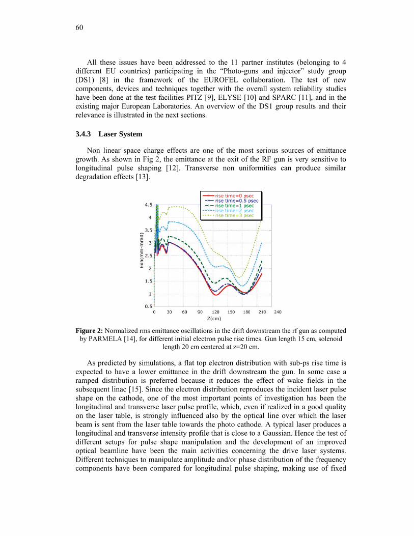
60
All these issues have been addressed to the 11 partner institutes (belonging to 4 different EU countries) participating in the “Photo-guns and injector” study group (DS1) [8] in the framework of the EUROFEL collaboration. The test of new components, devices and techniques together with the overall system reliability studies have been done at the test facilities PITZ [9], ELYSE [10] and SPARC [11], and in the existing major European Laboratories. An overview of the DS1 group results and their relevance is illustrated in the next sections.
3.4.3 Laser System
Non linear space charge effects are one of the most serious sources of emittance growth. As shown in Fig 2, the emittance at the exit of the RF gun is very sensitive to longitudinal pulse shaping [12]. Transverse non uniformities can produce similar degradation effects [13].
Figure 2: Normalized rms emittance oscillations in the drift downstream the rf gun as computed
by PARMELA [14], for different initial electron pulse rise times. Gun length 15 cm, solenoid length 20 cm centered at z=20 cm.
As predicted by simulations, a flat top electron distribution with sub-ps rise time is expected to have a lower emittance in the drift downstream the gun. In some case a ramped distribution is preferred because it reduces the effect of wake fields in the subsequent linac [15]. Since the electron distribution reproduces the incident laser pulse shape on the cathode, one of the most important points of investigation has been the longitudinal and transverse laser pulse profile, which, even if realized in a good quality on the laser table, is strongly influenced also by the optical line over which the laser beam is sent from the laser table towards the photo cathode. A typical laser produces a longitudinal and transverse intensity profile that is close to a Gaussian. Hence the test of different setups for pulse shape manipulation and the development of an improved optical beamline have been the main activities concerning the drive laser systems. Different techniques to manipulate amplitude and/or phase distribution of the frequency components have been compared for longitudinal pulse shaping, making use of fixed
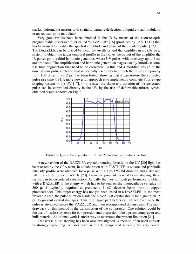
61
masks/ deformable mirrors with spatially variable deflection, a liquid-crystal modulator or an acousto-optic modulator.
Very good results have been obtained in the IR by means of the acousto-optic programmable dispersive filter called “DAZZLER” [16] (produced by FASTLITE) that has been used to modify the spectral amplitude and phase of the incident pulse [17,18]. The DAZZLER can be placed between the oscillator and the amplifier in a Ti:Sa laser system to obtain the target temporal profile in the IR. At the output of the amplifier the IR pulses go to a third harmonic generator, where UV pulses with an energy up to 4 mJ are produced. The amplification and harmonic generation stages usually introduce some rise time degradation that need to be corrected. To this end a modified design of the downstream pulse stretcher, that is normally used only to stretch the pulses temporally from 100 fs up to 8–12 ps, has been tested, showing that it can restore the corrected pulse rise time [19]. A more powerful approach is to implement a complete Fourie-type shaping system in the UV [17]. In this case, the shape and duration of the generated pulse can be controlled directly in the UV by the use of deformable mirror, typical obtained result is shown on Fig. 3.
Figure 3: Typical flat-top pulse of 10 FWHM duration with sub-ps rise time
A new version of the DAZZLER crystal operating directly on the UV [20] light has been tested by the CEA team, in collaboration with FASTLITE. A square and parabolic intensity profile were obtained for a pulse with a 3 ps FWHM duration and a rise and fall time of the order of 400 fs [20]. From the point of view of beam shaping, these results can be considered satisfactory. Actually the most difficult performance to obtain with a DAZZLER is the energy which has to be sent on the photocathode (a value of 500 µJ is typically required to produce a 1 nC electron beam from a copper photocathode). This target energy has not yet been tested in a DAZZLER. In the most favorable case, the pulse duration inside the DAZZLER crystal should be higher than 15 ps, to prevent crystal damages. Thus, the target parameters can be achieved once the pulse is stretched before the DAZZLER and then recompressed downstream. The main drawback of this method is the transmission of the compressor. One solution could be the use of lossless systems for compression and dispersion, like a prism compressor and bulk material. Additional work is under way to overcome the present limitation [21].
Transverse pulse shaping has been also investigated. A method often used consists in strongly expanding the laser beam with a telescope and selecting the very central
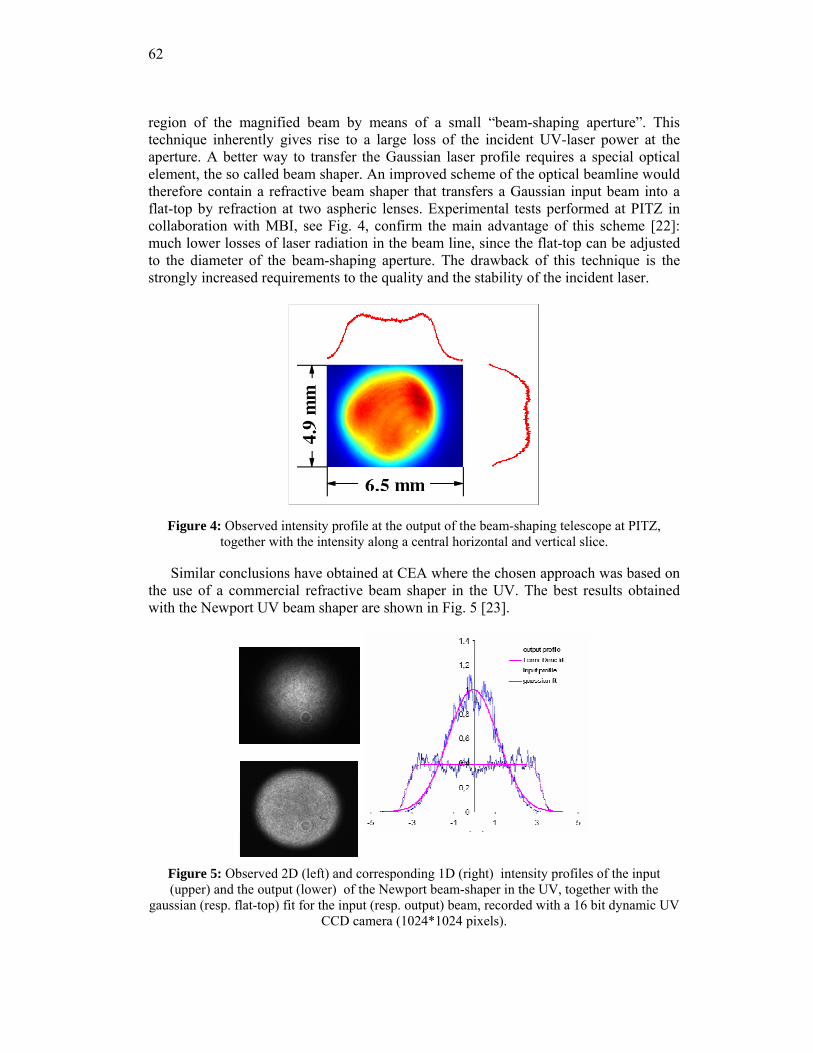
62
region of the magnified beam by means of a small “beam-shaping aperture”. This technique inherently gives rise to a large loss of the incident UV-laser power at the aperture. A better way to transfer the Gaussian laser profile requires a special optical element, the so called beam shaper. An improved scheme of the optical beamline would therefore contain a refractive beam shaper that transfers a Gaussian input beam into a flat-top by refraction at two aspheric lenses. Experimental tests performed at PITZ in collaboration with MBI, see Fig. 4, confirm the main advantage of this scheme [22]: much lower losses of laser radiation in the beam line, since the flat-top can be adjusted to the diameter of the beam-shaping aperture. The drawback of this technique is the strongly increased requirements to the quality and the stability of the incident laser.
Figure 4: Observed intensity profile at the output of the beam-shaping telescope at PITZ,
together with the intensity along a central horizontal and vertical slice.
Similar conclusions have obtained at CEA where the chosen approach was based on the use of a commercial refractive beam shaper in the UV. The best results obtained with the Newport UV beam shaper are shown in Fig. 5 [23].
Figure 5: Observed 2D (left) and corresponding 1D (right) intensity profiles of the input (upper) and the output (lower) of the Newport beam-shaper in the UV, together with the
gaussian (resp. flat-top) fit for the input (resp. output) beam, recorded with a 16 bit dynamic UV CCD camera (1024*1024 pixels).
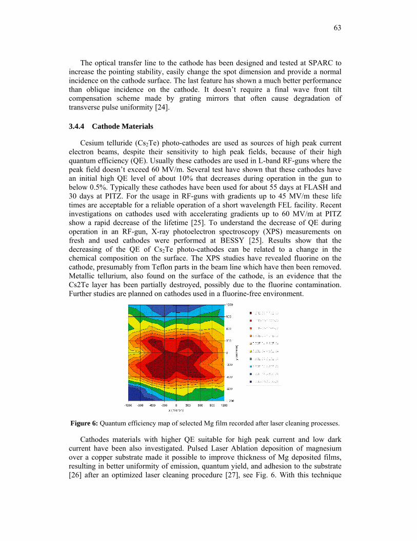
63
The optical transfer line to the cathode has been designed and tested at SPARC to increase the pointing stability, easily change the spot dimension and provide a normal incidence on the cathode surface. The last feature has shown a much better performance than oblique incidence on the cathode. It doesn’t require a final wave front tilt compensation scheme made by grating mirrors that often cause degradation of transverse pulse uniformity [24].
3.4.4 Cathode Materials
Cesium telluride (Cs2Te) photo-cathodes are used as sources of high peak current electron beams, despite their sensitivity to high peak fields, because of their high quantum efficiency (QE). Usually these cathodes are used in L-band RF-guns where the peak field doesn’t exceed 60 MV/m. Several test have shown that these cathodes have an initial high QE level of about 10% that decreases during operation in the gun to below 0.5%. Typically these cathodes have been used for about 55 days at FLASH and 30 days at PITZ. For the usage in RF-guns with gradients up to 45 MV/m these life times are acceptable for a reliable operation of a short wavelength FEL facility. Recent investigations on cathodes used with accelerating gradients up to 60 MV/m at PITZ show a rapid decrease of the lifetime [25]. To understand the decrease of QE during operation in an RF-gun, X-ray photoelectron spectroscopy (XPS) measurements on fresh and used cathodes were performed at BESSY [25]. Results show that the decreasing of the QE of Cs2Te photo-cathodes can be related to a change in the chemical composition on the surface. The XPS studies have revealed fluorine on the cathode, presumably from Teflon parts in the beam line which have then been removed. Metallic tellurium, also found on the surface of the cathode, is an evidence that the Cs2Te layer has been partially destroyed, possibly due to the fluorine contamination. Further studies are planned on cathodes used in a fluorine-free environment.
Figure 6: Quantum efficiency map of selected Mg film recorded after laser cleaning processes.
Cathodes materials with higher QE suitable for high peak current and low dark current have been also investigated. Pulsed Laser Ablation deposition of magnesium over a copper substrate made it possible to improve thickness of Mg deposited films, resulting in better uniformity of emission, quantum yield, and adhesion to the substrate [26] after an optimized laser cleaning procedure [27], see Fig. 6. With this technique
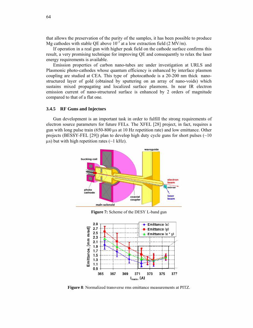
64
that allows the preservation of the purity of the samples, it has been possible to produce Mg cathodes with stable QE above 10-3 at a low extraction field (2 MV/m).
If operation in a real gun with higher peak field on the cathode surface confirms this result, a very promising technique for improving QE and consequently to relax the laser energy requirements is available.
Emission properties of carbon nano-tubes are under investigation at URLS and Plasmonic photo-cathodes whose quantum efficiency is enhanced by interface plasmon coupling are studied at CEA. This type of photocathode is a 20-200 nm thick nano-structured layer of gold (obtained by sputtering on an array of nano-voids) which sustains mixed propagating and localized surface plasmons. In near IR electron emission current of nano-structured surface is enhanced by 2 orders of magnitude compared to that of a flat one.
3.4.5 RF Guns and Injectors
Gun development is an important task in order to fulfill the strong requirements of electron source parameters for future FELs. The XFEL [28] project, in fact, requires a gun with long pulse train (650-800 μs at 10 Hz repetition rate) and low emittance. Other projects (BESSY-FEL [29]) plan to develop high duty cycle guns for short pulses (~10 μs) but with high repetition rates (~1 kHz).
Figure 7: Scheme of the DESY L-band gun
Figure 8: Normalized transverse rms emittance measurements at PITZ.
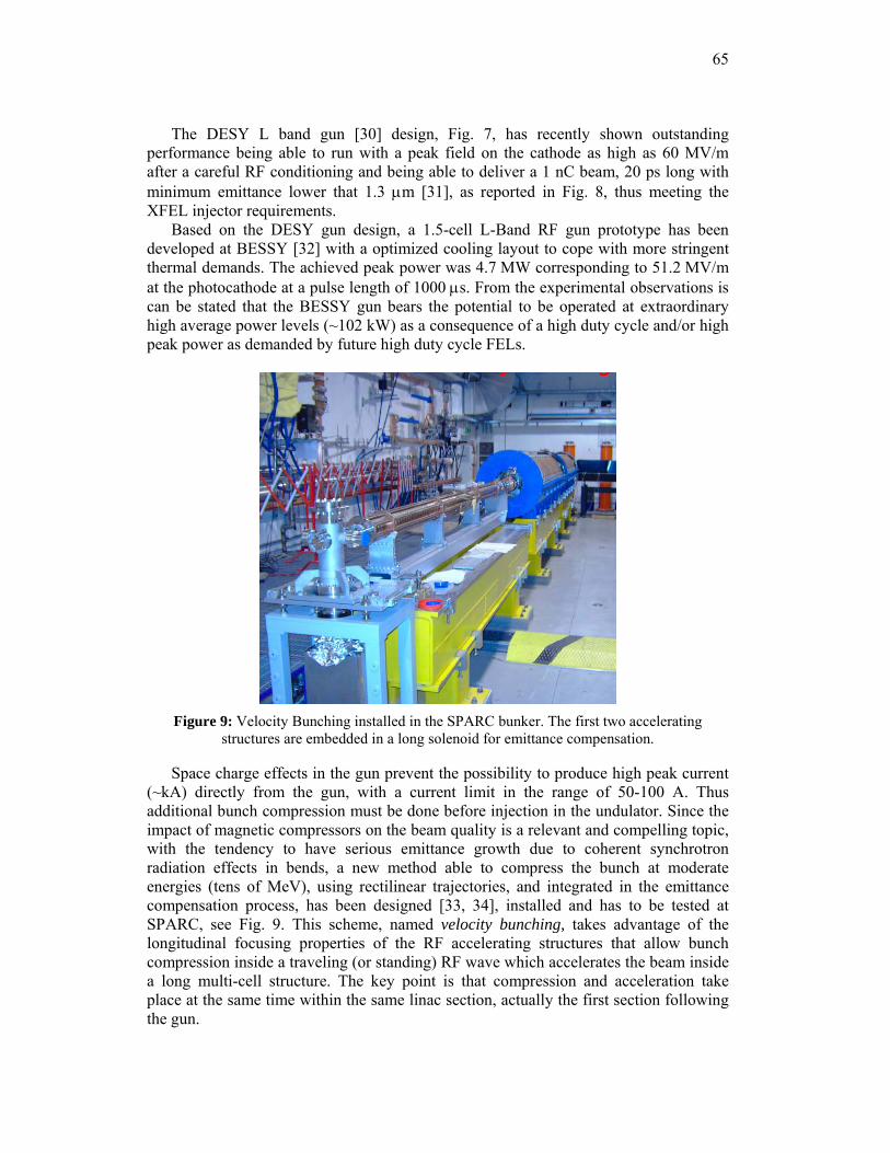
65
The DESY L band gun [30] design, Fig. 7, has recently shown outstanding performance being able to run with a peak field on the cathode as high as 60 MV/m after a careful RF conditioning and being able to deliver a 1 nC beam, 20 ps long with minimum emittance lower that 1.3 μm [31], as reported in Fig. 8, thus meeting the XFEL injector requirements.
Based on the DESY gun design, a 1.5-cell L-Band RF gun prototype has been developed at BESSY [32] with a optimized cooling layout to cope with more stringent thermal demands. The achieved peak power was 4.7 MW corresponding to 51.2 MV/m at the photocathode at a pulse length of 1000 μs. From the experimental observations is can be stated that the BESSY gun bears the potential to be operated at extraordinary high average power levels (~102 kW) as a consequence of a high duty cycle and/or high peak power as demanded by future high duty cycle FELs.
Figure 9: Velocity Bunching installed in the SPARC bunker. The first two accelerating
structures are embedded in a long solenoid for emittance compensation.
Space charge effects in the gun prevent the possibility to produce high peak current (~kA) directly from the gun, with a current limit in the range of 50-100 A. Thus additional bunch compression must be done before injection in the undulator. Since the impact of magnetic compressors on the beam quality is a relevant and compelling topic, with the tendency to have serious emittance growth due to coherent synchrotron radiation effects in bends, a new method able to compress the bunch at moderate energies (tens of MeV), using rectilinear trajectories, and integrated in the emittance compensation process, has been designed [33, 34], installed and has to be tested at SPARC, see Fig. 9. This scheme, named velocity bunching, takes advantage of the longitudinal focusing properties of the RF accelerating structures that allow bunch compression inside a traveling (or standing) RF wave which accelerates the beam inside a long multi-cell structure. The key point is that compression and acceleration take place at the same time within the same linac section, actually the first section following the gun.
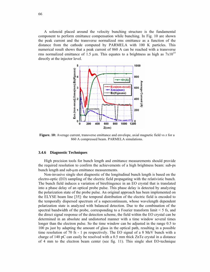
66
A solenoid placed around the velocity bunching structure is the fundamental component to perform emittance compensation while bunching. In Fig. 10 are shown the peak current and the transverse normalized rms emittance as a function of the distance from the cathode computed by PARMELA with 100 K particles. This numerical result shows that a peak current of 860 A can be reached with a transverse rms normalized emittance of 1.5 μm. This equates to a brightness as high as 7x10¹⁵ directly at the injector level.
Figure. 10: Average current, transverse emittance and envelope, axial magnetic field vs z for a
860 A compressed beam. PARMELA simulations.
3.4.6 Diagnostic Techniques
High precision tools for bunch length and emittance measurements should provide the required resolution to confirm the achievements of a high brightness beam: sub-ps bunch length and sub-μm emittance measurements.
Non-invasive single shot diagnostic of the longitudinal bunch length is based on the electro-optic (EO) sampling of the electric field propagating with the relativistic bunch. The bunch field induces a variation of birefringence in an EO crystal that is translated into a phase delay of an optical probe pulse. This phase delay is detected by analyzing the polarization state of the probe pulse. An original approach has been implemented on the ELYSE beam line [35]: the temporal distribution of the electric field is encoded to the temporally dispersed spectrum of a supercontinuum, whose wavelength dependent polarization state is analyzed with balanced detection. Due to the combination of the spectral bandwidth of the probe, corresponding to a Fourier transform limit < 5 fs, and the direct signal response of the detection scheme, the field within the EO crystal can be determined in an absolute and undistorted manner with a time window several times longer than the electron pulse. So the time window can be adjusted in the range 0.5 to 100 ps just by adapting the amount of glass in the optical path, resulting in a possible time resolution of 70 fs - 1 ps respectively. The EO signal of a 8 MeV bunch with a charge of 140 pC can easily be resolved with a 0.5 mm thick ZnTe crystal in a distance of 4 mm to the electron beam center (see fig. 11). This single shot EO-technique
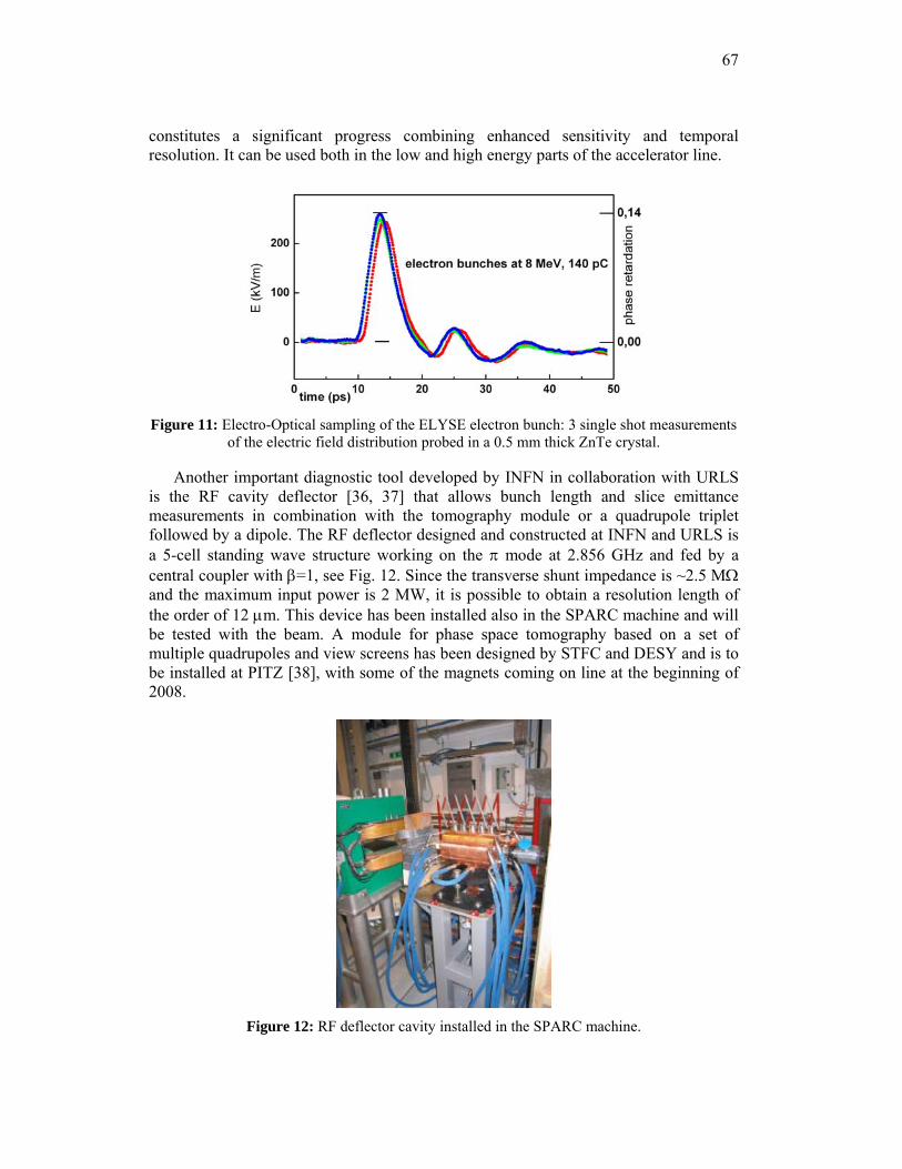
67
constitutes a significant progress combining enhanced sensitivity and temporal resolution. It can be used both in the low and high energy parts of the accelerator line.
Figure 11: Electro-Optical sampling of the ELYSE electron bunch: 3 single shot measurements of the electric field distribution probed in a 0.5 mm thick ZnTe crystal.
Another important diagnostic tool developed by INFN in collaboration with URLS is the RF cavity deflector [36, 37] that allows bunch length and slice emittance measurements in combination with the tomography module or a quadrupole triplet followed by a dipole. The RF deflector designed and constructed at INFN and URLS is a 5-cell standing wave structure working on the π mode at 2.856 GHz and fed by a central coupler with β=1, see Fig. 12. Since the transverse shunt impedance is ~2.5 MΩ and the maximum input power is 2 MW, it is possible to obtain a resolution length of the order of 12 μm. This device has been installed also in the SPARC machine and will be tested with the beam. A module for phase space tomography based on a set of multiple quadrupoles and view screens has been designed by STFC and DESY and is to be installed at PITZ [38], with some of the magnets coming on line at the beginning of 2008.
Figure 12: RF deflector cavity installed in the SPARC machine.
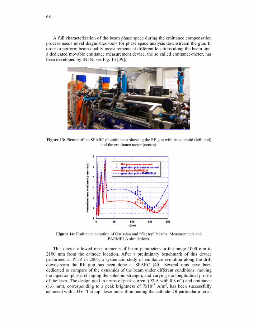
68
A full characterization of the beam phase space during the emittance compensation process needs novel diagnostics tools for phase space analysis downstream the gun. In order to perform beam quality measurements at different locations along the beam line, a dedicated movable emittance measurement device, the so called emittance-meter, has been developed by INFN, see Fig. 13 [39].
Figure 13: Picture of the SPARC photoinjector showing the RF gun with its solenoid (leftt end) and the emittance meter (centre).
Figure 14: Emittance evoution of Gaussian and “flat top” beams. Measurements and
PARMELA simulations.
This device allowed measurements of beam parameters in the range 1000 mm to 2100 mm from the cathode location. After a preliminary benchmark of this device performed at PITZ in 2005, a systematic study of emittance evolution along the drift downstream the RF gun has been done at SPARC [40]. Several runs have been dedicated to compare of the dynamics of the beam under different conditions: moving the injection phase, changing the solenoid strength, and varying the longitudinal profile of the laser. The design goal in terms of peak current (92 A with 0.8 nC) and emittance (1.6 mm), corresponding to a peak brightness of 7x10¹³ A/m2, has been successfully achieved with a UV “flat top” laser pulse illuminating the cathode. Of particular interest
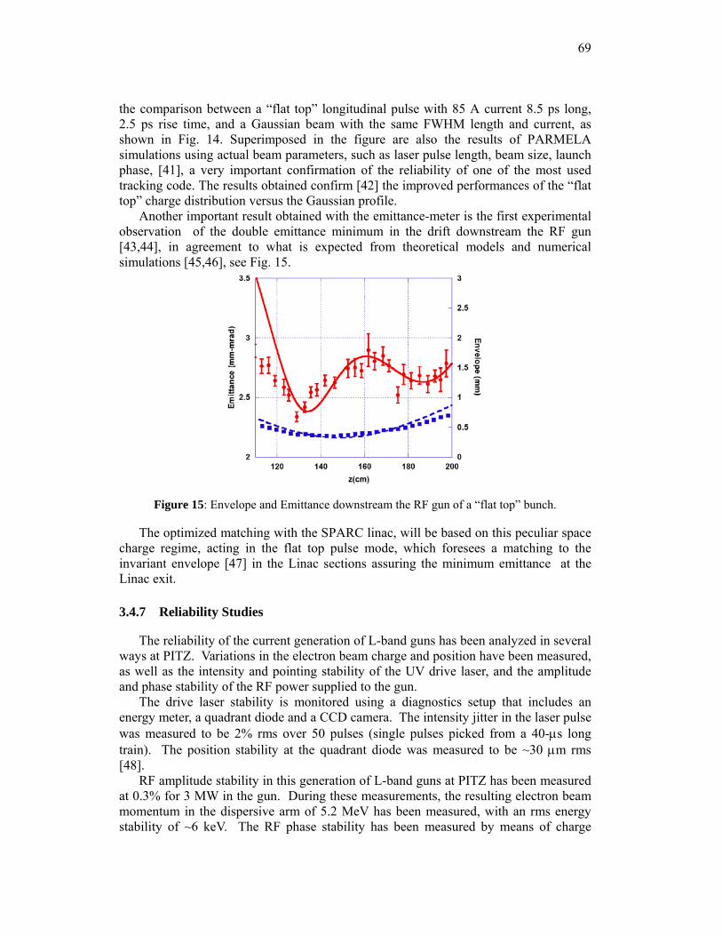
69
the comparison between a “flat top” longitudinal pulse with 85 A current 8.5 ps long, 2.5 ps rise time, and a Gaussian beam with the same FWHM length and current, as shown in Fig. 14. Superimposed in the figure are also the results of PARMELA simulations using actual beam parameters, such as laser pulse length, beam size, launch phase, [41], a very important confirmation of the reliability of one of the most used tracking code. The results obtained confirm [42] the improved performances of the “flat top” charge distribution versus the Gaussian profile.
Another important result obtained with the emittance-meter is the first experimental observation of the double emittance minimum in the drift downstream the RF gun [43,44], in agreement to what is expected from theoretical models and numerical simulations [45,46], see Fig. 15.
Figure 15: Envelope and Emittance downstream the RF gun of a “flat top” bunch.
The optimized matching with the SPARC linac, will be based on this peculiar space charge regime, acting in the flat top pulse mode, which foresees a matching to the invariant envelope [47] in the Linac sections assuring the minimum emittance at the Linac exit.
3.4.7 Reliability Studies
The reliability of the current generation of L-band guns has been analyzed in several ways at PITZ. Variations in the electron beam charge and position have been measured, as well as the intensity and pointing stability of the UV drive laser, and the amplitude and phase stability of the RF power supplied to the gun.
The drive laser stability is monitored using a diagnostics setup that includes an energy meter, a quadrant diode and a CCD camera. The intensity jitter in the laser pulse was measured to be 2% rms over 50 pulses (single pulses picked from a 40-μs long train). The position stability at the quadrant diode was measured to be ~30 μm rms [48].
RF amplitude stability in this generation of L-band guns at PITZ has been measured at 0.3% for 3 MW in the gun. During these measurements, the resulting electron beam momentum in the dispersive arm of 5.2 MeV has been measured, with an rms energy stability of ~6 keV. The RF phase stability has been measured by means of charge
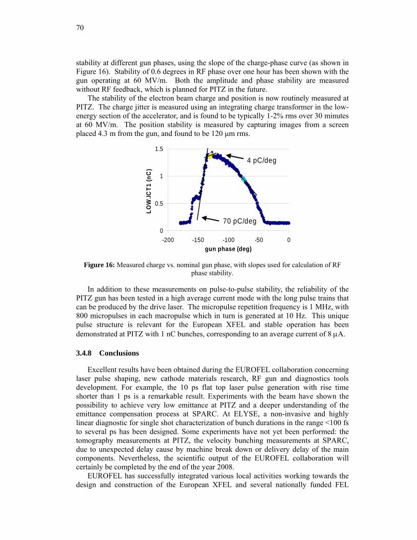
70
stability at different gun phases, using the slope of the charge-phase curve (as shown in Figure 16). Stability of 0.6 degrees in RF phase over one hour has been shown with the gun operating at 60 MV/m. Both the amplitude and phase stability are measured without RF feedback, which is planned for PITZ in the future.
The stability of the electron beam charge and position is now routinely measured at PITZ. The charge jitter is measured using an integrating charge transformer in the low-energy section of the accelerator, and is found to be typically 1-2% rms over 30 minutes at 60 MV/m. The position stability is measured by capturing images from a screen placed 4.3 m from the gun, and found to be 120 μm rms.
0
0.5
1
1.5
-200 -150 -100 -50 0gun phase (deg)
LOW
.ICT1
(nC
)
4 pC/deg
70 pC/deg
Figure 16: Measured charge vs. nominal gun phase, with slopes used for calculation of RF
phase stability.
In addition to these measurements on pulse-to-pulse stability, the reliability of the PITZ gun has been tested in a high average current mode with the long pulse trains that can be produced by the drive laser. The micropulse repetition frequency is 1 MHz, with 800 micropulses in each macropulse which in turn is generated at 10 Hz. This unique pulse structure is relevant for the European XFEL and stable operation has been demonstrated at PITZ with 1 nC bunches, corresponding to an average current of 8 μA.
3.4.8 Conclusions
Excellent results have been obtained during the EUROFEL collaboration concerning laser pulse shaping, new cathode materials research, RF gun and diagnostics tools development. For example, the 10 ps flat top laser pulse generation with rise time shorter than 1 ps is a remarkable result. Experiments with the beam have shown the possibility to achieve very low emittance at PITZ and a deeper understanding of the emittance compensation process at SPARC. At ELYSE, a non-invasive and highly linear diagnostic for single shot characterization of bunch durations in the range <100 fs to several ps has been designed. Some experiments have not yet been performed: the tomography measurements at PITZ, the velocity bunching measurements at SPARC, due to unexpected delay cause by machine break down or delivery delay of the main components. Nevertheless, the scientific output of the EUROFEL collaboration will certainly be completed by the end of the year 2008.
EUROFEL has successfully integrated various local activities working towards the design and construction of the European XFEL and several nationally funded FEL
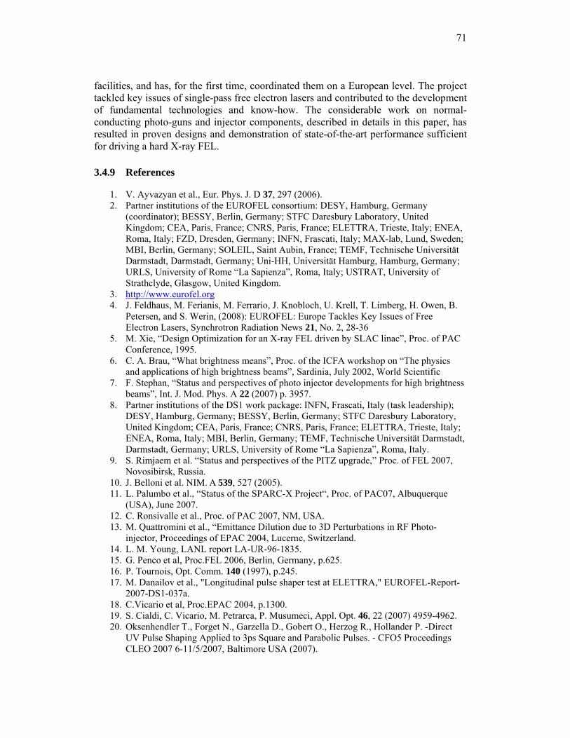
71
facilities, and has, for the first time, coordinated them on a European level. The project tackled key issues of single-pass free electron lasers and contributed to the development of fundamental technologies and know-how. The considerable work on normal-conducting photo-guns and injector components, described in details in this paper, has resulted in proven designs and demonstration of state-of-the-art performance sufficient for driving a hard X-ray FEL.
3.4.9 References
1. V. Ayvazyan et al., Eur. Phys. J. D 37, 297 (2006). 2. Partner institutions of the EUROFEL consortium: DESY, Hamburg, Germany
(coordinator); BESSY, Berlin, Germany; STFC Daresbury Laboratory, United Kingdom; CEA, Paris, France; CNRS, Paris, France; ELETTRA, Trieste, Italy; ENEA, Roma, Italy; FZD, Dresden, Germany; INFN, Frascati, Italy; MAX-lab, Lund, Sweden; MBI, Berlin, Germany; SOLEIL, Saint Aubin, France; TEMF, Technische Universität Darmstadt, Darmstadt, Germany; Uni-HH, Universität Hamburg, Hamburg, Germany; URLS, University of Rome “La Sapienza”, Roma, Italy; USTRAT, University of Strathclyde, Glasgow, United Kingdom.
3. http://www.eurofel.org 4. J. Feldhaus, M. Ferianis, M. Ferrario, J. Knobloch, U. Krell, T. Limberg, H. Owen, B.
Petersen, and S. Werin, (2008): EUROFEL: Europe Tackles Key Issues of Free Electron Lasers, Synchrotron Radiation News 21, No. 2, 28-36
5. M. Xie, “Design Optimization for an X-ray FEL driven by SLAC linac”, Proc. of PAC Conference, 1995.
6. C. A. Brau, “What brightness means”, Proc. of the ICFA workshop on “The physics and applications of high brightness beams”, Sardinia, July 2002, World Scientific
7. F. Stephan, “Status and perspectives of photo injector developments for high brightness beams”, Int. J. Mod. Phys. A 22 (2007) p. 3957.
8. Partner institutions of the DS1 work package: INFN, Frascati, Italy (task leadership); DESY, Hamburg, Germany; BESSY, Berlin, Germany; STFC Daresbury Laboratory, United Kingdom; CEA, Paris, France; CNRS, Paris, France; ELETTRA, Trieste, Italy; ENEA, Roma, Italy; MBI, Berlin, Germany; TEMF, Technische Universität Darmstadt, Darmstadt, Germany; URLS, University of Rome “La Sapienza”, Roma, Italy.
9. S. Rimjaem et al. “Status and perspectives of the PITZ upgrade,” Proc. of FEL 2007, Novosibirsk, Russia.
10. J. Belloni et al. NIM. A 539, 527 (2005). 11. L. Palumbo et al., “Status of the SPARC-X Project“, Proc. of PAC07, Albuquerque
(USA), June 2007. 12. C. Ronsivalle et al., Proc. of PAC 2007, NM, USA. 13. M. Quattromini et al., “Emittance Dilution due to 3D Perturbations in RF Photo-
injector, Proceedings of EPAC 2004, Lucerne, Switzerland. 14. L. M. Young, LANL report LA-UR-96-1835. 15. G. Penco et al, Proc.FEL 2006, Berlin, Germany, p.625. 16. P. Tournois, Opt. Comm. 140 (1997), p.245. 17. M. Danailov et al., "Longitudinal pulse shaper test at ELETTRA," EUROFEL-Report-
2007-DS1-037a. 18. C.Vicario et al, Proc.EPAC 2004, p.1300. 19. S. Cialdi, C. Vicario, M. Petrarca, P. Musumeci, Appl. Opt. 46, 22 (2007) 4959-4962. 20. Oksenhendler T., Forget N., Garzella D., Gobert O., Herzog R., Hollander P. -Direct
UV Pulse Shaping Applied to 3ps Square and Parabolic Pulses. - CFO5 Proceedings CLEO 2007 6-11/5/2007, Baltimore USA (2007).
72
21. O. Gobert, S. Grabielle, D. Garzella, "Longitudinal pulse shaper test at CEA," EUROFEL-Report-2006-DS1-037b.
22. G. Klemz et al, EUROFEL-Report-2007-DS 1-042. 23. O. Gobert, S. Grabielle, D. Garzella "Transverse pulse shaper test at CEA,” EUROFEL-
Report-2007-DS1-042b. 24. C. Vicario, "Improved Optical Beam Lines for SPARC”, EUROFEL-Report-2007-DS1-
063. 25. S. Lederer et al., “XPS studies of Cs2Te photocathodes” , Proc. of FEL 2007,
Novosibirsk, Russia. 26. L. Cultrera et al., Appl. Surf. Sci. 253 (2007) p. 6531. 27. L. Cultrera et al., J. Phys. D: Appl. Phys., 40 (2007) p. 5965. 28. M. Altarelli et al. (eds.), XFEL The European X-Ray Free-Electron-Laser – Technical
Design Report, DESY 2006-097, DESY, Hamburg (2006); http://xfel.desy.de. 29. http://www.bessy.de 30. S. Lederer et al., “Conditioning of a new gun cavity towards 60 MV/m at PITZ” , Proc.
PAC 2007, Albuquerque, NM, USA 31. L. Staykov et al. “Measurement of the Projected Normalized Transverse Emittance at
PITZ,” Proc. of FEL 2007, Novosibirsk, Russia. 32. F. Marhauser et al., “A High Average Power RF Photoinjector Gun Cavity Developed
for the BESSY Soft X-Ray FEL,” Proc. 28th Free Electron Laser Conference, Berlin, Germany.
33. L. Serafini, M. Ferrario, “Velocity Bunching in PhotoInjectors” , AIP CP 581, 2001, pag.87.
34. C. Ronsivalle et al., "RF compressor optimization study for SPARC-SPARX," SPARC-BD-05 /01.
35. U. Schmidhammer, V. de Waele, J. R. Marquès, N. Bourgeois, M. Mostafavi, "Single Shot Linear Detection of 0.01 - 10 THz Electromagnetic Fields," submitted to Appl. Phys.
36. D. Alesini et al., "Design of an RF Deflector for SPARC," EUROFEL-Report-2005-DS1-013.
37. C. Vaccarezza et al., "Beam slice measurements with RF deflector at SPARC," EUROFEL-Report-2007-DS1-067
38. D. Holder et al., "Beam dynamics simulations through diagnostic elements," EUROFEL-Report-2007-DS1-059
39. L. Catani et al., "Design and characterization of a movable emittance meter for low-energy electron beams," Rev. of Sci. Instr. 77, 093301 2006.
40. A. Cianchi et al., Phys. Rev. ST-AB 11, 032801 (2008). 41. C. Ronsivalle et al., “Comparison Between SPARC E-Meter Measurements and
Simulations”, Proc. PAC 2007, Albuquerque, USA. 42. J. Yang et al., Journal of Applied Physics 92(3), (2002). 43. M. Ferrario et al., "Direct measurement of double emittance minimum in the SPARC
high brightness photoinjector," Phys. Rev. Lett. 99, 234801 (2007). 44. A. Mostacci et al., Review of Scientific Instruments 79, 013303 (2008). 45. M. Ferrario et al., “HOMDYN study for the LCLS RF photoinjector”, SLAC-PUB-
8400, (2000). 46. C.-X. Wang et al., Phys. Rev. ST - AB 10, 104201 (2007). 47. L. Serafini, J. B. Rosenzweig, Phys. Rev. E 55 (1997) 7565. 48. M. Hänel et al., “Photocathode Laser Pulse Diagnostics at PITZ“, Proc. 29th Intl. FEL
Conf., Novosibirsk, Russia, 2007
73
3.5 Electron Gun Development at Argonne National Laboratory
J. W. Lewellen†,‡ and J. G. Power† †Argonne National Laboratory Argonne, IL 60439 USA ‡Naval Postgraduate School, Monterey, CA 93943 USA
Mail to: [email protected]
3.5.1 Introduction
Argonne National Laboratory is a multi-purpose Department of Energy (DOE) laboratory. Its mission includes building and operating user facilities for outside researchers, as well as performing basic and applied research directly.
The two divisions at Argonne that have traditionally been deeply involved in electron gun research and use are the Advanced Photon Source (APS) [1], and in the High Energy Physics (HEP), the Argonne Wakefield Accelerator (AWA) group [2]. The work done at APS has focused both on development and use of robust, long-lived, simple-to-operate sources for filling the storage ring, as well as development of sources relevant to next-generation light sources and related technologies. The work done at the AWA, in contrast, has historically focused more on accelerator development for next-generation colliders; but this, in turn, has driven development and research on advanced electron beam sources to be used for this research.
Recent initiatives at the Laboratory include discussions and the start of collaboration on high-brightness, pulsed beam sources for electron microscopy applications, and, at the Argonne Department of Defense Project Office, designs for advanced electron guns intended for high-power energy-recovery linac-based free-electron lasers.
For this article, we broadly classify the electron sources in use and under development at Argonne into three categories: The APS workhorses, high-brightness, and research (both experimental and theoretical). Due to the wide variety of work being conducted in these categories only brief summaries are provided in the sections below and the reader is encouraged to consult the references for in-depth treatment. Where appropriate, we also mention cathode research, development, and use, since the cathode is a critical element of any electron beam source.
3.5.2 APS Thermionic Cathode RF Guns
We define a “workhorse” electron gun as one that has reliability, consistency, and ease of operation as its defining characteristics. These characteristics are often emphasized over qualities such as brightness, average current, etc., in the interests of ensuring that the application the workhorse gun is driving, experiences the maximum up-time possible.
The cost to operate the APS 3rd-generation x-ray synchrotron source works out to be approximately US$11,500 per hour. Having a robust, reliable and easily repairable beam source, therefore, is critical. To satisfy this need, two identical second-generation S-band (2.856 GHz) thermionic-cathode (TC) RF guns are used as primary and backup beam sources for APS operation. The APS injector system can switch between the primary and backup gun within a few minutes. A third TC RF gun is kept as a “ready spare” to swap out a failed gun at the next convenient scheduled access, and an injector
74
test stand (ITS) is available to facilitate injector repair and testing. All of the guns have been characterized in the ITS [3], and found to be of effectively identical performance; thus, any gun can be installed in either the primary or backup station within the APS linac without requiring changes to the operational settings.
The APS TC RF guns use tungsten dispenser thermionic cathodes. Beam injection into the APS linac is gated with a cross-field kicker system in the gun-to-linac beamlines. The TC RF structure consists of a full cell and a cathode cell, connected by a side-coupling cavity. In electrical terms, the guns operate in the very stable π/2 mode, while the electron beam “sees” a π-mode field. The guns, in terms of RF and beam characteristics, are very similar to the first-generation TC RF guns originally used at the APS [4], but incorporate several features intended to improve maintenance [5]. This includes a cathode cartridge system, and gun port placement decisions.
The cathode cartridge system ensures precise placement of the thermionic cathode with respect to the back wall of the gun. This eliminates the need to use a network analyzer to verify the gun’s state of tune during cathode replacement and makes cathode replacement a procedure that can be performed in situ with the gun installed in the beamline. Ignoring vent / pumpdown times, cathode replacement time has been reduced from what was typically a full day’s effort, to a matter of minutes. Similarly, a rationalized port placement scheme on the second-generation gun design has reduced the time to swap out a gun from several hours, to under an hour (again ex. vent and pumpdown times).
3.5.3 Operational High-Brightness Photocathode Guns
A high-brightness gun is one intended to produce high-quality electron beams in an “operational” setting. These photocathode (PC) RF guns typically require more operator skill and are more maintenance-intensive than the “workhorse” guns, but are still expected to achieve high levels of routine performance. In contrast with most of the “research” guns discussed in the next section, these are PC RF guns of the conventional vintage: iris-loaded copper cavities operating in a TM010-like mode powered by a single RF feed.
3.5.3.1 AWA High-Charge Photocathode Guns
Two different varieties of L-band photocathode (PC) RF guns have been designed and operated as high-charge “drive” guns at the Argonne Wakefield Accelerator (AWA): an 0.5 cell [6, 7] and a 1.5 cell [8] version. In a wakefield accelerator, a high-gradient wakefield is generated by a leading, high-charge drive beam (either a single drive bunch or a bunch train) to accelerate a trailing witness beam. The first generation drive gun commissioned at the AWA in the early 1990's was optimized for both low-power consumption and high charge delivery. It was an 0.5 cell, standing-wave cavity, and operated at a peak field of 90 MV/m at P=1.5 MW (f0=1.3 GHz, Q0=13,000) on the cathode to deliver 100 nC bunches at 2 MeV. The gun was not operated in the emittance compensation mode, but used a curved laser wavefront and nonlinear focusing solenoids matched to the angle-energy correlation computed for the 100 nC bunch. A number of different photocathode materials were tested in the drive gun and quantum efficiency (QE) was measured at very low laser intensities to keep space-charge effects negligible. Results obtained for the QE were: copper: 4x10⁻⁵;
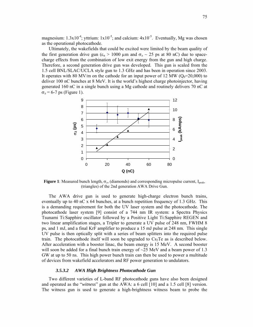
75
magnesium: 1.3x10⁻⁴; yttrium: 1x10⁻⁵; and calcium: 4x10⁻⁵. Eventually, Mg was chosen as the operational photocathode.
Ultimately, the wakefields that could be excited were limited by the beam quality of the first generation drive gun (εn > 1000 μm and σz ~ 25 ps at 80 nC) due to space-charge effects from the combination of low exit energy from the gun and high charge. Therefore, a second generation drive gun was developed. This gun is scaled from the 1.5 cell BNL/SLAC/UCLA style gun to 1.3 GHz and has been in operation since 2003. It operates with 80 MV/m on the cathode for an input power of 12 MW (Q0=20,000) to deliver 100 nC bunches at 8 MeV. It is the world’s highest charge photoinjector, having generated 160 nC in a single bunch using a Mg cathode and routinely delivers 70 nC at σz = 6-7 ps (Figure 1).
0123456789
0 20 40 60 80Q (nC)
σ Z (p
s)
0
2
4
6
8
10
12
I peak
(kA
mps
)
Figure 1: Measured bunch length, σz, (diamonds) and corresponding micropulse current, Ipeak, (triangles) of the 2nd generation AWA Drive Gun.
The AWA drive gun is used to generate high-charge electron bunch trains, eventually up to 40 nC x 64 bunches, at a bunch repetition frequency of 1.3 GHz. This is a demanding requirement for both the UV laser system and the photocathode. The photocathode laser system [9] consist of a 744 nm IR system: a Spectra Physics Tsunami Ti:Sapphire oscillator followed by a Positive Light Ti:Sapphire REGEN and two linear amplification stages, a Tripler to generate a UV pulse of 248 nm, FWHM 8 ps, and 1 mJ, and a final KrF amplifier to produce a 15 mJ pulse at 248 nm. This single UV pulse is then optically split with a series of beam splitters into the required pulse train. The photocathode itself will soon be upgraded to Cs2Te as is described below. After acceleration with a booster linac, the beam energy is 15 MeV. A second booster will soon be added for a final bunch train energy of ~25 MeV and a beam power of 1.3 GW at up to 50 ns. This high power bunch train can then be used to power a multitude of devices from wakefield accelerators and RF power generation to undulators.
3.5.3.2 AWA High Brightness Photocathode Gun
Two different varieties of L-band RF photocathode guns have also been designed and operated as the “witness” gun at the AWA: a 6 cell [10] and a 1.5 cell [8] version. The witness gun is used to generate a high-brightness witness beam to probe the
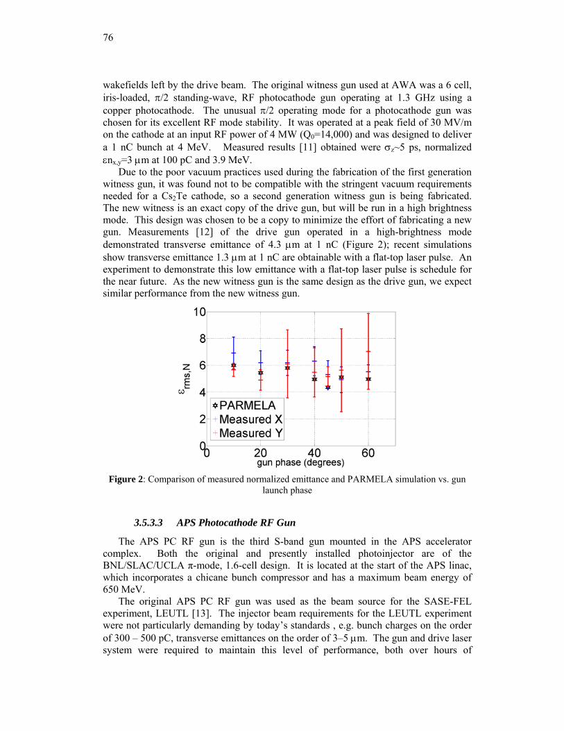
76
wakefields left by the drive beam. The original witness gun used at AWA was a 6 cell, iris-loaded, π/2 standing-wave, RF photocathode gun operating at 1.3 GHz using a copper photocathode. The unusual π/2 operating mode for a photocathode gun was chosen for its excellent RF mode stability. It was operated at a peak field of 30 MV/m on the cathode at an input RF power of 4 MW (Q0=14,000) and was designed to deliver a 1 nC bunch at 4 MeV. Measured results [11] obtained were σz~5 ps, normalized εnx,y=3 μm at 100 pC and 3.9 MeV.
Due to the poor vacuum practices used during the fabrication of the first generation witness gun, it was found not to be compatible with the stringent vacuum requirements needed for a Cs2Te cathode, so a second generation witness gun is being fabricated. The new witness is an exact copy of the drive gun, but will be run in a high brightness mode. This design was chosen to be a copy to minimize the effort of fabricating a new gun. Measurements [12] of the drive gun operated in a high-brightness mode demonstrated transverse emittance of 4.3 μm at 1 nC (Figure 2); recent simulations show transverse emittance 1.3 μm at 1 nC are obtainable with a flat-top laser pulse. An experiment to demonstrate this low emittance with a flat-top laser pulse is schedule for the near future. As the new witness gun is the same design as the drive gun, we expect similar performance from the new witness gun.
Figure 2: Comparison of measured normalized emittance and PARMELA simulation vs. gun
launch phase
3.5.3.3 APS Photocathode RF Gun
The APS PC RF gun is the third S-band gun mounted in the APS accelerator complex. Both the original and presently installed photoinjector are of the BNL/SLAC/UCLA π-mode, 1.6-cell design. It is located at the start of the APS linac, which incorporates a chicane bunch compressor and has a maximum beam energy of 650 MeV.
The original APS PC RF gun was used as the beam source for the SASE-FEL experiment, LEUTL [13]. The injector beam requirements for the LEUTL experiment were not particularly demanding by today’s standards , e.g. bunch charges on the order of 300 – 500 pC, transverse emittances on the order of 3–5 μm. The gun and drive laser system were required to maintain this level of performance, both over hours of
77
continuous operation at 6 Hz pulse rates, and from day to day for different experimental shifts. Further, the other beam properties, e.g. beta function, energy, arrival time at the capture linac section, etc., also had to remain stable.
The photocathode laser system for the APS PC RF gun is a quadrupled Nd:Glass laser in a MOPA configuration. A Time-Bandwidth master oscillator provides a pulse train at 119 MHz. A single pulse extracted from the train is sent through a Positive Light regenerative amplifier, frequency-quadrupled, and sent through a transport line. Due to the modest emittance requirements, an aperture was used to clip the pulse transversely at approximately 1σ, but no longitudinal pulse shaping was used. Although one Mg cathode was used in this gun, the majority of the gun’s run time used Cu cathodes. As with most BNL/SLAC/UCLA-type S-band photoinjectors, the cathode was an integral part of the back wall of the cathode cell.
While initially used primarily for the LEUTL experiment, the APS PC RF gun also provided beam for early experiments in bunch compression and CSR studies [14], and has been used to help test the beam position monitor system for the Linac Coherent Light Source [15].
The original APS PC RF gun was removed from the linac after approximately 10 years of continuous service, when it was found to have sustained too much arc damage to either hold high gradients or to be returned to a 1:1 field balance. The gun has since been replaced by a BNL/SLAC/UCLA-style photoinjector on loan from the Sprangle group at the Naval Research Laboratory.
3.5.4 Research Guns & Related Technologies – Experimental
In addition to the quasi-conventional guns described above (TC RF and metallic PC RF guns), Argonne pursues an innovative electron source program to address some of the limitations of the standard gun designs.
3.5.4.1 APS BBC gun
The primary mission of the APS injector test stand (ITS) is the repair and maintenance of the TC RF guns used in the APS linac. In service, those guns have proven to be extremely reliable, and the ITS has been designed to serve as a research area as well as a repair platform [16]. Most of the experimental work to date has been performed with the APS ballistic bunch compression gun.
The ballistic bunch compression (BBC) gun is a 3-cell (1 cathode cell plus two full cells) S-band gun, with each cell having its own high-power RF feed. This allows the field gradient and phase in each cell to be altered independently and thus gives additional parameters that can be used to optimize the performance of the gun for a particular task. For example, a BBC-type gun can be “tuned” to deliver maximum beam energy (by running in a π-like mode), minimum energy spread, or a “chirped” bunch that will self-compress as it drifts [17]. Also, by “powering down” cells, a direct beam-based measurement can be made of each cell’s shunt impedance [18]. The APS BBC gun’s interior cell geometry is based on that of the APS TC RF gun cells, and can function well with either a thermionic cathode or a photocathode.
78
3.5.4.2 Ballistic bunching & THz generation
Given the ability of the BBC gun to generate short bunches, it is a natural candidate for a high-power THz source via either synchrotron radiation or coherent optical transition radiation (COTR) based techniques. Initial experiments in the ITS have demonstrated this capability with COTR. The observed signal on the detector was shown to be transition radiation, as opposed to thermal heating of the OTR target, via observing the dependence of the angular separation of the radiation lobes with incident electron beam energy [19].
3.5.4.3 Photothermal Cathode Studies
Metallic photocathodes, such as those used in the APS PC RF gun, are usually considered robust but have low QE. Cathodes with high QE are typically very sensitive to vacuum conditions, and often have limited lifetime in the environment of RF guns. A photothermal cathode is similar to a dispenser thermionic cathode, in that it is typically a sintered material (typically tungsten) impregnated with emissive materials (e.g. calcium, barium), that can be driven to the surface of the cathode via heating. A photothermal cathode is heated to just below the temperature where thermionic emission becomes detectable (~600 C depending on the cathode), effectively lowering the work function and increasing the QE of the cathode when used with an external drive laser
Besides a significantly higher QE than typical metallic cathodes, a photothermal cathode offers the ability to be reconditioned (or cleaned) in-situ and without risk of damage to the cathode surface via the built-in cathode heater.
The original tungsten dispenser of the APS BBC gun was operated as a photothermal cathode, using both the APS PC RF gun photocathode laser and a frequency-quadrupled, Q-switched Nd;YAG Continuum Minilite-II drive laser. Later, in collaboration with Dr. D. Feldman at the University of Maryland, an M-type dispenser cathode was also tested with excellent results [20].
3.5.4.4 AWA Arc Testing Gun
An experimental study of high-gradient breakdown in RF cavities has been initiated at the AWA facility [21, 22] using the first generation AWA drive gun (described above). RF breakdown is not well understood and several theories have been put forward to describe its origin. Experimentally, it is observed that RF breakdown events are always preceded by emission of dark current caused by field emission from the surface of the cavity. Typically, the total dark current emitted from a cavity is measured and only the average Fowler-Nordheim field enhancement factor (β) is obtained.
Our goal is to study a single emission site (“an emitter”) in a controlled environment by correlating the physical features of an emitter to the intensity of its dark current emission using the following method. First, since the photocathode is removable, its surface can be closely examined, both before and after a dark current measurement, or a breakdown event, using surface imaging techniques (e.g. SEM). This allows us to measure the geometric features of the emitter (e.g. to look for the legendary “hairs”) as well to examine its surface chemistry in case field emission can not be explained in purely geometric terms. Second, the dark current emission from a single emitter on the cathode surface will be imaged to a phosphor screen. The dark current imaging system will use a solenoid to image electrons emitted from the photocathode to the Ce:YAG
79
screen located just downstream of the gun. This technique therefore gives us a direct measurement of β at the emitter sight. In addition to the dark current study, the same setup can be used to study RF breakdown by monitoring β and the surface features before and after a breakdown.
3.5.4.5 GaN Cathodes
Ideally, a high QE photocathode has high QE at visible or IR laser wavelengths, a long lifetime in poor vacuum, and a prompt emission response time. In the first category, GaAs has QE ~5% at 532 nm and K2CsSb has QE ~8% at 532 nm, but both require extremely good vacuum with P ~10-10 Torr and even then have lifetimes of only a few to tens of hours. (Note that the QE numbers given are characteristic numbers and the numbers reported in the literature vary considerably.) A more vacuum robust high QE photocathode is Cs2Te, but it requires a UV laser and is therefore prone to thermal limitations such as explosive emission.
An Argonne-University of Maryland collaboration has initiated a program to develop a Gallium Nitride (GaN) photocathode with the potential for high QE (~7%) at near visible wavelengths (~350nm) which can be generated from the 3rd harmonic of an Nd:YAG or Nd:YLF laser. GaN photocathodes are thin films deposited on a substrate (generally quartz). Once the surface is cleaned, a layer of cesium is deposited, resulting in a negative electron affinity surface. The high quality, single crystal films needed for an efficient photocathode were first demonstrated in the 90’s during the development of blue LEDs and laser diodes. The photoemissive properties of GaN have been studied via XPS by a group at the Stanford Synchrotron Radiation Laboratory (SSRL) [23].
Argonne has recently developed a GaN fabrication chamber and has measured very high QE, approximately 20% at λ=311 nm. The ultimate aim is to test a NEA Cs:GaN in the RF gun but this will be preceded by preliminary tests. We are planning experiments to measure the response time of these cathodes since this is a critical characteristic of a cathode in an RF gun. Simultaneously, in collaboration with the group at SSRL and SVT Associates, we are working to evaluate GaN heterojunction cathodes (which do not require activation with cesium) in an RF gun. An s-band, 0.5 cell gun has been fabricated for this purpose and was installed at the ITS in the APS and is currently undergoing initial commissioning.
3.5.4.6 AWA Cs2Te Cathode Fabrication & Testing
As mentioned above, the AWA drive gun photocathode will be upgraded from Mg to Cs2Te in order to increase the QE for the purposes of generating a high-current bunch train. The goal is to generate a bunch train of up to 50 nC per micropulse for up to a total of 64 bunches. To generate the bunch train, a single 15 mJ, UV laser pulse is optically split into the desired number of UV pulses with a series of laser beam splitters [24] and directed onto the photocathode. Due to the low UV energy in the individual micropulses a QE of greater than 0.5% is needed. Development of this photocathode is especially challenging since the surface area of the photocathode is very large (~25 mm diameter) due to the extremely high charges (100 nC) that will be generated.
The AWA has recently developed a Cs2Te fabrication chamber and load-lock transport system. We now consistently generate a QE in the 1% to 3% range, with the highest observed being around 6%. What is more important is that the QE has been maintained above 1% for at least 3 weeks inside the fabrication chamber (1.5x10⁻¹⁰ Torr
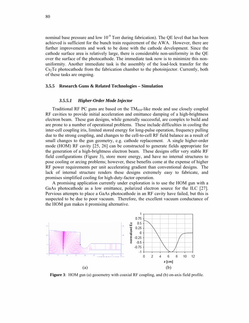
80
nominal base pressure and low 10-9 Torr during fabrication). The QE level that has been achieved is sufficient for the bunch train requirement of the AWA. However, there are further improvements and work to be done with the cathode development. Since the cathode surface area is relatively large, there is considerable non-uniformity in the QE over the surface of the photocathode. The immediate task now is to minimize this non-uniformity. Another immediate task is the assembly of the load-lock transfer for the Cs2Te photocathode from the fabrication chamber to the photoinjector. Currently, both of these tasks are ongoing.
3.5.5 Research Guns & Related Technologies – Simulation
3.5.5.1 Higher-Order Mode Injector
Traditional RF PC guns are based on the TM010-like mode and use closely coupled RF cavities to provide initial acceleration and emittance damping of a high-brightness electron beam. These gun designs, while generally successful, are complex to build and are prone to a number of operational problems. These include difficulties in cooling the inter-cell coupling iris, limited stored energy for long-pulse operation, frequency pulling due to the strong coupling, and changes to the cell-to-cell RF field balance as a result of small changes to the gun geometry, e.g. cathode replacement. A single higher-order mode (HOM) RF cavity [25, 26] can be constructed to generate fields appropriate for the generation of a high-brightness electron beam. These designs offer very stable RF field configurations (Figure 3), store more energy, and have no internal structures to pose cooling or arcing problems; however, these benefits come at the expense of higher RF power requirements per unit accelerating gradient than conventional designs. The lack of internal structure renders these designs extremely easy to fabricate, and promises simplified cooling for high-duty-factor operation.
A promising application currently under exploration is to use the HOM gun with a GaAs photocathode as a low emittance, polarized electron source for the ILC [27]. Pervious attempts to place a GaAs photocathode in an RF cavity have failed, but this is suspected to be due to poor vacuum. Therefore, the excellent vacuum conductance of the HOM gun makes it promising alternative.
(a) (b)
Figure 3: HOM gun (a) geoemetry with coaxial RF coupling, and (b) on-axis field profile.
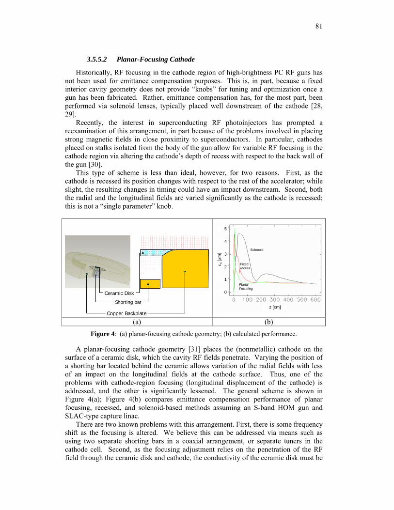
81
3.5.5.2 Planar-Focusing Cathode
Historically, RF focusing in the cathode region of high-brightness PC RF guns has not been used for emittance compensation purposes. This is, in part, because a fixed interior cavity geometry does not provide “knobs” for tuning and optimization once a gun has been fabricated. Rather, emittance compensation has, for the most part, been performed via solenoid lenses, typically placed well downstream of the cathode [28, 29].
Recently, the interest in superconducting RF photoinjectors has prompted a reexamination of this arrangement, in part because of the problems involved in placing strong magnetic fields in close proximity to superconductors. In particular, cathodes placed on stalks isolated from the body of the gun allow for variable RF focusing in the cathode region via altering the cathode’s depth of recess with respect to the back wall of the gun [30].
This type of scheme is less than ideal, however, for two reasons. First, as the cathode is recessed its position changes with respect to the rest of the accelerator; while slight, the resulting changes in timing could have an impact downstream. Second, both the radial and the longitudinal fields are varied significantly as the cathode is recessed; this is not a “single parameter” knob.
Solenoid
Fixedrecess
PlanarFocusing
z [cm]
1
2
3
4
5
0
ε n[μ
m]
Solenoid
Fixedrecess
PlanarFocusing
z [cm]
1
2
3
4
5
0
ε n[μ
m]
(a) (b) Figure 4: (a) planar-focusing cathode geometry; (b) calculated performance.
A planar-focusing cathode geometry [31] places the (nonmetallic) cathode on the surface of a ceramic disk, which the cavity RF fields penetrate. Varying the position of a shorting bar located behind the ceramic allows variation of the radial fields with less of an impact on the longitudinal fields at the cathode surface. Thus, one of the problems with cathode-region focusing (longitudinal displacement of the cathode) is addressed, and the other is significantly lessened. The general scheme is shown in Figure 4(a); Figure 4(b) compares emittance compensation performance of planar focusing, recessed, and solenoid-based methods assuming an S-band HOM gun and SLAC-type capture linac.
There are two known problems with this arrangement. First, there is some frequency shift as the focusing is altered. We believe this can be addressed via means such as using two separate shorting bars in a coaxial arrangement, or separate tuners in the cathode cell. Second, as the focusing adjustment relies on the penetration of the RF field through the ceramic disk and cathode, the conductivity of the ceramic disk must be
Shorting bar
Copper Backplate
Ceramic Disk
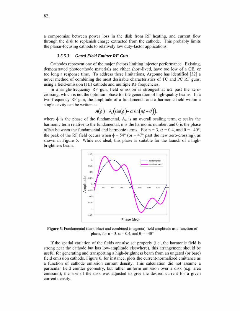
82
a compromise between power loss in the disk from RF heating, and current flow through the disk to replenish charge extracted from the cathode. This probably limits the planar-focusing cathode to relatively low duty-factor applications.
3.5.5.3 Gated Field Emitter RF Gun
Cathodes represent one of the major factors limiting injector performance. Existing, demonstrated photocathode materials are either short-lived, have too low of a QE, or too long a response time. To address these limitations, Argonne has identified [32] a novel method of combining the most desirable characteristics of TC and PC RF guns, using a field-emission (FE) cathode and multiple RF frequencies.
In a single-frequency RF gun, field emission is strongest at π/2 past the zero-crossing, which is not the optimum phase for the generation of high-quality beams. In a two-frequency RF gun, the amplitude of a fundamental and a harmonic field within a single cavity can be written as:
A φ( )= Ao sin φ( )+ α sin nφ + θ( )( ),
where φ is the phase of the fundamental, Ao is an overall scaling term, α scales the harmonic term relative to the fundamental, n is the harmonic number, and θ is the phase offset between the fundamental and harmonic terms. For n = 3, α = 0.4, and θ = –40°, the peak of the RF field occurs when φ ~ 54° (or ~ 47° past the new zero-crossing), as shown in Figure 5. While not ideal, this phase is suitable for the launch of a high-brightness beam.
-1.25
-1
-0.75
-0.5
-0.25
0
0.25
0.5
0.75
1
1.25
0 45 90 135 180 225 270 315 360
Phase (deg)
Ampl
itude
fundamental
plus harmonic
Figure 5: Fundamental (dark blue) and combined (magenta) field amplitude as a function of
phase, for n = 3, α = 0.4, and θ = −40°
If the spatial variation of the fields are also set properly (i.e., the harmonic field is strong near the cathode but has low-amplitude elsewhere), this arrangement should be useful for generating and transporting a high-brightness beam from an ungated (or bare) field emission cathode. Figure 6, for instance, plots the current-normalized emittance as a function of cathode emission current density. This calculation did not assume a particular field emitter geometry, but rather uniform emission over a disk (e.g. area emission); the size of the disk was adjusted to give the desired current for a given current density.
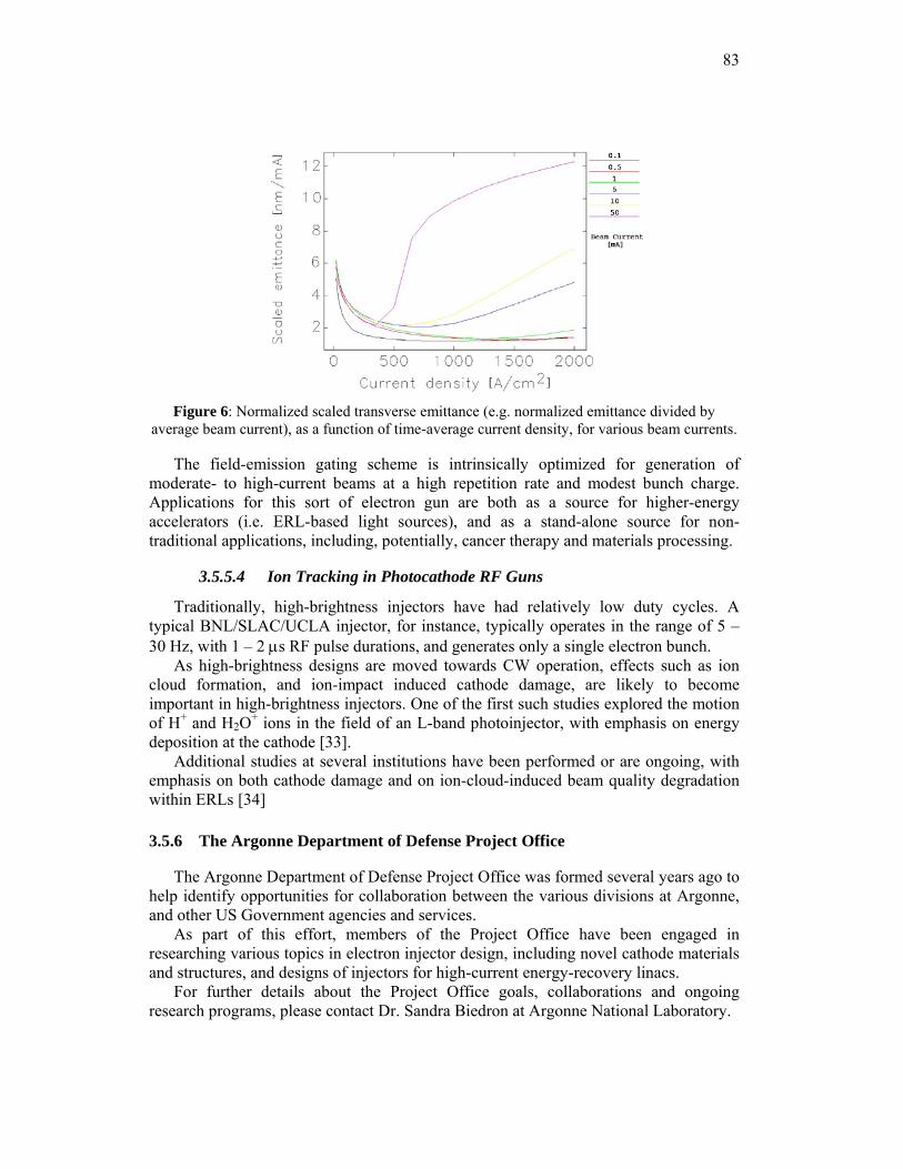
83
Figure 6: Normalized scaled transverse emittance (e.g. normalized emittance divided by
average beam current), as a function of time-average current density, for various beam currents.
The field-emission gating scheme is intrinsically optimized for generation of moderate- to high-current beams at a high repetition rate and modest bunch charge. Applications for this sort of electron gun are both as a source for higher-energy accelerators (i.e. ERL-based light sources), and as a stand-alone source for non-traditional applications, including, potentially, cancer therapy and materials processing.
3.5.5.4 Ion Tracking in Photocathode RF Guns
Traditionally, high-brightness injectors have had relatively low duty cycles. A typical BNL/SLAC/UCLA injector, for instance, typically operates in the range of 5 – 30 Hz, with 1 – 2 μs RF pulse durations, and generates only a single electron bunch.
As high-brightness designs are moved towards CW operation, effects such as ion cloud formation, and ion-impact induced cathode damage, are likely to become important in high-brightness injectors. One of the first such studies explored the motion of H+ and H2O+ ions in the field of an L-band photoinjector, with emphasis on energy deposition at the cathode [33].
Additional studies at several institutions have been performed or are ongoing, with emphasis on both cathode damage and on ion-cloud-induced beam quality degradation within ERLs [34]
3.5.6 The Argonne Department of Defense Project Office
The Argonne Department of Defense Project Office was formed several years ago to help identify opportunities for collaboration between the various divisions at Argonne, and other US Government agencies and services.
As part of this effort, members of the Project Office have been engaged in researching various topics in electron injector design, including novel cathode materials and structures, and designs of injectors for high-current energy-recovery linacs.
For further details about the Project Office goals, collaborations and ongoing research programs, please contact Dr. Sandra Biedron at Argonne National Laboratory.
84
3.5.7 The Argonne-NIU Beam Laboratory
Argonne National Laboratory has partnered with Northern Illinois University to construct and operate a beam dynamics and diagnostics development laboratory. The laboratory, to be located at Argonne, will initially use an existing TC RF gun with a photothermal cathode to provide beam for ERL diagnostics development and testing. As the program expands, novel source development and testing will also be undertaken in the Laboratory.
For further details on the status of the joint Laboratory, please contact Dr. John Noonan at Argonne or Dr. Philippe Piot at Northern Illinois University.
3.5.8 Conclusions
Argonne National Laboratory has a rich history of electron gun research and operation. The research aspects have explored, and continue to explore, important topics in electron gun performance and operational enhancements, in theory, simulation and as part of several experimental programs. Argonne also makes daily use of electron guns as part of their operational programs at both the Advanced Photon Source and Argonne Wakefield Accelerator facilities.
The operational and research programs have a symbiotic relationship; for instance the Injector Test Stand at the Advanced Photon Source provides both a repair and maintenance facility for the APS injector system, as well as a convenient test framework for high-brightness gun experiments.
Argonne is also actively working with outside institutions to leverage our internal strengths and capabilities to meet the needs and interests of our research partners.
3.5.9 References
1. http://www.aps.anl.gov/ 2. http://www.hep.anl.gov/awa 3. J. W. Lewellen et al., “The Advanced Photon Source injector test stand,” PAC01,
Chicago, Illinois. 4. M. Borland, “An improved thermionic microwave gun and emittance-preserving
transport line,” PAC93, Washington, DC 5. K. J. Beczek et al., “A Rationalized Approach to Thermionic RF Gun Design,” PAC01,
Chicago, Illinois. 6. P. Schoessow, et al., "The Argonne Wakefield Accelerator High Current Photocathode
Gun and Drive Linac", PAC95, Dallas, Texas. 7. C. H. Ho, et. al., “High Power Test Results of the First SRRC/ANL High Current L-
Band RF Gun”, LINAC96, Chicago, Illinois. 8. M. E. Conde et al., “The Argonne Wakefield Accelerator Facility: Status and Recent
Activities”, PAC05, Knoxville, Tennessee. 9. J. G. Power et al., "Transverse beam envelope measurements and the limitations of the
3-screen emittance method for space-charge dominated beams,” NIMPR A 546 (2005), 345–355.
10. J. Power et al., “Witness Gun for the Argonne Wakefield Accelerator”, PAC95, Dallas, Texas.
11. J. G. Power and M. E. Conde, Rev. Sci. Instrum. 69, 1295 (1998). 12. J. G. Power et al., “Pepper-Pot Based Emittance Measurements of the AWA
Photoinjector”, PAC07, Albuquerque, New Mexico.
85
13. S. V. Milton et al., “Exponential Gain and Saturation of a Self-Amplified Spontaneous Emission Free-Electron Laser,” Science, 15 June 2007, vol. 292, no. 5524, pp. 2037-2041.
14. M. Borland and J. W. Lewellen, “Initial characterization of coherent synchrotron radiation effects in the APS bunch compressor,” PAC01, Chicago, Illinois.
15. Private communication, S. V. Milton, 2006. 16. J. W. Lewellen et al., "A flexible injector test stand design," PAC03, Portland, Oregon. 17. J. W. Lewellen and S. V. Milton, “Preliminary calculations of ballistic bunch
compression with thermionic cathode RF guns,” Proc. SPIE 3154 no. 162 (1997). 18. Y.-E. Sun and J. W. Lewellen, “Shunt impedance measurement of the APS BBC gun,”
LINAC06, Knoxville, Tennessee. 19. S. G. Biedron et al., “Compact, High-Power Electron Beam Based Terahertz Sources,”
Proc. IEEE 95 no. 8, p. 1666-1678 (August 2007). 20. Y.-E. Sun, J. W. Lewellen and D. W. Feldman, “Photothermal cathode measurements at
the Advanced Photon Source,” LINAC 2006, Knoxville, Tennessee. 21. S. Antipov, et al., “Proposed Dark Current Studies at the Argonne Wakefield
Accelerator Facility”, PAC07, Albuquerque, New Mexico. 22. S. Antipov, et al., “Proposed RF Breakdown Studies at the AWA”, AIP 978, Advanced
Accelerator Concepts: 12th Workshop, 2006 23. Z. Liu et al., “Electron Scattering Study Within the Depletion Region of the GaN(0001)
and the GaAs(100) Surface”, Appl. Phys. Lett. 85, 1541 24. J. G. Power et al., “Measurements of the Longitudinal Wakefields in a Multimode,
Dielectric Wakefield Accelerator Driven by a Train of Electron Bunches”, Phys. Rev. ST Accelerators and Beams, 3, 101302 (October 2000).
25. J. W. Lewellen, "High Order RF Guns," Phys. Rev. 4, 040101 (2001). 26. J. W. Lewellen, “Simulation of a Higher-Order Mode RF Photoinjector,” LINAC 2002 27. J. W. Wang et al., “The RF Design of an HOM Polarized RF Gun for the ILC”, LINAC
2006 28. L. Serafini and J.B. Rosenzweig, “Envelope analysis of intense relativistic quasilaminar
beams in RF photoinjectors: a theory of emittance compensation,” Phys. Rev. E 55, 7565-7590 (1997).
29. P. R. Bolton et al., “Photoinjector design for the LCLS,” Nucl. Instrum. Meth. A, 481, May 2002 (pp. 296-300).
30. D. Janssen and V. Volkov, “RF focusing – an instrument for beam quality improvement in superconducting RF guns,” Nucl. Instrum. Meth. A, 452 (2000), pp. 34-43.
31. J. W. Lewellen and J. Noonan, “Planar-focusing cathodes,” FEL05, Stanford, California 32. J. W. Lewellen and J. Noonan, “Field-emission cathode gating for rf electron guns,”
Phys. Rev. ST Accel. Beams 8, 033502 (2005). 33. J. W. Lewellen, “Ion tracking in photocathode rf guns,” Phys Rev. ST Accel. Beams 5,
020101 (2002). 34. G. H. Hoffstaetter and C. Spethmann, “Equilibrium ion distribution in the presence of
clearing electrodes and its influence on electron dynamics,” PAC07, Albuquerque, New Mexico.
86
3.6 Low-Frequency, High-Repetition Rate Photoinjectors for FEL and ERL Applications
F. Sannibale, J. Staples, K. Baptiste, J. Corlett, S. Kwiatkowski, S. Lidia, J. Qiang , K. Sonnad, S. Virostek, R. Wells
Lawrence Berkeley National Laboratory, One Cyclotron Road, Berkeley,California 94720-8211, USA
Mail to: [email protected]
3.6.1 Introduction
A number of schemes for the next generation of ERL and FEL-based light sources require 0.1-1 nC electron bunches with normalized emittance smaller than 10-6 m at as high a duty factor as possible [1-4]. We are proposing a CW room-temperature photoinjector operating in the VHF frequency spectrum (30-300 MHz) that will be capable of delivering such beams at MHz repetition rates (limited only by the RF frequency or by the laser capability) with a field at the photocathode of ~20 MV/m and energy approaching 1 MeV.
Superconducting, high-frequency cavities are potentially promising but not mature yet and additionally may not be compatible with many cathode materials and can prevent by flux exclusion the application of controlled magnetic fields at the cathode for emittance manipulation techniques [5, 6]. DC guns have not yet achieved reliability at voltages higher than ~ 400 kV and cannot deliver the higher energies required for these beam parameters. High-frequency (L- to S-band) normal-conducting radio-frequency (RF) guns do not present such limitations but the average power density in the cavity structure limits the practical repetition rate to the kHz range [7]. By decreasing the RF frequency, the size of the cavities increases with a beneficial reduction of the power density on the structure walls and higher duty cycles can be achieved. The Boeing gun has achieved 25% duty cycle operation at 433 MHz [8], a 700 MHz CW normal conducting gun has been proposed [9], and a group at Los Alamos is completing the construction of a 700 MHz normal-conducting RF gun where a sophisticated and state of the art cooling system will allow the gun to operate in CW mode [10]. A lower frequency scheme that has been proven in operation is the gun used at the ELSA 19 MeV linac [11, 12], where the 144 MHz gun has produced high charge-low emittance beams within a 150 microsecond macropulse at 10 Hz repetition rate.
In our approach [13-15], we lowered the frequency down into the Very High Frequency (VHF) range (30-300 MHz) with design examples at 106, 201 and 350 MHz. The resulting modest power load on the walls is compatible with the use of standard and conventional technology for cooling the structure and makes it capable to operate in CW mode at ~750 kV across the accelerating gap and ~20 MV/m gradients. The relative large size of the cavity and the long RF wavelength allow the design of an efficient vacuum system with large pumping apertures capable of pressures compatible with the operation of many kind of cathodes including semiconductor materials. An embedded solenoid permits the easy control of the magnetic field in the cathode area.
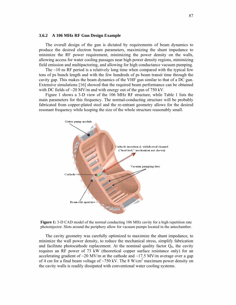
87
3.6.2 A 106 MHz RF Gun Design Example
The overall design of the gun is dictated by requirements of beam dynamics to produce the desired electron beam parameters, maximizing the shunt impedance to minimize the RF power requirement, minimizing the power density on the walls, allowing access for water cooling passages near high power density regions, minimizing field emission and multipactoring, and allowing for high conductance vacuum pumping.
The ~10 ns RF period is a relatively long time when compared with the typical few tens of ps bunch length and with the few hundreds of ps beam transit time through the cavity gap. This makes the beam dynamics of the VHF gun similar to that of a DC gun. Extensive simulations [16] showed that the required beam performance can be obtained with DC fields of ~20 MV/m and with energy out of the gun of 750 kV.
Figure 1 shows a 3-D view of the 106 MHz RF structure, while Table 1 lists the main parameters for this frequency. The normal-conducting structure will be probably fabricated from copper-plated steel and the re-entrant geometry allows for the desired resonant frequency while keeping the size of the whole structure reasonably small.
Figure 1: 3-D CAD model of the normal conducting 106 MHz cavity for a high repetition rate photoinjector. Slots around the periphery allow for vacuum pumps located in the antechamber.
The cavity geometry was carefully optimized to maximize the shunt impedance, to minimize the wall power density, to reduce the mechanical stress, simplify fabrication and facilitate photocathode replacement. At the nominal quality factor Q0, the cavity requires an RF power of 73 kW (theoretical copper surface resistance only) for an accelerating gradient of ~20 MV/m at the cathode and ~17.5 MV/m average over a gap of 4 cm for a final beam voltage of ~750 kV. The 8 W/cm2 maximum power density on the cavity walls is readily dissipated with conventional water cooling systems.
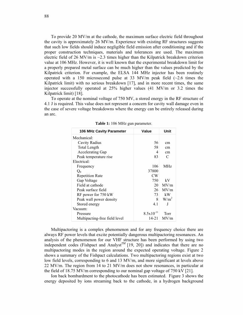
88
To provide 20 MV/m at the cathode, the maximum surface electric field throughout the cavity is approximately 26 MV/m. Experience with existing RF structures suggests that such low fields should induce negligible field emission after conditioning and if the proper construction techniques, materials and tolerances are used. The maximum electric field of 26 MV/m is ~2.3 times higher than the Kilpatrick breakdown criterion value at 106 MHz. However, it is well known that the experimental breakdown limit for a properly prepared metal surface can be much higher than the values predicted by the Kilpatrick criterion. For example, the ELSA 144 MHz injector has been routinely operated with a 150 microsecond pulse at 33 MV/m peak field (~2.6 times the Kilpatrick limit) with no serious breakdown [17], and in more recent times, the same injector successfully operated at 25% higher values (41 MV/m or 3.2 times the Kilpatrick limit) [18].
To operate at the nominal voltage of 750 MV, a stored energy in the RF structure of 4.1 J is required. This value does not represent a concern for cavity wall damage even in the case of severe voltage breakdowns where the energy can be entirely released during an arc.
Table 1: 106 MHz gun parameter.
106 MHz Cavity Parameter Value Unit
Mechanical: Cavity Radius Total Length Accelerating Gap Peak temperature rise Electrical: Frequency Q0 Repetition Rate Gap Voltage Field at cathode Peak surface field RF power for 750 kW Peak wall power density Stored energy Vacuum: Pressure Multipacting-free field level
56584
83
10637800
CW7502026738
4.1
8.5x10⁻¹¹
14-21
cm cm cm C
MHz
kV MV/m MV/m
kW W/m2
J
Torr MV/m
Multipactoring is a complex phenomenon and for any frequency choice there are
always RF power levels that excite potentially dangerous multipactoring resonances. An analysis of the phenomenon for our VHF structure has been performed by using two independent codes (Fishpact and AnalystTM [19, 20]) and indicates that there are no multipactoring modes in the region around the expected operating voltage. Figure 2 shows a summary of the Fishpact calculations. Two multipactoring regions exist at two low field levels, corresponding to 6 and 13 MV/m, and more significant at levels above 22 MV/m. The region from 14 to 21 MV/m does not show resonances, in particular at the field of 18.75 MV/m corresponding to our nominal gap voltage of 750 kV [21].
Ion back bombardment to the photocathode has been estimated. Figure 3 shows the energy deposited by ions streaming back to the cathode, in a hydrogen background
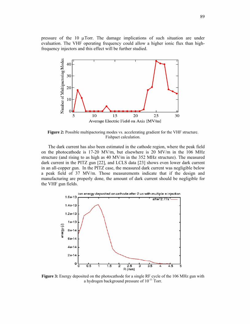
89
pressure of the 10 μTorr. The damage implications of such situation are under evaluation. The VHF operating frequency could allow a higher ionic flux than high-frequency injectors and this effect will be further studied.
Figure 2: Possible multipactoring modes vs. accelerating gradient for the VHF structure. Fishpact calculation.
The dark current has also been estimated in the cathode region, where the peak field on the photocathode is 17-20 MV/m, but elsewhere is 20 MV/m in the 106 MHz structure (and rising to as high as 40 MV/m in the 352 MHz structure). The measured dark current in the PITZ gun [22], and LCLS data [23] shows even lower dark current in an all-copper gun. In the PITZ case, the measured dark current was negligible below a peak field of 37 MV/m. Those measurements indicate that if the design and manufacturing are properly done, the amount of dark current should be negligible for the VHF gun fields.
Figure 3: Energy deposited on the photocathode for a single RF cycle of the 106 MHz gun with
a hydrogen background pressure of 10-11 Torr.
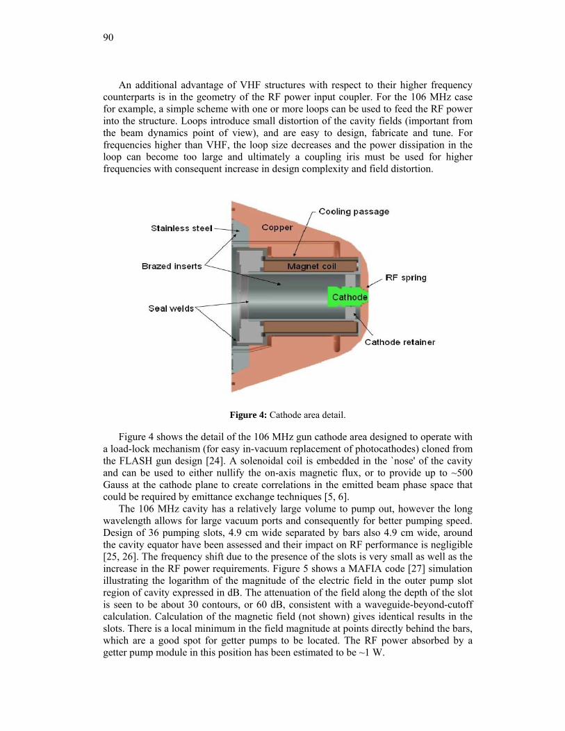
90
An additional advantage of VHF structures with respect to their higher frequency counterparts is in the geometry of the RF power input coupler. For the 106 MHz case for example, a simple scheme with one or more loops can be used to feed the RF power into the structure. Loops introduce small distortion of the cavity fields (important from the beam dynamics point of view), and are easy to design, fabricate and tune. For frequencies higher than VHF, the loop size decreases and the power dissipation in the loop can become too large and ultimately a coupling iris must be used for higher frequencies with consequent increase in design complexity and field distortion.
Figure 4: Cathode area detail.
Figure 4 shows the detail of the 106 MHz gun cathode area designed to operate with a load-lock mechanism (for easy in-vacuum replacement of photocathodes) cloned from the FLASH gun design [24]. A solenoidal coil is embedded in the `nose' of the cavity and can be used to either nullify the on-axis magnetic flux, or to provide up to ~500 Gauss at the cathode plane to create correlations in the emitted beam phase space that could be required by emittance exchange techniques [5, 6].
The 106 MHz cavity has a relatively large volume to pump out, however the long wavelength allows for large vacuum ports and consequently for better pumping speed. Design of 36 pumping slots, 4.9 cm wide separated by bars also 4.9 cm wide, around the cavity equator have been assessed and their impact on RF performance is negligible [25, 26]. The frequency shift due to the presence of the slots is very small as well as the increase in the RF power requirements. Figure 5 shows a MAFIA code [27] simulation illustrating the logarithm of the magnitude of the electric field in the outer pump slot region of cavity expressed in dB. The attenuation of the field along the depth of the slot is seen to be about 30 contours, or 60 dB, consistent with a waveguide-beyond-cutoff calculation. Calculation of the magnetic field (not shown) gives identical results in the slots. There is a local minimum in the field magnitude at points directly behind the bars, which are a good spot for getter pumps to be located. The RF power absorbed by a getter pump module in this position has been estimated to be ~1 W.
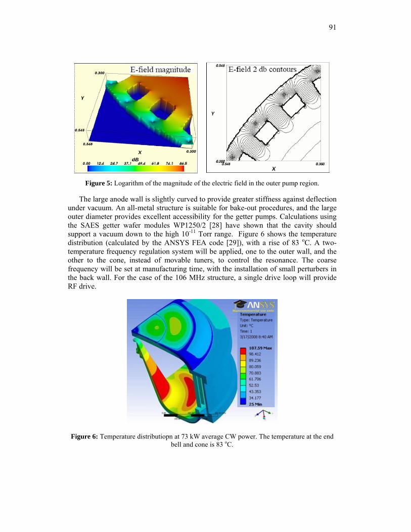
91
Figure 5: Logarithm of the magnitude of the electric field in the outer pump region.
The large anode wall is slightly curved to provide greater stiffness against deflection under vacuum. An all-metal structure is suitable for bake-out procedures, and the large outer diameter provides excellent accessibility for the getter pumps. Calculations using the SAES getter wafer modules WP1250/2 [28] have shown that the cavity should support a vacuum down to the high 10-11 Torr range. Figure 6 shows the temperature distribution (calculated by the ANSYS FEA code [29]), with a rise of 83 oC. A two-temperature frequency regulation system will be applied, one to the outer wall, and the other to the cone, instead of movable tuners, to control the resonance. The coarse frequency will be set at manufacturing time, with the installation of small perturbers in the back wall. For the case of the 106 MHz structure, a single drive loop will provide RF drive.
Figure 6: Temperature distributiopn at 73 kW average CW power. The temperature at the end bell and cone is 83 oC.
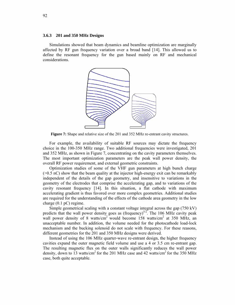
92
3.6.3 201 and 350 MHz Designs
Simulations showed that beam dynamics and beamline optimization are marginally affected by RF gun frequency variation over a broad band [14]. This allowed us to define the resonant frequency for the gun based mainly on RF and mechanical considerations.
Figure 7: Shape and relative size of the 201 and 352 MHz re-entrant cavity structures.
For example, the availability of suitable RF sources may dictate the frequency choice in the 100-350 MHz range. Two additional frequencies were investigated, 201 and 352 MHz, as shown in Figure 7, concentrating on the cavity parameters themselves. The most important optimization parameters are the peak wall power density, the overall RF power requirement, and external geometric constraints.
Optimization studies of some of the VHF gun parameters at high bunch charge (>0.5 nC) show that the beam quality at the injector high-energy exit can be remarkably independent of the details of the gap geometry, and insensitive to variations in the geometry of the electrodes that comprise the accelerating gap, and to variations of the cavity resonant frequency [14]. In this situation, a flat cathode with maximum accelerating gradient is thus favored over more complex geometries. Additional studies are required for the understanding of the effects of the cathode area geometry in the low charge (0.1 pC) regime.
Simple geometrical scaling with a constant voltage integral across the gap (750 kV) predicts that the wall power density goes as (frequency)5/2. The 106 MHz cavity peak wall power density of 8 watts/cm2 would become 158 watts/cm2 at 350 MHz, an unacceptable number. In addition, the volume needed for the photocathode load-lock mechanism and the bucking solenoid do not scale with frequency. For these reasons, different geometries for the 201 and 350 MHz designs were derived.
Instead of using the 106 MHz quarter-wave re-entrant design, the higher frequency cavities expand the outer magnetic field volume and use a 4 or 3.5 cm re-entrant gap. The resulting magnetic flux on the outer walls significantly reduces the wall power density, down to 13 watts/cm2 for the 201 MHz case and 42 watts/cm2 for the 350 MHz case, both quite acceptable.
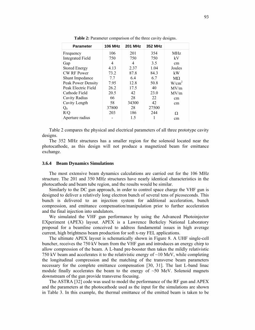
93
Table 2: Parameter comparison of the three cavity designs.
Parameter 106 MHz 201 MHz 352 MHz
Frequency Integrated Field Gap Stored Energy CW RF Power Shunt Impedance Peak Power Density Peak Electric Field Cathode Field Cavity Radius Cavity Length Q0 R/Q Aperture radius
106 750 4
4.13 73.2 7.7 7.95 26.2 20.5 66 58
37800 203
-
201 750
4 2.37 87.8 6.4
12.8 17.5 42 28
34300 28 186 1.5
354 750 3.5
1.04 84.3 6.7
50.8 40
23.0 22 42
27500 244
1
MHz kV cm
Joules kW MΩ
W/cm2
MV/m MV/m
cm cm
Ω cm
Table 2 compares the physical and electrical parameters of all three prototype cavity
designs. The 352 MHz structures has a smaller region for the solenoid located near the
photocathode, as this design will not produce a magnetized beam for emittance exchange.
3.6.4 Beam Dynamics Simulations
The most extensive beam dynamics calculations are carried out for the 106 MHz structure. The 201 and 350 MHz structures have nearly identical characteristics in the photocathode and beam tube region, and the results would be similar.
Similarly to the DC gun approach, in order to control space charge the VHF gun is designed to deliver a relatively long electron bunch of several tens of picoseconds. This bunch is delivered to an injection system for additional acceleration, bunch compression, and emittance compensation/manipulation prior to further acceleration and the final injection into undulators.
We simulated the VHF gun performance by using the Advanced Photoinjector EXperiment (APEX) layout. APEX is a Lawrence Berkeley National Laboratory proposal for a beamline conceived to address fundamental issues in high average current, high brightness beam production for soft x-ray FEL applications.
The ultimate APEX layout is schematically shown in Figure 8. A UHF single-cell buncher, receives the 750 kV beam from the VHF gun and introduces an energy chirp to allow compression of the beam. A L-band pre-booster then takes the mildly relativistic 750 kV beam and accelerates it to the relativistic energy of ~10 MeV, while completing the longitudinal compression and the matching of the transverse beam parameters necessary for the complete emittance compensation [30, 31]. The last L-band linac module finally accelerates the beam to the energy of ~50 MeV. Solenoid magnets downstream of the gun provide transverse focusing.
The ASTRA [32] code was used to model the performance of the RF gun and APEX and the parameters at the photocathode used as the input for the simulations are shown in Table 3. In this example, the thermal emittance of the emitted beam is taken to be
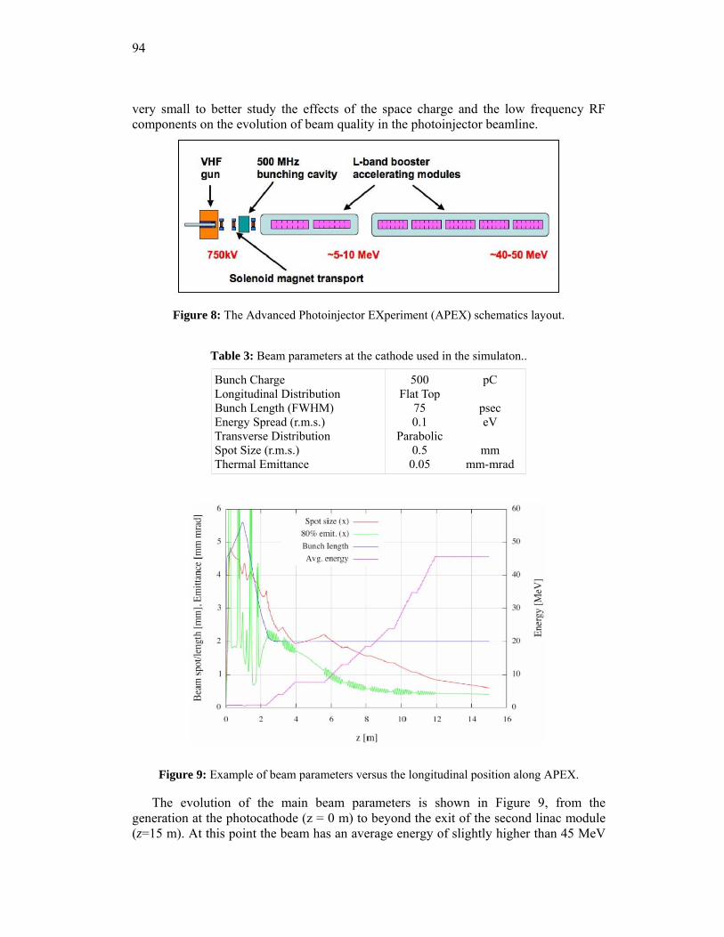
94
very small to better study the effects of the space charge and the low frequency RF components on the evolution of beam quality in the photoinjector beamline.
Figure 8: The Advanced Photoinjector EXperiment (APEX) schematics layout.
Table 3: Beam parameters at the cathode used in the simulaton..
Bunch Charge Longitudinal Distribution Bunch Length (FWHM) Energy Spread (r.m.s.) Transverse Distribution Spot Size (r.m.s.) Thermal Emittance
500 Flat Top
75 0.1
Parabolic 0.5 0.05
pC
psec eV
mm
mm-mrad
Figure 9: Example of beam parameters versus the longitudinal position along APEX.
The evolution of the main beam parameters is shown in Figure 9, from the generation at the photocathode (z = 0 m) to beyond the exit of the second linac module (z=15 m). At this point the beam has an average energy of slightly higher than 45 MeV
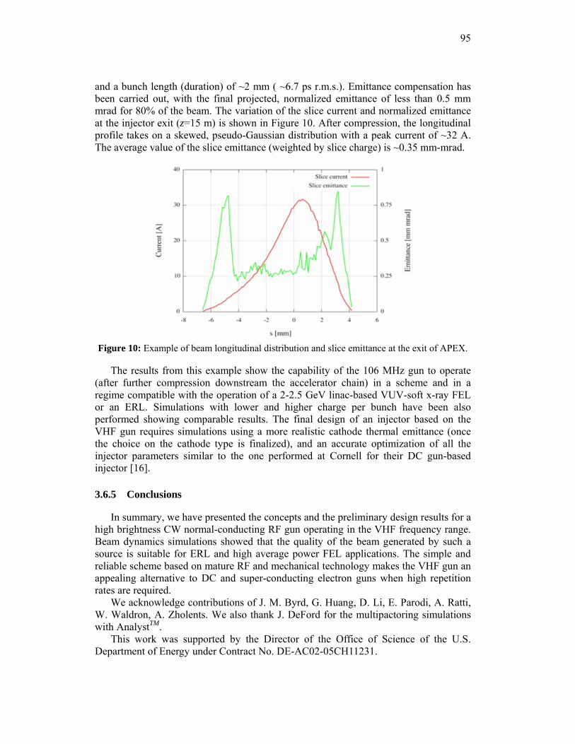
95
and a bunch length (duration) of ~2 mm ( ~6.7 ps r.m.s.). Emittance compensation has been carried out, with the final projected, normalized emittance of less than 0.5 mm mrad for 80% of the beam. The variation of the slice current and normalized emittance at the injector exit (z=15 m) is shown in Figure 10. After compression, the longitudinal profile takes on a skewed, pseudo-Gaussian distribution with a peak current of ~32 A. The average value of the slice emittance (weighted by slice charge) is ~0.35 mm-mrad.
Figure 10: Example of beam longitudinal distribution and slice emittance at the exit of APEX.
The results from this example show the capability of the 106 MHz gun to operate (after further compression downstream the accelerator chain) in a scheme and in a regime compatible with the operation of a 2-2.5 GeV linac-based VUV-soft x-ray FEL or an ERL. Simulations with lower and higher charge per bunch have been also performed showing comparable results. The final design of an injector based on the VHF gun requires simulations using a more realistic cathode thermal emittance (once the choice on the cathode type is finalized), and an accurate optimization of all the injector parameters similar to the one performed at Cornell for their DC gun-based injector [16].
3.6.5 Conclusions
In summary, we have presented the concepts and the preliminary design results for a high brightness CW normal-conducting RF gun operating in the VHF frequency range. Beam dynamics simulations showed that the quality of the beam generated by such a source is suitable for ERL and high average power FEL applications. The simple and reliable scheme based on mature RF and mechanical technology makes the VHF gun an appealing alternative to DC and super-conducting electron guns when high repetition rates are required.
We acknowledge contributions of J. M. Byrd, G. Huang, D. Li, E. Parodi, A. Ratti, W. Waldron, A. Zholents. We also thank J. DeFord for the multipactoring simulations with AnalystTM.
This work was supported by the Director of the Office of Science of the U.S. Department of Energy under Contract No. DE-AC02-05CH11231.
96
3.6.6 References
1. J. Corlett, et al., Proc. PAC07, Albuquerque, NM, 2007, p. 1167. 2. A. M. M. Todd, "State-of-the art electron guns and injector designs," Presented at the
32nd ICFA Advanced Beam Dynamics Workshop on Energy Recovery Linacs, Newport News, VA, USA, March 19, 2005.
3. I. Ben-Zvi, I.V.Bazarov, NIMPR A 557, 337 (2006). 4. Summary of working group on guns and injectors, 41st Advanced ICFA Beam
Dynamics Workshop on Energy Recovery Linacs, Daresbury Laboratory, UK, May 21-25, 2007.
5. R. Brinkmann, Y. Derbenev, K. Flottmann, PRST-AB 4, 053501 (2001). 6. P. Emma et al., PRST-AB, 9, 100702 (2006). 7. J. W. Staples, S. P. Virostek and S. M. Lidia, Proc. EPAC04, Lucerne, July 2004, p.
473. 8. D. Dowell, et al., Appl. Phys. Lett. 63(15), 2035 (1993). 9. R. A. Rimmer, Proc. PAC05, Knoxville, TN, May 2005, p. 3049. 10. S. S. Kurennoy et al., NIMPR A 528, 392 (2004). 11. R. Dei-cas, et al., NIMPR A 296, p. 209 (1990). 12. J.-G. Marmouget et al., Proc. EPAC02, Paris, June 2002, p. 1795. 13. J. Staples, F. Sannibale, S. Virostek, "VHF-band Photoinjector," LBNL CBP Tech
Note-366, October 2006. 14. Steven Lidia et al., "Development of a high-brightness VHF electron source at LBNL,"
ERL07 Workshop, Daresbury, UK, May 2007. 15. J. Staples et al., Proc. PAC07, Albuquerque, NM, 2007, p. 2990. 16. I. Bazarov, C. Sinclair, PRST-AB 8, 034202 (2005) 17. R. Dei-cas, et al., NIMPR A 331, pp. 199 (1993). 18. D. Guilhem,et al., Proc. EPAC06, Edinburgh, July 2006, p. 1927. 19. Genfa Wu, Fermi National Laboratory, private communication. 20. Analyst code, http://www.staarinc.com/. 21. J. Staples, "Multipactoring Calculations for the VHF Photoinjector Cavity using
Fishpact," LBNL CBP Tech Note-377, July 2007. 22. J. H. Han, XFEL Beam Dynamics Meeting, Hamburg, June 19 2006. 23. John Schmerge, LCLS, private communication 24. D. Sertore et al., "First Operation of Cesium Telluride Photocathodes in the TTF
Injector RF Gun," Proc. 21st Intl. FEL Conf., Hamburg, 1999. 25. J. Staples, G. Huang, R. Wells, "Pump Port Calculations for the VHF Photoinjector
Cavity," LBNL CBP Tech Note-378, July 2007. 26. J. Staples, "VHF Injector Pumping Slot RF Shielding Effectiveness," LBNL CBP Tech
Note-379, August 2007. 27. MAFIA, CST Ltd., Bad Nauheimer Strasse 19, 64289 Darmstadt, Frankfurt, Germany. 28. http://www.saesgetters.com/Default.aspx 29. http://www.ansys.com/ 30. B. E. Carlsten, NIMPR A 285, 313 (1989). 31. L. Serafini, J. B. Rosenzweig, Physical Review E 55, 7565 (1997). 32. http://www.desy.de/ mpyflo/Astradokumentation.
97
3.7 High Voltage DC Photoemission Electron Guns – Current Status and Technical Challenges
Charles K. Sinclair P.O. Box 8713, Medford, OR 97504
(Cornell University, retired) Mail to: [email protected]
3.7.1 Introduction
Ambitious electron accelerators are currently being proposed or under development for a number of new applications, such as electron cooling for RHIC, very high average power FELs, and new X-ray light sources based on both energy recovery linac (ERL) and FEL technologies. Many of these machines require high average beam currents, and the beam brightness requirements are often at or beyond the established state-of-the-art. The electron source and injector system for these machines is a key element, as the beam properties of the full accelerator are no better than those at injection. Photoemission cathodes are nearly universally employed as the electron sources for these machines, as they offer the potential for very high beam brightness. These cathodes are installed in either DC, normal conducting RF, or superconducting RF electron guns. Each of these gun types has its own set of technical issues apart from the photocathodes themselves. In this article, we will discuss the state-of-the-art and the technical challenges associated with the use of very high voltage DC electron guns, along with more general comments on photoemission cathodes and their associated laser systems.
Thermionic emission cathodes, generally with grids, mounted in moderate voltage DC electron guns have been the primary electron source for accelerators for many years. Photoemission cathodes were first introduced as electron sources to produce beams of polarized electrons for basic physics studies, a topic not discussed further here [1]. However, it is worthwhile to note that many developments in DC electron guns and photoemission cathodes have been made by groups pursuing improved polarized electron sources. Much of this work is reported in the proceedings of various workshops associated with the series of Spin Physics conferences held every other year since 1974 [2].
Following this first accelerator application of photocathodes, it was demonstrated that they could deliver very high peak currents and large bunch charges in relatively short duration (~ 2 ns) pulses [3]. RF guns with photoemission cathodes illuminated by short optical pulses were soon developed to deliver trains of high charge bunches for FEL applications [4]. This latter application motivated computational studies of the evolution of the bunched beam emittance through the electron gun and injector, which lead to the very important discovery of emittance compensation [5]. Since these early developments, photoemission cathodes have been increasingly used in both DC and RF guns to generate high bunch charge and high brightness electron beams.
The use of photoemission cathodes adds considerably to the complexity and expense of an electron source. Thus they are used only when the unique capabilities they provide justify the costs. These unique capabilities include beam polarization, high brightness, and a beam directly bunched at the photocathode. High beam brightness results from the
98
very high peak current densities possible from many photoemitters, and from the naturally low thermal emittance characteristic of certain photoemitters. Mirror smooth cathode surfaces and the absence of a grid also aid the beam brightness. The use of a beam bunched directly at the cathode can greatly reduce the need for, and the cost and detrimental effects of, subsequent chopping and bunching. To produce a high average current beam bunched at very high frequency from a continuous beam, such chopping and bunching schemes typically require dumping a significant fraction of the beam, particularly if beam brightness requirements lead to limitations on the phase spread at the entrance of the buncher. This can be challenging at high electron gun energies.
There are two notable exceptions to the use of photoemission cathodes in very high voltage DC guns. These are the 550 kV gun developed by the Haimson Research Corporation for accelerator studies at MIT [6], and the 500 kV gun developed for the SCSS FEL at SPring-8 [7]. Both of these guns have ungridded thermionic emitters, pulsed high voltage, and oil insulation. The beam pulse length is determined by the duration of the high voltage pulse applied to the gun cathode, and is thus relatively long. By their very nature, these guns deliver relatively low duty factor beams with modest beam brightness. We will not consider thermionic guns further here.
In virtually all DC photoemission guns now in use, cathode illumination is by optical pulses with a duration short compared to the time required for electrons to transit the cathode-anode gap. The emittance and bunch length increase under the influence of space charge as the bunch transits this gap. There is no analytic way to calculate these effects, or to determine the proper downstream focusing and bunching to obtain the minimum final emittance from a full injector. The problem is compounded by a number of constraints, such as the physical size of various elements, the need for components like vacuum valves and ports for the admission of light, the distance required to change between room temperature to the 2 K temperature of superconducting cavities, and ultimately, the need to be able to physically assemble the system. Although present day codes allow good quality tracking of a bunch through an injector, the large number of parameters and constraints and the nonlinearity of the space charge forces make an analytic optimization impossible.
With the benefit of large scale parallel processing, a genetic algorithm based computational optimization for DC gun injectors has been developed. This computation accounts for the physical constraints in the system, and allows the strength and location of individual elements to be varied within these constraints. The transverse and temporal profiles of the optical beam incident on the cathode are allowed to vary. ASTRA [8] is used for the tracking through the injector, although limited comparisons with PARMELA [9] were done, with acceptable results. The injector optimization computation, and the results obtained over a wide range of parameters, has been described in detail [10]. An important result was the demonstration that over a range of bunch charge between 80 and 800 pC, the emittance at the exit of the full injector was dominated by the thermal emittance of the photocathode. Such computational optimizations are a very powerful tool to develop injector designs to deliver specified beam qualities.
There are a number of technical issues associated with the operation of photoemission cathodes, particularly those having high quantum efficiency, in any electron gun structure. These include the choice of photocathode, the necessary laser and electro-optic systems, and the ultrahigh vacuum system. With very high voltage DC guns, there are additional issues such as the choice of gun structure; field emission from
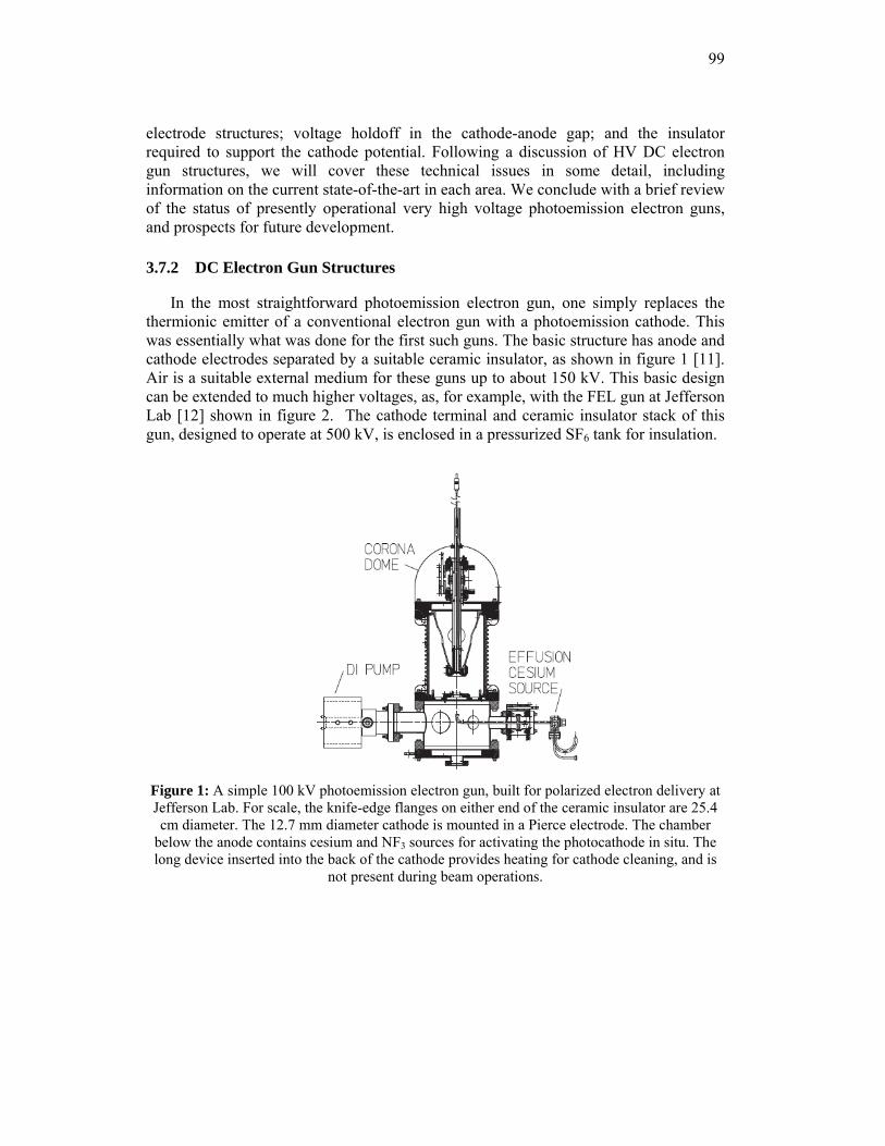
99
electrode structures; voltage holdoff in the cathode-anode gap; and the insulator required to support the cathode potential. Following a discussion of HV DC electron gun structures, we will cover these technical issues in some detail, including information on the current state-of-the-art in each area. We conclude with a brief review of the status of presently operational very high voltage photoemission electron guns, and prospects for future development.
3.7.2 DC Electron Gun Structures
In the most straightforward photoemission electron gun, one simply replaces the thermionic emitter of a conventional electron gun with a photoemission cathode. This was essentially what was done for the first such guns. The basic structure has anode and cathode electrodes separated by a suitable ceramic insulator, as shown in figure 1 [11]. Air is a suitable external medium for these guns up to about 150 kV. This basic design can be extended to much higher voltages, as, for example, with the FEL gun at Jefferson Lab [12] shown in figure 2. The cathode terminal and ceramic insulator stack of this gun, designed to operate at 500 kV, is enclosed in a pressurized SF6 tank for insulation.
Figure 1: A simple 100 kV photoemission electron gun, built for polarized electron delivery at Jefferson Lab. For scale, the knife-edge flanges on either end of the ceramic insulator are 25.4 cm diameter. The 12.7 mm diameter cathode is mounted in a Pierce electrode. The chamber
below the anode contains cesium and NF3 sources for activating the photocathode in situ. The long device inserted into the back of the cathode provides heating for cathode cleaning, and is
not present during beam operations.
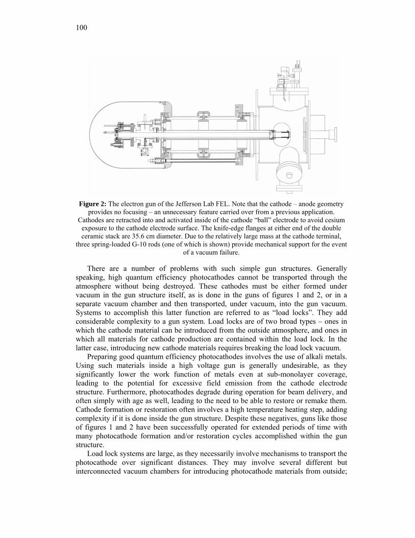
100
Figure 2: The electron gun of the Jefferson Lab FEL. Note that the cathode – anode geometry
provides no focusing – an unnecessary feature carried over from a previous application. Cathodes are retracted into and activated inside of the cathode “ball” electrode to avoid cesium
exposure to the cathode electrode surface. The knife-edge flanges at either end of the double ceramic stack are 35.6 cm diameter. Due to the relatively large mass at the cathode terminal,
three spring-loaded G-10 rods (one of which is shown) provide mechanical support for the event of a vacuum failure.
There are a number of problems with such simple gun structures. Generally speaking, high quantum efficiency photocathodes cannot be transported through the atmosphere without being destroyed. These cathodes must be either formed under vacuum in the gun structure itself, as is done in the guns of figures 1 and 2, or in a separate vacuum chamber and then transported, under vacuum, into the gun vacuum. Systems to accomplish this latter function are referred to as “load locks”. They add considerable complexity to a gun system. Load locks are of two broad types – ones in which the cathode material can be introduced from the outside atmosphere, and ones in which all materials for cathode production are contained within the load lock. In the latter case, introducing new cathode materials requires breaking the load lock vacuum.
Preparing good quantum efficiency photocathodes involves the use of alkali metals. Using such materials inside a high voltage gun is generally undesirable, as they significantly lower the work function of metals even at sub-monolayer coverage, leading to the potential for excessive field emission from the cathode electrode structure. Furthermore, photocathodes degrade during operation for beam delivery, and often simply with age as well, leading to the need to be able to restore or remake them. Cathode formation or restoration often involves a high temperature heating step, adding complexity if it is done inside the gun structure. Despite these negatives, guns like those of figures 1 and 2 have been successfully operated for extended periods of time with many photocathode formation and/or restoration cycles accomplished within the gun structure.
Load lock systems are large, as they necessarily involve mechanisms to transport the photocathode over significant distances. They may involve several different but interconnected vacuum chambers for introducing photocathode materials from outside;
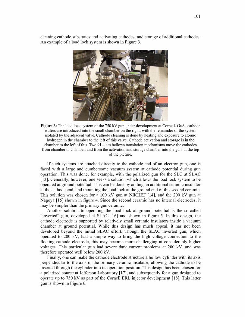
101
cleaning cathode substrates and activating cathodes; and storage of additional cathodes. An example of a load lock system is shown in Figure 3.
Figure 3: The load lock system of the 750 kV gun under development at Cornell. GaAs cathode
wafers are introduced into the small chamber on the right, with the remainder of the system isolated by the adjacent valve. Cathode cleaning is done by heating and exposure to atomic hydrogen in the chamber to the left of this valve. Cathode activation and storage is in the
chamber to the left of this. Two 91.4 cm bellows translation mechanisms move the cathodes from chamber to chamber, and from the activation and storage chamber into the gun, at the top
of the picture.
If such systems are attached directly to the cathode end of an electron gun, one is faced with a large and cumbersome vacuum system at cathode potential during gun operation. This was done, for example, with the polarized gun for the SLC at SLAC [13]. Generally, however, one seeks a solution which allows the load lock system to be operated at ground potential. This can be done by adding an additional ceramic insulator at the cathode end, and mounting the load lock at the ground end of this second ceramic. This solution was chosen for a 100 kV gun at NIKHEF [14], and the 200 kV gun at Nagoya [15] shown in figure 4. Since the second ceramic has no internal electrodes, it may be simpler than the primary gun ceramic.
Another solution to operating the load lock at ground potential is the so-called “inverted” gun, developed at SLAC [16] and shown in figure 5. In this design, the cathode electrode is supported by relatively small ceramic insulators inside a vacuum chamber at ground potential. While this design has much appeal, it has not been developed beyond the initial SLAC effort. Though the SLAC inverted gun, which operated to 200 kV, had a simple way to bring the high voltage connection to the floating cathode electrode, this may become more challenging at considerably higher voltages. This particular gun had severe dark current problems at 200 kV, and was therefore operated well below 200 kV.
Finally, one can make the cathode electrode structure a hollow cylinder with its axis perpendicular to the axis of the primary ceramic insulator, allowing the cathode to be inserted through the cylinder into its operation position. This design has been chosen for a polarized source at Jefferson Laboratory [17], and subsequently for a gun designed to operate up to 750 kV as part of the Cornell ERL injector development [18]. This latter gun is shown in Figure 6.
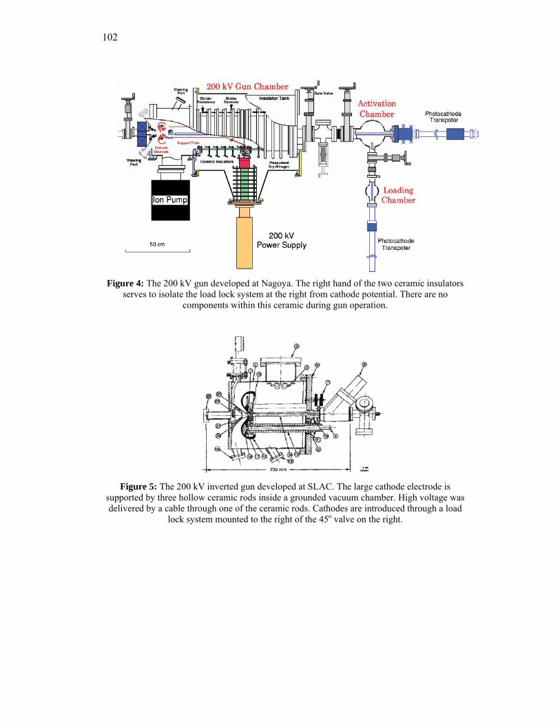
102
Figure 4: The 200 kV gun developed at Nagoya. The right hand of the two ceramic insulators
serves to isolate the load lock system at the right from cathode potential. There are no components within this ceramic during gun operation.
Figure 5: The 200 kV inverted gun developed at SLAC. The large cathode electrode is
supported by three hollow ceramic rods inside a grounded vacuum chamber. High voltage was delivered by a cable through one of the ceramic rods. Cathodes are introduced through a load
lock system mounted to the right of the 45o valve on the right.
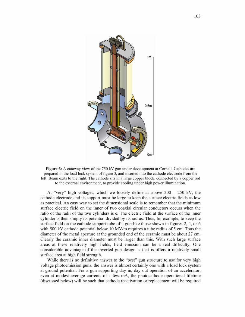
103
Figure 6: A cutaway view of the 750 kV gun under development at Cornell. Cathodes are
prepared in the load lock system of figure 3, and inserted into the cathode electrode from the left. Beam exits to the right. The cathode sits in a large copper block, connected by a copper rod
to the external environment, to provide cooling under high power illumination.
At “very” high voltages, which we loosely define as above 200 – 250 kV, the cathode electrode and its support must be large to keep the surface electric fields as low as practical. An easy way to set the dimensional scale is to remember that the minimum surface electric field on the inner of two coaxial circular conductors occurs when the ratio of the radii of the two cylinders is e. The electric field at the surface of the inner cylinder is then simply its potential divided by its radius. Thus, for example, to keep the surface field on the cathode support tube of a gun like those shown in figures 2, 4, or 6 with 500 kV cathode potential below 10 MV/m requires a tube radius of 5 cm. Thus the diameter of the metal aperture at the grounded end of the ceramic must be about 27 cm. Clearly the ceramic inner diameter must be larger than this. With such large surface areas at these relatively high fields, field emission can be a real difficulty. One considerable advantage of the inverted gun design is that is offers a relatively small surface area at high field strength.
While there is no definitive answer to the “best” gun structure to use for very high voltage photoemission guns, the answer is almost certainly one with a load lock system at ground potential. For a gun supporting day in, day out operation of an accelerator, even at modest average currents of a few mA, the photocathode operational lifetime (discussed below) will be such that cathode reactivation or replacement will be required
104
with some regularity. This basically requires a load lock system to avoid excessive down time for cathode reactivation or replacement, eliminating the simple guns of figures 1 and 2. At very high voltages, the length of the cathode transportation mechanism of the figure 3 gun may become problematic, and the need for a second ceramic, however simple, is annoying. The inverted gun design has much appeal – a relatively small surface area at high field strength, the possibility of a smaller vacuum chamber surface area at a given cathode potential, and the freedom from ceramic punch through failure (topics discussed below) all argue in its favor. By contrast, the guns of figures 4 and 6 require very large ceramic insulators, and have much larger electrode areas at high field strength. However, adapting the inverted gun design to much higher voltages has yet to be demonstrated, and doing so will likely uncover unanticipated problems.
3.7.3 Technical Challenges
3.7.3.1 Field Emission and Voltage Holdoff of the Cathode-Anode Gap
Field emission from the cathode electrode structure is a significant problem in DC guns operating at very high voltage. Field emission can cause charging of the ceramic insulator, leading ultimately to “punch through” failures and a loss of vacuum. Field emitted electrons striking the gun anode or gun chamber walls can cause localized melting and release significant quantities of gas, leading in turn to ion production and in the worst case, feedback to the cathode electrode resulting in a breakdown across the gap. Field emitted electrons originate from very small areas, and consequently impact relatively small areas. As the electron range in the struck materials is generally small, and these materials generally have very small thermal conductivities, the local heating from even a fairly small field emission current can be quite dramatic.
Field emission from large area electrodes is not well understood. Very substantial field emission currents are observed at field strengths more than two orders of magnitude below those calculated from the Fowler-Nordheim equation. At the present time, there is no prescription for either electrode materials or material treatments which can guarantee good field emission performance in a very high voltage gun having large electrode areas at high field strength.
It is well known that the holdoff voltage of a vacuum gap increases more slowly than linearly with the gap dimension. This is illustrated in figure 7, which is a compilation of the “best” reported results for voltage holdoff versus the vacuum gap dimension [19]. The data points in this figure make no reference to the particular electrode materials used, their treatment, or even the area at high field. Also shown in the figure are the operating points for two very high voltage DC guns – the JLab FEL gun, which has been operated extensively over several years at 350 kV with an 8 cm gap, and the 750 kV gun under development at Cornell, which is shown at 625 kV with a 5 cm gap. Clearly these guns operate (or are planned to operate) at the very limit of current technology.
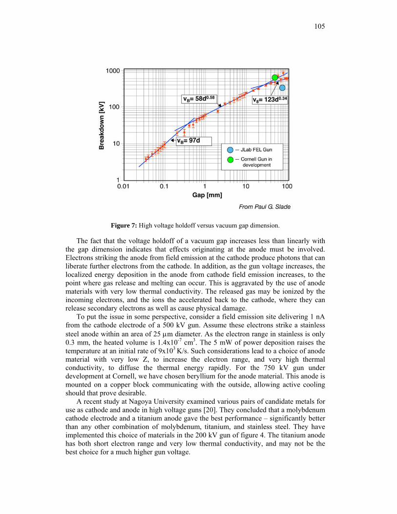
105
Figure 7: High voltage holdoff versus vacuum gap dimension.
The fact that the voltage holdoff of a vacuum gap increases less than linearly with the gap dimension indicates that effects originating at the anode must be involved. Electrons striking the anode from field emission at the cathode produce photons that can liberate further electrons from the cathode. In addition, as the gun voltage increases, the localized energy deposition in the anode from cathode field emission increases, to the point where gas release and melting can occur. This is aggravated by the use of anode materials with very low thermal conductivity. The released gas may be ionized by the incoming electrons, and the ions the accelerated back to the cathode, where they can release secondary electrons as well as cause physical damage.
To put the issue in some perspective, consider a field emission site delivering 1 nA from the cathode electrode of a 500 kV gun. Assume these electrons strike a stainless steel anode within an area of 25 μm diameter. As the electron range in stainless is only 0.3 mm, the heated volume is 1.4x10⁻⁷ cm3. The 5 mW of power deposition raises the temperature at an initial rate of 9x10³ K/s. Such considerations lead to a choice of anode material with very low Z, to increase the electron range, and very high thermal conductivity, to diffuse the thermal energy rapidly. For the 750 kV gun under development at Cornell, we have chosen beryllium for the anode material. This anode is mounted on a copper block communicating with the outside, allowing active cooling should that prove desirable.
A recent study at Nagoya University examined various pairs of candidate metals for use as cathode and anode in high voltage guns [20]. They concluded that a molybdenum cathode electrode and a titanium anode gave the best performance – significantly better than any other combination of molybdenum, titanium, and stainless steel. They have implemented this choice of materials in the 200 kV gun of figure 4. The titanium anode has both short electron range and very low thermal conductivity, and may not be the best choice for a much higher gun voltage.
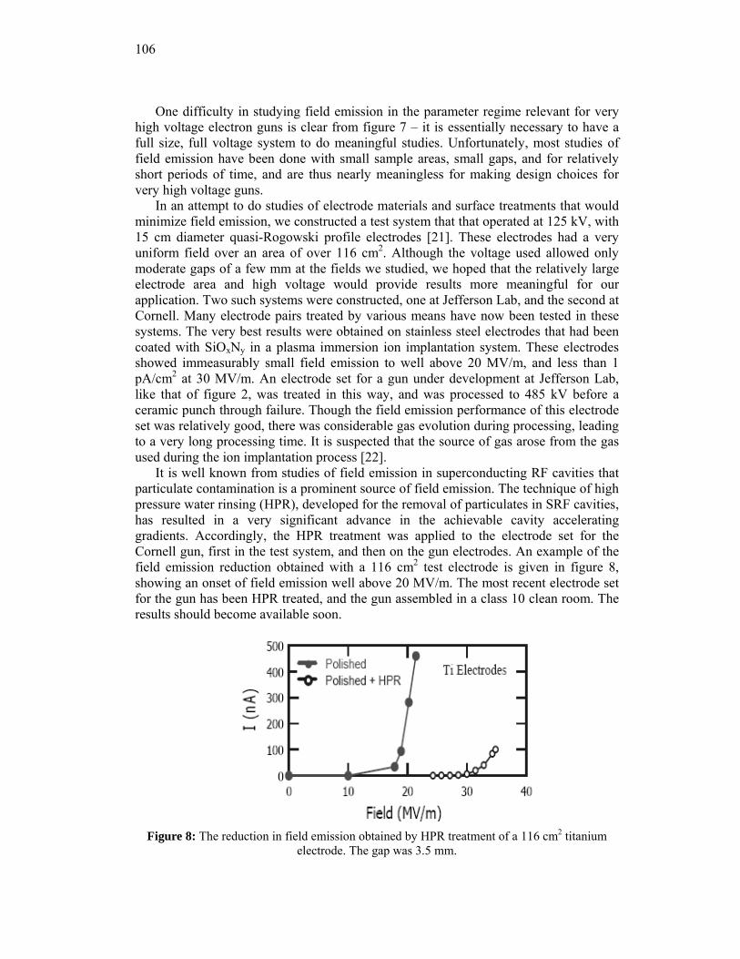
106
One difficulty in studying field emission in the parameter regime relevant for very high voltage electron guns is clear from figure 7 – it is essentially necessary to have a full size, full voltage system to do meaningful studies. Unfortunately, most studies of field emission have been done with small sample areas, small gaps, and for relatively short periods of time, and are thus nearly meaningless for making design choices for very high voltage guns.
In an attempt to do studies of electrode materials and surface treatments that would minimize field emission, we constructed a test system that that operated at 125 kV, with 15 cm diameter quasi-Rogowski profile electrodes [21]. These electrodes had a very uniform field over an area of over 116 cm2. Although the voltage used allowed only moderate gaps of a few mm at the fields we studied, we hoped that the relatively large electrode area and high voltage would provide results more meaningful for our application. Two such systems were constructed, one at Jefferson Lab, and the second at Cornell. Many electrode pairs treated by various means have now been tested in these systems. The very best results were obtained on stainless steel electrodes that had been coated with SiOxNy in a plasma immersion ion implantation system. These electrodes showed immeasurably small field emission to well above 20 MV/m, and less than 1 pA/cm2 at 30 MV/m. An electrode set for a gun under development at Jefferson Lab, like that of figure 2, was treated in this way, and was processed to 485 kV before a ceramic punch through failure. Though the field emission performance of this electrode set was relatively good, there was considerable gas evolution during processing, leading to a very long processing time. It is suspected that the source of gas arose from the gas used during the ion implantation process [22].
It is well known from studies of field emission in superconducting RF cavities that particulate contamination is a prominent source of field emission. The technique of high pressure water rinsing (HPR), developed for the removal of particulates in SRF cavities, has resulted in a very significant advance in the achievable cavity accelerating gradients. Accordingly, the HPR treatment was applied to the electrode set for the Cornell gun, first in the test system, and then on the gun electrodes. An example of the field emission reduction obtained with a 116 cm2 test electrode is given in figure 8, showing an onset of field emission well above 20 MV/m. The most recent electrode set for the gun has been HPR treated, and the gun assembled in a class 10 clean room. The results should become available soon.
Figure 8: The reduction in field emission obtained by HPR treatment of a 116 cm2 titanium
electrode. The gap was 3.5 mm.
107
3.7.3.2 Ceramic Insulators
For voltages of several hundred kV, ceramic insulators must be fairly large – several 10s of cm in diameter, and 50 or more cm in length. They, and their braze joints, must support the external pressure, which can be several bar when a pressurized gas such as SF6 is used as an insulator. However, the most challenging aspect of a high voltage ceramic arises from field emission. If electrons field emitted from the cathode electrode structure or its support strike the ceramic, it becomes locally charged. Even at hundreds of kV, the electron range in a typical ceramic is well less than one mm. The exceptionally high bulk resistivity of most ceramics prevents the dissipation of this charge, so charging continues until the local field is high enough to prevent the arrival of further electrons. Before this occurs, the ceramic typically suffers a punch through failure, destroying the vacuum. Though such vacuum failures are easily repaired, they recur unless the root cause of field emission is eliminated. Thus, the key to a successful ceramic insulator lies in dealing with the charge accumulation issue.
Ceramics with an internal surface coating or treatment to provide a sheet resistance have been used to drain this charge. This becomes more problematic at higher voltages, as the electrons penetrate deeper into the ceramic material. The ceramics of the Jefferson Lab FEL gun were treated by platinum ion implantation to produce a suitable sheet resistance [23], and have been trouble free during several years of operation at 350 kV. More recently, one suffered a punch through failure during HV processing at 485 kV. The ion implantation process is presently not done in the US, and is very difficult to do with ceramics larger than those of the Jefferson Lab gun. The initial ceramics for the Cornell 750 kV gun employed a proprietary surface coating from CPI, but these ceramics have suffered punch through failures during HV processing. The ERLP project at Daresbury obtained a ceramic with a bulk resistivity for their gun, which otherwise is a fairly close copy of the Jefferson Lab gun of figure 2. The resistivity of this ceramic was, however, not measured.
One difficulty with coated ceramics, and very likely with bulk resistive ceramics as well, is that the resistance has a strong dependence on the voltage, dropping dramatically as the voltage increases. The functional form of the resistance on voltage is not known, making it difficult to know that one has achieved the desired resistance at the design voltage. The resistivity of these coatings also decreases with increasing temperature, making a thermal runaway situation at least intellectually possible. In general, one would like any ceramic resistivity, either bulk or surface, to result in a current at the design voltage that is large compared to any field emission current. At very high voltages, however, only a few 10s of microamps of current gives significant ohmic heating. This latter problem is aggravated by the very low thermal conductivity of ceramics. The situation is close to unsatisfactory, since it is necessary to process the gun structure to reach high voltage, encountering field emission along the way at voltages below the design voltage. At lower voltages, the resistance is higher, and the current through the ceramic smaller, making the likelihood of a punch through during processing more probable.
It is possible to make a gun insulator from a stack of ceramic rings, each ring separated from the next by an annular sheet metal segment. The metal segments are shaped to have no sharp edges, and to effectively cover the inner surface of the ceramic, preventing electrons from striking the ceramic itself. The potential is graded along the ceramic by interconnecting the metal rings with resistors. Since these resistors are outside the ceramic, they are convectively cooled by the insulating gas, making a
108
current draw larger than for the case of a coated or resistive ceramic feasible. Many successful insulators of this type have been made for electron guns up to 500 kV by the Haimson Research Corporation [24]. Ceramic stacks like this may well be the best solution to the challenging problem of making a gun insulator.
Another difficulty with very large diameter ceramics arises from the need to make reliable ceramic to metal joints, allow the ceramic to be mounted to the gun structure. The “standard” external Kovar to ceramic braze is very difficult to accomplish at large diameter, due to the very large difference in the thermal expansion of the ceramic and the Kovar. CPI has developed a seal using a copper ring on the inside diameter of the ceramic, which they have found to be quite reliable. As implemented in the Cornell gun, the copper ring was brazed into the corresponding knife edge flange at the same time as the copper to ceramic braze. This required the use of knife edge flanges made of 316LN stainless steel, to avoid softening the knife edge at the braze temperatures. Presently, 316LN steel is no longer manufactured in the US, and it is becoming increasingly difficult to find vendors for very large knife edge flanges of this material.
One considerable advantage of the inverted gun design is that the ceramic insulators are not large, and are not easily susceptible to charging from field emission. They need only deal with the relatively minor possibility of a surface flashover.
3.7.3.3 Cathode Choices and Issues
The instantaneous current generated from a linear photoemission cathode is given by:
i(mA) =λ(nm)124
× P(W) × QE(%) (1)
where i is the instantaneous current in mA, λ is the illumination wavelength in nm, P is the instantaneous optical power incident on the photocathode in W, and QE is the cathode quantum efficiency – the number of electrons emitted per incident photon, expressed as a percentage. For illumination by an optical pulse, this expression can be integrated over time to give the charge produced by a pulse of total energy E in μJ:
Q(nC) =λ(nm)124
× E(μJ) × QE(%) (2)
These expressions underline the importance of photocathodes with high quantum efficiency at the longest practical wavelength for high average current and high bunch charge applications.
Four distinct families of photocathodes have been used in accelerator applications, and a fifth has been proposed and demonstrated. These are bare metals, alkali tellurides, alkali antimonides, negative electron affinity (NEA) semiconductors, and conventional thermionic dispenser cathodes heated close to the point of thermionic emission, respectively. The alkali antimonides and NEA semiconductors offer reasonably high quantum efficiencies from the near IR (NEA only) to the near UV. The alkali tellurides have fairly high quantum efficiencies in the UV, while bare metals generally have QEs no higher than about 0.01% and require UV illumination. Dispensers provide about 0.1% QE in the near UV. Representative performances of these various cathode types
109
are given in Table 1. The QE values used in this table are not the highest achieved for the various cathode types, but rather are fairly representative of good initial values obtained in practice. Generally speaking, cathode performance deteriorates with age and with beam delivery, particularly in the case of the high QE cathodes, so the yield numbers are appropriate only for initial performance. It is not uncommon to operate photoemission cathodes as their QE decays by factors of 10 to 20, requiring a similar range of optical power to be available. A dispenser cathode operated at a temperature giving good thermionic emission continuously replenishes its low work function surface, and thus has a stable yield in time. At the reduced temperatures employed when these cathodes are used as photoemitters, there is less evidence on this point. One disadvantage of the dispenser cathode in very high voltage guns is the need to provide heating power at the cathode potential.
Clearly bare metal photocathodes are inappropriate for average current in the mA range, if for no other reason than that the optical power requirements are prohibitive (to say nothing of cathode heating). To date, metal cathodes have been employed only in low duty factor normal conducting RF guns, though there are plans to use a lead cathode in an SRF gun. Dispenser cathodes, while having better yields than metal cathodes, seem similarly inappropriate for higher average current applications. We will not discuss metal and dispenser cathodes further here, restricting our attention to the three cathode families that provide relatively high QE.
The NEA cathodes differ from the antimonide and telluride cathodes in two very significant ways. First, the antimonides and tellurides are stoichiometric compounds, while the NEA cathodes are made by adding a single atomic layer of activating chemicals, typically cesium and either oxygen or fluorine, to the atomically clean surface of an appropriate semiconductor. Secondly, the antimonide and telluride cathodes have positive electron affinity (PEA). This means that the bottom of their conduction band lies below the external vacuum level. In the NEA case, the conduction band minimum lies above the external vacuum level, so it is energetically possible for an electron at the conduction band minimum to escape, while this is not so for PEA cathodes. Interestingly, NEA photocathodes have been applied only in DC guns to date, while the PEA cathodes have been used only in RF guns. There is no fundamental reason for this fact, and efforts are underway to change it. There are good reasons to suspect that the operational lifetime of antimonide and telluride cathodes in DC guns may be better than for NEA cathodes.
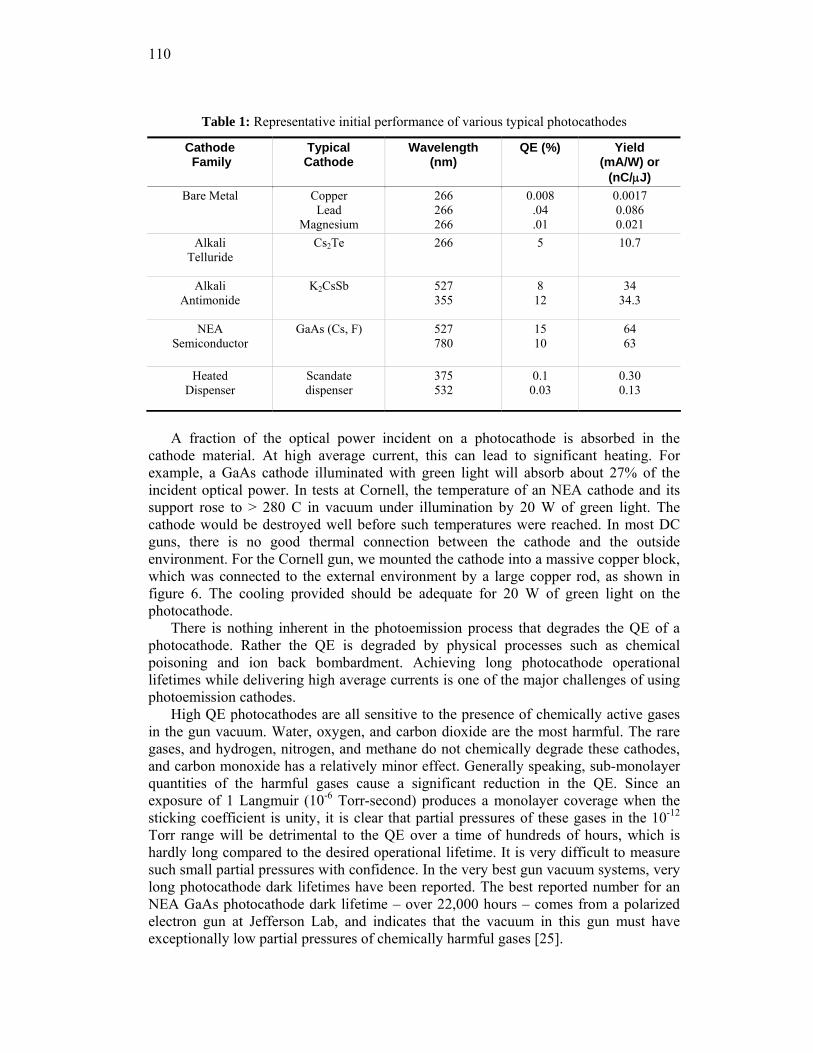
110
Table 1: Representative initial performance of various typical photocathodes
Cathode Family
Typical Cathode
Wavelength (nm)
QE (%) Yield (mA/W) or
(nC/μJ) Bare Metal Copper
Lead Magnesium
266 266 266
0.008 .04 .01
0.0017 0.086 0.021
Alkali Telluride
Cs2Te 266 5 10.7
Alkali Antimonide
K2CsSb 527 355
8 12
34 34.3
NEA Semiconductor
GaAs (Cs, F) 527 780
15 10
64 63
Heated Dispenser
Scandate dispenser
375 532
0.1 0.03
0.30 0.13
A fraction of the optical power incident on a photocathode is absorbed in the
cathode material. At high average current, this can lead to significant heating. For example, a GaAs cathode illuminated with green light will absorb about 27% of the incident optical power. In tests at Cornell, the temperature of an NEA cathode and its support rose to > 280 C in vacuum under illumination by 20 W of green light. The cathode would be destroyed well before such temperatures were reached. In most DC guns, there is no good thermal connection between the cathode and the outside environment. For the Cornell gun, we mounted the cathode into a massive copper block, which was connected to the external environment by a large copper rod, as shown in figure 6. The cooling provided should be adequate for 20 W of green light on the photocathode.
There is nothing inherent in the photoemission process that degrades the QE of a photocathode. Rather the QE is degraded by physical processes such as chemical poisoning and ion back bombardment. Achieving long photocathode operational lifetimes while delivering high average currents is one of the major challenges of using photoemission cathodes.
High QE photocathodes are all sensitive to the presence of chemically active gases in the gun vacuum. Water, oxygen, and carbon dioxide are the most harmful. The rare gases, and hydrogen, nitrogen, and methane do not chemically degrade these cathodes, and carbon monoxide has a relatively minor effect. Generally speaking, sub-monolayer quantities of the harmful gases cause a significant reduction in the QE. Since an exposure of 1 Langmuir (10-6 Torr-second) produces a monolayer coverage when the sticking coefficient is unity, it is clear that partial pressures of these gases in the 10-12 Torr range will be detrimental to the QE over a time of hundreds of hours, which is hardly long compared to the desired operational lifetime. It is very difficult to measure such small partial pressures with confidence. In the very best gun vacuum systems, very long photocathode dark lifetimes have been reported. The best reported number for an NEA GaAs photocathode dark lifetime – over 22,000 hours – comes from a polarized electron gun at Jefferson Lab, and indicates that the vacuum in this gun must have exceptionally low partial pressures of chemically harmful gases [25].
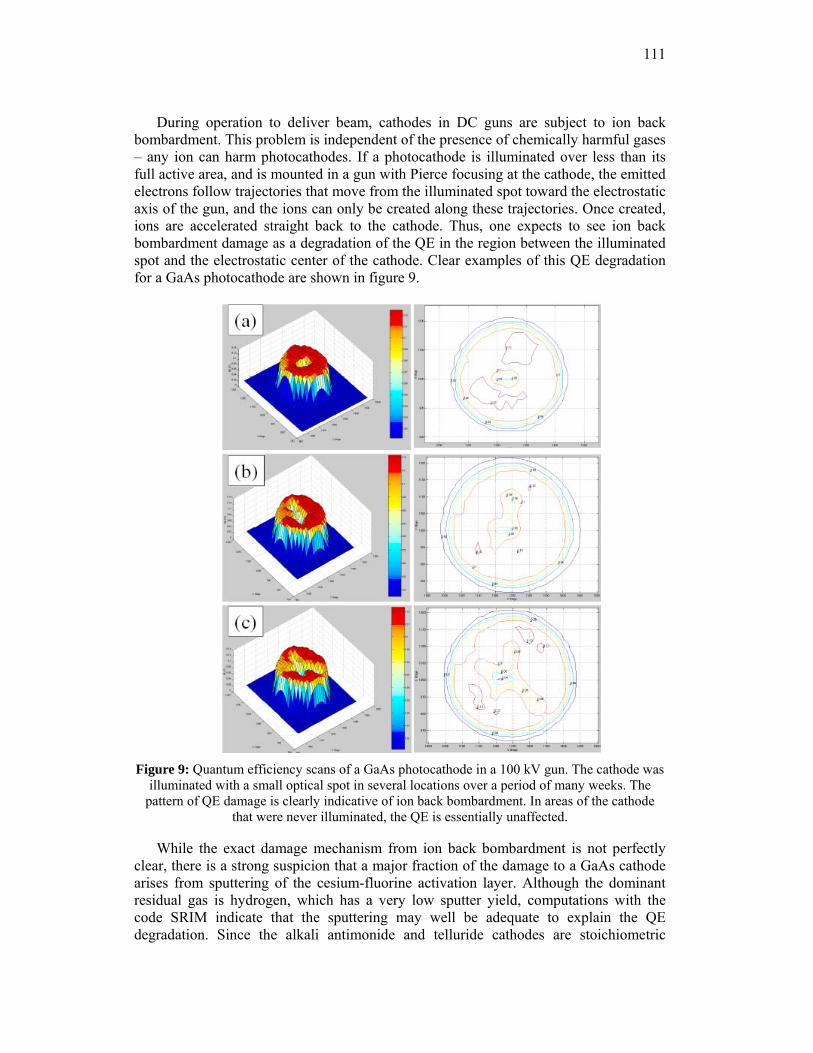
111
During operation to deliver beam, cathodes in DC guns are subject to ion back bombardment. This problem is independent of the presence of chemically harmful gases – any ion can harm photocathodes. If a photocathode is illuminated over less than its full active area, and is mounted in a gun with Pierce focusing at the cathode, the emitted electrons follow trajectories that move from the illuminated spot toward the electrostatic axis of the gun, and the ions can only be created along these trajectories. Once created, ions are accelerated straight back to the cathode. Thus, one expects to see ion back bombardment damage as a degradation of the QE in the region between the illuminated spot and the electrostatic center of the cathode. Clear examples of this QE degradation for a GaAs photocathode are shown in figure 9.
Figure 9: Quantum efficiency scans of a GaAs photocathode in a 100 kV gun. The cathode was
illuminated with a small optical spot in several locations over a period of many weeks. The pattern of QE damage is clearly indicative of ion back bombardment. In areas of the cathode
that were never illuminated, the QE is essentially unaffected.
While the exact damage mechanism from ion back bombardment is not perfectly clear, there is a strong suspicion that a major fraction of the damage to a GaAs cathode arises from sputtering of the cesium-fluorine activation layer. Although the dominant residual gas is hydrogen, which has a very low sputter yield, computations with the code SRIM indicate that the sputtering may well be adequate to explain the QE degradation. Since the alkali antimonide and telluride cathodes are stoichiometric
112
compounds, sputtering may not affect them in the same was as for the NEA photocathodes, since removal of surface material leaves identical underlying material. Thus, it might be that the antimonide and telluride photocathodes are much less affected by ion back bombardment. This important possibility has yet to be investigated.
The ion back bombardment damage to a cathode can be characterized by the number of coulombs delivered from a particular illuminated area. This is an imperfect characterization, as the ions can damage the cathode outside the illuminated area. However, the great majority of the ions are produced close to the cathode in a very high voltage gun, and we will use this parameter to characterize the ion back bombardment damage. If the 1/e degradation of the cathode is characterized by a value of Q0 C/cm2, then the cathode can deliver a constant average current I0 (in Amperes) for a time T given by:
⎟⎟⎠
⎞⎜⎜⎝
⎛=
0
0max
0
0
24.1ln
IP
IAQT λη (3)
where A is the illuminated area (assumed uniform), η0 is the absolute quantum efficiency, λ is the illumination wavelength in μm, and Pmax is the maximum laser power available in W. A value of Q0 greater than 106 C/cm2 has been reported for GaAs cathodes in a 100 kV gun at Jefferson Lab [26]. If this performance can be achieved reliably, then a 10 W maximum power laser system operating at 527 nm should be able to deliver 100 mA average current beam for over 100 hours from a 1.8 mm diameter illuminated spot on a cathode with 10% initial QE. Such performance is yet to be demonstrated. Of course, as shown in figure 9, it is generally possible to operate a cathode from multiple illuminated spots, effectively extending the operational life of the cathode.
High average current and high total charge delivery from photoemission cathodes has been accomplished in relatively few laboratories. The polarized source at Jefferson Laboratory probably has the record for the most total charge delivered. In tests, they have operated GaAs photocathodes up to 10 mA for extended periods, and have delivered over 2000 C from a 1.55 mm diameter illuminated spot. The Jefferson Lab FEL has operated GaAs at average currents up to 9.1 mA. The Cornell 750 kV gun has been operated with GaAs at about 20 mA briefly, at reduced voltage. A K2CsSb cathode was operated in a 433 MHz RF gun at 32 ma average current (128 mA at 25% duty factor) [27]. In the majority of cases, the total charge delivered from a single illuminated spot and single cathode preparation was typically no more than a few hundred C. Clearly work remains before one can reliably deliver high average currents for extended periods of time from high QE photoemission cathodes.
The thermal emittance and temporal response of photocathodes are very important parameters. In general, antimonide (and by inference telluride) cathodes have a rapid temporal response, as evidenced by their use in streak cameras. For NEA cathodes like GaAs, the situation is more complicated. Optical absorption in GaAs is strongly wavelength dependent. At long wavelengths, the absorption is small, so electrons are excited into the conduction bank deep in the material. These then diffuse to the surface where they may be emitted. Given the quadratic dependence of diffusion time on diffusion distance, the temporal response of GaAs photocathodes near the fundamental bandgap is relatively slow – about 20 ps. At shorter wavelengths, the electrons have to diffuse a shorter distance, and the response becomes much faster. In the green, GaAs is
113
a sub-ps emitter. The temporal response as a function of wavelength for NEA GaAs cathodes has recently been measured, and is in good agreement with a diffusion model [28].
The Cornell group has also completed an extensive set of measurements of the thermal emittance as a function of wavelength from NEA GaAs cathodes [28]. Their measurements are in good agreement with those made over a decade earlier [29]. For photon energies close to the bandgap, electrons are excited to the conduction band over a large depth in the material, due to the low optical absorption. The electrons lose excess energy through electron-phonon collisions as they diffuse to the surface, with the result that the emission is from a population nearly thermalized at the temperature of the semiconductor – about 25 meV at room temperature. As the wavelength gets shorter, the excess electron energy above the conduction band minimum increases, and the necessary distance they must traverse by diffusion decreases, so one expects the thermal emittance to increase. This is exactly what is observed. With the extensive measurements of the thermal emittance and temporal response over a broad wavelength range, NEA GaAs is by far the most well characterized photoemission cathode. Similar quality measurements of the thermal emittance from antimonide and telluride cathodes as a function of wavelength are yet to be reported, though interest in these measurements is growing.
It is worth noting that cooling NEA photocathodes below room temperature should result in a reduction in the thermal emittance. This idea has been pursued at GSI Darmstadt to produce cold electron beams for ion beam cooling. The effect of cooling the cathode is clearly seen in the transverse energy distributions from the cathode [30]. While the thought of operating a very high voltage gun with a cathode cooled to, say, liquid nitrogen temperatures may seem daunting, the very first photoemission gun used just such a cooled cathode. A similar emittance reduction with cooling is not expected for PEA photocathodes.
3.7.3.4 Laser Systems
Laser systems capable of delivering adequate average power with suitable time structure at appropriate wavelengths for illumination of photoemission electron sources are technically demanding and complex. Individual optical pulses must be shaped both transversely and temporally to obtain the highest electron beam brightness. Maintaining adequately stable synchronization between the pulses provided by a laser and the RF accelerating fields generally requires great attention to issues such as the stability of temperature and humidity and the absence of mechanical vibrations and air currents over the complete optical system, including the laser and its associated electro-optical components, the optical beam transport to the electron gun, and the optics at the location where the optical beam enters the electron gun vacuum system. It is typically found necessary to install the complete laser system in an isolated room providing a highly stable mechanical and thermal environment. Temperature stability better than 0.1 C and stable relative humidity is required. Many find it necessary to firmly attach all electronic cables to optical tables or concrete floors. All these aspects of providing illumination for a photoemission electron gun should be planned for in advance. No laser and electro-optical system for a photoemission gun has ever been described as being better than required.
For average beam currents in the 10 to 100 mA range, optical powers of 10 W or more at the photocathode are necessary to support operation over a reasonable range of
114
QE degradation. The optical power losses associated with transverse and temporal shaping and optical beam transport can easily exceed a factor of 2. In addition, optical frequency doubling, tripling, or quadrupling is often required to reach the desired wavelength for cathode illumination, adding to the power requirements from the fundamental laser. Fundamental laser powers of several tens of Watts can easily be required to operate a relatively high average current photocathode for a useful period of time. Furthermore, consideration of the illuminated spot size at the photocathode and the distance between the last optical element and the photocathode shows that the available apertures along the final optical beam line can sometimes be close to the diffraction limit. This reality places a premium on using fundamental lasers with good efficiency, to avoid optical beam quality degradation from thermal effects.
With the need for fairly high average optical power and good optical beam quality, there are relatively few choices for lasers. Lasers based on Nd, Er, Yb, and Ti ions are the only ones in present use. Only Ti lasers can be used without frequency doubling for illumination of NEA photocathodes. All lasers based on Nd, Er, and Yb ions must be at least frequency doubled, and often tripled or quadrupled, to reach suitable wavelengths for use with high QE photoemitters, and even Ti lasers are often doubled or tripled.
The advent of efficient diode pump lasers and fiber-optic technology has greatly increased the ability to develop specialized lasers delivering high average power, good optical beam quality, and the specialized time structures required. A Jefferson Lab group has reported on a diode pumped, frequency doubled Er:Yb fiber laser delivering over 2 W average at 780 nm in a 499 MHz cw pulse train [31]. They state that considerably higher average power should be possible with this system. One very nice technique they employed is RF gain switching of the diode laser oscillator. Gain switching is a passive electrical technique in which a biased diode laser is driven by RF, in this case derived directly from the accelerator master oscillator. This technique reliably assures that the optical pulse train is very stably synchronized to the accelerator RF. One unfortunate aspect is that the optical pulses from RF gain switching are relatively long – about 40 ps. This pulse length is problematic for temporal pulse shaping.
The Cornell group has developed a frequency doubled Yb fiber oscillator amplifier system to deliver more than 20 W at 520 nm in a 1300 MHz cw pulse train to their 750 kV gun [32]. Yb fiber has the considerable advantage of a very low quantum defect, so that thermal effects at high laser powers are minimized. This laser system was originally planned to be mode-locked to the 26th harmonic of a fundamental 50 MHz laser, but it proved to be difficult to achieve adequate temporal stability with this solution, and a commercial 1300 MHz oscillator is used instead. Two stages of amplification are required. The pulse length at 520 nm is 2.3 ps FWHM (1 ps rms).
Temporal shaping is required to obtain minimize the uncorrelated emittance growth, and has been demonstrated with the above laser [33]. The method uses a series of birefringent crystals of differing thicknesses to divide an optical pulse into pairs of pulses of alternating linear polarization, and stack the sequence of pulses. One obtains a final shaped pulse with the rise and fall times of the input pulse, and a width and flat top quality determined by the number and thickness of the crystals used. It is quite a versatile technique. As the individual pulses comprising the final pulse have alternating linear polarization, one must be careful to assure that both polarizations are transmitted equally to the photocathode. A different technique, using frequency domain pulse
115
shaping, has also been demonstrated [34]. The birefringent crystal stack, which is both simpler and passive, seems a better solution.
Transverse profile shaping is also necessary to minimize uncorrelated emittance growth. The straightforward method of making a tophat profile by illuminating a aperture small compared with the optical beam spot size, and imaging this aperture on the photocathode, is simply too wasteful of optical power to be used in applications where significant average current is required. Furthermore, the near-tophat profile produced this way may not be the ideal transverse profile. Commercial aspheric optical systems have been developed to transform a beam with a Gaussian transverse profile to a flat top. Unfortunately, these devices are exceptionally sensitive to the input beam profile, position, and angle, and are now not used for transverse shaping for photoemission gun applications. A group at SPring-8 has demonstrated transverse shaping with a microlens array, giving a significant improvement to an initially poor profile optical beam [35].
3.7.3.5 Ultrahigh and Extreme High Vacuum
The vacuum requirements are determined by the need for a useful operational lifetime from a high QE photoemission cathode. To achieve this, the vacuum must be free of the chemically active gases that degrade the QE, and the total pressure must be as low as possible to limit QE degradation by ion back bombardment. With care, one can reach total pressures at or below 10-11 Torr in a large gun chamber. In the course of reaching such low total pressures, the chemically harmful residual gases are generally nearly totally eliminated.
As a practical matter, vacuum chambers for DC guns are fabricated from stainless steel, with commercial knife-edge flanges on the ports. Stainless steel is readily machined, and assembled by TIG welding. All machining lubricants are removed by cleaning with a powerful detergent at elevated temperature, followed by DI water rinsing. Once the gun is completely assembled, it is “baked” to high temperature under vacuum to remove water and other residual contaminants. The base pressure occurs when the gas source term, from outgassing of the chamber walls and internal gun components, is in equilibrium with the gas removal by pumping. Pumping is generally provided by a combination of sputter ion and non-evaporable getter (NEG) pumps. Recently, large arrays of NEG pumps have been employed in an attempt to reach the lowest possible total pressures. The gun shown in figure 6 contains NEG pump arrays with a total pumping speed of 2.2x10⁴ l/s. In a carefully prepared chamber, the residual gas is almost entirely hydrogen [36].
It is important to construct DC guns to easily accommodate high temperature bakeout, as this is an absolutely necessary step to achieving the required vacuum. The gun of figure 6 was constructed on a stainless steel table with a thermally very well insulated top. For bakeout, walls made of thermal insulation contained within stainless steel sheets form the sides and top of the oven. Heating is provided by commercial hot air blowers. This heats the entire gun to a very uniform temperature – important for obtaining the best result from baking.
The evidence that chemically harmful gases are absent is had by measuring the dark lifetime of a photocathode. As noted earlier, 1/e dark lifetimes over 2.2 x 10⁴ hours (2.5 years) have been observed in certain guns at JLab, and 1/e dark lifetimes over 103 hours are readily achieved in practice in most chambers. Assuming that a 1/e exposure corresponds roughly to a 1 Langmuir exposure, the JLab result implies that the sum of
116
the partial pressures of harmful residual gases was about 10-14 Torr. It is not presently possible to measure such tiny partial pressures. Although good commercial residual gas analyzers (RGAs) have sensitivities in the 10-14 Torr range, these instruments also influence their vacuum environment at levels well above this. As several labs using NEA GaAs photocathodes report very good dark lifetimes, it appears that the elimination of harmful residual gases from DC gun vacuum chambers is well within the current state-of-the-art.
The primary vacuum issue is then to reduce the outgassing from the chamber walls. This is generally done by firing the chamber at quite high temperatures for extended times, either in air or under vacuum. Various recipes have been proposed. Unfortunately, following a recipe does not presently guarantee a good result. For example, the electrodes and chamber of the gun in figure 6 were baked at 400 C in air for 100 hours, following a procedure used by the VIRGO gravity wave detector [37]. While ref. 37 reported an outgassing rate of about 7x10-15 Torr-l/s-cm2, the outgassing rate we achieved was considerably higher – by about two orders of magnitude. The presence of significant areas of thick stainless may be a factor in the poor results. There is a considerable literature on outgassing we cannot review here. Suffice it to say that no DC photoemission gun has yet reported a measured outgassing rate nearly as good as the best quoted in the literature, for reasons that are not perfectly clear at this time. One potential advantage of the inverted gun design is that it may well offer a smaller total surface area at a given operating potential, leading to a lower total outgassing load.
Measurement of the total pressure and residual gas composition at the pressures reached in present DC guns is a challenge. Extractor gauges have an X-ray limit about 10-12 Torr. RGAs have partial pressure sensitivities well below this value, but must be carefully calibrated due to their use of an electron multiplier to reach these sensitivities. Both gauges and RGAs use hot filaments as the electron source to create the ions. This is problematic because of the heating of both the gauge structure and the nearby chamber walls, resulting in elevated outgassing. The electrons ultimately hit the gauge or RGA anode, giving false signals from electron stimulated desorption (ESD). These and other problems make accurate measurements below about 10-11 Torr total or partial pressure very difficult.
An attempt was made to understand the vacuum achieved in the gun of figure 6 over a ten day long holiday period at the end of 2006. The gun was baked according to the prescription of ref. 37, and the NEG pumps activated to the manufacturer’s specifications. This should provide a hydrogen pumping speed of ~ 2.2x10⁴ l/sec. These pumps were supplemented by a 400 l/s DI style ion pump. Normally all gauges and RGAs were unpowered, and the system allowed to come to a stable pressure, as determined by the ion pump current, at the temperature of the room. A special ion pump power supply was used to allow measurement of the very tiny ion pump currents [38]. At various times after reaching a stable state, one or the other of the RGA or extractor gauge would be powered on, its results quickly recorded, and then powered down. On several occasions, both devices were left powered for extended periods of time to reach thermal and vacuum equilibrium, again with the results recorded. It was very apparent during these measurements that both the RGA and the extractor gauge influenced the system pressure. The net result of these measurements was that the ion pump stabilized with a current of ~ 1.25 nA, and the extractor gauge, when turned on from a cold start and allowed to stabilize, settled at about 8x10-12 mbar. Turning on the RGA always increased the ion pump current. However, spectra taken with the RGA stable but “cold”
117
showed hydrogen to be the predominant gas. Overall, our estimate was that with the gauging unpowered, the system base pressure was likely in the range of 5x10-12 to 1x10-
11 Torr. This result is very similar to one obtained in a similar fashion with the JLab polarized guns, which are physically considerably smaller [25]. While this is a very good base pressure for such a large and internally complex system, further improvements are desirable.
3.7.4 Conclusions
Presently DC photoemission guns operating at or above 200 kV are under active development in four laboratories. These are a 200 kV polarized gun at Nagoya; the 500 keV gun for the JLab FEL; a close copy of this gun for the ERLP project at Daresbury; and the 750 kV gun for ERL injector development at Cornell. The Nagoya and Daresbury guns are intended to operate only with relatively low average current, while both the JLab and Cornell guns seek to reach 100 mA average current. All of these guns use NEA GaAs photocathodes. To date, the JLab FEL gun holds the record voltage for long term operation at 350 kV. While pulsed DC guns presently operate at 500 to 550 V, no true DC photoemission gun has operated for extended periods of time about 350 kV.
The largest single challenge with these gun designs appears to be the susceptibility of the necessary ceramic insulator to failures associated with charging. Of course the root cause of the problem is field emission from the cathode support structure. Either a redesign of the ceramic to eliminate the charging problem, or a significant reduction in field emission appear to be the only possible solutions. There is reason for optimism on the latter front, by using techniques such as HPR, but real gains have yet to be demonstrated. Of course the inverted gun design avoids the ceramic charging problem naturally.
If the field emission problem were eliminated, one would seek to increase the cathode operating potential. High voltage power supplies to accommodate this appear practical. Kaiser Systems has developed a proprietary insulating core transformer technology that makes possible very high voltage, high average current supplies that are very compact, and insulated by moderate pressures of SF6 [39]. The supply for the Cornell gun, for example, delivers 100 mA average current at 750 kV. The high voltage section of the supply – a stack of 62 circuit boards, each delivering 100 mA at 12.5 kV and separated one from another by 5 mm – occupies well under 0.1 m3. The HV section is powered by an external driver occupying a single standard equipment cabinet. It appears possible to extend this technology to voltages well above 1 MV.
The use of antimonide, and possibly telluride photocathodes in DC guns should be explored. While the thermal emittance from these cathodes is likely larger than that from NEA semiconductors, for applications where the highest brightness is not required, they may be a superior choice. In particular, their QE degradation by ion back bombardment should be understood, as it may be significantly lower than for the NEA cathodes. The best NEA cathode operational lifetimes yet measured, in 100 kv guns at JLab, if reproduced in a very high voltage gun should support deliver of a very high brightness 100 ma beam for many tens of hours. Lifetime improvements are highly very desirable, and reduction of the total pressure seems to be he only possibility. Here again, the potentially smaller chamber of an inverted gun may offer some advantage. It is worth noting that at very high voltages, the ion back bombardment problem with
118
NEA cathodes eases somewhat, as the ions penetrate the cathode more deeply with reduced damage to the activation layer. Calculations indicate that the QE damage may be a factor of three less at 500 kV compared to 100 kV, but this needs to be experimentally confirmed.
Laser systems to support delivery of 100 mA average currents from either antimonide or NEA photocathodes appear feasible, although expensive and complex. Suitable temporal pulse shaping has been demonstrated, but transverse profile shaping may require additional effort.
Overall, there do not appear to be fundamental showstoppers to reliable operation of 500 – 750 kV photoemission guns at high average currents. Satisfactory, or nearly satisfactory solutions to each technical challenge have been demonstrated. Unfortunately some of these solutions are at the very edge of the state-of-the-art, and one has yet to assemble all of these solutions in a single electron gun. The promise of beams with emittances dominated by a naturally small thermal emittance is powerful, with the possibility of even brighter beams from cooled NEA cathodes. No doubt these motivations will continue to drive the development of very high voltage DC guns, as well as normal conducting and superconducting RF guns, until one or the other of these technologies clearly becomes the best way to produce high average current, high brightness electron beams for the demanding applications now under consideration.
3.7.5 References
1. C. Y. Prescott et al., Phys. Lett. 77B, 347 (1978). 2. The International Symposium on High energy Spin Physics conferences have been held
every other year since 1974. The first polarized source workshop was held in 1983 as a stand alone meeting, and since 1988, has been held in association with the Spin Physics Conference. The proceedings of these conferences and associated workshops have been published in a variety of venues.
3. C. K. Sinclair and R. H. Miller, Proc. PAC81, IEEE Trans. Nucl. Sci. 28, 2649 (1981). 4. J. S. Fraser et al., Proc. PAC87, IEEE Trans. Nucl. Sci. 34, 1705 (1987). 5. B. E. Carlsten, Nucl. Instr. Meth. A 285, 313 (1989). 6. J. Haimson et al., Proc. PAC97, Vancouver, p. 2808. 7. K. Togawa et al., PRST-AB 10, 020703 (2007) 8. K. Floettmann, ASTRA: A Space Charge Tracking Algorithm, http://www.desy.de/
mpyflo/Astra_dokumentation/ 9. J. Billen and L. Young, Los Alamos Laboratory Technical Report No. LA-UR-96-1835,
2000. 10. Ivan V. Bazarov and Charles K. Sinclair, PRST-AB 8, 034202 (2005). 11. B. M. Dunham, Ph.D. thesis, University of Illinois at Urbana-Champaign, 1993. 12. T. Siggins et al., Nucl. Instr. Meth. A 475, 549 (2001); C. Hernandez-Garcia et al.,
Proc. PAC05, Knoxville, p. 3117. 13. R. Alley et al., Nucl. Instr. Meth. A 365, 1 (1995) 14. M. J. J. van den Putte et al., Seventh International Workshop on Polarized Gas Targets
and Polarized Beams, AIP Conf. Proc. No. 421, p. 260. 15. Y. Yamamoto et al., Proc. LINAC2002, Gyeongju, Korea, p. 680. 16. M. Breidenbach et al., Nucl. Instr. Meth. A 350, 1 (1994) 17. W. J. Schneider et al., Proc. PAC99, New York, p. 1991. 18. C. K. Sinclair et al., Proc. PAC07, Albuquerque, NM, p. 1224. 19. Paul G. Slade, Eaton Corporation, private communication. 20. F. Furuta et al., Nucl. Instr. Meth. A 538, 33 (2005). 21. C. K. Sinclair et al., Proc. PAC01, Chicago, IL, p. 610.
119
22. C. Hernaneez-Garcia, Jefferson Lab, private communication. 23. F. Liu et al., Proc. PAC97, Vancouver, p. 3752. 24. J. Haimson, Proc. PAC75, IEEE Trans. Nucl. Sci. NS 22, 1354 (1975) 25. C. K. Sinclair et al., PRST-AB 10, 023501 (2007) 26. J. Grames et al, Proc. 2006 High Energy Spin Physics Conference, Kyoto, JP, AIP
Conference Proceedings No 915, 1037 (2007) 27. D. Dowell et al., Nucl. Instr. Meth. A 356, 167 (1995) 28. I. V. Bazarov et al., J. Appl. Phys. 103, 054901 (2008) 29. B. M. Dunham, L. S. Cardman, and C. K. Sinclair, Proc. PAC95, Dallas, TX, p. 1030. 30. D. A. Orlov et al., Appl. Phys. Lett. 78, 2721 (2001); Nucl. Instr. Meth. A 532, 418
(2004). 31. J. Hansknecht and M. Poelker, PRST-AB 9, 063501 (2006). 32. D. G. Ouzounov et al., Proc. PAC07, Albuquerque, NM, p. 530. 33. Ivan V. Bazarov et al., PRST-AB 11, 040702 (2008). 34. J. Yang et al., J. Appl. Phys. 92, 1608 (2002). 35. H. Tomizawa et al., Proc. EPAC02, Paris, p. 1819. 36. Johan K. Fremerey, Vacuum 53, 197 (1999). 37. M. Bernardini et al., J. Vac. Sci. Technol. A 16, 188 (1998). 38. J. Hansknecht, Jefferson Laboratory, private communication. 39. K. Kaiser, Kaiser Systems Inc., private communication.
3.8 The High Brightness Electron Beam Physics and Photoinjector Technology Program at UCLA
J. B. Rosenzweig UCLA Department of Physics and Astronomy
405 Hilgard Ave., Los Angeles, CA 90095 Mail to: [email protected]
3.8.1 Introduction
This report is intended to provide an overview of the photoinjector physics and technology program at UCLA, which has both strong on-campus components at the UCLA Neptune and Pegasus labs and also important off-campus efforts at an impressively large number of high-profile photoinjector labs worldwide. The results described here arose from a very large number of participants — these will be listed at the end of the section.
The push to obtain very high brightness electron beams [1] arises from many applications in both advanced accelerators and light sources [2]. While such beams may be obtained in the future using novel schemes such as laser-plasma acceleration, at present, the state-of-the-art performance is obtained through high-field radiofrequency photoinjectors, a technique that is now honed by over 20 years of development [3]. In the case of advanced accelerators, one is typically interested in producing high current, ultra-short pulses for driving wake-field accelerators [4] or plasma lens systems; at the opposite limit in charge, in injecting beams into laser driven accelerators with bunches having length on the order of optical wave-length [5,6]. We will discuss several such applications that below in the context of UCLA projects. While sources for advanced accelerator applications are demanding, however, more stringent requirements still arise in the context of 4th generation light sources. In addition, the last two photoinjectors
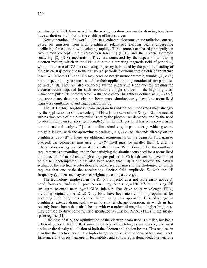
120
constructed at UCLA — as well as the next generation now on the drawing boards —have as their central mission the enabling of light sources.
New generations of powerful, ultra-fast, coherent electromagnetic radiation sources, based on emission from high brightness, relativistic electron beams undergoing oscillating forces, are now developing rapidly. These sources are based principally on two related concepts, the free-electron laser [7] (FEL), and the inverse Compton scattering [8] (ICS) mechanism. They are connected by the aspect of undulating electron motion, which in the FEL is due to a alternating magnetic field of period λu while in the case of ICS the oscillating trajectory is induced by the periodic bending of the particle trajectory due to the transverse, periodic electromagnetic fields of an intense laser. While both FEL and ICS may produce nearly monochromatic, tunable ( λu ∝γ−2 ) photon spectra, they are most noted for their application to generation of sub-ps pulses of X-rays [9]. They are also connected by the underlying technique for creating the electron beams required for such revolutionary light sources — the high-brightness ultra-short pulse RF photoinjector. With the electron brightness defined as Be = 2I /εn
2 , one appreciates that these electron beam must simultaneously have low normalized transverse emittance εn and high peak current I.
The UCLA high brightness beam program has indeed been motivated most strongly by the application to short wavelength FELs. In the case of the X-ray FEL, the needed sub-ps time scale of the X-ray pulse is set by the photon user demands, and by the need to obtain high gain (or short gain length Lg ) in the FEL per se. It has been shown using one-dimensional analysis [7] that the dimensionless gain parameter ρ which governs the gain length, with the approximate scaling Lg ≅ λu / 4π 3ρ , depends directly on the brightness, as ρ ∝ B1/ 3 . There are additional requirements on the beam for FEL gain to proceed: the geometric emittance ε =εn /βγ itself must be smaller than λr and the relative slice energy spread must be smaller than ρ . With X-ray FELs, the emittance requirement is demanding, and in fact satisfying the simultaneous need for a normalized emittance of 10−6 m-rad and a high charge per pulse (~1 nC) has driven the development of the RF photoinjector. It has also been noted that [10] if one follows the natural scaling of the electron acceleration and collective dynamics in the photoinjector, which requires that one scale the accelerating electric field amplitude E0 with the RF frequency fRF , then one may expect brightness scaling as B ∝ fRF
2 . The technology employed in the RF photoinjector does not scale easily above S-
band, however, and so in practice one may access E0 ≅120 MV/m, utilizing RF structures resonant near fRF =3 GHz. Injectors that drive short wavelength FELs, including originally the LCLS X-ray FEL, have been most commonly optimized for obtaining high brightness electron beams using this approach. This advantage in brightness extends dramatically even to smaller charge operation, in which in has recently been shown that sub-fs beams with two orders of magnitude higher brightness may be used to drive self-amplified spontaneous emission (SASE) FELs in the single-spike regime [11].
In the case of ICS, the optimization of the electron beam used is similar, but has a different genesis. As the ICS source is a type of colliding beam scheme, one must optimize the density at collision of both the electron and photon beams. This requires in turn that the electron beam have high charge per pulse, and be focused to a small spot. Emittance is a direct measure of focusablity, and so low εn is demanded. Further, one
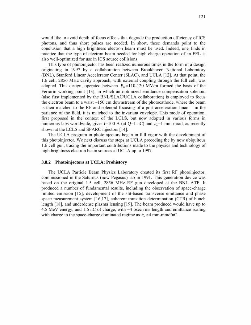
121
would like to avoid depth of focus effects that degrade the production efficiency of ICS photons, and thus short pulses are needed. In short, these demands point to the conclusion that a high brightness electron beam must be used. Indeed, one finds in practice that the type of electron beam needed for high charge operation of an FEL is also well-optimized for use in ICS source collisions.
This type of photoinjector has been realized numerous times in the form of a design originating in 1997 by a collaboration between Brookhaven National Laboratory (BNL), Stanford Linear Accelerator Center (SLAC), and UCLA [12]. At that point, the 1.6 cell, 2856 MHz cavity approach, with external coupling through the full cell, was adopted. This design, operated between E0 =110-120 MV/m formed the basis of the Ferrario working point [13], in which an optimized emittance compensation solenoid (also first implemented by the BNL/SLAC/UCLA collaboration) is employed to focus the electron beam to a waist ~150 cm downstream of the photocathode, where the beam is then matched to the RF and solenoid focusing of a post-acceleration linac -- in the parlance of the field, it is matched to the invariant envelope. This mode of operation, first proposed in the context of the LCLS, but now adopted in various forms in numerous labs worldwide, gives I=100 A (at Q=1 nC) and εn=1 mm-mrad, as recently shown at the LCLS and SPARC injectors [14].
The UCLA program in photoinjectors began in full vigor with the development of this photoinjector. We next discuss the steps at UCLA preceding the by now ubiquitous 1.6 cell gun, tracing the important contributions made to the physics and technology of high brightness electron beam sources at UCLA up to 1997.
3.8.2 Photoinjectors at UCLA: Prehistory
The UCLA Particle Beam Physics Laboratory created its first RF photoinjector, commissioned in the Saturnus (now Pegasus) lab in 1991. This generation device was based on the original 1.5 cell, 2856 MHz RF gun developed at the BNL ATF. It produced a number of fundamental results, including the observation of space-charge limited emission [15], development of the slit-based transverse emittance and phase space measurement system [16,17], coherent transition determination (CTR) of bunch length [18], and underdense plasma lensing [19]. The beam produced would have up to 4.5 MeV energy, and 1.6 nC of charge, with ~4 psec rms length and emittance scaling with charge in the space-charge dominated regime as εn ≅4 mm-mrad/nC.
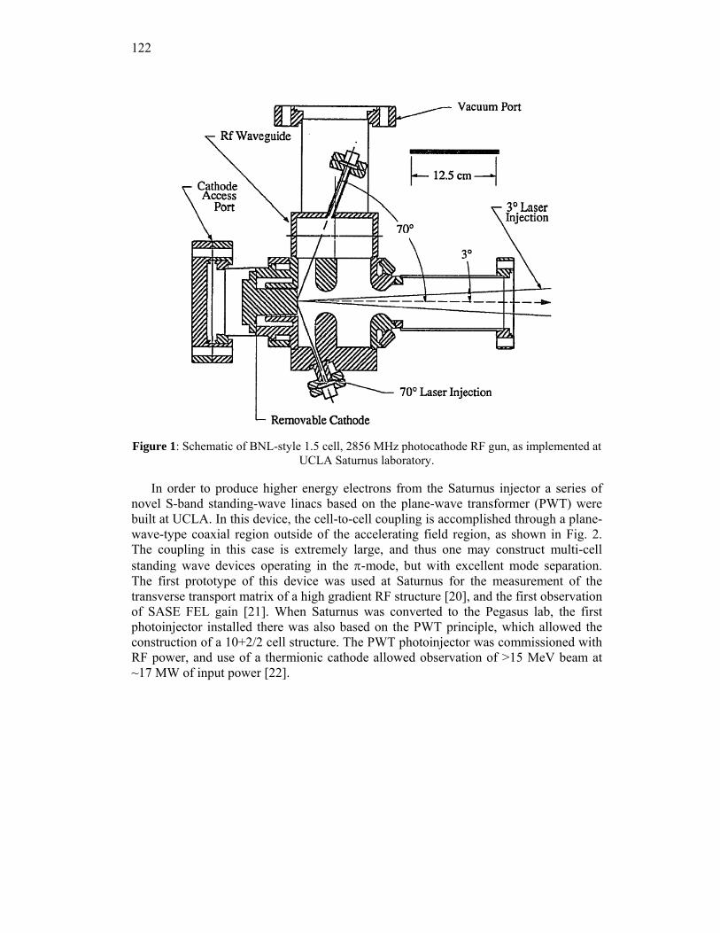
122
Figure 1: Schematic of BNL-style 1.5 cell, 2856 MHz photocathode RF gun, as implemented at
UCLA Saturnus laboratory.
In order to produce higher energy electrons from the Saturnus injector a series of novel S-band standing-wave linacs based on the plane-wave transformer (PWT) were built at UCLA. In this device, the cell-to-cell coupling is accomplished through a plane-wave-type coaxial region outside of the accelerating field region, as shown in Fig. 2. The coupling in this case is extremely large, and thus one may construct multi-cell standing wave devices operating in the π-mode, but with excellent mode separation. The first prototype of this device was used at Saturnus for the measurement of the transverse transport matrix of a high gradient RF structure [20], and the first observation of SASE FEL gain [21]. When Saturnus was converted to the Pegasus lab, the first photoinjector installed there was also based on the PWT principle, which allowed the construction of a 10+2/2 cell structure. The PWT photoinjector was commissioned with RF power, and use of a thermionic cathode allowed observation of >15 MeV beam at ~17 MW of input power [22].
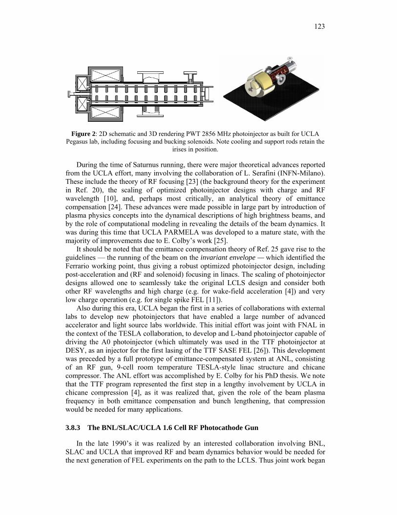
123
Figure 2: 2D schematic and 3D rendering PWT 2856 MHz photoinjector as built for UCLA
Pegasus lab, including focusing and bucking solenoids. Note cooling and support rods retain the irises in position.
During the time of Saturnus running, there were major theoretical advances reported from the UCLA effort, many involving the collaboration of L. Serafini (INFN-Milano). These include the theory of RF focusing [23] (the background theory for the experiment in Ref. 20), the scaling of optimized photoinjector designs with charge and RF wavelength [10], and, perhaps most critically, an analytical theory of emittance compensation [24]. These advances were made possible in large part by introduction of plasma physics concepts into the dynamical descriptions of high brightness beams, and by the role of computational modeling in revealing the details of the beam dynamics. It was during this time that UCLA PARMELA was developed to a mature state, with the majority of improvements due to E. Colby’s work [25].
It should be noted that the emittance compensation theory of Ref. 25 gave rise to the guidelines — the running of the beam on the invariant envelope — which identified the Ferrario working point, thus giving a robust optimized photoinjector design, including post-acceleration and (RF and solenoid) focusing in linacs. The scaling of photoinjector designs allowed one to seamlessly take the original LCLS design and consider both other RF wavelengths and high charge (e.g. for wake-field acceleration [4]) and very low charge operation (e.g. for single spike FEL [11]).
Also during this era, UCLA began the first in a series of collaborations with external labs to develop new photoinjectors that have enabled a large number of advanced accelerator and light source labs worldwide. This initial effort was joint with FNAL in the context of the TESLA collaboration, to develop and L-band photoinjector capable of driving the A0 photoinjector (which ultimately was used in the TTF photoinjector at DESY, as an injector for the first lasing of the TTF SASE FEL [26]). This development was preceded by a full prototype of emittance-compensated system at ANL, consisting of an RF gun, 9-cell room temperature TESLA-style linac structure and chicane compressor. The ANL effort was accomplished by E. Colby for his PhD thesis. We note that the TTF program represented the first step in a lengthy involvement by UCLA in chicane compression [4], as it was realized that, given the role of the beam plasma frequency in both emittance compensation and bunch lengthening, that compression would be needed for many applications.
3.8.3 The BNL/SLAC/UCLA 1.6 Cell RF Photocathode Gun
In the late 1990’s it was realized by an interested collaboration involving BNL, SLAC and UCLA that improved RF and beam dynamics behavior would be needed for the next generation of FEL experiments on the path to the LCLS. Thus joint work began
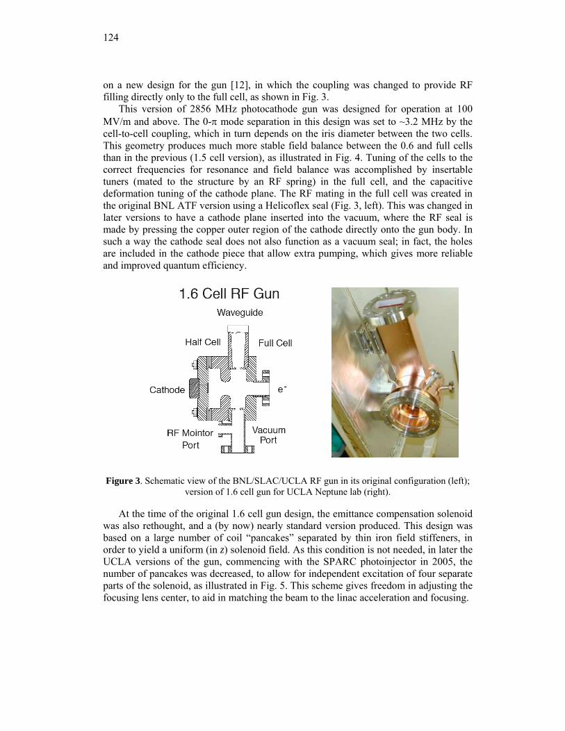
124
on a new design for the gun [12], in which the coupling was changed to provide RF filling directly only to the full cell, as shown in Fig. 3.
This version of 2856 MHz photocathode gun was designed for operation at 100 MV/m and above. The 0-π mode separation in this design was set to ~3.2 MHz by the cell-to-cell coupling, which in turn depends on the iris diameter between the two cells. This geometry produces much more stable field balance between the 0.6 and full cells than in the previous (1.5 cell version), as illustrated in Fig. 4. Tuning of the cells to the correct frequencies for resonance and field balance was accomplished by insertable tuners (mated to the structure by an RF spring) in the full cell, and the capacitive deformation tuning of the cathode plane. The RF mating in the full cell was created in the original BNL ATF version using a Helicoflex seal (Fig. 3, left). This was changed in later versions to have a cathode plane inserted into the vacuum, where the RF seal is made by pressing the copper outer region of the cathode directly onto the gun body. In such a way the cathode seal does not also function as a vacuum seal; in fact, the holes are included in the cathode piece that allow extra pumping, which gives more reliable and improved quantum efficiency.
Figure 3. Schematic view of the BNL/SLAC/UCLA RF gun in its original configuration (left); version of 1.6 cell gun for UCLA Neptune lab (right).
At the time of the original 1.6 cell gun design, the emittance compensation solenoid was also rethought, and a (by now) nearly standard version produced. This design was based on a large number of coil “pancakes” separated by thin iron field stiffeners, in order to yield a uniform (in z) solenoid field. As this condition is not needed, in later the UCLA versions of the gun, commencing with the SPARC photoinjector in 2005, the number of pancakes was decreased, to allow for independent excitation of four separate parts of the solenoid, as illustrated in Fig. 5. This scheme gives freedom in adjusting the focusing lens center, to aid in matching the beam to the linac acceleration and focusing.
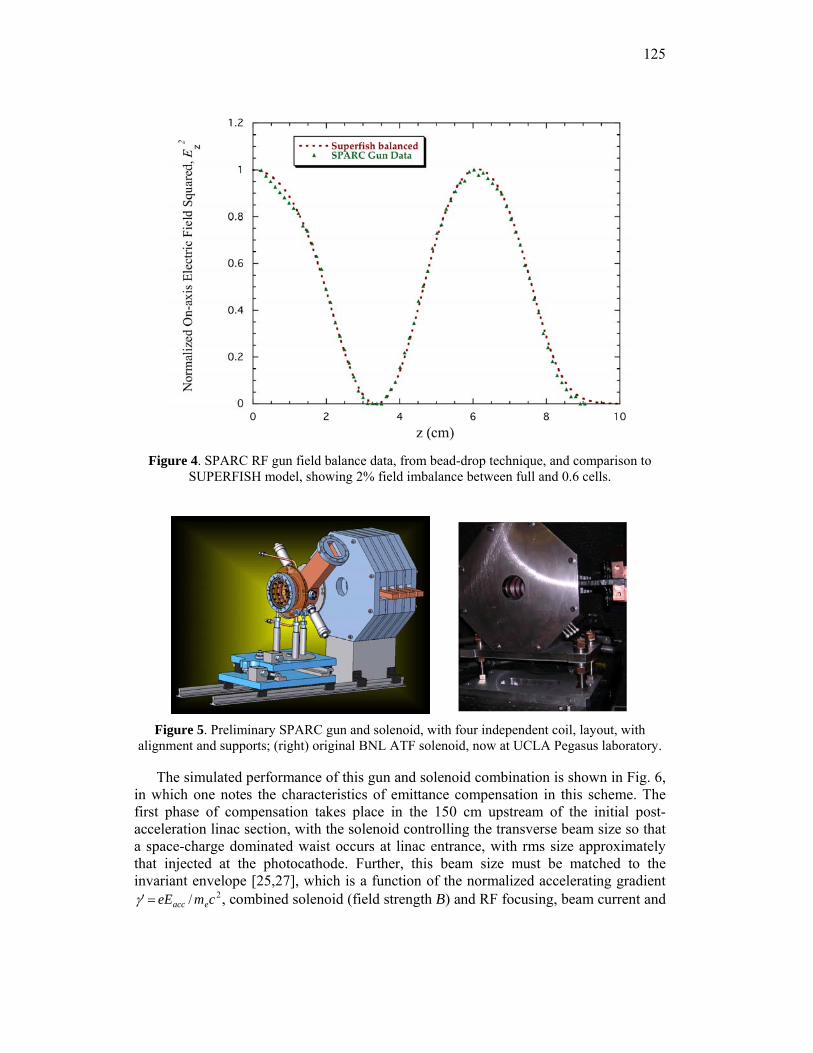
125
Figure 4. SPARC RF gun field balance data, from bead-drop technique, and comparison to
SUPERFISH model, showing 2% field imbalance between full and 0.6 cells.
Figure 5. Preliminary SPARC gun and solenoid, with four independent coil, layout, with
alignment and supports; (right) original BNL ATF solenoid, now at UCLA Pegasus laboratory.
The simulated performance of this gun and solenoid combination is shown in Fig. 6, in which one notes the characteristics of emittance compensation in this scheme. The first phase of compensation takes place in the 150 cm upstream of the initial post-acceleration linac section, with the solenoid controlling the transverse beam size so that a space-charge dominated waist occurs at linac entrance, with rms size approximately that injected at the photocathode. Further, this beam size must be matched to the invariant envelope [25,27], which is a function of the normalized accelerating gradient
′ γ = eEacc / mec2, combined solenoid (field strength B) and RF focusing, beam current and
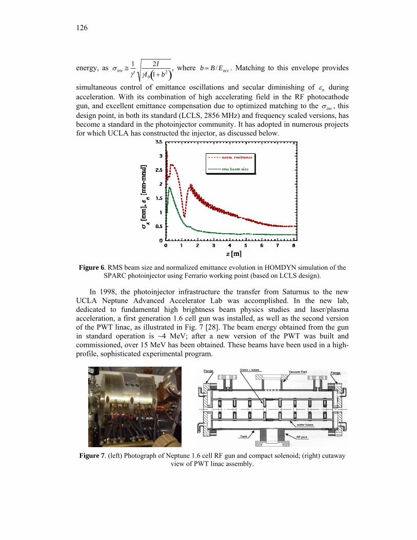
126
energy, as σ inv ≅ 1′ γ
2IγI0 1+ b2( )
, where b = B / Eacc . Matching to this envelope provides
simultaneous control of emittance oscillations and secular diminishing of εn during acceleration. With its combination of high accelerating field in the RF photocathode gun, and excellent emittance compensation due to optimized matching to the σ inv , this design point, in both its standard (LCLS, 2856 MHz) and frequency scaled versions, has become a standard in the photoinjector community. It has adopted in numerous projects for which UCLA has constructed the injector, as discussed below.
Figure 6. RMS beam size and normalized emittance evolution in HOMDYN simulation of the
SPARC photoinjector using Ferrario working point (based on LCLS design).
In 1998, the photoinjector infrastructure the transfer from Saturnus to the new UCLA Neptune Advanced Accelerator Lab was accomplished. In the new lab, dedicated to fundamental high brightness beam physics studies and laser/plasma acceleration, a first generation 1.6 cell gun was installed, as well as the second version of the PWT linac, as illustrated in Fig. 7 [28]. The beam energy obtained from the gun in standard operation is ~4 MeV; after a new version of the PWT was built and commissioned, over 15 MeV has been obtained. These beams have been used in a high-profile, sophisticated experimental program.
Figure 7. (left) Photograph of Neptune 1.6 cell RF gun and compact solenoid; (right) cutaway
view of PWT linac assembly.
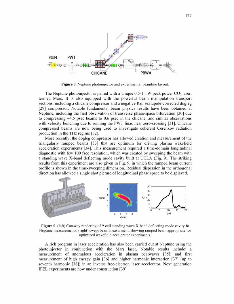
127
Figure 8. Neptune photoinjector and experimental beamline layout.
The Neptune photoinjector is paired with a unique 0.5-1 TW peak power CO2 laser, termed Mars. It is also equipped with the powerful beam manipulation transport sections, including a chicane compressor and a negative R56, sextupole-corrected dogleg [29] compressor. Notable fundamental beam physics results have been obtained at Neptune, including the first observation of transverse phase-space bifurcation [30] due to compressing ~4.5 psec beams to 0.6 psec in the chicane, and similar observations with velocity bunching due to running the PWT linac near zero-crossing [31]. Chicane compressed beams are now being used to investigate coherent Cerenkov radiation production in the THz regime [32].
More recently, the dogleg compressor has allowed creation and measurement of the triangularly ramped beams [33] that are optimum for driving plasma wakefield acceleration experiments [34]. This measurement required a time-domain longitudinal diagnostic with few 100 fsec resolution, which was created by sweeping the beam with a standing wave X-band deflecting mode cavity built at UCLA (Fig. 9). The striking results from this experiment are also given in Fig. 9, in which the ramped beam current profile is shown in the time-sweeping dimension. Residual dispersion in the orthogonal direction has allowed a single shot picture of longitudinal phase space to be displayed.
Figure 9. (left) Cutaway rendering of 9-cell standing wave X-band deflecting mode cavity fo Neptune measurements; (right) swept beam measurment, showing ramped beam appropriate for
optimized wakefield accelerator experiments.
A rich program in laser acceleration has also been carried out at Neptune using the photoinjector in conjunction with the Mars laser. Notable results include: a measurement of anomalous acceleration in plasma beatwaves [35]; and first measurement of high energy gain [36] and higher harmonic interaction [37] (up to seventh harmonic [38]) in an inverse free-electron laser accelerator. Next generation IFEL experiments are now under construction [39].
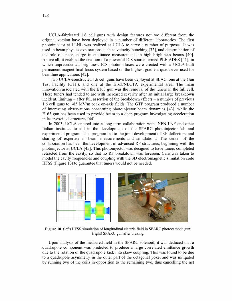
128
UCLA-fabricated 1.6 cell guns with design features not too different from the original version have been deployed in a number of different laboratories. The first photoinjector at LLNL was realized at UCLA to serve a number of purposes. It was used in beam physics explorations such as velocity bunching [32], and determination of the role of space-charge in emittance measurements in high brightness beams [40]. Above all, it enabled the creation of a powerful ICS source termed PLEIADES [41], in which unprecedented brightness ICS photon fluxes were created with a UCLA-built permanent magnet final focus system based on the highest gradient quads ever used for beamline applications [42].
Two UCLA-constructed 1.6 cell guns have been deployed at SLAC, one at the Gun Test Facility (GTF), and one at the E163/NLCTA experimental area. The main innovation associated with the E163 gun was the removal of the tuners in the full cell. These tuners had tended to arc with increased severity after an initial large breakdown incident, limiting – after full assertion of the breakdown effects – a number of previous 1.6 cell guns to ~85 MV/m peak on-axis fields. The GTF program produced a number of interesting observations concerning photoinjector beam dynamics [43], while the E163 gun has been used to provide beam to a deep program investigating acceleration in laser-excited structures [44].
In 2003, UCLA entered into a long-term collaboration with INFN-LNF and other Italian institutes to aid in the development of the SPARC photoinjector lab and experimental program. This program led to the joint development of RF deflectors, and sharing of expertise in beam measurements and simulations. The center of the collaboration has been the development of advanced RF structures, beginning with the photoinjector at UCLA [45]. This photoinjector was designed to have tuners completed retracted from the cavity, so that no RF breakdown was foreseen. Care was taken to model the cavity frequencies and coupling with the 3D electromagnetic simulation code HFSS (Figure 10) to guarantee that tuners would not be needed.
Figure 10. (left) HFSS simulation of longitudinal electric field in SPARC photocathode gun; (right) SPARC gun after brazing.
Upon analysis of the measured field in the SPARC solenoid, it was deduced that a quadrupole component was predicted to produce a large correlated emittance growth due to the rotation of the quadrupole kick into skew coupling. This was found to be due to a quadrupole asymmetry in the outer part of the octagonal yoke, and was mitigated by running two of the coils in opposition to the remaining two, thus cancelling the net
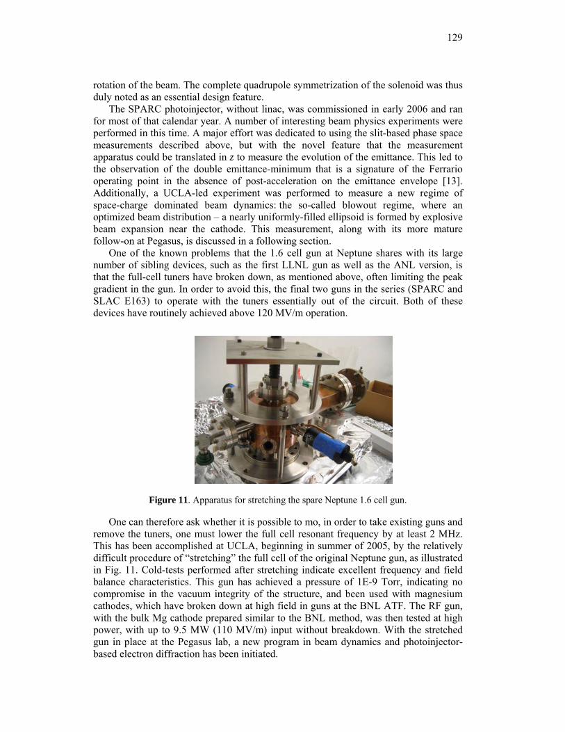
129
rotation of the beam. The complete quadrupole symmetrization of the solenoid was thus duly noted as an essential design feature.
The SPARC photoinjector, without linac, was commissioned in early 2006 and ran for most of that calendar year. A number of interesting beam physics experiments were performed in this time. A major effort was dedicated to using the slit-based phase space measurements described above, but with the novel feature that the measurement apparatus could be translated in z to measure the evolution of the emittance. This led to the observation of the double emittance-minimum that is a signature of the Ferrario operating point in the absence of post-acceleration on the emittance envelope [13]. Additionally, a UCLA-led experiment was performed to measure a new regime of space-charge dominated beam dynamics: the so-called blowout regime, where an optimized beam distribution – a nearly uniformly-filled ellipsoid is formed by explosive beam expansion near the cathode. This measurement, along with its more mature follow-on at Pegasus, is discussed in a following section.
One of the known problems that the 1.6 cell gun at Neptune shares with its large number of sibling devices, such as the first LLNL gun as well as the ANL version, is that the full-cell tuners have broken down, as mentioned above, often limiting the peak gradient in the gun. In order to avoid this, the final two guns in the series (SPARC and SLAC E163) to operate with the tuners essentially out of the circuit. Both of these devices have routinely achieved above 120 MV/m operation.
Figure 11. Apparatus for stretching the spare Neptune 1.6 cell gun.
One can therefore ask whether it is possible to mo, in order to take existing guns and remove the tuners, one must lower the full cell resonant frequency by at least 2 MHz. This has been accomplished at UCLA, beginning in summer of 2005, by the relatively difficult procedure of “stretching” the full cell of the original Neptune gun, as illustrated in Fig. 11. Cold-tests performed after stretching indicate excellent frequency and field balance characteristics. This gun has achieved a pressure of 1E-9 Torr, indicating no compromise in the vacuum integrity of the structure, and been used with magnesium cathodes, which have broken down at high field in guns at the BNL ATF. The RF gun, with the bulk Mg cathode prepared similar to the BNL method, was then tested at high power, with up to 9.5 MW (110 MV/m) input without breakdown. With the stretched gun in place at the Pegasus lab, a new program in beam dynamics and photoinjector-based electron diffraction has been initiated.
130
3.8.4 Dynamically Optimized Photoelectron Beams
The standard method for obtaining the highest brightness electron beams from photoinjectors, is now use of the emittance compensation process. Optimization of this process demands that the transverse fields be as uniform, and linear (in radius r) as possible. The existing theoretical and experimental studies of emittance compensation have thus assumed use of a uniform density electron beam, having a cylindrical shape. However, this shape produces space-charge fields near the beam head and tail that have notable nonlinear dependences on the spatial coordinates. These nonlinearities can cause both transverse and longitudinal emittance growth.
It has been known since the 1950’s from the results of Kapchinskii and Vladimirski [46], that a uniform density distribution having ellipsoidal shape yields space-charge fields that are linear in all dimensions (e.g. Ex ∝ x, Ez ∝ z). Under such conditions, it is conceivable that one may obtain essentially emittance-growth-free dynamics. Production of such a distribution has, until recently, remained an elusive proposition. In the past ten years, 1997, Serafini [47] and later Luiten, et al., [48] proposed the dynamic creation of an ellipsoidal bunch by launching an ultra-short, radially shaped beam, which then evolves through longitudinal expansion of differing radii in the beam to achieve the desired longitudinal shape. The major contribution given by Luiten, et al. is that in obtaining the correct final ellipsoidal distribution, there is essentially no requirement on the shape of the initial laser pulse other than it be ultra-short (length τ l much shorter than eventual beam length after space charge expansion). Thus such laser pulses are a natural, and technically achievable way, of producing an ellipsoidal-shaped, nearly uniform density beam.
However, the beam dynamics near the cathode are qualitatively different in the traditional emittance compensation scenario and in the Luiten-Serafini scheme, it is not obvious that one may successfully combine the two. We have shown that shown that this marriage is possible [49]; further, the combination emittance compensation and dynamic creation of the ellipsoidal shaped beam produces results that in many ways are superior to those obtained in current designs. As the bunches that are produced are shorter than in such standard cases, higher current, low emittance beams creation are made possible. Further, the longitudinal space-charge forces are linear in z, thus giving the possibility of a more compressible beam.
The central concept of the Luiten-Serafini scheme is straightforward: the beam profile expands and deforms longitudinally to produce a uniformly filled ellipsoid of charge. The final state beam is thus nearly optimized — more so than the beer-can distribution used in prevailing designs — for minimizing nonlinear space charge. In the process of the “blowout”, however, phase space rearrangements occur which may degrade the emittances. Such a promising scheme demands experimental investigations, which we now discuss, in two detailed scenarios: the SPARC and Pegasus photoinjector laboratories.
In order to understand effects relevant to the blowout, to specify experimental requirements, and to identify experimental signatures associated with the process, the dynamics of space-charge-dominated beam expansion have been analyzed.
This analysis may be summarized in a few points:
— First, the injected bunch surface charge densityσ b = dQb /dA must not be too high, or image charge effects at the cathode distort the final pulse
131
profile so that it is not ellipsoidal. This is quantified by the condition α ≡ 4πσ b / E0 <<1.
— Second, the beam must be much shorter than its eventual size in order to be able to ignore the details of the initial pulse profile, which is not a serious constraint. In practice 100 fs laser pulses (typical of the limitations of the SPARC and E163 photocathode lasers) excite roughly the same length electron bunch, which expands to around 4 psec in our example cases. The pulse length after expansion is estimated as Lb ≈ 2πσ bmec
2 E02 .
— The current density that is achieved after expansion, is Jz = eE02 4πmec ,
a constant dependent only on the applied electric field E0. All beams become uniform in density.
— To achieve the ellipsoidal beam shape, one must choose the correct initial surface current density distributionσ b r( )= 3Q /2πa2( ) 1− r /a( )2 .
Going beyond the analysis of the beam dynamics, the central issue of the compatibility of this regime with emittance compensation must be explored with simulations. The initial simulations we performed are in the context of the SPARC scenario, so that the experimental tests of this regime at INFN-LNF may be discussed.
3.8.5 Measurements in the Blowout Regime at SPARC
There are many experimental signatures one can look for in tests of this operating regime, but the most direct are found in the longitudinal profile. Here one may use a streak camera to observe the t-dependence of the current, and also spatially resolve the transverse direction, thus measuring e.g., a (x,z) slice of the beam, which should give a uniformly filled ellipse. Streak cameras may have resolution as low as 0.25 ps (in practice it may be a bit larger), but at SPARC there was a 2 psec FWHM streak camera available, which was just adequate to resolve the beam, which, depending on choice of total charge, is in the range of longer than 4-10 psec full width. We note, of course that an RF deflector is preferred for this measurement. While one was not available in the SPARC experiments, the later Pegasus experiments exploited well the excellent resolution available from deflectors, as discussed below.
For time resolved streak-camera-basd measurements one converts the beam spatial information to photons with a prompt emitter. As transition radiation gives too weak of a signal at this energy, a Cerenkov convertor was used. In order to have a manageably small-angle of emission we chose aerogel, which has small index (n=1.005-1.02). At 5 MeV the Cerenkov emission threshold is reached for n=1.005; a mechanically robust aerogel fabricated at JPL is obtained with a lower threshold, having n=1.008.
A Monte Carlo approach to the imaging and temporal resolution properties of the Cerenkov light from creation through transport to the streak camera was used to design the experiment. Electrons from PARMELA are employed in GEANT, which simulates material scattering of the electrons and generates a collection of Cerenkov photons in
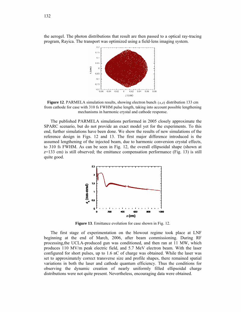
132
the aerogel. The photon distributions that result are then passed to a optical ray-tracing program, Rayica. The transport was optimized using a field-lens imaging system.
Figure 12. PARMELA simulation results, showing electron bunch (x,z) distribution 133 cm
from cathode for case with 310 fs FWHM pulse length, taking into account possible lengthening mechanisms in harmonic crystal and cathode response.
The published PARMELA simulations performed in 2005 closely approximate the SPARC scenario, but do not provide an exact model yet for the experiments. To this end, further simulations have been done. We show the results of new simulations of the reference design in Figs. 12 and 13. The first major difference introduced is the assumed lengthening of the injected beam, due to harmonic conversion crystal effects, to 310 fs FWHM. As can be seen in Fig. 12, the overall ellipsoidal shape (shown at z=133 cm) is still observed; the emittance compensation performance (Fig. 13) is still quite good.
Figure 13. Emittance evolution for case shown in Fig. 12.
The first stage of experimentation on the blowout regime took place at LNF beginning at the end of March, 2006, after beam commissioning. During RF processing,the UCLA-produced gun was conditioned, and then ran at 11 MW, which produces 110 MV/m peak electric field, and 5.7 MeV electron beam. With the laser configured for short pulses, up to 1.6 nC of charge was obtained. While the laser was set to approximately correct transverse size and profile shapes, there remained spatial variations in both the laser and cathode quantum efficiency. Thus the conditions for observing the dynamic creation of nearly uniformly filled ellipsoidal charge distributions were not quite present. Nevertheless, encouraging data were obtained.
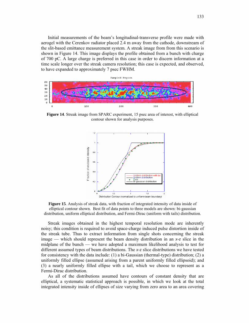
133
Initial measurements of the beam’s longitudinal-transverse profile were made with aerogel with the Cerenkov radiator placed 2.4 m away from the cathode, downstream of the slit-based emittance measurement system. A streak image from from this scenario is shown in Figure 14. This image displays the profile obtained from a bunch with charge of 700 pC. A large charge is preferred in this case in order to discern information at a time scale longer over the streak camera resolution; this case is expected, and observed, to have expanded to approximately 7 psec FWHM.
Figure 14. Streak image from SPARC experiment, 15 psec area of interest, with elliptical contour shown for analysis purposes.
Figure 15. Analysis of streak data, with fraction of integrated intensity of data inside of elliptical contour shown. Best fit of data points to three models are shown: bi-gaussian
distribution, uniform elliptical distribution, and Fermi-Dirac (uniform with tails) distribution.
Streak images obtained in the highest temporal resolution mode are inherently noisy; this condition is required to avoid space-charge induced pulse distortion inside of the streak tube. Thus to extract information from single shots concerning the streak image — which should represent the beam density distribution in an x-z slice in the midplane of the bunch — we have adopted a maximum likelihood analysis to test for different assumed types of beam distributions. The x-z slice distributions we have tested for consistency with the data include: (1) a bi-Gaussian (thermal-type) distribution; (2) a uniformly filled ellipse (assumed arising from a parent uniformly filled ellipsoid); and (3) a nearly uniformly filled ellipse with a tail, which we choose to represent as a Fermi-Dirac distribution.
As all of the distributions assumed have contours of constant density that are elliptical, a systematic statistical approach is possible, in which we look at the total integrated intensity inside of ellipses of size varying from zero area to an area covering
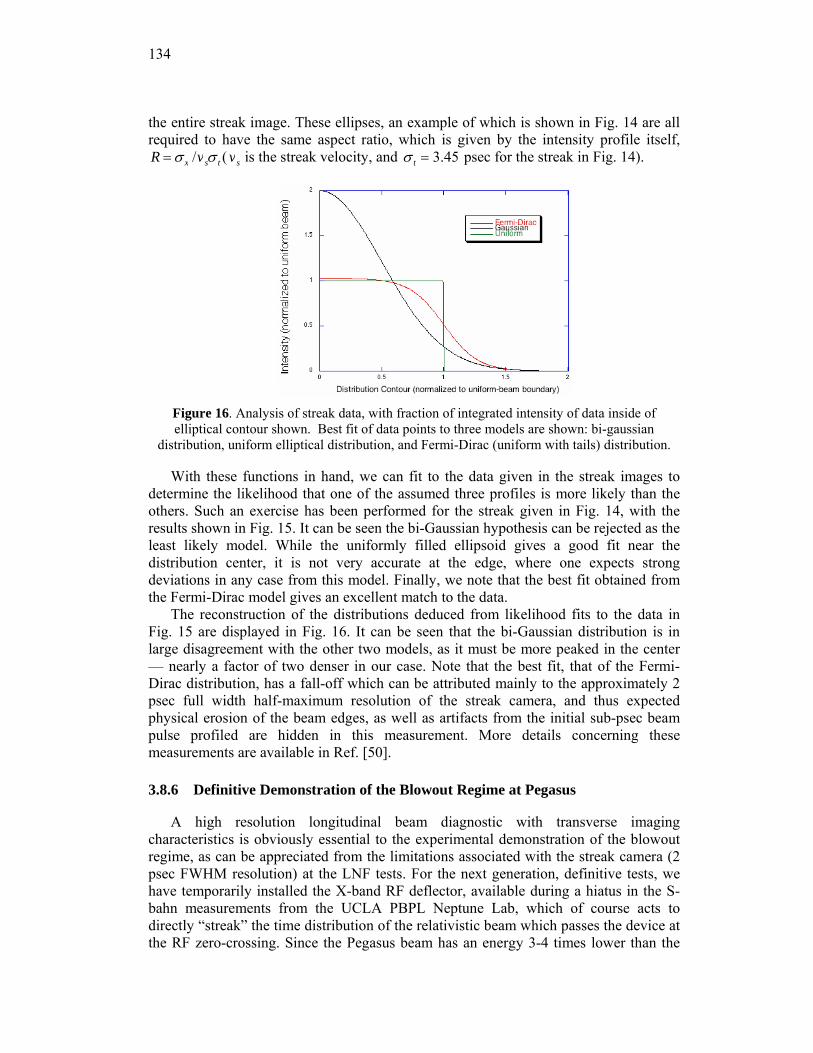
134
the entire streak image. These ellipses, an example of which is shown in Fig. 14 are all required to have the same aspect ratio, which is given by the intensity profile itself, R = σ x /vsσ t ( vs is the streak velocity, and σ t = 3.45 psec for the streak in Fig. 14).
Figure 16. Analysis of streak data, with fraction of integrated intensity of data inside of elliptical contour shown. Best fit of data points to three models are shown: bi-gaussian
distribution, uniform elliptical distribution, and Fermi-Dirac (uniform with tails) distribution.
With these functions in hand, we can fit to the data given in the streak images to determine the likelihood that one of the assumed three profiles is more likely than the others. Such an exercise has been performed for the streak given in Fig. 14, with the results shown in Fig. 15. It can be seen the bi-Gaussian hypothesis can be rejected as the least likely model. While the uniformly filled ellipsoid gives a good fit near the distribution center, it is not very accurate at the edge, where one expects strong deviations in any case from this model. Finally, we note that the best fit obtained from the Fermi-Dirac model gives an excellent match to the data.
The reconstruction of the distributions deduced from likelihood fits to the data in Fig. 15 are displayed in Fig. 16. It can be seen that the bi-Gaussian distribution is in large disagreement with the other two models, as it must be more peaked in the center — nearly a factor of two denser in our case. Note that the best fit, that of the Fermi-Dirac distribution, has a fall-off which can be attributed mainly to the approximately 2 psec full width half-maximum resolution of the streak camera, and thus expected physical erosion of the beam edges, as well as artifacts from the initial sub-psec beam pulse profiled are hidden in this measurement. More details concerning these measurements are available in Ref. [50].
3.8.6 Definitive Demonstration of the Blowout Regime at Pegasus
A high resolution longitudinal beam diagnostic with transverse imaging characteristics is obviously essential to the experimental demonstration of the blowout regime, as can be appreciated from the limitations associated with the streak camera (2 psec FWHM resolution) at the LNF tests. For the next generation, definitive tests, we have temporarily installed the X-band RF deflector, available during a hiatus in the S-bahn measurements from the UCLA PBPL Neptune Lab, which of course acts to directly “streak” the time distribution of the relativistic beam which passes the device at the RF zero-crossing. Since the Pegasus beam has an energy 3-4 times lower than the
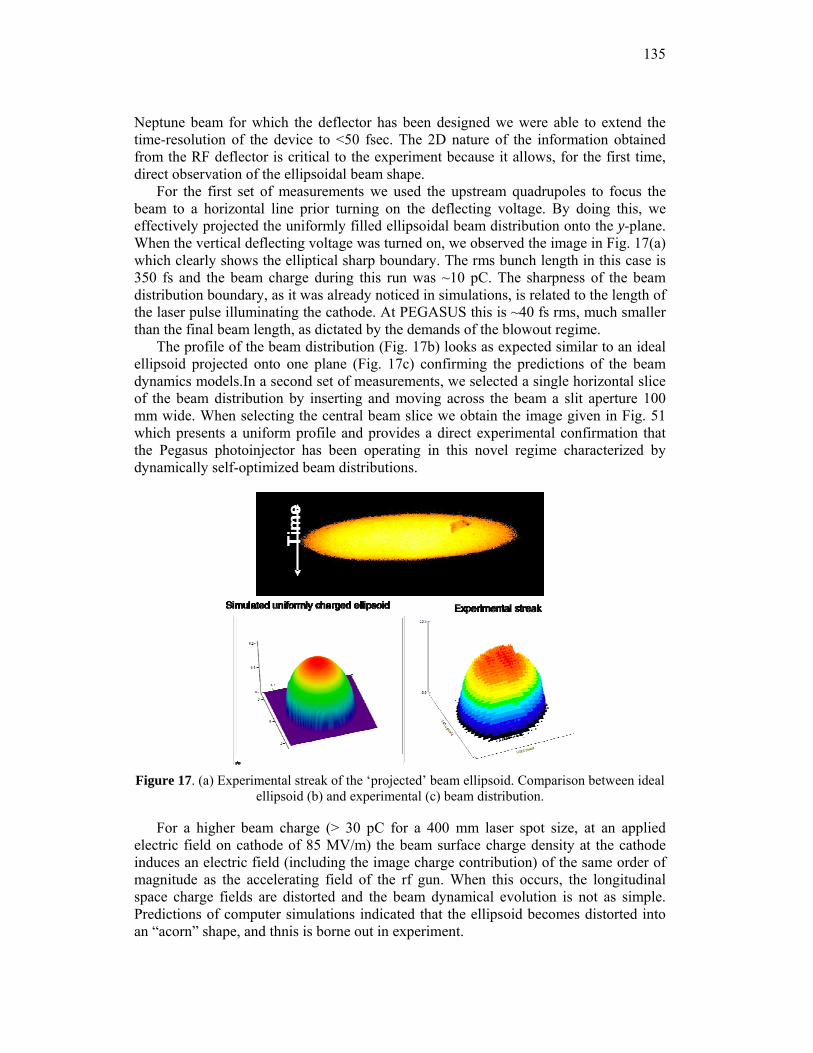
135
Neptune beam for which the deflector has been designed we were able to extend the time-resolution of the device to <50 fsec. The 2D nature of the information obtained from the RF deflector is critical to the experiment because it allows, for the first time, direct observation of the ellipsoidal beam shape.
For the first set of measurements we used the upstream quadrupoles to focus the beam to a horizontal line prior turning on the deflecting voltage. By doing this, we effectively projected the uniformly filled ellipsoidal beam distribution onto the y-plane. When the vertical deflecting voltage was turned on, we observed the image in Fig. 17(a) which clearly shows the elliptical sharp boundary. The rms bunch length in this case is 350 fs and the beam charge during this run was ~10 pC. The sharpness of the beam distribution boundary, as it was already noticed in simulations, is related to the length of the laser pulse illuminating the cathode. At PEGASUS this is ~40 fs rms, much smaller than the final beam length, as dictated by the demands of the blowout regime.
The profile of the beam distribution (Fig. 17b) looks as expected similar to an ideal ellipsoid projected onto one plane (Fig. 17c) confirming the predictions of the beam dynamics models.In a second set of measurements, we selected a single horizontal slice of the beam distribution by inserting and moving across the beam a slit aperture 100 mm wide. When selecting the central beam slice we obtain the image given in Fig. 51 which presents a uniform profile and provides a direct experimental confirmation that the Pegasus photoinjector has been operating in this novel regime characterized by dynamically self-optimized beam distributions.
Figure 17. (a) Experimental streak of the ‘projected’ beam ellipsoid. Comparison between ideal
ellipsoid (b) and experimental (c) beam distribution.
For a higher beam charge (> 30 pC for a 400 mm laser spot size, at an applied electric field on cathode of 85 MV/m) the beam surface charge density at the cathode induces an electric field (including the image charge contribution) of the same order of magnitude as the accelerating field of the rf gun. When this occurs, the longitudinal space charge fields are distorted and the beam dynamical evolution is not as simple. Predictions of computer simulations indicated that the ellipsoid becomes distorted into an “acorn” shape, and thnis is borne out in experiment.
Time
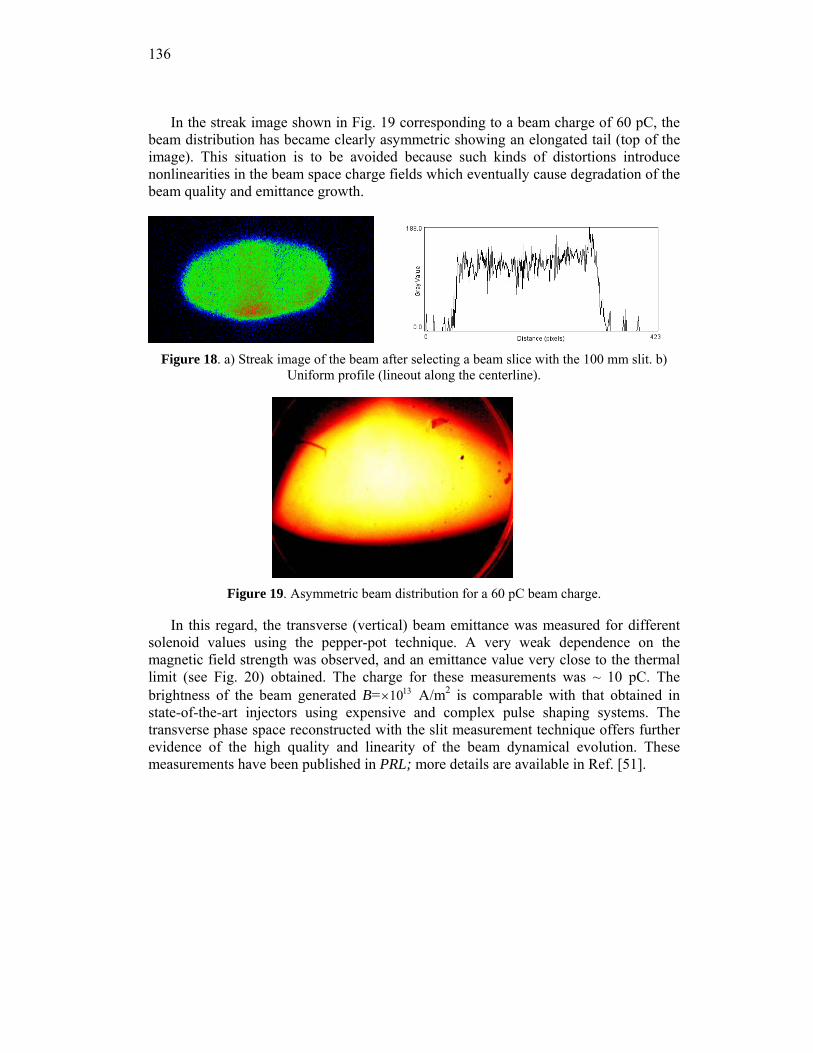
136
In the streak image shown in Fig. 19 corresponding to a beam charge of 60 pC, the beam distribution has became clearly asymmetric showing an elongated tail (top of the image). This situation is to be avoided because such kinds of distortions introduce nonlinearities in the beam space charge fields which eventually cause degradation of the beam quality and emittance growth.
Figure 18. a) Streak image of the beam after selecting a beam slice with the 100 mm slit. b)
Uniform profile (lineout along the centerline).
Figure 19. Asymmetric beam distribution for a 60 pC beam charge.
In this regard, the transverse (vertical) beam emittance was measured for different solenoid values using the pepper-pot technique. A very weak dependence on the magnetic field strength was observed, and an emittance value very close to the thermal limit (see Fig. 20) obtained. The charge for these measurements was ~ 10 pC. The brightness of the beam generated B= ×1013 A/m2 is comparable with that obtained in state-of-the-art injectors using expensive and complex pulse shaping systems. The transverse phase space reconstructed with the slit measurement technique offers further evidence of the high quality and linearity of the beam dynamical evolution. These measurements have been published in PRL; more details are available in Ref. [51].
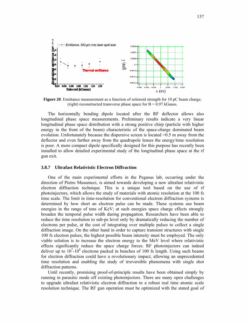
137
Figure 20. Emittance measurement as a function of solenoid strength for 10 pC beam charge;
(right) reconstructed transverse phase space for B = 0.97 kGauss.
The horizontally bending dipole located after the RF deflector allows also longitudinal phase space measurements. Preliminary results indicate a very linear longitudinal phase space distribution with a strong positive chirp (particle with higher energy in the front of the beam) characteristic of the space-charge dominated beam evolution. Unfortunately because the dispersive screen is located >0.5 m away from the deflector and even further away from the quadrupole lenses the energy/time resolution is poor. A more compact dipole specifically designed for this purpose has recently been installed to allow detailed experimental study of the longitudinal phase space at the rf gun exit.
3.8.7 Ultrafast Relativistic Electron Diffraction
One of the main experimental efforts in the Pegasus lab, occurring under the direction of Pietro Musumeci, is aimed towards developing a new ultrafast relativistic electron diffraction technique. This is a unique tool based on the use of rf photoinjectors, which allows the study of materials with atomic resolution at the 100 fs time scale. The limit in time-resolution for conventional electron diffraction systems is determined by how short an electron pulse can be made. These systems use beam energies in the range of tens of KeV; at such energies space charge effects strongly broaden the temporal pulse width during propagation. Researchers have been able to reduce the time resolution to sub-ps level only by dramatically reducing the number of electrons per pulse, at the cost of integrating over multiple pulses to collect a single diffraction image. On the other hand in order to capture transient structures with single 100 fs electron pulses, the highest possible beam intensity must be employed. The only viable solution is to increase the electron energy to the MeV level where relativistic effects significantly reduce the space charge forces. RF photoinjectors can indeed deliver up to 107-108 electrons packed in bunches of 100 fs length. Using such beams for electron diffraction could have a revolutionary impact, allowing an unprecedented time resolution and enabling the study of irreversible phenomena with single shot diffraction patterns.
Until recently, promising proof-of-principle results have been obtained simply by running in parasitic mode off existing photoinjectors. There are many open challenges to upgrade ultrafast relativistic electron diffraction to a robust real time atomic scale resolution technique. The RF gun operation must be optimized with the stated goal of
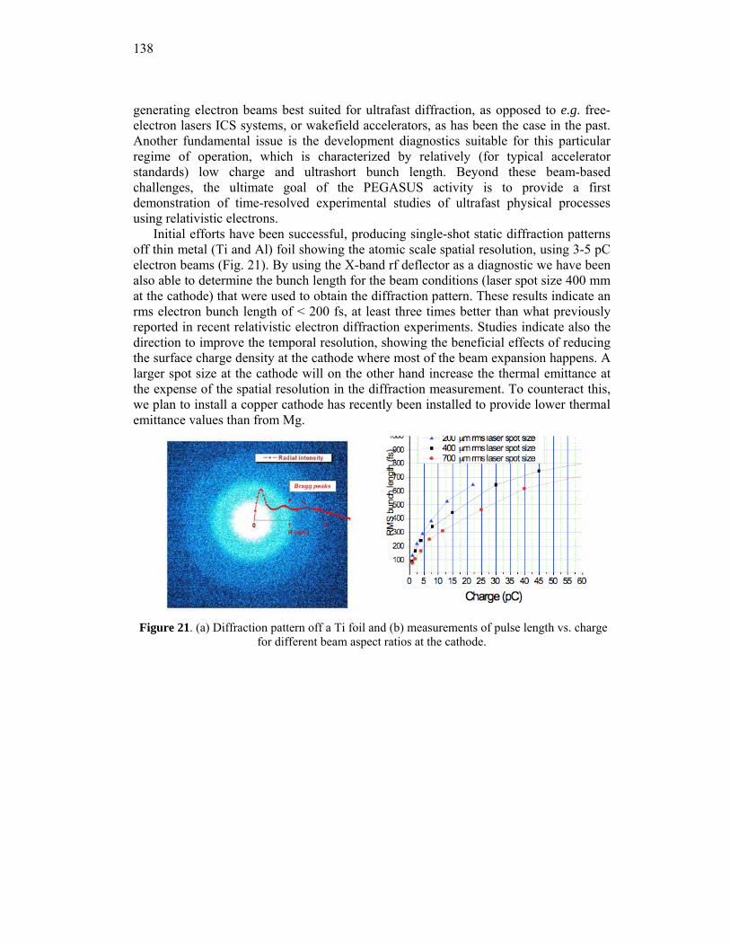
138
generating electron beams best suited for ultrafast diffraction, as opposed to e.g. free-electron lasers ICS systems, or wakefield accelerators, as has been the case in the past. Another fundamental issue is the development diagnostics suitable for this particular regime of operation, which is characterized by relatively (for typical accelerator standards) low charge and ultrashort bunch length. Beyond these beam-based challenges, the ultimate goal of the PEGASUS activity is to provide a first demonstration of time-resolved experimental studies of ultrafast physical processes using relativistic electrons.
Initial efforts have been successful, producing single-shot static diffraction patterns off thin metal (Ti and Al) foil showing the atomic scale spatial resolution, using 3-5 pC electron beams (Fig. 21). By using the X-band rf deflector as a diagnostic we have been also able to determine the bunch length for the beam conditions (laser spot size 400 mm at the cathode) that were used to obtain the diffraction pattern. These results indicate an rms electron bunch length of < 200 fs, at least three times better than what previously reported in recent relativistic electron diffraction experiments. Studies indicate also the direction to improve the temporal resolution, showing the beneficial effects of reducing the surface charge density at the cathode where most of the beam expansion happens. A larger spot size at the cathode will on the other hand increase the thermal emittance at the expense of the spatial resolution in the diffraction measurement. To counteract this, we plan to install a copper cathode has recently been installed to provide lower thermal emittance values than from Mg.
Figure 21. (a) Diffraction pattern off a Ti foil and (b) measurements of pulse length vs. charge
for different beam aspect ratios at the cathode.
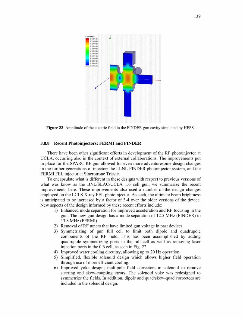
139
Figure 22. Amplitude of the electric field in the FINDER gun cavity simulated by HFSS.
3.8.8 Recent Photoinjectors: FERMI and FINDER
There have been other significant efforts in development of the RF photoinjector at UCLA, occurring also in the context of external collaborations. The improvements put in place for the SPARC RF gun allowed for even more adventuresome design changes in the further generations of injector: the LLNL FINDER photoinjector system, and the FERMI FEL injector at Sincrotrone Trieste.
To encapsulate what is different in these designs with respect to previous versions of what was know as the BNL/SLAC/UCLA 1.6 cell gun, we summarize the recent improvements here. These improvements also used a number of the design changes employed on the LCLS X-ray FEL photoinjector. As such, the ultimate beam brightness is anticipated to be increased by a factor of 3-4 over the older versions of the device. New aspects of the design informed by these recent efforts include:
1) Enhanced mode separation for improved acceleration and RF focusing in the gun. The new gun design has a mode separation of 12.5 MHz (FINDER) to 13.8 MHz (FERMI).
2) Removal of RF tuners that have limited gun voltage in past devices. 3) Symmetrizing of gun full cell to limit both dipole and quadrupole
components of the RF field. This has been accomplished by adding quadrupole symmetrizing ports in the full cell as well as removing laser injection ports in the 0.6 cell, as seen in Fig. 22.
4) Improved water cooling circuitry, allowing up to 20 Hz operation. 5) Simplified, flexible solenoid design which allows higher field operation
through use of more efficient cooling. 6) Improved yoke design; multipole field correctors in solenoid to remove
steering and skew-coupling errors. The solenoid yoke was redesigned to symmetrize the fields. In addition, dipole and quad/skew-quad correctors are included in the solenoid design.
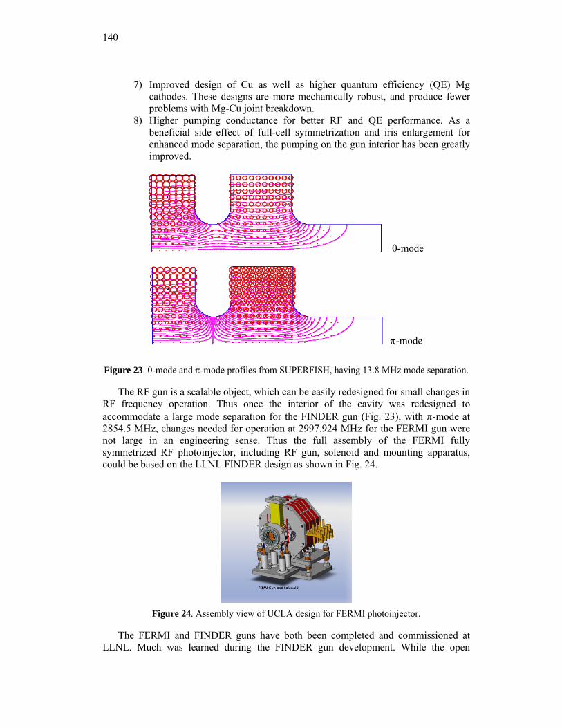
140
7) Improved design of Cu as well as higher quantum efficiency (QE) Mg cathodes. These designs are more mechanically robust, and produce fewer problems with Mg-Cu joint breakdown.
8) Higher pumping conductance for better RF and QE performance. As a beneficial side effect of full-cell symmetrization and iris enlargement for enhanced mode separation, the pumping on the gun interior has been greatly improved.
0-mode
π-mode
Figure 23. 0-mode and π-mode profiles from SUPERFISH, having 13.8 MHz mode separation.
The RF gun is a scalable object, which can be easily redesigned for small changes in RF frequency operation. Thus once the interior of the cavity was redesigned to accommodate a large mode separation for the FINDER gun (Fig. 23), with π-mode at 2854.5 MHz, changes needed for operation at 2997.924 MHz for the FERMI gun were not large in an engineering sense. Thus the full assembly of the FERMI fully symmetrized RF photoinjector, including RF gun, solenoid and mounting apparatus, could be based on the LLNL FINDER design as shown in Fig. 24.
Figure 24. Assembly view of UCLA design for FERMI photoinjector.
The FERMI and FINDER guns have both been completed and commissioned at LLNL. Much was learned during the FINDER gun development. While the open
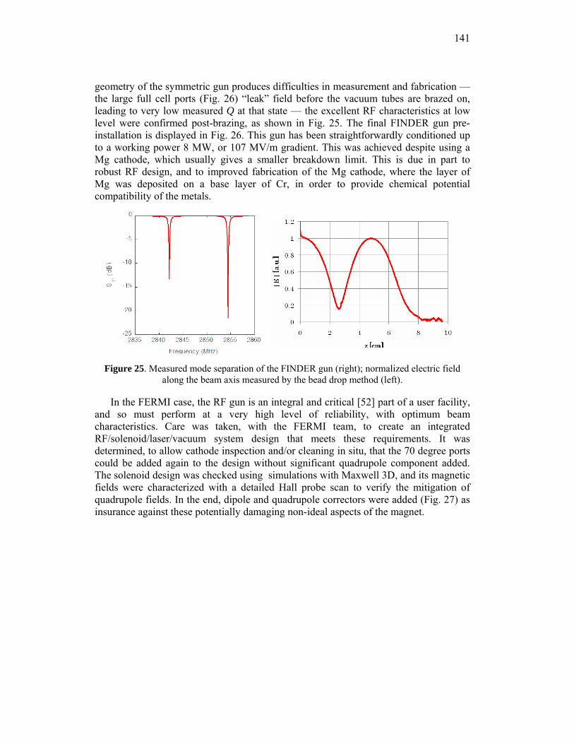
141
geometry of the symmetric gun produces difficulties in measurement and fabrication — the large full cell ports (Fig. 26) “leak” field before the vacuum tubes are brazed on, leading to very low measured Q at that state — the excellent RF characteristics at low level were confirmed post-brazing, as shown in Fig. 25. The final FINDER gun pre-installation is displayed in Fig. 26. This gun has been straightforwardly conditioned up to a working power 8 MW, or 107 MV/m gradient. This was achieved despite using a Mg cathode, which usually gives a smaller breakdown limit. This is due in part to robust RF design, and to improved fabrication of the Mg cathode, where the layer of Mg was deposited on a base layer of Cr, in order to provide chemical potential compatibility of the metals.
Figure 25. Measured mode separation of the FINDER gun (right); normalized electric field
along the beam axis measured by the bead drop method (left).
In the FERMI case, the RF gun is an integral and critical [52] part of a user facility, and so must perform at a very high level of reliability, with optimum beam characteristics. Care was taken, with the FERMI team, to create an integrated RF/solenoid/laser/vacuum system design that meets these requirements. It was determined, to allow cathode inspection and/or cleaning in situ, that the 70 degree ports could be added again to the design without significant quadrupole component added. The solenoid design was checked using simulations with Maxwell 3D, and its magnetic fields were characterized with a detailed Hall probe scan to verify the mitigation of quadrupole fields. In the end, dipole and quadrupole correctors were added (Fig. 27) as insurance against these potentially damaging non-ideal aspects of the magnet.
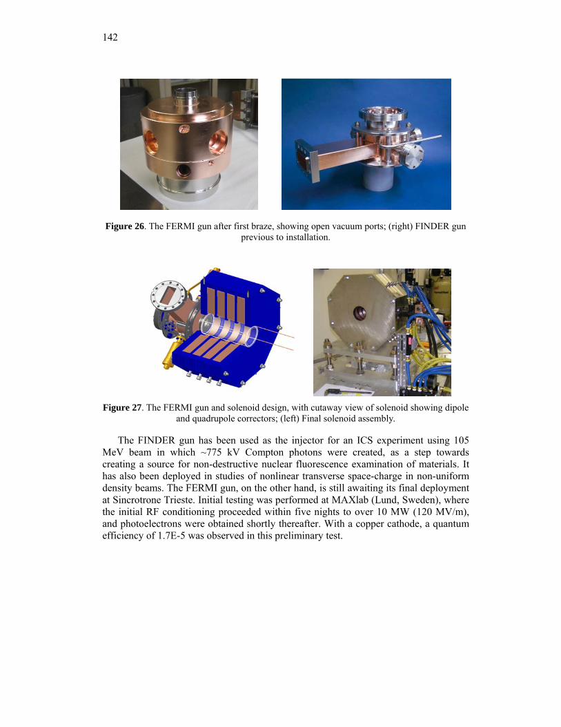
142
Figure 26. The FERMI gun after first braze, showing open vacuum ports; (right) FINDER gun previous to installation.
Figure 27. The FERMI gun and solenoid design, with cutaway view of solenoid showing dipole
and quadrupole correctors; (left) Final solenoid assembly.
The FINDER gun has been used as the injector for an ICS experiment using 105 MeV beam in which ~775 kV Compton photons were created, as a step towards creating a source for non-destructive nuclear fluorescence examination of materials. It has also been deployed in studies of nonlinear transverse space-charge in non-uniform density beams. The FERMI gun, on the other hand, is still awaiting its final deployment at Sincrotrone Trieste. Initial testing was performed at MAXlab (Lund, Sweden), where the initial RF conditioning proceeded within five nights to over 10 MW (120 MV/m), and photoelectrons were obtained shortly thereafter. With a copper cathode, a quantum efficiency of 1.7E-5 was observed in this preliminary test.
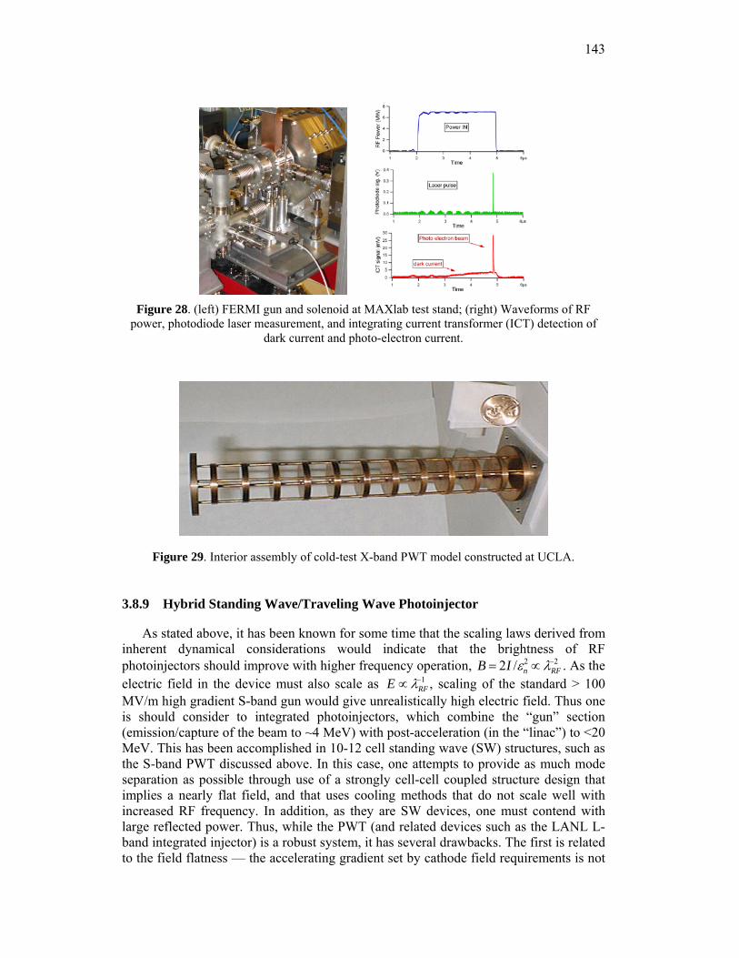
143
Figure 28. (left) FERMI gun and solenoid at MAXlab test stand; (right) Waveforms of RF
power, photodiode laser measurement, and integrating current transformer (ICT) detection of dark current and photo-electron current.
Figure 29. Interior assembly of cold-test X-band PWT model constructed at UCLA.
3.8.9 Hybrid Standing Wave/Traveling Wave Photoinjector
As stated above, it has been known for some time that the scaling laws derived from inherent dynamical considerations would indicate that the brightness of RF photoinjectors should improve with higher frequency operation, B = 2I /εn
2 ∝ λRF−2 . As the
electric field in the device must also scale as E ∝ λRF−1 , scaling of the standard > 100
MV/m high gradient S-band gun would give unrealistically high electric field. Thus one is should consider to integrated photoinjectors, which combine the “gun” section (emission/capture of the beam to ~4 MeV) with post-acceleration (in the “linac”) to <20 MeV. This has been accomplished in 10-12 cell standing wave (SW) structures, such as the S-band PWT discussed above. In this case, one attempts to provide as much mode separation as possible through use of a strongly cell-cell coupled structure design that implies a nearly flat field, and that uses cooling methods that do not scale well with increased RF frequency. In addition, as they are SW devices, one must contend with large reflected power. Thus, while the PWT (and related devices such as the LANL L-band integrated injector) is a robust system, it has several drawbacks. The first is related to the field flatness — the accelerating gradient set by cathode field requirements is not
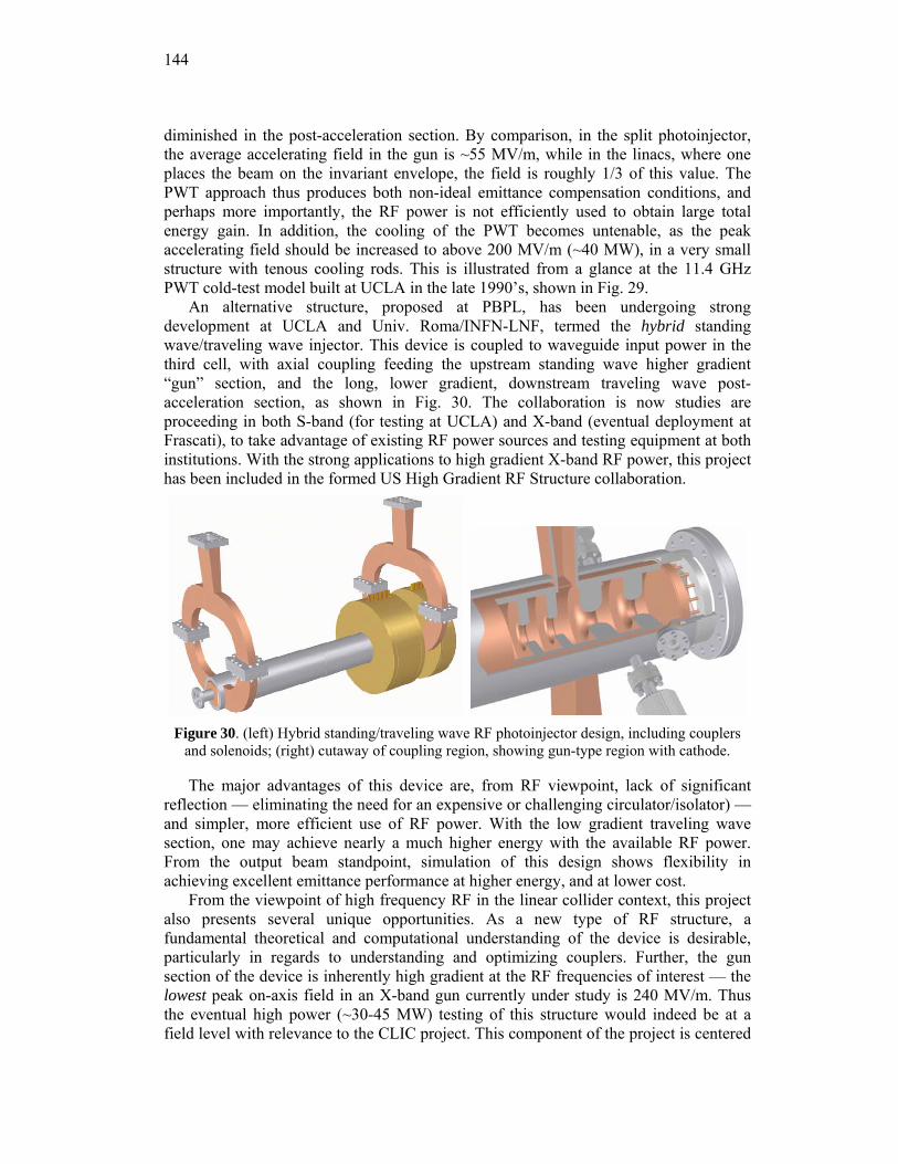
144
diminished in the post-acceleration section. By comparison, in the split photoinjector, the average accelerating field in the gun is ~55 MV/m, while in the linacs, where one places the beam on the invariant envelope, the field is roughly 1/3 of this value. The PWT approach thus produces both non-ideal emittance compensation conditions, and perhaps more importantly, the RF power is not efficiently used to obtain large total energy gain. In addition, the cooling of the PWT becomes untenable, as the peak accelerating field should be increased to above 200 MV/m (~40 MW), in a very small structure with tenous cooling rods. This is illustrated from a glance at the 11.4 GHz PWT cold-test model built at UCLA in the late 1990’s, shown in Fig. 29.
An alternative structure, proposed at PBPL, has been undergoing strong development at UCLA and Univ. Roma/INFN-LNF, termed the hybrid standing wave/traveling wave injector. This device is coupled to waveguide input power in the third cell, with axial coupling feeding the upstream standing wave higher gradient “gun” section, and the long, lower gradient, downstream traveling wave post-acceleration section, as shown in Fig. 30. The collaboration is now studies are proceeding in both S-band (for testing at UCLA) and X-band (eventual deployment at Frascati), to take advantage of existing RF power sources and testing equipment at both institutions. With the strong applications to high gradient X-band RF power, this project has been included in the formed US High Gradient RF Structure collaboration.
Figure 30. (left) Hybrid standing/traveling wave RF photoinjector design, including couplers
and solenoids; (right) cutaway of coupling region, showing gun-type region with cathode.
The major advantages of this device are, from RF viewpoint, lack of significant reflection — eliminating the need for an expensive or challenging circulator/isolator) — and simpler, more efficient use of RF power. With the low gradient traveling wave section, one may achieve nearly a much higher energy with the available RF power. From the output beam standpoint, simulation of this design shows flexibility in achieving excellent emittance performance at higher energy, and at lower cost.
From the viewpoint of high frequency RF in the linear collider context, this project also presents several unique opportunities. As a new type of RF structure, a fundamental theoretical and computational understanding of the device is desirable, particularly in regards to understanding and optimizing couplers. Further, the gun section of the device is inherently high gradient at the RF frequencies of interest — the lowest peak on-axis field in an X-band gun currently under study is 240 MV/m. Thus the eventual high power (~30-45 MW) testing of this structure would indeed be at a field level with relevance to the CLIC project. This component of the project is centered
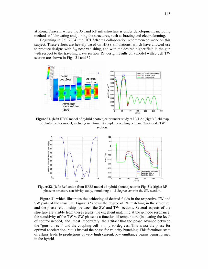
145
at Rome/Frascati, where the X-band RF infrastructure is under development, including methods of fabricating and joining the structures, such as brazing and electroforming.
Beginning in Fall 2004, the UCLA/Roma collaboration recommenced work on this subject. These efforts are heavily based on HFSS simulations, which have allowed use to produce designs with S11 near vanishing, and with the desired higher field in the gun with respect to the traveling wave section. RF design results on a model with 3 cell TW section are shown in Figs. 31 and 32.
Figure 31. (left) HFSS model of hybrid photoinjector under study at UCLA; (right) Field map
of photoinjector model, includng input/output coupler, coupling cell, and 2π/3 mode TW section.
Figure 32. (left) Reflection from HFSS model of hybrid photoinjector in Fig. 31; (right) RF
phase in structure sensitivity study, simulating a 1.1 degree error in the SW section.
Figure 31 which illustrates the achieving of desired fields in the respective TW and SW parts of the structure. Figure 32 shows the degree of RF matching in the structure, and the phase relationships between the SW and TW sections. Several aspects of the structure are visible from these results: the excellent matching at the π-mode resonance, the sensitivity of the TW v. SW phase as a function of temperature (indicating the level of control needed) and, most importantly, the artifact that the phase advance between the “gun full cell” and the coupling cell is only 90 degrees. This is not the phase for optimal acceleration, but is instead the phase for velocity bunching. This fortuitous state of affairs leads to predictions of very high current, low emittance beams being formed in the hybrid.
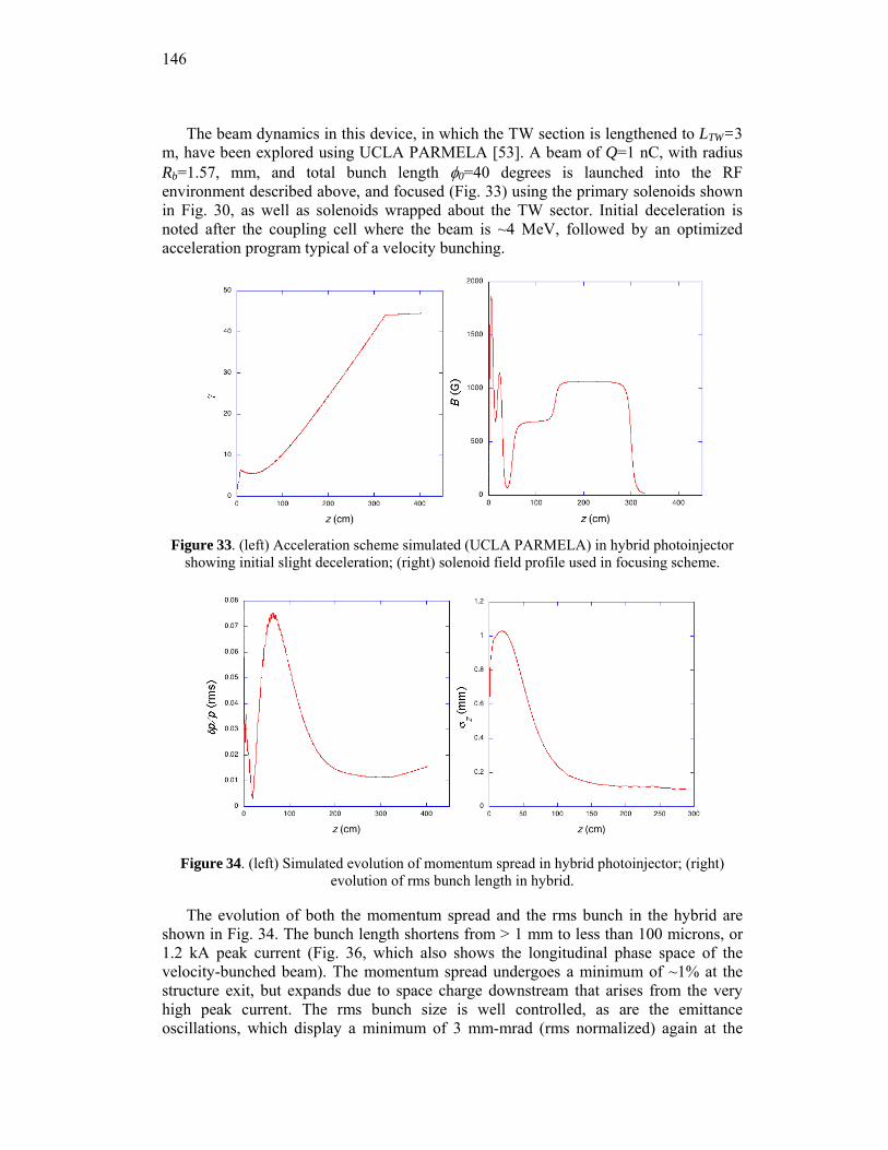
146
The beam dynamics in this device, in which the TW section is lengthened to LTW=3 m, have been explored using UCLA PARMELA [53]. A beam of Q=1 nC, with radius Rb=1.57, mm, and total bunch length φ0=40 degrees is launched into the RF environment described above, and focused (Fig. 33) using the primary solenoids shown in Fig. 30, as well as solenoids wrapped about the TW sector. Initial deceleration is noted after the coupling cell where the beam is ~4 MeV, followed by an optimized acceleration program typical of a velocity bunching.
Figure 33. (left) Acceleration scheme simulated (UCLA PARMELA) in hybrid photoinjector
showing initial slight deceleration; (right) solenoid field profile used in focusing scheme.
Figure 34. (left) Simulated evolution of momentum spread in hybrid photoinjector; (right) evolution of rms bunch length in hybrid.
The evolution of both the momentum spread and the rms bunch in the hybrid are shown in Fig. 34. The bunch length shortens from > 1 mm to less than 100 microns, or 1.2 kA peak current (Fig. 36, which also shows the longitudinal phase space of the velocity-bunched beam). The momentum spread undergoes a minimum of ~1% at the structure exit, but expands due to space charge downstream that arises from the very high peak current. The rms bunch size is well controlled, as are the emittance oscillations, which display a minimum of 3 mm-mrad (rms normalized) again at the
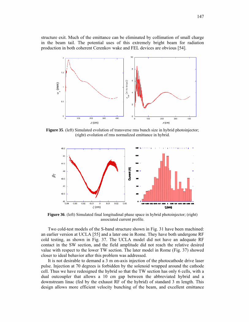
147
structure exit. Much of the emittance can be eliminated by collimation of small charge in the beam tail. The potential uses of this extremely bright beam for radiation production in both coherent Cerenkov wake and FEL devices are obvious [54].
Figure 35. (left) Simulated evolution of transverse rms bunch size in hybrid photoinjector;
(right) evolution of rms normalized emittance in hybrid.
Figure 36. (left) Simulated final longitudinal phase space in hybrid photoinjector; (right)
associated current profile.
Two cold-test models of the S-band structure shown in Fig. 31 have been machined: an earlier version at UCLA [55] and a later one in Rome. They have both undergone RF cold testing, as shown in Fig. 37. The UCLA model did not have an adequate RF contact in the SW section, and the field amplitude did not reach the relative desired value with respect to the lower TW section. The later model in Rome (Fig. 37) showed closer to ideal behavior after this problem was addressed.
It is not desirable to demand a 3 m on-axis injection of the photocathode drive laser pulse. Injection at 70 degrees is forbidden by the solenoid wrapped around the cathode cell. Thus we have redesigned the hybrid so that the TW section has only 6 cells, with a dual outcoupler that allows a 10 cm gap between the abbreviated hybrid and a downstream linac (fed by the exhaust RF of the hybrid) of standard 3 m length. This design allows more efficient velocity bunching of the beam, and excellent emittance
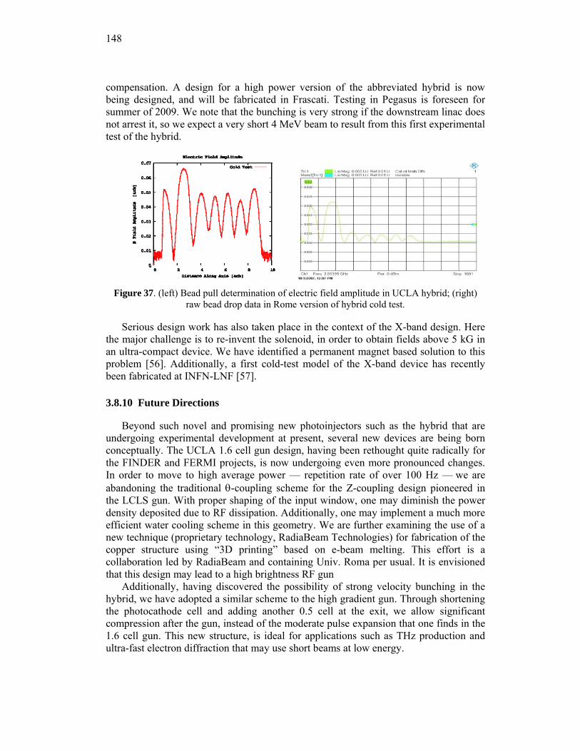
148
compensation. A design for a high power version of the abbreviated hybrid is now being designed, and will be fabricated in Frascati. Testing in Pegasus is foreseen for summer of 2009. We note that the bunching is very strong if the downstream linac does not arrest it, so we expect a very short 4 MeV beam to result from this first experimental test of the hybrid.
Figure 37. (left) Bead pull determination of electric field amplitude in UCLA hybrid; (right)
raw bead drop data in Rome version of hybrid cold test.
Serious design work has also taken place in the context of the X-band design. Here the major challenge is to re-invent the solenoid, in order to obtain fields above 5 kG in an ultra-compact device. We have identified a permanent magnet based solution to this problem [56]. Additionally, a first cold-test model of the X-band device has recently been fabricated at INFN-LNF [57].
3.8.10 Future Directions
Beyond such novel and promising new photoinjectors such as the hybrid that are undergoing experimental development at present, several new devices are being born conceptually. The UCLA 1.6 cell gun design, having been rethought quite radically for the FINDER and FERMI projects, is now undergoing even more pronounced changes. In order to move to high average power — repetition rate of over 100 Hz — we are abandoning the traditional θ-coupling scheme for the Z-coupling design pioneered in the LCLS gun. With proper shaping of the input window, one may diminish the power density deposited due to RF dissipation. Additionally, one may implement a much more efficient water cooling scheme in this geometry. We are further examining the use of a new technique (proprietary technology, RadiaBeam Technologies) for fabrication of the copper structure using “3D printing” based on e-beam melting. This effort is a collaboration led by RadiaBeam and containing Univ. Roma per usual. It is envisioned that this design may lead to a high brightness RF gun
Additionally, having discovered the possibility of strong velocity bunching in the hybrid, we have adopted a similar scheme to the high gradient gun. Through shortening the photocathode cell and adding another 0.5 cell at the exit, we allow significant compression after the gun, instead of the moderate pulse expansion that one finds in the 1.6 cell gun. This new structure, is ideal for applications such as THz production and ultra-fast electron diffraction that may use short beams at low energy.
149
3.8.11 Acknowledgements
The work discussed here is based on the efforts of a very large number of students, post-docs, researchers, and faculty at UCLA. Here we give a (hopefully not too incomplete) listing: S. Anderson, R. Agusstson, N. Barov, S. Boucher, E. Colby, M. Conde, A. Cook, J. Davis, X. Ding, A. Doyuran, M. Dunning, R.J. England, G. Hairapetian, E. Hemsing, M. Hogan, P. Frigola, A. Fukusawa, C. Joshi, J. Lim, J. Moody, A. Murokh, P. Musumeci, B. O’Shea, C. Pellegrini, S. Reiche, D. Schiller, S. Scoby, M. Thompson, R. Tikhoplav, S. Tochitsky, G. Travish, A. Tremaine, H. Suk, O. Williams, R. Yoder, R. Zhang. Apologies to our external collaborators; they are too numerous to list.
This work was supported in part by grants from: the US Dept. of Energy, Division of High Energy Physics, Division of Basic Energy Sciences, the Office of Naval Research, the Joint Technology Office, the National Science Foundation, Istituto Nazionale di Fisica Nucleare (INFN, Italy), Sincrotrone Trieste, and The University of California.
3.8.12 References
1. C. Brau, in The Physics and Applications of High Brightness Electron Beams, edited by J. B. Rosenzweig, L. Serafni, G. Travish (World Scientific, 2003), p. 20.
2. The Physics and Applications of High Brightness Electron Beams, edited by L. Palumbo, J. B. Rosenzweig, L. Serafni (World Scientific, 2007)
3. B. E. Carlsten, Nucl. Instrum. Methods A 285, 313 (1989). 4. J. B. Rosenzweig, N. Barov and E. Colby, IEEE Trans. Plasma Sci. 24, 409 (1996). 5. W. Kimura et al., Phys. Rev. Lett. 92, 054801 (2004). 6. Christopher M. S. Sears, et al., PRST-AB 11, 061301 (2008). 7. R. Bonifacio, C. Pellegrini, and L. Narducci, Opt. Commun. 50, 373 (1984). 8. R.W. Schoenlein, et al., Science 274, 2361 (1996). 9. Linac Coherent Light Source Conceptual Design Report, SLAC-R-593, SLAC, 2002. 10. J. B. Rosenzweig and E. Colby, Advanced Accelerator Concepts p. 724 (AIP Conf.
Proc. 335, 1995). 11. J. B. Rosenzweig, et al., NIM A 10 1016/ j.nima.2008.04.08 (2008). 12. D. T. Palmer, Ph.D. thesis, Stanford University (1998). 13. M. Ferrario, J. E. Clendenin, D.T. Palmer, J. Rosenzweig and L. Serafini, in The
Physics of High Brightness Beams, 534 (Eds. J. Rosenzweig and L. Serafini, World Scientific, 2000).
14. M. Ferrario, et al., Phys. Rev. Lett. 99, 234801 (2007). 15. J. B. Rosenzweig, et al., Nucl. Instr. Methods A 341, 379 (1994). 16. S. Hartman, et al., Nucl. Instr. Methods A 340, 219 (1994). 17. S. G. Anderson, J. B. Rosenzweig, G. P. Le Sage, J.K. Crane, PRST-AB 4, 014201
(2001). 18. A. Murokh, et al., Nuclear Instruments and Methods A 410, 549 (1998). 19. G. Hairapetian, et al., Phys. Rev. Lett. 72, 2403 (1994). 20. S. Reiche, et al., Phys. Rev. E 56, 3572 (1997). 21. M. Hogan, et al. Phys. Rev. Lett. 80, 289 (1998). 22. S. Telfer, G. Andonian, P. Frigola, S. Reiche, J. B. Rosenzweig, Proc. PAC01, p. 2263
(IEEE, 2001). 23. J. B. Rosenzweig and L. Serafini, Phys. Rev. E 49, 1499 (1994). 24. Luca Serafini and James Rosenzweig, Phys. Rev. E 55, 7565 (1997). 25. E. Colby, UCLA PhD Thesis, FERMILAB-THESIS-1997-03 (FNAL, 1997).
150
26. J. Andruszkow, et al., Phys. Rev. Lett. 85, 3825 (2000). 27. S. G. Anderson and J. B. Rosenzweig, PRST-AB 3, 094201 (2000). 28. R. Zhang, et al., Proc. PAC95 (IEEE, 1995). 29. R. J. England, J. B. Rosenzweig, G. Andonian, P. Musumeci, G. Travish, and R. Yoder,
PRST-AB 8, 012801 (2005). 30. S.G. Anderson, J. B. Rosenzweig, P. Musumeci, M. C. Thompson, Phys. Rev. Lett. 91,
074803 (2003). 31. S. G. Anderson, et al., PRST-AB 8, 014401 (2005). 32. A. M. Cook, et al., Proc. PAC07, p. 3041 (Albuquerque, 2007). 33. R. J. England, J. B. Rosenzweig, and G. Travish, Phys. Rev. Lett. 100, 214802 (2008). 34. J. B. Rosenzweig, et al., Phys. Rev. A - Rapid Comm. 44, R6189 (1991). 35. S. Ya. Tochitsky, et. al., Phys. Rev. Lett. 92, 095004 (2004). 36. P. Musumeci, et al., Phys. Rev. Lett. 94, 154801 (2005). 37. P. Musumeci, C. Pellegrini, J. B. Rosenzweig, Phys. Rev. E 72, 016501 (2005). 38. S. Ya. Tochitsky, et. al., submitted to Physical Review Letters. 39. R. Tikhoplav, et al., Proc. PAC07, p. 3055 (Albuquerque, 2007). 40. S. G. Anderson, J. B. Rosenzweig, G. P. Le Sage, J. K. Crane, PRST-AB 4, 014201
(2001). 41. David J. Gibson, et al., Phys. Plasmas, 11 2857 (2004). 42. J. K. Lim, et al., PRST-AB 8, 072401 (2005). 43. J. Schmerge, et al., in The Physics and Applications of High Brightness Electron
Beams, edited by L. Palumbo, J. B. Rosenzweig, L. Serafini (World Scientific, 2007). 44. T. Plettner, et al., Phys. Rev. Lett. 95, 134801 (2005). 45. James Rosenzweig et al., Proc. PA05 (IEEE, 2005). 46. I. M. Kapchinskii and V. V. Vladimirskii, Proc. Intl. Conf. on High Energy
Accelerators, CERN, Geneva (Scientific Information Service CERN, Geneva, 1959), p. 274.
47. L. Serafini, AIP Conf. Proc. 413, 321 (1997). 48. O. J. Luiten, S. B. van der Geer, M. J. de Loos, F. B. Kiewiet, M. J. van der Wiel, Phys.
Rev. Lett., 93, 094802-1(2004). 49. J. B. Rosenzweig, A. M. Cook, R. J. England, M. Dunning, S. G. Anderson and
Massimo Ferrario, NIM A 57, 87 (2006). 50. J. B. Rosenzweig, et al., Intl. Journal Modern Phys. A 23, 4333 (2007). 51. P. Musumeci, J. T. Moody, R. J. England, J. B. Rosenzweig, and T. Tran, Phys. Rev.
Lett. 100, 244801 (2008). 52. M. Cornacchia et al., Phys. Rev. ST Accel. Beams 9, 120701 (2006). 53. J. B. Rosenzweig, et al., Proc. 2006 Adv. Accelerator Concepts Workshop (Lake
Geneva, AIP). 54. D. Alesini, et al., Proc. EPAC 2006, 2487 (JACOW, 2006). 55. B. D. O'Shea, et al., Proc. PAC07, p. 2418 (Albuquerque, 2007). 56. A. Fukasawa, et al., to be published in Proc. FEL 2008. 57. B. Spataro, private communication.
151
3.9 High-Current RF Photoinjector Development for Free Electron Lasers
D. C. Nguyen Los Alamos National Laboratory, Los Alamos, NM 87545
Mail to: [email protected]
3.9.1 Introduction
A key component of the high-average-power FEL is a low-emittance, high-average-current RF photoinjector. High average current requires high bunch charge and high duty factor. While the accelerating gradient can exceed 100 MV/m in a pulsed normal conducting RF (NCRF) injector, it is significantly lower in a cw or high-duty RF injector. Emittance compensation has been achieved in NCRF injectors with an axial solenoid magnetic field near the photocathode to produce normalized rms emittance on the order of a few microns. The use of emittance compensation eliminates the need for very high accelerating gradients, thereby minimizing ohmic heating in a high duty RF photoinjector. Three high-duty NCRF photoinjectors have been designed with one being tested. Two superconducting RF photoinjectors with different emittance compensation techniques have been designed and are being either fabricated or tested. This paper reviews the development of normal-conducting and superconducting RF photoinjectors leading to high average current.
3.9.2 RF Photoinjector Development
The RF photoinjector was invented by Fraser et al. [1] at LANL in 1985 as a high-brightness electron source for the Strategic Defense Initiative (SDI) FEL program. This invention traced its origin to the laser-irradiated photocathode DC gun developed by Sinclair [2] and the thermionic-cathode RF gun invented by Madey [3]. By replacing the cathode-anode gap with a re-entrant RF cavity, Fraser, Sheffield and Gray were able to achieve much higher accelerating field than the DC gun, thus improving the rms emittance of electron beams at high bunch charge. The use of a high quantum efficiency (QE) Cs3Sb photocathode instead of a thermionic cathode enabled much higher current density, about 200 A/cm2 [4]. The LANL photoinjector design had “nose cones” on the re-entrant cavity walls, to achieve linear radial dependence of the RF fields, which was thought to reduce RF-induced emittance growth (Fig. 1). To transport the electron beam, a solenoid producing an axial magnetic field was placed at the exit of the photoinjector.
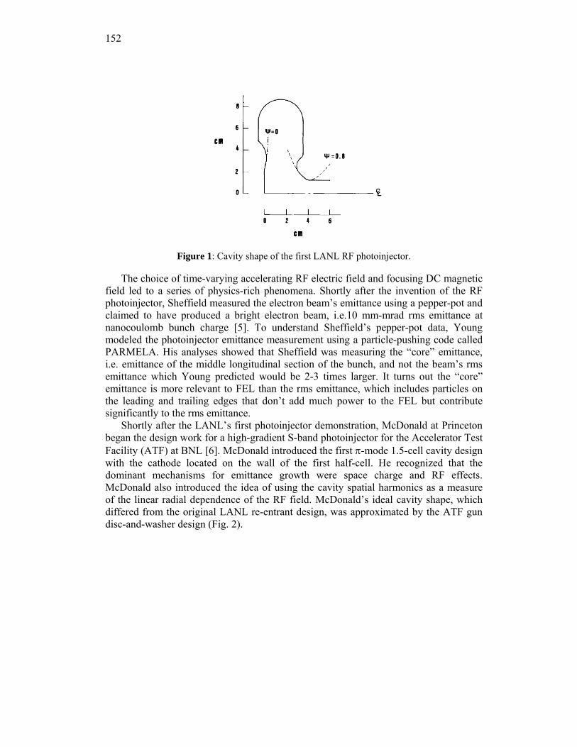
152
Figure 1: Cavity shape of the first LANL RF photoinjector.
The choice of time-varying accelerating RF electric field and focusing DC magnetic field led to a series of physics-rich phenomena. Shortly after the invention of the RF photoinjector, Sheffield measured the electron beam’s emittance using a pepper-pot and claimed to have produced a bright electron beam, i.e.10 mm-mrad rms emittance at nanocoulomb bunch charge [5]. To understand Sheffield’s pepper-pot data, Young modeled the photoinjector emittance measurement using a particle-pushing code called PARMELA. His analyses showed that Sheffield was measuring the “core” emittance, i.e. emittance of the middle longitudinal section of the bunch, and not the beam’s rms emittance which Young predicted would be 2-3 times larger. It turns out the “core” emittance is more relevant to FEL than the rms emittance, which includes particles on the leading and trailing edges that don’t add much power to the FEL but contribute significantly to the rms emittance.
Shortly after the LANL’s first photoinjector demonstration, McDonald at Princeton began the design work for a high-gradient S-band photoinjector for the Accelerator Test Facility (ATF) at BNL [6]. McDonald introduced the first π-mode 1.5-cell cavity design with the cathode located on the wall of the first half-cell. He recognized that the dominant mechanisms for emittance growth were space charge and RF effects. McDonald also introduced the idea of using the cavity spatial harmonics as a measure of the linear radial dependence of the RF field. McDonald’s ideal cavity shape, which differed from the original LANL re-entrant design, was approximated by the ATF gun disc-and-washer design (Fig. 2).
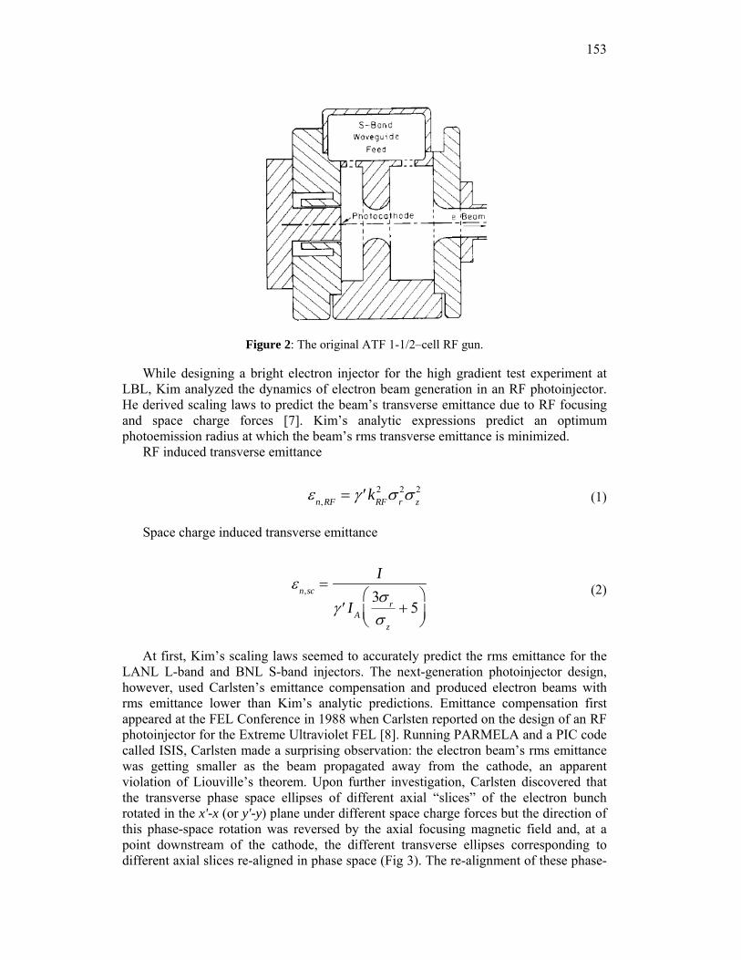
153
Figure 2: The original ATF 1-1/2–cell RF gun.
While designing a bright electron injector for the high gradient test experiment at LBL, Kim analyzed the dynamics of electron beam generation in an RF photoinjector. He derived scaling laws to predict the beam’s transverse emittance due to RF focusing and space charge forces [7]. Kim’s analytic expressions predict an optimum photoemission radius at which the beam’s rms transverse emittance is minimized.
RF induced transverse emittance
εn,RF = ′γ kRF2 σ r
2σ z2 (1)
Space charge induced transverse emittance
εn,sc =I
′γ I A
3σ r
σ z
+ 5⎛
⎝⎜⎞
⎠⎟
(2)
At first, Kim’s scaling laws seemed to accurately predict the rms emittance for the LANL L-band and BNL S-band injectors. The next-generation photoinjector design, however, used Carlsten’s emittance compensation and produced electron beams with rms emittance lower than Kim’s analytic predictions. Emittance compensation first appeared at the FEL Conference in 1988 when Carlsten reported on the design of an RF photoinjector for the Extreme Ultraviolet FEL [8]. Running PARMELA and a PIC code called ISIS, Carlsten made a surprising observation: the electron beam’s rms emittance was getting smaller as the beam propagated away from the cathode, an apparent violation of Liouville’s theorem. Upon further investigation, Carlsten discovered that the transverse phase space ellipses of different axial “slices” of the electron bunch rotated in the x'-x (or y'-y) plane under different space charge forces but the direction of this phase-space rotation was reversed by the axial focusing magnetic field and, at a point downstream of the cathode, the different transverse ellipses corresponding to different axial slices re-aligned in phase space (Fig 3). The re-alignment of these phase-
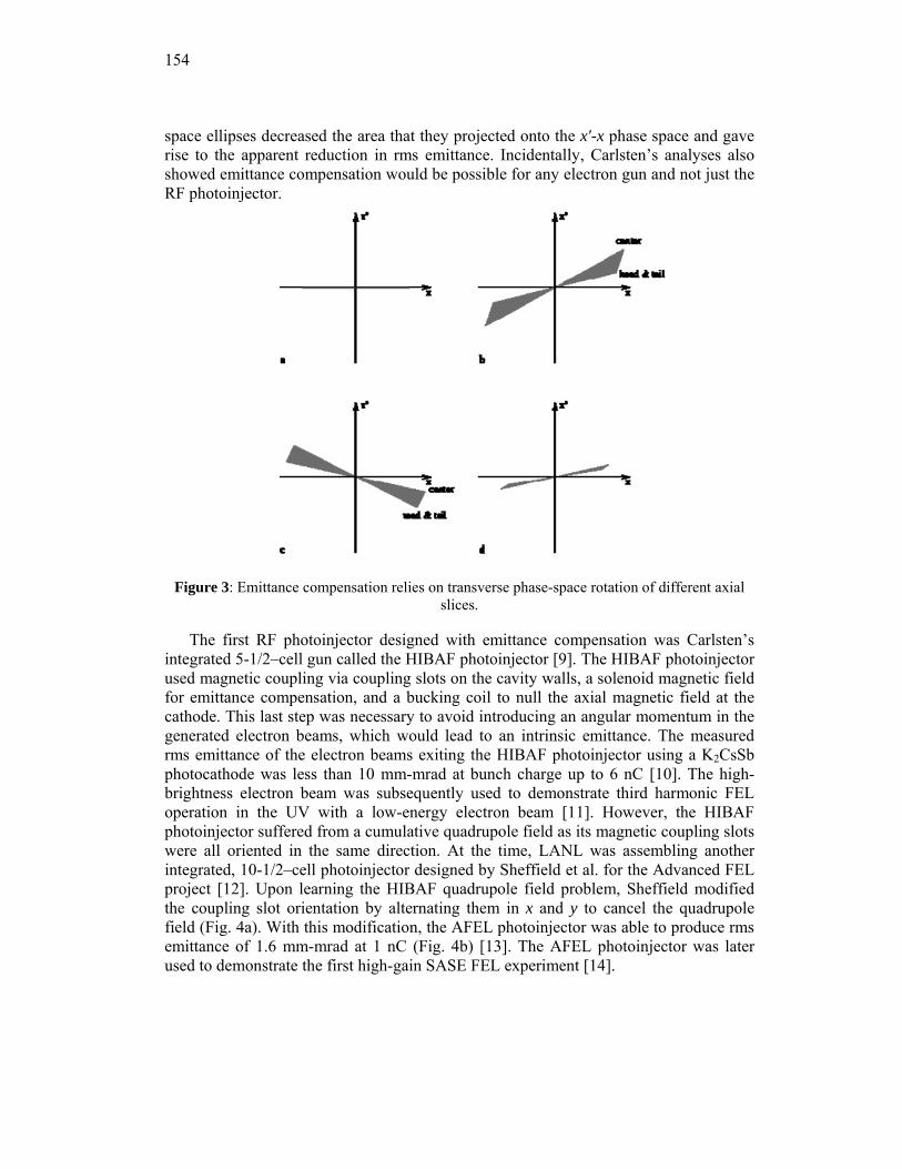
154
space ellipses decreased the area that they projected onto the x'-x phase space and gave rise to the apparent reduction in rms emittance. Incidentally, Carlsten’s analyses also showed emittance compensation would be possible for any electron gun and not just the RF photoinjector.
Figure 3: Emittance compensation relies on transverse phase-space rotation of different axial slices.
The first RF photoinjector designed with emittance compensation was Carlsten’s integrated 5-1/2–cell gun called the HIBAF photoinjector [9]. The HIBAF photoinjector used magnetic coupling via coupling slots on the cavity walls, a solenoid magnetic field for emittance compensation, and a bucking coil to null the axial magnetic field at the cathode. This last step was necessary to avoid introducing an angular momentum in the generated electron beams, which would lead to an intrinsic emittance. The measured rms emittance of the electron beams exiting the HIBAF photoinjector using a K2CsSb photocathode was less than 10 mm-mrad at bunch charge up to 6 nC [10]. The high-brightness electron beam was subsequently used to demonstrate third harmonic FEL operation in the UV with a low-energy electron beam [11]. However, the HIBAF photoinjector suffered from a cumulative quadrupole field as its magnetic coupling slots were all oriented in the same direction. At the time, LANL was assembling another integrated, 10-1/2–cell photoinjector designed by Sheffield et al. for the Advanced FEL project [12]. Upon learning the HIBAF quadrupole field problem, Sheffield modified the coupling slot orientation by alternating them in x and y to cancel the quadrupole field (Fig. 4a). With this modification, the AFEL photoinjector was able to produce rms emittance of 1.6 mm-mrad at 1 nC (Fig. 4b) [13]. The AFEL photoinjector was later used to demonstrate the first high-gain SASE FEL experiment [14].
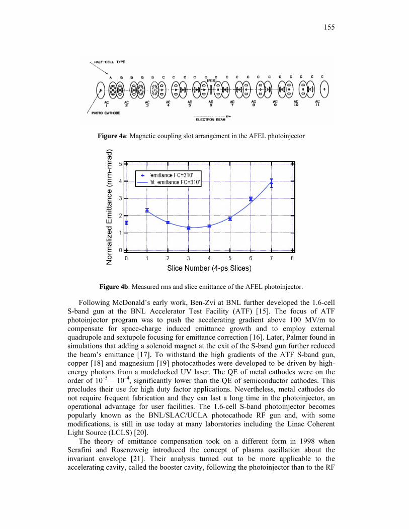
155
Figure 4a: Magnetic coupling slot arrangement in the AFEL photoinjector
Figure 4b: Measured rms and slice emittance of the AFEL photoinjector.
Following McDonald’s early work, Ben-Zvi at BNL further developed the 1.6-cell S-band gun at the BNL Accelerator Test Facility (ATF) [15]. The focus of ATF photoinjector program was to push the accelerating gradient above 100 MV/m to compensate for space-charge induced emittance growth and to employ external quadrupole and sextupole focusing for emittance correction [16]. Later, Palmer found in simulations that adding a solenoid magnet at the exit of the S-band gun further reduced the beam’s emittance [17]. To withstand the high gradients of the ATF S-band gun, copper [18] and magnesium [19] photocathodes were developed to be driven by high-energy photons from a modelocked UV laser. The QE of metal cathodes were on the order of 10–5 – 10–4, significantly lower than the QE of semiconductor cathodes. This precludes their use for high duty factor applications. Nevertheless, metal cathodes do not require frequent fabrication and they can last a long time in the photoinjector, an operational advantage for user facilities. The 1.6-cell S-band photoinjector becomes popularly known as the BNL/SLAC/UCLA photocathode RF gun and, with some modifications, is still in use today at many laboratories including the Linac Coherent Light Source (LCLS) [20].
The theory of emittance compensation took on a different form in 1998 when Serafini and Rosenzweig introduced the concept of plasma oscillation about the invariant envelope [21]. Their analysis turned out to be more applicable to the accelerating cavity, called the booster cavity, following the photoinjector than to the RF
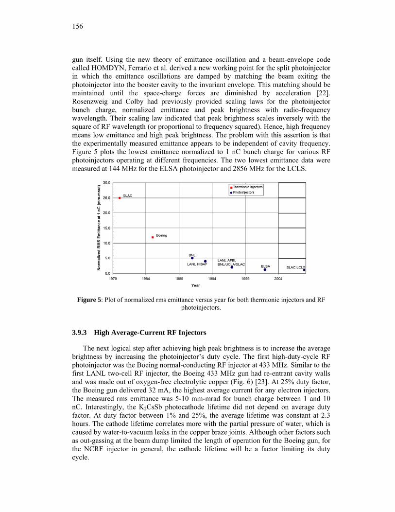
156
gun itself. Using the new theory of emittance oscillation and a beam-envelope code called HOMDYN, Ferrario et al. derived a new working point for the split photoinjector in which the emittance oscillations are damped by matching the beam exiting the photoinjector into the booster cavity to the invariant envelope. This matching should be maintained until the space-charge forces are diminished by acceleration [22]. Rosenzweig and Colby had previously provided scaling laws for the photoinjector bunch charge, normalized emittance and peak brightness with radio-frequency wavelength. Their scaling law indicated that peak brightness scales inversely with the square of RF wavelength (or proportional to frequency squared). Hence, high frequency means low emittance and high peak brightness. The problem with this assertion is that the experimentally measured emittance appears to be independent of cavity frequency. Figure 5 plots the lowest emittance normalized to 1 nC bunch charge for various RF photoinjectors operating at different frequencies. The two lowest emittance data were measured at 144 MHz for the ELSA photoinjector and 2856 MHz for the LCLS.
Figure 5: Plot of normalized rms emittance versus year for both thermionic injectors and RF photoinjectors.
3.9.3 High Average-Current RF Injectors
The next logical step after achieving high peak brightness is to increase the average brightness by increasing the photoinjector’s duty cycle. The first high-duty-cycle RF photoinjector was the Boeing normal-conducting RF injector at 433 MHz. Similar to the first LANL two-cell RF injector, the Boeing 433 MHz gun had re-entrant cavity walls and was made out of oxygen-free electrolytic copper (Fig. 6) [23]. At 25% duty factor, the Boeing gun delivered 32 mA, the highest average current for any electron injectors. The measured rms emittance was 5-10 mm-mrad for bunch charge between 1 and 10 nC. Interestingly, the K2CsSb photocathode lifetime did not depend on average duty factor. At duty factor between 1% and 25%, the average lifetime was constant at 2.3 hours. The cathode lifetime correlates more with the partial pressure of water, which is caused by water-to-vacuum leaks in the copper braze joints. Although other factors such as out-gassing at the beam dump limited the length of operation for the Boeing gun, for the NCRF injector in general, the cathode lifetime will be a factor limiting its duty cycle.
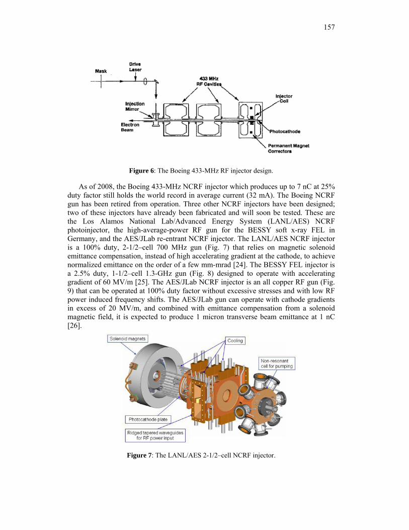
157
Figure 6: The Boeing 433-MHz RF injector design.
As of 2008, the Boeing 433-MHz NCRF injector which produces up to 7 nC at 25% duty factor still holds the world record in average current (32 mA). The Boeing NCRF gun has been retired from operation. Three other NCRF injectors have been designed; two of these injectors have already been fabricated and will soon be tested. These are the Los Alamos National Lab/Advanced Energy System (LANL/AES) NCRF photoinjector, the high-average-power RF gun for the BESSY soft x-ray FEL in Germany, and the AES/JLab re-entrant NCRF injector. The LANL/AES NCRF injector is a 100% duty, 2-1/2–cell 700 MHz gun (Fig. 7) that relies on magnetic solenoid emittance compensation, instead of high accelerating gradient at the cathode, to achieve normalized emittance on the order of a few mm-mrad [24]. The BESSY FEL injector is a 2.5% duty, 1-1/2–cell 1.3-GHz gun (Fig. 8) designed to operate with accelerating gradient of 60 MV/m [25]. The AES/JLab NCRF injector is an all copper RF gun (Fig. 9) that can be operated at 100% duty factor without excessive stresses and with low RF power induced frequency shifts. The AES/JLab gun can operate with cathode gradients in excess of 20 MV/m, and combined with emittance compensation from a solenoid magnetic field, it is expected to produce 1 micron transverse beam emittance at 1 nC [26].
Figure 7: The LANL/AES 2-1/2–cell NCRF injector.
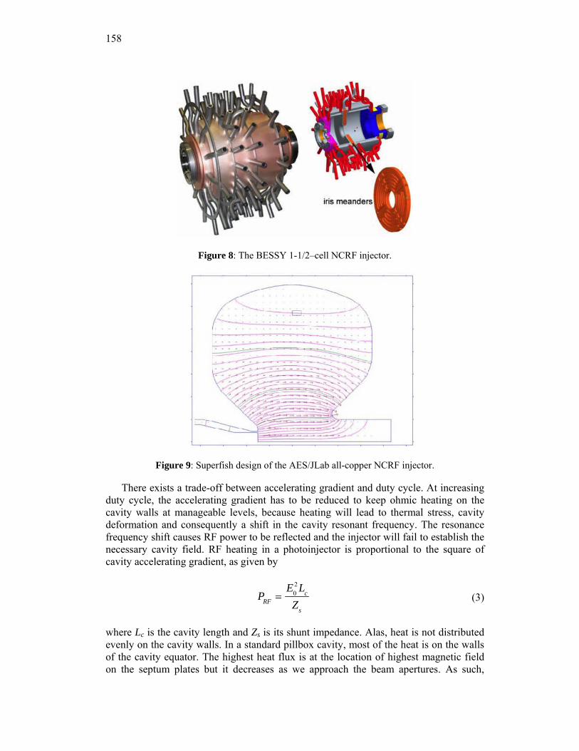
158
Figure 8: The BESSY 1-1/2–cell NCRF injector.
Figure 9: Superfish design of the AES/JLab all-copper NCRF injector.
There exists a trade-off between accelerating gradient and duty cycle. At increasing duty cycle, the accelerating gradient has to be reduced to keep ohmic heating on the cavity walls at manageable levels, because heating will lead to thermal stress, cavity deformation and consequently a shift in the cavity resonant frequency. The resonance frequency shift causes RF power to be reflected and the injector will fail to establish the necessary cavity field. RF heating in a photoinjector is proportional to the square of cavity accelerating gradient, as given by
PRF =E0
2 Lc
Zs
(3)
where Lc is the cavity length and Zs is its shunt impedance. Alas, heat is not distributed evenly on the cavity walls. In a standard pillbox cavity, most of the heat is on the walls of the cavity equator. The highest heat flux is at the location of highest magnetic field on the septum plates but it decreases as we approach the beam apertures. As such,
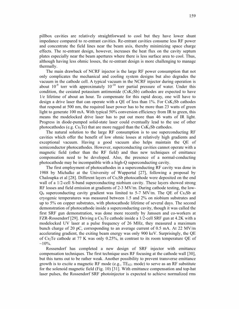
159
pillbox cavities are relatively straightforward to cool but they have lower shunt impedance compared to re-entrant cavities. Re-entrant cavities consume less RF power and concentrate the field lines near the beam axis, thereby minimizing space charge effects. The re-entrant design, however, increases the heat flux on the cavity septum plates especially near the beam apertures where there is less surface area to cool. Thus, although having less ohmic losses, the re-entrant design is more challenging to manage thermally.
The main drawback of NCRF injector is the large RF power consumption that not only complicates the mechanical and cooling system designs but also degrades the vacuum in the cathode cell. A typical vacuum in the NCRF injector during operation is about 10-9 torr with approximately 10-10 torr partial pressure of water. Under this condition, the cesiated potassium antimonide (CsK2Sb) cathodes are expected to have 1/e lifetime of about an hour. To compensate for this rapid decay, one will have to design a drive laser that can operate with a QE of less than 1%. For CsK2Sb cathodes that respond at 500 nm, the required laser power has to be more than 23 watts of green light to generate 100 mA. With typical 50% conversion efficiency from IR to green, this means the modelocked drive laser has to put out more than 46 watts of IR light. Progress in diode-pumped solid-state laser could eventually lead to the use of other photocathodes (e.g. Cs2Te) that are more rugged than the CsK2Sb cathodes.
The natural solution to the large RF consumption is to use superconducting RF cavities which offer the benefit of low ohmic losses at relatively high gradients and exceptional vacuum. Having a good vacuum also helps maintain the QE of semiconductor photocathodes. However, superconducting cavities cannot operate with a magnetic field (other than the RF field) and thus new techniques of emittance compensation need to be developed. Also, the presence of a normal-conducting photocathode may be incompatible with a high-Q superconducting cavity.
The first employment of photocathodes in a superconducting RF cavity was done in 1988 by Michalke at the University of Wuppertal [27], following a proposal by Chaloupka et al [28]. Different layers of Cs3Sb photocathode were deposited on the end wall of a 1/2-cell S-band superconducting niobium cavity. These layers showed strong RF losses and field emission at gradients of 2-3 MV/m. During cathode testing, the low-Q0 superconducting cavity gradient was limited to 5-7 MV/m. The QE of Cs3Sb at cryogenic temperatures was measured between 1.5 and 2% on niobium substrates and up to 5% on copper substrates, with photocathode lifetime of several days. The second demonstration of photocathode inside a superconducting cavity, though it was called the first SRF gun demonstration, was done more recently by Janssen and co-workers at FZR-Rossendorf [29]. Driving a Cs2Te cathode inside a 1/2-cell SRF gun at 4.2K with a modelocked UV laser at a pulse frequency of 26 MHz, they measured a maximum bunch charge of 20 pC, corresponding to an average current of 0.5 mA. At 22 MV/m accelerating gradient, the exiting beam energy was only 900 keV. Surprisingly, the QE of Cs2Te cathode at 77 K was only 0.25%, in contrast to its room temperature QE of ~10%.
Rossendorf has completed a new design of SRF injector with emittance compensation techniques. The first technique uses RF focusing at the cathode wall [30], but this turns out to be rather weak. Another possibility to prevent transverse emittance growth is to excite a magnetic RF mode (e.g., TE021 mode) to serve as an RF substitute for the solenoid magnetic field (Fig. 10) [31]. With emittance compensation and top-hat laser pulses, the Rossendorf SRF photoinjector is expected to achieve normalized rms
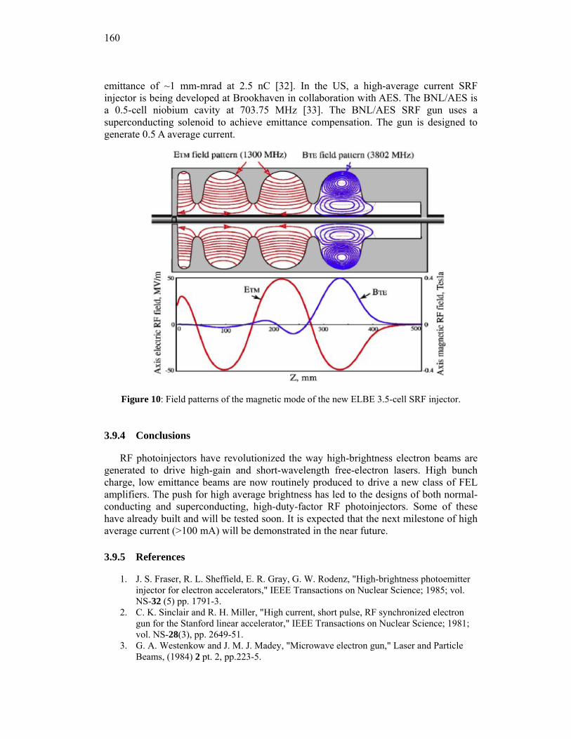
160
emittance of ~1 mm-mrad at 2.5 nC [32]. In the US, a high-average current SRF injector is being developed at Brookhaven in collaboration with AES. The BNL/AES is a 0.5-cell niobium cavity at 703.75 MHz [33]. The BNL/AES SRF gun uses a superconducting solenoid to achieve emittance compensation. The gun is designed to generate 0.5 A average current.
Figure 10: Field patterns of the magnetic mode of the new ELBE 3.5-cell SRF injector.
3.9.4 Conclusions
RF photoinjectors have revolutionized the way high-brightness electron beams are generated to drive high-gain and short-wavelength free-electron lasers. High bunch charge, low emittance beams are now routinely produced to drive a new class of FEL amplifiers. The push for high average brightness has led to the designs of both normal-conducting and superconducting, high-duty-factor RF photoinjectors. Some of these have already built and will be tested soon. It is expected that the next milestone of high average current (>100 mA) will be demonstrated in the near future.
3.9.5 References
1. J. S. Fraser, R. L. Sheffield, E. R. Gray, G. W. Rodenz, "High-brightness photoemitter injector for electron accelerators," IEEE Transactions on Nuclear Science; 1985; vol. NS-32 (5) pp. 1791-3.
2. C. K. Sinclair and R. H. Miller, "High current, short pulse, RF synchronized electron gun for the Stanford linear accelerator," IEEE Transactions on Nuclear Science; 1981; vol. NS-28(3), pp. 2649-51.
3. G. A. Westenkow and J. M. J. Madey, "Microwave electron gun," Laser and Particle Beams, (1984) 2 pt. 2, pp.223-5.
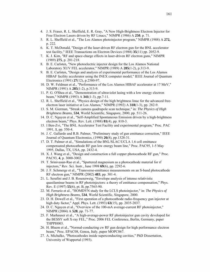
161
4. J. S. Fraser, R. L. Sheffield, E. R. Gray, "A New High-Brightness Electron Injector for Free Electron Lasers driven by RF Linacs," NIMPR (1986) A 250, p. 71.
5. R. L. Sheffield et al., "The Los Alamos photoinjector program," NIMPR (1988) A 272, p. 222.
6. K. T. McDonald, "Design of the laser-driven RF electron gun for the BNL accelerator test facility," IEEE Transactions on Electron Devices (1988) 35(11) pp. 2052-9.
7. K. J. Kim, "RF and space-charge effects in laser-driven RF electron guns," NIMPR (1989) 275, p. 201-218.
8. B. E. Carlsten, "New photoelectric injector design for the Los Alamos National Laboratory XUV FEL accelerator," NIMPR (1989) A 285(1-2), p.313-9.
9. B. E. Carlsten, "Design and analysis of experimental performance of the Los Alamos HIBAF facility accelerator using the INEX computer model," IEEE Journal of Quantum Electronics (1991) 27(12), p.2580-97.
10. D. W. Feldman et al., "Performance of the Los Alamos HIBAF accelerator at 17 MeV," NIMPR (1991) A 285(1-2), p.313-9.
11. P. G. O'Shea et al., "Demonstration of ultraviolet lasing with a low energy electron beam," NIMPR (1993) A 341(1-3), pp.7-11.
12. R. L. Sheffield et al., "Physics design of the high brightness linac for the advanced free-electron laser initiative at Los Alamos," NIMPR (1992) A 318(1-3), pp. 282-9.
13. S. M. Gierman, "Streak camera quadrupole scan technique," in: The Physics of High Brightness Beams, 534, World Scientific, Singapore, 2000, pp. 511-26.
14. D. C. Nguyen et al., "Self-Amplified Spontaneous Emission driven by a high-brightness electron beam," Phys. Rev. Lett. (1988) 81(4), pp. 810-3.
15. I Ben-Zvi, "The BNL Accelerator Test Facility and experimental program," Proc. PAC 1991, 1, pp. 550-4.
16. J. C. Gallardo and R.B. Palmer, "Preliminary study of gun emittance correction," IEEE Journal of Quantum Electronics, (1990) 26(8), pp.1328-31.
17. D. T. Palmer et al., "Simulations of the BNL/SLAC/UCLA 1.6 cell emittance compensated photocathode RF gun low energy beam line," Proc. PAC95, 1-5 May 1995, Dallas, TX, USA, pp. 2432-4.
18. X. J. Wang et al., "Design and construction a full copper photocathode RF gun," Proc. PAC93, 4, p. 3000-3002.
19. T. Srinivasan-Rao et al., "Sputtered magnesium as a photocathode material for rf injectors," Rev. Sci. Instr., June 1998 69(6), pp. 2292-6.
20. J. F. Schmerge et al., "Transverse-emittance measurements on an S-band photocathode RF electron gun," NIMPR (2002) 483, pp. 301-4.
21. L. Serafini and J. B. Rosenzweig, "Envelope analysis of intense relativistic quasilaminar beams in RF photoinjectors: a theory of emittance compensation," Phys. Rev. E (1997) 55(6), pt. B, pp.7565-90.
22. M. Ferrario et al., "HOMDYN study for the LCLS photoinjector," in: The Physics of High Brightness Beams, 534, World Scientific, Singapore, 2000.
23. D. H. Dowell et al., "First operation of a photocathode radio-frequency gun injector at high duty factor," Appl. Phys. Lett. (1993) 63(15), pp. 2035-2037.
24. D. C. Nguyen et al., "Overview of the 100-mA average-current RF photoinjector," NIMPR (2004) A 528, pp. 71-77.
25. F. Marhauser et al., “A high-average-power RF photoinjector gun cavity developed for the BESSY soft X-ray FEL,” Proc. 2006 FEL Conference, Berlin, Germany, paper THPPH003.
26. H. Bluem et al., "Normal-conducting cw RF gun design for high performance electron beam," Proc. EPAC08, Genoa, Italy, paper MOPC067.
27. A. Michalke, "Photocathodes inside superconducting cavities," PhD Dissertation, University of Wuppertal (1993).
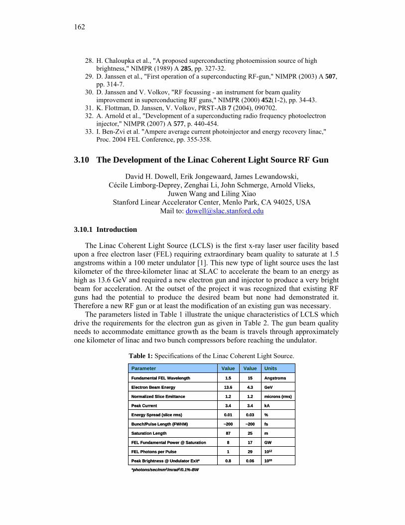
162
28. H. Chaloupka et al., "A proposed superconducting photoemission source of high brightness," NIMPR (1989) A 285, pp. 327-32.
29. D. Janssen et al., "First operation of a superconducting RF-gun," NIMPR (2003) A 507, pp. 314-7.
30. D. Janssen and V. Volkov, "RF focussing - an instrument for beam quality improvement in superconducting RF guns," NIMPR (2000) 452(1-2), pp. 34-43.
31. K. Flottman, D. Janssen, V. Volkov, PRST-AB 7 (2004), 090702. 32. A. Arnold et al., "Development of a superconducting radio frequency photoelectron
injector," NIMPR (2007) A 577, p. 440-454. 33. I. Ben-Zvi et al. "Ampere average current photoinjector and energy recovery linac,"
Proc. 2004 FEL Conference, pp. 355-358.
3.10 The Development of the Linac Coherent Light Source RF Gun
David H. Dowell, Erik Jongewaard, James Lewandowski, Cécile Limborg-Deprey, Zenghai Li, John Schmerge, Arnold Vlieks,
Juwen Wang and Liling Xiao Stanford Linear Accelerator Center, Menlo Park, CA 94025, USA
Mail to: [email protected]
3.10.1 Introduction
The Linac Coherent Light Source (LCLS) is the first x-ray laser user facility based upon a free electron laser (FEL) requiring extraordinary beam quality to saturate at 1.5 angstroms within a 100 meter undulator [1]. This new type of light source uses the last kilometer of the three-kilometer linac at SLAC to accelerate the beam to an energy as high as 13.6 GeV and required a new electron gun and injector to produce a very bright beam for acceleration. At the outset of the project it was recognized that existing RF guns had the potential to produce the desired beam but none had demonstrated it. Therefore a new RF gun or at least the modification of an existing gun was necessary.
The parameters listed in Table 1 illustrate the unique characteristics of LCLS which drive the requirements for the electron gun as given in Table 2. The gun beam quality needs to accommodate emittance growth as the beam is travels through approximately one kilometer of linac and two bunch compressors before reaching the undulator.
Table 1: Specifications of the Linac Coherent Light Source.
*photons/sec/mm2/mrad2/0.1%-BW
10330.060.8Peak Brightness @ Undulator Exit*
1012291FEL Photons per Pulse
GW178FEL Fundamental Power @ Saturation
m2587Saturation Length
fs~200~200Bunch/Pulse Length (FWHM)
%0.030.01Energy Spread (slice rms)
kA3.43.4Peak Current
microns (rms)1.21.2Normalized Slice Emittance
GeV4.313.6Electron Beam Energy
Angstroms151.5Fundamental FEL Wavelength
UnitsValueValueParameter
163
These beam requirements were demonstrated during the recent commissioning runs of the LCLS injector and linac [2] due to the successful design, fabrication, testing and operation of the LCLS gun. The goal of this paper is to relate the technical background of how the gun was able to achieve and in some cases exceed these requirements by understanding and correcting the deficiencies of the prototype S-band RF photocathode gun, the BNL/SLAC/UCLA Gun III.
Table 2: Requirements of the LCLS gun
3keV (rms)Uncorrelated Energy Spread
3x10⁻⁵Quantum Efficiency
<5 % (rms)Bunch Length Stability
<2 % (rms)Charge Stability
<0.1 deg (rms)Gun RF Phase Stability
<0.50 ps (rms)Gun Laser Stability
120MV/mPeak Cathode Field
120 HzRepetition Rate
<1.2 / 1.0 micron (rms)Normalized Transverse Emittance: Projected/Slice
1 nCCharge
100 APeak Current
ValueParameter
This paper begins with a brief history and technical description of Gun III and the
Gun Test Facility (GTF) at SLAC, and studies of the gun’s RF and emittance compensation solenoid. The work at the GTF identified the gun and solenoid deficiencies, and helped to define the specifications for the LCLS gun. Section 4.10.5 describes the modeling used to compute and correct the gun RF fields and Section 4.10.6 describes the use of these fields in the electron beam simulations. The magnetic design and measurements of the emittance compensation solenoid are discussed in Section 4.10.7. The novel feature of the LCLS solenoid is the embedded quadrupole correctors. The thermo-mechanical engineering of the LCLS gun is discussed in Section 4.10.8, and the cold and hot RF tests are described in Section 4.10.9. The results of this work are summarized and concluding remarks are given in Section 4.10.10.
3.10.2 The History and Characteristics of the BNL/SLAC/UCLA S-Band Gun III and the Gun Test Facility (GTF) at SLAC
The SLAC Gun Test Facility (GTF) was initiated by Herman Winick in the early 1990s to test and develop the electron source necessary to drive the Linac Coherent Light Source. Following the proposal [3] for a short wavelength SASE FEL using the SLAC linac, a study group led by Pellegrini and Winick investigated the requirements. Foremost among these was a high brightness electron gun with performance beyond that of any in existence at that time. This led to the GTF project to develop an appropriate laser-driven, high gradient RF photoinjector.
The GTF was located in the SSRL injector linac vault taking advantage of the existing RF power, radiation shielding, safety interlocks, and staff technical support. The accelerator (a 3m S-band linac section made available by SLAC) and diagnostics were installed and commissioned under the leadership of John Schmerge and the late James Weaver. The laser was developed by graduate student David Reis in
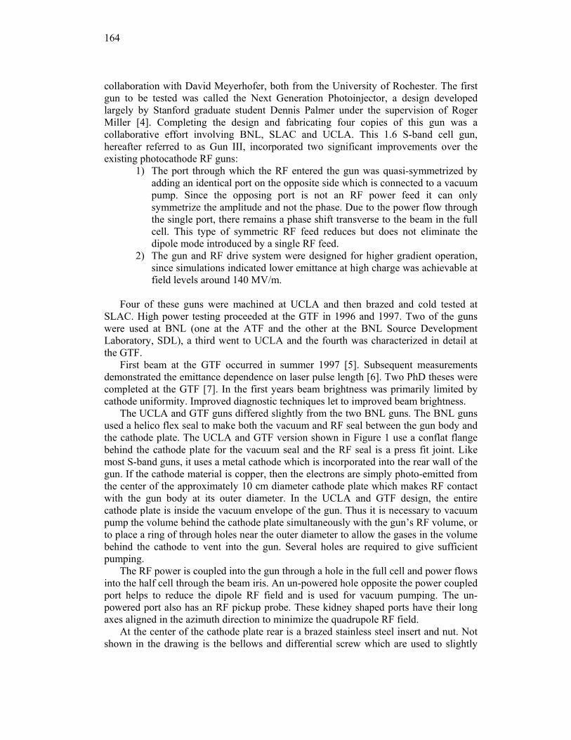
164
collaboration with David Meyerhofer, both from the University of Rochester. The first gun to be tested was called the Next Generation Photoinjector, a design developed largely by Stanford graduate student Dennis Palmer under the supervision of Roger Miller [4]. Completing the design and fabricating four copies of this gun was a collaborative effort involving BNL, SLAC and UCLA. This 1.6 S-band cell gun, hereafter referred to as Gun III, incorporated two significant improvements over the existing photocathode RF guns:
1) The port through which the RF entered the gun was quasi-symmetrized by adding an identical port on the opposite side which is connected to a vacuum pump. Since the opposing port is not an RF power feed it can only symmetrize the amplitude and not the phase. Due to the power flow through the single port, there remains a phase shift transverse to the beam in the full cell. This type of symmetric RF feed reduces but does not eliminate the dipole mode introduced by a single RF feed.
2) The gun and RF drive system were designed for higher gradient operation, since simulations indicated lower emittance at high charge was achievable at field levels around 140 MV/m.
Four of these guns were machined at UCLA and then brazed and cold tested at
SLAC. High power testing proceeded at the GTF in 1996 and 1997. Two of the guns were used at BNL (one at the ATF and the other at the BNL Source Development Laboratory, SDL), a third went to UCLA and the fourth was characterized in detail at the GTF.
First beam at the GTF occurred in summer 1997 [5]. Subsequent measurements demonstrated the emittance dependence on laser pulse length [6]. Two PhD theses were completed at the GTF [7]. In the first years beam brightness was primarily limited by cathode uniformity. Improved diagnostic techniques let to improved beam brightness.
The UCLA and GTF guns differed slightly from the two BNL guns. The BNL guns used a helico flex seal to make both the vacuum and RF seal between the gun body and the cathode plate. The UCLA and GTF version shown in Figure 1 use a conflat flange behind the cathode plate for the vacuum seal and the RF seal is a press fit joint. Like most S-band guns, it uses a metal cathode which is incorporated into the rear wall of the gun. If the cathode material is copper, then the electrons are simply photo-emitted from the center of the approximately 10 cm diameter cathode plate which makes RF contact with the gun body at its outer diameter. In the UCLA and GTF design, the entire cathode plate is inside the vacuum envelope of the gun. Thus it is necessary to vacuum pump the volume behind the cathode plate simultaneously with the gun’s RF volume, or to place a ring of through holes near the outer diameter to allow the gases in the volume behind the cathode to vent into the gun. Several holes are required to give sufficient pumping.
The RF power is coupled into the gun through a hole in the full cell and power flows into the half cell through the beam iris. An un-powered hole opposite the power coupled port helps to reduce the dipole RF field and is used for vacuum pumping. The un-powered port also has an RF pickup probe. These kidney shaped ports have their long axes aligned in the azimuth direction to minimize the quadrupole RF field.
At the center of the cathode plate rear is a brazed stainless steel insert and nut. Not shown in the drawing is the bellows and differential screw which are used to slightly
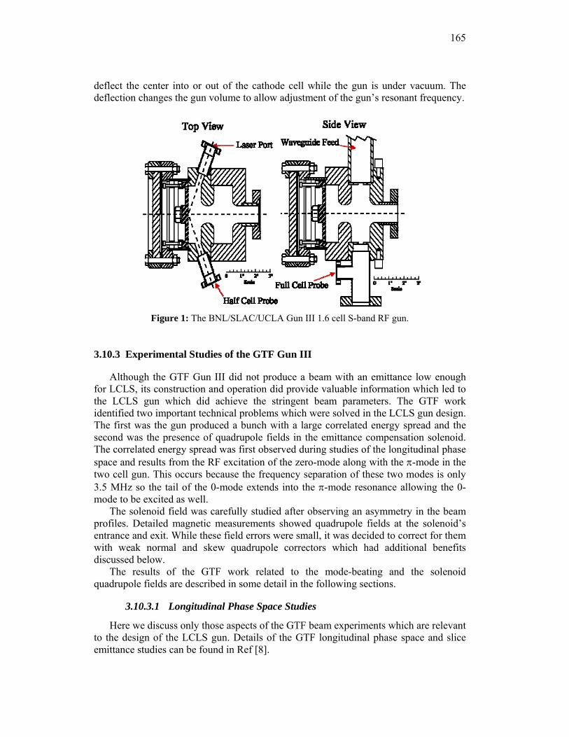
165
deflect the center into or out of the cathode cell while the gun is under vacuum. The deflection changes the gun volume to allow adjustment of the gun’s resonant frequency.
Figure 1: The BNL/SLAC/UCLA Gun III 1.6 cell S-band RF gun.
3.10.3 Experimental Studies of the GTF Gun III
Although the GTF Gun III did not produce a beam with an emittance low enough for LCLS, its construction and operation did provide valuable information which led to the LCLS gun which did achieve the stringent beam parameters. The GTF work identified two important technical problems which were solved in the LCLS gun design. The first was the gun produced a bunch with a large correlated energy spread and the second was the presence of quadrupole fields in the emittance compensation solenoid. The correlated energy spread was first observed during studies of the longitudinal phase space and results from the RF excitation of the zero-mode along with the π-mode in the two cell gun. This occurs because the frequency separation of these two modes is only 3.5 MHz so the tail of the 0-mode extends into the π-mode resonance allowing the 0-mode to be excited as well.
The solenoid field was carefully studied after observing an asymmetry in the beam profiles. Detailed magnetic measurements showed quadrupole fields at the solenoid’s entrance and exit. While these field errors were small, it was decided to correct for them with weak normal and skew quadrupole correctors which had additional benefits discussed below.
The results of the GTF work related to the mode-beating and the solenoid quadrupole fields are described in some detail in the following sections.
3.10.3.1 Longitudinal Phase Space Studies
Here we discuss only those aspects of the GTF beam experiments which are relevant to the design of the LCLS gun. Details of the GTF longitudinal phase space and slice emittance studies can be found in Ref [8].
166
The correlated energy spread first exhibited itself during our measurements of the longitudinal emittance and its phase space distribution. In these experiments the longitudinal emittance and Twiss parameters are determined from electron energy spectra after a 3-meter linac section as a function of the linac section RF phase. Data and simulations for 16 pC bunch charge are shown in Figure 2 of the rms bunch energy spread as functions of the linac phase. The measurements are at low charge in order to minimize the effects of space charge and longitudinal wakefields which can also increase the energy spread. The linac phase of zero degrees S-band (degS) is defined as maximum energy gain in the linac or on crest. The correlated energy spread from the gun can be estimated by the amount of chirp needed from the linac to produce the minimum energy spread. The final chirp to first-order is given by
linaclinac
gun ddEEE φ
φΔ+Δ=Δ 1 (1)
The overall energy spread is a minimum when the linac introduces an energy chirp which cancels that coming from the gun,
linaclinaclinaclinaclinac
gun EddEE φφφ
φΔ=Δ−=Δ sin , (2)
where the linac energy gain is given by linaclinacE φcos . Using the observed 8 degS phase and the 30 MeV energy gain of the linac yields a correlated energy of 73 KeV/degS.
Also shown in Figure 2 are simulations of a particle-tracking code [9] which uses 0- and π-mode field distributions given by Superfish [10] to compute the energy spread after the linac. Unfortunately Superfish cannot give the phase relation between the two modes which comes from the RF dynamics while the gun is filling, therefore both the 0-mode field strength and the relative phase where varied to produce a best fit to the data. As expected the π-mode only simulation using 110 MV/m gives a minimum energy spread near 0 degS, but an additional 0-mode field of 13 MV/m with a 0-π relative phase of –85 degS is needed to reproduce the data [11].
167
Figure 2: The measured and computed beam energy spread at 30 MeV as a function of the
booster linac phase.
This analysis showed this energy spread results from the presence of the 0-mode which unbalances the total field between the two cells and chirps the beam. The 0-mode for the GTF Gun III is only 3.5 MHz lower than the desired π-mode and is easily excited. The next section describes RF measurement which verified the beating between the two modes at the mode separation frequency.
3.10.3.2 RF Measurements of 0-π Mode Beating
Given the large energy spread there were concerns about the physical condition of the GTF Gun III and whether or not it has somehow changed during operation. Therefore it was removed from the GTF beamline and its field balance measured using the bead drop (Slater perturbation) method. The results are given in Figure 3 for both the π- and 0-mode, along with a Superfish simulation [12]. The position of the cathode plate was adjusted in the simulation to match the π-mode data, and the 0-mode simulation was then done with the same parameters. The data show the gun was still balanced and was not the cause of the large correlated energy spread.
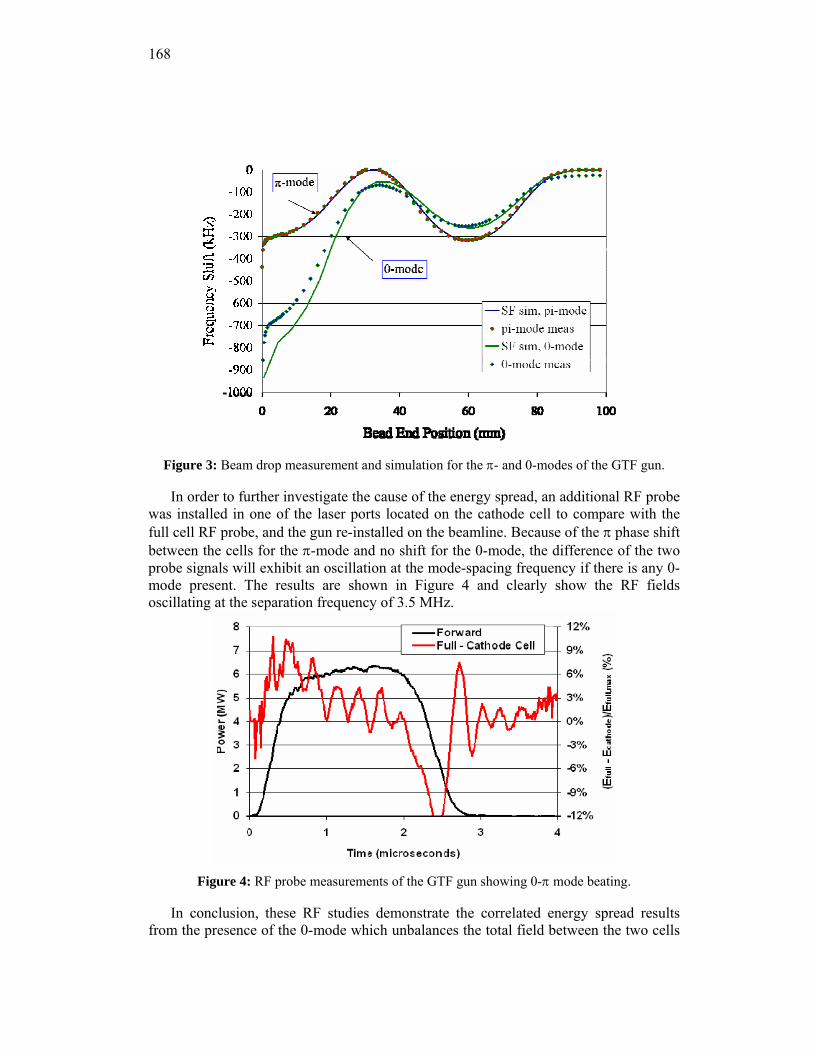
168
Figure 3: Beam drop measurement and simulation for the π- and 0-modes of the GTF gun.
In order to further investigate the cause of the energy spread, an additional RF probe was installed in one of the laser ports located on the cathode cell to compare with the full cell RF probe, and the gun re-installed on the beamline. Because of the π phase shift between the cells for the π-mode and no shift for the 0-mode, the difference of the two probe signals will exhibit an oscillation at the mode-spacing frequency if there is any 0-mode present. The results are shown in Figure 4 and clearly show the RF fields oscillating at the separation frequency of 3.5 MHz.
Figure 4: RF probe measurements of the GTF gun showing 0-π mode beating.
In conclusion, these RF studies demonstrate the correlated energy spread results from the presence of the 0-mode which unbalances the total field between the two cells
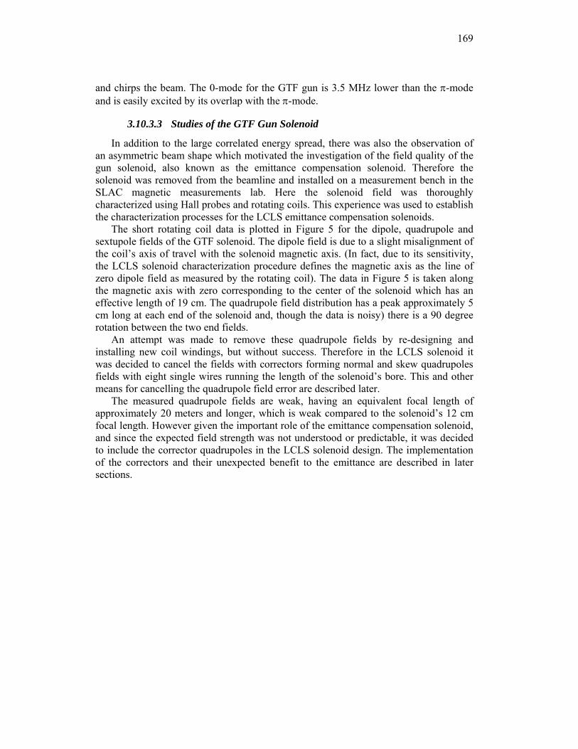
169
and chirps the beam. The 0-mode for the GTF gun is 3.5 MHz lower than the π-mode and is easily excited by its overlap with the π-mode.
3.10.3.3 Studies of the GTF Gun Solenoid
In addition to the large correlated energy spread, there was also the observation of an asymmetric beam shape which motivated the investigation of the field quality of the gun solenoid, also known as the emittance compensation solenoid. Therefore the solenoid was removed from the beamline and installed on a measurement bench in the SLAC magnetic measurements lab. Here the solenoid field was thoroughly characterized using Hall probes and rotating coils. This experience was used to establish the characterization processes for the LCLS emittance compensation solenoids.
The short rotating coil data is plotted in Figure 5 for the dipole, quadrupole and sextupole fields of the GTF solenoid. The dipole field is due to a slight misalignment of the coil’s axis of travel with the solenoid magnetic axis. (In fact, due to its sensitivity, the LCLS solenoid characterization procedure defines the magnetic axis as the line of zero dipole field as measured by the rotating coil). The data in Figure 5 is taken along the magnetic axis with zero corresponding to the center of the solenoid which has an effective length of 19 cm. The quadrupole field distribution has a peak approximately 5 cm long at each end of the solenoid and, though the data is noisy) there is a 90 degree rotation between the two end fields.
An attempt was made to remove these quadrupole fields by re-designing and installing new coil windings, but without success. Therefore in the LCLS solenoid it was decided to cancel the fields with correctors forming normal and skew quadrupoles fields with eight single wires running the length of the solenoid’s bore. This and other means for cancelling the quadrupole field error are described later.
The measured quadrupole fields are weak, having an equivalent focal length of approximately 20 meters and longer, which is weak compared to the solenoid’s 12 cm focal length. However given the important role of the emittance compensation solenoid, and since the expected field strength was not understood or predictable, it was decided to include the corrector quadrupoles in the LCLS solenoid design. The implementation of the correctors and their unexpected benefit to the emittance are described in later sections.
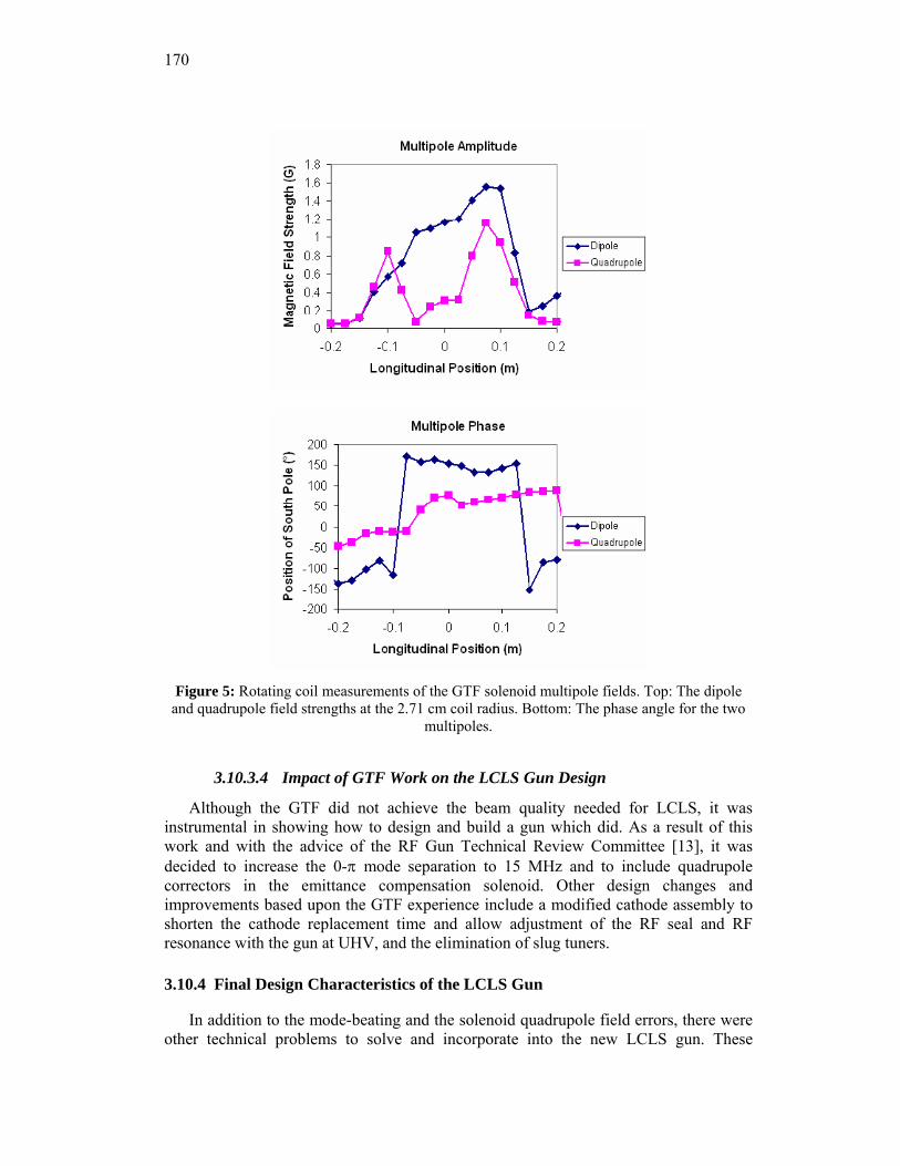
170
Figure 5: Rotating coil measurements of the GTF solenoid multipole fields. Top: The dipole
and quadrupole field strengths at the 2.71 cm coil radius. Bottom: The phase angle for the two multipoles.
3.10.3.4 Impact of GTF Work on the LCLS Gun Design
Although the GTF did not achieve the beam quality needed for LCLS, it was instrumental in showing how to design and build a gun which did. As a result of this work and with the advice of the RF Gun Technical Review Committee [13], it was decided to increase the 0-π mode separation to 15 MHz and to include quadrupole correctors in the emittance compensation solenoid. Other design changes and improvements based upon the GTF experience include a modified cathode assembly to shorten the cathode replacement time and allow adjustment of the RF seal and RF resonance with the gun at UHV, and the elimination of slug tuners.
3.10.4 Final Design Characteristics of the LCLS Gun
In addition to the mode-beating and the solenoid quadrupole field errors, there were other technical problems to solve and incorporate into the new LCLS gun. These
171
included pulsed RF heating which would reduce the gun’s lifetime due to cracking of high-stress surfaces, RF breakdown on surfaces with high peak fields, wakefields between the gun exit and the booster linac entrance, RF field asymmetry in both the gun and booster linac, phase balance of the two arms of the dual RF feed, etc. These and other design and fabrication issues benefited from the guidance of the RF Gun Technical Review Committee, and many of their suggestions were incorporated into LCLS gun [14].
A summary of changes made to Gun III which enabled the LCLS gun meet the stringent requirements of the x-ray FEL are:
1. Dual RF feed to eliminate any transverse RF field asymmetry due to the flow of RF power.
2. A racetrack shape in the full cell to correct for quadrupole fields introduced by the dual feed and other penetrations.
3. Increased the mode separation from 3 to 15 MHz which greatly reduces beating between the 0 and π RF modes.
4. The iris between the two cells was reshaped to reduce its surface field to be lower than the cathode field. This and the larger iris diameter needed to increase the mode separation had the added benefit of reducing the spherical aberration at the iris.
5. The RF power is coupled into the full cell using two longitudinal rectangular ports running the full length of the cell. The combination of z-coupling and increasing the radius of the edges greatly reduces the pulsed heating.
6. Deformation tuners consisting of studs brazed into areas where the walls are thinned allow for small tuning corrections to the resonant frequency and cell-to-cell field balance. The slug tuners used on the GTF Gun III were a source of field breakdown and mechanical failure. The LCLS gun deformation tuners were never used as the machining was done within 0.0004 inches of the design dimensions.
7. Cooling channels capable of dissipating 4 KW of average RF power. At 120 Hz this corresponds to a cathode peak field of 140 MV/m.
8. The cathode was designed for rapid replacement with a new mounting allowing for adjustment of the RF seal and resonance frequency with the gun under vacuum. This design is compatible with a future load lock for installing cathodes needing UHV.
9. Dipole and quadrupole field correctors incorporated into the magnetic solenoid. The gun solenoid was fully characterized using Hall probe and rotating coil measurements.
10. A bucking coil was added to cancel the small magnetic field at the cathode and the emittance growth it causes.
The following subsections describe how these features were incorporated into the
RF design of the LCLS gun and the emittance compensation coil. The thermo-mechanical engineering details are given in Section 4.10.8.
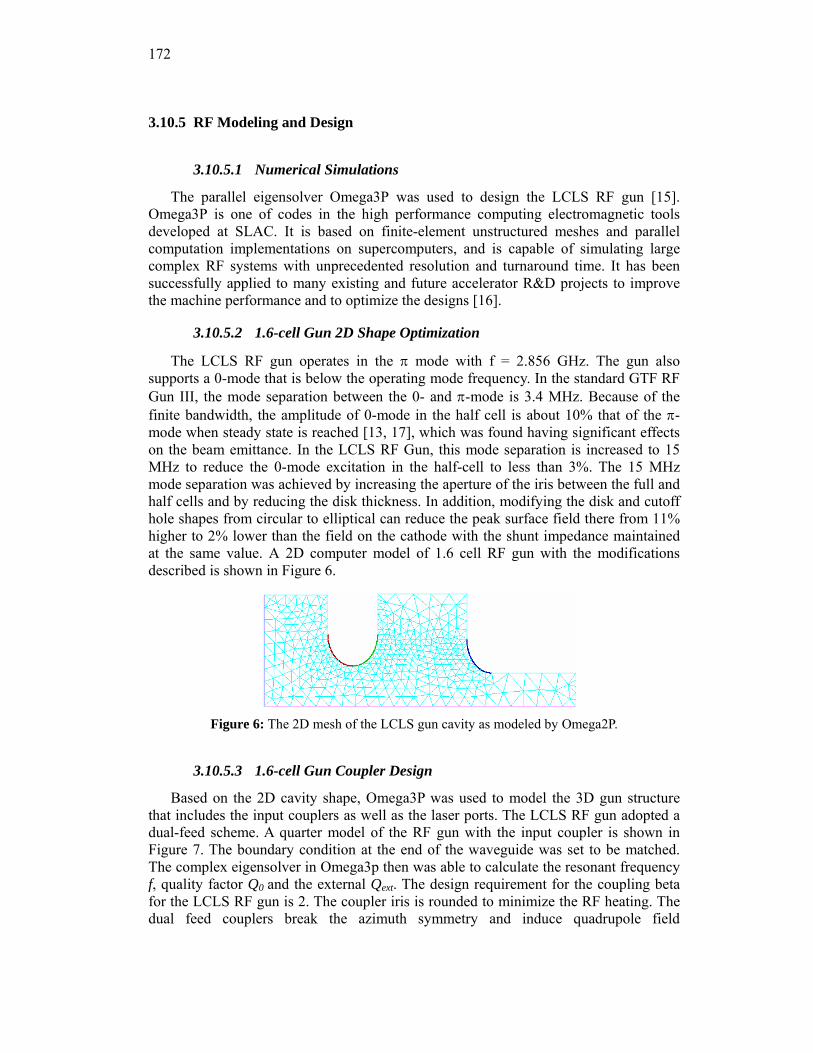
172
3.10.5 RF Modeling and Design
3.10.5.1 Numerical Simulations
The parallel eigensolver Omega3P was used to design the LCLS RF gun [15]. Omega3P is one of codes in the high performance computing electromagnetic tools developed at SLAC. It is based on finite-element unstructured meshes and parallel computation implementations on supercomputers, and is capable of simulating large complex RF systems with unprecedented resolution and turnaround time. It has been successfully applied to many existing and future accelerator R&D projects to improve the machine performance and to optimize the designs [16].
3.10.5.2 1.6-cell Gun 2D Shape Optimization
The LCLS RF gun operates in the π mode with f = 2.856 GHz. The gun also supports a 0-mode that is below the operating mode frequency. In the standard GTF RF Gun III, the mode separation between the 0- and π-mode is 3.4 MHz. Because of the finite bandwidth, the amplitude of 0-mode in the half cell is about 10% that of the π-mode when steady state is reached [13, 17], which was found having significant effects on the beam emittance. In the LCLS RF Gun, this mode separation is increased to 15 MHz to reduce the 0-mode excitation in the half-cell to less than 3%. The 15 MHz mode separation was achieved by increasing the aperture of the iris between the full and half cells and by reducing the disk thickness. In addition, modifying the disk and cutoff hole shapes from circular to elliptical can reduce the peak surface field there from 11% higher to 2% lower than the field on the cathode with the shunt impedance maintained at the same value. A 2D computer model of 1.6 cell RF gun with the modifications described is shown in Figure 6.
Figure 6: The 2D mesh of the LCLS gun cavity as modeled by Omega2P.
3.10.5.3 1.6-cell Gun Coupler Design
Based on the 2D cavity shape, Omega3P was used to model the 3D gun structure that includes the input couplers as well as the laser ports. The LCLS RF gun adopted a dual-feed scheme. A quarter model of the RF gun with the input coupler is shown in Figure 7. The boundary condition at the end of the waveguide was set to be matched. The complex eigensolver in Omega3p then was able to calculate the resonant frequency f, quality factor Q0 and the external Qext. The design requirement for the coupling beta for the LCLS RF gun is 2. The coupler iris is rounded to minimize the RF heating. The dual feed couplers break the azimuth symmetry and induce quadrupole field
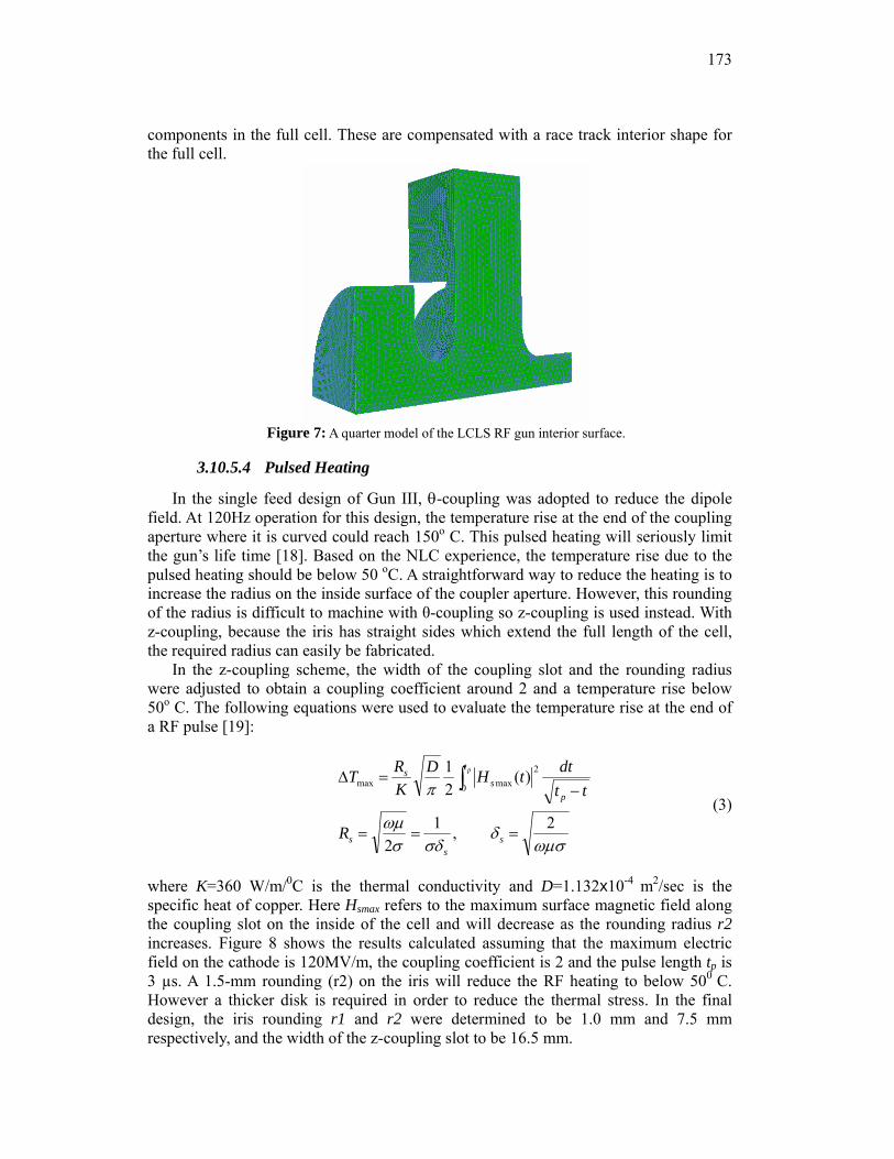
173
components in the full cell. These are compensated with a race track interior shape for the full cell.
Figure 7: A quarter model of the LCLS RF gun interior surface.
3.10.5.4 Pulsed Heating
In the single feed design of Gun III, θ-coupling was adopted to reduce the dipole field. At 120Hz operation for this design, the temperature rise at the end of the coupling aperture where it is curved could reach 150o C. This pulsed heating will seriously limit the gun’s life time [18]. Based on the NLC experience, the temperature rise due to the pulsed heating should be below 50 oC. A straightforward way to reduce the heating is to increase the radius on the inside surface of the coupler aperture. However, this rounding of the radius is difficult to machine with θ-coupling so z-coupling is used instead. With z-coupling, because the iris has straight sides which extend the full length of the cell, the required radius can easily be fabricated.
In the z-coupling scheme, the width of the coupling slot and the rounding radius were adjusted to obtain a coupling coefficient around 2 and a temperature rise below 50o C. The following equations were used to evaluate the temperature rise at the end of a RF pulse [19]:
ωμσδ
σδσωμ
π
2,12
)(21
0
2maxmax
===
−=Δ ∫
ss
s
t
ps
s
R
ttdttHD
KRT p
(3)
where K=360 W/m/0C is the thermal conductivity and D=1.132x10⁻⁴ m2/sec is the specific heat of copper. Here Hsmax refers to the maximum surface magnetic field along the coupling slot on the inside of the cell and will decrease as the rounding radius r2 increases. Figure 8 shows the results calculated assuming that the maximum electric field on the cathode is 120MV/m, the coupling coefficient is 2 and the pulse length tp is 3 µs. A 1.5-mm rounding (r2) on the iris will reduce the RF heating to below 500 C. However a thicker disk is required in order to reduce the thermal stress. In the final design, the iris rounding r1 and r2 were determined to be 1.0 mm and 7.5 mm respectively, and the width of the z-coupling slot to be 16.5 mm.
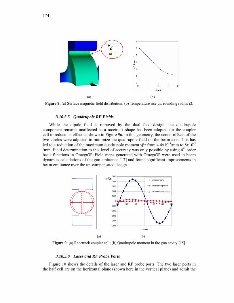
174
(a) (b)
Figure 8: (a) Surface magnetic field distribution; (b) Temperature rise vs. rounding radius r2.
3.10.5.5 Quadrupole RF Fields
While the dipole field is removed by the dual feed design, the quadrupole component remains unaffected so a racetrack shape has been adopted for the coupler cell to reduce its effect as shown in Figure 9a. In this geometry, the center offsets of the two circles were adjusted to minimize the quadrupole field on the beam axis. This has led to a reduction of the maximum quadrupole moment γβr from 4.4x10⁻³/mm to 8x10⁻⁵
/mm. Field determination to this level of accuracy was only possible by using 4th order basis functions in Omega3P. Field maps generated with Omega3P were used in beam dynamics calculations of the gun emittance [17] and found significant improvements in beam emittance over the un-compensated design.
-0.005
-0.004
-0.003
-0.002
-0.001
0
0.001
0.002
0.003
0.004
0.005
-180 -120 -60 0 60 120 180
rf phase
cylindrical cavity
racetrack coupler cell
half-cell with laser ports
γβr
(a) (b)
Figure 9: (a) Racetrack coupler cell; (b) Quadrupole moment in the gun cavity [15].
3.10.5.6 Laser and RF Probe Ports
Figure 10 shows the details of the laser and RF probe ports. The two laser ports in the half cell are on the horizontal plane (shown here in the vertical plane) and admit the
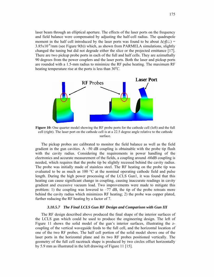
175
laser beam through an elliptical aperture. The effects of the laser ports on the frequency and field balance were compensated by adjusting the half-cell radius. The quadrupole moment in the half cell introduced by the laser ports was found to be about Δ(γβ⊥) = 3.85x10⁻⁴/mm (see Figure 9(b)) which, as shown from PARMELA simulations, slightly changed the tuning but did not degrade either the slice or the projected emittance [17]. There are two pickup probe ports in each of the full and half cells. They are azimuthally 90 degrees from the power couplers and the laser ports. Both the laser and pickup ports are rounded with a 1.5-mm radius to minimize the RF pulse heating. The maximum RF heating temperature rise at the ports is less than 30oC.
Figure 10: One quarter model showing the RF probe ports for the cathode cell (left) and the full
cell (right). The laser port on the cathode cell is at a 22.5 degree angle relative to the cathode surface.
The pickup probes are calibrated to monitor the field balance as well as the field gradient in the gun cavities. A –50 dB coupling is obtainable with the probe tip flush with the cavity radius. Considering the requirements in power handling of the electronics and accurate measurement of the fields, a coupling around -60dB coupling is needed, which requires that the probe tip be slightly recessed behind the cavity radius. The probe was initially made of stainless steel. The RF heating on the probe tip was evaluated to be as much as 100 °C at the nominal operating cathode field and pulse length. During the high power processing of the LCLS Gun1, it was found that this heating can cause significant change in coupling, causing inaccurate readings in cavity gradient and excessive vacuum load. Two improvements were made to mitigate this problem: 1) the coupling was lowered to –77 dB, the tip of the probe retreats more behind the cavity radius which minimizes RF heating; 2) the probe was copper plated, further reducing the RF heating by a factor of 7.
3.10.5.7 The Final LCLS Gun RF Design and Comparison with Gun III
The RF design described above produced the final shape of the interior surfaces of the LCLS gun which could be used to produce the engineering design. The left of Figure 11 shows the solid model of the gun’s interior surfaces, illustrating the z-coupling of the vertical waveguide feeds to the full cell, and the horizontal location of one of the two RF probes. The half cell portion of the solid model shows one of the laser ports in the horizontal plane and its two RF probes positioned vertically. The geometry of the full cell racetrack shape is produced by two circles offset horizontally by 5.9 mm as illustrated in the left drawing of Figure 11 [15].
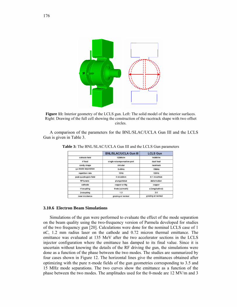
176
Figure 11: Interior geometry of the LCLS gun. Left: The solid model of the interior surfaces. Right: Drawing of the full cell showing the construction of the racetrack shape with two offset
circles.
A comparison of the parameters for the BNL/SLAC/UCLA Gun III and the LCLS Gun is given in Table 3.
Table 3: The BNL/SLAC/UCLA Gun III and the LCLS Gun parameters
3.10.6 Electron Beam Simulations
Simulations of the gun were performed to evaluate the effect of the mode separation on the beam quality using the two-frequency version of Parmela developed for studies of the two frequency gun [20]. Calculations were done for the nominal LCLS case of 1 nC, 1.2 mm radius laser on the cathode and 0.72 micron thermal emittance. The emittance was evaluated at 135 MeV after the two accelerator sections in the LCLS injector configuration where the emittance has damped to its final value. Since it is uncertain without knowing the details of the RF driving the gun, the simulations were done as a function of the phase between the two modes. The studies are summarized by four cases shown in Figure 12. The horizontal lines give the emittances obtained after optimizing with the pure π-mode fields of the gun geometries corresponding to 3.5 and 15 MHz mode separations. The two curves show the emittance as a function of the phase between the two modes. The amplitudes used for the 0-mode are 12 MV/m and 3
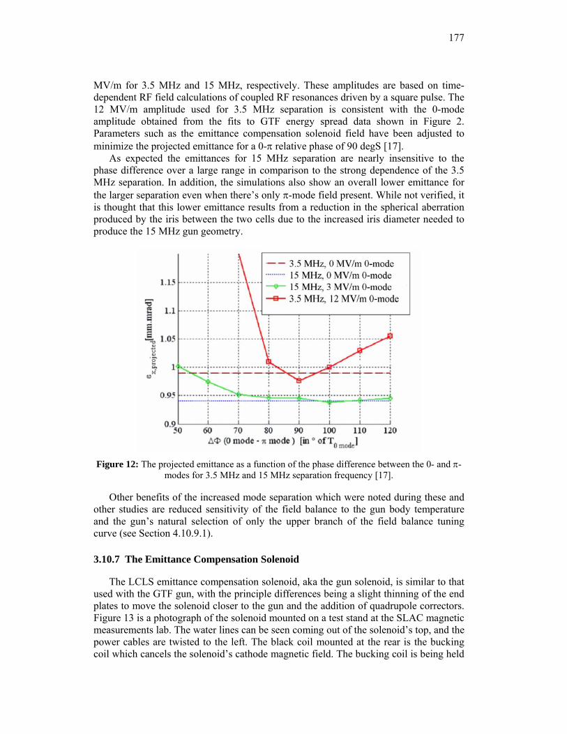
177
MV/m for 3.5 MHz and 15 MHz, respectively. These amplitudes are based on time-dependent RF field calculations of coupled RF resonances driven by a square pulse. The 12 MV/m amplitude used for 3.5 MHz separation is consistent with the 0-mode amplitude obtained from the fits to GTF energy spread data shown in Figure 2. Parameters such as the emittance compensation solenoid field have been adjusted to minimize the projected emittance for a 0-π relative phase of 90 degS [17].
As expected the emittances for 15 MHz separation are nearly insensitive to the phase difference over a large range in comparison to the strong dependence of the 3.5 MHz separation. In addition, the simulations also show an overall lower emittance for the larger separation even when there’s only π-mode field present. While not verified, it is thought that this lower emittance results from a reduction in the spherical aberration produced by the iris between the two cells due to the increased iris diameter needed to produce the 15 MHz gun geometry.
Figure 12: The projected emittance as a function of the phase difference between the 0- and π-
modes for 3.5 MHz and 15 MHz separation frequency [17].
Other benefits of the increased mode separation which were noted during these and other studies are reduced sensitivity of the field balance to the gun body temperature and the gun’s natural selection of only the upper branch of the field balance tuning curve (see Section 4.10.9.1).
3.10.7 The Emittance Compensation Solenoid
The LCLS emittance compensation solenoid, aka the gun solenoid, is similar to that used with the GTF gun, with the principle differences being a slight thinning of the end plates to move the solenoid closer to the gun and the addition of quadrupole correctors. Figure 13 is a photograph of the solenoid mounted on a test stand at the SLAC magnetic measurements lab. The water lines can be seen coming out of the solenoid’s top, and the power cables are twisted to the left. The black coil mounted at the rear is the bucking coil which cancels the solenoid’s cathode magnetic field. The bucking coil is being held
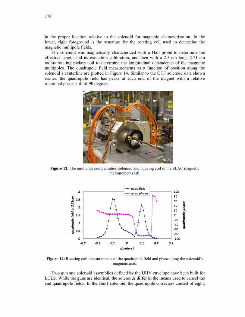
178
in the proper location relative to the solenoid for magnetic characterization. In the lower, right foreground is the armature for the rotating coil used to determine the magnetic multipole fields.
The solenoid was magnetically characterized with a Hall probe to determine the effective length and its excitation calibration, and then with a 2.5 cm long, 2.71 cm radius rotating pickup coil to determine the longitudinal dependence of the magnetic multipoles. The quadrupole field measurements as a function of position along the solenoid’s centerline are plotted in Figure 14. Similar to the GTF solenoid data shown earlier, the quadrupole field has peaks at each end of the magnet with a relative rotational phase shift of 90 degrees.
Figure 13: The emittance compensation solenoid and bucking coil in the SLAC magnetic
measurements lab.
0
0.5
1
1.5
2
2.5
3
-0.3 -0.2 -0.1 0 0.1 0.2 0.3z(meters)
quad
rupl
e fie
ld a
t 2.7
1cm
-100-80-60-40-20020406080100
quad
rupo
le p
hase
quad fieldquad phase
Figure 14: Rotating coil measurements of the quadrupole field and phase along the solenoid’s
magnetic axis.
Two gun and solenoid assemblies defined by the UHV envelope have been built for LCLS. While the guns are identical, the solenoids differ in the means used to cancel the end quadrupole fields. In the Gun1 solenoid, the quadrupole correctors consist of eight,
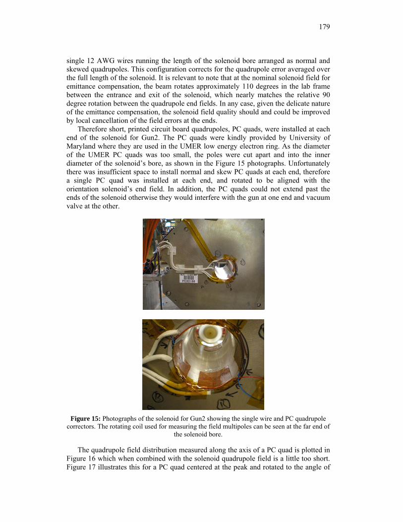
179
single 12 AWG wires running the length of the solenoid bore arranged as normal and skewed quadrupoles. This configuration corrects for the quadrupole error averaged over the full length of the solenoid. It is relevant to note that at the nominal solenoid field for emittance compensation, the beam rotates approximately 110 degrees in the lab frame between the entrance and exit of the solenoid, which nearly matches the relative 90 degree rotation between the quadrupole end fields. In any case, given the delicate nature of the emittance compensation, the solenoid field quality should and could be improved by local cancellation of the field errors at the ends.
Therefore short, printed circuit board quadrupoles, PC quads, were installed at each end of the solenoid for Gun2. The PC quads were kindly provided by University of Maryland where they are used in the UMER low energy electron ring. As the diameter of the UMER PC quads was too small, the poles were cut apart and into the inner diameter of the solenoid’s bore, as shown in the Figure 15 photographs. Unfortunately there was insufficient space to install normal and skew PC quads at each end, therefore a single PC quad was installed at each end, and rotated to be aligned with the orientation solenoid’s end field. In addition, the PC quads could not extend past the ends of the solenoid otherwise they would interfere with the gun at one end and vacuum valve at the other.
Figure 15: Photographs of the solenoid for Gun2 showing the single wire and PC quadrupole
correctors. The rotating coil used for measuring the field multipoles can be seen at the far end of the solenoid bore.
The quadrupole field distribution measured along the axis of a PC quad is plotted in Figure 16 which when combined with the solenoid quadrupole field is a little too short. Figure 17 illustrates this for a PC quad centered at the peak and rotated to the angle of
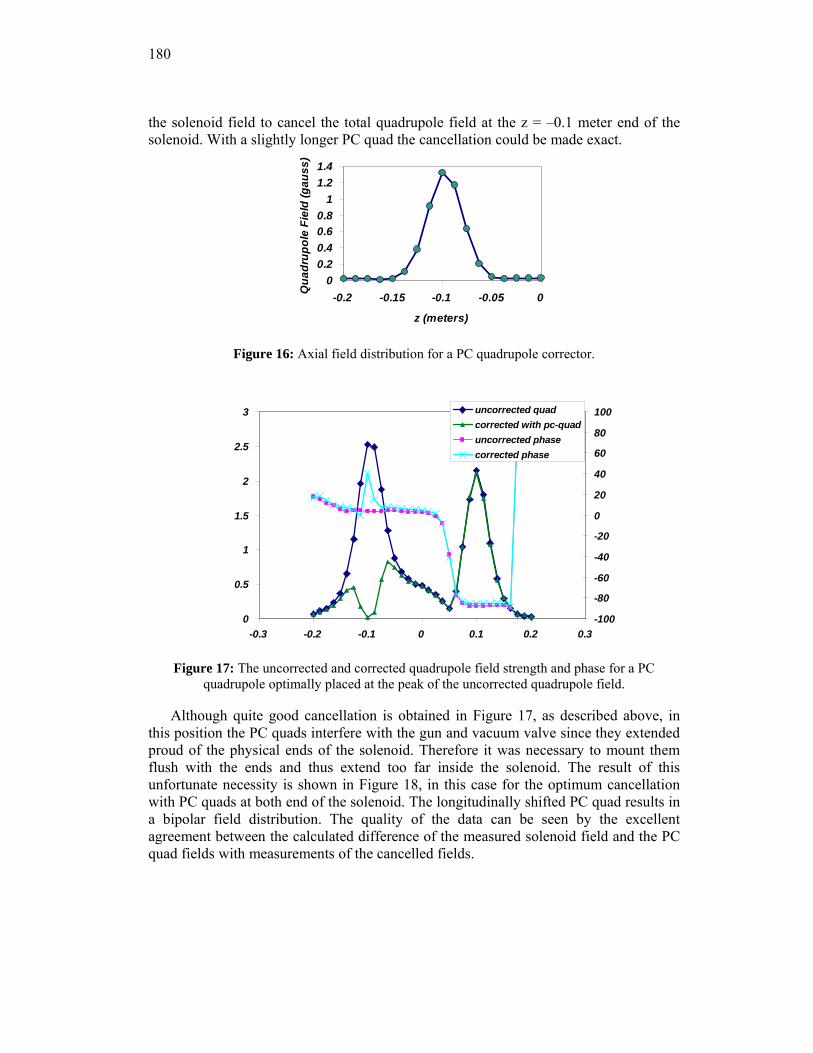
180
the solenoid field to cancel the total quadrupole field at the z = –0.1 meter end of the solenoid. With a slightly longer PC quad the cancellation could be made exact.
00.20.40.60.8
11.21.4
-0.2 -0.15 -0.1 -0.05 0
z (meters)Q
uadr
upol
e Fi
eld
(gau
ss)
Figure 16: Axial field distribution for a PC quadrupole corrector.
0
0.5
1
1.5
2
2.5
3
-0.3 -0.2 -0.1 0 0.1 0.2 0.3-100
-80
-60
-40
-20
0
20
40
60
80
100uncorrected quadcorrected with pc-quaduncorrected phasecorrected phase
Figure 17: The uncorrected and corrected quadrupole field strength and phase for a PC
quadrupole optimally placed at the peak of the uncorrected quadrupole field.
Although quite good cancellation is obtained in Figure 17, as described above, in this position the PC quads interfere with the gun and vacuum valve since they extended proud of the physical ends of the solenoid. Therefore it was necessary to mount them flush with the ends and thus extend too far inside the solenoid. The result of this unfortunate necessity is shown in Figure 18, in this case for the optimum cancellation with PC quads at both end of the solenoid. The longitudinally shifted PC quad results in a bipolar field distribution. The quality of the data can be seen by the excellent agreement between the calculated difference of the measured solenoid field and the PC quad fields with measurements of the cancelled fields.
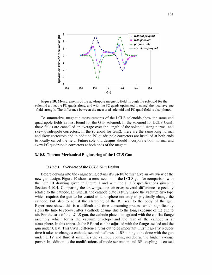
181
-4
-3
-2
-1
0
1
2
3
-0.3 -0.2 -0.1 0 0.1 0.2 0.3z(m)
Qua
drup
ole
field
at 2
.71c
m ra
dius
(G) without pc-quad
with pc-quadpc quad onlysol minus pc-quad
Figure 18: Measurements of the quadrupole magnetic field through the solenoid for the
solenoid alone, the PC quads alone, and with the PC quads optimized to cancel the local average field strength. The difference between the measured solenoid and PC quad field is also plotted.
To summarize, magnetic measurements of the LCLS solenoids show the same end quadrupole fields as first found for the GTF solenoid. In the solenoid for LCLS Gun1, these fields are cancelled on average over the length of the solenoid using normal and skew quadrupole correctors. In the solenoid for Gun2, there are the same long normal and skew correctors and in addition PC quadrupole correctors are installed at both ends to locally cancel the field. Future solenoid designs should incorporate both normal and skew PC quadrupole correctors at both ends of the magnet.
3.10.8 Thermo-Mechanical Engineering of the LCLS Gun
3.10.8.1 Overview of the LCLS Gun Design
Before delving into the engineering details it’s useful to first give an overview of the new gun design. Figure 19 shows a cross section of the LCLS gun for comparison with the Gun III drawing given in Figure 1 and with the LCLS specifications given in Section 4.10.4. Comparing the drawings, one observes several differences especially related to the cathode. In Gun III, the cathode plate is fully inside the vacuum envelope which requires the gun to be vented to atmosphere not only to physically change the cathode, but also to adjust the clamping of the RF seal to the body of the gun. Experience shows this is a difficult and time consuming process which significantly slows the time to recover after a cathode change due to the long exposure of the gun to air. For the case of the LCLS gun, the cathode plate is integrated with the conflat flange assembly which forms the vacuum envelope and the rear of the cathode is at atmosphere. In this approach the RF seal can be adjusted with the flanges sealed and the gun under UHV. This trivial difference turns out to be important. First it greatly reduces time it takes to change a cathode, second it allows all RF tuning to be done with the gun under UHV and third it simplifies the cathode cooling needed at the higher average power. In addition to the modifications of mode separation and RF coupling discussed
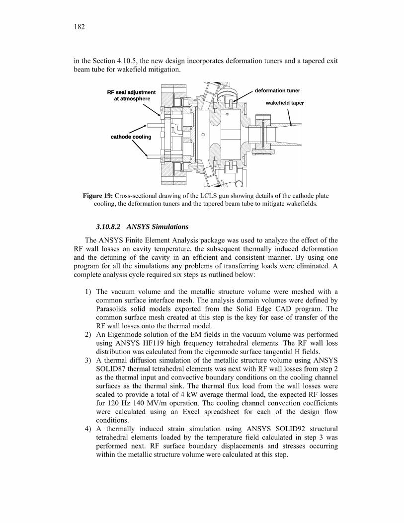
182
in the Section 4.10.5, the new design incorporates deformation tuners and a tapered exit beam tube for wakefield mitigation.
deformation tuner
wakefield taper
RF seal adjustment at atmosphere
cathode cooling
deformation tuner
wakefield taper
deformation tuner
wakefield taper
RF seal adjustment at atmosphere
cathode cooling
Figure 19: Cross-sectional drawing of the LCLS gun showing details of the cathode plate
cooling, the deformation tuners and the tapered beam tube to mitigate wakefields.
3.10.8.2 ANSYS Simulations
The ANSYS Finite Element Analysis package was used to analyze the effect of the RF wall losses on cavity temperature, the subsequent thermally induced deformation and the detuning of the cavity in an efficient and consistent manner. By using one program for all the simulations any problems of transferring loads were eliminated. A complete analysis cycle required six steps as outlined below:
1) The vacuum volume and the metallic structure volume were meshed with a
common surface interface mesh. The analysis domain volumes were defined by Parasolids solid models exported from the Solid Edge CAD program. The common surface mesh created at this step is the key for ease of transfer of the RF wall losses onto the thermal model.
2) An Eigenmode solution of the EM fields in the vacuum volume was performed using ANSYS HF119 high frequency tetrahedral elements. The RF wall loss distribution was calculated from the eigenmode surface tangential H fields.
3) A thermal diffusion simulation of the metallic structure volume using ANSYS SOLID87 thermal tetrahedral elements was next with RF wall losses from step 2 as the thermal input and convective boundary conditions on the cooling channel surfaces as the thermal sink. The thermal flux load from the wall losses were scaled to provide a total of 4 kW average thermal load, the expected RF losses for 120 Hz 140 MV/m operation. The cooling channel convection coefficients were calculated using an Excel spreadsheet for each of the design flow conditions.
4) A thermally induced strain simulation using ANSYS SOLID92 structural tetrahedral elements loaded by the temperature field calculated in step 3 was performed next. RF surface boundary displacements and stresses occurring within the metallic structure volume were calculated at this step.
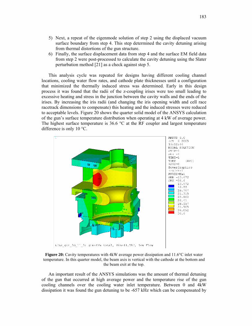
183
5) Next, a repeat of the eigenmode solution of step 2 using the displaced vacuum surface boundary from step 4. This step determined the cavity detuning arising from thermal distortions of the gun structure.
6) Finally, the surface displacement data from step 4 and the surface EM field data from step 2 were post-processed to calculate the cavity detuning using the Slater perturbation method [21] as a check against step 5.
This analysis cycle was repeated for designs having different cooling channel
locations, cooling water flow rates, and cathode plate thicknesses until a configuration that minimized the thermally induced stress was determined. Early in this design process it was found that the radii of the z-coupling irises were too small leading to excessive heating and stress in the junction between the cavity walls and the ends of the irises. By increasing the iris radii (and changing the iris opening width and cell race racetrack dimensions to compensate) this heating and the induced stresses were reduced to acceptable levels. Figure 20 shows the quarter solid model of the ANSYS calculation of the gun’s surface temperature distribution when operating at 4 kW of average power. The highest surface temperature is 36.6 °C at the RF coupler and largest temperature difference is only 10 °C.
Figure 20: Cavity temperatures with 4kW average power dissipation and 11.6°C inlet water
temperature. In this quarter model, the beam axis is vertical with the cathode at the bottom and the beam exit at the top.
An important result of the ANSYS simulations was the amount of thermal detuning of the gun that occurred at high average power and the temperature rise of the gun cooling channels over the cooling water inlet temperature. Between 0 and 4kW dissipation it was found the gun detuning to be -657 kHz which can be compensated by
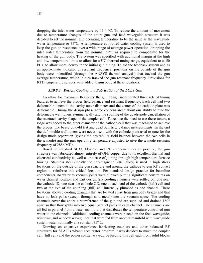
184
dropping the inlet water temperature by 13.4 °C. To reduce the amount of movement due to temperature changes of the entire gun and feed waveguide structure it was decided to set the nominal gun operating temperature to be the same as the waveguide water temperature or 35°C. A temperature controlled water cooling system is used to keep the gun on resonance over a wide range of average power operation, dropping the inlet water temperature from the nominal 35°C as required to compensate for the heating of the gun body. The system was specified with additional margin at the high and low temperature limits to allow for ±3°C thermal tuning range, equivalent to ±150 kHz, to allow more leeway in the initial gun tuning. To aid the feedback system and as an approximate indicator of resonant frequency, positions on the outside of the gun body were indentified (through the ANSYS thermal analysis) that tracked the gun average temperature, which in turn tracked the gun resonant frequency. Provisions for RTD temperature sensors were added to gun body at these locations.
3.10.8.3 Design, Cooling and Fabrication of the LCLS Gun
To allow for maximum flexibility the gun design incorporated three sets of tuning features to achieve the proper field balance and resonant frequency. Each cell had two deformable tuners at the cavity outer diameter and the center of the cathode plate was deformable. During the design phase some concern arose about our ability to tune the deformable wall tuners symmetrically and the spoiling of the quadrupole cancellation of the racetrack cavity shape of the coupler cell. To reduce the need to use these tuners, a ridge was added to the outer diameter of the cathode cell that was machined to achieve the proper tune based on cold test and bead pull field balance measurements. In the end the deformable wall tuners were never used, with the cathode plate used to tune for the design mode separation (giving the desired 1:1 field balance between the two cells in the π-mode) and the gun operating temperature adjusted to give the π-mode resonant frequency of 2856 MHz.
Based on standard SLAC klystron and RF component design practice, the gun structure was fabricated almost entirely of OFE copper due to its excellent thermal and electrical conductivity as well as the ease of joining through high temperature furnace brazing. Stainless steel (mostly the non-magnetic 304L alloy) is used in high stress locations on the outside of the gun structure and around the cathode to gun RF contact region to reinforce this critical location. Per standard design practice for beamline components, no water to vacuum joints were allowed putting significant constraints on water channel location and part design. Six cooling channels were settled on, one near the cathode ID, one near the cathode OD, one at each end of the cathode (half) cell and two at the exit of the coupling (full) cell internally plumbed as one channel. These locations allowed cooling channels that are located away from gun body brazes and that have no leak paths (except through sold metal) into the vacuum space. The cooling channels cover the entire circumference of the gun and are supplied and drained 180° apart so that flow splits into two equal parallel paths in each channel. The channels are all fed in parallel from a water manifold that distributes the temperature controlled gun water to the channels. Additional cooling channels were placed on the feed waveguide, windows, and window waveguides that were fed from another manifold with waveguide system water nominally at a constant 35° C.
Drawing on extensive experience fabricating couplers and other balanced RF structures for SLAC’s x-band accelerator program it was decided to make the coupler cell (full cell) and the power splitter waveguide feeding this cell each from solid blocks
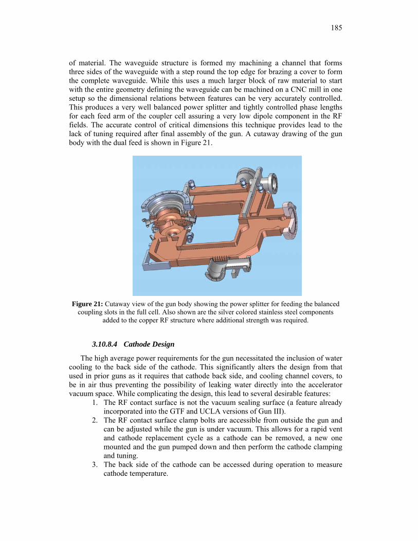
185
of material. The waveguide structure is formed my machining a channel that forms three sides of the waveguide with a step round the top edge for brazing a cover to form the complete waveguide. While this uses a much larger block of raw material to start with the entire geometry defining the waveguide can be machined on a CNC mill in one setup so the dimensional relations between features can be very accurately controlled. This produces a very well balanced power splitter and tightly controlled phase lengths for each feed arm of the coupler cell assuring a very low dipole component in the RF fields. The accurate control of critical dimensions this technique provides lead to the lack of tuning required after final assembly of the gun. A cutaway drawing of the gun body with the dual feed is shown in Figure 21.
Figure 21: Cutaway view of the gun body showing the power splitter for feeding the balanced
coupling slots in the full cell. Also shown are the silver colored stainless steel components added to the copper RF structure where additional strength was required.
3.10.8.4 Cathode Design
The high average power requirements for the gun necessitated the inclusion of water cooling to the back side of the cathode. This significantly alters the design from that used in prior guns as it requires that cathode back side, and cooling channel covers, to be in air thus preventing the possibility of leaking water directly into the accelerator vacuum space. While complicating the design, this lead to several desirable features:
1. The RF contact surface is not the vacuum sealing surface (a feature already incorporated into the GTF and UCLA versions of Gun III).
2. The RF contact surface clamp bolts are accessible from outside the gun and can be adjusted while the gun is under vacuum. This allows for a rapid vent and cathode replacement cycle as a cathode can be removed, a new one mounted and the gun pumped down and then perform the cathode clamping and tuning.
3. The back side of the cathode can be accessed during operation to measure cathode temperature.
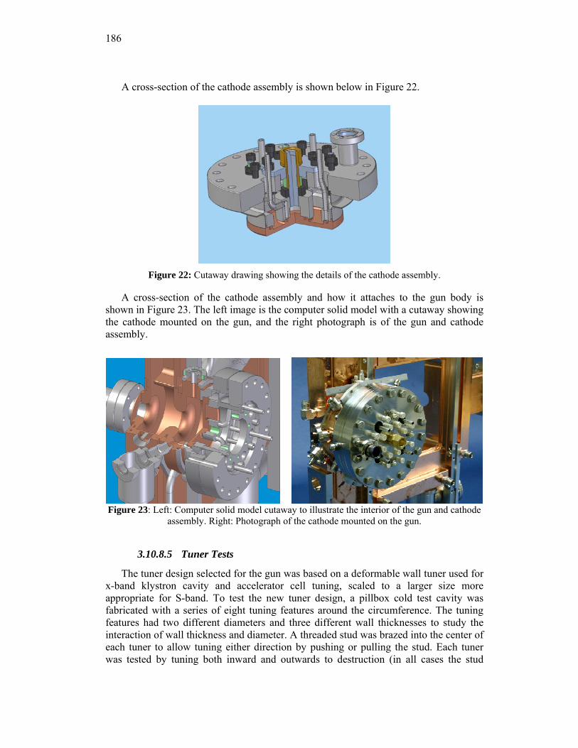
186
A cross-section of the cathode assembly is shown below in Figure 22.
Figure 22: Cutaway drawing showing the details of the cathode assembly.
A cross-section of the cathode assembly and how it attaches to the gun body is shown in Figure 23. The left image is the computer solid model with a cutaway showing the cathode mounted on the gun, and the right photograph is of the gun and cathode assembly.
Figure 23: Left: Computer solid model cutaway to illustrate the interior of the gun and cathode assembly. Right: Photograph of the cathode mounted on the gun.
3.10.8.5 Tuner Tests
The tuner design selected for the gun was based on a deformable wall tuner used for x-band klystron cavity and accelerator cell tuning, scaled to a larger size more appropriate for S-band. To test the new tuner design, a pillbox cold test cavity was fabricated with a series of eight tuning features around the circumference. The tuning features had two different diameters and three different wall thicknesses to study the interaction of wall thickness and diameter. A threaded stud was brazed into the center of each tuner to allow tuning either direction by pushing or pulling the stud. Each tuner was tested by tuning both inward and outwards to destruction (in all cases the stud
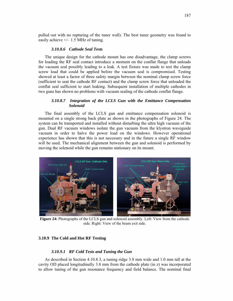
187
pulled out with no rupturing of the tuner wall). The best tuner geometry was found to easily achieve +/– 1.5 MHz of tuning.
3.10.8.6 Cathode Seal Tests
The unique design for the cathode mount has one disadvantage, the clamp screws for loading the RF seal contact introduce a moment on the conflat flange that unloads the vacuum seal possibly leading to a leak. A test fixture was made to test the clamp screw load that could be applied before the vacuum seal is compromised. Testing showed at least a factor of three safety margin between the nominal clamp screw force (sufficient to seat the cathode RF contact) and the clamp screw force that unloaded the conflat seal sufficient to start leaking. Subsequent installation of multiple cathodes in two guns has shown no problems with vacuum sealing of the cathode conflat flange.
3.10.8.7 Integration of the LCLS Gun with the Emittance Compensation Solenoid
The final assembly of the LCLS gun and emittance compensation solenoid is mounted on a single strong back plate as shown in the photographs of Figure 24. The system can be transported and installed without disturbing the ultra high vacuum of the gun. Dual RF vacuum windows isolate the gun vacuum from the klystron waveguide vacuum in order to halve the power load on the windows. However operational experience has shown that this is not necessary and in the future a single RF window will be used. The mechanical alignment between the gun and solenoid is performed by moving the solenoid while the gun remains stationary on its mount.
Figure 24: Photographs of the LCLS gun and solenoid assembly. Left: View from the cathode side. Right: View of the beam exit side.
3.10.9 The Cold and Hot RF Testing
3.10.9.1 RF Cold Tests and Tuning the Gun
As described in Section 4.10.8.3, a tuning ridge 3.8 mm wide and 1.0 mm tall at the cavity OD placed longitudinally 3.8 mm from the cathode plate (in z) was incorporated to allow tuning of the gun resonance frequency and field balance. The nominal final
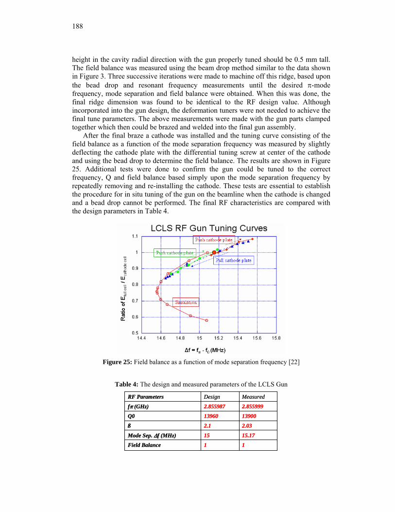
188
height in the cavity radial direction with the gun properly tuned should be 0.5 mm tall. The field balance was measured using the beam drop method similar to the data shown in Figure 3. Three successive iterations were made to machine off this ridge, based upon the bead drop and resonant frequency measurements until the desired π-mode frequency, mode separation and field balance were obtained. When this was done, the final ridge dimension was found to be identical to the RF design value. Although incorporated into the gun design, the deformation tuners were not needed to achieve the final tune parameters. The above measurements were made with the gun parts clamped together which then could be brazed and welded into the final gun assembly.
After the final braze a cathode was installed and the tuning curve consisting of the field balance as a function of the mode separation frequency was measured by slightly deflecting the cathode plate with the differential tuning screw at center of the cathode and using the bead drop to determine the field balance. The results are shown in Figure 25. Additional tests were done to confirm the gun could be tuned to the correct frequency, Q and field balance based simply upon the mode separation frequency by repeatedly removing and re-installing the cathode. These tests are essential to establish the procedure for in situ tuning of the gun on the beamline when the cathode is changed and a bead drop cannot be performed. The final RF characteristics are compared with the design parameters in Table 4.
Figure 25: Field balance as a function of mode separation frequency [22]
Table 4: The design and measured parameters of the LCLS Gun
1
15
2.1
13960
2.855987
Design
1Field Balance
15.17Mode Sep. Δf (MHz)
2.03ß
13900Q0
2.855999fπ (GHz)
MeasuredRF Parameters
1
15
2.1
13960
2.855987
Design
1Field Balance
15.17Mode Sep. Δf (MHz)
2.03ß
13900Q0
2.855999fπ (GHz)
MeasuredRF Parameters
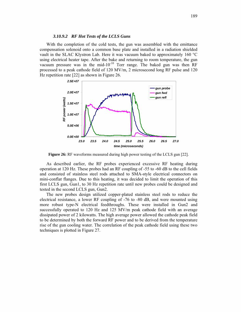
189
3.10.9.2 RF Hot Tests of the LCLS Guns
With the completion of the cold tests, the gun was assembled with the emittance compensation solenoid onto a common base plate and installed in a radiation shielded vault in the SLAC Klystron Lab. Here it was vacuum baked to approximately 160 °C using electrical heater tape. After the bake and returning to room temperature, the gun vacuum pressure was in the mid-10-10 Torr range. The baked gun was then RF processed to a peak cathode field of 120 MV/m, 2 microsecond long RF pulse and 120 Hz repetition rate [22] as shown in Figure 26.
0.0E+00
5.0E+06
1.0E+07
1.5E+07
2.0E+07
2.5E+07
23.0 23.5 24.0 24.5 25.0 25.5 26.0 26.5 27.0time (microseconds)
RF
pow
er (w
atts
)
gun probegun fwdgun refl
Figure 26: RF waveforms measured during high power testing of the LCLS gun [22].
As described earlier, the RF probes experienced excessive RF heating during operation at 120 Hz. These probes had an RF coupling of -55 to -60 dB to the cell fields and consisted of stainless steel rods attached to SMA-style electrical connectors on mini-conflat flanges. Due to this heating, it was decided to limit the operation of this first LCLS gun, Gun1, to 30 Hz repetition rate until new probes could be designed and tested in the second LCLS gun, Gun2.
The new probes design utilized copper-plated stainless steel rods to reduce the electrical resistance, a lower RF coupling of -76 to -80 dB, and were mounted using more robust type-N electrical feedthroughs. These were installed in Gun2 and successfully operated to 120 Hz and 125 MV/m peak cathode field with an average dissipated power of 2 kilowatts. The high average power allowed the cathode peak field to be determined by both the forward RF power and to be derived from the temperature rise of the gun cooling water. The correlation of the peak cathode field using these two techniques is plotted in Figure 27.
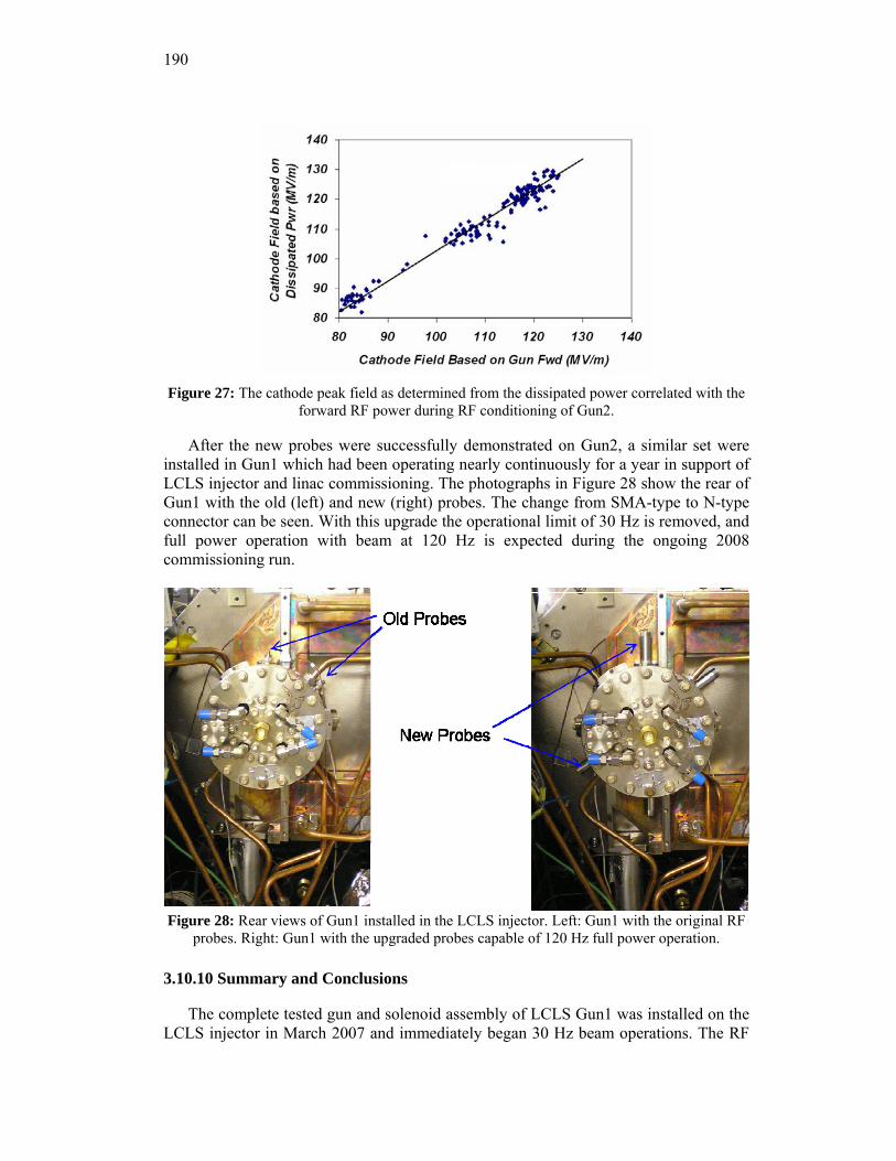
190
Figure 27: The cathode peak field as determined from the dissipated power correlated with the
forward RF power during RF conditioning of Gun2.
After the new probes were successfully demonstrated on Gun2, a similar set were installed in Gun1 which had been operating nearly continuously for a year in support of LCLS injector and linac commissioning. The photographs in Figure 28 show the rear of Gun1 with the old (left) and new (right) probes. The change from SMA-type to N-type connector can be seen. With this upgrade the operational limit of 30 Hz is removed, and full power operation with beam at 120 Hz is expected during the ongoing 2008 commissioning run.
Figure 28: Rear views of Gun1 installed in the LCLS injector. Left: Gun1 with the original RF probes. Right: Gun1 with the upgraded probes capable of 120 Hz full power operation.
3.10.10 Summary and Conclusions
The complete tested gun and solenoid assembly of LCLS Gun1 was installed on the LCLS injector in March 2007 and immediately began 30 Hz beam operations. The RF
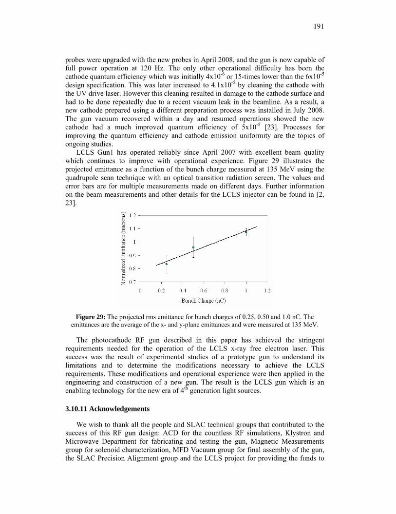
191
probes were upgraded with the new probes in April 2008, and the gun is now capable of full power operation at 120 Hz. The only other operational difficulty has been the cathode quantum efficiency which was initially 4x10⁻⁶ or 15-times lower than the 6x10⁻⁵ design specification. This was later increased to 4.1x10⁻⁵ by cleaning the cathode with the UV drive laser. However this cleaning resulted in damage to the cathode surface and had to be done repeatedly due to a recent vacuum leak in the beamline. As a result, a new cathode prepared using a different preparation process was installed in July 2008. The gun vacuum recovered within a day and resumed operations showed the new cathode had a much improved quantum efficiency of 5x10⁻⁵ [23]. Processes for improving the quantum efficiency and cathode emission uniformity are the topics of ongoing studies.
LCLS Gun1 has operated reliably since April 2007 with excellent beam quality which continues to improve with operational experience. Figure 29 illustrates the projected emittance as a function of the bunch charge measured at 135 MeV using the quadrupole scan technique with an optical transition radiation screen. The values and error bars are for multiple measurements made on different days. Further information on the beam measurements and other details for the LCLS injector can be found in [2, 23].
Figure 29: The projected rms emittance for bunch charges of 0.25, 0.50 and 1.0 nC. The
emittances are the average of the x- and y-plane emittances and were measured at 135 MeV.
The photocathode RF gun described in this paper has achieved the stringent requirements needed for the operation of the LCLS x-ray free electron laser. This success was the result of experimental studies of a prototype gun to understand its limitations and to determine the modifications necessary to achieve the LCLS requirements. These modifications and operational experience were then applied in the engineering and construction of a new gun. The result is the LCLS gun which is an enabling technology for the new era of 4th generation light sources.
3.10.11 Acknowledgements
We wish to thank all the people and SLAC technical groups that contributed to the success of this RF gun design: ACD for the countless RF simulations, Klystron and Microwave Department for fabricating and testing the gun, Magnetic Measurements group for solenoid characterization, MFD Vacuum group for final assembly of the gun, the SLAC Precision Alignment group and the LCLS project for providing the funds to
192
execute such a successful design. We also thank Herman Winick for providing the history of the GTF at SLAC.
3.10.12 References
1. J. Arthur et al., SLAC-R-593, April 2002. 2. R. Akre et al., PRST-AB 11, 030703 (2008) and references therein. 3. Claudio Pellegrini, February 1992 Workshop on Fourth Generation Light Sources;
SSRL Report 92/02, pp. 364-375. 4. Dennis Palmer PhD Thesis, SLAC Report 500. 5. J. Schmerge et al., Proc. 19th Intl. FEL Conf., Beijing, China, August 1997, pp. II73-
74, 1998. 6. D. A. Reis, M. Hernandez, J. F. Schmerge, H. Winick and M. J. Hogan, NIMPR A 429,
341 (1999). Also SLAC-PUB-8018. 7. D. Reis PhD thesis, SLAC report 539; M. Hernandez PhD thesis, SLAC report 741. 8. D. H. Dowell et al., “Longitudinal Emittance Measurements at the SLAC Gun Test
Facility,” Proc. 2002 FEL Conference, Argonne, pp. 331-334 (2002); D. H. Dowell et al., “Analysis of Slice Emittance Measurements for the SLAC Gun Test Facility,” Proc. PAC 2003, Portland, pp.2104-2106 (2003); H. Loos et al., “Longitudinal Phase Space Tomography at the SLAC Gun Test Facility and the BNL DUV-FEL," Proc. 2003 FEL Conference, Tsukuba, pp. 189-193 (2003).
9. General Particle Tracer (GPT), Pulsar Physics, [email protected] 10. J. H. Billen and L. M. Young, “Poisson Superfish,” LANL Report LA-UR-96-1834,
revised November 9, 2001. 11. J. Schmerge et al., “The 1.6 cell Gun Correlated Energy Spread Dependence on � and
0 Mode Amplitude,” Proc. High Brightness Electron Beam Workshop, Erice, Sicily, October 10-14, 2005.
12. J. Lewellen, private communication. 13. Report of the LCLS Injector Technical Review Committee, V. Dolgashev, J. Haimson,
E. Jongewaard, R. Miller, S. Tantawi, J. Wang (chair), A. Vlieks, SLAC Memorandum Dated November 22, 2004.
14. We wish to acknowledge R. Miller’s advice to use z-coupling for the RF ports on the gun’s dual feed. This greatly reduced the pulsed heating and improved the vacuum pumping.
15. L. Xiao, R. F. Boyce, D. H. Dowell, Z. Li, C. Limborg-Deprey, J. Schmerge, “Dual Feed RF Gun Design for LCLS,” Proc. 2005 PAC.
16. Z. Li et al., “High Performance Computing in Accelerating Structure Design and Analysis”, Proc. ICAP2004.
17. C. Limborg et al., “RF Design of the LCLS Gun”, LCLS-TN-05-3, May 2005. 18. R. F. Boyce et al., “Design Considerations for the LCLS RF Gun”, LCLS TN-04-4,
April 2004. 19. D. P. Pritzkau et al., “Experimental Study of RF Pulsed Heating on Oxygen Free
Electric Copper”, PRST-AB 5, 112002 (2002). 20. D. H. Dowell et al., “A Two-Frequency RF Photocathode Gun,” Proc. 2003 Intl. Free
Electron Laser Conference, Tsukuba, Japan, September 8-12, 2003. 21. John C. Slater, Microwave Electronics, Van Nostrand, New York, 1950. 22. D. H. Dowell et al., “Results of the SLAC LCLS Gun High-Power RF Tests,” Proc.
2007 PAC, Albuquerque, NM, June25-29, 2007. 23. R. Akre et al., Contribution to 2008 FEL Conference Proceedings.
193
4 Activity Reports
4.1 An Introduction to the SuperB Accelerator Project
Maria Enrica Biagini for the SuperB Accelerator Team [1] INFN, Laboratori Nazionali di Frascati, Via E. Fermi 40, 00044, Frascati, Italy
Mail to: [email protected]
4.1.1 Introduction
The PEP-II at SLAC, and KEKB at Tsukuba, asymmetric B-Factories [2, 3] have successfully produced unprecedented luminosities, above 1034 cm–2 s–1, taking our understanding of accelerator physics and engineering demands of asymmetric e+e–
colliders to a new parameter regime. This very high luminosity, coupled with the innovation of continuous injection and the high efficiency of the accelerators and detectors, as allowed each of these machines to produce more than 1400 fb–1 in total up to day. As a nascent international enterprise and multi-lab effort, SuperB aims at the construction of a very high luminosity (1036 cm–2 s–1 at least) asymmetric e+e-
Flavour Factory, with possible location at the campus of the University of Rome Tor Vergata, near the INFN Frascati National Laboratory (Italy). With the much larger data sample made possible by a Super B-Factory, qualitatively new studies will be possible. These studies will provide a uniquely important source of information about the details of the New Physics uncovered at hadron colliders in the coming decade.
Attempts to design a Super B-Factory date to 2001. The initial approach at SLAC and KEK had much in common: they were extrapolations of the very successful B-Factory designs, with increased bunch charge, more bunches, somewhat reduced βy* values, and crab cavities to correct for the crossing angle at the Interaction Point. These proposed designs reached luminosities of 5 to 7 x 1035 cm–2 s–1 but had wall plug power of the order of 100 MW. This daunting power consumption was a motivation to adapt linear collider concepts from SLC and ILC to the regime of high luminosity storage ring colliders. Among the possible schemes were a two arcs SLC-like layout and a 2 Linacs (ILC-like) layout.
The implementation of a new colliding scheme [4] with the combination of “large Piwinski angle”, low βy*, ultra low emittances and “crab waist” transformation opened new possibilities with the return to the usual two rings layout. This allowed for the design of a SuperB Factory with a target luminosity two orders of magnitude higher than presently achieved, by overcoming some of the issues that have plagued earlier super e+e- collider designs, such as very high beam currents and very short bunches. This scheme is being firstly tested at the upgraded DAΦNE Φ-Factory in Frascati, with very encouraging results so far [5]. The details on the scheme features and principles can be found in [6].
In the more recent SuperB design an electron beam (7 GeV, HER) and a positron beam (4 GeV, LER) are stored in two low-emittance damping rings similar to those designed for an International Linear Collider (ILC) or the next generation light source. An ILC style Interaction Region (IR) is included in the rings to produce sub-millimeter vertical beta functions at the collision point (IP). A large crossing angle (±24 mrad) is
194
used at the IP to allow better beam separation. A “crab waist” scheme is used to reduce the hourglass effect and restore peak luminosity. Beam currents of the order of 1.9 A can produce a luminosity of 1036/cm2/s with upgrade possibilities. Such a collider would produce an integrated luminosity of about 10,000 fb-1 (10 ab-1) in a running year (107 s) at the Υ(4S) resonance. A longitudinally polarized electron beam in the HER, with injection of a transversely polarized electron beam and a spin rotator section, will allow for producing polarized τ leptons, opening an entirely new realm of exploration in lepton flavor physics.
4.1.2 The SuperB Process
Since Fall 2005, when the first international study group was settled, 8 Workshops and 2 accelerator “retreats” have taken place in order to focus on the accelerator and detector designs and on physics motivations.
A Conceptual Design Report (CDR) [7] was issued in May 2007, with about 200 pages dedicated to the accelerator design. This report discusses site requirements, “crab waist” compensation, parameters optimization in order to save power, IP quadrupole design, Touschek backgrounds, spin rotator scheme, and project costs. As many as 320 scientists from 85 Institutions, spread in 15 countries, have signed the CDR. The contribution to the accelerator design, about 200 pages, came from machine experts from LNF (Italy), SLAC (US), KEKB (Japan), BINP (Russia), BLNL (US) and Cockcroft (UK).
In order to evaluate the proposal, an International Review Committee (IRC) has been established in 2007, chaired by J. Dainton (Daresbury, UK). In November 2007 and April 2008 two IRC meetings were organized for the presentation of the various aspects of the proposal. The final report (May 2008) from the committee was very positive, acknowledging the challenges of the accelerator design but strongly recommending the realization of the project and the establishment of a Machine Advisory Committee for the accelerator.
A Machine Advisory Committee chaired by J. Dorfan (SLAC) has then been appointed and started its activity in July 2008 to focus on the accelerator design.
A presentation to the CERN Strategy Group before any formal approval and funding model definition is foreseen for fall 2008, a Technical Design Report (TDR) will be then issued on the time scale of 1.5 years.
Most of the accelerator issues have been discussed at the “High luminosity e+e- Factories” ICFA Workshop held at BINP, Novosibirsk (Russia) on April 14-17 2008.
A possible location of SuperB at Tor Vergata University near Rome – in synergy with the FEL SPARX project to be built on the same grounds – is shown in Figure 1.
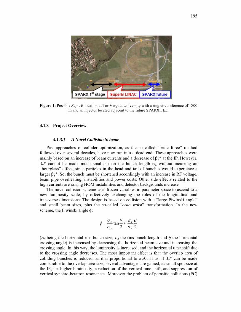
195
Figure 1: Possible SuperB location at Tor Vergata University with a ring circumference of 1800
m and an injector located adjacent to the future SPARX FEL.
4.1.3 Project Overview
4.1.3.1 A Novel Collision Scheme
Past approaches of collider optimization, as the so called “brute force” method followed over several decades, have now run into a dead end. These approaches were mainly based on an increase of beam currents and a decrease of βy* at the IP. However, βy* cannot be made much smaller than the bunch length σz without incurring an “hourglass” effect, since particles in the head and tail of bunches would experience a larger βy*. So, the bunch must be shortened accordingly with an increase in RF voltage, beam pipe overheating, instabilities and power costs. Other side effects related to the high currents are raising HOM instabilities and detector backgrounds increase.
The novel collision scheme uses frozen variables in parameter space to ascend to a new luminosity scale, by effectively exchanging the roles of the longitudinal and transverse dimensions. The design is based on collision with a “large Piwinski angle” and small beam sizes, plus the so-called “crab waist” transformation. In the new scheme, the Piwinski angle φ:
22tan θ
σσθ
σσ
φx
z
x
z ≈=
(σx being the horizontal rms bunch size, σz the rms bunch length and θ the horizontal crossing angle) is increased by decreasing the horizontal beam size and increasing the crossing angle. In this way, the luminosity is increased, and the horizontal tune shift due to the crossing angle decreases. The most important effect is that the overlap area of colliding bunches is reduced, as it is proportional to σx/θ. Thus, if βy* can be made comparable to the overlap area size, several advantages are gained, as small spot size at the IP, i.e. higher luminosity, a reduction of the vertical tune shift, and suppression of vertical synchro-betatron resonances. Moreover the problem of parasitic collisions (PC)
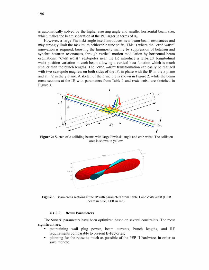
196
is automatically solved by the higher crossing angle and smaller horizontal beam size, which makes the beam separation at the PC larger in terms of σx.
However, a large Piwinski angle itself introduces new beam-beam resonances and may strongly limit the maximum achievable tune shifts. This is where the “crab waist” innovation is required, boosting the luminosity mainly by suppression of betatron and synchro-betatron resonances, through vertical motion modulation by horizontal beam oscillations. “Crab waist” sextupoles near the IR introduce a left-right longitudinal waist position variation in each beam allowing a vertical beta function which is much smaller than the bunch lengths. The “crab waist” transformation can easily be realized with two sextupole magnets on both sides of the IP, in phase with the IP in the x plane and at π/2 in the y plane. A sketch of the principle is shown in Figure 2, while the beam cross sections at the IP, with parameters from Table 1 and crab waist, are sketched in Figure 3.
Figure 2: Sketch of 2 colliding beams with large Piwinski angle and crab waist. The collision
area is shown in yellow.
Figure 3: Beam cross sections at the IP with parameters from Table 1 and crab waist (HER beam in blue, LER in red).
4.1.3.2 Beam Parameters
The SuperB parameters have been optimized based on several constraints. The most significant are:
maintaining wall plug power, beam currents, bunch lengths, and RF requirements comparable to present B-Factories;
planning for the reuse as much as possible of the PEP-II hardware, in order to save money;
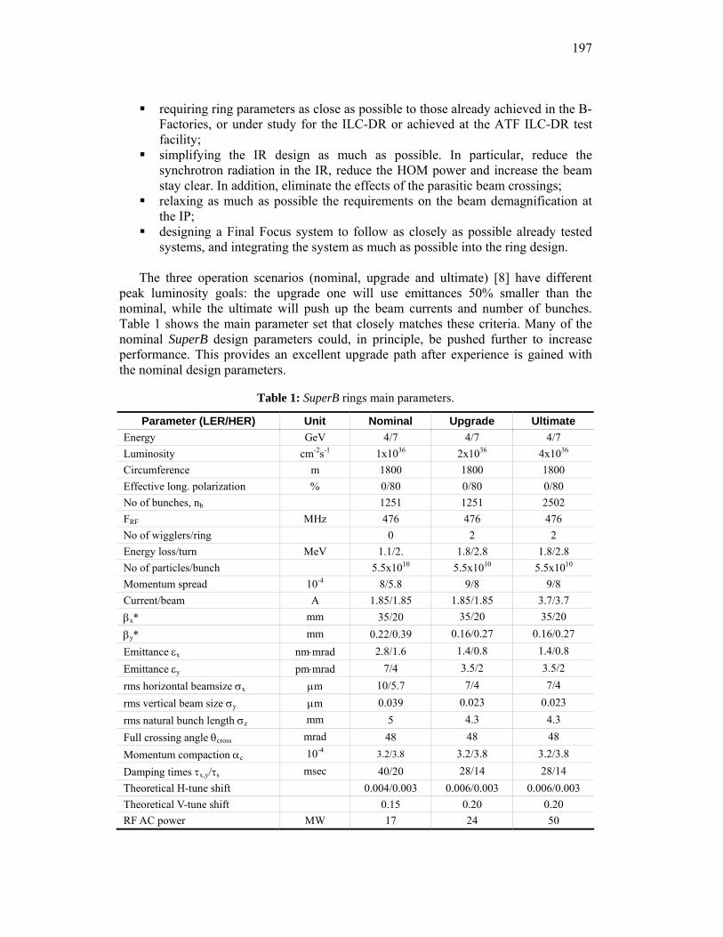
197
requiring ring parameters as close as possible to those already achieved in the B-Factories, or under study for the ILC-DR or achieved at the ATF ILC-DR test facility;
simplifying the IR design as much as possible. In particular, reduce the synchrotron radiation in the IR, reduce the HOM power and increase the beam stay clear. In addition, eliminate the effects of the parasitic beam crossings;
relaxing as much as possible the requirements on the beam demagnification at the IP;
designing a Final Focus system to follow as closely as possible already tested systems, and integrating the system as much as possible into the ring design.
The three operation scenarios (nominal, upgrade and ultimate) [8] have different
peak luminosity goals: the upgrade one will use emittances 50% smaller than the nominal, while the ultimate will push up the beam currents and number of bunches. Table 1 shows the main parameter set that closely matches these criteria. Many of the nominal SuperB design parameters could, in principle, be pushed further to increase performance. This provides an excellent upgrade path after experience is gained with the nominal design parameters.
Table 1: SuperB rings main parameters.
Parameter (LER/HER) Unit Nominal Upgrade Ultimate Energy GeV 4/7 4/7 4/7 Luminosity cm-2s-1 1x1036 2x1036 4x1036 Circumference m 1800 1800 1800 Effective long. polarization % 0/80 0/80 0/80 No of bunches, nb 1251 1251 2502 FRF MHz 476 476 476 No of wigglers/ring 0 2 2 Energy loss/turn MeV 1.1/2. 1.8/2.8 1.8/2.8 No of particles/bunch 5.5x10¹⁰ 5.5x10¹⁰ 5.5x10¹⁰ Momentum spread 10-4 8/5.8 9/8 9/8 Current/beam A 1.85/1.85 1.85/1.85 3.7/3.7 βx* mm 35/20 35/20 35/20 βy* mm 0.22/0.39 0.16/0.27 0.16/0.27 Emittance εx nm⋅mrad 2.8/1.6 1.4/0.8 1.4/0.8 Emittance εy pm⋅mrad 7/4 3.5/2 3.5/2 rms horizontal beamsize σx μm 10/5.7 7/4 7/4 rms vertical beam size σy μm 0.039 0.023 0.023 rms natural bunch length σz mm 5 4.3 4.3 Full crossing angle θcross mrad 48 48 48 Momentum compaction αc 10-4 3.2/3.8 3.2/3.8 3.2/3.8 Damping times τx,y/τs msec 40/20 28/14 28/14 Theoretical H-tune shift 0.004/0.003 0.006/0.003 0.006/0.003 Theoretical V-tune shift 0.15 0.20 0.20 RF AC power MW 17 24 50
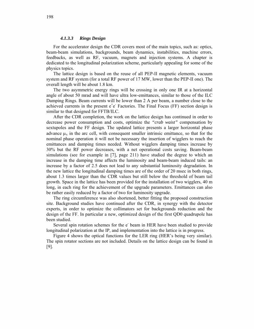
198
4.1.3.3 Rings Design
For the accelerator design the CDR covers most of the main topics, such as: optics, beam-beam simulations, backgrounds, beam dynamics, instabilities, machine errors, feedbacks, as well as RF, vacuum, magnets and injection systems. A chapter is dedicated to the longitudinal polarization scheme, particularly appealing for some of the physics topics.
The lattice design is based on the reuse of all PEP-II magnetic elements, vacuum system and RF system (for a total RF power of 17 MW, lower than the PEP-II one). The overall length will be about 1.8 km.
The two asymmetric energy rings will be crossing in only one IR at a horizontal angle of about 50 mrad and will have ultra low-emittances, similar to those of the ILC Damping Rings. Beam currents will be lower than 2 A per beam, a number close to the achieved currents in the present e+e- Factories. The Final Focus (FF) section design is similar to that designed for FFTB/ILC.
After the CDR completion, the work on the lattice design has continued in order to decrease power consumption and costs, optimize the “crab waist” compensation by sextupoles and the FF design. The updated lattice presents a larger horizontal phase advance μx in the arc cell, with consequent smaller intrinsic emittance, so that for the nominal phase operation it will not be necessary the insertion of wigglers to reach the emittances and damping times needed. Without wigglers damping times increase by 30% but the RF power decreases, with a net operational costs saving. Beam-beam simulations (see for example in [7], page 211) have studied the degree to which an increase in the damping time affects the luminosity and beam-beam induced tails: an increase by a factor of 2.5 does not lead to any substantial luminosity degradation. In the new lattice the longitudinal damping times are of the order of 20 msec in both rings, about 1.3 times larger than the CDR values but still below the threshold of beam tail growth. Space in the lattice has been provided for the installation of two wigglers, 40 m long, in each ring for the achievement of the upgrade parameters. Emittances can also be rather easily reduced by a factor of two for luminosity upgrade.
The ring circumference was also shortened, better fitting the proposed construction site. Background studies have continued after the CDR, in synergy with the detector experts, in order to optimize the collimators set for backgrounds reduction and the design of the FF. In particular a new, optimized design of the first QD0 quadrupole has been studied.
Several spin rotation schemes for the e- beam in HER have been studied to provide longitudinal polarization at the IP, and implementation into the lattice is in progress.
Figure 4 shows the optical functions for the LER ring (HER’s being very similar). The spin rotator sections are not included. Details on the lattice design can be found in [9].
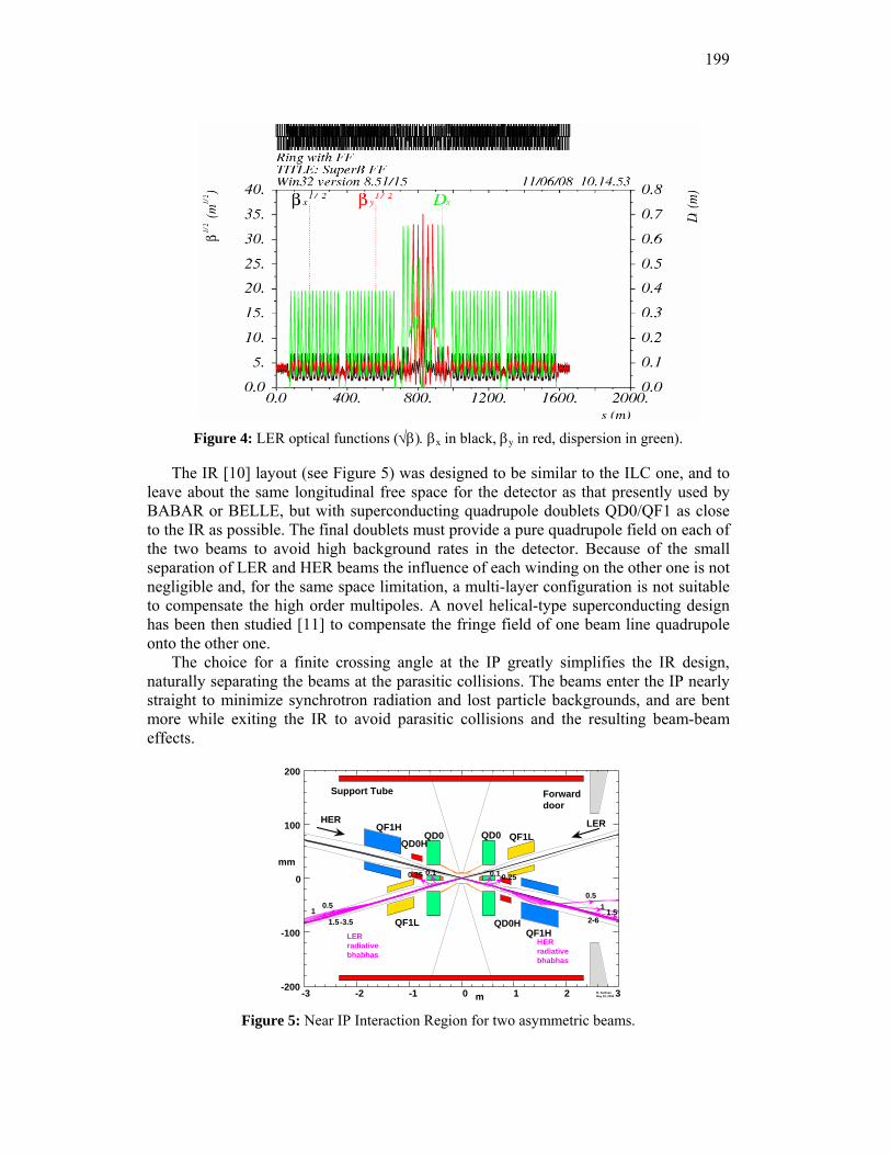
199
Figure 4: LER optical functions (√β). βx in black, βy in red, dispersion in green).
The IR [10] layout (see Figure 5) was designed to be similar to the ILC one, and to leave about the same longitudinal free space for the detector as that presently used by BABAR or BELLE, but with superconducting quadrupole doublets QD0/QF1 as close to the IR as possible. The final doublets must provide a pure quadrupole field on each of the two beams to avoid high background rates in the detector. Because of the small separation of LER and HER beams the influence of each winding on the other one is not negligible and, for the same space limitation, a multi-layer configuration is not suitable to compensate the high order multipoles. A novel helical-type superconducting design has been then studied [11] to compensate the fringe field of one beam line quadrupole onto the other one.
The choice for a finite crossing angle at the IP greatly simplifies the IR design, naturally separating the beams at the parasitic collisions. The beams enter the IP nearly straight to minimize synchrotron radiation and lost particle backgrounds, and are bent more while exiting the IR to avoid parasitic collisions and the resulting beam-beam effects.
0.10.25
0.51
1.5-3.5
LER radiative bhabhas
0.1 0.25
0.51
1.52-6
HER radiative bhabhas
0
100
200
-100
-200 0 1 2 3-1-2-3
QD0 QD0 QF1L
QF1HQF1L
QF1HQD0H
QD0H
Support Tube Forward door
mm
m M. Sullivan May 29, 2008
HER LER
Figure 5: Near IP Interaction Region for two asymmetric beams.
200
4.1.4 Synergy with the ILC
The ILC and SuperB IR have very similar characteristics with flat beams and overall geometries. The ratio of IP β-functions is similar, and collimation schemes are comparable. The chromatic correction of the final doublets using sextupoles is very similar, and almost identical to the one tested in the FFTB experiment.
There are also significant similarities between SuperB storage rings and the ILC-DR [12]. Beam energies and beam sizes are similar, the ILC-DR have a circumference three times larger than the SuperB rings (because of the need to store a long train of bunches with bunch spacing sufficiently large to allow injection and extraction of individual bunches); the nominal bunch charge is smaller in the ILC-DR than in the SuperB storage rings, leading to a lower average current. Nevertheless, one may expect the overall beam dynamics in the two facilities to be in comparable regimes. A similar lattice design is used in both cases, - the SuperB lattice having a smaller intrinsic emittance, - the main difference being a reduction in circumference and the insertion of an IR in the case of SuperB.
The ILC-DR and the SuperB storage rings will face similar demands on beam quality and stability: SuperB for direct production of luminosity, ILC-DR for reliable tuning and operation of the downstream systems, to ensure efficient luminosity production from the extracted beams. Other significant issues common to both the SuperB rings and the ILC-DR include: alignment of the magnets; reduction of magnet vibration to a minimum; optimization of lattice design and tuning to ensure sufficient dynamic aperture for good injection; bunch-by-bunch feedbacks to keep the beam instabilities and beam-beam collisions under control; control of beam instabilities, including ECI and ion effects. These are all active areas of research and development for the ILC-DR. In general, the similarity of the proposed operating regimes presents an opportunity for a well-coordinated program of activities that could yield much greater benefits than would be achieved by separate, independent research and development programs.
4.1.5 Conclusions
The new “large Piwinski angle” collision scheme will allow for peak luminosity well beyond the current state-of-the-art, without a significant increase in beam currents or shorter bunch lengths. The use of the “crab waist” sextupoles will add a bonus for suppression of dangerous resonances. This scheme is being successfully tested at the DAΦNE Φ-Factory in Frascati.
There is a growing international interest and participation to the SuperB, with R&D proceeding on various items. The design of the accelerator is in an advanced stage.
A Conceptual Design Report has been prepared in 2007 and a Technical Design Report will be ready by the end of 2009.
4.1.6 References
1. SuperB Accelerator Team: M. E. Biagini, R. Boni, M. Boscolo, T. Demma, A. Drago, S. Guiducci, P. Raimondi, S. Tomassini, M. Zobov (INFN Laboratori Nazionali Frascati, Italy), K. Bertsche, A. Novokhatski, J. Seeman, M. Sullivan, U. Wienands, W.
201
Wittmer (SLAC, USA), S. Bettoni (CERN, Switzerland), E. Paoloni, G. Marchiori (Pisa University, Italy), A. Bogomyagkov, I. Koop, E. Levichev, S. Nikitin, P. Piminov, D. Shatilov (BINP, Russia).
2. J. Seeman et al, “Last year of the PEP-II collider”, Proc. EPAC08, June 2008, Genoa, Italy.
3. Y. Funakoshi, “Performance of KEKB with crab cavities”, Proc. EPAC08, June 2008, Genoa, Italy.
4. P. Raimondi, 2nd LNF Workshop on SuperB, Frascati, 16-18 March 2006, http://www.lnf.infn.it/conference/superbf06/
5. P. Raimondi, “Crab waist collisions in DAΦNE and SuperB design”, Proc. EPAC08, June 2008, Genoa, Italy.
6. P. Raimondi, D. Shatilov, M. Zobov, “Beam-beam issues for colliding schemes with large Piwinski angle and crab waist”, LNF-07/003 (IR), January 2007.
7. SuperB Conceptual Design Report, INFN/AE-07/2, SLAC-R-856, LAL 07-15, March 2007, also at http://arxiv.org/abs/0709.0451, 480 pp.
8. J. Seeman et al, “Design of a 1036cm-2s-1 SuperB Factory”, Proc. EPAC08, June 2008, Genoa, Italy.
9. M. E. Biagini et al, “New low emittance lattice for the SuperB accelerator”, Proc. EPAC08, June 2008, Genoa, Italy.
10. M. K. Sullivan et al, “SuperB interaction region design”, Proc. EPAC08, June 2008, Genoa, Italy.
11. E. Paoloni et al, “IR SC quadrupole design for SuperB”, Proc. EPAC08, June 2008, Genoa, Italy.
12. “ILC Baseline Configuration Document”: http://www.linearcollider.org/wiki/doku.php?id=bcd:bcd home
5 Workshop and Conference Reports
5.1 Summary of the 43rd ICFA Advanced Beam Dynamics Workshop Nanobeam2008
Nikolay Vinokurov Budker Institute of Nuclear Physics (Novosibirsk, Russia)
Mail to: [email protected]
5.1.1 Introduction
The Nanobeam 2008 Workshop was held on May 25 - 30, 2008, in the Novosibirsk Scientific Center (Akademgorodok). Two previous Nanobeam workshops took place at Lausanne (Switzerland) in 2002 and at Uji (Japan) in 2005.
Recently high quality beams with nanometer and sub-nanometer scale emittance and few-nanocoulomb charge per bunch became available. It opens great prospects for different applications. The first and the most ambitious is the linear collider. The numerous lower-scale projects cover the wide field from advanced x-ray sources to heavy-ion therapy. New challenges on beam quality, beam-optical systems, diagnostics, feedback, and stabilization of beam line components are under intensive investigation now. From the other hand, achievements of accelerator technology are used in
202
nanoscience and nanotechnology, and number of such applications increases from year to year.
The Nanobeam 2008 workshop was organized by the Budker Institute of Nuclear Physics. The scientific interests of this institution lie in the field of advanced accelerator techniques as round beam collider, free electron lasers and synchrotron radiation x-ray sources, energy recovery devices, electron coolers, linear colliders, advanced beam sources, etc. It was reflected in the scientific program of the workshop, which was focused not only on the linear collider issues, but on other advanced accelerator applications also.
The workshop web site is Ref. [1]. Unfortunately, the low-level funding of the ILC project led to the relatively low
(about 30) number of participants. It was partly compensated by the use of web-based communication. It made possible significant number of remote talks and discussions. Totally, about 40 oral talks were made during the workshop.
5.1.2 Linear Collider Related Topics
Traditionally, the most part of talks was devoted to linear colliders. In spite of marginal funding and extremely tough specifications for subsystems, the progress in solution of many physical and technological problems took place during the three years after the last Nanobeam. As the problem of electron and positron acceleration to TeV energies is supposed to be solved, the most of linear collider related talks were concentrated on obtaining high luminosity and matching of meeting point geometry with detectors. The achievement of high luminosity requires low emittances of both beams, high average beam currents and high stability of beam transverse coordinates at meeting point. Therefore different options for positron sources, feedback systems, and precise beam diagnostics were addressed in many talks. It worse to note the experimental researches at ATF2 storage ring with ultra-low emittance beamline, mechanical stabilization of magnets at CLIC, and the crystal positron convertors at KEK.
5.1.3 Accelerator Technology
The significant amount of talks described new accelerator technologies. For example, one of the most interesting presentations was devoted to the laser wakefield acceleration in plasmas. It looks very promising for obtaining of high peak currents at low emittances.
5.1.4 References
1. Workshop website: http://ssrc.inp.nsk.su/NB08/
203
6 Recent Doctoral Theses
6.1 Linear Beam Dynamics and Ampere Class Superconducting RF Cavities at RHIC
Rama Calaga Stony Brook University, New York, U.S.A.
Thesis advisors: Ilan Ben-Zvi, Steve Peggs (BNL)
Abstract: The Relativistic Heavy Ion Collider (RHIC) is a hadron collider designed to collide
a range of ions from protons to gold. RHIC operations began in 2000 and have successfully completed five physics runs with several species including gold, deuteron, copper, and polarized protons. Linear optics and coupling are fundamental issues affecting the collider performance. Measurement and correction of optics and coupling are important to maximize the luminosity and sustain stable operation. A numerical approach, first developed at SLAC, was implemented to measure linear optics from coherent betatron oscillations generated by ac dipoles and recorded at multiple beam position monitors (BPMs) distributed around the collider. The approach is extended to a fully coupled 2D case and equivalence relationships between Hamiltonian and matrix formalisms are derived. Detailed measurements of the transverse coupling terms are carried out at RHIC and correction strategies are applied to compensate coupling both locally and globally. A statistical approach to determine BPM reliability and performance over the past three runs and future improvements are also discussed.
Aiming at a ten-fold increase in the average heavy-ion luminosity, electron cooling is the enabling technology for the next luminosity upgrade (RHIC II). Cooling gold ion beams at 100 GeV/nucleon requires electron beam energy of approximately 54 MeV and a high average current in the range of 50-200 mA. All existing e- coolers are based on low energy DC accelerators. The only viable option to generate high current, high energy, low emittance CW electron beam is through a superconducting energy recovery linac (SC-ERL). In this option, an electron beam from a superconducting injector gun is accelerated using a high gradient (~20 MV/m) superconducting RF (SRF) cavity. The electrons are returned back to the cavity with a 180º phase shift to recover the energy back into the cavity before being dumped. A design and development of a half-cell electron gun and a five-cell SRF linac cavity are presented. Several RF and beam dynamics issues ultimately resulting in an optimum cavity design are discussed in detail.
(This dissertation earned the APS DPB Thesis Award. Calaga is presently an Assistant Scientist at BNL.)
204
6.2 Diagnostics of the Fermilab Tevatron Using an AC Dipole
Ryoichi Miyamoto University of Texas at Austin, Texas, U.S.A.
Thesis advisors: Sacha Kopp (U. of Texas at Austin), Mike Syphers (Fermilab)
Abstract: The Fermilab Tevatron is currently the world's highest energy colliding
beam facility. Its counter-rotating proton and antiproton beams collide at 2 TeV center-of-mass. Delivery of such intense beam fluxes to experiments has required improved knowledge of the Tevatron's beam optical lattice. An oscillating dipole magnet, referred to as an AC dipole, is one of such a tool to non-destructively assess the optical properties of the synchrotron.
We discusses development of an AC dipole system for the Tevatron, a fast-oscillating (f ~ 20 kHz) dipole magnet which can be adiabatically turned on and off to establish sustained coherent oscillations of the beam particles without affecting the transverse emittance. By utilizing an existing magnet and a higher power audio amplifier, the cost of the Tevatron AC dipole system became relatively inexpensive. We discuss corrections which must be applied to the driven oscillation measurements to obtain the proper interpretation of beam optical parameters from AC dipole studies. After successful operations of the Tevatron AC dipole system, AC dipole systems, similar to that in the Tevatron, will be built for the CERN LHC. We present several measurements of linear optical parameters (beta function and phase advance) for the Tevatron, as well as studies of non-linear perturbations from sextupole and octupole elements.
(Miyamoto will be a Toohig Fellow in the LHC Accelerator Research Program.)
7 Forthcoming Beam Dynamics Events
7.1 44th ICFA Advanced Beam Dynamics Workshop: X-Band RF Structure and Beam Dynamics
Roger M. Jones, FInstP Mail to: [email protected]
This workshop will take place at the Cockcroft Institute (UK), from Monday 1st
December through Wednesday 3rd December, 2008. This workshop will address RF issues pertinent to X-band accelerating structures in
linear colliders and light sources. In particular, RF fields in structures and cavities, wakefields, RF couplers and beam dynamics issues will be explored. The workshop will also embrace both active and passive overmoded and quasi-optical components Accelerating structures, light sources and drive beams will be amongst the areas of
205
interest. A series of invited plenary talks will be given in addition to contributed topics. This will also include breakdown issues pertinent to high gradient structures, but the focus of the workshop will be on RF and impedance issues both from both a theoretical and experimental perspective. A satellite workshop will also be conducted on medical X-band linacs. Papers submitted to the workshop will be published on the JACoW database.
This will be a full ICFA workshop (proceedings will be published). Program Committee: Drs. R. M. Jones (chair), W. Wuensch, S. Tantawi, T. Higo, D. Schulte, Prof. S. Chattopadhyay.
7.2 2009 International Computational Accelerator Physics Conference
Robert D. Ryne Center for Beam Physics, Accelerator and Fusion Research Division, LBNL
Mail to: [email protected]
The 2009 International Computational Accelerator Conference will be held Aug 30 – Sept 4, 2009 in the San Francisco Bay Area.
The conference venue will be the Mark Hopkins Intercontinental Hotel (http://www.markhopkins.net) located at 1 Nob Hill in the heart of San Francisco.
ICAP focuses on the latest advances in computational accelerator physics. ICAP 2009 will be the 10th in the conference series following meetings in La Jolla, California (1988), Los Alamos, New Mexico (1990), Pleasanton, California (1993), Williamsburg, Virginia (1996), Monterey, California (1998), Darmstadt, Germany (2000), East Lansing, Michigan (2002), St. Petersburg, Russia (2004), and Chamonix, France (2006).
ICAP 2009 is being organized by the Lawrence Berkeley National Laboratory and the Stanford Linear Accelerator Center. For further information see the conference web site which will be accessible from the JACoW Collaboration Conferences page at http://www.jacow.org
7.3 FFAG'08
Chris R. Prior Rutherford Appleton Lab Mail to: [email protected]
The 2008 workshop dedicated to the study of Fixed Field Alternating Gradient
(FFAG) Accelerators will take place 1-5 September 2008 at the University of Manchester, England. Details are available at:
http://www.cockcroft.ac.uk/events/FFAG08
206
7.4 ICFA Beam Dynamics Mini-Workshop: 2nd Workshop on Short Bunches in Storage Rings
John Byrd Lawrence Berkeley National Laboratory, USA
Mail to: [email protected]
This workshop will be held in the San Francisco Bay Area (venue TBD), 30 March – 1 April 2009. The organizers are:
Bob Hettel, SSRL/SLAC, USA David Robin, ALS/LBNL, USA John Byrd, LBNL, USA
There is substantial interest in achieving sub-10 picosecond pulses of x-rays and
coherent terahertz radiation from electron storage rings. There are a number of proposed schemes for achieving this such as low momentum compaction, laser slicing, vertical deflecting cavities (crabbing), etc. There are also a number of challenges for each of these schemes such as beam instabilities, higher order momentum compaction, etc. Following the successful ICFA mini-workshop held on this subject in Frascati in November 2005, there has been substantial progress in many of these areas. In addition, half a dozen third generation light sources have been commissioned since then. This workshop will review the scientific case and recent progress in this area and explore the frontiers for new developments with an emphasis on short synchrotron light pulses. There will be particularly focus on schemes compatible with normal ring operation.
8 Announcements of the Beam Dynamics Panel
8.1 ICFA Beam Dynamics Newsletter
8.1.1 Aim of the Newsletter
The ICFA Beam Dynamics Newsletter is intended as a channel for describing unsolved problems and highlighting important ongoing works, and not as a substitute for journal articles and conference proceedings that usually describe completed work. It is published by the ICFA Beam Dynamics Panel, one of whose missions is to encourage international collaboration in beam dynamics.
Normally it is published every April, August and December. The deadlines are 15 March, 15 July and 15 November, respectively.

207
Categories of Articles The categories of articles in the newsletter are the following:
1. Announcements from the panel.
2. Reports of beam dynamics activity of a group.
3. Reports on workshops, meetings and other events related to beam dynamics.
4. Announcements of future beam dynamics-related international workshops and meetings.
5. Those who want to use newsletter to announce their workshops are welcome to do so. Articles should typically fit within half a page and include descriptions of the subject, date, place, Web site and other contact information.
6. Review of beam dynamics problems: This is a place to bring attention to unsolved problems and should not be used to report completed work. Clear and short highlights on the problem are encouraged.
7. Letters to the editor: a forum open to everyone. Anybody can express his/her opinion on the beam dynamics and related activities, by sending it to one of the editors. The editors reserve the right to reject contributions they judge to be inappropriate, although they have rarely had cause to do so.
The editors may request an article following a recommendation by panel members.
However anyone who wishes to submit an article is strongly encouraged to contact any Beam Dynamics Panel member before starting to write.
8.1.2 How to Prepare a Manuscript
Before starting to write, authors should download the template in Microsoft Word format from the Beam Dynamics Panel web site:
http://www-bd.fnal.gov/icfabd/news.html
It will be much easier to guarantee acceptance of the article if the template is used
and the instructions included in it are respected. The template and instructions are expected to evolve with time so please make sure always to use the latest versions.
The final Microsoft Word file should be sent to one of the editors, preferably the issue editor, by email.
The editors regret that LaTeX files can no longer be accepted: a majority of contributors now prefer Word and we simply do not have the resources to make the conversions that would be needed. Contributions received in LaTeX will now be returned to the authors for re-formatting.
In cases where an article is composed entirely of straightforward prose (no equations, figures, tables, special symbols, etc.) contributions received in the form of plain text files may be accepted at the discretion of the issue editor.
Each article should include the title, authors’ names, affiliations and e-mail addresses.
208
8.1.3 Distribution
A complete archive of issues of this newsletter from 1995 to the latest issue is available at
http://icfa-usa.jlab.org/archive/newsletter.shtml.
This is now intended as the primary method of distribution of the newsletter. Readers are encouraged to sign-up for electronic mailing list to ensure that they will
hear immediately when a new issue is published. The Panel’s Web site provides access to the Newsletters, information about future
and past workshops, and other information useful to accelerator physicists. There are links to pages of information of local interest for each of the three ICFA areas.
Printed copies of the ICFA Beam Dynamics Newsletters are also distributed (generally some time after the Web edition appears) through the following distributors: Weiren Chou [email protected] North and South Americas Rainer Wanzenberg [email protected] Europe++ and Africa Susumu Kamada [email protected] Asia** and Pacific
++ Including former Soviet Union. ** For Mainland China, Jiu-Qing Wang ([email protected]) takes care of the distribution
with Ms. Su Ping, Secretariat of PASC, P.O. Box 918, Beijing 100039, China.
To keep costs down (remember that the Panel has no budget of its own) readers are encouraged to use the Web as much as possible. In particular, if you receive a paper copy that you no longer require, please inform the appropriate distributor.
8.1.4 Regular Correspondents
The Beam Dynamics Newsletter particularly encourages contributions from smaller institutions and countries where the accelerator physics community is small. Since it is impossible for the editors and panel members to survey all beam dynamics activity worldwide, we have some Regular Correspondents. They are expected to find interesting activities and appropriate persons to report them and/or report them by themselves. We hope that we will have a “compact and complete” list covering all over the world eventually. The present Regular Correspondents are as follows: Liu Lin [email protected] LNLS Brazil Sameen Ahmed Khan [email protected] SCOT, Middle East and Africs
We are calling for more volunteers as Regular Correspondents.
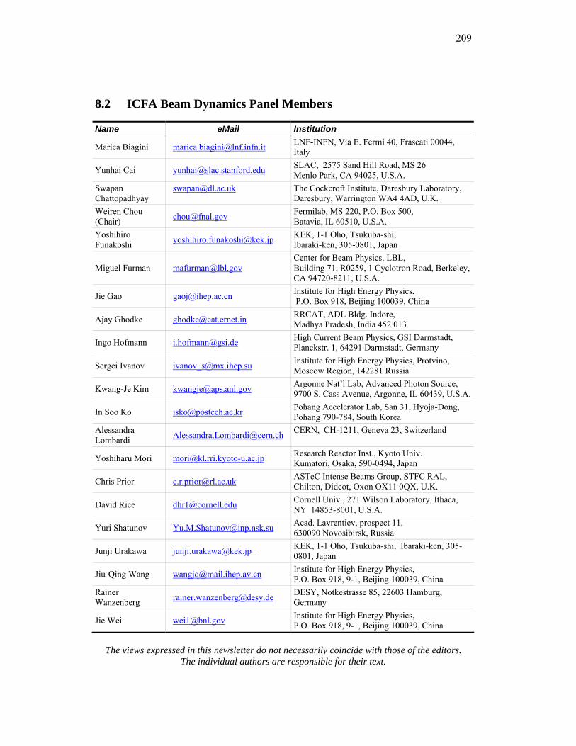
209
8.2 ICFA Beam Dynamics Panel Members
Name eMail Institution
Marica Biagini [email protected] LNF-INFN, Via E. Fermi 40, Frascati 00044, Italy
Yunhai Cai [email protected] SLAC, 2575 Sand Hill Road, MS 26 Menlo Park, CA 94025, U.S.A.
Swapan Chattopadhyay
The Cockcroft Institute, Daresbury Laboratory, Daresbury, Warrington WA4 4AD, U.K.
Weiren Chou (Chair) [email protected] Fermilab, MS 220, P.O. Box 500,
Batavia, IL 60510, U.S.A. Yoshihiro Funakoshi [email protected] KEK, 1-1 Oho, Tsukuba-shi,
Ibaraki-ken, 305-0801, Japan
Miguel Furman [email protected] Center for Beam Physics, LBL, Building 71, R0259, 1 Cyclotron Road, Berkeley, CA 94720-8211, U.S.A.
Jie Gao [email protected] Institute for High Energy Physics, P.O. Box 918, Beijing 100039, China
Ajay Ghodke [email protected] RRCAT, ADL Bldg. Indore, Madhya Pradesh, India 452 013
Ingo Hofmann [email protected] High Current Beam Physics, GSI Darmstadt, Planckstr. 1, 64291 Darmstadt, Germany
Sergei Ivanov [email protected] Institute for High Energy Physics, Protvino, Moscow Region, 142281 Russia
Kwang-Je Kim [email protected] Argonne Nat’l Lab, Advanced Photon Source, 9700 S. Cass Avenue, Argonne, IL 60439, U.S.A.
In Soo Ko [email protected] Pohang Accelerator Lab, San 31, Hyoja-Dong, Pohang 790-784, South Korea
Alessandra Lombardi [email protected] CERN, CH-1211, Geneva 23, Switzerland
Yoshiharu Mori [email protected] Research Reactor Inst., Kyoto Univ. Kumatori, Osaka, 590-0494, Japan
Chris Prior [email protected] ASTeC Intense Beams Group, STFC RAL, Chilton, Didcot, Oxon OX11 0QX, U.K.
David Rice [email protected] Cornell Univ., 271 Wilson Laboratory, Ithaca, NY 14853-8001, U.S.A.
Yuri Shatunov [email protected] Acad. Lavrentiev, prospect 11, 630090 Novosibirsk, Russia
Junji Urakawa [email protected] KEK, 1-1 Oho, Tsukuba-shi, Ibaraki-ken, 305-0801, Japan
Jiu-Qing Wang [email protected] Institute for High Energy Physics, P.O. Box 918, 9-1, Beijing 100039, China
Rainer Wanzenberg [email protected] DESY, Notkestrasse 85, 22603 Hamburg,
Germany
Jie Wei [email protected] Institute for High Energy Physics, P.O. Box 918, 9-1, Beijing 100039, China
The views expressed in this newsletter do not necessarily coincide with those of the editors.
The individual authors are responsible for their text.