ba 218 usa, ca edition b 2012, 1, en-us - mercedes-benz canada
TRANSCRIPT
CLSOperator's Manual
SymbolsRegistered trademarks:RBluetooth® is a registered trademark of
Bluetooth SIG Inc.RDTS is a registered trademark of DTS, Inc.RDolby and MLP are registered trademarks
of DOLBY Laboratories.RBabySmart™, ESP® and PRE-SAFE® are
registered trademarks of Daimler AG.RHomeLink® is a registered trademark of
Prince.RiPod® and iTunes® are registered
trademarks of Apple Inc.RLogic 7® is a registered trademark of
Harman International Industries.RMicrosoft® and Windows media® are
registered trademarks of MicrosoftCorporation.RSIRIUS is a registered trademark of Sirius
XM radio Inc.RHD Radio is a registered trademark of
iBiquity Digital Corporation.RGracenote® is a registered trademark of
Gracenote, Inc.RZAGATSurvey® and related brands are
registered trademarks of ZagatSurvey,LLC.
In this Operator's Manual, you will find thefollowing symbols:
G WARNINGWarning notes draw your attention to hazardsthat endanger your health or life, or the healthor life of others.
! Notes on material damage alert you todangers that could lead to damage to yourvehicle.
i This symbol indicates useful instructionsor further information that could be helpfulto you.
X This symbol designates aninstruction you must follow.
X Several consecutive symbolsindicate an instruction with severalsteps.
(Y page) This symbol tells you where youcan find further information on atopic.
YY This symbol indicates a warning oran instruction that is continued onthe next page.
Display This font indicates a displaymessage in the multifunctiondisplay/COMAND display.
Parts of the software in the vehicle areprotected by copyright © 2005The FreeType Projecthttp://www.freetype.org. All rightsreserved.

Welcome to the world of Mercedes-BenzBefore you drive off, please familiarizeyourself with your vehicle and read thismanual, especially the safety and warningnotes. This will help you to obtain themaximum pleasure from your vehicle andavoid endangering yourself and others.The equipment or model designation of yourvehicle may differ according to:RmodelRorderRcountry variantRavailabilityMercedes-Benz is constantly updating itsvehicles to the state of the art.Mercedes-Benz therefore reserves the rightto introduce changes in the following areas:RdesignRequipmentRtechnical featuresThe equipment in your vehicle may thereforediffer from that shown in the descriptions andillustrations.The following are integral components of thevehicle:ROperator's ManualRMaintenance BookletREquipment-dependent supplementsKeep these documents in the vehicle at alltimes. If you sell the vehicle, always pass thedocuments on to the new owner.The technical documentation team atDaimler AG wishes you safe and pleasantmotoring.Mercedes-Benz Canada, Inc.A Daimler Company
2185841381 É2185841381lËÍ

Index ....................................................... 4
Introduction ......................................... 21
At a glance ........................................... 27
Safety ................................................... 37
Opening/closing ................................. 73
Seats, steering wheel and mirrors .... 93
Lights and windshield wipers .......... 107
Climate control ................................. 119
Driving and parking .......................... 133
On-board computer and displays .... 199
Stowage and features ...................... 261
Maintenance and care ...................... 285
Breakdown assistance ..................... 299
Wheels and tires ............................... 319
Technical data ................................... 349
Contents 3

1, 2, 3 ...12 V socket
see Sockets 4ETS
see ETS/4ETS (ElectronicTraction System)
4MATIC (permanent four-wheeldrive) .................................................. 1754MATIC off-road system ................... 175
AABS (Anti-lock Braking System)
Display message ............................ 221Function/notes ................................ 63Important safety notes .................... 63Warning lamp ................................. 250
Activating/deactivating coolingwith air dehumidification ................. 124Active Blind Spot Assist
Activating/deactivating (on-board computer) ............................ 211Function/information .................... 192
Active Driving Assistance package . 191Active Lane Keeping Assist
Activating/deactivating (on-board computer) ............................ 211Display message ............................ 236Function/information .................... 194
Active multicontour seat .................... 98Active Parking Assist
Display message ............................ 237Important safety notes .................. 179
Active service system PLUSsee ASSYST PLUS service intervaldisplay
ADAPTIVE BRAKE ................................. 69Adaptive Highbeam Assist
Display message ............................ 231Function/notes ............................. 112Switching on/off (on-boardcomputer) ...................................... 213
Additives (engine oil) ........................ 355Air bags
Display message ............................ 228Front air bag (driver, frontpassenger) ....................................... 42
Important safety notes .................... 40Knee bag .......................................... 42PASSENGER AIR BAG OFFindicator lamp .................................. 45Pelvis air bag ................................... 44Safety guidelines ............................. 39Side impact air bag .......................... 43Window curtain air bag .................... 44
Air-conditioning systemsee Climate control
AIR FLOW ........................................... 125AIRMATIC
Display message ............................ 234Function/notes ............................. 172
Air pressuresee Tire pressure
Air ventsGlove box ....................................... 130Important safety notes .................. 129Rear ............................................... 131Setting ........................................... 129Setting the center air vents ........... 130Setting the side air vents ............... 130
Alarm systemsee ATA (Anti-Theft Alarm system)
Alertness Assistantsee ATTENTION ASSIST
Ambient lightingSetting the brightness (on-boardcomputer) ...................................... 213Setting the color (on-boardcomputer) ...................................... 214
AMG adaptive sport suspensionsystem ................................................ 174AMG menu (on-board computer) ..... 216Anti-lock Braking System
see ABS (Anti-lock Braking System) Anti-Theft Alarm system
see ATA (Anti-Theft Alarm system) Ashtray ............................................... 271Assistance menu (on-boardcomputer) .......................................... 210ATA (Anti-Theft Alarm system)
Activating/deactivating ................... 71Function ........................................... 71Switching off the alarm .................... 71
4 Index

ATTENTION ASSISTActivating/deactivating ................. 211Display message ............................ 234Function/notes ............................. 183
Audio menu (on-board computer) .... 207Audio system
see separate operating instructions Authorized Mercedes-Benz Center
see Qualified specialist workshop Authorized workshop
see Qualified specialist workshop AUTO lights
Display message ............................ 231see Lights
Automatic engine start (ECO start/stop function) .................................... 139Automatic engine switch-off (ECOstart/stop function) .......................... 139Automatic headlamp mode .............. 109Automatic transmission
Automatic drive program ............... 146Changing gear ............................... 144DIRECT SELECT lever ..................... 142Display message ............................ 243Drive program display .................... 143Driving tips .................................... 144Emergency running mode .............. 149Engaging drive position .................. 144Engaging neutral ............................ 143Engaging park position (AMGvehicles) ........................................ 143Engaging reverse gear ................... 143Engaging the park position ............ 143Kickdown ....................................... 145Manual drive program .................... 147Problem (malfunction) ................... 149Program selector button ................ 145Pulling away ................................... 137Selector lever ................................ 142Shift ranges ................................... 146Starting the engine ........................ 137Steering wheel paddle shifters ...... 146Transmission positiondisplay ................................... 142, 143
Automatic transmissionemergency mode ............................... 149
BBack support
see Lumbar support Backup lamp
Changing bulbs .............................. 115Display message ............................ 230
Bag hook ............................................ 266BAS (Brake Assist System) ................. 64Basic settings
see Settings BAS PLUS (Brake Assist SystemPLUS) .................................................... 64Battery (SmartKey)
Checking .......................................... 77Important safety notes .................... 77Replacing ......................................... 77
Battery (vehicle)Charging ........................................ 309Display message ............................ 233Important safety notes .................. 308Jump starting ................................. 311
Beltsee Seat belts
Blind Spot AssistActivating/deactivating ................. 211Notes/function .............................. 188see Active Blind Spot Assist
Bottle holder ...................................... 269Brake Assist System
see BAS (Brake Assist System) Brake fluid
Display message ............................ 223Notes ............................................. 355
Brake fluid level ................................ 289Brake lamps
Display message ............................ 230Brakes
ABS .................................................. 63BAS .................................................. 64BAS PLUS ........................................ 64Brake fluid (notes) ......................... 355Display message ............................ 221Driving tips .................................... 155High-performance brake system .... 157Important safety notes .................. 155Maintenance .................................. 156
Index 5
Parking brake ................................ 153Warning lamp ................................. 249
Breakdownsee Flat tire see Towing away
Bulbssee Changing bulbs
CCalifornia
Important notice for retailcustomers and lessees .................... 22
Calling up a malfunctionsee Display messages
Carsee Vehicle
CareCarpets .......................................... 297Car wash ........................................ 291Display ........................................... 295Exterior lights ................................ 294Gear or selector lever .................... 297Interior ........................................... 295Matte finish ................................... 293Night View Assist Plus ................... 296Notes ............................................. 291Paint .............................................. 293Plastic trim .................................... 296Power washer ................................ 292Rear view camera .......................... 295Roof lining ...................................... 297Seat belt ........................................ 297Seat cover ..................................... 297Sensors ......................................... 295Steering wheel ............................... 297Tail pipes ....................................... 295Trim pieces .................................... 297Washing by hand ........................... 292Wheels ........................................... 293Windows ........................................ 294Wiper blades .................................. 294Wooden trim .................................. 297
Cargo tie down rings ......................... 266Car wash (care) ................................. 291CD player/CD changer (on-boardcomputer) .......................................... 207
Center consoleLower section .................................. 33Lower section (AMG vehicles) .......... 34Upper section .................................. 32
Central lockingAutomatic locking (on-boardcomputer) ...................................... 215Locking/unlocking (SmartKey) ........ 74
Changing bulbsImportant safety notes .................. 114Overview of bulb types .................. 115Reversing lamps ............................ 115
Child-proof locksImportant safety notes .................... 61Rear doors ....................................... 61
ChildrenIn the vehicle ................................... 57Restraint systems ............................ 57
Child seatLATCH-type (ISOFIX) child seatanchors ............................................ 59Special seat belt retractor ............... 59Top Tether ....................................... 60
Cigarette lighter ................................ 272Cleaning
Mirror turn signal ........................... 294Climate control
Automatic climate control (3-zone) .............................................. 123Controlling automatically ............... 125Cooling with air dehumidification . . 124Defrosting the windows ................. 128Defrosting the windshield .............. 127Dual-zone automatic climatecontrol ........................................... 121Important safety notes .................. 120Indicator lamp ................................ 125Maximum cooling .......................... 127Notes on using automatic climatecontrol ................................... 122, 124Overview of systems ...................... 120Problems with cooling with airdehumidification ............................ 125Problem with the rear windowdefroster ........................................ 128Rear control panel ......................... 123Setting the air distribution ............. 126Setting the airflow ......................... 126
6 Index

Setting the air vents ...................... 129Setting the climate mode (AIRFLOW) ............................................ 125Setting the temperature ................ 125Setting the temperature (rearcompartment) ................................ 126Switching air-recirculation modeon/off ............................................ 128Switching on/off ........................... 124Switching residual heat on/off ...... 129Switching the rear windowdefroster on/off ............................ 128Switching the ZONE function on/off .................................................. 127
CockpitOverview .......................................... 28see Instrument cluster
Collapsible spare wheelInflating ......................................... 306see Emergency spare wheel
COMANDsee separate operating instructions
Combination switch .......................... 110Compass
Calibrating ..................................... 284Calling up ....................................... 283Setting ........................................... 283
Consumption statistics (on-boardcomputer) .......................................... 205Convenience closing feature .............. 88Convenience opening feature ............ 88Coolant (engine)
Checking the level ......................... 288Display message ............................ 232Filling capacity ............................... 356Notes ............................................. 355Temperature (on-board computer) . 216Temperature gauge ........................ 200Warning lamp ................................. 255
Coolingsee Climate control
Cornering light (display message) ... 229Cornering light function
Function/notes ............................. 111Crash-responsive emergencylighting ............................................... 114
Cruise controlCruise control lever ....................... 159Deactivating ................................... 160Display message ............................ 240Driving system ............................... 159Function/notes ............................. 159Important safety notes .................. 159Setting a speed .............................. 160Storing and maintaining currentspeed ............................................. 159
Cup holderCenter console .............................. 268Important safety notes .................. 267Rear compartment ......................... 268
Customer Assistance Center (CAC) ... 25Customer Relations Department ....... 25
DDashboard
see Cockpit Data
see Technical data Daytime running lamps
Display message ............................ 231Switching on/off (on-boardcomputer) ...................................... 213Switching on/off (switch) .............. 109
Dealershipsee Qualified specialist workshop
Delayed switch-offExterior lighting (on-boardcomputer) ...................................... 214Interior lighting .............................. 214
Diagnostics connection ...................... 24Digital speedometer ......................... 205DIRECT SELECT lever
see Automatic transmission Display (cleaning instructions) ........ 295Display messages
Calling up (on-board computer) ..... 220Driving systems ............................. 234Engine ............................................ 232General notes ................................ 220Hiding (on-board computer) ........... 220KEYLESS-GO .................................. 245Lights ............................................. 229Safety systems .............................. 221
Index 7

Service interval display .................. 290SmartKey ....................................... 245Tires ............................................... 240Vehicle ........................................... 243
Distance display (on-boardcomputer) .......................................... 210Distance recorder ............................. 205
see Odometer see Trip odometer
Distance warning (warning lamp) .... 257DISTRONIC PLUS
Deactivating ................................... 168Display message ............................ 238Displays in the multifunctiondisplay ........................................... 167Driving tips .................................... 168Function/notes ............................. 160Important safety notes .................. 160Setting the specified minimumdistance ......................................... 166Warning lamp ................................. 257
DoorsAutomatic locking (on-boardcomputer) ...................................... 215Automatic locking (switch) ............... 81Central locking/unlocking(SmartKey) ....................................... 74Control panel ................................... 36Display message ............................ 244Emergency locking ........................... 82Emergency unlocking ....................... 82Important safety notes .................... 80Opening (from inside) ...................... 81
Drinking and driving ......................... 155Drinks holder
see Cup holder Drive program
Automatic ...................................... 146Display ........................................... 142Display (DIRECT SELECT lever) ...... 143Manual ........................................... 147SETUP (on-board computer) .......... 217
Drive program selector ..................... 145Driver's door
see Doors Driver's seat
see Seats
Driving abroadMercedes-Benz Service ................. 291Symmetrical low beam .................. 108
Driving lampssee Daytime running lamps
Driving on flooded roads .................. 158Driving safety systems
ABS (Anti-lock Braking System) ....... 63ADAPTIVE BRAKE ............................. 69BAS (Brake Assist System) .............. 64BAS PLUS (Brake Assist SystemPLUS) ............................................... 64Electronic brake force distribution ... 69ESP® (Electronic StabilityProgram) .......................................... 65ETS/4ETS (Electronic TractionSystem) ........................................... 66Important safety information ........... 63Overview .......................................... 62PRE-SAFE® Brake ............................. 69
Driving systemsActive Blind Spot Assist ................. 192Active Driving Assistancepackage ......................................... 191Active Lane Keeping Assist ............ 194Active Parking Assist ..................... 179AIRMATIC ...................................... 172AMG adaptive sport suspensionsystem ........................................... 174ATTENTION ASSIST ........................ 183Blind Spot Assist ............................ 188Cruise control ................................ 159Display message ............................ 234DISTRONIC PLUS ........................... 160HOLD function ............................... 170Lane Keeping Assist ...................... 190Lane Tracking package .................. 188Night View Assist Plus ................... 184PARKTRONIC ................................. 175RACE START (AMG vehicles) .......... 171Rear view camera .......................... 182
Driving tipsAMG ceramic brakes ..................... 157Automatic transmission ................. 144Brakes ........................................... 155Break-in period .............................. 134DISTRONIC PLUS ........................... 168
8 Index

Downhill gradient ........................... 156Drinking and driving ....................... 155Driving abroad ............................... 108Driving in winter ............................. 158Driving on flooded roads ................ 158Driving on wet roads ...................... 158Exhaust check ............................... 155Fuel ................................................ 154General .......................................... 154Hydroplaning ................................. 158Icy road surfaces ........................... 158Limited braking efficiency onsalted roads ................................... 156Pedals ............................................ 155Snow chains .................................. 323Symmetrical low beam .................. 108Wet road surface ........................... 156
DVD audio (on-board computer) ...... 207DVD video (on-board computer) ...... 208
EEASY-ENTRY feature
Activating/deactivating ................. 215Function/notes ............................. 101
EASY-EXIT featureCrash-responsive ........................... 102Function/notes ............................. 101Switching on/off ........................... 215
EBD (electronic brake forcedistribution)
Display message ............................ 222Function/notes ................................ 69
ECO start/stop functionDeactivating/activating ................. 139General information ....................... 138
Electrical fusessee Fuses
Electronic brake force distributionsee EBD (electronic brake forcedistribution)
Electronic Stability Programsee ESP® (Electronic Stability Program)
Electronic Traction Systemsee ETS/4ETS (ElectronicTraction System)
Emergency releaseDriver's door .................................... 82Fuel filler flap ................................. 150Trunk ............................................... 86Vehicle ............................................. 82
Emergency spare wheelStorage location ............................ 301Stowing .......................................... 301
Emergency Tensioning DevicesFunction ........................................... 56Safety guidelines ............................. 39
Emissions controlService and warranty information .... 21
EngineCheck Engine warning lamp ........... 254Display message ............................ 232ECO start/stop function ................ 138Engine number ............................... 352Irregular running ............................ 141Jump-starting ................................. 311Starting problems .......................... 141Starting the engine with the key .... 137Starting with KEYLESS-GO ............. 137Switching off .................................. 152Tow-starting (vehicle) ..................... 315
Engine electronicsProblem (malfunction) ................... 141
Engine oilAdding ........................................... 288Additives ........................................ 355Checking the oil level ..................... 287Checking the oil level using thedipstick .......................................... 287Display message ............................ 233Filling capacity ............................... 355Notes about oil grades ................... 354Notes on oil level/consumption .... 287Temperature (on-board computer) . 216Viscosity ........................................ 355
ESP® (Electronic StabilityProgram)
AMG menu (on-board computer) . . . 217Deactivating/activating (AMGvehicles) .......................................... 67Deactivating/activating (exceptAMG vehicles) ................................ 210Deactivating/activating (notes;except AMG vehicles) ...................... 66
Index 9
Display message ............................ 221ETS/4ETS ........................................ 66Function/notes ................................ 65Important safety information ........... 65Warning lamp ................................. 251
ETS/4ETS (Electronic TractionSystem) ................................................ 66Exhaust check ................................... 155Exhaust tail pipe (cleaninginstructions) ...................................... 295Exterior lighting
see Lights Exterior mirrors
Adjusting ....................................... 102Dipping (automatic) ....................... 104Folding in/out (automatically) ....... 103Folding in/out (electrically) ........... 103Folding in when locking (on-boardcomputer) ...................................... 216Out of position (troubleshooting) ... 103Setting ........................................... 103Storing settings (memoryfunction) ........................................ 105Storing the parking position .......... 104
FFiller cap
see Fuel filler flap Filling capacities (Technical data) . . . 352First-aid kit ......................................... 300Flat tire
Changing a wheel/mounting thespare wheel ................................... 302MOExtended run-flat system ......... 307Preparing the vehicle ..................... 302Raising the vehicle ......................... 303
Floormat ............................................. 284Front windshield
see Windshield Fuel
Additives ........................................ 354Consumption statistics .................. 205Displaying the currentconsumption .................................. 205Displaying the range ...................... 205Driving tips .................................... 154Fuel gauge ....................................... 29
Grade (gasoline) ............................ 353Important safety notes .................. 353Premium-grade unleaded gasoline . 353Problem (malfunction) ................... 152Refueling ........................................ 149Tank content/reserve fuel ............. 353
Fuel filler flapEmergency release ........................ 150Opening/closing ............................ 150
Fuel levelCalling up the range (on-boardcomputer) ...................................... 205
Fuel tankCapacity ........................................ 353Problem (malfunction) ................... 152
Fuse allocation chart (vehicle toolkit) ...................................................... 300Fuses
Allocation chart ............................. 316Before changing ............................. 316Fuse box in the enginecompartment ................................. 316Fuse box in the trunk ..................... 316Important safety notes .................. 315
GGarage door opener
Clearing the memory ..................... 283Notes ............................................. 280Opening/closing the garage door .. 283Programming (button in the rear-view mirror) ................................... 281
Gear indicator (on-boardcomputer) .......................................... 216Gear or selector lever (cleaningguidelines) ......................................... 297Genuine Mercedes-Benz parts ......... 350Glove box ........................................... 262
HHandbrake
see Parking brake Hazard warning lamps ...................... 111Headlamp cleaning system
Notes ............................................. 356
10 Index

HeadlampsAdding fluid to cleaning system ..... 289Cleaning system (function) ............ 110Fogging up ..................................... 113see Automatic headlamp mode
Head restraintsAdjusting ......................................... 96Adjusting (electrically) ..................... 96Adjusting (rear) ................................ 97Installing/removing (rear) ................ 97Luxury .............................................. 96see NECK-PRO head restraints/NECK-PRO luxury head restraints
Heatingsee Climate control
High-beam headlampsDisplay message ............................ 230Switching Adaptive HighbeamAssist on/off ................................. 112Switching on/off ........................... 110
Hill start assist .................................. 138HOLD function
Display message ............................ 235Function/notes ............................. 170
HoodClosing ........................................... 287Display message ............................ 244Opening ......................................... 286
Hydroplaning ..................................... 158
IIgnition lock
see Key positions Immobilizer .......................................... 71Indicator lamps
see Warning and indicator lamps Indicators
see Turn signals Instrument cluster
Overview .......................................... 29Settings ......................................... 212Warning and indicator lamps ........... 30
Instrument cluster lighting .............. 213Instrument lighting
see Instrument cluster lighting Interior lighting ................................. 113
Automatic control .......................... 114
Delayed switch-off (on-boardcomputer) ...................................... 214Emergency lighting ........................ 114Manual control ............................... 114Overview ........................................ 113Reading lamp ................................. 113Setting the brightness of theambient lighting (on-boardcomputer) ...................................... 213Setting the brightness of thedisplay/switch (on-boardcomputer) ...................................... 213Setting the color of the ambientlighting (on-board computer) ......... 214
JJack
Storage location ............................ 300Using ............................................. 303
Jump starting (engine) ...................... 311
KKey
see SmartKey KEYLESS-GO
Convenience closing feature ............ 88Display message ............................ 245Locking ............................................ 75Start/Stop button .......................... 135Starting the engine ........................ 137Unlocking ......................................... 75
Key positionsKEYLESS-GO .................................. 135SmartKey ....................................... 135
KickdownDriving tips .................................... 145Manual drive program .................... 148
Knee bag .............................................. 42
LLamps
see Warning and indicator lamps Lane-change assistant
see Blind Spot Assist Lane detection (automatic)
see Lane Keeping Assist
Index 11

Lane Keeping AssistActivating/deactivating ................. 211Display message ............................ 236Function/information .................... 190
Lane Tracking package ..................... 188Lap time (RACETIMER) ...................... 217LATCH-type (ISOFIX) child seatanchors ................................................ 59Light function, active
Display message ............................ 231Lighting
see Lights Lights
Activating/deactivating theinterior lighting delayed switch-off . 214Automatic headlamp mode ............ 109Cornering light function ................. 111Display message ............................ 229Driving abroad ............................... 108Hazard warning lamps ................... 111High beam flasher .......................... 111High-beam headlamps ................... 110Light switch ................................... 108Low-beam headlamps .................... 109Rear fog lamp ................................ 110Setting the brightness of theambient lighting (on-boardcomputer) ...................................... 213Setting the brightness of thedisplay/switch (on-boardcomputer) ...................................... 213Setting the color of the ambientlighting (on-board computer) ......... 214Standing lamps .............................. 108Switching Adaptive HighbeamAssist on/off ................................. 213Switching the daytime runninglamps on/off (on-boardcomputer) ...................................... 213Switching the daytime runninglamps on/off (switch) .................... 109Switching the exterior lightingdelayed switch-off on/off (on-board computer) ............................ 214
Switching the surround lightingon/off (on-board computer) .......... 214Turn signals ................................... 110see Changing bulbs see Interior lighting
Light sensor (display message) ....... 231Loading guidelines ............................ 262Locking
see Central locking Locking (doors)
Automatic ........................................ 81Emergency locking ........................... 82From inside (central lockingbutton) ............................................. 81
Locking centrallysee Central locking
Locking verification signal (on-board computer) ............................... 215Low-beam headlamps
Display message ............................ 229Setting for driving abroad(symmetrical) ................................. 108Switching on/off ........................... 109
Lumbar supportAdjusting the 4-way lumbarsupport ............................................ 99
Luxury head restraints ....................... 96
MM+S tires ............................................ 322Maintenance
see ASSYST PLUS service intervaldisplay
Malfunction messagesee Display messages
Massage function (PULSE) ................. 99Matte finish (cleaninginstructions) ...................................... 293mbrace
Call priority .................................... 278Display message ............................ 224Downloading destinations(COMAND) ..................................... 278Emergency call .............................. 275Important safety notes .................. 274Locating a stolen vehicle ............... 280MB info call button ........................ 277
12 Index

Remote vehicle locking .................. 279Roadside Assistance button .......... 276Search & Send ............................... 279Self-test ......................................... 275System .......................................... 274Vehicle remote unlocking .............. 279
Mechanical keyFunction/notes ................................ 76Locking vehicle ................................ 82Unlocking the driver's door .............. 82
Memory card (audio) ......................... 207Memory function ............................... 105Message memory (on-boardcomputer) .......................................... 220Messages
see Display messages Mirrors
see Exterior mirrors see Vanity mirror
Mobile phoneMenu (on-board computer) ............ 208see Phone
Modifying the programming(SmartKey) ........................................... 76MOExtended run-flat system ........... 307MP3
Operation ....................................... 207see separate operating instructions
Multicontour seat ................................ 98Multifunction display
Function/notes ............................. 202Permanent display ......................... 212
Multifunction steering wheelOperating the on-board computer . 201Overview .......................................... 31
NNavigation
Menu (on-board computer) ............ 206On-board computer ....................... 206see separate operating instructions
NECK-PRO head restraintsOperation ......................................... 50Resetting after being triggered ........ 51
NECK-PRO luxury head restraintsOperation ......................................... 50Resetting after being triggered ........ 51
Night View Assist PlusActivating/deactivating ................. 185Cleaning ......................................... 296Function/notes ............................. 184Problem (malfunction) ................... 188
Notes on breaking-in a newvehicle ................................................ 134
OOccupant Classification System(OCS)
Faults ............................................... 49Operation ......................................... 45System self-test ............................... 48
Occupant safetyChildren in the vehicle ..................... 57System overview .............................. 38
OCSFaults ............................................... 49Operation ......................................... 45System self-test ............................... 48
Odometer ........................................... 205see Trip odometer
Oilsee Engine oil
On-board computerAMG menu ..................................... 216Assistance menu ........................... 210Audio menu ................................... 207Convenience submenu .................. 215Displaying a service message ........ 290Display messages .......................... 220DISTRONIC PLUS ........................... 167Factory settings submenu ............. 216Important safety notes .................. 200Instrument cluster submenu .......... 212Lighting submenu .......................... 213Menu overview .............................. 204Message memory .......................... 220Navigation menu ............................ 206Operation ....................................... 201RACETIMER ................................... 217Service menu ................................. 212Settings menu ............................... 212Standard display ............................ 205Telephone menu ............................ 208Trip menu ...................................... 205
Index 13
Vehicle submenu ........................... 215Video DVD operation ..................... 208
Operating safetyDiagnostics connection ................... 24
Operating systemsee On-board computer
Outside temperature display ........... 201Overhead control panel ...................... 35Override feature
Rear side windows ........................... 61
PPaint code number ............................ 351Paintwork (cleaning instructions) . . . 293Panic alarm .......................................... 62Parcel net ........................................... 264Parking ............................................... 152
Important safety notes .................. 152Parking brake ................................ 153Position of exterior mirror, front-passenger side ............................... 104Rear view camera .......................... 182see PARKTRONIC
Parking aidActive Parking Assist ..................... 179see Exterior mirrors see PARKTRONIC
Parking brakeDisplay message ............................ 223Notes/function .............................. 153
PARKTRONICDeactivating/activating ................. 177Driving system ............................... 175Function/notes ............................. 175Important safety notes .................. 175Problem (malfunction) ................... 179Range of the sensors ..................... 176Warning display ............................. 177
PASSENGER AIR BAG OFF indicatorlamp ...................................................... 45Pedals ................................................. 155Plastic trim (cleaning instructions) . 296Power washers .................................. 292Power windows
see Side windows
PRE-SAFE® (Preventive occupantsafety system)
Display message ............................ 224Operation ......................................... 50
PRE-SAFE® BrakeActivating/deactivating ................. 211Display message ............................ 224Function/notes ................................ 69Warning lamp ................................. 257
Preventive occupant safetysystem
see PRE-SAFE® (Preventiveoccupant safety system)
Product information ............................ 21Program selector button .................. 145Pulling away (automatictransmission) ..................................... 137
QQualified specialist workshop ........... 24
RRACE START (AMG vehicles) ............. 171RACETIMER (on-board computer) .... 217Radar sensor system
Activating/deactivating ................. 215Display message ............................ 235
RadioSelecting a station ......................... 207see separate operating instructions
Reading lamp ..................................... 113Rear axle level control (AMGadaptive sport suspensionsystem) .............................................. 174Rear compartment
Setting the air vents ...................... 131Setting the temperature ................ 126
Rear fog lampSwitching on/off ........................... 110
Rear lampssee Lights
Rear seatDisplay message ............................ 244
Rear seat (folding the backrestforwards/back) ................................. 265
14 Index
Rear view cameraCleaning instructions ..................... 295Function/notes ............................. 182
Rear-view mirrorDipping (automatic) ....................... 104
Rear window blind ............................ 270Rear window defroster
Problem (malfunction) ................... 128Switching on/off ........................... 128
RefuelingFuel gauge ....................................... 29Important safety notes .................. 149Refueling process .......................... 150see Fuel
Remote controlGarage door opener ....................... 280Programming (garage dooropener) .......................................... 281
Reporting safety defects .................... 25Reserve (fuel tank)
see Fuel Reserve fuel
Display message ............................ 234Warning lamp ................................. 254see Fuel
Residual heat (climate control) ........ 129Restraint system
see SRS (Supplemental RestraintSystem)
Reverse gear (selector lever) ........... 142Roadside Assistance (breakdown) . . . . 22Roller blind
see Roller sunblind Roller sunblind
Rear window .................................. 270Roof carrier ........................................ 267Roof lining and carpets (cleaningguidelines) ......................................... 297Roof load (maximum) ........................ 357Route (navigation)
see Route guidance (navigation) Route guidance (navigation) ............ 206
SSafety
Children in the vehicle ..................... 57Child restraint systems .................... 57
Occupant Classification System(OCS) ............................................... 45Overview of occupant safetysystems ........................................... 38
Safety systemssee Driving safety systems
Seat beltsAdjusting the driver's and front-passenger seat belt ......................... 55Adjusting the height ......................... 55Belt force limiters ............................ 56Cleaning ......................................... 297Correct usage .................................. 53Emergency Tensioning Devices ........ 56Fastening ......................................... 54Important safety guidelines ............. 52Releasing ......................................... 55Safety guidelines ............................. 39Special seat belt retractor ............... 59Switching belt adjustment on/off(on-board computer) ...................... 216Warning lamp ................................. 247Warning lamp (function) ................... 55
SeatsActive multicontour seat .................. 98Adjusting (electrically) ..................... 96Adjusting the 4-way lumbarsupport ............................................ 99Adjusting the head restraint ............ 96Cleaning the cover ......................... 297Correct driver's seat position ........... 94Important safety notes .................... 95Multicontour seat ............................ 98Seat backrest display message ..... 244Seat heating problem .................... 100Seat ventilation problem ................ 100Storing settings (memoryfunction) ........................................ 105Switching seat heating on/off ......... 99Switching seat ventilation on/off . . 100
Sensors (cleaning instructions) ....... 295Service Center
see Qualified specialist workshop Service interval display
Displaying service messages ......... 290Hiding service messages ............... 290Notes ............................................. 290Service messages .......................... 290
Index 15

Service menu (on-board computer) . 212Service products
Brake fluid ..................................... 355Coolant (engine) ............................ 355Engine oil ....................................... 354Fuel ................................................ 353Important safety notes .................. 352Washer fluid ................................... 356
SettingsFactory (on-board computer) ......... 216On-board computer ....................... 212
Setting the air distribution ............... 126Setting the airflow ............................ 126SETUP (on-board computer) ............. 217Side impact air bag ............................. 43Side marker lamp (displaymessage) ............................................ 230Side windows
Convenience closing feature ............ 88Convenience opening feature .......... 88Important safety information ........... 87Opening/closing .............................. 87Problem (malfunction) ..................... 89Resetting ......................................... 89
Sliding sunroofImportant safety notes .................... 89Opening/closing .............................. 90Problem (malfunction) ..................... 91Resetting ......................................... 91
SmartKeyChanging the battery ....................... 77Changing the programming ............. 76Checking the battery ....................... 77Convenience closing feature ............ 88Convenience opening feature .......... 88Display message ............................ 245Door central locking/unlocking ....... 74Important safety notes .................... 74Loss ................................................. 79Mechanical key ................................ 76Positions (ignition lock) ................. 135Problem (malfunction) ..................... 79Starting the engine ........................ 137
Snow chains ...................................... 323Sockets
Center console .............................. 273Points to observe before use ......... 273Rear compartment ......................... 274
Trunk ............................................. 274Under the armrest ......................... 273
Spare wheelNotes/data .................................... 346Storage location ............................ 301Stowing .......................................... 301see Emergency spare wheel
Specialist workshop ............................ 24Speed, controlling
see Cruise control Speedometer
Digital ............................................ 205In the Instrument cluster ................. 29Segments ...................................... 201Selecting the unit ofmeasurement ................................ 212see Instrument cluster
SPORT handling modeActivating/deactivating (AMGvehicles) .......................................... 67Warning lamp ................................. 252
SRS (Supplemental RestraintSystem)
Display message ............................ 225Introduction ..................................... 38Warning lamp ................................. 253Warning lamp (function) ................... 38
Standing lampsDisplay message ............................ 230Switching on/off ........................... 108
Starting (engine) ................................ 136Station
see Radio Steering (display message) .............. 245Steering wheel
Adjusting (electrically) ................... 101Button overview ............................... 31Buttons (on-boardcomputer) ...................................... 201Cleaning ......................................... 297Important safety notes .................. 100Paddle shifters ............................... 146Steering wheel heating .................. 101Storing settings (memoryfunction) ........................................ 105
Steering wheel heatingProblem (malfunction) ................... 101Switching on/off ........................... 101
16 Index
Steering wheel paddle shifters ........ 146Stopwatch (RACETIMER) ................... 217Stowage areas ................................... 262Stowage compartments
Armrest (under) ............................. 263Center console .............................. 263Cup holders ................................... 267Glove box ....................................... 262Important safety information ......... 262Parcel net ...................................... 264Rear ............................................... 264Under driver's seat/front-passenger seat .............................. 264
Stowage well beneath the trunkfloor .................................................... 266Summer opening
see Convenience opening feature Summer tires ..................................... 322Sun visor ............................................ 269Supplemental Restraint System
see SRS (Supplemental RestraintSystem)
Surround lighting (on-boardcomputer) .......................................... 214Suspension tuning
AIRMATIC ...................................... 173AMG adaptive sport suspensionsystem ........................................... 174SETUP (on-board computer) .......... 217
Switching air-recirculation modeon/off ................................................. 128Switching off the alarm (ATA) ............ 71
TTachometer ........................................ 201Tail lamps
Display message ............................ 230see Lights
Tanksee Fuel tank
Tank contentFuel gauge ....................................... 29
Technical dataCapacities ...................................... 352Notes ............................................. 350Tires/wheels ................................. 344Vehicle data ................................... 357
TELEAIDCall priority .................................... 278Display message ............................ 224Downloading destinations(COMAND) ..................................... 278Emergency call .............................. 275Important safety notes .................. 274Locating a stolen vehicle ............... 280MB info call button ........................ 277Remote vehicle locking .................. 279Roadside Assistance button .......... 276Search & Send ............................... 279Self-test ......................................... 275System .......................................... 274Vehicle remote unlocking .............. 279
TelephoneAccepting a call ............................. 209Menu (on-board computer) ............ 208Number from the phone book ........ 209Redialing ........................................ 209Rejecting/ending a call ................. 209
TemperatureCoolant .......................................... 200Coolant (on-board computer) ......... 216Engine oil (on-board computer) ...... 216Outside temperature ...................... 201Setting (climate control) ................ 125
Theft deterrent systemsATA (Anti-Theft Alarm system) ......... 71Immobilizer ...................................... 71
Through-loading feature ................... 265Tilt/sliding sunroof
see Sliding sunroof Timing (RACETIMER) ......................... 217Tiredness assistant
see ATTENTION ASSIST Tire pressure
Calling up (on-board computer) ..... 328Checking manually ........................ 327Display message ............................ 240Maximum ....................................... 326Notes ............................................. 325Pressure loss warning .................... 327Recommended ............................... 324
Tire pressure monitoring systemFunction/notes ............................. 328Restarting ...................................... 331Warning lamp ................................. 258
Index 17

TiresAspect ratio (definition) ................. 343Average weight of the vehicleoccupants (definition) .................... 341Bar (definition) ............................... 341Characteristics .............................. 341Checking ........................................ 321Definition of terms ......................... 341Direction of rotation ...................... 344Display message ............................ 240Distribution of the vehicleoccupants (definition) .................... 343DOT, Tire Identification Number(TIN) ............................................... 340DOT (Department ofTransportation) (definition) ............ 341GAWR (Gross Axle Weight Rating)(definition) ..................................... 342GVW (Gross Vehicle Weight)(definition) ..................................... 342GVWR (Gross Vehicle WeightRating) (definition) ......................... 342Important safety notes .................. 320Increased vehicle weight due tooptional equipment (definition) ...... 341Kilopascal (kPa) (definition) ........... 342Labeling (overview) ........................ 337Load bearing index (definition) ...... 343Load index ..................................... 340Load index (definition) ................... 342Maximum loaded vehicle weight(definition) ..................................... 342Maximum load on a tire(definition) ..................................... 342Maximum permissible tirepressure (definition) ....................... 342Maximum tire load ......................... 335Maximum tire load (definition) ....... 342Optional equipment weight(definition) ..................................... 343PSI (pounds per square inch)(definition) ..................................... 342Replacing ....................................... 344Service life ..................................... 321Sidewall (definition) ....................... 343Speed rating (definition) ................ 342Storing ........................................... 344
Structure and characteristics(definition) ..................................... 341Temperature .................................. 337TIN (Tire Identification Number)(definition) ..................................... 343Tire bead (definition) ...................... 343Tire pressure (definition) ................ 343Tire pressures (recommended) ...... 341Tire size (data) ............................... 344Tire size designation, load-bearingcapacity, speed rating .................... 338Tire tread ....................................... 321Tire tread (definition) ..................... 343Total load limit (definition) ............. 343Traction ......................................... 336Traction (definition) ....................... 343Tread wear ..................................... 336Uniform Tire Quality GradingStandards ...................................... 336Uniform Tire Quality GradingStandards (definition) .................... 341Unladen weight (definition) ............ 342Wear indicator (definition) ............. 343Wheel rim (definition) .................... 341see Flat tire
Top Tether ............................................ 60Towing
Important safety guidelines ........... 312Installing the towing eye ................ 313Removing the towing eye ............... 314With the rear axle raised ................ 314
Towing awayWith both axles on the ground ....... 314
Tow-startingEmergency engine starting ............ 315Important safety notes .................. 312
Transmissionsee Automatic transmission
Transmission position display ......... 143Transmission position display(DIRECT SELECT lever) ...................... 143Transporting the vehicle .................. 315Trim pieces (cleaning instructions) . 297Trip computer (on-boardcomputer) .......................................... 205Trip meter
see Trip odometer
18 Index

Trip odometerCalling up ....................................... 205Resetting (on-board computer) ...... 206
TrunkEmergency release .......................... 86Important safety notes .................... 83Locking separately ........................... 86Opening/closing (automaticallyfrom outside) ................................... 84Opening (automatically frominside) .............................................. 85
Trunk lidDisplay message ............................ 244Opening/closing .............................. 83
Turn signalsDisplay message ............................ 229Switching on/off ........................... 110
Type identification platesee Vehicle identification plate
UUnlocking
Emergency unlocking ....................... 82From inside the vehicle (centralunlocking button) ............................. 81
VVanity mirror (in the sun visor) ........ 270Vehicle
Correct use ...................................... 24Data acquisition ............................... 25Display message ............................ 243Emergency unlocking ....................... 82Equipment ....................................... 21Individual settings .......................... 212Limited Warranty ............................. 25Loading .......................................... 331Locking (in an emergency) ............... 82Locking (SmartKey) .......................... 74Lowering ........................................ 306Maintenance .................................... 22Parking for a long period ................ 154Pulling away ................................... 137Raising ........................................... 303Reporting problems ......................... 24Towing away .................................. 312
Transporting .................................. 315Unlocking (in an emergency) ........... 82Unlocking (SmartKey) ...................... 74Vehicle data ................................... 357
Vehicle batterysee Battery (vehicle)
Vehicle data ....................................... 357Vehicle dimensions ........................... 357Vehicle emergency locking ................ 82Vehicle identification number
see VIN Vehicle identification plate .............. 351Vehicle level
AIRMATIC ...................................... 172Vehicle level (display message) ....... 234Vehicle tool kit .................................. 300Video (DVD) ........................................ 208VIN ...................................................... 351
WWarning and indicator lamps
ABS ................................................ 250Brakes ........................................... 249Check Engine ................................. 254Coolant .......................................... 255Distance warning ........................... 257DISTRONIC PLUS ........................... 257ESP® .............................................. 251ESP® OFF ....................................... 252Fuel tank ........................................ 254Overview .......................................... 30PASSENGER AIR BAG OFFindicator lamp .................................. 45Reserve fuel ................................... 254Seat belt ........................................ 247SPORT handling mode ................... 252SRS ................................................ 253Tire pressure monitor .................... 258
Warranty ............................................ 351Washer fluid
Display message ............................ 245Wheel bolt tightening torque ........... 306Wheel chock ...................................... 303Wheels
Changing a wheel .......................... 302Checking ........................................ 321Cleaning ......................................... 293
Index 19
Important safety notes .................. 320Interchanging/changing ................ 344Mounting a new wheel ................... 305Removing a wheel .......................... 305Storing ........................................... 344Tightening torque ........................... 306Wheel size/tire size ....................... 344
Window curtain air bagDisplay message ............................ 225Operation ......................................... 44
WindowsCleaning ......................................... 294see Side windows
WindshieldDefrosting ...................................... 127
Windshield washer fluidsee Windshield washer system
Windshield washer system .............. 289Notes ............................................. 356
Windshield wipersProblem (malfunction) ................... 118Replacing the wiper blades ............ 116Switching on/off ........................... 116
Winter drivingImportant safety notes .................. 322Slippery road surfaces ................... 158Snow chains .................................. 323
Winter tiresM+S tires ....................................... 322
Wiper bladesCleaning ......................................... 294Important safety notes .................. 116Replacing (windshield) ................... 117
Wooden trim (cleaninginstructions) ...................................... 297Workshop
see Qualified specialist workshop
20 Index
Product information
Mercedes-Benz recommends that you usegenuine Mercedes-Benz parts, conversionparts and accessories that have beenapproved for the type of vehicle.Mercedes-Benz tests genuine parts as well asconversion parts and accessories which havebeen specifically approved for your vehicle fortheir reliability, safety and suitability. Despiteongoing market research, Mercedes-Benz isunable to assess other parts. Therefore,Mercedes-Benz accepts no responsibility forthe use of such parts in Mercedes-Benzvehicles, even if they have beenindependently or officially approved. The useof non-approved parts could affect yourvehicle's operating safety. Mercedes-Benztherefore recommends that you use genuineMercedes-Benz parts, conversion parts andaccessories that have been approved for thetype of vehicle. Genuine Mercedes-Benzparts, approved conversion parts andaccessories are available from any authorizedMercedes-Benz Center. Here, you will receiveadvice about permissible technicalmodifications, and the parts will beprofessionally installed.
Operator's Manual
Notes on the Operator's ManualThis Operator's Manual contains a great dealof helpful information. We urge you to read itcarefully and familiarize yourself with thevehicle before driving.For your own safety and longer service life ofthe vehicle, we urge you to follow theinstructions and warnings contained in thisOperator's Manual. Ignoring them couldresult in damage to the vehicle or personalinjury to you or others. Vehicle damagecaused by failure to follow instructions is notcovered by the Mercedes-Benz LimitedWarranty.
Vehicle equipmentThis Operator's Manual describes all modelsand all standard and optional equipment ofyour vehicle available at the time of going toprint. Country-specific differences arepossible. Please note that your vehicle maynot be equipped with all features described.This also applies to safety-related systemsand functions. The equipment in your vehiclemay therefore differ from some of thedescriptions or illustrations.The original purchase agreement lists allsystems installed in your vehicle.Contact an authorized Mercedes-Benz Centerif you have any questions about equipment oroperation.The Operator's Manual and the MaintenanceBooklet are important documents and shouldbe kept in the vehicle.
Service and vehicle operation
Service and literatureYour vehicle is covered under the terms of thewarranties printed in the Service andWarranty Information booklet. Yourauthorized Mercedes-Benz Center willexchange or repair any defective partsoriginally installed in the vehicle inaccordance with the terms of the followingwarranties:RNew Vehicle Limited WarrantyREmission Systems WarrantyREmission Performance WarrantyRCalifornia, Connecticut, Maine,
Massachusetts, New York, Pennsylvania,Rhode Island and Vermont EmissionControl Systems WarrantyRState warranty enforcement laws (lemon
laws)
Introduction 21
Information for customers inCalifornia
Under California law you may be entitled to areplacement of your vehicle or a refund of thepurchase price or lease price, if after areasonable number of repair attemptsMercedes-Benz USA, LLC and/or itsauthorized repair or service facilities fail to fixone or more substantial defects ormalfunctions in the vehicle that are coveredby its express warranty. During the period of18 months from original delivery of thevehicle or the accumulation of 18 000 miles(approximately 29 000 km) on the odometerof the vehicle, whichever occurs first, areasonable number of repair attempts ispresumed for a retail buyer or lessee if one ormore of the following occurs:(1) the same substantial defect or
malfunction results in a condition that islikely to cause death or serious bodilyinjury if the vehicle is driven, that defector malfunction has been subject to repairtwo or more times, and you have directlynotified Mercedes-Benz USA, LLC inwriting of the need for its repair.
(2) the same substantial defect ormalfunction of a less serious nature thancategory (1) has been subject to repairfour or more times and you have directlynotified Mercedes-Benz in writing of theneed for its repair.
(3) the vehicle is out of service by reason ofrepair of the same or different substantialdefects or malfunctions for a cumulativetotal of more than 30 calendar days.
Please send your written notice to:Mercedes-Benz USA, LLCCustomer Assistance CenterOne Mercedes DriveMontvale, NJ 07645-0350
MaintenanceThe Service and Warranty Booklet describesall the necessary maintenance work whichshould be done at regular intervals.Always have the Service and WarrantyBooklet with you when you bring the vehicleto an authorized Mercedes-Benz Center. Theservice advisor will record every service foryou in the Service and Warranty Booklet.
Breakdown assistanceThe Mercedes-Benz Roadside AssistanceProgram offers technical help in the event ofa breakdown. Calls to the toll-free RoadsideAssistance Hotline are answered by ouragents 24 hours a day, 365 days a year.1-800-FOR-MERCedes(1-800-367-6372) (USA) 1-800-387-0100 (Canada)For additional information, refer to theMercedes-Benz Roadside AssistanceProgram brochure (USA) or the "RoadsideAssistance" section in the Service andWarranty booklet (Canada). You will find bothin your vehicle literature portfolio.
Change of address or change ofownership
If you sell your Mercedes, please leave theentire literature in the vehicle so that it isavailable to the next owner.
Vehicle operation outside the USAand Canada
If you plan to operate your vehicle in foreigncountries, please be aware that:Rservice facilities or replacement parts may
not be readily available.Runleaded fuel for vehicles with a catalytic
converter may not be available. Leaded fuel
22 Introduction
may cause damage to the catalyticconverter.Rthe fuel may have a considerably lower
octane rating. Unsuitable fuel can causeengine damage.
Some Mercedes-Benz models are availablefor delivery in Europe through our EuropeanDelivery Program. For details, consult anauthorized Mercedes-Benz Center or write toone of the following addresses.
In the USAMercedes-Benz USA, LLCEuropean Delivery DepartmentOne Mercedes DriveMontvale, NJ 07645-0350
In CanadaMercedes-Benz Canada, Inc.European Delivery Department98 Vanderhoof AvenueToronto, Ontario M4G 4C9
Operating safety
Safety notes
G WARNINGWork improperly carried out on electroniccomponents and associated software couldcause them to cease functioning. Because thevehicle's electronic components areinterconnected, any modifications made mayproduce an undesired effect on othersystems. Electronic malfunctions couldseriously impair the operating safety of yourvehicle.Contact an authorized Mercedes-Benz Centerfor repairs or modifications to electroniccomponents.Other improper work or modifications on thevehicle could also have a negative impact onthe operating safety of the vehicle.
Some safety systems only function when theengine is running. You should therefore neverturn off the engine while driving.
G WARNINGHeavy blows against the vehicle underbody ortires/wheels may cause serious damage andimpair the operating safety of your vehicle.Such blows can be caused, for example, byrunning over an obstacle, road debris or apothole.If you feel a sudden significant vibration orride disturbance, or you suspect that damageto your vehicle has occurred:Rturn on your hazard warning flashers.Rslow down carefully.Rdrive with caution to an area which is a safe
distance from the road.Inspect the vehicle underbody and tires/wheels for possible damage. If the vehicleappears unsafe, have it towed to the nearestauthorized Mercedes-Benz Center or otherqualified maintenance or repair facility forfurther inspection or repairs.
Declarations of conformity
Vehicle components which receiveand/or transmit radio wavesUSA: "The wireless devices of this vehiclecomply with Part 15 of the FCC Rules.Operation is subject to the following twoconditions: 1) These devices may not causeharmful interference, and 2) These devicesmust accept any interference received,including interference that may causeundesired operation. Changes ormodifications not expressly approved by theparty responsible for compliance could voidthe user’s authority to operate theequipment."Canada: "The wireless devices of this vehiclecomply with Industry Canada license-exemptRSS standard(s). Operation is subject to thefollowing two conditions: (1) These devices
Introduction 23
Z
may not cause interference, and (2) Thesedevices must accept any interference,including interference that may causeundesired operation of the device."
Diagnostics connection
G WARNINGIf you connect equipment to the diagnosticsconnection, it can affect the operation of thevehicle systems. This can impair the operatingsafety of your vehicle while driving. There is arisk of accident.Do not connect any equipment to thediagnostics connection.
G WARNINGLoose equipment or equipment cables thatare connected to the diagnostics connectioncan obstruct the area around the pedals. Theequipment or the cables could get betweenthe pedals in the event of sudden braking oracceleration. As a result, the movement of thepedals may be impaired. There is a risk ofaccident.Do not attach any equipment or cables in thedriver footwell.
! If the engine is switched off andequipment on the diagnostics connectionis used, the starter battery may discharge.
The diagnostics connection is only intendedfor the connection of diagnostic equipment ata qualified specialist workshop.Connecting equipment to the diagnosticsconnection can, for example, lead toemissions monitoring information beingreset. This may lead to the vehicle failing tomeet the requirements of the next emissionstest during the main inspection.
Qualified specialist workshopAn authorized Mercedes-Benz Center is aqualified specialist workshop. It has the
necessary specialist knowledge, tools andqualifications to correctly carry out the workrequired on your vehicle. This is especially thecase for work relevant to safety.Observe the notes in the MaintenanceBooklet.Always have the following work carried out atan authorized Mercedes-Benz Center:Rwork relevant to safetyRservice and maintenance workRrepair workRalterations, installation work and
modificationsRwork on electronic components
Correct use
G WARNINGThere are various warning stickers affixed toyour vehicle. Their purpose is to alert you andothers to various dangers. Therefore, do notremove any warning stickers unless thesticker clearly states that you may do so.If you remove any warning stickers, you orothers could fail to recognize certain dangersand be injured.
When driving your vehicle observe thefollowing information:Rthe safety notes in this manualRthe "Technical data" section in this manualRtraffic rules and regulationsRlaws and safety standards pertaining to
motor vehicles
Problems with your vehicleIf you should experience a problem with yourvehicle, particularly one that you believe mayaffect its safe operation, we urge you tocontact an authorized Mercedes-Benz Centerimmediately to have the problem diagnosedand rectified. If the problem is not resolved toyour satisfaction, please discuss the problem
24 Introduction
again with a Mercedes-Benz Center orcontact us at one of the following addresses.
In the USACustomer Assistance CenterMercedes-Benz USA, LLCOne Mercedes DriveMontvale, NJ 07645-0350
In CanadaCustomer Relations DepartmentMercedes-Benz Canada, Inc.98 Vanderhoof AvenueToronto, Ontario M4G 4C9
Reporting malfunctions relevant tosafety
USA only:The following text is reproduced as requiredof all manufacturers according to Title 49,Code of U.S. Federal Regulations, Part 575pursuant to the National Traffic and MotorVehicle Safety Act of 1966.
Reporting safety defectsIf you believe that your vehicle has a defectwhich could cause a crash or could causeinjury or death, you should immediatelyinform the National Highway Traffic SafetyAdministration (NHTSA) in addition tonotifying Mercedes-Benz USA, LLC.If NHTSA receives similar complaints, it mayopen an investigation, and if it finds that asafety defect exists in a group of vehicles, itmay order a recall and remedy campaign.However, NHTSA cannot become involved inindividual problems between you, yourdealer, or Mercedes-Benz USA, LLC.To contact NHTSA, you may call the VehicleSafety Hotline toll-free at1-888-327-4236(TTY: 1-800-424-9153); go
to http://www.safercar.gov; or write to:Administrator, NHTSA Headquarters,1200 New Jersey Avenue, SE, West Building,Washington, DC 20590.You can obtain additional information aboutvehicle safety from:http://www.safercar.gov.
Limited Warranty! Follow the instructions in this manual
about the proper operation of your vehicleas well as about possible vehicle damage.Damage to your vehicle that arises fromculpable contraventions against theseinstructions is not covered either by theMercedes-Benz Limited Warranty or by theNew or Used-Vehicle Warranty.
Data stored in the vehicle
Information about electronic dataacquisition in the vehicle
(Including notice pursuant to California Code§ 9951)Your vehicle records electronic data. If yourvehicle is equipped with mbrace1, data istransmitted in the event of an accident.This information helps, for example, to testvehicle systems after an accident and tocontinually improve vehicle safety.Daimler AG can access this data and submitit:Rfor safety research or vehicle diagnosis
purposesRwith the consent of the vehicle ownerRon the instruction of prosecuting
authoritiesRfor use in arbitration of disputes that
involve Daimler AG, its affiliates or its salesand service organizationsRas otherwise required or permitted by law.
1 The system is called TELE AID in Canada.
Introduction 25
Z
Please observe the mbrace1 purchaseagreement for further details on the recordingand transfer of data by this system.
1 The system is called TELE AID in Canada.
26 Introduction

Cockpit ................................................. 28Instrument cluster .............................. 29Multifunction steering wheel ............. 31Center console .................................... 32Overhead control panel ...................... 35Door control panel .............................. 36
27
At a
gla
nce

Cockpit
Function Page: Steering wheel paddle
shifters 146
; Cruise control lever 159
= Instrument cluster 29
? Horn
A DIRECT SELECT lever 142
B PARKTRONIC warningdisplay 175
C Overhead control panel 35
D Climate control systems 120
E Ignition lock 135Start/Stop button 135
Function PageF Adjusts the steering wheel 100
Steering wheel heating 101
G Combination switch 110
H Parking brake 153
I Diagnostics connection 24
J Opens the hood 286
K Releases the parking brake 153
L Light switch 108
M Night View Assist Plus 184
28 CockpitAt
a g
lanc
e
Instrument cluster
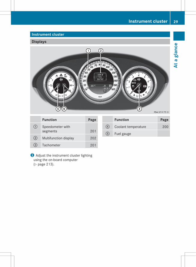
Displays
Function Page: Speedometer with
segments 201
; Multifunction display 202
= Tachometer 201
Function Page? Coolant temperature 200
A Fuel gauge
i Adjust the instrument cluster lightingusing the on-board computer(Y page 213).
Instrument cluster 29
At a
gla
nce
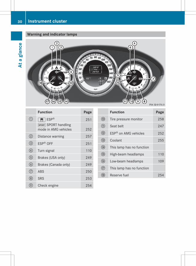
Warning and indicator lamps
Function Page: ÷ ESP® 251
M SPORT handlingmode in AMG vehicles 252
; Distance warning 257
= ESP® OFF 251
? Turn signal 110
A Brakes (USA only) 249
B Brakes (Canada only) 249
C ABS 250
D SRS 253
E Check engine 254
Function PageF Tire pressure monitor 258
G Seat belt 247
H ESP® on AMG vehicles 252
I Coolant 255
J This lamp has no function
K High-beam headlamps 110
L Low-beam headlamps 109
M This lamp has no function
N Reserve fuel 254
30 Instrument clusterAt
a g
lanc
e
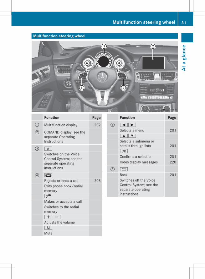
Multifunction steering wheel
Function Page: Multifunction display 202
; COMAND display; see theseparate OperatingInstructions
= ?
Switches on the VoiceControl System; see theseparate operatinginstructions
? ~
Rejects or ends a call 208Exits phone book/redialmemory6
Makes or accepts a callSwitches to the redialmemoryWX
Adjusts the volume8
Mute
Function PageA =;
Selects a menu 2019:
Selects a submenu orscrolls through lists 201a
Confirms a selection 201Hides display messages 220
B %
Back 201Switches off the VoiceControl System; see theseparate operatinginstructions
Multifunction steering wheel 31
At a
gla
nce
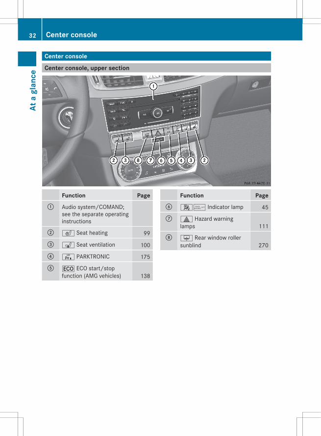
Center console
Center console, upper section
Function Page: Audio system/COMAND;
see the separate operatinginstructions
; c Seat heating 99
= s Seat ventilation 100
? c PARKTRONIC 175
A ¤ ECO start/stopfunction (AMG vehicles) 138
Function PageB 45 Indicator lamp 45
C £ Hazard warninglamps 111
D u Rear window rollersunblind 270
32 Center consoleAt
a g
lanc
e

Center console, lower section
Function PageE Stowage compartment 262
Ashtray 271Cigarette lighter 272Power socket 273Cup holder 267
F Cup holder 267
G e Sets the suspensiontuning 173
Function PageH É Sets the vehicle level 172
I Stowage compartment 262
J Ú Selects the driveprogram 145
K Audio/COMANDcontroller; see the separateoperating instructions
Center console 33
At a
gla
nce
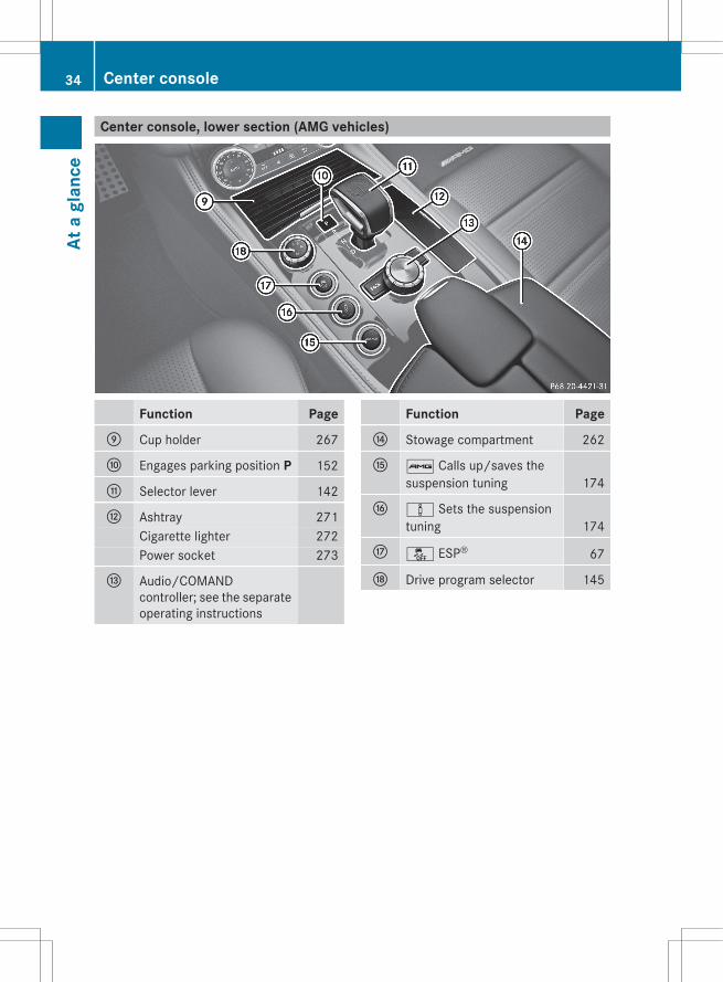
Center console, lower section (AMG vehicles)
Function PageE Cup holder 267
F Engages parking position P 152
G Selector lever 142
H Ashtray 271Cigarette lighter 272Power socket 273
I Audio/COMANDcontroller; see the separateoperating instructions
Function PageJ Stowage compartment 262
K ß Calls up/saves thesuspension tuning 174
L à Sets the suspensiontuning 174
M å ESP® 67
N Drive program selector 145
34 Center consoleAt
a g
lanc
e
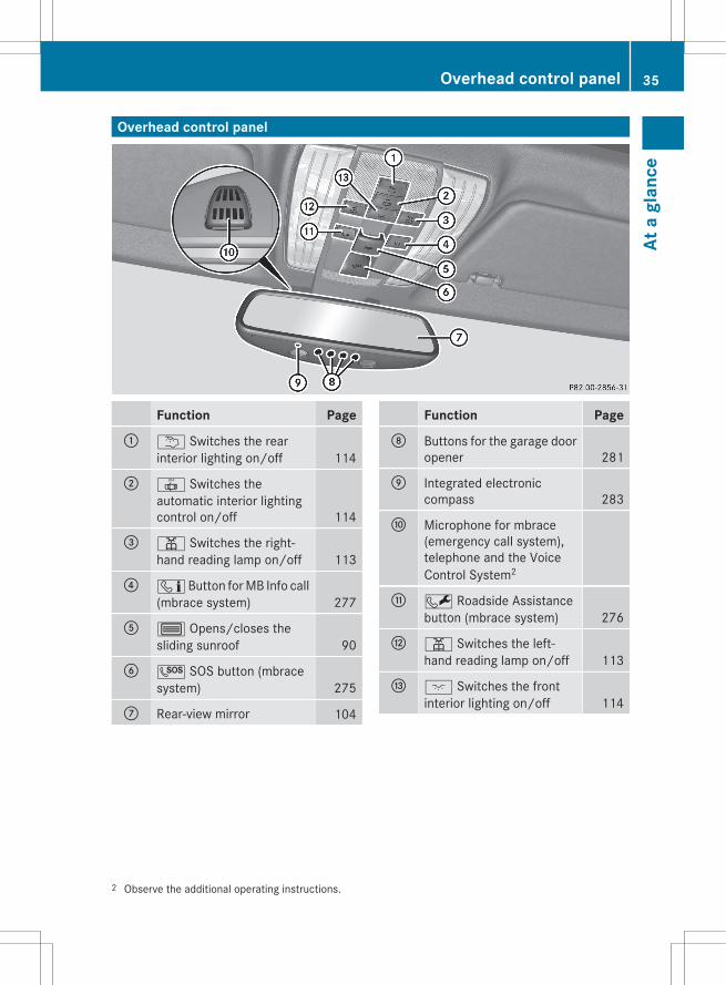
Overhead control panel
Function Page: u Switches the rear
interior lighting on/off 114
; | Switches theautomatic interior lightingcontrol on/off 114
= p Switches the right-hand reading lamp on/off 113
? ï Button for MB Info call(mbrace system) 277
A 3 Opens/closes thesliding sunroof 90
B G SOS button (mbracesystem) 275
C Rear-view mirror 104
Function PageD Buttons for the garage door
opener 281
E Integrated electroniccompass 283
F Microphone for mbrace(emergency call system),telephone and the VoiceControl System2
G F Roadside Assistancebutton (mbrace system) 276
H p Switches the left-hand reading lamp on/off 113
I c Switches the frontinterior lighting on/off 114
2 Observe the additional operating instructions.
Overhead control panel 35
At a
gla
nce

Door control panel
Function Page: r45=
Stores settings for the seat,exterior mirrors andsteering wheel 105
; Adjusts the seat electrically 96
= %& Unlocks/locksthe vehicle 81
? Opens the door 81
A 7Zö\Adjusts and folds theexterior mirrors in/outelectrically 102
Function PageB W Opens/closes the
side windows 87
C n Activates/deactivates the overridefeature for the sidewindows in the rearcompartment 61
D p Opens/closes thetrunk lid 85
36 Door control panelAt
a g
lanc
e
Useful information .............................. 38Occupant safety .................................. 38Children in the vehicle ........................ 57Panic alarm .......................................... 62Driving safety systems ....................... 62Theft deterrent locking system ......... 71
37
Safe
ty

Useful information
i This Operator's Manual describes allmodels and all standard and optionalequipment of your vehicle available at thetime of publication of the Operator'sManual. Country-specific differences arepossible. Please note that your vehicle maynot be equipped with all featuresdescribed. This also applies to safety-related systems and functions.
i Please read the information on qualifiedspecialist workshops (Y page 24).
Occupant safety
Overview of occupant safetyIn this section, you will learn the mostimportant facts about the restraint systemcomponents of the vehicle.The restraint system consists of:Rseat beltsRchild restraint systemsRLATCH-type (ISOFIX) child seat anchorsAdditional protection is provided by:RSRS (Supplemental Restraint System)RNECK-PRO head restraints/NECK-PRO
luxury head restraintsRPRE-SAFE®
RAir bag system components with:- PASSENGER AIR BAG OFF indicator lamp- front-passenger seat with Occupant
Classification System (OCS)The different air bag systems workindependently of each other. The protectivefunctions of the system work in conjunctionwith each other. Not all air bags are deployedin an accident.
G WARNINGModifications to or work improperlyconducted on restraint system componentsor their wiring, as well as tampering with
interconnected electronic systems, can leadto the restraint systems no longer functioningas intended.Air bags or Emergency Tensioning Devices(ETDs), for example, could deployinadvertently or fail to deploy in accidentsalthough the deceleration threshold for airbag deployment is exceeded. Therefore,never modify the restraint systems. Do nottamper with electronic components or theirsoftware.
i See "Children in the vehicle"(Y page 57) for more information oninfants and children traveling with you inthe vehicle and restraints for infants andchildren.
SRS (Supplemental Restraint System)
IntroductionSRS consists of:Rthe 6 SRS warning lampRair bagsRair bag control unit (with crash sensors)REmergency Tensioning DevicesRbelt force limitersSRS reduces the risk of occupants cominginto contact with the vehicle's interior in theevent of an accident. It can also reduce theeffect of the forces to which occupants aresubjected during an accident.
SRS warning lampSRS functions are checked regularly whenyou switch on the ignition and when theengine is running. Therefore, malfunctionscan be detected in good time.The 6 SRS warning lamp in the instrumentcluster lights up when the ignition is switchedon. It goes out no later than a few secondsafter the engine is started.
38 Occupant safetySa
fety
The SRS components are in operationalreadiness if the 6 SRS warning lamp is notlit while the engine is running.
G WARNINGThe SRS self-check has detected amalfunction if the 6 SRS indicator lamp:Rdoes not light up at allRdoes not go out after approximately four
seconds after the engine is startedRcomes on after the engine was started or
while driving.For your safety, Mercedes-Benz stronglyrecommends that you have the systemchecked as soon as possible at an authorizedMercedes-Benz Center. SRS may otherwisefail to activate when it is needed in the eventof an accident, which could lead to serious orfatal injuries. SRS might also be activatedunexpectedly and unnecessarily, which couldalso result in injury.In addition, work carried out improperly onSRS may render SRS inoperative or causeunintended air bag deployment. Work on theSRS system should only be carried out byqualified specialist personnel. Consult anauthorized Mercedes-Benz Center.If it is necessary to modify an air bag systemto accommodate a person with disabilities,contact an authorized Mercedes-Benz Centerfor details. USA only: for further informationcontact our Customer Assistance center at1-800-FOR-MERCedes (1-800-367-6372).
Safety guidelines for seat belts,Emergency Tensioning Devices (ETDs)and air bags
G WARNINGRDamaged seat belts or seat belts that have
been subjected to stress in an accidentmust be replaced. Their anchoring pointsmust also be checked. Only use seat belts
installed or supplied by an authorizedMercedes-Benz Center.RAir bags and pyrotechnic Emergency
Tensioning Devices (ETDs) containperchlorate material, which may requirespecial handling and regard for theenvironment. Check your national disposalguidelines. California residents, seewww.dtsc.ca.gov/HazardousWaste/Perchlorate/index.cfm.RAir bags and ETDs are designed to function
on a one-time-only basis. An air bag or ETDthat has deployed must be replaced. PRE-SAFE® has electrically operated reversiblebelt tensioners in addition to thepyrotechnic ETDs.RDo not pass seat belts over sharp edges.
They could tear.RDo not make any modification that could
change the effectiveness of the seat belts.RDo not bleach or dye seat belts as this may
severely weaken them. In a crash they maynot be able to provide adequate protection.RNo modifications of any kind may be made
to any components or wiring of the SRS.RDo not change or remove any component
or part of the SRS.RDo not install additional trim material, seat
covers, badges, etc. to the:- padded steering wheel boss- knee bag covers- front-passenger air bag cover- outer side of front seat bolsters- side trim next to the rear seat backrest- roof lining trimRDo not install additional electrical/
electronic equipment on or near SRScomponents and wiring.RKeep area between air bags and occupants
free of objects (e.g. packages, purses,umbrellas, etc.).RDo not hang items such as coat hangers
from the coat hooks or handles over thedoor. These items may be thrown around in
Occupant safety 39
Safe
ty
Z
the vehicle and cause head and otherinjuries when the window curtain air bag isdeployed.RAir bag system components will be hot after
an air bag has inflated. Do not touch them.RNever place your feet on the instrument
panel, dashboard, or on the seat. Alwayskeep both feet on the floor in front of theseat.RImproper repair work on the SRS creates a
risk of rendering the SRS inoperative orcausing unintended air bag deployment.Work on the SRS must therefore only beperformed by qualified technicians.Contact an authorized Mercedes-BenzCenter.RFor your protection and the protection of
others, when scrapping the air bag unit orETD, our safety instructions must befollowed. These instructions are availablefrom any authorized Mercedes-BenzCenter.RGiven the considerable deployment speed,
required inflation volume, and the materialof the air bags, there is the possibility ofabrasions or other, potentially more seriousinjuries resulting from air bag deployment.
If you sell your vehicle, Mercedes-Benzstrongly recommends that you inform thesubsequent owner that the vehicle isequipped with SRS. Also, refer them to theapplicable section in the Operator's Manual.
Air bags
Important safety notes
G WARNINGAir bags are designed to reduce the incidenceof injuries and fatalities in certain situations:Rfrontal impacts (driver's and front-
passenger front air bags and knee bags)Rside impacts (side impact air bags, window
curtain air bags and pelvis air bags)Rrollover (window curtain air bags)However, no system available today cancompletely eliminate injuries and fatalities.When the air bags are deployed, a smallamount of powder is released. The powdergenerally does not constitute a health hazardand does not indicate that there is a fire in thevehicle. In order to prevent potentialbreathing difficulties, you should leave thevehicle as soon as it is safe to do so. If youhave any breathing difficulty but cannot getout of the vehicle after the air bag inflates,then get fresh air by opening a window ordoor.
G WARNINGIn order to reduce the potential danger ofinjuries caused during the deployment of thefront air bags, the driver and front passengermust always be correctly seated and weartheir seat belts.For maximum protection in the event of acollision, you must always be in the normalseat position with your back against thebackrest. Fasten your seat belt and make surethat it is correctly positioned on your body.
40 Occupant safetySa
fety
As the air bag inflates with considerablespeed and force, a proper seating positionand correct positioning of the hands on thesteering wheel will help to keep you at a safedistance from the air bag. Occupants who arenot wearing their seat belt, are not seatedproperly or are too close to the air bag can beseriously injured or killed by an air bag, as itinflates with great force instantaneously:Rsit with the seat belt fastened correctly and
in a position that is as upright as possiblewith your back against the backrest.Rmove the driver's seat as far back as
possible, still permitting proper operationof vehicle controls. The distance from thecenter of the driver's chest to the center ofthe air bag cover on the steering wheelmust be at least 10 inches (25 cm). Youshould be able to accomplish this byadjusting the seat and steering wheel. Ifyou have any difficulties, please contact anauthorized Mercedes-Benz Center.Rdo not lean your head or chest close to the
steering wheel or dashboard.Ronly hold the steering wheel on the outside.
Placing hands and arms inside the rim canincrease the risk and potential severity ofhand/arm injury if the driver front air baginflates.Radjust the front-passenger seat as far back
as possible from the dashboard when theseat is occupied.Roccupants, especially children, should
never place their bodies or lean their headsin the area of the door where the sideimpact air bag inflates. This could result inserious or fatal injuries should the sideimpact air bag be deployed. Always sit asupright as possible, wear the seat beltproperly and use an appropriately sizedinfant restraint, toddler restraint or boosterseat recommended for the size and weightof the child.
Failure to follow these instructions can resultin severe injuries to you or other occupants.
If you sell your vehicle, it is important that youmake the buyer aware of this safetyinformation. Be sure to give the buyer thisOperator's Manual.
G WARNINGAccident research shows that the safest placefor children in an automobile is in a rear seat.A side impact air bag related injury may occurif occupants, especially children, are notproperly seated or restrained when next to aside impact air bag which needs to deployrapidly in a side impact in order to do its job.To help avoid the possibility of injury, pleasefollow these guidelines:
(1) Always sit as upright as possibleand use the seat belts properly.Make sure that children 12 yearsold and under use an appropriatelysized child restraint, infantrestraint, or booster seatrecommended for the size andweight of the child.
(2) Always wear seat belts properly.
The air bags are only deployed if the air bagcontrol unit detects the need for deployment.Only in the event of such a situation will theyprovide their supplemental protection.The driver and passenger should always weartheir seat belts. Otherwise, it is not possiblefor the air bags to provide their supplementalprotection.In the event of other types of impacts andimpacts below air bag deploymentthresholds, the air bags will not deploy. Thedriver and passengers will then be protectedto the extent possible by a properly fastenedseat belt. A properly fastened seat belt is alsoneeded to provide the best possibleprotection in a rollover.Air bags provide additional protection; theyare not, however, a substitute for seat belts.All vehicle occupants must fasten their seatbelts regardless of whether your vehicle isequipped with air bags or not.
Occupant safety 41
Safe
ty
Z

It is important for your safety and that of yourpassenger to have deployed air bags replacedand to have any malfunctioning air bagsrepaired. This will help to make sure the airbags continue to perform their protectivefunction for the vehicle occupants in theevent of a crash.
Front air bagsThe front air bags increase protection for thedriver's and front-passenger's head andchest.
Driver's air bag : deploys in front of thesteering wheel; front-passenger front airbag ; deploys in front of and above the glovebox.They are deployed:Rin the event of certain frontal impactsRif the system determines that air bag
deployment can offer additional protectionto that provided by the seat beltRif the seat belt is fastenedRindependently of other air bags in the
vehicleIf the vehicle overturns, the front air bags aregenerally not deployed. If the system detectshigh vehicle deceleration in a longitudinaldirection, the front air bags are deployed.Your vehicle has adaptive, two-stage front airbags. In the event of a collision, the air bagcontrol unit evaluates the vehicledeceleration. In the first deployment stage,the front air bag is filled with enoughpropellant gas to reduce the risk of injuries.
The front air bag is fully deployed if a seconddeployment threshold is exceeded within afew milliseconds.The deployment of the front-passenger frontair bag is also influenced by the weightcategory of the front passenger, which isdetermined by the Occupant ClassificationSystem (OCS) (Y page 45).The lighter the passenger-side occupant, thehigher the vehicle deceleration rate required(predicted at the start of the impact) forsecond stage inflation of the front-passengerfront air bag. In the second stage, the frontair bags are inflated with the maximumamount of propellant gas available.The front air bags are not deployed insituations where a low impact severity ispredicted. You will then be protected by thefastened seat belt.The front-passenger front air bag will onlydeploy if:Rthe system, based on the OCS weight
sensor readings, detects that the front-passenger seat is occupied.Rthe 45 indicator lamp in the center
console is not lit, (Y page 45).Rthe air bag control unit predicts a high
impact severity.
Knee bags
G WARNINGObserve "Important safety notes"(Y page 40).
42 Occupant safetySa
fety

Knee bags provide increased protection forthe driver and front passenger against the riskof:Rknee injuriesRthigh injuriesRlower leg injuriesDriver's knee bag : deploys underneath thesteering column and front-passenger kneebag ; underneath the glove box. Theydeploy together with the front air bags. Theyare designed to operate together with thefront air bags in frontal impacts if certainthresholds are exceeded. The knee bagsoperate at best in conjunction with correctlypositioned and fastened seat belts.
Side impact air bags
G WARNINGThe pressure sensors for side impact air bagcontrol are located in the doors. Do notmodify any components of the doors or doortrim panels including, for example, theaddition of door speakers.Improper repair work on the doors or themodification or addition of components to thedoors create a risk of rendering the sideimpact air bags inoperative or causingunintended air bag deployment. Work on thedoors must therefore only be performed byqualified technicians. Contact an authorizedMercedes-Benz Center.
G WARNINGOnly use seat covers which have been testedand approved by Mercedes-Benz for yourvehicle model. Using seat covers or other seatcoverings can cause a malfunction of the sideimpact air bags and/or the pelvis air bags.Contact an authorized Mercedes-Benz Centerfor availability.
When deployed, the side impact air bags offeradditional protection for the thorax of thevehicle occupants on the side of the vehicleon which the impact occurs. However, theydo not protect the:RheadRneckRarms
Front side impact air bags : and rear sideimpact air bags ; deploy next to the outerseat cushions.The side impact air bags are deployed:Ron the side on which an impact occursRat the start of an accident with a high rate
of lateral vehicle deceleration oracceleration, e.g. in a side impactRindependently of the use of the seat beltRindependently of the front air bagsRindependently of the ETDsIf the vehicle overturns, the side impact airbags are generally not deployed. Exception: ifthe system detects high vehicle decelerationor acceleration in a lateral direction anddetermines that deployment can offeradditional protection to that provided by theseat belt.Side impact air bags will not deploy in sideimpacts which do not exceed the system'spreset deployment thresholds for lateralacceleration/deceleration. You will then beprotected by the fastened seat belt.
Occupant safety 43
Safe
ty
Z

The side impact air bag on the front-passenger side will not deploy under thefollowing conditions:Rthe OCS detects that the front-passenger
seat is not occupied.Rthe front-passenger seat belt is not
fastened.The side impact air bag on the front-passenger side will deploy if the front-passenger seat belt is fastened, regardless ofwhether the front-passenger seat is occupiedor not.
Pelvis air bags
G WARNINGOnly use seat covers which have been testedand approved by Mercedes-Benz for yourvehicle model. Using seat covers or other seatcoverings can cause a malfunction of the sideimpact air bags and/or the pelvis air bags.Contact an authorized Mercedes-Benz Centerfor availability.
Pelvis air bag deployment enhances the levelof protection of the vehicle occupants on theside of the vehicle on which the impactoccurs.
Pelvis air bags : deploy next to and belowthe outer seat cushions. They are deployed:Ron the side on which an impact occursRat the start of an accident with a high rate
of lateral vehicle deceleration oracceleration, e.g. in a side impactRindependently of the use of the seat belt
Rindependently of the front air bagsRindependently of the ETDsIf the vehicle overturns, the pelvis air bags aregenerally not deployed. Exception: if thesystem detects high vehicle deceleration oracceleration in a lateral direction anddetermines that deployment can offeradditional protection to that provided by theseat belt.Pelvis air bags : will not deploy in sideimpacts which do not exceed the system'spreset deployment thresholds for lateralacceleration/deceleration. You will then beprotected by the fastened seat belt.The pelvis air bag on the front-passenger sidewill not deploy under the following conditions:Rthe OCS detects that the front-passenger
seat is not occupied.Rthe front-passenger seat belt is not
fastened.The pelvis air bag on the front-passenger sidewill deploy if the front-passenger seat belt isfastened, regardless of whether the front-passenger seat is occupied or not.
Window curtain air bagsThe window curtain air bags enhance the levelof protection for the head, but not chest orarms, of the vehicle occupants on the side ofthe vehicle on which the impact occurs.The window curtain air bags are integratedinto the side of the roof frame and deploy inthe area from the A-pillar to the C-pillar.
44 Occupant safetySa
fety

Window curtain air bags : are deployed:Ron the side on which an impact occursRat the start of an accident with a high rate
of lateral vehicle deceleration oracceleration, e.g. in a side impactRregardless of whether the front-passenger
seat is occupiedRindependently of seat belt useRif the vehicle overturns and the system
determines that window curtain air bagdeployment can offer additional protectionto that provided by the seat beltRindependently of the front air bagsWindow curtain air bags : will not deploy inimpacts with deceleration rates which do notexceed the system's preset deploymentthresholds for vehicle deceleration oracceleration. You will then be protected bythe fastened seat belt.
Occupant Classification System(OCS)
How the Occupant ClassificationSystem worksThe Occupant Classification System (OCS)categorizes the occupant on the front-passenger seat by means of a weight sensor.The front-passenger front air bag and thefront-passenger knee bag are deactivatedautomatically for certain weight categories.The 45 indicator lamp shows you thecurrent status. When the 45 indicatorlamp is illuminated, the front-passenger frontair bag and the front-passenger knee bag aredeactivated.The system does not deactivate:Rthe side impact air bagRthe pelvis air bagRthe window curtain air bagRthe Emergency Tensioning Devices
To be classified correctly, the front passengermust sit:Rwith the seat belt fastened correctlyRin a position that is as upright as possible
with their back against the seat backrestRwith their feet on the floorIf the front-passenger's weight is transferredto another object in the vehicle (e.g. byleaning on armrests), OCS may not be able toapproximate the occupant's weight category.If the front-passenger seat, the seat cover orthe seat cushion are damaged, have thenecessary repair work carried out at anauthorized Mercedes-Benz Center.For safety reasons, Mercedes-Benzrecommends that you only use seataccessories that have been approved byMercedes-Benz.Both the driver and the passenger shouldalways use the 45 indicator lamp asan indication of whether or not the passengeris properly positioned.
G WARNINGIf the 45 indicator lamp illuminateswhen an adult or someone larger than a smallindividual is in the front-passenger seat, havethe front passenger reposition himself orherself in the seat until the 45indicator lamp goes out.In the event of a collision, the air bag controlunit will not allow front-passenger front airbag deployment when the OCS has classifiedthe front-passenger seat occupant asweighing as much as or less than a typical 12-month-old child in a standard child restraintor if the front-passenger seat is classified asbeing empty.When the OCS senses that the front-passenger seat occupant is classified asbeing up to or less than the weight of a typical12-month-old child in a standard childrestraint, the 45 indicator lamp willilluminate when the engine is started andremain illuminated, indicating that the front-passenger front air bag is deactivated.
Occupant safety 45
Safe
ty
Z
When the OCS senses that the front-passenger seat is classified as being empty,the 45 indicator lamp will illuminatewhen the engine is started and remainilluminated, indicating that the front-passenger front air bag is deactivated.When the OCS senses that the front-passenger seat occupant is classified asbeing heavier than the weight of a typical 12-month-old child seated in a standard childrestraint or as being a small individual (suchas a young teenager or a small adult), the45 indicator lamp will illuminate forapproximately 6 seconds when the engine isstarted and then, depending on occupantweight sensor readings from the front-passenger seat, remain illuminated or go out.With the 45 indicator lampilluminated, the front-passenger front air bagis deactivated. With the 45 indicatorlamp out, the front-passenger front air bag isactivated.When the OCS senses that the front-passenger seat occupant is classified as anadult or someone larger than a smallindividual, the 45 indicator lamp willilluminate for approximately 6 seconds whenthe engine is started and then go out,indicating that the front-passenger front airbag is activated.If the 45 indicator lamp is illuminated,the front-passenger front air bag and thefront-passenger knee bag are deactivated andwill not be deployed.If the 45 indicator lamp is notilluminated, the front-passenger front air bagand the front-passenger knee bag areactivated and will be deployed:Rin the event of certain frontal impactsRif impact exceeds a preset deployment
thresholdRindependently of the side impact air bag or
pelvis air bag
If the front-passenger front air bag isdeployed, the rate of inflation will beinfluenced by:Rthe rate of relevant vehicle deceleration as
assessed by the air bag control unitRthe front passenger's weight category as
identified by OCS
For further information, see "Air bag displaymessages" (Y page 228).
G WARNINGAccording to accident statistics, children aresafer when properly restrained on the rearseats than on the front-passenger seat. Thus,we strongly recommend that children beplaced in the rear seats whenever possible.Regardless of seating position, children 12years old and under must be seated andproperly secured in an appropriate infantrestraint, toddler restraint, or booster seatrecommended for the size and weight of thechild.The infant or child restraint must be properlysecured with the vehicle's seat belt, the seatbelt and Top Tether strap, or lower ISOFIXchild seat retaining loops and Top Tetherstrap, fully in accordance with the infant orchild seat manufacturer's instructions.Occupants, especially children, should alwayssit as upright as possible, wear the seat beltproperly and use an appropriately sized infantrestraint, toddler restraint, or booster seatrecommended for the size and weight of thechild.Children can be killed or seriously injured byan inflating air bag.Note the following important information if itis necessary to carry a child on the front-passenger seat:RYour vehicle is equipped with air bag
technology designed to deactivate thefront-passenger front air bag and the front-passenger knee bag in your vehicle whenthe system senses the weight of a typical12-month-old child or less along with the
46 Occupant safetySa
fety
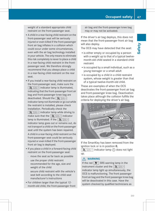
weight of a standard appropriate childrestraint on the front-passenger seat.RA child in a rear-facing child restraint on the
front-passenger seat will be seriouslyinjured or even killed if the front-passengerfront air bag inflates in a collision whichcould occur under some circumstances,even with the air bag technology installedin your vehicle. The only means to eliminatethis risk completely is never to place a childin a rear-facing child restraint in the front-passenger seat. We therefore stronglyrecommend that you always place a childin a rear-facing child restraint on the rearseat.RIf you install a rear-facing child restraint on
the front-passenger seat, make sure the45 indicator lamp is illuminated,indicating that the front-passenger front airbag and front-passenger knee bag aredeactivated. Should the 45indicator lamp not illuminate or go out whilethe restraint is installed, please checkinstallation. Periodically check the45 indicator lamp while driving tomake sure that the 45 indicatorlamp is illuminated. If the 45indicator lamp goes out or remains out, donot transport a child on the front-passengerseat until the system has been repaired.A child in a rear-facing child restraint on thefront-passenger seat could be seriouslyinjured or even killed if the front-passengerfront air bag is deployed.RIf you place a child in a forward-facing child
restraint on the front-passenger seat:- move the seat as far back as possible- use the proper child restraint
recommended for the age, size andweight of the child
- secure child restraint with the vehicle'sseat belt according to the child seatmanufacturer's instructions
RFor children larger than the typical 12-month-old child, the front-passenger front
air bag and the front-passenger knee bagmay or may not be activated.
If the driver's air bag deploys, this does notmean that the front-passenger front air bagwill also deploy.The OCS may have detected that the seat:Ris either empty or occupied by a person
with a weight up to that of a typical twelve-month-old child seated in a standard childrestraintRis occupied by a small individual, such as a
young teenager or a small adultRis occupied by a child in a child restraint
system, whose weight is greater than thatof a typical twelve-month-old child.
These are examples of when the OCSdeactivates the front-passenger front air bagand front-passenger knee bag. Deactivationtakes place although the collision fulfills thecriteria for deploying the driver's air bag.
If the SmartKey has been removed from theignition lock or is in position 0,45 indicator lamp : does not lightup.
G WARNINGIf the red 6 SRS warning lamp in theinstrument cluster and the 45indicator lamp light up simultaneously, theOCS is malfunctioning. The front passengerfront air bag and the front passenger knee bagwill be deactivated in this case. Have thesystem checked by qualified technicians as
Occupant safety 47
Safe
ty
Z
soon as possible. Contact an authorizedMercedes-Benz Center.Only have the seat repaired or replaced at anauthorized Mercedes-Benz Center.In order to ensure proper operation of the airbag system and OCS:RSit with the seat belt properly fastened in a
position that is as upright as possible withyour back against the seat backrest.RWhen seated, a passenger should not
position him/herself in such a way as tocause the passenger's weight to be liftedfrom the seat cushion as this may result inthe OCS being unable to correctlyapproximate the passenger's weightcategory.RRead and observe all warnings in this
chapter.
System self-testThe 45 indicator lamp illuminateswhen you:Rturn the SmartKey to position 1 or 2 in the
ignition lockRon vehicles with KEYLESS-GO, press the
Start/Stop button once or twiceIf an adult occupant is sitting properly on thefront-passenger seat and the OCS classifiesthe occupant as an adult, the 45indicator lamp will illuminate and go out againafter approximately six seconds.If the seat is not occupied and the OCSclassifies the front passenger seat as beingunoccupied, the 45 indicator lampwill illuminate and not go out.
G WARNINGIf the 4 5 indicator lamp does notilluminate, the system is not functioning. Youmust contact an authorized Mercedes-BenzCenter before seating any child on the frontpassenger seat.
For more information, see "Problems with theOccupant Classification System"(Y page 49).
G WARNINGNever place anything between seat cushionand child seat (e.g. a pillow), since it reducesthe effectiveness of the OCS. The undersideand rear side child restraint system must beplaced entirely on the seat cushion and thebackrest of the front-passenger seatbackrest.If necessary, adjust the tilt of the passengerseat backrest.An incorrectly mounted child seat could causeinjuries to the child in case of an accident,instead of increasing protection for the child.Follow the manufacturer's instructions forinstallation of child restraint systems.
48 Occupant safetySa
fety
Problems with the Occupant Classification System
Problem Possible causes/consequences and M Solutions
The 45indicator lampilluminates andremains illuminated.The person on thefront-passenger seat:Rhas the weight of a
typical adultRhas been determined
by the system not tobe a child
The OCS is malfunctioning.X Have the OCS checked as soon as possible at an authorized
Mercedes-Benz Center.X Observe the additional display messages in the multifunction
display (Y page 228).
G WARNINGIf the 45 indicator lamp illuminates and remains illuminated when the weight of a typicaladult or someone larger than a small individual has been detected on the passenger seat, do notallow any occupant to use the passenger seat until the system has been repaired.
Problem Possible causes/consequences and M Solutions
The 45indicator lamp does notilluminate and/or doesnot remain illuminated.The front-passengerseat is:RunoccupiedRoccupied with a
weight up to that of atypical twelve-month-old child in astandard childrestraint system
The OCS is malfunctioning.X Make sure there is nothing between the seat cushion and the
child seat.X Check the installation of the child restraint system.X Make sure that no objects are applying additional weight onto
the seat.X If the 45 indicator lamp does not illuminate, have the
OCS checked as soon as possible at an authorized Mercedes-Benz Center. Do not transport a child on the front-passengerseat as long as the OCS is not functioning.
X Observe the additional display messages in the multifunctiondisplay (Y page 228).
G WARNINGIf the 45 indicator lamp does not illuminate or remains out with the weight of a typical12-month-old child in a standard child restraint or less, or is unoccupied, on the front-passengerseat, do not transport a child on the front-passenger seat until the system has been repaired.
Occupant safety 49
Safe
ty
Z
PRE-SAFE® (preventative occupantprotection)
G WARNINGThe PRE-SAFE® system reduces the impact ofan accident on vehicle occupants, as long astheir seat belts have been fastened correctly.Although your vehicle is equipped with a PRE-SAFE® system, the possibility of injury in theevent of an accident cannot be ruled out. Youshould therefore always drive carefully andadapt your driving style to the prevailing road,weather and traffic conditions.
PRE-SAFE® takes preemptive measures toprotect occupants in certain hazardoussituations.PRE-SAFE® intervenes:Rif BAS PLUS intervenes powerfully on
vehicles with DISTRONIC PLUSRif, on vehicles with DISTRONIC PLUS, the
radar sensor system detects an imminentdanger of collision in certain situationsRin critical driving situations, e.g. when
physical limits are exceeded and thevehicle understeers or oversteers severely
PRE-SAFE® takes the following measuresdepending on the hazardous situationdetected:Rthe front seat belts are pre-tensioned.Rthe front-passenger seat is adjusted if it is
in an unfavorable position.Rvehicles with a multicontour seat or active
multicontour seat: the air pressure in theside bolsters of the seat cushion andbackrest is increased.Rif the vehicle skids, the sliding sunroof/
panorama roof with power tilt/slidingpanel and the side windows are closed sothat only a small gap remains.
If the hazardous situation passes withoutresulting in an accident, PRE-SAFE® slackensthe belt pretensioning. The air pressure in theside bolsters on the multicontour seat/activemulticontour seat is reduced again. All
settings made by PRE-SAFE® can then bereversed.If the seat belts are not released:X Move the backrest or seat back slightly, but
only when the vehicle is stationary.The belt pretensioning is reduced and thelocking mechanism is released.
G WARNINGMake sure that nobody can become trappedas you adjust the seat.
! Make sure that there are no objects in thefootwell or behind the seats when resettingthe seats. There is a risk that the seatsand/or the objects could be damaged.
More information about seat-beltadjustment, a convenience functionintegrated into PRE-SAFE®, can be found inthe "Seat-belt adjustment" section(Y page 55).
NECK-PRO head restraints/NECK-PRO luxury head restraints
NECK-PRO head restraints/NECK-PRO luxuryhead restraints increase protection of thedriver's and front-passenger's head andneck. In the event of a rear collision of acertain severity, the NECK-PRO headrestraints/NECK-PRO luxury head restraintson the driver's and front-passenger seats aremoved forwards and upwards. This providesbetter head support.
G WARNINGDo not attach any objects (e.g. a coat hanger)to the NECK-PRO head restraints/NECK-PROluxury head restraints. Otherwise, the NECK-PRO head restraints/NECK-PRO luxury headrestraints may not function properly and inthe event of a rear-end collision may not offerthe protection they are designed to provide.
50 Occupant safetySa
fety
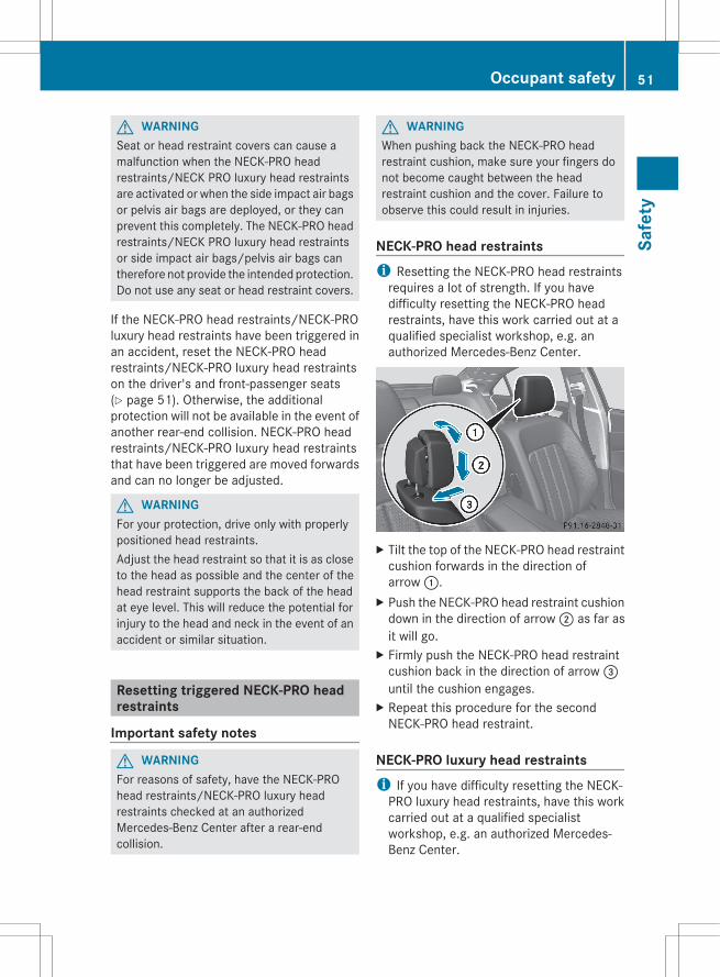
G WARNINGSeat or head restraint covers can cause amalfunction when the NECK-PRO headrestraints/NECK PRO luxury head restraintsare activated or when the side impact air bagsor pelvis air bags are deployed, or they canprevent this completely. The NECK-PRO headrestraints/NECK PRO luxury head restraintsor side impact air bags/pelvis air bags cantherefore not provide the intended protection.Do not use any seat or head restraint covers.
If the NECK-PRO head restraints/NECK-PROluxury head restraints have been triggered inan accident, reset the NECK-PRO headrestraints/NECK-PRO luxury head restraintson the driver's and front-passenger seats(Y page 51). Otherwise, the additionalprotection will not be available in the event ofanother rear-end collision. NECK-PRO headrestraints/NECK-PRO luxury head restraintsthat have been triggered are moved forwardsand can no longer be adjusted.
G WARNINGFor your protection, drive only with properlypositioned head restraints.Adjust the head restraint so that it is as closeto the head as possible and the center of thehead restraint supports the back of the headat eye level. This will reduce the potential forinjury to the head and neck in the event of anaccident or similar situation.
Resetting triggered NECK-PRO headrestraints
Important safety notes
G WARNINGFor reasons of safety, have the NECK-PROhead restraints/NECK-PRO luxury headrestraints checked at an authorizedMercedes-Benz Center after a rear-endcollision.
G WARNINGWhen pushing back the NECK-PRO headrestraint cushion, make sure your fingers donot become caught between the headrestraint cushion and the cover. Failure toobserve this could result in injuries.
NECK-PRO head restraintsi Resetting the NECK-PRO head restraints
requires a lot of strength. If you havedifficulty resetting the NECK-PRO headrestraints, have this work carried out at aqualified specialist workshop, e.g. anauthorized Mercedes-Benz Center.
X Tilt the top of the NECK-PRO head restraintcushion forwards in the direction ofarrow :.
X Push the NECK-PRO head restraint cushiondown in the direction of arrow ; as far asit will go.
X Firmly push the NECK-PRO head restraintcushion back in the direction of arrow =until the cushion engages.
X Repeat this procedure for the secondNECK-PRO head restraint.
NECK-PRO luxury head restraintsi If you have difficulty resetting the NECK-
PRO luxury head restraints, have this workcarried out at a qualified specialistworkshop, e.g. an authorized Mercedes-Benz Center.
Occupant safety 51
Safe
ty
Z
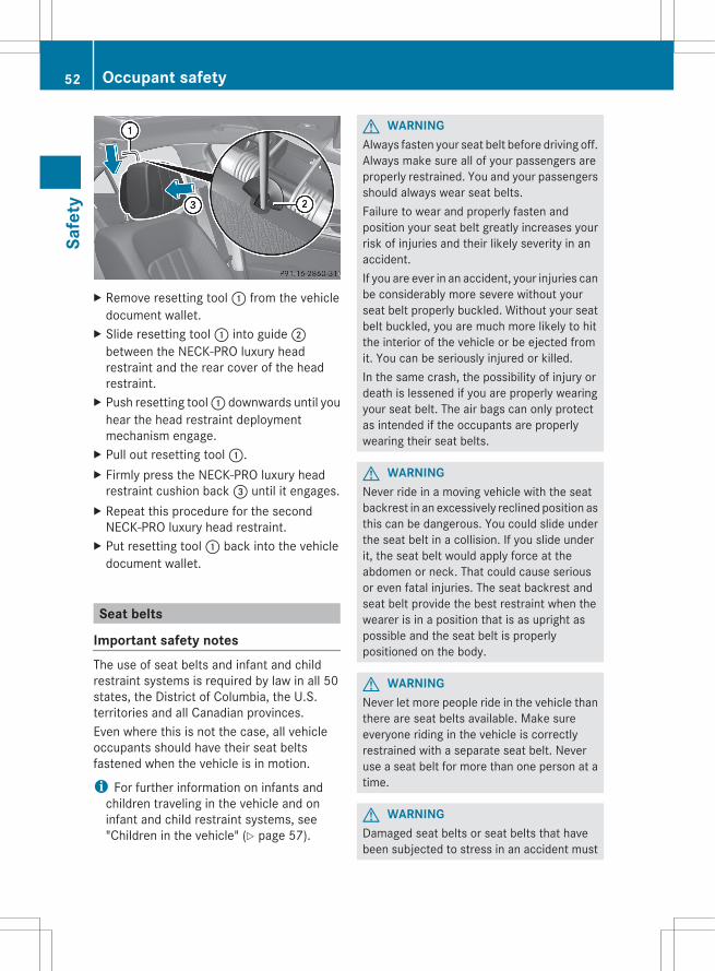
X Remove resetting tool : from the vehicledocument wallet.
X Slide resetting tool : into guide ;between the NECK-PRO luxury headrestraint and the rear cover of the headrestraint.
X Push resetting tool : downwards until youhear the head restraint deploymentmechanism engage.
X Pull out resetting tool :.X Firmly press the NECK-PRO luxury head
restraint cushion back = until it engages.X Repeat this procedure for the second
NECK-PRO luxury head restraint.X Put resetting tool : back into the vehicle
document wallet.
Seat belts
Important safety notesThe use of seat belts and infant and childrestraint systems is required by law in all 50states, the District of Columbia, the U.S.territories and all Canadian provinces.Even where this is not the case, all vehicleoccupants should have their seat beltsfastened when the vehicle is in motion.
i For further information on infants andchildren traveling in the vehicle and oninfant and child restraint systems, see"Children in the vehicle" (Y page 57).
G WARNINGAlways fasten your seat belt before driving off.Always make sure all of your passengers areproperly restrained. You and your passengersshould always wear seat belts.Failure to wear and properly fasten andposition your seat belt greatly increases yourrisk of injuries and their likely severity in anaccident.If you are ever in an accident, your injuries canbe considerably more severe without yourseat belt properly buckled. Without your seatbelt buckled, you are much more likely to hitthe interior of the vehicle or be ejected fromit. You can be seriously injured or killed.In the same crash, the possibility of injury ordeath is lessened if you are properly wearingyour seat belt. The air bags can only protectas intended if the occupants are properlywearing their seat belts.
G WARNINGNever ride in a moving vehicle with the seatbackrest in an excessively reclined position asthis can be dangerous. You could slide underthe seat belt in a collision. If you slide underit, the seat belt would apply force at theabdomen or neck. That could cause seriousor even fatal injuries. The seat backrest andseat belt provide the best restraint when thewearer is in a position that is as upright aspossible and the seat belt is properlypositioned on the body.
G WARNINGNever let more people ride in the vehicle thanthere are seat belts available. Make sureeveryone riding in the vehicle is correctlyrestrained with a separate seat belt. Neveruse a seat belt for more than one person at atime.
G WARNINGDamaged seat belts or seat belts that havebeen subjected to stress in an accident must
52 Occupant safetySa
fety
be replaced and their anchoring points mustalso be checked.Only use seat belts which have been approvedby Mercedes-Benz.Do not make any modifications to the seatbelts. This can lead to unintended activationof the ETDs or to their failure to activate whennecessary.Do not bleach or dye seat belts as this mayseverely weaken them. In a crash they maynot be able to provide adequate protection.Have all work carried out only by qualifiedtechnicians. Contact an authorizedMercedes-Benz Center.
Correct use of the seat belts
G WARNINGUSE SEAT BELTS PROPERLYRSeat belts can only work when used
properly. Never wear seat belts in any otherway than as described in this section, asthat could result in serious injuries in theevent of an accident.REach occupant should wear their seat belt
at all times, because seat belts help reducethe likelihood of and potential severity ofinjuries in accidents, including rollovers.The integrated restraint system includesSRS (driver front air bag, driver's side kneebag, front-passenger front air bag, sideimpact air bags, pelvis air bags, windowcurtain air bags for the side windows),Emergency Tensioning Devices, seat beltforce limiters, and front seat knee bolsters.The system is designed to enhance theprotection offered to properly beltedoccupants in certain frontal (front air bags,driver's side knee bag and ETDs) and side(side impact air bags, window curtain airbags, and ETDs) impacts which exceedpreset deployment thresholds and incertain rollovers (window curtain air bagsand ETDs).
RNever wear the shoulder belt under yourarm, across your neck or off your shoulder.In a frontal crash, your body would movetoo far forward. That would increase thechance of head and neck injuries. The seatbelt would also apply too much force to theribs or abdomen, which could severelyinjure internal organs such as your liver orspleen.Adjust the seat belt so that the shouldersection is located as close as possible tothe middle of the shoulder. It should nottouch the neck. Never pass the shoulderportion of the seat belt under your arm. Forthis purpose, you can adjust the height ofthe seat belt outlet.RPosition the lap belt as low as possible on
your hips and not across the abdomen. Ifthe lap belt is positioned across yourabdomen, it could cause serious injuries ina crash.RNever wear seat belts over rigid or
breakable objects in or on your clothing,such as eyeglasses, pens, keys etc., asthese might cause injuries.RMake sure the seat belt is always fitted
snugly. Take special care of this whenwearing loose clothing.RNever use a seat belt for more than one
person at a time. Do not fasten a seat beltaround a person and another person orother objects at the same time.RSeat belts should not be worn twisted. In a
crash, you would not have the full width ofthe seat belt to distribute impact forces.The twisted seat belt against your bodycould cause injuries.RPregnant women should also always use a
lap-shoulder belt. The lap belt portionshould be positioned as low as possible onthe hips to avoid any possible pressure onthe abdomen.RPlace the seat backrest in a position that is
as upright as possible.RCheck your seat belt during travel to make
sure it is properly positioned.
Occupant safety 53
Safe
ty
Z
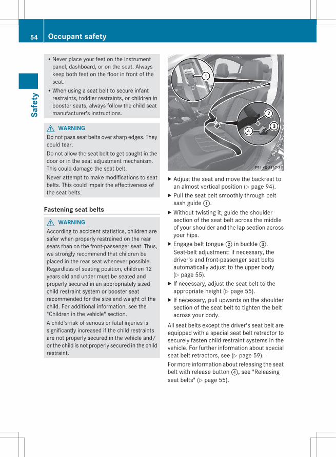
RNever place your feet on the instrumentpanel, dashboard, or on the seat. Alwayskeep both feet on the floor in front of theseat.RWhen using a seat belt to secure infant
restraints, toddler restraints, or children inbooster seats, always follow the child seatmanufacturer's instructions.
G WARNINGDo not pass seat belts over sharp edges. Theycould tear.Do not allow the seat belt to get caught in thedoor or in the seat adjustment mechanism.This could damage the seat belt.Never attempt to make modifications to seatbelts. This could impair the effectiveness ofthe seat belts.
Fastening seat belts
G WARNINGAccording to accident statistics, children aresafer when properly restrained on the rearseats than on the front-passenger seat. Thus,we strongly recommend that children beplaced in the rear seat whenever possible.Regardless of seating position, children 12years old and under must be seated andproperly secured in an appropriately sizedchild restraint system or booster seatrecommended for the size and weight of thechild. For additional information, see the"Children in the vehicle" section.A child's risk of serious or fatal injuries issignificantly increased if the child restraintsare not properly secured in the vehicle and/or the child is not properly secured in the childrestraint.
X Adjust the seat and move the backrest toan almost vertical position (Y page 94).
X Pull the seat belt smoothly through beltsash guide :.
X Without twisting it, guide the shouldersection of the seat belt across the middleof your shoulder and the lap section acrossyour hips.
X Engage belt tongue ; in buckle =.Seat-belt adjustment: if necessary, thedriver's and front-passenger seat beltsautomatically adjust to the upper body(Y page 55).
X If necessary, adjust the seat belt to theappropriate height (Y page 55).
X If necessary, pull upwards on the shouldersection of the seat belt to tighten the beltacross your body.
All seat belts except the driver's seat belt areequipped with a special seat belt retractor tosecurely fasten child restraint systems in thevehicle. For further information about specialseat belt retractors, see (Y page 59).For more information about releasing the seatbelt with release button ?, see "Releasingseat belts" (Y page 55).
54 Occupant safetySa
fety
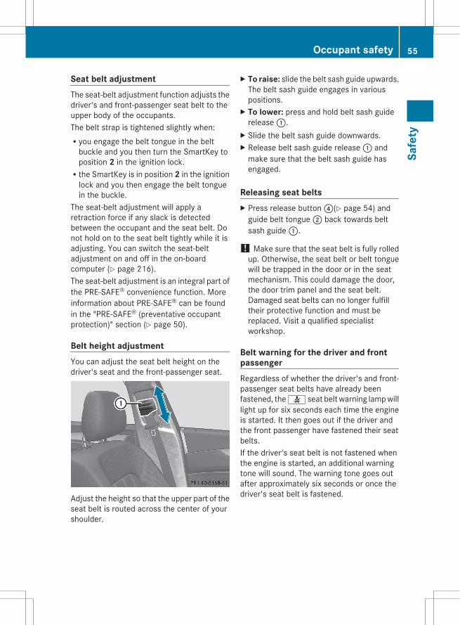
Seat belt adjustmentThe seat-belt adjustment function adjusts thedriver's and front-passenger seat belt to theupper body of the occupants.The belt strap is tightened slightly when:Ryou engage the belt tongue in the belt
buckle and you then turn the SmartKey toposition 2 in the ignition lock.Rthe SmartKey is in position 2 in the ignition
lock and you then engage the belt tonguein the buckle.
The seat-belt adjustment will apply aretraction force if any slack is detectedbetween the occupant and the seat belt. Donot hold on to the seat belt tightly while it isadjusting. You can switch the seat-beltadjustment on and off in the on-boardcomputer (Y page 216).The seat-belt adjustment is an integral part ofthe PRE-SAFE® convenience function. Moreinformation about PRE-SAFE® can be foundin the "PRE-SAFE® (preventative occupantprotection)" section (Y page 50).
Belt height adjustmentYou can adjust the seat belt height on thedriver's seat and the front-passenger seat.
Adjust the height so that the upper part of theseat belt is routed across the center of yourshoulder.
X To raise: slide the belt sash guide upwards.The belt sash guide engages in variouspositions.
X To lower: press and hold belt sash guiderelease :.
X Slide the belt sash guide downwards.X Release belt sash guide release : and
make sure that the belt sash guide hasengaged.
Releasing seat beltsX Press release button ?(Y page 54) and
guide belt tongue ; back towards beltsash guide :.
! Make sure that the seat belt is fully rolledup. Otherwise, the seat belt or belt tonguewill be trapped in the door or in the seatmechanism. This could damage the door,the door trim panel and the seat belt.Damaged seat belts can no longer fulfilltheir protective function and must bereplaced. Visit a qualified specialistworkshop.
Belt warning for the driver and frontpassengerRegardless of whether the driver's and front-passenger seat belts have already beenfastened, the 7 seat belt warning lamp willlight up for six seconds each time the engineis started. It then goes out if the driver andthe front passenger have fastened their seatbelts.If the driver's seat belt is not fastened whenthe engine is started, an additional warningtone will sound. The warning tone goes outafter approximately six seconds or once thedriver's seat belt is fastened.
Occupant safety 55
Safe
ty
Z
If after six seconds the driver's or front-passenger seat belt is not fastened and thedoors are closed, the 7 seat belt warninglamp will remain lit:Runtil the driver's or front passenger's seat
belt is fastenedRonce the vehicle has exceeded a speed of
15 mph (25 km/h), in addition a warningtone will sound with increasing intensity forup to 60 seconds or until the driver's orfront-passenger seat belt is fastened.
If the driver or front passenger unfastens theirseat belt during the journey, the 7 seatbelt warning lamp lights up and the warningtone sounds again.The warning tone ceases after 60 secondseven if the driver or front passenger has stillnot fastened their seat belt. The 7 seatbelt warning lamp stops flashing, but remainslit.After the vehicle has come to a stop, thewarning tone will be reactivated and the7 seat belt warning lamp will flash againonce the vehicle has exceeded a speed of15 mph (25 km/h).The 7 seat belt warning lamp will not goout until:Rboth the driver and the front passenger
have fastened their seat belts.orRthe vehicle is stationary and a door is open.
i For more information on the 7 seatbelt warning lamp, see "Warning andindicator lamps in the instrument cluster,seat belt" (Y page 247).
Emergency Tensioning Devices, beltforce limitersThe seat belts are equipped with ETDs andseat belt force limiters.The ETDs tighten the seat belts in an accident,pulling them close against the body.The ETDs do not correct incorrect seatpositions or incorrectly fastened seat belts.
The ETDs do not pull vehicle occupants backtowards the backrest.Seat belt force limiters, when triggered, helpto reduce the peak force exerted by the seatbelt on the vehicle occupant.The seat belt force limiters for the front seatsare synchronized with the front air bags.These take on a part of the deceleration force.Thus, the force exerted on the occupant isdistributed over a greater area.The ETDs can only be activated when:Rthe ignition is switched on.Rthe restraint systems are operational; see
"SRS warning lamp" (Y page 38).Rthe belt tongue is engaged in the buckle on
each of the lap-shoulder belts in the front.Rthe front-passenger seat is occupied and
the belt tongue is engaged in the buckle onthe front-passenger side.
The ETDs on the seats in the rearcompartment are triggered independently ofthe lock status of the seat belts.The ETDs are triggered depending on the typeand severity of an accident:Rif, in the event of a head-on or rear-end
collision, the vehicle decelerates oraccelerates rapidly in a longitudinaldirection during the initial stages of theimpactRif, in the event of a side impact, on the side
opposite the impact the vehicledecelerates or accelerates rapidly in alateral directionRif, in certain situations where the vehicle
overturns, the system determines that itcan provide additional protection
If the air bags are deployed, you will hear abang, and a small amount of powder may alsobe released. Only in rare cases will the bangaffect your hearing. The powder that isreleased generally does not constitute ahealth hazard. The 6 SRS warning lamplights up.
56 Occupant safetySa
fety
G WARNINGPyrotechnic Emergency Tensioning Devicesthat have been deployed must be renewed.For your safety, when disposing of EmergencyTensioning Devices, always observe thesafety instructions. These are available fromany authorized Mercedes-Benz Center.The PRE-SAFE® system has electricallyoperated reversible pre-tensioners that donot require replacement after activation.
! If the front-passenger seat is notoccupied, do not engage the seat belttongue in the buckle on the front-passenger seat. Otherwise, the EmergencyTensioning Device could be triggered in theevent of an accident.
Children in the vehicle
Child restraint systems
Important safety notesWe recommend that all infants and childrenbe properly secured in an infant or childrestraint system at all times while the vehicleis in motion.The use of seat belts and infant and childrestraint systems is required by law in all 50states, the District of Columbia, the U.S.territories and all Canadian provinces.Infants and children must always be seated inan appropriate infant or child restraint systemrecommended for the size and weight of thechild. The infant or child restraint systemmust be properly secured in accordance withthe manufacturer's instructions. All infant orchild restraint systems must comply with U.S.Federal Motor Vehicle Safety Standards 213and 225 and Canadian Motor Vehicle SafetyStandards 213 and 210.2.An information label on the child restraintsystem indicates whether it meets thesestandards. This information is also providedin the installation instructions supplied withthe child restraint system.
Always read and follow the manufacturer'sinstructions when using an infant or childrestraint system or booster seat.Observe all warning signs in the vehicleinterior and on the infant or child restraint.
G WARNINGAccording to accident statistics, children aresafer when properly restrained in the rearseating positions than in the front seatingposition. Thus, we strongly recommend thatchildren be placed in the rear seats wheneverpossible. Regardless of seating position,children 12 years old and under must beseated and properly secured in an appropriateinfant restraint, toddler restraint, or boosterseat recommended for the size and weight ofthe child.The infant or child restraint must be properlysecured with the vehicle's seat belt, the seatbelt and top tether strap, or lower anchors andtop tether strap, fully in accordance with thechild seat manufacturer's instructions.Occupants, especially children, should alwayssit as upright as possible, wear the seat beltproperly and use an appropriately sized infantrestraint, toddler restraint, or booster seatrecommended for the size and weight of thechild.Children can be killed or seriously injured byan inflating air bag. Note the followingimportant information when circumstancesrequire you to place a child in the frontpassenger seat:RYour vehicle is equipped with air bag
technology designed to deactivate the frontpassenger front air bag in your vehiclewhen the system senses the weight of atypical 12-month-old child or less alongwith the weight of a standard appropriatechild restraint on the front passenger seat.RFor children larger than the typical
12-month-old child, the front passengerfront air bag may or may not be activated.Always make sure the 4 5 indicator
Children in the vehicle 57
Safe
ty
Z
lamp is illuminated, indicating that the frontpassenger front air bag is deactivated.RA child in a rear-facing child restraint on the
front passenger seat will be seriouslyinjured or even killed if the front passengerfront air bag inflates in a collision whichcould occur under some circumstances,even with the air bag technology installedin your vehicle. The only means tocompletely eliminate this risk is to neverplace a child in a rear-facing child restraintin the front seat. We therefore stronglyrecommend that you always place a childin a rear-facing child restraint in a backseat.RIf you must install a rear-facing child
restraint on the front passenger seatbecause circumstances require you to doso, make sure the 4 5 indicatorlamp is illuminated, indicating that the frontpassenger front air bag is deactivated.Should the 4 5 indicator lamp notilluminate or go out while the restraint isinstalled, please check installation.Periodically check the 4 5 indicatorlamp while driving to make sure the 45 indicator lamp is illuminated. If the4 5 indicator lamp goes out orremains out, do not transport a child on thefront passenger seat until the system hasbeen repaired.A child in a rear-facing child restraint on thefront passenger seat will be seriouslyinjured or even killed if the front passengerfront air bag inflates.RIf you have to place a child in a forward-
facing child restraint on the front passengerseat, move the seat as far back as possible,use the proper child restraintrecommended for the age, size and weightof the child, and secure child restraint withthe vehicle's seat belt according to thechild seat manufacturer's instructions.
G WARNINGInfants and small children should never sharea seat belt with another occupant. In the event
of an accident, they could be crushedbetween the occupant and seat belt.A child's risk of serious or fatal injuries issignificantly increased if the child restraintsare not properly secured in the vehicle and/or the child is not properly secured in the childrestraint.Children that are too large for a child restraintmust travel in seats using normal seat belts.Position the shoulder belt across the chestand shoulder, not face or neck. A booster seatmay be necessary to achieve proper seat beltpositioning for children over 41 lb (18 kg) untilthey reach a height where a lap-shoulder beltfits properly without a booster.When the child restraint is not in use, removeit from the vehicle or secure it with the seatbelt to prevent the child restraint frombecoming a projectile in the event of anaccident.
If an infant or child is traveling in the vehicle:X Secure the infant or child with an
appropriate infant or child restraintrecommended for the child's age andweight.
X Make sure that the infant or child isproperly secured at all times while thevehicle is in motion.
G WARNINGWhen leaving the vehicle, always remove theSmartKey from the ignition lock. Always takethe SmartKey with you and lock the vehicle.Do not leave children unattended in thevehicle, even if they are secured in a childrestraint system, or with access to anunlocked vehicle. A child's unsupervisedaccess to a vehicle could result in an accidentand/or serious personal injury. The childrencould:Rinjure themselves on parts of the vehicleRbe seriously or fatally injured through
excessive exposure to extreme heat or coldRinjure themselves or cause an accident with
vehicle equipment that can be operated
58 Children in the vehicleSa
fety
even if the SmartKey is removed from theignition lock or removed from the vehicle,such as seat adjustment, steering wheeladjustment, or the memory function
If children open a door, they could injure otherpersons or get out of the vehicle and injurethemselves or be injured by following traffic.Do not expose the child restraint system todirect sunlight. The child restraint system'smetal parts, for example, could become veryhot, and the child could be burned on theseparts.
G WARNINGDo not carry heavy or hard objects in thepassenger compartment or trunk unless theyare firmly secured in place.Unsecured or improperly positioned cargoincreases a child's risk of injury in the eventofRstrong braking maneuversRsudden changes of directionRan accident
Special seat belt retractorAll seat belts except the driver's seat belt areequipped with a special seat belt retractor.When activated, the special seat beltretractor ensures the seat belt will notslacken once the child restraint system hasbeen secured.Installing a child restraint system:X Always comply with the manufacturer's
installation instructions.X Pull the seat belt smoothly from the inertia
reel.X Engage the seat belt tongue in the belt
buckle.
Activating the special seat belt retractor:X Pull the seat belt out fully and let the inertia
reel retract it again.While the seat belt is retracting, you shouldhear a ratcheting sound. The special seatbelt retractor is enabled.
X Push down on the child restraint system totake up any slack.
Removing a child restraint system/deactivating the special seat belt retractor:X Always comply with the manufacturer's
installation instructions.X Press the seat belt release button and
guide the belt tongue to the belt outlet.The special seat belt retractor isdeactivated.
G WARNINGNever release the seat belt buckle while thevehicle is in motion, since the special seat beltretractor will be deactivated.
LATCH-type (ISOFIX) child seat anchorsin the rear
G WARNINGChildren that are too large for a child restraintmust travel in seats using normal seat belts.Position shoulder belt across the chest andshoulder, not face or neck.A booster seat may be necessary to achieveproper seat belt positioning for children over41 lb (18 kg) until they reach a height wherea lap/shoulder belt fits properly without abooster.Install the child restraint system inaccordance with the manufacturer'sinstructions.Attach the child restraint system to bothsecuring rings.An incorrectly installed child restraint systemcould come loose during an accident andseriously or even fatally injure the child.
Children in the vehicle 59
Safe
ty
Z
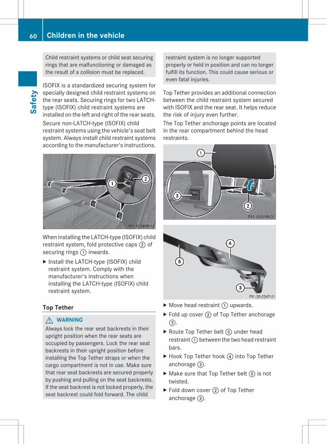
Child restraint systems or child seat securingrings that are malfunctioning or damaged asthe result of a collision must be replaced.
ISOFIX is a standardized securing system forspecially designed child restraint systems onthe rear seats. Securing rings for two LATCH-type (ISOFIX) child restraint systems areinstalled on the left and right of the rear seats.Secure non-LATCH-type (ISOFIX) childrestraint systems using the vehicle's seat beltsystem. Always install child restraint systemsaccording to the manufacturer's instructions.
When installing the LATCH-type (ISOFIX) childrestraint system, fold protective caps 2 ofsecuring rings 1 inwards.X Install the LATCH-type (ISOFIX) child
restraint system. Comply with themanufacturer's instructions wheninstalling the LATCH-type (ISOFIX) childrestraint system.
Top Tether
G WARNINGAlways lock the rear seat backrests in theirupright position when the rear seats areoccupied by passengers. Lock the rear seatbackrests in their upright position beforeinstalling the Top Tether straps or when thecargo compartment is not in use. Make surethat rear seat backrests are secured properlyby pushing and pulling on the seat backrests.If the seat backrest is not locked properly, theseat backrest could fold forward. The child
restraint system is no longer supportedproperly or held in position and can no longerfulfill its function. This could cause serious oreven fatal injuries.
Top Tether provides an additional connectionbetween the child restraint system securedwith ISOFIX and the rear seat. It helps reducethe risk of injury even further.The Top Tether anchorage points are locatedin the rear compartment behind the headrestraints.
X Move head restraint : upwards.X Fold up cover ; of Top Tether anchorage=.
X Route Top Tether belt A under headrestraint : between the two head restraintbars.
X Hook Top Tether hook ? into Top Tetheranchorage =.
X Make sure that Top Tether belt A is nottwisted.
X Fold down cover ; of Top Tetheranchorage =.
60 Children in the vehicleSa
fety
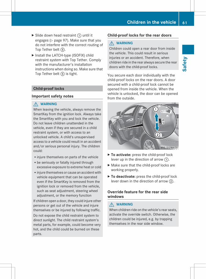
X Slide down head restraint : until itengages (Y page 97). Make sure that youdo not interfere with the correct routing ofTop Tether belt A.
X Install the LATCH-type (ISOFIX) childrestraint system with Top Tether. Complywith the manufacturer's installationinstructions when doing so. Make sure thatTop Tether belt A is tight.
Child-proof locks
Important safety notes
G WARNINGWhen leaving the vehicle, always remove theSmartKey from the ignition lock. Always takethe SmartKey with you and lock the vehicle.Do not leave children unattended in thevehicle, even if they are secured in a childrestraint system, or with access to anunlocked vehicle. A child's unsupervisedaccess to a vehicle could result in an accidentand/or serious personal injury. The childrencould:Rinjure themselves on parts of the vehicleRbe seriously or fatally injured through
excessive exposure to extreme heat or coldRinjure themselves or cause an accident with
vehicle equipment that can be operatedeven if the SmartKey is removed from theignition lock or removed from the vehicle,such as seat adjustment, steering wheeladjustment, or the memory function
If children open a door, they could injure otherpersons or get out of the vehicle and injurethemselves or be injured by following traffic.Do not expose the child restraint system todirect sunlight. The child restraint system'smetal parts, for example, could become veryhot, and the child could be burned on theseparts.
Child-proof locks for the rear doors
G WARNINGChildren could open a rear door from insidethe vehicle. This could result in seriousinjuries or an accident. Therefore, whenchildren ride in the rear always secure the reardoors with the child-proof locks.
You secure each door individually with thechild-proof locks on the rear doors. A doorsecured with a child-proof lock cannot beopened from inside the vehicle. When thevehicle is unlocked, the door can be openedfrom the outside.
X To activate: press the child-proof locklever up in the direction of arrow :.
X Make sure that the child-proof locks areworking properly.
X To deactivate: press the child-proof locklever down in the direction of arrow ;.
Override feature for the rear sidewindows
G WARNINGWhen children ride on the vehicle's rear seats,activate the override switch. Otherwise, thechildren could be injured, e.g. by trappingthemselves in the rear side window.
Children in the vehicle 61
Safe
ty
Z

X To activate/deactivate: press button ;.If indicator lamp : is lit, operation of therear side windows is deactivated.Operation is only possible using theswitches in the driver's door. If indicatorlamp : is off, operation is possible usingthe switches in the rear compartment.
Panic alarm
X To activate: press ! button : for atleast one second.An alarm sounds and the exterior lightingflashes.
X To deactivate: press ! button :again.
orX Insert the SmartKey into the ignition lock.orX Press the KEYLESS-GO Start/Stop button.
The KEYLESS-GO key must be in thevehicle.
i USA only:This device complies with Part 15 of theFCC Rules. Operation is subject to thefollowing two conditions:1. This device may not cause harmfulinterference, and2. this device must accept any interferencereceived, including interference that maycause undesired operation.Any unauthorized modification to thisdevice could void the user's authority tooperate the equipment.The product label with FCC ID and ICcertification number can be found in thebattery case of the SmartKey.
i Canada only:This device complies with RSS-Gen ofIndustry Canada. Operation is subject tothe following two conditions:1. This device may not cause interference,and2. this device must accept any interferencereceived, including interference that maycause undesired operation.Any unauthorized modification to thisdevice could void the user's authority tooperate the equipment.The product label with FCC ID and ICcertification number can be found in thebattery case of the SmartKey.
Driving safety systems
Driving safety systems overviewIn this section, you will find information aboutthe following driving safety systems:RABS (Anti-lock Braking System)RBAS (Brake Assist System)RBAS PLUS (Brake Assist System Plus)RESP® (Electronic Stability Program)REBD (Electronic Brake force Distribution)RADAPTIVE BRAKERPRE-SAFE® Brake
62 Driving safety systemsSa
fety
Important safety notes
G WARNINGThe following factors increase the risk ofaccidents:RExcessive speed, especially in turnsRWet and slippery road surfacesRFollowing another vehicle too closelyThe driving safety systems described in thissection cannot reduce these risks or preventthe natural laws of physics from acting on thevehicle. They cannot increase braking orsteering efficiency beyond that afforded bythe condition of the vehicle brakes and tiresor the traction afforded.Only a safe, attentive, and skillful driver canprevent accidents.The capabilities of a vehicle equipped with thedriving safety systems described in thissection must never be exploited in a recklessor dangerous manner which could jeopardizethe user's safety or the safety of others.Always adjust your driving style to theprevailing road and weather conditions andkeep a safe distance to other road users andobjects on the street.If a driving system malfunctions, other drivingsafety systems may also switch off. Observeindicator and warning lamps that may comeon as well as messages in the multifunctiondisplay that may appear.
i Please note that the driving safetysystems described only work as effectivelyas possible when there is adequate contactbetween the tires and the road surface. Payparticular attention to the informationregarding tires, recommended minimumtire tread depths etc. in the "Wheels andtires" section (Y page 320).In wintry driving conditions, always usewinter tires (M+S tires) and if necessary,snow chains. Only in this way will thedriving safety systems described in thissection work as effectively as possible.
ABS (Anti-lock Braking System)
Important safety notesi Observe the "Important safety notes"
section (Y page 63).ABS regulates brake pressure in such a waythat the wheels do not lock when you brake.This allows you to continue steering thevehicle when braking.ABS works from a speed of about 5 mph(8 km/h) upwards, regardless of road-surfaceconditions. ABS works on slippery surfaces,even if you only brake gently.
G WARNINGIf the ABS malfunctions, other driving systemssuch as the BAS or the ESP® are also switchedoff. Observe indicator and warning lamps thatmay come on as well as messages in themultifunction display that may appear.If the ABS malfunctions, the wheels may lockduring hard braking, reducing the steeringcapability and extending the braking distance.
The ! warning lamp in the instrumentcluster lights up when the ignition is switchedon. It goes out when the engine is running.
BrakesIf ABS intervenes when braking, you will feela pulsing in the brake pedal.X If ABS intervenes: continue to depress the
brake pedal vigorously until the brakingsituation is over.
X To make a full brake application:depress the brake pedal with full force.
The pulsating brake pedal can be anindication of hazardous road conditions, andfunctions as a reminder to take extra carewhile driving.
G WARNINGDo not pump the brake pedal. Use firm, steadybrake pedal pressure instead. Pumping thebrake pedal defeats the purpose of the ABS
Driving safety systems 63
Safe
ty
Z
and significantly reduces brakingeffectiveness.
BAS (Brake Assist System)i Observe the "Important safety notes"
section (Y page 63).BAS operates in emergency brakingsituations. If you depress the brake pedalquickly, BAS automatically boosts the brakingforce, thus shortening the stopping distance.X Keep the brake pedal firmly depressed until
the emergency braking situation is over.ABS prevents the wheels from locking.
The brakes will function as usual once yourelease the brake pedal. BAS is deactivated.
G WARNINGIf the BAS malfunctions, the brake system stillfunctions, but without the additional brakeboost available that the BAS would normallyprovide in an emergency braking maneuver.Therefore, the braking distance may increase.
BAS PLUS (Brake Assist System Plus)BAS PLUS is only available in vehiclesequipped with DISTRONIC PLUS.
i Observe the "Important safety notes"section (Y page 63).
BAS PLUS assists you when braking in ahazardous situation at speeds of over 4 mph(7 km/h), and uses the radar sensor systemto assess traffic conditions.
i This device has been approved by the FCCas a "Vehicular Radar System". The radarsensor is intended for use in an automotiveradar system only. Removing, altering ortampering with the device will void anywarranties, and is not permitted by theFCC. Do not tamper with, alter, or use inany non-approved way.
Any unauthorized modification to thisdevice could void the user's authority tooperate the equipment.
With the help of the radar sensor system, BASPLUS can detect obstacles that are in thepath of your vehicle for an extended period oftime.BAS PLUS can also react to stationaryobstacles, e.g. stopped or parked vehicles, atspeeds of up to approximately 40 mph(70 km/h).Should you approach an obstacle and BASPLUS has detected a risk of collision, BASPLUS calculates the braking force necessaryto avoid a rear-end collision.RFor speeds above 20 mph (30 km/h): if
you apply the brakes forcefully, BAS PLUSautomatically increases the braking forceto a level suitable for the traffic conditions.RFor speeds below 20 mph (30 km/h): if
you apply the brakes, BAS PLUS isactivated. Braking is performed as late aspossible.
If BAS PLUS demands particularly highbraking force, preventative passengerprotection measures (PRE-SAFE®) areactivated simultaneously.X Keep the brake pedal depressed until the
emergency braking situation is over.ABS prevents the wheels from locking.
The brakes will work normally again if:Ryou release the brake pedal.Rthere is no longer any danger of a rear-end
collision.Rno obstacle is detected in front of your
vehicle.BAS PLUS is then deactivated.For BAS PLUS to assist you when driving, theradar sensor system must be switched on andoperational; see "Radar sensor system" in theindex.
64 Driving safety systemsSa
fety
G WARNINGBAS PLUS cannot always clearly identifyobjects and complex traffic situations. BASPLUS cannot intervene in these cases.There is a risk of an accident. Always paycareful attention to the traffic situation and beready to brake.
In particular, the detection of obstacles canbe impaired if there is:Rdirt on the sensors or anything else
covering the sensorsRsnow or heavy rainRinterference by other radar sourcesRthe possibility of strong radar reflections,
for example in parking garagesRa narrow vehicle traveling in front, e.g. a
motorbikeRa vehicle traveling in front on a different line
G WARNINGBAS PLUS does not react:Rto people or animalsRto oncoming vehiclesRto crossing trafficRin curvesAs a result, BAS PLUS cannot intervene incritical situations. There is a risk of anaccident. Always pay careful attention to thetraffic situation and be ready to brake.
Following damage to the front end of thevehicle, have the configuration and operationof the radar sensors checked at a qualifiedspecialist workshop. This also applies tocollisions at low speeds where there is novisible damage to the front of the vehicle.If BAS PLUS is not available due to amalfunction in the radar sensor system, thebrake system remains available with fullbrake boosting effect and BAS.
ESP® (Electronic Stability Program)
Important safety notesi See the "Important safety notes" section
(Y page 63).
If ESP® detects that the vehicle is deviatingfrom the direction desired by the driver, oneor more wheels are braked to stabilize thevehicle. If necessary, the engine output is alsomodified to keep the vehicle on the desiredcourse within physical limits. ESP® assiststhe driver when pulling away on wet orslippery roads. ESP® can also stabilize thevehicle during braking.If ESP® intervenes, the ÷ ESP® warninglamp flashes in the instrument cluster.
G WARNINGUnder no circumstances should youdeactivate ESP® when the ÷ ESP®
warning lamp in the instrument clusterflashes. Proceed as follows:Rwhen driving off, apply as little throttle as
possible.Rwhile driving, ease up on the accelerator
pedal.Radapt your speed to suit the prevailing road
and weather conditions.Failure to observe these guidelines couldcause the vehicle to skid. ESP® cannotprevent accidents resulting from excessivespeed.
! Vehicles without 4MATIC: switch theignition off when:Rthe parking brake is being tested using a
dynamometerRthe vehicle is being towed with the front
axle raisedApplication of the brakes by ESP® mayotherwise destroy the brake system.
! Vehicles with 4MATIC: switch off theignition when the parking brake is beingtested on a brake dynamometer.
Driving safety systems 65
Safe
ty
Z
Application of the brakes by ESP® mayotherwise destroy the brake system.
i Only use wheels with the recommendedtire sizes. Only then will ESP® functionproperly.
ETS/4ETS (Electronic Traction System)i Observe the "Important safety notes"
section (Y page 62).
Traction control is part of ESP®.Traction control brakes the drive wheelsindividually if they spin. This enables you topull away and accelerate on slippery surfaces,for example if the road surface is slippery onone side. On vehicles with 4MATIC, moredrive torque is also transferred to the wheelor wheels with traction.Traction control remains active if youdeactivate ESP®.
Deactivating/activating ESP® (exceptAMG vehicles)
G WARNINGESP® should not be deactivated duringnormal driving other than in thecircumstances described below. Disablingthe system will reduce vehicle stability indriving maneuvers.Do not deactivate ESP® when the emergencyor spare wheel is mounted.
ESP® is activated automatically when theengine is started.It may be best to deactivate ESP® in thefollowing situations:Rwhen using snow chainsRin deep snowRon sand or gravel
G WARNINGSwitch on ESP® immediately if one of thepreviously stated conditions is no longer met.
Otherwise, ESP® cannot stabilize the vehicleif it begins to lurch or when a wheel spins.
If you deactivate ESP®:RESP® no longer improves driving stability.Rengine torque is not limited and the drive
wheels are able to spin. The spinningwheels produce a cutting effect for bettertraction.Rtraction control is still activated.RESP® still provides support when you
brake.If ESP® is deactivated and one or more wheelsstart to spin, the ÷ ESP® warning lamp inthe instrument cluster flashes. In suchsituations, ESP® will not stabilize the vehicle.X To deactivate:(Y page 210).
The å ESP® OFF warning lamp in theinstrument cluster lights up.
G WARNINGWhen the å ESP® OFF warning lamp is lit,ESP® is deactivated.If the ÷ ESP® warning lamp and theå ESP® OFF warning lamp remain lit,ESP® is not available due to a malfunction.When ESP® is deactivated or not operational,vehicle stability in standard drivingmaneuvers is reduced.Adapt your speed and driving to the prevailingroad conditions and to the non-operatingstatus of the ESP®.
! Avoid spinning the driven wheels for anextended period with ESP® deactivated.You could otherwise damage the drivetrain.
X To activate:(Y page 210).The å ESP® OFF warning lamp in theinstrument cluster goes out.
66 Driving safety systemsSa
fety
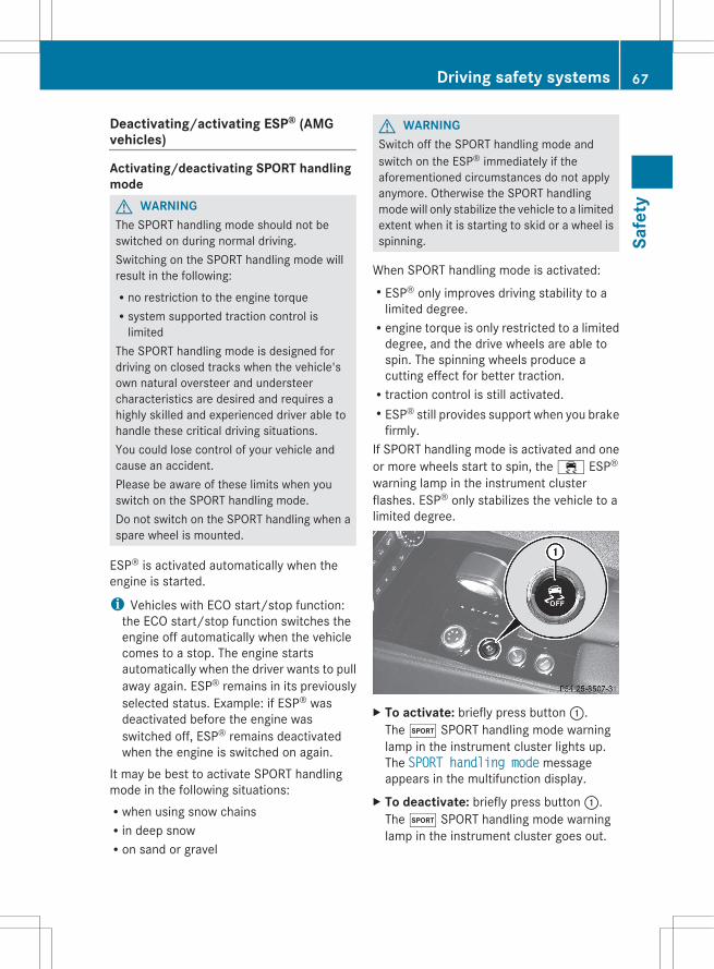
Deactivating/activating ESP® (AMGvehicles)
Activating/deactivating SPORT handlingmodeG WARNINGThe SPORT handling mode should not beswitched on during normal driving.Switching on the SPORT handling mode willresult in the following:Rno restriction to the engine torqueRsystem supported traction control is
limitedThe SPORT handling mode is designed fordriving on closed tracks when the vehicle'sown natural oversteer and understeercharacteristics are desired and requires ahighly skilled and experienced driver able tohandle these critical driving situations.You could lose control of your vehicle andcause an accident.Please be aware of these limits when youswitch on the SPORT handling mode.Do not switch on the SPORT handling when aspare wheel is mounted.
ESP® is activated automatically when theengine is started.
i Vehicles with ECO start/stop function:the ECO start/stop function switches theengine off automatically when the vehiclecomes to a stop. The engine startsautomatically when the driver wants to pullaway again. ESP® remains in its previouslyselected status. Example: if ESP® wasdeactivated before the engine wasswitched off, ESP® remains deactivatedwhen the engine is switched on again.
It may be best to activate SPORT handlingmode in the following situations:Rwhen using snow chainsRin deep snowRon sand or gravel
G WARNINGSwitch off the SPORT handling mode andswitch on the ESP® immediately if theaforementioned circumstances do not applyanymore. Otherwise the SPORT handlingmode will only stabilize the vehicle to a limitedextent when it is starting to skid or a wheel isspinning.
When SPORT handling mode is activated:RESP® only improves driving stability to a
limited degree.Rengine torque is only restricted to a limited
degree, and the drive wheels are able tospin. The spinning wheels produce acutting effect for better traction.Rtraction control is still activated.RESP® still provides support when you brake
firmly.If SPORT handling mode is activated and oneor more wheels start to spin, the ÷ ESP®
warning lamp in the instrument clusterflashes. ESP® only stabilizes the vehicle to alimited degree.
X To activate: briefly press button :.The M SPORT handling mode warninglamp in the instrument cluster lights up.The SPORT handling mode messageappears in the multifunction display.
X To deactivate: briefly press button :.The M SPORT handling mode warninglamp in the instrument cluster goes out.
Driving safety systems 67
Safe
ty
Z
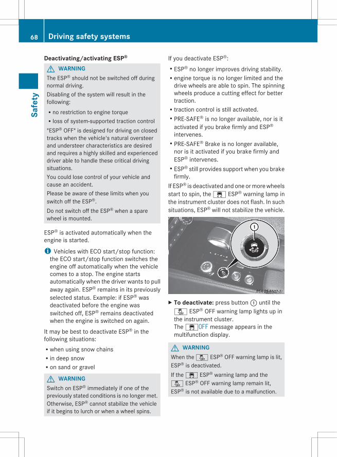
Deactivating/activating ESP®
G WARNINGThe ESP® should not be switched off duringnormal driving.Disabling of the system will result in thefollowing:Rno restriction to engine torqueRloss of system-supported traction control"ESP® OFF" is designed for driving on closedtracks when the vehicle's natural oversteerand understeer characteristics are desiredand requires a highly skilled and experienceddriver able to handle these critical drivingsituations.You could lose control of your vehicle andcause an accident.Please be aware of these limits when youswitch off the ESP®.Do not switch off the ESP® when a sparewheel is mounted.
ESP® is activated automatically when theengine is started.
i Vehicles with ECO start/stop function:the ECO start/stop function switches theengine off automatically when the vehiclecomes to a stop. The engine startsautomatically when the driver wants to pullaway again. ESP® remains in its previouslyselected status. Example: if ESP® wasdeactivated before the engine wasswitched off, ESP® remains deactivatedwhen the engine is switched on again.
It may be best to deactivate ESP® in thefollowing situations:Rwhen using snow chainsRin deep snowRon sand or gravel
G WARNINGSwitch on ESP® immediately if one of thepreviously stated conditions is no longer met.Otherwise, ESP® cannot stabilize the vehicleif it begins to lurch or when a wheel spins.
If you deactivate ESP®:RESP® no longer improves driving stability.Rengine torque is no longer limited and the
drive wheels are able to spin. The spinningwheels produce a cutting effect for bettertraction.Rtraction control is still activated.RPRE-SAFE® is no longer available, nor is it
activated if you brake firmly and ESP®
intervenes.RPRE-SAFE® Brake is no longer available,
nor is it activated if you brake firmly andESP® intervenes.RESP® still provides support when you brake
firmly.If ESP® is deactivated and one or more wheelsstart to spin, the ÷ ESP® warning lamp inthe instrument cluster does not flash. In suchsituations, ESP® will not stabilize the vehicle.
X To deactivate: press button : until theå ESP® OFF warning lamp lights up inthe instrument cluster.The ÷OFF message appears in themultifunction display.
G WARNINGWhen the å ESP® OFF warning lamp is lit,ESP® is deactivated.If the ÷ ESP® warning lamp and theå ESP® OFF warning lamp remain lit,ESP® is not available due to a malfunction.
68 Driving safety systemsSa
fety
When ESP® is deactivated or not operational,vehicle stability in standard drivingmaneuvers is reduced.Adapt your speed and driving to the prevailingroad conditions and to the non-operatingstatus of the ESP®.
! Avoid spinning the driven wheels for anextended period with ESP® deactivated.You could otherwise damage the drivetrain.
X To activate: briefly press button :.The å ESP® OFF warning lamp in theinstrument cluster goes out. The ÷ONmessage appears in the multifunctiondisplay.
EBD (electronic brake forcedistribution)
i Observe the "Important safety notes"section (Y page 63).
EBD monitors and controls the brakepressure on the rear wheels to improvedriving stability while braking.
G WARNINGIf EBD has malfunctioned, the braking systemremains available with full brake boostingeffect. However, the rear wheels can still lock,e.g. under full braking. This could cause youto lose control of your vehicle and cause anaccident. You should therefore adapt yourdriving style to the different handlingcharacteristics.
X Observe the notes on warning and indicatorlamps (Y page 250) as well as displaymessages (Y page 222).
ADAPTIVE BRAKEADAPTIVE BRAKE enhances braking safetyand offers increased braking comfort. Inaddition to the braking function, ADAPTIVEBRAKE also has the HOLD function
(Y page 170) and hill start assist(Y page 138). For further information, seeDriving tips (Y page 155).
PRE-SAFE® BrakePRE-SAFE® Brake is only available in vehicleswith DISTRONIC PLUS.
i Observe the "Important safety notes"section (Y page 63).
PRE-SAFE® Brake can help you to minimizethe risk of a frontal collision with a vehicleahead or reduce the effects of such acollision. If PRE-SAFE® Brake has detected arisk of collision, you will be warned visuallyand acoustically as well as by automaticbraking. PRE-SAFE® Brake cannot prevent acollision without your intervention.At speeds above approximately4 mph (7 km/h), this function warns youwhen you are rapidly approaching the vehiclein front. An intermittent warning tone willthen sound and the · distance warninglamp in the instrument cluster will light up.X Brake immediately in order to increase the
distance from the vehicle in front.orX Take evasive action provided it is safe to do
so.If the driver and front passenger have theirseat belt fastened, PRE-SAFE® Brake can alsobrake the vehicle automatically at speedsfrom approximately 4 mph (7 km/h) toapproximately 124 mph (200 km/h).Due to the nature of the system, particularlycomplicated driving conditions may causeunnecessary warnings or the unnecessaryintervention of PRE-SAFE® Brake. To stop thebraking action, you can either depress theaccelerator pedal further, activate kickdownor release the brake pedal.
Driving safety systems 69
Safe
ty
Z

The braking action of PRE-SAFE® Brake isended automatically if:Ryou maneuver to avoid the obstacle.Rthere is no longer any danger of a rear-end
collision.Rthere is no longer an obstacle detected in
front of your vehicle.
i USA only: This device has been approvedby the FCC as a "Vehicular Radar System".The radar sensor is intended for use in anautomotive radar system only. Removing,altering or tampering with the device willvoid any warranties, and is not permittedby the FCC. Do not tamper with, alter, oruse in any non-approved way.Any unauthorized modification to thisdevice could void the user's authority tooperate the equipment.
i Canada only: This device complies withRSS-210 of Industry Canada. Operation issubject to the following two conditions:1. This device may not cause interference,and2. this device must accept any interferencereceived, including interference that maycause undesired operation of the device.Removal, tampering, or altering of thedevice will void any warranties, and is notpermitted. Do not tamper with, alter, or usein any non-approved way.Any unauthorized modification to thisdevice could void the user's authority tooperate the equipment.
With the help of the radar sensor system,PRE-SAFE® Brake can detect obstacles thatare in front of your vehicle for an extendedperiod of time.At speeds up to approximately 40 mph(70 km/h), PRE-SAFE® Brake can also reactto stationary obstacles, for example stoppedor parked vehicles.If you approach an obstacle and PRE-SAFE®
Brake detects a risk of collision, the systemwill initially alert you both visually and
acoustically. If you do not brake or takeevasive action, the system will warn you byautomatically braking the vehicle gently. Ifthere is an increased risk of collision,preventative passenger protection measures(PRE-SAFE®) are activated (Y page 50). If therisk of collision remains at speeds of over20 mph (30 km/h) and you do not brake, takeevasive action or accelerate significantly, thevehicle may perform automatic braking up tothe level of emergency braking. Automaticemergency braking is not performed untilimmediately prior to an accident that can nolonger be avoided.
G WARNINGEven if PRE-SAFE® Brake slows the vehiclebefore an imminent rear-end collision, thesystem cannot avert a collision without theintervention of the driver. There is a risk of anaccident. Brake according to the situation ortake evasive action. Delayed intervention bythe driver can lead to an accident.
G WARNINGPRE-SAFE® Brake cannot always detectcomplex traffic situations properly.In these cases, PRE-SAFE(R) Brake may:Rgive an unnecessary warning and then
brake the vehicleRneither give a warning nor interveneThere is a risk of an accident. Always payparticular attention to the traffic situation andbe ready to brake, especially if PRE-SAFE(R)Brake warns you. Terminate the interventionin a non-critical driving situation.
In particular, the detection of obstacles canbe impaired if there is:Rdirt on the sensors or anything else
covering the sensorsRsnow or heavy rainRinterference by other radar sourcesRthe possibility of strong radar reflections,
for example in parking garages
70 Driving safety systemsSa
fety
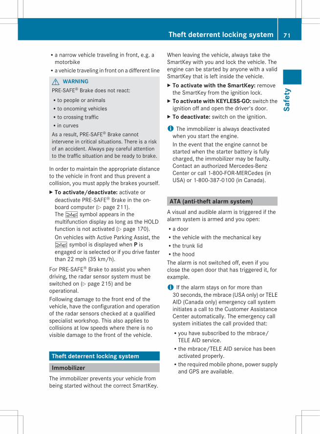
Ra narrow vehicle traveling in front, e.g. amotorbikeRa vehicle traveling in front on a different line
G WARNINGPRE-SAFE® Brake does not react:Rto people or animalsRto oncoming vehiclesRto crossing trafficRin curvesAs a result, PRE-SAFE® Brake cannotintervene in critical situations. There is a riskof an accident. Always pay careful attentionto the traffic situation and be ready to brake.
In order to maintain the appropriate distanceto the vehicle in front and thus prevent acollision, you must apply the brakes yourself.X To activate/deactivate: activate or
deactivate PRE-SAFE® Brake in the on-board computer (Y page 211).The Ä symbol appears in themultifunction display as long as the HOLDfunction is not activated (Y page 170).On vehicles with Active Parking Assist, theÄ symbol is displayed when P isengaged or is selected or if you drive fasterthan 22 mph (35 km/h).
For PRE-SAFE® Brake to assist you whendriving, the radar sensor system must beswitched on (Y page 215) and beoperational.Following damage to the front end of thevehicle, have the configuration and operationof the radar sensors checked at a qualifiedspecialist workshop. This also applies tocollisions at low speeds where there is novisible damage to the front of the vehicle.
Theft deterrent locking system
ImmobilizerThe immobilizer prevents your vehicle frombeing started without the correct SmartKey.
When leaving the vehicle, always take theSmartKey with you and lock the vehicle. Theengine can be started by anyone with a validSmartKey that is left inside the vehicle.X To activate with the SmartKey: remove
the SmartKey from the ignition lock.X To activate with KEYLESS-GO: switch the
ignition off and open the driver's door.X To deactivate: switch on the ignition.
i The immobilizer is always deactivatedwhen you start the engine.In the event that the engine cannot bestarted when the starter battery is fullycharged, the immobilizer may be faulty.Contact an authorized Mercedes-BenzCenter or call 1-800-FOR-MERCedes (inUSA) or 1-800-387-0100 (in Canada).
ATA (anti-theft alarm system)A visual and audible alarm is triggered if thealarm system is armed and you open:Ra doorRthe vehicle with the mechanical keyRthe trunk lidRthe hoodThe alarm is not switched off, even if youclose the open door that has triggered it, forexample.
i If the alarm stays on for more than30 seconds, the mbrace (USA only) or TELEAID (Canada only) emergency call systeminitiates a call to the Customer AssistanceCenter automatically. The emergency callsystem initiates the call provided that:Ryou have subscribed to the mbrace/
TELE AID service.Rthe mbrace/TELE AID service has been
activated properly.Rthe required mobile phone, power supply
and GPS are available.
Theft deterrent locking system 71
Safe
ty
Z

X To arm: lock the vehicle with the SmartKeyor KEYLESS-GO.Indicator lamp : flashes. The alarmsystem is armed after approximately15 seconds.
X To disarm: unlock the vehicle with theSmartKey or KEYLESS-GO.
X To stop the alarm using the SmartKey:insert the SmartKey into the ignition lock.The alarm is switched off.
orX Press the % or & button on the
SmartKey.The alarm is switched off.
X To stop the alarm using KEYLESS-GO:grasp the outside door handle. TheSmartKey must be outside the vehicle.The alarm is switched off.
orX Press the Start/Stop button on the
dashboard. The SmartKey must be insidethe vehicle.The alarm is switched off.
72 Theft deterrent locking systemSa
fety
Useful information .............................. 74SmartKey ............................................. 74Doors .................................................... 80Trunk .................................................... 83Side windows ...................................... 87Sliding sunroof .................................... 89
73
Open
ing/
clos
ing

Useful information
i This Operator's Manual describes allmodels and all standard and optionalequipment of your vehicle available at thetime of publication of the Operator'sManual. Country-specific differences arepossible. Please note that your vehicle maynot be equipped with all featuresdescribed. This also applies to safety-related systems and functions.
i Please read the information on qualifiedspecialist workshops (Y page 24).
SmartKey
Important safety notes
G WARNINGWhen leaving the vehicle, always remove theSmartKey from the ignition lock. Always takethe SmartKey with you and lock the vehicle.Do not leave children unsupervised in thevehicle, even if they are secured in a childrestraint system, and do not give them accessto an unlocked vehicle. A child's unsupervisedaccess to a vehicle could result in an accidentand/or serious personal injury. They could:Rinjure themselves on vehicle partsRbe seriously or fatally injured by extreme
heat or coldRinjure themselves or have an accident with
vehicle equipment that may still be inoperation even after the SmartKey hasbeen removed from the ignition, such as theseat adjustment, steering wheeladjustment or memory function.
If children open a door, they could causesevere or even fatal injury to other persons; ifthey get out of the vehicle, they could injurethemselves when doing so or be seriously oreven fatally injured by any passing traffic.Do not expose the child restraint system todirect sunlight. The child restraint system'smetal parts, for example, could become very
hot, and a child could be burned on theseparts.
G WARNINGIf a key ring is too heavy or too large, theweight acting on the key could cause it to turnin the ignition lock or catch on the steeringwheel. This could cause the engine to beswitched off suddenly. You may lose controlof the vehicle and cause an accident. Do notattach any heavy or large key rings to the keythat is inserted in the ignition.
General notesIf you cannot lock or unlock the vehicle withthe SmartKey, either the battery in theSmartKey is discharged, the SmartKey isfaulty or the starter battery is discharged.X Check the battery in the SmartKey and
replace it if necessary (Y page 77).X Unlock the driver's door using the
mechanical key (Y page 82).X Lock the vehicle using the mechanical key
(Y page 82).X Have the starter battery and the battery
contacts checked at a qualified specialistworkshop.
If the SmartKey is faulty, contact RoadsideAssistance or a qualified specialist workshop.
SmartKey functionsThe SmartKey centrally locks/unlocks:Rthe doorsRthe trunk lidRthe fuel filler flap
74 SmartKeyOp
enin
g/cl
osin
g
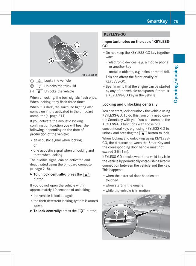
: & Locks the vehicle; F Unlocks the trunk lid= % Unlocks the vehicle
When unlocking, the turn signals flash once.When locking, they flash three times.When it is dark, the surround lighting alsocomes on if it is activated in the on-boardcomputer (Y page 214).If you activate the acoustic lockingconfirmation function you will hear thefollowing, depending on the date ofproduction of the vehicle:Ran acoustic signal when locking
orRone acoustic signal when unlocking and
three when locking.The audible signal can be activated anddeactivated using the on-board computer(Y page 215).X To unlock centrally: press the %
button.
If you do not open the vehicle withinapproximately 40 seconds of unlocking:Rthe vehicle is locked again.Rthe theft deterrent locking system is armed
again.X To lock centrally: press the & button.
KEYLESS-GO
Important notes on the use of KEYLESS-GORDo not keep the KEYLESS-GO key together
with:- electronic devices, e.g. a mobile phone
or another key- metallic objects, e.g. coins or metal foil.This can affect the functionality ofKEYLESS-GO.RBear in mind that the engine can be started
by any of the vehicle occupants if there isa KEYLESS-GO key in the vehicle.
Locking and unlocking centrallyYou can start, lock or unlock the vehicle usingKEYLESS-GO. To do this, you only need carrythe SmartKey with you. You can combine theKEYLESS-GO functions with those of aconventional key, e.g. using KEYLESS-GO tounlock and pressing the & button to lock.When locking and unlocking using KEYLESS-GO, the distance between the SmartKey andthe corresponding door handle must notexceed 3 ft (1 m).KEYLESS-GO checks whether a valid key is inthe vehicle by periodically establishing a radioconnection between the vehicle and the key.This happens:Rwhen the external door handles are
touchedRwhen starting the engineRwhile the vehicle is in motion
SmartKey 75
Open
ing/
clos
ing
Z

X To unlock the vehicle: touch the innersurface of the door handle.
X To lock the vehicle: touch sensorsurface :.
X Convenience closing feature: touchrecessed sensor surface ; for anextended period (Y page 88).
If you pull on the handle of the trunk lid, onlythe trunk of the vehicle is unlocked.
Changing the settings of the lockingsystem
You can change the setting of the lockingsystem in such a way that only the driver'sdoor and the fuel filler flap are unlocked. Thisis useful if you frequently travel on your own.X To change the setting: press and hold
down the % and & buttonssimultaneously for approximatelysix seconds until the battery check lampflashes twice (Y page 77).
i If the setting of the locking system ischanged within the signal range of thevehicle, pressing the & or % buttonlocks or unlocks the vehicle.
The SmartKey now functions as follows:X To unlock the driver's door: press the% button once.
X To unlock centrally: press the %button twice.
X To lock centrally: press the & button.
The KEYLESS-GO function is changed asfollows:X To unlock the driver's door: touch the
inner surface of the door handle on thedriver's door.
X To unlock centrally: touch the innersurface of the door handle on the front-passenger door or the rear door.
X To lock centrally: touch the outer sensorsurface on one of the door handles.
Restoring the factory settingsX Press the % and & buttons
simultaneously for approximatelysix seconds until the battery check lampflashes twice.
Mechanical key
General notesIf the vehicle can no longer be locked orunlocked with the SmartKey, use themechanical key.If you use the mechanical key to unlock andopen the driver's door or the trunk lid, theanti-theft alarm system will be triggered(Y page 71).There are several ways to turn off the alarm:X To turn the alarm off with the
SmartKey: press the % or & buttonon the SmartKey.
orX Insert the SmartKey into the ignition lock.orX To deactivate the alarm with KEYLESS-
GO: press the Start/Stop button in theignition lock. The SmartKey must be in thevehicle.
orX Lock or unlock the vehicle using KEYLESS-
GO. The SmartKey must be outside thevehicle.
If you unlock the vehicle using the mechanicalkey, the fuel filler flap will not be unlockedautomatically.X To unlock the fuel filler flap: insert the
SmartKey in the ignition lock.
76 SmartKeyOp
enin
g/cl
osin
g
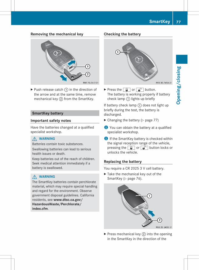
Removing the mechanical key
X Push release catch : in the direction ofthe arrow and at the same time, removemechanical key ; from the SmartKey.
SmartKey battery
Important safety notesHave the batteries changed at a qualifiedspecialist workshop.
G WARNINGBatteries contain toxic substances.Swallowing batteries can lead to serioushealth issues or death.Keep batteries out of the reach of children.Seek medical attention immediately if abattery is swallowed.
G WARNINGThe SmartKey batteries contain perchloratematerial, which may require special handlingand regard for the environment. Observegovernment disposal guidelines. Californiaresidents, see www.dtsc.ca.gov/HazardousWaste/Perchlorate/index.cfm.
Checking the battery
X Press the & or % button.The battery is working properly if batterycheck lamp : lights up briefly
If battery check lamp : does not light upbriefly during the test, the battery isdischarged.X Changing the battery (Y page 77)
i You can obtain the battery at a qualifiedspecialist workshop.
i If the SmartKey battery is checked withinthe signal reception range of the vehicle,pressing the & or % button locks orunlocks the vehicle.
Replacing the batteryYou require a CR 2025 3 V cell battery.X Take the mechanical key out of the
SmartKey (Y page 76).
X Press mechanical key ; into the openingin the SmartKey in the direction of the
SmartKey 77
Open
ing/
clos
ing
Z

arrow until battery tray cover : opens.When doing so, do not hold cover : shut.
X Remove battery tray cover :.
X Repeatedly tap the SmartKey against yourpalm until battery = falls out.
X Insert the new battery with the positiveterminal facing upwards. Use a lint-freecloth to do so.
X Make sure that the surface of the battery isfree from lint, grease and all other forms ofcontamination.
X Insert the front tabs of battery traycover : and then press to close it.
X Insert the mechanical key into theSmartKey.
X Check the function of all SmartKey buttonson the vehicle.
78 SmartKeyOp
enin
g/cl
osin
g
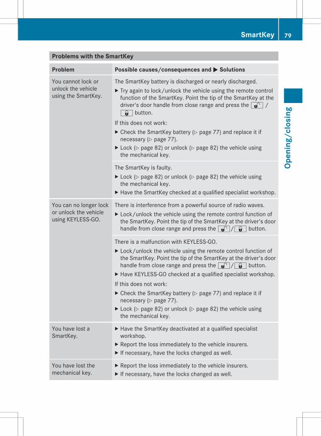
Problems with the SmartKey
Problem Possible causes/consequences and M Solutions
You cannot lock orunlock the vehicleusing the SmartKey.
The SmartKey battery is discharged or nearly discharged.X Try again to lock/unlock the vehicle using the remote control
function of the SmartKey. Point the tip of the SmartKey at thedriver's door handle from close range and press the % /& button.
If this does not work:X Check the SmartKey battery (Y page 77) and replace it if
necessary (Y page 77).X Lock (Y page 82) or unlock (Y page 82) the vehicle using
the mechanical key.
The SmartKey is faulty.X Lock (Y page 82) or unlock (Y page 82) the vehicle using
the mechanical key.X Have the SmartKey checked at a qualified specialist workshop.
You can no longer lockor unlock the vehicleusing KEYLESS-GO.
There is interference from a powerful source of radio waves.X Lock/unlock the vehicle using the remote control function of
the SmartKey. Point the tip of the SmartKey at the driver's doorhandle from close range and press the %/& button.
There is a malfunction with KEYLESS-GO.X Lock/unlock the vehicle using the remote control function of
the SmartKey. Point the tip of the SmartKey at the driver's doorhandle from close range and press the %/& button.
X Have KEYLESS-GO checked at a qualified specialist workshop.If this does not work:X Check the SmartKey battery (Y page 77) and replace it if
necessary (Y page 77).X Lock (Y page 82) or unlock (Y page 82) the vehicle using
the mechanical key.
You have lost aSmartKey.
X Have the SmartKey deactivated at a qualified specialistworkshop.
X Report the loss immediately to the vehicle insurers.X If necessary, have the locks changed as well.
You have lost themechanical key.
X Report the loss immediately to the vehicle insurers.X If necessary, have the locks changed as well.
SmartKey 79
Open
ing/
clos
ing
Z
Problem Possible causes/consequences and M Solutions
The engine cannot bestarted using theSmartKey.
The on-board voltage is too low.X Switch off non-essential consumers, e.g. seat heating or interior
lighting, and try to start the engine again.If this does not work:X Check the starter battery and charge it if necessary
(Y page 308).orX Jump-start the vehicle (Y page 311).orX Consult a qualified specialist workshop.
The engine cannot bestarted using KEYLESS-GO. The SmartKey is inthe vehicle.
A door is open. Therefore, the SmartKey cannot be detected aseasily.X Close the door and try to start the vehicle again.
There is interference from a powerful source of radio waves.X Start your vehicle with the SmartKey in the ignition lock.
Doors
Important safety notes
G WARNINGWhen leaving the vehicle, always remove theSmartKey from the ignition lock. Always takethe SmartKey with you and lock the vehicle.Do not leave children unsupervised in thevehicle, even if they are secured in a childrestraint system, and do not give them accessto an unlocked vehicle. A child's unsupervisedaccess to a vehicle could result in an accidentand/or serious personal injury. They could:Rinjure themselves on vehicle partsRbe seriously or fatally injured by extreme
heat or coldRinjure themselves or have an accident with
vehicle equipment that may still be inoperation even after the SmartKey hasbeen removed from the ignition, such as theseat adjustment, steering wheeladjustment or memory function.
If children open a door, they could causesevere or even fatal injury to other persons; ifthey get out of the vehicle, they could injurethemselves when doing so or be seriously oreven fatally injured by any passing traffic.Do not expose the child restraint system todirect sunlight. The child restraint system'smetal parts, for example, could become veryhot, and a child could be burned on theseparts.
G WARNINGDo not carry heavy or hard objects in thepassenger compartment or trunk unless theyare firmly secured in place.Unsecured or improperly positioned cargoincreases a child's risk of injury in the eventofRstrong braking maneuversRsudden changes of directionRan accident
80 DoorsOp
enin
g/cl
osin
g
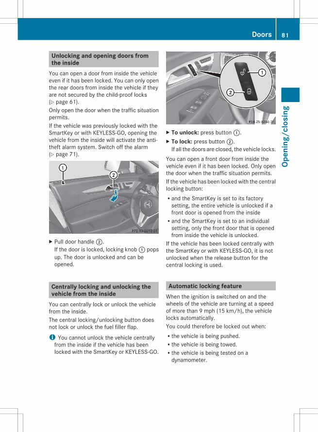
Unlocking and opening doors fromthe inside
You can open a door from inside the vehicleeven if it has been locked. You can only openthe rear doors from inside the vehicle if theyare not secured by the child-proof locks(Y page 61).Only open the door when the traffic situationpermits.If the vehicle was previously locked with theSmartKey or with KEYLESS-GO, opening thevehicle from the inside will activate the anti-theft alarm system. Switch off the alarm(Y page 71).
X Pull door handle ;.If the door is locked, locking knob : popsup. The door is unlocked and can beopened.
Centrally locking and unlocking thevehicle from the inside
You can centrally lock or unlock the vehiclefrom the inside.The central locking/unlocking button doesnot lock or unlock the fuel filler flap.
i You cannot unlock the vehicle centrallyfrom the inside if the vehicle has beenlocked with the SmartKey or KEYLESS-GO.
X To unlock: press button :.X To lock: press button ;.
If all the doors are closed, the vehicle locks.You can open a front door from inside thevehicle even if it has been locked. Only openthe door when the traffic situation permits.If the vehicle has been locked with the centrallocking button:Rand the SmartKey is set to its factory
setting, the entire vehicle is unlocked if afront door is opened from the insideRand the SmartKey is set to an individual
setting, only the front door that is openedfrom inside the vehicle is unlocked.
If the vehicle has been locked centrally withthe SmartKey or with KEYLESS-GO, it is notunlocked when the release button for thecentral locking is used.
Automatic locking featureWhen the ignition is switched on and thewheels of the vehicle are turning at a speedof more than 9 mph (15 km/h), the vehiclelocks automatically.You could therefore be locked out when:Rthe vehicle is being pushed.Rthe vehicle is being towed.Rthe vehicle is being tested on a
dynamometer.
Doors 81
Open
ing/
clos
ing
Z
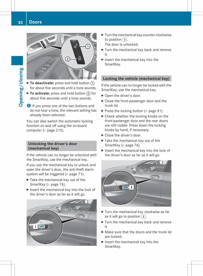
X To deactivate: press and hold button :for about five seconds until a tone sounds.
X To activate: press and hold button ; forabout five seconds until a tone sounds.
i If you press one of the two buttons anddo not hear a tone, the relevant setting hasalready been selected.
You can also switch the automatic lockingfunction on and off using the on-boardcomputer (Y page 215).
Unlocking the driver's door(mechanical key)
If the vehicle can no longer be unlocked withthe SmartKey, use the mechanical key.If you use the mechanical key to unlock andopen the driver's door, the anti-theft alarmsystem will be triggered (Y page 71).X Take the mechanical key out of the
SmartKey (Y page 76).X Insert the mechanical key into the lock of
the driver's door as far as it will go.
X Turn the mechanical key counter-clockwiseto position 1.The door is unlocked.
X Turn the mechanical key back and removeit.
X Insert the mechanical key into theSmartKey.
Locking the vehicle (mechanical key)If the vehicle can no longer be locked with theSmartKey, use the mechanical key.X Open the driver's door.X Close the front-passenger door and the
trunk lid.X Press the locking button (Y page 81).X Check whether the locking knobs on the
front-passenger door and the rear doorsare still visible. Press down the lockingknobs by hand, if necessary.
X Close the driver's door.X Take the mechanical key out of the
SmartKey (Y page 76).X Insert the mechanical key into the lock of
the driver's door as far as it will go.
X Turn the mechanical key clockwise as faras it will go to position 1.
X Turn the mechanical key back and removeit.
X Make sure that the doors and the trunk lidare locked.
X Insert the mechanical key into theSmartKey.
82 DoorsOp
enin
g/cl
osin
g
i If you lock the vehicle as described above,the fuel filler flap is not locked. The anti-theft alarm system is not armed.
Trunk
Important safety notesDo not leave the SmartKey in the trunk. Youcould otherwise lock yourself out.
G WARNINGWhen leaving the vehicle, always remove theSmartKey from the ignition lock. Always takethe SmartKey with you and lock the vehicle.Do not leave children unsupervised in thevehicle, even if they are secured in a childrestraint system, and do not give them accessto an unlocked vehicle. A child's unsupervisedaccess to a vehicle could result in an accidentand/or serious personal injury. They could:Rinjure themselves on vehicle partsRbe seriously or fatally injured by extreme
heat or coldRinjure themselves or have an accident with
vehicle equipment that may still be inoperation even after the SmartKey hasbeen removed from the ignition, such as theseat adjustment, steering wheeladjustment or memory function.
If children open a door, they could causesevere or even fatal injury to other persons; ifthey get out of the vehicle, they could injurethemselves when doing so or be seriously oreven fatally injured by any passing traffic.Do not expose the child restraint system todirect sunlight. The child restraint system'smetal parts, for example, could become veryhot, and a child could be burned on theseparts.
G WARNINGDo not carry heavy or hard objects in thepassenger compartment or trunk unless theyare firmly secured in place.
Unsecured or improperly positioned cargoincreases a child's risk of injury in the eventofRstrong braking maneuversRsudden changes of directionRan accident
G WARNINGMake sure the trunk lid is closed when theengine is running and while driving. Amongother dangers, deadly carbon monoxide (CO)gases may enter the vehicle interior resultingin unconsciousness and death.
! The trunk lid swings upwards whenopened. Therefore, make sure that there issufficient clearance above the trunk lid.
To open the trunk lid completely, a minimumclearance of 5.41 ft (1.65 m) above theground is necessary.Vehicles without trunk lid remote closing feature: the trunk lid can be:Ropened and closed manually from outsideRopened automatically from outsideRopened automatically from insideRlocked separatelyRunlocked with the mechanical keyRopened with the emergency release buttonVehicles with trunk lid remote closing feature: the trunk lid can be:Ropened and closed manually from outsideRopened and closed automatically from
outsideRopened and closed automatically from
insideRlocked separatelyRunlocked with the mechanical keyRopened with the emergency release button
Trunk 83
Open
ing/
clos
ing
Z
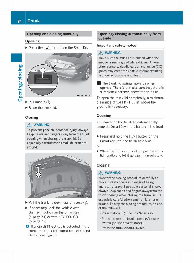
Opening and closing manually
OpeningX Press the % button on the SmartKey.
X Pull handle :.X Raise the trunk lid.
Closing
G WARNINGTo prevent possible personal injury, alwayskeep hands and fingers away from the trunkopening when closing the trunk lid. Beespecially careful when small children arearound.
X Pull the trunk lid down using recess :.X If necessary, lock the vehicle with
the & button on the SmartKey(Y page 74) or with KEYLESS-GO(Y page 75).
i If a KEYLESS-GO key is detected in thetrunk, the trunk lid cannot be locked andthen opens again.
Opening/closing automatically fromoutside
Important safety notes
G WARNINGMake sure the trunk lid is closed when theengine is running and while driving. Amongother dangers, deadly carbon monoxide (CO)gases may enter the vehicle interior resultingin unconsciousness and death.
! The trunk lid swings upwards whenopened. Therefore, make sure that there issufficient clearance above the trunk lid.
To open the trunk lid completely, a minimumclearance of 5.41 ft (1.65 m) above theground is necessary.
OpeningYou can open the trunk lid automaticallyusing the SmartKey or the handle in the trunklid.X Press and hold the F button on the
SmartKey until the trunk lid opens.orX When the trunk is unlocked, pull the trunk
lid handle and let it go again immediately.
Closing
G WARNINGMonitor the closing procedure carefully tomake sure no one is in danger of beinginjured. To prevent possible personal injury,always keep hands and fingers away from thetrunk opening when closing the trunk lid. Beespecially careful when small children arearound. To stop the closing procedure, do oneof the following:RPress button F on the SmartKey.RPress the remote trunk opening/closing
switch (on the driver's door).RPress the trunk closing switch.
84 TrunkOp
enin
g/cl
osin
g
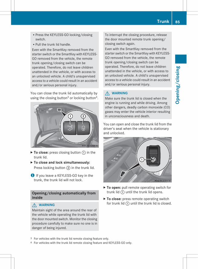
RPress the KEYLESS-GO locking/closingswitch.RPull the trunk lid handle.Even with the SmartKey removed from thestarter switch or the SmartKey with KEYLESS-GO removed from the vehicle, the remotetrunk opening/closing switch can beoperated. Therefore, do not leave childrenunattended in the vehicle, or with access toan unlocked vehicle. A child's unsupervisedaccess to a vehicle could result in an accidentand/or serious personal injury.
You can close the trunk lid automatically byusing the closing button3 or locking button4.
X To close: press closing button : in thetrunk lid.
X To close and lock simultaneously:Press locking button ; in the trunk lid.
i If you leave a KEYLESS-GO key in thetrunk, the trunk lid will not lock.
Opening/closing automatically frominside
G WARNINGMaintain sight of the area around the rear ofthe vehicle while operating the trunk lid withthe door mounted switch. Monitor the closingprocedure carefully to make sure no one is indanger of being injured.
To interrupt the closing procedure, releasethe door mounted remote trunk opening/closing switch again.Even with the SmartKey removed from thestarter switch or the SmartKey with KEYLESS-GO removed from the vehicle, the remotetrunk opening/closing switch can beoperated. Therefore, do not leave childrenunattended in the vehicle, or with access toan unlocked vehicle. A child's unsupervisedaccess to a vehicle could result in an accidentand/or serious personal injury.
G WARNINGMake sure the trunk lid is closed when theengine is running and while driving. Amongother dangers, deadly carbon monoxide (CO)gases may enter the vehicle interior resultingin unconsciousness and death.
You can open and close the trunk lid from thedriver's seat when the vehicle is stationaryand unlocked.
X To open: pull remote operating switch fortrunk lid : until the trunk lid opens.
X To close: press remote operating switchfor trunk lid : until the trunk lid is closed.
3 For vehicles with the trunk lid remote closing feature only.4 For vehicles with the trunk lid remote closing feature and KEYLESS-GO only.
Trunk 85
Open
ing/
clos
ing
Z

Locking the trunk separatelyYou can lock the trunk separately. If you thenunlock the vehicle centrally, the trunkremains locked and cannot be opened.X Close the trunk lid.X Take the mechanical key out of the
SmartKey (Y page 76).
X Insert the mechanical key into the trunk lidlock as far as the stop.
X Turn the mechanical key clockwise fromposition 1 to position 2.
X Remove the mechanical key.X Insert the mechanical key into the
SmartKey.
Unlocking the trunk (mechanical key)! The trunk lid swings upwards when
opened. Therefore, make sure that there issufficient clearance above the trunk lid.
If the trunk cannot be unlocked with theSmartKey or KEYLESS-GO, use themechanical key.If you use the mechanical key to unlock andopen the trunk lid, the anti-theft alarm systemwill be triggered (Y page 71).X Take the mechanical key out of the
SmartKey (Y page 76).X Insert the mechanical key into the trunk lid
lock as far as the stop.
X Turn the mechanical key counter-clockwisefrom position 1 as far as it will go toposition 2.The trunk is unlocked.
X Turn the mechanical key back to position1 and remove it.
X Insert the mechanical key into theSmartKey.
Trunk emergency releaseYou can open the trunk lid from inside thevehicle with the emergency release button.
X Briefly press emergency releasebutton :.The trunk lid unlocks and opens.
The trunk lid can be unlocked and openedwith the trunk lid emergency release whenthe vehicle is stationary or while driving.
86 TrunkOp
enin
g/cl
osin
g
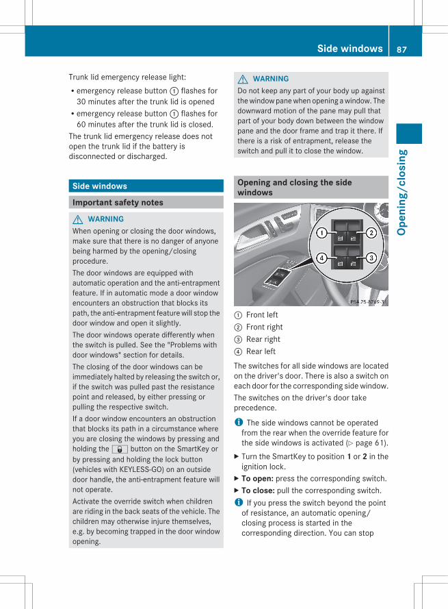
Trunk lid emergency release light:Remergency release button : flashes for
30 minutes after the trunk lid is openedRemergency release button : flashes for
60 minutes after the trunk lid is closed.The trunk lid emergency release does notopen the trunk lid if the battery isdisconnected or discharged.
Side windows
Important safety notes
G WARNINGWhen opening or closing the door windows,make sure that there is no danger of anyonebeing harmed by the opening/closingprocedure.The door windows are equipped withautomatic operation and the anti-entrapmentfeature. If in automatic mode a door windowencounters an obstruction that blocks itspath, the anti-entrapment feature will stop thedoor window and open it slightly.The door windows operate differently whenthe switch is pulled. See the "Problems withdoor windows" section for details.The closing of the door windows can beimmediately halted by releasing the switch or,if the switch was pulled past the resistancepoint and released, by either pressing orpulling the respective switch.If a door window encounters an obstructionthat blocks its path in a circumstance whereyou are closing the windows by pressing andholding the & button on the SmartKey orby pressing and holding the lock button(vehicles with KEYLESS-GO) on an outsidedoor handle, the anti-entrapment feature willnot operate.Activate the override switch when childrenare riding in the back seats of the vehicle. Thechildren may otherwise injure themselves,e.g. by becoming trapped in the door windowopening.
G WARNINGDo not keep any part of your body up againstthe window pane when opening a window. Thedownward motion of the pane may pull thatpart of your body down between the windowpane and the door frame and trap it there. Ifthere is a risk of entrapment, release theswitch and pull it to close the window.
Opening and closing the sidewindows
: Front left; Front right= Rear right? Rear left
The switches for all side windows are locatedon the driver's door. There is also a switch oneach door for the corresponding side window.The switches on the driver's door takeprecedence.
i The side windows cannot be operatedfrom the rear when the override feature forthe side windows is activated (Y page 61).
X Turn the SmartKey to position 1 or 2 in theignition lock.
X To open: press the corresponding switch.X To close: pull the corresponding switch.i If you press the switch beyond the point
of resistance, an automatic opening/closing process is started in thecorresponding direction. You can stop
Side windows 87
Open
ing/
clos
ing
Z

automatic operation by operating theswitch again.
i You can continue to operate the sidewindows after you switch off the engine orremove the SmartKey. This function isavailable for up to five minutes or until thedriver's or front-passenger door is opened.
Convenience openingYou can ventilate the vehicle before you startdriving. To do this, the key is used to carry outthe following functions simultaneously:Runlock the vehicleRopen the side windowsRopen the sliding sunroofRswitch on the seat ventilation for the
driver's seat
i The convenience opening feature canonly be operated using the SmartKey. TheSmartKey must be close to the driver'sdoor handle.
X Point the tip of the SmartKey at the driver'sdoor handle.
X Press and hold the % button until theside windows and the sliding sunroof are inthe desired position.
X To interrupt convenience opening:release the % button.
Convenience closing
General notesWhen you lock the vehicle, you cansimultaneously:Rclose the side windowsRclose the sliding sunroof
G WARNINGWhen closing the door windows and thesliding sunroof, make sure that there is no
danger of anyone being harmed by the closingprocedure.If potential danger exists, proceed as follows:RRelease the & button to stop the closing
procedure. To open, press and hold the% button. To continue the closingprocedure after making sure that there isno danger of anyone being harmed by theclosing procedure, press and hold the& button.
Vehicles with KEYLESS-GO:RRelease the sensor surface on the outside
door handle to stop the closing procedure.RImmediately pull on the same outside door
handle and hold firmly. The door windowsand the sliding sunroof will open for as longas the door handle is held but the door isnot opened.
Using the SmartKeyi The SmartKey must be close to the
driver's door handle.X Point the tip of the SmartKey at the driver's
door handle.X Press and hold the & button until the
side windows and the sliding sunroof arefully closed.
X Make sure that all the side windows and thesliding sunroof are closed.
X To interrupt convenience closing:release the & button.
Using KEYLESS-GOThe KEYLESS-GO key must be outside thevehicle. All the doors must be closed.
88 Side windowsOp
enin
g/cl
osin
g
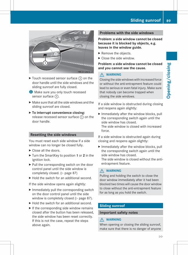
X Touch recessed sensor surface : on thedoor handle until the side windows and thesliding sunroof are fully closed.
i Make sure you only touch recessedsensor surface :.
X Make sure that all the side windows and thesliding sunroof are closed.
X To interrupt convenience closing:release recessed sensor surface : on thedoor handle.
Resetting the side windowsYou must reset each side window if a sidewindow can no longer be closed fully.X Close all the doors.X Turn the SmartKey to position 1 or 2 in the
ignition lock.X Pull the corresponding switch on the door
control panel until the side window iscompletely closed. (Y page 87)
X Hold the switch for an additional second.
If the side window opens again slightly:X Immediately pull the corresponding switch
on the door control panel until the sidewindow is completely closed (Y page 87).
X Hold the switch for an additional second.X If the corresponding side window remains
closed after the button has been released,the side window has been reset correctly.If this is not the case, repeat the stepsabove again.
Problems with the side windowsProblem: a side window cannot be closed because it is blocked by objects, e.g. leaves in the window guide.X Remove the objects.X Close the side window.Problem: a side window cannot be closed and you cannot see the cause.
G WARNINGClosing the side windows with increased forceor without the anti-entrapment feature couldlead to serious or even fatal injury. Make surethat nobody can become trapped whenclosing the side windows.
If a side window is obstructed during closingand reopens again slightly:X Immediately after the window blocks, pull
the corresponding switch again until theside window has closed.The side window is closed with increasedforce.
If a side window is obstructed again duringclosing and reopens again slightly:X Immediately after the window blocks, pull
the corresponding switch again until theside window has closed.The side window is closed without the anti-entrapment feature.
G WARNINGPulling and holding the switch to close thedoor window immediately after it had beenblocked two times will cause the door windowto close without the anti-entrapment featurefor as long as you hold the switch.
Sliding sunroof
Important safety notes
G WARNINGWhen opening or closing the sliding sunroof,make sure that there is no danger of anyone
Sliding sunroof 89
Open
ing/
clos
ing
Z
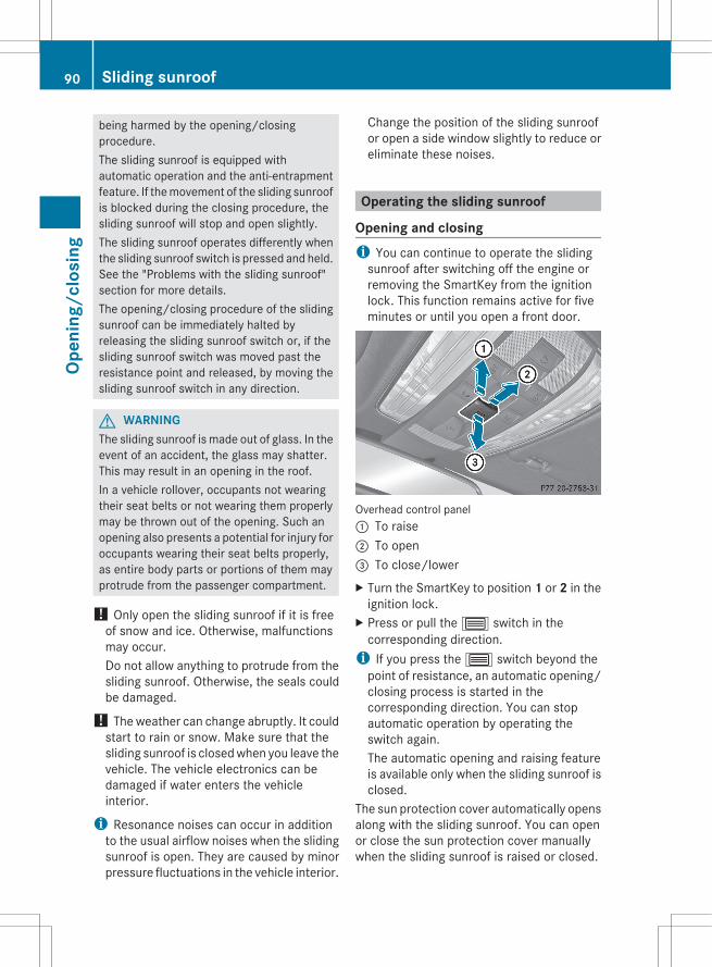
being harmed by the opening/closingprocedure.The sliding sunroof is equipped withautomatic operation and the anti-entrapmentfeature. If the movement of the sliding sunroofis blocked during the closing procedure, thesliding sunroof will stop and open slightly.The sliding sunroof operates differently whenthe sliding sunroof switch is pressed and held.See the "Problems with the sliding sunroof"section for more details.The opening/closing procedure of the slidingsunroof can be immediately halted byreleasing the sliding sunroof switch or, if thesliding sunroof switch was moved past theresistance point and released, by moving thesliding sunroof switch in any direction.
G WARNINGThe sliding sunroof is made out of glass. In theevent of an accident, the glass may shatter.This may result in an opening in the roof.In a vehicle rollover, occupants not wearingtheir seat belts or not wearing them properlymay be thrown out of the opening. Such anopening also presents a potential for injury foroccupants wearing their seat belts properly,as entire body parts or portions of them mayprotrude from the passenger compartment.
! Only open the sliding sunroof if it is freeof snow and ice. Otherwise, malfunctionsmay occur.Do not allow anything to protrude from thesliding sunroof. Otherwise, the seals couldbe damaged.
! The weather can change abruptly. It couldstart to rain or snow. Make sure that thesliding sunroof is closed when you leave thevehicle. The vehicle electronics can bedamaged if water enters the vehicleinterior.
i Resonance noises can occur in additionto the usual airflow noises when the slidingsunroof is open. They are caused by minorpressure fluctuations in the vehicle interior.
Change the position of the sliding sunroofor open a side window slightly to reduce oreliminate these noises.
Operating the sliding sunroof
Opening and closingi You can continue to operate the sliding
sunroof after switching off the engine orremoving the SmartKey from the ignitionlock. This function remains active for fiveminutes or until you open a front door.
Overhead control panel: To raise; To open= To close/lowerX Turn the SmartKey to position 1 or 2 in the
ignition lock.X Press or pull the 3 switch in the
corresponding direction.i If you press the 3 switch beyond the
point of resistance, an automatic opening/closing process is started in thecorresponding direction. You can stopautomatic operation by operating theswitch again.The automatic opening and raising featureis available only when the sliding sunroof isclosed.
The sun protection cover automatically opensalong with the sliding sunroof. You can openor close the sun protection cover manuallywhen the sliding sunroof is raised or closed.
90 Sliding sunroofOp
enin
g/cl
osin
g

ResettingReset the sliding sunroof if it does not movesmoothly.X Turn the SmartKey to position 2 in the
ignition lock.X Raise the sliding sunroof fully at the rear
(Y page 90).X Keep the 3 switch pressed for another
second.X Make sure that the sliding sunroof can be
fully opened and closed again (Y page 90).X If this is not the case, repeat the steps
above again.
! If the sliding sunroof still cannot beopened or closed fully after resetting,contact a qualified specialist workshop.
Problems with the sliding sunroofProblem: the sunroof cannot be closed and you cannot see the cause.
G WARNINGYou could be severely or even fatally injuredwhen closing the sliding sunroof withincreased closing force or if the anti-entrapment feature is deactivated. Make surethat nobody can become trapped whenclosing the sliding sunroof.
If the sliding sunroof is obstructed duringclosing and reopens again slightly:X Immediately after the sliding sunroof
blocks, pull the 3 switch in theoverhead control panel down to the pointof resistance and hold it until the slidingsunroof is closed.The sliding sunroof is closed with increasedforce.
If the sliding sunroof is obstructed againduring closing and reopens again slightly:X Immediately after the sliding sunroof
blocks, pull the 3 switch in theoverhead control panel down to the point
of resistance and hold it until the slidingsunroof is closed.The sliding sunroof is closed without theanti-entrapment feature.
G WARNINGPressing and holding the sliding sunroofswitch to close the sliding sunroofimmediately after it had been blocked twotimes will cause the sliding sunroof to closewithout the anti-entrapment feature for aslong as you hold the switch.
! If the sliding sunroof still cannot beopened or closed as a result of amalfunction, contact a qualified specialistworkshop.
Sliding sunroof 91
Open
ing/
clos
ing
Z

92
Useful information .............................. 94Correcting the driver's seat posi-tion ....................................................... 94Seats .................................................... 95Steering wheel .................................. 100Mirrors ............................................... 102Memory function .............................. 105
93
Seat
s, s
teer
ing
whe
el a
nd m
irror
s
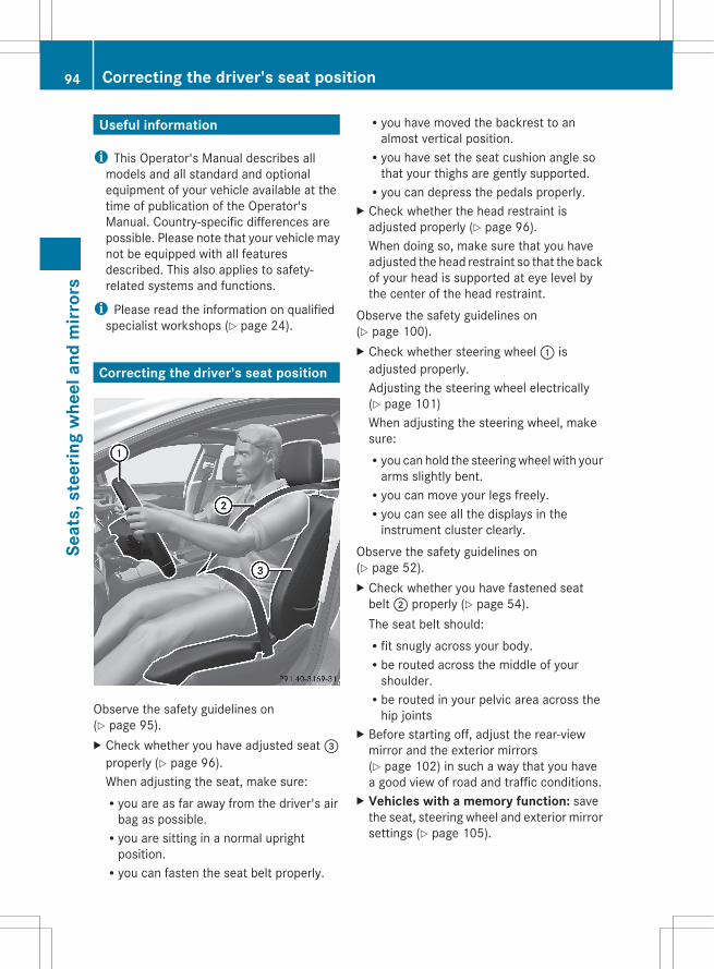
Useful information
i This Operator's Manual describes allmodels and all standard and optionalequipment of your vehicle available at thetime of publication of the Operator'sManual. Country-specific differences arepossible. Please note that your vehicle maynot be equipped with all featuresdescribed. This also applies to safety-related systems and functions.
i Please read the information on qualifiedspecialist workshops (Y page 24).
Correcting the driver's seat position
Observe the safety guidelines on(Y page 95).X Check whether you have adjusted seat =
properly (Y page 96).When adjusting the seat, make sure:Ryou are as far away from the driver's air
bag as possible.Ryou are sitting in a normal upright
position.Ryou can fasten the seat belt properly.
Ryou have moved the backrest to analmost vertical position.Ryou have set the seat cushion angle so
that your thighs are gently supported.Ryou can depress the pedals properly.
X Check whether the head restraint isadjusted properly (Y page 96).When doing so, make sure that you haveadjusted the head restraint so that the backof your head is supported at eye level bythe center of the head restraint.
Observe the safety guidelines on(Y page 100).X Check whether steering wheel : is
adjusted properly.Adjusting the steering wheel electrically(Y page 101)When adjusting the steering wheel, makesure:Ryou can hold the steering wheel with your
arms slightly bent.Ryou can move your legs freely.Ryou can see all the displays in the
instrument cluster clearly.Observe the safety guidelines on(Y page 52).X Check whether you have fastened seat
belt ; properly (Y page 54).The seat belt should:Rfit snugly across your body.Rbe routed across the middle of your
shoulder.Rbe routed in your pelvic area across the
hip jointsX Before starting off, adjust the rear-view
mirror and the exterior mirrors(Y page 102) in such a way that you havea good view of road and traffic conditions.
X Vehicles with a memory function: savethe seat, steering wheel and exterior mirrorsettings (Y page 105).
94 Correcting the driver's seat positionSe
ats,
ste
erin
g w
heel
and
mirr
ors
Seats
Important safety notes
G WARNINGIn order to avoid possible loss of vehiclecontrol, all seat, head restraint, steeringwheel and rear view mirror adjustments, aswell as fastening of seat belts, must be donebefore setting the vehicle in motion.
G WARNINGDo not adjust the driver's seat while driving.Adjusting the seat while driving could causethe driver to lose control of the vehicle.Never travel in a moving vehicle with the seatbackrest in an excessively reclined position asthis can be dangerous. You could slide underthe seat belt in a collision. If you slide underit, the seat belt would apply force at theabdomen or neck. This could cause serious orfatal injuries. The seat backrest and seat beltsprovide the best restraint when the wearer isin a position that is as upright as possible andseat belts are properly positioned on thebody.
G WARNINGYour seat belt must be adjusted so that youcan correctly fasten your seat belt.Observe the following points:Radjust the seat backrest until your arms are
slightly angled when holding the steeringwheel.Radjust the seat to a comfortable seating
position that still allows you to reach theaccelerator/brake pedal safely. Theposition should be as far back as possiblewith the driver still able to operate thecontrols properly.Radjust the head restraint so that it is as
close to the head as possible and the center
of the head restraint supports the back ofthe head at eye level.Rnever place hands under the seat or near
any moving parts while a seat is beingadjusted.
Failure to do so could result in an accidentand/or serious personal injury.
G WARNINGThe electrically adjustable seats can beoperated at any time. Therefore, do not leavechildren unattended in the vehicle, or withaccess to an unlocked vehicle. A child'sunsupervised access to a vehicle could resultin an accident and/or serious personal injury.
G WARNINGAccording to accident statistics, children aresafer when properly restrained on the rearseats than on the front-passenger seat. Thus,we strongly recommend that children beplaced in the rear seat whenever possible.Regardless of seating position, children 12years old and under must be seated andproperly secured in an appropriately sizedchild restraint system or booster seatrecommended for the size and weight of thechild. For additional information, see the"Children in the vehicle" section.A child's risk of serious or fatal injuries issignificantly increased if the child restraintsare not properly secured in the vehicle and/or the child is not properly secured in the childrestraint.
G WARNINGFor your protection, drive only with properlypositioned head restraints.Adjust the head restraint so that it is as closeto the head as possible and the center of thehead restraint supports the back of the headat eye level. This will reduce the potential forinjury to the head and neck in the event of anaccident or similar situation.
Seats 95
Seat
s, s
teer
ing
whe
el a
nd m
irror
s
Z
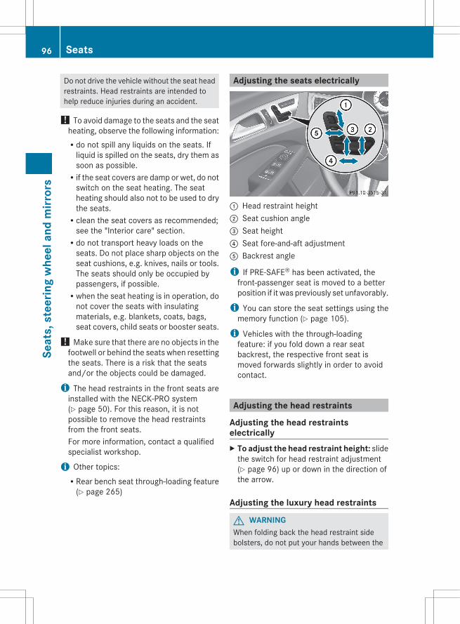
Do not drive the vehicle without the seat headrestraints. Head restraints are intended tohelp reduce injuries during an accident.
! To avoid damage to the seats and the seatheating, observe the following information:Rdo not spill any liquids on the seats. If
liquid is spilled on the seats, dry them assoon as possible.Rif the seat covers are damp or wet, do not
switch on the seat heating. The seatheating should also not to be used to drythe seats.Rclean the seat covers as recommended;
see the "Interior care" section.Rdo not transport heavy loads on the
seats. Do not place sharp objects on theseat cushions, e.g. knives, nails or tools.The seats should only be occupied bypassengers, if possible.Rwhen the seat heating is in operation, do
not cover the seats with insulatingmaterials, e.g. blankets, coats, bags,seat covers, child seats or booster seats.
! Make sure that there are no objects in thefootwell or behind the seats when resettingthe seats. There is a risk that the seatsand/or the objects could be damaged.
i The head restraints in the front seats areinstalled with the NECK-PRO system(Y page 50). For this reason, it is notpossible to remove the head restraintsfrom the front seats.For more information, contact a qualifiedspecialist workshop.
i Other topics:RRear bench seat through-loading feature
(Y page 265)
Adjusting the seats electrically
: Head restraint height; Seat cushion angle= Seat height? Seat fore-and-aft adjustmentA Backrest angle
i If PRE-SAFE® has been activated, thefront-passenger seat is moved to a betterposition if it was previously set unfavorably.
i You can store the seat settings using thememory function (Y page 105).
i Vehicles with the through-loadingfeature: if you fold down a rear seatbackrest, the respective front seat ismoved forwards slightly in order to avoidcontact.
Adjusting the head restraints
Adjusting the head restraintselectricallyX To adjust the head restraint height: slide
the switch for head restraint adjustment(Y page 96) up or down in the direction ofthe arrow.
Adjusting the luxury head restraints
G WARNINGWhen folding back the head restraint sidebolsters, do not put your hands between the
96 SeatsSe
ats,
ste
erin
g w
heel
and
mirr
ors
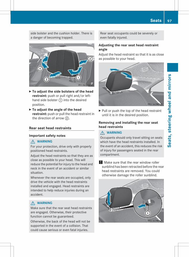
side bolster and the cushion holder. There isa danger of becoming trapped.
X To adjust the side bolsters of the head restraint: push or pull right and/or left-hand side bolster : into the desiredposition.
X To adjust the angle of the head restraint: push or pull the head restraint inthe direction of arrow ;.
Rear seat head restraints
Important safety notesG WARNINGFor your protection, drive only with properlypositioned head restraints.Adjust the head restraints so that they are asclose as possible to your head. This willreduce the potential for injury to the head andneck in the event of an accident or similarsituation.Whenever the rear seats are occupied, onlydrive the vehicle with the head restraintsinstalled and engaged. Head restraints areintended to help reduce injuries during anaccident.
G WARNINGMake sure that the rear seat head restraintsare engaged. Otherwise, their protectivefunction cannot be guaranteed.Otherwise, the back of the head will not besupported in the event of a collision. Thatcould cause serious or even fatal injuries.
Rear seat occupants could be severely oreven fatally injured.
Adjusting the rear seat head restraintangleAdjust the head restraint so that it is as closeas possible to your head.
X Pull or push the top of the head restraintuntil it is in the desired position.
Removing and installing the rear seathead restraintsG WARNINGOccupants should only travel sitting on seatswhich have the head restraints installed. Inthe event of an accident, this reduces the riskof injury for passengers seated in the rearcompartment.
! Make sure that the rear window rollersunblind has been retracted before the rearhead restraints are removed. You couldotherwise damage the roller sunblind.
Seats 97
Seat
s, s
teer
ing
whe
el a
nd m
irror
s
Z

X To remove: pull the head restraint up tothe stop.
X Press release catch : and pull the headrestraint out of the guides.
X To re-install: insert the head restraint sothat the notches on the bar are on the leftwhen viewed in the direction of travel.
X Push the head restraint down until you hearit engage in position.
Adjusting the multicontour seat5
You can adjust the contour of the driver's seatso as to provide optimum support for yourback and sides.
: To adjust the thigh cushion; To adjust the backrest contour in the
lumbar region= To adjust the backrest contour in the
upper back region? To adjust the side bolsters of the seat
backrestX Make sure that the SmartKey is in position
2 in the ignition lock.
Adjusting the active multicontourseat
The active multicontour seat on the driver'sside automatically adapts the sides of thebackrest to your current driving style. You canadjust the contour of the seats individually so
as to provide optimum support for your backand sides.
: To adjust the seat cushion length; To switch the dynamic function on or off= To adjust the side bolsters of the seat
backrest? To switch the massage function on or offA To adjust the contour of the backrest to
increase/decrease supportB To adjust the height/depth of the
backrest contour
Dynamic functionThe dynamic function adjusts the air cushionsin the side bolsters of the seat backrests toensure ideal lateral support at all times.You can choose between two different levels.
Level 1 (oneindicator lamp)
Standard setting:slightly increasedlateral support andslow build-up of airpressure in the sidebolsters of the seatbackrest.
Level 2 (twoindicator lamps)
Sport setting:increased lateralsupport and fastbuild-up of pressurein the side bolstersof the seat backrest.
5 Canada only.
98 SeatsSe
ats,
ste
erin
g w
heel
and
mirr
ors

X To switch on: press button ; once ortwice until the desired level is set.One or two indicator lamps in button ;light up.
X To switch off: press button ; repeatedlyuntil all indicator lamps in button ; go out.
Massage function (PULSE)The massage function helps you to preventmuscle tension on long journeys. You canchoose between two levels.X To switch on: press button ? once or
twice until the desired level is set.One or two indicator lamps in button ?light up. The air cushions in the lumbarregion vibrate for approximately20 minutes.
Adjusting the four-way lumbarsupport
You can adjust the contour of the front seatbackrests individually to provide optimumsupport for your back.
: To raise the backrest contour; To soften the backrest contour= To lower the backrest contour? To harden the backrest contour
Switching the seat heating on/off
Switching on/off
G WARNINGRepeatedly setting the seat heating to level3 may result in excessive seat temperatures.The health of passengers that have limitedtemperature sensitivity or a limited ability toreact to excessively high temperatures maybe affected or they may even suffer burn-likeinjuries. Therefore, do not use seat heatinglevel 3 repeatedly.
The three red indicator lamps in the buttonindicate the heating level you have selected.
i If the battery voltage is too low, the seatheating may switch off.
Driver's and front-passenger seat
Rear seats6
Driver's and front-passenger seat: thesystem automatically switches down fromlevel 3 to level 2 after approximately eightminutes.
6 Canada only.
Seats 99
Seat
s, s
teer
ing
whe
el a
nd m
irror
s
Z

Rear seat: the system automaticallyswitches down from level 3 to level 2 afterapproximately five minutes.The system automatically switches downfrom level 2 to level 1 after approximately tenminutes.The system automatically switches offapproximately 20 minutes after it is set tolevel 1.X Make sure that the SmartKey is in position
1 or 2 in the ignition lock.X To switch on: press button : repeatedly
until the desired heating level is set.X To switch off: press button : repeatedly
until all the indicator lamps go out.
Problems with the seat heatingThe seat heating has switched offprematurely or cannot be switched on. Thevehicle's electrical system voltage is too lowbecause too many electrical consumers areswitched on.X Switch off electrical consumers that you do
not need, such as the rear windowdefroster or interior lighting.
Switching the seat ventilation on/off
Switching on/offThe three blue indicator lamps in the buttonsindicate the ventilation level you haveselected.
i If the battery voltage is too low, the seatventilation may switch off.
X Make sure that the SmartKey is in position2 in the ignition lock.
X To switch on: press button : repeatedlyuntil the desired ventilation level is set.
i You can open the side windows and thesliding sunroof with the SmartKey(Y page 88). The seat ventilation of thedriver's seat automatically switches to thehighest level.
X To switch off: press button : repeatedlyuntil all the indicator lamps go out.
Problems with the seat ventilationThe seat ventilation has switched offprematurely or cannot be switched on. Thevehicle's electrical system voltage is too lowbecause too many electrical consumers areswitched on.X Switch off electrical consumers which you
do not need, such as the rear windowdefroster or interior lighting.
Steering wheel
Important safety notes
G WARNINGDo not adjust the steering wheel while driving.Adjusting the steering wheel while drivingcould cause the driver to lose control of thevehicle.The electrical steering wheel adjustmentfeature can be operated at any time.
100 Steering wheelSe
ats,
ste
erin
g w
heel
and
mirr
ors
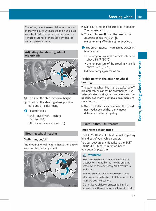
Therefore, do not leave children unattendedin the vehicle, or with access to an unlockedvehicle. A child's unsupervised access to avehicle could result in an accident and/orserious personal injury.
Adjusting the steering wheelelectrically
: To adjust the steering wheel height; To adjust the steering wheel position
(fore-and-aft adjustment)
i Related topics:REASY-ENTRY/EXIT feature
(Y page 101)RStoring settings (Y page 105)
Steering wheel heating
Switching on/offThe steering-wheel heating heats the leatherareas of the steering wheel.
X Make sure that the SmartKey is in position2 in the ignition lock.
X To switch on/off: turn the lever in thedirection of arrow : or ;.Indicator lamp = lights up or goes out.
i The steering wheel heating may switch offtemporarily if:Rthe temperature of the vehicle interior is
above 86 ‡ (30 †)Rthe temperature of the steering wheel is
above 95 ‡ (35 †)Indicator lamp = remains on.
Problems with the steering wheelheatingThe steering wheel heating has switched offprematurely or cannot be switched on. Thevehicle's electrical system voltage is too lowbecause too many electrical consumers areswitched on.X Switch off electrical consumers that you do
not need, such as the rear windowdefroster or interior lighting.
EASY-ENTRY/EXIT feature
Important safety notesThe EASY-ENTRY/EXIT feature makes gettingin and out of your vehicle easier.You can activate and deactivate the EASY-ENTRY/EXIT feature in the on-boardcomputer (Y page 215).
G WARNINGYou must make sure no one can becometrapped or injured by the moving steeringwheel when the easy-entry/exit feature isactivated.To stop steering wheel movement, movesteering wheel adjustment stalk or press thememory position switch.Do not leave children unattended in thevehicle, or with access to an unlocked vehicle.
Steering wheel 101
Seat
s, s
teer
ing
whe
el a
nd m
irror
s
Z
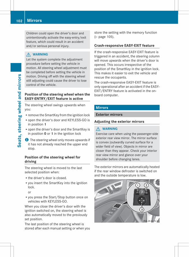
Children could open the driver's door andunintentionally activate the easy-entry/exitfeature, which could result in an accidentand/or serious personal injury.
G WARNINGLet the system complete the adjustmentprocedure before setting the vehicle inmotion. All steering wheel adjustment mustbe completed before setting the vehicle inmotion. Driving off with the steering wheelstill adjusting could cause the driver to losecontrol of the vehicle.
Position of the steering wheel when theEASY-ENTRY/EXIT feature is activeThe steering wheel swings upwards whenyou:Rremove the SmartKey from the ignition lockRopen the driver's door and KEYLESS-GO is
in position 1Ropen the driver's door and the SmartKey is
in position 0 or 1 in the ignition lock
i The steering wheel only moves upwards ifit has not already reached the upper endstop.
Position of the steering wheel fordrivingThe steering wheel is moved to the lastselected position when:Rthe driver's door is closed.Ryou insert the SmartKey into the ignition
lock.orRyou press the Start/Stop button once on
vehicles with KEYLESS-GO.When you close the driver's door with theignition switched on, the steering wheel isalso automatically moved to the previouslyset position.The last position of the steering wheel isstored after each manual setting or when you
store the setting with the memory function(Y page 105).
Crash-responsive EASY-EXIT featureIf the crash-responsive EASY-EXIT feature istriggered in an accident, the steering columnwill move upwards when the driver's door isopened. This occurs irrespective of theposition of the SmartKey in the ignition lock.This makes it easier to exit the vehicle andrescue the occupants.The crash-responsive EASY-EXIT feature isonly operational after an accident if the EASY-EXIT/ENTRY feature is activated in the on-board computer.
Mirrors
Exterior mirrors
Adjusting the exterior mirrors
G WARNINGExercise care when using the passenger-sideexterior rear view mirror. The mirror surfaceis convex (outwardly curved surface for awider field of view). Objects in mirror arecloser than they appear. Check your interiorrear view mirror and glance over yourshoulder before changing lanes.
The exterior mirrors are automatically heatedif the rear window defroster is switched onand the outside temperature is low.
102 MirrorsSe
ats,
ste
erin
g w
heel
and
mirr
ors
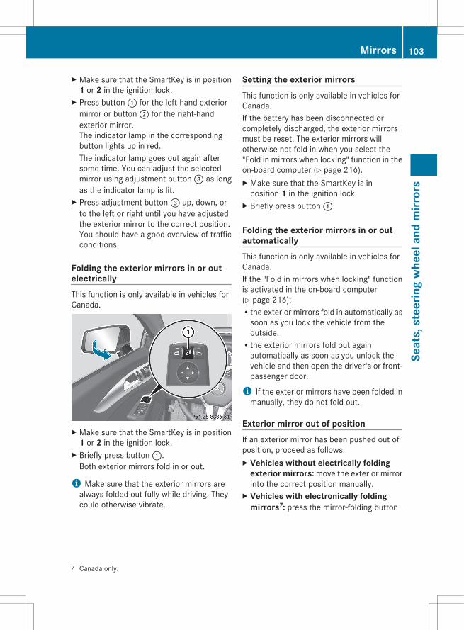
X Make sure that the SmartKey is in position1 or 2 in the ignition lock.
X Press button : for the left-hand exteriormirror or button ; for the right-handexterior mirror.The indicator lamp in the correspondingbutton lights up in red.The indicator lamp goes out again aftersome time. You can adjust the selectedmirror using adjustment button = as longas the indicator lamp is lit.
X Press adjustment button = up, down, orto the left or right until you have adjustedthe exterior mirror to the correct position.You should have a good overview of trafficconditions.
Folding the exterior mirrors in or outelectricallyThis function is only available in vehicles forCanada.
X Make sure that the SmartKey is in position1 or 2 in the ignition lock.
X Briefly press button :.Both exterior mirrors fold in or out.
i Make sure that the exterior mirrors arealways folded out fully while driving. Theycould otherwise vibrate.
Setting the exterior mirrorsThis function is only available in vehicles forCanada.If the battery has been disconnected orcompletely discharged, the exterior mirrorsmust be reset. The exterior mirrors willotherwise not fold in when you select the"Fold in mirrors when locking" function in theon-board computer (Y page 216).X Make sure that the SmartKey is in
position 1 in the ignition lock.X Briefly press button :.
Folding the exterior mirrors in or outautomaticallyThis function is only available in vehicles forCanada.If the "Fold in mirrors when locking" functionis activated in the on-board computer(Y page 216):Rthe exterior mirrors fold in automatically as
soon as you lock the vehicle from theoutside.Rthe exterior mirrors fold out again
automatically as soon as you unlock thevehicle and then open the driver's or front-passenger door.
i If the exterior mirrors have been folded inmanually, they do not fold out.
Exterior mirror out of positionIf an exterior mirror has been pushed out ofposition, proceed as follows:X Vehicles without electrically folding
exterior mirrors: move the exterior mirrorinto the correct position manually.
X Vehicles with electronically folding mirrors7: press the mirror-folding button
7 Canada only.
Mirrors 103
Seat
s, s
teer
ing
whe
el a
nd m
irror
s
Z
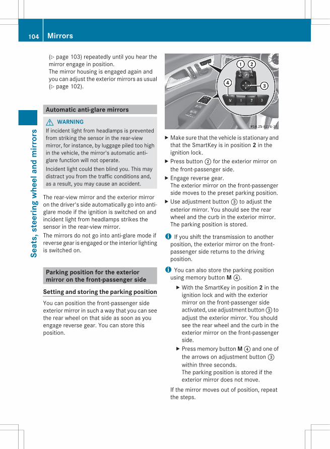
(Y page 103) repeatedly until you hear themirror engage in position.The mirror housing is engaged again andyou can adjust the exterior mirrors as usual(Y page 102).
Automatic anti-glare mirrors
G WARNINGIf incident light from headlamps is preventedfrom striking the sensor in the rear-viewmirror, for instance, by luggage piled too highin the vehicle, the mirror's automatic anti-glare function will not operate.Incident light could then blind you. This maydistract you from the traffic conditions and,as a result, you may cause an accident.
The rear-view mirror and the exterior mirroron the driver's side automatically go into anti-glare mode if the ignition is switched on andincident light from headlamps strikes thesensor in the rear-view mirror.The mirrors do not go into anti-glare mode ifreverse gear is engaged or the interior lightingis switched on.
Parking position for the exteriormirror on the front-passenger side
Setting and storing the parking positionYou can position the front-passenger sideexterior mirror in such a way that you can seethe rear wheel on that side as soon as youengage reverse gear. You can store thisposition.
X Make sure that the vehicle is stationary andthat the SmartKey is in position 2 in theignition lock.
X Press button ; for the exterior mirror onthe front-passenger side.
X Engage reverse gear.The exterior mirror on the front-passengerside moves to the preset parking position.
X Use adjustment button = to adjust theexterior mirror. You should see the rearwheel and the curb in the exterior mirror.The parking position is stored.
i If you shift the transmission to anotherposition, the exterior mirror on the front-passenger side returns to the drivingposition.
i You can also store the parking positionusing memory button M ?.X With the SmartKey in position 2 in the
ignition lock and with the exteriormirror on the front-passenger sideactivated, use adjustment button = toadjust the exterior mirror. You shouldsee the rear wheel and the curb in theexterior mirror on the front-passengerside.
X Press memory button M ? and one ofthe arrows on adjustment button =within three seconds.The parking position is stored if theexterior mirror does not move.
If the mirror moves out of position, repeatthe steps.
104 MirrorsSe
ats,
ste
erin
g w
heel
and
mirr
ors
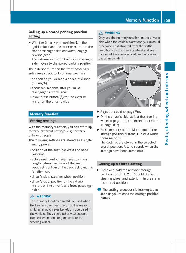
Calling up a stored parking positionsettingX With the SmartKey in position 2 in the
ignition lock and the exterior mirror on thefront-passenger side activated, engagereverse gear.The exterior mirror on the front-passengerside moves to the stored parking position.
The exterior mirror on the front-passengerside moves back to its original position:Ras soon as you exceed a speed of 6 mph
(10 km/h)Rabout ten seconds after you have
disengaged reverse gearRif you press button : for the exterior
mirror on the driver's side
Memory function
Storing settingsWith the memory function, you can store upto three different settings, e.g. for threedifferent people.The following settings are stored as a singlememory preset:Rposition of the seat, backrest and head
restraintRactive multicontour seat: seat cushion
length, lateral cushions of the seatbackrest, contour of the backrest, dynamicfunction levelRdriver's side: steering wheel positionRdriver's side: position of the exterior
mirrors on the driver's and front-passengersides
G WARNINGThe memory function can still be used whenthe key has been removed. For this reason,children should never be left unsupervised inthe vehicle. They could otherwise becometrapped when adjusting the seat or thesteering wheel.
G WARNINGOnly use the memory function on the driver'sside when the vehicle is stationary. You couldotherwise be distracted from the trafficconditions by the steering wheel and seatmoving of their own accord, and as a resultcause an accident.
X Adjust the seat (Y page 96).X On the driver's side, adjust the steering
wheel (Y page 101) and the exterior mirrors(Y page 102).
X Press memory button M and one of thestorage position buttons 1, 2 or 3 withinthree seconds.The settings are stored in the selectedpreset position. A tone sounds when thesettings have been completed.
Calling up a stored settingX Press and hold the relevant storage
position button 1, 2 or 3, until the seat,steering wheel and exterior mirrors are inthe stored position.
i The setting procedure is interrupted assoon as you release the storage positionbutton.
Memory function 105
Seat
s, s
teer
ing
whe
el a
nd m
irror
s
Z

106

Useful information ............................ 108Exterior lighting ................................ 108Interior lighting ................................. 113Replacing bulbs ................................. 114Windshield wipers ............................ 116
107
Ligh
ts a
nd w
inds
hiel
d w
iper
s
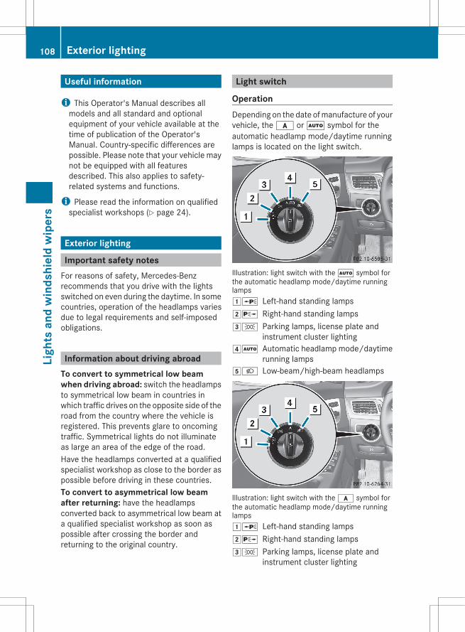
Useful information
i This Operator's Manual describes allmodels and all standard and optionalequipment of your vehicle available at thetime of publication of the Operator'sManual. Country-specific differences arepossible. Please note that your vehicle maynot be equipped with all featuresdescribed. This also applies to safety-related systems and functions.
i Please read the information on qualifiedspecialist workshops (Y page 24).
Exterior lighting
Important safety notesFor reasons of safety, Mercedes-Benzrecommends that you drive with the lightsswitched on even during the daytime. In somecountries, operation of the headlamps variesdue to legal requirements and self-imposedobligations.
Information about driving abroadTo convert to symmetrical low beam when driving abroad: switch the headlampsto symmetrical low beam in countries inwhich traffic drives on the opposite side of theroad from the country where the vehicle isregistered. This prevents glare to oncomingtraffic. Symmetrical lights do not illuminateas large an area of the edge of the road.Have the headlamps converted at a qualifiedspecialist workshop as close to the border aspossible before driving in these countries.To convert to asymmetrical low beam after returning: have the headlampsconverted back to asymmetrical low beam ata qualified specialist workshop as soon aspossible after crossing the border andreturning to the original country.
Light switch
OperationDepending on the date of manufacture of yourvehicle, the c or à symbol for theautomatic headlamp mode/daytime runninglamps is located on the light switch.
Illustration: light switch with the à symbol forthe automatic headlamp mode/daytime runninglamps1W Left-hand standing lamps2X Right-hand standing lamps3T Parking lamps, license plate and
instrument cluster lighting4Ã Automatic headlamp mode/daytime
running lamps5L Low-beam/high-beam headlamps
Illustration: light switch with the c symbol forthe automatic headlamp mode/daytime runninglamps1W Left-hand standing lamps2X Right-hand standing lamps3T Parking lamps, license plate and
instrument cluster lighting
108 Exterior lightingLi
ghts
and
win
dshi
eld
wip
ers
4c Automatic headlamp mode/daytimerunning lamps
5L Low-beam/high-beam headlamps
The turn signals, high-beam headlamps andthe high-beam flasher are operated using thecombination switch (Y page 110).
! Switch off the parking lamps and standinglamps when you leave the vehicle. Thisprevents the battery from discharging.
The exterior lighting (except the parking/standing lamps) switches off automatically ifyou:Rremove the SmartKey from the ignition lockRopen the driver's door with the SmartKey
in position 0If you hear a warning tone when you leave thevehicle, the lights may still be switched on.X Turn the light switch to c or Ã.
Low-beam headlampsX To switch on the low-beam headlamps:
turn the SmartKey in the ignition lock toposition 2 or start the engine.
X Turn the light switch to L.The L indicator lamp in the instrumentcluster lights up.
Daytime running lamps
Daytime running lamps in CanadaThe daytime running lamps function isrequired by law in Canada. It cannot thereforebe deactivated.X Turn the light switch to c or Ã.
With the engine running: depending on theambient light, the daytime running lamps orthe low-beam headlamps are switched on.When the low-beam headlamps areswitched on, the L indicator lamp in theinstrument cluster lights up.
When the engine is running and the vehicle isstationary: if you move the selector lever froma drive position to P, the daytime runninglamps/low-beam headlamps go out afterthree minutes.When the engine is running, the vehicle isstationary and in high ambient lightbrightness: if you turn the light switchto T, the daytime running lamps and theparking lamps are switched on.If the engine is running and you turn the lightswitch to L, the manual settings takeprecedence over the daytime running lamps.
Daytime running lamps in the USAIn the USA, the daytime running lamps aredeactivated upon delivery from the factory.X To activate the daytime running
lamps: activate the daytime running lampsfunction in the on-board computer(Y page 213).
X Turn the light switch to c or Ã.With the engine running: depending on theambient light, the daytime running lamps orthe low-beam headlamps are switched on.When the low-beam headlamps areswitched on, the L indicator lamp in theinstrument cluster lights up.
If the engine is running and you turn the lightswitch to T or L, the manual settingstake precedence over the daytime runninglamps.
Automatic headlamp modeX To switch on automatic headlamp
mode: turn the light switch to c orÃ.SmartKey in position 1 in the ignition lock:the parking lamps are switched on or offautomatically depending on the brightnessof the ambient light.With the engine running: depending on thebrightness of the ambient light, the daytime
Exterior lighting 109
Ligh
ts a
nd w
inds
hiel
d w
iper
s
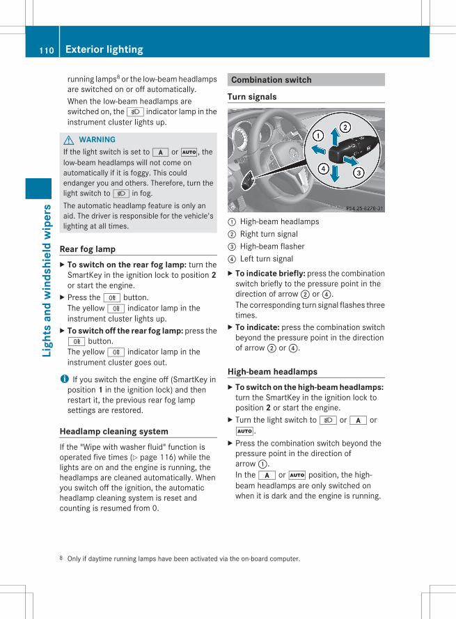
running lamps8 or the low-beam headlampsare switched on or off automatically.When the low-beam headlamps areswitched on, the L indicator lamp in theinstrument cluster lights up.
G WARNINGIf the light switch is set to c or Ã, thelow-beam headlamps will not come onautomatically if it is foggy. This couldendanger you and others. Therefore, turn thelight switch to L in fog.The automatic headlamp feature is only anaid. The driver is responsible for the vehicle'slighting at all times.
Rear fog lampX To switch on the rear fog lamp: turn the
SmartKey in the ignition lock to position 2or start the engine.
X Press the R button.The yellow R indicator lamp in theinstrument cluster lights up.
X To switch off the rear fog lamp: press theR button.The yellow R indicator lamp in theinstrument cluster goes out.
i If you switch the engine off (SmartKey inposition 1 in the ignition lock) and thenrestart it, the previous rear fog lampsettings are restored.
Headlamp cleaning systemIf the "Wipe with washer fluid" function isoperated five times (Y page 116) while thelights are on and the engine is running, theheadlamps are cleaned automatically. Whenyou switch off the ignition, the automaticheadlamp cleaning system is reset andcounting is resumed from 0.
Combination switch
Turn signals
: High-beam headlamps; Right turn signal= High-beam flasher? Left turn signalX To indicate briefly: press the combination
switch briefly to the pressure point in thedirection of arrow ; or ?.The corresponding turn signal flashes threetimes.
X To indicate: press the combination switchbeyond the pressure point in the directionof arrow ; or ?.
High-beam headlampsX To switch on the high-beam headlamps:
turn the SmartKey in the ignition lock toposition 2 or start the engine.
X Turn the light switch to L or c orÃ.
X Press the combination switch beyond thepressure point in the direction ofarrow :.In the c or à position, the high-beam headlamps are only switched onwhen it is dark and the engine is running.
8 Only if daytime running lamps have been activated via the on-board computer.
110 Exterior lightingLi
ghts
and
win
dshi
eld
wip
ers
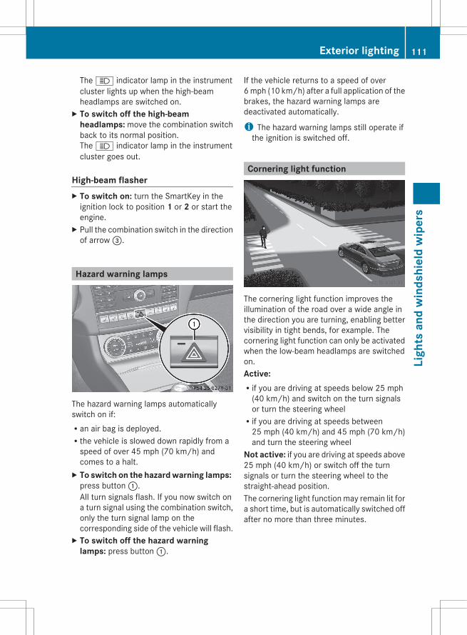
The K indicator lamp in the instrumentcluster lights up when the high-beamheadlamps are switched on.
X To switch off the high-beam headlamps: move the combination switchback to its normal position.The K indicator lamp in the instrumentcluster goes out.
High-beam flasherX To switch on: turn the SmartKey in the
ignition lock to position 1 or 2 or start theengine.
X Pull the combination switch in the directionof arrow =.
Hazard warning lamps
The hazard warning lamps automaticallyswitch on if:Ran air bag is deployed.Rthe vehicle is slowed down rapidly from a
speed of over 45 mph (70 km/h) andcomes to a halt.
X To switch on the hazard warning lamps: press button :.All turn signals flash. If you now switch ona turn signal using the combination switch,only the turn signal lamp on thecorresponding side of the vehicle will flash.
X To switch off the hazard warning lamps: press button :.
If the vehicle returns to a speed of over6 mph (10 km/h) after a full application of thebrakes, the hazard warning lamps aredeactivated automatically.
i The hazard warning lamps still operate ifthe ignition is switched off.
Cornering light function
The cornering light function improves theillumination of the road over a wide angle inthe direction you are turning, enabling bettervisibility in tight bends, for example. Thecornering light function can only be activatedwhen the low-beam headlamps are switchedon.Active: Rif you are driving at speeds below 25 mph
(40 km/h) and switch on the turn signalsor turn the steering wheelRif you are driving at speeds between
25 mph (40 km/h) and 45 mph (70 km/h)and turn the steering wheel
Not active: if you are driving at speeds above25 mph (40 km/h) or switch off the turnsignals or turn the steering wheel to thestraight-ahead position.The cornering light function may remain lit fora short time, but is automatically switched offafter no more than three minutes.
Exterior lighting 111
Ligh
ts a
nd w
inds
hiel
d w
iper
s
Z
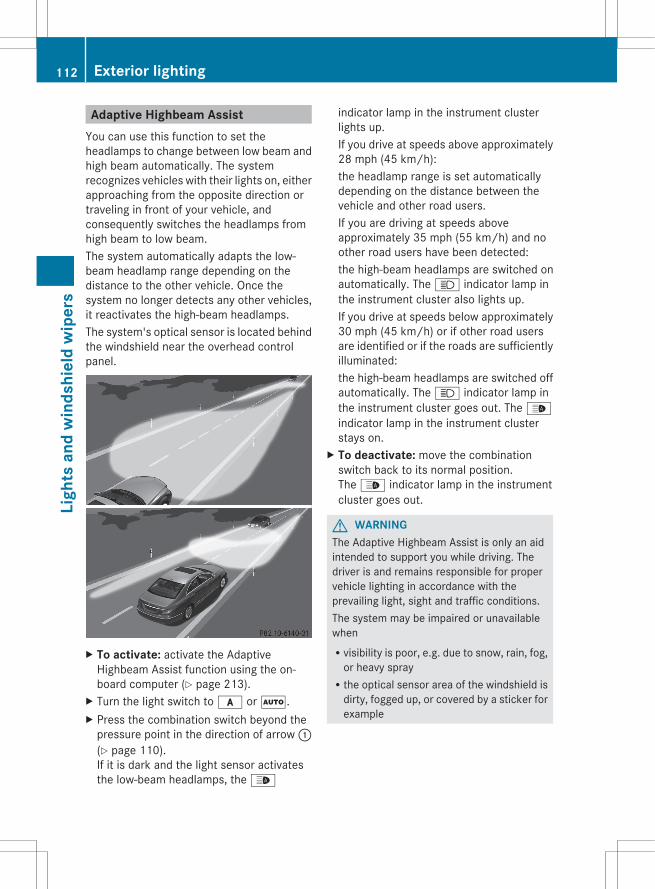
Adaptive Highbeam AssistYou can use this function to set theheadlamps to change between low beam andhigh beam automatically. The systemrecognizes vehicles with their lights on, eitherapproaching from the opposite direction ortraveling in front of your vehicle, andconsequently switches the headlamps fromhigh beam to low beam.The system automatically adapts the low-beam headlamp range depending on thedistance to the other vehicle. Once thesystem no longer detects any other vehicles,it reactivates the high-beam headlamps.The system's optical sensor is located behindthe windshield near the overhead controlpanel.
X To activate: activate the AdaptiveHighbeam Assist function using the on-board computer (Y page 213).
X Turn the light switch to c or Ã.X Press the combination switch beyond the
pressure point in the direction of arrow :(Y page 110).If it is dark and the light sensor activatesthe low-beam headlamps, the _
indicator lamp in the instrument clusterlights up.If you drive at speeds above approximately28 mph (45 km/h):the headlamp range is set automaticallydepending on the distance between thevehicle and other road users.If you are driving at speeds aboveapproximately 35 mph (55 km/h) and noother road users have been detected:the high-beam headlamps are switched onautomatically. The K indicator lamp inthe instrument cluster also lights up.If you drive at speeds below approximately30 mph (45 km/h) or if other road usersare identified or if the roads are sufficientlyilluminated:the high-beam headlamps are switched offautomatically. The K indicator lamp inthe instrument cluster goes out. The _indicator lamp in the instrument clusterstays on.
X To deactivate: move the combinationswitch back to its normal position.The _ indicator lamp in the instrumentcluster goes out.
G WARNINGThe Adaptive Highbeam Assist is only an aidintended to support you while driving. Thedriver is and remains responsible for propervehicle lighting in accordance with theprevailing light, sight and traffic conditions.The system may be impaired or unavailablewhenRvisibility is poor, e.g. due to snow, rain, fog,
or heavy sprayRthe optical sensor area of the windshield is
dirty, fogged up, or covered by a sticker forexample
112 Exterior lightingLi
ghts
and
win
dshi
eld
wip
ers
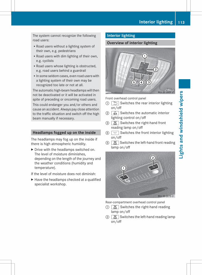
The system cannot recognize the followingroad users:RRoad users without a lighting system of
their own, e.g. pedestriansRRoad users with dim lighting of their own,
e.g. cyclistsRRoad users whose lighting is obstructed,
e.g. road users behind a guardrailRIn some seldom cases, even road users with
a lighting system of their own may berecognized too late or not at all.
The automatic high-beam headlamps will thennot be deactivated or it will be activated inspite of preceding or oncoming road users.This could endanger you and/or others andcause an accident. Always pay close attentionto the traffic situation and switch off the highbeam manually if necessary.
Headlamps fogged up on the insideThe headlamps may fog up on the inside ifthere is high atmospheric humidity.X Drive with the headlamps switched on.
The level of moisture diminishes,depending on the length of the journey andthe weather conditions (humidity andtemperature).
If the level of moisture does not diminish:X Have the headlamps checked at a qualified
specialist workshop.
Interior lighting
Overview of interior lighting
Front overhead control panel: u Switches the rear interior lighting
on/off; | Switches the automatic interior
lighting control on/off= p Switches the right-hand front
reading lamp on/off? c Switches the front interior lighting
on/offA p Switches the left-hand front reading
lamp on/off
Rear-compartment overhead control panel: p Switches the right-hand reading
lamp on/off; p Switches the left-hand reading lamp
on/off
Interior lighting 113
Ligh
ts a
nd w
inds
hiel
d w
iper
s
Z
Interior lighting control
Important notesIn order to prevent the vehicle's battery fromdischarging, the interior lighting functions areautomatically deactivated after some timeexcept for when the SmartKey is in position2 in the ignition lock.The color and brightness of the ambientlighting may be set using the on-boardcomputer (Y page 213).
Automatic interior lighting controlX To switch on/off: press the | button.
When the automatic interior lightingcontrol is activated, the button is flush withthe overhead control panel.
The interior lighting automatically switcheson if you:Runlock the vehicleRopen a doorRremove the SmartKey from the ignition lockThe interior light is activated for a short whilewhen the SmartKey is removed from theignition lock. You can activate this delayedswitch-off using the on-board computer(Y page 214).
Manual interior lighting controlX To switch the front interior lighting on/
off: press the c button.X To switch the rear interior lighting on/
off: press the u button.X To switch the reading lamps on/off:
press the p button.
Crash-responsive emergency lightingThe interior lighting is activated automaticallyif the vehicle is involved in an accident.
X To switch off the crash-responsive emergency lighting: press the hazardwarning lamp button.
orX Lock and then unlock the vehicle using the
SmartKey.
Replacing bulbs
Important safety notes
Xenon bulbs
G DANGERXenon bulbs carry a high voltage. You couldget an electric shock and be seriously or evenfatally injured if you touch the electriccontacts on Xenon bulbs. Therefore, neverremove the cover from Xenon bulbs.Do not change the Xenon bulbs yourself, buthave them replaced at a qualified workshop.
Bulbs and lamps are an important aspect ofvehicle safety. You must therefore make surethat these function correctly at all times.Have the headlamp setting checked regularly.
LED lampsYou can neither replace Xenon bulbs nor LEDbulbs. Have LED bulbs changed at a qualifiedspecialist workshop.Bulbs and lamps are an important aspect ofvehicle safety. You must therefore make surethat these function correctly at all times.Have the headlamp setting checked regularly.
Other bulbs
G WARNINGBulbs and lamps can become very hot. Forthis reason, allow them to cool down beforechanging them. Otherwise, you could burnyourself when you touch them.Keep bulbs out of the reach of children.Otherwise, they could, for example, damagethe bulbs and injure themselves.
114 Replacing bulbsLi
ghts
and
win
dshi
eld
wip
ers
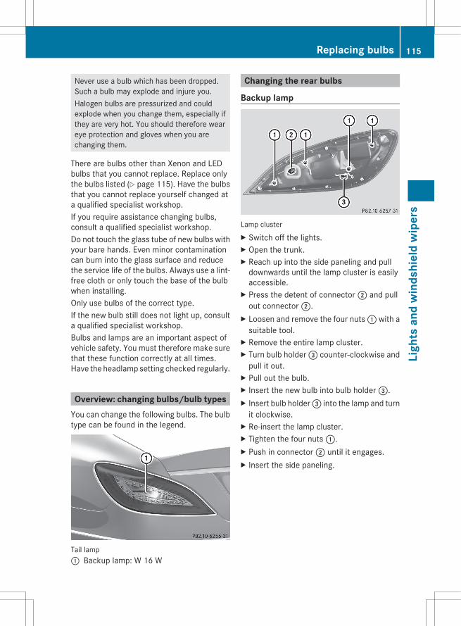
Never use a bulb which has been dropped.Such a bulb may explode and injure you.Halogen bulbs are pressurized and couldexplode when you change them, especially ifthey are very hot. You should therefore weareye protection and gloves when you arechanging them.
There are bulbs other than Xenon and LEDbulbs that you cannot replace. Replace onlythe bulbs listed (Y page 115). Have the bulbsthat you cannot replace yourself changed ata qualified specialist workshop.If you require assistance changing bulbs,consult a qualified specialist workshop.Do not touch the glass tube of new bulbs withyour bare hands. Even minor contaminationcan burn into the glass surface and reducethe service life of the bulbs. Always use a lint-free cloth or only touch the base of the bulbwhen installing.Only use bulbs of the correct type.If the new bulb still does not light up, consulta qualified specialist workshop.Bulbs and lamps are an important aspect ofvehicle safety. You must therefore make surethat these function correctly at all times.Have the headlamp setting checked regularly.
Overview: changing bulbs/bulb typesYou can change the following bulbs. The bulbtype can be found in the legend.
Tail lamp: Backup lamp: W 16 W
Changing the rear bulbs
Backup lamp
Lamp clusterX Switch off the lights.X Open the trunk.X Reach up into the side paneling and pull
downwards until the lamp cluster is easilyaccessible.
X Press the detent of connector ; and pullout connector ;.
X Loosen and remove the four nuts : with asuitable tool.
X Remove the entire lamp cluster.X Turn bulb holder = counter-clockwise and
pull it out.X Pull out the bulb.X Insert the new bulb into bulb holder =.X Insert bulb holder = into the lamp and turn
it clockwise.X Re-insert the lamp cluster.X Tighten the four nuts :.X Push in connector ; until it engages.X Insert the side paneling.
Replacing bulbs 115
Ligh
ts a
nd w
inds
hiel
d w
iper
s
Z

Windshield wipers
Switching the windshield wipers on/off
G WARNINGWiper blades are components that are subjectto wear and tear. Replace the wiper bladestwice a year, preferably in the spring and fall.Otherwise the windshield will not be wipedproperly. As a result, you may not be able toobserve surrounding traffic conditions andcould cause an accident.
! Do not operate the windshield wiperswhen the windshield is dry, as this coulddamage the wiper blades. Moreover, dirtthat has collected on the windshield canscratch the glass if wiping takes place whenthe windshield is dry.
! If the windshield wipers leave smears onthe windshield after the vehicle has beenwashed in an automatic car wash, wax orother residues may be the reason for this.Clean the windshield using washer fluidafter washing the vehicle in an automaticcar wash.
Combination switch1 $ Windshield wipers off2 Ä Intermittent wipe, low9
3 Å Intermittent wipe, high10
4 ° Continuous wipe, slow
5 ¯ Continuous wipe, fastB í Single wipe/ î To wipe the
windshield using washer fluidX Switch on the ignition.X Turn the combination switch to the
corresponding position.
! Intermittent wiping with rain sensor: dueto optical influences and the windshieldbecoming dirty in dry weather conditions,the windshield wipers may be activatedinadvertently. This could then damage thewindshield wiper blades or scratch thewindshield.For this reason, you should always switchoff the windshield wipers in dry weather.
In the Ä or Å position, the appropriatewiping frequency is set automaticallyaccording to the intensity of the rain. Inthe Å position, the rain sensor is moresensitive than in the Ä position, causingthe windshield wipers to wipe morefrequently.
Replacing the wiper blades
Important safety notes
G WARNINGFor safety reasons, switch off the windshieldwipers and remove the SmartKey from theignition lock before changing the wiper blades(vehicles with KEYLESS-GO: make sure thatthe on-board electronics are in state 0).Otherwise, the wiper motor could be switchedon suddenly and cause injury.
! Never open the hood if a windshield wiperarm has been folded away from thewindshield.Never fold a windshield wiper arm withouta wiper blade back onto the windshield.
9 Rain sensor set to low sensitivity.10 Rain sensor set to high sensitivity.
116 Windshield wipersLi
ghts
and
win
dshi
eld
wip
ers
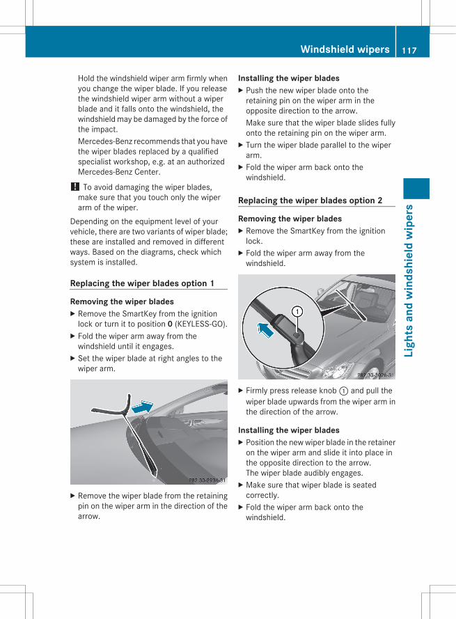
Hold the windshield wiper arm firmly whenyou change the wiper blade. If you releasethe windshield wiper arm without a wiperblade and it falls onto the windshield, thewindshield may be damaged by the force ofthe impact.Mercedes-Benz recommends that you havethe wiper blades replaced by a qualifiedspecialist workshop, e.g. at an authorizedMercedes-Benz Center.
! To avoid damaging the wiper blades,make sure that you touch only the wiperarm of the wiper.
Depending on the equipment level of yourvehicle, there are two variants of wiper blade;these are installed and removed in differentways. Based on the diagrams, check whichsystem is installed.
Replacing the wiper blades option 1
Removing the wiper bladesX Remove the SmartKey from the ignition
lock or turn it to position 0 (KEYLESS-GO).X Fold the wiper arm away from the
windshield until it engages.X Set the wiper blade at right angles to the
wiper arm.
X Remove the wiper blade from the retainingpin on the wiper arm in the direction of thearrow.
Installing the wiper bladesX Push the new wiper blade onto the
retaining pin on the wiper arm in theopposite direction to the arrow.Make sure that the wiper blade slides fullyonto the retaining pin on the wiper arm.
X Turn the wiper blade parallel to the wiperarm.
X Fold the wiper arm back onto thewindshield.
Replacing the wiper blades option 2
Removing the wiper bladesX Remove the SmartKey from the ignition
lock.X Fold the wiper arm away from the
windshield.
X Firmly press release knob : and pull thewiper blade upwards from the wiper arm inthe direction of the arrow.
Installing the wiper bladesX Position the new wiper blade in the retainer
on the wiper arm and slide it into place inthe opposite direction to the arrow.The wiper blade audibly engages.
X Make sure that wiper blade is seatedcorrectly.
X Fold the wiper arm back onto thewindshield.
Windshield wipers 117
Ligh
ts a
nd w
inds
hiel
d w
iper
s
Z
Problems with the windshield wipers
The windshield wipers are obstructedLeaves or snow, for example, may beobstructing the windshield wiper movement.The wiper motor has been deactivated.X For safety reasons, you should remove the
SmartKey from the ignition lock.orX Switch off the engine using the Start/Stop
button and open the driver's door.X Remove the cause of the obstruction.X Switch the windshield wipers back on.
The windshield wipers are inoperativeThe windshield wiper drive is malfunctioning.X Select another wiper speed on the
combination switch.X Have the windshield wipers checked at a
qualified specialist workshop.
The spray nozzles are misalignedThe windshield washer fluid from the spraynozzles no longer hits the center of thewindshield. The spray nozzles are misaligned.X Have the spray nozzles adjusted at a
qualified specialist workshop.
118 Windshield wipersLi
ghts
and
win
dshi
eld
wip
ers
Useful information ............................ 120Overview of climate control sys-tems ................................................... 120Operating the climate control sys-tems ................................................... 124Setting the air vents ......................... 129
119
Clim
ate
cont
rol

Useful information
i This Operator's Manual describes allmodels and all standard and optionalequipment of your vehicle available at thetime of publication of the Operator'sManual. Country-specific differences arepossible. Please note that your vehicle maynot be equipped with all featuresdescribed. This also applies to safety-related systems and functions.
i Please read the information on qualifiedspecialist workshops (Y page 24).
Overview of climate control systems
Important safety notes
G WARNINGSevere conditions (e.g. strong air pollution)may require replacement of the filter beforeits scheduled replacement interval. A cloggedfilter will reduce the air volume to the interiorand the windows could fog up, impairingvisibility and endangering you and others.Have a blocked filter replaced at a Mercedes-Benz Center as soon as possible.
G WARNINGFollow the recommended settings for heatingand cooling given on the following pages.Otherwise, the windows could fog up,impairing visibility and endangering you andothers.
The automatic climate control/automaticclimate control controls the temperature andthe humidity of the vehicle interior and filtersout undesirable substances from the air.The automatic climate control is onlyoperational when the engine is running.11
Optimum operation is only achieved if youdrive with the side windows and slidingsunroof/panorama roof with power tilt/sliding panel closed.
i Ventilate the vehicle for a brief periodduring warm weather, e.g. using theconvenience opening feature (Y page 88).This will speed up the cooling process andthe desired vehicle interior temperaturewill be reached more quickly.
i The integrated filter can filter out mostparticles of dust and completely filters outpollen. A clogged filter reduces the amountof air supplied to the vehicle interior. Forthis reason, you should always observe theinterval for replacing the filter, which isspecified in the Maintenance Booklet. As itdepends on environmental conditions, e.g.heavy air pollution, the interval may beshorter than stated in the MaintenanceBooklet.
11 The residual heat function can only be activated/deactivated when the ignition is switched off.
120 Overview of climate control systemsCl
imat
e co
ntro
l
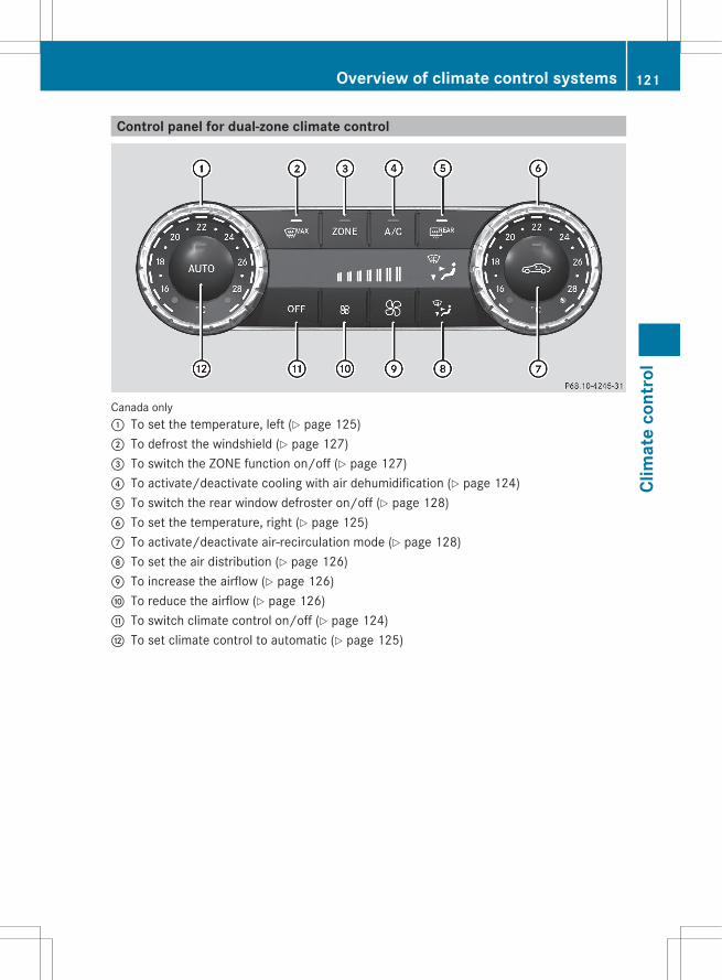
Control panel for dual-zone climate control
Canada only: To set the temperature, left (Y page 125); To defrost the windshield (Y page 127)= To switch the ZONE function on/off (Y page 127)? To activate/deactivate cooling with air dehumidification (Y page 124)A To switch the rear window defroster on/off (Y page 128)B To set the temperature, right (Y page 125)C To activate/deactivate air-recirculation mode (Y page 128)D To set the air distribution (Y page 126)E To increase the airflow (Y page 126)F To reduce the airflow (Y page 126)G To switch climate control on/off (Y page 124)H To set climate control to automatic (Y page 125)
Overview of climate control systems 121
Clim
ate
cont
rol
Z
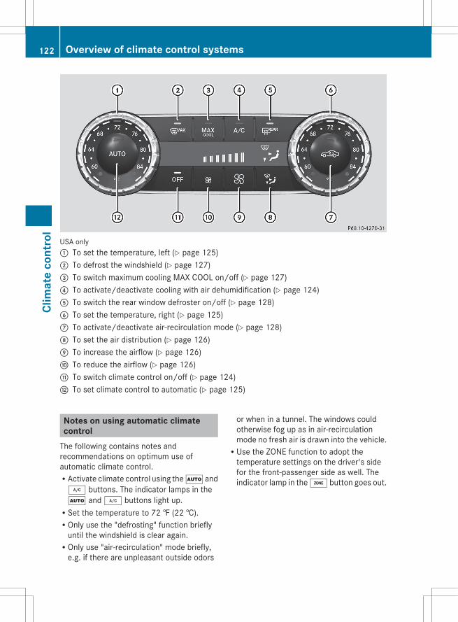
USA only: To set the temperature, left (Y page 125); To defrost the windshield (Y page 127)= To switch maximum cooling MAX COOL on/off (Y page 127)? To activate/deactivate cooling with air dehumidification (Y page 124)A To switch the rear window defroster on/off (Y page 128)B To set the temperature, right (Y page 125)C To activate/deactivate air-recirculation mode (Y page 128)D To set the air distribution (Y page 126)E To increase the airflow (Y page 126)F To reduce the airflow (Y page 126)G To switch climate control on/off (Y page 124)H To set climate control to automatic (Y page 125)
Notes on using automatic climatecontrol
The following contains notes andrecommendations on optimum use ofautomatic climate control.RActivate climate control using the à and¿ buttons. The indicator lamps in theà and ¿ buttons light up.RSet the temperature to 72 ‡ (22 †).ROnly use the "defrosting" function briefly
until the windshield is clear again.ROnly use "air-recirculation" mode briefly,
e.g. if there are unpleasant outside odors
or when in a tunnel. The windows couldotherwise fog up as in air-recirculationmode no fresh air is drawn into the vehicle.RUse the ZONE function to adopt the
temperature settings on the driver's sidefor the front-passenger side as well. Theindicator lamp in the á button goes out.
122 Overview of climate control systemsCl
imat
e co
ntro
l
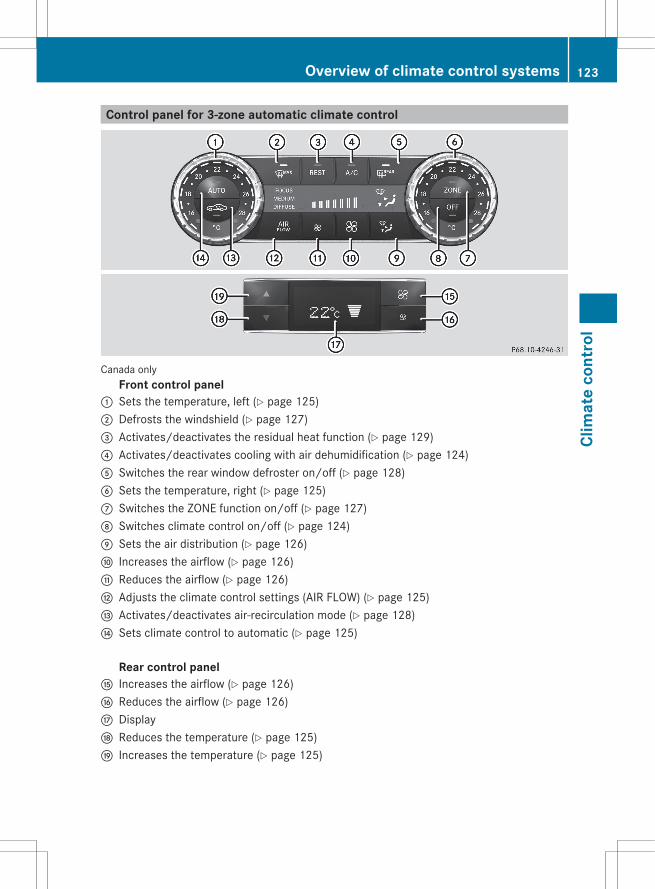
Control panel for 3-zone automatic climate control
Canada onlyFront control panel
: Sets the temperature, left (Y page 125); Defrosts the windshield (Y page 127)= Activates/deactivates the residual heat function (Y page 129)? Activates/deactivates cooling with air dehumidification (Y page 124)A Switches the rear window defroster on/off (Y page 128)B Sets the temperature, right (Y page 125)C Switches the ZONE function on/off (Y page 127)D Switches climate control on/off (Y page 124)E Sets the air distribution (Y page 126)F Increases the airflow (Y page 126)G Reduces the airflow (Y page 126)H Adjusts the climate control settings (AIR FLOW) (Y page 125)I Activates/deactivates air-recirculation mode (Y page 128)J Sets climate control to automatic (Y page 125)
Rear control panel
K Increases the airflow (Y page 126)L Reduces the airflow (Y page 126)M DisplayN Reduces the temperature (Y page 125)O Increases the temperature (Y page 125)
Overview of climate control systems 123
Clim
ate
cont
rol
Z
Notes on using 2-zone automaticclimate control
The following contains instructions andrecommendations to enable you to get themost out of your automatic climate control.RActivate climate control using the à and¿ buttons. The indicator lamps in theà and ¿ buttons light up.RIn automatic mode, you can also use theñ button to set a climate mode(FOCUS/MEDIUM/DIFFUSE). TheMEDIUM level is recommended.RSet the temperature to 72 ‡ (22 †).ROnly use the "defrosting" function briefly
until the windshield is clear again.ROnly use "air-recirculation" mode briefly,
e.g. if there are unpleasant outside odorsor when in a tunnel. The windows couldotherwise fog up as in air-recirculationmode no fresh air is drawn into the vehicle.RUse the ZONE function to adopt the
temperature settings on the driver's sidefor the front-passenger side and the rearcompartment as well. The indicator lamp inthe á button goes out.RUse the residual heat function if you want
to heat or ventilate the vehicle interiorwhen the ignition is switched off. The"residual heat" function can only beactivated or deactivated with the ignitionswitched off.
Operating the climate controlsystems
Activating/deactivating climatecontrol
Important information
G WARNINGWhen the climate control system isdeactivated, the outside air supply andcirculation are also deactivated. Only choosethis setting for a short time. Otherwise the
windows could fog up, impairing visibility andendangering you and others.
i Switch on climate control primarily usingthe à button (Y page 125).
Activating/deactivatingX Turn the SmartKey to position 2 in the
ignition lock.X To switch on: press the à button.
The indicator lamp in the à button lightsup. Airflow and air distribution are set toautomatic mode.
orX Press button ^.
The indicator lamp in the ̂ button goesout. The previously selected settings comeinto effect again.
X To switch off: press the ^ button.The indicator lamp in the ̂ button lightsup.
Activating/deactivating cooling withair dehumidification
Important informationThe cooling with air dehumidification functionis only available when the engine is running.The air inside the vehicle is cooled anddehumidified according to the temperatureselected.
G WARNINGIf you switch off the cooling function, thevehicle will not be cooled when weatherconditions are warm. The windows can fog upmore quickly. Window fogging may impairvisibility and endanger you and others.
Condensation may drip from the underside ofthe vehicle when it is in cooling mode. This isnormal and not a sign that there is amalfunction.
124 Operating the climate control systemsCl
imat
e co
ntro
l
i The cooling with air dehumidificationfunction uses refrigerant R134a. Thiscoolant does not containchlorofluorocarbons, and therefore doesnot damage the ozone layer.
Activating/deactivatingX To activate: press the ¿ button.
The indicator lamp in the ¿ button lightsup.
X To switch off: press the ¿ button.The indicator lamp in the ¿ button goesout. The cooling with air dehumidificationfunction has a delayed switch-off feature.
Problems with the cooling with airdehumidification functionWhen you press the ¿ button, theindicator lamp in the button flashes threetimes or remains off. You can no longer switchon the cooling with air dehumidificationfunction.X Consult a qualified specialist workshop.
Setting climate control to automatic
G WARNINGIf you switch off the cooling function, thevehicle will not be cooled when weatherconditions are warm. The windows can fog upmore quickly. Window fogging may impairvisibility and endanger you and others.
In automatic mode, the set temperature ismaintained automatically at a constant level.The system automatically regulates thetemperature of the dispensed air, the airflowand the air distribution.Automatic mode will achieve optimaloperation if cooling with air dehumidificationis also activated. If desired, cooling with airdehumidification can be deactivated.
Adjusting the climate mode settings(AIR FLOW)
This function is only available with automaticclimate control.The climate control settings are especiallyeffective at high temperatures.You can select the following climate controlsettings in automatic mode:FOCUS high airflow that is set slightly
coolerMEDIUM medium airflow, standard settingDIFFUSE low airflow that is set slightly
warmer and with a lower rate ofairflow
X Turn the SmartKey to position 2 in theignition lock.
X Press the à button.X Press the ñ button repeatedly until the
desired climate mode appears in thedisplay.
Setting the temperature
Climate controlDifferent temperatures can be set for thedriver's and front-passenger sides.X Turn the SmartKey to position 2 in the
ignition lock.X To increase/reduce: turn controls : andB clockwise or counter-clockwise(Y page 121).Only change the temperature setting insmall increments. Start at 72 ‡ (22 † ).
Operating the climate control systems 125
Clim
ate
cont
rol
Z
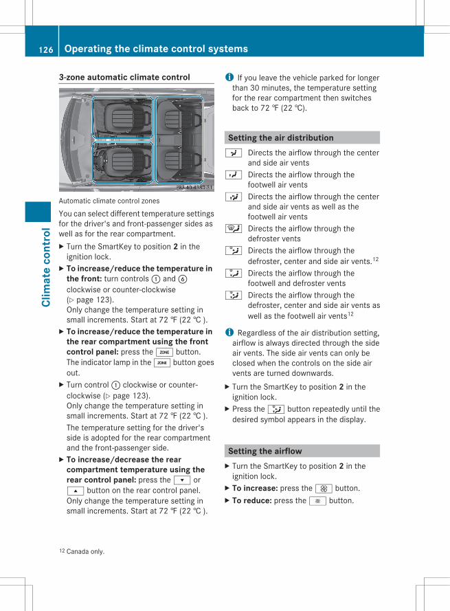
3-zone automatic climate control
Automatic climate control zones
You can select different temperature settingsfor the driver's and front-passenger sides aswell as for the rear compartment.X Turn the SmartKey to position 2 in the
ignition lock.X To increase/reduce the temperature in
the front: turn controls : and Bclockwise or counter-clockwise(Y page 123).Only change the temperature setting insmall increments. Start at 72 ‡ (22 † ).
X To increase/reduce the temperature in the rear compartment using the front control panel: press the á button.The indicator lamp in the á button goesout.
X Turn control : clockwise or counter-clockwise (Y page 123).Only change the temperature setting insmall increments. Start at 72 ‡ (22 † ).The temperature setting for the driver'sside is adopted for the rear compartmentand the front-passenger side.
X To increase/decrease the rear compartment temperature using the rear control panel: press the r ors button on the rear control panel.Only change the temperature setting insmall increments. Start at 72 ‡ (22 † ).
i If you leave the vehicle parked for longerthan 30 minutes, the temperature settingfor the rear compartment then switchesback to 72 ‡ (22 †).
Setting the air distributionP Directs the airflow through the center
and side air ventsO Directs the airflow through the
footwell air ventsS Directs the airflow through the center
and side air vents as well as thefootwell air vents
¯ Directs the airflow through thedefroster vents
b Directs the airflow through thedefroster, center and side air vents.12
a Directs the airflow through thefootwell and defroster vents
_ Directs the airflow through thedefroster, center and side air vents aswell as the footwell air vents12
i Regardless of the air distribution setting,airflow is always directed through the sideair vents. The side air vents can only beclosed when the controls on the side airvents are turned downwards.
X Turn the SmartKey to position 2 in theignition lock.
X Press the _ button repeatedly until thedesired symbol appears in the display.
Setting the airflowX Turn the SmartKey to position 2 in the
ignition lock.X To increase: press the K button.X To reduce: press the I button.
12 Canada only.
126 Operating the climate control systemsCl
imat
e co
ntro
l
i You can use automatic climate control toset the airflow in the rear compartmentseparately.
Switching the ZONE function on/offX To switch on: press the á button.
The indicator lamp in the á button lightsup.Dual-zone automatic climate control: thetemperature setting for the driver's side isnot adopted for the front-passenger side.3-zone automatic climate control: thetemperature setting for the driver's side isnot adopted for the front-passenger sideand the rear compartment.
When the buttons or controls fortemperature, airflow or air distribution areactivated, the temperature setting for thedriver's side is not adopted for the otherclimate control zones.X To switch off: press the á button.
The indicator lamp in the á button goesout.Dual-zone automatic climate control: thetemperature setting for the driver's side isadopted for the front-passenger side.3-zone automatic climate control: thetemperature setting for the driver's side isadopted for the front-passenger side andthe rear compartment.
Defrosting the windshieldYou can use this function to defrost thewindshield or to defrost the inside of thewindshield and the side windows.
i You should only select the defrostingfunction until the windshield is clear again.
X Turn the SmartKey to position 2 in theignition lock.
X To activate: press the ¬ button.The indicator lamp in the ¬ button lightsup.The climate control system switches to thefollowing functions:Rcooling with air dehumidification onRhigh airflow13
Rhigh temperature13
Rair distribution to the windshield andfront side windowsRair-recirculation mode off
X To switch off: press the ¬ button.The indicator lamp in the ¬ button goesout. The previously selected settings comeinto effect again. The cooling with airdehumidification function remains on. Air-recirculation mode remains deactivated.
orX Press the à button.
The indicator lamp in the ¬ button goesout. Airflow and air distribution are set toautomatic mode.
orX Turn controls : or B clockwise or
counter-clockwise (Y page 121),(Y page 123).
orX Press the K or I button.
MAX COOL maximum coolingThe MAX COOL function is only available invehicles for the USA.MAX COOL is only operational when theengine is running.
13 Depending on the outside temperature.
Operating the climate control systems 127
Clim
ate
cont
rol
Z
When you activate MAX COOL, climatecontrol switches to the following functions:Rmaximum coolingRmaximum airflowRair-recirculation mode onX To activate: press the Ù button.
The indicator lamp in the button lights up.X To deactivate: press the Ù button
again.The indicator lamp goes out. The previouslyselected settings come into effect again.
Defrosting the windows
Windows fogged up on the insideX Activate the ¿ cooling with air
dehumidification function.X Activate automatic mode Ã.X If the windows continue to fog up, activate
the defrosting function (Y page 127).
i You should only select this setting untilthe windshield is clear again.
Windows fogged up on the outsideX Switch on the windshield wipers.X Press the _ button repeatedly until theP or O symbol appears in thedisplay.
i You should only select this setting untilthe windshield is clear again.
Rear window defroster
Activating/deactivating
G WARNINGAny accumulation of snow and ice should beremoved from the rear window before driving.Visibility could otherwise be impaired,endangering you and others.
The rear window defroster has a high currentdraw. You should therefore switch it off assoon as the window is clear. Otherwise, therear window defroster switches offautomatically after several minutes.If the battery voltage is too low, the rearwindow defroster may switch off.X Turn the SmartKey to position 2 in the
ignition lock.X Press the ¤ button.
The indicator lamp in the ¤ button lightsup or goes out.
Problems with the rear windowdefrosterThe rear window defroster has deactivatedprematurely or cannot be activated.X Switch off any consumers that are not
required, e.g. reading lamps or interiorlighting.When the battery is sufficiently charged,the rear window defroster is activatedagain automatically.
Activating/deactivating air-recirculation mode
You can deactivate the flow of fresh air ifunpleasant odors are entering the vehiclefrom outside. The air already inside thevehicle will then be recirculated.The operation of air-recirculation mode is thesame for all control panels.
G WARNINGFogged windows impair visibility,endangering you and others. If the windowsbegin to fog on the inside, switching off theair recirculation mode immediately shouldclear interior window fogging. If interiorwindow fogging persists, make sure the airconditioning is activated, or press the ¬button.
128 Operating the climate control systemsCl
imat
e co
ntro
l
X Turn the SmartKey to position 2 in theignition lock.
X To activate: press the g button.The indicator lamp in the g button lightsup.
i In the event of high pollution levels14 or athigh outside temperatures, air-recirculation mode is automaticallyactivated. When air-recirculation mode isactivated automatically, the indicator lampin the g button is not lit.Outside air is added after about 30minutes.
X To deactivate: press the g button.The indicator lamp in the g button goesout.
i Air-recirculation mode deactivatesautomatically:Rafter approximately five minutes if
outside temperatures are less than about41 ‡ (5 † )Rafter approximately five minutes if
cooling with air dehumidification isdeactivatedRafter approximately 30 minutes if outside
temperatures are over about41 ‡ (5 † )
Activating/deactivating the residualheat function
The residual heat function is only available invehicles for Canada with automatic climatecontrol.It is possible to make use of the residual heatof the engine to continue heating thestationary vehicle for up to 30 minutes afterthe engine has been switched off. The heatingtime depends on the temperature that hasbeen set.
i The blower will run at a low speedregardless of the airflow setting.
i If you activate the residual heat functionat high temperatures, only the ventilationwill be activated. The blower runs atmedium speed.
X Turn the SmartKey to position 0 in theignition lock or remove it.
X To activate: press the Ì button.The indicator lamp in the Ì button lightsup.
X To deactivate: press the Ì button.The indicator lamp in the Ì button goesout.
i Residual heat is deactivatedautomatically:Rafter about 30 minutesRwhen the ignition is switched onRif the battery voltage dropsRif the coolant temperature is too low
Setting the air vents
Important safety notes
G WARNINGWhen operating the climate control, the airthat enters the passenger compartmentthrough the air vents can be very hot or verycold (depending on the set temperature). Thiscould cause burns or frostbite to unprotectedskin in the immediate area of the air vents.Always keep sufficient distance betweenunprotected parts of the body and the airvents. If necessary, use the air distributionadjustment to direct the air to air vents in thevehicle interior that are not in the immediatearea of unprotected skin.
14 Automatic climate control only.
Setting the air vents 129
Clim
ate
cont
rol
Z
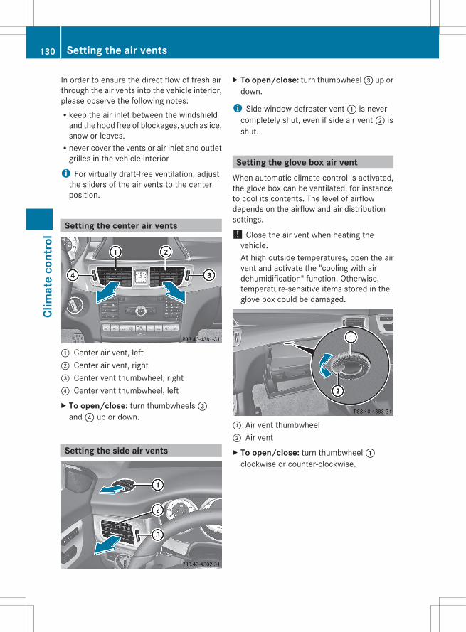
In order to ensure the direct flow of fresh airthrough the air vents into the vehicle interior,please observe the following notes:Rkeep the air inlet between the windshield
and the hood free of blockages, such as ice,snow or leaves.Rnever cover the vents or air inlet and outlet
grilles in the vehicle interior
i For virtually draft-free ventilation, adjustthe sliders of the air vents to the centerposition.
Setting the center air vents
: Center air vent, left; Center air vent, right= Center vent thumbwheel, right? Center vent thumbwheel, leftX To open/close: turn thumbwheels =
and ? up or down.
Setting the side air vents
X To open/close: turn thumbwheel = up ordown.
i Side window defroster vent : is nevercompletely shut, even if side air vent ; isshut.
Setting the glove box air ventWhen automatic climate control is activated,the glove box can be ventilated, for instanceto cool its contents. The level of airflowdepends on the airflow and air distributionsettings.
! Close the air vent when heating thevehicle.At high outside temperatures, open the airvent and activate the "cooling with airdehumidification" function. Otherwise,temperature-sensitive items stored in theglove box could be damaged.
: Air vent thumbwheel; Air ventX To open/close: turn thumbwheel :
clockwise or counter-clockwise.
130 Setting the air ventsCl
imat
e co
ntro
l
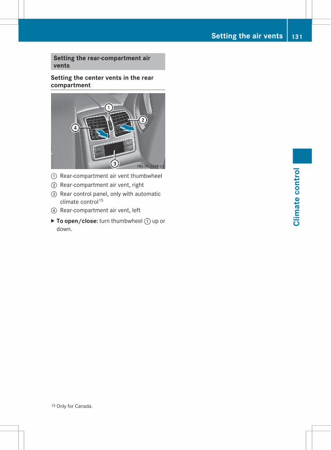
Setting the rear-compartment airvents
Setting the center vents in the rearcompartment
: Rear-compartment air vent thumbwheel; Rear-compartment air vent, right= Rear control panel, only with automatic
climate control15
? Rear-compartment air vent, leftX To open/close: turn thumbwheel : up or
down.
15 Only for Canada.
Setting the air vents 131
Clim
ate
cont
rol
Z

132
Useful information ............................ 134Breaking-in notes .............................. 134Driving ............................................... 134Automatic transmission ................... 142Refueling ............................................ 149Parking ............................................... 152Driving tips ........................................ 154Driving systems ................................ 159
133
Driv
ing
and
park
ing

Useful information
i This Operator's Manual describes allmodels and all standard and optionalequipment of your vehicle available at thetime of publication of the Operator'sManual. Country-specific differences arepossible. Please note that your vehicle maynot be equipped with all featuresdescribed. This also applies to safety-related systems and functions.
i Please read the information on qualifiedspecialist workshops (Y page 24).
Breaking-in notes
The first 1,000miles (1,500 km)The more you look after the engine when it isnew, the more satisfied you will be with itsperformance in the future.RYou should therefore drive at varying
vehicle and engine speeds for the first1,000miles (1,500km).RAvoid heavy loads, e.g. driving at full
throttle, during this period.RChange gear in good time, before the
tachometer needle is Ô of the way to thered area of the tachometer.RDo not manually shift to a lower gear to
brake the vehicle.RIf possible, do not depress the accelerator
pedal past the point of resistance(kickdown).ROnly select shift ranges 3, 2 or 1 when
driving slowly, e.g. in mountainous terrain.After 1,000 miles (1,500km), you canincrease the engine speed gradually and bringthe vehicle up to full speed.
Additional breaking-in notes for AMGvehicles:Rdo not drive faster than 85 mph
(140 km/h) for the first 1,000 miles(1,500 km).Ronly allow the engine to reach a maximum
engine speed of 4,500 rpm briefly.Rchange gear in good time.
i You should also observe these breaking-in notes if the engine or parts of the drivetrain on your vehicle have been replaced.
i Always observe the respective speedlimits.
AMG vehicles with rear axle lockingdifferential
Your vehicle is equipped with a self-lockingdifferential on the rear axle. To improve theprotection of the differential on the rear axle,change the oil after a break-in distance of2,000 miles (3,000 km). This oil changeextends the service life of the differential.Have the oil change carried out at a qualifiedspecialist workshop.
Driving
Important safety notes
G WARNINGMake sure absolutely no objects areobstructing the pedals' range of movement.Keep the driver's footwell clear of allobstacles. If there are any floormats orcarpets in the footwell, make sure the pedalsstill have sufficient clearance.During sudden driving or braking maneuversthe objects could get caught between thepedals. You could then no longer brake oraccelerate. This could lead to accidents andinjury.
134 DrivingDr
ivin
g an
d pa
rkin
g

G WARNINGOn slippery road surfaces, never downshift inorder to obtain braking action. This couldresult in drive wheel slip and reduced vehiclecontrol. Your vehicle's ABS will not preventthis type of loss of control.
G WARNINGIt is dangerous to shift the automatictransmission out of parking position P orneutral position N if the engine speed ishigher than idle speed. If your foot is not firmlyon the brake pedal, the vehicle couldaccelerate quickly forward or in reverse. Youcould lose control of the vehicle and hitsomeone or something. Only shift into gearwhen the engine is idling normally and whenyour right foot is firmly on the brake pedal.
! Warm up the engine quickly. Do not usethe engine's full performance until it hasreached operating temperature.Only shift the automatic transmission tothe desired drive position when the vehicleis stationary.Where possible, avoid spinning the drivewheels when pulling away on slipperyroads. You could otherwise damage thedrive train.
! AMG vehicles: at low engine oiltemperatures below 68 ‡ (+20 †), themaximum engine speed is restricted inorder to protect the engine. To protect theengine and maintain smooth engineoperation, avoid driving at full throttle whenthe engine is cold.
SmartKey positions
SmartKey
g To remove the SmartKey(shift the transmission to position P)
1 Power supply for some consumers, suchas the windshield wipers
2 Ignition (power supply for all consumers)and drive position
3 To start the engine
If the SmartKey is in position 0 in the ignitionlock for an extended period of time, it can nolonger be turned in the ignition lock. Thesteering is then locked. To unlock, remove theSmartKey and reinsert it into the ignition lock.The steering is locked when you remove theSmartKey from the ignition lock.
i The SmartKey can be turned in theignition lock even if it is not the correctSmartKey for the vehicle. The ignition is notswitched on. The engine cannot be started.
KEYLESS-GO
General informationVehicles with KEYLESS-GO are equipped witha SmartKey featuring an integrated KEYLESS-GO function and a detachable Start/Stopbutton.The Start/Stop button must be inserted intothe ignition lock and the SmartKey must be inthe vehicle.Pressing the Start/Stop button several timesin succession corresponds to the different
Driving 135
Driv
ing
and
park
ing
Z

SmartKey positions in the ignition lock. Thisis only the case if you are not depressing thebrake pedal.If you depress the brake pedal and press theStart/Stop button, the engine startsimmediately.The Start/Stop button can be removed fromthe ignition lock. Then, you can insert theSmartKey into the ignition lock.
i You do not have to remove the Start/Stopbutton from the ignition lock when youleave the vehicle. However, you shouldalways take the SmartKey with you whenleaving the vehicle. The vehicle can bestarted with the Start/Stop button and theelectrical equipment can be operated whilethe SmartKey is in the vehicle.
: Start/Stop button; Ignition lockX Insert Start/Stop button : into ignition
lock ;.
i When you insert Start/Stop button :into ignition lock ;, the system requires adetection time of approximatelytwo seconds before you can use Start/Stop button :.
Start/Stop button= USA only? Canada onlyX Position 0: if Start/Stop button : has not
yet been pressed, this corresponds to theSmartKey being removed from the ignition.
X Position 1: press Start/Stop button :.You can now activate the windshieldwipers, for example.
i If you then open the driver's door when inthis position, the power supply isdeactivated.
X Position 2 (ignition): press Start/Stopbutton : twice.
i If you press Start/Stop button : oncewhen in this position and the driver's dooris open, the power supply is deactivatedagain.
As soon as the ignition is switched on, all theindicator lamps in the instrument cluster lightup. If an indicator lamp does not go out afterthe engine is started or if it lights up while thevehicle is in motion, see (Y page 249).
Starting the engine
Important safety notes
G WARNINGInhalation of exhaust gas is hazardous to yourhealth. All exhaust gas contains carbonmonoxide (CO), and inhaling it can causeunconsciousness and possible death.
136 DrivingDr
ivin
g an
d pa
rkin
g
Do not run the engine in confined areas (suchas a garage) which are not properly ventilated.If you think that exhaust gas fumes areentering the vehicle while driving, have thecause determined and correctedimmediately. If you must drive under theseconditions, drive only with at least onewindow fully open at all times.
! Do not depress the accelerator pedalwhen starting the engine.
General informationi The catalytic converter is preheated for
up to 30seconds after a cold start. Thesound of the engine may change during thistime.
i The catalytic converter is preheated forup to 30seconds after a cold start. Thesound of the engine may change during thistime.
Automatic transmissionX Shift the transmission to position P.
The transmission position display in themultifunction display shows P.
i You can also start the engine when thetransmission is in position N.
Starting procedure with the SmartKeyi To start the engine using the SmartKey
instead of KEYLESS-GO, pull the Start/Stop button out of the ignition lock.
X Turn the SmartKey to position 3 in theignition lock (Y page 135) and release it assoon as the engine is running.
Using KEYLESS-GO to start the engine
G WARNINGAs long as the SmartKey is in your vehicle, thevehicle can be started. Therefore, never leavechildren unattended in the vehicle, as theycould otherwise accidentally start the engine.
When leaving the vehicle, always take theSmartKey with you and lock the vehicle. Donot leave children unattended in the vehicle,or with access to an unlocked vehicle. Achild's unsupervised access to a vehicle couldresult in an accident and/or serious personalinjury.
i The Start/Stop button can be used tostart the vehicle manually without insertingthe SmartKey into the ignition lock. TheStart/Stop button must be inserted intothe ignition lock and the SmartKey must bein the vehicle. This mode for starting theengine operates independently of the ECOstart/stop automatic engine start function.
X Depress the brake pedal and keep itdepressed.
X Press the Start/Stop button (Y page 135)once.The engine starts.
Pulling away
Automatic transmission
G WARNINGIt is dangerous to shift the automatictransmission out of parking position P orneutral position N if the engine speed ishigher than idle speed. If your foot is not firmlyon the brake pedal, the vehicle couldaccelerate quickly forward or in reverse. Youcould lose control of the vehicle and hitsomeone or something. Only shift into gearwhen the engine is idling normally and whenyour right foot is firmly on the brake pedal.
i It is only possible to shift the transmissionfrom position P to the desired position ifyou depress the brake pedal. Only then isthe parking lock released. If you do notdepress the brake pedal, you can move theDIRECT SELECT lever but the parking lockremains engaged.
Driving 137
Driv
ing
and
park
ing
Z

X Depress the brake pedal and keep itdepressed.
X Shift the transmission to position D or R.X Release the parking brake (Y page 153).X Release the brake pedal.X Carefully depress the accelerator pedal.
! If a warning tone sounds and theRelease Park. Brake message appearsin the multifunction display, the parkingbrake is still applied. Release the parkingbrake.
i The vehicle locks centrally once you havepulled away. The locking knobs in the doorsdrop down.You can open the doors from the inside atany time.You can also deactivate the automaticlocking feature (Y page 215).
i Upshifts take place at higher enginespeeds after a cold start. This helps thecatalytic converter to reach its operatingtemperature more quickly.
Hill start assistHill start assist helps you when pulling awayforwards or in reverse on an uphill gradient.It holds the vehicle for a short time after youhave removed your foot from the brake pedal.This gives you enough time to move your footfrom the brake pedal to the accelerator pedaland to depress it before the vehicle begins toroll.
G WARNINGNever leave the vehicle when it is held by hillstart assist. After approximately one second,hill start assist will no longer brake yourvehicle and it could roll away.
X Take your foot off the brake pedal.i Once you have taken your foot off the
brake pedal, the vehicle is held for aroundone second.
X Pull away.
Hill start assist will not function if:Ryou are pulling away on a level road or on
a downhill gradient.Rthe transmission is in position N.Rthe parking brake is applied.RESP® is malfunctioning.
ECO start/stop function
General notesThe ECO start/stop function is only availablefor the CLS 63 AMG.The ECO start/stop function is only availablein drive program C.The ECO start/stop function switches theengine off automatically when the vehiclestops moving.The engine starts automatically when thedriver wants to pull away again. The ECOstart/stop function thereby helps you toreduce the fuel consumption and emissionsof your vehicle.The ECO start/stop function is activated eachtime the engine is switched on. If allconditions for automatic engine switch-offare fulfilled (Y page 139), the green ¤symbol is shown in the multifunction displayand the Stop/Start active messageappears. If not all the conditions are fulfilled,the ¤ symbol is shown in yellow and theStop/Start inactive message is shown.If the ECO start/stop function is deactivated(Y page 139), the ¤ symbol is not shown.
G WARNINGIf the engine is switched off and the ECOsymbol is shown in green in the multifunctiondisplay, the engine has been switched offautomatically. All of the vehicle's systemsremain active. If you open the door, unfastenyour seat belt or remove your foot from thebrake pedal, the engine will automaticallystart. The vehicle may begin moving. You
138 DrivingDr
ivin
g an
d pa
rkin
g

could suffer serious or even fatal injury orcause an accident resulting in injury or death.Never leave the vehicle while the ECO symbolin the multifunction display is shown in greenor yellow. Always secure the vehicle againstrolling away before leaving it.
! Always switch the ignition off and take thekey with you when leaving the vehicle.
Automatic engine switch-offThe ECO start/stop function switches theengine off automatically if the vehicle isbraked to a standstill and the brake remainsdepressed with the transmission in positionD or N.
i You can still activate the HOLD functionwhen the vehicle is stationary, even if theengine has been switched offautomatically. It is then not necessary tocontinue applying the brakes during theautomatic stop phase. When you depressthe accelerator pedal, the engine startsautomatically and the braking effect of theHOLD function is deactivated. Depress theaccelerator pedal carefully, as the enginemust be started first.
The engine is only switched off if:Rthe outside temperature is within the range
which is suitable for the system.Rthe engine is at normal operating
temperature.Rthe set temperature for the vehicle interior
has been reached.Rthe battery is sufficiently charged.Rthe system detects that the windshield is
not fogged up when the air-conditioningsystem is switched on.Rthe hood is closed.Rno engine-relevant diagnostics are active.Rthe front door is closed and the seat belt is
fastened.
i During automatic engine switch-off, theclimate control system only operates at a
reduced capacity. If you require full climatecontrol capacity, the ECO start/stopfunction can be deactivated by pressing theECO button (Y page 139).
Automatic engine startThe engine is started automatically if you:Rrelease the brake pedal when HOLD is not
activated and the transmission is inposition D or NRshift the transmission to position RRdepress the accelerator pedalRswitch off the ECO start/stop function by
pressing the ECO buttonRswitch to drive program S, S+ or MRunfasten your seat belt or open the driver's
doorThe engine is also started automatically if:Rthe vehicle starts to roll.Rthe brake system requires this.Rthe system detects moisture on the
windshield when the air-conditioningsystem is switched on.Rthe temperature in the vehicle interior
deviates from the set range.Rthe charge level of the battery is too low.
Deactivating/activating the ECO start/stop function
Example: ECO button
i If indicator lamp ; is off, the ECO start/stop function has been deactivatedmanually or as the result of a malfunction.
Driving 139
Driv
ing
and
park
ing
Z

The engine will then not be switched offautomatically when the vehicle stops.
i Every time you start the engine, the ECOstart/stop function is switched on and theautomatic transmission shifts to automaticdrive program C.
DeactivatingX Press button : in drive program C.
orX Switch to drive program S, S+ or M
(Y page 145).Indicator lamp ; on button : and the¤ symbol in the multifunction display goout.The Stop/Start active or Stop/Start inactive message in the AMG menu in themultifunction display goes out.
ActivatingX Press button :.
Indicator lamp ; lights up. If driveprogram S, S+ or M is active, the automatictransmission switches to drive program C.If all conditions for automatic engineswitch-off (Y page 139) are fulfilled, the¤ symbol is shown in green in themultifunction display. In addition, theStop/Start active message is shown inthe AMG menu in the multifunction display.If not all conditions for automatic engineswitch-off (Y page 139) are fulfilled, theStop/Start inactive message appearsin the AMG menu of the multifunctiondisplay and the ¤ symbol is shown inyellow. If this is the case, the ECO start/stop function is not available.
140 DrivingDr
ivin
g an
d pa
rkin
g

Problems with the engine
Problem Possible causes/consequences and M Solutions
The engine does notstart. The starter motorcan be heard.
RThere is a malfunction in the engine electronics.RThere is a malfunction in the fuel supply.X Before attempting to start the engine again, turn the SmartKey
in the ignition back to position 0 or press the Start/Stop buttonrepeatedly until all indicator lamps in the instrument cluster goout.
X Try to start the engine again (Y page 136). Avoid excessivelylong and frequent attempts to start the engine as these will drainthe battery.
If the engine does not start after several attempts:X Consult a qualified specialist workshop.
The engine does notstart. You cannot hearthe starter motor.
The on-board voltage is too low because the battery is too weakor discharged.X Jump-start the vehicle (Y page 311).If the engine does not start despite attempts to jump-start it:X Consult a qualified specialist workshop.
The starter motor was exposed to a thermal load that was too high.X Allow the starter motor to cool down for approximately two
minutes.X Try to start the engine again.If the engine still does not start:X Consult a qualified specialist workshop.
The engine is notrunning smoothly andis misfiring.
There is a malfunction in the engine electronics or in a mechanicalcomponent of the engine management system.X Only depress the accelerator pedal slightly.
Otherwise, non-combusted fuel may get into the catalyticconverter and damage it.
X Have the cause rectified immediately at a qualified specialistworkshop.
The coolanttemperature gaugeshows a value above248 ‡ (120 †).
The coolant level is too low. The coolant is too hot and the engineis no longer being cooled sufficiently.X Stop as soon as possible and allow the engine and the coolant
to cool down.X Check the coolant level (Y page 288). Observe the warning
notes as you do so and add coolant if necessary.
Driving 141
Driv
ing
and
park
ing
Z
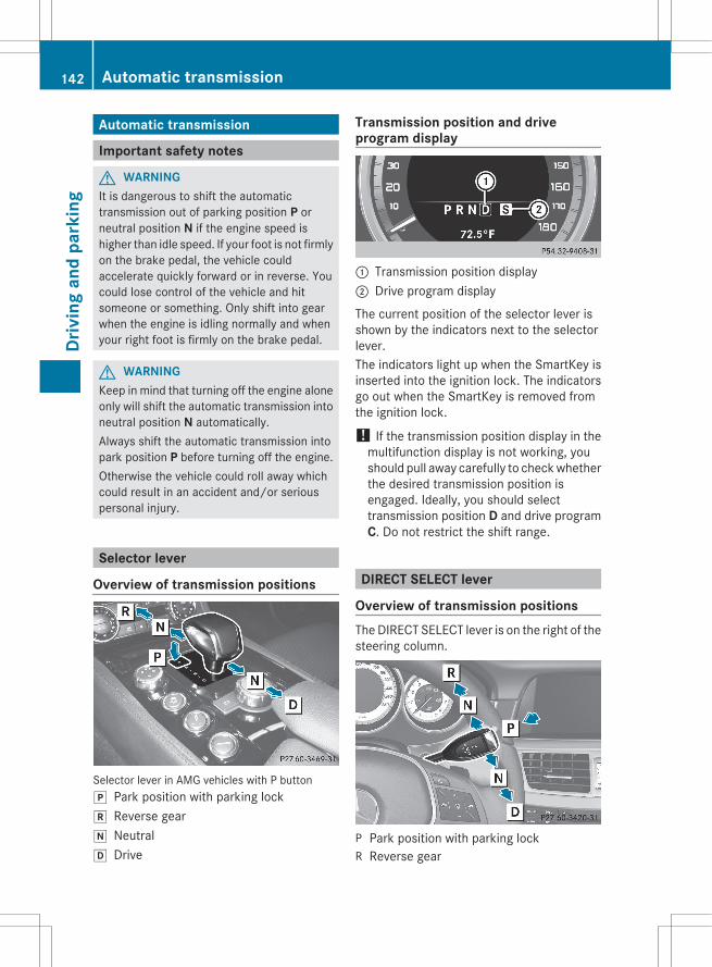
Automatic transmission
Important safety notes
G WARNINGIt is dangerous to shift the automatictransmission out of parking position P orneutral position N if the engine speed ishigher than idle speed. If your foot is not firmlyon the brake pedal, the vehicle couldaccelerate quickly forward or in reverse. Youcould lose control of the vehicle and hitsomeone or something. Only shift into gearwhen the engine is idling normally and whenyour right foot is firmly on the brake pedal.
G WARNINGKeep in mind that turning off the engine aloneonly will shift the automatic transmission intoneutral position N automatically.Always shift the automatic transmission intopark position P before turning off the engine.Otherwise the vehicle could roll away whichcould result in an accident and/or seriouspersonal injury.
Selector lever
Overview of transmission positions
Selector lever in AMG vehicles with P buttonj Park position with parking lockk Reverse geari Neutralh Drive
Transmission position and driveprogram display
: Transmission position display; Drive program display
The current position of the selector lever isshown by the indicators next to the selectorlever.The indicators light up when the SmartKey isinserted into the ignition lock. The indicatorsgo out when the SmartKey is removed fromthe ignition lock.
! If the transmission position display in themultifunction display is not working, youshould pull away carefully to check whetherthe desired transmission position isengaged. Ideally, you should selecttransmission position D and drive programC. Do not restrict the shift range.
DIRECT SELECT lever
Overview of transmission positionsThe DIRECT SELECT lever is on the right of thesteering column.
P Park position with parking lockR Reverse gear
142 Automatic transmissionDr
ivin
g an
d pa
rkin
g

N NeutralD Drive
i The DIRECT SELECT lever always returnsto its original position. The currenttransmission position P, R, N or D appearsin the transmission position display(Y page 142) in the multifunction display.
Transmission position and driveprogram displayThe current transmission position and driveprogram appear in the multifunction display.
: Transmission position display; Drive program display
i The arrows in the transmission positiondisplay show how and into whichtransmission positions you can changeusing the DIRECT SELECT lever.
! If the transmission position display in themultifunction display is not working, youshould pull away carefully to check whetherthe desired transmission position isengaged. Ideally, you should selecttransmission position D and drive programE or S. Do not restrict the shift range.
Engaging park position PX Push the DIRECT SELECT lever in the
direction of arrow P.
i The automatic transmission shiftsautomatically into park position P if youopen the driver's door when the vehicle isstationary or driving at very low speed, andthe transmission is in position D or R.
! If the engine speed is too high or thevehicle is moving, do not shift the
automatic transmission directly from D toR, from R to D or directly to P. Theautomatic transmission could otherwise bedamaged.
HOLD function or DISTRONIC PLUS: theautomatic transmission automaticallyswitches to transmission position P if thevehicle is braked by the HOLD function orDISTRONIC PLUS. In addition, at least one ofthe following conditions must be fulfilled:Rthe engine is switched off.Rthe driver's door is open and the seat belt
is not in the buckle.
Engaging park position P in AMGvehicles
X If the vehicle is stationary, press Pbutton :.
Engaging reverse gear R! Only shift the automatic transmission to
R when the vehicle is stationary.X When the vehicle is stationary, depress the
brake pedal.X Push the DIRECT SELECT lever up past the
first point of resistance.
Shifting to neutral NX When the vehicle is stationary, depress the
brake pedal.X Push the DIRECT SELECT lever up or down
to the first point of resistance.
Automatic transmission 143
Driv
ing
and
park
ing
Z

If the engine has been switched off, theautomatic transmission automaticallyswitches to N.
Remaining in neutral NIf the automatic transmission is to remain inneutral N, e.g. for washing the vehicle in carwashes with a towing device, please observethe following instructions:
G WARNINGWhen leaving the SmartKey in the starterswitch, do not leave children unattended inthe vehicle. It is possible for children to switchon the ignition which could result inunsupervised use of vehicle equipment.Unsupervised use of vehicle equipment couldresult in an accident and/or serious personalinjury.
Using the SmartKey:Rmake sure that the ignition is switched on.Rwhen the vehicle is stationary, depress the
brake pedal and keep it depressed.Rshift to neutral N.Rrelease the brake pedal.Rif the parking brake is applied, release it.Rswitch off the ignition and leave the
SmartKey in the ignition lock.Using KEYLESS-GO:Rmake sure that the ignition is switched on.Rwhen the vehicle is stationary, depress the
brake pedal and keep it depressed.Rengage park position P.Rrelease the brake pedal.Rremove the Start/Stop button from the
ignition lock.Rinsert the SmartKey into the ignition lock.Rswitch on the ignition.Rdepress the brake pedal and keep it
depressed.Rshift to neutral N.Rrelease the brake pedal.
Rif the parking brake is applied, release it.Rswitch off the ignition and leave the
SmartKey in the ignition lock.
Engaging drive position DX When the vehicle is stationary, depress the
brake pedal.X Push the DIRECT SELECT lever down past
the first point of resistance.
Changing gearThe automatic transmission shifts to theindividual gears automatically when it is intransmission position D. This automaticgearshifting behavior is determined by:Ra shift range restriction, if selectedRthe selected drive program (Y page 145)Rthe position of the accelerator pedalRthe road speed
Driving tips
AMG vehiclesWhen shifting down, the double-clutchfunction is active regardless of the currentlyselected drive program. The double-clutchfunction reduces load change reactions andis conducive to a sporty driving style. Thesound generated by the double-clutchfunction depends on the drive programselected.
144 Automatic transmissionDr
ivin
g an
d pa
rkin
g
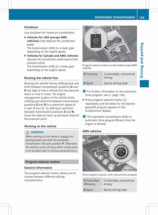
KickdownUse kickdown for maximum acceleration.X Vehicles for USA (except AMG
vehicles): fully depress the acceleratorpedal.The transmission shifts to a lower geardepending on the engine speed.
X Vehicles for Canada and AMG vehicles:depress the accelerator pedal beyond thepressure point.The transmission shifts to a lower geardepending on the engine speed.
Rocking the vehicle freeRocking the vehicle free by shifting back andforth between transmission positions D andR can help to free a vehicle that has becomestuck in mud or snow. The enginemanagement system of the vehicle limitsshifting back and forth between transmissionpositions D and R to a maximum speed of5 mph (9 km/h). To shift back and forthbetween transmission positions D and R,move the selector lever up and down beyondthe pressure point.
Working on the vehicle
G WARNINGWhen working on the vehicle, engage theparking brake and shift the automatictransmission into park position P. Otherwisethe vehicle could roll away which could resultin an accident and/or serious personal injury.
Program selector button
General informationThe program selector button allows you tochoose between different drivingcharacteristics.
Program selector button on all models except AMGvehicles
E Economy Comfortable, economicaldriving
S Sport Sporty driving style
i For further information on the automaticdrive program, see (Y page 146).
X Press program selector button :repeatedly until the letter for the desiredgearshift program appears in themultifunction display.
i The automatic transmission shifts toautomatic drive program E each time theengine is started.
AMG vehicles
Drive program selector with manual drive program
C ControlledEfficiency
Comfortable, economicaldriving
S Sport Sporty driving style
Automatic transmission 145
Driv
ing
and
park
ing
Z
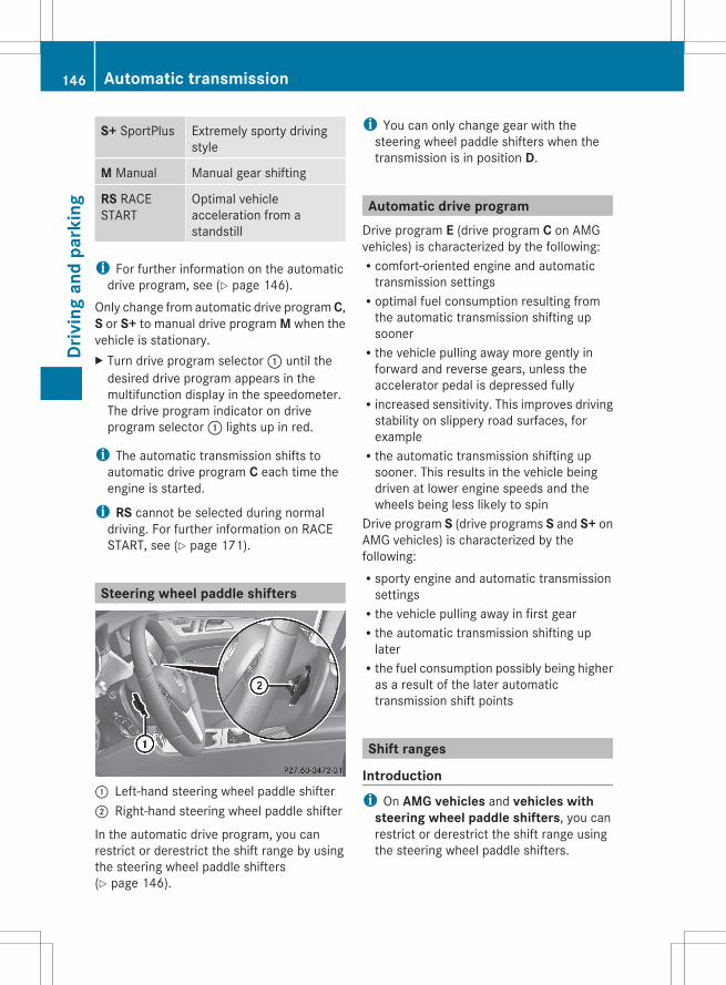
S+ SportPlus Extremely sporty drivingstyle
M Manual Manual gear shifting
RS RACESTART
Optimal vehicleacceleration from astandstill
i For further information on the automaticdrive program, see (Y page 146).
Only change from automatic drive program C,S or S+ to manual drive program M when thevehicle is stationary.X Turn drive program selector : until the
desired drive program appears in themultifunction display in the speedometer.The drive program indicator on driveprogram selector : lights up in red.
i The automatic transmission shifts toautomatic drive program C each time theengine is started.
i RS cannot be selected during normaldriving. For further information on RACESTART, see (Y page 171).
Steering wheel paddle shifters
: Left-hand steering wheel paddle shifter; Right-hand steering wheel paddle shifter
In the automatic drive program, you canrestrict or derestrict the shift range by usingthe steering wheel paddle shifters(Y page 146).
i You can only change gear with thesteering wheel paddle shifters when thetransmission is in position D.
Automatic drive programDrive program E (drive program C on AMGvehicles) is characterized by the following:Rcomfort-oriented engine and automatic
transmission settingsRoptimal fuel consumption resulting from
the automatic transmission shifting upsoonerRthe vehicle pulling away more gently in
forward and reverse gears, unless theaccelerator pedal is depressed fullyRincreased sensitivity. This improves driving
stability on slippery road surfaces, forexampleRthe automatic transmission shifting up
sooner. This results in the vehicle beingdriven at lower engine speeds and thewheels being less likely to spin
Drive program S (drive programs S and S+ onAMG vehicles) is characterized by thefollowing:Rsporty engine and automatic transmission
settingsRthe vehicle pulling away in first gearRthe automatic transmission shifting up
laterRthe fuel consumption possibly being higher
as a result of the later automatictransmission shift points
Shift ranges
Introductioni On AMG vehicles and vehicles with
steering wheel paddle shifters, you canrestrict or derestrict the shift range usingthe steering wheel paddle shifters.
146 Automatic transmissionDr
ivin
g an
d pa
rkin
g
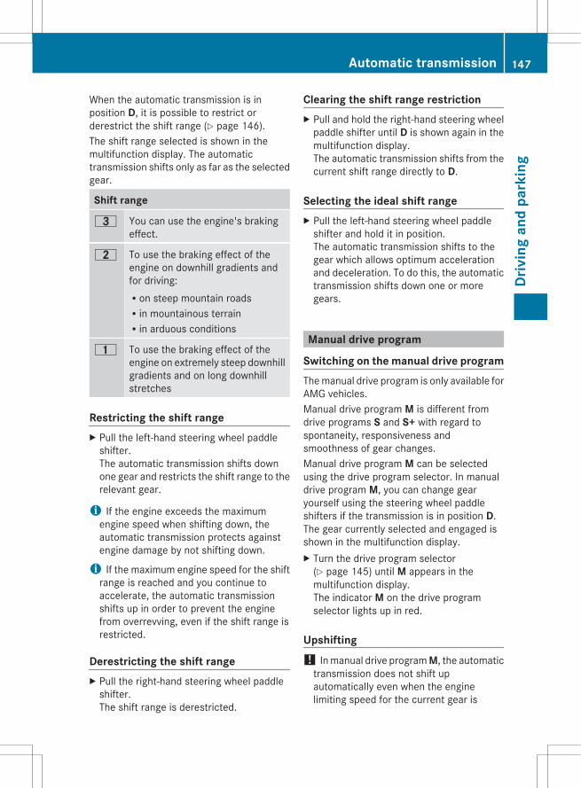
When the automatic transmission is inposition D, it is possible to restrict orderestrict the shift range (Y page 146).The shift range selected is shown in themultifunction display. The automatictransmission shifts only as far as the selectedgear.
Shift range
= You can use the engine's brakingeffect.
5 To use the braking effect of theengine on downhill gradients andfor driving:Ron steep mountain roadsRin mountainous terrainRin arduous conditions
4 To use the braking effect of theengine on extremely steep downhillgradients and on long downhillstretches
Restricting the shift rangeX Pull the left-hand steering wheel paddle
shifter.The automatic transmission shifts downone gear and restricts the shift range to therelevant gear.
i If the engine exceeds the maximumengine speed when shifting down, theautomatic transmission protects againstengine damage by not shifting down.
i If the maximum engine speed for the shiftrange is reached and you continue toaccelerate, the automatic transmissionshifts up in order to prevent the enginefrom overrevving, even if the shift range isrestricted.
Derestricting the shift rangeX Pull the right-hand steering wheel paddle
shifter.The shift range is derestricted.
Clearing the shift range restrictionX Pull and hold the right-hand steering wheel
paddle shifter until D is shown again in themultifunction display.The automatic transmission shifts from thecurrent shift range directly to D.
Selecting the ideal shift rangeX Pull the left-hand steering wheel paddle
shifter and hold it in position.The automatic transmission shifts to thegear which allows optimum accelerationand deceleration. To do this, the automatictransmission shifts down one or moregears.
Manual drive program
Switching on the manual drive programThe manual drive program is only available forAMG vehicles.Manual drive program M is different fromdrive programs S and S+ with regard tospontaneity, responsiveness andsmoothness of gear changes.Manual drive program M can be selectedusing the drive program selector. In manualdrive program M, you can change gearyourself using the steering wheel paddleshifters if the transmission is in position D.The gear currently selected and engaged isshown in the multifunction display.X Turn the drive program selector
(Y page 145) until M appears in themultifunction display.The indicator M on the drive programselector lights up in red.
Upshifting! In manual drive program M, the automatic
transmission does not shift upautomatically even when the enginelimiting speed for the current gear is
Automatic transmission 147
Driv
ing
and
park
ing
Z
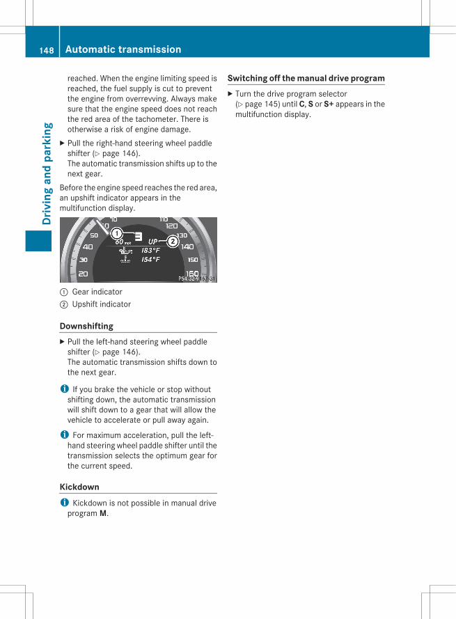
reached. When the engine limiting speed isreached, the fuel supply is cut to preventthe engine from overrevving. Always makesure that the engine speed does not reachthe red area of the tachometer. There isotherwise a risk of engine damage.
X Pull the right-hand steering wheel paddleshifter (Y page 146).The automatic transmission shifts up to thenext gear.
Before the engine speed reaches the red area,an upshift indicator appears in themultifunction display.
: Gear indicator; Upshift indicator
DownshiftingX Pull the left-hand steering wheel paddle
shifter (Y page 146).The automatic transmission shifts down tothe next gear.
i If you brake the vehicle or stop withoutshifting down, the automatic transmissionwill shift down to a gear that will allow thevehicle to accelerate or pull away again.
i For maximum acceleration, pull the left-hand steering wheel paddle shifter until thetransmission selects the optimum gear forthe current speed.
Kickdowni Kickdown is not possible in manual drive
program M.
Switching off the manual drive programX Turn the drive program selector
(Y page 145) until C, S or S+ appears in themultifunction display.
148 Automatic transmissionDr
ivin
g an
d pa
rkin
g

Problems with the transmission
Problem Possible causes/consequences and M Solutions
The transmission hasproblems shifting gear.
The transmission is losing oil.X Have the transmission checked at a qualified specialist
workshop immediately.
The acceleration abilityis deteriorating.The transmission nolonger changes gear.
The transmission is in emergency mode.It is only possible to shift into second gear and reverse gear.X Stop the vehicle.X Shift the transmission to position P.X Switch off the engine.X Wait at least 10seconds before restarting the engine.X Shift the transmission to position D or R.
If D is selected, the transmission shifts into second gear; if R isselected, the transmission shifts into reverse gear.
X Have the transmission checked at a qualified specialistworkshop immediately.
Refueling
Important safety notes
G WARNINGGasoline is highly flammable and poisonous.It burns violently and can cause seriouspersonal injury.Never allow sparks, flames or smokingmaterials near gasoline.Turn off the engine before refueling.Whenever you are around gasoline, avoidinhaling fumes and any skin or clothingcontact.Direct skin contact with fuels and theinhalation of fuel vapors are damaging to yourhealth.
G WARNINGOverfilling of the fuel tank may createpressure in the system which could cause agas discharge. This could cause the gasolineto spray back out when removing the fuelpump nozzle, which could cause personalinjury.
! Do not use diesel to refuel vehicles with agasoline engine. Even small amounts of thewrong fuel result in damage to the fuelsystem and engine.
! Do not switch on the ignition if youaccidentally refuel with the wrong fuel.Otherwise, the fuel will enter the fuel lines.Notify a qualified specialist workshop andhave the fuel tank and fuel lines drainedcompletely.
! Overfilling the fuel tank could damage thefuel system.
! Take care not to spill any fuel on paintedsurfaces. You could otherwise damage thepaintwork.
! Use a filter when refueling from a fuel can.Otherwise, the fuel lines and/or injectionsystem could be blocked by particles fromthe fuel can.
Further information on fuel and on fuel gradescan be found in the "Fuel" section(Y page 353).
Refueling 149
Driv
ing
and
park
ing
Z
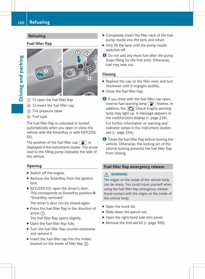
Refueling
Fuel filler flap
: To open the fuel filler flap; To insert the fuel filler cap= Tire pressure table? Fuel type
The fuel filler flap is unlocked or lockedautomatically when you open or close thevehicle with the SmartKey or with KEYLESS-GO.The position of the fuel filler cap 8 isdisplayed in the instrument cluster. The arrownext to the filling pump indicates the side ofthe vehicle.
OpeningX Switch off the engine.X Remove the SmartKey from the ignition
lock.X KEYLESS-GO: open the driver’s door.
This corresponds to SmartKey position 0:"SmartKey removed".The driver’s door can be closed again.
X Press the fuel filler flap in the direction ofarrow :.The fuel filler flap opens slightly.
X Open the fuel filler flap fully.X Turn the fuel filler flap counter-clockwise
and remove it.X Insert the fuel filler cap into the holder
bracket on the inside of filler flap ;.
X Completely insert the filler neck of the fuelpump nozzle into the tank and refuel.
X Only fill the tank until the pump nozzleswitches off.
i Do not add any more fuel after the pumpstops filling for the first time. Otherwise,fuel may leak out.
ClosingX Replace the cap on the filler neck and turn
clockwise until it engages audibly.X Close the fuel filler flap.
i If you drive with the fuel filler cap open,reserve fuel warning lamp 8 flashes. Inaddition, the ; Check Engine warninglamp may light up. A message appears inthe multifunction display (Y page 234).For further information on warning andindicator lamps in the instrument cluster,see (Y page 254).
i Close the fuel filler flap before locking thevehicle. Otherwise, the locking pin of thecentral locking prevents the fuel filler flapfrom closing.
Fuel filler flap emergency release
G WARNINGThe edges on the inside of the vehicle bodycan be sharp. You could injure yourself whenusing the fuel filler flap emergency release.Avoid contact with the edges on the inside ofthe vehicle body.
X Open the trunk lid.X Slide down the parcel net.X Open the right-hand side trim panel.X Remove the first-aid kit (Y page 300).
150 RefuelingDr
ivin
g an
d pa
rkin
g
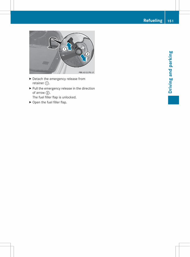
X Detach the emergency release fromretainer :.
X Pull the emergency release in the directionof arrow ;.The fuel filler flap is unlocked.
X Open the fuel filler flap.
Refueling 151
Driv
ing
and
park
ing
Z
Problems with fuel and the fuel tank
Problem Possible causes/consequences and M Solutions
Fuel is leaking from thevehicle.
G Risk of explosion or fireThe fuel line or the fuel tank is defective.X Turn the SmartKey to position 0 in the ignition lock immediately
and remove it (Y page 135).X Do not restart the engine under any circumstances.X Consult a qualified specialist workshop.
The fuel filler flapcannot be opened.
The fuel filler flap is not unlocked.orThe SmartKey battery is discharged.X Unlock the vehicle using the mechanical key (Y page 76).X Open the trunk lid.X Manually unlock the fuel filler flap using the emergency release
(Y page 150).
The fuel filler flap is unlocked, but the opening mechanism isjammed.X Consult a qualified specialist workshop.
Parking
Important safety notes
G WARNINGDo not park this vehicle in areas wherecombustible materials can come into contactwith the hot exhaust system. Do not park thevehicle on dry grassland or harvested grainfields. Combustible materials, such as grass,hay or leaves could be ignited by the hotexhaust system and cause a vehicle fire.Unintended vehicle movement can causeserious personal injury or damage to thevehicle or the vehicle drivetrain. To reducesuch risks, always do the following beforeturning off the engine and leaving the vehicle:Rkeep your right foot on the brake pedal.Rengage the parking brake.Rshift the automatic transmission to park
position P.
Rslowly release the brake pedal.Rwhen parked on an incline, always turn the
front wheels towards the road curb.Rturn the SmartKey in the ignition lock to
position 0 and remove the SmartKey fromthe ignition lock, or press the KEYLESS-GOStart/Stop button.Rtake the SmartKey with you and lock the
vehicle when leaving.
Switching off the engine
Important safety notes
G WARNINGDo not turn off the engine before the vehiclehas come to a complete stop. With the enginenot running, there is no power assistance forthe brake and steering systems. In this case,it is important to keep in mind that a
152 ParkingDr
ivin
g an
d pa
rkin
g

considerably higher degree of effort isnecessary to brake and steer the vehicle.
G WARNINGKeep in mind that turning off the engine aloneonly will shift the automatic transmission intoneutral position N automatically.Always shift the automatic transmission intopark position P before turning off the engine.Otherwise the vehicle could roll away whichcould result in an accident and/or seriouspersonal injury.
Vehicles with automatic transmissionX Apply the parking brake firmly.X Standard vehicles: shift the transmission
to P.
Selector lever in AMG vehicles with P buttonX AMG vehicles: press P button :.
Using the SmartKeyX Turn the SmartKey to position 0 in the
ignition lock and remove it.The immobilizer is activated.
i If you turn off the engine with theSmartKey and then remove it from theignition lock or open a front door, theautomatic transmission shifts to Pautomatically.
Using KEYLESS-GOX Press the Start/Stop button (Y page 135).
The engine stops and all the indicatorlamps in the instrument cluster go out.
i When the driver's door is closed, thiscorresponds to SmartKey position 1. Whenthe driver's door is open, it corresponds toSmartKey position 0 or "SmartKeyremoved".
i If you use the Start/Stop button to switchoff the engine, the automatic transmissionshifts to N automatically. If you then openthe driver's or front-passenger door, theautomatic transmission shifts to P.
i The engine can be turned off while thevehicle is in motion by pressing and holdingthe Start/Stop button for three seconds.This function operates independently fromthe ECO start/stop automatic engineswitch-off function.
Parking brake
G WARNINGEngaging the parking brake while the vehicleis in motion can cause the rear wheels to lockup. You could lose control of the vehicle andcause an accident. In addition, the vehicle'sbrake lights do not light up when the parkingbrake is engaged.
G WARNINGWhen leaving the vehicle, always remove theSmartKey from the starter switch, take it withyou, and lock the vehicle. Do not leavechildren unattended in the vehicle, or withaccess to an unlocked vehicle. Children couldrelease the parking brake and/or shift theautomatic transmission out of park positionP, either of which could result in an accidentand/or serious personal injury.
Parking 153
Driv
ing
and
park
ing
Z
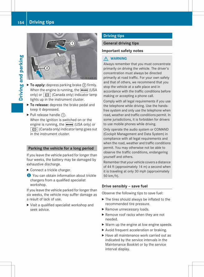
X To apply: depress parking brake ; firmly.When the engine is running, the $ (USAonly) or J (Canada only) indicator lamplights up in the instrument cluster.
X To release: depress the brake pedal andkeep it depressed.
X Pull release handle :.When the ignition is switched on or theengine is running, the $ (USA only) orJ (Canada only) indicator lamp goes outin the instrument cluster.
Parking the vehicle for a long periodIf you leave the vehicle parked for longer thanfour weeks, the battery may be damaged byexhaustive discharge.X Connect a trickle charger.i You can obtain information about trickle
chargers from a qualified specialistworkshop.
If you leave the vehicle parked for longer thansix weeks, the vehicle may suffer damage asa result of lack of use.X Visit a qualified specialist workshop and
seek advice.
Driving tips
General driving tips
Important safety notes
G WARNINGAlways remember that you must concentrateprimarily on driving the vehicle. The driver'sconcentration must always be directedprimarily at road traffic. For your own safetyand that of others, we recommend that youstop the vehicle at a safe place and inaccordance with the traffic conditions beforemaking or accepting a phone call.Comply with all legal requirements if you usethe telephone while driving. Use the hands-free system and only use the telephone whenroad, weather and traffic conditions permit. Insome jurisdictions, it is forbidden for driversto use mobile phones while driving.Only operate the audio system or COMAND(Cockpit Management and Data System) incompliance with all legal requirements andwhen the road, weather and traffic conditionspermit. You may otherwise not be able toobserve the traffic conditions, endangeringyourself and others.Remember that your vehicle covers a distanceof 44 ft (approximately 14 m) a second whenit is traveling at only 30 mph (approximately50 km/h).
Drive sensibly – save fuelObserve the following tips to save fuel:X The tires should always be inflated to the
recommended tire pressure.X Remove unnecessary loads.X Remove roof racks when they are not
needed.X Warm up the engine at low engine speeds.X Avoid frequent acceleration or braking.X Have all maintenance work carried out as
indicated by the service intervals in theMaintenance Booklet or by the serviceinterval display.
154 Driving tipsDr
ivin
g an
d pa
rkin
g
Fuel consumption also increases whendriving in cold weather, in stop-and-go trafficand in mountainous terrain.
Drinking and driving
G WARNINGDrinking and driving and/or taking drugs anddriving are very dangerous combinations.Even a small amount of alcohol or drugs canaffect your reflexes, perceptions andjudgment.The possibility of a serious or even fatalaccident are greatly increased when you drinkor take drugs and drive.Do not drink or take drugs and drive or allowanyone to drive who has been drinking ortaking drugs.
Pedals
G WARNINGMake sure absolutely no objects areobstructing the pedals' range of movement.Keep the driver's footwell clear of allobstacles. If there are any floormats orcarpets in the footwell, make sure that thepedals still have sufficient clearance.During sudden driving or braking maneuvers,the objects could get caught between thepedals. You could then no longer brake oraccelerate. This could lead to accidents andinjury.
Rolling with the engine switched off
G WARNINGThere is no power assistance for the steeringand the brake when the engine is not running.Steering and braking requires significantlymore effort and you could lose control of thevehicle and cause an accident as a result.Do not turn off the engine while the vehicle isin motion.
Exhaust check
G WARNINGInhalation of exhaust gas is hazardous to yourhealth. All exhaust gas contains carbonmonoxide (CO), and inhaling it can causeunconsciousness and possible death.Do not run the engine in confined areas (suchas a garage) which are not properly ventilated.If you think that exhaust gas fumes areentering the vehicle while driving, have thecause determined and correctedimmediately. If you must drive under theseconditions, drive only with at least onewindow fully open at all times.
Certain engine systems are designed to keepthe level of poisonous components in exhaustfumes within legal limits.These systems only work at peak efficiency ifthey are serviced exactly in accordance withthe manufacturer's specifications. For thisreason, all work on the engine should only becarried out by qualified and authorizedMercedes-Benz technicians.The engine settings must not be changedunder any circumstances. Furthermore, allspecific service work must be carried out atregular intervals and in accordance with theMercedes-Benz service requirements. Detailscan be found in the Maintenance Booklet.
Brakes
Important safety notes
G WARNINGOn slippery road surfaces, never downshift inorder to obtain braking action. This couldresult in drive wheel slip and reduced vehiclecontrol. Your vehicle's ABS will not preventthis type of loss of control.
G WARNINGMake sure that you do not endanger otherroad users when you apply the brakes.
Driving tips 155
Driv
ing
and
park
ing
Z
Downhill gradients! On long and steep gradients, you must
reduce the load on the brakes by shiftingearly to a lower gear. This allows you to takeadvantage of the engine braking effect andhelps avoid overheating and excessivewear of the brakes.When you take advantage of the enginebraking effect, a drive wheel may not turnfor some time, e.g. on a slippery roadsurface. This could cause damage to thedrive train. This type of damage is notcovered by the Mercedes-Benz warranty.
Heavy and light loads
G WARNINGDepressing the brake pedal constantly resultsin excessive and premature wear to the brakepads.It may also cause the brakes to overheat,seriously impairing their effectiveness. It maythen not be possible to stop the vehicle insufficient time to avoid an accident.
If the brakes have been subjected to a heavyload, do not stop the vehicle immediately, butdrive on for a short while. This allows theairflow to cool the brakes more quickly.
Wet roads
G WARNINGAfter driving in heavy rain for some timewithout applying the brakes or through waterdeep enough to wet brake components, thefirst braking action may be somewhatreduced. You have to depress the brake pedalmore firmly. Maintain a safe distance fromvehicles in front.
After driving on a wet road or having thevehicle washed, brake firmly while payingattention to the traffic conditions. This willwarm up the brake discs, thereby drying themmore quickly and protecting them againstcorrosion.
Limited braking performance on salt-treated roads
G WARNINGThe layer of salt on the brake discs and thebrake pads/linings may cause a delay in thebraking effect, resulting in a significantlylonger braking distance, which could lead toan accident.To avoid this danger, you should:Roccasionally brake carefully, without
putting other road users at risk, when youare driving on salted roads. This helps toremove any salt that may have started tobuild up on the brake discs and the brakepads/linings.Rmaintain a greater distance to the vehicle
ahead and drive with particular care.Rcarefully apply the brakes at the end of a
trip and immediately after commencing anew trip, so that salt residues are removedfrom the brake discs.
Servicing the brakes! If the red brake warning lamp lights up in
the instrument cluster and you hear awarning tone while the engine is running,the brake fluid level may be too low.Observe additional warning messages inthe multifunction display.The brake fluid level may be too low due tobrake pad wear or leaking brake lines.Have the brake system checkedimmediately. This work should be carriedout at a qualified specialist workshop.
All checks and maintenance work on thebrake system must be carried out at aqualified specialist workshop. Consult aqualified specialist workshop to arrange this.Have brake pads installed and brake fluidreplaced at a qualified specialist workshop.
G WARNINGIf brake pads or brake fluid other than thoserecommended are used, the braking
156 Driving tipsDr
ivin
g an
d pa
rkin
g
properties of the vehicle can be degraded toan extent that safe braking is substantiallyimpaired. This could result in an accident.
! Vehicles with 4MATIC: function orperformance tests may only be carried outon a 2-axle dynamometer. If you areplanning to have the vehicle tested on sucha dynamometer, contact an authorizedMercedes-Benz Center to obtain furtherinformation first. Otherwise, you coulddamage the drive train or the brake system.
! Vehicles with 4MATIC: as the ESP®
system operates automatically, the engineand the ignition must be switched off(SmartKey in position 0 or 1 in the ignitionlock or Start/Stop button in position 0 or1) while the parking brake is being testedon a brake dynamometer.Braking maneuvers triggered automaticallyby ESP® may seriously damage the brakesystem.
! Vehicles with 4MATIC: as the ESP®
system operates automatically, the engineand the ignition system must be switchedoff (SmartKey in position 0 or 1 in theignition lock or Start/Stop button inposition 0 or 1) when:Rtesting the parking brake on a brake
dynamometer.Ryou intend to have the vehicle towed with
one of the axles raised.Braking maneuvers triggered automaticallyby ESP® may seriously damage the brakesystem.
If the brake system has only been subject tomoderate loads, you should test thefunctionality of your brakes at regularintervals. To do so, press firmly on the brakepedal when driving at a high speed. Thisimproves the grip of the brake pads.
G WARNINGMake sure that you do not endanger otherroad users when you apply the brakes.
You can find a description of Brake Assist(BAS) on (Y page 64) or of BAS PLUS on(Y page 64).
AMG high-performance and ceramicbrakesThe high-performance brake system isinstalled only on the CLS 63 AMG.
G WARNINGNew vehicle brake pads and discs, andreplacement brake pads and discs may takeseveral hundred miles of driving until theyprovide optimum braking efficiency. Until thattime, you may need to use increased brakepedal pressure while braking. Please be awareof this and adjust your driving and brakingaccordingly during this break-in period.Excessive high-demand braking will causecorrespondingly high brake wear. Please beattentive to the brake warning lamp in theinstrument cluster and brake conditionmessages in the multifunction display.Especially for high performance driving, it isimportant to maintain and have the brakesystem checked regularly.
The AMG brake systems are designed forheavy loads. This may lead to noise whenbraking. This will depend on:RspeedRbraking forceRenvironmental conditions, such as
temperature and humidityThe wear of individual components of thebrake system, such as the brake pads/liningsor brake discs, depends on the individualdriving style and operating conditions.For this reason, it is impossible to state amileage that will be valid under allcircumstances. An aggressive driving stylewill lead to high wear. You can obtain furtherinformation about this from your authorizedMercedes-Benz Center.
Driving tips 157
Driv
ing
and
park
ing
Z
Driving on wet roads
HydroplaningIf water has accumulated to a certain depthon the road surface, there is a danger ofhydroplaning occurring, even if:Ryou drive at low speeds.Rthe tires have adequate tread depth.For this reason, in the event of heavy rain orin conditions in which hydroplaning canoccur, you must drive in the followingmanner:Rlower your speed.Ravoid ruts.Rbrake carefully.
Driving on flooded roads! Do not drive through flooded areas.
Check the depth of any water before drivingthrough it. Drive slowly through standingwater. Otherwise, water may enter thevehicle interior or the engine compartment.This can damage the electroniccomponents in the engine or the automatictransmission. Water can also be drawn inby the engine's air suction nozzles and thiscan cause engine damage.
Winter driving
Important safety notes
G WARNINGIf the vehicle becomes trapped in snow,ensure that snow is kept away from theexhaust pipe and from around the vehicle aslong as the engine is running. Otherwise,poisonous carbon monoxide (CO) may enterthe vehicle, resulting in loss of consciousnessand even death.To assure sufficient fresh air ventilation, opena window slightly on the side of the vehiclenot facing the wind.
Have your vehicle winterproofed at a qualifiedspecialist workshop at the onset of winter.Observe the notes in the "Winter operation"section (Y page 322).
Driving with summer tiresObserve the notes in the "Winter operation"section (Y page 322).
Slippery road surfaces
G WARNINGThe outside temperature indicator is notdesigned to serve as an ice-warning deviceand is therefore unsuitable for that purpose.Indicated temperatures just above thefreezing point do not guarantee that the roadsurface is free of ice. The road may still be icy,especially in wooded areas or on bridges.
G WARNINGOn slippery road surfaces, never downshift inorder to obtain braking action. This couldresult in drive wheel slip and reduced vehiclecontrol. Your vehicle's ABS will not preventthis type of loss of control.
Drive particularly carefully on slippery roadsurfaces. Avoid sudden acceleration, steeringand braking maneuvers. Do not use the cruisecontrol or DISTRONIC PLUS.If the vehicle threatens to skid or cannot bestopped when moving at low speed:X Shift the transmission to position N.
i For more information on driving withsnow chains, see (Y page 323).
G WARNINGMake sure that you do not endanger otherroad users when you apply the brakes.
158 Driving tipsDr
ivin
g an
d pa
rkin
g
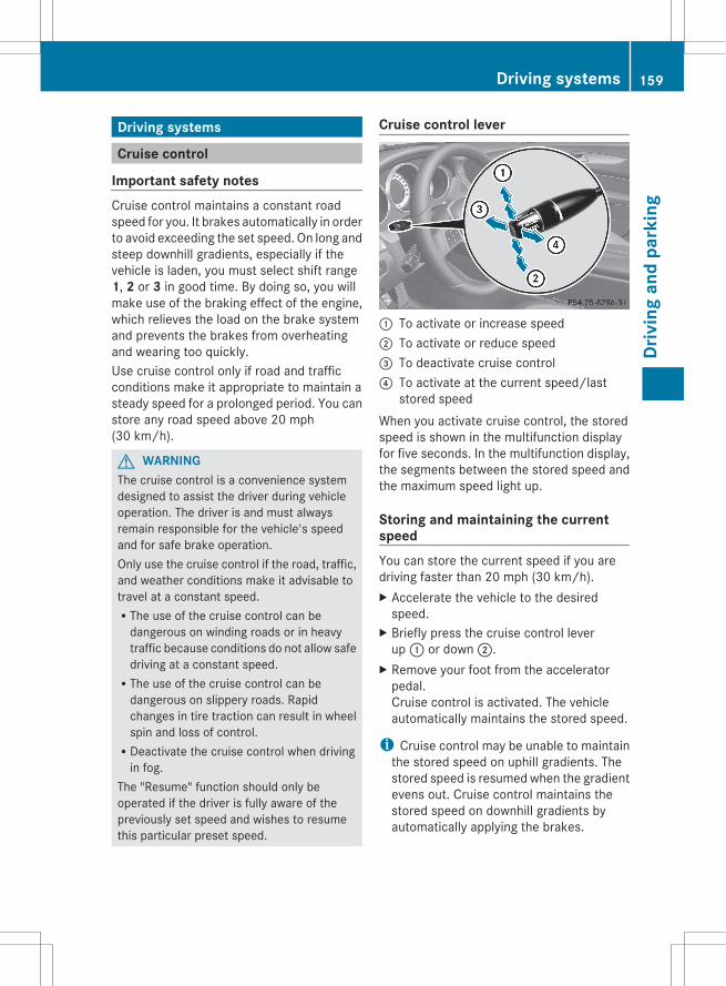
Driving systems
Cruise control
Important safety notesCruise control maintains a constant roadspeed for you. It brakes automatically in orderto avoid exceeding the set speed. On long andsteep downhill gradients, especially if thevehicle is laden, you must select shift range1, 2 or 3 in good time. By doing so, you willmake use of the braking effect of the engine,which relieves the load on the brake systemand prevents the brakes from overheatingand wearing too quickly.Use cruise control only if road and trafficconditions make it appropriate to maintain asteady speed for a prolonged period. You canstore any road speed above 20 mph(30 km/h).
G WARNINGThe cruise control is a convenience systemdesigned to assist the driver during vehicleoperation. The driver is and must alwaysremain responsible for the vehicle's speedand for safe brake operation.Only use the cruise control if the road, traffic,and weather conditions make it advisable totravel at a constant speed.RThe use of the cruise control can be
dangerous on winding roads or in heavytraffic because conditions do not allow safedriving at a constant speed.RThe use of the cruise control can be
dangerous on slippery roads. Rapidchanges in tire traction can result in wheelspin and loss of control.RDeactivate the cruise control when driving
in fog.The "Resume" function should only beoperated if the driver is fully aware of thepreviously set speed and wishes to resumethis particular preset speed.
Cruise control lever
: To activate or increase speed; To activate or reduce speed= To deactivate cruise control? To activate at the current speed/last
stored speedWhen you activate cruise control, the storedspeed is shown in the multifunction displayfor five seconds. In the multifunction display,the segments between the stored speed andthe maximum speed light up.
Storing and maintaining the currentspeedYou can store the current speed if you aredriving faster than 20 mph (30 km/h).X Accelerate the vehicle to the desired
speed.X Briefly press the cruise control lever
up : or down ;.X Remove your foot from the accelerator
pedal.Cruise control is activated. The vehicleautomatically maintains the stored speed.
i Cruise control may be unable to maintainthe stored speed on uphill gradients. Thestored speed is resumed when the gradientevens out. Cruise control maintains thestored speed on downhill gradients byautomatically applying the brakes.
Driving systems 159
Driv
ing
and
park
ing
Z
Storing the current speed or calling upthe last stored speed
G WARNINGThe set speed stored in memory should onlybe set again if prevailing road conditions andlegal speed limits permit. Possibleacceleration or deceleration differencesarising from returning to the preset speedcould cause an accident and/or serious injuryto you and others.
X Briefly pull the cruise control lever towardsyou ?.
X Remove your foot from the acceleratorpedal.The first time cruise control is activated, itstores the current speed or regulates thespeed of the vehicle to the previouslystored speed.
Setting a speed
G WARNINGKeep in mind that it may take a brief momentuntil the vehicle has made the necessaryadjustments.Increase or decrease the set vehicle speed toa value that the prevailing road conditions andlegal speed limits permit. Otherwise, suddenand unexpected acceleration or decelerationof the vehicle could cause an accident and/or serious injury to you and others.
X Press the cruise control lever up : for ahigher speed or down ; for a lower speed.
X To adjust the speed in 1 mph increments (1 km/h increments): brieflypress the cruise control lever up : ordown ; to the pressure point.The last speed stored is increased ordecreased every time the cruise controllever is pushed up : or down ;.
X To adjust the speed in 5 mph increments (10 km/h increments): briefly press the cruise control lever
up : or down ; beyond the pressurepoint.The last speed stored is increased ordecreased every time the cruise controllever is pushed up : or down ;.
i Cruise control is not deactivated if youdepress the accelerator pedal. Forexample, if you accelerate briefly toovertake, cruise control adjusts thevehicle's speed to the last speed storedafter you have finished overtaking.
Deactivating cruise controlThere are several ways to deactivate cruisecontrol:X Briefly press the cruise control lever
forwards =.orX Brake.Cruise control is automatically deactivated if:Ryou depress the parking brake.Ryou are driving at less than 20 mph
(30 km/h)RESP® intervenes or you deactivate ESP®.Ryou shift the transmission to position N
while driving.Ryou shift the transmission to position N
while driving.If cruise control is deactivated, you will heara warning tone. You will see the Cruise Control Off message in the multifunctiondisplay for approximately five seconds.
i When you switch off the engine, the lastspeed stored is cleared.
DISTRONIC PLUS
Important safety notesDISTRONIC PLUS regulates the speed andautomatically helps you maintain thedistance to the vehicle detected in front.
160 Driving systemsDr
ivin
g an
d pa
rkin
g

DISTRONIC PLUS brakes automatically sothat the set speed is not exceeded.On long and steep downhill gradients,especially if the vehicle is laden, you mustselect shift range 1, 2 or 3 in good time. Bydoing so, you will make use of the brakingeffect of the engine, which relieves the loadon the brake system and prevents the brakesfrom overheating and wearing too quickly.If DISTRONIC PLUS detects a slower-movingvehicle in front, your vehicle is braked in orderto maintain the preset distance to the vehiclein front.
G WARNINGThe DISTRONIC PLUS requires familiarity withits operational characteristics. We stronglyrecommend that you review the followinginformation carefully before operating thesystem.
G WARNINGThe DISTRONIC PLUS is a conveniencesystem. Its speed adjustment reductioncapability is intended to make cruise controlmore effective and usable when traffic speedsvary. It is not however, intended to, nor doesit, replace the need for extreme care.The responsibility for the vehicle's speed,distance to the preceding vehicle and, mostimportantly, brake operation to ensure a safestopping distance, always remains with thedriver.The DISTRONIC PLUS cannot take street andtraffic conditions into account.Complex driving situations are not alwaysfully recognized by the DISTRONIC PLUS. Thiscould result in wrong or missing distancewarnings.
If you want DISTRONIC PLUS to assist you,the radar sensor system must be activated(Y page 215) and operational.If there is no vehicle in front, DISTRONICPLUS operates in the same way as cruisecontrol in the speed range between 20 mph(Canada: 30 km/h) and 120 mph (Canada:
200 km/h). If a vehicle is driving in front ofyou, it operates in the speed range between0 mph (0 km/h) and 120 mph (Canada:200 km/h).Do not use DISTRONIC PLUS while driving onroads with steep gradients.As DISTRONIC PLUS transmits radar waves,it can resemble the radar detectors of theresponsible authorities. You can refer to therelevant chapter in the Operator's Manual ifquestions are asked about this.
i USA only:This device has been approved by the FCCas a “Vehicular Radar System”. The radarsensor is intended for use in an automotiveradar system only. Removal, tampering, oraltering of the device will void anywarranties, and is not permitted by theFCC. Do not tamper with, alter, or use inany non-approved way.Any unauthorized modification to thisdevice could void the user’s authority tooperate the equipment.
i Canada only: This device complies withRSS-210 of Industry Canada. Operation issubject to the following two conditions:1. This device may not cause interference,and2. this device must accept any interferencereceived, including interference that maycause undesired operation of the device.Removal, tampering, or altering of thedevice will void any warranties and is notpermitted. Do not tamper with, alter, or usethe device in any non-approved way.Any unauthorized modification to thisdevice could void the user's authority tooperate the equipment.
G WARNINGDISTRONIC PLUS distance is not a substitutefor the active intervention of the driver. It doesnot detect pedestrians or stationary objects,nor can it detect, recognize or predict theroad's course or the movements of vehicles
Driving systems 161
Driv
ing
and
park
ing
Z
in front. DISTRONIC PLUS can only brake thevehicle using 40% of the vehicle's maximumavailable brake force.DISTRONIC PLUS may not detect narrowvehicles driving in front, e.g. motorcycles, orvehicles driving in the lane beyond the lanenext to your vehicle, especially if the vehiclesare not driving on the middle of their lane.The driver must always pay careful attentionto the road, weather and traffic conditions.The driver must drive, steer and brake in amanner which will allow him to always havecontrol of the vehicle.Sources of high-frequency radio waves, suchas toll stations, speed-measuring radar, etc.,can cause DISTRONIC PLUS to failtemporarily.
G WARNINGThe DISTRONIC PLUS cannot take road andtraffic conditions into account. Only use theDISTRONIC PLUS if the road, weather andtraffic conditions make it advisable to travelat a constant speed.
G WARNINGUse of the DISTRONIC PLUS can bedangerous on slippery roads. Rapid changesin tire traction can result in wheel spin andloss of control.The DISTRONIC PLUS does not function inadverse sight and distance conditions. Do notuse the DISTRONIC PLUS during conditions offog, heavy rain, snow or sleet.
G WARNINGThe DISTRONIC PLUS cannot take weatherconditions into account. Switch off theDISTRONIC PLUS or do not switch it on if:Rroads are slippery or covered with snow or
ice. The wheels could lose traction whilebraking or accelerating, and the vehiclecould skid.Rthe DISTRONIC PLUS system sensor covers
are dirty or visibility is diminished due tosnow, rain or fog, for example. The distance
control system functionality could beimpaired.
Always pay attention to surrounding trafficconditions even while the DISTRONIC PLUS isswitched on. Otherwise, you may not be ableto recognize dangerous situations until it istoo late. This could cause an accident in whichyou and/or others could be injured.
G WARNINGThe "Resume" function should only beoperated if the driver is fully aware of thepreviously set speed and wishes to resumethis particular preset speed.
G WARNINGYour undivided attention to street and trafficconditions is necessary at all times whetherDISTRONIC PLUS is active or not.The use of DISTRONIC PLUS can bedangerous on winding roads or in heavy trafficbecause conditions do not allow safe drivingat a constant speed.DISTRONIC PLUS does not react to stationaryobjects on the road (for example, a vehiclestopped in traffic or an abandoned vehicle).DISTRONIC PLUS likewise does not react tooncoming vehicles.Deactivate DISTRONIC PLUS:Rwhen changing to the right lane, if the
vehicles in the left lane are driving slowerRwhen driving into a filter lane or an
expressway exitRin complex driving situations, for example
in construction sites on an expresswayIn these situations DISTRONIC PLUS willmaintain the set speed if it is not deactivated.DISTRONIC PLUS is intended only formaintaining a set speed and a set distancefrom the objects moving in front of thevehicle.
G WARNINGAn intermittent warning sounds and thedistance warning lamp · in the instrument
162 Driving systemsDr
ivin
g an
d pa
rkin
g
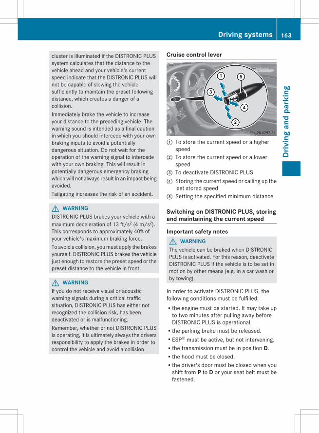
cluster is illuminated if the DISTRONIC PLUSsystem calculates that the distance to thevehicle ahead and your vehicle's currentspeed indicate that the DISTRONIC PLUS willnot be capable of slowing the vehiclesufficiently to maintain the preset followingdistance, which creates a danger of acollision.Immediately brake the vehicle to increaseyour distance to the preceding vehicle. Thewarning sound is intended as a final cautionin which you should intercede with your ownbraking inputs to avoid a potentiallydangerous situation. Do not wait for theoperation of the warning signal to intercedewith your own braking. This will result inpotentially dangerous emergency brakingwhich will not always result in an impact beingavoided.Tailgating increases the risk of an accident.
G WARNINGDISTRONIC PLUS brakes your vehicle with amaximum deceleration of 13 ft/s2 (4 m/s2).This corresponds to approximately 40% ofyour vehicle's maximum braking force.To avoid a collision, you must apply the brakesyourself. DISTRONIC PLUS brakes the vehiclejust enough to restore the preset speed or thepreset distance to the vehicle in front.
G WARNINGIf you do not receive visual or acousticwarning signals during a critical trafficsituation, DISTRONIC PLUS has either notrecognized the collision risk, has beendeactivated or is malfunctioning.Remember, whether or not DISTRONIC PLUSis operating, it is ultimately always the driversresponsibility to apply the brakes in order tocontrol the vehicle and avoid a collision.
Cruise control lever
: To store the current speed or a higherspeed
; To store the current speed or a lowerspeed
= To deactivate DISTRONIC PLUS? Storing the current speed or calling up the
last stored speedA Setting the specified minimum distance
Switching on DISTRONIC PLUS, storingand maintaining the current speed
Important safety notesG WARNINGThe vehicle can be braked when DISTRONICPLUS is activated. For this reason, deactivateDISTRONIC PLUS if the vehicle is to be set inmotion by other means (e.g. in a car wash orby towing).
In order to activate DISTRONIC PLUS, thefollowing conditions must be fulfilled:Rthe engine must be started. It may take up
to two minutes after pulling away beforeDISTRONIC PLUS is operational.Rthe parking brake must be released.RESP® must be active, but not intervening.Rthe transmission must be in position D.Rthe hood must be closed.Rthe driver's door must be closed when you
shift from P to D or your seat belt must befastened.
Driving systems 163
Driv
ing
and
park
ing
Z
Rthe front-passenger door and rear doorsmust be closed.Rthe vehicle must not skid.
Activating while drivingWhen driving at speeds below 20 mph(30 km/h), you can only activate DISTRONICPLUS if the vehicle in front has been detectedand is shown in the multifunction display. Ifthe vehicle in front is no longer detected anddisplayed, DISTRONIC PLUS switches off anda tone sounds.X Briefly pull the cruise control lever towards
you ?, or press it up : or down ;.DISTRONIC PLUS is selected.
X Press the cruise control lever repeatedlyup : or down ; until the desired speedis set.
X Remove your foot from the acceleratorpedal.Your vehicle adapts its speed to that of thevehicle in front, but only up to the desiredstored speed.
i If you do not fully release the acceleratorpedal, the DISTRONIC PLUS Overridemessage appears in the multifunctiondisplay. The set distance to a slower-moving vehicle in front will then not bemaintained. You will be driving at the speedyou determine by the position of theaccelerator pedal.
Activating when driving towards astationary vehicleIf the vehicle in front of you is stationary, youcan only activate DISTRONIC PLUS once yourvehicle is stationary as well.X Briefly pull the cruise control lever towards
you ?, or press it up : or down ;.DISTRONIC PLUS is selected.
i DISTRONIC PLUS can only be activated atunder 20 mph (30km/h) if a vehicle in fronthas been detected. Therefore, theDISTRONIC PLUS distance display in the
instrument cluster should be activated(Y page 210).
X Press the cruise control lever repeatedlyup : or down ; until the desired speedis set.
i You can use the cruise control lever to setthe stored speed and the control on thecruise control lever to set the specifiedminimum distance (Y page 166).
Pulling awayX If the vehicle in front pulls away: remove
your foot from the brake pedal.X Briefly pull the cruise control lever towards
you ?.orX Accelerate briefly.
Your vehicle pulls away and adapts itsspeed to that of the vehicle in front.
DrivingIf there is no vehicle in front, DISTRONICPLUS operates in the same way as cruisecontrol.If DISTRONIC PLUS detects that the vehiclein front has slowed down, it brakes yourvehicle. In this way, the distance you haveselected is maintained.If DISTRONIC PLUS detects that the vehiclein front is driving faster, it accelerates yourvehicle, but only up to the speed you havestored.
G WARNINGIf you depress the brake, DISTRONIC PLUS isdeactivated unless your vehicle is stationary.DISTRONIC PLUS then no longer brakes yourvehicle. In such cases, control the distancefrom vehicles travelling in front with the brakealone. You could otherwise cause an accidentand thereby injure yourself and others. Thedriver remains fully responsible for thevehicle's distance from other vehicles, thespeed being driven and for braking in goodtime.
164 Driving systemsDr
ivin
g an
d pa
rkin
g
Changing lanesIf you change to the passing lane, DISTRONICPLUS supports you when:Ryou are driving faster than 40mph
(60 km/h).RDISTRONIC PLUS is maintaining the
distance to a vehicle in front.Ryou switch on the appropriate turn signal.RDISTRONIC PLUS does not detect a danger
of collision.If these conditions are fulfilled, your vehicleis accelerated. Acceleration will beinterrupted if changing lanes takes too longor if the distance between your vehicle andthe vehicle in front becomes too small.
i When changing lanes, DISTRONIC PLUSmonitors the left lane on left-hand drivevehicles and the right lane on right-handdrive vehicles.
G WARNINGDISTRONIC PLUS and Active Blind Spot Assistare only aids designed to assist driving.They do not relieve you of the responsibilityof paying attention. The driver remains fullyresponsible for the vehicle's distance fromother vehicles, the vehicle's speed and forbraking in good time. Always pay attention totraffic conditions and your surroundings.Otherwise, you may fail to recognize dangersin time, cause an accident and injure yourselfand others.
StoppingG WARNINGNever get out of the vehicle when DISTRONICPLUS is activated.DISTRONIC PLUS must also never beoperated, activated or deactivated by apassenger or from outside the vehicle.DISTRONIC PLUS does not replace theparking brake and must not be used forparking.
The DISTRONIC PLUS braking effect iscanceled and the vehicle can start moving if:RDISTRONIC PLUS is deactivated using the
cruise control lever.Ryou accelerate.Rthere is a malfunction in the system or an
interruption in the power supply, e.g.battery failure.Rthe electrical system in the engine
compartment, the battery or the fuses aretampered with.Rthe battery is disconnected.If you wish to leave the vehicle or park it,deactivate DISTRONIC PLUS and secure thevehicle against rolling away.
If DISTRONIC PLUS detects that the vehiclein front is stopping, it brakes your vehicle untilit is stationary.Once your vehicle is stationary, it remainsstationary and you do not need to depress thebrake.
i Depending on the specified minimumdistance, your vehicle will come to astandstill at a sufficient distance behind thevehicle in front. The specified minimumdistance is set using the control on thecruise control lever.
When DISTRONIC PLUS is activated, thetransmission is shifted automatically toposition P if:Rthe driver's door is open and the driver's
seat belt is unfastened.Rthe engine is switched off.Rthe hood is opened.Ra system malfunction occurs.Rthe power supply is not sufficient.
Setting a speed
G WARNINGKeep in mind that it may take a brief momentuntil the vehicle has made the necessaryadjustments.
Driving systems 165
Driv
ing
and
park
ing
Z

Increase or decrease the set vehicle speed toa value that the prevailing road conditions andlegal speed limits permit. Otherwise, suddenand unexpected acceleration or decelerationof the vehicle could cause an accident and/or serious injury to you and others.
X Press the cruise control lever up : for ahigher speed or down ; for a lower speed.
X To adjust the speed in 1 mph increments (1 km/h increments): brieflypress the cruise control lever up : ordown ; to the pressure point.The last speed stored is increased ordecreased every time the cruise controllever is pushed up : or down ;.
X To adjust the speed in 5 mph increments (10 km/h increments): briefly press the cruise control leverup : or down ; beyond the pressurepoint.The last speed stored is increased ordecreased every time the cruise controllever is pushed up : or down ;.
i DISTRONIC PLUS is not deactivated if youdepress the accelerator pedal. If youaccelerate to overtake, DISTRONIC PLUSadjusts the vehicle's speed to the lastspeed stored after you have finishedovertaking.
Storing the current speed or calling upa stored speed
G WARNINGThe set speed stored in memory should onlybe set again if prevailing road conditions andlegal speed limits permit. Possibleacceleration or deceleration differencesarising from returning to the preset speedcould cause an accident and/or serious injuryto you and others.
X Briefly pull the cruise control lever towardsyou ?.
X Remove your foot from the acceleratorpedal.DISTRONIC PLUS is activated. The firsttime it is activated, the current speed isstored. Otherwise, it sets the vehicle cruisespeed to the previously stored value.
Setting the specified minimum distanceYou can set the specified minimum distancefor DISTRONIC PLUS by varying the time spanbetween one and two seconds. With thisfunction, you can set the minimum distancethat DISTRONIC PLUS keeps to the vehicle infront, dependent on vehicle speed. You cansee this distance in the multifunction display(Y page 167).
G WARNINGIt is up to the driver to exercise discretion toselect the appropriate setting given roadconditions, traffic, driver's preferred drivingstyle and applicable laws and drivingrecommendations for safe following distance.
166 Driving systemsDr
ivin
g an
d pa
rkin
g
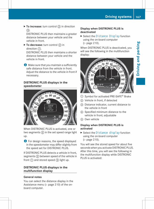
X To increase: turn control ; in direction=.DISTRONIC PLUS then maintains a greaterdistance between your vehicle and thevehicle in front.
X To decrease: turn control ; indirection :.DISTRONIC PLUS then maintains a shorterdistance between your vehicle and thevehicle in front.
i Make sure that you maintain a sufficientlysafe distance from the vehicle in front.Adjust the distance to the vehicle in front ifnecessary.
DISTRONIC PLUS displays in thespeedometer
When DISTRONIC PLUS is activated, one ortwo segments ; in the set speed range lightup.
i For design reasons, the speed displayedin the speedometer may differ slightly fromthe speed set for DISTRONIC PLUS.
If DISTRONIC PLUS detects a vehicle in front,segments ; between speed of the vehicle infront : and stored speed = light up.
DISTRONIC PLUS displays in themultifunction display
General notesYou can select the distance display in theAssistance menu (Y page 210) of the on-board computer.
Display when DISTRONIC PLUS isdeactivatedX Select the Distance Display function
using the on-board computer(Y page 210).
When DISTRONIC PLUS is deactivated, youwill see the following in the multifunctiondisplay:
: Symbol for activated PRE-SAFE® Brake; Vehicle in front, if detected= Distance indicator, current distance to
the vehicle in front? Specified minimum distance to the
vehicle in front; adjustableA Own vehicle
Display when DISTRONIC PLUS isactivatedX Select the Distance display function
using the on-board computer(Y page 210).
You will see the stored speed for about fiveseconds when you activate DISTRONIC PLUS.After this time, you will see the following inthe multifunction display while DISTRONICPLUS is activated:
Driving systems 167
Driv
ing
and
park
ing
Z

: DISTRONIC PLUS activated; Own vehicle= Specified minimum distance to the
vehicle in front; adjustable? Vehicle in front, if detected
Deactivating DISTRONIC PLUS
There are several ways to deactivateDISTRONIC PLUS:X Briefly press the cruise control lever
forwards :.orX Brake, unless the vehicle is stationary.When you deactivate DISTRONIC PLUS, theDISTRONIC PLUS Off message is shown inthe multifunction display for approximatelyfive seconds.
i The last speed stored remains stored untilyou switch off the engine.
DISTRONIC PLUS is automaticallydeactivated if:Ryou engage the parking brake.Ryou are driving slower than 15 mph
(25km/h) and there is no vehicle in front,or if the vehicle in front is no longerdetected.RESP® intervenes or you deactivate ESP®.Rthe transmission is in the P, R or N position.Ryou switch off the radar sensor system
(Y page 215).Ryou pull the cruise control lever towards
you in order to pull away and the front-passenger door or one of the rear doors isopen.Rthe vehicle has skidded.If DISTRONIC PLUS is deactivated, you willhear a warning tone. The DISTRONIC PLUS Off message is shown in the multifunctiondisplay for approximately five seconds.
G WARNINGDISTRONIC PLUS is deactivated and releasesthe brakes if the vehicle is slowed down to aspeed below 20 mph (30km/h) by the system,provided that DISTRONIC PLUS does notdetect a vehicle directly in front. At this point,the driver must apply the brakes in order toslow down further and bring the vehicle to astandstill.
Tips for driving with DISTRONIC PLUS
Important safety notesThe following contains descriptions of certainroad and traffic conditions in which you mustbe particularly attentive. In such situations,brake if necessary. DISTRONIC PLUS is thendeactivated.
G WARNINGThe DISTRONIC PLUS works to maintain thespeed selected by the driver unless a movingobstacle proceeding directly ahead of it in thesame travel direction is detected (e.g.
168 Driving systemsDr
ivin
g an
d pa
rkin
g

following another vehicle ahead of you at yourset distance).This means that:RYour vehicle can pass another vehicle after
you have changed lanes.RWhile in a sharp turn or if the preceding
vehicle is in a sharp turn, the DISTRONICPLUS could lose sight of the precedingvehicle. Your vehicle could then accelerateto the previously selected speed.
The DISTRONIC PLUS regulates only thedistance between your vehicle and thosedirectly ahead of it. It may not registerstationary objects in the road, e.g.:Ra stopped vehicle in a traffic jamRa disabled vehicleRan oncoming vehicleThe driver must always be alert, observe alltraffic and intercede as required by means ofsteering or braking the vehicle.
G WARNINGThe DISTRONIC PLUS should not be used insnowy or icy road conditions.
Cornering, going into and coming out of abend
The ability of DISTRONIC PLUS to detectvehicles when cornering is limited. Yourvehicle may brake unexpectedly or late.
Vehicles traveling on a different line
DISTRONIC PLUS may not detect vehiclestraveling on a different line. The distance tothe vehicle in front will be too short.
Other vehicles changing lane
DISTRONIC PLUS has not detected thevehicle cutting in yet. The distance to thisvehicle will be too short.
Narrow vehicles
DISTRONIC PLUS has not yet detected thevehicle in front on the edge of the road,
Driving systems 169
Driv
ing
and
park
ing
Z
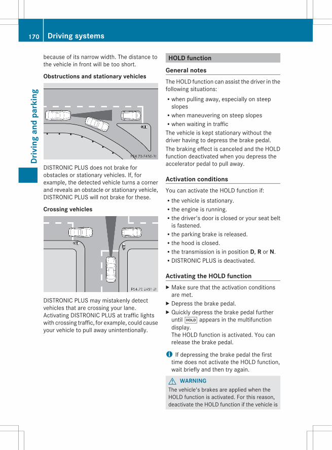
because of its narrow width. The distance tothe vehicle in front will be too short.
Obstructions and stationary vehicles
DISTRONIC PLUS does not brake forobstacles or stationary vehicles. If, forexample, the detected vehicle turns a cornerand reveals an obstacle or stationary vehicle,DISTRONIC PLUS will not brake for these.
Crossing vehicles
DISTRONIC PLUS may mistakenly detectvehicles that are crossing your lane.Activating DISTRONIC PLUS at traffic lightswith crossing traffic, for example, could causeyour vehicle to pull away unintentionally.
HOLD function
General notesThe HOLD function can assist the driver in thefollowing situations:Rwhen pulling away, especially on steep
slopesRwhen maneuvering on steep slopesRwhen waiting in trafficThe vehicle is kept stationary without thedriver having to depress the brake pedal.The braking effect is canceled and the HOLDfunction deactivated when you depress theaccelerator pedal to pull away.
Activation conditionsYou can activate the HOLD function if:Rthe vehicle is stationary.Rthe engine is running.Rthe driver's door is closed or your seat belt
is fastened.Rthe parking brake is released.Rthe hood is closed.Rthe transmission is in position D, R or N.RDISTRONIC PLUS is deactivated.
Activating the HOLD functionX Make sure that the activation conditions
are met.X Depress the brake pedal.X Quickly depress the brake pedal further
until ë appears in the multifunctiondisplay.The HOLD function is activated. You canrelease the brake pedal.
i If depressing the brake pedal the firsttime does not activate the HOLD function,wait briefly and then try again.
G WARNINGThe vehicle's brakes are applied when theHOLD function is activated. For this reason,deactivate the HOLD function if the vehicle is
170 Driving systemsDr
ivin
g an
d pa
rkin
g
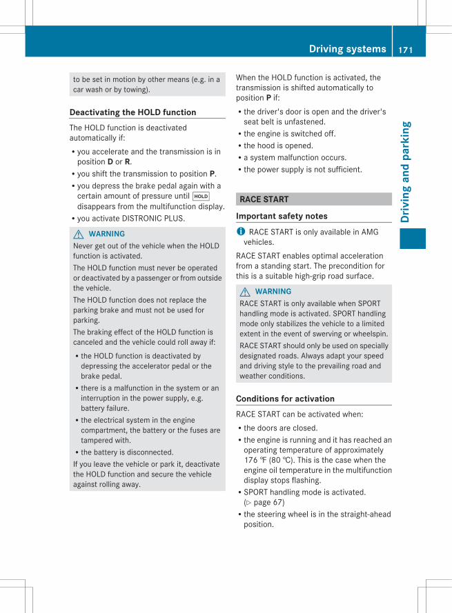
to be set in motion by other means (e.g. in acar wash or by towing).
Deactivating the HOLD functionThe HOLD function is deactivatedautomatically if:Ryou accelerate and the transmission is in
position D or R.Ryou shift the transmission to position P.Ryou depress the brake pedal again with a
certain amount of pressure until ëdisappears from the multifunction display.Ryou activate DISTRONIC PLUS.
G WARNINGNever get out of the vehicle when the HOLDfunction is activated.The HOLD function must never be operatedor deactivated by a passenger or from outsidethe vehicle.The HOLD function does not replace theparking brake and must not be used forparking.The braking effect of the HOLD function iscanceled and the vehicle could roll away if:Rthe HOLD function is deactivated by
depressing the accelerator pedal or thebrake pedal.Rthere is a malfunction in the system or an
interruption in the power supply, e.g.battery failure.Rthe electrical system in the engine
compartment, the battery or the fuses aretampered with.Rthe battery is disconnected.If you leave the vehicle or park it, deactivatethe HOLD function and secure the vehicleagainst rolling away.
When the HOLD function is activated, thetransmission is shifted automatically toposition P if:Rthe driver's door is open and the driver's
seat belt is unfastened.Rthe engine is switched off.Rthe hood is opened.Ra system malfunction occurs.Rthe power supply is not sufficient.
RACE START
Important safety notesi RACE START is only available in AMG
vehicles.RACE START enables optimal accelerationfrom a standing start. The precondition forthis is a suitable high-grip road surface.
G WARNINGRACE START is only available when SPORThandling mode is activated. SPORT handlingmode only stabilizes the vehicle to a limitedextent in the event of swerving or wheelspin.RACE START should only be used on speciallydesignated roads. Always adapt your speedand driving style to the prevailing road andweather conditions.
Conditions for activationRACE START can be activated when:Rthe doors are closed.Rthe engine is running and it has reached an
operating temperature of approximately176 ‡ (80 †). This is the case when theengine oil temperature in the multifunctiondisplay stops flashing.RSPORT handling mode is activated.
(Y page 67)Rthe steering wheel is in the straight-ahead
position.
Driving systems 171
Driv
ing
and
park
ing
Z

Rthe vehicle is stationary and the brakepedal is depressed (left foot).Rthe transmission is in position D.
Activating RACE STARTX Depress the brake pedal with your left foot,
and keep it depressed.X Turn the drive program selector clockwise
(Y page 145) until the RS lamp lights up.The multifunction display shows the RACE START Confirm: Paddle UP Cancel: Paddle DOWN message.
i If the activation conditions are no longerfulfilled, RACE START is canceled. Themultifunction display shows the RACE START Canceled message.
X To cancel: pull the left steering wheel shiftpaddle (Y page 146).
orX To confirm: pull the right steering wheel
shift paddle (Y page 146).The multifunction display shows the RACE START Available Depress gas pedalmessage.
i If you do not depress the acceleratorpedal fully within two seconds, RACESTART is canceled. The multifunctiondisplay shows the RACE START Not Possible See Operator's Manualmessage.
X Depress the accelerator pedal fully.The engine speed increases toapproximately 3500 rpm.The multifunction display shows the RACE START Release brake to startmessage.
i If you do not release the brake pedalwithin five seconds, RACE START iscanceled. The multifunction display showsthe RACE START Canceled message.
X Take your foot off the brake, but keep theaccelerator pedal depressed.The vehicle pulls away at maximumacceleration.
The multifunction display shows the RACE START Active message.
RACE START is deactivated when the vehiclereaches a speed of approximately 30 mph(Canada: 50 km/h). Drive program S+ isactivated. SPORT handling mode remainsactivated.RACE START is deactivated immediately ifyou release the accelerator pedal duringRACE START or if any of the activationconditions are no longer fulfilled. Themultifunction display shows the RACE START Not Possible See Operator's Manualmessage.
i If RACE START is used repeatedly withina short period of time, it is only availableagain after the vehicle has been driven acertain distance.
AIRMATIC
Vehicle level
Important safety notesYour vehicle regulates its heightautomatically. All-round level control ensuresthe best possible suspension and constantground clearance, even with a laden vehicle.When you drive fast, the vehicle is loweredautomatically to improve driving safety and toreduce fuel consumption.The following vehicle levels are possible:RNormalRraised: the vehicle is raised by about
0.80 in (20 mm) when compared with thenormal levelRlowered: the vehicle is lowered by about
0.40 in (10 mm) when compared with thenormal level
i These changes in level are so slight thatyou are hardly aware of them.
The "Normal" and "Raised" vehicle levels canbe set manually.
172 Driving systemsDr
ivin
g an
d pa
rkin
g
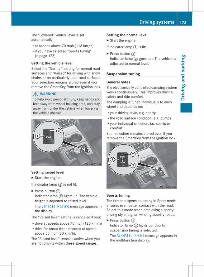
The "Lowered” vehicle level is setautomatically:Rat speeds above 70 mph (113 km/h)Rif you have selected "Sports tuning"
(Y page 173)
Setting the vehicle levelSelect the "Normal" setting for normal roadsurfaces and "Raised" for driving with snowchains or on particularly poor road surfaces.Your selection remains stored even if youremove the SmartKey from the ignition lock.
G WARNINGTo help avoid personal injury, keep hands andfeet away from wheel housing area, and stayaway from under the vehicle when loweringthe vehicle chassis.
Setting raised levelX Start the engine.
If indicator lamp ; is not lit:X Press button :.
Indicator lamp ; lights up. The vehicleheight is adjusted to raised level.The Vehicle Rising message appears inthe display.
The "Raised level" setting is canceled if you:Rdrive at speeds above 75 mph (120 km/h)Rdrive for about three minutes at speeds
above 50 mph (80 km/h).The "Raised level" remains active when youare not driving within these speed ranges.
Setting the normal levelX Start the engine.
If indicator lamp ; is lit:X Press button :.
Indicator lamp ; goes out. The vehicle isadjusted to normal level.
Suspension tuning
General notesThe electronically controlled damping systemworks continuously. This improves drivingsafety and ride comfort.The damping is tuned individually to eachwheel and depends on:Ryour driving style, e.g. sportyRthe road surface condition, e.g. bumpsRyour individual selection, i.e. sports or
comfortYour selection remains stored even if youremove the SmartKey from the ignition lock.
Sports tuningThe firmer suspension tuning in Sport modeensures even better contact with the road.Select this mode when employing a sportydriving style, e.g. on winding country roads.X Press button :.
Indicator lamp ; lights up. Sportssuspension tuning is selected.The AIRMATIC SPORT message appears inthe multifunction display.
Driving systems 173
Driv
ing
and
park
ing
Z
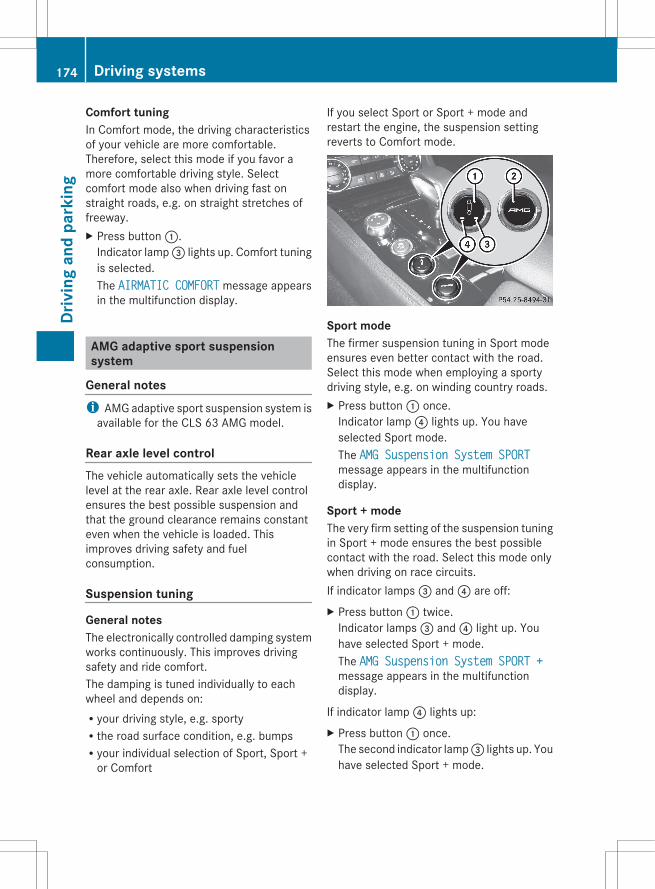
Comfort tuningIn Comfort mode, the driving characteristicsof your vehicle are more comfortable.Therefore, select this mode if you favor amore comfortable driving style. Selectcomfort mode also when driving fast onstraight roads, e.g. on straight stretches offreeway.X Press button :.
Indicator lamp = lights up. Comfort tuningis selected.The AIRMATIC COMFORT message appearsin the multifunction display.
AMG adaptive sport suspensionsystem
General notesi AMG adaptive sport suspension system is
available for the CLS 63 AMG model.
Rear axle level controlThe vehicle automatically sets the vehiclelevel at the rear axle. Rear axle level controlensures the best possible suspension andthat the ground clearance remains constanteven when the vehicle is loaded. Thisimproves driving safety and fuelconsumption.
Suspension tuning
General notesThe electronically controlled damping systemworks continuously. This improves drivingsafety and ride comfort.The damping is tuned individually to eachwheel and depends on:Ryour driving style, e.g. sportyRthe road surface condition, e.g. bumpsRyour individual selection of Sport, Sport +
or Comfort
If you select Sport or Sport + mode andrestart the engine, the suspension settingreverts to Comfort mode.
Sport modeThe firmer suspension tuning in Sport modeensures even better contact with the road.Select this mode when employing a sportydriving style, e.g. on winding country roads.X Press button : once.
Indicator lamp ? lights up. You haveselected Sport mode.The AMG Suspension System SPORTmessage appears in the multifunctiondisplay.
Sport + modeThe very firm setting of the suspension tuningin Sport + mode ensures the best possiblecontact with the road. Select this mode onlywhen driving on race circuits.If indicator lamps = and ? are off:X Press button : twice.
Indicator lamps = and ? light up. Youhave selected Sport + mode.The AMG Suspension System SPORT +message appears in the multifunctiondisplay.
If indicator lamp ? lights up:X Press button : once.
The second indicator lamp = lights up. Youhave selected Sport + mode.
174 Driving systemsDr
ivin
g an
d pa
rkin
g
The AMG Suspension System SPORT +message appears in the multifunctiondisplay.
Comfort modeIn Comfort mode, the driving characteristicsof your vehicle are more comfortable.Therefore, select this mode if you favor amore comfortable driving style. Selectcomfort mode also when driving fast onstraight roads, e.g. on straight stretches offreeway.X Press button : repeatedly until indicator
lamps = and ? go out.You have selected Comfort mode.The AMG Suspension System COMFORTmessage appears in the multifunctiondisplay.
Storing and calling up settingsOnce the suspension tuning and driveprogram have been selected, you can storeand call up your settings using AMGbutton ;.X To store: press AMG button ; until you
hear a tone.X To call up: press AMG button ;.
The stored suspension tuning and driveprogram are selected.
X To display: briefly press AMG button ;.Your selection appears in the multifunctiondisplay.
4MATIC (permanent four-wheel drive)4MATIC ensures that all four wheels arepermanently driven. Together with ESP®, itimproves the traction of your vehiclewhenever a drive wheel spins due toinsufficient grip.
G WARNINGIf a drive wheel is spinning due to insufficienttraction:RWhile driving off, apply as little throttle as
possible.RWhile driving, ease up on the accelerator
pedal.RAdapt your speed and driving style to the
prevailing road conditions.Failure to observe these guidelines couldcause the vehicle to skid.4MATIC cannot prevent accidents resultingfrom excessive speed.
! Never tow the vehicle with one axleraised. This may damage the transfer case.Damage of this sort is not covered by theMercedes-Benz Limited Warranty. Allwheels must remain either on the groundor be fully raised. Observe the instructionsfor towing the vehicle with all wheels in fullcontact with the ground.
i In wintry driving conditions, the maximumeffect of 4MATIC can only be achieved ifyou use winter tires (M+S tires), with snowchains if necessary.
PARKTRONIC
Important safety notes
G WARNINGThe PARKTRONIC is a supplemental system.It is not intended to, nor does it replace, theneed for extreme care. The responsibilityduring parking and other critical maneuversalways remains with the driver.
G WARNINGMake sure no persons or animals are in ornear the area in which you are parking/maneuvering. Otherwise, they could beinjured.
Driving systems 175
Driv
ing
and
park
ing
Z
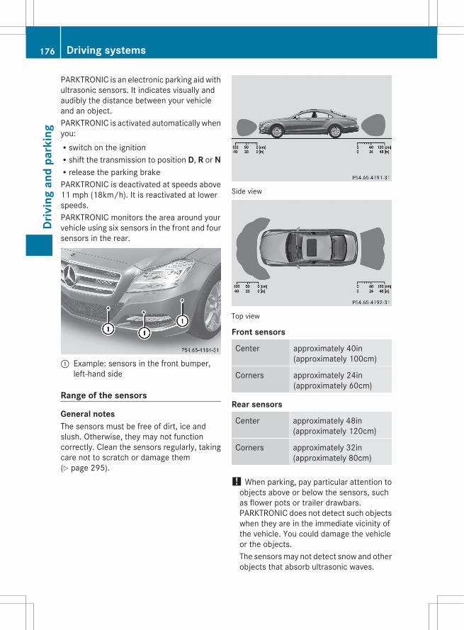
PARKTRONIC is an electronic parking aid withultrasonic sensors. It indicates visually andaudibly the distance between your vehicleand an object.PARKTRONIC is activated automatically whenyou:Rswitch on the ignitionRshift the transmission to position D, R or NRrelease the parking brakePARKTRONIC is deactivated at speeds above11 mph (18km/h). It is reactivated at lowerspeeds.PARKTRONIC monitors the area around yourvehicle using six sensors in the front and foursensors in the rear.
: Example: sensors in the front bumper,left-hand side
Range of the sensors
General notesThe sensors must be free of dirt, ice andslush. Otherwise, they may not functioncorrectly. Clean the sensors regularly, takingcare not to scratch or damage them(Y page 295).
Side view
Top view
Front sensors
Center approximately 40in(approximately 100cm)
Corners approximately 24in(approximately 60cm)
Rear sensors
Center approximately 48in(approximately 120cm)
Corners approximately 32in(approximately 80cm)
! When parking, pay particular attention toobjects above or below the sensors, suchas flower pots or trailer drawbars.PARKTRONIC does not detect such objectswhen they are in the immediate vicinity ofthe vehicle. You could damage the vehicleor the objects.The sensors may not detect snow and otherobjects that absorb ultrasonic waves.
176 Driving systemsDr
ivin
g an
d pa
rkin
g
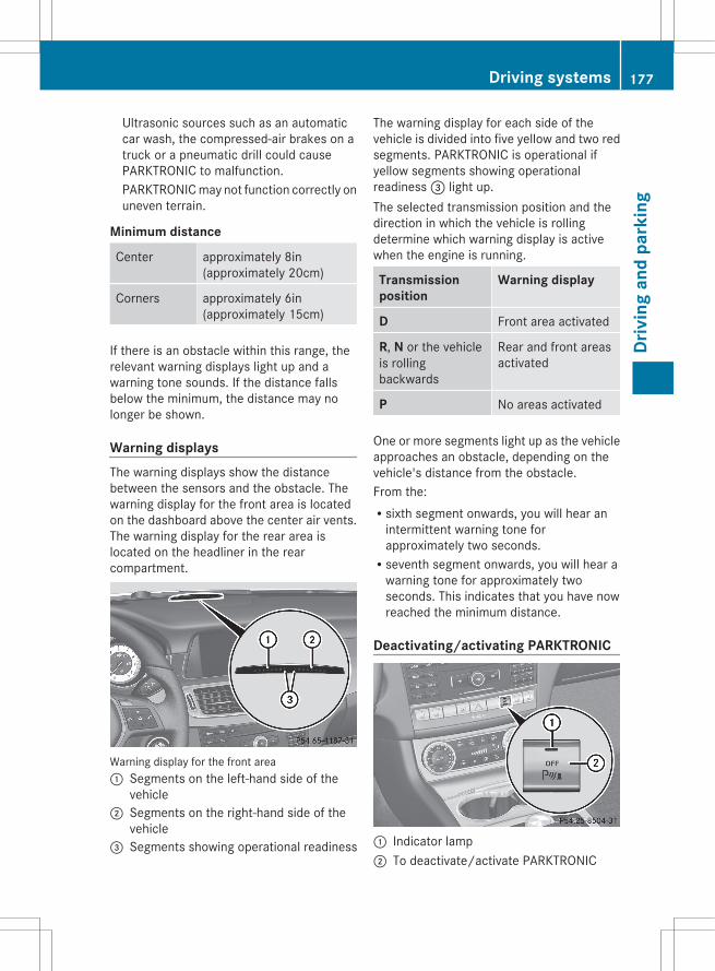
Ultrasonic sources such as an automaticcar wash, the compressed-air brakes on atruck or a pneumatic drill could causePARKTRONIC to malfunction.PARKTRONIC may not function correctly onuneven terrain.
Minimum distance
Center approximately 8in(approximately 20cm)
Corners approximately 6in(approximately 15cm)
If there is an obstacle within this range, therelevant warning displays light up and awarning tone sounds. If the distance fallsbelow the minimum, the distance may nolonger be shown.
Warning displaysThe warning displays show the distancebetween the sensors and the obstacle. Thewarning display for the front area is locatedon the dashboard above the center air vents.The warning display for the rear area islocated on the headliner in the rearcompartment.
Warning display for the front area: Segments on the left-hand side of the
vehicle; Segments on the right-hand side of the
vehicle= Segments showing operational readiness
The warning display for each side of thevehicle is divided into five yellow and two redsegments. PARKTRONIC is operational ifyellow segments showing operationalreadiness = light up.The selected transmission position and thedirection in which the vehicle is rollingdetermine which warning display is activewhen the engine is running.
Transmission position
Warning display
D Front area activated
R, N or the vehicleis rollingbackwards
Rear and front areasactivated
P No areas activated
One or more segments light up as the vehicleapproaches an obstacle, depending on thevehicle's distance from the obstacle.From the:Rsixth segment onwards, you will hear an
intermittent warning tone forapproximately two seconds.Rseventh segment onwards, you will hear a
warning tone for approximately twoseconds. This indicates that you have nowreached the minimum distance.
Deactivating/activating PARKTRONIC
: Indicator lamp; To deactivate/activate PARKTRONIC
Driving systems 177
Driv
ing
and
park
ing
Z
If indicator lamp : lights up, PARKTRONIC isdeactivated. Active Park Assist is then alsodeactivated.
i PARKTRONIC is automatically activatedwhen you turn the SmartKey to position 2in the ignition lock.
178 Driving systemsDr
ivin
g an
d pa
rkin
g
Problems with PARKTRONIC
Problem Possible causes/consequences and M Solutions
Only the red segmentsin the PARKTRONICwarning displays are lit.You also hear a warningtone for approximatelytwo seconds.PARKTRONIC isdeactivated afterapproximately20 seconds, and theindicator lamp in thePARKTRONIC buttonlights up.
PARKTRONIC has malfunctioned and has switched off.X If problems persist, have PARKTRONIC checked at a qualified
specialist workshop.
Only the red segmentsin the PARKTRONICwarning displays are lit.PARKTRONIC isdeactivated afterapproximately20 seconds.
The PARKTRONIC sensors are dirty or there is interference.X Clean the PARKTRONIC sensors (Y page 295).X Switch the ignition back on.
The problem may be caused by an external source of radio orultrasound waves.X See if PARKTRONIC functions in a different location.
Active Parking Assist
Important safety notesActive Parking Assist is an electronic parkingaid with ultrasound. Ultrasound is used tomeasure the road on both sides of the vehicle.A suitable parking space is indicated by theparking symbol. Active steering interventioncan assist you during parking. You may alsouse PARKTRONIC (Y page 175). WhenPARKTRONIC is switched off, Active ParkingAssist is also unavailable.
G WARNINGActive Parking Assist is merely an aid and maysometimes recommend parking spaces thatare not suitable for parking. For example,these might be spaces where parking isprohibited, driveways, unsuitable surfaces,etc.
Active Parking Assist measures the parkingspace as you drive past it. Any later changesto the parking space are not taken intoaccount. For instance, this may be the casewhen the vehicle parked in front of or behindthe space changes its position or when anobstacle is moved into the parking space.Active Parking Assist does not relieve you ofthe responsibility of paying attention. If yourely solely on Active Parking Assist, you couldcause an accident and injure yourself andothers.You are always responsible for safety andmust continue to pay attention to yourimmediate surroundings when parking andmaneuvering.
Driving systems 179
Driv
ing
and
park
ing
Z
G WARNINGObjects located above the height range ofActive Parking Assist will not be detectedwhen the parking space is measured. Theseare not taken into account when the parkingprocedure is calculated, e.g. overhangingloads, tail sections or loading ramps of goodsvehicles. In some circumstances, ActiveParking Assist may therefore guide you intothe parking space too early. This may lead toa collision. For this reason, you should avoidusing Active Parking Assist in such situations.
G WARNINGThe front of the vehicle will veer out in thedirection of the oncoming traffic during theparking operation. In some cases, the vehiclewill also take you onto sections of theoncoming lane during the parking procedure.You are responsible for safety at all times andmust pay attention to any road usersapproaching or passing. Stop the vehicle ifnecessary or cancel the Active Parking Assistparking procedure.
G WARNINGMake sure no persons or animals are in ornear the area in which you are parking/maneuvering. Otherwise, they could beinjured.
Use Active Parking Assist for parking spaces:Rthat are parallel to the direction of travelRthat are on straight roads, not bendsRthat are on the same level as the road, e.g.
not on the pavementParking tips:Ron narrow roads, drive past the parking
space as close as possible.Rparking spaces that are littered, overgrown
or partially occupied by trailer drawbarsmight be identified incorrectly or not at all.Rsnowfall or heavy rain may lead to a parking
space being measured inaccurately.
Rpay attention to the PARKTRONIC(Y page 177) warning messages during theparking procedure.Ryou can intervene in the steering procedure
to correct it at any time. Active ParkingAssist will then be canceled.Rwhen transporting a load which protrudes
from your vehicle, you should not useActive Parking Assist.Rwhen snow chains or an emergency spare
wheel are installed, you should not useActive Parking Assist here either.Rmake sure that the tire pressures are
always correct. This has a direct influenceon the parking characteristics of thevehicle.Rthe way your vehicle is positioned in the
parking space after parking is dependenton various factors. These include theposition and shape of the vehicles parkedin front and behind it and the conditions ofthe location. It may be the case that ActiveParking Assist guides you too far into aparking space, or not far enough into it. Insome cases, it may also lead you across oronto the curb. If necessary, you shouldabort the parking procedure with ActiveParking Assist.Ryou can also engage forward gear
prematurely. The vehicle redirects anddoes not drive as far into the parking space.Should the gear change occur too soon toachieve a sensible parking position, theparking procedure will be aborted.
! If unavoidable, you should drive overobstacles such as curbs slowly and not ata sharp angle. Otherwise, you may damagethe wheels or tires.
Detecting a parking spaceActive Parking Assist is switched onautomatically when driving forwards. Thesystem is operational at speeds of up toapproximately 22 mph (35 km/h). While inoperation, the system independently locates
180 Driving systemsDr
ivin
g an
d pa
rkin
g
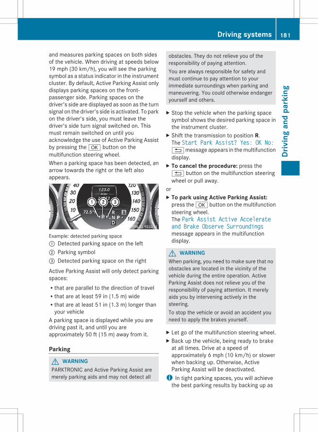
and measures parking spaces on both sidesof the vehicle. When driving at speeds below19 mph (30 km/h), you will see the parkingsymbol as a status indicator in the instrumentcluster. By default, Active Parking Assist onlydisplays parking spaces on the front-passenger side. Parking spaces on thedriver's side are displayed as soon as the turnsignal on the driver's side is activated. To parkon the driver's side, you must leave thedriver's side turn signal switched on. Thismust remain switched on until youacknowledge the use of Active Parking Assistby pressing the a button on themultifunction steering wheel.When a parking space has been detected, anarrow towards the right or the left alsoappears.
Example: detected parking space: Detected parking space on the left; Parking symbol= Detected parking space on the right
Active Parking Assist will only detect parkingspaces:Rthat are parallel to the direction of travelRthat are at least 59 in (1.5 m) wideRthat are at least 51 in (1.3 m) longer than
your vehicleA parking space is displayed while you aredriving past it, and until you areapproximately 50 ft (15 m) away from it.
Parking
G WARNINGPARKTRONIC and Active Parking Assist aremerely parking aids and may not detect all
obstacles. They do not relieve you of theresponsibility of paying attention.You are always responsible for safety andmust continue to pay attention to yourimmediate surroundings when parking andmaneuvering. You could otherwise endangeryourself and others.
X Stop the vehicle when the parking spacesymbol shows the desired parking space inthe instrument cluster.
X Shift the transmission to position R.The Start Park Assist? Yes: OK No:% message appears in the multifunctiondisplay.
X To cancel the procedure: press the% button on the multifunction steeringwheel or pull away.
orX To park using Active Parking Assist:
press the a button on the multifunctionsteering wheel.The Park Assist Active Accelerate and Brake Observe Surroundingsmessage appears in the multifunctiondisplay.
G WARNINGWhen parking, you need to make sure that noobstacles are located in the vicinity of thevehicle during the entire operation. ActiveParking Assist does not relieve you of theresponsibility of paying attention. It merelyaids you by intervening actively in thesteering.To stop the vehicle or avoid an accident youneed to apply the brakes yourself.
X Let go of the multifunction steering wheel.X Back up the vehicle, being ready to brake
at all times. Drive at a speed ofapproximately 6 mph (10 km/h) or slowerwhen backing up. Otherwise, ActiveParking Assist will be deactivated.
i In tight parking spaces, you will achievethe best parking results by backing up as
Driving systems 181
Driv
ing
and
park
ing
Z
far as possible. When doing so, alsoobserve the PARKTRONIC messages.
X Stop as soon as PARKTRONIC sounds thecontinuous warning tone, if not before.Maneuvering may be required in tightparking spaces.
The Park Assist Active Select D Observe Surroundings message appears inthe multifunction display.X Shift the transmission to position D while
the vehicle is stationary.Active Parking Assist immediately steers inthe other direction.The Park Assist Active Accelerate and Brake Observe Surroundingsmessage appears in the multifunctiondisplay.
i You will achieve the best results bywaiting for the steering procedure tocomplete before pulling away.
X Drive forwards and be ready to brake at alltimes.
X Stop as soon as PARKTRONIC sounds thecontinuous warning tone, if not before.
The Park Assist active Select R Observe Surroundings message appears inthe multifunction display.X Further transmission shifts may be
necessary.As soon as the parking procedure iscomplete, the Park Assist Disabledmessage appears in the multifunctiondisplay. PARKTRONIC continues to beavailable.X Maneuver if necessary.X Always observe the warning messages
displayed by PARKTRONIC (Y page 177).
Canceling Active Parking AssistYou can cancel Active Parking Assist at anytime.
X Stop the movement of the multifunctionsteering wheel or steer yourself.Active Parking Assist will be canceled atonce. The Park Assist Canceledmessage appears in the multifunctiondisplay.
orX Press the PARKTRONIC button on the
center console (Y page 177).PARKTRONIC is switched off and ActiveParking Assist is immediately canceled.The Park Assist Canceled messageappears in the multifunction display.
Active Parking Assist is canceledautomatically if:Rthe transmission is shifted too early.Rparking using Active Parking Assist is no
longer possible.Ryou are driving faster than 6mph
(10 km/h).Ra wheel spins, ESP® intervenes or fails. The
ä warning lamp lights up in theinstrument cluster.
A warning tone sounds. The parking spacesymbol disappears and the Park Assist Canceled message appears in themultifunction display.When Active Parking Assist is canceled, youmust steer again yourself.
Rear view camera
Important safety notesThe rear view camera is an optical parking aid.It shows the area behind your vehicle in theCOMAND display.
G WARNINGMake sure that no persons or animals are inthe maneuvering range. Otherwise, theycould be injured.
The rear view camera is located in the handlestrip of the trunk lid.
182 Driving systemsDr
ivin
g an
d pa
rkin
g
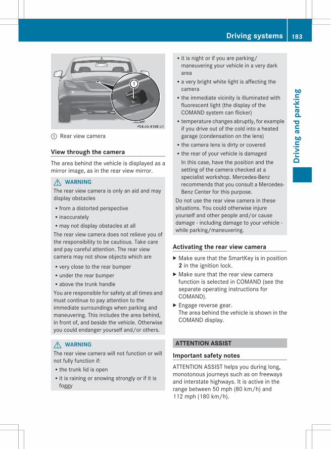
: Rear view camera
View through the cameraThe area behind the vehicle is displayed as amirror image, as in the rear view mirror.
G WARNINGThe rear view camera is only an aid and maydisplay obstaclesRfrom a distorted perspectiveRinaccuratelyRmay not display obstacles at allThe rear view camera does not relieve you ofthe responsibility to be cautious. Take careand pay careful attention. The rear viewcamera may not show objects which areRvery close to the rear bumperRunder the rear bumperRabove the trunk handleYou are responsible for safety at all times andmust continue to pay attention to theimmediate surroundings when parking andmaneuvering. This includes the area behind,in front of, and beside the vehicle. Otherwiseyou could endanger yourself and/or others.
G WARNINGThe rear view camera will not function or willnot fully function if:Rthe trunk lid is openRit is raining or snowing strongly or if it is
foggy
Rit is night or if you are parking/maneuvering your vehicle in a very darkareaRa very bright white light is affecting the
cameraRthe immediate vicinity is illuminated with
fluorescent light (the display of theCOMAND system can flicker)Rtemperature changes abruptly, for example
if you drive out of the cold into a heatedgarage (condensation on the lens)Rthe camera lens is dirty or coveredRthe rear of your vehicle is damaged
In this case, have the position and thesetting of the camera checked at aspecialist workshop. Mercedes-Benzrecommends that you consult a Mercedes-Benz Center for this purpose.
Do not use the rear view camera in thesesituations. You could otherwise injureyourself and other people and/or causedamage - including damage to your vehicle -while parking/maneuvering.
Activating the rear view cameraX Make sure that the SmartKey is in position
2 in the ignition lock.X Make sure that the rear view camera
function is selected in COMAND (see theseparate operating instructions forCOMAND).
X Engage reverse gear.The area behind the vehicle is shown in theCOMAND display.
ATTENTION ASSIST
Important safety notesATTENTION ASSIST helps you during long,monotonous journeys such as on freewaysand interstate highways. It is active in therange between 50 mph (80 km/h) and112 mph (180 km/h).
Driving systems 183
Driv
ing
and
park
ing
Z
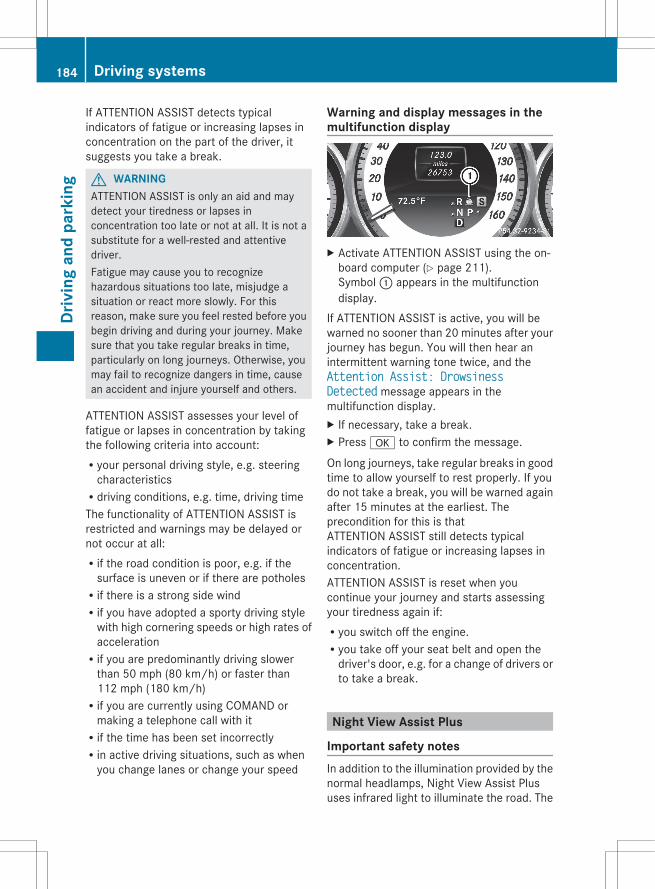
If ATTENTION ASSIST detects typicalindicators of fatigue or increasing lapses inconcentration on the part of the driver, itsuggests you take a break.
G WARNINGATTENTION ASSIST is only an aid and maydetect your tiredness or lapses inconcentration too late or not at all. It is not asubstitute for a well-rested and attentivedriver.Fatigue may cause you to recognizehazardous situations too late, misjudge asituation or react more slowly. For thisreason, make sure you feel rested before youbegin driving and during your journey. Makesure that you take regular breaks in time,particularly on long journeys. Otherwise, youmay fail to recognize dangers in time, causean accident and injure yourself and others.
ATTENTION ASSIST assesses your level offatigue or lapses in concentration by takingthe following criteria into account:Ryour personal driving style, e.g. steering
characteristicsRdriving conditions, e.g. time, driving timeThe functionality of ATTENTION ASSIST isrestricted and warnings may be delayed ornot occur at all:Rif the road condition is poor, e.g. if the
surface is uneven or if there are potholesRif there is a strong side windRif you have adopted a sporty driving style
with high cornering speeds or high rates ofaccelerationRif you are predominantly driving slower
than 50 mph (80 km/h) or faster than112 mph (180 km/h)Rif you are currently using COMAND or
making a telephone call with itRif the time has been set incorrectlyRin active driving situations, such as when
you change lanes or change your speed
Warning and display messages in themultifunction display
X Activate ATTENTION ASSIST using the on-board computer (Y page 211).Symbol : appears in the multifunctiondisplay.
If ATTENTION ASSIST is active, you will bewarned no sooner than 20 minutes after yourjourney has begun. You will then hear anintermittent warning tone twice, and theAttention Assist: Drowsiness Detected message appears in themultifunction display.X If necessary, take a break.X Press a to confirm the message.
On long journeys, take regular breaks in goodtime to allow yourself to rest properly. If youdo not take a break, you will be warned againafter 15 minutes at the earliest. Theprecondition for this is thatATTENTION ASSIST still detects typicalindicators of fatigue or increasing lapses inconcentration.ATTENTION ASSIST is reset when youcontinue your journey and starts assessingyour tiredness again if:Ryou switch off the engine.Ryou take off your seat belt and open the
driver's door, e.g. for a change of drivers orto take a break.
Night View Assist Plus
Important safety notesIn addition to the illumination provided by thenormal headlamps, Night View Assist Plususes infrared light to illuminate the road. The
184 Driving systemsDr
ivin
g an
d pa
rkin
g
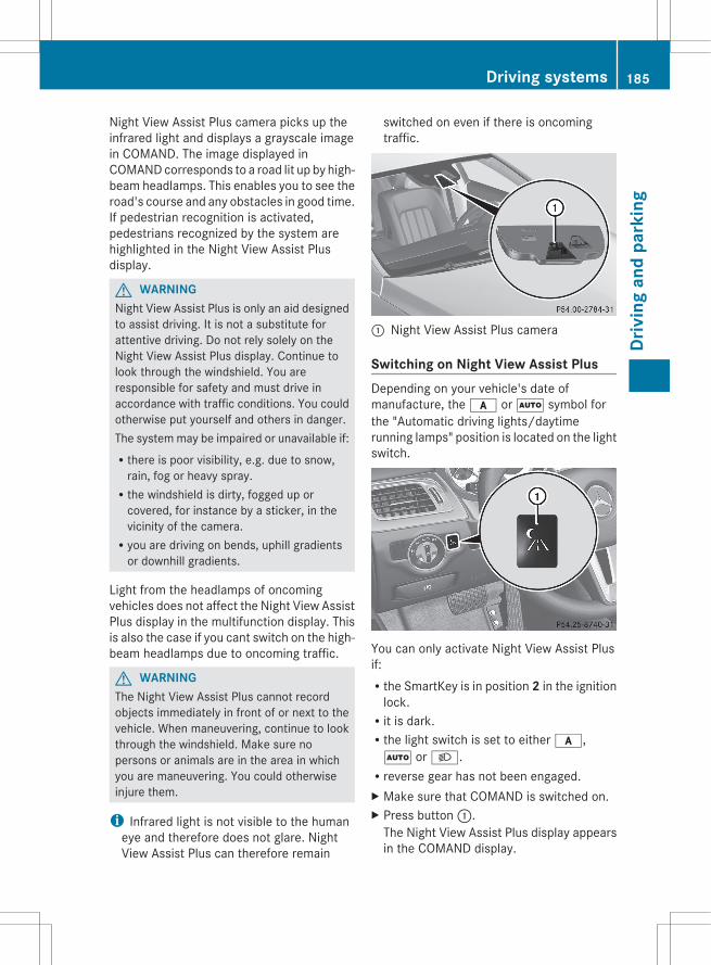
Night View Assist Plus camera picks up theinfrared light and displays a grayscale imagein COMAND. The image displayed inCOMAND corresponds to a road lit up by high-beam headlamps. This enables you to see theroad's course and any obstacles in good time.If pedestrian recognition is activated,pedestrians recognized by the system arehighlighted in the Night View Assist Plusdisplay.
G WARNINGNight View Assist Plus is only an aid designedto assist driving. It is not a substitute forattentive driving. Do not rely solely on theNight View Assist Plus display. Continue tolook through the windshield. You areresponsible for safety and must drive inaccordance with traffic conditions. You couldotherwise put yourself and others in danger.The system may be impaired or unavailable if:Rthere is poor visibility, e.g. due to snow,
rain, fog or heavy spray.Rthe windshield is dirty, fogged up or
covered, for instance by a sticker, in thevicinity of the camera.Ryou are driving on bends, uphill gradients
or downhill gradients.
Light from the headlamps of oncomingvehicles does not affect the Night View AssistPlus display in the multifunction display. Thisis also the case if you cant switch on the high-beam headlamps due to oncoming traffic.
G WARNINGThe Night View Assist Plus cannot recordobjects immediately in front of or next to thevehicle. When maneuvering, continue to lookthrough the windshield. Make sure nopersons or animals are in the area in whichyou are maneuvering. You could otherwiseinjure them.
i Infrared light is not visible to the humaneye and therefore does not glare. NightView Assist Plus can therefore remain
switched on even if there is oncomingtraffic.
: Night View Assist Plus camera
Switching on Night View Assist PlusDepending on your vehicle's date ofmanufacture, the c or à symbol forthe "Automatic driving lights/daytimerunning lamps" position is located on the lightswitch.
You can only activate Night View Assist Plusif:Rthe SmartKey is in position 2 in the ignition
lock.Rit is dark.Rthe light switch is set to either c,Ã or L.Rreverse gear has not been engaged.X Make sure that COMAND is switched on.X Press button :.
The Night View Assist Plus display appearsin the COMAND display.
Driving systems 185
Driv
ing
and
park
ing
Z

: Night View Assist Plus display; Pedestrian recognized= Framing? Symbol for active pedestrian recognition
You can read about how to adjust thebrightness of the COMAND display in theCOMAND operating instructions.
i The infrared lamps switch onautomatically from a speed of about6 mph (10 km/h). This means that you donot have the full visual range while thevehicle is stationary and cant checkwhether Night View Assist Plus is working.
Pedestrian recognition
G WARNINGPedestrian recognition may be impaired orinoperative if:Rpedestrians are partially or entirely
obscured by objects, e.g. parked vehicles.Rthe silhouette of the pedestrian in the Night
View Assist Plus display is incomplete orinterrupted, e.g. by powerful lightreflections.Rpedestrians do not contrast with the
surroundings.Rpedestrians are not standing upright, for
example, if they are sitting, crouching orlying down.
i Animals are not recognized by pedestrianrecognition.
Night View Assist Plus is able to recognizepedestrians by typical characteristics, e.g. asilhouette in the shape of a person.Pedestrian recognition is then switched onautomatically if:RNight View Assist Plus is activated.Ryou are driving faster than 6 mph
(10 km/h).Rthe surroundings are dark, e.g. when
driving outside built-up areas withoutstreet lighting.
If pedestrian recognition is active,symbol ? appears. If pedestrians arerecognized, they are framed = and therebyhighlighted. If the pedestrian recognitionsystem has brought a pedestrian to yourattention, look through the windshield toevaluate the situation. The actual distance toobjects and pedestrians cant be gaugedaccurately by looking at a screen.It may be the case that objects are highlightedas well as pedestrians.
Fogged up or dirty windshieldIf the windshield in front of the camera isfogged up or dirty on the inside or outside, theNight View Assist Plus display is affected.
G WARNINGAlways remember that you must concentrateprimarily on driving the vehicle. A driver'sattention to the road must always be his/herprimary focus when driving. For your safetyand the safety of others: stop the vehiclebefore attempting to clean fogged upwindows or the windshield area in front of theNight View Assist Plus camera.Please remember that when your vehicle istraveling at a speed of only 30 mph(approximately 50 km/h) it covers a distanceof 44 ft (approximately 14 m) per second.
186 Driving systemsDr
ivin
g an
d pa
rkin
g
X To defrost: check the automatic airconditioning settings (Y page 128) and folddown the camera cover (Y page 296).
X To defrost the inside of the windshield:fold down the camera cover (Y page 296)and clean the windshield (Y page 294).
Driving systems 187
Driv
ing
and
park
ing
Z
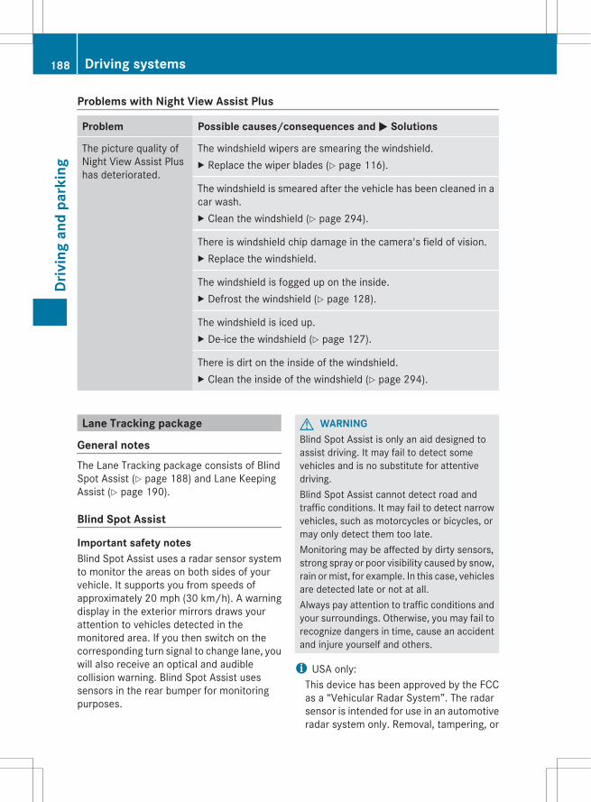
Problems with Night View Assist Plus
Problem Possible causes/consequences and M Solutions
The picture quality ofNight View Assist Plushas deteriorated.
The windshield wipers are smearing the windshield.X Replace the wiper blades (Y page 116).
The windshield is smeared after the vehicle has been cleaned in acar wash.X Clean the windshield (Y page 294).
There is windshield chip damage in the camera's field of vision.X Replace the windshield.
The windshield is fogged up on the inside.X Defrost the windshield (Y page 128).
The windshield is iced up.X De-ice the windshield (Y page 127).
There is dirt on the inside of the windshield.X Clean the inside of the windshield (Y page 294).
Lane Tracking package
General notesThe Lane Tracking package consists of BlindSpot Assist (Y page 188) and Lane KeepingAssist (Y page 190).
Blind Spot Assist
Important safety notesBlind Spot Assist uses a radar sensor systemto monitor the areas on both sides of yourvehicle. It supports you from speeds ofapproximately 20 mph (30 km/h). A warningdisplay in the exterior mirrors draws yourattention to vehicles detected in themonitored area. If you then switch on thecorresponding turn signal to change lane, youwill also receive an optical and audiblecollision warning. Blind Spot Assist usessensors in the rear bumper for monitoringpurposes.
G WARNINGBlind Spot Assist is only an aid designed toassist driving. It may fail to detect somevehicles and is no substitute for attentivedriving.Blind Spot Assist cannot detect road andtraffic conditions. It may fail to detect narrowvehicles, such as motorcycles or bicycles, ormay only detect them too late.Monitoring may be affected by dirty sensors,strong spray or poor visibility caused by snow,rain or mist, for example. In this case, vehiclesare detected late or not at all.Always pay attention to traffic conditions andyour surroundings. Otherwise, you may fail torecognize dangers in time, cause an accidentand injure yourself and others.
i USA only:This device has been approved by the FCCas a “Vehicular Radar System”. The radarsensor is intended for use in an automotiveradar system only. Removal, tampering, or
188 Driving systemsDr
ivin
g an
d pa
rkin
g
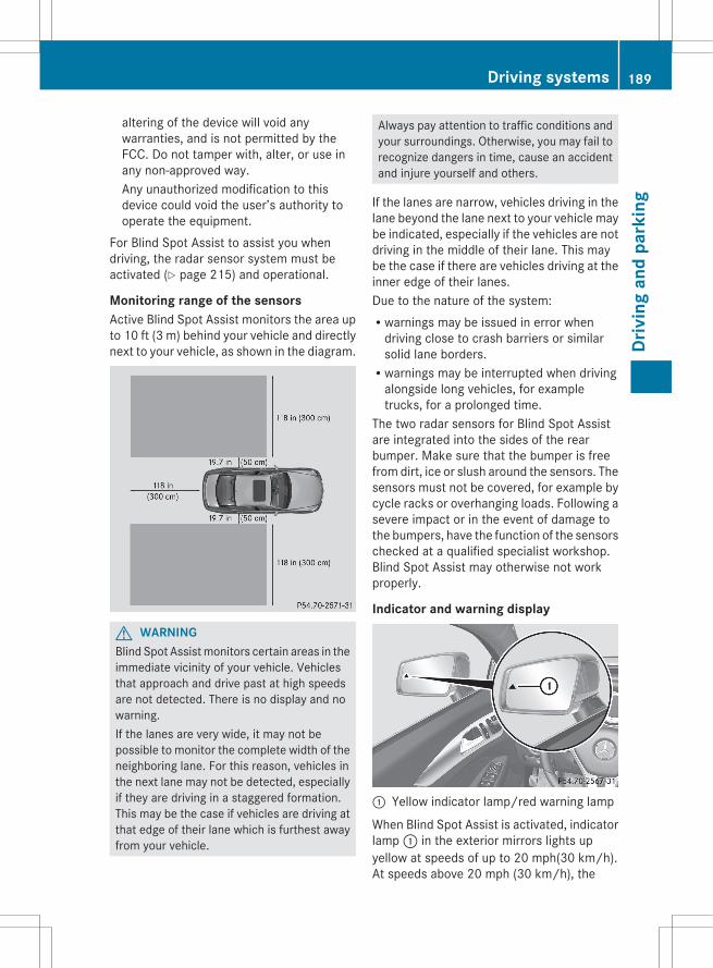
altering of the device will void anywarranties, and is not permitted by theFCC. Do not tamper with, alter, or use inany non-approved way.Any unauthorized modification to thisdevice could void the user’s authority tooperate the equipment.
For Blind Spot Assist to assist you whendriving, the radar sensor system must beactivated (Y page 215) and operational.
Monitoring range of the sensorsActive Blind Spot Assist monitors the area upto 10 ft (3 m) behind your vehicle and directlynext to your vehicle, as shown in the diagram.
G WARNINGBlind Spot Assist monitors certain areas in theimmediate vicinity of your vehicle. Vehiclesthat approach and drive past at high speedsare not detected. There is no display and nowarning.If the lanes are very wide, it may not bepossible to monitor the complete width of theneighboring lane. For this reason, vehicles inthe next lane may not be detected, especiallyif they are driving in a staggered formation.This may be the case if vehicles are driving atthat edge of their lane which is furthest awayfrom your vehicle.
Always pay attention to traffic conditions andyour surroundings. Otherwise, you may fail torecognize dangers in time, cause an accidentand injure yourself and others.
If the lanes are narrow, vehicles driving in thelane beyond the lane next to your vehicle maybe indicated, especially if the vehicles are notdriving in the middle of their lane. This maybe the case if there are vehicles driving at theinner edge of their lanes.Due to the nature of the system:Rwarnings may be issued in error when
driving close to crash barriers or similarsolid lane borders.Rwarnings may be interrupted when driving
alongside long vehicles, for exampletrucks, for a prolonged time.
The two radar sensors for Blind Spot Assistare integrated into the sides of the rearbumper. Make sure that the bumper is freefrom dirt, ice or slush around the sensors. Thesensors must not be covered, for example bycycle racks or overhanging loads. Following asevere impact or in the event of damage tothe bumpers, have the function of the sensorschecked at a qualified specialist workshop.Blind Spot Assist may otherwise not workproperly.
Indicator and warning display
: Yellow indicator lamp/red warning lamp
When Blind Spot Assist is activated, indicatorlamp : in the exterior mirrors lights upyellow at speeds of up to 20 mph(30 km/h).At speeds above 20 mph (30 km/h), the
Driving systems 189
Driv
ing
and
park
ing
Z
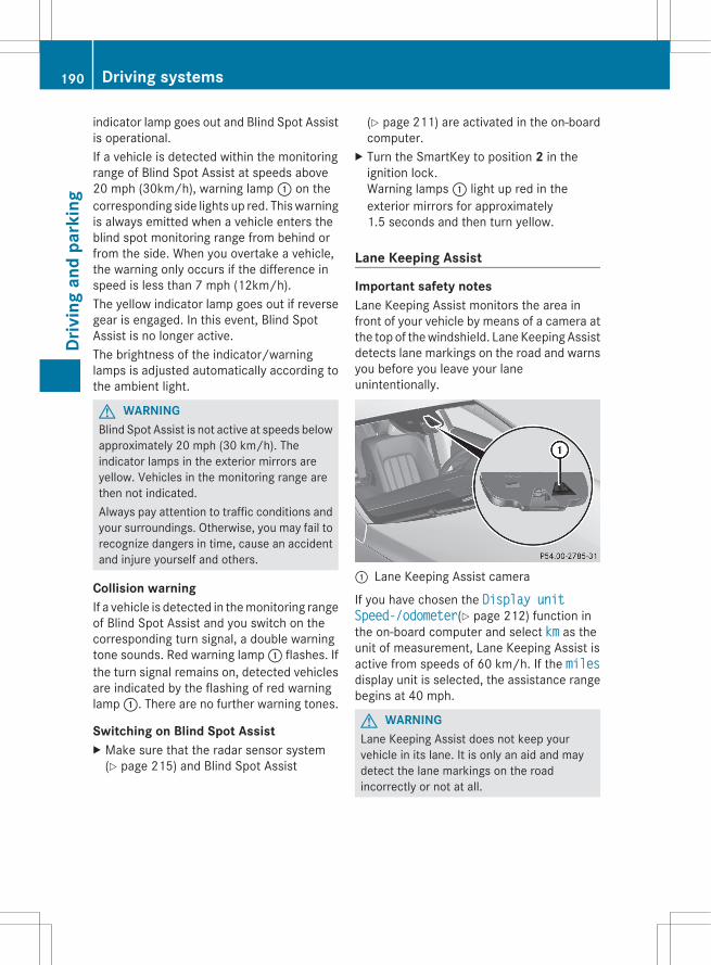
indicator lamp goes out and Blind Spot Assistis operational.If a vehicle is detected within the monitoringrange of Blind Spot Assist at speeds above20 mph (30km/h), warning lamp : on thecorresponding side lights up red. This warningis always emitted when a vehicle enters theblind spot monitoring range from behind orfrom the side. When you overtake a vehicle,the warning only occurs if the difference inspeed is less than 7 mph (12km/h).The yellow indicator lamp goes out if reversegear is engaged. In this event, Blind SpotAssist is no longer active.The brightness of the indicator/warninglamps is adjusted automatically according tothe ambient light.
G WARNINGBlind Spot Assist is not active at speeds belowapproximately 20 mph (30 km/h). Theindicator lamps in the exterior mirrors areyellow. Vehicles in the monitoring range arethen not indicated.Always pay attention to traffic conditions andyour surroundings. Otherwise, you may fail torecognize dangers in time, cause an accidentand injure yourself and others.
Collision warningIf a vehicle is detected in the monitoring rangeof Blind Spot Assist and you switch on thecorresponding turn signal, a double warningtone sounds. Red warning lamp : flashes. Ifthe turn signal remains on, detected vehiclesare indicated by the flashing of red warninglamp :. There are no further warning tones.
Switching on Blind Spot AssistX Make sure that the radar sensor system
(Y page 215) and Blind Spot Assist
(Y page 211) are activated in the on-boardcomputer.
X Turn the SmartKey to position 2 in theignition lock.Warning lamps : light up red in theexterior mirrors for approximately1.5 seconds and then turn yellow.
Lane Keeping Assist
Important safety notesLane Keeping Assist monitors the area infront of your vehicle by means of a camera atthe top of the windshield. Lane Keeping Assistdetects lane markings on the road and warnsyou before you leave your laneunintentionally.
: Lane Keeping Assist camera
If you have chosen the Display unit Speed-/odometer(Y page 212) function inthe on-board computer and select km as theunit of measurement, Lane Keeping Assist isactive from speeds of 60 km/h. If the milesdisplay unit is selected, the assistance rangebegins at 40 mph.
G WARNINGLane Keeping Assist does not keep yourvehicle in its lane. It is only an aid and maydetect the lane markings on the roadincorrectly or not at all.
190 Driving systemsDr
ivin
g an
d pa
rkin
g

The system may be impaired or may notfunction if:Rthere is poor visibility, e.g. due to
insufficient illumination of the road, or dueto snow, rain, fog or spray.Rthere is glare, e.g. from oncoming traffic,
the sun, or reflection from other vehicles.Rthe windshield is dirty, fogged up or
covered, for instance by a sticker, in thevicinity of the camera.Rseveral or no lane markings for a single lane
are present.Rthe lane markings are worn away, dark or
covered up, e.g. by dirt or snow.Rthe distance to the vehicle in front is too
small and the lane markings thus cannot bedetected.Rthe lane markings on the road are unclear,
e.g. near roadworks.Rthe lane markings change quickly, e.g.
lanes branch off, cross one another ormerge.Rthe road is narrow and winding.Lane Keeping Assist cannot detect road andtraffic conditions. It is not a substitute forattentive driving. You are responsible for thevehicle's speed, braking in good time, andsteering correctly. Always adapt your drivingstyle to suit the prevailing road and weatherconditions. Always pay attention to trafficconditions and your surroundings. Otherwise,you may fail to recognize dangers in time,cause an accident and injure yourself andothers.
A warning may be given if a front wheelpasses over a lane marking. It will warn youby means of intermittent vibration in thesteering wheel for up to 1.5 seconds.In order that you are warned only whennecessary and in good time if you cross thelane marking, the system recognizes certainconditions and warns you accordingly.
The warning vibration occurs earlier if:Ryou approach the outer lane marking on a
bend.Rthe road has very wide lanes, e.g. a
freeway.Rthe system recognizes solid lane markings.The warning vibration occurs later if:Rthe road has narrow lanes.Ryou cut the corner on a bend.No warning vibration occurs if:Ryou clearly and actively steer, brake or
accelerate.Ryou cut the corner on a sharp bend.Ra driving safety system intervenes, e.g.
ABS, BAS or ESP®.Ryou switch on the turn signals. In this event,
the warnings are suppressed for a certainperiod of time.
Switching on Lane Keeping Assist
X Activate Lane Keeping Assist using the on-board computer (Y page 211).Symbol : appears in the multifunctiondisplay.If your speed exceeds 40 mph (60 km/h)and lane markings are detected,symbol : is highlighted in green. LaneKeeping Assist is ready for use.
Active Driving Assistance package
General notesThe Active Driving Assistance packageconsists of DISTRONIC PLUS (Y page 160),Active Blind Spot Assist (Y page 192) andActive Lane Keeping Assist (Y page 194).
Driving systems 191
Driv
ing
and
park
ing
Z

Active Blind Spot Assist
Important safety notesActive Blind Spot Assist uses a radar sensorsystem to monitor the side areas of yourvehicle which are in back of the driver. Awarning display in the exterior mirrors drawsyour attention to vehicles detected in themonitored area. If you then switch on thecorresponding turn signal to change lane, youwill also receive an optical and audiblecollision warning. If a risk of lateral collisionis detected, corrective braking may help youavoid a collision. To support the course-correcting brake application, Active BlindSpot Assist also uses the forward-facing radarsensor system. Active Blind Spot Assistsupports you from a speed of approximately20 mph (30 km/h).
G WARNINGActive Blind Spot Assist is only an aid, andmay detect vehicles/obstacles incorrectly ornot at all.The system may be impaired or may notfunction if:Rthere is poor visibility, e.g. due to snow,
rain, fog or spray.Rthe rear and/or front sensors are dirty.Active Blind Spot Assist may not detectnarrow vehicles, such as motorcycles orbicycles, or may only detect them too late. Itcannot detect vehicles that are overtaken ata small distance and then enter the blind spotarea.Active Blind Spot Assist cannot detect roadand traffic conditions. It is not a substitute forattentive driving. You are responsible for thevehicle's speed, braking in good time, andsteering correctly. Always adapt your drivingstyle to suit the prevailing road and weatherconditions. Always pay attention to trafficconditions and your surroundings. Otherwise,you may fail to recognize dangers in time,cause an accident and injure yourself andothers.
i USA only:This device has been approved by the FCCas a “Vehicular Radar System”. The radarsensor is intended for use in an automotiveradar system only. Removal, tampering, oraltering of the device will void anywarranties, and is not permitted by theFCC. Do not tamper with, alter, or use inany non-approved way.Any unauthorized modification to thisdevice could void the user’s authority tooperate the equipment.
For Active Blind Spot Assist to assist youwhen driving, the radar sensor system mustbe activated (Y page 215) and operational.
Monitoring areaActive Blind Spot Assist monitors the area upto 10 ft (3 m) behind your vehicle and directlynext to your vehicle, as shown in the diagram.For this purpose, Active Blind Spot Assistuses radar sensors in the rear bumper.
G WARNINGActive Blind Spot Assist monitors certainareas in the immediate vicinity of your vehicle.Vehicles that approach and drive past at highspeeds are not detected. No visual noraudible warnings are emitted and the systemdoes not brake the vehicle to correct yourcourse.
192 Driving systemsDr
ivin
g an
d pa
rkin
g
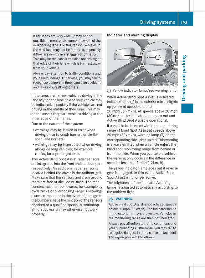
If the lanes are very wide, it may not bepossible to monitor the complete width of theneighboring lane. For this reason, vehicles inthe next lane may not be detected, especiallyif they are driving in a staggered formation.This may be the case if vehicles are driving atthat edge of their lane which is furthest awayfrom your vehicle.Always pay attention to traffic conditions andyour surroundings. Otherwise, you may fail torecognize dangers in time, cause an accidentand injure yourself and others.
If the lanes are narrow, vehicles driving in thelane beyond the lane next to your vehicle maybe indicated, especially if the vehicles are notdriving in the middle of their lane. This maybe the case if there are vehicles driving at theinner edge of their lanes.Due to the nature of the system:Rwarnings may be issued in error when
driving close to crash barriers or similarsolid lane borders.Rwarnings may be interrupted when driving
alongside long vehicles, for exampletrucks, for a prolonged time.
Two Active Blind Spot Assist radar sensorsare integrated into the front and rear bumpersrespectively. An additional radar sensor islocated behind the cover in the radiator grill.Make sure that the sensors and areas aroundthem are free of dirt, ice or slush. The rearsensors must not be covered, for example bycycle racks or overhanging cargo. Followinga severe impact or in the event of damage tothe bumpers, have the function of the sensorschecked at a qualified specialist workshop.Blind Spot Assist may otherwise not workproperly.
Indicator and warning display
: Yellow indicator lamp/red warning lamp
When Active Blind Spot Assist is activated,indicator lamp : in the exterior mirrors lightsup yellow at speeds of up to20 mph(30 km/h). At speeds above 20 mph(30km/h), the indicator lamp goes out andActive Blind Spot Assist is operational.If a vehicle is detected within the monitoringrange of Blind Spot Assist at speeds above20 mph (30km/h), warning lamp : on thecorresponding side lights up red. This warningis always emitted when a vehicle enters theblind spot monitoring range from behind orfrom the side. When you overtake a vehicle,the warning only occurs if the difference inspeed is less than 7 mph (12km/h).The yellow indicator lamp goes out if reversegear is engaged. In this event, Active BlindSpot Assist is no longer active.The brightness of the indicator/warninglamps is adjusted automatically according tothe ambient light.
G WARNINGActive Blind Spot Assist is not active at speedsbelow 20 mph (30km/h). The indicator lampsin the exterior mirrors are yellow. Vehicles inthe monitoring range are then not indicated.Always pay attention to traffic conditions andyour surroundings. Otherwise, you may fail torecognize dangers in time, cause an accidentand injure yourself and others.
Driving systems 193
Driv
ing
and
park
ing
Z
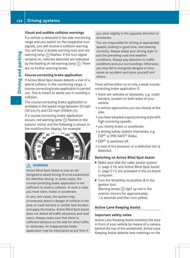
Visual and audible collision warningsIf a vehicle is detected in the side monitoringrange and you switch on the respective turnsignals, you will receive a collision warning.You will hear a double warning tone and redwarning lamp : flashes. If the turn signalremains on, vehicles detected are indicatedby the flashing of red warning lamp :. Thereare no further warning tones.
Course-correcting brake applicationIf Active Blind Spot Assist detects a risk of alateral collision in the monitoring range, acourse-correcting brake application is carriedout. This is meant to assist you in avoiding acollision.The course-correcting brake application isavailable in the speed range between 20 mph(30 km/h) and120 mph (200km/h).If a course-correcting brake applicationoccurs, red warning lamp : flashes in theexterior mirror and the following is shown inthe multifunction display, for example:
G WARNINGActive Blind Spot Assist is only an aiddesigned to assist driving. It is not a substitutefor attentive driving. In some cases, thecourse-correcting brake application is notsufficient to avoid a collision. In such a case,you must steer, brake or accelerate.In very rare cases, the system mayerroneously detect a danger of collision in thearea of crash barriers or similar lane bordersand apply the brakes. Active Blind Spot Assistdoes not detect all traffic situations and roadusers. Always make sure that there issufficient distance on the side for other trafficor obstacles. An inappropriate brakeapplication may be interrupted at any time if
you steer slightly in the opposite direction oraccelerate.You are responsible for driving at appropriatespeeds, braking in good time, and steeringcorrectly. Always adapt your driving style tosuit the prevailing road and weatherconditions. Always pay attention to trafficconditions and your surroundings. Otherwise,you may fail to recognize dangers in time,cause an accident and injure yourself andothers.
There will be either no or only a weak course-correcting brake application if:Rthere are vehicles or obstacles, e.g. crash
barriers, located on both sides of yourvehicle.Ra vehicle approaches you too closely at the
side.Ryou have adopted a sporty driving style with
high cornering speeds.Ryou clearly brake or accelerate.Ra driving safety system intervenes, e.g.
ESP® or PRE-SAFE® Brake.RESP® is switched off.Ra loss of tire pressure or a defective tire is
detected.
Switching on Active Blind Spot AssistX Make sure that the radar sensor system
(Y page 215) and Active Blind Spot Assist(Y page 211) are activated in the on-boardcomputer.
X Turn the SmartKey to position 2 in theignition lock.Warning lamps : light up red in theexterior mirrors for approximately1.5 seconds and then turn yellow.
Active Lane Keeping Assist
Important safety notesActive Lane Keeping Assist monitors the areain front of your vehicle by means of a camerabehind the top of the windshield. Active LaneKeeping Assist detects lane markings on the
194 Driving systemsDr
ivin
g an
d pa
rkin
g
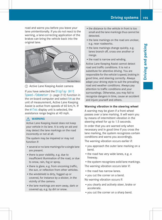
road and warns you before you leave yourlane unintentionally. If you do not react to thewarning, a lane-correcting application of thebrakes can bring the vehicle back into theoriginal lane.
: Active Lane Keeping Assist camera
If you have selected the Display Unit Speed-/Odometer:(Y page 212) function inthe on-board computer and select km as theunit of measurement, Active Lane KeepingAssist is active from speeds of 60 km/h. Ifthe miles display unit is selected, theassistance range begins at 40 mph.
G WARNINGActive Lane Keeping Assist does not keepyour vehicle in its lane. It is only an aid andmay detect the lane markings on the roadincorrectly or not at all.The system may be impaired or may notfunction if:Rseveral or no lane markings for a single lane
are present.Rthere is poor visibility, e.g. due to
insufficient illumination of the road, or dueto snow, rain, fog or spray.Rthere is glare, e.g. from oncoming traffic,
the sun, or reflection from other vehicles.Rthe windshield is dirty, fogged up or
covered, for instance by a sticker, in thevicinity of the camera.Rthe lane markings are worn away, dark or
covered up, e.g. by dirt or snow.
Rthe distance to the vehicle in front is toosmall and the lane markings thus cannot bedetected.Rthe lane markings on the road are unclear,
e.g. near roadworks.Rthe lane markings change quickly, e.g.
lanes branch off, cross one another ormerge.Rthe road is narrow and winding.Active Lane Keeping Assist cannot detectroad and traffic conditions. It is not asubstitute for attentive driving. You areresponsible for the vehicle's speed, braking ingood time, and steering correctly. Alwaysadapt your driving style to suit the prevailingroad and weather conditions. Always payattention to traffic conditions and yoursurroundings. Otherwise, you may fail torecognize dangers in time, cause an accidentand injure yourself and others.
Warning vibration in the steering wheelA warning may be given if a front wheelpasses over a lane marking. It will warn youby means of intermittent vibration in thesteering wheel for up to 1.5 seconds.In order that you are warned only whennecessary and in good time if you cross thelane marking, the system recognizes certainconditions and warns you accordingly.The warning vibration occurs earlier if:Ryou approach the outer lane marking on a
bend.Rthe road has very wide lanes, e.g. a
freeway.Rthe system recognizes solid lane markings.The warning vibration occurs later if:Rthe road has narrow lanes.Ryou cut the corner on a bend.No warning vibration occurs if:Ryou clearly and actively steer, brake or
accelerate.Ryou cut the corner on a sharp bend.
Driving systems 195
Driv
ing
and
park
ing
Z
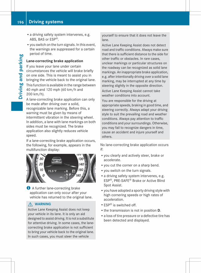
Ra driving safety system intervenes, e.g.ABS, BAS or ESP®.Ryou switch on the turn signals. In this event,
the warnings are suppressed for a certainperiod of time.
Lane-correcting brake applicationIf you leave your lane under certaincircumstances the vehicle will brake brieflyon one side. This is meant to assist you inbringing the vehicle back to the original lane.This function is available in the range between40 mph and 120 mph (60 km/h and200 km/h).A lane-correcting brake application can onlybe made after driving over a solid,recognizable lane marking. Before this, awarning must be given by means ofintermittent vibration in the steering wheel.In addition, a lane with lane markings on bothsides must be recognized. The brakeapplication also slightly reduces vehiclespeed.If a lane-correcting brake application occurs,the following, for example, appears in themultifunction display:
i A further lane-correcting brakeapplication can only occur after yourvehicle has returned to the original lane.
G WARNINGActive Lane Keeping Assist does not keepyour vehicle in its lane. It is only an aiddesigned to assist driving. It is not a substitutefor attentive driving. In some cases, the lane-correcting brake application is not sufficientto bring your vehicle back to the original lane.In such cases, you must steer the vehicle
yourself to ensure that it does not leave thelane.Active Lane Keeping Assist does not detectroad and traffic conditions. Always make surethat there is sufficient distance to the side forother traffic or obstacles. In rare cases,unclear markings or particular structures onthe roadway can be recognized as solid lanemarkings. An inappropriate brake application,e.g. after intentionally driving over a solid lanemarking, may be interrupted at any time bysteering slightly in the opposite direction.Active Lane Keeping Assist cannot takeweather conditions into account.You are responsible for the driving atappropriate speeds, braking in good time, andsteering correctly. Always adapt your drivingstyle to suit the prevailing road and weatherconditions. Always pay attention to trafficconditions and your surroundings. Otherwise,you may fail to recognize dangers in time,cause an accident and injure yourself andothers.
No lane-correcting brake application occursif:Ryou clearly and actively steer, brake or
accelerate.Ryou cut the corner on a sharp bend.Ryou switch on the turn signals.Ra driving safety system intervenes, e.g.
ESP®, PRE-SAFE® Brake or Active BlindSpot Assist.Ryou have adopted a sporty driving style with
high cornering speeds or high rates ofacceleration.RESP® is switched off.Rthe transmission is not in position D.Ra loss of tire pressure or a defective tire has
been detected and displayed.
196 Driving systemsDr
ivin
g an
d pa
rkin
g
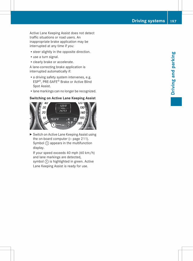
Active Lane Keeping Assist does not detecttraffic situations or road users. Aninappropriate brake application may beinterrupted at any time if you:Rsteer slightly in the opposite direction.Ruse a turn signal.Rclearly brake or accelerate.A lane-correcting brake application isinterrupted automatically if:Ra driving safety system intervenes, e.g.
ESP®, PRE-SAFE® Brake or Active BlindSpot Assist.Rlane markings can no longer be recognized.
Switching on Active Lane Keeping Assist
X Switch on Active Lane Keeping Assist usingthe on-board computer (Y page 211).Symbol : appears in the multifunctiondisplay.If your speed exceeds 40 mph (60 km/h)and lane markings are detected,symbol : is highlighted in green. ActiveLane Keeping Assist is ready for use.
Driving systems 197
Driv
ing
and
park
ing
Z

198
Useful information ............................ 200Important safety notes .................... 200Displays and operation .................... 200Menus and submenus ...................... 204Display messages ............................. 220Warning and indicator lamps in theinstrument cluster ............................ 247
199
On-b
oard
com
pute
r and
dis
play
s
Useful information
i This Operator's Manual describes allmodels and all standard and optionalequipment of your vehicle available at thetime of publication of the Operator'sManual. Country-specific differences arepossible. Please note that your vehicle maynot be equipped with all featuresdescribed. This also applies to safety-related systems and functions.
i Please read the information on qualifiedspecialist workshops (Y page 24).
Important safety notes
You will find an illustration of the instrumentcluster in the "At a glance" section(Y page 29).
G WARNINGThe driver's concentration must always bedirected primarily at road traffic.For your safety and the safety of others,selecting features through the multifunctionsteering wheel should only be done by thedriver when traffic and road conditions permitit to be done safely.Bear in mind that at a speed of only 30 mph(approximately 50 km/h), the vehicle coversa distance of 44 feet (approximately 14 m) persecond.
G WARNINGNo messages will be displayed if either theinstrument cluster or the multifunctiondisplay is inoperative.As a result, you will not be able to seeinformation about your driving conditions,such asRspeedRoutside temperatureRwarning/indicator lamps
Rmalfunction/warning messagesRfailure of any systemsDriving characteristics may be impaired.If you must continue to drive, do so with addedcaution. Contact an authorized Mercedes-Benz Center as soon as possible.
G WARNINGMalfunction and warning messages are onlyindicated for certain systems and areintentionally not very detailed. Themalfunction and warning messages aresimply a reminder with respect to theoperation of certain systems. They do notreplace the owner's and/or driver'sresponsibility to maintain the vehicle'soperating safety. Have all requiredmaintenance and safety checks performed onthe vehicle. Bring the vehicle to an authorizedMercedes-Benz Center to address themalfunction and warning messages.
Displays and operation
coolant temperature display
G WARNINGDriving when your engine is overheated cancause some fluids which may have leaked intothe engine compartment to catch fire. Youcould be seriously burned.Steam from an overheated engine can causeserious burns which can occur just by openingthe engine hood. Stay away from the engineif you see or hear steam coming from it.Stop the vehicle in a safe location away fromother traffic. Turn off the engine, get out of thevehicle and do not stand near the vehicle untilthe engine has cooled down.
The coolant temperature gauge is in theinstrument cluster on the left-hand side.Under normal operating conditions and withthe specified coolant level, the coolanttemperature may rise to 248 ‡ (120 †).
200 Displays and operationOn
-boa
rd c
ompu
ter a
nd d
ispl
ays
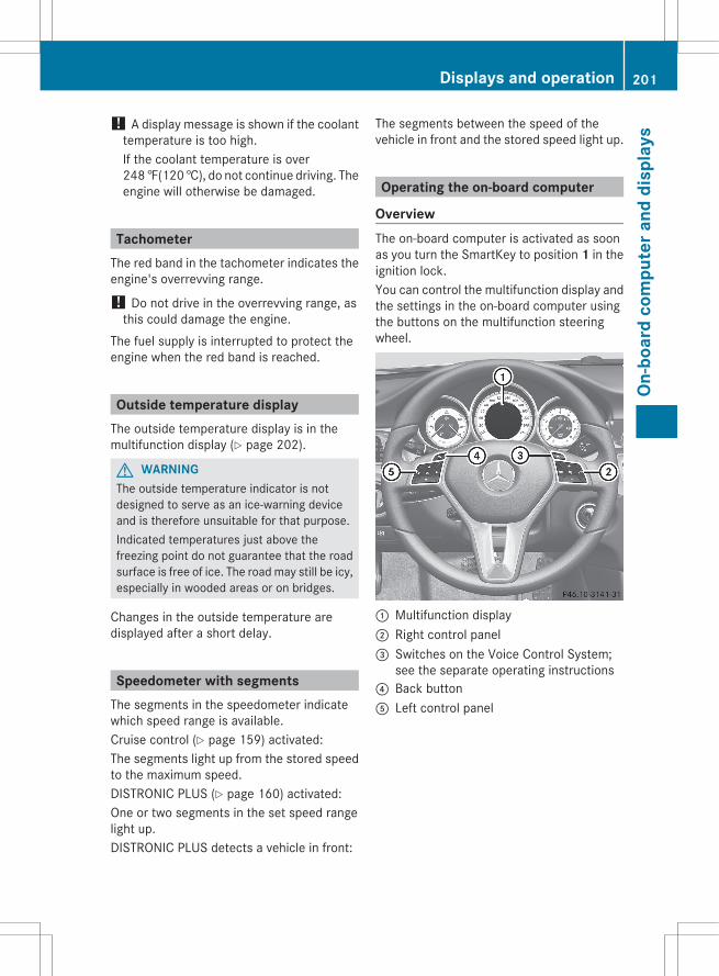
! A display message is shown if the coolanttemperature is too high.If the coolant temperature is over248 ‡(120 †), do not continue driving. Theengine will otherwise be damaged.
TachometerThe red band in the tachometer indicates theengine's overrevving range.
! Do not drive in the overrevving range, asthis could damage the engine.
The fuel supply is interrupted to protect theengine when the red band is reached.
Outside temperature displayThe outside temperature display is in themultifunction display (Y page 202).
G WARNINGThe outside temperature indicator is notdesigned to serve as an ice-warning deviceand is therefore unsuitable for that purpose.Indicated temperatures just above thefreezing point do not guarantee that the roadsurface is free of ice. The road may still be icy,especially in wooded areas or on bridges.
Changes in the outside temperature aredisplayed after a short delay.
Speedometer with segmentsThe segments in the speedometer indicatewhich speed range is available.Cruise control (Y page 159) activated:The segments light up from the stored speedto the maximum speed.DISTRONIC PLUS (Y page 160) activated:One or two segments in the set speed rangelight up.DISTRONIC PLUS detects a vehicle in front:
The segments between the speed of thevehicle in front and the stored speed light up.
Operating the on-board computer
OverviewThe on-board computer is activated as soonas you turn the SmartKey to position 1 in theignition lock.You can control the multifunction display andthe settings in the on-board computer usingthe buttons on the multifunction steeringwheel.
: Multifunction display; Right control panel= Switches on the Voice Control System;
see the separate operating instructions? Back buttonA Left control panel
Displays and operation 201
On-b
oard
com
pute
r and
dis
play
s
Z
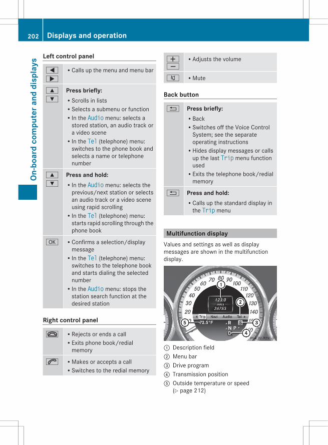
Left control panel
=
;
RCalls up the menu and menu bar
9
:
Press briefly:RScrolls in listsRSelects a submenu or functionRIn the Audio menu: selects a
stored station, an audio track ora video sceneRIn the Tel (telephone) menu:
switches to the phone book andselects a name or telephonenumber
9
:
Press and hold:RIn the Audio menu: selects the
previous/next station or selectsan audio track or a video sceneusing rapid scrollingRIn the Tel (telephone) menu:
starts rapid scrolling through thephone book
a RConfirms a selection/displaymessageRIn the Tel (telephone) menu:
switches to the telephone bookand starts dialing the selectednumberRIn the Audio menu: stops the
station search function at thedesired station
Right control panel
~ RRejects or ends a callRExits phone book/redial
memory
6 RMakes or accepts a callRSwitches to the redial memory
WX
RAdjusts the volume
8 RMute
Back button
% Press briefly:RBackRSwitches off the Voice Control
System; see the separateoperating instructionsRHides display messages or calls
up the last Trip menu functionusedRExits the telephone book/redial
memory
% Press and hold:RCalls up the standard display in
the Trip menu
Multifunction displayValues and settings as well as displaymessages are shown in the multifunctiondisplay.
: Description field; Menu bar= Drive program? Transmission positionA Outside temperature or speed
(Y page 212)
202 Displays and operationOn
-boa
rd c
ompu
ter a
nd d
ispl
ays
X To show menu bar ;: press the =or ; button on the steering wheel.
Further information on displaying thetransmission position (Y page 142).The following messages may appear in themultifunction display:XjY Active Parking Assist (Y page 179)_ Adaptive Highbeam Assist
(Y page 112)À ATTENTION ASSIST (Y page 183)Ã Lane Keeping Assist (Y page 190) or
Active Lane Keeping Assist(Y page 194)
ë HOLD function (Y page 170)Ä PRE-SAFE® Brake (Y page 69)
Displays and operation 203
On-b
oard
com
pute
r and
dis
play
s
Z

Menus and submenus
Menu overviewThe number of menus shown depends on the optional equipment in the vehicle.
Function: Trip menu (Y page 205)
; Navi menu (navigation instructions) (Y page 206)
= Audio menu (Y page 207)
? Tel menu (telephone) (Y page 208)
A DriveAssist. menu (assistance) (Y page 210)
B Serv. menu (Y page 212)Rcalls up display messages (Y page 220)Rtire pressure loss warning system (Canada only) (Y page 327)Rtire pressure monitor (Y page 328)RASSYST PLUS service interval display (Y page 290)
C Sett. menu (Y page 212)
D AMG menu in AMG vehicles (Y page 216)
204 Menus and submenusOn
-boa
rd c
ompu
ter a
nd d
ispl
ays
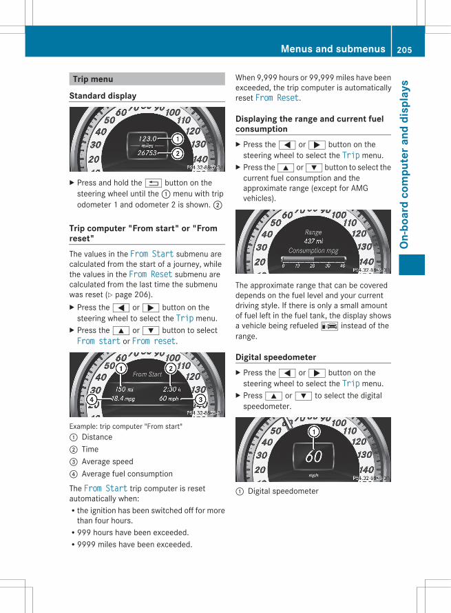
Trip menu
Standard display
X Press and hold the % button on thesteering wheel until the : menu with tripodometer 1 and odometer 2 is shown. ;
Trip computer "From start" or "Fromreset"The values in the From Start submenu arecalculated from the start of a journey, whilethe values in the From Reset submenu arecalculated from the last time the submenuwas reset (Y page 206).X Press the = or ; button on the
steering wheel to select the Trip menu.X Press the 9 or : button to selectFrom start or From reset.
Example: trip computer "From start": Distance; Time= Average speed? Average fuel consumption
The From Start trip computer is resetautomatically when:Rthe ignition has been switched off for more
than four hours.R999 hours have been exceeded.R9999 miles have been exceeded.
When 9,999 hours or 99,999 miles have beenexceeded, the trip computer is automaticallyreset From Reset.
Displaying the range and current fuelconsumptionX Press the = or ; button on the
steering wheel to select the Trip menu.X Press the 9 or : button to select the
current fuel consumption and theapproximate range (except for AMGvehicles).
The approximate range that can be covereddepends on the fuel level and your currentdriving style. If there is only a small amountof fuel left in the fuel tank, the display showsa vehicle being refueled C instead of therange.
Digital speedometerX Press the = or ; button on the
steering wheel to select the Trip menu.X Press 9 or : to select the digital
speedometer.
: Digital speedometer
Menus and submenus 205
On-b
oard
com
pute
r and
dis
play
s
Z
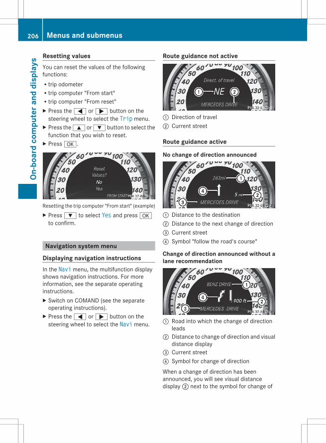
Resetting valuesYou can reset the values of the followingfunctions:Rtrip odometerRtrip computer "From start"Rtrip computer "From reset"X Press the = or ; button on the
steering wheel to select the Trip menu.X Press the 9 or : button to select the
function that you wish to reset.X Press a.
Resetting the trip computer "From start" (example)X Press : to select Yes and press a
to confirm.
Navigation system menu
Displaying navigation instructionsIn the Navi menu, the multifunction displayshows navigation instructions. For moreinformation, see the separate operatinginstructions.X Switch on COMAND (see the separate
operating instructions).X Press the = or ; button on the
steering wheel to select the Navi menu.
Route guidance not active
: Direction of travel; Current street
Route guidance active
No change of direction announced
: Distance to the destination; Distance to the next change of direction= Current street? Symbol "follow the road's course"
Change of direction announced without alane recommendation
: Road into which the change of directionleads
; Distance to change of direction and visualdistance display
= Current street? Symbol for change of direction
When a change of direction has beenannounced, you will see visual distancedisplay ; next to the symbol for change of
206 Menus and submenusOn
-boa
rd c
ompu
ter a
nd d
ispl
ays
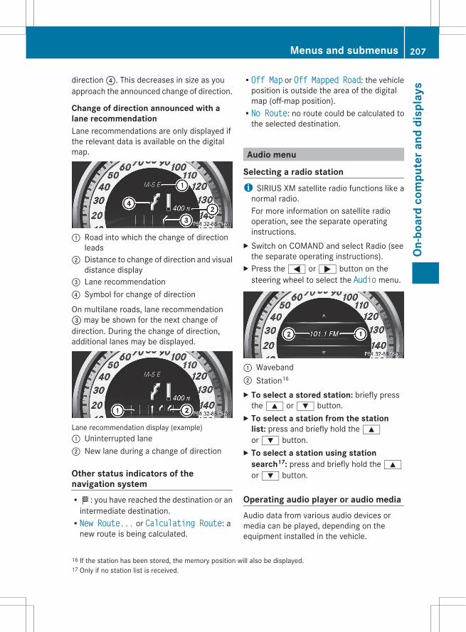
direction ?. This decreases in size as youapproach the announced change of direction.
Change of direction announced with alane recommendationLane recommendations are only displayed ifthe relevant data is available on the digitalmap.
: Road into which the change of directionleads
; Distance to change of direction and visualdistance display
= Lane recommendation? Symbol for change of direction
On multilane roads, lane recommendation= may be shown for the next change ofdirection. During the change of direction,additional lanes may be displayed.
Lane recommendation display (example): Uninterrupted lane; New lane during a change of direction
Other status indicators of thenavigation systemRO: you have reached the destination or an
intermediate destination.RNew Route... or Calculating Route: a
new route is being calculated.
ROff Map or Off Mapped Road: the vehicleposition is outside the area of the digitalmap (off-map position).RNo Route: no route could be calculated to
the selected destination.
Audio menu
Selecting a radio stationi SIRIUS XM satellite radio functions like a
normal radio.For more information on satellite radiooperation, see the separate operatinginstructions.
X Switch on COMAND and select Radio (seethe separate operating instructions).
X Press the = or ; button on thesteering wheel to select the Audio menu.
: Waveband; Station16
X To select a stored station: briefly pressthe 9 or : button.
X To select a station from the station list: press and briefly hold the 9or : button.
X To select a station using station search17: press and briefly hold the 9or : button.
Operating audio player or audio mediaAudio data from various audio devices ormedia can be played, depending on theequipment installed in the vehicle.
16 If the station has been stored, the memory position will also be displayed.17 Only if no station list is received.
Menus and submenus 207
On-b
oard
com
pute
r and
dis
play
s
Z
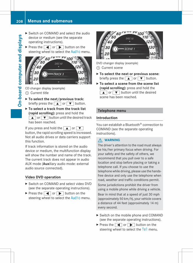
X Switch on COMAND and select the audiodevice or medium (see the separateoperating instructions).
X Press the = or ; button on thesteering wheel to select the Audio menu.
CD changer display (example): Current titleX To select the next/previous track:
briefly press the 9 or : button.X To select a track from the track list
(rapid scrolling): press and hold the9 or : button until the desired trackhas been reached.
If you press and hold the 9 or :button, the rapid scrolling speed is increased.Not all audio drives or data carriers supportthis function.If track information is stored on the audiodevice or medium, the multifunction displaywill show the number and name of the track.The current track does not appear in audioAUX mode (Auxiliary audio mode: externalaudio source connected).
Video DVD operationX Switch on COMAND and select video DVD
(see the separate operating instructions).X Press the = or ; button on the
steering wheel to select the Audio menu.
DVD changer display (example): Current sceneX To select the next or previous scene:
briefly press the 9 or : button.X To select a scene from the scene list
(rapid scrolling): press and hold the9 or : button until the desiredscene has been reached.
Telephone menu
IntroductionYou can establish a Bluetooth® connection toCOMAND (see the separate operatinginstructions).
G WARNINGThe driver's attention to the road must alwaysbe his/her primary focus when driving. Foryour safety and the safety of others, werecommend that you pull over to a safelocation and stop before placing or taking atelephone call. If you choose to use thetelephone while driving, please use the hands-free device and only use the telephone whenroad, weather and traffic conditions permit.Some jurisdictions prohibit the driver fromusing a mobile phone while driving a vehicle.Bear in mind that at a speed of just 30 mph(approximately 50 km/h), your vehicle coversa distance of 44 feet (approximately 14 m)every second.
X Switch on the mobile phone and COMAND(see the separate operating instructions).
X Press the = or ; button on thesteering wheel to select the Tel menu.
208 Menus and submenusOn
-boa
rd c
ompu
ter a
nd d
ispl
ays
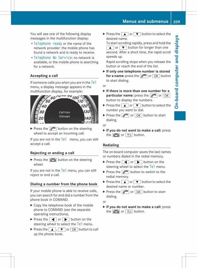
You will see one of the following displaymessages in the multifunction display:RTelephone ready or the name of the
network provider: the mobile phone hasfound a network and is ready to receive.RTelephone No Service: no network is
available, or the mobile phone is searchingfor a network.
Accepting a callIf someone calls you when you are in the Tel menu, a display message appears in themultifunction display, for example:
X Press the 6 button on the steeringwheel to accept an incoming call.
If you are not in the Tel menu, you can stillaccept a call.
Rejecting or ending a callX Press the ~ button on the steering
wheel.If you are not in the Tel menu, you can stillreject or end a call.
Dialing a number from the phone bookIf your mobile phone is able to receive calls,you can search for and dial a number from thephone book in COMAND.X Copy the telephone book of the mobile
phone to COMAND (see the separateoperating instructions).
X Press the = or ; button on thesteering wheel to select the Tel menu.
X Press the 9, : or a button to callup the phone book.
X Press the 9 or : button to select thedesired name.To start scrolling rapidly, press and hold the9 or : button for longer than onesecond. After a short time, the rapid scrollspeeds up.Rapid scrolling stops when you release thebutton or reach the end of the list.
X If only one telephone number is stored for a name: press the 6 or a buttonto start dialing.
orX If there is more than one number for a
particular name: press the 6 or abutton to display the numbers.
X Press the 9 or : button to select thenumber you want to dial.
X Press the 6 or a button to startdialing.
orX If you do not want to make a call: press
the ~ or % button.
RedialingThe on-board computer saves the last namesor numbers dialed in the redial memory.X Press the = or ; button on the
steering wheel to select the Tel menu.X Press the 6 button to switch to the
redial memory.X Press the 9 or : button to select the
desired name or number.X Press the 6 or a button to start
dialing.orX If you do not want to make a call: press
the ~ or % button.
Menus and submenus 209
On-b
oard
com
pute
r and
dis
play
s
Z
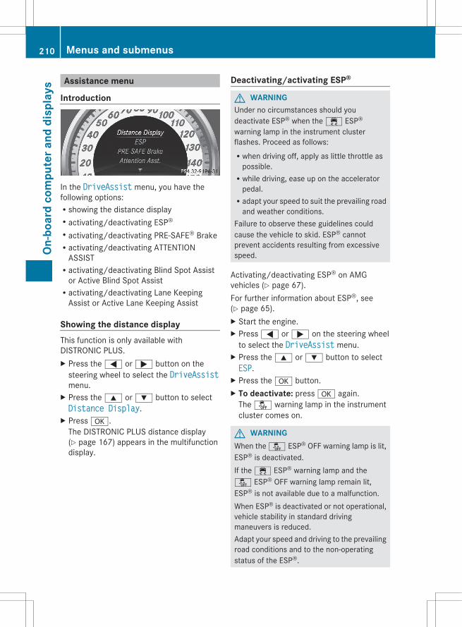
Assistance menu
Introduction
In the DriveAssist menu, you have thefollowing options:Rshowing the distance displayRactivating/deactivating ESP®
Ractivating/deactivating PRE-SAFE® BrakeRactivating/deactivating ATTENTION
ASSISTRactivating/deactivating Blind Spot Assist
or Active Blind Spot AssistRactivating/deactivating Lane Keeping
Assist or Active Lane Keeping Assist
Showing the distance displayThis function is only available withDISTRONIC PLUS.X Press the = or ; button on the
steering wheel to select the DriveAssistmenu.
X Press the 9 or : button to selectDistance Display.
X Press a.The DISTRONIC PLUS distance display(Y page 167) appears in the multifunctiondisplay.
Deactivating/activating ESP®
G WARNINGUnder no circumstances should youdeactivate ESP® when the ÷ ESP®
warning lamp in the instrument clusterflashes. Proceed as follows:Rwhen driving off, apply as little throttle as
possible.Rwhile driving, ease up on the accelerator
pedal.Radapt your speed to suit the prevailing road
and weather conditions.Failure to observe these guidelines couldcause the vehicle to skid. ESP® cannotprevent accidents resulting from excessivespeed.
Activating/deactivating ESP® on AMGvehicles (Y page 67).For further information about ESP®, see(Y page 65).X Start the engine.X Press = or ; on the steering wheel
to select the DriveAssist menu.X Press the 9 or : button to selectESP.
X Press the a button.X To deactivate: press a again.
The å warning lamp in the instrumentcluster comes on.
G WARNINGWhen the å ESP® OFF warning lamp is lit,ESP® is deactivated.If the ÷ ESP® warning lamp and theå ESP® OFF warning lamp remain lit,ESP® is not available due to a malfunction.When ESP® is deactivated or not operational,vehicle stability in standard drivingmaneuvers is reduced.Adapt your speed and driving to the prevailingroad conditions and to the non-operatingstatus of the ESP®.
210 Menus and submenusOn
-boa
rd c
ompu
ter a
nd d
ispl
ays
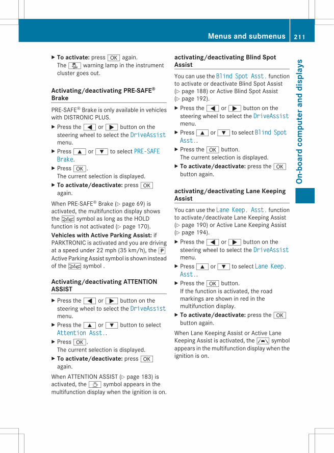
X To activate: press a again.The å warning lamp in the instrumentcluster goes out.
Activating/deactivating PRE-SAFE®
BrakePRE-SAFE® Brake is only available in vehicleswith DISTRONIC PLUS.X Press the = or ; button on the
steering wheel to select the DriveAssistmenu.
X Press 9 or : to select PRE-SAFE Brake.
X Press a.The current selection is displayed.
X To activate/deactivate: press aagain.
When PRE-SAFE® Brake (Y page 69) isactivated, the multifunction display showsthe Ä symbol as long as the HOLDfunction is not activated (Y page 170).Vehicles with Active Parking Assist: ifPARKTRONIC is activated and you are drivingat a speed under 22 mph (35 km/h), the jActive Parking Assist symbol is shown insteadof the Ä symbol .
Activating/deactivating ATTENTIONASSISTX Press the = or ; button on the
steering wheel to select the DriveAssistmenu.
X Press the 9 or : button to selectAttention Asst..
X Press a.The current selection is displayed.
X To activate/deactivate: press aagain.
When ATTENTION ASSIST (Y page 183) isactivated, the À symbol appears in themultifunction display when the ignition is on.
activating/deactivating Blind SpotAssistYou can use the Blind Spot Asst. functionto activate or deactivate Blind Spot Assist(Y page 188) or Active Blind Spot Assist(Y page 192).X Press the = or ; button on the
steering wheel to select the DriveAssistmenu.
X Press 9 or : to select Blind Spot Asst..
X Press the a button.The current selection is displayed.
X To activate/deactivate: press the abutton again.
activating/deactivating Lane KeepingAssistYou can use the Lane Keep. Asst. functionto activate/deactivate Lane Keeping Assist(Y page 190) or Active Lane Keeping Assist(Y page 194).X Press the = or ; button on the
steering wheel to select the DriveAssistmenu.
X Press 9 or : to select Lane Keep. Asst..
X Press the a button.If the function is activated, the roadmarkings are shown in red in themultifunction display.
X To activate/deactivate: press the abutton again.
When Lane Keeping Assist or Active LaneKeeping Assist is activated, the à symbolappears in the multifunction display when theignition is on.
Menus and submenus 211
On-b
oard
com
pute
r and
dis
play
s
Z
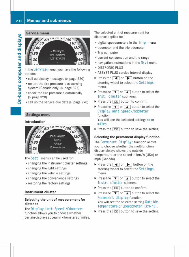
Service menu
In the Service menu, you have the followingoptions:Rcall up display messages (Y page 220)Rrestart the tire pressure loss warning
system (Canada only) (Y page 327)Rcheck the tire pressure electronically
(Y page 328)Rcall up the service due date (Y page 290)
Settings menu
Introduction
The Sett. menu can be used for:Rchanging the instrument cluster settingsRchanging the light settingsRchanging the vehicle settingsRchanging the convenience settingsRrestoring the factory settings
Instrument cluster
Selecting the unit of measurement fordistanceThe Display Unit Speed-/Odometer:function allows you to choose whethercertain displays appear in kilometers or miles.
The selected unit of measurement fordistance applies to:Rdigital speedometers in the Trip menuRodometer and the trip odometerRTrip computerRcurrent consumption and the rangeRnavigation instructions in the Navi menuRDISTRONIC PLUSRASSYST PLUS service interval displayX Press the = or ; button on the
steering wheel to select the Settingsmenu.
X Press the : or 9 button to select theInst. cluster submenu.
X Press the a button to confirm.X Press the : or 9 button to select theDisplay unit Speed-/odometerfunction.You will see the selected setting: km ormiles.
X Press the a button to save the setting.
Selecting the permanent display functionThe Permanent Display: function allowsyou to choose whether the multifunctiondisplay always shows the outsidetemperature or the speed in km/h (USA) ormph (Canada).X Press the = or ; button on the
steering wheel to select the Settingsmenu.
X Press the : or 9 button to select theInstr. cluster submenu.
X Press the a button to confirm.X Press the : or 9 button to select thePermanent display function.You will see the selected setting Outside Temperature or Speedometer [km/h]:.
X Press the a button to save the setting.
212 Menus and submenusOn
-boa
rd c
ompu
ter a
nd d
ispl
ays
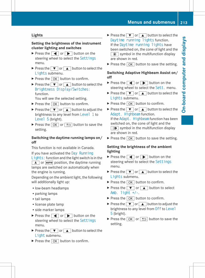
Lights
Setting the brightness of the instrumentcluster lighting and switchesX Press the = or ; button on the
steering wheel to select the Settingsmenu.
X Press the : or 9 button to select theLights submenu.
X Press the a button to confirm.X Press the : or 9 button to select theBrightness Display/Switches:function.You will see the selected setting.
X Press the a button to confirm.X Press the : or 9 button to adjust the
brightness to any level from Level 1 toLevel 5 (bright).
X Press the a or % button to save thesetting.
Switching the daytime running lamps on/offThis function is not available in Canada.If you have activated the Day Running Lights: function and the light switch is in thec or à position, the daytime runninglamps are switched on automatically whenthe engine is running.Depending on the ambient light, the followingwill additionally light up:Rlow-beam headlampsRparking lampsRtail lampsRlicense plate lampRside marker lampsX Press the = or ; button on the
steering wheel to select the Settingsmenu.
X Press the : or 9 button to select theLight submenu.
X Press the a button to confirm.
X Press the : or 9 button to select theDaytime running lights function.If the Daytime running lights havebeen switched on, the cone of light and theW symbol in the multifunction displayare shown in red.
X Press the a button to save the setting.
Switching Adaptive Highbeam Assist on/offX Press the = or ; button on the
steering wheel to select the Sett. menu.X Press the : or 9 button to select theLights submenu.
X Press the a button to confirm.X Press the : or 9 button to select theAdapt. Highbeam function.If the Adapt. Highbeam function has beenswitched on, the cone of light and the_ symbol in the multifunction displayare shown in red.
X Press the a button to save the setting.
Setting the brightness of the ambientlightingX Press the = or ; button on the
steering wheel to select the Settingsmenu.
X Press the : or 9 button to select theLights submenu.
X Press the a button to confirm.X Press the : or 9 button to selectAmb. light +/-.
X Press the a button to confirm.X Press the : or 9 button to adjust the
brightness to any level from Off to Level 5 (bright).
X Press the a or % button to save thesetting.
Menus and submenus 213
On-b
oard
com
pute
r and
dis
play
s
Z
Setting the ambient lighting colorX Press the = or ; button on the
steering wheel to select the Settingsmenu.
X Press the : or 9 button to select theLight submenu.
X Press the a button to confirm.X Press the : or 9 button to select theAmb. light col. function.
X Press the a button to confirm.X Press the : or 9 button to set the
color to SOLAR, NEUTRAL or POLAR.X Press the a or % button to save the
setting.
Activating/deactivating surroundlighting and exterior lighting delayedswitch-offIf you have activated the Surround Lighting function and the light switch is inthe c or à position, the followingfunctions are active when it is dark:RSurround lighting: the exterior lighting
remains lit for 40 seconds after unlockingwith the key. The exterior lighting switchesoff when you open the driver's door.RExterior lighting delayed switch-off: the
exterior lighting remains lit for 60 secondsafter the engine is switched off. If you closeall the doors, the exterior lighting goes offafter 15 seconds.
If you activate the Surround lightingfunction, the following light up depending onthe vehicle's equipment:Rparking lampsRlow-beam headlampsRdaytime running lampsRside marker lampsRsurround lighting in the exterior mirrorsX Press the = or ; button on the
steering wheel to select the Sett. menu.X Press the : or 9 button to select theLights submenu.
X Press the a button to confirm.X Press the : or 9 button to select theSurround Lighting function.When the Surround lighting function isactivated, the light cone and the areaaround the vehicle are displayed in red inthe multifunction display.
X Press the a button to save the setting.
Deactivating delayed switch-off of theexterior lighting temporarily:X Before leaving the vehicle, turn the
SmartKey to position 0 in the ignition lock.X Turn the SmartKey to position 2 in the
ignition lock and back to position 0.The exterior lighting delayed switch-off isdeactivated.
Delayed switch-off of the exterior lighting isreactivated the next time you start theengine.
Activating/deactivating the interiorlighting delayed switch-offIf you activate the Light. delay function,the interior lighting remains on for 20secondsafter you remove the key from the ignitionlock.X Press the = or ; button on the
steering wheel to select the Settingsmenu.
X Press the : or 9 button to select theLight submenu.
X Press the a button to confirm.X Press the : or 9 button to select theInterior lighting delay sw. off:function.When the Light. delay function isactivated, the vehicle interior is displayedin red in the multifunction display.
X Press the a button to save the setting.
214 Menus and submenusOn
-boa
rd c
ompu
ter a
nd d
ispl
ays

Vehicle
Activating/deactivating the automaticdoor locking mechanismIf you select the Auto. Door Locks function,the vehicle is centrally locked above a speedof around 9 mph (15km/h).
i For further information on the automaticlocking feature, see (Y page 81).
X Press the = or ; button on thesteering wheel to select the Settingsmenu.
X Press the : or 9 button to select theVehicle submenu.
X Press the a button to confirm.X Press the : or 9 button to select theAuto. door lock function.When the Auto. door locks function isactivated, the vehicle doors are displayedin red in the multifunction display.
X Press the a button to save the setting.
Activating/deactivating the acousticlocking verification signalIf you activate the Acoustic Lock function,an audible signal sounds depending on thevehicle's date of manufacture:Rwhen locking
orRonce when unlocking and three times when
lockingX Press the = or ; button on the
steering wheel to select the Settingsmenu.
X Press the : or 9 button to select theVehicle submenu.
X Press the a button to confirm.X Press the : or 9 button to select theAcoustic Lock function.If the Acoustic Lock function is activated,the & symbol in the multifunctiondisplay lights up red.
X Press the a button to save the setting.
Activating/deactivating the radar sensorsystemThe following systems are switched off whenthe radar sensor system is deactivated:RDISTRONIC PLUS (Y page 160)RBAS PLUS (Y page 64)RPRE-SAFE® Brake (Y page 69)RBlind Spot Assist (Y page 188)RActive Blind Spot Assist (Y page 192)X Press the = or ; button on the
steering wheel to select the Sett. menu.X Press the : or 9 button to select theVehicle submenu.
X Press a to confirm.X Press the 9 or : button to selectRadar Sensor (See Oper. Manual):.You will see the selected setting: Enabledor Disabled.
X Press the a button to save the setting.
Convenience
Activating/deactivating the EASY-ENTRY/EXIT featureYou can use the Easy Entry/Exit: functionto activate or deactivate the EASY ENTRY/EXIT feature (Y page 101).
G WARNINGYou must make sure no one can becometrapped or injured by the moving steeringwheel when the easy-entry/exit feature isactivated.To stop steering wheel movement, movesteering wheel adjustment lever or press oneof the memory position buttons.Do not leave children unattended in thevehicle, or with access to an unlocked vehicle.Children could open the driver's door andunintentionally activate the easy-entry/exitfeature, which could result in an accidentand/or serious personal injury.
Menus and submenus 215
On-b
oard
com
pute
r and
dis
play
s
Z
X Press the = or ; button on thesteering wheel to select the Settingsmenu.
X Press the : or 9 button to select theConvenience submenu.
X Press the a button to confirm.X Press the : or 9 button to select theEasy Entry/Exit function.If the Easy Entry/Exit function isactivated, the vehicle steering wheel isdisplayed in red in the multifunctiondisplay.
X Press the a button to save the setting.
Switching the belt adjustment on/offFor further information on belt adjustment(Y page 55).X Press the = or ; button on the
steering wheel to select the Settingsmenu.
X Press the : or 9 button to select theConvenience submenu.
X Press the a button to confirm.X Press the : or 9 button to select theBelt Adjustment function.When the Belt adjustment function isactivated, the vehicle seat belt is displayedin red in the multifunction display.
X Press the a button to save the setting.
Switching the fold-in mirrors whenlocking feature is on/offThis function is only available in Canada.If you switch on the Auto. Mirror Folding function, the exterior mirrors fold inwhen you lock the vehicle. If you unlock thevehicle and then open the driver's or front-passenger door, the exterior mirrors fold outagain.If you have switched the function on and youfold the exterior mirrors in using the buttonon the door (Y page 103), they will not foldout automatically. The exterior mirrors canthen only be folded out using the button onthe door.
X Press the = or ; button on thesteering wheel to select the Settingsmenu.
X Press the : or 9 button to select theConvenience submenu.
X Press the a button to confirm.X Press the : or 9 button to select theAuto. fold in function.If the Auto. fold in function is activated,the vehicle's exterior mirror is displayed inred in the multifunction display.
X Press the a button to save the setting.
Restoring the factory settingsFor safety reasons, the Day Lights functionin the Lights submenu is only reset when thevehicle is stationary.X Press the = or ; button on the
steering wheel to select the Sett. menu.X Press the : or 9 button to select theFactory Setting submenu.
X Press the a button to confirm.The Reset All Settings? messageappears.
X Press the : or 9 button to selectNo or Yes.
X Press the a button to confirm theselection.If you select Yes, the multifunction displayshows a confirmation message.
AMG menu in AMG vehicles
AMG displaysX Press the = or ; button on the
steering wheel to select the AMG menu.
216 Menus and submenusOn
-boa
rd c
ompu
ter a
nd d
ispl
ays

: Digital speedometer; Gear indicator= Upshift indicator? Engine oil temperatureA Coolant temperature
Upshift indicator UP = indicates that theengine has reached the overrevving rangewhen in the manual gearshift program.Upshift indicator UP = fades out othermessages until you have shifted up.When the engine oil temperature is below80 †, the oil temperature is shown in blue.Avoid driving at full engine output during thistime.
SETUPSETUP shows the drive program, the ESP®
(Electronic Stability Program) mode and theSPORT handling mode.X Press the = or ; button on the
steering wheel to select the AMG menu.X Press the 9 button repeatedly until
SETUP is displayed.orX Briefly press the AMG button on the center
console.
: Drive program (C/S/S+/M); ESP® mode (ON/OFF) or SPORT handling
mode (SPORT)3 Suspension tuning (COMFORT/SPORT/
SPORT+)
RACETIMER
Displaying and starting RACETIMERG WARNINGThe RACETIMER feature is only for use onroads and in conditions where high speeddriving is permitted. Racing on public roads isprohibited under all circumstances. The driveris and must always remain responsible forfollowing posted speed limits.
You can use the RACETIMER to store laptimes.X Press = or ; on the steering wheel
to select the AMG menu.X Press the 9 button repeatedly until the
RACETIMER is shown.
i If RACETIMER is selected, the menu barcannot be called up with the =and ; buttons.
: Lap; RACETIMER
Menus and submenus 217
On-b
oard
com
pute
r and
dis
play
s
Z
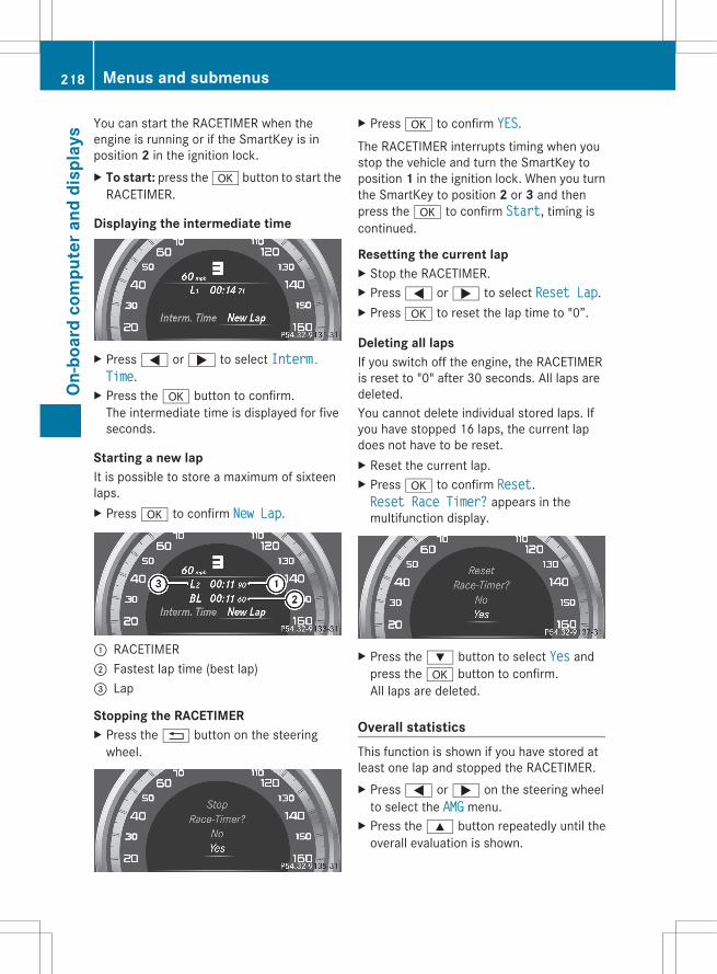
You can start the RACETIMER when theengine is running or if the SmartKey is inposition 2 in the ignition lock.X To start: press the a button to start the
RACETIMER.
Displaying the intermediate time
X Press = or ; to select Interm. Time.
X Press the a button to confirm.The intermediate time is displayed for fiveseconds.
Starting a new lapIt is possible to store a maximum of sixteenlaps.X Press a to confirm New Lap.
: RACETIMER; Fastest lap time (best lap)= Lap
Stopping the RACETIMERX Press the % button on the steering
wheel.
X Press a to confirm YES.
The RACETIMER interrupts timing when youstop the vehicle and turn the SmartKey toposition 1 in the ignition lock. When you turnthe SmartKey to position 2 or 3 and thenpress the a to confirm Start, timing iscontinued.
Resetting the current lapX Stop the RACETIMER.X Press = or ; to select Reset Lap.X Press a to reset the lap time to "0”.
Deleting all lapsIf you switch off the engine, the RACETIMERis reset to "0" after 30 seconds. All laps aredeleted.You cannot delete individual stored laps. Ifyou have stopped 16 laps, the current lapdoes not have to be reset.X Reset the current lap.X Press a to confirm Reset.Reset Race Timer? appears in themultifunction display.
X Press the : button to select Yes andpress the a button to confirm.All laps are deleted.
Overall statisticsThis function is shown if you have stored atleast one lap and stopped the RACETIMER.X Press = or ; on the steering wheel
to select the AMG menu.X Press the 9 button repeatedly until the
overall evaluation is shown.
218 Menus and submenusOn
-boa
rd c
ompu
ter a
nd d
ispl
ays
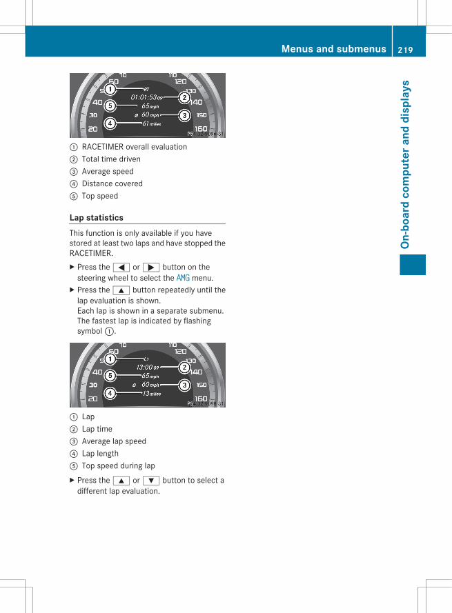
: RACETIMER overall evaluation; Total time driven= Average speed? Distance coveredA Top speed
Lap statisticsThis function is only available if you havestored at least two laps and have stopped theRACETIMER.X Press the = or ; button on the
steering wheel to select the AMG menu.X Press the 9 button repeatedly until the
lap evaluation is shown.Each lap is shown in a separate submenu.The fastest lap is indicated by flashingsymbol :.
: Lap; Lap time= Average lap speed? Lap lengthA Top speed during lapX Press the 9 or : button to select a
different lap evaluation.
Menus and submenus 219
On-b
oard
com
pute
r and
dis
play
s
Z

Display messages
General notes
G WARNINGAll categories of messages contain important information which should be taken note of and,where a malfunction is indicated, addressed as soon as possible at an authorized Mercedes-BenzCenter.Failure to repair the condition noted may cause damage not covered by the Mercedes-BenzLimited Warranty, or result in property damage or personal injury.
Display messages appear in the multifunction display.Display messages with graphic displays may be shown in simplified form in the Operator'sManual and may differ from the messages shown in the multifunction display.Please respond in accordance with the display messages and follow the additional notes inthis Operator's Manual.Certain display messages are accompanied by an audible warning tone or a continuous tone.When you stop and park the vehicle, please observe the notes on the HOLD function(Y page 170) and parking (Y page 152).
Hiding display messagesYou can hide some display messages with a low priority.X Press the a or % button on the steering wheel to hide the display message.
The display message is cleared.Display messages with a high priority are shown in red.You cannot hide display messages of the highest priority. The multifunction display showsthese messages continuously until the causes for the messages have been remedied.
Message memoryThe on-board computer saves certain display messages. You can call up the display messagesin the message memory.X Press the = or ; button on the steering wheel and select the Serv. menu.
If there are display messages, the multifunction display shows, for example, 2 messages.X Press the 9 or : button to select the entry, e.g. 2 messages.X Confirm with a.X Press the 9 or : button to scroll through the display messages.
When the ignition is switched off, all display messages are deleted, apart from some high-priority display messages. Once the causes of the high-priority display messages have beenrectified, the corresponding display messages are also deleted.
220 Display messagesOn
-boa
rd c
ompu
ter a
nd d
ispl
ays
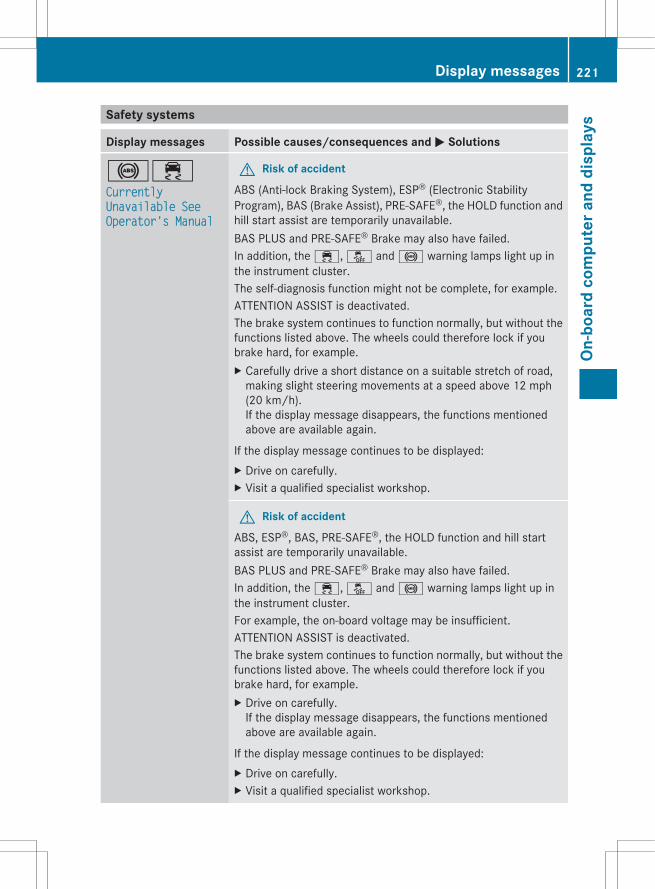
Safety systems
Display messages Possible causes/consequences and M Solutions
!÷Currently Unavailable See Operator's Manual
G Risk of accident
ABS (Anti-lock Braking System), ESP® (Electronic StabilityProgram), BAS (Brake Assist), PRE-SAFE®, the HOLD function andhill start assist are temporarily unavailable.BAS PLUS and PRE-SAFE® Brake may also have failed.In addition, the ÷, å and ! warning lamps light up inthe instrument cluster.The self-diagnosis function might not be complete, for example.ATTENTION ASSIST is deactivated.The brake system continues to function normally, but without thefunctions listed above. The wheels could therefore lock if youbrake hard, for example.X Carefully drive a short distance on a suitable stretch of road,
making slight steering movements at a speed above 12 mph(20 km/h).If the display message disappears, the functions mentionedabove are available again.
If the display message continues to be displayed:X Drive on carefully.X Visit a qualified specialist workshop.
G Risk of accident
ABS, ESP®, BAS, PRE-SAFE®, the HOLD function and hill startassist are temporarily unavailable.BAS PLUS and PRE-SAFE® Brake may also have failed.In addition, the ÷, å and ! warning lamps light up inthe instrument cluster.For example, the on-board voltage may be insufficient.ATTENTION ASSIST is deactivated.The brake system continues to function normally, but without thefunctions listed above. The wheels could therefore lock if youbrake hard, for example.X Drive on carefully.
If the display message disappears, the functions mentionedabove are available again.
If the display message continues to be displayed:X Drive on carefully.X Visit a qualified specialist workshop.
Display messages 221
On-b
oard
com
pute
r and
dis
play
s
Z
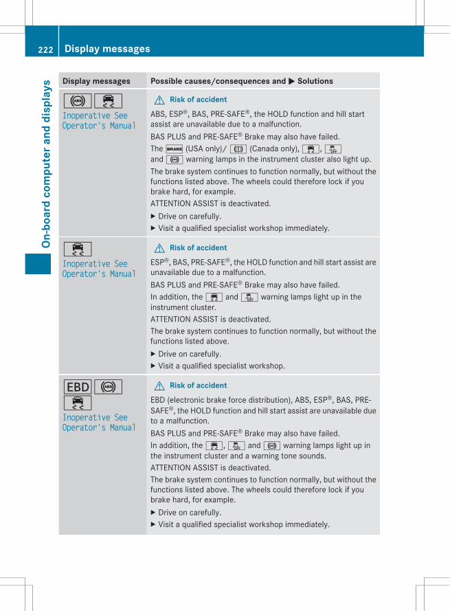
Display messages Possible causes/consequences and M Solutions
!÷Inoperative See Operator's Manual
G Risk of accident
ABS, ESP®, BAS, PRE-SAFE®, the HOLD function and hill startassist are unavailable due to a malfunction.BAS PLUS and PRE-SAFE® Brake may also have failed.The $ (USA only)/ J (Canada only), ÷, åand ! warning lamps in the instrument cluster also light up.The brake system continues to function normally, but without thefunctions listed above. The wheels could therefore lock if youbrake hard, for example.ATTENTION ASSIST is deactivated.X Drive on carefully.X Visit a qualified specialist workshop immediately.
÷Inoperative See Operator's Manual
G Risk of accident
ESP®, BAS, PRE-SAFE®, the HOLD function and hill start assist areunavailable due to a malfunction.BAS PLUS and PRE-SAFE® Brake may also have failed.In addition, the ÷ and å warning lamps light up in theinstrument cluster.ATTENTION ASSIST is deactivated.The brake system continues to function normally, but without thefunctions listed above.X Drive on carefully.X Visit a qualified specialist workshop.
T!÷Inoperative See Operator's Manual
G Risk of accident
EBD (electronic brake force distribution), ABS, ESP®, BAS, PRE-SAFE®, the HOLD function and hill start assist are unavailable dueto a malfunction.BAS PLUS and PRE-SAFE® Brake may also have failed.In addition, the ÷, å and ! warning lamps light up inthe instrument cluster and a warning tone sounds.ATTENTION ASSIST is deactivated.The brake system continues to function normally, but without thefunctions listed above. The wheels could therefore lock if youbrake hard, for example.X Drive on carefully.X Visit a qualified specialist workshop immediately.
222 Display messagesOn
-boa
rd c
ompu
ter a
nd d
ispl
ays
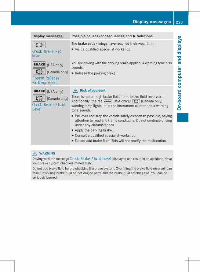
Display messages Possible causes/consequences and M Solutions
#Check Brake Pad Wear
The brake pads/linings have reached their wear limit.X Visit a qualified specialist workshop.
$ (USA only)
J (Canada only)Please Release Parking Brake
You are driving with the parking brake applied. A warning tone alsosounds.X Release the parking brake.
$ (USA only)
J (Canada only)Check Brake Fluid Level
G Risk of accidentThere is not enough brake fluid in the brake fluid reservoir.Additionally, the red $ (USA only)/ J (Canada only)warning lamp lights up in the instrument cluster and a warningtone sounds.X Pull over and stop the vehicle safely as soon as possible, paying
attention to road and traffic conditions. Do not continue drivingunder any circumstances.
X Apply the parking brake.X Consult a qualified specialist workshop.X Do not add brake fluid. This will not rectify the malfunction.
G WARNINGDriving with the message Check Brake Fluid Level displayed can result in an accident. Haveyour brake system checked immediately.Do not add brake fluid before checking the brake system. Overfilling the brake fluid reservoir canresult in spilling brake fluid on hot engine parts and the brake fluid catching fire. You can beseriously burned.
Display messages 223
On-b
oard
com
pute
r and
dis
play
s
Z
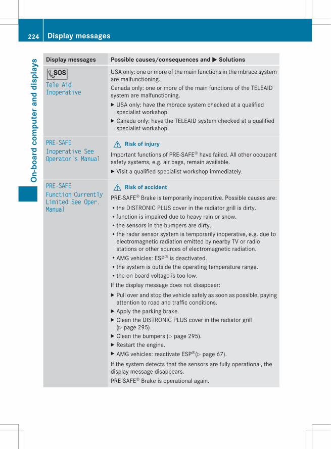
Display messages Possible causes/consequences and M Solutions
GTele Aid Inoperative
USA only: one or more of the main functions in the mbrace systemare malfunctioning.Canada only: one or more of the main functions of the TELEAIDsystem are malfunctioning.X USA only: have the mbrace system checked at a qualified
specialist workshop.X Canada only: have the TELEAID system checked at a qualified
specialist workshop.
PRE-SAFEInoperative See Operator's Manual
G Risk of injury
Important functions of PRE-SAFE® have failed. All other occupantsafety systems, e.g. air bags, remain available.X Visit a qualified specialist workshop immediately.
PRE-SAFEFunction Currently Limited See Oper. Manual
G Risk of accident
PRE-SAFE® Brake is temporarily inoperative. Possible causes are:Rthe DISTRONIC PLUS cover in the radiator grill is dirty.Rfunction is impaired due to heavy rain or snow.Rthe sensors in the bumpers are dirty.Rthe radar sensor system is temporarily inoperative, e.g. due to
electromagnetic radiation emitted by nearby TV or radiostations or other sources of electromagnetic radiation.RAMG vehicles: ESP® is deactivated.Rthe system is outside the operating temperature range.Rthe on-board voltage is too low.If the display message does not disappear:X Pull over and stop the vehicle safely as soon as possible, paying
attention to road and traffic conditions.X Apply the parking brake.X Clean the DISTRONIC PLUS cover in the radiator grill
(Y page 295).X Clean the bumpers (Y page 295).X Restart the engine.X AMG vehicles: reactivate ESP®(Y page 67).If the system detects that the sensors are fully operational, thedisplay message disappears.PRE-SAFE® Brake is operational again.
224 Display messagesOn
-boa
rd c
ompu
ter a
nd d
ispl
ays
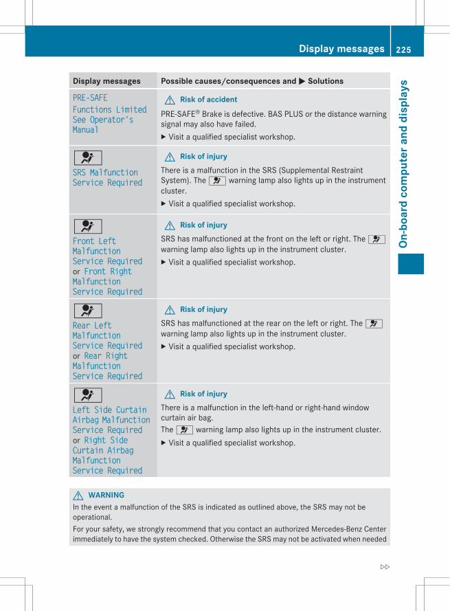
Display messages Possible causes/consequences and M Solutions
PRE-SAFEFunctions Limited See Operator's Manual
G Risk of accident
PRE-SAFE® Brake is defective. BAS PLUS or the distance warningsignal may also have failed.X Visit a qualified specialist workshop.
6SRS Malfunction Service Required
G Risk of injuryThere is a malfunction in the SRS (Supplemental RestraintSystem). The 6 warning lamp also lights up in the instrumentcluster.X Visit a qualified specialist workshop.
6Front Left Malfunction Service Required or Front Right Malfunction Service Required
G Risk of injurySRS has malfunctioned at the front on the left or right. The 6warning lamp also lights up in the instrument cluster.X Visit a qualified specialist workshop.
6Rear Left Malfunction Service Required or Rear Right Malfunction Service Required
G Risk of injurySRS has malfunctioned at the rear on the left or right. The 6warning lamp also lights up in the instrument cluster.X Visit a qualified specialist workshop.
6Left Side Curtain Airbag Malfunction Service Required or Right Side Curtain Airbag Malfunction Service Required
G Risk of injuryThere is a malfunction in the left-hand or right-hand windowcurtain air bag.The 6 warning lamp also lights up in the instrument cluster.X Visit a qualified specialist workshop.
G WARNINGIn the event a malfunction of the SRS is indicated as outlined above, the SRS may not beoperational.For your safety, we strongly recommend that you contact an authorized Mercedes-Benz Centerimmediately to have the system checked. Otherwise the SRS may not be activated when needed
Display messages 225
On-b
oard
com
pute
r and
dis
play
s
Z
in an accident, which could result in serious or fatal injury, or it might deploy unexpectedly andunnecessarily which could also result in injury.
226 Display messagesOn
-boa
rd c
ompu
ter a
nd d
ispl
ays
Display messages Possible causes/consequences and M Solutions
Front Passenger Airbag EnabledSee Operator's Manual
The front-passenger air bag and front-passenger knee bag areenabled during the journey, even though:Ra child, a small adult or an object weighing less than the
system's weight threshold is located on the front-passengerseat.Rthe front-passenger seat is unoccupied.The system may detect objects or forces applying additionalweight on the seat.X Pull over and stop the vehicle safely as soon as possible, paying
attention to road and traffic conditions.X Apply the parking brake.X Switch the ignition off.X Open the front-passenger door.X Remove the child and the child restraint system from the front-
passenger seat.X If necessary, secure the child in a child restraint system on a
suitable rear seat.X Make sure that there are no objects on the seat adding to the
weight.The system may otherwise detect the additional weight andinterpret the seat occupant's weight as greater than it actuallyis.
X Keep the seat unoccupied, close the front-passenger door andswitch on the ignition.
Observe the 45(Y page 45) indicator lamp and themultifunction display and check the following:Seat unoccupied and ignition switched on:Rthe 45 indicator lamp must light up and remain lit. When
the indicator lamp is on, OCS (Y page 45) has deactivated thefront-passenger air bag and front-passenger knee bag.Rthe Front Passenger Airbag Enabled See Operator's Manual or Front Passenger Airbag Disabled See Operator's Manual display messages must not appear in themultifunction display. Wait for a period of at least 60 secondsuntil the necessary system checks have been completed and tomake sure that the display messages do not appear in themultifunction display.
If these conditions are fulfilled, the front-passenger seat can beoccupied again. Whether the 45 indicator lamp remains litor goes out depends on how OCS classifies the occupant.If the conditions are not fulfilled, the system is not operatingcorrectly.
Display messages 227
On-b
oard
com
pute
r and
dis
play
s
Z

Display messages Possible causes/consequences and M SolutionsX Visit a qualified specialist workshop immediately.
G WARNINGIf the 45 indicator lamp remains off even after performing the above corrective steps, donot have any children twelve years old and under and other small individuals use the front-passenger seat until the system has been repaired.
Display messages Possible causes/consequences and M Solutions
Front Passenger Airbag DisabledSee Operator's Manual
The front-passenger air bag and the front-passenger knee bag aredeactivated during the journey even though an adult or a personlarger than a certain size is occupying the front-passenger seat. Ifadditional forces are applied to the seat, the system may interpretthe occupant's weight as lower than it actually is.X Pull over and stop the vehicle safely as soon as possible, paying
attention to road and traffic conditions.X Apply the parking brake.X Switch the ignition off.X Have the occupant get out of the vehicle.X Keep the seat unoccupied, close the front-passenger door and
switch on the ignition.Observe the 45(Y page 45) indicator lamp and themultifunction display and check the following:Seat unoccupied and ignition switched on:Rthe 45 indicator lamp must light up and remain lit. When
the indicator lamp is on, OCS (Y page 45) has deactivated thefront-passenger air bag and front-passenger knee bag.Rthe Front Passenger Airbag Enabled See Operator's Manual or Front Passenger Airbag Disabled See Operator's Manual display messages must not appear in themultifunction display. Wait for a period of at least 60 secondsuntil the necessary system checks have been completed and tomake sure that the display messages do not appear in themultifunction display.
If these conditions are fulfilled, the front-passenger seat can beoccupied again. Whether the 45 indicator lamp remains litor goes out depends on how OCS classifies the occupant.If the conditions are not fulfilled, the system is not operatingcorrectly.X Visit a qualified specialist workshop immediately.
228 Display messagesOn
-boa
rd c
ompu
ter a
nd d
ispl
ays

G WARNINGIf the 45 indicator lamp remains lit with an adult occupant on the front-passenger seateven after performing the above corrective steps, do not have any passenger use the front-passenger seat until the system has been repaired.
Lightsi Display messages about LEDs:
This display message will only appear if all LEDs have failed.
Display messages Possible causes/consequences and M Solutions
bCheck Left Cornering Light or Check Right Cornering Light
The left or right-hand cornering light is defective.X Visit a qualified specialist workshop.
bCheck Left Low Beam or Check Right Low Beam
The left or right-hand low-beam headlamp is defective.X Visit a qualified specialist workshop.
bCheck Rear Left Turn Signal or Check Rear Right Turn Signal
The rear left-hand or rear right-hand turn signal is defective.X Visit a qualified specialist workshop.
bCheck Front Left Turn Signal or Check Front Right Turn Signal
The front left-hand or front right-hand turn signal is defective.X Visit a qualified specialist workshop.
bCheck Left Mirror Turn Signal or Check Right Mirror Turn Signal
The turn signal in the left-hand or right-hand exterior mirror isdefective.X Visit a qualified specialist workshop.
Display messages 229
On-b
oard
com
pute
r and
dis
play
s
Z
Display messages Possible causes/consequences and M Solutions
bCheck Center Brake Lamp
The high-mounted brake lamp is faulty.X Visit a qualified specialist workshop.
bCheck Left Tail and Brake Lamps or Check Right Tail and Brake Lamps
The left or right-hand tail lamp/brake lamp is defective.X Visit a qualified specialist workshop.
bCheck Left High Beam or Check Right High Beam
The left or right-hand high beam is defective.X Visit a qualified specialist workshop.
bCheck Front Left Parking Lamp or Check Front Right Parking Lamp
The front left or front right parking or standing lamp is defective.X Visit a qualified specialist workshop.
bCheck Left Reverse Lamp or Check Right Reverse Lamp
The left or right-hand backup lamp is defective.X Replace the bulb (Y page 114).orX Visit a qualified specialist workshop.
bCheck Front Left Sidemarker Lamp or Check Front Right Sidemarker Lamp
The left or right front side marker lamp is defective.X Visit a qualified specialist workshop.
bCheck Rear Left Sidemarker Lamp or Check Rear Right Sidemarker Lamp
The rear left or right side marker lamp is defective.X Visit a qualified specialist workshop.
230 Display messagesOn
-boa
rd c
ompu
ter a
nd d
ispl
ays
Display messages Possible causes/consequences and M Solutions
bCheck Left Daytime Running Light or Check Right Daytime Running Light
The left or right-hand daytime running lamp is defective.X Visit a qualified specialist workshop.
bActive Headlamps Inoperative
The active light function is defective.X Visit a qualified specialist workshop.
bMalfunction See Operator's Manual
The exterior lighting is defective.X Visit a qualified specialist workshop.
bAUTO Lamp Function Inoperative
The light sensor is defective.X Visit a qualified specialist workshop.
bSwitch Off Lights
The lights are still switched on when you leave the vehicle. Awarning tone also sounds.X Turn the light switch to c or Ã.
Adaptive Highbeam Assist Inoperative
Adaptive Highbeam Assist is faulty.X Visit a qualified specialist workshop.
Adaptive Highbeam Assist Currently Unavailable See Operator's Manual
Adaptive Highbeam Assist is deactivated and temporarilyinoperative. Possible causes are:Rthe windshield in the camera's field of vision is dirty.Rvisibility is impaired due to heavy rain, snow or fog.X Clean the windshield.If the system detects that the camera is fully functional again, theAdaptive Highbeam Assist Now Available display messageis shown.Adaptive Highbeam Assist is operational again.
Display messages 231
On-b
oard
com
pute
r and
dis
play
s
Z
Engine
Display messages Possible causes/consequences and M Solutions
+Check Coolant Level See Operator's Manual
The coolant level is too low.X Add coolant, observing the warning notes when doing so
(Y page 288).X If coolant needs to be added more often than usual, have the
engine coolant system checked at a qualified specialistworkshop.
G WARNINGDo not spill antifreeze on hot engine parts. Antifreeze contains ethylene glycol which may burnif it comes into contact with hot engine parts. You could be seriously burned.
! The coolant level is too low. Avoid making long journeys with too little coolant in the coolingsystem. The engine will otherwise be damaged.The display messages and the corresponding symbol that indicate that the coolant level istoo low must not be ignored.
Display messages Possible causes/consequences and M Solutions
?Coolant Level Low Stop Vehicle Turn Engine Off
The coolant is too hot.X Pull over and stop the vehicle safely and switch off the engine,
paying attention to road and traffic conditions.X Make sure that the air supply to the engine radiator is not
blocked, e.g. by snow, slush or ice.X Wait until the display message disappears before restarting the
engine. Otherwise, the engine could be damaged.X Pay attention to the coolant temperature display.X If the temperature increases again, visit a qualified specialist
workshop immediately.
G WARNINGDriving when your engine is overheated can cause some fluids which may have leaked into theengine compartment to catch fire. You could be seriously burned.Steam from an overheated engine can cause serious burns which can occur just by opening theengine hood. Stay away from the engine if you see or hear steam coming from it.Stop the vehicle in a safe location away from other traffic. Turn off the engine, get out of thevehicle and do not stand near the vehicle until the engine has cooled down.
! If the coolant temperature is over 248 ‡ (120 †), do not continue driving. The engine willotherwise be damaged.
232 Display messagesOn
-boa
rd c
ompu
ter a
nd d
ispl
ays
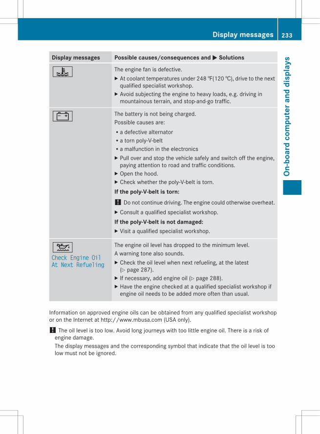
Display messages Possible causes/consequences and M Solutions
? The engine fan is defective.X At coolant temperatures under 248 ‡(120 †), drive to the next
qualified specialist workshop.X Avoid subjecting the engine to heavy loads, e.g. driving in
mountainous terrain, and stop-and-go traffic.
# The battery is not being charged.Possible causes are:Ra defective alternatorRa torn poly-V-beltRa malfunction in the electronicsX Pull over and stop the vehicle safely and switch off the engine,
paying attention to road and traffic conditions.X Open the hood.X Check whether the poly-V-belt is torn.If the poly-V-belt is torn:! Do not continue driving. The engine could otherwise overheat.X Consult a qualified specialist workshop.If the poly-V-belt is not damaged:X Visit a qualified specialist workshop.
4Check Engine Oil At Next Refueling
The engine oil level has dropped to the minimum level.A warning tone also sounds.X Check the oil level when next refueling, at the latest
(Y page 287).X If necessary, add engine oil (Y page 288).X Have the engine checked at a qualified specialist workshop if
engine oil needs to be added more often than usual.
Information on approved engine oils can be obtained from any qualified specialist workshopor on the Internet at http://www.mbusa.com (USA only).
! The oil level is too low. Avoid long journeys with too little engine oil. There is a risk ofengine damage.The display messages and the corresponding symbol that indicate that the oil level is toolow must not be ignored.
Display messages 233
On-b
oard
com
pute
r and
dis
play
s
Z
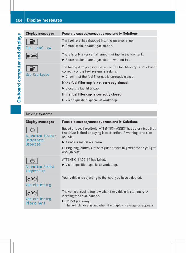
Display messages Possible causes/consequences and M Solutions
8Fuel Level Low
The fuel level has dropped into the reserve range.X Refuel at the nearest gas station.
C There is only a very small amount of fuel in the fuel tank.X Refuel at the nearest gas station without fail.
8Gas Cap Loose
The fuel system pressure is too low. The fuel filler cap is not closedcorrectly or the fuel system is leaking.X Check that the fuel filler cap is correctly closed.
If the fuel filler cap is not correctly closed:X Close the fuel filler cap.
If the fuel filler cap is correctly closed:X Visit a qualified specialist workshop.
Driving systems
Display messages Possible causes/consequences and M Solutions
ÀAttention Assist: Drowsiness Detected
Based on specific criteria, ATTENTION ASSIST has determined thatthe driver is tired or paying less attention. A warning tone alsosounds.X If necessary, take a break.During long journeys, take regular breaks in good time so you getenough rest.
ÀAttention Assist Inoperative
ATTENTION ASSIST has failed.X Visit a qualified specialist workshop.
¨Vehicle Rising
Your vehicle is adjusting to the level you have selected.
¨Vehicle Rising Please Wait
The vehicle level is too low when the vehicle is stationary. Awarning tone also sounds.X Do not pull away.
The vehicle level is set when the display message disappears.
234 Display messagesOn
-boa
rd c
ompu
ter a
nd d
ispl
ays

Display messages Possible causes/consequences and M Solutions
¨Pull Over Car Too Low
You have pulled away while the vehicle level is still too low.AIRMATIC sets the vehicle to the selected level after a shortperiod.X Pull over and stop the vehicle safely as soon as possible, paying
attention to road and traffic conditions.X Apply the parking brake.X Wait until the display message disappears before pulling away.
G Risk of accidentAIRMATIC is defective. A warning tone also sounds.X Do not drive faster than 50 mph (80km/h).X Make only slight steering movements. Otherwise, the front
fender or the tires could be damaged if the steering movementis too large.
X Listen for scraping sounds.X Pull over and stop the vehicle safely, paying attention to road
and traffic conditions, and select a higher vehicle level.Depending on the malfunction, it may be possible to raise thevehicle.
X Visit a qualified specialist workshop.
¨Malfunction
G Risk of accidentThe AIRMATIC function is restricted. The vehicle's handlingcharacteristics may be affected.X Do not drive faster than 50 mph (80km/h).X Visit a qualified specialist workshop.
ëOff
The HOLD function is deactivated. The vehicle is skidding.A warning tone also sounds.X Reactivate the HOLD function later (Y page 170).
Radar SensorsDeactivated See Operator's Manual
The radar sensor system is deactivated.X Switch on the radar sensor system (Y page 215).
Display messages 235
On-b
oard
com
pute
r and
dis
play
s
Z
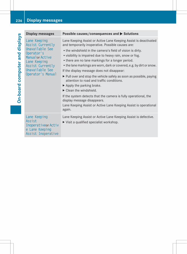
Display messages Possible causes/consequences and M Solutions
Lane Keeping Assist Currently Unavailable See Operator's Manualor Active Lane Keeping Assist Currently Unavailable See Operator's Manual
Lane Keeping Assist or Active Lane Keeping Assist is deactivatedand temporarily inoperative. Possible causes are:Rthe windshield in the camera's field of vision is dirty.Rvisibility is impaired due to heavy rain, snow or fog.Rthere are no lane markings for a longer period.Rthe lane markings are worn, dark or covered, e.g. by dirt or snow.If the display message does not disappear:X Pull over and stop the vehicle safely as soon as possible, paying
attention to road and traffic conditions.X Apply the parking brake.X Clean the windshield.If the system detects that the camera is fully operational, thedisplay message disappears.Lane Keeping Assist or Active Lane Keeping Assist is operationalagain.
Lane Keeping Assist Inoperativeor Active Lane Keeping Assist Inoperative
Lane Keeping Assist or Active Lane Keeping Assist is defective.X Visit a qualified specialist workshop.
236 Display messagesOn
-boa
rd c
ompu
ter a
nd d
ispl
ays

Display messages Possible causes/consequences and M Solutions
Blind Spot Assist Currently Unavailable See Operator's Manualor Active Blind Spot Assist Currently Unavailable See Operator's Manual
Blind Spot Assist or Active Blind Spot Assist is temporarilyinoperative. Possible causes are:Rthe sensors are dirty.Rfunction is impaired due to heavy rain or snow.Rthe radar sensor system is outside the operating temperature
range.Rthe radar sensor system is temporarily inoperative, e.g. due to
electromagnetic radiation emitted by nearby TV or radiostations or other sources of electromagnetic radiation.
The yellow 9 indicator lamps also light up in the exteriormirrors.If the display message does not disappear:X Pull over and stop the vehicle safely as soon as possible, paying
attention to road and traffic conditions.X Apply the parking brake.X Clean the sensors (Y page 295).X Restart the engine.If the system detects that the sensors are fully operational, thedisplay message disappears.Blind Spot Assist or Active Blind Spot Assist is operational again.
Blind Spot Assist Inoperativeor Active Blind Spot Assist Inoperative
Blind Spot Assist or Active Blind Spot Assist is defective.The yellow 9 indicator lamps also light up in the exteriormirrors.X Visit a qualified specialist workshop.
Park AssistCanceled
The driver's door is open and the driver's seat belt has not beenfastened.X Repeat the parking process with the seat belt fastened and the
driver's door closed.
You have inadvertently touched the multifunction steering wheelwhile steering intervention was active.X While steering intervention is active, make sure that the
multifunction steering wheel is not touched unintentionally.
The vehicle has started to skid and ESP® has intervened.X Use Active Parking Assist again later (Y page 179).
Display messages 237
On-b
oard
com
pute
r and
dis
play
s
Z
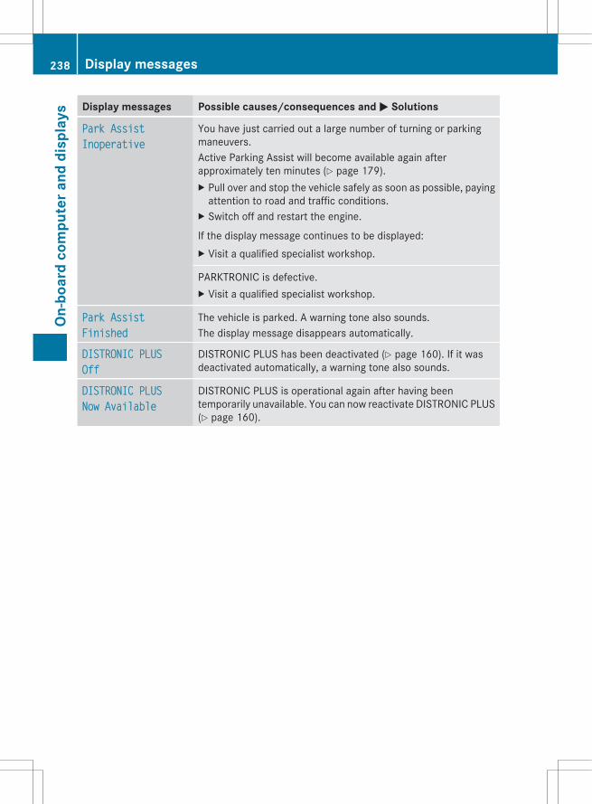
Display messages Possible causes/consequences and M Solutions
Park AssistInoperative
You have just carried out a large number of turning or parkingmaneuvers.Active Parking Assist will become available again afterapproximately ten minutes (Y page 179).X Pull over and stop the vehicle safely as soon as possible, paying
attention to road and traffic conditions.X Switch off and restart the engine.
If the display message continues to be displayed:X Visit a qualified specialist workshop.
PARKTRONIC is defective.X Visit a qualified specialist workshop.
Park AssistFinished
The vehicle is parked. A warning tone also sounds.The display message disappears automatically.
DISTRONIC PLUSOff
DISTRONIC PLUS has been deactivated (Y page 160). If it wasdeactivated automatically, a warning tone also sounds.
DISTRONIC PLUSNow Available
DISTRONIC PLUS is operational again after having beentemporarily unavailable. You can now reactivate DISTRONIC PLUS(Y page 160).
238 Display messagesOn
-boa
rd c
ompu
ter a
nd d
ispl
ays
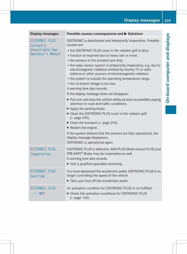
Display messages Possible causes/consequences and M Solutions
DISTRONIC PLUSCurrently Unavailable See Operator's Manual
DISTRONIC is deactivated and temporarily inoperative. Possiblecauses are:Rthe DISTRONIC PLUS cover in the radiator grill is dirty.Rfunction is impaired due to heavy rain or snow.Rthe sensors in the bumpers are dirty.Rthe radar sensor system is temporarily inoperative, e.g. due to
electromagnetic radiation emitted by nearby TV or radiostations or other sources of electromagnetic radiation.Rthe system is outside the operating temperature range.Rthe on-board voltage is too low.A warning tone also sounds.If the display message does not disappear:X Pull over and stop the vehicle safely as soon as possible, paying
attention to road and traffic conditions.X Apply the parking brake.X Clean the DISTRONIC PLUS cover in the radiator grill
(Y page 295).X Clean the bumpers (Y page 295).X Restart the engine.If the system detects that the sensors are fully operational, thedisplay message disappears.DISTRONIC is operational again.
DISTRONIC PLUSInoperative
DISTRONIC PLUS is defective. BAS PLUS (Brake Assist PLUS) andPRE-SAFE® Brake may be inoperative as well.A warning tone also sounds.X Visit a qualified specialist workshop.
DISTRONIC PLUSOverride
You have depressed the accelerator pedal. DISTRONIC PLUS is nolonger controlling the speed of the vehicle.X Take your foot off the accelerator pedal.
DISTRONIC PLUS --- mph
An activation condition for DISTRONIC PLUS is not fulfilled.X Check the activation conditions for DISTRONIC PLUS
(Y page 160).
Display messages 239
On-b
oard
com
pute
r and
dis
play
s
Z

Display messages Possible causes/consequences and M Solutions
Cruise ControlInoperative
Cruise control is defective.A warning tone also sounds.X Visit a qualified specialist workshop.
Cruise Control --- mph
A condition for activating cruise control has not been fulfilled.You have tried to store a speed below 20 mph (30 km/h), forexample.X If conditions permit, drive faster than 20 mph (30 km/h) and
store the speed.X Check the activation conditions for cruise control
(Y page 159).
Tires
G WARNINGDo not drive with a flat tire. A flat tire affects the ability to steer or brake the vehicle. You maylose control of the vehicle. Continued driving with a flat tire will cause excessive heat build-upand possibly a fire.
G WARNINGFollow recommended tire inflation pressures.Do not underinflate tires. Underinflated tires wear excessively and/or unevenly, adversely affecthandling and fuel economy, and are more likely to fail from being overheated.Do not overinflate tires. Overinflated tires can adversely affect handling and ride comfort, wearunevenly, increase stopping distance, and result in sudden deflation (blowout) because they aremore likely to become punctured or damaged by road debris, potholes etc.
240 Display messagesOn
-boa
rd c
ompu
ter a
nd d
ispl
ays

Display messages Possible causes/consequences and M Solutions
Check TirePressure Soon
G Risk of accidentThe tire pressure loss warning system has detected a significantloss in pressure.A warning tone also sounds.X Stop the vehicle without making any sudden steering or braking
maneuvers. Pay attention to the traffic conditions as you do so.X Check the tires and, if necessary, change the wheel
(Y page 344).X Check the tire pressures and, if necessary, set them to the
correct tire pressure.X Restart the tire pressure loss warning system when the tire
pressure is correct (Y page 327).
Check Tire PressureThen Restart Run Flat Indicator
The tire pressure loss warning system generated a displaymessage and has not been restarted since.X Set the correct tire pressure in all four tires.X Restart the tire pressure loss warning system (Y page 327).
Run Flat IndicatorInoperative
The tire pressure loss warning system is faulty.X Visit a qualified specialist workshop.
Tire pressureswill be displayed after driving a few minutes
The tire pressure monitor is measuring the tire pressure.X Drive on.
The tire pressures appear in the multifunction display after youhave been driving for a few minutes.
Tire Press. MonitorInoperative
The tire pressure monitor is faulty.X Visit a qualified specialist workshop.
Tire Press. MonitorInoperative No Wheel Sensors
The wheels mounted do not have a suitable tire pressure sensor.The tire pressure monitor is deactivated.X Mount wheels with suitable tire pressure sensors.
The tire pressure monitor is activated automatically after drivingfor a few minutes.
Display messages 241
On-b
oard
com
pute
r and
dis
play
s
Z
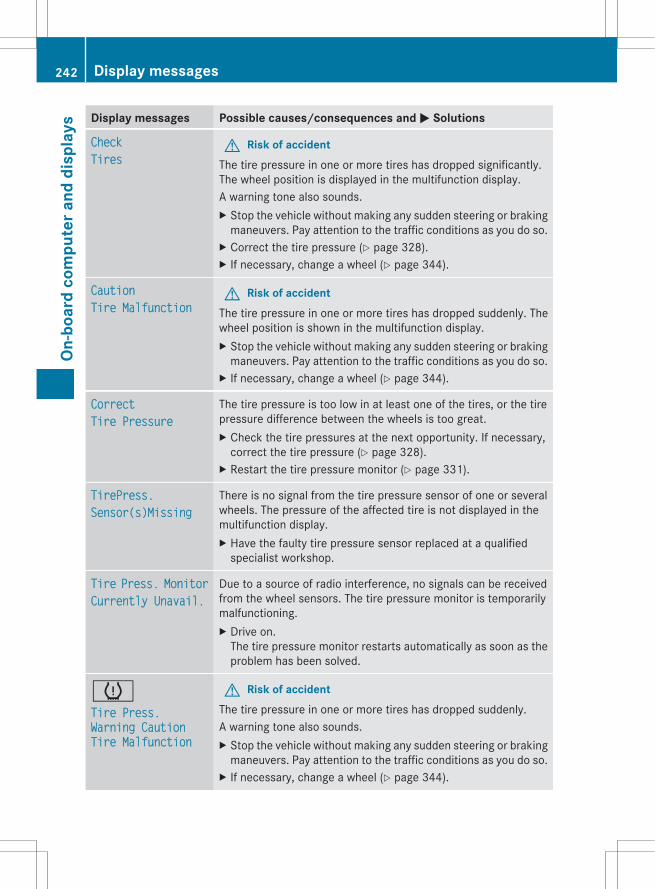
Display messages Possible causes/consequences and M Solutions
CheckTires
G Risk of accidentThe tire pressure in one or more tires has dropped significantly.The wheel position is displayed in the multifunction display.A warning tone also sounds.X Stop the vehicle without making any sudden steering or braking
maneuvers. Pay attention to the traffic conditions as you do so.X Correct the tire pressure (Y page 328).X If necessary, change a wheel (Y page 344).
CautionTire Malfunction
G Risk of accidentThe tire pressure in one or more tires has dropped suddenly. Thewheel position is shown in the multifunction display.X Stop the vehicle without making any sudden steering or braking
maneuvers. Pay attention to the traffic conditions as you do so.X If necessary, change a wheel (Y page 344).
CorrectTire Pressure
The tire pressure is too low in at least one of the tires, or the tirepressure difference between the wheels is too great.X Check the tire pressures at the next opportunity. If necessary,
correct the tire pressure (Y page 328).X Restart the tire pressure monitor (Y page 331).
TirePress.Sensor(s)Missing
There is no signal from the tire pressure sensor of one or severalwheels. The pressure of the affected tire is not displayed in themultifunction display.X Have the faulty tire pressure sensor replaced at a qualified
specialist workshop.
Tire Press. MonitorCurrently Unavail.
Due to a source of radio interference, no signals can be receivedfrom the wheel sensors. The tire pressure monitor is temporarilymalfunctioning.X Drive on.
The tire pressure monitor restarts automatically as soon as theproblem has been solved.
hTire Press. Warning Caution Tire Malfunction
G Risk of accidentThe tire pressure in one or more tires has dropped suddenly.A warning tone also sounds.X Stop the vehicle without making any sudden steering or braking
maneuvers. Pay attention to the traffic conditions as you do so.X If necessary, change a wheel (Y page 344).
242 Display messagesOn
-boa
rd c
ompu
ter a
nd d
ispl
ays

Display messages Possible causes/consequences and M Solutions
hCheck Tire Pressure
G Risk of accidentThe tire pressure in one or more tires has dropped significantly.X Stop the vehicle without making any sudden steering or braking
maneuvers. Pay attention to the traffic conditions as you do so.X If necessary, change a wheel (Y page 344).X Check the tire pressure. If necessary, correct the tire pressure
(Y page 328).
hCorrect Tire Pressure
The tire pressure is too low in at least one of the tires, or the tirepressure difference between the wheels is too great.X Check the tire pressures at the next opportunity. If necessary,
correct the tire pressure (Y page 328).
Vehicle
Display messages Possible causes/consequences and M Solutions
Shift to 'P' or 'N'to Start Engine
You have attempted to start the engine with the transmission inposition R or D.X Shift the transmission to position P or N.
Auxiliary BatteryMalfunction
The auxiliary battery for the automatic transmission is no longerbeing charged.X Visit a qualified specialist workshop.
Apply Brake to Shift from 'P'
You have attempted to move the transmission selector lever toposition D, R or N without depressing the brake pedal.X Depress the brake pedal.
Door OpenVehicle Not in 'P'
The driver's door is open and the transmission is in position R, Nor D.A warning tone also sounds.X Shift the transmission to position P.X Apply the parking brake.
Display messages 243
On-b
oard
com
pute
r and
dis
play
s
Z

Display messages Possible causes/consequences and M Solutions
Service RequiredDo Not Shift Gears Visit Dealer
You cannot change the transmission position due to a malfunction.A warning tone also sounds.If transmission position D is selected:X Drive to a qualified specialist workshop without shifting the
transmission from position D.
If transmission position R, N or P is selected:X Notify a qualified specialist workshop or breakdown service.
Only Shiftto 'P' when Vehicle is Stationary
The vehicle is moving.X Pull over and stop the vehicle safely as soon as possible, paying
attention to road and traffic conditions.X Shift the transmission to position P.
N The trunk lid is open.X Close the trunk lid.
M G Risk of accidentThe hood is open.X Pull over and stop the vehicle safely as soon as possible, paying
attention to road and traffic conditions.X Apply the parking brake.X Close the hood.
C At least one door is open.X Close all the doors.
_Rear Left Backrest Not LatchedorRear Right Backrest Not Latched
G Risk of injuryThe backrest in the rear is not engaged on the left-hand and/orright-hand side.X Push the backrest back until it engages.
_Lock Seat Backrest Front LeftorLock Seat Backrest Front Right
The driver's or front passenger's seat backrest is not engaged. Awarning tone also sounds.X Push the backrest back until it engages.
244 Display messagesOn
-boa
rd c
ompu
ter a
nd d
ispl
ays
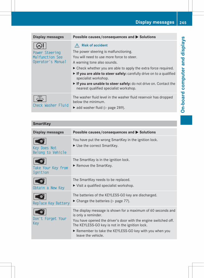
Display messages Possible causes/consequences and M Solutions
DPower Steering Malfunction See Operator's Manual
G Risk of accidentThe power steering is malfunctioning.You will need to use more force to steer.A warning tone also sounds.X Check whether you are able to apply the extra force required.X If you are able to steer safely: carefully drive on to a qualified
specialist workshop.X If you are unable to steer safely: do not drive on. Contact the
nearest qualified specialist workshop.
¥Check Washer Fluid
The washer fluid level in the washer fluid reservoir has droppedbelow the minimum.X add washer fluid (Y page 289).
SmartKey
Display messages Possible causes/consequences and M Solutions
ÂKey Does Not Belong to Vehicle
You have put the wrong SmartKey in the ignition lock.X Use the correct SmartKey.
ÂTake Your Key from Ignition
The SmartKey is in the ignition lock.X Remove the SmartKey.
ÂObtain a New Key
The SmartKey needs to be replaced.X Visit a qualified specialist workshop.
ÂReplace Key Battery
The batteries of the KEYLESS-GO key are discharged.X Change the batteries (Y page 77).
ÂDon't Forget Your Key
The display message is shown for a maximum of 60 seconds andis only a reminder.You have opened the driver's door with the engine switched off.The KEYLESS-GO key is not in the ignition lock.X Remember to take the KEYLESS-GO key with you when you
leave the vehicle.
Display messages 245
On-b
oard
com
pute
r and
dis
play
s
Z
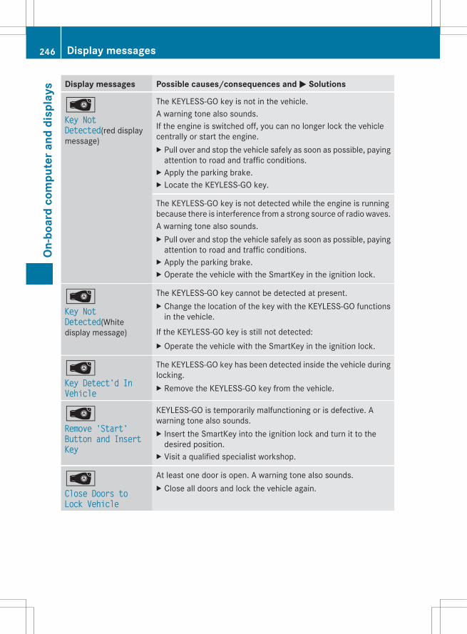
Display messages Possible causes/consequences and M Solutions
ÂKey Not Detected(red displaymessage)
The KEYLESS-GO key is not in the vehicle.A warning tone also sounds.If the engine is switched off, you can no longer lock the vehiclecentrally or start the engine.X Pull over and stop the vehicle safely as soon as possible, paying
attention to road and traffic conditions.X Apply the parking brake.X Locate the KEYLESS-GO key.
The KEYLESS-GO key is not detected while the engine is runningbecause there is interference from a strong source of radio waves.A warning tone also sounds.X Pull over and stop the vehicle safely as soon as possible, paying
attention to road and traffic conditions.X Apply the parking brake.X Operate the vehicle with the SmartKey in the ignition lock.
ÂKey Not Detected(Whitedisplay message)
The KEYLESS-GO key cannot be detected at present.X Change the location of the key with the KEYLESS-GO functions
in the vehicle.
If the KEYLESS-GO key is still not detected:X Operate the vehicle with the SmartKey in the ignition lock.
ÂKey Detect'd In Vehicle
The KEYLESS-GO key has been detected inside the vehicle duringlocking.X Remove the KEYLESS-GO key from the vehicle.
ÂRemove 'Start' Button and Insert Key
KEYLESS-GO is temporarily malfunctioning or is defective. Awarning tone also sounds.X Insert the SmartKey into the ignition lock and turn it to the
desired position.X Visit a qualified specialist workshop.
ÂClose Doors to Lock Vehicle
At least one door is open. A warning tone also sounds.X Close all doors and lock the vehicle again.
246 Display messagesOn
-boa
rd c
ompu
ter a
nd d
ispl
ays
Warning and indicator lamps in the instrument cluster
Seat belts
Problem Possible causes/consequences and M Solutions
7
After starting theengine, the red seatbelt warning lamp lightsup for six seconds.
The seat belt warning lamp reminds the driver and front passengerto fasten their seat belts.X Fasten your seat belt (Y page 52).
7
After starting theengine, the red seatbelt warning lamp lightsup. In addition, awarning tone soundsfor up to six seconds.
G Risk of injuryThe driver's seat belt is not fastened.X Fasten your seat belt (Y page 52).
The warning tone ceases.
7
The red seat beltwarning lamp lights upafter the engine starts,as soon as the driver'sor the front-passengerdoor is closed.
G Risk of injuryThe driver or front passenger has not fastened their seat belt.X Fasten your seat belt (Y page 52).
The warning lamp goes out.
G Risk of injuryThere are objects on the front-passenger seat.X Remove the objects from the front-passenger seat and stow
them in a secure place.The warning lamp goes out.
Warning and indicator lamps in the instrument cluster 247
On-b
oard
com
pute
r and
dis
play
s
Z
Problem Possible causes/consequences and M Solutions
7
The red seat beltwarning lamp flashesand an intermittentaudible warningsounds.
G Risk of injuryThe driver or front passenger has not fastened their seat belt. Inaddition, you are driving faster than 15 mph (25 km/h) or you havebriefly driven faster than 15 mph (25 km/h).X Fasten your seat belt (Y page 52).
The warning lamp goes out and the intermittent warning toneceases.
G Risk of injuryThere are objects on the front-passenger seat. In addition, you aredriving faster than 15 mph (25 km/h) or you have briefly drivenfaster than 15 mph (25 km/h).X Remove the objects from the front-passenger seat and stow
them in a secure place.The warning lamp goes out and the intermittent warning toneceases.
248 Warning and indicator lamps in the instrument clusterOn
-boa
rd c
ompu
ter a
nd d
ispl
ays
Safety systems
Problem Possible causes/consequences and M Solutions
$ (USA only)J (Canada only)The red brake systemwarning lamp comes onwhile the engine isrunning. A warning tonealso sounds.
G Risk of accidentThe brake boosting effect is malfunctioning and the brakingcharacteristics may be affected.X Pull over and stop the vehicle safely as soon as possible, paying
attention to road and traffic conditions. Do not continue drivingunder any circumstances.
X Apply the parking brake.X Consult a qualified specialist workshop.X Observe the additional display messages in the multifunction
display.
$ (USA only)J (Canada only)The red brake systemwarning lamp comes onwhile the engine isrunning. A warning tonealso sounds.
G Risk of accidentThere is not enough brake fluid in the brake fluid reservoir.X Pull over and stop the vehicle safely as soon as possible, paying
attention to road and traffic conditions. Do not continue drivingunder any circumstances.
X Apply the parking brake.X Consult a qualified specialist workshop immediately.X Observe the additional display messages in the multifunction
display.Do not add brake fluid. This will not rectify the malfunction.
G WARNINGDriving with the brake warning lamp illuminated can result in an accident. Have your brake systemchecked immediately if the brake warning lamp stays on. Do not add brake fluid before checkingthe brake system.Overfilling the brake fluid reservoir can result in spilling brake fluid on hot engine parts and thebrake fluid catching fire. You can be seriously burned.
Warning and indicator lamps in the instrument cluster 249
On-b
oard
com
pute
r and
dis
play
s
Z
Problem Possible causes/consequences and M Solutions
!
The yellow ABS warninglamp is lit while theengine is running.
G Risk of accidentABS (Anti-lock Brake System) is deactivated due to a malfunction.BAS (Brake Assist), BAS PLUS, ESP® (Electronic StabilityProgram), PRE-SAFE®, PRE-SAFE® Brake, the HOLD function andhill start assist are therefore also deactivated, for example.The brake system continues to function normally, but without thefunctions listed above. The wheels could therefore lock if youbrake hard, for example.ATTENTION ASSIST is deactivated.X Observe the additional display messages in the multifunction
display.X Drive on carefully.X Visit a qualified specialist workshop.
!
The yellow ABS warninglamp is lit while theengine is running.
G Risk of accident
ABS is temporarily unavailable. BAS, BAS PLUS, ESP®, EBD(electronic brake force distribution), PRE-SAFE®,PRE-SAFE® Brake, the HOLD function, hill start assist are thereforealso deactivated, for example.Self-diagnosis is not yet complete or the on-board voltage may beinsufficient, for example.The brake system continues to function normally, but without thefunctions listed above. The wheels could therefore lock if youbrake hard, for example.ATTENTION ASSIST is deactivated.X Carefully drive a short distance on a suitable stretch of road,
making slight steering movements at a speed above 12 mph(20 km/h).The functions mentioned above are available again when thewarning lamp goes out.
If the warning lamp is still on:X Observe the additional display messages in the multifunction
display.X Drive on carefully.X Visit a qualified specialist workshop.
250 Warning and indicator lamps in the instrument clusterOn
-boa
rd c
ompu
ter a
nd d
ispl
ays
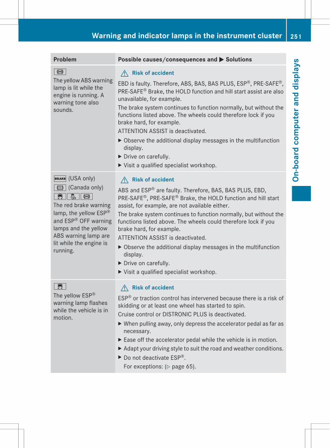
Problem Possible causes/consequences and M Solutions
!
The yellow ABS warninglamp is lit while theengine is running. Awarning tone alsosounds.
G Risk of accident
EBD is faulty. Therefore, ABS, BAS, BAS PLUS, ESP®, PRE-SAFE®,PRE-SAFE® Brake, the HOLD function and hill start assist are alsounavailable, for example.The brake system continues to function normally, but without thefunctions listed above. The wheels could therefore lock if youbrake hard, for example.ATTENTION ASSIST is deactivated.X Observe the additional display messages in the multifunction
display.X Drive on carefully.X Visit a qualified specialist workshop.
$ (USA only)J (Canada only)֌!
The red brake warninglamp, the yellow ESP®
and ESP® OFF warninglamps and the yellowABS warning lamp arelit while the engine isrunning.
G Risk of accident
ABS and ESP® are faulty. Therefore, BAS, BAS PLUS, EBD,PRE-SAFE®, PRE-SAFE® Brake, the HOLD function and hill startassist, for example, are not available either.The brake system continues to function normally, but without thefunctions listed above. The wheels could therefore lock if youbrake hard, for example.ATTENTION ASSIST is deactivated.X Observe the additional display messages in the multifunction
display.X Drive on carefully.X Visit a qualified specialist workshop.
÷
The yellow ESP®
warning lamp flasheswhile the vehicle is inmotion.
G Risk of accident
ESP® or traction control has intervened because there is a risk ofskidding or at least one wheel has started to spin.Cruise control or DISTRONIC PLUS is deactivated.X When pulling away, only depress the accelerator pedal as far as
necessary.X Ease off the accelerator pedal while the vehicle is in motion.X Adapt your driving style to suit the road and weather conditions.X Do not deactivate ESP®.
For exceptions: (Y page 65).
Warning and indicator lamps in the instrument cluster 251
On-b
oard
com
pute
r and
dis
play
s
Z

Problem Possible causes/consequences and M Solutions
å
The yellow ESP® OFFwarning lamp is lit whilethe engine is running.
G Risk of accident
ESP® is deactivated. ESP® will not stabilize the vehicle if it startsto skid or if a wheel starts to spin.X Reactivate ESP®.
For exceptions: (Y page 65).X Adapt your driving style to suit the road and weather conditions.
If ESP® cannot be activated:X Have ESP® checked at a qualified specialist workshop.
M
AMG vehicles only:The yellow SPORThandling mode warninglamp is lit while theengine is running.
G Risk of accident
SPORT handling mode is activated. ESP® only stabilizes the vehiclein extreme situations. ESP® intervention may not be able toprovide sufficient assistance in such situations and the vehiclemay start to skid.X Reactivate ESP®.
Exceptions: (Y page 65).
If ESP® cannot be activated:X Have ESP® checked at a qualified specialist workshop.
֌
The yellow ESP® andESP® OFF warninglamps are lit while theengine is running.
G Risk of accident
ESP®, BAS, BAS PLUS, PRE-SAFE®, PRE-SAFE® Brake, the HOLDfunction and hill start assist are not available due to a malfunction.ESP® will not stabilize the vehicle if it starts to skid or if a wheelstarts to spin.The brake system continues to function normally, but without thefunctions listed above.ATTENTION ASSIST is deactivated.X Observe the additional display messages in the multifunction
display.X Drive on carefully.X Visit a qualified specialist workshop.
252 Warning and indicator lamps in the instrument clusterOn
-boa
rd c
ompu
ter a
nd d
ispl
ays

Problem Possible causes/consequences and M Solutions
$ (USA only)J (Canada only)The red brake systemwarning lamp comes onwhile the vehicle ismoving. A warning tonealso sounds.
You are driving with the parking brake applied.X Release the parking brake.
The warning lamp goes out and the warning tone ceases.
6
The red SRS warninglamp is lit while theengine is running.
G Risk of injuryThe restraint systems are malfunctioning. The air bags or ETDsmay either be triggered unintentionally or, in the event of anaccident, not be triggered at all.X Drive on carefully.X Visit a qualified specialist workshop immediately.
G WARNINGIn the event a malfunction of the SRS is indicated as outlined above, the SRS may not beoperational.For your safety, we strongly recommend that you contact an authorized Mercedes-Benz Centerimmediately to have the system checked. Otherwise the SRS may not be activated when neededin an accident, which could result in serious or fatal injury, or it might deploy unexpectedly andunnecessarily which could also result in injury.
Warning and indicator lamps in the instrument cluster 253
On-b
oard
com
pute
r and
dis
play
s
Z
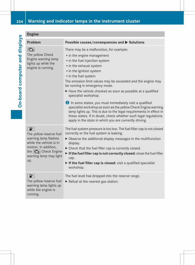
Engine
Problem Possible causes/consequences and M Solutions
;
The yellow CheckEngine warning lamplights up while theengine is running.
There may be a malfunction, for example:Rin the engine managementRin the fuel injection systemRin the exhaust systemRin the ignition systemRin the fuel systemThe emission limit values may be exceeded and the engine maybe running in emergency mode.X Have the vehicle checked as soon as possible at a qualified
specialist workshop.
i In some states, you must immediately visit a qualifiedspecialist workshop as soon as the yellow Check Engine warninglamp lights up. This is due to the legal requirements in effect inthese states. If in doubt, check whether such legal regulationsapply in the state in which you are currently driving.
8
The yellow reserve fuelwarning lamp flasheswhile the vehicle is inmotion. In addition,the ; Check Enginewarning lamp may lightup.
The fuel system pressure is too low. The fuel filler cap is not closedcorrectly or the fuel system is leaking.X Observe the additional display messages in the multifunction
display.X Check that the fuel filler cap is correctly closed.X If the fuel filler cap is not correctly closed: close the fuel filler
cap.X If the fuel filler cap is closed: visit a qualified specialist
workshop.
8
The yellow reserve fuelwarning lamp lights upwhile the engine isrunning.
The fuel level has dropped into the reserve range.X Refuel at the nearest gas station.
254 Warning and indicator lamps in the instrument clusterOn
-boa
rd c
ompu
ter a
nd d
ispl
ays
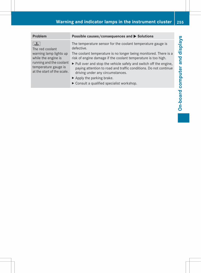
Problem Possible causes/consequences and M Solutions
?
The red coolantwarning lamp lights upwhile the engine isrunning and the coolanttemperature gauge isat the start of the scale.
The temperature sensor for the coolant temperature gauge isdefective.The coolant temperature is no longer being monitored. There is arisk of engine damage if the coolant temperature is too high.X Pull over and stop the vehicle safely and switch off the engine,
paying attention to road and traffic conditions. Do not continuedriving under any circumstances.
X Apply the parking brake.X Consult a qualified specialist workshop.
Warning and indicator lamps in the instrument cluster 255
On-b
oard
com
pute
r and
dis
play
s
Z
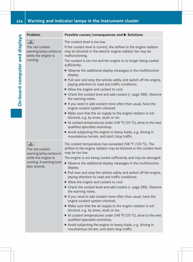
Problem Possible causes/consequences and M Solutions
?
The red coolantwarning lamp comes onwhile the engine isrunning.
The coolant level is too low.If the coolant level is correct, the airflow to the engine radiatormay be blocked or the electric engine radiator fan may bemalfunctioning.The coolant is too hot and the engine is no longer being cooledsufficiently.X Observe the additional display messages in the multifunction
display.X Pull over and stop the vehicle safely and switch off the engine,
paying attention to road and traffic conditions.X Allow the engine and coolant to cool.X Check the coolant level and add coolant (Y page 288). Observe
the warning notes.X If you need to add coolant more often than usual, have the
engine coolant system checked.X Make sure that the air supply to the engine radiator is not
blocked, e.g. by snow, slush or ice.X At coolant temperatures under 248 ‡(120 †), drive to the next
qualified specialist workshop.X Avoid subjecting the engine to heavy loads, e.g. driving in
mountainous terrain, and start/stop traffic.
?
The red coolantwarning lamp comes onwhile the engine isrunning. A warning tonealso sounds.
The coolant temperature has exceeded 248 ‡ (120 †). Theairflow to the engine radiator may be blocked or the coolant levelmay be too low.The engine is not being cooled sufficiently and may be damaged.X Observe the additional display messages in the multifunction
display.X Pull over and stop the vehicle safely and switch off the engine,
paying attention to road and traffic conditions.X Allow the engine and coolant to cool.X Check the coolant level and add coolant (Y page 288). Observe
the warning notes.X If you need to add coolant more often than usual, have the
engine coolant system checked.X Make sure that the air supply to the engine radiator is not
blocked, e.g. by snow, slush or ice.X At coolant temperatures under 248 ‡(120 †), drive to the next
qualified specialist workshop.X Avoid subjecting the engine to heavy loads, e.g. driving in
mountainous terrain, and start/stop traffic.
256 Warning and indicator lamps in the instrument clusterOn
-boa
rd c
ompu
ter a
nd d
ispl
ays
G WARNINGDriving when your engine is overheated can cause some fluids which may have leaked into theengine compartment to catch fire. You could be seriously burned.Steam from an overheated engine can cause serious burns which can occur just by opening theengine hood. Stay away from the engine if you see or hear steam coming from it.Stop the vehicle in a safe location away from other traffic. Turn off the engine, get out of thevehicle and do not stand near the vehicle until the engine has cooled down.
! If the coolant temperature is over 248 ‡ (120 †), do not continue driving. The engine willotherwise be damaged.
Driving systems
Problem Possible causes/consequences and M Solutions
·
The red distancewarning lamp lights upwhile the vehicle is inmotion. A warning tonealso sounds.
G Risk of accidentYou are approaching a vehicle or a stationary obstacle in your lineof travel at too high a speed.X Be prepared to brake immediately.X Pay careful attention to the traffic situation. You may have to
brake or take evasive action.More information about DISTRONIC PLUS (Y page 160) andPRE-SAFE® Brake (Y page 69).
Warning and indicator lamps in the instrument cluster 257
On-b
oard
com
pute
r and
dis
play
s
Z
Tires
Problem Possible causes/consequences and M Solutions
h
USA only:The yellow tire pressuremonitor warning lamp(pressure loss/malfunction) is lit.Canada only:The yellow tire pressuremonitor warning lamp(pressure loss) is lit.
G Risk of accidentThe tire pressure monitor has detected a loss of pressure in atleast one of the tires.X Stop the vehicle without making any sudden steering or braking
maneuvers. Pay attention to the traffic conditions as you do so.X Observe the additional display messages in the multifunction
display.X Check the tire pressure. If necessary, correct the tire pressure
(Y page 328).X If necessary, change a wheel (Y page 344).
h
USA only:The yellow tire pressuremonitor (pressureloss/malfunction)warninglamp flashes for oneminute and thenremains lit.
The tire pressure monitor is faulty.X Observe the additional display messages in the multifunction
display.X Visit a qualified specialist workshop.
G WARNINGEach tire, including the spare (if provided), should be checked at least once every two weekswhen cold and inflated to the pressure recommended by the vehicle manufacturer on the Tireand Loading Information placard on the driver's side B-pillar or the tire pressure label on theinside of the fuel filler flap. If your vehicle has tires of a different size than the size indicated onthe Tire and Loading Information placard or, if available, the tire pressure label, you shoulddetermine the proper tire pressure for those tires.As an added safety feature, your vehicle has been equipped with a tire pressure monitoringsystem (TPMS) that illuminates a low tire pressure indicator lamp when one or more of your tiresare significantly underinflated. Accordingly, when the low tire pressure telltale illuminates, youshould stop and check your tires as soon as possible, and inflate them to the proper pressure.Driving on a significantly underinflated tire causes the tire to overheat and can lead to tire failure.Underinflation also reduces fuel efficiency and tire tread life, and may affect the vehicle's handlingand stopping ability. Please note that the TPMS is not a substitute for proper tire maintenance,and it is the driver's responsibility to maintain correct tire pressure, even if underinflation hasnot reached the level to trigger illumination of the TPMS low tire pressure indicator lamp.USA only:Your vehicle has also been equipped with a TPMS malfunction indicator to indicate when thesystem is not operating properly. The TPMS malfunction indicator is combined with the low tirepressure telltale. When the system detects a malfunction, the indicator lamp will flash for
258 Warning and indicator lamps in the instrument clusterOn
-boa
rd c
ompu
ter a
nd d
ispl
ays
approximately one minute and then remain continuously illuminated. This sequence will berepeated every time the vehicle is started as long as the malfunction exists. When the malfunctionindicator is illuminated, the system may not be able to detect or signal low tire pressure asintended.TPMS malfunctions may occur for a variety of reasons, including the installation of incompatiblereplacement or alternate tires or wheels on the vehicle that prevent the TPMS from functioningproperly. Always check the TPMS malfunction telltale after replacing one or more tires or wheelson your vehicle to ensure that the replacement or alternate tires and wheels allow the TPMS tocontinue to function properly.
Warning and indicator lamps in the instrument cluster 259
On-b
oard
com
pute
r and
dis
play
s
Z

260
Useful information ............................ 262Loading guidelines ............................ 262Stowage areas .................................. 262Features ............................................. 267
261
Stow
age
and
feat
ures
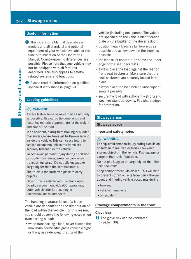
Useful information
i This Operator's Manual describes allmodels and all standard and optionalequipment of your vehicle available at thetime of publication of the Operator'sManual. Country-specific differences arepossible. Please note that your vehicle maynot be equipped with all featuresdescribed. This also applies to safety-related systems and functions.
i Please read the information on qualifiedspecialist workshops (Y page 24).
Loading guidelines
G WARNINGAlways fasten items being carried as securelyas possible. Use cargo tie-down rings andfastening materials appropriate for the weightand size of the load.In an accident, during hard braking or suddenmaneuvers, loose items will be thrown aroundinside the vehicle. This can cause injury tovehicle occupants unless the items aresecurely fastened in the vehicle.To help avoid personal injury during a collisionor sudden maneuver, exercise care whentransporting cargo. Do not pile luggage orcargo higher than the seat backrests.The trunk is the preferred place to carryobjects.Never drive a vehicle with the trunk open.Deadly carbon monoxide (CO) gases mayenter vehicle interior resulting inunconsciousness and death.
The handling characteristics of a ladenvehicle are dependent on the distribution ofthe load within the vehicle. For this reason,you should observe the following notes whentransporting a load:Rwhen transporting a load, never exceed the
maximum permissible gross vehicle weightor the gross axle weight rating of the
vehicle (including occupants). The valuesare specified on the vehicle identificationplate on the B-pillar of the driver's door.Rposition heavy loads as far forwards as
possible and as low down in the trunk aspossible.Rthe load must not protrude above the upper
edge of the seat backrests.Ralways place the load against the rear or
front seat backrests. Make sure that theseat backrests are securely locked intoplace.Ralways place the load behind unoccupied
seats if possible.Rsecure the load with sufficiently strong and
wear-resistant tie-downs. Pad sharp edgesfor protection.
Stowage areas
Stowage space
Important safety notes
G WARNINGTo help avoid personal injury during a collisionor sudden maneuver, exercise care whenstoring objects in the vehicle. Put luggage orcargo in the trunk if possible.Do not pile luggage or cargo higher than theseat backrests.Keep compartment lids closed. This will helpto prevent stored objects from being thrownabout and injuring vehicle occupants duringRbrakingRvehicle maneuversRan accident
Stowage compartments in the front
Glove boxi The glove box can be ventilated
(Y page 130).
262 Stowage areasSt
owag
e an
d fe
atur
es

X To open: pull handle : and open glove boxflap ;.
X To close: fold glove box flap ; upwardsuntil it engages.
The glove box can only be locked andunlocked using the mechanical key.
X To lock: insert the mechanical key into thelock and turn it 90° clockwise to position2.
X To unlock: insert the mechanical key intothe lock and turn it 90° counter-clockwiseto position 1.
Stowage compartments in the centerconsole
All models except AMG vehiclesX To open: slide the cover forwards by
handle : in the direction of the arrow untilit engages.
X To close: briefly press the front ofhandle :.
AMG vehiclesX Briefly press trim :.
i The stowage tray can be removed.
Stowage compartment under the armresti Depending on the vehicle's equipment, a
12 V socket, a USB socket, and an AUX INconnection or Media Interface are installedin the stowage compartment. A MediaInterface is a universal interface for mobileaudio equipment, e.g. for an iPod® or MP3player (see the separate COMANDoperating instructions).
Stowage areas 263
Stow
age
and
feat
ures
Z
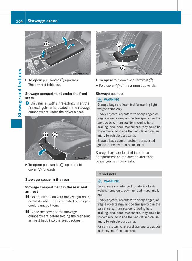
X To open: pull handle : upwards.The armrest folds out.
Stowage compartment under the frontseatsi On vehicles with a fire extinguisher, the
fire extinguisher is located in the stowagecompartment under the driver's seat.
X To open: pull handle : up and foldcover ; forwards.
Stowage space in the rear
Stowage compartment in the rear seatarmrest! Do not sit or lean your bodyweight on the
armrests when they are folded out as youcould damage them.
! Close the cover of the stowagecompartment before folding the rear seatarmrest back into the seat backrest.
X To open: fold down seat armrest ;.X Fold cover : of the armrest upwards.
Stowage pocketsG WARNINGStorage bags are intended for storing light-weight items only.Heavy objects, objects with sharp edges orfragile objects may not be transported in thestorage bag. In an accident, during hardbraking, or sudden maneuvers, they could bethrown around inside the vehicle and causeinjury to vehicle occupants.Storage bags cannot protect transportedgoods in the event of an accident.
Storage bags are located in the rearcompartment on the driver's and front-passenger seat backrests.
Parcel nets
G WARNINGParcel nets are intended for storing light-weight items only, such as road maps, mail,etc.Heavy objects, objects with sharp edges, orfragile objects may not be transported in theparcel nets. In an accident, during hardbraking, or sudden maneuvers, they could bethrown around inside the vehicle and causeinjury to vehicle occupants.Parcel nets cannot protect transported goodsin the event of an accident.
264 Stowage areasSt
owag
e an
d fe
atur
es
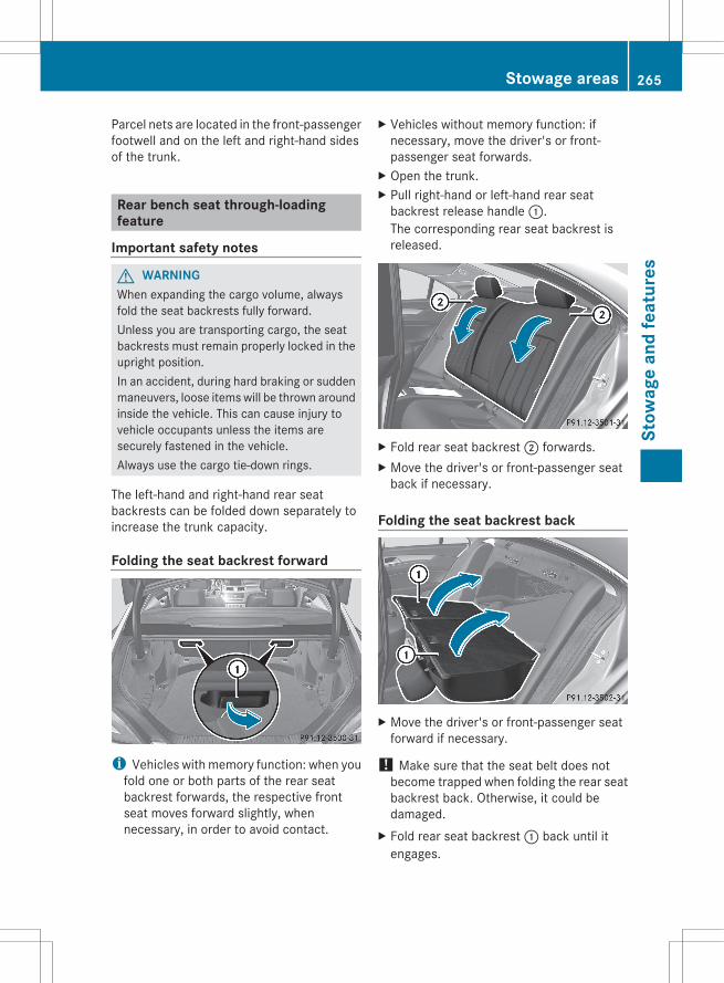
Parcel nets are located in the front-passengerfootwell and on the left and right-hand sidesof the trunk.
Rear bench seat through-loadingfeature
Important safety notes
G WARNINGWhen expanding the cargo volume, alwaysfold the seat backrests fully forward.Unless you are transporting cargo, the seatbackrests must remain properly locked in theupright position.In an accident, during hard braking or suddenmaneuvers, loose items will be thrown aroundinside the vehicle. This can cause injury tovehicle occupants unless the items aresecurely fastened in the vehicle.Always use the cargo tie-down rings.
The left-hand and right-hand rear seatbackrests can be folded down separately toincrease the trunk capacity.
Folding the seat backrest forward
i Vehicles with memory function: when youfold one or both parts of the rear seatbackrest forwards, the respective frontseat moves forward slightly, whennecessary, in order to avoid contact.
X Vehicles without memory function: ifnecessary, move the driver's or front-passenger seat forwards.
X Open the trunk.X Pull right-hand or left-hand rear seat
backrest release handle :.The corresponding rear seat backrest isreleased.
X Fold rear seat backrest ; forwards.X Move the driver's or front-passenger seat
back if necessary.
Folding the seat backrest back
X Move the driver's or front-passenger seatforward if necessary.
! Make sure that the seat belt does notbecome trapped when folding the rear seatbackrest back. Otherwise, it could bedamaged.
X Fold rear seat backrest : back until itengages.
Stowage areas 265
Stow
age
and
feat
ures
Z
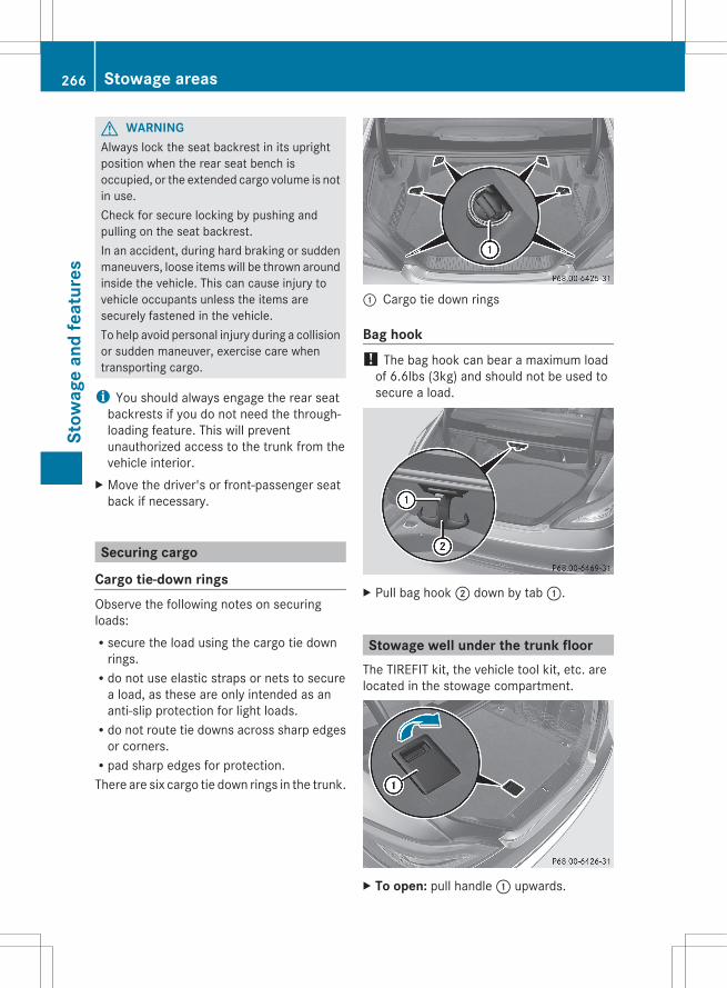
G WARNINGAlways lock the seat backrest in its uprightposition when the rear seat bench isoccupied, or the extended cargo volume is notin use.Check for secure locking by pushing andpulling on the seat backrest.In an accident, during hard braking or suddenmaneuvers, loose items will be thrown aroundinside the vehicle. This can cause injury tovehicle occupants unless the items aresecurely fastened in the vehicle.To help avoid personal injury during a collisionor sudden maneuver, exercise care whentransporting cargo.
i You should always engage the rear seatbackrests if you do not need the through-loading feature. This will preventunauthorized access to the trunk from thevehicle interior.
X Move the driver's or front-passenger seatback if necessary.
Securing cargo
Cargo tie-down ringsObserve the following notes on securingloads:Rsecure the load using the cargo tie down
rings.Rdo not use elastic straps or nets to secure
a load, as these are only intended as ananti-slip protection for light loads.Rdo not route tie downs across sharp edges
or corners.Rpad sharp edges for protection.There are six cargo tie down rings in the trunk.
: Cargo tie down rings
Bag hook! The bag hook can bear a maximum load
of 6.6lbs (3kg) and should not be used tosecure a load.
X Pull bag hook ; down by tab :.
Stowage well under the trunk floorThe TIREFIT kit, the vehicle tool kit, etc. arelocated in the stowage compartment.
X To open: pull handle : upwards.
266 Stowage areasSt
owag
e an
d fe
atur
es

X Hook handle : into rain trough ;.
! Unhook the handle before again beforeclosing the trunk lid and clip it in securelyto prevent the handle flap from protruding.Otherwise, you could damage the handle.
Roof carrier
Important safety notes
G WARNINGOnly use roof racks approved by Mercedes-Benz for your vehicle model to avoid damageto the vehicle.Follow the manufacturer's installationinstructions. Otherwise, an improperlyattached roof rack system or its load couldbecome detached from the vehicle.Do not exceed the maximum roof load of220 lb (100 kg).Take into consideration that when the roofrack is loaded, the handling characteristicsare different from those when operating thevehicle without the roof rack loaded.
! Mercedes-Benz recommends that youonly use roof carriers that have been testedand approved for Mercedes-Benz vehicles.This helps to prevent damage to thevehicle.Position the load on the roof carrier in sucha way that the vehicle will not sustaindamage even when it is in motion.Ensure that, depending on the vehicle'sequipment, you can raise the sliding
sunroof fully and open the trunk lid fullywhen the roof carrier is installed.
! To avoid damaging or scratching thecovers, do not use metallic or hard objectsto open them.
Attaching the roof carrier
X Open covers : carefully in the direction ofthe arrow.
X Fold covers : upwards.X Only secure the roof carrier to the
anchorage points under covers :.X Observe the manufacturer's installation
instructions.
Features
Cup holders
Important safety notes
G WARNINGIn order to help prevent spilling liquids onvehicle occupants and/or vehicle equipment,only use containers that fit into the cupholder. Use lids on open containers and donot fill containers to a height where thecontents, especially hot liquids, could spillduring braking, vehicle maneuvers, or in anaccident. Liquids spilled on vehicle occupantsmay cause serious personal injury. Liquidsspilled on vehicle equipment may causedamage not covered by the Mercedes-BenzLimited Warranty.
Features 267
Stow
age
and
feat
ures
Z
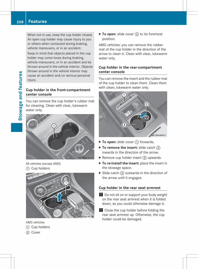
When not in use, keep the cup holder closed.An open cup holder may cause injury to youor others when contacted during braking,vehicle maneuvers, or in an accident.Keep in mind that objects placed in the cupholder may come loose during braking,vehicle maneuvers, or in an accident and bethrown around in the vehicle interior. Objectsthrown around in the vehicle interior maycause an accident and/or serious personalinjury.
Cup holder in the front-compartmentcenter consoleYou can remove the cup holder's rubber matfor cleaning. Clean with clear, lukewarmwater only.
All vehicles (except AMG): Cup holders
AMG vehicles: Cup holders; Cover
X To open: slide cover ; to its foremostposition.
AMG vehicles: you can remove the rubbermat of the cup holder in the direction of thearrow to clean it. Clean with clear, lukewarmwater only.
Cup holder in the rear-compartmentcenter consoleYou can remove the insert and the rubber matof the cup holder to clean them. Clean themwith clean, lukewarm water only.
X To open: slide cover : forwards.X To remove the insert: slide catch ;
inwards in the direction of the arrow.X Remove cup holder insert = upwards.X To re-install the insert: place the insert in
the stowage space.X Slide catch ; outwards in the direction of
the arrow until it engages.
Cup holder in the rear seat armrest! Do not sit on or support your body weight
on the rear seat armrest when it is foldeddown, as you could otherwise damage it.
! Close the cup holder before folding therear seat armrest up. Otherwise, the cupholder could be damaged.
268 FeaturesSt
owag
e an
d fe
atur
es
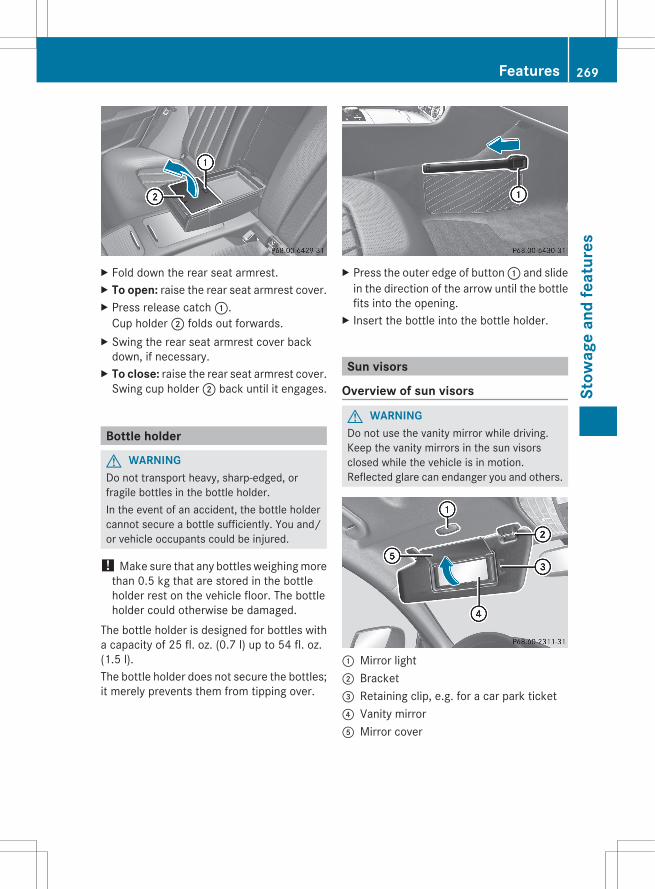
X Fold down the rear seat armrest.X To open: raise the rear seat armrest cover.X Press release catch :.
Cup holder ; folds out forwards.X Swing the rear seat armrest cover back
down, if necessary.X To close: raise the rear seat armrest cover.
Swing cup holder ; back until it engages.
Bottle holder
G WARNINGDo not transport heavy, sharp-edged, orfragile bottles in the bottle holder.In the event of an accident, the bottle holdercannot secure a bottle sufficiently. You and/or vehicle occupants could be injured.
! Make sure that any bottles weighing morethan 0.5 kg that are stored in the bottleholder rest on the vehicle floor. The bottleholder could otherwise be damaged.
The bottle holder is designed for bottles witha capacity of 25 fl. oz. (0.7 l) up to 54 fl. oz.(1.5 l).The bottle holder does not secure the bottles;it merely prevents them from tipping over.
X Press the outer edge of button : and slidein the direction of the arrow until the bottlefits into the opening.
X Insert the bottle into the bottle holder.
Sun visors
Overview of sun visors
G WARNINGDo not use the vanity mirror while driving.Keep the vanity mirrors in the sun visorsclosed while the vehicle is in motion.Reflected glare can endanger you and others.
: Mirror light; Bracket= Retaining clip, e.g. for a car park ticket? Vanity mirrorA Mirror cover
Features 269
Stow
age
and
feat
ures
Z
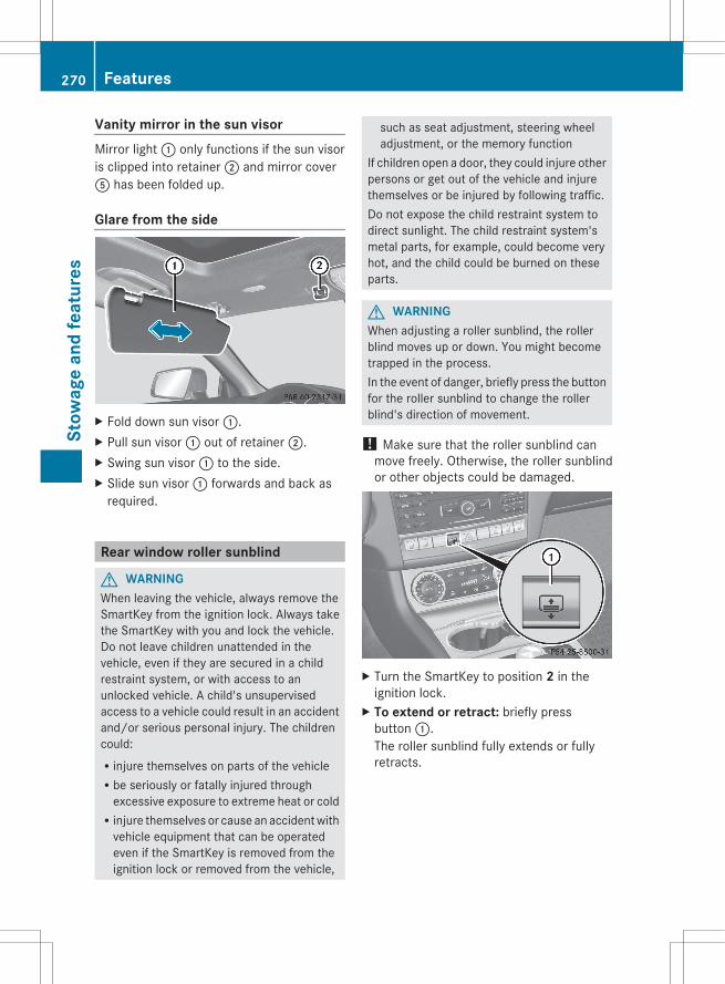
Vanity mirror in the sun visorMirror light : only functions if the sun visoris clipped into retainer ; and mirror coverA has been folded up.
Glare from the side
X Fold down sun visor :.X Pull sun visor : out of retainer ;.X Swing sun visor : to the side.X Slide sun visor : forwards and back as
required.
Rear window roller sunblind
G WARNINGWhen leaving the vehicle, always remove theSmartKey from the ignition lock. Always takethe SmartKey with you and lock the vehicle.Do not leave children unattended in thevehicle, even if they are secured in a childrestraint system, or with access to anunlocked vehicle. A child's unsupervisedaccess to a vehicle could result in an accidentand/or serious personal injury. The childrencould:Rinjure themselves on parts of the vehicleRbe seriously or fatally injured through
excessive exposure to extreme heat or coldRinjure themselves or cause an accident with
vehicle equipment that can be operatedeven if the SmartKey is removed from theignition lock or removed from the vehicle,
such as seat adjustment, steering wheeladjustment, or the memory function
If children open a door, they could injure otherpersons or get out of the vehicle and injurethemselves or be injured by following traffic.Do not expose the child restraint system todirect sunlight. The child restraint system'smetal parts, for example, could become veryhot, and the child could be burned on theseparts.
G WARNINGWhen adjusting a roller sunblind, the rollerblind moves up or down. You might becometrapped in the process.In the event of danger, briefly press the buttonfor the roller sunblind to change the rollerblind's direction of movement.
! Make sure that the roller sunblind canmove freely. Otherwise, the roller sunblindor other objects could be damaged.
X Turn the SmartKey to position 2 in theignition lock.
X To extend or retract: briefly pressbutton :.The roller sunblind fully extends or fullyretracts.
270 FeaturesSt
owag
e an
d fe
atur
es

Ashtray
Ashtray in the front-compartmentcenter consolei You can remove the ashtray insert and
use the resulting compartment forstowage.
! The stowage space under the ashtray isnot heat resistant. Before placing litcigarettes in the ashtray, make sure thatthe ashtray is properly engaged. Otherwise,the stowage space could be damaged.
All vehicles (except AMG)X To open: slide cover : forwards until it
engages.X To remove insert: hold insert = by the
ribbing at the sides and lift it up ; and out.X To re-install the insert: press insert =
into the holder until it engages.X To close: press cover : briefly at the
front.The cover moves back.
AMG vehicles
X To open: briefly press the trim oncover :.The stowage compartment opens.
X To remove the insert: slide insert ;forwards in the direction of the arrow.
X Remove insert ;.X To re-install the insert: place the insert
into the holder and press it in the oppositedirection of the arrow until it engages.
X To close: fold down cover :.
Ashtray in the rear-compartment centerconsole
X To open: slide cover ; forwards until itengages.
X To remove the insert: pull insert : upand out.
X To install the insert: put insert : fromabove into the holder and press down intothe holder until it engages.
Features 271
Stow
age
and
feat
ures
Z

Cigarette lighter
G WARNINGWhen leaving the vehicle, always remove theSmartKey from the ignition lock. Always takethe SmartKey with you and lock the vehicle.Do not leave children unattended in thevehicle, even if they are secured in a childrestraint system, or with access to anunlocked vehicle. A child's unsupervisedaccess to a vehicle could result in an accidentand/or serious personal injury. The childrencould:Rinjure themselves on parts of the vehicleRbe seriously or fatally injured through
excessive exposure to extreme heat or coldRinjure themselves or cause an accident with
vehicle equipment that can be operatedeven if the SmartKey is removed from theignition lock or removed from the vehicle,such as seat adjustment, steering wheeladjustment, or the memory function
If children open a door, they could injure otherpersons or get out of the vehicle and injurethemselves or be injured by following traffic.Do not expose the child restraint system todirect sunlight. The child restraint system'smetal parts, for example, could become veryhot, and the child could be burned on theseparts.
G WARNINGNever touch the heating element or sides ofthe lighter; they are extremely hot. Hold theknob only.Make sure any children traveling with you donot injure themselves or start a fire with thehot cigarette lighter.
All vehicles (except AMG)X Turn the SmartKey to position 2 in the
ignition lock.X To open: slide cover : forwards until it
engages.X Press in cigarette lighter ;.
Cigarette lighter ; will pop outautomatically when the heating element isred-hot.
AMG vehiclesX To open: briefly press the trim on
cover :.The stowage compartment opens.
X Press in cigarette lighter ;.Cigarette lighter ; will pop outautomatically when the heating element isred-hot.
272 FeaturesSt
owag
e an
d fe
atur
es

12 V sockets
Points to observe before use! If you are using all sockets in the vehicle,
make sure that you do not exceed themaximum current draw of 55 A. Otherwise,you will overload the fuses.
The sockets can be used for accessories witha maximum draw of 180 W (15 A).Accessories include such items as lamps orchargers for mobile phones.If you use the sockets for long periods whenthe engine is switched off, the battery maydischarge.X Turn the SmartKey to position 1 in the
ignition lock.
i An emergency cut-out ensures that theon-board voltage does not drop too low. Ifthe on-board voltage is too low, the powerto the sockets is automatically cut. Thisensures that there is sufficient power tostart the engine.
Socket under the armrest
X Open the stowage space under the armrest(Y page 263).
X Lift up the cover of socket :.
On vehicles without ashtrays or lighters, thereis an additional socket in the center console.
Socket in the front-compartment centerconsole
All vehicles (except AMG)X To open: slide cover : forwards until it
engages.X Lift up the cover of socket ;.X To close: press cover : briefly at the
front.The cover moves back.
AMG vehiclesX To open: briefly press the trim on
cover :.The stowage compartment opens.
X Lift up the cover of socket ;.X To close: fold down cover :.
Features 273
Stow
age
and
feat
ures
Z

Socket in the rear-compartment centerconsole
X Slide cover ; forwards until it engages.X Lift up the cover of socket :.
Socket in the trunk
X Lift up the cover of socket :.
mbrace
Important safety notes! A license agreement must exist in order
to activate the mbrace service. Ensure thatyour system is activated and ready for use,and press the ï MB Info call button toregister. If any of the steps mentioned isnot carried out, the system may not beactivated.
If you have questions about the activation,contact one of the following telephoneassistance services:RUSA: Mercedes-Benz Customer
Assistance Center under1-800-FOR-MERCedes(1-800-367-6372) or 1-888-990-9007RCanada: Customer Service at
1-888-923-8367Shortly after successfully registering with thembrace service, a user ID and password willbe sent to you by mail. You can use thispassword to log in to the mbrace sectionunder "Owners Online" at http://www.mbusa.com18.The mbrace system is available if:Rit has been activated and is operational.Rthe corresponding mobile phone network
is available for transmitting data to theCustomer Center.Ra service subscription is available.Rthe starter battery is sufficiently charged.
i Determining the location of the vehicle ona map is only possible if there is sufficientGPS reception and the vehicle position canbe forwarded to the Customer Center.
The mbrace systemThe mbrace system provides differentservices, e.g.:Rautomatic and manual emergency callRRoadside Assistance callRMB Info callTo adjust the volume during an mbrace call,proceed as follows:X Press the W or X button on the
multifunction steering wheel.orX Use the volume controller of the audio
system/COMAND.
18 USA only.
274 FeaturesSt
owag
e an
d fe
atur
es

You can find further information and adescription of all available features under"Owners Online" at http://www.mbusa.com19.
System self-testAfter you have switched on the ignition, thesystem carries out a self-diagnosis.
G WARNINGA malfunction in the system has beendetected if one of the following conditionsoccurs:Rthe indicator lamp in the SOS button does
not light up during the system self-diagnosis.Rthe indicator lamp in the F Roadside
Assistance button does not light up duringthe system self-diagnosis.RThe indicator lamp in the ï information
button does not light up during self-diagnosis of the system.Rthe indicator lamp in the SOS button,
F Roadside Assistance button or ïinformation button continues to be lit redafter the system self-diagnosis.RThe Tele Aid Inoperative or Tele Aid Not Activated message appears in themultifunction display after the system self-test.
If a malfunction is indicated as outlined above,the system may not operate as expected. Inthe event of an emergency, assistance mustbe summoned by other means.Have the system checked at the nearestauthorized Mercedes-Benz Center or contactthe following service hotlines:RUSA: Mercedes-Benz Customer Assistance
Center under1-800-FOR-MERCedes(1-800-367-6372)or 1-888-990-9007RCanada: Customer Service at
1-888-923-8367
Emergency call
Important safety notes! A license agreement must exist in order
to activate the mbrace service. Ensure thatyour system is activated and ready for use,and press the ï MB Info call button toregister. If any of the steps mentioned isnot carried out, the system may not beactivated.If you have questions about the activation,contact one of the following telephoneassistance services:RUSA: Mercedes-Benz Customer
Assistance Center under1-800-FOR-MERCedes(1-800-367-6372) or 1-888-990-9007RCanada: Customer Service at
1-888-923-8367An emergency call is dialed automatically ifan air bag or Emergency Tensioning Device istriggered.
i An mbrace emergency call that has beeninitiated automatically cannot beterminated by the customer.
An emergency call can also be initiatedmanually.As soon as the emergency call has beeninitiated, the indicator lamp in the SOS buttonflashes. The Connecting Call messageappears on the multifunction display.The audio output is muted.Once a connection has been established, theCall Connected message appears in themultifunction display.All important information on the emergencyis transmitted, for example:Rcurrent location of the vehicle (as
determined by the GPS system)Rvehicle identification numberRinformation on the type of emergencyShortly after the emergency call has beeninitiated, a voice connection is automatically
19 USA only.
Features 275
Stow
age
and
feat
ures
Z
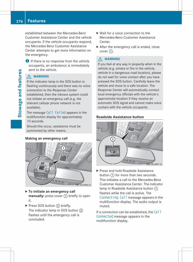
established between the Mercedes-BenzCustomer Assistance Center and the vehicleoccupants. If the vehicle occupants respond,the Mercedes-Benz Customer AssistanceCenter attempts to get more information onthe emergency.
i If there is no response from the vehicleoccupants, an ambulance is immediatelysent to the vehicle.
G WARNINGIf the indicator lamp in the SOS button isflashing continuously and there was no voiceconnection to the Response Centerestablished, then the mbrace system couldnot initiate an emergency call (e.g. therelevant cellular phone network is notavailable).The message Call Failed appears in themultifunction display for approximately10 seconds.Should this occur, assistance must besummoned by other means.
Making an emergency call
X To initiate an emergency call manually: press cover : briefly to openit.
X Press SOS button ; briefly.The indicator lamp in SOS button ;flashes until the emergency call isconcluded.
X Wait for a voice connection to theMercedes-Benz Customer AssistanceCenter.
X After the emergency call is ended, closecover :.
G WARNINGIf you feel at any way in jeopardy when in thevehicle (e.g. smoke or fire in the vehicle,vehicle in a dangerous road location), pleasedo not wait for voice contact after you havepressed the SOS button. Carefully leave thevehicle and move to a safe location. TheResponse Center will automatically contactlocal emergency officials with the vehicle'sapproximate location if they receive anautomatic SOS signal and cannot make voicecontact with the vehicle occupants.
Roadside Assistance button
X Press and hold Roadside Assistancebutton : for more than two seconds.This initiates a call to the Mercedes-BenzCustomer Assistance Center. The indicatorlamp in Roadside Assistance button :flashes while the call is active. TheConnecting Call message appears in themultifunction display. The audio output ismuted.
If a connection can be established, the Call Connected message appears in themultifunction display.
276 FeaturesSt
owag
e an
d fe
atur
es
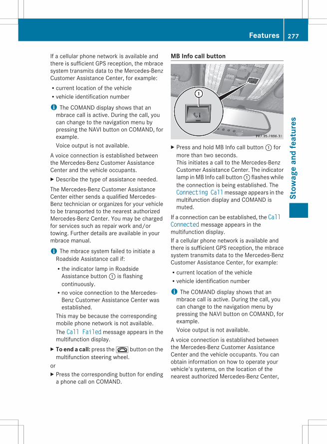
If a cellular phone network is available andthere is sufficient GPS reception, the mbracesystem transmits data to the Mercedes-BenzCustomer Assistance Center, for example:Rcurrent location of the vehicleRvehicle identification number
i The COMAND display shows that anmbrace call is active. During the call, youcan change to the navigation menu bypressing the NAVI button on COMAND, forexample.Voice output is not available.
A voice connection is established betweenthe Mercedes-Benz Customer AssistanceCenter and the vehicle occupants.X Describe the type of assistance needed.The Mercedes-Benz Customer AssistanceCenter either sends a qualified Mercedes-Benz technician or organizes for your vehicleto be transported to the nearest authorizedMercedes-Benz Center. You may be chargedfor services such as repair work and/ortowing. Further details are available in yourmbrace manual.
i The mbrace system failed to initiate aRoadside Assistance call if:Rthe indicator lamp in Roadside
Assistance button : is flashingcontinuously.Rno voice connection to the Mercedes-
Benz Customer Assistance Center wasestablished.
This may be because the correspondingmobile phone network is not available.The Call Failed message appears in themultifunction display.
X To end a call: press the ~ button on themultifunction steering wheel.
orX Press the corresponding button for ending
a phone call on COMAND.
MB Info call button
X Press and hold MB Info call button : formore than two seconds.This initiates a call to the Mercedes-BenzCustomer Assistance Center. The indicatorlamp in MB Info call button : flashes whilethe connection is being established. TheConnecting Call message appears in themultifunction display and COMAND ismuted.
If a connection can be established, the Call Connected message appears in themultifunction display.If a cellular phone network is available andthere is sufficient GPS reception, the mbracesystem transmits data to the Mercedes-BenzCustomer Assistance Center, for example:Rcurrent location of the vehicleRvehicle identification number
i The COMAND display shows that anmbrace call is active. During the call, youcan change to the navigation menu bypressing the NAVI button on COMAND, forexample.Voice output is not available.
A voice connection is established betweenthe Mercedes-Benz Customer AssistanceCenter and the vehicle occupants. You canobtain information on how to operate yourvehicle's systems, on the location of thenearest authorized Mercedes-Benz Center,
Features 277
Stow
age
and
feat
ures
Z
and on further products and services offeredby Mercedes-Benz USA.Further details on the mbrace system can befound under http://www.mbusa.com20.Log in under "Owners Online".
i The mbrace system failed to initiate anMB Info call if:Rthe indicator lamp in MB Info call
button : is flashing continuously.Rno voice connection to the Mercedes-
Benz Customer Assistance Center wasestablished.
This may be because the correspondingmobile phone network is not available.The Call Failed message appears in themultifunction display.
X To end a call: press the ~ button on themultifunction steering wheel.
orX Press the corresponding button for ending
a phone call on COMAND.
Call priorityWhen service calls are active, e.g. RoadsideAssistance or MB Info calls, an emergencycall can still be initiated. In this case, anemergency call will take priority and overrideall other active calls.The indicator lamp of the respective buttonflashes until the call is ended. An emergencycall can only be terminated by the Mercedes-Benz Customer Assistance Center. All othercalls can be ended by pressing the ~button on the multifunction steering wheel orthe corresponding button for ending atelephone call on COMAND.
i If an mbrace call is initiated, audio outputis muted. The mobile phone is no longerconnected to COMAND. However, if youwant to use your mobile phone, werecommend that you do this only when thevehicle is stationary and in a safe location.
Downloading destinationsi Information on the components and
operating principles of COMAND can befound in the separate COMAND operatinginstructions.
i You can only use the DestinationDownload function if the vehicle isequipped with a navigation system.
Destination Download gives you access to adatabase with over 15 million points ofinterest (POIs)/important destinations thatcan be downloaded onto the navigationsystem of your vehicle. If you know thedestination, you can download the address orobtain the location of points of interest(POIs)/important destinations in thesurrounding area.You are prompted to confirm route guidanceto the address entered.X Select Yes with the = or ; buttons
on COMAND.X Press the 9 button on COMAND to
confirm.The system calculates the route andsubsequently starts the route guidance withthe address entered.
i If you select No, the address can be storedin the address book.
i The Destination Download function isavailable if the corresponding mobilephone network is available and datatransfer is possible.
Route AssistanceThis service is part of the mbrace PLUSPackage and cannot be purchasedseparately.
i You can also use the Route Assistancefunction if your vehicle is not equipped witha navigation system.
Within the framework of this service, youreceive a professional and reliable form of
20 USA only.
278 FeaturesSt
owag
e an
d fe
atur
es

navigation support without having to leaveyour vehicle.The customer service representativedetermines a suitable driving route based onyour current vehicle position and the desireddestination and guides you live through thecurrent sections of the route.
Search & Send"Search & Send" is a destination entryservice. You can find further information on"Search & Send" in the separate COMANDoperating instructions.
Vehicle remote openingIf you have unintentionally locked yourvehicle (e.g. the SmartKey is still in thevehicle) and a replacement SmartKey is notavailable, the vehicle can be opened by aMercedes-Benz Customer Assistance Center.The vehicle can be opened remotely up to fourdays after the ignition was last switched off.X Contact the following service hotlines:RUSA: Mercedes-Benz Customer
Assistance Center at1-800-FOR-MERCedes(1-800-367-6372) or 1-888-990-9007RCanada: Customer Service at
1-888-923-8367You will be asked for your password.
X Return to your vehicle at the time agreedupon with the Mercedes-Benz CustomerAssistance Center.
X Pull on the trunk lid handle for at least20 seconds until the indicator lamp in theSOS button (Y page 275) flashes.The Connecting Call message appearson the multifunction display.
Alternatively, the vehicle can also be openedvia the Internet or an iPhone in the "OwnersOnline" section using your ID number andpassword21.
i Vehicle remote unlocking is only possibleif the corresponding mobile phone networkis accessible.The SOS button flashes and theConnecting Call message appears in themultifunction display to confirm that thecommand for vehicle remote unlocking hasbeen received.If you pull on the trunk handle for more than20 seconds before receiving authorizationfor remote unlocking, you must wait15 minutes before you can pull on the trunklid handle again.
Vehicle remote closingIf you forget to lock your vehicle but are nolonger in the vicinity of the vehicle, it can belocked for you by the Mercedes-BenzCustomer Assistance Center.The vehicle can be locked remotely up to fourdays after the ignition was last switched off.X Contact the following service hotlines:RUSA: Mercedes-Benz Customer
Assistance Center under 1-800-FOR-MERCedes(1-800-367-6372) or1-888-990-9007RCanada: Customer Service at
1-888-923-8367You will be asked for your PIN.
The next time you are in your vehicle andswitch on the ignition, the Tele Aid: Doors Locked by Remote message appears in themultifunction display.Alternatively, the vehicle can also be lockedvia the Internet or an iPhone in the "OwnersOnline" section using your ID number andpassword.
i The vehicle valet locking feature isavailable when the relevant mobile phonenetwork is available and data connection ispossible.
21 USA only.
Features 279
Stow
age
and
feat
ures
Z
Stolen vehicle recovery serviceIf your vehicle has been stolen:X Notify the police.
The police will issue a numbered incidentreport.
X This number will be forwarded to theMercedes-Benz Customer AssistanceCenter together with your PIN.The Mercedes-Benz Customer AssistanceCenter then attempts to locate the mbracesystem. The Mercedes-Benz CustomerAssistance Center contacts you and thelocal law enforcement agency if the vehicleis located. However, only the lawenforcement agency is informed of thelocation of the vehicle.
i If the anti-theft alarm system is active forlonger than 30 seconds, mbraceautomatically informs the Mercedes-BenzCustomer Assistance Center.
Garage door opener
Important safety notesThe HomeLink® garage door openerintegrated in the rear-view mirror allows youto operate up to three different door and gatesystems.
i Certain garage door drives areincompatible with the integrated garagedoor opener. If you have difficultyprogramming the integrated garage dooropener, contact an authorized Mercedes-Benz Center or call one of the followingtelephone hotlines:RUSA: Mercedes-Benz Customer
Assistance Center at1-800-FOR-MERCedesRCanada: Customer Service at
1-800-387-0100
G WARNINGBefore programming the integrated remotecontrol to a garage door opener or gate
operator, make sure people and objects areout of the way of the device to preventpotential harm or damage. Whenprogramming a garage door opener, the doormoves up or down. When programming a gateoperator, the gate opens or closes.Do not use the integrated remote control withany garage door opener that lacks safety stopand reverse features as required by U.S.federal safety standards (this includes anygarage door opener model manufacturedbefore April 1, 1982). A garage door thatcannot detect an object - signaling the doorto stop and reverse - does not meet currentU.S. federal safety standards.When programming a garage door opener,park vehicle outside the garage.Do not run the engine while programming theintegrated remote control. Inhalation ofexhaust gas is hazardous to your health. Allexhaust gas contains carbon monoxide (CO),and inhaling it can cause unconsciousnessand possible death. All exhaust gas containscarbon monoxide (CO), and inhaling it cancause unconsciousness and possible death.
i USA only:This device complies with Part 15 of theFCC Rules. Operation is subject to thefollowing two conditions:1. This device may not cause harmfulinterference, and2. this device must accept any interferencereceived, including interference that maycause undesired operation.Any unauthorized modification to thisdevice could void the user's authority tooperate the equipment.FCC ID: CB2HMIHL4
i Canada only:This device complies with RSS-210 ofIndustry Canada. Operation is subject tothe following two conditions:1. This device may not cause interference,and
280 FeaturesSt
owag
e an
d fe
atur
es
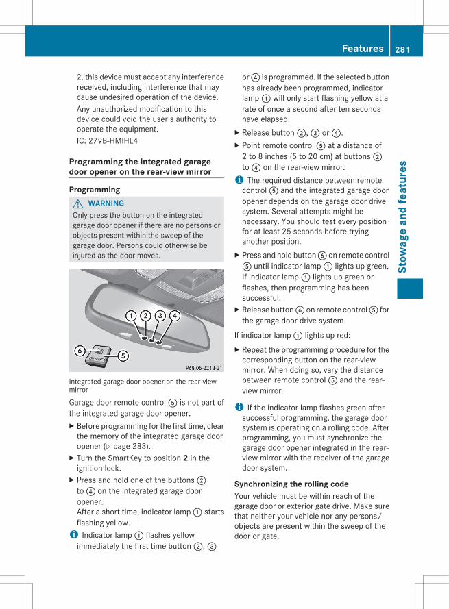
2. this device must accept any interferencereceived, including interference that maycause undesired operation of the device.Any unauthorized modification to thisdevice could void the user's authority tooperate the equipment.IC: 279B-HMIHL4
Programming the integrated garagedoor opener on the rear-view mirror
ProgrammingG WARNINGOnly press the button on the integratedgarage door opener if there are no persons orobjects present within the sweep of thegarage door. Persons could otherwise beinjured as the door moves.
Integrated garage door opener on the rear-viewmirror
Garage door remote control A is not part ofthe integrated garage door opener.X Before programming for the first time, clear
the memory of the integrated garage dooropener (Y page 283).
X Turn the SmartKey to position 2 in theignition lock.
X Press and hold one of the buttons ;to ? on the integrated garage dooropener.After a short time, indicator lamp : startsflashing yellow.
i Indicator lamp : flashes yellowimmediately the first time button ;, =
or ? is programmed. If the selected buttonhas already been programmed, indicatorlamp : will only start flashing yellow at arate of once a second after ten secondshave elapsed.
X Release button ;, = or ?.X Point remote control A at a distance of
2 to 8 inches (5 to 20 cm) at buttons ;to ? on the rear-view mirror.
i The required distance between remotecontrol A and the integrated garage dooropener depends on the garage door drivesystem. Several attempts might benecessary. You should test every positionfor at least 25 seconds before tryinganother position.
X Press and hold button B on remote controlA until indicator lamp : lights up green.If indicator lamp : lights up green orflashes, then programming has beensuccessful.
X Release button B on remote control A forthe garage door drive system.
If indicator lamp : lights up red:X Repeat the programming procedure for the
corresponding button on the rear-viewmirror. When doing so, vary the distancebetween remote control A and the rear-view mirror.
i If the indicator lamp flashes green aftersuccessful programming, the garage doorsystem is operating on a rolling code. Afterprogramming, you must synchronize thegarage door opener integrated in the rear-view mirror with the receiver of the garagedoor system.
Synchronizing the rolling codeYour vehicle must be within reach of thegarage door or exterior gate drive. Make surethat neither your vehicle nor any persons/objects are present within the sweep of thedoor or gate.
Features 281
Stow
age
and
feat
ures
Z
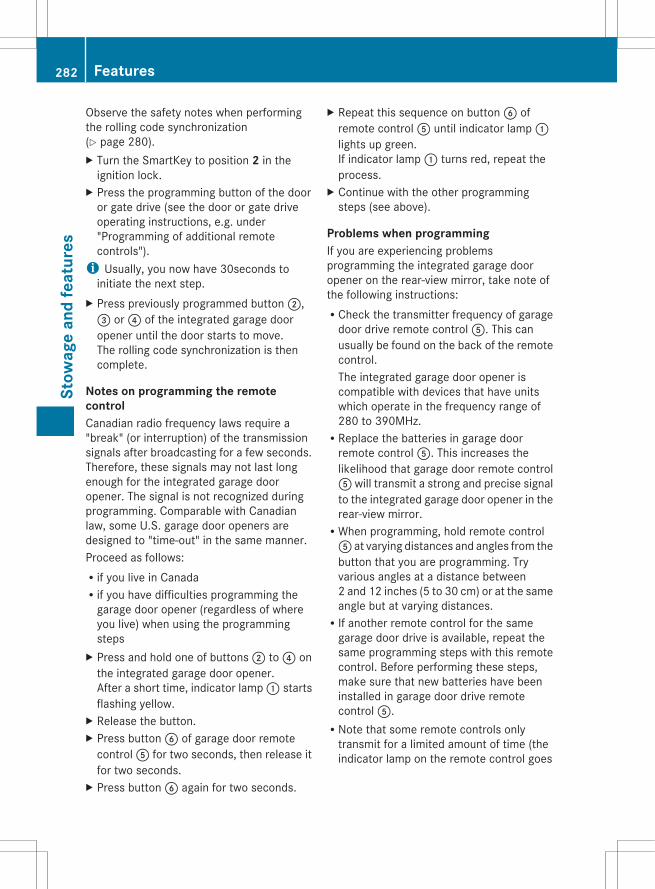
Observe the safety notes when performingthe rolling code synchronization(Y page 280).X Turn the SmartKey to position 2 in the
ignition lock.X Press the programming button of the door
or gate drive (see the door or gate driveoperating instructions, e.g. under"Programming of additional remotecontrols").
i Usually, you now have 30seconds toinitiate the next step.
X Press previously programmed button ;,= or ? of the integrated garage dooropener until the door starts to move.The rolling code synchronization is thencomplete.
Notes on programming the remotecontrolCanadian radio frequency laws require a"break" (or interruption) of the transmissionsignals after broadcasting for a few seconds.Therefore, these signals may not last longenough for the integrated garage dooropener. The signal is not recognized duringprogramming. Comparable with Canadianlaw, some U.S. garage door openers aredesigned to "time-out" in the same manner.Proceed as follows:Rif you live in CanadaRif you have difficulties programming the
garage door opener (regardless of whereyou live) when using the programmingsteps
X Press and hold one of buttons ; to ? onthe integrated garage door opener.After a short time, indicator lamp : startsflashing yellow.
X Release the button.X Press button B of garage door remote
control A for two seconds, then release itfor two seconds.
X Press button B again for two seconds.
X Repeat this sequence on button B ofremote control A until indicator lamp :lights up green.If indicator lamp : turns red, repeat theprocess.
X Continue with the other programmingsteps (see above).
Problems when programmingIf you are experiencing problemsprogramming the integrated garage dooropener on the rear-view mirror, take note ofthe following instructions:RCheck the transmitter frequency of garage
door drive remote control A. This canusually be found on the back of the remotecontrol.The integrated garage door opener iscompatible with devices that have unitswhich operate in the frequency range of280 to 390MHz.RReplace the batteries in garage door
remote control A. This increases thelikelihood that garage door remote controlA will transmit a strong and precise signalto the integrated garage door opener in therear-view mirror.RWhen programming, hold remote controlA at varying distances and angles from thebutton that you are programming. Tryvarious angles at a distance between2 and 12 inches (5 to 30 cm) or at the sameangle but at varying distances.RIf another remote control for the same
garage door drive is available, repeat thesame programming steps with this remotecontrol. Before performing these steps,make sure that new batteries have beeninstalled in garage door drive remotecontrol A.RNote that some remote controls only
transmit for a limited amount of time (theindicator lamp on the remote control goes
282 FeaturesSt
owag
e an
d fe
atur
es

out). Press button B on remote controlA again before transmission ends.RAlign the antenna cable of the garage door
opener unit. This can improve signalreception/transmission.
Opening/closing the garage doorAfter it has been programmed, the integratedgarage door opener performs the function ofthe garage door system remote control.Please also read the operating instructionsfor the garage door system.X Turn the SmartKey to position 2 in the
ignition lock.X Press button ;, = or ? that you have
programmed to operate the garage door.Garage door system with a fixed code:indicator lamp : lights up green.Garage door system with a rolling code:indicator lamp : flashes green.
i The transmitter will transmit a signal foras long as the button is pressed. Thetransmission is halted after a maximum often seconds and indicator lamp : flashesyellow. Press button ;, = or ? again ifnecessary.
Clearing the memory of the integratedgarage door opener on the rear-viewmirrorX Turn the SmartKey to position 2 in the
ignition lock.X Press buttons ; and ?.
The indicator lamp lights up yellow.X Press and hold buttons ; and ? until the
indicator lamp turns green.
i Make sure that you clear the memory ofthe integrated garage door opener beforeselling the vehicle.
Compass
Calling up the compass
To obtain a correct display in rear-viewmirror :, the compass must be calibratedand the magnetic field zone must be set.X Press button = briefly.
The compass shows the direction in whichthe vehicle is currently traveling: N, NE, E,SE, S, SW, W or NW.
Setting the compassX Determine your position using the following
zone maps.
North America zone map
Features 283
Stow
age
and
feat
ures
Z
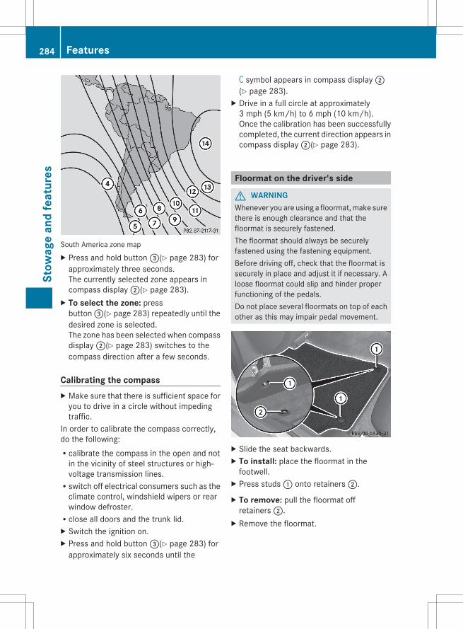
South America zone mapX Press and hold button =(Y page 283) for
approximately three seconds.The currently selected zone appears incompass display ;(Y page 283).
X To select the zone: pressbutton =(Y page 283) repeatedly until thedesired zone is selected.The zone has been selected when compassdisplay ;(Y page 283) switches to thecompass direction after a few seconds.
Calibrating the compassX Make sure that there is sufficient space for
you to drive in a circle without impedingtraffic.
In order to calibrate the compass correctly,do the following:Rcalibrate the compass in the open and not
in the vicinity of steel structures or high-voltage transmission lines.Rswitch off electrical consumers such as the
climate control, windshield wipers or rearwindow defroster.Rclose all doors and the trunk lid.X Switch the ignition on.X Press and hold button =(Y page 283) for
approximately six seconds until the
C symbol appears in compass display ;(Y page 283).
X Drive in a full circle at approximately3 mph (5 km/h) to 6 mph (10 km/h).Once the calibration has been successfullycompleted, the current direction appears incompass display ;(Y page 283).
Floormat on the driver's side
G WARNINGWhenever you are using a floormat, make surethere is enough clearance and that thefloormat is securely fastened.The floormat should always be securelyfastened using the fastening equipment.Before driving off, check that the floormat issecurely in place and adjust it if necessary. Aloose floormat could slip and hinder properfunctioning of the pedals.Do not place several floormats on top of eachother as this may impair pedal movement.
X Slide the seat backwards.X To install: place the floormat in the
footwell.X Press studs : onto retainers ;.
X To remove: pull the floormat offretainers ;.
X Remove the floormat.
284 FeaturesSt
owag
e an
d fe
atur
es

Useful information ............................ 286Engine compartment ........................ 286Maintenance ...................................... 290Care .................................................... 291
285
Mai
nten
ance
and
car
e

Useful information
i This Operator's Manual describes allmodels and all standard and optionalequipment of your vehicle available at thetime of publication of the Operator'sManual. Country-specific differences arepossible. Please note that your vehicle maynot be equipped with all featuresdescribed. This also applies to safety-related systems and functions.
i Please read the information on qualifiedspecialist workshops (Y page 24).
Engine compartment
Hood
Opening the hood
G WARNINGDo not pull the release lever while the vehicleis in motion. Otherwise, the hood could beforced open by passing air flow.This could cause the hood to come loose andinjure you and/or others.
G WARNINGDo not open the hood when the engine isoverheated. You could be seriously injured.Observe the coolant temperature gauge todetermine whether the engine may beoverheated. If you see flames or smokecoming from the engine compartment, moveaway from the vehicle. Wait until the enginehas cooled. If necessary, call the firedepartment.
G WARNINGThere is a risk of injury if the hood is open,even if the engine is not running.Some engine components can become veryhot.To avoid the risk of burns, only touch thosecomponents described in the Operator'sManual and observe the relevant safety notes.
G WARNINGTo avoid injury, stay clear of moving partswhen the hood is open and the engine isrunning.The radiator fan may continue to run forapproximately 30seconds or may even restartafter the engine has been switched off. Forthis reason, you must not reach into the fanrotation area.
G WARNINGThe engine is equipped with a transistorizedignition system. Because of the high voltage,it is dangerous to touch any components(ignition coils, spark plug sockets, diagnosticsocket) of the ignition system:Rwith the engine runningRwhile starting the engineRwhen the ignition is switched on and the
engine is turned manually
X Make sure that the windshield wipers areswitched off.
G WARNINGThe windshield wipers and wiper linkagecould be set in motion.When the hood is open, you or others couldbe injured by the wiper linkage.Make sure that the windshield wipers areswitched off. Remove the SmartKey or makesure that no ignition position has beenselected with KEYLESS-GO. All indicatorlamps must be off in the instrument panel.
286 Engine compartmentM
aint
enan
ce a
nd c
are
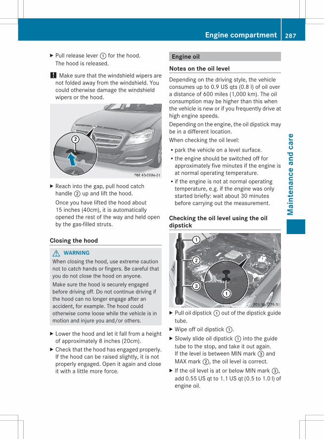
X Pull release lever : for the hood.The hood is released.
! Make sure that the windshield wipers arenot folded away from the windshield. Youcould otherwise damage the windshieldwipers or the hood.
X Reach into the gap, pull hood catchhandle ; up and lift the hood.Once you have lifted the hood about15 inches (40cm), it is automaticallyopened the rest of the way and held openby the gas-filled struts.
Closing the hood
G WARNINGWhen closing the hood, use extreme cautionnot to catch hands or fingers. Be careful thatyou do not close the hood on anyone.Make sure the hood is securely engagedbefore driving off. Do not continue driving ifthe hood can no longer engage after anaccident, for example. The hood couldotherwise come loose while the vehicle is inmotion and injure you and/or others.
X Lower the hood and let it fall from a heightof approximately 8 inches (20cm).
X Check that the hood has engaged properly.If the hood can be raised slightly, it is notproperly engaged. Open it again and closeit with a little more force.
Engine oil
Notes on the oil levelDepending on the driving style, the vehicleconsumes up to 0.9 US qts (0.8 l) of oil overa distance of 600 miles (1,000 km). The oilconsumption may be higher than this whenthe vehicle is new or if you frequently drive athigh engine speeds.Depending on the engine, the oil dipstick maybe in a different location.When checking the oil level:Rpark the vehicle on a level surface.Rthe engine should be switched off for
approximately five minutes if the engine isat normal operating temperature.Rif the engine is not at normal operating
temperature, e.g. if the engine was onlystarted briefly: wait about 30 minutesbefore carrying out the measurement.
Checking the oil level using the oildipstick
X Pull oil dipstick : out of the dipstick guidetube.
X Wipe off oil dipstick :.X Slowly slide oil dipstick : into the guide
tube to the stop, and take it out again.If the level is between MIN mark = andMAX mark ;, the oil level is correct.
X If the oil level is at or below MIN mark =,add 0.55 US qt to 1.1 US qt (0.5 to 1.0 l) ofengine oil.
Engine compartment 287
Mai
nten
ance
and
car
e
Z
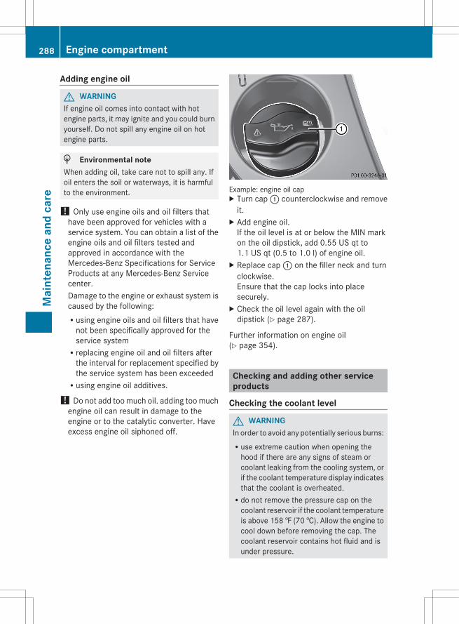
Adding engine oil
G WARNINGIf engine oil comes into contact with hotengine parts, it may ignite and you could burnyourself. Do not spill any engine oil on hotengine parts.
H Environmental noteWhen adding oil, take care not to spill any. Ifoil enters the soil or waterways, it is harmfulto the environment.
! Only use engine oils and oil filters thathave been approved for vehicles with aservice system. You can obtain a list of theengine oils and oil filters tested andapproved in accordance with theMercedes-Benz Specifications for ServiceProducts at any Mercedes-Benz Servicecenter.Damage to the engine or exhaust system iscaused by the following:Rusing engine oils and oil filters that have
not been specifically approved for theservice systemRreplacing engine oil and oil filters after
the interval for replacement specified bythe service system has been exceededRusing engine oil additives.
! Do not add too much oil. adding too muchengine oil can result in damage to theengine or to the catalytic converter. Haveexcess engine oil siphoned off.
Example: engine oil capX Turn cap : counterclockwise and remove
it.X Add engine oil.
If the oil level is at or below the MIN markon the oil dipstick, add 0.55 US qt to1.1 US qt (0.5 to 1.0 l) of engine oil.
X Replace cap : on the filler neck and turnclockwise.Ensure that the cap locks into placesecurely.
X Check the oil level again with the oildipstick (Y page 287).
Further information on engine oil(Y page 354).
Checking and adding other serviceproducts
Checking the coolant level
G WARNINGIn order to avoid any potentially serious burns:Ruse extreme caution when opening the
hood if there are any signs of steam orcoolant leaking from the cooling system, orif the coolant temperature display indicatesthat the coolant is overheated.Rdo not remove the pressure cap on the
coolant reservoir if the coolant temperatureis above 158 ‡ (70 †). Allow the engine tocool down before removing the cap. Thecoolant reservoir contains hot fluid and isunder pressure.
288 Engine compartmentM
aint
enan
ce a
nd c
are
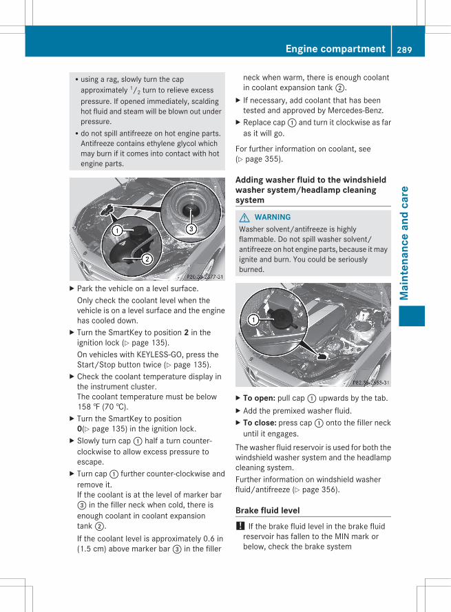
Rusing a rag, slowly turn the capapproximately 1/2 turn to relieve excesspressure. If opened immediately, scaldinghot fluid and steam will be blown out underpressure.Rdo not spill antifreeze on hot engine parts.
Antifreeze contains ethylene glycol whichmay burn if it comes into contact with hotengine parts.
X Park the vehicle on a level surface.Only check the coolant level when thevehicle is on a level surface and the enginehas cooled down.
X Turn the SmartKey to position 2 in theignition lock (Y page 135).On vehicles with KEYLESS-GO, press theStart/Stop button twice (Y page 135).
X Check the coolant temperature display inthe instrument cluster.The coolant temperature must be below158 ‡ (70 †).
X Turn the SmartKey to position0(Y page 135) in the ignition lock.
X Slowly turn cap : half a turn counter-clockwise to allow excess pressure toescape.
X Turn cap : further counter-clockwise andremove it.If the coolant is at the level of marker bar= in the filler neck when cold, there isenough coolant in coolant expansiontank ;.If the coolant level is approximately 0.6 in(1.5 cm) above marker bar = in the filler
neck when warm, there is enough coolantin coolant expansion tank ;.
X If necessary, add coolant that has beentested and approved by Mercedes-Benz.
X Replace cap : and turn it clockwise as faras it will go.
For further information on coolant, see(Y page 355).
Adding washer fluid to the windshieldwasher system/headlamp cleaningsystem
G WARNINGWasher solvent/antifreeze is highlyflammable. Do not spill washer solvent/antifreeze on hot engine parts, because it mayignite and burn. You could be seriouslyburned.
X To open: pull cap : upwards by the tab.X Add the premixed washer fluid.X To close: press cap : onto the filler neck
until it engages.The washer fluid reservoir is used for both thewindshield washer system and the headlampcleaning system.Further information on windshield washerfluid/antifreeze (Y page 356).
Brake fluid level! If the brake fluid level in the brake fluid
reservoir has fallen to the MIN mark orbelow, check the brake system
Engine compartment 289
Mai
nten
ance
and
car
e
Z

immediately for leaks. Also check thethickness of the brake linings. Visit aqualified specialist workshop immediately.Do not add brake fluid. This does notcorrect the malfunction.
Only check the brake fluid level when thevehicle is stationary and on a level surface.
If the brake fluid level is between MINmarking ; and MAX marking : on the brakefluid reservoir, it is correct.
Maintenance
Service interval display
Service messagesInformation on the type of service and serviceintervals (see separate MaintenanceBooklet).You can obtain further information from anauthorized Mercedes-Benz Center or athttp://www.mbusa.com (USA only).The service interval display informs you of thenext service due date.If a service due date has been exceeded, youalso hear an acoustic signal.The multifunction display shows a servicemessage for a few seconds, e.g.Next service A due in .. daysService A dueService A overdue by ... daysThe letter indicates which service is due. Astands for a minor service and B for a major
service. A number or another letter may bedisplayed after the letter. This figure indicatesany necessary additional maintenance workto be performed.You can obtain further information from anauthorized Mercedes-Benz Center.The service interval display does not take intoaccount any periods of time during which thebattery is disconnected.Maintaining the time-dependent serviceschedule:X Note down the service due date displayed
in the multifunction display beforedisconnecting the battery.
orX Subtract the battery disconnection periods
from the service date shown on the displayafter reconnecting the battery.
Hiding a service messageX Press the % or a button on the
steering wheel.
Displaying service messagesX Switch on the ignition.X Press = or ; on the steering wheel
to select the Serv. menu.X Press 9 or : to select the ASSYST PLUS submenu and press a to confirm.The service due date appears in themultifunction display.
Please bear the following in mind
Resetting service interval displayIf the qualified specialist workshop, e.g. aMercedes-Benz Center, carried out themaintenance work, the service intervaldisplay will be reset.Further information, on maintenance forexample, can be obtained at an authorizedMercedes-Benz Center or directly fromMercedes-Benz.
290 MaintenanceM
aint
enan
ce a
nd c
are
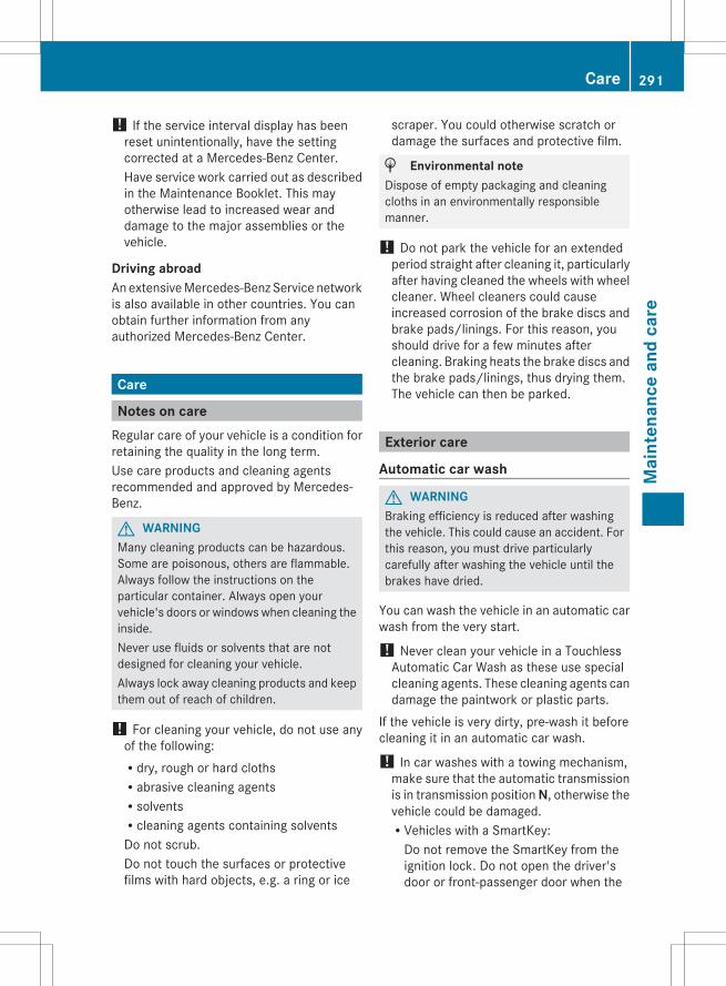
! If the service interval display has beenreset unintentionally, have the settingcorrected at a Mercedes-Benz Center.Have service work carried out as describedin the Maintenance Booklet. This mayotherwise lead to increased wear anddamage to the major assemblies or thevehicle.
Driving abroadAn extensive Mercedes-Benz Service networkis also available in other countries. You canobtain further information from anyauthorized Mercedes-Benz Center.
Care
Notes on careRegular care of your vehicle is a condition forretaining the quality in the long term.Use care products and cleaning agentsrecommended and approved by Mercedes-Benz.
G WARNINGMany cleaning products can be hazardous.Some are poisonous, others are flammable.Always follow the instructions on theparticular container. Always open yourvehicle's doors or windows when cleaning theinside.Never use fluids or solvents that are notdesigned for cleaning your vehicle.Always lock away cleaning products and keepthem out of reach of children.
! For cleaning your vehicle, do not use anyof the following:Rdry, rough or hard clothsRabrasive cleaning agentsRsolventsRcleaning agents containing solventsDo not scrub.Do not touch the surfaces or protectivefilms with hard objects, e.g. a ring or ice
scraper. You could otherwise scratch ordamage the surfaces and protective film.
H Environmental noteDispose of empty packaging and cleaningcloths in an environmentally responsiblemanner.
! Do not park the vehicle for an extendedperiod straight after cleaning it, particularlyafter having cleaned the wheels with wheelcleaner. Wheel cleaners could causeincreased corrosion of the brake discs andbrake pads/linings. For this reason, youshould drive for a few minutes aftercleaning. Braking heats the brake discs andthe brake pads/linings, thus drying them.The vehicle can then be parked.
Exterior care
Automatic car wash
G WARNINGBraking efficiency is reduced after washingthe vehicle. This could cause an accident. Forthis reason, you must drive particularlycarefully after washing the vehicle until thebrakes have dried.
You can wash the vehicle in an automatic carwash from the very start.
! Never clean your vehicle in a TouchlessAutomatic Car Wash as these use specialcleaning agents. These cleaning agents candamage the paintwork or plastic parts.
If the vehicle is very dirty, pre-wash it beforecleaning it in an automatic car wash.
! In car washes with a towing mechanism,make sure that the automatic transmissionis in transmission position N, otherwise thevehicle could be damaged.RVehicles with a SmartKey:
Do not remove the SmartKey from theignition lock. Do not open the driver'sdoor or front-passenger door when the
Care 291
Mai
nten
ance
and
car
e
Z
engine is switched off. Otherwise, theautomatic transmission selects parkposition P automatically and locks thewheels. You can prevent this by shiftingthe automatic transmission to Nbeforehand.RVehicles with KEYLESS-GO:
Do not open the driver's door or front-passenger door when the engine isswitched off. Otherwise, the automatictransmission selects park position Pautomatically and locks the wheels.
Observe the following to make sure that theautomatic transmission stays in position N:X Make sure the vehicle is stationary and the
ignition is switched off.X Turn the key to position 2(Y page 135) in
the ignition lock.Use the SmartKey instead of the Start/Stop button on vehicles with KEYLESS-GO.
X Depress and hold the brake pedal.X Shift the automatic transmission to
position N.X Release the brake pedal.X Release the parking brake.X Switch off the ignition and leave the
SmartKey in the ignition lock.
! Make sure that:Rthe side windows and the sliding sunroof
are fully closed.Rthe ventilation/heating is switched off
(the OFF button has been pressed).Rthe windshield wiper switch is in position
0.Otherwise, the vehicle might be damaged.
After using an automatic car wash, wipe offwax from the windshield and the wiperblades. This will prevent smears and reducewiping noises caused by residue on thewindshield.
Washing by handIn some countries, washing by hand is onlyallowed at specially equipped washing bays.Observe the legal requirements in allcountries concerned.X Do not use hot water and do not wash the
vehicle in direct sunlight.X Use a soft sponge to clean.X Use a mild cleaning agent, such as a car
shampoo approved by Mercedes-Benz.X Thoroughly hose down the vehicle with a
gentle jet of water.X Do not point the water jet directly towards
the air inlet.X Use plenty of water and rinse out the
sponge frequently.X Rinse the vehicle with clean water and dry
thoroughly with a chamois.X Do not let the cleaning agent dry on the
paintwork.When using the vehicle in winter, remove alltraces of road salt deposits carefully and assoon as possible.
Power washers
G WARNINGDo not use power washers with circular-jetnozzles (dirt grinders) to clean your vehicle, inparticular the tires. You could otherwisedamage the tires and cause an accident.
! Always maintain a distance of at least11.8 in (30 cm) between the vehicle and thepower washer nozzle. Information aboutthe correct distance is available from theequipment manufacturer.Move the power washer nozzle aroundwhen cleaning your vehicle.Do not aim directly at any of the following:RtiresRdoor gaps, roof gaps, joints, etc.Relectrical componentsRbattery
292 CareM
aint
enan
ce a
nd c
are
RconnectorsRlightsRsealsRtrimRventilation slotsDamaged seals or electrical componentscan lead to leaks or failures.
Cleaning the wheels! Do not use acidic wheel cleaning products
to remove brake dust. This could damagewheel bolts and brake components.
! Do not park the vehicle for an extendedperiod straight after cleaning it, particularlyafter having cleaned the wheels with wheelcleaner. Wheel cleaners could causeincreased corrosion of the brake discs andbrake pads/linings. For this reason, youshould drive for a few minutes aftercleaning. Braking heats the brake discs andthe brake pads/linings, thus drying them.The vehicle can then be parked.
Cleaning the paintworkScratches, corrosive deposits, areas affectedby corrosion and damage caused byinadequate care cannot always be completelyrepaired. In such cases, visit a qualifiedspecialist workshop.X Remove dirt immediately, where possible,
while avoiding rubbing too hard.X Soak insect remains with insect remover
and rinse off the treated areas afterwards.X Soak bird droppings with water and rinse
off the treated areas afterwards.X Remove coolant, brake fluid, tree resin,
oils, fuels and greases by rubbing gentlywith a cloth soaked in petroleum ether orlighter fluid.
X Use tar remover to remove tar stains.X Use silicone remover to remove wax.
! Do not affix:RstickersRfilmsRmagnetic plates or similar itemsto painted surfaces. You could otherwisedamage the paintwork.
If water no longer forms "beads" on the paintsurface, use the paint care productsrecommended and approved by Mercedes-Benz. This is the case approximately everythree to five months, depending on theclimate conditions and the care product used.If the dirt has penetrated the paint surface orif the paintwork has become dull, then thepaintwork should be cleaned. For cleaning,please use the paint cleaner recommend andapproved by Mercedes Benz.Do not use these care products in the sun oron the hood while the hood is hot.X Use a suitable touch-up stick, e.g. MB
Touch-Up Stick, to repair slight damage tothe paintwork quickly and provisionally.
Matte finish careIf your vehicle has a clear matte finish,observe the following instructions in order toavoid damage to the paintwork due toincorrect care.These notes also apply to light alloy wheelswith a clear matte finish.
! Never polish the vehicle or the light alloywheels. Polishing causes the finish toshine.
! The following may cause the paint tobecome shiny and thus reduce the matteeffect:RVigorous rubbing with unsuitable
materials.RFrequent use of car washes.RWashing the vehicle in direct sunlight.
! Never use paint cleaner, buffing orpolishing products, or gloss preserver, e.g.wax. These products are only suitable for
Care 293
Mai
nten
ance
and
car
e
Z
high-gloss surfaces. Their use on vehicleswith matte finish leads to considerablesurface damage (shiny, spotted areas).Always have paintwork repairs carried outat a qualified specialist workshop.
! Do not use wash programs with a hot waxtreatment under any circumstances.
i The vehicle should preferably be washedby hand using a soft sponge, car shampooand plenty of water.
i Use only insect remover and car shampoofrom the range of recommended andapproved Mercedes-Benz care products.
Cleaning the windows
G WARNINGBefore cleaning the windshield or wiperblades, switch off the windshield wipers andremove the SmartKey from the ignition lock.On vehicles with KEYLESS-GO, press theStart/Stop button repeatedly until allindicator lamps in the instrument cluster havegone out. The windshield wipers couldotherwise move and injure you.
X Clean the inside and outside of thewindows with a damp cloth and a cleaningagent that is recommended and approvedby Mercedes-Benz.
! Do not use dry cloths, abrasive products,solvents or cleaning agents containingsolvents to clean the inside of the windows.Do not touch the insides of the windowswith hard objects, e.g. an ice scraper orring. There is otherwise a risk of damagingthe windows.
! Clean the water drainage channels of thewindshield and the rear window at regularintervals. Deposits such as leaves, petalsand pollen may under certaincircumstances prevent water from drainingaway. This can lead to corrosion damageand damage to electronic components.
Cleaning the wiper blades
G WARNINGBefore cleaning the windshield or wiperblades, switch off the windshield wipers andremove the SmartKey from the ignition lock.On vehicles with KEYLESS-GO, press theStart/Stop button repeatedly until allindicator lamps in the instrument cluster havegone out. The windshield wipers couldotherwise move and injure you.
! Do not pull the wiper blade. Otherwise,the wiper blade could be damaged.
! Do not clean wiper blades too often anddo not rub them too hard. Otherwise, thegraphite coating could be damaged. Thiscould cause wiper noise.
X Fold the wiper arms away from thewindshield.
X Carefully clean the wiper blades with adamp cloth.
X Fold the windshield wipers back againbefore switching on the ignition.
! Hold the wiper arm securely when foldingback. The windshield could be damaged ifthe wiper arm smacks against it suddenly.
Cleaning the exterior lighting! Only use cleaning agents or cleaning
cloths which are suitable for plastic lightlenses. Unsuitable cleaning agents orcleaning cloths could scratch or damagethe plastic light lenses.
X Clean the plastic lenses of the exteriorlighting using a wet sponge and a mildcleaning agent, e.g. Mercedes-Benz carshampoo. Or clean the exterior lightingwith cleaning cloths.
Cleaning the mirror turn signals! Only use cleaning agents or cleaning
cloths that are suitable for plastic lenses.Unsuitable cleaning agents or cleaning
294 CareM
aint
enan
ce a
nd c
are

cloths could scratch or damage the plasticlenses of the mirror turn signals.
X Clean the plastic lenses of the mirror turnsignals using a wet sponge and a mildcleaning agent, e.g. Mercedes-Benz carshampoo. Cleaning cloths may be used aswell.
Cleaning the sensors
X Clean sensors : of the driving systemswith water, car shampoo and a soft cloth.
! If you clean the sensors with a powerwasher, make sure that you keep adistance of at least 11.8 in (30 cm) betweenthe vehicle and the power washer nozzle.Information about the correct distance isavailable from the equipmentmanufacturer.
Cleaning the rear view camera
X Use clear water and a soft cloth to cleancamera lens :.
! Do not clean the camera lens and the areaaround the rear view camera with a powerwasher.
Cleaning the exhaust pipesImpurities combined with the effects of roadgrit and corrosive environmental factors maycause flash rust to form on the surface. Youcan restore the original shine of the exhausttail pipe by cleaning it regularly, especially inwinter and after washing.
! Do not clean the exhaust tail pipes withalkaline-based cleaning agents, such aswheel cleaner.
X Clean the exhaust tail pipes with a chromecare product tested and approved byMercedes-Benz.
Interior care
Cleaning the displayX Before cleaning the display, make sure that
it is switched off and has cooled down.X Clean the display surface using a
commercially-available microfiber clothand TFT/LCD display cleaner.
X Dry the display surface using a drymicrofiber cloth.
Care 295
Mai
nten
ance
and
car
e
Z
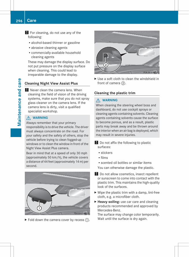
! For cleaning, do not use any of thefollowing:Ralcohol-based thinner or gasolineRabrasive cleaning agentsRcommercially-available household
cleaning agentsThese may damage the display surface. Donot put pressure on the display surfacewhen cleaning. This could lead toirreparable damage to the display.
Cleaning Night View Assist Plus! Never clean the camera lens. When
cleaning the field of vision of the drivingsystems, make sure that you do not sprayglass cleaner on the camera lens. If thecamera lens is dirty, visit a qualifiedspecialist workshop.
G WARNINGAlways remember that your primaryresponsibility is to drive the vehicle. The drivermust always concentrate on the road. Foryour safety and the safety of others, stop thevehicle before trying to clean fogged-upwindows or to clean the window in front of theNight View Assist Plus camera.Bear in mind that at a speed of only 30 mph(approximately 50 km/h), the vehicle coversa distance of 44 feet (approximately 14 m) persecond.
X Fold down the camera cover by recess :.
X Use a soft cloth to clean the windshield infront of camera ;.
Cleaning the plastic trim
G WARNINGWhen cleaning the steering wheel boss anddashboard, do not use cockpit sprays orcleaning agents containing solvents. Cleaningagents containing solvents cause the surfaceto become porous, and as a result, plasticparts may break away and be thrown aroundthe interior when an air bag is deployed, whichmay result in severe injuries.
! Do not affix the following to plasticsurfaces:RstickersRfilmsRscented oil bottles or similar itemsYou can otherwise damage the plastic.
! Do not allow cosmetics, insect repellentor sunscreen to come into contact with theplastic trim. This maintains the high-qualitylook of the surfaces.
X Wipe the plastic trim with a damp, lint-freecloth, e.g. a microfiber cloth.
X Heavy soiling: use car care and cleaningproducts recommended and approved byMercedes-Benz.The surface may change color temporarily.Wait until the surface is dry again.
296 CareM
aint
enan
ce a
nd c
are
Cleaning the steering wheel and gear orselector leverX Thoroughly wipe with a damp cloth or use
leather care agents that have beenrecommended and approved by Mercedes-Benz.
Cleaning genuine wood and trimelementsX Wipe the wooden trim and trim pieces with
a damp, lint-free cloth, e.g. a microfibercloth.
X Heavy soiling: use car care and cleaningproducts recommended and approved byMercedes-Benz.
! Do not use solvent-based cleaning agentssuch as tar remover, wheel cleaners,polishes or waxes. There is otherwise a riskof damaging the surface.
! Do not use chrome polish on trim pieces.The trim pieces have a chrome look but aremostly made of anodized aluminum andcan lose their shine if chrome polish isused. Use a damp, lint-free cloth insteadwhen cleaning the trim pieces.If the chrome-plated trim pieces are verydirty, you can use a chrome polish. If youare unsure as to whether the trim piecesare chrome-plated or not, consult anauthorized Mercedes-Benz Center.
Cleaning the seat covers! Do not use microfiber cloths to clean
genuine leather, artificial leather orAlcantara® covers. If used often, these candamage the cover.
! Observe the following when cleaning:Rclean genuine leather covers carefully
with a damp cloth and then wipe thecovers down with a dry cloth. Make surethat the leather does not becomesoaked. It may otherwise become roughand cracked. Only use leather care
agents that have been tested andapproved by Mercedes-Benz. You canobtain these from a qualified specialistworkshop.Rclean artificial leather covers with a cloth
moistened with a solution containing 1%detergent (e.g. dish washing liquid).Rclean cloth covers with a microfiber cloth
moistened with a solution containing 1%detergent (e.g. dish washing liquid). Rubcarefully and always wipe entire seatsections to avoid leaving visible lines.Leave the seat to dry afterwards.Cleaning results depend on the type ofdirt and how long it has been there.Rclean Alcantara® covers with a damp
cloth. Make sure that you wipe entireseat sections to avoid leaving visiblelines.
i Note that regular care is essential toensure that the appearance and comfort ofthe covers is retained over time.
Cleaning the seat beltsX Use clean, lukewarm water and soap
solution.
! Do not clean the seat belts using chemicalcleaning agents. Do not dry the seat beltsby heating at temperatures above 176 ‡(80 †) or in direct sunlight.
G WARNINGDo not bleach or dye seat belts as this mayseverely weaken them. In a crash, they maynot be able to provide adequate protection.
Cleaning the headliner and carpetsX Headliner: use a soft brush or a cleaning
agent recommended and approved byMercedes-Benz to remove heavy soiling.
X Carpets: use the carpet and textilecleaning agents recommended andapproved by Mercedes-Benz.
Care 297
Mai
nten
ance
and
car
e
Z

298
Useful information ............................ 300Where will I find...? ........................... 300Flat tire .............................................. 302Battery ............................................... 308Jump-starting .................................... 311Towing and tow-starting .................. 312Fuses .................................................. 315
299
Brea
kdow
n as
sist
ance
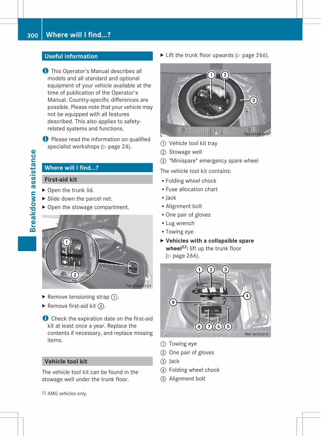
Useful information
i This Operator's Manual describes allmodels and all standard and optionalequipment of your vehicle available at thetime of publication of the Operator'sManual. Country-specific differences arepossible. Please note that your vehicle maynot be equipped with all featuresdescribed. This also applies to safety-related systems and functions.
i Please read the information on qualifiedspecialist workshops (Y page 24).
Where will I find...?
First-aid kitX Open the trunk lid.X Slide down the parcel net.X Open the stowage compartment.
X Remove tensioning strap :.X Remove first-aid kit ;.
i Check the expiration date on the first-aidkit at least once a year. Replace thecontents if necessary, and replace missingitems.
Vehicle tool kitThe vehicle tool kit can be found in thestowage well under the trunk floor.
X Lift the trunk floor upwards (Y page 266).
: Vehicle tool kit tray; Stowage well= "Minispare" emergency spare wheel
The vehicle tool kit contains:RFolding wheel chockRFuse allocation chartRJackRAlignment boltROne pair of glovesRLug wrenchRTowing eyeX Vehicles with a collapsible spare
wheel22: lift up the trunk floor(Y page 266).
: Towing eye; One pair of gloves= Jack? Folding wheel chockA Alignment bolt
22 AMG vehicles only.
300 Where will I find...?Br
eakd
own
assi
stan
ce
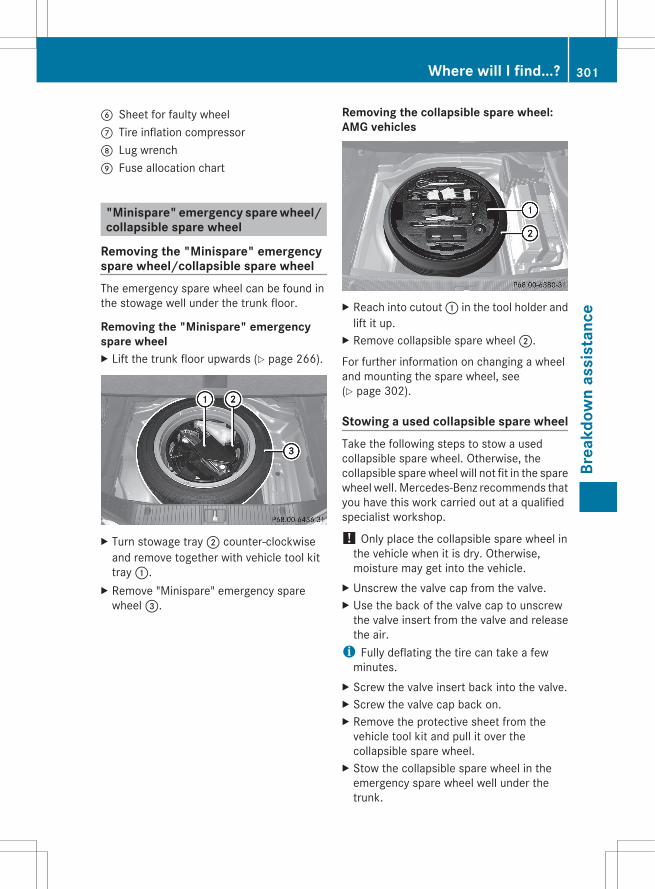
B Sheet for faulty wheelC Tire inflation compressorD Lug wrenchE Fuse allocation chart
"Minispare" emergency spare wheel/collapsible spare wheel
Removing the "Minispare" emergencyspare wheel/collapsible spare wheelThe emergency spare wheel can be found inthe stowage well under the trunk floor.
Removing the "Minispare" emergencyspare wheelX Lift the trunk floor upwards (Y page 266).
X Turn stowage tray ; counter-clockwiseand remove together with vehicle tool kittray :.
X Remove "Minispare" emergency sparewheel =.
Removing the collapsible spare wheel:AMG vehicles
X Reach into cutout : in the tool holder andlift it up.
X Remove collapsible spare wheel ;.
For further information on changing a wheeland mounting the spare wheel, see(Y page 302).
Stowing a used collapsible spare wheelTake the following steps to stow a usedcollapsible spare wheel. Otherwise, thecollapsible spare wheel will not fit in the sparewheel well. Mercedes-Benz recommends thatyou have this work carried out at a qualifiedspecialist workshop.
! Only place the collapsible spare wheel inthe vehicle when it is dry. Otherwise,moisture may get into the vehicle.
X Unscrew the valve cap from the valve.X Use the back of the valve cap to unscrew
the valve insert from the valve and releasethe air.
i Fully deflating the tire can take a fewminutes.
X Screw the valve insert back into the valve.X Screw the valve cap back on.X Remove the protective sheet from the
vehicle tool kit and pull it over thecollapsible spare wheel.
X Stow the collapsible spare wheel in theemergency spare wheel well under thetrunk.
Where will I find...? 301
Brea
kdow
n as
sist
ance
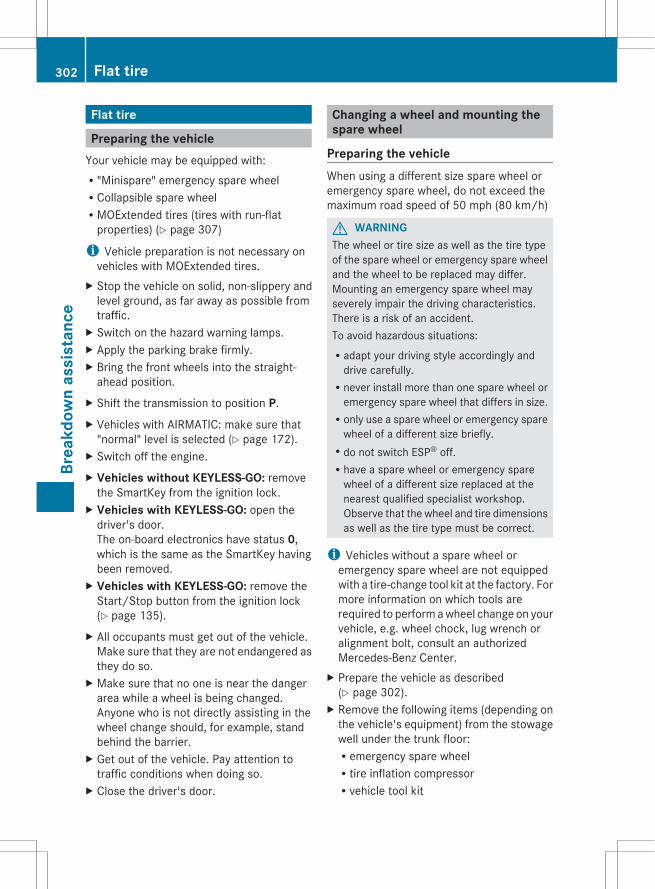
Flat tire
Preparing the vehicleYour vehicle may be equipped with:R"Minispare" emergency spare wheelRCollapsible spare wheelRMOExtended tires (tires with run-flat
properties) (Y page 307)
i Vehicle preparation is not necessary onvehicles with MOExtended tires.
X Stop the vehicle on solid, non-slippery andlevel ground, as far away as possible fromtraffic.
X Switch on the hazard warning lamps.X Apply the parking brake firmly.X Bring the front wheels into the straight-
ahead position.X Shift the transmission to position P.X Vehicles with AIRMATIC: make sure that
"normal" level is selected (Y page 172).X Switch off the engine.X Vehicles without KEYLESS-GO: remove
the SmartKey from the ignition lock.X Vehicles with KEYLESS-GO: open the
driver's door.The on-board electronics have status 0,which is the same as the SmartKey havingbeen removed.
X Vehicles with KEYLESS-GO: remove theStart/Stop button from the ignition lock(Y page 135).
X All occupants must get out of the vehicle.Make sure that they are not endangered asthey do so.
X Make sure that no one is near the dangerarea while a wheel is being changed.Anyone who is not directly assisting in thewheel change should, for example, standbehind the barrier.
X Get out of the vehicle. Pay attention totraffic conditions when doing so.
X Close the driver's door.
Changing a wheel and mounting thespare wheel
Preparing the vehicleWhen using a different size spare wheel oremergency spare wheel, do not exceed themaximum road speed of 50 mph (80 km/h)
G WARNINGThe wheel or tire size as well as the tire typeof the spare wheel or emergency spare wheeland the wheel to be replaced may differ.Mounting an emergency spare wheel mayseverely impair the driving characteristics.There is a risk of an accident.To avoid hazardous situations:Radapt your driving style accordingly and
drive carefully.Rnever install more than one spare wheel or
emergency spare wheel that differs in size.Ronly use a spare wheel or emergency spare
wheel of a different size briefly.Rdo not switch ESP® off.Rhave a spare wheel or emergency spare
wheel of a different size replaced at thenearest qualified specialist workshop.Observe that the wheel and tire dimensionsas well as the tire type must be correct.
i Vehicles without a spare wheel oremergency spare wheel are not equippedwith a tire-change tool kit at the factory. Formore information on which tools arerequired to perform a wheel change on yourvehicle, e.g. wheel chock, lug wrench oralignment bolt, consult an authorizedMercedes-Benz Center.
X Prepare the vehicle as described(Y page 302).
X Remove the following items (depending onthe vehicle's equipment) from the stowagewell under the trunk floor:Remergency spare wheelRtire inflation compressorRvehicle tool kit
302 Flat tireBr
eakd
own
assi
stan
ce
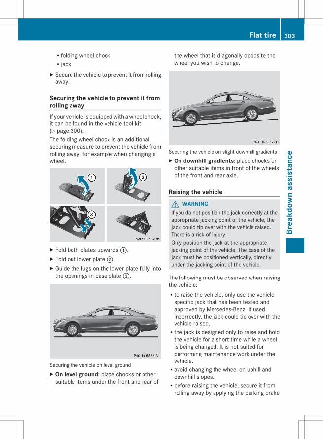
Rfolding wheel chockRjack
X Secure the vehicle to prevent it from rollingaway.
Securing the vehicle to prevent it fromrolling awayIf your vehicle is equipped with a wheel chock,it can be found in the vehicle tool kit(Y page 300).The folding wheel chock is an additionalsecuring measure to prevent the vehicle fromrolling away, for example when changing awheel.
X Fold both plates upwards :.X Fold out lower plate ;.X Guide the lugs on the lower plate fully into
the openings in base plate =.
Securing the vehicle on level groundX On level ground: place chocks or other
suitable items under the front and rear of
the wheel that is diagonally opposite thewheel you wish to change.
Securing the vehicle on slight downhill gradientsX On downhill gradients: place chocks or
other suitable items in front of the wheelsof the front and rear axle.
Raising the vehicle
G WARNINGIf you do not position the jack correctly at theappropriate jacking point of the vehicle, thejack could tip over with the vehicle raised.There is a risk of injury.Only position the jack at the appropriatejacking point of the vehicle. The base of thejack must be positioned vertically, directlyunder the jacking point of the vehicle.
The following must be observed when raisingthe vehicle:Rto raise the vehicle, only use the vehicle-
specific jack that has been tested andapproved by Mercedes-Benz. If usedincorrectly, the jack could tip over with thevehicle raised.Rthe jack is designed only to raise and hold
the vehicle for a short time while a wheelis being changed. It is not suited forperforming maintenance work under thevehicle.Ravoid changing the wheel on uphill and
downhill slopes.Rbefore raising the vehicle, secure it from
rolling away by applying the parking brake
Flat tire 303
Brea
kdow
n as
sist
ance
Z

and inserting wheel chocks. Neverdisengage the parking brake while thevehicle is raised.Rthe jack must be placed on a firm, flat and
non-slip surface. On a loose surface, alarge, load-bearing underlay must be used.On a slippery surface, a non-slip underlaymust be used, e.g. rubber mats.Rdo not use wooden blocks or similar
objects as a jack underlay. Otherwise, thejack will not be able to achieve its load-bearing capacity due to the restrictedheight.RThe maximum clearance between the
underside of the tire and the ground mustbe 1.2 in (3 cm).Rnever place your hands and feet under the
raised vehicle.Rnever lie under the raised vehicle.Rnever start the engine when the vehicle is
raised.Rnever open or close a door or the trunk lid
when the vehicle is raised.Rmake sure that no persons are present in
the vehicle when the vehicle is raised.
X Using lug wrench :, loosen the bolts onthe wheel you wish to change by about onefull turn. Do not unscrew the boltscompletely.
The jacking points are located just behind thewheel housings of the front wheels and justin front of the wheel housings of the rearwheels (arrows).
! The jack is designed exclusively forjacking up the vehicle at the jacking points.Otherwise, your vehicle could be damaged.
X Position jack = at jacking point ;.
X Make sure that the base of the jack ispositioned directly under the jacking point.
X Turn crank ? clockwise until jack = sitscompletely on jacking point ; and thebase of the jack lies evenly on the ground.
X Turn handle ? until the tire is 1.2 in(3 cm) from the ground at most.
304 Flat tireBr
eakd
own
assi
stan
ce
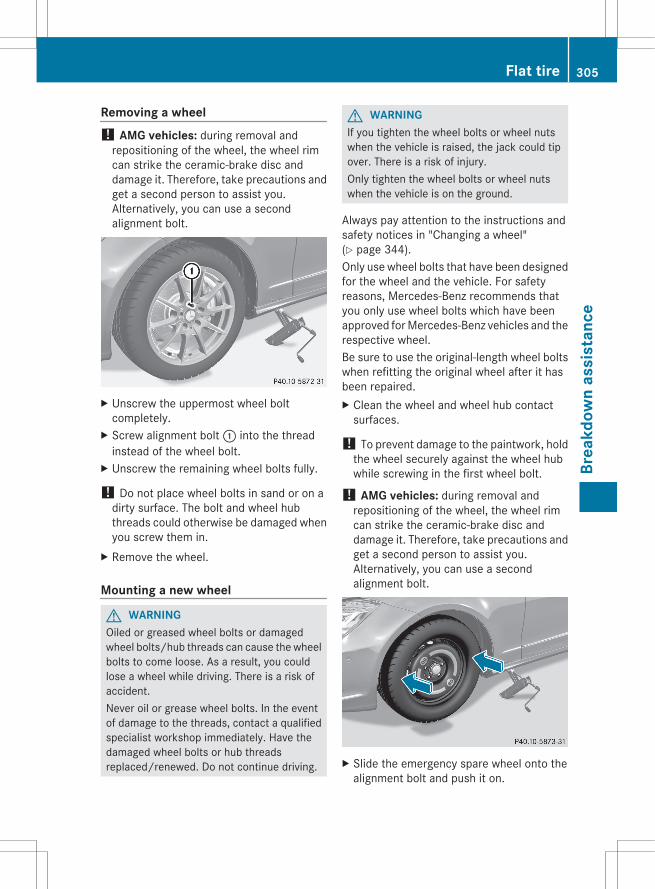
Removing a wheel! AMG vehicles: during removal and
repositioning of the wheel, the wheel rimcan strike the ceramic-brake disc anddamage it. Therefore, take precautions andget a second person to assist you.Alternatively, you can use a secondalignment bolt.
X Unscrew the uppermost wheel boltcompletely.
X Screw alignment bolt : into the threadinstead of the wheel bolt.
X Unscrew the remaining wheel bolts fully.
! Do not place wheel bolts in sand or on adirty surface. The bolt and wheel hubthreads could otherwise be damaged whenyou screw them in.
X Remove the wheel.
Mounting a new wheel
G WARNINGOiled or greased wheel bolts or damagedwheel bolts/hub threads can cause the wheelbolts to come loose. As a result, you couldlose a wheel while driving. There is a risk ofaccident.Never oil or grease wheel bolts. In the eventof damage to the threads, contact a qualifiedspecialist workshop immediately. Have thedamaged wheel bolts or hub threadsreplaced/renewed. Do not continue driving.
G WARNINGIf you tighten the wheel bolts or wheel nutswhen the vehicle is raised, the jack could tipover. There is a risk of injury.Only tighten the wheel bolts or wheel nutswhen the vehicle is on the ground.
Always pay attention to the instructions andsafety notices in "Changing a wheel"(Y page 344).Only use wheel bolts that have been designedfor the wheel and the vehicle. For safetyreasons, Mercedes-Benz recommends thatyou only use wheel bolts which have beenapproved for Mercedes-Benz vehicles and therespective wheel.Be sure to use the original-length wheel boltswhen refitting the original wheel after it hasbeen repaired.X Clean the wheel and wheel hub contact
surfaces.
! To prevent damage to the paintwork, holdthe wheel securely against the wheel hubwhile screwing in the first wheel bolt.
! AMG vehicles: during removal andrepositioning of the wheel, the wheel rimcan strike the ceramic-brake disc anddamage it. Therefore, take precautions andget a second person to assist you.Alternatively, you can use a secondalignment bolt.
X Slide the emergency spare wheel onto thealignment bolt and push it on.
Flat tire 305
Brea
kdow
n as
sist
ance
Z

X Tighten the wheel bolts until they arefinger-tight.
X Unscrew the alignment bolt.X Tighten the last wheel bolt until it is finger-
tight.X Vehicles with a collapsible spare
wheel: inflate the collapsible spare wheel(Y page 306) and then lower the vehicle(Y page 306).
orX Vehicles with the "Minispare"
emergency spare wheel: lower thevehicle (Y page 306).
Inflating the collapsible spare wheel! Inflate the collapsible spare wheel using
the tire inflation compressor beforelowering the vehicle. The wheel rim couldotherwise be damaged.
X Pull plug ? and the air hose out of thehousing.
X Remove the cap from the valve on thecollapsible spare wheel.
X Screw air hose union nut : onto the valve.X Make sure the tire inflation compressor's
on/off switch A is set to 0.X Insert plug ? into the socket of the
cigarette lighter (Y page 272) or into a 12 Vpower socket (Y page 273) in your vehicle.
X Make sure that the SmartKey is in position1 (Y page 135) in the ignition lock.
X Press on/off switch A on the tire inflationcompressor to I.The tire inflation compressor is switchedon. The tire is inflated. The tire pressure isread at pressure gauge =.
! Do not operate the tire inflationcompressor for longer than eight minutesat a time without a break. It may otherwiseoverheat.The tire inflation compressor can beoperated again once it has cooled down.
X Inflate the tire to the specified tirepressure.The specified tire pressure is printed on theyellow label of the emergency spare wheel.
X When the specified tire pressure has beenreached, press on/off switch A on the tireinflation compressor to 0.The tire inflation compressor is switchedoff.
X Turn the SmartKey to position 0 in theignition lock.
X If the tire pressure is higher than thespecified pressure, press pressure releasebutton ; until the correct tire pressure hasbeen reached.
X Unscrew air hose union nut : from thevalve.
X Screw the valve cap onto the collapsiblespare wheel valve again.
X Stow plug ? and the air hose in the lowersection of the compressor housing.
X Stow the tire inflation compressor in thevehicle.
Lowering the vehicle
G WARNINGTire pressure that is too high or too low canlead to a blowout of the mounted emergencyspare wheel/spare wheel, particularly when
306 Flat tireBr
eakd
own
assi
stan
ce
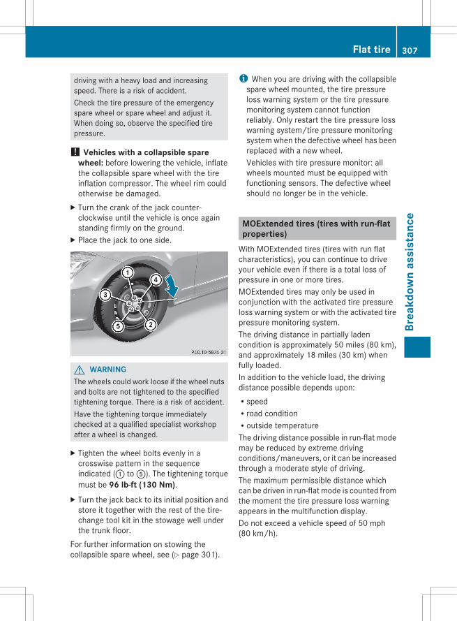
driving with a heavy load and increasingspeed. There is a risk of accident.Check the tire pressure of the emergencyspare wheel or spare wheel and adjust it.When doing so, observe the specified tirepressure.
! Vehicles with a collapsible spare wheel: before lowering the vehicle, inflatethe collapsible spare wheel with the tireinflation compressor. The wheel rim couldotherwise be damaged.
X Turn the crank of the jack counter-clockwise until the vehicle is once againstanding firmly on the ground.
X Place the jack to one side.
G WARNINGThe wheels could work loose if the wheel nutsand bolts are not tightened to the specifiedtightening torque. There is a risk of accident.Have the tightening torque immediatelychecked at a qualified specialist workshopafter a wheel is changed.
X Tighten the wheel bolts evenly in acrosswise pattern in the sequenceindicated (: to A). The tightening torquemust be 96 lb-ft (130 Nm).
X Turn the jack back to its initial position andstore it together with the rest of the tire-change tool kit in the stowage well underthe trunk floor.
For further information on stowing thecollapsible spare wheel, see (Y page 301).
i When you are driving with the collapsiblespare wheel mounted, the tire pressureloss warning system or the tire pressuremonitoring system cannot functionreliably. Only restart the tire pressure losswarning system/tire pressure monitoringsystem when the defective wheel has beenreplaced with a new wheel.Vehicles with tire pressure monitor: allwheels mounted must be equipped withfunctioning sensors. The defective wheelshould no longer be in the vehicle.
MOExtended tires (tires with run-flatproperties)
With MOExtended tires (tires with run flatcharacteristics), you can continue to driveyour vehicle even if there is a total loss ofpressure in one or more tires.MOExtended tires may only be used inconjunction with the activated tire pressureloss warning system or with the activated tirepressure monitoring system.The driving distance in partially ladencondition is approximately 50 miles (80 km),and approximately 18 miles (30 km) whenfully loaded.In addition to the vehicle load, the drivingdistance possible depends upon:RspeedRroad conditionRoutside temperatureThe driving distance possible in run-flat modemay be reduced by extreme drivingconditions/maneuvers, or it can be increasedthrough a moderate style of driving.The maximum permissible distance whichcan be driven in run-flat mode is counted fromthe moment the tire pressure loss warningappears in the multifunction display.Do not exceed a vehicle speed of 50 mph(80 km/h).
Flat tire 307
Brea
kdow
n as
sist
ance
Z
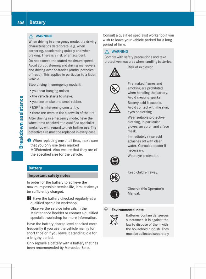
G WARNINGWhen driving in emergency mode, the drivingcharacteristics deteriorate, e.g. whencornering, accelerating quickly and whenbraking. There is a risk of an accident.Do not exceed the stated maximum speed.Avoid abrupt steering and driving maneuvers,and driving over obstacles (curbs, potholes,off-road). This applies in particular to a ladenvehicle.Stop driving in emergency mode if:Ryou hear banging noises.Rthe vehicle starts to shake.Ryou see smoke and smell rubber.RESP® is intervening constantly.Rthere are tears in the sidewalls of the tire.After driving in emergency mode, have thewheel rims checked at a qualified specialistworkshop with regard to their further use. Thedefective tire must be replaced in every case.
i When replacing one or all tires, make surethat you only use tires markedMOExtended. Also ensure that they are ofthe specified size for the vehicle.
Battery
Important safety notesIn order for the battery to achieve themaximum possible service life, it must alwaysbe sufficiently charged.
! Have the battery checked regularly at aqualified specialist workshop.Observe the service intervals in theMaintenance Booklet or contact a qualifiedspecialist workshop for more information.
Have the battery charge level checked morefrequently if you use the vehicle mainly forshort trips or if you leave it standing idle fora lengthy period.Only replace a battery with a battery that hasbeen recommended by Mercedes-Benz.
Consult a qualified specialist workshop if youwish to leave your vehicle parked for a longperiod of time.
G WARNINGComply with safety precautions and takeprotective measures when handling batteries.
Risk of explosion
Fire, naked flames andsmoking are prohibitedwhen handling the battery.Avoid creating sparks.Battery acid is caustic.Avoid contact with the skin,eyes or clothing.Wear suitable protectiveclothing, in particulargloves, an apron and a facemask.Immediately rinse acidsplashes off with cleanwater. Consult a doctor ifnecessary.Wear eye protection.
Keep children away.
Observe this Operator'sManual.
H Environmental noteBatteries contain dangeroussubstances. It is against thelaw to dispose of them withthe household rubbish. Theymust be collected separately
308 BatteryBr
eakd
own
assi
stan
ce

and recycled to protect theenvironment.Dispose of batteries in anenvironmentally friendlymanner. Take dischargedbatteries to a qualifiedspecialist workshop or aspecial collection point forused batteries.
G WARNINGFailure to follow these instructions can resultin severe injury or death.Never lean over batteries while connecting.You might get injured.Battery fluid contains sulfuric acid. Do notallow this fluid to come in contact with eyes,skin or clothing. In case it does, immediatelyflush affected area with water and seekmedical help if necessary.A battery will also produce hydrogen gas,which is flammable and explosive. Keepflames or sparks away from battery, avoidimproper connection of jumper cables,smoking etc.
G WARNINGDo not place any metal objects on the batteryas this could result in a short circuit.Use leak-proof batteries only to avoid the riskof acid burns in the event of an accident.Take care that you do not become staticallycharged, e.g. by wearing synthetic clothing orrubbing against textiles. For this reason, youalso should not pull or push the battery overcarpets or other synthetic materials.Never touch the battery first. First, touch theoutside body of the vehicle in order to releaseany possible electrostatic charges.Do not rub the battery with rags or cloths. Thebattery could explode if touched due toelectrostatic charge or due to sparkformation.
! Before working on the battery, e.g.loosening the battery terminals, switch off
the engine and remove the SmartKey fromthe ignition. On vehicles with KEYLESS-GO,make sure that the ignition is switched off.Check that all the indicator lamps in theinstrument cluster are off. You mayotherwise destroy electronic components,such as the alternator.
! Like other batteries, the vehicle batterymay discharge over time if you do not usethe vehicle. In this case, have the batterydisconnected at a qualified specialistworkshop. You can also charge the batterywith a charger recommended by Mercedes-Benz. Contact a qualified specialistworkshop for further information.The battery and the cover of the positiveterminal clamp must be installed securelyduring operation.
i Remove the SmartKey if you park thevehicle and do not require any electricalconsumers. The vehicle will then use verylittle energy, thus conserving batterypower.
Mercedes-Benz recommends that you do notcarry out work on batteries yourself, e.g.removing or charging. Have this workperformed at a qualified specialist workshop.
Charging the battery
G WARNINGNever charge a battery still installed in thevehicle unless a battery charger unit approvedby Mercedes-Benz is being used. Gases mayescape during charging and cause explosionsthat may result in paint damage, corrosion orpersonal injury.A battery charger unit specially adapted forMercedes-Benz vehicles and tested andapproved by Mercedes-Benz is available as anaccessory. It permits the charging of thebattery in its installed position. Contact anauthorized Mercedes-Benz Center for furtherinformation and availability.
Battery 309
Brea
kdow
n as
sist
ance
Z
Charge the battery in accordance with theseparate instructions for the battery charger.
G WARNINGThere is a risk of acid burns during thecharging process due to the gases whichescape from the battery. Do not lean over thebattery during the charging process.
G WARNINGBattery acid is caustic. Avoid contact with theskin, eyes or clothing.
! Only charge the installed battery with abattery charger which has been tested andapproved by Mercedes-Benz. These batterychargers allow the battery to be chargedwhile still installed in the vehicle.
! Only use battery chargers with amaximum charging voltage of 14.8 V.
! Only charge the battery using the jump-starting connection point.
The jump-starting connection point is in theengine compartment (Y page 311).X Open the hood (Y page 286).X Connect the battery charger to the positive
terminal and ground point in the sameorder as when connecting the donorbattery in the jump-starting procedure(Y page 311).
X Read the battery charger's operatinginstructions before charging the battery.
310 BatteryBr
eakd
own
assi
stan
ce

Jump-starting
G WARNINGFailure to follow these directions will cause damage to the electronic components, and can leadto a battery explosion and severe injury or death.Never lean over batteries while connecting or jump starting. You might get injured.Battery fluid contains sulfuric acid. Do not allow this fluid to come in contact with eyes, skin orclothing. In case it does, immediately flush affected area with water, and seek medical help ifnecessary.A battery will also produce hydrogen gas, which is flammable and explosive. Keep flames orsparks away from battery, avoid improper connection of jumper cables, smoking, etc.Attempting to jump start a frozen battery can result in it exploding, causing personal injury.Read all instructions before proceeding.
G WARNINGNon-combusted fuel can collect in the exhaust system and ignite. There is a risk of fire. Avoidrepeated and lengthy starting attempts.
! Avoid repeated and lengthy starting attempts. Otherwise, the catalytic converter could bedamaged by the non-combusted fuel.
Do not use a rapid charging device to start the vehicle. If your vehicle's battery is discharged,the engine can be jump-started from another vehicle or from a second battery using jumpercables. Observe the following points:RThe battery is not accessible in all vehicles. If the other vehicle's battery is not accessible,
jump-start the vehicle using a second battery or a jump-starting device.RYou may only jump-start the vehicle when the engine and catalytic converter are cold.RDo not start the engine if the battery is frozen. Let the battery thaw first.Rjump-starting may only be performed from batteries with a nominal voltage of 12 V.ROnly use jumper cables which have a sufficient cross-section and insulated terminal clamps.RIf the battery is fully discharged, leave the battery that is being used to jump-start connected
for a few minutes before attempting to start. This charges the empty battery a little.RMake sure that the two vehicles do not touch.Make sure that:Rthe jumper cables are not damaged.Rbare parts of the terminal clamp do not come into contact with other metal parts while the
jumper cables are connected to the battery.Rthe jumper cables cannot come into contact with parts such as the V-belt pulley or the fan.
These parts move when the engine is started and while it is running.X Apply the parking brake firmly.X Shift the transmission to position P.X Switch off all electrical consumers (e.g. radio, blower, etc.).X Open the hood (Y page 286).
Jump-starting 311
Brea
kdow
n as
sist
ance
Z
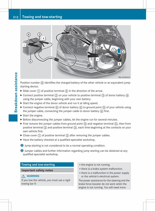
Position number B identifies the charged battery of the other vehicle or an equivalent jump-starting device.X Slide cover : of positive terminal ; in the direction of the arrow.X Connect positive terminal ; on your vehicle to positive terminal = of donor battery B
using the jumper cable, beginning with your own battery.X Start the engine of the donor vehicle and run it at idling speed.X Connect negative terminal ? of donor battery B to ground point A of your vehicle using
the jumper cable, connecting the jumper cable to donor battery B first.X Start the engine.X Before disconnecting the jumper cables, let the engine run for several minutes.X First remove the jumper cables from ground point A and negative terminal ?, then from
positive terminal ; and positive terminal =, each time beginning at the contacts on yourown vehicle first.
X Close cover : of positive terminal ; after removing the jumper cables.X Have the battery checked at a qualified specialist workshop.
i Jump-starting is not considered to be a normal operating condition.
i Jumper cables and further information regarding jump starting can be obtained at anyqualified specialist workshop.
Towing and tow-starting
Important safety notes
G WARNINGIf you tow the vehicle, you must use a rigidtowing bar if:
Rthe engine is not running.Rthere is a brake system malfunction.Rthere is a malfunction in the power supply
or the vehicle's electrical system.The power assistance for the steering and thebrake force booster do not work when theengine is not running. You will need more
312 Towing and tow-startingBr
eakd
own
assi
stan
ce
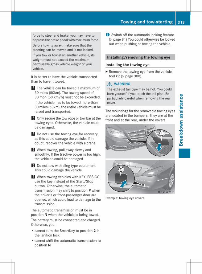
force to steer and brake, you may have todepress the brake pedal with maximum force.Before towing away, make sure that thesteering can be moved and is not locked.If you tow or tow-start another vehicle, itsweight must not exceed the maximumpermissible gross vehicle weight of yourvehicle.
It is better to have the vehicle transportedthan to have it towed.
! The vehicle can be towed a maximum of30 miles (50km). The towing speed of30 mph (50 km/h) must not be exceeded.If the vehicle has to be towed more than30 miles (50km), the entire vehicle must beraised and transported.
! Only secure the tow rope or tow bar at thetowing eyes. Otherwise, the vehicle couldbe damaged.
! Do not use the towing eye for recovery,as this could damage the vehicle. If indoubt, recover the vehicle with a crane.
! When towing, pull away slowly andsmoothly. If the tractive power is too high,the vehicles could be damaged.
! Do not tow with sling-type equipment.This could damage the vehicle.
! When towing vehicles with KEYLESS-GO,use the key instead of the Start/Stopbutton. Otherwise, the automatictransmission may shift to position P whenthe driver's or front-passenger door areopened, which could lead to damage to thetransmission.
The automatic transmission must be inposition N when the vehicle is being towed.The battery must be connected and charged.Otherwise, you:Rcannot turn the SmartKey to position 2 in
the ignition lockRcannot shift the automatic transmission to
position N
i Switch off the automatic locking feature(Y page 81) You could otherwise be lockedout when pushing or towing the vehicle.
Installing/removing the towing eye
Installing the towing eyeX Remove the towing eye from the vehicle
tool kit (Y page 300).
G WARNINGThe exhaust tail pipe may be hot. You couldburn yourself if you touch the tail pipe. Beparticularly careful when removing the rearcover.
The mountings for the removable towing eyesare located in the bumpers. They are at thefront and at the rear, under the covers.
Example: towing eye covers
Towing and tow-starting 313
Brea
kdow
n as
sist
ance
Z
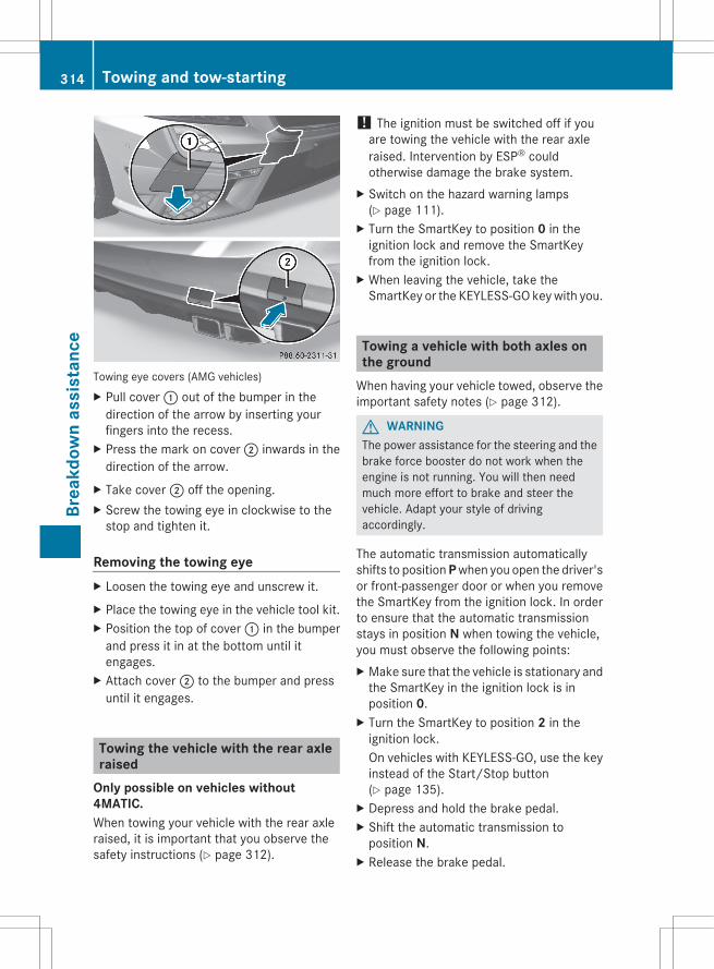
Towing eye covers (AMG vehicles)X Pull cover : out of the bumper in the
direction of the arrow by inserting yourfingers into the recess.
X Press the mark on cover ; inwards in thedirection of the arrow.
X Take cover ; off the opening.X Screw the towing eye in clockwise to the
stop and tighten it.
Removing the towing eyeX Loosen the towing eye and unscrew it.X Place the towing eye in the vehicle tool kit.X Position the top of cover : in the bumper
and press it in at the bottom until itengages.
X Attach cover ; to the bumper and pressuntil it engages.
Towing the vehicle with the rear axleraised
Only possible on vehicles without 4MATIC.When towing your vehicle with the rear axleraised, it is important that you observe thesafety instructions (Y page 312).
! The ignition must be switched off if youare towing the vehicle with the rear axleraised. Intervention by ESP® couldotherwise damage the brake system.
X Switch on the hazard warning lamps(Y page 111).
X Turn the SmartKey to position 0 in theignition lock and remove the SmartKeyfrom the ignition lock.
X When leaving the vehicle, take theSmartKey or the KEYLESS-GO key with you.
Towing a vehicle with both axles onthe ground
When having your vehicle towed, observe theimportant safety notes (Y page 312).
G WARNINGThe power assistance for the steering and thebrake force booster do not work when theengine is not running. You will then needmuch more effort to brake and steer thevehicle. Adapt your style of drivingaccordingly.
The automatic transmission automaticallyshifts to position P when you open the driver'sor front-passenger door or when you removethe SmartKey from the ignition lock. In orderto ensure that the automatic transmissionstays in position N when towing the vehicle,you must observe the following points:X Make sure that the vehicle is stationary and
the SmartKey in the ignition lock is inposition 0.
X Turn the SmartKey to position 2 in theignition lock.On vehicles with KEYLESS-GO, use the keyinstead of the Start/Stop button(Y page 135).
X Depress and hold the brake pedal.X Shift the automatic transmission to
position N.X Release the brake pedal.
314 Towing and tow-startingBr
eakd
own
assi
stan
ce
X Release the parking brake.X Switch on the hazard warning lamps
(Y page 111).X Leave the SmartKey in position 2 in the
ignition lock.i When towing with the hazard warning
lamps switched on, use the combinationswitch as usual to signal a change ofdirection. In this case, only the turn signalsfor the desired direction flash. When thecombination switch is reset, the hazardwarning lamps start flashing again.
Transporting the vehicleThe towing eye can be used to pull the vehicleonto a trailer or transporter for transportingpurposes.X Turn the SmartKey to position 2 in the
ignition lock.X Shift the automatic transmission to
position N.
As soon as the vehicle is loaded:X Prevent the vehicle from rolling away by
applying the parking brake.X Shift the automatic transmission to
position P.X Turn the SmartKey to position 0 in the
ignition lock and remove the SmartKeyfrom the ignition lock.
X Secure the vehicle.
! Only lash the vehicle down by the wheelsor wheel rims, not by parts of the vehiclesuch as axle or steering components.Otherwise, the vehicle could be damaged.
Notes for 4MATIC vehicles! Vehicles with 4MATIC must not be towed
with either the front or the rear axle raised,as doing so will damage the transmission.
If the vehicle has transmission damage ordamage to the front or rear axle, have ittransported on a transporter or trailer.In the event of damage to the electrical systemIf the battery is defective, the automatictransmission will be locked in position P. Toshift the automatic transmission to positionN, you must provide power to the vehicle'selectrical system in the same way as whenjump-starting (Y page 311).Have the vehicle transported on a transporteror trailer.
Tow-starting (emergency starting)! Vehicles with automatic transmission
must not be started by tow-starting. Thiscould otherwise damage the transmission.
For further information on "Jump-starting"see (Y page 311).
Fuses
Important safety notes
G WARNINGOnly use fuses that have been approved forMercedes-Benz vehicles and that have thecorrect fuse rating for the systemsconcerned. Do not attempt to repair or bridgefaulty fuses. Using fuses that have not beenapproved or attempting to repair or bridgefaulty fuses could cause the fuse to beoverloaded and result in a fire. Have the causetraced and rectified at a qualified specialistworkshop.
The fuses in your vehicle serve to close downfaulty circuits. If a fuse blows, all thecomponents on the circuit and their functionsstop operating.Blown fuses must be replaced with fuses ofthe same rating, which you can recognize bythe color and value. The fuse ratings are listedin the fuse allocation chart.
Fuses 315
Brea
kdow
n as
sist
ance
Z
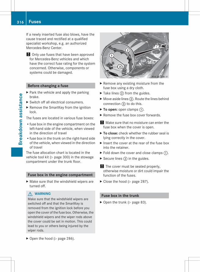
If a newly inserted fuse also blows, have thecause traced and rectified at a qualifiedspecialist workshop, e.g. an authorizedMercedes-Benz Center.
! Only use fuses that have been approvedfor Mercedes-Benz vehicles and whichhave the correct fuse rating for the systemconcerned. Otherwise, components orsystems could be damaged.
Before changing a fuseX Park the vehicle and apply the parking
brake.X Switch off all electrical consumers.X Remove the SmartKey from the ignition
lock.The fuses are located in various fuse boxes:Rfuse box in the engine compartment on the
left-hand side of the vehicle, when viewedin the direction of travelRfuse box in the trunk on the right-hand side
of the vehicle, when viewed in the directionof travel
The fuse allocation chart is located in thevehicle tool kit (Y page 300) in the stowagecompartment under the trunk floor.
Fuse box in the engine compartmentX Make sure that the windshield wipers are
turned off.
G WARNINGMake sure that the windshield wipers areswitched off and that the SmartKey isremoved from the ignition lock before youopen the cover of the fuse box. Otherwise, thewindshield wipers and the wiper rods abovethe cover could be set in motion. This couldlead to you or others being injured by thewiper rods.
X Open the hood (Y page 286).
X Remove any existing moisture from thefuse box using a dry cloth.
X Take lines ; from the guides.X Move aside lines ;. Route the lines behind
connection = to do this.X To open: open clamps :.X Remove the fuse box cover forwards.
! Make sure that no moisture can enter thefuse box when the cover is open.
X To close: check whether the rubber seal islying correctly in the cover.
X Insert the cover at the rear of the fuse boxinto the retainer.
X Fold down the cover and close clamps :.X Secure lines ; in the guides.
! The cover must be seated properly,otherwise moisture or dirt could impair thefunction of the fuses.
X Close the hood (Y page 287).
Fuse box in the trunkX Open the trunk (Y page 83).
316 FusesBr
eakd
own
assi
stan
ce
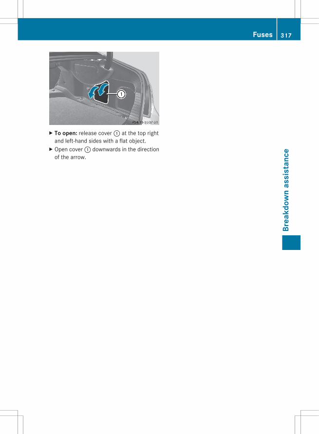
X To open: release cover : at the top rightand left-hand sides with a flat object.
X Open cover : downwards in the directionof the arrow.
Fuses 317
Brea
kdow
n as
sist
ance
Z

318
Useful information ............................ 320Important safety notes .................... 320Operation ........................................... 320Winter operation ............................... 322Tire pressure ..................................... 324Loading the vehicle .......................... 331Maximum load rating ....................... 335Uniform Tire Quality GradingStandards .......................................... 336Tire labeling ....................................... 337Definition of terms for tires andloading ............................................... 341Changing a wheel ............................. 344Wheel and tire combinations ........... 344
319
Whe
els
and
tires
Useful information
i This Operator's Manual describes allmodels and all standard and optionalequipment of your vehicle available at thetime of publication of the Operator'sManual. Country-specific differences arepossible. Please note that your vehicle maynot be equipped with all featuresdescribed. This also applies to safety-related systems and functions.
i Please read the information on qualifiedspecialist workshops (Y page 24).
Important safety notes
G WARNINGIf wheels and tires of the wrong size are used,the wheel brakes or suspension componentsmay be damaged. There is a risk of accident.Always replace wheels and tires with thosethat fulfill the specifications of the originalpart (designation, manufacturer, model).
G WARNINGA flat tire severely impairs the driving,steering and braking characteristics of thevehicle. There is a risk of accident.Tires without run-flat characteristics:Rdo not drive with a flat tire.Rimmediately replace the flat tire with your
emergency spare wheel or spare wheel, orconsult a qualified specialist workshop.
Tires with run-flat characteristics:Rpay attention to the information and
warning notices on MOExtended tires (tireswith run-flat characteristics).
Accessories that are not approved for yourvehicle by Mercedes-Benz or are not beingused correctly can impair the operatingsafety.
Before purchasing and using non-approvedaccessories, visit a qualified specialistworkshop and inquire about:RsuitabilityRlegal stipulationsRfactory recommendationsInformation on the dimensions and types ofwheels and tires for your vehicle can be foundin the "Wheel/tire combinations" section(Y page 344).Information on air pressure for the tires onyour vehicle can be found:Ron the vehicle's Tire and Loading
Information placard on the B-pillarRon the tire pressure label on the fuel filler
flapRin the "Tire pressure" sectionPay special attention to the country-specificrequirements for tire approval. Theserequirements can stipulate a specific tire typefor your vehicle. Furthermore, the use ofcertain tire types in certain regions and areasof operation can be highly beneficial. You canfind further information regarding tires atspecialist tire retailers, at qualified specialistworkshops or at any authorized Mercedes-Benz Center.
i Further information on wheels and tirescan be obtained at any qualified specialistworkshop.
Operation
Notes on drivingRIf the vehicle is heavily laden, check the tire
pressures and correct them if necessary.RWhen parking your vehicle, make sure that
the tires do not get deformed by the curbor other obstacles. If it is necessary to driveover curbs, speed humps or similarelevations, try to do so slowly and at anobtuse angle. Otherwise, the tires,particularly the sidewalls, can getdamaged.
320 OperationW
heel
s an
d tir
es
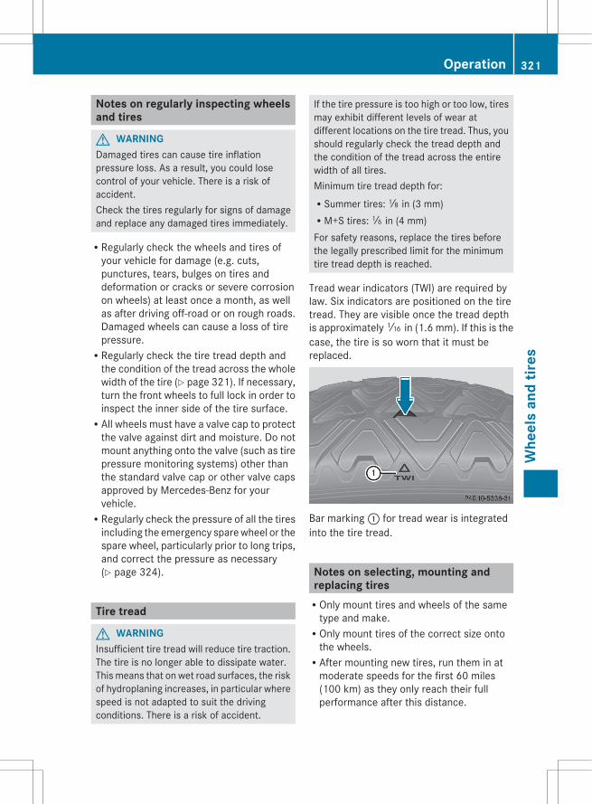
Notes on regularly inspecting wheelsand tires
G WARNINGDamaged tires can cause tire inflationpressure loss. As a result, you could losecontrol of your vehicle. There is a risk ofaccident.Check the tires regularly for signs of damageand replace any damaged tires immediately.
RRegularly check the wheels and tires ofyour vehicle for damage (e.g. cuts,punctures, tears, bulges on tires anddeformation or cracks or severe corrosionon wheels) at least once a month, as wellas after driving off-road or on rough roads.Damaged wheels can cause a loss of tirepressure.RRegularly check the tire tread depth and
the condition of the tread across the wholewidth of the tire (Y page 321). If necessary,turn the front wheels to full lock in order toinspect the inner side of the tire surface.RAll wheels must have a valve cap to protect
the valve against dirt and moisture. Do notmount anything onto the valve (such as tirepressure monitoring systems) other thanthe standard valve cap or other valve capsapproved by Mercedes-Benz for yourvehicle.RRegularly check the pressure of all the tires
including the emergency spare wheel or thespare wheel, particularly prior to long trips,and correct the pressure as necessary(Y page 324).
Tire tread
G WARNINGInsufficient tire tread will reduce tire traction.The tire is no longer able to dissipate water.This means that on wet road surfaces, the riskof hydroplaning increases, in particular wherespeed is not adapted to suit the drivingconditions. There is a risk of accident.
If the tire pressure is too high or too low, tiresmay exhibit different levels of wear atdifferent locations on the tire tread. Thus, youshould regularly check the tread depth andthe condition of the tread across the entirewidth of all tires.Minimum tire tread depth for:RSummer tires: â in (3 mm)RM+S tires: ã in (4 mm)For safety reasons, replace the tires beforethe legally prescribed limit for the minimumtire tread depth is reached.
Tread wear indicators (TWI) are required bylaw. Six indicators are positioned on the tiretread. They are visible once the tread depthis approximately á in (1.6 mm). If this is thecase, the tire is so worn that it must bereplaced.
Bar marking : for tread wear is integratedinto the tire tread.
Notes on selecting, mounting andreplacing tiresROnly mount tires and wheels of the same
type and make.ROnly mount tires of the correct size onto
the wheels.RAfter mounting new tires, run them in at
moderate speeds for the first 60 miles(100 km) as they only reach their fullperformance after this distance.
Operation 321
Whe
els
and
tires
Z
RDo not drive with tires which have too littletread depth, as this significantly reducesthe traction on wet roads (hydroplaning).RReplace the tires after six years at the
latest, regardless of wear. This also appliesto the spare wheel/emergency sparewheel.
The service life of tires depends on thefollowing factors amongst other things:Rdriving styleRtire pressureRdistance covered
MOExtended tires (tires with run-flatproperties)
MOExtended tires (tires with run-flatproperties) allow you to continue driving yourvehicle even if one or more tires are entirelydeflated.MOExtended tires may be used only inconjunction with the activated tire pressureloss warning system or the activated tirepressure monitoring system and only onwheels specifically tested by Mercedes-Benz.Notes on driving with MOExtended tires in theevent of a flat tire can be found in the"Breakdown assistance" section(Y page 307).
Winter operation
Please bear the following in mindHave your vehicle winterproofed at a qualifiedspecialist workshop at the onset of winter.Observe the notes in the "Changing a wheel"section (Y page 344).
Driving with summer tiresAt temperatures below 45 ‡ (+7 †), theelasticity of summer tires and therefore alsothe traction and braking capability arereduced considerably. Mount M+S tires on
your vehicle. Using summer tires at very coldtemperatures could cause cracks to form,thereby damaging the tires permanently.Mercedes-Benz cannot accept responsibilityfor this type of damage.
M+S tiresAt temperatures below 45 ‡ (+7 †), usewinter tires or all-season tires. Both types oftire are identified by the M+S marking.Only winter tires bearing the i snowflakesymbol in addition to the M+S markingprovide the best possible grip in wintry roadconditions. Only these tires will allow drivingsafety systems such as ABS and ESP® tofunction optimally in winter. These tires havebeen developed specifically for driving insnow.Use M+S tires of the same make and tread onall wheels to maintain safe handlingcharacteristics.
G WARNINGM+S tires with a tire tread depth of less thanã in (4 mm) are not suitable for use in winterand do not provide sufficient traction. Thereis a risk of an accident.M+S tires with a tread depth of less than ãin (4 mm) must be replaced immediately.
Always observe the maximum permissiblespeed specified for the M+S tires you havemounted.When you have mounted M+S tires:X Check the tire pressures (Y page 327).X Vehicles for Canada: restart the tire
pressure loss warning system(Y page 327).
X Restart the tire pressure monitor(Y page 328).
Drive no faster than 50 mph (80 km/h) withthe spare wheel or emergency spare wheelmounted.
322 Winter operationW
heel
s an
d tir
es
G WARNINGThe wheel or tire size as well as the tire typeof the spare wheel or emergency spare wheeland the wheel to be replaced may differ.Mounting an emergency spare wheel mayseverely impair the driving characteristics.There is a risk of an accident.To avoid hazardous situations:Radapt your driving style accordingly and
drive carefully.Rnever install more than one spare wheel or
emergency spare wheel that differs in size.Ronly use a spare wheel or emergency spare
wheel of a different size briefly.Rdo not switch ESP® off.Rhave a spare wheel or emergency spare
wheel of a different size replaced at thenearest qualified specialist workshop.Observe that the wheel and tire dimensionsas well as the tire type must be correct.
Snow chainsFor safety reasons, Mercedes-Benzrecommends that you only use snow chainsthat have been specially approved for yourvehicle by Mercedes-Benz, or are of acorresponding standard of quality.
! On vehicles with AIRMATIC, you mustdrive at raised vehicle level if snow chainshave been mounted. The vehicle mayotherwise be damaged.
! On some tire sizes there is not enoughspace for snow chains. To avoid damage tothe vehicle or tires, observe the "Wheel andtire combinations" section under "Tires andwheels".Ronly use snow chains when driving on roads
completely covered by snow. Do notexceed the maximum permissible speed of30 mph (50 km/h). Remove the snow
chains as soon as possible if you are drivingon roads that are no longer snow-covered.Rlocal regulations may restrict the use of
snow chains. Observe the appropriateregulations if you wish to mount snowchains.Rsnow chains may not be mounted on the
emergency spare wheel.If you intend to mount snow chains, pleasebear the following points in mind:Rsnow chains may not be mounted on all
wheel/tire combinations. Permittedwheel/tire combinations (Y page 344).Rmount snow chains only in pairs and only
on the rear wheels. Observe themanufacturer's mounting instructions.
! If snow chains are mounted on the frontwheels, the snow chains could grindagainst the bodywork or components of thechassis. This could result in damage to thevehicle or the tires.
! Vehicles with steel wheels: if you wishto mount snow chains on steel wheels,make sure that you remove the respectivewheels' hubcaps first. The hubcaps mayotherwise be damaged.
i You may wish to deactivateESP®(Y page 65) when pulling away withsnow chains mounted. This way you canallow the wheels to spin in a controlledmanner, achieving an increased drivingforce (cutting action).
Winter operation 323
Whe
els
and
tires
Z
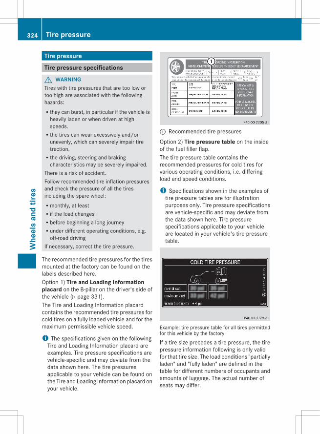
Tire pressure
Tire pressure specifications
G WARNINGTires with tire pressures that are too low ortoo high are associated with the followinghazards:Rthey can burst, in particular if the vehicle is
heavily laden or when driven at highspeeds.Rthe tires can wear excessively and/or
unevenly, which can severely impair tiretraction.Rthe driving, steering and braking
characteristics may be severely impaired.There is a risk of accident.Follow recommended tire inflation pressuresand check the pressure of all the tiresincluding the spare wheel:Rmonthly, at leastRif the load changesRbefore beginning a long journeyRunder different operating conditions, e.g.
off-road drivingIf necessary, correct the tire pressure.
The recommended tire pressures for the tiresmounted at the factory can be found on thelabels described here.Option 1) Tire and Loading Information placard on the B-pillar on the driver's side ofthe vehicle (Y page 331).The Tire and Loading Information placardcontains the recommended tire pressures forcold tires on a fully loaded vehicle and for themaximum permissible vehicle speed.
i The specifications given on the followingTire and Loading Information placard areexamples. Tire pressure specifications arevehicle-specific and may deviate from thedata shown here. The tire pressuresapplicable to your vehicle can be found onthe Tire and Loading Information placard onyour vehicle.
: Recommended tire pressures
Option 2) Tire pressure table on the insideof the fuel filler flap.The tire pressure table contains therecommended pressures for cold tires forvarious operating conditions, i.e. differingload and speed conditions.
i Specifications shown in the examples oftire pressure tables are for illustrationpurposes only. Tire pressure specificationsare vehicle-specific and may deviate fromthe data shown here. Tire pressurespecifications applicable to your vehicleare located in your vehicle's tire pressuretable.
Example: tire pressure table for all tires permittedfor this vehicle by the factory
If a tire size precedes a tire pressure, the tirepressure information following is only validfor that tire size. The load conditions "partiallyladen" and "fully laden" are defined in thetable for different numbers of occupants andamounts of luggage. The actual number ofseats may differ.
324 Tire pressureW
heel
s an
d tir
es
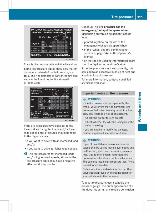
Example: tire pressure table with tire dimensions
Some tire pressure tables show only the rimdiameters instead of the full tire size, e.g.R18. The rim diameter is part of the tire sizeand can be found on the tire sidewall(Y page 338).
If the tire pressures have been set to thelower values for lighter loads and/or lowerroad speeds, the pressures should be resetto the higher values:Rif you want to drive with an increased load
and/orRif you want to drive at higher road speeds.
i The tire pressures for increased loadsand/or higher road speeds, shown in thetire pressure table, may have a negativeeffect on driving comfort.
Option 3) The tire pressure for the emergency/collapsible spare wheel(depending on vehicle equipment) can befound:Rprinted in yellow on the rim of the
emergency/collapsible spare wheelRin the "Wheel and tire combinations"
section (Y page 344) in this Operator'sManualRon the Tire and Loading Information placard
on the B-pillar on the driver's side.If the tire pressure is not set correctly, thiscan lead to an excessive build up of heat anda sudden loss of pressure.For more information, contact a qualifiedspecialist workshop.
Important notes on tire pressure
G WARNINGIf the tire pressure drops repeatedly, thewheel, valve or tire may be damaged. Tirepressure that is too low may result in a tireblow-out. There is a risk of an accident.RCheck the tire for foreign objects.RCheck whether the wheel is losing air or the
valve is leaking.If you are unable to rectify the damage,contact a qualified specialist workshop.
G WARNINGIf you fit unsuitable accessories onto tirevalves, the tire valves may be overloaded andmalfunction, which can cause tire pressureloss. Due to their design, retrofitted tirepressure monitors keep the tire valve open.This can also result in tire pressure loss. Thereis a risk of an accident.Only screw the standard valve cap or othervalve caps approved by Mercedes-Benz foryour vehicle onto the tire valve.
To test tire pressure, use a suitable tirepressure gauge. The outer appearance of atire does not permit any reliable conclusion
Tire pressure 325
Whe
els
and
tires
Z
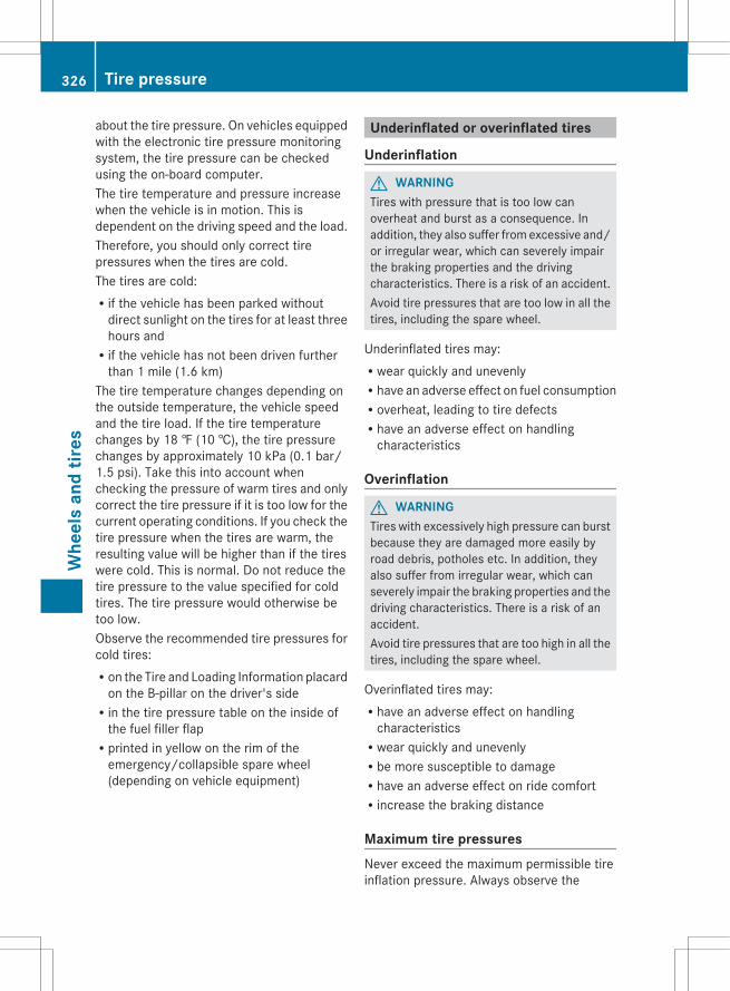
about the tire pressure. On vehicles equippedwith the electronic tire pressure monitoringsystem, the tire pressure can be checkedusing the on-board computer.The tire temperature and pressure increasewhen the vehicle is in motion. This isdependent on the driving speed and the load.Therefore, you should only correct tirepressures when the tires are cold.The tires are cold:Rif the vehicle has been parked without
direct sunlight on the tires for at least threehours andRif the vehicle has not been driven further
than 1 mile (1.6 km)The tire temperature changes depending onthe outside temperature, the vehicle speedand the tire load. If the tire temperaturechanges by 18 ‡ (10 †), the tire pressurechanges by approximately 10 kPa (0.1 bar/1.5 psi). Take this into account whenchecking the pressure of warm tires and onlycorrect the tire pressure if it is too low for thecurrent operating conditions. If you check thetire pressure when the tires are warm, theresulting value will be higher than if the tireswere cold. This is normal. Do not reduce thetire pressure to the value specified for coldtires. The tire pressure would otherwise betoo low.Observe the recommended tire pressures forcold tires:Ron the Tire and Loading Information placard
on the B-pillar on the driver's sideRin the tire pressure table on the inside of
the fuel filler flapRprinted in yellow on the rim of the
emergency/collapsible spare wheel(depending on vehicle equipment)
Underinflated or overinflated tires
Underinflation
G WARNINGTires with pressure that is too low canoverheat and burst as a consequence. Inaddition, they also suffer from excessive and/or irregular wear, which can severely impairthe braking properties and the drivingcharacteristics. There is a risk of an accident.Avoid tire pressures that are too low in all thetires, including the spare wheel.
Underinflated tires may:Rwear quickly and unevenlyRhave an adverse effect on fuel consumptionRoverheat, leading to tire defectsRhave an adverse effect on handling
characteristics
Overinflation
G WARNINGTires with excessively high pressure can burstbecause they are damaged more easily byroad debris, potholes etc. In addition, theyalso suffer from irregular wear, which canseverely impair the braking properties and thedriving characteristics. There is a risk of anaccident.Avoid tire pressures that are too high in all thetires, including the spare wheel.
Overinflated tires may:Rhave an adverse effect on handling
characteristicsRwear quickly and unevenlyRbe more susceptible to damageRhave an adverse effect on ride comfortRincrease the braking distance
Maximum tire pressuresNever exceed the maximum permissible tireinflation pressure. Always observe the
326 Tire pressureW
heel
s an
d tir
es

recommended tire pressure for your vehiclewhen adjusting the tire pressure(Y page 324).
: Example: maximum permissible tirepressure
i The actual values for tires are vehicle-specific and may deviate from the values inthe illustration.
Checking the tire pressures
Important safety notesObserve the "Tire pressure information"section (Y page 324).Information on air pressure for the tires onyour vehicle can be found:Ron the vehicle's Tire and Loading
Information placard on the B-pillarRon the tire pressure label on the fuel filler
flapRin the "Tire pressure information" section
Checking tire pressures manuallyTo determine and set the correct tirepressure, proceed as follows:X Remove the valve cap of the tire that is to
be checked.X Press the tire pressure gauge securely onto
the valve.X Read the tire pressure and compare it with
the recommended value on the Tire andLoading Information placard on theB-pillar on the driver's side of your vehicle.
X If necessary, increase the tire pressure tothe recommended value (Y page 324).
X If the tire pressure is too high, release airby pressing down the metal pin in the valveusing the tip of a pen, for example. Thencheck the tire pressure again using the tirepressure gauge.
X Screw the valve cap onto the valve.X Repeat these steps for the other tires.
Tire pressure loss warning system(Canada only)
Important safety notesWhile the vehicle is in motion, the tirepressure loss warning system monitors theset tire pressure using the rotational speed ofthe wheels. This enables the system to detectsignificant pressure loss in a tire. If the speedof rotation of a wheel changes as a result ofa loss of pressure, a corresponding warningmessage will appear in the multifunctiondisplay.The tire pressure warning system does notwarn you of an incorrectly set tire pressure.Observe the notes on the recommended tirepressure (Y page 324).The tire pressure loss warning system doesnot replace the need to regularly check yourvehicle's tire pressures, since an even loss ofpressure on several tires at the same timecannot be detected by the tire pressure losswarning system.The tire pressure monitor is not able to warnyou of a sudden loss of pressure, e.g. if thetire is penetrated by a foreign object. In theevent of a sudden loss of pressure, bring thevehicle to a halt by braking carefully. Avoidabrupt steering maneuvers.The function of the tire pressure loss warningsystem is limited or delayed if:Rsnow chains are mounted to your vehicle's
tires.Rroad conditions are wintry.
Tire pressure 327
Whe
els
and
tires
Z
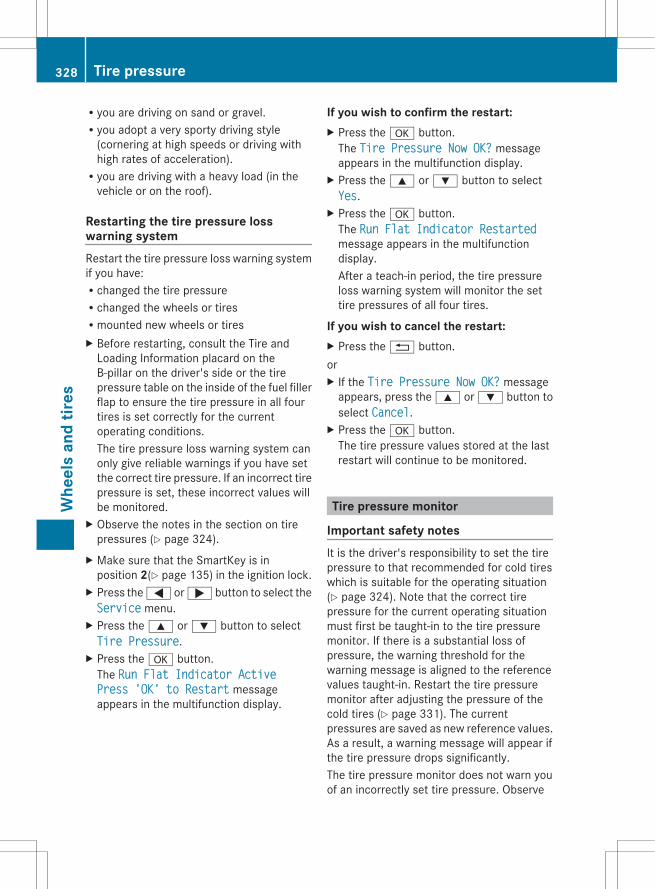
Ryou are driving on sand or gravel.Ryou adopt a very sporty driving style
(cornering at high speeds or driving withhigh rates of acceleration).Ryou are driving with a heavy load (in the
vehicle or on the roof).
Restarting the tire pressure losswarning systemRestart the tire pressure loss warning systemif you have:Rchanged the tire pressureRchanged the wheels or tiresRmounted new wheels or tiresX Before restarting, consult the Tire and
Loading Information placard on theB-pillar on the driver's side or the tirepressure table on the inside of the fuel fillerflap to ensure the tire pressure in all fourtires is set correctly for the currentoperating conditions.The tire pressure loss warning system canonly give reliable warnings if you have setthe correct tire pressure. If an incorrect tirepressure is set, these incorrect values willbe monitored.
X Observe the notes in the section on tirepressures (Y page 324).
X Make sure that the SmartKey is inposition 2(Y page 135) in the ignition lock.
X Press the = or ; button to select theService menu.
X Press the 9 or : button to selectTire Pressure.
X Press the a button.The Run Flat Indicator Active Press 'OK' to Restart messageappears in the multifunction display.
If you wish to confirm the restart:X Press the a button.
The Tire Pressure Now OK? messageappears in the multifunction display.
X Press the 9 or : button to selectYes.
X Press the a button.The Run Flat Indicator Restartedmessage appears in the multifunctiondisplay.After a teach-in period, the tire pressureloss warning system will monitor the settire pressures of all four tires.
If you wish to cancel the restart:X Press the % button.orX If the Tire Pressure Now OK? message
appears, press the 9 or : button toselect Cancel.
X Press the a button.The tire pressure values stored at the lastrestart will continue to be monitored.
Tire pressure monitor
Important safety notesIt is the driver's responsibility to set the tirepressure to that recommended for cold tireswhich is suitable for the operating situation(Y page 324). Note that the correct tirepressure for the current operating situationmust first be taught-in to the tire pressuremonitor. If there is a substantial loss ofpressure, the warning threshold for thewarning message is aligned to the referencevalues taught-in. Restart the tire pressuremonitor after adjusting the pressure of thecold tires (Y page 331). The currentpressures are saved as new reference values.As a result, a warning message will appear ifthe tire pressure drops significantly.The tire pressure monitor does not warn youof an incorrectly set tire pressure. Observe
328 Tire pressureW
heel
s an
d tir
es

the notes on the recommended tire pressure(Y page 324).The tire pressure monitor is not able to warnyou of a sudden loss of pressure, e.g. if thetire is penetrated by a foreign object. In theevent of a sudden loss of pressure, bring thevehicle to a halt by braking carefully. Avoidabrupt steering maneuvers.If a tire pressure monitor system is installed,the vehicle's wheels have sensors thatmonitor the tire pressures in all four tires. Thetire pressure monitor warns you if thepressure drops in one or more of the tires. Thetire pressure monitor only functions if thecorrect sensors are installed to all wheels.The tire pressure monitor has a yellowwarning lamp in the instrument cluster forindicating pressure loss/malfunctions (USA)or pressure loss (Canada). Whether thewarning lamp flashes or lights up indicateswhether a tire pressure is too low or the tirepressure monitoring system ismalfunctioning:Rif the warning lamp is lit continuously, the
tire pressure on one or more tires issignificantly too low. The tire pressuremonitor is not malfunctioning.RUSA only: if the warning lamp flashes for
around a minute and then remains litconstantly, the tire pressure monitor ismalfunctioning.
G WARNINGEach tire, including the spare (if provided),should be checked at least once a monthwhen cold and inflated to the pressurerecommended by the vehicle manufactureron the Tire and Loading Information placardon the driver's door B-pillar or the tirepressure label on the inside of the fuel fillerflap. If your vehicle has tires of a different sizethan the size indicated on the Tire and LoadingInformation placard or the tire pressure label,you should determine the proper tire pressurefor those tires.As an added safety feature, your vehicle hasbeen equipped with a tire pressure monitoring
system (TPMS) that illuminates a low tirepressure telltale when one or more of yourtires are significantly underinflated.Accordingly, when the low tire pressuretelltale illuminates, you should stop and checkyour tires as soon as possible, and inflatethem to the proper pressure. Driving on asignificantly underinflated tire causes the tireto overheat and can lead to tire failure.Underinflation also reduces fuel efficiencyand tire tread life, and may affect the vehicle'shandling and stopping ability.Please note that the TPMS is not a substitutefor proper tire maintenance, and it is thedriver's responsibility to maintain correct tirepressure, even if underinflation has notreached the level to trigger illumination of theTPMS low tire pressure telltale.USA only:Your vehicle has also been equipped with aTPMS malfunction indicator to indicate if thesystem is not operating properly. The TPMSmalfunction indicator is combined with thelow tire pressure telltale. When the systemdetects a malfunction, the warning lamp willflash for approximately a minute and thenremain continuously illuminated. Thissequence will be repeated every time thevehicle is started as long as the malfunctionexists.When the malfunction indicator is illuminated,the system may not be able to detect or signallow tire pressure as intended. TPMSmalfunctions may occur for a variety ofreasons, including the installation ofincompatible replacement or alternate tiresor wheels on the vehicle that prevent theTPMS from functioning properly. Alwayscheck the TPMS malfunction telltale afterreplacing one or more tires or wheels on yourvehicle to ensure that the replacement oralternate tires and wheels allow the TPMS tocontinue to function properly.
i USA only:If the tire pressure monitor ismalfunctioning, it may take more than ten
Tire pressure 329
Whe
els
and
tires
Z

minutes for the tire pressure warning lampto inform you of the malfunction by flashingfor approximately one minute and thenremaining lit.When the malfunction has been rectified,the tire pressure warning lamp goes outafter a few minutes of driving.
Information on tire pressures is displayed inthe multifunction display. After a few minutesof driving, the current tire pressure of eachtire is shown in the multifunction display.
i The tire pressure values indicated by theon-board computer may differ from thosemeasured at a gas station with a pressuregauge. The tire pressures shown by the on-board computer refer to those measured atsea level. At high altitudes, the tire pressurevalues indicated by a pressure gauge arehigher than those shown by the on-boardcomputer. In this case, do not reduce thetire pressures.
i The operation of the tire pressure monitorcan be affected by interference from radiotransmitting equipment (e.g. radioheadphones, two-way radios) that may bebeing operated in or near the vehicle.
i USA only:This device complies with part 15 of theFCC Rules. Operation is subject to thefollowing two conditions:1. This device may not cause harmfulinterference, and2. this device must accept any interferencereceived, including interference that maycause undesired operation of the device.Any unauthorized modification to thisdevice could void the user’s authority tooperate the equipment.
i Canada only:This device complies with RSS-210 ofIndustry Canada. Operation is subject tothe following two conditions:1. This device may not cause harmfulinterference, and
2. this device must accept any interferencereceived, including interference that maycause undesired operation of the device.Any unauthorized modification to thisdevice could void the user’s authority tooperate the equipment.
Checking tire pressure electronicallyX Make sure that the SmartKey is in
position 2(Y page 135) in the ignition lock.X Press the = or ; button on the
steering wheel to select the Service
menu.X Press the 9 or : button to selectTire Pressure.
X Press the a button.The current tire pressure for each wheel willbe displayed in the multifunction display.
If the vehicle has been parked for longer than20minutes, the Tire Pressures Displayed After Driving A Few Minutes message appears.After a teach-in period, the tire pressuremonitor automatically recognizes new wheelsor new sensors. As long as a clear allocationof the tire pressure values to the individualwheels is not possible, the Tire Pressure Monitor Active display message is showninstead of the tire pressure display. The tirepressures are already being monitored.
i If a spare wheel/emergency spare wheelis mounted, the system may continue toshow the tire pressure of the wheel that hasbeen removed for a few minutes. If thisoccurs, note that the value displayed forthe position where the spare tire ismounted is not the same as the sparewheel/emergency spare wheel's currenttire pressure.
Tire pressure monitor warningmessagesIf the tire pressure monitor detects asignificant pressure loss on one or more tires,
330 Tire pressureW
heel
s an
d tir
es

a warning message is shown in themultifunction display. A warning tone alsosounds and the tire pressure warning lamplights up in the instrument cluster.Each tire that is affected by a significant lossof pressure is highlighted with a color.If the Correct Tire Pressure messageappears in the multifunction display:X Check the tire pressure on all four wheels
and correct it if necessary.
i If the wheel positions on the vehicle areinterchanged, the tire pressures may bedisplayed for the wrong positions for ashort time. This is rectified after a fewminutes of driving, and the tire pressuresare displayed for the correct positions.
Restarting the tire pressure monitorWhen you restart the tire pressure monitor,all existing warning messages are deleted andthe warning lamps go out. The monitor usesthe currently set tire pressures as thereference values for monitoring.The tire pressure monitor must be restartedwhen you set the tire pressure to a new value(as a result of changed drive or loadcharacteristics, for example). The tirepressure monitor then monitors the new tirepressure values.
i Canada only: in most cases, the tirepressure monitor recognizes the newreference values automatically. However,you can also define reference valuesmanually as described here.
Restart the tire pressure monitor after youhave set the tire pressure to the valuerecommended for the desired drivingsituation (Y page 324). Only correct tirepressures on cold tires. Comply with therecommended tire pressures on the Tire andLoading Information placard the B-pillar onthe driver's side. Additional tire pressurevalues for driving at high speeds or with heavyloads can be found in the tire pressure tableon the inside of the fuel filler flap.
X Make sure that the tire pressure is correcton all four wheels.
X Make sure that the SmartKey is in position2 in the ignition lock.
X Press the = or ; button on thesteering wheel to select the Service
menu.X Press the 9 or : button to selectTire Pressure.
X Press the a button.The multifunction display shows thecurrent tire pressure of the individual tiresor the Tire pressures will be displayed after driving a few minutes message.
X Press the : button.The Use Current Pressures as New Reference Values message appears inthe multifunction display.
If you wish to confirm the restart:X Press the a button.
The Tire Press. Monitor Restartedmessage appears in the multifunctiondisplay.After driving for a few minutes, the systemchecks whether the current tire pressuresare within the specified range. The new tirepressures are then accepted as referencevalues and monitored.
If you wish to cancel the restart:X Press the % button.
The tire pressure values stored at the lastrestart will continue to be monitored.
Loading the vehicle
Instruction labels for tires and loads
G WARNINGOverloaded tires can overheat, causing ablowout. Overloaded tires can also impair thesteering and driving characteristics and leadto brake failure. There is a risk of accident.
Loading the vehicle 331
Whe
els
and
tires
Z
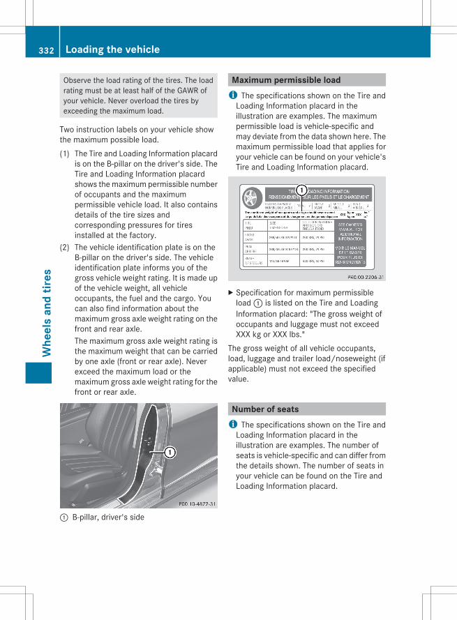
Observe the load rating of the tires. The loadrating must be at least half of the GAWR ofyour vehicle. Never overload the tires byexceeding the maximum load.
Two instruction labels on your vehicle showthe maximum possible load.(1) The Tire and Loading Information placard
is on the B-pillar on the driver's side. TheTire and Loading Information placardshows the maximum permissible numberof occupants and the maximumpermissible vehicle load. It also containsdetails of the tire sizes andcorresponding pressures for tiresinstalled at the factory.
(2) The vehicle identification plate is on theB-pillar on the driver's side. The vehicleidentification plate informs you of thegross vehicle weight rating. It is made upof the vehicle weight, all vehicleoccupants, the fuel and the cargo. Youcan also find information about themaximum gross axle weight rating on thefront and rear axle.The maximum gross axle weight rating isthe maximum weight that can be carriedby one axle (front or rear axle). Neverexceed the maximum load or themaximum gross axle weight rating for thefront or rear axle.
: B-pillar, driver's side
Maximum permissible loadi The specifications shown on the Tire and
Loading Information placard in theillustration are examples. The maximumpermissible load is vehicle-specific andmay deviate from the data shown here. Themaximum permissible load that applies foryour vehicle can be found on your vehicle'sTire and Loading Information placard.
X Specification for maximum permissibleload : is listed on the Tire and LoadingInformation placard: "The gross weight ofoccupants and luggage must not exceedXXX kg or XXX lbs."
The gross weight of all vehicle occupants,load, luggage and trailer load/noseweight (ifapplicable) must not exceed the specifiedvalue.
Number of seatsi The specifications shown on the Tire and
Loading Information placard in theillustration are examples. The number ofseats is vehicle-specific and can differ fromthe details shown. The number of seats inyour vehicle can be found on the Tire andLoading Information placard.
332 Loading the vehicleW
heel
s an
d tir
es

Maximum number of seats : determines themaximum number of occupants allowed totravel in the vehicle. This information can befound on the Tire and Loading Informationplacard.
Determining the correct load limit
Step-by-step instructionsThe following steps have been developed asrequired of all manufacturers under Title 49,Code of U.S. Federal Regulations, Part 575pursuant to the "National Traffic and MotorVehicle Safety Act of 1966".X Step 1: Locate the statement "The
combined weight of occupants and cargoshould never exceed XXX kg or XXX lbs." onyour vehicle’s Tire and Loading Informationplacard.
X Step 2: Determine the combined weight ofthe driver and passengers that will be ridingin your vehicle.
X Step 3: Subtract the combined weight ofthe driver and passengers from XXXkilograms or XXX lbs.
X Step 4: The resulting figure equals theavailable amount of cargo and luggage loadcapacity. For example, if the "XXX" amountequals 1400 lbs and there will be five 150lbs passengers in your vehicle, the amountof available cargo and luggage loadcapacity is 650 lbs (1 400 - 750 (5 x 150)= 650 lbs).
X Step 5: Determine the combined weight ofluggage and cargo being loaded on thevehicle. That weight may not safely exceedthe available cargo and luggage loadcapacity calculated in step 4.
X Step 6 (if applicable): If your vehicle willbe towing a trailer, load from your trailerwill be transferred to your vehicle. Consultthis manual to determine how this reducesthe available cargo and luggage loadcapacity of your vehicle (Y page 335).
Loading the vehicle 333
Whe
els
and
tires
Z

Example: steps 1 to 3The following table shows examples on how to calculate total and cargo load capacities withvarying seating configurations and number and size of occupants. The following examples usea load limit of 1 500 lbs (680 kg). This is for illustration purposes only. Make sure you areusing the actual load limit for your vehicle stated on your vehicle's Tire and Loading Informationplacard (Y page 332).
Example 1 Example 2 Example 3
Step 1 Combined maximum weight of occupants and cargo (data from the Tire and Loading Information placard)
1500 lbs(680 kg)
1500 lbs(680 kg)
1500 lbs(680 kg)
Example 1 Example 2 Example 3
Step 2 Number of people in the vehicle (driver and occupants)
5 3 1
Distribution of the occupants
Front: 2Rear: 3
Front: 1Rear: 2
Front: 1
Weight of the occupants
Occupant 1:150 lbs (68 kg)Occupant 2:180 lbs (82 kg)Occupant 3:160 lbs (73 kg)Occupant 4:140 lbs (63 kg)Occupant 5:120 lbs (54 kg)
Occupant 1:200 lbs (91 kg)Occupant 2:190 lbs (86 kg)Occupant 3:150 lbs (68 kg)
Occupant 1:150 lbs (68 kg)
Gross weight of all occupants
750 lbs (340 kg) 540 lbs (245 kg) 150 lbs (68 kg)
334 Loading the vehicleW
heel
s an
d tir
es
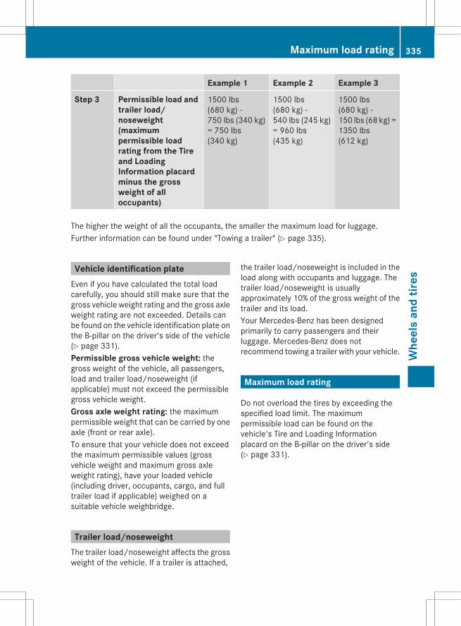
Example 1 Example 2 Example 3
Step 3 Permissible load and trailer load/noseweight (maximum permissible load rating from the Tire and Loading Information placard minus the gross weight of all occupants)
1500 lbs(680 kg) -750 lbs (340 kg)= 750 lbs(340 kg)
1500 lbs(680 kg) -540 lbs (245 kg)= 960 lbs(435 kg)
1500 lbs(680 kg) -150 lbs (68 kg) =1350 lbs(612 kg)
The higher the weight of all the occupants, the smaller the maximum load for luggage.Further information can be found under "Towing a trailer" (Y page 335).
Vehicle identification plateEven if you have calculated the total loadcarefully, you should still make sure that thegross vehicle weight rating and the gross axleweight rating are not exceeded. Details canbe found on the vehicle identification plate onthe B-pillar on the driver's side of the vehicle(Y page 331).Permissible gross vehicle weight: thegross weight of the vehicle, all passengers,load and trailer load/noseweight (ifapplicable) must not exceed the permissiblegross vehicle weight.Gross axle weight rating: the maximumpermissible weight that can be carried by oneaxle (front or rear axle).To ensure that your vehicle does not exceedthe maximum permissible values (grossvehicle weight and maximum gross axleweight rating), have your loaded vehicle(including driver, occupants, cargo, and fulltrailer load if applicable) weighed on asuitable vehicle weighbridge.
Trailer load/noseweightThe trailer load/noseweight affects the grossweight of the vehicle. If a trailer is attached,
the trailer load/noseweight is included in theload along with occupants and luggage. Thetrailer load/noseweight is usuallyapproximately 10% of the gross weight of thetrailer and its load.Your Mercedes-Benz has been designedprimarily to carry passengers and theirluggage. Mercedes-Benz does notrecommend towing a trailer with your vehicle.
Maximum load rating
Do not overload the tires by exceeding thespecified load limit. The maximumpermissible load can be found on thevehicle's Tire and Loading Informationplacard on the B-pillar on the driver's side(Y page 331).
Maximum load rating 335
Whe
els
and
tires
Z

i The actual values for tires are vehicle-specific and may deviate from the values inthe illustration.
Maximum tire load : is the maximumpermissible weight for which the tire isapproved.
Uniform Tire Quality GradingStandards
Overview of Tire Quality GradingStandards
Uniform Tire Quality Grading Standards areU.S. government specifications. Theirpurpose is to provide drivers with uniformreliable information on tire performance data.Tire manufacturers have to grade tires usingthree performance factors: tread wear :,tire traction ;, and heat resistance =. Alltires sold in North America are provided withthe corresponding quality class mark on thesidewall of the tire, even though theseregulations do not apply to Canada.
i The actual values for tires are vehicle-specific and may deviate from the values inthe illustration.
Where applicable, the tire gradinginformation can be found on the tire sidewallbetween the tread shoulder and maximumtire width.For example:
Tread wear Traction Temperature
200 AA A
All passenger car tires must conform to thestatutory safety requirements in addition tothese grades.
Tread wearThe tread wear grade is a comparative ratingbased on the wear rate of the tire when testedunder controlled conditions on a specifiedU.S. government course. For example, a tiregraded 150 would wear one and one-halftimes as well on the government course as atire graded 100.The relative performance of tires dependsupon the actual conditions of their use,however, and may depart significantly fromthe norm, due to variations in driving habits,service practices and differences in roadcharacteristics and climate conditions.
Traction
G WARNINGThe traction grade assigned to this tire isbased on straight-ahead braking tractiontests, and does not include acceleration,cornering, hydroplaning, or peak tractioncharacteristics.
The traction grades, from highest to lowest,are AA, A, B, and C. Those grades representthe tire's ability to stop on a wet surface asmeasured under controlled conditions on
336 Uniform Tire Quality Grading StandardsW
heel
s an
d tir
es
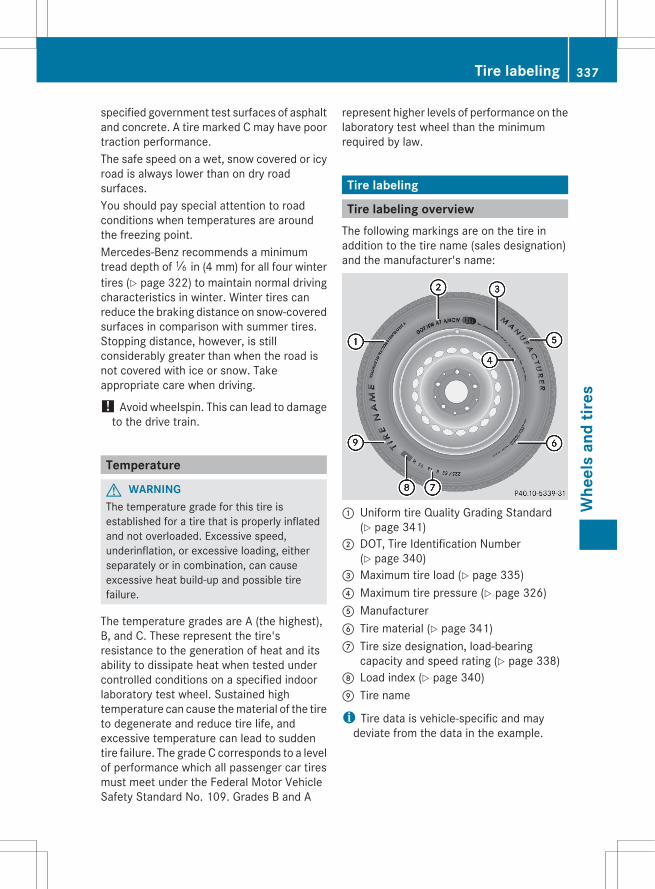
specified government test surfaces of asphaltand concrete. A tire marked C may have poortraction performance.The safe speed on a wet, snow covered or icyroad is always lower than on dry roadsurfaces.You should pay special attention to roadconditions when temperatures are aroundthe freezing point.Mercedes-Benz recommends a minimumtread depth of ã in (4 mm) for all four wintertires (Y page 322) to maintain normal drivingcharacteristics in winter. Winter tires canreduce the braking distance on snow-coveredsurfaces in comparison with summer tires.Stopping distance, however, is stillconsiderably greater than when the road isnot covered with ice or snow. Takeappropriate care when driving.
! Avoid wheelspin. This can lead to damageto the drive train.
Temperature
G WARNINGThe temperature grade for this tire isestablished for a tire that is properly inflatedand not overloaded. Excessive speed,underinflation, or excessive loading, eitherseparately or in combination, can causeexcessive heat build-up and possible tirefailure.
The temperature grades are A (the highest),B, and C. These represent the tire'sresistance to the generation of heat and itsability to dissipate heat when tested undercontrolled conditions on a specified indoorlaboratory test wheel. Sustained hightemperature can cause the material of the tireto degenerate and reduce tire life, andexcessive temperature can lead to suddentire failure. The grade C corresponds to a levelof performance which all passenger car tiresmust meet under the Federal Motor VehicleSafety Standard No. 109. Grades B and A
represent higher levels of performance on thelaboratory test wheel than the minimumrequired by law.
Tire labeling
Tire labeling overviewThe following markings are on the tire inaddition to the tire name (sales designation)and the manufacturer's name:
: Uniform tire Quality Grading Standard(Y page 341)
; DOT, Tire Identification Number(Y page 340)
= Maximum tire load (Y page 335)? Maximum tire pressure (Y page 326)A ManufacturerB Tire material (Y page 341)C Tire size designation, load-bearing
capacity and speed rating (Y page 338)D Load index (Y page 340)E Tire name
i Tire data is vehicle-specific and maydeviate from the data in the example.
Tire labeling 337
Whe
els
and
tires
Z
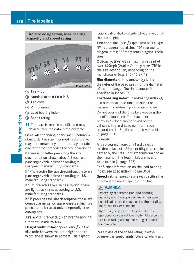
Tire size designation, load-bearingcapacity and speed rating
: Tire width; Nominal aspect ratio in %= Tire code? Rim diameterA Load bearing indexB Speed rating
i Tire data is vehicle-specific and maydeviate from the data in the example.
General: depending on the manufacturer'sstandards, the size imprinted in the tire wallmay not contain any letters or may containone letter that precedes the size description.If there is no letter preceding the sizedescription (as shown above): these arepassenger vehicle tires according toEuropean manufacturing standards.If "P" precedes the size description: these arepassenger vehicle tires according to U.S.manufacturing standards.If "LT" precedes the size description: theseare light truck tires according to U.S.manufacturing standards.If "T" precedes the size description: these arecompact emergency spare wheels at high tirepressure, to be used only temporarily in anemergency.Tire width: tire width : shows the nominaltire width in millimeters.Height-width ratio: aspect ratio ; is thesize ratio between the tire height and tirewidth and is shown in percent. The aspect
ratio is calculated by dividing the tire width bythe tire height.Tire code: tire code = specifies the tire type."R" represents radial tires; "D" representsdiagonal tires; "B" represents diagonal radialtires.Optionally, tires with a maximum speed ofover 149mph (240km/h) may have "ZR" inthe size description, depending on themanufacturer (e.g. 245/40 ZR 18).Rim diameter: rim diameter ? is thediameter of the bead seat, not the diameterof the rim flange. The rim diameter isspecified in inches (in).Load-bearing index: load-bearing index Ais a numerical code that specifies themaximum load-bearing capacity of a tire.Do not overload the tires by exceeding thespecified load limit. The maximumpermissible load can be found on thevehicle's Tire and Loading Informationplacard on the B-pillar on the driver's side(Y page 331).Example:A load-bearing index of 91 indicates amaximum load of 1,356lb (615kg) that can becarried by the tires. For further information onthe maximum tire load in kilograms andpounds, see (Y page 335).For further information on the load-bearingindex, see Load index (Y page 340).Speed rating: speed rating B specifies theapproved maximum speed of the tire.
G WARNINGExceeding the stated tire load-bearingcapacity and the approved maximum speedcould lead to tire damage or the tire bursting.There is a risk of accident.Therefore, only use tire types and sizesapproved for your vehicle model. Observe thetire load rating and speed rating required foryour vehicle.
Regardless of the speed rating, alwaysobserve the speed limits. Drive carefully and
338 Tire labelingW
heel
s an
d tir
es
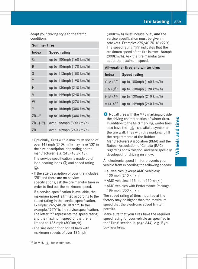
adapt your driving style to the trafficconditions.
Summer tires
Index Speed rating
Q up to 100mph (160 km/h)
R up to 106mph (170 km/h)
S up to 112mph (180 km/h)
T up to 118mph (190 km/h)
H up to 130mph (210 km/h)
V up to 149mph (240 km/h)
W up to 168mph (270 km/h)
Y up to 186mph (300 km/h)
ZR...Y up to 186mph (300 km/h)
ZR...(..Y) over 186mph (300 km/h)
ZR over 149mph (240 km/h)
ROptionally, tires with a maximum speed ofover 149 mph (240km/h) may have "ZR" inthe size description, depending on themanufacturer (e.g. 245/40 ZR 18).The service specification is made up ofload-bearing index A and speed ratingB.RIf the size description of your tire includes
"ZR" and there are no servicespecifications, ask the tire manufacturer inorder to find out the maximum speed.If a service specification is available, themaximum speed is limited according to thespeed rating in the service specification.Example: 245/40 ZR 18 97 Y. In thisexample, "97 Y" is the service specification.The letter "Y" represents the speed ratingand the maximum speed of the tire islimited to 186 mph (300km/h).RThe size description for all tires with
maximum speeds of over 186mph
(300km/h) must include "ZR", and theservice specification must be given inbrackets. Example: 275/40 ZR 18 (99 Y).The speed rating "(Y)" indicates that themaximum speed of the tire is over 186mph(300km/h). Ask the tire manufacturerabout the maximum speed.
All-weather tires and winter tires
Index Speed rating
Q M+S23 up to 100mph (160 km/h)
T M+S23 up to 118mph (190 km/h)
H M+S23 up to 130mph (210 km/h)
V M+S23 up to 149mph (240 km/h)
i Not all tires with the M+S marking providethe driving characteristics of winter tires.In addition to the M+S marking, winter tiresalso have the i snowflake symbol onthe tire wall. Tires with this marking fulfillthe requirements of the RubberManufacturers Association (RMA) and theRubber Association of Canada (RAC)regarding snow traction, and were speciallydeveloped for driving on snow.
An electronic speed limiter prevents yourvehicle from exceeding the following speeds:Rall vehicles (except AMG vehicles):
130 mph (210 km/h)RAMG vehicles: 155 mph (250 km/h)RAMG vehicles with Performance Package:
186 mph (300 km/h)The speed rating of tires mounted at thefactory may be higher than the maximumspeed that the electronic speed limiterpermits.Make sure that your tires have the requiredspeed rating for your vehicle as specified inthe "Tires" section (Y page 344), e.g. if youbuy new tires.
23 Or M+Si for winter tires.
Tire labeling 339
Whe
els
and
tires
Z

Further information about reading tire datacan be obtained from any qualified specialistworkshop.
Load index
i Tire data is vehicle-specific and maydeviate from the data in the example.
In addition to the load bearing index, loadindex : may be imprinted after the lettersthat identify speed rating B (Y page 338) onthe sidewall of the tire.RIf no specification is given: no text (as in the
example above), represents a standardload (SL) tireRXL or Extra Load: represents a reinforced
tireRLight load: represents a light load tireRC, D, E: represents a load range that
depends on the maximum load that the tirecan carry at a certain pressure
DOT, Tire Identification Number (TIN)U.S. tire regulations prescribe that everymanufacturer of new tires or retreader has toimprint a TIN in or on the sidewall of each tireproduced.
The TIN is a unique identification number. TheTIN enables the tire manufacturers to informpurchasers of recalls and other safety-relevant matters. It makes it possible for thepurchaser to easily identify the affected tires.The TIN is made up of manufactureridentification code ;, tire size =, tire typecode ? and manufacturing date A.
i Tire data is vehicle-specific and maydeviate from the data in the example.
DOT (Department of Transportation): tiresymbol : indicates that the tire complieswith the requirements of the U.S. Departmentof Transportation.Manufacturer identification code: manufacturer identification code ; providesdetails on the tire manufacturer. New tireshave a code with two symbols. Retreadedtires have a code with four symbols.Further information about retreaded tires(Y page 320).Tire size: identifier = describes the tire size.Tire type code: tire type code ? can beused by the manufacturer as a code todescribe specific characteristics of the tire.Date of manufacture: date of manufactureA provides information about the age of atire. The first and second positions representthe week of manufacture, starting with "01"for the first calendar week. Positions threeand four represent the year of manufacture.For example, a tire that is marked with"3208", was manufactured in week 32 in2008.
340 Tire labelingW
heel
s an
d tir
es
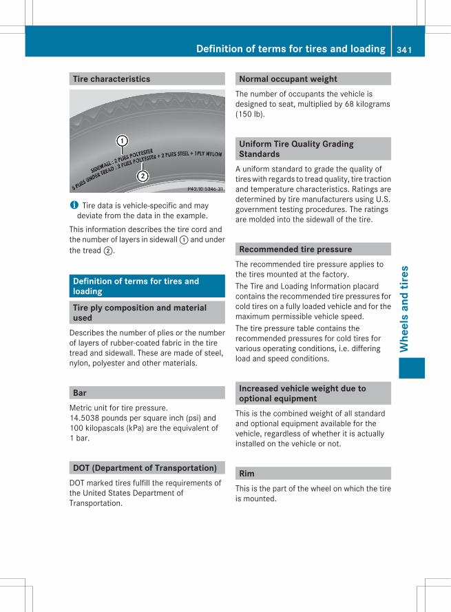
Tire characteristics
i Tire data is vehicle-specific and maydeviate from the data in the example.
This information describes the tire cord andthe number of layers in sidewall : and underthe tread ;.
Definition of terms for tires andloading
Tire ply composition and materialused
Describes the number of plies or the numberof layers of rubber-coated fabric in the tiretread and sidewall. These are made of steel,nylon, polyester and other materials.
BarMetric unit for tire pressure.14.5038 pounds per square inch (psi) and100 kilopascals (kPa) are the equivalent of1 bar.
DOT (Department of Transportation)DOT marked tires fulfill the requirements ofthe United States Department ofTransportation.
Normal occupant weightThe number of occupants the vehicle isdesigned to seat, multiplied by 68 kilograms(150 lb).
Uniform Tire Quality GradingStandards
A uniform standard to grade the quality oftires with regards to tread quality, tire tractionand temperature characteristics. Ratings aredetermined by tire manufacturers using U.S.government testing procedures. The ratingsare molded into the sidewall of the tire.
Recommended tire pressureThe recommended tire pressure applies tothe tires mounted at the factory.The Tire and Loading Information placardcontains the recommended tire pressures forcold tires on a fully loaded vehicle and for themaximum permissible vehicle speed.The tire pressure table contains therecommended pressures for cold tires forvarious operating conditions, i.e. differingload and speed conditions.
Increased vehicle weight due tooptional equipment
This is the combined weight of all standardand optional equipment available for thevehicle, regardless of whether it is actuallyinstalled on the vehicle or not.
RimThis is the part of the wheel on which the tireis mounted.
Definition of terms for tires and loading 341
Whe
els
and
tires
Z

GAWR (Gross Axle Weight Rating)The GAWR is the maximum permissible axleload. The actual load on an axle must neverexceed the gross axle weight rating. Thegross axle weight rating can be found on thevehicle identification plate on the B-pillar onthe driver's side.
Speed ratingThe speed rating is part of the tireidentification. It specifies the speed range forwhich the tire is approved.
GVW (Gross Vehicle Weight)The gross vehicle weight includes the weightof the vehicle including fuel, tools, the sparewheel, accessories installed, occupants,luggage and the drawbar noseweight, ifapplicable. The gross vehicle weight must notexceed the gross vehicle weight rating GVWRas specified on the vehicle identification plateon the B-pillar on the driver's side.
GVWR (Gross Vehicle Weight Rating)The GVWR is the maximum permissible grossweight of a fully loaded vehicle (the weight ofthe vehicle including all accessories,occupants, fuel, luggage and the drawbarnoseweight, if applicable). The gross vehicleweight rating is specified on the vehicleidentification plate on the B-pillar on thedriver's side.
Maximum loaded vehicle weightThe maximum weight is the sum of the curbweight of the vehicle, the weight of theaccessories, the total load limit and theweight of the optional equipment installed atthe factory.
Kilopascal (kPa)Metric unit for tire pressure. 6.9 kPacorresponds to 1 psi. Another unit for tirepressure is bar. There are 100 kilopascals(kPa) to 1 bar.
Load indexIn addition to the load-bearing index, the loadindex may also be imprinted on the sidewallof the tire. This specifies the load-bearingcapacity more precisely.
Curb weightThe weight of a vehicle with standardequipment including the maximum capacityof fuel, oil and coolant. It also includes the air-conditioning system and optional equipmentif these are installed in the vehicle, but doesnot include passengers or luggage.
Maximum load ratingThe maximum load rating in kilograms orpounds is the maximum weight for which atire is approved.
Maximum permissible tire pressureMaximum permissible tire pressure for onetire.
Maximum load on one tireMaximum load on one tire. This is calculatedby dividing the maximum axle load of one axleby two.
PSI (pounds per square inch)A standard unit of measure for tire pressure.
342 Definition of terms for tires and loadingW
heel
s an
d tir
es
Aspect ratioRelationship between tire height and tirewidth in percent.
Tire pressureThis is pressure inside the tire applying anoutward force to each square inch of the tire'ssurface. The tire pressure is specified inpounds per square inch (psi), in kilopascal(kPa) or in bar. The tire pressure should onlybe corrected when the tires are cold.
Tire pressure of cold tiresThe tires are cold:Rif the vehicle has been parked without
direct sunlight on the tires for at least threehours andRif the vehicle has not been driven more than
1 mile (1.6 km).
TreadThe part of the tire that comes into contactwith the road.
BeadThe tire bead ensures that the tire sitssecurely on the wheel. There are several steelwires in the bead to prevent the tire fromcoming loose from the wheel rim.
SidewallThe part of the tire between the tread and thebead.
Weight of optional extrasThe combined weight of those optional extrasthat weigh more than the replaced standardpart and more than 2.3 kg (5 lb). These
optional extras, such as high-performancebrakes, level control, a roof rack or a high-performance battery, are not included in thecurb weight and the weight of theaccessories.
TIN (Tire Identification Number)This is a unique identifier which can be usedby a tire manufacturer to identify tires, forexample for a product recall, and thus identifythe purchasers. The TIN is made up of themanufacturer's identification code, tire size,tire type code and the manufacturing date.
Load bearing indexThe load bearing index (also load index) is acode that contains the maximum load bearingcapacity of a tire.
TractionTraction is the result of friction between thetires and the road surface.
Treadwear indicatorsNarrow bars (tread wear bars) that aredistributed over the tire tread. If the tire treadis level with the bars, the wear limit of á in(1.6 mm) has been reached.
Occupant distributionThe distribution of occupants in a vehicle attheir designated seating positions.
Total load limitRated cargo and luggage load plus68 kilograms (150 lb), multiplied by thevehicle's designated seating capacity.
Definition of terms for tires and loading 343
Whe
els
and
tires
Z
Changing a wheel
Flat tireThe "Breakdown assistance" section(Y page 302) contains information and noteson how to deal with a flat tire. It also providesinstructions on changing a wheel or mountingthe spare wheel/emergency spare wheel.
Interchanging the wheels
G WARNINGInterchanging the front and rear wheels mayseverely impair the driving characteristics ifthe wheels or tires have different dimensions.The wheel brakes or suspension componentsmay also be damaged. There is a risk ofaccident.Rotate front and rear wheels only if the wheelsand tires are of the same dimensions.
Always pay attention to the instructions andsafety notes in the "Changing tires andmounting the spare wheel" section(Y page 302).The wear patterns on the front and rear tiresdiffer, depending on the operating conditions.Rotate the wheels before a clear wear patternhas formed on the tires. Front tires typicallywear more on the shoulders and the rear tiresin the center.If your vehicle's tire configuration allows, youcan rotate the wheels according to theintervals in the tire manufacturer's warrantybook in your vehicle documents. If this is notavailable, the tires should then be replacedevery 3000 to 6000 miles (5000 to10,000 km), or earlier if the tire wear requiresthis. Do not change the direction of wheelrotation.Clean the contact surfaces of the wheel andthe brake disc thoroughly every time a wheelis interchanged. Check the tire pressures.For information on changing tires andmounting the spare wheel, see (Y page 302).
! On vehicles equipped with a tire pressuremonitor, electronic components arelocated in the wheel.Tire-mounting tools should not be usednear the valve. This could damage theelectronic components.Only have tires changed at a qualifiedspecialist workshop.
Direction of rotationTires with a specified direction of rotationhave additional benefits, e.g. if there is a riskof hydroplaning. You will only gain thesebenefits if the correct direction of rotation ismaintained.An arrow on the sidewall of the tire indicatesits correct direction of rotation.You may mount a spare wheel/emergencyspare wheel against the direction of rotation.Observe the time restriction on use as well asthe speed limit specified on the spare wheel/emergency spare wheel.
Storing wheelsStore wheels that are not being used in a cool,dry and preferably dark place. Protect thetires from oil, grease, gasoline and diesel.
Cleaning the wheels
G WARNINGDo not use power washers with circular-jetnozzles (dirt grinders) to clean your vehicle, inparticular the tires. You could otherwisedamage the tires and cause an accident.
Wheel and tire combinations
Please bear the following in mind! For safety reasons, Mercedes-Benz
recommends that you only use tires andwheels which have been approved by
344 Wheel and tire combinationsW
heel
s an
d tir
es
Mercedes-Benz specifically for yourvehicle.These tires have been specially adapted foruse with the control systems, such as ABSor ESP®, and are marked as follows:RMO = Mercedes-Benz OriginalRMOE = Mercedes-Benz Original Extended
(tires featuring run-flat characteristics)RMO1 = Mercedes-Benz Original (only
certain AMG tires)Mercedes-Benz Original Extended tiresmay only be used on wheels that have beenspecifically approved by Mercedes-Benz.Only use tires, wheels or accessoriestested and approved by Mercedes-Benz.Certain characteristics, e.g. handling,vehicle noise emissions or fuelconsumption, may otherwise be adverselyaffected. In addition, when driving with aload, tire dimension variations could causethe tires to come into contact with thebodywork and axle components. This couldresult in damage to the tires or the vehicle.Mercedes-Benz accepts no liability fordamage resulting from the use of tires,wheels or accessories other than thosetested and approved.Information on tires, wheels and approvedcombinations can be obtained from anyqualified specialist workshop.
i The recommended pressures for variousoperating conditions can be found:Ron the Tire and Loading Information
placard with the recommended tirepressures on the B-pillar on the driver'ssideRin the tire pressure table on the inside of
the fuel filler flapObserve the notes on recommended tirepressures under various operatingconditions (Y page 324).Check tire pressures regularly, and onlywhen the tires are cold. Comply with the
maintenance recommendations of the tiremanufacturer in the vehicle documentwallet.
i Notes on the vehicle equipment – alwaysequip the vehicle with:Rtires of the same size on a given axle
(left/right)Rthe same type of tires at a given time
(summer tires, winter tires, MOExtendedtires)
i On the following pages, you can findinformation on approved wheel rims andtire sizes for equipping your vehicle withwinter tires. Winter tires are not availableat the factory as standard equipment oroptional extras.If you would like to equip your vehicle withapproved winter tires, you may also, incertain circumstances, require rims of theappropriate size. The sizes of the approvedwinter tires may deviate from that of thestandard tires. This is dependent on themodel and the equipment installed at thefactory.The tires and wheel rims, as well as furtherinformation, can be obtained at a qualifiedspecialist workshop.
i Overview of abbreviations used in thefollowing tire tables:RBA: both axlesRFA: front axleRRA: rear axle
In the following table, the wheel/tirecombinations are assigned to the vehiclemodels through variants, e.g. V1, V2 etc.:
V1 CLS 55024, CLS 550 4MATIC24
V2 CLS 63 AMG
i Not all wheel and tire combinations areavailable at the factory for all countries.
24 BlueEFFICIENCY
Wheel and tire combinations 345
Whe
els
and
tires
Z

Tires
Summer tires Alloy wheels V1 V2
FA RA
255/40 R18 99 Y XLMOExtended25
285/35 R18 97 YMOExtended25, 26
8.5 J x 18 H2Wheel offset: 1.36 in (34.5 mm)9.5 J x 18 H2Wheel offset: 1.89 in (48 mm)
# —
FA RA
255/35 R19 96 Y XL 285/30 R19 98 Y XL26
8.5 J x 19 H2Wheel offset: 1.36 in (34.5 mm)9.5 J x 19 H2Wheel offset: 1.89 in (48 mm)
# —
FA RA
255/35 ZR 19 (96 Y) XL 285/30 ZR19 (98 Y) XL26
9.0 J x 19 H2Wheel offset: 1.46 in (37 mm)10.0 J x 19 H2Wheel offset: 1.85 in (47 mm)
— #
All-weather tires Alloy wheels V1 V2
FA RA
255/40 R18 99 H XL M+S 285/35 R18 97 H M+S26
8.5 J x 18 H2Wheel offset: 1.36 in (34.5 mm)9.5 J x 18 H2Wheel offset: 1.89 in (48 mm)
# —
Winter tires Alloy wheels V1 V2
BA 255/40 R18 99 V XL M+Si 8.5 J x 18 H2Wheel offset: 1.36 in (34.5 mm)
# —
BA 255/40 R18 99 V XL M+SiMOExtended25
8.5 J x 18 H2Wheel offset: 1.36 in (34.5 mm)
# —
FA RA
255/35 R19 96 V XL M+Si 255/35 R19 96 V XL M+Si
9.0 J x 19 H2Wheel offset: 1.46 in (37 mm)9.5 J x 19 H2Wheel offset: 2.05 in (52 mm)
— #
FA RA
255/35 R19 96 V XL M+Si 285/30 R19 98 V XL M+Si26
9.0 J x 19 H2Wheel offset: 1.46 in (37 mm)9.5 J x 19 H2Wheel offset: 2.05 in (52 mm)
— #
25 MOExtended tires (tires with run-flat properties) only in combination with an activated tire pressure losswarning system or tire pressure monitor.
26 Use of snow chains is not permitted. Observe the notes in the "Snow chains" section.
346 Wheel and tire combinationsW
heel
s an
d tir
es

"Minispare" emergency spare wheel26
Tires Alloy wheels V1 V2
T 155/60 R18 107 MTire pressure: 420 kPa (4.2 bar/61 psi)
4.5 B x 18 H2Wheel offset: 1.42 in (36 mm)
# —
Collapsible spare wheel26
Tires Alloy wheels V1 V2
175/50 - 19 97 PTire pressure: 350 kPa (3.5 bar/51 psi)
6.5 B x 19 H2Wheel offset: 0.55 in (14 mm)
— #
i The specified tire pressure is printed in yellow on the emergency spare wheel.
26 Use of snow chains is not permitted. Observe the notes in the "Snow chains" section.
Wheel and tire combinations 347
Whe
els
and
tires
Z

348
Useful information ............................ 350Notes on technical data ................... 350Genuine Mercedes-Benz parts ......... 350Warranty ............................................ 351Identification plates ......................... 351Service products and filling capaci-ties ..................................................... 352Vehicle data ...................................... 357
349
Tech
nica
l dat
a
Useful information
i This Operator's Manual describes allmodels and all standard and optionalequipment of your vehicle available at thetime of publication of the Operator'sManual. Country-specific differences arepossible. Please note that your vehicle maynot be equipped with all featuresdescribed. This also applies to safety-related systems and functions.
i Please read the information on qualifiedspecialist workshops (Y page 24).
Notes on technical data
i The data stated here specifically refers toa vehicle with standard equipment. Consulta Mercedes-Benz Center for the data for allvehicle variants and trim levels.
Genuine Mercedes-Benz parts
All Mercedes-Benz Centers maintain a supplyof genuine Mercedes-Benz parts fornecessary service and repair work. Inaddition, strategically located parts deliverycenters provide for quick and reliable partsservice.There are more than 300,000 differentgenuine Mercedes-Benz parts available forMercedes-Benz models.Genuine Mercedes-Benz parts are subject tostrict quality control. Each part has beenspecially developed, manufactured orselected for Mercedes-Benz vehicles andfine-tuned for them.Therefore, only genuine Mercedes-Benz partsshould be used.
G WARNINGDriving safety may be impaired if non-approved parts, tires and wheels or safety-relevant accessories are used.
This could lead to malfunctions in safety-relevant systems, e.g. the brake system. Thiscould cause you to lose control of your vehicleand cause an accident.For this reason, Mercedes-Benz recommendsthat you use genuine Mercedes-Benz parts orparts of equal quality. Only use tires, wheelsand accessories that have been specificallyapproved for your vehicle.
! Air bags and Emergency TensioningDevices, as well as control units andsensors for these restraint systems may beinstalled in the following areas of yourvehicle:RdoorsRdoor pillarsRdoor sillsRseatsRdashboardRinstrument clusterRcenter consoleDo not install accessories such as audiosystems in these areas. Do not carry outrepairs or welding. You could impair theoperating efficiency of the restraintsystems.Have aftermarket accessories installed ata qualified specialist workshop. Mercedes-Benz recommends that you use anauthorized Mercedes-Benz Center for thispurpose.
H Environmental noteDaimler AG also supplies reconditioned majorassemblies and parts which are of the samequality as new parts. They are covered by thesame Limited Warranty entitlements as newparts.
Always specify the vehicle identificationnumber (VIN) (Y page 351) and the enginenumber (Y page 352) when ordering genuineMercedes-Benz parts.
350 Genuine Mercedes-Benz partsTe
chni
cal d
ata
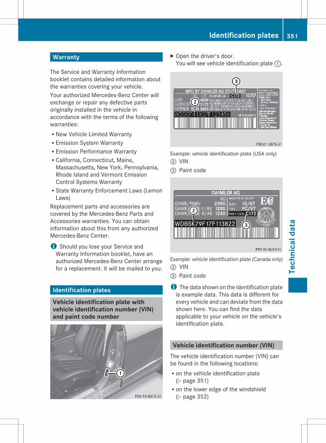
Warranty
The Service and Warranty Informationbooklet contains detailed information aboutthe warranties covering your vehicle.Your authorized Mercedes-Benz Center willexchange or repair any defective partsoriginally installed in the vehicle inaccordance with the terms of the followingwarranties:RNew Vehicle Limited WarrantyREmission System WarrantyREmission Performance WarrantyRCalifornia, Connecticut, Maine,
Massachusetts, New York, Pennsylvania,Rhode Island and Vermont EmissionControl Systems WarrantyRState Warranty Enforcement Laws (Lemon
Laws)Replacement parts and accessories arecovered by the Mercedes-Benz Parts andAccessories warranties. You can obtaininformation about this from any authorizedMercedes-Benz Center.
i Should you lose your Service andWarranty Information booklet, have anauthorized Mercedes-Benz Center arrangefor a replacement. It will be mailed to you.
Identification plates
Vehicle identification plate withvehicle identification number (VIN)and paint code number
X Open the driver's door.You will see vehicle identification plate :.
Example: vehicle identification plate (USA only); VIN= Paint code
Example: vehicle identification plate (Canada only); VIN= Paint code
i The data shown on the identification plateis example data. This data is different forevery vehicle and can deviate from the datashown here. You can find the dataapplicable to your vehicle on the vehicle'sidentification plate.
Vehicle identification number (VIN)The vehicle identification number (VIN) canbe found in the following locations:Ron the vehicle identification plate
(Y page 351)Ron the lower edge of the windshield
(Y page 352)
Identification plates 351
Tech
nica
l dat
a
Z

In addition to being stamped on the vehicleidentification plate, the vehicle identificationnumber (VIN) is also stamped onto the vehiclebody.It is located on the floor in front of the right-hand front seat.
X Slide the right-hand front seat to itsrearmost position.
X Fold floor covering : upwards.You will see vehicle identification number(VIN) ;.
Engine number
: Emission control information plate,including the certification of both federaland Californian emissions standards
; Engine number (stamped into thecrankcase)
= VIN (on the lower edge of the windshield)
Service products and fillingcapacities
Important safety notes
G WARNINGComply with all valid regulations with respectto handling, storing and disposing of servicefluids. Otherwise, you could endangerpersons or the environment.Keep service fluids out of the reach ofchildren.For health reasons, you should preventservice fluids from coming into direct contactwith your skin or clothing.If a service fluid is swallowed, contact aphysician immediately.
H Environmental noteDispose of service products in anenvironmentally responsible manner.
Service products include the following:RfuelsRlubricants (e.g. engine oil, transmission oil)RcoolantRbrake fluidRwindshield washer fluidRclimate control system refrigerantComponents and service products must bematched. You should therefore only useproducts that have been tested and approvedby Mercedes-Benz.Information on tested and approved productscan be obtained at an authorized Mercedes-Benz Center or on the Internet athttp://bevo.mercedes-benz.com.You can recognize service products approvedby Mercedes-Benz by the followinginscription on the containers:RMB approval (e.g. MB approval 229.51)RMB Approval (e.g. MB Approval 229.51)Other designations or recommendationsindicate a level of quality or a specification inaccordance with an MB Sheet number (e.g.
352 Service products and filling capacitiesTe
chni
cal d
ata
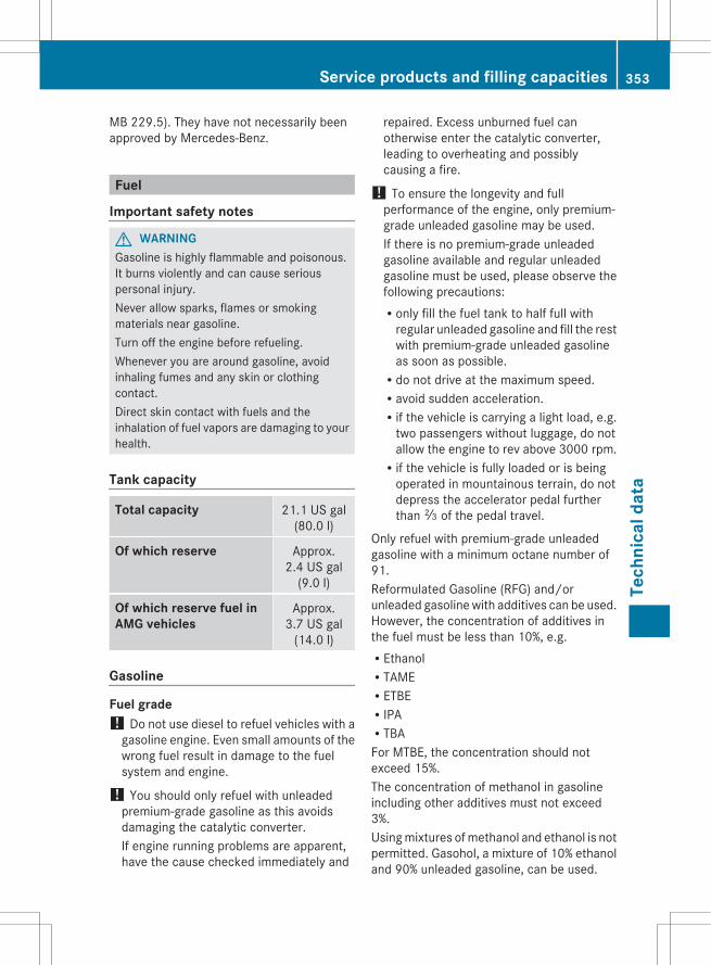
MB 229.5). They have not necessarily beenapproved by Mercedes-Benz.
Fuel
Important safety notes
G WARNINGGasoline is highly flammable and poisonous.It burns violently and can cause seriouspersonal injury.Never allow sparks, flames or smokingmaterials near gasoline.Turn off the engine before refueling.Whenever you are around gasoline, avoidinhaling fumes and any skin or clothingcontact.Direct skin contact with fuels and theinhalation of fuel vapors are damaging to yourhealth.
Tank capacity
Total capacity 21.1 US gal(80.0 l)
Of which reserve Approx.2.4 US gal
(9.0 l)
Of which reserve fuel in AMG vehicles
Approx.3.7 US gal
(14.0 l)
Gasoline
Fuel grade! Do not use diesel to refuel vehicles with a
gasoline engine. Even small amounts of thewrong fuel result in damage to the fuelsystem and engine.
! You should only refuel with unleadedpremium-grade gasoline as this avoidsdamaging the catalytic converter.If engine running problems are apparent,have the cause checked immediately and
repaired. Excess unburned fuel canotherwise enter the catalytic converter,leading to overheating and possiblycausing a fire.
! To ensure the longevity and fullperformance of the engine, only premium-grade unleaded gasoline may be used.If there is no premium-grade unleadedgasoline available and regular unleadedgasoline must be used, please observe thefollowing precautions:Ronly fill the fuel tank to half full with
regular unleaded gasoline and fill the restwith premium-grade unleaded gasolineas soon as possible.Rdo not drive at the maximum speed.Ravoid sudden acceleration.Rif the vehicle is carrying a light load, e.g.
two passengers without luggage, do notallow the engine to rev above 3000 rpm.Rif the vehicle is fully loaded or is being
operated in mountainous terrain, do notdepress the accelerator pedal furtherthan Ô of the pedal travel.
Only refuel with premium-grade unleadedgasoline with a minimum octane number of91.Reformulated Gasoline (RFG) and/orunleaded gasoline with additives can be used.However, the concentration of additives inthe fuel must be less than 10%, e.g.REthanolRTAMERETBERIPARTBAFor MTBE, the concentration should notexceed 15%.The concentration of methanol in gasolineincluding other additives must not exceed3%.Using mixtures of methanol and ethanol is notpermitted. Gasohol, a mixture of 10% ethanoland 90% unleaded gasoline, can be used.
Service products and filling capacities 353
Tech
nica
l dat
a
Z
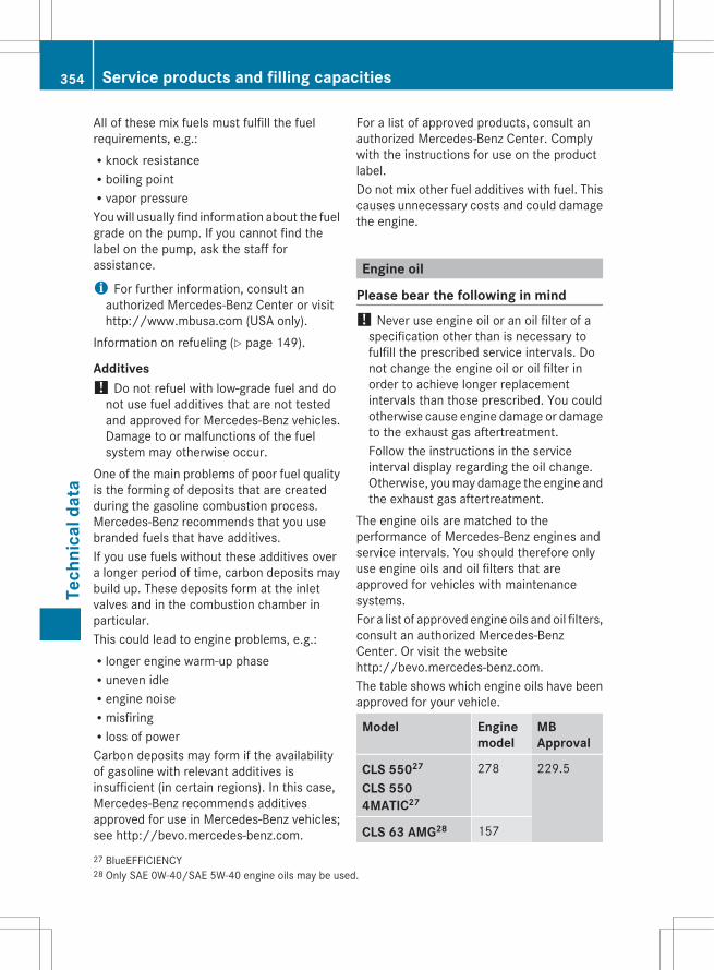
All of these mix fuels must fulfill the fuelrequirements, e.g.:Rknock resistanceRboiling pointRvapor pressureYou will usually find information about the fuelgrade on the pump. If you cannot find thelabel on the pump, ask the staff forassistance.
i For further information, consult anauthorized Mercedes-Benz Center or visithttp://www.mbusa.com (USA only).
Information on refueling (Y page 149).
Additives! Do not refuel with low-grade fuel and do
not use fuel additives that are not testedand approved for Mercedes-Benz vehicles.Damage to or malfunctions of the fuelsystem may otherwise occur.
One of the main problems of poor fuel qualityis the forming of deposits that are createdduring the gasoline combustion process.Mercedes-Benz recommends that you usebranded fuels that have additives.If you use fuels without these additives overa longer period of time, carbon deposits maybuild up. These deposits form at the inletvalves and in the combustion chamber inparticular.This could lead to engine problems, e.g.:Rlonger engine warm-up phaseRuneven idleRengine noiseRmisfiringRloss of powerCarbon deposits may form if the availabilityof gasoline with relevant additives isinsufficient (in certain regions). In this case,Mercedes-Benz recommends additivesapproved for use in Mercedes-Benz vehicles;see http://bevo.mercedes-benz.com.
For a list of approved products, consult anauthorized Mercedes-Benz Center. Complywith the instructions for use on the productlabel.Do not mix other fuel additives with fuel. Thiscauses unnecessary costs and could damagethe engine.
Engine oil
Please bear the following in mind! Never use engine oil or an oil filter of a
specification other than is necessary tofulfill the prescribed service intervals. Donot change the engine oil or oil filter inorder to achieve longer replacementintervals than those prescribed. You couldotherwise cause engine damage or damageto the exhaust gas aftertreatment.Follow the instructions in the serviceinterval display regarding the oil change.Otherwise, you may damage the engine andthe exhaust gas aftertreatment.
The engine oils are matched to theperformance of Mercedes-Benz engines andservice intervals. You should therefore onlyuse engine oils and oil filters that areapproved for vehicles with maintenancesystems.For a list of approved engine oils and oil filters,consult an authorized Mercedes-BenzCenter. Or visit the websitehttp://bevo.mercedes-benz.com.The table shows which engine oils have beenapproved for your vehicle.
Model Enginemodel
MBApproval
CLS 55027
CLS 550 4MATIC27
278 229.5
CLS 63 AMG28 157
27 BlueEFFICIENCY28 Only SAE 0W-40/SAE 5W-40 engine oils may be used.
354 Service products and filling capacitiesTe
chni
cal d
ata
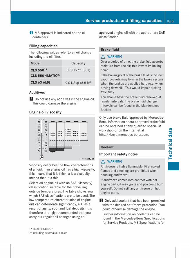
i MB approval is indicated on the oilcontainers.
Filling capacitiesThe following values refer to an oil changeincluding the oil filter.
Model Capacity
CLS 55029
CLS 550 4MATIC298.5 US qt (8.0 l)
CLS 63 AMG 9.0 US qt (8.5 l)30
Additives! Do not use any additives in the engine oil.
This could damage the engine.
Engine oil viscosity
Viscosity describes the flow characteristicsof a fluid. If an engine oil has a high viscosity,this means that it is thick; a low viscositymeans that it is thin.Select an engine oil with an SAE (viscosity)classification suitable for the prevailingoutside temperatures. The table shows youwhich SAE classifications are to be used. Thelow-temperature characteristics of engineoils can deteriorate significantly, e.g. as aresult of aging, soot and fuel deposits. It istherefore strongly recommended that youcarry out regular oil changes using an
approved engine oil with the appropriate SAEclassification.
Brake fluid
G WARNINGOver a period of time, the brake fluid absorbsmoisture from the air; this lowers its boilingpoint.If the boiling point of the brake fluid is too low,vapor pockets may form in the brake systemwhen the brakes are applied hard (e.g. whendriving downhill). This would impair brakingefficiency.You should have the brake fluid renewed atregular intervals. The brake fluid changeintervals can be found in the MaintenanceBooklet.
Only use brake fluid approved by Mercedes-Benz. Information about approved brake fluidcan be obtained at any qualified specialistworkshop or on the Internet athttp://bevo.mercedes-benz.com.
Coolant
Important safety notes
G WARNINGAntifreeze is highly flammable. Fire, nakedflames and smoking are prohibited whenhandling antifreeze.If antifreeze comes into contact with hotengine parts, it may ignite and you could burnyourself. Do not spill any antifreeze on hotengine parts.
! Only add coolant that has been premixedwith the desired antifreeze protection. Youcould otherwise damage the engine.Further information on coolants can befound in the Mercedes-Benz Specificationsfor Service Products, MB Specifications for
29 BlueEFFICIENCY30 Including external oil cooler.
Service products and filling capacities 355
Tech
nica
l dat
a
Z

Service Products 310.1, e.g. on theInternet athttp://bevo.mercedes-benz.com. Orcontact a qualified specialist workshop.
! Always use a suitable coolant mixture,even in countries where high temperaturesprevail.Otherwise, the engine cooling system is notsufficiently protected from corrosion andoverheating.
The coolant is a mixture of water andantifreeze/corrosion inhibitor. It performsthe following tasks:Rcorrosion protectionRantifreeze protectionRraising the boiling pointIf the coolant has antifreeze protection downto -35 ‡ (-37 †), the boiling point of thecoolant under operating conditions isapproximately 266 ‡ (130 †).The antifreeze/corrosion inhibitorconcentration in the engine cooling systemshould:Rbe at least 50 %. This will protect the engine
cooling system against freezing down toapproximately -35 ‡ (-37 †).Rnot exceed 55% (antifreeze protection
down to -49 ‡ [-45 †]). Otherwise, heatwill not be dissipated as effectively.
If the vehicle has lost coolant, add equalamounts of water and antifreeze/corrosioninhibitor. Mercedes-Benz recommends anantifreeze/corrosion inhibitor concentrate inaccordance with MB Specifications forService Products 310.1.The coolant is checked with everymaintenance interval at a qualified specialistworkshop.
i When the vehicle is first delivered, it isfilled with a coolant mixture that ensuresadequate antifreeze and corrosionprotection.
Capacity
Model Capacity
All models except AMG vehicles
Approx. 14.8 US qt(14.0 l)
CLS 63 AMG Without auxiliaryradiator:
Approx. 13.6 US qt(12.9 l)
With auxiliaryradiator:
Approx. 14.8 US qt(14.0 l)
i Use MB 325.0 or MB 326.0 corrosioninhibitor/antifreeze.
Washer fluid
G WARNINGWasher solvent/antifreeze is highlyflammable. Do not spill washer solvent/antifreeze on hot engine parts, because it mayignite and burn. You could be seriouslyburned.
! Only use washer fluid that is suitable forplastic lamp lenses, e.g. MB SummerFit orMB WinterFit. Unsuitable washer fluidcould damage the plastic lenses of theheadlamps.
! Do not add distilled or de-ionized water tothe washer fluid container. Otherwise, thelevel sensor may be damaged.
! Only MB SummerFit and MB WinterFitwasher fluid should be mixed together. Thespray nozzles may otherwise becomeblocked.
356 Service products and filling capacitiesTe
chni
cal d
ata
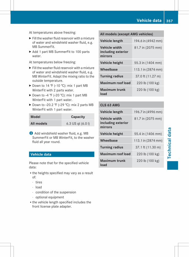
At temperatures above freezing:X Fill the washer fluid reservoir with a mixture
of water and windshield washer fluid, e.g.MB SummerFit.
X Add 1 part MB SummerFit to 100 partswater.
At temperatures below freezing:X Fill the washer fluid reservoir with a mixture
of water and windshield washer fluid, e.g.MB WinterFit. Adapt the mixing ratio to theoutside temperature.
X Down to 14 ‡ (Ò10 †): mix 1 part MBWinterFit with 2 parts water.
X Down to Ò4 ‡ (Ò20 †): mix 1 part MBWinterFit with 1 part water.
X Down to Ò20.2 ‡ (Ò29 †): mix 2 parts MBWinterFit with 1 part water.
Model Capacity
All models 6.3 US qt (6.0 l)
i Add windshield washer fluid, e.g. MBSummerFit or MB WinterFit, to the washerfluid all year round.
Vehicle data
Please note that for the specified vehicledata:Rthe heights specified may vary as a result
of:- tires- load- condition of the suspension- optional equipmentRthe vehicle length specified includes the
front license plate adapter.
All models (except AMG vehicles)
Vehicle length 194.6 in (4942 mm)
Vehicle width including exterior mirrors
81.7 in (2075 mm)
Vehicle height 55.3 in (1404 mm)
Wheelbase 113.1 in (2874 mm)
Turning radius 37.0 ft (11.27 m)
Maximum roof load 220 lb (100 kg)
Maximum trunk load
220 lb (100 kg)
CLS 63 AMG
Vehicle length 196.7 in (4996 mm)
Vehicle width including exterior mirrors
81.7 in (2075 mm)
Vehicle height 55.4 in (1406 mm)
Wheelbase 113.1 in (2874 mm)
Turning radius 37.1 ft (11.30 m)
Maximum roof load 220 lb (100 kg)
Maximum trunk load
220 lb (100 kg)
Vehicle data 357
Tech
nica
l dat
a
Z

358

359

360
Publication detailsInternet
Further information about Mercedes-Benzvehicles and about Daimler AG can be foundon the following websites:http://www.mbusa.com (USA only)http://www.mercedes-benz.ca (Canadaonly)
Editorial office
Not to be reprinted, translated or otherwisereproduced, in whole or in part, without thewritten permission of Daimler AG.
As at 19.08.2011

Order no. 6515 1468 13 Part no. 218 584 13 81 Edition B 2012
É2185841381lËÍ2185841381