azura surgery center renalus crestview - green-simmons
TRANSCRIPT
AHCA Client Code/File No.: 14/14960974-101-1 Tenant: Azura Vascular Care 52 East Swedesford Road Suite 110 Malvern, PA 19355 ARCHITECT: Jeffrey K. Griffin, AIA 931 Monroe Drive NE, Suite A102-181 Atlanta, GA 30308 404-310-8827 Project: Azura Surgery Center Renalus Crestview
For Construction June 27, 2019
PROJECT MANUAL
FOR THE
CONSTRUCTION OF
PROJECT MANUAL
FOR THE
CONSTRUCTION
OF
Azura Surgery Center Renalus Crestview
Tenant Improvements (TI)
J e f f r e y K . G r i f f i n , A I A
Azura Surgery Center Renalus Crestview TC-1 06/19
Azura Surgery Center Renalus Crestview
SPECIFICATIONS-Tenant Improvements
TABLE OF CONTENTS
SPECIFICATIONS
DIVISION 1 - GENERAL REQUIREMENTS
Section 01015 Contractor’s Use of the Premises
Section 01070 Abbreviations and Definitions
Section 01100 Alternates & Substitutions
Section 01200 Project Meetings
Section 01340 Shop Drawings, Product Data and Samples
Section 01410 Testing and Inspection
Section 01420 Master Submittal Transmittal Form
Section 01500 Temporary Facilities and Controls
Section 01600 Owner Furnished Equipment
Section 01640 Product Handling
Section 01700 Contract Closeout
Section 01700 Attic Stock Checklist – Appendix A
Section 01700 Life Safety Manual Checklist - Appendix B
Section 01700 Damper Inspection Report – Appendix C
Section 01710 Cleaning
Section 01720 Project Record Documents
DIVISION 2 - SITEWORK
No Sections
DIVISION 3 - CONCRETE
Section 03300 Cast In Place Concrete
DIVISION 4 - MASONRY
No Sections
DIVISION 5 - METALS
Section 05500 Metal Fabrications
DIVISION 6 - WOOD, PLASTICS AND COMPOSITES
Section 06100 Rough Carpentry
Section 06402 Interior Architectural Woodwork
DIVISION 7 - THERMAL AND MOISTURE PROTECTION
Section 07210 Thermal Insulation
Azura Surgery Center Renalus Crestview TC-2 06/19
Section 07841 Penetration Firestopping
Section 07844 Fire-Resistive Joint Systems
Section 07920 Joint Sealants & Waterproofing
DIVISION 8 - OPENINGS
Section 08111 Steel Doors and Frames
Section 08211 Flush Wood Doors
Section 08411 Aluminum-Framed Entrances and Storefronts
Section 08561 Pass Through Windows
Section 08710 Door Hardware
Section 08720 Automatic Door Operators
Section 08800 Glass and Glazing
DIVISION 9 - FINISHES
Section 09260 Gypsum Board Assemblies
Section 09300 Tiling
Section 09511 Acoustical Panel Ceilings
Section 09650 Resilient Flooring
Section 09900 Paints and Coatings
Section 09672 Resinous Flooring
DIVISION 10 - SPECIALTIES
Section 10190 Cubicle Curtains and Tracks
Section 10260 Wall and Door Protection
Section 10440 Interior Signage
Section 10500 Lockers
Section 10520 Fire-Protection Specialties
Section 10810 Toilet Accessories, Paper & Soap Dispensers
DIVISION 11 - EQUIPMENT
No Sections
DIVISION 12 - FURNISHINGS
No Sections
DIVISION 13 - SPECIAL CONSTRUCTION
Section 13090 Radiation Shielding Protection
DIVISION 14 - CONVEYING SYSTEMS
DIVISION 15 - MECHANICAL
Section 15010 General Mechanical Requirements
Section 15140 Hangers & Supports for Piping and Equipment
Section 15190 Equipment and Piping Identification
Azura Surgery Center Renalus Crestview TC-3 06/19
Section 15200 Insulation – HVAC and Plumbing
Section 15210 Vibration Isolation
Section 15400 Plumbing Piping
Section 15405 Medical Gas Systems
Section 15410 Plumbing Fixtures
Section 15500 Fire Protection Systems
Section 15530 Refrigerant Piping
Section 15535 Refrigerant Specialties
Section 15720 Packaged DX Constant Volume Rooftop Units
Section 15770 Ductless Split System Units
Section 15800 Ductwork
Section 15810 Fans and Hoods
Section 15820 Registers, Grilles, and Diffusers
Section 15830 Ductwork Accessories
Section 15980 Testing, Adjusting and Balancing
DIVISION 16 - ELECTRICAL
Section 16010 General Electrical Requirements
Section 16110 Raceways and Wiring –600 Volt
Section 16140 Devices
Section 16175 Electrical Identification
Section 16200 Service and Distribution – 600 Volt
Section 16340 Motor Controls and Wiring
Section 16450 Grounding Systems
Section 16500 Lighting
Section 16610 Emergency Standby Generator
Section 16650 MOV SPDS
Section 16702 Nurse Call System
Section 16721 Life Safety System – Lo Rise
Section 16730 Category 6, Coaxial, Audio, and Video Cable
Section 16780 Lightning Protection
END OF TABLE OF CONTENTS
Azura Surgery Center Renalus Crestview 01015-1
SECTION 01015
CONTRACTOR’S USE OF THE PREMISES
PART 1 - GENERAL
1.01 DESCRIPTION
A. Work Included: This Section applies to situations in which the Contractor or his
representatives including, but not necessarily limited to, suppliers, subcontractors, employees,
and field engineers, enter upon the Owner’s property.
B. Related Work:
1. Documents affecting work of this Section include, but are not necessarily limited to,
General Conditions, Supplementary Conditions, and Sections in Division 1 of these
Specifications.
1.02 QUALITY ASSURANCE
A. Promptly upon award of the Contract, notify all pertinent personnel regarding requirements of
this Section.
B. Require that all personnel who will enter upon the Owner’s property certify their awareness of
familiarity with the requirements of this Section.
1.03 USE OF PREMISES
A. The Contractor shall confine his apparatus, storage of materials and operations of his
workmen to limits as required by the Owner, and shall not unreasonably encumber the
premises with his materials.
B. The Contractor shall maintain access to and egress from the building in a safe manner, well
marked and in locations as required by the local authorities having jurisdiction over this work.
They shall be responsible for furnishing and maintaining in a safe condition all barricades,
temporary enclosures, railings, lights, etc., and removing same at completion of job.
C. At no time shall the structure be loaded beyond safe limits, and in no case shall any loads
exceed the design limits.
D. All work shall be done during the regular work hours of the day, unless specifically approved
and/or requested by the Owner. All work carried on outside of regular working hours shall be
done at the Contractor’s expense, and no extras will be allowed. The use of “Overtime” shall
be at the Contractor’s option.
1.04 SECURITY
A. Restrict the access of all persons entering upon the Owner’s property in connection with the
Work to the Access Route and to the actual site of the work.
1.05 COORDINATION OF WORK
A. The Contractor shall limit the storage of materials and equipment to the areas indicated or
required by the Owner.
Azura Surgery Center Renalus Crestview 01015-2
B. At no time during the work under the Contract shall the Contractor place, or cause to be
placed, any material or equipment, etc. at any location that would impede or impair access to
or from the present facilities for other tenants, employees, or delivery facilities.
C. The Contractor shall cooperate with the Owner to the fullest extent in providing traffic control
during the course of construction so as to provide a minimum of inconvenience to existing
tenants.
D. The Contractor shall send proper notices, make all necessary arrangements, and perform all
services required in the care and maintenance of all public utilities. The Contractor shall,
during the construction period and until final acceptance of the work as a whole by the
Owner, assume all responsibility concerning the same for which the Owner may be liable.
E. It is of paramount importance that the work of this Contract does not interfere in any way with
the normal operation of the existing utility services in use, and no interruption of the utility
services in use in the existing building can be allowed. Coordinate all work affecting service
in the existing building with the Architect and the Owner.
1.06 NOISE AND DUST CONTROL
A. Exercise all possible care to control excessive noise and dust during the construction to keep
these problems to a minimum. Traffic or construction areas shall be kept clean as required by
the Owner and in accordance with applicable local requirements.
B. Notify the Owner prior to using air compressor, jack-hammers, etc. in sufficient time to
permit removal of any occupants close enough to be affected by such disturbances. Screen all
noisy equipment with temporary enclosures to shield adjacent areas as much as possible.
C. Comply with all local noise and dust control requirements or as may be required by AHJ.
1.07 ADJACENT WORK
A. In preparing the Proposal, the Contractor and Subcontractors shall be aware that adjacent
work may be required due to the scope of the work indicated by the Documents. These areas
include, but are not limited to:
1. Adjacent space to remain.
2. Remote mechanical or electrical locations.
3. Roof areas above or adjacent to the space.
4. Site improvements and landscaping.
END OF SECTION
Azura Surgery Center Renalus Crestview 01070-1 07/17
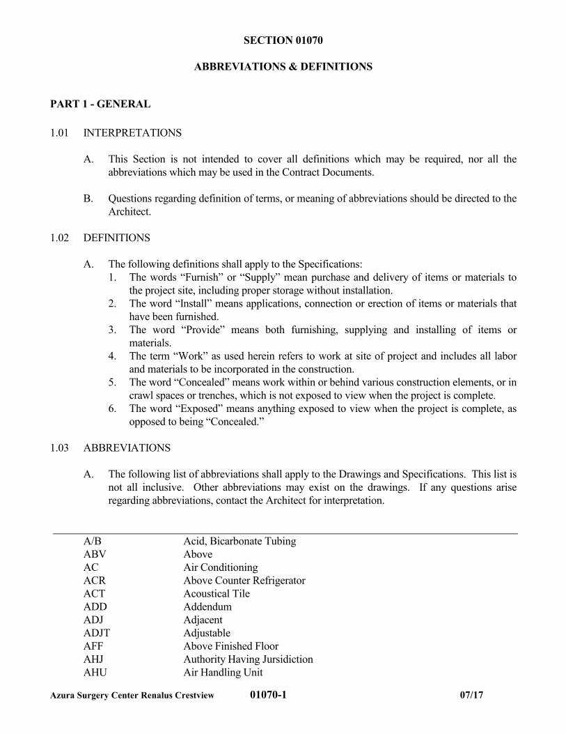
SECTION 01070
ABBREVIATIONS & DEFINITIONS
PART 1 - GENERAL
1.01 INTERPRETATIONS
A. This Section is not intended to cover all definitions which may be required, nor all the
abbreviations which may be used in the Contract Documents.
B. Questions regarding definition of terms, or meaning of abbreviations should be directed to the
Architect.
1.02 DEFINITIONS
A. The following definitions shall apply to the Specifications:
1. The words “Furnish” or “Supply” mean purchase and delivery of items or materials to
the project site, including proper storage without installation.
2. The word “Install” means applications, connection or erection of items or materials that
have been furnished.
3. The word “Provide” means both furnishing, supplying and installing of items or
materials.
4. The term “Work” as used herein refers to work at site of project and includes all labor
and materials to be incorporated in the construction.
5. The word “Concealed” means work within or behind various construction elements, or in
crawl spaces or trenches, which is not exposed to view when the project is complete.
6. The word “Exposed” means anything exposed to view when the project is complete, as
opposed to being “Concealed.”
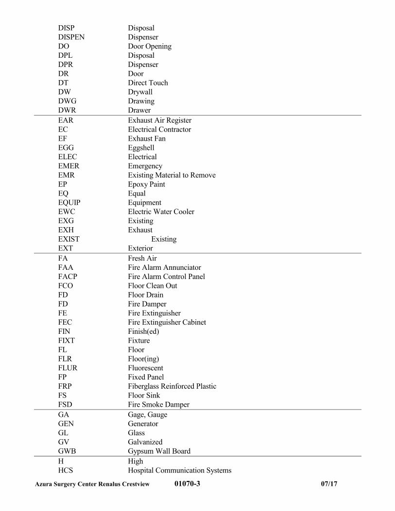
1.03 ABBREVIATIONS
A. The following list of abbreviations shall apply to the Drawings and Specifications. This list is
not all inclusive. Other abbreviations may exist on the drawings. If any questions arise
regarding abbreviations, contact the Architect for interpretation.
A/B Acid, Bicarbonate Tubing
ABV Above
AC Air Conditioning
ACR Above Counter Refrigerator
ACT Acoustical Tile
ADD Addendum
ADJ Adjacent
ADJT Adjustable
AFF Above Finished Floor
AHJ Authority Having Jursidiction
AHU Air Handling Unit
Azura Surgery Center Renalus Crestview 01070-2 07/17
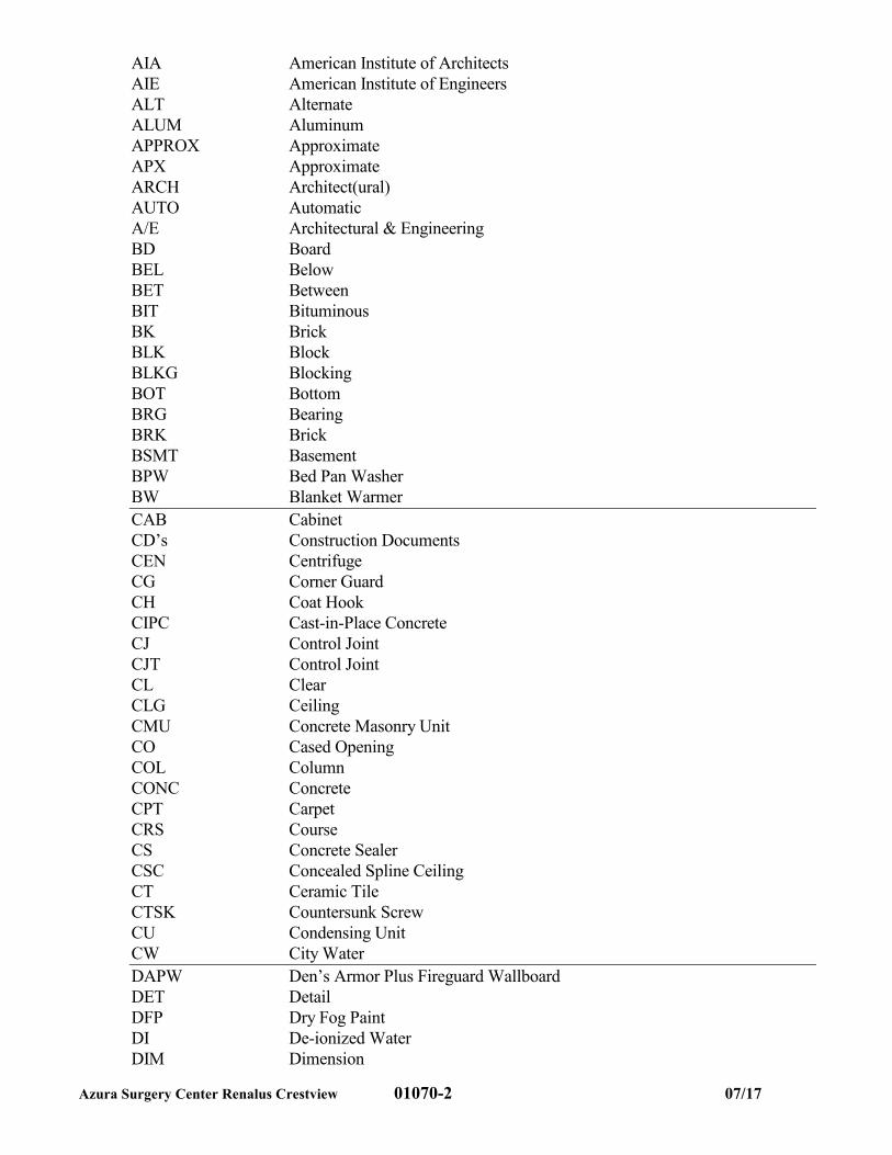
AIA American Institute of Architects
AIE American Institute of Engineers
ALT Alternate
ALUM Aluminum
APPROX Approximate
APX Approximate
ARCH Architect(ural)
AUTO Automatic
A/E Architectural & Engineering
BD Board
BEL Below
BET Between
BIT Bituminous
BK Brick
BLK Block
BLKG Blocking
BOT Bottom
BRG Bearing
BRK Brick
BSMT Basement
BPW Bed Pan Washer
BW Blanket Warmer
CAB Cabinet
CD’s Construction Documents
CEN Centrifuge
CG Corner Guard
CH Coat Hook
CIPC Cast-in-Place Concrete
CJ Control Joint
CJT Control Joint
CL Clear
CLG Ceiling
CMU Concrete Masonry Unit
CO Cased Opening
COL Column
CONC Concrete
CPT Carpet
CRS Course
CS Concrete Sealer
CSC Concealed Spline Ceiling
CT Ceramic Tile
CTSK Countersunk Screw
CU Condensing Unit
CW City Water
DAPW Den’s Armor Plus Fireguard Wallboard
DET Detail
DFP Dry Fog Paint
DI De-ionized Water
DIM Dimension
Azura Surgery Center Renalus Crestview 01070-3 07/17
DISP Disposal
DISPEN Dispenser
DO Door Opening
DPL Disposal
DPR Dispenser
DR Door
DT Direct Touch
DW Drywall
DWG Drawing
DWR Drawer
EAR Exhaust Air Register
EC Electrical Contractor
EF Exhaust Fan
EGG Eggshell
ELEC Electrical
EMER Emergency
EMR Existing Material to Remove
EP Epoxy Paint
EQ Equal
EQUIP Equipment
EWC Electric Water Cooler
EXG Existing
EXH Exhaust
EXIST Existing
EXT Exterior
FA Fresh Air
FAA Fire Alarm Annunciator
FACP Fire Alarm Control Panel
FCO Floor Clean Out
FD Floor Drain
FD Fire Damper
FE Fire Extinguisher
FEC Fire Extinguisher Cabinet
FIN Finish(ed)
FIXT Fixture
FL Floor
FLR Floor(ing)
FLUR Fluorescent
FP Fixed Panel
FRP Fiberglass Reinforced Plastic
FS Floor Sink
FSD Fire Smoke Damper
GA Gage, Gauge
GEN Generator
GL Glass
GV Galvanized
GWB Gypsum Wall Board
H High
HCS Hospital Communication Systems
Azura Surgery Center Renalus Crestview 01070-4 07/17
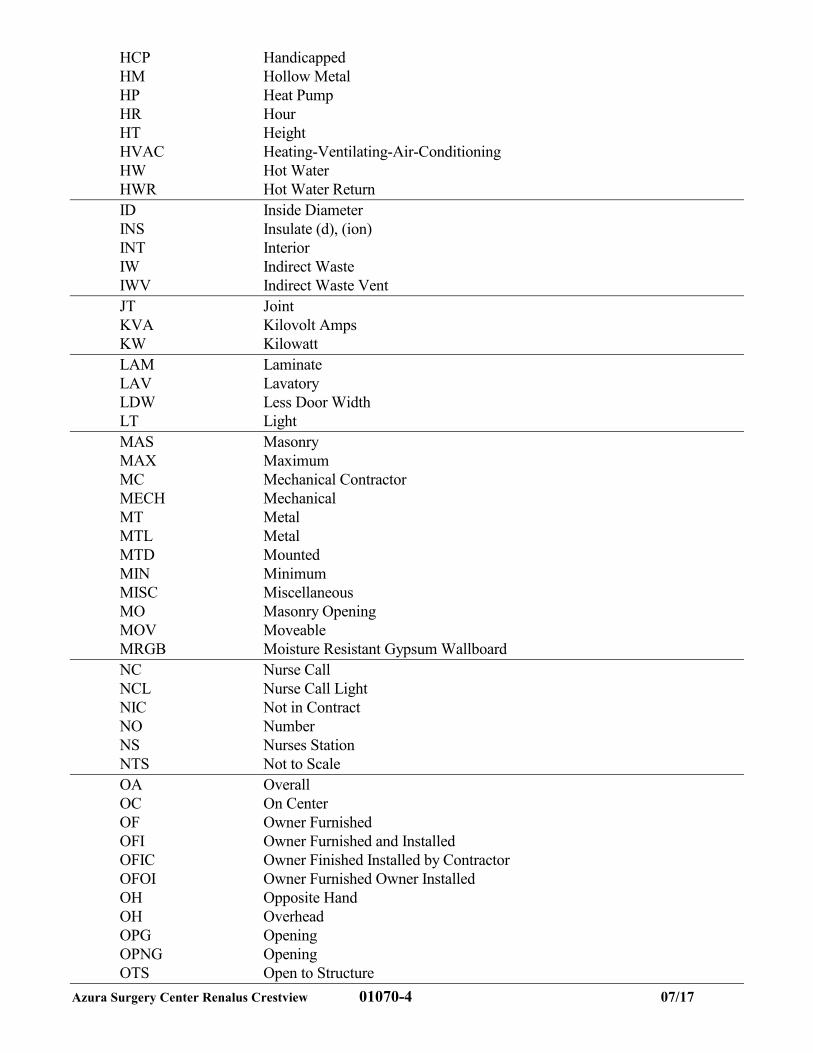
HCP Handicapped
HM Hollow Metal
HP Heat Pump
HR Hour
HT Height
HVAC Heating-Ventilating-Air-Conditioning
HW Hot Water
HWR Hot Water Return
ID Inside Diameter
INS Insulate (d), (ion)
INT Interior
IW Indirect Waste
IWV Indirect Waste Vent
JT Joint
KVA Kilovolt Amps
KW Kilowatt
LAM Laminate
LAV Lavatory
LDW Less Door Width
LT Light
MAS Masonry
MAX Maximum
MC Mechanical Contractor
MECH Mechanical
MT Metal
MTL Metal
MTD Mounted
MIN Minimum
MISC Miscellaneous
MO Masonry Opening
MOV Moveable
MRGB Moisture Resistant Gypsum Wallboard
NC Nurse Call
NCL Nurse Call Light
NIC Not in Contract
NO Number
NS Nurses Station
NTS Not to Scale
OA Overall
OC On Center
OF Owner Furnished
OFI Owner Furnished and Installed
OFIC Owner Finished Installed by Contractor
OFOI Owner Furnished Owner Installed
OH Opposite Hand
OH Overhead
OPG Opening
OPNG Opening
OTS Open to Structure
Azura Surgery Center Renalus Crestview 01070-5 07/17
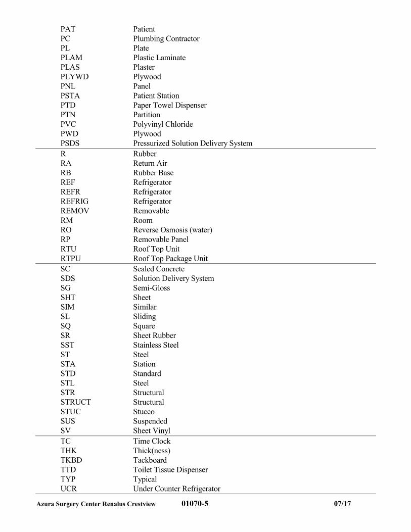
PAT Patient
PC Plumbing Contractor
PL Plate
PLAM Plastic Laminate
PLAS Plaster
PLYWD Plywood
PNL Panel
PSTA Patient Station
PTD Paper Towel Dispenser
PTN Partition
PVC Polyvinyl Chloride
PWD Plywood
PSDS Pressurized Solution Delivery System
R Rubber
RA Return Air
RB Rubber Base
REF Refrigerator
REFR Refrigerator
REFRIG Refrigerator
REMOV Removable
RM Room
RO Reverse Osmosis (water)
RP Removable Panel
RTU Roof Top Unit
RTPU Roof Top Package Unit
SC Sealed Concrete
SDS Solution Delivery System
SG Semi-Gloss
SHT Sheet
SIM Similar
SL Sliding
SQ Square
SR Sheet Rubber
SST Stainless Steel
ST Steel
STA Station
STD Standard
STL Steel
STR Structural
STRUCT Structural
STUC Stucco
SUS Suspended
SV Sheet Vinyl
TC Time Clock
THK Thick(ness)
TKBD Tackboard
TTD Toilet Tissue Dispenser
TYP Typical
UCR Under Counter Refrigerator
Azura Surgery Center Renalus Crestview 01070-6 07/17
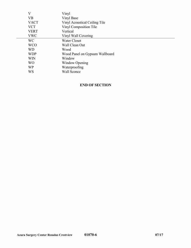
V Vinyl
VB Vinyl Base
VACT Vinyl Acoustical Ceiling Tile
VCT Vinyl Composition Tile
VERT Vertical
VWC Vinyl Wall Covering
WC Water Closet
WCO Wall Clean Out
WD Wood
WDP Wood Panel on Gypsum Wallboard
WIN Window
WO Window Opening
WP Waterproofing
WS Wall Sconce
END OF SECTION
Azura Surgery Center Renalus Crestview 01100-1 07-2017
SECTION 01100
ALTERNATES & SUBSTITUTIONS
1.01 PROVISIONS INCLUDED
A. The conditions of the Contract and Division 1, General Requirements, apply to the work under
this Section.
1.02 DESCRIPTION OF WORK
A. Furnish all labor, materials and services necessary for the proper and complete execution of
accepted alternates. The amount of alternate prices to be added to or deducted from the base
bid shall be stated on the Bid Form and shall include the cost of any and all modifications made
necessary by the Owner’s acceptance of an alternate.
B. State the amount to be added to or deducted from the base bid for each of the following
alternates, if these alternates are added to the work of the Contract. The base bid shall not
include the following listed alternates or work required to be performed in connection thereto.
C. There should be no substitution and/or deviation from the specified products or design without
notable benefit to the owner by either enhanced quality, functionality or cost / scheduling
savings.
1.03 SUBSTITUTIONS
A. Substitution requests shall be made during the bidding process with sufficient time for the
Architect to respond.
B. No substitutions will be accepted after contract award.
C. Substitution requests shall include the following:
1. Effect substitution has on dimensions indicated on drawings.
2. Effect substitution has on Electrical, Mechanical, Plumbing, Life Safety, Structure,
Finishes, Architectural, etc.
3. Difference between proposed and specified item.
4. Manufacturer’s guarantee and if different from specified.
5. Include all product data.
6. Indicate savings or increase in contract sum if substitution is accepted by Owner.
D. GC agrees to pay all Architectural or Engineering costs, if required, to review, test or revise
drawings or specifications caused by the substitution.
END OF SECTION
Azura Surgery Center Renalus Crestview 01200-1 07/17
SECTION 01200
PROJECT MEETINGS
PART 1 - GENERAL
1.01 SECTION INCLUDES:
A. Contractor’s Responsibilities:
1. Schedule and administer meetings throughout duration of work.
2. Prepare agenda for meetings.
3. Distribute written notice of each meeting seven working days in advance of meeting
date.
4. Make physical arrangements for meetings.
5. Preside at meetings.
6. Record the minutes; include all significant proceedings and decisions.
7. Reproduce and distribute copies of minutes within three working days after each
meeting.
8. Provide one copy to:
a) All participants in the meeting, including the Architect.
b) All parties affected by decisions made at the meeting.
B. Participants:
1. Qualified representative of Contractors, Subcontractors, and Suppliers authorized to
act on behalf of the parties they represent.
2. Owner’s Representative at their option.
3. Architect at the discretion of the Project Manager.
1.02 PRE-CONSTRUCTION MEETING
A. Schedule meeting within the early stages of Construction as determined by the General
Contractor.
B. Suggested agenda: Prepare written material, distribute lists, and discuss the following:
1. Identification of major Subcontractors and Suppliers.
2. Projected construction schedules.
3. Critical work sequencing.
4. Major equipment deliveries and priorities.
5. Project coordination, including designation of responsible person.
6. Procedures for, and processing of:
a) Field decisions.
b) Proposal requests.
c) Submittals.
d) Change orders.
e) Applications for payments.
7. Adequacy of distribution of Contract Documents.
8. Procedures for Maintaining Record Documents.
9. Use of premises:
a) Office, work, and storage areas.
b) Owner’s requirements.
c) Compliance with applicable CDC Guidelines
Azura Surgery Center Renalus Crestview 01200-2 07/17
10. Construction facilities, construction aids, and controls.
11. Temporary utilities.
12. Safety and first aid procedures.
13. Security procedures.
14. Housekeeping procedures.
15. Working days/hours.
1.03 PROGRESS MEETINGS
A. Schedule regular (weekly or as warranted by construction progress) meetings and as
necessary, schedule additional meetings.
1. Meetings shall be conducted as GoToMeeting or other web based video conference call
and held on the same day and time each week. GC shall coordinate a time that is
acceptable to Owner Representative and Architect.
B. Suggested Agenda:
1. Review and approval of minutes of previous meeting.
2. Review of work progress since previous meeting.
3. Field observations, problems, and conflicts.
4. Problems which impede construction schedule.
5. Review of off-site fabrication, delivery schedules.
6. Corrective measures and procedures required to regain projected schedule.
7. Revisions to construction schedule.
8. Plan progress and schedule for succeeding work period.
9. Coordination of schedules.
10. Review submittal schedules; expedite as required.
11. Maintenance of quality standards
12. Review proposed changes for:
a) Effect on construction schedule and on completion date.
b) Effect on other contracts of the Project.
13. Other business.
1.04 PRE-INSTALLATION
A. When required in an individual Specification Section, schedule a pre-installation meeting at
the job site prior to starting the work of the Section.
B. Require attendance of entities directly affecting, or affected by, the work of the Section.
C. Notify Owner’s Representative two weeks in advance of meeting date that requires on site
attendance.
END OF SECTION
Azura Surgery Center Renalus Crestview 01340-1 07/17
SECTION 01340
SHOP DRAWINGS, PRODUCT DATA AND SAMPLES
PART 1 - GENERAL
1.01 GENERAL CONDITIONS
A. Refer to paragraphs 4.2 and 3.12 of the General Conditions.
B. In the event of conflict between requirements of the General Conditions and this Section covering
shop drawings, product data and samples, the requirements of Section 01340 shall govern.
Unaltered provisions remain in effect.
1.02 DESCRIPTION
A. Submit to the Architect shop drawings, product data and samples required by specification
sections.
B. Prepare and submit the Construction Schedule, a separate schedule listing dates for submission
and dates reviewed shop drawings, product data and samples will be needed for each product.
PART 2 PRODUCTS
2.01 SHOP DRAWINGS
A. Submit shop drawings electronically in PDF. Include fabrication, erection, layout and
setting drawings and other such drawings as required under various sections of the
specifications until final approval is obtained. Reproduction of Contract Drawings will not
be used for Shop Drawings.
1. Shop drawings and other data shall be combined (bound) in a single file.
B. Date and mark shop drawings to show name of the Project, the Architect, Contractor,
originating Subcontractor, Manufacturer or Supplier, and separate details as pertinent.
C. Completely identify on shop drawings specification section and locations at which
materials or equipment are to be installed.
2.02 PRODUCT DATA
A. Submit manufacturer’s descriptive data including catalog sheets for materials, equipment
and fixtures, showing dimensions, performance characteristics and capacities, wiring
diagram and controls, schedule and other pertinent information as required.
B. Submit brochures and other submittal data. Mark product data to show the name of the
Project, Architect, Contractor, originating Subcontractor, Manufacturer or Supplier, and
separate details if pertinent.
Azura Surgery Center Renalus Crestview 01340-2 07/17
C. Completely identify on product data specification section and location at which materials
or equipment are to be installed.
D. Clearly mark to show pertinent data applicable to the Project.
2.03 SAMPLES
A. Submit physical examples of materials in duplicate when required by specification
sections to illustrate materials, workmanship or to establish standards by which completed
work shall be judged.
B. Date samples and mark to show the name of the project, Architect, Contractor, originating
Subcontractor, Manufacturer or Supplier and separate details if pertinent.
C. Completely identify on samples specification section and location in which materials or
equipment are to be installed.
D. Provide wall and ceiling finish material samples from the manufacturer or supplier with
attached flame resistance testing classification information (Class A, B or C) for use in
Section 01700 Contract Closeout.
E. Provide floor finish material samples from the manufacturer or supplier with attached
critical radiant flux testing classification information (Class I or Class II) for use in Section
01700 Contract Closeout.
2.04 CONTRACTOR RESPONSIBILITIES
A. Review shop drawings, product data and samples prior to submission to the Architect.
B. Include on submittals the Contractor's stamp, initialed or signed, certifying review of
submittals, verification of field dimensions and compliance with Contract Documents.
Shop drawings, product data and samples not so stamped, and checked and approved by
the Contractor will not be reviewed by the Architect, but will be returned to the
Contractor. Shop drawings stamped and signed as approved by the Contractor but showing
evidence that they have not been carefully checked by the Contractor may be returned to
the Contractor to be re-checked and re-submitted to the Architect.
C. Clearly identify where the submission deviates from the design intent or construction
drawings.
2.05 SUBSTITUTIONS
A. Approval required:
1. The Contract is based on the standards of quality established in the Contract
Documents.
Azura Surgery Center Renalus Crestview 01340-3 07/17
2. All products proposed for use, including those specified by required attributes and
performance, require approval by the Architect before being incorporated into the
Work.
3. Do not substitute materials, equipment or methods unless such substitution has been
specifically approved for this Work by the Architect.
B. “Or equal”:
1. Where the phrase “or equal” or “or equal as approved by the Architect” occurs in the
Contract Documents, do not assume that materials, equipment or methods will be
approved as equal unless the items have been specifically approved for this Work by
the Architect.
2. Substitutions shall be judged against the specified item for quality, durability,
operation, appearance, and other applicable qualities including fitness for use in this
situation. The decision of the Architect is final.
PART 3 - EXECUTION
3.01 SUBMISSION REQUIREMENTS
A. Schedule submissions at least two weeks before date reviewed submittals will be needed.
B. Accompany submittals with transmittal letters containing the date, project title,
Contractor’s name and address, number of each shop drawing, product data and samples
submitted, and notification of deviation from Contract Documents.
1. Material Safety Data Sheet
Contractor shall furnish to the Architect, for review, four (4) copies of Material Safety
Data Sheets (MSDS) for all products as specified or required. Allow ample time for
Architect’s comment and review.
Do not install products until confirmation of review is obtained.
MSDS copies should be included at the same submittal with shop drawings or
product submittal. The following products must include the MSDS copy with the
shop drawing or submittal:
a) Mechanical Insulation
b) Mastic or Adhesive
c) Ceiling Tiles or other Composite Materials
d) Sealants or Caulking
e) Materials containing or releasing volatile organic compounds (VOC’s)
f) Paints, Varnishes, Stains or other similar coatings
Azura Surgery Center Renalus Crestview 01340-4 07/17
2. Flame Spread Certificates
Contractor shall furnish to the Architect, for review, four (4) copies of Flame Spread
Certificates for all products as specified or required.
Allow ample time for Architect’s comment and review.
Do not install products until confirmation of review is obtained.
Flame Spread Certificate copies should be included at the same submittal with shop
drawings or product submittal. The following products must include the Flame
Spread Certificate copy with the shop drawing or submittal:
a) Carpet
b) Wallcovering
c) Fabrics
d) Cubicle curtains
3.02 RESUBMISSION REQUIREMENTS
A. Shop Drawings: Revise initial drawings as required and resubmit as specified for
initial submittals. Clearly identify on drawings any changes which have been made
other than those requested by the Architect.
B. Product Data and Samples: Submit new datum and samples as required for initial
submittal.
C. GC shall be responsible for costs associated with review of submissions beyond two
reviews. Such costs shall include but are not limited to the Architect’s and/or
Engineer’s time, cost of reproduction, scanning, and shipping charges.
3.03 DISTRIBUTION OF SHOP DRAWINGS AND SUBMITTALS
A. Contractor is still responsible for obtaining and distributing prints of shop drawings as
necessary after as well as before final approval and for coordination of submittals
between his subcontractors and suppliers.
B. Make prints of approved shop drawings which carry the Architect's appropriate stamp.
C. The cost of scanning and printing is the responsibility of the Contractor.
END OF SECTION
Azura Surgery Center Renalus Crestview 01410-1 07/17
SECTION 01410
TESTING AND INSPECTION
TABLE OF CONTENTS
Sub-Section/Title
1. General Provisions (For Testing and Inspection)
2. Testing and Inspection
3. Materials Acceptance Tests
4. Concrete Mix Designs
5. Earthwork
6. Concrete
7. Masonry
8. Structural Steel, Steel Joists and Metal Decks
9. Concrete Slab Moisture
PART 1 GENERAL
1.01 GENERAL PROVISIONS
A. These specifications for Testing and Inspection are applicable to the Project and the Contract
Documents therefore are hereby incorporated into these Specifications.
B. The Testing Agency shall conform to applicable requirements of ASTM E329, and any
additional requirements specified herein or in the Contract Documents.
1. Examine the Contract Documents and the Report on Subsurface Investigation and become
thoroughly acquainted with the detailed testing and inspection requirements, especially those
of the following Sections where incorporated into the work:
Division 2 - Site Work
Division 3 - Concrete
Division 4 - Masonry
Division 5 – Metal
Division 9 – Finishes
C. The Testing Agency shall make all necessary arrangements with the Contractor in ensuring the
presence of the required Inspectors at all Contract Operations specified to be included under the
Testing and Inspection Agreement.
D. The Contractor shall notify the Testing Agency a reasonable time in advance (not less than 24
hours) of the time when operations requiring inspection or testing are scheduled to start.
E. Provide necessary personnel, equipment and facilities for tests and inspection. Personnel shall be
experienced and competent in their particular specialties.
F. Nothing herein specified permits the Testing Agency to allow the Contractor to deviate from the
requirements of the Contract Documents.
Azura Surgery Center Renalus Crestview 01410-2 07/17
G. The Testing Agency shall conduct its work so as not to cause delay in the progress of
construction. Any non-compliance with the Contract Documents shall be immediately reported
to the Contractor and Architect.
H. The costs of the following tests and inspections shall be accounted for separately:
1. Tests and inspection of materials and workmanship not conforming to Specification
requirements.
2. Acceptance tests for materials because of changes in properties or changed sources.
3. Tests and services of inspectors required by a Public Authority.
1.02 TESTING AND INSPECTION
A. The Testing Agency shall maintain and distribute a continuous record of the quality of materials
and workmanship under its control, and certify that such materials and workmanship meet the
Specification requirements.
B. The inspection and control shall be performed under the direction of the Architect.
C. The duties of the Testing Agency shall include:
1. Test and certification of materials or components designated to be tested at source, at place of
fabrication, or at the job site.
2. Supervision and certification of installation of materials designated to be inspected.
3. Submission of reports:
a) Reports of source and field inspections shall be prepared and distributed within 3 days of
the test. Digital copies of each report of tests shall be distributed to the project team
within 2 days of the performance of tests. Results of tests showing non-conformance to
specification requirements shall be advised to the Contractor and the Architect via email
at the same time the reports are distributed.
b) Distribution of one copy of each report shall be as follows:
(1) Owner’s Representative
(2) Architect ([email protected])
(3) Contractor
(4) Local Building Inspectors, when required by them.
c) All reports shall include accurate and unambiguous descriptions of the source of the
materials and their location in the project and a statement whether the work inspected or
tested conforms or does not conform to the Contract Documents.
1.03 MATERIALS ACCEPTANCE TESTS
A. To determine that materials to be used on the job meet Specification requirements, the following
tests shall be made prior to actual use of materials:
1. Composition, gradation and moisture-density relationships for compacted and ordinary fill
materials. One set of tests for each type of material from each source.
2. Review of Contractor's qualification test results for cements, and for fine and coarse
aggregates for:
a) Normal weight concrete
3. Review of Contractor's qualification test results for masonry unit and masonry prism
strengths.
Azura Surgery Center Renalus Crestview 01410-3 07/17
B. Whenever the source or characteristics of materials change or the quality of materials provided
indicates lack of compliance with Specification requirements, full or partial acceptance tests
shall be repeated as directed by the Architect until such materials conform. Cost of such tests and
inspection repetitions shall be kept separately.
1.04 CONCRETE MIX DESIGNS
A. The Testing Agency shall review and/or make acceptance tests as specified for concrete design
mixes provided by the Contractor:
1. A mix for each specified strength and type of concrete, and each admixture or combination of
admixtures specified.
2. All materials and design mixtures to be supplied by the Contractor at least five (5) weeks
prior to proposed use.
1.05 EARTHWORK
A. Inspection and control shall include:
1. In-place density tests, generally at the rate of 3 tests per lift for compacted fill and 1 test per
lift for ordinary fill. Tests for moisture content control of subgrade as required by existing
conditions.
2. Inspection of foundation pier excavation, footing bottoms and finished subgrades for bearing
capacity and workmanship.
3. Review and make necessary recommendations to ensure compliance to Specification
requirements of all lime or cement stabilization, and compaction operations, materials,
methods and equipment proposed by the Contractor.
4. Inspection of and necessary adjustment recommendations for fills and subgrade stabilization
materials and installation.
1.06 CONCRETE
A. Inspection and control shall, in general, conform to ACI Recommended Practice for Concrete
Inspection, ACI 311, and shall include:
1. Inspection of forms and form facing materials for line, grade, tightness, quality of surface,
and cleanliness.
2. Inspection of reinforcement for quantity, details, clearances and placement, including proper
use of accessories.
3. Inspection of concrete at the mixing plant, consisting of inspection of materials for
conformance to the approved materials, check of batch quantities for compliance with design
mixes and project requirements, recommendations for adjustment of batches for consistency.
4. Inspection of concrete at the job site, including transportation, mixing, placement, protection
and curing.
5. Sampling of concrete at site, fabrication of compression test specimens, transportation to
laboratory and performing standard compression tests. One set of three (3) specimens shall be
made for each 50 cubic yards of concrete placed, but not less than one (1) set for each day's
placement for each design mix used.
6. Periodic slump, air content and density tests at the site. These tests shall be made whenever
cylinders are taken or whenever field conditions indicate non-compliance with Specification
requirements.
Azura Surgery Center Renalus Crestview 01410-4 07/17
7. In addition to the above, the Contractor may direct additional control cylinders to be made,
cured and tested to check strengths for shoring or adequacy of curing or cold weather
protection. In such instances, the cylinders shall be cured with the concrete in the field under
the least advantageous conditions. All work requested by the Contractor or all work required
by non-compliance with the Specifications shall be at the Contractor's expense, utilizing the
selected Testing Agency.
8. When tests of control specimens fall below the required strength, the Architect may require
core specimens to be taken from the concrete which it represents, and tested in accordance
with ASTM Methods, at Contractor's expense.
1.07 MASONRY
A. Inspection shall be of a nature as to determine, in general, that the construction and workmanship
are in accordance with the Contract Documents, and shall include:
1. Inspection of materials in field for conformance to Specification requirements and adequacy
of Contractor's protection measures.
2. Full time inspection of installation of all reinforced masonry.
3. Inspection of reinforcement for quantity, details, clearances and placement.
4. Inspection of grouting to ensure that required spaces are properly filled.
5. Compression tests of field samples of mortar and grout at the rate of one set of 5 samples for
each 1,000 square feet of wall (but not less than one set for each day's production).
1.08 STRUCTURAL STEEL, STEEL JOISTS & METAL DECKS
A. Inspection and control shall include:
1. When directed by the Architect, inspection of materials and workmanship at shop to verify
effectiveness of Contractor's quality control and conformance to Specification requirements.
2. Verification of welder qualifications.
3. Certification that quality and size of all field welds meet Specification requirements.
4. Checking bolt installation and certifying that all bolts required are provided and properly
tightened.
5. Checking of high-strength bolt tightening tools for accurate performance. Procedure shall be
approved by the Architect or Engineer.
6. Inspection of primer paint film thickness and touch-up painting.
7. Inspection (upon delivery to site) of steel joist weld quality and sizes for conformance to
Specification requirements.
8. Inspection of steel deck welding in the field.
1.09 FLOOR TESTING FOR MOISTURE VAPOR PRESSURE
A. Inspection and Control shall be performed by an independent testing agency and include the
following:
1. Alkalinity and adhesion testing:
a) Perform all tests as recommended by manufacturer of flooring product(s) to be installed.
b) Proceed with flooring installation only after substrates pass testing.
2. Verify that substrates are dry and free from curing compounds, sealers and hardeners.
a) Perform anhydrous calcium chloride test per ASTM F 1869. Proceed with flooring
installation only after substrates have maximum moisture-vapor-emission rate within the
Azura Surgery Center Renalus Crestview 01410-5 07/17
parameters of the glue and flooring manufacturer’s installation and warranty
requirements.
b) Perform Relative humidity test (probe test) per ASTM F-2170. Proceed with flooring
installation only after test results fall within the parameters of the glue and flooring
manufacturer’s installation and warranty requirements.
c) Perform pH testing per ASTM F-710. Proceed with flooring installation only after
substrates have an alkalinity rating within the parameters of the glue and flooring
manufacturer’s installation and warranty requirements.
3. Provide written documentation of testing results via email to Owner’s Representative and
Architect.
END OF SECTION
Azura Surgery Center Renalus Crestview 01410-1
SECTION 01410
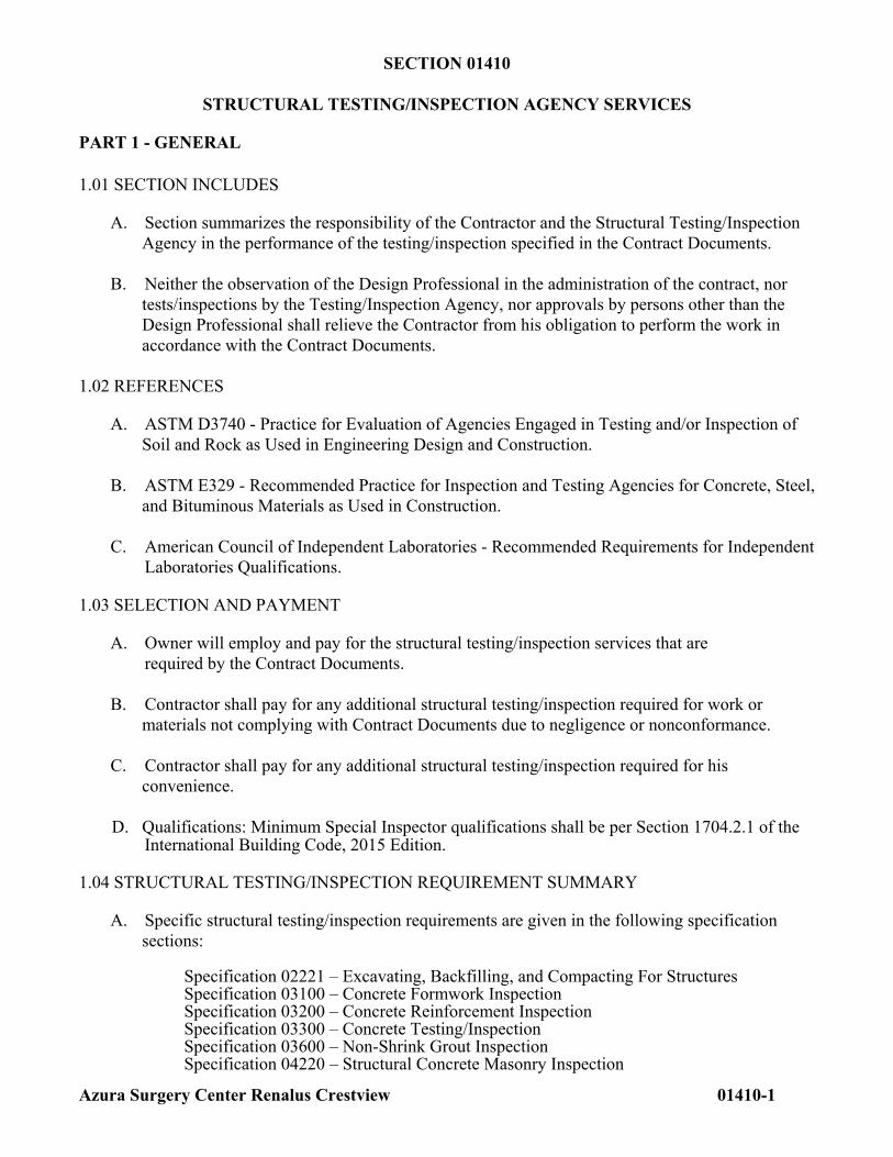
STRUCTURAL TESTING/INSPECTION AGENCY SERVICES
PART 1 - GENERAL 1.01 SECTION INCLUDES
A. Section summarizes the responsibility of the Contractor and the Structural Testing/Inspection Agency in the performance of the testing/inspection specified in the Contract Documents.
B. Neither the observation of the Design Professional in the administration of the contract, nor
tests/inspections by the Testing/Inspection Agency, nor approvals by persons other than the Design Professional shall relieve the Contractor from his obligation to perform the work in accordance with the Contract Documents.
1.02 REFERENCES
A. ASTM D3740 - Practice for Evaluation of Agencies Engaged in Testing and/or Inspection of Soil and Rock as Used in Engineering Design and Construction.
B. ASTM E329 - Recommended Practice for Inspection and Testing Agencies for Concrete, Steel,
and Bituminous Materials as Used in Construction. C. American Council of Independent Laboratories - Recommended Requirements for Independent
Laboratories Qualifications.
1.03 SELECTION AND PAYMENT
A. Owner will employ and pay for the structural testing/inspection services that are required by the Contract Documents.
B. Contractor shall pay for any additional structural testing/inspection required for work or
materials not complying with Contract Documents due to negligence or nonconformance. C. Contractor shall pay for any additional structural testing/inspection required for his
convenience. D. Qualifications: Minimum Special Inspector qualifications shall be per Section 1704.2.1 of the
International Building Code, 2015 Edition.
1.04 STRUCTURAL TESTING/INSPECTION REQUIREMENT SUMMARY
A. Specific structural testing/inspection requirements are given in the following specification sections:
Specification 02221 – Excavating, Backfilling, and Compacting For Structures Specification 03100 – Concrete Formwork Inspection
Specification 03200 – Concrete Reinforcement Inspection Specification 03300 – Concrete Testing/Inspection Specification 03600 – Non-Shrink Grout Inspection Specification 04220 – Structural Concrete Masonry Inspection
Azura Surgery Center Renalus Crestview 01410-2
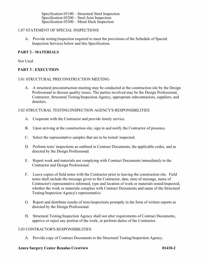
Specification 05100 – Structural Steel Inspection Specification 05200 – Steel Joist Inspection Specification 05300 – Metal Deck Inspection
1.07 STATEMENT OF SPECIAL INSPECTIONS
A. Provide testing/inspection required to meet the provisions of the Schedule of Special Inspection Services below and this Specification.
PART 2 - MATERIALS Not Used.
PART 3 - EXECUTION 3.01 STRUCTURAL PRECONSTRUCTION MEETING
A. A structural preconstruction meeting may be conducted at the construction site by the Design Professional to discuss quality issues. The parties involved may be the Design Professional, Contractor, Structural Testing/Inspection Agency, appropriate subcontractors, suppliers, and detailers.
3.02 STRUCTURAL TESTING/INSPECTION AGENCY'S RESPONSIBILITIES
A. Cooperate with the Contractor and provide timely service. B. Upon arriving at the construction site, sign in and notify the Contractor of presence. C. Select the representative samples that are to be tested/ inspected. D. Perform tests/ inspections as outlined in Contract Documents, the applicable codes, and as
directed by the Design Professional. E. Report work and materials not complying with Contract Documents immediately to the
Contractor and Design Professional. F. Leave copies of field notes with the Contractor prior to leaving the construction site. Field
notes shall include the message given to the Contractor, date, time of message, name of Contractor's representative informed, type and location of work or materials tested/inspected, whether the work or materials complies with Contract Documents and name of the Structural Testing/Inspection Agency's representative.
G. Report and distribute results of tests/inspections promptly in the form of written reports as
directed by the Design Professional. H. Structural Testing/Inspection Agency shall not alter requirements of Contract Documents,
approve or reject any portion of the work, or perform duties of the Contractor.
3.03 CONTRACTOR'S RESPONSIBILITIES
A. Provide copy of Contract Documents to the Structural Testing/Inspection Agency.
Azura Surgery Center Renalus Crestview 01410-3
B. Arrange the preconstruction meeting to discuss quality issues. C. Notify the Structural Testing/Inspection Agency sufficiently in advance of operations to allow
assignment of personnel and scheduling of tests. D. Cooperate with Structural Testing/Inspection Agency and provide access to work. E. Provide samples of materials to be tested in required quantities. F. Furnish copies of mill test reports when requested. G. Provide storage space for Structural Testing/Inspection Agency's exclusive use, such as for
storing and curing concrete testing samples. H. Provide labor to assist the Structural Testing/Inspection Agency in performing
tests/inspections.
END OF SECTION
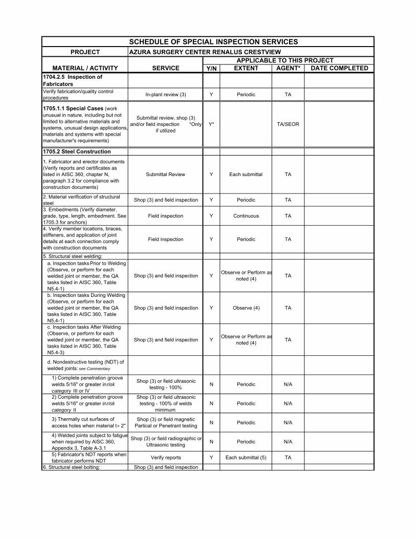
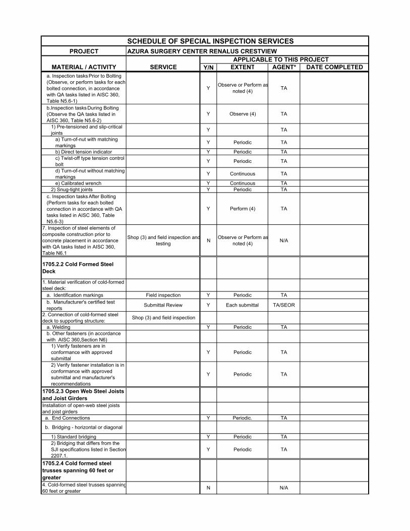
SCHEDULE OF SPECIAL INSPECTION SERVICESPROJECT AZURA SURGERY CENTER RENALUS CRESTVIEW
APPLICABLE TO THIS PROJECTMATERIAL / ACTIVITY SERVICE Y/N EXTENT AGENT* DATE COMPLETED
1704.2.5 Inspection of FabricatorsVerify fabrication/quality control procedures
In-plant review (3) Y Periodic TA
1705.1.1 Special Cases (work unusual in nature, including but not limited to alternative materials and systems, unusual design applications,materials and systems with special manufacturer's requirements)
Submittal review, shop (3) and/or field inspection *Only
if utilizedY* TA/SEOR
1705.2 Steel Construction
1. Fabricator and erector documents (Verify reports and certificates as listed in AISC 360, chapter N, paragraph 3.2 for compliance with construction documents)
Submittal Review Y Each submittal TA
2. Material verification of structural steel
Shop (3) and field inspection Y Periodic TA
3. Embedments (Verify diameter, grade, type, length, embedment. See 1705.3 for anchors)
Field inspection Y Continuous TA
4. Verify member locations, braces, stiffeners, and application of joint details at each connection comply with construction documents
Field inspection Y Periodic TA
5. Structural steel welding: a. Inspection tasks Prior to Welding (Observe, or perform for each welded joint or member, the QA tasks listed in AISC 360, Table N5.4-1)
Shop (3) and field inspection YObserve or Perform as
noted (4)TA
b. Inspection tasks During Welding (Observe, or perform for each welded joint or member, the QA tasks listed in AISC 360, Table N5.4-1)
Shop (3) and field inspection Y Observe (4) TA
c. Inspection tasks After Welding (Observe, or perform for each welded joint or member, the QA tasks listed in AISC 360, Table N5.4-3)
Shop (3) and field inspection YObserve or Perform as
noted (4)TA
d. Nondestructive testing (NDT) of welded joints: see Commentary
1) Complete penetration groove welds 5/16" or greater in risk category III or IV
Shop (3) or field ultrasonic testing - 100%
N Periodic N/A
2) Complete penetration groove welds 5/16" or greater in risk category II
Shop (3) or field ultrasonic testing - 100% of welds
minimumN Periodic N/A
3) Thermally cut surfaces of access holes when material t > 2"
Shop (3) or field magnetic Partical or Penetrant testing
N Periodic N/A
4) Welded joints subject to fatiguewhen required by AISC 360, Appendix 3, Table A-3.1
Shop (3) or field radiographic or Ultrasonic testing
N Periodic N/A
5) Fabricator's NDT reports when fabricator performs NDT
Verify reports Y Each submittal (5) TA
6. Structural steel bolting: Shop (3) and field inspection
SCHEDULE OF SPECIAL INSPECTION SERVICESPROJECT AZURA SURGERY CENTER RENALUS CRESTVIEW
APPLICABLE TO THIS PROJECTMATERIAL / ACTIVITY SERVICE Y/N EXTENT AGENT* DATE COMPLETED
a. Inspection tasks Prior to Bolting (Observe, or perform tasks for each bolted connection, in accordance with QA tasks listed in AISC 360, Table N5.6-1)
YObserve or Perform as
noted (4)TA
b.Inspection tasks During Bolting (Observe the QA tasks listed in AISC 360, Table N5.6-2)
Y Observe (4) TA
1) Pre-tensioned and slip-critical joints
Y TA
a) Turn-of-nut with matching markings
Y Periodic TA
b) Direct tension indicator Y Periodic TAc) Twist-off type tension control bolt
Y Periodic TA
d) Turn-of-nut without matching markings
Y Continuous TA
e) Calibrated wrench Y Continuous TA2) Snug-tight joints Y Periodic TA
c. Inspection tasks After Bolting (Perform tasks for each bolted connection in accordance with QA tasks listed in AISC 360, Table N5.6-3)
Y Perform (4) TA
7. Inspection of steel elements of composite construction prior to concrete placement in accordance with QA tasks listed in AISC 360, Table N6.1
Shop (3) and field inspection andtesting
NObserve or Perform as
noted (4)N/A
1705.2.2 Cold Formed Steel Deck
1. Material verification of cold-formed steel deck:
a. Identification markings Field inspection Y Periodic TAb. Manufacturer's certified test reports
Submittal Review Y Each submittal TA/SEOR
2. Connection of cold-formed steel deck to supporting structure:
Shop (3) and field inspection
a. Welding Y Periodic TAb. Other fasteners (in accordance with AISC 360,Section N6)
1) Verify fasteners are in conformance with approved submittal
Y Periodic TA
2) Verify fastener installation is in conformance with approved submittal and manufacturer's recommendations
Y Periodic TA
1705.2.3 Open Web Steel Joists and Joist GirdersInstallation of open-web steel joists and joist girders a. End Connections Y Periodic. TA
b. Bridging - horizontal or diagonal
1) Standard bridging Y Periodic TA2) Bridging that differs from the SJI specifications listed in Section2207.1.
Y Periodic TA
1705.2.4 Cold formed steel trusses spanning 60 feet or greater4. Cold-formed steel trusses spanning60 feet or greater
N N/A
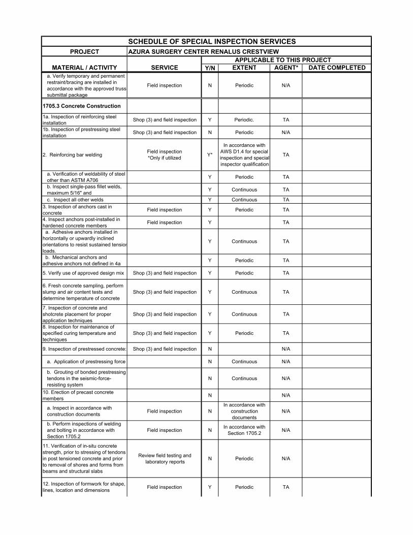
SCHEDULE OF SPECIAL INSPECTION SERVICESPROJECT AZURA SURGERY CENTER RENALUS CRESTVIEW
APPLICABLE TO THIS PROJECTMATERIAL / ACTIVITY SERVICE Y/N EXTENT AGENT* DATE COMPLETED
a. Verify temporary and permanent restraint/bracing are installed in accordance with the approved truss submittal package
Field inspection N Periodic N/A
1705.3 Concrete Construction
1a. Inspection of reinforcing steel installation
Shop (3) and field inspection Y Periodic. TA
1b. Inspection of prestressing steel installation
Shop (3) and field inspection N Periodic N/A
2. Reinforcing bar weldingField inspection *Only if utilized
Y*
In accordance with AWS D1.4 for special inspection and special inspector qualification
TA
a. Verification of weldability of steel other than ASTM A706
Y Periodic TA
b. Inspect single-pass fillet welds, maximum 5/16" and
Y Continuous TA
c. Inspect all other welds Y Continuous TA3. Inspection of anchors cast in concrete
Field inspection Y Periodic TA
4. Inspect anchors post-installed in hardened concrete members
Field inspection Y TA
a. Adhesive anchors installed in horizontally or upwardly inclined orientations to resist sustained tensionloads.
Y Continuous TA
b. Mechanical anchors and adhesive anchors not defined in 4a
Y Periodic TA
5. Verify use of approved design mix Shop (3) and field inspection Y Periodic TA
6. Fresh concrete sampling, perform slump and air content tests and determine temperature of concrete
Shop (3) and field inspection Y Continuous TA
7. Inspection of concrete and shotcrete placement for proper application techniques
Shop (3) and field inspection Y Continuous TA
8. Inspection for maintenance of specified curing temperature and techniques
Shop (3) and field inspection Y Periodic TA
9. Inspection of prestressed concrete: Shop (3) and field inspection N N/A
a. Application of prestressing force N Continuous N/A
b. Grouting of bonded prestressing tendons in the seismic-force-resisting system
N Continuous N/A
10. Erection of precast concrete members
N N/A
a. Inspect in accordance with construction documents
Field inspection NIn accordance with
construction documents
N/A
b. Perform inspections of welding and bolting in accordance with Section 1705.2
Field inspection NIn accordance with
Section 1705.2N/A
11. Verification of in-situ concrete strength, prior to stressing of tendons in post tensioned concrete and prior to removal of shores and forms from beams and structural slabs
Review field testing and laboratory reports
N Periodic N/A
12. Inspection of formwork for shape, lines, location and dimensions
Field inspection Y Periodic TA
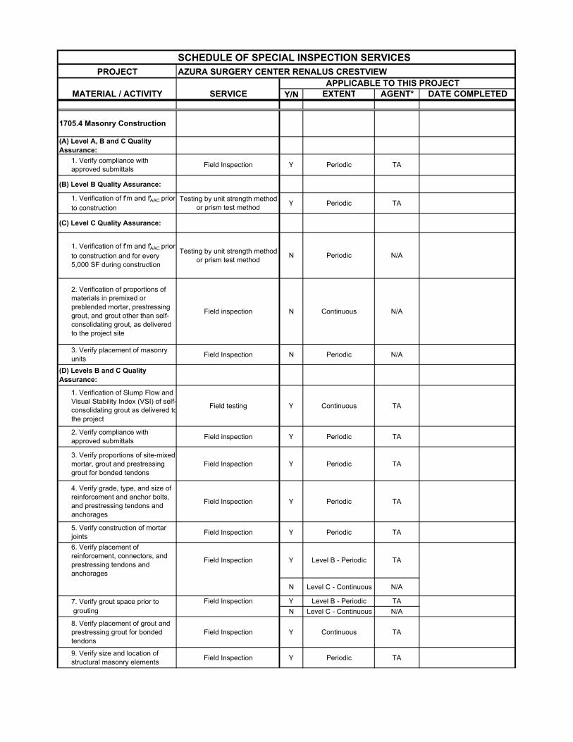
SCHEDULE OF SPECIAL INSPECTION SERVICESPROJECT AZURA SURGERY CENTER RENALUS CRESTVIEW
APPLICABLE TO THIS PROJECTMATERIAL / ACTIVITY SERVICE Y/N EXTENT AGENT* DATE COMPLETED
1705.4 Masonry Construction
(A) Level A, B and C Quality Assurance:
1. Verify compliance with approved submittals
Field Inspection Y Periodic TA
(B) Level B Quality Assurance:
1. Verification of f'm and f'AAC prior to construction
Testing by unit strength method or prism test method
Y Periodic TA
(C) Level C Quality Assurance:
1. Verification of f'm and f'AAC prior to construction and for every 5,000 SF during construction
Testing by unit strength method or prism test method
N Periodic N/A
2. Verification of proportions of materials in premixed or preblended mortar, prestressing grout, and grout other than self-consolidating grout, as delivered to the project site
Field inspection N Continuous N/A
3. Verify placement of masonry units
Field Inspection N Periodic N/A
(D) Levels B and C Quality Assurance:
1. Verification of Slump Flow and Visual Stability Index (VSI) of self-consolidating grout as delivered tothe project
Field testing Y Continuous TA
2. Verify compliance with approved submittals
Field inspection Y Periodic TA
3. Verify proportions of site-mixed mortar, grout and prestressing grout for bonded tendons
Field Inspection Y Periodic TA
4. Verify grade, type, and size of reinforcement and anchor bolts, and prestressing tendons and anchorages
Field Inspection Y Periodic TA
5. Verify construction of mortar joints
Field Inspection Y Periodic TA
6. Verify placement of reinforcement, connectors, and prestressing tendons and anchorages
Field Inspection Y Level B - Periodic TA
N Level C - Continuous N/A
7. Verify grout space prior to Field Inspection Y Level B - Periodic TA grouting N Level C - Continuous N/A
8. Verify placement of grout and prestressing grout for bonded tendons
Field Inspection Y Continuous TA
9. Verify size and location of structural masonry elements
Field Inspection Y Periodic TA
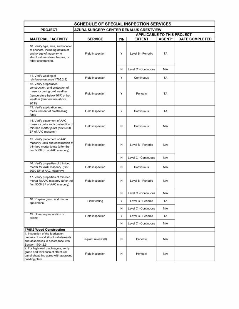
SCHEDULE OF SPECIAL INSPECTION SERVICESPROJECT AZURA SURGERY CENTER RENALUS CRESTVIEW
APPLICABLE TO THIS PROJECTMATERIAL / ACTIVITY SERVICE Y/N EXTENT AGENT* DATE COMPLETED
10. Verify type, size, and location of anchors, including details of anchorage of masonry to structural members, frames, or other construction.
Field inspection Y Level B - Periodic TA
N Level C - Continuous N/A
11. Verify welding of reinforcement (see 1705.2.2)
Field inspection Y Continuous TA
12. Verify preparation, construction, and protestion of masonry during cold weather
(temperature below 40oF) or hot weather (temperature above
90oF)
Field inspection Y Periodic TA
13. Verify application and measurement of prestressing force
Field Inspection Y Continuous TA
14. Verify placement of AAC masonry units and construction of thin-bed mortar joints (first 5000 SF of AAC masonry)
Field inspection N Continuous N/A
15. Verify placement of AAC masonry units and construction of thin-bed mortar joints (after the first 5000 SF of AAC masonry)
Field inspection N Level B - Periodic N/A
N Level C - Continuous N/A
16. Verify properties of thin-bed mortar for AAC masonry (first 5000 SF of AAC masonry)
Field inspection N Continuous N/A
17. Verify properties of thin-bed mortar forAAC masonry (after the first 5000 SF of AAC masonry)
Field inspection N Level B - Periodic N/A
N Level C - Continuous N/A
18. Prepare grout and mortar specimens
Field testing Y Level B - Periodic TA
N Level C - Continuous N/A
19. Observe preparation of prisms
Field inspection Y Level B - Periodic TA
N Level C - Continuous N/A
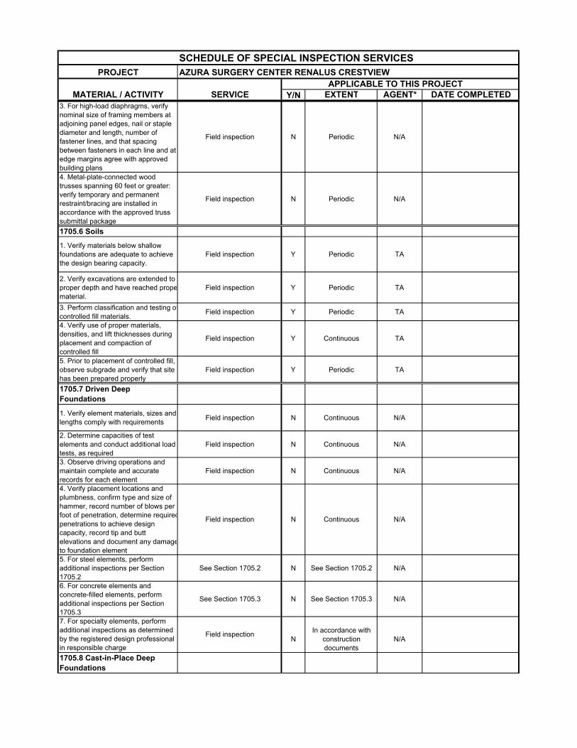
1705.5 Wood Construction1. Inspection of the fabrication process of wood structural elements and assemblies in accordance with Section 1704.2.5
In-plant review (3) N Periodic N/A
2. For high-load diaphragms, verify grade and thickness of structural panel sheathing agree with approved building plans
Field inspection N Periodic N/A
SCHEDULE OF SPECIAL INSPECTION SERVICESPROJECT AZURA SURGERY CENTER RENALUS CRESTVIEW
APPLICABLE TO THIS PROJECTMATERIAL / ACTIVITY SERVICE Y/N EXTENT AGENT* DATE COMPLETED
3. For high-load diaphragms, verify nominal size of framing members at adjoining panel edges, nail or staple diameter and length, number of fastener lines, and that spacing between fasteners in each line and at edge margins agree with approved building plans
Field inspection N Periodic N/A
4. Metal-plate-connected wood trusses spanning 60 feet or greater: verify temporary and permanent restraint/bracing are installed in accordance with the approved truss submittal package
Field inspection N Periodic N/A
1705.6 Soils
1. Verify materials below shallow foundations are adequate to achieve the design bearing capacity.
Field inspection Y Periodic TA
2. Verify excavations are extended to proper depth and have reached propematerial.
Field inspection Y Periodic TA
3. Perform classification and testing ofcontrolled fill materials.
Field inspection Y Periodic TA
4. Verify use of proper materials, densities, and lift thicknesses during placement and compaction of controlled fill
Field inspection Y Continuous TA
5. Prior to placement of controlled fill, observe subgrade and verify that site has been prepared properly
Field inspection Y Periodic TA
1705.7 Driven Deep Foundations
1. Verify element materials, sizes and lengths comply with requirements
Field inspection N Continuous N/A
2. Determine capacities of test elements and conduct additional load tests, as required
Field inspection N Continuous N/A
3. Observe driving operations and maintain complete and accurate records for each element
Field inspection N Continuous N/A
4. Verify placement locations and plumbness, confirm type and size of hammer, record number of blows per foot of penetration, determine requiredpenetrations to achieve design capacity, record tip and butt elevations and document any damageto foundation element
Field inspection N Continuous N/A
5. For steel elements, perform additional inspections per Section 1705.2
See Section 1705.2 N See Section 1705.2 N/A
6. For concrete elements and concrete-filled elements, perform additional inspections per Section 1705.3
See Section 1705.3 N See Section 1705.3 N/A
NIn accordance with
construction documents
N/A
1705.8 Cast-in-Place Deep Foundations
7. For specialty elements, perform additional inspections as determined by the registered design professional in responsible charge
Field inspection
SCHEDULE OF SPECIAL INSPECTION SERVICESPROJECT AZURA SURGERY CENTER RENALUS CRESTVIEW
APPLICABLE TO THIS PROJECTMATERIAL / ACTIVITY SERVICE Y/N EXTENT AGENT* DATE COMPLETED
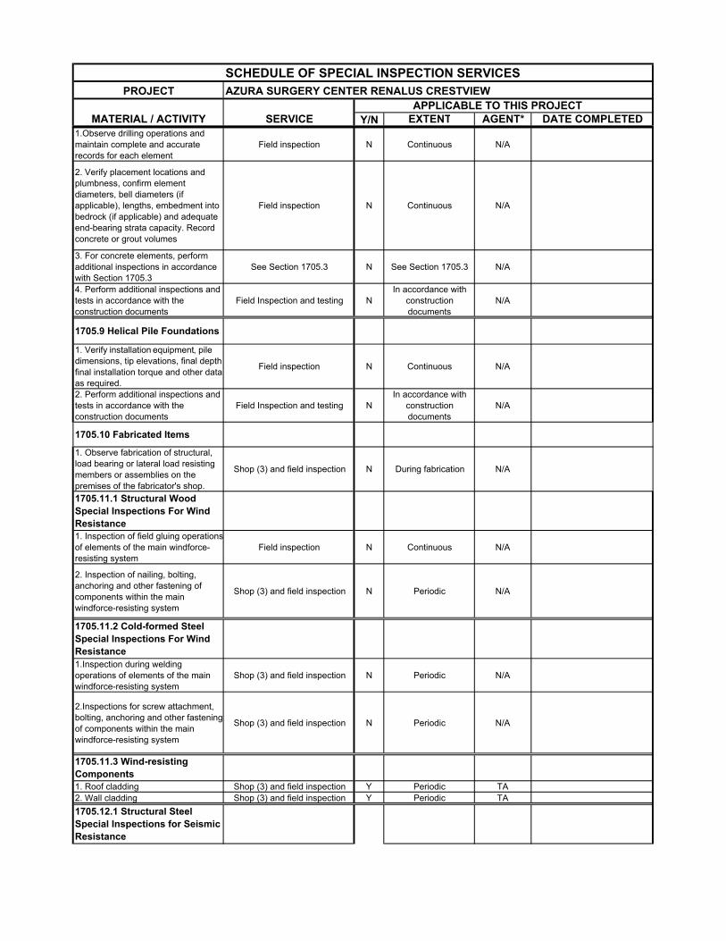
1.Observe drilling operations and maintain complete and accurate records for each element
Field inspection N Continuous N/A
2. Verify placement locations and plumbness, confirm element diameters, bell diameters (if applicable), lengths, embedment into bedrock (if applicable) and adequate end-bearing strata capacity. Record concrete or grout volumes
Field inspection N Continuous N/A
3. For concrete elements, perform additional inspections in accordance with Section 1705.3
See Section 1705.3 N See Section 1705.3 N/A
4. Perform additional inspections and tests in accordance with the construction documents
Field Inspection and testing NIn accordance with
construction documents
N/A
1705.9 Helical Pile Foundations
1. Verify installation equipment, pile dimensions, tip elevations, final depth,final installation torque and other data as required.
Field inspection N Continuous N/A
2. Perform additional inspections and tests in accordance with the construction documents
Field Inspection and testing NIn accordance with
construction documents
N/A
1705.10 Fabricated Items
1. Observe fabrication of structural, load bearing or lateral load resisting members or assemblies on the premises of the fabricator's shop.
Shop (3) and field inspection N During fabrication N/A
1705.11.1 Structural Wood Special Inspections For Wind Resistance1. Inspection of field gluing operations of elements of the main windforce-resisting system
Field inspection N Continuous N/A
2. Inspection of nailing, bolting, anchoring and other fastening of components within the main windforce-resisting system
Shop (3) and field inspection N Periodic N/A
1705.11.2 Cold-formed Steel Special Inspections For Wind Resistance1.Inspection during welding operations of elements of the main windforce-resisting system
Shop (3) and field inspection N Periodic N/A
2.Inspections for screw attachment, bolting, anchoring and other fastening of components within the main windforce-resisting system
Shop (3) and field inspection N Periodic N/A
1705.11.3 Wind-resisting Components1. Roof cladding Shop (3) and field inspection Y Periodic TA2. Wall cladding Shop (3) and field inspection Y Periodic TA
1705.12.1 Structural Steel Special Inspections for Seismic Resistance
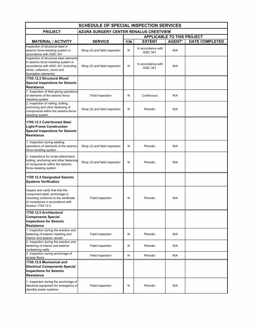
SCHEDULE OF SPECIAL INSPECTION SERVICESPROJECT AZURA SURGERY CENTER RENALUS CRESTVIEW
APPLICABLE TO THIS PROJECTMATERIAL / ACTIVITY SERVICE Y/N EXTENT AGENT* DATE COMPLETED
Inspection of structural steel in seismic force-resisting system in accordance with AISC 341
Shop (3) and field inspection N In accordance with
AISC 341N/A
Inspection of structural steel elementsin seismic force-resisting system in accordance with AISC 341 (including struts, collectors, chord and foundation elements)
Shop (3) and field inspection N In accordance with
AISC 341N/A
1705.12.2 Structural Wood Special Inspections for Seismic Resistance1. Inspection of field gluing operations of elements of the seismic-force resisting system
Field inspection N Continuous N/A
2. Inspection of nailing, bolting, anchoring and other fastening of components within the seismic-force-resisting system
Shop (3) and field inspection N Periodic N/A
1705.12.3 Cold-formed Steel Light-Frame Construction Special Inspections for Seismic Resistance
1. Inspection during welding operations of elements of the seismic-force-resisting system
Shop (3) and field inspection N Periodic N/A
2. Inspections for screw attachment, bolting, anchoring and other fastening of components within the seismic-force-resisting system
Shop (3) and field inspection N Periodic N/A
1705.12.4 Designated Seismic Systems Verification
Inspect and verify that that the component label, anchorage or mounting conforms to the certificate of compliance in accordance with Section 1705.12.3
Field inspection N Periodic N/A
1705.12.5 Architectural Components Special Inspections for Seismic Resistance1. Inspection during the erection and fastening of exterior cladding and interior and exterior veneer
Field inspection N Periodic N/A
2. Inspection during the erection and fastening of interior and exterior nonbearing walls
Field inspection N Periodic N/A
3. Inspection during anchorage of access floors
Field inspection N Periodic N/A
1705.12.6 Mechanical and Electrical Components Special Inspections for Seismic Resistance
1. Inspection during the anchorage of electrical equipment for emergency or standby power systems
Field inspection N Periodic N/A
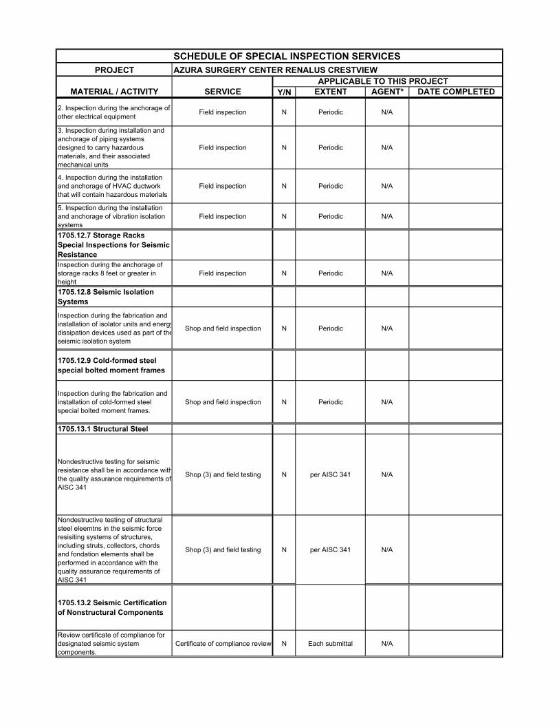
SCHEDULE OF SPECIAL INSPECTION SERVICESPROJECT AZURA SURGERY CENTER RENALUS CRESTVIEW
APPLICABLE TO THIS PROJECTMATERIAL / ACTIVITY SERVICE Y/N EXTENT AGENT* DATE COMPLETED
2. Inspection during the anchorage of other electrical equipment
Field inspection N Periodic N/A
3. Inspection during installation and anchorage of piping systems designed to carry hazardous materials, and their associated mechanical units
Field inspection N Periodic N/A
4. Inspection during the installation and anchorage of HVAC ductwork that will contain hazardous materials
Field inspection N Periodic N/A
5. Inspection during the installation and anchorage of vibration isolation systems
Field inspection N Periodic N/A
1705.12.7 Storage Racks Special Inspections for Seismic ResistanceInspection during the anchorage of storage racks 8 feet or greater in height
Field inspection N Periodic N/A
1705.12.8 Seismic Isolation Systems
Inspection during the fabrication and installation of isolator units and energydissipation devices used as part of theseismic isolation system
Shop and field inspection N Periodic N/A
1705.12.9 Cold-formed steel special bolted moment frames
Inspection during the fabrication and installation of cold-formed steel special bolted moment frames.
Shop and field inspection N Periodic N/A
1705.13.1 Structural Steel
Nondestructive testing for seismic resistance shall be in accordance withthe quality assurance requirements of AISC 341
Shop (3) and field testing N per AISC 341 N/A
Nondestructive testing of structural steel eleemtns in the seismic force resisiting systems of structures, including struts, collectors, chords and fondation elements shall be performed in accordance with the quality assurance requirements of AISC 341
Shop (3) and field testing N per AISC 341 N/A
1705.13.2 Seismic Certification of Nonstructural Components
Review certificate of compliance for designated seismic system components.
Certificate of compliance review N Each submittal N/A
SCHEDULE OF SPECIAL INSPECTION SERVICESPROJECT AZURA SURGERY CENTER RENALUS CRESTVIEW
APPLICABLE TO THIS PROJECTMATERIAL / ACTIVITY SERVICE Y/N EXTENT AGENT* DATE COMPLETED
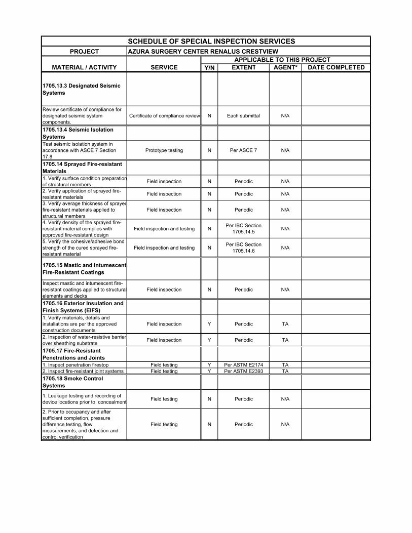
1705.13.3 Designated Seismic Systems
Review certificate of compliance for designated seismic system components.
Certificate of compliance review N Each submittal N/A
1705.13.4 Seismic Isolation SystemsTest seismic isolation system in accordance with ASCE 7 Section 17.8
Prototype testing N Per ASCE 7 N/A
1705.14 Sprayed Fire-resistant Materials1. Verify surface condition preparation of structural members
Field inspection N Periodic N/A
2. Verify application of sprayed fire-resistant materials
Field inspection N Periodic N/A
3. Verify average thickness of sprayedfire-resistant materials applied to structural members
Field inspection N Periodic N/A
4. Verify density of the sprayed fire-resistant material complies with approved fire-resistant design
Field inspection and testing NPer IBC Section
1705.14.5N/A
5. Verify the cohesive/adhesive bond strength of the cured sprayed fire-resistant material
Field inspection and testing NPer IBC Section
1705.14.6N/A
1705.15 Mastic and Intumescent Fire-Resistant Coatings
Inspect mastic and intumescent fire-resistant coatings applied to structuralelements and decks
Field inspection N Periodic N/A
1705.16 Exterior Insulation and Finish Systems (EIFS)1. Verify materials, details and installations are per the approved construction documents
Field inspection Y Periodic TA
2. Inspection of water-resistive barrier over sheathing substrate
Field inspection Y Periodic TA
1705.17 Fire-Resistant Penetrations and Joints1. Inspect penetration firestop Field testing Y Per ASTM E2174 TA2. Inspect fire-resistant joint systems Field testing Y Per ASTM E2393 TA
1705.18 Smoke Control Systems
1. Leakage testing and recording of device locations prior to concealment
Field testing N Periodic N/A
2. Prior to occupancy and after sufficient completion, pressure difference testing, flow measurements, and detection and control verification
Field testing N Periodic N/A
SCHEDULE OF SPECIAL INSPECTION SERVICESPROJECT AZURA SURGERY CENTER RENALUS CRESTVIEW
APPLICABLE TO THIS PROJECTMATERIAL / ACTIVITY SERVICE Y/N EXTENT AGENT* DATE COMPLETED
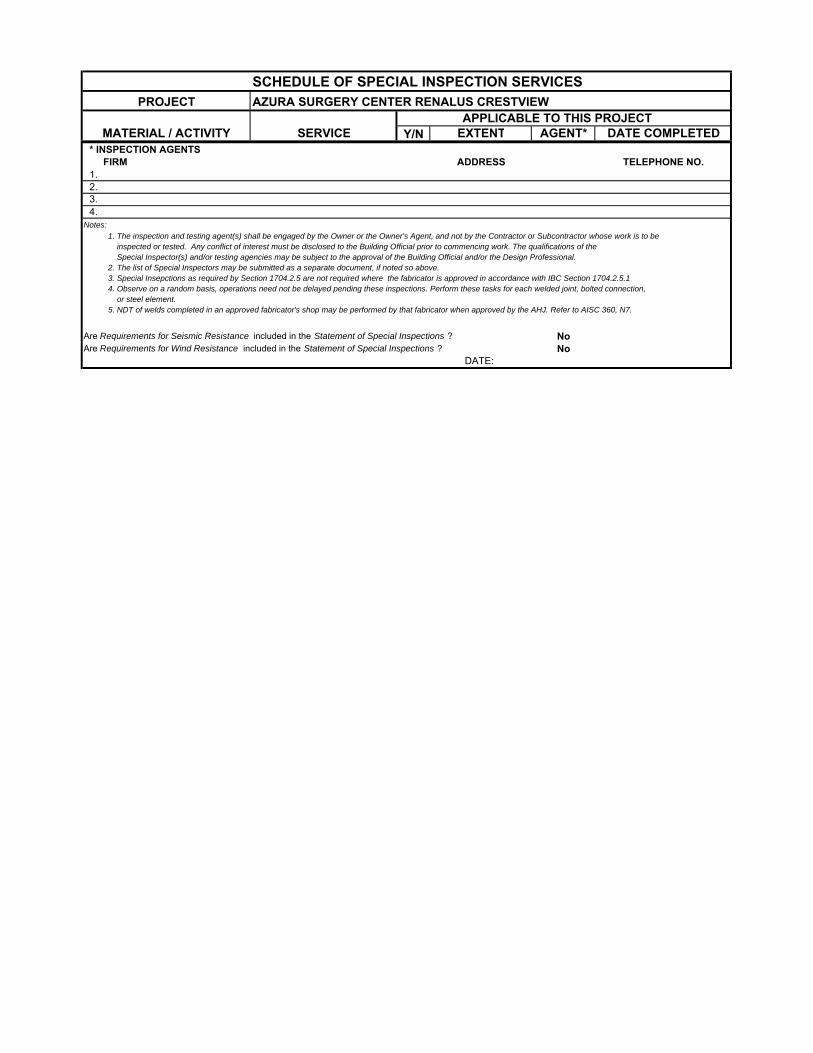
* INSPECTION AGENTS FIRM ADDRESS TELEPHONE NO. 1.
3. 4. Notes:
Are Requirements for Seismic Resistance included in the Statement of Special Inspections ? NoAre Requirements for Wind Resistance included in the Statement of Special Inspections ? No
DATE:
2.
1. The inspection and testing agent(s) shall be engaged by the Owner or the Owner's Agent, and not by the Contractor or Subcontractor whose work is to be inspected or tested. Any conflict of interest must be disclosed to the Building Official prior to commencing work. The qualifications of the Special Inspector(s) and/or testing agencies may be subject to the approval of the Building Official and/or the Design Professional. 2. The list of Special Inspectors may be submitted as a separate document, if noted so above. 3. Special Insepctions as required by Section 1704.2.5 are not required where the fabricator is approved in accordance with IBC Section 1704.2.5.1 4. Observe on a random basis, operations need not be delayed pending these inspections. Perform these tasks for each welded joint, bolted connection, or steel element. 5. NDT of welds completed in an approved fabricator's shop may be performed by that fabricator when approved by the AHJ. Refer to AISC 360, N7.
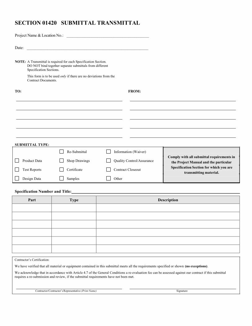
SECTION 01420 SUBMITTAL TRANSMITTAL
Project Name & Location No.: ________________________________________
Date: ___________________________________________________________
NOTE: A Transmittal is required for each Specification Section.
DO NOT bind together separate submittals from different
Specification Sections.
This form is to be used only if there are no deviations from the
Contract Documents.
TO: FROM:
SUBMITTAL TYPE: Re-Submittal Information (Waiver)
Comply with all submittal requirements in Product Data Shop Drawings Quality Control/Assurance
Test Reports Certificate Contract Closeout
Design Data Samples Other
the Project Manual and the particular
Specification Section for which you are
transmitting material.
Specification Number and Title:
Part Type Description
Contractor’s Certification:
We have verified that all material or equipment contained in this submittal meets all the requirements specified or shown (no exceptions).
We acknowledge that in accordance with Article 4.7 of the General Conditions a re-evaluation fee can be assessed against our contract if this submittal
requires a re-submission and review, if the submittal requirements have not been met.
Contractor/Contractor’s Representative (Print Name) Signature
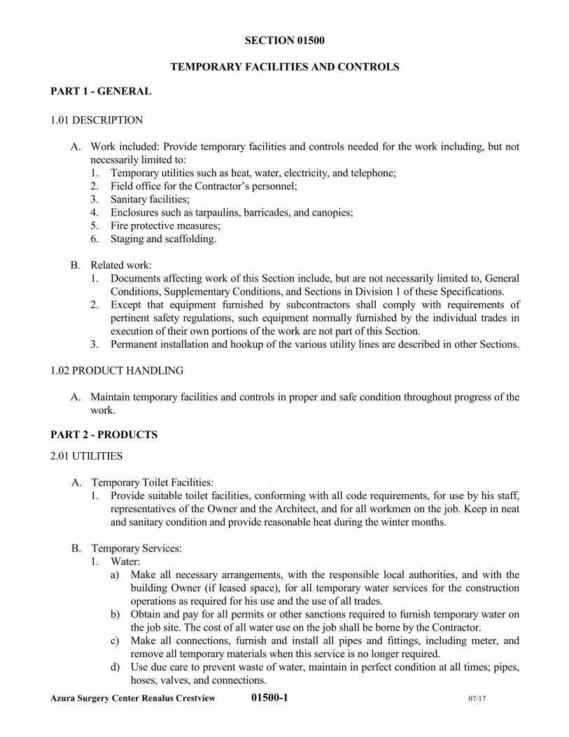
Azura Surgery Center Renalus Crestview 01500-1 07/17
SECTION 01500
TEMPORARY FACILITIES AND CONTROLS
PART 1 - GENERAL
1.01 DESCRIPTION
A. Work included: Provide temporary facilities and controls needed for the work including, but not
necessarily limited to:
1. Temporary utilities such as heat, water, electricity, and telephone;
2. Field office for the Contractor’s personnel;
3. Sanitary facilities;
4. Enclosures such as tarpaulins, barricades, and canopies;
5. Fire protective measures;
6. Staging and scaffolding.
B. Related work:
1. Documents affecting work of this Section include, but are not necessarily limited to, General
Conditions, Supplementary Conditions, and Sections in Division 1 of these Specifications.
2. Except that equipment furnished by subcontractors shall comply with requirements of
pertinent safety regulations, such equipment normally furnished by the individual trades in
execution of their own portions of the work are not part of this Section.
3. Permanent installation and hookup of the various utility lines are described in other Sections.
1.02 PRODUCT HANDLING
A. Maintain temporary facilities and controls in proper and safe condition throughout progress of the
work.
PART 2 - PRODUCTS
2.01 UTILITIES
A. Temporary Toilet Facilities:
1. Provide suitable toilet facilities, conforming with all code requirements, for use by his staff,
representatives of the Owner and the Architect, and for all workmen on the job. Keep in neat
and sanitary condition and provide reasonable heat during the winter months.
B. Temporary Services:
1. Water:
a) Make all necessary arrangements, with the responsible local authorities, and with the
building Owner (if leased space), for all temporary water services for the construction
operations as required for his use and the use of all trades.
b) Obtain and pay for all permits or other sanctions required to furnish temporary water on
the job site. The cost of all water use on the job shall be borne by the Contractor.
c) Make all connections, furnish and install all pipes and fittings, including meter, and
remove all temporary materials when this service is no longer required.
d) Use due care to prevent waste of water, maintain in perfect condition at all times; pipes,
hoses, valves, and connections.
Azura Surgery Center Renalus Crestview 01500-2 07/17
e) Provide adequate drinking water satisfactorily cooled for all workmen on the job; water
units shall be strategically located throughout the job.
2. Temporary Electricity:
a) Make arrangements with local electric company for temporary electric service, pay
expenses in connection with installation, operation and removal thereof and pay cost of
energy consumed by all trades.
b) Provide power distribution as required throughout structure 120/208 - volt, 3-phase, 60
cycle, AC. Termination or power distribution shall be one location on each floor or each
major wing or section of building. Termination shall be provided complete with circuit
breakers, disconnect switches and other electrical devices as required to protect power
supply system.
c) Temporary lighting systems shall be furnished, installed and maintained by Contractor as
required to satisfy minimum requirements of safety and security. Temporary lighting to
illuminate staging, stockpiles, trenches, projections, etc., to the satisfaction of the
Architect and general illumination throughout, adequate for watchmen and emergency
personnel.
d) Temporary equipment and wiring for power and lighting shall be in accordance with
applicable provisions of governing codes. Temporary wiring shall be maintained in safe
manner and utilized so as not to constitute a hazard to persons or property.
e) When permanent electrical power and lighting systems are in operating condition, they
may be used for temporary power lighting for construction purposes, provided that
Contractor obtains written approval of Architect and Owner, assumed full responsibility
for entire power and lighting systems, and pays costs for operation and restoration of
systems.
f) At completion of construction work or at such time as Contractor makes use of
permanent electrical installation, temporary wiring, lighting and other temporary
electrical equipment and devices shall be properly removed by Contractor.
3. Temporary Heat:
a) Provide all heat as may be necessary for thawing out and heating the ground or materials,
and for the proper execution, protection and drying out of his and his Subcontractor’s
work before permanent apparatus is installed.
b) Temporary heaters shall be smokeless, portable unit heaters, (Underwriter’s
Laboratories, Factory Mutual, and Fire Marshall approved).
c) After the building or portion thereof has been enclosed, either temporarily or
permanently, provide temporary heat and maintain continuously at a temperature of not
less than 60 degrees nor more than 75 degrees until final acceptance of the work.
Comply with requirements under Division 15, Heating, Ventilating, and Air
Conditioning for use of permanent heating system for temporary heat.
d) Provide heat as required for temporary structures of a type approved by the Architect.
e) Include all costs of temporary heat in his proposal.
f) When permanent heating system, or suitable portion thereof, is in operating condition,
such system may be used for temporary heating, provided that Contractor obtains written
approval of Architect and Owner, assumes full responsibility for new heating system,
and pays costs for operation and maintenance, and restoration of system.
g) Furnish an acceptable operator for the new heating plant during the period when
temporary heat is required.
h) Upon conclusion of temporary heating period, remove temporary piping, temporary
radiators, other equipment and pay costs in connection with repairing damage caused by
Azura Surgery Center Renalus Crestview 01500-3 07/17
installation or removal of temporary heating equipment, and thoroughly clean and
recondition those parts of permanent heating system used for temporary service.
2.02 STAGING AND SCAFFOLDING
A. Furnish, erect, and maintain all staging and scaffolding (exterior and interior) eight (8) feet or over
in height for all trades for such use. Furnish, erect and maintain all staging and scaffolding
(exterior and interior) for his own use during construction of the building. Staging and scaffolding
shall be of approved design, erected and removed by experienced stage builders, and shall have all
accident prevention devices required by Federal, State, and Local Laws.
B. Erect and maintain heavy duty air and dust barriers to completely isolate areas undergoing
demolition and construction from occupied areas. Barriers shall be erected so as to prevent the
passage of dust, air, debris, etc. into adjoining spaces. Maintain relative negative pressure within
areas of demo/construction activities.
C. Employ tacky floor coverings immediately outside of any entrances to the work area. Tacky
surfaces shall be renewed daily or as required to maintain effectiveness.
D. Erect such staging and scaffolding in sufficient time and in proper sequence so as not to delay
work. Subcontractors shall schedule and commence their work so that building progress is not
delayed or obstructed once staging and scaffolding become available.
E. Each Subcontractor entering upon the work shall furnish, erect, and maintain all staging and
scaffolding under 8 feet in height required for work under his subcontract, and where so indicated,
all other staging and scaffolding required for his work. On completion of his work, each
Subcontractor shall dismantle and remove such staging and scaffolding.
F. Erection of all staging, scaffolding, rigging, etc. shall be supervised and directed by a Licensed
Rigger and inspected by a Registered Engineer. A certified affidavit shall be submitted to the
Architect by this Engineer stating that all staging, scaffolding, rigging, etc. has been safely erected
and conforms in all respects to State and Local Codes. The General Contractor shall pay for all
services in connection with the erection and inspection of all staging, scaffolding, and rigging, etc.
G. Above facilities shall be constructed and maintained in accordance with applicable requirements
of “American Standard Safety Code of Building and Construction”, published by USASI, and be
removed after they have served their purpose or when directed by Architect.
H. Permanent stairs shall be erected as soon as possible and Contractor shall provide suitable
temporary treads, risers, etc. as required to protect permanent stair members, and provide
temporary railing as required for safety.
2.03 FIELD OFFICE AND TELEPHONE
A. The General Contractor is to provide a complete contact list for all pertinent project personnel and
subcontractors.
B. An address where project-related mail can be received must also be made available for the
duration of the project.

Azura Surgery Center Renalus Crestview 01500-4 07/17
Azura Surgery Center Renalus Crestview 01500-5 07/17
2.04 TEMPORARY STRUCTURES
A. The Contractor and Subcontractor shall construct and maintain, in locations approved by the
Architect, all temporary structures, sheds, and similar needs for the storing of their respective
materials for the duration of the Contract.
B. All temporary structures shall be of substantial construction and weather tight. Temporary
structures shall be removed from site when no longer needed by the Contractor or trade
responsible for their erection.
PART 3 - EXECUTION
3.01 FIRE PROTECTIVE MEASURES
A. The Contractor shall maintain a rubbish-free building and building site, and shall provide metal
barrels into which all luncheon refuse shall be deposited. All such barrels shall have tight-fitting
covers.
B. Store materials so they do not create natural pockets for papers or other combustible materials.
C. Construction debris shall not be thrown from the windows of the building but shall be removed
through tight strong chutes, and all debris shall be wet down if necessary, or as directed by
Architect.
D. When building materials with combustible contents are stored in the building during construction,
they shall be located within easy reach of fire protection equipment.
E. An approved number of fire extinguishers shall be placed throughout work areas, temporary paint
shop and within easy reach of mechanics who are operating plumber’s furnaces, burning or
welding apparatus. The number and location shall be approved from time to time by the local fire
department.
F. It shall be the duty and responsibility of the General Contractor or any subcontractor performing
any cutting or welding, to comply with the safety provisions of the national Fire Protection
Association’s “National Fire Codes” pertaining to such work and the respective contractor shall be
responsible for all damages resulting from a failure to do so comply.
3.02 POLICE, FIREMEN AND INSPECTORS
A. Any police officer, fireman or inspector required by the local authorities having jurisdiction over
the work, shall be employed by the Contractor and paid the standard rate or wage for the
respective occupation of the work area. All personnel employed shall be covered by Workman’s
Compensation and Employer’s Liability Insurance by the Contractor.
3.03 WINTER CONSTRUCTION
A. Remove snow and ice which may impair progress of work, be detrimental to workmen, or impair
trucking, delivery or moving of materials at job site or prevent adequate drainage at site or
adjoining areas.
Azura Surgery Center Renalus Crestview 01500-6 07/17
B. Contractor shall take special precautions against damage to materials and work installed in
freezing weather, by providing special heat and covering to prevent damage by elements, in
manner approved by Architect. Ground surfaces under footings and under pipe lines, and
masonry, concrete and other work subject to damage shall be protected against freezing.
3.04 MAINTENANCE AND REMOVAL
A. Maintain temporary facilities and controls as long as needed for safe and proper completion of the
work.
B. Remove such temporary facilities and controls as rapidly as progress of the Work will permit, or
as directed by the Architect.
END OF SECTION
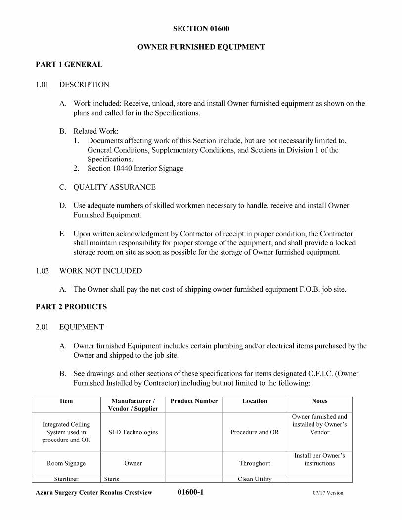
Azura Surgery Center Renalus Crestview 01600-1 07/17 Version
SECTION 01600
OWNER FURNISHED EQUIPMENT
PART 1 GENERAL
1.01 DESCRIPTION
A. Work included: Receive, unload, store and install Owner furnished equipment as shown on the
plans and called for in the Specifications.
B. Related Work:
1. Documents affecting work of this Section include, but are not necessarily limited to,
General Conditions, Supplementary Conditions, and Sections in Division 1 of the
Specifications.
2. Section 10440 Interior Signage
C. QUALITY ASSURANCE
D. Use adequate numbers of skilled workmen necessary to handle, receive and install Owner
Furnished Equipment.
E. Upon written acknowledgment by Contractor of receipt in proper condition, the Contractor
shall maintain responsibility for proper storage of the equipment, and shall provide a locked
storage room on site as soon as possible for the storage of Owner furnished equipment.
1.02 WORK NOT INCLUDED
A. The Owner shall pay the net cost of shipping owner furnished equipment F.O.B. job site.
PART 2 PRODUCTS
2.01 EQUIPMENT
A. Owner furnished Equipment includes certain plumbing and/or electrical items purchased by the
Owner and shipped to the job site.
B. See drawings and other sections of these specifications for items designated O.F.I.C. (Owner
Furnished Installed by Contractor) including but not limited to the following:
Item Manufacturer /
Vendor / Supplier
Product Number Location Notes
Integrated Ceiling
System used in
procedure and OR
SLD Technologies Procedure and OR
Owner furnished and
installed by Owner’s
Vendor
Room Signage
Owner Throughout
Install per Owner’s
instructions
Sterilizer Steris Clean Utility
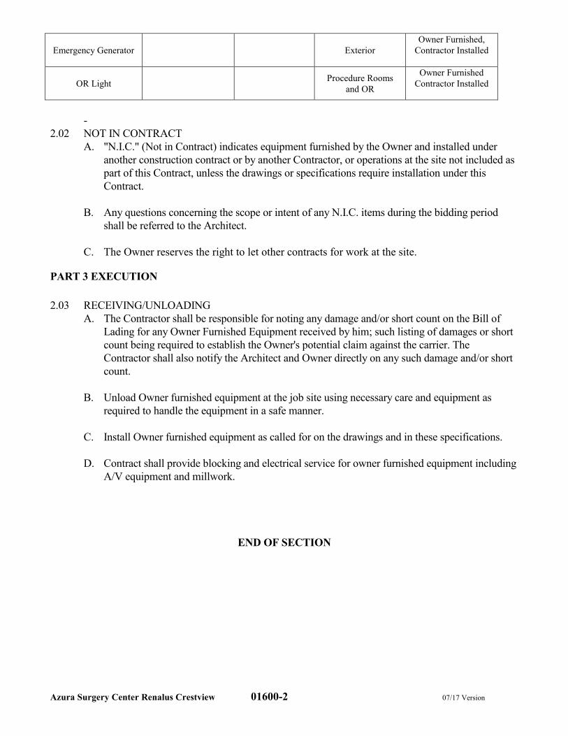
Azura Surgery Center Renalus Crestview 01600-2 07/17 Version
Emergency Generator Exterior
Owner Furnished,
Contractor Installed
OR Light Procedure Rooms
and OR
Owner Furnished
Contractor Installed
-
2.02 NOT IN CONTRACT
A. "N.I.C." (Not in Contract) indicates equipment furnished by the Owner and installed under
another construction contract or by another Contractor, or operations at the site not included as
part of this Contract, unless the drawings or specifications require installation under this
Contract.
B. Any questions concerning the scope or intent of any N.I.C. items during the bidding period
shall be referred to the Architect.
C. The Owner reserves the right to let other contracts for work at the site.
PART 3 EXECUTION
2.03 RECEIVING/UNLOADING
A. The Contractor shall be responsible for noting any damage and/or short count on the Bill of
Lading for any Owner Furnished Equipment received by him; such listing of damages or short
count being required to establish the Owner's potential claim against the carrier. The
Contractor shall also notify the Architect and Owner directly on any such damage and/or short
count.
B. Unload Owner furnished equipment at the job site using necessary care and equipment as
required to handle the equipment in a safe manner.
C. Install Owner furnished equipment as called for on the drawings and in these specifications.
D. Contract shall provide blocking and electrical service for owner furnished equipment including
A/V equipment and millwork.
END OF SECTION
Azura Surgery Center Renalus Crestview 01640-1 07/17
SECTION 01640
PRODUCT HANDLING
PART 1 - GENERAL
1.01 DESCRIPTION
A. Work included: Products scheduled for use in the Work by means including, but not necessarily
limited to, those described in this Section.
B. Related Work:
1. Documents affecting work of this Section include, but are not necessarily limited to, General
Conditions, Supplementary Conditions, and Sections in Division 1 of these Specifications.
2. Additional procedures also may be prescribed in other Sections of these Specifications.
1.02 QUALITY ASSURANCE
A. Include within the Contractor’s quality assurance program such procedures as are required to
assure full protection of work and materials.
1.03 MANUFACTURERS’ RECOMMENDATIONS
A. Except as otherwise approved by the Architect and Owner, determine and comply with
manufacturers’ recommendations on product handling, storage and protection.
1.04 PACKAGING
A. Deliver products to the job site in their manufacturer’s original container, with labels intact and
legible.
1. Maintain packaged materials with seals unbroken and labels intact until time of use.
2. Promptly remove damaged material and unsuitable items from the job site, and promptly
replace with material meeting the specified requirements, at no additional cost to the Owner.
B. The Owner may reject as non-complying such material and products that do not bear identification
satisfactory to the Owner as to manufacturer, grade, quality and other pertinent information.
1.05 PROTECTION
A. Every precaution shall be taken to see that all building materials and equipment of all descriptions
and parts of the building under construction are properly braced and secured, protected from
injury by water, fire, accident, cold weather or other cause; both during work hours and non-
working hours.
B. Furnish, erect and maintain exterior barricades, fences and all other safety protection measures
required by traffic, municipal and state safety regulation. Remove all enclosures when no longer
needed.
Azura Surgery Center Renalus Crestview 01640-2 07/17
C. All damage to materials shall be replaced at no cost to the Owner.
D. Temporary wood doors with self-closing hardware and padlocks shall be provided for exterior
entrances and elsewhere as required.
E. Provide protection for all concrete and finished floors, treads, platforms and the like against
mechanical damage, oil, grease, paint and other material which will stain the floor finish. Install
and maintain adequate strips of Polyethylene laminated to sisal reinforced paper on finished floors
where further work will be done by trades or where subject to traffic.
F. After the installation of work by a given Subcontractor is properly completed, the Contractor shall
be responsible for protection and for repair, replacement or cleaning should the subject work be
damaged by other trades or by any other cause. All work shall be in perfect condition at the time
of final acceptance of the project.
G. Keep all access roads, walks and common corridors clear of construction equipment, materials,
debris and all other items. Repair all work disturbed by construction operation and leave in as
good or better condition after completion as found before new work started.
H. Protect everything on the premises from injury by water, frost, wind, fire, accident or other cause
and any interference.
I. Provide ways and means to control the flow of water from every source, which may cause
inconvenience or damage during the building operation.
J. All temporary protection and coverage shall be removed at the completion of the work.
1.06 REPAIRS AND REPLACEMENTS
A. In event of damage, promptly make replacements and repairs to the approval of the Architect and
at no additional cost to the Owner.
B. Additional time required to secure replacements and to make repairs will not be considered by the
Owner to justify an extension in the Contract Time of Completion.
1.07 BROKEN GLASS
A. The Contractor shall be responsible for all broken, scratched and cracked glass, regardless of
cause and no matter by who damaged, from the time construction has begun until the project is
accepted by the Owner. He shall replace all damaged glass and deliver the entire job with all
glazing intact and clean.
END OF SECTION
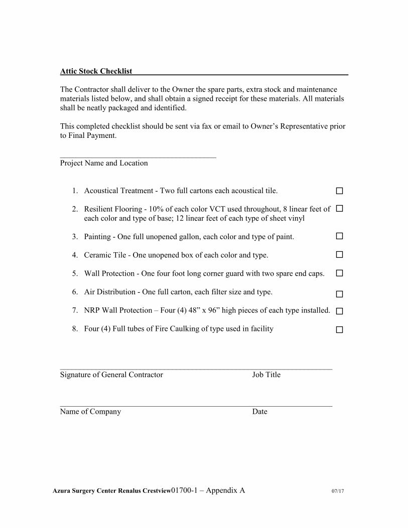
Azura Surgery Center Renalus Crestview01700-1 – Appendix A 07/17
Attic Stock Checklist
The Contractor shall deliver to the Owner the spare parts, extra stock and maintenance
materials listed below, and shall obtain a signed receipt for these materials. All materials
shall be neatly packaged and identified.
This completed checklist should be sent via fax or email to Owner’s Representative prior
to Final Payment.
_______________________________________
Project Name and Location
1. Acoustical Treatment - Two full cartons each acoustical tile.
2. Resilient Flooring - 10% of each color VCT used throughout, 8 linear feet of
each color and type of base; 12 linear feet of each type of sheet vinyl
3. Painting - One full unopened gallon, each color and type of paint.
4. Ceramic Tile - One unopened box of each color and type.
5. Wall Protection - One four foot long corner guard with two spare end caps.
6. Air Distribution - One full carton, each filter size and type.
7. NRP Wall Protection – Four (4) 48” x 96” high pieces of each type installed.
8. Four (4) Full tubes of Fire Caulking of type used in facility
____________________________________________________________________
Signature of General Contractor Job Title
____________________________________________________________________
Name of Company Date

Azura Surgery Center Renalus Crestview 01700-1 07/17
SECTION 01700
CONTRACT CLOSEOUT
PART 1 -GENERAL
1.01 DESCRIPTION
A. Work included: Provide an orderly and efficient transfer of the completed Work to the Owner.
B. Related work:
1. Documents affecting work of this Section include, but are not necessarily limited to, General
Conditions, Supplementary Conditions, and Sections in Division 1 of these Specifications.
2. Activities relative to Contract closeout are described in, but not necessarily limited to, the
General Conditions.
3. “Substantial Completion” is defined in the General Conditions.
1.02 QUALITY ASSURANCE
A. Prior to requesting inspection by the Owner, use adequate means to assure that the Work is
completed in accordance with the specified requirements and is ready for the requested inspection.
1.03 PROCEDURES
A. Substantial Completion:
1. Prepare and submit the punch list required by the General Conditions. Punch list shall be
ordered by room number. Include photos of work to be completed or remedied.
2. Within a reasonable time after receipt of the list, the Owner and/or Architect will inspect to
determine status of completion and prepare Owner’s list of work to be completed or
remedied.
3. Should the Owner determine that the Work is not substantially complete:
a) The Owner promptly will so notify the Contractor, in writing, giving the reasons
therefore.
b) Contractor shall remedy the deficiencies promptly, and notify the Owner when ready for
re-inspection.
c) The Owner will re-inspect the Work.
4. When the Owner concurs that the Work is substantially complete:
a) The Architect will prepare a “Certificate of Substantial Completion” on AIA Form
G704, accompanied by the Contractor’s list of items to be completed or corrected, as
verified by the Owner.
b) The Architect will submit the Certificate to the Owner and to the Contractor for their
written acceptance of the responsibilities assigned to them in the Certificate.
B. Final Completion:
1. Prepare and submit the notice required by the General Conditions.
2. Verify that the Work is complete including, but not necessarily limited to, the items
mentioned in the General Conditions.
3. Certify that:
Azura Surgery Center Renalus Crestview 01700-2 07/17
a) Contract Documents have been reviewed;
b) Work has been inspected for compliance with the Contract Documents;
c) Work has been completed in accordance with the Contract Documents;
d) Equipment and systems have been tested as required, and are operational;
e) Work is completed and ready for final inspection.
4. If the Contractor is not complete for any of the above requested inspections, the Contractor
shall bear the cost of any subsequent inspections to examine the work not complete at
previously requested inspections. Costs due Owner will include any travel costs and related
direct hourly costs from the Architect and Owner’s Representative.
5. The Owner will make an inspection to verify status of completion.
6. Should the Owner determine that the Work is incomplete or defective:
a) The Owner promptly will so notify the Contractor, in writing, listing the incomplete or
defective work.
b) Contractor shall remedy the deficiencies promptly, and notify the Owner when ready for
re-inspections.
7. When the Owner determines that the work is acceptable under the Contract Documents, he
will request the Contractor to make closeout submittals.
C. Closeout submittals include, but are not necessarily limited to:
1. Project Record Documents described in Section 01720:
a) Two (2) complete sets of operation and maintenance manuals, and data for items so
listed in pertinent other Sections of these Specifications, and for other items when so
directed by the Owner.
2. Warranties and bonds including, but not limited, to the following:
a) Termite bond
b) Product and appliance warranties
c) Plumbing fixture warranties
d) Med Gas and Vacuum systems
e) Roofing material warranties
f) Electronic systems and components warranties
(1) Nurse call system
(2) Intercom system
(3) Fire alarm system
3. Keys and keying schedule;
a) Deliver keys and spare keys as specified in keying schedule.
4. Spare parts and materials extra stock. The Contractor shall deliver to the Owner the spare
parts, extra stock and maintenance materials listed below, and shall obtain a signed receipt for
these materials. Materials shall be neatly packaged and identified.
a) Provide as required by section 01700 – Attic Stock Checklist.
5. Evidence of compliance with requirements of governmental agencies having jurisdiction
including, but not necessarily limited to:
a) Certificates of Inspection;
b) Certificates of Occupancy;
6. Certificates of Insurance for products and completed operations;
7. Evidence of payment and release of liens (see Lien Release Form at the end of this Section);
8. List of Subcontractors, service organizations, and principal vendors, including names,
addresses, and telephone numbers where they can be reached for emergency service at all
times including nights, weekends and holidays.
Azura Surgery Center Renalus Crestview 01700-3 07/17
9. Project data catalog sheets and shop drawings approved and returned by architect described in
Section 01340.
10. Class B Fire Alarm System:
a) Provide a detailed one-line wiring diagram of each specified system and the
interconnection wiring between all systems.
11. Item numbers 2, 3,5, 6, 7, 8, 9 and 10 above shall be tabulated and bound into two (2) three-
ring binders with the project name firmly affixed to the cover and binder spine. This
document should be labeled “Operations and Maintenance Manual”. Two CD’s containing
digital scans of all above documents along with one (1) hard copy for the facility is required.
Deliver to Owner’s representative prior to final closeout and payment.
12. Provide As-Built drawing markups to Architect of Record.
13. Life Safety Manual:
a) The Life Safety Manual shall consist of a three-ring binder with sleeves to hold papers,
material samples and other pertinent documents related to the service contracts, fire
ratings as well as all service and inspection reports of all materials used in the
construction of the facility.
b) Each section of the manual shall be tabbed by number and sub-number for easy access to
all documents.
c) All documents required for inclusion in the manual described in Section 01700 -
Appendix B of this specification shall be included in the Life Safety Manual at project
closeout. The parties responsible for each item listed in the appendix are also listed for
clarification.
d) Section 01700 - Appendix B also serves as a checklist for completion of the manual and a
Table of Contents for the front of the manual.
e) Only one (1) manual with this information will be required per project.
f) This manual should be delivered to the Owner prior to final closeout and payment.
14. Turnover Commissioning Record
a) A statement that systems have been completed in accordance with the contract
documents and that the systems are performing in accordance with the final owner’s
project requirements document.
b) Identification and discussion of any substitutions, compromises, or variances between
the final design intent, contract documents and as-built conditions.
c) Description of components and systems that exceed owner’s project requirements and
those which do not meet the requirements and why.
d) Summary of all issues resolved and unresolved and any recommendations for
resolution.
e) The final commissioning report will be a critical reference and benchmark document
for future recommissioning of the facility.
D. Project Closeout Timelines:
1. The Owner’s Representative must receive all closeout submittals and a final statement of
accounting from the Contractor within thirty (30) days of the Owner’s written acceptance of
the Certificate of Substantial Completion.
2. The Owner must receive all closeout submittals and a final statement of accounting from the
Contractor before final payment can be made.
E. Final adjustment of accounts:
Azura Surgery Center Renalus Crestview 01700-4 07/17
1. Submit a final statement of accounting to the Owner, showing all adjustments to the Contract
Sum.
2. If so required, the Owner will prepare a final Change Order showing adjustment to the
Contract Sum which was not made previously by Change orders.
1.04 STAFF TRAINING & INSTRUCTION
A. Provide training and instruction for the Owner’s personnel in proper operation and maintenance of
all systems and equipment, after acceptance of Operation and Maintenance Manual. It is the
Contractor’s responsibility to schedule training with the Owner’s personnel.
B. Any appropriate personnel or subcontractors should be on site to train the staff on their particular
specialty.
C. It is intended for all facility systems to be reviewed with owner’s personnel on one complete day
at some point prior to the opening and operation of the facility.
D. Provide at the Final Completion walkthrough a schedule of such training, allowing the following
time periods:
1. Mechanical Systems – 2 hours
a) Show locations and describe operation of thermostats
b) Show location of package unit filters and how to replace them
c) Describe operation of water heater thermostat
2. Electrical, Lighting, Alarm, Nurse Call Systems – 2 hours
a) Describe operation of Generator ATS (if provided)
b) Describe operation and layout of main distribution panels
c) Describe VFD operation
d) Show locations and describe fire alarm system operation
e) Operation of the timeclock
f) Operation of photo eye for parking lot lighting
3. Plumbing Systems – 2 hours
a) Location of incoming water
b) Show location of water meter and describe its function
c) Show locations of sewer cleanouts
d) Describe sprinkler riser layout and operation
END OF SECTION
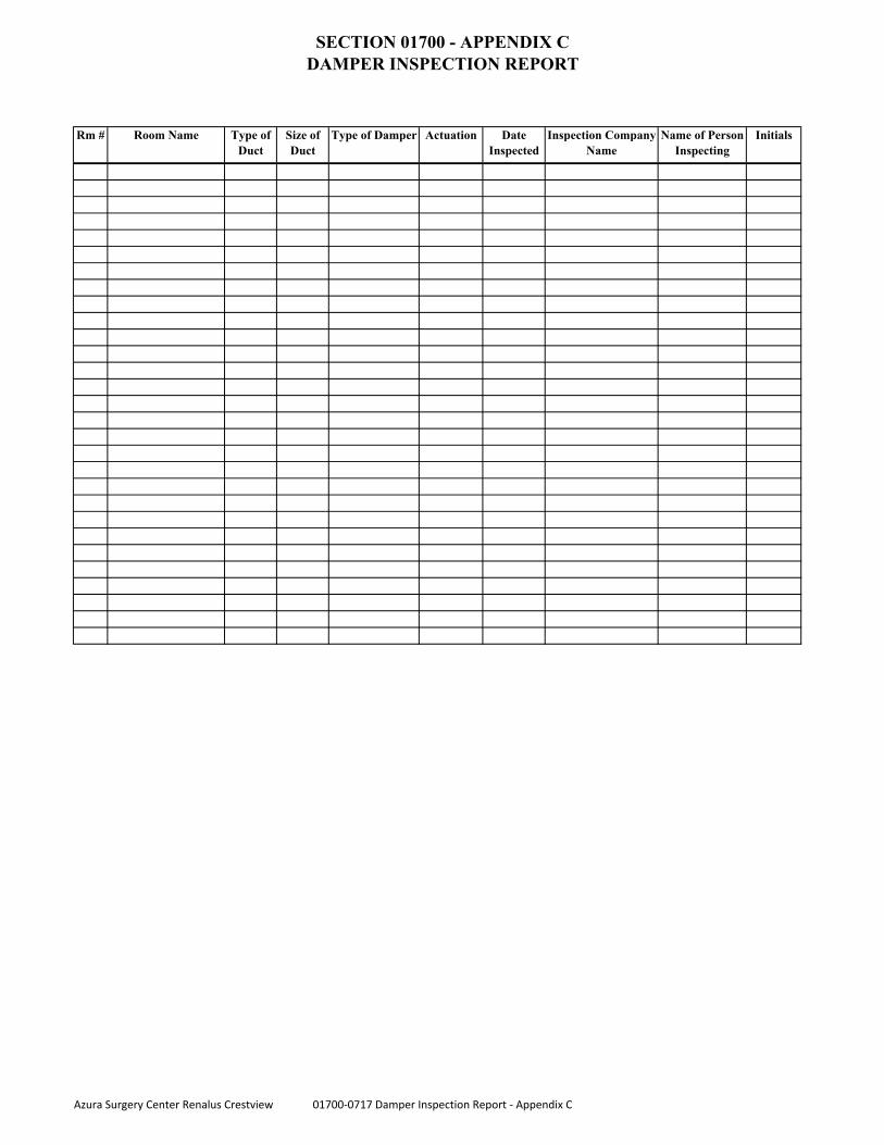
SECTION 01700 - APPENDIX C
DAMPER INSPECTION REPORT
Rm # Room Name Type of
Duct
Size of
Duct
Type of Damper Actuation Date
Inspected
Inspection Company
Name
Name of Person
Inspecting
Initials
Azura Surgery Center Renalus Crestview 01700-0717 Damper Inspection Report - Appendix C
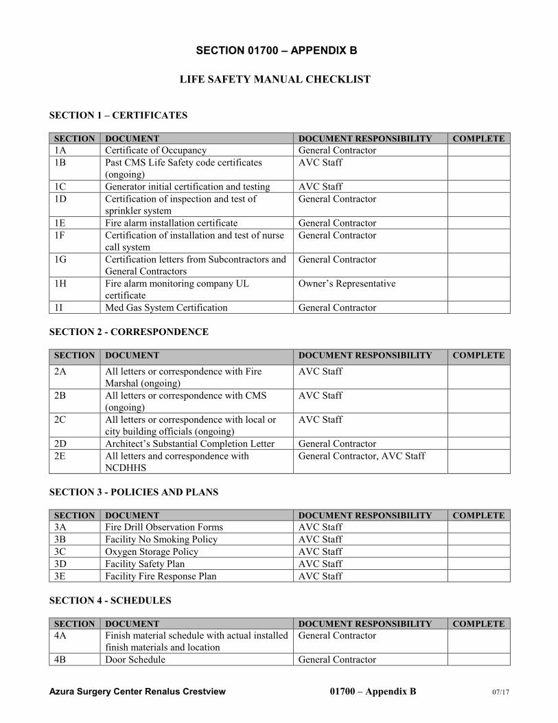
Azura Surgery Center Renalus Crestview 01700 – Appendix B 07/17
SECTION 01700 – APPENDIX B
LIFE SAFETY MANUAL CHECKLIST
SECTION 1 – CERTIFICATES
SECTION DOCUMENT DOCUMENT RESPONSIBILITY COMPLETE
1A Certificate of Occupancy General Contractor
1B Past CMS Life Safety code certificates
(ongoing)
AVC Staff
1C Generator initial certification and testing AVC Staff
1D Certification of inspection and test of
sprinkler system
General Contractor
1E Fire alarm installation certificate General Contractor
1F Certification of installation and test of nurse
call system
General Contractor
1G Certification letters from Subcontractors and
General Contractors
General Contractor
1H Fire alarm monitoring company UL
certificate
Owner’s Representative
1I Med Gas System Certification General Contractor
SECTION 2 - CORRESPONDENCE
SECTION DOCUMENT DOCUMENT RESPONSIBILITY COMPLETE
2A All letters or correspondence with Fire
Marshal (ongoing)
AVC Staff
2B All letters or correspondence with CMS
(ongoing)
AVC Staff
2C All letters or correspondence with local or
city building officials (ongoing)
AVC Staff
2D Architect’s Substantial Completion Letter General Contractor
2E All letters and correspondence with
NCDHHS
General Contractor, AVC Staff
SECTION 3 - POLICIES AND PLANS
SECTION DOCUMENT DOCUMENT RESPONSIBILITY COMPLETE
3A Fire Drill Observation Forms AVC Staff
3B Facility No Smoking Policy AVC Staff
3C Oxygen Storage Policy AVC Staff
3D Facility Safety Plan AVC Staff
3E Facility Fire Response Plan AVC Staff
SECTION 4 - SCHEDULES
SECTION DOCUMENT DOCUMENT RESPONSIBILITY COMPLETE
4A Finish material schedule with actual installed
finish materials and location
General Contractor
4B Door Schedule General Contractor
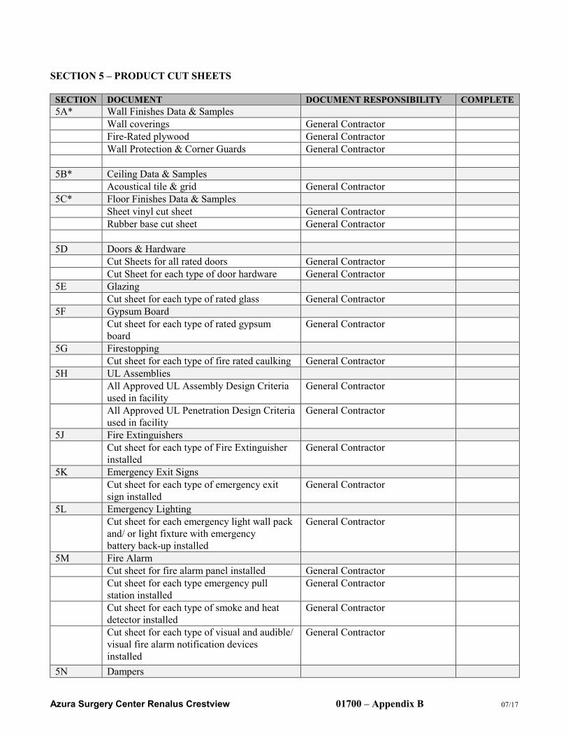
Azura Surgery Center Renalus Crestview 01700 – Appendix B 07/17
SECTION 5 – PRODUCT CUT SHEETS
SECTION DOCUMENT DOCUMENT RESPONSIBILITY COMPLETE
5A* Wall Finishes Data & Samples
Wall coverings General Contractor
Fire-Rated plywood General Contractor
Wall Protection & Corner Guards General Contractor
5B* Ceiling Data & Samples
Acoustical tile & grid General Contractor
5C* Floor Finishes Data & Samples
Sheet vinyl cut sheet General Contractor
Rubber base cut sheet General Contractor
5D Doors & Hardware
Cut Sheets for all rated doors General Contractor
Cut Sheet for each type of door hardware General Contractor
5E Glazing
Cut sheet for each type of rated glass General Contractor
5F Gypsum Board
Cut sheet for each type of rated gypsum
board
General Contractor
5G Firestopping
Cut sheet for each type of fire rated caulking General Contractor
5H UL Assemblies
All Approved UL Assembly Design Criteria
used in facility
General Contractor
All Approved UL Penetration Design Criteria
used in facility
General Contractor
5J Fire Extinguishers
Cut sheet for each type of Fire Extinguisher
installed
General Contractor
5K Emergency Exit Signs
Cut sheet for each type of emergency exit
sign installed
General Contractor
5L Emergency Lighting
Cut sheet for each emergency light wall pack
and/ or light fixture with emergency
battery back-up installed
General Contractor
5M Fire Alarm
Cut sheet for fire alarm panel installed General Contractor
Cut sheet for each type emergency pull
station installed
General Contractor
Cut sheet for each type of smoke and heat
detector installed
General Contractor
Cut sheet for each type of visual and audible/
visual fire alarm notification devices
installed
General Contractor
5N Dampers
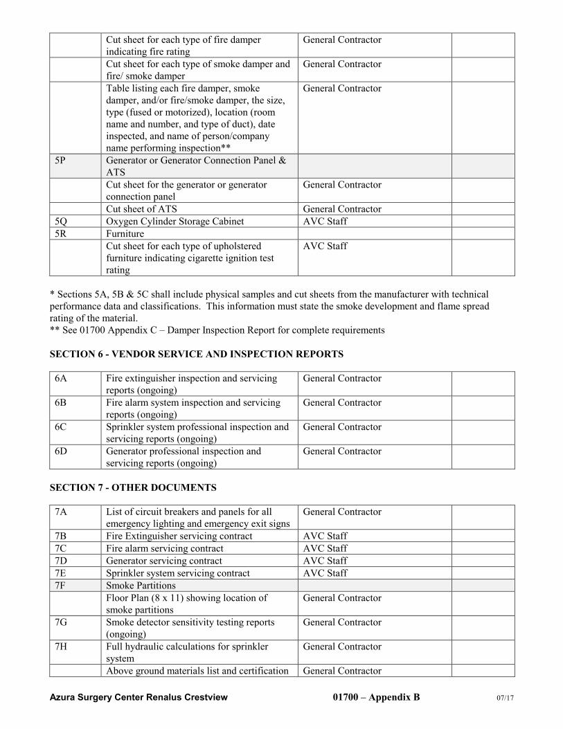
Azura Surgery Center Renalus Crestview 01700 – Appendix B 07/17
Cut sheet for each type of fire damper
indicating fire rating
General Contractor
Cut sheet for each type of smoke damper and
fire/ smoke damper
General Contractor
Table listing each fire damper, smoke
damper, and/or fire/smoke damper, the size,
type (fused or motorized), location (room
name and number, and type of duct), date
inspected, and name of person/company
name performing inspection**
General Contractor
5P Generator or Generator Connection Panel &
ATS
Cut sheet for the generator or generator
connection panel
General Contractor
Cut sheet of ATS General Contractor
5Q Oxygen Cylinder Storage Cabinet AVC Staff
5R Furniture
Cut sheet for each type of upholstered
furniture indicating cigarette ignition test
rating
AVC Staff
* Sections 5A, 5B & 5C shall include physical samples and cut sheets from the manufacturer with technical
performance data and classifications. This information must state the smoke development and flame spread
rating of the material.
** See 01700 Appendix C – Damper Inspection Report for complete requirements
SECTION 6 - VENDOR SERVICE AND INSPECTION REPORTS
6A Fire extinguisher inspection and servicing
reports (ongoing)
General Contractor
6B Fire alarm system inspection and servicing
reports (ongoing)
General Contractor
6C Sprinkler system professional inspection and
servicing reports (ongoing)
General Contractor
6D Generator professional inspection and
servicing reports (ongoing)
General Contractor
SECTION 7 - OTHER DOCUMENTS
7A List of circuit breakers and panels for all
emergency lighting and emergency exit signs
General Contractor
7B Fire Extinguisher servicing contract AVC Staff
7C Fire alarm servicing contract AVC Staff
7D Generator servicing contract AVC Staff
7E Sprinkler system servicing contract AVC Staff
7F Smoke Partitions
Floor Plan (8 x 11) showing location of
smoke partitions
General Contractor
7G Smoke detector sensitivity testing reports
(ongoing)
General Contractor
7H Full hydraulic calculations for sprinkler
system
General Contractor
Above ground materials list and certification General Contractor
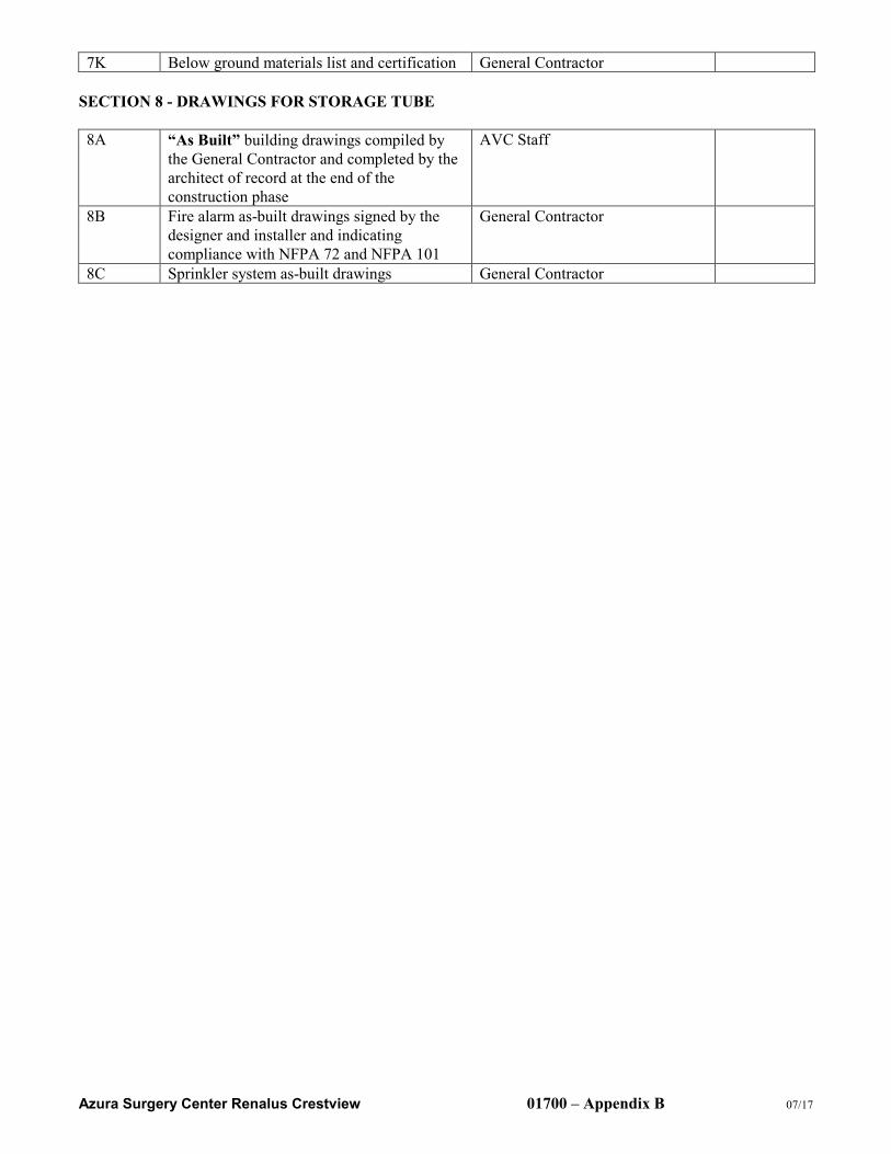
Azura Surgery Center Renalus Crestview 01700 – Appendix B 07/17
7K Below ground materials list and certification General Contractor
SECTION 8 - DRAWINGS FOR STORAGE TUBE
8A “As Built” building drawings compiled by
the General Contractor and completed by the
architect of record at the end of the
construction phase
AVC Staff
8B Fire alarm as-built drawings signed by the
designer and installer and indicating
compliance with NFPA 72 and NFPA 101
General Contractor
8C Sprinkler system as-built drawings General Contractor
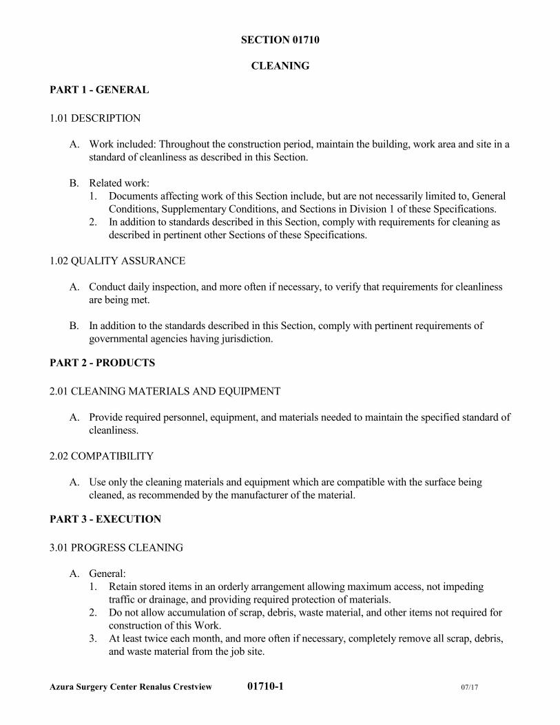
Azura Surgery Center Renalus Crestview 01710-1 07/17
SECTION 01710
CLEANING
PART 1 - GENERAL
1.01 DESCRIPTION
A. Work included: Throughout the construction period, maintain the building, work area and site in a
standard of cleanliness as described in this Section.
B. Related work:
1. Documents affecting work of this Section include, but are not necessarily limited to, General
Conditions, Supplementary Conditions, and Sections in Division 1 of these Specifications.
2. In addition to standards described in this Section, comply with requirements for cleaning as
described in pertinent other Sections of these Specifications.
1.02 QUALITY ASSURANCE
A. Conduct daily inspection, and more often if necessary, to verify that requirements for cleanliness
are being met.
B. In addition to the standards described in this Section, comply with pertinent requirements of
governmental agencies having jurisdiction.
PART 2 - PRODUCTS
2.01 CLEANING MATERIALS AND EQUIPMENT
A. Provide required personnel, equipment, and materials needed to maintain the specified standard of
cleanliness.
2.02 COMPATIBILITY
A. Use only the cleaning materials and equipment which are compatible with the surface being
cleaned, as recommended by the manufacturer of the material.
PART 3 - EXECUTION
3.01 PROGRESS CLEANING
A. General:
1. Retain stored items in an orderly arrangement allowing maximum access, not impeding
traffic or drainage, and providing required protection of materials.
2. Do not allow accumulation of scrap, debris, waste material, and other items not required for
construction of this Work.
3. At least twice each month, and more often if necessary, completely remove all scrap, debris,
and waste material from the job site.
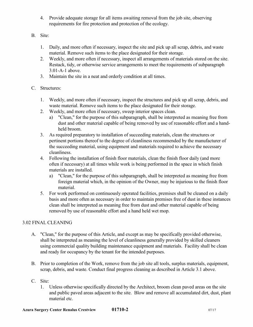
Azura Surgery Center Renalus Crestview 01710-2 07/17
4. Provide adequate storage for all items awaiting removal from the job site, observing
requirements for fire protection and protection of the ecology.
B. Site:
1. Daily, and more often if necessary, inspect the site and pick up all scrap, debris, and waste
material. Remove such items to the place designated for their storage.
2. Weekly, and more often if necessary, inspect all arrangements of materials stored on the site.
Restack, tidy, or otherwise service arrangements to meet the requirements of subparagraph
3.01-A-1 above.
3. Maintain the site in a neat and orderly condition at all times.
C. Structures:
1. Weekly, and more often if necessary, inspect the structures and pick up all scrap, debris, and
waste material. Remove such items to the place designated for their storage.
2. Weekly, and more often if necessary, sweep interior spaces clean.
a) "Clean," for the purpose of this subparagraph, shall be interpreted as meaning free from
dust and other material capable of being removed by use of reasonable effort and a hand-
held broom.
3. As required preparatory to installation of succeeding materials, clean the structures or
pertinent portions thereof to the degree of cleanliness recommended by the manufacturer of
the succeeding material, using equipment and materials required to achieve the necessary
cleanliness.
4. Following the installation of finish floor materials, clean the finish floor daily (and more
often if necessary) at all times while work is being performed in the space in which finish
materials are installed.
a) "Clean," for the purpose of this subparagraph, shall be interpreted as meaning free from
foreign material which, in the opinion of the Owner, may be injurious to the finish floor
material.
5. For work performed on continuously operated facilities, premises shall be cleaned on a daily
basis and more often as necessary in order to maintain premises free of dust in these instances
clean shall be interpreted as meaning free from dust and other material capable of being
removed by use of reasonable effort and a hand held wet mop.
3.02 FINAL CLEANING
A. "Clean," for the purpose of this Article, and except as may be specifically provided otherwise,
shall be interpreted as meaning the level of cleanliness generally provided by skilled cleaners
using commercial quality building maintenance equipment and materials. Facility shall be clean
and ready for occupancy by the tenant for the intended purposes.
B. Prior to completion of the Work, remove from the job site all tools, surplus materials, equipment,
scrap, debris, and waste. Conduct final progress cleaning as described in Article 3.1 above.
C. Site:
1. Unless otherwise specifically directed by the Architect, broom clean paved areas on the site
and public paved areas adjacent to the site. Blow and remove all accumulated dirt, dust, plant
material etc.
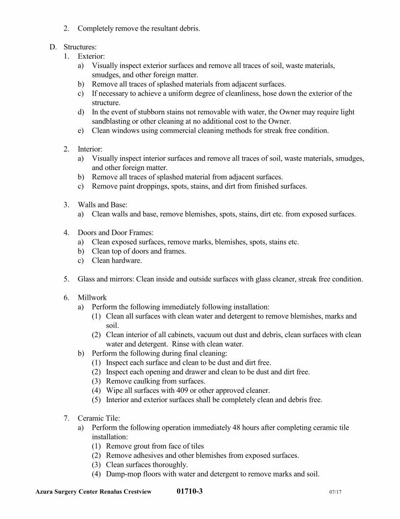
Azura Surgery Center Renalus Crestview 01710-3 07/17
2. Completely remove the resultant debris.
D. Structures:
1. Exterior:
a) Visually inspect exterior surfaces and remove all traces of soil, waste materials,
smudges, and other foreign matter.
b) Remove all traces of splashed materials from adjacent surfaces.
c) If necessary to achieve a uniform degree of cleanliness, hose down the exterior of the
structure.
d) In the event of stubborn stains not removable with water, the Owner may require light
sandblasting or other cleaning at no additional cost to the Owner.
e) Clean windows using commercial cleaning methods for streak free condition.
2. Interior:
a) Visually inspect interior surfaces and remove all traces of soil, waste materials, smudges,
and other foreign matter.
b) Remove all traces of splashed material from adjacent surfaces.
c) Remove paint droppings, spots, stains, and dirt from finished surfaces.
3. Walls and Base:
a) Clean walls and base, remove blemishes, spots, stains, dirt etc. from exposed surfaces.
4. Doors and Door Frames:
a) Clean exposed surfaces, remove marks, blemishes, spots, stains etc.
b) Clean top of doors and frames.
c) Clean hardware.
5. Glass and mirrors: Clean inside and outside surfaces with glass cleaner, streak free condition.
6. Millwork
a) Perform the following immediately following installation:
(1) Clean all surfaces with clean water and detergent to remove blemishes, marks and
soil.
(2) Clean interior of all cabinets, vacuum out dust and debris, clean surfaces with clean
water and detergent. Rinse with clean water.
b) Perform the following during final cleaning:
(1) Inspect each surface and clean to be dust and dirt free.
(2) Inspect each opening and drawer and clean to be dust and dirt free.
(3) Remove caulking from surfaces.
(4) Wipe all surfaces with 409 or other approved cleaner.
(5) Interior and exterior surfaces shall be completely clean and debris free.
7. Ceramic Tile:
a) Perform the following operation immediately 48 hours after completing ceramic tile
installation:
(1) Remove grout from face of tiles
(2) Remove adhesives and other blemishes from exposed surfaces.
(3) Clean surfaces thoroughly.
(4) Damp-mop floors with water and detergent to remove marks and soil.
Azura Surgery Center Renalus Crestview 01710-4 07/17
(5) Clean tile trim, remove sealant, paint or grout from faces.
8. Resilient Tile Flooring (VCT, LVT):
a) Scrub the floor with a neutral detergent solution (Armstrong S-485 Floor Cleaner or
equivalent) and a scrubbing pad (3M blue/green or equal) or equivalent brushes.
b) Thoroughly rinse floor and allow it to dry.
c) Do not apply wax to the floor.
d) Protect flooring from traffic.
9. Resilient Sheet Vinyl:
a) Scrub the floor with a neutral detergent solution (Armstrong S-485 Floor Cleaner or
equivalent) and a scrubbing pad (3M blue/green or equal) or equivalent brushes.
b) Thoroughly rinse floor and allow it to dry.
c) Do not apply wax to the floor.
d) Protect flooring from traffic.
10. Carpet:
a) Use manufacturer’s recommended cleaning products only.
b) Spot clean blemishes and stains.
c) Vacuum floor using commercial vacuum equipment to remove dust, dirt, debris.
d) Clean all exposed surfaces.
11. Polished Surfaces: Surfaces requiring routine application of buffed polish, apply the polish
recommended by the manufacturer of the material being polished.
12. Plumbing Fixtures:
a) Clean all exposed surfaces, remove marks, blemishes, soil.
b) Polish faucets and other hardware.
c) Clean toilet tanks, remove any debris from tanks.
13. Light Fixtures
a) Clean lenses and exposed surfaces.
b) Remove exposed tags, stickers etc except where required by code.
c) Replace inoperable lamps.
1. Polished surfaces: To surfaces requiring routine application of buffed polish, apply the
polish recommended by the manufacturer of the material being polished.
B. Schedule final cleaning as approved by the Owner to Provide to the Owner a completely clean
project ready for occupancy and use as intended.
2.03 CLEANING DURING OWNER'S OCCUPANCY
A. Should the Owner occupy the Work or any portion thereof prior to its completion by the
Contractor and acceptance by the Owner, responsibilities for interim and final cleaning shall be as
determined by the Owner in accordance with the General Conditions of the Contract.
END OF SECTION

Azura Surgery Center Renalus Crestview 01710-5 07/17
Azura Surgery Center Renalus Crestview 01720-1 07/17 Version
SECTION 01720
PROJECT RECORD DOCUMENTS
PART 1 - GENERAL
1.01 DESCRIPTION
A. Work included:
1. Throughout progress of the Work, maintain an accurate record of changes in the Contract
Documents, as described in Article 3.01 below.
2. Upon completion of the Work, transfer the recorded changes to a set of Record Documents,
as described in Article 3.02 below.
B. Related Work:
1. Documents affecting the work of this Section include, but are not necessarily limited to,
General Conditions, Supplementary Conditions, and Sections in Division 1 of these
Specifications.
2. Other requirements affecting Project Record Documents may appear in other pertinent
Sections of these Specifications.
1.02 QUALITY ASSURANCE
A. Delegate the responsibility for maintenance of Record Documents to one person on the
Contractor's staff as approved by the Architect.
B. Accuracy of Records:
1. Thoroughly coordinate changes within the Record Documents, making adequate and proper
entries on each page of Specifications and each sheet of Drawings and other Documents
where such entry in required to show the change properly.
2. Accuracy of records shall be such that future searches for items shown in the Contract
Documents may reasonably rely on information obtained from the approved Project Record
Documents.
C. Make entries within 24 hours after receipt of information that the change has occurred.
1.03 SUBMITTALS
A. Comply with pertinent provisions of Section 01340.
B. Prior to submitting request for final payment, submit the final Project Record Documents to the
Architect and secure his approval.
PART 2 - PRODUCTS
2.01 RECORD DOCUMENTS
A. Job Set Documents: Promptly following the receipt of the Owner's Notice to Proceed, secure
from the Architect at no charge to the Contractor one complete set of all Documents comprising
Azura Surgery Center Renalus Crestview 01720-2 07/17 Version
the Contract.
B. Final Record Documents: At a time nearing the completion of the Work, the GC may print one
clean set of all Drawings in the Contract if job set becomes too difficult to read. Cost of printing
shall be borne by GC.
PART 3 - EXECUTION
3.01 MAINTENANCE OF JOB SET
A. Immediately upon receipt of the job set described in Paragraph 2.01A above, stamp or otherwise
identify each of the Documents with the title "RECORD DOCUMENTS - JOB SET".
B. Preservation:
1. Do not use the Job Set for any purpose except entry of new data and for review by the
Architect.
2. Maintain the Job Set at the site of work.
C. Making entries on the Drawings:
1. Using an erasable colored pencil (not ink or indelible pencil), clearly describe the change by
graphic line and note as required.
2. Date all entries.
3. Call attention to the entry by a “cloud” drawn around the area or areas affected.
4. In the event of overlapping changes, use different colors for overlapping changes.
D. Make entries in any other pertinent Documents as approved by the Architect.
E. Conversion of Schematic Layouts:
1. In some cases on the Drawings, arrangements of conduits, circuits, ducts, and similar items
are shown schematically and are not intended to portray precise physical layout.
a) Final physical arrangement is determined by the Contractor, subject to the Architect's
approval.
b) However, design of future modifications of the facility may require accurate information
as to the final physical layout of items which are shown only schematically on the
Drawings.
2. Show on the Job Set of Record Documents, by dimension, accurate within one inch, the
centerline of each run of items such as are described in subparagraph 3.01E.1 above.
a) Clearly identify the item by accurate note such as “cast iron drain”, “galv. water”, and the
like.
b) Show, by symbol or note, the vertical location of the item, such as “under slab”, “in
ceiling”, “exposed”, and the like.
c) Make all identification sufficiently descriptive that it may be related reliably to the
Specifications.
3. The Architect may waive the requirements for conversion of schematic layouts where, in the
Architect's judgment, conversion serves no useful purpose. However, do not rely upon
Azura Surgery Center Renalus Crestview 01720-3 07/17 Version
waivers being issued except as specifically issued in writing by the Architect.
3.02 FINAL PROJECT RECORD DOCUMENTS
A. The purpose of the final Project Record Documents is to provide factual information regarding all
aspects of the Work, both concealed and visible, to enable future modification of the work to
proceed without lengthy and expensive site measurement, investigation, and examination.
B. Project Record Documents are also known as “As-Built” drawings because they represent what
was actually built on a given project. They are an important tool for the building owner when
making future repairs to the building.
C. Review and Submittal:
1. Submit the completed set of Project Record Documents to the Architect as described in
Paragraph 1.03D above.
2. Participate in review meetings with the architect as required to explain all as-built changes.
3. Make any additional changes requested by the Architect to the Final Record Documents and
promptly deliver the final documents to the Architect.
4. If any such Document is not deemed acceptable by the Architect, secure a new copy of that
Document from the Architect at the Architect's usual charge for reproduction and handling,
and carefully transfer the change data to the new copy to the approval of the Architect.
D. Transfer of As-Built project information to the drawings:
1. Following the transfer of as-built data from Job Set Documents to Final Record Documents,
the GC is to submit all drawings to the Architect for incorporation into a final, revised set of
CAD as-built drawings which will be provided to the owner under the A/E contract.
E. Transfer data to other Documents:
1. If the Documents other than the Drawings have been kept clean during the progress of the
Work, and if entries thereon have been orderly to the approval of the Architect, the job set of
those Documents other than Drawings will be accepted as final Record Documents.
2. If any such Document is not so approved by the Architect, secure a new copy of that
Document from the Architect at the Architect's usual charge for reproduction and handling,
and carefully transfer the change data to the new copy to the approval of the Architect.
3.03 CHANGES SUBSEQUENT TO ACCEPTANCE
A. The Contractor has no responsibility for recording changes in the Work subsequent to Final
Completion, except for changes resulting from work performed under Warranty.
END OF SECTION
Azura Surgery Center Renalus Crestview 03300-1 07/17
SECTION 03300
CAST-IN-PLACE CONCRETE
PART 1 - GENERAL
1.1 DESCRIPTION OF WORK
A. Work Included: Provide labor, materials and equipment necessary to complete the work of this
Section, including but not limited to the following:
1. Cast-in-place concrete, including formwork, reinforcement, concrete materials, mixture
design, placement procedures and finishes for the following applications:
a. Footings.
b. Foundation walls.
c. Slabs-on-grade.
d. Suspended slabs.
e. Concrete toppings.
f. Building frame members.
g. Building walls.
h. Cutting and patching of mechanical and electrical penetrations through cast-in-
place concrete.
i. Generator pad.
j. Utility trench Infill.
B. Items To Be Installed Only: Install the following items as furnished by the designated
Sections:
1. Section 04200 - UNIT MASONRY:
a. Dovetail slots for masonry anchors.
2. Section 05500 - METAL FABRICATIONS:
a. Lintels, sleeves, anchors, inserts, plates and similar items for miscellaneous and
ornamental metal.
3. Section 15900 - FIRE PROTECTION:
a. Lintels, sleeves, anchors, inserts, plates and similar items for fire protection
systems.
4. Section 15300 - PLUMBING:
a. Lintels, sleeves, anchors, inserts, plates, sumps and similar items for plumbing
systems.
5. Section 15500 - HEATING, VENTILATING AND AIR CONDITIONING:
a. Lintels, sleeves, anchors, inserts, plates, and similar items for heating, ventilating,
and air conditioning systems.
b. Pipe and duct sleeves for placement into cast-in-place concrete openings.
6. Section 16111 - ELECTRICAL:
a. Lintels, sleeves, anchors, inserts, plates, floor boxes and similar items for electrical
systems.
7. Section 16231 – PACKAGED ENGINE GENERATOR:
a. Anchors.
C. Items To Be Furnished Only: Not Applicable.
D. Related Work: The following items are not included in this Section and will be performed
under the designated Sections:
1. Section 02300 - EARTHWORK for drainage fill under slabs-on-grade.
Azura Surgery Center Renalus Crestview 03300-2 07/17
1.2 DEFINITIONS
A. Cementitious Materials: Portland cement alone or in combination with one or more of the
following: blended hydraulic cement, fly ash and other pozzolans, ground granulated blast-
furnace slag, and silica fume; subject to compliance with requirements.
1.3 SUBMITTALS
A. Product Data: For each type of product indicated.
B. Design Mixtures: For each concrete mixture. Submit alternate design mixtures when
characteristics of materials, Project conditions, weather, test results, or other circumstances
warrant adjustments.
1. Indicate amounts of mixing water to be withheld for later addition at Project site.
2. Indicate amount of fly ash in the mix.
C. Steel Reinforcement Shop Drawings: Placing drawings that detail fabrication, bending, and
placement. Include bar sizes, lengths, material, grade, bar schedules, stirrup spacing, bent bar
diagrams, bar arrangement, splices and laps, mechanical connections, tie spacing, hoop
spacing, and supports for concrete reinforcement.
1. Indicate coordination requirements for reinforcement locations with requirements of
structural steel, steel joints and steel deck.
D. Formwork Shop Drawings: Prepared by or under the supervision of a qualified professional
engineer detailing fabrication, assembly, and support of formwork.
1. Shoring and Reshoring: Indicate proposed schedule and sequence of stripping formwork,
shoring removal, and installing and removing reshoring.
2. Blockouts for Architectural Joint Systems: Indicate blockouts and coordination with
architectural joint systems.
E. Formwork Inspection: Indicate compliance with approved shop drawings.
F. Anchor Bolt Location: Indicate compliance with approved shop drawings.
G. Material Test Reports: For the following, from a qualified testing agency, indicating
compliance with requirements:
1. Aggregates.
H. Material Certificates: For each of the following, signed by manufacturers:
1. Cementitious materials.
2. Admixtures.
3. Porosity Inhibiting Admixture (PIA):
a. Product Data: Manufacturer’s printed data.
b. Independent product test reports performed by a qualified testing agency
evidencing compliance and/or certification with the US Army Corps of Engineers.
c. Sample copy of copyrighted “Life of the Concrete” warranty.
d. Sample copy of copyrighted Adhesion Guarantee.
e. Sample copy of copyrighted Moisture Letter.
f. HPD Health Product Declaration (Independently verified).
g. Safety Data Sheet. (SDS)
h. Provide copy of USA based insurance coverage to confirm warranty enforcement
and legitimacy upon request.
i. National reference list of 2800+ standard “Life of the Concrete” warranted projects;
all of which had ASTM 5084 testing and/or Army Corps of Engineers CRD C48-92
performed.
4. Form materials and form-release agents.
Azura Surgery Center Renalus Crestview 03300-3 07/17
5. Steel reinforcement and accessories.
6. Fiber reinforcement.
7. Waterstops.
8. Curing compounds.
9. Floor and slab treatments.
10. Bonding agents.
11. Adhesives.
12. Vapor retarders.
13. Semi-rigid joint filler.
14. Joint filler strips.
15. Repair materials.
I. Floor surface flatness and levelness measurements to determine compliance with specified
tolerances and requirements for applied finishes and materials, except as noted for slope to
drains.
J. Field quality-control test and inspection reports.
K. Minutes of pre-installation conference.
1.4 QUALITY ASSURANCE
A. Manufacturer Qualifications: A firm experienced in manufacturing ready-mixed concrete
products and that complies with ASTM C 94/C 94M requirements for production facilities and
equipment.
1. Porosity Inhibiting Admixture Manufacturer Qualifications: A manufacturer with not less
than Ten (10) years’ experience in the actual manufacturing of concrete enhancement
technology admixtures. Selected product manufacturer must have certification of
compliance with ASTM C494 /C494M testing protocols from an independent AASHTO /
Corps of Engineers approved laboratory. A manufactured product is a stand-alone source
or entity that manufacturers the porosity inhibiting admixture “PIA” and its components
primarily in house. Manufacturer must have legitimate USA manufacturing presence to
assure legitimate warranty enforcement. Manufacturer will provide an on-site, contracted
independent ACI certified technical representative capable of randomly sampling each
day’s placement. One random cylinder per day’s concrete placement should be
independently tested per ASTM 5084 and / or Army Corp of Engineers CRD C48-92
testing criteria.
2. Porosity Inhibiting Admixture (“PIA”) Warranty Requirements:
a. “PIA” must be installed according to, and in compliance with, the manufacturer’s
published data sheet, including:
1) Dosing instructions.
2) Onsite independent representation and sampling requirements.
3) Use of an ASTM E 1745 vapor retarder installed following ASTM E 1643
and ACI 303.2R -06 and ASTM F710 guidelines; elevated slabs to receive
flooring do not require a vapor retarder.
4) The design and specifications for roof deck assemblies, to include but not
limited to, the use of air barriers and/or vapor retarders is the sole
responsibility of the design professional and is excluded from this warranty
as are any costs incurred due to roofing overburden.
Azura Surgery Center Renalus Crestview 03300-4 07/17
5) Curing for all moisture sensitive products should be in compliance with ACI
308-16 “Guide to External Curing of Concrete” Section 4.1.4 “Moisture
Sensitive Floors”
b. “PIA” Manufacturer's Standard Warranty shall include:
1) Term: Life of the Concrete Warranty.
2) Repair and/or removal of failed flooring or roofing.
3) Placement of a topical moisture remediation system.
4) Replacement of flooring/roofing materials like original installed to include
material and labor.
5) Sodium Silicate Free Concrete Enhancement Technology (CET) known as a
Porosity Inhibiting Admixture “PIA”
c. Manufacturer’s Adhesion Warranty shall include:
1) Warranty term to match that of the adhesive and/or primer manufacturer's
material defect warranty.
2) Issued upon “PIA” manufacturer’s acceptance of field adhesive bond testing
which followed flooring / adhesive manufacturer guidelines and requirements
noted in ASTM F-710 for installation on a nonporous surface.
d. Moisture Letter: “PIA” Manufacturer shall provide a standard moisture letter
indicating warrantability up to 100% RH per qualified ASTM 2170 Insitu Probe
testing and up 25lbs for ASTM 1869 CaCl testing.
B. Testing Agency Qualifications: An independent agency, acceptable to authorities having
jurisdiction, qualified according to ASTM C 1077 and ASTM E 329 for testing indicated, as
documented according to ASTM E 548.
1. Personnel conducting field tests shall be qualified as ACI Concrete Field Testing
Technician, Grade 1, according to ACI CP-01 or an equivalent certification program.
2. Personnel performing laboratory tests shall be ACI-certified Concrete Strength Testing
Technician and Concrete Laboratory Testing Technician - Grade I. Testing Agency
laboratory supervisor shall be an ACI-certified Concrete Laboratory Testing Technician -
Grade II.
3. Porosity Inhibiting Admixture Collection Agent / Representative Qualifications:
a. Daily sample collections shall be taken by an ACI Concrete Field Testing
Technician, Grade 1, or equivalent, on behalf and at cost of the PIA manufacturer.
b. Slab Moisture Testing and Evaluation: Personnel performing laboratory tests shall
be certified in the conduct of ASTM D5084 and/or Army Corp of Engineers CRD
C48-92 under the supervision of a licensed geotechnical engineer. The
determination as to whether the concrete slab is prepared to receive flooring,
coatings, roofing, etc. rests with the “PIA” manufacturer in conjunction with
adherence and compliance with manufacture’s installation guidelines.
C. Source Limitations: Obtain each type or class of cementitious material of the same brand from
the same manufacturer’s plant, obtain aggregate from one source, and obtain admixtures
through one source from a single manufacturer.
D. Welding: Qualify procedures and personnel according to AWS D1.4, “Structural Welding
Code--Reinforcing Steel.”
E. ACI Publications: Comply with the following unless modified by requirements in the Contract
Documents:
1. ACI 301, “Specification for Structural Concrete.”
2. ACI 117, “Specifications for Tolerances for Concrete Construction and Materials.”
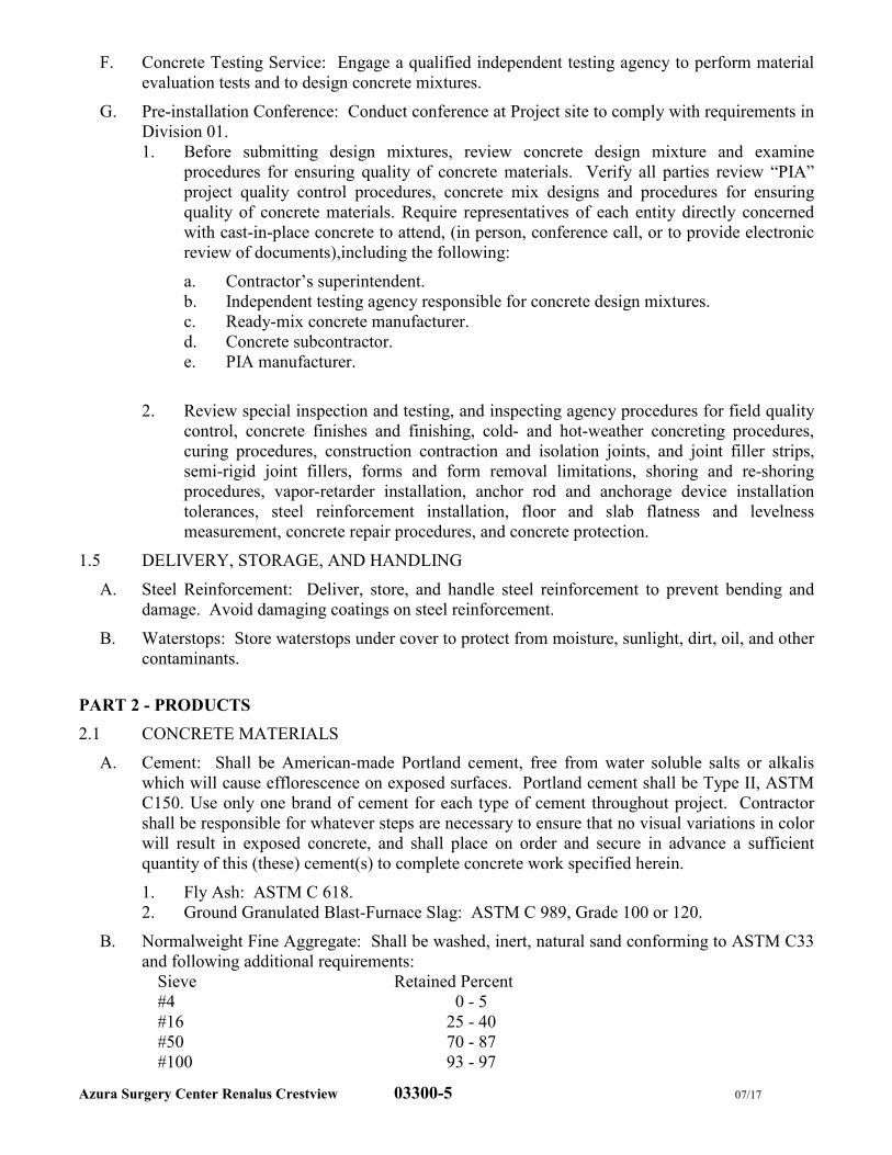
Azura Surgery Center Renalus Crestview 03300-5 07/17
F. Concrete Testing Service: Engage a qualified independent testing agency to perform material
evaluation tests and to design concrete mixtures.
G. Pre-installation Conference: Conduct conference at Project site to comply with requirements in
Division 01.
1. Before submitting design mixtures, review concrete design mixture and examine
procedures for ensuring quality of concrete materials. Verify all parties review “PIA”
project quality control procedures, concrete mix designs and procedures for ensuring
quality of concrete materials. Require representatives of each entity directly concerned
with cast-in-place concrete to attend, (in person, conference call, or to provide electronic
review of documents),including the following:
a. Contractor’s superintendent.
b. Independent testing agency responsible for concrete design mixtures.
c. Ready-mix concrete manufacturer.
d. Concrete subcontractor.
e. PIA manufacturer.
2. Review special inspection and testing, and inspecting agency procedures for field quality
control, concrete finishes and finishing, cold- and hot-weather concreting procedures,
curing procedures, construction contraction and isolation joints, and joint filler strips,
semi-rigid joint fillers, forms and form removal limitations, shoring and re-shoring
procedures, vapor-retarder installation, anchor rod and anchorage device installation
tolerances, steel reinforcement installation, floor and slab flatness and levelness
measurement, concrete repair procedures, and concrete protection.
1.5 DELIVERY, STORAGE, AND HANDLING
A. Steel Reinforcement: Deliver, store, and handle steel reinforcement to prevent bending and
damage. Avoid damaging coatings on steel reinforcement.
B. Waterstops: Store waterstops under cover to protect from moisture, sunlight, dirt, oil, and other
contaminants.
PART 2 - PRODUCTS
2.1 CONCRETE MATERIALS
A. Cement: Shall be American-made Portland cement, free from water soluble salts or alkalis
which will cause efflorescence on exposed surfaces. Portland cement shall be Type II, ASTM
C150. Use only one brand of cement for each type of cement throughout project. Contractor
shall be responsible for whatever steps are necessary to ensure that no visual variations in color
will result in exposed concrete, and shall place on order and secure in advance a sufficient
quantity of this (these) cement(s) to complete concrete work specified herein.
1. Fly Ash: ASTM C 618.
2. Ground Granulated Blast-Furnace Slag: ASTM C 989, Grade 100 or 120.
B. Normalweight Fine Aggregate: Shall be washed, inert, natural sand conforming to ASTM C33
and following additional requirements:
Sieve Retained Percent
#4 0 - 5
#16 25 - 40
#50 70 - 87
#100 93 - 97
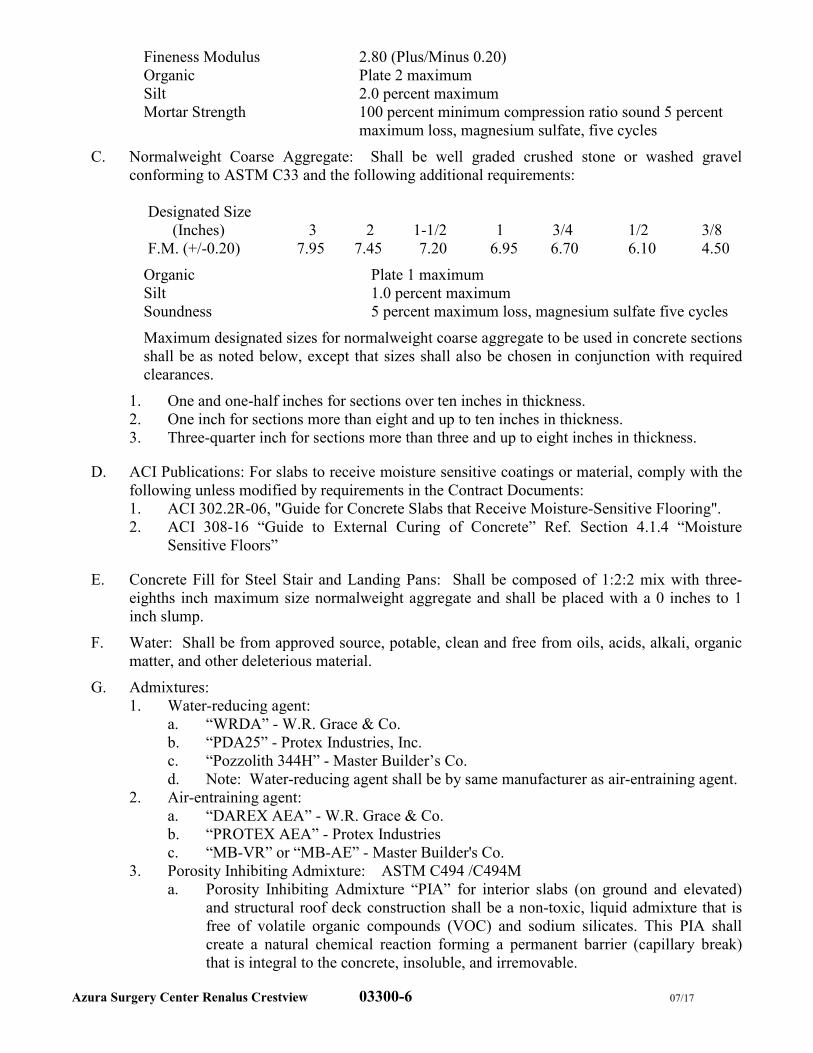
Azura Surgery Center Renalus Crestview 03300-6 07/17
Fineness Modulus 2.80 (Plus/Minus 0.20)
Organic Plate 2 maximum
Silt 2.0 percent maximum
Mortar Strength 100 percent minimum compression ratio sound 5 percent
maximum loss, magnesium sulfate, five cycles
C. Normalweight Coarse Aggregate: Shall be well graded crushed stone or washed gravel
conforming to ASTM C33 and the following additional requirements:
Designated Size
(Inches) 3 2 1-1/2 1 3/4 1/2 3/8
F.M. (+/-0.20) 7.95 7.45 7.20 6.95 6.70 6.10 4.50
Organic Plate 1 maximum
Silt 1.0 percent maximum
Soundness 5 percent maximum loss, magnesium sulfate five cycles
Maximum designated sizes for normalweight coarse aggregate to be used in concrete sections
shall be as noted below, except that sizes shall also be chosen in conjunction with required
clearances.
1. One and one-half inches for sections over ten inches in thickness.
2. One inch for sections more than eight and up to ten inches in thickness.
3. Three-quarter inch for sections more than three and up to eight inches in thickness.
D. ACI Publications: For slabs to receive moisture sensitive coatings or material, comply with the
following unless modified by requirements in the Contract Documents:
1. ACI 302.2R-06, "Guide for Concrete Slabs that Receive Moisture-Sensitive Flooring".
2. ACI 308-16 “Guide to External Curing of Concrete” Ref. Section 4.1.4 “Moisture
Sensitive Floors”
E. Concrete Fill for Steel Stair and Landing Pans: Shall be composed of 1:2:2 mix with three-
eighths inch maximum size normalweight aggregate and shall be placed with a 0 inches to 1
inch slump.
F. Water: Shall be from approved source, potable, clean and free from oils, acids, alkali, organic
matter, and other deleterious material.
G. Admixtures:
1. Water-reducing agent:
a. “WRDA” - W.R. Grace & Co.
b. “PDA25” - Protex Industries, Inc.
c. “Pozzolith 344H” - Master Builder’s Co.
d. Note: Water-reducing agent shall be by same manufacturer as air-entraining agent.
2. Air-entraining agent:
a. “DAREX AEA” - W.R. Grace & Co.
b. “PROTEX AEA” - Protex Industries
c. “MB-VR” or “MB-AE” - Master Builder's Co.
3. Porosity Inhibiting Admixture: ASTM C494 /C494M
a. Porosity Inhibiting Admixture “PIA” for interior slabs (on ground and elevated)
and structural roof deck construction shall be a non-toxic, liquid admixture that is
free of volatile organic compounds (VOC) and sodium silicates. This PIA shall
create a natural chemical reaction forming a permanent barrier (capillary break)
that is integral to the concrete, insoluble, and irremovable.
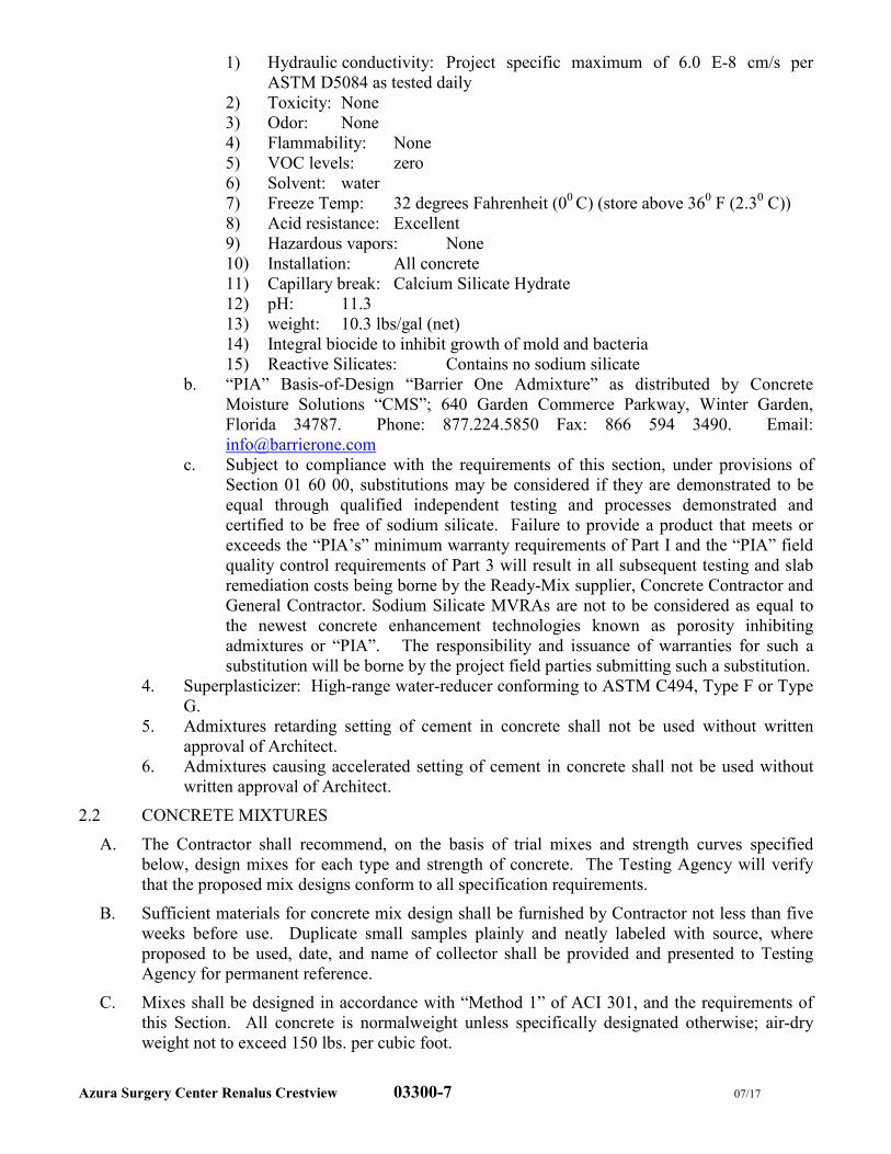
Azura Surgery Center Renalus Crestview 03300-7 07/17
1) Hydraulic conductivity: Project specific maximum of 6.0 E-8 cm/s per
ASTM D5084 as tested daily
2) Toxicity: None
3) Odor: None
4) Flammability: None
5) VOC levels: zero
6) Solvent: water
7) Freeze Temp: 32 degrees Fahrenheit (00
C) (store above 360 F (2.3
0 C))
8) Acid resistance: Excellent
9) Hazardous vapors: None
10) Installation: All concrete
11) Capillary break: Calcium Silicate Hydrate
12) pH: 11.3
13) weight: 10.3 lbs/gal (net)
14) Integral biocide to inhibit growth of mold and bacteria
15) Reactive Silicates: Contains no sodium silicate
b. “PIA” Basis-of-Design “Barrier One Admixture” as distributed by Concrete
Moisture Solutions “CMS”; 640 Garden Commerce Parkway, Winter Garden,
Florida 34787. Phone: 877.224.5850 Fax: 866 594 3490. Email:
c. Subject to compliance with the requirements of this section, under provisions of
Section 01 60 00, substitutions may be considered if they are demonstrated to be
equal through qualified independent testing and processes demonstrated and
certified to be free of sodium silicate. Failure to provide a product that meets or
exceeds the “PIA’s” minimum warranty requirements of Part I and the “PIA” field
quality control requirements of Part 3 will result in all subsequent testing and slab
remediation costs being borne by the Ready-Mix supplier, Concrete Contractor and
General Contractor. Sodium Silicate MVRAs are not to be considered as equal to
the newest concrete enhancement technologies known as porosity inhibiting
admixtures or “PIA”. The responsibility and issuance of warranties for such a
substitution will be borne by the project field parties submitting such a substitution.
4. Superplasticizer: High-range water-reducer conforming to ASTM C494, Type F or Type
G.
5. Admixtures retarding setting of cement in concrete shall not be used without written
approval of Architect.
6. Admixtures causing accelerated setting of cement in concrete shall not be used without
written approval of Architect.
2.2 CONCRETE MIXTURES
A. The Contractor shall recommend, on the basis of trial mixes and strength curves specified
below, design mixes for each type and strength of concrete. The Testing Agency will verify
that the proposed mix designs conform to all specification requirements.
B. Sufficient materials for concrete mix design shall be furnished by Contractor not less than five
weeks before use. Duplicate small samples plainly and neatly labeled with source, where
proposed to be used, date, and name of collector shall be provided and presented to Testing
Agency for permanent reference.
C. Mixes shall be designed in accordance with “Method 1” of ACI 301, and the requirements of
this Section. All concrete is normalweight unless specifically designated otherwise; air-dry
weight not to exceed 150 lbs. per cubic foot.
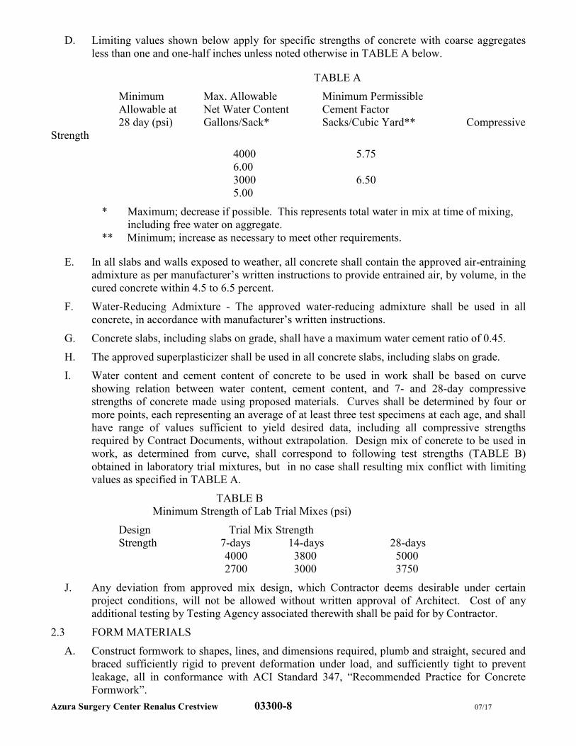
Azura Surgery Center Renalus Crestview 03300-8 07/17
D. Limiting values shown below apply for specific strengths of concrete with coarse aggregates
less than one and one-half inches unless noted otherwise in TABLE A below.
TABLE A
Minimum Max. Allowable Minimum Permissible
Allowable at Net Water Content Cement Factor
28 day (psi) Gallons/Sack* Sacks/Cubic Yard** Compressive
Strength
4000 5.75
6.00
3000 6.50
5.00
* Maximum; decrease if possible. This represents total water in mix at time of mixing,
including free water on aggregate.
** Minimum; increase as necessary to meet other requirements.
E. In all slabs and walls exposed to weather, all concrete shall contain the approved air-entraining
admixture as per manufacturer’s written instructions to provide entrained air, by volume, in the
cured concrete within 4.5 to 6.5 percent.
F. Water-Reducing Admixture - The approved water-reducing admixture shall be used in all
concrete, in accordance with manufacturer’s written instructions.
G. Concrete slabs, including slabs on grade, shall have a maximum water cement ratio of 0.45.
H. The approved superplasticizer shall be used in all concrete slabs, including slabs on grade.
I. Water content and cement content of concrete to be used in work shall be based on curve
showing relation between water content, cement content, and 7- and 28-day compressive
strengths of concrete made using proposed materials. Curves shall be determined by four or
more points, each representing an average of at least three test specimens at each age, and shall
have range of values sufficient to yield desired data, including all compressive strengths
required by Contract Documents, without extrapolation. Design mix of concrete to be used in
work, as determined from curve, shall correspond to following test strengths (TABLE B)
obtained in laboratory trial mixtures, but in no case shall resulting mix conflict with limiting
values as specified in TABLE A.
TABLE B
Minimum Strength of Lab Trial Mixes (psi)
Design Trial Mix Strength
Strength 7-days 14-days 28-days
4000 3800 5000
2700 3000 3750
J. Any deviation from approved mix design, which Contractor deems desirable under certain
project conditions, will not be allowed without written approval of Architect. Cost of any
additional testing by Testing Agency associated therewith shall be paid for by Contractor.
2.3 FORM MATERIALS
A. Construct formwork to shapes, lines, and dimensions required, plumb and straight, secured and
braced sufficiently rigid to prevent deformation under load, and sufficiently tight to prevent
leakage, all in conformance with ACI Standard 347, “Recommended Practice for Concrete
Formwork”.
Azura Surgery Center Renalus Crestview 03300-9 07/17
B. Formwork for exposed concrete shall be medium-density plastic overlaid plywood, 5/8"
minimum thickness; for concealed concrete shall be “Plyform” plywood, 5/8" minimum
thickness.
C. Chamfer Strips: Half-inch, 45 degree poplar wood strips, nailed six inches on center, and
installed in inside corners of all forms, unless otherwise directed by Architect.
D. Form Ties and Spreaders: Richmond Tyscrus by Richmond Screw Anchor Co.; Superior-ties
by Superior Concrete Accessories, Ind.; or Sure-Grip Ties by Dayton Sure-Grip and Shore Co.
Wire ties shall not be used. Ties for foundation walls shall be snap-ties or type specified above
with removal cones and shall incorporate water seal washer. Ties shall be arranged in a
symmetrical manner.
E. Form Release Agent: Non-staining and non-emulsifiable type, or equal approved by Architect.
Form release agent shall be biodegradable and shall not impart any stain to concrete nor
interfere with adherence of any material to be applied to concrete surfaces.
2.4 REINFORCEMENT AND ACCESSORIES
A. Reinforcing Steel Bars: Shall be newly rolled billet steel conforming to ASTM A615 Grade
60. Bars shall be bent cold.
B. Welded Wire Fabric: Shall conform to ASTM A185.
C. All structural steel reinforcement and embedded items shall be hot-dip galvanized after
fabrication in accordance with ASTM A123.
D. All hot-dip galvanized steel shall be inspected for compliance with ASTM A123 and shall be
marked with a stamp that indicates the number of ounces of zinc per square foot of steel. After
galvanizing, the bars shall be dipped in a 0.2 percent chromic acid solution. A notarized
Certificate of Compliance with all of the above shall be required from the galvanizer.
E. Reinforcement Accessories: Shall conform to Product Standard PS7-766, National Bureau of
Standards, Department of Commerce, Class C, as produced by Superior Concrete Accessories,
Inc.; Dayton Sure-Grip Co.; or R.K.L. Building Specialties Co., Inc. Reinforcement
accessories shall include spacers, chairs, ties, slab bolsters, clips, chair bars, and other devices
for properly assembling, placing, spacing, supporting, and fastening reinforcement. Tie wire
shall be galvanized or stainless wire of sufficient strength for intended purpose, but not less
than No. 18 gauge. Metal supports shall be of such type as not to penetrate surface of
formwork and show through surface of concrete. Accessories touching interior formed
surfaces exposed to view shall have not less than 1/8 inch of plastic between metal and concrete
surface. Plastic tips shall extend not less than 1/2 inch up on metal legs. Individual and
continuous slab bolsters and chairs shall be of type to suit various conditions encountered and
must be capable of supporting 300 pound load without damage or permanent distortion.
F. Generator pad reinforcement shall be two (2) layers of #5 rebar laid continuously at perimeter
of pad. Grid of #5 rebar to be laid at 12" o.c. at center of 8" slab.
2.5 MISCELLANEOUS MATERIALS
A. Grout: Shall be ready-to-use metallic aggregate product requiring only addition of water at job
site such as “Embeco Pre-mixed Grout” by Master Builder's; “Vibro-Foil Ready-Mixed” by
W.R. Grace & Co.; or “Ferrolith G” by Sonneborn Building Products, Inc. Grout shall be easily
workable and shall have no drying shrinkage at any age. Compressive strength of grout (2" x
2" cubes) shall not be less than 5000 psi at 7 days, and 7500 psi at 28 days.
B. Under Slab Vapor Barrier
1. Stego Wrap 15 mil Vapor Barrier
Azura Surgery Center Renalus Crestview 03300-10 07/17
2. Husky 15 mil Vapor Barrier
C. Vapor Barrier Seaming Tape
1. Stego Tape – red polyethylene seam bonding tape (3.75" wide)
2. Husky Yellow Guard – yellow polyethylene seam bonding tape (4" wide)
D. Concrete Bonding Tape
1. Stego Crete Claw (3" and 6" widths)
2. Husky Crete Lock (6" width)
E. Membrane Curing Compound: Shall conform to ASTM C309, Type 1. Product used shall be
shown to be compatible with the later application of coatings. Curing compound shall not be
used on any floor slab scheduled to receive an adhered floor finish.
F. Chemical Hardener: All exposed concrete floor slabs shall be hardened with three applications
of fluosilicate chemical hardener followed by two applications of clear acrylic concrete sealer
by Sonneborn Division, ChemRex Inc. “Lapidolith”; or equal product by W.R. Meadows Co.
or Concrete Service Material Company.
2.6 MORTAR-BASED, UTILITY TRENCH INFILL
G. Provide ready-to-use mortar product for filling in trench openings in existing slab for the
installation and/or rerouting of utilities. Follow all installation requirements.
1. Approved products:
a. Mapei Topcem Premix, Ready To Use – Accelerated Cure Screed
PART 3 - EXECUTION
3.1 INSPECTION
A. Examine all work prepared by others to receive work of this Section and report any defects
affecting installation to the Contractor for correction. Commencement of work will be
construed as complete acceptance of preparatory work by others.
1. Inspection shall be performed by a structural engineer licensed by the local authorities
having jurisdiction. Certify compliance with shop drawings.
3.2 HANDLING, STORAGE, AND PROTECTION OF MATERIALS
A. Handle and store materials separately in such manner as to prevent intrusion of foreign matter,
segregation, or deterioration. Do not use foreign materials or those containing ice. Remove
improper and rejected materials immediately from point of use. Cover materials, including
steel reinforcement and accessories, during construction period. Stockpile concrete
constituents properly to assure uniformity throughout project.
3.3 ERECTION OF FORMWORK, SHORING AND RESHORING
A. Set and maintain formwork to ensure complete concrete work within tolerance limits listed in
ACI 347 latest edition, “Recommended Practice for Concrete Formwork”, and with following
additional requirements:
1. Maximum variations from plumb:
a. In surfaces of columns and walls:
In any 10 feet of length 1/4 inch
Maximum for entire length 1/2 inch
2. Maximum variations from established position in plan shown on the drawings:
Column 1/2 inch
Azura Surgery Center Renalus Crestview 03300-11 07/17
Walls 3/4 inch
3. Variations in cross-sectional dimensions of columns and beams and in thickness of slabs
and walls.
B. For a minimum of one hour prior to concrete placement, wet forms continuously with water to
swell forms in order to prevent leakage of concrete matrix and to minimize absorption of
concrete matrix water by form materials. This requirement may be waived for those specific
cases where Architect deems it unnecessary or impractical. Care must be exercised to prevent a
build-up of water at base of forms.
C. Before form materials can be re-used, surfaces that will be in contact with freshly cast concrete
shall be thoroughly cleaned, damaged areas repaired and projecting nails withdrawn. Re-use of
form material shall be subject to approval by Architect.
PART 4 - PLACING OF REINFORCEMENT
A. Reinforcement shall be placed in accordance with requirements of CRSI 93, “Recommended
Practice for Placing Reinforcing Bars”; CRSI 93, “Recommended Practice for Placing Bar
Supports”; and with further requirements below.
B. Reinforcement shall be accurately placed in accordance with Contract Documents and shall be
firmly secured in position by wire ties, chairs, spacers, and hangers, each of type approved by
Architect.
C. Bending, welding or cutting reinforcement in field in any manner other than as shown on
Drawings is prohibited unless specific approval for each case is given by Architect.
D. Reinforcement shall be continuous through construction joints unless otherwise indicated on
Drawings.
E. Reinforcement shall be spliced only in accordance with requirements of Contract Documents or
as otherwise specifically approved by Architect. Splices of reinforcement at points of
maximum stress shall generally be avoided. Welded wire fabric shall lap six inches or one
space plus two inches, whichever is larger, and shall be wired together.
F. At time concrete is placed, reinforcement shall be free of excessive rust, scale, or other coatings
that will destroy or reduce bond requirements. Reinforcement expected to be exposed to
weather for a considerable length of time shall be painted with a heavy coat of cement grout.
Protect stored materials so as not to end or distort bars in any way. Bars that become damaged
will be rejected.
G. Before concrete is cast, check all reinforcement after it is placed to insure that reinforcement
conforms to Contract Documents and approved Shop Drawings. Such checking shall be done
only by qualified experienced personnel. In addition, the Architect shall be notified at least 36
hours prior to concrete placement and given opportunity to inspect completed reinforcement
and formwork before concrete placement. Prior approval of Shop Drawings shall in no way
limit Architect’s right to demand modifications or additions to reinforcement or accessories.
4.2 JOINTS
A. Construction and control joints indicated on Drawings are mandatory and shall not be omitted.
B. Joints not indicated or specified shall be placed to least impair strength of structure and shall be
subject to approval of Architect.
Azura Surgery Center Renalus Crestview 03300-12 07/17
4.3 INSTALLATION OF EMBEDDED ITEMS
A. Conform to requirements of ACI 318, paragraph 6.3, “Conduits and Pipes Embedded in
Concrete”, and as specified below.
B. Install steel sleeves, embedded wall plates and similar items, furnished by other trades, at
locations shown on the Drawings.
C. Anchor bolts for column baseplates shall be installed with templates provided. Vertical
alignment and plan locations shall be maintained within one-sixteenth inch of the locations
shown on the Drawings.
1. Inspection shall be performed by a surveyor licensed by the local authorities having
jurisdiction. Certify compliance with Shop Drawings.
4.4 MIXING, CONSISTENCY, AND DELIVERY OF CONCRETE
A. Concrete shall be ready-mixed, produced by plant acceptable to Architect. Hand or site mixing
shall not be done. Constituents, including admixtures except certain corrosion inhibitors and
superplasticizers, shall be batched at central batch plant. Admixtures shall be pre-mixed in
solution form and dispensed as recommended by manufacturer.
B. Central plant and rolling stock equipment and methods shall conform to Truck Mixer and
Agitator Standard of Truck Mixer Manufacturer’s Bureau of National Ready-Mixed Concrete
Association, and Contract Documents. Consistency of concrete at time of deposit shall be as
follows:
Slump
Portion of Structure Recommended Max. Range
Walls, columns 4" 3" - 5"
Slabs, beams 3" 2" - 4"
C. Ready-mixed concrete shall be transported to site in watertight agitator or mixer trucks loaded
not in excess of rated capacities. Discharge at site shall be within one and one-half hours after
cement was first introduced into mix. Discard cement not discharged within one and one-half
hours and dispose of legally. Concrete with a temperature greater than 85 degrees F. shall not
be placed. Central mixed concrete shall be plant mixed a minimum of five minutes. Agitation
shall begin immediately after pre-mixed concrete is placed in truck and shall continue without
interruption until discharged. Transit mixed concrete shall be mixed at mixing speed for at
least ten minutes immediately after charging truck followed by agitation without interruption
until discharged. Concrete shall be furnished by a single plant unless accepted by the Architect
in writing.
D. Re-tempering of concrete which has partially hardened, that is, mixing with or without
additional cement, aggregates, or water, will not be permitted.
4.5 PLACING CONCRETE
A. Intent of this Specification is that concrete shall not be pumped. Refer to “Submittals and
Concrete Constituents” in this Section for requirements should pumping be proposed.
B. Remove water and foreign matter from forms and excavations and, except in freezing weather
or as otherwise directed, thoroughly wet wood forms just prior to placing concrete. Place no
concrete on frozen soil and provide adequate protection against frost action during freezing
weather.
C. To secure full bond at construction joints, surfaces of concrete already placed, including
vertical and inclined surfaces, shall be thoroughly cleaned of foreign materials and laitance,
roughened with suitable tools such as chipping hammers or wire brushes, and re-cleaned by
Azura Surgery Center Renalus Crestview 03300-13 07/17
stream of water or compressed air. Well before new concrete is deposited, joints shall be
saturated with water. After free or glistening water disappears, joints shall be given thorough
coating of neat cement slurry mixed to consistency of very heavy paste. Surface shall receive
coating of approximately one-eighth inch thick; this shall be scrubbed in by means of stiff
bristle brushes. New concrete shall be deposited before neat cement dries or changes color.
D. Do not place concrete having slump outside of allowable slump range.
E. Transport concrete from mixer to place of final deposit as rapidly as practical by methods
which prevent separation of ingredients and displacement of reinforcement, and which avoid
rehandling. Deposit no partially hardened concrete. When concrete is conveyed by chutes,
equipment shall be of such size and U-shaped design as to ensure continuous flow in chute.
Flat (coal) chutes shall not be employed. Chutes shall be of metal or metal lines and different
portions shall have approximately same slope. Slope shall not be less than 25 degrees nor more
than 45 degrees from horizontal and shall be such as to prevent segregation of ingredients.
Discharge end of chute shall be provided with baffle plate or spout to prevent segregation. If
discharge end of chute is more than five feet above surface of concrete in forms, spout shall be
used and lower and maintained as near surface of deposit as practicable. When operation is
intermittent, chute shall discharge into hopper. Chute shall be thoroughly cleaned before and
after each run and debris and any water used shall be discharged outside forms. Concrete shall
not be allowed to flow horizontally over distances exceeding five feet.
F. Concrete shall be placed in such manner as to prevent segregation, and accumulations of
hardened concrete on forms or reinforcement above mass of concrete being placed. To achieve
this end, suitable hoppers, spouts with restricted outlets and tremies, shall be used as required.
G. During and immediately after depositing, concrete shall be thoroughly compacted by means of
internal type mechanical vibrators or other tools, or by spading to produce required quality of
finish. Vibration shall be done by experienced operators under close supervision and shall be
carried on only enough to produce homogeneity and optimum consolidation without permitting
segregation of constituents or “pumping” of air. Vibrators used for normalweight concrete
shall operate at speed at not less than 7,000 vpm and be of suitable capacity. Do not use
vibrators to move concrete. Vibration shall be supplemented by proper wooden spade puddling
to remove included bubbles and honeycomb adjacent to visible surfaces. At least one vibrator
shall be on hand for every 10 cubic yards of concrete placed per hour, plus one spare.
Vibrators shall be operable and on site prior to starting placement.
H. Vertical lifts shall not exceed 18 inches. Vibrate completely through successive lifts to avoid
pour lines. Vibrate first lift thoroughly until top of lift glistens to avoid stone pockets,
honeycomb, and segregation.
I. Concrete shall be deposited continuously, and in layers of such thickness that no concrete will
be deposited on concrete which has hardened sufficiently to cause formation of seams and
planes of weakness within section. If section cannot be placed continuously between planned
construction joints, as specified, field joint and additional reinforcement shall be introduced so
as to preserve structural continuity. Architect shall be notified in any such case.
J. Cold joints, particularly in exposed concrete, including “honeycomb”, are unacceptable. If they
occur in concrete surfaces exposed to view, Architect will require that entire section in which
blemish occurs be removed and replaced with new materials at Contractor’s expense.
K. When placing exposed concrete walls or columns, strike corners of forms rapidly and
repeatedly from outside along full height while depositing concrete and vibrating.
Azura Surgery Center Renalus Crestview 03300-14 07/17
L. Chutes, hoppers, spouts, adjacent work, etc. shall be thoroughly cleaned before and after each
run, and water and debris shall be discharged outside form.
4.6 FLOOR FLATNESS/LEVELNESS TOLERANCES
A. FF defines maximum floor curvature allowed over 24 inches. Computed on basis of successive
12 inch elevation differentials, FF is commonly referred to as “flatness F-Number”.
B. FL defines relative conformity of floor surface to horizontal plane as measured over 10 feet IN
distance. FL is commonly referred to as “levelness F-Number”.
C. Measure floors in accordance with ASTM E1155.
D. Overall FF or FL number represents test surface defined as total floor area of one building level.
E. Local FF or FL numbers represent test section surfaces. Each single concrete pour at one
building level is separated into test sections which shall not exceed 2500 square feet.
F. Ensure slabs achieve specified overall tolerances. Minimum local tolerance (1/2 bay or as
designated by Architect) is 2/3 of specified tolerance unless noted otherwise.
G. FL tolerances do not apply to unshored, framed construction.
1. Variations from elevations identified on Drawings: Plus/Minus 1/2 inch.
4.7 TYPES OF SLAB FINISHES
A. Scratch Finish: Level to FF15/FL13 tolerance with minimum local tolerance of FF13/FL10,
roughen surface with stiff brushes or rakes before final set.
1. Locations: Slabs to receive thick set mortar beds, concrete floor topping, and other
similar bonded cementitious finish flooring materials over 1 inch in thickness.
B. Float Finish: After screeding, consolidating, and leveling concrete slabs, do not work surface
until ready for floating.
1. Begin floating when surface water has disappeared and when concrete has stiffened
sufficiently to permit operation of power-driven floats.
2. Cut down high spots and fill low spots.
3. Immediately after leveling, re-float surface to uniform, sandy texture and FF20/FL15
tolerance.
4. Locations: Where concrete flatwork is to receive waterproofing membranes or setting
beds for finished materials and for top surfaces of walls, slabs and beams.
C. Trowel Finish: After float finish, follow by power troweling and then hand troweling.
1. Begin final troweling when surface produces ringing sound as trowel is moved over
surface.
2. Finish surfaces free of trowel marks; leave uniform in texture and appearance.
3. Flatness/Levelness Tolerances and Locations: FF 25/FL 20 (typical).
4. Grind surface smooth to remove defects which may telegraph through applied finish.
5. Locations: Slabs left exposed to view, slabs covered with resilient flooring, carpet,
seamless flooring, epoxy flooring or other similar applied finish.
D. Fine Broom Finish: After trowel finish, while surface is still plastic, draw soft fiber bristle
broom uniformly over surface to create fine-grained but smooth texture to match Architect's
sample.
1. Locations: At exterior concrete walks, pavements and steps. Provide smooth edging.
E. Contractor, at his own expense, shall level depressed spots and grind high spots in concrete
surfaces which are in excess of specified tolerances. Leveling materials proposed for providing
proper surface shall be approved by Architect.
Azura Surgery Center Renalus Crestview 03300-15 07/17
4.8 REPAIRING OF UNFORMED CONCRETE SURFACES
A. Tops of slabs and walls shall be repaired by using either same material as originally cast or by
use of dry-pack material, as approved by Architect. Areas affected shall be chipped back
square and to depth of one inch minimum. Hole shall then be moistened with water for a
minimum of two hours, followed by brush coat of 1/16 inch thick cement paste. Immediately
plug hole with concrete, or with dry-pack material consisting of 1:1.5 mixture of cement and
concrete sand mixed slightly damp to touch. Hammer dry-pack into hole until dense and
excess paste appears on surface. Finish patch flush and to same texture as surrounding
concrete. For large repairs employ 1-1-2 mixture of cement, concrete sand and pea gravel at
same dry-pack consistency.
4.9 CURING AND PROTECTION
A. When concrete is placed at or below ambient air temperatures of 40 degrees F. or whenever in
opinion of Architect, such or lower temperatures are likely to occur within 48 hours after
placement of concrete, cold weather concreting procedures, according to ACI 306 and as
specified herein, shall be followed. To this end, entire area affected shall be protected by
adequate housing or covering, and heating. No salt, chemicals or other foreign materials shall
be used in the mix to lower freezing point of concrete.
B. Protect concrete work against injury from heat, cold, and defacement of any nature during
construction operations.
C. Concrete shall be treated and protected immediately after concreting or cement finishing is
completed, to provide continuous moist curing above 50 degrees F. for at least seven days,
regardless of ambient air temperatures.
D. Curing compounds will not be permitted for slab and beams.
E. Keep permanent temperature records showing date and outside temperature for concreting
operations. Thermometer readings shall be taken at start of work in morning, at noon, and
again late in afternoon. Locations of concrete placed during such periods shall likewise be
recorded, in such manner as to show any effect temperatures may have had on construction.
Copies of temperature record shall be distributed daily to Architect.
4.10 HARDENER
A. Prepare surfaces and apply surface hardener to all concrete floors not receiving resilient
flooring, ceramic tile or membrane waterproofing.
B. Prepare surface and apply special sealer system to all concrete flatwork and curbs exposed to
the elements.
4.11 REMOVAL OF FORMWORK, SHORING AND RESHORING
A. Contractor shall be responsible for proper removal of formwork, shoring, and reshoring.
B. Forms shall be removed only after concrete has attained sufficient strength to support its shown
weight, construction loads to be placed thereon and lateral loads, without damage to structure
or excessive deflection.
C. Forms and supports shall remain in place for not less than minimum periods of time noted
below. These periods represent cumulative number of days or fractions thereof, consecutive
unless otherwise approved by Architect during which time mean daily air temperature at
surfaces of concrete is above 50 degrees F.
1. Vertical surfaces: Concrete shall have reached 100 day-degrees# and shall have attained
strength of not less than 30 percent of f'c. Where such forms also support formwork for
slab or beam soffits, removal times for latter shall govern.
Azura Surgery Center Renalus Crestview 03300-16 07/17
2. Horizontal surfaces: Except as noted below, concrete shall have reached 300 day-
degrees# of curing and attained strength of not less than 60 percent of f'c.
a. Soffits of beams or girders shall remain supported and in place until concrete has
attained 600 day-degrees#.
b. Forms and supports of floor slabs shall remain in place until concrete has reached
400 day-degrees#.
c. #Definition of day-degrees: Total number of days times mean daily air temperature
at surfaces of concrete. For example, five days at temperature of 60 degrees F.
equals 300 day-degrees. Days or fractions of days in which temperature is below
50 degrees F. shall not be included in calculation of day-degrees.
D. Form removal shall be so performed that reshores are placed at same time as stripping
operations, and that no area larger than one-fourth of a slab panel is unsupported at any time.
E. Any test cylinders required to verify the specified minimum strengths for form removal shall be
field cured under the same conditions as the concrete they represent. Such cylinders and testing
shall be at the Contractor’s expense.
4.12 REPAIRING AND FINISHING OF FORMED AND ARCHITECTURAL CONCRETE
SURFACES
A. In accordance with the provisions of ACI 301, Chapter 10, all concrete shall have “smooth
form finish”.
B. Intent of this Specification is to require forms, mixtures of concrete, and workmanship so that
concrete surfaces will require no patching, except for plugging of tie holes. However, where
patching is acceptable to Architect, procedure described below shall be followed.
C. Defective concrete and honeycombed areas shall not be patched unless examined and approval
is given by Architect. If such approval is received by Contractor, areas involved shall be
chipped down square and at least one inch deep to sound concrete by means of cold chisels or
pneumatic chipping hammers. If honeycomb exists around reinforcement, chip to provide clear
space at least three-quarter inch wide all around steel to afford proper ultimate bond thereto.
For areas less than one and one-half inches deep, patch shall be made in same manner as
described above for filling unformed concrete surfaces, care being exercised to use crumbly-
dry (non-trowelable) mixtures and to avoid sagging. Thicker repairs shall require build-up in
successive days, each layer being applied as described. To aid strength and bonding of
multiple layer repairs, non-shrink, non-metallic aggregate shall be used as an additive as
follows:
Materials Volumes Weights
Cement 1.0 1.0
Non-Metallic Aggregate 0.15 0.25
Sand 1.5 1.55
For very heavy (generally formed) patches, pea gravel may be added to mixture and proportions
modified as follows:
Materials Volumes Weights
Cement 1.0 1.0
Non-Metallic Aggregate 0.2 0.33
Sand 1.0 1.0
Pea Gravel 1.5 1.55
After hardening, rub lightly as described above for form tie holes.
Azura Surgery Center Renalus Crestview 03300-17 07/17
1. Mortar for patching shall be same mix as above except aggregate shall pass a No. 14
sieve.
2. For all concrete to receive “smooth” finish, remove formwork fins and clean entire
surface of grease, form oil, laitance, dust, and other foreign matter.
3. “Smooth” finish shall consist of having all fins removed, joint marks smoothed off,
blemishes removed, and surfaces left smooth and unmarred.
4. Begin finishing operations as soon as practicable after removal of forms, continue with
curing operations after finishing is completed. After concrete has been well cured,
carefully inspect surfaces. Remove any fins, rough spots, streaks, hardened mortar or
grout and other foreign material. Patch defects with finishing mortar as specified above,
to satisfaction of Architect.
D. Patches which become crazed, cracked, or sound hollow upon tapping shall be removed and
replaced with new material at Contractor’s expense.
E. Concrete slabs installed over utility trenches (which are cut into existing slabs) shall be
reinforced to equal reinforcing in existing slabs. As a minimum provide #4 bars, doweled at
24" o.c. (staggered into existing slab), and 2 continuous #4 bars 12" apart running the length of
the trench on top of the doweled rods. Top of fill concrete to be ½" below adjacent slab. After
the concrete fill has dried sufficiently, fill the top ½" with pourable non-shrink, self-leveling
Portland cement based filler to bring trench topping level with surrounding slab.
F. Vapor barriers that are cut by trenching operations must be repaired with minimal 6 mil
material equal to or better than the original vapor barrier, with all seams carefully sealed and
taped.
G. When required to correct any unsatisfactory floor surface due to undue settlement, shrinkage or
cracking, leveling agent shall be used. Apply material, when required, in accordance with
manufacturer’s printed instructions when, in the opinion of the Architect, it is necessary to
provide an acceptable surface. Application to be in accordance with Section 03530.
4.13 CLEANING
A. Concrete surfaces shall be cleaned of objectionable stains as determined by the Architect.
Materials containing acid in any form or methods which will damage “skin” of concrete
surfaces shall not be employed, except where otherwise specified.
END OF SECTION
Azura Surgery Center Renalus Crestview 05500-1 07/17 Version
SECTION 05500
METAL FABRICATIONS
PART 1 - GENERAL
1.1 GENERAL PROVISIONS
A. Attention is directed to the CONTRACT AND GENERAL CONDITIONS and all Sections
within DIVISION 01 - GENERAL REQUIREMENTS which are hereby made a part of this
Section of the Specifications.
1.2 DESCRIPTION OF WORK
A. Work Included: Provide labor, materials and equipment necessary to complete the work of this
Section, including but not limited to the following:
1. All Work in this Section, including Schedule in Paragraph 2.1 of this Section.
B. Related Work: The following items are not included in this Section and will be performed
under the designated Sections:
1. Section 03300 - CAST-IN-PLACE CONCRETE for installing metal items into concrete.
2. Section 04200 - UNIT MASONRY for installing metal items into masonry walls.
3. Section 10605 - WIRE MESH PARTITIONS for interior wire mesh partitions.
1.3 PERFORMANCE REQUIREMENTS
A. Structural Performance of Ladders: Provide ladders capable of withstanding the effects of
loads and stresses within limits and under conditions specified in ANSI A14.3.
B. Thermal Movements: Provide exterior metal fabrications that allow for thermal movements
resulting from the following maximum change (range) in ambient and surface temperatures by
preventing buckling, opening of joints, overstressing of components, failure of connections,
and other detrimental effects. Base engineering calculation on surface temperatures of
materials due to both solar heat gain and nighttime-sky heat loss.
1. Temperature Change (Range): 120 deg F ambient; 180 deg F material surfaces.
1.4 SUBMITTALS
A. Product Data: For the following:
1. Paint products.
2. Grout.
B. Shop Drawings: Show fabrication and installation details for metal fabrications.
1. Include plans, elevations, sections, and details of metal fabrications and their
connections. Show anchorage and accessory items.
2. Provide templates for anchors and bolts specified for installation under other Sections.
3. For installed products indicated to comply with design loads, include structural analysis
data signed and sealed by the qualified professional engineer, licensed by the local
authorities having jurisdiction, responsible for their preparation.
4. Where fabrications are to receive sprayed-on fireproofing, include statement that primer
is compatible with fireproofing proposed for use.
C. Welding certificates.
D. Qualification Data: For professional engineer.
1.5 QUALITY ASSURANCE
A. Welding: Qualify procedures and personnel according to the following:
Azura Surgery Center Renalus Crestview 05500-2 07/17 Version
1. AWS D1.1, “Structural Welding Code--Steel.”
2. AWS D1.3, “Structural Welding Code--Sheet Steel.”
B. Metal Surfaces, General: Provide materials with smooth, flat surfaces, unless otherwise
indicated. For metal fabrications exposed to view in the completed Work, provide materials
without seam marks, roller marks, rolled trade names, or blemishes.
1.6 PROJECT CONDITIONS
A. Field Measurements: Verify actual locations of walls and other construction contiguous with
metal fabrications by field measurements before fabrication and indicate measurements on
Shop Drawings.
1. Established Dimensions: Where field measurements cannot be made without delaying
the Work, establish dimensions and proceed with fabricating metal fabrications without
field measurements. Coordinate wall and other contiguous construction to ensure that
actual dimensions correspond to established dimensions.
2. Provide allowance for trimming and fitting at site.
1.7 COORDINATION
A. Coordinate installation of anchorages for metal fabrications. Furnish setting drawings,
templates, and directions for installing anchorages, including sleeves, concrete inserts, anchor
bolts, and items with integral anchors that are to be embedded in concrete or masonry. Deliver
such items to Project site in time for installation.
B. Coordinate installation of steel weld plates and angles for casting into concrete that are
specified in this Section but required for work of another Section. Deliver such items to Project
site in time for installation.
PART 2 - PRODUCTS
2.1 SCHEDULE
A. Miscellaneous items include the following. Requirements for materials, hot-dip galvanizing
and shop-applied primers are included with each item as applicable.
1. Steel framing and supports with shop-applied primer for sliding doors.
2. Steel framing and supports for countertops with shop-applied primer.
3. Galvanized steel framing and supports for mechanical and electrical equipment.
4. Steel framing and supports for applications where framing and supports are not specified
in other Sections; galvanized at exterior locations and in exterior walls.
5. Galvanized steel bollards with shop-applied primer.
2.2 FERROUS METALS
A. Steel Plates, Shapes, and Bars: ASTM A 36/A 36M.
B. Steel Tubing: ASTM A 500, cold-formed steel tubing.
C. Steel Pipe: ASTM A 53/A 53M, standard weight (Schedule 40), unless another weight is
indicated or required by structural loads.
D. Cast Iron: ASTM A 48/A 48M, Class 30, unless another class is indicated or required by
structural loads.
2.3 FASTENERS
A. General: Unless otherwise indicated, provide Type 316 stainless-steel fasteners for exterior use
and zinc-plated fasteners with coating complying with ASTM B 633, Class Fe/Zn 5, at exterior
walls. Provide stainless-steel fasteners for fastening aluminum. Select fasteners for type,
grade, and class required.
Azura Surgery Center Renalus Crestview 05500-3 07/17 Version
B. Anchor Bolts: ASTM F 1554, Grade 36. Provide hot-dip or mechanically deposited, zinc-
coated anchor bolts where item being fastened is indicated to be galvanized.
C. Cast-in-Place Anchors in Concrete: Anchors capable of sustaining, without failure, a load
equal to four times the load imposed, as determined by testing according to ASTM E 488,
conducted by a qualified independent testing agency.
1. Threaded or wedge type; galvanized ferrous castings, either ASTM A 47/A 47M
malleable iron or ASTM A 27/A 27M cast steel. Provide bolts, washers, and shims as
needed, hot-dip galvanized per ASTM A 153/A 153M.
D. Expansion Anchors: Anchor bolt and sleeve assembly with capability to sustain, without
failure, a load equal to six times the load imposed when installed in unit masonry and four
times the load imposed when installed in concrete, as determined by testing according to
ASTM E 488, conducted by a qualified independent testing agency.
1. Acceptable Manufacturers: Kwik-Bolt 3 by Hilti, Inc., TruBolt Wedge Anchor by ITW
Red Head or Power-Stud by Powers Fasteners.
2.4 MISCELLANEOUS MATERIALS
A. Welding Rods and Bare Electrodes: Select according to AWS specifications for metal alloy
welded.
B. Universal Shop Primer: Fast-curing, lead- and chromate-free, universal modified-alkyd primer
complying with MPI#79. Use primer containing pigments that make it easily distinguishable
from zinc-rich primer.
C. Zinc-Rich Primer: Complying with SSPC-Paint 20 or SSPC-Paint 29 and compatible with
topcoat.
D. Galvanizing Repair Paint: High-zinc-dust-content paint for re-galvanizing welds in steel,
complying with SSPC-Paint 20.
E. Bituminous Paint: Cold-applied asphalt emulsion complying with ASTM D 1187.
F. Nonshrink, Nonmetallic Grout: Factory-packaged, nonstaining, noncorrosive, nongaseous
grout complying with ASTM C 1107. Provide grout specifically recommended by
manufacturer for interior and exterior applications.
2.5 FABRICATION, GENERAL
A. Shop Assembly: Preassemble items in the shop to greatest extent possible. Disassemble units
only as necessary for shipping and handling limitations. Use connections that maintain
structural value of joined pieces. Clearly mark units for reassembly and coordinated
installation.
B. Cut, drill, and punch metals cleanly and accurately. Remove burrs and ease edges to a radius of
approximately 1/32 inch, unless otherwise indicated. Remove sharp or rough areas on exposed
surfaces.
C. Form bent-metal corners to smallest radius possible without causing grain separation or
otherwise impairing work.
D. Form exposed work true to line and level with accurate angles and surfaces and straight edges.
E. Weld corners and seams continuously to comply with the following:
1. Use materials and methods that minimize distortion and develop strength and corrosion
resistance of base metals.
2. Obtain fusion without undercut or overlap.
3. Remove welding flux immediately.
Azura Surgery Center Renalus Crestview 05500-4 07/17 Version
4. At exposed connections, finish exposed welds and surfaces smooth and blended so no
roughness shows after finishing and contour of welded surface matches that of adjacent
surface.
F. Form exposed connections with hairline joints, flush and smooth, using concealed fasteners
where possible. Where exposed fasteners are required, use Phillips flat-head (countersunk)
screws or bolts, unless otherwise indicated. Locate joints where least conspicuous.
G. Fabricate seams and other connections that will be exposed to weather in a manner to exclude
water. Provide weep holes where water may accumulate.
H. Cut, reinforce, drill, and tap metal fabrications as indicated to receive finish hardware, screws,
and similar items.
I. Provide for anchorage of type indicated; coordinate with supporting structure. Space anchoring
devices to secure metal fabrications rigidly in place and to support indicated loads.
2.6 MISCELLANEOUS FRAMING AND SUPPORTS
A. General: Provide steel framing and supports not specified in other Sections as needed to
complete the Work.
B. Fabricate units from steel shapes, plates, and bars of welded construction, unless otherwise
indicated. Fabricate to sizes, shapes, and profiles indicated and as necessary to receive adjacent
construction retained by framing and supports. Cut, drill, and tap units to receive hardware,
hangers, and similar items.
1. Furnish inserts if units are installed after concrete is placed.
2.7 METAL BOLLARDS
A. Fabricate metal bollards from Schedule 40 steel pipe.
2.8 FINISHES, GENERAL
A. Comply with NAAMM’s “Metal Finishes Manual for Architectural and Metal Products” for
recommendations for applying and designating finishes.
B. Finish metal fabrications after assembly.
2.9 STEEL PRIMERS AND FINISHES
A. Preparation for Shop Priming: Prepare uncoated ferrous-metal surfaces to comply with
minimum requirements indicated below for SSPC surface preparation specifications and
environmental exposure conditions of installed metal fabrications:
1. Exteriors (SSPC Zone 1B) and Items Indicated to Receive Zinc-Rich Urethane Primer:
SSPC-SP 6/NACE No. 3, “Commercial Blast Cleaning.”
2. Interiors (SSPC Zone 1A): SSPC-SP 7, “Brush Off Blast Cleaning.”
3. Apply shop primer to uncoated surfaces of metal fabrications, except those with
galvanized finishes and those to be field welded, embedded in concrete or masonry,
unless otherwise indicated. Extend priming of partially embedded members to a depth of
2 inches.
4. Comply with SSPC-PA 1, “Paint Application Specification No. 1: Shop, Field, and
Maintenance Painting of Steel,” for shop painting.
5. Comply with SSPC-PA 2, “Measurement of Dry Coating Thickness with magnetic
Gages.”
B. Zinc-Rich Primer: Urethane zinc rich primer compatible with topcoat Specified in Section
09900 - PAINTING. Provide primer with a VOC content of 340 g/L (2.8 lb/gal.) or less per
OTC ozone standards when calculated according to 40 CFR 59, Subpart D (EPA Method 24).
Azura Surgery Center Renalus Crestview 05500-5 07/17 Version
Provide Tnemec Series 394 Perimerprime or Ameron Series 68HS at 3.0 mils DFT or approved
equal by DuPont or Carboline.
C. Hot-Dip Galvanizing: For steel exposed to the elements, weather or corrosive environments
and other steel indicated to be galvanized, provide coating for iron and steel fabrications
applied by the hot-dip process. Comply with ASTM A 123 for fabricated products and ASTM
A 153 for hardware. Provide thickness of galvanizing specified in referenced standards. The
galvanizing bath shall contain high grade zinc and other earthly materials. Fill vent holes and
grind smooth after galvanizing.
D. Hot-Dip Galvanizing And Factory-Applied Primer for Steel: Provide hot-dip galvanizing and
factory-applied prime coat, certified OTC/VOC compliant less than 2.8 lbs/gal., and
conforming to EPA and local requirements. Apply primer within 12 hours after galvanizing at
the galvanizer’s plant in a controlled environment meeting applicable environmental
regulations and as recommended by the primer coating manufacturer. Blast cleaning of the
surface is unacceptable for surface preparation. Primer shall have a minimum two year re-coat
window for application of finish coat. Coatings must meet or exceed the following
performance criteria:
1. Abrasion: ASTM D 4060, CS17 Wheel, 1,000 gram load.
2. Adhesion: ASTM D 3359, Method B, 5 mm crosshatch.
3. Humidity Resistance: ASTM D 4585.
4. Salt Spray (Fog): ASTM B 117.
PART 3 - EXECUTION
3.1 INSTALLATION, GENERAL
A. Cutting, Fitting, and Placement: Perform cutting, drilling, and fitting required for installing
metal fabrications. Set metal fabrications accurately in location, alignment, and elevation with
edges and surfaces level, plumb, true, and free of rack; and measured from established lines and
levels.
B. Fit exposed connections accurately together to form hairline joints. Weld connections that are
not to be left as exposed joints but cannot be shop welded because of shipping size limitations.
Do not weld, cut, or abrade surfaces of exterior units that have been hot-dip galvanized after
fabrication and are for bolted or screwed field connections.
C. Field Welding: Comply with the following requirements:
1. Use materials and methods that minimize distortion and develop strength and corrosion
resistance of base metals.
2. Obtain fusion without undercut or overlap.
3. Remove welding flux immediately.
4. At exposed connections, finish exposed welds and surfaces smooth and blended so no
roughness shows after finishing and contour of welded surface matches that of adjacent
surface.
D. Fastening to In-Place Construction: Provide anchorage devices and fasteners where metal
fabrications are required to be fastened to in-place construction. Provide threaded fasteners for
use with concrete and masonry inserts, toggle bolts, through bolts, lag bolts, wood screws, and
other connectors.
E. Provide temporary bracing or anchors in formwork for items that are to be built into concrete,
masonry, or similar construction.
F. Corrosion Protection: Coat concealed surfaces of aluminum that will come into contact with
grout, concrete, masonry, wood, or dissimilar metals with a heavy coat of bituminous paint.
Azura Surgery Center Renalus Crestview 05500-6 07/17 Version
3.2 INSTALLING MISCELLANEOUS FRAMING AND SUPPORTS
A. General: Install framing and supports to comply with requirements of items being supported,
including manufacturers’ written instructions and requirements indicated on Shop Drawings.
B. Anchor supports for operable partitions securely to and rigidly brace from building structure.
C. Support steel girders on solid grouted masonry, concrete or steel pipe columns. Secure girders
with anchor bolts embedded in grouted masonry or concrete or with bolts through top plates of
pipe columns.
1. Where grout space under bearing plates is indicated for girders supported on concrete or
masonry, install as specified in this Section.
D. Install pipe columns on concrete footings with grouted baseplates. Position and grout column
baseplates as specified in this Section.
1. Grout baseplates of columns supporting steel girders after girders are installed and
leveled.
3.3 INSTALLING PIPE BOLLARDS
A. Anchor bollards in place with concrete footings. Center and align bollards in holes 3 inches
above bottom of excavation. Place concrete and vibrate or tamp for consolidation. Support
and brace bollards in position until concrete has cured.
B. Fill bollards solidly with concrete, mounding top surface to shed water.
3.4 ADJUSTING AND CLEANING
A. Touchup Painting: Immediately after erection, clean field welds, bolted connections, and
abraded areas. Paint uncoated and abraded areas with the same material as used for shop
painting to comply with SSPC-PA 1 for touching up shop-painted surfaces.
1. Apply by brush or spray to provide a minimum 2.0-mil dry film thickness.
B. Galvanized Surfaces: Clean field welds, bolted connections, and abraded areas and repair
galvanizing to comply with ASTM A 780.
END OF SECTION
Azura Surgery Center Renalus Crestview 06100-1 07/17 Version
SECTION 06100
ROUGH CARPENTRY
PART 1 - GENERAL
1.1 DESCRIPTION OF WORK
A. Work Included: Provide labor, materials and equipment necessary to complete the work of this
Section, including but not limited to the following:
1. Wood blocking, metal blocking, cants, and nailers.
2. Plywood backing panels.
3. Rooftop equipment bases and support curbs.
B. Related Work: The following items are not included in this Section and will be performed
under the designated Sections:
1. Section 06402 - INTERIOR ARCHITECTURAL WOODWORK for interior woodwork
not specified in this Section.
1.2 SUBMITTALS
A. Product Data: For each type of process and factory-fabricated product, indicate component
materials and dimensions, and include construction and application details.
1. Include data for wood-preservative treatment from chemical treatment manufacturer and
certification by treating plant that treated materials comply with requirements. Indicate
type of preservative used, net amount of preservative retained, and chemical treatment
manufacturer’s written instructions for handling, storing, installing, and finishing treated
material.
2. Include data for fire-retardant treatment from chemical treatment manufacturer and
certification by treating plant that treated materials comply with requirements. Include
physical properties of treated materials, both before and after exposure to elevated
temperatures when tested according to ASTM D 5516 and ASTM D 5664.
3. For products receiving a waterborne treatment, include statement that moisture content of
treated materials was reduced to levels specified before shipment to Project site.
4. Include copies of warranties from chemical treatment manufacturers for each type of
treatment.
5. Manufacturers’ product data for construction adhesive, including printed statement of
VOC content.
6. Composite wood manufacturer’s product data for each composite wood product used
indicating that bonding agent used contains no urea formaldehyde.
1.3 DELIVERY, STORAGE, AND HANDLING
A. Stack lumber, plywood, and other panels; place spacers between each bundle to provide air
circulation. Provide for air circulation around stacks and under coverings.
PART 2 - PRODUCTS
2.1 WOOD PRODUCTS, GENERAL
A. Lumber: DOC PS 20 and applicable rules of lumber grading agencies certified by the
American Lumber Standards Committee Board of Review.
1. Factory mark each piece of lumber with grade stamp of grading agency.
2. Where nominal sizes are indicated, provide actual sizes required by DOC PS 20 for
moisture content specified. Where actual sizes are indicated, they are minimum dressed
sizes for dry lumber.
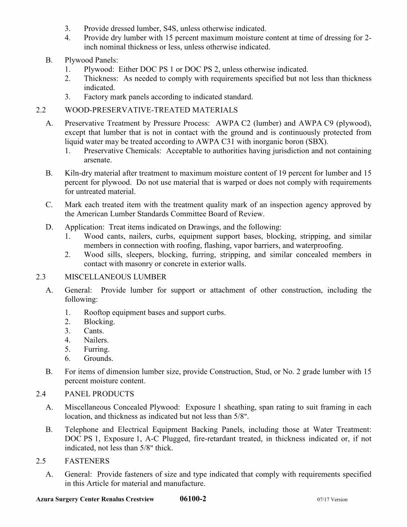
Azura Surgery Center Renalus Crestview 06100-2 07/17 Version
3. Provide dressed lumber, S4S, unless otherwise indicated.
4. Provide dry lumber with 15 percent maximum moisture content at time of dressing for 2-
inch nominal thickness or less, unless otherwise indicated.
B. Plywood Panels:
1. Plywood: Either DOC PS 1 or DOC PS 2, unless otherwise indicated.
2. Thickness: As needed to comply with requirements specified but not less than thickness
indicated.
3. Factory mark panels according to indicated standard.
2.2 WOOD-PRESERVATIVE-TREATED MATERIALS
A. Preservative Treatment by Pressure Process: AWPA C2 (lumber) and AWPA C9 (plywood),
except that lumber that is not in contact with the ground and is continuously protected from
liquid water may be treated according to AWPA C31 with inorganic boron (SBX).
1. Preservative Chemicals: Acceptable to authorities having jurisdiction and not containing
arsenate.
B. Kiln-dry material after treatment to maximum moisture content of 19 percent for lumber and 15
percent for plywood. Do not use material that is warped or does not comply with requirements
for untreated material.
C. Mark each treated item with the treatment quality mark of an inspection agency approved by
the American Lumber Standards Committee Board of Review.
D. Application: Treat items indicated on Drawings, and the following:
1. Wood cants, nailers, curbs, equipment support bases, blocking, stripping, and similar
members in connection with roofing, flashing, vapor barriers, and waterproofing.
2. Wood sills, sleepers, blocking, furring, stripping, and similar concealed members in
contact with masonry or concrete in exterior walls.
2.3 MISCELLANEOUS LUMBER
A. General: Provide lumber for support or attachment of other construction, including the
following:
1. Rooftop equipment bases and support curbs.
2. Blocking.
3. Cants.
4. Nailers.
5. Furring.
6. Grounds.
B. For items of dimension lumber size, provide Construction, Stud, or No. 2 grade lumber with 15
percent moisture content.
2.4 PANEL PRODUCTS
A. Miscellaneous Concealed Plywood: Exposure 1 sheathing, span rating to suit framing in each
location, and thickness as indicated but not less than 5/8".
B. Telephone and Electrical Equipment Backing Panels, including those at Water Treatment:
DOC PS 1, Exposure 1, A-C Plugged, fire-retardant treated, in thickness indicated or, if not
indicated, not less than 5/8" thick.
2.5 FASTENERS
A. General: Provide fasteners of size and type indicated that comply with requirements specified
in this Article for material and manufacture.
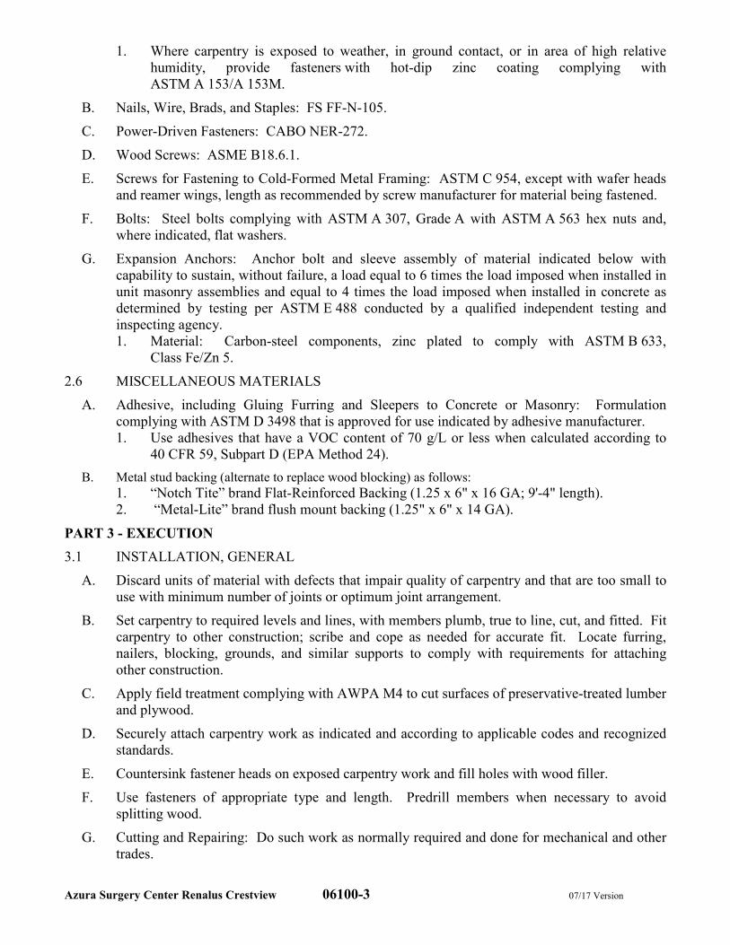
Azura Surgery Center Renalus Crestview 06100-3 07/17 Version
1. Where carpentry is exposed to weather, in ground contact, or in area of high relative
humidity, provide fasteners with hot-dip zinc coating complying with
ASTM A 153/A 153M.
B. Nails, Wire, Brads, and Staples: FS FF-N-105.
C. Power-Driven Fasteners: CABO NER-272.
D. Wood Screws: ASME B18.6.1.
E. Screws for Fastening to Cold-Formed Metal Framing: ASTM C 954, except with wafer heads
and reamer wings, length as recommended by screw manufacturer for material being fastened.
F. Bolts: Steel bolts complying with ASTM A 307, Grade A with ASTM A 563 hex nuts and,
where indicated, flat washers.
G. Expansion Anchors: Anchor bolt and sleeve assembly of material indicated below with
capability to sustain, without failure, a load equal to 6 times the load imposed when installed in
unit masonry assemblies and equal to 4 times the load imposed when installed in concrete as
determined by testing per ASTM E 488 conducted by a qualified independent testing and
inspecting agency.
1. Material: Carbon-steel components, zinc plated to comply with ASTM B 633,
Class Fe/Zn 5.
2.6 MISCELLANEOUS MATERIALS
A. Adhesive, including Gluing Furring and Sleepers to Concrete or Masonry: Formulation
complying with ASTM D 3498 that is approved for use indicated by adhesive manufacturer.
1. Use adhesives that have a VOC content of 70 g/L or less when calculated according to
40 CFR 59, Subpart D (EPA Method 24).
B. Metal stud backing (alternate to replace wood blocking) as follows:
1. “Notch Tite” brand Flat-Reinforced Backing (1.25 x 6" x 16 GA; 9'-4" length).
2. “Metal-Lite” brand flush mount backing (1.25" x 6" x 14 GA).
PART 3 - EXECUTION
3.1 INSTALLATION, GENERAL
A. Discard units of material with defects that impair quality of carpentry and that are too small to
use with minimum number of joints or optimum joint arrangement.
B. Set carpentry to required levels and lines, with members plumb, true to line, cut, and fitted. Fit
carpentry to other construction; scribe and cope as needed for accurate fit. Locate furring,
nailers, blocking, grounds, and similar supports to comply with requirements for attaching
other construction.
C. Apply field treatment complying with AWPA M4 to cut surfaces of preservative-treated lumber
and plywood.
D. Securely attach carpentry work as indicated and according to applicable codes and recognized
standards.
E. Countersink fastener heads on exposed carpentry work and fill holes with wood filler.
F. Use fasteners of appropriate type and length. Predrill members when necessary to avoid
splitting wood.
G. Cutting and Repairing: Do such work as normally required and done for mechanical and other
trades.
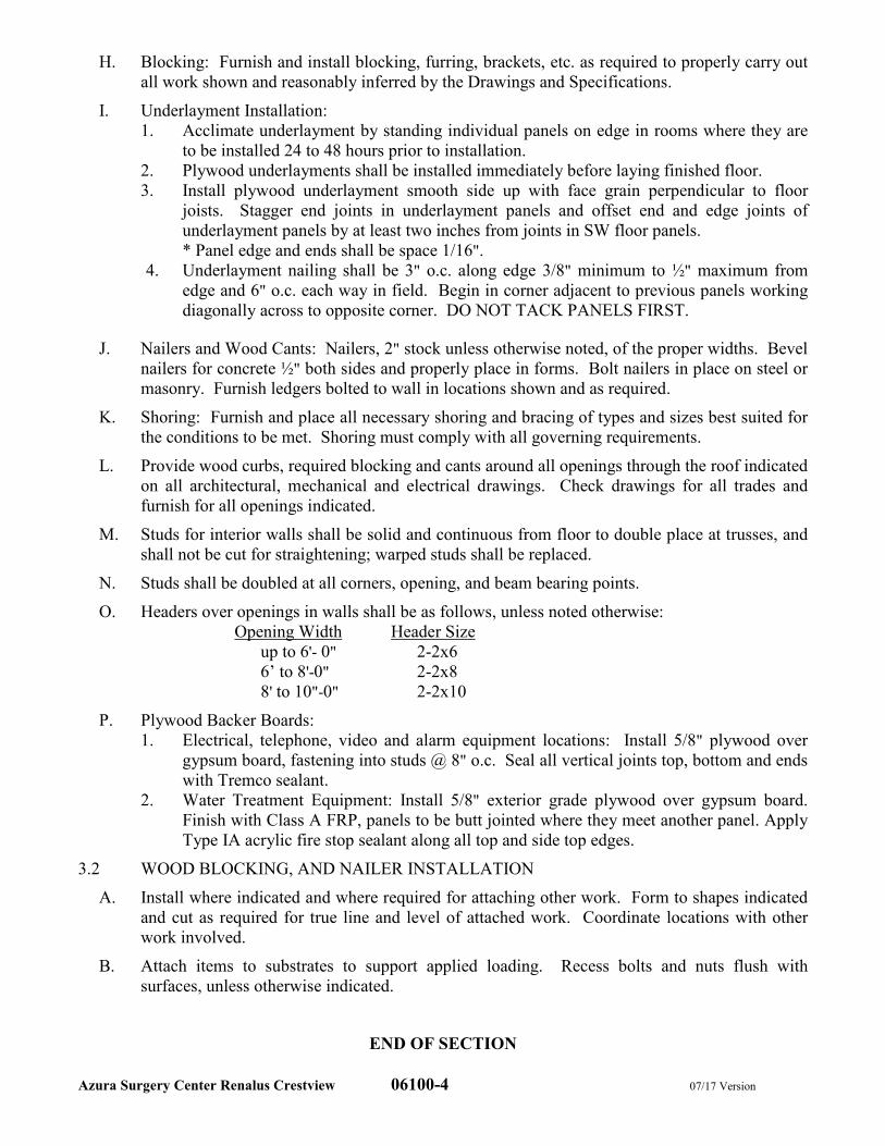
Azura Surgery Center Renalus Crestview 06100-4 07/17 Version
H. Blocking: Furnish and install blocking, furring, brackets, etc. as required to properly carry out
all work shown and reasonably inferred by the Drawings and Specifications.
I. Underlayment Installation:
1. Acclimate underlayment by standing individual panels on edge in rooms where they are
to be installed 24 to 48 hours prior to installation.
2. Plywood underlayments shall be installed immediately before laying finished floor.
3. Install plywood underlayment smooth side up with face grain perpendicular to floor
joists. Stagger end joints in underlayment panels and offset end and edge joints of
underlayment panels by at least two inches from joints in SW floor panels.
* Panel edge and ends shall be space 1/16".
4. Underlayment nailing shall be 3" o.c. along edge 3/8" minimum to ½" maximum from
edge and 6" o.c. each way in field. Begin in corner adjacent to previous panels working
diagonally across to opposite corner. DO NOT TACK PANELS FIRST.
J. Nailers and Wood Cants: Nailers, 2" stock unless otherwise noted, of the proper widths. Bevel
nailers for concrete ½" both sides and properly place in forms. Bolt nailers in place on steel or
masonry. Furnish ledgers bolted to wall in locations shown and as required.
K. Shoring: Furnish and place all necessary shoring and bracing of types and sizes best suited for
the conditions to be met. Shoring must comply with all governing requirements.
L. Provide wood curbs, required blocking and cants around all openings through the roof indicated
on all architectural, mechanical and electrical drawings. Check drawings for all trades and
furnish for all openings indicated.
M. Studs for interior walls shall be solid and continuous from floor to double place at trusses, and
shall not be cut for straightening; warped studs shall be replaced.
N. Studs shall be doubled at all corners, opening, and beam bearing points.
O. Headers over openings in walls shall be as follows, unless noted otherwise:
Opening Width Header Size
up to 6'- 0" 2-2x6
6’ to 8'-0" 2-2x8
8' to 10"-0" 2-2x10
P. Plywood Backer Boards:
1. Electrical, telephone, video and alarm equipment locations: Install 5/8" plywood over
gypsum board, fastening into studs @ 8" o.c. Seal all vertical joints top, bottom and ends
with Tremco sealant.
2. Water Treatment Equipment: Install 5/8" exterior grade plywood over gypsum board.
Finish with Class A FRP, panels to be butt jointed where they meet another panel. Apply
Type IA acrylic fire stop sealant along all top and side top edges.
3.2 WOOD BLOCKING, AND NAILER INSTALLATION
A. Install where indicated and where required for attaching other work. Form to shapes indicated
and cut as required for true line and level of attached work. Coordinate locations with other
work involved.
B. Attach items to substrates to support applied loading. Recess bolts and nuts flush with
surfaces, unless otherwise indicated.
END OF SECTION
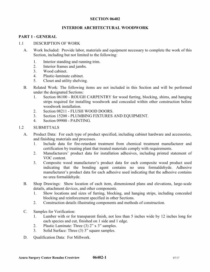
Azura Surgery Center Renalus Crestview 06402-1 07/17
SECTION 06402
INTERIOR ARCHITECTURAL WOODWORK
PART 1 - GENERAL
1.1 DESCRIPTION OF WORK
A. Work Included: Provide labor, materials and equipment necessary to complete the work of this
Section, including but not limited to the following:
1. Interior standing and running trim.
2. Interior frames and jambs.
3. Wood cabinet.
4. Plastic-laminate cabinet.
5. Closet and utility shelving.
B. Related Work: The following items are not included in this Section and will be performed
under the designated Sections:
1. Section 06100 - ROUGH CARPENTRY for wood furring, blocking, shims, and hanging
strips required for installing woodwork and concealed within other construction before
woodwork installation.
2. Section 08211 - FLUSH WOOD DOORS.
3. Section 15200 - PLUMBING FIXTURES AND EQUIPMENT.
4. Section 09900 - PAINTING.
1.2 SUBMITTALS
A. Product Data: For each type of product specified, including cabinet hardware and accessories,
and finishing materials and processes.
1. Include data for fire-retardant treatment from chemical treatment manufacturer and
certification by treating plant that treated materials comply with requirements.
2. Manufacturers’ product data for installation adhesives, including printed statement of
VOC content.
3. Composite wood manufacturer’s product data for each composite wood product used
indicating that the bonding agent contains no urea formaldehyde. Adhesive
manufacturer’s product data for each adhesive used indicating that the adhesive contains
no urea formaldehyde.
B. Shop Drawings: Show location of each item, dimensioned plans and elevations, large-scale
details, attachment devices, and other components.
1. Show locations and sizes of furring, blocking, and hanging strips, including concealed
blocking and reinforcement specified in other Sections.
2. Construction details illustrating components and methods of construction.
C. Samples for Verification:
1. Lumber with or for transparent finish, not less than 5 inches wide by 12 inches long for
each species and cut, finished on 1 side and 1 edge.
2. Plastic Laminate: Three (3) 2” x 3” samples.
3. Solid Surface: Three (3) 3” square samples.
D. Qualification Data: For Millwork.
Azura Surgery Center Renalus Crestview 06402-2 07/17
1.3 QUALITY ASSURANCE
A. Qualifications: Shop that employs skilled workers who install millwork products similar to
those required for this Project and have a record of successful in-service performance.
1.4 DELIVERY, STORAGE, AND HANDLING
A. Millwork shall be delivered by millwork vendor to job site. Accept materials, unload and store
materials. Conform to requirements of Section 01640 and herein.
B. Coordinate delivery date with millwork vendor. Do not schedule delivery of millwork or
woodwork until painting and similar operations that could damage woodwork have been
completed in installation areas. If product must be stored in other than installation areas, store
only in areas where environmental conditions comply with requirements specified in “Project
Conditions” Article.
C. Long Lead Items: Order long lead-time materials with sufficient time to comply with
manufacturers’ delivery schedule, without causing delay to the construction schedule.
1.5 PROJECT CONDITIONS
A. Environmental Limitations: Do not deliver or install woodwork until building is enclosed, wet
work is complete, and HVAC system is operating and maintaining temperature and relative
humidity at occupancy levels during the remainder of the construction period.
B. Field Measurements: 1. Millwork:
a. Where millwork is indicated to fit to other construction, verify dimensions of other
construction by field measurements and relay that information to the Millwork Vendor
before fabrication. Coordinate fabrication schedule with construction progress to avoid
delaying the Work.
b. Where woodwork is indicated to fit to other construction, verify dimensions of other
construction by field measurements before fabrication, and indicate measurements on Shop
Drawings. Coordinate fabrication schedule with construction progress to avoid delaying
the Work.
2. Locate concealed framing, blocking, reinforcements and floor drains that support
woodwork by field measurements before being enclosed, and indicate measurements on
Shop Drawings. Coordinate blocking locations with Millwork Vendor.
3. Established Dimensions: Where field measurements cannot be made without delaying
the Work, establish dimensions and proceed with fabricating woodwork without field
measurements. Provide allowance for trimming at site, and coordinate construction to
ensure that actual dimensions correspond to established dimensions.
1.6 COORDINATION
A. Coordinate sizes and locations of framing, blocking, furring, reinforcements, and other related
units of Work specified in other Sections to ensure that interior architectural woodwork can be
supported and installed as indicated.
B. Coordinate sizes of gypsum board soffits with approved Millwork Shop Drawings.
PART 2 - PRODUCTS
2.1 MATERIALS
A. General: Provide materials that comply with requirements of AWI’s quality standard for each
type of woodwork and quality grade specified, unless otherwise indicated.
B. Wood Species and Cut for Transparent Finish: Birch, plain sawn or sliced.
Azura Surgery Center Renalus Crestview 06402-3 07/17
C. Wood Species for Opaque Finish: Any closed-grain hardwood.
D. Wood Products: Comply with the following:
1. Hardboard: AHA A135.4.
2. Medium-Density Fiberboard: ANSI A208.2, Grade MD, made with binder containing no
urea formaldehyde.
3. Particleboard: ANSI A208.1, Grade M-2-Exterior Glue.
4. Softwood Plywood: DOC PS 1, Medium Density Overlay.
5. Veneer-Faced Panel Products (Hardwood Plywood): HPVA HP-1, made with adhesive
containing no urea formaldehyde.
6. Softwood Plywood: DOC PS 1, Medium Density Overlay.
E. High-Pressure Decorative Laminate: NEMA LD 3, grades as indicated.
1. Available Manufacturers: Subject to compliance with requirements, manufacturers
offering high-pressure decorative laminates that may be incorporated into the Work
include:
a. Wilsonart
F. Solid-surfacing material: Homogenous solid sheets of filled plastic resin complying with
ISSFA-2.
1. Available products: Subject to compliance with requirements, products that may be
incorporated into the Work include, but are not limited to, the following:
a. Wilsonart
G. Solid Surface Dividers: Provide 1" inch thick solid surface material. Ease all edges. Secure to
upper cabinet with aluminum channel, caulked all around. Color options as indicated below.
1. For laminate countertop installations:
a. Refer to most current Finish Schedule.
2. For solid surface countertop installations:
a. Match countertop color.
H. Glass Splash Guards and Hardware (at nurse station chases and prep station dividers):
1. Glass: Clear, Low Iron, Tempered Glass – 1/4" thickness.
2. Edge Trim at Vertical Chase: CR Laurence #FA10SC – Satin Chrome Finish.
3. 18" Vertical Posts: CR Laurence #D990A18E – Satin Chrome Finish.
2.2 CABINET HARDWARE AND ACCESSORIES
A. General: Provide cabinet hardware and accessory materials associated with architectural
cabinets, except for items specified in Section 08710 - DOOR HARDWARE.
B. All other cabinet doors: Frameless Concealed Hinges (European Type); BHMA A156.9,
B01602 100+ degrees of opening, self-closing.
C. Concealed panel clips (For all cabinet undersinks): Hafele 245.07.702.
D. Back-Mounted Pulls: BHMA A156.9, B02011.
1. Provide brushed chrome wire pulls for all operating drawers and panel fronts.
E. Double Roller Catches: Push-in magnetic catches, BHMA A156.9, B03131. 1. Provide Double Roller Catch – Hafele 244.01.125, black.
F. Adjustable Shelf Standards and Supports: KV85 Series Standards (KV85ANO); KV 185
Series Brackets (KV185ANO).
G. Drawer Slides: BHMA A156.9, B05091; side mounted and extending under bottom edge of
drawer; 3/4-extension type; epoxy-coated-steel with steel ball-bearings; of the following
grades:
Azura Surgery Center Renalus Crestview 06402-4 07/17
1. Box Drawer Slides: Grade 1.
2. File Drawer Slides: Grade 1HD-100.
H. Aluminum Slides for Sliding Glass Doors: BHMA A156.9, B07063.
I. Grommets for Cable Passage through Countertops: 3" Molded-plastic grommets and matching
plastic caps with slot for wire passage. Field locate and drill as directed by Owner.
J. Exposed Hardware Finishes: For exposed hardware, provide finish that complies with
BHMA A156.18 for BHMA finish number indicated, unless noted otherwise.
1. Satin Stainless Steel: BHMA 630.
2. Satin Chrome Finish: US26D (BHMA 626).
K. For concealed hardware, provide manufacturer’s standard finish that complies with product
class requirements in BHMA A156.9.
A. Quick Leveling Glide: Hafele 637.05.000.
2.3 MISCELLANEOUS MATERIALS
A. Furring, Blocking, Shims, and Hanging Strips: Softwood lumber, kiln dried to less than 15
percent moisture content.
B. Anchors: Select material, type, size, and finish required for each substrate for secure
anchorage. Provide nonferrous-metal or hot-dip galvanized anchors and inserts on inside face
of exterior walls and elsewhere as required for corrosion resistance. Provide toothed-steel or
lead expansion sleeves for drilled-in-place anchors.
C. Handrail Brackets: Cast from malleable iron with wall flange drilled for exposed anchor and
with support arm for screwing to underside of rail. Sized to provide 1-1/2 inch clearance
between handrail and wall.
D. Adhesives, General: Do not use adhesives that contain urea formaldehyde.
E. VOC Limits for Installation Adhesives and Glues: Use installation adhesives that comply with
the following limits for VOC content when calculated according to 40 CFR 59, Subpart D
(EPA Method 24):
1. Wood Glues: 30 g/L.
2. Contact Adhesive: 250 g/L.
2.4 FABRICATION, GENERAL
A. Wood Moisture Content: Comply with requirements of referenced quality standard for wood
moisture content in relation to ambient relative humidity during fabrication and in installation
areas.
B. Sand wood lightly to remove raised grain on exposed surfaces before fabrication.
C. Fabricate woodwork to dimensions, profiles, and details indicated. Ease edges.
D. Millwork Vendor shall complete fabrication, including assembly, finishing, and hardware
application, to maximum extent possible before shipment to Project site. Components will be
disassembled only as necessary for shipment and installation. Where necessary for fitting at
site product will provide allowance for scribing, trimming, and fitting.
E. Millwork Vendor will shop-cut openings to maximum extent possible to receive hardware,
appliances, plumbing fixtures, electrical work, and similar items. Locate openings accurately
and use templates or roughing-in diagrams to produce accurately sized and shaped openings. 1. Coordinate with Millwork Vendor for openings to be field cut.
Azura Surgery Center Renalus Crestview 06402-5 07/17
a. Seal edges of openings in countertops with a coat of varnish.
2.5 INTERIOR STANDING AND RUNNING TRIM FOR TRANSPARENT FINISH
A. Grade: Custom.
B. Wood Species and Cut: Match species and cut indicated for other types of transparent-finished
architectural woodwork located in same area of building, unless otherwise indicated.
1. Provide split species on trim that faces areas with different wood species, matching each
face of woodwork to species and cut of finish wood surfaces in areas finished.
C. For trim items wider than available lumber, use veneered construction. Do not glue for width.
D. For rails wider or thicker than available lumber, use veneered construction. Do not glue for
width or thickness.
E. Backout or groove backs of flat trim members and kerf backs of other wide, flat members,
except for members with ends exposed in finished work.
F. Assemble casings in plant except where limitations of access to place of installation require
field assembly.
2.6 PLASTIC-LAMINATE CABINETS
A. Grade: Custom.
2.7 SOLID-SURFACING-MATERIAL COUNTERTOPS
A. Grade: Custom.
B. Solid-Surfacing-Material Thickness: 1/2" SS material over 1" MDF.
2.8 SOLID SURFACE MATERIAL DIVIDERS, SIDESPLASHES & BACKSPLASHES
A. Grade: Custom.
B. Solid-Surfacing-Material Thickness: 1/2 inch.
2.9 CLOSET AND UTILITY SHELVING
A. Grade: Custom.
B. Shelf Material: 3/4-inch NAUF Particle Board with white melamine; .5mm edge band all
edges.
C. KV85ANO Standards, KV185ANO Standards.
PART 3 - EXECUTION
3.1 PREPARATION
A. Before installation, condition woodwork to average prevailing humidity conditions in
installation areas.
B. Before installing architectural woodwork, examine shop-fabricated work for completion and
complete work as required, including removal of packing and back priming.
3.2 INSTALLATION
A. Grade: Install woodwork to comply with requirements for the same grade specified in Part 2
for fabrication of type of woodwork involved.
B. Assemble woodwork and complete fabrication at Project site to comply with requirements for
fabrication in Part 2, to extent that it was not completed in the shop.
Azura Surgery Center Renalus Crestview 06402-6 07/17
C. Install woodwork level, plumb, true, and straight. Shim as required with concealed shims.
Install level and plumb (including tops) to a tolerance of 1/8 inch in 96 inches.
D. Scribe and cut woodwork to fit adjoining work, refinish cut surfaces, and repair damaged finish
at cuts.
E. Anchor woodwork to anchors or blocking built in or directly attached to substrates. Secure
with countersunk, concealed fasteners and blind nailing as required for complete installation.
Use fine stainless steel finishing nails or finishing screws for exposed fastening, countersunk
and filled flush with woodwork and matching final finish if transparent finish is indicated.
F. Standing and Running Trim: Install with minimum number of joints possible, using full-length
pieces (from maximum length of lumber available) to greatest extent possible. Do not use
pieces less than 60 inches long, except where shorter single-length pieces are necessary. Scarf
running joints and stagger in adjacent and related members.
1. Fill gaps, if any, between top of base and wall with plastic wood filler, sand smooth, and
finish same as wood base if finished.
2. Install wall railings on indicated metal brackets securely fastened to wall framing.
3. Install standing and running trim with no more variation from a straight line than 1/8 inch
in 96 inches.
G. Cabinets: Install without distortion so doors and drawers fit openings properly and are
accurately aligned. Adjust hardware to center doors and drawers in openings and to provide
unencumbered operation. Complete installation of hardware and accessory items as indicated.
1. Install cabinets with no more than 1/8 inch in 96-inch sag, bow, or other variation from a
straight line.
2. Secure wall-hung cabinetry into wall blocking and/or framing.
3. Coordinate installation with construction so that all drawers and doors are fully
operational.
4. Install door stops on walls where cabinets doors open and touch walls.
H. Countertops: Anchor securely by screwing through corner blocks of base cabinets or other
supports into underside of countertop.
1. Align adjacent solid-surfacing-material countertops and form seams to comply with
manufacturer’s written recommendations using adhesive in color to match countertop.
Carefully dress joints smooth, remove surface scratches, and clean entire surface.
2. Install countertops with no more than 1/8 inch in 96-inch sag, bow, or other variation
from a straight line.
3. Install removable access panels in the dialysis counter with a 1/16" gap at both ends so
that they are easily removable.
4. Secure side splashes to tops and to walls with adhesive.
5. Caulk space between backsplash and wall with sealant specified in Section 07920 -
JOINT SEALANTS.
3.3 ADJUSTING AND CLEANING
A. Repair damaged and defective woodwork, where possible, to eliminate functional and visual
defects; where not possible to repair, replace woodwork. Adjust joinery for uniform
appearance.
B. Clean, lubricate, and adjust hardware.
Azura Surgery Center Renalus Crestview 06402-7 07/17
C. Clean woodwork on exposed and semi-exposed surfaces. Touch up shop-applied finishes to
restore damaged or soiled areas.
END OF SECTION

Azura Surgery Center Renalus Crestview 07210-1 07/17 Version
SECTION 07210
THERMAL INSULATION
PART 1 - GENERAL
1.1 DESCRIPTION OF WORK
A. Work Included: Provide labor, materials and equipment necessary to complete the work of this
Section, including but not limited to the following:
1. Perimeter insulation under slabs-on-grade.
2. Perimeter foundation wall insulation.
3. Concealed building insulation.
4. Vapor retarders.
B. Related Work: The following items are not included in this Section and will be performed
under the designated Sections:
1. Section 07841 - PENETRATION FIRESTOPPING for firestopping insulation.
2. Section 07500 - ROOF REMODELING for roofing insulation.
3. Section 09260 - GYPSUM BOARD ASSEMBLIES for acoustic insulation in gypsum
board assemblies.
4. Division 15 - PLUMBING for plumbing insulation.
5. Division 15 - HEATING, VENTILATING, AND AIR CONDITIONING for mechanical
insulation.
1.2 SUBMITTALS
A. Product Data: For each type of product indicated.
1. Manufacturer’s product data indicating percentages by weight of post-consumer and pre-
consumer recycled content for products having recycled content.
2. Manufacturer’s product data indicating no urea-formaldehyde content.
1.3 QUALITY ASSURANCE
A. Source Limitations: Obtain each type of building insulation through one source from a single
manufacturer.
B. Fire-Test-Response Characteristics: Provide insulation and related materials with the fire-test-
response characteristics indicated, as determined by testing identical products per test method
indicated below by UL or another testing and inspecting agency acceptable to authorities
having jurisdiction. Identify materials with appropriate markings of applicable testing and
inspecting agency.
1. Surface-Burning Characteristics: ASTM E 84.
1.4 DELIVERY, STORAGE, AND HANDLING
A. Protect insulation materials from physical damage and from deterioration by moisture, soiling,
and other sources. Store inside and in a dry location. Comply with manufacturer’s written
instructions for handling, storing, and protecting during installation.
B. Protect plastic insulation as follows:
1. Do not expose to sunlight, except to extent necessary for period of installation and
concealment.
2. Protect against ignition at all times. Do not deliver plastic insulating materials to Project
site before installation time.
3. Complete installation and concealment of plastic materials as rapidly as possible in each
area of construction.
Azura Surgery Center Renalus Crestview 07210-2 07/17 Version
PART 2 - PRODUCTS
2.1 FOAM-PLASTIC BOARD INSULATION
A. Available Products: Subject to compliance with requirements, products that may be
incorporated into the Work include, but are not limited to, the following:
1. DiversiFoam Products.
2. Dow Chemical Company.
3. Owens Corning.
B. Extruded-Polystyrene Board Insulation: ASTM C 578, Type IV, with maximum flame-spread
and smoke-developed indexes of 75 and 450, respectively.
2.2 GLASS-FIBER BLANKET INSULATION
A. Available Manufacturers:
1. CertainTeed Corporation.
2. Guardian Fiberglass, Inc.
3. Johns Manville.
4. Knauf Fiber Glass.
5. Owens Corning.
B. Unfaced, Glass-Fiber Blanket Insulation: ASTM C 665, Type I (blankets without membrane
facing); consisting of fibers; with maximum flame-spread and smoke-developed indexes of 25
and 50, respectively; passing ASTM E 136 for combustion characteristics.
C. Faced, Glass-Fiber Blanket Insulation: ASTM C 665, Type III (blankets with reflective
membrane facing), Class A (membrane-faced surface with a flame-spread index of 25 or less);
Category 1 (membrane is a vapor barrier), faced with foil-scrim-kraft vapor-retarder membrane
on 1 face.
D. Where glass-fiber blanket insulation is indicated by the following thicknesses, provide blankets
in batt or roll form with thermal resistances indicated:
1. 3-1/2 inches thick with a thermal resistance of 11 deg F x h x sq. ft./Btu at 75 deg F.
2. 9-1/2 inches thick with a thermal resistance of 30 deg F x h x sq. ft./Btu at 75 deg F.
E. Provide glass-fiber blanket insulation as follows:
1. Recycled content of 20% minimum.
2. Contain no urea-formaldehyde resins.
F. Where the thermal performance of an existing roof is not indicated on the drawings,
Contractor shall verify the existing R-Valve prior to bidding. Contractor’s bid shall include an
alternate identifying the existing R-Valve and the cost to achieve an R-Valve that meets
governing energy codes but is not less than R-19. Furnish and install Batt Insulation at the
underside of the existing roof to attain required values.
2.3 VAPOR RETARDERS
A. Polyethylene Vapor Retarders: ASTM D 4397, 6 mils thick, with maximum permeance rating
of 0.13 perm.
B. Vapor-Retarder Tape: Pressure-sensitive tape of type recommended by vapor-retarder
manufacturer for sealing joints and penetrations in vapor retarder.
2.4 AUXILIARY INSULATING MATERIALS
A. Adhesive for Bonding Insulation: Product with demonstrated capability to bond insulation
securely to substrates indicated without damaging insulation and substrates.
Azura Surgery Center Renalus Crestview 07210-3 07/17 Version
PART 3 - EXECUTION
3.1 EXAMINATION
A. Examine substrates and conditions, with Installer present, for compliance with requirements of
Sections in which substrates and related work are specified and for other conditions affecting
performance.
1. Proceed with installation only after unsatisfactory conditions have been corrected.
3.2 PREPARATION
A. Clean substrates of substances harmful to insulation or vapor retarders, including removing
projections capable of puncturing vapor retarders or of interfering with insulation attachment.
3.3 INSTALLATION, GENERAL
A. Comply with insulation manufacturer’s written instructions applicable to products and
application indicated.
B. Install insulation that is undamaged, dry, and unsoiled and that has not been left exposed at any
time to ice, rain, and snow.
C. Extend insulation in thickness indicated to envelop entire area to be insulated. Cut and fit
tightly around obstructions and fill voids with insulation. Remove projections that interfere
with placement.
3.4 INSTALLATION OF PERIMETER AND UNDER-SLAB INSULATION
A. On vertical surfaces, set insulation units in adhesive applied according to manufacturer’s
written instructions. Use adhesive recommended by insulation manufacturer.
1. If not otherwise indicated, extend insulation a minimum of 48 inches below exterior
grade line.
B. On horizontal surfaces, loosely lay insulation units according to manufacturer’s written
instructions. Stagger end joints and tightly abut insulation units.
3.5 INSTALLATION OF GENERAL BUILDING INSULATION
A. Apply insulation units to substrates by method indicated, complying with manufacturer’s
written instructions. If no specific method is indicated, bond units to substrate with adhesive or
use mechanical anchorage to provide permanent placement and support of units.
B. Seal joints between foam-plastic insulation units by applying adhesive, mastic, or sealant to
edges of each unit to form a tight seal as units are shoved into place. Fill voids in completed
installation with adhesive, mastic, or sealant as recommended by insulation manufacturer.
C. Set vapor-retarder-faced units with vapor retarder in location indicated of construction, unless
otherwise indicated.
1. Tape joints and ruptures in vapor retarder, and seal each continuous area of insulation to
surrounding construction to ensure airtight installation.
3.6 INSTALLATION OF VAPOR RETARDERS
A. General: Extend vapor retarder to extremities of areas to be protected from vapor transmission.
Secure in place with adhesives or other anchorage system as indicated. Extend vapor retarder
to cover miscellaneous voids in insulated substrates, including those filled with loose-fiber
insulation.
Azura Surgery Center Renalus Crestview 07210-4 07/17 Version
B. Seal vertical joints in vapor retarders over framing by lapping not less than two wall studs.
Fasten vapor retarders to wood framing at top, end, and bottom edges; at perimeter of wall
openings; and at lap joints. Space fasteners 16 inches o.c.
C. Firmly attach vapor retarders to metal framing and solid substrates with vapor-retarder
fasteners as recommended by vapor-retarder manufacturer.
D. Seal joints caused by pipes, conduits, electrical boxes, and similar items penetrating vapor
retarders with vapor-retarder tape to create an airtight seal between penetrating objects and
vapor retarder.
E. Repair tears or punctures in vapor retarders immediately before concealment by other work.
Cover with vapor-retarder tape or another layer of vapor retarder.
3.7 PROTECTION
A. Protect installed insulation from damage due to harmful weather exposures, physical abuse, and
other causes. Provide temporary coverings or enclosures where insulation is subject to abuse
and cannot be concealed and protected by permanent construction immediately after
installation.
END OF SECTION
Azura Surgery Center Renalus Crestview 07841-1 07/17
SECTION 07841
PENETRATION FIRESTOPPING
PART 1 - GENERAL
1.1 DESCRIPTION OF WORK
A. Work Included: Provide labor, materials and equipment necessary to complete the work of this
Section, including but not limited to the following:
1. Through-penetration firestop systems for penetrations through fire-resistance-rated
constructions, including both empty openings and openings containing penetrating items.
2. Fire-resistive joint systems for floor, wall, and head-of-wall joints.
3. Firewall stencils.
B. Related Work: The following items are not included in this Section and will be performed
under the designated Sections:
1. Section 07844 - FIRE-RESISTIVE JOINT SYSTEMS for fire-resistive joint sealers.
2. Section 07920 - JOINT SEALANTS for standard joint sealers.
3. Division 15 - FIRE PROTECTION for fire-suppression piping penetrations.
4. Division 15 - PLUMBING for piping penetrations.
5. Division 15 - HEATING, VENTILATING AND AIR CONDITIONING for duct and
piping penetrations.
6. Division 16 - ELECTRICAL for cable and conduit penetrations.
1.2 PERFORMANCE REQUIREMENTS
A. General: For penetrations through fire-resistance-rated constructions, including both empty
openings and openings containing penetrating items, provide through-penetration firestop
systems that are produced and installed to resist spread of fire according to requirements
indicated, resist passage of smoke and other gases, and maintain original fire-resistance rating
of construction penetrated.
B. F-Rated Systems: Provide through-penetration firestop systems with F-ratings indicated, but
not less than that equaling or exceeding fire-resistance rating of constructions penetrated, as
determined per ASTM E 814.
C. For through-penetration firestop systems exposed to view, traffic, moisture, and physical
damage, provide products that, after curing, do not deteriorate when exposed to these
conditions both during and after construction.
1. For piping penetrations for plumbing and wet-pipe sprinkler systems, provide moisture-
resistant through-penetration firestop systems.
2. For floor penetrations with annular spaces exceeding 4 inches in width and exposed to
possible loading and traffic, provide firestop systems capable of supporting floor loads
involved, either by installing floor plates or by other means.
3. For penetrations involving insulated piping, provide through-penetration firestop systems
not requiring removal of insulation.
1.3 SUBMITTALS
A. Product Data: For each type of product indicated.
B. Shop Drawings: For each through-penetration firestop system, show each type of construction
condition penetrated, relationships to adjoining construction and type of penetrating item.
Azura Surgery Center Renalus Crestview 07841-2 07/17
Include firestop design designation of qualified testing and inspecting agency that evidences
compliance with requirements for each condition indicated.
1. Submit documentation, including illustrations, from a qualified testing and inspecting
agency that is applicable to each through-penetration firestop system configuration for
construction and penetrating items.
C. Through-Penetration Firestop System Schedule: Indicate locations of each through-penetration
firestop system, along with the following information:
1. Types of penetrating items.
2. Types of constructions penetrated, including fire-resistance ratings and, where applicable,
thicknesses of construction penetrated.
3. Through-penetration firestop systems for each location identified by firestop design
designation of qualified testing and inspecting agency.
D. Qualification Data: For Installer.
1.4 QUALITY ASSURANCE
A. Installer Qualifications: Either a firm that has been approved by FMG according to FMG 4991,
“Approval of Firestop Contractors" or a firm experienced in installing through-penetration
firestop systems similar in material, design, and extent to that indicated for this Project, whose
work has resulted in construction of a minimum of five projects with a record of successful
performance. Qualifications include having the necessary experience, staff, and training to
install manufacturer's products per specified requirements.
B. Source Limitations: Obtain through-penetration firestop systems, for each kind of penetration
and construction condition indicated, through one source from a single manufacturer.
C. Fire-Test-Response Characteristics: Provide through-penetration firestop systems that comply
with the following requirements and those specified in Part 1 “Performance Requirements”
Article:
1. Firestopping tests are performed by a qualified testing and inspecting agency. A
qualified testing and inspecting agency is UL or another agency performing testing and
follow-up inspection services for firestop systems acceptable to authorities having
jurisdiction.
2. Through-penetration firestop systems are identical to those tested per testing standard
referenced in “Part 1 Performance Requirements” Article. Provide rated systems
complying with the following requirements:
a. Through-penetration firestop system products bear classification marking of
qualified testing and inspecting agency.
b. Through-penetration firestop systems correspond to those indicated by reference to
through-penetration firestop system designations listed in the UL “Fire Resistance
Directory.”
D. Preinstallation Conference: Conduct conference at Project site to comply with requirements in
Division 01.
1.5 DELIVERY, STORAGE, AND HANDLING
A. Deliver through-penetration firestop system products to Project site in original, unopened
containers or packages with intact and legible manufacturers’ labels identifying product and
manufacturer, date of manufacture, lot number, shelf life if applicable, qualified testing and
inspecting agency’s classification marking applicable to Project, curing time, and mixing
instructions for multicomponent materials.
Azura Surgery Center Renalus Crestview 07841-3 07/17
B. Store and handle materials for through-penetration firestop systems to prevent their
deterioration or damage due to moisture, temperature changes, contaminants, or other causes.
1.6 PROJECT CONDITIONS
A. Environmental Limitations: Do not install through-penetration firestop systems when ambient
or substrate temperatures are outside limits permitted by through-penetration firestop system
manufacturers or when substrates are wet due to rain, frost, condensation, or other causes.
B. Ventilate through-penetration firestop systems per manufacturer’s written instructions by
natural means or, where this is inadequate, forced-air circulation.
1.7 COORDINATION
A. Coordinate construction of openings and penetrating items to ensure that through-penetration
firestop systems are installed according to specified requirements.
B. Coordinate sizing of sleeves, openings, core-drilled holes, or cut openings to accommodate
through-penetration firestop systems.
C. Do not cover up through-penetration firestop system installations that will become concealed
behind other construction until each installation has been examined by the building inspector, if
required by authorities having jurisdiction.
PART 2 - PRODUCTS
2.1 MANUFACTURERS
A. Available Products: Subject to compliance with requirements, through-penetration firestop
systems that may be incorporated into the Work include, but are not limited to, those systems
indicated in the Through-Penetration Firestop System Schedule at the end of Part 3.
1. Hilti, Inc.
2. BioFireshield; RectorSeal Corporation.
3. 3M; Fire Protection Products Division.
4. Or approved equal.
2.2 FIRESTOPPING MATERIALS
A. Compatibility: Provide through-penetration firestop systems that are compatible with one
another; with the substrates forming openings; and with the items, if any, penetrating through-
penetration firestop systems, under conditions of service and application, as demonstrated by
through-penetration firestop system manufacturer based on testing and field experience.
B. Materials: Provide through-penetration firestop systems containing primary materials and fill
materials which are part of the tested assemblies indicated in the Through-Penetration Firestop
System Schedule at the end of Part 3. Fill materials are those referred to in directories of
referenced testing and inspecting agencies as “fill,” “void,” or “cavity” materials.
C. Accessories: Provide components for each through-penetration firestop system that are needed
to install fill materials and to comply with Part 1 “Performance Requirements” Article. Use
only components specified by through-penetration firestop system manufacturer and approved
by qualified testing and inspecting agency for firestop systems indicated.
D. Approved Colors: Provide Firestopping materials (caulk, putty, sealants) that are red in color
whenever possible as they provide better visibility for inspection.
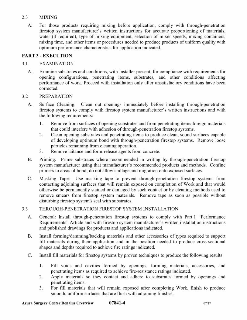
Azura Surgery Center Renalus Crestview 07841-4 07/17
2.3 MIXING
A. For those products requiring mixing before application, comply with through-penetration
firestop system manufacturer’s written instructions for accurate proportioning of materials,
water (if required), type of mixing equipment, selection of mixer speeds, mixing containers,
mixing time, and other items or procedures needed to produce products of uniform quality with
optimum performance characteristics for application indicated.
PART 3 - EXECUTION
3.1 EXAMINATION
A. Examine substrates and conditions, with Installer present, for compliance with requirements for
opening configurations, penetrating items, substrates, and other conditions affecting
performance of work. Proceed with installation only after unsatisfactory conditions have been
corrected.
3.2 PREPARATION
A. Surface Cleaning: Clean out openings immediately before installing through-penetration
firestop systems to comply with firestop system manufacturer’s written instructions and with
the following requirements:
1. Remove from surfaces of opening substrates and from penetrating items foreign materials
that could interfere with adhesion of through-penetration firestop systems.
2. Clean opening substrates and penetrating items to produce clean, sound surfaces capable
of developing optimum bond with through-penetration firestop systems. Remove loose
particles remaining from cleaning operation.
3. Remove laitance and form-release agents from concrete.
B. Priming: Prime substrates where recommended in writing by through-penetration firestop
system manufacturer using that manufacturer’s recommended products and methods. Confine
primers to areas of bond; do not allow spillage and migration onto exposed surfaces.
C. Masking Tape: Use masking tape to prevent through-penetration firestop systems from
contacting adjoining surfaces that will remain exposed on completion of Work and that would
otherwise be permanently stained or damaged by such contact or by cleaning methods used to
remove smears from firestop system materials. Remove tape as soon as possible without
disturbing firestop system's seal with substrates.
3.3 THROUGH-PENETRATION FIRESTOP SYSTEM INSTALLATION
A. General: Install through-penetration firestop systems to comply with Part 1 “Performance
Requirements” Article and with firestop system manufacturer’s written installation instructions
and published drawings for products and applications indicated.
B. Install forming/damming/backing materials and other accessories of types required to support
fill materials during their application and in the position needed to produce cross-sectional
shapes and depths required to achieve fire ratings indicated.
C. Install fill materials for firestop systems by proven techniques to produce the following results:
1. Fill voids and cavities formed by openings, forming materials, accessories, and
penetrating items as required to achieve fire-resistance ratings indicated.
2. Apply materials so they contact and adhere to substrates formed by openings and
penetrating items.
3. For fill materials that will remain exposed after completing Work, finish to produce
smooth, uniform surfaces that are flush with adjoining finishes.
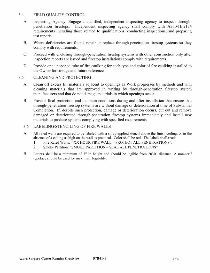
Azura Surgery Center Renalus Crestview 07841-5 07/17
3.4 FIELD QUALITY CONTROL
A. Inspecting Agency: Engage a qualified, independent inspecting agency to inspect through-
penetration firestops. Independent inspecting agency shall comply with ASTM E 2174
requirements including those related to qualifications, conducting inspections, and preparing
test reports.
B. Where deficiencies are found, repair or replace through-penetration firestop systems so they
comply with requirements.
C. Proceed with enclosing through-penetration firestop systems with other construction only after
inspection reports are issued and firestop installations comply with requirements.
D. Provide one unopened tube of fire caulking for each type and color of fire caulking installed to
the Owner for storage and future reference.
3.5 CLEANING AND PROTECTING
A. Clean off excess fill materials adjacent to openings as Work progresses by methods and with
cleaning materials that are approved in writing by through-penetration firestop system
manufacturers and that do not damage materials in which openings occur.
B. Provide final protection and maintain conditions during and after installation that ensure that
through-penetration firestop systems are without damage or deterioration at time of Substantial
Completion. If, despite such protection, damage or deterioration occurs, cut out and remove
damaged or deteriorated through-penetration firestop systems immediately and install new
materials to produce systems complying with specified requirements.
3.6 LABELING/STENCILING OF FIRE WALLS
A. All rated walls are required to be labeled with a spray-applied stencil above the finish ceiling, or in the
absence of a ceiling as high on the wall as practical. Color shall be red. The labels shall read: 1. Fire Rated Walls: “XX HOUR FIRE WALL – PROTECT ALL PENETRATIONS”.
2. Smoke Partition: “SMOKE PARTITION – SEAL ALL PENETRATIONS”
B. Letters shall be a minimum of 3" in height and should be legible from 20'-0" distance. A non-serif
typeface should be used for maximum legibility.
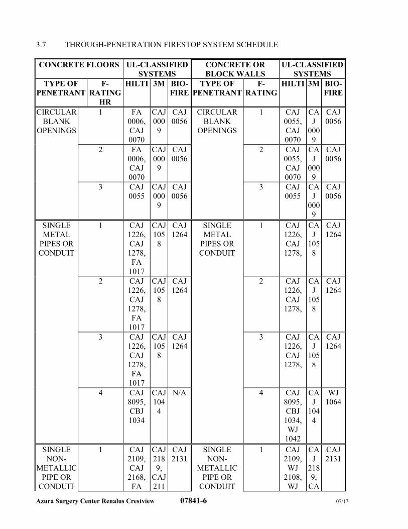
Azura Surgery Center Renalus Crestview 07841-6 07/17
3.7 THROUGH-PENETRATION FIRESTOP SYSTEM SCHEDULE
CONCRETE FLOORS UL-CLASSIFIED
SYSTEMS
CONCRETE OR
BLOCK WALLS
UL-CLASSIFIED
SYSTEMS
TYPE OF
PENETRANT
F-
RATING
HR
HILTI 3M BIO-
FIRE
TYPE OF
PENETRANT
F-
RATING
HILTI 3M BIO-
FIRE
CIRCULAR
BLANK
OPENINGS
1 FA
0006,
CAJ
0070
CAJ
000
9
CAJ
0056
CIRCULAR
BLANK
OPENINGS
1 CAJ
0055,
CAJ
0070
CA
J
000
9
CAJ
0056
2 FA
0006,
CAJ
0070
CAJ
000
9
CAJ
0056
2 CAJ
0055,
CAJ
0070
CA
J
000
9
CAJ
0056
3 CAJ
0055
CAJ
000
9
CAJ
0056
3 CAJ
0055
CA
J
000
9
CAJ
0056
SINGLE
METAL
PIPES OR
CONDUIT
1 CAJ
1226,
CAJ
1278,
FA
1017
CAJ
105
8
CAJ
1264
SINGLE
METAL
PIPES OR
CONDUIT
1 CAJ
1226,
CAJ
1278,
CA
J
105
8
CAJ
1264
2 CAJ
1226,
CAJ
1278,
FA
1017
CAJ
105
8
CAJ
1264
2 CAJ
1226,
CAJ
1278,
CA
J
105
8
CAJ
1264
3 CAJ
1226,
CAJ
1278,
FA
1017
CAJ
105
8
CAJ
1264
3 CAJ
1226,
CAJ
1278,
CA
J
105
8
CAJ
1264
4 CAJ
8095,
CBJ
1034
CAJ
104
4
N/A 4 CAJ
8095,
CBJ
1034,
WJ
1042
CA
J
104
4
WJ
1064
SINGLE
NON-
METALLIC
PIPE OR
CONDUIT
1 CAJ
2109,
CAJ
2168,
FA
CAJ
218
9,
CAJ
211
CAJ
2131
SINGLE
NON-
METALLIC
PIPE OR
CONDUIT
1 CAJ
2109,
WJ
2108,
WJ
CA
J
218
9,
CA
CAJ
2131
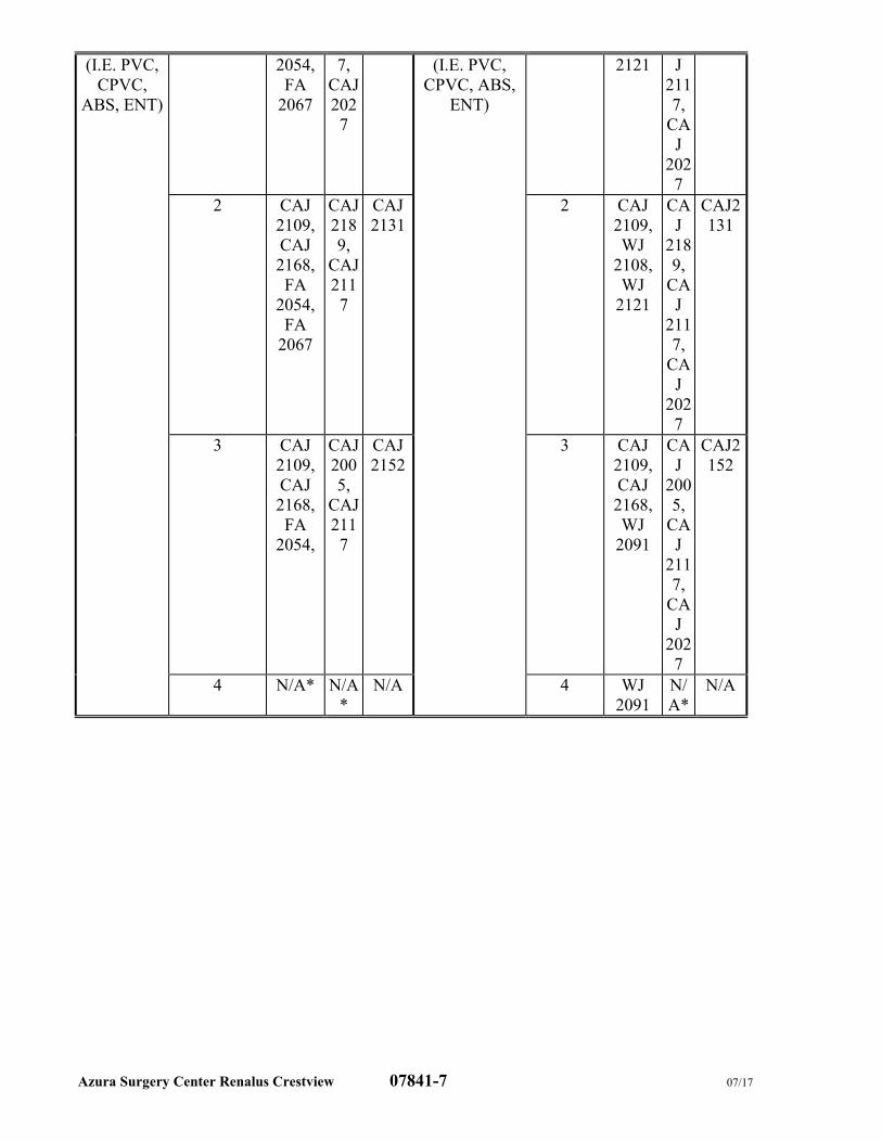
Azura Surgery Center Renalus Crestview 07841-7 07/17
(I.E. PVC,
CPVC,
ABS, ENT)
2054,
FA
2067
7,
CAJ
202
7
(I.E. PVC,
CPVC, ABS,
ENT)
2121 J
211
7,
CA
J
202
7
2 CAJ
2109,
CAJ
2168,
FA
2054,
FA
2067
CAJ
218
9,
CAJ
211
7
CAJ
2131
2 CAJ
2109,
WJ
2108,
WJ
2121
CA
J
218
9,
CA
J
211
7,
CA
J
202
7
CAJ2
131
3 CAJ
2109,
CAJ
2168,
FA
2054,
CAJ
200
5,
CAJ
211
7
CAJ
2152
3 CAJ
2109,
CAJ
2168,
WJ
2091
CA
J
200
5,
CA
J
211
7,
CA
J
202
7
CAJ2
152
4 N/A* N/A
*
N/A 4 WJ
2091
N/
A*
N/A
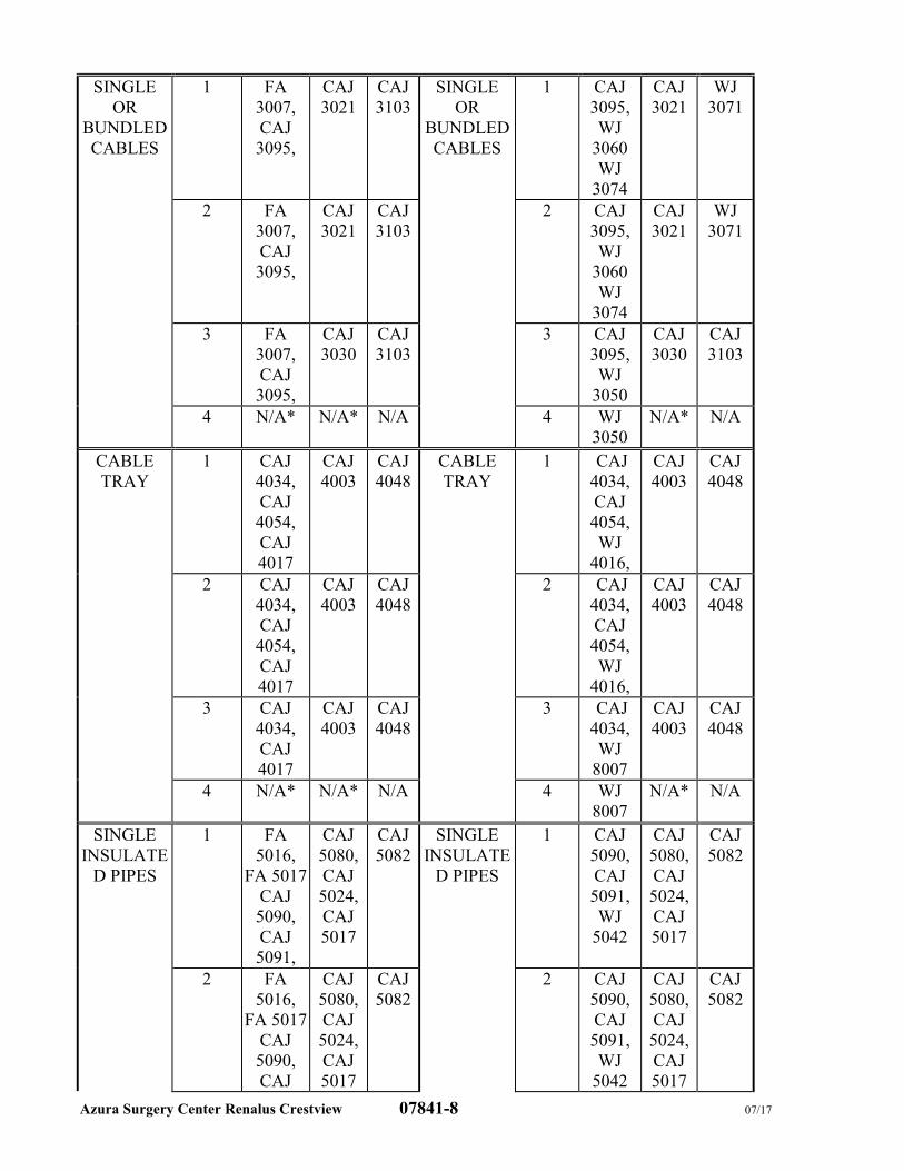
Azura Surgery Center Renalus Crestview 07841-8 07/17
SINGLE
OR
BUNDLED
CABLES
1 FA
3007,
CAJ
3095,
CAJ
3021
CAJ
3103
SINGLE
OR
BUNDLED
CABLES
1 CAJ
3095,
WJ
3060
WJ
3074
CAJ
3021
WJ
3071
2 FA
3007,
CAJ
3095,
CAJ
3021
CAJ
3103
2 CAJ
3095,
WJ
3060
WJ
3074
CAJ
3021
WJ
3071
3 FA
3007,
CAJ
3095,
CAJ
3030
CAJ
3103
3 CAJ
3095,
WJ
3050
CAJ
3030
CAJ
3103
4 N/A* N/A* N/A 4 WJ
3050
N/A* N/A
CABLE
TRAY
1 CAJ
4034,
CAJ
4054,
CAJ
4017
CAJ
4003
CAJ
4048
CABLE
TRAY
1 CAJ
4034,
CAJ
4054,
WJ
4016,
CAJ
4003
CAJ
4048
2 CAJ
4034,
CAJ
4054,
CAJ
4017
CAJ
4003
CAJ
4048
2 CAJ
4034,
CAJ
4054,
WJ
4016,
CAJ
4003
CAJ
4048
3 CAJ
4034,
CAJ
4017
CAJ
4003
CAJ
4048
3 CAJ
4034,
WJ
8007
CAJ
4003
CAJ
4048
4 N/A* N/A* N/A 4 WJ
8007
N/A* N/A
SINGLE
INSULATE
D PIPES
1 FA
5016,
FA 5017
CAJ
5090,
CAJ
5091,
CAJ
5080,
CAJ
5024,
CAJ
5017
CAJ
5082
SINGLE
INSULATE
D PIPES
1 CAJ
5090,
CAJ
5091,
WJ
5042
CAJ
5080,
CAJ
5024,
CAJ
5017
CAJ
5082
2 FA
5016,
FA 5017
CAJ
5090,
CAJ
CAJ
5080,
CAJ
5024,
CAJ
5017
CAJ
5082
2 CAJ
5090,
CAJ
5091,
WJ
5042
CAJ
5080,
CAJ
5024,
CAJ
5017
CAJ
5082
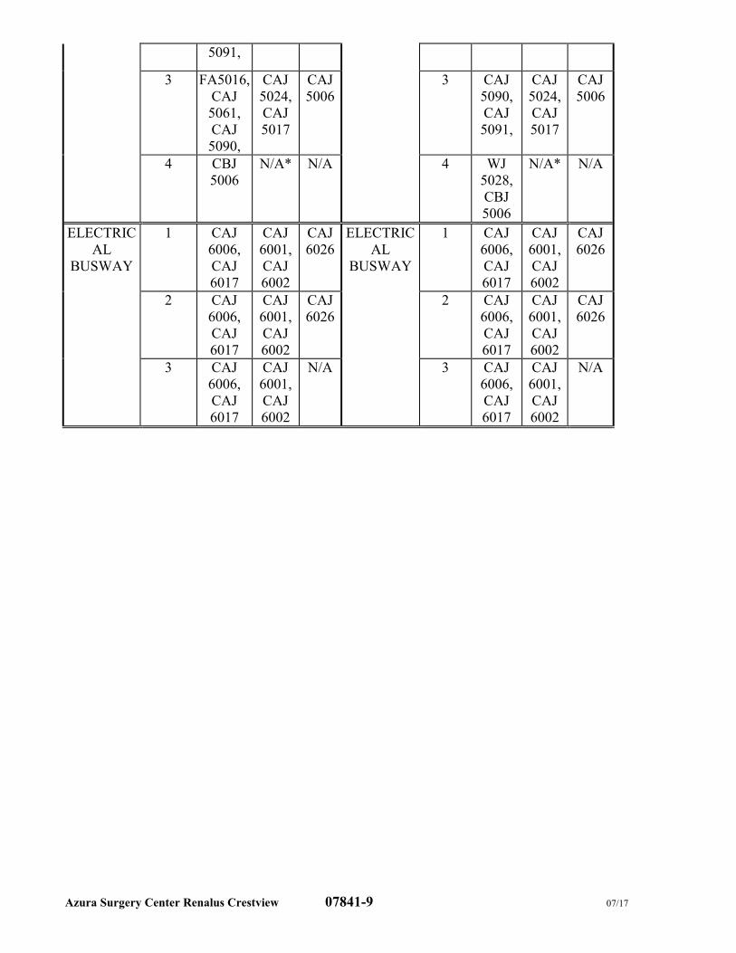
Azura Surgery Center Renalus Crestview 07841-9 07/17
5091,
3 FA5016,
CAJ
5061,
CAJ
5090,
CAJ
5024,
CAJ
5017
CAJ
5006
3 CAJ
5090,
CAJ
5091,
CAJ
5024,
CAJ
5017
CAJ
5006
4 CBJ
5006
N/A* N/A 4 WJ
5028,
CBJ
5006
N/A* N/A
ELECTRIC
AL
BUSWAY
1 CAJ
6006,
CAJ
6017
CAJ
6001,
CAJ
6002
CAJ
6026
ELECTRIC
AL
BUSWAY
1 CAJ
6006,
CAJ
6017
CAJ
6001,
CAJ
6002
CAJ
6026
2 CAJ
6006,
CAJ
6017
CAJ
6001,
CAJ
6002
CAJ
6026
2 CAJ
6006,
CAJ
6017
CAJ
6001,
CAJ
6002
CAJ
6026
3 CAJ
6006,
CAJ
6017
CAJ
6001,
CAJ
6002
N/A 3 CAJ
6006,
CAJ
6017
CAJ
6001,
CAJ
6002
N/A
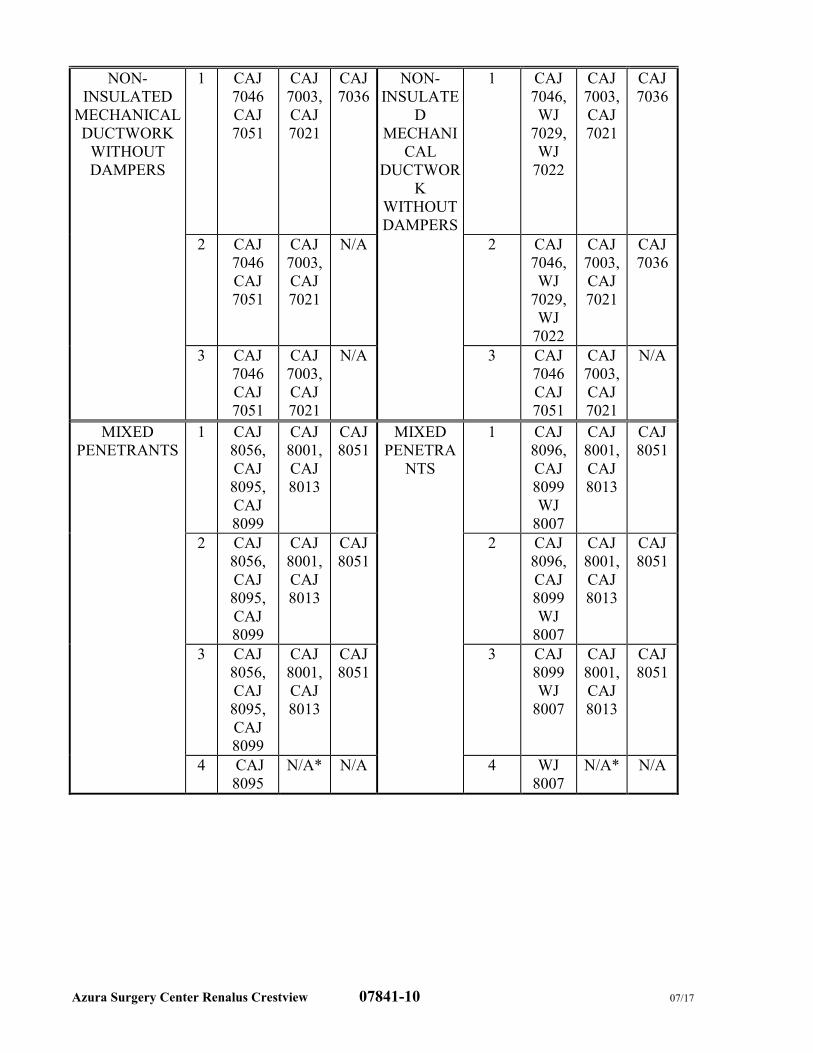
Azura Surgery Center Renalus Crestview 07841-10 07/17
NON-
INSULATED
MECHANICAL
DUCTWORK
WITHOUT
DAMPERS
1 CAJ
7046
CAJ
7051
CAJ
7003,
CAJ
7021
CAJ
7036
NON-
INSULATE
D
MECHANI
CAL
DUCTWOR
K
WITHOUT
DAMPERS
1 CAJ
7046,
WJ
7029,
WJ
7022
CAJ
7003,
CAJ
7021
CAJ
7036
2 CAJ
7046
CAJ
7051
CAJ
7003,
CAJ
7021
N/A 2 CAJ
7046,
WJ
7029,
WJ
7022
CAJ
7003,
CAJ
7021
CAJ
7036
3 CAJ
7046
CAJ
7051
CAJ
7003,
CAJ
7021
N/A 3 CAJ
7046
CAJ
7051
CAJ
7003,
CAJ
7021
N/A
MIXED
PENETRANTS
1 CAJ
8056,
CAJ
8095,
CAJ
8099
CAJ
8001,
CAJ
8013
CAJ
8051
MIXED
PENETRA
NTS
1 CAJ
8096,
CAJ
8099
WJ
8007
CAJ
8001,
CAJ
8013
CAJ
8051
2 CAJ
8056,
CAJ
8095,
CAJ
8099
CAJ
8001,
CAJ
8013
CAJ
8051
2 CAJ
8096,
CAJ
8099
WJ
8007
CAJ
8001,
CAJ
8013
CAJ
8051
3 CAJ
8056,
CAJ
8095,
CAJ
8099
CAJ
8001,
CAJ
8013
CAJ
8051
3 CAJ
8099
WJ
8007
CAJ
8001,
CAJ
8013
CAJ
8051
4 CAJ
8095
N/A* N/A 4 WJ
8007
N/A* N/A
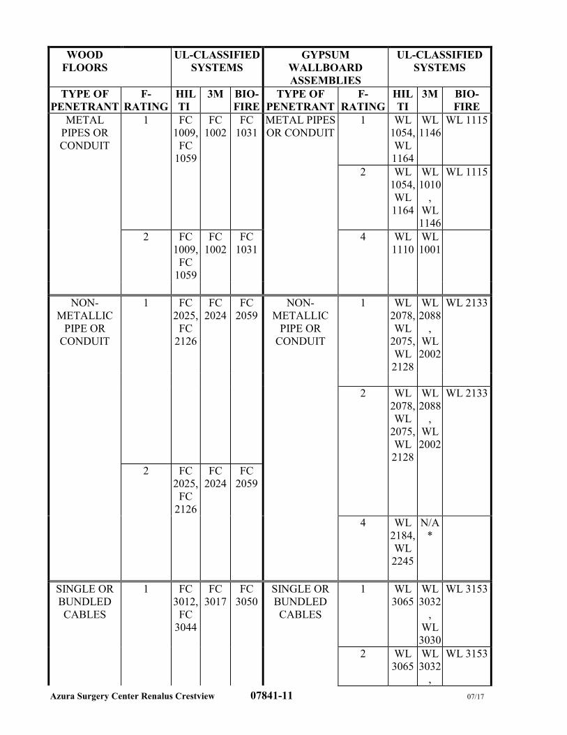
Azura Surgery Center Renalus Crestview 07841-11 07/17
WOOD
FLOORS
UL-CLASSIFIED
SYSTEMS
GYPSUM
WALLBOARD
ASSEMBLIES
UL-CLASSIFIED
SYSTEMS
TYPE OF
PENETRANT
F-
RATING
HIL
TI
3M BIO-
FIRE
TYPE OF
PENETRANT
F-
RATING
HIL
TI
3M BIO-
FIRE
METAL
PIPES OR
CONDUIT
1 FC
1009,
FC
1059
FC
1002
FC
1031
METAL PIPES
OR CONDUIT
1 WL
1054,
WL
1164
WL
1146
WL 1115
2 WL
1054,
WL
1164
WL
1010
,
WL
1146
WL 1115
2 FC
1009,
FC
1059
FC
1002
FC
1031
4 WL
1110
WL
1001
NON-
METALLIC
PIPE OR
CONDUIT
1 FC
2025,
FC
2126
FC
2024
FC
2059
NON-
METALLIC
PIPE OR
CONDUIT
1 WL
2078,
WL
2075,
WL
2128
WL
2088
,
WL
2002
WL 2133
2 WL
2078,
WL
2075,
WL
2128
WL
2088
,
WL
2002
WL 2133
2 FC
2025,
FC
2126
FC
2024
FC
2059
4 WL
2184,
WL
2245
N/A
*
SINGLE OR
BUNDLED
CABLES
1 FC
3012,
FC
3044
FC
3017
FC
3050
SINGLE OR
BUNDLED
CABLES
1 WL
3065
WL
3032
,
WL
3030
WL 3153
2 WL
3065
WL
3032
,
WL 3153
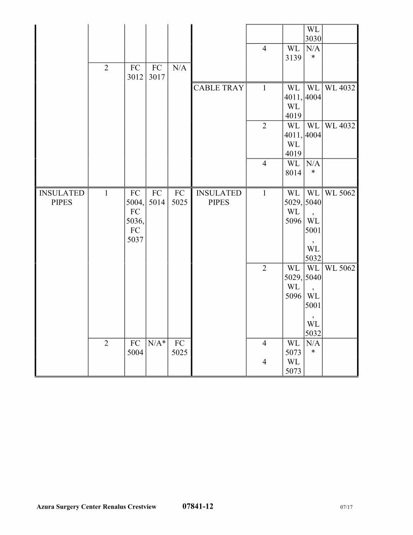
Azura Surgery Center Renalus Crestview 07841-12 07/17
WL
3030
4 WL
3139
N/A
*
2 FC
3012
FC
3017
N/A
CABLE TRAY 1 WL
4011,
WL
4019
WL
4004
WL 4032
2 WL
4011,
WL
4019
WL
4004
WL 4032
4 WL
8014
N/A
*
INSULATED
PIPES
1 FC
5004,
FC
5036,
FC
5037
FC
5014
FC
5025
INSULATED
PIPES
1 WL
5029,
WL
5096
WL
5040
,
WL
5001
,
WL
5032
WL 5062
2 WL
5029,
WL
5096
WL
5040
,
WL
5001
,
WL
5032
WL 5062
2 FC
5004
N/A* FC
5025
4 WL
5073
N/A
*
4 WL
5073
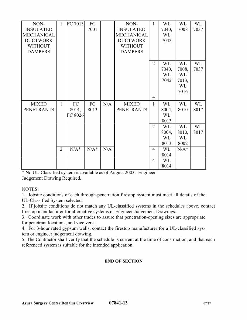
Azura Surgery Center Renalus Crestview 07841-13 07/17
NON-
INSULATED
MECHANICAL
DUCTWORK
WITHOUT
DAMPERS
1 FC 7013 FC
7001
NON-
INSULATED
MECHANICAL
DUCTWORK
WITHOUT
DAMPERS
1 WL
7040,
WL
7042
WL
7008
WL
7037
2 WL
7040,
WL
7042
WL
7008,
WL
7013,
WL
7016
WL
7037
4
MIXED
PENETRANTS
1 FC
8014,
FC 8026
FC
8013
N/A MIXED
PENETRANTS
1 WL
8004,
WL
8013
WL
8010
WL
8017
2 WL
8004,
WL
8013
WL
8010,
WL
8002
WL
8017
2 N/A* N/A* N/A 4 WL
8014
N/A*
4 WL
8014
* No UL-Classified system is available as of August 2003. Engineer
Judgement Drawing Required.
NOTES:
1. Jobsite conditions of each through-penetration firestop system must meet all details of the
UL-Classified System selected.
2. If jobsite conditions do not match any UL-classified systems in the schedules above, contact
firestop manufacturer for alternative systems or Engineer Judgement Drawings.
3. Coordinate work with other trades to assure that penetration-opening sizes are appropriate
for penetrant locations, and vice versa.
4. For 3-hour rated gypsum walls, contact the firestop manufacturer for a UL-classified sys-
tem or engineer judgement drawing.
5. The Contractor shall verify that the schedule is current at the time of construction, and that each
referenced system is suitable for the intended application.
END OF SECTION
Azura Surgery Center Renalus Crestview 07844-1 07/17
SECTION 07844
FIRE-RESISTIVE JOINT SYSTEMS
PART 1 - GENERAL
1.1 DESCRIPTION OF WORK
A. Work Included: Provide labor, materials and equipment necessary to complete the Work of
this Section, including but not limited to fire-resistive joint systems for the following:
1. Floor-to-floor joints.
2. Floor-to-wall joints.
3. Head-of-wall joints.
4. Wall-to-wall joints.
5. Perimeter fire-resistive joint systems consisting of floor-to-wall joints between perimeter
edges of fire-resistance-rated floor assemblies and exterior curtain walls.
B. Related Work: The following items are not included in this Section and will be performed
under the designated Sections:
1. Section 07841 - PENETRATION FIRESTOPPING for firestopping.
2. Section 07920 - JOINT SEALANTS for standard joint sealers.
3. Division 15 - FIRE PROTECTION for fire-suppression piping penetrations.
4. Division 15 - PLUMBING for piping penetrations.
5. Division 15 - HEATING, VENTILATING AND AIR CONDITIONING for duct and
piping penetrations.
6. Division 16 - ELECTRICAL for cable and conduit penetrations.
1.2 PERFORMANCE REQUIREMENTS
A. General: Provide fire-resistive joint systems that are produced and installed to resist spread of
fire according to requirements indicated, resist passage of smoke and other gases, and maintain
original fire-resistance rating of assembly in which fire-resistive joint systems are installed.
B. For fire-resistive systems exposed to view, provide products with flame-spread and smoke-
developed indexes of less than 25 and 450, respectively, as determined per ASTM E 84.
1.3 SUBMITTALS
A. Product Data: For each type of product indicated.
B. Shop Drawings: For each fire-resistive joint system, show each kind of construction condition
in which joints are installed; also show relationships to adjoining construction. Include fire-
resistive joint system design designation of testing and inspecting agency acceptable to
authorities having jurisdiction that demonstrates compliance with requirements for each
condition indicated.
1. Submit documentation, including illustrations, from a qualified testing and inspecting
agency that is applicable to each fire-resistive joint system configuration for construction
and penetrating items.
C. Product Certificates: For each type of fire-resistive joint system, signed by product
manufacturer.
D. Qualification Data: For Installer.
E. Field quality-control test reports.
Azura Surgery Center Renalus Crestview 07844-2 07/17
F. Research/Evaluation Reports: For each type of fire-resistive joint system.
1.4 QUALITY ASSURANCE
A. Installer Qualifications: Either a firm that has been approved by FMG according to FMG 4991,
“Approval of Firestop Contractors" or a firm experienced in installing through-penetration
firestop systems similar in material, design, and extent to that indicated for this Project, whose
work has resulted in construction of a minimum of five projects with a record of successful
performance. Qualifications include having the necessary experience, staff, and training to
install manufacturer's products per specified requirements.
B. Installation Responsibility: Assign installation of through-penetration firestop systems and
fire-resistive joint systems in Project to a single qualified installer.
C. Source Limitations: Obtain fire-resistive joint systems, for each kind of joint and construction
condition indicated, through one source from a single manufacturer.
D. Fire-Test-Response Characteristics: Provide fire-resistive joint systems that comply with the
following requirements and those specified in Part 1 "Performance Requirements" Article:
1. Fire-resistance tests are performed by a qualified testing and inspecting agency. A
qualified testing and inspecting agency is UL or another agency performing testing and
follow-up inspection services for fire-resistive joint systems acceptable to authorities
having jurisdiction.
2. Fire-resistive joint systems are identical to those tested per methods indicated in Part 1
"Performance Requirements" Article and comply with the following:
a. Fire-resistive joint system products bear classification marking of qualified testing
and inspecting agency.
b. Fire-resistive joint systems correspond to those indicated by referencing system
designations of the qualified testing and inspecting agency.
1.5 DELIVERY, STORAGE, AND HANDLING
A. Deliver fire-resistive joint system products to Project site in original, unopened containers or
packages with qualified testing and inspecting agency's classification marking applicable to
Project and with intact and legible manufacturers' labels identifying product and manufacturer,
date of manufacture, lot number, shelf life, curing time, and mixing instructions for multi-
component materials.
B. Store and handle materials for fire-resistive joint systems to prevent their deterioration or
damage due to moisture, temperature changes, contaminants, or other causes.
1.6 PROJECT CONDITIONS
A. Environmental Limitations: Do not install fire-resistive joint systems when ambient or
substrate temperatures are outside limits permitted by fire-resistive joint system manufacturers
or when substrates are wet due to rain, frost, condensation, or other causes.
B. Ventilate fire-resistive joint systems per manufacturer's written instructions by natural means
or, if this is inadequate, forced-air circulation.
1.7 COORDINATION
A. Coordinate construction of joints to ensure that fire-resistive joint systems are installed
according to specified requirements.
B. Coordinate sizing of joints to accommodate fire-resistive joint systems.
Comment [LEH1]:
Azura Surgery Center Renalus Crestview 07844-3 07/17
C. Do not cover up fire-resistive joint system installations that will become concealed behind
other construction until Owner’s inspecting agency and building inspector of authorities having
jurisdiction have examined each installation.
PART 2 - PRODUCTS
2.1 MANUFACTURERS
A. Available Products: Subject to compliance with requirements, fire-resistive joint systems that
may be incorporated into the Work include, but are not limited to, those systems indicated in
the Fire-Resistive Joint System Schedule at the end of Part 3.
1. Hilti, Inc.
2. BioFireshield; RectorSeal Corporation.
3. 3M; Fire Protection Products Division.
4. Or approved equal.
2.2 FIRE-RESISTIVE JOINT SYSTEMS
A. Compatibility: Provide fire-resistive joint systems that are compatible with joint substrates,
under conditions of service and application, as demonstrated by fire-resistive joint system
manufacturer based on testing and field experience.
B. Accessories: Provide components of fire-resistive joint systems, including primers and forming
materials, that are needed to install fill materials and to comply with Part 1 "Performance
Requirements" Article. Use only components specified by fire-resistive joint system
manufacturer and approved by the qualified testing and inspecting agency for systems
indicated.
PART 3 - EXECUTION
3.1 EXAMINATION
A. Examine substrates and conditions, with Installer present, for compliance with requirements for
joint configurations, substrates, and other conditions affecting performance of work.
1. Proceed with installation only after unsatisfactory conditions have been corrected.
3.2 PREPARATION
A. Surface Cleaning: Clean joints immediately before installing fire-resistive joint systems to
comply with fire-resistive joint system manufacturer's written instructions and the following
requirements:
1. Remove from surfaces of joint substrates foreign materials that could interfere with
adhesion of fill materials.
2. Clean joint substrates to produce clean, sound surfaces capable of developing optimum
bond with fill materials. Remove loose particles remaining from cleaning operation.
3. Remove laitance and form-release agents from concrete.
B. Priming: Prime substrates where recommended in writing by fire-resistive joint system
manufacturer using that manufacturer's recommended products and methods. Confine primers
to areas of bond; do not allow spillage and migration onto exposed surfaces.
C. Masking Tape: Use masking tape to prevent fill materials of fire-resistive joint system from
contacting adjoining surfaces that will remain exposed on completion of Work and that would
otherwise be permanently stained or damaged by such contact or by cleaning methods used to
remove smears from fire-resistive joint system materials. Remove tape as soon as possible
Azura Surgery Center Renalus Crestview 07844-4 07/17
without disturbing fire-resistive joint system's seal with substrates or damaging adjoining
surfaces.
3.3 INSTALLATION
A. General: Install fire-resistive joint systems to comply with Part 1 "Performance Requirements"
Article and fire-resistive joint system manufacturer's written installation instructions for
products and applications indicated.
B. Install forming/packing/backing materials and other accessories of types required to support fill
materials during their application and in position needed to produce cross-sectional shapes and
depths required to achieve fire ratings indicated.
C. Install fill materials for fire-resistive joint systems by proven techniques to produce the
following results:
1. Fill voids and cavities formed by openings and forming/packing/backing materials as
required to achieve fire-resistance ratings indicated.
2. Apply fill materials so they contact and adhere to substrates formed by joints.
3. For fill materials that will remain exposed after completing Work, finish to produce
smooth, uniform surfaces that are flush with adjoining finishes.
3.4 FIELD QUALITY CONTROL
A. Inspecting Agency: Engage a qualified independent inspecting agency to inspect fire-resistive
joint systems and prepare inspection reports.
B. Testing Services: Inspecting of completed installations of fire-resistive joint systems shall take
place in successive stages as installation of fire-resistive joint systems proceeds. Do not
proceed with installation of joint systems for the next area until inspecting agency determines
completed work shows compliance with requirements.
1. Inspecting agency shall state in each report whether inspected fire-resistive joint systems
comply with or deviate from requirements.
C. Remove and replace fire-resistive joint systems where inspections indicate that they do not
comply with specified requirements.
D. Additional inspecting, at Contractor's expense, will be performed to determine compliance of
replaced or additional work with specified requirements.
E. Proceed with enclosing fire-resistive joint systems with other construction only after inspection
reports are issued and fire-resistive joint systems comply with requirements.
3.5 CLEANING AND PROTECTING
A. Clean off excess fill materials adjacent to joints as Work progresses by methods and with
cleaning materials that are approved in writing by fire-resistive joint system manufacturers and
that do not damage materials in which openings occur.
B. Provide final protection and maintain conditions during and after installation that ensure fire-
resistive joint systems are without damage or deterioration at time of Substantial Completion.
If damage or deterioration occurs despite such protection, cut out and remove damaged or
deteriorated fire-resistive joint systems immediately and install new materials to produce fire-
resistive joint systems complying with specified requirements.
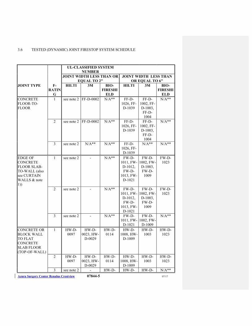
Azura Surgery Center Renalus Crestview 07844-5 07/17
3.6 TESTED (DYNAMIC) JOINT FIRESTOP SYSTEM SCHEDULE
UL-CLASSIFIED SYSTEM
NUMBER
JOINT WIDTH LESS THAN OR
EQUAL TO 2"
JOINT WIDTH LESS THAN
OR EQUAL TO 6"
JOINT TYPE F-
RATIN
G
HILTI 3M BIO-
FIRESHI
ELD
HILTI 3M BIO-
FIRESHI
ELD
CONCRETE
FLOOR-TO-
FLOOR
1 see note 2 FF-D-0002 N/A** FF-D-
1026, FF-
D-1039
FF-D-
1002, FF-
D-1003,
FF-D-
1004
N/A**
2 see note 2 FF-D-0002 N/A** FF-D-
1026, FF-
D-1039
FF-D-
1002, FF-
D-1003,
FF-D-
1004
N/A**
3 see note 2 N/A** N/A** FF-D-
1026, FF-
D-1039
N/A** N/A**
EDGE OF
CONCRETE
FLOOR SLAB-
TO-WALL (also
see CURTAIN
WALLS & note
1))
1 see note 2 - N/A** FW-D-
1011, FW-
D-1012,
FW-D-
1013, FW-
D-1021
FW-D-
1002, FW-
D-1003,
FW-D-
1009
FW-D-
1023
2 see note 2 - N/A** FW-D-
1011, FW-
D-1012,
FW-D-
1013, FW-
D-1021
FW-D-
1002, FW-
D-1003,
FW-D-
1009
FW-D-
1023
3 see note 2 - N/A** FW-D-
1011, FW-
D-1021
FW-D-
1002, FW-
D-1009
N/A**
CONCRETE OR
BLOCK WALL
TO FLAT
CONCRETE
SLAB FLOOR
(TOP-OF-WALL)
1 HW-D-
0097
HW-D-
0023, HW-
D-0029
HW-D-
0114
HW-D-
1008, HW-
D-1009
HW-D-
1003
HW-D-
1023
2 HW-D-
0097
HW-D-
0023, HW-
D-0029
HW-D-
0114
HW-D-
1008, HW-
D-1009
HW-D-
1003
HW-D-
1023
3 see note 2 - HW-D- HW-D- HW-D- N/A**
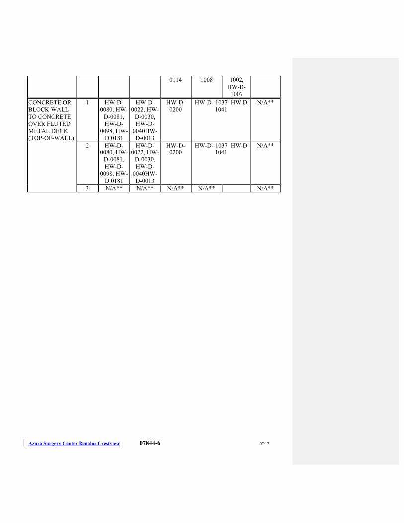
Azura Surgery Center Renalus Crestview 07844-6 07/17
0114 1008 1002,
HW-D-
1007
CONCRETE OR
BLOCK WALL
TO CONCRETE
OVER FLUTED
METAL DECK
(TOP-OF-WALL)
1 HW-D-
0080, HW-
D-0081,
HW-D-
0098, HW-
D 0181
HW-D-
0022, HW-
D-0030,
HW-D-
0040HW-
D-0013
HW-D-
0200
HW-D- 1037 HW-D
1041
N/A**
2 HW-D-
0080, HW-
D-0081,
HW-D-
0098, HW-
D 0181
HW-D-
0022, HW-
D-0030,
HW-D-
0040HW-
D-0013
HW-D-
0200
HW-D- 1037 HW-D
1041
N/A**
3 N/A** N/A** N/A** N/A** N/A**
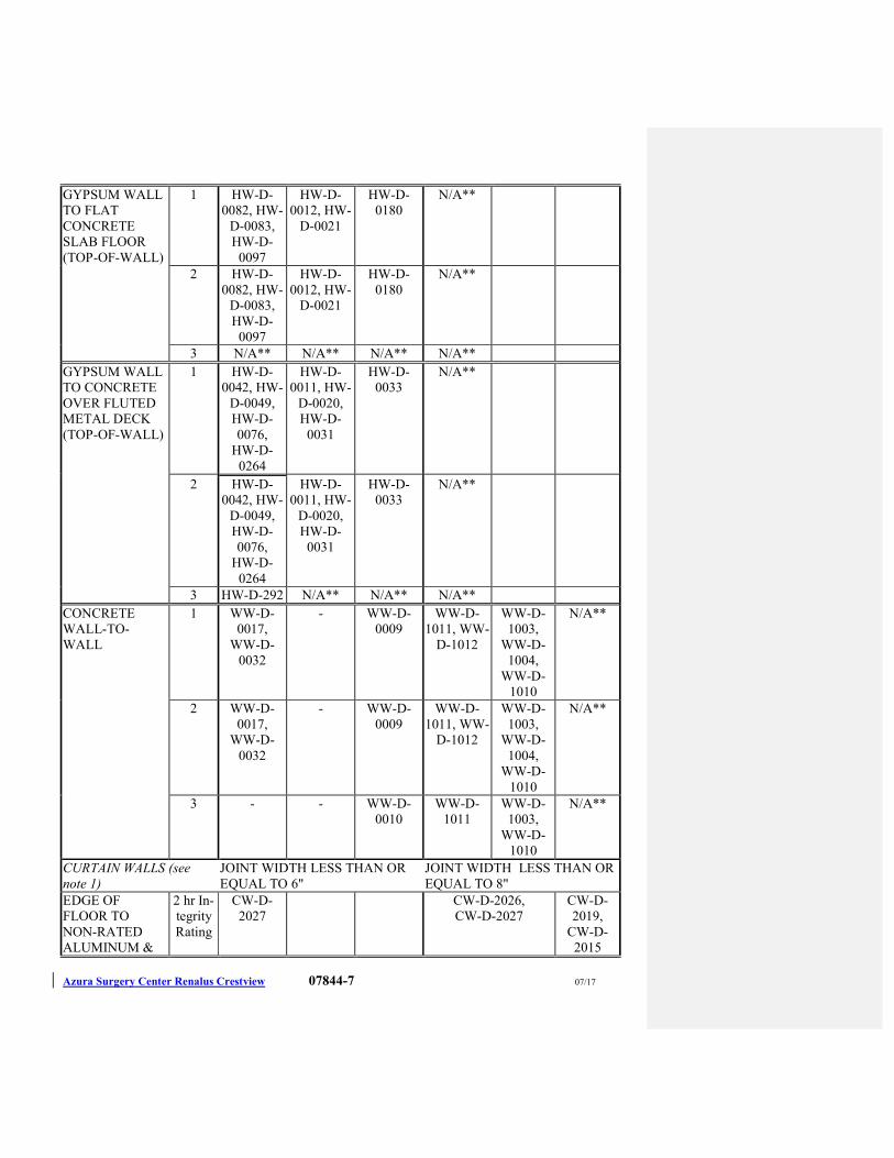
Azura Surgery Center Renalus Crestview 07844-7 07/17
GYPSUM WALL
TO FLAT
CONCRETE
SLAB FLOOR
(TOP-OF-WALL)
1 HW-D-
0082, HW-
D-0083,
HW-D-
0097
HW-D-
0012, HW-
D-0021
HW-D-
0180
N/A**
2 HW-D-
0082, HW-
D-0083,
HW-D-
0097
HW-D-
0012, HW-
D-0021
HW-D-
0180
N/A**
3 N/A** N/A** N/A** N/A**
GYPSUM WALL
TO CONCRETE
OVER FLUTED
METAL DECK
(TOP-OF-WALL)
1 HW-D-
0042, HW-
D-0049,
HW-D-
0076,
HW-D-
0264
HW-D-
0011, HW-
D-0020,
HW-D-
0031
HW-D-
0033
N/A**
2 HW-D-
0042, HW-
D-0049,
HW-D-
0076,
HW-D-
0264
HW-D-
0011, HW-
D-0020,
HW-D-
0031
HW-D-
0033
N/A**
3 HW-D-292 N/A** N/A** N/A**
CONCRETE
WALL-TO-
WALL
1 WW-D-
0017,
WW-D-
0032
- WW-D-
0009
WW-D-
1011, WW-
D-1012
WW-D-
1003,
WW-D-
1004,
WW-D-
1010
N/A**
2 WW-D-
0017,
WW-D-
0032
- WW-D-
0009
WW-D-
1011, WW-
D-1012
WW-D-
1003,
WW-D-
1004,
WW-D-
1010
N/A**
3 - - WW-D-
0010
WW-D-
1011
WW-D-
1003,
WW-D-
1010
N/A**
CURTAIN WALLS (see
note 1)
JOINT WIDTH LESS THAN OR
EQUAL TO 6"
JOINT WIDTH LESS THAN OR
EQUAL TO 8"
EDGE OF
FLOOR TO
NON-RATED
ALUMINUM &
2 hr In-
tegrity
Rating
CW-D-
2027
CW-D-2026,
CW-D-2027
CW-D-
2019,
CW-D-
2015
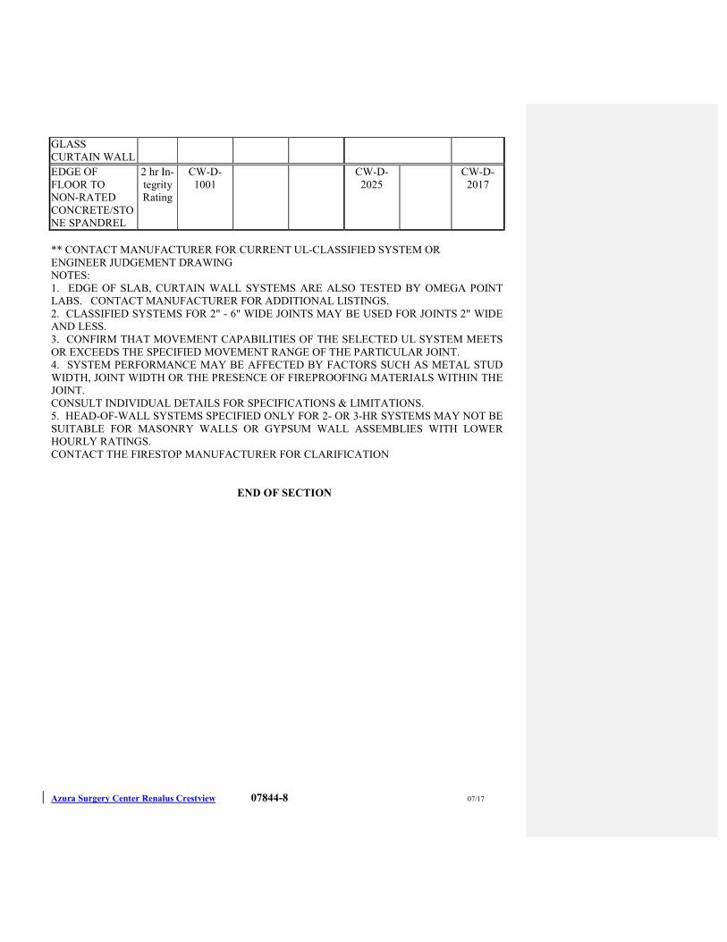
Azura Surgery Center Renalus Crestview 07844-8 07/17
GLASS
CURTAIN WALL
EDGE OF
FLOOR TO
NON-RATED
CONCRETE/STO
NE SPANDREL
2 hr In-
tegrity
Rating
CW-D-
1001
CW-D-
2025
CW-D-
2017
** CONTACT MANUFACTURER FOR CURRENT UL-CLASSIFIED SYSTEM OR
ENGINEER JUDGEMENT DRAWING
NOTES:
1. EDGE OF SLAB, CURTAIN WALL SYSTEMS ARE ALSO TESTED BY OMEGA POINT
LABS. CONTACT MANUFACTURER FOR ADDITIONAL LISTINGS.
2. CLASSIFIED SYSTEMS FOR 2" - 6" WIDE JOINTS MAY BE USED FOR JOINTS 2" WIDE
AND LESS.
3. CONFIRM THAT MOVEMENT CAPABILITIES OF THE SELECTED UL SYSTEM MEETS
OR EXCEEDS THE SPECIFIED MOVEMENT RANGE OF THE PARTICULAR JOINT.
4. SYSTEM PERFORMANCE MAY BE AFFECTED BY FACTORS SUCH AS METAL STUD
WIDTH, JOINT WIDTH OR THE PRESENCE OF FIREPROOFING MATERIALS WITHIN THE
JOINT.
CONSULT INDIVIDUAL DETAILS FOR SPECIFICATIONS & LIMITATIONS.
5. HEAD-OF-WALL SYSTEMS SPECIFIED ONLY FOR 2- OR 3-HR SYSTEMS MAY NOT BE
SUITABLE FOR MASONRY WALLS OR GYPSUM WALL ASSEMBLIES WITH LOWER
HOURLY RATINGS.
CONTACT THE FIRESTOP MANUFACTURER FOR CLARIFICATION
END OF SECTION
Azura Surgery Center Renalus Crestview 07920-1 07/17
SECTION 07920
JOINT SEALANTS & WATERPROOFING
PART 1 - GENERAL
1.1 DESCRIPTION OF WORK
A. Work Included: Provide labor, materials and equipment necessary to complete the work of this
Section, including but not limited to the following:
1. Joint sealants and fillers.
2. Waterproofing membranes.
B. This Section includes joint sealants for the applications specified with the products in this
Section and as indicated on the Drawings.
C. Related Work: The following items are not included in this Section and will be performed
under the designated Sections:
1. Section 04200 - UNIT MASONRY for masonry control and expansion joint fillers and
gaskets.
2. Section 08800 - GLAZING for glazing sealants.
3. Section 09260 - GYPSUM BOARD ASSEMBLIES for sealing perimeter joints of
gypsum board partitions to reduce sound transmission.
4. Section 09511 - ACOUSTICAL PANEL CEILINGS for sealing edge moldings at
perimeters of acoustical ceilings.
1.2 PERFORMANCE REQUIREMENTS
A. Provide elastomeric joint sealants that establish and maintain watertight and airtight continuous
joint seals without staining or deteriorating joint substrates.
B. Provide joint sealants for interior applications that establish and maintain airtight and water-
resistant continuous joint seals without staining or deteriorating joint substrates.
1.3 SUBMITTALS
A. Product Data: For each joint-sealant product indicated.
1. Manufacturers’ product data for interior sealants, including printed statement of VOC
content.
B. Samples for Verification: For each type and color of joint sealant required, provide samples
with joint sealants in 1/2 inch wide joints formed between two 6 inch long strips of material
matching the appearance of exposed surfaces adjacent to joint sealants.
C. Qualification Data: For Installer.
D. Preconstruction Field Test Reports: Indicate which sealants and joint preparation methods
resulted in optimum adhesion to joint substrates based on preconstruction testing specified in
“Quality Assurance” Article.
E. Compatibility and Adhesion Test Reports: From sealant manufacturer, indicating the
following:
1. Materials forming joint substrates and joint sealant backings have been tested for
compatibility and adhesion with joint sealants.
2. Interpretation of test results and written recommendations for primers and substrate
preparation needed for adhesion.
F. Field Test Report Log: For each elastomeric sealant application.
Azura Surgery Center Renalus Crestview 07920-2 07/17
G. Product Test Reports: Based on comprehensive testing of product formulations performed by a
qualified testing agency, indicating that sealants comply with requirements.
1.4 QUALITY ASSURANCE
A. Installer Qualifications: Manufacturer’s authorized Installer who is approved or licensed for
installation of elastomeric sealants required for this Project.
B. Source Limitations: Obtain each type of joint sealant through one source from a single
manufacturer.
C. Preconstruction Compatibility and Adhesion Testing: Submit to joint sealant manufacturers,
for testing indicated below, samples of materials that will contact or affect joint sealants.
1. Use manufacturer’s standard test method to determine whether priming and other specific
joint preparation techniques are required to obtain rapid, optimum adhesion of joint
sealants to joint substrates.
2. Schedule sufficient time for testing and analyzing results to prevent delaying the Work.
3. For materials failing tests, obtain joint sealant manufacturer’s written instructions for
corrective measures including use of specially formulated primers.
4. Testing will not be required if joint sealant manufacturers submit joint preparation data
that are based on previous testing of current sealant products for adhesion to, and
compatibility with, joint substrates and other materials matching those submitted.
D. Preconstruction Field-Adhesion Testing: Before installing elastomeric sealants, field test their
adhesion to Project joint substrates as follows:
1. Locate test joints where indicated on Project or, if not indicated, as directed by Architect.
2. Conduct field tests for each application indicated below:
a. Each type of elastomeric sealant and joint substrate indicated.
b. Each type of non-elastomeric sealant and joint substrate indicated.
3. Notify Architect seven days in advance of dates and times when test joints will be
erected.
a. Test Method: Test joint sealants according to Method A, Field-Applied Sealant
Joint Hand Pull Tab, in Appendix X1 in ASTM C 1193.
1) For joints with dissimilar substrates, verify adhesion to each substrate
separately; extend cut along one side, verifying adhesion to opposite side.
Repeat procedure for opposite side.
4. Report whether sealant in joint connected to pulled-out portion failed to adhere to joint
substrates or tore cohesively. Include data on pull distance used to test each type of
product and joint substrate. For sealants that fail adhesively, retest until satisfactory
adhesion is obtained.
5. Evaluation of Preconstruction Field-Adhesion-Test Results: Sealants not evidencing
adhesive failure from testing, in absence of other indications of noncompliance with
requirements, will be considered satisfactory. Do not use sealants that fail to adhere to
joint substrates during testing.
E. Preinstallation Conference: Conduct conference at Project site to comply with requirements in
Division 01.
1.5 PROJECT CONDITIONS
A. Do not proceed with installation of joint sealants under the following conditions:
1. When ambient and substrate temperature conditions are outside limits permitted by joint
sealant manufacturer or are below 40 deg F.
Azura Surgery Center Renalus Crestview 07920-3 07/17
2. When joint substrates are wet.
3. Where joint widths are less than those allowed by joint sealant manufacturer for
applications indicated.
4. Contaminants capable of interfering with adhesion have not yet been removed from joint
substrates.
1.6 WARRANTY
A. Special Installer’s Warranty: Installer’s standard form in which Installer agrees to repair or
replace elastomeric joint sealants that do not comply with performance and other requirements
specified in this Section within specified warranty period.
1. Warranty Period: Two years from date of Substantial Completion.
B. Special Manufacturer’s Warranty: Manufacturer's standard form in which elastomeric sealant
manufacturer agrees to furnish elastomeric joint sealants to repair or replace those that do not
comply with performance and other requirements specified in this Section within specified
warranty period.
1. Warranty Period: Five years from date of Substantial Completion.
C. Special warranties specified in this Article exclude deterioration or failure of elastomeric joint
sealants from the following:
1. Movement of the structure resulting in stresses on the sealant exceeding sealant
manufacturer’s written specifications for sealant elongation and compression caused by
structural settlement or errors attributable to design or construction.
2. Disintegration of joint substrates from natural causes exceeding design specifications.
3. Mechanical damage caused by individuals, tools, or other outside agents.
4. Changes in sealant appearance caused by accumulation of dirt or other atmospheric
contaminants.
PART 2 - PRODUCTS
2.1 MATERIALS, GENERAL
A. Compatibility: Provide joint sealants, backings, and other related materials that are compatible
with one another and with joint substrates under conditions of service and application, as
demonstrated by sealant manufacturer, based on testing and field experience.
B. VOC Content of Interior Sealants: Provide interior sealants and sealant primers that comply
with the following limits for VOC content when calculated according to 40 CFR 59, Subpart D
(EPA Method 24):
1. Sealants: 250 g/L.
2. Sealant Primers for Nonporous Substrates: 250 g/L.
3. Sealant Primers for Porous Substrates: 775 g/L.
C. Colors of Exposed Joint Sealants: As indicated by manufacturer’s designations.
2.2 JOINT SEALANTS
A. Elastomeric Sealants: Comply with ASTM C 920 and other requirements indicated for each
liquid-applied chemically curing sealant specified, including those referencing ASTM C 920
classifications for type, grade, class, and uses related to exposure and joint substrates.
B. Stain-Test-Response Characteristics: Elastomeric sealants shall be nonstaining to porous
substrates. Provide products that have undergone testing according to ASTM C 1248 and have
not stained porous joint substrates indicated for Project.
Azura Surgery Center Renalus Crestview 07920-4 07/17
C. Single-Component Neutral-Curing Silicone Sealant:
1. Available Products: Subject to compliance with requirements, products that may be
incorporated into the Work include, but are not limited to, the following:
a. Dow Corning Corporation; 790.
b. GE Silicones; SilPruf LM SCS2700.
c. Tremco; Spectrem 1.
d. Pecora Corporation; 864.
2. Extent of Use: Joints in exterior vertical and soffit surfaces.
D. Multicomponent Pourable Urethane Sealant:
1. Available Products: Subject to compliance with requirements, products that may be
incorporated into the Work include, but are not limited to, the following:
a. Bostik Findley; Chem-Calk 550.
b. Meadows, W. R., Inc.; POURTHANE.
c. Pecora Corporation; Urexpan NR-200.
d. Tremco; THC-901.
2. Extent of Use: Joints in exterior horizontal surfaces.
E. Single-Component Mildew-Resistant Acid-Curing Silicone Sealant:
1. Available Products: Subject to compliance with requirements, products that may be
incorporated into the Work include, but are not limited to, the following:
a. Dow Corning Corporation; 786 Mildew Resistant.
b. GE Silicones; Sanitary SCS1700.
c. Tremco; Tremsil 200.
2. Extent of Use: Sanitary joints at toilet rooms and wet areas.
F. Latex Sealant: Comply with ASTM C 834, Type P, Grade NF.
1. Available Products: Subject to compliance with requirements, products that may be
incorporated into the Work include, but are not limited to, the following:
a. Bostik Findley; Chem-Calk 600.
b. Pecora Corporation; AC-20+.
c. Sonneborn, Division of Degussa; Sonolac.
d. Tremco; Tremflex 834.
2.3 JOINT-SEALANT BACKING
A. General: Provide sealant backings of material and type that are nonstaining; are compatible
with joint substrates, sealants, primers, and other joint fillers; and are approved for applications
indicated by sealant manufacturer based on field experience and laboratory testing.
B. Elastomeric Tubing Sealant Backings: Neoprene, butyl, EPDM, or silicone tubing complying
with ASTM D 1056, nonabsorbent to water and gas, and capable of remaining resilient at
temperatures down to minus 26 deg F. Provide products with low compression set and of size
and shape to provide a secondary seal, to control sealant depth, and to otherwise contribute to
optimum sealant performance.
C. Bond-Breaker Tape: Polyethylene tape or other plastic tape recommended by sealant
manufacturer for preventing sealant from adhering to rigid, inflexible joint-filler materials or
Azura Surgery Center Renalus Crestview 07920-5 07/17
joint surfaces at back of joint where such adhesion would result in sealant failure. Provide self-
adhesive tape where applicable.
2.4 MISCELLANEOUS MATERIALS
A. Primer: Material recommended by joint sealant manufacturer where required for adhesion of
sealant to joint substrates indicated, as determined from preconstruction joint-sealant-substrate
tests and field tests.
B. Cleaners for Nonporous Surfaces: Chemical cleaners acceptable to manufacturers of sealants
and sealant backing materials, free of oily residues or other substances capable of staining or
harming joint substrates and adjacent nonporous surfaces in any way, and formulated to
promote optimum adhesion of sealants to joint substrates.
C. Masking Tape: Nonstaining, nonabsorbent material compatible with joint sealants and surfaces
adjacent to joints.
PART 3 - EXECUTION
3.1 EXAMINATION
A. Examine joints indicated to receive joint sealants, with Installer present, for compliance with
requirements for joint configuration, installation tolerances, and other conditions affecting joint
sealant performance.
B. Proceed with installation only after unsatisfactory conditions have been corrected.
3.2 PREPARATION
A. Surface Cleaning of Joints: Clean out joints immediately before installing joint sealants to
comply with joint sealant manufacturer’s written instructions and the following requirements:
1. Remove all foreign material from joint substrates that could interfere with adhesion of
joint sealant, including dust, paints (except for permanent, protective coatings tested and
approved for sealant adhesion and compatibility by sealant manufacturer), old joint
sealants, oil, grease, waterproofing, water repellents, water, surface dirt, and frost.
2. Clean porous joint substrate surfaces by brushing, grinding, blast cleaning, mechanical
abrading, or a combination of these methods to produce a clean, sound substrate capable
of developing optimum bond with joint sealants. Remove loose particles remaining after
cleaning operations above by vacuuming or blowing out joints with oil-free compressed
air. Porous joint substrates include concrete, masonry and unglazed surfaces of ceramic
tile.
3. Remove laitance and form-release agents from concrete.
4. Clean nonporous surfaces with chemical cleaners or other means that do not stain, harm
substrates, or leave residues capable of interfering with adhesion of joint sealants.
Nonporous joint substrates include the following metal, glass, porcelain enamel and
glazed surfaces of ceramic tile.
B. Joint Priming: Prime joint substrates, where recommended in writing by joint sealant
manufacturer, based on preconstruction joint-sealant-substrate tests or prior experience. Apply
primer to comply with joint sealant manufacturer’s written instructions. Confine primers to
areas of joint sealant bond; do not allow spillage or migration onto adjoining surfaces.
C. Masking Tape: Use masking tape where required to prevent contact of sealant with adjoining
surfaces that otherwise would be permanently stained or damaged by such contact or by
cleaning methods required to remove sealant smears. Remove tape immediately after tooling
without disturbing joint seal.
Azura Surgery Center Renalus Crestview 07920-6 07/17
3.3 INSTALLATION OF JOINT SEALANTS
A. General: Comply with joint sealant manufacturer’s written installation instructions for
products and applications indicated, unless more stringent requirements apply.
B. Sealant Installation Standard: Comply with recommendations in ASTM C 1193 for use of joint
sealants as applicable to materials, applications, and conditions indicated.
C. Install sealant backings of type indicated to support sealants during application and at position
required to produce cross-sectional shapes and depths of installed sealants relative to joint
widths that allow optimum sealant movement capability.
1. Do not leave gaps between ends of sealant backings.
2. Do not stretch, twist, puncture, or tear sealant backings.
3. Remove absorbent sealant backings that have become wet before sealant application and
replace them with dry materials.
D. Install bond-breaker tape behind sealants where sealant backings are not used between sealants
and backs of joints.
E. Install sealants using proven techniques that comply with the following and at the same time
backings are installed:
1. Place sealants so they directly contact and fully wet joint substrates.
2. Completely fill recesses in each joint configuration.
3. Produce uniform, cross-sectional shapes and depths relative to joint widths that allow
optimum sealant movement capability.
F. Tooling of Nonsag Sealants: Immediately after sealant application and before skinning or
curing begins, tool sealants according to requirements specified below to form smooth, uniform
beads of configuration indicated to eliminate air pockets, and to ensure contact and adhesion of
sealant with sides of joint.
1. Remove excess sealant from surfaces adjacent to joints.
2. Use tooling agents that are approved in writing by sealant manufacturer and that do not
discolor sealants or adjacent surfaces.
3. Provide concave joint configuration per Figure 5A in ASTM C 1193, unless otherwise
indicated.
G. Provide caulking at the following locations. This schedule is not to be construed to be
complete. Provide caulking at other areas as indicated.
1. Control joints in masonry surfaces, interior and exterior.
2. Control joints in concrete surfaces, interior and exterior.
3. Perimeter of door frames, interior and exterior.
4. Perimeter of window frames, interior and exterior.
5. Perimeter of louvers and grilles, interior and exterior.
6. Perimeter of aluminum sections, interior and exterior.
7. Setting bed for countertops at prefabricated cabinet locations.
8. Along wall and cabinet where indicated on drawings.
Note: At interior partitions caulking is required at all joints between dissimilar materials where
the joint width exceeds 1/16".
3.4 CLEANING
A. Clean off excess sealant or sealant smears adjacent to joints as the Work progresses by methods
and with cleaning materials approved in writing by manufacturers of joint sealants and of
products in which joints occur.
Azura Surgery Center Renalus Crestview 07920-7 07/17
3.5 PROTECTION
A. Protect joint sealants during and after curing period from contact with contaminating
substances and from damage resulting from construction operations or other causes so sealants
are without deterioration or damage at time of Substantial Completion. If, despite such
protection, damage or deterioration occurs, cut out and remove damaged or deteriorated joint
sealants immediately so installations with repaired areas are indistinguishable from original
work.
END OF SECTION
Azura Surgery Center Renalus Crestview 08111-1 07/17
SECTION 08111
STEEL DOORS AND FRAMES
PART 1 - GENERAL
1.1 DESCRIPTION OF WORK
A. Work Included: Provide labor, materials and equipment necessary to complete the work of this
Section, including but not limited to the following:
1. Standard hollow metal steel doors.
2. Standard hollow metal steel frames.
B. Related Work: The following items are not included in this Section and will be performed
under the designated Sections:
1. Section 04200 - UNIT MASONRY for building anchors into and grouting steel frames in
masonry construction.
2. Section 08710 - DOOR HARDWARE for door hardware for steel doors.
3. Section 08800 - GLASS AND GLAZING for glazed lites.
4. Section 09900 - PAINTING for field painting steel doors and frames.
1.2 SUBMITTALS
A. Product Data: Include construction details, material descriptions, core descriptions, label
compliance, fire-resistance rating, temperature-rise ratings, and finishes for each type of steel
door and frame specified.
B. Shop Drawings:
1. Elevations of each door design.
2. Details of doors, including vertical and horizontal edge details and metal thicknesses.
3. Frame details for each frame type, including dimensioned profiles and metal thicknesses.
4. Locations of reinforcement and preparations for hardware.
5. Details of each different wall opening condition.
6. Details of anchorages, joints, field splices, and connections.
7. Details of accessories.
8. Details of moldings, removable stops, and glazing.
9. Details of conduit and preparations for power, signal, and control systems.
10. Manufacturer’s recommended installation procedures, which when approved by the
Architect, will become the basis for accepting or rejecting actual installation procedures
used on the work.
C. Schedule: Provide a schedule of hollow metal work prepared by or under the supervision of
supplier, using same reference numbers for details and openings as those on Drawings.
Coordinate with door hardware schedule.
D. Qualification Data: For Installer.
E. Product Test Reports: Based on evaluation of comprehensive fire tests performed by a
qualified testing agency, for each type of standard steel door and frame.
Azura Surgery Center Renalus Crestview 08111-2 07/17
1.3 QUALITY ASSURANCE
A. Installer Qualifications: An employer of workers trained and approved by manufacturer.
B. Source Limitations: Obtain standard steel doors and frames through one source from a single
manufacturer.
C. Fire-Rated Door, Sidelight and Transom Frame Assemblies: Assemblies complying with
NFPA 80 that are listed and labeled by a testing and inspecting agency acceptable to authorities
having jurisdiction, for fire-protection ratings indicated. Identify each fire door or frame with
UL labels, indicating the applicable fire rating of both door and frame.
1. Temperature-Rise Limit: At vertical exit enclosures and exit passageways, provide doors
that have a maximum transmitted temperature end point of not more than 450 deg F
above ambient after 30 minutes of standard fire-test exposure.
1.4 DELIVERY, STORAGE, AND HANDLING
A. Deliver doors and frames palletized, wrapped, or crated to provide protection during transit and
Project-site storage. Do not use non-vented plastic.
B. Deliver welded frames with two removable spreader bars across bottom of frames, tack welded
to jambs and mullions.
C. General Contractor must inspect and inventory all deliveries within 24 hours of delivery. All
freight damage must be signed as damaged on the Bill of Lading document and reported to the
freight carrier. General Contractor must report to the supplier any missing, incorrect or
damaged goods immediately. Failure to report missing, damaged or incorrect material within
48 hours means the receiver has accepted the shipment as complete and correct.
D. Store hollow metal work under cover at Project site. Place in stacks of five units maximum in a
vertical position with heads up, spaced by blocking, on minimum 4-inch-high wood blocking.
Do not store in a manner that traps excess humidity.
1. Provide minimum 1/4 inch space between each stacked door to permit air circulation.
1.5 PROJECT CONDITIONS
A. Field Measurements: Verify actual dimensions of openings by field measurements before
fabrication.
1.6 COORDINATION
A. Coordinate installation of anchorages for hollow metal frames. Furnish setting drawings,
templates, and directions for installing anchorages, including sleeves, concrete inserts, anchor
bolts, and items with integral anchors. Deliver such items to Project site in time for
installation.
PART 2 - PRODUCTS
2.1 MANUFACTURERS
A. Available Manufacturers: Subject to compliance with requirements, manufacturers offering
products that may be incorporated into the Work include, but are not limited to, the following:
1. Steelcraft Hollow Metal Door and Frames
2. Curries Hollow Metal Doors and Frames
2.2 MATERIALS
A. Cold-Rolled Steel Sheet: ASTM A 1008/A 1008M, Commercial Steel (CS), Type B; suitable
for exposed applications.
Azura Surgery Center Renalus Crestview 08111-3 07/17
B. Hot-Rolled Steel Sheet: ASTM A 1011/A 1011M, Commercial Steel (CS), Type B; free of
scale, pitting, or surface defects; pickled and oiled.
C. Metallic-Coated Steel Sheet: ASTM A 653/A 653M, Commercial Steel (CS), Type B; with
minimum G60 metallic coating.
D. Frame Anchors: ASTM A 591/A 591M, Commercial Steel (CS), 40Z coating designation; mill
phosphatized.
1. For anchors built into exterior walls, steel sheet complying with ASTM A 1008/A 1008M
or ASTM A 1011/A 1011M, hot-dip galvanized according to ASTM A 153/A 153M,
Class B.
E. Inserts, Bolts, and Fasteners: Hot-dip galvanized according to ASTM A 153/A 153M.
F. Powder-Actuated Fasteners in Concrete: Fastener system of type suitable for application
indicated, fabricated from corrosion-resistant materials, with clips or other accessory devices
for attaching hollow metal frames of type indicated.
G. Grout: ASTM C 476, except with a maximum slump of 4 inches, as measured according to
ASTM C 143/C 143M.
H. Mineral-Fiber Insulation: ASTM C 665, Type I (blankets without membrane facing);
consisting of fibers manufactured from slag or rock wool with 6- to 12-lb/cu. ft. density; with
maximum flame-spread and smoke-development indexes of 25 and 50, respectively; passing
ASTM E 136 for combustion characteristics.
I. Glazing: Comply with requirements in Section 08800 – GLASS AND GLAZING.
J. Bituminous Coating: Cold-applied asphalt mastic, SSPC-Paint 12, compounded for 15-mil dry
film thickness per coat. Provide inert-type noncorrosive compound free of asbestos fibers,
sulfur components, and other deleterious impurities. All bituminous coating to be supplied and
installed by the General Contractor.
2.3 STANDARD STEEL DOORS
A. General: Provide doors of design indicated, not less than thickness indicated; fabricated with
smooth surfaces, without visible joints or seams on exposed faces, unless otherwise indicated.
Comply with ANSI A250.8.
1. Design: Flush panel.
2. Core Construction: Manufacturer’s standard kraft-paper honeycomb, polystyrene,
polyurethane, mineral-board, or vertical steel-stiffener core that produces doors
complying with ANSI A250.8.
a. Fire Door Core: As required to provide fire-protection and temperature-rise ratings
indicated.
b. Thermal-Rated (Insulated) Exterior Doors: Where indicated, provide doors
fabricated with thermal-resistance value (R-value) of not less than 4.0 deg F x h x
sq. ft./Btu when tested according to ASTM C 1363.
3. Top and Bottom Edges: Closed with flush or inverted 0.042-inch-thick end closures or
channels of same material as face sheets.
4. Tolerances: Comply with SDI 117, “Manufacturing Tolerances for Standard Steel Doors
and Frames.”
B. Exterior Doors: Face sheets fabricated from metallic-coated steel sheet. Provide doors
complying with requirements indicated below by referencing ANSI A250.8 for level and model
and ANSI A250.4 for physical-endurance level:
Azura Surgery Center Renalus Crestview 08111-4 07/17
1. Level 3 and Physical Performance Level A (Extra Heavy Duty), Model 1, 1-3/4 inches
thick.
C. Interior Doors: Face sheets fabricated from cold-rolled steel sheet, unless otherwise indicated
to comply with exterior door requirements. Provide doors complying with requirements
indicated below by referencing ANSI A250.8 for level and model and ANSI A250.4 for
physical-endurance level:
1. Level 2 and Physical Performance Level B (Heavy Duty), Model 1, 1-3/4 inches thick.
D. Hardware Reinforcement: Fabricate according to ANSI/SDI A250.6 with reinforcing plates
from same material as door face sheets.
E. Fabricate concealed stiffeners and hardware reinforcement from either cold- or hot-rolled steel
sheet.
2.4 STANDARD STEEL FRAMES
A. General: Comply with ANSI A250.8 and with details indicated for type and profile.
Combination type with integral stop.
B. Exterior Frames: Fabricated from metallic-coated steel sheet.
1. Fabricate frames with mitered or coped and welded face corners and seamless face joints.
2. Frames for Level 3 Steel Doors: 0.053-inch-thick steel sheet.
C. Interior Frames: Fabricated from cold-rolled steel sheet, unless otherwise indicated to comply
with exterior frame requirements.
1. Fabricate frames with mitered or coped and welded face corners and seamless face joints.
2. Frames for Level 2 Steel Doors: 0.053-inch-thick steel sheet.
3. Knock down frames may be used on doors 36” wide or less, and without automatic or
power actuated openers.
D. Interior Frame for Hospital Privacy Set at Patient Toilets: Fabricated from cold-rolled steel sheet,
unless otherwise indicated to comply with exterior frame requirements.
1. Fabricate frames without integral stop and prep for jamb mount pivot hinge set per HW
Set 30.
E. Hardware Reinforcement: Fabricate according to ANSI/SDI A250.6 with reinforcement plates
from same material as frames.
F. Plaster Guards: Formed from same material as frames, not less than 0.016-inch thick.
2.5 FRAME ANCHORS
A. Jamb Anchors:
1. Masonry Type: Adjustable strap-and-stirrup or T-shaped anchors to suit frame size, not
less than 0.042 inch thick, with corrugated or perforated straps not less than 2 inches
wide by 10 inches long; or wire anchors not less than 0.177 inch thick.
2. Stud-Wall Type: Designed to engage stud, welded to back of frames not less than 0.042
inch thick.
3. Compression Type for Drywall Slip-on Frames: Adjustable compression anchors.
4. Post installed Expansion Type for In-Place Concrete or Masonry: Minimum 3/8 inch
diameter bolts with expansion shields or inserts. Provide pipe spacer from frame to wall,
with throat reinforcement plate, welded to frame at each anchor location.
Azura Surgery Center Renalus Crestview 08111-5 07/17
B. Floor Anchors: Formed from same material as frames, not less than 0.042 inch (1.0 mm) thick,
and as follows:
1. Monolithic Concrete Slabs: Clip-type anchors, with two holes to receive fasteners.
2. Separate Topping Concrete Slabs: Adjustable-type anchors with extension clips,
allowing not less than 2-inch height adjustment. Terminate bottom of frames at finish
floor surface.
2.6 HOLLOW METAL PANELS
A. Provide hollow metal panels of same materials, construction, and finish as specified for
adjoining hollow metal work.
2.7 STOPS AND MOLDINGS
A. Moldings for Glazed Lites in Doors: Minimum 0.032 inch thick, fabricated from same material
as door face sheet in which they are installed.
B. Fixed Frame Moldings: Formed integral with hollow metal frames, a minimum of 5/8 inch
high unless otherwise indicated.
C. Loose Stops for Glazed Lites in Frames: Minimum 0.032 inch thick, fabricated from same
material as frames in which they are installed.
2.8 LOUVERS
A. Provide louvers for interior doors, where indicated, that comply with SDI 111C, with blades or
baffles formed of 0.020-inch-thick, cold-rolled steel sheet set into 0.032-inch-thick steel frame.
1. Sightproof Louver: Stationary louvers constructed with inverted V-shaped or Y-shaped
blades.
2. Fire-Rated Automatic Louvers: Louvers constructed with movable blades closed by
actuating fusible link, and listed and labeled for use in fire-rated door assemblies of type
and fire-resistance rating indicated by same testing and inspecting agency that established
fire-resistance rating of door assembly.
2.9 ACCESSORIES
A. Mullions and Transom Bars: Join to adjacent members by welding or rigid mechanical
anchors.
B. Ceiling Struts: Minimum 1/4 inch thick by 1 inch wide steel.
C. Grout Guards: Formed from same material as frames, not less than 0.016 inch thick.
2.10 FABRICATION
A. Fabricate hollow metal work to be rigid and free of defects, warp, or buckle. Accurately form
metal to required sizes and profiles, with minimum radius for thickness of metal. Where
practical, fit and assemble units in manufacturer’s plant. To ensure proper assembly at Project
site, clearly identify work that cannot be permanently factory assembled before shipment.
B. Tolerances: Fabricate hollow metal work to tolerances indicated in SDI 117.
C. Hollow Metal Doors:
1. Exterior Doors: Provide weep-hole openings in bottom of exterior doors to permit
moisture to escape. Seal joints in top edges of doors against water penetration.
2. Glazed Lites: Factory cut openings in doors.
Azura Surgery Center Renalus Crestview 08111-6 07/17
3. Astragals: Provide overlapping astragal on one leaf of pairs of doors where required by
NFPA 80 for fire-performance rating or where indicated. Extend minimum 3/4 inch
beyond edge of door on which astragal is mounted.
D. Hollow Metal Frames: Where frames are fabricated in sections due to shipping or handling
limitations, provide alignment plates or angles at each joint, fabricated of same thickness metal
as frames.
1. Welded Frames: Weld flush face joints continuously; grind, fill, dress, and make smooth,
flush, and not visible.
2. Sidelight and Transom Bar Frames: Provide closed tubular members with no visible face
seams or joints, fabricated from same material as door frame. Fasten members at
crossings and to jambs by butt welding.
3. Provide countersunk, flat- or oval-head exposed screws and bolts for exposed fasteners
unless otherwise indicated.
4. Plaster/Grout Guards: Weld guards to frame at back of hardware mortises in frames
installed in concrete or masonry and to be grouted.
5. Floor Anchors: Weld anchors to bottom of jambs and mullions with at least four spot
welds per anchor.
6. Jamb Anchors: Provide number and spacing of anchors as follows:
a. Masonry Type: Locate anchors not more than 18 inches from top and bottom of
frame. Space anchors not more than 32 inches o.c. and as follows:
1) Two anchors per jamb up to 60 inches high.
2) Three anchors per jamb from 60 to 90 inches high.
3) Four anchors per jamb from 90 to 120 inches high.
4) Four anchors per jamb plus 1 additional anchor per jamb for each 24 inches
or fraction thereof above 120 inches high.
b. Stud-Wall Type: Locate anchors not more than 18 inches from top and bottom of
frame. Space anchors not more than 32 inches o.c. and as follows:
1) Three anchors per jamb up to 60 inches high.
2) Four anchors per jamb from 60 to 90 inches high.
3) Five anchors per jamb from 90 to 96 inches high.
4) Five anchors per jamb plus 1 additional anchor per jamb for each 24 inches
or fraction thereof above 96 inches high.
5) Two anchors per head for frames above 42 inches wide and mounted in
metal-stud partitions.
c. Compression Type: Not less than two anchors in each jamb.
d. Post installed Expansion Type: Locate anchors not more than 6 inches from top
and bottom of frame. Space anchors not more than 26 inches o.c.
7. Door Silencers: Except on weather-stripped doors, drill stops to receive door silencers as
follows. Keep holes clear during construction.
a. Single-Door Frames: Drill stop in strike jamb to receive three door silencers.
b. Double-Door Frames: Drill stop in head jamb to receive two door silencers.
E. Fabricate concealed stiffeners, edge channels, and hardware reinforcement from either cold- or
hot-rolled steel sheet.
F. Hardware Preparation: Factory prepare hollow metal work to receive templated mortised
hardware; include cutouts, reinforcement, mortising, drilling, and tapping according to the
Azura Surgery Center Renalus Crestview 08111-7 07/17
Door Hardware Schedule and templates furnished as specified in Section 08710 - DOOR
HARDWARE.
1. Locate hardware as indicated, or if not indicated, according to ANSI/SDI A250.8.
2. Reinforce doors and frames at the manufacturer’s plant to receive non-templated,
mortised and surface-mounted door hardware.
3. Comply with applicable requirements in ANSI/SDI A250.6 and ANSI/DHI A115 Series
specifications for preparation of hollow metal work for hardware.
4. Coordinate locations of conduit and wiring boxes for electrical connections with Section
16100 - ELECTRICAL.
G. Stops and Moldings: Provide stops and moldings around glazed lites where indicated. Form
corners of stops and moldings with butted or mitered hairline joints.
1. Single Glazed Lites: Provide fixed stops and moldings welded on secure side of hollow
metal work.
2. Multiple Glazed Lites: Provide fixed and removable stops and moldings so that each
glazed lite is capable of being removed independently.
3. Provide fixed frame moldings on outside of exterior and on secure side of interior doors
and frames.
4. Provide loose stops and moldings on inside of hollow metal work.
5. Coordinate rabbet width between fixed and removable stops with type of glazing and
type of installation indicated.
2.11 STEEL FINISHES
A. Prime Finish: Apply manufacturer’s standard primer immediately after cleaning and
pretreating.
1. Shop Primer: Manufacturer’s standard, fast-curing, lead- and chromate-free primer
complying with ANSI/SDI A250.10 acceptance criteria; recommended by primer
manufacturer for substrate; compatible with substrate and field-applied coatings despite
prolonged exposure.
PART 3 - EXECUTION
3.1 EXAMINATION
A. Examine substrates, areas, and conditions, with Installer present, for compliance with
requirements for installation tolerances and other conditions affecting performance of the
Work.
B. Examine roughing-in for embedded and built-in anchors to verify actual locations before frame
installation.
C. Proceed with installation only after unsatisfactory conditions have been corrected.
3.2 PREPARATION
A. Remove welded-in shipping spreaders installed at factory. Restore exposed finish by grinding,
filling, and dressing, as required to make repaired area smooth, flush, and invisible on exposed
faces.
B. Prior to installation, adjust and securely brace welded hollow metal frames for squareness,
alignment, twist, and plumbness to the following tolerances:
1. Squareness: Plus or minus 1/16 inch, measured at door rabbet on a line 90 degrees from
jamb perpendicular to frame head.
Azura Surgery Center Renalus Crestview 08111-8 07/17
2. Alignment: Plus or minus 1/16 inch, measured at jambs on a horizontal line parallel to
plane of wall.
3. Twist: Plus or minus 1/16 inch, measured at opposite face corners of jambs on parallel
lines, and perpendicular to plane of wall.
4. Plumbness: Plus or minus 1/16 inch, measured at jambs on a perpendicular line from
head to floor.
C. Drill and tap doors and frames to receive non-templated, mortised, and surface-mounted door
hardware.
3.3 INSTALLATION
A. General: Install hollow metal work plumb, rigid, properly aligned, and securely fastened in
place; comply with Drawings and manufacturer’s written instructions.
B. Hollow Metal Frames: Install hollow metal frames of size and profile indicated. Comply with
ANSI/SDI A250.11.
1. Set frames accurately in position, plumbed, aligned, and braced securely until permanent
anchors are set. After wall construction is complete, remove temporary braces, leaving
surfaces smooth and undamaged.
a. At fire-protection-rated openings, install frames according to NFPA 80.
b. Where frames are fabricated in sections because of shipping or handling
limitations, field splice at approved locations by welding face joint continuously;
grind, fill, dress, and make splice smooth, flush, and invisible on exposed faces.
c. Install frames with removable glazing stops located on secure side of opening.
d. Install door silencers in frames before grouting.
e. Remove temporary braces necessary for installation only after frames have been
properly set and secured.
f. Check plumbness, squareness, and twist of frames as walls are constructed. Shim
as necessary to comply with installation tolerances.
g. Field apply bituminous coating to backs of frames that are filled with grout.
h. Remove shipping bars before installing frames.
2. Floor Anchors: Provide floor anchors for each jamb and mullion that extends to floor,
and secure with post installed expansion anchors.
a. Floor anchors may be set with powder-actuated fasteners instead of post installed
expansion anchors if so indicated and approved on Shop Drawings.
3. Metal-Stud Partitions: Solidly pack mineral-fiber insulation behind frames.
4. Masonry Walls: Coordinate installation of frames to allow for solidly filling space
between frames and masonry with grout.
5. Concrete Walls: Solidly fill space between frames and concrete with grout. Take
precautions, including bracing frames, to ensure that frames are not deformed or damaged
by grout forces.
6. In-Place Concrete or Masonry Construction: Secure frames in place with post installed
expansion anchors. Countersink anchors, and fill and make smooth, flush, and invisible
on exposed faces.
7. In-Place Gypsum Board Partitions: Secure frames in place with post installed expansion
anchors through floor anchors at each jamb. Countersink anchors, and fill and make
smooth, flush, and invisible on exposed faces.
8. Ceiling Struts: Extend struts vertically from top of frame at each jamb to overhead
structural supports or substrates above frame unless frame is anchored to masonry or to
other structural support at each jamb. Bend top of struts to provide flush contact for
Azura Surgery Center Renalus Crestview 08111-9 07/17
securing to supporting construction. Provide adjustable wedged or bolted anchorage to
frame jamb members.
9. Installation Tolerances: Adjust hollow metal door frames for squareness, alignment,
twist, and plumb to the following tolerances:
a. Squareness: Plus or minus 1/16 inch, measured at door rabbet on a line 90 degrees
from jamb perpendicular to frame head.
b. Alignment: Plus or minus 1/16 inch, measured at jambs on a horizontal line
parallel to plane of wall.
c. Twist: Plus or minus 1/16 inch, measured at opposite face corners of jambs on
parallel lines, and perpendicular to plane of wall.
d. Plumbness: Plus or minus 1/16 inch, measured at jambs at floor.
C. Hollow Metal Doors: Fit hollow metal doors accurately in frames, within clearances specified
below. Shim as necessary.
1. Non-Fire-Rated Standard Steel Doors:
a. Jambs and Head: 1/8 inch plus or minus 1/16 inch.
b. Between Edges of Pairs of Doors: 1/8 inch plus or minus 1/16 inch.
c. Between Bottom of Door and Top of Threshold: Maximum 3/8 inch.
d. Between Bottom of Door and Top of Finish Floor (No Threshold): Maximum 3/4
inch.
2. Fire-Rated Doors: Install doors with clearances according to NFPA 80.
3. Smoke-Control Doors: Install doors according to NFPA 105.
D. Glazing: Comply with hollow metal manufacturer’s written instructions.
1. Secure stops with countersunk flat- or oval-head machine screws spaced uniformly not
more than 9 inches o.c. and not more than 2 inches o.c. from each corner.
3.4 ADJUSTING AND CLEANING
A. Final Adjustments: Check and readjust operating hardware items immediately before final
inspection. Leave work in complete and proper operating condition. Remove and replace
defective work, including hollow metal work that is warped, bowed, or otherwise unacceptable.
B. Remove grout and other bonding material from hollow metal work immediately after
installation.
C. Prime-Coat Touchup: Immediately after erection, sand smooth rusted or damaged areas of
prime coat and apply touchup of compatible air-drying, rust-inhibitive primer.
D. Metallic-Coated Surfaces: Clean abraded areas and repair with galvanizing repair paint
according to manufacturer’s written instructions.
END OF SECTION
Azura Surgery Center Renalus Crestview 08211-1 07/17
SECTION 08211
FLUSH WOOD DOORS
PART 1 - GENERAL
1.1 DESCRIPTION OF WORK
A. Work Included: Provide labor, materials and equipment necessary to complete the work of this
Section, including but not limited to the following:
1. Solid-core doors with wood-veneer faces.
2. Factory fitting flush wood doors to frames and factory machining for hardware.
3. Factory finishing for wood doors.
4. Factory glazing for wood doors.
B. Related Work: The following items are not included in this Section and will be performed
under the designated Sections:
1. Section 04200 - UNIT MASONRY for building anchors into and grouting steel frames in
masonry construction.
2. Section 08111 - STEEL DOORS AND FRAMES.
3. Section 08710 - DOOR HARDWARE for hardware for wood doors.
1.2 SUBMITTALS
A. Product Data: For each type of door. Include details of core and edge construction, and trim
for openings. Include factory-finishing specifications. Include manufacturer’s specifications
and other data needed to prove compliance with specified requirements.
B. Shop Drawings: Indicate location, size, and hand of each door; elevation of each kind of door;
construction details not covered in Product Data; location and extent of hardware blocking; and
other pertinent data.
1. Indicate dimensions and locations of mortises and holes for hardware.
2. Indicate dimensions and locations of cutouts.
3. Indicate requirements for veneer matching.
4. Indicate doors to be factory finished and finish requirements.
5. Indicate fire ratings for fire doors.
C. Samples: Three (3) 6” square samples of proposed finish. Note provide photographic evidence that
proposed finish matches existing.
1.3 QUALITY ASSURANCE
A. Wood Doors covered in this section shall be provided and installed by the General Contractor
unless otherwise noted on the drawings.
B. Source Limitations: Obtain flush wood doors through one source from a single manufacturer.
C. Quality Standard: complying with WDMA I.S 1A-11 Industry Standard for Architectural
Wood Flush Doors, Windows and Door Manufacturers’ Association.
D. Fire-Rated Wood Doors: Doors complying with NFPA 80 that are listed and labeled by a
testing and inspecting agency acceptable to authorities having jurisdiction, for fire ratings
indicated, based on testing according to UL 10-C Positive Pressure fire test requirements.
Provide Category A intumescent concealed in door edge.
Azura Surgery Center Renalus Crestview 08211-2 07/17
E. Pre-installation Conference: Conduct conference at Project site to comply with requirements in
Division 01.
F. For renovation projects General Contractor to verify and provide to supplier the existing
species and finish stain of existing to remain wood doors.
1.4 DELIVERY, STORAGE, AND HANDLING
A. Comply with requirements of referenced standard and manufacturer’s written instructions.
B. Package doors individually in plastic bags.
C. Mark each door on top and bottom rail with opening number used on Shop Drawings.
Indicating manufacturer’s name, brand name, size and thickness.
D. General Contractor must inspect and inventory all deliveries within 24 hours of delivery. All
freight damage must be signed as damaged on the Bill of Lading document and reported to the
freight carrier. General Contractor must report to the supplier any missing, incorrect or
damaged goods immediately. Failure to report missing, damaged or incorrect material within
48 hours means the receiver has accepted the shipment as complete and correct.
1.5 PROJECT CONDITIONS
A. Environmental Limitations: Do not deliver or install doors until building is enclosed, wet work
is complete, and HVAC system is operating and will maintain temperature and relative
humidity at occupancy levels during the remainder of the construction period.
1.6 WARRANTY
A. Special Warranty: Manufacturer’s standard form, signed by Manufacturer, Installer, and
Contractor, in which manufacturer agrees to repair or replace doors that are defective in
materials or workmanship, have warped (bow, cup, or twist) more than 1/4 inch in a 42-by-84-
inch section, or show telegraphing of core construction in face veneers exceeding 0.01 inch in a
3-inch span.
1. Warranty shall also include installation and finishing that may be required due to repair
or replacement of defective doors at no cost to Owner.
2. Warranty shall be in effect during the following period of time from date of Substantial
Completion:
a. Solid-Core Interior Doors: Life of installation.
PART 2 - PRODUCTS
2.1 MANUFACTURERS
A. Flush Wood Doors:
a. Marshfield Door Systems
b. VT Industries Inc.
c. Eggers Industries
2.2 DOOR CONSTRUCTION, GENERAL
A. Provide WDMA I.S. 1A-Extra Heavy Duty performance construction and Premium Grade
Aesthetic Standard.
B. Doors for Transparent Finish:
1. Grade: Match Existing
Azura Surgery Center Renalus Crestview 08211-3 07/17
2. Species and Cut: Match Existing
3. Match between Veneer Leaves: Match Existing
4. Assembly of Veneer Leaves on Door Faces: Running with Remainders. (Keeps cost
down. Refer to our Veneer Guideline for appearance details.)
5. Pair and Set Match: Provide for doors hung in same opening or separated only by
mullions.
6. Transom Match: Continuous match.
7. Stiles: Same species as faces or a compatible species.
8. Provide cutouts and molding type W-6, manufactured by Marshfield Door Systems or
approved equal.
2.3 SOLID-CORE DOORS
A. Particleboard Cores: Comply with the following requirements:
1. Particleboard: ANSI A208.1, Grade LD-2.
2. Provide doors with Structural Composite Lumber (Stave Lumber Core is outdated, lower
performance and increases cost) cores instead of particleboard cores at locations where
exit devices are indicated.
B. Interior Veneer-Faced Doors:
1. Core: Particleboard, PC-5 construction.
2. Construction: Five plies with stiles and rails bonded to core, then entire unit abrasive
planed before veneering. 1-3/4" thick, flush type. Hot Press technology only. Cold
Press technology is not acceptable.
a. Exposed crossbands are not acceptable.
b. Outer stiles to be constructed with 1/16" compatible veneer edge bands with SCL
backer. Wood tape is not acceptable.
C. Fire-Rated Doors:
1. Construction: Construction and core specified above for type of face indicated or
manufacturer's standard mineral-core construction as needed to provide fire rating
indicated.
2. Solid Blocking: For rated doors, provide composite blocking (wherever closers are to be
mounted) with improved screw-holding capability approved for use in doors of fire
ratings indicated as needed to eliminate through-bolting hardware.
3. Edge Construction: At hinge stiles, provide manufacturer’s standard laminated-edge
construction with improved screw-holding capability and split resistance, and with outer
stile matching face veneer.
4. Pairs: Provide fire-rated pairs with fire-retardant stiles matching face veneer that are
labeled and listed for kinds of applications indicated without formed-steel edges and
astragals. Provide stiles with concealed intumescent seals. Cat B, Positive Pressure is not
acceptable.
D. Lead Lined Doors
1. Core: Particleboard core ANSI A208.1
2. Construction: Five plies with stiles and rails bonded to core, then entire unit abrasive
planed before veneering. 1-3/4" thick, flush type. Hot Press technology only. Cold
Press technology is not acceptable.
3. Lead Thickness: As required by Owner’s shielding report.
4. Lead Location: Outer lead – 1/32” to ¼”, Center Lead if over ¼”.
Azura Surgery Center Renalus Crestview 08211-4 07/17
5. Exposed crossbands are not acceptable.
a. Outer stiles to be constructed with 1/16" compatible veneer edge bands with SCL
backer. Wood tape is not acceptable.
2.4 LIGHT FRAMES
A. Wood Beads for Light Openings in Wood Doors:
1. Wood Species: Same species as door faces.
2. Profile: Manufacturer’s standard shape. Molding type W-6.
3. At 20-minute, fire-rated, wood-core doors, provide wood beads and metal glazing clips
approved for such use.
B. Wood-Veneered Beads for Light Openings in Fire Doors: Manufacturer’s standard wood-
veneered noncombustible beads matching veneer species of door faces and approved for use in
doors of fire rating indicated. Include concealed metal glazing clips where required for
opening size and fire rating indicated.
2.5 FABRICATION
A. Factory fit doors to suit frame-opening sizes indicated, with the following uniform clearances
and bevels, unless otherwise indicated:
1. Comply with clearance requirements of referenced quality standard for fitting. Comply
with requirements in NFPA 80 for fire-rated doors.
B. Factory machine doors for hardware that is not surface applied. Locate hardware to comply
with DHI-WDHS-3. Comply with final hardware schedules, door frame Shop Drawings,
DHI A115-W series standards, and hardware templates.
1. Coordinate measurements of hardware mortises in metal frames to verify dimensions and
alignment before factory machining.
2. Metal Astragals: Pre-machine astragals and formed-steel edges for hardware for pairs of
fire-rated doors.
3. Factory pre-drill pilot holes for hinge screws.
C. Transom and Side Panels: Fabricate matching panels with same construction, exposed
surfaces, and finish as specified for associated doors. Finish bottom edges of transoms and top
edges of rabbeted doors same as door stiles.
1. Fabricate door and transom panels with full-width, solid-lumber meeting rails. Provide
factory-installed spring bolts for concealed attachment into jambs of metal door frames.
D. Openings: Cut and trim openings through doors to comply with applicable requirements of
referenced standards for kind(s) of door(s) required.
1. Light Openings: Trim openings with moldings of material and profile indicated.
E. Undercut all doors a minimum of 1/2" and a maximum of 3/4" with the exception of fire rated
doors, which must comply with NFPA 80.
2.6 FACTORY FINISHING
A. General: Comply with WDMA I.S. 1A-04 standards for factory finishing.
B. Finish doors at factory that are indicated to receive transparent finish. Factory prime and
prepare for field finish doors indicated to receive opaque finish.
Azura Surgery Center Renalus Crestview 08211-5 07/17
C. Transparent Finish:
1. Grade: Premium.
2. Finish: WDMA TR-6 Catalyzed Polyurethane, UV Cured.
3. Effect: Open grain finish.
4. Sheen: Satin.
5. Stain colors:
a. Refer to Finish Schedule.
6. Top and Bottom Rails: To be factory sealed. If rails are modified in the field, they must
be resealed after field modification. Modification must be approved by Architect/Owner.
PART 3 - EXECUTION
3.1 EXAMINATION
A. Examine doors and installed door frames before hanging doors.
1. Verify that frames comply with indicated requirements for type, size, location, and swing
characteristics, and have been installed with level heads and plumb jambs.
2. Reject doors with defects.
B. Proceed with installation only after unsatisfactory conditions have been corrected.
3.2 INSTALLATION
A. Hardware: Refer to 08710 - DOOR HARDWARE section for type and location. Receive and
retain custody of door hardware furnished for the work of this section under Section 08710 of
these specifications and, except as otherwise directed by the Architect, install all such hardware
in strict accordance with manufacturer’s installation instructions.
B. Manufacturer’s Written Instructions: Install doors to comply with manufacturer’s written
instructions, referenced quality standard, and as indicated.
1. Install fire-rated doors in corresponding fire-rated frames according to NFPA 80.
C. Factory-Fitted Doors: Align in frames for uniform clearance at each edge.
3.3 ADJUSTING
A. Operation: Rehang or replace doors that do not swing or operate freely. Once inserted do not
remove hinge screws from stiles of positive pressure fire doors. 1. Doors shall remain in position without stops.
B. Finished Doors: Replace doors that are damaged or do not comply with requirements. Doors
may be repaired or refinished if work complies with requirements and shows no evidence of
repair or refinishing.
3.4 COMPLIANCE
A. The Owner reserves the right to request and pay for an inspection by a representative of the
referenced organization to determine that the work of this Section has been performed in
accordance with the specified standards.
B. In the event such inspection determines that the work of this Section does not comply with the
specified requirements, immediately remove the non-complying items and replace them with
items complying with the specified requirements, all at no additional cost to the Owner, and
reimburse the Owner for the cost of the inspection.

Azura Surgery Center Renalus Crestview 08211-6 07/17
END OF SECTION
Azura Surgery Center Renalus Crestview 08411-1 07/17 Version
SECTION 08411
ALUMINUM-FRAMED ENTRANCES AND STOREFRONTS
PART 1 - GENERAL
1.1 DESCRIPTION OF WORK
A. Work Included: Provide labor, materials and equipment necessary to complete the work of this
Section, including but not limited to the following:
1. Exterior and interior aluminum-framed storefronts.
2. Exterior and interior power assisted-swing aluminum doors.
B. Related Work: The following items are not included in this Section and will be performed
under the designated Sections:
1. Section 07920 - JOINT SEALANTS for installation of joint sealants installed with
aluminum-framed systems and for sealants to the extent not specified in this Section.
2. Section 08710 - DOOR HARDWARE for hardware type, lock cylinders and keying.
3. Section 08800 - GLASS AND GLAZING for glazing requirements to the extent not
specified in this Section.
4. Section 08720 – Automatic door operators
5. Section 08461 – Sliding automatic entrance doors
1.2 PERFORMANCE REQUIREMENTS
A. General: Provide aluminum-framed systems, including anchorage, capable of withstanding,
without failure, the effects of the following:
1. Structural loads.
2. Thermal movements.
3. Dimensional tolerances of building frame and other adjacent construction.
4. Failure includes the following:
a. Deflection exceeding specified limits.
b. Thermal stresses transferred to building structure.
c. Framing members transferring stresses, including those caused by thermal and
structural movements, to glazing.
d. Noise or vibration created by wind and thermal and structural movements.
e. Loosening or weakening of fasteners, attachments, and other components.
f. Sealant failure.
g. Failure of operating units to function properly.
B. Structural Loads: Wind and seismic loads as indicated on the Structural Drawings, but not less
than that required by Code.
C. Deflection of Framing Members:
1. Deflection Normal to Wall Plane: Limited to 1/175 of clear span for spans up to 13 feet 6
inches (and to 1/240 of clear span plus 1/4 inch for spans greater than 13 feet 6 inches or
an amount that restricts edge deflection of individual glazing lites to 3/4 inch, whichever
is less.
2. Deflection Parallel to Glazing Plane: Limited to 1/360 of clear span or 1/8 inch,
whichever is smaller, amount not exceeding that which reduces glazing bite to less than
75 percent of design dimension and that which reduces edge clearance between framing
members and glazing or other fixed components directly below to less than 1/8 inch and
clearance between members and operable units directly below to less than 1/16 inch.
Azura Surgery Center Renalus Crestview 08411-2 07/17 Version
D. Thermal Movements: Provide aluminum-framed systems that allow for thermal movements
resulting from the following maximum change (range) in ambient and surface temperatures.
Base engineering calculation on surface temperatures of materials due to both solar heat gain
and nighttime-sky heat loss.
1. Temperature Change (Range): 120 deg F, ambient; 180 deg F, material surfaces.
E. Air Infiltration Test: Test unit in accordance with ASTM E 283, as follows:
1. Static Air Pressure Difference: 6.24 psf for fixed storefront units, and 1.567 psf for
doors.
2. Performance: Maximum air leakage shall not exceed the following: fixed storefront
units, 1.0 cfm/sf.: glazed entrance door units, 0.3 cfm/sf of other areas.
F. Water Leakage Test: Test fixed framing system in accordance with ASTM E 331.
1. Test Pressure: 8 psf.
2. Performance: No leakage as defined in test method at specified test pressure. No
uncontrolled water penetrating system or appearing on normally exposed interior
surfaces.
G. Solar Heat-Gain Coefficient: Provide units with a whole-unit SHGC maximum as required by
Code, determined according to NFRC 200 procedures. Submit proof of compliance with
submittals as specified.
H. Thermal Transmittance: Provide window units that have a U-value as required by Code rated in
BTU/hour/sq. ft./degrees F at 15-mph exterior wind velocity, when tested in accordance with
AAMA 1503.1. Test unit to be 4 ft. x 6 ft. Submit proof of compliance with submittals as
specified.
I. Condensation Resistance: Provide aluminum-framed systems with fixed glazing and framing
areas having condensation-resistance factor (CRF) of not less than 45 for fixed storefront units
and not less than 48 for doors when tested according to AAMA 1503.
1.3 SUBMITTALS
A. Product Data: Include construction details, material descriptions, dimensions of individual
components and profiles, and finishes for each type of product indicated. Include
manufacturer’s specification and other data to provide compliance with specified requirements.
B. Shop Drawings: For aluminum-framed systems. Include plans, elevations, sections, details,
and attachments to other work.
1. Include structural analysis data signed and sealed by the qualified professional engineer,
licensed by the local authorities having jurisdiction, responsible for their preparation.
2. Include structural analysis of story drift and deflection from anticipated live loads, and
determination whether head receptors are required.
3. Include details of provisions for system expansion and contraction and for draining
moisture occurring within the system to the exterior.
4. For entrances, include hardware schedule and indicate operating hardware types,
functions, quantities, and locations.
C. Samples for Verification: For each type of exposed finish required, in manufacturer’s standard
sizes.
D. Qualification Data: For Installer.
E. Product Test Reports: Based on evaluation of comprehensive tests performed by a qualified
testing agency, for aluminum-framed systems.
Azura Surgery Center Renalus Crestview 08411-3 07/17 Version
F. Performance Reports: Based on systems, components and glazing methods proposed for use on
this Project, proof that units as glazed for this Project meet or exceed Code requirements for the
following:
1. U-value.
2. Solar heat-gain coefficient.
G. Maintenance Data: For aluminum-framed systems to include in maintenance manuals.
H. Warranties: Special warranties specified in this Section.
1.4 QUALITY ASSURANCE
A. Installer Qualifications: Capable of assuming engineering responsibility and performing work
of this Section and who is acceptable to manufacturer.
1. Engineering Responsibility: Preparation of data for aluminum-framed systems including
Shop Drawings based on testing and engineering analysis of manufacturer’s standard
units in assemblies similar to those indicated for this Project and submission of reports of
tests performed on manufacturer’s standard assemblies.
B. Accessible Entrances: Comply with local Architectural Access Board and the U.S.
Architectural & Transportation Barriers Compliance Board’s “Americans with Disabilities Act
(ADA), Accessibility Guidelines for Buildings and Facilities (ADAAG).”
1.5 PROJECT CONDITIONS
A. Field Measurements: Verify actual locations of structural supports for aluminum-framed
systems by field measurements before fabrication and indicate measurements on Shop
Drawings.
1. Established Dimensions: Where field measurements cannot be made without delaying
the Work, establish dimensions and proceed with fabricating aluminum-framed systems
without field measurements. Coordinate construction to ensure that actual dimensions
correspond to established dimensions.
1.6 WARRANTY
A. Upon completion of work and as a condition of its acceptance, deliver to the architect two
copies of written warranty agreeing to replace work of this section, which fails due to defective
materials or workmanship. This includes failures in operation of components or components
leakage, or air infiltration in excess of specified standard; defects which contribute to unsightly
appearance; potential safety hazard or potential untimely failure of work of this section; or
work as a whole within three years after substantial completion.
B. Special Finish Warranty: Manufacturer’s standard form in which manufacturer agrees to repair
or replace components on which finishes fail within specified warranty period. Warranty does
not include normal weathering.
1. Warranty Period: 10 years from date of Substantial Completion.
PART 2 - PRODUCTS
2.1 MANUFACTURERS
A. Provide and install glass, aluminum frames and related hardware provided under Section 08710
as shown on architectural drawings.
1. Exterior Storefront, insulated, 2 inch by 4-1/2 inch profile:
a. Kawneer, VG451T.
Azura Surgery Center Renalus Crestview 08411-4 07/17 Version
b. Approved equal.
c. Finish – Match existing
2. Interior Storefront, 2 inch by 4-1/2 inch profile:
a. Kawneer, VG450-2.
b. Raco Interior OfficeFronts Classic.
c. Approved equal.
d. Finish – Fluropon, Medium Bronze.
3. Exterior Doors, Thermal, Medium Stile (Warm Climates):
a. Kawneer, Series 350.
b. Approved equal. c. Finish – Match Existing
4. Interior Doors, Medium Stile:
a. Kawneer, 360.
b. Raco Interior OfficeFronts – Series 550.
c. Approved equal.
d. Finish – Match Existing
2.2 MATERIALS
A. Aluminum: Alloy and temper recommended by manufacturer for type of use and finish
indicated.
1. Sheet and Plate: ASTM B 209.
2. Extruded Bars, Rods, Profiles, and Tubes: ASTM B 221.
3. Extruded Structural Pipe and Tubes: ASTM B 429.
4. Structural Profiles: ASTM B 308/B 308M.
5. Welding Rods and Bare Electrodes: AWS A5.10/A5.10M.
B. Steel Reinforcement: With manufacturer’s standard corrosion-resistant primer complying with
SSPC-PS Guide No. 12.00 applied immediately after surface preparation and pretreatment.
Select surface preparation methods according to recommendations in SSPC-SP COM and
prepare surfaces according to applicable SSPC standard.
1. Structural Shapes, Plates, and Bars: ASTM A 36/A 36M.
2. Cold-Rolled Sheet and Strip: ASTM A 1008/A 1008M.
3. Hot-Rolled Sheet and Strip: ASTM A 1011/A 1011M.
2.3 FRAMING SYSTEMS
A. Framing Members: Manufacturer’s standard extruded-aluminum framing members of thickness
required and reinforced as required to support imposed loads.
1. Construction for Exterior Framing: Thermal-break.
B. Brackets and Reinforcements: Manufacturer’s standard high-strength aluminum with
nonstaining, nonferrous shims for aligning system components.
C. Fasteners and Accessories: Manufacturer’s standard corrosion-resistant, nonstaining,
nonbleeding fasteners and accessories compatible with adjacent materials.
1. Where fasteners are subject to loosening or turning out from thermal and structural
movements, wind loads, or vibration, use self-locking devices.
2. Reinforce members as required to receive fastener threads.
Azura Surgery Center Renalus Crestview 08411-5 07/17 Version
3. Use exposed fasteners with countersunk Phillips screw heads, finished to match framing
system.
D. Concrete and Masonry Inserts: Hot-dip galvanized cast-iron, malleable-iron, or steel inserts
complying with ASTM A 123/A 123M or ASTM A 153/A 153M requirements.
E. Flashing: Manufacturer's standard corrosion-resistant, nonstaining, nonbleeding flashing
compatible with adjacent materials. Form exposed flashing from sheet aluminum finished to
match framing and of sufficient thickness to maintain a flat appearance without visible
deflection.
F. Framing System Gaskets and Sealants: Manufacturer’s standard recommended by manufacturer
for joint type.
2.4 GLAZING SYSTEMS
A. Glazing: As specified in Section 08800 - GLASS AND GLAZING.
B. Glazing Gaskets: Manufacturer’s standard compression types, replaceable, molded or extruded,
that maintain uniform pressure and watertight seal.
C. Spacers and Setting Blocks: Manufacturer’s standard elastomeric types.
2.5 DOORS
A. Doors: Manufacturer’s standard glazed doors, for manual swing operation.
1. Door Construction: Mechanical clip fastening, SIGMA deep penetration plus welds and
1-1/8 inch long fillet welds inside and outside of all four corners. Glazing stops shall be
hook-in type and EPDM glazing gaskets reinforced with non-stretchable cord.
2.6 DOOR HARDWARE
A. General: Provide heavy-duty units in sizes and types indicated in SECTION 08710 – Door
Hardware. Coordinate and install hardware in the factory as required. Provide all hardware
required for a proper and complete installation.
1. Opening-Force Requirements:
a. Egress Doors: Not more than 30 lbf required to set door in motion and not more
than 15 lbf required to open door to minimum required width.
b. Accessible Interior Doors: Not more than 5 lbf.
B. Pivot Hinges: BHMA A156.4, Grade 1.
C. Locking Devices, General: As specified in Section 08710 – Door Hardware. Do not require
use of key, tool, or special knowledge for operation.
1. Opening-Force Requirements:
a. Delayed-Egress Locks: Lock releases within 15 seconds after applying a force of
not more than 15 lbf (67 N) for not more than 3 seconds.
b. Latches and Exit Devices: Not more than 15 lbf (67 N) required to release latch.
D. Mortise Auxiliary Locks: BHMA A156.5, Grade 1.
E. Panic Exit Devices: As specified in Section 08710 Door Hardware. Listed and labeled by a
testing and inspecting agency acceptable to authorities having jurisdiction, for panic protection,
based on testing according to UL 305.
1. Standard: BHMA A156.3, Grade 1.
F. Cylinders: As specified in Section 08710 – Door Hardware.
Azura Surgery Center Renalus Crestview 08411-6 07/17 Version
G. Strikes: As specified in Section 08710 – Door Hardware.
H. Operating Trim: BHMA A156.6.
I. Closers: Refer to Section 08710 and 08720 – Automatic door operators.
J. Concealed Overhead Holders: Refer to Section 08710 BHMA A156.8, Grade 1.
K. Surface-Mounted Holders: Refer to Section 08710 BHMA A156.16, Grade 1.
L. Door Stops: BHMA A156.16, Grade 1, floor or wall mounted, as appropriate for door location
indicated, with integral rubber bumper.
M. Weather Stripping: Manufacturer’s standard replaceable components at exterior doors.
1. Compression Type: Made of ASTM D 2000, molded neoprene, or ASTM D 2287,
molded PVC.
N. Weather Sweeps: Manufacturer’s standard exterior-door bottom sweep with concealed
fasteners on mounting strip, at exterior doors.
O. Silencers: BHMA A156.16, Grade 1.
P. Finger Guards: Manufacturer’s standard collapsible neoprene or PVC gasket anchored to
frame hinge-jamb at center-pivoted doors.
Q. Finishes: Match framing, as indicated below.
2.7 ACCESSORY MATERIALS
A. Insulating Materials: As specified in Section 07210 - INSULATION.
B. Joint Sealants: For installation at perimeter of aluminum-framed systems, as specified in
Section 07920 - JOINT SEALANTS.
C. Bituminous Paint: Cold-applied asphalt-mastic paint complying with SSPC-Paint 12
requirements except containing no asbestos, formulated for 30-mil thickness per coat.
2.8 FABRICATION
A. Form aluminum shapes before finishing.
B. Weld in concealed locations to greatest extent possible to minimize distortion or discoloration
of finish. Remove weld spatter and welding oxides from exposed surfaces by descaling or
grinding.
C. Framing Members, General: Fabricate components that, when assembled, have the following
characteristics:
1. Profiles that are sharp, straight, and free of defects or deformations.
2. Accurately fitted joints with ends coped or mitered.
3. Means to drain water-passing joints, condensation occurring within framing members,
and moisture migrating within the system to exterior.
4. Physical and thermal isolation of glazing from framing members.
5. Accommodations for thermal and mechanical movements of glazing and framing to
maintain required glazing edge clearances.
6. Fasteners, anchors, and connection devices that are concealed from view to greatest
extent possible.
D. Mechanically Glazed Framing Members: Fabricate for flush glazing (without projecting stops).
E. Door Frames: Reinforce as required to support loads imposed by door operation and for
installing hardware.
Azura Surgery Center Renalus Crestview 08411-7 07/17 Version
1. At exterior doors, provide compression weather stripping at fixed stops.
2. At interior doors, provide silencers at stops to prevent metal-to-metal contact. Install
three silencers on strike jamb of single-door frames and two silencers on head of frames
for pairs of doors.
F. Doors: Reinforce doors as required for installing hardware.
1. At pairs of exterior doors, provide sliding weather stripping retained in adjustable strip
mortised into door edge.
2. At exterior doors, provide weather sweeps applied to door bottoms.
G. Hardware Installation: Factory install hardware to the greatest extent possible. Cut, drill, and
tap for factory-installed hardware before applying finishes.
H. After fabrication, clearly mark components to identify their locations in Project according to
Shop Drawings.
2.9 ALUMINUM FINISHES
A. Comply with NAAMM's “Metal Finishes Manual for Architectural and Metal Products” for
recommendations for applying and designating finishes.
B. Finish designations prefixed by AA comply with the system established by the Aluminum
Association for designating aluminum finishes.
C. Class I, Color Anodic Finish: AA-M12C22A42/A44 (Mechanical Finish: nonspecular as
fabricated; Chemical Finish: etched, medium matte; Anodic Coating: Architectural Class I,
integrally colored or electrolytically deposited color coating 0.018 mm or thicker) complying
with AAMA 611.
1. Color: Medium Bronze
PART 3 - EXECUTION
3.1 EXAMINATION
A. Examine areas, with Installer present, for compliance with requirements for installation
tolerances and other conditions affecting performance of work.
1. Proceed with installation only after unsatisfactory conditions have been corrected.
3.2 INSTALLATION
A. General:
1. Comply with manufacturer’s written instructions.
2. Do not install damaged components.
3. Fit joints to produce hairline joints free of burrs and distortion.
4. Rigidly secure non-movement joints.
5. Install anchors with separators and isolators to prevent metal corrosion and electrolytic
deterioration.
6. Seal joints watertight, unless otherwise indicated.
7. Comply with original design and approved shop drawings and governing codes and
regulations.
B. Metal Protection:
1. Where aluminum will contact dissimilar metals, protect against galvanic action by
painting contact surfaces with primer or by applying sealant or tape or installing
nonconductive spacers as recommended by manufacturer for this purpose.
Azura Surgery Center Renalus Crestview 08411-8 07/17 Version
2. Where aluminum will contact concrete or masonry, protect against corrosion by painting
contact surfaces with bituminous paint.
C. Install components to drain water-passing joints, condensation occurring within framing
members, and moisture migrating within the system to exterior.
D. Set continuous sill members and flashing in full sealant bed as specified in Section 07920 -
JOINT SEALANTS and to produce weathertight installation.
E. Install components plumb and true in alignment with established lines and grades, without warp
or rack.
F. Install glazing as specified in Section 08800 - GLASS AND GLAZING.
1. Structural-Sealant Glazing:
a. Prepare surfaces that will contact structural sealant according to sealant
manufacturer’s written instructions to ensure compatibility and adhesion.
Preparation includes, but is not limited to, cleaning and priming surfaces.
b. Install weatherseal sealant according to Section 07920 - JOINT SEALANTS and
according to sealant manufacturer’s written instructions to produce weatherproof
joints. Install joint filler behind sealant as recommended by sealant manufacturer.
G. Entrances: Install to produce smooth operation and tight fit at contact points.
1. Exterior Entrances: Install to produce tight fit at weather stripping and weathertight
closure.
2. Field-Installed Hardware: Install surface-mounted hardware according to hardware
manufacturer’s written instructions using concealed fasteners to greatest extent possible.
H. Erection Tolerances: Install aluminum-framed systems to comply with the following
maximum tolerances:
1. Location and Plane: Limit variation from true location and plane to 1/8 inch in 12 feet;
1/4 inch over total length.
2. Alignment:
a. Where surfaces abut in line, limit offset from true alignment to 1/16 inch.
b. Where surfaces meet at corners, limit offset from true alignment to 1/32 inch.
3. Diagonal Measurements: Limit difference between diagonal measurements to 1/8 inch.
3.3 FIELD QUALITY CONTROL
A. Testing Agency: Engage a qualified independent testing and inspecting agency to perform
field tests and inspections and prepare test reports.
B. Testing Services: Testing and inspecting of representative areas to determine compliance of
installed systems with specified requirements shall take place as follows and in successive
stages as indicated on Drawings. Do not proceed with installation of the next area until test
results for previously completed areas show compliance with requirements.
1. Air Infiltration: Areas shall be tested for air leakage of 1.5 times the rate specified for
laboratory testing under Part 1 “Performance Requirements” Article, but not more than
0.09 cfm/sq. ft. of fixed wall area when tested according to ASTM E 783 at a minimum
static-air-pressure difference of 6.24 lbf/sq. ft.
2. Water Penetration: Areas shall be tested according to ASTM E 1105 at a minimum
cyclic static-air-pressure difference of 0.67 times the static-air-pressure difference
specified for laboratory testing under Part 1 “Performance Requirements” Article, but not
less than 4.18 lbf/sq. ft., and shall not evidence water penetration.
Azura Surgery Center Renalus Crestview 08411-9 07/17 Version
3. Water Spray Test: Before installation of interior finishes has begun, a minimum area of
75 feet by 1 story of aluminum-framed systems designated by Architect shall be tested
according to AAMA 501.2 and shall not evidence water penetration.
C. Repair or remove work where test results and inspections indicate that it does not comply with
specified requirements.
D. Additional testing and inspecting, at Contractor’s expense, will be performed to determine
compliance of replaced or additional work with specified requirements.
3.4 ADJUSTING
A. Entrances: Adjust operating hardware for smooth operation according to hardware
manufacturer’s written instructions.
1. For doors accessible to people with disabilities, adjust closers to provide a 3-second
closer sweep period for doors to move from a 70-degree open position to 3 inches from
the latch measured to the leading door edge.
END OF SECTION
Azura Surgery Center Renalus Crestview 08568-1 05/19
SECTION 08561
PASS-THROUGH WINDOWS
PART 1 - GENERAL
1.1 DESCRIPTION OF WORK
A. Work Included: Provide labor, materials and equipment necessary to complete the work of this
Section, including but not limited to the following:
1. Interior Pass-Through Window Assemblies
B. Related Work: The following items are not included in this Section and will be performed
under the designated Sections:
1. Section 07920 - JOINT SEALANTS for installation of joint sealants installed with
aluminum-framed systems and for sealants to the extent not specified in this Section.
2. Section 08800 - GLASS AND GLAZING for glazing requirements to the extent not
specified in this Section.
1.2 PERFORMANCE REQUIREMENTS
A. General: Provide stainless steel framed window system with the following characteristics:
1. Manual operating vertical sliding window.
2. Tempered clear glazing.
3. Self Closing operation; window shall close automatically.
4. Gasketed for air tight sealing.
1.3 SUBMITTALS
A. Product Data: Include construction details, material descriptions, dimensions of individual
components and profiles, and finishes for each type of product indicated. Include
manufacturer’s specification and other data to provide compliance with specified requirements.
B. Shop Drawings: For Pass-Through Windows: Include plans, elevations, sections, details, and
attachments to other work.
1. Include construction type (welded), frame materials, glass type and thickness, and
operating mechanisms
1.4 QUALITY ASSURANCE
A. Manufacturer Qualifications: Capable of supplying specified product.
1.5 PROJECT CONDITIONS
1. Framing: Inspect rough opening and adjoining materials prior to installation.
1.6 WARRANTY
A. Upon completion of work and as a condition of its acceptance, deliver to the architect two
copies of written warranty agreeing to replace work of this section, which fails due to defective
materials or workmanship. This includes failures in operation, potential safety hazard or
potential untimely failure of work of this section; or work as a whole within three years after
substantial completion.
Azura Surgery Center Renalus Crestview 08568-2 05/19
PART 2 - PRODUCTS
2.1 MANUFACTURERS
A. Provide vertical sliding manual pass through window as manufactured by: 1. Continental Metal Products Co., Inc- 36 Olympia Avenue, Woburn, MA 01801. Ph:781-935-
4400. www.continentalmetal.com, [email protected]
B. Product:
1. Double hung, self closing, vertical sliding pass through window.
2. Model No PTW-2436 Pass Thru Window w/Wall Frame
3. Size: 24” W x 36” H (Nominal)
2.2 MATERIALS
A. Window and Frame: Type 304 Stainless Steel. Exposed surfaces polished to #4 finish
B. Glass: 1/4” thick, tempered, clear
C. Shelf: Type 304 Stainless Steel – Size as indicated on drawings.
D. Gaskets: Fully gasketed to prevent passage of air.
2.3 CONSTRUCTION
A. Fully welded construction, mitered corners.
2.4 OPERATION
1. Non Locking, manual, self closing. Gasketed.
2.5 FABRICATION
A. Form shapes before finishing.
B. Weld in concealed locations to greatest extent possible to minimize distortion or discoloration
of finish. Remove weld spatter and welding oxides from exposed surfaces by descaling or
grinding.
PART 3 - EXECUTION
3.1 EXAMINATION
A. Examine areas, with Installer present, for compliance with requirements for installation
tolerances and other conditions affecting performance of work.
1. Proceed with installation only after unsatisfactory conditions have been corrected.
3.2 INSTALLATION
A. General:
1. Comply with manufacturer’s written instructions.
2. Do not install damaged components.
3. Fit joints to produce hairline joints free of burrs and distortion.
4. Rigidly secure non-movement joints.
5. Install anchors with separators and isolators to prevent metal corrosion and electrolytic
deterioration.
6. Seal joints watertight, unless otherwise indicated.
B. Install components plumb and true in alignment with established lines and grades, without warp
or rack.
Azura Surgery Center Renalus Crestview 08568-3 05/19
3.3 ADJUSTING
A. Pass-Through Windows: Adjust doors for smooth, non-binding operation.
END OF SECTION
Azura Surgery Center Renalus Crestview 08710-1 07/17 Version
SECTION 08710
DOOR HARDWARE
PART 1 - GENERAL
1.1 RELATED DOCUMENTS
A. Drawings and general provisions of the Contract, including General and Supplementary
Conditions and Division 1 Specification Sections, apply to this Section.
1.2 SUMMARY
A. Section Includes:
1. Furnishing and installation of all mechanical and electrical finish hardware necessary for all
doors and hardware as specified herein; as enumerated in hardware sets; and as indicated
and required by actual conditions at the building. The hardware shall include the furnishing
of all necessary screws, bolts, expansion shields, drop plates, and all other devices
necessary for the proper application of the hardware. Installation shall include field
modification and preparation of existing doors and/or frames for new hardware being
installed. Provide necessary fillers, Dutchmen, reinforcements, and fasteners for mounting
new hardware and to cover existing door/frame preps.
B. Vendors:
1. All door hardware covered in this section shall be provided and installed by the General
Contractor.
2. Division 6 Section - FINISH CARPENTRY.
3. Division 8 Section - HOLLOW METAL DOORS AND FRAMES.
4. Division 8 Section - WOOD DOORS.
5. Division 8 Section - ALUMINUM FRAMED STOREFRONTS.
6. Section 08720 - AUTOMATIC DOOR OPERATORS for doors with low-energy operators.
7. Division 16 Section - ELECTRICAL for electrical connections including conduit and wiring
for electrified hardware.
C. Specific Omissions: Hardware for the following is specified or indicated elsewhere, unless
specifically listed in the hardware sets:
1. Windows.
2. Cabinets of all kinds, including open wall shelving and locks.
1.3 REFERENCES
A. Applicable state and local building codes and standards.
B. FIRE/LIFE SAFETY
1. NFPA - National Fire Protection Association
a. NFPA 70 – National Electric Code
b. NFPA 80 - Standard for Fire Doors and Fire Windows
c. NFPA 101 - Life Safety Code
d. NFPA 105 - Smoke and Draft Control Door Assemblies
C. UL - Underwriters Laboratories
1. UL 10C - Positive Pressure Test of Fire Door Assemblies
2. UL 1784 - Air Leakage Tests of Door Assemblies
3. UL 305 - Panic Hardware
D. Accessibility
1. ADA - Americans with Disabilities Act
Azura Surgery Center Renalus Crestview 08710-2 07/17 Version
2. ICC (CABO) / ANSI A117.1 - Accessible and Usable Buildings and Facilities
E. DHI - Door and Hardware Institute
1. Sequence and Format for the Hardware Schedule
2. Recommended Locations for Builders Hardware
F. ANSI - American National Standards Institute
1. ANSI/BHMA A156.1 - A156.24 - Standards for Hardware and Specialties
1.4 SUBMITTALS
A. General: Submit the following in accordance with Conditions of Contract and Division 1
requirements. Prior to submittal, field verify existing doors and/or frames receiving new
hardware, and/or existing conditions receiving new openings. Verify new hardware is
compatible with the existing door/frame preparation and/or existing conditions. Advise architect
within the submittal package of incompatibility or issues.
B. Catalog Cuts: Product data including manufacturers’ technical product data for each item of
door hardware, installation instructions, and maintenance of operating parts and finish, and other
information necessary to show compliance with requirements.
C. Final Hardware Schedule Content: Submit schedule with hardware sets in vertical format as
illustrated by the Sequence of Format for the Hardware Schedule as published by the Door and
Hardware Institute. Indicate complete designations of each item required for each door or
opening, Include the following information:
1. Door Index; include door number, heading number, and Architects hardware set number.
2. Opening Lock Function Spreadsheet; list locking device and function for each opening.
3. Type, style, function, size, and finish of each hardware item.
4. Name and manufacturer of each item.
5. Fastenings and other pertinent information.
6. Location of each hardware set cross-referenced to indications on Drawings.
7. Explanation of all abbreviations, symbols, and codes contained in schedule.
8. Mounting locations for hardware.
9. Door and frame sizes and materials.
10. Name and phone number for the local manufacturer’s representative for each product.
11. Operational Description of openings with any electrified hardware (locks, exits,
electromagnetic locks, electric strikes, automatic operators, door position switches,
magnetic holders or closer/holder units, and/or access control components). Operational
description should include how the door will operate on egress, ingress, and/or fire/smoke
alarm connection.
D. Templates: After final approval of the hardware schedule, provide templates for doors, frames,
and other work specified to be factory prepared for the installation of door hardware.
E. Riser and Wiring Diagrams: After final approval of the hardware schedule, submit riser and
wiring diagrams as required for the proper installation of complete electrical, electromechanical,
and electromagnetic products.
F. Operations and Maintenance Data: Provide in accordance with Division 1 and include the
following:
1. Complete information on care, maintenance, and adjustment; data on repair and replacement
parts; and information on preservation of finishes.
2. Catalog pages for each product.
3. Name, address, and phone number of local representative for each manufacturer.
4. Parts list for each product.
Azura Surgery Center Renalus Crestview 08710-3 07/17 Version
5. Copy of final approved hardware schedule, edited to reflect “As installed.”
6. Copy of final keying schedule.
7. As installed “Wiring Diagrams” for each opening connected to power, both low voltage and
110 volts.
8. One (1) complete set of special tools required for maintenance and adjustment of hardware,
including changing of cylinders.
9. Copy of warranties including appropriate reference numbers for manufacturers to identify the
project.
G. Certificates of Compliance: Upon request of Architect or Authority Having Jurisdiction,
certificates of compliance for fire-rated hardware and installation instructions shall be made
available.
1.5 QUALITY ASSURANCE
A. Items specified as “no substitute” shall be provided exactly as listed.
B. Single Source Responsibility: Obtain each type of hardware (latch and locksets, hinges, exit
devices, closers, etc.) from a single manufacturer.
C. Fire-Rated Openings: Provide door hardware for fire-rated openings that complies with NFPA
Standard No. 80 and requirements of authorities having jurisdiction. Provide only items of door
hardware that are listed and are identical to products tested by Underwriters Laboratories,
Intertek Testing Services, Factory Mutual, or other testing and inspecting organizations
acceptable to the authorities having jurisdiction for use on types and sizes of doors indicated in
compliance with requirements of fire-rated door and door frame labels.
D. Electronic Security Hardware: When electrified hardware is included in the hardware
specification, the hardware supplier must employ an individual knowledgeable in electrified
components and systems who is capable of producing wiring diagrams and consulting as
needed. Coordinate installation of the electronic security hardware with the Architect and
electrical engineers, and provide installation and technical data to the Architect and other related
subcontractors. Upon completion of electronic security hardware installation, inspect and verify
that all components are working properly.
1.6 DELIVERY, STORAGE, AND HANDLING
A. Tag each item or package separately with identification related to the final hardware schedule,
and include installation instructions with each item or package.
B. Each article of hardware shall be individually packaged in manufacturer's original packaging.
C. Contractor will provide secure lock-up for door hardware delivered to the Project, but not yet
installed. Control handling and installation of hardware items so that completion of Work will
not be delayed by hardware losses both before and after installation.
D. Items damaged in shipment shall be replaced promptly and with proper material and paid for by
whoever did the damage or caused the damage to occur.
E. Hardware shall be handled in a manner to avoid damage, marring, or scratching. Irregularities
that occur to the hardware after it has been delivered to the Project shall be corrected, replaced,
or repaired by the Contractor. Hardware shall be protected against malfunction due to paint,
solvent, cleanser, or any chemical agent.
F. General Contractor must inspect and inventory all deliveries within 24 hours of delivery. All
freight damage must be signed as damaged on the Bill of Lading document and reported to the
freight carrier. General Contractor must report to supplier any missing, incorrect or damaged
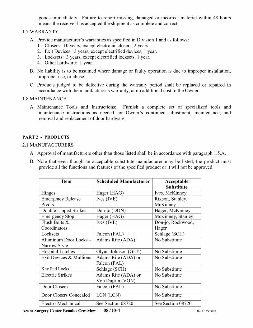
Azura Surgery Center Renalus Crestview 08710-4 07/17 Version
goods immediately. Failure to report missing, damaged or incorrect material within 48 hours
means the receiver has accepted the shipment as complete and correct.
1.7 WARRANTY
A. Provide manufacturer’s warranties as specified in Division 1 and as follows:
1. Closers: 10 years, except electronic closers, 2 years.
2. Exit Devices: 3 years, except electrified devices, 1 year.
3. Locksets: 3 years, except electrified locksets, 1 year.
4. Other hardware: 1 year.
B. No liability is to be assumed where damage or faulty operation is due to improper installation,
improper use, or abuse.
C. Products judged to be defective during the warranty period shall be replaced or repaired in
accordance with the manufacturer’s warranty, at no additional cost to the Owner.
1.8 MAINTENANCE
A. Maintenance Tools and Instructions: Furnish a complete set of specialized tools and
maintenance instructions as needed for Owner’s continued adjustment, maintenance, and
removal and replacement of door hardware.
PART 2 - PRODUCTS
2.1 MANUFACTURERS
A. Approval of manufacturers other than those listed shall be in accordance with paragraph 1.5.A.
B. Note that even though an acceptable substitute manufacturer may be listed, the product must
provide all the functions and features of the specified product or it will not be approved.
Item Scheduled Manufacturer Acceptable
Substitute
Hinges Hager (HAG) Ives, McKinney
Emergency Release
Pivots
Ives (IVE) Rixson, Stanley,
McKinney
Double Lipped Strikes Don-jo (DON) Hager, McKinney
Emergency Stop Hager (HAG) McKinney, Stanley
Flush Bolts &
Coordinators
Ives (IVE) Don-jo, Rockwood,
Hager
Locksets Falcon (FAL) Schlage (SCH)
Aluminum Door Locks –
Narrow Style
Adams Rite (ADA) No Substitute
Hospital Latches Glynn-Johnson (GLY) No Substitute
Exit Devices & Mullions Adams Rite (ADA) or
Falcon (FAL)
No Substitute
Key Pad Locks Schlage (SCH) No Substitute
Electric Strikes Adams Rite (ADA) or
Von Duprin (VON)
No Substitute
Door Closers Falcon (FAL) No Substitute
Door Closers Concealed LCN (LCN) No Substitute
Electro-Mechanical See Section 08720 See Section 08720
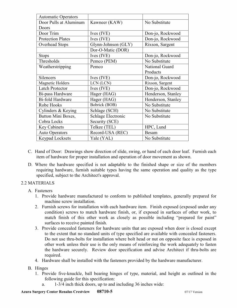
Azura Surgery Center Renalus Crestview 08710-5 07/17 Version
Automatic Operators
Door Pulls at Aluminum
Doors
Kawneer (KAW) No Substitute
Door Trim Ives (IVE) Don-jo, Rockwood
Protection Plates Ives (IVE) Don-jo, Rockwood
Overhead Stops Glynn-Johnson (GLY) Rixson, Sargent
Dor-O-Matic (DOR)
Stops Ives (IVE) Don-jo, Rockwood
Thresholds Pemco (PEM) No Substitute
Weatherstripping Pemco National Guard
Products
Silencers Ives (IVE) Don-jo, Rockwood Magnetic Holders LCN (LCN) Rixson, Sargent
Latch Protector Ives (IVE) Don-jo, Rockwood
Bi-pass Hardware Hager (HAG) Henderson, Stanley
Bi-fold Hardware Hager (HAG) Henderson, Stanley
Robe Hooks Bobrick (BOB) No Substitute
Cylinders & Keying Schlage (SCH) No Substitute
Button Mini Boxes,
Cobra Locks
Schlage Electronic
Security (SCE)
No Substitute
Key Cabinets Telkee (TEL) HPC, Lund
Auto Operators Record-USA (REC) Besam
Keypad Locksets Yale (YAL) No Substitute
C. Hand of Door: Drawings show direction of slide, swing, or hand of each door leaf. Furnish each
item of hardware for proper installation and operation of door movement as shown.
D. Where the hardware specified is not adaptable to the finished shape or size of the members
requiring hardware, furnish suitable types having the same operation and quality as the type
specified, subject to the Architect's approval.
2.2 MATERIALS
A. Fasteners
1. Provide hardware manufactured to conform to published templates, generally prepared for
machine screw installation.
2. Furnish screws for installation with each hardware item. Finish exposed (exposed under any
condition) screws to match hardware finish, or, if exposed in surfaces of other work, to
match finish of this other work as closely as possible including “prepared for paint”
surfaces to receive painted finish.
3. Provide concealed fasteners for hardware units that are exposed when door is closed except
to the extent that no standard units of type specified are available with concealed fasteners.
Do not use thru-bolts for installation where bolt head or nut on opposite face is exposed in
other work unless their use is the only means of reinforcing the work adequately to fasten
the hardware securely. Review door specification and advise Architect if thru-bolts are
required.
4. Hardware shall be installed with the fasteners provided by the hardware manufacturer.
B. Hinges
1. Provide five-knuckle, ball bearing hinges of type, material, and height as outlined in the
following guide for this specification:
a. 1-3/4 inch thick doors, up to and including 36 inches wide:
Azura Surgery Center Renalus Crestview 08710-6 07/17 Version
Exterior: standard weight, BB1191 stainless steel, 4-1/2 inches high
Interior: standard weight, BB1279 steel, 4-1/2 inches high
b. 1-3/4 inch thick doors over 36 inches wide:
Exterior: heavy weight, BB1199 stainless steel, 4-1/2 inches high
Interior: heavy weight, BB1168 steel, 4-1/2 inches high
2. Provide three hinges per door leaf for doors 90 inches or less in height, and one additional
hinge for each 30 inches of additional door height.
3. Provide continuous hinges on doors with lead lining and as scheduled.
a. Continuous Hinge: 790-905, stainless steel, machine screw with adjustment studs.
Hagar.
4. Hinge Pins: Except as otherwise indicated, provide hinge pins as follows:
a. Steel Hinges: Steel pins
b. Non-Ferrous Hinges: Stainless steel pins
c. Out-Swinging Exterior Doors: Non-removable pins
d. Out-Swinging Interior Lockable Doors: Non-removable pins
e. Interior Non-lockable Doors: Non-rising pins
5. Adjust hinge width as required for door, frame, and/or wall conditions to allow proper degree
of opening.
6. Provide hinges with electrified option where specified. Provide with sufficient number and
gage of concealed wires to accommodate electric function of specified hardware. Locate
electric hinge nearest to the electrified locking component.
7. Provide mortar guard for each electrified hinge specified, unless specified in hollow metal
frame specification.
C. Emergency Release Pivots
1. Provide emergency release pivot sets, where specified, offset-hung to allow door to swing
open in opposite direction unless detailed otherwise.
D. Double Lipped Strike
1. Provide double lip strike, where specified, offset-hung to allow door to swing open in
opposite direction unless detailed otherwise. Size for specific frame depth. Coordinate
special latchbolt-hole location and/or special template, as required, to operate with the
mortise lock being used as specified.
2. Provide a compatible emergency stop/release as recommended by the manufacturer of the
double lip strike or engineered to operate with the double lip strike.
E. Emergency Stop/Release
1. Provide emergency stop/release, where specified, for doors with double lip strikes offset-
hung to allow door to swing open in opposite direction unless detailed otherwise.
F. Flush Bolts
1. Provide automatic and manual flush bolts with stainless steel face plates, levers, and guides
and strikes. Provide 12 inch steel rods at doors up to 90 inches in height. Top rods at
manual flush bolts for doors over 90 inches in height shall be increased by 6 inches for each
additional 6 inches of door height. Provide dust-proof strikes at each bottom flush bolt.
G. Coordinators
1. Provide a bar-type coordinating device, surface applied to the underside of the stop at the
frame head where pairs of doors are equipped with automatic flush bolts, an astragal, or
other hardware that requires synchronized closing of the doors.
2. Provide a filler bar of the correct length for the unit to span the entire width of the opening,
and appropriate brackets for parallel arm door closers and surface vertical rod exit device
strikes. Factory-prep coordinators for vertical rod devices if required.
Azura Surgery Center Renalus Crestview 08710-7 07/17 Version
H. Aluminum Door Locks - Narrow Style
1. Provide narrow style aluminum door locks as specified. Cylinders: Refer to 2.4 KEYING.
2. Provide locks with a 1-1/8 inches, or 1-1/2 inches backset as required for door detail with a
full 5/8" throw latchbolt.
3. Provide manufacturers’ standard strikes unless extended lip strikes are necessary to protect
trim.
I. Cylindrical Locks - Grade 1
1. Provide Grade 1 cylindrical locks, where specified, conforming to ANSI A156.2 Series 4000,
Grade 1. Cylinders: Refer to 2.4 KEYING.
2. Provide locksets able to withstand 1500 inch pounds of torque applied to the locked outside
lever without gaining access per ANSI A156.2 Abusive Locked Lever Torque Test and
cycle tested to 3 million cycles per ANSI A156.2 Cycle Test.
3. Provide locks with a standard 2-3/4 inches backset, unless noted otherwise, with a 1/2 inch
latch throw. Provide proper latch throw for UL listing at pairs.
4. Provide locksets with separate anti-rotation through-bolts, and shall have no exposed screws.
Levers shall operate independently, and shall have two external return spring cassettes
mounted under roses to prevent lever sag.
5. Provide standard ASA strikes unless extended lip strikes are necessary to protect trim.
6. Provide electrical options as scheduled. Provide power supplies, recommended and approved
by the manufacturer of the electrified lock and other components requiring a power supply.
7. Lever trim shall be solid cast levers without plastic inserts, and wrought roses on both sides.
Locksets shall be through-bolted to assure proper alignment.
a. Lever design shall be Falcon Dane.
b. Lever trim on the secure side of doors serving rooms considered by the authority
having jurisdiction to be hazardous shall have a tactile warning.
J. Mortise Locks - Push/Pull Trim
1. Provide mortise locks with push/pull trim, where specified, certified as ANSI A156.13,
Grade 1 Operational, Grade 1 Security, and manufactured from heavy gauge steel,
containing components of steel with a zinc dichromate plating for corrosion resistance.
Lock case shall be multi-function and field reversible for handing without opening the case.
Cylinders: Refer to 2.4 KEYING.
2. Provide locks with a standard 2-3/4 inches backset with a full 3/4 inch throw stainless steel
mechanical anti-friction latchbolt. Deadbolt shall be a full 1 inch throw, constructed of
stainless steel.
3. Provide standard ASA strikes unless extended lip strikes are necessary to protect trim.
4. Trim shall be push paddle mounted up and pull paddle mounted down except at psychiatric
or security areas provide both paddles mounted down for safety, unless noted otherwise.
a. Trim on the secure side of doors serving rooms considered by the authority having
jurisdiction to be hazardous shall have a tactile warning.
K. Exit Devices – Heavy Duty
1. Exit devices shall be tested to ANSI/BHMA A156.3 Grade 1, and UL listed for Panic Exit
and/or Fire Exit Hardware. Cylinders: Refer to 2.4 KEYING.
2. Provide touchpad type exit devices, fabricated of stainless steel, or aluminum, plated to the
standard architectural finishes to match the balance of the door hardware.
3. Exit devices shall incorporate a fluid damper or other device that eliminates noise associated
with exit device operation. Touchpad shall extend a minimum of one half of the door
width, but not the full length of the exit device rail. End-cap will have two-point
attachment to door. For all other finishes, the touch-pad finish shall be of compatible finish
Azura Surgery Center Renalus Crestview 08710-8 07/17 Version
to exit device. Only compression springs will be used in devices, latches, and outside trims
or controls.
4. Devices to incorporate a dead-latching feature for security and/or for future addition of alarm
kits and/or other electrical requirements.
5. Vertical rod devices shall be capable of being field modified to less bottom rod devices by
removal of bottom rod and adding firing pin(s), if required at fire rated openings.
6. Provide manufacturer’s standard strikes.
7. Provide exit devices cut to door width and height. Locate exit devices at a height
recommended by the exit device manufacturer, allowable by governing building codes, and
approved by the Architect.
8. Mechanism case shall sit flush on the face of all flush doors, or spacers shall be furnished to
fill gaps behind devices. Where glass trims or molding projects off the face of the door,
provide glass bead kits.
9. Non-fire-rated exit devices shall have hex key dogging.
10. Where lever handles are specified as outside trim for exit devices, provide heavy-duty lever
trims with forged or cast escutcheon plates. Provide vandal-resistant levers that will travel
to a 90-degree down position when more than 35 pounds of torque are applied, and which
can easily be reset.
a. Lever style will match the lever style of the locksets.
11. Exit devices for fire rated openings shall be UL labeled fire exit hardware.
12. Provide electrical options as scheduled.
13. Provide power transfer sufficient for number and gage of wires to accommodate electric
function of specified hardware. Electric power transfer is to be located per manufacturer’s
template and UL requirements, unless interference with operation of door or other hardware
items.
14. Provide power supplies, recommended and approved by the manufacturer of the electrified
exit device and other components requiring a power supply.
L. Key Pad Locks
1. Provide manually programmable locks conforming to ANSI A156 standards. Cylinders:
Refer to 2.4 KEYING.
2. Provide manufacturer’s standard strikes.
3. Provide keypad product with a minimum of 100 users.
M. Electric Strikes
1. Provide electric strikes, as specified, designed for use with the type locks shown at each
opening.
2. Provide electric strikes UL Listed as burglary-resistant electric door strikes and, where
required, shall be UL Listed as electric strikes for fire doors and frames. Provide fail-secure
type electric strikes unless specified otherwise.
3. Provide transformers and rectifiers for each strike as required. Verify voltage with electrical
contractor.
N. Door Closers – Heavy Duty
1. Provide heavy-duty door closers at exterior doors where specified, certified to ANSI/BHMA
A156.4 Grade 1 requirements by a BHMA certified independent testing laboratory. Surface
mounted mechanical closers shall be certified to exceed ten million (10,000,000) full load
cycles by a recognized independent testing laboratory. Closers shall be ISO 9000 certified.
Units shall be stamped with date of manufacture code.
2. Door closers shall have fully hydraulic, full rack and pinion action with a high strength cast
iron cylinder and shall utilize full complement bearings at shaft. Cylinder body shall be 1-
1/2 inch diameter, and double heat-treated pinion shall be 11/16 inch diameter.
Azura Surgery Center Renalus Crestview 08710-9 07/17 Version
3. Provide hydraulic fluid requiring no seasonal closer adjustment for temperatures ranging
from 120 degrees F to -30 degrees F. Fluid shall be fireproof and shall pass the
requirements of the UL10C “positive pressure” fire test.
4. Spring power shall be continuously adjustable over the full range of closer sizes, and allow
for reduced opening force as required by accessibility codes and standards. Hydraulic
regulation shall be by tamper-proof, non-critical valves. Closers shall have separate
adjustment for latch speed, general speed, and back check.
5. Provide closers with a solid forged steel main arms and factory assembled heavy-duty forged
forearms for parallel arm closers. When closers are parallel arm mounted, provide closers
which mount within a 6 inch top rail without the use of a mounting plate so that closer shall
not be visible through vision panel from pull side.
6. Provide special templates, drop plates, mounting brackets, or adapters for arms as required
for details, overhead stops, and other finish hardware items interfering with closer
mounting.
7. Mount closers inside of exterior and vestibule doors.
8. Door closers meeting this specification: As scheduled.
O. Electro-Mechanical Automatic Operators
1. Specified in Section 08720.
P. Door Trim
1. Provide flush pulls as specified. Where required, provide back-to-back mounted model.
2. Provide wire pulls of solid bar stock, diameter and length as scheduled.
Q. Protection Plates
1. Provide kick plates and armor plates minimum of 0.050 inch thick and beveled 4 edges as
scheduled. Furnish with machine or wood screws, finished to match plates. Sizes of plates
shall be as follows:
a. Kick Plates – 10 inches high x 2 inches less width of door on single doors, 1 inch less
width of door on pairs
b. Armor Plates – 30 inches high x 2 inches less width of door on single doors, 1 inch
less width of door on pairs. If labeled door doesn’t allow 30 inch high armor plate,
provide 16 inch high kick plate.
c. Standard finish – stainless steel.
2. Acceptable manufacturers and/or products: Ives, Don-Jo, Rockwood.
R. Overhead Stops and Overhead Stop/Holders
1. Provide heavy duty concealed, mounted overhead stop or overhead stop/holder as specified
for exterior and interior vestibule single acting doors.
2. Provide medium duty, concealed mounted overhead stop as specified for double acting doors
with emergency release hardware.
3. Provide heavy- or medium duty and concealed or surface mounted overhead stop, or
overhead stop/holder for interior doors as specified. Provide medium duty, surface mounted
overhead stop for interior doors and at any door that swings more than 140 degrees before
striking a wall; opens against equipment, casework, sidelights, and/or where conditions do
not allow a wall stop; or a floor stop presents a tripping hazard.
4. Where overhead holders are specified, provide friction type at doors without a closer and
positive type at doors with a closer.
2.3 FINISHES
A. Finish of all hardware shall be satin chrome plated US26D (BHMA 626) with the exceptions as
follows:
1. Door Closers: Metallic Powder Coat to Match.
Azura Surgery Center Renalus Crestview 08710-10 07/17 Version
2. Latch Protectors: To match.
3. Weather-stripping: Clear Anodized Aluminum.
4. Thresholds: Mill Finish Aluminum.
2.4 KEYING
A. Provide cores for the Owner’s Existing Schlage key system conforming to the following
requirements:
1. Provide removable core cylinders at all keyed devices. Provide construction cores with
construction master keying for use during construction. The temporary construction cores
are to be returned to the hardware supplier.
2. Provide permanent cores keyed by the manufacturer or authorized distributor into the
existing key system as directed by the Owner. Provide owner with a copy of the bitting list,
return receipt requested.
3. Provide keys as follows:
a. GM - Grand Master opens all doors (Provide 2 non-duplicating keys).
b. M - Interior Master opens all doors (Provide 2 non-duplicating keys)
c. K1 - Keyed alike, exterior doors only (Provide 6 non-duplicating keys).
d. K - Keyed differently, opens assigned office (Provide 2 keys for each office).
e. K2 - Keyed different, exterior door with interchangeable core- Vacuum Room
4. Visual key control:
a. Keys shall be stamped with their respective key set number and stamped “DO NOT
DUPLICATE”.
b. All keys shall be stamped with their respective key set letters.
c. Do not stamp any keys with the factory key change number.
d. Do not stamp any cores with key set on face (front) of Core. Stamp on back or side of
cores so not to be visible when core is in cylinder.
5. Deliver all keys and/or key blanks from the factory or authorized distributor directly to the
Owner in sealed containers, return receipt requested. Failure to comply with these
requirements may be cause to require replacement of all or any part of the keying system
that was compromised at no additional cost to the Owner.
6. Approved products: Schlage Everest B, No Substitute. Restricted keyway authorization
letter included in this master specification.
2.5 KEY CONTROL SYSTEM
A. Provide a key control system, including envelopes, labels, tags with self-locking key clips,
receipt forms, 3-way visible card index, temporary markers, permanent markers, and standard
metal cabinet; all as recommended by system manufacturer, with capacity for 150% of the
number of locks required for the Project.
1. Provide complete cross index system set up by the hardware supplier, and place keys on
markers and hooks in the cabinet as determined by the final key schedule.
2. Provide hinged-panel type cabinet for wall mounting.
PART 3 - EXECUTION
3.1 EXAMINATION
A. Prior to installation of any hardware, examine all doors, frames, walls and related items for
conditions that would prevent proper installation of finish hardware. Correct all defects prior to
proceeding with installation.
3.2 INSTALLATION
A. Coordination:
Azura Surgery Center Renalus Crestview 08710-11 07/17 Version
1. Prior to installation of hardware, General Contractor will schedule and hold a meeting with
the installer for the purpose of instructing installers on proper installation and adjustment of
finish hardware.
2. Prior to ordering electrified hardware, General Contractor will schedule and hold a meeting
with the installer for the purpose of coordinating finish hardware with security, electrical,
doors and frames, and other related suppliers.
B. Hardware will be installed by qualified tradesmen, skilled in the application of commercial grade
hardware.
C. Mount hardware units at heights indicated in “Recommended Locations for Builders Hardware
for Standard Steel Doors and Frames” by the Door and Hardware Institute.
D. Install each hardware item in compliance with the manufacturer’s instructions and
recommendations, using only the fasteners provided by the manufacturer.
E. Do not install surface mounted items until finishes have been completed on the substrate. Protect
all installed hardware during painting.
F. Set units level, plumb and true to line and location. Adjust and reinforce the attachment
substrate as necessary for proper installation and operation.
G. Operating parts shall move freely and smoothly without binding, sticking, or excessive
clearance.
H. Existing Doors and/or Frames: Remove existing hardware being replaced, tag, and store
according to contract documents. Field modifies and prepares existing door and/or frame for
new hardware being installed. Provide necessary fillers, Dutchmen, reinforcements, and
fasteners for mounting new hardware and to cover existing door/frame preps.
I. Wire (including low voltage), conduit, junction boxes, and pulling of wire are by Division 16,
Electrical. Electrical Contractor shall connect wire to door position switches and run wire to
central room or area as directed by the Architect. Wires shall be tested and labeled with the
Architect’s opening number. Connections to/from power supplies to electrified hardware and
any connection to fire/smoke alarm system, and/or smoke evacuation system where specified is
by Division 16 Electrical.
3.3 ADJUSTING, CLEANING, AND DEMONSTRATING
A. Adjust and check each operating item of hardware and each door, to ensure proper operation or
function of every unit. Replace units which cannot be adjusted to operate freely and smoothly.
B. Where door hardware is installed more than one month prior to acceptance or occupancy of a
space or area, return to the installation during the week prior to acceptance or occupancy and
make a final check and adjustment of all hardware items in such space or area. Clean operating
items as necessary to restore proper function and finish of hardware and doors. Adjust door
control devices to compensate for final operation of heating and ventilating equipment.
C. Clean adjacent surfaces soiled by hardware installation.
D. Instruct Owner’s personnel in the proper adjustment, lubrication, and maintenance of door
hardware and hardware finishes.
3.4 PROTECTION
A. Provide for the proper protection of complete items of hardware until the Owner accepts the
project as complete. Damaged or disfigured hardware shall be replaced or repaired by the
responsible party.
3.5 HARDWARE SCHEDULE
Azura Surgery Center Renalus Crestview 08710-12 07/17 Version
A. Provide hardware for each door to comply with requirements of Section “Finish Hardware,”
hardware set numbers indicated in door schedule, and in the following schedule of hardware
sets.
B. It is intended that the following schedule includes complete items of finish hardware necessary to
complete the work. If a discrepancy is found in the schedule such as a missing item, improper
hardware for a frame, door or fire codes, the preamble will be the deciding document.
C. Locksets, exit devices, and other hardware items are referenced in the Hardware Sets for series,
type, and function. Refer to the preamble for special features, options, cylinders/keying, and
other requirements.
D. Hardware Sets
HW SETS 01-05 NOT USED
HW SET: 06 NON-SECURE ENTRANCE - ALUM STOREFRONT OR EXISTING- SGLE WITH PANIC DEVICE
– EMERGENCY EGRESS FROM PRE/POST OP
3 EA HINGES AS SPECIFIED HAG
1 EA ALUMINUM DOOR PANIC
DEVICE
8400 SERIES `ADA
1 EA CYLINDER 80-103 X 626 SCH
1 EA LOCK GUARD LG11 IVE
1 EA OFFSET DOOR PULL CO-9 BY ALUMINUM DOOR SUPPLIER AW
1 EA SURFACE CLOSER SC81 HD X 689 FAL
1 EA OVERHEAD STOP CONCEALED HEAVY DUTY 100S SERIES GLY
1 SET SEALS BY ALUMINUM DOOR SUPPLIER
1 EA DOOR SWEEP 368DN BY ALUMINUM DOOR SUPPLIER PEM
1 EA THRESHOLD 273 X 3DFG BY ALUMINUM DOOR SUPPLIER PEM
HW SET: 07 SECURE ENTRANCE - ALUM SGLE WITH ACCESS CONTROL PANIC DEVICE – STAFF
ENTRANCE
3 EA HINGES AS SPECIFIED HAG
1 EA ELECTRONIC TRIM CO-100-993R-70-KP RHO 4B BD SCE
1 EA PERMANENT CORE 80-036 B123 KEYWAY SCH
1 EA CONSTRUCTION CORE 80-035 SCH
1 EA PANIC DEVICE 24-R-EO FAL
1 EA SURFACE CLOSER SC81 RW/PA X 689 FAL
1 EA CLOSER MOUNTING PLATE SC80 18-PA FAL
1 EA OVERHEAD STOP CONCEALED HEAVY DUTY 100S SERIES GLY
1 SET SEALS BY ALUMINUM DOOR SUPPLIER.
1 EA DOOR SWEEP BY ALUMINUM DOOR SUPPLIER PEM
1 EA THRESHOLD BY ALUMINUM DOOR SUPPLIER PEM
HW SET: 07A SECURE ENTRANCE - ALUM SGLE WITH ACCESS CONTROL– MECH ROOM
3 EA HINGES AS SPECIFIED HAG
1 EA ELECTRONIC TRIM CO-100-993R-70-KP RHO 4B BD SCE
1 EA PERMANENT CORE 80-036 B123 KEYWAY SCH
1 EA CONSTRUCTION CORE 80-035 SCH
1 EA SURFACE CLOSER SC81 RW/PA X 689 FAL
1 EA CLOSER MOUNTING PLATE SC80 18-PA FAL
1 EA OVERHEAD STOP CONCEALED HEAVY DUTY 100S SERIES GLY
1 SET SEALS BY ALUMINUM DOOR SUPPLIER.
1 EA DOOR SWEEP BY ALUMINUM DOOR SUPPLIER PEM
Azura Surgery Center Renalus Crestview 08710-13 07/17 Version
1 EA THRESHOLD BY ALUMINUM DOOR SUPPLIER PEM
HW SET: 08 SECURE MAIN ENTRANCE - ALUM SGLE WITH PANIC DEVICE, ELEC STRIKE, AND AUTO
OPERATOR- PATIENT ENTRANCE
3 EA HINGES AS SPECIFIED HAG
1 EA ALUMINUM DOOR PANIC
DEVICE
8400 SERIES ADA
1 EA CYLINDER HOUSING 80-103 X 626 SSCH
1 EA PERMANENT CORE 80-036 B123 KEYWAY SCH
1 EA CONSTRUCTION CORE 80-035 SCH
1 EA ELECTRIC STRIKE 7100 FAIL SECURE ADA
1 EA LOCK GUARD LG11 IVE
1 EA OFFSET DOOR PULL CO-9 KAW
1 EA AUTO. OPERATOR 8100 SERIES (AS SPECIFIED IN 08720) REC
1 EA OVERHEAD STOP CONCEALED HEAVY DUTY 100S SERIES GLY
1 SET SEALS BY ALUMINUM DOOR SUPPLIER.
1 EA DOOR SWEEP BY ALUMINUM DOOR SUPPLIER PEM
1 EA THRESHOLD BY ALUMINUM DOOR SUPPLIER PEM
2 EA WALL PLATE SWITCH AS SPECIFIED IN 08720 REC
2 EA BUTTON MINI BOX 660-PB REC
ALL WIRING AND CONNECTIONS BY DIVISION 16.
OPERATIONAL DESCRIPTION:
FOR CONTROLLED ENTRY (TOGGLE IN SECURE POSITION) -
IMMEDIATE EGRESS ALWAYS ALLOWED. MANUAL ACCESS BY KEY. AUTOMATIC OPERATION FOR
ACCESS BY REMOTE RELEASE AT RECEPTIONIST AND NURSE STATION, OR AUTOMATIC
OPERATION FOR EGRESS BY ACTUATOR IN WAITING AREA WHICH SIGNALS AUTOMATIC
OPERATOR TO RELEASE ELECTRIC STRIKE AND OPEN DOOR. LOCATE REMOTE RELEASE AND
ACTUATORS AS DIRECTED BY ARCHITECT.
FOR NON-CONTROLLED ENTRY (TOGGLE IN NON-SECURE POSITION) -
IMMEDIATE EGRESS ALWAYS ALLOWED. TOGGLE (BY OTHERS) IN AUTOMATIC OPERATOR HEAD
TO RELEASE AND HOLD ELECTRIC STRIKE AND ENABLE OUTSIDE AUTOMATIC OPERATOR
ACTUATOR. MANUAL OPERATION BY PUSH N’ GO FEATURE OR AUTOMATIC OPERATION BY
PUSHING EITHER ACTUATOR WHICH WILL SIGNAL AUTOMATIC OPERATOR TO OPEN DOOR.
LOCATE ACTUATORS AS DIRECTED BY ARCHITECT.
A. POWER ON, FIRE ALARM QUIET:
- DOOR OPERATOR IS SECURE/UNSECURED VIA ROCKER SWITCH LOCATED IN DOOR
OPERATOR.
B. POWER OUT, FIRE ALARM QUIET:
- DOOR OPERATOR IS INOPERABLE DUE TO LOSS OF POWER. ELECTRIC STRIKE “FAIL
SECURE”. HARDWARE WILL ALLOW EGRESS FROM WAITING ROOM BUT NOT GAIN ENTRY
FROM OUTSIDE WITHOUT KEY.
C. POWER ON, FIRE ALARM ACTIVE:
- FIRE ALARM DE-ENERGIZES ELECTRIC STRIKE AND DOOR OPERATOR. DOOR OPERATOR IS
INOPERABLE DUE TO LOSS OF POWER. ELECTRIC STRIKE “FAIL SECURE”. HARDWARE WILL
ALLOW EGRESS FROM WAITING ROOM BUT NOT GAIN ENTRY FROM OUTSIDE WITHOUT KEY.
HW SETS: 9-17 – NOT USED
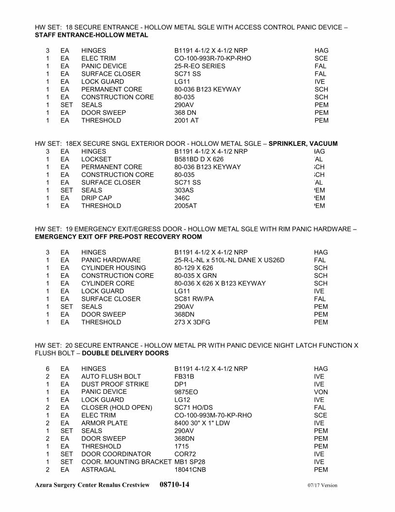
Azura Surgery Center Renalus Crestview 08710-14 07/17 Version
HW SET: 18 SECURE ENTRANCE - HOLLOW METAL SGLE WITH ACCESS CONTROL PANIC DEVICE –
STAFF ENTRANCE-HOLLOW METAL
3 EA HINGES B1191 4-1/2 X 4-1/2 NRP HAG
1 EA ELEC TRIM CO-100-993R-70-KP-RHO SCE
1 EA PANIC DEVICE 25-R-EO SERIES FAL
1 EA SURFACE CLOSER SC71 SS FAL
1 EA LOCK GUARD LG11 IVE
1 EA PERMANENT CORE 80-036 B123 KEYWAY SCH
1 EA CONSTRUCTION CORE 80-035 SCH
1 SET SEALS 290AV PEM
1 EA DOOR SWEEP 368 DN PEM
1 EA THRESHOLD 2001 AT PEM
HW SET: 18EX SECURE SNGL EXTERIOR DOOR - HOLLOW METAL SGLE – SPRINKLER, VACUUM
3 EA HINGES B1191 4-1/2 X 4-1/2 NRP HAG
1 EA LOCKSET B581BD D X 626 FAL
1 EA PERMANENT CORE 80-036 B123 KEYWAY SCH
1 EA CONSTRUCTION CORE 80-035 SCH
1 EA SURFACE CLOSER SC71 SS FAL
1 SET SEALS 303AS PEM
1 EA DRIP CAP 346C PEM
1 EA THRESHOLD 2005AT PEM
HW SET: 19 EMERGENCY EXIT/EGRESS DOOR - HOLLOW METAL SGLE WITH RIM PANIC HARDWARE –
EMERGENCY EXIT OFF PRE-POST RECOVERY ROOM
3 EA HINGES B1191 4-1/2 X 4-1/2 NRP HAG
1 EA PANIC HARDWARE 25-R-L-NL x 510L-NL DANE X US26D FAL
1 EA CYLINDER HOUSING 80-129 X 626 SCH
1 EA CONSTRUCTION CORE 80-035 X GRN SCH
1 EA CYLINDER CORE 80-036 X 626 X B123 KEYWAY SCH
1 EA LOCK GUARD LG11 IVE
1 EA SURFACE CLOSER SC81 RW/PA FAL
1 SET SEALS 290AV PEM
1 EA DOOR SWEEP 368DN PEM
1 EA THRESHOLD 273 X 3DFG PEM
HW SET: 20 SECURE ENTRANCE - HOLLOW METAL PR WITH PANIC DEVICE NIGHT LATCH FUNCTION X
FLUSH BOLT – DOUBLE DELIVERY DOORS
6 EA HINGES B1191 4-1/2 X 4-1/2 NRP HAG
2 EA AUTO FLUSH BOLT FB31B IVE
1 EA DUST PROOF STRIKE DP1 IVE
1 EA PANIC DEVICE 9875EO VON
1 EA LOCK GUARD LG12 IVE
2 EA CLOSER (HOLD OPEN) SC71 HO/DS FAL
1 EA ELEC TRIM CO-100-993M-70-KP-RHO SCE
2 EA ARMOR PLATE 8400 30" X 1" LDW IVE
1 SET SEALS 290AV PEM
2 EA DOOR SWEEP 368DN PEM
1 EA THRESHOLD 1715 PEM
1 SET DOOR COORDINATOR COR72 IVE
1 SET COOR. MOUNTING BRACKET MB1 SP28 IVE
2 EA ASTRAGAL 18041CNB PEM
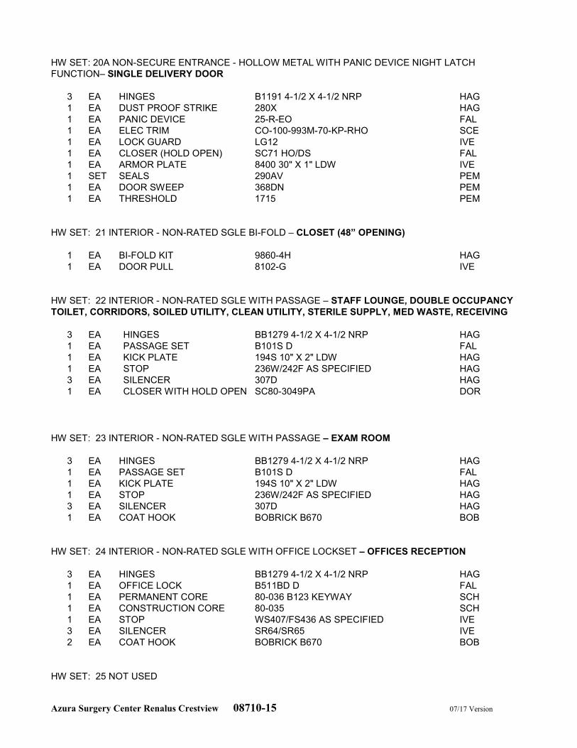
Azura Surgery Center Renalus Crestview 08710-15 07/17 Version
HW SET: 20A NON-SECURE ENTRANCE - HOLLOW METAL WITH PANIC DEVICE NIGHT LATCH
FUNCTION– SINGLE DELIVERY DOOR
3 EA HINGES B1191 4-1/2 X 4-1/2 NRP HAG
1 EA DUST PROOF STRIKE 280X HAG
1 EA PANIC DEVICE 25-R-EO FAL
1 EA ELEC TRIM CO-100-993M-70-KP-RHO SCE
1 EA LOCK GUARD LG12 IVE
1 EA CLOSER (HOLD OPEN) SC71 HO/DS FAL
1 EA ARMOR PLATE 8400 30" X 1" LDW IVE
1 SET SEALS 290AV PEM
1 EA DOOR SWEEP 368DN PEM
1 EA THRESHOLD 1715 PEM
HW SET: 21 INTERIOR - NON-RATED SGLE BI-FOLD – CLOSET (48” OPENING)
1 EA BI-FOLD KIT 9860-4H HAG
1 EA DOOR PULL 8102-G IVE
HW SET: 22 INTERIOR - NON-RATED SGLE WITH PASSAGE – STAFF LOUNGE, DOUBLE OCCUPANCY
TOILET, CORRIDORS, SOILED UTILITY, CLEAN UTILITY, STERILE SUPPLY, MED WASTE, RECEIVING
3 EA HINGES BB1279 4-1/2 X 4-1/2 NRP HAG
1 EA PASSAGE SET B101S D FAL
1 EA KICK PLATE 194S 10" X 2" LDW HAG
1 EA STOP 236W/242F AS SPECIFIED HAG
3 EA SILENCER 307D HAG
1 EA CLOSER WITH HOLD OPEN SC80-3049PA DOR
HW SET: 23 INTERIOR - NON-RATED SGLE WITH PASSAGE – EXAM ROOM
3 EA HINGES BB1279 4-1/2 X 4-1/2 NRP HAG
1 EA PASSAGE SET B101S D FAL
1 EA KICK PLATE 194S 10" X 2" LDW HAG
1 EA STOP 236W/242F AS SPECIFIED HAG
3 EA SILENCER 307D HAG
1 EA COAT HOOK BOBRICK B670 BOB
HW SET: 24 INTERIOR - NON-RATED SGLE WITH OFFICE LOCKSET – OFFICES RECEPTION
3 EA HINGES BB1279 4-1/2 X 4-1/2 NRP HAG
1 EA OFFICE LOCK B511BD D FAL
1 EA PERMANENT CORE 80-036 B123 KEYWAY SCH
1 EA CONSTRUCTION CORE 80-035 SCH
1 EA STOP WS407/FS436 AS SPECIFIED IVE
3 EA SILENCER SR64/SR65 IVE
2 EA COAT HOOK BOBRICK B670 BOB
HW SET: 25 NOT USED
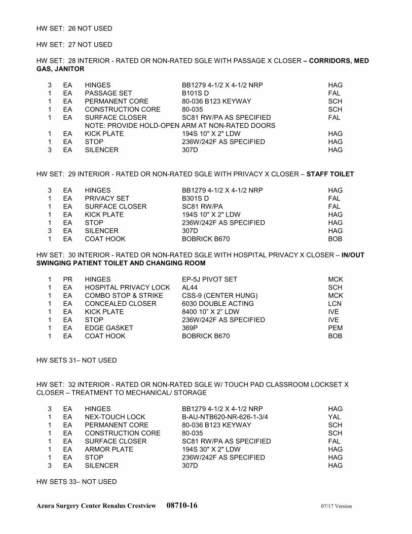
Azura Surgery Center Renalus Crestview 08710-16 07/17 Version
HW SET: 26 NOT USED
HW SET: 27 NOT USED
HW SET: 28 INTERIOR - RATED OR NON-RATED SGLE WITH PASSAGE X CLOSER – CORRIDORS, MED
GAS, JANITOR
3 EA HINGES BB1279 4-1/2 X 4-1/2 NRP HAG
1 EA PASSAGE SET B101S D FAL
1 EA PERMANENT CORE 80-036 B123 KEYWAY SCH
1 EA CONSTRUCTION CORE 80-035 SCH
1 EA SURFACE CLOSER SC81 RW/PA AS SPECIFIED FAL
NOTE: PROVIDE HOLD-OPEN ARM AT NON-RATED DOORS
1 EA KICK PLATE 194S 10" X 2" LDW HAG
1 EA STOP 236W/242F AS SPECIFIED HAG
3 EA SILENCER 307D HAG
HW SET: 29 INTERIOR - RATED OR NON-RATED SGLE WITH PRIVACY X CLOSER – STAFF TOILET
3 EA HINGES BB1279 4-1/2 X 4-1/2 NRP HAG
1 EA PRIVACY SET B301S D FAL
1 EA SURFACE CLOSER SC81 RW/PA FAL
1 EA KICK PLATE 194S 10" X 2" LDW HAG
1 EA STOP 236W/242F AS SPECIFIED HAG
3 EA SILENCER 307D HAG
1 EA COAT HOOK BOBRICK B670 BOB
HW SET: 30 INTERIOR - RATED OR NON-RATED SGLE WITH HOSPITAL PRIVACY X CLOSER – IN/OUT
SWINGING PATIENT TOILET AND CHANGING ROOM
1 PR HINGES EP-5J PIVOT SET MCK
1 EA HOSPITAL PRIVACY LOCK AL44 SCH
1 EA COMBO STOP & STRIKE CSS-9 (CENTER HUNG) MCK
1 EA CONCEALED CLOSER 6030 DOUBLE ACTING LCN
1 EA KICK PLATE 8400 10” X 2” LDW IVE
1 EA STOP 236W/242F AS SPECIFIED IVE
1 EA EDGE GASKET 369P PEM
1 EA COAT HOOK BOBRICK B670 BOB
HW SETS 31– NOT USED
HW SET: 32 INTERIOR - RATED OR NON-RATED SGLE W/ TOUCH PAD CLASSROOM LOCKSET X
CLOSER – TREATMENT TO MECHANICAL/ STORAGE
3 EA HINGES BB1279 4-1/2 X 4-1/2 NRP HAG
1 EA NEX-TOUCH LOCK B-AU-NTB620-NR-626-1-3/4 YAL
1 EA PERMANENT CORE 80-036 B123 KEYWAY SCH
1 EA CONSTRUCTION CORE 80-035 SCH
1 EA SURFACE CLOSER SC81 RW/PA AS SPECIFIED FAL
1 EA ARMOR PLATE 194S 30" X 2" LDW HAG
1 EA STOP 236W/242F AS SPECIFIED HAG
3 EA SILENCER 307D HAG
HW SETS 33– NOT USED
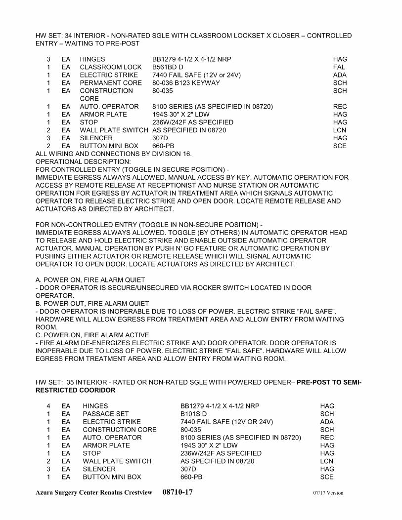
Azura Surgery Center Renalus Crestview 08710-17 07/17 Version
HW SET: 34 INTERIOR - NON-RATED SGLE WITH CLASSROOM LOCKSET X CLOSER – CONTROLLED
ENTRY – WAITING TO PRE-POST
3 EA HINGES BB1279 4-1/2 X 4-1/2 NRP HAG
1 EA CLASSROOM LOCK B561BD D FAL
1 EA ELECTRIC STRIKE 7440 FAIL SAFE (12V or 24V) ADA
1 EA PERMANENT CORE 80-036 B123 KEYWAY SCH
1 EA CONSTRUCTION
CORE
80-035 SCH
1 EA AUTO. OPERATOR 8100 SERIES (AS SPECIFIED IN 08720) REC
1 EA ARMOR PLATE 194S 30" X 2" LDW HAG
1 EA STOP 236W/242F AS SPECIFIED HAG
2 EA WALL PLATE SWITCH AS SPECIFIED IN 08720 LCN
3 EA SILENCER 307D HAG
2 EA BUTTON MINI BOX 660-PB SCE
ALL WIRING AND CONNECTIONS BY DIVISION 16.
OPERATIONAL DESCRIPTION:
FOR CONTROLLED ENTRY (TOGGLE IN SECURE POSITION) -
IMMEDIATE EGRESS ALWAYS ALLOWED. MANUAL ACCESS BY KEY. AUTOMATIC OPERATION FOR
ACCESS BY REMOTE RELEASE AT RECEPTIONIST AND NURSE STATION OR AUTOMATIC
OPERATION FOR EGRESS BY ACTUATOR IN TREATMENT AREA WHICH SIGNALS AUTOMATIC
OPERATOR TO RELEASE ELECTRIC STRIKE AND OPEN DOOR. LOCATE REMOTE RELEASE AND
ACTUATORS AS DIRECTED BY ARCHITECT.
FOR NON-CONTROLLED ENTRY (TOGGLE IN NON-SECURE POSITION) -
IMMEDIATE EGRESS ALWAYS ALLOWED. TOGGLE (BY OTHERS) IN AUTOMATIC OPERATOR HEAD
TO RELEASE AND HOLD ELECTRIC STRIKE AND ENABLE OUTSIDE AUTOMATIC OPERATOR
ACTUATOR. MANUAL OPERATION BY PUSH N' GO FEATURE OR AUTOMATIC OPERATION BY
PUSHING EITHER ACTUATOR OR REMOTE RELEASE WHICH WILL SIGNAL AUTOMATIC
OPERATOR TO OPEN DOOR. LOCATE ACTUATORS AS DIRECTED BY ARCHITECT.
A. POWER ON, FIRE ALARM QUIET
- DOOR OPERATOR IS SECURE/UNSECURED VIA ROCKER SWITCH LOCATED IN DOOR
OPERATOR.
B. POWER OUT, FIRE ALARM QUIET
- DOOR OPERATOR IS INOPERABLE DUE TO LOSS OF POWER. ELECTRIC STRIKE "FAIL SAFE".
HARDWARE WILL ALLOW EGRESS FROM TREATMENT AREA AND ALLOW ENTRY FROM WAITING
ROOM.
C. POWER ON, FIRE ALARM ACTIVE
- FIRE ALARM DE-ENERGIZES ELECTRIC STRIKE AND DOOR OPERATOR. DOOR OPERATOR IS
INOPERABLE DUE TO LOSS OF POWER. ELECTRIC STRIKE "FAIL SAFE". HARDWARE WILL ALLOW
EGRESS FROM TREATMENT AREA AND ALLOW ENTRY FROM WAITING ROOM.
HW SET: 35 INTERIOR - RATED OR NON-RATED SGLE WITH POWERED OPENER– PRE-POST TO SEMI-
RESTRICTED COORIDOR
4 EA HINGES BB1279 4-1/2 X 4-1/2 NRP HAG
1 EA PASSAGE SET B101S D SCH
1 EA ELECTRIC STRIKE 7440 FAIL SAFE (12V OR 24V) ADA
1 EA CONSTRUCTION CORE 80-035 SCH
1 EA AUTO. OPERATOR 8100 SERIES (AS SPECIFIED IN 08720) REC
1 EA ARMOR PLATE 194S 30" X 2" LDW HAG
1 EA STOP 236W/242F AS SPECIFIED HAG
2 EA WALL PLATE SWITCH AS SPECIFIED IN 08720 LCN
3 EA SILENCER 307D HAG
1 EA BUTTON MINI BOX 660-PB SCE
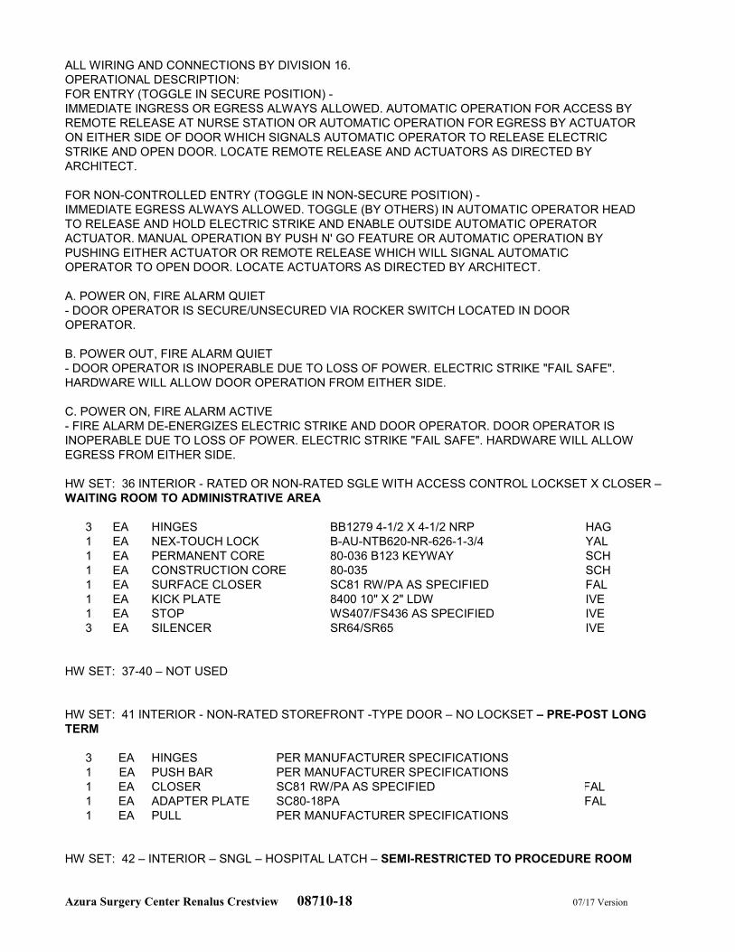
Azura Surgery Center Renalus Crestview 08710-18 07/17 Version
ALL WIRING AND CONNECTIONS BY DIVISION 16.
OPERATIONAL DESCRIPTION:
FOR ENTRY (TOGGLE IN SECURE POSITION) -
IMMEDIATE INGRESS OR EGRESS ALWAYS ALLOWED. AUTOMATIC OPERATION FOR ACCESS BY
REMOTE RELEASE AT NURSE STATION OR AUTOMATIC OPERATION FOR EGRESS BY ACTUATOR
ON EITHER SIDE OF DOOR WHICH SIGNALS AUTOMATIC OPERATOR TO RELEASE ELECTRIC
STRIKE AND OPEN DOOR. LOCATE REMOTE RELEASE AND ACTUATORS AS DIRECTED BY
ARCHITECT.
FOR NON-CONTROLLED ENTRY (TOGGLE IN NON-SECURE POSITION) -
IMMEDIATE EGRESS ALWAYS ALLOWED. TOGGLE (BY OTHERS) IN AUTOMATIC OPERATOR HEAD
TO RELEASE AND HOLD ELECTRIC STRIKE AND ENABLE OUTSIDE AUTOMATIC OPERATOR
ACTUATOR. MANUAL OPERATION BY PUSH N' GO FEATURE OR AUTOMATIC OPERATION BY
PUSHING EITHER ACTUATOR OR REMOTE RELEASE WHICH WILL SIGNAL AUTOMATIC
OPERATOR TO OPEN DOOR. LOCATE ACTUATORS AS DIRECTED BY ARCHITECT.
A. POWER ON, FIRE ALARM QUIET
- DOOR OPERATOR IS SECURE/UNSECURED VIA ROCKER SWITCH LOCATED IN DOOR
OPERATOR.
B. POWER OUT, FIRE ALARM QUIET
- DOOR OPERATOR IS INOPERABLE DUE TO LOSS OF POWER. ELECTRIC STRIKE "FAIL SAFE".
HARDWARE WILL ALLOW DOOR OPERATION FROM EITHER SIDE.
C. POWER ON, FIRE ALARM ACTIVE
- FIRE ALARM DE-ENERGIZES ELECTRIC STRIKE AND DOOR OPERATOR. DOOR OPERATOR IS
INOPERABLE DUE TO LOSS OF POWER. ELECTRIC STRIKE "FAIL SAFE". HARDWARE WILL ALLOW
EGRESS FROM EITHER SIDE.
HW SET: 36 INTERIOR - RATED OR NON-RATED SGLE WITH ACCESS CONTROL LOCKSET X CLOSER –
WAITING ROOM TO ADMINISTRATIVE AREA
3 EA HINGES BB1279 4-1/2 X 4-1/2 NRP HAG
1 EA NEX-TOUCH LOCK B-AU-NTB620-NR-626-1-3/4 YAL
1 EA PERMANENT CORE 80-036 B123 KEYWAY SCH
1 EA CONSTRUCTION CORE 80-035 SCH
1 EA SURFACE CLOSER SC81 RW/PA AS SPECIFIED FAL
1 EA KICK PLATE 8400 10" X 2" LDW IVE
1 EA STOP WS407/FS436 AS SPECIFIED IVE
3 EA SILENCER SR64/SR65 IVE
HW SET: 37-40 – NOT USED
HW SET: 41 INTERIOR - NON-RATED STOREFRONT -TYPE DOOR – NO LOCKSET – PRE-POST LONG
TERM
3 EA HINGES PER MANUFACTURER SPECIFICATIONS
1 EA PUSH BAR PER MANUFACTURER SPECIFICATIONS
1 EA CLOSER SC81 RW/PA AS SPECIFIED FAL
1 EA ADAPTER PLATE SC80-18PA FAL
1 EA PULL PER MANUFACTURER SPECIFICATIONS
HW SET: 42 – INTERIOR – SNGL – HOSPITAL LATCH – SEMI-RESTRICTED TO PROCEDURE ROOM
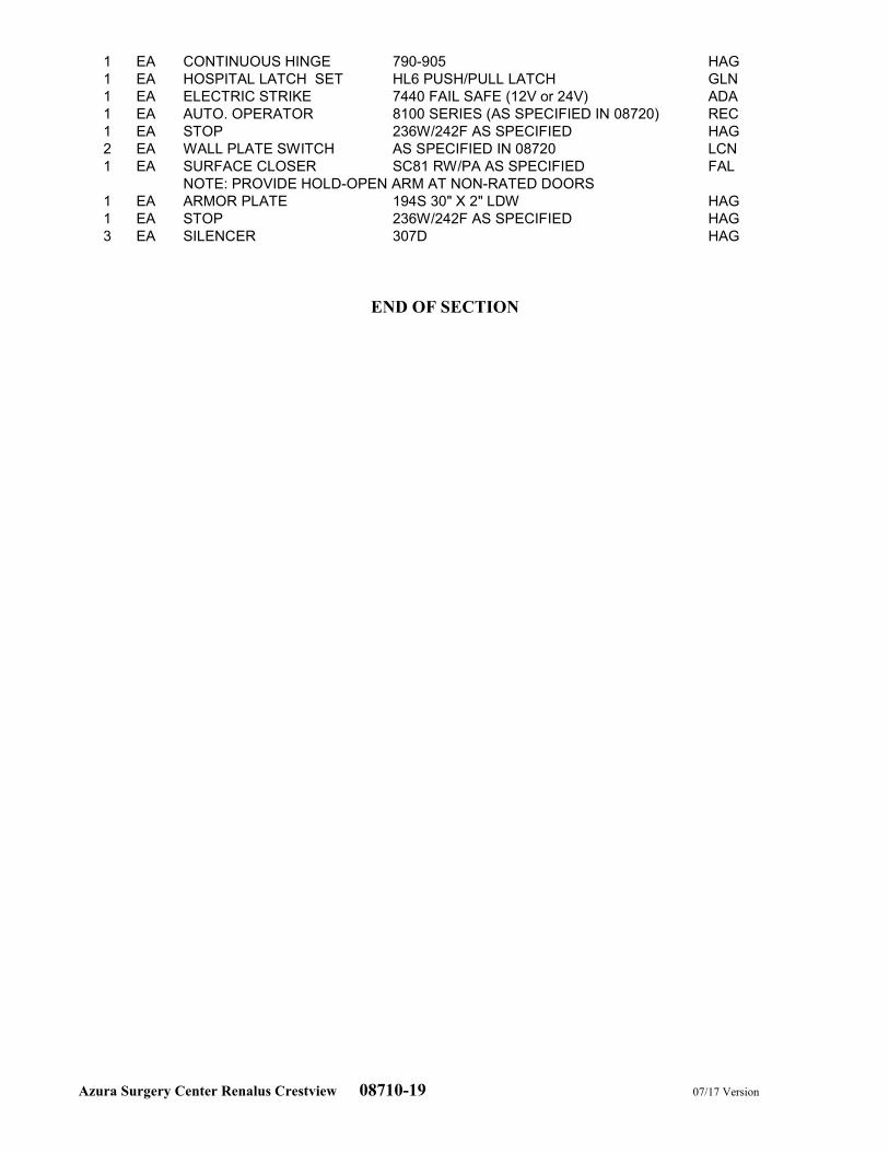
Azura Surgery Center Renalus Crestview 08710-19 07/17 Version
1 EA CONTINUOUS HINGE 790-905 HAG
1 EA HOSPITAL LATCH SET HL6 PUSH/PULL LATCH GLN
1 EA ELECTRIC STRIKE 7440 FAIL SAFE (12V or 24V) ADA
1 EA AUTO. OPERATOR 8100 SERIES (AS SPECIFIED IN 08720) REC
1 EA STOP 236W/242F AS SPECIFIED HAG
2 EA WALL PLATE SWITCH AS SPECIFIED IN 08720 LCN
1 EA SURFACE CLOSER SC81 RW/PA AS SPECIFIED FAL
NOTE: PROVIDE HOLD-OPEN ARM AT NON-RATED DOORS
1 EA ARMOR PLATE 194S 30" X 2" LDW HAG
1 EA STOP 236W/242F AS SPECIFIED HAG
3 EA SILENCER 307D HAG
END OF SECTION
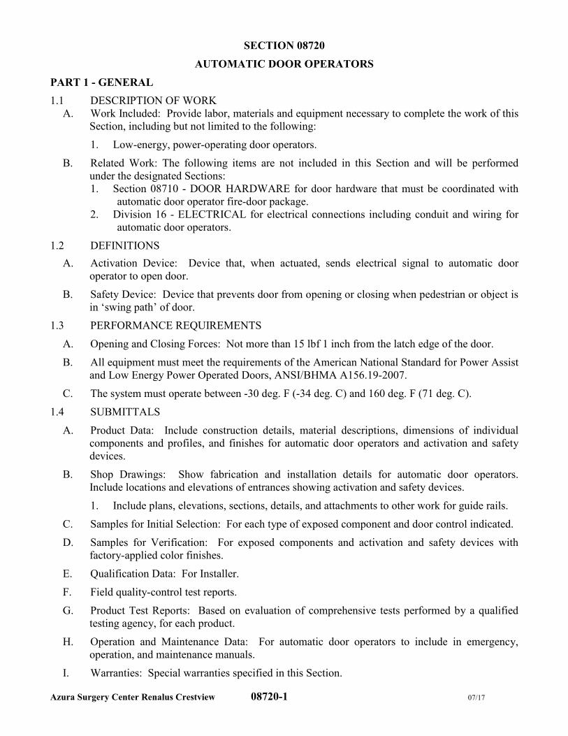
Azura Surgery Center Renalus Crestview 08720-1 07/17
SECTION 08720
AUTOMATIC DOOR OPERATORS
PART 1 - GENERAL
1.1 DESCRIPTION OF WORK
A. Work Included: Provide labor, materials and equipment necessary to complete the work of this
Section, including but not limited to the following:
1. Low-energy, power-operating door operators.
B. Related Work: The following items are not included in this Section and will be performed
under the designated Sections:
1. Section 08710 - DOOR HARDWARE for door hardware that must be coordinated with
automatic door operator fire-door package.
2. Division 16 - ELECTRICAL for electrical connections including conduit and wiring for
automatic door operators.
1.2 DEFINITIONS
A. Activation Device: Device that, when actuated, sends electrical signal to automatic door
operator to open door.
B. Safety Device: Device that prevents door from opening or closing when pedestrian or object is
in ‘swing path’ of door.
1.3 PERFORMANCE REQUIREMENTS
A. Opening and Closing Forces: Not more than 15 lbf 1 inch from the latch edge of the door.
B. All equipment must meet the requirements of the American National Standard for Power Assist
and Low Energy Power Operated Doors, ANSI/BHMA A156.19-2007.
C. The system must operate between -30 deg. F (-34 deg. C) and 160 deg. F (71 deg. C).
1.4 SUBMITTALS
A. Product Data: Include construction details, material descriptions, dimensions of individual
components and profiles, and finishes for automatic door operators and activation and safety
devices.
B. Shop Drawings: Show fabrication and installation details for automatic door operators.
Include locations and elevations of entrances showing activation and safety devices.
1. Include plans, elevations, sections, details, and attachments to other work for guide rails.
C. Samples for Initial Selection: For each type of exposed component and door control indicated.
D. Samples for Verification: For exposed components and activation and safety devices with
factory-applied color finishes.
E. Qualification Data: For Installer.
F. Field quality-control test reports.
G. Product Test Reports: Based on evaluation of comprehensive tests performed by a qualified
testing agency, for each product.
H. Operation and Maintenance Data: For automatic door operators to include in emergency,
operation, and maintenance manuals.
I. Warranties: Special warranties specified in this Section.
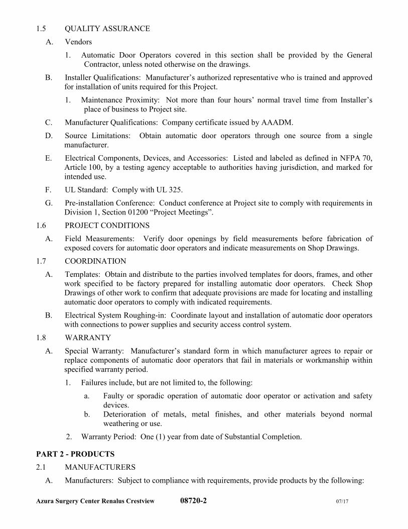
Azura Surgery Center Renalus Crestview 08720-2 07/17
1.5 QUALITY ASSURANCE
A. Vendors
1. Automatic Door Operators covered in this section shall be provided by the General
Contractor, unless noted otherwise on the drawings.
B. Installer Qualifications: Manufacturer’s authorized representative who is trained and approved
for installation of units required for this Project.
1. Maintenance Proximity: Not more than four hours’ normal travel time from Installer’s
place of business to Project site.
C. Manufacturer Qualifications: Company certificate issued by AAADM.
D. Source Limitations: Obtain automatic door operators through one source from a single
manufacturer.
E. Electrical Components, Devices, and Accessories: Listed and labeled as defined in NFPA 70,
Article 100, by a testing agency acceptable to authorities having jurisdiction, and marked for
intended use.
F. UL Standard: Comply with UL 325.
G. Pre-installation Conference: Conduct conference at Project site to comply with requirements in
Division 1, Section 01200 “Project Meetings”.
1.6 PROJECT CONDITIONS
A. Field Measurements: Verify door openings by field measurements before fabrication of
exposed covers for automatic door operators and indicate measurements on Shop Drawings.
1.7 COORDINATION
A. Templates: Obtain and distribute to the parties involved templates for doors, frames, and other
work specified to be factory prepared for installing automatic door operators. Check Shop
Drawings of other work to confirm that adequate provisions are made for locating and installing
automatic door operators to comply with indicated requirements.
B. Electrical System Roughing-in: Coordinate layout and installation of automatic door operators
with connections to power supplies and security access control system.
1.8 WARRANTY
A. Special Warranty: Manufacturer’s standard form in which manufacturer agrees to repair or
replace components of automatic door operators that fail in materials or workmanship within
specified warranty period.
1. Failures include, but are not limited to, the following:
a. Faulty or sporadic operation of automatic door operator or activation and safety
devices.
b. Deterioration of metals, metal finishes, and other materials beyond normal
weathering or use.
2. Warranty Period: One (1) year from date of Substantial Completion.
PART 2 - PRODUCTS
2.1 MANUFACTURERS
A. Manufacturers: Subject to compliance with requirements, provide products by the following:
Azura Surgery Center Renalus Crestview 08720-3 07/17
1. Record-USA
2. Besam-USA
B. Exclusions:
1. ALL TAXES
2. Dedicated 110VAC to operator(s)
3. Low Voltage Wire between Header, Wall Switches, Boxes & Conduit
4. Concrete Work, Cutting or Patching
5. Glass, Glazing and Caulking of Automatic Doors
6. Jambs, Transoms, Doors and Frames
7. Buttons at Nurse’s Station and Reception Area
8. Electric Strike
9. Non Standard Working Hours - Standard working hours 7:00am to 5:00pm.
2.2 MATERIALS
A. Aluminum: Alloy and temper recommended by manufacturer for type of use and finish
indicated, complying with standards indicated below:
1. Sheet: ASTM B 209.
2. Extrusions: ASTM B 221.
B. Welding Rods and Bare Electrodes: AWS A5.10/A5.10M.
2.3 MATERIALS & EQUIPMENT
A. The door operating equipment must use the completely electro-mechanical Astro-Swing motor
gearbox. The gearbox shall use an individually hand wound clock spring made from polished
special alloy nickel steel for maximum life. No electro-hydraulic equipment shall be allowed.
B. A two-position rocker switch clearly marked “SECURE” and “UNSECURE” will be mounted
on the front of the header case. This rocker switch may be located in Receptionist Office only
if requested by Owner’s Project Manager. In this special case, Electrical Contractor to provide
wiring between switch and door operator. This switch shall be furnished and marked by the
manufacturer. Due to certain job conditions, the header may have to be mounted as a pull
application. In this condition, the mounting of the two-position switch should be located to the
inside (opposite) part of the frame where security can be maintained. The two-position switch
must, at all times, be mounted in a securable location.
C. An energy saving Power Boost Close and Power Boost Hold, “PB” feature, shall be available at
the flip of a switch on the control box which is located inside the header case. The PB close
feature shall conserve energy by electronically increasing the door closing force from 9 lbs. to
15 lbs. in order to close and hold the door closed against the wind or stack pressure so that
conditioned air will not be let out of the building or annoying drafts let into the building. The
door shall be spring closed and spring held when the PB feature is not turned on. Control box
to be incorporated into closer case assembly.
D. The operator header must be 4-1/2" deep by 5-3/4" high, by the width of the door.
E. The header shall be bottom loading so it can be concealed in a wall above the door or in the
ceiling without the need of side access panels or special shafts or pivots.
F. Door activating and holding controls shall be by push plates. All controls shall be hard wired
push plates on the exterior or swing side and push plates on the interior or approach side. On
some existing conditions, radio controls may be accepted.
Azura Surgery Center Renalus Crestview 08720-4 07/17
2.4 FINISH
A. The header shall be provided in 204AIRI satin polished, etched, and anodized aluminum in
US28 clear aluminum finish to match framing, DC13 dark bronze aluminum finish where
entrance framing bronze.
1. Any exposed conduit shall match header in color.
2.5 FUNCTIONAL REQUIREMENTS AND MARKINGS
A. The equipment must be designed to handle swing doors up to a weight of 225 lbs.
B. Opening Speed:
1. The door shall be field adjusted so that opening speed to back check or 80o shall be 3
seconds or longer as required in Table I of ANSI/BHMA A.156.19-1997.
2. Opening speed to fully open shall be 4 seconds or longer.
C. Hold Open: The door shall be field adjusted to remain fully open for not less than 5 seconds or
more than 30 seconds.
D. Closing Speed:
1. Doors shall be field adjusted to close from 90o to 10o in 3 seconds or longer as required in
Table of ANSI/BHMA A156.19-1997.
2. Doors shall be field adjusted to close from 10o to fully closed in not less than 1.5 seconds.
E. The force required to prevent a door from opening or closing shall not exceed 15 lbs. applied 1"
from the latch edge of the door at any point in the opening or closing cycle.
F. In the event of a power failure, doors shall open with a manual pressure not to exceed 25 lbs. at
a point 1" from the latch edge of the door.
G. Doors shall be equipped with a sign(s) visible from either side, instructing the user as to the
operation and function of the door. Signs or stickers should include the following:
1. PUSH TO OPERATE
2. PULL TO OPERATE
3. AUTOMATIC PUSH SWITCH TO OPEN
4. CAUTION – AUTOMATIC DOOR
H. Upon completion of the work, apply a sticker to the operator header case where the owner can
easily read the installer's name, address, and phone number in the event a service call is needed.
2.6 SYSTEM OPERATION
A. For doors with security:
1. All operators will have a switch by the manufacturer with (2) settings labeled SECURE
AND UNSECURE mounted on the front of the header case.
2. When the switch is in the SECURE position, the panic device or latch shall be in an un-
dogged or locked mode whereby the door latches each time it closes. In this position, the
door will not operate or open by any person trying to gain access into the building when
depressing the nearby button or when pulling on the door. That person will have to use a
nearby intercom to signal two remote areas (RECEPTIONIST and NURSE’s STATION)
where activation of the door can occur with the push of a button. Both remote areas shall
work in conjunction with an electric strike which is usually on the main one entrance door
and the door to the Pre-Post Area from Waiting. This sequence of operation is as follows:
Nurse Station’s or Receptionist button is depressed, the electric strike is energized and
retracts followed with energizing of the operator to swing the door. In the SECURE
position, “exiting” will be possible with the PUSH-N-GO feature.
Azura Surgery Center Renalus Crestview 08720-5 07/17
3. When the switch is in the UNSECURE position, the panic device or latch shall be in a
dogged down, no latching mode whereby the door will open with either the appropriate
push buttons or the PUSH-N-GO (PULL-N-GO) feature when both exiting and entering.
B. For doors without security
1. Doors shall open by pushing or pulling door or by activating push switch.
PART 3 - EXECUTION
3.1 EXAMINATION
A. Examine conditions, with Installer present, for compliance with requirements for installation
tolerances, door and frame supports, and other conditions affecting performance of automatic
door operators.
1. For the record, prepare written report, endorsed by Installer, listing conditions detrimental
to performance.
B. Examine roughing-in for electrical systems to verify actual locations of power connections
before automatic door operator installation.
C. Proceed with installation only after unsatisfactory conditions have been corrected.
3.2 INSTALLATION
A. General: Install complete automatic door operator system, including activation and safety
devices, control wiring, and remote power units.
B. Power Door Operator Installation Standard: Comply with BHMA A156.10 for installation.
C. Low-Energy Power Door Operator Installation Standard: Comply with BHMA A156.19 for
installation.
D. Automatic Door Operators: Install door operator system, including control wiring, as follows:
1. Refer to Division 16 - ELECTRICAL for connection to electrical power distribution
system.
E. Activation and Safety Devices: Install devices and wiring, including connections to automatic
door operators, according to BHMA A156.19 and as follows:
1. Wall Switches: Provide push plates on both sides of each opening indicated to receive
automatic door operators.
F. Connect wiring according to Division 16 - ELECTRICAL.
3.3 FIELD QUALITY CONTROL
A. Testing Agency: Contractor will engage a qualified independent testing and inspecting agency
to perform field tests and inspections and prepare test reports.
B. Testing and Inspecting: After installation has been completed, testing and inspecting of each
automatic door operator shall be performed to verify compliance with applicable BHMA
standards.
1. Inspection Report: Submit report in writing to Architect and Contractor within 24 hours
after inspection.
C. Remove and replace automatic door operators where test results indicate they do not comply
with specified requirements.
Azura Surgery Center Renalus Crestview 08720-6 07/17
D. Additional testing and inspecting, at Contractor’s expense, shall be performed to determine
compliance of replaced or additional work with specified requirements.
3.4 ADJUSTING
A. Adjust automatic door operators and activation and safety devices to operate smoothly, easily,
and properly, and for safe operation and weather tight closure.
1. Adjust doors with low-energy door operators to close according to BHMA A156.19.
B. Lubricate operators, hardware, and other moving parts.
C. After completing installation of exposed, factory-finished automatic door operators, inspect
exposed finishes and repair damaged finishes.
D. Readjust automatic door operators and activation and safety devices after repeated operation of
completed installation equivalent to three days’ use by normal traffic (100 to 300 cycles).
Lubricate hardware, operating equipment, and other moving parts.
3.5 DEMONSTRATION
A. Engage a factory-authorized service representative to train Owner’s maintenance personnel to
adjust, operate, and maintain automatic door operators.
END OF SECTION
Azura Surgery Center Renalus Crestview 08800-1 07/17 Version
SECTION 08800
GLASS AND GLAZING
PART 1 - GENERAL
1.1 DESCRIPTION OF WORK
A. Work Included: Provide labor, materials and equipment necessary to complete the work of this
Section, including but not limited to the following:
1. Glass and glazing for the following products and applications:
a. Steel doors, frames and sidelights specified in Section 08111 - STEEL DOORS
AND FRAMES.
b. Wood doors specified in Section 08211 - FLUSH WOOD DOORS.
c. Glass doors specified in Section 08320 - SLIDING GLASS DOORS.
d. Glazed entrances and storefronts specified in Section 08411 - ALUMINUM-
FRAMED ENTRANCES AND STOREFRONT.
e. Interior borrowed lites.
f. Glazing film.
g. 3form Translucent Resin Panel System
B. Related Work: The following items are not included in this Section and will be performed
under the designated Sections:
1. Section 08320 - SLIDING GLASS DOORS for factory glazing for sliding doors.
2. Section 13090 – RADIATION SHIELDING PROTECTION
1.2 DEFINITIONS
A. Manufacturers of Glass Products: Firms that produce primary glass, fabricated glass, or both,
as defined in referenced glazing publications.
B. Glass Thicknesses: Indicated by thickness designations in millimeters according to
ASTM C 1036.
C. Interspace: Space between lites of an insulating-glass unit that contains dehydrated air or a
specified gas.
D. Deterioration of Coated Glass: Defects developed from normal use that are attributed to the
manufacturing process and not to causes other than glass breakage and practices for
maintaining and cleaning coated glass contrary to manufacturer's written instructions. Defects
include peeling, cracking, and other indications of deterioration in metallic coating.
E. Deterioration of Insulating Glass: Failure of hermetic seal under normal use that is attributed to
the manufacturing process and not to causes other than glass breakage and practices for
maintaining and cleaning insulating glass contrary to manufacturer’s written instructions.
Evidence of failure is the obstruction of vision by dust, moisture, or film on interior surfaces of
glass.
F. Deterioration of Laminated Glass: Defects developed from normal use that are attributed to the
manufacturing process and not to causes other than glass breakage and practices for
maintaining and cleaning laminated glass contrary to manufacturer’s written instructions.
Defects include edge separation, delamination materially obstructing vision through glass, and
blemishes exceeding those allowed by referenced laminated-glass standard.
Azura Surgery Center Renalus Crestview 08800-2 07/17 Version
1.3 PERFORMANCE REQUIREMENTS
A. General: Provide glazing systems capable of withstanding normal thermal movement and wind
and impact loads (where applicable) without failure, including loss or glass breakage
attributable to the following: defective manufacture, fabrication, and installation; failure of
sealants or gaskets to remain watertight and airtight; deterioration of glazing materials; or other
defects in construction.
B. Glass Design: Glass thickness designations indicated are minimums and are for detailing only.
Confirm glass thicknesses by analyzing Project loads and in-service conditions. Provide glass
lites in the thickness designations indicated for various size openings, but not less than
thicknesses and in strengths (annealed or heat treated) required to meet or exceed the following
criteria:
1. Glass Thicknesses: Select minimum glass thicknesses to comply with ASTM E 1300,
according to the following requirements:
a. Specified Design Wind Loads: As required by Code.
b. Probability of Breakage for Vertical Glazing: 8 lites per 1000 for lites set vertically
or not more than 15 degrees off vertical and under wind action.
1) Load Duration: 60 seconds or less
c. Maximum Lateral Deflection: For the following types of glass supported on all 4
edges, provide thickness required that limits center deflection at design wind
pressure to 1/50 times the short side length or 1 inch, whichever is less.
1) For monolithic-glass lites heat treated to resist wind loads.
2) For insulating glass.
3) For laminated-glass lites.
d. Minimum Glass Thickness for Exterior Lites: Not less than 6 mm.
C. Thermal Movements: Provide glazing that allows for thermal movements resulting from the
following maximum change (range) in ambient and surface temperatures acting on glass
framing members and glazing components. Base engineering calculation on surface
temperatures of materials due to both solar heat gain and nighttime-sky heat loss.
1. Temperature Change (Range): 120 deg F, ambient; 180 deg F, material surfaces.
D. Thermal and Optical Performance Properties: Provide glass with performance properties
specified based on manufacturer’s published test data, as determined according to procedures
indicated below:
1. For monolithic-glass lites, properties are based on units with lites 6.0 mm thick.
2. For laminated-glass lites, properties are based on products of construction indicated.
3. For insulating-glass units, properties are based on units with lites 6.0 mm thick and a
nominal 1/2-inch-wide interspace.
4. Center-of-Glass Values: Based on using LBL-44789 WINDOW 5.0 computer program
for the following methodologies:
a. U-Factors: NFRC 100 expressed as Btu/ sq. ft. x h x deg F.
b. Solar Heat Gain Coefficient: NFRC 200.
c. Solar Optical Properties: NFRC 300.
1.4 SUBMITTALS
A. Product Data: For each glass product and glazing material indicated.
B. Samples: For the following products, in the form of 12-inch- square samples for glass.
Azura Surgery Center Renalus Crestview 08800-3 07/17 Version
1. Wired glass.
2. Tempered glass.
3. Insulating glass for each designation indicated.
4. Glazing film.
5. For each color (except black) of exposed glazing sealant indicated.
C. Glazing Schedule: Use same designations indicated on Drawings for glazed openings in
preparing a schedule listing glass types and thicknesses for each size opening and location.
D. Product Certificates: Signed by manufacturers of glass and glazing products certifying that
products furnished comply with requirements.
1. For solar-control low-e-coated glass, provide documentation demonstrating that
manufacturer of coated glass is certified by coating manufacturer.
E. Qualification Data: For installers.
F. Preconstruction Adhesion and Compatibility Test Report: From glazing sealant manufacturer
indicating glazing sealants were tested for adhesion to glass and glazing channel substrates, and
for compatibility with glass and other glazing materials.
G. Product Test Reports: For each of the following types of glazing products:
1. Coated float glass.
2. Insulating glass.
3. Glazing film.
4. Glazing sealants.
5. Glazing gaskets.
H. Warranties: Special warranties specified in this Section.
1.5 QUALITY ASSURANCE
A. Installer Qualifications: An experienced installer who has completed glazing similar in
material, design, and extent to that indicated for this Project whose work has resulted in glass
installations with a record of successful in-service performance.
B. Source Limitations for Glass: Obtain the following through one source from a single
manufacturer for each glass type: clear float glass, laminated glass and insulating glass.
C. Source Limitations for Glass Sputter-Coated with Solar-Control Low-E Coatings: Where
solar-control low-e coatings of a primary glass manufacturer that has established a certified
fabricator program is specified, obtain sputter-coated solar-control low-e-coated glass in
fabricated units from a manufacturer that is certified by coated-glass manufacturer.
D. Source Limitations for Glazing Accessories: Obtain glazing accessories through one source
from a single manufacturer for each product and installation method indicated.
E. Elastomeric Glazing Sealant Product Testing: Obtain sealant test results for product test
reports in “Submittals” Article from a qualified testing agency based on testing current sealant
formulations within a 36-month period.
1. Sealant Testing Agency Qualifications: An independent testing agency qualified
according to ASTM C 1021 to conduct the testing indicated, as documented according to
ASTM E 548.
2. Test elastomeric glazing sealants for compliance with requirements specified by
reference to ASTM C 920 and, where applicable, to other standard test methods.
F. Preconstruction Adhesion and Compatibility Testing: Submit to elastomeric glazing sealant
manufacturers, for testing indicated below, samples of each glazing material type, tape sealant,
Azura Surgery Center Renalus Crestview 08800-4 07/17 Version
gasket, glazing accessory, and glass-framing member that will contact or affect elastomeric
glazing sealants:
1. Use ASTM C 1087 to determine whether priming and other specific joint preparation
techniques are required to obtain rapid, optimum adhesion of glazing sealants to glass,
tape sealants, gaskets, and glazing channel substrates.
2. Submit not fewer than eight pieces of each type of material, including joint substrates,
shims, joint-sealant backings, secondary seals, and miscellaneous materials.
3. Schedule sufficient time for testing and analyzing results to prevent delaying the Work.
4. For materials failing tests, obtain sealant manufacturer’s written instructions for
corrective measures, including the use of specially formulated primers.
5. Testing will not be required if elastomeric glazing sealant manufacturers submit data
based on previous testing of current sealant products for adhesion to, and compatibility
with, glazing materials matching those submitted.
G. Glazing for Fire-Rated Door Assemblies: Glazing for assemblies that comply with NFPA 80
and that are listed and labeled by a testing and inspecting agency acceptable to authorities
having jurisdiction, for fire-protection ratings indicated, based on testing according to
NFPA 252.
H. Safety Glazing Products: Comply with testing requirements in 16 CFR 120 and, for wired
glass, ANSI Z97.1.
1. Subject to compliance with requirements, obtain safety glazing products permanently
marked with certification label of the Safety Glazing Certification Council or another
certification agency] acceptable to authorities having jurisdiction.
2. Where glazing units, including Kind FT glass and laminated glass, are specified in Part 2
articles for glazing lites more than 9 sq. ft. in exposed surface area of one side, provide
glazing products that comply with Category II materials, for lites 9 sq. ft. or less in
exposed surface area of one side, provide glazing products that comply with Category I
or II materials, except for hazardous locations where Category II materials are required
by 16 CFR 1201 and regulations of authorities having jurisdiction.
I. Glazing Publications: Comply with published recommendations of glass product
manufacturers and organizations below, unless more stringent requirements are indicated.
Refer to these publications for glazing terms not otherwise defined in this Section or in
referenced standards.
1. GANA Publications: GANA Laminated Division’s “Laminated Glass Design Guide”
and GANA’s “Glazing Manual”.
2. IGMA Publication for Insulating Glass: SIGMA TM-3000, “Glazing Guidelines for
Sealed Insulating Glass Units”.
J. Insulating-Glass Certification Program: Permanently marked either on spacers or on at least
one component lite of units with appropriate certification label of the following testing and
inspecting agency:
1. Insulating Glass Certification Council.
K. Preinstallation Conference: Conduct conference at Project site to comply with requirements in
Division 01.
L. Comply with pertinent codes and regulations.
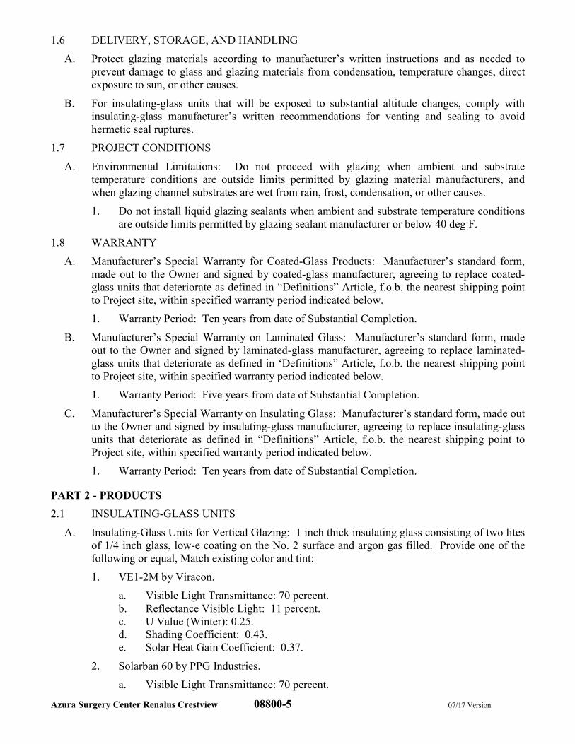
Azura Surgery Center Renalus Crestview 08800-5 07/17 Version
1.6 DELIVERY, STORAGE, AND HANDLING
A. Protect glazing materials according to manufacturer’s written instructions and as needed to
prevent damage to glass and glazing materials from condensation, temperature changes, direct
exposure to sun, or other causes.
B. For insulating-glass units that will be exposed to substantial altitude changes, comply with
insulating-glass manufacturer’s written recommendations for venting and sealing to avoid
hermetic seal ruptures.
1.7 PROJECT CONDITIONS
A. Environmental Limitations: Do not proceed with glazing when ambient and substrate
temperature conditions are outside limits permitted by glazing material manufacturers, and
when glazing channel substrates are wet from rain, frost, condensation, or other causes.
1. Do not install liquid glazing sealants when ambient and substrate temperature conditions
are outside limits permitted by glazing sealant manufacturer or below 40 deg F.
1.8 WARRANTY
A. Manufacturer’s Special Warranty for Coated-Glass Products: Manufacturer’s standard form,
made out to the Owner and signed by coated-glass manufacturer, agreeing to replace coated-
glass units that deteriorate as defined in “Definitions” Article, f.o.b. the nearest shipping point
to Project site, within specified warranty period indicated below.
1. Warranty Period: Ten years from date of Substantial Completion.
B. Manufacturer’s Special Warranty on Laminated Glass: Manufacturer’s standard form, made
out to the Owner and signed by laminated-glass manufacturer, agreeing to replace laminated-
glass units that deteriorate as defined in ‘Definitions” Article, f.o.b. the nearest shipping point
to Project site, within specified warranty period indicated below.
1. Warranty Period: Five years from date of Substantial Completion.
C. Manufacturer’s Special Warranty on Insulating Glass: Manufacturer’s standard form, made out
to the Owner and signed by insulating-glass manufacturer, agreeing to replace insulating-glass
units that deteriorate as defined in “Definitions” Article, f.o.b. the nearest shipping point to
Project site, within specified warranty period indicated below.
1. Warranty Period: Ten years from date of Substantial Completion.
PART 2 - PRODUCTS
2.1 INSULATING-GLASS UNITS
A. Insulating-Glass Units for Vertical Glazing: 1 inch thick insulating glass consisting of two lites
of 1/4 inch glass, low-e coating on the No. 2 surface and argon gas filled. Provide one of the
following or equal, Match existing color and tint:
1. VE1-2M by Viracon.
a. Visible Light Transmittance: 70 percent.
b. Reflectance Visible Light: 11 percent.
c. U Value (Winter): 0.25.
d. Shading Coefficient: 0.43.
e. Solar Heat Gain Coefficient: 0.37.
2. Solarban 60 by PPG Industries.
a. Visible Light Transmittance: 70 percent.
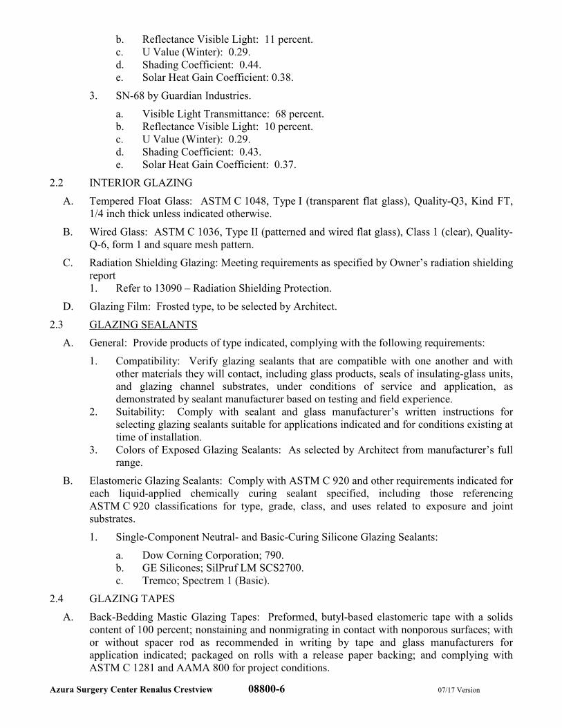
Azura Surgery Center Renalus Crestview 08800-6 07/17 Version
b. Reflectance Visible Light: 11 percent.
c. U Value (Winter): 0.29.
d. Shading Coefficient: 0.44.
e. Solar Heat Gain Coefficient: 0.38.
3. SN-68 by Guardian Industries.
a. Visible Light Transmittance: 68 percent.
b. Reflectance Visible Light: 10 percent.
c. U Value (Winter): 0.29.
d. Shading Coefficient: 0.43.
e. Solar Heat Gain Coefficient: 0.37.
2.2 INTERIOR GLAZING
A. Tempered Float Glass: ASTM C 1048, Type I (transparent flat glass), Quality-Q3, Kind FT,
1/4 inch thick unless indicated otherwise.
B. Wired Glass: ASTM C 1036, Type II (patterned and wired flat glass), Class 1 (clear), Quality-
Q-6, form 1 and square mesh pattern.
C. Radiation Shielding Glazing: Meeting requirements as specified by Owner’s radiation shielding
report
1. Refer to 13090 – Radiation Shielding Protection.
D. Glazing Film: Frosted type, to be selected by Architect.
2.3 GLAZING SEALANTS
A. General: Provide products of type indicated, complying with the following requirements:
1. Compatibility: Verify glazing sealants that are compatible with one another and with
other materials they will contact, including glass products, seals of insulating-glass units,
and glazing channel substrates, under conditions of service and application, as
demonstrated by sealant manufacturer based on testing and field experience.
2. Suitability: Comply with sealant and glass manufacturer’s written instructions for
selecting glazing sealants suitable for applications indicated and for conditions existing at
time of installation.
3. Colors of Exposed Glazing Sealants: As selected by Architect from manufacturer’s full
range.
B. Elastomeric Glazing Sealants: Comply with ASTM C 920 and other requirements indicated for
each liquid-applied chemically curing sealant specified, including those referencing
ASTM C 920 classifications for type, grade, class, and uses related to exposure and joint
substrates.
1. Single-Component Neutral- and Basic-Curing Silicone Glazing Sealants:
a. Dow Corning Corporation; 790.
b. GE Silicones; SilPruf LM SCS2700.
c. Tremco; Spectrem 1 (Basic).
2.4 GLAZING TAPES
A. Back-Bedding Mastic Glazing Tapes: Preformed, butyl-based elastomeric tape with a solids
content of 100 percent; nonstaining and nonmigrating in contact with nonporous surfaces; with
or without spacer rod as recommended in writing by tape and glass manufacturers for
application indicated; packaged on rolls with a release paper backing; and complying with
ASTM C 1281 and AAMA 800 for project conditions.
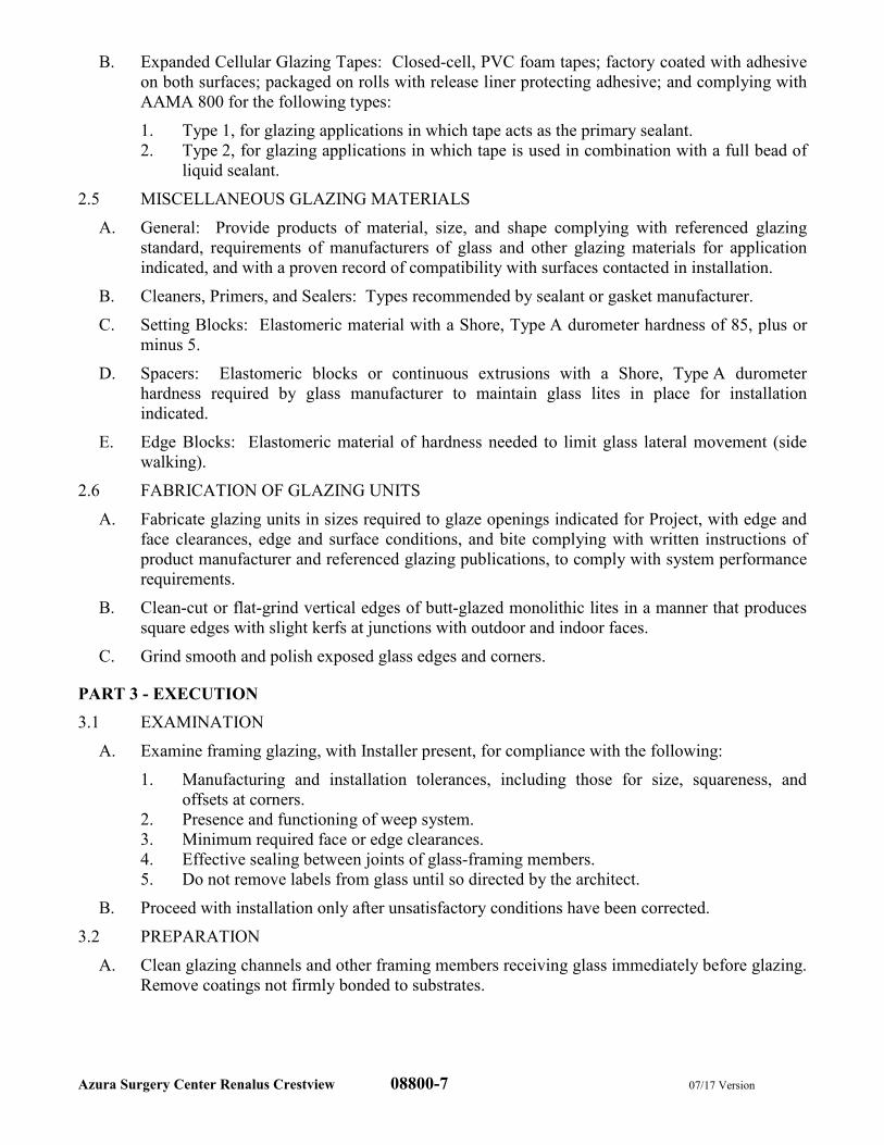
Azura Surgery Center Renalus Crestview 08800-7 07/17 Version
B. Expanded Cellular Glazing Tapes: Closed-cell, PVC foam tapes; factory coated with adhesive
on both surfaces; packaged on rolls with release liner protecting adhesive; and complying with
AAMA 800 for the following types:
1. Type 1, for glazing applications in which tape acts as the primary sealant.
2. Type 2, for glazing applications in which tape is used in combination with a full bead of
liquid sealant.
2.5 MISCELLANEOUS GLAZING MATERIALS
A. General: Provide products of material, size, and shape complying with referenced glazing
standard, requirements of manufacturers of glass and other glazing materials for application
indicated, and with a proven record of compatibility with surfaces contacted in installation.
B. Cleaners, Primers, and Sealers: Types recommended by sealant or gasket manufacturer.
C. Setting Blocks: Elastomeric material with a Shore, Type A durometer hardness of 85, plus or
minus 5.
D. Spacers: Elastomeric blocks or continuous extrusions with a Shore, Type A durometer
hardness required by glass manufacturer to maintain glass lites in place for installation
indicated.
E. Edge Blocks: Elastomeric material of hardness needed to limit glass lateral movement (side
walking).
2.6 FABRICATION OF GLAZING UNITS
A. Fabricate glazing units in sizes required to glaze openings indicated for Project, with edge and
face clearances, edge and surface conditions, and bite complying with written instructions of
product manufacturer and referenced glazing publications, to comply with system performance
requirements.
B. Clean-cut or flat-grind vertical edges of butt-glazed monolithic lites in a manner that produces
square edges with slight kerfs at junctions with outdoor and indoor faces.
C. Grind smooth and polish exposed glass edges and corners.
PART 3 - EXECUTION
3.1 EXAMINATION
A. Examine framing glazing, with Installer present, for compliance with the following:
1. Manufacturing and installation tolerances, including those for size, squareness, and
offsets at corners.
2. Presence and functioning of weep system.
3. Minimum required face or edge clearances.
4. Effective sealing between joints of glass-framing members.
5. Do not remove labels from glass until so directed by the architect.
B. Proceed with installation only after unsatisfactory conditions have been corrected.
3.2 PREPARATION
A. Clean glazing channels and other framing members receiving glass immediately before glazing.
Remove coatings not firmly bonded to substrates.
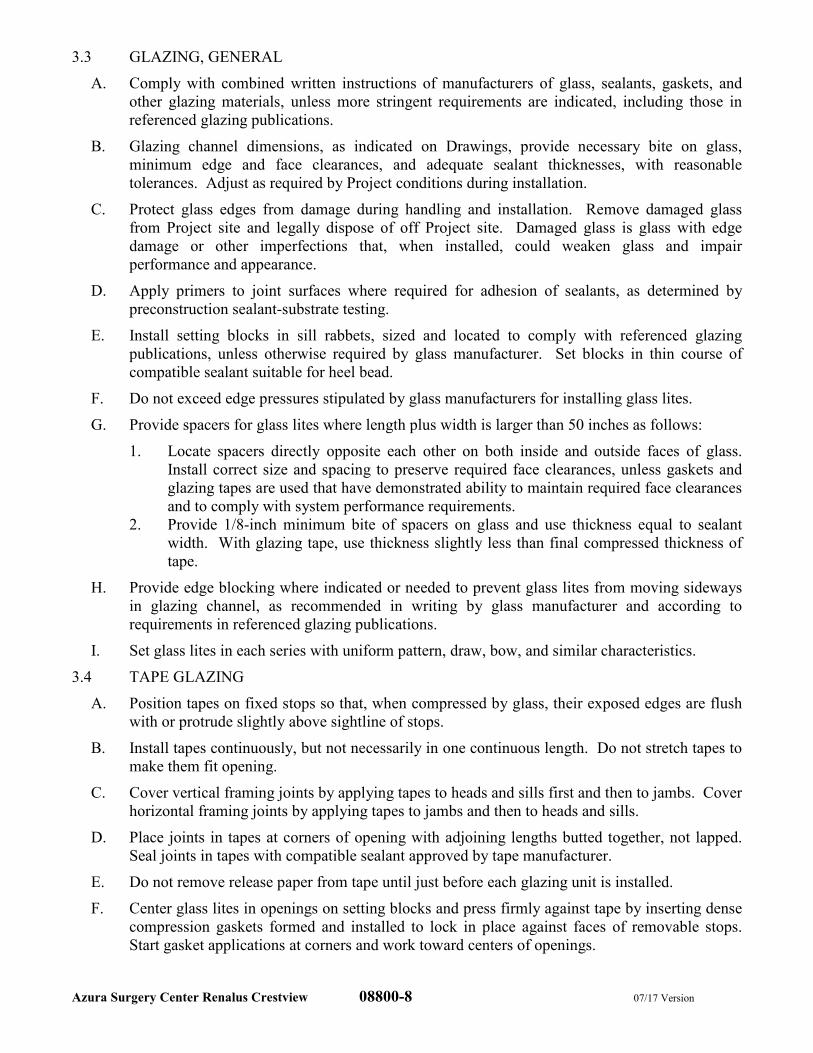
Azura Surgery Center Renalus Crestview 08800-8 07/17 Version
3.3 GLAZING, GENERAL
A. Comply with combined written instructions of manufacturers of glass, sealants, gaskets, and
other glazing materials, unless more stringent requirements are indicated, including those in
referenced glazing publications.
B. Glazing channel dimensions, as indicated on Drawings, provide necessary bite on glass,
minimum edge and face clearances, and adequate sealant thicknesses, with reasonable
tolerances. Adjust as required by Project conditions during installation.
C. Protect glass edges from damage during handling and installation. Remove damaged glass
from Project site and legally dispose of off Project site. Damaged glass is glass with edge
damage or other imperfections that, when installed, could weaken glass and impair
performance and appearance.
D. Apply primers to joint surfaces where required for adhesion of sealants, as determined by
preconstruction sealant-substrate testing.
E. Install setting blocks in sill rabbets, sized and located to comply with referenced glazing
publications, unless otherwise required by glass manufacturer. Set blocks in thin course of
compatible sealant suitable for heel bead.
F. Do not exceed edge pressures stipulated by glass manufacturers for installing glass lites.
G. Provide spacers for glass lites where length plus width is larger than 50 inches as follows:
1. Locate spacers directly opposite each other on both inside and outside faces of glass.
Install correct size and spacing to preserve required face clearances, unless gaskets and
glazing tapes are used that have demonstrated ability to maintain required face clearances
and to comply with system performance requirements.
2. Provide 1/8-inch minimum bite of spacers on glass and use thickness equal to sealant
width. With glazing tape, use thickness slightly less than final compressed thickness of
tape.
H. Provide edge blocking where indicated or needed to prevent glass lites from moving sideways
in glazing channel, as recommended in writing by glass manufacturer and according to
requirements in referenced glazing publications.
I. Set glass lites in each series with uniform pattern, draw, bow, and similar characteristics.
3.4 TAPE GLAZING
A. Position tapes on fixed stops so that, when compressed by glass, their exposed edges are flush
with or protrude slightly above sightline of stops.
B. Install tapes continuously, but not necessarily in one continuous length. Do not stretch tapes to
make them fit opening.
C. Cover vertical framing joints by applying tapes to heads and sills first and then to jambs. Cover
horizontal framing joints by applying tapes to jambs and then to heads and sills.
D. Place joints in tapes at corners of opening with adjoining lengths butted together, not lapped.
Seal joints in tapes with compatible sealant approved by tape manufacturer.
E. Do not remove release paper from tape until just before each glazing unit is installed.
F. Center glass lites in openings on setting blocks and press firmly against tape by inserting dense
compression gaskets formed and installed to lock in place against faces of removable stops.
Start gasket applications at corners and work toward centers of openings.
Azura Surgery Center Renalus Crestview 08800-9 07/17 Version
3.5 SEALANT GLAZING (WET)
A. Install continuous spacers, or spacers combined with cylindrical sealant backing, between glass
lites and glazing stops to maintain glass face clearances and to prevent sealant from extruding
into glass channel and blocking weep systems until sealants cure. Secure spacers or spacers
and backings in place and in position to control depth of installed sealant relative to edge
clearance for optimum sealant performance.
B. Force sealants into glazing channels to eliminate voids and to ensure complete wetting or bond
of sealant to glass and channel surfaces.
C. Tool exposed surfaces of sealants to provide a substantial wash away from glass.
3.6 CLEANING AND PROTECTION
A. Protect exterior glass from damage immediately after installation by attaching crossed
streamers to framing held away from glass. Do not apply markers to glass surface. Remove
nonpermanent labels, and clean surfaces.
B. Protect glass from contact with contaminating substances resulting from construction
operations, including weld splatter. If, despite such protection, contaminating substances do
come into contact with glass, remove substances immediately as recommended by glass
manufacturer.
C. Examine glass surfaces adjacent to or below exterior concrete and other masonry surfaces at
frequent intervals during construction, but not less than once a month, for buildup of dirt, scum,
alkaline deposits, or stains; remove as recommended in writing by glass manufacturer.
D. Remove and replace glass that is broken, chipped, cracked, or abraded or that is damaged from
natural causes, accidents, and vandalism, during construction period.
E. All loose lights shall be removed and reset before acceptance.
F. Final cleaning shall be done by the contractor under supplementary general conditions.
END OF SECTION
Azura Surgery Center Renalus Crestview 09260-1 07/17
SECTION 09260
GYPSUM BOARD ASSEMBLIES
PART 1 - GENERAL
1.1 DESCRIPTION OF WORK
A. Work Included: Provide labor, materials and equipment necessary to complete the work of this
Section, including but not limited to the following:
1. Interior gypsum wallboard.
2. Tile backing panels.
3. Paperless mold and mildew resistant wallboard.
4. Acoustic insulation in gypsum wallboard assemblies.
5. Non-load-bearing steel framing.
B. Related Work: The following items are not included in this Section and will be performed
under the designated Sections:
1. Section 06100 – Rough carpentry for installation of wood blocking.
2. Section 09900 – For wallboard priming and finishing.
3. Division 15 - FIRE PROTECTION for installation of access doors in gypsum board
assemblies.
4. Division 15 - PLUMBING for installation of access doors in gypsum board assemblies.
5. Division 15 - HEATING, VENTILATING, AND AIR CONDITIONING for installation
of access doors, pipes and duct sleeves in gypsum board assemblies.
6. Division 16 - ELECTRICAL for installation of access doors in gypsum board assemblies.
1.2 SUBMITTALS
A. Product Data: For each type of product indicated.
B. Samples: Full-size Sample in 12-inch-long length for each trim accessory indicated.
1. Manufacturers’ product data for adhesives used to laminate gypsum board panels to
substrates, including printed statement of VOC content.
1.3 QUALITY ASSURANCE
A. Fire-Resistance-Rated Assemblies: For fire-resistance-rated assemblies, provide materials and
construction identical to those tested in assembly indicated according to ASTM E 119 by an
independent testing agency.
B. STC-Rated Assemblies: For STC-rated assemblies, provide materials and construction
identical to those tested in assembly indicated according to ASTM E 90 and classified
according to ASTM E 413 by an independent testing agency.
1.4 STORAGE AND HANDLING
A. Store materials inside under cover and keep them dry and protected against damage from
weather, condensation, direct sunlight, construction traffic, and other causes. Stack panels flat
to prevent sagging.
1.5 PROJECT CONDITIONS
A. Environmental Limitations: Comply with ASTM C 840 requirements or gypsum board
manufacturer’s written recommendations, whichever are more stringent.
B. Do not install interior products until installation areas are enclosed and conditioned.
Azura Surgery Center Renalus Crestview 09260-2 07/17
C. Do not install panels that are wet, those that are moisture damaged, and those that are mold
damaged.
1. Indications that panels are wet or moisture damaged include, but are not limited to,
discoloration, sagging, or irregular shape.
2. Indications that panels are mold damaged include, but are not limited to, fuzzy or
splotchy surface contamination and discoloration.
1.6 STANDARD WALL TYPES
A. Refer to drawings for wall types.
PART 2 - PRODUCTS
2.1 NON-LOAD-BEARING STEEL FRAMING, GENERAL
A. Framing Members, General: Comply with ASTM C 754 for conditions indicated.
1. Steel Sheet Components: Comply with ASTM C 645 requirements for metal, unless
otherwise indicated.
2. Protective Coating: manufacturer's standard corrosion-resistant zinc coating, unless
otherwise indicated.
2.2 SUSPENSION SYSTEM COMPONENTS
A. Tie Wire: ASTM A 641/A 641M, Class 1 zinc coating, soft temper, 0.0625-inch-diameter
wire, or double strand of 0.0475-inch-diameter wire.
B. Hanger Attachments to Concrete:
1. Anchors: Fabricated from corrosion-resistant materials with holes or loops for attaching
wire hangers and capable of sustaining, without failure, a load equal to 5 times that
imposed by construction as determined by testing according to ASTM E 488 by an
independent testing agency.
a. Type: Post-installed, expansion anchor.
C. Wire Hangers: ASTM A 641/A 641M, Class 1 zinc coating, soft temper, 0.162-inch diameter.
D. Carrying Channels: Cold-rolled, commercial steel sheet with a base-metal thickness of 0.0538
inch and minimum 1/2 inch wide flanges with depth as required for span and loading and
indicated on Drawings.
E. Furring Channels (Furring Members): 0.0538-inch bare-steel thickness, with minimum 1/2 inch
wide flanges, 3/4 inch deep.
F. Grid Suspension System for Ceilings: ASTM C 645, direct-hung system composed of main
beams and cross-furring members that interlock.
1. Available Products: Subject to compliance with requirements, products that may be
incorporated into the Work include, but are not limited to, the following:
a. Armstrong World Industries, Inc.; Drywall Grid Systems.
b. Chicago Metallic Corporation; Drywall Furring System.
c. USG Corporation; Drywall Suspension System.
2.3 STEEL FRAMING FOR FRAMED ASSEMBLIES
A. Steel Studs and Runners: ASTM C 645.
1. Minimum Base-Metal Thickness: 25 GA for walls less than 13'-0" in height
2. Minimum Base-Metal Thickness: 20 GA for walls greater than 13'-0" in height and less
than 20'-0" in height.
Azura Surgery Center Renalus Crestview 09260-3 07/17
3. For walls greater than 20'-0" in height, structural engineers shall consider doubling 20
GA studs and/or decreasing the stud spacing to achieve height requirement as opposed to
decreasing the gauge of the studs.
4. At all corner guard locations, provide doubled 20 GA metal studs run continuously from
floor to structure above.
B. Slip-Type Head Joints: Where indicated, provide one of the following:
1. Single Long-Leg Runner System: ASTM C 645 top runner with 2 inch deep flanges in
thickness not less than indicated for studs, installed with studs friction fit into top runner
and with continuous bridging located within 12 inches of the top of studs to provide
lateral bracing.
2. Double-Runner System: ASTM C 645 top runners, inside runner with 2 inch deep
flanges in thickness not less than indicated for studs and fastened to studs, and outer
runner sized to friction fit inside runner.
3. Deflection Track: Steel sheet top runner manufactured to prevent cracking of finishes
applied to interior partition framing resulting from deflection of structure above; in
thickness not less than indicated for studs and in width to accommodate depth of studs.
a. Available Products: Subject to compliance with requirements, products that may
be incorporated into the Work include, but are not limited to, the following:
1) Steel Network Inc. (The); VertiClip Series.
2) Superior Metal Trim; Superior Flex Track System (SFT).
C. Flat Strap and Backing Plate: Steel sheet for blocking and bracing in length and width
indicated.
1. Minimum Base-Metal Thickness: 0.021 inch.
D. Cold-Rolled Channel Bridging: 0.0538-inch bare steel thickness, with minimum 1/2 inch wide
flanges.
1. Depth: 1-1/2 inches.
2. Clip Angle: Not less than 1-1/2 by 1-1/2 inches, 0.068 inch-thick, galvanized steel.
E. Hat-Shaped, Rigid Furring Channels: ASTM C 645.
1. Minimum Base Metal Thickness: 0.021 inch.
2. Depth: 1-1/2 inches.
F. Resilient Furring Channels: 1/2 inch deep, steel sheet members designed to reduce sound
transmission.
1. Configuration: Asymmetrical or hat shaped.
G. Z-Shaped Furring: With slotted or non-slotted web, face flange of 1-1/4 inches wall attachment
flange of 7/8 inch, minimum bare-metal thickness of 0.0179 inch, and depth required to fit
insulation thickness indicated.
H. Fasteners for Metal Framing: Of type, material, size, corrosion resistance, holding power and
other properties required to fasten steel members to substrates.
I. Isolation Strip at Exterior Walls: Adhesive-backed, closed-cell vinyl foam strips that allow
fastener penetration without foam displacement, 1/8 inch thick, in width to suit steel stud size.
2.4 INTERIOR GYPSUM BOARD
A. General: Complying with ASTM C 36/C 36M or ASTM C 1396/C 1396M, as applicable to
type of gypsum board indicated and whichever is more stringent.
Azura Surgery Center Renalus Crestview 09260-4 07/17
1. Available Manufacturers: Subject to compliance with requirements, manufacturers
offering products that may be incorporated into the Work include, but are not limited to,
the following:
a. USG Corporation.
b. Georgia Pacific.
c. National Gypsum Company.
B. Regular Type:
1. Thickness: 5/8 inch.
2. Long Edges: Tapered.
C. Fire-Resistant Type X:
1. Thickness: 5/8 inch.
2. Long Edges: Tapered.
D. Flexible Type: Manufactured to bend to fit radii and to be more flexible than standard regular
type gypsum board of same thickness.
1. Thickness: 1/4 inch.
2. Long Edges: Tapered.
E. Mold and Moisture Resistant Type – Gold Bond eXP Tile Backer
1. Thickness: Per Wall Type – TYPE X
2. Long edges: Square
3. Facer: Fiberglass Mat, moisture resistant, acrylic coated water barrier on front
2.5 TRIM ACCESSORIES
A. Interior Trim: ASTM C 1047.
1. Material: Galvanized or aluminum-coated steel sheet or rolled zinc.
2. Shapes:
a. Cornerbead.
b. Bullnose bead.
c. LC-Bead: J-shaped; exposed long flange receives joint compound.
d. Expansion (control) joint.
e. Curved-Edge Cornerbead: With notched or flexible flanges.
B. Aluminum Trim: Extruded accessories of profiles and dimensions indicated.
1. Available Manufacturers: Subject to compliance with requirements, manufacturers
offering products that may be incorporated into the Work include, but are not limited to,
the following:
a. Fry Reglet Corp.
b. Gordon, Inc.
c. Pittcon Industries.
2. Aluminum: Alloy and temper with not less than the strength and durability properties of
ASTM B 221, Alloy 6063-T5.
3. Finish: Corrosion-resistant primer compatible with joint compound and finish materials
specified.
2.6 JOINT TREATMENT MATERIALS
A. General: Comply with ASTM C 475/C 475M.
Azura Surgery Center Renalus Crestview 09260-5 07/17
B. Joint Tape:
1. Interior Gypsum Wallboard: Paper Tape: 2-1/16” wide
2. Interior Gypsum Wallboard Corners: Paper Tape: 2” wide with metal strips laminated
along center to form inside and outside corners.
3. Interior Gypsum at Tile locations: Fiberglass Tape: 2” wide with self-adhering tape.
C. Joint Compound for Interior Gypsum Wallboard: For each coat use formulation that is
compatible with other compounds applied on previous or for successive coats.
1. Prefilling: At open joints, rounded or beveled panel edges, and damaged surface areas,
use setting-type taping compound.
2. Embedding and First Coat: For embedding tape and first coat on joints, fasteners, and
trim flanges, use setting-type taping compound.
3. Fill Coat: For second coat, use setting-type, sandable topping compound.
4. Finish Coat: For third coat, use setting-type, sandable topping compound.
5. Skim Coat: For final coat of Level 4 finish, use setting-type, sandable topping
compound.
2.7 AUXILIARY MATERIALS
A. General: Provide auxiliary materials that comply with referenced installation standards and
manufacturer's written recommendations.
B. Laminating Adhesive: Adhesive or joint compound recommended for directly adhering
gypsum panels to continuous substrate.
1. Use adhesives that have a VOC content of 50 g/L or less when calculated according to
40 CFR 59, Subpart D (EPA Method 24).
C. Steel Drill Screws: ASTM C 1002, unless otherwise indicated.
1. Use screws complying with ASTM C 954 for fastening panels to steel members from
0.033 to 0.112 inch thick.
2. For fastening cementitious backer units, use screws of type and size recommended by
panel manufacturer.
D. Sound Attenuation Blankets: ASTM C 665, Type I (blankets without membrane facing)
produced by combining thermosetting resins with mineral fibers manufactured from glass, slag
wool, or rock wool.
1. Fire-Resistance-Rated Assemblies: Comply with mineral-fiber requirements of
assembly.
2. Thickness: 3” nominal.
E. Acoustical Sealant: Subject to compliance with requirements, products that may be
incorporated into the Work include, but are not limited to, the following:
1. Acoustical Sealant for Exposed and Concealed Joints:
a. Pecora Corp.; AC-20 FTR Acoustical and Insulation Sealant.
b. United States Gypsum Co.; SHEETROCK Acoustical Sealant.
2. Acoustical Sealant for Concealed Joints:
a. Ohio Sealants, Inc.; Pro-Series SC-170 Rubber Base Sound Sealant.
b. Pecora Corp.; BA-98.
c. Tremco, Inc.; Tremco Acoustical Sealant.
Azura Surgery Center Renalus Crestview 09260-6 07/17
F. Access Doors: Provide access doors in gypsum wallboard ceilings where required for access
to mechanical and electrical units (i.e., fire dampers, electrical boxes). Access doors shall be of
the size indicated on the drawings or as required for proper access to equipment beyond.
Provide mounting straps, concealed hinges and screwdriver locks. Door panel should open to
180 degrees. All doors to be constructed from 16 gauge. Door and frame to have prime coat
finish.
1. Fire Rated Walls and Ceilings
a. Acudor Products, Inc.; FB-5060 Access Door.
2. Non-Fire Rated Walls and Ceilings
a. Acudor Products, Inc.; DW-5040 Access Door.
PART 3 - EXECUTION
3.1 EXAMINATION
A. Examine areas and substrates, with Installer present, and including welded hollow metal frames
and framing, for compliance with requirements and other conditions affecting performance.
B. Examine panels before installation. Reject panels that are wet, moisture damaged, and mold
damaged.
C. Proceed with installation only after unsatisfactory conditions have been corrected.
3.2 PREPARATION
A. Suspended Assemblies: Coordinate installation of suspension systems with installation of
overhead structure to ensure that inserts and other provisions for anchorages to building
structure have been installed to receive hangers at spacing required to support the Work and
that hangers will develop their full strength.
1. Furnish concrete inserts and other devices indicated to other trades for installation in
advance of time needed for coordination and construction.
B. Coordination with Sprayed Fire-Resistive Materials:
1. Before sprayed fire-resistive materials are applied, attach offset anchor plates or ceiling
runners (tracks) to surfaces indicated to receive sprayed fire-resistive materials. Where
offset anchor plates are required, provide continuous plates fastened to building structure
not more than 24 inches o.c.
2. After sprayed fire-resistive materials are applied, remove them only to extent necessary
for installation of non-load-bearing steel framing. Do not reduce thickness of fire-
resistive materials below that required for fire-resistance ratings indicated. Protect
adjacent fire-resistive materials from damage.
3.3 INSTALLATION, GENERAL
A. Installation Standard: ASTM C 754. Also comply with requirements in ASTM C 840 that
apply to framing installation.
B. Install supplementary framing, and blocking to support fixtures, equipment services, heavy
trim, grab bars, toilet accessories, furnishings, or similar construction.
C. Install bracing at terminations in assemblies.
D. Do not bridge building control and expansion joints with non-load-bearing steel framing
members. Frame both sides of joints independently.
Azura Surgery Center Renalus Crestview 09260-7 07/17
3.4 INSTALLATION, MOLD AND MOISTURE RESISTANT TILE BACKER
A. Install in accordance with manufacturer recommendations, ASTM C 840 and GA-216
B. Install with acrylic coated water barrier side facing away from framings, so that finishes shall be applied
to coated side.
C. Caulk or seal penetrations and abutments to dissimilar mateirals.
D. Installation for walls with Tile Finish.
1. Install panels horizontal or vertical to supports spaced a maximum of 16” on center without
blocking or 24” on center with blocking at all joints.
2. Space fasteners 8’ on center along all supported members. Drive fasteners flush with panel
surface, do not countersink.
E. Installation for non-tile applications
1. Tape joints with fiberglass mesh tape and embed with setting type joint compound.
2. Skim surface with a setting or ready-mix joint compound.
3.5 INSTALLING SUSPENSION SYSTEMS
A. Install suspension system components in sizes and spacings indicated on Drawings, but not less
than those required by referenced installation standards for assembly types and other assembly
components indicated.
B. Isolate suspension systems from building structure where they abut or are penetrated by
building structure to prevent transfer of loading imposed by structural movement.
C. Suspend hangers from building structure as follows:
1. Install hangers plumb and free from contact with insulation or other objects within ceiling
plenum that are not part of supporting structural or suspension system.
a. Splay hangers only where required to miss obstructions and offset resulting
horizontal forces by bracing, countersplaying, or other equally effective means.
2. Where width of ducts and other construction within ceiling plenum produces hanger
spacings that interfere with locations of hangers required to support standard suspension
system members, install supplemental suspension members and hangers in the form of
trapezes or equivalent devices.
a. Size supplemental suspension members and hangers to support ceiling loads within
performance limits established by referenced installation standards.
3. Wire Hangers: Secure by looping and wire tying, either directly to structures or to
inserts, eye screws, or other devices and fasteners that are secure and appropriate for
substrate, and in a manner that will not cause hangers to deteriorate or otherwise fail.
4. Flat Hangers: Secure to structure, including intermediate framing members, by attaching
to inserts, eye screws, or other devices and fasteners that are secure and appropriate for
structure and hanger, and in a manner that will not cause hangers to deteriorate or
otherwise fail.
5. Do not attach hangers to steel roof deck.
6. Do not attach hangers to permanent metal forms. Furnish cast-in-place hanger inserts
that extend through forms.
7. Do not attach hangers to rolled-in hanger tabs of composite steel floor deck.
8. Do not connect or suspend steel framing from ducts, pipes, or conduit.
D. Fire-Resistance-Rated Assemblies: Wire tie furring channels to supports.
Azura Surgery Center Renalus Crestview 09260-8 07/17
E. Seismic Bracing: Sway-brace suspension systems with hangers used for support.
F. Grid Suspension Systems: Attach perimeter wall track or angle where grid suspension systems
meet vertical surfaces. Mechanically join main beam and cross-furring members to each other
and butt-cut to fit into wall track.
G. Installation Tolerances: Install suspension systems that are level to within 1/8 inch in 12 feet
measured lengthwise on each member that will receive finishes, and transversely between
parallel members that will receive finishes.
3.6 INSTALLING FRAMED ASSEMBLIES
A. Where studs are installed directly against exterior masonry walls or dissimilar metals at exterior
walls, install isolation strip between studs and exterior wall.
B. Install studs so flanges within framing system point in same direction.
C. Install tracks (runners) at floors and overhead supports. Extend framing full height to structural
supports or substrates above suspended ceilings, except where partitions are indicated to
terminate at suspended ceilings. Continue framing around ducts penetrating partitions above
ceiling.
1. Slip-Type Head Joints: Where framing extends to overhead structural supports, install to
produce joints at tops of framing systems that prevent axial loading of finished
assemblies.
2. Door Openings: Screw vertical studs at jambs to jamb anchor clips on door frames;
install runner track section (for cripple studs) at head and secure to jamb studs.
a. Install two studs at each jamb, unless otherwise indicated.
b. Install cripple studs at head adjacent to each jamb stud, with a minimum 1/2 inch
clearance from jamb stud to allow for installation of control joint in finished
assembly.
c. Extend jamb studs through suspended ceilings and attach to underside of overhead
structure.
3. Other Framed Openings: Frame openings other than door openings the same as required
for door openings, unless otherwise indicated. Install framing below sills of openings to
match framing required above door heads.
4. Fire-Resistance-Rated Partitions: Install framing to comply with fire-resistance-rated
assembly indicated and support closures and to make partitions continuous from floor to
underside of solid structure.
a. Firestop Track: Where indicated, install to maintain continuity of fire-resistance-
rated assembly indicated.
5. Sound-Rated Partitions: Install framing to comply with sound-rated assembly indicated.
6. Curved Partitions:
a. Bend track to uniform curve and locate straight lengths so they are tangent to arcs.
b. Begin and end each arc with a stud, and space intermediate studs equally along
arcs. On straight lengths of not less than 2 studs at ends of arcs, place studs 6
inches o.c.
D. Direct Furring: Attach to concrete or masonry with stub nails, screws designed for masonry
attachment, or powder-driven fasteners spaced 24 inches o.c.
E. Z-Furring Members:
Azura Surgery Center Renalus Crestview 09260-9 07/17
1. Erect insulation vertically and hold in place with Z-furring members spaced 24 inches
o.c.
2. Except at exterior corners, securely attach narrow flanges of furring members to wall
with concrete stub nails, screws designed for masonry attachment, or powder-driven
fasteners spaced 24 inches o.c.
3. At exterior corners, attach wide flange of furring members to wall with short flange
extending beyond corner; on adjacent wall surface, screw-attach short flange of furring
channel to web of attached channel. At interior corners, space second member no more
than 12 inches from corner and cut insulation to fit.
3.7 APPLYING AND FINISHING PANELS, GENERAL
A. Comply with ASTM C 840.
B. Install ceiling panels across framing to minimize the number of abutting end joints and to avoid
abutting end joints in central area of each ceiling. Stagger abutting end joints of adjacent
panels not less than one framing member.
C. Install panels with face side out. Butt panels together for a light contact at edges and ends with
not more than 1/16 inch of open space between panels. Do not force into place.
D. Locate edge and end joints over supports, except in ceiling applications where intermediate
supports or gypsum board back blocking is provided behind end joints. Do not place tapered
edges against cut edges or ends. Stagger vertical joints on opposite sides of partitions. Do not
make joints other than control joints at corners of framed openings.
E. Form control and expansion joints with space between edges of adjoining gypsum panels.
F. Cover both faces of support framing with gypsum panels in concealed spaces (above ceilings,
etc.), except in chases braced internally.
1. Unless concealed application is indicated or required for sound, fire, air, or smoke
ratings, coverage may be accomplished with scraps of not less than 8 sq. ft. in area.
2. Fit gypsum panels around ducts, pipes, and conduits.
3. Where partitions intersect structural members projecting below underside of floor/roof
slabs and decks, cut gypsum panels to fit profile formed by structural members; allow
1/4- to 3/8-inch wide joints to install sealant.
G. Isolate perimeter of gypsum board applied to non-load-bearing partitions at structural
abutments, except floors. Provide 1/4- to 1/2-inch wide spaces at these locations, and trim
edges with edge trim where edges of panels are exposed. Seal joints between edges and
abutting structural surfaces with acoustical sealant.
H. Attachment to Steel Framing: Attach panels so leading edge or end of each panel is attached to
open (unsupported) edges of stud flanges first.
3.8 APPLYING INTERIOR GYPSUM BOARD
A. Single-Layer Application:
1. On ceilings, apply gypsum panels before wall/partition board application to greatest
extent possible and at right angles to framing, unless otherwise indicated.
2. On partitions/walls, apply gypsum panels to minimize end joints.
3. On Z-furring members, apply gypsum panels vertically (parallel to framing) with no end
joints. Locate edge joints over furring members.
4. Fastening Methods: Apply gypsum panels to supports with steel drill screws.
B. Multi-Layer Application:
Azura Surgery Center Renalus Crestview 09260-10 07/17
1. On ceilings, apply gypsum board indicated for base layers before applying base layers on
walls/partitions; apply face layers in same sequence. Apply base layers at right angles to
framing members and offset face-layer joints 1 framing member, 16 inches minimum,
from parallel base-layer joints, unless otherwise indicated or required by fire-resistance-
rated assembly.
2. On partitions/walls, apply gypsum board indicated for base layers and face layers
vertically (parallel to framing) with joints of base layers located over stud or furring
member and face-layer joints offset at least one stud or furring member with base-layer
joints, unless otherwise indicated or required by fire-resistance-rated assembly. Stagger
joints on opposite sides of partitions.
3. On Z-furring members, apply base layer vertically (parallel to framing) and face layer
either vertically (parallel to framing) or horizontally (perpendicular to framing) with
vertical joints offset at least one furring member. Locate edge joints of base layer over
furring members.
4. Fastening Methods: Fasten base layers and face layers separately to supports with
screws.
C. Laminating to Substrate: Where gypsum panels are indicated as directly adhered to a substrate
(other than studs, joists, furring members, or base layer of gypsum board), comply with gypsum
board manufacturer's written recommendations and temporarily brace or fasten gypsum panels
until fastening adhesive has set.
D. Curved Surfaces:
1. Install panels horizontally (perpendicular to supports) and unbroken, to extent possible,
across curved surface plus 12-inch-long straight sections at ends of curves and tangent to
them.
2. For double-layer construction, fasten base layer to studs with screws 16 inches o.c.
Center gypsum board face layer over joints in base layer, and fasten to studs with screws
spaced 12 inches o.c.
3.9 APPLYING TILE BACKING PANELS
A. Areas Not Subject to Wetting: Install regular-type gypsum wallboard panels to produce a flat
surface except at showers, and all wet walls sink base cabinets, and other locations indicated to
receive water-resistant panels.
B. Where tile-backing panels abut other types of panels in same plane, shim surfaces to produce a
uniform plane across panel surfaces.
3.10 INSTALLING TRIM ACCESSORIES
A. General: For trim with back flanges intended for fasteners, attach to framing with same
fasteners used for panels. Otherwise, attach trim according to manufacturer's written
instructions.
B. Control Joints: Install control joints according to ASTM C 840 and in specific locations
approved by Architect for visual effect.
C. Interior Trim: Install in the following locations:
1. Cornerbead: Use at outside corners, unless otherwise indicated.
2. LC-Bead: Use at exposed panel edges.
3. Curved-Edge Cornerbead: Use at curved openings.
D. Aluminum Trim: Install in locations indicated on Drawings.
Azura Surgery Center Renalus Crestview 09260-11 07/17
3.11 FINISHING GYPSUM BOARD
A. General: Treat gypsum board joints, interior angles, edge trim, control joints, penetrations,
fastener heads, surface defects, and elsewhere as required to prepare gypsum board surfaces for
decoration. Promptly remove residual joint compound from adjacent surfaces.
B. Prefill open joints, rounded or beveled edges, and damaged surface areas.
C. Apply joint tape over gypsum board joints, except those with trim having flanges not intended
for tape.
D. Gypsum Board Finish Levels: Finish panels to levels indicated below:
1. Level 1: Ceiling plenum areas, concealed areas, and where indicated.
2. Level 2: Panels that are substrate for tile.
3. Level 4: At panel surfaces that will be exposed to view, unless otherwise indicated.
E. Tile Backer Units: Finish according to manufacturer’s written instructions.
3.12 PROTECTION
A. Protect installed products from damage from weather, condensation, direct sunlight,
construction, and other causes during remainder of the construction period.
B. Remove and replace panels that are wet, moisture damaged, or exhibit mold growth. Repair of
damaged panels in place is not acceptable.
1. Indications that panels are wet or moisture damaged include, but are not limited to,
discoloration, sagging, or irregular shape.
2. Indications that panels are mold damaged include, but are not limited to, fuzzy or
splotchy surface contamination and discoloration.
END OF SECTION
Azura Surgery Center Renalus Crestview 09300-1 07/17
SECTION 09300
TILING
PART 1 - GENERAL
1.1 DESCRIPTION OF WORK
A. Work Included: Provide labor, materials and equipment necessary to complete the work of this
Section, including but not limited to the following:
1. Floor tile.
2. Wall tile.
3. Stone thresholds installed as part of tile installations.
4. Waterproofing and crack-suppression membrane for thin-set tile installations.
5. Surface preparation for tile and accessories.
B. Related Work: The following items are not included in this Section and will be performed
under the designated Sections:
1. Section 03300 - CAST-IN-PLACE CONCRETE for monolithic slab finishes specified
for tile substrates.
2. Section 07920 - JOINT SEALANTS for sealing of expansion, contraction, control, and
isolation joints in tile surfaces.
3. Section 09260 - GYPSUM BOARD ASSEMBLIES for cementitious backer units.
4. Division 15 - FIRE PROTECTION for installation of access doors in tile.
5. Division 15 - PLUMBING for installation of access doors in tile.
6. Division 15 - HEATING, VENTILATING, AND AIR CONDITIONING for installation
of access doors in tile.
7. Division 16 - ELECTRICAL WORK for installation of access doors in tile.
1.2 PERFORMANCE REQUIREMENTS
A. Static Coefficient of Friction: For tile installed on walkway surfaces, provide products with the
following values as determined by testing identical products per ASTM C 1028:
1. Level Surfaces: Minimum 0.6.
2. Step Treads: Minimum 0.6.
3. Ramp Surfaces: Minimum 0.8.
1.3 SUBMITTALS
A. Product Data: For each type of product indicated.
1. Manufacturer’s product data for adhesives and sealants, including printed statement of
VOC content
B. Shop Drawings: Show locations of each type of tile and tile pattern. Show widths, details, and
locations of expansion, contraction, control, and isolation joints in tile substrates and finished
tile surfaces.
C. Samples for Verification:
1. Assembled samples with grouted joints for each type and composition of tile and for each
color and finish required, at least 12 inches square and mounted on rigid panel. Use grout
of type and in color or colors approved for completed work.
2. Full-size units of each type of trim and accessory for each color and finish required.
3. Stone thresholds in 6-inch lengths.
4. Metal edge strips in 6-inch lengths.
D. Qualification Data: For Installer.
E. Material Test Reports: For each tile-setting and -grouting product.
Azura Surgery Center Renalus Crestview 09300-2 07/17
1.4 QUALITY ASSURANCE
A. Source Limitations for Tile: Obtain all tile of same type and color or finish from one source or
producer.
1. Obtain tile from same production run and of consistent quality in appearance and
physical properties for each contiguous area.
B. Source Limitations for Setting and Grouting Materials: Obtain ingredients of a uniform quality
for each mortar, adhesive, and grout component from a single manufacturer and each aggregate
from one source or producer.
C. Source Limitations for Other Products: Obtain each of the following products specified in this
Section through one source from a single manufacturer for each product:
1. Stone thresholds.
2. Waterproofing.
3. Joint sealants.
4. Cementitious backer units.
5. Metal edge strips.
6. Transition Strips
D. Pre-installation Conference: Conduct conference at Project site to comply with requirements in
Division 01.
1.5 DELIVERY, STORAGE, AND HANDLING
A. Deliver and store packaged materials in original containers with seals unbroken and labels
intact until time of use. Comply with requirement in ANSI A137.1 for labeling sealed tile
packages.
B. Store tile and cementitious materials on elevated platforms, under cover, and in a dry location.
C. Store aggregates where grading and other required characteristics can be maintained and
contamination avoided.
D. Store liquid additives in unopened containers and protected from freezing.
1.6 PROJECT CONDITIONS
A. Environmental Limitations: Do not install tile until construction in spaces is complete and
ambient temperature and humidity conditions are maintained at the levels indicated in
referenced standards and manufacturer's written instructions.
PART 2 - PRODUCTS
2.1 TILE SCHEDULE
A. Floor Tile: Interior floor installation on concrete; thin-set mortar; TCA F113 and
ANSI A108.5.
1. Tile Type: See Finish Schedule
2. Thin-Set Mortar: Latex-Portland cement mortar
a. Custom Building Products ProLite Fortified Mortar
b. Laticrete 254 Platinu
3. Grout: Polymer-modified unsanded grout.
a. Custom Building Products Prism SureColor Grout (Prism can be applied from
1/16" to 1/2")
b. Laticrete PermaColor Grout
4. Joint Width: 3/16 inch
Azura Surgery Center Renalus Crestview 09300-3 07/17
B. Wall Tile Installation: Interior wall installation over gypsum board; thin-set mortar;
TCA W243 and ANSI A108.5.
1. Tile Type: See Finish Schedule
2. Thin-Set Mortar: Latex-Portland cement mortar
a. Custom Building Products ProLite Fortified Mortar (For Wall Applications req.
Non Sag Mortar)
b. Laticrete 254 Platinum
3. Grout: Polymer-modified unsanded grout
a. Custom Building Products Prism SureColor Grout
b. Laticrete PermaColor Grout
4. Joint Width: 3/16 inch
F. Glass Wall Tile Installation at Waiting Room: Interior wall installation over gypsum board;
thin-set mortar; TCNA W243 and ANSI A108.5.
1. Tile Type: Glass Mosaic
2. Thin-Set Mortar: Latex-Portland cement mortar.
a. Laticrete 254 Platinum White to be supplied by Trinity Surfaces to insure warranty
is in effect
3. Grout: Urethane
a. Laticrete Plasma Grout-Refer to plans for color-to be supplied by Trinity Surfaces
to insure warranty is in effect
4. Joint Width: 1/16" inch
2.2 COLOR SELECTION
A. Refer to Finish Schedule.
2.3 MANUFACTURERS
A. Available Manufacturers: Subject to compliance with requirements, manufacturers offering
products that may be incorporated into the Work include, but are not limited to, the following:
1. Refer to Finish Schedule
2.4 PRODUCTS, GENERAL
A. ANSI Ceramic Tile Standard: Provide tile that complies with ANSI A137.1, “Specifications
for Ceramic Tile,” for types, compositions, and other characteristics indicated.
1. Provide tile complying with Standard grade requirements, unless otherwise indicated.
2. For facial dimensions of tile, comply with requirements relating to tile sizes specified in
Part 1 “"Definitions” Article.
B. ANSI Standards for Tile Installation Materials: Provide materials complying with ANSI
standards referenced in “Setting and Grouting Materials” Article.
C. Factory Blending: For tile exhibiting color variations within ranges selected during Sample
submittals, blend tile in factory and package so tile units taken from one package show same
range in colors as those taken from other packages and match approved Samples.
D. Mounting: For factory-mounted tile, provide back- or edge-mounted tile assemblies as
standard with manufacturer, unless otherwise indicated.
E. Tile Trim Units: Matching characteristics of adjoining flat tile and coordinated with sizes and
coursing of adjoining flat tile where applicable. Provide shapes selected from manufacturer’s
standard shapes.
F. Marble Thresholds: Uniform, fine- to medium-grained white stone with gray veining,
ASTM C 503 with a minimum abrasion resistance of 10 per ASTM C 1353 or ASTM C 241
Azura Surgery Center Renalus Crestview 09300-4 07/17
and with honed finish. Fabricate to sizes and profiles indicated or required to provide transition
between adjacent floor finishes.
1. Bevel edges at 1:2 slope, aligning lower edge of bevel with adjacent floor finish. Limit
height of bevel to 1/2 inch or less, and finish bevel to match face of threshold.
G. Fabric-Reinforced, Fluid-Applied Waterproofing and Crack Suppression Membrane: System
consisting of liquid-latex rubber, with a VOC content of 65 g/L or less when calculated
according to 40 CFR 59, Subpart D (EPA Method 24), and fabric reinforcement.
1. Custom Building Products; RedGard Waterproofing and Anti-Fracture Membrane.
2. LATICRETE International Inc.; Laticrete Hydro Ban Waterproof Membrane.
3. MAPEI Corporation; PRP M19.
H. Trowelable Underlayments and Patching Compounds: Latex-modified, Portland cement-based
formulation provided or approved by manufacturer of tile-setting materials for installations
indicated.
I. Water-Cleanable, Tile-Setting Epoxy Adhesive: ANSI A118.3, with a VOC content of 65 g/L
or less when calculated according to 40 CFR 59, Subpart D (EPA Method 24).
J. Organic Adhesive: ANSI A136.1, Type I, with a VOC content of 65 g/L or less when
calculated according to 40 CFR 59, Subpart D (EPA Method 24).
K. Standard Sanded Cement Grout for Joint Widths Wider Than 1/8 inch: ANSI A118.7, color as
indicated.
L. Standard Unsanded Cement Grout for Joints Widths 1/8 inch or smaller: ANSI A118.7, color
as indicated.
M. Grout Sealer: For Application over Latex-Portland Cementitious Based Grouts - Water Based
Penetrating Sealer – Zero VOC Content. 1. Aqua Mix, Inc. Sealers’ Choice Gold
N. Tile Cleaner: A neutral cleaner capable of removing soil and residue without harming tile and
grout surfaces, specifically approved for materials and installations indicated by tile and grout
manufacturers. 1. Aqua Mix, Inc. Heavy Duty Tile & Grout Cleaner
2.5 PRODUCTS
A. Porcelain Wall and Floor Tile – Refer to finish Schedule
B. Glass Mosaic Wall Tile- Refer to finish Schedule
C. Urethane Grout (mosaic tile)
1. Plasma – by Laticrete
2. Color – Refer to finish schedule
3. Grout Sealer is not required for this product
4. Grout is to be supplied by Trinity Surfaces to assure manufacturer warranty
D. Cementitious Grout (for porcelain tile) 1. Prism – by Custom Building Products
2. Color – Refer to finish schedule
3. Provide 3/16" grout joints maximum 4. Grout Sealer is required for this product
E. Edge and Cove Strips
1. Schluter®-JOLLY a. Location: Horizontal and Vertical exposed edges.
Azura Surgery Center Renalus Crestview 09300-5 07/17
b. Description: L-shaped profile with 1/8" (3.2 mm) wide top section and vertical wall section
that together form the visible surface, integrated trapezoid-perforated anchoring leg, and
integrated grout joint spacer. c. Anchoring Leg:
1) Provide with straight anchoring leg 2) Provide with special radius anchoring leg for radius applications
d. Material and Finish
1) See Finish Schedule
2. Schluter®-DILEX-EHK
a. Location: Base of wall and floor (cove base)
b. Description: anodized aluminum profile with integrated trapezoid perforated anchoring leg,
connected at a 90-degree angle by a cove shaped section with 3/8" (10 mm) radius that
forms the visible surface.
c. Corners:
1) Provide with matching inside corners.
2) Provide with matching outside corners
3) Provide with matching end caps
4) Provide with matching connectors
d. Material and Finish:
1) See Finish Schedule
F. CRACK TRANSMISSION MEMBRANE
1. Provide self-bonding, fabric-reinforced asphaltic waterproofing/crack transmission
membrane for horizontal cracks up to 3/8". 2. Product:
a. Custom Building Products Crack Buster Pro – Crack Prevention Mat Underlayment
2.6 ELASTOMERIC SEALANTS
A. General: Provide manufacturer’s standard chemically curing, elastomeric sealants of base
polymer and characteristics indicated that comply with applicable requirements in Section
07920 - JOINT SEALANTS.
1. Use sealants that have a VOC content of 250 g/L or less when calculated according to
40 CFR 59, Subpart D (EPA Method 24).
B. Colors: Provide colors of exposed sealants to match colors of grout in tile adjoining sealed
joints, unless otherwise indicated.
C. One-Part, Mildew-Resistant Silicone Sealant: ASTM C 920; Type S; Grade NS; Class 25;
Uses NT, G, A, and, as applicable to nonporous joint substrates indicated, O; formulated with
fungicide, intended for sealing interior ceramic tile joints and other nonporous substrates that
are subject to in-service exposures of high humidity and extreme temperatures.
1. Available Products:
a. Laticrete Latasil 100% silicone caulk
b. Custom Building Products 100% Silicone Commercial Sealant (27 Colors)
c. Dow Corning Corporation; Dow Corning 786
d. GE Silicones; Sanitary 1700
e. Pecora Corporation; Pecora 898 Sanitary Silicone Sealant
f. Tremco, Inc.; Tremsil 600 White
D. Multipart, Pourable Urethane Sealant for Use T: ASTM C 920; Type M; Grade P; Class 25;
Uses T, M, A, and, as applicable to joint substrates indicated, O.
1. Available Products:
a. Bostik; Chem-Calk 550
b. Mameco International, Inc.; Vulkem 245
Azura Surgery Center Renalus Crestview 09300-6 07/17
c. Pecora Corporation; NR-200 Urexpan
d. Tremco, Inc.; THC-900
2.7 MIXING MORTARS AND GROUT
A. Mix mortars and grouts to comply with referenced standards and mortar and grout
manufacturers’ written instructions.
B. Add materials, water, and additives in accurate proportions.
C. Obtain and use type of mixing equipment, mixer speeds, mixing containers, mixing time, and
other procedures to produce mortars and grouts of uniform quality with optimum performance
characteristics for installations indicated.
PART 3 - EXECUTION
3.1 EXAMINATION
A. Examine substrates, areas, and conditions where tile will be installed, with Installer present, for
compliance with requirements for installation tolerances and other conditions affecting
performance of installed tile.
1. Verify that substrates for setting tile are firm; dry; clean; free of oil, waxy films, and
curing compounds; and within flatness tolerances required by referenced ANSI A108
Series of tile installation standards for installations indicated.
2. Verify that installation of grounds, anchors, recessed frames, electrical and mechanical
units of work, and similar items located in or behind tile has been completed before
installing tile.
3. Verify that joints and cracks in tile substrates are coordinated with tile joint locations; if
not coordinated, adjust joint locations in consultation with Architect.
B. Proceed with installation only after unsatisfactory conditions have been corrected.
3.2 PREPARATION
A. Remove coatings, including curing compounds and other substances that contain soap, wax, oil,
or silicone, that are incompatible with tile-setting materials.
B. Provide concrete substrates for tile floors that comply with flatness tolerances specified in
referenced ANSI A108 Series of tile installation standards.
1. Fill cracks, holes, and depressions with trowelable leveling and patching compound
according to tile-setting material manufacturer’s written instructions. Use product
specifically recommended by tile-setting material manufacturer.
2. Remove protrusions, bumps, and ridges by sanding or grinding.
C. Blending: For tile exhibiting color variations within ranges selected during Sample submittals,
verify that tile has been factory blended and packaged so tile units taken from one package
show same range of colors as those taken from other packages and match approved Samples. If
not factory blended, either return to manufacturer or blend tiles at Project site before installing.
3.3 INSTALLATION, GENERAL
A. ANSI Tile Installation Standards: Comply with parts of ANSI A108 Series “Specifications for
Installation of Ceramic Tile” that apply to types of setting and grouting materials and to
methods indicated in ceramic tile installation schedules.
B. TCA Installation Guidelines: TCA’s “Handbook for Ceramic Tile Installation.” Comply with
TCA installation methods indicated in ceramic tile installation schedules.
Azura Surgery Center Renalus Crestview 09300-7 07/17
C. Extend tile work into recesses and under or behind equipment and fixtures to form complete
covering without interruptions, unless otherwise indicated. Terminate work neatly at
obstructions, edges, and corners without disrupting pattern or joint alignments.
D. Accurately form intersections and returns. Perform cutting and drilling of tile without marring
visible surfaces. Carefully grind cut edges of tile abutting trim, finish, or built-in items for
straight aligned joints. Fit tile closely to electrical outlets, piping, fixtures, and other
penetrations so plates, collars, or covers overlap tile.
E. Jointing Pattern: Lay tile in grid pattern, unless otherwise indicated. Align joints when
adjoining tiles on floor, base, walls, and trim are same size. Lay out tile work and center tile
fields in both directions in each space or on each wall area. Adjust to minimize tile cutting.
Provide uniform joint widths, unless otherwise indicated.
1. For tile mounted in sheets, make joints between tile sheets same width as joints within
tile sheets so joints between sheets are not apparent in finished work.
F. Lay out tile wainscots to next full tile beyond dimensions indicated.
G. Expansion Joints: Locate expansion joints and other sealant-filled joints, including control,
contraction, and isolation joints, where indicated during installation of setting materials, mortar
beds, and tile. Do not saw-cut joints after installing tiles.
1. Locate joints in tile surfaces directly above joints in concrete substrates.
2. Prepare joints and apply sealants to comply with requirements in Section 07920 - JOINT
SEALANTS.
H. Grout tile to comply with requirements of the following tile installation standards:
1. For ceramic tile grouts (sand-Portland cement; dry-set, commercial Portland cement; and
latex-portland cement grouts), comply with ANSI A108.10.
I. At showers, tubs, and where indicated, install moisture resistant glass-mat gypsum wallboard
and treat joints to comply with ANSI A108.11 and manufacturer’s written instructions for type
of application indicated.
3.4 CRACK-SUPPRESSION MEMBRANE INSTALLATION
A. Install crack-suppression membrane to comply with manufacturer’s written instructions to
produce membrane of uniform thickness bonded securely to substrate.
3.5 FLOOR TILE INSTALLATION
A. General: Install tile to comply with requirements in the Floor Tile Installation Schedule,
including those referencing TCA installation methods and ANSI A108 Series of tile installation
standards.
1. For installations indicated below, follow procedures in ANSI A108 Series tile installation
standards for providing 95 percent mortar coverage.
B. Stone Thresholds: Install stone thresholds at locations indicated; set in same type of setting bed
as abutting field tile, unless otherwise indicated.
1. Set thresholds in latex-Portland cement mortar for locations where mortar bed would
otherwise be exposed above adjacent nontile floor finish.
C. Metal Edge Strips: Install at locations indicated or where exposed edge of tile flooring meets
carpet, wood, or other flooring that finishes flush with top of tile.
Azura Surgery Center Renalus Crestview 09300-8 07/17
3.6 WALL TILE INSTALLATION
A. Install types of tile designated for wall installations to comply with requirements in the Wall
Tile Installation Schedule, including those referencing TCA installation methods and ANSI
setting-bed standards.
3.7 CLEANING AND PROTECTING
A. Cleaning: On completion of placement and grouting, clean all ceramic tile surfaces so they are
free of foreign matter.
1. Remove grout residue from tile as soon as possible.
2. Clean grout smears and haze from tile according to tile and grout manufacturer’s written
instructions, but no sooner than 10 days after installation. Use only cleaners
recommended by tile and grout manufacturers and only after determining that cleaners
are safe to use by testing on samples of tile and other surfaces to be cleaned. Protect
metal surfaces and plumbing fixtures from effects of cleaning. Flush surfaces with clean
water before and after cleaning.
3. Remove temporary protective coating by method recommended by coating manufacturer
that is acceptable to tile and grout manufacturer. Trap and remove coating to prevent it
from clogging drains.
B. When recommended by tile manufacturer, apply coat of neutral protective cleaner to completed
tile walls and floors. Protect installed tile work with kraft paper or other heavy covering during
construction period to prevent staining, damage, and wear.
C. Prohibit foot and wheel traffic from tiled floors for at least seven days after grouting is
completed. After seven days, cover areas subject to construction traffic with heavy cardboard.
D. Before final inspection, remove protective coverings and rinse neutral cleaner from tile
surfaces.
END OF SECTION

Azura Surgery Center Renalus Crestview 09511-1 07/17
SECTION 09511
ACOUSTICAL PANEL CEILINGS
PART 1 - GENERAL
1.1 DESCRIPTION OF WORK
A. Work Included: Provide labor, materials and equipment necessary to complete the work of this
Section, including but not limited to the following:
1. Acoustical ceiling tiles and panels.
2. Suspension systems, grid systems and ceiling hangers.
3. Acoustical sealant at edge moldings at acoustical ceilings.
B. Related Work: The following items are not included in this Section and will be performed
under the designated Sections:
1. Section 09260 - GYPSUM BOARD ASSEMBLIES for gypsum board ceilings and
soffits.
2. Division 15 - FIRE PROTECTION for fire-suppression components located in ceilings.
3. Division 15 - HEATING, VENTILATING AND AIR CONDITIONING for air handling
and distribution components located in ceilings.
4. Division 16 - ELECTRICAL for light fixture and alarm system components located in
ceilings.
1.2 SUBMITTALS
A. Product Data: For each type of product indicated.
1. Manufacturer’s product data for sealants, including printed statement of VOC content and
material safety data sheets.
2. Manufacturer’s ceiling tile sample with attached fire resistance classification and other
technical data for each ceiling tile type installed to be used for Section 01700 Contract
Closeout.
B. Coordination Drawings: Reflected ceiling plans drawn to scale and coordinating penetrations
and ceiling-mounted items. Show the following:
1. Ceiling suspension members.
2. Method of attaching hangers to building structure. Furnish layouts for cast-in-place
anchors, clips, and other ceiling attachment devices whose installation is specified in
other Sections.
3. Ceiling-mounted items including lighting fixtures, diffusers, grilles, speakers, sprinklers,
access panels, and special moldings.
C. Asbestos Certification: Manufacturer’s written certification that acoustical ceiling products
contain no asbestos (0.0000%). Product labels indicating that it is the user’s responsibility to
test the products for asbestos are unacceptable and sufficient cause for rejection of the product
on site.
D. Maintenance Data: For finishes to include in maintenance manuals.
1.3 QUALITY ASSURANCE
A. Source Limitations:
1. Acoustical Ceiling Panels: Obtain each type through one source from a single
manufacturer.
2. Suspension Systems: Obtain each type through one source from a single manufacturer.
Azura Surgery Center Renalus Crestview 09511-2 07/17
B. Fire-Test-Response Characteristics: Provide acoustical panel ceilings that comply with the
following requirements:
1. Fire-Resistance Characteristics: Where indicated, provide acoustical panel ceilings
identical to those of assemblies tested for fire resistance per ASTM E 119 by UL or
another testing and inspecting agency acceptable to authorities having jurisdiction.
a. Fire-Resistance Ratings: Indicated by design designations from UL’s “Fire
Resistance Directory” or from the listings of another testing and inspecting agency.
b. Identify materials with appropriate markings of applicable testing and inspecting
agency.
2. Surface-Burning Characteristics: Provide acoustical panels complying with
ASTM E 1264 for Class A materials as determined by testing identical products per
ASTM E 84:
C. Preinstallation Conference: Conduct conference at Project site to comply with requirements in
Division 01.
1.4 DELIVERY, STORAGE, AND HANDLING
A. Deliver acoustical panels, suspension system components, and accessories to Project site in
original, unopened packages and store them in a fully enclosed, conditioned space where they
will be protected against damage from moisture, humidity, temperature extremes, direct
sunlight, surface contamination, and other causes.
B. Before installing acoustical panels, permit them to reach room temperature and stabilized
moisture content.
C. Handle acoustical panels carefully to avoid chipping edges or damaging units in any way.
1.5 PROJECT CONDITIONS
A. Environmental Limitations: Do not install acoustical panel ceilings until spaces are enclosed
and weatherproof, wet work in spaces is complete and dry, work above ceilings is complete,
and ambient temperature and humidity conditions are maintained at the levels indicated for
Project when occupied for its intended use.
1.6 COORDINATION
A. Coordinate layout and installation of acoustical panels and suspension system with other
construction that penetrates ceilings or is supported by them, including light fixtures, HVAC
equipment, fire-suppression system, and partition assemblies.
1.7 EXTRA MATERIALS
A. Furnish extra materials described below that match products installed and that are packaged
with protective covering for storage and identified with labels describing contents.
1. Acoustical Ceiling Panels: Full-size panels equal to two unopened boxes or each type.
PART 2 - PRODUCTS
2.1 ACOUSTICAL PANELS, GENERAL
A. Products: Subject to compliance with specified requirements, provide one of the following
products for each type indicated.
B. ACT-1: General office use and as indicated.
1. Manufacturer and Model Number:
a. Armstrong Fine Fissured
Azura Surgery Center Renalus Crestview 09511-3 07/17
2. Panel Size: 24 inches by 24 inches by 3/4 inch.
3. Panel Mounting: Square edge.
4. Noise Reduction Coefficient (NRC): Not less than 0.50.
5. Ceiling Attenuation Class (CAC): Not less than 35.
6. Color: White.
7. Grid Material: Painted aluminum. ASTM C 635, standard profile
8. Grid Face Width: 15/16 inch.
C. ACT-2: Semi Restricted areas. 1. Manufacturer and Model Number:
a. Armstrong: Clean Room VL, 870- Class A
2. Panel Size: 24 inches by 48 inches.
3. Panel Mounting: Square edge.
4. Noise Reduction Coefficient (NRC): Not less than 0.50.
5. Ceiling Attenuation Class (CAC): Not less than 40.
6. Color: White.
7. Grid Material: Painted aluminum.
8. Grid Face Width: 15/16 inch.
2.2 METAL SUSPENSION SYSTEMS
A. Metal Suspension System Standard: Provide manufacturer’s standard direct-hung metal
suspension systems of types, structural classifications, and finishes indicated that comply with
applicable requirements in ASTM C 635.
1. Manufacturer and Model Number:
a. Certainteed - 15/16" Classic Aluminum Capped Stab System.
b. USG – Donn DX/DXL Suspension System.
c. Armstrong – Prelude ML 15/16" Exposed Tee System.
2. Structural Classification: As recommended by manufacturer for the specified seismic
region.
3. Cross Tee End Condition:
a. Stainless Steel stab-in clip.
b. Hook-over end tab.
4. Face Design: Double web construction.
5. Cap Material:
a. Hot-dipped galvanized steel.
b. Aluminum capped components (for humid environments).
6. Color: White, prefinished.
7. Grid Face Width: 15/16".
B. Attachment Devices: Size for five times the design load indicated in ASTM C 635, Table 1,
“Direct Hung,” unless otherwise indicated.
1. Anchors in Concrete: Anchors with holes or loops for attaching hangers of type indicated
and with capability to sustain, without failure, a load equal to five times that imposed by
ceiling construction, as determined by testing per ASTM E 488 or ASTM E 1512 as
applicable, conducted by a qualified testing and inspecting agency; zinc-plated for Class
SC1 service.
2. Power-Actuated Fasteners in Concrete: Fastener system of type suitable for application
indicated, fabricated from corrosion-resistant materials, with clips or other accessory
devices for attaching hangers of type indicated, and with capability to sustain, without
failure, a load equal to 10 times that imposed by ceiling construction, as determined by
testing per ASTM E 1190, conducted by a qualified testing and inspecting agency.
Azura Surgery Center Renalus Crestview 09511-4 07/17
C. Wire Hangers, Braces, and Ties: Provide wires complying with the following requirements:
1. Zinc-Coated Carbon-Steel Wire: ASTM A 641/A 641M, Class 1 zinc coating, soft
temper.
2. Size: Select wire diameter so its stress at three times hanger design load (ASTM C 635,
Table 1, “Direct Hung”) will be less than yield stress of wire, but provide not less than
0.106 diameter wire.
D. Hold-Down Clips: At vestibules and areas subject to wind uplift, provide manufacturer’s
standard hold-down clips spaced 24 inches on all cross tees.
2.3 METAL EDGE MOLDINGS AND TRIM
A. Roll-Formed Sheet-Metal Edge Moldings and Trim: Type and profile indicated or, if not
indicated, manufacturer’s standard moldings for edges and penetrations that fit acoustical panel
edge details and suspension systems indicated; formed from sheet metal of same material,
finish, and color as that used for exposed flanges of suspension system runners.
1. For lay-in panels with reveal edge details, provide stepped edge molding that forms
reveal of same depth and width as that formed between edge of panel and flange at
exposed suspension member.
2. For circular penetrations of ceiling, provide edge moldings fabricated to diameter
required to fit penetration exactly.
3. For narrow-face suspension systems, provide suspension system and manufacturer’s
standard edge moldings that match width and configuration of exposed runners.
2.4 ACOUSTICAL SEALANT
A. Acoustical Sealant for Concealed Joints: Manufacturer’s standard nondrying, non-hardening,
non-skinning, nonstaining, gunnable, synthetic-rubber sealant, with a VOC content of 250 g/L
or less when calculated according to 40 CFR 59, Subpart D (EPA Method 24), recommended
for sealing interior concealed joints to reduce airborne sound transmission.
PART 3 - EXECUTION
3.1 EXAMINATION
A. Examine substrates, areas, and conditions, including structural framing to which acoustical
panel ceilings attach or abut, with Installer present, for compliance with requirements specified
in this and other Sections that affect ceiling installation and anchorage, and with requirements
for installation tolerances and other conditions affecting performance of acoustical panel
ceilings.
B. Proceed with installation only after unsatisfactory conditions have been corrected.
3.2 PREPARATION
A. Measure each ceiling area and establish layout of acoustical panels to balance border widths at
opposite edges of each ceiling. Avoid using less-than-half-width panels at borders, and comply
with layout shown on reflected ceiling plans.
3.3 INSTALLATION
A. General: Install acoustical panel ceilings to comply with ASTM C 636 per manufacturer’s
written instructions and CISCA’s “Ceiling Systems Handbook.”
B. Suspend ceiling hangers from building’s structural members and as follows:
1. Install hangers plumb and free from contact with insulation or other objects within ceiling
plenum that are not part of supporting structure or of ceiling suspension system.
Azura Surgery Center Renalus Crestview 09511-5 07/17
2. Splay hangers only where required to miss obstructions; offset resulting horizontal forces
by bracing, countersplaying, or other equally effective means.
3. Where width of ducts and other construction within ceiling plenum produces hanger
spacings that interfere with location of hangers at spacings required to support standard
suspension system members, install supplemental suspension members and hangers in
form of trapezes or equivalent devices. Size supplemental suspension members and
hangers to support ceiling loads within performance limits established by referenced
standards and publications.
4. Secure wire hangers to ceiling suspension members and to supports above with a
minimum of three tight turns. Connect hangers directly either to structures or to inserts,
eye screws, or other devices that are secure and appropriate for substrate, and that will
not deteriorate or otherwise fail due to age, corrosion, or elevated temperatures.
5. Do not support ceilings directly from permanent metal forms or floor deck. Fasten
hangers to cast-in-place hanger inserts, post-installed mechanical or adhesive anchors, or
power-actuated fasteners that extend through forms into concrete.
6. Do not attach hangers to steel deck tabs.
7. Space hangers not more than 48 o.c. along each member supported directly from hangers,
unless otherwise indicated; provide hangers not more than 8 inches from ends of each
member.
C. Install edge moldings and trim of type indicated at perimeter of acoustical ceiling area and
where necessary to conceal edges of acoustical panels.
1. Apply acoustical sealant in a continuous ribbon concealed on back of vertical legs of wall
moldings before they are installed.
2. Screw attach moldings to substrate at intervals not more than 16 inches o.c. and not more
than 3 inches from ends, leveling with ceiling suspension system to a tolerance of 1/8
inch in 12 feet. Miter corners accurately and connect securely.
3. Do not use exposed fasteners, including pop rivets, on moldings and trim.
D. Install suspension system runners so they are square and securely interlocked with one another.
Remove and replace dented, bent, or kinked members.
E. Install acoustical panels with undamaged edges and fit accurately into suspension system
runners and edge moldings. Scribe and cut panels at borders and penetrations to provide a neat,
precise fit.
1. Paint cut edges of panel remaining exposed after installation; match color of exposed
panel surfaces using coating recommended in writing for this purpose by acoustical panel
manufacturer.
2. Install hold-down clips in areas indicated, in areas required by authorities having
jurisdiction, and for fire-resistance ratings; space as recommended by panel
manufacturer’s written instructions, unless otherwise indicated.
3.4 CLEANING
A. Clean exposed surfaces of acoustical panel ceilings, including trim, edge moldings, and
suspension system members. Comply with manufacturer’s written instructions for cleaning and
touchup of minor finish damage. Remove and replace ceiling components that cannot be
successfully cleaned and repaired to permanently eliminate evidence of damage.
END OF SECTION
Azura Surgery Center Renalus Crestview 09650-1 07/17
SECTION 09650
RESILIENT FLOORING
PART 1 - GENERAL
1.1 DESCRIPTION OF WORK
A. Work Included: Provide labor, materials and equipment necessary to complete the work of this
Section, including but not limited to the following:
1. Heterogeneous Sheet Flooring
2. Vinyl Composition Tile (VCT)
3. Luxury Vinyl Tile (LVT)
4. Resilient wall base and accessories.
5. Concrete Slab Moisture and pH Testing
6. Substrate preparation for resilient flooring and accessories.
B. Related Work: The following items are not included in this Section and will be performed under
the designated Sections:
1. Section 09681 - SHEET CARPETING for carpet accessories.
1.2 REFERENCES
A. ASTM International:
1. ASTM F710-11, ‘Standard Practice for Preparing Concrete Floors to Receive Resilient
Flooring’.
2. ASTM F1869-11, ‘Standard Test Method for Measuring Moisture Vapor Emission Rate
of Concrete Subfloor Using Anhydrous Calcium Chloride’.
3. ASTM F2170-11, ‘Standard Test Method for Determining Relative Humidity in Concrete
Floor Slabs Using in situ Probes’.
B. International Concrete Repair Institute (ICRI):
1. ICRI Guideline 03732 - Selecting and Specifying Concrete Surface Preparation for
Sealers, Coatings, and Polymer Overlays.
1.3 SUBMITTALS
A. Product Data: For each type of product indicated.
1. Manufacturers’ product data for adhesives, including printed statement of VOC content.
B. Samples for Verification:
1. Tile Flooring: Full-size units of each color and pattern of resilient floor tile required.
2. Resilient Wall Base and Accessories: Manufacturer’s standard-size samples, but not less
than 12 inches long, of each resilient product color and pattern required.
C. Seaming Diagrams:
1. Submit complete floor plan diagram for all areas receiving sheet vinyl indicating all
proposed heat welding seam locations. a. Diagram shall be prepared at ¼”=1’-0” scale
D. Samples for Section 01700 Contract Closeout:
1. Tile Flooring (VCT, LVT & Sheet Vinyl): Manufacturer’s sample with attached critical
radiant flux testing (fire resistance) classification and other technical data for each floor
tile type and color installed to be used for Section 01700 Contract Closeout.
E. Maintenance Data: For resilient products to include in maintenance manuals.
F. Concrete Slab Moisture and pH Test Report which includes the following:
Azura Surgery Center Renalus Crestview 09650-2 07/17
1. Executive Summary.
2. Certified Moisture and Alkalinity (pH) Test Report.
3. Project floor plan with test points indicated.
4. Risk Assessment and Repair Option Chart.
5. Test results mapping diagrams.
6. Site Photographs.
7. Repair Option Specification.
8. Product Data and Installation Instructions.
G. All test results shall be forwarded to the Owner’s Representative immediately following testing.
H. Information furnished in Moisture Testing Report shall not be used to modify the requirements
of these specifications except as specifically required herein or unless otherwise specified or
directed by Owner’s Representative.
1.4 QUALITY ASSURANCE
A. Fire-Test-Response Characteristics: Provide products identical to those tested for fire-exposure
behavior per test method indicated by a testing and inspecting agency acceptable to authorities
having jurisdiction.
B. Concrete Slab Moisture and pH Testing: Concrete slab moisture vapor emission, in-situ relative
humidity and pH (alkalinity) testing will be conducted by Owner’s Moisture Testing Agency,
paid for by the General Contractor.
1. Owner’s Moisture Testing Agency: Independent Floor Testing & Inspection, Inc. (IFTI).
Contact: James Pouliot (800) 490-3657; email:
2. No substitutions or alternate testing company is permitted.
1.5 DELIVERY, STORAGE, AND HANDLING
A. Store resilient products and installation materials in dry spaces protected from the weather, with
ambient temperatures maintained within range recommended by manufacturer, but not less
than 50 deg F or more than 90 deg F. Store tiles on flat surfaces.
1.6 PROJECT CONDITIONS
A. Moisture Testing.
1. Testing conditions inside building shall be brought to same ambient temperature and
relative humidity levels as to be expected during normal occupancy of building (service
conditions). Service conditions include normal levels of humidity, lighting, heating, and
air conditioning:
a. If service conditions are not possible, test conditions shall be 75 ± 10°F (23.9 ±
5.5°C) and 50 ± 10% relative humidity.
2. Maintain these conditions forty eight (48) hours prior to, and during testing. Otherwise,
results may not accurately reflect amount of moisture present in concrete slab or would
normally be emitted from or through concrete slab during normal operating conditions.
3. If test conditions requirements cannot be satisfied at the time of the testing, the test must
postpone until such time as the required ambient conditions can be established.
B. Product Installation.
1. Maintain temperatures within range recommended by manufacturer, but not less than 70
deg F or more than 95 deg F in spaces to receive floor tile during the following time
periods, per ASTM E 1907:
Azura Surgery Center Renalus Crestview 09650-3 07/17
a. 48 hours before installation.
b. During installation.
c. 48 hours after installation.
C. After post installation period, maintain temperatures within range recommended by
manufacturer, but not less than 55 deg F or more than 95 deg F.
D. Close spaces to traffic during floor covering installation.
E. Close spaces to traffic for 48 hours after floor covering installation.
F. Install resilient products after other finishing operations, including painting, have been
completed.
PART 2 - PRODUCTS
2.1 DISTRIBUTERS:
A. Mannington Commercial.
2.2 HETEROGENEOUS SHEET FLOORING
A. Sheet Vinyl – Field Color (Woodgrain), Typical: ASTM F-1303, Type 1, Grade 1, Class B.
1. Product: Realities, by Mannington
2. Style and colors: Refer to Finish Schedule
3. Thickness: .080 inch
4. Size: 12'-0" wide x 37'-0" Long, Roll stock (standard)
B. Sheet Vinyl - Accent (Woodgrain), Typical: ASTM F-1913, Type 1, Grade 1, Class B.
1. Product: Realities, by Mannington
2. Style and colors: Refer to Finish Schedule
3. Thickness: .080 inch
4. Size: 12'-0" wide x 37'-0" Long, Roll stock (standard)
2.3 RESILIENT WALL BASE
A. Wall Base: ASTM F 1861.
1. Products:
a. Commercial Wall Base, by Mannington Commercial
2. Style and Colors: Refer to Finish Schedule
3. Type (Material Requirement): TV or TS (rubber, vulcanized thermoset), TP (rubber,
thermoplastic) or Vinyl
4. Shape: Straight (toeless) at carpet and coved at resilient flooring
5. Standard Thicknesses: 0.080 inch (vinyl); 0.125 inch (rubber)
6. Height: 4 inches
7. Lengths: Cut lengths 48 inches long or coils in manufacturer's standard length
8. Surface: Smooth
2.01 MOLDED VINYL WALL BASE
B. Wall Base: ASTM F 1861.
1. Products:
a. Elegance, by Mannington Commercial
2. Style and Colors: Refer to current FMC Finish Schedule.
3. Type (Material Requirement): TP (Thermoplastic Rubber)
4. Shape: High flat surface wall base profile with sculptured top
5. Standard Thicknesses: 0.1875 inches
Azura Surgery Center Renalus Crestview 09650-4 07/17
6. Height: 6 inches
7. Lengths: 36'-0" coiled length per carton
8. Corners: 15 pcs per carton
9. Mounting: Use MR101 Acrylic Wall Base Adhesive
2.4 RESILIENT MOLDING ACCESSORIES
A. Types Include the Following As Applicable: Carpet edge for glue-down applications, nosing for
carpet, nosing for resilient floor covering, reducer strip for resilient floor covering, joiner for
tile and carpet.
1. Manufacturer: Johnsonite
2. Material: Rubber or vinyl, as indicated
3. Profile and Dimensions: As indicated
B. Product: Trim Cap (for Heterogeneous Sheet Flooring)
1. Southland Aluminum Trim – Model #CC18
2. Color – Aluminum
3. Provided by Mannington
C. Product: Outside Corner Trim (for Heterogeneous Sheet Flooring)
1. Crain Trim Line Vinyl Corner System
2. Color – 207 Silver
2.5 INSTALLATION MATERIALS
A. Trowelable Leveling and Patching Compounds: Latex-modified, Portland cement based or
blended hydraulic cement based formulation provided or approved by resilient product
manufacturer for applications indicated.
1. Ardex Forti Finish – High Strength, Self-Drying Finishing Underlayment
B. Water-resistant type adhesives as provided in Owner’s Moisture Testing Agency Certified
Moisture Test Report to suit resilient products and substrate conditions indicated.
1. Use adhesives that comply with the following limits for VOC content when calculated
according to 40 CFR 59, Subpart D (EPA Method 24):
a. VCT and Asphalt Tile Adhesives: 50 g/L
b. Cove Base Adhesives: 50 g/L
C. Outside Corner Trim Adhesive
1. Johnsonite Power Tape Adhesive System
2.6 ADHESIVES – HETEROGENOUS SHEET FLOORING
A. For a documented moisture vapor emission rate (MVER), no more than 8 lb/1000 sq. ft. as
determined by ASTM F-1869 test method, and no more than 90% RH, PH between 5 and 9, as
determined by ASTM F-2170, use the following products unless in accordance with Owner’s
Moisture Testing Agency recommendations: 1. IVC iGrip Permanent Adhesive for Sheet Vinyl. No Substitution permitted.
a. 180 sq. ft. per gallon applied with recommended notched trowel.
b. Apply in full compliance with manufacturer instructions.
i. Apply IVC iGrip Permanent Adhesive for Sheet Vinyl to the substrate using the
appropriate trowel. If a seam is required, leave and 18” dry zone at the edge of the
seam. Then follow the manufacturer’s Seaming Instructions in a Permanent Full
Spread Bond Installation (Commercial)
Azura Surgery Center Renalus Crestview 09650-5 07/17
ii. Allow time for the adhesive to flash before positioning the flooring material. There
will be a slight transfer of adhesive to the skin when it is ready for installation. DO
NOT ALLOW THE ADHESIVE TO DRY COMPLETELY.
B. When the moisture vapor emission rate (MVER) is above 8 lb/1000 sq. ft. but less than 12
lb/1000 sq. ft. as determined by ASTM F-1869 test method and not more than 90% RH as
determined by ASTM F-2170.
C. When the moisture vapor emission rate (MVER) is above 12 lb/1000 sq. ft. as determined by
ASTM F-1869 test method and not more than 90% RH as determined by ASTM F-2170:
D. For high concrete alkali conditions (above 10 pH), concrete slab must be washed with an auto-
scrubber and clean water to reduce pH to below 10 prior to flooring installation.
PART 3 - EXECUTION
3.01 PREPARATION
A. General: Prepare and clean substrates according to resilient flooring manufacturer’s written
instructions for substrate indicated.
B. Concrete Substrates: Provide sound concrete surfaces free of laitance, glaze, efflorescence,
curing compounds, form-release agents, dust, dirt, grease, oil, and other contaminants
incompatible with resinous flooring.
1. Prepare floor substrate in accordance with ASTM F710-11, ‘Standard Practice for
Preparing Concrete Floors to Receive Resilient Flooring.’
2. Repair damaged and deteriorated concrete according to resilient flooring manufacturer’s
written recommendations.
C. Slab Moisture and Alkali Testing:
1. Provide access for and cooperate with Owner’s Moisture Testing Agency.
2. Maintain ambient temperatures of not less than 65 F or more than 85 F in spaces to
receive testing for 48 hours prior to commencement of and during testing.
3. Maintain relative humidity between 40 and 60 percent in spaces to receive testing for 48
hours prior to commencement of and during testing.
4. Notify Owner’s Moisture Testing Agency no less than 30 calendar days prior to the
building being enclosed and temperature and relative humidity meeting the requirements
for testing.
5. Notify Owner’s Moisture Testing Agency no less than 10 working days prior to
commencement of testing.
6. Moisture Testing to commence no less than 12 working days prior to scheduled flooring
installation.
7. Owner’s Moisture Testing Agency will require no more than 7 working days for testing
on Site and issuing Moisture Testing Report.
8. Perform anhydrous calcium chloride test in accordance with ASTM F 1869-11, Standard
Test Method for Measuring Moisture Vapor Emission Rate of Concrete Subfloor Using
Anhydrous Calcium Chloride and manufacturer’s instruction.
a. The number of tests required is determined by the square footage of the project: i. Three (3) tests are required for the first 1,000 square feet, and One (1) additional test
for each 1,000 square feet or fraction thereof.
9. Perform relative humidity test in accordance with ASTM 2170-11 Standard Test Method
for Determining Relative Humidity in Concrete Floor Slabs Using In Situ Probes.
a. The number of tests required is determined by the square-footage of the project:
Azura Surgery Center Renalus Crestview 09650-6 07/17
i. Three (3) tests are required for the first 1,000 square feet, and one (1)
additional test for each 1,000 square feet or fraction thereof.
10. Perform pH testing in accordance with ASTM F 710-11 ‘Standard Practice for Preparing
Concrete Floors to Receive Resilient Flooring’ at the same time as moisture testing.
D. Remove substrate coatings and other substances that are incompatible with adhesives and that
contain soap, wax, oil or silicone, using mechanical methods recommended by manufacturer.
Do not use solvents.
E. Use trowelable leveling and patching compound to fill cracks, holes, and depressions in
substrates.
F. Move resilient products and installation materials into spaces where they will be installed at least
48 hours in advance of installation.
1. Do not install resilient products until they are same temperature as space where they are
to be installed.
G. Sweep and vacuum clean substrates to be covered by resilient products immediately before
installation. After cleaning, examine substrates for moisture, alkaline salts, carbonation, and
dust. Proceed with installation only after unsatisfactory conditions have been corrected.
3.02 PRE-INSTALLATION TESTING BY CONTRACTOR
A. Bond Test: Determine suitability of concrete subfloor for receiving specified floor covering
with regard to moisture content and curing compounds. Use bond test recommended by flooring
manufacturer.
B. Perform bond test per ASTM C1583 at all newly poured trench fills.
3.03 RESILIENT FLOORING INSTALLATION, GENERAL
A. Install resilient flooring in strict accordance with the latest edition (available at the time of
installation) of flooring manufacturer’s installation instructions.
3.04 RESILIENT SHEET VINYL INSTALLATION
A. General Installation Instructions:
1. Cut order pieces should be rolled face out on a core to take to the job site. Otherwise, the
roll will flatten or “oval,” making it difficult to get the floor covering to lay flat when
unrolled.
2. The floor covering, adhesive, and room temperature must be kept at a minimum
temperature of 65°F with a maximum of 90°F for at least 48 hours before and during, and
48 hours after installation.
3. All subfloor patching on and below grade must be done with a quality cementitious floor
patch or embossing leveler as appropriate.
4. Never install Mannington sheet goods over residual asphalt-type (cut back) adhesive. It
can bleed through the new floor covering. Residual asphalt type adhesive must be
removed or isolated from the finished flooring by providing a mechanical barrier, such as
Mannington MVP-2023.
5. Should only be installed on properly prepared concrete substrates. (See concrete section
below.) Do not install Realities and Primus products on wood panel subfloors.
6. All seams must be heat welded with Mannington solid color weld rod.
B. Subfloor Information:
1. Careful and correct preparation of the subfloor is a major part of a satisfactory sheet floor
covering installation. Roughness or unevenness of the subfloor will telegraph through
Azura Surgery Center Renalus Crestview 09650-7 07/17
the new floor covering, resulting in an unsightly surface and excessive wear on high
spots. Proper subfloor selection and preparation are essential for a trouble-free job.
a. Wood subfloors – MANNINGTON COMMERCIAL PRODUCTS REALITIES
AND PRIMUS SHOULD NOT BE INSTALLED OVER WOOD PANEL
SUBFLOORS.
b. Concrete Subfloors
i. Concrete subfloors must be dry, smooth, and free from dust, solvent, paint,
wax, grease, oil, asphalt sealing compounds and other extraneous materials.
The surface must be hard and dense, and free from powder or flaking.
ii. New concrete slabs must be thoroughly dry (at least six (6) weeks) and
completely cured. Curing agents, surface hardeners and other additives may
cause adhesive bonding failure. These should be removed by sanding or
grinding.
iii. All concrete slabs shall be tested for moisture regardless of age or grade level
before installing floor covering material.
iv. Concrete floors with a radiant heating system are satisfactory, provided the
temperature of the floor does not exceed 90°F at any point.
v. Holes, grooves, and other depressions must be filled with Mannington MVP-
2023 patching and leveling compound (or equivalent), and troweled smooth
and feathered even with the surrounding surface.
C. Existing Resilient Floor Covering:
1. To achieve maximum product performance, Realities and Primus should not be installed
over existing resilient floor coverings. In the rare cases where removal of the existing
resilient floor coverings is not an option, the existing flooring must be covered with
Mannington MVP-2023 or other appropriate porous underlayment.
2. NOTE: Consult Mannington’s Commercial Installation Guide or the Recommended
Work Practices brochure from the Resilient Floor Covering Institute for specific
instructions on removal of old resilient floor covering. Visit www.rfci.com.
3. WARNING: Do not sand, dry sweep, dry scape, drill, saw, bead blast, or mechanically
chip or pulverize existing resilient flooring, backing, lining, felt, paint, asphaltic
“cutback” adhesives, or other adhesives. These products may contain asbestos fibers or
crystalline silica. Avoid creating dust.
4. Inhalation of such dust is a cancer and respiratory tract hazard. Smoking by individuals
exposed to asbestos fibers greatly increases the risk of serious bodily harm. Unless
positively certain that the product is a non-asbestos-containing material, you must
presume it contains asbestos.
5. Regulations may require that the material be tested to determine asbestos content. The
Resilient Floor Covering Institute (RFCI) document “Recommended Work Practices for
Removal of Resilient Floor Coverings” should be consulted for a defined set of
instructions addressed to the task of removing all resilient floor covering structures. For
more information, visit the Resilient Floor Covering Institute at www.rfci.com.
D. Cutting and Fitting:
1. It is imperative that the material, adhesive and job site be maintained at a minimum
ambient temperature of 65°F or a maximum of 90°F 48 hours before, during and 48 hours
after installation.
2. If the material has been stored at colder temperatures, it will be necessary to unroll the
material and allow it to relax overnight before proceeding with the installation.
3. If the job site is complex and requires a precise fit, traditional pattern scribing techniques
should be used.
Azura Surgery Center Renalus Crestview 09650-8 07/17
4. The material may also be fit using direct scribing techniques. Once the material has been
fit, it will be necessary to tube lap half of the sheet back to expose the underfloor for
adhesive application.
5. Care should be taken when folding the material back. Always fold the material in a wide
radius to avoid sharp kinks and creases which may cause breaks in the product.
E. Adhesive Application:
1. After the material has been trimmed to fit the room, it should be tubed or lapped back to
expose the underfloor.
2. On porous substrates, V-88 adhesive should be applied with a 1/16" wide, 1/32" deep,
spaced 1/32" apart, notched trowel.
3. Follow all directions on adhesive container.
4. The adhesive must be spread over 100% of the exposed subfloor, leaving no gaps or
puddles. Uniform coverage can be maintained by keeping the trowel clean and properly
notched.
5. After the adhesive has been applied, roll the sheet forward into the adhesive to eliminate
trapping air. Do not drop or flop the material into the adhesive. Roll the floor covering
with a three-section 100 lb. or heavier floor in both directions. After the first half of the
sheet has been adhered and rolled, fold back the second half and repeat the procedure.
6. Wait 1-2 hours then re-roll again to ensure full contact and to remove any trapped air.
CAUTION: When providing open time, do not permit the adhesive to ‘skin’ over or dry.
Too much open time will result in insufficient bonding.
F. Seaming:
1. Lay out resilient sheet vinyl flooring in conformance with the approved seaming diagram.
2. Realities and Primus are available only in 12' widths. Choose product width to eliminate
unnecessary seams and minimize waste. When seaming is required with Mannington
Commercial heterogeneous sheet flooring, the materials should be positioned Reverse
Sheets for seaming.
3. The construction of heterogeneous flooring requires that the seams be cut using the trace
cutting technique.
4. The selvage edge of one sheet should be straight-edged approximately 3/8" from the
edge.
5. Position the sheets in such a manner that the straight-edged is approximately 3/8" from
the edge.
6. Carefully trace along the edge of the top sheet with a utility knife with a sharp blade or a
cutting tool designed for this purpose. Remove the trimmed selvage edge of the bottom
sheet. Once the seams are cut, weigh the sheets and tube or lap back the sheets to expose
the underfloor. Apply the appropriate Mannington adhesive using the correctly notched
trowel over 100% of the exposed underfloor.
7. After providing sufficient open time for the adhesive, lay the straight-edged sheet in to
the adhesive first and then lay in the second sheet.
8. Roll the adhered areas to within about 6" of the seam line with a 100 lb. three-section
floor roller.
9. Roll the seam area with a hand seam roller to bring the seam edges level. Re-roll the
entire adhered area with the 100 lb. floor roller.
10. Thoroughly clean the seam area and wipe dry.
G. Heat Welding Heterogeneous Flooring:
1. Seams may be heat-welded using coordinating solid color weld rod.
2. Wait at least 24 hours after initial installation to allow the adhesive to cure before
grooving Realities and Primus to receive the heat weld rod.
Azura Surgery Center Renalus Crestview 09650-9 07/17
3. Proper temperature of the heat welding tool is critical to the success of this process. Heat
welding is always dependent on speed of application and temperature. Practice on a
scrap piece of material to determine optimum speed and temperature.
4. After the weld rod has cooled, trim the applied weld rod in two steps. Always use a trim
plate with a sharp spatula trim knife for the first pass. Trim weld rod flush with the
spatula knife, being careful to not gouge the vinyl surface.
5. Mannington Commercial Heat Weld Rod is color coordinated for use with Realities and
Primus. Contrasting colors may be used if so desired.
H. Heat Welded Seam Sealing:
1. Apply Mannington Quantum Guard HP Seam Coater to all heat welded seams after weld rod
installation is complete. Follow all manufacturer’s instructions.
2. Flash Coving:
3. All Mannington Commercial sheet flooring can be integrally self or flash coved at the
wall line. Flash coving is the procedure in which the flooring material is continued up
the wall to the height of 4 or 6 inches. This coving technique eliminates the floor-wall
juncture and provides for easy maintenance.
4. When flash coving is required, follow these recommendations:
a. Prepare the area by installing a cove fillet strip and a cove cap.
b. The cap should be firmly attached to the wall at the designated height. Outside
corners in the cap should be notched and formed rather than mitered. This
eliminates a sharp edge at the corner.
c. Cove fillet strip is available in both plastic and wood. The fillet strip should have a
minimum 1-1/3" radius.
d. The cove stick should be precisely mitered at all inside and outside corners and
firmly secured into the floor or the wall.
e. Best results can be obtained by pattern or template scribing Mannington
Commercial Sheet flooring when flash coving is required. Traditional pattern
scribing techniques should be followed.
f. Inside corners should be cut net, with no fullness or gaps. Outside corners must be
filled using “boot” plugs.
g. All Treatment Room cabinetry must be flash coved.
I. Finishing the Job:
1. Cover all exposed edges.
2. Use vinyl cove base along the walls, cabinet toe kicks, etc.
3. Use strips in doorways or where new flooring joins another floor covering.
4. Caulk along tubs, toilet bowls, etc.
5. Do not wash the floor for 48 hours after installation.
6. After 48 hours, damp mop with water only to remove residual surface dirt.
7. Follow appropriate maintenance schedule for heterogeneous flooring products.
J. Cautions and Miscellaneous:
1. Do not place heavy items on newly installed floor covering for at least 48 hours after
completion of the installation. Heavy furniture should be equipped with suitable non-staining,
wide-bearing casters.
2. Furniture should be moved onto the newly installed floor using an appliance hand truck
over hardboard runways.
3. Floor covering subjected to excessive heat and light exposure is subject to thermal
degradation. Use appropriate precautions to minimize potential affects on the floor covering.
4. Oil or petroleum-based products can result in surface staining. Do not track asphalt
driveway sealer or automobile oil drips on to the vinyl floor covering.
Azura Surgery Center Renalus Crestview 09650-10 07/17
5. Use non-staining walk-off mats at building entrances to remove excess dirt and grit from
foot traffic – rubber can discolor vinyl floor covering.
3.05 RESILIENT TILE INSTALLATION
A. Lay out tiles from center marks established with principal walls, discounting minor offsets, so
tiles at opposite edges of room are of equal width. Adjust as necessary to avoid using cut widths
that equal less than one-half tile at perimeter.
1. Lay tiles in pattern indicated.
B. Match tiles for color and pattern by selecting tiles from cartons in the same sequence as
manufactured and packaged, if so numbered. Discard broken, cracked, chipped, or deformed
tiles.
C. Scribe, cut, and fit tiles to butt neatly and tightly to vertical surfaces and permanent fixtures
including built-in furniture, cabinets, pipes, outlets, edgings, door frames, thresholds, and
nosings.
D. Extend tiles into toe spaces, door reveals, closets, and similar openings.
E. Maintain reference markers, holes, and openings that are in place or marked for future cutting by
repeating on floor tiles as marked on substrates. Use chalk or other non-permanent, non-
staining marking device.
F. Install tiles on covers for telephone and electrical ducts and similar items in finished floor areas.
Maintain overall continuity of color and pattern with pieces of tile installed on covers. Tightly
adhere tile edges to substrates that abut covers and to cover perimeters.
G. Adhere tiles to flooring substrates using a full spread of adhesive applied to substrate to produce
a completed installation without open cracks, voids, raising and puckering at joints,
telegraphing of adhesive spreader marks, and other surface imperfections.
3.06 RESILIENT WALL BASE INSTALLATION
A. Apply wall base to walls, columns, pilasters, casework and cabinets in toe spaces, and other
permanent fixtures in rooms and areas where base is required.
B. Install wall base in lengths as long as practicable without gaps at seams and with tops of
adjacent pieces aligned.
C. Tightly adhere wall base to substrate throughout length of each piece, with base in continuous
contact with horizontal and vertical substrates.
D. Do not stretch wall base during installation.
E. On masonry surfaces or other similar irregular substrates, fill voids along top edge of wall base
with manufacturer's recommended adhesive filler material.
F. Inside Corners: Meter, scribe or wrap base at inside corner.
G. Outside Corners: Wrap base around outside corners. Shave a strip approximately 1/4" wide and
1/4 the thickness from the back of the wall base where the corner will be positioned.
3.07 RESILIENT ACCESSORY INSTALLATION
H. Resilient Molding Accessories: Butt to adjacent materials and tightly adhere to substrates
throughout length of each piece. Install reducer strips at edges of floor coverings that would
otherwise be exposed.
Azura Surgery Center Renalus Crestview 09650-11 07/17
3.08 CLEANING AND PROTECTION
A. Perform the following operations immediately 48 hours after completing resilient product
installation:
1. Remove adhesive and other blemishes from exposed surfaces.
2. Sweep and vacuum surfaces thoroughly.
3. Damp-mop surfaces with water only to remove marks and soil.
a. Do not wash surfaces until after 48 hours.
B. Protect resilient products from mars, marks, indentations, and other damage from construction
operations and placement of equipment and fixtures during remainder of construction period.
Use protection methods recommended in writing by manufacturer.
1. Cover products installed on horizontal surfaces with un-dyed, untreated building paper
until Substantial Completion.
2. Do not move heavy and sharp objects directly over surfaces. Place hardboard or plywood
panels over flooring and under objects while they are being moved. Slide or roll objects
over panels without moving panels.
C. Provide Owner or Owner’s representative with in-service training seminar on manufacturer-
recommended application and maintenance of new resilient flooring surfaces at or prior to
Substantial Completion.
3.09 WARRANTIES
A. Mannington Commercial Flooring provides a 10 year warranty to Fresenius Medical Care on all
flooring installations with Mannington products that are installed according to the
manufacturer's installation instructions. Proper slab testing must be in place prior to flooring
installation. All installations must be documented with flooring and adhesive material purchase
orders and slab moisture-testing reports in order to achieve the full flooring installation warranty
from Mannington.
END OF SECTION
Azura Surgery Center Renalus Crestview 09670-1 04/19
SECTION 09670
RESINOUS FLOORING PART 1 – GENERAL
1.1 RELATED DOCUMENTS
A. Drawings and general provisions of the Contract, including General and Supplementary Conditions
and Division 1 Specification Sections, apply to this Section.
1.2 SUMMARY
A. This section includes the following:
1. Resinous flooring system as shown on the drawings and in schedules.
B. Related sections include the following:
1. Cast-in-Place Concrete, section 03 30 00
2. Concrete Curing, section 03 39 00
1.3 SYSTEM DESCRIPTION
A. The work shall consist of preparation of the substrate, the furnishing and application of a cementitious
urethane based self-leveling seamless flooring system with decorative chip broadcast and Epoxy
broadcast and topcoats.
B. The system shall have the color and texture as specified by the Owner with a nominal thickness of
3/16 inch. It shall be applied to the prepared area(s) as defined in the plans strictly in accordance with
the Manufacturer's recommendations.
C. Cove base (if required) to be applied where noted on plans and per manufacturers standard details un-
less otherwise noted
1.4 SUBMITTALS
A. Product Data: Latest edition of Manufacturer's literature including performance data and installation
procedures.
B. Manufacturer’s Material Safety Data Sheet (MSDS) for each product being used.
C. Samples: A 3 x 3 inch square sample of the proposed system. Color, texture, and thickness shall be
representative of overall appearance of finished system subject to normal tolerances.
1.5 QUALITY ASSURANCE
A. The Manufacturer shall have a minimum of 10 years experience in the production, sales, and technical
support of epoxy and urethane industrial flooring and related materials.
B. The Applicator shall have experience in installation of the flooring system as confirmed by the manu-
facturer in all phases of surface preparation and application of the product specified.
C. No requests for substitutions shall be considered that would change the generic type of the specified
system.
D. System shall be in compliance with requirements of United States Department of Agriculture (USDA),
Food, Drug Administration (FDA), and local Health Department.
E. System shall be in compliance with the Indoor Air Quality requirements of California section
01350 as verified by a qualified independent testing laboratory.
Azura Surgery Center Renalus Crestview 09670-2 04/19
F. A pre-installation conference shall be held between Applicator, General Contractor and the Owner to
review and clarification of this specification, application procedure, quality control, inspection and ac-
ceptance criteria and production schedule.
1.6 PRODUCT DELIVERY, STORAGE, AND HANDLING
A. Packing and Shipping
1. All components of the system shall be delivered to the site in the Manufacturer's packaging,
clearly identified with the product type and batch number.
B. Storage and Protection
1. The Applicator shall be provided with a dry storage area for all components. The area shall be
between 60 F and 85 F, dry, out of direct sunlight and in accordance with the Manufacturer's rec-
ommendations and relevant health and safety regulations.
2. Copies of Material Safety Data Sheets (MSDS) for all components shall be kept on site for review
by the Engineer or other personnel.
C. Waste Disposal
1. The Applicator shall be provided with adequate disposal facilities for non-hazardous waste gener-
ated during installation of the system.
1.7 PROJECT CONDITIONS
A. Site Requirements
1. Application may proceed while air, material and substrate temperatures are between 60 F and 85
F providing the substrate temperature is above the dew point. Outside of this range, the Manu-
facturer shall be consulted.
2. The relative humidity in the specific location of the application shall be less than 85 % and the
surface temperature shall be at least 5 F above the dew point.
3. The Applicator shall ensure that adequate ventilation is available for the work area. This shall
include the use of manufacturer’s approved fans, smooth bore tubing and closure of the work ar-
ea.
4. The Applicator shall be supplied with adequate lighting equal to the final lighting level during
the preparation and installation of the system.
B. Conditions of new concrete to be coated with cementitious urethane material.
1. Concrete shall be moisture cured for a minimum of 3 days and have fully cured a minimum of 5
days in accordance with ACI-308 prior to the application of the coating system pending mois-
ture tests.
2. Concrete shall have a flat rubbed finish, float or light steel trowel finish (a hard steel trowel finish
is neither necessary nor desirable).
3. Sealers and curing agents should not to be used.
4. Concrete shall have minimum design strength of 3.500 psi. and a maximum water/cement ratio
of 0.45
5. Concrete surfaces on grade shall have been constructed with a vapor barrier to protect against the
effects of vapor transmission and possible delamination of the system.
.
C. Safety Requirements
1. All open flames and spark-producing equipment shall be removed from the work area prior to
commencement of application.
Azura Surgery Center Renalus Crestview 09670-3 04/19
2. "No Smoking" signs shall be posted at the entrances to the work area.
3. The Owner shall be responsible for the removal of foodstuffs from the work area.
4. Non-related personnel in the work area shall be kept to a minimum.
1.8 WARRANTY
A. Dur-A-Flex, Inc. warrants that material shipped to buyers at the time of shipment substantially free
from material defects and will perform substantially to Dur-A-Flex, Inc. published literature if used in
accordance with the latest prescribed procedures and prior to the expiration date.
B. Dur-A-Flex, Inc. liability with respect to this warranty is strictly limited to the value of the material
purchase.
PART 2 – PRODUCTS
2.1 FLOORING
A. Dur-A-Flex, Inc, Hybri-Flex EC (self leveling chip broadcast ), epoxy/aliphatic urethane topcoat
seamless flooring system.
1. System Materials:
a. Topping: Dur-A-Flex, Inc, Poly-Crete MD resin, hardener and SL aggregate.
b. The broadcast aggregate shall be Dur-A-Flex, Inc. Macro or Micro chip.
c. Broadcast: Dur-A-Flex, Inc. Dur-A-Glaze #4, epoxy based two-component resin.
d. Seal coats: Dur-A-Flex, Inc Dur-A-Glaze #4, epoxy-based, two-component resin.
e. Top coat: Dur-A-Flex, Inc. Armor Top aliphatic urethane 2 component resin with grit.
2. Patch Materials
a. Shallow Fill and Patching: Use Dur-A-Flex, Inc. Poly-Crete MD (up to ¼ inch).
b. Deep Fill and Sloping Material (over ¼ inch): Use Dur-A-Flex, Inc. Poly-Crete WR.
2.2 MANUFACTURER
A. Dur-A-Flex, Inc., 95 Goodwin Street, East Hartford, CT 06108, Phone: (860) 528-9838, Fax: (860)
528-2802
B. Manufacturer of Approved System shall be single source and made in the USA.
2.3 PRODUCT REQUIREMENTS
A. Topping: Poly-Crete SL
1. Percent Reactive: 100 %
2. VOC: 0 g/L
3. Bond Strength to Concrete ASTM D 4541: 400 psi, substrates fails
4. Compressive Strength, ASTM C 579: 9,000 psi
5. Tensile Strength, ASTM D 638: 2,175 psi
6. Flexural Strength, ASTM D 790 : 5,076 psi
7. Impact Resistance @ 125 mils, MIL D-3134: 160 inch lbs
No visible damage or deterioration
B. Broadcast Coat: Dur-A-Glaze #4 Resin
1. Percent Reactive, 100 %
2. VOC <4 g/L
3. Water Absorption, ASTM D 570, 0.04%
Azura Surgery Center Renalus Crestview 09670-4 04/19
4. Tensile Strength, ASTM D 638: 4000psi
5. Coefficient of thermal expansion: ASTM D 696, 2 x 10⁻⁵
in/in/F
6. Flammability ASTM D-635:Self-Extinguishing
7. Flame Spread/ NFPA 101 ASTM E-84: Class A
C. Topcoat: Armor Top
1. VOC: 0 g/L
2. 60 Degree Gloss ASTM D523: 75+/-5
3. Mixed Viscosity, (Brookfield 25oC) :500 cps
4. Tensile strength, ASTM D 638: 7,000 psi
5. Abrasion Resistance, ASTM D4060: Gloss Satin CS 17 wheel (1,000 g load) 1,000 cycles
4 8 mg loss with grit 10 12 mg loss without grit
6. Pot life @ 70o F 50% RH: 2 hours
7. Dry properties, 70oF, 50% R.H. :8 hours tack free, 12 hours Dry
60oF, 30% RH :12 hours tack free, 18 hours Dry
80oF, 70%RH : 4 hours tack free, 6 hours Dry
8. Flash Point PMCC: 186oF
9. Full Chemical resistance:7 days
PART 3 – EXECUTION
3.1 EXAMINATION
A. Examine substrates, areas and conditions, with Applicator present, for compliance with requirements
for maximum moisture content, installation tolerances and other conditions affecting flooring perfor-
mance.
1. Verify that substrates and conditions are satisfactory for flooring installation and comply with re-
quirements specified.
3.2 PREPARATION
A. General
1. New and existing concrete surfaces shall be free of oil, grease, curing compounds, loose particles,
moss, algae growth, laitance, friable matter, dirt, and bituminous products.
2. Moisture Testing: Perform tests recommended by manufacturer and as follows.
. a. Perform anhydrous calcium chloride test ASTM F 1869-98. Application will proceed only
when the vapor/moisture emission rates from the slab is less than and not higher than 20
lbs/1,000 sf/24 hrs.
b. Perform relative humidity test using is situ probes, ASTM F 2170. Proceed with installation
only after substrates have a maximum 99% relative humidity level measurement.
c. If the vapor drive exceeds 99% relative humidity or 20 lbs/1,000 sf/24 hrs then the Owner
and/or Engineer shall be notified and advised of additional cost for the possible installation of
a vapor mitigation system that has been approved by the manufacturer or other means to lower
the value to the acceptable limit.
3. Mechanical surface preparation
a. Shot blast all surfaces to receive flooring system with a mobile steel shot, dust recycling ma-
chine (Blastrac or equal). All surface and embedded accumulations of paint, toppings hard-
ened concrete layers, laitance, power trowel finishes and other similar surface characteristics
shall be completely removed leaving a bare concrete surface having a minimum profile of
CSP 4-5 as described by the International Concrete Repair Institute.
b. Floor areas inaccessible to the mobile blast machines shall be mechanically abraded to the
same degree of cleanliness, soundness and profile using diamond grinders, needle guns, bush
hammers, or other suitable equipment.
Azura Surgery Center Renalus Crestview 09670-5 04/19
c. Where the perimeter of the substrate to be coated is not adjacent to a wall or curb, a minimum
1/4 inch key cut shall be made to properly seat the system, providing a smooth transition be-
tween areas. The detail cut shall also apply to drain perimeters and expansion joint edges.
d. Cracks and joints (non-moving) greater than 1/8 inch wide are to be chiseled or chipped-out
and repaired per manufacturer’s recommendations.
4. At spalled or worn areas, mechanically remove loose or delaminated concrete to a sound concrete
and patch per manufactures recommendations.
3.3 APPLICATION
A. General
1. The system shall be applied in five distinct steps as listed below:
a. Substrate preparation
b. Topping/overlay application with chip broadcast.
c. Resin application with chip broadcast.
d. Topcoat application
e. Second topcoat application.
2. Immediately prior to the application of any component of the system, the surface shall be dry and
any remaining dust or loose particles shall be removed using a vacuum or clean, dry, oil-free
compressed air.
3. The handling, mixing and addition of components shall be performed in a safe manner to achieve
the desired results in accordance with the Manufacturer's recommendations.
4. The system shall follow the contour of the substrate unless pitching or other leveling work has
been specified by the Architect.
5. A neat finish with well-defined boundaries and straight edges shall be provided by the Applicator.
B. Topping
1. The topping shall be applied as a self-leveling system as specified by the Architect. The topping
shall be applied in one lift with a nominal thickness of 1/8 inch.
2. The topping shall be comprised of three components, a resin, hardener and filler as supplied by
the Manufacturer.
3. The hardener shall be added to the resin and thoroughly dispersed by suitably approved mechani-
cal means. SL Aggregate shall then be added to the catalyzed mixture and mixed in a manner to
achieve a homogenous blend.
4. The topping shall be applied over horizontal surfaces using ½ inch “v” notched squeegee, trowels
or other systems approved by the Manufacturer.
5. Immediately upon placing, the topping shall be degassed with a loop roller.
6. Chip aggregate shall be broadcast to excess into the wet resin, Macro chip at the rate of 0.1 lbs/sf
and Micro chip at the rate of 0.15 lbs/sf.
7. Allow material to fully cure. Vacuum, sweep and/or blow to remove all loose chips.
C. Broadcast
1. The broadcast coat resin shall be applied at the rate of 100 sf/gal.
2. The broadcast coat shall be comprised of liquid components, combined at a ratio of 2 parts resin
to 1 part hardener by volume and shall be thoroughly blended by mechanical means such as a
high speed paddle mixer.
3. Chip aggregate shall be broadcast into the wet resin, Macro chips at the rate of 0.1 lbs/sf, Micro
chips at the rate of 0.15 lbs/sf.
4. Allow material to fully cure. Vacuum, sweep and/or blow to remove all loose chips.
D. Topcoat
Azura Surgery Center Renalus Crestview 09670-6 04/19
1. The first topcoat shall be squeegee applied with a coverage rate of 100 sf/gal.
2. The topcoat shall be comprised of liquid components, combined at a ratio of 2 parts resin to 1 part
hardener by volume and shall be thoroughly blended by mechanical means such as a high speed
paddle mixer.
3. The first topcoat will be back rolled and cross rolled to provide a uniform texture and finish
2. The second topcoat with grit shall be roller applier with a coverage rate of 500 sf/gal.
3. The finish floor will have a nominal thickness of 3/16 inch.
3.4 FIELD QUALITY CONTROL
A. Tests, Inspection
1. The following tests shall be conducted by the Applicator:
a. Temperature
1. Air, substrate temperatures and, if applicable, dew point.
b. Coverage Rates
1. Rates for all layers shall be monitored by checking quantity of material used against the
area covered.
3.5 CLEANING AND PROTECTION
A. Cure flooring material in compliance with manufacturer’s directions, taking care to prevent their con-
tamination during stages of application and prior to completion of the curing process.
B. Remove masking. Perform detail cleaning at floor termination, to leave cleanable surface for subse-
quent work of other sections.
END OF SECTION
Azura Surgery Center Renalus Crestview 09681-1 07/17
SECTION 09681
CARPET TILE
PART 1 - GENERAL
1.1 DESCRIPTION OF WORK
A. Work Included: Provide labor, materials and equipment necessary to complete the work of this
Section, including but not limited to the following:
1. Carpet tile for direct glue-down installation.
2. Carpet accessories.
3. Substrate preparation for carpet and accessories.
B. Related Work: The following items are not included in this Section and will be performed
under the designated Sections:
1. Section 09650 - RESILIENT FLOORING for resilient wall base and accessories installed
with carpet.
1.2 SUBMITTALS
A. Product Data: For each type of product indicated. Include manufacturer’s written data on
physical characteristics, durability, and fade resistance.
1. Manufacturers’ product data for carpet and installation adhesive including printed
statement of VOC content.
2. Manufacturer’s installation instructions for each type of product.
B. Concrete Slab Moisture and pH Test Report which includes the following:
1. Executive Summary.
2. Certified Moisture and Alkalinity (pH) Test Report.
3. Project floor plan with test points indicated.
4. Risk Assessment and Repair Option Chart.
5. Test results mapping diagrams.
6. Site Photographs.
7. Repair Option Specification.
8. Product Data and Installation Instructions.
C. All test results shall be forwarded to Owner’s Represetative immediately following testing.
D. Shop Drawings: Show the following:
1. Columns, doorways, enclosing walls or partitions, built-in cabinets, and locations where
cutouts are required in carpet.
2. Existing flooring materials to be removed.
3. Existing flooring materials to remain.
4. Carpet type, color, and dye lot.
5. Seam locations, types, and methods.
6. Type of subfloor.
7. Type of installation.
8. Pattern type, repeat size, location, direction, and starting point.
9. Pile direction.
10. Type, color, and location of insets and borders.
11. Type, color, and location of edge, transition, and other accessory strips.
12. Transition details to other flooring materials.
Azura Surgery Center Renalus Crestview 09681-2 07/17
E. Samples: For each of the following products and for each color and texture required. Label
each Sample with manufacturer’s name, material description, color, pattern, and designation
indicated on Drawings and in schedules.
1. Carpet: 12-inch- square Sample of each type.
2. Exposed Edge Stripping and Accessory: 12-inch-long Samples.
3. Carpet Seam: 6-inch Sample.
4. Carpet: 6-inch square manufacturer’s sample with attached critical radiant flux (fire
resistance) classification to be used for Section 01700 Contract Closeout.
F. Product Schedule: Use same room and product designations indicated on Drawings and in
schedules.
G. Maintenance Data: For carpet to include in maintenance manuals specified in Division 01.
Include the following:
1. Methods for maintaining carpet, including cleaning and stain-removal products and
procedures and manufacturer’s recommended maintenance schedule.
2. Precautions for cleaning materials and methods that could be detrimental to carpet.]
H. Warranty: For inclusion in close out documents.
1.3 QUALITY ASSURANCE
A. Installer Qualifications: An experienced installer who is certified by the Floor Covering
Installation Board or who can demonstrate compliance with its certification program
requirements.
B. Fire-Test-Response Characteristics: Provide products with the critical radiant flux
classification indicated in Part 2, as determined by testing identical products per ASTM E 648
by an independent testing and inspecting agency acceptable to authorities having jurisdiction.
C. Concrete Slab Moisture and pH Testing: Concrete slab moisture vapor emission, in-situ
relative humidity and pH (alkalinity) testing will be conducted by Owner’s Moisture Testing
Agency paid for by the General Contractor.
1. Owner’s Moisture Testing Agency: Independent Floor Testing & Inspection, Inc. (IFTI).
Contact: James Pouliot (800) 490-3657; email: [email protected].
2. No substitutions or alternate testing company is permitted.
1.4 DELIVERY, STORAGE, AND HANDLING
A. General: Comply with CRI 104, Section 5, “Storage and Handling.”
1.5 PROJECT CONDITIONS
A. General: Comply with CRI 104, Section 6.1, “Site Conditions, Temperature and Humidity.”
B. Environmental Limitations: Do not install carpet until wet work in spaces is complete and dry,
and ambient temperature and humidity conditions are maintained at the levels indicated for
Project when occupied for its intended use.
C. Do not install carpet over concrete slabs until slabs have cured and are sufficiently dry to bond
with adhesive and concrete slabs have pH range recommended by carpet manufacturer.
D. Where demountable partitions or other items are indicated for installation on top of carpet,
install carpet before installing these items.
Azura Surgery Center Renalus Crestview 09681-3 07/17
1.6 WARRANTY
A. General Warranty: Special warranty specified in this Article shall not deprive the Owner of
other rights the Owner may have under other provisions of the Contract Documents and shall
be in addition to, and run concurrent with, other warranties made by Contractor under
requirements of the Contract Documents.
B. Lifetime Commercial Limited Warranty. Manufacturer’s standard warranty.
1. Warranty Period: Lifetime warranty shall begin at the date of Substantial Completion.
PART 2 - PRODUCTS
2.1 CARPET TILE
A. Products:
1. CPT-1: For Offices and as scheduled24" x 24" carpet tile:
a. As scheduled
2. 24" x 24" Walk Off carpet for staff and patient entry areas
a. As schedule
B. VOC Limits: Provide carpet that complies with the following limits for VOC content when
tested according to ASTN D 5116:
1. Total VOCs: 0.5 mg/sq. m x h.
2. 4-PC (4-Phenylcyclohexene): 0.05 mg/sq. m x h.
3. Formaldehyde: 0.05 mg/sq. m x h.
4. Styrene: 0.4 mg/sq. m x h.
2.2 INSTALLATION ACCESSORIES
A. Trowelable Leveling and Patching Compounds: Latex-modified, hydraulic-cement-based
formulation provided by or recommended by the carpet manufacturer.
1. Ardex Feather Finish – Rapid Drying Smoothing and Patching Compound or approved
equal.
B. Adhesive: 1. For Shaw carpet tile use premium grade pressure sensitive anit-microbial adhesive:
a. Shaw 5036.
2. For excessive moisture locations, use:
a. Shaw 5800 (no greater than 10lb/95% RH/pH 7 to 10)
PART 3 - EXECUTION
3.1 EXAMINATION
A. Examine substrates, areas, and conditions for compliance with requirements for maximum
moisture content, alkalinity range, installation tolerances, and other conditions affecting carpet
performance. Verify that substrates and conditions are satisfactory for carpet installation and
comply with requirements specified.
B. Concrete Subfloors: Verify that concrete slabs comply with ASTM F 710 and the following:
1. Slab substrates are dry and free of curing compounds, sealers, hardeners, and other
materials that may interfere with adhesive bond. Determine adhesion and dryness
characteristics by performing bond and moisture tests recommended by the carpet
manufacturer.
2. Subfloors are free of cracks, ridges, depressions, scale, and foreign deposits.
Azura Surgery Center Renalus Crestview 09681-4 07/17
C. Proceed with installation only after unsatisfactory conditions have been corrected.
3.2 PREPARATION
A. General: Comply with CRI 104, Section 6.2, “Site Conditions; Floor Preparation,” and carpet
manufacturer’s written installation instructions for preparing substrates indicated to receive
carpet installation.
B. Site and Material Preparation
1. Follow manufacturer’s printed installation instructions.
2. The installation site must be acclimatized with HVAC in operation. The floor and room
temperature, as well as flooring materials and adhesive, must be maintained at 50°- 95° F.
Humidity should not fall below 40% during installation. See carpet manufacturer’s
installation instructions and CRI 104 Standard. Do not begin installation if the subfloor
temperature is below 50°F.
3. Sub floors must be structurally sound, smooth, dry and free of dust, dirt, wax, paint,
grease, curing agents, unapproved sealers, old adhesives and foreign matter.
4. Concrete floors must be fully cured and dry. Calcium Chloride Moisture Test (ASTM
F1869) results must not exceed 5.0 pounds, pH must be between 5.0 and 9.0 and In-Situ
relative humidity readings (ASTM F2170) must not exceed 85% prior to installation of
carpet product.
C. Preparing Existing Adhesive.
a. Existing non active multipurpose adhesive: Remove ridges, sweep or vacuum debris. b. Existing active multipurpose adhesive: Remove ridges then eliminate the adhesive tack
with a product such as Shaw 6200. c. Pressure sensitive adhesive affected by plasticizer migration: If the previous carpet tile had
a PVC backing and the plasticizer in the backing has transferred to the adhesive,
thoroughly remove adhesive by wet scrapping. d. Existing pressure sensitive adhesive: Evaluate the tack level of the existing
adhesive, if sufficient, the existing adhesive can be used to install Shaw’s tile
products. If insufficient, apply new adhesive over existing adhesive.
e. Active Cutback Adhesive: Wet scrape adhesive and reduce to a well bonded
residue.
f. Do not use adhesive removers: They affect the bond and the new adhesive being
used.
D. Use trowelable leveling and patching compounds, according to manufacturer’s written
instructions, to fill cracks, holes, and depressions in substrates.
E. Broom and vacuum clean substrates to be covered immediately before installing carpet. After
cleaning, examine substrates for moisture, alkaline salts, carbonation, or dust. Proceed with
installation only after unsatisfactory conditions have been corrected.
F. Do not sand or scrape Vinyl Asbestos Tile (VAT) without proper attention to abatement
procedures and precautions in accordance with all state and local codes.
G. Fill depression or cracks with liquid latex additive Portland cement base patching compound.
Do not use oil based (red) sweeping compounds.
H. For Peel and Stick systems it is important that the flor be completely free of dust or debris that
could contaminate the applied adhesive. To ensure proper bond, apply latex primer such as
Shaw 9050 to the subfloor to encapsulate any remaining dust prior to installation. Failure to
prime the subfloor may result in installation failure.
Azura Surgery Center Renalus Crestview 09681-5 07/17
1. Dusting/Powdering of Conrete: Prime the surface with a paint roll application of liquid latex,
Shaw 9050.
2. Patched, Leveler, Lightweight Concrete: Prime the surface with a paint roll application of liquid
latex, Shaw 9050.
3. VCT and VAT: Remove tiles and prepare sub floor as described herein.
3.3 INSTALLATION
A. Peel and Stick or Direct-Glue-Down Installation: Comply with CRI 104, Section 8, “Direct
Glue-Down Installation” and manufacturer’s printed instructions.
B. Comply with carpet manufacturer’s written recommendations for seam locations and direction
of carpet; maintain uniformity of carpet direction and lay of pile. At doorways, center seams
under the door in closed position.
C. Do not bridge building expansion joints with carpet.
D. Cut and fit carpet to butt tightly to vertical surfaces, permanent fixtures, and built-in furniture
including cabinets, pipes, outlets, edgings, thresholds, and nosings. Bind or seal cut edges as
recommended by carpet manufacturer.
E. Extend carpet into toe spaces, door reveals, closets, open-bottomed obstructions, removable
flanges, alcoves, and similar openings.
F. Maintain reference markers, holes, and openings that are in place or marked for future cutting
by repeating on finish flooring as marked on subfloor. Use nonpermanent, nonstaining
marking device.
G. Install pattern parallel to walls and borders.
3.4 CLEANING AND PROTECTION
A. Perform the following operations immediately after installing carpet:
1. Remove excess adhesive, seam sealer, and other surface blemishes using cleaner
recommended by carpet manufacturer.
2. Remove yarns that protrude from carpet surface.
3. Vacuum carpet using commercial machine with face-beater element.
B. Protect installed carpet to comply with CRI 104, Section 15, “Protection of Indoor
Installations.”
C. Protect carpet against damage from construction operations and placement of equipment and
fixtures during the remainder of construction period. Use protection methods indicated or
recommended in writing by carpet manufacturer.
END OF SECTION
Azura Surgery Center Renalus Crestview 09700-1 07/17 Version
SECTION 09700
WALL COVERINGS
PART 1 - GENERAL
1.1 DESCRIPTION OF WORK
A. Work Included: Provide labor, materials and equipment necessary to complete the work of this
Section, including but not limited to the following:
1. Vinyl wall covering.
2. Fiberglass reinforced plastic wall covering.
B. Related Work: The following items are not included in this Section and will be performed
under the designated Sections:
1. Section 09260 - GYPSUM BOARD ASSEMBLIES for substrate.
2. Section 09681 - SHEET CARPETING for floor carpeting.
3. Section 09900 - PAINTING for substrate primers.
1.2 SUBMITTALS
A. Product Data: For each type of product indicated. Include data on physical characteristics,
durability, fade resistance, and flame-resistance characteristics.
1. Manufacturers’ product data for adhesives, including printed statement of VOC content.
B. Shop Drawings: Show location and extent of each wall-covering type. Indicate pattern
placement, seams and termination points.
C. Samples for Verification: Full width by 36-inch-long section of wall covering from lot to be
used for each type of wall covering indicated for each color, texture, and pattern required.
1. Show complete pattern repeat.
2. Mark top and face of material.
D. Samples for Section 01700 Contract Closeout: Manufacturer’s sample with attached fire
resistance classification and other technical data for each type of vinyl wall covering installed.
E. Schedule: For wall coverings. Use same designations indicated on Drawings.
F. Maintenance Data: For wall coverings to include in maintenance manuals.
1.3 QUALITY ASSURANCE
A. Fire-Test-Response Characteristics: Provide wall coverings and adhesives with the following
fire-test-response characteristics as determined by testing identical products applied with
identical adhesives to substrates per test method indicated below by UL or another testing and
inspecting agency acceptable to authorities having jurisdiction.
1. Surface-Burning Characteristics: Class A Rating as follows, per ASTM E 84:
a. Flame-Spread Index: 25 or less
b. Smoke-Developed Index: 450 or less
2. Fire-Growth Contribution: Wall coverings complying with acceptance criteria of the
local authorities having jurisdiction.
1.4 PROJECT CONDITIONS
A. Environmental Limitations: Do not install wall coverings until spaces are enclosed and
weatherproof, wet work in spaces is complete and dry, work above ceilings is complete, and
Azura Surgery Center Renalus Crestview 09700-2 07/17 Version
ambient temperature and humidity conditions are maintained at the levels indicated for Project
when occupied for its intended use.
B. Lighting: Do not install wall covering until a permanent level of lighting is provided on the
surfaces to receive wall covering.
C. Ventilation: Provide continuous ventilation during installation and for not less than the time
recommended by wall-covering manufacturer for full drying or curing.
1.5 EXTRA MATERIALS
A. Furnish extra materials described below, before installation begins, that match products
installed and that are packaged with protective covering for storage and identified with labels
describing contents.
1. Wall-Covering Material: Two full rolls of each type installed.
PART 2 - PRODUCTS
2.1 WALL-COVERING PRODUCTS
A. General: Provide rolls of each type of wall covering from the same run number or dye lot.
B. Vinyl Wall Covering:
1. Products: As indicated on Finish Schedule
a. Class A
2. Vinyl Wall Covering Standards: Provide mildew-resistant products complying with the
following:
a. FS CCC-W-408 and CFFA-W-101 for Type II, Medium-Duty products.
3. Width: 54 inches.
4. Colors, Textures, and Patterns: Refer to Finish Schedule.
2.2 ACCESSORIES
A. Adhesive: Mildew-resistant, nonstaining, strippable adhesive, for use with specific wall
covering and substrate application, as recommended in writing by wall-covering manufacturer,
and with a VOC content of 50 g/L or less when calculated according to 40 CFR 59, Subpart D
(EPA Method 24).
B. Primer/Sealer: Mildew-resistant primer/sealer complying with requirements in Section 09900 -
PAINTING, and recommended in writing by wall-covering manufacturer for intended
substrate.
C. Seam Tape: As recommended in writing by wall-covering manufacturer.
D. Plastic Moldings and End Caps: As recommended in writing by wall-covering manufacturer.
Color to match wall-coverings.
PART 3 - EXECUTION
3.1 EXAMINATION
A. Examine substrates and conditions, with Installer present, for compliance with requirements for
levelness, wall plumbness, maximum moisture content, and other conditions affecting
performance of work.
B. Proceed with installation only after unsatisfactory conditions have been corrected.
Azura Surgery Center Renalus Crestview 09700-3 07/17 Version
3.2 PREPARATION
A. Comply with manufacturer’s written instructions for surface preparation.
B. Clean substrates of substances that could impair wall coverings’ bond including mold, mildew,
oil, grease, incompatible primers, dirt, and dust.
C. Prepare substrates to achieve a smooth, dry, clean, structurally sound surface free of flaking,
unsound coatings, cracks, and defects.
1. Moisture Content: Maximum of 5 percent on new plaster, concrete and concrete masonry
units when tested with an electronic moisture meter.
2. Plaster: Allow new plaster to cure. Neutralize areas of high alkalinity.
3. Metals: If not factory primed, clean and apply metal primer.
4. Gypsum Board: Prime with primer recommended by wall-covering manufacturer.
5. Painted Surfaces: Treat areas susceptible to pigment bleeding.
D. Check painted surfaces for pigment bleeding. Sand gloss, semi-gloss, and eggshell finishes
with fine sandpaper.
E. Back prime drywall surface behind the Xorel product with a primer tinted to closely match the
color of the wallcovering.
F. Remove hardware and hardware accessories, electrical plates and covers, light fixture trims,
and similar items.
G. Acclimatize wall-covering materials by removing them from packaging in the installation areas
not less than 24 hours before installation.
3.3 INSTALLATION
A. General: Comply with wall-covering manufacturers’ written installation instructions applicable
to products and applications indicated, except where more stringent requirements apply.
B. Cut wall-covering strips in roll number sequence. Change roll numbers at partition breaks and
corners.
C. Install strips in same order as cut from roll, unless indicated otherwise.
D. Install wall covering with no gaps or overlaps, no lifted or curling edges, and no visible
shrinkage.
E. Match pattern 72 inches above the finish floor.
F. Fully bond wall covering to substrate. Remove air bubbles, wrinkles, blisters, and other
defects.
G. Trim edges and seams for color uniformity, pattern match, and tight closure. Butt seams
without any overlay or spacing between strips.
H. Install all related trim, moldings, end caps, and installation accessories.
3.4 CLEANING
A. Remove excess adhesive at finished seams, perimeter edges, and adjacent surfaces.
B. Use cleaning methods recommended in writing by wall-covering manufacturer.
C. Replace strips that cannot be cleaned.
D. Reinstall hardware and hardware accessories, electrical plates and covers, light fixture trims,
and similar items.

Azura Surgery Center Renalus Crestview 09700-4 07/17 Version
END OF SECTION
Azura Surgery Center Renalus Crestview 09900-1
SECTION 09900
PAINTS AND COATINGS
PART 1 - GENERAL
1.1 DESCRIPTION OF WORK
A. Work Included: Provide labor, materials and equipment necessary to complete the work of this
Section, including but not limited to the following:
1. Field painting of exposed interior items and surfaces.
2. Field painting of exposed exterior items and surfaces.
3. Surface preparation for painting.
B. Related Work: The following items are not included in this Section and will be performed
under the designated Sections:
1. Section 05500 - METAL FABRICATIONS for shop priming ferrous metal.
2. Section 06402 - INTERIOR ARCHITECTURAL WOODWORK for shop priming
interior architectural woodwork.
3. Section 08111 - STEEL METAL DOORS AND FRAMES for factory priming steel
doors and frames.
4. Section 08211 - FLUSH WOOD DOORS for factory finishing.
5. Section 09260 - GYPSUM BOARD ASSEMBLIES for surface preparation of gypsum
board.
1.2 DEFINITIONS AND EXTENT
A. General: Standard coating terms defined in ASTM D 16 apply to this Section.
1. Flat refers to a lusterless or matte finish with a gloss range below 15 when measured at an
85-degree meter.
2. Eggshell refers to low-sheen finish with a gloss range between 20 and 35 when measured
at a 60-degree meter.
3. Semi-gloss refers to medium-sheen finish with a gloss range between 35 and 70 when
measured at a 60-degree meter.
4. Full gloss refers to high-sheen finish with a gloss range more than 70 when measured at a
60-degree meter.
B. This Section includes surface preparation and field painting of exposed exterior and interior
items and surfaces.
1. Surface preparation, priming, and finish coats specified in this Section are in addition to
shop priming and surface treatment specified in other Sections.
C. Paint exposed surfaces, except where these Specifications indicate that the surface or material
is not to be painted or is to remain natural. If an item or a surface is not specifically mentioned,
paint the item or surface the same as similar adjacent materials or surfaces. If a color of finish
is not indicated, Architect will select from standard colors and finishes available.
1. Painting includes field painting of exposed bare and covered pipes and ducts (including
color coding), hangers, exposed steel and iron supports, and surfaces of mechanical and
electrical equipment that do not have a factory-applied final finish.
2. All dialysis counter interior cavities and back prime underside of countertop lip.
D. Whenever possible, paint should match the corner guard that will be applied over it for the
lowest contrast possible.
Azura Surgery Center Renalus Crestview 09900-2
E. Do not paint prefinished items, concealed surfaces, finished metal surfaces, operating parts, and
labels – unless noted otherwise.
1. Prefinished items include the following factory-finished components:
a. Architectural woodwork.
b. Acoustical wall panels.
c. Metal toilet enclosures.
d. Metal lockers.
e. Kitchen appliances.
f. Elevator entrance doors and frames.
g. Elevator equipment.
h. Finished mechanical and electrical equipment.
i. Light fixtures.
j. Ceiling grid.
2. Concealed surfaces include walls or ceilings in the following generally inaccessible
spaces:
a. Foundation spaces.
b. Furred areas.
c. Ceiling plenums.
d. Utility tunnels.
e. Pipe spaces.
f. Duct shafts.
g. Elevator shafts.
3. Finished metal surfaces include the following:
a. Anodized aluminum.
b. Stainless steel.
c. Chromium plate.
d. Copper and copper alloys.
e. Bronze and brass.
4. Operating parts include moving parts of operating equipment and the following:
a. Valve and damper operators.
b. Linkages.
c. Sensing devices.
d. Motor and fan shafts.
5. Labels: Do not paint over UL, FMG, or other code-required labels or equipment name,
identification, performance rating, or nomenclature plates.
F. Manufacturers Abbreviations:
1. Moore – Benjamin Moore & Co.
2. DE – Dunn Edwards Paint Co.
3. SW – The Sherwin-Williams Company
1.3 SUBMITTALS
A. Product Data: For each paint system indicated. Include block fillers and primers.
1. Material List: An inclusive list of required coating materials. Indicate each material and
cross-reference specific coating, finish system, and application. Identify each material by
manufacturer's catalog number and general classification.
Azura Surgery Center Renalus Crestview 09900-3
2. Manufacturer's Information: Manufacturer's technical information, including label
analysis and instructions for handling, storing, and applying each coating material.
3. Manufacturers' product data for paints, including printed statement of VOC content and
chemical components.
B. Samples for Verification: For each color and material to be applied, with texture to simulate
actual conditions, on representative Samples of the actual substrate.
1. Provide stepped Samples, defining each separate coat, including block fillers and primers.
Use representative colors when preparing Samples for review. Resubmit until required
sheen, color, and texture are achieved.
2. Provide a list of materials and applications for each coat of each Sample. Label each
Sample for location and application.
3. Submit two eight inch by 12 inch Samples for each type of finish coating for Architect's
review of color and texture only.
C. Qualification Data: For Applicator.
D. Samples for Section 01700 Contract Closeout: For each type and color to be applied with
attached fire resistance classification.
E. Coating Maintenance Manual: Upon conclusion of the project, the Contractor or paint
manufacturer/supplier shall furnish a coating maintenance manual, such as Sherwin-Williams
“Custodian Project Color and Product Information” report or equal. Manual shall include an
Area Summary with finish schedule, Area Detail designating where each product/color/finish
was used, product data pages, Material Safety Data Sheets, care and cleaning instructions,
touch-up procedures, and color samples of each color and finish used.
1.4 QUALITY ASSURANCE
A. Applicator Qualifications: A firm or individual experienced in applying paints and coatings
similar in material, design, and extent to those indicated for this Project, whose work has
resulted in applications with a record of successful in-service performance.
B. Source Limitations: Obtain block fillers and primers for each coating system from the same
manufacturer as the finish coats.
1.5 DELIVERY, STORAGE, AND HANDLING
A. Deliver materials to Project site in manufacturer's original, unopened packages and containers
bearing manufacturer's name and label and the following information:
1. Product name or title of material.
2. Product description (generic classification or binder type).
3. Manufacturer's stock number and date of manufacture.
4. Contents by volume, for pigment and vehicle constituents.
5. Thinning instructions.
6. Application instructions.
7. Color name and number.
8. VOC content.
B. Store materials not in use in tightly covered containers in a well-ventilated area at a minimum
ambient temperature of 45 deg F. Maintain storage containers in a clean condition, free of
foreign materials and residue.
1. Protect from freezing. Keep storage area neat and orderly. Remove oily rags and waste
daily.
Azura Surgery Center Renalus Crestview 09900-4
1.6 PROJECT CONDITIONS
A. Apply waterborne paints only when temperatures of surfaces to be painted and surrounding air
are between 50 and 90 deg F.
B. Apply solvent-thinned paints only when temperatures of surfaces to be painted and surrounding
air are between 45 and 95 deg F.
C. Do not apply paint in snow, rain, fog, or mist; or when relative humidity exceeds 85 percent; or
at temperatures less than 5 deg F above the dew point; or to damp or wet surfaces.
1. Painting may continue during inclement weather if surfaces and areas to be painted are
enclosed and heated within temperature limits specified by manufacturer during
application and drying periods.
PART 2 - PRODUCTS
2.1 MANUFACTURERS
A. Available Products: Subject to compliance with requirements, products that may be
incorporated into the Work include, but are not limited to, manufacturers and products listed in
this Section or approved equal.
1. Paints
a. Benjamin Moore & Co. (herein “Moore”)
b. Dunn Edwards Paints (herein “DE”)
c. Sherwin Williams (herein “SW”) 2. Sealers
a. Benjamin Moore & Co. (herein “Moore”)
b. Sherwin Williams (herein “SW”)
c. BASF
2.2 PAINT MATERIALS, GENERAL
A. Material Compatibility: Provide block fillers, primers, and finish-coat materials that are
compatible with one another and with the substrates indicated under conditions of service and
application, as demonstrated by manufacturer based on testing and field experience.
B. Material Quality: Provide manufacturer's best-quality paint material of the various coating
types specified that are factory formulated and recommended by manufacturer for application
indicated. Paint-material containers not displaying manufacturer's product identification will
not be acceptable.
1. Proprietary Names: Use of manufacturer's proprietary product names to designate colors
or materials is not intended to imply that products named are required to be used to the
exclusion of equivalent products of other manufacturers. Furnish manufacturer's material
data and certificates of performance for proposed substitutions.
PART 3 - EXECUTION
3.1 EXAMINATION
A. Examine substrates, areas, and conditions, with Applicator present, for compliance with
requirements for paint application.
1. Proceed with paint application only after unsatisfactory conditions have been corrected
and surfaces receiving paint are thoroughly dry.
2. Start of painting will be construed as Applicator's acceptance of surfaces and conditions
within a particular area.
Azura Surgery Center Renalus Crestview 09900-5
B. Coordination of Work: Review other Sections in which primers are provided to ensure
compatibility of the total system for various substrates. On request, furnish information on
characteristics of finish materials to ensure use of compatible primers.
1. Notify Architect about anticipated problems when using the materials specified over
substrates primed by others.
3.2 PREPARATION
A. General: Remove hardware and hardware accessories, plates, machined surfaces, lighting
fixtures, and similar items already installed that are not to be painted. If removal is impractical
or impossible because of size or weight of the item, provide surface-applied protection before
surface preparation and painting.
1. After completing painting operations in each space or area, reinstall items removed using
workers skilled in the trades involved.
B. Cleaning: Before applying paint or other surface treatments, clean substrates of substances that
could impair bond of the various coatings. Remove oil and grease before cleaning.
1. Schedule cleaning and painting so dust and other contaminants from the cleaning process
will not fall on wet, newly painted surfaces.
C. Surface Preparation: Clean and prepare surfaces to be painted according to manufacturer's
written instructions for each particular substrate condition and as specified.
1. Provide barrier coats over incompatible primers or remove and reprime.
2. Cementitious Materials: Prepare concrete, concrete unit masonry, cement plaster, and
mineral-fiber-reinforced cement panel surfaces to be painted. Remove efflorescence,
chalk, dust, dirt, grease, oils, and release agents. Roughen as required to remove glaze.
If hardeners or sealers have been used to improve curing, use mechanical methods of
surface preparation.
a. Use abrasive blast-cleaning methods if recommended by paint manufacturer.
b. Determine alkalinity and moisture content of surfaces by performing appropriate
tests. If surfaces are sufficiently alkaline to cause the finish paint to blister and
burn, correct this condition before application. Do not paint surfaces if moisture
content exceeds that permitted in manufacturer's written instructions.
c. Clean concrete floors to be painted with a 5 percent solution of muriatic acid or
other etching cleaner. Flush the floor with clean water to remove acid, neutralize
with ammonia, rinse, allow to dry, and vacuum before painting.
3. Wood: Clean surfaces of dirt, oil, and other foreign substances with scrapers, mineral
spirits, and sandpaper, as required. Sand surfaces exposed to view smooth and dust off.
a. Scrape and clean small, dry, seasoned knots, and apply a thin coat of white shellac
or other recommended knot sealer before applying primer. After priming, fill holes
and imperfections in finish surfaces with putty or plastic wood filler. Sand smooth
when dried.
b. Prime, stain, or seal wood to be painted immediately on delivery. Prime edges,
ends, faces, undersides, and back sides of wood, including cabinets, counters,
cases, and paneling.
c. If transparent finish is required, backprime with spar varnish.
d. Backprime paneling on interior partitions where masonry, plaster, or other wet wall
construction occurs on back side.
e. Seal tops, bottoms, and cutouts of unprimed wood doors with a heavy coat of
varnish or sealer immediately on delivery.
Azura Surgery Center Renalus Crestview 09900-6
4. Ferrous Metals: Clean ungalvanized ferrous-metal surfaces that have not been shop
coated; remove oil, grease, dirt, loose mill scale, and other foreign substances. Use
solvent or mechanical cleaning methods that comply with SSPC's recommendations.
a. Blast steel surfaces clean as recommended by paint system manufacturer and
according to [SSPC-SP 6/NACE No. 3] [SSPC-SP 10/NACE No. 2].
b. Treat bare and sandblasted or pickled clean metal with a metal treatment wash coat
before priming.
5. Galvanized Surfaces: Clean galvanized surfaces with nonpetroleum-based solvents so
surface is free of oil and surface contaminants. Remove pretreatment from galvanized
sheet metal fabricated from coil stock by mechanical methods.
D. Material Preparation: Mix and prepare paint materials according to manufacturer's written
instructions.
1. Maintain containers used in mixing and applying paint in a clean condition, free of
foreign materials and residue.
2. Stir material before application to produce a mixture of uniform density. Stir as required
during application. Do not stir surface film into material. If necessary, remove surface
film and strain material before using.
3. Use only thinners approved by paint manufacturer and only within recommended limits.
E. Tinting: Tint each undercoat a lighter shade to simplify identification of each coat when
multiple coats of same material are applied. Tint undercoats to match the color of the finish
coat, but provide sufficient differences in shade of undercoats to distinguish each separate coat.
3.3 APPLICATION
A. General: Apply paint according to manufacturer's written instructions. Use applicators and
techniques best suited for substrate and type of material being applied.
1. Paint colors, surface treatments, and finishes are indicated in the finish schedule.
2. Do not paint over dirt, rust, scale, grease, moisture, scuffed surfaces, or conditions
detrimental to formation of a durable paint film.
3. Provide finish coats that are compatible with primers used.
4. The term "exposed surfaces" includes areas visible when permanent or built-in fixtures,
grilles, convector covers, covers for finned-tube radiation, and similar components are in
place. Extend coatings in these areas, as required, to maintain system integrity and
provide desired protection.
5. Paint surfaces behind movable equipment and furniture the same as similar exposed
surfaces. Before final installation of equipment, paint surfaces behind permanently fixed
equipment or furniture with prime coat only.
6. Paint interior surfaces of ducts with a flat, nonspecular black paint where visible through
registers or grilles.
7. Paint back sides of access panels and removable or hinged covers to match exposed
surfaces.
8. Finish exterior doors on tops, bottoms, and side edges the same as exterior faces.
9. Sand lightly between each succeeding enamel or varnish coat.
B. Scheduling Painting: Apply first coat to surfaces that have been cleaned, pretreated, or
otherwise prepared for painting as soon as practicable after preparation and before subsequent
surface deterioration.
1. The number of coats and film thickness required are the same regardless of application
method. Do not apply succeeding coats until previous coat has cured as recommended by
Azura Surgery Center Renalus Crestview 09900-7
manufacturer. If sanding is required to produce a smooth, even surface according to
manufacturer's written instructions, sand between applications.
2. Omit primer over metal surfaces that have been shop primed and touchup painted.
3. If undercoats, stains, or other conditions show through final coat of paint, apply
additional coats until paint film is of uniform finish, color, and appearance. Give special
attention to ensure that edges, corners, crevices, welds, and exposed fasteners receive a
dry film thickness equivalent to that of flat surfaces.
4. Allow sufficient time between successive coats to permit proper drying. Do not recoat
surfaces until paint has dried to where it feels firm, and does not deform or feel sticky
under moderate thumb pressure, and until application of another coat of paint does not
cause undercoat to lift or lose adhesion.
C. Application Procedures: Apply paints and coatings by brush, roller, spray, or other applicators
according to manufacturer's written instructions.
1. Brushes: Use brushes best suited for type of material applied. Use brush of appropriate
size for surface or item being painted.
2. Rollers: Use rollers of carpet, velvet-back, or high-pile sheep's wool as recommended by
manufacturer for material and texture required.
3. Spray Equipment: Use airless spray equipment with orifice size as recommended by
manufacturer for material and texture required.
D. Minimum Coating Thickness: Apply paint materials no thinner than manufacturer's
recommended spreading rate to achieve dry film thickness indicated. Provide total dry film
thickness of the entire system as recommended by manufacturer.
E. Mechanical and Electrical Work: Painting of mechanical and electrical work is limited to items
exposed in equipment rooms and occupied spaces. Paint all exposed ceilings and structural
elements in the mechanical and storage areas.
F. Mechanical items to be painted include, but are not limited to, the following:
1. Uninsulated metal piping.
2. Uninsulated plastic piping. (excluding R.O. piping)
3. Pipe hangers and supports.
4. Tanks that do not have factory-applied final finishes.
5. Visible portions of internal surfaces of metal ducts, without liner, behind air inlets and
outlets.
6. Duct, equipment, and pipe insulation having "all-service jacket" or other paintable jacket
material.
7. Mechanical equipment that is indicated to have a factory-primed finish for field painting.
G. Electrical items to be painted include, but are not limited to, the following:
1. Switchgear.
2. Panelboards.
3. Electrical equipment that is indicated to have a factory-primed finish for field painting.
H. Block Fillers: Apply block fillers to concrete masonry block at a rate to ensure complete
coverage with pores filled.
I. Prime Coats: Before applying finish coats, apply a prime coat, as recommended by
manufacturer, to material that is required to be painted or finished and that has not been prime
coated by others. Recoat primed and sealed surfaces where evidence of suction spots or
unsealed areas in first coat appears, to ensure a finish coat with no burn-through or other
defects due to insufficient sealing.
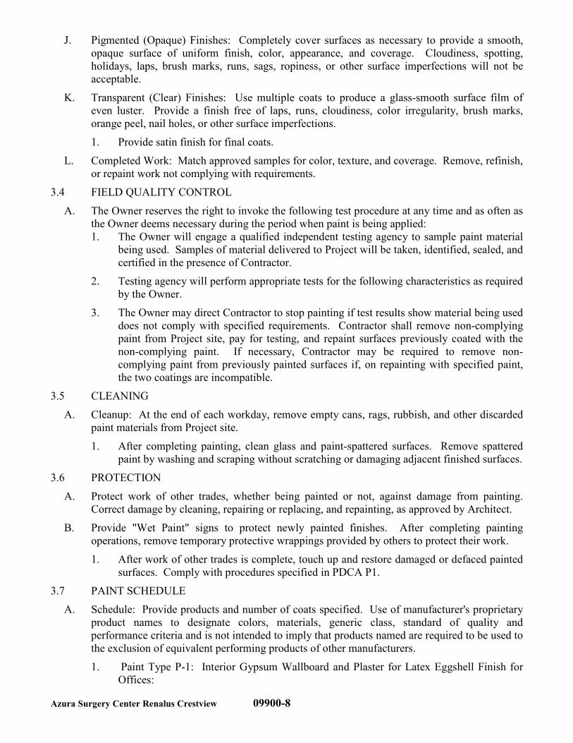
Azura Surgery Center Renalus Crestview 09900-8
J. Pigmented (Opaque) Finishes: Completely cover surfaces as necessary to provide a smooth,
opaque surface of uniform finish, color, appearance, and coverage. Cloudiness, spotting,
holidays, laps, brush marks, runs, sags, ropiness, or other surface imperfections will not be
acceptable.
K. Transparent (Clear) Finishes: Use multiple coats to produce a glass-smooth surface film of
even luster. Provide a finish free of laps, runs, cloudiness, color irregularity, brush marks,
orange peel, nail holes, or other surface imperfections.
1. Provide satin finish for final coats.
L. Completed Work: Match approved samples for color, texture, and coverage. Remove, refinish,
or repaint work not complying with requirements.
3.4 FIELD QUALITY CONTROL
A. The Owner reserves the right to invoke the following test procedure at any time and as often as
the Owner deems necessary during the period when paint is being applied:
1. The Owner will engage a qualified independent testing agency to sample paint material
being used. Samples of material delivered to Project will be taken, identified, sealed, and
certified in the presence of Contractor.
2. Testing agency will perform appropriate tests for the following characteristics as required
by the Owner.
3. The Owner may direct Contractor to stop painting if test results show material being used
does not comply with specified requirements. Contractor shall remove non-complying
paint from Project site, pay for testing, and repaint surfaces previously coated with the
non-complying paint. If necessary, Contractor may be required to remove non-
complying paint from previously painted surfaces if, on repainting with specified paint,
the two coatings are incompatible.
3.5 CLEANING
A. Cleanup: At the end of each workday, remove empty cans, rags, rubbish, and other discarded
paint materials from Project site.
1. After completing painting, clean glass and paint-spattered surfaces. Remove spattered
paint by washing and scraping without scratching or damaging adjacent finished surfaces.
3.6 PROTECTION
A. Protect work of other trades, whether being painted or not, against damage from painting.
Correct damage by cleaning, repairing or replacing, and repainting, as approved by Architect.
B. Provide "Wet Paint" signs to protect newly painted finishes. After completing painting
operations, remove temporary protective wrappings provided by others to protect their work.
1. After work of other trades is complete, touch up and restore damaged or defaced painted
surfaces. Comply with procedures specified in PDCA P1.
3.7 PAINT SCHEDULE
A. Schedule: Provide products and number of coats specified. Use of manufacturer's proprietary
product names to designate colors, materials, generic class, standard of quality and
performance criteria and is not intended to imply that products named are required to be used to
the exclusion of equivalent performing products of other manufacturers.
1. Paint Type P-1: Interior Gypsum Wallboard and Plaster for Latex Eggshell Finish for
Offices:
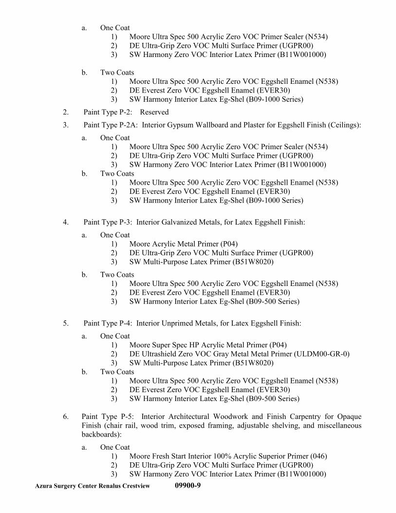
Azura Surgery Center Renalus Crestview 09900-9
a. One Coat
1) Moore Ultra Spec 500 Acrylic Zero VOC Primer Sealer (N534)
2) DE Ultra-Grip Zero VOC Multi Surface Primer (UGPR00)
3) SW Harmony Zero VOC Interior Latex Primer (B11W001000)
b. Two Coats
1) Moore Ultra Spec 500 Acrylic Zero VOC Eggshell Enamel (N538)
2) DE Everest Zero VOC Eggshell Enamel (EVER30)
3) SW Harmony Interior Latex Eg-Shel (B09-1000 Series)
2. Paint Type P-2: Reserved
3. Paint Type P-2A: Interior Gypsum Wallboard and Plaster for Eggshell Finish (Ceilings):
a. One Coat
1) Moore Ultra Spec 500 Acrylic Zero VOC Primer Sealer (N534)
2) DE Ultra-Grip Zero VOC Multi Surface Primer (UGPR00)
3) SW Harmony Zero VOC Interior Latex Primer (B11W001000)
b. Two Coats
1) Moore Ultra Spec 500 Acrylic Zero VOC Eggshell Enamel (N538)
2) DE Everest Zero VOC Eggshell Enamel (EVER30)
3) SW Harmony Interior Latex Eg-Shel (B09-1000 Series)
4. Paint Type P-3: Interior Galvanized Metals, for Latex Eggshell Finish:
a. One Coat
1) Moore Acrylic Metal Primer (P04)
2) DE Ultra-Grip Zero VOC Multi Surface Primer (UGPR00)
3) SW Multi-Purpose Latex Primer (B51W8020)
b. Two Coats
1) Moore Ultra Spec 500 Acrylic Zero VOC Eggshell Enamel (N538)
2) DE Everest Zero VOC Eggshell Enamel (EVER30)
3) SW Harmony Interior Latex Eg-Shel (B09-500 Series)
5. Paint Type P-4: Interior Unprimed Metals, for Latex Eggshell Finish:
a. One Coat
1) Moore Super Spec HP Acrylic Metal Primer (P04)
2) DE Ultrashield Zero VOC Gray Metal Metal Primer (ULDM00-GR-0)
3) SW Multi-Purpose Latex Primer (B51W8020)
b. Two Coats
1) Moore Ultra Spec 500 Acrylic Zero VOC Eggshell Enamel (N538)
2) DE Everest Zero VOC Eggshell Enamel (EVER30)
3) SW Harmony Interior Latex Eg-Shel (B09-500 Series)
6. Paint Type P-5: Interior Architectural Woodwork and Finish Carpentry for Opaque
Finish (chair rail, wood trim, exposed framing, adjustable shelving, and miscellaneous
backboards):
a. One Coat
1) Moore Fresh Start Interior 100% Acrylic Superior Primer (046)
2) DE Ultra-Grip Zero VOC Multi Surface Primer (UGPR00)
3) SW Harmony Zero VOC Interior Latex Primer (B11W001000)
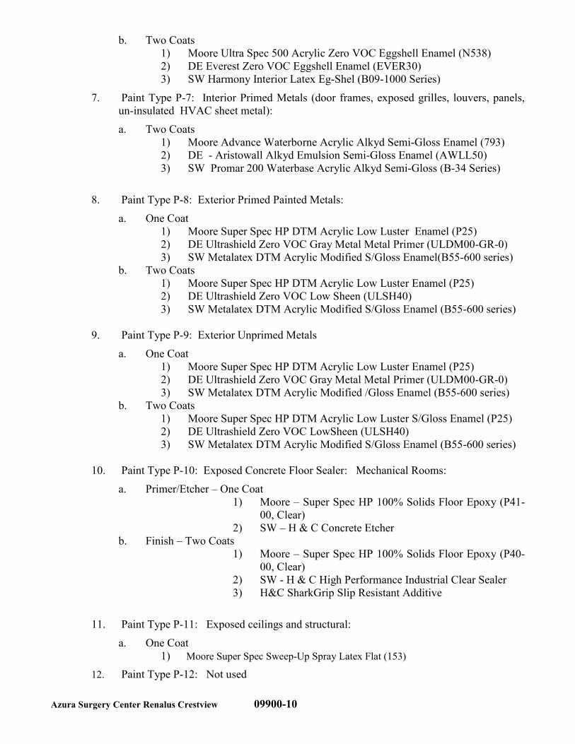
Azura Surgery Center Renalus Crestview 09900-10
b. Two Coats
1) Moore Ultra Spec 500 Acrylic Zero VOC Eggshell Enamel (N538)
2) DE Everest Zero VOC Eggshell Enamel (EVER30)
3) SW Harmony Interior Latex Eg-Shel (B09-1000 Series)
7. Paint Type P-7: Interior Primed Metals (door frames, exposed grilles, louvers, panels,
un-insulated HVAC sheet metal):
a. Two Coats
1) Moore Advance Waterborne Acrylic Alkyd Semi-Gloss Enamel (793)
2) DE - Aristowall Alkyd Emulsion Semi-Gloss Enamel (AWLL50)
3) SW Promar 200 Waterbase Acrylic Alkyd Semi-Gloss (B-34 Series)
8. Paint Type P-8: Exterior Primed Painted Metals:
a. One Coat
1) Moore Super Spec HP DTM Acrylic Low Luster Enamel (P25)
2) DE Ultrashield Zero VOC Gray Metal Metal Primer (ULDM00-GR-0)
3) SW Metalatex DTM Acrylic Modified S/Gloss Enamel(B55-600 series)
b. Two Coats
1) Moore Super Spec HP DTM Acrylic Low Luster Enamel (P25)
2) DE Ultrashield Zero VOC Low Sheen (ULSH40)
3) SW Metalatex DTM Acrylic Modified S/Gloss Enamel (B55-600 series)
9. Paint Type P-9: Exterior Unprimed Metals
a. One Coat
1) Moore Super Spec HP DTM Acrylic Low Luster Enamel (P25)
2) DE Ultrashield Zero VOC Gray Metal Metal Primer (ULDM00-GR-0)
3) SW Metalatex DTM Acrylic Modified /Gloss Enamel (B55-600 series)
b. Two Coats
1) Moore Super Spec HP DTM Acrylic Low Luster S/Gloss Enamel (P25)
2) DE Ultrashield Zero VOC LowSheen (ULSH40)
3) SW Metalatex DTM Acrylic Modified S/Gloss Enamel (B55-600 series)
10. Paint Type P-10: Exposed Concrete Floor Sealer: Mechanical Rooms:
a. Primer/Etcher – One Coat
1) Moore – Super Spec HP 100% Solids Floor Epoxy (P41-
00, Clear)
2) SW – H & C Concrete Etcher
b. Finish – Two Coats
1) Moore – Super Spec HP 100% Solids Floor Epoxy (P40-
00, Clear)
2) SW - H & C High Performance Industrial Clear Sealer
3) H&C SharkGrip Slip Resistant Additive
11. Paint Type P-11: Exposed ceilings and structural:
a. One Coat
1) Moore Super Spec Sweep-Up Spray Latex Flat (153)
12. Paint Type P-12: Not used
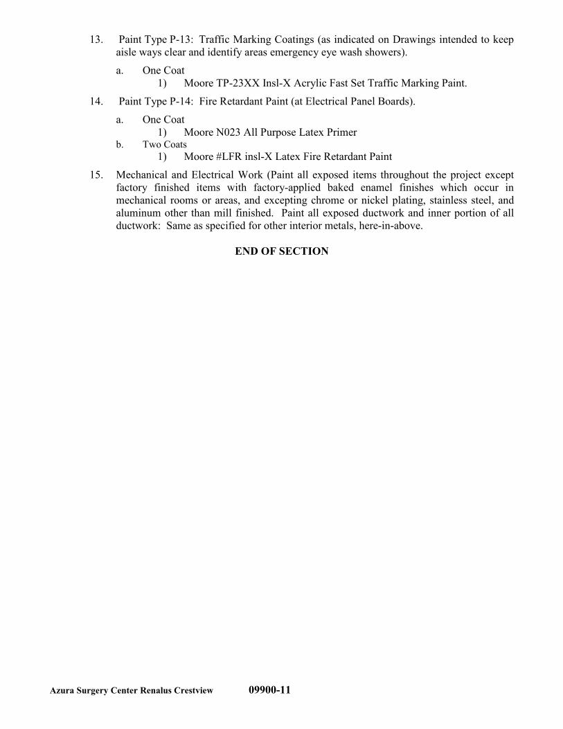
Azura Surgery Center Renalus Crestview 09900-11
13. Paint Type P-13: Traffic Marking Coatings (as indicated on Drawings intended to keep
aisle ways clear and identify areas emergency eye wash showers).
a. One Coat
1) Moore TP-23XX Insl-X Acrylic Fast Set Traffic Marking Paint.
14. Paint Type P-14: Fire Retardant Paint (at Electrical Panel Boards).
a. One Coat
1) Moore N023 All Purpose Latex Primer b. Two Coats
1) Moore #LFR insl-X Latex Fire Retardant Paint
15. Mechanical and Electrical Work (Paint all exposed items throughout the project except
factory finished items with factory-applied baked enamel finishes which occur in
mechanical rooms or areas, and excepting chrome or nickel plating, stainless steel, and
aluminum other than mill finished. Paint all exposed ductwork and inner portion of all
ductwork: Same as specified for other interior metals, here-in-above.
END OF SECTION
Azura Surgery Center Renalus Crestview 07/17 10190-1
SECTION 10190
CUBICLE CURTAINS AND TRACKS
PART 1 - GENERAL
1.01 SUMMARY
A. Work included: Provide labor, materials and equipment necessary to complete the work of this
Section, including but not limited to the following:
1. Cubicle curtains.
2. Cubicle curtain track and associated hardware.
B. Note – Cubicle Curtains are only required in certain states as required by individual state
regulations.
C. Related work: The following items are not included in this section and will be performed
under the designated Sections:
1. Section 09511 – ACOUSTICAL PANEL CEILINGS for grid-mounted curtain track.
1.02 SUBMITTALS
A. Comply with pertinent provisions of Section 01340; shop drawings, product data and samples.
1. Product Data: Within 20 calendar days after the Contractor has received Owner’s Notice
to Proceed, submit:
2. Materials list of items proposed to be provided under this Section.
3. Shop Drawings showing proposed method of installation, anchoring, and interface
between the work of this Section and the work of adjacent trades.
4. Manufacturer’s recommended installation procedures.
1.03 QUALITY ASSURANCE
A. Use adequate numbers of skilled personnel who are thoroughly trained and experienced in the
necessary crafts and who are completely familiar with the specified requirements and the
methods needed for proper performance of the work of this Section.
1.04 PRODUCT HANDLING
A. Deliver materials in unopened factory packaging to the jobsite.
B. Inspect materials at delivery to ensure that specified products have been received.
C. Store in original packaging in a climate controlled location away from direct sunlight.
PART 2 - PRODUCTS
2.01 MANUFACTURERS
A. Inpro Corporation, P.O. Box 406, Muskego, Wisconsin 53150
Phone: 1.800.222.5556, Fax: 888.715.8407
www.inprocorp.com
2.02 TRACK COMPONENTS
A. Cubicle Track: Provide extruded aluminum cubicle track with white baked acrylic enamel
finish. Section size is 3/4" high by 1-3/8" wide. Track to be prefabricated to shape in one
continuous piece whenever possible. Corner radius to be 12".
1. Acceptable Product: Clickeze “Optitrac” Cubicle Track.
Azura Surgery Center Renalus Crestview 07/17 10190-2
B. Curtain Carriers: Provide curtain carriers with virgin nylon bodies, stainless steel bead chain
and hard aluminum hooks.
C. Track End Stops: Provide molded thermoplastic end stops for all track section ends.
D. Track Attachment: Provide appropriate hardware accessories as required for attachment to
suspended ceiling grid.
2.03 CURTAIN MATERIAL
A. Provide opaque curtain material with anti-microbial coating and 1/2" nylon mesh attached at
the top of the curtain. Standard curtain and mesh color to be white (due to the use of
bleach to clean the curtains). Curtain material shall be flame resistant in accordance with
NFPA 701 and California Fire Marshall Title 19 test for vertical flammability. Mesh to be
flame retardant, 100% washable Nylon with 1/2" openings.
1. Acceptable Product: Clickeze Shower Curtain – Super Bio Stat.
a) Color – Maharam Increment Frame 511443-004
B. Typical curtain dimensions (for typical ceiling heights from 8'-0" to 10'0")
1. Curtain to be 15" A.F.F.
2. Nylon mesh to be 22" in height (includes 1" header and footer).
3. Cloth height varies, based on actual ceiling height.
4. Overall curtain width to be 10% greater than the length of finished track.
PART 3 - EXECUTION
3.01 SURFACE CONDITIONS
A. Examine the areas and conditions under which work of this Section will be performed. Correct
conditions detrimental to timely and proper completion of the Work. Do not proceed until
unsatisfactory conditions are corrected.
3.02 INSTALLATION
A. Install the work of this Section in strict accordance with the manufacturer’s recommendations.
B. Install curtains after final cleaning has been completed.
C. Provide two (2) extra sets of curtains to the clinic.
END OF SECTION
Azura Surgery Center Renalus Crestview 10260-1 07/17
SECTION 10260
WALL AND DOOR PROTECTION
PART 1 - GENERAL
1.1 DESCRIPTION OF WORK
A. Work Included: Provide labor, materials and equipment necessary to complete the work of this
Section, including but not limited to the following:
1. Corner guards.
2. Impact-resistant wall coverings.
3. Molded Chair Rail
B. Related Work: The following items are not included in this Section and will be performed
under the designated Sections:
1. Section 08710 - DOOR HARDWARE for metal armor, kick, mop and push plates.
1.2 SUBMITTALS
A. Product Data: Include construction details, material descriptions, impact strength, and fire-test-
response characteristics, dimensions of individual components and profiles, and finishes for
each impact-resistant wall-protection unit.
B. Shop Drawings: For each impact-resistant wall-protection unit showing locations and extent.
Include sections, details, and attachments to other work.
C. Samples for Verification: For each type of exposed finish required, prepared on Samples of
size indicated below.
1. Corner Guards: 12 inches long. Include examples of joinery, corners, end caps, top caps,
and field splices.
2. Impact-Resistant Wall Covering: 6 by 6 inches square.
D. Material Certificates: For each impact-resistant plastic material, signed by manufacturer.
E. Maintenance Data: For each impact-resistant wall-protection unit to include in maintenance
manuals.
1. Include recommended methods and frequency of maintenance for maintaining optimum
condition of plastic covers under anticipated traffic and use conditions. Include
precautions against using cleaning materials and methods that may be detrimental to
plastic finishes and performance.
F. Warranty: Special warranty specified in this Section.
1.3 QUALITY ASSURANCE
A. Installer Qualifications: An employer of workers trained and approved by manufacturer.
B. Source Limitations: Obtain impact-resistant wall-protection units through one source from a
single manufacturer.
C. Fire-Test-Response Characteristics: Provide impact-resistant, plastic wall-protection units with
surface-burning characteristics as determined by testing identical products per ASTM E 84,
NFPA 255, or UL 723 by UL or another testing and inspecting agency acceptable to authorities
having jurisdiction.
Azura Surgery Center Renalus Crestview 10260-2 07/17
1.4 DELIVERY, STORAGE, AND HANDLING
A. Store impact-resistant wall-protection units in original undamaged packages and containers
inside well-ventilated area protected from weather, moisture, soiling, extreme temperatures,
and humidity.
1. Maintain room temperature within storage area at not less than 70 deg F during the period
plastic materials are stored.
2. Keep plastic sheet material out of direct sunlight.
3. Store plastic wall-protection components for a minimum of 72 hours, or until plastic
material attains a minimum room temperature of 70 deg F.
a. Store corner-guard covers in a vertical position.
1.5 PROJECT CONDITIONS
A. Environmental Limitations: Do not deliver or install impact-resistant wall-protection units
until building is enclosed and weatherproof, wet work is complete and dry, and HVAC system
is operating and maintaining temperature at 70 deg F for not less than 72 hours before
beginning installation and for the remainder of the construction period.
B. Field Measurements: Verify actual locations of walls, columns, and other construction
contiguous with impact-resistant wall-protection units by field measurements before fabrication
and indicate measurements on Shop Drawings.
1.6 WARRANTY
A. Special Warranty: Manufacturer’s standard form in which manufacturer agrees to repair or
replace components of impact-resistant wall-protection units that fail in materials or
workmanship within specified warranty period.
1. Failures include, but are not limited to, the following:
a. Structural failures.
b. Deterioration of plastic and other materials beyond normal use.
2. Warranty Period: Five years from date of Substantial Completion, and a limited lifetime
warranty, where applicable.
1.7 EXTRA MATERIALS
A. Furnish extra materials described below that match products installed, and that are packaged
with protective covering for storage and identified with labels describing contents.
1. Corner-Guard Covers: Full-size plastic covers of maximum length equal to 2 percent of
each type, color, and texture of units installed, but no fewer than four, 4-foot-long units.
B. Include mounting and accessory components. Replacement materials shall be from same
production run as installed units.
PART 2 - PRODUCTS
2.1 MATERIALS
A. Extruded Rigid Plastic: ASTM D 1784, Class 1, textured, chemical- and stain-resistant, high-
impact-resistant PVC or acrylic-modified vinyl plastic with integral color throughout; thickness
as indicated.
1. Impact Resistance: Minimum 25.4 ft-lb-ft/in. of notch when tested according to
ASTM D 256, Test Method A.
2. Chemical and Stain Resistance: Tested according to ASTM D 543.
3. Self-extinguishing when tested according to ASTM D 635.
4. Flame-Spread Index: 25 or less.
Azura Surgery Center Renalus Crestview 10260-3 07/17
5. Smoke-Developed Index: 450 or less.
B. Aluminum Extrusions: Alloy and temper recommended by manufacturer for type of use and
finish indicated but with not less than strength and durability properties specified in
ASTM B 221 for Alloy 6063-T5.
C. Fasteners: Aluminum, nonmagnetic stainless steel, or other noncorrosive metal screws, bolts,
and other fasteners compatible with items being fastened. Use security-type fasteners where
exposed to view.
2.2 CORNER GUARDS
A. Surface-Mounted, Resilient, Plastic Corner Guards: Assembly consisting of snap-on plastic
cover installed over continuous retainer; including mounting hardware; fabricated with 90- or
135-degree turn to match wall condition.
1. Acceptable Products:
a. Model No. 150BN, 3” Wing, 90 Degree Surface Mount Corner Guard Profile.
b. Model No. 130BN, 135 Degree Surface Mount Corner Guard Profile.
c. Manufacturer - IPC Door and Wall Protection Systems; Division of InPro
Corporation, Muskego, WI 53150; www.inprocorp.com.
2. Cover: Extruded rigid plastic, minimum 0.08-inch wall thickness; as follows:
a. Profile: Nominal 2-inch-long leg and 1/4-inch corner radius.
b. Required Heights:
1) 48" – at typical corners.
2) 96" – at full height FRP and vinyl wall paneling.
c. Color and Texture: Refer to Finish Schedule.
3. Retainer: Minimum 0.070-inch-thick, 1-piece, extruded aluminum.
4. Top and Bottom Caps: Prefabricated, injection-molded plastic; color matching cover;
field adjustable for close alignment with snap-on cover.
5. Custom Angles – Provide vinyl covers and retainers with custom angles. Custom angles
shall be between 112.5° and 157.5°. Provide flexible top caps to bend to retainer angle.
6. Fire Rating: Same rating as wall in which corner guard is installed; UL listed and labeled
according to UL 2079.
2.3 IMPACT-RESISTANT WALL COVERINGS
A. Impact-Resistant Sheet Wall Covering: Fabricated from rigid plastic sheet material.
1. Designation on Drawings: RVP
2. Acceptable Product: IPC Rigid Vinyl Sheet by IPC Door and Wall Protection Systems;
Division of InPro Corporation, Muskego, WI 53150; www.inprocorp.com.
3. Size: 48 by 96 inches for sheet, minimum.
4. Sheet Thickness: 0.040 inches (standard); 0.080 (on wall behind scale).
5. Color and Texture: Refer to Finish Schedule.
6. Height: As indicated.
7. Trim and Joint Moldings: Extruded rigid plastic that matches sheet wall covering color.
8. Mounting: Use adhesive as recommended by manufacturer.
B. NON-Fiberglass Reinforced Plastic Panels (NRP-FR) with top coat; Class A (ASTM E-84):
1. Acceptable Product: Parkland Plastics NRP-FR panels; Part numbers: FRE3110C (4x8),
FRE3120C (4x10).
2. Size: 48 by 96 inches for sheet, minimum.
3. Sheet Thickness: 0.090 inches (standard).
4. Color and Texture: Refer to Finish Schedule.
Azura Surgery Center Renalus Crestview 10260-4 07/17
5. Height: As indicated.
6. Trim and Joint Moldings: Extruded rigid plastic that matches sheet wall covering color
Almond. 2-piece Divider moulding; 1-piece Inside Corner moulding; 1-piece Cap
moulding; 2-piece Outside Corner moulding.
7. Mounting: Refer to Manufacturers “Installation Guide”. Use adhesive only as
recommended by manufacturer.
2.4 FABRICATION
A. Fabricate impact-resistant wall-protection units to comply with requirements indicated for
design, dimensions, and member sizes, including thicknesses of components.
B. Assemble components in factory to greatest extent possible to minimize field assembly.
Disassemble only as necessary for shipping and handling.
C. Fabricate components with tight seams and joints with exposed edges rolled. Provide surfaces
free of wrinkles, chips, dents, uneven coloration, and other imperfections. Fabricate members
and fittings to produce flush, smooth, and rigid hairline joints.
PART 3 - EXECUTION
3.1 EXAMINATION
A. Examine substrates and wall areas, with Installer present, for compliance with requirements for
installation tolerances, fire rating, and other conditions affecting performance of work.
1. Examine walls to which impact-resistant wall protection will be attached for blocking,
grounds, and other solid backing that have been installed in the locations required for
secure attachment of support fasteners.
2. Proceed with installation only after unsatisfactory conditions have been corrected.
3.2 PREPARATION
A. Complete finishing operations, including painting, before installing impact-resistant wall-
protection system components.
B. Before installation, clean substrate to remove dust, debris, and loose particles.
3.3 INSTALLATION
A. General: Install impact-resistant wall-protection units level, plumb, and true to line without
distortions. Do not use materials with chips, cracks, voids, stains, or other defects that might be
visible in the finished Work.
1. Install impact-resistant wall-protection units in locations and at mounting heights
indicated on Drawings.
2. Provide splices, mounting hardware, anchors, and other accessories required for a
complete installation.
a. Provide anchoring devices to withstand imposed loads.
b. Where splices occur in horizontal runs of more than 20 feet, splice aluminum
retainers and plastic covers at different locations along the run, but no closer than
12 inches.
c. Adjust caps as required to ensure tight seams.
B. Impact-Resistant Wall Covering: Install top and edge moldings, corners, and divider bars as
required for a complete installation. Install panels vertically, with butt joints between panels.
C. Installation of Mannington Effectual vinyl wall base and chair rail: Install per manufacturer’s
specifications. Vinyl trim sections (particularly chair rail) can be nailed to the drywall substrate
to assist the adhesive bond. Nail holes should be filled to match trim for complete installation.
Azura Surgery Center Renalus Crestview 10260-5 07/17
3.4 CLEANING
A. Immediately after completion of installation, clean plastic covers and accessories using a
standard, ammonia-based, household cleaning agent.
B. Remove excess adhesive using methods and materials recommended in writing by
manufacturer.
END OF SECTION
Azura Surgery Center Renalus Crestview 10440 - 1 07/17
SECTION 10440
INTERIOR SIGNAGE
PART 1 - GENERAL
1.1 DESCRIPTION OF WORK
A. Work Included: Provide labor, materials and equipment necessary to complete the work of this
Section including, but not limited to, the following:
1. Installation of Interior Room Signs
B. Related Work: The following items are not included in this Section and will be performed
under the designated Sections:
1. Section 09260 - GYPSUM BOARD ASSEMBLIES for coordination with wall-mounted
units.
1.2 SUBMITTALS
A. Product Data illustrating size, mounting method, sign color, message.
1.3 REFERENCES
A. Americans with Disabilities Act (ADA):
1. ATBCB ADAAG - Americans with Disabilities Act Accessibility Guidelines.
B. American National Standards Institute (ANSI):
1. ANSI A117.1 - Accessible and Usable Buildings and Facilities.
2. ASTM International (ASTM).
3. ASTM D 635 - Standard Test Method for Rate of Burning and/or Extent and Time of
Burning of Plastics in a Horizontal Position.
4. ASTM D 1929 - Standard Test Method for Determining Ignition Temperature of Plastics.
5. ASTM E 84 - Standard Test Method for Surface Burning Characteristics of Building
Materials.
6. ASTM E 2073 - Standard Test Method for Photopic Luminance of Photoluminescent
(Phosphorescent) Markings.
C. Underwriters Laboratory (UL):
1. UL 94 - Tests for Flammability of Plastic Materials for Parts in Devices and Appliances.
2. UL 723 - Surface Burning Characteristics of Interior Finish Materials and Systems.
1.4 DELIVERY, STORAGE, AND HANDLING
A. Accept materials in unopened factory packaging.
B. Inspect materials upon delivery to verify entire order has been received.
C. Store products in manufacturer’s original packaging until ready for installation, in climate
controlled location away from direct sunlight.
1.5 COORDINATION
A. Coordinate height and location of signs with Owner and AHJ.
PART 2 - PRODUCTS
2.1 MANUFACTURERS
A. Manufacturer: Best Sign Systems, Inc., 1202 N. Park Avenue, Montrose, CO 81401, phone
970-249-2378
Azura Surgery Center Renalus Crestview 10440 - 2 07/17
B. Products
1. Signage supplied by Owner.
PART 3 - EXECUTION
3.1 PREPARATION
A. Verify mounting heights and locations comply with referenced standards.
B. Clean surfaces thoroughly prior to installation to remove dust, debris and loose particles.
C. Prepare surfaces using the methods recommended by the manufacturer for achieving the best
result for the substrate under the project conditions.
3.2 INSTALLATION
A. Locate the signage system as indicated on drawings for the appropriate substrate and in
accordance with manufacturer's installation instructions.
B. Install signage systems level and plumb at the height indicated on the drawings.
3.3 PROTECTING AND CLEANING
A. After installation, protect all signage from damage during construction.
B. If damage occurs despite such protection, remove and replace damaged components or entire
unit as required to provide units in their original, undamaged condition.
C. Touch-up, repair or replace damaged products before Substantial Completion.
END OF SECTION
Azura Surgery Center Renalus Crestview 10500-1 07/17 Version
SECTION 10500
LOCKERS
PART 1 - GENERAL
1.1 DESCRIPTION OF WORK
A. Work Included: Provide labor, materials and equipment necessary to complete the work of this
Section including, but not limited to, the following:
1. Phenolic Lockers
B. Related Work: The following items are not included in this Section and will be performed
under the designated Sections:
1. Section 06100 - ROUGH CARPENTRY for blocking and locker bases.
1.2 SUBMITTALS
A. Product Data: Include construction details, material descriptions, dimensions of individual
components and profiles, and finishes for each item.
B. Samples: Submit 12 inch square samples of locker material.
1.3 QUALITY ASSURANCE
A. Source Limitations: Obtain lockers through one source from a single manufacturer.
PART 2 - PRODUCTS
2.1 APPROVED MANUFACTURERS
A. ASI Storage Solutions.
2.2 PHENOLIC LOCKERS
A. Phenolic Lockers: Provide phenolic lockers with louvered vents and ADA compliant handles.
B. Doors shall be constructed of ½” solid phenolic core decorative plastic laminate with multiple
resin-impregnated kraft and surface sheets fused at high temperature and pressure.
C. Side and Back Panels shall be constructed of 3/8” solid phenolic core with Folkstone Celesta
decorative plastic laminate with multiple resin-impregnated kraft and surface sheets fused at
high temperature and pressure.
D. Tops, Bottoms, End Cover Panels, and Shelves shall be constructed of ½” solid phenolic core
decorative plastic laminate with multiple resin-impregnated kraft and surface sheets fused at
high temperature and pressure.
2.3 CONSTRUCTION
A. Doors shall be fitted with recessed handle, number plate, padlock hasp, and optional locking device.
Perimeter ventilation. Doors shall be mounted to side panel using powder coated steel piano-type hinges
and machined fasteners. Door edges shall be smooth and chamfered with corners radiused.
B. Side Panels shall be attached to all Tops, Bottoms, and Shelves, using rust-resistant and steel fasteners.
Exposed edges shall be smooth and chamfered.
C. Tops, Bottoms, and Shelves shall be attached to all Side Panels, using rust-resistant and steel fasteners.
Exposed edges shall be smooth and chamfered.
D. The color and texture of the finish on Phenolic Lockers is determined by the selected decorative plastic
laminate pattern. Color selection is allowed for Doors and End Cover Panels only; all other components
are Folkstone Celesta.
Azura Surgery Center Renalus Crestview 10500-2 07/17 Version
2.4 HARDWARE
A. Doors
1. All Hinges shall be of powder coated steel, 120° Limited hinge
2. Door Latches shall be mounted at the mid-point of each door. Hasps shall be mounted below each
handle and will accept standard padlock styles.
B. Fasteners shall be of rust resistant door hinges and latches, and handles will be mounted with rivets
and/or machine screws. Hooks and number plates will be mounted with rivets.
C. End Cover Panels will be mounted with stainless steel barrel screws.
D. Locker Units can be banked together will stainless steel barrel screws.
2.5 Acceptable Products:
a. ASI Traditional Phenolic Lockers by ASI Storage Solutions
1) Two Person Z Style: 12” x 12” x 72”
2) Color: As selected from manufacturer’s standard color chart. Submit chart to
Architect for selection
2. Sizes and Configurations: As indicated on Drawings.
3. Lockers must be able to accept padlocks by others.
4. Accessories: Coat hooks, coat rods, operating hardware, filler panels, and continuous
sloped tops.
2.6 FABRICATION
A. Assemble lockers to be truly straight, plumb, level and square with flat planes free from warps,
kinks and dents. Fabricate work with uniform, light-tight joints. Assemble lockers using
manufacturer’s standard methods. Do not expose fasteners on locker faces.
B. Number Plates: Provide etched, embossed or stamped plates with 3/8 inch high numbers
centered on each door near eye level. Provide numbering sequence as indicated on approved
shop drawings.
C. Filler Panels: Provide factory-fabricated filler panels as necessary to form a continuous locker
face of dimension indicated and between lockers and adjacent construction. Finish filler panels
to exactly match lockers.
PART 3 - EXECUTION
3.1 INSTALLATION
A. Strictly comply with manufacturer’s instructions and recommendations, except where more
restrictive requirements are specified in this section. Provide lockers at locations shown.
Install lockers plumb, level and in accurate alignment. Beginning work means Installer accepts
substrates and conditions.
B. Space fasteners at not more than 48" on center. Conceal fasteners as much as possible. Install
base, flat tops, and filler panels. Provide trim, fillers and other accessories as necessary to
provide a complete, uniform assembly.
Azura Surgery Center Renalus Crestview 10500-3 07/17 Version
3.2 ADJUSTING AND CLEANING
A. Adjust operating parts to work easily, smoothly, and correctly. Touch-up damaged coatings
and finishes to eliminate evidence of repair. Repair minor damage to eliminate all evidence of
repair. Clean exposed surfaces using materials and methods recommended by manufacturer of
material or product being cleaned. Remove and replace work that cannot be successfully
cleaned or repaired.
END OF SECTION
Azura Surgery Center Renalus Crestview 10520-1 07/17
SECTION 10520
FIRE-PROTECTION SPECIALTIES
PART 1 - GENERAL
1.1 DESCRIPTION OF WORK
A. Work Included: Provide labor, materials and equipment necessary to complete the work of this
Section, including but not limited to the following:
1. Portable fire extinguishers.
2. Fire-protection cabinets for portable fire extinguishers, fire hose valves, and fire hoses.
3. Mounting brackets for fire extinguishers.
B. Related Work: The following items are not included in this Section and will be performed
under the designated Sections:
1. Section 09900 - PAINTING for field painting fire-protection cabinets.
2. Division 15 - FIRE PROTECTION for fire hose valves and standpipes.
1.2 SUBMITTALS
A. Product Data: Include construction details, material descriptions, dimensions of individual
components and profiles, and finishes for each item.
1. Fire Extinguishers: Include rating and classification.
2. Fire-Protection Cabinets: Include roughing-in dimensions, details showing mounting
methods, relationships of box and trim to surrounding construction, door hardware,
cabinet type, trim style, and panel style.
3. Show location of knockouts for hose valves.
B. Maintenance Data: For fire extinguishers and fire-protection cabinets to include in
maintenance manuals.
1.3 QUALITY ASSURANCE
A. Source Limitations: Obtain fire extinguishers and fire-protection cabinets through one source
from a single manufacturer.
B. NFPA Compliance: Fabricate and label fire extinguishers to comply with NFPA 10, “Portable
Fire Extinguishers.”
C. Fire Extinguishers: Listed and labeled for type, rating, and classification by an independent
testing agency acceptable to authorities having jurisdiction.
D. Fire-Rated Fire-Protection Cabinets: Listed and labeled to comply with requirements of
ASTM E 814 for fire-resistance rating of walls where they are installed.
1.4 COORDINATION
A. Coordinate size of fire-protection cabinets to ensure that type and capacity of fire extinguishers
indicated are accommodated.
B. Coordinate size of fire-protection cabinets to ensure that type and capacity of fire hoses, hose
valves, and hose racks indicated are accommodated.
PART 2 - PRODUCTS
2.1 PORTABLE FIRE EXTINGUISHERS
A. General: Provide fire extinguishers of type, size, and capacity for each fire-protection cabinet
and mounting bracket indicated.
Azura Surgery Center Renalus Crestview 10520-2 07/17
B. Multipurpose Dry-Chemical Type in Steel Container: UL-rated 3A:40B:C, 6-lb nominal
capacity, with monoammonium phosphate-based dry chemical in enameled-steel container.
1. Product: Cosmic 6E series, by JL Industries, Inc.
2.2 FIRE-PROTECTION CABINET
A. Available Manufacturers: Subject to compliance with requirements, manufacturers offering
products that may be incorporated into the Work include, but are not limited to, the following:
1. JL Industries, Inc.
2. Larsen's Manufacturing Company.
3. Potter Roemer; Div. of Smith Industries, Inc.
B. Cabinet Type: Suitable for fire extinguisher, and hose and hose valve where applicable.
C. Cabinet Material: Enameled-steel sheet.
D. Semi-Recessed Cabinet: Cabinet box recessed in walls of sufficient depth to suit style of trim
indicated.
1. Trimless with Plaster Stop: Surface of surrounding wall finishes flush with exterior
finished surface of cabinet frame and door, without overlapping trim attached to cabinet.
Provide recessed flange, of same material as box, attached to box to act as plaster stop.
E. Door Material: Steel sheet with baked enamel finish, color as selected.
F. Door Style: Vertical duo panel with frame.
G. Door Glazing: Tempered break glass.
H. Door Hardware: Manufacturer’s standard door-operating hardware of proper type for cabinet
type, trim style, and door material and style indicated.
I. Accessories:
1. Mounting Bracket: Manufacturer’s standard steel, designed to secure fire extinguisher to
fire-protection cabinet, of sizes required for types and capacities of fire extinguishers
indicated, with plated or baked-enamel finish.
2. Break-Glass Strike: Manufacturer’s standard metal strike, complete with chain and
mounting clip, secured to cabinet.
3. Identification: Lettering complying with authorities having jurisdiction for letter style,
size, spacing, and location. Locate as indicated by Architect.
2.3 MOUNTING BRACKETS
A. Mounting Brackets: Manufacturer’s standard steel, designed to secure fire extinguisher to wall
or structure, of sizes required for types and capacities of fire extinguishers indicated, with
plated or baked-enamel finish.
1. Product: Mark Bracket MB808 for Cosmic 6E series, by JL Industries, Inc.
B. Identification: Lettering complying with authorities having jurisdiction for letter style, size,
spacing, and location. Locate as indicated by Architect.
2.4 FABRICATION
A. Fire-Protection Cabinets: Provide manufacturer’s standard box (tub), with trim, frame, door,
and hardware to suit cabinet type, trim style, and door style indicated.
1. Weld joints and grind smooth.
2. Construct fire-rated cabinets with double walls fabricated from 0.0428-inch-thick, cold-
rolled steel sheet lined with minimum 5/8-inch-thick, fire-barrier material.
a. Provide factory-drilled mounting holes.
Azura Surgery Center Renalus Crestview 10520-3 07/17
B. Cabinet Doors: Fabricate doors according to manufacturer’s standards, from materials
indicated and coordinated with cabinet types and trim styles selected.
1. Fabricate door frames with tubular stiles and rails and hollow-metal design, minimum 1/2
inch thick.
2. Miter and weld perimeter door frames.
C. Cabinet Trim: Fabricate cabinet trim in one piece with corners mitered, welded, and ground
smooth.
2.5 FINISHES, GENERAL
A. Comply with NAAMM's “Metal Finishes Manual for Architectural and Metal Products” for
recommendations for applying and designating finishes.
B. Protect mechanical finishes on exposed surfaces from damage by applying a strippable,
temporary protective covering before shipping.
C. Finish fire-protection cabinets after assembly.
D. Appearance of Finished Work: Variations in appearance of abutting or adjacent pieces are
acceptable if they are within one-half of the range of approved Samples. Noticeable variations
in the same piece are not acceptable. Variations in appearance of other components are
acceptable if they are within the range of approved Samples and are assembled or installed to
minimize contrast.
PART 3 - EXECUTION
3.1 EXAMINATION
A. Examine roughing-in for hose valves and cabinets to verify actual locations of piping
connections before cabinet installation.
B. Examine walls and partitions for suitable framing depth and blocking where recessed cabinets
will be installed.
C. Examine fire extinguishers for proper charging and tagging.
1. Remove and replace damaged, defective, or undercharged units.
D. Proceed with installation only after unsatisfactory conditions have been corrected.
3.2 PREPARATION
A. Prepare recesses for recessed fire-protection cabinets as required by type and size of cabinet
and trim style.
3.3 INSTALLATION
A. General: Install fire-protection specialties in locations and at mounting heights indicated on the
Drawings and acceptable to authorities having jurisdiction.
B. Fire-Protection Cabinets: Fasten fire-protection cabinets to structure, square and plumb.
1. Unless otherwise indicated, provide recessed fire-protection cabinets. If wall thickness is
not adequate for recessed cabinets, provide semi-recessed fire-protection cabinets.
2. Provide inside latch and lock for break-glass panels.
3. Fasten mounting brackets to inside surface of fire-protection cabinets, square and plumb.
C. Mounting Brackets: Fasten mounting brackets to surfaces, square and plumb, at locations
indicated.
D. Identification: Apply vinyl lettering at locations indicated.
Azura Surgery Center Renalus Crestview 10520-4 07/17
E. Signage: All signs must be installed perpendicular to the path of egress.
3.4 INSTALLATION OF FIRE-RATED CABINETS
A. Install cabinet with not more than 1/16-inch tolerance between pipe OD and knockout OD.
Center pipe within knockout.
B. Seal through penetrations with firestopping sealant as specified in Section 07841 -
PENETRATION FIRESTOPPING.
3.5 ADJUSTING AND CLEANING
A. Remove temporary protective coverings and strippable films, if any, as fire-protection
specialties are installed, unless otherwise indicated in manufacturer’s written installation
instructions.
B. Adjust fire-protection cabinet doors to operate easily without binding. Verify that integral
locking devices operate properly.
C. On completion of fire-protection cabinet installation, clean interior and exterior surfaces as
recommended by manufacturer.
D. Touch up marred finishes, or replace fire-protection cabinets that cannot be restored to factory-
finished appearance. Use only materials and procedures recommended or furnished by fire-
protection cabinet manufacturer.
E. Replace fire-protection cabinets that have been damaged or have deteriorated beyond
successful repair by finish touchup or similar minor repair procedures.
F. Service, charge, tag and obtain local fire department certification for each F.E. not more than 5
calendar days prior to the date of substantial completion of the work, as that date is established
by the architect.
END OF SECTION
Azura Surgery Center Renalus Crestview 10810-1 01/17
SECTION 10810
TOILET ACCESSORIES, PAPER & SOAP DISPENSERS
PART 1 - GENERAL
1.1 DESCRIPTION OF WORK
A. Work Included: Provide labor, materials and equipment necessary to complete the work of this
Section, including but not limited to the following:
1. Toilet accessories as scheduled on the Drawings. Coordinate with Owner for accessories
provided by Owner.
B. Related Work: The following items are not included in this Section and will be performed
under the designated Sections:
1. Section 06100 - ROUGH CARPENTRY for blocking.
2. Division 15 - PLUMBING.
1.2 SUBMITTALS
A. Product Data: For each type of product indicated. Include the following:
1. Construction details and dimensions.
2. Anchoring and mounting requirements, including requirements for cutouts in other work
and substrate preparation.
3. Material and finish descriptions.
4. Features that will be included for Project.
5. Manufacturer's warranty.
B. Product Schedule: Indicating types, quantities, sizes, and installation locations by room of each
accessory required.
1. Identify locations using room designations indicated on Drawings.
2. Identify products using designations indicated on Drawings.
C. Maintenance Data: For toilet accessories to include in maintenance manuals.
1.3 QUALITY ASSURANCE
A. Source Limitations: For products listed together in the same articles in Part 2, provide products
of same manufacturer unless otherwise approved by Architect.
1.4 COORDINATION
A. Coordinate accessory locations with other work to prevent interference with clearances
required for access by people with disabilities, and for proper installation, adjustment,
operation, cleaning, and servicing of accessories.
B. Deliver inserts and anchoring devices set into concrete or masonry as required to prevent
delaying the Work.
PART 2 - PRODUCTS
2.1 MANUFACTURERS
A. Available Manufacturers: Subject to compliance with requirements, manufacturers offering
products that may be incorporated into the Work include the following:
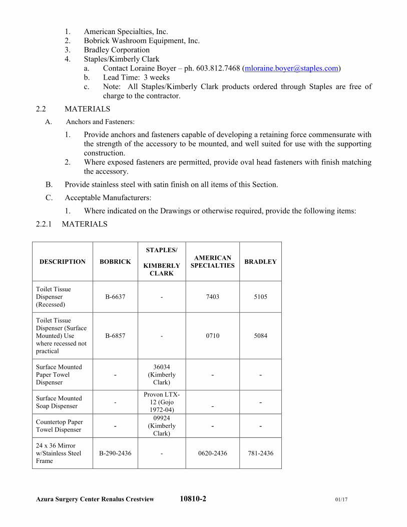
Azura Surgery Center Renalus Crestview 10810-2 01/17
1. American Specialties, Inc.
2. Bobrick Washroom Equipment, Inc.
3. Bradley Corporation
4. Staples/Kimberly Clark
a. Contact Loraine Boyer – ph. 603.812.7468 ([email protected])
b. Lead Time: 3 weeks
c. Note: All Staples/Kimberly Clark products ordered through Staples are free of
charge to the contractor.
2.2 MATERIALS
A. Anchors and Fasteners:
1. Provide anchors and fasteners capable of developing a retaining force commensurate with
the strength of the accessory to be mounted, and well suited for use with the supporting
construction.
2. Where exposed fasteners are permitted, provide oval head fasteners with finish matching
the accessory.
B. Provide stainless steel with satin finish on all items of this Section.
C. Acceptable Manufacturers:
1. Where indicated on the Drawings or otherwise required, provide the following items:
2.2.1 MATERIALS
DESCRIPTION BOBRICK
STAPLES/
KIMBERLY
CLARK
AMERICAN
SPECIALTIES BRADLEY
Toilet Tissue
Dispenser
(Recessed)
B-6637 - 7403 5105
Toilet Tissue
Dispenser (Surface
Mounted) Use
where recessed not
practical
B-6857 - 0710 5084
Surface Mounted
Paper Towel
Dispenser
-
36034
(Kimberly
Clark)
- -
Surface Mounted
Soap Dispenser -
Provon LTX-
12 (Gojo
1972-04)
- -
Countertop Paper
Towel Dispenser -
09924
(Kimberly
Clark)
- -
24 x 36 Mirror
w/Stainless Steel
Frame
B-290-2436 - 0620-2436 781-2436
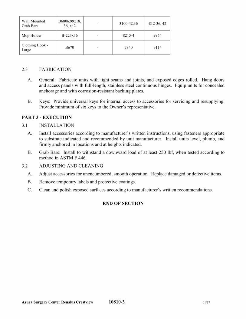
Azura Surgery Center Renalus Crestview 10810-3 01/17
Wall Mounted
Grab Bars
B6806.99x18,
36, x42 - 3100-42,36 812-36, 42
Mop Holder B-223x36 - 8215-4 9954
Clothing Hook -
Large B670 - 7340 9114
2.3 FABRICATION
A. General: Fabricate units with tight seams and joints, and exposed edges rolled. Hang doors
and access panels with full-length, stainless steel continuous hinges. Equip units for concealed
anchorage and with corrosion-resistant backing plates.
B. Keys: Provide universal keys for internal access to accessories for servicing and resupplying.
Provide minimum of six keys to the Owner’s representative.
PART 3 - EXECUTION
3.1 INSTALLATION
A. Install accessories according to manufacturer’s written instructions, using fasteners appropriate
to substrate indicated and recommended by unit manufacturer. Install units level, plumb, and
firmly anchored in locations and at heights indicated.
B. Grab Bars: Install to withstand a downward load of at least 250 lbf, when tested according to
method in ASTM F 446.
3.2 ADJUSTING AND CLEANING
A. Adjust accessories for unencumbered, smooth operation. Replace damaged or defective items.
B. Remove temporary labels and protective coatings.
C. Clean and polish exposed surfaces according to manufacturer’s written recommendations.
END OF SECTION
Azura Surgery Center Renalus Crestview 12494-1 07/17
SECTION 12494
MANUALLY OPERATED ROLLER SHADES
PART 1 - GENERAL
1.1 DESCRIPTION OF WORK
A. Work Included: Provide labor, materials and equipment necessary to complete the work of this
Section, including but not limited to the following:
1. Manually Operated Solar Screen Shades.
B. Related Work: The following items are not included in this Section and will be performed
under the designated Sections:
1. Section 06100 - Rough Carpentry: Wood blocking and grounds for mounting roller
shades and accessories.
2. Section 09260 - Gypsum Board Assemblies: Coordination with gypsum board
assemblies for installation of shade pockets, closures and related accessories.
3. Section 09511 - Acoustical Ceilings: Coordination with acoustical ceiling systems for
installation of shade pockets, closures and related accessories.
1.2 REFERENCES
A. ASTM G 21 - Standard Practice for Determining Resistance of Synthetic Polymeric Materials
to Fungi.
B. NFPA 701 - Fire Tests for Flame-Resistant Textiles and Films.
1.3 SUBMITTALS
A. Product Data: For each type of product indicated. Include styles, material descriptions,
construction details, dimensions of individual components and profiles, features, finishes, and
operating instructions.
B. Shop Drawings: Show location and extent of manually operated shades. Include elevations,
sections, details, and dimensions not shown in Product Data. Show installation details,
mountings, attachments to other Work, operational clearances, and relationship to adjoining
work.
C. Samples for Verification: Shade fabric in specified color, minimum 12" x 12" and aluminum
fascia.
D. Window Treatment Schedule: Include manually operated shades in schedule using same
window number and/or room designations indicated on Drawings.
E. Maintenance Data: For manually operated shades to include in maintenance manuals. Include
the following:
1. Methods for maintaining manually operated shades and finishes.
2. Precautions about cleaning materials and methods that could be detrimental to finishes
and performance.
3. Operating hardware.
1.4 QUALITY ASSURANCE
A. Source Limitations: Obtain manually operated shades through one source from a single
manufacturer.
B. Installer Qualifications: Installer trained and certified by the manufacturer.
Azura Surgery Center Renalus Crestview 12494-2 07/17
C. Fire-Test-Response Characteristics: Passes NFPA 701 small and large-scale vertical burn.
Materials tested shall be identical to products proposed for use.
D. Anti-Microbial Characteristics: ‘No Growth’ per ASTM G 21 results for fungi ATCC9642,
ATCC 9644, ATCC9645.
1.5 DELIVERY, STORAGE, AND HANDLING
A. Deliver roller in factory packages, marked with manufacturer and product name, and location of
installation using same room designations indicated on Drawings and in a window treatment
schedule.
1.6 PROJECT CONDITIONS
A. Environmental Limitations: Do not install manually operated shades until construction and wet
and dirty finish work in spaces, including painting, is complete and ambient temperature and
humidity conditions are maintained at the levels indicated for Project when occupied for its
intended use.
B. Field Measurements: Where manually operated shades are indicated to fit to other
construction, verify dimensions of other construction by field measurements before fabrication
and indicate measurements on Shop Drawings. Allow clearances for operable glazed units’
operation hardware throughout the entire operating range. Notify Architect of discrepancies.
Coordinate fabrication schedule with construction progress to avoid delaying the Work.
1.7 WARRANTY
A. Roller Shade Hardware and Chain Warranty: Manufacturer’s standard non-depreciating ten
year limited warranty.
B. Standard Shadecloth: Manufacturer’s standard ten year warranty.
C. Roller Shade Installation: One year from date of Substantial Completion, not including
scaffolding, lifts or other means to reach inaccessible areas.
PART 2 - PRODUCTS
2.1 MANUFACTURER
A. Available Manufacturer: Subject to compliance with requirements and basis of design,
manufacturer offering products that may be incorporated into the Work is limited to the
following:
1. Inpro Corporation – Solarity Solar Shades, Dawn Solar Screen Fabric
2. Hunter Douglas – M Screen 8505
3. MechoShade Systems – Urban Shade, Thermoveil Dense Basket Weave, 1300 Series.
4. Draper – Clutch FlexShade XD-Phifer 2920
2.2 MANUALLY OPERATED ROLLER SHADE TYPES
1. Mounting: Surface mounted with fascia.
2. Configuration: Single solar shadecloth.
3. Solar Shadecloths:
a. 5% Openness Factor
4. Shade Color: Match Inpro White/Bone with matching valance.
2.3 SHADE BAND
1. Shade Bands: Construction of shade band includes the fabric, the hem weight, hem-
pocket, shade roller tube, and the attachment of the shade band to the roller tube. Sewn
hems and open hem pockets are not acceptable.
Azura Surgery Center Renalus Crestview 12494-3 07/17
2. Hem Pockets and Hem Weights: Fabric hem pocket with RF-welded seams (including
welded ends) and concealed hem weights. Hem weights shall be of appropriate size and
weight for shade band. Hem weight shall be continuous inside a sealed hem pocket.
Hem pocket construction and hem weights shall be similar, for all shades within one
room.
2.4 SHADE BAND AND SHADE ROLLER ATTACHMENT:
1. Use extruded aluminum shade roller tube of a diameter and wall thickness required to
support shade fabric without excessive deflection. Roller tubes less than 1.55 inch (39.37
mm) in diameter for manual shades, and less than 2.55 inches (64.77 mm) for motorize
shades are not acceptable.
2. Provide for positive mechanical engagement with drive / brake mechanism.
3. Provide for positive mechanical attachment of shade band to roller tube; shade band shall
be made removable / replaceable with a “snap-on” snap-off” spline mounting, without
having to remove shade roller from shade brackets.
4. Mounting spline shall not require use of adhesives, adhesive tapes, staples, and/or rivets.
5. Any method of attaching shade band to roller tube that requires the use of adhesive,
adhesive tapes, staples, and/or rivets are not acceptable.
2.5 SHADE FABRICATION
1. Fabricate units to completely fill existing openings from head to sill and jamb-to-jamb,
unless specifically indicated otherwise.
2. Provide battens in standard shades as required to ensure proper tracking and uniform
rolling of the shadebands. Contractor shall be responsible for assuring the width-to-height
(W:H) ratios shall not exceed manufacturer’s standards or, in absence of such standards,
shall be responsible for establishing appropriate standards to assure proper tracking and
rolling of the shadecloth within specified standards. Battens shall be roll-formed stainless
steel or tempered steel, as required.
3. For railroaded shadebands, provide seams in railroaded multi-width shadebands as
required to meet size requirements and in accordance with seam alignment as acceptable
to Architect. Seams shall be properly located. Furnish battens in place of plain seams
when the width, height, or weight of the shade exceeds manufacturer’s standards. In
absence of such standards, assure proper use of seams or battens as required to, and
assure the proper tracking of the railroaded multi-width shadebands.
4. Provide battens for railroaded shades when width-to-height (W/H) ratios meet or exceed
manufacturer’s standards. In absence of manufacturer’s standards, be responsible for
proper use and placement of battens to assure proper tracking and roll of shade bands.
5. If window height is greater than 10'-0", use Mecho 5 system by MechoShade.
2.6 COMPONENTS
A. Access and Material Requirements:
1. Provide shade hardware allowing for the removal of shade roller tube from brackets
without removing hardware from opening and without requiring end or center supports to
be removed.
2. Provide shade hardware that allows for removal and re-mounting of the shade bands
without having to remove the shade tube, drive or operating support brackets.
3. Use only Delrin engineered plastics by DuPont for all plastic components of shade
hardware. Styrene based plastics, and/or polyester, or reinforced polyester will not be
acceptable.
B. Manual Operated Chain Drive Hardware and Brackets:
Azura Surgery Center Renalus Crestview 12494-4 07/17
1. Provide for universal, regular and offset drive capacity, allowing drive chain to fall at
front, rear or non-offset for all shade drive end brackets. Universal offset shall be
adjustable for future change.
2. Provide hardware capable for installation of a removable fascia, for both regular and/or
reverse roll, which shall be installed without exposed fastening devices of any kind.
3. Provide shade hardware system that allows for removable regular and/or reverse roll
fascias to be mounted continuously across two or more shade bands without requiring
exposed fasteners of any kind.
4. Provide shade hardware system that allows for operation of multiple shade bands (multi-
banded shades) by a single chain operator, subject to manufacturer’s design criteria.
Connectors shall be offset to assure alignment from the first to the last shade band.
5. Provide shade hardware system that allows multi-banded manually operated shades to be
capable of smooth operation when the axis is offset a maximum of 6 degrees on each side
of the plane perpendicular to the radial line of the curve, for a 12 degrees total offset.
6. Provide positive mechanical engagement of drive mechanism to shade roller tube.
Friction fit connectors for drive mechanism connection to shade roller tube are not
acceptable.
7. Provide shade hardware constructed of minimum 1/8 inch (3.18 mm) thick plated steel or
heavier as required to support 150 percent of the full weight of each shade.
8. Drive Bracket / Brake Assembly: MechoShade Drive Bracket Model M5 shall be fully
integrated with all MechoShade accessories, including, but not limited to: SnapLoc
fascia, room darkening side / sill channels, center supports and connectors for multi-
banded shades.
9. M5 drive sprocket and brake assembly shall rotate and be supported on a welded 3/8 inch
(9.525 mm) steel pin.
10. The brake shall be an over-running clutch design which disengages to 90 percent during
raising and lowering of a shade. The brake shall withstand a pull force of 50 lbs. (22 kg)
in the stopped position.
11. The braking mechanism shall be applied to an oil-impregnated hub on to which the brake
system is mounted. The oil impregnated hub design includes an articulated brake
assembly, which assures a smooth, non-jerky operation in raising and lowering the
shades. The assembly shall be permanently lubricated. Products that require externally
applied lubrication and/or not permanently lubricated are not acceptable.
12. The entire M5 assembly shall be fully mounted on the steel support bracket, and fully
independent of the shade tube assembly, which may be removed and reinstalled without
affecting the roller shade limit adjustments.
13. Drive Chain: #10 qualified stainless steel chain rated to 90 lb. (41 kg) minimum breaking
strength. Nickel plate chain shall not be accepted.
2.7 ACCESSORIES
A. Fascia:
1. Continuous removable extruded aluminum fascia that attaches to shade mounting
brackets without the use of adhesives, magnetic strips, or exposed fasteners.
2. Fascia shall be able to be installed across two or more shade bands in one piece.
3. Fascia shall fully conceal brackets, shade roller and fabric on the tube.
4. Provide bracket / fascia end caps where mounting conditions expose outside of roller
shade brackets.
5. Notching of Fascia for manual chain shall not be acceptable.
B. Product selection shall meet or exceed specifications for “Urban Shade” by MechoShade
Systems.
Azura Surgery Center Renalus Crestview 12494-5 07/17
PART 3 - EXECUTION
3.1 EXAMINATION
A. Examine substrates, areas, and conditions, with Installer present, for compliance with
requirements for installation tolerances, operational clearances, and other conditions affecting
performance. Proceed with installation only after unsatisfactory conditions have been
corrected.
3.2 MANUALLY OPERATED ROLLER SHADE INSTALLATION
A. Install roller shades level and plumb and aligned with adjacent units according to
manufacturer’s written instructions, and located so exterior fabric in any position is not closer
than 1 inch to interior face of glass. Allow clearances between adjacent shades and for
operating glazed opening’s operation hardware, if any.
3.3 ADJUSTING
A. Adjust roller shades to operate smoothly, easily, safely, and free from binding or malfunction
throughout entire operational range.
3.4 CLEANING AND PROTECTION
A. Clean shade surfaces after installation, according to manufacturer’s written instructions.
B. Provide final protection and maintain conditions, in a manner acceptable to manufacturer and
Installer that ensure roller shades are without damage or deterioration at time of Substantial
Completion.
C. Replace damaged shades that cannot be repaired, in a manner approved by Architect, before
time of Substantial Completion.
END OF SECTION
Azura Surgery Center Renalus Crestview 13090-1
SECTION 13090
RADIATION PROTECTION
PART 1 GENERAL
1.1 SECTION INCLUDES
A. Radiation protection products including the following: 1. Lead sheets. 2. Lead plates. 3. Lead-laminated gypsum board. 4. Lead-lined wood doors. 5. Lead-lined hollow metal door frames. 6. Radiation shielding leaded glass. 7. Radiation shielding X-ray safety glass. 8. Lead-lined hollow metal view window frames.
1.2 RELATED SECTIONS:
A. Section 06100 - Rough Carpentry.
B. Section 08111 - Steel Doors and Frames.
C. Section 08211 - Flush Wood Doors.
D. Section 09260 - Gypsum Board Assemblies.
E. Section 09900 - Painting and Coating.
1.3 REFERENCES
A. American Wood Products Association (AWPA): AWPA C27 - Fire Retardant Treatment by Pressure Processes.
B. ASTM International (ASTM): 1. ASTM B 749 - Standard Specification for Lead and Lead Alloy Strip, Sheet,
and Plate Products. 2. ASTM C 1396 - Standard Specification for Gypsum Board.
C. Federal Specifications: 1. QQL-171 Grade C. 2. QQL-201 F Grade C.
D. Hollow Metal Manufacturers Association (HMMA): 1. HMMA 840 - Installation and Storage of Hollow Metal Doors. 2. HMMA 861 - Commercial Hollow Metal Doors and Frames.
E. National Council on Radiation Protection (NCRP): Reports No. 33, No. 35 and No. 49.
F. Steel Door Institute (SDI): SDI-100 - Recommended Specifications for Standard
Azura Surgery Center Renalus Crestview 13090-2
Steel Doors and Frames.
1.4 DEFINITIONS
A. Lead Equivalence: Thickness of lead that provides same attenuation (reduction of radiation passing through) as material in question under specified conditions. Lead equivalence specified for materials used in diagnostic X-Ray rooms is measured at 150 kV unless indicated otherwise.
1.5 SYSTEM DESCRIPTION
A. Design Requirements: 1. Provide materials and workmanship, including joints and fasteners, that
maintain continuity of radiation protection at all points and all directions equivalent to materials specified in thicknesses and locations indicated. a. Refer to Owner’s Physicist Report provided by Onwer.
2. Lead-Lined Assemblies: Provide lead thickness in doors, door frames, window frames, and other items located in lead-lined assemblies, not less than that indicated for assemblies in which they are installed unless indicated
1.6 SUBMITTALS
A. Submit under provisions of Section 01300.
B. Product Data: Manufacturer's data sheets on each product to be used, including: 1. Preparation instructions and recommendations. 2. Storage and handling requirements and recommendations. 3. Installation methods.
C. Shop Drawings: 1. Indicate dimensions, description of materials and finishes and general
construction. 2. Indicate layout of radiation-protected areas. 3. Indicate lead thickness or lead equivalencies of components.
D. Selection Samples: For each finish product specified, two complete sets of color chips representing manufacturer's full range of available colors and patterns.
E. Verification Samples: For each finish product specified, two samples, minimum size 6 inches (150 mm) square, representing actual product, color, and patterns.
1.7 QUALITY ASSURANCE
A. Qualifications: Firm with minimum of 5 years successful experience manufacturing radiation protection products similar to those specified for this Project.
B. Radiation Protection Survey: Employ registered X-Ray physicist, certified by American Board of Radiology, for testing specified radiation protective Work and to conduct radiation protection survey of facility after radiation shielding materials are installed. 1. Take radiation measurements and indicate evaluation of measurements in
report. Submit report to Architect and Owner upon completion of report. 2. Take radiation measurements in locations indicated by Architect.
C. Radiation Protection Work: Comply with National Council of Radiation Protection (NCRP) Report No. 049 - Structural Shielding Design and Evaluation for Medical Use of X-Rays and Gamma Rays of Energies up to 10 MeV. 1. Comply with requirements of local regulatory agencies where local standards
Azura Surgery Center Renalus Crestview 13090-3
and criteria exceed requirements of NCRP Report No. 049.
D. Single Source Responsibility: Obtain radiation protection materials and accessories produced as standard products from single manufacturer regularly engaged in production of X-Ray shielding materials, equipment, and accessories.
1.8 DELIVERY, STORAGE, AND HANDLING
A. Comply with manufacturer's instruction for receiving, handling, storing, and protecting materials.
B. Deliver materials in manufacturer's original, unopened, undamaged containers with identification labels intact.
C. Store materials in original packaging, protected from exposure to harmful environmental conditions, including static electricity, and at temperature and humidity conditions recommended by manufacturer.
D. Exercise care to prevent edge damaged materials.
1.9 PROJECT CONDITIONS
A. Maintain environmental conditions (temperature, humidity, and ventilation) within limits recommended by manufacturer for optimum results. Do not install products under environmental conditions outside manufacturer's recommended limits.
1.10 WARRRANTY
A. Provide manufacturer’s standard limited warranty.
PART 2 PRODUCTS
2.1 MANUFACTURERS
A. Acceptable manufacturer/Basis of Design: Radiation Protection Products, Inc., 1000 Superior Boulevard, Suite 310, Wayzata, MN 55391. ASD. Tel: (888) 746-4777. Fax: (866) 554-8445. Email: [email protected]. Web: http://www.radiationproducts.com.
B. Substitutions: Provide evidence of meeting basis of design manufacturer.
2.2 MATERIALS
A. Lead Sheets: 99.9 percent pure unpierced virgin lead, free from dross, oxide inclusions, scale, laminations, blisters, and cracks. 1. Sheet Lead shall meet or exceed the Federal Specification QQL-201 F Grade
C and ÅSTM B 749 Standard Specification for Lead and Lead Alloy Strip, Sheet, and Plate Products, see NCRP reports No. 33, No. 35 and No. 49.
2. Thickness: As determined by Radiation Protection Survey, or not less than 1/16 inch (1.5 mm) if not indicated.
3. Variation in sheet thickness: Not to exceed 3 percent.
B. Lead Plates: 99.9 percent pure virgin lead, free from dross, oxide inclusions, scale, laminations, blisters, and cracks. 1. Lead plate shall meet or exceed the Federal Specification QQL-201 F Grade
C and ÅSTM B 749 Standard Specification for Lead and Lead Alloy Strip, Sheet, and Plate Products, see NCRP reports No. 33, No. 35 and No. 49.
2. Thickness: As indicated on drawings.
Azura Surgery Center Renalus Crestview 13090-4
3. Variation in plate thickness: Not to exceed 3 percent.
2.3 MANUFACTURED UNITS
A. Lead-Laminated Gypsum Board: Single unpierced layer of sheet lead laminated to back of gypsum board, ÅSTM C 1396/1396M; gypsum core wall panel with additives to enhance fire resistance of core and surfaced with paper on front, back, and long edges; Type X, UL rated. 1. Size: 48 inch (1219 mm) wide gypsum board sheets by height indicated. 2. Thickness: 5/8 inch (16 mm).
B. Lead-Lined Wood Doors: 1. Construction: Flush veneered construction using single layer of sheet lead in
center of door. Laminate wood cores under hydraulic pressure on each side of lead. a. Extend sheet lead lining to door edges providing X-Ray absorption
equal to partition in which door occurs. 2. Cores: Further bond cores with 6 poured lead dowels at the following
locations: a. Two at 8 inches (203 mm) from top and 4 inches (102 mm) sides, 2 at
center 4 inches from sides, and 2 at 8 inches (203 mm) from bottom and 4 inches (102 mm) sides.
3. Edge Strips: Minimum thickness of 2 inches (51 mm) each edges of door. a. Species same as wood face veneer. b. Glue strips to cores before face veneer is applied. c. Extend vertical edge strips full height of door and bevel 1/8 inch (3 mm)
for each 2 inches (51 mm) of door thickness. 4. Face Veneer for Opaque Finish: Match Wood doors specified elsewhere,
hardwood. 5. Glazing Stops: Secure glass with hardwood stops of same species as face
veneer. Secure frame to door with wood screws.
C. Lead-Lined Hollow Metal Door Frames: 16 gage (1.5 mm) welded steel frames with throat required for wall that frame is installed in, and 2 inches (51 mm) face. Provide angle iron spot welded at 6 inches (152 mm) on center, and anchor bolts to secure frame if lead thickness is 1/8 inch (3 mm) or greater. Design lead-lined door frames to accommodate lead lining up to 1/2 inch (13 mm) thick. 1. Door Frame Supports: 2-1/4 inches (57 mm) steel angle iron. 2. Operation: Swinging.
a. Frame: Fabricate from 1/4 inch (6 mm) thick steel. Provide lead lining and bottom lead lined sill, and welded wall and sill anchors. Provide five gussets.
3. Operation: Sliding. a. Structural Steel Supports: Engineer structural support system based
upon the length, width, thickness, and weight of the door. b. Structural Steel Compliance:
1) Beams: ASTM A 36. 2) Rectangular Tubing: ÅSTM A 500.
4. Perimeter of Door: a. Stiles and Rail Thickness: As indicated on Drawings. b. Reinforcing Bar Thickness: 3/4 inch (19 mm), full length of door at
hinge face. 5. Face Plates: Door manufacturer's lead shielding and polyethylene at hinge
face plates of door. Provide 1/2 inch (13 mm) by 5 inches (127 mm) welded diagonally to interior of face plate. a. Back Face: 1/4 inch (6 mm) thick steel welded to frame at 6 inches
Azura Surgery Center Renalus Crestview 13090-5
(152 mm) on center. b. Front Face: 1/4 inch (6 mm) thick steel screwed to frame at 12 inches
(304 mm) on center. 6. Core: Shielding contents and thickness of doors determined by
manufacturer’s licensed physicist. a. Materials: Lead, in interlocking plates.
7. Hardware and Accessories: a. Refer to Hardware Sets
D.Radiation Shielding Leaded Glass: Clear leaded glass containing 48 percent lead oxide (by weight) and 15 percent barium. Thickness as required to provide radiation protection equivalent to that provided by sheet lead in partition in which lead glass is installed.
E. Radiation Shielding X-Ray Safety Glass: Lead glass laminated to clear float glass to comply with applicable building codes for safety glass. 1. Total Thickness: 17/32 inch (13.5 mm). 2. Outer Lite: 5/16 inch thick leaded X-Ray glass (2.1mm lead equivalency). 3. Interlayer: 1/16 inch (1.5 mm) thick PVB. 4. Inner Lite: 5/32 inch (4 mm) thick clear float glass. 5.
2.4 ACCESSORlES
A. Screw Fasteners: Type S Bugle Head, length as required.
B. Lead Strips: 2 inches (51 mm) wide, unless indicated otherwise, by same thickness
C. Lead Discs: 3/8 inch (9.5 mm) diameter lead discs for use with screw heads.
D. Adhesive: Acceptable to radiation protection product manufacturer and capable of adhering lead sheets where required.
PART 3 EXECUTION
3.1 EXAMINATION
A. Verification of Conditions: Examine areas and conditions under which Work is to be performed and identify conditions detrimental to proper or timely completion.
B. Verify that steel framing is not less than 20 gage (0.9 mm) with studs spaced not more than 16 inches (406 mm) on center, unless noted otherwise.
C. Do not proceed until unsatisfactory conditions have been corrected.
3.2 INSTALLATION OF LEAD-LAMINATED GYPSUM BOARD
A. Comply with manufacturer's recommendations.
B. Adhere lead strips on face of studs at joints in lead-laminated gypsum board, including inside and outside corners. Use 2 inches (50 mm) wide strips by same thickness as sheet lead laminated on gypsum board.
C. Shim studs and other framing members as necessary to provide flat, flush finished surfaces.
D. Adhere lead discs to fastener heads. In each case, use method that provides continuous radiation shielding.
Azura Surgery Center Renalus Crestview 13090-6
E. Where lead-laminated gypsum board is final substrate, apply joint treatment on fasteners and joints per Section 09260.
F. Where second layer of gypsum board occurs over lead-laminated gypsum board, comply with Section 09260 for application of second layer.
3.3 INSTALLATION OF DOORS AND FRAMES
A. Install lead-lined steel door frames per Section 08 11 13 - Hollow-Metal Doors and Frames. Comply with NAAMM HMMA 840 unless otherwise indicated. Set frames accurately in position, plumb, and braced securely until permanent anchors are set. 1. Secure door frames with steel stud anchors if lead lining is below 1/8 inch (3
mm) thick. 2. Door Frame Supports (utilize if lead thickness is 1/8 inch (3 mm) or greater):
a. Run steel angle supports full height on each door frame jamb to structure above.
b. Bolt supports to wood joists. 3. Provide 3 anchors per jamb, located adjacent to hinge on hinge jamb, and at
corresponding heights on strike jamb. 4. In metal stud construction, use wall anchors attached to studs with screws. 5. Lap lead lining of frames over lining in walls at least 1 inch (25 mm). 6. Lead Lining of Frames: Line inside of frames with lead of thickness not less
than that required in doors and walls in which frames are used. Form lead to match frame contour, continuous in each jamb and across head, lapping stops. Form lead shields around areas prepared to receive hardware. Lap lining over lining in walls at least 1 inch (25 mm).
B. Install lead-lined wood doors per Flush Wood Doors Section unless otherwise indicated. Install doors in frames level and plumb, aligned with frames and with uniform clearance at edges.
C. Line covers, escutcheons, and plates to provide effective shielding at cutouts and penetrations of frames and doors. Refer to the Door Hardware Section for other installations requirements.
D. Touch up damaged finishes with compatible coating after sanding smooth.
3.4 INSTALLATION OF PENETRATING ITEMS
A. At penetrations of lead linings; provide lead shields to maintain continuity of protection.
B. Provide lead linings, sleeves, shields, and other protection in thickness not less than that required in assembly being penetrated.
C. Cut wall penetration covers from lead sheet of equal or greater thickness than backing on adjacent wall panels. Cut wall penetration covers to size required to cover wall penetrations with laps 1 inch (25 mm) minimum wide as indicated on penetration detail drawings.
D. Adhesive-apply lead sheet penetration covers on penetrating boxes and raceways and return penetration covers to backside of lead-backed wall panels with 1 inch (25 mm) minimum laps. 1. Do not use penetrating fasteners unless indicated otherwise.
E. Install outlet boxes and conduit between studs using steel telescoping mounting brackets. Cover or line with lead sheet lapped over adjacent lead lining at least 1
Azura Surgery Center Renalus Crestview 13090-7
inch (25 mm). Wrap conduit with lead sheet for 10 inches (250 mm) in from box.
3.5 INSTALLATION OF WALL PENETRATION COVERS
A. Duct Penetrations With 8 PSF or Less Lead Sheet: 1. Wrap ducts with wall penetration covers, lapping lead joints 1 inch (25 mm)
minimum. 2. Secure lead sheet in place with 1 inch (25 mm) minimum width steel bands
spaced not more than 12 inches (305 mm) on center. 3. Do not cut into lead sheet with tightening steel bands.
B. Duct Penetrations with Greater than 8 psf Lead Sheet and Where Duct Shielding Exceeds 24 Inches (610 mm) in Width: 1. Laminate wall penetration covers to plywood or other similar structural panels
conforming to shape of duct, lapping lead joints 1 inch (25 mm) minimum. 2. Secure lead laminated panels to ducts with mechanical fasteners located at
duct seams and corners. 3. Where necessary to prevent lead laminated panels from overloading duct
supports, independently suspend panels from hangers secured to overhead building structure.
4. Cover fastener heads with lead sheet matching thickness of adjacent lead.
C. Piping: Unless indicated otherwise, wrap piping with lead sheet for 10 inches (250 mm) from point of penetration.
3.6 ACCESSORY INSTALLATION
A. Comply with manufacturer's recommendations.
B. Wherever lead protection is penetrated, cut, or punctured, assure continuity of shielding by use of sheet lead, lead plugs or other approved method.
C. Install sheet lead lining within steel door frames to provide radiation protection to levels indicated or levels required to match adjacent wall protection.
D. Wrap electrical outlet boxes, view window frames, and other penetrations through lead barrier material with sheet lead to provide radiation protection to levels indicated or levels required to match adjacent wall protection.
3.7 FIELD QUALITY CONTROL
A. Field Inspection: Owner will engage qualified independent testing and inspecting agency to perform field tests and inspections and prepare test reports.
B. Correct deficiencies in, or remove and replace, radiation protection that inspection reports indicate does not comply with specified requirements.
C. Testing: After radiology equipment has been installed and placed in operating condition, Owner will engage radiation health physicist to test radiation protection.
D. Correct deficiencies in, or remove and replace, radiation protection that testing indicates does not comply with specified requirements, including finishes and other Work covering defective Work.
3.8 ADJUSTING
A. Check and readjust operating hardware items, leaving doors and frames undamaged and in proper operating condition.
Azura Surgery Center Renalus Crestview 13090-8
3.9 CLEANING
A. Remove excess materials from site and leave Work areas broom clean.
B. Leave exposed surfaces ready for site finishing.
3.10 PROTECTION
A. Lock radiation-protected rooms once doors hardware is installed. Limit access to only those persons performing Work in radiation-protected rooms or as directed by Owner.
B. Tape temporary paper signs on radiation-resistant walls with the following text: 1. "Do not mount equipment on this wall without covering penetrating fasteners
with lead sheet of thickness required by contract documents".
END OF SECTION
15010 GENERAL MECHANICAL REQUIREMENTS 15010-1
6/27/19
Azura Surgery Center Renalus Crestview
15010GENERAL MECHANICAL REQUIREMENTS
1.0 GENERAL
1.01 SUMMARY
A. Division 15 includes Division 15000 of the Specifications and Mechanical Drawings (HVAC, Plumbing, and Fire Protection). Elements of the Scope of Work include, but are not limited to, labor, materials, equipment, supplies, storage, transportation and all required permits, fees and licenses. Division 15 does not stand alone, but is part of the complete project and its Documents. Requirements of the General Conditions and Division 1 apply to all work in the Division.
B. Provide the necessary interface with other Divisions to provide a complete project. Carefully check the Documents of this Division with those Documents of other Divisions. Determine the requirements of any interfacing materials or equipment being furnished and/or installed by those Sections and Divisions, and provide proper installation and required interface.
C. No deviation from the Contract Documents shall be made without the written consent of the Architect and Engineer.
D. All Specifications and Drawings are to be considered together as the Contract Documents. Any work shown in one and not the other, or is implied by either, shall be provided to make a complete project. Should conflicts exist between the Specifications and Drawings or there is an item shown or noted for which is not clearly defined, immediately submit a request for clarification. Under no circumstance will conflicts between the Specifications and Drawings be grounds for additional cost to the Contract after the Contract is established.
E. The Drawings are schematic and are not intended to show the exact location of duct, piping, equipment, etc.
F. Dimensions and information regarding accurate locations of equipment, and structural limitations and finish shall be coordinated and verified with other Divisions of Work. Be prepared to furnish dimensions and information regarding the Work of this Division to other trades.
G. The right is reserved to relocate any device (thermostat, temperature sensor, humidity sensor, diffuser, register, grille, etc.) a maximum of 10’-0” before it is permanently installed without incurring additional cost to the Contract.
1.02 REFERENCE STANDARDS
A. All work shall comply with the most recently revised versions of all local, state and federal codes, ordinances of the authority having jurisdiction, laws, rules and regulations. Any modifications required by any of the above shall be
15010 GENERAL MECHANICAL REQUIREMENTS 15010-2
6/27/19
Azura Surgery Center Renalus Crestview
made without any additional cost to the Owner. Where requirements between governing Codes and Regulations vary, the more restrictive provision shall apply.
B. Nothing contained in the Contract Documents shall be construed as authority or permission to disregard legal requirements and regulations. The Contractor shall thoroughly review the Documents and bring any such conflicts to the attention of the Architect and Engineer prior to Installation.
C. All materials, installation, and workmanship shall comply standards and/or codes of the following:
1. North Carolina Building Code – 2018 edition
2. North Carolina Mechanical Code - 2018 edition
3. North Carolina Plumbing Code - 2018 edition
4. North Carolina Gas Code - 2018 edition
5. North Carolina Energy Conservation Code - 2018 edition
6. National Electrical Code – 2017 Edition
7. National Fire Protection Association (NFPA) 90A & 90B, 25 & 99.
8. Applicable Code sections as required by Florida Administrative Code 69A-3.012.
9. ANSI - American National Standards Institute
10. ASTM - American Society of Testing and Materials
11. NEMA - National Electrical Manufacturer’s Association
12. OSHA - Occupational Safety and Health Act
13. UL - Underwriter’s Laboratories
14. ASHRAE - American Society of Heating and Air Conditioning Engineers
15. SMACNA - Sheet Metal and Air Conditioning Contractors’ Nat’l Assoc.
D. All materials shall be new and shall bear the label of UL.
15010 GENERAL MECHANICAL REQUIREMENTS 15010-3
6/27/19
Azura Surgery Center Renalus Crestview
1.03 EXISTING CONDITIONS
A. Where work is to be performed in an existing facility, the contractor shall visit the site prior to bid and be familiar with all existing conditions. Special attention shall be given to work to be performed above an existing ceiling.
B. Where existing slabs are to be cut or core drilled, the contractor shall x-ray the existing slabs to avoid cutting or disrupting existing conduits, cables, plumbing or structural members.
C. HVAC systems, plumbing systems, and electrical service to the building shall not be interrupted without written consent of the building owner.
D. No allowance will be made for lack of knowledge of existing conditions.
E. At the completion of the project, all work under this Division shall be completely integrated with the existing systems and left in perfect operating condition.
F. Where work under this Division disrupts the continuity of any existing to remain electrical circuit or feeder, the Contractor shall repair/replace as necessary to return to a perfectly functional and safe operating condition.
G. Prior to any demolition or construction the Contractor shall have the existing conditions inspected by an EPA, OSHA certified asbestos abatement agency to identify the presence of asbestos. Should any asbestos be found, it shall be brought to the immediate attention of the Architect and Owner and specifically identified in writing.
1.04 DEFINITIONS
A. Provide: to furnish, install and connect.
B. Furnish: to supply all materials, labor, equipment, testing apparatus, controls, tests, accessories and all other items customarily required for the proper and complete application.
C. Install: to join, unite, fasten, link, attach, set-up or connect together, complete, tested, and ready for normal satisfactory operation.
D. Engineer: the Engineer of record.
E. Contract Documents: the complete set of Specifications and Drawings of all Divisions.
F. Work: labor, materials, equipment, accessories, controls and other items required for a complete installation.
15010 GENERAL MECHANICAL REQUIREMENTS 15010-4
6/27/19
Azura Surgery Center Renalus Crestview
G. Concealed: embedded in masonry or other construction, installed in furred spaces, within double partitions or hung ceilings, in trenches, in crawl spaces or in enclosures.
H. Exposed: not installed underground or concealed.
I. Equal: equal in quality, workmanship, materials, weight, size, design and efficiency of the specified product, conforming with manufacturers.
J. Supply: to purchase, procure, acquire and deliver complete with related accessories.
K. Authority Having Jurisdiction (AHJ): applicable local, state and federal authorities having jurisdiction over any part of the Scope within this Division and other Divisions.
2.0 PRODUCTS
2.01 MANUFACTURERS
A. Manufacturer’s names and catalog numbers specified in the Contract Documents are intended to describe the material and set the standard of quality. All bids shall be based on material specified. Request for approval of material not specified shall be considered if the request is in written form and submitted to the Architect no later than fourteen (14) days prior to the bid date. All requests shall conform to the provisions of the general and supplementary conditions.
B. When specific names are not stated, only the best available quality of material or equipment shall be submitted for review and used in the installation.
2.02 BASIS OF DESIGN
A. Where a product is designated as "BASIS OF DESIGN", the Contractor is notified that mechanical, electrical, structural, architectural, space conditions and/or other features of the overall project design have been based on the requirements of the "BASIS OF DESIGN" product.
B. Where a product is substituted for a "BASIS OF DESIGN" product, the Contractor is notified that changes in project design may be mandatory in order to permit use and installation of the substitute product. Shop drawing submittal for a substitute product shall include a complete schedule of changes in project design, if any, which must be made in order to permit use and installation of the substitute product. The Contractor shall bear all expenses related to the use of a substitute product.
2.03 SHOP DRAWINGS AND PRODUCT DATA
15010 GENERAL MECHANICAL REQUIREMENTS 15010-5
6/27/19
Azura Surgery Center Renalus Crestview
A. The Contractor shall obtain complete shop drawings, product data and samples from the manufacturers, suppliers, vendors, and all Division 15 Subcontractors, for all materials and equipment as specified herein in various Sections of the Specifications, and shall submit data and details of such materials and equipment for review by the Architect and Engineer. Prior to submission of the shop drawings, product data and samples to the Architect and Engineer, the Contractor shall thoroughly review the shop drawings, product data and samples and certify they are in compliance with the Contract Drawings. Further, the Contractor shall check all materials and equipment upon their arrival on the Project site and verify their condition and compliance with the Contract Documents. Any Work which proceeds prior to receiving reviewed shop drawings shall be modified as required to comply with the Contract Documents and the shop drawings. A minimum period of ten (10) working days, exclusive of transmittal time, will be required in the Engineer’s office each time a shop drawing, product data and/or sample is submitted or resubmitted for review. This time period shall be considered by the Contractor when scheduling his Work. The initial shop drawing review for equipment and materials may be expedited through the mutual consent of the Contractor, Architect, Engineer, and Owner providing the Contractor agrees to submit complete, certified, documented, and coordinated shop drawings for review in accordance with the requirements of the Contract Documents.
B. The review of shop drawings, product data, and samples by the Architect and Engineer shall not relieve the Contractor of the responsibility for dimensions or errors that may be contained therein, or for deviations from requirements in the Contract Documents. Is shall be clearly understood that the noting of some errors by the Engineer but overlooking others does not grant the Contractor permission to proceed in error.
C. All shop drawings and product data/submittals shall be submitted in compliance with the requirements of the general and supplementary conditions. No more than four (4) copies of submittal data will be reviewed. Any additional copies will be returned unmarked. The responsibility of copying review comments on any additional copies will rest solely with the Contractor.
D. All product data/submittals shall bear the name of the manufacturer to be used.
E. All shop drawings and submittals shall include a stamped indication signifying that the submittal has been reviewed for compliance with the Contract Documents by the Contractor. This stamped indication also represents the fact that the Contractor has checked this submittal for its interaction with all other Divisions and certifies by his signature or initials that all coordination has taken place. The stamp shall include the date, name of the Contracting Firm, the signature of the Contractor, certification of compliance and approval. This stamp shall be on the submittal before the Engineer will review it.
15010 GENERAL MECHANICAL REQUIREMENTS 15010-6
6/27/19
Azura Surgery Center Renalus Crestview
F. The Engineer will review an individual submittal not more than twice. If the submittal is rejected again on the second review, the Contractor will bare all responsibility for paying for the Engineer’s time for additional reviews. Such payments to the Engineer shall be withheld from the next monthly pay application.
G. Shop drawings and/or product data shall be submitted for the following for review:
1. HVAC duct system layouts, including supply air, return air, exhaust air, and outside air. HVAC piping system layouts. Plumbing piping system layouts. These drawings must include associated equipment, drawn to scale based on submittals for that equipment, must be dimensioned, and must include duct, piping and equipment elevation tags (distance above finished floor to bottom).
The Contractor is encouraged to develop their own shop drawings, without having have the Engineer’s CAD files (as previously stated, the Engineer’s drawings are schematic/diagrammatic in nature). Should the Contractor insist on using the Engineer’s CAD files in the procurement of shop drawings, the Contractor must pay the Engineer $150.00 per sheet for the CAD files.
The Contractor shall give the Engineer a written release, acceptable to the Engineer, signed by a corporate officer of the Contractor. This release shall also include a copyright statement indicating that these drawings or electronic data contained will not be used on any other project. The release and payment for the files must be received PRIOR to delivery of the CAD files.
2. Equipment, including but not limited to: chillers, cooling towers, boilers, pumps, heat exchangers, rooftop units, split systems, fans, heaters, water-cooled self-contained units, water-source heat pumps, coils, air distribution devices (diffusers, etc.), air terminal units (PIU’s, etc.), ductwork accessories, louvers, hoods, water heaters, plumbing fixtures, booster systems, lift stations, heat tracing, insulation, piping specialties, etc.
2.04 AS-BUILT DRAWINGS
A. The Contractor shall maintain on a daily basis at the Project site a complete set of “Record Drawings”. The “Record Drawings” shall consist of a set of black-line or blue-line prints or AutoCAD files of the Contractor Coordination Drawings for this Division. The prints shall be marked or the AutoCAD file electronically updated to show the precise location of all work and equipment, and all changes and deviations in the work from that shown on the Contract Documents. This requirement shall not be construed as authorization for the Contractor to make changes in the layout or work without definite instructions
15010 GENERAL MECHANICAL REQUIREMENTS 15010-7
6/27/19
Azura Surgery Center Renalus Crestview
from the Architect or Engineer. The continuously updated coordination drawings (shop drawings previously described) shall be used to produce the final “Record Drawings” which shall be delivered to the Owner in AutoCAD electronic format (CD) upon Project completion.
B. Record dimensions shall clearly and accurately delineate the work as installed; locations shall be suitably identified by at least two dimensions to permanent structures.
C. The Contractor and Subcontractor shall mark all “Record Drawings” on the drawings with a rubber stamp impression or an AutoCAD image that states such.
3.0 EXECUTION
3.01 INSTALLATION
A. The equipment selections used in the preparation of the Contract Documents will fit into the physical spaces provided and indicated, allowing ample room for access, servicing, removal and replacement of parts, etc. Adequate space shall be allowed for clearance in accordance with the Code requirements and the requirements of the local Authorities having jurisdiction, and the equipment manufacturer‘s recommendations.
B. In the preparation of Drawings, a reasonable effort to accommodate acceptable equipment manufacturer’s space requirements has been made. However, since space requirements and equipment arrangement vary according to each manufacturer, the responsibility for initial access, maintenance access, code required access, and proper fit rests with the Contractor.
C. Physical dimensions and arrangements of equipment to be installed shall be subject to the Architect’s and Engineer’s review.
D. The General Contractor and all Subcontractors shall coordinate the installation of ductwork, conduit, busway, piping, cable trays, etc., installation with lighting fixtures, special ceiling construction, air distribution equipment, and the structure. Provide additional rises, drops and offsets as required. If after installed, new ductwork, conduit, busway, piping or cable is found to be in conflict with the architecture, structure, or other trade Work which is either existing or shown on the Contract Documents, the ductwork, conduit, busway, piping or cable shall be relocated without additional cost to the Owner.
E. No ductwork, piping, equipment, etc., shall be installed in contact with fire protection/sprinkler piping.
F. Accessibility and Clearance:
15010 GENERAL MECHANICAL REQUIREMENTS 15010-8
6/27/19
Azura Surgery Center Renalus Crestview
1. Mechanical equipment, ductwork, piping, etc. shall be installed in accessible locations, avoiding obstructions, preserving headroom, and keeping openings and passageways clear.
2. Minor adjustments in the locations of equipment shall be made where necessary, providing such adjustments do not adversely affect functioning of the equipment.
G. Scaffolds and staging for installation of mechanical work shall be provided under the work of this Division.
3.02 STRUCTURAL FITTINGS
A. Furnish and install the necessary sleeves, inserts, hangers, anchor bolts, and related structural items. Install at the proper time.
B. Openings may have been indicated on the Architectural and Structural drawings. Should any additional openings or holes be required, the same shall be provided at no additional cost to the Owner.
C. Location: At a time in advance of the work, verify openings shown on the Architectural and Structural drawings, and coordinate any additional openings.
D. If the work of this Section requires modification of the Architectural or Structural drawings, furnish new instructions as to requirements for these openings. Submit for review and coordination to Architect.
E. Sleeves shall be supplied for mechanical piping passing through walls or slabs and shall be placed before concrete is poured.
F. Equipment supports for mechanical work shall be fastened to the structure by inserts, anchor bolts, bolting to drilled and tapped structural members, or shall be welded to the structure.
1. Welding shall be done by the electric arc method with fully competent welders. Supporting members shall be shop coated with a suitable primer.
2. Surfaces damaged by installation of supports shall be touched up with primer to match shop coat. Any drilling of structural members shall be approved by the Architect.
G. Flashing:
1. Wherever ductwork and/or piping pass through the roof or outer walls, base flashing and counter-flashing shall be provided.
15010 GENERAL MECHANICAL REQUIREMENTS 15010-9
6/27/19
Azura Surgery Center Renalus Crestview
2. Such flashing shall be properly installed by skilled workmen, and shall include grouting, mastic or tar application, or other means to insure a permanent, waterproof, neat and workmanlike installation.
3. Insofar as possible, flashing shall comply with and be similar to requirements for flashing in General Construction Work.
H. Anchor bolts and inserts shall be galvanized and of adequate size and strength for installation of electrical work and shall be placed in forms before concrete is poured.
1. Placement of bolts in bases shall be done under other Division. Furnish detail drawings, templates, and anchor bolts for bases to the General Contractor in time to avoid delaying work schedules.
2. Expansion shields shall only be used with specific approval of the Architect. Wooden or soft metal plugs shall not be used.
I. Cutting and patching:
1. All additional cutting, patching and reinforcement of construction of building, subject to review by the Architect, shall be performed under this Section.
2. Refer to appropriate Division for requirements.
WEATHERPROOF EQUIPMENT
A. Mechanical devices or equipment located in damp, semi-exposed areas shall be weather-resistant. Enclosures shall comply with NEMA Type 3R requirements.
B. Air distribution devices located in damp areas our outside shall be weather-resistant (aluminum, etc.).
CLEANING
A. Brush and clean work prior to concealing, painting and acceptance. Perform in stages if directed.
B. Painted exposed work soiled or damaged: Clean and repair to match adjoining work before final acceptance.
C. Remove dust and debris from inside and outside of material and equipment.
TESTS AND DEMONSTRATIONS
A. All systems shall be tested in the presence of the Owner or an Owner designated representative upon completion of the Work. Contractor shall
15010 GENERAL MECHANICAL REQUIREMENTS 15010-10
6/27/19
Azura Surgery Center Renalus Crestview
demonstrate that the installation is in accordance with the Contract Documents.
B. All motors shall be checked and adjusted for correct direction of rotation.
C. Any work found not to be in compliance with the Contract documents shall be repaired or replaced without incurring additional cost to the Contract price.
D. Provide all instruction to the Owner on maintenance and operation of all systems and equipment provided under this Division.
WARRANTIES
A. The warranty period for all systems, equipment, components, work, etc. shall be no less than one (1) year, unless specified otherwise hereinafter and shall include at least one (1) full heating season and one (1) full cooling season. The warranty shall include parts and labor.
B. The Contractor shall, without cost to the Owner, remedy any defects within a reasonable time to be specified in notice from the Architect. In default thereof, the Owner may have such work done and charge all costs to the Contractor.
C. The start of the Contractor’s warranty period, as defined in the General Conditions, shall commence on the issue of a “Certificate of Substantial Completion”, by the Owner or the Owner’s Representative for each item of material, equipment or system.
D. The Subcontractor shall confer with the General Contractor prior to the bid date concerning the project schedule and determine if there is a need to operate any items of equipment or systems for temporary heating and/or cooling or other reasons prior to “Substantial Completion”. All required extended warranty costs for equipment, materials, and systems shall be included in the Subcontractor’s bid.
END OF SECTION 15010
15140 HANGERS & SUPPORT FOR PIPING & EQUIPMENT 15140-1
6/27/19
Azura Surgery Center Renalus Crestview
15140HANGERS & SUPPORTS FOR PIPING & EQUIPMENT
1.0 GENERAL 1.01 RELATED DOCUMENTS
A. The Conditions of the Contract and applicable requirements of Division 1, “General Requirements”, and Section 15010 “General Mechanical Requirements”, govern this Section.
1.02 DESCRIPTION OF WORK
A. Work Included: Provide pipe hangers, supports, and required appurtenances as specified and indicated.
1.03 QUALITY ASSURANCE
A. MSS Standard Compliance: Provide pipe hangers and supports of materials, design, and manufacture which comply with ANSI/MSS SP-58, SP-59, SP-89, and SP-90.
B. Acceptable Manufacturers: The model numbers listed in the Specification establish a level of quality and material. Subject to compliance with requirements, provide products and materials by the following:1. ITT Grinnell Corporation,2. Fee and Mason,3. Central Iron Manufacturing Company, and 4. F& S Manufacturing Company
PART 2 – PRODUCTS
2.01 PIPE HANGERS AND SUPPORTS:
A. General: Provide pipe hangers and supports as specified. Comply with local codes and standards for pipe and equipment support and anchorage. Pipe supports shall be of material that will prevent electrolytic action.
B. Inserts: Provide Grinnell No. 282 inserts for concrete construction.
C. Piping in Multiple Parallel Runs: Provide Grinnell No. 45 or No. 50 with Grinnell No. 137 U-bolt pipe clamps or structural channels or angles with U-bolt clamps, supported as trapeze hangers where multiple parallel runs of piping are shown. Select and size members for weights to be carried and span dimensions between supports.
15140 HANGERS & SUPPORT FOR PIPING & EQUIPMENT 15140-2
6/27/19
Azura Surgery Center Renalus Crestview
D. Piping in Single Runs: Provide Fee and Mason Fig. 239 or Grinnell No. 260 clevis hanger.
E. Hanger Rod: Provide hanger rods of required length. Rod diameters shall be as listed in the following table. Rod diameters may be adjusted after consultation with the Structural Engineer concerning the building framing system, the method of attachment to the structure and the support rod spacing.
Pipe Sizes Rod Diameter3/4” - 2” 3/8” 2-1/2” – 3 1/2” 4” – 5 5/8” 6” 3/4”8” – 12” 7/8”
F. Riser Clamps: Provide Fee and Mason Figure 241 riser clamps. Riser clamps for copper tube shall be copper-plated.
G. Saddles and Shields:1. Saddles for Horizontal Insulated Piping Without Vapor Barrier: At
each hanger or support on horizontal runs, provide Grinnell No. 160 or Fee and Mason Figure 171, 1710, 1712, or 172 saddles, as applicable. Shields as described below may be used instead of the saddles. On heating water systems below 140ºF (60ºC), hangers may be sized for the pipe size and of a material compatible with the pipe. Where dissimilar materials are used, provide dielectric separation. Carry insulation over the hanger and seal where hanger is sized for pipe.
2. Shields for Horizontal Insulated Water Piping With Vapor Barrier: At each hanger or support for water piping, provide a half section of preformed 6 PCF density fiberglass or rigid calcium silicate, with jacket of adjacent insulation brought across unbroken, supported on semicircular 16 gauge shields. Shields for pipe 4” and smaller shall be 12” long; shields for pipe 5” to 8” shall be 18” long; and shields for larger pipe shall be 24” long.
H. Piping on Roof: Roof mounted pipe supports are discouraged. If roof supports are necessary, installation methods must be approved by the design team, general contractor and the Roofing Contractor.
PART 2 – EXECUTION
3.01 INSTALLATION:
A. Independent Support: Support fire sprinkler and standpipe piping independently of other piping in accordance with NFPA-approved methods and local codes and standards.
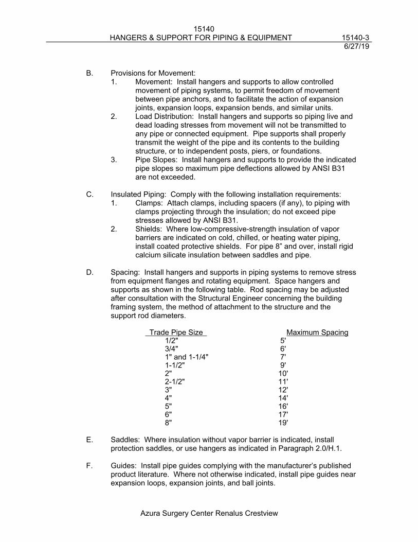
15140 HANGERS & SUPPORT FOR PIPING & EQUIPMENT 15140-3
6/27/19
Azura Surgery Center Renalus Crestview
B. Provisions for Movement:1. Movement: Install hangers and supports to allow controlled
movement of piping systems, to permit freedom of movement between pipe anchors, and to facilitate the action of expansion joints, expansion loops, expansion bends, and similar units.
2. Load Distribution: Install hangers and supports so piping live and dead loading stresses from movement will not be transmitted to any pipe or connected equipment. Pipe supports shall properly transmit the weight of the pipe and its contents to the building structure, or to independent posts, piers, or foundations.
3. Pipe Slopes: Install hangers and supports to provide the indicated pipe slopes so maximum pipe deflections allowed by ANSI B31 are not exceeded.
C. Insulated Piping: Comply with the following installation requirements:1. Clamps: Attach clamps, including spacers (if any), to piping with
clamps projecting through the insulation; do not exceed pipe stresses allowed by ANSI B31.
2. Shields: Where low-compressive-strength insulation of vapor barriers are indicated on cold, chilled, or heating water piping, install coated protective shields. For pipe 8” and over, install rigid calcium silicate insulation between saddles and pipe.
D. Spacing: Install hangers and supports in piping systems to remove stress from equipment flanges and rotating equipment. Space hangers and supports as shown in the following table. Rod spacing may be adjusted after consultation with the Structural Engineer concerning the building framing system, the method of attachment to the structure and the support rod diameters.
Trade Pipe Size Maximum Spacing1/2" 5'3/4" 6'1" and 1-1/4" 7'1-1/2" 9'2" 10'2-1/2" 11'3" 12'4" 14'5" 16'6" 17'8" 19'
E. Saddles: Where insulation without vapor barrier is indicated, install protection saddles, or use hangers as indicated in Paragraph 2.0/H.1.
F. Guides: Install pipe guides complying with the manufacturer’s published product literature. Where not otherwise indicated, install pipe guides near expansion loops, expansion joints, and ball joints.
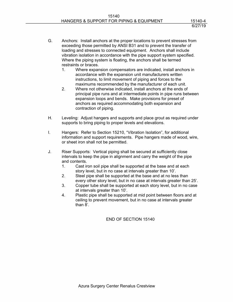
15140 HANGERS & SUPPORT FOR PIPING & EQUIPMENT 15140-4
6/27/19
Azura Surgery Center Renalus Crestview
G. Anchors: Install anchors at the proper locations to prevent stresses from exceeding those permitted by ANSI B31 and to prevent the transfer of loading and stresses to connected equipment. Anchors shall include vibration isolation in accordance with the pipe support system specified. Where the piping system is floating, the anchors shall be termed restraints or braces.1. Where expansion compensators are indicated, install anchors in
accordance with the expansion unit manufacturers written instructions, to limit movement of piping and forces to the maximums recommended by the manufacturer of each unit.
2. Where not otherwise indicated, install anchors at the ends of principal pipe runs and at intermediate points in pipe runs between expansion loops and bends. Make provisions for preset of anchors as required accommodating both expansion and contraction of piping.
H. Leveling: Adjust hangers and supports and place grout as required under supports to bring piping to proper levels and elevations.
I. Hangers: Refer to Section 15210, “Vibration Isolation”, for additional information and support requirements. Pipe hangers made of wood, wire, or sheet iron shall not be permitted.
J. Riser Supports: Vertical piping shall be secured at sufficiently close intervals to keep the pipe in alignment and carry the weight of the pipe and contents.1. Cast iron soil pipe shall be supported at the base and at each
story level, but in no case at intervals greater than 10’.2. Steel pipe shall be supported at the base and at no less than
every other story level, but in no case at intervals greater than 25’.3. Copper tube shall be supported at each story level, but in no case
at intervals greater than 10’.4. Plastic pipe shall be supported at mid point between floors and at
ceiling to prevent movement, but in no case at intervals greater than 8’.
END OF SECTION 15140
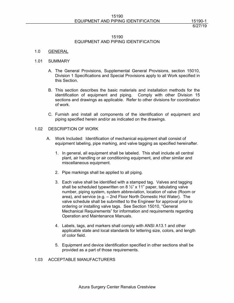
15190EQUIPMENT AND PIPING IDENTIFICATION 15190-1
6/27/19
Azura Surgery Center Renalus Crestview
15190EQUIPMENT AND PIPING IDENTIFICATION
1.0 GENERAL
1.01 SUMMARY
A. The General Provisions, Supplemental General Provisions, section 15010, Division 1 Specifications and Special Provisions apply to all Work specified in this Section.
B. This section describes the basic materials and installation methods for the identification of equipment and piping. Comply with other Division 15 sections and drawings as applicable. Refer to other divisions for coordination of work.
C. Furnish and install all components of the identification of equipment and piping specified herein and/or as indicated on the drawings.
1.02 DESCRIPTION OF WORK
A. Work Included: Identification of mechanical equipment shall consist of equipment labeling, pipe marking, and valve tagging as specified hereinafter.
1. In general, all equipment shall be labeled. This shall include all central plant, air handling or air conditioning equipment, and other similar and miscellaneous equipment.
2. Pipe markings shall be applied to all piping.
3. Each valve shall be identified with a stamped tag. Valves and tagging shall be scheduled typewritten on 8 ½” x 11” paper, tabulating valve number, piping system, system abbreviation, location of valve (Room or area), and service (e.g. – 2nd Floor North Domestic Hot Water). The valve schedule shall be submitted to the Engineer for approval prior to ordering or installing valve tags. See Section 15010, “General Mechanical Requirements” for information and requirements regarding Operation and Maintenance Manuals.
4. Labels, tags, and markers shall comply with ANSI A13.1 and other applicable state and local standards for lettering size, colors, and length of color field.
5. Equipment and device identification specified in other sections shall be provided as a part of those requirements.
1.03 ACCEPTABLE MANUFACTURERS
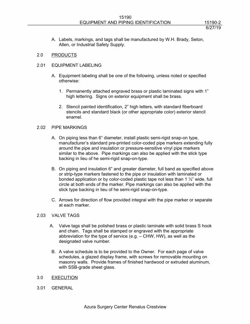
15190EQUIPMENT AND PIPING IDENTIFICATION 15190-2
6/27/19
Azura Surgery Center Renalus Crestview
A. Labels, markings, and tags shall be manufactured by W.H. Brady, Seton, Allen, or Industrial Safety Supply.
2.0 PRODUCTS
2.01 EQUIPMENT LABELING
A. Equipment labeling shall be one of the following, unless noted or specified otherwise:
1. Permanently attached engraved brass or plastic laminated signs with 1” high lettering. Signs on exterior equipment shall be brass.
2. Stencil painted identification, 2” high letters, with standard fiberboard stencils and standard black (or other appropriate color) exterior stencil enamel.
2.02 PIPE MARKINGS
A. On piping less than 6” diameter, install plastic semi-rigid snap-on type, manufacturer’s standard pre-printed color-coded pipe markers extending fully around the pipe and insulation or pressure-sensitive vinyl pipe markers similar to the above. Pipe markings can also be applied with the stick type backing in lieu of he semi-rigid snap-on-type.
B. On piping and insulation 6” and greater diameter, full band as specified above or strip-type markers fastened to the pipe or insulation with laminated or bonded application or by color-coded plastic tape not less than 1 ½” wide, full circle at both ends of the marker. Pipe markings can also be applied with the stick type backing in lieu of he semi-rigid snap-on-type.
C. Arrows for direction of flow provided integral with the pipe marker or separate at each marker.
2.03 VALVE TAGS
A. Valve tags shall be polished brass or plastic laminate with solid brass S hook and chain. Tags shall be stamped or engraved with the appropriate abbreviation for the type of service (e.g. – CHW, HW), as well as the designated valve number.
B. A valve schedule is to be provided to the Owner. For each page of valve schedules, a glazed display frame, with screws for removable mounting on masonry walls. Provide frames of finished hardwood or extruded aluminum, with SSB-grade sheet glass.
3.0 EXECUTION
3.01 GENERAL
15190EQUIPMENT AND PIPING IDENTIFICATION 15190-3
6/27/19
Azura Surgery Center Renalus Crestview
A. Identification labeling, marking, and tagging shall be applied after insulation and painting has been completed.
B. Coordinate names, abbreviations, and other designations used in mechanical identification work with corresponding designations shown, specified, or scheduled on drawings. Prior to ordering any labels, markings, or tags, obtain the approval of the Engineer regarding names, abbreviations, etc.
C. The Plumbing, HVAC, and Fire Protection Contractors shall coordinate labeling, marking, and tagging to ensure consistent and coordinated identification. In existing buildings, utilize similar names, abbreviations, and other designations that are currently in use to remain consistent with existing identification.
D. Equipment labeling shall consist of unit designation as shown on the drawings. Exhaust fan labeling shall also indicate service or the room or area of service.
E. Pipe and ductwork markers shall be placed on piping and ductwork on 25’ centers in mechanical rooms and concealed spaces. In locations where piping and ductwork is exposed, place markers on 50’ centers. Flow directional arrows should be marked on the piping at taps from the main and riser.
F. Valve tags shall be placed on each valve except those intended for isolation of individual heat pumps or terminal units (e.g. - VAV boxes, fan coil units, unit heaters, etc.). Valve tag schedules shall be prepared as specified hereinbefore. Copies of one schedule shall be laminated in clear plastic and placed where directed by the Owner. Other sets shall be included in the Operating and Maintenance Manuals.
END OF SECTION 15190
15200INSULATION – HVAC AND PLUMBING 15200-1
6/27/19
Azura Surgery Center Renalus Crestview
15200INSULATION – HVAC AND PLUMBING
1.0 GENERAL
1.01 SUMMARY
A. The General Provisions, Supplemental General Provisions, section 15010, Division 1 Specifications and Special Provisions apply to all Work specified in this Section.
B. This section describes the basic materials and installation methods for the insulation of HVAC and Plumbing piping, duct, and equipment. Comply with other Division 15 sections and drawings as applicable. Refer to other divisions for coordination of work.
C. Furnish and install all components of the insulation system specified herein, as indicated on the drawings, and as required to provide complete and operating systems.
1.02 QUALITY ASSURANCE
A. Manufacturer: Approved manufacturers are Armstrong, Calsite, Cell-U-Foarm Corp, Ceelco, Certainteed Corp, Dow Chemical Company, Forrest Mfg Co, Foster / Chilers, Gemco, Johns Manville, Knauf Fiberglass, Midwest Fastners, Owens Corning Fiberglass, Pittsburg Corning Fiberglass, Rubatex, Trymer, and Venture Tape.
B. All insulation, jacket and adhesive shall have a fire and smoke hazard ratings as tested under ASTM E 84, NFPA 255, and UL 723 not exceeding:
Flame Spread: 25 Fuel Contributed: 50 Smoke Developed: 50
Exceptions: Type B Insulation and PVC Fitting Covers
1.03 SUBMITTALS
A. Per Section 15010.
B. Product Data
1. Type A Insulation 2. Type B Insulation 3. Type D Insulation 4. Type E Insulation 5. Type F Insulation6. Vinyl Lacquer Paint for Type B Insulation
15200INSULATION – HVAC AND PLUMBING 15200-2
6/27/19
Azura Surgery Center Renalus Crestview
7. Metal Jacket
1.04 DEFINITIONS
A. The phrase "Storm Drainage Conductor" refers to that portion of the storm drain interior to the building, between the roof drain body and where the pipe goes below grade.
B. The word “plenum” shall mean a ceiling space or mechanical room used for the transfer of conditioned return and/or outside air.
2.0 PRODUCTS
2.01 PIPING INSULATION
A. Type A – Fiberglass (indoor)
1. One Piece glass fiber, rigid molded sectional pipe covering with factory applied aluminum foil and white craft paper flame retardant vapor barrier jacket, conforming to ASTM C547, Class II, Mineral Fiber Preformed Pipe Insulation.
2. Thermal Conductivity (k) equals approximately 0.23 (BTU/HR., SF., Degree F, IN) at 75 °F.
3. Similar to Johns Manville Corp “Micro Lox 650 AP T”, or approved equal.
B. Type B - Closed Cell (indoor)
1. Closed cell, flexible foamed plastic conforming to ASTM C534, "Preformed Flexible Elastomeric Cellular Thermal Insulation in Sheet and Tubular Form." Insulation shall be suitable for a temperature range from –40 degrees F to 220 degrees F.
2. Conductivity (k) equals approximately 0.27 (BTUHR., SF., Degree F, IN) at 75 °F.
3. Similar to Armstrong “Armaflex”, or approved equal.
C. Type E
1. Calcium silicate block conforming to ASTM C 553, Type I (1200 degrees F. max), asbestos free.
2. Conductivity (k) equals approximately 0.42 (BTU IN/HR., SF., degree F) per inch thickness at 200 °F.
3. Similar to Calsilite, or approved equal.
15200INSULATION – HVAC AND PLUMBING 15200-3
6/27/19
Azura Surgery Center Renalus Crestview
2.02 DUCTWORK INSULATION
A. Type F – Duct Wrap
1. Duct insulation shall be 2" thick, minimum 3/4 lb. density fiberglass with an FSKL aluminum foil jacket, reinforced with fiberglass scrim.
2. Conductivity (k) equals approximately 0.27 (BTUHR., SF., degrees F, IN) at 75 °F.
3. Integral UL rated vapor barrier of:
a. Aluminum foil reinforced with fiberglass scrim laminated to 30-lb. kraft paper.
b. Class I white vinyl 0.004 inch thick, where specified.
4. Similar to Johns Manville Corp “Microlite”, or approved equal.
2.03 METAL JACKET
A. Smooth aluminum jacket 0.016 inch thick. B. Integral polykraft or poly-surlyn moisture barrier.
C. Banded locking joints with field applied silicone weatherproof sealant.
D. Similar to Johns Manville Corp, or approved equal.
2.04 INSULATION ACCESSORIES A. The following accessories shall be used in the application of the thermal
insulations specified under this Section:
1. PVC Fittings Covers: similar to Johns Manville Corp “Zeston”, or approved equal.
2. Pressure Sensitive polyester film tape to secure pipe insulation up to 12” outside diameter: Similar to 3M 30-80, or approved equal.
3. Vapor Seal Mastic: Similar to Childers CP-35, or approved equal.
4. Lagging Adhesive: Similar to Childers CP-52, or approved equal.
5. Wire: 16 gauge soft stainless steel.
6. Insulation Bonding Adhesive (To Metal): Similar to Childers CP-82, or approved equal.
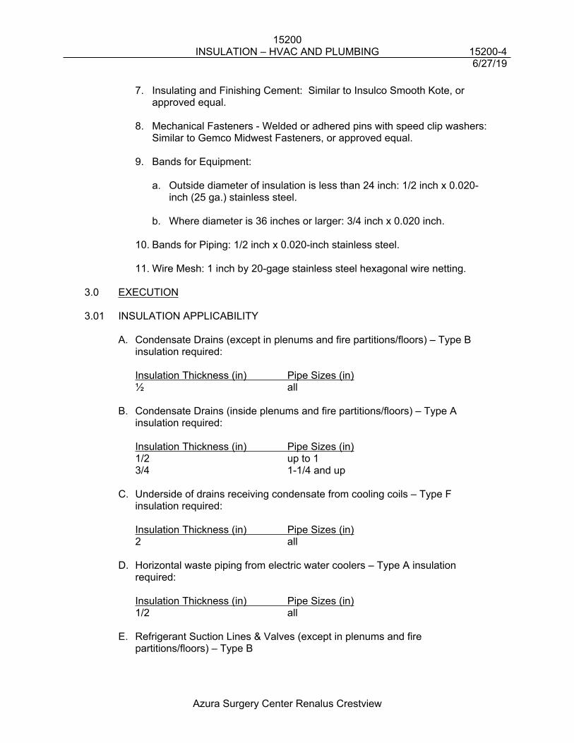
15200INSULATION – HVAC AND PLUMBING 15200-4
6/27/19
Azura Surgery Center Renalus Crestview
7. Insulating and Finishing Cement: Similar to Insulco Smooth Kote, or approved equal.
8. Mechanical Fasteners - Welded or adhered pins with speed clip washers: Similar to Gemco Midwest Fasteners, or approved equal.
9. Bands for Equipment:
a. Outside diameter of insulation is less than 24 inch: 1/2 inch x 0.020-inch (25 ga.) stainless steel.
b. Where diameter is 36 inches or larger: 3/4 inch x 0.020 inch.
10. Bands for Piping: 1/2 inch x 0.020-inch stainless steel.
11. Wire Mesh: 1 inch by 20-gage stainless steel hexagonal wire netting.
3.0 EXECUTION
3.01 INSULATION APPLICABILITY
A. Condensate Drains (except in plenums and fire partitions/floors) – Type B insulation required:
Insulation Thickness (in) Pipe Sizes (in)½ all
B. Condensate Drains (inside plenums and fire partitions/floors) – Type A insulation required:
Insulation Thickness (in) Pipe Sizes (in)1/2 up to 13/4 1-1/4 and up
C. Underside of drains receiving condensate from cooling coils – Type F insulation required:
Insulation Thickness (in) Pipe Sizes (in)2 all
D. Horizontal waste piping from electric water coolers – Type A insulation required:
Insulation Thickness (in) Pipe Sizes (in)1/2 all
E. Refrigerant Suction Lines & Valves (except in plenums and fire partitions/floors) – Type B
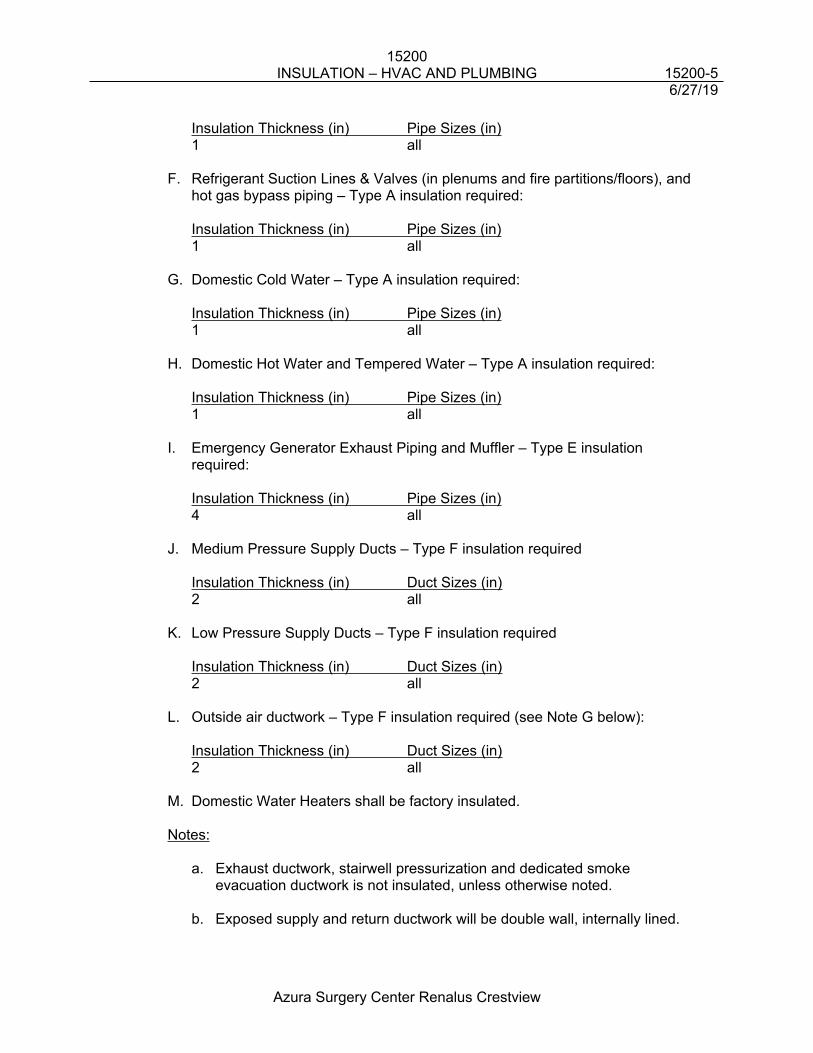
15200INSULATION – HVAC AND PLUMBING 15200-5
6/27/19
Azura Surgery Center Renalus Crestview
Insulation Thickness (in) Pipe Sizes (in)1 all
F. Refrigerant Suction Lines & Valves (in plenums and fire partitions/floors), and hot gas bypass piping – Type A insulation required:
Insulation Thickness (in) Pipe Sizes (in)1 all
G. Domestic Cold Water – Type A insulation required:
Insulation Thickness (in) Pipe Sizes (in)1 all
H. Domestic Hot Water and Tempered Water – Type A insulation required:
Insulation Thickness (in) Pipe Sizes (in)1 all
I. Emergency Generator Exhaust Piping and Muffler – Type E insulation required:
Insulation Thickness (in) Pipe Sizes (in)4 all
J. Medium Pressure Supply Ducts – Type F insulation required
Insulation Thickness (in) Duct Sizes (in)2 all
K. Low Pressure Supply Ducts – Type F insulation required
Insulation Thickness (in) Duct Sizes (in)2 all
L. Outside air ductwork – Type F insulation required (see Note G below):
Insulation Thickness (in) Duct Sizes (in)2 all
M. Domestic Water Heaters shall be factory insulated.
Notes:
a. Exhaust ductwork, stairwell pressurization and dedicated smoke evacuation ductwork is not insulated, unless otherwise noted.
b. Exposed supply and return ductwork will be double wall, internally lined.
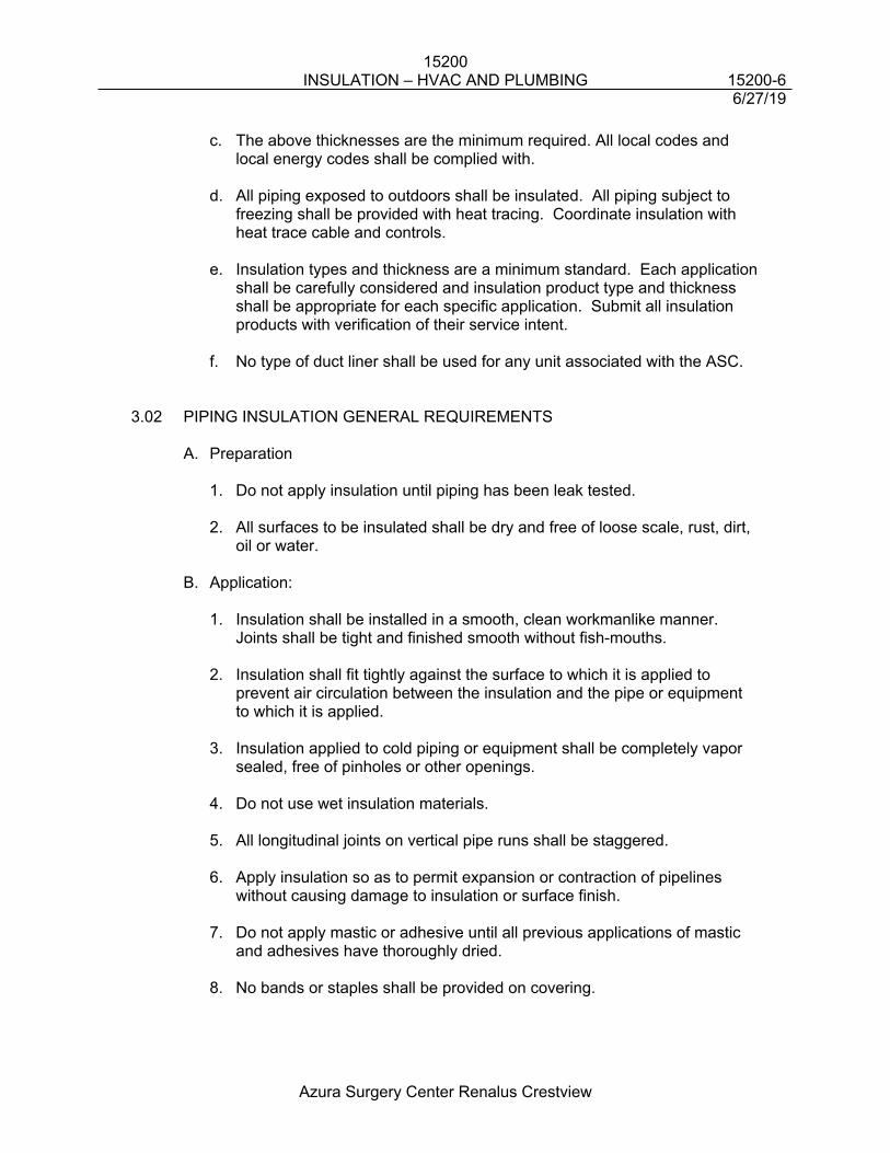
15200INSULATION – HVAC AND PLUMBING 15200-6
6/27/19
Azura Surgery Center Renalus Crestview
c. The above thicknesses are the minimum required. All local codes and local energy codes shall be complied with.
d. All piping exposed to outdoors shall be insulated. All piping subject to freezing shall be provided with heat tracing. Coordinate insulation with heat trace cable and controls.
e. Insulation types and thickness are a minimum standard. Each application shall be carefully considered and insulation product type and thickness shall be appropriate for each specific application. Submit all insulation products with verification of their service intent.
f. No type of duct liner shall be used for any unit associated with the ASC.
3.02 PIPING INSULATION GENERAL REQUIREMENTS
A. Preparation
1. Do not apply insulation until piping has been leak tested.
2. All surfaces to be insulated shall be dry and free of loose scale, rust, dirt, oil or water.
B. Application:
1. Insulation shall be installed in a smooth, clean workmanlike manner. Joints shall be tight and finished smooth without fish-mouths.
2. Insulation shall fit tightly against the surface to which it is applied to prevent air circulation between the insulation and the pipe or equipment to which it is applied.
3. Insulation applied to cold piping or equipment shall be completely vapor sealed, free of pinholes or other openings.
4. Do not use wet insulation materials.
5. All longitudinal joints on vertical pipe runs shall be staggered.
6. Apply insulation so as to permit expansion or contraction of pipelines without causing damage to insulation or surface finish.
7. Do not apply mastic or adhesive until all previous applications of mastic and adhesives have thoroughly dried.
8. No bands or staples shall be provided on covering.
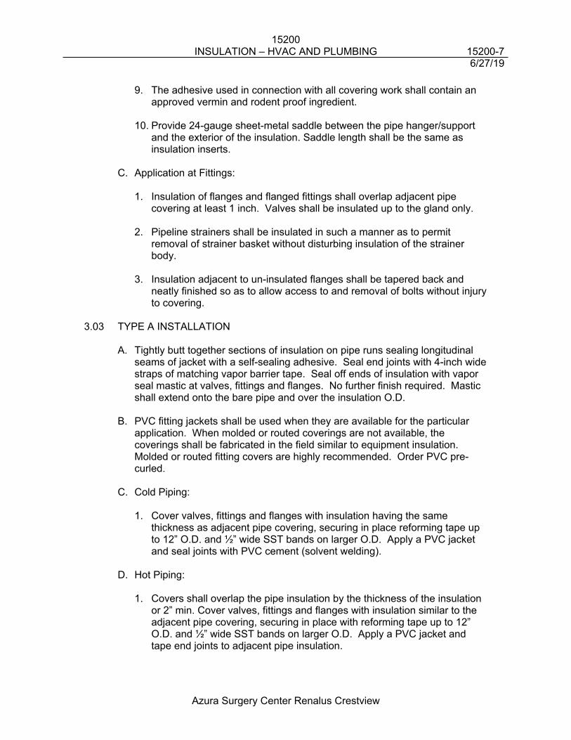
15200INSULATION – HVAC AND PLUMBING 15200-7
6/27/19
Azura Surgery Center Renalus Crestview
9. The adhesive used in connection with all covering work shall contain an approved vermin and rodent proof ingredient.
10. Provide 24-gauge sheet-metal saddle between the pipe hanger/support and the exterior of the insulation. Saddle length shall be the same as insulation inserts.
C. Application at Fittings:
1. Insulation of flanges and flanged fittings shall overlap adjacent pipe covering at least 1 inch. Valves shall be insulated up to the gland only.
2. Pipeline strainers shall be insulated in such a manner as to permit removal of strainer basket without disturbing insulation of the strainer body.
3. Insulation adjacent to un-insulated flanges shall be tapered back and neatly finished so as to allow access to and removal of bolts without injury to covering.
3.03 TYPE A INSTALLATION
A. Tightly butt together sections of insulation on pipe runs sealing longitudinal seams of jacket with a self-sealing adhesive. Seal end joints with 4-inch wide straps of matching vapor barrier tape. Seal off ends of insulation with vapor seal mastic at valves, fittings and flanges. No further finish required. Mastic shall extend onto the bare pipe and over the insulation O.D.
B. PVC fitting jackets shall be used when they are available for the particular application. When molded or routed coverings are not available, the coverings shall be fabricated in the field similar to equipment insulation. Molded or routed fitting covers are highly recommended. Order PVC pre-curled.
C. Cold Piping:
1. Cover valves, fittings and flanges with insulation having the same thickness as adjacent pipe covering, securing in place reforming tape up to 12” O.D. and ½” wide SST bands on larger O.D. Apply a PVC jacket and seal joints with PVC cement (solvent welding).
D. Hot Piping:
1. Covers shall overlap the pipe insulation by the thickness of the insulation or 2” min. Cover valves, fittings and flanges with insulation similar to the adjacent pipe covering, securing in place with reforming tape up to 12” O.D. and ½” wide SST bands on larger O.D. Apply a PVC jacket and tape end joints to adjacent pipe insulation.
15200INSULATION – HVAC AND PLUMBING 15200-8
6/27/19
Azura Surgery Center Renalus Crestview
2. Do not use PVC fitting jackets where the surface of the insulation is above 150 degrees F.
E. Exterior Piping:
1. Exterior above grade water piping shall be finished with a weatherproof jacket and an aluminum jacket. Lap and seal joints as per manufacturer's instructions. Place laps to shed water.
3.04 TYPE B INSTALLATION
A. Type B insulation shall be slipped on the pipe prior to connection, and the butt joints shall be sealed. Where the slip on technique is not possible, the insulation shall be carefully slit and applied to the pipe.
B. All joints shall be completely butt sealed with the manufacturer's
recommended adhesive.
C. Do not apply Type B insulation in multiple layers.
D. Type B insulation shall not be used in plenums nor firewall penetrations.
E. This Contractor shall paint Type B insulation exterior to the building with two coats of a vinyl acrylic paint recommended by the insulation manufacturer for protection against ultraviolet degradation and shall be flexible with no cracking. It is recommended in high humid areas to coat the insulation with a vapor barrier mastic to .037 min. DFT.
3.05 TYPE C INSTALLATION
A. Exterior
1. Butter joints of insulation with non-setting adhesive. Secure with factory applied Self-Seal laps. Installation shall be as per manufacturer’s guidelines.
2. Finish shall be factory applied All Service Jackets. All fittings shall be finished with vapor seal mastic reinforced with white glass mesh. Minimum 0.037 thick DFT of mastic.
3. Piping exposed in machine rooms shall be finished with vapor seal mastic and open weave membrane 10 x 10.
4. Piping exposed to weather shall be finished with all service jacket and additional finish of 0.16 thick aluminum jacket. Aluminum jacket shall be secured with stainless bands located on maximum centers of 12 inches and at the overlap. No screws or pop rivets shall be used.
15200INSULATION – HVAC AND PLUMBING 15200-9
6/27/19
Azura Surgery Center Renalus Crestview
5. Fittings and valves shall be finished with vapor seal mastic, reinforced with minimum 0.037” DFT of mastic, glass mesh and aluminum preformed fitting covers.
3.06 TYPE D AND E INSTALLATION
A. Equipment Insulation Application:
1. Apply insulation to fit as closely as possible to equipment. 2. Stagger joints where possible.3. Bevel insulation around nameplates, ASME stamp and access plates. 4. Insulation on equipment that must be opened periodically shall be
constructed so insulation can be removed and replaced without damage. 5. Do not install Type E insulation on aluminum surfaces or with aluminum
jacket.
3.07 TYPE F INSTALLATION A. Ductwork Insulation Application:
1. Apply insulation tightly and smoothly to duct.
2. Secure insulation on the bottom of ducts and plenums and on the sides of plenums and other places where the insulation will sag and max 3” from any corner.
3. Impale insulation over pins or anchors located not more than 18 inches apart and hold in place with washers and clips.
4. Cut off protruding pin after clips are secured and seal with 2-mil. aluminum foil backed pressure sensitive tape.
5. Apply insulation with joints tightly butted.
6. Seal all ductwork joints, punctures and fittings with a mastic type sealant containing a vapor barrier.
7. Cover all breaks, joints, punctures and voids with a vapor seal mastic and cover with a vapor barrier material identical to vapor barrier on the insulation, where gaps exceed 2”.
8. Bevel insulation around nameplates, access plates and doors.
9. Insulation shall be continuous through walls and floors except at fire dampers.
3.08 METAL JACKET INSTALLATION
15200INSULATION – HVAC AND PLUMBING 15200-10
6/27/19
Azura Surgery Center Renalus Crestview
A. Cover all piping insulation exposed to the exterior with metal jacket as specified herein.
3.09 HANGERS A. Continue insulation through pipe hangers. Provide either rigid insulation
inserts or sheet metal inserts at all outside pipe hangers. Provide rigid insulation inserts for piping operating below 60 °F. and sheet metal inserts for piping above 60 °F.
B. Provide rigid insulation (on non-insulated piping) or sheet metal inserts (on insulated piping) between the pipe and pipe hanger - shall be of a thickness equal to the adjoining insulation and shall be provided with vapor barrier where required. Insulation insert shall not be less than the following lengths:
1/2” to 2 1/2" pipe size 10 Inches Long3” to 6" pipe size 12 Inches Long8” to 10" pipe size 16 Inches Long
C. Inserts for cold piping shall have a vapor barrier facing of the same material as the adjacent pipe insulation. Seal inserts into insulation with vapor seal mastic.
D. Sheet metal inserts shall be of steel sheet. Gauge shall conform to manufacturer's recommendation for pipe size. Sheet metal inserts shall have insulation filler of the same material as the adjacent pipe insulation.
3.10 PIPE SLEEVES A. Pipe insulation and vapor barrier shall be continuous through sleeves in walls
and floors.
B. Type B insulation shall not be used in sleeves through firewalls or fire rated (2-hour) floor systems. Use Type A or Type C through the sleeve instead and vapor seal the joint between the two insulations.
C. Provide 26 gauge galvanized steel or 0.020 inch aluminum jacket over insulation on pipe passing through sleeves where sealant is required.
D. Where penetrating interior walls, extend the metal jacket 2 inches out either side of the wall and secure each end with a metal band compressing the insulation slightly.
E. Where penetrating floors, extend the metal jacket 2 inches below the floor and 5 inches above the floor. Secure with metal bands.
END OF SECTION 15200
15210VIBRATION ISOLATION 15210-1
6/27/19
Azura Surgery Center Renalus Crestview
15210VIBRATION ISOLATION
1.0 GENERAL
1.01 SUMMARY
A. The General Provisions, Supplemental General Provisions, section 15010, Division 1 Specifications and Special Provisions apply to all Work specified in this Section.
B. This section describes the basic materials and installation methods for the vibration isolation systems. Comply with other Division 15 sections and drawings as applicable. Refer to other divisions for coordination of work.
C. Furnish and install all components of the vibration isolation systems specified herein, as indicated on the drawings, and as required to provide complete and operating systems.
1.02 DESCRIPTION OF WORK
A. Work Included: Provide vibration isolation work as specified and indicated, including the following:
1. Support isolation for motor-driven mechanical equipment
2. Inertia base frames in conjunction with equipment isolation
3. Support isolation of air-handling housings
4. Isolation including support isolation for piping risers
5. Support isolation of piping
6. Flexible ductwork connections
1.03 QUALITY ASSURANCE
A. General: Except as otherwise indicated, obtain support isolation units from a single manufacturer.
B. Supervision: Manufacturer shall provide technical supervision of the installation of support isolation units produced by him and of associated inertia bases.
C. Manufacturers: Provide vibration isolation support units manufactured by one of the following or an approved equal: Amber-Booth, Vibrations Mounting and Controls, Inc., Korfund Dynamics Corporation, Consolidated Kinetics Corporation.
15210VIBRATION ISOLATION 15210-2
6/27/19
Azura Surgery Center Renalus Crestview
2.0 PRODUCTS
2.01 MATERIALS
A. Chilled, Condenser and Heating Hot Water Pumps: Provide concrete inertia bases with structural steel pouring forms sized and reinforced as required for the intended service. Size bases to support the piping elbow supports and furnish with Type RSW recessed spring isolators properly sized for one-inch static deflection. Mount springs on concrete bases 3-1/2" high. Inertia base is not required for pumps installed on slabs on grade.
B. Suspended Fans: Isolate with not less than four combination spring and rubber-in-shear vibration isolators.
C. Suspended Heat Pump Units: Unit shall be isolated with hanger and vibration isolation kit supplied by unit manufacturer or a vibration isolation manufacturer.
D. Suspended Fan & Coil Unit: Isolate with not less than four combination spring and rubber “in-shear” vibration isolators.
E. Flexible Pipe Connections at Cooling Tower: Isolate supply and return piping to the cooling tower with flanged rubber, spherical double-arch expansion joints.
F. Flexible Pipe Connections at Rotating Equipment: Isolate supply and return piping to each pump with braided metal hose connectors between pump and valve.
G. Flexible Ductwork Connections to Equipment: Install flexible connections between sheet metal ductwork and equipment or fan collar. Locate as close to fan as possible. Isolate the duct system from the equipment by at least 1”.
H. Roof Mounted Air Handling Units: Provide housed spring type isolators with vertical limit stops. Provide with 1” deflection (0 to 500 rpm) or .75” deflection (501 and over rpm).
3.0 EXECUTION
3.01 ISOLATOR PERFORMANCE
A. General: Comply with the minimum static deflections recommended by the American Society of Heating, Refrigerating and Air Conditioning Engineers, including the definitions of critical and non-critical locations, for the selection and application of vibration isolation materials and units as indicated.
15210VIBRATION ISOLATION 15210-3
6/27/19
Azura Surgery Center Renalus Crestview
B. Manufacturer's Recommendations: Except as otherwise indicated, comply with manufacturer's instructions for selection and application of vibration isolation materials and units.
3.02 RELATED WORK EXAMINATION
A. Examination and Reporting: Installer of vibration isolation work shall observe the installation of other work related to and connected to vibration isolation work. After completion of other related work (but before equipment start-up), installer shall furnish a written report to the Contractor, with a copy to the Engineer, listing observed inadequacies for proper operation and performance of vibration isolation work.
B. Correction and Start-up: Do not start-up equipment until inadequacies have been corrected in a manner acceptable to the vibration isolation Installer.
3.03 EQUAL LOADING
A. General: Equipment installed on vibration isolating mountings shall be level after load is applied. Further vibration isolating mountings shall be selected and installed to compensate for unequal loading. Spring isolators with coils touching during equipment start-up or operation will not be acceptable.
END OF SECTION 15210
15400PLUMBING PIPING 15400-1
6/27/19
Azura Surgery Center Renalus Crestview
15400PLUMBING PIPING
1.0 GENERAL
1.01 SUMMARY
A. The General Provisions, Supplemental General Provisions, section 15010, Division 1 Specifications and Special Provisions apply to all Work specified in this Section.
B. This section describes the basic materials and installation methods for the plumbing piping systems. Comply with other Division 15 sections and drawings as applicable. Refer to other divisions for coordination of work.
C. Furnish and install all components of the plumbing piping systems specified herein, as indicated on the drawings, and as required to provide complete and operating systems.
1.02 DESCRIPTION OF WORK
A. Work Included: Provide complete operating plumbing piping systems including pipe, tube, fittings, and appurtenances as indicated and in compliance with these Specifications.
B. Applications: Applications of piping systems include, but are not limited to, the systems as listed below:
Working OperatingSystem Pressure Temperatures
Domestic Cold WaterHigh 350 psig 55 to 80°FMedium 300 psig 55 to 80°FLow 150 psig 55 to 80°F
Domestic Hot WaterHigh 350 psig 90 to 120°FMedium 300 psig 90 to 120°FLow 150 psig 90 to 120°F
Makeup WaterHigh 350 psig 55 to 80°FMedium 300 psig 55 to 80°FLow 150 psig 55 to 80°F
Condensate Drainage -- 40 to 60°F
15400PLUMBING PIPING 15400-2
6/27/19
Azura Surgery Center Renalus Crestview
Sanitary Drainage -- --
Storm Drainage -- --
Natural Gas -- --
1.03 QUALITY ASSURANCE
A. Welding: Qualify welding procedures, welders, and operators in accordance with ANSI B31.1, Paragraph 127.5, for shop and job site welding of piping work. Make welded joints on the piping system with continuous welds, without backing rings and with pipe ends beveled before welding. Gas cuts shall be true and free from burned metal. Before welding, surfaces shall be thoroughly cleaned. The piping shall be carefully aligned and no weld metal shall project inside the pipe.
2.0 PRODUCTS
2.01 PIPING MATERIALS
A. General: Provide pipe and tube of type, joint, grade, size, and weight (wall thickness, schedule or class) indicated for each service. Comply with applicable governing regulations and industry standards.
1. Steel Pipe: ASTM A53, ASTM A106, or ASTM A120, black or hot-dipped galvanized as specified.
2. Copper Tube: ASTM B88, Types "K", Type "L", or Type "M" copper water tube as defined by the Copper and Brass Research Association.
3. Ductile Iron Pipe: ANSI A21.51, Class 150 with bell and spigot ends for push-on joints.
4. Cast Iron Soil Pipe: ASTM A74, standard weight, hub and spigot-type.
5. Hubless Cast Iron Pipe: CISPI 301-78, standard weight with spigot bead ends for coupling assembly.
6. Polyvinyl Chloride (PVC) Pipe: Sewer main SDR 41, ASTM D3034 with bell ends and pre-inserted gasket joints.
7. Pre-insulated Steel Pipe: ASTM A53, ASTM A106, ASTM A120, and ANSI B31.1.
8. Polyvinyl Chloride (PVC) Water Pipe: Class 150, thickwall, Schedule 80, AWWA C90 mechanical joint.
9. Copper Drainage Pipe: DWV copper piping.
15400PLUMBING PIPING 15400-3
6/27/19
Azura Surgery Center Renalus Crestview
10. Polyvinyl Chloride (PVC) Drainage Pipe: Schedule 40 PVC.
11. Chlorinated Polyvinyl Chloride (CPVC) Drainage Pipe: Schedule 40 CPVC. Type IV Grade I with cell classification of 23447 as defined in ASTM D1784. Rated for temperatures up to and including 200°F.
2.02 PIPE / TUBE FITTINGS
A. General: Provide factory-fabricated fittings of type, materials, grade, class, and pressure rating indicated for each service and pipe size. Provide sizes and types matching pipe, tube, valve, and equipment connections. Where not otherwise indicated, comply with governing regulations, industry standards, and where applicable, with pipe manufacturer's instructions for selections.
1. Cast Iron Flanged Fittings: ANSI B16.1, Class 125 or Class 250, black or galvanized as specified, including bolting and gasketing.
2. Cast Iron Threaded Fittings: ANSI B16.4 or ASTM A126, Class 125 or Class 250, black or galvanized as specified.
3. Malleable Iron Threaded Fittings: ANSI B16.3, Class 150 or Class 300, black or galvanized as specified.
4. Malleable Iron Threaded Unions: ANSI B16.39, select for proper piping fabrication and service requirements including style, end connections, and metal-to-metal seats (iron, bronze, or brass), plain or galvanized as specified.
5. Threaded Pipe Plugs: ANSI B16.14.
6. Steel Flanges/Fittings: ANSI B16.5, including bolting, gasketing, and butt weld end connections.
7. Forged Steel Socket-welding and Threaded Fittings: ANSI B16.11, rated to match schedule of connected pipe.
8. Wrought Steel Butt-welding Fittings: ANSI B16.9, except ANSI B16.28 for short radius elbows and returns; rated to match connected pipe.
9. Cast Iron Drainage Fittings: ANSI B16.22 galvanized with pitched threaded ends.
10. Pipe Nipples: Fabricated from same pipe as used for connected pipe, except do not use less than Schedule 80 pipe where length remaining unthreaded is less than 1/2". Do not thread nipples full length (no all-thread nipples).
15400PLUMBING PIPING 15400-4
6/27/19
Azura Surgery Center Renalus Crestview
11. Wrought Copper/Bronze Solder-Joint Fittings: ANSI B16.22 suitable for working pressure up to 250 psig.
12. Hub-less Cast Iron Pipe Fittings: CISPI 301-78 and comply with governing regulations.
13. Cast Iron Soil Pipe Fittings: ASTM A74.
14. Compression Gaskets: CISPI HSN-75.
15. Lead/Oakum Joint Materials: Comply with governing regulations for service use indicated.
16. Grooved End Fittings: ASTM A47 or ASTM A536 joined with Victaulic Style 77 couplings and Grade "E" gaskets.
17. Flanged Fittings: Comply with ANSI B16.15 for bolt-hole dimensioning, materials, and flange-thickness.
18. Flange Bolts: Bolts shall be carbon steel ASTM A307 Grade A hexagon head bolts and hexagonal nuts. Where one or both flanges are cast iron, furnish Grade B bolts. Cap screws utilized with flanged butterfly valves shall be ASTM A307 Grade B with hexagon heads.
19. Flange Bolt Thread Lubricant: Lubricant shall be an anti-seize compound designed for temperatures up to 1000°F and shall be Crane Anti-Seize Thread Compound or approved equal.
20. Polyvinyl Chloride (PVC) Fittings: ASTMD-2665, Lasco or Spears Manufacturing high strength sewer fittings.
21. Copper Drainage Fitting: DWV copper drainage fittings.
B. Miscellaneous Piping Materials/Products:
1. Welding Materials: Comply with ASME Boiler and Pressure Vessels Code, Section II, Part C, for welding materials.
2. Brazing Materials: American Welding Society, AWS A5.B, Classification BCup-5.
3. Gaskets for Flanged Joints: 1/8" thick gaskets. Ring-type shall be used between raised face flanges and full face-type between flat face flanges with punched bolt holes and pipe opening. Gaskets shall be Garlock Style 3400 compressed non-asbestos or equal.
4. Insulating (Dielectric) Unions: Provide dielectric unions at all pipe connections between ferrous and nonferrous piping. Unions shall be
15400PLUMBING PIPING 15400-5
6/27/19
Azura Surgery Center Renalus Crestview
"Delvin" as made by Pipeline Seal and Insulator Company or "EPCO" as made by Epco Sales, Inc. and shall have nylon insulation or equal.
5. Gaskets for Cast Iron Soil Pipe: ASTM C 564, neoprene, compression-type.
6. Push-on-Joints: ANSI A21.11, rubber compression-type, "Tyton Joint" as manufactured by US Pipe or equal.
7. Hub-less Cast Iron Joints: CISPI 310, stainless steel corrugated shield and clamp assembly over one piece neoprene sealing sleeve.
3.0 EXECUTION
3.01 PIPING INSTALLATION
A. General:
1. Industry Practices: Install pipe, tube, and fittings in accordance with recognized industry practices which will achieve permanently leak-proof piping systems, capable of performing each indicated service without failure or degradation of service. Install each run with a minimum of joints and couplings, but with adequate and accessible unions or flanged connections to permit disassembly for maintenance/ replacement of valves and equipment. Reduce sizes (where indicated) by use of reducing fittings. Align accurately at connections. Coordinate piping locations with other trades to avoid conflict. Give ductwork preference unless directed otherwise by the Engineer.
2. Systems: Install piping parallel or perpendicular to lines of building, true to line and grade, and with sufficient hangers to prevent sags between hangers. Provide fittings at changes in direction. Piping in finished areas shall be concealed, except in mechanical rooms. Where pipes of different sizes join, provide reducing elbows, tees, or couplings. Bushings will not be acceptable.
3. Expansion and Contraction: Install loops, offsets, sizing joints, and expansion joints, as necessary, to avoid strain resulting from expansion and contraction of piping systems on fixtures and equipment. Provide mechanical grooved connections required by the application to reduce vibration at equipment connections. Provide expansion joints in piping systems by mechanical grooved connections where required.
C. Steel Pipe: Ream steel pipe after cutting and before threading. Thread with clean-cut taper threads of length to engage all threads in fittings and leave no full-cut threads exposed after make-up.
D. Copper Pipe: Cut copper pipe square and ream to remove burrs. Clean fitting socket and pipe ends with sand cloth or wire brush.
15400PLUMBING PIPING 15400-6
6/27/19
Azura Surgery Center Renalus Crestview
E. PVC Pipe: Cut PVC pipe square and remove all burrs. Clean fitting and pipe butt prior to installation. Install all PVC piping in accordance with the manufacturer's recommendations. PVC piping shall not be installed in return air plenums unless wrapped with 25/50 flame spread complaint plenum rated wrap.
F. Final Connections to Equipment Furnished by Owner or Under Other Divisions of These Specifications: Where equipment is to be furnished under other Divisions of these Specifications or by the Owner, such equipment will be delivered to the site, uncrated, assembled, and set in-place under those other Divisions of these Specifications or under the separate contracts. Any required automatic control valves shall also be provided under those other Divisions of these Specifications or other separate contracts. Make all final connections of hot water, condenser water, gas, domestic water, waste, and vent as required. Provide valves, unions, strainers, check valves, and traps as required for proper operation of systems and equipment. Equipment not shown on the Architectural Drawings or noted by the Architect and/or Engineer shall not be included in the scope of this requirement.
G. Excavation, Installation, and Backfill for Underground Pipe:
1. Layout: Pipes shall be laid and pipe joints made in presence of the General Contractor and field measurements, layouts, batter board alignment, grade establishments, and similar locations shall be performed by a Professional Engineer in the employ of the Contractor. The Contractor's engineer shall be on the job during all underground work. A "Bench-Mark" reference shall be provided by the General Contractor.
2. Pipe Grading: Lay and maintain all pipes at required lines and grades during the course of the Work.
3. Trench: Excavate the trench to the depth required. Properly brace and de-water the trench and keep it free of water during installation, testing pipe, and backfilling. No water shall be discharged onto the street or freeway without approval by the Owner.
4. Excavation: The trench shall be at least 18" wider than the maximum diameter of the pipe or largest bell and the pipe shall be laid in the center of the trench. The trench shall be excavated to a depth sufficient to provide for pipe cushions or supports as specified. Trench width may be increased as required and piling left in place until sufficient compacted backfill is in place. Properly sheet and brace all open trenches to render them secure and remove all such sheeting and bracing before completing the backfill. Comply with all applicable national, state, and local codes and regulations. The quantity of excavation required to install sheeting and the installation and removal of sheetings and bracings will not be regarded as Extra Work. All costs incurred for this excavation and the installation of sheeting shall be included in the Contract Price.
15400PLUMBING PIPING 15400-7
6/27/19
Azura Surgery Center Renalus Crestview
5. Grading: Upon completion of excavation and prior to the laying of the pipe, the trench bottom shall be brought up to the required elevation with a pipe cushion, except where the cushion has been eliminated by the General Contractor. Pipe cushions shall be select material deposited in the trench and shall be compacted, leveled off, and shaped to obtain a smooth compacted bed along the laying length of the pipe. Pipe cushion material shall be as follows:
a. Domestic Water Pipes: Material for pipe cushion shall comply with local codes and conform with the geo-technical report. In absence of local code requirements and/or geo-technical report, the cushion shall be bank sand or select backfill material approved by the General Contractor. Any material used shall pass a one-inch screen.
b. Sanitary and Storm Sewers: Material for pipe cushion shall comply with local codes and conform with the geo-technical report. In absence of local code requirements and/or geo-technical report, the cushion shall be bank sand or select backfill material approved by the General Contractor. Any material used shall pass a one-inch screen.
6. Anchors: Cast iron pipes shall have concrete anchors at each change in direction and/or as directed. Any change in direction exceeding 15 degrees shall be anchored. Concrete anchors shall rest against solid (virgin) ground with the required area of bearing on pipe and ground to provide suitable anchoring.
7. Backfill: Backfill trenches only after piping has been inspected, tested, and approved by the General Contractor. Backfill shall be provided as recommended in the geo-technical report included in these Contract Documents, or in the absence of a geo-technical report, as required by site conditions. Refer to Division 2 or elsewhere in the Contract Documents for additional trenching and backfill requirements.
8. Existing Surfaces: Restore existing streets, driveways, and sidewalks damaged during the excavation work to acceptable condition, subject to approval by the Owner.
9. Safety: Provide street and sidewalk excavations with approved barricades, warning lights, and cover plates as required by the local authorities.
3.02 PLUMBING SERVICES
A. Scope:
1. This Contractor shall provide the building sanitary sewer to 5 feet outside the building and shall extend the domestic water service from the main shutoff valve stubbed above floor in the building.
15400PLUMBING PIPING 15400-8
6/27/19
Azura Surgery Center Renalus Crestview
2. Provide storm drainage system as required to 5 feet outside the building.
3. Verify locations and conditions.
B. General: Install the various piping systems as described hereinafter, and as required by the local plumbing inspection department.
1. Slope domestic hot and cold water piping to drain and provide with hose valves (drain valves) at low points.
2. Install soil, waste, and vent piping with horizontal lines pitched in accordance with local codes, but in no case less than 1/4" per foot for pipe 2-1/2" and smaller, and 1/8" per foot for pipe 3" and larger. Install soil, waste, and vent piping with hubs of each length of piping in the upstream position.
3. Make-up lead and oakum joints with molten lead run into hubs in one continuous pour, to a minimum depth of one inch.
4. Make-up "Ty-Seal" or "Dual-Tite" gasketed joints using lubrication and joining tools as instructed by the manufacturers. Base of stacks, horizontal runs under pressure, and gasketed pipe 5" and larger shall be made up using "Lubrifast" joining material.
5. Torque "No-Hub" joints in accordance with manufacturer's instructions. Do not install "No-Hub" joints below ground.
6. Provide chrome-plated piping at each fixture installed in a finished space. Install with proper strap wrenches to avoid marking or defacing.
7. Provide proper restraints on riser and stack offsets.
C. Plumbing Connections to Fixtures and Equipment:
1. General: Provide necessary pipe and fittings. Make final connections to provide cold water make-up and natural gas supply to mechanical equipment. Locate cold water make-up and gas supply where shown and connect with suitable stop valves.
2. Cold Water Make-up: Provide cold water make-up to closed loop condenser water circulating systems, cooling tower system, and hot water heating systems.
3. Gas Supply: Provide gas supply separately metered to an approved location for future routing to kitchen locations.
D. The domestic water service shall be Class 150 AWWA cement lined C.I. with Class 250 fittings, mechanical joints or push-on rubber ring gaskets, ASTM
15400PLUMBING PIPING 15400-9
6/27/19
Azura Surgery Center Renalus Crestview
A377-66 or PVC AWWA C900 with solvent welded fittings. Provide tie rods and thrust blocks as required.
3.03 MAKE-UP WATER PIPING SYSTEMS
A. Connections: Connect domestic water to automatic fill and manual quick-fill connections on each piping system as indicated on Drawings. Provide reduced pressure backflow preventers at each system.
B. Compatibility: Use piping and fittings of same material type as materials of the domestic water supply.
3.04 CONDENSATE DRAINAGE
A. General: Provide a condensate drain pipe to connect each cooling unit drain pan or funnel and to extend to and discharge into an open type drain in the sanitary plumbing system. Funnel type floor drain requirements are to be coordinated with the Plumbing Contractor. Provide union or solder joint at connection to HVAC equipment.
B. Assembly: Use hard drawn Type “M” or DWV copper tubing with matching fittings. Assemble fittings to form a trap with depth equal to or greater than operating pressure of the unit served. Drains shall be of the size not less than the full size of the drain pan connection. Air handling unit drains shall have deep seal traps to permit unit pan drainage. The deep seal trap shall be installed for each blow-through or draw-through air handling unit to maintain the water seal.
C. Contractor Options:
1. No-hub cast iron2. PVC (except in return air plenums)
3.05 DOMESTIC HOT AND COLD WATER PIPING SYSTEMS
A. Interior Hot and Cold Water Piping:
3. Piping 3" and smaller, Type "L" copper tubing with wrought copper solder end fittings. At the Contractor's option, this piping may be as specified for piping 4" and larger.
4. Piping 4" and larger, Schedule 10, stainless steel pipe, ASTM A312 with stainless steel fittings, or stainless steel flanged fittings.
5. Provide isolation fitting whenever dissimilar materials are used.
6. Option: At the Contractor's option, for piping 3" or larger, Victaulic Style 77 couplings, Victaulic fittings and tees may be used instead of the
15400PLUMBING PIPING 15400-10
6/27/19
Azura Surgery Center Renalus Crestview
above, if Victaulic groove depth control tool is used for field grooving. Victaulic flanges and reducing couplings shall not be installed.
7. Piping Run-outs to Fixtures: Provide piping run-outs to fixtures sized to comply with governing regulations. Each fixture shall be provided with a shut-off valve for each supply line. Provide all shutoff valves necessary to isolate mains to each restroom. Exposed lines shall be chromium-plated.
D. Air Chambers: Provide the necessary air chambers, shock absorbers, or water hammer arrestors, specifically sized for the application to prevent water hammer.
3.06 UNDERGROUND DOMESTIC WATER SERVICE & FIRE PROTECT. PIPING
A. Piping Two-and-a-half Inches and Smaller: Type "K", copper tubing with wrought copper brazed end fittings.
B. Piping Three Inches and Larger: Ductile iron bell and spigot, push-on joint, pressure water pipe. Joints shall be of the push-on-type employing a molded rubber gasket retained in a ring recessed into the inside of the bell. Pipe and joints shall be manufactured by Tyler Pipe and Foundry Company or equal. Coat pipe and fittings inside and outside with the manufacturer's standard coal tar enamel suitable for domestic water service. PVC AWWA C900 piping with solvent welded fittings can be used where acceptable by the local authorities.
3.07 SANITARY DRAINAGE PIPING SYSTEMS
A. Soil, Waste, and Vent Piping Underground: Service weight cast iron soil pipe and fittings with lead and oakum joints or neoprene gasket joints made up with "Lubrifast" joining material or PVC piping with solvent welded joints. Provide and install code-approved manholes as required.
B. Soil, Waste, and Vent Piping Above Ground: Service weight cast iron soil pipe and fittings with neoprene gasket joints or hub-less cast iron pipe and fittings with coupling assembly.
1. Option: At the Contractor's option, for branch piping only, galvanized steel, Schedule 40, ASTM A53 pipe with galvanized malleable iron fittings for vent piping and galvanized cast iron drainage fitting for soil and waste piping may be used instead of the above. NOTE: Use of PVC piping with solvent welded joints only where allowed by code and approved by owner. PVC used in return air plenums shall be wrapped with UL listed plenum wrap (UL 910 & 1887).
C. Pump Discharge Piping: Discharge from pumps to the horizontal gravity main shall be Schedule 40 galvanized steel with galvanized cast iron drainage fittings, or Schedule 40 PVC piping and fittings where code allows. PVC used in return air plenums shall be wrapped with UL listed plenum wrap
15400PLUMBING PIPING 15400-11
6/27/19
Azura Surgery Center Renalus Crestview
(UL 910 & 1887). Each pump discharge shall be carried separately to the horizontal gravity main and shall discharge into the top of the horizontal gravity main.
D. Cleanouts:
1. General: Care shall be used when locating cleanouts. Wherever possible, do not place cleanouts in "finished" areas. All locations shall be approved by the Architect.
2. Finished Floor: Jay R. Smith No. 4434, cast iron adjustable assembly with nickel bronze cover and tapered thread bronze plug. Provide clamping collar when installed in floors having waterproof membrane.
3. Unfinished Areas: Jay R. Smith No. 4434 cleanout with cadmium-plated, cast iron plug.
4. Walls: Jay R. Smith No. 4434, cast iron with nickel bronze, square, smooth, access cover, vandal-proof screws.
5. Outside: Jay R. Smith No. 4434, non-slip, vandal-proof cover.
6. Locations:
a. At base of every drainage stack
b. Maximum distance between cleanouts is 90 feet.
c. At turns greater than 45 degrees.
d. Other locations required by local code.
3.08 CLEANING, FLUSHING, TESTING, AND INSPECTING
A. Cleaning: Clean exterior surfaces of installed piping systems and prepare surface for application of any required coatings.
B. Flushing: Flush piping systems with clean water prior to performing any required tests.
C. Piping Tests:
1. General: Blank off equipment during tests. Perform tests before piping is enclosed in walls, floors, partitions or in any other way concealed from view. Tests may be performed in sections. Tests shall be witnessed by the General Contractor and local inspectors and the test results presented to the Engineer for acceptance and approval prior to concealing piping from view. Provide all necessary equipment for testing,
15400PLUMBING PIPING 15400-12
6/27/19
Azura Surgery Center Renalus Crestview
including pumps and gauges. Note: All test results are to be submitted to the Engineer as specified in Section 15995.
2. Domestic Water Systems: Test hot and cold water systems hydrostatically to a pressure of 150 psig or 1-1/2 times working pressure, whichever is greater, for a period of 4 hours. Repair all leaks, replacing materials as necessary, and repeat tests until systems are proven tight.
3. Soil, Waste, and Vent Piping System: Test soil, waste, and vent piping by plugging all openings and filling system to height required by City Plumbing Inspector, but not less than 10'. Inspect all joints for leaks, repair all leaks found, and retest until piping is demonstrated to be free from leaks. In addition to water test, apply peppermint or smoke tests, if required by local code. All underground main piping shall be inspected with a camera and the taped test results submitted to the Owner.
4. Storm Drainage Piping System: Test storm drainage piping same as specified for Soil, Waste, and Vent Piping System.
5. Natural Gas Piping System: Test natural gas piping with compressed air or nitrogen at 5 times service pressure but not less than 100 psig for 24 hours and in accordance with the requirements of the local codes and the serving utility company. Repair all leaks, replacing materials as necessary, and repeat test until systems are proven tight.
6. Disinfecting of Water Systems: Disinfect as required by code. Where code does not dictate tests to be conducted, at a minimum disinfect the hot and cold water systems as follows: Fill systems with water solution containing 50 ppm available chlorine; allow to stand for 4 hours, opening and closing all valves several times during this period; thoroughly flush; refill and place system in service; ensure a chlorine content of 2.5 ppm.
7. Cleaning and Adjusting: Thoroughly clean and disinfect all plumbing fixtures, including all exposed trim. Adjust all flush valves for proper flushing, but without excess use of water.
E. Inspecting: Visually inspect each run of each system for completion of joints, adequate hangers, supports, and inclusion of accessories.
F. Chemical Treating: Refer to Section 15970, "Water Treatment Systems", for flushing and cleaning systems.
G. Identification: Refer to Section 15190, “Equipment and Piping Identification” for nameplates and labeling requirements.
END OF SECTION 15400
15405MEDICAL GAS SYSTEMS 15405-1
6/27/18
Azura Surgery Center Renalus Crestview
15405MEDICAL GAS SYSTEMS
1.0 GENERAL
1.01 EXTENT OF WORK
A. This Section pertains to all other labor, equipment and services necessary for and incidental to the piped medical gas and vacuum systems (PMGVS) including oxygen, medical air, medical vacuum, waste anesthesia gas disposal (WAGD), nitrogen, nitrous oxide and carbon dioxide systems as shown on the drawings and/specified herein.
B. All materials used shall be new and of the best grade and quality obtainable, and workmanship shall be first class in every respect. Contractor shall be responsible for compliance with all Local, State or Federal codes.
C. Provide all elements and accessories required for complete systems per NFPA 99 most recent edition.
D. Contractor shall make all necessary connections to owner furnished equipment.
E. Install all piping as shown on Drawings, as described herein and as described in Section 15050, Basic Materials and Methods, using methods of fabrication, grading, testing, repairing cleaning and other procedures as described.
F. Electrical power wiring for medical vacuum pump(s), medical air compressor(s), ceiling columns, alarms, and modular accessories associated with the system(s) shall be part of the electrical contract. Any equipment supplied by mechanical that requires additional electrical services than specified products shall be responsibility of mechanical contractor to supply these services.
G. Perform Installer pressure testing, cross connection testing and final testing per NFPA 99 most recent edition in every material respect and ready to be put into operation.
H. Finished Medical Gas and Vacuum systems shall be complete, compliant with NFPA 99 most recent edition in every material respect and ready to be put into operation.
I. Retain a qualified third party verifier acceptable to the engineer and owner to Perform and attest to final verification of the systems. Make corrections as required, including additional testing if necessary to attain full and unqualified certification.
1.02 COORDINATION
15405MEDICAL GAS SYSTEMS 15405-2
6/27/18
Azura Surgery Center Renalus Crestview
A. Medical Gas Contractor shall coordinate with other trades to ensure timely installations and avoid conflicts and interference.
B. Work with metal stud partition installer and/or mason to ensure anchors, sleeves and similar items are provided in sufficient time to avoid delays; chases and openings are properly sized and prepared.
C. Medical Gas Contractor shall supply and install all medical gas alarm systems, including the signal wiring and conduit. The electrical contractor shall provide power wiring to each alarm panel. Termination shall be done by or under supervision of manufacturer of alarm panels. Alarm panel wire shall be of type specified by the alarm manufacturer. Wire limitations shall be as specified by the alarm manufacturer. Install all alarm wiring in conduit.
D. Coordinate with owner to ensure medical gas outlets, whether owner supplied or contractor supplied, in walls, ceiling and all equipment is provided by the same MGEM as may be present in existing facility.
1.03 REFERENCES
A. All references refer to the most recent edition1. National Fire Protection Association (NFPA), NFPA 99 Health Care
Facilities2. National Fire Protection Association (NFPA), NEC National Electrical
Code.3. American Society of Sanitary Engineers (ASSE) 6010 Professional
Qualification Standards for Medical Gas System Installers.4. American Society of Sanitary Engineers (ASSE) 6030 Professional
Qualification Standards for Medical Gas System Verifiers.
1.04 SUBMITTALS
A. Medical Gas Equipment Manufacturer (MGEM) Submittals shall include:1. Complete specifications for the product intended to be installed,
dimensional drawings, and wiring schematics.2. Complete installation instructions for the use of the installer.3. Statement of specific compliance with paragraphs of NFPA 99 most
recent edition as relevant to the equipment and as listed in those sections.
4. Complete maintenance schedules.5. Warranty statement, which must encompass all system components.
Warranties covering only specific components for containing exclusions are not acceptable.
6. Name and contact information for warranty and service.7. Description of available Preventative Maintenance programs for Owners
review.8. Information on training programs available to maintenance personnel for
Owners review.
15405MEDICAL GAS SYSTEMS 15405-3
6/27/18
Azura Surgery Center Renalus Crestview
9. Name, contact information, MGPHO Credential Number and reference list provided by the intended third party verifier. Reference list to include not fewer than three references on projects of similar size and complexity.
B. Pre-approval:1. Written pre-approval is required for equipment not matching specifications
exactly. Submit the information required under Submittals above, attaching a cover letter stating the exact areas of deviation.
2. A Request for pre-approval of equipment must be received by the Engineer not less than ten working days prior to bid.
3. The contractor shall be responsible for providing evidence that substituted equipment will fit into space provided for equipment as shown on the medical gas plans.
1.05 QUALITY ASSURANCE
A. Regulatory Requirements: 1. Electrical Control systems and Medical Gas Alarms are to be UL listed as
assemblies with label affixed. 2. Medical air, instrument air, medical vacuum and WAGD controls are to be
wired in accordance with NEC. 3. MGEM will include with submittals affidavit attesting to compliance with all
relevant paragraphs of NFPA 99 most recent edition including (d) below. 4. MGEM personnel assembling medical air, instrument air, vacuum and
WAGD plant shall meet NFPA 5.1.10.6.11 Qualification of Installers and hold medical gas endorsements as under ASSE 6010.
5. The installer shall furnish documentation attesting that all installed piping materials were purchased cleaned and complied with the requirements of NFPA 99 5.1.10.1 and 5.1.10.2.
B. Installation and Start-up:1. The manufacturer shall provide factory authorized representatives to
review installation and perform initial start up of system.
C. Warranty:1. All Medical Air, Instrument Air, Medical Vacuum and WAGD source
equipment will be warranted by the MGEM of record:a. For 24 months or longer from start-up.b. Warranty will be expressly complete, include all components
of the system and be the responsibility of the MGEM of record only. Warranties limiting the responsibility of the MGEM for any system component or which pass through the MGEM to another manufacturer are not acceptable.
c. Warranties shall include on site repairs including travel, labor and parts. Warranties requiring return of equipment for adjustment are not acceptable.
D. Maintenance:1. MGEM shall demonstrate a national service capability able to perform
major overhauls.
15405MEDICAL GAS SYSTEMS 15405-4
6/27/18
Azura Surgery Center Renalus Crestview
2. MGEM shall offer preventative maintenance contract for the owners consideration.
3. MGEM shall offer formal maintenance training courses for owners review.
E. Certification: 1. Medical Gas Contractor shall deliver to the owner a complete system
certification without qualifications.
2.0 PRODUCTS
2.01 QUALIFICATION OF MANUFACTURER
A. One Medical Gas Equipment Manufacturer (MGEM) shall generally supply the medical-gas system(s) and equipment to include outlets, valves and gauges, valve boxes, alarm panels, manifolds, medical air, instrument air, vacuum and WAGD sources. This MGEM shall have a product specialist available to periodically check with the Contractor during installation of the pipeline systems equipment. MGEM shall provide service support to the hospital after turnover. Demonstrate factory trained service is available within 200 miles of facility.
B. Approved Medical Gas Equipment Manufacturers:1. Piping Systems Components:
a. Beacon Medical Productsb. Allied Chemtronc. Amico
2. Medical Vacuum Pump:a. Beacon Medical Productsb. Allied Chemtronc. Amico
3. Medical Gas Manifolds:a. Beacon Medical Productsb. Allied Chemtronc. Amico
2.02 MATERIALS
A. All pressurized medical gas piping shall be:1. Seamless ASTM B-819, type K or L hard drawn seamless medical gas
copper tubing, identified by the markings “OXY””MED””OXY/MED””OXY/ACR”, or “ACR/MED” in green (type K) or blue (Type L).
2. Fittings shall be wrought copper, brass or bronze designed expressly for brazed connection.
3. Pipe (Tube), fittings, valves and other components shall be specially cleaned for oxygen service in a facility equipped to clean, rinse, and purge the material in accordance with the requirements of NFPA 5.1.10.1.1 and received on job site cleaned and capped. On site cleaning
15405MEDICAL GAS SYSTEMS 15405-5
6/27/18
Azura Surgery Center Renalus Crestview
of the interior surfaces of tubes, valves, fittings, and other components is not allowed.
4. Brazing alloy shall be BCuP-5 Brazing alloy or equivalent alloy with at least 1000 degree F melting point.
5. Underground piping shall be completely encased in schedule 80 PVC pipe with either screwed or socket weld fittings.
B. All vacuum and WAGD tubing 3 inch and smaller shall be:1. Type ‘L’, ‘M’, or ASTM B-280 ACR copper.2. Brazed with BCuP-5 Brazing alloy or equivalent alloy with at least 1000
degree F melting point.
C. Isolation of copper tubing from dissimilar metal shall be accomplished either through use of copper or copper plated hangers or hangers with plastic isolators.
2.03 HANGERS AND SUPPORTS
A. Pipe supports shall be in accordance with NFPA Standard 99 latest edition.
B. Pipe hangers and accessories shall be Elcen, Fee & Mason, Grinnell, or Carpenter and Paterson, Inc., and all hangers shall be the adjustable type.
C. Provide any special type of equipment supports required for supporting, guiding, or anchoring all piping and equipment and details of such supports shall be approved. Supports from bar joists shall be panel points, or joist shall have supplemental reinforcing as required.
D. Provide any intermediate supporting steel necessary for properly supporting, guiding, or anchoring the complete piping systems or equipment. Supplemental steel must be provided where required.
E. Supplemental steel shall be “Structural Grade” in accordance with the standard specifications of the American Society for Testing materials for “Steel for Buildings and Bridges”, Serial Designation A36-1970T and factory primed.
F. Except where used for anchor purposes or supports for vertical pipes, and pipe clamp type, hanger shall be free fit on the pipe and spacers shall be used to prevent binding.
G. Beam clamps: Grinnell Fig #131.
H. Hangers: Grinnell Fig. CT-99c (plastic coated).
2.04 BULK SYSTEMS
A. Gas Cylinder Manifolds:1. Manifolds shall meet the requirements of NFPA 99 5.1.3.4.9.
15405MEDICAL GAS SYSTEMS 15405-6
6/27/18
Azura Surgery Center Renalus Crestview
2. The manifold control(s) shall be fully automatic, including shifting to reserve bank when the service bank is exhausted with automatic reset of replaced bank to reserve status. Semi-automatic manifolds are not acceptable.
3. The manifold control(s) shall incorporate:a. Pressure switches to actuate designated signal systems when
service bank is exhausted.b. Visible display on control unit to determine when either bank is
exhausted and the reserve bank is in operation.c. A continuously lit green indicator to indicate normal.d. Gauges to indicate contents of each header and line pressure.e. An indicator of header ready for the header in reserve.f. A pressure gauge for line pressure.
4. Manifold design shall ensure that the failure of any one component does not prevent continued supply of gas to patients.
5. Manifolds design shall incorporate dome biased regulators for header switching and shall not require heaters for any gas.
6. Manifolds shall be designed such that type “H” cylinders will fit underneath manifold control cabinet.
7. Oxygen manifolds shall not include polymeric materials:a. Furnish Copper pigtails. Flexible leads with polymeric linings are
not acceptable.b. Cylinder check valves shall contain no Teflon or Kel-F.c. Header valves shall be furnished with copper seats.d. Manifolds shall be designed to permit cylinders to be placed under
the manifold controls.e. Manifolds shall be type and size as scheduled on the plans.
B. Medical Vacuum Pumps: 1. Provide a complete medical vacuum source, complying with NFPA 99
5.1.3.6 in all respects, as specified and scheduled on the drawings and as manufactured by Beacon Medical Products or pre-approved equal.
2. All components shall be at least duplexed and valved to permit service to any component without interrupting vacuum supply to the facility during any maintenance operation or any condition of single fault failure.
3. Furnish complete plant consisting of pumps, receiver and controls capable of providing the scheduled capacity with one pump out of service. All capacities will be indicated in SCFM at 19 inches HG.
4. System shall be completely factory assembled, requiring only interconnection between modules on site. Systems requiring site assembly other than interconnection are not acceptable (removal of components of shipping is permitted).
5. Each pump will be direct or close coupled to a NEMA rated High Efficiency TEFC motor with a service factor of 1.15.
6. Each pump will include inlet and outlet flex connectors. 7. Programmable Logic Controllers (PLC) will be used to implement
operating logic. PLC has integral memory and EPROM backup. PLC shall control the automatic alternation of the vacuum pumps with provisions for simultaneous operation if required, and automatic activation
15405MEDICAL GAS SYSTEMS 15405-7
6/27/18
Azura Surgery Center Renalus Crestview
of reserve unit if required. A lag alarm on control cabinet and contacts for the master alarm will be provided.
8. The complete control system and all electrical components shall be NEMA 12 and UL labeled.
9. The control system shall provide:a. Automatic lead/lag sequencing including self adjusting minimum
run timers which optimize the number of pump starts based on demand.
b. Circuit breaker disconnects for each vacuum pump with external operators. Units with fuses instead of circuit breakers in motor circuit are not acceptable. The control system shall include an automatic minimum run time adjustment to automatically adjust run time based on demand.
c. Full voltage motor starters with overload protection.d. Redundant 120 volt control circuit transformers.e. Visual and audible reserve unit alarm with isolated contacts for
remote alarms and audio cancel.f. Control cabinet shall have lighted HOA selector switches.g. Panel mounted vacuum gauge.h. Runtime hourmeter for each pump.
10. Provide oil lubricated rotary vane pumps, dynamically balanced multi vane design with heavy duty aluminum alloy vanes for maximum heat dissipation. Minimum vane life is 50,000 operation hours. Oil recirculation is differential pressure with full recirculation and multistage exhaust oil separation rated at not less than 99.998% efficiency. Each pump is provided with an oil non-return valve, filter change indicator for exhaust oil separation filters, and high discharge temperature switch. Service to the oil lubrication system filters does not require disconnection of the exhaust piping. The oil lubrication system shall all be enclosed in one module to minimize oil leaks. Systems with external piping for oil lubrication are not acceptable. Systems requiring separate additional external electric motors for oil cooling are not acceptable. Rubber hose flex connectors and hose clamps are not acceptable for assembling package.
C. Medical Gas Outlet Stations:1. Medical gas outlet stations shall be modular, quick-disconnect recessed
type, or DISS screw thread recessed type equal to Beacon Medical Series B. Provide keying systems compatible with existing keying system in existing hospital. Threaded DISS connector shall be per CGA standards.
2. Outlets shall be field assembled with sequences and services indicated. Centerline spacing of multiple outlets shall be 5 inches minimum.
3. Outlet stations shall have a die cast, epoxy powder coated cover plate. Furnish indexing pins for safety keying and gas specific cover plate to the appropriate rough in box, with color coded gas service identification. The safety keying index pins shall be permanently captured between the cover plate and latch assembly and un-removable without destroying the outlet. Designs with index pins molded in plastic are not acceptable.
15405MEDICAL GAS SYSTEMS 15405-8
6/27/18
Azura Surgery Center Renalus Crestview
4. The latch mechanisms shall be designed for one handed, single thrust mounting and one handed fingertip release of secondary equipment.
5. The complete outlet shall be made, cleaned and packaged to NFPA 99 Standards, UL Listed and CSA certified. Medical gas outlets shall be cleaned for oxygen service in accordance with CGA Pamphlet G-4.1. The assembly shall be capped and the finish assembly poly bagged for shipment.
6. The rough in assembly shall be of modular design and include a gas specific 16 gauge steel mounting plate designed to permit on-site ganging of multiple outlets, on 5” centerline spacing. A machined brass outlet block shall be permanently attached to the mounting bracket to permit the ½” OD, type-K copper inlet to swivel 360 degrees for attachment to the piping system. The rough in assembly shall contain a double seal to prevent gas leakage between the rough in and latch-valve assemblies after the wall is finished. A single 0-ring seal shall not be acceptable.
7. The latch-valve assembly shall telescope up to ¾” to allow for variation in finished wall thickness from ½” to 1-1/4”.
8. DISS Outlets shall be used for all ceiling mount applications.9. Furnish hose assemblies for all ceiling outlets for the finished ceiling
height as indicated on drawings. Provide each hose with a heavy-duty chain type dual retractor for pressure gases and triple for vacuum. Retractors made of stainless cable are not acceptable. Allow an extra 18” of hose length for retractors.
D. Medical Gas Ceiling Outlet Stations:1. Medical gas outlet stations shall be Puritan Bennett Series, Modular
D.I.S.S. type. Modular outlet stations shall be field-assembled with sequences and services indicated on the plans.a. Centerline spacing of multiple outlets shall be 5” minimum.
2. Outlet stations for medical gases shall have a die cast, light gray, epoxy power-coated cover plate. The cover plate assembly shall contain indexing pins for safety keying the gas-specific cover plate to the appropriate rough-in box. The safety keying index pins shall be permanently captured between the cover plate and index pin retainer.a. Designs with index pins molded in plastic are not acceptable.b. Provide a color-coded, molded plastic gas service identification
label on each cover plate. 3. The outlet stations shall be capable of supporting common secondary
equipment; including suction regulator and half-gallon collection bottle, without the use of slide brackets.
4. The cover plate shall attach to the primary valve assembly and rough-in box. The primary D.I.S.S. valve shall be independently safety-keyed to prevent cross-connection.a. The primary valve shall be made of brass and shall contain a
poppet that is self-sealing in service, requiring no dust cap or cover.
b. The primary valve shall be adjustable to compensate for variations in plaster thickness.
5. Quantity and gas type shall be provided as indicated on plans.
15405MEDICAL GAS SYSTEMS 15405-9
6/27/18
Azura Surgery Center Renalus Crestview
6. Each rough-in box shall contain a base and tube assembly consisting of a Type K copper pigtail, flared to accept a ¼” ID, 3/8”OD supply line, brass block and base housing a secondary check valve in accordance with NFPA 56F (not required in vacuum), primary valve O-ring seal, check valve deflator spring, (except vacuum), pressure testing cap plug, and plaster shield. The copper inlet tube shall be capable of rotating 360º to adjust for field piping conditions.
7. Medical gas outlets shall be cleaned for oxygen service in accordance with CGA Pamphlet G-4.1. The assembly shall be capped and internal parts poly-bagged for shipment. The outlet assembly shall bear the label of listing under Re-examination Service of Underwriters Laboratory.
E. Hose Drop Assemblies:1. Hose assemblies shall use gas specific color-coded hose that meets or
exceeds conductivity requirements specified in NFPA 56A, (NFPA 99, Chapter 3).a. Hose assembly shall consist of a D.I.S.S. female fitting for
attaching to the ceiling outlet, a hose retractor and Puritan Bennett quick-connect coupler (Dyna-con for N2) with inherent primary and secondary check valves, for attaching to hoses connected to patient care equipment.
2. Hose assemblies are to be supplied for a finished ceiling height as indicated on drawings.a. Quantities and gas services as indicated.b. Each hose to have Puritan Bennett hose retractor 6-132002-00.
Retractor to be of heavy-duty chain type with dual retractors forpressure gases and triple for vacuum. Allow and extra 18” of hose length when using retractors.
F. Nitrogen (N2) Control Panel:1. Nitrogen panel shall be designed to deliver variable pressures to power
Pneumatic surgical tools2. Located immediately upstream of this gauge shall be a supply line shutoff
valve, rated at not less than 300 psig. A quarter turn of the valve handle shall be required to obtain a fully “open” or “closed” position.
3. An adjustable self relieving type pressure regulator, with a operating range or 12 to 250 psig shall provide required pressure to the service outlet.
4. The nitrogen control panel shall be pre-piped internally requiring only external supply line connections. Additional outlets in the same room may be connected to the remote outlet pigtail furnished in the control panel. Remote outlets shall be regulated by the adjustable pressure regulator within the panel and shall match the nitrogen control panel outlet.
5. The control panel shall be available in horizontal or vertical orientation.
G. Medical Gas Valves:1. All Medical Gas Valves shall be specially prepared for oxygen service and
shall conform to NFPA 99. Valves shall be ball-type, with Teflon seats and adjusting stem packing gland with Teflon stem seal.
15405MEDICAL GAS SYSTEMS 15405-10
6/27/18
Azura Surgery Center Renalus Crestview
2. Ball valves shall be rated 600 WOG, actuate from full “ON” to full “OFF” by 90 degree turn of vinyl gripped valve handle.
3. Furnish and install only valves with factory installed type K copper tubing extentions.
4. Valves not in valve boxes shall be provided with locking handles, Beacon Medical series 4255 (locks to be installed by owner).
5. All valves shall be cleaned for oxygen, capped and sealed in a polyethylene bag for shipping and storage.
H. Zone Valve Box:1. Valve boxes shall be constructed of 18 gauge steel with white enamel
finish. The valve box shall have a sliding, opaque door with pull ring and clear gauge window. The removable window cannot be replaced when any valve is closed. The frame assembly shall be capable of adjusting for variances in wall thickness up to 1”. The window shall conceal exposed piping and mounting screws. Window shall be labeled “Caution – Medical Gas Shut – Off Valves – Close Only in Emergency.” Clear viewing space shall be provided in the window to display the gas service and the area pressure gauges.
2. Provide color coded self-adhesive gas labels for compliance with NFPA 99 labeling requirements. Apply labels to each valve in the assembly for gas service identification according to manufactures recommendations.
3. Zone valves shall include a 1 1/2” pressure gauge reading 0 to 100 psig for oxygen, air, nitrous oxide; 0 to 300 psig for nitrogen; and 0 to 30 HG for vacuum and WAGD. The gauge port shall be equipped with removable plug for pressure testing before final assembly of gauge.
4. All zone valve boxes assemblies shall read pressure downstream and vacuum upstream of the valve per NFPA 99. Valves shall be piped left to right with right being on patient side.
I. Medical Gas Alarm Systems1. General Requirements
a. Alarm panels shall supervise its wiring to sensors and switches, indicating at the relevant panel(s) if any wire is cut. This shall comply with requirements set forth in accordance with section 517-30 © (3) of NFPA 70, National Electric Code.
b. All Medical Gas Alarm panels shall be UL listed as an assembly and shall include factory wiring, transformers, and circuitry requiring only 115 or 230 volt primary power.
c. Alarm panels shall meet the Federal Electromagnetic Compatibility Standard for Medical Devices 201-0004 to reduce possibility of magnetic radiation interference with other equipment.
d. Each power supply shall be capable of powering at least eight modules and converting 120 volts AC to low voltage DC. This module shall contain a fuse to protect the system from voltage and amperage surges and yellow POWER ON indicator. Each power module shall provide an audible signal activated by any fault signal in its associated modules.
15405MEDICAL GAS SYSTEMS 15405-11
6/27/18
Azura Surgery Center Renalus Crestview
e. The alarm shall be modular in design allowing for incremental expansion in future but shall arrive on the job site pre-configured as shown on the drawings and schedules.
f. Each signal will include an indicator light to signify the condition monitored. Activation of any switch will light its LED and actuate the audio alarm.
g. Each module shall include a power on indicator and test function for testing the module electrically.
h. Alarms shall be able to interface with a computer based Network Monitor System and shall be compatible with Johnson Control Metasys protocol or building information system. Install any required devices in panels at time of installation. Provide owner with any software and manuals required for interface at time of commissioning.
i. Termination of alarm wiring to be done by or under supervision of manufacturer of alarm.
2. Master Alarms:a. Furnish exact duplicate Master Alarm Panels at the two
locations shown on the plans.b. Wire the master alarm panels alarms directly to the
individual sensors/switches, furnishing duplicate sensors/switches as required.
c. Alarms shall be tested and fully operational for owner.d. Provide alarm points as indicated in NFPA 99 Table A5..9.2.
and as detailed on drawings.3. Area Alarms:
a. Each area alarm shall include one power supply module, a sensor module for each specific gas, and one digital module for each specific gas.
b. The power supply module shall be capable of supplying eight digital modules and converting 115 Volts AC to low voltage DC. This module to contain a fuse to protect the system from voltage and amperage surges. Each power module shall provide an audible signal activated by a fault signal at the Digital Module and a yellow Power On Indicator.
c. The area alarm shall provide an audible and visual signal when and advisory or a fault signal is received. Signal limits shall be factory set, with the ability to be field adjusted without the use of tools.
d. Each module shall provide the digital display, high pressure, low pressure (or vacuum) and three visual signals which function as a point alarm. Each gas pressure shall be displayed continuously.
e. The Sensor Module shall contain a transducer to drive the Digital Module. Sensor Modules shall be gas specific, provided with integral demand checks an capable of mounting directly in the gas pipeline system above the ceiling. Connectors shall be provided for attaching field wiring.
15405MEDICAL GAS SYSTEMS 15405-12
6/27/18
Azura Surgery Center Renalus Crestview
f. Furnish and install the alarm. Coordinate the power wiring with Division 16. low voltage signal wiring will be provided and installed by this contractor.
g. Termination of signal wiring at alarm location will be done by or under supervision of manufacturer or alarm.
h. Provide alarm points as indicated in NFPA 99 Table A5.1.9.3. and as detailed on drawings.
3.0 EXECUTION
3.01 INSTALLATION
A. All installation shall be performed in strict accordance with NFPA 99 5.1.10. Brazing procedures shall be as detailed in NFPA 99.5.1.10.5. Brazing shall be performed only by brazers qualified under NFPA 99.5.1.10.6.11.
B. Where piping runs underground, install in accordance with NFPA 99 5.1.10.6.5.
C. Copper, tubing, valves and fittings shall be pre-cleaned and prepared for oxygen service by the manufacturer and received sealed on the job. Certificates of origin and of proper preparation shall be maintained on the job site attesting the above.
D. The use of flux is prohibited when making of joints between copper to copper pipes and fittings.
E. During any brazing operation, the interior of the pipe shall be purged continuously with oil free, dry nitrogen following the procedure in NFPA 99 5.1.10.5.5. At the completion of any section, all open pipe ends shall be capped using an EXTERNAL cap.
F. Threaded joints in piping systems shall be avoided whenever possible. Where unavoidable, make up the male threads with polytetrafluorethylene (such as Teflon) tape. Do not use liquid sealants.
G. Piping shall be supported with pipe stays or hangers at intervals as shown on the drawings or as defined in NFPA 99 Table 5.1.10.6.4.5. piping shall not be supported by other piping. Isolation of copper piping from dissimilar metals shall be of a firm, positive nature. Duct tape is not acceptable as isolation material.
H. After installation of the piping, but before installation of the outlet valves, blow lines clear using oil-free air or nitrogen.
I. Piping exposed to physical damage shall be protected.
J. Label piping with name of gas service, identification color and direction of flow. Where nonstandard pressures are piped, label for pressure. Labels
15405MEDICAL GAS SYSTEMS 15405-13
6/27/18
Azura Surgery Center Renalus Crestview
shall be placed at least once every 20 feet of linear run or once in each story (whichever is more frequent. A label shall additionally be place immediately on each side of each wall or floor penetration. Pipe labels shall be self adhesive vinyl or other water resistant material with permanent adhesive colored in accordance with NFPA 99 Table 5.1.11 and shall be visible on all sides of the pipe. Pipe labels shall be Beacon Medical Series 6-435.
K. Alarms and valves shall be labeled for gas service and areas monitored or controlled. Coordinate with owner for final room or area designations. Label valves with name and identification color of the gas and direction of flow.
L. Piping penetrating an electromagnetic shield shall have a isolation device on each side of shield.
3.02 CONCRETE EQUIPMENT PADS
A. Provide a concrete equipment pad for the Medical Air Compressor and the Medical Vacuum pump.
B. Construct concrete bases of dimensions indicated, but not less than 4 inches (100 mm) larger in both directions than supported unit and not less than 4 inches high.
C. Refer to Division 3 Section “Cast-in-Place Concrete” for reinforcement, framing, and concrete materials for 4000-psig, 28-day compressive strength concrete.
3.03 INSTALLER TESTING
A. Prior to declaring the lines ready for final verification, the installing contractor shall follow strictly the procedures for verification as described in NFPA 99 5.1.12.2 and attest in writing over the notarized signature of an officer of their company to the following:1. That all brazing was conducted by brazers qualified to ASSE 6010 and
holding current medical gas endorsements.2. That all brazing was conducted with nitrogen purging. (Procedure per
NFPA 99 5.1.10.5.5).3. That the lines have been blown clear of any construction debris using oil
free dry nitrogen or air are clean and ready for use. (Procedure per NFPA 99 5.1.12.2.2).
4. That the assembled piping, prior to the installation of any devices, maintained a test pressure 1 ½ times the standard pressures listed in NFPA 99 Table 5.1.11 without leaks (Procedure per JFPA 99 5.1.12.2.3).
5. That after installation of all devices, the pipeline was proven leak free for 24 hours at a pressure 20% above the standard pressures listed in NFPA 99 Table 5.1.11. (Procedure per NFPA 99 5.1.12.2.2.6).
6. That the systems have been checked for cross connections and none were found. (Procedure per NFPA 99 5.1.12.2.4).
15405MEDICAL GAS SYSTEMS 15405-14
6/27/18
Azura Surgery Center Renalus Crestview
7. That the manufacturer has started up all medical air compressors, medical vacuum pumps WAGD producers, liquid oxygen system(s) and manifolds, and that they are in operating order.
B. Provide four originals of the affidavit, distributed: (1) to the engineer, (1) to the owner’s representative, (1) to the general contractor and (1) to the verifier.
3.04 VERIFIER TESTING
A. Prior to handing over the systems to the owner, contractor shall retain a Verifier acceptable to the owner who shall follow strictly the procedures for verification as described in NFPA 99 5.1.12.3 and provide a written report and certificate bearing the notarized signature of an officer of the verification company which contains the following:1. A current ACORD insurance certificate indicating a policy valid at least
one year from the date of the affidavit.2. A listing of all tests performed, and listing each source, outlet, valve and
alarm included in the testing.3. An assertion that all tests were performed by a MGPHO Certified Medical
Gas Verifier (CMGV) or by individuals qualified to perform the work and under the immediate supervision a CMGV Verifier. Include the names, credential numbers an expiration dates for all individuals working on the project.
4. A statement form the intended third party verifier stating that the verifier undertakes to verify this project and thus agrees to disqualify themselves from supplying any equipment which will be included in the scope of there verification. No verifier who supplies equipment shall be permitted to verify that equipment or any component of the system connected to that equipment.
5. A statement that equipment used was calibrated at least within the last six months by a method traceable to a National Bureau of Standard Reference and enclosing certificates or other evidenced of such calibrations(s). where outside laboratories are used in lieu of on site equipment, those laboratories shall be named and their original reports enclosed.
6. A statement that where and when needed, equipment was recalibrated during the verification process and describing the method(s) used.
7. A statement that the systems were tested and found to be free of debris to a procedure per NFPA 99 5.1.12.3.7.
8. The flow from each outlet when tested to a procedure per NFPA 99 5.1.12.3.10.
9. A statement that the systems were tested and found to have no cross-connections to a procedure per NFPA 99 5.1.12.3.3.
10. A statement that the systems were tested and found to be free of contaminants to a procedure per NFPA 99 5.1.12.3.8.
11. A statement that all local signals function as required under NFPA 99 5.1.3.4.7 and as per the relevant NFPA 99 sections relating to the sources.
12. A listing of local alarms, their function and activation per NFPA 99 5.1.12.3.14.
15405MEDICAL GAS SYSTEMS 15405-15
6/27/18
Azura Surgery Center Renalus Crestview
13. A listing of local alarms, their function and activation, including pressures for high and low alarms per NFPA 99 5.1.12.3.5.2.
14. A listing of area alarms, their function and activation pressures per NFPA 99 5.1.12.3.5.3.
15. A statement that the sources include all alarms required by NFPA 99 Table 5.1.9.4.
16. The concentration of each component of NFPA 99 Table 5.1.12.3.12 in he medical air after 24 hours of operation of the medical air source.
17. The concentration of each gas at each outlet as specified in NFPA 99 5.1.12.3.11.
18. A statement that all valves and alarms are accurately labeled as to zone of control.
B. Provide four originals of this affidavit, distributed: (1) to the engineer, (1) to the owner’s representative, (1) to the general contractor and (1) to the installing contractor.
END OF SECTION 15405
15410PLUMBING FIXTURES 15410-1
6/27/19
Azura Surgery Center Renalus Crestview
15410PLUMBING FIXTURES
1.0 GENERAL
1.01 SUMMARY
A. The General Provisions, Supplemental General Provisions, section 15010, Division 1 Specifications and Special Provisions apply to all Work specified in this Section.
B. This section describes the basic materials and installation methods for the plumbing fixtures. Comply with other Division 15 sections and drawings as applicable. Refer to other divisions for coordination of work.
C. Furnish and install all components of the plumbing fixtures specified herein, as indicated on the drawings, and as required to provide complete and operating systems.
1.02 DESCRIPTION OF WORK
A. Acceptable Manufacturers: The model numbers listed in the Specifications establish a level of quality and material. The following manufacturers are acceptable subject to compliance with the requirements of these Specifications.
1. Fixtures
a. American Standard
b. Kohler Company
c. Crane Company
d. Toto
e. Zurn
2. Faucets
a. Chicago Faucet Company
b. Speakman Company
c. T & S Brass and Bronze Works, Inc.
d. Delta
e. Zurn Industries, Inc.
15410PLUMBING FIXTURES 15410-2
6/27/19
Azura Surgery Center Renalus Crestview
f.
g. American Standard
h. Moen
3. Flush Valves
a. Sloan Valve Company
b. Delany Flush Valves
c. Zurn Industries, Inc.
4. Seats
a. Church Products, Forbes-Wright Ind., Inc.
b. Olsonite Corporation
c. Beneke Corporation
d. Bemis
5. Carriers
a. Zurn Industries, Inc.
b. J. R. Smith Mfg. Co.
c. Wade Div./Tyler Pipe
6. Drinking Fountains
a. Halsey Taylor - Div. Household Int. Co.
b. Elkay Mfg. Company
c. Ebco/Oasis
7. Stainless Steel Sinks
a. Elkay Mfg. Company
b. Just Mfg. Company
2.0 PRODUCTS
1. See drawings for Fixture Schedule
15410PLUMBING FIXTURES 15410-3
6/27/19
Azura Surgery Center Renalus Crestview
2. All handwashing sinks must be no less than 144 square inches with a minimum dimension in either direction of 9”. Discharge point of the faucet to the sink basin must be no less than 10”. Wrist blades must be at least 4” long. Substitution of the Basis of Design fixtures must comply with these dimensional requirements and verification of compliance is the burden of the contractor.
3.0 EXECUTION
3.01 INSTALLATION
A. Heights: Set fixtures at heights as shown on the Architect's Drawings.
B. Caulking: This Contractor shall caulk the joint between the finished wall surface and all plumbing fixtures. Verify colors with the Architect. Caulking material shall comply with the appropriate section of these Specifications.
C. Emergency Shower: Install an emergency shower and eye wash adjacent to the chemical treatment feeder system, and in other locations as required by code or as indicated on the drawings. Pipe domestic cold water to shower.
D. Each fixture shall be provided with a shut-off valve for each supply line. All exposed lines shall be chromium-plated.
END OF SECTION 15410
15500FIRE PROTECTION SYSTEMS 15500 - 1
6/27/19
Azura Surgery Center Renalus Crestview
15500FIRE PROTECTION SYSTEMS
PART 1 - GENERAL
1.01 SUMMARY
A. The General Provisions, Supplemental General Provisions, section 15010, Division 1 Specifications and Special Provisions apply to all Work specified in this Section.
B. This section describes the basic materials and installation methods for the fire protection system. Comply with other Division 15 sections and drawings as applicable. Refer to other divisions for coordination of work.
C. Furnish and install all components of the fire protection system specified herein, as indicated on the drawings, and as required to provide complete and operating systems.
1.02 DESCRIPTION OF WORK
A. Work Included: Modify the existing sprinkler system.
B. Related Work by Others: The following work shall be provided by the Contractor:1. The Electrical/Fire Alarm Contractor will provide a complete fire alarm
system and will make connections to flow switches and gate supervisory switches from the fire panel.
C. Applications: Application of the fire protection system shall include, but are not limited to, the systems as listed below:1. Hydraulically designed sprinkler system.
D. Quality Assurance:1. Materials shall be installed in accordance with NFPA 13. Valves, fittings,
sprinkler heads, and equipment shall be UL listed and FM approved. 2. Hose threads shall conform to local fire department requirements.3. Coordination Drawings: The following supplements, and does not replace,
the provisions for submittals called for in Section 23 01 00, "Basic Mechanical Requirements", of this Specification.a. Before starting fabrication or installation of equipment, the Contractor
shall submit to Architect, for his consideration, three sets of Shop Drawings noted as reviewed by the ISO for insurance rate making purposes only.
b. After Contract award and prior to releasing any equipment orders for fabrication, six sets of Shop Drawings showing dimensions, weights, performance data, structural details, and physical appearance of valves, and controls shall be submitted to the Architect for review and approval.
15500FIRE PROTECTION SYSTEMS 15500 - 2
6/27/19
Azura Surgery Center Renalus Crestview
4. Acceptable Manufacturers: The model numbers listed in the Specifications establish a level of quality and material. The following manufacturers are acceptable subject to compliance with the requirements of these Specifications:a. Sprinkler Equipment
1) Viking Corporation2) Tyco Fire Protection Products3) Victaulic Corporation4) Reliable Automatic Sprinkler Company
E. Pipe Hangers and Supports: Support fire protection pipe with UL-listed and FM approved hangers and support devices. Provide any special hangers or supports that may be required. The design, selection, spacing, and application of horizontal pipe hangers, supports, restraints, anchors, and guides shall be in accordance with the NFPA 13 and NFPA 14. Support vertical pipes at least every other floor with approved riser clamps.
F. Sprinkler System:1. System piping shall be hydraulically designed throughout areas in
accordance with the rules and regulations of NFPA 13, using design densities of:a. Light hazard areas: 0.10 gpm per 1,500 square feet with maximum
Sprinkler head spacing of 225 square feet per sprinkler head.b. All ordinary hazard areas: 0.20 gpm per 1,500 square feet with
maximum sprinkler head spacing of 130 square feet.2. Cross main pipe sizes shall be a minimum of 2" diameter for loop systems
and 2 1/2" for single main (non-loop) systems. Generally, provide coverage at the rate required by NFPA and applicable state and local codes.
3. System shall include required drain lines, drum drip (for maintenance), test connections, spare heads, tools, fire department inlet connections, water motor alarms, circuit closers, monitor switches, alarm valves, isolation valves and similar items.
4. Sprinkler heads, valves, alarms, and similar items shall be as manufactured by Viking, Grinnell, or other approved manufacturer. Sprinkler heads shall be plain brass, up-right type in unfinished areas and concealed pendent sprinklers in areas with ceilings. Material and equipment used in the installation of the sprinkler systems and standpipes shall be listed and approved by the Underwriters' Laboratories, Inc., and shall be the latest design of the manufacturer.
G. Valves: Valves shall be UL-listed and FM approved for the pressures at which they are installed.1. Check valves shall be swing type with iron body, bronze trim, cast iron
disc, bolted cover, and screwed or flanged ends. Check valves in the discharge may be spring loaded, quiet type, and shall be UL-listed and FM approved. Swing check valves may be installed in horizontal pipe only.
2. Gate valves 2" and smaller shall be bronze body, OS&Y, and screwed ends. 150 psig valves shall have bronze trim, single disc, screwed
15500FIRE PROTECTION SYSTEMS 15500 - 3
6/27/19
Azura Surgery Center Renalus Crestview
bonnet, and bronze seats. 300 and 400 psig valves shall have bronze wedge disc, union bonnet, and bronze body seat rings.
3. Gate valves over 2" shall be iron body, OS&Y, bolted bonnet, bronze seats, ANSI 16.1, flanged ends. 150 psig valves shall have double or single disc, and bronze trim. 300 and 400 psig valves shall have wedge disc and brass stem.
4. Butterfly valves 2" and larger shall be grooved type. Furnish with built-in supervisory switches.
5. Supervised valves shall include valve tamper switches. Valve tamper switches shall be double-pole single-throw type with cast aluminum housing and tamperproof cover. Switch rating shall be at least 7 amperes at 125/250 volts.
PART 2 - PRODUCTS
2.01 PIPING
A. Pipe: Standpipe and sprinkler piping shall be ASTM A135, Schedule 40 black steel for pipe sizes 2” and smaller. Thin-wall pipe (schedule 10), ASTM A135, may be used for sprinkler piping larger than 2”. All code approvals shall be secured before shop drawing submittal to Architect.
B. Fittings: Fittings shall be cast iron threaded sprinkler fittings ANSI B16.4 or grooved ends fittings joined by grooved couplings Victaulic Firelock or equal or welded fittings, ANSI B16.9. Flanges shall be screwed or welded neck type ANSI B16.5.
2.02 EQUIPMENT
A. Sprinkler Heads: Brass up-right or pendant heads as required with ordinary temperature rating, except in specially designated areas of high-temperature where heads shall be rated per NFPA 13. Heads in public and tenant space shall be concealed pendent with flat cover plate installed at finished ceiling height. Verify color of sprinkler cover plate with Architect. Pendent heads exposed to weather or freezing conditions shall be dry pendant type. Furnish spare heads equal to 1% of total number of heads installed. The heads shall be representative of, and in proportion to, the number of each type and temperature rating of heads installed. Furnish spare head cabinet and wrench for each riser. Locate cabinets as directed by Architect.
PART 3 - EXECUTION
3.01 INSTALLATION OF PIPING SYSTEMS
A. General: Comply with the requirements of the piping section of this Specification, NFPA 13 and NFPA 14 for installation and testing of piping system and per local code.1. Piping shall be concealed, except in mechanical equipment rooms,
stairwells, or where otherwise required.
15500FIRE PROTECTION SYSTEMS 15500 - 4
6/27/19
Azura Surgery Center Renalus Crestview
2. Grade piping to eliminate traps and pockets. Where air pockets or water traps cannot be avoided, provide hose bibs for drainage.
3. The Sprinkler Contractor shall arrange with the General Contractor to notch or pre-drill the occasional beam in order to maintain the sprinkler mains as high as possible.
4. All required sprinkler heads shall be individually dropped from the main to the ceiling. Provide each drop with a horizontal swing arm type branch run to allow future movement of the head.
5. All sprinkler heads in areas to be finished shall be installed at finished ceiling height only where the ceiling is to be installed at this time such as elevator lobbies and restrooms. In future tenant spaces, install upright heads at a maximum of 100 square feet per sprinkler head, pending development of the areas. Also, in future tenant spaces, a 1” outlet shall be provided with a temporary 1” nipple and 1” x ½” reducer and a temporary sprinkler head. Coordinate locations to ensure sprinkler heads are centered in ceiling tiles.
6. Sprinkler piping shall be installed and coordinated with the duct and other mechanical and electrical services in the ceiling cavities by this Contractor, to provide the clearances for lighting fixtures as required.
7. Sprinkler piping shall be installed so as not to impede access to mechanical, electrical, or plumbing equipment.
8. Refer to Section 15190, “Equipment and Piping Identification” for painting, nameplates, and labeling requirements. Painting is not part of this contract scope unless otherwise specified within the contract documents.
9. Sprinkler piping shall be flushed to remove excess oils and contaminants that support the growth of microorganisms.
B. No other trade shall come in contact with fire protection piping. All piping shall be suspended in the ceiling cavity as to not come in contact with ductwork, domestic water piping, conduit, etc.
C. Protection during Construction: Provide necessary fire protection during construction and initial occupancy in accordance with NFPA and Local Codes. Provide active sprinkler systems in areas requiring sprinklers during this period before tenant finish-out. If specifically approved for this Project by the local inspector, this Contractor may install active sprinklers only in areas designated as storage areas, in public areas to be finished with the base building, mechanical spaces, and limited other areas required by the inspector during construction. Coordinate these areas with the General Contractor.
D. Inspections and Tests: All inspections, examinations, and tests required by the authorities and/or agencies specified hereinbefore shall be arranged and paid for by this Contractor, as necessary, to obtain complete and final acceptance of the system as installed. The certificates of inspection shall be in quadruplicate, and shall be delivered to the Architect for distribution.
END OF SECTION 15500
15500FIRE PROTECTION SYSTEMS 15500 - 5
6/27/19
Azura Surgery Center Renalus Crestview
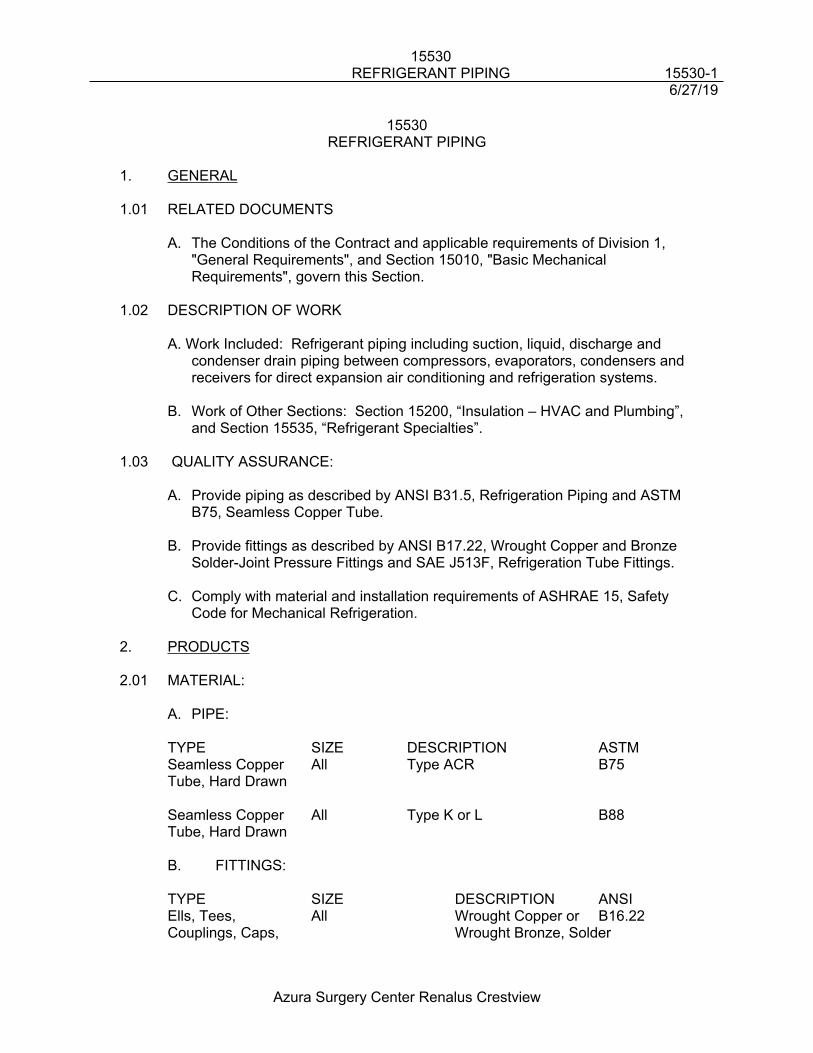
15530REFRIGERANT PIPING 15530-1
6/27/19
Azura Surgery Center Renalus Crestview
15530REFRIGERANT PIPING
1. GENERAL
1.01 RELATED DOCUMENTS
A. The Conditions of the Contract and applicable requirements of Division 1, "General Requirements", and Section 15010, "Basic Mechanical Requirements", govern this Section.
1.02 DESCRIPTION OF WORK
A. Work Included: Refrigerant piping including suction, liquid, discharge and condenser drain piping between compressors, evaporators, condensers and receivers for direct expansion air conditioning and refrigeration systems.
B. Work of Other Sections: Section 15200, “Insulation – HVAC and Plumbing”, and Section 15535, “Refrigerant Specialties”.
1.03 QUALITY ASSURANCE:
A. Provide piping as described by ANSI B31.5, Refrigeration Piping and ASTM B75, Seamless Copper Tube.
B. Provide fittings as described by ANSI B17.22, Wrought Copper and Bronze Solder-Joint Pressure Fittings and SAE J513F, Refrigeration Tube Fittings.
C. Comply with material and installation requirements of ASHRAE 15, Safety Code for Mechanical Refrigeration.
2. PRODUCTS
2.01 MATERIAL:
A. PIPE:
TYPE SIZE DESCRIPTION ASTMSeamless Copper All Type ACR B75Tube, Hard Drawn
Seamless Copper All Type K or L B88Tube, Hard Drawn
B. FITTINGS:
TYPE SIZE DESCRIPTION ANSIElls, Tees, All Wrought Copper or B16.22Couplings, Caps, Wrought Bronze, Solder
15530REFRIGERANT PIPING 15530-2
6/27/19
Azura Surgery Center Renalus Crestview
Reducers Joint FittingsJoint Material Silver Solder
3. EXECUTION
3.01 EXAMINATION:
A. Examine areas and conditions under which refrigerant piping is to be installed.
B. Do not proceed with work until satisfactory conditions are present.
3.02 INSTALLATION OF REFRIGERANT PIPING:
A. Install refrigerant piping in accordance with piping and equipment manufacturer's recommendations.
B. Install refrigerant piping with 1/8" per foot (1%) downward slope in direction of oil return to compressor.
C. Provide oil traps and double risers where required to provide oil return.
D. Clean refrigerant piping by swabbing with dry lint-free cloth, followed by refrigerant oil soaked swab.
E. Remove excess oil by swabbing with cloth soaked in high flash point petroleum solvent, squeezed dry.
F. Bleed dry nitrogen through refrigerant piping during brazing operations.
3.03 EQUIPMENT CONNECTIONS:
A. Connect refrigerant piping to mechanical equipment according to equipment manufacturer's instructions.
3.04 DEHYDRATION AND CHARGING SYSTEM
A. After testing and acceptance of installation, evacuate refrigerant system with vacuum pump until 35°F temperature is reached on vacuum dehydration indicator.
B. During evacuation, apply heat to pockets, elbows, and low spots in piping.
C. Maintain vacuum on system for minimum of 5 hours after closing valve between vacuum pump and system.
15530REFRIGERANT PIPING 15530-3
6/27/19
Azura Surgery Center Renalus Crestview
D. Break vacuum with refrigerant gas, allow pressure to build up to 2 psi.
E. Complete charging system using new filter dryer core in charging line.
F. Provide full operating charge.
END OF SECTION 15530
15535REFRIGERANT SPECIALTIES 15535-1
6/27/19
Azura Surgery Center Renalus Crestview
Section 15535REFRIGERANT SPECIALTIES
1. GENERAL
1.01 RELATED DOCUMENTS:A. The Conditions of the Contract and applicable requirements of Division 1,
"General Requirements", and Section 15010, "General Mechanical Requirements", govern this Section.
1.02 DESCRIPTION OF WORK:
A. Work Included: Refrigerant specialties for Direct Expansion air conditioning and refrigeration systems
B. Work of Other Sections: Section 15675, “Air Cooled Condensing Units” and Section 15730, “Air Cooled Split System Air Conditioning Units.”
1.03 QUALITY ASSURANCE
A. Comply with material and installation requirements of:1. ARI 710, Liquid-Line Dryers2. ARI 750, Thermostatic Refrigerant Expansion Valves3. ARI 730, Flow-Capacity Rating and Application of Suction-Line Filters and
Filter Dryers 4. ARI 495, Refrigerant Liquid Receivers5. ARI 770, Refrigerant Pressure Regulating Valves6. UL 207, Refrigerant Containing Components and Accessories, Non-
electrical
2. PRODUCTS
2.01 MANUFACTURERS:
A. Sporlan Valve Co., St. Louis, MOB. Henry Valve Co., Melrose Park, ILC. Parker Hannifin Corp., Lyons, NY
2.02 EQUIPMENT:
A. Provide refrigerant specialties of sizes, types, ratings and capacities required to comply with installation requirements.
B. Refrigerant Valves:1. Globe Shutoff Valves:
a. Cast iron, packed, back seating type with winged seal cap.b. 300F temperature rating, 300 psi working pressure.
2. Check Valves:a. Cast iron, accessible internal parts.b. 300F temperature rating, 300 psi working pressure.
15535REFRIGERANT SPECIALTIES 15535-2
6/27/19
Azura Surgery Center Renalus Crestview
3. 2-Way Solenoid Valve:a. Forged brass or steel, normally closed, Teflon valve seat.b. NEMA 1 solenoid enclosure, 24 volt, 60 Hz., UL-listed, 1/2" conduit
adapter.c. 300F temperature rating, 500 psi working pressure.d. Provide manual operator to open valve.
C. Refrigerant Strainers:1. Straight line or angle line type.2. Brass shell and end connections.3. 100 mesh, stainless steel screen.4. UL-listed.5. 430 psi working pressure.
D. Moisture - Liquid Indicator:1. Copper plated steel with solder connections.2. Paper indicator element held under sight glass.3. UL-listed.4. Rated working pressure 430 psi.
E. Filter - Dryers (Sealed Core):1. Steel shell.2. Molded desiccant core.3. Solder or flare connections.4. UL-listed.5. 500 psi working pressure.
F. Filter - Dryers (Replaceable Core):1. Steel Shell with bolted end plate.2. Replaceable molded desiccant core.3. Solder or pipe connections.4. UL-listed.5. 500 psi working pressure.
G. Evaporator Pressure Regulator:1. Steel body.2. Pressure operated, adjustable pressure regulator.3. Solder connections.
H. Thermostatic Expansion Valve:1. Brass body and stainless steel diaphragm.2. Externally adjustable.3. External pressure equalizer.4. Removable inlet strainer.5. Flare connections.6. Strap-on bulb with 5' of tubing.
I. Receiver:1. Copper shell with brazed points and fusible relief plug
15535REFRIGERANT SPECIALTIES 15535-3
6/27/19
Azura Surgery Center Renalus Crestview
2. 450 psig working pressure3. Flare connections
3. EXECUTION
3.01 EXAMINATION:
A. Examine areas and conditions under which refrigerant piping materials and products are to be installed.
B. Do not proceed with work until satisfactory conditions are present.
3.02 Installation of Refrigerant Valves:
A. Install refrigerant valves in accordance with manufacturer's instructions.B. Remove accessible internal parts before soldering or brazing, replace after
joints are completed.C. Install solenoid valves with stem pointing upwards.
3.03 Installation of Refrigerant Accessories:
A. Install accessories in locations accessible for service.B. Adjust evaporator pressure regulators, if required, for proper evaporator
pressure.C. Install filter drier cores after leak test but before evacuation.
END OF SECTION 15535
15720PACKAGED DX CONSTANT VOLUME ROOFTOP UNITS 15720-1
6/27/18
Azura Surgery Center Renalus Crestview
15720PACKAGED DX CONSTANT VOLUME ROOFTOP UNITS
1.0 GENERAL
1.01 SUMMARY
A. The General Provisions, Supplemental General Provisions, section 15010, Division 1 Specifications and Special Provisions apply to all Work specified in this Section.
B. This section describes the basic materials and installation methods for the packaged direct expansion constant volume rooftop units. Comply with other Division 15 sections and drawings as applicable. Refer to other divisions for coordination of work.
C. Furnish and install all components of the packaged DX constant volume rooftop units specified herein, as indicated on the drawings, and as required to provide complete and operating systems.
1.02 DESCRIPTION OF WORK
A. Work Included: Provide roof top constant air volume air-conditioning system, complete with controls and accessories as specified. Roof curbs are furnished under this section. Coordinate installation of curbs with Roofing Contractor.
B. Units shall be self-contained, rooftop curb-mounted, single package type. The rooftop units shall be completely factory assembled as a unitary package complete with operating controls and shall be completely piped, internally wired and fully charged with R-410a, R-134a or R-22 refrigerant. Only one electrical power connection shall be required.
1.03 QUALITY ASSURANCE
A. Equipment shall be installed and wired in accordance with applicable local and national codes.
B. Unit shall conform to the requirements and specifications of NFPA, and applicable local, state, and national codes.
C. Units shall be warranted by manufacturer with full factory warranty on materials and workmanship for one year from date of start-up, or the date of beneficial use, whichever is later.
D. Manufacturer shall provide a minimum five year material warranty on compressor.
1.04 SUBMITTALS
15720PACKAGED DX CONSTANT VOLUME ROOFTOP UNITS 15720-2
6/27/18
Azura Surgery Center Renalus Crestview
A. Shop drawings submittals shall include, but are not limited to, the following:
1. Unit cut-sheets clearly showing all features, accessories, dimensions, weights, and capacities.
2. Written instructions for equipment installation.
3. Wiring and piping diagrams and connection locations.
4. Performance certifications and test results.
5. Warranty information.
6. Additional information as required in Section 15010.
2.0 PRODUCTS
2.01 MANUFACTURERS
A. The “Basis of Design” is Daikin. Other acceptable manufacturers are:
1. York
2. Carrier
3. Trane
2.02 ROOFTOP UNITS
A. General
1. Factory assembled, single piece heating and cooling unit.
2. Contained within unit enclosure shall be all factory wiring, piping, refrigerant charge operating oil charge, dual refrigerant circuits, microprocessor based control system and associated hardware.
B. Unit Cabinet
1. Unit cabinet shall be constructed of heavy gauge galvanized steel with a weather resistant baked enamel finish tested in accordance with ASTM B117.
2. Cabinet panels shall be hinged or removable for easy servicing and shall provide a water tight seal. All panels and covers shall be insulated with ½ inch, one pound density matt faced, fire resistant, permanent, odorless, fiber glass insulation.
15720PACKAGED DX CONSTANT VOLUME ROOFTOP UNITS 15720-3
6/27/18
Azura Surgery Center Renalus Crestview
3. Lifting lugs shall be factory installed to facilitate overhead rigging.
4. Unit shall be equipped with factory-supplied condensate drain connection for evaporator coil.
C. Fans
1. Evaporator Fan
a. Fans shall be forward curved, centrifugal, belt driven single or double wheel and mounted on a common shaft with adjustable motor sheaves. Fan shall be statically and dynamically balanced and tested in the factory. Fan shall not pass through its first critical speed to meet its scheduled performance. The fan and motor assembly shall be mounted on a common base. For units with motor sizes greater than five (5) HP, the entire assembly shall be internally isolated from the rest of the unit with double deflection vibration isolators. Motors shall be thermally protected.
2. Condenser Fan
a. Outdoor fans shall be of the direct driven propeller type statically and dynamically balanced in the factory and be protected by a wire guard.
b. Outdoor fans shall discharge air vertically upward and shall have permanently lubricated bearings and thermal overload protection.
D. Compressors
1. Two semi-hermetic or scroll type with unloading capability. Units larger than 25 tons shall be capable of at least four stages of loading.
2. Factory mounted on spring vibration isolators.
3. Equipped with factory-installed crankcase heater, high and low pressure control, outdoor ambient protection, height motor temperature cut-out, compressor sump heat, three phase overload protection, and anti-cycle timer.
E. Coils
1. Evaporator and condenser coils shall have aluminum plate fins mechanically bonded to seamless copper tubes with all joints brazed. The coils shall be leak tested at the factory to 200 psig and pressure tested to 450 psig.
2. Coils shall be intertwined circuited to provide two independent refrigeration system.
15720PACKAGED DX CONSTANT VOLUME ROOFTOP UNITS 15720-4
6/27/18
Azura Surgery Center Renalus Crestview
3. Provide hot-gas reheat section and dehumidification sequence when indicated in the schedule.
F. Electric Heating Section
1. Electric heating sections shall be furnished with nickel-chromium open coil resistance heating elements with each element protected by an automatic reset high-limit thermostat and manual reset high- limit thermostat for the primary and secondary over-current/thermal protection. Controls shall provide for multiple stage start-up and operation. Electric module shall be UL listed.
G. Refrigerant Components
1. Refrigerant circuit components shall include: Filter dryers, liquid line sight glasses, compressor discharge valves, liquid line service valves and thermal expansion valves.
H. Filter Section
1. Standard filter section shall consist of low velocity, disposable two inch thick glass fiber filters in commercially available sizes. Filters shall be not less than 30% efficient when tested in accordance with ASHRAE Standards. Temporary filer media shall be provide throughout the course of construction and shall be changed as required to maintain proper unit operation and filtration. Provide new set of filters when building is turned over to the Owner.
I. Controls, Safeties and Diagnostics
1. Controls: Controls shall be accomplished through use of factory installed, microprocessor based control system and associated electronic and electrical hardware. For building with BAS systems, all required control capability and alarm monitoring shall be made available via a compatible interface with the BAS system.
2. Compressor safeties: Compressors shall be equipped with the following protections:
a. Over temperature (shuts down compressor).
b. Over current (shut down individual compressor).
c. Crankcase heaters.
d. Ground fault (shuts down individual compressor).
15720PACKAGED DX CONSTANT VOLUME ROOFTOP UNITS 15720-5
6/27/18
Azura Surgery Center Renalus Crestview
e. High-pressure switch (shuts down individual compressor, automatic reset type).
f. Low pressure switch (shuts down compressor, automatic reset type).
3. Heating Section Safeties: Heating Section shall be equipped with the following protections:
a. Loss of airflow switch.
b. Temperature limit switches.
c. Flame rollout switches. (gas heating only)
d. Centrifugal switch mounted on each induced draft fan motor. (gas heating only)
e. Automatically reset high-limit over-current/thermal protection. (electric heating only)
f. Manually reset high-limit over-current/thermal protection. (electric heating only)
4. Interlocks shall be made to the duct-mounted smoke detectors in each units supply and return ductwork to shut the unit off and fully close the return air dampers to prevent migration of smoke upon its detection.
J. Operating Characteristics:
1. Unit shall be capable of starting and running at 115ºF ambient outdoor temperature per maximum load criteria of ARI Standard 360.
2. Compressor with standard controls shall be capable of operation down to 0ºF ambient outdoor temperature .
3. Provides multistage mechanical cooling capability.
4. Unit shall be factory equipped with shutoff valve and tubing to maintain capacity control at minimal cooling loads.
K. Electrical Requirements: All unit power wiring shall enter cabinet at single location.
L. Motors
1. Compressor motors shall be cooled by suction gas passing through motor winding and shall have internal thermal overload protection.
2. Indoor blower poly-phase motor bearing shall be of ball bearing type.
15720PACKAGED DX CONSTANT VOLUME ROOFTOP UNITS 15720-6
6/27/18
Azura Surgery Center Renalus Crestview
3. Outdoor totally enclosed motors shall have permanently lubricated sealed ball bearing and inherent automatic reset thermal overload protection.
4. Each poly-phase compressor and indoor fan motor shall be protected against over-current and single phasing conditions. Protection devices shall be manual reset type.
M. Accessories to include:
1. Integrated Economizer: For units 7.5 tons and greater, enthalpy controlled integrated type consisting of dampers, motors and linkages, and potentiometer in conjunction with control system to provide primary cooling using outdoor air, enthalpy permitting, supplemented with mechanical cooling when necessary.
a. Dampers shall be low-leakage type, not to exceed one percent leakage at one inch water gauge pressure differential when fully closed.
b. Linkages shall have spring return feature which shuts dampers upon power interruption or unit shutdown.
c. Capable of introducing up to 100% outside air.
d. Exhaust/Return Air Fan, capable of 100% of maximum economizer supply air flow, shall be forward-curved centrifugal belt type only with fixed pitch pulley drive with optional factory installed inlet vanes or variable speed drive for capacity control Fan shall be controlled by building pressure sensor for active pressure control. Pressure sensor shall be installed in a location representative of the overall building pressure.
2. Barometric relief damper package: (Exhaust fan to be used on units over 20 tons)
a. Package shall relieve internal pressure and consist of damper assembly, hoods, damper screen, seal strip and required hardwire.
b. Damper assembly shall close due to gravity upon unit shutoff.
c. Unit mounted down-flow units only.
3. Curb:
A. Each unit shall be provided with a full perimeter, curb and allow for MERV 14 filter installation where indicated on the schedule. The roof curb shall be of the same manufacturer as the unit, shall support the unit and provide a
15720PACKAGED DX CONSTANT VOLUME ROOFTOP UNITS 15720-7
6/27/18
Azura Surgery Center Renalus Crestview
watertight enclosure to protect ductwork and utility services. Gaskets must be provided at supply/return air openings.
3.0 EXECUTION
3.01 START-UP
A. A factory certified trained service technician shall supervise the installation of equipment and start-up.
B. A factory certified service technician shall fully instruct Owner's personnel in the operation and maintenance of units.
3.02 INSTALLATION
A. Roof Top Air Unit
1. Install units on roof curbs furnished by unit manufacturer and in accordance with manufacturer's installation instructions.
2. The rigging and setting of the units shall be in accordance with the unit manufacturer’s recommendations.
3. All penetrations through unit are to be in factory provided chases. No penetrations through the condensate pan, etc. are permitted.
END OF SECTION 15720
15770DUCTLESS SPLIT SYSTEM UNITS 15770-1
6/27/19
Azura Surgery Center Renalus Crestview
15770DUCTLESS SPLIT SYSTEM UNITS
PART 1 GENERAL
1.1 SUMMARY
A. The General Provisions, Supplemental General Provisions, section 15010, Division 1 Specifications and Special Provisions apply to all Work specified in this Section.
B. This section describes the basic materials and installation methods for the ductless, variable capacity, heat pump heat recovery air conditioning system. Comply with other Division 15 sections and drawings as applicable. Refer to other divisions for coordination of work.
C. Furnish and install all components of the variable capacity, heat pump heat recovery air conditioning system specified herein, as indicated on the drawings, and as required to provide complete and operating systems.
1.2 DESCRIPTION OF WORK
A. Work Included: Provide a UL listed split system air conditioning unit work including, but not limited to, the furnishing and installation of an indoor evaporator unit, an air-cooled condensing unit, filters, refrigerant piping thermostat, accessories and other controls as required by local, state, and other applicable codes.
1.3 QUALITY ASSURANCE
A. Manufacturer: “Basis of Design” is Mitsubishi. Acceptable alternate manufacturers:
1. Daikin
B. Certification: Provide manufacturer’s certification of compliance with ARI Standard 210.
C. The units shall be listed by Electrical Laboratories (ETL) and bear the ETL label.
D. All wiring shall be in accordance with the National Electrical Code (N.E.C.).
E. The units shall be manufactured in a facility registered to ISO 9001 and ISO14001 which is a set of standards applying to environmental protection set by the International Standard Organization (ISO).
F. A full charge of R-410A for the condensing unit only shall be provided in the condensing unit.
1.4 SUBMITTALS
A. Shop drawings submittals shall include, but are not limited to, the following:
15770DUCTLESS SPLIT SYSTEM UNITS 15770-2
6/27/19
Azura Surgery Center Renalus Crestview
1. Unit cut-sheets clearly showing all features, accessories, dimensions, weight, and capacities.
2. Written instructions for equipment to installation.3. Wiring and piping diagrams and connection locations.4. Performance certifications and test results.5. Warranty information.6. Additional information as required in Section 15010.
1.5 PRODUCT DELIVERY, STORAGE, AND HANDLING
A. Deliver split system air conditioning units and accessories in factory-fabricated water-resistant wrapping.
B. Handle units and accessories carefully to avoid damage to material components, enclosure and finish.
C. Store units and accessories in a clean, dry space and protect from the weather.
1.6 WARRANTY
A. The units shall be covered by an extended manufacturer’s limited warranty for a period of five (5) years from date of installation.
B. In addition the compressor shall have a manufacturer’s limited warranty for a period of six (6) years from date of installation.
C. If, during this period, any part should fail to function properly due to defects in workmanship or material, it shall be replaced or repaired at the discretion of the manufacturer. This warranty shall not include labor.
D. System shall be installed by an authorized dealer with factory installation and service training.
PART 2 PRODUCTS
2.1 R2-SERIES OUTDOOR UNIT
A. General:The R2-Series PURY outdoor unit shall be used specifically with CITY MULTI VRFZ components. The R2-Series shall consist of the PURY outdoor unit, Branch Circuit (BC) Controller, indoor units (-E models), and M-NET DDC (Direct Digital Controls). The PURY outdoor units shall be equipped with multiple circuit boards that interface to the M-NET controls system and shall perform all functions necessary for operation. The outdoor unit shall have a powder coated finish. The outdoor unit shall be completely factory assembled, piped and wired. Each unit shall be run tested at the factory.
1. The sum of connected capacity of all indoor air handlers shall range from 50% to 150% of outdoor rated capacity.
15770DUCTLESS SPLIT SYSTEM UNITS 15770-3
6/27/19
Azura Surgery Center Renalus Crestview
2. Outdoor unit shall have a sound rating no higher than 63 dB(A).3. Both refrigerant lines from the outdoor unit to the BC (Branch Circuit) Controller
(Single or Main) shall be insulated.4. There shall be no more than 3 branch circuit controllers connected to any one
outdoor unit. 5. The outdoor unit shall have an accumulator with refrigerant level sensors and
controls.6. The outdoor unit shall have a high pressure safety switch, over-current protection
and DC bus protection.7. The outdoor unit shall have the ability to operate with a maximum height
difference of 164 feet and have total refrigerant tubing length of 1000 feet. The greatest length is not to exceed 492 feet between outdoor unit and the indoor units without the need for line size changes or traps.
8. The outdoor unit shall be capable of operating in heating down to 0F ambient temperature without additional low ambient controls.
9. The outdoor unit shall not cease operation in any mode based solely on outdoor ambient temperature.
10. The outdoor unit shall have a high efficiency oil separator plus additional logic controls to ensure adequate oil volume in the compressor is maintained.
B. Unit Cabinet:
1. The casing(s) shall be fabricated of galvanized steel, bonderized and finished with a powder coated baked enamel.
C. Fan:
1. The PURY-P72 / P96 / P108 / P126 / P144TGMU outdoor unit shall be furnished with one direct drive, variable speed propeller type fan.
2. The PURY-P168 / P192 / P204 / P216 / P234TGMU outdoor unit shall be furnished with two direct drive, variable speed propeller type fans.
3. All fan motors shall have inherent protection, have permanently lubricated bearings, and be completely variable speed.
4. All fan motors shall be mounted for quiet operation.5. All fans shall be provided with a raised guard to prevent contact with moving
parts.6. The outdoor unit shall have vertical discharge airflow.
D. Refrigerant
1. R410A refrigerant shall be required for PURY-P-TGMU-A outdoor unit systems.
E. Coil:
1. The outdoor coil shall be of nonferrous construction with lanced or corrugated plate fins on copper tubing.
2. The coil fins shall have a factory applied corrosion resistant blue-fin finish.3. The coil shall be protected with an integral metal guard.
15770DUCTLESS SPLIT SYSTEM UNITS 15770-4
6/27/19
Azura Surgery Center Renalus Crestview
4. Refrigerant flow from the outdoor unit shall be controlled by means of an inverter driven compressor.
5. The outdoor coil shall include 4 circuits with two position valves for each circuit, except for the last stage.
F. Compressor:
1. The PURY-P72 / P96 / P108 / P126 / P144TGMU outdoor units shall be equipped with one inverter driven scroll hermetic compressor.
2. The PURY-P168 / P192 / P204 / P216 / P234TGMU outdoor unit shall be equipped with one inverter driven scroll hermetic compressor and one scroll hermetic compressor.
3. A crankcase heater(s) shall be factory mounted on the compressor(s).4. The outdoor unit compressor shall have an inverter to modulate capacity. The
capacity shall be completely variable down to 16% of rated capacity.5. The compressor will be equipped with an internal thermal overload.6. The compressor shall be mounted to avoid the transmission of vibration.
G. Electrical:
1. The outdoor unit electrical power shall be 208/230 volts, 3-phase, 60 hertz. 2. The outdoor unit shall be capable of satisfactory operation within voltage limits of
187-228 volts (208V/60Hz) or 207-253V (230V/60Hz).3. The outdoor unit shall be controlled by integral microprocessors.4. The control circuit between the indoor units, BC Controller and the outdoor unit
shall be 24VDC completed using a 2-conductor, twisted pair shielded cable to provide total integration of the system.
2.2 BRANCH CIRCUIT (BC) CONTROLLERS FOR R2-SERIES SYSTEMS
A. General:The BC (Branch Circuit) Controllers shall be specifically used with R410A R2-Series systems. These units shall be equipped with a circuit board that interfaces to the M-NET controls system and shall perform all functions necessary for operation. The unit shall have a galvanized steel finish. The BC Controller shall be completely factory assembled, piped and wired. Each unit shall be run tested at the factory. This unit shall be mounted indoors. The sum of connected capacity of all indoor air handlers shall range from 50% to 150% of rated capacity.
B. BC Unit Cabinet:
1. The casing shall be fabricated of galvanized steel.2. Each cabinet shall house a liquid-gas separator and multiple refrigeration control
valves.3. The unit shall house two tube-in-tube heat exchangers.
C. Refrigerant
15770DUCTLESS SPLIT SYSTEM UNITS 15770-5
6/27/19
Azura Surgery Center Renalus Crestview
1. R410A refrigerant shall be required for CMB-P-NU-G/GA/GB BC Controllers in conjunction with PURY-P-TGMU-A outdoor unit systems.
D. Refrigerant valves:
1. The unit shall be furnished with multiple branch circuits which can individually accommodate up to 54,000 BTUH and/or three indoor units. Branches may be twinned to allow more than 54,000 BTUH.
2. Each branch shall have multiple two-position valves to control refrigerant flow.3. Service shut-off valves shall be field-provided/installed for each branch to allow
service to any indoor unit without field interruption to overall system operation.4. Linear electronic expansion valves shall be used to control the variable
refrigerant flow.
E. Integral Drain Pan:An integral condensate pan and drain shall be provided.
F. Electrical:
1. The unit electrical power shall be 208/230 volts, 1 phase, 60 hertz. 2. The unit shall be capable of satisfactory operation within voltage limits of 187-228
volts (208V/60Hz) or 207-253V (230V/60Hz).3. The BC Controller shall be controlled by integral microprocessors.4. The control circuit between the indoor units and the outdoor unit shall be 24VDC
completed using a 2-conductor, twisted pair shielded cable to provide total integration of the system.
2.3 PKFY (WALL-MOUNTED) INDOOR UNIT
A. General:The PKFY shall be wall-mounted indoor unit section with a slim silhouette and shall have a modulating linear expansion device. The PKFY shall be used with the R2-Series outdoor unit and BC Controller, Y-Series outdoor unit, or S-Series outdoor unit. The PKFY shall support individual control using M-NET DDC controllers.
B. Indoor UnitThe indoor unit shall be factory assembled, wired and run tested. Contained within the unit shall be all factory wiring, piping, electronic modulating linear expansion device, control circuit board and fan motor. The unit shall have a self-diagnostic function, 3-minute time delay mechanism, an auto restart function, and a test run switch. Indoor unit and refrigerant pipes shall be charged with dehydrated air before shipment from the factory.
C. Unit Cabinet:
1. The casing shall have a white finish.2. Multi directional drain and refrigerant piping offering four (4) directions for
refrigerant piping and two (2) directions for draining shall be standard.3. There shall be a separate back plate which secures the unit firmly to the wall.
15770DUCTLESS SPLIT SYSTEM UNITS 15770-6
6/27/19
Azura Surgery Center Renalus Crestview
D. Fan:
1. The indoor fan shall be an assembly with one or two line-flow fan(s) direct driven by a single motor.
2. The indoor fan shall be statically and dynamically balanced to run on a motor with permanently lubricated bearings.
3. A manual adjustable guide vane shall be provided with the ability to change the airflow from side to side (left to right).
4. A motorized air sweep louver shall provide an automatic change in airflow by directing the air up and down to provide uniform air distribution.
E. Filter:
1. Return air shall be filtered by means of an easily removable, washable filter.
F. Coil:
1. The indoor coil shall be of nonferrous construction with smooth plate fins on copper tubing.
2. The tubing shall have inner grooves for high efficiency heat exchange.3. All tube joints shall be brazed with phos-copper or silver alloy.4. The coils shall be pressure tested at the factory.5. A condensate pan and drain shall be provided under the coil.6. Both refrigerant lines to the PKFY indoor units shall be insulated.
G. Electrical:
1. The unit electrical power shall be 208/230 volts, 1-phase, 60 hertz.2. The system shall be capable of satisfactory operation within voltage limits of 187-
228 volts (208V/60Hz) or 207-253 volts (230V/60Hz)
H. Controls:
1. This unit shall use controls provided by Mitsubishi Electric to perform functions necessary to operate the system. Please refer to Part 5 of this guide specification for details on controllers and other control options.
2.4 PLFY-P**NBMU-E (4-WAY CEILING-RECESSED CASSETTE WITH GRILLE) INDOOR UNIT
A. General:
1. The PLFY shall be a four-way cassette style indoor unit that recesses into the ceiling with a ceiling grille. The indoor unit shall be factory assembled, wired and run tested. Contained within the unit shall be all factory wiring, piping, electronic modulating linear expansion device, control circuit board and fan motor. The unit shall have a self-diagnostic function, 3-minute time delay mechanism, an auto restart function, an emergency operation function and a test run switch. Indoor
15770DUCTLESS SPLIT SYSTEM UNITS 15770-7
6/27/19
Azura Surgery Center Renalus Crestview
unit and refrigerant pipes shall be charged with dehydrated air before shipment from the factory.
B. Unit Cabinet:
1. The cabinet shall be space-saving ceiling-recessed cassette.2. The cabinet panel shall have provisions for a field installed filtered outside air
intake.3. Branch ducting shall be allowed from cabinet.4. Four-way grille shall be fixed to bottom of cabinet allowing two, three or four-way
blow.5. The grille vane angles shall be individually adjustable from the wired remote
controller to customize the airflow pattern for the conditioned space
C. Fan:
1. The indoor fan shall be an assembly with a turbo fan direct driven by a single motor.
2. The indoor fan shall be statically and dynamically balanced to run on a motor with permanently lubricated bearings.
3. The indoor fan shall consist of five (5) speed settings, Low, Mid1, Mid2, High and Auto.
4. The fan shall have a selectable Auto fan setting that will adjust the fan speed based on the difference between controller set-point and space temperature.
5. The indoor unit shall have an adjustable air outlet system offering 4-way airflow, 3-way airflow, or 2-way airflow.
6. The indoor unit shall have switches that can be set to provide optimum airflow based on ceiling height and number of outlets used.
7. The indoor unit vanes shall have 5 fixed positions and a swing feature that shall be capable of automatically swinging the vanes up and down for uniform air distribution.
8. The vanes shall have an Auto-Wave selectable option in the heating mode that shall randomly cycle the vanes up and down to evenly heat the space.
9. If specified, the grille shall have an optional i-see sensor that will measure room temperature variations and adjust the airflow accordingly to evenly condition the space.
D. Filter:
1. Return air shall be filtered by means of a long-life washable filter
E. Coil:
1. The indoor coil shall be of nonferrous construction with smooth plate fins on copper tubing.
2. The tubing shall have inner grooves for high efficiency heat exchange.3. All tube joints shall be brazed with phos-copper or silver alloy.4. The coils shall be pressure tested at the factory.5. A condensate pan and drain shall be provided under the coil.
15770DUCTLESS SPLIT SYSTEM UNITS 15770-8
6/27/19
Azura Surgery Center Renalus Crestview
6. The unit shall include a condensate lift mechanism that will be able to raise drain water 33 inches above the condensate pan.
7. Both refrigerant lines to the PLFY indoor units shall be insulated.
F. Electrical:
1. The unit electrical power shall be 208/230 volts, 1-phase, 60 hertz.2. The system shall be capable of satisfactory operation within voltage limits of 187-
228 volts (208V/60Hz) or 207-253 volts (230V/60Hz).
G. Controls:
1. This unit shall use controls provided by Mitsubishi Electric to perform functions necessary to operate the system.
2.5 PLFY-P**NCMU-E (4-WAY CEILING-RECESSED CASSETTE WITH GRILLE) INDOOR UNIT
A. General:
1. The PLFY shall be a four-way cassette style indoor unit that recesses into the ceiling with a ceiling grille. The indoor unit shall be factory assembled, wired and run tested. Contained within the unit shall be all factory wiring, piping, electronic modulating linear expansion device, control circuit board and fan motor. The unit shall have a self-diagnostic function, 3-minute time delay mechanism, an auto restart function, an emergency operation function and a test run switch. Indoor unit and refrigerant pipes shall be charged with dehydrated air before shipment from the factory.
B. Unit Cabinet:
1. The cabinet shall be a compact 22-7/16” wide x 22-7/16” deep so it will fit within a standard 24” square suspended ceiling grid.
2. The cabinet panel shall have provisions for a field installed filtered outside air intake.
3. Four-way grille shall be fixed to bottom of cabinet allowing two, three or four-way blow.
C. Fan:
1. The indoor fan shall be an assembly with a turbo fan direct driven by a single motor.
2. The indoor fan shall be statically and dynamically balanced to run on a motor with permanently lubricated bearings.
3. The indoor fan shall consist of three (3) speeds, Low, Mid, and High.4. The indoor unit shall have an adjustable air outlet system offering 4-way airflow,
3-way airflow, or 2-way airflow.5. The auto air swing vanes shall be capable of automatically swinging up and
down for uniform air distribution.
15770DUCTLESS SPLIT SYSTEM UNITS 15770-9
6/27/19
Azura Surgery Center Renalus Crestview
D. Filter:
1. Return air shall be filtered by means of a long-life washable filter.
E. Coil:
1. The indoor coil shall be of nonferrous construction with smooth plate fins on copper tubing.
2. The tubing shall have inner grooves for high efficiency heat exchange.3. All tube joints shall be brazed with phos-copper or silver alloy.4. The coils shall be pressure tested at the factory.5. A condensate pan and drain shall be provided under the coil.6. The unit shall include a condensate lift mechanism that will be able to raise drain
water 19-3/4” inches above the condensate pan.7. Both refrigerant lines to the PLFY indoor units shall be insulated.
F. Electrical:
1. The unit electrical power shall be 208/230 volts, 1-phase, 60 hertz.2. The system shall be capable of satisfactory operation within voltage limits of 187-
228 volts (208V/60Hz) or 207-253 volts (230V/60Hz).
G. Controls:
1. This unit shall use controls provided by Mitsubishi Electric to perform functions necessary to operate the system.
2.6 PMFY (1-WAY CEILING-RECESSED CASSETTE WITH GRILLE) INDOOR UNIT
A. General:
1. The PMFY shall be a one-way cassette indoor unit that recesses into the ceiling with a ceiling grille and shall have a modulating linear expansion device. The PMFY shall be used with the R2-Series outdoor unit and BC Controller, Y-Series outdoor unit, or S-Series outdoor unit. The PMFY shall support individual control using M-NET DDC controllers.
B. Indoor Unit.
1. The indoor unit shall be factory assembled, wired and run tested. Contained within the unit shall be all factory wiring, piping, electronic modulating linear expansion device, control circuit board and fan motor. The unit shall have a self-diagnostic function, 3-minute time delay mechanism, an auto restart function, an emergency operation function and a test run switch. Indoor unit and refrigerant pipes shall be charged with dehydrated air before shipment from the factory.
C. Unit Cabinet:
15770DUCTLESS SPLIT SYSTEM UNITS 15770-10
6/27/19
Azura Surgery Center Renalus Crestview
1. The cabinet shall be space-saving ceiling recessed.2. The cabinet panel shall have provisions for a field installed filtered outside air
intake.3. Branch ducting shall be allowed from cabinet.4. The one-way grille shall be fixed to bottom of cabinet allowing for one-way
airflow.
D. Fan:
1. The indoor fan shall be an assembly with one line-flow fan direct driven by a single motor.
2. The indoor fan shall be statically and dynamically balanced to run on a motor with permanently lubricated bearings.
3. The indoor fan shall consist of four (4) speeds, Low, Mid1, Mid2, and High.
E. Filter:
1. Return air shall be filtered by means of a long-life washable permanent filter.
F. Coil:
1. The indoor coil shall be of nonferrous construction with smooth plate fins on copper tubing.
2. The tubing shall have inner grooves for high efficiency heat exchange.3. All tube joints shall be brazed with phos-copper or silver alloy.4. The coils shall be pressure tested at the factory.5. A condensate pan and drain shall be provided under the coil.6. The condensate lift mechanism shall be able to raise drain water 23 inches
above the condensate pan.7. Both refrigerant lines to the PMFY indoor units shall be insulated.
G. Electrical:
1. The unit electrical power shall be 208/230 volts, 1-phase, 60 hertz.2. The system shall be capable of satisfactory operation within voltage limits of 187-
228 volts (208V/60Hz) or 207-253 volts (230V/60Hz).
H. Controls:
1. This unit shall use controls provided by Mitsubishi Electric to perform functions necessary to operate the system. Please refer to Part 5 of this guide specification for details on controllers and other control options.
2.7 PDFY (CEILING-CONCEALED DUCTED) INDOOR UNIT
A. General:The PDFY shall be a ceiling-concealed ducted indoor fan coil design that mounts above the ceiling with a 2-position, field adjustable return and a fixed horizontal discharge supply and shall have a modulating linear expansion device. The PDFY shall be used
15770DUCTLESS SPLIT SYSTEM UNITS 15770-11
6/27/19
Azura Surgery Center Renalus Crestview
with the R2-Series outdoor unit and BC Controller, Y-Series outdoor unit, or S-Series outdoor unit. The PDFY shall support individual control using M-NET DDC controllers
B. Indoor Unit.The indoor unit shall be factory assembled, wired and run tested. Contained within the unit shall be all factory wiring, piping, electronic modulating linear expansion device, control circuit board and fan motor. The unit shall have a self-diagnostic function, 3-minute time delay mechanism, and an auto restart function. Indoor unit and refrigerant pipes shall be charged with dehydrated air before shipment from the factory.
C. Unit Cabinet:
1. The unit shall be space saving, ceiling-concealed, ducted.2. The cabinet panel shall have provisions for a field installed filtered outside air
intake.
D. Fan:
1. The indoor unit fan shall be an assembly with one or two Sirocco fan(s) direct driven by a single motor.
2. The indoor fan shall be statically and dynamically balanced and run on a motor with permanently lubricated bearings.
3. The indoor unit shall have a ducted air outlet system and ducted return air system.
E. Filter:
1. Return air shall be filtered by means of a standard factory installed return air filter.
2. Optional return filter box (rear or bottom placement) with high-efficiency filter shall be available for all PDFY indoor units.
F. Coil:
1. The indoor coil shall be of nonferrous construction with smooth plate fins on copper tubing.
2. The tubing shall have inner grooves for high efficiency heat exchange.3. All tube joints shall be brazed with phos-copper or silver alloy.4. The coils shall be pressure tested at the factory.5. A condensate pan and drain shall be provided under the coil.6. The condensate shall be gravity drained from the fan coil.7. Both refrigerant lines to the PDFY indoor units shall be insulated.
G. Electrical:
1. The unit electrical power shall be 208/230 volts, 1-phase, 60 hertz.2. The system shall be capable of satisfactory operation within voltage limits of 187-
228 volts (208V/60Hz) or 207-253 volts (230V/60Hz).
15770DUCTLESS SPLIT SYSTEM UNITS 15770-12
6/27/19
Azura Surgery Center Renalus Crestview
H. Controls:
1. This unit shall use controls provided by Mitsubishi Electric to perform functions necessary to operate the system. Please refer to Part 5 of this guide specification for details on controllers and other control options.
2.8 PEFY-NMLU (LOW PROFILE CEILING-CONCEALED DUCTED) INDOOR UNIT
A. General:
1. The PEFY-NMLU (Low Profile) unit shall be a high-performance ceiling-concealed ducted indoor fan coil that mounts above the ceiling with a 2-position, field adjustable return and a fixed horizontal discharge supply and shall have a modulating linear expansion device. The PEFY-NMLU shall be used with the R2-Series outdoor unit and BC Controller, Y-Series outdoor unit, or S-Series outdoor unit. The PEFY-NMLU shall support individual control using M-NET DDC controllers. PEFY (Low Profile) models shall have an extremely compact profile (8-7/8”) which requires minimal ceiling space.
B. Indoor Unit.
1. The indoor unit shall be factory assembled, wired and run tested. Contained within the unit shall be all factory wiring, piping, electronic modulating linear expansion device, control circuit board and fan motor. The unit shall have a self-diagnostic function, 3-minute time delay mechanism, and an auto restart function. Indoor unit and refrigerant pipes shall be charged with dehydrated air before shipment from the factory.
C. Unit Cabinet:
1. The cabinet shall be space saving, low profile, ceiling-concealed ducted.2. The cabinet panel shall have provisions for a field installed filtered outside air
intake.
D. Fan:
1. The indoor unit fan shall be an assembly with one Sirocco fan direct driven by a single motor.
2. The indoor fan shall be statically and dynamically balanced to run on a motor with permanently lubricated bearings.
3. The indoor fan shall consist of three (3) speeds, High, Mid, and Low.4. The indoor unit shall have a ducted air outlet system and ducted return air
system.
E. Filter:
1. Return air shall be filtered by means of a standard factory installed return air filter.
15770DUCTLESS SPLIT SYSTEM UNITS 15770-13
6/27/19
Azura Surgery Center Renalus Crestview
F. Coil:
1. The indoor coil shall be of nonferrous construction with smooth plate fins on copper tubing.
2. The tubing shall have inner grooves for high efficiency heat exchange.3. All tube joints shall be brazed with phos-copper or silver alloy.4. The coils shall be pressure tested at the factory.5. A condensate pan and drain shall be provided under the coil.6. The condensate shall be gravity drained from the fan coil.7. Both refrigerant lines to the PEFY indoor units shall be insulated.
G. Electrical:
1. The unit electrical power shall be 208/230 volts, 1 phase, 60 hertz.2. The system shall be capable of satisfactory operation within voltage limits of 187-
228 volts (208V/60Hz) or 207-253 volts (230V/60Hz).
H. Controls:
1. This unit shall use controls provided by Mitsubishi Electric to perform functions necessary to operate the system. Please refer to Part 5 of this guide specification for details on controllers and other control options.
2.9 PEFY-NMHU (ALTERNATE HIGH STATIC OPTION, CEILING-CONCEALED DUCTED) INDOOR UNIT
A. General:
1. The PEFY-NMHU (Alternate High Static Option) unit shall be a high-performance ceiling concealed ducted indoor fan coil that mounts above the ceiling with a fixed rear return and a horizontal discharge supply, and shall have a modulating linear expansion device. The PEFY-NMHU shall be used with the R2-Series outdoor unit and BC Controller, Y-Series outdoor unit, or S-Series outdoor unit. The PEFY-NMLU shall support individual control using M-NET DDC controllers. PEFY-NMHU (Alternate High Static Option) models shall feature external static pressure settings up 0.80 in. WG (230 Volts.
B. Indoor Unit.
1. The indoor unit shall be factory assembled, wired and run tested. Contained within the unit shall be all factory wiring, piping, electronic modulating linear expansion device, control circuit board and fan motor. The unit shall have a self-diagnostic function, 3-minute time delay mechanism, and an auto restart function. Indoor unit and refrigerant pipes shall be charged with dehydrated air before shipment from the factory.
C. Unit Cabinet:
1. The cabinet shall be ceiling-concealed, ducted.
15770DUCTLESS SPLIT SYSTEM UNITS 15770-14
6/27/19
Azura Surgery Center Renalus Crestview
2. The cabinet panel shall have provisions for a field installed filtered outside air intake.
D. Fan:
1. The indoor unit fan shall be an assembly with one or two Sirocco fan(s) direct driven by a single motor.
2. The indoor fan shall be statically and dynamically balanced to run on a motor with permanently lubricated bearings.
3. The indoor unit shall have a ducted air outlet system and ducted return air system.
E. Filter:
1. Return air shall be filtered by a field-supplied filter.2. Optional rear return filter box with long-life filter shall available for all PEFY-
NMHU-E indoor units.
F. Coil:
1. The indoor coil shall be of nonferrous construction with smooth plate fins on copper tubing.
2. The tubing shall have inner grooves for high efficiency heat exchange.3. All tube joints shall be brazed with phos-copper or silver alloy.4. The coils shall be pressure tested at the factory.5. A condensate pan and drain shall be provided under the coil.6. The condensate shall be gravity drained from the fan coil.7. Both refrigerant lines to the PEFY indoor units shall be insulated.
G. Electrical:
1. The unit electrical power shall be 208/230 volts, 1-phase, 60 hertz, except for the PEFY-P72NMHU-E and PEFY-P86NMHU-E. The PEFY-P72NMHU-E and PEFY-P96NMHU=E shall be 208/230 volts, 3-phase, 60 hertz.
2. The system shall be capable of satisfactory operation within voltage limits of 187-228 volts (208V/60Hz) or 207-253 volts (230V/60Hz).
H. Controls:
1. This unit shall use controls provided by Mitsubishi Electric to perform functions necessary to operate the system. Please refer to Part 5 of this guide specification for details on controllers and other control options.
2.10 PFFY (FLOOR-STANDING-EXPOSED or FLOOR-STANDING-CONCEALED) INDOOR UNIT
A. General:
15770DUCTLESS SPLIT SYSTEM UNITS 15770-15
6/27/19
Azura Surgery Center Renalus Crestview
1. The PFFY shall consist of a floor-standing indoor section with and shall have a modulating linear expansion device. The PFFY shall be used with the R2-Series outdoor unit and BC Controller, Y-Series outdoor unit, or S-Series outdoor unit. The PFFY shall support individual control using M-NET DDC controllers.
B. Indoor Unit
1. The indoor unit shall be factory assembled, wired and run tested. Contained within the unit shall be all factory wiring, piping, electronic modulating linear expansion device, control circuit board and fan motor. The unit shall have a self-diagnostic function, 3-minute time delay mechanism, an auto restart function, and a test run switch. Indoor unit and refrigerant pipes shall be charged with dehydrated air before shipment from the factory.
C. Unit Cabinet, Exposed:
1. The casing shall have a beige Acrylic paint finish.
D. Unit Cabinet, Recessed:
1. The casing shall have a galvanized sheet metal finish.
E. Fan:
1. The indoor unit fan shall be an assembly with one or two Sirocco fan(s) direct driven by a single motor.
2. The indoor fan shall be statically and dynamically balanced to run on a motor with permanently lubricated bearings.
3. The indoor fan shall consist of two (2) speeds, High and Low.
F. Filter:
1. Return air shall be filtered by means of an easily removable washable filter.
G. Coil:
1. The indoor coil shall be of nonferrous construction with smooth plate fins on copper tubing.
2. The tubing shall have inner grooves for high efficiency heat exchange.3. All tube joints shall be brazed with phos-copper or silver alloy.4. The coils shall be pressure tested at the factory.5. A condensate pan and drain shall be provided under the coil.6. Both refrigerant lines to the PFFY indoor units shall be insulated.
H. Electrical:
1. The unit electrical power shall be 208/230 volts, 1-phase, 60 hertz.2. The system shall be capable of satisfactory operation within voltage limits of 187-
228 volts (208V/60Hz) or 207-253 volts (230V/60Hz).
15770DUCTLESS SPLIT SYSTEM UNITS 15770-16
6/27/19
Azura Surgery Center Renalus Crestview
I. Controls:
1. This unit shall use controls provided by Mitsubishi Electric to perform functions necessary to operate the system. Please refer to Part 5 of this guide specification for details on controllers and other control options.
2.11 PCFY (CEILING-SUSPENDED) INDOOR UNIT
A. General:
1. The PCFY shall be ceiling-suspended indoor unit section providing powerful airflow and shall have a modulating linear expansion device. The PCFY shall be used with the R2-Series outdoor unit and BC Controller(s), Y-Series outdoor unit, or S-Series outdoor unit. The PCFY shall support individual control using M-NET DDC controllers.
B. Indoor Unit
1. The indoor unit shall be factory assembled, wired and run tested. Contained within the unit shall be all factory wiring, piping, electronic modulating linear expansion device, control circuit board and fan motor. The unit shall have a self-diagnostic function, 3-minute time delay mechanism, an auto restart function, and a test run switch. Indoor unit and refrigerant pipes shall be charged with dehydrated air before shipment from the factory.
C. Unit Cabinet:
1. The casing shall have a white finish.
D. Fan:
1. The indoor unit fan shall be an assembly with two, three, or four Sirocco fan(s) direct driven by a single motor.
2. The indoor fan shall be statically and dynamically balanced to run on a motor with permanently lubricated bearings.
3. The indoor fan shall consist of four (4) speeds, Low, Mid1, Mid2, and High.
E. Filter:
1. Return air shall be filtered by means of an easily removable, washable filter.
F. Coil:
1. The indoor coil shall be of nonferrous construction with smooth plate fins on copper tubing.
2. The tubing shall have inner grooves for high efficiency heat exchange.3. All tube joints shall be brazed with phos-copper or silver alloy.4. The coils shall be pressure tested at the factory.
15770DUCTLESS SPLIT SYSTEM UNITS 15770-17
6/27/19
Azura Surgery Center Renalus Crestview
5. A condensate pan and drain shall be provided under the coil.6. Both refrigerant lines to the PCFY indoor units shall be insulated.
G. Electrical:
1. The unit electrical power shall be 208/230 volts, 1 phase, 60 hertz.2. The system shall be capable of satisfactory operation within voltage limits of 187-
228 volts (208V/60Hz) or 207-253 volts (230V/60Hz)
H. Controls:
1. This unit shall use controls provided by Mitsubishi Electric to perform functions necessary to operate the system. Please refer to Part 5 of this guide specification for details on controllers and other control options
2.12 CMCN: Remote Controllers
A. Deluxe MA Remote Controller (PAR-21MAA)The Deluxe MA Remote Controller (PAR-21MAA) shall be capable of controlling up to 16 indoor units (defined as 1 group). The Deluxe MA Remote Controller shall be approximately 5” x 5” in size and white in color with a light-green LCD display. The PAR-21MAA shall support a selection from multiple languages (Spanish, German, Japanese, Chinese, English, Russian, Italian, or French) for display information. The Deluxe MA supports temperature display selection of Fahrenheit or Celsius. The Deluxe MA Remote Controller shall control the following grouped operations: On/Off, Operation Mode (cool, heat, auto (R2-Series only), dry, and fan), temperature set point, fan speed setting, and airflow direction setting. The Deluxe MA Remote Controller shall support timer settings of on/off/temperature up to 8 times in a day in 1-minute increments. The Deluxe MA Remote Controller shall support an Auto Off timer. The Deluxe MA Remote Controller shall be able to limit the set temperature range from the Deluxe MA. The room temperature shall be sensed at either the Deluxe MA Remote Controller or the Indoor Unit dependent on the indoor unit dipswitch setting. The Deluxe MA Remote Controller shall display a four-digit error code in the event of system abnormality/error.
The Deluxe MA Remote Controller shall only be used in the same group with other Deluxe MA Remote Controllers (PAR-21MAA), Wireless MA (PAR-FL32MA / PAR-FA32MA), or Simple MA Remote Controllers (PAC-YT51CRB), with up to two remote controllers per group.
The Deluxe MA Remote Controller shall require no addressing. The Deluxe MA Remote Controller shall connect using two-wire, stranded, non-polar control wire to TB15 connection terminal on the indoor unit. The PAR-21MAA shall require cross-over wiring for grouping across indoor units.
PAR-21MAA (Deluxe MA Remote Controller)Item Description Operation DisplayON/OFF Run and stop operation for a single group Each
GroupEach Group
15770DUCTLESS SPLIT SYSTEM UNITS 15770-18
6/27/19
Azura Surgery Center Renalus Crestview
PAR-21MAA (Deluxe MA Remote Controller)Item Description Operation DisplayOperation Mode
Switches between Cool/Dry/Auto/Fan/Heat.Operation modes vary depending on the air conditioner unit. Auto mode is in the R2-Series only.
Each Group
Each Group
Temperature Setting
Sets the temperature for a single group. Range of temperature settingCool/Dry: 67°F-87°F (57°F-87°F for PEFY/PDFY/PFFY-E)Heat: 63°F-83°F (63°F-83°F for PEFY/PDFY/PFFY-E)Auto: 67°F-83°F (63°F-83°F for PEFY/PDFY/PFFY-E)
Each Group
Each Group
Fan Speed Setting
Models with 4 air flow speed settings: Hi/Mid-2/Mid-1/LowModels with 3 air flow speed settings: Hi/Mid/LowModels with 2 air flow speed settings: Hi/Low
Each Group
Each Group
Air Flow Direction Setting
Air flow direction angles 100%-80%-60%-40%, Swing, Louver ON/OFF. Air flow direction settings vary depending on the model.
Each Group
Each Group
Weekly Scheduler
ON/OFF/Temperature setting can be done up to 8 times one day in the week. The time can be set by the 1-minute interval.
Each Group
Each Group
Permit / Prohibit Local Operation
Individually prohibit operation of each local remote control function (Start/Stop, Change operation mode, Set temperature, Reset filter).
*1: Centrally Controlled is displayed on the remote controller for prohibited functions.
N/A Each Group *1
Prohibition / Permission of Specified Mode
Setting via the System Controller, the operation for the following modes is prohibited:Cooling Prohibited: Cool, Dry, AutoHeating Prohibited: Heat, AutoCooling-Heating Prohibited: Cool, Heat, Dry, Auto
N/A Each Group
Display Indoor Unit Intake Temp
Measures and displays the intake temperature of the indoor unit when the indoor unit is operating.
N/A Each Group
Error When an error is currently occurring on an air conditioner unit, the afflicted unit and the error code are displayed
N/A Each Unit
Test Run Operates air conditioner units in test run mode. Each Group
Each Group
Ventilation Equipment
Up to 16 indoor units can be connected to an interlocked system that has one LOSSNAY unit. LOSSNAY items that can be set are “Hi”, “Low”, and “Stop”. Ventilation mode switching is not available.
Each Group
Each Group
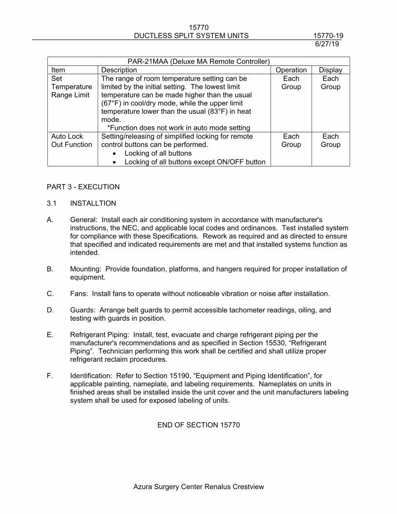
15770DUCTLESS SPLIT SYSTEM UNITS 15770-19
6/27/19
Azura Surgery Center Renalus Crestview
PAR-21MAA (Deluxe MA Remote Controller)Item Description Operation DisplaySet Temperature Range Limit
The range of room temperature setting can be limited by the initial setting. The lowest limit temperature can be made higher than the usual (67°F) in cool/dry mode, while the upper limit temperature lower than the usual (83°F) in heat mode. *Function does not work in auto mode setting
Each Group
Each Group
Auto Lock Out Function
Setting/releasing of simplified locking for remote control buttons can be performed.
Locking of all buttons Locking of all buttons except ON/OFF button
Each Group
Each Group
PART 3 - EXECUTION
3.1 INSTALLTION
A. General: Install each air conditioning system in accordance with manufacturer's instructions, the NEC, and applicable local codes and ordinances. Test installed system for compliance with these Specifications. Rework as required and as directed to ensure that specified and indicated requirements are met and that installed systems function as intended.
B. Mounting: Provide foundation, platforms, and hangers required for proper installation of equipment.
C. Fans: Install fans to operate without noticeable vibration or noise after installation.
D. Guards: Arrange belt guards to permit accessible tachometer readings, oiling, and testing with guards in position.
E. Refrigerant Piping: Install, test, evacuate and charge refrigerant piping per the manufacturer's recommendations and as specified in Section 15530, “Refrigerant Piping”. Technician performing this work shall be certified and shall utilize proper refrigerant reclaim procedures.
F. Identification: Refer to Section 15190, “Equipment and Piping Identification”, for applicable painting, nameplate, and labeling requirements. Nameplates on units in finished areas shall be installed inside the unit cover and the unit manufacturers labeling system shall be used for exposed labeling of units.
END OF SECTION 15770
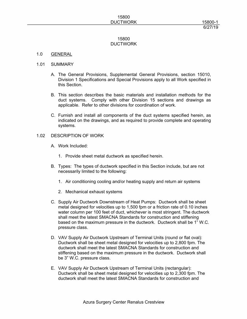
15800DUCTWORK 15800-1
6/27/19
Azura Surgery Center Renalus Crestview
15800DUCTWORK
1.0 GENERAL
1.01 SUMMARY
A. The General Provisions, Supplemental General Provisions, section 15010, Division 1 Specifications and Special Provisions apply to all Work specified in this Section.
B. This section describes the basic materials and installation methods for the duct systems. Comply with other Division 15 sections and drawings as applicable. Refer to other divisions for coordination of work.
C. Furnish and install all components of the duct systems specified herein, as indicated on the drawings, and as required to provide complete and operating systems.
1.02 DESCRIPTION OF WORK
A. Work Included:
1. Provide sheet metal ductwork as specified herein.
B. Types: The types of ductwork specified in this Section include, but are not necessarily limited to the following:
1. Air conditioning cooling and/or heating supply and return air systems
2. Mechanical exhaust systems
C. Supply Air Ductwork Downstream of Heat Pumps: Ductwork shall be sheet metal designed for velocities up to 1,500 fpm or a friction rate of 0.10 inches water column per 100 feet of duct, whichever is most stringent. The ductwork shall meet the latest SMACNA Standards for construction and stiffening based on the maximum pressure in the ductwork. Ductwork shall be 1” W.C. pressure class.
D. VAV Supply Air Ductwork Upstream of Terminal Units (round or flat oval): Ductwork shall be sheet metal designed for velocities up to 2,800 fpm. The ductwork shall meet the latest SMACNA Standards for construction and stiffening based on the maximum pressure in the ductwork. Ductwork shall be 3” W.C. pressure class.
E. VAV Supply Air Ductwork Upstream of Terminal Units (rectangular): Ductwork shall be sheet metal designed for velocities up to 2,300 fpm. The ductwork shall meet the latest SMACNA Standards for construction and
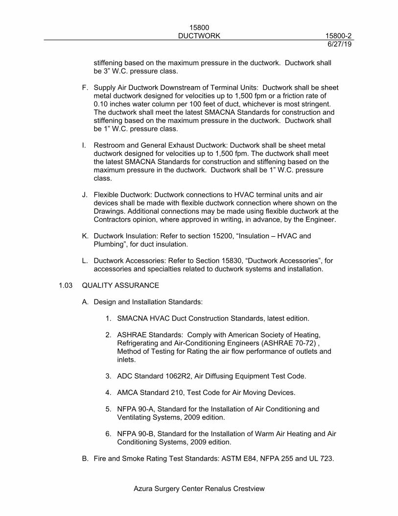
15800DUCTWORK 15800-2
6/27/19
Azura Surgery Center Renalus Crestview
stiffening based on the maximum pressure in the ductwork. Ductwork shall be 3” W.C. pressure class.
F. Supply Air Ductwork Downstream of Terminal Units: Ductwork shall be sheet metal ductwork designed for velocities up to 1,500 fpm or a friction rate of 0.10 inches water column per 100 feet of duct, whichever is most stringent. The ductwork shall meet the latest SMACNA Standards for construction and stiffening based on the maximum pressure in the ductwork. Ductwork shall be 1” W.C. pressure class.
I. Restroom and General Exhaust Ductwork: Ductwork shall be sheet metal ductwork designed for velocities up to 1,500 fpm. The ductwork shall meet the latest SMACNA Standards for construction and stiffening based on the maximum pressure in the ductwork. Ductwork shall be 1” W.C. pressure class.
J. Flexible Ductwork: Ductwork connections to HVAC terminal units and air devices shall be made with flexible ductwork connection where shown on the Drawings. Additional connections may be made using flexible ductwork at the Contractors opinion, where approved in writing, in advance, by the Engineer.
K. Ductwork Insulation: Refer to section 15200, “Insulation – HVAC and Plumbing”, for duct insulation.
L. Ductwork Accessories: Refer to Section 15830, “Ductwork Accessories”, for accessories and specialties related to ductwork systems and installation.
1.03 QUALITY ASSURANCE
A. Design and Installation Standards:
1. SMACNA HVAC Duct Construction Standards, latest edition.
2. ASHRAE Standards: Comply with American Society of Heating, Refrigerating and Air-Conditioning Engineers (ASHRAE 70-72) , Method of Testing for Rating the air flow performance of outlets and inlets.
3. ADC Standard 1062R2, Air Diffusing Equipment Test Code.
4. AMCA Standard 210, Test Code for Air Moving Devices.
5. NFPA 90-A, Standard for the Installation of Air Conditioning and Ventilating Systems, 2009 edition.
6. NFPA 90-B, Standard for the Installation of Warm Air Heating and Air Conditioning Systems, 2009 edition.
B. Fire and Smoke Rating Test Standards: ASTM E84, NFPA 255 and UL 723.
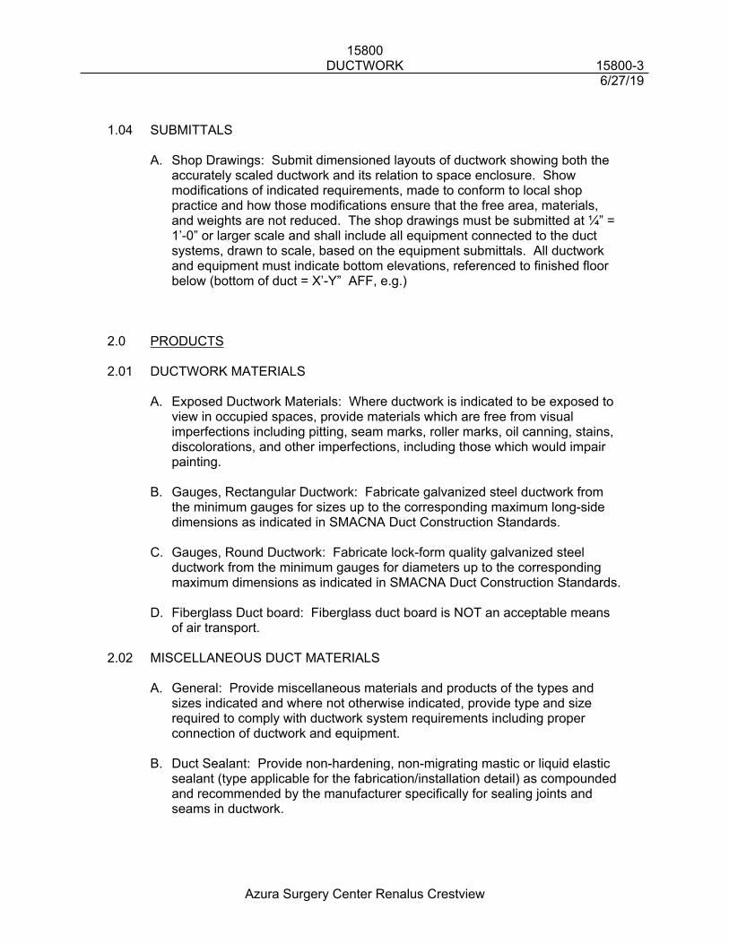
15800DUCTWORK 15800-3
6/27/19
Azura Surgery Center Renalus Crestview
1.04 SUBMITTALS
A. Shop Drawings: Submit dimensioned layouts of ductwork showing both the accurately scaled ductwork and its relation to space enclosure. Show modifications of indicated requirements, made to conform to local shop practice and how those modifications ensure that the free area, materials, and weights are not reduced. The shop drawings must be submitted at ¼” = 1’-0” or larger scale and shall include all equipment connected to the duct systems, drawn to scale, based on the equipment submittals. All ductwork and equipment must indicate bottom elevations, referenced to finished floor below (bottom of duct = X’-Y” AFF, e.g.)
2.0 PRODUCTS
2.01 DUCTWORK MATERIALS
A. Exposed Ductwork Materials: Where ductwork is indicated to be exposed to view in occupied spaces, provide materials which are free from visual imperfections including pitting, seam marks, roller marks, oil canning, stains, discolorations, and other imperfections, including those which would impair painting.
B. Gauges, Rectangular Ductwork: Fabricate galvanized steel ductwork from the minimum gauges for sizes up to the corresponding maximum long-side dimensions as indicated in SMACNA Duct Construction Standards.
C. Gauges, Round Ductwork: Fabricate lock-form quality galvanized steel ductwork from the minimum gauges for diameters up to the corresponding maximum dimensions as indicated in SMACNA Duct Construction Standards.
D. Fiberglass Duct board: Fiberglass duct board is NOT an acceptable means of air transport.
2.02 MISCELLANEOUS DUCT MATERIALS
A. General: Provide miscellaneous materials and products of the types and sizes indicated and where not otherwise indicated, provide type and size required to comply with ductwork system requirements including proper connection of ductwork and equipment.
B. Duct Sealant: Provide non-hardening, non-migrating mastic or liquid elastic sealant (type applicable for the fabrication/installation detail) as compounded and recommended by the manufacturer specifically for sealing joints and seams in ductwork.
15800DUCTWORK 15800-4
6/27/19
Azura Surgery Center Renalus Crestview
C. Ductwork Support Materials: Except as otherwise indicated, provide hot-dipped galvanized steel fasteners, anchors, rods, straps, trim, and angles for support of ductwork.
D. Flexible Ductwork: Insulated flexible ductwork shall be Wiremold Type VTCK. Approved equal flexible ductwork by Certainteed Corporation, Flexaust Company, Genflex or Owens-Corning Fiberglass will be acceptable. Provide either 45 degree angle taps with manual volume dampers or "spin-in" taps with manual volume dampers at main duct tap as shown on Drawings.
3.0 EXECUTION
3.01 GENERAL REQUIREMENTS
A. Standards: Round and rectangular sheet metal ductwork shall be constructed in accordance with SMACNA "HVAC Duct Constructions Standards", latest Edition, ASHRAE Guide and Data Book, "Handbook of Fundamentals", latest edition, specifically Chapter 25 and NFPA Standard 90-A, "Standard for the Installation of Air Conditioning and Ventilating Systems".
B. All ductwork required for the heating, ventilating and air conditioning systems shall be constructed and erected in a first class workmanlike manner. This work shall be guaranteed for a period of one year from and after the date of acceptance of the job against noise, chatter, whistling, vibration, and free from pulsation under all conditions of operation.
C. The interior surface of all ductwork shall be smooth with no parts projecting into the air stream unless specified to do so. All seams and joints shall be external. The inside of all ductwork shall be thoroughly cleaned and all fans operated to remove any debris prior to connection of air devices.
D. All holes in ducts for damper rods and other necessary devices shall be either drilled or machine punched (not pin punched), and shall not be any larger than necessary. All duct openings shall be provided with sheet metal caps if the openings are to be left unconnected for any length of time.
E. Where ducts, exposed to view (including equipment rooms), pass through walls, floors or ceilings, furnish and install sheet metal collars around the duct.
F. Sheet metal plenums shall be constructed and reinforced in accordance with SMACNA standards. Where plenums are connected to louvers, the plenum bottom shall be sloped to drain to the louver.
G. Ductwork which is exposed to weather shall have soldered joints and seams and shall be painted with a suitable epoxy coating. In lieu of solder joints, the use of duct-mate or TDC manufactured flanges are acceptable.
15800DUCTWORK 15800-5
6/27/19
Azura Surgery Center Renalus Crestview
3.02 COORDINATION
A. Prior to submitting ductwork shop drawings, the Division 15 Contractor shall fully coordinate the routing and height of all ductwork with all other trades and with ceiling heights, lighting fixtures and building construction.
3.03 GENERAL DUCTWORK FABRICATION
A. Duct Gauge and Reinforcing:
1. Rectangular Ductwork: Minimum metal gauges and reinforcement shall be in accordance with SMACNA HVAC Duct Construction Standards (SDCS) Tables 1-3 through 1-13. Minimum aluminum gauges and reinforcement shall be in accordance with SDCS Tables 1-14 through 1-16. Reinforcing shall be installed per SDCS Fig. 1-9 through 1-12.
2. Round Ductwork: Minimum metal gauges for longitudinal and spiral seam round ductwork shall be in accordance with SDCS Table 3-2. Minimum aluminum gauges for longitudinal and spiral seam round ductwork shall be in accordance with SDCS Table 3-3. Longitudinal seam ductwork larger than 12" diameter shall not be permitted unless welded seams are used.
3. Cross-breaking: Cross-break or transverse bead all flat surfaces which are more than 12" wide. Transverse beading shall be on 12" centers and shall be a minimum of 1/8" deep at the center of the bead and 3/8" wide at the base of the bead.
4. Minimum Gauges: The metal gauges listed in the SDCS for round and rectangular ductwork are the minimum recommended. It shall be the Contractor's responsibility to select a metal gauge heavy enough to withstand the physical abuse of installation.
B. Duct Joints And Seams:
1. General: Make all joints airtight. The distance between transverse joints on any size duct shall not exceed 5'.
2. Rectangular Ductwork: Transverse joints and longitudinal seams in ductwork shall be constructed in accordance with SDCS Fig. 1-4 and 1-5. Drive slips may be used on rectangular ductwork on short sides only, up to 18" maximum. Gauge of drive slips shall be at least as heavy as ductwork on which they are installed. Bend drive slips over at least 3/4" at corners. Corner closures shall be in accordance with SDCS Fig. 1-13 through 1-18. All longitudinal seams shall be "Pittsburgh Lock" or button punch snap lock at corner seams and grooved seam or seam welded in sides between corners, in accordance with SDCS Fig. 1-5. At the Contractor's option, transverse joints may be transverse duct flange joints
15800DUCTWORK 15800-6
6/27/19
Azura Surgery Center Renalus Crestview
or Ductmate EP12/11 prefabricated galvanized "Ductmate" sections. The proposed gasket material, flange, corner piece and Ductmate details shall be submitted for approval.
3. Round Ductwork: Transverse joints for round ductwork shall be beaded sleeve type constructed in accordance with SDCS Fig. 3-2, properly secured and sealed. Draw bands shall not be used on round ductwork. Longitudinal and spiral seams shall be constructed in accordance with SDCS Fig. 3-1.
4. Ductwork Sealing: Seal all longitudinal and transverse ductwork joints and seams using SMACNA ductwork sealant and 3" wide open weave tape to provide positive seal. Sufficient sealant shall be used to completely imbed the cloth.
C. Connections and Take-offs:
1. Rectangular Ductwork: Parallel flow branches shall be constructed using radius elbow take-offs in accordance with SDCS Fig. 2-7. Branch duct connections shall be 45 degree entry expanded taps constructed in accordance with SDCS Fig. 2-8. Duct-mounted coil connections shall be constructed in accordance with SDCS Fig. 2-11.
2. Round Ductwork: Connections and takeoffs shall be made using 90 degree conical taps, 45 degree lateral taps or wye fittings constructed in accordance with SDCS Fig. 3-4 and 3-5. Use of 90 degree tees shall not be allowed.
3. Spin-in Fittings: Spin-in fittings may be used for duct taps to air supply and exhaust devices and shall include quadrant dampers even though a volume damper may be specified for the air device. Spin-in fittings shall be sealed at the duct tap with a gasket and compression fit or sealed with duct sealant. The location of spin-in fittings in the ducts shall be determined after terminal units are hung and the location of the light fixtures is known so as to minimize flexible duct lengths and sharp bends. Spin-ins shall be installed with their damper axis parallel to airflow. A minimum of 18” must be provided between fittings.
4. Flexible Joints In Ductwork: Provide flexible connections where ductwork connects to air-handling units, fans, and similar powered equipment items and where required for expansion and contraction of the ductwork or the building structure. A minimum of one inch (1") slack shall be provided in all flexible connection to insure vibration isolation. Flexible joints are not required where equipment is connected with flexible duct. Flexible connections shall be rigidly connected to metal work on each side and shall be airtight. Bond flanges of flexible duct connectors to ducts and housings to provide airtight connections. Seal seams and penetrations to prevent air leakage.
15800DUCTWORK 15800-7
6/27/19
Azura Surgery Center Renalus Crestview
D. Elbows and Tees:
1. Rectangular Ductwork: Provide radius or square elbows in ductwork, where shown on the Drawings. Where radius elbows are shown, radius elbows must be provided. Where square elbows are shown, square or radius elbows may be provided, at the Contractor's option. Elbows shall be constructed in accordance with SDCS Fig. 2-2. Turning vanes are required in all square elbows of 46 degrees or greater angle. Turning vanes are not required in radius elbows. Turning vanes shall be single vane type without a trailing edge and shall be constructed and installed in accordance with SDCS Fig. 2-3 and 2-4.
2. Round Ductwork: Provide radius elbows of the stamped or segmented type constructed in accordance with SDCS Fig. 3-3. Segmented elbows shall have a minimum of three segments for 45 degree elbows and five segments for 90 degree elbows.
E. Offsets and Transitions: Where duct width increases, maximum angle of slope shall be 20 degrees (one inch (1") in 2.7"). Where duct width decreases, maximum angle of slope shall be 30 degrees (one inch (1") in 1.7"). Offsets and transitions shall be constructed in accordance with SDCS Fig. 2-9 and 2-10.
F. Air Device Connections: Make connections to air devices and fabricate air device plenums as detailed on the Drawings and in accordance with SDCS Fig. 2-16 through 2-18.
3.05 DUCTWORK INSTALLATION
A. General: Assemble and install ductwork in accordance with recognized industry practices which will achieve airtight and noiseless systems, capable of performing each indicated service. Install each run with a minimum of joints. Align ductwork accurately at connections, within 1/8" misalignment tolerance and with internal surfaces smooth. Support ducts rigidly with suitable ties, braces, hangers, and anchors of the type which will hold ducts true-to-shape and prevent buckling.
B. Inserts: Install concrete inserts for support of ductwork in coordination with formwork, as required to avoid delays in the work.
C. Completion: Complete fabrication of work at the project as necessary to match shop-fabricated work and accommodate installation requirements.
D. Run Location: Locate ductwork runs, except as otherwise indicated, vertically and horizontally and avoid diagonal runs wherever possible. Locate runs as indicated by diagrams, grams, details, and notations or, if not otherwise indicated, run ductwork in the shortest route which does not obstruct usable space or block access for servicing the building and its equipment.
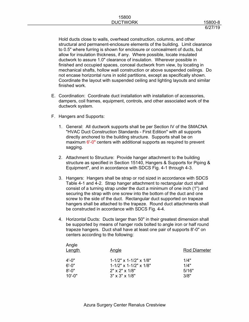
15800DUCTWORK 15800-8
6/27/19
Azura Surgery Center Renalus Crestview
Hold ducts close to walls, overhead construction, columns, and other structural and permanent-enclosure elements of the building. Limit clearance to 0.5" where furring is shown for enclosure or concealment of ducts, but allow for insulation thickness, if any. Where possible, locate insulated ductwork to assure 1.0" clearance of insulation. Wherever possible in finished and occupied spaces, conceal ductwork from view, by locating in mechanical shafts, hollow wall construction or above suspended ceilings. Do not encase horizontal runs in solid partitions, except as specifically shown. Coordinate the layout with suspended ceiling and lighting layouts and similar finished work.
E. Coordination: Coordinate duct installation with installation of accessories, dampers, coil frames, equipment, controls, and other associated work of the ductwork system.
F. Hangers and Supports:
1. General: All ductwork supports shall be per Section IV of the SMACNA "HVAC Duct Construction Standards - First Edition" with all supports directly anchored to the building structure. Supports shall be on maximum 6'-0" centers with additional supports as required to prevent sagging.
2. Attachment to Structure: Provide hanger attachment to the building structure as specified in Section 15140, Hangers & Supports for Piping & Equipment", and in accordance with SDCS Fig. 4-1 through 4-3.
3. Hangers: Hangers shall be strap or rod sized in accordance with SDCS Table 4-1 and 4-2. Strap hanger attachment to rectangular duct shall consist of a turning strap under the duct a minimum of one inch (1") and securing the strap with one screw into the bottom of the duct and one screw to the side of the duct. Rectangular duct supported on trapeze hangers shall be attached to the trapeze. Round duct attachments shall be constructed in accordance with SDCS Fig. 4-4.
4. Horizontal Ducts: Ducts larger than 50" in their greatest dimension shall be supported by means of hanger rods bolted to angle iron or half round trapeze hangers. Duct shall have at least one pair of supports 8'-0" on centers according to the following:
AngleLength Angle Rod Diameter
4'-0" 1-1/2" x 1-1/2" x 1/8" 1/4"6'-0" 1-1/2" x 1-1/2" x 1/8" 1/4"8'-0" 2" x 2" x 1/8" 5/16"10'-0" 3" x 3" x 1/8" 3/8"
15800DUCTWORK 15800-9
6/27/19
Azura Surgery Center Renalus Crestview
5. Vertical Ducts: Ducts shall be supported where they pass through the floor lines with 1-1/2" x 1-1/2" x 1/4" angles for ducts up to 60". Above 60", the angles must be increased in strength and sized on an individual basis considering space requirements.
G. Flexible Ductwork:
1. General: Flexible ductwork shall be provided as shown on Drawings. Flexible ducts shall be installed in a fully extended condition free of sags and kinks, using only the minimum length required to make the connection, subject to the maximum lengths herein and below. Bends in any length of flexible duct shall not exceed 45 degrees for HVAC terminal unit connections or 135 degrees for air device connections and shall not exceed that recommended by the flexible ductwork manufacturer. Unless otherwise shown on the Drawings, the length of any one run of flexible ductwork shall not exceed 2 feet to terminal units or 6 feet to air devices.
2. Supports: Where flexible duct extension exceeds 48", horizontally, a support shall be provided. Duct shall be suspended on 48" centers with a minimum two inch (2") wide flat banding material. Refer to SDCS Fig. 3-9 and 3-10 and Page 3-17 for additional requirements.
3. Terminal Unit Flexible Duct Connections: The terminal ends of the duct core shall be secured by stainless steel worm gear type clamps. The fittings on terminal units and on sheet metal duct shall be coated with sealant, then the flexible duct core slipped over duct and the clamp tightened, and the connections shall sealed with duct sealant. Insulation of flexible duct shall be slipped over connection to point where insulation abuts terminal unit or insulation on duct and attached with self-locking nylon straps. The insulation connections shall then be sealed using foil duct tape to provide vapor barrier. Refer to SDCS Page 3-13 and 3-15 for additional requirements.
4. Air Device Flexible Duct Connections: All joints and connections shall be made by turning back the insulation and securing the inner liner with self-locking nylon straps and sealing with two wraps of duct tape. The insulation shall then be placed over the joint, attached with a self-locking nylon strap and sealed on the exterior with an approved foil duct tape. Refer to SDCS Page 3-13 and 3-15 for additional requirements.
H. Duct Mounted Devices:
1. Install duct mounted sensors and control devices furnished under Section “Building Controls". Provide access doors at each duct mounted control device. Coordinate location of devices and installation requirements with the Controls Contractor.
15800DUCTWORK 15800-10
6/27/19
Azura Surgery Center Renalus Crestview
2. Install duct type smoke detectors furnished under Division 16. Provide access doors at each sampling tube assembly. Coordinate location of detectors and installation requirements with Division 16.
3. Provide duct test ports in ductwork as required to properly balance all air systems. Test ports shall be located per ANSI/ASHRAE Standard III to allow accurate pitot-tube traverse measurements in ductwork.
3.07 CLEANING AND PROTECTION
A. General: Clean ductwork internally, section-by-section of dust and debris as it is installed. Clean external surfaces of foreign substances which might cause corrosive deterioration of the metal or, where ductwork is to be painted, might interfere with painting or cause paint damage.
B. Repairs: Strip protective paper from stainless ductwork surfaces and repair finish or replace ductwork portion wherever it has been damaged.
C. Temporary Closure: At ends of ducts which are not connected to equipment or air distribution devices at the time of ductwork installation, provide temporary closure of polyethylene film or other covering which will prevent the entrance of dust and debris until such time that connections are to be completed.
END OF SECTION 15800
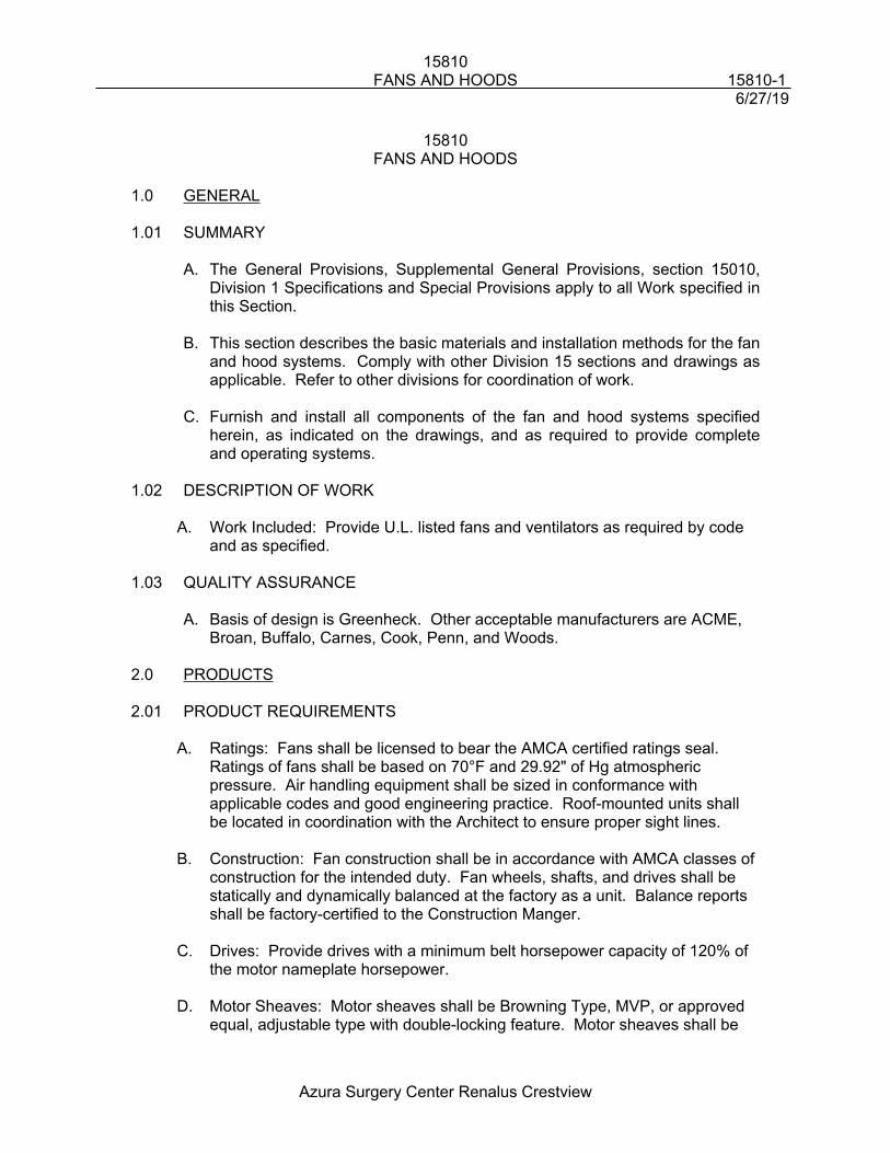
15810FANS AND HOODS 15810-1
6/27/19
Azura Surgery Center Renalus Crestview
15810FANS AND HOODS
1.0 GENERAL
1.01 SUMMARY
A. The General Provisions, Supplemental General Provisions, section 15010, Division 1 Specifications and Special Provisions apply to all Work specified in this Section.
B. This section describes the basic materials and installation methods for the fan and hood systems. Comply with other Division 15 sections and drawings as applicable. Refer to other divisions for coordination of work.
C. Furnish and install all components of the fan and hood systems specified herein, as indicated on the drawings, and as required to provide complete and operating systems.
1.02 DESCRIPTION OF WORK
A. Work Included: Provide U.L. listed fans and ventilators as required by code and as specified.
1.03 QUALITY ASSURANCE
A. Basis of design is Greenheck. Other acceptable manufacturers are ACME, Broan, Buffalo, Carnes, Cook, Penn, and Woods.
2.0 PRODUCTS
2.01 PRODUCT REQUIREMENTS
A. Ratings: Fans shall be licensed to bear the AMCA certified ratings seal. Ratings of fans shall be based on 70°F and 29.92" of Hg atmospheric pressure. Air handling equipment shall be sized in conformance with applicable codes and good engineering practice. Roof-mounted units shall be located in coordination with the Architect to ensure proper sight lines.
B. Construction: Fan construction shall be in accordance with AMCA classes of construction for the intended duty. Fan wheels, shafts, and drives shall be statically and dynamically balanced at the factory as a unit. Balance reports shall be factory-certified to the Construction Manger.
C. Drives: Provide drives with a minimum belt horsepower capacity of 120% of the motor nameplate horsepower.
D. Motor Sheaves: Motor sheaves shall be Browning Type, MVP, or approved equal, adjustable type with double-locking feature. Motor sheaves shall be
15810FANS AND HOODS 15810-2
6/27/19
Azura Surgery Center Renalus Crestview
selected for the rated fan rpm and shall be adjustable to as close as 10% above and below the rated fan speed.
E. Fan Sheaves: Provide adjustable or nonadjustable sheaves with removable machined bushings. Sheaves shall be machined on surfaces. Sheaves with over three grooves shall be dynamically balanced and the manufacturer shall so designate on each sheave. Fan sheaves with three grooves or less shall be statically balanced and weights required for balancing shall be welded to the sheaves. Manufacturers shall be Browning, Eaton, Yale, Towne, Dodge Manufacturing Company, or Fort Worth Steel and Machinery Company.
F. Belts: Provide standard "V-groove" belts suitable for the service intended with the required capacities. The belts shall be closely matched and tagged prior to delivery to the job site. If the belts do not appear to be properly matched during operation, they shall be rechecked and, if necessary, replaced. Belts shall be as manufactured by Gates, Durkee-Atwood, Goodyear, Browning, or Uniroyal.
G. Bearings: Provide SKF, Sealmaster, Timken, or Fafnir externally or internally-mounted, grease-lubricated, self-aligning ball bearings. Bearings shall have grease type zerk fittings.
H. Motor Mount: Motors shall be mounted on an adjustable base rigidly supported on the fan and shall have extended shaft to accommodate the adjustable pitch sheave.
2.02 CENTRIFUGAL FANS
A. General: Provide centrifugal fans of the single-width, single-inlet type with either forward or backward curved fan blades, and adjustable belt drives.
B. Motors: Provide standard drip-proof motors. Provide cast iron housings for motors larger than 10 hp, riveted or spot-weld wheels with steel rims and hub plates.
C. Fan: Blades shall be die cut, die-formed, and hubs shall be machined close-grained cast iron. Steel housings shall have lock-seam construction with discharge reinforcement and shall be adjustable with continuous inlet collars. Provide weatherproof enclosure for motors and drive, if units are exposed to weather.
2.03 CEILING EXHAUST FANS
A. General: Provide direct driven ceiling exhaust fans as required. Fan shall be acoustically insulated and have a maximum sound level rating as scheduled.
B. Motor: Motor shall be suitably grounded and mounted on rubber-in-shear vibration isolators and speeds shall not exceed that scheduled.
15810FANS AND HOODS 15810-3
6/27/19
Azura Surgery Center Renalus Crestview
C. Accessories:
1. Provide totally noise-free, integral backdraft damper, with no metal to metal contact.
2. Inlet grille shall be white molded plastic with egg-crate or perforated shape and provide 85% free open area.
3. Provide terminal box on the housing with cord, plug, and receptacle inside the housing.
3.0 EXECUTION
3.01 VENTILATION AND EXHAUST FANS
A. General: Ventilating and exhaust fans not having integral vibration isolation shall be mounted on or suspended by vibration isolators as specified under Section 15210. Where ductwork is connected to fans, Contractor shall provide UL labeled flexible duct connections.
B. Curbs: Factory-fabricated roof curbs, caps, and similar items, shall be supplied and installed by Mechanical Contractor. Coordinate installation with Roofing Contractor.
3.02 SYSTEMS
A. Refer to Section 15190, “Equipment and Piping Identification” for applicable painting, nameplate, and labeling requirements.
B. Placement of fans and noise levels generated by the fans shall be taken into consideration. Refer to specification 15010 for additional information.
END OF SECTION 15810
15820REGISTERS, GRILLES, AND DIFFUSERS 15820-1
6/27/19
Azura Surgery Center Renalus Crestview
15820REGISTERS, GRILLES, AND DIFFUSERS
1.0 GENERAL
1.01 SUMMARY
A. The General Provisions, Supplemental General Provisions, section 15010, Division 1 Specifications and Special Provisions apply to all Work specified in this Section.
B. This section describes the basic materials and installation methods for the registers, grilles, and diffusers. Comply with other Division 15 sections and drawings as applicable. Refer to other divisions for coordination of work.
C. Furnish and install all components of the registers, grilles, and diffusers specified herein, as indicated on the drawings, and as required to provide complete and operating systems.
1.02 DESCRIPTION OF WORK
A. Work Included: Provide air outlets and inlets as required for the finished or non-tenant areas of the project including the following:
1. Ceiling air registers, grilles, diffusers
2. Wall mounted registers and grilles
3. Laminar flow diffusers
4. Linear lay-in slot diffusers
5. Architectural linear diffusers
1.03 QUALITY ASSURANCE
A. Basis of design is Titus. Other acceptable manufacturers are Krueger, Anemostat, Carnes, Metal Aire, Price, or Tuttle & Bailey.
B. NFPA Compliance: Comply with NFPA 90, as applicable to air diffuser construction and installation.
C. Air Distribution Equipment: Maximum space temperature variation shall not exceed 2°F through the conditioned area from 2’ above the floor to 7’ above the floor. The air outlets shall be selected by the manufacturer to suit the volume, throw, and noise level criteria described in these Specifications, and maintain maximum terminal velocities of 50 fpm, unless otherwise indicated.
2.0 PRODUCTS
15820REGISTERS, GRILLES, AND DIFFUSERS 15820-2
6/27/19
Azura Surgery Center Renalus Crestview
2.01 AIR OUTLETS AND INLETS
A. General: Provide air outlets and inlets of the size, shape, and type, constructed of materials and components, and with finishes as required. Apply corrosion resistant treatment to surfaces prior to applying prime coat.
B. Ceiling Diffusers: Provide diffusers with corrosion resistant treated surfaces and finished in baked enamel unless otherwise required. Where applicable, provide adapters with diffusers to permit connection to round supply duct.
C. Registers and Grilles:
1. General: Provide registers that contain a key-operated multi-louvered opposed blade damper operable from the face side.
2. Supply Air Register: Provide supply air registers of the double deflection type.
3. Laminar Flow Type: Provide aluminum, laminar flow grilles with adjustment through face.
4. Return Air Grilles and Return Air Registers: Provide grilles and registers as required.
D. Supply Linear Diffuser:
1. Provide supply linear diffuser with length and width as required. The supply diffuser shall be installed above the ceiling and located as indicated on the Architectural and Mechanical Drawings.
2. The diffuser shall be designed, tested, and constructed in a manner so as to comply with the performance criteria and sound level requirements specified elsewhere in these Specifications. Plenum shall be constructed of at least 24 gauge galvanized steel and shall be reinforced as required. The air volume, length and duct connection size shall be as required. Coordinate the attachment, support, and similar features of the supply plenum with the ceiling Subcontractor.
3. The plenum shall be painted flat black on interior surfaces and the exposed surfaces as viewed from below the ceiling system shall be painted flat black.
3.0 EXECUTION
3.01 INSTALLATION
15820REGISTERS, GRILLES, AND DIFFUSERS 15820-3
6/27/19
Azura Surgery Center Renalus Crestview
A. General: Install air outlets and inlets in accordance with manufacturer's written instructions and recognized industry practices to ensure that products serve intended functions.
B. Duct Connection to Diffuser:
1. Where flexible duct is connected to ceiling diffusers, the contractor shall use one of these three methods:
a. Insulated flexible duct with Titus FlexRight flexible duct support, UL listed, to form duct elbow.
b. A sheet metal elbow, externally insulated.c. Insulated flexible metal duct consisting of flexible metal core of
corrugated aluminum with external insulation.
2. In all cases duct connection/elbow shall be made with a bend that has not less than one duct diameter centerline radial.
3. Provide hard duct connection to diffuser in Operating Room systems.
C. Coordination: Coordinate with other trades, including ductwork, and ductwork accessories, as necessary to interface air outlets and inlets properly with other work.
3.02 FIELD CONTROL QUALITY CONTROL
A. Test installed devices to demonstrate satisfactory compliance with specified and indicated requirements.
END OF SECTION 15820
15830DUCTWORK ACCESSORIES 15830-1
6/27/19
Azura Surgery Center Renalus Crestview
15830DUCTWORK ACCESSORIES
1.0 GENERAL
1.01 SUMMARY
A. The General Provisions, Supplemental General Provisions, section 15010, Division 1 Specifications and Special Provisions apply to all Work specified in this Section.
B. This section describes the basic materials and installation methods for the ductwork accessories. Comply with other Division 15 sections and drawings as applicable. Refer to other divisions for coordination of work.
C. Furnish and install all components of the duct systems specified herein, as indicated on the drawings, and as required to provide complete and operating systems.
1.02 DESCRIPTION OF WORK
A. Work Included: Provide ductwork accessories as required for the project including the following:
1. Turning vanes,
2. Access doors,
3. Fire dampers.
1.03 QUALITY ASSURANCE
A. SMACNA Compliance: Comply with applicable portions of Sheet Metal and Air Conditioning Contractors' National Association (SMACNA) Duct Construction Standards (latest edition).
B. ASHRAE Standards: Comply with American Society of Heating, Refrigerating, and Air Conditioning Engineers, Inc. (ASHRAE) recommendations pertaining to construction of ductwork accessories.
1.04 SUBMITTALSA. Shop Drawings: Show modifications of indicated requirements, if applicable,
made to conform to local shop practice and show how these modifications ensure that the materials and weights are not reduced and that the fabricated units are equivalent to the specified requirements in every significant way.
2.0 PRODUCTS
2.01 DUCTWORK ACCESSORIES, FABRICATION AND MATERIALS
15830DUCTWORK ACCESSORIES 15830-2
6/27/19
Azura Surgery Center Renalus Crestview
A. General: Provide ductwork accessories that comply with the Section 15800, "Ductwork", and other applicable product requirements of ductwork materials noted in this Section.
2.02 FLEXIBLE CONNECTIONS
A. General: Flexible connections shall be UL-labeled, 30 ounces glass fabric-lined with insulation and coated on both sides with neoprene, complete with attachment accessories, "Vent-Glass" by Vent-Fabrics, Inc. or approved equal.
2.03 DUCTWORK HARDWARE
A. General: Damper operators for concealed inaccessible ductwork shall be Young Regulator Company, Catalog No. 700 or No. 315, as shown. Non-insulated accessible ductwork shall be Young Regulator Company, Catalog No. 433. Accessible insulated ductwork shall be Young Regulator Company, Catalog No. 443. Approved equal units by Duo-Dyne or Vent Fabrics, Inc. will be acceptable.
2.04 DIRECTIONAL, VOLUME CONTROL, AND FIRE DAMPERS
A. General: Provide all direction and volume control and fire dampers shown or noted on Drawings. All damper control devices shall be installed so as to be fully concealed in finished rooms and spaces.
B. Control Dampers:
1. Splitter Dampers: Splitter dampers shall be not less than 16 gauge. Splitter dampers shall be 1-1/2 times the width of narrowest duct leaving split, except not less than 12" long and shall have not more than 1/4" less height than duct in which it is installed. Splitter dampers having area less than 2.25 square feet shall be adjusted by means of a locking quadrant mounted on end of shaft. Splitter dampers having larger area shall be adjusted by means of one or more push rods in accordance with Figure 2-5, SMACNA "Low Velocity Duct Construction Standards".
2. Extractors: Provide extractors of the size and type required, with hex-key operated adjustable blades, and with gang operated galvanized steel blades on one-inch centers.
3. Pressure Taps: Where rectangular take-offs of branches from main ducts are used with 45 degree entry, provide manual volume regulators with lockable operators and nylon bushings on both sides of damper blade rod.
15830DUCTWORK ACCESSORIES 15830-3
6/27/19
Azura Surgery Center Renalus Crestview
4. Round Taps: Where taps to main ducts or their branches are made, provide 45 degree angle taps or 90 degree spin-in taps with manual volume dampers and nylon bushings on both sides of damper blade rod.
5. Multi-leaf Dampers: Where multi-leaf dampers are required, provide opposed blade-type in accordance with Figure 2-12, SMACNA "Low Velocity Duct Construction Standards".
C. Fire Dampers: Provide fire dampers at duct penetrations of floors, smoke partitions, fire walls, and where required by the applicable building codes or authority having jurisdiction. Fire dampers shall comply with state and local codes, be inspected and approved by an approved inspection agency and be labeled at the factory in accordance with Uniform Building Code Standard 43, Section 43.714.
1. Provide one-hour rated dampers where penetrations are in required one-hour fire rated assemblies.
2. Provide 1-1/2 hour rated dampers where penetrations are in required 2-hour fire rated assemblies.
3. Provide 3 hour rated dampers where penetrations are in required 4-hour fire rated assemblies; 4-hour occupancy separating walls are excepted.
2.05 FLASHING AND COUNTER-FLASHING
A. General: Flashing and counter-flashing shall be as specified in other Divisions of these Specifications.
2.06 DUCT ACCESS DOORS
A. General: Provide hinged duct access doors, gasketed and with insulation where ductwork is indicated to be insulated. Provide construction per SMACNA Standards. Access doors shall be at least 15" x 15".
B. Inspection Plates: Provide inspection plates as required. Provide a minimum opening of 4" x 4" with a 6" x 6" cover plate. The cover plate shall be one gauge heavier than the ductwork, gasketed and secured with a minimum of eight sheetmetal screws.
2.07 MISCELLANEOUS DUCTWORK MATERIALS
A. General: Provide miscellaneous materials for ductwork accessories, including hinges, refrigerator latches, sash locks, bolts and wing nuts, gaskets and pitot tubes as recommended by the ductwork accessories manufacturer for the application indicated.
2.08 TURNING VANES
15830DUCTWORK ACCESSORIES 15830-4
6/27/19
Azura Surgery Center Renalus Crestview
A. Construct turning vanes in accordance with SMACNA Standards (current edition).
3.0 EXECUTION
3.01 INSTALLATION
A. Access Doors: Install access doors so that the doors open against the system air pressure wherever feasible and that their latches are operable from either side, except where the duct is too small to be entered. Provide access to each fire damper link to permit resetting. Comply with the applicable building codes or authority having jurisdiction and NFPA 96.
B. Inspection Plates: Install plates at each primary zone damper and where otherwise required for inspection of operable mechanisms within the duct systems.
C. Multileaf Dampers: Install multileaf volume dampers in each zone duct of multizone units and as otherwise required for balancing.
D. Splitter Dampers: Install splitter dampers at all divisions of ductwork for proper air pattern control.
E. Turning Vanes:
1. Install turning vanes for all rectangular mitered elbows. Install turning vanes in accordance with SMACNA Standards.
2. Turning vanes for Ducts with air velocity less than 2500 FPM: Use single wall type vanes for ducts having width equal to or less than 12 inches.
3. Use double wall type vanes for (2” radius, 2–1/8” spacing) for ducts having widths greater than 12 inches.
4. If duct sizes change in a mitered elbow, use single wall type vanes with a trailing edge extension.
3.02 TESTING
A. General: Check installed ductwork accessories for required operation and leak-proof performance during the system's operational test. Repair or replace faulty accessories, as required to obtain proper operation and leak-proof performance.
END OF SECTION 15830
15980TESTING, ADJUSTING, AND BALANCING 15980-1
6/27/19
Azura Surgery Center Renalus Crestview
15980TESTING, ADJUSTING, AND BALANCING
1.0 GENERAL
1.01 SUMMARY
A. The General Provisions, Supplemental General Provisions, section 15010, Division 1 Specifications and Special Provisions apply to all Work specified in this Section.
B. This section describes the basic materials and installation methods for the testing, adjusting, and balancing of HVAC systems. Comply with other Division 15 sections and drawings as applicable. Refer to other divisions for coordination of work.
C. Provide testing, adjusting, and balancing specified herein, as indicated on the drawings, and as required to provide complete and operating systems.
1.02 DESCRIPTION OF WORK
A. Work Included:
1. All air and water systems shall be tested, adjusted, and balanced to optimize operating and comfort conditions. Record test data as outlined hereinafter and submit for review and approval. Systems shall be fully tested and balanced prior to Building commissioning and acceptance.
2. Conduct tests as specified herein, and as required by authorities having jurisdiction, including Local Inspection Department or Construction Manger.
3. Repair or replace defects discovered or resulting from the required tests to a like new condition.
4. All tenant finish air balancing will be by the tenant finish contractor. All air and water moving equipment installed under the shell building contracts will be balanced by the shell contractor.
1.03 QUALITY ASSURANCE
A. Personnel: Submit evidence to show that the personnel who will actually balance the systems are qualified. Evidence showing that the personnel have passed the tests required by the Associated Air Balance Council (AABC) or the National Environmental Balancing Bureau (NEBB) will be sufficient.
2.0 PRODUCTS
15980TESTING, ADJUSTING, AND BALANCING 15980-2
6/27/19
Azura Surgery Center Renalus Crestview
Not applicable.
3.0 EXECUTION
3.01 TEST DATA
A. General: Record test data after balancing has been completed and deliver recorded data to the Engineer for review and evaluation. Should deficiencies or discrepancies be found, repeat balancing procedures to achieve correct test data results. Certify the test and balancing data as being true and correct over the Contractor's signature. Execute the Certification by an authorized officer if the contracting firm is a corporation, by a partner if the firm is a partnership, by the firm's owner if the firm is a sole proprietorship, or by the authorized representative if the firm is a joint venture. Include a copy of the approved test and balancing data in the Owner's Manual.
B. Test Forms: Record and submit test and balancing data on forms similar to those of the AABC or NEBB.
3.02 CALIBRATION TEST
A. Submit evidence to show that the balancing devices are properly calibrated before proceeding with system balancing.
3.03 PRELIMINARY AIR TESTING
A. General: Preliminary air tests shall be performed before duct work or equipment is enclosed in walls, floors, ceilings, chases, or in any other way concealed from view. Tests may be conducted on individual systems. Submit notification when systems are ready for preliminary air tests. Condenser water shall not be required for preliminary air tests. Make necessary arrangements to energize fan motors for the tests. Where possible, conduct the tests before the application of exterior duct insulation and installation of grilles or diffusers. Remove section of duct to allow design airflow at design static pressure where necessary.
B. Tests: Demonstrate that there is no excessive leakage of the duct work by visual inspection, that fans are operating at essentially the correct speed, that motors will not overload, and that equipment delivers design cfm. Correct any deficiencies found. Repeat preliminary air tests until tests have proven satisfactory.
C. Inspection: Inspection and acceptance of the Work shall, in addition to the foregoing requirements, be subject to the following conditions:
1. Instruments: Test instruments, devices, and similar items, their accuracy and the methods by which instruments are employed, shall be approved by AABC or NEBB for use at the job site.
15980TESTING, ADJUSTING, AND BALANCING 15980-3
6/27/19
Azura Surgery Center Renalus Crestview
2. Control Diagrams: Post framed, full-sized copies of the approved automatic control diagram with typewritten sequence of operation in the mechanical rooms and include an unframed, reduced size copy in the Owner's Manual. Post only the diagrams that apply to equipment or systems within each mechanical room.
3.04 Pumped Water Balancing:
A. General: When equipment start-up and pipe cleaning and testing procedures have been completed, and systems are complete and ready for operation, perform the following steps of water balancing and record the results.
1. Compression Tanks and Air Vents: Verify that compression tanks have water-showing gauge glasses, but that tanks are not water logged. Check air vents at system high points and at water coils to ensure all air has been removed from the circulating systems.
2. Open System Tests: Open stops, balancing, and control valves. Read and record pressure rise across pumps.
3. Adjusted System Tests: Adjust balancing valves at each coil for design flow. Adjust balancing valves at pumps to obtain design water flow. Record pressure rise across pumps and gpm flow from pump curve. Permanently mark the balanced position for each valve.
4. Ampere Readings: Read and record full load amperes for each pump motor.
5. Temperature Readings: Read and record entering and leaving water temperature at floor and the central heat exchanger. Adjust as necessary to secure design temperatures and conditions.
6. Pressure Readings: Read and record suction and discharge pressure and shutoff head for each circulating and domestic water pump.
3.05 FINAL AIR BALANCE
A. General: When tests have been completed and systems are complete and ready for operation, perform the following steps of final air balance and record the results.
B. Motors: Verify correct rotation of rotating equipment. Verify that properly sized thermal heater elements are installed in starters. Verify that properly sized duel-element fuses, where specified, are installed in disconnect switches.
C. Filters: Check air filters or filter media. Balance system only with clean filters or filter media.
15980TESTING, ADJUSTING, AND BALANCING 15980-4
6/27/19
Azura Surgery Center Renalus Crestview
D. Airflow at Each Unit: Read and record return and/or outside air, supply air cfm, and temperature at each fan and blower.
E. Water flow at Each Unit: Set thermostat for full cooling and for full heating loads. Measure and record supply and return water flow at each cooling/heating coil.
F. Coil Temperatures: Set thermostat for full cooling and for full heating loads. Read and record entering and leaving dry bulb and wet bulb temperatures at each cooling and heating coil.
G. Outlet Airflow: Adjust each air exhaust inlet and supply diffuser, register, and grille to within 10% of design air cfm. Dampers in diffusers (if specified) may be used for only 10% adjustment from full open airflow. Include terminal points of air supply and points of exhaust.
H. Pressure requirements: Where Pressure requirements are indicated in the drawings, pressure must be met regardless of the grille/diffuser being balanced within 10%. Contractor shall continue to adjust until room pressure requirement is met.
END OF SECTION 15980
16010GENERAL ELECTRICAL REQUIREMENTS 16010-1
6/27/19
Azura Surgery Center Renalus Crestview
16010GENERAL ELECTRICAL REQUIREMENTS
1.0 GENERAL
1.01 SUMMARY
A. Division 16 includes Division 16000 of the Specifications and Electrical Drawings. Elements of the Scope of Work include, but are not limited to, labor, materials, equipment, supplies, storage, transportation and all required permits and licenses. Division 16 does not stand alone, but is part of the complete project and its Documents. Requirements of the General Conditions and Division 1 apply to all work in the Division.
B. Provide the necessary interface with other Divisions to provide a complete project. Carefully check the Documents of this Division with those Documents of other Divisions. Determine the requirements of any interfacing materials or equipment being furnished and/or installed by those Sections and Divisions, and provide proper installation and required interface.
C. No deviation from the Contract Documents shall be made without the written consent of the Architect and Engineer.
D. All Specifications and Drawings are to be considered together as the Contract Documents. Any work shown in one and not the other, or is implied by either, shall be provided to make a complete project. Should conflicts exist between the Specifications and Drawings or there is an item shown or noted for which is not clearly defined, immediately submit a request for clarification.
E. The Drawings are schematic and are not intended to show the exact location of outlets, devices, etc. or the routing of conduit.
F. Dimensions and information regarding accurate locations of equipment, and structural limitations and finish shall be coordinated and verified with other Divisions of Work. Be prepared to furnish dimensions and information regarding the Work of this Division to other trades.
G. The right is reserved to relocate any device (receptacle, switch, fire alarm, audio/visual, junction box, outlet, etc.) a maximum of 10’-0” before it is permanently installed without incurring additional cost to the Contract.
1.02 REFERENCE STANDARDS
A. All work shall comply with the most recently revised versions of all local, state and federal codes, ordinances of the authority having jurisdiction, laws, rules and regulations. Any modifications required by any of the above shall be made without any additional cost to the owner. Where requirements between
16010GENERAL ELECTRICAL REQUIREMENTS 16010-2
6/27/19
Azura Surgery Center Renalus Crestview
governing Codes and Regulations vary, the more restrictive provision shall apply.
B. Nothing contained in the Contract Documents shall be construed as authority or permission to disregard legal requirements and regulations. The Contractor shall thoroughly review the Documents and bring any such conflicts to the attention of the Architect and Engineer prior to Installation.
C. All materials shall comply with standards of the following:1. NEC – National Electrical Code2. NFPA – National Fire Protection Association3. ANSI – American National Standards Institute4. ASTM – American Society of Testing and Materials5. NEMA – National Electrical Manufacturer’s Association6. IEEE – Institute of Electrical and Electronic Engineers7. CBM – Certified Ballast Manufacturers8. FAA – Federal Aviation Administration9. FCC – Federal Communications Commission10. IES – Illuminating Engineering Society11. OSHA – Occupational Safety and Health Act12. NETA – National Electrical Testing Association13. IBC – International Building Codes14. U.L. – Underwriter’s Laboratories
D. All materials shall be new and shall bear the label of U.L.
1.03 EXISTING CONDITIONS
A. Where work is to be performed in an existing facility, the contractor shall visit the site prior to bid and be familiar with all existing conditions. Special attention shall be given to work to be performed above an existing ceiling.
B. Where existing slabs are to be cut or core drilled, the contractor shall x-ray the existing slabs to avoid cutting or disrupting existing conduits, cables, plumbing or structural members.
C. The electrical service to the building shall not be interrupted without written consent of the building owner.
D. No allowance will be made for lack of knowledge of existing conditions.
E. At the completion of the project, all work under this Division shall be completely integrated with the existing systems and left in perfect operating condition.
F. Where work under this Division disrupts the continuity of any existing to remain circuit or feeder, the Contractor shall repair/replace as necessary to return to a perfectly functional and safe operating condition.
G. Prior to any demolition or construction the Contractor shall have the existing conditions inspected by an EPA, OSHA certified asbestos abatement agency
16010GENERAL ELECTRICAL REQUIREMENTS 16010-3
6/27/19
Azura Surgery Center Renalus Crestview
to identify the presence of asbestos. Should any asbestos be found it shall be brought to the immediate attention of the Architect and Owner and specifically identified in writing.
1.04 DEFINITIONS
A. Provide: to furnish, install and connect.
B. Furnish: to supply all materials, labor, equipment, testing apparatus, controls, tests, accessories and all other items customarily required for the proper and complete application.
C. Install: to join, unite, fasten, link, attach, set-up or connect together, complete, tested, and ready for normal satisfactory operation.
D. Engineer: the Engineer of record.
E. Contract Documents: the complete set of Specifications and Drawings of all Divisions.
F. Work: labor, materials, equipment, accessories, controls and other items required for a complete installation.
G. Concealed: embedded in masonry or other construction, installed in furred spaces, within double partitions or hung ceilings, in trenches, in crawl spaces or in enclosures.
H. Conduit: rigid steel; intermediate metal conduit (IMC), plastic conduit (PVC), electrical metallic tubing (EMT), or flexible steel conduit.
I. Manufactured Cable: pre-wired metal clad manufactured cable bearing a U.L. label; metal clad cable (MC), health care (HCF).
J. Wiring/Wired: all wire installed in conduit to equipment, device, junction box, light fixture, etc. from panel board or switchgear with all required boxes, connectors, couplings, etc.
K. Exposed: not installed underground or concealed.
L. Equal: equal in quality, workmanship, materials, weight, size, design and efficiency of the specified product, conforming with manufacturers.
M. Supply: to purchase, procure, acquire and deliver complete with related accessories.
N. Authority Having Jurisdiction (AHJ): applicable local, state and federal authorities having jurisdiction over any part of the Scope within this Division and other Divisions.
2.0 PRODUCTS
16010GENERAL ELECTRICAL REQUIREMENTS 16010-4
6/27/19
Azura Surgery Center Renalus Crestview
2.01 MANUFACTURERS
A. Manufacturer’s names and catalog numbers specified in the Contract Documents are intended to describe the material and set the standard of quality. All bids shall be based on material specified. Request for approval of material not specified shall be considered if the request is in written form and submitted to the Architect no later than fourteen (14) days prior to the bid date. All requests shall conform with the provisions of the general and supplementary conditions.
B. When specific names are not stated, only the best available quality of material or equipment shall be submitted for review and used in the installation.
2.02 SHOP DRAWINGS AND PRODUCT DATA
A. The Contractor shall obtain complete shop drawings, product data and samples from the manufacturers, suppliers, vendors, and all Division 16 Subcontractors, for all materials and equipment as specified herein in various Sections of the Specifications, and shall submit data and details of such materials and equipment for review by the Architect and Engineer. Prior to submission of the shop drawings, product data and samples to the Architect and Engineer, the Contractor shall thoroughly review the shop drawings, product data and samples and certify they are in compliance with the Contract Drawings. Further, the Contractor shall check all materials and equipment upon their arrival on the Project site and verify their condition and compliance with the Contract Documents. Any Work which proceeds prior to receiving reviewed shop drawings shall be modified as required to comply with the Contract Documents and the shop drawings. A minimum period of ten (10) working days, exclusive of transmittal time, will be required in the Engineer’s office each time a shop drawing, product data and/or sample is submitted or resubmitted for review. This time period shall be considered by the Contractor when scheduling his Work. The initial shop drawing review for equipment and materials may be expedited through the mutual consent of the Contractor, Architect, Engineer, and Owner providing the Contractor agrees to submit complete, certified, documented, and coordinated shop drawings for review in accordance with the requirements of the Contract Documents.
B. The review of shop drawings, product data, and samples by the Architect and Engineer shall not relieve the Contractor of the responsibility for dimensions or errors that may be contained therein, or for deviations from requirements in the Contract Documents. Is shall be clearly understood that the noting of some errors by the Engineer but overlooking others does not grant the Contractor permission to proceed in error.
C. All shop drawings and product data/submittals shall be submitted in compliance with the requirements of the general and supplementary conditions. No more than four (4) copies of submittal data will be reviewed. Any additional copies will be returned unmarked. The responsibility of
16010GENERAL ELECTRICAL REQUIREMENTS 16010-5
6/27/19
Azura Surgery Center Renalus Crestview
copying review comments on any additional copies will rest solely with the contractor.
D. All product data/submittals shall bear the name of the manufacturer to be used.
E. All shop drawings and submittals shall include a stamped indication signifying that the submittal has been reviewed for compliance with the Contract Documents by the Contractor. This stamped indication also represents the fact that the Contractor has checked this submittal for its interaction with all other Divisions and certifies by his signature or initials that all coordination has taken place. The stamp shall include the date, name of the Contracting Firm, the signature of the Contractor, certification of compliance and approval. This stamp shall be on the submittal before the Engineer will review it.
F. The engineer will review an individual submittal not more than twice. If the submittal is rejected again on the second review, the contractor will bare all responsibility for paying for the Engineer’s time for additional reviews. Such payments to the engineer shall be withheld from the next monthly pay application.
G. Shop drawings and/or product data shall be submitted for the following for review:1. Switchboards, panelboards, transformers, busway, motor control centers,
ground fault system and other equipment associated with the main distribution.
2. Disconnect switches, fuses, motor starters.3. Life Safety System.4. Lighting fixtures, lighting control system, dimming system, emergency
batteries and other equipment associated with lighting.5. Transient voltage surge protection.6. Generator, UPS, transfer switches, batteries, static switches, transition
switches, switchgear and other equipment associated with emergency and/or standby back-up power systems.
7. Devices, receptacles, switches, coverplates, motion sensors. The product data shall include the manufacturers name, model number, size and color.
8. Conduit, wire, boxes, fittings.
2.03 AS-BUILT DRAWINGS
A. The Contractor shall maintain on a daily basis at the Project site a complete set of “Record Drawings”. The “Record Drawings” shall consist of a set of blueline prints or AutoCAD files of the Contractor Coordination Drawings for this Division. The prints shall be marked or the AutoCAD file electronically updated to show the precise location of all buried or concealed work and equipment, including embedded conduit and junction boxes, and all changes and deviations in the Electrical work from that shown on the Contract Documents. This requirement shall not be construed as authorization for the Contractor to make changes in the layout or work without definite instructions
16010GENERAL ELECTRICAL REQUIREMENTS 16010-6
6/27/19
Azura Surgery Center Renalus Crestview
from the Architect or Engineer. Prior to commencing work, the Contractor shall obtain from the Architect or Engineer a set of AutoCAD Release 2004 or compatible format Architectural and Engineering Drawings on CD, to be used only to produce the Contractor’s Coordination Drawings. The continuously update coordination drawings shall be used to produce the final “Record Drawings” which shall be delivered to the Owner in AutoCAD electronic format (CD) upon Project completion. The Contractor shall give to the Engineer a written release acceptable to the Engineer signed by a corporate officer of the Contractor prior to receipt of the Engineer’s Drawings.
B. Record dimensions shall clearly and accurately delineate the work as installed; locations shall be suitably identified by at least two dimensions to permanent structures.
C. The Contractor and Subcontractor shall mark all “Record Drawings” on the drawings with a rubber stamp impression or an AutoCAD image that states such.
3.0 EXECUTION
3.01 INSTALLATION
A. The equipment selections used in the preparation of the Contract Documents will fit into the physical spaces provided and indicated, allowing ample room for access, servicing, removal and replacement of parts, etc. Adequate space shall be allowed for clearance in accordance with the Code requirements and the requirements of the local Authorities having jurisdiction, and the equipment manufacturer‘s recommendations.
B. In the preparation of Drawings, a reasonable effort to accommodate acceptable equipment manufacturer’s space requirements has been made. However, since space requirements and equipment arrangement vary according to each manufacturer, the responsibility for initial access, maintenance access, code required access, and proper fit rests with the Contractor.
C. Physical dimensions and arrangements of equipment to be installed shall be subject to the Architect’s and Engineer’s review.
D. The General Contractor and all Subcontractors shall coordinate the installation of ductwork, conduit, busway, piping, cable trays, etc., installation with lighting fixtures, special ceiling construction, air distribution equipment, and the structure. Provide additional rises, drops and offsets as required. If after installed, new ductwork, conduit, busway, piping or cable is found to be in conflict with the architecture, structure, or other trade Work which is either existing or shown on the Contract Documents, the ductwork, conduit, busway, piping or cable shall be relocated without additional cost to the Owner.
16010GENERAL ELECTRICAL REQUIREMENTS 16010-7
6/27/19
Azura Surgery Center Renalus Crestview
E. No conduit, equipment, busway, etc., shall be installed in the eight (8) inch high zone directly above the ceiling in tenant areas to allow for tenant build-out and flexibility unless otherwise specifically shown on the Drawings or prior written authorization is received from the Engineer.
F. Accessibility and Clearance:1. Electrical equipment, outlets, junction and pull boxes shall be installed in
accessible locations, avoiding obstructions, preserving headroom, and keeping openings and passageways clear.
2. Minor adjustments in the locations of equipment shall be made where necessary, providing such adjustments do not adversely affect functionality of the equipment.
G. Scaffolds and staging for installation of electrical work shall be provided under the work of this Division.
3.02 STRUCTURAL FITTINGS
A. Furnish and install the necessary sleeves, inserts, hangers, anchor bolts, and related structural items. Install at the proper time.
B. Openings may have been indicated on the Architectural and Structural drawings. Should any additional openings or holes be required, the same shall be provided at no additional cost to the Owner.
C. Location: At a time in advance of the work, verify openings shown on the Architectural and Structural drawings, and coordinate any additional openings.
D. If the work of this Section requires modification of the Architectural or Structural drawings, furnish new instructions as to requirements for these openings. Submit for review and coordination to Architect.
E. Sleeves shall be supplied for electrical conduits passing through walls or slabs and shall be placed before concrete is poured.
F. Equipment supports for electrical work shall be fastened to the structure by inserts, anchor bolts, bolting to drilled and tapped structural members, or be welding to the structure.1. Welding shall be done by the electric arc method with fully competent
welders. Supporting members shall be shop coated with a suitable primer.
2. Surfaces damaged by installation of supports shall be touched up with primer to match shop coat. Any drilling of structural members shall be approved by the Architect.
G. Flashing:1. Wherever conduits pass through the roof or outer walls, base flashing and
counterflashing shall be provided.
16010GENERAL ELECTRICAL REQUIREMENTS 16010-8
6/27/19
Azura Surgery Center Renalus Crestview
2. Such flashing shall be properly installed by skilled workmen, and shall include grouting, mastic or tar application, or other means to insure a permanent, waterproof, neat and workmanlike installation.
3. Insofar as possible, flashing shall comply with and be similar to requirements for flashing in General Construction Work.
H. Anchor bolts and inserts shall be galvanized and of adequate size and strength for installation of electrical work and shall be placed in forms before concrete is poured.1. Placement of bolts in bases shall be done under other Division. Furnish
detail drawings, templates, and anchor bolts for bases to the General Contractor in time to avoid delaying work schedules.
2. Expansion shields shall only be used with specific approval of the Architect. Wooden or soft metal plugs shall not be used.
I. Cutting and patching:1. All additional cutting, patching and reinforcement of construction of
building, subject to review by the Architect, shall be performed under this Section.
2. Refer to appropriate Division for requirements.
3.03 WEATHERPROOF EQUIPMENT
A. Electrical devices or equipment located in damp, semi-exposed areas shall be weather-resistant. Enclosures shall comply with NEMA Type 3R requirements.
B. Surface mounted outlet boxes shall be cast metal with threaded bolts. Pull or junction boxes shall be cast metal with bolted and gasketed covers.
C. Outlet box covers shall be of a suitable weatherproof type with gaskets, packing glands, weatherproof doors, or other required means to prevent entry of moisture.
D. Lighting fixtures shall be installed with suitable gasket, and UL labeled for location.
3.04 CLEANING
A. Brush and clean work prior to concealing, painting and acceptance. Perform in stages if directed.
B. Painted exposed work soiled or damaged: Clean and repair to match adjoining work before final acceptance.
C. Remove dust and debris from inside and outside of material and equipment.
3.05 IDENTIFICATION OF CIRCUITS AND EQUIPMENT
16010GENERAL ELECTRICAL REQUIREMENTS 16010-9
6/27/19
Azura Surgery Center Renalus Crestview
A. Numbered adhesive strip tags shall be attached to branch circuit wiring in conduits at every point where runs are broken or terminated. Also tag pull wires in empty conduits.
B. Junction and Pull boxes shall have covers stenciled with box number when shown on the drawings, or circuit numbers according to panel schedules. Data shall be lettered in a conspicuous manner with a color contrasting to finish.
3.06 TESTS AND DEMONSTRATIONS
A. All systems shall be tested in the presence of the Owner or an Owner designated representative upon completion of the Work and demonstrate that the installation is in accordance with the Contract Documents.
B. All motors shall be checked and adjusted for correct direction of rotation.
C. Loading of circuits and feeders in panelboards shall be checked and balanced.
D. Any work found not to be in compliance with the Contract documents shall be repaired or replaced without incurring additional cost to the Contract price.
E. Provide all in instruction to the Owner on maintenance and operation of all systems and equipment provided under this Division.
3.07 WARRANTIES
A. The warranty period for all systems, equipment, components, work, etc. shall be no less than one (1) year, unless specified otherwise hereinafter and shall include at least one (1) full heating season and one (1) full cooling season.
B. The Contractor shall, without cost to the Owner, remedy any defects within a reasonable time to be specified in notice from the Architect. In default thereof, the Owner may have such work done and charge all costs to the Contractor.
C. The start of the Contractor’s warranty period, as defined in the General Conditions, shall commence on the issue of a “Certificate of Substantial Completion”, by the Owner or the Owner’s Representative for each item of material, equipment or system.
D. The Subcontractor shall confer with the General Contractor prior to the bid date concerning the project schedule and determine if there is a need to operate any items of equipment or systems for temporary heating an/or cooling or other reasons prior to “Substantial Completion”. All required extended warranty costs for equipment, materials, and systems shall be included in the Subcontractor’s bid.
END OF SECTION
16110RACEWAYS AND WIRING – 600 VOLT 16110-1
6/27/19
Azura Surgery Center Renalus Crestview
16110RACEWAYS AND WIRING – 600 VOLT
1.0 GENERAL
1.01 SUMMARY
A. The General Provisions, Supplemental General Provisions, section 16010, Division 1 Specifications and Special Provisions apply to all Work specified in this Section.
B. This Section describes the basic materials and installation methods for raceways and wiring of which are acceptable. Comply with other Division 16 Sections and Drawings as applicable. Refer to other Divisions for coordination of Work.
C. Furnish and install all raceways and wiring specified herein and as required to provide a complete system throughout the project as indicated on the Drawings.
2.0 PRODUCTS
2.01 CONDUIT
A. Galvanized Rigid Steel Conduit (GRC): Rigid steel conduit shall be galvanized, constructed of high-grade raw steel piping, galvanized inside and outside with threaded joints.
B. Intermediate Metal Conduit (IMC): IMC shall be constructed of high-grade steel tubing, galvanized inside and outside with threaded joints. Zinc coating shall be applied by the hot-dip, galvanized process.
C. Electrical Metallic Tubing (EMT): EMT shall be constructed of high-grade steel, zinc coated and galvanized inside and outside.
D. Rigid Plastic Conduit (PVC): PVC conduit shall be polyvinyl chloride rigid scheduled to heavy wall type. PVC conduit shall be joined with PVC couplings of the solvent cement type to provide complete watertight joints. Conduit systems shall be UL listed for direct burial and exposed use.
E. Flexible Metal Conduit: Shall be flexible steel conduit tubing spirally wound having a hot-dip galvanized coating and meeting requirements of UL for flexible metal conduit.
F. Liquidtight Flexible Metal Conduit: Shall be flexible steel conduit spirally wound and shall have a copper grounding strand and factory-applied
16110RACEWAYS AND WIRING – 600 VOLT 16110-2
6/27/19
Azura Surgery Center Renalus Crestview
neoprene jacket. Liquidtight flexible conduit shall meet the requirements of UL.
G. PVC coated galvanized rigid conduit: Shall be UL listed. The PVC coating must have been approved by UL as providing the primary corrosion protection for the rigid conduit. The PVC coated conduit must be ETL Verified to the Intertek ETL SEMKO High Temperature H2O PVC Coating Adhesion Test Procedure for 200 hours. The PVC coated conduit must bare the ETL Verified PVC-001 label to signify compliance to the adhesion performance standard. Ferrous fittings for general service locations must be UL Listed with PVC as the primary corrosion protection. Hazardous location fittings, prior to the plastic coating must be UL Listed. All conduit and fittings must be new, and unused material. Applicable UL standards may include: UL6 Standard for Safety. Rigid Metal Conduit, UL514B Standard for Safety, Fittings for Conduit and Outlet Boxes. Conduit and Fittings shall be evaluated for reliability and performance. Certified test results and the respective test data that have been witnessed and certified to be accurate by an independent, recognized third party.
2.02 CONDUIT FITTINGS
A. GRC and IMC: shall be factory-made taper threaded and of the same material as the conduit. Provide with molded nylon insulating bushing or throat at all boxes and cabinets with locknuts inside and outside. Provide watertight hubs in wet locations for terminations into enclosures. Provide insulated grounding bushing where required.
B. EMT: shall be of the same material as the conduit and shall be hexnut compression or steel setscrew. Provide with molded nylon insulating bushing or throat at all boxes and cabinets. Provided insulated grounding bushing where required.
C. PVC: shall be Schedule 40 and of the same manufacturer as the conduit.
D. Flexible Metal Conduit and Liquidtight Flexible Metal Conduit: Provide couplings at connections between flexible and rigid conduit suitable for that application. Provide with nylon-insulated busing or throat at all boxes and cabinets with locknuts.
E. Expansion Joints: Provide O.Z./Gedney, Type AX expansion joint fittings for all conduit which crosses an expansion joint. Provide with internal ground and external bonding jumper.
F. PVC Coated Galvanized rigid conduit: Acceptable conduit and fitting PVC bonds shall be confirmed with a minimum average of 30 days in a heat and humidity test (ASTM D1151 and D2247) with the temperature at 150 degrees F AND 95% relative humidity. Acceptable seal performance shall be confirmed at 15 psig (positive) and 25 in. of mercury (vacuum) for 72 hours.
G. Wire Support Bushings: Provide for vertical runs as required by the NEC.
16110RACEWAYS AND WIRING – 600 VOLT 16110-3
6/27/19
Azura Surgery Center Renalus Crestview
2.03 PRE-WIRED MANUFACTURED CABLE
A. Pre-wired manufactured cable may be used for branch circuit wiring for receptacle and lighting circuits where acceptable by the AHJ.
B. Pre-wired manufactured cables shall NOT be used for:1. Mechanical equipment branch circuits2. Feeders3. Homeruns4. Exposed
C. Conduits connecting receptacle and switch circuits to lighting and power homerun boxes in finished areas, type “MC” cable consisting of one (1), two (2), three (3) or four (4) copper “THW”, “THHN” or “THHN/THWN” insulated phase, neutral and ground conductors. Ground shall be of minimum size required by NEC, as specified in other Sections and as noted on the Drawings.
D. Pre-wired cables used for receptacle and equipment through-out a “health-care facility” shall be type “HCF” type MC cable with second ground wire, with a continuous green colored metal sheath UL approved for grounding purposes.
E. Pre-wired manufactured cable may be used where concealed in walls or in millwork only. Cable shall run from the first device in the wall or millwork or first light fixture to a structurally mounted junction box no more than 10’-0” from the point which the cable enters the ceiling space or from first light fixture.
F. Cable shall not pass through a fire rated wall or assembly.
G. Acceptable cable manufactures are AFC, Alflex and Southwire.
H. Cable termination fittings shall be T&B # 3131-TB, Steel City Series XC-730, Bridgeport AMC-50 or approved equal clamp-type, malleable iron fittings. Die-cast fittings are not acceptable.
2.04 JUNCTION BOXES AND PULL BOXES
A. Junction boxes and Pull boxes shall be galvanized steel with mode size and gauge as required by the NEC in accordance with voltage parameters. Covers shall be of the same gauge as the box as shall be screw fastened. Boxes shall be sized as required but no smaller than 4 inches square and 1-1/2 inches deep.
B. Covers shall be accessible.
C. Provide galvanized cast iron or aluminum with threaded hubs and gaskets for outdoor and damp locations.
D. Boxes in grade or underwater shall be cast brass or bronze.
16110RACEWAYS AND WIRING – 600 VOLT 16110-4
6/27/19
Azura Surgery Center Renalus Crestview
2.05 OUTLET BOXES
A. Outlet boxes shall be UL listed, and of sizes and types required for the application.
B. Boxes Recessed in Construction: Sheet steel boxes, unless noted or required otherwise. Boxes shall be no lighter than 14 gauge and shall be galvanized after fabrication. Set so face of box will finish flush with building surface.1. For Lighting Fixture Outlets: 4-inch square with raided fixture ring. 2. For Wall Switches, Receptacles, and Communication Use: 4 inch
square, one-piece; no sectional boxes permitted. Use boxes with plaster rings in all plastered walls where wall thickness permits. Use boxes less than 1-1/2 inch deep only in locations where deep boxes cannot be accommodated by construction.
C. Boxes Used Outdoors or in Damp/Wet Locations: Cast metal boxes (iron and alloy) with gasketed covers and threaded hubs.
D. Boxes in Hazardous Areas: Approved cast metal boxes with appropriate sealing fittings.
E. Provide blank cover for boxes without fixture or device.
F. Boxes in grade or underwater shall be cast brass or bronze.
G. Cycolac: Per code for pools and fountains only.
2.06 WIREWAYS AND AUXILLARY GUTTERS
A. Wireways shall be constructed in accordance with UL 870. Every component including lengths, connectors, and fittings shall be UL listed and labeled. Provision shall be included in the construction to allow screwing the hinged cover closed without the use of parts other than the standard lengths, fittings, and connectors. It shall also be possible to seal the cover in the closed position with a sealing wire.
B. Wireways shall be constructed with/without knockouts, as required. Enclosure type shall be as required by conditions encountered.
C. Gutters and Wireways shall be suitable for “lay-in” conductors. Connector covers shall be permanently attached so that removal is not necessary to utilize the lay-in feature.
D. All sheet metal parts shall be provided with a rust-inhibiting phosphatizing coating and gray baked enamel finish. All hardware shall be plated to prevent corrosion. All screws installed toward the inside shall be protected by spring nuts or otherwise guarded to prevent wire insulation damage.
16110RACEWAYS AND WIRING – 600 VOLT 16110-5
6/27/19
Azura Surgery Center Renalus Crestview
E. All connectors shall be slip-in type with self-retaining mounting screws. All hangers shall be two-piece with hook-together feature to permit pre-assembly of wireway and hanger bottom plate before hanging on pre-installed upper bracket.
2.07 SURFACE METAL RACEWAY
A. Surface metal raceway shall be UL listed and labeled; shall be used together with couplings, clips, bushings, straps, connectors, connection covers, elbows, extension boxes, fixture boxes, extension adapters, blank covers and all other required fittings; shall be of the proper size to accommodate the conductors to be installed therein in each case.
2.08 CONDUCTORS – 600 VOLTS OR LESS
A. Provide conductors of stranded copper, 98% conductivity, new building wire, insulated in accordance with the requirements of the NEC. Insulation shall be rated no less than 600-volt. Conductors shall be Type “THWN” or “THHN/THWN”. Conductors used for service and distribution feeders shall be “XHHW”. Solid conductors terminating in a breaker or device shall be utilized for wire size No. 12. Sizes specified are AWG gauge for No. 4/0 and smaller and circular mils (kcmil) for sizes larger than No. 4/0. Minimum wire size shall be No. 12.
B. Connectors: Make spices and connections in conductors using UL connectors.1. Stranded Conductors: UL listed, solderless, bolted pressure or
compression connectors. Connectors shall be of proper sizes to match conductor sizes.
2. Solid Conductors: UL listed, bolted pressure or spring connectors. Connectors shall be of proper sizes to match conductor sizes.
3. Motor Lead Pigtails: UL listed, crimp lugs with through-bolt fasteners between lugs. Lugs shall be of proper sizes to match conductors. Proper sized dies and tools shall be furnished to apply connectors.
4. Lighting Fixture Taps: Electrical spring connectors as specified for solid conductors.
5. Ground connections: Burndy ground clamps or connectors of a type suitable for and having a UL listing for grounding applications.
C. All conductor sizes shown on the Drawings are copper unless specifically noted otherwise. All ground conductors shall be copper.
2.09 MANUFACTURERS
A. Conduit (GRC, IMC, EMT)1. Allied2. Republic3. Triangle4. Wheatland
B. Conduit Fittings (GRC, IMC, EMT)
16110RACEWAYS AND WIRING – 600 VOLT 16110-6
6/27/19
Azura Surgery Center Renalus Crestview
1. Appleton2. O.Z. Gedney3. Steel City4. Thomas and Betts5. Raco
C. Flexible Metal Conduit1. AFC2. Alflex3. Anaconda4. International Metal Hose
D. Liquidtight Flexible Metal Conduit1. American Brass Company2. Anaconda3. Electri-Flex Company
E. PVC coated Galvanized Rigid Conduit1. Plasti-Bond2. Permicoat
F. PVC Conduit and Fittings3. Thomas & Betts4. Prime Conduit5. Cantex6. Certainteed7. Triangle
G. Conductors, Copper, 600 Volts or less1. American Insulated Wire2. Southwire
H. Conductors, Aluminum, 600 volt or less (where specified)1. Alcan Cable2. Southwire
I. Outlets and Boxes1. Appleton2. Raco3. Steel City4. Midland
3.0 EXECUTION
3.01 CONDUIT
A. PVC (encased in 4” concrete on all sides) or Galvanized Rigid Steel (GRC) meeting corrosion resistant protection of NEC 300.6 shall be used for underground service entrance and underground feeders. When PVC is used,
16110RACEWAYS AND WIRING – 600 VOLT 16110-7
6/27/19
Azura Surgery Center Renalus Crestview
a transition to metal conduit shall be made below grade using GRC 90 degree fitting such that only metal conduit exits concrete or ground.
B. GRC or Intermediate Metal Conduit (IMC) shall be used where exposed and subject to physical damage, or installed in damp or wet locations.
C. PVC shall be used for underground branch circuits, underground feeders where run below the slab on grade, 1” maximum in the slab on grade, 1” maximum in the slabs above grade, in concrete columns and concrete wall and in masonry walls.
D. PVC Schedule 80 (or GRC meeting corrosion resistant protection of NEC 300.6) may be used for direct burial for branch circuits only. When PVC is used, a transition to metal conduit shall be made below grade using GRC 90 degree fitting such that only metal conduit exits concrete or ground
E. Electrical Metalic Tubing (EMT) shall be used for branch circuits concealed in walls and ceilings. EMT may be used for feeders where not exposed to damage and/or not installed in wet or damp locations.
F. Flexible Metal Conduit shall be used for connections to rotating or vibrating equipment. The lengths shall be as short as possible, in no case longer than 6’ or shorter than 12”.
G. Liquidtight Flexible Metal Conduit shall be used for connections to rotating or vibrating equipment where located outdoors or in damp or wet locations. The lengths shall be as short as possible but in no case longer than 6’ or shorter than 12”. Liquidtight Flexible Metal Conduit shall NOT be located above a ceiling, in an air shaft or in a mechanical room utilized as a return air plenum.
H. Raceways shall be installed as a complete and total wiring enclosure system from outlet to outlet, to junction box, pull box, panel or cabinet prior to the installation of the conductors.
I. All conduit shall be run concealed (except in electrical, mechanical and similar area) unless shown otherwise. Where conduit is run exposed it shall be run in a net and orderly manner. All conduit shall be run parallel and perpendicular to the building structure.
J. Conduits shall be secure to all boxes, cabinets, panels and equipment with locknuts and bushings and shall be securely fastened in place on intervals required by the Code and local codes; hangers, supports or fastenings shall be provided at each elbow and at the end of each straight run within 3’ of a termination to a box or cabinet. All supports shall be independent and shall not use ceiling supporting system wires.
K. Use threaded rods and hangers for supporting single conduit. Multiple conduits shall be supported using a trapeze of Unistrut (or Kindorf) channels and threaded rods with double nut/washer.
16110RACEWAYS AND WIRING – 600 VOLT 16110-8
6/27/19
Azura Surgery Center Renalus Crestview
L. Provide pullboxes as shown and/or as required by Code and where necessary in the raceway system to avoid excessive runs or too many bends. Boxes shall have removable hinged or screw covers and shall be accessible.
M. The minimum size conduit shall be ½” diameter. Homeruns shall extend from the first outlet or device to the panel designated and shall be a minimum ¾” diameter.
N. Provide non-hardening elastic type duct seal compound for each conduit entering the building from the outside and from one space to another having a normal operating temperature differential greater or less than 10 degrees F.
O. Provide seals around all conduit and sleeves penetrating through walls, partition or ceilings. Provide UL approved fire resistant seal around all penetrations through fire rated barriers to maintain the barrier rating.
P. Provide pull wire or nylon rope in all empty conduits.
3.02 CONDUIT PROTECTION
A. Install underground conduit with a top cover at least 30“ below finished grade and no more than 48”.
B. Mark all duct bank runs with a detectible warning tape specifically formulated for prolonged use underground, resistant to alkalis and acids found in soil, installed no less than 8 inches and no more than 12 inches above the top of the duct bank concrete. Place warning tape along the approximate center line of the duct bank run. Warning tape shall be permanent, red in color, continuous printed, aluminum backed tape, compounded for direct burial not less than 3 inches wide and 4 mils thick. Printed legend shall be indicative of general type of underground line below.
C. Mark all underground conduit runs with a detectible warning tape specifically formulated for prolonged use underground, resistant to alkalis and acids found in soil, installed no less than 6 inches and no more than 10 inches above the top of the conduit. Place warning tape along the approximate center line of the conduit run. Warning tape shall be permanent, red in color, continuous printed, aluminum backed tape, compounded for direct burial not less than 3 inches wide and 4 mils thick. Printed legend shall be indicative of general type of underground line below.
3.03 CONDUCTORS – 600 VOLTS OR LESS
A. No conductor shall be smaller than No. 12 except for signal or control circuits.
B. All conductors shall be installed in conduit.
C. Where a connection is made to any terminal of 40 amperes or more and/or conductors No. 8 or larger, copper terminal lugs shall be bolted to the conductors. Where multiple terminal lugs are made, individual lugs for each
16110RACEWAYS AND WIRING – 600 VOLT 16110-9
6/27/19
Azura Surgery Center Renalus Crestview
conductor shall be used. Where aluminum conductors are accepted in this Section or noted on the drawings, the terminations shall be made with high compression lugs as manufactured by Ideal or MAC.
D. A maximum of six (6) current carrying conductors shall be run in a conduit. The neutral shall be considered a current carrying conductor.
E. For homeruns of 120 Volt, 20 amp circuits, where the length of run from the panelboard to the center of the load exceeds 100’-0” the conductors shall be No. 10 minimum. If that length exceeds 200’-0” the conductors shall be No. 8 minimum.
F. For homeruns of 277 Volt, 20 amp circuits where the length of run from the panelboard to the center of the load exceeds 200’-0” the conductors shall be No. 10 minimum.
G. Multiple branch circuits homeruns serving computer loads, electronic lighting ballasts and/or H.I.D. lighting ballasts shall utilize a neutral conductor one trade size larger than the phase conductors or use separate neutrals for each circuit. Neutral conductors for individual branch circuits may the same size as the phase conductor but not less.
H. Provide an equipment grounding conductor in all feeder and branch circuit conduits. Size per code unless shown otherwise.
I. Conductors shall have color coded jackets the entire length for sizes No. 6 and smaller. The conductors No. 4 and larger shall have color coded conductor jackets the entire length. Colors shall be as follows:
J. Where phase marking tape is used it shall be wrapped 2” wide and located at two (2) locations 6” and 18” from the termination. Phase marking tape for the neutral and grounding conductors shall be provided where visible at any point where the conductor is accessible.
K. Before pulling any wire into conduit, thoroughly swab the conduit and clean the boxes of debris.
L. Run feeders in continuous lengths, without joints or splices. Joints shall occur in branch circuits only in locations where they divide.
M. Run conductors for emergency power in conduits separate from all other wiring.
120/208 Volt SystemPhase A – BlackPhase B – RedPhase C – BlueNeutral – WhiteGround – Green
16110RACEWAYS AND WIRING – 600 VOLT 16110-10
6/27/19
Azura Surgery Center Renalus Crestview
N. Bundle conductors in switchboards and panelboard cabinets and similar using nylon straps made for the purpose. Conductors No. 8 and larger shall be bundled in individual circuits.
3.04 JUNCTION BOXES, PULL BOXES, AND OUTLET BOXES
A. All junction boxes and pullboxes shall be size in accordance with the Code.
B. All boxes shall be rigidly secured in position to building structure. Boxes larger than 4” shall be secured at two points.
C. Outlet boxes shall be flush with the finished wall or ceiling, or not more than ¼” back, unless specifically shown as surface mounted or its purpose is to be above the ceiling.
D. Provide galvanized steel or cast type outlet boxes. Where exposed GRC or IMC terminates in a box, provide cast box with threaded hubs.
E. All boxes shall be provided with a cover plate.
F. All outlet boxes shall be mounted vertically unless noted otherwise.
G. Where outlets are shown at the same location but at different heights, they shall be mounted one above the other along the same centerline.
H. The exact mounting height of an outlet may be adjusted slightly to align with masonry joint where approved by the Architect.
I. Verify outlet locations in finished spaces with Drawings of interior details and finishes.
J. Outlets shall NOT be located back to back. Where outlets are shown on opposite sides of a wall, they shall be located in separate stud spaces.
K. Protect floor boxes from entering debris during construction using temporary covers approved by the floor box manufacturer.
L. Provide barriers in outlet boxes for switches separating different phases for voltages exceeding 150 volts to ground.
M. Boxes shall not be supported from a suspended ceiling.
END OF SECTION
16140DEVICES 16140-1
6/27/19
Azura Surgery Center Renalus Crestview
16140DEVICES
1.0 GENERAL
1.01 SUMMARY
A. The General Provisions, Supplemental General Provisions, section 16010, Division 1 Specifications and Special Provisions apply to all Work specified in this Section.
B. This Section describes the basic materials and installation methods for devices of which are acceptable. Comply with other Division 16 Sections and Drawings as applicable. Refer to other Divisions for coordination of Work.
C. Furnish and install all devices specified herein, as indicated on the Drawings and as required to provide complete and operating systems.
D. The wiring devices shall be designed, manufactured and tested in accordance with the latest version of the following standards:1. NEMA WD-12. NEMA WD-53. Underwriters Laboratories4. NEC
E. All devices (Outlets, Switches, Cover Plates, etc) shall be provided by the same manufacturer to ensure all devices match in appearance and color.
2.0 PRODUCTS
2.01 GENERAL
A. The color of all devices, wall plates and coverplates shall be as selected by the Architect.
2.02 SWITCHES
A. Wall switches, unless noted otherwise, shall be flush mounted, commercial grade 120/277 volt, 20 amp, toggle switches:1. Single Pole: Leviton No. 1221 Series or equal by Hubbell, P&S or Cooper2. Double Pole: Leviton No. 1222 Series or equal by Hubbell, P&S or
Cooper3. 3-way: Leviton No. 1223 Series or equal by Hubbell, P&S or Cooper4. 4-way: Leviton No. 1224 Series or equal by Hubbell, P&S or Cooper
C. Dimmer switches, unless specified otherwise in the Drawings or by the Architect, shall be Lutron Nova T-star series with wattage and type as
16140DEVICES 16140-2
6/27/19
Azura Surgery Center Renalus Crestview
required by the load and color/finish as selected by the Architect. Provide 3-way and 4-way dimmers where multiple dimmers as shown to control the same lights. Where on/off switches are indicated adjacent to dimmer switches they shall be ganged together and the on/off switches shall also be Lutron Nova T-star series to match the look of the dimmer switches.
D. Motor rated switches and switches indicated as pilot switches, unless noted otherwise, shall be flush mounted industrial grade, red pilot light “on” with overload protection as follows (note: wire per manufacturers recommendation):1. 120V, 20 amp Circuits – Hubbell HBL1221PL2. 277V, 20 amp Circuits – Hubbell HBL1221PL73. 120V, 30 amp Circuits – Hubbell HBL3031PL
E. Key switches, unless noted otherwise, shall be flush mounted, commercial grade, 120/277V, 20 amp:1. Single Pole: Leviton No. 1221-2L Series or equal by Hubbell, P&S or
Cooper2. Double Pole: Leviton No. 1222-2L Series or equal by Hubbell, P&S or
Cooper 3. 3-Way: Leviton No. 1223-2L Series or equal by Hubbell, P&S or Cooper4. 4-Way: Leviton No. 1224-2L Series or equal by Hubbell, P&S or Cooper
F. Wall switches in back of house areas, unless noted otherwise, shall be commercial grade 120/277 volt, 20 amp, toggle switch Leviton No. 1221 Series or equal by Hubbell, P&S or Cooper.
G. Timer switches, unless noted otherwise, shall be digital time switch 24VAC or 120/277VAC as required. ,Timeout adjustments from 5 minutes to 12 hours. Set timer in the field to 4 hours for equipment rooms and 30 minutes for all other areas. For timer setting greater than 2 hours select the visual flash option and audible sound option. Color shall match that selected for the switches unless noted otherwise.
H. Wall mounted motion sensors, unless noted otherwise, shall be Wattstopper WS-250 Series for wall mounted applications at switch height and Wattstopper CI-200 for ceiling mounts. Provide power packs, relays, etc. as required to provide a complete system per area. Color as selected by Architect. Adjust interval to 15 minutes at project completion unless noted otherwise. (Coordinate sensor type with lighting ballasts and provide accessories as required). Approved equals by Leviton and Cooper.
2.03 RECEPTACLES
A. Receptacles shall be plastic, 2P, 3W, grounded as follows:1. Duplex receptacles - for multi-outlet circuits, 125 volt, 15 amp rating
Leviton 5262 Series or equal by Hubbell, P&S or Cooper.2. Duplex receptacles - for dedicated, single-outlet circuits, 125 volt, 20 amp
rating Leviton 5362 series or equal by Hubbell, P&S or Cooper.
16140DEVICES 16140-3
6/27/19
Azura Surgery Center Renalus Crestview
3. Duplex isolated ground receptacle -125 volt, 20 amp rating Leviton 5362-IG series (provide color alternate of color for standard receptacles as selected by Architect) or equal by Hubbell, P&S or Cooper.
4. Simplex (single) receptacles -125 volt, 20 amp rating Leviton 5361 series or equal by Hubbell, P&S or Cooper.
C. Ground Fault Interrupter Receptacles (GFCI) shall be plastic, 2P, 3W, 125 volt, 20 amp, self protecting type Leviton 8898 series or equal by Hubbell, P&S or Cooper. Hospital GFCI receptacles shall be Leviton 8898-HG or equal by Hubbell, P&S or Cooper.
D. Weatherproof receptacles shall have a duplex GFCI receptacle as specified above with a gasketed extra-duty in-use weatherproof coverplate T&B CKLSVU or approved equal by P&S, Leviton or Hubbell.
E. Arc Fault Interrupter Receptacles (AFCI) shall be plastic, 2P, 3W, 125 volt, 20 amp, self protecting type Leviton AFTR2 or equal by Hubbell, P&S or Cooper.
F. Hospital Grade receptacles shall be Leviton 8300 (duplex) and T7899 (GFCI) as applicable. Approved equals by Hubbell, P&S or Cooper.
G. Controlled Devices shall be permanently marked (imprinted) with the word “controlled” and power symbol to clearly identify which receptacles are turned off when the workspace is vacant per ASHERA 90.1 2013. Leviton CR020 series or equal by Hubbell, P&S or Cooper.
2.04 COVERPLATES
A. Coverplates shall be satin finish 302 stainless steel standard size (provide jumbo size for concrete and masonry walls) by Leviton or equal by Hubbell, P&S or Cooper.
B. Provide multigang plates for devices shown at the same location. Coordinate gang configuration with the Architect where more than 3 devices are shown at one location.
C. Coverplates for all back-of-house equipment rooms (i.e. mechanical, electrical, loading dock, service corridor, etc.) shall be stainless steel.
3.0 EXECUTION
3.01 INSTALLATION
A. Provide appropriate outlet box for each device or multi-ganged devices.
B. Provide plaster ring reducer for boxes larger than the device plate.
C. Provide dimmer switch type and size to match load.
16140DEVICES 16140-4
6/27/19
Azura Surgery Center Renalus Crestview
D. Coordinate locations of all devices with the Architect and the interior detail Drawings.
E. Coordinate cutting, obtain pre-cut openings from manufacturer for door switches, metal partitions and furniture mounted devices.
F. In general, devices in finished spaces shall be flush mounted. Verify the requirements of all spaces with the Architect.
G. Each device shall have a coverplate as is appropriate for the application. Coverplates shall be installed true and plumb with building lines, mortar joints and architectural features.
H. Mount receptacles and special systems outlets vertical and 18” above the finished floor to the device centerline, unless noted or required otherwise.
I. Mount switches vertical and 48” above the finished floor to the device centerline and 6” from a door strike, unless noted or required otherwise.
J. All exterior devices shall be provided with a weatherproof cover/enclosure. Exterior receptacles shall be GFCI type.
K. Coordinate mounting heights for devices indicated to be mounted over counter with the Architect.
L. Install a green insulated bonding jumper for all grounded devices and bond to the outlet box.
M. Each outlet used as a junction box, or for future device or fixture, shall be fitted with a blank coverplate to match other device coverplates.
N. Floor outlets shall be of the necessary type suitable for the application and installed per the manufacturers recommendation. Fire ratings shall be maintained. Where the installation of a specified or required floor box effects the elevated slab/floor fire rating, the necessary fire assembly (approved by the Architect) shall be constructed below the slab.
O. Do not locate junction boxes or voice/data conduit stub downs for poke-thru devices above a non-accessible ceiling. In these cases extend the poke-thru conduit to an accessible ceiling.
END OF SECTION
16175ELECTRICAL IDENTIFICATION 16175-1
6/27/19
Azura Surgery Center Renalus Crestview
16175ELECTRICAL IDENTIFICATION
1.0 GENERAL
1.01 SUMMARY
A. The General Provisions, Supplemental General Provisions, section 16010, Division 1 Specifications and Special Provisions apply to all Work specified in this Section.
B. This Section describes the materials and methods required for identification of electrical equipment and related accessories.
C. Furnish and install all equipment, materials, tools and labor to properly identify electrical equipment and related accessories as specified in this Section, other relation Division 16 Sections and the Drawings.
D. Provide identification for the following:1. Switchgear, switchboards, distribution panels, panelboards, disconnect
switches, circuit breakers, motor starters, motor control switches, start/stop buttons, EPO switches, and other electrical equipment.
2. Junction boxes and pullboxes.3. Wiring devices.4. Wiretags for wiring.5. Raceways.
2.0 PRODUCTS
2.01 IDENTIFICATION
A. Nameplates1. Nameplates shall have the surface color and core color for engraved
letters as follows:a. Normal distribution 1) 120/208V. equipment – black surface with white coreb. Emergency distribution 1) 120/208V. equipment – red surface with white core
2. Provide a nameplate for each switchgear, switchboard, panelboard, distribution panel, motor starter, disconnect switches, motor control center and similar distribution equipment clearly identifying the equipments’ name to match that indicated in the Drawings.
3. Provide a nameplate for each feeder protective device in each switchgear, switchboard, distribution panel, motor control center and any other similar equipment. Identify the specific load it serves.
4. Nameplates shall be bakelite, 1/16” thick minimum with 3/8” high letters.
B. Junction Boxes and Pullboxes
16175ELECTRICAL IDENTIFICATION 16175-2
6/27/19
Azura Surgery Center Renalus Crestview
1. Provide identification with permanent ink marking pen on the cover of junction boxes noting the branch circuits and systems within the conduit.
2. Pullboxes shall be marked using stenciled paint noting the voltage and systems served. Letters shall be appropriate height so that they can be read from the floor.
3. Boxes containing Emergency systems: write the abbreviation “EMER” above the circuit number on junction box covers. Write “EMERGENCY” in stenciled “RED” paint on pullboxes above other markings.
C. Disconnect switches and motor starters1. Provide nameplates as described above for all disconnect switches and
motor starters located 8’-0” above finished floor or less. Identify equipment served.
2. Provide identification with permanent ink marking pen on all disconnect switches and motor starters mounted over 8’-0” above finished floor. Write marking clearly and in a location that can be read from the floor when the area is finished (e.g. marking for disconnects serving mechanical equipment that will be above the ceiling when the area is finished shall be located on the bottom or bottom front of the disconnect so it can be read when a ceiling tile is removed).
D. Wiring device wall plates1. For critical care outlets in health care facilities provide identification on the
face of the coverplate with red printed lettering on a white adhesive background as to the panel and circuit the outlet is served. Characters shall be ¼” high.
E. Push button switches1. Provide nameplates as described above for all push button switches.
Letters shall be ¼” high.
F. Emergency power off buttons (EPO)1. Provide nameplates as described above for EPO switches. Nameplate
shall have a red surface and a white core. The letter shall be ½” high reading “EMERGENCY POWER OFF”.
G. Wire markers1. Wire markers for identification of wiring shall be self-adhesive type having
letters and numerals indicating feeder or branch circuit number. Locate markings on wiring where visible near the terminations and taps in all junction boxes, outlet boxes, panelboards, distribution panel boards, switchboards and motor control centers.
H. Electrical services1. Where multiple electrical services are provided to a building, provide
nameplates as described above identifying the appropriate service number. Letters shall be 1” high.
2. Where the multiple electrical services are in different locations, provide a nameplate at each service noting the locations of the other service(s) as required by the NEC and the AHJ.
16175ELECTRICAL IDENTIFICATION 16175-3
6/27/19
Azura Surgery Center Renalus Crestview
3.0 EXECUTION
A. Nameplates shall be applied to a cleaned surface and shall be plum and level.
END OF SECTION
16200SERVICE AND DISTRIBUTION – 600 VOLT 16200-1
6/27/19
Azura Surgery Center Renalus Crestview
16200SERVICE AND DISTRIBUTION – 600 VOLT
1.0 GENERAL
1.01 SUMMARY
A. The General Provisions, Supplemental General Provisions, section 16010, Division 1 Specifications and Special Provisions apply to all Work specified in this Section.
B. This Section describes the basic materials and methods for service and distribution equipment rated 600 volts or less of which are acceptable. Comply with other Division 16 Sections and Drawings as applicable. Refer to other Divisions for coordination of Work.
C. Furnish and install all distribution switchgear as specified herein, as indicated on the Drawings and as required to provide a complete and operating system. All distribution equipment shall be of the same manufacturer including, but not limited to, switchboards, panelboards, transformers, disconnects, and busway.
D. The distribution equipment shall be designed, manufactured and tested in accordance with the latest version of the following standards:1. NFPA 702. NEMA AB13. NEMA KS14. NEMA PB25. NEMA PB16. NEMA PB1.17. NEMA PB2.18. NEMA PB1.19. NEMA 25010. NEMA TP-1-200211. ANSI/IEEE C12.112. ANSI C39.113. ANSI C57.1314. UL 50, 67, 89, 98, 48915. ASTM
E. Provide nameplates for all distribution equipment as specified herein and per Section 16175.
1.02 SUBMITTALS
A. The following data shall be submitted according to the General Condition, Division 1 and Section 16010 and shall include but not limited to:
16200SERVICE AND DISTRIBUTION – 600 VOLT 16200-2
6/27/19
Azura Surgery Center Renalus Crestview
1. Physical dimensions, nameplate data, voltage, amperage, plan views, elevations, schematic wiring diagrams, bus capacities, circuit schedule, short circuit ratings, etc.
2. Over current protection devices serving life safety systems and elevators shall be fully rated with selective coordination when applied in series with other devices.
3. The switchgear manufacturer shall provide an ARC flash study. Provide labels on all switchboards, panels, and other electrical equipment as required per NEC 110.16.
4. The ARC flash and coordination studies shall be performed in SKM software. A working SKM file shell be provided as part of the study so the owner can update study in the future with SKM software.
B. A ¼” scale dimensioned floor plan shall be provided with the switchgear submittals for all equipment rooms identifying actual size, clearance, access and spacing of the electrical equipment.
1.03 DELIVERY, STORAGE AND HANDLING1. Deliver, store, protect, and handle products in conformance with
manufacturer’s recommended practices as outlined in application installation and Maintenance Manuals.
2. Each switchboard section shall be delivered in individual shipping splits for ease of handling. They shall be individually wrapped for protection and mounted on shipping skids.
3. Inspect and report concealed damage to carrier within their required time period for repair or replacement.
4. Store in a clean, dry space. Maintain factory protection and/or provide an additional heavy canvas or heavy plastic cover to protect structure from dirt, water, construction debris, and traffic. Where applicable, provide adequate heating within enclosures to prevent condensation.
5. Handle in accordance with NEMA PB 2.1 and manufacturer’s written instructions. Lift only by lifting means provided for this express purpose. Handle carefully to avoid damage to switchboard internal components, enclosures, and finish.
1.04 ELECTRICAL SERVICE
A. Furnish and install the building electrical service from the Power Company transformer(s) to the main service distribution equipment as shown on the Drawings. Any charges required by the Power Company for permanent power shall be included in this Contract.
B. Coordinate all installation requirements with the Power Company prior to bid and include all trenching, conduits, vaults, equipment pads, current transformers, potential transformers, potential taps as required. Coordinate all Work with the Power Company.
C. Provide conduit, C.T. enclosures, switchgear metering compartments, etc. as required by the Power Company for metering. Contractor shall coordinate all
16200SERVICE AND DISTRIBUTION – 600 VOLT 16200-3
6/27/19
Azura Surgery Center Renalus Crestview
meter requirements with the Power Company prior to proceeding with this Work.
D. The secondary service to the building shall be 120/208 volts, 3 phase, 4 wire, 60 Hertz AC
E. Provide (1) 1” conduit from each power company transformer to the telephone room and main service distribution equipment for pulse metering interface if available.
2.0 PRODUCTS
2.02 PANELBOARDS
A. System Description1. Short circuit rating of panelboards shall be the interrupting rating of lowest
rated device in the panel or application UL series for proper main and branch device combinations.
2. Panelboards shall have a maximum of 42 protective devices per panel, including sub-feeders and excluding main overcurrent protective devices. For more than 42 devices, 2 or more panelboards are required.
3. With 2 or more panelboards, sub-feed lug or thru-feed lugs shall be used in all by 1 section of each panelboard. Lugs shall have same capacity as incoming mains.
4. Protective devices shall be molded case circuit breakers.
B. Enclosure1. Boxes shall be a nominal 20 inches wide and 6 inches deep with wire
bending space per the National Electric Code.2. Fronts shall be door-in-door construction with reinforced steel with
concealed hinges and concealed trim adjusting screws. Trim clamps are unacceptable.
3. All door locks shall be corrosion proof Valox (or equal) with retractable latches. All door locks shall be keyed for a single key.
4. Clean Lexan (or equal) directory card holders shall be permanently mounted on front door.
5. All panelboard series ratings shall be prominently displayed on dead front shield.
6. Interiors shall permit top or bottom incoming cables.
C. Bus bars1. Bus bars shall be copper, phase sequenced, fully insulated and
supported by high impact Noryl (or equal) interior base assemblies.2. Bus bars shall be mechanically supported by zinc finished galvanneal
steel frames to prevent vibration and damage from short circuits.3. Terminations shall be UL tested and listed and suitable for UL copper.4. Provide 1 continuous bus bar per phase. Each bus bar shall have
sequentially phased branch circuit connectors for bolt-on branch circuit breakers. Bus bars shall be rated as indicated in Drawings.
16200SERVICE AND DISTRIBUTION – 600 VOLT 16200-4
6/27/19
Azura Surgery Center Renalus Crestview
5. Split solid neutral bus shall be plated and located in main compartment for all incoming neutral cables to be same length. 200% rated solid neutral shall be provided as indicated on the Drawings and shall be plated copper for non-linear load applications subject to harmonics. 200% rated solid neutral shall be self-certified by Manufacturer.
6. Lugs shall be rated for 75 degree C terminations.7. Interiors shall be field convertible for top or bottom incoming feed. Main
lug interiors up to 400 amperes shall be field convertible to main breaker. Interior leveling provisions shall be provided for flush mounted applications.
8. Lug bodies shall bolt in place.
D. Circuit Breakers1. Molded case circuit breakers shall be bolt-in devices for 120/208V panels
and 277/480V panels.2. All circuit breakers shall have thermal and magnetic trip elements in each
pole.3. Multiple pole breakers shall have internal common trip crossbars for
simultaneous tripping of each pole.4. Circuit breakers rated below the panel ratings shall not be restricted to
any mounting location within a panel due to physical size.5. All branch breakers 15 to 100 amperes shall be able to be mounted in
any panel position for twin or double mounting without space penalty. Sum of ratings for 2 such twin mounted devices shall not exceed 180 amperes.
6. Main and sub-feed circuit breakers may be vertically or horizontally mounted.
7. Branch breaker panelboard connections shall be copper to copper.8. All panelboard terminations shall be rated as indicated in Drawings.9. All breakers shall have an over center mechanism and be quick make
and quick break.10. All breakers shall have handle trip indication and a trip indicator in window
of circuit breaker housing.11. Breaker handle and faceplate shall indicate rated ampacity.12. Circuit breaker escutcheon shall have standard ON/OFF markings.13. Main breakers shall be UL listed for use with: Shunt, Under Voltage, and
Ground Fault Shunt Trips; Auxiliary and Alarm Switches; and Mechanical Lug Kits.
14. Branch breakers shall be UL listed for use with: Shunt Trips, Auxiliary and Alarm Switches.
E. Finish1. Boxes shall be corrosion resistant, zinc finish galvanneal.2. Fronts shall be powder finish painted ANSI 61 gray.3. Panels shall be manufactured by General Electric, Square D, Cutler-
Hammer or Siemens.
2.03 DISTRIBUTION PANELBOARDS
16200SERVICE AND DISTRIBUTION – 600 VOLT 16200-5
6/27/19
Azura Surgery Center Renalus Crestview
A. System Description1. Equipment shall be indoor deadfront power panelboards for molded-case
circuit breakers.2. Panelboards shall meet service entrance equipment where indicated on
the Drawings.3. Panelboards shall have integrated short circuit rating. Fully rated panel
rating is that of lowest rated device in panelboard. Series ratings are for the UL tested main-branch combination.
B. Enclosures1. Panel box shall be galvanized code gauge sheet steel with removable
end walls.2. Enclosures shall be surface mounted.
C. Fronts1. Provide a four-piece front to cover wiring gutter and wiring access areas.
Provide a lockable hinged door with semi-concealed hinges to cover access to circuit breakers.
2. Hinged door fronts, when specified, shall be provided with a lockable inner door with leaf hinges. An inner door shall cover the circuit protective devices and shall be able to be locked.
3. Door hinges shall be continuous piano hinges, welded to door(s) and bolted on front.
4. Door locks shall be Yale #511.
D. Interiors1. Panelboard interior shall by symmetrically designed and assembled such
that circuit protective modules are connected onto bus bar with positive gripping jaw assemblies and locked pressure connections.
2. Circuit-protective modules shall be designed for removal or replacement without disturbing adjacent protective devices and without removing main bus and branch circuit connections.
3. Interiors shall allow installation of molded-case circuit breakers in same panelboard.
4. Lugs shall be UL listed to accept solid or stranded copper cables. Lugs shall be bolted in place.
5. Panelboards shall be rated as indicated in Drawings. Main devices shall have maximum rating of 1200 amperes.
6. Panelboards shall have flat, stacked, vertically aligned bus bars.7. Bus bars shall be copper. The bus bars shall have sufficient cross
sectional area to meet UL 67 temperature rise requirements through actual tests. The bus bars shall be standard density rated for 1000 amperes per square inch.
8. Bus bars shall be phase-sequenced and rigidly supported by high impact resistant, insulated bus supporting assemblies to prevent vibration or short circuit mechanical damage.
9. Neutral bus shall be fully rated and able to be located in either corner of enclosure at line end to facilitate conductor termination. Furnish 200% rated neutral bus, if required by plans or another specification section.
10. All solderless terminations shall be suitable for copper UL listed wire or cable and shall be tested and listed in conjunction with appropriate UL
16200SERVICE AND DISTRIBUTION – 600 VOLT 16200-6
6/27/19
Azura Surgery Center Renalus Crestview
standards. Terminations shall be rated for use with conductor ampacity as assigned in the NEC 75 degree C table.
11. Ground wire terminations shall be provided as an optional kit for installation by panelboard installer without voiding UL label.
E. Main and Branch Devices1. Circuit breakers
a. Main and branch circuit breaker shall be quick-make, quick-break, and trip indicating, low voltage molded-case.
b. Circuit breaker case shall have ON/OFF and International I/O position indicators.
c. Breaker faceplate shall list current rating, UL and IEC certification standards, and AIC ratings.
d. Circuit breakers shall be factory sealed and shall be date coded on breaker case.
e. Breakers shall be UL listed for reverse connection without restrictive line or load markings. Circuit breakers shall be able to mount in any operating position.
f. 3-pole breakers with ampere ratings greater than 150 ampere shall have rating plugs.
g. All circuit protective devices shall have the following minimum symmetrical current interrupting capacity of 18kA. Interrupting rating of breakers shall not be less than maximum short circuit current available at incoming line terminals as shown on plans.
h. Breakers shall have UL listed series ratings, if specified in Drawings.i. Main breakers and lugs shall be convertible by installer for top or
bottom incoming feed.j. Where indicated on the drawings, elsewhere in the specifications, or
as required for coordination, the main breaker shall be provided with integral ground pick-up and delay settings and adjustable long time, instantaneous and short time settings.
F. Series Ratings1. Panelboard series-connected ratings shall be attached to the panelboard
enclosure.
G. Distribution panels shall be manufactured by General Electric, Square D, Cutler-Hammer or Siemens.
2.04 TRANSFORMERS
A. System Description
1. Power transformers shall be 2 winding dry type for general power and lighting applications. Transformers rated 1000 KVA or below shall be UL listed, DOE 2016 efficiency standard, and bear required UL Listing Mark.
B. Dry-type general purpose transformers shall be rated as indicated in Drawings.
16200SERVICE AND DISTRIBUTION – 600 VOLT 16200-7
6/27/19
Azura Surgery Center Renalus Crestview
C. Transformers shall use properly classified UL approved temperature ratings. Temperature rise ratings shall be in accordance with UL 506. Insulation ratings shall be as indicated in Drawings.
D. Transformers shall be UL recognized 220 degree insulation system and shall be designed so that under full load the average conductor temperature rise does not exceed 115 degrees C rise above a 40 degree C ambient and the enclosure does not exceed a 50 degree C rise at any point.
E. Transformers 5 KVA and above shall be able to meet ANSI/IEEE C57.96 daily overload requirement listed in Drawings. Transformers loaded in accordance with this paragraph shall be capable of long service life under thermal conditions specified. There shall be no need for derating.
F. Transformers shall have sound levels equal to or lower than those established in latest revision of ANSI/IEEE C89.2 as shown in drawings.
G. Enclosures shall meet UL 506 requirement for the following characteristics:1. Ventilation Openings;2. Corrosion Resistance;3. Cable Bending Space;4. Surface Temperature Rise;5. Wiring Compartment Temperature Rise;6. Terminations.
H. Transformer Construction1. Transformer cores shall be constructed of high grade, non-aging silicon
steel with high magnetic permeability and low hysteresis and eddy current losses. Magnetic flux densities shall be kept well below core saturation point. Core laminations above 112.5 KVA shall be miter cut at core corners to reduce hot spots, core loss, current and sound level. Core laminations shall be clamped together with steel angles. Cores for transformers above 300 KVA shall be clamped using insulated bolts through core laminations to provide proper pressure throughout core length. Completed core and coil shall be bolted to enclosure base and isolated from base by rubber vibration-absorbing mounts. There shall be no metal-to-metal contact between core and coil and enclosure. Sound isolation systems requiring complete removal of all fastening devices is not acceptable.
2. Transformer core shall be visibly grounded to enclosure by flexible grounding conductor meeting UL and NEC size requirements.
3. Enclosure shall be constructed of heavy gauge steel.4. Coils shall be copper.
I. Load Taps1. Transformers shall have following high voltage load tap arrangements
unless noted otherwise in plans:a. Through 2 KVA – no taps;b. Through 23 KVA – no taps;c. 3 though 23 KVA 2 above, 2 below nominal 4, 2-1/2 percent taps
voltage;
16200SERVICE AND DISTRIBUTION – 600 VOLT 16200-8
6/27/19
Azura Surgery Center Renalus Crestview
d. Through 500 KVA – 6, 2-1/2 percent taps, 2 above, 4 below nominal voltage.
J. Finish1. Finish shall consist of degreasing, phosphate cleaning, and
electrodeposits ANSI gray enamel paint.
H. Transformers – standard shall be as manufactured by General Electric or Square D, Cutler-Hammer or Siemens.
2.05 BUSWAY
A. System Description1. Busway shall be a totally enclosed, indoor low-impedance system.2. Material and installation shall comply with all applicable codes,
recommended practices, and standards of ANSI, IEEE, NEMA, UL, CSA, and ASTA. All busway components shall be UL listed. Arrangements, details, and location shall be as indicated in Drawings. Busway shall be tested and conform to Seismic Zone 4 requirements.
3. Short circuit rating of fittings with protective devices shall be equal to the lower short circuit rating of the protective device or the busway. Short circuit rating of busway plugs equals the rating of the fuses of circuit breaker used in the plug.
B. Busway housing shall be extruded aluminum for maximum protection against corrosion from water and other contaminants normally encountered during construction. Housing shall be totally enclosed for protection against mechanical damage and dust accumulation. All hardware shall be plated to prevent corrosion.
C. All bus insulation material shall be epoxy NEMA Class B (130 degree C). Insulation shall be UL rated as self-extinguishing and shall be impervious to acids, alkalis, acetones, machine oils and lubricants commonly found in industrial environments. Manufacturer shall provide test data documenting insulation’s impact resistance, chemical resistance, and expected life (50 years).
D. Busway shall be rated as indicated in Drawings.
E. Bus bars shall be 98% conductivity copper or aluminum. The aluminum bus bars shall be silver or tin plated. Temperature rise at any point in busway shall not exceed 55 degrees C above ambient when operating at rated load current.
F. If housing ground path is used, system connections shall be silver plated.
G. Hanger System1. Horizontal busway runs shall be UL listed to hang on 10 foot centers in
any position. Vertical busway riser runs shall be supported with spring hangers.
16200SERVICE AND DISTRIBUTION – 600 VOLT 16200-9
6/27/19
Azura Surgery Center Renalus Crestview
H. Where busway passes through walls or floors, manufacturers shall, at user’s request, provide UL-Listed three-hour firestop system [No. 539], GE PENSIL 100 or 500 (or equal).
I. Joints shall have plus or minus 5/8 inch adjustability and be the one-bolt removable type. Joints shall be able to be made from one side when busway is installed against a wall or ceiling. Plug-in and feeder shall use identical parts. All multi-stack shall be phase collected.
J. Plug-in busway shall be identical to feeder construction and performance except it shall have 5 dead-front hinged cover type plug outlets per side per 10 foot length. All outlets shall be usable simultaneously.
K. Plug-In Unit Safety Device1. Busway plugs shall be of the type(s) and rating listed in Contract.
Switching device(s) shall be completely enclosed in sheet steel housing. 2. Shields shall protect stabs and ground plug body and shielding to prevent
access to live parts when cover is open. A ground stab shall engage ground tab on busway and internal ground bus shall be provided when required.
3. Cover and operating handle shall have provision to padlock in OFF position. Operating handle shall be easily moved from end to side or vice versa.
4. A releasable cover interlock shall prevent opening cover except when switch is OFF.
5. Operation switch type plugs shall have a positive quick-made, quick-break interrupter. Circuit breaker plugs shall have true RMS electronic sensing and an interrupting rating of at least the available amperes RMS indicated on the plans, with interchangeable rating of a least the available amperes RMS indicate don the plans, with interchangeable rating plugs.
L. Short Circuit Ratings1. The short circuit rating of the busway, including its integral fittings and
protective devices, shall be the lowest of the short circuit ratings of the busway, its fittings or protective devices. For example, a fusible power takeoff rated 200,000 amperes with Class J fuses is installed on a 65,000 ampere rated busway. The rating of this system is 65,000 amperes.
M. Accessories1. Thermal expansion fittings for:
a. Runs longer than 150 feet when busway is not free to move at ends of run;
b. When busway run crosses building expansion joint.2. Reducer cubicles and special adapter cubicles, as required in Drawings.3. Furnish Joint-Guard Protective System that uses a “torque sensing bolt”.
The system shall measure the “elongation of the busway joint bolt”. When the bolt looses proper torque, a “red indication shall appear in the bolt head”. After re-torquing the bolt, the red indication shall recede and
16200SERVICE AND DISTRIBUTION – 600 VOLT 16200-10
6/27/19
Azura Surgery Center Renalus Crestview
the bolt head shall return to normal color. The system shall be “self renewing” without bolt replacement.
N. Finish1. ANSI-61 gray enamel.
O. Installation1. Provide floor or wall flanges at all fire separations s as required.
Coordinate installation of floor flanges and firestop systems with waterproof curbs.
2. All busway joints shall be torqued as recommended by the manufacturer. A recheck of torque setting shall be made by the Electrical Subcontractor after the busway has been in service and subjected to varying load conditions. The Electrical Subcontractor shall submit a report of this recheck to the Owner upon completion.
3. All connections to bus switches shall be made with flexible meal conduit. No “hard-pipe” connections to bus switches are allowed. All bus switch connections shall be in place prior to final adjustment and isolation of all vertical bus risers.
P. Busway Hangers and Supports1. All horizontal busways throughout the building shall be thoroughly and
substantially supported in accordance with the National Electrical Code. Busways may be supported individually with approved hangers or in groups using Unistrut and hangers. Hangers shall not be spaced more than ten (10) feet apart. Additional hangers shall be provided where required by the manufacturer or the local Authority having jurisdiction. Busway shall be attached to the hanger supports. Perforated extension hangers will not be accepted in any part of the Work.
2. All vertical busways shall be substantially supported at each floor line to carry the weight of the busway in a satisfactory manner, with allowance for expansion and contraction. Installation shall comply with the manufacturer’s requirements including maximum and minimum spring hangar deflection, expansion section tolerances, and torque settings. Coordinate installation of hangers and supports with waterproof curbs provided under another Division.
3. Special hangers and supports shall be provided where they may be required because of any peculiarities of construction. Adequate space shall be provided between adjacent busways to provide for maintenance of joints.
4. Hanger rod sizes shall be recommended by the hanger and/or busway manufacturer for the service intended.
Q. Busway shall be as manufactured by General Electric, Square D, Cutler-Hammer or Siemens.
equal.
2.06 DISCONNECT SWITCHES
16200SERVICE AND DISTRIBUTION – 600 VOLT 16200-11
6/27/19
Azura Surgery Center Renalus Crestview
A. Switches shall be heavy-duty type. The switch blades shall be visible when the switch is OFF and the cover is open. Lugs shall be front removable and UL listed for 75 degrees C conductor. Provide removable arc suppressor to facilitate easy access to line side up.
B. Switches shall have provisions for a field installable electrical interlock.
C. The switch operating mechanism shall be quick-make, quick-break.
D. Provide padlock provisions for locking in the OFF position.
E. Provide NEMA type enclosure suitable for the application (indoor, outdoor, wet or damp, corrosive, etc.). Type 3R enclosure shall contain no knockouts (supply watertight hubs).
F. Enclosure shall have ON and OFF markings stamped on the enclosure.
G. Switches shall be horsepower rated.
H. Fused disconnect switches shall have rejection type fuse clips with dual element current limiting fuses of rating shown or required by the Manufacturer’s nameplate of the equipment being supplied. The UL short circuit rating shall be 200,000 amps RMS SYM when used with Class R or J fuses.
2.07 FUSES
A. Fuses shall have 200,000 Amp RMS SYS rating.
B. Fuses for circuits 1 to 600 amperes shall be dual element, current limiting time delay (500% of rated current for minimum of 10 seconds) with separate overload and short circuit clearing chamber. Bussman “Low Peak” or equal by Littlefuse or Ferraz Shawmut. UL Class J.
C. Fuses for circuits above 600 amperes shall be current limiting, time delay (500% of rated current for minimum of 4 seconds, clear 20 times rated current in 0/1 seconds or less). Bussman, “Hi-Cap” or equal by Littlefuse or Ferraz Shawmut. UL Class L.
D. Provide one (1) set of spare fuses for each set of three (3). A maximum of three (3) sets of fuses is required to be provided for the same type and rating.
3.0 EXECUTION
2.01 GENERAL
A. Clean all enclosures free of all foreign matter and dust.
B. Remove all rust marks and repaint to new condition.
16200SERVICE AND DISTRIBUTION – 600 VOLT 16200-12
6/27/19
Azura Surgery Center Renalus Crestview
C. Provide all necessary hardware to level and secure all switchgear.
D. Provide engraved nameplates on all switchgear per Section 16175 including but not limited to, switchboards, switchboard overcurrent protection devices, panelboards, distributor panelboards, disconnects, contactors, busway, busplugs.
E. Provide a typewritten directory for all panelboards. Make spares in pencil.
3.02 FIELD TESTING
A. Infra-red Testing1. After the electrical distribution system has been checked, adjusted,
calibrated and under load just prior to substantial complete, it shall be subjected to an infra-red thermograph test by a NETA certified technician. The test shall be performed with a minimum load of 20% of the rating of the equipment/connection being tested. Load banks shall be supplied if necessary to provide this load factor.
2. Two (2) copies of the test report shall be furnished to the Engineer upon completion of the test. Connections indicated having higher temperatures than acceptable shall be tightened or corrected as required. After corrections have been made, the connections shall be subjected to an addition thermograph test and rechecked to confirm the problem has been corrected.
3. The following components and connections shall be included in the thermograph testing:a. Service entranceb. Switchboardsc. Switchboard main and feeder devicesd. Feeder tapse. Busway cable terminationsf. Busway joints
g. Bustaps and busplug connectionsh. Emergency distribution systemi. UPS systemj. Motor control centersk. Distribution panelsl. Panelboards
m. Mechanical equipment connections (over 100 amps)n. Transformers
END OF SECTION
16430MOTOR CONTROLS AND WIRING 16430-1
6/27/19
Azura Surgery Center Renalus Crestview
16430MOTOR CONTROLS AND WIRING
1.0 GENERAL
1.01 SUMMARY
A. The General Provisions, Supplemental General Provisions, section 16010, Division 1 Specifications and Special Provisions apply to all Work specified in this Section.
B. This Section describes the materials and methods required for the operation of motors and motorized equipment.
C. Furnish and install all equipment, materials, tools and labor to provide a complete system for motor operation. Refer to other related Sections of Division 15 and 16 and the Mechanical, Electrical and Plumbing Drawings.
D. A Motor starter shall be proved by Division 16 for each motor except for those specified in Division 15 to be furnished by that Division. All motor starters not integral to the equipment served shall be installed and connected by Division 16.
E. All low voltage control wiring shall be provided by Division 15 unless specifically noted otherwise on the Drawings.
F. Provide 120 volt line voltage for controls as required. Provide 120 volt to all line voltage motor operated dampers. Provide fire alarm connections to all fire and smoke dampers. Coordinate with Division 15.
2.0 PRODUCTS
2.01 MOTOR STARTERS
A. All motor starters shall be UL listed.
B. The motor starters shall be front wired with all terminals accessible for wiring directly from the front. All contacts shall be solid silver cadmium oxide alloy. Bare copper or silver-flashed type shall not be permitted. Operating coils shall be pressure molded and so designed that if accidentally connected to excessive voltage they will not expand, bubble, or melt. When a coil fails under over-voltage conditions, the motor controller shall definitely drop out and not freeze the contacts in the “ON” position.
C. All three-phase full voltage magnetic motor starters shall have overload protection in all three phases. All single phase full voltage magnetic motor controllers shall have overload protection in ungrounded phases. All two-
16430MOTOR CONTROLS AND WIRING 16430-2
6/27/19
Azura Surgery Center Renalus Crestview
speed full voltage magnetic motor controllers shall have overload protection in all six (6) legs of the controller. Overload relays shall be furnished for each phase and shall be of the hand-reset trip-free variety so that blocking the reset mechanism in the reset position will not prevent the motor controller from dropping out if the motor is overloaded. This specifically excludes those overload relays which change to automatic reset from hand-reset when the reset mechanism is blocked. Accidentally depressing the reset button or mechanism will not shut-off the motor. Overload relays shall NOT be field convertible from hand to automatic reset type. Overload relays shall be the thermal bi-metallic type. Circuit breaker disconnects for combination motor starters shall be thermal magnetic only.
D. Motor starters shall be provided with auxiliary dry contacts as follows: 1. NEMA size 3 and larger: two (2) N.O. and two (2) N.C.2. NEMA size 2: two (2) N.O. and one (1) N.C.3. NEMA size 1 and 0: one (1) N.O. and one (1) N.C.
E. Provide necessary terminal strips and relays as required for interface with the
motor operation, the Building Automation System, Fire Alarm System, and Fireman’s Override Panel (if applicable). Coordinate with Division 15.
F. In general, motor starter enclosures shall be NEMA Type 1, general purpose unless exposed to the weather or unless otherwise specified on the Drawings. Motor starters exposed to the weather shall be NEMA Type 3R watertight.
G. Generally, holding coils in full voltage magnetic motor starters shall be suitable for use on 120 volt, AC control voltage. Each controller shall have a control power transformer with primary and secondary fuses. Control power transformer shall have at least 50 VA capacity over and above the standard capacity required for holding coil and LED pilot light duty. Sizing of control transformers shall be coordinated with Division 15.
H. Two-speed motor starters for two-speed motors shall have “decelerating relay” between high and low speed.
I. Each motor starter shall be equipped with a handoff-automatic or start-stop push-button, as required by Division 15. Provide green LED light for “RUNNING”, red LED light for “STOPPED”. Provide amber LED light reading “TRIPPED” and interfaced with overload relay alarm contacts. Two-speed motor starters shall have “fast-slow” LED lights as well as a fast-slow selector switch in conjunctions with the HOA as required by Division 15. LED lights will be operated by an interlock in the motor starters not placed across the operating coil. In addition to the holding interlock and LED light interlocks, each starter shall have four extra interlock contacts – two normally open and two normally closed.
J. Where indicated on the Drawings at individual motor starters, provide surge protection on the load side of the motor controller. Surge protection shall consist of one protective capacitor and one secondary arrestor.
16430MOTOR CONTROLS AND WIRING 16430-3
6/27/19
Azura Surgery Center Renalus Crestview
K. Acceptable manufacturers are General Electric, Square ‘D’, Cutler-Hammer, Siemens, Allen-Bradley.
2.02 MOTOR CONTROL CENTERS
A. A combination starter shall be provided in the motor control center for each motor and shall be plug-in circuit breaker with voidable cover interlock. Provide provision for padlocking the cover and operating handle. Provide interrupting capacity as required, minimum 65KA RMS SYM.
B. Motor starters shall be mounted in individual compartment below the breaker associated with it.
C. Provide a mechanical interlock to prevent opening the starter compartment door unless it is in the “off” position.
D. Provide an individual control circuit transformer in each section of the motor control center with fused secondary.
E. Provide a control terminal strip in the Motor Control Center. The control wiring from these terminal strips, external to the Motor Control Center, to the respective control device, shall be included in Division 15.
F. Acceptable manufacturers are General Electric, Square ‘D’, Cutler-Hammer, and Siemens. All circuit breakers, motor starters, push buttons and pilot lights shall be of the same manufacturer as the electrical distribution equipment (switchboards, panelboards, etc.).
3.0 EXECUTION
3.01 INSTALLATION
A. All motor starters shall be installed by Division 16 unless an integral part of a piece of equipment.
B. Provide all power wiring to motors unless prewired as part of a packaged unit.
C. Provide line voltage power wiring through a control device (i.e. fire stats, thermostat, aqua stat) where required. Coordinate with Division 15.
D. Where multiple mechanical terminal units (e.g. PIU’s) containing multi-phase heating elements and single phase motors are connected together on the same multi-phase homerun/circuit, the single-phase motors shall be connected to alternate phases to balance the load. Coordinate with Division 15. Provide a neutral conductor of equal size to the phase conductors unless noted otherwise on the Drawings.
END OF SECTION
16450GROUNDING SYSTEM 16450-1
6/27/19
Azura Surgery Center Renalus Crestview
16450GROUNDING SYSTEM
1.0 GENERAL
1.01 SUMMARY
A. The General Provisions, Supplemental General Provisions, section 16010, Division 1 Specifications and Special Provisions apply to all Work specified in this Section.
B. This Section describes the materials and methods required to provide a complete grounding system. Comply with other Division 16 Sections and Drawings as applicable. Refer to other Divisions for coordination of Work.
C. Furnish and install all equipment, materials, tools, and labor to provide a complete grounding system.
D. Ground all metallic parts of the electrical system which are not intended to carry current such as conduit, busduct, switchgear, panelboards, cabinets and enclosures, motor frames, device boxes, etc., in accordance with the NEC and applicable codes.
E. In non-metallic conduits, maintain continuity of equipment grounding by installing an insulated grounding conductor and connected by an acceptable method.
2.0 PRODUCTS
2.01 GENERAL
A. All equipment and materials provided under this Section of the Specifications shall be new, UL listed, and bear the UL label.
B. All switchboards, panelboards, motor control centers, transformers, busway, etc. shall be provided with a copper equipment ground bar bolted, brazed, or riveted to the associated enclosure or cabinet. All receptacles, switches, disconnects, individual motor controllers, etc. shall be provided with a grounding terminal connected to the device frame or enclosure.
C. All conduit, cable tray, manufactured wiring systems, raceways, junction boxes, pull boxes, etc. shall be made electrically continuous by means of grounding conductors, bonding jumpers, grounding bushings, etc. as required by the NEC and the authorities having jurisdiction.
D. Refer to other Sections for additional grounding requirements.
2.02 GROUNDING CONDUCTORS
16450GROUNDING SYSTEM 16450-2
6/27/19
Azura Surgery Center Renalus Crestview
A. All grounding electrode conductors shall be bare or green insulated copper conductors sized per the NEC, unless noted on the Drawings. Where the authorities having jurisdiction or local code requires grounding electrode conductor sizing in excess of that shown on the Drawings or specified herein, the larger size conductor shall be installed.
B. All equipment grounding conductors shall be green insulated copper conductors sized as indicated on the Drawings. Where the authorities having jurisdiction or local code requires equipment grounding conductor sizing in excess of that shown on the Drawings or specified herein, the larger size conductor shall be installed.
C. All bonding conductors shall be flexible copper bonding jumpers sized in accordance with the NEC for grounding electrode conductors.
2.03 GROUND RODS
A. All ground rods shall be a minimum of ¾” x 10’-0” copper clad steel unless otherwise indicated on the Drawings.
3.0 EXECUTION
3.01 INSTALLATION
A. Provide adequate and permanent service neutral and equipment grounding in accordance with the NEC and as follows.
B. Each system of electrically continuous metallic piping and ductwork shall be electrically grounded in accordance with the requirements of the NEC for “bonding” as they apply to the “bonding of piping systems”. Isolated metallic piping and duct systems shall be bonded to the building equipment grounding system.
C. Bonding and grounding conductors shall be sized, shall be run in conduit, and shall be connected to various services in accordance with the requirements of the authorities having jurisdiction and the NEC.
D. Grounding Electrode System1. Provide a made electrode consisting of three (3) ground rods spaced 6’
apart in the form of an equilateral triangle. Each rod shall be installed a minimum of 12” below finished grade and a minimum of 36” clear of the foundation with No. 3/0 bare stranded copper conductors bonded together 24” below finished grade to form a loop (grounding triad).
2. Extend from the made electrode a No. 3/0 insulated stranded copper conductor in a 1 1/4” conduit to a single point ground bar (Erico EGBA144**GG Length as required) at each main service disconnect and connect to the main disconnect neutral bar, housing and frame using No. 3/0 stranded conductor.
3. Provide a building grounding riser as follows:
16450GROUNDING SYSTEM 16450-3
6/27/19
Azura Surgery Center Renalus Crestview
a. Provide a single point ground bar in the main electrical room connected to the made electrode and each service main disconnect with a No. 3/0 insulated stranded copper conductor in a 1” conduit.
b. Provide a ground bar (TGBA16L08PT) in each communications room (and other rooms as noted on the Drawings) connected back to the closest electrical room ground bar on the same floor with a #2 insulated stranded copper conductor in a 1” conduit.
5. The following electrodes shall be bonded together with a No. 3/0 insulated stranded copper conductor in 1” conduit to form a grounding electrode system:a. Made electrode described above.b. Underground main metallic water pipe. Connect ahead of the first
valve and provide a bonding jumper across the water meter.c. Structured steel building frame.d. Where the above electrodes are not available or feasible, provide
suitable grounding electrodes per NEC.6. Where nonmetallic insulating coupling, dielectric flanges or similar are
used in metallic water piping, provide a No. 3/0 insulated stranded copper conductor across the couplings with the conductor attached to the water line with clamps on each side of the coupling.
7. Provide exothermic type chemical welded type connectors (Cadweld or approved equal) for the joining of conductors to ground rods, grounding plates and splicing. Provide compression and bolted type connectors for the joining of grounding electrode conductors to the ground bars.
8. Provide a separate green-insulated equipment grounding conductor, with insulation of the same rating as the phase conductors, for all feeders and branch circuits. Install the grounding conductors in the raceway with related phase and neutral conductors. Where parallel conductors in separate raceways occur, provide a grounding conductor in each raceway. Connect all grounding conductors to ground terminals at each end of the run so that there will be no uninterrupted grounding circuit from the point of ground fault back to a point of connection of the equipment ground and system neutral.
9. Connect the secondary neutral point and the enclosure in each dry type transformer together and run a grounding electrode conductor from their common point of connection to the building grounding electrode system.
10. Provide grounding bushings on all raceways terminating within all electrical enclosures. Provide grounding conductors from such bushings to the frame of the enclosure, ground bus and equipment grounding strap where one occurs.
11. Connect the unit substation neutrals where applicable and equipment ground to a common point within the metallic enclosure containing the main service disconnecting means. Equipment grounds and the identified neutral of the wiring system shall not be interconnected beyond this point in the interior wiring system.
12. Assure the electrical continuity of all metallic raceway systems, pulling up all conduits and/or locknuts wrench-tight. Where expansion joints or telescoping joints occur, provide bonding jumpers. Wherever flexible metallic conduit is employed, provide a green insulated ground jumper installed in the flexible conduit.
16450GROUNDING SYSTEM 16450-4
6/27/19
Azura Surgery Center Renalus Crestview
13. Provide an insulated green bonding jumper from the grounding screw in the outlet box. Do not install behind the device mounting screws.
14. Provide a No. 6 copper ground to the telephone company main distribution frame and to each telephone backboard.
3.02 TESTS
A. Provide ground continuity tests at all switchboards, transformers, panel boards, distribution panels, motor control centers, main disconnects, transfer switch equipment.
B. After completion of the grounding system measure the system ground resistance. If the resistance to ground exceeds 5 ohms, additional ground rods, or other method approved by the Engineer, shall be provided until a reading of 5 ohms or less is achieved.
C. Perform tests in dry weather and not less than 48 hours after rainfall.
D. Test instruments: Null balance type, Biddle Meggar Earth Tester or approved equal.
E. Provide a report with all resistance readings, calculations and performed corrections and submit two (2) copies to the Architect.
END OF SECTION
16500LIGHTING 16500-1
6/27/19
Azura Surgery Center Renalus Crestview
16500LIGHTING
1.0 GENERAL
1.01 SUMMARY
A. The General Provisions, Supplemental General Provisions, section 16010, Division 1 Specifications and Special Provisions apply to all Work specified in this Section.
B. This Section describes the materials and methods required for lighting fixtures. Comply with other Division 16 Sections and Drawings as applicable. Refer to other Divisions for coordination of Work.
C. Furnish and install lighting fixtures complete with all lamps as specified on the Electrical, Architectural, Interior and Lighting Designer Drawings. Furnish and install all supports, brackets, connectors, materials, tools, wiring, controls and labor to provide a complete and operating lighting system.
D. All blemished, damaged or unsatisfactory fixtures shall be replaced in a satisfactory manner as directed by the Architect.
E. Where a fixture type designated has been omitted, cannot be determined or is in conflict with other Drawings or Specifications, request a clarification from the Architect, prior to bid, and provide suitable fixture type as directed.
F. All lamps shall be operating at project completion and for a period of six (6) months after the final acceptance by the Owner.
G. Confirm exact locations of lighting fixtures with the Architectural Reflected Ceiling Plan and mechanical equipment above or on the ceiling.
H. All recessed lighting fixtures shall match the ceiling type and be tested and certified by the fixture manufacturer for the type of mounting.
1.02 PRODUCT DELIVERY, STORAGE AND HANDLING
A. Handle lighting fixtures carefully to prevent breakage, denting and scoring the fixture finish. Do not install damaged lighting fixtures; replace and return damaged units to equipment Manufacturer.
B. Store lighting fixtures in clean, dry space. Store in original cartons and protect from dirt, physical damage, weather and construction traffic.
1.03 SUBMITTALS
16500LIGHTING 16500-2
6/27/19
Azura Surgery Center Renalus Crestview
A. The following submittal data shall be furnished according to the Conditions of the Construction Contract, Division 1 Specifications, and Section 16010 and shall include by not be limited to:1. Lighting fixtures complete with physical dimensions, materials, connector
details, voltage, current, installation details, air handling capability, etc.2. Lamps, complete with base or pin configuration, lumen rating, life
expectancy, color temperature, starting characteristics, etc.
2.0 PRODUCTS
2.01 LIGHTING FIXTURES
A. Base bid lighting fixtures shall be based on manufacturer and descriptions listed. Alternate fixture manufacturers not specified and proposed by the Contractor shall be submitted for approval prior to base bid.
B. Fixtures are designated on the Drawings by “type” as indicated by a letter that corresponds to a lighting fixture description and specification on the lighting fixture schedule.
C. Each lighting fixture shall comply with local codes and the authority having jurisdiction.
D. Provide a lighting fixture complete with lamps, ballasts and required accessories for each lighting fixture shown. Provide all mounting and trim hardware to suit the specific installation and location.
E. All lighting fixtures shall bear a U.L. label.
F. Where fixtures are specified with acrylic lenses, provide virgin acrylic with 0.125 inch thickness.
G. Exit lighting fixtures shall meet the requirements of all federal, state and local codes.
2.02 LAMPS
A. All lamps shall be as specified on the Lighting Fixture Schedule.
B. Acceptable manufacturers are General Electric, Osram-Sylvania or Philips.
2.03 BALLASTS
A. General1. All ballasts shall be UL listed and CBM certified. Ballasts shall be CSA
certified where applicable.2. Ballast shall be approved for operating with specified lamp. Ballast shall
provide normal rated lamp life as stated by acceptable lamp manufacturer.
16500LIGHTING 16500-3
6/27/19
Azura Surgery Center Renalus Crestview
3. Ballast shall be suitable to operate on the voltage system they are connected to and maintain correct lamp operation with 10% fluctuation of rated input voltage with no damage to ballasts or lamps.
4. Ballast shall have the lowest sound rating available for the lamps specified. Replace noisy ballasts as directed by Engineer at no cost to the Owner.
5. Ballast shall contain no PCBs.6. Ballasts shall be identical within each fixture type. All ballasts within the
same luminaire shall be from the same manufacturer.7. Ballast shall support a sustained short to ground on open circuit of any
output leads without damage to the ballast and without blowing fuses either inside the ballast or in line with the ballast.
8. Ballast shall be suitable to operate in:a. Indoor heated or air conditioned spaces: 50ºF to 150ºF ambient.b. Outdoor or in unheated spaces: 0ºF to 105ºF.c. Un-air-conditioned spaces: 50ºF to 150ºF at rated life in pendant
mounted industrial type fixture.d. Recess mounted fixtures: in maximum 140ºF ceiling cavity.e. With fire-rated covering, clear air space between fixture and covering
minimum of 3 inches.9. Ballast for T-4 and T-5 lamps shall have lamp fault interrupter for end of
life failure.10. Manufacturer shall have been manufacturing ballasts for at least 5 years.
B. Drivers for LED Fixtures
1. Electronic Driver for LED Fixtures: Comply with UL 1310 Class 2 requirements for dry and damp locations. Include the following features unless otherwise indicated:
a. Rated for 50,000 hours of life, unless otherwise noted.
b. Sound Rating: Class A.
c. Total Harmonic Distortion Rating: 15 percent or less.
d. Current Crest Factor: 1.5 or less.
e. 0-10V Dimming Standard (Step Dimming does not qualify)
2.04 EMERGENCY BATTERY LIGHTING
A. Lighting fixtures indicated on the drawings to be provided with an emergency battery ballast shall provide emergency lighting by using standard fluorescent lamp or lamps and an emergency battery ballast. The ballast shall consist of a field replaceable high temperature, maintenance free nickel cadmium battery, charger and electronic circuitry contained in one metal case. Provide a solid state charging indicator light to monitor the charger and battery, double pole test switch and installation hardware. The battery ballast shall provide power to the fluorescent lamp upon failure of the normal supply to the fixture.
16500LIGHTING 16500-4
6/27/19
Azura Surgery Center Renalus Crestview
B. The test button and indicator light shall be integral in the fixture reflector and shall be positioned within or on the surface of the fixture so as to be accessible and identifiable.
C. Under normal mode the battery ballast shall keep the batteries at full charge. Upon loss of normal power the battery ballast shall operate the fluorescent lamp or lamps for 90 minutes.
D. Battery recharge time shall not exceed 16 hours to fully recharge and shall not exceed 225 milliamperes charging current.
E. The lumen output of the lamp or lamps powered by battery unit shall be not less than 1100 lumens initially for a four foot fluorescent lamp.
F. The battery ballast shall meet or exceed all the requirements set forth in UL924 “Emergency Lighting and Power Equipment” and shall be UL listed for installation on top of or remote from the fixture. Emergency illumination shall meet or exceed the requirements set forth in the National Electric Code, Life Safety Code and UL 90-Minute Requirements.
2.05 LED FIXTURES
A. Except as otherwise indicated, provide LED luminaires, of types and sizes indicated on fixture schedules.
B. Include the following features unless otherwise indicated:
1. Each Luminaire shall consist of an assembly that utilizes LEDs as the light source. In addition, a complete luminaire shall consist of a housing, LED array, and electronic driver (power supply).
2. Each luminaire shall be rated for a minimum operational life of 50,000 hours utilizing a minimum ambient temperature of (25°C).
3. Light Emitting Diodes tested under LM-80 Standards for a minimum of 12,000 hours.
4. Color Rendering Index (CRI) of 82 at a minimum.5. Color temperature shall be 3500K unless otherwise indicated.6. Rated lumen maintenance at 70% lumen output for 50,000 hours, unless
otherwise indicated.7. Fixture efficacy of 60 Lumens/Watt, minimum.8. 5 year luminaire warranty, minimum.9. Photometry must comply with IESNA LM-79.10. The individual LEDs shall be constructed such that a catastrophic loss of
the failure of one LED will not result in the loss of the entire luminaire.11. Luminaire shall be constructed such that LED modules may be replaced
or repaired without the replacement of the whole fixture.
16500LIGHTING 16500-5
6/27/19
Azura Surgery Center Renalus Crestview
C. Technical Requirements
1. Luminaire shall have a minimum efficacy of 60 lumens per watt. The luminaire shall not consume power in the off state.
2. Operation Voltage: The luminaire shall operate from a 50 HZ to 60 HZ AC line over a voltage ranging from 120 VAC to 277 VAC. The fluctuations of line voltage shall have no visible effect on the luminous output.
3. Power Factor: The luminaire shall have a power factor of 0.9 or greater.4. THD: Total harmonic distortion (current and voltage) induced into an AC
power line by a luminaire shall not exceed 15 percent.5. Operational Performance: The LED circuitry shall prevent visible flicker to
the unaided eye over the voltage range specified above.
D. Thermal Management
1. The thermal management (of the heat generated by the LEDs) shall be of sufficient capacity to assure proper operation of the luminaire over the expected useful life.
2. The LED manufacturer’s maximum thermal pad temperature for the expected life shall not be exceeded.
3. Thermal management shall be passive by design. The use of fans or other mechanical devices shall not be allowed.
4. The luminaire shall have a minimum heat sink surface such that LED manufacturer’s maximum junction temperature is not exceeded at maximum rated ambient temperature.
3.0 EXECUTION
3.01 GENERAL
A. Locations on the Drawings are diagrammatic. Verify exact locations with Architectural Reflected Ceiling Plans and coordinate space conditions with other trades.
B. Modify locations in mechanical equipment rooms to suit the conditions of the mechanical equipment while maintaining a sufficient and uniform lighting level equal to that provided by the layout shown on the Drawings.
C. Fixtures of the same type and in the same ceiling shall have lamps, socket assembling and door hinges oriented in the same direction.
D. Reflector cones, baffles, aperture plates, light controlling element for air handling fixtures and decorative elements shall be installed after completion of ceiling tiles, painting and general cleanup.
E. Target and focus adjustable lighting fixtures after regular working hours and before building acceptance. Permanently indicate targeting on fixture and provide positive locking devices to preclude mis-focus relamping. Target and focus in the presence of the Architect and Lighting Designer.
16500LIGHTING 16500-6
6/27/19
Azura Surgery Center Renalus Crestview
F. Relamp all incandescent and low-voltage fixtures immediately prior to Owner’s acceptance of building. Replace non-operating, damaged or darkened fluorescent and high intensity discharge lamps immediately to Owner’s acceptance of building.
G. Clean all fixture reflectors, lenses, louver, decorative accessories and lamps immediately prior to Owner’s acceptance of building. Destaticize plastic lenses and diffusers after cleaning.
H. Lighting fixtures mounted within, under, on or integral with millwork shall be given special consideration. Fixture counting and sizes shall be coordinated with the applicable space and adjusted accordingly. This coordination shall occur prior to ordering fixtures. Refer to Architectural Drawings for details.
3.02 SUPPORT OF LIGHT FIXTURES
A. Support directly from building structure, any lighting fixture which weighs in excess of the capacity of the suspended ceiling on which it is installed. Support each such fixture with the quantity of threaded rods or fixture support wires required to prevent fixture warping; however provide no less than two rods or wire per fixture.
B. Outlets, which are recessed in a suspended ceiling and support the weight of surface-mounted or suspended fixtures, shall be supported from a channel spanning and secured to the ceiling support system. Support each end of the channel with a fixture support wire attached to structure.
C. Installation in grid-type suspended ceiling:1. Support each corner of a grid opening, in which a lay-in fixture is located,
with a fixture support wire attached to structure. Provide a support clip, securely fastened to the ceiling grid, at or near each corner of each lay-in fixture.
2. Support fixtures, which are smaller than the ceiling grid opening and which are recessed in the acoustical panel, with at least two metal channels spanning, and secured to, the ceiling grid. Support each end of each channel or each corner of the grid opening with a fixture support wire attached to structure. Do no support fixtures by ceiling acoustical panels.
D. Provide additional supports as required by local codes and seismic zone.
END OF SECTION
16610EMERGENCY STANDBY GENERATOR 16610-1
6/27/19
Azura Surgery Center Renalus Crestview
16610EMERGENCY STANDBY GENERATOR
1.0 GENERAL
1.01 SUMMARY
A. The General Provisions, Supplemental General Provisions, section 16010, Division 1 Specifications and Special Provisions apply to all Work specified in this Section.
B. This Section describes the basic materials and installation methods for Emergency Stand-by Systems of which are acceptable. Comply with other Division 16 Sections and Drawings as applicable. Refer to other Divisions for coordination of Work.
C. Provide all labor and material necessary to install a standby diesel engine generator set in accordance with the contract documents and manufacturer’s drawings and installation instructions in a complete and operating condition.
D. The engine – generator set shall be suitable for outdoor use and complete with weather-protective enclosure and components as identified in this specification.
E. Generator and Fuel tank supplied shall the UL 2200 listed.
1.02 SUBMITTALS
A. Furnish a comprehensive component list and manufacturer produced data sheets showing the following information:1. Technical Data - Manufacturer produced generator set specification or
data sheets identifying make and model of engine and generator, and including relevant component design and performance data.
2. Engine: a. Make and model of engine and generatorb. Type, aspiration, compression ratio, and combustion cycle c. Bore, stroke, displacement, and number of cylinders d. Engine lubricating oil capacity e. Engine coolant capacity without radiator f. Engine coolant capacity with radiatorg. Coolant pump external resistance (maximum) h. Coolant pump flow at maximum resistance
3. Alernator:a. Model b. Framec. Insulation class
16610EMERGENCY STANDBY GENERATOR 16610-2
6/27/19
Azura Surgery Center Renalus Crestview
d. Number of leads e. Weight, total f. Weight, rotor g. Air flow
4. Technical Data at rated voltage: a. Efficiency at 0.8 power factor for: 50%, 75%, 100% load b. Time constants, short circuit transient (T'D) c. Time constants, armature short circuit (TA)d. Reactance, subtransient - direct axis (X"D), e. Reactance, transient - saturated (X'D)f. Reactance, synchronous - direct axis (XD) g. Reactance, negative sequence (X2) h. Reactance, zero sequence (X0) i. Fault current, 3 phase symmetrical j. Decrement curve
5. Radiator:a. Modelb. Typec. Fan drive ratiod. Coolant capacity, radiator e. Coolant capacity, radiator and engine f. Weight: dry & wet
6. System: Dimensions: length, width, height Weight: dry & wet
7. Performance - Based on SAE J1349 standard conditions of 100kPa (29.61 in hg) and 25C (77F); also at conditions of ISO 3046/1, DIN 6271 and BS 5514. Fuel rates are based on ISO 3046 and on fuel oil of 35 degrees API (16C or 60F) gravity having a LHV of 42780 kJ/kg (18,390 Btu/lb) when used at 29C (85F) and weighing 838.9 g/l (7.001 lbs/U.S. gal). Performance of the genset shall also meet the design site conditions.
8. Auxiliary Equipment – Specification and data sheets, including switchgear, transfer switch, vibration isolators, enclosure, muffler, battery charger, batteries, cooling system and fuel tank.
9. Drawings - General dimensions drawings showing overall generator set measurements, mounting location, and interconnect points for load leads, fuel, exhaust, cooling and drain lines.
10. Wiring - Wiring diagrams, schematics and control panel outline drawings published by the manufacturer in Joint Industrial Council (JIC) format for controls and switchgear showing interconnected points and logic diagrams for use by contractor and owner.
11. Warranty Statements - Warranty verification published by the manufacturer.
1.03 SYSTEM DESCRIPTION
A. The electric power generating system shall have a site capability of that shown on the drawings. This power shall be applied for Standby operation.
16610EMERGENCY STANDBY GENERATOR 16610-3
6/27/19
Azura Surgery Center Renalus Crestview
B. The system shall consist of generator set(s) which include all controls, protection, wiring, and accessories for automatic start-stop operation. After starting, the unit(s) will attain rated speed and voltage, and accept rated load. Generator set speed shall be controlled by the engine governor, while generator output voltage regulation shall be a function of the generator automatic voltage regulator. Manual adjustment of generator speed and voltage shall be provided.
C. The set shall immediately shut down in the event of overspeed, low oil pressure, high water temperature and overcrank. Cause of shutdown shall be indicated by a light annunciator. System logic shall prevent restart until fault is cleared. There shall also be a provision for manual shutdown.
1.04 SYSTEM PERFORMANCE
A. The generator output kW shall be as identified in this specification and shall take into consideration all generator mounted parasitic and external loads such as radiator fans.
B. The kW rating shall be for continuous electrical service during interruption of the normal utility source and shall be certified by the manufacturer for the actual shipped unit. The output rating shall be capable of the design conditions identified in this specification. The genset shall also meet the following minimum industry standards: ISO 3046; BS 5514, DIN 6271, SAE J1349 and API 7B-11C.
C. Diesel engines shall be able to deliver rated power at design ambient when operating on No. 2 diesel fuel having 35 degree API (16C, 60F) specific gravity. Fuel rates shall be based on a low heating value of 42,780 kJ/kg (18,390 Btu/lb) when used at 29C (85F) and weighing 838.9 g/l (7.001 lbs/U.S. gal).
D. Generators shall start, achieve rated voltage and frequency, and be capable of accepting load within 10 seconds when properly equipped and maintained.
E. The generator set shall be capable of accepting a 100% block load as applied in a single step and shall be able to recover to a steady state condition within the timeframe identified in the following paragraph. Generator transient response performance shall conform to ISO 8528. No other definition of transient response shall be accepted.
F. The maximum voltage dip shall be no greater than that identified in the following paragraph. The voltage dip shall be identified as that recorded by a light beam oscilloscope and strip chart recorder. No other definition of voltage dip shall be accepted.
G. The power generating system shall satisfy the following performance criteria at site conditions:
16610EMERGENCY STANDBY GENERATOR 16610-4
6/27/19
Azura Surgery Center Renalus Crestview
Total of Power Capability: as shown Frequency: 60 Hz 3 Phase Volts: as shown Allowable Voltage Dip: 25% Average Power Factor: 0.8 Altitude: per site location Design Ambient Temperature: 110 F Fuel Type: Diesel
Total air restriction 0.75” (for use with enclosures)
The bidding manufacturer is required to provide a product that meets the designed power capability at the design ambient and air restrictions. If the manufacturer’s product and output rating is not based on the above ambient conditions, than they are responsible for providing a product that is capable for producing the specified rating at the design conditions. Any de-rating requirements must be clearly identified on page one of the Bidder’s bill of materials.
1.05 EQUIPEMENT ALTERNATIVES
A. In additional to submittal requirements contained in other parts of this specification, data for substitute equipment shall be made a minimum of ten (10) days prior to bid date and include the following: 1. Plan Drawing - Verification that substitute equipment will fit into the space
allocated and allow for removal and service. 2. Air Flow Requirements - Provision for combustion, ventilating, and
radiator cooling air. 3. Product Rating conditions and any required de-rating for operating
conditions other than design conditions noted in this specification shall be clearly noted and highlighted by the bidder.
4. Connections - Wiring and piping diagrams describing interconnect changes.
5. Load Study - Complete load review to confirm that generating equipment operates satisfactory and complies to original specification during all phases of operation, including motor starting and transient loading capabilities.
6. Specifications - Specification sheets and support literature to show that alternate equipment is in compliance with all specifications.
7. Certfication - List of projects using similar equipment operating under similar design conditions for the last five years. Copies of certified site test reports shall also be provided with ambient conditions listed on the reports.
8. Exceptions - All deviations from these specifications shall be clearly highlighted and noted in the bill of materials.
2.0 MATERIALS
2.01 MANUFACTURER
16610EMERGENCY STANDBY GENERATOR 16610-5
6/27/19
Azura Surgery Center Renalus Crestview
A. The equipment shall be as manufactured by Caterpillar Kohler, Generac or Cummins provided the product being offered meets this specification as defined within the content.
B. All components shall have been designed to achieve optimum physical and performance compatibility and prototype tested to prove integrated design capability. The complete system shall have been factory fabricated, assembled and production tested by the manufacturer.
C. Special ratings and non-standard consists will not be accepted. Published specification sheets must be produced for the product being offered. The manufacturer shall have the product being offered installed in a minimum of 20 sites.
D. Prototype and production testing must be performed for the specific rating and consist being offered and certified test reports shall be provided.
2.02 ENGINE
A. The engine shall be water cooled, in-line or vee-type, four stroke compression ignition diesel. It shall meet specifications when operation on number 2 diesel fuel. Diesel engines requiring premium fuels will not be considered. The engine shall be equipped with air filters, fuel filters, oil filters, fuel pressure gauge, lube oil, lube oil cooler, fuel transfer pump, 50/50 glycol mixture, pressure gauge, water pump, water temperature gauge, service hour meter, flywheel, and flywheel housing.
B. The engine block shall be of one piece design and cast of high tensile strength iron in the system manufacturer's own foundry. The crankshaft shall be a one piece forging with regrind able wear surfaces hardened through heat treat methods. The cylinder wear surfaces shall be induction hardened over their entire length. Main and rod bearings shall consist of aluminum bonded by copper to a steel backing.
2.03 LUBRICATION SYSTEM
A. The lubrication oil pump shall be a positive displacement type that is integral with the engine and gear driven from the engine gear train. The system shall incorporate full flow filtration with bypass valve to continue lubrication in the event of filter clogging. The bypass valve must be integral with the engine filter base or receptacle. The oil filter shall incorporate a self-lubricating, free rotating seal and have a nonmetallic core sufficiently rigid to minimize movement or shifting of the filtration media.
2.04 DIESEL FUEL SYSTEM
A. The engine fuel system shall consist of a fuel filter, engine mounted fuel transfer pump, injection pumps, lines, and nozzles. The fuel transfer pump, injection pumps, rack and pinion assembly, and timing mechanism shall be maintenance and adjustment free for the life of the equipment. The fuel filter
16610EMERGENCY STANDBY GENERATOR 16610-6
6/27/19
Azura Surgery Center Renalus Crestview
shall not require changing more frequently than once per year or every 250 hours, whichever comes first.
B. The engine transfer pump shall deliver fuel under low pressure to individual injection pumps - one for each cylinder. External, high pressure (greater than 5,000 psi) fuel systems will not be accepted.
C. Racor brand fuel/water separator shall protect the fuel system from water damage. A manual fuel priming pump shall facilitate priming and bleeding air from the system. Flexible fuel lines between engine and fuel supply shall be installed to isolate vibration.
D. A primary fuel filter shall also be provided to protect the fuel transfer pump from impurities and debris in the fuel system.
2.05 FUEL STORAGE SYSTEM
A. Sub-base Fuel Tank - UL142 listed, double wall, sub-base fuel tank shall be provided with the generator set. The tank shall have a low level alarm, critical low shutoff, high level alarm, leak detection and shall have flexible supply and return line connections. The sub-base fuel tank shall be furnished with a stub up area for mechanical and electrical connections. Steel cross members shall support genset and add rigidity to the base with vibration isolators install between the generator set and supports. Fuel tank shall be sized for 24 hours of run time.
2.06 GOVERNOR
A. The engine governor shall control engine speed and transient load response within commercial and ISO 8528 tolerances. It will be selected, installed, and tested by the generator set manufacturer.
B. The engine governor shall be a minimum quality of a Caterpillar ADEM or Woodward 2301 Governor. Speed droop shall be externally adjustable from 0 (isochronous) to 10% from no load to full rated load. Steady state frequency regulation shall be +/- 0.25 percent. Speed shall be sensed by a magnetic pickup off the engine flywheel ring gear. A provision for remote speed adjustment shall be included. In the event of a DC power loss, the forward acting actuator will move to the minimum fuel position.
2.07 COOLING SYSTEM
A. A radiator with blower fan shall be provided to maintain safe operation at the specified ambient temperature. Air flow restriction through the radiator shall not exceed 0.5” H2O. Provide ductwork with flexible connection between radiator and discharge louver frame.
B. A radiator with blower fan shall be provided to maintain safe operation at the specified ambient temperature. Air flow restriction through the radiator shall not exceed 0.5” H2O. Provide ductwork with flexible connection between
16610EMERGENCY STANDBY GENERATOR 16610-7
6/27/19
Azura Surgery Center Renalus Crestview
radiator and discharge louver frame.
C. The radiator shall be sized to cool the engine continuously while operating at full rated load and at site conditions based on a site air flow restriction of 0.5” and a minimum ambient temperature of 110-degrees F. Any required additional de-rations of the radiator resulting from placing the genset inside a standard enclosure, sound attenuated enclosure or inside a building, shall be taken into consideration by the system supplier.
D. The radiator shall be supplied with a 50/50 glycol mixture.
E. Provide an engine jacket water heater with thermostat to maintain coolant temperature at not lower than 90 degrees F. Manual shutoff valves shall be incorporated to isolate the jacket water heater during servicing.
2.08 INLET AIR SYSTEM
A. The engine air cleaner shall be engine mounted with dry element requiring replacement no more frequently than 250 operating hours or once each year. If external ducting is required, maximum restriction to the combustion air inlet shall be 27 in H2O with air flow of 932 cfm. Design inlet air restriction shall be based on 0.75” H2O for use with an enclosure or 0.50” for use inside a building.
2.09 EXHAUST SYSTEM
A. Outdoor Exhaust System – A critical grade exhaust silencer, companion flanges and flexible stainless steel exhaust fittings shall be provided according to the manufacturer’s recommendations. The silencer shall be mounted so that its weight is not supported by the engine. Exhaust pipe size shall be sufficient to ensure that exhaust back-pressure does not exceed the maximum limitations specified by the engine manufacturer.
For non-sound attenuated enclosures, the muffler shall be designed for mounting on top of the enclosure. For sound attenuated enclosures, the muffler shall be designed for mounting inside the enclosure and the manufacturer shall provide insulation for the muffler and flexible connection.
2.10 WIRING AND CONDUIT
A. Engine and generator control wiring shall be multi-strand annealed copper conductors encased by cross-linked polyethylene insulation resistant to heat, abrasion, oil, water, antifreeze, and diesel fuel. Wiring shall be suitable for continuous use at 120C (250F) with insulation not brittle at -50C (-60F). Cables shall be enclosed in nylon flexible conduit which is slotted to allow easy access and moisture to escape. Reusable bulkhead fittings will attach the conduit to generator set mounted junction boxes.
2.11 ELECTRICAL STARTING SYSTEMS
16610EMERGENCY STANDBY GENERATOR 16610-8
6/27/19
Azura Surgery Center Renalus Crestview
A. The engine starting system shall include 24 volt DC starting motor(s), starter relay, and automatic reset circuit breaker to protect against butt engagement.
B. A belt driven battery charging alternator shall be provided with transistorized voltage regulator. Voltage shall match the electric starting system.
C. Batteries shall be maintenance free, lead acid type mounted near the starting motor and supplied with a corrosion resistant battery rack. Required cables will be furnished and sized to satisfy circuit requirements. The system shall be capable of starting a properly equipped engine within 10 seconds at ambient temperatures greater than –10 Degrees F. For gensets above 1000kW, the batteries shall have a 2600 CCA, 380 AH rating and shall be rated for operation in ambient temperatures of –10-degrees F.
D. For generators rated 800kW and below, 10 ampere, dual rate, constant voltage charger shall be provided. For generators over 800kW, a 20 ampere dual rate, constant voltage, battery charger shall be provided. The charger shall accept 120 - 208 - 240 volt AC single phase input to provide 24 volt DC output. It shall be fused on the AC input and DC output, and incorporate current limiting circuitry to avoid the need for a crank disconnect relay. An AC voltage power switch shall be mounted on the face of the charger and shielded from accidental switching. The charger shall include an AC ammeter and voltmeter, a failure malfunction alarm switch, and be housed in a NEMA 1 enclosure suitable for wall mounting.
2.12 GENERATOR
A. The generator shall be close coupled, drip proof and guarded, constructed to NEMA 1 and IP 22 standards, single bearing, salient pole, revolving field, synchronous type with amortisseur windings in the pole faces of the rotating field.
B. The generator shall in inherently capable of parallel operation with other power sources of equivalent electrical characteristics.
C. The generator shall be brushless, permanent magnet, and shall be capable of withstanding a three phase plad of 300% rated current for 10 seconds, and sustaining 150% of continuous load current for 2 minutes with field set for normal rated load excitation. It shall exhibit less than 5% waveform deviation at no load.
D. The generator terminal box shall provide generous space for entrance and installation of power cables.
E. Generator shall be equipped with an AC single phase space heater to minimize condensation while the generator set is idle. The heaters shall be capable of easily mounting in the assembled alternator.
2.13 VOLTAGE REGULATOR
16610EMERGENCY STANDBY GENERATOR 16610-9
6/27/19
Azura Surgery Center Renalus Crestview
A. The automatic voltage regulator shall maintain alternator output voltage by controlling the current applied to the exciter field of the alternator.
B. The regulator shall be a solid state design which includes electronic voltage buildup and overcurrent protection. The voltage regulator shall be equivalent to either a Caterpillar VR3 or DVR. It shall incorporate 1:1 volts per Hertz characteristics with the regulated voltage a linear function proportional to frequency over a 30 to 70 Hz range.
C. The regulator shall be suitable for mounting within or external to the alternator assembly, and have provision for remote voltage level control, using 16 ga shielded wire.
D. As installed, the voltage regulator shall meet the applicable sections of the Canadian Standards Association (CSA),International Electrotechnical Commission (IEC), Institute of Electrical and Electronic Engineers (IEEE), National Electrical Manufacturers Association (NEMA)
2.14 MOUNTING
A. The engine and generator shall be assembled to a common base by the engine-generator manufacturer. The generator set base shall be designed and built by the engine-generator manufacturer to resist deflection, maintain alignment, and minimize resonant linear vibration.
B. The generator set shall be mounted to the sub-base fuel tank with spring type vibration isolators between the generator rails and sub-base fuel tank. Flexible fuel lines shall be connected from the sub-base fuel tank to the generator fuel supply and return connections.
2.15 WEATHERPROOF ENCLOSURE
A. The package generators set shall be supplied with a weatherproof enclosure integrally mounted to the sub-base fuel tank. The enclosure shall be constructed to allow full access to the engine for maintenance without exposing personnel to any moving machinery and shall have two personnel doors.
B. Exhaust muffler shall be mounted on top of the enclosure with mounting brackets and designed with a flexible exhaust fitting that prevents the weight of the muffler is not supported by the engine.
C. Enclosure shall have oil drain, coolant drain and crankcase breather lines extended to exterior of enclosure.
2.16 AUTOMATIC LOAD TRANSFER SWITCHES
A. The amperage rating of the automatic load transfer switch shall be as shown. Each transfer switch shall be 4-pole or 3-pole with cross-over neutral. Manufacturer shall be ASCO, Russell or Zenith.
16610EMERGENCY STANDBY GENERATOR 16610-10
6/27/19
Azura Surgery Center Renalus Crestview
B. The automatic transfer switch shall be mechanically held on both the emergency and the normal side. The switch shall be double throw with the main contacts rigidly and mechanically interlocked to insure only two possible positions: Normal or Emergency. A manual operator must be provided to enable manual operation without having to assemble the handle.
C. The automatic load transfer control shall be open transition and rated for continuous duty when enclosed in a non-ventilated NEMA 1 enclosure. It shall be rated for all classes of load, including inductive and non-inductive, at 600 volts and tungsten lamp load at 250 volts. The transfer switch portion of the control shall be designed, built and tested to close on an inrush current up to and including twenty (20) times the continuous rating of the switch without welding or excessive burning of the contacts. The transfer switch shall be capable of enduring six thousand (6000) cycles of operation, at rated current, at a rate of six (6) cycles per minute, without failure. One cycle shall consist of one complete opening and closure of both sets of contacts on an inrush current of ten (10) times the continuous rating of the switch.
D. The transfer switch shall be as listed under U.L. 1008. Switch utilizing reversing contactor mechanisms as a means to transfer load are disallowed and will not be considered.
E. The automatic load transfer switch shall include the following accessories:1. Engine starting contacts to provide for generator starting.2. Full phase protection. Three-phase relays shall be field adjustable, close
differential type with 92-95% pickup and 82-85% drop out. Relays are to be connected across live lines.
3. Test switch, to simulate a power outage.4. Adjustable time delay on engine starting to override momentary outages
and nuisance voltage dips.5. Adjustable time delay on transfer of load to emergency source.
Adjustable time delay to open transfer switch contact to allow motor loads to decay.
6. Adjustable time delay on retransfer of load to normal with 5 minute cool-down timer wherein the generator set runs unloaded after transfer to line.
7. Plant exerciser to start and run the generator set with or without load each 168 hours for a 30 minute interval. Selector switch will be provided for with-load or without-load testing.
8. Two auxiliary contacts closed on emergency and two auxiliary contact open on emergency.
9. Pilot lights to indicate the normal and emergency position of the transfer switch.
10. Isolated (un-grounded) neutral bar.11. Disconnect plug.
2.17 CONTROLS, PROTECTION & MONITORING
A. The controls, protection, and monitoring systems of the generator set and its operation shall be the responsibility of the generator set manufacturer. All
16610EMERGENCY STANDBY GENERATOR 16610-11
6/27/19
Azura Surgery Center Renalus Crestview
subsystem components, interfaces, and logic shall be compatible with engine mounted devices.
B. The control panel shall be shock mounted on the generator and have the capability to face either side or the rear of the generator and shall control, protect, meter and annunciate all functions necessary to confirm the operational status of the generator set.
C. The control panel shall be sealed in a dust tight and watertight module with sealed wire entries into the enclosure so as to protect the circuitry and internal components from oil, soot, fumes, diesel fuel, dirt, moisture and debris. The panel module shall comply with NEMA 4 for environmental protection, while the total panel shall qualify for IEC 144 and NEMA 12.
D. The 24 volt DC system shall incorporate energize to run logic and include:
Control:
Alternator voltage level rheostat and ammeter/voltmeter phase selector switch shall be mounted on the panel door. The engine start-stop switch shall be door mounted and include positions for off/reset, run, start and automatic mode. Start-stop logic shall have provisions for cycle cranking programmable from 5-60 second cycles, for total crank time of 5-120 seconds. Cooldown operation shall be programmable from 0-30 minutes with a signal to allow removal of the load from the generator set during cooldown.
Shutdowns/Annunciation:
The generator set shall shut down and red flashing LEDs shall signal operational faults of overcrank, overspeed, high water temperature, and low oil pressure. High water temperature, low coolant level, and low oil pressure shall be programmable for shutdown or alarm. A minimum of three (3) spare fault inputs shall be available which can be programmed for alarm or shutdown, with 0-250 second time delay. There shall be a lamp test switchpad accessible from the front of the panel.
Monitor:
Monitoring devices shall include AC voltmeter, AC ammeter, ammeter/voltmeter phase select switch, frequency meter, electric hour-meter, oil pressure, water temperature, engine RPM, battery DC volts, oil pressure, and jacket water temperature.
Safety Devices:
ISO red emergency stop pushbutton shall be provided, and all controls, annunciation, and monitors labeled with ISO symbols.
16610EMERGENCY STANDBY GENERATOR 16610-12
6/27/19
Azura Surgery Center Renalus Crestview
Protection:
A lockable door shall be included which is bottom hinged to allow full panel exposure when open.
E. A cycle crank timer shall provide five 10 second cranking periods separated by 10 second rest periods. A cool down timer shall provide an adjustable 0-30 minute engine running period before shutdown after removal of load.
2.18 ALARM - NFPA 99
A. NFPA-99 requirements for local annunciation shall be satisfied by a solid state panel which includes a common red indicating light and silencable alarm horn to annunciate all alarms and shutdowns provided by the generator set control panel when equipped with the NFPA-99 alarm module.
2.19 REMOTE ANNUNCIATOR PANEL - NFPA 110
A. NFPA-110 requirements for remote annunciation shall be satisfied by a remote mounted solid state panel which includes a common red indicating light and silencable alarm horn to annunciate all alarms and shutdowns provided by the generator set control panel when equipped with the NFPA-110 alarm module. The remote annunciator shall have a minimum of 16 lights.
B. Locate the annunciator panel as directed by the Owner.
2.20 GENERATOR MAIN CIRCUIT BREAKER
A. The generator main circuit breaker(s) shall be mounted inside the weatherproof enclosure and on the generator in a termination box. The main breaker and distribution breakers shall be sized according to the drawings.
B. The circuit breaker shall be sized such that the generator will be capable of producing the 100% rated kW of the genset at a 0.8 power factor for a minimum of 4 hours. If a molded case breaker is provided, the breaker shall be have a breaker frame size with a minimum of 120% of the full load amperage of the generator. If an insulated case breaker is provided, the breaker can be sized for 100% of the full load amperage of the generator.
3.0 EXECUTION
3.01 GENERAL
A. The following articles and paragraphs are intended to define acceptable procedures and practices of manufacturing, inspecting, installing, and testing the generator set and associated equipment.
16610EMERGENCY STANDBY GENERATOR 16610-13
6/27/19
Azura Surgery Center Renalus Crestview
B. The genset shall be subjected to a full load, resistive load test prior to shipment to the jobsite. The tests shall demonstrate at a minimum the full rated load capability of the genset, voltage, amperage, fuel consumption shall be recorded.
3.02 SHIPMENT TO JOBSITE
A. Delivery shall be FOB to the jobsite by the system manufacturer's authorized dealer.
3.03 INSTALLATION
A. The installation shall be performed in accordance with shop drawings, specifications, and the manufacturer's instructions.
3.04 FIELD QUALITY CONTROL
A. The system supplier shall perform a pre-startup inspection . The complete installation shall be checked for procedural and operational compliance and any deficiencies shall be noted and corrected by the Contractor.
3.05 POST INSTALLATION TESTING
A. Following installation, the following tests shall be performed by the system supplier in the presence of the owner's engineer or designated appointee:
PRESTART CHECKS:
oil level water level day tank fuel level battery connection and charge condition air start supply pressure (if so equipped) engine to control interconnects engine generator intake/exhaust obstructions engine room ventilation obstructions removal of all packing materials
OPERATION:
Load - 1-hours operation at 50% of full load rating. 1 hours at 75% full load rating. 1- hours operation at 100% of full load rating. 0 to 100% step load, 0 to 50% step load, 0 to 75% step load and 15 minute intervals. The following shall be recorded at fifteen minute intervals:
Voltage and amperage (3 phase), frequency Fuel pressure, oil pressure and water temperature Exhaust gas temperature at engine exhaust outlet Ambient temperature
Upon successful completion of the above test, the generator set shall be
16610EMERGENCY STANDBY GENERATOR 16610-14
6/27/19
Azura Surgery Center Renalus Crestview
subjected to a 100% block load test and the recovery timeframe to steady state recorded. This test shall be repeated a total of 4 times.
Proper operation of controls, engine shutdown, and safety devices shall be demonstrated and all testing requirements of NFPA 110 shall be met. A resistive type load bank shall be used for this testing and a test report shall be provided at the successful conclusion of the above test.
3.05 MINIMUM SERVICE AND WARRANTY QUALIFICATIONS
A. The manufacturer's warranty shall in no event be for a period of less than five (5) years from date of initial start-up of the system or 1500 operating hours, whichever comes first.
B. The warranty shall include repair parts, labor, reasonable travel expense necessary for repairs at the jobsite, and expendables (lubricating oil, filters, antifreeze, and other service items made unusable by the defect) used during the course of repair. Applicable deductible costs shall be specified in the manufacturer's warranty.
C. The system supplier shall provide factory trained servicemen and shall have sufficient parts inventory to maintain over the counter availability of at least 90% of any required parts and shall guarantee 100% parts availability within 48 hours from the time an order is entered with the dealer. Manufacturers who do not meet this qualification will be rejected in their entirety.
3.06 ORIENTATION
A. The system supplier shall provide a complete orientation for the owner's engineering and maintenance personnel. Orientation shall include both classroom and hands-on instruction. Topics covered shall include control operation, schematics, wiring diagrams, meters, indicators, warning lights, shutdown system and routine maintenance.
3.07 SERVICE MANUALS AND PARTS BOOKS
A. The system manufacturer's authorized local dealer shall furnish one copy each of the manuals and books listed below for each unit under this contract: 1. OPERATING INSTRUCTIONS - with description and illustration of all
switchgear controls and indicators and engine and generator controls. 2. PARTS BOOKS - that illustrate and list all assemblies, subassemblies
and components, except standard fastening hardware (nuts, bolts, washers, etc.).
3. PREVENTATIVE MAINTENANCE INSTRUCTIONS - on the complete system that cover daily, weekly, monthly, biannual , and annual maintenance requirements and include a complete lubrication chart.
4. ROUTINE TEST PROCEDURES - for all electronic and electrical circuits and for the main AC generator.
5. TROUBLESHOOTING CHART - covering the complete generator set showing description of trouble, probable cause, and suggested remedy.
16610EMERGENCY STANDBY GENERATOR 16610-15
6/27/19
Azura Surgery Center Renalus Crestview
6. RECOMMENDED SPARE PARTS LIST - showing all consumables anticipated to be required during routine maintenance and test.
7. WIRING DIAGRAMS AND SCHEMATICS - showing function of all electrical components.
END OF SECTION
16650SURGE PROTECTIVE DEVICE 16450-1
6/27/19
Azura Surgery Center Renalus Crestview
16650SURGE PROTECTIVE DEVICE
1.0 GENERAL
1.01 DESCRIPTION
A. The Surge Protection Device (SPD) covered under this section includes all service entrance type surge protection devices suitable for use as Type 1 or Type 2 devices per UL1449 3rd Edition, applied to the line or load side of the utility feed inside the facility.
B. A SPD is located at Service Entrance (see plans for additional SPD devices).
C. Contractor shall provide all labor, materials, equipment and incidentals as shown, specified and required to finish and install surge protection devices.
1.02 QUALITY ASSURANCE
A. Reference Standard: Comply with the latest edition of the applicable provisions and recommendations of the following, except as otherwise stated in this document:
1. UL 1449 3rd Edition 2009 Revision (effective 9/29/2007).2. UL 1283.3. ANSI/IEEE C62.41, Recommended Practice for Surge Voltages in Low-
Voltage AC Power Circuits.4. ANSI/IEEE C62.45, Guide for Surge Testing for equipment connected to
Low-Voltage AC Power Circuits.5. UL96A6. IEEE 1100 Emerald Book.7. National Fire Protection Association (NFPA 70: National Electrical Code).
1.03 SUBMITTALS/QUALITY ASSURANCE – SUBMIT THE FOLLOWING:
A. Package must include show drawings complete with all technical information, unit dimensions, detailed installation instructions, maintenance manual, recommended replacement parts list and wiring configuration.
B. Copies of Manufacturer’s catalog data, technical information and specifications on equipment proposed for use.
C. Copies of documentation stating that the Surge Protection Device is listed by UL to UL1449 3rd Edition, category code VZCA.
D. Copies of actual let through voltage data in the form of oscillograph results for both ANSI/IEEE C62.41 Category C3 (combination wave) and B3 (Ring wave) tested in accordance with ANSI/IEEE C6245.
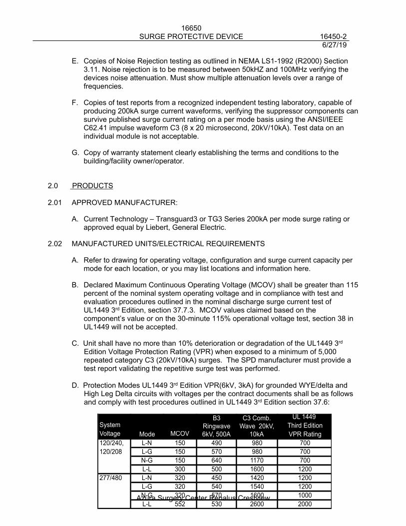
16650SURGE PROTECTIVE DEVICE 16450-2
6/27/19
Azura Surgery Center Renalus Crestview
E. Copies of Noise Rejection testing as outlined in NEMA LS1-1992 (R2000) Section 3.11. Noise rejection is to be measured between 50kHZ and 100MHz verifying the devices noise attenuation. Must show multiple attenuation levels over a range of frequencies.
F. Copies of test reports from a recognized independent testing laboratory, capable of producing 200kA surge current waveforms, verifying the suppressor components can survive published surge current rating on a per mode basis using the ANSI/IEEE C62.41 impulse waveform C3 (8 x 20 microsecond, 20kV/10kA). Test data on an individual module is not acceptable.
G. Copy of warranty statement clearly establishing the terms and conditions to the building/facility owner/operator.
2.0 PRODUCTS
2.01 APPROVED MANUFACTURER:
A. Current Technology – Transguard3 or TG3 Series 200kA per mode surge rating or approved equal by Liebert, General Electric.
2.02 MANUFACTURED UNITS/ELECTRICAL REQUIREMENTS
A. Refer to drawing for operating voltage, configuration and surge current capacity per mode for each location, or you may list locations and information here.
B. Declared Maximum Continuous Operating Voltage (MCOV) shall be greater than 115 percent of the nominal system operating voltage and in compliance with test and evaluation procedures outlined in the nominal discharge surge current test of UL1449 3rd Edition, section 37.7.3. MCOV values claimed based on the component’s value or on the 30-minute 115% operational voltage test, section 38 in UL1449 will not be accepted.
C. Unit shall have no more than 10% deterioration or degradation of the UL1449 3rd Edition Voltage Protection Rating (VPR) when exposed to a minimum of 5,000 repeated category C3 (20kV/10kA) surges. The SPD manufacturer must provide a test report validating the repetitive surge test was performed.
D. Protection Modes UL1449 3rd Edition VPR(6kV, 3kA) for grounded WYE/delta and High Leg Delta circuits with voltages per the contract documents shall be as follows and comply with test procedures outlined in UL1449 3rd Edition section 37.6:
UL 1449 System Third EditionVoltage MCOV VPR Rating120/240, L-N 150 490 980 700120/208 L-G 150 570 980 700
N-G 150 640 1170 700L-L 300 500 1600 1200
277/480 L-N 320 450 1420 1200L-G 320 540 1540 1200N-G 320 570 1600 1000L-L 552 530 2600 2000
Mode
B3Ringwave6kV, 500A
C3 Comb.Wave 20kV,
10kA
16650SURGE PROTECTIVE DEVICE 16450-3
6/27/19
Azura Surgery Center Renalus Crestview
E. Electrical Noise Filter - each unit shall include a high performance EMI/RFI noise rejection filter with a maximum attenuation of 54dB per MIL-STD-220B.
1. SPD shall include a EMI/RFI noise rejection filter for all L-N modes as well as a removable filter in the N-G mode.
F. Integral Disconnect Switch1. The device shall have an optional NEMA compliant safety interlocked
integral disconnect switch with an externally mounted metal manual operator.
2. The switch shall disconnect all underground circuit conductors from the distribution system to enable testing and maintenance without interruption to the facility’s distribution system.
3. The switch shall be rated for 600Vac.4. The SPD device shall be tested to UL1449 3rd Edition listed with the
integral disconnect switch and the UL1449 VPR ratings shall be provided.5. The integral disconnect switch shall be capable of withstanding, without
failure, the published maximum surge current magnitude without failure or damage to the switch.
6. The line side of the integral disconnect shall be blocked off so that when the SPD is opened there is no direct access to the voltage present on the line side of the disconnect.
G. The UL1449 Voltage Protective Rating (VPR) shall be permanently affixed to the SPD unit.
H. The UL1449 Nominal Discharge Surge Current Rating shall be 20kA.
I. The SCCR rating of the SPD shall be 200kAIC without the need for upstream over current protection.
J. The SPD shall be listed as Type 1 SPD, suitable for use in Type 1 or Type 2 applications.
K. The SPD shall have the following monitoring options.1. Time Date stamp, duration and magnitude for the following power quality
events (sags, swells, surges, dropouts, outages, THD, frequency, Volts RMS per phase)
2. SPD monitoring shall track surge protection and display it as a percentage.
3. SPD shall provide a surge counter with three categories to be defined as Low Level surge (100A-500A) Medium Level surge (500A-3,000A) High Level surge (>3,000A)
4. Remote communications via ModBus or Ethernet
16650SURGE PROTECTIVE DEVICE 16450-4
6/27/19
Azura Surgery Center Renalus Crestview
3.0 EXECUTION/INSTALLATION
3.01 The SPD manufacturer’s technician shall perform a system checkout and start-up in the field to assure proper installation, operation and to initiate the warranty of the system. The technician will be required to do the following:
A. Verify voltage clamping levels utilizing a diagnostic test kit, comparing factory readings to installed readings.
B. Verify N-G connection.
C. Record information to a product signature card for each product installed.
3.02 Unit may be installed on either the line or load side of the main service disconnect. If installed on the line side unit shall be installed with an integral disconnect. If installed on the load side the unit shall be installed on the largest breaker size available. If installed lead length exceeds 5’ installer shall use a low impedance (HPI) cable to reduce the lead lengths effect on the installed performance of the SPD.
4.0 PRODUCT WARRANTY
4.01 Warranty on defective material and workmanship shall be for 15 years.
4.02 Copy of Warranty to be sent with submittal.
END OF SECTION 16650
16650SURGE PROTECTIVE DEVICE 16450-5
6/27/19
Azura Surgery Center Renalus Crestview
16702 NURSE CALL EQUIPMENT 16702-1
6/27/19
Azura Surgery Center Renalus Crestview
SECTION 16702
NURSE CALL EQUIPMENT
PART 1 - GENERAL
1.01 WORK INCLUDED
A. Furnish and install a complete nurse call system between the Nurse’s Station and the Separation, Pre and Post OP, Operating Rooms and Patient Toilet Rooms.
B. This work includes a master station, remote stations, dome lights, transformer, conduit and wiring as illustrated on the accompanying drawings and hereinafter specified.
C. All nurse call equipment/systems shall be UL 1069 listed.
1.02 REFERENCE DOCUMENTS
A. The Special Provisions for electrical work are hereby made a part of this Section of the Work. Refer to Section 16010.
1.03 SUBMITTALS
A. Submit complete manufacturer’s specification data on the complete system and each type of material to be used.
PART 2 - PRODUCTS
2.01 MASTER NURSE CALL UNIT
A. Furnish and install Cornell Series 4000 Annunciator, Model #A-4006. Provide Model #A-4010 if more than 6 nurse calls, #A-4020 if more than 10, #A-4030 if more than 20, etc. Station complete with flush box, cover, visual LED’s, buzzer and silence switch for operation at 24V A.C. at Nurse Station and Reception ASC where applicable, as shown on drawings.
B. Furnish and install Cornell Series 4000 Power Supply, Model #P-512243A, 120/24V, 30 VA capacity.
2.02 REMOTE STATIONS
A. Patient toilet stations shall be Cornell Series 4000, Model #E-114-3 single switch, with flush cover plate and Germ Free & Glow in the Dark Nylon pull cord mounted adjacent to water closet as noted on plans. All pull strings shall be fire retardant and devices shall be rated for Oxygen Rich Environments.
B. Separation Room and Exam Rooms – in states where required. Call stations (one required) shall be Cornell Series 4000, Model #E-114-3 single switch, flush wall plate, with call-placed indicator light mounted on single gang flush cover.1. Install DS-110 Duty Station (audio annunciator) as indicated on plans.
C. Dome lights shall be Cornell Series 4000, Model #L-101, with white lamp mounted above door trim, outside room and model #L-102 with Blue Lamp/Cover on top and White Lamp/cover on the bottom.
16702 NURSE CALL EQUIPMENT 16702-2
6/27/19
Azura Surgery Center Renalus Crestview
D. Changing Rooms shall be Cornell Series 4000, Model #E-114-3, pull station with single switch, flush wall plate, and call placed indicator light mounted on single gang flush cover.
E. Lounge Duty Station shall be Cornell Series 4000, Model #DS-110, annunciator with LED indication and manual high or low volume tone.
2.03 SYSTEM WIRING
A. Wire transformer (2) 12# THHN, (1) 12# Cu Gnd. - 1/2" C; from transformer secondary extend (2) 14# THHN, (1) 14# Cu Gnd. fused at transformer, to master nurse call annunciator.
B. From annunciator extend (4) 16# AWG to each call station with (2) 16# to each call station dome light.
PART 3 - EXECUTION
3.01 STATIONS
A. Mount master station flush at 50" above finished floor, or at Nurse’s Station where specified on the drawings.
B. Mount signal devices flush as shown on the plans.
C. All Low-Voltage interconnecting wiring shall be 16#AWG or larger.
END OF SECTION
16721LIFE SAFETY SYSTEM – LO RISE 16721-1
6/27/19
Azura Surgery Center Renalus Crestview
16721LIFE SAFETY SYSTEM – LO RISE
1.0 GENERAL
1.01 SUMMARY
A. The Fire Alarm System survivability requirements for the system shall be a Level 0. All wiring and devices shall be provided in accordance with 2013 NFPA 72 sections 12.4 and 24.3.6.
B. This Section describes the basic materials and installation methods for the Life Safety System. Comply with other Division 16 Sections and Drawings as applicable. Refer to other Divisions for coordination of Work.
C. This performance specification provides the minimum requirements for the Life Safety System. The system shall include, but not limited to all equipment, materials, labor, documentation and services necessary to furnish and install a complete, operational system to include but not limited to the following functions:1. Smoke and fire detection. 2. Sprinkler suppression system monitoring and control.3. Off-premise notification
C. Drawings are diagrammatic. The devices shown on the plans are for general architectural and owner coordination and shall be considered a minimum; additional devices shall be provided as required as part of this contract. The contractor shall provide all components, devices, and connections necessary to provide a complete and operating system as required by NFPA and the authority having jurisdiction. The contractor shall coordinate with all trades and provide the necessary devices, connections and zone required (included, but not exclusive, duct mounted smoke detectors, sprinkler system flow and tamper switches, HVAC controls, elevator controls, etc.) Provide quantity of audio/visual devices and power supplies as required by NFPA and the authority having jurisdiction.
1.02 MANUFACTURER
A. The General Provisions, Supplemental General Provisions, section 16010, Division 1, Division 14, Division 15, Specifications and Special Provisions apply to all Work specified in this Section.
B. The manufacturer of the system equipment shall be regularly involved in the design, manufacture, and distribution of all products specified in this document. These processes shall be monitored under a quality assurance program that meets the ISO 9000 requirements.
C. All System components shall be the cataloged products of a single supplier. All products shall be listed by the manufacturer for their intended purpose.
16721LIFE SAFETY SYSTEM – LO RISE 16721-2
6/27/19
Azura Surgery Center Renalus Crestview
D. Edwards Systems Technology, Inc. products constitute the minimum type and quality of equipment to be installed. Acceptable alternate manufacturers and panels are as follows: Notifier NFP 640, Pyrotronics MXLV.
E. All control panel assemblies and connected field appliances shall be both designed and manufactured by the same company, and shall be tested and cross-listed as to ensure that a fully functioning is designed and installed. The system supplied under this specification shall be a microprocessor-based, system. The system shall utilize independently addressed, microprocessor-based smoke detectors, heat detectors, and modules as described in this specification.
1.03 ALTERNATES
A. Strict conformance to this specification is required to ensure that the installed and programmed system will function as designed, and will accommodate the future requirements and operations of the building Owner. All specified operational features must be met without exception.
B. All equipment and components shall be the manufacturer's current model and all equipment shall be by the same manufacture. The materials, appliances, equipment and devices shall be tested and listed by a nationally recognized approvals agency for use as part of a protected premises protective signaling system, access control, and smoke control. The authorized representative of the manufacturer of the major equipment, such as control panels, shall be responsible for the satisfactory installation of the complete system.
C. Any other equipment considered equivalent must be submitted to the Engineer of record not less than ten (10) calendar days prior to the bid, for approval. Submitting of material does not constitute acceptance or approval of said equipment. All deviations from the specification must be listed in a point-by-point statement showing compliance or non-compliance with the specifications. The acceptability of any alternate proposed system shall be the sole decision of the Engineer, Owner or his authorized representative.
1.04 REFERENCES
A. General (references)1. All work and materials shall conform to all applicable Federal, State and
local codes and regulations governing the installation. If there is a conflict between the referenced standards, federal, state or local codes, and this specification, it is the bidder's responsibility to immediately bring the conflict to the attention of the Engineer for resolution. National standards shall prevail unless local codes are more stringent. The bidder shall not attempt to resolve conflicts directly with the local authorities unless specifically authorized by the Engineer.
2. System components proposed in this specification shall be UL listed to operate together as a system. The supplier shall provide evidence, with his submittal, of listings of all proposed equipment and combinations of
16721LIFE SAFETY SYSTEM – LO RISE 16721-3
6/27/19
Azura Surgery Center Renalus Crestview
equipment. The supplier shall be responsible for filing of all documents, paying all fees (including, but not limited to plan checking and permit) and securing all permits, inspections and approvals. Upon receipt of approved drawings from the authority having jurisdiction, the supplier shall immediately forward two sets of drawings to the Owner. These drawings shall either be stamped approved or a copy of the letter stating approval shall be included.
B. Codes1. Fire - The equipment and installation shall comply with the current
provisions of the following codes and standards:a. NFPA 70 - 2017 National Electric Code®b. NFPA 72 - 2013 National Fire Alarm Code®c. NFPA 90A - 2015 Air Conditioning Systemsd. NFPA 101- 2013 Life Safety Code®e. UL 864 - Control Units for Fire Protective Signaling Systems.f. UL 268 - Smoke Detectors for Fire Protective Signaling Systems.g. UL 268A - Smoke Detectors for Duct Applications.h. UL 521 - Heat Detectors for Fire Protective Signaling Systems.i. UL 228 - Door Closers-Holders, With or Without Integral Smoke
Detectors.j. UL 464 - Audible Signaling Appliances.k. UL 38 - Manually Actuated Signaling Boxes for Use with Fire-
Protective Signaling Systemsl. UL 346 - Waterflow Indicators for Fire Protective Signaling Systems.m. UL 1971 - Signaling Devices for the Hearing-Impaired.n. UL 1481 - Power Supplies for Fire Protective Signaling Systems.o. Factory Mutual (FM) approvalp. AHJq. Federal Codes and Regulationsr. Americans with Disabilities Act (ADA)
1.05 SYSTEM DESCRIPTION
A. GeneralThe Contractor shall furnish all labor, services and materials necessary to furnish and install a complete, functional fire alarm system (System). The System shall comply in respects with all pertinent codes, rules, regulations and laws of the Authority, and local jurisdiction. The System shall comply in all respects with the requirements of the specifications, manufacturer's recommendations and Underwriters Laboratories Inc. (ULI) listings.
B. System Features1. Provide and install a new fire detection and alarm system that shall
consist of:a. Fire Alarm Control Panel.b. LCD remote annunciator(s).c. Printer.d. Manual pull stations, smoke detectors, heat detectors, beam detectors
16721LIFE SAFETY SYSTEM – LO RISE 16721-4
6/27/19
Azura Surgery Center Renalus Crestview
and duct detectors.e. Sprinkler system waterflow(s) and valve supervisory switch(s).f. Interface with suppression system(s).g. Audio/visual devices.
h. Synchronized visual notification appliances.i. Magnetic door holders (coordinate with Architect and door hardware).
2. Provide elevator recall functions for primary and alternate floors and elevator power shunt trip activation.
3. Provide connection to a central station. The owner shall arrange for two dedicated phone lines to be terminated as directed by the installing contractor.
C. Sequent of Operations1. The alarm activation of any area smoke detector, heat detector, manual
pull station, sprinkler waterflow, the following functions shall automatically occur:a. The internal audible device shall sound at the control panel and
remote annunciator.b. The LCD display shall indicate all applicable information associated
with the alarm condition including; device type, device location and time/date.
c. All system activity/events shall be documented in system history and on the system printer.
d. Any remote or local annunciator LCD/LED's associated with the alarm shall be illuminated.
e. Activate notification audible appliances throughout the building or as required by code.
f. Activate visual strobes notification appliances throughout the building or as required by code. The visual strobe shall continue to flash until the system has been reset. The visual strobe shall not stop operating when the "Alarm Silence" is pressed.
g. Transmit an alarm signal to the central station.h. All automatic events programmed to the alarm point shall be executed
and the associated outputs activated.i. All stairwell/exit doors shall unlock throughout the building.j. All self-closing fire/smoke doors held open shall be released.
2. The Alarm activation of any duct smoke detector, the following functions shall automatically occur:a. The internal audible device shall sound at the control panel and
remote annunciator.b. The LCD display shall indicate all applicable information associated
with the alarm condition including; device type, device location and time/date.
c. All system activity/events shall be recorded on the system printer and system history file.
d. Any remote or local annunciator LED's associated with the alarm shall be illuminated.
e. Transmit signals to remote annunciators located as shown on the
16721LIFE SAFETY SYSTEM – LO RISE 16721-5
6/27/19
Azura Surgery Center Renalus Crestview
contract drawings.f. Transmit an alarm signal to the central station.g. Shutdown the local air handling unit. h. All automatic events programmed to the alarm point shall be executed
and the associated outputs activated.
3. Upon supervisory activation of any sprinkler valve supervisory switch, the following functions shall automatically occur:a. The internal audible device shall sound at the control panel and
remote annunciator.b. The LCD display shall indicate all applicable information associated
with the supervisory condition including; device type, device location and time/date.
c. All system activity/events shall be documented on the system printer and system history file.
d. Any remote or local annunciator LCD/LED's associated with the supervisory activation shall be illuminated.
e. Transmit a supervisory signal to the central station.4. Upon activation of a trouble condition or signal from any device on the
system, the following functions shall automatically occur:a. The internal audible device shall sound at the control panel and
remote annunciator.b. The LCD display shall indicate all applicable information associated
with the trouble condition including; device type, device location and time/date.
c. All system activity/events shall be documented on the system printer and system history file.
d. Any remote or local annunciator LCD/LED's associated with the trouble zone shall be illuminated.
e. Transmit a trouble signal to the central station.
D. System Configuration1. General
a. All Life Safety System equipment shall be arranged and programmed to provide a system for the early detection of fire, the notification of building occupants, the automatic summoning of the local fire department, the override of the HVAC system operation, and the activation of other auxiliary systems to inhibit the spread of smoke and fire, and to facilitate the safe evacuation of building occupants.
b. The System shall utilize independently addressed, smoke detectors, heat detectors and input/output modules as described elsewhere in this specification.
2. Power Supplya. The power supply shall be a high efficiency switch mode type with line
monitoring to automatically switch to batteries for power failure or brown out conditions. The automatic battery charger shall have low battery discharge protection. The power supply shall provide internal power and 24 Vdc at 6.0A continuous for notification appliance circuits. All outputs shall be power limited. The battery shall be sized
16721LIFE SAFETY SYSTEM – LO RISE 16721-6
6/27/19
Azura Surgery Center Renalus Crestview
to support the system for 60 hours of supervisory and trouble signal current plus general alarm for 15 minutes. The power supply shall be an EST model 2-PPS6/A.
b. Auxiliary power supplies shall be a high efficiency switch mode type with line monitoring to automatically switch to batteries for power failure or brown out conditions. The automatic battery charger shall have low battery discharge protection. The power supply shall provide internal power and 24 Vdc at 6.4 continuous for notification appliance circuits. The power supply shall be capable of providing 8A to output circuits for a maximum period of 100 ms. All outputs shall be power limited. The battery shall be sized to support the system for 60 hours of supervisory and trouble signal current plus general alarm for 30 minutes. All supervision of the auxiliary supply shall be transmitted via addressable analog loop without additional equipment. The auxiliary power supply shall be an EST model SIGA-APS.
3. Displaya. The display module shall be of membrane style construction with a 4
line by 20 character Liquid Crystal Display. The LCD shall use super-twist technology and backlighting for high contrast visual clarity. In the normal mode display the time, the total number of active events and the total number of disable points. In the alarm mode display the total number of events and the type of event on display. Reserve 40 characters of display space for user custom messages. The module shall have visual indicators for the following common control functions; AC Power, alarm, supervisory, monitor, trouble, disable, ground fault, CPU fail, and test. There shall be common control keys and visual indicators for; reset, alarm silence, trouble silence, drill, and one custom programmable key/indicator. Provide four pairs of display control keys for selection of event display by type (alarm, supervisory, monitor and trouble) and forward / backward scrolling through event listings. The operation of these keys shall be integrated with the related common control indicator that lights when an event of its type is active. Allow the first event of the highest priority to capture the LCD for display so that arriving fire fighters can view the first alarm event "hands free". Provide system function keys; status, reports, enable, disable, activate, restore, program, and test. The module shall have a numeric keypad, zero through nine with delete and enter keys.
b. The display module shall be an EST model 2-LCD.4. Initiating Device Circuits
a. The Initiating device circuits (IDC) used to monitor waterflow switches, valve supervisory switches, fire pump functions, and air pressure supervisory switches shall be Class B.
b. The Initiating device circuits shall be EST Signature series modules.5. 24 VDC Notification Appliance Circuits
a. 24 VDC Notification appliance circuits (NAC) shall be Class B. All notification appliance circuits shall have a minimum circuit output rating of 2 amp @ 24 vdc. The notification circuits shall be power limited. Non-power limited circuits are not acceptable.
b. The 24 VDC Notification appliance circuits shall be EST Signature
16721LIFE SAFETY SYSTEM – LO RISE 16721-7
6/27/19
Azura Surgery Center Renalus Crestview
series modules.6. Audio Notification Appliance Circuits
a. One-way audio notification appliance circuits (NAC) shall Class B. All notification appliance circuits shall have a minimum circuit output rating of 35W @70Vrms. The notification circuits shall be power limited. Non-power limited circuits are not acceptable.
b. The one-way audio notification appliance circuits shall be EST Signature series modules.
7. Signaling Line Circuitsa. The signaling line circuit shall communicate from a panel/node to
analog/addressable detectors, input modules, output modules, isolation modules and notification appliance circuits.
b. Each signaling circuit connected to addressable/analog devices shall provide a minimum of 20 spare addresses.
c. When a signaling line circuit covers more than one fire/smoke compartments, a wire-to-wire short shall not effect the operation of the circuit from the other fire/smoke compartments.
d. The signaling line circuit (SLC) connecting panels and annunciators shall be Class B.
e. The signaling line circuit connecting to addressable/analog devices including, detectors, monitor modules, control modules, isolation modules, and notification circuit modules shall be Class B.
8. DACTa. The panel shall have a dialer (alarm communicator transmitter
(DACT)) module to transmit alarm, supervisory and trouble signals to a Central Monitoring Station (CMS). The DACT shall support two separate technologies for communication with telephones lines, 20 PPS 4/2 communications, and configured for dual tone multi-frequency (DTMF) or pulse modes, cellular or radio system. It shall be possible to delay AC power failure reports, auto test call, and site program using a touch tone phone and password.
b. The dialer shall be an EST model DL2. c. The dialer shall utilize two separate technologies for notification in
accordance with 2013 NFPA 72 26.6.3.2.1.
E. Submittals1. Project Submittal
a. The contractor shall purchase no equipment for the system specified herein until the owner has approved the project submittals in their entirety and has returned them to the contractor. It is the responsibility of the contractor to meet the entire intent and functional performance detailed in these specifications. Approved submittals shall only allow the contractor to proceed with the installation and shall not be construed to mean that the contractor has satisfied the requirements of these specifications. The contractor shall submit ten (10) complete sets of documentation including point to point CAD drawings and submittals within 30 calendar days after award of purchase order.
b. Each submittal shall include a cover letter providing a list of each variation that the submittal may have from the requirements of the
16721LIFE SAFETY SYSTEM – LO RISE 16721-8
6/27/19
Azura Surgery Center Renalus Crestview
contract documents. In addition the contractor shall provide specific notation on each shop drawing, sample, catalog cut, data sheet, installation manual, etc. submitted for review and approval, of each such variation.
c. All drawings and diagrams shall include the Contractor's title block, complete with drawing title, contractor's name, address, date including revisions, and preparer's and reviewer’s initials.
d. Product Data - Data sheets with the printed logo or trademark of the manufacturer for all equipment. Indicated in the documentation will be the type, size, rating, style, and catalog number for all items proposed to meet the system performance detailed in this specification. The proposed equipment shall be subject to the approval of the Architect/Engineer.
e. Shop Drawings - A complete set of shop drawings shall be supplied. The shop drawings shall be reproduced electronically in digital format. This package shall include but not be limited to: i. Control panel wiring and interconnection schematics.ii. Complete point to point wiring diagrams. A vertical riser is not
acceptable. All drawings must be in CAD.iii. Detailed system operational description and operational
matrix.iv. Complete system bill of material.
f. All drawings shall be reviewed and signed off by an individual having a minimum of a NICET III certification in fire protection engineering technology, subfield of fire alarm systems.
2. Qualifications of Contractora. The contractor shall have successfully installed similar system fire
detection, signaling control components on a previous project of comparable size and complexity. The owner reserves the right to reject any control components for which evidence of a successful prior installation performed by the contractor cannot be provided.
b. The contractor shall have in-house engineering and project management capability consistent with the requirements of this project. Qualified and approved representatives of the system manufacturer shall perform the detailed engineering design of central and remote control equipment. Qualified and approved representatives of the system manufacturer shall produce all panel and equipment drawings and submittals, operating manuals. The contractor is responsible for retaining qualified and approved representative(s) of those system manufacturers specified for detailed system design and documentation, coordination of system installation requirements, and final system testing and commissioning in accordance with these specifications.
c. Quality Assurance/Control Installer's Certificationi. The engineered systems distributor must be licensed in the
state of project location and have been incorporated in the business in that state for a minimum of 5 years.
ii. Provide in the submittal a copy of the contractors training certification issued by the manufacturer of the Life Safety
16721LIFE SAFETY SYSTEM – LO RISE 16721-9
6/27/19
Azura Surgery Center Renalus Crestview
System.d. Provide a copy of the installing technician's NICET certification level
III or IV.e. System Calculations - complete calculations shall be provided which
show the electrical load on the following system components:i. Each system power supply, including stand alone booster
supplies.ii. Each standby power supply (batteries).iii. Each notification appliance circuit.iv. Each auxiliary control circuit that draws power from any
system power supply.3. Closeout Submittal
a. Four (4) copies of the following documents shall be delivered to the building owner's representative at the time of system acceptance. The close out submittals shall include:i. Project specific operating manuals covering the installed Life
Safety System. A generic or typical owner's instruction and operation manual shall not be acceptable to fulfill this requirement.
ii. As-Built drawings consisting of: a scaled plan of each building showing the placement of each individual item of the Life Safety System equipment as well as raceway size and routing, junction boxes, and conductor size, quantity, and color in each raceway. All drawings must reflect point to point wiring, device address and programmed characteristics as verified in the presence of the engineer and/or the end user unless device addressing is electronically generated, and automatically graphically documented by the system.
iii. Provide all drawings shall be provided in standard .DXF format.
iv. Provide the name, address and telephone of the authorized factory representative.
v. A filled out Record of Completion similar to NFPA 72, 1999 edition figure 1-6.2.1.
F. Warranty and Maintenance1. Warranty
a. The contractor shall warranty all materials, installation and workmanship for one (1) year from date of acceptance, unless otherwise specified. A copy of the manufacturer's warranty shall be provided with close-out documentation and included with the operation and installation manuals.
b. The System Supplier shall maintain a service organization with adequate spare parts stock within 100 miles of the installation. Any defects that render the system inoperative shall be repaired within 24 hours of the owner notifying the contractor.
2. Spare Partsa. The Contractor shall supply the following spare parts:
i. Automatic detection devices - Two (2) percent of the installed quantity of each type.
16721LIFE SAFETY SYSTEM – LO RISE 16721-10
6/27/19
Azura Surgery Center Renalus Crestview
ii. Manual fire alarm stations - Two (2) percent of the installed quantity of each type.
iii. Glass rods or panels for break glass manual fire alarm stations (if used) - <Ten> percent of the installed quantity, but no less than two devices.
iv. Audible and visible devices - One (1) percent of the installed quantity of each type, but no less than two (2) devices.
v. Keys - A minimum of three (3) sets of keys shall be provided and appropriately identified.
G. Training1. The System Supplier shall schedule and present a minimum of 4 hours of
documented formalized instruction for the building owner, detailing the proper operation of the installed System.
2. The instruction shall be presented in an organized and professional manner by a person factory trained in the operation and maintenance of the equipment and who is also thoroughly familiar with the installation.
3. The instruction shall cover the schedule of maintenance required by NFPA 72 and any additional maintenance recommended by the system manufacturer.
4. Instruction shall be made available to the Local Municipal Fire Department if requested by the Local Authority Having Jurisdiction.
2.0 PRODUCTS
2.01 MANUFACTURER
A. Acceptable fire alarm system manufacturers include:1. Edwards Systems Technology, Inc.2. Notifier AM 20203. Pyrotronics MXLV
2.02 PANEL COMPONENTS & FUNCTIONS
A. General 1. The control panel shall be a multi-processor-based system designed
specifically for fire and releasing system applications. The control panel shall be listed and approved for the application standard(s) as listed under the General section.
2. The control panel shall include all required hardware, software and system programming to provide a complete and operational system. The control panel shall assure that life safety takes precedence among all panel activities.
3. The control panel shall include the following capacities:a. Support up to 380 analog/addressable points per panel (1,900 total
with 5 networked panels)b. Support up to 5 fully supervised network remote annunciators.c. Support a DACT (dialer) for off premise notification.d. Support up to 576 chronological events in history.
16721LIFE SAFETY SYSTEM – LO RISE 16721-11
6/27/19
Azura Surgery Center Renalus Crestview
e. Provide 25% spare capacity on each data line.4. The control panel shall include the following features:
a. Provide autoprogramming and electronic addressing and mapping of analog/addressable devices.
b. Provide an operator interface display that shall include functions required for annunciation, command and control system functions.
c. Provide a discreet system control switch provided for reset, alarm silence, local silence, drill switch, up/down switches, status switch, program switch, enable and disable switches, activate and restore switches, reports switch and test switch.
d. Provide system reports that provide sensitivity and history details.e. Provide an authorized operator with the ability to operate or modify
system functions like system time, date, passwords; and autoprogram, enable mapping, restart the system and clear control panel event history file.
f. Provide an authorized operator to perform test functions within the installed system.
5. Supervision of system components, wiring, initiating devices and software shall be provided by the control panel. Failure or fault of system component or wiring shall be indicated by type and location on the LCD display. Software and processor operation shall be independently monitored for failure.
B. Annunciation1. The system shall be designed and equipped to receive, monitor, and
annunciate signals from devices and circuits installed throughout the building. Manufacturer's standard control switches shall be acceptable if they provide the required operation, including performance, supervision and position indication. If the manufacturers' standard switches do not comply with these requirements, fabrication of custom manual controls acceptable to the owner is required.
2. Receipt of alarm, trouble, and supervisory signals shall activate integral audible devices at the control panel(s) and at each remote annunciation device.
3. The annunciator shall contain the following system status indicators:a. 80 character Backlit Liquid Crystal Displayb. System Power Indicator – green LEDc. System Common Alarm – red LEDd. System Common Trouble – yellow LEDe. System Common Supervisory – yellow LEDf. System Common Monitor – yellow LEDg. System Ground Fault – yellow LEDh. System CPU Fault – yellow LEDi. System Disables – yellow LEDj. System Test Point(s) – yellow LEDk. System Reset Switch with Integral yellow LEDl. System Alarm Silence Switch with Integral yellow LEDm. System Local Silence Switch with Integral yellow LEDn. System Drill Switch with Integral yellow LEDo. System Message Queue Scroll Switches
16721LIFE SAFETY SYSTEM – LO RISE 16721-12
6/27/19
Azura Surgery Center Renalus Crestview
p. Additional button as required to provide system control and operator functions.
4. The network annunciator(s) shall be an EST 2 series.
C. Power Supply1. Each system power supply shall be a minimum of 6 amps @ 24 vdc.2. Upon failure of normal (AC) power, the affected portion(s) of the system
shall automatically switch over to secondary power without losing any alarm, trouble or operator acknowledgment signals.
3. Each system power supply shall be individually annunciated and shall identify the inoperable power supply in the event of a trouble condition.
4. All standby batteries shall be continuously monitored by the system. Low battery and disconnection of battery power supply conditions shall immediately annunciate as a trouble signal, identifying the deficient batteries.
5. All system power supplies shall be capable of recharging their associated batteries, from a fully discharged condition to a capacity sufficient to allow the system to perform consistent with the requirements of this section, in 48 hours maximum.
6. All AC power connections shall be to the building's designated emergency electrical power circuit and shall meet the requirements of Section 1-5.2 of NFPA 72 - 1999. The AC power circuit shall be installed in conduit raceway. The power circuit disconnect means shall be clearly labeled FIRE ALARM CIRCUIT CONTROL and shall have a red marking. The location of the circuit disconnect shall be labeled permanently inside the each control panel.
7. The power supply shall be an EST model 2-PPS/6A.
D. Display1. The system shall allow message routing to be configured to any or all
annunciators.2. All system printer port shall be configurable to output any combination of
alarm, supervisory, trouble, or monitor, event messages.3. Each LCD display on each annunciator shall be configurable to display
the status of any combination of alarm, supervisory, trouble, or monitor, event messages.
4. Clear distinction shall be provided between alarm, supervisory, trouble, and monitor status messages.
5. The system shall provide the ability to retrieve data from the analog/addressable detectors to a PC while the system is on-line and operational in the protected premises. The uploaded data may then be analyzed in a diagnostic program supplied by the system manufacturer.
6. A standby power supply shall automatically supply electrical energy to the system upon primary power supply failure.
E. Dialer – DACT1. The system shall provide an off premise Digital Alarm Communications
Transmitter (DACT) capable of transmitting system alarm, trouble and supervisory events to a central monitoring station (CMS). The DACT shall support dual telephone lines, 20 PPS 4/2 communications, and
16721LIFE SAFETY SYSTEM – LO RISE 16721-13
6/27/19
Azura Surgery Center Renalus Crestview
configured for dual tone multi-frequency (DTMF) or pulse modes. It shall be possible to delay AC power failure reports, auto test call, and site program the DACT using a touch tone phone and password.
2. The DACT shall be an EST model DL2.
F. Reports1. The system shall provide the operator with system reports that give
detailed chronological description of the last 576 system events. The system shall provide a report that gives a listing of the sensitivity and environmental compensation usage of all of the detectors on the system, or specified analog/addressable circuit.
2. The system report shall also include facility name, compiled date, compiler revision, project revision and report date. The system shall output these reports via the main LCD, and reports shall be capable of being printed on the system printer.
2.03 FIELD-MOUNTED SYSTEM COMPONENTS
A. Initiating Devices1. Smoke Detectors & Accessories
a. Analog Addressable Smoke Generali. Each analog addressable smoke detector's sensitivity shall be
capable of being programmed individually as: most sensitive, more sensitive, normal, less sensitive or least sensitive.
ii. The system shall allow for changing of detector types for service replacement purposes without the need to reprogram the system. The replacement detector type shall automatically continue to operate with the same programmed sensitivity levels and functions as the detector it replaced. System shall display an off-normal condition until the proper detector type has been installed or change in the application program profile has been made.
b. Smoke Detector Photoelectric or Photo/Heati. Provide analog/addressable photoelectric smoke detectors as
required. The system shall have the ability to set the sensitivity and alarm verification of each of the individual detectors on the circuit. It shall be possible to automatically change the sensitivity of individual analog/addressable detectors for the day and night periods. Each smoke detector shall be capable of transmitting alarm signals as well as normal, trouble and need cleaning information. It shall be possible to program control panel activity to each level. Each smoke detector may be individually programmed to operate at any one of five (5) sensitivity settings. Each detector microprocessor shall contain an environmental compensation algorithm that identifies and sets ambient environmental thresholds approximately six times an hour. The microprocessor shall monitor the environmental compensation value and alert the system operator when the detector approaches 80% and 100% of the allowable environmental
16721LIFE SAFETY SYSTEM – LO RISE 16721-14
6/27/19
Azura Surgery Center Renalus Crestview
compensation value.ii. The analog/addressable photoelectric smoke detector shall be
an EST model SIGA-PS.iii. Where required by designed drawings provide a combination
photo/heat detector in one device. The unit shall be EST model SIGA-PHS.
c. Duct Detector Housingi. Provide smoke detector duct housing assemblies to mount an
analog/addressable detector along with a standard, relay or isolator detector mounting base. The housing shall also protect the measuring chamber from damage and insects. The housing shall utilize an air exhaust tube and an air sampling inlet tube that extends into the duct air stream up to ten feet. Drilling templates and gaskets to facilitate locating and mounting the housing shall also be provided. The housing shall be finished in baked red enamel. Remote alarm LED indicators and remote test stations shall be provided.
ii. The smoke detector duct housing shall be an EST model SIGA-DH.
d. Relay Modulei. Provide addressable control relay circuit modules as required.
The module shall provide one (1) form C dry relay contacts rated at 24Vdc @ 2 amps (pilot duty) to control external appliances or equipment. The position of the relay contact shall be confirmed by the system firmware.
ii. The addressable control relay circuit module shall be an EST model SIGA-CR.
2. Fixed Temperature – ROR Heat Detectora. Provide analog/addressable combination fixed temperature / rate-of-
rise detectors at the locations shown on the drawings. The heat detector shall have a nominal fixed temperature alarm point rating of 135°F (57°C) and a rate of rise alarm point of 15°F (9°C) per minute. The heat detector shall be rated for ceiling installation at a minimum of 70 ft (21.3m) centers and be suitable for wall mount applications.
b. The analog/addressable combination fixed temperature / rate-of-rise detector shall be EST model SIGA-HRS.
3. Detector Bases – Standarda. Provide standard detector mounting bases suitable for mounting on
either North American 1-gang, 3½ or 4 inch octagon box and 4 inch square box, or European BESA or 1-gang box. The base shall, contain no electronics and support all series detector types.
b. The standard detector base shall be an EST model SIGA-SB4.4. Manual Station - Double Action Single Stage
a. Provide analog/addressable double action, single stage fire alarm stations at the locations shown on the drawings. The fire alarm station shall be of polycarbonate construction and incorporate an internal toggle switch. A locked test feature shall be provided. The station shall be finished in red with silver "PULL IN CASE OF FIRE" lettering. The manual station shall be suitable for mounting on North
16721LIFE SAFETY SYSTEM – LO RISE 16721-15
6/27/19
Azura Surgery Center Renalus Crestview
American 2 ½ (64mm) deep 1-gang boxes and 1 ½ (38mm) deep 4 square boxes with 1-gang covers.
b. The analog/addressable double action, single stage fire alarm station shall be EST model SIGA-278.
5. Door Holdersa. Provide electromagnetic Floor or Wall mounted door holders as
shown on the contract drawings. The door holders housing shall be finished aluminum color, durable, baked polyester powder paint. The floor or wall section houses the electromagnet while the contact plate attaches to the door. The contact plate has a shock absorbing nylon swivel ball which allows the plate to adjust to any door angle. The door holder shall have a holding force of approximately 25Lbf. (111N). The door holders shall be suitable for mounting on North American 2 x 4 inch outlet boxes. The model number is EST 1504-AQ.
6. Beam Detectors a. Provide beam detectors with automatic gain control and designed to
detect smoke in a large volume. The system will be comprised of three pieces, a transmitter head, a receiver head, and a control box. When the signal strength is reduced to a level between the obscuration threshold and 93% for more than 8 to 10 seconds, the fire alarm output relay is activated. The alarm obscuration threshold may be set at 25%, 35% or 50% obscuration, depending on the application. Reduction in signal strength below 93% is indicated as a fault condition. The model number is EST Fireray 2000.
7. 120VAC Smoke Detectorsa. Provide Gentex 3120F 120 Volt smoke detectors as required in
compliance with UL 217, applicable IBC/IFC Standards and NFPA 72. Provide with a 9 VDC alkaline battery for backup in the event building power is lost. The battery impedance shall be verified and the detector shall provide a low or missing battery warning. Provide three position test feature that simulates a 0.85% and 3.5% actual smoke condition in full compliance with NFPA 72 and UL Standards.
b. Provide Form A/Form C dry contacts for remote annunciation. Provide interface to FACP.
c. For all rooms indicated by the Architect to be handicap accessible provide a Gentex 7109 CS-W wall mounted 120VAC smoke detector with 9 VDC battery backup with local 90dba piezo and 177 candela strobe with “FIRE” lettering and listed per UL 1971.
B. Control Modules1. Control Relay Module - SIGA-CR
a. Provide intelligent control relay modules as required. The Control Relay Module shall provide one form "C" dry relay contact rated at 2 amps @ 24 VDC to control external appliances or equipment shutdown. The control relay shall be rated for pilot duty and releasing systems. The position of the relay contact shall be confirmed by the system firmware. The control relay module shall be suitable for mounting on North American 2 ½" (64mm) deep 1-gang boxes and 1 ½" (38mm) deep 4" square boxes with 1-gang covers.
16721LIFE SAFETY SYSTEM – LO RISE 16721-16
6/27/19
Azura Surgery Center Renalus Crestview
c. The addressable control relay circuit module shall be an EST model SIGA-CR.
2. Dual Input Module - SIGA-CT2a. Provide intelligent dual input modules as required. The Dual Input
Module shall provide two (2) supervised Class B input circuits each capable of a minimum of 4 personalities, each with a distinct operation. The module shall be suitable for mounting on North American 2 ½" (64mm) deep 1-gang boxes and 1 ½" (38mm) deep 4" square boxes with 1-gang covers. The dual input module shall support the following circuit types:o Normally-Open Alarm Latching (Manual Stations, Heat Detectors,
etc.)o Normally-Open Alarm Delayed Latching (Waterflow Switches)o Normally-Open Active Non-Latching (Monitor, Fans, Dampers,
Doors, etc.)o Normally-Open Active Latching (Supervisory, Tamper Switches
b. The intelligent dual input module shall be an EST model SIGA-CT2.3. Dual Input Signal Module - SIGA-CC2
a. Provide intelligent dual input signal modules as required. The Dual Input (Dual Riser Select) Signal Module shall provide a means to selectively connect one of two (2) signaling circuit power risers to one (1) supervised output circuit. The module shall be suitable for mounting on North American 2 ½" (64mm) deep 2-gang boxes and 1 ½" (38mm) deep 4" square boxes with 2-gang covers, or European 100mm square boxes. The dual input signal module shall support the following operation:
Audible/Visible Signal Power Selector (Polarized 24 Vdc @ 2A, 25 Vrms @ 50w or 70 Vrms @ 35w of Audio).
b. The intelligent dual input signal module shall be an EST model SIGA- CC2.
4. Isolator Module - SIGA-IMa. Provide intelligent fault isolators modules as required. The Isolator
Module shall be capable of isolating and removing a fault from a class A data circuit while allowing the remaining data loop to continue operating. The module shall be suitable for mounting on North American 2 ½" (64mm) deep 2-gang boxes and 1 ½" (38mm) deep 4" square boxes with 2-gang covers, or European 100mm square boxes.
b. The intelligent fault isoloator module shall be an EST model SIGA-IM.5. Monitor Module - SIGA-MM1
a. Provide intelligent monitor modules as required. The Monitor Module shall be factory set to support one (1) supervised Class B Normally-Open Active Non-Latching Monitor circuit. The monitor module shall be suitable for mounting on North American 2 ½" (64mm) deep 1-gang boxes and 1 ½" (38mm) deep 4" square boxes with 1-gang covers.
b. The intelligent monitor module shall be an EST model SIGA-MM1.6. Single Input Module - SIGA-CT1
a. Provide intelligent single input modules as required. The Single Input Module shall provide one (1) supervised Class B input circuit capable
16721LIFE SAFETY SYSTEM – LO RISE 16721-17
6/27/19
Azura Surgery Center Renalus Crestview
of a minimum of 4 personalities, each with a distinct operation. The module shall be suitable for mounting on North American 2 ½" (64mm) deep 1-gang boxes and 1 ½" (38mm) deep 4" square boxes with 1-gang covers. The single input module shall support the following circuit types:o Normally-Open Alarm Latching (Manual Stations, Heat
Detectors, etc.)o Normally-Open Alarm Delayed Latching (Waterflow Switches)o Normally-Open Active Non-Latching (Monitor, Fans, Dampers,
Doors, etc.)o Normally-Open Active Latching (Supervisory, Tamper Switches)
b. The intelligent single input module shall be an EST model SIGA-CT1.7. Single Input Signal Module - SIGA-CC1
a. Provide intelligent single input signal modules as required. The Single Input (Single Riser Select) Signal Module shall provide one (1) supervised Class B output circuit capable of a minimum of 2 personalities, each with a distinct operation. When selected as a telephone power selector, the module shall be capable of generating its own "ring tone". The module shall be suitable for mounting on North American 2 ½" (64mm) deep 2-gang boxes and 1 ½" (38mm) deep 4" square boxes with 2-gang covers, or European 100mm square boxes. The single input signal module shall support the following operations:
o Audible/Visible Signal Power Selector (Polarized 24 Vdc @ 2A, 25Vrms @50w or 70 Vrms @ 35 Watts of Audio)
o Telephone Power Selector with Ring Tone (Fire Fighter's Telephone)
b. The intelligent single input signal module shall be an EST model SIGA-CC1.
8. Universal Class AB Module - SIGA-UMa. Provide intelligent class A/B modules as required.The Universal Class
A/B Module shall be capable of a minimum of fifteen (15) distinct operations. The module shall be suitable for mounting on North American 2 ½" (64mm) deep 2-gang boxes and 1 ½" (38mm) deep 4" square boxes with 2-gang covers, or European 100mm square boxes. The universal class A/B module shall support the following circuit types:o Two (2) supervised Class B Normally-Open Alarm Latching.o Two (2) supervised Class B Normally-Open Alarm Delayed
Latching.o Two (2) supervised Class B Normally-Open Active Non-
Latching.o Two (2) supervised Class B Normally-Open Active Latching.o One (1) form "C" dry relay contact rated at 2 amps @ 24 Vdc.o One (1) supervised Class A Normally-Open Alarm Latching.o One (1) supervised Class A Normally-Open Alarm Delayed
Latching.o One (1) supervised Class A Normally-Open Active Non-
Latching.o One (1) supervised Class A Normally-Open Active Latching.
16721LIFE SAFETY SYSTEM – LO RISE 16721-18
6/27/19
Azura Surgery Center Renalus Crestview
o One (1) supervised Class A 2-wire Smoke Alarm Non-Verified. o One (1) supervised Class B 2-wire Smoke Alarm Non-Verified.o One (1) supervised Class A 2-wire Smoke Alarm Verified o One (1) supervised Class B 2-wire Smoke Alarm Verifiedo One (1) supervised Class A Signal Circuit, 24Vdc @ 2A.o One (1) supervised Class B Signal Circuit, 24Vdc @ 2A.
b. The intelligent class A/B module shall be an EST model SIGA-UM.9. Waterflow-Tamper Module - SIGA-WTM
a. Provide intelligent waterflow/tamper modules as required. The Waterflow/Tamper Module shall be factory set to support two (2) supervised Class B input circuits. Channel A shall support a Normally-Open Alarm Delayed Latching Waterflow Switch circuit. Channel B shall support a Normally-Open Active Latching Tamper Switch. The waterflow/tamper module shall be suitable for mounting on North American 2 ½" (64mm) deep 1-gang boxes and 1 ½" (38mm) deep 4" square boxes with 1-gang covers.
b. The intelligent waterflow/tamper module shall be an EST model SIGA-WTM.
C. Notification Appliances1. General (signals)
a. All appliances, which are supplied, for the requirements of this specification shall be UL Listed for Fire Protective Service, and shall be capable of providing the "equivalent facilitation" which is allowed under the Americans with Disabilities Act Accessibilities Guidelines (ADA(AG)), and shall be UL 1971 Listed.
b. All appliances shall be of the same manufacturer as the fire alarm control panel specified to insure absolute compatibility between the appliances and the control panels, and to insure that the application of the appliances are done in accordance with the single manufacturer's instructions.
c. Any appliances that do not meet the above requirements, and are submitted for use must show written proof of their compatibility for the purpose intended. Such proof shall be in the form of documentation from all manufacturers that clearly states that their equipment (as submitted) is 100% compatible with each other for the purpose intended. All strobes shall be provided with lens markings oriented for wall mounting.
d. All notification appliances shall be white unless noted otherwise on the drawings.
2. Low Profile Hornsa. Provide low profile wall mount horns as required. The horn shall
provide an 84-dBA sound output at 10 ft. when measured in reverberation room per UL-464. The horn shall have a selectable steady or synchronized temporal output. In and out screw terminals shall be provided for wiring. The horn shall mount in a North American 1-gang box.
b. The low profile wall mount horns shall be EST Genesis series.3. Low Profile Horn-Strobes
a. Provide low profile wall mount horn/strobes as required. The
16721LIFE SAFETY SYSTEM – LO RISE 16721-19
6/27/19
Azura Surgery Center Renalus Crestview
horn/strobe shall provide an audible output of 84 dBA at 10 ft. when measured in reverberation room per UL-464. Strobes shall provide synchronized flash outputs. The strobe output shall be determined as required by its specific location and application from a family of 15cd, 30cd, 60cd, 75cd & 110cd devices. The horn shall have a selectable steady or synchronized temporal output. In and out screw terminals shall be provided for wiring. Low profile horn/strobes shall mount in a North American 1-gang box.
b. The low profile wall mount horn/strobes shall be EST Genesis series.4. Low Profile Strobes
a. Provide low profile wall mounted strobes as requried. In and out screw terminals shall be provided for wiring. Strobes shall provide synchronized flash outputs. Strobe output shall be determined as required by its specific location and application from a family of 15cd, 30cd, 60cd, 75cd, or 110cd devices. Low profile strobes shall mount in a North American 1-gang box.
b. The low profile wall mounted strobes shall be EST Genesis series.
3.0 EXECUTION
3.01 INSTALLATION
A. General
1. Install system components and all associated devices in accordance with applicable NFPA Standards and manufacturer's recommendations.
2. Installation personnel shall be supervised by persons who are qualified and experienced in the installation, inspection, and testing of fire alarm systems. Examples of qualified personnel shall include, but not be limited to, the following:
a. Factory trained and certified personnel.b. National Institute of Certification in Engineering Technologies
(NICET) fire alarm level II certified personnel.
3. Contractor shall be certified by state or local authority.
4. All equipment shall be attached to walls and ceiling/floor assemblies and shall be mounted firmly in place.
5. Detectors shall not be supported solely by suspended ceilings. Fasteners and supports shall be sized to support the required load.
B. Installation Sequence1. Installation of the systems shall be conducted in stages and phased such
that circuits and equipment are installed in the following order:a. Riser conduits, AC power conduits and control cabinets.
16721LIFE SAFETY SYSTEM – LO RISE 16721-20
6/27/19
Azura Surgery Center Renalus Crestview
b. Fire command center, remote control panel(s), control component(s), annunciator(s), remote CRT terminal(s), and printer(s). Provide temporary mounting of fire command center in <location.>
c. Conduits and wiring for complete notification circuits and appliance installation throughout facility.
d. Pre-test the audible and visual notification appliance circuits.e. Install all new detection devices.f. Terminations between field devices and the associated control
equipment. g. The detection system shall be switched over and end of each day the
system shall be operational. At no time will the system be placed out of service over night.
h. Complete the interface to the building automation system.i. Complete contractor pre-test of system.j. Complete system testing.
C. Conductors–Open Cable-Raceway1. The requirement of this section apply to all system conductors, including
all signaling line, initiating device, notification appliance, auxiliary function, remote signaling, AC and DC power and grounding/shield drain circuits, and any other wiring installed by the Contractor pursuant to the requirements of these Specifications.
2. All circuits shall be rated power limited in accordance with NEC Article 760.
3. All circuits shall be installed in raceway or plenum rated cable at the discretion of the Engineer.
4. All new system conductors shall be of the type(s) specified herein.5. All initiating circuit, signaling line circuit, AC power conductors, shield
drain conductors and grounding conductors, shall be solid copper, stranded or bunch tinned (bonded) stranded copper.
6. All signaling line circuits, including all addressable initiating device circuits shall be 18 AWG minimum multi-conductor jacketed twisted cable or twisted shielded or as per manufacturer's requirements.
7. All non-addressable initiating device circuits, 24 VDC auxiliary function circuits shall be 18 AWG minimum or per manufacturer's requirements.
8. All notification appliance circuit conductors shall be solid copper or bunch tinned (bonded) stranded copper. Where stranded conductors are utilized, a maximum of 7 strands shall be permitted for No. 16 and No. 18 conductors, and a maximum of 19 strands shall be permitted for No. 14 and larger conductors.
9. All audible notification appliance circuits shall be 14 AWG minimum twisted pairs or twisted pairs shielded or per manufacturer's requirements.
10. All visual notification appliance circuits shall be 14 AWG minimum THHN or twisted pairs or twisted shielded pairs or per manufacturer's requirements.
11. Conductors and Racewaya. The contractor shall neatly tie-wrap all field-wiring conductors in the
gutter spaces of the control panels and secure the wiring away from all circuit boards and control equipment components. All field-wiring circuits shall be neatly and legibly labeled in the control panel. No
16721LIFE SAFETY SYSTEM – LO RISE 16721-21
6/27/19
Azura Surgery Center Renalus Crestview
wiring except home runs from life safety system circuits and system power supply circuits shall be permitted in the control panel enclosures. No wiring splices shall be permitted in a control panel enclosure.
b. All penetration of floor slabs and firewalls shall be fire stopped in accordance with all local fire codes.
12. Open Cable a. Power-limited cable in accordance with NEC 70, where used, not
installed in UL listed metal conduit or raceway shall be mechanically protected by building construction features.
b. Installation shall be in areas not subjected to mechanical injury.c. All circuits shall be supported by the building structure. Cable shall be
attached by straps to the building structure at intervals not greater than 10 feet. Wiring installed above drop ceilings, cable shall not be laid on ceiling tiles. Cable shall not be fastened in a manner that puts tension on the cable.
d. Cable type shall be FPLP, FPLR or FPL, or permitted substitutions, selected for the installation application as required by NEC 70, Section 760-61.
e. All cable that is not enclosed by conduit shall be supported and anchored with nylon straps or clamps. The use of staples is prohibited.
13. Conduit Racewaya. All systems and system components listed to UL864 Control Units for
Fire Protective Signaling Systems maybe installed within a common conduit raceway system, in accordance with the manufacture's recommendations. System(s) or system components not listed to the UL864 standard shall utilize a separate conduit raceway system for each of the sub-systems.
b. The requirements of this section apply to all system conduits, raceways, electrical enclosures, junction boxes, pull boxes and device back boxes.
c. All system conduits shall be of the sizes and types specified.d. All system conduits shall be EMT, 3/4 -inch minimum, except for
flexible metallic conduit used for whips to devices only, maximum length 6 feet, 3/4-inch diameter, minimum.
e. All system conduits, which are installed in areas, which may be subject to physical damage or weather, shall be IMC or rigid steel, 3/4 -inch minimum.
f. Conduits shall be sized according to the conductors contained therein. Cross sectional area percentage fill for system conduits shall not exceed 40%.
g. Provide all new conduit raceway and conduit riser.h. All fire alarm conduit systems shall be routed and installed to minimize
the potential for physical, mechanical or by fire damage, and so as not to interfere with existing building systems, facilities or equipment, and to facilitate service and minimize maintenance.
i. All conduits, except flexible conduit whips to devices, shall be solidly attached to building structural members, ceiling slabs or permanent walls. Conduits shall not be attached to existing conduit, duct work,
16721LIFE SAFETY SYSTEM – LO RISE 16721-22
6/27/19
Azura Surgery Center Renalus Crestview
cable trays, other ceiling equipment, drop ceiling hangers/grids or partition walls, except where necessary to connect to initiating, notification, or auxiliary function devices.
j. All system conduits, junction boxes, pull boxes, terminal cabinets, electrical enclosures and device back boxes shall be readily accessible for inspection, testing, service and maintenance.
3.02 FIELD QUALITY CONTROL
A. Test & Inspection1. All intelligent analog addressable devices shall be tested for current
address, sensitivity, and user defined message. 2. All wiring shall be tested for continuity, shorts, and grounds before the
system is activated. 3. All test equipment, instruments, tools and labor required to conduct the
tests shall be made available by the installing contractor.4. The system including all its sequence of operations shall be
demonstrated to the Owner, his representative, and the local fire inspector. In the event the system does not operate properly, the test shall be terminated. Corrections shall be made and the testing procedure shall be repeated until it is acceptable to the Owner, his representatives and the fire inspector.
5. At the final test and inspection, a factory trained representative of the system manufacturer shall demonstrate that the system functions properly in accordance with these specifications. The representative shall provide technical supervision, and participate during all of the testing for the system.
6. All fire alarm testing shall be in accordance with National Fire Alarm Code, NFPA 72 - 1999, Chapter 7.
7. A letter from the Contractor certifying that the system is installed entirely in accordance with the system manufacturer's recommendations and within the limitations of the required listings and approvals, that all system hardware and software has been visually inspected and functionally tested by a manufacturer's certified representative, and that the system is in proper working order.
END OF SECTION 16721
16731CATEGORY 6, COAXIAL, AUDIO & VIDEO CABLE 16730-1
6/27/19
Azura Surgery Center Renalus Crestview
SECTION 16730
CATEGORY 6, COAXIAL, AUDIO & VIDEO CABLE
PART 1 - GENERAL1.01 WORK INCLUDED
A. Furnish and install Category 6 and coaxial wire for the phone, data, patient care entertainment and Clinical Network System.
B. This work includes conduit, wiring and terminations as illustrated on the accompanying drawings and hereinafter specified.
1.02 REFERENCE DOCUMENTSA. The Special Provisions for electrical work are hereby made a part of this Section of the
Work. Refer to Section 16010.1.03 SUBMITTALS
A. Submit complete manufacturer’s specification data on the type of CAT 6 wire and RG6 coax cable material to be used.
B. Submit a certified copy of the following for approval.1.Voice and data, CAT6 test reports required and described by this specification and in
accordance with ANSI/TIA 568-C.1 and ANSI/TIA 568-C.2 field testing procedures.1.04 REFERENCES
A. ANSI/NFPA 70 – National Electrical Code.B. Local and State Code.C. Electronic Industry Association (EIA).D. Telecommunication Industry Association (TIA).
PART 2 - PRODUCTS2.01 CATEGORY 6 CABLE
A. Cable Construction1. Cable Conductors shall be 23 AWG solid bare annealed copper with Polyolefin for
non-plenum and (3) pairs FEP plus (1) pair Polyolefin for plenum insulation.2. Cable Conductors shall be color coded as follows:
Pair 1: Blue – White/BluePair 2: Orange – White/OrangePair 3: Green – White/GreenPair 4: Brown – White/Brown, non-plenum Brown – White, plenum.
3. Rip cord is applied longitudinally under cable jacket.4. Cable jacket shall be :
a. Non-plenum, flame retardant PVCb. Plenum, low-smoke, flex guard flame-retardant PVC
B. Cable Physical Data1. Nominal cable diameter, 0.022 inches
16731CATEGORY 6, COAXIAL, AUDIO & VIDEO CABLE 16730-2
6/27/19
Azura Surgery Center Renalus Crestview
2. Minimum bend radius, 1 inch3. Maximum pulling force, 25 lbs
C. The cable jacket colors for their intended use shall be blue:Blue Not UsedBlue Patient station, ClinicalBlue Patient station, Auxiliary Data, Wireless Access PointsBlue Workstation DataBlue Voice, Telephone
D. Provide all Category 6 cable from one manufacturer. Cable specifications and performance shall meet and or exceed General Cable, Gen Speed 6000 product line.Manufacturer’s cable shall be UL performance level tested product.
2.02 NETWORK RACKSA. Wall mounted and/or Floor mounted
i. Contractor is responsible for terminating CAT 6 to the patch panel.ii. All horizontal data and voice cable runs shall be tested to EIA/TIA requirements
at minimum of category 6 specification.iii. Provide wall mounted rack for patch panels. Size of rack as required for number
of patch panels. Provide number of patch panels as required for number of cable drops plus 20% spare. Rack shall be mounted 66” above finished floor.
2.03 COAXIAL CABLE, RG-6/U Quad ShieldA. Cable Construction:
1. Cable conductor shall be 18 AWG bare copper.2. Insulation shall be gas-injected or foam polyethylene.3. Shield shall be 95% bare copper braid.4. Jacket shall be:
a. Non-plenum, PVC compound.b. Plenum, low-smoke, flex guard flame-retardant PVC.
B. Provide all coaxial cable from one manufacturer. C. For all low voltage hospital TV systems installations provide either of the following RG-6/U
CCTV Coaxial Cable products. No substitutions.1. West Penn 8062. Coleman 92045
D. For all overhead/soffit-mounted TV installations, provide either of the following plenum RG-6/U CATV Coaxial Cable products. No substitutions.1. West Penn 8412. Coleman 92003
2.04 AUDIO & VIDEO CABLEA. For all hard wired TV audio cable installations from soffit to dialysis chase. No
substitutions.1. West Penn 231
16731CATEGORY 6, COAXIAL, AUDIO & VIDEO CABLE 16730-3
6/27/19
Azura Surgery Center Renalus Crestview
2.05 PLENUM GRADEA. The contractor shall adjust the conductor’s jacket for Plenum rating as required by local or
state regulations, or as job requirements dictate. 2.06 GROUND ROD
A. Provide ground rod with wire as shown on contract drawing for use by owners equipment installer.
PART 3 - EXECUTION3.01 CATEGORY 6 INSTALLATION
A. Provide recessed mount 4-square box with single gang mud ring with 1" conduit sleeve to 6" A.F.C. for all locations and at heights as shown on contract drawings.
B. Run cables continuously without splice from wiring closet rack punch down to wall box jack with corresponding identification numbers on each end of each wire.
C. Terminate wire in accordance with 568B standard wiring code at all telephone, data, patient entertainment, and Clinical Network System terminal locations as designated on the contract drawing.
3.02 COAX TV CABLE INSTALLATIONA. Run coax cable continuously without splice from wiring closet patch panel to each patient
entertainment location as shown on the contract drawing with corresponding identification numbers on each end of every cable. Provide 5'-0" whip at each end for television vendor to terminate.
3.03 AUDIO CABLE INSTALLATIONA. Run coax cable continuously without splice from electrical panel @ dialysis chase to each
patient entertainment location as shown on the contract drawing with corresponding identification numbers on each end of every cable. Provide 5'-0" whip at each end for television vendor to terminate.
3.04 CABLE SUPPORTA. Where wires and cables are permitted to be run without conduit. They shall be
independently supported from the building structure at intervals not exceeding four (4) feet on center, utilizing cable supports (J-Hooks, Arlington Loops) specifically approved for the purpose.
B. Wires and cables shall not rest on or depend on support from suspended ceiling media (tiles, spines, runners, bars, or support wires in the plane of the ceiling), nor shall they be supported from pipes, ducts or conduits.
C. Where cables are bundled together, separate bundles shall be provided separately for each type of cabling and separately for each independent system. Bundling and/or supporting ties shall be of a type suitable for use in a ceiling air handling plenum regardless of whether or not installed in a plenum.1. Cables shall be tagged or labeled at each termination point and in each intermediate-
junction box, pull box or cabinet through which they pass.
16731CATEGORY 6, COAXIAL, AUDIO & VIDEO CABLE 16730-4
6/27/19
Azura Surgery Center Renalus Crestview
D. Comply with applicable requirements for locating and routing circuitry, for installing circuitry, and for-fire-stopping as described in other sub-section of Section 16010 and Section 07841.
3.04 FIELD TESTING AND CERTIFICATIONA. The installing Contractor shall submit test plans, test design specifications and procedures
for all field tests to the Architect. The test plans shall be sufficiently documented by the Contractor to ensure that each test is comprehensive and representative of the functions noted in item “D” below.
B. 100 OHM transmission performance testing for Category 6 cables shall meet or exceed the applicable requirements in AHSI/TIA 568-C.1 and C.2 including their addenda.
C. Link test configuration shall be tested as a channel from each outlet connector through the patch panel device.
D. The wire map test for all pairs shall be performed and recorded for all segments. Wire map test electrical performance at 100MHz frequency shall meet or exceed the values expressed below in db per 328ft (100m) length.1. PSACR 10.322. ACR 13.33. Attenuation 22.04. PSNEXT 32.35. NEXT 35.36. PSELFEXT 20.87. ELFEXT 23.88. Return Loss 20.1Any pair that fails to meet the above performance values will require cable replacement and retesting.
E. Field test measurements data documentation for each pair shall be printed in a summary report and made available to Fresenius Medical Care, Project Manager within 5 days following the test.
END OF SECTION
16780CCE LIGHTNING ROTECTION 16780-1
6/27/19
Azura Surgery Center Renalus Crestview
16780LIGHTNING PROTECTION
1.0 GENERAL
1.01 SUMMARY
A. The General Provisions, Supplemental General Provisions, section 16010, Division 1 Specifications and Special Provisions apply to all Work specified in this Section.
B. This Section describes the material and methods required for all UL Master
label lightning protection system for the Generator.
C. All work shall be in compliance with the following:1. Underwriters Laboratories (UL)2. NFPA 7803. Lightning Protection Institute (LPI)
D. The UL “Mater Label” shall be furnished with LPI certification.
1.02 SHOP DRAWINGS
A. The shop drawings shall be complete including all system components, wiring diagrams, devices, parts, installation details, etc.
B. Provide 1/8”=1’-0” scaled plans (minimum 24”x36” sheet) indicating all air terminal locations, downleads, horizontal conductors, grounding locations, bi-metal taps, and the like and all associated details and specifications.
C. Provide 8 1/2” x 11” submittal with cutsheet of all components to be used.
2.0 PRODUCTS
2.01 CONDUCTORS
A. Conductors shall be copper.
B. Aluminum conductors of equivalent capacity may be used for horizontal conductors on the roof. UL approved bi-metal components shall be used where aluminum to copper taps occur.
C. The angle of any turn shall not exceed 90 degrees nor have a radius smaller than 24”.
D. Conductor fasteners shall be non-corrosive metal with ample strength to support the conductor.
16780CCE LIGHTNING ROTECTION 16780-2
6/27/19
Azura Surgery Center Renalus Crestview
E. Fasten conductors on not more than 3’-0”.
2.02 AIR TERMINALS
A. Air terminals shall be copper or aluminum and extend a minimum 10” above the object it protects.
B. Air terminals shall have a proper base support for the surface on which they are used and shall be securely anchored to the surface.
3.0 EXECUTION
3.01 INSTALLATION
A. Ground connections shall be provided as required to comply with NFPA, LPI, and local codes and as necessary for the soil conditions.
B. Provide a counterpoise loop for buildings more than 100 feet above finished grade.
C. Bond lightning protection system grounding to building grounding electrode per NEC.
END OF SECTION