auu .. dj~igs selective ventilation in large enclosures - aivc
TRANSCRIPT
I
AIVC #13049
!~lEl\..GY ;.\ND
auU .. DJ~IGS ELSEVIER Energy and Buildings 32 (2000) 281-289
www .elsevier.com/ locate / enbuild
Selective ventilation in large enclosures 1 .
R.K. Calay *, B.A. Borresen , A.E. Hold~ Fluid Mechanics Research Group, Faculty of Engineering and Information Sciences, University of Hertfordshire, Hatfield, ALJO 9AB, UK
Received 30 August 1999; accepted 22 March 2000
Abstract
A new method for providing ventilation in large enclosures, which utilizes the principle of 'selective withdrawal' of contaminants while ensuring energy-efficiency and allowing a better use of space, is presented in this study. The concept is based on dividing the enclosed space ventilation-wise into separate zones using a combination of horizontal partitions by stratification and vertical partitions by temporary walls. This gives a high degree of flexibility in the use of available space. The relative influence of all the parameters on the flow patterns inside an enclosure is discussed in order to identify the design parameters that should be controlled to apply the technique successfully. An experimental study in a scale model was conducted, which provided a better understanding of the physical processes that occur in such enclosures. The influence of exhaust location on the flow field was studied in particular. It was found that by controlling the position of exhaust the stratification effects are enhanced and maintained at a desired level in order to achieve a successful utilization of the selective ventilation system. © 2000 Elsevier Science S.A. All rights reserved.
Keywords: Displacement ventilation; Large enclosures; Airflow pattern; Stratification
1. Introduction
Large enclosures such as industrial buildings, aircraft hangars and gymnasiums have ventilating needs very different to those of small buildings. For example, manufacturing plants are typically large, single-cell buildings partially partitioned in some cases. Various manufacturing activities such as welding, assembly and painting take place side by side in one big hall. These activities have different ventilation needs, firstly due to different level of indoor air quality necessary to achieve the best performance and secondly due to different levels of pollutant produced during different activities, which need efficient removal. Thus, different regions in a large space may have distinct ventilation needs to one another. At the same time, it is not always practical to separate these activities by erecting vertical and horizontal partitions because in a
' Corresponding author. Tel.: +44-1707-284124; fax: +44-1707-285086.
E-mail address: [email protected] (R.K. Calay). 1 Present address: TechnoConsult Claude Montes alle 5, N-1300 Sand
vika, Norway.
manufacturing bay free movement of lifts, cranes and personnel is essential.
The flow pattern in a large enclosure is dominated by convection currents and thermal stratification. Stratification is very common in buildings with a single large open space. Warm air rises under the influence of buoyancy forces, which cause a positive temperature gradient between the floor and ceiling. Activities such as heating and welding act as additional heat sources and contribute to already existing temperature gradients across the space. In a study of stratification effects in a poultry building 5.2 m high with a single space heater mounted at 3 m above the floor and ceiling fans running floor to ceiling temperature differences of up to 18°C have been reported by Bottcher et al. [1]. Thermal stratification can have a significant impact on a building's heating energy requirement. Approximately, 38% excess heating requirement due to strong stratification (8°C floor to ceiling temperature difference) in a hangar building was predicted compared to the case with no stratification [2]. Therefore, in many cases efforts are made to generate flow that de-stratifies the air volume.
However, in other buildings where indoor air quality and cooling load are important, stratification effects can be desirable. Cooling season stratification can reduce the cooling loads because warm stratified layer below the
0378-7788 /00 /$ - see front matter © 2000 Elsevier Science S.A. All rights res~rved. PII: S03 7 8-77 8 8(00)00054-2
282 R.K. Calay et al./ Energy and Buildings 32 (2000) 281-289
Air supply ------
Temporary vertical wall
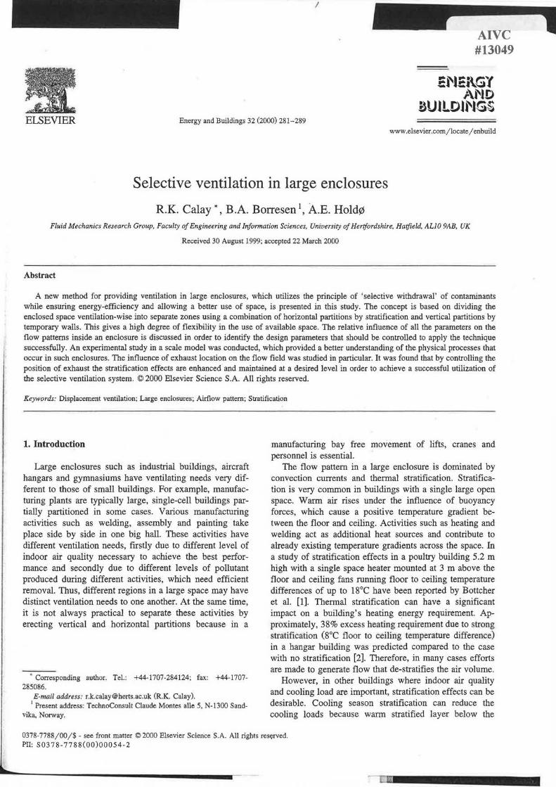
Fig. 1. Selective withdrawal of polluted air in a manufacturing unit [4].
ceiling acts as an insulating buffer, which reduces the roof and lighting heat gain components. An additional reduction in cooling load is achieved by locating the extract at the height of stratification because heat extracted per unit of mass flow would be significantly higher than if the extract was positioned below the stratified layer. Designers of industrial air-conditioning systems have taken advantage of thermal stratification to achieve significant savings by cooling only the lower occupied zones in buildings with
Air
<==Q) Welding I
high ceiling. Stratification may also be beneficial to keep the working zone clean of pollutants. Therefore, stratification effects that occur under normal conditions in large enclosures can be used positively in improving the ventilation of the space. The pollutants are confined inside a limited height range at a certain height above the floor level in the stratified layers. These trapped pollutants can be extracted selectively at that height. The spaces above and below this height remain clean because pollutants are entrained at source and are re-circulated only to small extent. These observations have led to the idea of utilising the principle of 'selective withdrawal' of pollutants in large enclosures [3,4]. The term 'selective withdrawal' is commonly used for the withdrawal of water from temperature-stratified reservoirs and estuaries. It is possible to withdraw the fluid selectively from a thin horizontal layer at the level of the intake without interfering with the fluid above or below this level due to the prevailing vertical density gradients. Fig. 1 shows a general representation of withdrawal of a polluted layer of air through selective ventilation. Open spaces are separated ventilation-wise thus providing better use of available space in terms of unrestricted movements of trucks, cranes and personnel. The ventilation rate provided can also be optimized to achieve maximum energy efficiency.
The principle of selective withdrawal has been applied in an aircraft maintenance hangar where the fuselage of an aircraft was painted. The ventilation air was supplied below the ceiling at 1°C-2°C higher temperature than the room air. The air was extracted at the floor level in front of the aircraft's nose. Measurement of solvent vapours and dust showed that no dust occurred outside the enclosure and the concentration of solvent vapours was more than an
Air extract shutoff
40m ~
/) Painting
CD Air
extract Air extract
shut off
80m
Clean zone
~
~ ) ~
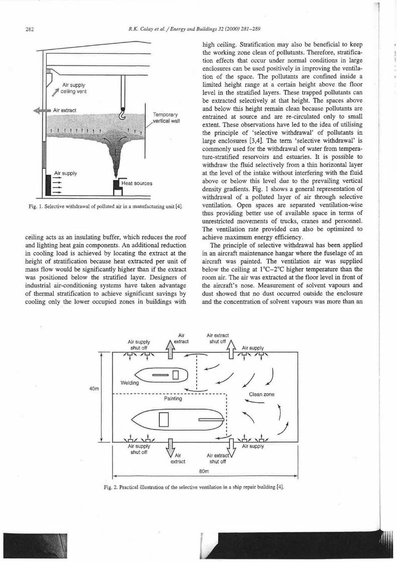
Fig. 2. Practical illustration of the selective ventilation in a ship repair building [ 4 ].
f j
.1
- .j I
R.K. Calay et al./ Energy and Buildings 32 (2000) 281-289 283
order of magnitude less than the hygienic limit. The principle was also applied to the ventilation of the ship repair building ( 40 X 80 X 40 m) of K vaerner Kimek in Kirkenes, Norway [4]. It was possible to divide the entire space into different zones by temporary vertical walls, which only needed to reach 3-4 m above the floor with no physical ceiling (Fig. 2). In the processes where contaminant emission and heat generation is not coupled, polluted air can be displaced across the space where it is extracted through designated extract openings from each zone. While different activities could go side by side unaffected by each other, the transport at floor level could also go on between different zones and the cranes could pass freely above the zones.
The concept has therefore proved to be successful in practice. However, to design a suitable system of selective supply and withdrawal for a certain building, it is necessary to understand the physical phenomena that lead to stratification of the flow. It is important to see how stratification can be enhanced and the stability maintained under the effect of various conditions that prevail in a real building. The flow pattern inside a building is influenced by many factors. The aim of this paper is to study the extent of thermal stratification under different conditions in order to provide an understanding of various factors that contribute to it. This requires the investigation of the effect of temperature, typical velocities and convective currents on the stratification of flow.
2. Theoretical background
In general, fluid flow in an enclosed space depends on fluid properties and geometric parameters of the domain which can be grouped together as non-dimensional numbers i.e. Prandtl number, Rayleigh number and Reynolds number. The momentum and temperature differential that exist across the space results into complex interaction between buoyancy driven and forced convection. Thus, even in a simple geometry, a variety of different flow structures often involving transition from laminar to turbulent may occur. A large scientific effort has been devoted to study the various aspects of flow in enclosures since very early in the century. It includes ciassical studies of natural convection in a layer heated from below by Benard (5) and Rayleigh (6), investigation of wall jets and inlets [7] and measurements of heat transfer coefficients in enclosures (8,9]. Many studies were devoted to the analysis of the stability and behaviour of fluid layers of infinite horizontal extent. The fluid mechanics of buoyancy driven flow within naturally ventilated spaces have been studied largely with the presence of heat source (10,11) and due to the difference in buoyancy of interior and exterior fluid (12]. It was found that the steady states or stable stratification develops within the space containing constant buoyancy and openings to the exterior.
3. Stratified flow in enclosures
The stratification in buildings is similar to the more familiar one observed in the atmosphere and in lakes and its influence on flow in these systems is frequently studied. Many of the reported laboratory experiments on stratification were performed to study special effects of stratification. However, there still is a need for fundamental experimental data for use in general studies of stratification.
One of the basic properties of the stratified flow is its ability to maintain internal waves. Vertical motions that tend to carry heavy fluid upwards and light fluid downward are thus inhibited. Fluid layers at different heights move back and forth horizontally apparently independent of each other and with little or no vertical mixing between the layers. The stability of the layers is characterised by a collapse in turbulence and low vertical mass transfer. Different stability criteria are used to characterise the stratified layers but following are the most commonly used:
(a) Kelvin-Helmholtz instability (b) Disturbance Froude number (c) Keulegan number
4. Kelvin-Helmholtz instability
This instability begins to develop between the upwards moving warmer fluid and the ambient medium. When the temperature difference between the fluid and the ambient is increased, flow is convected upward faster and, as a result, the shear between the convected flow and the medium is increased, leading to a stronger Kelvin-Helmholtz shearing instability. The situation is similar to that of a jet. The wavelength of the instability is of the order of 2 'TT r, where r is the distance over which the change of velocity in the outer envelope of the jet occurs or where the velocity across the jet changes from maximum velocity to that of the ambient velocity. The instability can lead to the formation of spiral-like patterns (Benard cells) and eventually turbulence.
The strength of stratification can be quantified by comparing the buoyancy forces to the inertial forces acting in the flow i.e. the local gradient Richardson number:
ap -g-
Ri= ily
p( :: r (1)
The minus sign here is due to the directional density variation. Negative Ri correspond to a destabilizing density gradient where both shear and buoyancy give rise to
284 R.K. Ca/ay et al./ Energy and Buildings 32 (2000) 281-289
turbulence i.e. when density increases upwards the buoyancy provides additional source of turbulence.
When density variations are due to temperature variations, Ri can be expressed in terms of temperature gradient:
(la)
Ri is zero for non-stratified flow and increases with the strength of the stratification. Laminar layers of stratified fluid are stable with respect to small perturbations when Ri number becomes large.
However, turbulence may still exist in the stratification situation due to the local instabilities caused by concentrated vortical motion. Based on overall Ri number, a turbulent shear layer is expected to laminarise if:
1 4 <Ri ~ 1 (2)
The overturning of fluid on an interface leads to destabilization of the interface.
5. Disturbance Froude number
In a stably stratified fluid, a displaced fluid particle tends to return to its original level. This means that the internal waves can be generated in an expanse of fluid that is otherwise at rest. A fluid particle displaced vertically due to buoyancy oscillates about its original position with an angular velocity N:
( a ) i12
N= -; a: (3)
N is called the Brunt-Vais ala frequency, the buoyancy frequency or the frequency of gravity waves in stable environment [13). The stability of layers is connected to a local disturbance Froude number, which is written as the ratio of inertial to coriolis forces:
u p. =-
dtst LN (4)
Hopfinger [13] found out that turbulence will start to collapse when Fdist - 1. When Fctist decreases to about 0.2-0.3, the turbulence can no longer be sustained and the layers will start to stratify.
6. Keulegan number
For flows at very low Reynolds number, the stability can be described by the Keulegan number [14];
u3 K=
vg' (5)
The Keulegan number can be thought of as a Ri-number condition based on viscous length scale l = (vx/u)0
·5
and with a weak dependence on the Re-number.
1 K= -ffe
Ri
7. Flow in enclosures
(6)
In order to utilise the stratification effects in space ventilation, it is important to predict and understand the nature of flow that occurs in large room. In a high ceiling, single-cell building, natural thennal stratified layers build up. In addition to this, different sources may produce a multi-layered stratification with each plume teo:n:inating in a given layer. Buoyant fluid accumulates at the top and flows out through upper level openings and ambient air flows in at low levels to generate upward displacement ventilation. Initial momentum and buoyancy of the supply flow determine the fonnation of stratified layers and how they are disturbed, shifted or maintained by employing local or global concepts of forced ventilation. As a volume of fluid enters into the building, it starts mixing with fluid that is already there. Convective currents due to air infiltration and temperature differences that exist across the space dominate the flow. In most cases, the initial buoyancy effects start to decrease as fluid spreads in the direction away from the inlet. The machines and activities, such as welding, act as additional heat sources. The flow above a heat ource resembles a plume that rises to the ceiling (Fig. 1).
A large number of studies have been made to study the plume rise in the built environment and empirical relationships to determine the local flow characteri tics of plume from a single or multiple sources are available [10-12,15). The relative magnitude of the buoyancy and viscous forces govern the flow of a rising plume in the stratified surroundings . Characteristics of such flow can be investigated employing the Taylor's assumption i.e. the entrainment velocity is assumed to be proportional to the characteristic velocity in the plume. As the plume rises, it entrains the flow from the surroundings, which has a cooling effect on the plume. At a certain height, a point of neutral buoyancy is reached where the density or temperature difference between the plume and surroundings is zero. At this level, the plume begins to spread sideways after reaching its maximum height. The interface develops where the entrained flow volume of the plume is equal to the supplied air volume flow. Thus, a measurement of height of the interface for various volume flow at the source provides the data for the relationship of the plume volume flow and the height from the source. Baines and Turner [16) showed
that by;
Q3/
Fdl
whe
Qo~ I
z(Q
ops cal1
(N Eq
Q,
pl1 cc
ill si Cl
b s n Id t
R.K. Calay et al./ Energy and Buildings 32 (2000) 281-289 285
that for a constant entrainment coefficient a, Q is given by;
Q 3/5 ( 6 )4/5 __ = 31;s -a 7T'2;sz FJ l5 5
(7)
where F0 is buoyancy flux at the source given by F0 =
Qog'. For the flow volume Q0 at the source, the flow at any
z(Q,) can be expressed by simplifying Eq. (7):
(8)
The height from the source where this interface develops will be where Q, becomes equal to Q0 , which can be calculated
= [ 0.016Q5 ]'15
Zmax g'a4 (9)
(Note: a represents entrainment coefficient of a plume in Eqs. 7-9 and its value is obtained experimentally.)
Another commonly used correlation for Qi is based on the convective heat of the source [17):
Q, = o.oos1p 113z513 (9)
Jin [18) found a relationship for the height to which a plume will rise in stratified surroundings in terms of the convective heat source and the temperature gradient:
z =6P'l4 -(dT)-3 /s
max dz (10)
These relationships are commonly used both in heavy industry ventilation design and for smoke ventilation design in fire modelling. The ventilation flow in buildings is complex due to pressure as well as temperature differences between the interior and the ambient outside conditions. Several constant heat sources may exist in terms of equipment, lights and occupants where buoyant plumes develop. However, the ventilation flows in buildings can be broadly divided into two main categories, namely, mixing ventilation and displacement ventilation. In mixing ventilation, the incoming ambient fluid fully mixes with the fluid within the space as is the case when air at a lower temperature and/or with high momentum is supplied through a high level inlet. The vertical stratification is weak in this case. In displacement ventilation, cool air is supplied at low level, which displaces the warm (lighter) fluid within the space out through the high level openings. Strong stably stratified layers form and, as a result, there is very little mixing between the interior fluid and the supplied fluid. In reality, the ventilation systems in buildings produce flows that are intermediate between these two. Because the cold draughts down along, the outside walls highly reduce the layering effects. The radiative heat transfer between the surfaces redistribute the heat from the warm upper parts of the room down to the lower parts and
thus has strong influence on the strength of stratified layers. An increase in radiative heat transfer results in reducing the temperature differential across the layers and the strength of stratification.
8. Principle of selective ventilation
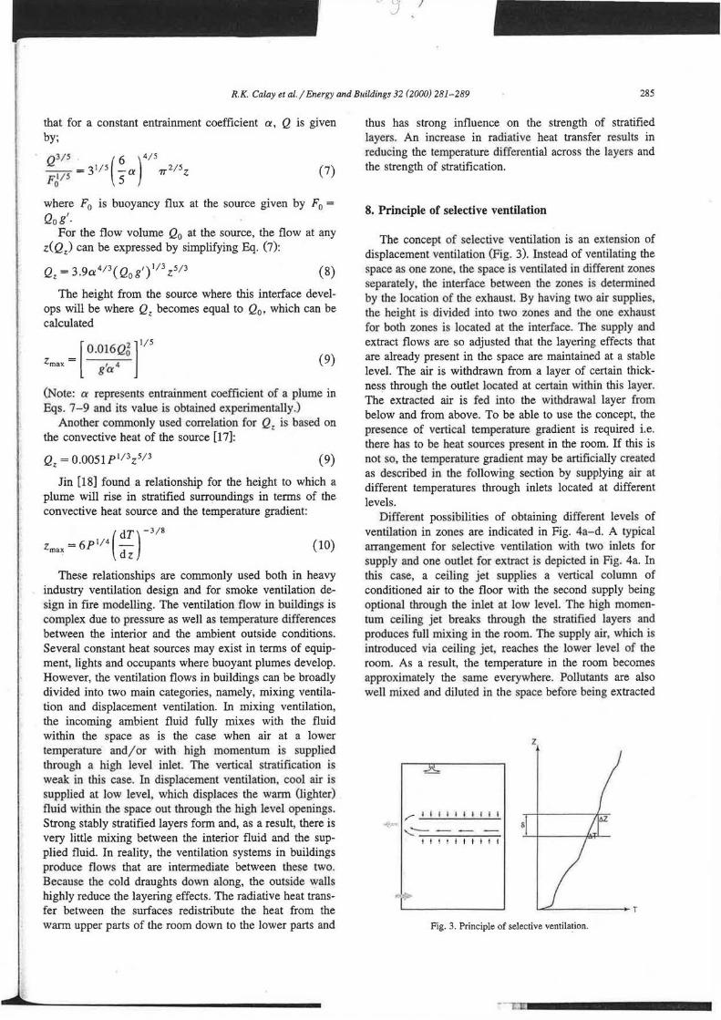
The concept of selective ventilation is an extension of displacement ventilation (Fig. 3). Instead of ventilating the space as one zone, the space is ventilated in different zones separately, the interface between the zones is detennined by the location of the exhaust. By having two air supplies, the height is divided into two zones and the one exhaust for both zones is located at the interface. The supply and extract flows are so adjusted that the layering effects that are already present in the space are maintained at a stable level. The air is withdrawn from a layer of certain thickness through the outlet located at certain within this layer. The extracted air is fed into the withdrawal layer from below and from above. To be able to use the concept, the presence of vertical temperature gradient is required i.e. there has to be heat sources present in the room. If this is not so, the temperature gradient may be artificially created as described in the following section by supplying air at different temperatures through inlets located at different levels.
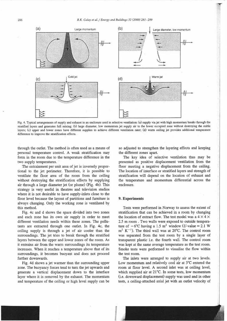
Different possibilities of obtaining different levels of ventilation in zones are indicated in Fig. 4a- d. A typical arrangement for selective ventilation with two inlets for supply and one outlet for extract is depicted in Fig. 4a. In this case, a ceiling jet supplies a vertical column of conditioned air to the floor with the second supply being optional through the inlet at low level. The high momentum ceiling jet breaks through the stratified layers and produces full mixing in the room. The supply air, which is introduced via ceiling jet, reaches the lower level of the room. As a result, the temperature in the room becomes approximately the same everywhere. Pollutants are also well mixed and diluted in the space before being extracted
z
t t t t I I t It t
Fig. 3. Principle of selective ventilation.
286 R.K. Calay et al./ Energy and Buildings 32 (2000) 281-289
(a) Large momentum (b) ~ Large diameter, low momentum _, ~
·? ~ .,,_
-~
j l - -(c) (d)
Warm jet
Fig. 4. Typical arrangements of supply and exhaust in an enclosure used in selective ventilation: (a) supply via jet with high momentum breaks through the stratified layers and generates full mixing; (b) large diameter, low momentum jet supply air to the lower occupied zone without destroying the stable layers; (c) upper and lower zones have different supplies to achieve different ventilation rater; (d) warm ceiling jet provides additional temperature difference to improve the stratification effects.
through the outlet. The method is often used as a means of personal temperature control. A weak stratification may form in the room due to the temperature difference in the two supply temperatures.
The entrainment per unit area of jet is inversely proportional to the jet perimeter. Therefore, it is possible to ventilate the floor area of the room from the ceiling without destroying the stratification effects by supplying air through a large diameter jet (or plume) (Fig. 4b). This strategy is very useful in theatres and television studios where it is not desirable to have supply-inlets close to the floor level because the layout of partitions and furniture is always changing. Only the working zone is ventilated by this method.
Fig. 4c and d shows the space divided into two zones and each zone has its own air supply in order to meet different ventilation needs within these zones. The pollutants are extracted through one outlet. In Fig. 4c, the ceiling supply is through a jet of air cooler than the surroundings. The jet tries to break through the stratified layers between the upper and lower zones of the room. As it entrains air from the warm surroundings its temperature increases. When it reaches a temperature above that of its surroundings, it becomes buoyant and does not proceed further downwards.
Fig. 4d shows a jet warmer than the surrounding upper zone. The buoyancy forces tend to tum the jet upwards and generate a vertical displacement down to the interface layer where it is removed by the exhaust. The momentum and temperature of the ceiling or high level supply can be
so adjusted to strengthen the layering effects and keeping the different zones apart.
The key idea of selective ventilation thus may be presented as positive displacement ventilation from the floor meeting a negative displacement from the ceiling. The location of interface or stratified layers and strength of stratification will depend on the location of exhaust and the temperature and momentum differential across the enclosure.
9. Experiments
Tests were performed in Norway to assess the extent of stratification that can be achieved in a room by changing the location of extract flow. The test model was a 4 X 4 X
2.5 m room . Two walls were exposed to outside temperature of -6°C having a 1.5 m2 window (U-value = 2.1 W m2 K- 1
). The third wall was at 20°C. The control room was separated from the test room by a single layer of transparent plastic i.e. the fourth wall. The control room was kept at the same average temperature as the test room. Smoke tests were performed to visualise the flow within the test room.
The inlets were arranged to supply air at two levels. Low momentum and relatively cool air at 3°C entered the room at floor level. A second inlet was at ceiling level, which supplied air at 21°C. In some tests, low momentum (i.e. downward displacement) supply was used and in other tests, a ceiling-attached axial jet with an outlet velocity of

I
R.K. Calay et al./ Energy and Buildings 32 (2000) 281-289 287
approximately 2 m s - 1 was used. The fl.ow rate at each supply was 0.0275 m3 s- 1
• The extract rate was 0.055 m3
s - 1 taken from the location in the wall at 1.45 m high. The vertical temperature measurements were made in the middle of the room away from the supply and exhaust locations using thermocouples.
10. Results and discussion
Only the vertical temperature profiles at a location away from the exhaust are presented here because the convection currents generated from the jets of cold and warm air supply locally affect the layers close to the floor and ceiling. The strong stratification effects over the total height are clearly evident in Fig. 5. The two temperature profiles correspond to different exhaust positions. There is a sharp stratification close to the floor in both cases up to 0.5. Above this height, the stratifying effects seem to be slightly reduced, which may be due to the increased level of convection. Still higher, the slope becomes sharper indicating stronger stratification effect. The position where slope changes is influenced by many parameters such as difference in supply momentum and temperature between the floor and ceiling supply and the position of the exhaust. Here, we limit our discussion to the effect of changing the vertical position of exhaust on the stratification effects. Repositioning the exhaust upward by 0.35 m clearly generates a similar shift in the temperature profile. Two profiles are quite close up to the height of 1 m but in the second case where the exhaust is located at higher position, stratification effects start at a higher point, which is approximately the same as the shift in the exhaust location. As we move towards the ceiling, the two profiles begin to come closer. Thus, by maintaining other parameters constant and only by repositioning the exhaust, different level of stratification effects in a room can be achieved. Separate air supplies combined with one or more exhausts generate a two-zone flow in each zone. Therefore, exhaust height location(s) significantly influence the thickness of
16 ---
14 u Ol Q) "O
ci. 12
E Q) I-
10
8 '~-·-I ··---------•·:;;---- -- ....
0 0.5 1.5 2 2.5
Height, m
Fig. 5. Vertical temperature profile in a stratified flow within the test room.
1.5----------------~
-lar ~ · O.-" 12
--a-- tor RI ~ o.a
~ 0,9
J OS
03
0.5 1.5 2.5
Heighl,m
Fig. 6. Allowable mean velocity variations based on Ri stability criterion for the exhaust location at 1.2 m.
each stratified zone. This confirms the importance of the exhaust location and the immediate effect it has on the stratification.
From practical point of view, it is important to know the optimum form of stratification for a certain specific situation and how to achieve it. More important is how to maintain these effects to ensure the performance of the ventilation system at all times. In real situations, stratification involves disturbances due to the general movement of machinery and personnel within the room and draught through openings. These movements will have typical velocities in the range of 0.3 to 1.0 m s - t. Due to the effects of infiltrating air and general movements in the room there is a horizontal mean flow. The mean flow velocity also varies vertically and this velocity gradient can lead to generation of turbulence in the usual way through the action of inertia forces, which tends to destabilise the stratification.
From the consideration of various stability criteria discussed in the previous section, the relative significance of inertia and buoyancy forces is made in terms of Ri (Richardson number). A positive Richardson number corresponds to stabilising density (temperature) gradient; turbulent motions cannot be sustained when Ri becomes large. Therefore, Ri stability criterion can be applied to obtain the allowable air movements i.e. the maximum variations in the velocity that can be sustained within the stable layers for a certain temperature gradient. Different researchers use different criterion for stability to exist. Based on Ri number stability criterion, a turbulent shear layer is expected to laminarise when Ri exceeds 0.25 everywhere in the flow. However, some researchers report that for fully stabilised flow, Ri should exceed 0.8.
The temperature profiles confirmed that strong stratification was achieved in the room. By applying the' Ri stability criterion, the velocity profile in the vertical direction is obtained (see Fig. 6). A range of velocity profile using the two limits, 0.25 and 0.8 for Ri number was calculated. Any variation between the two profiles can be interpreted that some turbulence may exist but flow will be
288 R.K. Calay et al. / Energy and Buildings 32 (2000) 281-289
1.5
1.2
~ 0.9 ~ ·5 0
0.6 a; >
0.3
0
0 0.5 . 1 Height, m
1.5 2.5
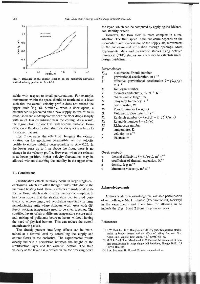
Fig. 7. Influence of the exhaust location on the maximum allowable vertical velocity profile for Ri = 0.25.
stable with respect to small perturbations. For example, movements within the space should be restricted to a level such that the overall velocity profile does not exceed the upper limit (Fig. 6). Similarly, when a door opens, a disturbance is generated and a new supply source of air is established and air-temperature near the floor drops sharply with much less disturbance near the ceiling. As a result, the region close to floor level will become unstable. However, once the door is shut stratification quickly returns to its normal pattern.
Fig. 7 compares the effect of changing the exhaust location on the maximum permissible vertical velocity profile to ensure stability corresponding to Ri = 0.25. In the lower zone up to 1 m above the floor, there is no change in the velocity profile. However, when the exhaust is at lower position, higher velocity fluctuations may be allowed without disturbing the stability in the upper zone.
11. Conclusions
Stratification effects naturally occur in large single-cell enclosures, which are often thought undesirable due to the increased heating load. Usually efforts are made to destratify the flow, which adds to extra energy consumption. It has been shown that the stratification can be used positively to achieve improved ventilation especially in large manufacturing units where different work areas with different working temperature need to be sited together. The stratified layers of air at different temperature ensure minimal mixing of pollutants between layers without having the need of physical barriers. This can reduce the overall _ manufacturing costs.
The already present stratifying effects can be maintained at a desired level by controlling the supply and extract flows in the enclosure. The experimental results clearly indicate a correlation between the height of the stratification layer and the exhaust location. The fluid velocity at the layer has a critical value for breaking down
the layer, which can be computed by applying the Richardson stability criteria.
However, the flow field is more complex in a real situation. The fluid speed in the enclosure depends on the momentum and temperature of the supply air, movements in the enclosure and infiltration through openings. More experimental data and parametric studies using detailed numerical (CFD) studies are necessary to establish useful design guidelines.
Nomenclature Fdist disturbance Froude number g gravitational acceleration, m s- 2
g' effective gravitational acceleration ( = g Ll p / p ), m s- 2
K Keulegan number k thennal conductivity, W m- 1 K- 1
L characteristic length, m N buoyancy frequency, s - 1
P heat transfer, W Pr Prandtl number ( = a/ v) Q Volumetric flow rate, m3 s- 1
Ra Rayleigh number ( = (g {3(T- T. )L3)/ a v)
Re Reynolds number ( = uL / v) Ri Richardson number T temperature, K u velocity, m s- 1
z distance, m
Greek symbols a thermal diffusivity ( = k/ pep), m2 s- 1
13 coefficient of thermal expansion, K - 1
p density, k g m - 3
v kinematic viscosity, m 2 s - 1
Acknowledgements
Authors wish to acknowledge the valuable participation of our colleague Mr. H. Skistad (TechnoConsult, Norway) in the experiments and thank him for allowing us to include the Figs. 1 and 2 from his previous work.
References
[l] R.W. Bottcher, G.R. Baughman, G.R Driggers, Temperature stratification in broiler houses and the effect of ceiling fan, Am. Soc. Agric. Eng., Applic. Eng. Agric. 4 (1) (1988) 66-71.
[2] M.N.A. Said, R.A. Macdonald, G.C. Durrant, Measurement of thermal stratification in large single cell buildings, Energy Build. 24 (1996) 105-115.
[3] B.A. Borresen, H. Skistad, Private communication.
f' '"'' !'"' , , • I! 'I • ! , .. i1:111ii11ti
0
·111 l1n1r.
0 / J
R.K. Calay et al./ Energy and Buildings 32 (2000) 281-289 289
[4] H. Skistad, Utilizing selective withdrawal in the ventilation of large rooms: select-vent, Room Vent Conference, Stockholm, June.' 1998.
[5] H. Benard, Les tourbillons cellulaires dans une nappe liquide, Rev. Gen. Sci. Pures Appl., 11 (1990) 1261-1271, 1309-1328.
[6) L. Rayleigh, On convective currents in a horizontal layer of fluid when the higher temperature is on the underside., Philos. Mag. 32 (1916) 546- 549.
[7] G.P. Hammond, Complete velocity profile and optimum skin friction fonnuJas for the plane wall jet, J. Fluid Eng. 104 (1982) 59-66.
[8] R.K. Calay, A.E. Hold!!), G.P. Hammond, Natural convective heat transfer rates in rectangular enclosures, Energy Build. 27 (1998) 137-146.
[9] F. Bauman, A. Gadgil, R. Kammerud, R. Grief, Buoyancy driven convection in rectangular enclosures: experimental results and numerical calculations, Proceedings of the 9th National Heat Transfer Conference, ASME, Paper 80-HT-66, Orlando, FL, 1980.
[10] B.R. Morton, G.I. Taylor, J.S. Turner, Turbulent gravitational convection from maintained and instantaneous sources, Proc. R. Soc. London, Ser. A 234 (1956) 1-23.
[11] J.F. Linden, P. Cooper, Multiple sources of buoyancy in a naturally ventilated enclosures, J. Fluid Mech. 311 (1996) 177-192.
(12] J.F. Linden, G.F. Lane-Serf, D.A. Smeed, Emptying filling boxes: the fluid mechanics of natural ventilation, J. Fluid Mech. 212 (1990) 330-335.
(13] E.J. Hopfinger, Turbulence in stratified fluids: a review, J. Geophys. Res. 92 (C5) (1987) 5287-5303.
[14] D.J. Tritton, Physical Fluid Dynamics, Van Nostrand-Reinhold, New York.
(15] J.S. Turner, Buoyancy Effects in Fluids, Cambridge Univ. Press, Cambridge, UK, 1979.
[16] W.D. Baines, J.S . Turner, Turbulent buoyant convection from a source in a confined region, J. Fluid Mech. 37 (1969) 51-80.
[17] V.V. Baturin, Fundamentals of Industrial Ventilation, Pergamon, Oxford, UK, 1960.
(18] Y. Jin, Particle Transport in Turbulent Buoyant Plumes Rising in a Stratified Environment, Arbete och Helsa, 1993, p. 23, ISBN 91-7-45-228-8.