automation - 2019 / 2020-industrial communication technology
TRANSCRIPT
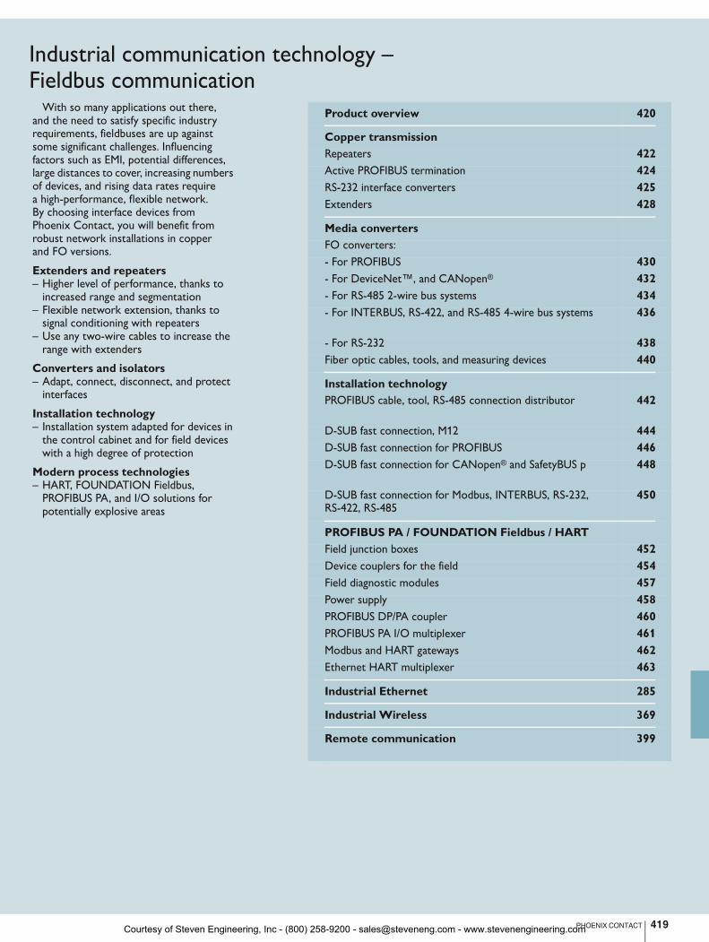
Product overview 420
Copper transmission
Repeaters 422 Active PROFIBUS termination 424 RS-232 interface converters 425 Extenders 428
Media converters
FO converters: - For PROFIBUS 430 - For DeviceNet™, and CANopen® 432 - For RS-485 2-wire bus systems 434 - For INTERBUS, RS-422, and RS-485 4-wire bus systems 436
- For RS-232 438 Fiber optic cables, tools, and measuring devices 440
Installation technology
PROFIBUS cable, tool, RS-485 connection distributor 442
D-SUB fast connection, M12 444 D-SUB fast connection for PROFIBUS 446 D-SUB fast connection for CANopen® and SafetyBUS p 448
D-SUB fast connection for Modbus, INTERBUS, RS-232, RS-422, RS-485
450
PROFIBUS PA / FOUNDATION Fieldbus / HART
Field junction boxes 452 Device couplers for the field 454 Field diagnostic modules 457 Power supply 458 PROFIBUS DP/PA coupler 460 PROFIBUS PA I/O multiplexer 461 Modbus and HART gateways 462 Ethernet HART multiplexer 463
Industrial Ethernet 285
Industrial Wireless 369
Remote communication 399
419PHOENIX CONTACT
With so many applications out there, and the need to satisfy specific industry requirements, fieldbuses are up against some significant challenges. Influencing factors such as EMI, potential differences, large distances to cover, increasing numbers of devices, and rising data rates require a high-performance, flexible network. By choosing interface devices from Phoenix Contact, you will benefit from robust network installations in copper and FO versions.
Extenders and repeaters– Higher level of performance, thanks to
increased range and segmentation– Flexible network extension, thanks to
signal conditioning with repeaters– Use any two-wire cables to increase the
range with extenders
Converters and isolators– Adapt, connect, disconnect, and protect
interfaces
Installation technology– Installation system adapted for devices in
the control cabinet and for field devices with a high degree of protection
Modern process technologies– HART, FOUNDATION Fieldbus,
PROFIBUS PA, and I/O solutions for potentially explosive areas
Industrial communication technology – Fieldbus communication
Courtesy of Steven Engineering, Inc - (800) 258-9200 - [email protected] - www.stevenengineering.com
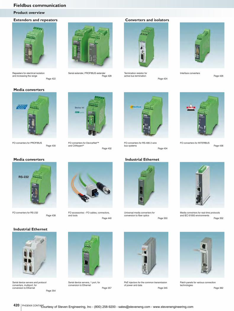
Extenders and repeaters Converters and isolators Installation technology
Repeaters for electrical isolation
and increasing the range
Page 422
Serial extender, PROFIBUS extender
Page 428
Termination resistor for
active bus termination
Page 424
Interface converters
Page 426
Media converters
FO converters for PROFIBUS
Page 430
FO converters for DeviceNet™
and CANopen®
Page 432
FO converters for RS-485 2-wire
bus systems
Page 434
FO converters for INTERBUS
Page 436
Media converters Industrial Ethernet PROFIBUS PA / FOUNDATION Fieldbus HART
FO converters for RS-232
Page 438
FO accessories – FO cables, connectors,
and tools
Page 440
Universal media converters for
conversion to fiber optics
Page 350
Media converters for real-time protocols
and IEC 61850 environments
Page 352
Industrial Ethernet
Serial device servers and protocol
converters, multiport, for
conversion to Ethernet
Page 354
Serial device servers, 1 port, for
conversion to Ethernet
Page 357
PoE injectors for the common transmission
of power and data
Page 345
Patch panels for various connection
technologies
Page 362
420 PHOENIX CONTACT
Fieldbus communicationProduct overview
Courtesy of Steven Engineering, Inc - (800) 258-9200 - [email protected] - www.stevenengineering.com
For further information and full technical data, visit phoenixcontact.net/products
Extenders and repeaters Converters and isolators Installation technology
Type A Fast Connect PROFIBUS cable
and quick stripping tool
Page 442
M12 D-SUB fast connection for
PROFIBUS and CANopen®
Page 444
D-SUB fast connection for
PROFIBUS and CANopen®
Page 446
D-SUB fast connection for Modbus,
INTERBUS, RS-232, RS-422, RS-485
Page 450
PROFIBUS PA / FOUNDATION Fieldbus
Field connection boxes in stainless steel
Page 453
Device couplers for the field
Page 454
Device couplers for the field,
Ex zone 1 and 2
Page 456
Field diagnostic modules for
FOUNDATION Fieldbus
Page 457
Media converters Industrial Ethernet PROFIBUS PA / FOUNDATION Fieldbus HART
PROFIBUS PA I/O multiplexer
Page 461
Modbus gateways for PROFIBUS DP/PA
and FOUNDATION Fieldbus
Page 462
HART gateways for PROFIBUS DP/PA
and FOUNDATION Fieldbus
Page 462
Ethernet HART multiplexer
Page 463
Industrial Wireless Remote communication
Radioline wireless modules, WirelessHART,
and accessories
Page 369
Wireless multiplexer with antennas
Page 386
WirelessHART, gateway and adapter
Page 384
Alerts, remote maintenance,
and remote control
Page 399
421PHOENIX CONTACT
Fieldbus communicationProduct overview
Courtesy of Steven Engineering, Inc - (800) 258-9200 - [email protected] - www.stevenengineering.com
Ex:
422 PHOENIX CONTACT
H
WD
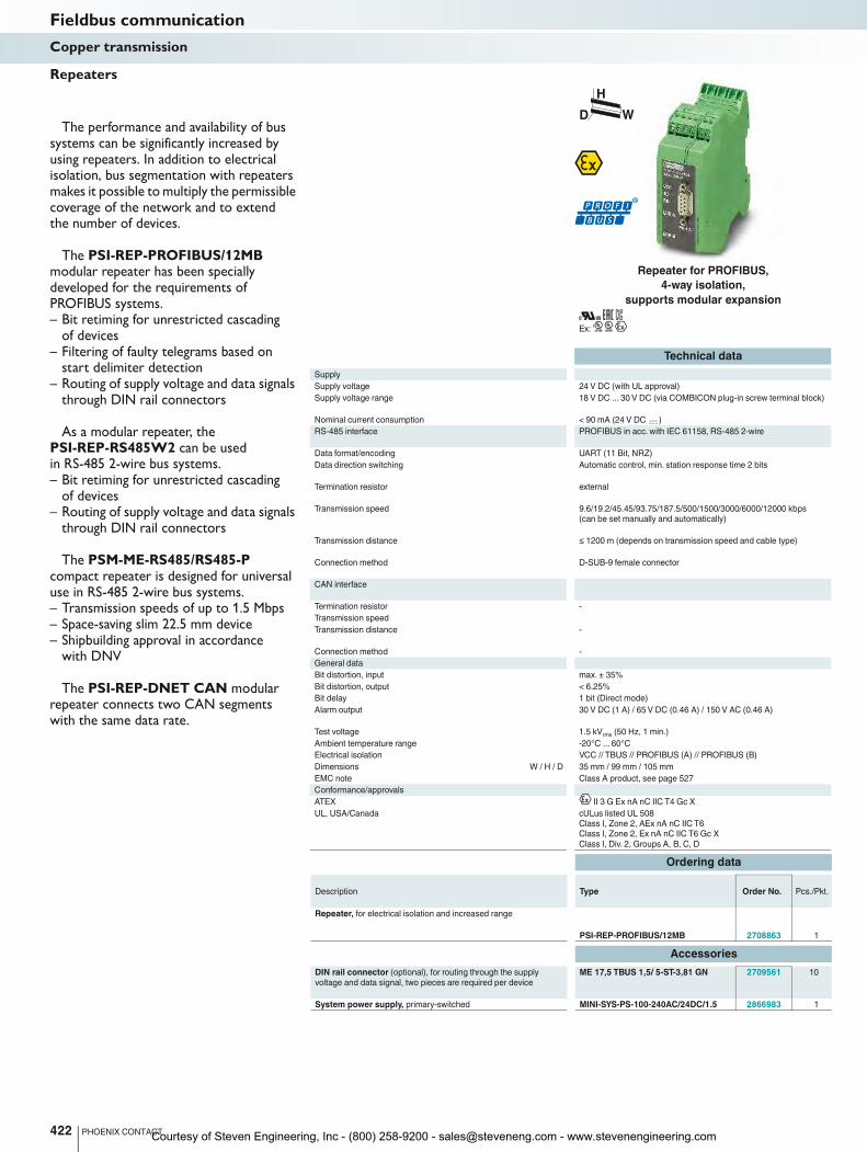
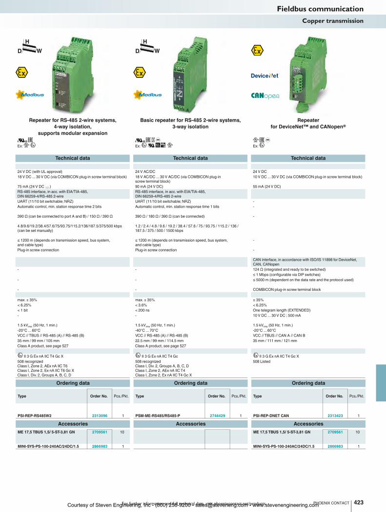
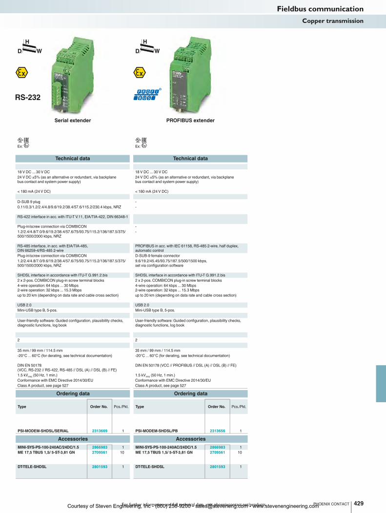
Repeaters
The performance and availability of bus systems can be significantly increased by using repeaters. In addition to electrical isolation, bus segmentation with repeaters makes it possible to multiply the permissible coverage of the network and to extend the number of devices.
The PSI-REP-PROFIBUS/12MB modular repeater has been specially developed for the requirements of PROFIBUS systems.– Bit retiming for unrestricted cascading
of devices– Filtering of faulty telegrams based on
start delimiter detection– Routing of supply voltage and data signals
through DIN rail connectors
As a modular repeater, the PSI-REP-RS485W2 can be used in RS-485 2-wire bus systems.– Bit retiming for unrestricted cascading
of devices– Routing of supply voltage and data signals
through DIN rail connectors
The PSM-ME-RS485/RS485-P compact repeater is designed for universal use in RS-485 2-wire bus systems.– Transmission speeds of up to 1.5 Mbps– Space-saving slim 22.5 mm device– Shipbuilding approval in accordance
with DNV
The PSI-REP-DNET CAN modular repeater connects two CAN segments with the same data rate.
Technical data
Supply
Supply voltage 24 V DC (with UL approval) 24 V DC (with UL approval) 24 V AC/DC 24 V DC
Supply voltage range 18 V DC ... 30 V DC (via COMBICON plug-in screw terminal block) 18 V DC ... 30 V DC (via COMBICON plug-in sc
Nominal current consumption < 90 mA (24 V DC ) 75 mA (24 V DC
RS-485 interface PROFIBUS in acc. with IEC 61158, RS-485 2-wire
Data format/encoding UART (11 Bit, NRZ)
Data direction switching Automatic control, min. station response time 2 bits Automatic control, min. station response time 2 bit
Termination resistor external
Transmission speed 9.6/19.2/45.45/93.75/187.5/500/1500/3000/6000/12000 kbps
(can be set manually and automatically)
Transmission distance ≤ 1200 m (depends on transmission speed and cable type)
Connection method D-SUB-9 female connector Plug-in screw connection Plug-in screw connection -
CAN interface
Termination resistor -
Transmission speed
Transmission distance -
Connection method -
General data
Bit distortion, input max. ± 35%
Bit distortion, output < 6.25%
Bit delay 1 bit (Direct mode)
Alarm output 30 V DC (1 A) / 65 V DC (0.46 A) / 150 V AC (0.46 A) - - 10 V DC ... 30 V DC ; 500 mA
Test voltage 1.5 kVrms
(50 Hz, 1 min.) 1.5 kV
Ambient temperature range -20°C ... 60°C
Electrical isolation VCC // TBUS // PROFIBUS (A) // PROFIBUS (B) VCC // TBUS // RS-485 (A) // RS-485 (B) VCC // RS-485 (A) // RS-4
Dimensions W / H / D 35 mm / 99 mm / 105 mm 35 mm / 99 mm / 105 mm 22.5 mm / 99 mm / 114.5 mm 35 mm / 111 mm / 121 mm
EMC note Class A product, see page 527 Class A product, see page 527 Class A product, see page 527
Conformance/approvals
ATEX II 3 G Ex nA nC IIC T4 Gc X
UL, USA/Canada cULus listed UL 508
Class I, Zone 2, AEx nA nC IIC T6
Class I, Zone 2, Ex nA nC IIC T6 Gc X
Class I, Div. 2, Groups A, B, C, D
Ordering data
Description Type Order No. Pcs./Pkt.
Repeater, for electrical isolation and increased range
PSI-REP-PROFIBUS/12MB 2708863 1
Accessories
DIN rail connector (optional), for routing through the supply
voltage and data signal, two pieces are required per device
ME 17,5 TBUS 1,5/ 5-ST-3,81 GN 2709561 10
System power supply, primary-switched MINI-SYS-PS-100-240AC/24DC/1.5 2866983 1
Fieldbus communicationCopper transmission
Repeater for PROFIBUS,
4-way isolation,
supports modular expansion
Courtesy of Steven Engineering, Inc - (800) 258-9200 - [email protected] - www.stevenengineering.com
For further information and full technical data, visit phoenixcontact.net/products
Ex:
Ex:
Ex:
423PHOENIX CONTACT
H
WD
H
WD
Technical data Technical data Technical data
Supply voltage 24 V DC (with UL approval) 24 V DC (with UL approval) 24 V AC/DC 24 V DC
Supply voltage range 18 V DC ... 30 V DC (via COMBICON plug-in screw terminal block) 18 V DC ... 30 V DC (via COMBICON plug-in screw terminal block) 18 V AC/DC ... 30 V AC/DC (via COMBICON plug-in
screw terminal block)
10 V DC ... 30 V DC (via COMBICON plug-in screw terminal block)
) 75 mA (24 V DC ) 90 mA (24 V DC) 55 mA (24 V DC)
RS-485 interface, in acc. with EIA/TIA-485,
DIN 66259-4/RS-485 2-wire
RS-485 interface, in acc. with EIA/TIA-485,
DIN 66259-4/RS-485 2-wire
UART (11/10 bit switchable; NRZ) UART (11/10 bit switchable; NRZ) -
Data direction switching Automatic control, min. station response time 2 bits Automatic control, min. station response time 2 bits Automatic control, min. station response time 1 bits -
390 Ω (can be connected to port A and B) / 150 Ω / 390 Ω 390 Ω / 180 Ω / 390 Ω (can be connected) -
4.8/9.6/19.2/38.4/57.6/75/93.75/115.2/136/187.5/375/500 kbps
(can be set manually)
1.2 / 2.4 / 4.8 / 9.6 / 19.2 / 38.4 / 57.6 / 75 / 93.75 / 115.2 / 136 /
187.5 / 375 / 500 / 1500 kbps
≤ 1200 m (depends on transmission speed, bus system,
and cable type)
≤ 1200 m (depends on transmission speed, bus system,
and cable type)
-
Connection method D-SUB-9 female connector Plug-in screw connection Plug-in screw connection -
CAN interface, in accordance with ISO/IS 11898 for DeviceNet,
CAN, CANopen
- - 124 Ω (integrated and ready to be switched)
≤ 1 Mbps (configurable via DIP switches)
- - ≤ 5000 m (dependent on the data rate and the protocol used)
- - COMBICON plug-in screw terminal block
max. ± 35% max. ± 35% ± 35%
< 6.25% < 3.6% < 6.25%
< 1 bit < 200 ns One telegram length (EXTENDED)
A) - - 10 V DC ... 30 V DC ; 500 mA
(50 Hz, 1 min.) 1.5 kVrms
(50 Hz, 1 min.) 1.5 kVrms
(50 Hz, 1 min.) 1.5 kVrms
(50 Hz, 1 min.)
-20°C ... 60°C -40°C ... 70°C -20°C ... 60°C
) VCC // TBUS // RS-485 (A) // RS-485 (B) VCC // RS-485 (A) // RS-485 (B) VCC // TBUS // CAN A // CAN B
Dimensions W / H / D 35 mm / 99 mm / 105 mm 35 mm / 99 mm / 105 mm 22.5 mm / 99 mm / 114.5 mm 35 mm / 111 mm / 121 mm
EMC note Class A product, see page 527 Class A product, see page 527 Class A product, see page 527
II 3 G Ex nA IIC T4 Gc X II 3 G Ex nA IIC T4 Gc II 3 G Ex nA IIC T4 Gc X
508 recognized
Class I, Zone 2, AEx nA IIC T6
Class I, Zone 2, Ex nA IIC T6 Gc X
Class I, Div. 2, Groups A, B, C, D
508 recognized
Class I, Div. 2, Groups A, B, C, D
Class I, Zone 2, AEx nA IIC T4
Class I, Zone 2, Ex nA IIC T4 Gc X
508 Listed
Ordering data Ordering data Ordering data
Type Order No. Pcs./Pkt. Type Order No. Pcs./Pkt. Type Order No. Pcs./Pkt.
PSI-REP-RS485W2 2313096 1 PSM-ME-RS485/RS485-P 2744429 1 PSI-REP-DNET CAN 2313423 1
Accessories Accessories Accessories
ME 17,5 TBUS 1,5/ 5-ST-3,81 GN 2709561 10 ME 17,5 TBUS 1,5/ 5-ST-3,81 GN 2709561 10
MINI-SYS-PS-100-240AC/24DC/1.5 2866983 1 MINI-SYS-PS-100-240AC/24DC/1.5 2866983 1
Fieldbus communicationCopper transmission
Repeater for RS-485 2-wire systems,
4-way isolation,
supports modular expansion
Basic repeater for RS-485 2-wire systems,
3-way isolation
Repeater
for DeviceNet™ and CANopen®
Courtesy of Steven Engineering, Inc - (800) 258-9200 - [email protected] - www.stevenengineering.com
Ex:
Technical data
Supply
Supply voltage 24 V DC (via COMBICON plug-in screw terminal block)
Supply voltage range 18 V DC ... 30 V DC (via COMBICON plug-in screw terminal block)
Nominal current consumption 10 mA (24 V DC, no load on D-SUB)
RS-485 interface PROFIBUS in acc. with IEC 61158, RS-485 2-wire
Termination resistor 390 Ω / 220 Ω / 390 Ω (can be connected)
Transmission speed ≤ 12 Mbps
Transmission distance ≤ 1200 m (depends on transmission speed and cable type)
Connection method D-SUB 9, COMBICON
General data
Test voltage 1.5 kV AC (50 Hz, 1 min.)
Ambient temperature range -40°C ... 70°C
Housing material PA 6.6-FR
Electrical isolation DIN EN 50178 (RS-485 // VCC)
Dimensions W / H / D 22.5 mm / 92 mm / 73 mm
EMC note Class A product, see page 527
Conformance/approvals
UL, USA/Canada 508 Listed
Ordering data
Description Type Order No. Pcs./Pkt.
Active termination resistor, bus termination can be activated,
programming interface
PSI-TERMINATOR-PB-TBUS 2702636 1
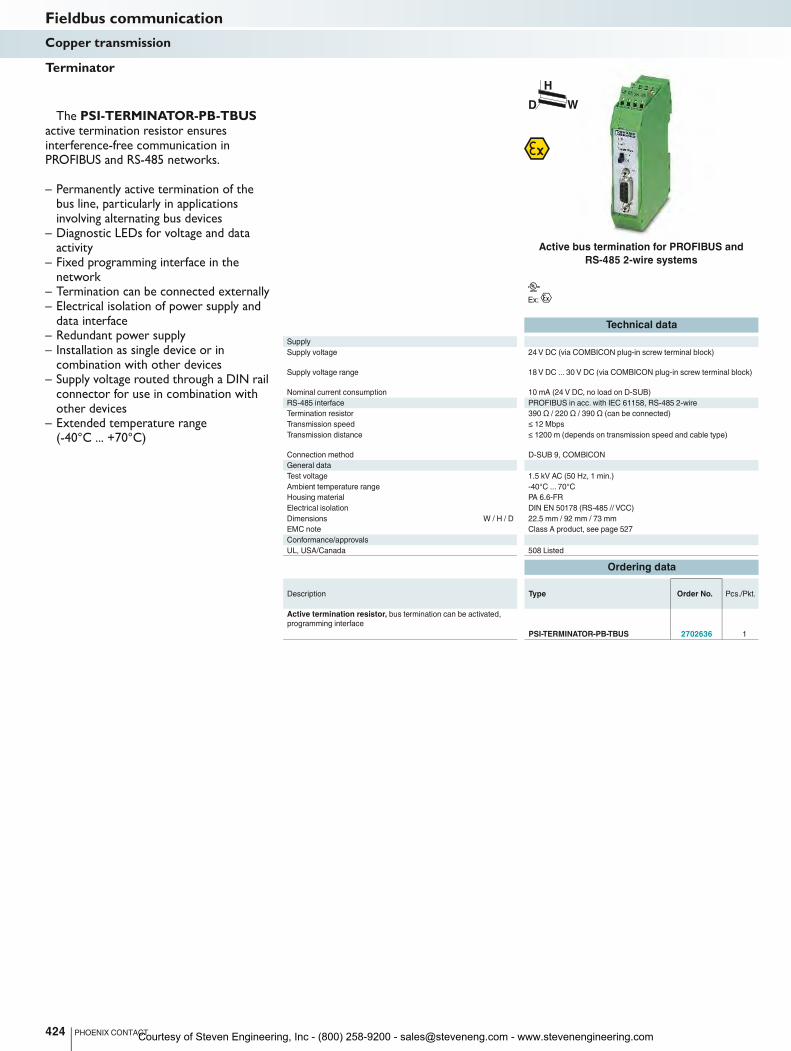
424 PHOENIX CONTACT
The PSI-TERMINATOR-PB-TBUS active termination resistor ensures interference-free communication in PROFIBUS and RS-485 networks.
– Permanently active termination of the bus line, particularly in applications involving alternating bus devices
– Diagnostic LEDs for voltage and data activity
– Fixed programming interface in the network
– Termination can be connected externally– Electrical isolation of power supply and
data interface– Redundant power supply– Installation as single device or in
combination with other devices– Supply voltage routed through a DIN rail
connector for use in combination with other devices
– Extended temperature range (-40°C ... +70°C)
Terminator
Fieldbus communicationCopper transmission
H
WD
Active bus termination for PROFIBUS and
RS-485 2-wire systems
Courtesy of Steven Engineering, Inc - (800) 258-9200 - [email protected] - www.stevenengineering.com
For further information and full technical data, visit phoenixcontact.net/products
Ex:
Technical data
PSM-ME-RS232/RS485-P PSM-EG-RS232/RS422-P/4K
Supply
Supply voltage range 18 V AC/DC ... 30 V AC/DC
(via COMBICON plug-in
screw terminal block)
19.2 V DC ... 28.8 V DC
Nominal current consumption 85 mA (24 V DC) 130 mA (24 V DC)
RS-232 interface RS-232 interface in acc. with ITU-T V.28, EIA/TIA-232, DIN 66259-1
Transmission speed 1.2; 2.4; 4.8; 7.2; 9.6; 19.2;
31.25; 38.4; 57.6; 75; 93.75;
115.2 kbps
64 kbps
Connection method D-SUB 9 plug D-SUB 9 plug
RS-422 interface RS-422 interface in acc. with ITU-T V.11, EIA/TIA-422, DIN 66348-1
Termination resistor 390 Ω / 150 Ω / 390 Ω
(can be connected)
510 Ω / 150 Ω / 510 Ω
(can be connected)
Transmission speed 1.2; 2.4; 4.8; 9.6; 19.2; 38.4;
57.6; 75; 93.75; 115.2 kbps
64 kbps
Transmission distance 1200 m (shielded twisted pair) 1200 m (twisted pair)
Connection method Plug-in screw connection D-SUB-15 male connector
RS-485 interface RS-485 interface in acc. with EIA/TIA-485, DIN 66259-1
Data direction switching Automatic control or
via RTS/CTS
Termination resistor 390 Ω / 150 Ω / 390 Ω
(can be connected)
Transmission speed 1.2; 2.4; 4.8; 9.6; 19.2; 38.4;
57.6; 75; 93.75; 115.2 kbps
Transmission distance 1200 m (shielded twisted pair)
Connection method Plug-in screw connection
General data
Bit delay ≤ 2.5 µs ≤ 3 µs
Test voltage 1.5 kV AC 2.5 kV
Ambient temperature range -40°C ... 70°C 0°C ... 50°C
Transmission channels 2 (1/1), RxD, TxD, full duplex 4 (2/2), RxD, TxD, RTS, CTS;
full duplex
Electrical isolation VCC // RS-232 // RS-485 VCC // RS-232 // RS-422
Dimensions W / H / D 22.5 mm / 99 mm / 114.5 mm 45 mm / 75 mm / 110 mm
EMC note Class A product, see page 527
Conformance/approvals
UL, USA/Canada 508 recognized
Class I, Div. 2, Groups A, B, C, D
Class I, Zone 2, AEx nA IIC T4
Class I, Zone 2, Ex nA IIC T4 Gc X
cUL 508 Recognized
Ordering data
Description Type Order No. Pcs./Pkt.
Interface converter
- for converting RS-232 (V.24) to RS-485 PSM-ME-RS232/RS485-P 2744416 1
- for converting RS-232 (V.24) to RS-422 (V.11) PSM-EG-RS232/RS422-P/4K 2761266 1
425PHOENIX CONTACT
PSM-ME-RS232/RS485-PThe RS-422 standard can be used to set
up rapid, interference-free point-to-point connections in industrial applications.
The RS-485 standard allows more than two devices to communicate with one another. Converting the RS-232 point-to-point interface into the bus-capable RS-485 standard makes it possible to network up to 32 devices via a 2- or 4-wire cable.
Features:– RS-422 4-wire point-to-point mode– RS-485 2-wire mode, half duplex– RS-485 4-wire mode, full duplex– Automatic RS-485 transmit/receive
changeover– Integrated data indicator for dynamic
indication of send and receive data– High-quality 3-way isolation for safe
decoupling of potentials
Applications:– Fast and interference-free point-to-point
connection between two RS-232 interfaces via RS-422
– Increase in range or remote transmission up to 1200 m
PSM-EG-RS 232/RS 422-P/4KThe PSM-EG... control cabinet module
also converts the RS-232 signals in full duplex mode with a data rate of up to 64 kbps to the powerful RS-422 standard. However, in addition to the TxD/RxD transmit and receive channels, the converter also provides two further channels for transmitting RTS and CTS control lines.
Features:– RS-422 4-wire point-to-point mode– High-quality 3-way isolation between the
power supply, RS-232, and RS-422 for reliable electrical isolation of the potentials with 2.5 kV
– Integrated surge protection with transient discharge to the DIN rail
Applications:– Fast and interference-free point-to-point
connection between two RS-232 interfaces via RS-422
– Programming or parameterization connection between PC (RS-232) and, for example, PLC or variable frequency drive with RS-422 connection
– Increased range of up to 1200 m, incl. control cables
Interface converters RS-232 (V.24) / RS-422 (V.11)RS-232 (V.24) / RS-485
Fieldbus communicationCopper transmission
RS-232 converter for
RS-485 and RS-422
Courtesy of Steven Engineering, Inc - (800) 258-9200 - [email protected] - www.stevenengineering.com
RS-232
(V.24)15 m
15 mRS-232
(V.24)
Ex:
Technical data
Supply
Supply voltage 24 V AC/DC ±20%
Supply voltage range 19.2 V AC/DC ... 28.8 V AC/DC
Nominal current consumption 40 mA (24 V DC)
RS-232 interface RS-232 interface in acc. with ITU-T V.28, EIA/TIA-232,
DIN 66259-1
Transmission speed 115.2 kbps
Transmission distance 15 m (shielded twisted pair)
Connection method D-SUB 9 plug
Plug-in screw connection
General data
Bit distortion < 5%
Bit delay < 3 µs
Test voltage 2 kVrms
(50 Hz, 1 min.)
Ambient temperature range 0°C ... 55°C
Housing material PA
Transmission channels 4 (2/2), RxD, TxD, RTS, CTS; full duplex
Electrical isolation VCC // RS-232 (A) // RS-232 (B)
Dimensions W / H / D 22.5 mm / 99 mm / 118.6 mm
EMC note Class A product, see page 527
Conformance/approvals
UL, USA/Canada 508 recognized
Class I, Div. 2, Groups A, B, C, D
Class I, Zone 2, AEx nA IIC T4
Class I, Zone 2, Ex nA IIC T4 Gc X
Ordering data
Description Type Order No. Pcs./Pkt.
Interface isolator, for electrical isolation of RS-232 (V.24) interfaces,
four channels, rail-mountable
PSM-ME-RS232/RS232-P 2744461 1
426 PHOENIX CONTACT
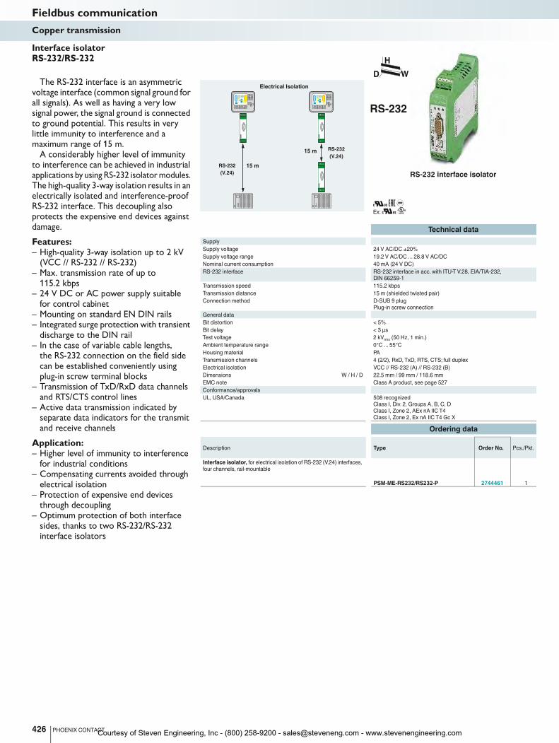
The RS-232 interface is an asymmetric voltage interface (common signal ground for all signals). As well as having a very low signal power, the signal ground is connected to ground potential. This results in very little immunity to interference and a maximum range of 15 m.
A considerably higher level of immunity to interference can be achieved in industrial applications by using RS-232 isolator modules. The high-quality 3-way isolation results in an electrically isolated and interference-proof RS-232 interface. This decoupling also protects the expensive end devices against damage.
Features:– High-quality 3-way isolation up to 2 kV
(VCC // RS-232 // RS-232)– Max. transmission rate of up to
115.2 kbps– 24 V DC or AC power supply suitable
for control cabinet– Mounting on standard EN DIN rails– Integrated surge protection with transient
discharge to the DIN rail– In the case of variable cable lengths,
the RS-232 connection on the field side can be established conveniently using plug-in screw terminal blocks
– Transmission of TxD/RxD data channels and RTS/CTS control lines
– Active data transmission indicated by separate data indicators for the transmit and receive channels
Application:– Higher level of immunity to interference
for industrial conditions– Compensating currents avoided through
electrical isolation– Protection of expensive end devices
through decoupling– Optimum protection of both interface
sides, thanks to two RS-232/RS-232 interface isolators
Interface isolator RS-232/RS-232
Fieldbus communicationCopper transmission
H
WD
RS-232 interface isolator
Electrical Isolation
Courtesy of Steven Engineering, Inc - (800) 258-9200 - [email protected] - www.stevenengineering.com
RS-232
(V.24) RS-232
(V.24)
15 m
TTYTTY
1000 m
For further information and full technical data, visit phoenixcontact.net/products
Ex:
Technical data
Supply
Supply voltage 24 V AC/DC ±20% (via COMBICON plug-in screw terminal block)
Nominal current consumption 75 mA (24 V DC)
RS-232 interface RS-232 interface in acc. with ITU-T V.28, EIA/TIA-232,
DIN 66259-1
Transmission speed ≤ 19.2 kbps
Transmission distance 15 m (shielded twisted pair)
Connection method D-SUB 9 plug
TTY interface TTY interface, CL2 in acc. with DIN 66348-1
Transmission speed ≤ 19.2 kbps
Transmission distance 1000 m (shielded twisted pair)
Connection method Plug-in screw connection
Operating mode Active, semi active, passive
Load ≤ 500 Ω
General data
Bit distortion < 5%
Bit delay < 3 µs
Test voltage 2 kVrms
(50 Hz, 1 min.)
Ambient temperature range 0°C ... 55°C
Housing material PA
Transmission channels 2 (1/1), RxD, TxD, full duplex
Electrical isolation VCC // RS-232 // TTY
Dimensions W / H / D 22.5 mm / 99 mm / 118.6 mm
EMC note Class A product, see page 527
Conformance/approvals
UL, USA/Canada 508 recognized
Class I, Div. 2, Groups A, B, C, D
Class I, Zone 2, AEx nA IIC T4
Class I, Zone 2, Ex nA IIC T4 Gc X
Ordering data
Description Type Order No. Pcs./Pkt.
Interface converter, for conversion from RS-232 (V.24) to TTY,
with electrical isolation, two channels, rail-mountable
PSM-ME-RS232/TTY-P 2744458 1
427PHOENIX CONTACT
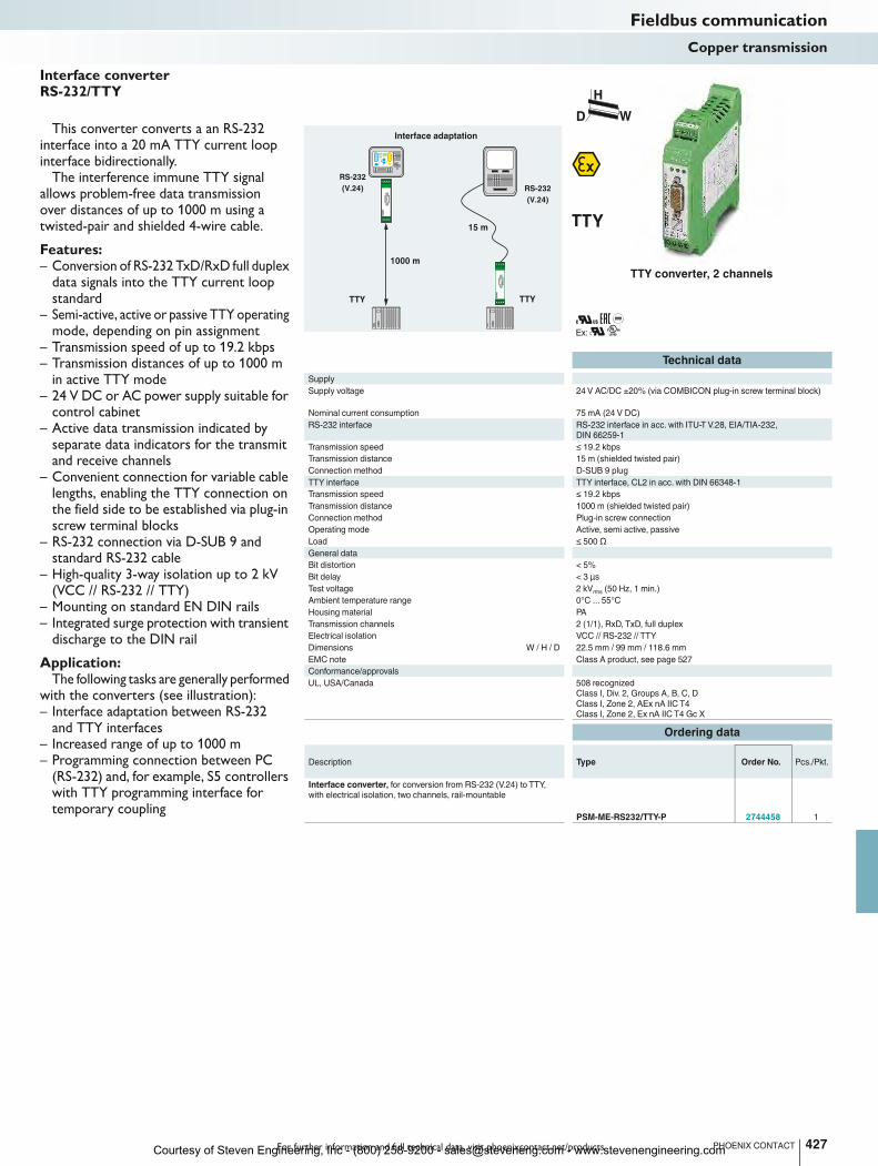
This converter converts a an RS-232 interface into a 20 mA TTY current loop interface bidirectionally.
The interference immune TTY signal allows problem-free data transmission over distances of up to 1000 m using a twisted-pair and shielded 4-wire cable.
Features:– Conversion of RS-232 TxD/RxD full duplex
data signals into the TTY current loop standard
– Semi-active, active or passive TTY operating mode, depending on pin assignment
– Transmission speed of up to 19.2 kbps– Transmission distances of up to 1000 m
in active TTY mode– 24 V DC or AC power supply suitable for
control cabinet– Active data transmission indicated by
separate data indicators for the transmit and receive channels
– Convenient connection for variable cable lengths, enabling the TTY connection on the field side to be established via plug-in screw terminal blocks
– RS-232 connection via D-SUB 9 and standard RS-232 cable
– High-quality 3-way isolation up to 2 kV (VCC // RS-232 // TTY)
– Mounting on standard EN DIN rails– Integrated surge protection with transient
discharge to the DIN rail
Application:The following tasks are generally performed
with the converters (see illustration):– Interface adaptation between RS-232
and TTY interfaces– Increased range of up to 1000 m– Programming connection between PC
(RS-232) and, for example, S5 controllers with TTY programming interface for temporary coupling
Interface converter RS-232/TTY
Fieldbus communicationCopper transmission
H
WD
TTY converter, 2 channels
Interface adaptation
Courtesy of Steven Engineering, Inc - (800) 258-9200 - [email protected] - www.stevenengineering.com
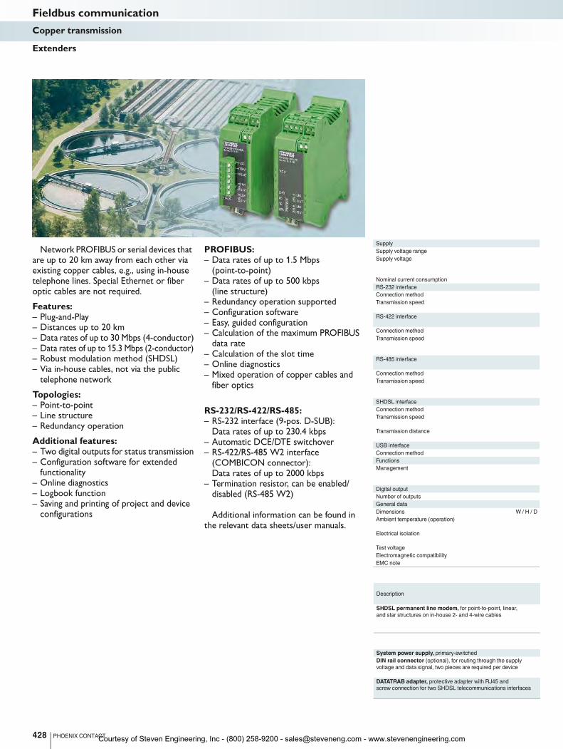
Network PROFIBUS or serial devices that are up to 20 km away from each other via existing copper cables, e.g., using in-house telephone lines. Special Ethernet or fiber optic cables are not required.
Features:– Plug-and-Play– Distances up to 20 km– Data rates of up to 30 Mbps (4-conductor)– Data rates of up to 15.3 Mbps (2-conductor)– Robust modulation method (SHDSL)– Via in-house cables, not via the public
telephone network
Topologies:– Point-to-point– Line structure– Redundancy operation
Additional features:– Two digital outputs for status transmission– Configuration software for extended
functionality– Online diagnostics– Logbook function– Saving and printing of project and device
configurations
PROFIBUS:– Data rates of up to 1.5 Mbps
(point-to-point)– Data rates of up to 500 kbps
(line structure)– Redundancy operation supported– Configuration software– Easy, guided configuration– Calculation of the maximum PROFIBUS
data rate– Calculation of the slot time– Online diagnostics– Mixed operation of copper cables and
fiber optics
RS-232/RS-422/RS-485:– RS-232 interface (9-pos. D-SUB):
Data rates of up to 230.4 kbps– Automatic DCE/DTE switchover– RS-422/RS-485 W2 interface
(COMBICON connector): Data rates of up to 2000 kbps
– Termination resistor, can be enabled/disabled (RS-485 W2)
Additional information can be found in the relevant data sheets/user manuals.
Supply
Supply voltage range
Supply voltage
Nominal current consumption < 180 mA (24 V DC) < 180 mA (24 V DC)
RS-232 interface
Connection method
Transmission speed
RS-422 interface
Connection method
Transmission speed
RS-485 interface
Connection method
Transmission speed
SHDSL interface
Connection method
Transmission speed
Transmission distance up to 20 km (depending on data rate and cable cross section) up to 20 km (depending on data rate and cable
USB interface
Connection method
Functions
Management
Digital output
Number of outputs
General data
Dimensions W / H / D 35 mm / 99 mm / 114.5 mm 35 mm / 99 mm / 114.5 mm
Ambient temperature (operation) -20°C ... 60°C (for derating, see technical documentation) -20°C ... 60°C (for derating, see tech
Electrical isolation
Test voltage
Electromagnetic compatibility Conformance with EMC Directive 2014/30/EU Conformance with EMC Directive 2014/30/EU
EMC note
Description
SHDSL permanent line modem, for point-to-point, linear,
and star structures on in-house 2- and 4-wire cables
System power supply, primary-switched
DIN rail connector (optional), for routing through the supply
voltage and data signal, two pieces are required per device
DATATRAB adapter, protective adapter with RJ45 and
screw connection for two SHDSL telecommunications interfaces
428 PHOENIX CONTACT
Extenders
Fieldbus communicationCopper transmission
Courtesy of Steven Engineering, Inc - (800) 258-9200 - [email protected] - www.stevenengineering.com
For further information and full technical data, visit phoenixcontact.net/products
Ex:
Ex:
Technical data Technical data
18 V DC ... 30 V DC 18 V DC ... 30 V DC
24 V DC ±5% (as an alternative or redundant, via backplane
bus contact and system power supply)
24 V DC ±5% (as an alternative or redundant, via backplane
bus contact and system power supply)
Nominal current consumption < 180 mA (24 V DC) < 180 mA (24 V DC)
D-SUB 9 plug -
0.11/0.3/1.2/2.4/4.8/9.6/19.2/38.4/57.6/115.2/230.4 kbps, NRZ -
RS-422 interface in acc. with ITU-T V.11, EIA/TIA-422, DIN 66348-1
Plug-in/screw connection via COMBICON -
1.2/2.4/4.8/7.0/9.6/19.2/38.4/57.6/75/93.75/115.2/136/187.5/375/
500/1500/2000 kbps, NRZ
-
RS-485 interface, in acc. with EIA/TIA-485,
DIN 66259-4/RS-485 2-wire
PROFIBUS in acc. with IEC 61158, RS-485 2-wire, half duplex,
automatic control
Plug-in/screw connection via COMBICON D-SUB-9 female connector
1.2/2.4/4.8/7.0/9.6/19.2/38.4/57.6/75/93.75/115.2/136/187.5/375/
500/1500/2000 kbps, NRZ
9.6/19.2/45.45/93.75/187.5/500/1500 kbps,
set via configuration software
SHDSL interface in accordance with ITU-T G.991.2.bis SHDSL interface in accordance with ITU-T G.991.2.bis
2 x 2-pos. COMBICON plug-in screw terminal blocks 2 x 2-pos. COMBICON plug-in screw terminal blocks
4-wire operation: 64 kbps ... 30 Mbps
2-wire operation: 32 kbps ... 15.3 Mbps
4-wire operation: 64 kbps ... 30 Mbps
2-wire operation: 32 kbps ... 15.3 Mbps
Transmission distance up to 20 km (depending on data rate and cable cross section) up to 20 km (depending on data rate and cable cross section)
USB 2.0 USB 2.0
Mini-USB type B, 5-pos. Mini-USB type B, 5-pos.
User-friendly software: Guided configuration, plausibility checks,
diagnostic functions, log book
User-friendly software: Guided configuration, plausibility checks,
diagnostic functions, log book
2 2
Dimensions W / H / D 35 mm / 99 mm / 114.5 mm 35 mm / 99 mm / 114.5 mm
Ambient temperature (operation) -20°C ... 60°C (for derating, see technical documentation) -20°C ... 60°C (for derating, see technical documentation)
DIN EN 50178
(VCC, RS-232 // RS-422, RS-485 // DSL (A) // DSL (B) // FE)
DIN EN 50178 (VCC // PROFIBUS // DSL (A) // DSL (B) // FE)
1.5 kVrms
(50 Hz, 1 min.) 1.5 kVrms
(50 Hz, 1 min.)
Electromagnetic compatibility Conformance with EMC Directive 2014/30/EU Conformance with EMC Directive 2014/30/EU
Class A product, see page 527 Class A product, see page 527
Ordering data Ordering data
Type Order No. Pcs./Pkt. Type Order No. Pcs./Pkt.
PSI-MODEM-SHDSL/SERIAL 2313669 1 PSI-MODEM-SHDSL/PB 2313656 1
Accessories Accessories
MINI-SYS-PS-100-240AC/24DC/1.5 2866983 1 MINI-SYS-PS-100-240AC/24DC/1.5 2866983 1
ME 17,5 TBUS 1,5/ 5-ST-3,81 GN 2709561 10 ME 17,5 TBUS 1,5/ 5-ST-3,81 GN 2709561 10
DT-TELE-SHDSL 2801593 1 DT-TELE-SHDSL 2801593 1
429PHOENIX CONTACT
Fieldbus communicationCopper transmission
H
WD
H
WD
Serial extender PROFIBUS extender
Courtesy of Steven Engineering, Inc - (800) 258-9200 - [email protected] - www.stevenengineering.com
E
T
T
Supply
Supply voltage range
Nominal current consumption 100 mA (24 V DC) 120 mA (24 V DC) 55 mA (24 V DC)
RS-485 interface
Data format/encoding
Transmission speed
Transmission distance
Connection method
Optical interface
Connection
Wavelength
Transmission distance incl. 3 dB system reserve 70 m (with F-P 980/1000 230 dB/km with quick mounting connector)
General data
Bit delay
Alarm output
Ambient temperature range -20°C ... 60°C -20°C ... 60°C -20°C ... 60°C
Dimensions W / H / D 35 mm / 99 mm / 106 mm 35 mm / 99 mm / 106 mm 35 mm / 105 mm / 106 mm
EMC note
Conformance/approvals
ATEX
UL, USA/Canada
Description
FO converter, for converting data signals to fiber optics
- End device with one FO interface
- T-coupler with two FO interfaces
DIN rail connector (optional), for routing through the supply
voltage and data signal, two pieces are required per device
DIN rail connector, (optional), for routing through the supply
voltage, two pieces are required per device
System power supply, primary-switched
430 PHOENIX CONTACT
Linear structure
FO
FO
FO
Max. 31
Max. 31
Max. 31
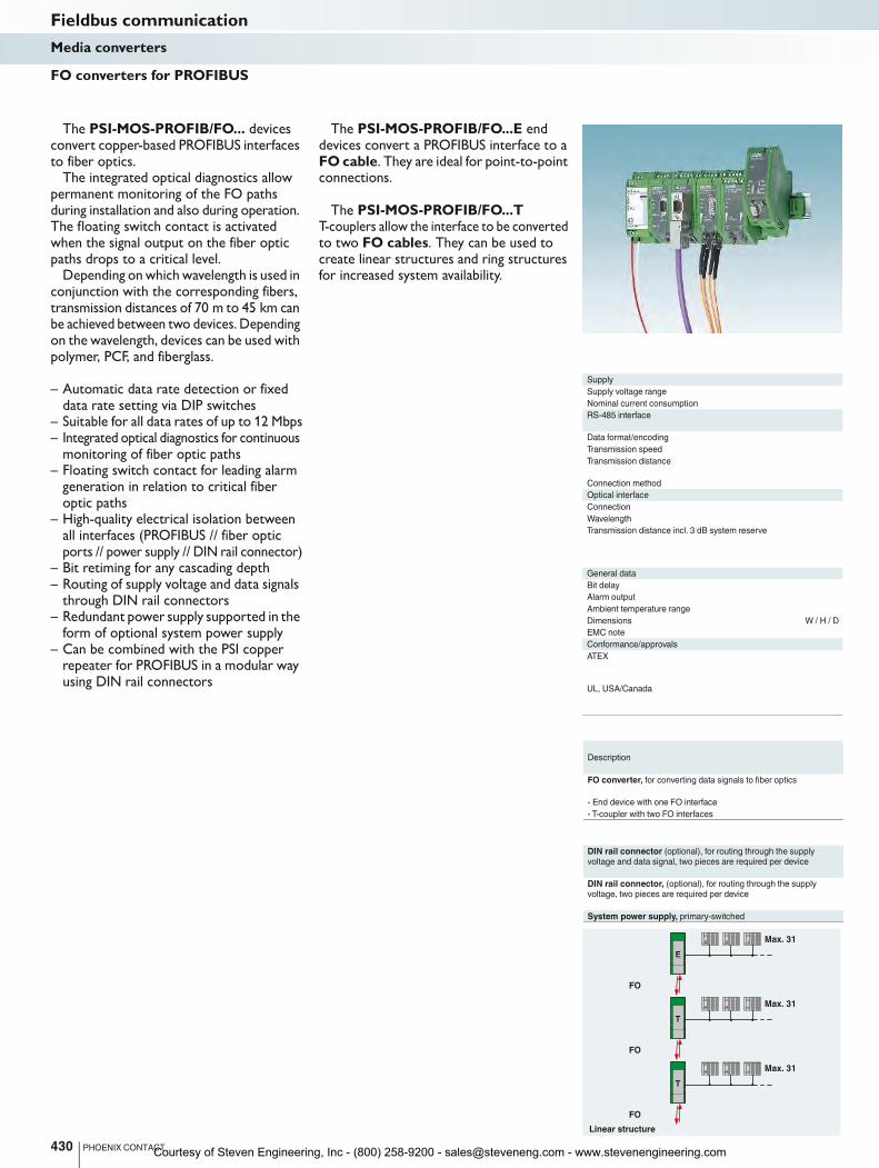
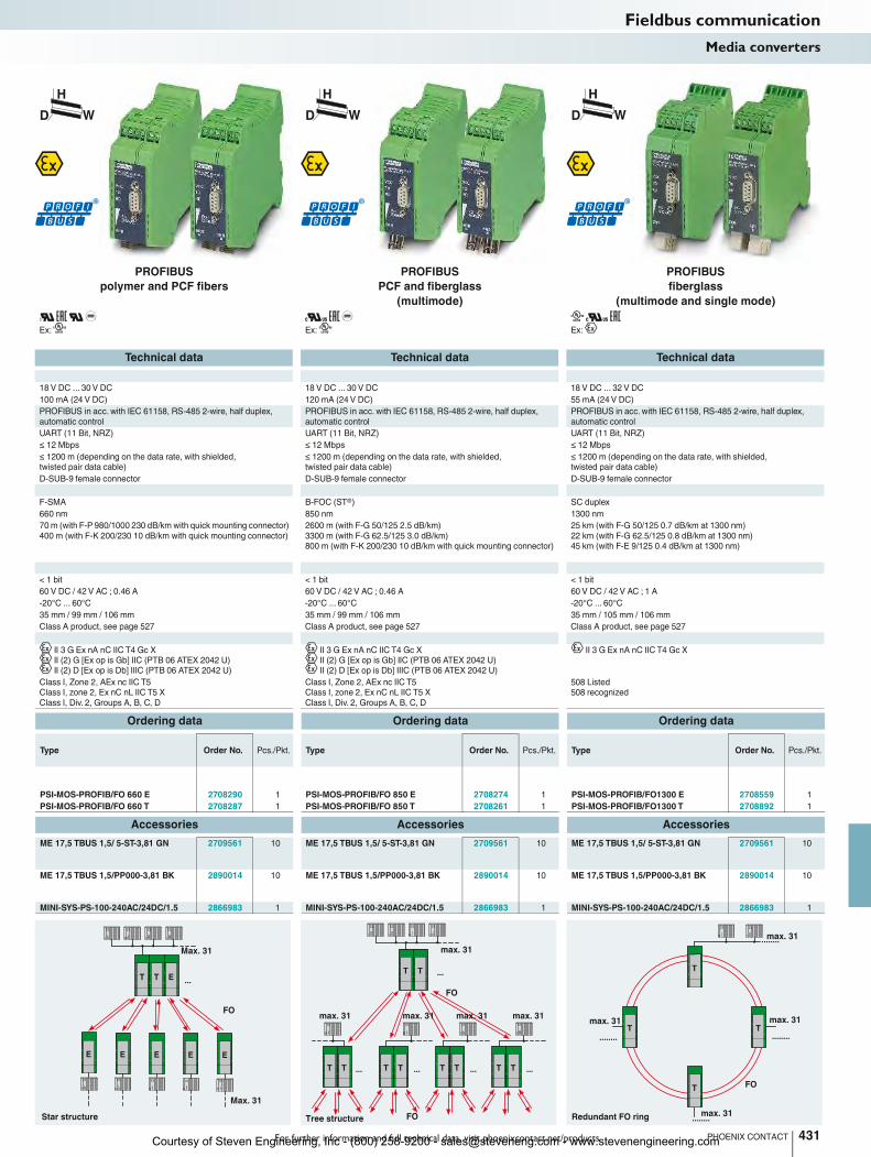
The PSI-MOS-PROFIB/FO... devices convert copper-based PROFIBUS interfaces to fiber optics.
The integrated optical diagnostics allow permanent monitoring of the FO paths during installation and also during operation. The floating switch contact is activated when the signal output on the fiber optic paths drops to a critical level.
Depending on which wavelength is used in conjunction with the corresponding fibers, transmission distances of 70 m to 45 km can be achieved between two devices. Depending on the wavelength, devices can be used with polymer, PCF, and fiberglass.
– Automatic data rate detection or fixed data rate setting via DIP switches
– Suitable for all data rates of up to 12 Mbps– Integrated optical diagnostics for continuous
monitoring of fiber optic paths– Floating switch contact for leading alarm
generation in relation to critical fiber optic paths
– High-quality electrical isolation between all interfaces (PROFIBUS // fiber optic ports // power supply // DIN rail connector)
– Bit retiming for any cascading depth– Routing of supply voltage and data signals
through DIN rail connectors– Redundant power supply supported in the
form of optional system power supply– Can be combined with the PSI copper
repeater for PROFIBUS in a modular way using DIN rail connectors
The PSI-MOS-PROFIB/FO...E end devices convert a PROFIBUS interface to a FO cable. They are ideal for point-to-point connections.
The PSI-MOS-PROFIB/FO...T T-couplers allow the interface to be converted to two FO cables. They can be used to create linear structures and ring structures for increased system availability.
FO converters for PROFIBUS
Fieldbus communicationMedia converters
Courtesy of Steven Engineering, Inc - (800) 258-9200 - [email protected] - www.stevenengineering.com
T T E
E E E E
...
E
T T
T TT T T T T T
...
... ... ... ...
........
................
........
TT
T
T
For further information and full technical data, visit phoenixcontact.net/products
Ex:
Ex:
Ex:
Technical data Technical data Technical data
18 V DC ... 30 V DC 18 V DC ... 30 V DC 18 V DC ... 32 V DC
Nominal current consumption 100 mA (24 V DC) 120 mA (24 V DC) 55 mA (24 V DC)
PROFIBUS in acc. with IEC 61158, RS-485 2-wire, half duplex,
automatic control
PROFIBUS in acc. with IEC 61158, RS-485 2-wire, half duplex,
automatic control
PROFIBUS in acc. with IEC 61158, RS-485 2-wire, half duplex,
automatic control
UART (11 Bit, NRZ) UART (11 Bit, NRZ) UART (11 Bit, NRZ)
≤ 12 Mbps ≤ 12 Mbps ≤ 12 Mbps
≤ 1200 m (depending on the data rate, with shielded,
twisted pair data cable)
≤ 1200 m (depending on the data rate, with shielded,
twisted pair data cable)
≤ 1200 m (depending on the data rate, with shielded,
twisted pair data cable)
D-SUB-9 female connector D-SUB-9 female connector D-SUB-9 female connector
F-SMA B-FOC (ST®) SC duplex
660 nm 850 nm 1300 nm
Transmission distance incl. 3 dB system reserve 70 m (with F-P 980/1000 230 dB/km with quick mounting connector)
400 m (with F-K 200/230 10 dB/km with quick mounting connector)
2600 m (with F-G 50/125 2.5 dB/km)
3300 m (with F-G 62.5/125 3.0 dB/km)
800 m (with F-K 200/230 10 dB/km with quick mounting connector)
25 km (with F-G 50/125 0.7 dB/km at 1300 nm)
22 km (with F-G 62.5/125 0.8 dB/km at 1300 nm)
45 km (with F-E 9/125 0.4 dB/km at 1300 nm)
< 1 bit < 1 bit < 1 bit
60 V DC / 42 V AC ; 0.46 A 60 V DC / 42 V AC ; 0.46 A 60 V DC / 42 V AC ; 1 A
Ambient temperature range -20°C ... 60°C -20°C ... 60°C -20°C ... 60°C
Dimensions W / H / D 35 mm / 99 mm / 106 mm 35 mm / 99 mm / 106 mm 35 mm / 105 mm / 106 mm
Class A product, see page 527 Class A product, see page 527 Class A product, see page 527
II 3 G Ex nA nC IIC T4 Gc X
II (2) G [Ex op is Gb] IIC (PTB 06 ATEX 2042 U)
II (2) D [Ex op is Db] IIIC (PTB 06 ATEX 2042 U)
II 3 G Ex nA nC IIC T4 Gc X
II (2) G [Ex op is Gb] IIC (PTB 06 ATEX 2042 U)
II (2) D [Ex op is Db] IIIC (PTB 06 ATEX 2042 U)
II 3 G Ex nA nC IIC T4 Gc X
Class I, Zone 2, AEx nc IIC T5
Class I, zone 2, Ex nC nL IIC T5 X
Class I, Div. 2, Groups A, B, C, D
Class I, Zone 2, AEx nc IIC T5
Class I, zone 2, Ex nC nL IIC T5 X
Class I, Div. 2, Groups A, B, C, D
508 Listed
508 recognized
Ordering data Ordering data Ordering data
Type Order No. Pcs./Pkt. Type Order No. Pcs./Pkt. Type Order No. Pcs./Pkt.
PSI-MOS-PROFIB/FO 660 E 2708290 1 PSI-MOS-PROFIB/FO 850 E 2708274 1 PSI-MOS-PROFIB/FO1300 E 2708559 1
PSI-MOS-PROFIB/FO 660 T 2708287 1 PSI-MOS-PROFIB/FO 850 T 2708261 1 PSI-MOS-PROFIB/FO1300 T 2708892 1
Accessories Accessories Accessories
ME 17,5 TBUS 1,5/ 5-ST-3,81 GN 2709561 10 ME 17,5 TBUS 1,5/ 5-ST-3,81 GN 2709561 10 ME 17,5 TBUS 1,5/ 5-ST-3,81 GN 2709561 10
ME 17,5 TBUS 1,5/PP000-3,81 BK 2890014 10 ME 17,5 TBUS 1,5/PP000-3,81 BK 2890014 10 ME 17,5 TBUS 1,5/PP000-3,81 BK 2890014 10
MINI-SYS-PS-100-240AC/24DC/1.5 2866983 1 MINI-SYS-PS-100-240AC/24DC/1.5 2866983 1 MINI-SYS-PS-100-240AC/24DC/1.5 2866983 1
431PHOENIX CONTACT
Star structure
FO
Max. 31
Max. 31
max. 31 max. 31 max. 31 max. 31
max. 31
FO
FOTree structure
max. 31
max. 31max. 31
max. 31
FO
Redundant FO ring
H
WD
H
WD
H
WD
Fieldbus communicationMedia converters
PROFIBUS
polymer and PCF fibers
PROFIBUS
PCF and fiberglass
(multimode)
PROFIBUS
fiberglass
(multimode and single mode)
Courtesy of Steven Engineering, Inc - (800) 258-9200 - [email protected] - www.stevenengineering.com
B
B
BE
BE
Supply
Supply voltage range
Nominal current consumption 100 mA (24 V DC) 100 mA (24 V DC) 130 mA (24 V DC)
CAN interface
Termination resistor
Transmission speed
Transmission distance
Connection method
Optical interface
Connection
Wavelength
Transmission distance incl. 3 dB system reserve
General data
Bit delay
Alarm output
Test voltage
Ambient temperature range -20°C ... 60°C -20°C ... 60°C -20°C ... 60°C
Dimensions W / H / D 22.5 mm / 99 mm / 114.5 mm 22.5 mm / 99 mm / 114.5 mm 35 mm / 102 mm / 119 mm
EMC note
Conformance/approvals
ATEX
UL, USA/Canada
Description
FO converter, for converting data signals to fiber optics
- Basic module with one FO interface
- Extension module with one FO interface
- End device with one FO interface
- T-coupler with two FO interfaces
432 PHOENIX CONTACT
Branch line / redundant branch line
FO
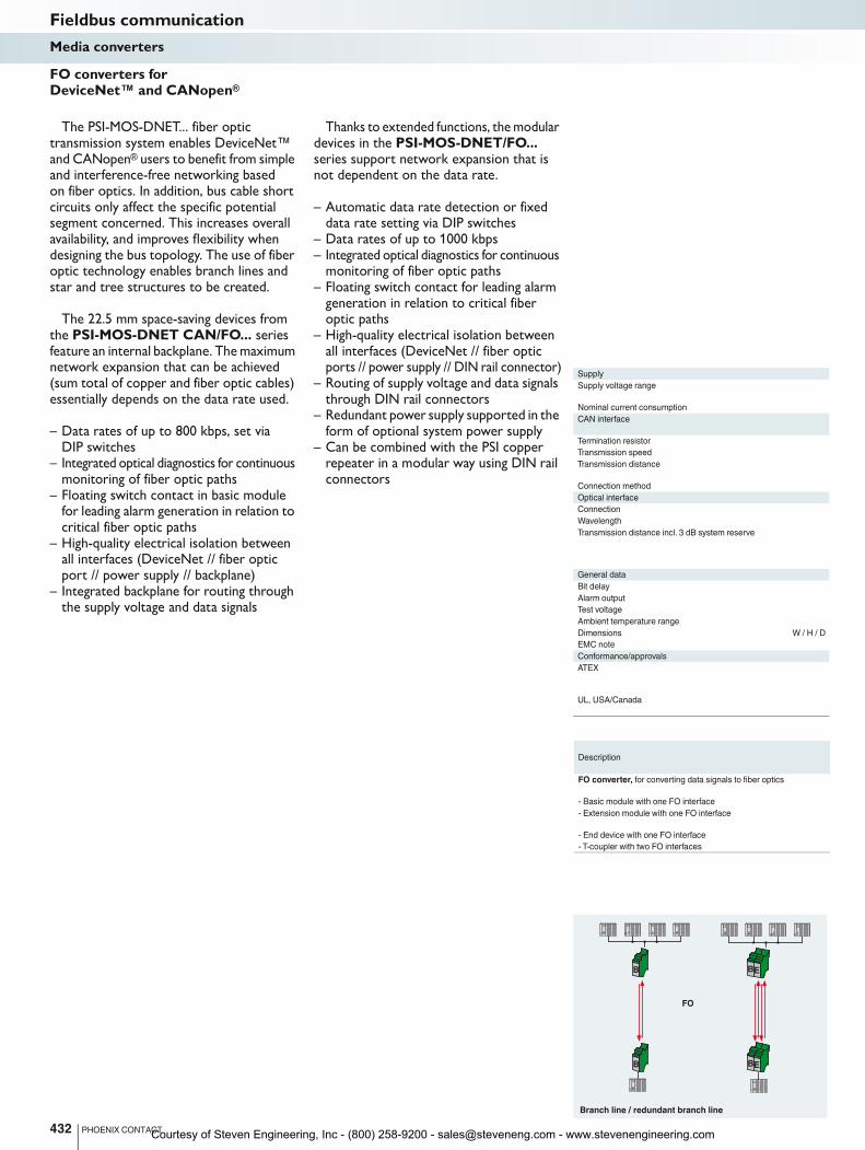
The PSI-MOS-DNET... fiber optic transmission system enables DeviceNet™ and CANopen® users to benefit from simple and interference-free networking based on fiber optics. In addition, bus cable short circuits only affect the specific potential segment concerned. This increases overall availability, and improves flexibility when designing the bus topology. The use of fiber optic technology enables branch lines and star and tree structures to be created.
The 22.5 mm space-saving devices from the PSI-MOS-DNET CAN/FO... series feature an internal backplane. The maximum network expansion that can be achieved (sum total of copper and fiber optic cables) essentially depends on the data rate used.
– Data rates of up to 800 kbps, set via DIP switches
– Integrated optical diagnostics for continuous monitoring of fiber optic paths
– Floating switch contact in basic module for leading alarm generation in relation to critical fiber optic paths
– High-quality electrical isolation between all interfaces (DeviceNet // fiber optic port // power supply // backplane)
– Integrated backplane for routing through the supply voltage and data signals
Thanks to extended functions, the modular devices in the PSI-MOS-DNET/FO... series support network expansion that is not dependent on the data rate.
– Automatic data rate detection or fixed data rate setting via DIP switches
– Data rates of up to 1000 kbps– Integrated optical diagnostics for continuous
monitoring of fiber optic paths– Floating switch contact for leading alarm
generation in relation to critical fiber optic paths
– High-quality electrical isolation between all interfaces (DeviceNet // fiber optic ports // power supply // DIN rail connector)
– Routing of supply voltage and data signals through DIN rail connectors
– Redundant power supply supported in the form of optional system power supply
– Can be combined with the PSI copper repeater in a modular way using DIN rail connectors
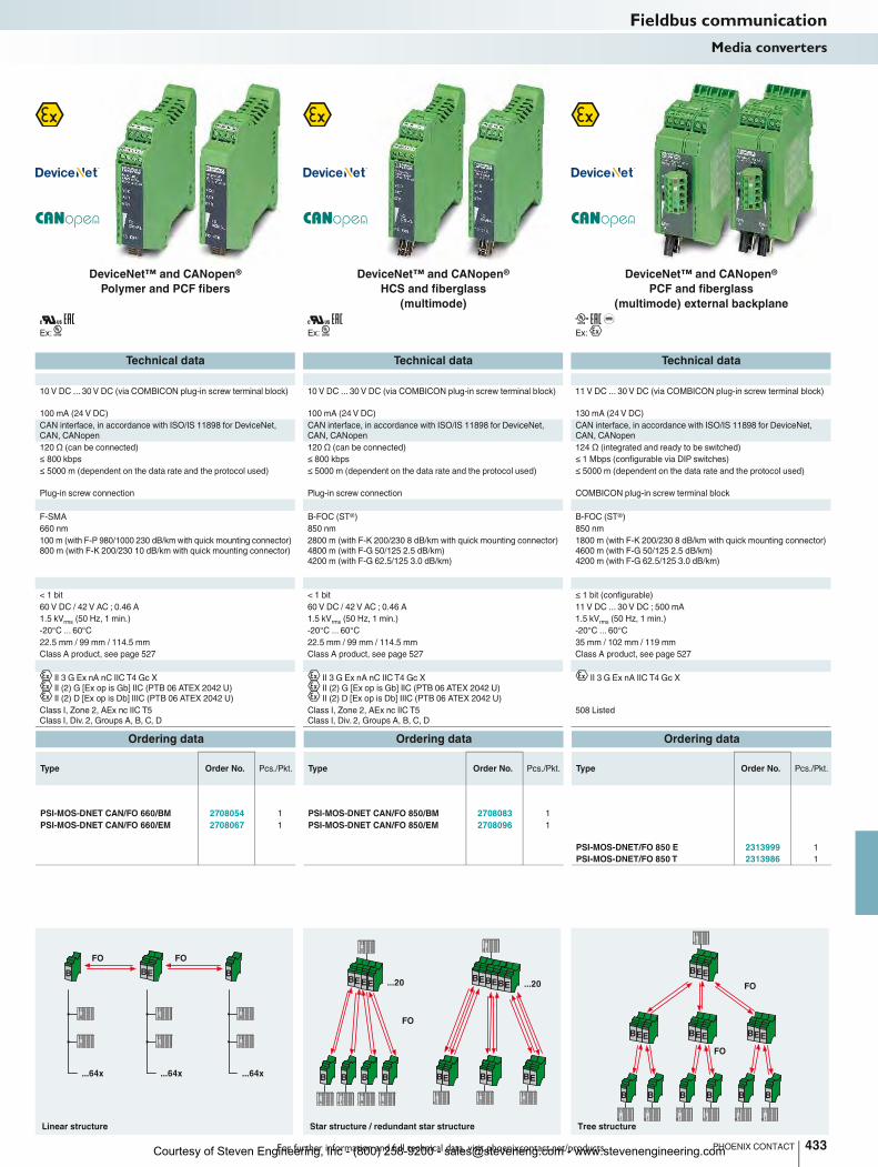
FO converters for DeviceNet™ and CANopen®
Fieldbus communicationMedia converters
Courtesy of Steven Engineering, Inc - (800) 258-9200 - [email protected] - www.stevenengineering.com
BE BBBEEE
B B B B
...20
BEBEBE
BEBEBE ...20
BEEBEE
BEE
BEE
BBBBBB
For further information and full technical data, visit phoenixcontact.net/products
Ex:
Ex:
Ex:
Technical data Technical data Technical data
10 V DC ... 30 V DC (via COMBICON plug-in screw terminal block) 10 V DC ... 30 V DC (via COMBICON plug-in screw terminal block) 11 V DC ... 30 V DC (via COMBICON plug-in screw terminal block)
Nominal current consumption 100 mA (24 V DC) 100 mA (24 V DC) 130 mA (24 V DC)
CAN interface, in accordance with ISO/IS 11898 for DeviceNet,
CAN, CANopen
CAN interface, in accordance with ISO/IS 11898 for DeviceNet,
CAN, CANopen
CAN interface, in accordance with ISO/IS 11898 for DeviceNet,
CAN, CANopen
120 Ω (can be connected) 120 Ω (can be connected) 124 Ω (integrated and ready to be switched)
≤ 800 kbps ≤ 800 kbps ≤ 1 Mbps (configurable via DIP switches)
≤ 5000 m (dependent on the data rate and the protocol used) ≤ 5000 m (dependent on the data rate and the protocol used) ≤ 5000 m (dependent on the data rate and the protocol used)
Plug-in screw connection Plug-in screw connection COMBICON plug-in screw terminal block
F-SMA B-FOC (ST®) B-FOC (ST®)
660 nm 850 nm 850 nm
100 m (with F-P 980/1000 230 dB/km with quick mounting connector)
800 m (with F-K 200/230 10 dB/km with quick mounting connector)
2800 m (with F-K 200/230 8 dB/km with quick mounting connector)
4800 m (with F-G 50/125 2.5 dB/km)
4200 m (with F-G 62.5/125 3.0 dB/km)
1800 m (with F-K 200/230 8 dB/km with quick mounting connector)
4600 m (with F-G 50/125 2.5 dB/km)
4200 m (with F-G 62.5/125 3.0 dB/km)
< 1 bit < 1 bit ≤ 1 bit (configurable)
60 V DC / 42 V AC ; 0.46 A 60 V DC / 42 V AC ; 0.46 A 11 V DC ... 30 V DC ; 500 mA
1.5 kVrms
(50 Hz, 1 min.) 1.5 kVrms
(50 Hz, 1 min.) 1.5 kVrms
(50 Hz, 1 min.)
Ambient temperature range -20°C ... 60°C -20°C ... 60°C -20°C ... 60°C
Dimensions W / H / D 22.5 mm / 99 mm / 114.5 mm 22.5 mm / 99 mm / 114.5 mm 35 mm / 102 mm / 119 mm
Class A product, see page 527 Class A product, see page 527 Class A product, see page 527
II 3 G Ex nA nC IIC T4 Gc X
II (2) G [Ex op is Gb] IIC (PTB 06 ATEX 2042 U)
II (2) D [Ex op is Db] IIIC (PTB 06 ATEX 2042 U)
II 3 G Ex nA nC IIC T4 Gc X
II (2) G [Ex op is Gb] IIC (PTB 06 ATEX 2042 U)
II (2) D [Ex op is Db] IIIC (PTB 06 ATEX 2042 U)
II 3 G Ex nA IIC T4 Gc X
Class I, Zone 2, AEx nc IIC T5
Class I, Div. 2, Groups A, B, C, D
Class I, Zone 2, AEx nc IIC T5
Class I, Div. 2, Groups A, B, C, D
508 Listed
Ordering data Ordering data Ordering data
Type Order No. Pcs./Pkt. Type Order No. Pcs./Pkt. Type Order No. Pcs./Pkt.
PSI-MOS-DNET CAN/FO 660/BM 2708054 1 PSI-MOS-DNET CAN/FO 850/BM 2708083 1
PSI-MOS-DNET CAN/FO 660/EM 2708067 1 PSI-MOS-DNET CAN/FO 850/EM 2708096 1
PSI-MOS-DNET/FO 850 E 2313999 1
PSI-MOS-DNET/FO 850 T 2313986 1
433PHOENIX CONTACT
Linear structure
FOFO
...64x ...64x ...64x
Star structure / redundant star structure
FO
Tree structure
FO
FO
Fieldbus communicationMedia converters
DeviceNet™ and CANopen®
Polymer and PCF fibers
DeviceNet™ and CANopen®
HCS and fiberglass
(multimode)
DeviceNet™ and CANopen®
PCF and fiberglass
(multimode) external backplane
Courtesy of Steven Engineering, Inc - (800) 258-9200 - [email protected] - www.stevenengineering.com
E
E
T
T
Supply voltage range
Nominal current consumption 100 mA (24 V DC) 120 mA (24 V DC) 55 mA (24 V DC)
RS-485 interface
Data format/encoding
Termination resistor
Transmission speed
Transmission distance
Connection method
Optical interface
Connection
Wavelength
Transmission distance incl. 3 dB system reserve
General data
Test voltage
Ambient temperature range -20°C ... 60°C -20°C ... 60°C -20°C ... 60°C
Dimensions W / H / D 35 mm / 99 mm / 105 mm 35 mm / 99 mm / 105 mm 35 mm / 99 mm / 105 mm
EMC note
Conformance/approvals
ATEX
UL, USA/Canada
Description
FO converter, for converting data signals to fiber optics
- End device with one FO interface
- T-coupler with two FO interfaces
DIN rail connector (optional), for routing through the supply
voltage and data signal, two pieces are required per device
DIN rail connector, (optional), for routing through the supply
voltage, two pieces are required per device
System power supply, primary-switched
434 PHOENIX CONTACT
Point-to-point connection Redundantpoint-to-point connection
FO
Max. 31 Max. 31
Max. 31 Max. 31
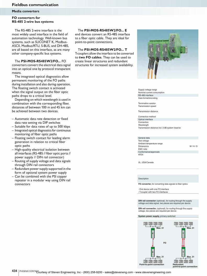
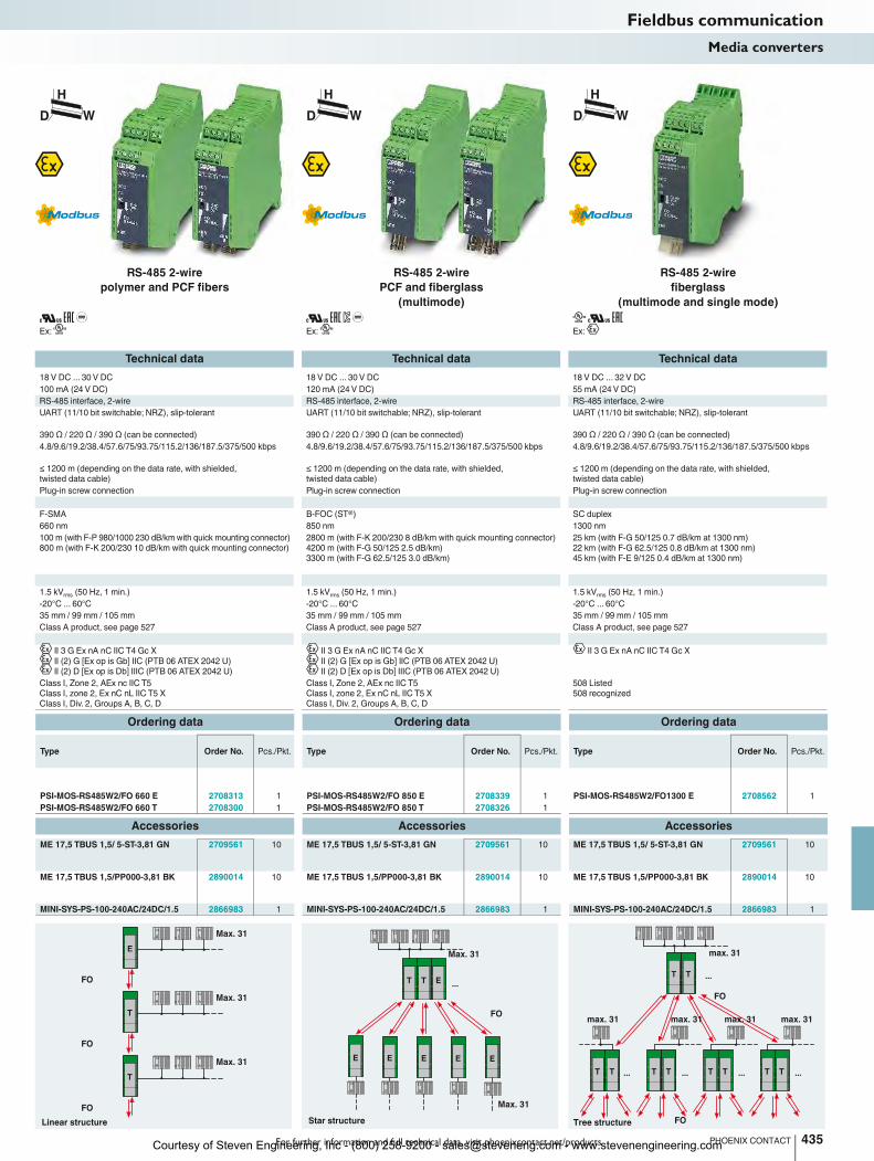
The RS-485 2-wire interface is the most widely used interface in the field of automation technology. Well-known bus systems, such as SUCONET K, Modbus-ASCII, Modbus/RTU, S-BUS, and DH-485, are all based on this interface, as are many other company-specific bus systems.
The PSI-MOS-RS485W2/FO... FO converters convert the electrical data signal into an optical one by protocol transparent means.
The integrated optical diagnostics allow permanent monitoring of the FO paths during installation and also during operation. The floating switch contact is activated when the signal output on the fiber optic paths drops to a critical level.
Depending on which wavelength is used in combination with the corresponding fiber, distances of between 100 m and 45 km can be achieved between two devices.
– Automatic data rate detection or fixed data rate setting via DIP switches
– Suitable for data rates of up to 500 kbps– Integrated optical diagnostics for continuous
monitoring of fiber optic paths– Floating switch contact for leading alarm
generation in relation to critical fiber optic paths
– High-quality electrical isolation between all interfaces (RS-485 // fiber optic ports // power supply // DIN rail connector)
– Routing of supply voltage and data signals through DIN rail connectors
– Redundant power supply supported in the form of optional system power supply
– Can be combined with the PSI copper repeater in a modular way using DIN rail connectors
The PSI-MOS-RS485W2/FO... E end devices convert an RS-485 interface to a fiber optic cable. They are ideal for point-to-point connections.
The PSI-MOS-RS485W2/FO... T T-couplers allow the interface to be converted to two FO cables. They can be used to create linear structures and redundant structures for increased system availability.
FO converters for RS-485 2-wire bus systems
Fieldbus communicationMedia converters
Courtesy of Steven Engineering, Inc - (800) 258-9200 - [email protected] - www.stevenengineering.com
E
T
T
T T E
E E E E
...
E
T T
T TT T T T T T
...
... ... ... ...
For further information and full technical data, visit phoenixcontact.net/products
Ex:
Ex:
Ex:
Technical data Technical data Technical data
18 V DC ... 30 V DC 18 V DC ... 30 V DC 18 V DC ... 32 V DC
Nominal current consumption 100 mA (24 V DC) 120 mA (24 V DC) 55 mA (24 V DC)
RS-485 interface, 2-wire RS-485 interface, 2-wire RS-485 interface, 2-wire
UART (11/10 bit switchable; NRZ), slip-tolerant UART (11/10 bit switchable; NRZ), slip-tolerant UART (11/10 bit switchable; NRZ), slip-tolerant
390 Ω / 220 Ω / 390 Ω (can be connected) 390 Ω / 220 Ω / 390 Ω (can be connected) 390 Ω / 220 Ω / 390 Ω (can be connected)
4.8/9.6/19.2/38.4/57.6/75/93.75/115.2/136/187.5/375/500 kbps 4.8/9.6/19.2/38.4/57.6/75/93.75/115.2/136/187.5/375/500 kbps 4.8/9.6/19.2/38.4/57.6/75/93.75/115.2/136/187.5/375/500 kbps
≤ 1200 m (depending on the data rate, with shielded,
twisted data cable)
≤ 1200 m (depending on the data rate, with shielded,
twisted data cable)
≤ 1200 m (depending on the data rate, with shielded,
twisted data cable)
Plug-in screw connection Plug-in screw connection Plug-in screw connection
F-SMA B-FOC (ST®) SC duplex
660 nm 850 nm 1300 nm
100 m (with F-P 980/1000 230 dB/km with quick mounting connector)
800 m (with F-K 200/230 10 dB/km with quick mounting connector)
2800 m (with F-K 200/230 8 dB/km with quick mounting connector)
4200 m (with F-G 50/125 2.5 dB/km)
3300 m (with F-G 62.5/125 3.0 dB/km)
25 km (with F-G 50/125 0.7 dB/km at 1300 nm)
22 km (with F-G 62.5/125 0.8 dB/km at 1300 nm)
45 km (with F-E 9/125 0.4 dB/km at 1300 nm)
1.5 kVrms
(50 Hz, 1 min.) 1.5 kVrms
(50 Hz, 1 min.) 1.5 kVrms
(50 Hz, 1 min.)
Ambient temperature range -20°C ... 60°C -20°C ... 60°C -20°C ... 60°C
Dimensions W / H / D 35 mm / 99 mm / 105 mm 35 mm / 99 mm / 105 mm 35 mm / 99 mm / 105 mm
Class A product, see page 527 Class A product, see page 527 Class A product, see page 527
II 3 G Ex nA nC IIC T4 Gc X
II (2) G [Ex op is Gb] IIC (PTB 06 ATEX 2042 U)
II (2) D [Ex op is Db] IIIC (PTB 06 ATEX 2042 U)
II 3 G Ex nA nC IIC T4 Gc X
II (2) G [Ex op is Gb] IIC (PTB 06 ATEX 2042 U)
II (2) D [Ex op is Db] IIIC (PTB 06 ATEX 2042 U)
II 3 G Ex nA nC IIC T4 Gc X
Class I, Zone 2, AEx nc IIC T5
Class I, zone 2, Ex nC nL IIC T5 X
Class I, Div. 2, Groups A, B, C, D
Class I, Zone 2, AEx nc IIC T5
Class I, zone 2, Ex nC nL IIC T5 X
Class I, Div. 2, Groups A, B, C, D
508 Listed
508 recognized
Ordering data Ordering data Ordering data
Type Order No. Pcs./Pkt. Type Order No. Pcs./Pkt. Type Order No. Pcs./Pkt.
PSI-MOS-RS485W2/FO 660 E 2708313 1 PSI-MOS-RS485W2/FO 850 E 2708339 1 PSI-MOS-RS485W2/FO1300 E 2708562 1
PSI-MOS-RS485W2/FO 660 T 2708300 1 PSI-MOS-RS485W2/FO 850 T 2708326 1
Accessories Accessories Accessories
ME 17,5 TBUS 1,5/ 5-ST-3,81 GN 2709561 10 ME 17,5 TBUS 1,5/ 5-ST-3,81 GN 2709561 10 ME 17,5 TBUS 1,5/ 5-ST-3,81 GN 2709561 10
ME 17,5 TBUS 1,5/PP000-3,81 BK 2890014 10 ME 17,5 TBUS 1,5/PP000-3,81 BK 2890014 10 ME 17,5 TBUS 1,5/PP000-3,81 BK 2890014 10
MINI-SYS-PS-100-240AC/24DC/1.5 2866983 1 MINI-SYS-PS-100-240AC/24DC/1.5 2866983 1 MINI-SYS-PS-100-240AC/24DC/1.5 2866983 1
435PHOENIX CONTACT
Linear structure
FO
FO
FO
Max. 31
Max. 31
Max. 31
Star structure
FO
Max. 31
Max. 31
max. 31 max. 31 max. 31 max. 31
max. 31
FO
FOTree structure
H
WD
H
WD
H
WD
Fieldbus communicationMedia converters
RS-485 2-wire
polymer and PCF fibers
RS-485 2-wire
PCF and fiberglass
(multimode)
RS-485 2-wire
fiberglass
(multimode and single mode)
Courtesy of Steven Engineering, Inc - (800) 258-9200 - [email protected] - www.stevenengineering.com
E
E
E EREMOTE IN REMOTE OUT
REMOTE IN
Supply
Supply voltage range
Nominal current consumption 100 mA (24 V DC) 120 mA (24 V DC) 110 mA (24 V DC)
RS-422 interface
Transmission speed
Transmission distance
Connection method
Optical interface
Connection
Wavelength
Transmission distance incl. 3 dB system reserve
General data
Bit delay
Alarm output
Test voltage
Ambient temperature range -20°C ... 60°C -20°C ... 60°C -20°C ... 60°C
Dimensions W / H / D 35 mm / 99 mm / 103 mm 35 mm / 99 mm / 103 mm 35 mm / 105 mm / 103 mm
EMC note
Conformance/approvals
ATEX
UL, USA/Canada
Description
FO converter, for converting data signals to fiber optics
- End device with one FO interface
- T-coupler with two FO interfaces
DIN rail connector, (optional), for routing through the supply
voltage, two pieces are required per device
System power supply, primary-switched
436 PHOENIX CONTACT
INTERBUS withPSI-MOS-RS-422
LWL (FO)
INTERBUS Master
LWL (FO)
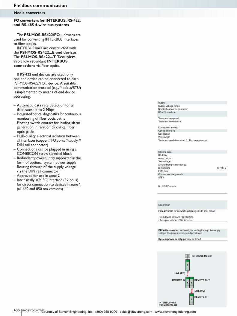
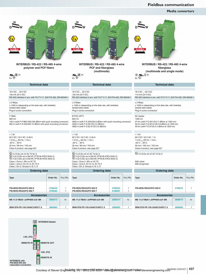
The PSI-MOS-RS422/FO... devices are used for converting INTERBUS interfaces to fiber optics.
INTERBUS lines are constructed with the PSI-MOS-RS422...E end devices. The PSI-MOS-RS422...T T-couplers also allow redundant INTERBUS connections via fiber optics.
If RS-422 end devices are used, only one end device can be connected to each PSI-MOS-RS422/FO... device. A suitable communication protocol (e.g., Modbus/RTU) is implemented by means of end device addressing.
– Automatic data rate detection for all data rates up to 2 Mbps
– Integrated optical diagnostics for continuous monitoring of fiber optic paths
– Floating switch contact for leading alarm generation in relation to critical fiber optic paths
– High-quality electrical isolation between all interfaces (copper // FO ports // supply // DIN rail connector)
– Connections can be plugged in using a COMBICON screw terminal block
– Redundant power supply supported in the form of optional system power supply
– Routing through of the supply voltage via the DIN rail connector
– Approved for use in zone 2– Intrinsically safe FO interface (Ex op is)
for direct connection to devices in zone 1 (all 660 and 850 nm versions)
FO converters for INTERBUS, RS-422, and RS-485 4-wire bus systems
Fieldbus communicationMedia converters
Courtesy of Steven Engineering, Inc - (800) 258-9200 - [email protected] - www.stevenengineering.com
REMOTE IN REMOTE OUT
REMOTE IN
T
T
T T
For further information and full technical data, visit phoenixcontact.net/products
Ex:
Ex:
Ex:
Technical data Technical data Technical data
18 V DC ... 30 V DC 18 V DC ... 30 V DC 18 V DC ... 32 V DC
Nominal current consumption 100 mA (24 V DC) 120 mA (24 V DC) 110 mA (24 V DC)
RS-422 interface in acc. with ITU-T V.11, EIA/TIA-422, DIN 66348-1 RS-422 interface in acc. with ITU-T V.11, EIA/TIA-422, DIN 66348-1 RS-422 interface in acc. with ITU-T V.11, EIA/TIA-422, DIN 66348-1
≤ 2 Mbps ≤ 2 Mbps ≤ 2 Mbps
≤ 1000 m (depending on the data rate, with shielded,
twisted data cable)
≤ 1000 m (depending on the data rate, with shielded,
twisted data cable)
≤ 1000 m (depending on the data rate, with shielded,
twisted data cable)
Plug-in screw connection Plug-in screw connection Plug-in screw connection
F-SMA B-FOC (ST®) SC duplex
660 nm 850 nm 1300 nm
100 m (with F-P 980/1000 230 dB/km with quick mounting connector)
800 m (with F-K 200/230 10 dB/km with quick mounting connector)
2800 m (with F-K 200/230 8 dB/km with quick mounting connector)
4200 m (with F-G 50/125 2.5 dB/km)
4800 m (with F-G 62.5/125 3.0 dB/km)
27 km (with F-G 50/125 0.7 dB/km at 1300 nm)
22 km (with F-G 62.5/125 0.8 dB/km at 1300 nm)
45 km (with F-E 9/125 0.4 dB/km at 1300 nm)
< 1 bit < 1 bit < 1 bit
60 V DC / 42 V AC ; 0.46 A 60 V DC / 42 V AC ; 0.46 A 60 V DC / 42 V AC ; 1 A
1.5 kVrms
(50 Hz, 1 min.) 1.5 kVrms
(50 Hz, 1 min.) 1.5 kVrms
(50 Hz, 1 min.)
Ambient temperature range -20°C ... 60°C -20°C ... 60°C -20°C ... 60°C
Dimensions W / H / D 35 mm / 99 mm / 103 mm 35 mm / 99 mm / 103 mm 35 mm / 105 mm / 103 mm
Class A product, see page 527 Class A product, see page 527 Class A product, see page 527
II 3 G Ex nA nC IIC T4 Gc X
II (2) G [Ex op is Gb] IIC (PTB 06 ATEX 2042 U)
II (2) D [Ex op is Db] IIIC (PTB 06 ATEX 2042 U)
II 3 G Ex nA nC IIC T4 Gc X
II (2) G [Ex op is Gb] IIC (PTB 06 ATEX 2042 U)
II (2) D [Ex op is Db] IIIC (PTB 06 ATEX 2042 U)
II 3 G Ex nA nC IIC T4 Gc X
Class I, Zone 2, AEx nc IIC T5
Class I, zone 2, Ex nC nL IIC T5 X
Class I, Div. 2, Groups A, B, C, D
Class I, Zone 2, AEx nc IIC T5
Class I, zone 2, Ex nC nL IIC T5 X
Class I, Div. 2, Groups A, B, C, D
508 Listed
508 recognized
Ordering data Ordering data Ordering data
Type Order No. Pcs./Pkt. Type Order No. Pcs./Pkt. Type Order No. Pcs./Pkt.
PSI-MOS-RS422/FO 660 E 2708342 1 PSI-MOS-RS422/FO 850 E 2708355 1 PSI-MOS-RS422/FO1300 E 2708575 1
PSI-MOS-RS422/FO 660 T 2708384 1 PSI-MOS-RS422/FO 850 T 2708397 1
Accessories Accessories Accessories
ME 17,5 TBUS 1,5/PP000-3,81 BK 2890014 10 ME 17,5 TBUS 1,5/PP000-3,81 BK 2890014 10 ME 17,5 TBUS 1,5/PP000-3,81 BK 2890014 10
MINI-SYS-PS-100-240AC/24DC/1.5 2866983 1 MINI-SYS-PS-100-240AC/24DC/1.5 2866983 1 MINI-SYS-PS-100-240AC/24DC/1.5 2866983 1
437PHOENIX CONTACT
INTERBUS withPSI-MOS-RS-422redundant connection
LWL (FO)
INTERBUS Master
LWL (FO)
H
WD
H
WD
H
WD
Fieldbus communicationMedia converters
INTERBUS / RS-422 / RS-485 4-wire
polymer and PCF fibers
INTERBUS / RS-422 / RS-485 4-wire
PCF and fiberglass
(multimode)
INTERBUS / RS-422 / RS-485 4-wire
fiberglass
(multimode and single mode)
Courtesy of Steven Engineering, Inc - (800) 258-9200 - [email protected] - www.stevenengineering.com
E T
E T
Supply
Supply voltage range
Nominal current consumption 100 mA (24 V DC) 120 mA (24 V DC) 100 mA (24 V DC)
RS-232 interface
Transmission speed
Transmission distance
Connection method
Optical interface
Connection
Wavelength
Transmission distance incl. 3 dB system reserve
General data
Bit delay
Alarm output
Test voltage
Ambient temperature range -20°C ... 60°C -20°C ... 60°C -20°C ... 60°C
Dimensions W / H / D 35 mm / 99 mm / 105 mm 35 mm / 99 mm / 105 mm 35 mm / 99 mm / 105 mm
EMC note
Conformance/approvals
ATEX
UL, USA/Canada
Description
FO converter, for converting data signals to fiber optics
- End device with one FO interface
- T-coupler with two FO interfaces
DIN rail connector (optional), for routing through the supply
voltage and data signal, two pieces are required per device
DIN rail connector, (optional), for routing through the supply
voltage, two pieces are required per device
System power supply, primary-switched
438 PHOENIX CONTACT
Redundant point topoint connection
Point-to-point connection
FO
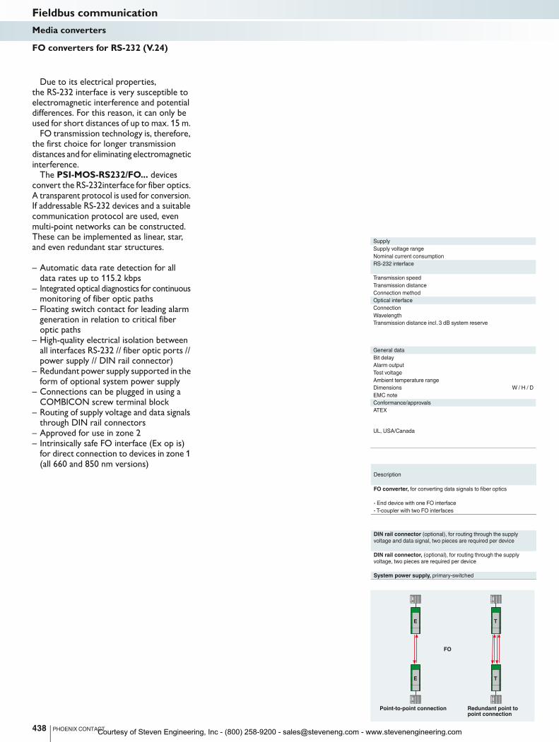
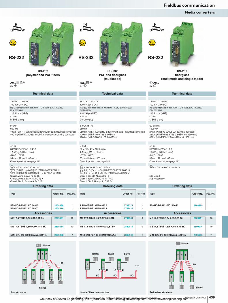
Due to its electrical properties, the RS-232 interface is very susceptible to electromagnetic interference and potential differences. For this reason, it can only be used for short distances of up to max. 15 m.
FO transmission technology is, therefore, the first choice for longer transmission distances and for eliminating electromagnetic interference.
The PSI-MOS-RS232/FO... devices convert the RS-232interface for fiber optics. A transparent protocol is used for conversion. If addressable RS-232 devices and a suitable communication protocol are used, even multi-point networks can be constructed. These can be implemented as linear, star, and even redundant star structures.
– Automatic data rate detection for all data rates up to 115.2 kbps
– Integrated optical diagnostics for continuous monitoring of fiber optic paths
– Floating switch contact for leading alarm generation in relation to critical fiber optic paths
– High-quality electrical isolation between all interfaces RS-232 // fiber optic ports // power supply // DIN rail connector)
– Redundant power supply supported in the form of optional system power supply
– Connections can be plugged in using a COMBICON screw terminal block
– Routing of supply voltage and data signals through DIN rail connectors
– Approved for use in zone 2– Intrinsically safe FO interface (Ex op is)
for direct connection to devices in zone 1 (all 660 and 850 nm versions)
FO converters for RS-232 (V.24)
Fieldbus communicationMedia converters
Courtesy of Steven Engineering, Inc - (800) 258-9200 - [email protected] - www.stevenengineering.com
T T E
E E E E
...
E
E T T
A AB B
.......
TT T ...
T T T
For further information and full technical data, visit phoenixcontact.net/products
Ex:
Ex:
Ex:
Technical data Technical data Technical data
18 V DC ... 30 V DC 18 V DC ... 30 V DC 18 V DC ... 32 V DC
Nominal current consumption 100 mA (24 V DC) 120 mA (24 V DC) 100 mA (24 V DC)
RS-232 interface in acc. with ITU-T V.28, EIA/TIA-232,
DIN 66259-1
RS-232 interface in acc. with ITU-T V.28, EIA/TIA-232,
DIN 66259-1
RS-232 interface in acc. with ITU-T V.28, EIA/TIA-232,
DIN 66259-1
115.2 kbps (NRZ) 115.2 kbps (NRZ) 115.2 kbps (NRZ)
≤ 15 m ≤ 15 m ≤ 15 m
D-SUB 9 plug D-SUB 9 plug D-SUB 9 plug
F-SMA B-FOC (ST®) SC duplex
660 nm 850 nm 1300 nm
100 m (with F-P 980/1000 230 dB/km with quick mounting connector)
800 m (with F-K 200/230 10 dB/km with quick mounting connector)
2800 m (with F-K 200/230 8 dB/km with quick mounting connector)
4200 m (with F-G 50/125 2.5 dB/km)
4800 m (with F-G 62.5/125 3.0 dB/km)
27 km (with F-G 50/125 0.7 dB/km at 1300 nm)
22 km (with F-G 62.5/125 0.8 dB/km at 1300 nm)
45 km (with F-E 9/125 0.4 dB/km at 1300 nm)
< 1 bit < 1 bit < 1 bit
60 V DC / 42 V AC ; 0.46 A 60 V DC / 42 V AC ; 0.46 A 60 V DC / 42 V AC ; 1 A
1.5 kVrms
(50 Hz, 1 min.) 1.5 kVrms
(50 Hz, 1 min.) 1.5 kVrms
(50 Hz, 1 min.)
Ambient temperature range -20°C ... 60°C -20°C ... 60°C -20°C ... 60°C
Dimensions W / H / D 35 mm / 99 mm / 105 mm 35 mm / 99 mm / 105 mm 35 mm / 99 mm / 105 mm
Class A product, see page 527 Class A product, see page 527 Class A product, see page 527
II 3 G Ex nA nC IIC T4 Gc X
II (2) G [Ex op is Gb] IIC (PTB 06 ATEX 2042 U)
II (2) D [Ex op is Db] IIIC (PTB 06 ATEX 2042 U)
II 3 G Ex nA nC IIC T4 Gc X
II (2) G [Ex op is Gb] IIC (PTB 06 ATEX 2042 U)
II (2) D [Ex op is Db] IIIC (PTB 06 ATEX 2042 U)
II 3 G Ex nA nC IIC T4 Gc X
Class I, Zone 2, AEx nc IIC T5
Class I, zone 2, Ex nC nL IIC T5 X
Class I, Div. 2, Groups A, B, C, D
Class I, Zone 2, AEx nc IIC T5
Class I, zone 2, Ex nC nL IIC T5 X
Class I, Div. 2, Groups A, B, C, D
508 Listed
508 recognized
Ordering data Ordering data Ordering data
Type Order No. Pcs./Pkt. Type Order No. Pcs./Pkt. Type Order No. Pcs./Pkt.
PSI-MOS-RS232/FO 660 E 2708368 1 PSI-MOS-RS232/FO 850 E 2708371 1 PSI-MOS-RS232/FO1300 E 2708588 1
PSI-MOS-RS232/FO 660 T 2708410 1 PSI-MOS-RS232/FO 850 T 2708423 1
Accessories Accessories Accessories
ME 17,5 TBUS 1,5/ 5-ST-3,81 GN 2709561 10 ME 17,5 TBUS 1,5/ 5-ST-3,81 GN 2709561 10 ME 17,5 TBUS 1,5/ 5-ST-3,81 GN 2709561 10
ME 17,5 TBUS 1,5/PP000-3,81 BK 2890014 10 ME 17,5 TBUS 1,5/PP000-3,81 BK 2890014 10 ME 17,5 TBUS 1,5/PP000-3,81 BK 2890014 10
MINI-SYS-PS-100-240AC/24DC/1.5 2866983 1 MINI-SYS-PS-100-240AC/24DC/1.5 2866983 1 MINI-SYS-PS-100-240AC/24DC/1.5 2866983 1
439PHOENIX CONTACT
Star structure
FO
Slaves
Master
Master/Slave line structure
FO FOFO
Master Slave Slave
Redundant structure
Master
FO
Slaves
H
WD
H
WD
H
WD
Fieldbus communicationMedia converters
RS-232
polymer and PCF fibers
RS-232
PCF and fiberglass
(multimode)
RS-232
fiberglass
(multimode and single mode)
Courtesy of Steven Engineering, Inc - (800) 258-9200 - [email protected] - www.stevenengineering.com
440 PHOENIX CONTACT
Fieldbus communicationFiber optic installation technology
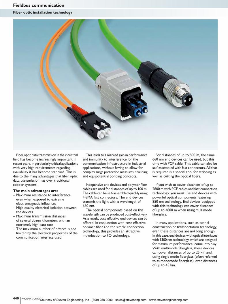
Fiber optic data transmission in the industrial field has become increasingly important in recent years. In particularly critical applications with very high requirements regarding availability it has become standard. This is due to the many advantages that fiber optic data transmission has over traditional copper systems.
The main advantages are:– Maximum resistance to interference,
even when exposed to extreme electromagnetic influences
– High-quality electrical isolation between the devices
– Maximum transmission distances of several dozen kilometers with an extremely high data rate
– The maximum number of devices is not limited by the electrical properties of the communication interface used
This leads to a marked gain in performance and immunity to interference for the communication infrastructure in industrial applications, without having to allow for complex surge protection measures, shielding and equipotential bonding concepts.
Inexpensive end devices and polymer fiber
cables are used for distances of up to 100 m. The cable can be self-assembled quickly using F-SMA fast connectors. The end devices transmit the light with a wavelength of 660 nm.
The optical components based on this wavelength can be produced cost-effectively. As a result, cost-effective end devices can be offered. In conjunction with cost-effective polymer fiber and the simple connection technology, this provides an attractive introduction to FO technology.
For distances of up to 800 m, the same 660 nm end devices can be used, but this time with PCF cable. This cable can also be self-assembled with fast connectors. All that is required is a special tool for stripping as well as cutting the optical fibers.
If you wish to cover distances of up to
2800 m with PCF cables and fast connection technology, you must use end devices with powerful optical components featuring 850 nm technology. End devices equipped with this technology can cover distances of up to 4800 m when using multimode fiberglass.
In many applications, such as tunnel construction or transportation technology, even these distances are not long enough. In this case, end devices with optical interfaces with 1300 nm technology, which are designed for maximum performance, come into play. With multimode fiberglass, these devices can cover distances of up to 25 km and, using single mode fiberglass (often referred to as monomode fiberglass), even distances of up to 45 km.
Courtesy of Steven Engineering, Inc - (800) 258-9200 - [email protected] - www.stevenengineering.com

For further information and full technical data, visit phoenixcontact.net/products 441PHOENIX CONTACT
Fieldbus communicationFiber optic installation technology
Cables – By the meterPhoenix Contact cables and connection
systems offer solutions for various fields of application.– Polymer Optical Fiber (POF):
Up to a maximum of 100 Mbps– Polymer-Cladded Fiber (PCF):
Up to a maximum of 1 Gbps– Glass Optical Fiber (GOF) multimode:
Up to 10 Gbps– Glass Optical Fiber (GOF) single mode:
Up to 40 Gbps
Cables – AssembledImplement flexible, consistent data
transmission solutions based on our comprehensive range of standardized FO connectors.– Compact LC duplex connectors– SC-RJ with push-pull technology for
POF, PCF, and GOF– Established F-SMA and ST connectors
Fixed patch cablesThe patch cables have a robust design
for industrial use. The strong outer sheath and connector transitions with bending protection sleeve mean that they can be safely used inside control cabinets.– Pre-assembled patch cables for fast
integration of fiber optic devices into existing fiber optic networks
– For the SC-RJ, SC duplex, LC, and B-FOC (ST®) connector formats
– Single and multimode fiberglass in lengths of one, two, and five meters
Assembly toolsAssemble fiber optic cables directly
in the field. The assembly tools from Phoenix Contact enable reliable connection in next to no time.– Tools for all fiber types– No bonding or polishing, thanks to
mechanical splice– Tool sets with practical accessories
ConnectorsThese connectors are easy to assemble
and allow fast and simple self-assembly on site. They correspond to the international F-SMA, B-FOC (STR), SC-RJ, and SC duplex standards, though their quick mounting mechanism makes them stand out from the conventional connectors.
The tools required are available as a complete assembly case for polymer and HCS fibers.
CouplingsCouplings connect FO connectors with
the same pin arrangement. Couplings are also used when a cable needs to be extended or when creating a non-permanent panel feed-through.
The sets include two F-SMA couplings or two B-FOC (ST®) couplings for connecting duplex cables.
The SC-RJ duplex, SC duplex, and LC couplings are supplied separately.
Your web code: #1516
Your web code: #0524
Your web code: #0526
Your web code: #1515
Your web code: #0493 Your web code: #1514
Courtesy of Steven Engineering, Inc - (800) 258-9200 - [email protected] - www.stevenengineering.com
Technical data Technical data
General data
External cable diameter 8 mm ±0.4 mm -
Ambient temperature (operation) -40°C ... 60°C -
Loop resistance ≤ 110.00 Ω/km -
Cable capacity approx. 28.5 nF/km (at 1 kHz) -
Cable impedance 150 Ω ±10% (3 ... 20 MHz) -
Conductor material Bare Cu wire -
AWG signal line 22 -
Cable cross section 2x 0.34 mm² -
Outer sheath, material PVC FR VI -
Outer sheath, color Violet -
Flame resistance in accordance with IEC 60332-3-24 (Cat. C)
in accordance with CMG FT4
-
Resistance to oil Limited resistance to mineral oils and greases
in accordance with IEC 60811-2-1, 4 h at 70°C
-
Cable type PROFIBUS in acc. with IEC 61158, Type A -
Ordering data Ordering data
Description Type Order No. Pcs./Pkt. Type Order No. Pcs./Pkt.
PROFIBUS cable, Fast Connect type, up to 12 Mbps,
for permanent connection (02YSY (ST)CY 1X2X22 AWG)
(Length in meters as per customer specifications)
PSM-CABLE-PROFIB/FC 2744652 1
Quick stripping tool for PROFIBUS cable, Fast Connect type
PSM-STRIP-FC/PROFIB 2744623 1
Accessories Accessories
Replacement knife block for quick stripping tool blue PSM-STRIP-KNIFEBLOCK 2744636 1
Stripping tool, for conductors and cables black QUICK WIREFOX 6 1204384 1 QUICK WIREFOX 6 1204384 1
PVC outer sheath
Braided shield
Shielding foil
Separator foil
Filler
Cell PE
0.34 mm² solid copper
442 PHOENIX CONTACT
Fieldbus communicationInstallation technology
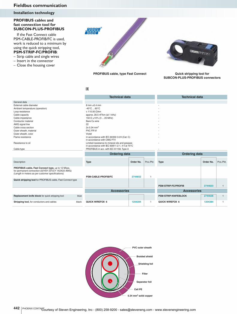
PROFIBUS cable, type Fast Connect Quick stripping tool for
SUBCON-PLUS-PROFIBUS connectors
If the Fast Connect cable PSM-CABLE-PROFIB/FC is used, work is reduced to a minimum by using the quick stripping tool, PSM-STRIP-FC/PROFIB:– Strip cable and single wires– Insert in the connector– Close the housing cover
PROFIBUS cables and fast connection tool for SUBCON-PLUS-PROFIBUS
Courtesy of Steven Engineering, Inc - (800) 258-9200 - [email protected] - www.stevenengineering.com
1
2
3
4
5
6
7
8
9
Shield
Shield 12
3
4
5
6
7
8
9
For further information and full technical data, visit phoenixcontact.net/products
Technical data Technical data
General data
Plug connection Incoming D-SUB 9 male connector D-SUB 9 male connector
Outgoing D-SUB-9 female connector D-SUB-9 female connector
Branching D-SUB-9 female connector 4 x D-SUB-9 female connector
COMBICON connector -
Nominal voltage UN
60 V AC/DC 60 V AC/DC
Nominal current IN
1 A 1 A
Test voltage 500 V AC (50 Hz, 1 min, rms) 500 V AC (50 Hz, 1 min, rms)
Shield connection D-SUB frame or shield clip D-SUB frame
Connection cross section rigid / flexible / AWG 0.14 - 1.5 mm² / 0.14 - 1.5 mm² / 26 - 16 -
Torque 0.4 Nm -
Ambient temperature (operation) -25°C ... 70°C -25°C ... 70°C
Housing material PVC PVC
Pin assignment all 1:1 all 1:1
Dimensions W/H/D 56 mm / 89.6 mm / 48 mm 89.8 mm / 89.6 mm / 39 mm
Ordering data Ordering data
Description Type Order No. Pcs./Pkt. Type Order No. Pcs./Pkt.
Passive RS-485 T-distributor, fitted with a 9 pos. D-SUB
male connector and two 9-pos. D-SUB female connectors,
as well as a 9-pos. PCB terminal block with shield clip.
PSM PTK 2760623 1
Passive RS-485 T-distributor, fitted with one 9-pos. D-SUB
male connector and five 9-pos. D-SUB female connectors
PSM PTK-4 2799364 1
Accessories Accessories
Screwdriver SZS 0,4X2,5 VDE 1205037 10 SZS 0,4X2,5 VDE 1205037 10
443PHOENIX CONTACT
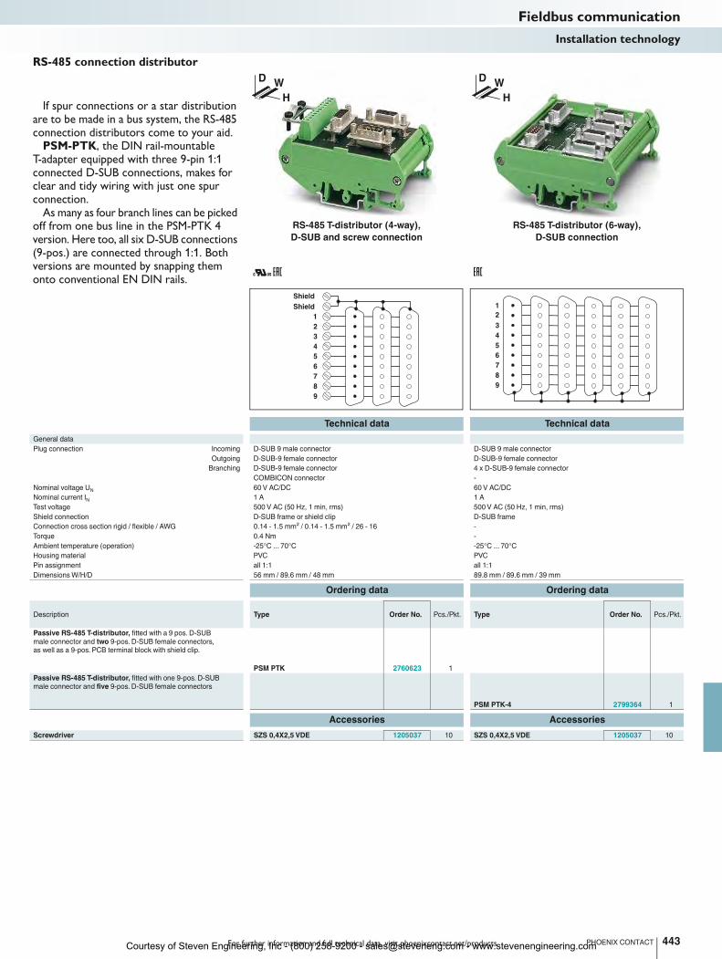
If spur connections or a star distribution are to be made in a bus system, the RS-485 connection distributors come to your aid.
PSM-PTK, the DIN rail-mountable T-adapter equipped with three 9-pin 1:1 connected D-SUB connections, makes for clear and tidy wiring with just one spur connection.
As many as four branch lines can be picked off from one bus line in the PSM-PTK 4 version. Here too, all six D-SUB connections (9-pos.) are connected through 1:1. Both versions are mounted by snapping them onto conventional EN DIN rails.
D W
H
D W
H
RS-485 connection distributor
Fieldbus communicationInstallation technology
RS-485 T-distributor (4-way),
D-SUB and screw connection
RS-485 T-distributor (6-way),
D-SUB connection
Courtesy of Steven Engineering, Inc - (800) 258-9200 - [email protected] - www.stevenengineering.com
54321
12345
2 3 5 6 7 9 1 4 8
2 3 5 6 7 9 1 4 8
1 2
345
2 1
43
5
93
42
39
34 30
35
89
38
M1
2M
12 4
6
2
1 3
4
5
1
2
3
4
5
54321
12345
3 5 8 6 9 7 4 2 1
3 5 8 6 9 7 4 2 1
Technical data
General data
Cable entry 90° (left)
Ambient temperature (operation) -30°C ... 80°C
Degree of protection IP40
Housing material Polyamide
Number of positions 5
Termination resistor separately via M12 termination resistor separately via M12 termination resistor separately via M12 terminatio
SUBCON fixing 4-40 UNC 0.4 Nm
Dimensions W / H / D 16 mm / 41 mm / 93 mm 16 mm / 40 mm / 71 mm 16 mm / 46 mm / 79 mm 16 mm / 75 mm / 38 mm
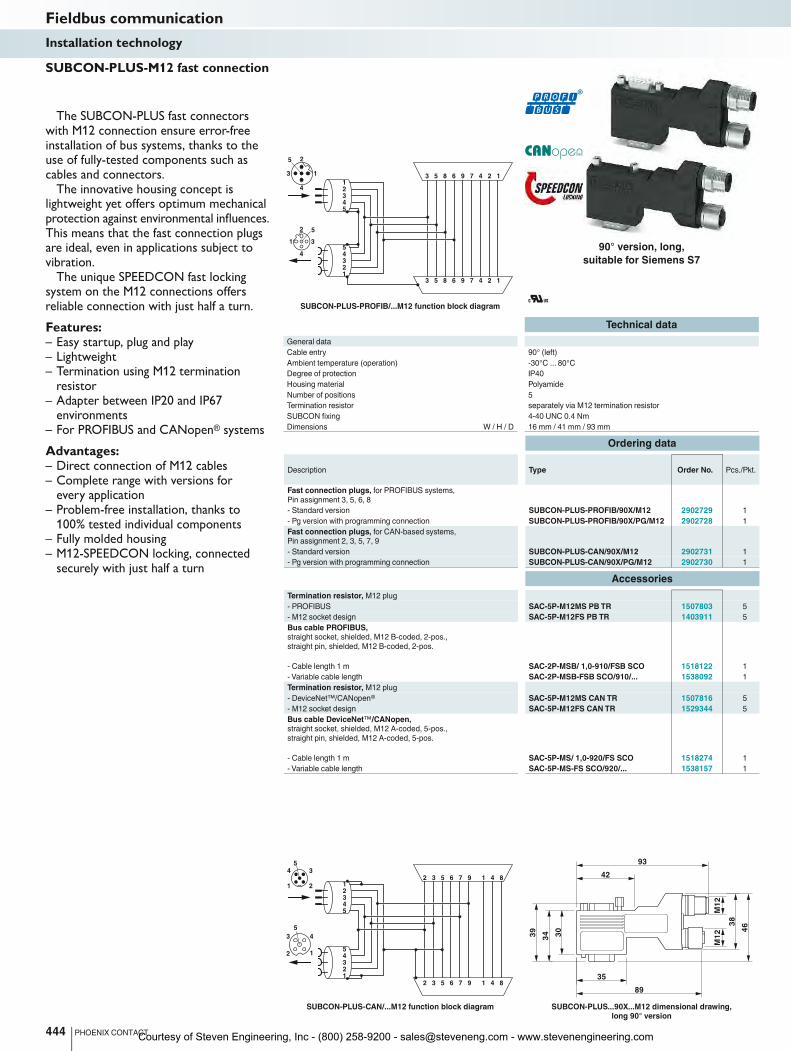
Ordering data
Description Type Order No. Pcs./Pkt.
Fast connection plugs, for PROFIBUS systems,
Pin assignment 3, 5, 6, 8
- Standard version SUBCON-PLUS-PROFIB/90X/M12 2902729 1
- Pg version with programming connection SUBCON-PLUS-PROFIB/90X/PG/M12 2902728 1
Fast connection plugs, for CAN-based systems,
Pin assignment 2, 3, 5, 7, 9
- Standard version SUBCON-PLUS-CAN/90X/M12 2902731 1
- Pg version with programming connection SUBCON-PLUS-CAN/90X/PG/M12 2902730 1
Accessories
Termination resistor, M12 plug
- PROFIBUS SAC-5P-M12MS PB TR 1507803 5
- M12 socket design SAC-5P-M12FS PB TR 1403911 5
Bus cable PROFIBUS,
straight socket, shielded, M12 B-coded, 2-pos.,
straight pin, shielded, M12 B-coded, 2-pos.
- Cable length 1 m SAC-2P-MSB/ 1,0-910/FSB SCO 1518122 1
- Variable cable length SAC-2P-MSB-FSB SCO/910/... 1538092 1
Termination resistor, M12 plug
- DeviceNet™/CANopen® SAC-5P-M12MS CAN TR 1507816 5
- M12 socket design SAC-5P-M12FS CAN TR 1529344 5
Bus cable DeviceNet™/CANopen,
straight socket, shielded, M12 A-coded, 5-pos.,
straight pin, shielded, M12 A-coded, 5-pos.
- Cable length 1 m SAC-5P-MS/ 1,0-920/FS SCO 1518274 1
- Variable cable length SAC-5P-MS-FS SCO/920/... 1538157 1
444 PHOENIX CONTACT
SUBCON-PLUS-CAN/...M12 function block diagram SUBCON-PLUS...90X...M12 dimensional drawing,
long 90° version
SUBCON-PLUS-M12 fast connection
The SUBCON-PLUS fast connectors with M12 connection ensure error-free installation of bus systems, thanks to the use of fully-tested components such as cables and connectors.
The innovative housing concept is lightweight yet offers optimum mechanical protection against environmental influences. This means that the fast connection plugs are ideal, even in applications subject to vibration.
The unique SPEEDCON fast locking system on the M12 connections offers reliable connection with just half a turn.
Features:– Easy startup, plug and play– Lightweight– Termination using M12 termination
resistor– Adapter between IP20 and IP67
environments– For PROFIBUS and CANopen® systems
Advantages:– Direct connection of M12 cables– Complete range with versions for
every application– Problem-free installation, thanks to
100% tested individual components– Fully molded housing– M12-SPEEDCON locking, connected
securely with just half a turn
Fieldbus communicationInstallation technology
90° version, long,
suitable for Siemens S7
SUBCON-PLUS-PROFIB/...M12 function block diagram
Courtesy of Steven Engineering, Inc - (800) 258-9200 - [email protected] - www.stevenengineering.com
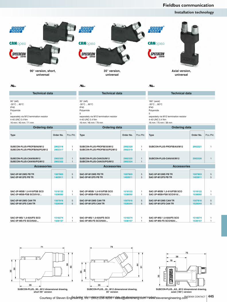
71
35
35 3
0
38
45
79
35
35 3
0
44
51
75
38
18
35
For further information and full technical data, visit phoenixcontact.net/products
Technical data Technical data Technical data
90° (left) 35° (left) 180° (axial)
-30°C ... 80°C -30°C ... 80°C -30°C ... 80°C
IP40 IP40 IP40
Polyamide Polyamide Polyamide
5 5 5
Termination resistor separately via M12 termination resistor separately via M12 termination resistor separately via M12 termination resistor separately via M12 termination resistor
4-40 UNC 0.4 Nm 4-40 UNC 0.4 Nm 4-40 UNC 0.4 Nm
Dimensions W / H / D 16 mm / 41 mm / 93 mm 16 mm / 40 mm / 71 mm 16 mm / 46 mm / 79 mm 16 mm / 75 mm / 38 mm
Ordering data Ordering data Ordering data
Type Order No. Pcs./Pkt. Type Order No. Pcs./Pkt. Type Order No. Pcs./Pkt.
SUBCON-PLUS-PROFIB/90/M12 2902318 1 SUBCON-PLUS-PROFIB/35/M12 2902320 1 SUBCON-PLUS-PROFIB/AX/M12 2902321 1
SUBCON-PLUS-PROFIB/90/PG/M12 2902317 1 SUBCON-PLUS-PROFIB/35/PG/M12 2902319 1
SUBCON-PLUS-CAN/90/M12 2902323 1 SUBCON-PLUS-CAN/35/M12 2902325 1 SUBCON-PLUS-CAN/AX/M12 2902326 1
SUBCON-PLUS-CAN/90/PG/M12 2902322 1 SUBCON-PLUS-CAN/35/PG/M12 2902324 1
Accessories Accessories Accessories
SAC-5P-M12MS PB TR 1507803 5 SAC-5P-M12MS PB TR 1507803 5 SAC-5P-M12MS PB TR 1507803 5
SAC-5P-M12FS PB TR 1403911 5 SAC-5P-M12FS PB TR 1403911 5 SAC-5P-M12FS PB TR 1403911 5
SAC-2P-MSB/ 1,0-910/FSB SCO 1518122 1 SAC-2P-MSB/ 1,0-910/FSB SCO 1518122 1 SAC-2P-MSB/ 1,0-910/FSB SCO 1518122 1
SAC-2P-MSB-FSB SCO/910/... 1538092 1 SAC-2P-MSB-FSB SCO/910/... 1538092 1 SAC-2P-MSB-FSB SCO/910/... 1538092 1
SAC-5P-M12MS CAN TR 1507816 5 SAC-5P-M12MS CAN TR 1507816 5 SAC-5P-M12MS CAN TR 1507816 5
SAC-5P-M12FS CAN TR 1529344 5 SAC-5P-M12FS CAN TR 1529344 5 SAC-5P-M12FS CAN TR 1529344 5
SAC-5P-MS/ 1,0-920/FS SCO 1518274 1 SAC-5P-MS/ 1,0-920/FS SCO 1518274 1 SAC-5P-MS/ 1,0-920/FS SCO 1518274 1
SAC-5P-MS-FS SCO/920/... 1538157 1 SAC-5P-MS-FS SCO/920/... 1538157 1 SAC-5P-MS-FS SCO/920/... 1538157 1
445PHOENIX CONTACT
SUBCON-PLUS...90...M12 dimensional drawing,
short 90° version
SUBCON-PLUS...35...M12 dimensional drawing,
35° version
SUBCON-PLUS...AX...M12 dimensional drawing,
axial (180°) version
Fieldbus communicationInstallation technology
90° version, short,
universal
35° version,
universal
Axial version,
universal
Courtesy of Steven Engineering, Inc - (800) 258-9200 - [email protected] - www.stevenengineering.com
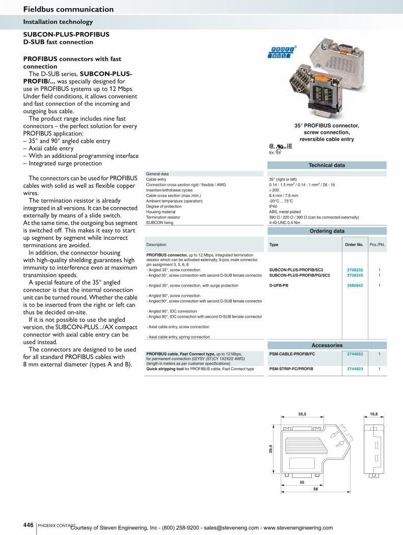
16,635,5
39
,4
35
58
Ex:
446 PHOENIX CONTACT
Technical data
General data
Cable entry 35° (right or left)
Connection cross section rigid / flexible / AWG 0.14 - 1.5 mm² / 0.14 - 1 mm² / 26 - 16 0.14 - 1.5 mm² / 0.14 - 1 mm² / 26 - 16 0.
Insertion/withdrawal cycles > 200
Cable cross section (max./min.) 8.4 mm / 7.6 mm
Ambient temperature (operation) -20°C ... 75°C
Degree of protection IP40
Housing material ABS, metal-plated
Termination resistor 390 Ω / 220 Ω / 390 Ω (can be connected externally) 390
SUBCON fixing 4-40 UNC 0.4 Nm
Ordering data
Description Type Order No. Pcs./Pkt.
PROFIBUS connector, up to 12 Mbps, integrated termination
resistor which can be activated externally, 9-pos. male connector,
pin assignment 3, 5, 6, 8
- Angled 35°, screw connection SUBCON-PLUS-PROFIB/SC2 2708232 1
- Angled 35°, screw connection with second D-SUB female connector SUBCON-PLUS-PROFIB/PG/SC2 2708245 1
- Angled 35°, screw connection, with surge protection D-UFB-PB 2880642 1
- Angled 90°, screw connection
- Angled 90°, screw connection with second D-SUB female connector
- Angled 90°, IDC connection
- Angled 90°, IDC connection with second D-SUB female connector
- Axial cable entry, screw connection
- Axial cable entry, spring connection
Accessories
PROFIBUS cable, Fast Connect type, up to 12 Mbps,
for permanent connection (02YSY (ST)CY 1X2X22 AWG)
(length in meters as per customer specifications)
PSM-CABLE-PROFIB/FC 2744652 1
Quick stripping tool for PROFIBUS cable, Fast Connect type PSM-STRIP-FC/PROFIB 2744623 1
SUBCON-PLUS-PROFIBUS D-SUB fast connection
PROFIBUS connectors with fast connection
The D-SUB series, SUBCON-PLUS-PROFIB/... was specially designed for use in PROFIBUS systems up to 12 Mbps. Under field conditions, it allows convenient and fast connection of the incoming and outgoing bus cable.
The product range includes nine fast connectors – the perfect solution for every PROFIBUS application:– 35° and 90° angled cable entry– Axial cable entry– With an additional programming interface– Integrated surge protection
The connectors can be used for PROFIBUS cables with solid as well as flexible copper wires.
The termination resistor is already integrated in all versions. It can be connected externally by means of a slide switch. At the same time, the outgoing bus segment is switched off. This makes it easy to start up segment by segment while incorrect terminations are avoided.
In addition, the connector housing with high-quality shielding guarantees high immunity to interference even at maximum transmission speeds.
A special feature of the 35° angled connector is that the internal connection unit can be turned round. Whether the cable is to be inserted from the right or left can thus be decided on-site.
If it is not possible to use the angled version, the SUBCON-PLUS.../AX compact connector with axial cable entry can be used instead.
The connectors are designed to be used for all standard PROFIBUS cables with 8 mm external diameter (types A and B).
Fieldbus communicationInstallation technology
35° PROFIBUS connector,
screw connection,
reversible cable entry
Courtesy of Steven Engineering, Inc - (800) 258-9200 - [email protected] - www.stevenengineering.com
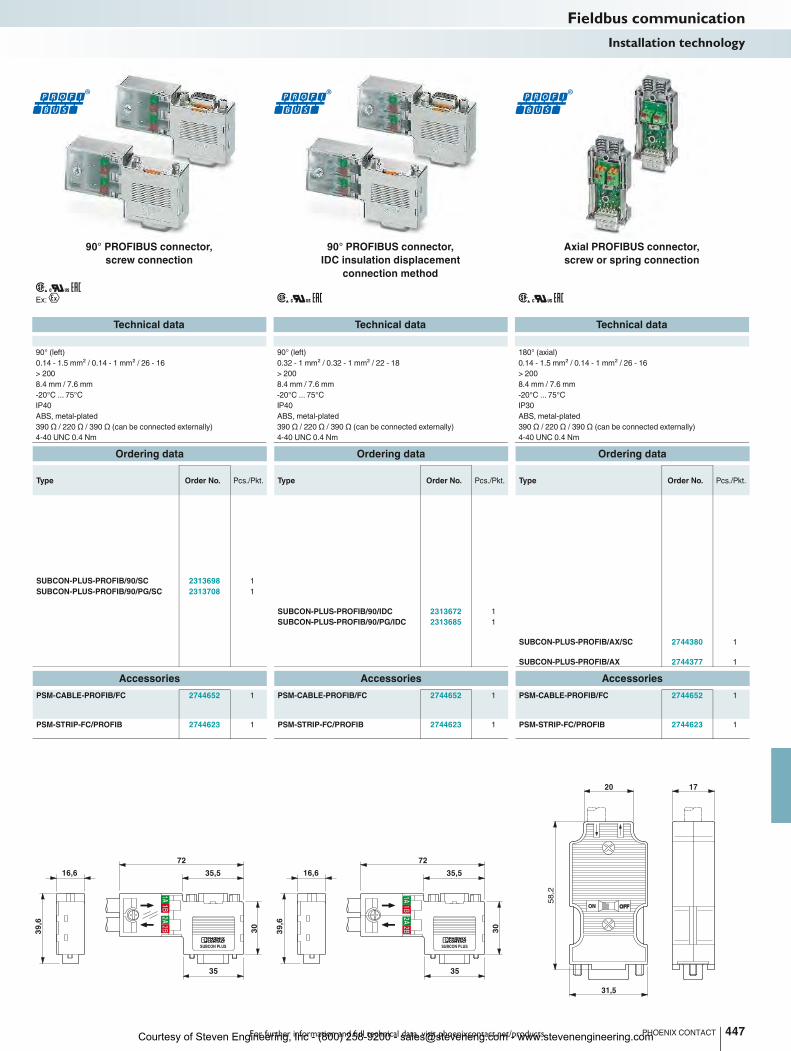
SUBCON PLUS
1A2A
2B2B1B1B
72
35,5
35
30
16,6
39
,6
SUBCON PLUS
1A2A
2B2B1B1B
72
35,5
35
30
16,6
39
,6
ON OFFOFF
1720
31,5
58
,2
For further information and full technical data, visit phoenixcontact.net/products
Ex:
447PHOENIX CONTACT
Technical data Technical data Technical data
90° (left) 90° (left) 180° (axial)
Connection cross section rigid / flexible / AWG 0.14 - 1.5 mm² / 0.14 - 1 mm² / 26 - 16 0.14 - 1.5 mm² / 0.14 - 1 mm² / 26 - 16 0.32 - 1 mm² / 0.32 - 1 mm² / 22 - 18 0.14 - 1.5 mm² / 0.14 - 1 mm² / 26 - 16
> 200 > 200 > 200
8.4 mm / 7.6 mm 8.4 mm / 7.6 mm 8.4 mm / 7.6 mm
-20°C ... 75°C -20°C ... 75°C -20°C ... 75°C
IP40 IP40 IP30
ABS, metal-plated ABS, metal-plated ABS, metal-plated
(can be connected externally) 390 Ω / 220 Ω / 390 Ω (can be connected externally) 390 Ω / 220 Ω / 390 Ω (can be connected externally) 390 Ω / 220 Ω / 390 Ω (can be connected externally)
4-40 UNC 0.4 Nm 4-40 UNC 0.4 Nm 4-40 UNC 0.4 Nm
Ordering data Ordering data Ordering data
Type Order No. Pcs./Pkt. Type Order No. Pcs./Pkt. Type Order No. Pcs./Pkt.
SUBCON-PLUS-PROFIB/90/SC 2313698 1
SUBCON-PLUS-PROFIB/90/PG/SC 2313708 1
SUBCON-PLUS-PROFIB/90/IDC 2313672 1
SUBCON-PLUS-PROFIB/90/PG/IDC 2313685 1
SUBCON-PLUS-PROFIB/AX/SC 2744380 1
SUBCON-PLUS-PROFIB/AX 2744377 1
Accessories Accessories Accessories
PSM-CABLE-PROFIB/FC 2744652 1 PSM-CABLE-PROFIB/FC 2744652 1 PSM-CABLE-PROFIB/FC 2744652 1
PSM-STRIP-FC/PROFIB 2744623 1 PSM-STRIP-FC/PROFIB 2744623 1 PSM-STRIP-FC/PROFIB 2744623 1
Fieldbus communicationInstallation technology
90° PROFIBUS connector,
screw connection
90° PROFIBUS connector,
IDC insulation displacement
connection method
Axial PROFIBUS connector,
screw or spring connection
Courtesy of Steven Engineering, Inc - (800) 258-9200 - [email protected] - www.stevenengineering.com
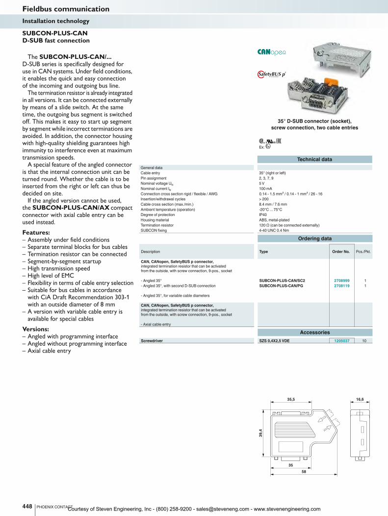
16,635,5
39
,4
35
58
Ex:
448 PHOENIX CONTACT
Technical data
General data
Cable entry 35° (right or left)
Pin assignment 2, 3, 7, 9
Nominal voltage UN
5 V
Nominal current IN
100 mA
Connection cross section rigid / flexible / AWG 0.14 - 1.5 mm² / 0.14 - 1 mm² / 26 - 16 0.14 - 1.5 mm² / 0.14 - 1 mm² / 26 - 16 0.
Insertion/withdrawal cycles > 200
Cable cross section (max./min.) 8.4 mm / 7.6 mm
Ambient temperature (operation) -20°C ... 75°C
Degree of protection IP40
Housing material ABS, metal-plated
Termination resistor 120 Ω (can be connected externally) 120
SUBCON fixing 4-40 UNC 0.4 Nm
Ordering data
Description Type Order No. Pcs./Pkt.
CAN, CANopen, SafetyBUS p connector,
integrated termination resistor that can be activated
from the outside, with screw connection, 9-pos., socket
- Angled 35° SUBCON-PLUS-CAN/SC2 2708999 1
- Angled 35°, with second D-SUB connection SUBCON-PLUS-CAN/PG 2708119 1
- Angled 35°, for variable cable diameters
CAN, CANopen, SafetyBUS p connector,
integrated termination resistor that can be activated
from the outside, with screw connection, 9-pos., socket
- Axial cable entry
Accessories
Screwdriver SZS 0,4X2,5 VDE 1205037 10
SUBCON-PLUS-CAN D-SUB fast connection
The SUBCON-PLUS-CAN/... D-SUB series is specifically designed for use in CAN systems. Under field conditions, it enables the quick and easy connection of the incoming and outgoing bus line.
The termination resistor is already integrated in all versions. It can be connected externally by means of a slide switch. At the same time, the outgoing bus segment is switched off. This makes it easy to start up segment by segment while incorrect terminations are avoided. In addition, the connector housing with high-quality shielding guarantees high immunity to interference even at maximum transmission speeds.
A special feature of the angled connector is that the internal connection unit can be turned round. Whether the cable is to be inserted from the right or left can thus be decided on site.
If the angled version cannot be used, the SUBCON-PLUS-CAN/AX compact connector with axial cable entry can be used instead.
Features:– Assembly under field conditions– Separate terminal blocks for bus cables– Termination resistor can be connected– Segment-by-segment startup– High transmission speed– High level of EMC– Flexibility in terms of cable entry selection– Suitable for bus cables in accordance
with CiA Draft Recommendation 303-1 with an outside diameter of 8 mm
– A version with variable cable entry is available for special cables
Versions:– Angled with programming interface– Angled without programming interface– Axial cable entry
Fieldbus communicationInstallation technology
35° D-SUB connector (socket),
screw connection, two cable entries
Courtesy of Steven Engineering, Inc - (800) 258-9200 - [email protected] - www.stevenengineering.com
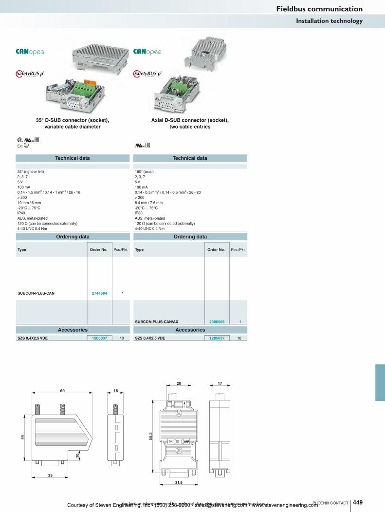
1660
44
35
10
ON OFFOFF
1720
31,5
58
,2
For further information and full technical data, visit phoenixcontact.net/products
Ex:
449PHOENIX CONTACT
Technical data Technical data
35° (right or left) 180° (axial)
2, 3, 7 2, 3, 7
5 V 5 V
100 mA 100 mA
Connection cross section rigid / flexible / AWG 0.14 - 1.5 mm² / 0.14 - 1 mm² / 26 - 16 0.14 - 1.5 mm² / 0.14 - 1 mm² / 26 - 16 0.14 - 0.5 mm² / 0.14 - 0.5 mm² / 26 - 20
> 200 > 200
10 mm / 6 mm 8.4 mm / 7.6 mm
-20°C ... 75°C -20°C ... 75°C
IP40 IP30
ABS, metal-plated ABS, metal-plated
(can be connected externally) 120 Ω (can be connected externally) 120 Ω (can be connected externally)
4-40 UNC 0.4 Nm 4-40 UNC 0.4 Nm
Ordering data Ordering data
Type Order No. Pcs./Pkt. Type Order No. Pcs./Pkt.
SUBCON-PLUS-CAN 2744694 1
SUBCON-PLUS-CAN/AX 2306566 1
Accessories Accessories
SZS 0,4X2,5 VDE 1205037 10 SZS 0,4X2,5 VDE 1205037 10
Fieldbus communicationInstallation technology
35° D-SUB connector (socket),
variable cable diameter
Axial D-SUB connector (socket),
two cable entries
Courtesy of Steven Engineering, Inc - (800) 258-9200 - [email protected] - www.stevenengineering.com
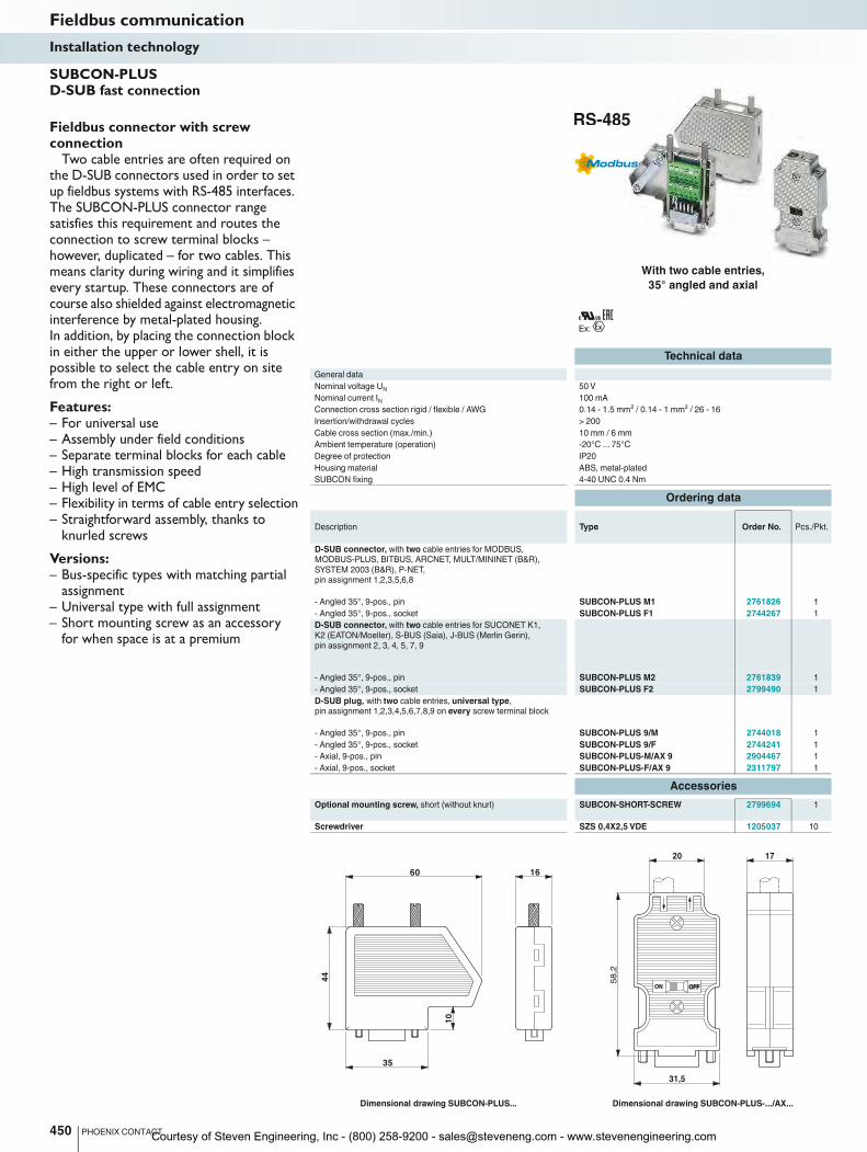
1660
44
35
10
ON OFFOFF
1720
31,5
58
,2
Ex:
Technical data
General data
Nominal voltage UN
50 V
Nominal current IN
100 mA
Connection cross section rigid / flexible / AWG 0.14 - 1.5 mm² / 0.14 - 1 mm² / 26 - 16
Insertion/withdrawal cycles > 200
Cable cross section (max./min.) 10 mm / 6 mm
Ambient temperature (operation) -20°C ... 75°C
Degree of protection IP20
Housing material ABS, metal-plated
SUBCON fixing 4-40 UNC 0.4 Nm
Ordering data
Description Type Order No. Pcs./Pkt.
D-SUB connector, with two cable entries for MODBUS,
MODBUS-PLUS, BITBUS, ARCNET, MULT/MININET (B&R),
SYSTEM 2003 (B&R), P-NET,
pin assignment 1,2,3,5,6,8
- Angled 35°, 9-pos., pin SUBCON-PLUS M1 2761826 1
- Angled 35°, 9-pos., socket SUBCON-PLUS F1 2744267 1
D-SUB connector, with two cable entries for SUCONET K1,
K2 (EATON/Moeller), S-BUS (Saia), J-BUS (Merlin Gerin),
pin assignment 2, 3, 4, 5, 7, 9
- Angled 35°, 9-pos., pin SUBCON-PLUS M2 2761839 1
- Angled 35°, 9-pos., socket SUBCON-PLUS F2 2799490 1
D-SUB plug, with two cable entries, universal type,
pin assignment 1,2,3,4,5,6,7,8,9 on every screw terminal block
- Angled 35°, 9-pos., pin SUBCON-PLUS 9/M 2744018 1
- Angled 35°, 9-pos., socket SUBCON-PLUS 9/F 2744241 1
- Axial, 9-pos., pin SUBCON-PLUS-M/AX 9 2904467 1
- Axial, 9-pos., socket SUBCON-PLUS-F/AX 9 2311797 1
Accessories
Optional mounting screw, short (without knurl) SUBCON-SHORT-SCREW 2799694 1
Screwdriver SZS 0,4X2,5 VDE 1205037 10
Dimensional drawing SUBCON-PLUS... Dimensional drawing SUBCON-PLUS-.../AX...
450 PHOENIX CONTACT
Fieldbus connector with screw connection
Two cable entries are often required on the D-SUB connectors used in order to set up fieldbus systems with RS-485 interfaces. The SUBCON-PLUS connector range satisfies this requirement and routes the connection to screw terminal blocks – however, duplicated – for two cables. This means clarity during wiring and it simplifies every startup. These connectors are of course also shielded against electromagnetic interference by metal-plated housing. In addition, by placing the connection block in either the upper or lower shell, it is possible to select the cable entry on site from the right or left.
Features:– For universal use– Assembly under field conditions– Separate terminal blocks for each cable– High transmission speed– High level of EMC– Flexibility in terms of cable entry selection– Straightforward assembly, thanks to
knurled screws
Versions:– Bus-specific types with matching partial
assignment– Universal type with full assignment– Short mounting screw as an accessory
for when space is at a premium
SUBCON-PLUS D-SUB fast connection
Fieldbus communicationInstallation technology
With two cable entries,
35° angled and axial
Courtesy of Steven Engineering, Inc - (800) 258-9200 - [email protected] - www.stevenengineering.com
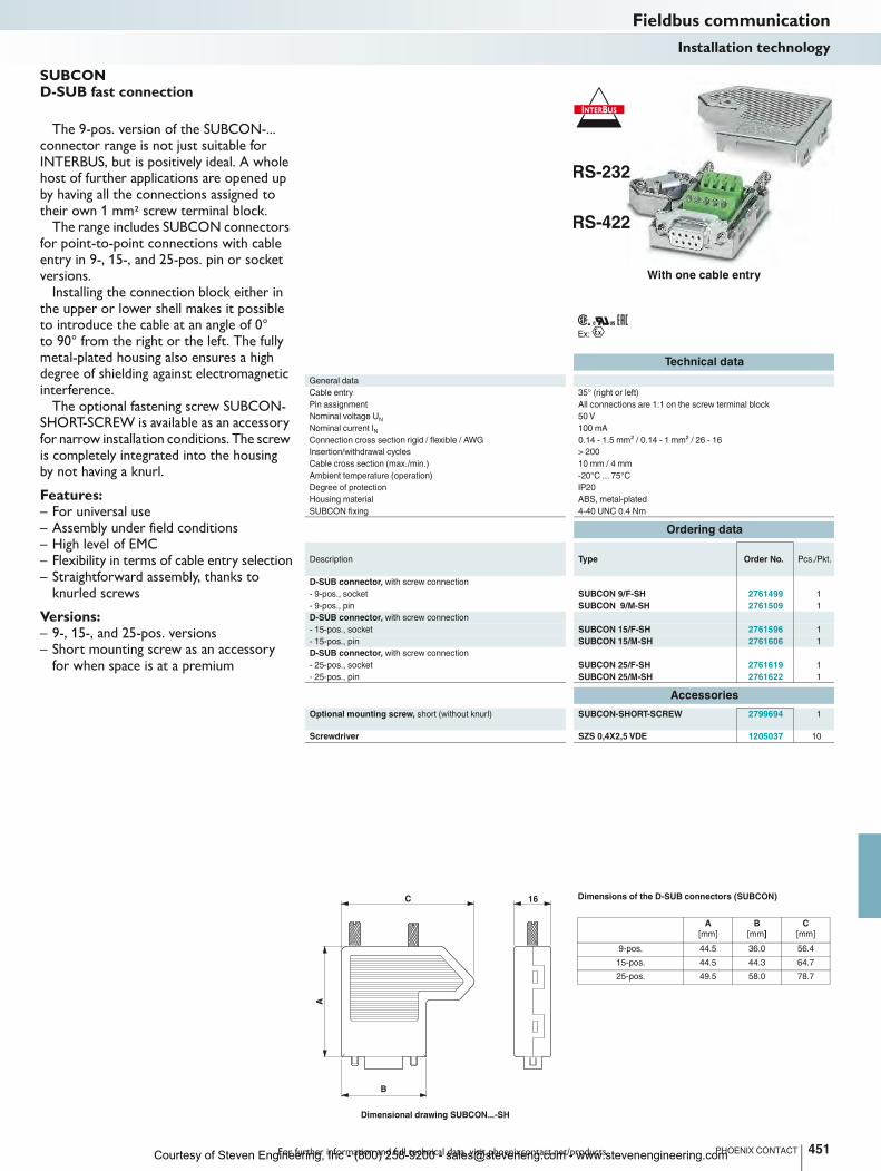
16C
B
A
For further information and full technical data, visit phoenixcontact.net/products
Ex:
Technical data
General data
Cable entry 35° (right or left)
Pin assignment All connections are 1:1 on the screw terminal block
Nominal voltage UN
50 V
Nominal current IN
100 mA
Connection cross section rigid / flexible / AWG 0.14 - 1.5 mm² / 0.14 - 1 mm² / 26 - 16
Insertion/withdrawal cycles > 200
Cable cross section (max./min.) 10 mm / 4 mm
Ambient temperature (operation) -20°C ... 75°C
Degree of protection IP20
Housing material ABS, metal-plated
SUBCON fixing 4-40 UNC 0.4 Nm
Ordering data
Description Type Order No. Pcs./Pkt.
D-SUB connector, with screw connection
- 9-pos., socket SUBCON 9/F-SH 2761499 1
- 9-pos., pin SUBCON 9/M-SH 2761509 1
D-SUB connector, with screw connection
- 15-pos., socket SUBCON 15/F-SH 2761596 1
- 15-pos., pin SUBCON 15/M-SH 2761606 1
D-SUB connector, with screw connection
- 25-pos., socket SUBCON 25/F-SH 2761619 1
- 25-pos., pin SUBCON 25/M-SH 2761622 1
Accessories
Optional mounting screw, short (without knurl) SUBCON-SHORT-SCREW 2799694 1
Screwdriver SZS 0,4X2,5 VDE 1205037 10
451PHOENIX CONTACT
The 9-pos. version of the SUBCON-... connector range is not just suitable for INTERBUS, but is positively ideal. A whole host of further applications are opened up by having all the connections assigned to their own 1 mm2 screw terminal block.
The range includes SUBCON connectors for point-to-point connections with cable entry in 9-, 15-, and 25-pos. pin or socket versions.
Installing the connection block either in the upper or lower shell makes it possible to introduce the cable at an angle of 0° to 90° from the right or the left. The fully metal-plated housing also ensures a high degree of shielding against electromagnetic interference.
The optional fastening screw SUBCON-SHORT-SCREW is available as an accessory for narrow installation conditions. The screw is completely integrated into the housing by not having a knurl.
Features:– For universal use– Assembly under field conditions– High level of EMC– Flexibility in terms of cable entry selection– Straightforward assembly, thanks to
knurled screws
Versions:– 9-, 15-, and 25-pos. versions– Short mounting screw as an accessory
for when space is at a premium
SUBCON D-SUB fast connection
Dimensional drawing SUBCON...-SH
A
[mm]
B
[mm]
C
[mm]
9-pos. 44.5 36.0 56.4
15-pos. 44.5 44.3 64.7
25-pos. 49.5 58.0 78.7
Dimensions of the D-SUB connectors (SUBCON)
Fieldbus communicationInstallation technology
With one cable entry
Courtesy of Steven Engineering, Inc - (800) 258-9200 - [email protected] - www.stevenengineering.com
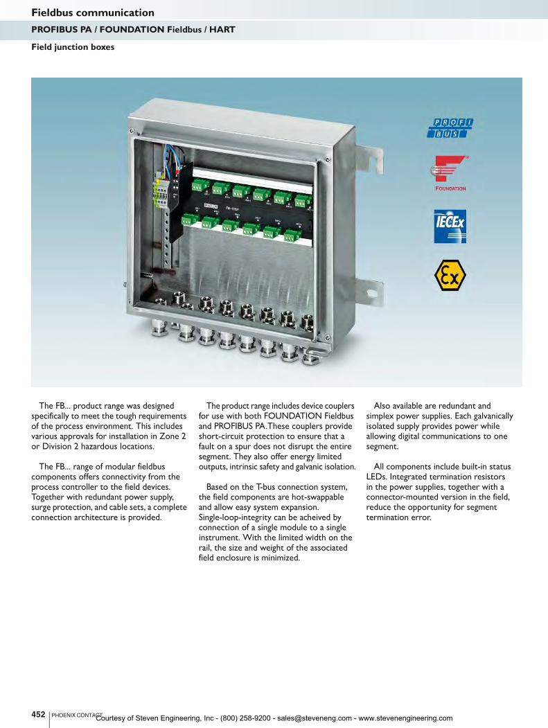
The FB... product range was designed specifically to meet the tough requirements of the process environment. This includes various approvals for installation in Zone 2 or Division 2 hazardous locations.
The FB... range of modular fieldbus components offers connectivity from the process controller to the field devices. Together with redundant power supply, surge protection, and cable sets, a complete connection architecture is provided.
The product range includes device couplers for use with both FOUNDATION Fieldbus and PROFIBUS PA.These couplers provide short-circuit protection to ensure that a fault on a spur does not disrupt the entire segment. They also offer energy limited outputs, intrinsic safety and galvanic isolation.
Based on the T-bus connection system, the field components are hot-swappable and allow easy system expansion. Single-loop-integrity can be acheived by connection of a single module to a single instrument. With the limited width on the rail, the size and weight of the associated field enclosure is minimized.
Also available are redundant and simplex power supplies. Each galvanically isolated supply provides power while allowing digital communications to one segment.
All components include built-in status LEDs. Integrated termination resistors in the power supplies, together with a connector-mounted version in the field, reduce the opportunity for segment termination error.
452 PHOENIX CONTACT
Field junction boxes
Fieldbus communicationPROFIBUS PA / FOUNDATION Fieldbus / HART
Courtesy of Steven Engineering, Inc - (800) 258-9200 - [email protected] - www.stevenengineering.com
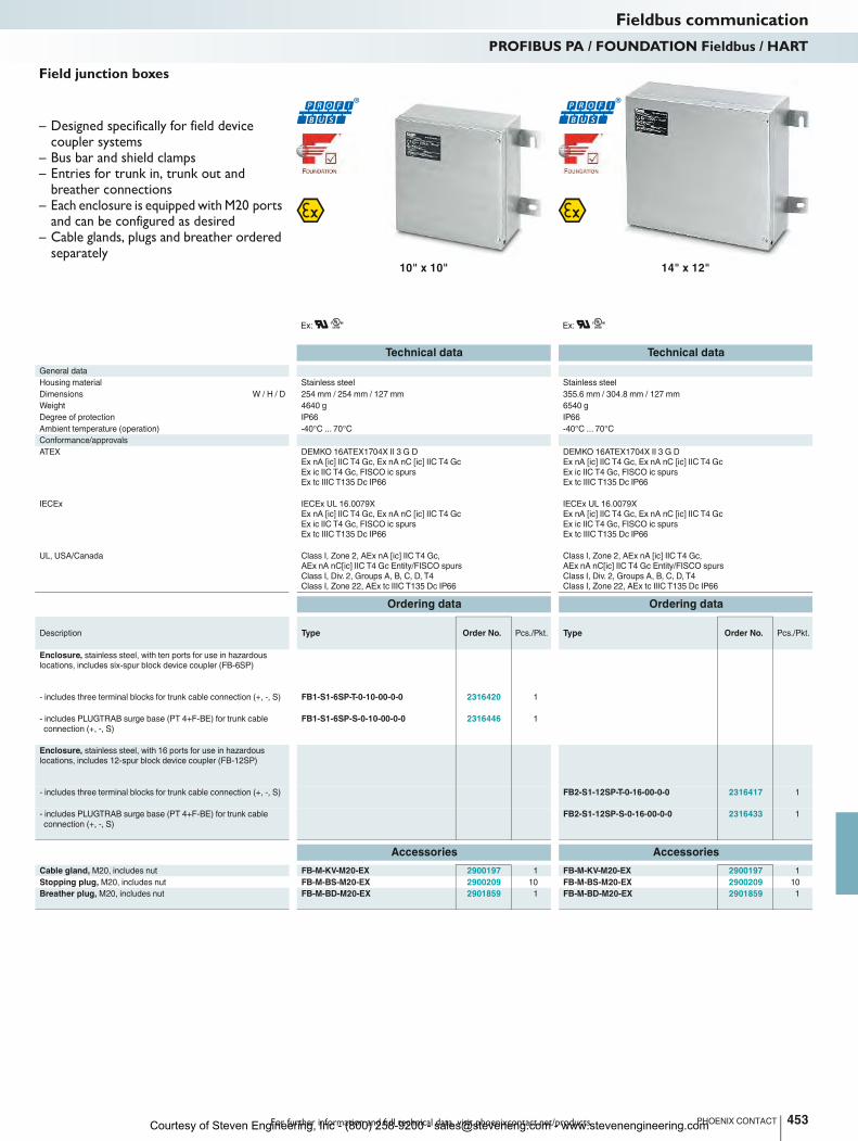
For further information and full technical data, visit phoenixcontact.net/products
Ex: Ex:
Technical data Technical data
General data
Housing material Stainless steel Stainless steel
Dimensions W / H / D 254 mm / 254 mm / 127 mm 355.6 mm / 304.8 mm / 127 mm
Weight 4640 g 6540 g
Degree of protection IP66 IP66
Ambient temperature (operation) -40°C ... 70°C -40°C ... 70°C
Conformance/approvals
ATEX DEMKO 16ATEX1704X II 3 G D
Ex nA [ic] IIC T4 Gc, Ex nA nC [ic] IIC T4 Gc
Ex ic IIC T4 Gc, FISCO ic spurs
Ex tc IIIC T135 Dc IP66
DEMKO 16ATEX1704X II 3 G D
Ex nA [ic] IIC T4 Gc, Ex nA nC [ic] IIC T4 Gc
Ex ic IIC T4 Gc, FISCO ic spurs
Ex tc IIIC T135 Dc IP66
IECEx IECEx UL 16.0079X
Ex nA [ic] IIC T4 Gc, Ex nA nC [ic] IIC T4 Gc
Ex ic IIC T4 Gc, FISCO ic spurs
Ex tc IIIC T135 Dc IP66
IECEx UL 16.0079X
Ex nA [ic] IIC T4 Gc, Ex nA nC [ic] IIC T4 Gc
Ex ic IIC T4 Gc, FISCO ic spurs
Ex tc IIIC T135 Dc IP66
UL, USA/Canada Class I, Zone 2, AEx nA [ic] IIC T4 Gc,
AEx nA nC[ic] IIC T4 Gc Entity/FISCO spurs
Class I, Div. 2, Groups A, B, C, D, T4
Class I, Zone 22, AEx tc IIIC T135 Dc IP66
Class I, Zone 2, AEx nA [ic] IIC T4 Gc,
AEx nA nC[ic] IIC T4 Gc Entity/FISCO spurs
Class I, Div. 2, Groups A, B, C, D, T4
Class I, Zone 22, AEx tc IIIC T135 Dc IP66
Ordering data Ordering data
Description Type Order No. Pcs./Pkt. Type Order No. Pcs./Pkt.
Enclosure, stainless steel, with ten ports for use in hazardous
locations, includes six-spur block device coupler (FB-6SP)
- includes three terminal blocks for trunk cable connection (+, -, S) FB1-S1-6SP-T-0-10-00-0-0 2316420 1
- includes PLUGTRAB surge base (PT 4+F-BE) for trunk cable
connection (+, -, S)
FB1-S1-6SP-S-0-10-00-0-0 2316446 1
Enclosure, stainless steel, with 16 ports for use in hazardous
locations, includes 12-spur block device coupler (FB-12SP)
- includes three terminal blocks for trunk cable connection (+, -, S) FB2-S1-12SP-T-0-16-00-0-0 2316417 1
- includes PLUGTRAB surge base (PT 4+F-BE) for trunk cable
connection (+, -, S)
FB2-S1-12SP-S-0-16-00-0-0 2316433 1
Accessories Accessories
Cable gland, M20, includes nut FB-M-KV-M20-EX 2900197 1 FB-M-KV-M20-EX 2900197 1
Stopping plug, M20, includes nut FB-M-BS-M20-EX 2900209 10 FB-M-BS-M20-EX 2900209 10
Breather plug, M20, includes nut FB-M-BD-M20-EX 2901859 1 FB-M-BD-M20-EX 2901859 1
453PHOENIX CONTACT
Fieldbus communicationPROFIBUS PA / FOUNDATION Fieldbus / HART
10" x 10" 14" x 12"
– Designed specifically for field device coupler systems
– Bus bar and shield clamps– Entries for trunk in, trunk out and
breather connections– Each enclosure is equipped with M20 ports
and can be configured as desired– Cable glands, plugs and breather ordered
separately
Field junction boxes
Courtesy of Steven Engineering, Inc - (800) 258-9200 - [email protected] - www.stevenengineering.com
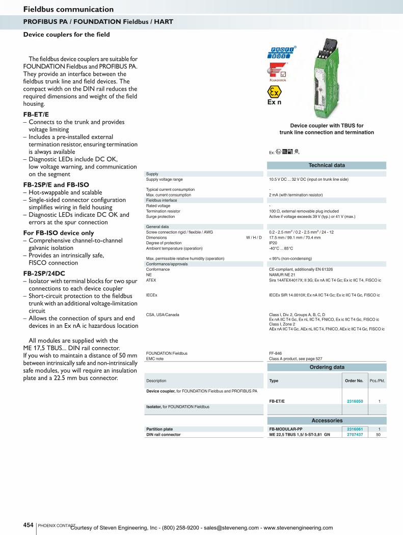
Ex:
454 PHOENIX CONTACT
Device couplers for the field
The fieldbus device couplers are suitable for FOUNDATION Fieldbus and PROFIBUS PA. They provide an interface between the fieldbus trunk line and field devices. The compact width on the DIN rail reduces the required dimensions and weight of the field housing.
FB-ET/E– Connects to the trunk and provides
voltage limiting– Includes a pre-installed external
termination resistor, ensuring termination is always available
– Diagnostic LEDs include DC OK, low voltage warning, and communication on the segment
FB-2SP/E and FB-ISO– Hot-swappable and scalable– Single-sided connector configuration
simplifies wiring in field housing– Diagnostic LEDs indicate DC OK and
errors at the spur connection
For FB-ISO device only– Comprehensive channel-to-channel
galvanic isolation– Provides an intrinsically safe,
FISCO connection
FB-2SP/24DC– Isolator with terminal blocks for two spur
connections to each device coupler– Short-circuit protection to the fieldbus
trunk with an additional voltage-limitation circuit
– Allows the connection of spurs and end devices in an Ex nA ic hazardous location
All modules are supplied with the ME 17,5 TBUS... DIN rail connector. If you wish to maintain a distance of 50 mm between intrinsically safe and non-intrinsically safe modules, you will require an insulation plate and a 22.5 mm bus connector.
Technical data
Supply
Supply voltage range 10.5 V DC ... 32 V DC (input on trunk line side) 10.5 V DC ... 32 V DC (via FB-ET/E) 17 V DC ... 32 V DC (inp
Typical current consumption -
Max. current consumption 2 mA (with termination resistor) 3.5 mA (no-load) - -
Fieldbus interface
Rated voltage -
Termination resistor 100 Ω, external removable plug included - - -
Surge protection Active if voltage exceeds 39 V (typ.) or 41 V (max.) - - -
General data
Screw connection rigid / flexible / AWG 0.2 - 2.5 mm² / 0.2 - 2.5 mm² / 24 - 12 0.2 - 2.5 mm² / 0.2 - 2.5 mm² / 24 - 12 0.2 - 2.5
Dimensions W / H / D 17.5 mm / 99.1 mm / 70.4 mm 17.5 mm / 89.7 mm / 70.4 mm 17.5 mm / 89.7 mm / 70.4 mm 17.5 mm / 89.7 mm / 70.4 mm
Degree of protection IP20
Ambient temperature (operation) -40°C ... 85°C
Max. permissible relative humidity (operation) < 95% (non-condensing) < 95% (non-condensing) < 95% (non-condensing) -
Conformance/approvals
Conformance CE-compliant, additionally EN 61326 - CE-compliant, additionally EN 61326 -
NE NAMUR NE 21
ATEX Sira 14ATEX4017X; II 3G; Ex nA IIC T4 Gc; Ex ic IIC T4, FISCO ic Sira 14ATEX4018X;
IECEx IECEx SIR 14.0010X; Ex nA IIC T4 Gc; Ex ic IIC T4 Gc, FISCO ic IECEx SIR 14.0011X;
CSA, USA/Canada Class I, Div. 2, Groups A, B, C, D
Ex nA IIC T4 Gc, Ex nL IIC T4, FNICO, Ex ic IIC T4 Gc, FISCO ic
Class I, Zone 2
AEx nA IIC T4 Gc, AEx nL IIC T4, FNICO, AEx ic IIC T4 Gc, FISCO ic
FOUNDATION Fieldbus FF-846
EMC note Class A product, see page 527 Class A product, see page
Ordering data
Description Type Order No. Pcs./Pkt.
Device coupler, for FOUNDATION Fieldbus and PROFIBUS PA
FB-ET/E 2316050 1
Isolator, for FOUNDATION Fieldbus
Accessories
Partition plate FB-MODULAR-PP 2316061 1
DIN rail connector ME 22,5 TBUS 1,5/ 5-ST-3,81 GN 2707437 50
Fieldbus communicationPROFIBUS PA / FOUNDATION Fieldbus / HART
Device coupler with TBUS for
trunk line connection and termination
Courtesy of Steven Engineering, Inc - (800) 258-9200 - [email protected] - www.stevenengineering.com

FOUNDATION FOUNDATION FOUNDATION
For further information and full technical data, visit phoenixcontact.net/products
Ex: Ex:
455PHOENIX CONTACT
Technical data Technical data Technical data
de) 10.5 V DC ... 32 V DC (via FB-ET/E) 17 V DC ... 32 V DC (input on trunk line side) 9 V DC ... 30 V DC
- 10 mA -
Max. current consumption 2 mA (with termination resistor) 3.5 mA (no-load) - -
≤ 32 V (per spur) ≥ 10 V (per spur) ≤ 32 V (per spur)
, external removable plug included - - -
Surge protection Active if voltage exceeds 39 V (typ.) or 41 V (max.) - - -
5 mm² / 24 - 12 0.2 - 2.5 mm² / 0.2 - 2.5 mm² / 24 - 12 0.2 - 2.5 mm² / 0.2 - 2.5 mm² / 24 - 12 0.2 - 2.5 mm² / 0.2 - 2.5 mm² / 24 - 12
Dimensions W / H / D 17.5 mm / 99.1 mm / 70.4 mm 17.5 mm / 89.7 mm / 70.4 mm 17.5 mm / 89.7 mm / 70.4 mm 17.5 mm / 89.7 mm / 70.4 mm
IP20 IP20 IP20
-40°C ... 85°C (depending on set rated current) -40°C ... 60°C -40°C ... 85°C
Max. permissible relative humidity (operation) < 95% (non-condensing) < 95% (non-condensing) < 95% (non-condensing) -
Conformance CE-compliant, additionally EN 61326 - CE-compliant, additionally EN 61326 -
NAMUR NE 21 NAMUR NE 21 NAMUR NE 21
ATEX Sira 14ATEX4017X; II 3G; Ex nA IIC T4 Gc; Ex ic IIC T4, FISCO ic Sira 14ATEX4018X; II 3(3)G
Ex nA [ic] IIC T4 Gc;
Ex nA [ic] IIC T4 Gc, FISCO ic spurs
II 3(3) G Ex nA [nL Gc] IIC T4 Gc, FNICO power supply (spur)
II 3(1) GD Ex nA [ia Ga Da] IIC T4 Gc, FISCO power supply (spur)
Sira 13ATEX4016;
II 3(3)G Ex nA [ic] IIC T4 Gc
IECEx IECEx SIR 14.0010X; Ex nA IIC T4 Gc; Ex ic IIC T4 Gc, FISCO ic IECEx SIR 14.0011X;
Ex nA [ic] IIC T4 Gc;
Ex nA [ic] IIC T4 Gc, FISCO ic spurs
Ex nA [nL Gc] IIC T4 Gc, FNICO power supply (spur)
Ex nA [ia Ga Da] IIC T4 Gc, FISCO power supply (spur)
IECEx SIR 13.0001X;
Ex nA [ic] IIC T4 Gc
Class I, Div. 2, Groups A,B,C,D
Ex nL IIC T4 FNICO, Ex ic IIC T4 FISCO ic
Ex nA [nL] IIC T4, Ex nA [ic] IIC T4
Ex nA [nL] IIC T4 FNICO spurs, Ex nA [ic] IIC T4 FISCO ic spurs
Class I, Zone 2
AEx nL IIC T4 FNICO, AEx ic IIC T4 FISCO ic
AEx nA [nL] IIC T4, AEx nA [ic] IIC T4
AEx nA [nL] IIC T4 FNICO spurs, AEx nA [ic] IIC T4 FISCO ic spurs
Ex nA [ia] IIC T4 Class I, Div. 2, Groups A, B, C, D; Ex nA[ic] IIC T4 Gc
Class I, Zone 2; AEx nA[ic] IIC T4 Gc
FF-846 - FF-846
EMC note Class A product, see page 527 Class A product, see page 527 Class A product, see page 527 Class A product, see page 527
Ordering data Ordering data Ordering data
Type Order No. Pcs./Pkt. Type Order No. Pcs./Pkt. Type Order No. Pcs./Pkt.
FB-2SP/E 2316052 1 FB-ISO 2316064 1
FB-2SP/24DC 2316352 1
Accessories Accessories Accessories
FB-MODULAR-PP 2316061 1 FB-MODULAR-PP 2316061 1 FB-MODULAR-PP 2316061 1
ME 22,5 TBUS 1,5/ 5-ST-3,81 GN 2707437 50 ME 22,5 TBUS 1,5/ 5-ST-3,81 GN 2707437 50 ME 22,5 TBUS 1,5/ 5-ST-3,81 GN 2707437 50
Fieldbus communicationPROFIBUS PA / FOUNDATION Fieldbus / HART
Device coupler with TBUS for 2 spurs Device coupler with TBUS for
1 electrically isolated spur connection
Isolator for Zone 2 installation using the
intrinsically safe [ic] protection method
Courtesy of Steven Engineering, Inc - (800) 258-9200 - [email protected] - www.stevenengineering.com
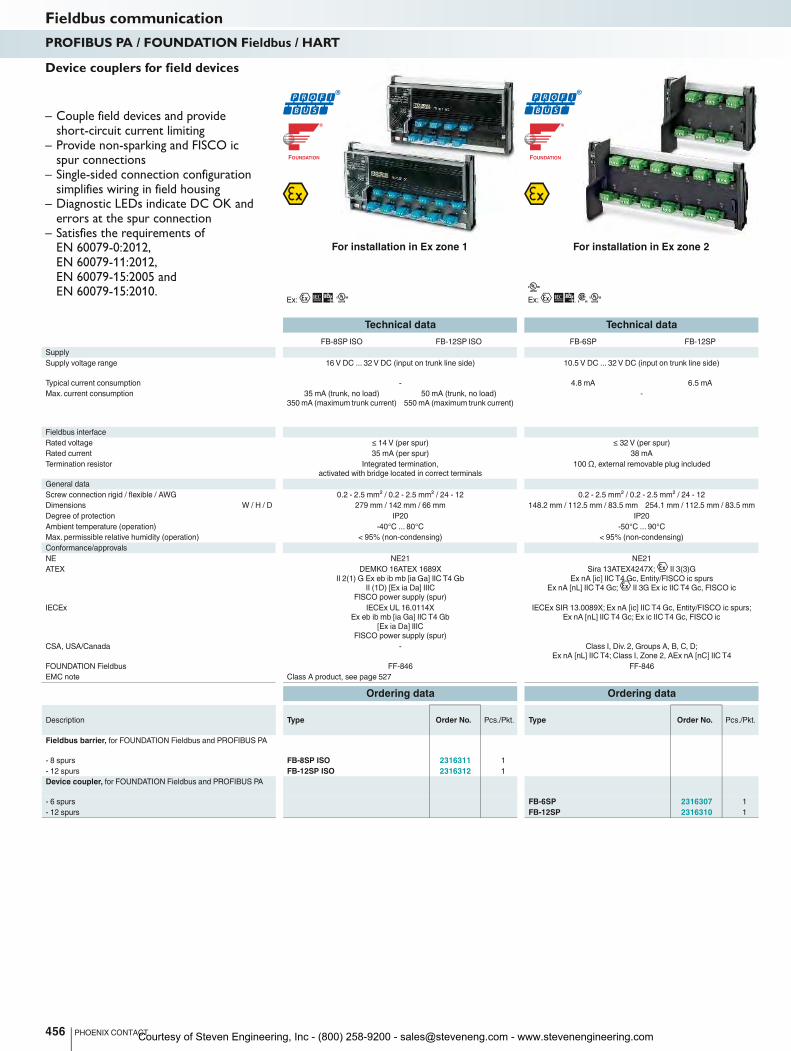
FOUNDATION FOUNDATION
Ex: Ex:
Technical data Technical data
FB-8SP ISO FB-12SP ISO FB-6SP FB-12SP
Supply
Supply voltage range 16 V DC ... 32 V DC (input on trunk line side) 10.5 V DC ... 32 V DC (input on trunk line side)
Typical current consumption - 4.8 mA 6.5 mA
Max. current consumption 35 mA (trunk, no load)
350 mA (maximum trunk current)
50 mA (trunk, no load)
550 mA (maximum trunk current)
-
Fieldbus interface
Rated voltage ≤ 14 V (per spur) ≤ 32 V (per spur)
Rated current 35 mA (per spur) 38 mA
Termination resistor Integrated termination,
activated with bridge located in correct terminals
100 Ω, external removable plug included
General data
Screw connection rigid / flexible / AWG 0.2 - 2.5 mm² / 0.2 - 2.5 mm² / 24 - 12 0.2 - 2.5 mm² / 0.2 - 2.5 mm² / 24 - 12
Dimensions W / H / D 279 mm / 142 mm / 66 mm 148.2 mm / 112.5 mm / 83.5 mm 254.1 mm / 112.5 mm / 83.5 mm
Degree of protection IP20 IP20
Ambient temperature (operation) -40°C ... 80°C -50°C ... 90°C
Max. permissible relative humidity (operation) < 95% (non-condensing) < 95% (non-condensing)
Conformance/approvals
NE NE21 NE21
ATEX DEMKO 16ATEX 1689X
II 2(1) G Ex eb ib mb [ia Ga] IIC T4 Gb
II (1D) [Ex ia Da] IIIC
FISCO power supply (spur)
Sira 13ATEX4247X; II 3(3)G
Ex nA [ic] IIC T4 Gc, Entity/FISCO ic spurs
Ex nA [nL] IIC T4 Gc; II 3G Ex ic IIC T4 Gc, FISCO ic
IECEx IECEx UL 16.0114X
Ex eb ib mb [ia Ga] IIC T4 Gb
[Ex ia Da] IIIC
FISCO power supply (spur)
IECEx SIR 13.0089X; Ex nA [ic] IIC T4 Gc, Entity/FISCO ic spurs;
Ex nA [nL] IIC T4 Gc; Ex ic IIC T4 Gc, FISCO ic
CSA, USA/Canada - Class I, Div. 2, Groups A, B, C, D;
Ex nA [nL] IIC T4; Class I, Zone 2, AEx nA [nC] IIC T4
FOUNDATION Fieldbus FF-846 FF-846
EMC note Class A product, see page 527
Ordering data Ordering data
Description Type Order No. Pcs./Pkt. Type Order No. Pcs./Pkt.
Fieldbus barrier, for FOUNDATION Fieldbus and PROFIBUS PA
- 8 spurs FB-8SP ISO 2316311 1
- 12 spurs FB-12SP ISO 2316312 1
Device coupler, for FOUNDATION Fieldbus and PROFIBUS PA
- 6 spurs FB-6SP 2316307 1
- 12 spurs FB-12SP 2316310 1
456 PHOENIX CONTACT
Fieldbus communicationPROFIBUS PA / FOUNDATION Fieldbus / HART
For installation in Ex zone 1 For installation in Ex zone 2
– Couple field devices and provide short-circuit current limiting
– Provide non-sparking and FISCO ic spur connections
– Single-sided connection configuration simplifies wiring in field housing
– Diagnostic LEDs indicate DC OK and errors at the spur connection
– Satisfies the requirements of EN 60079-0:2012, EN 60079-11:2012, EN 60079-15:2005 and EN 60079-15:2010.
Device couplers for field devices
Courtesy of Steven Engineering, Inc - (800) 258-9200 - [email protected] - www.stevenengineering.com
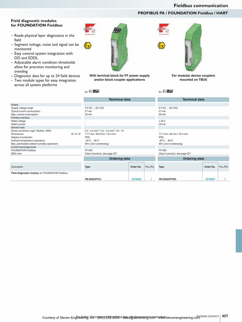
For further information and full technical data, visit phoenixcontact.net/products
Ex: Ex:
Technical data Technical data
Supply
Supply voltage range 9 V DC ... 32 V DC 9 V DC ... 32 V DC
Typical current consumption 27 mA 27 mA
Max. current consumption 29 mA 29 mA
Fieldbus interface
Rated voltage - ≤ 32 V
Rated current - 29 mA
General data
Screw connection rigid / flexible / AWG 0.2 - 2.5 mm² / 0.2 - 2.5 mm² / 24 - 12 -
Dimensions W / H / D 17.7 mm / 93.9 mm / 70.4 mm 17.7 mm / 85 mm / 70.4 mm
Degree of protection IP20 IP20
Ambient temperature (operation) -40°C ... 85°C -40°C ... 85°C
Max. permissible relative humidity (operation) 95% (non-condensing) 95% (non-condensing)
Conformance/approvals
FOUNDATION Fieldbus FF-830 FF-830
EMC note Class A product, see page 527 Class A product, see page 527
Ordering data Ordering data
Description Type Order No. Pcs./Pkt. Type Order No. Pcs./Pkt.
Field diagnostic module, for FOUNDATION Fieldbus
FB-DIAG/FF/LI 2316284 1 FB-DIAG/FF/NC 2316297 1
457PHOENIX CONTACT
Fieldbus communicationPROFIBUS PA / FOUNDATION Fieldbus / HART
With terminal block for FF power supply
and/or block coupler applications
For modular device couplers
mounted on TBUS
– Reads physical layer diagnostics in the field
– Segment voltage, noise and signal can be monitored
– Easy control system integration with DD and EDDL
– Adjustable alarm condition thresholds allow for precision monitoring and trending
– Diagnostic data for up to 24 field devices– Two module types for easy integration
across all system platforms
Field diagnostic modules for FOUNDATION Fieldbus
Courtesy of Steven Engineering, Inc - (800) 258-9200 - [email protected] - www.stevenengineering.com
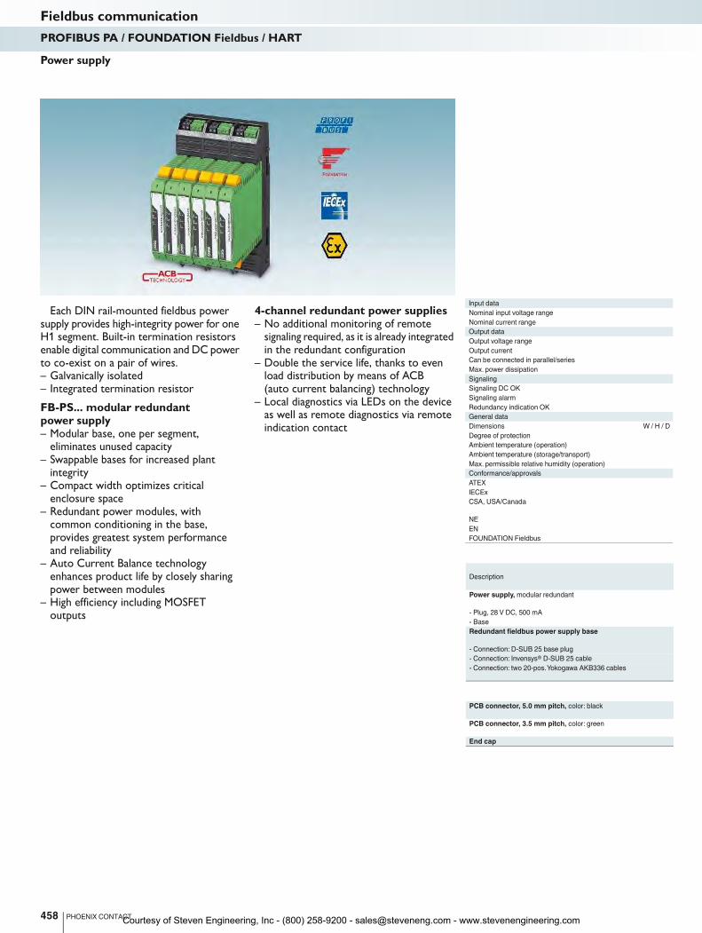
Each DIN rail-mounted fieldbus power supply provides high-integrity power for one H1 segment. Built-in termination resistors enable digital communication and DC power to co-exist on a pair of wires.– Galvanically isolated– Integrated termination resistor
FB-PS... modular redundant power supply– Modular base, one per segment,
eliminates unused capacity– Swappable bases for increased plant
integrity– Compact width optimizes critical
enclosure space– Redundant power modules, with
common conditioning in the base, provides greatest system performance and reliability
– Auto Current Balance technology enhances product life by closely sharing power between modules
– High efficiency including MOSFET outputs
4-channel redundant power supplies– No additional monitoring of remote
signaling required, as it is already integrated in the redundant configuration
– Double the service life, thanks to even load distribution by means of ACB (auto current balancing) technology
– Local diagnostics via LEDs on the device as well as remote diagnostics via remote indication contact
Input data
Nominal input voltage range 18.5 V DC ... 30.5 V DC
Nominal current range 700 mA ... 1.1 A - -
Output data
Output voltage range
Output current
Can be connected in parallel/series Yes / No - / - - / -
Max. power dissipation 4 W (typical) - -
Signaling
Signaling DC OK
Signaling alarm
Redundancy indication OK Green LED - -
General data
Dimensions W / H / D 17.5 / 117.6 / 115 mm 36 / 202.5 / 61.5 mm 180 / 77 / 180 mm
Degree of protection
Ambient temperature (operation) -40°C ... 70°C -40°C ... 70°C -40°C ... 70°C
Ambient temperature (storage/transport) -40°C ... 85°C -40°C ... 85°C -40°C ... 85°C
Max. permissible relative humidity (operation) 95% (non-condensing) 95% (non-condensing) 95% (non-condensing)
Conformance/approvals
ATEX
IECEx
CSA, USA/Canada
NE
EN
FOUNDATION Fieldbus FF-831 FF-831 FF-831
Description
Power supply, modular redundant
- Plug, 28 V DC, 500 mA
- Base
Redundant fieldbus power supply base
- Connection: D-SUB 25 base plug
- Connection: Invensys® D-SUB 25 cable
- Connection: two 20-pos. Yokogawa AKB336 cables
PCB connector, 5.0 mm pitch, color: black
PCB connector, 3.5 mm pitch, color: green
End cap
458 PHOENIX CONTACT
Power supply
Fieldbus communicationPROFIBUS PA / FOUNDATION Fieldbus / HART
Courtesy of Steven Engineering, Inc - (800) 258-9200 - [email protected] - www.stevenengineering.com
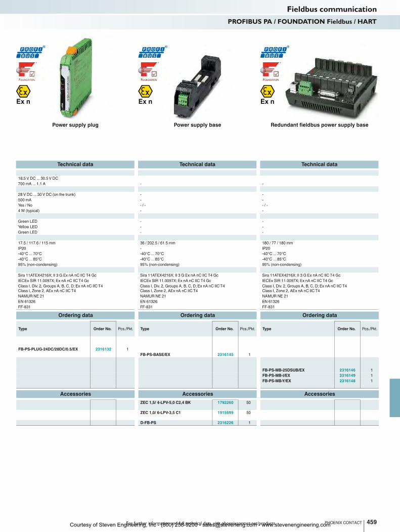
For further information and full technical data, visit phoenixcontact.net/products
Technical data Technical data Technical data
Nominal input voltage range 18.5 V DC ... 30.5 V DC
Nominal current range 700 mA ... 1.1 A - -
28 V DC ... 30 V DC (on the trunk) - -
500 mA - -
Can be connected in parallel/series Yes / No - / - - / -
Max. power dissipation 4 W (typical) - -
Green LED - -
Yellow LED - -
Redundancy indication OK Green LED - -
Dimensions W / H / D 17.5 / 117.6 / 115 mm 36 / 202.5 / 61.5 mm 180 / 77 / 180 mm
IP20 - IP20
Ambient temperature (operation) -40°C ... 70°C -40°C ... 70°C -40°C ... 70°C
Ambient temperature (storage/transport) -40°C ... 85°C -40°C ... 85°C -40°C ... 85°C
Max. permissible relative humidity (operation) 95% (non-condensing) 95% (non-condensing) 95% (non-condensing)
Sira 11ATEX4216X; II 3 G Ex nA nC IIC T4 Gc Sira 11ATEX4216X; II 3 G Ex nA nC IIC T4 Gc Sira 11ATEX4216X; II 3 G Ex nA nC IIC T4 Gc
IECEx SIR 11.0097X; Ex nA nC IIC T4 Gc IECEx SIR 11.0097X; Ex nA nC IIC T4 Gc IECEx SIR 11.0097X; Ex nA nC IIC T4 Gc
Class I, Div. 2, Groups A, B, C, D; Ex nA nC IIC T4
Class I, Zone 2, AEx nA nC IIC T4
Class I, Div. 2, Groups A, B, C, D; Ex nA nC IIC T4
Class I, Zone 2, AEx nA nC IIC T4
Class I, Div. 2, Groups A, B, C, D; Ex nA nC IIC T4
Class I, Zone 2, AEx nA nC IIC T4
NAMUR NE 21 NAMUR NE 21 NAMUR NE 21
EN 61326 EN 61326 EN 61326
FOUNDATION Fieldbus FF-831 FF-831 FF-831
Ordering data Ordering data Ordering data
Type Order No. Pcs./Pkt. Type Order No. Pcs./Pkt. Type Order No. Pcs./Pkt.
FB-PS-PLUG-24DC/28DC/0.5/EX 2316132 1
FB-PS-BASE/EX 2316145 1
FB-PS-MB-25DSUB/EX 2316146 1
FB-PS-MB-I/EX 2316149 1
FB-PS-MB-Y/EX 2316148 1
Accessories Accessories Accessories
ZEC 1,5/ 4-LPV-5,0 C2,4 BK 1793260 50
ZEC 1,0/ 6-LPV-3,5 C1 1915699 50
D-FB-PS 2316226 1
459PHOENIX CONTACT
Fieldbus communicationPROFIBUS PA / FOUNDATION Fieldbus / HART
Power supply plug Power supply base Redundant fieldbus power supply base
Courtesy of Steven Engineering, Inc - (800) 258-9200 - [email protected] - www.stevenengineering.com
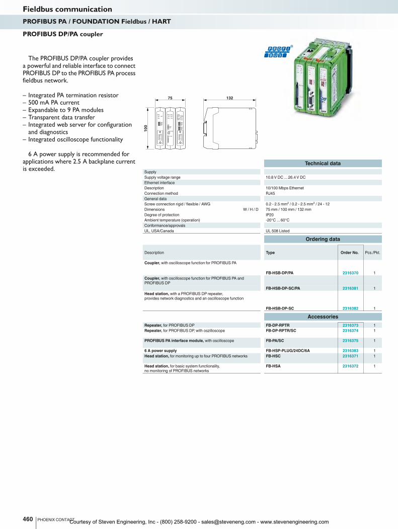
RDY
RX
SW
ER
NW 0NW 1REDH/S
RDY
SF
USB
IOF
ETH
SD
MENU
NAV.
HEADPHONE
SD CARD
RDY
RX2
SW2
ER2
RX1
SW1
ER1
NW 0NW 1REDH/S
NW 0NW 1REDH/S1
00
75 132
Technical data
Supply
Supply voltage range 10.8 V DC ... 26.4 V DC
Ethernet interface
Description 10/100 Mbps Ethernet
Connection method RJ45
General data
Screw connection rigid / flexible / AWG 0.2 - 2.5 mm² / 0.2 - 2.5 mm² / 24 - 12
Dimensions W / H / D 75 mm / 100 mm / 132 mm
Degree of protection IP20
Ambient temperature (operation) -20°C ... 60°C
Conformance/approvals
UL, USA/Canada UL 508 Listed
Ordering data
Description Type Order No. Pcs./Pkt.
Coupler, with oscilloscope function for PROFIBUS PA
FB-HSB-DP/PA 2316370 1
Coupler, with oscilloscope function for PROFIBUS PA and
PROFIBUS DP
FB-HSB-DP-SC/PA 2316381 1
Head station, with a PROFIBUS DP repeater,
provides network diagnostics and an oscilloscope function
FB-HSB-DP-SC 2316382 1
Accessories
Repeater, for PROFIBUS DP FB-DP-RPTR 2316373 1
Repeater, for PROFIBUS DP, with oszilloscope FB-DP-RPTR/SC 2316374 1
PROFIBUS PA interface module, with oscilloscope FB-PA/SC 2316375 1
6 A power supply FB-HSP-PLUG/24DC/6A 2316383 1
Head station, for monitoring up to four PROFIBUS networks FB-HSC 2316371 1
Head station, for basic system functionality,
no monitoring of PROFIBUS networks
FB-HSA 2316372 1
460 PHOENIX CONTACT
The PROFIBUS DP/PA coupler provides a powerful and reliable interface to connect PROFIBUS DP to the PROFIBUS PA process fieldbus network.
– Integrated PA termination resistor– 500 mA PA current– Expandable to 9 PA modules– Transparent data transfer– Integrated web server for configuration
and diagnostics– Integrated oscilloscope functionality
6 A power supply is recommended for applications where 2.5 A backplane current is exceeded.
PROFIBUS DP/PA coupler
Fieldbus communicationPROFIBUS PA / FOUNDATION Fieldbus / HART
Courtesy of Steven Engineering, Inc - (800) 258-9200 - [email protected] - www.stevenengineering.com
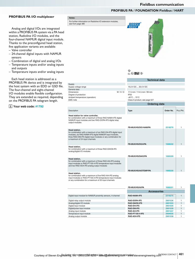
For further information and full technical data, visit phoenixcontact.net/products
Ex:
Technical data
Supply
Supply voltage range 19.2 V DC ... 30.5 V DC
General data
Dimensions W / H / D 17.5 mm / 114.5 mm / 99 mm
Degree of protection IP20
Ambient temperature (operation) -40°C ... 70°C
EMC note Class A product, see page 527
Ordering data
Description Type Order No. Pcs./Pkt.
Head station for valve controller,
for combination with a maximum of three RAD-NAM4-IFS digital
NAMUR input modules and two RAD-DOR4-IFS digital relay
output modules
FB-MUX/HS/DIO-NAM/PA 2316270 1
Head station,
for combination with a maximum of six RAD-DI4-IFS digital input
modules, six RAD-NAM4-IFS digital NAMUR input modules,
three RAD-DI8-IFS digital input modules or any combination for
a maximum of 24 input channels
FB-MUX/HS/DI24/PA 1005332 1
Head station,
for combination with a maximum of three RAD-DAIO6-IFS
analog/digital I/O modules
FB-MUX/HS/DAIO/PA 1005329 1
Head station,
for combination with a maximum of three RAD-AI4-IFS analog
input modules or RAD-PT100-4-IFS temperature input modules
and two RAD-AO4-IFS analog output modules
FB-MUX/HS/AIOTEMP/PA 1005330 1
Head station,
for combination with a maximum of five RAD-AI4-IFS analog
input modules or RAD-PT100-4-IFS temperature input modules
or any combination for a maximum of 20 input channels
FB-MUX/HS/AI/PA 1005331 1
Accessories
Digital input module for NAMUR proximity sensors, 4-channel RAD-NAM4-IFS 2316275 1
Digital relay output module RAD-DOR4-IFS 2901536 1
Analog/digital I/O module RAD-DAIO6-IFS 2901533 1
Digital input module RAD-DI4-IFS 2901535 1
Digital/pulse input module RAD-DI8-IFS 2901539 1
Analog input module RAD-AI4-IFS 2901537 1
Temperature input module RAD-PT100-4-IFS 2904035 1
Analog output module RAD-AO4-IFS 2901538 1
461PHOENIX CONTACT
Analog and digital I/Os are integrated within a PROFIBUS PA system via a PA head station, Radioline I/O modules, and the four-channel NAMUR digital input module. Thanks to the preconfigured head station, five application variants are available:– Valve controller– 24-channel digital inputs with NAMUR
sensors– Combination of digital and analog I/Os– Temperature inputs and/or analog inputs
and outputs– Temperature inputs and/or analog inputs
Each head station is addressed as a PROFIBUS PA device and is integrated by the host system with an EDD or GSD file. The four-channel and eight-channel I/O modules enable flexible configuration. They are extended as required, depending on the PROFIBUS PA telegram length.
Your web code: #1792
PROFIBUS PA I/O multiplexer
Fieldbus communicationPROFIBUS PA / FOUNDATION Fieldbus / HART
Notes:
For further information on Radioline I/O extension modules,
see from page 380
Courtesy of Steven Engineering, Inc - (800) 258-9200 - [email protected] - www.stevenengineering.com
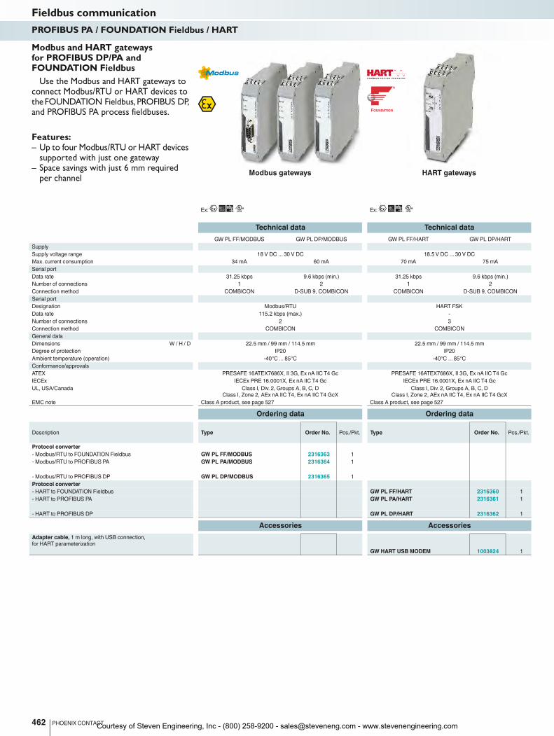
FOUNDATION
Ex: Ex:
Technical data Technical data
GW PL FF/MODBUS GW PL DP/MODBUS GW PL FF/HART GW PL DP/HART
Supply
Supply voltage range 18 V DC ... 30 V DC 18.5 V DC ... 30 V DC
Max. current consumption 34 mA 60 mA 70 mA 75 mA
Serial port
Data rate 31.25 kbps 9.6 kbps (min.) 31.25 kbps 9.6 kbps (min.)
Number of connections 1 2 1 2
Connection method COMBICON D-SUB 9, COMBICON COMBICON D-SUB 9, COMBICON
Serial port
Designation Modbus/RTU HART FSK
Data rate 115.2 kbps (max.) -
Number of connections 2 3
Connection method COMBICON COMBICON
General data
Dimensions W / H / D 22.5 mm / 99 mm / 114.5 mm 22.5 mm / 99 mm / 114.5 mm
Degree of protection IP20 IP20
Ambient temperature (operation) -40°C ... 85°C -40°C ... 85°C
Conformance/approvals
ATEX PRESAFE 16ATEX7686X, II 3G, Ex nA IIC T4 Gc PRESAFE 16ATEX7686X, II 3G, Ex nA IIC T4 Gc
IECEx IECEx PRE 16.0001X, Ex nA IIC T4 Gc IECEx PRE 16.0001X, Ex nA IIC T4 Gc
UL, USA/Canada Class I, Div. 2, Groups A, B, C, D
Class I, Zone 2, AEx nA IIC T4, Ex nA IIC T4 GcX
Class I, Div. 2, Groups A, B, C, D
Class I, Zone 2, AEx nA IIC T4, Ex nA IIC T4 GcX
EMC note Class A product, see page 527 Class A product, see page 527
Ordering data Ordering data
Description Type Order No. Pcs./Pkt. Type Order No. Pcs./Pkt.
Protocol converter
- Modbus/RTU to FOUNDATION Fieldbus GW PL FF/MODBUS 2316363 1
- Modbus/RTU to PROFIBUS PA GW PL PA/MODBUS 2316364 1
- Modbus/RTU to PROFIBUS DP GW PL DP/MODBUS 2316365 1
Protocol converter
- HART to FOUNDATION Fieldbus GW PL FF/HART 2316360 1
- HART to PROFIBUS PA GW PL PA/HART 2316361 1
- HART to PROFIBUS DP GW PL DP/HART 2316362 1
Accessories Accessories
Adapter cable, 1 m long, with USB connection,
for HART parameterization
GW HART USB MODEM 1003824 1
462 PHOENIX CONTACT
Fieldbus communicationPROFIBUS PA / FOUNDATION Fieldbus / HART
Modbus gateways HART gateways
Use the Modbus and HART gateways to connect Modbus/RTU or HART devices to the FOUNDATION Fieldbus, PROFIBUS DP, and PROFIBUS PA process fieldbuses.
Features:– Up to four Modbus/RTU or HART devices
supported with just one gateway– Space savings with just 6 mm required
per channel
Modbus and HART gateways for PROFIBUS DP/PA and FOUNDATION Fieldbus
Courtesy of Steven Engineering, Inc - (800) 258-9200 - [email protected] - www.stevenengineering.com
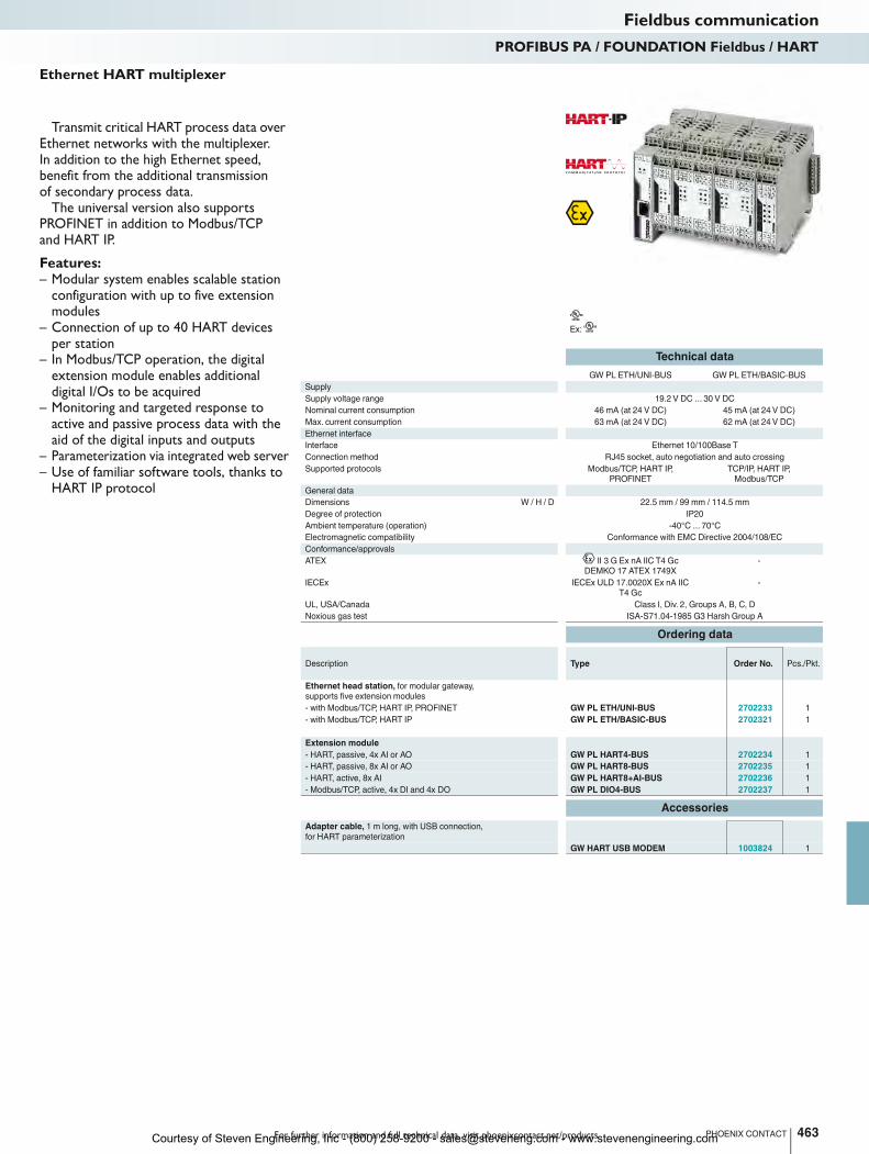
For further information and full technical data, visit phoenixcontact.net/products
Ex:
Technical data
GW PL ETH/UNI-BUS GW PL ETH/BASIC-BUS
Supply
Supply voltage range 19.2 V DC ... 30 V DC
Nominal current consumption 46 mA (at 24 V DC) 45 mA (at 24 V DC)
Max. current consumption 63 mA (at 24 V DC) 62 mA (at 24 V DC)
Ethernet interface
Interface Ethernet 10/100Base T
Connection method RJ45 socket, auto negotiation and auto crossing
Supported protocols Modbus/TCP, HART IP,
PROFINET
TCP/IP, HART IP,
Modbus/TCP
General data
Dimensions W / H / D 22.5 mm / 99 mm / 114.5 mm
Degree of protection IP20
Ambient temperature (operation) -40°C ... 70°C
Electromagnetic compatibility Conformance with EMC Directive 2004/108/EC
Conformance/approvals
ATEX II 3 G Ex nA IIC T4 Gc
DEMKO 17 ATEX 1749X
-
IECEx IECEx ULD 17.0020X Ex nA IIC
T4 Gc
-
UL, USA/Canada Class I, Div. 2, Groups A, B, C, D
Noxious gas test ISA-S71.04-1985 G3 Harsh Group A
Ordering data
Description Type Order No. Pcs./Pkt.
Ethernet head station, for modular gateway,
supports five extension modules
- with Modbus/TCP, HART IP, PROFINET GW PL ETH/UNI-BUS 2702233 1
- with Modbus/TCP, HART IP GW PL ETH/BASIC-BUS 2702321 1
Extension module
- HART, passive, 4x AI or AO GW PL HART4-BUS 2702234 1
- HART, passive, 8x AI or AO GW PL HART8-BUS 2702235 1
- HART, active, 8x AI GW PL HART8+AI-BUS 2702236 1
- Modbus/TCP, active, 4x DI and 4x DO GW PL DIO4-BUS 2702237 1
Accessories
Adapter cable, 1 m long, with USB connection,
for HART parameterization
GW HART USB MODEM 1003824 1
463PHOENIX CONTACT
Transmit critical HART process data over Ethernet networks with the multiplexer. In addition to the high Ethernet speed, benefit from the additional transmission of secondary process data.
The universal version also supports PROFINET in addition to Modbus/TCP and HART IP.
Features:– Modular system enables scalable station
configuration with up to five extension modules
– Connection of up to 40 HART devices per station
– In Modbus/TCP operation, the digital extension module enables additional digital I/Os to be acquired
– Monitoring and targeted response to active and passive process data with the aid of the digital inputs and outputs
– Parameterization via integrated web server– Use of familiar software tools, thanks to
HART IP protocol
Ethernet HART multiplexer
Fieldbus communicationPROFIBUS PA / FOUNDATION Fieldbus / HART
Courtesy of Steven Engineering, Inc - (800) 258-9200 - [email protected] - www.stevenengineering.com