attention microfiche user - international nuclear information
TRANSCRIPT
Attention Microfiche User,
The original document from which this microfiche was made was found tocontain some imperfection(s) that reduce full comprehension of some of thetext despite the good technical quality of the microfiche itself. Theimperfections may be:
missing or illegible pages/figureswrong pagination
- poor overall printing quality, etc.
We normally refuse to microfiche such a document and request areplacement document (or pages) from the National INIS Centre concerned.However, our experience shows that many months pass before such documents arereplaced. Sometimes the Centre is not able to supply a better copy or, insome cases, the pages that were supposed to be missing correspond to a wrongpagination only. We feel that it is better to proceed with distributing themicrofiche made of these documents than to withhold them till theimperfections are removed. If the removals are subsequestly made thenreplacement microfiche can be issued. In line with this approach then, ourspecific practice for microfiching documents with imperfections is as follows:
1. A microfiche of an imperfect document will be marked with a specialsymbol (black circle) on the left of the title. This symbol willappear on all masters and copies of the document (1st fiche andtrailer fiches) even if the imperfection is on one fiche of thereport only.
2. If imperfection is not too general the reason will be specified on asheet such as this, in the space below.
3. The microfiche will be considered as temporary, but sold at the thenormal price. Replacements, if they can be issued, will be availablefor purchase at the regular price.
A. A new document will be requested from the supplying Centre.
5. If the Centre can supply the necessary pages/document a new masterfiche will be made to permit production of any replacement microfichethat may be requested.
The original document from which this microfiche has been prepared hasthese imperfections:
{ I Missing pages/figures numbered:
j | wrong pagination
poor overall printing quality INIS ClearinghouseIAEAP.O. Box 100
cut text A-1400, ViennaAUSTRIA
| |other
i r J I S - m f - - 1 1 1 5 6
/ ^ " " - --•" ' '• •? r . -~ j - . •*•. t *•= f j - ' - . y
: , / . ! : " T 5 ••'"•%
/ ^ / r.,\
Li
JuJv I-"'3<S i 841-302
In t.rcd:.'.c(" i or:
The Nation.-.) Uranium Tnilinyr: Program has ccra .issioned a
study to c-vfllyatc flexible membrane liners (gr.-ornerr.branes)
as long-term barriers for Canadian uranium mill. taiJ i;:go.
Colder Associates, together with their subconsultants
Ontario Research Foundation and SErtE.S Consultants, have
been retained by Supply and Services Canada to carry out
Phase I of the study.
This study reviews the common liner types and addresses
flexible liners (polymeric membranes and asphalt) in detail.
are reviewed. Conceptual designs are presented for basins
to aceonuuodate 20 years accumulation of uranium tailings
from mills in Klliot hakd and southeastern Athabasca.
The study concludes with an outline of a proposed Phase II
test program to carry out a detailed laboratory evaluation
of candidate materials.
Lincr Typoa
Nine polymeric and three asphalt liner types have been
considered with xe.opuct t.o the physical and chemical
environment in the uranium producing areas of Ci-wiada. 7*11
materials indie a': c g a o d c h •?. r:. i c a 1 i •?.~ i r~ t •? p. z e to vi r a n: um
wantos but are subject, fio installation p
July 19S-'. j ; 3<l-2o:r--
Tfia l i n e r typor. cc:!-jic:crc:d £?:c:
1. roiyovhylcnr (i.\-.:*
2. High iK-.ii-iiy Polyothy.' cne (III'?1;;
3. Chlorinated Poly.?thy3 ane (CPE)
4. Chloro:j\ilp;ionatod Polyethylene (CSV")
5. Polyvinyl Chloride (PVC)
6. Ethylene Propylene Diene Monomer (XPDK)
7. Butyl Rubber
8. Polychioroprene (CR)
9. Polyurethane
10. Asp I .ait Emulsions
11. Catalytic Airblown Asphalt
12. Asphaltic/Elastomeric Compounds
Surface sealants, including asphalt, show very low
laboratory permeabilities but are subject to variable rates
of application, are difficult to inspect during installation
and are susceptible to damage duo to differential movements,
equipment traffic and cyclical cJirnate effects including
freeze-thaw cyclic loading. Asphaltic membranes must be
provided with a soil cover.
Polymeric novnbranes offer wide ranging chemical resistance
and are readily inspected. However, they are susceptible
to damage during installation largely oue to improper
subyrade preparation and vehicular trairic. They require
verv careful i nstaI 1 «i" i.nrx ;->.r\i\ r.reir pnrforninnco i r? dpp-'-nder.t
on careful arid succt'&Kfu •. fi^IJ s;-jr,i:L.Kj. P.icl;i s*;vu.'..i i*q is,
in <":crerc>l, a dct«iilo.''. cind ""f.i..<:••. vo oror::•.*:; or.. V7;~.il:hrr,
.inolud.irjy t^^poraturc and procipi'i. l.i-':;-:, in gen; rally t!i;:
governing factor. In this regarct, the olsato-.ifiric liners
corssiderred in cr.is study, »eun«jly, Butyl, Polynhloropr«ne
and EPDM would t'ppcir to present the xaoat pxohlcms in field
JL-.1V It-*' iii L'42-3015
r.c.:ur..i.r.g. Oi the: rcv.-.airuri' li'/:-x. ty^-Ji; c.'nsi^ercd, success-
ful fic-iu r^a-uin? h.v; b-er, ;'<• ••••-.;-. -ci; J., •" :nt\: l.DV<-:, i~, C5VZ,
CPE P.n-.l PVC. It i..- .-ic'cd r-,-''ver, \_:\.-><- '':cro ,,r;: snrio'ir-
T.L-. cKcul tiic ionc;-tci.:.". •...?j.L.*:-.;r:.i:.,; ; j.'. y of T'\'C t'.iicx TV..
There art: no st,ar.diirdi.:t:d n<.U."-rial &;.•.-'CJ fications for
polymeric or asph.aitic i:ie.T.brane linnj:^ in either Canada or
tlie U.S.A. HovttiV'ir, recently developed documents by the
National Sr.Nation Foundation (NSF) offer some proirise of
standardization. It is recomin.endad that the r.'SF standards
be used when specifying minimum material properties.
Liner Environment
m e environment in wnicn the caiiings nasins are constructed
is an important aspect of liner toquireir.ents. Tailings
basins in Elliot Lake and southeastern Athabasca would
typically be situated in topographic lows with groundwater
levels at or near ground surface, Sites would typically be
underlain by organic matter, soils of moderate permeability
and moderate to low permeability bedrock.
A significant chemical characteristic of the Elliot Lake
uranium tailings leachate is the potential for oxidization
of; sulphide bearing minerals and the generation of sulpha-te
rich, acidic porewater. As a result,- the porewater could
contain some dissolved radionuclides and heavy metals from
the tailings.
Liner Insta lie tier;
Proper s>ibc?rade preparation and c:o»i.=ii-.ruci-.ioii is crucial for
a successful liner installation and would typically consist
of subexcavation of compressible materials, sterilisation of
July lS'S''.
tho .'";:byr,-: s.. r'T.ovs] or all r o o t s , KI.tc:> •;, ntri.c? e nd
^* .-1. i -...,• ^ ^ ' . v i , . 4 / *... t - ' " - - — - • - - / t. ... Jt...i.^.^.J^.^.^l w 4 _ i#t^
sar:'": cv.::':iio,"i, jircr arid rcil csvsr, i"r.:. axli t"' i-i. of ..h-t
liner ana fit'J.d ::e.:-,dnq Lik'juid be- c^rrioti out by approvt-o.
int-.L s Ilr:r£5 r.j! ical'/Url y iol T nv.'i nq l.'riv.r supplier instruc-
tions.
Soil cover is desirable but will require liner inclinations
flatter than about 3 horizontal to 1 vertical.
Liner Performance
With the exception of polyurethane the base polymeric resins
and asphalt show promise for long term resistance to the major
ant\cipated constituents of uranium tailings. Caution should
be ncted with regard to the following:
- CPE nay bs affected by WROK sulphuric acid
solutions
- while not employed at Elliot Lake, kercv.ena is
used for solvent extraction in scrr-.e milling
operations and was sre-rrified for consideration
in this study. Most of the liners will offer
satisfactory resistanre to the low keror.ene
concentrations antif j
-• mO^t liiitir:; would L _ adv::rG£iy ^ZZi.ci.cd by hich
kerosene concentrations asE.ocicit.ed with accidental
epillage.
CojfiOd i: "• hi. 1 i f y ff'^.t- i ivj i-3i-r i'"'' <-,iv>" '"'V r>^,«-;rir> 7,:. i-(-!.v/»-«:t-.
Laboratories (FNt) on CSfS, FVC. HD?K ar>o Cstawfcic
Airblow Asphalt in the presence of simulated acidic
July 1'JSv v 841-3015
ur;i!ntiiii t J.i 3'. ;if.'s l e a e h a ^ . c W A S r<~-.v?. c... .-(i. Tl.-r ciata iri'li <;;:'_ t:5.;
!:i-..;t, v.'Ll-h t n c •:':;••.'-''ptinn o f P V C , <-!•<:.-• r..i i..;>• i.-:!.1; v e r e
r e l a t i v e ! / uji.if L o c c c d b y t h e 3 t_-ac.-M.?.t-- ' n r t h e s h o r t t e n ;
periods.
A review of published information acldrassincj t,ha effects of
high levc-Js of garcna radiation on the physical properties of
polymeric liners indicated that HDPE was least effected,
followed closely by CSPE, EPDM, CPE and CR. PVC and Butyl
showed the greatest reaction to gairuna radiation exposure.
PNL estimates of the effect of gamma radiation on asphalt
indicated that no physical defects were observed under the
conditions of testing.
Thin flexible membrane iJ.ners are susceptible to overstress-
ing by stz-ains associated with larqe differential defornotions
in the subgradc. It will therefore probably be necesotry to
subexcavate and replace coroprassible materials encountered
over the subgrade prior to liner installation. Similar
concerns exist for liners placed on slopes and dam sections
and wherr- there is a potential for excess hydrostatic or
gas pressure buildup beneath the liner.
Rates
Scr>r>x.rji through liners is priivi-3rilv throuuh liner defects.
A rational apprr-'-'Th to evaluating apparent cr field Itnec
i t i .:3 is ;.!.--.-u-;r. ic ta i l r^ ™o:-:i r.^rj n-j of ov'.rtir.a
ior.s. ReviL-.-.1 o/ s-ich dr.t.3. ••;;;; in j tie.i.-?d diiriry
tnir. siaicV/-
uiate.s of liiiar releast ret... . 'o undertaken a^iiiiiitng
permeable subsurface conditions ;. -T:T:ability great-r-r than
1 x 10 "* ciii/sec) and tailings per;;.. -.lity of 1 :-: 10 cs\/s<zc.
July 19"< vi E41-3025
The analy^.. ; : ; li-.Ciccto tL: i t on n: :phaJ l-.i c "<....:oi\ir.<» wouldi^f iucc cc'cpni: ' ' t o v-bou* r,Q c c r c>:nt of ,-;, u.-3 i;..---i b a s i n
— Pf o r a f j c l ' . i l i r . v r p*-r:: .",-bl .1 i t y nf 1 x .10 ' o?"-" i K o t r c ; .
p-^r E i ' c o r : i . "-')i y r - ' - r i . c l i r s t ' r . - w i t h ^n r . i f e e ' : i.v.; p<- rr.;t- «-bi i i t y
of 1. x 10 A ce-r.t iiiicstiT'-s p'.ii" acco!1.': would rrriucc seepage to
J.o£;a than 10 par ciTit of an i;nli.r,cu b.i^jr..
Costs
Cost estimates for lined tailings basins indicate that while
liner costs are large, they are overshadowed by the cost of
the related civil works. Asphalt, CSPE and HDPE liners,
installed at Elliot Lake, are estimated to cost 1/5 to i/3
of total facility costs of $74 to $39 million.
The reduced tailings volumes associated with the high grade
ore in southeastern Athabasca results in substantially lover
liner and inipoundir.ent facility costs. AsphaJt, CSPE and HOPE
liners are estimated to cost 1/5 to 1/3 of total facility
costs of $15 to $17 million.
Warranties provided by liner suppliers only cover a portion
of the cost relating tc- supply arid installation of tlie membrane.
They do not cover the con.sequential costs of failure or the
cost of related civil works. These latter costs alone can
exceed liner costs by 3 to 4
Ph-jf!" T7 Tf»st: pro
Tr> order: to select nn-1 preclir;!: v'.t.h reancr.able confidence
l o n g tc.-"«i lii"i<=}." p-;r f ori-.^nc »J / .il- i.~ '•.r'tcr-.^surv t o Co.ri.~y o u t
further study. A ctrcly h23 b'.'en propound vhich vould
consisc of detailed laboratory testing and continuation of
the industry user survey. Six candidate jr.aterie.is wculd be
July 10?'-. vii ?4I-3C2 !3
init.ii-.2iy .' •:r--i-i:o£. ri..r".i ac-je.lcra-.'.-d r.-'Jtir;q w o u J o h»<
c s T •'..'"'• o u t o n [< 'firx-.r wi-.'ri"-'!'. .": t '' *p-'r'--rfl(t,'(-:., ."5
would - .'ijiii.r'.f 2'j year :> w.i1. ;» t-n <?st i r •.'.ccj .v.."., t of (•'..?,'JOQ.
It in reccrjncndcd that ;;n expanded survey of. industrial
users of flexible minors !:o carried o'-t before ^inal ir. j ny
the Phase II program.
Jui.ll'. t , I'.-Sv \ 841-203->
KKSU'-:S-: )-:x;:crj'i : r
Lo l'ïO'ir;;:1::-.: .'•i-:. u .-. 1 ;:-; l'.cjpt:; i:'l)r.'Mia..i a cc:.:: :;. <•;ei oriö
une '5i.,i!]e po-ic r1'.; i'.i// 1 'efli f\ici u ; de i ' u ; i J iija^ion G C Ü
rove Leihen tri c<- iTVjm't'rdr.o:: souples (çéor.iovbr cine;:) '.;o;vjr.e
cloisons a )ür»<v lennc pour lea r^jnts de i-iroyf-ur:. d'uranjum
au Canada. Ltr mandat ci 'entreprendre ló pre.Tiibrc c-tape de
l'étude a été confié, par Approvisionnements et Services
Canada, à Golder Associates, conjointement avec leurs
sous-conseillers Ontario Research Foundation et SENE5
Consultants.
Cette étude passe en revue les genres de revêtement les
plus connus et examine en détail los revêtements souples
(membranes polvmériques et <1'asphalt«3.'. La f abri r <-i <~>*i,
la conception, l'installation et la performance des revëterrients
sont révisées. Des études conceptuelJc:; sont présentées pour
de parer, à rejets qui permetteraient l'entreposage de 20 ans
d'accumulation de rejets des broyeurs d'uranium qui se trouvent
à Elliot Lake et au sud-est de l'Athabasca.
L'étude se termine avec une série de propositions pour la
deuxième étape, ayant en vue d'entreprednre un programme
d'essai pour évaluer rai laboratoire les matériaux considérés.
"euf genres de revStonr.cnt poi;/.r.5riqi:r. c-t trci:-:- d'acph-lto one
ete considered pour ce qui eat de I'environnemcjit physique et
chii.iiqun qui i.o urcuyc dans 3.ss rSgion.c 3 ' c-rp'J c-:>. ti.^ti.ori
•:i' )irani«m au Canada. Tons l&r, Tn<~t.*~>ri O:JX fi^s.i: rxcif. une bonne
resistance ^liiiaique au rejefcs d*uraniurr- mair; i l s sont j« jc ts
a des di£ficult5t; <3'installation.
J ' . i 1 l e t , i f "
li-j*: cjonrcr. fie ;\ 'Vetcn.r>nt^ cons ide r . - : : .'-• «r*f. ion .;•.;:/snL.1 :
1. Poly./U.yli'MHj (I-.-;)
2 . l :-ojycthyi :~rr . dc h u u t c 'J-.-;-.->i .'.:.'• (JUJI-I-;)
3 . Poiy<-thyl?T.R C h l o i u r c {Cr'C}
'I. Polyethylene Chloru^ulpliop.'; (C:'W{.)
5. Cliloruro de polyvinyle (PVC)
6. Monomere Diune de Propylene Ethyl fine (EPTiM)
7. Caoutchouc de Butyle
8. Polychloruprane (CH)
9. Polyureth&ne
10. Emulsion D'Asphalte
11. Asphalte Catalycique A Pressioa D'Air
12. Composes Asphaltique Elastomerique
I-es materiaux qui scei lent la surface t e l que los aspra) t«s ,
dt'rxntrent oii laboratoira des perrneab.vlites qui :jont tr<!;
basses. Cependant ccux-ci sont sujets S des taux d 1appl icat ion
var iables , i l s sont Oif.(j.ciles & inspector durant 1' i n s t a l l a t i o n
et i l s sont aur.si susceptibles -IUX dommages qui psuvent fctre
occasionnes par les dcp.; acements d i f f e r e n t i a l s , la c i rcu la t ion
de 3.' equipe •ent <_-t les effets cycliques du c l i n a t t e l que le
chfirgcnent eye] ique t'rjs prriodes de qSlement-'l-'-gel^ment.
Los /nor.ibranei ">;;phaltique<3 doivent 6 t re rocouvcrtes de . jl .
Los. rr;c:ifbrai.oG poly;r;Sr i.qu^c of front une grsrjdf rr^j.-^tanrrs
chimique e t c>l"!t;-j r-cnt nxs&.h'^nt inspectees. Tou':erois, e l l e s
pau/--nt £ t re cnthtoiwgiies cli taiit 1' iiistall.^Lion uue, en gra::de
p.i):tie, &. la propnratioii inadequate du substvatara e t S la
dvCuIttLion, Lcju.r '.na I j • If- ;:i»>n aoi t o t ic cii'cc:t.u£2 avee sci n
c*" 3 cur per f crrr.arico t'-'oenrj s'irto1.:1. t?.o 1' att-7 •"••:'.•?-" T oj't".4-Q A
fabrication df -joints cur chanv.ier est une operation c£3 icate
qui necessite ure attention scrupuleuse aux GStetils. Les
Juillct, I-;.:"; iii 8 4 1 - 2 '•- 'j. V.
condition.- u!./:o::p!ier;qu::c, soil In Lor-p'-rc turo r;t la
P VK: - i JJJL t<.» t. i ' - ' . J , b O l i t L i t <J ! . . ' : \" i ».* C t 'i. i i A. ."•:> L e ^ p->.i.<:.i x J r . ^ o I ' ' - t ^ i i L i i
(.•jui affacto I ' <.'f ricar:i te ue cos joint-;;. A co vajet , lc:i
rov'-tciricnf;;; ol.'is toimici qui.-s consit'en'n dans <;<-.'. tc (-tutio,
:;oient- la MUt.yle, le PoJ yc!ilor'jpri*-ne ct. ]•: h.r M, .--';r;.b] ora -lc nt
pn:;<jr lo plus dre difficulty 's pour co qui •'• <• dr; la fabrication
do jo in t s .sur chant icr . Do touri l' js ctuu."•.-.. iev5tcacii(:i
considercs, do:: j o in t s one etc eftc-ctues sur place, ovec
succes, en u t i l i s a n t le HDPE, le PK, le CSPK, le CPE e t le
PVC. I I e s t 5 nofc£ que la res is tance du PVC e t du PE aux
conditions metoorologiq'Jos dans le long terme demeure douteusr;.
Prtsentement, i l n ' ex i s t e aucunes specifica'riens star.c'ardisses
des '.lateriaux pour los rcvctemer.r.s de racnbrs.nos polymeriques
cu fispb.all.ic or:.-, au CrinarJ."? o>) ai'x n ',-n.'.: s 'Jr. I:.. Ceruin.s
docurr.ents rdcarrirnent produits par l.s Fonda tio:> National
Sani';rition off rent nGciraoir. . la poi.siblilit.C: rh normal i sa t ioa.
I l >:st recon.j-'iancie que ies standards HJK f-oicr.t utilise-1; loi's
de la specif j.cacion des standards minimums ties matoriaux de
r'Rvetemcnt.
Rr.•/i.ronnemont _do;-> Revel:einr;nts_
L'invironr.rmcit oC l(?t: pores St i"oj'-t3 -ovoni: c o i s t r i n t s fist, un
aspect irr.portar.t d-i:i:i la f.lC+'crmir.at.iot; dr_s «y.iq"nccy en 1:crsr.es
do ravGtcnents. Cr, jdricr^l, ic^ p.-res £ : .• ]-:tr ^ r:" "• •; ov; l.rt*
«t au sud-ect do 1' Athabasca i;or.-,: r:nt. sif.r'-r; dpT.s r\<-z regions
b i s s o j : a n n i v c i i u t o p o y r a p i i j uu; ; o u i d u q . j " - p!: r-%i i. j -.jut- >i?
tro'.'ve soi au nivoa-j du sol on f-r&?j pro-,. L'-'fi s ines
..i.- . . »... < ~ v. *
i ] It;; , i-j':'.-'• )V d 41 - J U1 i
U/iO cj,'i;^'.t':'j;.i i>:ue i.-pport .iT'.to du I j ::: v a q o fle r^jei.n
d 'uran; ':;n S. L ] 1 iot Lake c;c lo potent j.f.-1 pour 1 ' oxid.s ti or.
do uii;;cn>i sulfv;;-.: ct .1 .i p;:o;;---.c: ti c;r. ;;'.;::u intern r i tic-lie ,
riche < n suiiat,'. En sei:.r.. , l'tai: i :; t-.:r3 titiell c ponrrait
cont.enir J C J ra^.i r,r.uci. i i oor, <i i..r;so2u.; rt des :r.iT-tau;: lcurds
provun.'int don re j'.'l.s.
IiutaJ. la f. i - ' i_ vl c_rr. ncvet-:Hii on 1: s
Pour assurer le succ&s do 1'installation des revotemonts il
est absolument ncccssaire que le substratum soit prepare et
construit de fa<jon adequate. Ce travail consisterait
t'-'piquement de la sous~e>rcavation de matieres orgi.niques
compressibles, la sterilisation du substratum, 1'enlevement
de racines, tiges, cailioux ot tout autres decombres, ]e
nivelleruen'r et. 1c. cc;:r.pact. ic:i du sub:;traturr., 1' apprevisionr,er.cr.*•
d'un coussin yablonr.eux, !<• tout fin;ileir.ent suivls du rovetorr.ent
e t 1 e recouvrcn\e;11 d e t,cr .r>-•.
L'execution des travaux d'installation da revStement ot la
fabrication des joints doivent ctre cntrepris par dos travail.1 cars
experts darib ce metier ot ]es instructions 6ar, fournis^eurs
de rsvefceraents doivont otro suivios a la lettro.
Quoiqui'il soit preferable .e rccoiivrir ]e rovetcmont do terre,
1(.::J inclinaisons pour les pente^ revenues ceront par nccessitfi
au liioins d' environ 3 i:ori::cnLal pour 1 /::rtic£:l.
i'frtoriii-Hiico dos Kovdtnr.viius
Lan . ••-'•:.'S de bases po\y.'ne)L i-jue O L i'.icphal L C soitiblrnt clO:; irabier
pour co qui •-»"!" dc lour rcsictaiino !: Icr-j t':rrnc c;v-x i'lesc::ts
«,^-,.-•-** ~. 4. *- ..._^^,.,.^ ... *. rT,.t > . -., .••»i v "^.r. v- .•- *- /- .-» ' M f i n i n m 1 O P
precautions suivantes so:\z v notoes:
J u i l j c t ,
le f'PK pout Gi.re al loci 6 par de. fdiblos :;:.•! ut ions
(3 'i)':iup su'lf!iurique
- lo k0ro.c^ji>; n'or.t pas u 'u l i se a El l io t ha'rc maj.s
i\ sci/l: roulufois dans quelques c; >.-rat LOHS Uv broycuir
ot ::.on uri i i r .at ion a Cite cortziO.Cr•'-•:• danij cottc etude.
La nia'jorite dos revetenients offrent une resistance
satisi 'ai ScinLu aux faiblcs concantratioiis de keros&ne
prcvuois.
- la ma^orite des revetements se ra i t affectee de
faijon adverse par de fortes concentrations d^
kerosene qui pourraient se produire lors d'un
debordoment accidentel .
Des ossais >.Ie cuiiipatibilito unt ete effectues par Pacific
Northvest Laboratories (PNL) sur le CSPE, lo PVC, le HDPE
C3t 1 ' of.pnalto catalytiquc- S pression d ' a i r dans la presence
do lixivagc do rc j e t s d'uranium acidiuue ciraule. Los
re su l t a t s de ces essa.is ont i':ta passos on revue au cours de
cet to etude ot les donnees inrfiguent que ces materiaux sent
rolativernont ir.af-Tecl;<5s par la lixivage durant les courtes
periodes d 'essa is a 1"exception du rvc.
I-1 informal ion publiee au sujot de 1'effct de nivesux r.uperieurs
de rayonncKcnt gaiiuna Gur les propriety.:-; physiques der, revcternent
pel .yinoi iivufs iiiditjin? qaa le i niT. t;>t 1<: i.ioiii.11. s<?''i.~>ibio suivia
de proa par 1c CSTK, 1c i:i';)M, le CPH ct "'.c' CR. Le PVC et le
Jiutylo riOinontrcnt ia plus grar;jc reaction a 1 "• expo:; i t ion du
rayo-MficniorU; yn:r,r.-,r.. V'N)., esti:r.u que sour ]er> cor.ditior.f3 des
CBsain, iiuciiic aoiCi:tuosi::.L: n :a etc obs'jrvuo p^i auiv.c dc-:-.
xay oili!.._ii".ciiL <l.-i..i.,ici : ;ui 1 ' a^p l i a l Lu • Lc^. luVCLci.:;.!";':; Cc rro~i^"anCo
txnsio;):; ussocices aux girando:; cleformatiers difi'Crc.nticl3.er;

vi 841-201'J
d i i s v . b s t v . i i I I : D . . >•>! . ->• !•.->•'•.•"(.•• l i t . 3 ' i i ; : ; ' . . r i ] 1 ; ; i . i . O i ' j <?c. : : < ~ - v ~ t c - i : : e : ] ' _ i l
: ; e r a d ' a he r'.' p i o b a b ] P::-.:.MI t r .C 'Ce.s i ia i r<- d ' or . l e v e r f t d e
1'C-;.;JJJ a c a r lo;.-. i.;..ii.i~r i .'HJ:-. c o i u p i / i ' s t i i b i .-.... L ; \ ; . I V . J . . u i i e
substra tum. I'VJ-, co:):, i .iej a L'i on:-, sernb i rb i •::: e>:i:U.enV. pour
Jos rov*' teniciit;- coi'.f. trr.it.-, si;r les p'T, !•-•.:, r.i.." l e s ucct ioi is
do bariraqcr; <"-t anr.f.i aax eridroit^ oil If potu' n'.io 1 e x i s t o
pour 1' accurr,;]) at.ion tie; pnias ion o x c i s i v f i d ' hydrosta tiqu<» ou
do yaz sou:.; le revOtcmcnt.
Tf-nix D'Echappemcnt
Les ddEectuosites dos revetements sont la cause primaire da
suintement a travers ceux-ci. Unfi fagon d'evaluer la
permeabilite apparent.e ou sur place des revetements est par
un programme de sur /eillanco dStaille des installations
ac t .uc l lCE . i - Ui'iC r e v u f <.le L v l l t ' s doi":;ioc-s a €t.& C i l i c p r i s o a u
cours de cetv.e etude.
I»'t'-valua t; on des taux d ' echappement des roveLer.icnt. a c'to
entreprise en presuiiiant dej conditions de substratum permeables
(permeabilite superioure a 1 x 10 cm/sec) et une permeabilite
do rejets do 1 x 10 cm/sec. L'analyse indique qu'un
revetement do membrane asphaltiquo avec une permeabilite de
1 x ]0 centiinfltre par seconds ri'duirait le auincerr.ent d'un
ba::in de rejeLs nan:: rcvC-tcrinent a 50 pour cent. Los rcvi5 tements
jiulymeriques ovee une pc-rrr.Sabili 11'~ effective dc 1 x 10
"..Tiie t i c * : ? i>vtx s» sC(.? i KJ '._• / i.vi'.j j i V L i e i i L 2 A :
Rcir.r, de .1.0 uour cent, da cclv.l d' i:;: bs:;ir: san - revC:ternent.
CoQt<:.
associ£-.s (i.ux pro jets * Le cotlt de? rev^ toinen ts d 'asphalts,
vii 841-301J
iK: C!'i'l\ e t d e 1!L:''K q u i o n t 6tC i n s t a l l e r ; :i ' " l l i o t L a k e
conr . i r. t c ?>p;. :::.v i ir.u t ivt .-ruMit d e v:r. 1 /5 a 1 /3 du e n f l t g l o b a l
l i e s l.u;.'.''n..u;ci!i..:n i.:: ( * 7 • 1 a f>S
Lei' volun/js inf 0-.fi eurr. do ri.-jci.rj qui r.om iriioc ii;r; avr c lor
minoi-a.is ?l ]-,:iutu icnour dn sud-ost do- 1 ' Al:habc:;c:c< result.ont
en des cofitc do revetment et d' amiinaqomfnUs do stockaqo
consjid?rablerr.ont roduits . I c i , le cofit di. s revetements
ri'asphalte, dc CSPE et de HOPE sont cvaluys, dc 2/5 'A 1/.1
du coOt global des arnenageinents ($15 a 17 mi l l ions) .
Les garanties offertes par les fournisseurs de revetements ne
couvrent qu'une portion des coOts re l i es a 1'approvisionnement
et 1 ' ins ta l l a t ion des membranes. Tls ne suffisent pas
l o r s q u ' i l s ' a g i t d e couvr i r le coO.t d'une defaillance du
revGter.'.ent ou le coD I dt_-t> travaux civili : asbocids au:-:
p ro je t s . I,r. coQt de ces travaux, par exeinple, pt'Ut etre de
3 a 4 fois plus Sieve quo Je ccOt des; rcvetemcrits.
Programmo D'Es pa i - Deux i 5me Etnpg
Afin de choisir et de prOidire, avec un certain niveau de
cont'iance, In. performance a lontj term'? d'un rovetem-?nt, i l
es t nfeessaire d' enl.reprendre uno T'tude plus approfendie.
Ceti.e etude com;isto.rait. d'c-s.sais dota i l les en lahoratoire e t
do la continuation du ix;r,da^o do. u t i l i s eu r s dc 1' industrie
do revi'tpmc-nt. Ao dii'uut, :si.>: id..; Lor. iuiix ;;<-:!.ai c.-n t co;\si£i6r5" .
Par la -suite, dos essnis di'f. -i ni fc.i fs c-t •-.ccC-icrCo scraitvnt
cntrepi; i.s sui: troii? mat.r:.riaux dc revoiciMrit, a <i niveaux citr
temperature, a 3 niveaux. do tension et a 5 intcM:vo l.ler> de
temps. Cotto et.uae se ra i t uttcctvieo au courr. d' un>i pC*rioil«i
dt- 2 rtiis, le C(.JQ L. pjroitiLe ('tcinfc. du $'<3!),GGC.
I l es t roeommande qu'un sondaye da plua grande cnvergure des
utiliuours industriela de revetements souples soit entrepris
avant dc coir.pleucr ia deuxicme dtapc du programme.
T/\BL2 C:? CON7T.VPS Page No.
EXECUTI7" SUMMARY
1. INTRODUCTION 1
2. TERMS OF REFERENCE 3
3. OVERVIEW OF LINER TYPES 6
3.1 General 63.2 Polymeric Membranes 73.3 Surface Sealants 93.4 Native Soils 123.5 Soil Additives 14
3.5.1 Cement 153.5.2 Lime 153.5.3 Bentonite 163.5.4 Dispersants 17
4. POLYMERIC MEMBRANES 19
4.1 Introduction 194.2 Manufacture 20
4.2.1 Description of thePolymeric Liner Industry 20
4.2.2 Polymerization 214.2.3 Film Manufacture 214.2.4 Liner Fabrication 244.2.5 Reinforcement 284.2.6 Quality Control 30
4.3 General Characteristics ofLim-r Typos 334.3.1 Polyethylene (PE) 344.3.2 High Density Polyethylene
(HOPE) ' ' 364 .3 .3 Ch.loraua.rea Paiyethyiene
(CPE) '. 414.3.4 Ch.'iorosnirhonated
Polyethylene (C5rE) 414.3.5 Pol y v x n y i Ch lo r i da {T VC) ;'< 54 . 3 . 6 F t h y l o n e PTo^y jo r i " 0;--r>!»
Honoc'.ei" fiiPDH/ 474 . 3 . 7 «\v_yj R.\ :- ' . -r 504 . 3 . B P o l ' / ' . - h i o r o n r e n e (CR) 524.3.V* Poiyuretnane 54
4.4 Liner HAter.ial 3p«ci £ icdtlorts 56
Ju lv 1934 i>; :J-'l-3015
?AT>Lr. OF QOlWC.rVE (Continued) Pscrc No.
5. ASPHALT IC Hi" GRAVES 78
5.1 Introduction 785.2 Asphalt Emulsions 315.3 Catalytic Airblown Asphalt 825.4 Arjphaltic/EIaatcmeric Compounds 845.5 Material Specifications 86
6. LINER ENVIRONMENT 91
6.1 General 916.2 Background 926.3 Site Considerations 94
6.3.1 Introduction 946.3.2 Site Conditions and the
Requirement for SeepageBarriers 94
6.3.3 Elliot Lake Area 96o . J . t aoutu Ldbteni Aunaj-iiiaCd
Region 1Q<L6.3.5 Other Uranium Producing
Areas6.4 Characteristics of Uranium
Tailings6.4.1 General6.4.2 Background 1176.4.3 Physical Properties 1206.4.4 Chemical Properties 123
7. CONTAINMENT FACILITY DESIGN AND LINERINSTALLATION 129
7.1 General 1297.2 Site Selection 1327.3 Engineering Design 1337.4 Lir.or t'«i;!."icdtitj'i 134
7.5 Subgrade Preparation7.5.1 Clearint-r Grubbing and
Stripping7.5.2. S t e r i l i za t ion or Subgradc7.5.3 c'xeavation and Falling7.5.4 Linyr Subdrainage ana Gas
7.5.5 Fin.ishj'na 138V.b Liner i n s t a l l a t i on *-*?
7.6.1 Polymeric Lim-rs 1397.6.2 Field f-er-rainq 1^37.6.3 Asphalt Liners 144
?.? Scil Covei* 1467.8 Quality Control
-Js.ki.A211 * ?<i-3oif
TA'-'-LE O.F_crN'Vl-:W7.;S (Continued) Page 1-io.
8 . PE?.?O"HANCE CRITERIA AND FAILCP.SMFCH^USMS 152
8.1 Introduction 1528.2 Performance Criteria 1528.3 Liner Compatibility ana
Durability 1538.3.1 General 1538.3.2 Polymeric Liners 156
8.3.2.1 General ChemicalResistance 156
8.3.2.2 Resistance toUranium Tailings 161
8.3.2.3 Resistance toRadiation 164
8.3.3 Asphaltic Liners 1638.3.3.1 General Chemical
Resistance 1688.3.3.2 Res is t-.a.nce rr>
Uranium Tailings 1698.3.3.3 Resistance to
Radiation 1708.4 Failure Mechanicms 171
8.4.1 Physical failure 1718.4.2 Chemical Failure 1758.4.3 Biological Failure 176
8.5 Mechanisms and Rates of LinerDegradation 176
9. RESULTS OF INDUSTRY SURVEY 185
10. RELEASE MECHANISMS AND RATES 192
10.1 Release Mechanisms 192j.0.2 Release Rates 19310.3 Elliot r,aJ:e 196
10.4 Southeastern Athabasca 198
11. LINER COSTS 200
11.1 Elliot L--:ke 20011.1.1 General 20011.1.2 Draiii«9e 20111.1.3 Site Preparation 20111.1.4 Dans " 20211.1.5 Liners 202
•July I9S4 xi 341-2315
LE 05' cr'r:r*.T3 (Continued) Page No.
11.2 Southeastern Athabasca 20411.2.1 General 20411.2.2 Site Preparation 20511.2.3 Da;r.s 20511.2.4 Liners 2C511.2.5 Soil Cover 205
11.3 Sammary 206
12o WARRANTIES 209
12.1 Polymeric Liners 20912.2 Asphalt 21212.3 Summary 212
13. TEST PROGRAM FOR THE LONG-TERMSTABILITY OF FLEXIBLE LINERS
13.1 Requirements of Test Program 21413.2 Approach 21413.3 Methodology 21613.4 Anticipated Degree of Success 21713.5 Program Costs 218
14. CONCLUSIONS AND RECOMMENDATIONS 221
BIBLIOGRAPHY 224
,: JH;-±^_
l''''! 4 iiii R4!)-3015
, j
W LIP? o r ^J)L}]J±JI Page No.
rj
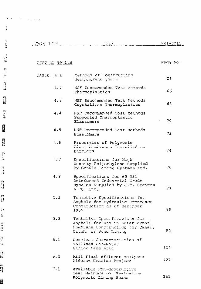
ii TA3LC 4.1 Methods o': Construcr.i.r.oGeo;.v:mbrar:e Seaiiis «-6
r<J 4.2 NSF Rucornrr.ended Te:;t Mfithcds
Therraoplasti.es ^6•If] 4.3 NSF Recommended Test Methods
Crystalline Thermoplastics 68f| 4.4 NSF Recommended last Methods» Supported Thermoplastic
Elastomers 70S 4.5 NSF Recoimaended Test Methods
Elastomers 7 2
\i 4.6 Properties of Polymeric
Barriers ~4
f|<>4 4.7 Specifications for High
Density Polyethylene Supplied•7 By Gundle Lining Systraes Ltd. 7 6
;j4.8 Specifications for 60 Mil
T» Reinforced Industrial Grade| Hypalon Supplied by J.P. Stevens* & CO. Inc. ~7\ 5.1 Tentative Specificaticna for-» Asphalt for Hydraulic H^inbrance
Construction as of Decc:nbcr? 1965 89.i&
5.2 TenLative GpsiCj.fiC(.i!:i.wiw Torj Asphalt for Use in Water Proof=; Membrane Construction foi" Canal," Dj.tch, or Pona Lining &0
' 6.1 Chsmicni Characteristics of•* Tailings i.:'ort?.watar
h 11 .i r>r. Lake Arf:r. J- 24
I 6.2 mill Final nffluenc ftri.iij'sesMidwast Uraiiiuui rrcjG\ct 127
6
I 7.1 Available Kor.-destructiveT e s t - Mi=> H i CHIPS f n r K v a .
, Polymeric Lining Seams
J u l y 1*-0 ''. v i i i P,! x- " 01
L I C T O r •;;..I>.;..K.-5 ( C o n t i n u e d ) Paoe Ho.
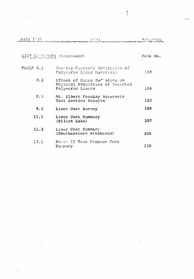
2LE 0.1 Cor...-rf;i r ^ n i c ^ I Rc;r;iKLrnce ofLiner Matcri alfj 159
8.2 Effect of GiMT.a .Ra ' aticn onPhynical Properties of .'vfjjoctedPolymeric Linora 166
8.3 Mt- Elbert Forebay Reservoir
Test Section Results 182
9.1 Liner User Survey 188
11.1 Liner Cost Summary(Elliot Lake) 207
11.2 Liner Cost Summary(Southeastern Athabasca) 208
13.1 Ph.:,:;-. II Test Program Coct220
. ? u •>».- :• x.iv
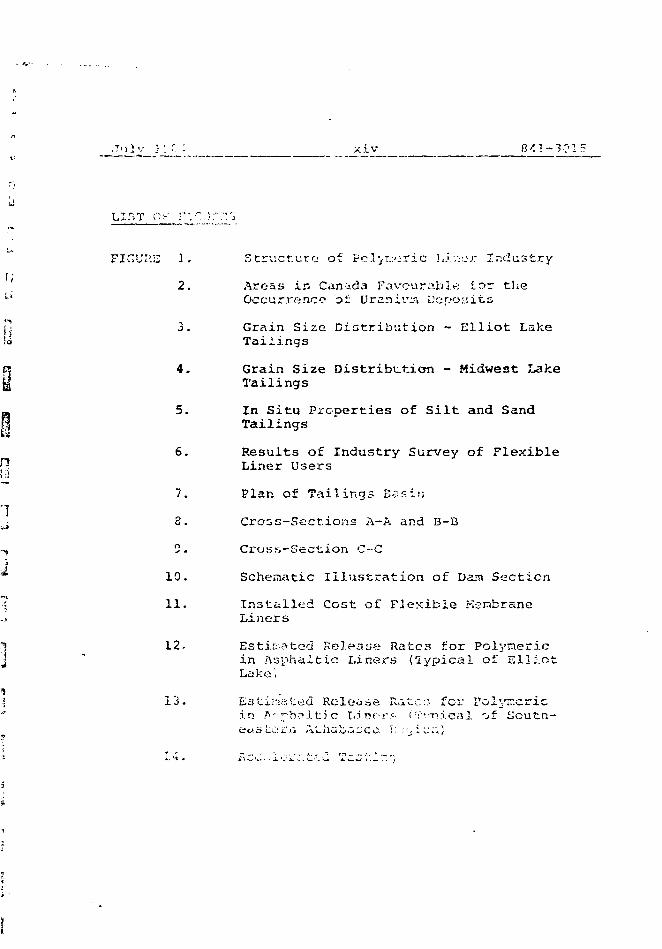
FICUI'.Jj 2. StructA-.rrj of Po.l>r.:oric ),i.:v.:-r Industry
2. Areas in Can-i-da Favourable lor theOccurrence of Uranium Deposits
3. Grain Size Distribution - Elliot LakeTailings
4. Grain Size Distribution - Midwest LakeTailings
5. In Situ Properties of Silt and SandTailings
6. Results of Industry Survey of FlexibleLiner Users
7. Plan of Tailings E^sis;
3. Cross-Sections A-A and B-B
2. Cross-Section C--C
10. Schematic Illustration of Dam Section
11. Installed Cost of FJexible KsnbraneLiners
12. Estimated Release Rates for Polynericin Asphaltic Liners (Typical of ElliotLake',
13. Estimated Release Rate::- for Polymericin A'si-bcj.t.i c t.irif-r.'- i?'-nj.CtiI 'jf S o u t f i -
_Jul.V_]JJ_8f _ £41-?. 01 5
LIST OF ftpPKj^OJCK5
APPENDIX A StatciTcnt of l.'orr:
B Polymeric Flexible Membrane 3" ir.crsKat.erii.1 Property Speciflotions sndSpecial Tost Methcna and Tfinu ProceduresNational Sanitation Foundation (h'SF)Standard No. 54
C Representative List of Organizationsin Liner Industry
D Liner Suppliers
E Liner Users
F Typical Warranties
J u ?. •/;•:•,:". i 8 /. i - 1 2 1 s
Goldc-L" A'ssaci:: t^s has be; on r«'t:;. ir.d ny '.Iw.ply and 5.?r vi..-es
Canada to carry out Phase I ot A strjey co ^ V B I U J H . £ 1 I; ;•. i b J. <_>
membrane liners (gtjo.iiembrjnes) ,-.c ion -i' r-i barrier;; for
Canadian uranium mill tailings. Tho stuay was ^nitiatc-J by
a request foe proposal, OSS File N'o. L4SQ.23241-3-1662, to
which Golder Associates, together with subconsuitants,
Ontario Research Foundation and SL'N'ES Consultants
responded.
[| As outlined in the request for proposal. Phase I of the
study involves th~ gsr.eration o' -.r. ! r.Ccrrnaticn base and
"? ' focuses on commercially availabl..- f. xible liners (,ilso
referred to as tir-mb rent's ot y c.-.; v:u: fines) , their properties,
p manufacture, installstion, anticipated ptri'oi.T.ar.ce and
U associated coats. Phase I alrr- includes the preparation of
a technical proposal and cost estimate for Phase II of the
j,| study which would consist of a laboratory test programme to
evalute the long-term perfoctnar.ee of flexible liners exposed;, to se1. acted wastes.
f] The information provided in th,\;; report hes bean co? ic-ctod
from a number of souices incl UL I«• •-j :
,-i
° i) iRcsnstries with Iinc-c; facilities in operstior;
Li i>.) f'.'iPUi nctutf'L's ii«>.; suppJ. i c r s o f l i n i n g s y s t e m s
iii) Csnauian and uiiin^d itdtea ycvetsiaienc
July 1.924
iv) Inriepen^-Tit publications
v) Internal files and private sources.
These sources vary \ idely in the nature, quality, and
subjectivity of the information provided. This report
attempts to present the gathered information in a
comprehensive and objective manner.
The study commenced with a review of liner types presently
in use and their general availability. Following initial
discussions with the Scientific Authority (National Uranium
Tailings Program), the following flexible liner types have
been selected for relatively detailed consideration and are
addressed in this report::
i) polyethylene (P.E.)
ii) high density polyethylene (HOPE)
iii) chlorinated polyethylene (CPE)
iv) chlorosulphorsated polyethyl.-r>» (CSPE)
(commonly known by the Dupor-t trade rnark-
HYPALOK)
v) polyvinyl chloride (PVC)
vi) ethylGne nropylene dione monomer (LFDM)
vi i) butyl rubbiii
viii) asphalt
The roDort also addresses nsoprene aod polyutechane in
s on•':w hat lose detail.
TF.I-.MS
The terirs of rtrereace :or the Phn.-c I v-tudy were outlined
in the Sf".at<:-;''''nr of Work attached to th1? conl-.rjct and
included with this report as Append i x A. The terms of
reference require preparation of an inf ortia c ion base and
recommendations for a Phase II test, programme.
Phase I of the study focuses on the properties, manufacture,
placement, performance and cost of flexible membrane liners.
The study assumes that the liners are to be provided with a
soil cover and that the materials may be used as both dam
membranes and complete tailings basin liners. The study
concentrates on the two main uranium producing areas of
Saskatchewan and the Elliot Lake - Blind River area of
Ontario. The study also addresses other potential uranium
producing areas of Canada including areas of continuous
permafrost.
The design period of consideration for this study is up to
1000 years.
Consistent with tne terns of reference:, the Phase I sf.idy
includes the following:
i) A description oC the pt oper i: ies of S
comrtiercial ly available materials which may
be suitable as floxible linor."; for uranium
tr)i 1 i ncjs.
ii) .'•. •!;••::! i pt ion or the laanuf r.ictur i v.r, retnod ^cr
ths'.1 rev in c-.r.a sheet for the ru't.et i ."• i r m: Ice ted
for chc study as wf.ll as the necessary quality
control :TIP3scr:f v,,
iii) A description of the site prf?p«ra': j on and
installation procedures requir.-.-ii for continuous
liners, including field seaming techniques and
field quality control.
iv) Estimates of the rate of release of contami-
nants through the liners selected for study
as a function of time.
vj H uiscussioti, oasea on ava
of the anticipated failure mechanisms and rates
of degradation of thw lir.er matoiri.iln in the?
expected tield condition;;, including a descrip-
tion of the potential failure mechanisms o'i
factory and field seams.
vi) Estimates of the installation costs of the
se lee tod liner material at the two .T.ain
uranium producing areas.
vii) Tbr- preparation o'J a t-^rbn i c^ 1 pronor.al and
cost oatiirsate fer the ?hase II tost programme.
There i & prf.aentiy only limited inf orr.ij 11 or: available
a.ssoci. fl 5"'\"J wi v.h tho actual perforr.ir-.nce of flexible liners to
contain lirdin ur;! tailings. ri?.r,ed or. the i r» f o r rr: a t i <-P.
collGctt'o in Phr.-r.--' I, a rh«:.;e II prc-j::.-:':: has been proposed
whicli will involve a detailed laboratory test progratr.rne and
associated atuil y;;e.s. The tost pcogrc:^:..c would be carried
out on selected i infer materials in contact with poteriti^l
contaminants in order to assers failure mechanisms,
degradation rates and rates of contaminant release.
TYPES
3.1 Conors].
There are gone-rally two ma jot techniques utilised to
minimize subsurface flow of cont.irr,inants from uranium mill(1)
tailings disposal facilities:
i) techniques which take advantage of favourable
site hydrogeology and subsurface soil and rock
conditions to minimize contaminant transport
ii) techniques wnich involve the construction of
barriers (pond liners) to contain and thus minimize
t-iit encty UL wuiaonniidL^ IUCO aunticii uz gtounu—
water.
Where less than ideal hydrcyeological conditions prevail at
a prospective waste disposal .-site, a reliable seepage
control mechanism in the form oE a pond liner is oftan
considered.
A large variety o£ liner types rt.ay be considered during the
selection, of a liner materiel to meet specified criteria and
installation requirements. Most of the available and
generally flexible liner types are briefly addressed in the
following sections with respect to their potential for
^application a.r. tailings pcr.c liners. For discussion
purposes, liner materials are separated into four
categories :
i) nnl uiwrir:
j u i y i y y«
i i ) 3ur £' ?. co seal a n t. r,
iii) natural soilr;
iv) ' rr-tura3 <>oi)n with additives
Thi; nucpcoc: of: this stuJy is to study flexible- rvin-nbranc
Liners (gc-osembranes) whor,o base product is a synthetic
polymer or asphalt.
3.2 Polymeric Membranes
The most common synthetic polymers j ^sently used as base
products in the manufacture of polymeric membranes may be
classified as:
i) thermoplastics
ii) crystalline theirmoplast: cs
iii) thermoplastic elastomers
iv) elastomers
The membranes manufactured from the above grojp of synthetic-
polymers offer considerable variation in their chemical and
physical properties, methods of installation, costs and
interaction with various wastes. In addition, there can be
considerable variation in the membranes fabricated from the
same polymer due to differences in compounding and methods
of construction.
Col 1 t.-cti rel y r r.ynthet.'lc linorr. di.;:.pl:;v a p.y.irber of
advantages and disadvantages wruch may ne suniwi i i-rd as
follow;;:
a) can ccr.f.:in a ivico v a r i e t y of fluidr, with
mini ;;iu:n sc-rpnge due to very low repor ted
ifi-eabi i i t i c s of t y p i c a l l y 1 >• in
centimetres per second or less
b) have relatively high resistance to chemical
and bacterial deterioration
c) are readily installed for many applications
d) are relatively economical to install and
maintain.
D i sadVantages
a) are relatively vulnerable to attack from
ozone and ultra-violet light
b) have, limited ability to withstand stress
from heavy machinery
c) have not been in service long
enough to evaluate long-t> rrrt performance
d) are comparatively susceptible to laceration,
c) iio.T.c r . ' a12 t i uID i'.ve iir">'P' f"'."' c< '••."!•. i r," a n d
cra s i . rKf et : .low ?:.--r.Tr>.^r;.-;-:uT.or; o i yiiL'fc'fcchisv
cinrf ( .? i ' ! i - f t r t - ion a'r. h i ' . ih te.:.iO>jr3i:u c c "
Julv 19!-"i 9 841-2015
f) although readily installed there are often
d i £ 1'. i c u i t ie£> a s s o c i a t<;U w i t h i l i t i i c . . j E c r n i r i c .
3 . 3 S u r f <'ce Sea] a n t s
Sealants, many of which are sprayable, can be installed as
flexible liners to provide impoundment and containment of
wastes. Because these products are placed on the exposed
soil surface of the containment area they are referred to as
surface sealants. A number of products are available
including:
- Alkyd
- Asphalt
- Concrete
- Epoxy
- Polyester
- Polysulfida
- Polyurethane
- Silicone
- Synthetic Rubber
- Thermoplastic Molten Sulfur
- Vinyl
These materials have, in general, been developed for
applications such as caulking Roslanfcs, coil stabilizers,
waterproof barriet;:, and co^ro:*icn protective- caatir;cc.
Their application to date, for waste or tailings
containment, is limited.
Surface sealants can be formulated to produce either
flexible or riyic? lining structures. As a class, these
July
materials <.";;•• not interact with the oJ:i.r;11:i? .~uLar-(-;c of tha
tai lir.-jrj ponds or czinr-, but provide a rmrfece coating over
the prc-pato-ii ".ni.yr c1.r:.
Surface sealants c«n ba instnlltd with three basic
techniques:
(i) In Situ Chemical CUT.Q
The materials chemically cure or harden
after being applied to the surface. These
materials usually involve more than one
specific chemical.
(ii} Heat Application
Materials which ara solid in th«a desired
operating temperat me cange are applied at
elevated temperatures to improve ease of
appl icrition.
( i i i) Surface Drying
The rnaterial is formulated in a water
emulsion or diluted in a solvent carrier
fo£' c ppl ictition . The eatrifcr svapordtus
leaving a solid coating.
Corrbinations of the above techniques are also ilearfible in
marvy ca.;e^. The object is to prepare the material fo" esse
of application usually with conventional wpcaying tquipnvrnt.
Tha actual technique tor application is a 1: once ion of i:'ne
specitic matariai.
July 1984 11 841-3C15
Ir>. soi:ia C2t;es scrim (fabric reinforce.aont) supports are
reqo.ii.fea for strength, ^.niJe in others, the material must be
placed on ^n ;< di. tio-.i l i-npervious Ivitrj i-ir tc prevent
interaction with the substrata. Thi"; is particularly true
for sor..e of the chemically rured co;;tings.
The primary advantages and disadvantages of surface sealants
are:
Advantages
a) either sufficient flexibility to conform with
or sufficient strength to support the design load
bparina (oede.str i an or vphifiiff traffic for
example),
b) good veatherabi1ity and service life,
c) compatability with the stored product,
d) immunity to biological attack,
e) sufficient puncture and abrasion resistance,
f) capability of being placed with minimal
defects
g) easily f-paircible , and
h) onsf- of <=!pp] ication 3nrS prodi.ir-os an integral
liner with no joints.
July J^84 12 341-2f!!S
a) Relatively difficult to regulate: the rate
of application end thus the thickner.s and
uniformity of the sealant.
b) As a class these materials are relatively
expensive. The high initial cost versus
relative ease of application for the spray-ons
shoulu be considered for specific applications.
3. 4 Native So.i Is
The obvious advantage of local native soils for use as
containment pond liners is one of economics. The use of
local soils would preclude the purchase and import of a
synthetic or other form of liner. The costs of liner
construction would be limited to the costs of preparing an
existing depot-.it or the costs associated with mining a
suitable local deposit and hauling and placing- it at the
chosen containment site.
The advantage of using a native soil liner would of course
diminish as the distance of the suitable dapor.it from the
disposal site iociedie;;.
Per:;ie.abili ty of potou:; wria is defined by Darcy's Lzu which
rtatcr. that "eepoae velocity is linearly rtvlsted V.o
hydraulic hzc.3, and gradient. Liquid vircosity and density
will also intluencp seepage velocity br.c in most civil
engineering applications the. liquid is water and the minor
July iSC-i 13 E41-331r>
variation1- in viscosity and density ai:o icjmrod. By these
asfiun-pLiot'ii; permeability has I'.nits of vi-Ioc'cv and is
synonor.cii.is ivith hydraulic conductivity.
The most often cited disadvantage of native soil liners is
their relatively high permeabilities compared to synthetic
membranes. There is considerable variation in opinion on
the required permeability for an effective liner ranging
from 10 to 18 centimetres per second . A
specified permeability in the order of 10 centimetres per
second is often considered applicable for natural soil
liners. Evaluation of natural soil for liners should*-. ~._~;,a ; — -A^i*-l,-*~ + *-. »_.«.. u ^ t r * — *-••*:- /- v- .: ~» ~> ~ £ *-*—
natural soil liner or deposit as well as its contaminant
attenuation capacity and propensity for geochemical
immobi1izat ion.
Due to their relatively low permeabilities, clay or soils
with high clay content are commonly considered for use as
liners. It is known, however, that the relatively low
perrceabi 1 itie.s of natural clays can be adversely affectod by
wastes with high cation content, low pH or organic
1 iquid-be.tring wast.es
The variable nature of natural soil deposits has also been
ci':<?d sr; npv> of f*h~-ir rii sntiv ni-. npr.. V^inn or ntririoora of
mote pe'ciiiesult.' iPtiter in i s :nyy run tljfou<jh tiie deposit of
otY\ir'»ir,'?. s'jit;;bls l.;:-;or rrstcviol:":. T'r.cjc.f! \'crlnr- m^y provide
conduits contJ:ibutirt.j to los^ of lc-;cnatc froi.j the
containment arsa and into tha Qccur.d'..'ator. This vould net
normally be a problem where the natural soil is excavated
from a local deposit and placed in the containment area
J u l y I'jrvs 14
s i n c e the rr.r.ul t. ing ini;r:ng would rid V.he u » r c t i ^ l of
iniioii ^i. r. ii vj^-r-. V.'h i.'o .. i. ".tur.il ,oii ir, ;.c b :
-iu a iinc-L in .:ilu :,nd wiic-re L.';:rr;pr.: aie z.
concern it would be necessary to properiv rc-ori Lne soil to
an ad'.i'unt'j depth to product.- a lioitogentio::.: ..riitorn l.ner.
"his would, ou course, incceucs the cor;t of this, m e t m d of
waste contuinment.
3, 5 Soil Additives
Soil stabilization using additives is defined as a treatment
to modify thi? physical properties of the soil. Because of
the great variability of <5oil types, no one addicive is
universal. The main properties of a soii which can be
ncdlTied with aodicives are; volume stability (shrinking and
svellirig), strength, permeability, durability, and a
reduction in frost susceptibility.
The wore corr.moii additives utilized to stabilize or alter the
chai. icter istics of ^oi'.s inclurio:
i) cement
i i) 1ime
i ii) bunionjte
iv) dispercantr.c
Bituminous {aroh.v;! t) r,tabil i- ai: ion --nay !••-• L1:;*' in gr^n.ulsr
soils to increase .strc-nqtn and decrease pei.tieabili ty but
bi turr:inoa5 stabi. 1 i zed soj li: havy £>ppar en \. ly not boon used
for liner construction in taiiinyi> basins. !iow«rvei:,
asphaltic r^^nibrarcr; (cj!:rscf! SPALOHV.S) have oe- ri J.S*O «».s
liners and are discussed elsewhere in chic report.
J u1v 1Z3 4 15 8 4 i - 3 " 1 r.
3.5..' Portloi!;1 '.' .'neni:
P o r t l a n d n-r..- is the TIOV. t- eor-.on <•<;'-! i t: I V P -jr .'-J. t o
s t a b i l i s e c r • .provf s o i l p r o p e r t i o n . It rv.s p r i m a r i l y b-H:n
us^d for cod'-i construct j on but has b -tri successfully used
fcr water bL.-.:iers . !.rst natural and crccrr.scd so; 1;. c;in6)
be treated w.-.'jh cement with the following eycej/tions:
i) hiohly organic soils
ii) clean gravel and crushed stone
iii) soils with in excess of 50 per cent passing
limits in excess ol 5fi and 1C per cent,
r cspecti ve1y.
T*ie properties of cemen. stabilized soils depends on cement
content and degree of compaction before hydration. Cement
treated soils generally show increases in strength and
durability. In cohesionless soils tno permeability
decrci:.js with incrcasiny cetr-crit coR':>;nt, Permeabilities
for siity sand and Cine sand soils created with 2-6 net cent-6 -? * {5, /)
o:fr,er:t range trorr. 13 to IS centimetres per second
3.5.2 Li me
C tahi L i za t i cn v/it'.i hydr.:tod hint is c-xr.nler. to cogentSi..' ': *• i 7. X 1-T • v,-, \i; !;!•.-, t M , e •'•}.',:•• t. •>. :•;•'-) r.g ;*,".d C o n s t r u c t i o n
tfc-.-.r) iq'-'cs ate usiw. It in i^s,^ ^uir^bla £oc yrifiuidr
materials than ccr.ont and z-.or.-2 ^ffecti-e on clcycy soils.
It is often, used <is a construction expedient, to prepare soil
fee further treatment or to suppcLt construction traffic.
Juiv 19>'-:- 16
Liifie i.i a v;t'il jirrjvcn .'. tabi 1 i acjr an<?. in;i- cto^ion and e.;ri be
ui,td to irscr e •.-.'.'; irurfi.cc s. trc-nqth. L::;Q q.-'ivfrol 1 y doo.- not
improve ttKi liquid rotainirifj proper t i ••:;; or ? sci).; in L e t
1 i;rie way rnaka a soil more pecsreable but probably not enough
to render an othervfisc acceptable soil ynsuitnble tor linoc
construct ion. It it; significant, in relation to iirmes since
lirno coulti render an unsuitable clayey soil (very pla^3tic
and wet) suitable for liner or dam construction by
increasing its strength without significantly increasing its
permeability.
3.5.3 Bentonite
tsentonite is a naturally occurrmy ln'iL'junx-j sweiaiH ciu;
which is marketed under various cruda names. Bentonite can
swell up to 15 timer its dry volume in water and w'uen mixed
with in situ soil can form a seepage bsrricc o£ low
permeabi1ity.
The level of ionic salts found in certain wastes is often
sufficient to reduce the swelling of Hunter.it;- «uu therefore
reduce its offoctivtness .is a scr.lar,L. tven v here the
bentonite ii nr^NyiJcatc-d with fresr: wauer . tne presence of
large qnantitic^s of." di~?olved sa'tn could ieijd to the
dot:'irior.it:i|"'i of the pT-hyrlratec* clay. The use of specially
f octr.u la ted types o£ ben ten i to, .vuch as "Saline Seal"
,v .-', >- .** \.- ^-.i.v-'.-.,— <~J^-T1 — -* ' <""*•....»*-*-*.*. w - i-. . i. f- ,1 "i , r " v ^ " n r n cilioti-.i:'.'.:^ W'I '-.Lie!! .L_I^ ;I w -^ - i. u *- - .. - • i.-~- s. / » J. C [- .. .. s * ' j •- * - * * -• • ^
t h a t a f t e r r j c e h ^ r i t a t i o n , t h e h e r i t t n i t a rerrtct it»<; s w o l l e n a n d
t ; o - ' 3 n e t u r - ; t c r i c r a i . o a ^ r . ; ; ^ i d l y ; . h ^ r : •;-ypOi:o-:5 <:o h i g h ' ' - v e l s
July 193-1 ''' * ? -i 1 - :> v5 i 5
The U S E ct" bontor:i£^ is usu-'J.ly restricted to sealing
siLudUcn:; wharcj the :joii. ha:, a rcl --i': i n'! y hir.n void ratio,
such as in sandy and opi.-ii !.:cx'rured joils, uiid where strength
is not an important -io; :..:•„: L I O T . Vis i JO solt and
susceptible to traffic •:;.>;'.1< •:..-, a bene (.: ioi a 1 property of
bentoni to ' « plastic nature is itn :;el i-iieal: ng ability.
when saturated the consistency of bentonj.te is such that(8)
minor: breaks or tears will heal theirselves.
Permeability testing carried out by the American Colloid(9)
Company indicates that sandy soils treated with 2
kilograms per square metre of Saline Seal worked into the
top 50 millimetres of soil had permeabilities ranging from 4
x 10 to 1 x 10 centimetres per second, The liquid used
represented up to 5 circes the conca^inaiii; concentration
(dissolved salts) of a sanitary landtiJl leachate. American
Colloid Company also reports that ion a polyrrier-bentonite
sealant applied at rates of cetween tt.6 and 6,, 9 kilograms
per square metre, permeabi 1 j. t ies of bftveen 1 ;< 10
-acentimetres per second and 1 x 10 centimetres per second,
respectively, could be anticipated.
s arc inorganic compounds which mouity tlio
ir.'terpsrt i c i.e forces associated witn citiy misierals KUC'D that
ccn;p;sct;:d dansitics are increised. Dir.porsar.ts ti^v^ thi?
effect: of blocking the-- se^ciaqe paths with clay fines but
they do not have a ce-rr -ritirsq effect: and do not provide w.itor
repel lency to the r>oi' 9 aius. Typical di spetaants a:«
tetrasodiurn pyrophosphatc, sorfiun ti: • poiypho.cphate ana
sodium hextinit>hHiohoRnh'"i
Hi ?.f\-'
Secau.vr- .J i iper.';.;•, nta <-<ot by altering tho r,i!rf-;c-;!
characteristics ot tne soil, tney work bo^t with soiio of
iiigh specific sucfJCO such as clay? anO ciits «nd are
inei:ect: ve wi th clean canes and CMLT.L? SOi !5. Previous
experience with di iioersantrj where a 20 •! mil liretre thick
blanket of clayey till was treated with C.I per cent of
sodium tetraphosphatc indic-jited a decreasR in petrmeabi 1 i ty(13)
by an order of magnitude.
Dispersants are commercially available ar.d since they ara
used in trace quantities, they permit lou- cost treatment.
For liner construction they could be used to decrease -he
permeability and frost susceptibility of fine grained soils,
Houpvpr rMr.nprsants have a short 1 i f c scan. less than 10
years; thin can be attributed to continual ion exchange,
resulting in loss of swelling capacity/ and the water
solubility of salts. In addition, the use o£
is relatively undeveloped and unproven for
containment of uranium tailincs.
4.1 I_n t r n cV.ict_i on
Polymers are chemical compounds of high n.uleculdir weight.
The synthetic polymers used to manufacture rcettbtanes or
lir.ecs arc- generally classified as thermoplastics and
elastomers. As noted in a previous section they may be
further subdivided into crystalline thermoplastics and
thermoplastic elastomers.
As a group, the basic advantages of polymeric membranes
include very low permeability, the ability to conform to
resistance. With respect to perireabi li ty, values for intact
.-.-implex of polymeric linors in the order of 1 x IS to 1 Y.— i 2
1.3 centimetres per fsecond or Lower are often quoted. It
should be noted that these values for permeabilities of
liner specimens are generally oignificantly lower than
permeabilities considered operative or representative of
installations as a whole. Thi.3 very important aspect is
addressed in sr.ore detail in subsequent sections of chis
roport.
Polymeric linc-rs are susceptible to liamaqe duninq
installation oc to ground subsidence. They can also bo
P'jp.c'''.1 v f d d u T . ' i m r»i>«»r •"• t I T*. ox'9t t o n*<? b'.j j 1 d tip, K ' i n ^ l l v ,
polymeric liners are particularly surceptible to poor
The g ? n •..* r 31 cbd^cter. ist ics of liner pjt-j.Tial;^, '.'a rf; culcsrl
in U T U S of." chemical corcp^tability, n\o. uiroaliv ai scus:?fcd i
t<.-nm of the- ba::c pulyr.'.-t or taw material (ie. PVC, PE,
CV'Z, CfPK ;-tc) o;'.cd. The 3 icjiii £ ic.M)!: erfecln on
cornpatibi 1 ity o£ the various additive?.; it; the- compounds
which form the liners aro generally not taknn into account.
In this section the polymeric lining industry and the
manufacture of the membranes are briefly discussed and
general comments associated with the materials selected for
the study are provided. Finally, liner properties provided
by manufacturers and suppliers as well as from independe.it
studies are addressed.
4.2.1. Description of the Polymeric Liner Industry
The structure of the polymeric liner industry is illustrated
schematically on Figure 1 and can be seen to break down into
four main segments; they are:
- raw material producers
- manufacturers of sht;etinq or roll goods
- fabricators of liner panel;;
- installation contractors
n pcVi.~ t icu 1 ox. cc;.iOctr»y iw LUIJ iPtw^ctvy rr.cy p^rnorrv. t 'c or r^ore
of these functions; e.y. a sheeting ~.aru>f;ctu:ct mighc also
labmcaze and ir.st.iil p:.r,d liiv-.rc. '"ha ir't«r:r</lcfcior!?hip of
s r - ; : c ; ? 1 » s • r ;.• .
4.2.2 rolynecization
All thin ffieabrane linings ar<e unaie from materials that are
the result of the chemical reaction called polymerization,
whorin-in snail molecules join together with themselves or
u ine i ,nuu«.-«.uji*?:> co for» ilor.ij cna in pc»dyTi*»rc- i-or
when o-tmy2>»oe -.ontaer iz fod to tbi ; r e a c t o r , polj>-
res in is producrd. j isssl .fr ly -J3-.T» vjnyl ci-lrsrJde it» ncrcr i s
fed in , I'fiiy.'iny 1 ch lo r ide cc-ssn i s ti1""- pro--2.ct. A
coabifiutjjin «>f ?o'ioac:s can b<» nixc-d in the pelymErizcr to
prc*dcc.r- copolyasfLs, t r ipolyrc,'. i s , tot po] yr>cr s , and <-o on.
li'ityl r u tbo r , for ex3Kpl<», r e s u l t s fro.-n a copolymptiz
react if-rj b e i w e n the wnci"<?rs isobutyleno .i.*.d sxnallcr
n ; /^ j* i3 i^ r tu r^ t in-13^ 1 l y c ---- T our.o:» t?»e r e s i n s w i t h
addi.tivs.-s, ni'o slii:.-pvu to processors to be converted into
the fin:-.] product.
Additional cJc.i'civ^-3 arc usualiy included in t.v? r.sic
compounds by the processors. Additive:, which jr-.- typically
compounded with the b^se resinn are fillers, fibres,
processing aids, plasticizers, carbon Mack, stabilizers,
antioxidants and fungicides. Typical filler materials would
include mineral particles, metallic oxides, ground polymers
and/or sawdust with the ratio of filler to total polymeric
compound (including filler) typically 0 to 20 per cent for
thermoplastics and between 10 and 50 per cent for(12)
elastomers. Processing aids are used to reinforce or
soften the compound during manufacturing while plasticizers
provide u e x i D U u y . u-. _< cio or piascic.1 zer to oase
product is typically 0 to 2 per cent for elastorneric
compounds and can be up to 55 ner cent for PVC(12)
compounds. Carbon black is typically addod to
concentrations of less than 2 per cent lor thermoplastics
and up to 45 per cent for elastomers to provide colouring to
resist the aging effects of ul traviolf.'t light and for ir.
case of elastomers, tc increase stiffness. Stabilizers
and antioxidants help reduce aging and provido stability
during manufacture and fungicides prevent fungal ?,nd
bsctocial attack.
She r-t Pro due t_ion
Following compounding, including i:lur addition of additives,
coating«
J u i y
S;".- i •.<} coatino which c:or:si:its o£ c-.pti2.idi ng a >->oIy;.*«r en a
fabric or f:ii.-«t of paper i*; seldom utilizer] fcr co-.rron lin'jz
rn tc-i: i oi.-; ->o will net bo di rcu.r:c^d £u;:ii.'i.
Of the lirK?r iMfcerials to b-.: considered in this study only
polyethylene is lenovn to be produced by r-xtrusion. In thic
ptocfSo a molten polymer, usoa]ly of the polyoicfin family,
is extruded into a non-neinforcc?d sheet.
Calendering ia by far the most frequently used method of
producing the sheets. Calendering consists of passing a
heated polymeric compound through a series of highly
polished steel rollers. Calendered unreinforced membranes
are often produced by simultaneously running more than one
sheet of compound through the calenders to minimize the
effects of pinhole= caused by grit or othpr impurities.
Calendered reinforced membranes are produced by running
sheets of compound and reinforcement through th& calenders.
A 3-ply membrane would have one sheet of reinforcement
between two sheets of compound while a 5-ply membrane would
have two sheets of r< : forcement covered by and separated by
three sheets of C O D ; jnd.
The membranes arc usually manufactured in sheets typically
1.2 to 1.8 metres wide, but in SOITK-; cases up to 10 metres
wide, and in varying thickness. The thickness oc the
me-.rnbrune is usually specified in rr.ilr: vhich 3r^ units equal
to thousandths of an inch (P.RfH inches or 8.C254
mi il irastre:;} ,.
July I-<:••• /• i
4.2.4 Liner fabri
The r.oisbtan.-s produced in wide (5 to 1G ir.etrr- ) <.-r.d heavy
rclis £te qeiv.'i'aity shipped to the site !:c t-e i: eld-seamed
to produce the liner. The lighter narrower tollr. would be
shipped to a fabrication factory where they are factory
seamed into large blankets. The size of the factory
fabricated blankets is usunlly only limited by handling
weiyht and dimension. The liner is fabricated on the site
from either the larger rolls as noted above cr the factory
produced blanket.
The technique used for seaming the rolls or blankets in the
field and factory is dependent on the composition of the
liner m.-Jtet'io 1 „ Seme materials can be sesrr.ed by a r.urr.bcr of
techniques. The methods of seaming are categorized as
follows:
i) Thermal, including electronic (dielectric)
bonding, hct air bonding, hot wedge or knife
bonding.
ii) Solvents or cements including solvent bonding,
bodied solvent adhesives, solvent cements and
contact cements.
iii) Tapea only including polyethylene tape or
uncured gum tape.
iv) Vulcanization using uncured tape ot achesives.
v) Extrusion or fusion weiuing.
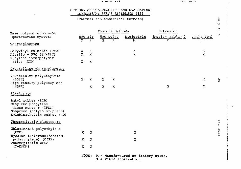
July l*3--i 2b 841-3C15
vi) iV.-ch.'snical (friction or sewn).
Of the above noted methods, dielectric bonder..-; w« -j3<i not be
used in thti fi<=la due to the nature o£ v.!:i t;:quipn>.imt
required. Extrusion welding is only used with hiqh density
polyethylone.
A summary of available membrane seaming methods is presented
on Table 4.1
METHODS OF CONSTRUCTING AND EVALUATINGGEOMSKBRAME 5£Ll:.S RSI ERENCE (13)
(Thermal and M e c h a n i c a l Methods)
Basa poiyiisr of commongeoir<eKibr«me systems
Therrooplanti c£
Folyvinyl chloride (PVC)Nitrile - PVC (TN-PVC)Ethylene s-nterpolymeralley (SMA)
rnopJastius
Low-density(LDP£)
Hicjh-dens.ity polyothylenu(HOPE)
X X
X
HotM
XX
airF
XX
Thermal
Hot weM F
j:t hods
a DielectricM
XX
Extrusion
X
X
X
X
(Fusion -nic;u
iX
C
Butyl rubliar (IIR)Ethyleno propylene
dione mouorcr (7JPDM)Nooprenui (pclyc hlorc prano)£pichlorohycii:i rubier (CO)
'. Lan t crv.:rg
Chlorinated polyethylana(CFE)
Hypalon (chlorosulfor.atadpolyethylene) (CS?K)
EPDi.'
X X
X X
X X
X
X
IIf.'
o
NOTE: M « Hanufantured or factory seams,v » Field fabrication
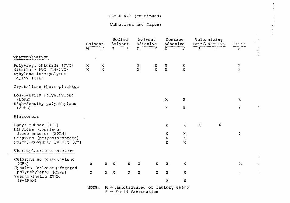
TABLE 4.1 (continued)
(Adhesives anc Tapes)
Thermoplastics
Poiyvinyl cblorida (PVC)Uitrilfi •- rVG (TN-tVG)Ethylene in.terpolyr.-firalloy (liI/;;
Crystalline tlrarmop 1:-;st'i.cs
Low -de n s;;. ty go lye t' .y lena
polyethylene(J1DPE)
F.laston-3::s
Eutyl rubber
diene lWincnar (CPLM)I'coprcna (pclychloroprene)Epichlorohydria ru!.b-;r (CO)
SolventH F
X XX X
!3odisdSolventM t-
SoAdiM
XX
Lventeaive
F
XX
ContactAdhesiveM
XX
F
XX
Vulc^.nizTar.o/t'.d'r.'r.
•A
m e:.i.v
X
X
XXX
X
X
XXX
Tar -2 -,
y.
>
Chlorinated polyethylene(CPK)
Uypalcn {chlorcsulfonatadpolyethylene) (CSTE)
Thariroplastic EPiJM
X
X
NOTE:
X X
X X X
X
X
X
X
X
X
X
X
X
M - ilanufacturec or factory eeam3F - Field fabrication
July iSr,4 23 3-51-3aij
Factory ne;:rrii: grr:e tally are considered to have; higher
:,• ^.-.I.J ,OUMiiuv.^ quail;7 i-.-.ari ti'jlo.'--i bricat
desi fable to prooLCu iai.y;.- iin<ir jjit-ci.-f.; it tiv: factory.
There is no ntanuard size t'oi factory r bi: i>.iud pieces and
most producers will provide what the customer Lt-qussts. As
a guide, pieces approaching 1930 square n:i»trr"> of 3t" mil
materials are produced quite regularly and would weigh about
2000 kilograms.
4.2.5 Reinforcement
Both reinforced and unreinforced polymeric liners are
considered in this report. The introduction of
reinforcement or serin to a liner generally improves the
sheer st-iran- jth of the liner and therefore wou'd iiujjso-.'e its
resistance to failure du3 to shrinkage, creep, tear and
puncture. It may also facilitate handling and seaming o-'
tne membrane both in the factory and during field
installation by improving dimensioral stability.
Polyester is new the dominant scrim material, having
generally replaced ryJon due to its better jcia and sunlight
resistance.
The principal disadvantages of reinforced liners ace lover
elongation to rupture, less ability tu conform to ground
irregular i ties, less flexibility, increased po-.&nti».l for
dejlandna cion oC calendered sheets and wicking, and greater
costs.
There are differing philosophies related to the most
desirable ixner property to resist imposed stresses.
Julv 20 I-'. 1-201!
a do;ni:,r..-.
•;.: j'.,••.•• ::c:-; tiv:- II;.' r s)
i:o L'.'jctor ic'c i c wViilf*
i'O ci. ii L x c. 1 r.oi: iijO.i i
of i:hij is --i ;;cLi:iScd in saj'/.-qui
i : -.J.O ;• •;..-:-.-> h i ; : ; -trer;c,t_h r.
.•:;•- v.'v.r :;i.v-^ost3 the Liner
iou'-'j :. I'yfi • ';'!>•.-_• *J i i: x Z tC<::;-3
.''!. -ic-ct 2 ;>i:.-> ol thii? rcDot;:.
Provided th'i qubgradtt of tlic tailing'; hasin is properly
prepared no thnt it is relatively c;: ooth aiid will not
transmit Lo.id to the liner duo to novf.-rviKnt or require it to
carry excessive hydrostatic stresses, the liner would
probably be subjected to the most significant stresses
during installation. Careful planning will be required to
minimize handling stress on the liner. It is desirable,
however, that the liner possess sufficient tensile strength
to permit ease in handling and to resist unavoidable
stresses. Further, due to the potential for some polymeric
liters tc creep, it would pzotabiy be desirable to have sctne
rainf or cement in linors susceptible to creep when tfjcy are
placed on slopes.
As notedr reinforced liners may be more susceptible to
^elimination„ It is considered that this is a function of
scrim size and spacing. The polymeric sheeting depends on
coMpourtd strike through to adhere to itsell. Heavy,
tightly-woven scrims, would nrcbably reduce the percentage o
strike area and t'no inte-rpiy bond may be lessened. in an
effort to enhance strike through, so?e manufacturers use
heavier ncrim with lower thread count vh.ich provides a
1c :gr-r weave opening.
The'. 1 ther potential problem or-socist2d with linsc
reirsf orcen ent noted above is wickinq. Wicking is a process
v;hich causes dolcsmination when the scrim material is exposed
to the waste effluent. The scrim strands absorb effluent
July 1004 3? 841-3315
r.i-::<j. 11 i. r:" in fccappc-J eCCluoo!; i/yi:woon Pv i'tan."? s'f '-fcts.
Dc-! iii inc. t/i or. ce^ults duo to the formation of rj^s babbles
I.KJO'I T;va,-'Or <; t ion or c^composi t ion of the wisto. To orcvont
this, se.'. •.'.:.cc- -?oy>:.•:;• are r.-o.v p4.ovi-J.-d tot v.hc membrane d u n n y
tho r.o. lender ing process. This is done by terminating the
scrim nviterial 12 to 25 millimetres fro.-' the liner's ed^e.
The covering of exposed edges in fie]d se-r^inc must also be
specified to further protect against wicking. This is
especially necessary when the liner must be tailored to fit
around internal basin structures and whenever there is a
chance of the factory selvage edge being removed.
It may be noted that a scrim is characterized by its count
and the linear density of its yarns. The count is the
..V....U, ..r ,-*..-.., poi: unit wiJth i;. c^l J;j.-..--.i;r. iizzri^^f
a;j ths warp direction and filling direction (machine
direction and cross machine direction). Linear density is
uiass per unit length with the traditional unit being the
dernier which is; equal to 0.11 nill iyr^sns per metre.
Examples of common scrims in North America are:
i) 10 s 8/inch; liS dernier x 2S0 dernier; lino
v-oave; often called 8 x 8 , 250.
ii) 13 y. 10/.inch; 1L'(?S dernier (both directions);
plain wnaje; enter) called IS x 13, 1080.
p •• -•; ] • ';•••
n s s r j o n i n ; - / ; . ' • • ' • i o n c o ] 1-• ^ *; c c'i f r ; ? •!.••;' ' .v^r v - r ;:;• t ?. o n - w i t h
l i n e r r::a'iv!f j ^ t - J C v : •; J ^ i i ; «/O0.1J ( ^ ; v o : : ' w V-r I c . c ,
VaC ic j t : . o n s i n t h , ; q u a l i t y cc r _ r c l pfc-;;r?.-:-"'1.'; r^"* t i n e l y
c a r r i e d c u t d u r i n g f a c t o r y fv.br i •::-:*. t i o n o f V v « e r : i . riie.>e
o r f . c r ,•> T I , I > . > S - ; . : u : r i v c i r y f r o . ! , v i s u a l (.•>:.-..r:ii n o ' . i o n c : v h o
s . i . r : i b r a n : ; i u . : r ;!:••; ^ a b r i c j i ' ^ n t o d c - t . - 2 i i. e - 3 t . r v . *• i n - g i n c i . u < : i
i ) c u v / r . : - t . ~ r i a l t o r . t l r r . ' t o " j " 2 : - -j •— rr p r • : • ! •" l ' ~ - ?
.'(•• a 1 1 - r 1 c 1 s i j p p i i r - . ,
11) con11 nIJo'.:s visud] inspection dLirino film
maivj facture
iii) physical property determination of random
samples from the sheet rolls
iv) visual inspection and testing of all factory
seams.
Tests carried out tc"finger print" the raw material or
verity coo? iste-ix. ,,uCuct quality nucj'-st include:
i) the xp.lt index (ASTM D.12 30) v;hich is a
numerical cual1tiration of the molecular
weight
ii) the density of the materiJl which is -3d
indication o£ 3 range or properties
including Lensile strencth, hardn^ss snu
cl)»"-m i ca 1 res i s f.juci'
LIJ) moisruru content.
Visual inspection is carries! out to identify pos^iUle
t.ir.ur.antu or thfl rrc-r;enco of oi nhol :?.-j or oV.'ne?. defact
Citlilib* AC.2A.-
8 < 1 - ?, >'« 1 5
T!if _o. c t i m c:. r r !•:•:' c.iH f.> •-'.:• t>i r:?.i n o [::••/:;':.•;: ;>: •,;.ir:r t i e s o *
r ..'::-.k. ";> i.ipii.Of.'S nj-jijt; i n-..: i r.d<;:
i) t.h i c!>:;)••. :"<''. J<4 t o c™ i ;:JI t i o n
i i 5 car b o n •:o;11.• n t
iii) tcn;.ilc strength -T.d elcngat ion testni.,
iv) carbon bl;.ck content
v} tensile impact testing
vi) stress crackinc resistance
It is anticipated that the larger more experienced liner
manufacturers would have in effect a more detailed quality
control programme including many of the tests outlined
above. In any event, following selection of a lining
material for a particular installation, a mini.;.urn quality
conti.ol pui'jti.^tf during liner fabr icet i--o «t;uld incluio the
LOllowir.q :
i) "finger printing" o^ each batch of raw material
ii) independent verification of the chemical composi-
tion of.' e.= ch new batch oi polymetic cof-povind.
j. i i} routine rx\d fccqueiiL v ' .-. i'.a to the r^"iof actuiror
to i nspec t ttit- i:i• sU i n<T i•:.c i 1 i t it:s, Cactor y
operations, and fjctoty Sij<i<tii!O
iv; r;:ir c i i i •,:-.'. 1 jboiriityry t>-vt r---'.i!t:- provided for
'Men nay's production of h n c : rrater i,-) .
v) continuous testing oi' Ail factory t;eaiTi.> by a
•^rthoc! si.J"!) as aic iaociny.
Cua 1 i t:y cent; ol Jut-inn liner in:; t-i 1 K* t ; ~r: is di^cuLLcci
in St'.cti^n 7 .
Various ther.T.oplast ics and elAsLorrers nave found application
as lj.n-.ar materials; nine differsnt r.iatc?rials 3re considered
in this study. The following is a ijeriur l discussion of the
characteristics ot" the various niaterials. The discussion
considers the base polymer but not the possible effects of
varying concentrations and types of additives used by
different suppliers and manufacturers during the compounding
stage of production. Specific material properties ara not.
discussed in this section but wnera information is available
related to liner permeability,- values are quoted. There is
significant variation, in the valuc-j quctud, which may, in
part, be duo to:
i) difference in polymeric compounds
ii) variable laboratory testing techniques
and test fluids
iii) permeabilities which are representative
of fif.*lei conditions but which iv.p.y not
represent the value obtaineo by testing on
\nti-ct pieces of lir-^r.
It must: of* nttnr<r.r*c, fh^t \ t [••'. very difficult to carry out
iccnr.ite perr.;eabi i i ty fcestir.^1 on f.»ol y;:-:-! i c '..itmW. v^-, r:&^ doe to
th<Mr oxt rf;n<e.l\' low periue^bi 1 i ty, Further, it is recoanized
tlut the n'itrchawituns by which flui'Jy Clow tIscc-uyh
J i s i y ; > : ; M < 34 3 4 1 - 3 Ci 3. S
t h r o u - . j h s f i i ' i i i: t h . - l ; P e r c y ' s "UJV d i i : s n o t ; : t r i . c t ) y >" :np ly . i
It is wry cnnvcr.iont, however, !:o de;;;:r ibe liner I
p e t u u . r r t b i 1 i L y : :"i t<" j t i i i 3 u s u a l l y i; <.; s o t \ o i o i : . ; u i ] . \ > . Z T i i i a l l y ,
i t i s iTpoc fc..snt i.o n o t e f o o t t^i.ich cu li,-j r e p o r t e d i
perivit?^bi 1 i l.y u . ' t a r e l a t e s t o c c f t n r ) in t h e p r e s e n c e o t a i
L e a c h a t e of i. ritei'c j.*it. Where a l i n i n g n i ^ ' : e r i a ! ir, n o t I
p a r t i c u l a r l y c o m p a t i b l e w i t h t'r.'.f l e a c h a t e , pc-rn.<»abi 1 1 t yj
could be significantly higher. •'i
4.3.1 Polyethylene (PE) !i
Polyethylene is produced by the polymerization of ethyler.;? |
and is classified as a crystalline thermoplastic. |
Conventional (low density) polyethylene in pr~.';ncdd witT !
high pressure polymerization giving a non-linear chain.
i'oiyotliy .ene doez not contain plaatici^yti zo increase
flexibility so it iv, produce:', by extrusion with thicknesses
limited to the 4-17. mil range. i-iaterial pconertios cor this
class of liner can be modified by various processing
techniques producing cross-iani'nated or pro-."t^essed lining
mater ials.
The following properties have been noted for polyethylene:
(14)- low initial cost
(14)- law shipping weight
a "" '"'•' '" "'(3'7) "°
•- few r e s t r i c t i o n : : on chc-iiea I rKno.iuie/ " •" i
- ooo'3 l o w cc-i".iX'r;it.ijti» c h a r a c t e r i r - f . i c s
- (s^b-c i tfc 1 od Ly o. \p-v; -u ie t o u'. i . r a v i c l o - i J 1
( 1 7 )- p o *j u i j i u u v . L a i c £ t'* J A --> i_ c* i»C o
. . (14)- pcoc .•iljr.. sion resistance
{i b)- pooz tear strength
- uu'U-nptib'i.e to stress cracki-o
- very ~i'.i££ to 'lap.csie, except in thickness
unch--r 8 mils, f:f;p'icially ?n s;ib- frees m.]. . U4,1C)
cotsdi t ions-0
- ^rrr.eabi 1 i cy of 1.5 x I? centimetresper second
Polyethylene has a crystalline structure and becomes brittle(18)
when exposed to weathering . The characteristics of
poor weatherability and poor puncture resistance can be
offset to some extent by using a soil cover over the liner(16, 19)
, thus polyethylene liners are not considered for" ., ( 8 )
Polyethylene can be heat-sealed in the faczTy, producing
good seals betv.:jen panels. In the field, scs;«s are usuallyUS)
scaled with self-adhesive tapes or ceisants. These
joints have low shear strenqth &nd adhesion can deteriorate(1R)
under continuous liquid immersion
(8)Polyethylene is inert to most solvents and is generally
cons ifitr d to ritoc fair to cood cvor<-ill hydrocarbon
ccsiut.'inco: ' . Tru-ue linec?7 .K-'.1 -also relatively
inexpensive, however, lifa expectancy is proportionally
ahCi'c.-E i:._*L;i'civ'-.' tu li.t> ii.orv- ex[.eii.~s i v.j liiiei" iViattcials.
fioid Rplicxoe atf j-srs to i"'". th1? ir^-ioc drawback of
July 1904 3C
4.3.2 ilirjh r •:: p. s i. V y Polyethylene il,'u?B)
Many cf the o.-iuc'iirable f.'-.atutcs o£ 3tai.uci.u j.K/ivet'iyiene
mr.y bs avoided by modifying the material u:>i;,g liiijh density
oolyethvlenc pclymars and low pressure polymerization to{22}
produce Linec-r chains. Like low density polyethylene
i-IDPE does not contain plastici^ers; it is octrudec] in sheet
thicknesses of 20 to IBS rr.ils.
The following general properties of HDPE have been noted:
(i) Chemical resistance to hydrocarbons
oil, acids and alkalies is superior to
that of rubber (butyl and polychloroarene)(23,24)
membranes.
(ii) Material ."nay ha placed on slopes with the
stability of the soil and not that ai th«(23,24)
liner being the limiting factor*
(iii) The material has excellent puncture and
tear resistance and personnel and rubber
tired vehicles can move freely on the sheet
durirso installation,- maintenance, and" . (23,24)
inspect lon.
(iv) 'A" he; T33 X: a r i a 1 of tors exctO. Ipnt ui tzn-violr. t
r e s i s t ance . Hcsthoro.r.stsc 'costing inuicatoss
an unnioterrted lit*; <?xo?ctAncy of. vrextcr than
37
(v) l-'i.'-ld welding of r.r,iins i;j by ;noat::', of Euaicn
or extrusion joining ap.'.?rati.is which extrudo'
a ribbon of M£L'£ which ic th^n ?•.;::?-••; by c-
roller c'ain; thus, gluf.s, ijoivcnta and
(•"iu.'jssivr;r; are not required.
(vi) Non-destcuctive quality control o,r all soams
can be carried out by ultrasonic testing
methods.
(vii) The lack of plasticizers reduces: concerns(25)
about microbial attack.
(viii) Superior strength and elongation(22)
properties.
(ix) Rat'jd to 203 degrees Fahrenheit continuous(22)
exposure.
(x) Rated to -76 degress Fahrenheit continuous(22)
exposure.
(xi) Good resistance to exposure to qammaa. . (25)
radiation„
(xii) Permeability teportedly in the order of, -13 . ' (24)
1 s it? centimetres per n;;eoncu
Cost of iiDPE KiHy t><; tto.-ir.c;.viiiat hiqher than the other lining
i~5terials be in-9 cons io.es:'.vu. The; other noyativs
characteristic of thi.3 product ia its sti££n«ss, its high
coefficient at fciiera^l exosnsjon and its ooor
uly I'MUi • 38 r?.tl-?C3
>-f---Kii l ; t"'_, •''•; ~h r'-- n •••' <••• ••:•=. it- c o — b ° f '.prr- ?"•';: h.^odJ. i im v><]
placing i'i t::'J iioI'J,
Until celfltiv^-iy i«et.-nLly HDP^ hc.u Iirait...J u>;o in l i-jc
i >ii: tal Is t ions in Worth America. How^veit . tho installation
ot HDPC f&i: uEtinium ••railings pond liners ct the Dawn Uranium
Mining faci. ii tier, in Ford, Washington (11.3 hcctrices in
1?81) and at other large installations such as the Public
Service Company o£ Colorado's Power Station facilities (26.9
hectares in 1979 and 1S80), has generated considerable
interest in the use of HDPE.
4.3.3 Chlorinated Polyethylene (CPE)
Chlorinated polyethylene (CPE) was introduced commercially
in 1S65 by Dow Chemical Company for applications between
vinyl and butyl and is classified as a v.herii5opidstic
elastc-fGr. It is cier.c-_"ally specified in thickrtojrces between
20 and 45 mil:.. it is an inhecently flexible; therraoplastic
produc" d by chlorinating high density polyethylene.
Compounded CPE sheets commonly contain between 2~5 per cent
additives. CPE formulations contain little or no(26)
plastic7.i.ers but may contain a controlled amount of PVC
polyrr.er to aid dinonsional stability and processabi 3 i. ty.
Alternatively, these polyrc&rs can be reinforced with nylon"(IS)
or polyester . CPE is comp^tible with many other
plastics and rubbers while retaining most of its desirable
character i.st ics. It YIP?, be<r»n success jru) I y blenoeci wit'n
polyethylene, TVC, A3i; r.d "::-verr:l ^:ynrhetic rubb->i: to
improve csracK cesi stance ' ' .
7. . I - -[o<v 39 34 1-3C15
Tho foilowiiirj p r o p e r t i e s hsve been noti.d for CP3 resin.'
- s ince Ct>b' i s a ccmpiereLy satut .at^u pol^Her
(no double bonds) i t is not cur .eept iu ls to
ozone attack and i t displays excel lent(27, 28)
wea t h 12 r a b i 1 i ty
- because it contains little or no plasticizer
CPE has good resistance to growth of mold,{27, 29, 28)
mildew, fungus, and bacteria
, ., (29)- non-volatile
(16)- good tensile and elongation strength
- good resistance to ultra-violet light
(29)- serviceable to low temperatures
- excellent crack and impact resistance at(8)
low temperature
- good resistance to deterioration by many{28 }
corrosive and toxic chemicals
- limited range of tolerance for aliphatic
hydrocarbons and oil? but cv-n bp fcr^ul^t(0, 20)
to improve resistance
- tend:? to swell in oil vtv.n irc^cn.^.d, but
r(-•"!• 111-a•).*• losn in tensile sticonoth still
within auitibls working range'
Jul : ' 1934
•>:••.•••• l i ; > ' ; i r s w e l l i n h i c r h i v a r o . r . A t i c, , . (15) ' 'hydr oca x. tons
(18)low i.-'.-covv-ty when .•iubjoccc-o to t -ir:.'.•>; 1 <- s U o i s
permeabil i ty cjenersllv reported to be less-12
than 1 x 10 cent imetres per second
(25)l imited res i s t ance to acids
- requires reinforcement on
slopes limited to i.5 horizontal to
1 vertical
Th& propstties of CTE aie similar to those of HYPALOM
(CSPE). Sines CPK is generally unvulcanized it can be
seamed by sdhesivc-s, solvent welding, or dielectric heat(31)
sealing. Field joints are corriraonly solvent welded,
often with xyleno or a mixture o£ tetrahydroCuran and
toluene. Fiold joints are difficult to aakc at temperatures
Ie5;s than IS degrees Celsius due to the high flash point of
the solvent wold ing solution, in other words aarly adhesive(IS)
strength cf the jointing surfaces docs not develop. The
overall intcsnr it*.' on thes;c: solvent voU:.:d joints; has been, (13) '
questioned.
Whwtvf there wi'. 1 bs no dancrcr of r-vch~:iical ds^iigi-.-, CP£
linc-i..-; co.ri bo uced exposed. S aiv.pl es t'spos;ed ir« Pirisona ici:
nearly ten yoas:*-? cec-riinr.-d 3? per cent of the i r t e n s i l e i*nd
oiorwafcion p r o p e r t i e s , with l i t t l e or; no ciianye in low
t>'iiii.«£-r tore nc^sct r e s i s t a n c e . fts ar. ?>>:pos&d conta iim^nc
m.ribcari&r CT" is expected to Ic>.-it more thc.n ':e.n years, cased. . . (21}
on no i.iecii nica 1 azr..zq™.
CPD Iinere" a\c; in the lo / to radium price r.cr.v.- for
comparable :->nLhetic liners. *
4.3.4 chlorosulphonated Polyethylene (CSPti)
Chlorosulphonated polyethylene (CSPE) is a family of
polymers prepared by reacting polyethylene in solution with
chorine and sulphur dioxide. Presently available polymers
contain 25-43 per cent chlorine and 1-1.4 per cent sulphur.
CSP)3 is commonly known by the DuPont trade name, HYPALON.
Although the polymer was developed in the early 1940*s it
until I960. In liners, it is used in unvulcanized compounds
containing at least 45 per cent of the base resin. Other
ingredients are predominantly fillers.
CSPE may be both a plastic and an elastomer, depending on
the degree of curing. It is classified as a thermoplastic
elastosar.
Most CSPE lir.on sheeting is made with fabric reinforcement{ 9 Q "
(nylon scrirp.) . After PVC, i t ir, the roost common of the( 2'! )
polymeric flexible liner materials ' . The minimum and
most po-mlcr shc-at thickness is ?/J nil but it is available
The use of unsupporecu fiyf-alon is generally iv. u recor.usr.de^.
fcha iinc?:yrrn ststr; ^r;d rn^L'.I ti r.tj i?i:ii;;-;I l.-i t ion c-:id crcc-p

metre u-idc- .st_-:ni-cur-. J panels, and cun be fuct'-\y fabricated
in up to ISS'j square nacre panels "" .
CSPE sheets arc rnorn.\-curcd w'u>r. installed cr^ li^ld >
(vulcanizing pro ret" a) taker; a ;.-ro;;inatel y \.:-r, to ••.':tf
months in relatively warm sunder temperature::; '.
The following properties have beet) noted:
(16, 29, 34)- good puncture resistance
(32)- good resistance to microbiological attack
- excellent resistance to low temperature
cracking
.. . (24)
excellent weather resistance and aqi.r.q due
to slow vulcanizing process
good resistance to ozone and ultra-violet(8)
light
flexible and resilient, accoiunodates(32)
movement due to settling
(8. 16)low tensile strength but oood
recovery of tensile strength
uncut"«id CSPE is more thermoplastic than
otheE elsntcriiars but after curing it 'acs
good dimQnsion-'*! stability at hi«h(21, 28)
:•••:• r i*" t; a o i i. J ty <•;-.'.-. • 1 5 / cr-crtoii co ho of the
ovo •_•:•; or. i : I;: <•_ (. n t. j. ;r,: tr<--r. rcr r;oci>:id in
w a t fc r
- other i n f e r e n c e s inuic-jte. perrieabi ii tv of-10 (11) "
1 x IS centimetres per second
As the rcatetial cures in the field, tensile strength
increases, elongation decreases and the film becoues less(33)
vulnerable to puncture . Dimensional stability, creep
resistance, and operating temperature are ail related; the
material will tend to shrink and soften at elevated(15)
temperatures . rsj>K sweiis in aromatic nvasrocacoonsMilder hydrocarbons have a less severe effect and in some
instances, CSPE shows resistance to certain hydrocarbons.
The material will recover if cleaned of hydrocarbons within(34)
a -few days of contact . As the material cares, its
hydrocarbon resistance will improve. Higher t-.c-rrparatures,
on the other hand, reduce hydrocarbon resistance.
When first introduced t Q.Z7Z developed a poor reputation with
respect to:
• i) pinw.l-;--
j i} nhrin'r -;<;e
PinhoI.e c o n t r o l hzs i n r g o l y L^^;; r.i;r. i t v e d by la^iiaa t iori .
Sani'"ic>;i::'j a rc i r t fotc i rsy [?rr i c b-vt-?^^-* th.^ I ami n.-.t i or:(14)
<i 4
A c o - . r o n ' 1 1 r,"-;.'i i e d rr.;."b-' r.v.-.? i'. P-ur':-.r -,'! i.ii. 1 .-i/.'-.uor t'.-d
l i y p o i o n •.;;i*c'u c c n r ; i:, i_:. ^i f.;,..; .1;. ;/....• r:/J :.: •_•,..;?•:. .7 u ::;--? 'ir-ni:''
["•eiv^jtii i; »•:•••• i.-.ii •.••:; o f B y p a i o u . D u r > . _• •;'J r.m. :,!:/;M:tc:ci
liy :•••-: i o n coris j :.t:; o.c ti-.'o l;:-,'-;;r'. o f :-of ,•/.)]• t i\\\) ^ziin t'itwc;c-n
r; p l i i v " ;;i' H ' y p a l o n .
One o'.'. tV;e 1 inii ta t ions of CPP£ is the detailed se(li)
technique which must be followed exactly . CSPE can be
seamed by adhesiver>, heat welding or solvent welding
The material is commonly sealed in the factory by solvent
welding. Prior to installation, the liner should be stored
away from ultra-violet light to ensure adhesion during field
seaming . Field welds with solvent are best made on warm
summer days and solvent seals must be applied before the
Hind !-UL<J is: ccnoiet?. The solvent <:<-••;\.- - J.. ',--\Z oer ctr.t
oy v.-eight CoT-E polymer blended into a solvent adhesive
The solvent; ^!-:c>5 the uncorcJ material ia s a - p r\s i '>n .;nd
the lost ma tc=r i ..Us are replaced by t'm CSPH in the
adhe?ive . This joiating system ia not affected by(lii)
weather and produces a horaoqenious r>e-j.T.. CSPS lifiet
have found application for both exponoa and uno-xno.srd
service.
The- above disease ion . Jijc O.T."-' 3 C3PL in ^ n e t a l , Major
suppliers d o , h o w e v t i , ^ufiyiy Lwo qi:.".i.::v oZ ~.it•::r i..-i 1 often
d o s e n b e i 'js s'r.enci/itci o*. p'jv-.it/i •- »-.ii.*•.-,: ^u^w--: C.".:'C >;r.d
ir'Ju^'.rrial Gr:'3e or '.m, w t ^ r -•••;.-.-, L-r: t-i o;. CiTV!.:, r'he "u>::r
distinction ii 'w;;jt the inuu:; Ur i-i J ', L •_'.-••••: <_.ji-'L. WL'J.C !IJ,'>; a
rriur!; r-'.-cl JC-.M.*; U-!:o'^'/.y lo ::brrvcb wet';: (or ch-:nucsl
loacituv-t:} r and thus wooifj w.- uiU'vCi.fcv ;.:o iiavc .ji^iijiicii'.cl
c h a r a c t e r i s t i c s . tor trie ;."j; pusa u.C
:• • • : - •• '•'• i '
d i t c u ; : : j i o-i". , c n l y ( . h e : ; r o p t . J: t i ••-•* u i i r d i ; : i r i a \ . ; r ; : - i . ; u r l o w
w a t e r ; v - r , i ; ; p i ; i 0:1 C^Pl1, w i l l DO cuf i i i l o e r •. ri *n .•••i.bsc-; ' j ^ c t
s e c t i n i l s o f t f i i i ; r e p o r t .
^ y ^ a I o n J i r . - e r s . J I - : i n i r . n o i r . ^ d i e r r . t o h i r ; h ; : r i c e r a n o e f o r
c o i r . p a r \i)j \ •.- .".y :'i ' ;h- ' L i c l i i > ; - C i .
4.3.5 Foiyvinyi Chloride (.PVC)
Polyvinyl chloride, classified as o thermoplastic, 5.s a
calendered material available in a wide variety of
thicknesses, colours, and compositions.
Polyvinyl chloride (PVC) sheets contain 30-50 per cent of
one or more pl£.sticizers, 2 per cent stabilizers, and some
filler. Thicknesses oC 10-30 mil ace corrimori, and niost PVC
films ^t.(- used ar ^r.ruppor !-•: ' ';!ie?rc. .r"/C can also be
i'abric ^einL'orcoo if reouired. T!ie physical and chenucal
proper t i v.-v. ot VVC riln arc J function of t!u-» specific
pl.3d t ic i z..f r •; used in various compound^
The following properties have been noted:
- poor resistance to ozone and ultraviolet
light: resulting i:r» cross bciiaiiv] ;ir..l increased,
stiffness hut car. be i'norcvoc o'ith proper
stabilization [ L i' 2' '
p i .i." f. i c i 7.!-1,! '-'.'C f i i ; n ir, oui'co r t : ; i r l : . T n t{2'M
t e p i r . c t u r o ; a n d i .-viac l v o l y e.'i.-;y t o s p l i c e
qt! t e n s i l e s t r c ; ; iL ! i
" 4 1 - 3 -.31 5
;>e f ; ' j o t x.o ' " ' " o c : . r .o r . ios .M :: o r v
t.Cot. :> :';0W t h a t :30:' •.' COIfi^Juno J f-."~.O t.O
r.jr.-.r.-'r; , * r j r.:.!;;: i n k o n c v J i-•- c-jct--^: -i: •'• * o
t:o :TU id•;:<•; and Cuvinuf;(I.'?)
w h e n co.i.'po'jnJod p r o p e r l y
higher coat and shipping weight than
polyethylene
moderate oa.T.ma radiation oxposure results in(i'5)
soft and tacky compound
reported perrnpabi I i tos :
ra/sne (lsndfiM le-13
7.3 x 10 cm/sec (20 mil sheet in
The principal problems with standard T-\'C. liners are usually
• •:.-'.jsed by the miqrat'on of the ncn-poi ynvjr ic plnctici zer s
from the base PVC siieot. Mii;r.aticn of: the plasticizer
results in a hard, brittle liner' reducing resistance to
cold weather cracKir.o and jti^cr.inq el'j.^.oticn properties.
Fxt^nrf'^J .'io;it iixposur-"1 t^rds to ccilncitc this nlast ici7.t:r( 1 8 ) "
103^: and SC:-H planticirorr c.:n '--.: -Jr-ir.idvd hy
„ « . ^ . ^ . . . w . . . . . . _ _ . . . . - - . . - . ^ ' , j ( - , '
t o s f i r i n x w i t h t r u ? l . o ; , s o\ p i , v » : t o r . ' . c r
P V C t i l iv. y e n - . - r a i. i y i i o i . i j u p w c ) . i i n b U L i ^ i t c ; t - u , 'r.-jwevvj,
• - • • - • . • » • . . • ( . » , " «C ,
i.% v j ! i ' V* f. J L >"-••.» l i d V l * ( i f L ^ l ! i l i i ' i l . C U i O l \ . ' ^ > U i - i ^ L j ^ V wl v i * « fc-U v * ! '•- - j ( J ^. V. * i . i

July l?n-i 47 a<il-3«lb
pi ;•!:>':.» c* / o r CO. ::<:
t r. i- life of Hvv rr-.a tt?£ i/-1
.loss and t'?oi y<:;r cit gradiit ic;
t-cor. :;.:-• ::'l:^ J t-"> i n c r ~
U L C : : volatile plar; t
factory jci:>t.<. ore- commonly heat s'';.k(i( while* field jcir.t
art: usually n-..v.;e with a :;troni.j s o l v e n t ' . Sealing
tochniqui-'S can cause local izcJ loss oi: piA:itic u e r . C ie
effect of tbi.'» is degradation of filn tep^ icabil ity
Cold weather installation can be a problem with PVC(16)
liners . Low temperature flexibility and field jointing(1 o )
are potential concerns under these conditions
Standard PVC films are low in cost relative to most other
synthetic liners. Field joint integrity over long periods
of time and the effects of plastici2<?r loss on liner
properties h.? boen questioned
Where hydrocarbon resistance 15 required at a particular
installation, oil-resistant, compounds of polyvinyl chloxiide
are available. Since the Canadian uranium tailings see not
expected to have elevated hydrocarbon concentrations, this
grade oc PVC is not considered in this study.
4.3.6 Ethylc-ne Ptopylene Oione Monomer (EPOtf)
EPC'M i s a s y n t h e t i c r^bbes: ,~3^a frorr. a t h y l e n e peony 1 e n e
ait.'in: i!!C'.n.'.-'.»:i and i it ci.*«r; i i!" i«.-..» os ir. clr^r. terrier . C-Jrc-.4. SPDK
i '•• I.;~<'<1 ;;c r .v . tmfacturc e i t h e r u n u i i r ^ o r t t ' i or ?c r i w-p.nppor tod
.vheti t ing iu>, th»? r anqc oi" 2'j t o t-t> iriil -cfii c.'r.e'>w. i'ii<* w s t
pcrv. J a r r.hcrit thick.•;<-'.--;.-, i. u {b csi 1, .-.r.d thfi fo? t sat:cer4«f u l
i j p p i i C a L i o n s liavu L<-c n moasrar.v-s : JC :u<." i:n; si.."1 ic»r->i C>.KVr i r.)
ii i ii J '
J'.':) V ± 0 H t V 8 A 1 - ?. i ] S
Di:-Dvi : ; v n i h « '-, i e '. i'-^r-i a r o - ;.•;: i f - iar i i v (.''.•-:; i o r . r - d f o r c o n t a c t' i :*•)
w; i" .b p o t r b l v ^ w , M ' ' : and a rc £abr ici tcci fro.y ca lender 06
- h - u t s 1 to l.L. .•;.?•: t-?s wioo.
The f:o Licwi. ri3 propetti^ii have be on no;.v..d iros tlii;; clj.ar, of
synthetic iinftt:
good agina and weathering character-(16)
lStlC3
(16)good low tetflpecature flexibility
good heat resistance
~ superior to butyl rubber for ozone resistance
slightly higher rate of water absorption than
butyl rubber
excellent resistance to vate.: vapour. . (26!
transmission
r«?&if»t«nt to nsililow, r.old, funnus and, • , , (32, 25)
ra 1 c r o b i <J 1 afctaci;
(18)- low p.'.'- x ;;p.o siifcit fcreiiot
(72)~ gocd gt;ri6Eal chemical Eeii
- poor fiisists-nce to aroroatxc
c-*i-2r-1r
- E 1 ; r l l :*:.'. v 7.'•':*.; :"'"••:-;i c V.J rt t t o u c ; ; i : i o ! i
- ;., p.;;: t e d ^:.z.:--~^bi 1 i t i - J i :
- w i t h i ; a iuL '<ry l a n d f i l l l.'.vt.cb.:. tf* 1 s '.C(3.,1-oJ
c *•• •. i >: i n;-1 r < • s o e r 3 «? c o r -
- vit.h W;M>»C 2.3 \ 13 " centimetres per
second
EPDM liners arc- not recommended for exposure to solvents or
hydrocarbons ' . Laboratory tests show swelling in
aromatic and other cyclic hydrocarbons.
FPDM sheets are jointed into panels prior to heat curing.
Factory fabricated joints are good, but the same jointing(18) '
process cannot be used for field fibrication . Field
seaming techniques cosrnonly employ adliesi.'ti such as one or
two-part c-.T;-jnt." and gummed tap". It is oi£Cicult to
develop uooa peel strength with these field seaming
techniques, arid fic-lrf searsiny in rGoist oc cold conditions is
relatively difficult. Failures in EPDK liners h«ve been(12)
reported due to field joints . These joints CAU
de-toriorate fhon subject to i;ii«v>rsion under liquids for
I:Ktended reriocla of ti"e> or ./nvn cubiectod to shear(ID)
E P D M linarrj a r e i a the- racUiun to h i c n pi i c e r a n g e Cor
corapar-i;'!.'.: !": y'ntho t ic iiitor1*. •<"'•; jr; coopi-jd v.'ith achnoi/lf'dg^
p o o r r.ar.i-.' 'i^-.t-.-.ii to ir-.:-:: •• c i : ':/;;rt:oitb3r::. cir-d f.ii f f i c u L L :-.•<> i
fi e l d ?-n! i c i n^ , tedis-r-1?. tin- V'O t:>ro t s a V oi: lU'CM l i n e c s Cor
•T;,\Tiy c o : i V •*. l ;;••:> 'ii t .i f ? : ; l i •;.;s V. i ? : ; ; ; ,
/ . i l h o c - j h i.\-v* vfixi f ;o lyr . - -"ES o f '.TO:-; a r o r r o : ; ^ ••;::>'• <.r,x\'''- t o
n r c r J u c c , t h e i r u ' i J ' . : ; : o p t" o p e c t i •:-•-. « l l o < « ' thv.'fi i 'o a b s o r b a
1 ' " ! " <7 C v - > l : . > . - • o f -"^ '• . . " - o s ' . r j . i i p o c i " - • . v i c r ' i l r t i i n c ) I ' ' - ; - , p r o : J u C i . ! -ii
l c \ « r co : ; t Ciniaiv.-d p r o d u c t whet: '.-.•o. p.-ir.-. ; fjo o-ai^'x
4.3.7 Butyl Rubbit
although developed during World War II for automobile tubes-
butyl was not applied to the lining fielu until 196S. Butyl
rubber was the first el as tone c to antes: the lit,ing field
some 15 years after polyvinyl chloride and polyef-.hyhleiie
plastic materials.
Butyl rubber sheeting is a copolymer containing
appcoirir.:,-.to? y r-.-r cent iscb;:tylene a. d a fiiir.c*- ?"*.~:}rt '•>*:
isoprene. Cured butyl rubber co>apounus -5i:e us=d to
iiianufact:uc<? eithei: ensapportfd or fabric reint'orc^'l -4'!•*»•>!: 1115
in the r.anq'3 of 2i' to 125 nil thicknessses. Sorae recent
compounds contain SIH^II amounts of EPDM rubber to improve
ozone resistance of tbe finished sheei:.
Tbs following properties Si-ave b*!«n noted Cor this CI-J^S of
synthetic liner:
e-i:cc:llen'c r; -.; i.-:ta.--;o to watr-r ar.-i v-t^tr(2S, 14)
[ - • • » * £ i n i i ' t * 'C i t i l l
£ :•: c: e i .11.'n i\ CO:- i s t n n c a t o ul t r c v : o ; :?t :.;•;?•:::
t:o o;:o".->
5'.i[;:-ril.'v •• o'.'.a w e l l , r.Lthouqh 'r-o.uv c:c( 2 'j)
w i l i ozon-v crsclx on Long expocuio
(8)hic;h tolerance? for tor-.'-.X'raturc- e t
(29)contains lov.f amounts of extractahle material
- good ttMisile and tear strength, good resistance(27)
to puncture
(15)- poor resistance to hydrocarbons , particularly
petroleum solvents, aromatic hvdroc-arbons and(8)
halogens ted solvents
(IB)- lnw nppl nci shear strffnoth
- d.iffic:ult field jcintu
- excellent elonqetion orocettios
- r e p o r t e d pc-rin-.'abi 1 i t i e « :-10 (36)
1 K 1.0 ra/£ec with l a n d f i l l Jeaclutre! . l s 18 crr>/:;ec w i t h w a t e r
In o u t d o o r w^tei ; (nanaoc-rwen'c u:~'->, butrvl j.jh.c-efci rsg ht>a"(29)
y e a r s of aorrvici? i- ' ith r « d c g r a d . 3 t i o n ' . The o v e r a l l
w^at i i t - r i r tg tf- %i..-!;.;;,co .ip ;^;-;;::: to bo c r u r c t i o p . o£ t h e
i 1' i c co'riroi.m;: I utj .
.So^r.irKj, p»:r t i c M l / f f l y f i i e ld j o i n t s , ^ r W ' ^ s i:o be a pLo
^ ' i* l ' T ^ p ' i c i ' i ' ! ; f--"'.r w iCM 1 *r: 1. y i i .,i?r=id <-»•"•»?t:hs»r» h a s t 'e^u
in lin?->5: fs\l>ir<? . Th»s i-;->y»t corunion probl ' i . 'a w i t h f i e l d
U5 " ! : ; . : : i ' I 'm.".!: : - WI! 11;i i >
b u t y l 1 : . p i n y i s .'.•'>::"..•-reed r:o>:e t h a n t lv- i-.r.;_ iv.:j p ; o c - > r
Adl:i.'.':i v>3 s y s t o ^ s ->:o co" . r*on ly i :3cd t o cc^ic . - racf - h u t y i
l i n ^ r : " ; ; br';! '! c n o .-nri t w o - p - r t uGi ie j iv i - . : ; , ;jnd ctv-.••.•;• c5 t s n e
l i s v e i ^ : r : " . c i . '.i.\f,'l lir:CC53 3 r d n o t h:7 .•:,<: o r ivul *'<?.':i., , . (2V) '
Butyl liners ar.? Tot reccr--.ei»ded for trie- retention o£(IS) (1 &)
hydrocarbons and solvents ^ . Laboratory firsts ' showswelling in aromatic and other cyclic hydrocarbons.
The fact that butyl liners are in the medium to high price
range for comparable synthetic liners, coupled with
acknowledged difficulties in field splicing reduces the
potential of butyl liners for inar.y containment appl ic-it ioas
4 . 3 . S Folych loropr.?oe (CM)
Poiychlocoprone, an elastomer, was introduced by DuPont in
1932 cis ?, synthetic material having good -resistance to oil,
gasoline, heat, light and osone. It is ccrnnonl/ known by
the Dupont t.'ude nace rseoprens.
Ths bsr,e resin £or nsoprene sheeting is P^lj•.•••loroprcn»
rublror. tJcoprenc- ia available; in 2'---C'? uiil c:- ?d !?h«-*?t,
eithox Ecriin supportyd or unsuppcr t.:.<5. Th^ iio-^t popular
sheet is reinforced 21 rail tor rrsaoy ..-.pplicr.cior.c.
Th'-.* foi. 1 oi-?ir«<7 prnr.e-rt-ips h-ir/c- b^von noted:
sol :.!*• i.•;•••.•» «;.•.•.;.•:;•;:- i n t a x .i":--:a
f) e -, „ -> <> •*
psrfcic;:li'.' 1 v' v.>h*?n in contact within ; 2!J)
- r n s ; ••';..«: .^tii-.iek by s o i l m i c r o - o r c r - n i . ' . r > i , mi( 3 2 )
overall good ceaistance to hydrocarbons.- bat shows
some swell in acoraatics and other cyclic hydro-U S , 32)
carbons
flexible *nd elastic over a wide ranee of(32)
temperatures
- with the exception of chlorinat«d solvents at
ccsistance
- relatively poor .strength propartic;
radiation resistance is cO'.ip-arVole to
C S P E( 2 5 )
- rer.icts punctures and tear ing from abrasive(32)
over lavr.
- not heat oc solvent sealable
c*-' be i.\T,roved with proper compounding.
lOutTiJ Ot'.i"i'i*iT »11~« *-J. ;*t o J c-f-'v Ckr t. OT I O £." it L;> ur*-,ifir U i t. Z Ti V i 0 1 C '
(27) ' ' """ ' ' "' " *
t:-..1 o p ;<.-;•)(> : :?• o:v'-" c 1: Zr"
p r o p e r l y ' ' . ^ n i ' . ' b ' - i : o f c e j . > ; r . c a a t e r c c : o : . v . : - . ? n C i ; - d , i i ; -u~ . 1 1 "
('-• £ )'•.uo-p^rt sy.'>tc."3 ., In fic-id pc^mir.r r h.l^h tc.Tfp^rnr.ur^
and dry v;r:atfr--r; ire. required f-o r-roOLicc a t. i 1 n '.-r.-srinq bond.Cs2)
a is ;: i f.L icu 1V. to saam xn colo wc-;itr.{»r
Field so^rwing di ff icuLtio^, coupled with the fact that
nooprene Is one o£: the r;ost e>.pa.'isi \ri; ;-;yn.ch ••»'.- ic liners,
reduce it.-> potential use. Searaing and cost not withstanding,(30)
neoprene is in demand for ita hydrocarbon resistance
4.3.9 Polyurethane
There are two typos of urethc-.Tes which have been suggested
for film manufacture: eater and ether based polyvrethanes,
Polyurethc>no l inorc can b-a urmd for o i l s o i l l(21)(21)
contani;'.;ont, beiriq onn of the tcoaho^', s*~,d rfiost ilor^blt?(27)
l ine r mate r i s l s ava i lab le . I'owavcr, these l ine r s ace(27)
considered to be prcmuir- priced . As a c l a s s , theurethanes offer outstanding che-raical and o i l re=sisvanc« and
(27)'l • f-.nt low t^ . j c i j t u t e f l en ibv l i ty . The spec i f i c
p rope r t i e s of the 1:0 basic types a r e :
- fa i r to cood res i s t ance to osonc- and u l t r a v i o l e t
ligh".
- cooci r"-iai:v':«r.c.^ to tniJciov a;-.;.i (u:)i?u5 at w.-.c'-- wijon
srT.-;wh«t ;;u->cu'ior in bvc* re carbon rtjsisf.aiicf* than
r. h c c c n'.? r c a ••; ed t c a inn
- good resistance to ozone and ultraviolet light
(21)- good resistance to mildew and fungus attack
("* 1)The main factor affecting all urethanss is hydrolysis;
that is, their tendency to break down over long periods of
time.
tends to affect the life expectancy of
Estimates nave been sugqested for the life span of ester(51)
polyucenhanes i-ssuraing no mechanical dar.iags
Exposed Service ~ 3-4 years at 2C-30 degrees Celsius
ambient temperature; 5 years at 10
degrees Celsius ambient temperature
Busied Service - 20 years plus in the absence of
alhaline soil, fungus and other
The c r i t i c f t l l i c t o r a tc r ur ' i t r^na sne-ar.ing \r<> husnio aging,
h&va r:-ocr^r t ^ n o i i s i t r ^ n o t h £'-•• tea5:.ion wf'ils the et!v;•£•«-; i(21)
Urathc'.rso ^c-i-cnir-y can be accomplished by b^.at.{ r•(.•az-.n t, nod
s o l v e n t s . „ '?\\h ndh'-'sivo system?; in -j:.;e . rcr S<&••x 1.2r to
those u.ct?d fo>: c r ? " rird involve the uc.e or- bc'.lii.a solvent."( - • > « )
Sheet thic^ROS!; i'.:- usually limited to aporoxiiuatelv 18 mil(30)
one to cost cons ids-rations . Conditional on the various
drawbacks discussed above, urethane Iiner3 offoc limited
containment application. The prime disadvantages are cost
and the long term eEfects ol; hydrolysis, soil alkalinity and
possibly microbiological attach:.
4.4 Liner Material Specifications
corsGidGring th*» variety of applications Eoc polywctic liners
it ? .*> not £;'-' i;pr i« ing fch-^t there are na universally
acknowledged testing and acceptance procedures.
Specifi' -5 have been both developed and adopted by
manat :'. ->->i3 fabricators. The specifications have come
out c n:, plastic and textile technologies ^nd have
vairi•.-•-. . . ...sbiyo S o m e o f th e crc.*nizc'.tions «?bich
prep; . :.-:J..-..- . :.' i cations for lining ••-•:utr.es: i<«Is ace:
(i) Afnerican Society for Testinn and Materials
' i i) A::*2tic;n ^c~ic':y oC Civil r^'jin^-^rrs (*fCS;
(iii) •'.•;acicc.n Society or Agricultural hjrtgin
(i.u) A.;..'sr ica n K.7::-COF Ssoritr. Assnc ; .r. i.; J n ; .".VrrvA ;
•ci f .' C.'J L J c '. r. u-'.u::1!1/ i f'c .'.>.'•:• a rr-'n..r •-•'• "t •• r:d-j,"d t c i t s
.-.•'-fxtT-^: e n ;•-=.; lyv.'r ic "-Irr-cr iu or-'i-'r '-.0 .;:::":;s th3 ;.r
i;jually j;-.':'fon ii-jii in j c c o i . d ^ n c i \)'itl\ st;..:)0-:'di?.-id
proced'Jtf.s; often ASV.'I ncthcis. These i.'_-Su:; sarve to
produco comparative iriiJorr.iat ion on various lin-^r products
and to provide information which allows speculation on
installed chacactc-ristics.
Problems in comparing liner characteristics arise, as will
be seen later in this section, when comparing test results.
Similar but not identical testing is carried out for the
different liner types. However, there appears to be some
ceiaciveiy Eecsnc tu.i^aucs a\. t.CBiK»di(jt^i::y cases anu U S S L
procedures at least among the various c^sin classes (ie.
thermepi a .si-ics, th rmop;.--;_• t ic elastomers, etc.).
Further, as noted above, laboratory test results allow
.spocult.tion on installed liner characteristics or
anticipated performrinoe but genera) ly cannot- be readily used
ho predict; perforir.inci; and thei-tefo': 1; should not be used as a
subst.it.ite for good onginaering design. In additiori, these
.=• l:<itidi( rt\ •. ;-.:••-<~i t.esrs d o n o t 1.3i:o into a c c o u n c L h o e f f e c t s of.
the wasi_o f;at'Tf i a l s on t h e liner p r o p e r t i e s . . T h i s , of
nov~~e>. i r-\ r>f p r i m p ••.\.<rir:'--<:p in t h " rlr>^ir;n of e n v fnr-ility.
1 a b o 2: o t v c y t c- s t r ft:; u 11 s t. u f i e 1 <1 p <-• r L O r ;M I n c •.•- v.:-, y be n o t e d .
t'.;••?
••;a t'-r ia 1 ;:>.•!••..: i:-.c-<J •-.: u c t i .1 e auov.- -18 c.c<.;z&<j'~- Celsius,
HovovtT, in ;iir- f i .-J i 0, brittle fracture w~". noted -sfr
tr.-.-.rjr;r"j '-.•:••..•;: a/. hio:h a:.: li doqce:;3 C o 1:~ i vs n:, T'-.o a.vrnc'v V ^ L
a t ct ib J t.':.ii tr in--:ro<: r.irr strain r o. l: <•-. s arid ;-.r/.hL :;:: ?s:.ic.: < atcu
w:\_h scnl'j oi labo;.:; cocy test ^poei.nc;;:; no i..,'.:.,. vfj to ucr.uul
lir.ov si:-;e ane thw effects on properties. Ar.ouiier example
would iiivoi'.'o testing for dimensional stability (A5TM D1234)
usually carried out for periods between 15 minutes rind 7
days. This type of testing may be helpful in comp^... ing
products (where the tests are identical) but rnay be of
little benefit in the absolute assessment of a product's
dimensional stability over 3 lifetime of several decades or
scores of years.
With respect to pond design for tailings basins,
cons idr>ra*"> i f ^joniticance is placeu on s-.h.e ':ensi j.e
properties and in particular tensile Ptrengt:1. and elongation
at yield oc break, while thenc propertios are considered
significant, they nay not be particularly relevant if the
effect of tiia liner environment i icluding waste properties
is not tsl'.en i ito account by cosrpat ibi 1 i ty testing.
Further, with respect to tensile strength, it may be noted
that where a lin^r material is covered by soil or tailings
it is doubtful uh'ithec any line-: croul.d ceji^t rr.ajor strenses
associ -Ju^d with loss oi support or substantial movcr.^nL. In
addition,, while dof orrn-: 11: : ; or: r. tt lowenli; of tailings
f>-~io!i !'):•:.'••':•, "it i.r. f;Kti:c"dy tJi <: r icr, 11 to d^ternine th«
over vhich to fii r.-.rr ibnc^ cc-1..•i.--\<? c ion . Thi.j i;Ho;.i^ji;ion is
u> .,;.; : : •'• • l':.i. '.,:..-.,r,-\;:\ •••,.•• * r 1; -..\w th.-'Or^ti:1.1.:,.'. .:'.::" ;; •..:. i o r .
*•* - «.i T - ^
r . i - o a r v . - - , i : . : • : ; ; : : • - o f t ' . , • _ • : . ' . -> t . o r i a 1 • . > - • • ; : / i : ~ y j r ; ; s u n d e r 1 y i r . 7
t h e j i (•:•-.• r w , - ; . u - ! > w o u l d t ' . - ' ; u t o I i : ; i 2 i l . ! r : « . i b i 1 . : v . y o f l i n e r : ; t o
: ; v t . ; i n : ) v i j t i . i c ' . ; » . • j f i - ' i i . ; .
T h e , ; i ; c v i . ? -J i :;..-:i:..:-i i o r i n o t w ; t hr-j t , ' (n.1 : • ? , ;. t. i ;> c c ; ; : ; K i t * r . - M t h i i .
-1 c -1 r is j -« I ' W •; * ' i i 1 : h n r .". \/i>J•..» r i i n i :;ro:7i r - > c ' . ' . •' vo 'v - ' . • . • ' • ! 'K'. L O r i -\ i >
p r o p c t t . i f r " s .">. r o i m p o r t a n t r ^ r a nu ' -n r - r 01" r * : - \ s o i ) s , i rio 1 '.u' i a-j
t n e f o l 1 cwi.-.o :
i ) t h e y pi .ovi . i5e 1 c a t i o n s I b ^ s i s f o r d e s i u n in
that i t nay be sa id a t some p o i n t in the f u t u r e
that a l i n e r m a t e r i a l with c e r t a i n p c o p ^ r t i e s
did or d id not perform a d e q u a t e l y in a p a r t i -
c u l a r env i ronment .
i i ) s p e c i f i c a t i o n * ; u e r e q u i r e d for q u a l i t y c o n t r o l
to er!;:r r ' i t^e supp1 ' / of n i t T M i s of ^nown and
con t i r. t ent qua I i t. y .
i l l ) sc;'f nuifer ia l nropec t i-?-; ;uch .JS t^ : i : i i ic
s t r e n g t h and di;v.ens ion.i 1 s t a b i l i t y w i l l b^
s i g n i f i c a n t > ! > i r - i n . j ••:••)'\-j t t r u c f 1 o n .
T h e m o s t c o ' n p t • - ! I - - . M I S i v e d o c u m e n t a v a i l a b l e w h i c h d - : ; a l s i w i t h
p o l y m e r i c n ^ j i i - . b r . i n o s i s t ; ! i e r e c e n t l y p r o d u c r u ' . ; p c c i f i c a t i i . n
b y ' i o t i o r u i l C . i r u t , l t i o n f o u n d a t i o n ['-::y) f v : ! : i M i ' ; i " S t ; : n d a r . ' i
: ; j ^ : ; e r 5 4 , F l e x i b l e f . c ^ l i M r . ' ? L i m T b " ' , T h e '.'SV M r 3 t T : . ' > r . i
j . ' i ' u v i i l t ' - s i t j o . j d i i . 1 . : . ! r . - J •;! j r< i r . i a n , ' u ^ l c r j , "•• 1 .";.: c p « . _ r L i ~ ~ s f . ^ x : r : o " t
p e l vf..^:1 i . : ~ i . : : b r l i i ^ s i n c l i 1 - - : : i t r . . ' a l l c f * h o r^o 1 v n e r r c ' r a t e r i . i l : '
c o n s i c i o c i - ' r i 1 v- t . h i r . s t » : ' . y w . i r ; ; : r ; ; o e x e - . ' p ' c : c : 1 O L ; < O 1 y u L ' - i . i i •»;•».•.
T h i > H S f r v ' c o r . i r r o r i > . i c o ! . c - ; ! : ^ ^ t h o d n a n d : i i i i i ; i i r \ j t o r t v a l u e s . s n - j
i ^ l ncof-K.i n o r . a r c o x ^ a n i i . . ' . i a c c o i d M V ] t J ; i - o ; : i C ' I . I M S
rt> i:i;pCi;ilui;iHi i n Aj.jj.'*_-!iu i x u-, Tliy us. Lu i i»s i p£ •%• t <--1 '". i c >;
July l'.'-o4 <:•!- 841--361
ci I. J u'..- s z. .''J.:i;'vi.. i. <_> L c . '*•- .'/L i i;uv> £ •j i M < - J- j .;..c -i I-* I. i-
su:" r.ar izt^ri •::•; 'itblni 4.2 to 4 .'>, a'. C.;;e «i<; cs t tr;: s r.n<.:tion
o £ t h e ropor'.. . 7 h i n [•;.;? ;•", i v s t.'?".dy tc:r rar i ru n ;.'long t::e
rr»':j. n '•) ..i -:.•;<:> \nr n e t it-.1 f ••.•';•;-J'I rt-^in rL'. s s « s ( i o . C.JH n'jy r.o
e a s i l y co(rp,>.r.:-:i w i t h C:'.;•• r h u t n o t v;ith n D P C ) .
A b r i e f d e s e r. i p t ioci e n d L h e sii?.oi t J C o n c o o E t h e ptilymccic
mat-.c-rial pr^pei: t ics selected by the U'SF for cons idora t i on
f o1. lows :
1. Minimum Specific Gravity
Specific gravity is often specified for polyethylenes
to distinguish between high, medium and low density
grades. For other liner materials, specific gravity
is not a meaningful property.
2. T on s i ]'.? Prop or t ies
Ultirr.ato t e n s i l e s t r e n g t h , modulus and e l o n g a t i o n
(ar.d sometimes y i e l d Littength and y i e l d e longa t ion}
a r e s p e c i f i e d . One of the more impor tant
p r o p e r t i e s of the l i n e r i s i t s u l t i m a t e e l o n g a t i o n
- the a b i l i t y to s t r e t c h be fo re f a i l i n g . Breaking
s t r e n g t h and s t i t r n ^ s s (mooulus) a r e rnore impor tant
d u r i n q j n :: t ,-i 1.3 n v i o n .
l u D i i t j . i - r . o r . r i o v s c r i y a s; t i i e « ; i a e w . n h W i i i c h tiic* o u t
p r o p . - i q . : i f . f ' s t h r o ' . " ? h t h e rnrst•.?>: i i ' - l . L i n ^ i . s w i t h l o w
t s ; u : a t r o t i y t - h v a i u ' . ; s f v h i ; ; c ; a : i i . j u u ! i ' ; ^c.:.*S i c t i i . :> o r
i J i i j k r r £•-•>. ; L i o i i o W i l l i i i i ^ t : d l u i l J u i n . y L o p Z C t j C. ~, :'.*•-<~- L T . O
r . E " . o r e t h i W » i ! ! « ' • . ( • w i t r i h i q h e s r f a r r-1 c f? n -3 f- h
Thi.'v t o u t " (>.-~»t;:i.il i:ihc?ti a !:.;•;-,; > 3 r < ? t u:<.-:- a t v ' n i c h P d t e c i a l
ciian-Jr-r; f::c.ri rubbs-ry to br i i\ tl«.. T^c results ore
urtyfu L in cocipar in>j iTTGfnbi-'tsnos which .:;l.'f,> exposed and
subjected to low temperatures.
5. Dimensional Stability
Dimensional stability is measured as a percentage
of dimen3ional change due to the exposure of the
test specimens at elevated temperatures. Dimen-
sional change is usually due to the stresses built
i(iv.u cnu lineL in tan jJtouuctniii process*. m e ttr^c
is run at the elevated temperature so that the
CPEU1";S are obtained in ,2 reasonable tiine. TIA--?
s^li.?,Q diraensJ0n.1l chjtKja is expected to take place
at much lower temperatures but at considerably
longer time.
6 . V'Q] gt i lo CJc«_s
This tost r.>.ca;,uti!3 weiyht Josis oC th>'; &.%cp 1 c wr.en
subject: i-J to »•.-i o v 5 (:•••; d te-vtv- f.i tut .>•:•.. The t-rr;t
r ^ ^ t* ] *•• 1 y t ; n ^ r i P r t n ^ •- h r* r • > ' • ^ -i ^ .- r-- /?, r r1 *- h ' v r-'.. *- r -* ; ; 1
f;o V v ; lo;" . ; ; o f ' j c T f o f t - i ^ w r - " 1 v o J s ' . j ] r r c o ' . ' P o n c - T i t i ,
• • - - : > • • • • j ' > " •'• ' -: ' - *••••• > • " • ' • ' > v . T 1 . 1 . - ^ ; . : » , . : . i * . - ! . • :.y
62
R^jv i.-, >• ••;• J -. c = ^ _i- CJ -Jj. i_l l . u r i j j
I n t h i s t e s t , O..-VTre:<-.•-»<? of - . " c h ^ n i c s l ; - ' ^ : - . - : r t i ! - ?
{ti.Tif^j !.•:. :;. c r . - n c t h , d o n a t i o n : ru! :• I i i: f r ; ;v( . : ) o f
t h e l i •;;':'.: ; =j «_CT i . ; 1 K i t i e d i n : , o i i i ~ r . ' . - I i i . ' . u d ,
B f c a u i R o f i t c c o n t . s c t w i t h r j o i l , t h e i i n i . - r t i i o u i d
hav« good cesistanM to soil bur ia l .
Hydrostf'.'.tric Resistance
This test ns-easuros resistancs of unsupported sheettQ hydrostcstic pressure. The results of the testhave l i t t l e meaning for the field application.
neK-'i by i t i r e l f does r.ot c o r r e l a t e ^ i t h any
aspec t of the f i e l d a p p l i c a t i o n . Usua l ly s t i f? ;? r
m a t e r i a l s art? a l s o h a r d e r .
.? j.st.-;r,'-r- andK. ' , rer E z t r a c t i c n
The wattle estrsction test evalu*tes extrict icn cf
variccs componentr> o£ a l.imc by v.,\:rn. Wstci-
a b c o r p * : i o n r^enr-iurr 'S t h e u;.?nr<•••••:••. t o w n i c h w s t e c i;»
•sbsorb-.i-d b y the? l i n e r . !'c>roii-:> P I T - t o r i 1 •? • ••>.;>\rf
1 •;;'.>?• : ' " ^c j f :<-s t h i s t -s^t o n l y ' o r ?."••'.cctrd u r . ; r s i ,
t t : > . . ; ' u , y t ? - : ; . ;wol i. ir.-rj ;.~:ii3 ch&r.ij'-.- o f p - ' - •» -;<•' •• '• ^ ° f
l i r i o i . f j suej.i-crv...':-..1! t o o i l .
1 2 . 0 • - o f• o r : <••:; "_tr--ncc
Thia test Csaaaucea ceoiatance of stressed el
to oioria. Ozone resistancs j.s important Cor the
exposed portion of tha liner.
13. Environmental Stress Cracking
Polyethylene, whan in thi* stcesscd condition, is
s u s f p p r i b i e to ecv\s:ofjra-t5ntaJ ^t^c-^r? •?r••*<•;kvnrj -
creek intj censed by vrtsrious subat3nc?3, to which
;:>olyetl;yl«"!•_• is erponca.. Son-u i-ubatsnees ntrrrsent
in th« t s i l i p^a lcachste stay causa s t ress crachmg
of th(? l i n e r . Low dnr.^ity polynciiylena has bet ter
steeds cc-2cl'iny cesistonce th/in the l;i<j!i density
oast.
i.
i ; - . . L- • -' . . i . ' . - .
'l-~s • . n o f c !;•:.* i .. . • < i n , i L - r a l i ; ; o r s 3 i C t - r . t > - : \ i ' o > : r - l
The KSi* s t a r .us rd s p e c i f i c s t e s t i n g of scsfl
s tcssng th , pea l adheaion and r e s i s t a n c e to s o i l
b u r i a l of f a c t o r y seams. The3e t e s t s a t e riieant
to e n s u r e soundness cf f a c t o r y soaras.
The NSF standards form a good basis foe pceliminary
evaluation of. material proper t ies -=ind for sotse comparisons
between liner iviaterials. Thcce are probl*jrjg conjpoicing
publi.^hcc? fce?.t results for lining mate1' i -">1 , As
c»v3r>plc, a t opr err-on ta t i ve ftetr-^isry of l i n e r p r o p - i r t i o s
a c t e d fco.1:; r.eir-cericc (.• .i11-r 3.a L i s praGtrt ted ori 1\~.bls
4 . 6 - It; may be no tad t h a t fche aasr.a te^fc ptococsaces v;ece
used for a l l l i n e r types and r e s i n c l a s u e a wh i l e the-:
tecsKicrided KSF t s s t methods arfi d i t fes . ' ent for tha vacioua
t o s i n cl&asfir,. By r e f e r c i n g '.:o the ir.-iterial p r o p « £ t i a s .rici
t o s t rrathods sutiw.arised on T-jble 4 .6 srsd t he reco."t nc:T<J!?U ?'K;
s t a n d a r d s on Tab les 4 .2 to o.G snd in r.pp-_-nei:-t B.. i t aey be
tiotr-d Lh-.it £c>r; r'o~t ps.'opn-rti . ~ <n.~<'cc copwri:-on:? cannot bs
r.u;da. With »;o v%s-.:ozicr.-it t>:- ^ t « r - ^ L f ?.-»:>?-rt i c -" prov?d<>
M- rji? ?.'.:c t •;:;-"':;:' Oc--.. ; t i onris i j"? r"" '."T '.>;•:- ? C'.r K'cis '.:'.'rtv ^ • . • • I J " J I l
* - L » * A I

J i . - iv I?':-' fcfi B - i l - i T ' l O
p r c ;.•:•!:'.-. i r .; ••loOrer.: ^ d ;s-d t t c t • -: v: '•. o: • i: u t i. L J i-':d i n tbi*£'i^
r ; \ i c i 1; 1 C t - r ' <-•"•"• ' - ' i t h <-.!io-,r> r r c o r . .:nd>--.." ir> tru? t.ST s t a r . c i a r d j
i c. C : T ! LJ I. '- : ^!^;C ::'O:;V. '•.•«{.•. rsct. t i i p r ! ^ " : : ? : ^ i c s n b o
r?f.: w r t i i t o M', . ' 3 ( : i i : ; i r ; i:d „ " h o v.W - C a n j . i r : . ^ .:rf; r e p r o d u c e d
i n C c t ^ i i ^ i . ' . ; ; p « n d i x fi a. .d V'r.c? r:.v t .»c : a I - p o c i i i c a K i o : i s
p r o v i d ' i f i by . " • ' . p . i j ' . a ch i i ' ^ t s -U'.1 s u r i a r x3tvd ir) A p p e n d i x D.
The reasons Tor variations b^tvnen published raptorial
propart ies , spsci f ica t IOTS providc-d by the nsanut'acturers and
available standard? such ess the KSF publication ace
associated with the lack of a universally accepted standard.
Although the NSF publication is a re la t ive ly new documsnt/
there appears to be some movement by the l iner industry
towards standardization of specifications according to this
publication rir.d there may be nx>re widespread contocmance to
i t in t!t»-» future. .\ t.;-..>iJinvi 1/, fjiveij LhaL i t appears io be
a re .soricibly eomprohs.Misi '-re Occupant, i t is re-ceir;.ienc«f3 th«t
the filT standacd sne-u):] i-.p i:sc.d and that sa^pliecra of
n a t e r i i l s considered foi; use at a prospective ins ta l l a t ion
be r,>ca .red to provide material D?:Oparties in accordant:-
<rfith the NSF standard. Final raafc^rial specifications w
typically ,:,<v based on the compatibility -and accelerated
test ing c-arrJC'd out in the 1 ir.ar evaluation cegvimnt of
project dc.sign.
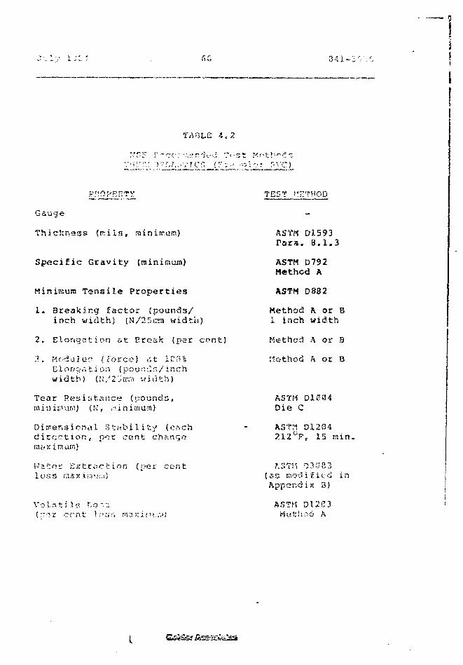
3 41 -:
TABLE 4.2
'; '* 1*5 O (-• ,"; r '*< zt I'-'-XV.^-t••••> i ' • : r - ^ - ' C )
TEST "L'THOD
Gauge
T h i c k n e s s (rr : i ls f rainiirum)
Specific Gravity (minimum)
Minimum Tensile Properties
1. 3reakir.g factor (pounds/inch width) (N/25raa width)
2. Elongation at Break {par cont)
?.. Modulus (force) at IP^^El on or. t i on (pounds/ inchwidth) (K/2'Jrr3 width)
Tear Resistance (pounds,} (ri, ,'!ini;num)
l Stability (eachdirection, nor cent changera«Kimam)
!•-' 21 F» r K K t .c .> c fc i o n (f >e r c i? n tl o s s mjsxiiiiur.i)
V o l n t i l s Lon:;("•rfir cent lot;:'-, mj;ci..';".:.",!;
AST« D1593Para. 8.1.3
ASTM D792Method A
ASTM D882
Kethod A or B1 inch width
Method A or B
t'.Gthod h or Q
ASTM D1004Die C
ASTM DX2S4?.12°F r 15 min.
hSTi'i 03 fJ 8 3(s s K o d i f i e d i nAppendix B)
ftSTH DX2C3Mwtrhoo A
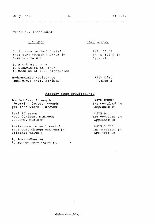
fv7
1.3LE '" .2 (Con t i nu fd )
r.or i':.'.-..-.no t o ' ^o i l n u r i a l RST*: O.".'.:£3( f a r cent, ' i w i j e r;-.. i v. i r> u -n in (.•-••• nvci iiir.-.l in
1. Breaking Factor2. elongation at Br^ak3. Modulus at 100% Elongation
Hydrostatic Resistance ASTM D731(psi ,min.) (HPa, nsinirnuia) Method A
Factory Seam Rgquirea.jnts
Bonded Seara Strength ASTM D3083(breaking factors pounds ^^s modififid inper inch width) (N/25ICTO Appendix B)
Peal Adhesion *.3TM U-iL.i(pounds/inch, tainirav.sn) {as ncdjficd in
) Appoi.ciix B)
Resistance to Soil Burial ASTH D.'.'rS.l(per cent change maximum in (as tr.odi I ied inor ig ina l value) : ApP- "cux B)
1. Peel Adhesion2. Bonded Seem Strength
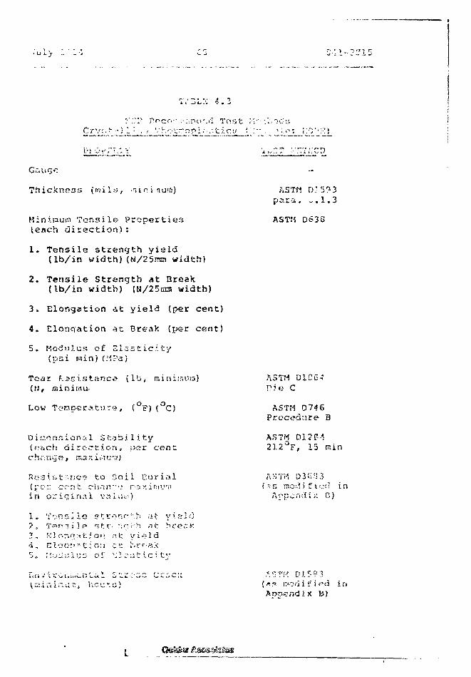
P n c o r - :'::rn-•'.<"! T o s t i V ' l ^ T - u ^
Thickness {roil;-;, • ;< ini:nu«i)
Hinirauai Tensile Propertiesleach direction):
1. Tensile strength yield(lb/in width) (N/25rr«! width)
2. Tensile Strength at Break(Ib/in width) (M/25tna width)
3. Elongation at yield (per cent)
4. Elonqation at Break (per cent)
5. Modulus of Elasticity(P3i inin) (MF-a)
Tear resistance (lb, minirnora)(H, lainimu.
Low Temperature, (°F)(°C)
Dinnnsional Sr.--3bili.ty(p<tcii direction, per centc h c-••. n g e , ma K i .•••! c TJ )
Rcs.i-^t^nce to So i l Curiail(pc- c r n t cris.TR-v; ns^.ir.iij'viin o r i g i n a l vaiiji-)
1. T'if!2lie s t r-T:r--.h at y> a id7' ^ -1p ,w ?: rz x \ f* rj; * v-, . - • rr ; - S, ,->
3 , K3on«sfc ior» f. t yiv-ld4 , El«o:'.-;tiGfj cr. »S>rf-«x5 , lUjuxlxrj of v:}. o a f i c : t y
7- . , .! , _ ^ 1 . 1 r- t . -r ~ r- ~* f . ~. *
para. -.1.3
ASTM D638
ASTH D1CG-?PJe C
ASTM 0746Procedure B
A.STH D120-'212°F, 15 min
(~n modified inAppend is: V,}
rj I C Ci 'i
inB)
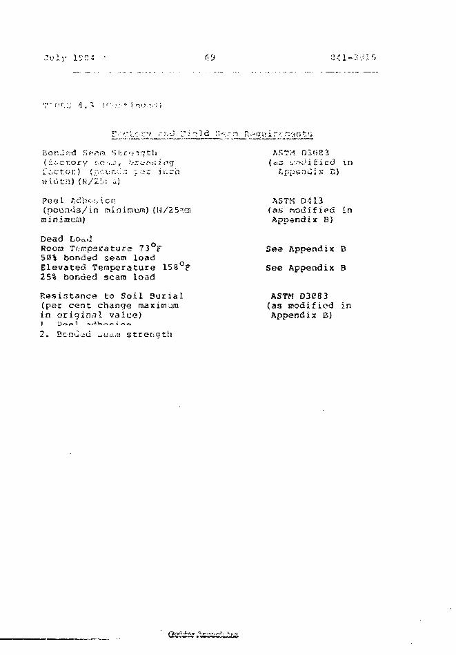
15,'E-S
B o n J £-:d S e ^ ra S !-. r ••".-1 q 11«(:":•:-cr.ory r.c •,..•;, >.,-rc-A;;i eg[ a c t o r ) (pcup.<..'3 f - i : i i ; chw i a t h ) (J-i/2!.-; -)
Peel ftcbc-:.-. icn(pounds/in ninimum)minimusi)
5".En
D e a d Lo<r,dRocra Temperature 73°F50% bonded seam loadElevated Temperature 158°F25% bonded scam load
Resistance to Soil Burial(per cent change maximumin original value)
2. Bcnu>d otic;:.:! strength
/".STM 03!) 3 3«s L-.oJific-d in/.ppenili;: B)
ASTK D413(as ^odifi^d inAppendix B)
See Appendix B
See Appendix B
ASTM D3083(as modified inAppendix B)
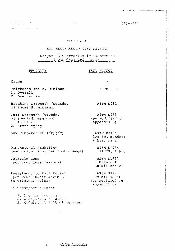
>• 1 -I
iv.' r. c <
S c p p o r \t.-.i Tr-T?rt^c;pld:•;:•••:'.-;:.•') 11"-:;: C P
Gauge
Thickness (rruis, minimum)1. Ovccall2. Over sccira
Breaking Strength (pounds,niniraara) (N, raininiuro)
Tear Strength (pounds,minimum) (M, rainir.iura)L. Initi.-il
ASTM D701
ASTH D751
ASTM D751(as modified inAppendix B)
Low Tompe (°f) (°C)
DimGnsional Stability(each direction, per cent change)
Volatile Loss(pet cent loss naximum)
ASTH 021351/8 in. mandrel4 hrs. pass
ASTM D1204212°F, 1 hr.
ASTM O17.S3Method A
3G tail sheet
Resistance; to Poll Burial(por cerst ciianqe masin original value)
a)
1. VZOCI):IT;Z s t r i-r.-j t-.h
2 . ?> i t> f'• ' j c. t i „ •. i •?. •_ b i f c< -C
3 , Ky; l ' . . ! iL- ? •"'"• l i " 5 t i •••! Ci 8 i. ion
ASTM D30 3 333 rail sriaeL
(as modified inAppendix a)
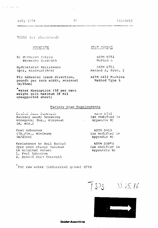
July 1-
pp.opr.;!?y KCT MCTKOf
b)Brea«.iny Strorgt.h
Hydrostatic Ronistance(psi, minimum)(Ufa)
Ply Adhesion (each direction,pounds per inch width, minimum)(N/25ram)
*Water Absorption (30 per cent
weight gain maximum 30 milunsupported sheet)
ASTM D751Method ,\
ASTM D751Method A, Proc. 1
AS1M D413 MachineMethod Type A
Factory Seam Requirements
factory seam; breakingstregnth; lbs., minimum)(N, min.)
Peel Adhesion(Ib./in., minimum)(H/25iritn)
Resistance tc Soil Burial(pet cent change maximumin original value)1. Pea 1 Adhea i.on2^ Bonded Ssa-i Strength
(as modified inAppendix B)
ASTM D413(as modified inAppe?ndix B)
ASTM D30R3(as modified inAppenidix B)
For raw water (industrial grade) CFPS
/
6
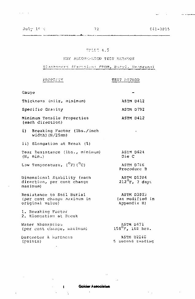
July lc'••: 11. c 4 1 - 3 C?15
NHL' KLCOM-M-KDCD TEST METHODS
TEST .METHOD
Gauqe
Thickness (rails, minimum)
Specific Gravity
Minimum Tensile Properties(each direction)
i) Breaking Factor (lbs./inchwidth)(N/25mm)
ii) Elongation at Break (%)
Teat Resistance (lbs.r minimum)(N, min.)
Low Temperature, (°F)(°C)
Dimensicnal Stability (eachdirection, per cent changemaximum)
Resistance to Soil Burial(per cent change maximum inoriginal value)
1. Breaking Factor2. Elongation at i.Vj;ea!c
Water Absorption(per cent change, maximum)
Durcmetor A Hardness(points)
ASTM D412
ASTM D792
ASTM D412
ASTM D624Die C
ASTM D7-5 5Procedure 9
AST I D1204212°F, 7 dayi
ASTK D303i(as modified inAppendix B)
ASTM U<*7115S°F, i&S hrs.
ASTM D224C5 second
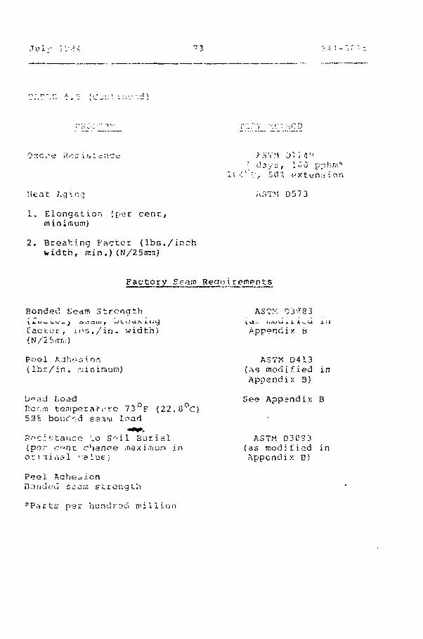
Jul-/ I'j.ii 7 3
r* - r- / r; /,
.; days, 1».3 p Phm*.1 '> •'[' :.' - S CT 7, « x 11-' n :i i o n
Heat .qinq A;'iTM D57 3
1. Elongstxor, ;per cent,minimum)
2. Breaking Factor (lbs./inchwidth, min.,) (N/?.5tnn)
Factory Seam Regui.rements
Bondetl Seam Strength AST:-. Oi*8 3
factor, ins./in. width) Appendix B(N/2S.TJ\:)
Pf>el Adhesion ASTM D413( lbs r / in . r.iinimum) (as modified in
Appendix: B)
D'- rtd Load Gee Appendix Braf-i'ro 73°F (22< S°C)
3% bonc"r:d saam load
R^CJsfcance uo S" i l Bur ia l ASTM D3CS3(por c j n t rhanoe .nax irrium in (as modified ino v n i r i a l <"alufe'} Appendix B)
Peel Aahet>ionDondeu Strain strongL'.i
*Pacfcs p e r h u D d r s a m i l l i o n
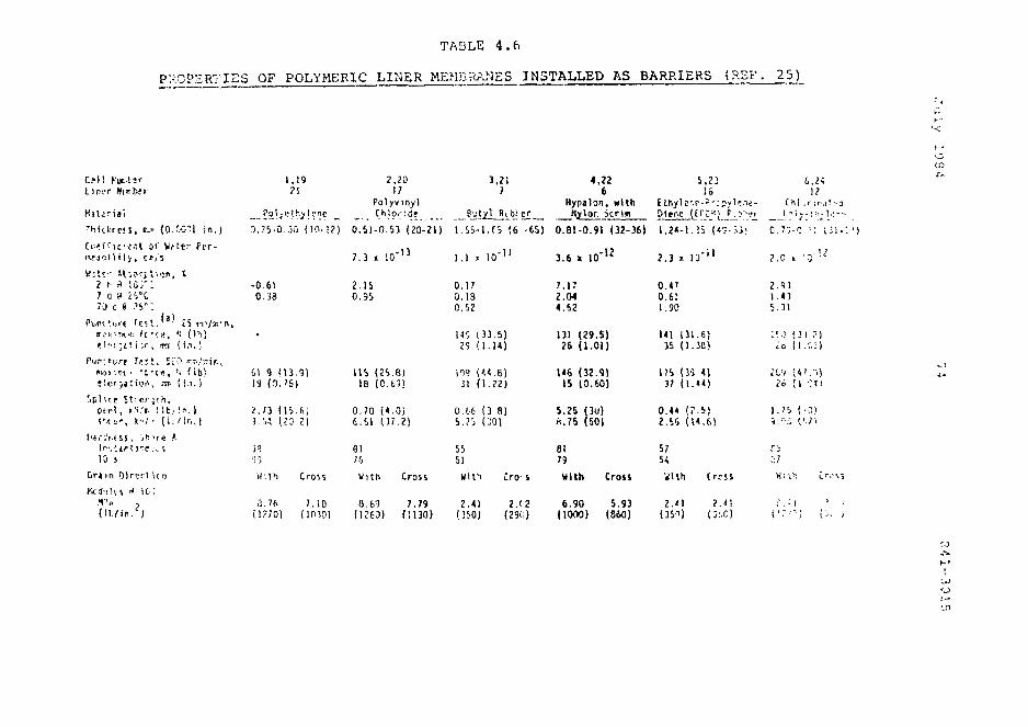
TABLE 4.f i
PROPERTIES OF POLYMERIC LINER MEMBRANES INSTALLED AS BARRIERS (P.SF. 2 5 )
CM! ts&lirI. 17!,'.'l" Nlffbir
Thkl:tc!S, «>» (O.Kttl in.)
Ccsfice.-.l ai' Wt t r Pcr-
H:t<;- StsorpSion, 12 h a i o r ;7 rj t» i'-"C70 d f .'S'••".
P i . i i ( ! i ! r | Test. * 3 " ZS re'/iR'ff.»» )TH:l: ft " ! f , '; ( I h )
e l c t ; i l i ;r , us ( i . i . )
Pw.'vrt T e s t . 5CD •--,';-ir.,B'-4Ji?t • VC " ! « , 'i ( ib)
1.19 2 , 2 0 3 .21 4 , 2 2?! 17 7 6
Polyvinyl Hypalon, with_ Polyethylene _ Ch!o.:df _ Bj: t/l_JU b! er Hylor. Scrtn Dltr.c
3.35Q.30 (10-12) 0.51-0.53 (20-21) 1.55-l.f-5 (6 -65) 0.81-0.91 (32-36)
-0 610.38
6 1 . 9 ( 1 3 . 9 )19 ( D . ' 6 )
-137.3 x 10
2.IS0.55
115 (25.8)18 (0.69)
1.1 z 10"11
0.170.130.52
140 (33 .5 )?9 (1 .14 )
109 (44.8)31 (1.22)
3.6 x 10'12
7.172.044.52
131 (29.5)2S (1.01)
1«6 (32.9)15 (0.60)
5,23 6,?<16 1?
p-3-;.ny]p,le- Chi ,f W.lt :-J
; 5 (<7-S3: c . r ; - c •: ; J I -
2 . 3 % 1 3 " 1 1
0.4'0.611.90
141 ( 3 1 . 6 )35 ( 1 . 3 B )
W5 (30 4)37 ( 1 . 4 4 )
1 .435 .31
' . ' • ) [ I I ? )ii (i.r.i)
C4!
; .p t r l , ».'i.'r. f i t , !-•.)( f i t i ' , *'•'.'' ( I . ' !r , . |
( 1 5 . 6 j(
0.70 (TOi£.11 (37.2)
0.66 (3 8)5.?5 (20)
5.25 (3u)«.75 (50)
0 . 4 4 ( ? . S )2 . 5 6 ( 1 4 . 6 )
1 .75 ( 0 )V i (-.71
10 s
G r i m Dirt;!'! k n
3 . 7 6 7 . 1 0( l ? 7 0 ) (1P50)
ei75
With Cross
8.69 7.79(1263) (1130)
5551
With
2.41(350)
Cro s
2.(2
8179
With Cross
6.90 5.93(10O0) (860)
5/54With
2.41(350)
CrrSS
2 . 4 !
C'X)

c. o o *">
r -— N O *~* <
£ O | • <^ • - • - if* O *"
1*4 O i « ^ * ' - • - »•" ^ ^ »•"
Mri O
<a3C
•r-(
OO
• SI:CM —
O
i
— — QO O
- i»*. • ru
*n -— O «• "E ^r CM- o • — • •
a s.Hi -S»r o
%o*~ o *n\ii ^ m
iflO K* OO C3
1 2
. S•w o ^J
CSfa
t. cr «-« ' * v 'O
- v i ^ , i i , s ^ , i r,~ iS^5 I'?*' °':~ s
T S *? . ? * : ' " ^^t**~ ^ o - * " Cfti »-•»:•• i i o - -
U s _ • c * c
^ - O 3 C * - " T J £ — * C l " - ' O i ^ i r » J * « - fc~l-~ • • • • •
A H > U J »— bj
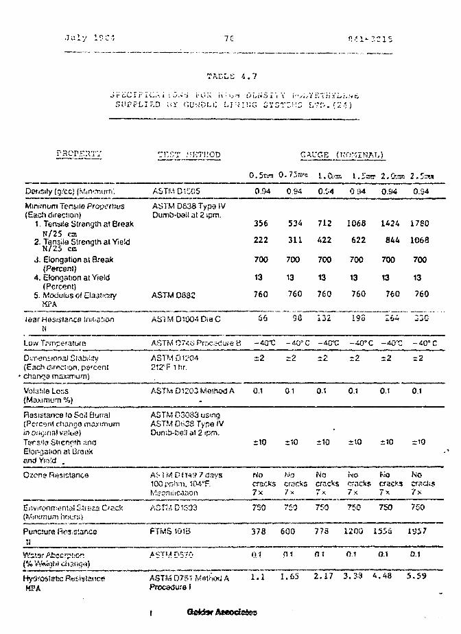
Ji:Iy 13C-1 7G " * I * ?." 15
. rt L> l-t t, 4 . /
S U P P L I E D Hi" f;U:ODf.i: L .TJ IKG ZYZVZVD [ / r r> .{2 -< )
T H o T MKTHOD GAUGE | (UQy.7Mf.Ta)
O.Stan 0. 73HPU i.fa 1.5OT 2.O.as 2.SOTS
ity (g.'cc) (rv'.in'.Ts ASTMD1M5 0.94 0.94 0.S4 0 LM 0.S4 0.S4
Minimofn TenylG Propetbus(Each directioii)
1. Tensile Strangth at BreakN/25 cm
2. Tensiia Strength at YieldN/25 CB
.}. Elongation at Break(Percent)
4. Elongation at Yield(Percent)
5. ModuiusofMPA
ASTM D638 Typo IVDumb-bei! at 2 ipm.
ASTM D83i
356
222
700
13
760
534
311
700
13
760
712
422
700
13
760
1063622
700
13
760
1424844
700
13
760
1780
1068
700
13
760
lear Hesistar.cs iniiis:;oriN
98 132 191 26A 330
Low Tpinperature
Dimensional 5ia£s;::ry(Each (jircci'on, psrcentchangg maximum)
Volatile Loss(Maximum %)
ASTM 07^6 Prcx;.K!ure 8
ASTM DU'04212°F 1 hr.
ASTM D1203 Method A
-40X
~ 2
0.1
r 2
01
: -4CC
i 2
0.1
-40° C -40T
-2 r2
0.1 0.1
: -4o» c
=2
0.1
Rasistance fo Sol! Burial(Percgr.t chango maximumin o.'iijina) value)Ttyns'la Strength anoElor-?,a!ion at Orcakand Yiftld .
ASTM D3Q83 usingASTM D638 Type IV
e!! at 2 ipm.*io no ±io =10
zcfis Resistance104"F.
Ho No No i\io K-o Nocracks cr«?cks cracks cmcAs cacKs crsd7x 7x 7* 7x 7x 7x
rit'ntal SUi>S3 Crack(Minimum houru)
750 750 750 750 750 750
Puncsura Res.s'.ar.cs FTMS 101B 378 600 778 1200 1356
n i 0.1 o.t Q.1(% VVMO
HPAASTMD75i'M<.tnoi*A~ 1.1 1.63 2.17 3.33 4.48 5.59Procsdura 1
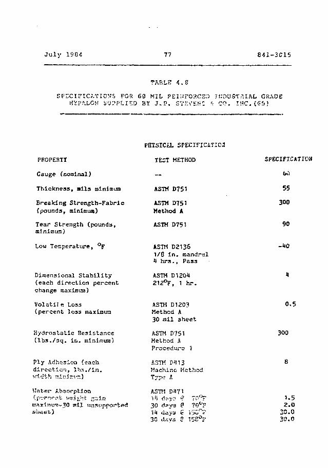
July 1904 77 841-3C15
TABLE 4 . 8
SPECIFICATION'S FOR 60 NILHVP/VLCH SUPPLIED BY J . P .
t;DUST?.IAL GRADECO. I « C . (<55)
PROPERTY
Gauge (nooinal)
Thickness , a l l s minimum
Breaking Strength-Fabric(pounds, minimum)
Tear Strength (pounds*,minimus)
Low Temperaturet °F
Dimensional Stability(each direction percentchange maximum)
Volatil e Loss(percent loss maxianua
Hydrostatic Resistance(lbs./sq. in. minimum)
Ply Adhesion (eachdirection,
VJater Absorption(percent- WM^ht jj intssKi!;Tiu'!!-30 wii unsupportedshunt.)
PEISICtL SPECIFICiTICa
TEST METHOD
ASTH D751
ASTM D751Method A
ASTM D751
ASTM D21361/8 in. oandrslU brs.. Pass
ASTM D120U212°F, 1 hr.
ASTM D1203Method A30 ail sheet
ASTM D751Methoci AProcedure 1
ASTK D«513Machine- MethodType Jl
SPECIFICATICH
bO
55
300
90
0,5
300
30 days1U days £30 daya g 15
1-52.0
30.030.0

July 1934 It
5.1 Introduct-.ior.
Various aspholtic conpoaitions may be considered tor use as
tailings basin liners. The compositions are categorized as:
i) sprayed on asphaltic membranes
ii) asphalt'c concrete
iii) soil asphalt
By definition asphaltic concrete and soil asphalt are
generally noc considereu to be "Lhin flexible membranes"a
Further, due to the costs associated with asphaltic concrete
versus polyraaric or aspha'tic membranes, and due to
permeabilities of soil asphalt mixtures (which ate
reoortedly several orders of magnitude higher than most(25)
other liner types ) only the sprayed on asphaltic
membranes will be considered in this study.
Asphalt is obtained either from natural deposits or as a
by-product of oil distillation. Asphaltic materials are
widely available, are relatively inexpensive and can produce
good waterproofing membranes, The rslative advantages an<i
disadvantages of asphaltic materials, with respect to their
use as liners, arc:
Advantages
- stable in tne presence ot most industrial
wastes
Julv iSB4 79 ' 841-2'JlS
rr?5> ist«. rit r.o methyl «»nd t'tr.y' .-Lotia); sr.cl
gJ.ycola
resis^r.t to mont cxici/irvj -;cvo:i with the
exception of nitric scicl
resistant to mineral 3alts oni alkalies up(2S)
to concsntratior;5 of 30 per cent in solution
good rrsistanc to corrosive gases such as
hydrogen sulphide and sulphur dioxide but may
show variable to poor performance when exposed(8)
to hydrogen halide vapours
osusceptible to oxidization, by exposure t(25)
ultraviolet radiation
- sometimes attacked by microbes if not protected
by biocides
- susceptible to subgrade displacement due to
poor compaction, fteeze/thsw volume changes,
and subsidence
- soluble in 5% hydrocarbon solutions
- 'che thickness of sprayed on aspfcaltic membranes
is difficult to control rr.d may vjtrry .cicnil'i-
£i:ofrt one location to snot\~,GV
C3
The use of ri;r-~ ccph-slt in n^a^tar-s f^n- Tonr.itit-^res a n
ef jT^cf i Vv» cony !-coct ioo f r-n fro.a the #J t ar»«Ip-Ji ..•£ of
control 3nd cjst e£fee':i vent-so. However, i£ Cully
this form has Griou" -^icaclvantages in subj:a<!e fc
weathering and -i.jiri'j b»CAjs* of «.-.*.poarre to
solar radiation and heat, erosion from turbulent water, and(39)
daaago from mschanicanl equipment . In order to retain
the advantages of a membrane lining while eliminating or
minimizing the disadvantages, new types of asphaltic
materials were developed involving additives to the basic(8)
asphaltic material
include fillers, fibres, and elsstoraers. Fillers such as
limestone:, calcium carbonate, clay-, fly ssh, etc. are adds
to reduce the basic costs and increase membrane ciffneas
while fibices such as a3bestos or glass fibres tcay be added
to the asphalt to reinforce it . Considerable interest
tiaa been generated with the use of el3?;COifiara such zs
thermoplastic butadiene-Etyrftne-butodiene copolymcr, or
reclaimed rubber from tir?*3 with asphsltic compounds to
improve? cheiE ^sch^rsical bshsv^our and cc-?.ist.'.nc? to
weathering. Elastomers ar« typical ly <sdcad at: becwesn S a
lr. per cent by weight, but recent ^oveiop.nanto involve
acidiny <>L>out 25 per cent gi.adfcd lublier pai-Lic
to forrf an asnhalt/rubbor mixture ' .
Tor the nuruo^es of this studv ssrsb^It -cTJ.-ra
Jul v 193i 81
ii) Catalytic Mtbiown /-t-ohalt
iii) A'phaltic Elastomeric Coicpound'i
5.2 Ar.phalt Saulai o.*u
Asphalt emulsions are dispersions of asphalt in a continuous
aqueous phase containing small amounts of emulsifiers.
ftnionic, cationic and non-ionic grades are available. These
emulsions revert to a solid coating by evaporation. To
improve toughness and dimensional stability, asphaltic
emulsions are generally usrrd in combination with «;e-Jed
Permeabiii t-y costing carried cut en a 7.6 millimetre thick
specimen (393 mil) focrred by i-praying emulsified asphalt a\.
a rate of 2.1 litres per square metre onto a iion-wovi»n
polypropvlene fabric yielded permeabilities of tbs ordar of-5 (V)
1 x 10 centimetres par second
Asphalt emulsions i:s«d to form an asphaltic mer.ibrane have
several limitations which affect their suitability for.(25)
service . of primary concern is the relatively
small amount Gf asphalt applied poc unit area to forra this
type of liner. I" 'h? evont thf->t a hole developed in the
asphalt, t>." eabrir- •-•.•Id be er.po?-td to potentially i^naging
mat^ri^ln in v.rhich Cc.se t' e very thin asphalt isenibrane would
b*» requitsJ to wit'rste'id t:.'. t- nailfi and shear stresses
inpoasc* by the fcsi
Further, tha potential for oxidati with the resulting loss
of flexibility and the potential EOL .'•ilatnination of the
(- J )rnnzvscnt .1 likely failure i-.;;ch.-.ni5!u . fir.sl
Ir<:i !-he fabric- T J ~ >'•''• ir cc:v; i-!cred f;
r.\r. real bg .":i.;-11'::J at L<*:-poratur:-s .ibove
f reexiivj .
5.3 C^.t.'tlytic Ajrblcwn Asntvilt
Catalytic Airblown Asphalt (also called hot sprayable
asphalt) membrane3 are produced by blowing air st high
temperatures through petroleum derived asphelt, in the
presence of a phosphorous pentoxide or ferric chlorideo
catalyst. The heated asphalt (minimum 204 C) is sprayed on
a stabilized base generally at a liniciun application rate of
/ litres per square metre. Repeated sppl ications ar«»
necessary to ensure that all pinhole3 are tilled and covered
with asphalt. Applications arc typica'.ly carried out in at
least three oa:>s«3 with sufficient overlap of the aaphalt
distributor between passes and suitable staggering of the
joints of -ach preceding application.
Hot sprayed coatings arc flexible, tough Materials which are
relatively impervious to water. They are usually covered
with a soil layer to prevent r-.ichanical damage and licnt
deterioration. Hov^ver, side H1ODO»3 stx-ep<?r than 4
horitontal to 1 vertical arp n«t ^o^.^r?.ny r«»romrs«»nd«»
In addition- low t<="T?p»rctur« .luciility i1-; tepn-tedlv a
rrj wo. Ln toss ^Yi-a 01 asp;"j<i^ L I C ;v,..ur ;.,« .
In order t.o evaIj'it-= {.hz- potential *zr. ;r.ir.g catalytic
accelerated aging testing. . The t"*»t prGcjr^Ky^ «lso
included permeability testing which addressed change oc

('••'., !"'''?-.],
CeSO 5 C e , 3
CaCO* 1 8 . 1
MgSO 8 . 6
K a 2 S ° 4 7 * 4
NaCl 7 . 4
F> 0 2 . 4
A12°3
The? catalytic aitbiowa <*iphalt ,>';:.branc us^d in t:io r. :uoy
was applied in two lifts :.t An apri ic.t i on r <"•;«* or f-.3
litres per iquari' metre i.-iJ m. avp) i c? t ion t^rn&c acoro ofo
22b C. Perrrseabi 1 i ty testing indicatro liner perrai?abi i t j.»<j- 1 0 - ••)
canning from 1 x 15 centilitres pec second to 1 x K"
ccntJKetrcs pfc second for ';Xpos-.ire condition:; •-'.sryin frt^
norr:.al to highly icri>li.'r<it.:;i. <\c •'.•.-• l«-r a tod f»ifx.sur->
CO:J'J i t. ionr, wete simui^ced by iccr ,r J A . no osy^i-n contenl: dn<i
t <•>.•«(«.'f <31;: rt: dar:nq C:T'1 i?*»O';i;rf poricf! O7. -u csv s . ;•«.". si;«i onl . i i - ? 1 * t > ' J C f l t O l . " v t f r f j L ' . ! : • - • ' . : V » c : ! ' » i y l ; C .-; i n b i - r ^ ; ; f u r L " ? : • " » . ; • ! e - : i J
an anticipated field uiicr pc-rweab i I i t y of 7 K IS
ccnt i r .e t r t i pot: :,i:r:o^C. '
Tr*f chemical cs!".s».tani;;ty i^r.t'.r-v c-.ir r; ••- ~ cv-t- r,-» r-;r
catalytic sir&lown asphalt wn-hrsr,*-;! nr.c -r Ari-^U-ritpd
conditions iritiicrtted a maxirsiitn peiirtration by i sv» ieacnato
of 8.5 per cent of the total linet thickness ' . P.-ssed on
." r . t t r •_• c < : i i " j •: .: : • . •; \ •• », , i : , . j n w r , i ; • ••>. t ' . * " <» • ' ' ' • •'*. ' . . • » • ! ' - •
o J - r - . v i i r i f w r ;•••••-., < ! w a < " ' . ' ; - . - i • , ; . ? ? U < : : = .•> t T . ' • • ; » l i r v r •.••:•. U i < 5 ! ••-•
*•• s \ - e - ; y . . < r . \ V •' . . « , : • . - C t - c f i v e f . . r .-> * ' . . ! • < , a * . ", J v< d • ; , • • , < : • . • f - [ v r p \ : •_•>
c . ' i t < r • t : i ) C f f i . ' • ! • ; • < [ t h s n r . f f w : , . i l < ! ! • - » i ' . f ; f , r r . O c i . A s
M i i t . n l i.*it. . - r x:> t "i S a t o ; : c t t , w » d o rv . i t . - r j t c e w i t h
o x l r . i f - j l A t is_-ri Ly reorw t J..-, ii o n e u c i i f s r o f t n a < » i i t. >J J«f •
B « s « ' . i o n t h e p r o » ) » i r.-j c o s u i t ; ? o f fch<* l a b • ' 5 ^ . • ^ ^ o r y t e » t
p r o q t nr*xw, c u t * ] y t i c « i r b l o w n - s r . p h s l t t n c n s b r a c i e s v e r « a l s o
ffu1".iecirec! t o f i e l d s t u d i e s i n a p i t e x c a v a t * K l i n a n e v . i » t i n < j
u t ' i n i t w t . s i l s r " i « o i l ? . I t wfls c o n c l ' j d ' ^ d a t t h t » i - nd o f tfi**
f i e l d o r O ' t r ^ ^ i : - t ' l - i t . t h t « a s p l ^ a i t i r . f n b d t r i s p ^ r i o r ^ - d
e i i e ; ; t s v ^ i y a a « U r n e f t o ;«?«•:!":'>!:•": f i o « d u « t o l o w
p e r f s p A b i 2 i ?:/ c ! » u r ic t ^ r i.'»!. i ~:n . Hov*>vi- r , ••le i ' • ! ;c t h r r * e
t e a l e n 1 ) s d i d n o t p e r f o c - a.1* t. i «if , i c t i i r i ! y ' J u e to i . - ; r o r " !
a p p l i c a t i o n -irjci i n n p o c t i c r i !>r . s - : t i o ' - i t \ o r * r > « l r ^ •-. ; i . ? r c
p o r t i o n o f th<? i i n e r h a d t * i ? n a p p l i e d w i t h i a s u f f i c i *'r>t:
- i ' l p h . ' j l t . t x - s u U i r . ' ; i n i i o l e n g f . - p r o i c i ^ . j u l y e n c c>?" V. i rrc*« r e i n
d i a n e t e r . " . . u s s E» ci«.-r .or . '»tr . i •«. i vc; o f <-,• tf o f t r . e P . ; ; O (
c o n c e r n s A S S O C i iri?<5 w i r . h s p r a y « ; J .^;;; • 11 -™ ! c i n i ' ; 5 t u n i f o r •"'
&pp 1 i c s t ? o n r n t e 1 ! -vri-,i ai1'>q'.;,i t;»» .••.•.!b';!r-«'5*> c n v c - r s-jc- ai."f»
d i f f ! C » U t o a c h i e v e a n d m o n i t o r < iv*n u i v - e : ':.>.•' v r - r y
controlled conditions prrvuihiv;.
A -v p r -i 1 t i c nio z o i i l l s s >? I « " t '.• .1 Cor h •?«: ~ E p r -~ y .;• -i ?-.r.- • :••. r n, ~. * •
a p p i i c a t i o n t r u s t rv»!»t t. ' ie Ce.T,p*»ra!: u r e r*-q;j>. rt'.T.*»nt f? -'.'or
E p p i i C3 r. i r>r., b e f i « x i b i c a t t h ^ Lcw--?"t e s p
a n d b?> r?uf f i r i e n t l v v i n c o u a «-:.t t ^ e h i q ^ e s t
ffi t o r « 3 i « r . f i o « i n } on a l o ; » » d s e c t i o n s
•• - . 1 ' . • • ' . \ •••• • , ' • . . - : • •': •- I , w - t • . . . : < : < • . • , . ; • . • ; • , , . - , ; , ' . - . . • , . • • • : : • , « • : . • j • c -
C y - . 1 1 I r . : • • • > • ; ' • * • . ' i - l • ! ) • ; i t ; . r , '•• ; • : / . • . * " : I ' . ; » ; ; • ; ; ; . ' • ' , . ' ; •• • • • . - I
i l t c s ' . 7 : «. i . ; i / l . - f i ; ; . c j •• - ; - ! > . i 1 t. ^ . • , . i J r , i r , c s .-i t (- • ; . " ' . « r « ) i y
^ l a r - f : I - ' , ( . n o <••»• r x - t t ? 2 i f t. S , f i ' i i : . : • ; ' . - , o - } f c ; r V t h t ' t ; ; ; ; r ! ;'<>
. i s / : h , * i t nt-^-iji ni)(*n , t o s e a l f. S n ! i o 1 • ? » f orr r<-» . . i b y e a c a p i u j
- i t o i a t u r ' ? i n t h , » f i r s t i i f t . T h « ? r j b f i s r t ; p d i s p h A 1 '_ w i j i d
a J s o l><» a p p 5 . i e < * . a t r - ; i t f 5 ' » s i m i l a r r . o •> t ; v -<»r i w i r . b r i n f S
<-3 i S ' - u ' ; f : < > j ( i f » , 7 i i t r » s p r r ' n u s r f - o f . r * » J a n d w o u l d
t j ' p J <;.t 1 I V , '^i- p r o t o T t r->5 L^y .': ! - i y e r ; : i : o i i i . e ' r - r . . i - . i - s v yr i i !
! r . f . ' . t : : . . - , - . ' t I . r : • : : . • ' . ••'. i • ' • • : : • . ' • : : • • ' • r l / . t . i A S •"•:" ^ : ' . . " ' ! . • • ' . < •
r ' . ' .'- . ' i ' : • - • ! . ; r • / i i * : . i - ; / -.:• . i . . ; : ; ; - • ; ; ; • " . <> t i ••:.'..'- - ! ." -
, ' : t ; t v • 'i t. j ! . o i.!-.v! . , ; , -- . -! i f? '• t V ; ' . . ' . r .: . ' i • : ; r, . : t- j
f i f ; ' * ! ' . ! ' . ) ! " - 7 , : . f ' i n | ! y p r o i i T ! ; i = : , . " x ^ i "•••'; r r i t ; /
^ • ; ; • ! • . - 5 j * • / " : i . ' i •- r .* '. " ' ; • • ' •.; \ " t > J i *" T \ •.;•/> ' . > 2 "". ; •:• r < : r r V : i • . . ' : , • • r ' i -
L : - M - n ; • • • . - i - ; ' . • ; - • • ; • ; . T ' . f r . ; : , t - . t - r ;• i ~ ; . < • i ? r » - . " i r - : : . - , • • . . .•: ^ ( A
•*. C'~' '• '" ' •>.
; : r r c r * > t ' . ' . . ' . , . v ; r : c r r r - r r l , - . f ~ t - - ; '" r 2 "? * ;-.-.-; i ; : . - . > • • * • — • • r : . :
. - . : . • , z • • • < • • : , ? •: • . , - : - • ' . l j . , . - • . . ' . - i • : , • : : • . \ . • > ? ' . ' • : : • ; * • ? ' , - . : . : • - :
• . • • • : • . - • • • - • , ; . . . : , : . , . ••• ••-•:•:•• ; . •. : . i •, : , . ] • - - • . • . . - " .• i t ; L . . 4 ! ; :. i - • • - ;
• • . ' . i - 1 " - i ; . < . r i .]•••• r * ' . » 1 i < • w i •••"" I •. I . • i r. •• ' . ' . ••:: . ' r i . L ; ( • • - * : ' . '. i < • -* t •.• . i
• i > l : r r ^ « • . ' • " - ' c . i : : , , ^ r i . h t ; <,-!J.';•»:» o l t ' . - * n e . - . j r j f . i ' , c a u s c - o i ' -y
'.iclifiv d rosponaiblo tor an increasi; in permeability-8
tostin-j from about -• x 18 cs.-nt liaer, rr-j pf-r st-ccnd at (he-G
beginning of resting to sbjut 5 K 19 c«;ntirit-ttes per
s^ccnd fni'owino about 65 days erpn'-jro. A perfecti 2 i t/
i J ' J i •: •. •:>•'. •'. f . ; , ; J • ] t o C M e ? t A l ! ' t ; ' ! 3 1 e - i (." h i i «'- f . " i t - - - i . : i f n i t " . - . r ; d
- ^ 5 :. ; . • .• •. i :• r • , i • < ; i r . - • i r ."i t . i v » « • i *' i n • - . ; . • f t • . ! . - • t ' > : . - i '. 1 t v y f * '••.«*
. ! • • ; • ' • • . > . • ' , . ' . •• r , j ; t ; ' • , ' : • » . ••. ,-. . - .• : l i ; C l » : • " • • H ' l i i / , : • . : • • ; • • : . T ,
•• • ? . * ; • ' - s r '* ! " . . r " . 4 I .'". O ! . « • • < • n i ' . i f i i i " 2 • • > • ; ! •'.; > '. * V r < ' '• • i- ' ? • . • • : • ' ; ; . • ! • »
3 IJ i • • i o Q A • 3 7 R 4 i _ 7
- very inert to inorganic acids, bases and
salts
- the useful temperature range is extendedo o o
from -40 to 82 C as compared to 4 Co
to 49 C for asphalt and the membrane is
resilient across the temprature range
- inert to bacteria and fungi
- bonds well to concrete, asphalt, metals,
glass and all plastics and rubbers
- good elongation properties (1300 per cent
strain at failure)
- excellent resistance to strong acids and
bases except cfcrong oxidizing acids such
as nitric acid
Disadvantaqes
- should not be exposed t••> omcentrations of
organics
- should not be exposed to direct sunlight
for long-term applications
- fsif -^sistance to saturated hydrocarbons

- poor resistance to aromatic hydrocarbons
As a final note, it is anticipated that sprayed-on
SEP./asphalt membranes would be subject to the same concerns
as the other spray-on asphalts in terms of poor control or,
rate of application and membrane continuity.
5.5 Material Specifjcations
The only known specifications in use for the evaluation of
asphaltic membranes are those recommended by the Asphalt
Institute for hydraulic membrane construction and summarized
on Table 5.1. One of the recommended standards, ASTM
D-2521, entitled "Tentative Specifications for Asphalt for
Use in Waterproof Membrane Construction for Canal, Ditch, or
ASTM specification D2521 forms * reasonable basis for
evaluating asphalt\c membrane materials whara bitumen
constitutes the majority of the asphaltic compound and only
minor amounts of additives are included in the compound.
For the case of asphalt/rubber admixtures and SBR/asphalt
membranes discussed in Section 5.4, additional means of
controlling and specifying membrane properties ace probably
requited. Tn this regard consideration may be given to
usinq ASTM D2521 to roquiate the asphaltic portion of the
compound and a polymeric liner type of specification such ar.
the t'-iSF recommended mini mure standard?: 5c~ thermoplastic
elastomers for cl-e asphalt/rubber cou-.pounci; this
specification it; presented in Appendix B.
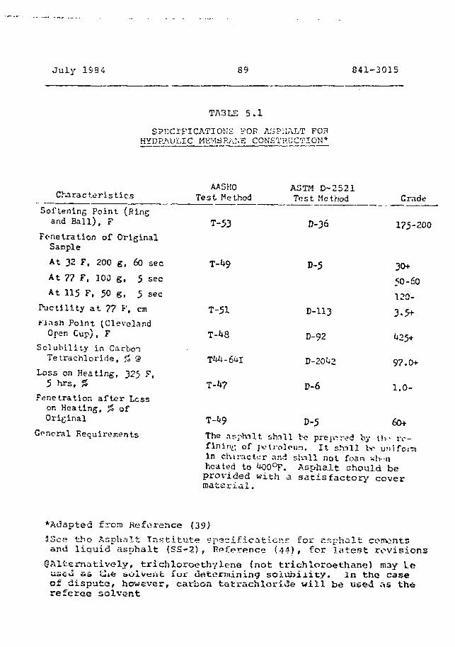
J u l y 1S3 4 89 841-3015
TABLE 5 . 1
SPECIFICATIONS FOK ASPHALT FOPHYDRAULIC MEMBRANE CONSTRUCTION-*
Characteristics
Softening Point (Ringand Ball), F
Fc-netration of OriginalSample
At 32 F, 200 g, 60 sec
At 77 F, 100 g, 5 sec
At 115 F, 50 g, 5 sec
Ductility at 77 F, cm
Mash Point tClevelandOpen Cup), F
Solubility in CarbonTetrachloride, % 'S
Loss on Heating, 325 F,5 hrs. %
Penetration after Lesson Heating, % ofOriginal
General Requirements
AASHOTest Method
T-53
T-51
T-^8
ASTM D-2521Test Method
D-36
Crade
175-200
D-5
D-113
D-92
D-20^2
D-6
30+
50-60120-
3-5+
^25+
97.0+
1.0-
T-^9 D-5 60+
The asphalt shnll be prewired by tlv iv-flninL; of jvlroloun. I t shill be Urin clvis-iclor and skill not foan wh-rheated to iK)0°F. Asphalt should beprovided with a s a t i s f a c t o r y coverma te r i a l .
•Adapted frora Reference (39)33ce tlio Asphalt Ins t i tu t e specifications for asphalt cementsand l iquid asphalt (SS-2), Reference (44)# for l a t e s t revisions
^Alternatively, trichloroethylene (not trichloroethane) m3y Leused a» tlie solvent for determining soiubi i icy. In tno caseof dispute, however, carbon tetrachloriiSe wi l l be used as thereferee solvent
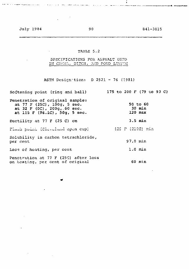
July 1984 90 841-3015
TABLE 5.2
SPECIFICATIONS FOR ASPHALT USEDIK C.sKAT,, DITCH, AND POKD LII-.VMG
ASTM Designation: D 2521 - 76 (1981)
Softening point (ring and ball)
Penetration of original sample:at 77 F (25C), lOOg, 5 sec.at 32 P (0C), 200g,.60 sec.at 115 F (96.1C), 50g, 5 sec.
Ductility at 77 F (25 C) cm
175 to 200 F (79 to 93 C)
50 to 6030 min120 max
3.5 min
Solubility in carbon tetrachloride,per cent
Loss of heating, per cent
Penetration at 77 F (25C) after losson heating, per cent of original
9 7.0 min
1.0 niin
60 min
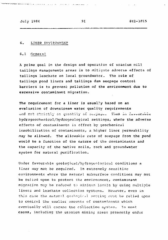
July 1984 91 841-3015
6• LIHER DKVIROKMBKT
6.1 General
A prime goal in the design and operation of uranium mill
tailings managements areas is to mitigate adverse effects of
tailings leachate on local groundwater. The role of
tailings pond liners and tailings dam seepage control
barriers is to prevent pollution of the environment due to
excessive contaminant migration.
The requirement for a liner is usual?y based on an
evaluation of downstream water quality requirements
iiw r t c C 1
hydrogeocheitucal/hydrogeological settings, where the adverse
effects of contaminants is offset by geochercical
irnmobilization of contaminants, a higher liner permeability
may be allowed. The allowable rate of seepage from the pond
would be a function of the nature of the contaminants and
the capacity of the native soils, rock and groundwater
system for natural purification.
Under favourable geological/hydrogeolonical conditions a
liner may not be required. In extremely sensitive
environments where the natural subsurface conditions may not
be relied upon to protect the environment, contaminant
migration may be reduced to mirurovjrr: levels by using multiple
liners and ieachate collection systems. However, even in
this c;»;-;e th*? natural geoi00 \rn\ netting nust be relied upon
to control the s.'uall&i: amoanta on contaminants which
eventually will escape the collection system. Tn most;
cases, including the uranium mining areas ptcsantly under
July 19S4 92 841-3315
consideration, it ia anticipated that the solution to the
contarninsnt Tniqraticn control problerr. would typically lie
between tlis two extreme conditions described above;.
As noted in the above discussion, the major factors
controlling seepage from tailings nanagetr.ent areas are:
i) site conditions
ii) the characteristics of the tailings
(and contaminants) and finally,
iii) the design of the liner system.
These factocs are discussed together with ucaiiiutn tailings
.tianagement philosophy in the following sections.
6.2 Background
Uranium mining and milling operations have been conducted in
Canada since the 1930's. Although the hydrogeology and
geology of every existing and potential tailings area is
highly site-specific, they tend to bs» situated in Canada in
areas of relatively shallow overburden (Elliot Lake),
moderate overburden thickness (Athabasca), and low
permeability bedrock.
In 1977, tije Atomic Energy Control Doacd (AECD) proposed
draft guidelines in which it was suggested that the average
permeability of a tailings basin should not exceed 13
centircetres per second and that the permeability of
containment cSams should not exceed 12 centimetres per
second. In the Elliot Lake area, particular site conditions

July 1934 93 841-2315
led to the incorporation of synthetic msrabranas in some
containment dciras.
These draft guidelines were not finalized, Hovever, in 198C
the AECB produced a consultative document CS31 on "Long Term
Aspects of Uranium Tailings Management". This document
stated that "synthetic membranes which will eventually
degrade, will not be credited in the evaluation of a
closed-out system". The approval of contaminant control
systems in Canada is now given on a site-by-site basis
without pre-set objectives which have to be met. However,
there is a marked trend towards either reducing seepage
losses to low levels or to intercepting seepage for
subsequent treatment.
The apparent changes in Canadian attitude towards different
categories of liners ace, to a large extent, consistent with
changes in governmental policy in the USA. Prior to 1932,
the Unites States Environmental Protection Agency (USEPA)
favoured natural soil {clay) liner systems. However, based
on the results of tests which indicated that concentrated
organic liquid-bearing wastes altered the structure of clay
soils and led to greatly increased permeabilities, the USEPA
currently favours synthetic membrane liners to reduce
seepage during the operational and early post-closure life
of a facility (20 to 30 years) while recognizing t'u-»t there
is very little long tozm experience with these materials.
Indeed, where n site m?iy be used for more than 38 years EPA
reco.T c-isds that since cl<*ys last longer than synthetic
membranes, a secondary clay liner be incorporated as a
back-up should the synthetic membrane deteriorate.
July 1334 94 641-3815
It should be nofcad that the climatic conditions in much of
the USA are very different to thosa generally prevailing
across Canada. In the uranium tailings areas of the
southwestern USA, there is net evaporation and it ha3 been
generally determined that liners are only required during
the active operation of a tailings basin. Following
closure, seepage is assumed to be minimal. Such conditions
will not apply in Canada, where there is net precipitation
at uranium tailings areas.
6.3 Site Considerations
The purpose of this section of the report is to discuss site
conditions and their effects on the requirements of a
seepage control system. The characteristics of sites where
artificial lining systems typically would and would not be
required are discussed followed by descrptions oE typical
site conditions in the Elliot Lake-Blind River and
southeastern Athabaska regions as well as other areas where
uranium mines* might be t?ei'elopod,
6.3.2 Site Conditions and the Requirement foe Seepage
Barriers
The iMJor factors affecting waste manaaoi.i'-'nt And site
selection and the effects of si to conditions on the(45)
requirements foe seepage b^srrisrs airs:
i) topographical
ii) climatic factors

July 1984 55 841-3012.
iii) hyuroloyical conditions
iv) geolo<j icil/hydrogeological conditions
Topography is a major factor influencing site suitability
and economics. Tailings management areas are ideally
situated, in ternr.s of economics, in local topographical lows
to take advantage of natural impoundment features and
minimize earthworks (dam construction). Disadvantages
include the fact that steep hillsides may require large(45)
embankments for small impoundment volumes . In addition,
and also significant, is the fact that topographical lows in
northern Canada generally support lake and river systems and
contain permeable alluvial strata and/or swampy (muskeg)
Climatic factors have a major effect on the requirements for
long-term management of a tailings area.
Precipitation/evaporation characteristics of a site
determine the potential for closed system design. In most
of Canada there is net precipitation and the tailings area
may require an effective cover to prevent a continuous
source for leachate and seepage generation. Finally,
abandonment of lincJ facilities involves too requirement for
a net precipitation/seepage balance to avcid overtopping or
alternatively a permanent excess waste water treatment
system.
Hydrological conditions influence site selection in that it
would be desirable to avoid stream, diversions and lake
dewatoring where possible. As a guideline, it h&s been
3ucjqe£»te>3 that Ci=»t.r:Vi.n*»!•>•• 5foa« latter fch^n 13 s^u.rc
kilometres (5 square miles) be avoided except where stream(45)
diversion can be carried out
July 3.584 9G
l ancJ geological condition-3 uL A pcosoeot i.»
tailings inanaci^ment area arc the mo^t icportant
considerations affecting the requite-went for an artificial
lining 3ystom or dam seepage barrier. The most significant
considerations in evaluating contaminant migration are rate(46)
and duration of seepage and contaminant concentration
Favourable; conditions would include natural soil/rock
deposits which have sufficiently low permeability and
thickness to retard th ; flow of contaminants to groundwater
and thus allow sufficient time for reductions in contaminant
concentrations in the groundwater through dispersion and
dilution. Another important consideration would be the -
ability of native soils and rocks to reduce contaminant
migration through geochemical reactions.
Where natural soil/cock strata do not have sufficiently low
permeability and thickness to retard seepage and contaminant
migration and where the chemistry of the soils and rock do
not sufficiently reduce contaminant transport,then
artificial means in the form of liners and/or dara seepage
barriers ace required to control contaminant migration.
6.3.3 Elliot Lake Area
Topography and Cl ires to
The Elliot L-ike raining area is located in north-cantc^l
Ontario. flu* topogedphy is tait ly cViai'Sc'ct'C i»tic oil Lhe
li Shield ^?,C <T.ay t>e described, ac rugc;i bur. of
T.i 5 v- IO34 ^7 f'.')-J.y IS
lcsc than SU Rt-trest Topographic high^ conji.,c typically of
cock knolls or cidcjes and topo«jc.j'viiic lows> generally contain
owamp3, lakes or streams.
The area experiences .-to avert. total precipitation of about
950 millimetres per year and the average .annual
evapotr.inspiral:io<i is Voont 580 millimetres. Thu3, the area
is characterized by abundant lakes and streams, with about
20 to 25 per cent of the total area covered by water.
Geology
The uranium deposits in the Elliot Lake area ac^ a^iiociateci
with an approximately 15 kilometre wide "sediinentacy h^sin of
PreCrimbrian Age which unconfortnsbly overlies metavolcanic
and metasediinantary basement rocks. The ore occurs in 3.5
to 3 metre thick pyritized quartz pebble conglomerate oe-'s
located near the has-? of the sedimentary sequence and is
generally of low grade (6.5 to 1.5 kilograms per tonne).
The various Cocnat ions within the sedin-onfcary basin (the
Quirke Syncline) are laargely comprised or quartzi te,
canglotmjrabH, cfceywacke, arkoae, arqillifce <smi minor
carbonates. These rocxs are generally siliceous in
comp<jt:i tiot! fjnd have 'jiyJiergons vcjional rr:ai:a;!"orohj :-;ifi .•such
that thpy coritain virtually no inteirqcanijlar porosity. They
attain s thie'enasr; or. cppruxi^ifcHly l^'.r.Sii ^euros tevj^rd the
centt<_- ci cii« t;yncline en-3 unconror'nably overlie a granitic
and istftavolcsriic b.'trt-i- ent compiex or Accftean Aqe.
Diabase dykes and s i l i s w^re intruded irtuo the
rr.atasedifnentary sequences follow!nr the deforffidtion o£ the
bs&in. The (iijbese has Ivun dated at shoot 21 f?J million
years. In addition to i-.hc diubjr.o intrusion, various
periods o£ faulting h.-vo also occurred within the area
including botn normal faulting and more ptcoctut-il ly ccaplex
thrust faulting.
A regional series of steeply dipping ncrn.il faults, spaced
at intervals of 5 to 7 kilometres, cut the basin in a
northwesterly direction. These faults are associated with
varying degrees of fracturing and brecciation. Local normal
faulting tends to be more intense (2 to 3 features per
3quare kilometre) and, while generally steeply dipping,
pxhibif-s v s r i a b ] p .st"rilrF» and Df<" «s i « ^ n r o . In aiirli J-j nn tn
the normal faulting, a major series of thrust faulting
f-ctics along the n-Tth and vi^t margins of the basin. The
thrusts trend parallel to the strike of the rock strata and
are traceable for a distance of 40 to 45 kilometres.
Penepianation of the rock strata comprising the Huronian
Supergroup occurred during the Middle and Late Proterozoic.
The resulting land surface has remained little changed to
the present tiii.;e and is characterized by gently rolling,
forraationaily controlled, dip and scarp bedrock ridges.
These bedrock ridges vary in elevation by up to 100 metres
and control the drainage patterns of la?-:'*s and streams
within the area.
Glaciation from the last ice age modified and polished the
bedrock leaving a verv hard, generally smooth, unweathered
surface. Unconsolidated glacial deposits are largely
restricted to the valleys between the bedrock ridges. These
. 1 . .&•".'.<.'.• l f . i ! n • • . ' . ' . • . ) • : i ' :;, .1 r i u v .5 ' . ' • : i ' . : . i "-';' r 1 : ' •" '•.:.' • ' • . : : • - / . • . : ; : i r \ . ; • ; " . • ' .
q r . v . ^ I n w i y u v j i :. c i u c - k r - . . - ; * f r r . - * :,.-••. >_•, , - . < - . . - . . r . ' s t o
in .2 x i:r:'.:."ri t l i ) c: J' n r • •, ;. •••; i n v'.u- o r O ' - r o ! :;.J ; . - . • ( . j s - s .
I i y 3 r i n r - o > o < r /
Grcundwater a p p e a r s to occur as a complex s e r i e s o'. ioc- i l
"perched" regine-a o s s o c i a t f d w i t h the iaka s y s L t n e . The
m a j o r i t y of groundwator t r a n s p o r t b<;t;w':-:ri th*-"io i o ' a l
reqirftes occurs, through overburden i n f i : ' i b e o r o c k '••;>«• -j or
major d i s c o n t i n u i t i e s { e . g . f a u l t s ) ; n t.-,<^ r o c k .
O v e r b u r ' l i ' n i . - ; ^ o n t r i c l n d t o t o p o q r - l i - ' . i c I i w s - i r ; j , - : - h - : ; . e
I ' X C ^ ' p t i o n o f c o c ( ; ( i l b o a o r - , * o r . p •:•- - - s : . , ' y . r . : ; : • . : . .
p r ' . 4 i - ' o i T - 1 n a n t i y ' • ' i ! 3 ] v i < 3 < • t 0 1 1 ' w . i : , ! , • ;: ! './ , ; , T : U ; , j - ; 3 • i t r f v i i s
o f ' 3 l ; i c i a l o r i g i n . f . o c t l d e p o M t . : : o f f-^ - < " x n t i * \ '. y
c o h c s i o n l e s s - s i l t y t o n . i n r l y t i l l VJ i . 1 0 o c c u r i n ! . . - v - - v f ? r - i ' U i c
I'-wr- o r pi •:* s r o r e d e n t!"i« flank.'i o f ;.-1- --J r ••; •- k hi'ih:;. TV. ->- 4
->'»r."!f?jbi J i t y o i t h e t i l l ; •; f - n i c ^ W y ; n (:!v nr :!•-••• -;• * J if- b
t o lv> c o n t J i't' r. r'".>cx r:)*t ri^c^-n'l > T h e p'Vtrr.rr . H ) I 1 t 1 t- v c ! «:'•.••
j r ' i n u l a r ^ ^ r i o - ; i f ;.; , ; i u ! - i c ' j ! -. r ! / V 1 . • ' ; ; - w . i ' ; h " . ' s r ; ' ; .'. v. <"j j ? " . i l . : < 1
f j . v p o . ' i i V . H , a £ C > c o n : ; i . j < > r a b l y h i ; : - . . r { i n * .h '> o t d n r o f 1 3 ' t o i
c e n t i n e t r o p<-.xr • l o c o r , ; ; ) .
?ne tj'.-drcr:'., in c v T w r r ^ n tn •.-
r o c c i. ~- n o i v o n ' . • • • • • r . ? " '• . 1 ' <•• .i
• - ; - • • • • • • • ! ' j .^ ii i »
f ' • "
d e c r e a s e s ' t c !r?".'; *har, J C! ; en ? j •• --1 L '-:• - •_•••• i :f_o;v~ :•-'.. .?
: : • : : • • r : • : . ' } • • • !•.•••• : ' r
.3 u s - p t h u f i j t - j 2 l i r w - t r o . ' i i . • ? - ; • . • v* t ' . > • i i i r l a d 1 > - [ f n * 1 - r o c s .
7 ! " . 5 « s « J - M f u r ' • • ; f i . r - i '. • . • • . - - t l 4 . r . ' f ' j ; . - ) > r ! ; > A I « ; ' . , - . « . " > o f • ; : o-i.-i j w . » U ' f
f l o w w i t h i n th<* b*i<irock. Th« p«- r me a b 12 11 i <» •* tro . i - iSi .-ci-steJ
w i t h t h e d e q t t e o of fpcf^H-sa of t h e fr-"n: t j f«i4 .trul t h « h i - j h e c
v a l u e s t e n d t o tx? r # l « t » d t.o n««ar r , u t f a c « w e a t h c c i n ^ (upp«*r
33 w t r r " ) . ! ! u w v « t , m. j jnf f a u i t f f ra to r*fs o f t o ' j i o n a ]
r -x t ' - n r w i t h i n ;.';(;• . u c i ( o n i ! i ;cpot con i ju s t r* f o r T r O u JV-5 w.-» t <*• r
- - ' ; - . i r o . . " k l a - • ' . r <":• ' -"-rr. p i f y . ' i
: ' ! ; v - r . ! j t f > ; • • • : "» '. J - . i - f l o w d s r
' ; : ; < • ( f ' < . t : j f < - v , - ' i - ^ - i . I r,
o r . ' l r ) i ; - . v r ' - ' : • . ; . : • , : . • ,\ f: i • • : • : •
<•> • ; . ? 1 1 f . •; - r ; > - • • • : .
c<>i;«ii-<i >' ; c c » ; . ' : . i J i -y t J ' t - i
ii) The valley walla wou]u be ccr.iprised, in
general, of relatively intact rock with
permeabilities in the order of 10 ~ to-5
i(? centimetres per second decreasing
to less than 10 centimetres per second
at shallow depths.
iii) The valley floors would typically contain a
few metres (1-3 metres) of peat overlying up
to 30 metres of outwash sand and gravel with
permeabilities in the 1 x 10 to 1 centi-
metre per second range and locally of sandy—4
silt till with permeabilities in the 10 to
10 centimetres per second range.
v) Local groundwater flow would typically be
from higher elevations to the valleys and
therafore in tailings management areas it
could be assumed that local groundwater levels
are at or above ths existing lake or swamp
elevations.
Saturated flow conditions in materials with
relatively high permeabilities ( 10
centimetres per second) could be assumed
iitwiediately below the bottom of tli«f tailings
vi) Should basin perraeaoi \ Li.ies oC 1.0
centirntrcs per second and da.n pcrrr.oabi li tic?-6
of IP centimetres per second or le.:;s oe
made a regulatory requirement tnen in most
ai.eas imported materials L'OE pona liner ana
dam seepage barrier construction would bo
required* Previous experience in the Elliot
Lakt area har indicated that the relatively
small amounts of calcium carbonate contained
in the outwash sand and gravel do promote
co-ptecipitation and adsorption of radionuclides
and heavy metals.
6.3.4 South Eastern Athabasca Region
Topography and Climate
The major belt of uranium mineralization in nocthern
Saskatchewan occurs north of 57 degrees latitude. The
rizr. r:c!:n hcc beer: c::t3r.3ivcly
scoured by glacial erosion ,=ind covered with a veneer of(47)
glacial and proglacial deposits . The topography is
characteristic of the Canadian Shield and local relief is(47)
generally less than 130 metres . Topographical
depressions are often infilled with peat. The entire area
is within the zone of discontinuous permafrost, and the peat
filled depressions often contain ice-rich, permanently
frozen ground
Northern Saskatchewan lies in the Boreal or sa'o-artic
climatic; region of Canada, typified by extreme temperatures
and relatively low precipitation. Meteorological dc.eso o
been recorded at Cr»e Lnkp (57 ??. ' !•!„ [,at. THf> 5V ' W.o o
Long.) since I97u. Extreme te.-aperacures oir 1-3-5 and -40 C
were reported during that period. The. mean t-.ot:«l
or.sci.pita'cion is 460 mm, of which 32?; mm fell ar. rain. T!••o
mean annual teir.persture was -2^8 c. The p e?n annual
U!«< I?"1, fill -T
mean annual thawing index is approximately 20G3 C ueyree. (47)days.
Geology
The uranium deposits of Northern Saskatchewan occur within
the Precambridn Shield around the periphery of the Athabasca
Formation. Within the eastern half of the region these
deposits, including Key Lake, Rabbit Lake and Midwest Lake,
occur within areas of relatively subdued topography. Each
of the areas is individually discussed in the following
paragraphs. Overburden deposits including glacial till and
outwash sand and gravel of varying thickness tend to be
persistent throughout these areas and bedrock outcropping is
1 i m i i-pH _
Midwest Lake
The Midwest Lake uranium deposit is located at the south end
of the eastern KcHahon Lake (renamed Midwest Lake) in
Northern Saskatchewan, some 700 kiloraetres north of
Saskatoon.
The uranium ore body roughly follows a north-south trending
fault underlying Miwlc Arm. The topography surrounding this
lake is characterised by undulating terrain consisting of
druivilins and esfcerr. Ji >v.n numerous lakes and low-lying swampy
areas in the intervening depressions.
Surficial materials in the Midwest deposit area consist o£
ground moraine, till ridges, outwash sanJ, irmskwg and
£rost-henved bedrock (felsenrnet?r) . Ground moraine up to 20
metres thick ir> present south and cant of Mink Asm overlying
the ore deposit.. A long, narrow, north-northeast trending
till ridge fores the western boundary of Mink htm. The
ground norraine ws»st of the Mink Arm rlcumlin is overlain
with outwash aft rid and gravel; an eflker vidge is present
along the western margin of the outwash sand.
Generally, lakes are present in depressions in the ground
morraine and muskeg is present in the low areas around and
between the lakes. Deep muskeg in this area may contain
permafrost at the base.
The glacial till in the area is silty and sandy, and
includes boulders of Athabasca sandstone and basement
gneisses. Generally the bulk of the material making up the
till is tnougnt to nave originated from local pregiaci?!
deposits.
The Athabasca sandstone underlying the area is made up of
mostly quartz grains and siliceous or argillaceous cement.
The usual stratification in the Midwest deposit area,
observed in core from top to bottom is given as follows:
110 to 120 metres of massive, jointed, siliceous cemented,
medium to coarse sandstone. Some thin stringers of fine to
silty sand are present. Between tha upper sandstone unit
and the basement, the sandstone b<?oo'!ies more argillaceous
downward, with nu nero :.!>••; pebbly layer?;, S?rr>« t>>in nilty clay
and sand stringers ace present. The increase in clrsy
contenW in the lower unit givea the core a rubbly
appearance.
The b«s&rr.c'nt; rocks underlying the arcs consist cf granite
July iyu4 1135 841-JW15
altered and weathered within about 15 metres of the
Athabasca sandstone contact. The weathered material
(regolith) grades into partially altered fractured gneisses,
which griide into fresh rock.
Key Lake
The project area is within the Canadian Shield on the
southern fringe of the Athabasca Plains physiographic
region. Topographically, the area consists of low elongated
ridges separated by shallow depressions containing lakes and
muskeg areas. The ridges and lakes ace aligned in a
northeast-southwest direction which approximately parallels
both the bedrock structural trend and the local ice movement
direction. The troughs have subsequently been infilled with
glacial sands and gravels to form an outwssh plain.
The glacial deposits overlying the orebodies extend to a
maximum thickness of approximately 35 metres in the deepest
part of the trough. To the northeast, and southwest, the
overburden shallows to approximately 10 to 15 metres at the
extremities of the Deilmann and Gaertnec ore -i>n>^s,
respectively, marking the boundaries of the glacial trough.
The predominant materials filling the trough dire clean
oufcwash sands, which are poorly graded and vary from uniform
coarse beiini to uniform fine sand to sandy silt, the
materials being interlsy.-ced throughout the basin. Moat of
this material apo^srs to have resulted fro>n erosion of the
Athabasca Formation.
July 1984 106 341-3C15
Immediately overlying the bedrock ia a coarse sand, gravel
and boulder horizon, which is known to range up to 30 metres
in thickness.
The deposits occur n^ar the southern edge of the basin of
deposition of the Athabasca sandstone. The lithology of the
Athabasca Formation is very uniform and consists of massive,
thickly bedded clean quartz sandstone and quartz/quartzite
conglomerates, which tend to be concentrated in the lower
part of the sequence. Some siltstone may occur locally and
cross-bedding is common. The degree of cementation varies
considerably, partly as the result of differences in the
original lithification. The rock, therefore, varies from
very ztL'cr.-j t~ \:2z]-. Ir. c::t"r c zzczz, t..z rcr!: rr.sy be
highly weathered rind similar to the overlying glacial sand,
a feature which has locally caused problems io defining the
overburden-bedrock contact.
The basement complex consists of a series of strongly
metamorphosed Precambrian rocks of Lower Proterozoic and
Atchean age. All tha rocks have been subjected to folding
and subsequent faulting, but show a general, moderate to
steap northerly dip in the vicinity of the deposits.
Rabbit: Lake
The local surface topography has been formed by uiECerential
weathering of the bedrock, by pre and post Athabasca
tectonics and by glacial deposits of till, sar.d and gravai.
The regional topography is low with local elevation changes
in the order of 75 metres. The morphology is typical of
July 1984 187 641-3015
northern Saskatchewan with many snail sloughs and muskeg
areas, together with atuntfid tree growth. All, but
approximately five per cent, of the bedrock is covered by
either glacial deposits or water.
The oldest rocks in the Rabbit Lake area which comprise the
basement complex are ancient Archean granites and are more
than two billion /ears old.
Lying on and enfolded into these are the remnants of
deformed and recrystallized sediments derived from the
Archean rocks. These are called Aphebian and are between
1.7 and 2.0 billion years in age.
undisturbed sandstone was laid down on top of the older
rocks.
It is at, or near, the interface of the overlying sandstone
and underlying rocks that the uranium deposits of northern
Saskatchewan occur.
During the deformation of the Aphebian rocks, badly crushed
zones were developed by the deforming forces. The Rabbit
Lake ore deposit was formed within such a crushed zone. In
the central part of the crushed zone, a hiqh grade
pitchblende core was present. This was sujcrounded by an
envelope of lower grade mineralisation. Thus, an ore
deposit was formed of approximately Si',5 metres ifi length,
1S0 iretrss in width, and 153 metres in depth.
Th« deposit:, coin a ho fche present; rock surface whara it was
scraped by the glaciers of about 18,300 years ago. The ice
July 19G4 138 841-21715
removed the upper, part of the ocebody and roneporii tad i t
v i th in the present soil or ov^rburdisn, so that t?conc"sic ore
value3 occur bol:h in tha soi l s and within the rode.
Col?.ins B?y
The surficial deposits and landforms of the Collins Bay area
are related directly or indirectly to the last continental
glaciation. Several varieties of glacial till cover most of
the region although eskers, kames and outwash plains are
found. Post glacial depositicn occurred in the form of
sporadic, fine lacustrine sediments within the larger lakes,
and as organic deposition over extensive, poorly drained
muskeg areas.
The most apparent influerce over the area is the last major
glaciation, which had a direction Cram the north-northeast.
Previous to this, older glacial, glaciofluvial, and
lacustrine deposits existed. While most of these were
removed during the latest glaciatu.n, remnants of till and
gravel deposits hav* been recognized within troughs and
protected bedrock valleys.
The tills deposited by the last glaciation are widely
distributed and exhibit variable characteristic:-.. Basal
till is most comiiion and is generally cojria tixt'.iii.>j<f and
stony although that which overlies crystalline rocks is
tinar textured (siity) than that over Athacasca bedrock;,
which has a corresponding high sand content» h difference
in bedrocK regimes has also arrectea tiiu suttaca and
submarine talit-f features. Dcuuiins, Zoi: iuatciiicc, aie-
CiiaLdvttiL iuLii: U L tiiOstr ateds lyitiy on toy ui i.li«
sandstone. The crystalline bedrock shows leas well
July 1984 109 841-3S15
developed glacial features but the effect of glaciatior. is
Ktill well evidenced. A cepping of boulcisry, loosef
ablation till usually rests on the thick deposits of basal
till which may be several yards thick particularly where the
Athabasca sandstone contacts other rock groups. Irregular,
lake filled and hutranocky topography, formed as a result of
stagnating glacial ice, is indicative of the presence of
those ablation tills.
During the shrinking and retreating of the ice sheet,
winding eskers trending north to south and northeast to
southwest were formed. They are generally comprised of well
to poorly sorted coarse sand and gravel. Outwash plains and
deltas developed periodically within or near the esker
system. Surface topography within these areas is also quite
humrrtocky. The soil is well drained due to the sorted, loose
nature of the underlying material.
The area of the Collins Bay deposit lies within the
Churchill Province cf the Canadian Shield, on the eastern
edge of a broad zone of transition between the predominantly
linear Wollaston group of rocks to the east and the Mudjatic
group of rocks to the west. These granitoid gneisses
typically outcrop as long thin don-.es surrounded by
paragneisrses containing variable amounts of graphite.
The Athabasca Formation of ilelikian age overlies Aphebian
ai;d Archean age rocks in the western part of the area. This
Formation consists primarily of quarts sandstones, grits,
lesser conglomerates, siitstones and shales.
July .1584 113
The conglomerates cccuirr ir.g at tufa base OL tho Athabasca
Formation are generally underlain by a weathered zone,
described as being lateritic in character,
Hydroncology
Groundwater flow within the Eastern Athabasca region can be
subdivided into 4 major components; the surficial glacial
deposits, the Athabasca Formation sandstone, the crystalline
basement complex and zones of regional faulting.
The surficial deposits of sandy till and outwash sand and
gravel within the region are permeable and comprise
surficial aquifers. The groundwatcr flow patterns within
these aquifers are largely controlled by local variations in
topography, upland regions being areas of recharge and the
lakes and streams being areas of discharge.
The Athabasca sandstone comprises a bedrock aquifer of low—4
to moderate permeability {a bulk permeability of about IS
centimetres par second) tnat attains a maximum thickness of
up to 200 metres within the areas of known mineralization._
The permeability is largely insignificant, due to the degree
of induration that tne rock has undergone.
Giroundwafcer flow within the sandstone is associated with
both shallow fresh-water flow systems which are directly
influenced by the local topography and deeper flow patterns
or regional extent. Such deeper flow patterns are indicated
by the occurrence or saline grounawtcr within the cc-sper
Sdiiustone strata coward tne centre of the Athabasca
sandstone basin.

July 1984 111 341-3015
Recharge to the sandstone occurs from outcrops or through
the overlying uurficial deposits, although th&ce vary from
permeable sands and gravels to till deposits of
significantly lowsr permeability. Local variations in the
bedding and lithological character of the sandstone also
influence its permeability.
In contrast to the surficial deposits and sandstone, the
crystalline basement complex is of much lower permeability.
These rocks tend to form the lower flow boundary of the
surficial deposits and sandstone aquifers.
Within the* aress of PXDased crvsfcallin« basement comolftx
beyond the areas of sanastone cover, the upper few metres of
the bedrock may tend, in a similar manner to Elliot Lake, to
be locally permeable due to the surficial weathering of
fractures. i'he growth-'water flow patterns within the
sandstone zn<* basement complex are locally intersected by
regional faulting, which form linear zones of moderate to
high permeability within the bedrock. Because of their
fractured nature, such faults are susceptible to weathering
and consequently tend to form linear topographic
depressions. As such, they are often associated with areas
of groundwater discharge commonly occupied by streams and
lakes.
With r«??pF"ct to typical sit*5 conditions in t-bo Southeastern
Athabasca Region, locations for tailings management areas
and the requirement for tailings basin liners and seepage
barriers, the following conclusions aro noted:
July 1984 112 3J1-3C15
i) Tailings [ncinayement areas would nost likely
be situated in topographical lows, which are
at present occupied by swamps, marshes and
lakes, nc in abandoned mines or pits. The
topographical lows would typically be broader
and would have flatter side slopes than those
in tha Elliot Lake region.
ii) The valley walls and base would typically be
comprised of glacial outwash sands and gravel,
coarse grained granular till, and sandstone.
iii> idninus basin peLiuticibi i i t itsa way ue cm low
as 1R centimeters per second locally but
would typically be greater than 10 centi-
metres per second.
iv) Tailings basins would typically contain
peat deposits.
v) Groundwater levels would typically corres-
pond to existing swamps and marshes with
groundwater levels somewhat higher in valley
walls with net groundwater flow toward the
basin.
vi) Basin liners c.nd dam seepage barriers would
likely be constructed oF. imported materials
as evidenced by the use of bentonito/soil
and no] yms>: in liners in the past and fcha
relatively infrequent occurrence of low
permeability soil (clay).
July 10 3 4 P. i 1 - 1.: 1
6.3.5 Other Otor. : ..'.f- Producing Ar< .- in Oruida
Areas favourable ..or the occurrence of uranium deposits ntn
shown on Figure -". It rmy be notc-i that potential deposit:-,
occur in all ro«;.ons of Canada although deposit:; are mort=
concentrated ir the ar°a north of the Great Lakes, northern
Saskatchewan, the Cordillera Region of British Columbia and
Alberta and the Northwest Territories. Site conditions,
including topography, climate, geology and hydrology vary
considerably across the country. However, with the
exception of potential deposits in the mountainous
Cordillera Region and those located in the upper sub-arctic
ard arctic n^jons ot" permafrost, trie comments on tailings
management ;.'.ovided for Elliot Lake and northern
Saskatchewan would probably also apply, albeit in a general
sense.
The development of tailings management areas at potential
uranium deposits in areas of permafrost shown o;i Figure 2
would pos'- special problems and would provide significantly
different conditions than those discussed for the main study
areas of ::lliot Lake and southeastern Ath'ibdsca, These .-nore
northerr; areas would be expected to be low-lying and poorly
drained "ith th? copoyr 3ph: c lnc'?, which fnight br- othfrwiso
suitable- for tailings dir-:po;-3! , oft':'n mur-kecr filled. The
Rioro SL.;.Ji;ed iropogra i.y C3L;1J c^q^ire lofcjci1 t-:lir."3
manager?-er.fc areas but generciily lower duius, All ol Lh?
problv. .;, i.-,3ociut(,:: '.;in'r. GcvGlopin^ poorly irair^-i zitas in
of a ir.ore harsh clirnatft would be e.'-rericr.rcd v/j.th its
I . 't T> 4 1 - .' -J i 'J
<•'.'>-..£ c:\ 1 a r :*-r : r . s « <si : » t : o n , : : D U ; . : :-•. -:;t r. ,\rL.-: . » ; . • ; r .
« ' ! " , ' j i j . ' . M : r J r . q p>' •»• L> 1 •.•:•• <j -s- i r - t o i < j t o ! w ;-. : i . : . M ; I . > » ' ; •..;c'; : i : r . u '
j j c r a v j l : e s t .
T h o c o n s t r a c e t o n j i i d p e r l o r x s n c t •" 1 p o n d l i m - r - ] , i i d
w o u l d i,-e e x p y e f d L o t>e a ' f e e t »?d b y t h f e p r < - ' - « T j c i ; o [
permafrost in a number of wayr. including:
i) i r r e g u l a r l y , frozen ground would general ly
not be considered A ^W\ t ab le *?ub.'jra'.3<? upon
which to place a l iner
1 1 ) e n e r - t h - * v f > u , m u s k ' " 3 « n ; j c t h c - r f i n e f j r . i i . e d
t ' r o . ' i t r , u f i f ; o p t i b i e ' j f . s l - ; : ; r •>•• u i o ; v j ' - . r
f o u t i d - 3 1 " i o n ? ; f o e d c i s s ; j r , ' - : ; j : i i r i l i r i « r n u u !
w o u l d b e s u r . c o p t i b i o t o l ^ r ' i - * , <i l f i . r > M ; 1 : » a I
• i n d q » p . e r a l l y u n p r t f d i ' . - t . » u l >? l i o t o r m ^ t i o n s
u n d e r l o a d i n g
i J. i ) r e i . i t i v ^ l a c k of , : .IJ J ^ . ; ' . i i > - f ; . i r i h ! / i r r ' / j
I f c o n s t r u c t i o n i s c a r r i e d o-.it . : > . r i n < ; r-iri t .^.". w h e r ? t h e
S i - . b q r r j d r ; f o r U n ^ r p . ; . c ^ • • • • • l * ' w - r i - . i - ' ' \ -• r t , - \ \ . :-•; f o • ! > , - i ' -
!^«.r s ^ ^ r t s i C ' j . r » L i, V i i ' , ^ > i ; L y » n o v» x * ' ^ « i . L ; » ^ ^ u > •". r ^ - 1 - . ' . . • - >2 ^ — - - ' - • -* - - -
w i l h p l < - : c i n q t i r - d . n f d f f . i i v i t h t ; i i r i f - f r;;.« r : « i i i l ' - ; • . : ; r, •; " » c > .. -I i
•j,, "1 .. 1 o p
when temperstiiro:.; ars permanently at or below 13 degrees
Celsius.
Construction during summer r.M-r'.hr, woulo have to contend with
poor site traff icabi 1. ity as v^li as the requirement that all
surficially unfrozen and softwood material be removed to
provide a suitable subgrade for liner construction.
The added very important problem associated with
constructing tajlings management areas is the effect of
lowering the zone of permafrost and thus thawing the upper
soils foe at least part of the year by disposing of the
tailings in a slurry in an unfrozen state. Most of the
soils encountered in these areas with the possible exception
cf t!"c ctrnrject cf granular "•atetialc '..cul ~c ^u^ccpLxlilc
to dr-.stic loss in shear strength and would be expected to
undergo large sh *:r deformations (failure) under the load
imposed by the ' ings. The liner materials and dam
seepa^ ? barci>?r •*' J?red in this study, namely flexible
geomernbranes, woulc: typically not be able to accommodate
large shear deformations. The results, of large shear
deformations is expected to be relatively large scale
rupture of basin liners and dam membranes with resulting
seepage of leachate into substrata.
Kven coarse-grained soils, which would form aquifers beneath
a basin in an unfrozen state, could have vezy low
permeabilities in a frozen stat^'"". Potential seeoage and
contaminant migration is directly relataJ to the likelihood
of tailings thawing ths subgrsdo. Provide-^ t-Vie thawed zone
did not Eully penetrate the perrticiCrouc, then leachate
migration from the area is unlikclv.
Where a g^or.iembrane is cons uic-red necessary for tailings
management area development in a permafrost envi ton.nent it
is considered that Hie following are minimum requirements
for a successful installation:
i) The management aiea should be sited in ~i
suitable topographical area comprir;eu
largely of material that will not be
sensitive to thawing. All urconsolidated
materials (overburden and organic matter)
could respond drastically to thawing so a
rock subgrade is considered desirable.
ii) A suitable fine-grained granular (sand)
irregular rock surfaces.
iii) The liner should be installed during summer
months and selection of the liner and field
seaming methods must ta/:e into account the
potential temperature extremes and relatively
harsh environment.
iv) The requirement for dam construct ion should
be kept to a minimum end should make use of
only coarse* orained qtanular material
considered relatively non-frjst susc-sptible
anr] which ir.corner.-,*•.;.•;: an crahcricivrf
geoaeiribtane s^epa^s barrier.
6.4 Characteristics of Uranium Tailings
G.4.1 General
The characteristics of uranium tailings which would impact
on liner performance and liner requirements include both
physical properties and chemical composition. Significant
physical properties of tailings would include:
i) grain size characteristics
ii) bulk unit weight
iii) permeability
iv) water content
v) shear strength
The chemical composition of uranium tailings both at active
and inactive tailings management ereas is significant due
bntci to present conditions and anticipated changes with
time. For the purpose of this study only available
information associated with the characteristics of the
tailings in the two main uranium producing areas are
considered.
6,4.2 Background
Uranium mining and nsilling operations have been conducted in
Canada sinc3 the 1930's. Since that time 19 uranium mining
operations have produced approximately 119 million tonnes of
tailings. Approximately 110 million tonnes have been
deposited in a variety of surface impoundment areas covering
a total of 635 hectares, with the remainder deposited
»iii£I'.utcr iTi laiitraj Ot 'jaeU cc> mil l b a c k f i l l . The bulk of
July 1984 U.a
the uranium mine tai3.ir.3s, 81 per cont (96 million tonnc-.c)
are located in the Elliot Lake area of Ontario.
Approximately l<i per cent (17 million tnnnpj) sre located in
northern Saskatchewan and 5 per cent {6 million tonne3) art
locaLed in the Bancroft area of Ontario.
Of the total quantity of tailings, approximately 44 per cent
or 52 million tonnes ace located in inactive tailings
impoundments which no longer receive tailings. The majority
of these tailings impoundments were operated from the mid
1950's to the mid 1960's and have been inactive since that
time. The remaining 56 per cent or 67 million tonnes of
tailings are located in active tailings impoundments which
currently receive tailings.
With the exception of the Eldorado Resources Limited
Beaverlodge operation which used an alkaline-leach process,
all the mine-mill operations use or have used acid -leach
process for the extraction of uranium from the ore. At the
present time there are four operating mines in Elliot Lake
and thre.3 in northern Saskatchewan, all using acid-leach
process, which produce a total of approximately 0 to 10
million tonnes of tailings per year.
The various active and inactive tailings impoundments in
Ontario anA northern Saskatchewan vary considerably in
character due to differences in siie, age, construction of
the tailings impoundment and con-.popition of the tailings, as
well as regional differences in climate and physiographic
setting. Those variations make each tailings impoundment
relatively unique.
July 1984 119 . ,1-3815
The uranium tailings impoundments in Canada range in size
from the small inactive Dyno tailings impoundments at
Bancroft which covers 4 hectares and contains only 0.36
million tonnes of tailings, to the active Long Lake tailings
impoundment at Elliot Lake which covers 125 hectares and
contains 40 million tonnes of tailings. The Nordic tailings
impoundment at Elliot Lake is currently the largest inactive
tailings impoundment covering 107 hectares and containing
10.9 million tonnes of tailings.
There is also considerable variation in the age of various
tailings impoundments. For example, the Dyno tailings
impoundment only operated for a short period fror 1958 to
I960 whereas the Lona Lake tailinqs impoundment has been in
continuous operation since 1959. The Rabbit Lake tailings
impourdmerit in northern Saskatchewan did not begin
operations until 1975. The wide ranges in size and age of
the uranium tailings impoundments also correspond to
differences in the design of the impoundments, the methods
of tailings deposition and the types of milling processes at
the various sites.
Ore deposits in the Elliot Lake area are large, relatively
low-grade deposits with ucanium and thorium occurring in
brannerite, uraninite and monasite minerals- The principal
accessory mineral in the Elliot Litre ores is .yrite 'iron
sulfidc). In contrast, the northern Saskatchewan one
deposits are typically small, high-grade deposits with
uranium occurring in pitchblende but -with little thorium.
Several of the known deposits have substantial quantities of
accessory metallic minerals such as gersdor££ite {nickfel
arsenic sulfids) cobaltite (cobalt arsenic sulfide) and
July 1S«4 120 841-3015
nullerite (nicke) sulfide), Thc^e accessory minerals can
have a considerable effect on the chemical composition of
the tailings.
6.4.3 Physical Properties
For the purpose of this study the information sources,
selected for the collection of physical properties of
uranium tailings from the Elliot Lake and northern
Saskatchewan study areas include:
i) Laboratory testing carried out on samples
of tailings obtained from Denison Mines'
Long Lake impoundment area.
ii) The results of testing carried out on
tailings from a tailings tent bed which
was considered characteristic of tailings
to be produced at the Midwest Lake
Uranium Mine.<68*-
The gradation ranges for coacse (sand) tailings and fine
(silt) tailings ate shown for the Denison Mines' tailings
area and the Midwest Lake test bed tailings on Figures 3 and
4, respectively. Gradation ranges for Midwest Lake tailings
are generally Located between those of slimes and sand
tailings in Elliot Laks^.
On Figure 5, natural water confcwnts, total <ir>d dcy unit
weights, in situ vertical effective stresses and undrairsed
aheat strength are plotted! against <3epth in the tailings
deposit for Dsnison tailings. Pros the information noted on
Figure 5, the natural water content of the fine tailing;}
July 3984 121 841-3915
ases noticeably with depth while the coarser tailings
demonstrate only a slight decrease in water content. Unit
weights and in nitu vertical effective stresses tend to
increase with depth in 3 similar fashion Cor both fine and
coarse tailings. Undrained shear strength in the tailings
deposit increased with depth to a relatively constant value
of about 15 kilopascals below a depth of about 4 metres.
The permeability of the tailings would be governed by void
ratio and is controlled by the finer fraction of the whole
sample.
Fermeability testing was carried out on samples of the silt
and sand tailings from the Midwest test and on samples of
the siit taninys fraction of the tiuoc uane railings. rne
permeability test result:" indicated that Midwest sand
tailings had permeabili- es typically in the 5 x 10
centimetres par second range for void ratios of between 2
and 4; the Midwest silt tailings had permeabilities-6 -7
typically between 5 x 10 and 1 x 10 centimetres per second(63)
for void ratios between 3 and 6; and the Elliot Lake
silt tailings had permeabilities between 1 x 10 to 2 x
10 centimetres per second for void ratios of between 1 and
2. The coefficient of permeability generally decreased with
decreasing void ratio. It was noted that the coefficient of
permeability of Midwest sand tailing!? was less sensitive to
variation in void ratio than that of silt tailings; whereas
for Elliot Laka tailings U<e nr.qxs tend to be parallel.
Further, the permeability testing indicated that at a given
water content (or void ratio) tho Midwest tailings appeared
to have lower coefficients of pern^sbili,ty than the Elliot

July 1934 112 841-3315
The coefficient of permeability ~ _ . .lular soil may al^o be
estimated based on grain size distribution characteristics.
These estimates are based on the effective grain size of the
sample corresponding to the 10 par. cent finer than line on
the grair. size diatribution curves. For the grain size
distribution curves present on Figures 3 and 4, the
following estimates for coefficient of permeability, K, are
made:
-4 -5Midwest Tailings: 3 x 10 to 6 x 10 cm/sec
Elliot Lake Tailings:
sand tailings: 2 x 10 to 5 x 10 cm/sec« 5
These estimated permeabilities are substantially higher than
those determined from permeability testing.
Based on the above discussion and the test results presented
on Figures 3 to 5, the following is a summary of
characteristic properties of uranium tailings considered
applicable for thits study:
i) in situ water content
- silt tailings - 60 per cent
- sand tailings - 3S per cent
ii) total unit weight - 1.8 Mrj/m
iii) '.liry unit vioiqlst - 1.2 Hq/m
iv) undrained shear strength - 15 kilopascals
July 1984 123 841-3015
v) permeabilifcy
- silt tailings - 5 x 10 cm/sc-c
- sand tailings - 1 x Hi cm/sec
6.4.4 Chemical Properties
The following discussion of the chemical properties of
uranium tailings is based on information collected from
hydrogeological and hydrogeocheraical investigations carried
out at active and inactive tailings ponds in the Elliot Lake
ara and the results of bench scale milling circuit testing(49)
carried out for the Midwest Lake Uranium project
The chc-irzl characteristic:; of t^ilir.ic eczewater f.zox the
Lake area are presented on Table 6.1 for both
alized tailings (tailings as discharged from the mill)
and oxidized tailings (tailings in storage area which have
experienced oxidization.), in Table 6.1 there is a large
difference in concentrations of certain elements as well as
pH for tailings porewater which has been significantly
influenced by iron sulphide (pyri'co) oxidation in the
tailings.
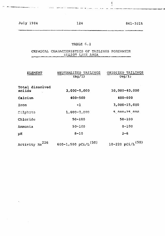
July 1984 124 341-3315
TABLE 6. 1
CHEMICAL CHARACTERISTICS OF TAILINGS PCPXWATERKT.LIOT r.«:'E AREA
ELEMENT NEUTRALIZED TAILINGS OXIDIZED TAILINGS
Total dissolvedsolids
Calcium
Iron
- l p h - 2
Chloride
Ammonia
PH
226Activity Ra
3,
1.
6G0-1,
(mg/1)
000-5,000
400-500
<1
000-2,000
50-100
50-100
8-10
500 pCi/L ( 5 0 )
(rag/1)
10,000-40,000
400-600
3,000-15,000
50-100
0-100
2-6
10-220 pCi/L ( 5 0 )
July 1984 125 841-3015
The uranium ore in Elliot Lake is milled using the sulphuric
acid-lfjch process. The tailings liquid is neutralized by
linn audition in the mills so that the tailings linuid has a
pH of 9 to 10 when tlie tailings are discharged. The
tailings contain about 3 to 7 per cent by weight iron
sulph.;de (Fe S , pyrite). When the discharge o£ the
tC'iL'.nys and the neutralized liquid to the impoundment area
ceases and the tailinqs are exposed to the atmosphere in the
unsaturated zone of the tailings, the pyrite reacts with
water and oxygen to produce iron and sulphate rich acific
water in the tailings. When the porewater becomes acidic,
sone radionucluides and heavy mstals desorb and dissolve
from the tailings causing increased porewater contaminant
levels. in areus wnete cut; Htuuuuwauei. iiow is w n u n u ; ^
acidic water produced in the unsaturated zone moves downward
replacing the neutralized tailings water and may eventually(53)
turn all of the tailings porewater acidic .
With respect to radionuclidas, it is anticipated that acidic
tailings water would have relatively high uranium and
thorium concentrations but as shown in Table 6.1, radium2.6 (52)
(Ra ) shows a tendency to decrease \n concentration
The mill effluent final analyses for the Midwest Lake(43)
project is presented on Table 6.2 . Actual
concentrations for neutralized or oxidized tailings
l>ota"ia'car. for noclr.harn Sacksichevsn ere not available.
However, the oxidisation of the sulphide rich sccassocy
••netillic r.;inerals such as oajsJot C f; £<r- r niccoljfc.?.
cobalt ite, pyrit-ir *>:;.-?. commonly associecaj with r-or thecn
•<j.-*<?k.'a*:f'iH*ua utrAiniom ac posits aiigl'.t ho c:>Cictcti to cause
sulphate rich acidic tailings porewator in a process similar
July 1984 1.26 341-3015
to that discussed for Elliot Lake tailings,, including the
anticipated higher levels of some radionuelid^y -snd heavy
metals in the railings porewatec.

1.27
Element
TSS
Cl
so4
Mg
Na
Ca
K
~ "4
TCC
Mo
Al
As
B
Ba
TABLE 6.2
MILL FIHAL EFFL'jr.IlT AK LVSKS
Activity:
< 5 ppm
120 ppm
3450 ppm
13 ppm
680 ppm
720 ppm
55 ppm
12 ppn
< 0.5 ppm
< 1 ppm
170 ppm
320 ppm
4 5 ppm
T.Pb2 1 0 1.08 pCi/L
T.Po2 1 0 1.08 pCi/L
T.Ra226 0.54 pCi/L
T.Th230 <0-27 pCi/'L
pH of neutral ized ta i l ings -- 11
ORGAN?CS
Ore; an ic
Tertiary Asxino
Xsodecanol
Kerosene (10% aromatic
50% paraffin
40% Naphthene)
Bi
Cd
Co
Cr
Cu
Fe
HgMn •
«i
Pb
Se
V
Zn
Total U
F. 51)
Concentrat.i.on
<5 ppb
<20 ppb
<15 ppb
6 ppb
15 ppb
<50 ppb
<10 ppb
30 ppb
45 ppb
60 ppb
1 ppb
20 ppb
<15 ppb
< 0.5 ppm
2 ppm
15 ppni
'/?-', 120 S 4 i - "J 3 I •
>'• i •? cjp.1. i .3i.: >'. <S L)\:I Lin.- t e n d e n c y tor irnrr. ivc t -t 11 i n <"r; to
•••otii'.H i n c r O'i'.i l ny 1 y rt'.. . d i e w o u l d L't> a c o n ci,-i :> sn ov^iu.itia 1]
i.!if l' i, ••: t-..i::n c o m p a f.iij i L i Ly of 'jeonit ir\br ,nv.-; »'itn or.»niu;n
t«i i l i r.••;•.. In t d d i t i o n , whil*? rr,i i c n u c l i<-e a c t i v: 11••-"> ^ r e
ccr.s i cori'ii i-o b e rol'i t i v«»l / l o w in in.-ict; i v*f t.i i 1 ! riq1;
irripounflnioM ';•.;, t h e i r l o n g t e r m e f f e c t w o u l d h-avo tr ha
c o n n i d o t o d .
As shown on Table 6.2, the concentrations of organics ace
relatively low. Most polymeric and asphaltic membranes will
probably not be adversely affected by the*>e very low
concentrations but corapatibi1ity should be considered.

July 126-i 129 841-3015
7. CnNTM.''M' 'IT ^ACTMTY '^STH'J ,V,"n I,1I!?P
7.1. Gqnora .1.
Site character istics with respect to liner requirements are
addressed in .'JucU on 6 of this report.
Uranium mining and milling operations have been conducted in
Ontario and Saskatchewan for more than 40 years while
undeveloped deposits exist in Newfoundland, British
Columbia, Nova Scotia and the Northwest Territories.
Obviously, throughout such a large geographic area, wide
variations in the hydrogeological setting should be
anticipated and desigr of tailings containment facilities
will be highly site specific. However, for the purpose of
this report we are assuming a somewhat simplified site
geology and hydrogeology consistent with the two uranium
producing areas of Canada. Specifically, this section of
the report (and Section 11) is based en ths following
assumptions.
o Low relief Canadian Shield topcgreiphy.
o Topographic highs consisting of rock knolls
and ridges (Elliot Lake).
o Topographic lows consisting of swampr., lakes
and .streams.
o Siliceous, sedimentary rock overlying
basement rocks of complex origin, structure
and mi. neret logy.
Qokim- Azszclaize
J-cly 1924
o Koc& biiLLace is na^ci, smoccn, wcj t:n»->r a
and relatively Permeable. Permeability
decre.ices with depth.
o Overburden in the topographic lows varyim
from gravel to si.!ty tills.
In addition to topography, geology and hydrogeology, the
design of a flexible liner system must also address the many
other factors that will substantially influence the ultimate
performance of the completed facility. Consideration must
be given to capability of contractor, climate, subgrade,
preparation, seaming, and quality control. In fact, more
than any other factors, the successful performance of the
completed liner installation wixl probably depend on the
contractor.
The following summarizes the steos outlined in the design(62) '
and installation of a liner . Those relating to
earthworks, site preparation, installation, and quality
control are discussed further in the balance of this
section.
1. Site Selection
2. Geological, Hydrogeoloqieal, and Hydrological
Investigation and Analysis
3. L,iicjineer ing Design
o earthwork:;'
o cornf'cs t J. 1/11 i t y t £ s>!.' >vi
Julv 19P-3 1.11
o material selection
o Ci-c'^czy c.:.J fieiu s d a a s e l e c t i o n
4. Preparation of Fabrication and Panel Layout
Drawings
5. Construction
o occc-ss road
o storage site tor materials
o subgrade preparation
o earthworks
o install pipes and other structures
o fine grade and excavate anchor tcench
6. Install Liner
o inspect surface conditions
o place, unroll and unfold liner panels
o seam panels together
o backfill anchor trench
o seal liner to penetrations
o install vents and ballast tubes
o test all field seams; repair if required
o inspection and acceptance
7. Introduce Tailings into Basin
8. Monitor Leak Detection Systems
Ametimtmm
July 1984 132 84i-ii?15
7 . 2 SJAc^ Sel oe_t u>n
Tho site selection process for a wc.nte containment facility
vi.ll consider economic, environmental and engineering
criteria. The economic factors associ.ited with land ose and
rost-bene£it analyses are considered beyond the scope of
this study. Engineering and environmental factors affecting
the site selection should address the following:
1. Identification of major aquifers,
aquicludes, recharge areas and sources of
groundwater.
2. Groundwater discharge zones.
j. oeoioaicai anomalies such as iauj.cs, wrst
terrain, 3ink holes, etc.
4. Topographical analysis with respect to area
hydrogeolcgy.
5. Metecological review with respect to preci-
pitation, temperature extremes, wind, etc.
6. Establish soil and groundwater conditions by
means o£ n subsurface invt>3tiaation.
Jii.lv li PA 133 ' - < ' - ••-\cy
~' Engineerino Design
Compatibility testing, material selection, and scam
selection are addressed in Section 8. This section of the
report discusses the other major design consideration which
is earthworks.
The major item of earthworks required will be based on the
type of disposal scheme chosen. Typical of the various site
selection options for disposal of mine wastes are:
- valley dams
- ring dykes
- open pit mines
- sneciallv dua Difcs
- underground mines
- 6eep lake disposal
The geology, topography, and precedent of the uranium
producing areas of Canada is compatible with containment of
tailings by valley dams. This and subsequent sections of
this report are written on that basis. The design
assumptions pertaining to the topography are presented in
Section 7.1.
An item of earthworks is the design of an access road to
the site. Design of such a read is consistent with
conventional design criteria fot- access roads. This
technology is well developed .ind does not require further
discussion in this report.
The other primary clement of earthworks design is the
dani(s). As ha3 been noted the in tec ted 3ite geometry will
consist of essentially parallel rock ridges containing a
valley filled with alluvium, organic deposits and water.
Dams will be required at one oc both ends of the valley to
form 3 containment area. Dams may also be required to
divert creeks and tributaries.
Once borrow areas have been selected, design of zoned
embankments (dams) will proceed based on the anticipated
strength of the compacted earth materials. Slope stability
analyses will be required to select stable design slopes and
ensure overall embankment foundation stability.
n*-h»r alomonfs of earthworks design ars disrrussed in the
pertinent sections relating to construction and liner
installation.
7.4 Liner Fabrication
Selection of linec type and seam type constitutes two major
design components. The design will also require liner panel
layout drawings of a site specific nature in order that the
fabricated panels match the site and design components. The
primary objective in providing panel layouts is to minimize
field seaming and maximize factory seaming.
7.5 Subgrao_jr JLL?P<»rntion
7.b.l Clearing Grubbing and Stripping
The site should be cleared of all grass, tree stumps,
shrubs, brush, tree limbs, roots or other vegetation which
could puncture the liner or create methane gas. Such
materials should be removed to a disposal site.
Where minor quantities of organic matter, such as 380
millimetres or so of topsoil, are encountered it should be
totally removed. However, in the areas considered in this
study, considerable quantities of muskeg, peat and other
organic materials will be encountered to depths of several
costly and difficult. Nevertheless, without the benefit of
prototype testing, this report assa.'wa that all organic
matter will be removed. This assumption is made on the
basis that the large total (and possibly differential)
settlements associated with comyzessive> (peat) foundations
will result in membrane failure. The final decision
regarding removal will, in part, ba a function of the cost
of removal of organic matter as compared to the cost of the
prototype testing-and the elaborate venting system required
if the organic matter remains.
Fin&ily, in comparing liner types, it should be noted that
while natural (ireported) soil liners or bentonite cur:e
soil liners could not be properly placed over past or
rauakeg, these is a chancs that synthetic liners minht: pr

7.5.2 Sterilization of
It is very important to remove rootr? and root contaminated
tcpsoil. However, became it is virtually impossible to
rerr.ova ICG per cont of all organic matter, the prepared
aubgrade should bo treated with a reliable herbicide. This
sttrilant should be applied in a uniform manner over the
entire site, including the top of the berms; it should be
then disked into the soil to a minimum depth of 50 to 100
millimetres and the earth moistened. Application rates
should be recommended by the manufacturer with sufficient
time allocated between treatment and placement of the liner,
to allow the sterilant to penetrate the soil.
7.5.3 Excavation and Filling
If the excavated surface is to receive the liner directly,
the area should be thoroughly proofrolled with a minimum 5
tonne sr.iooth-wheeled or pneumatic tire roller. Soft spots
should be removed, replaced and compacted. After
proofrolling the surface should be blade graded to a surface
tolerance of less than 30 millimetres across a 3 metres
straight edye. The surface should be smooth, and free from
any fractured rock, and no smooth rock should be over 5
millimetres iti diameter. If a sand bedding is placed over
the excavated surfsce or if a geotextile underlay is to be
installed, the K-S .O prcofrollin^ r{?Tjir*?n
P i l l should be placed Lo l i f t s not ttfcCSKKSiiiy ^Lout *2~
es in t h i c k n e s s . Each l i f t should bes compacted to
i-ei':<5ed [>Grc^;}L^C|e of the ;v.p«i;a;;::. dry ci^nsity ^s
atCEKir.Srd by the Gt-ndsra Troctor ?icictvsre-Os»naity
— 1 » »- i •>-. -J- " V. i ->
July lvtS4 137 U<ll-3ei5
7.5.4 Liner Subdrainage and Gas Venting
Liner subdraina<je is generally required when it becomes
necessary to monitor leakage through the liner sy3cem, or to
provide pressure relief from a high groundwater table.
Situations that necessitate the monitoring of leakage can
range from, identifying a high valued liquid loss, to a
hazardous waste which must be contained. A highly pervious
layer of soil or geotextile is placed under the liner
providing a predetermined path for the liquid to travel. At
various intervals, interceptor subdrains are tied to a main
collection header to safely convey the liquid to a
collection sump.
Certain site-specific conditions require the venting of gas
that may accumulate beneath the liner. If any organic
matter exists in the soils under the liner, or if natural
gas is present in the region, gas production is inevitable.
If the pressure is permitted to increase the membrane can be
lifted creating a void for additional gas accumulation and
possible overstressing of the liner.
Venting must al5O be considered when a fluctuating water
table is present iiprnediately balow the pond bottom. When
the water table falls, void spaces in the soil under the
liner are created. Air is then sucked into these voids from
ths surrounding soil. Conversely, when the water table
rises, air which wac pulled into the voids is displaced
upward. The amount of fluctuation and proximity of the
water table to the basin bottom, will dictate the reaction
of the membrane to this air pumping mechanism.
July 1984 138 S4I-S315
The need to vent accumulating g. s is boot accomplished by
providing a layei: of uniformly graded sand of which less
than 5 p't cent by waiq.it *?ill pa33 the 7.00 si»ve. A
geotoxtile may also be usftd, which allows gas to p£,33
through the fabric's cross-section under a surcharge load.
7.5.5 Finishing
Thorough preparation o' clie finished surface is a major
ingredient in the -.-u<?coss of a liner system. In general the
surface m.ist provide a firm, unyielding, and smooth
foundation, free of ditt, clods, roots, stones, rocks,
sticks, sharp objects., or debris of any kind. Two such
finished surfaces <*ce geouextile fabric and sand bedding.
Geotextile fabrics are an excellent surface for membrane
lined systems. They provide a cushion to protect against
abr^aive action and significantly reduce the coefficient of
friction between the liner and the substrate, increase the
evaporation rate of condensation fortr.ed beneath the liner,
and forris a parroeable layec to transmit gas while not
adhering to the liner.
If no geotextile is used, the finished grade should be a
minimum 150 millimetre soil layer, no coarser than pearly
graded sand, in accordance with the SP classification of the
Uniform Soil Classification Syatsm. No stereos, rocks at
debris of any kind should be within 158 reiliiiaesfcrea oE the
finished
Julv 1SC4 13* 841-3015
The surface should be- graded smooth and compacted to
finished elevations in accordance with the recommended
tolerances previously inaicated.
Particular care will be required around pipes, ducts, and
other appurtenances which will protrude through the finished
1iner.
7.6 Liner Instillation
7.6.1 Polymeric Liners
Polymeric liners are fabricated in the factory into a
minimum number of pieces to facilitate easy installation,
both directions, to minimize field handling. Installation
of the liner is, in roost cases as important to the overall
success as material selection. accordingly,, thcr liner
should be installed by a qualified contractor.
Prior to placing the liner, the surface of the impoundment
area should be free of projections and debris and graded to
properly suppoct the liner. Further discussion on subgrade
preparation is contained fn Section 7.5 of this report.
For unreinfocciid Iiner3, side slopos fitter than 3:1
(hccixantal co vertical) see generally considtfireJ ii-.aximu.ti
desirable slope .ingles. Side slope? should bo coraca^ted to
imize setclamant.
Rcinfcrccvi liners arc rcccr^nci^od for steep ziiz clepc
applications to improve creep r- ) «i:«nce, These scrims wi
improve puncturo resiseanee, uimsusional stability, tear
July 13 e-4 140 841-3215
strength and will allow the use of reduced totc'tl thickness
Cor the liner. liioh density polyethylene which is not
reinforced and which can be placed oa relatively steep
slopes 12 the exception.
Final selection of slope angle should be based on soil/liner
interaction and strength tests. Previous testing by Golder
Associates indicates that the effective friction angle
between sand and one particular membranes was only 20
degrees while the internal friction angle of the sand was
greater than 35 degrees. Furthermore, the harder the liner
material, the lower the effective friction angle.
The rolled and folded liner panel as delivered to site
snouia De cieariy marked on tne outside witti the panel
identification letter or number and the panel size. The
panel size is also generally marked on the top fold of the
panel inside the carton. Directions for unfolding the panel
should be clearly marked on the lid of the container by
arrows indicating the direction to "pull" and "spread".
"Pull" - indicates the direction in which
the length of the panel is unfolded.
"Spread" - indicates the direction in which the
width of the panel is unfolded.
When locating the packaged panels, thesa markings should be
observed so panels can be unfolded in the proper direction.
Packaging chould be left on the panel until ready to unfold.
The panel should not be exposed to direct sunlight bat
July 19 6 4 141 841-3(515
should be cc'ipletol.y shaded with c^aquG cheeting. It is
necessary to leave a frue-flCi/ir.g air space between the
opaque sheeting and the pschaq.-.-d panel.
When ready to install a sheet, it should be carefully
removed from the packaging. Any steel bands should be cut
and removed from the general area. The cardboard container
should be carefully removed by opening it along stapled
edges. Knives should not be used to cut away cardboard
siding, lest damage to the liner result. Before the panel
is pulled out, any staples on the bottom portion of the
carton should be removed and the pallet should be inspected
for any protrusions which miaht cause damage to the panel.
Positioning the panel and unfolding it from the pallet is
best handled with a large front-end loader or for!: lift.
The panel is usually double accordion folded with a mass as
much as 2000 kilograms.
To pell out the panel, the leading edge is laid on the
ground by removing several folds by hand fiom the too of the
panel. By positioning two or three workers on top of the
loading edge, the palletized panel can be lifted up with a
fork lift truck which can then reverse slow'v until the full
length of the panel is unfolded. It is helpful to have two
men positioned on either side of the palletised Danel to
walk along and help the folds off the top of the i-anel as
the fork lift backs up.
After the panel is extended to its fail length, it is
straightened out to the guiooiines indicated by thf> panel
layout or the Technical service Representative. The panel
is then spread into position. To achieve this men acs
July 1904 l'.2 3 •< I - 3 1 5
positioned along tht? edge oi: tii'i pan el ••inono/.imately 5
metrcT. apart dc?pei «.• ing on tht* Si?.o of the panel arid the
terrain to br; covered. IE r^quirr-d, rnon are positioned dt
the uphill end ot" z'n*. panel to keep it from sliding down the
slope as it is unfolded. If the edge to IJC- gripped is
subsequently to be bonded, then the panel edge is folded
back about r.-o or three feet, and the fold is gripped for
pulling rather than the edge. This is to avoid stretching
the edge where it is to be bonded.
Gripping of the panel can be facilitated by use of a short
length of dowel, 20 to 40 millimetres in diameter, and 300
to 450 mil 1 imetrer, lony. The liner is first wrapped around
the dowel, and fhon aripned. The pdaps ryf the dowf? I s -should
be carefully rounded off to prevent sharp edges from digging
into the Liner as it is pulled.
As the panel is pulled out it is necessary to maintain air
under the liner. This air can be obtained and maintained by
several means. One way is to simply hold the edge up and
advance at a rate fast enought to capture air underneath as
it is unfolded. Another way would be the same as above,
except tho edge is constantly raised "ir.d lowered ,is it i r>
being spread out to fan air under the liner. When tnero i;»"
a prevailing wind Crom the direction to which the* lin.?r is
being pulled, ;ii" can bo introduced by lifting thr.- <--•'•'7*; j'j t
enough to allow the required amount of die to blow i 0 ur;det:
the liner. Cf.re tnurt be exercise1! >n tn-is crs* t"> •only
raise the edqe of the linsr enouuh to let tno -josired sco-;rit
of air under the liner; it should then be lowered to cut off
the air as soon as enough air is captuseo; othurwise, it is
possible to have tha liner blow iway. A slight, lateral
tension should be maintained on t!v; leading edge of the
Julv 1964 143 341-3(51 5
panel being spread. TV*is iottrral tension facilitates thc-
£ 'prc'2 i ni o'^n'ii^n1;, P.nnols nbojlci no pos 11-icr.ec: so that
Succeeding pa:;tlr to be joined overlap bv at le^st 15C
mi 11 i me trss,
7.6.2 "ield Sea;\iin<j
The liner's strer.gth and sealing ability depends heavily on
the quality of the field seams. The f-^ld seam quality
depends on the installation crew. An i.:ept crew may do a
poor job even with the simplest seaming methods.
The necessity of a simple but effective means of
constructing field seams may be dramatically illustrated for
the case of the example on which costs are based in Section
11. For this example 232 hectares (575 acres) of
containment basin would require approximately 330 kilometres
(loS miies) o£ field seams. Considering the aependsnee u£
field seaming techniques on a variety of factors, some
hujnan, the odds oi providing a perfect seal for all 300
kilometres are extremely low.
The three basic requirements for credible field seam
production are heat, pressure and dwell tiiv.e. Job site
factors which may influence the field seaming operation
include:
i) the ambient temperature and humidity
prevailing during which the se^n-; r«c?
produced;
-5 4
i i) wind;
Hi) thy raoi:;turc content of thf> substrate;
i-•) the supporting surface on which tho r.r-ar-,
is bonded;
v) the skill of the seaming crew;
vi) the qualtiy and consistency of the
adhesive;
vii) the cleanliness of the seam interface.
7.6.3 Asphalt Liners
SBR refers to any of a multitude of styrene-butadiene
rubbers. By blending thermcpljstic SBX polymers with ori ne
grades of asphalt, a thermoplastic material has been
developed which behaves aa an elastic polymer. The presence
of the SBR provides added temperature stability; i.e.
flexibility at low temperature and viscosity at high
temperatures. This material contains rubber in
substantially larger quantities {.. bout 25 per cc-nt) than the
more conventional rubberized asphalt. This material looks
very promising and is regarded os a variation on aspbaltic
coricrrstG in i-'hirh ths rubber sets •"*.*? si li'i f'Tneric
aggregate. Uniiko the normal ispls.iltic concrete, it would
be -applied by ho L spi-'tiy ivp lit.ciUioii.
July \':Z'. US
(25)t.acaly^n." nituicwn .i!E;;nait m-.-nbrane is another product
which is hot sprayed and requites the use ot a catalyst to
modify its viscosity properties.
RycorwnenJc-d construction procedures for buried asphalt
membranes are suranariTred as follows:
o Preferred slope inclination 4 horizontal:!
vertical with maximum value of 2 horizontal
:1 vertical.
o Sharp objects and rocks should be removed
from the foundation soil.
o The foundation soil should be rolled with
_ ......... .. *krv-<c« -.W-VWA a.wA.««*^ \.\ hcuu^t: a^>ptloJLu
demand arid soil impregnation.
o In addition to rolling, if the subgrade is dry
and dusty, a light sprinkling of water is
beneficial.
oo ApplicaEion temperature of. 234 C with a
slot-type spray bar.
o Multiple passe;? (minimum of 2) is desirable.
o Recommended application spc»fd of 6.5 kilometres
m»r hour.
* — ft. - „ _ »

.July iyS4 146 G41-3015
7 ' 7 So i l Cover
It is generally accepted that ?n earth covor ov^r « linec
system wo'jld be enquired where the liner is particularly
susceptible to exposure to ultra-violet radiation, ozone oc
other weather related conditions; where there is a potential
for mechanical damage* due to traffic, animals oc vandalism;
where there is a potential for damage associated with the
placement of the wasto materials; and where a long-term
service life is required.
According to the manufacturers of the polymeric liners
selected for study in this report, most are described as not
particularly susceptible to weathering, and exposed use is
generally offered as a favourable marketing point. However,
essentially all cf the polymeric liners ita detritecntally
affected in varying degress by exposure. it would therefore
follow that the provision of an earth cover would extend
sotaewhat the anticipated service life of a given polymeric
1inet.
The discussion in Section 7.6.1 regarding acceptable slope
angle* should be considered. Eventually soil/liner
interaction and strength testing would be required. For the
present, it is reconaended that liners intended to receive
soil cover should not ba placed steepar ths«* 3 horizontal to
1 vertical.
Soste asphalts axe known to be affected by ulcra-viclot
radiation and both asphaltic concrete and sprayed asphalt
may b« susceptible to frost action. A sail cover would
iaprove cesiscsnee under these conditions*. AccGt"<3iin3?-.y, if
July 12 3 4 ' 14 7
tai \ in7* are not ;«r!d<*«3 J.POT»d i a t.? 1 y after /spnl <cr-f ion of the
membrane, then a soil protection cover at lef&sft 3G3
millimetres thick is r«cciac;ended.
Polyrxaric liners ar.d aprayed asphalt vnprabrarsf?3 are both
susceptible to irwrchanical equipment daraage during
installation. Further, if the exposed areas will be
subjected to traffic during pond operation, a liner covet
would minimize the potential for vandalism or accidental
damage. Kail and the potential for high wind induced
"air-lift" are additional conditions which affect soil cover
related decisions.
All liner systems, if exposed, would be susceptible to
damage caused by ice movement. Least susceptible would be
those liners with hiqher puncture resistance such as KDPB.
In addition to the above factors, the abrasion related
characteristics of the waste ovaterial in terms of the
potential for damaging a liner systera will require
investigation.
Based on the above discussion and neglecting costs, a soil
cover would appear to be benaficisl in that it would
probably increase the service life of a liner systera and
rcduca the potential for mec/ianical damage during basin
operation. However, the vecy operation of placement of a
soil cover rsay itself, 9».«?>.ificantly increase th<? chanceo of
puncturing or te»rin<] a 1 .a*r. Once coveredr dawasse to th«s
lin<s'- would probably go u.i loticerf and thus wow Id not be
repaired.
A soil cover should be:
1. Free of sharp atones and not rsxcesaively
abras iv*.
2. Compatible chemically with the contained
waste.
3. Stable and resistant to sloughing fron wave
action.
7.8 Quality Control
Quality control is an inherent and vital part of_-.*..:,-<€"_—*- — -.-. — , ^ . . - J T - - » * _ — J *• - v . - * — - *- J - —. - « "* i - : - _
mstecialii. The auality control must continue with the field
installation to ensure conformance with the daaign
sp-sci fi cat ions.
Testing, consistent with conventional civil and geotechoLeal
engineering practice is suitable for tha quality control of
<aarthwork3 relating to embankments/ subhead© preparation and
soil cover. ?h« primary test procs-iurea would include:
i} Coaspacticn. control using volumetric or
nuclear density sppaiftus. With regerd
to th« latteE social car® will b« required
to calibrate the eqwipr»«?nt for ojvsestioo in
the pse-aence o£ low level, radioactive westes.
ii) Straight ts>s and othisi;-survey
to cenfira lirsa *n<J ^r
iii) Visual countering which will prob.-.biy ba tn<?
noot effective focra of quality control. This
will b« particularly ao in ensuring fcec-dotn frees
aharp objects that could rupture the liner.
Visual observation should also be effective in monitoring
the condition of asphalt or polymeric membranes. Quality
control during the* manufacture of polymeric mscnbrane3 is
discussed in Section 4.2.6 of this report. Assuming lining
isaterials are delivered to the site in good condition and
visual monitoring confirns that they have not been dataaged
during installation, then the final itea requiring assurance
is field welds of polymeric liners. Both destructive and
non-destructive test toethods should be etaployed. Depending_.. *.w~ c: .1 J _ _ _ — - • _ _ __».u_J- «-v—._ j__ —•- _ _ -= _;_i_i_— .. ™ -- — ~ _ v — ^ ^ — ut* ~ ~~ _ . . • ^i v . £-— — v v _ w — ^ v .j«3.iL
include electronic techniques, -sir lanca testing, vacuum
c'.iarabee testing, shear and peel testing, tent coupons, etc.
Ideally, destructive teat tssethods should b<? kept to a
minimus* but should b« of sufficient quantity to verify
original design specifications. Typically a suitable field
quality control progran would include:
i) Viaual inspection at -all fiold saaras.
ii) Mechanical tes<:in<j o£ d^ily field se..»
iii) f.!n!j-o,i»?5'.;ri5ctiv« teiUnq of «IJL fi^ld *5*?••»•«a
noa-d-.tst?actiwft Sest tasthefis for po
^ y s typos oire euT&§,iriss'3 in ts.bl'i ?.1«*"*
Joiy
7ht»re are f£fw*r quidolinoa available for the fi.«id
evaluation of atph*]. f~ic liners. Kovrev^sr, daily testing of
tha asphalt to cnsuis it conforms with specificationa
outlined in Section 5 would b<a ttquire-d as would ireutine
coupon sarapling of placod asphalt to ensure the- requited
thickness ia being achieved. Constant and very careful
inspection of the asphalt placessent procedure would be a
prerequisite.
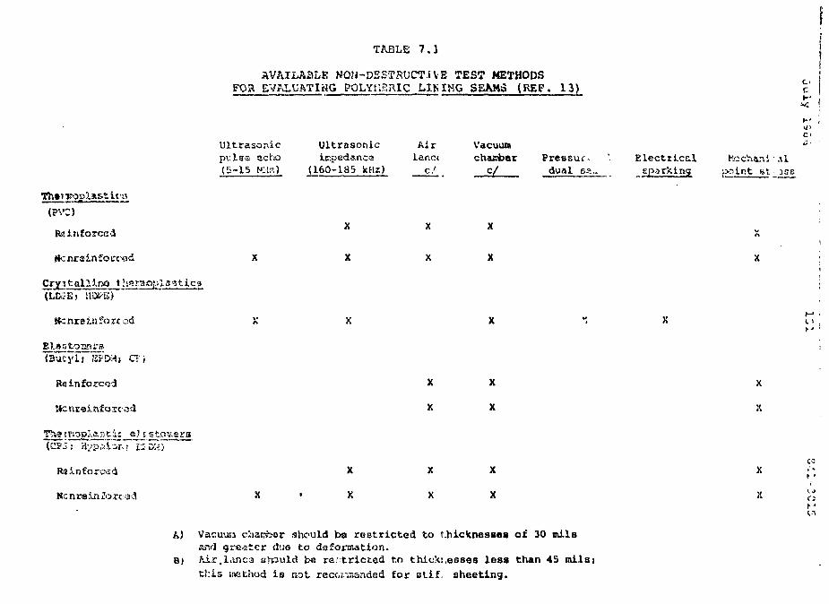
TABLE 7.1
AVAILABLE NON-DESTKUCT.IVE TEST METHODSFOR EVALUATING POLYMERIC LJ.MHG SEAMS (REF. 13)
t It'lt
Ultrasonicpulsa echo(5-15 IClz)
Ultrasonicirpedanca
(160-1S5
Airlanc(
c /
Vacuumchamber
c/Pressure
dual 6S..Electrical
sparkingKochani
}>ntr.t fit'-ilJSiT.
huc
Reinforced
1 s 11 c g
X
X
X
X
(Butyli "sf:KH» CT;
Ratnforcoi
11
Rainforcsd
Nc nrein JJ
X
X
X
X
X
X
X
X
X
X
X
X
X
It
A) Vacuun chanter ^hculd be restricted to i.hic^nesBes of 30 milsand grafter duo to daformation.
Bj Mr.lanca should be restricted to thicks,esses less than 45 milsjthis jnethod is not recoraanded for stif. sheeting.
July lb'j-i Lbl
8 • PEHrORKAHCS Cr:l';T--;jTA AND
8.1 Introduction
In previous sections general properties of the polymeric and
a3phaltic liner Materials, anticipated typical linec
environment including characteristics of uranium tailings,
and the design of containment facility and liner
installation have been addressed. In this section of the
report the requirements of the liner material under the
above noted conditions in terras of performance,
compatibility, durability, rate of degradation and release
rates are assessed and potential failure mechanisms are
discussed.
8.2 Perfr HI?nee Crit-^rA^
The primary function of th3 basin liner system and dsw
seepage barriers would be to impede the flow of leschate
(tailings pore liquid) to a sufficiently low rate to allow
the in situ soil/rock groundvater system to accept leachate
without adversely affecting gecundvater quality. The
acceptable seepage rate would ba & fune'eien of the nature of
the contaminants snd the capacity of ths native scilst :;ft:k
arid groundwater foe natural purification through the
mechanisms discus^eu in Sectiyn G.3.I.,
Bas&cJ on the above discuaaicn, the success or Caiius."1."; c-t a
lining system could bs evaluated on the bssis of whathor the
lining syst^^s tsit>',Jvjd coniaraiviants at. os baiay ths. usaign
July ].9£4 ' 153 841-3815
rate over the c'asion life of the tailings imooondraent
facility. Anirj ciujf.td release ratws ate audteSMwd in mote
detail in .Section 10.
During desion the liner materials under consideration are
usually evaluated, losing evaluation criteria discussed
above, in terms of the following general requirements:
1. Compatibility and durability of the liner
in the presence of the waste to be contained.
2. Reliability and risk of failure (potential
failure mechanisms).
3. Relative ease of installation, quality control,
repair and maintenance.
".ioet installation, quality control, repair and maintenance
are addressed in Section 7. Liner compatibility, durability
and potential liner failure mechanisms are addressed in the
fon owing sections. Rates of liner degradation and the
testing associated with liner evaluation are also discussed.
8.3 kinar Cr-r ,jatibi 1 i ty and Durabi 1 ifcy
8.3,, 1
The* cowpatibil i ty of a lin^r 'a.s»:eri«l in contact with a
given waste material, in this case ucaniuin t-.ailings, wou?.d
typically be evaluated in t!ir««» stages, nansely?
July 1084 154 8'; 1--3C J.5
i) Anticipated reactions of the liner to th.:-
waste baaed on available literature and
wariufacLuter' .s general cht*f:iiccii cebisUacy
charts.
ii) A screening tost programme in which li.iers
are immersed in waste for fairly short periods
of time and possibly at varying toraperature
to evaluate changes in material properties.
iii) Accelerated testing whereby the liners are
evaluated for long term exposure to the w?.ste
in laboratory testing which simulates aging of
the liners.
A possible fourth stage of liner evaluation would include
field testing of a small number of liner typos which proved
suitable basc?d on the three-staged evaluation noted above.
The level of detail associated with liner evaluation
provided in thI report would correspond to the first of the
three stager-. '. above. Stage II of the study involving
the laborat rograrame would correspond to the second
and third ?,• . evaluation lifted above.
The raajor :=.-':t«i. o£ information used in preparing the
section of -h i ~ report addressing Liner compatibility
include:
1. Previous studies undertaken by Pacific North
Wefit Liboratori.es on Kypalon and ar.phaitic
rcerebL-^nes in the presanca of simulated uresniura .
tailings leachate (ref. 25, 54).
Jv. lv ]3c-. .155 8 4 I - 3 £ l b
2. The results of testing carried out in the
presence of: uranium mil), tailings provided by
the suppliers of Hypalcn and high density
po lye thy] IMIC .
3. The general chemical resistance information
provider by liner suppliers.
4. Generally available chemical resistance of the
base polymeric resins to groups or classes of
chemicals (ref. 52, 53).
5. The general properties of polymeric and
asphaltic liners as discussed and referenced
As noted, the characteristics of the waste material to he
contained is oi: prime importance in evaluating
compatibility. In this case the wastes consist of uranium
mill tailings with general properties as discussed in
Section G.4. While the characteristics of the tailings will
vary from site to site, the general characteristics which
are considered particularly relevant include:
i) The lime-treated tailings pond fluid
initially has a pH of 1Q or 11 and is
i ib«d <iS a ationg salt oolu'cion.
i) Following oxidation of the sulphide
p.inernls, suiphrst« rich acidic tailings
porc-r.'stsr with a pH of about 2 coulc?
be in contract i<;Ii r.he liner.
July J.i-B . 156
iii) Snail concentrations of keror.ent will be
prosont ir> the tailings from northern
naskatchew,:)!!. There i:i also the potential
for the presence of large conci'iurationi' r-i
kerosene due; to accidental spills.
iv) Various radionuclides will be present in the
tailings and the liner would theci'iore be
subjected to some radiation.
3.3.2 Polymeric Liners
8.3.2.1 General Chemical Resistance
•me resistance ot various aeneric Cyprus on pojymers to
general categories of ch^..iicals are presented in the form of
tables throughout the literature. An example of this form
of comparison, in tabular form, is presented i;. Table 8.1.
The information presented in Table 3.1 corresponds to base
resins and not to the final compounded liner meterial.
It is important to consider the effects of various additives
durincj the compounding stage of liner manufacture.
Excellent resistance to a chemical by a base resin does not
guarantee that the final compoi.n-j will offer the .same
resistance. In the s rna vein, if a base resin shows poor
resistance to a chemical it in unlikely that compoundinq
wcjli i;r.\.rov'e rosis tone.. The; type cf i:if crrr.ation prc^ontcd
in Table 8.1 would thus torm a good starting point in
evaluating the various bi£::> poly.v-src.
The rati .TjG ir/n-l in Tab le 3 . 1 arc- v.vpl a i r ea cs f e l l o w s
i) Poor ( D - nee of t h e i r . o t e t i a l in t he
presence, oi the ^qent is not re-'c-in'Ti-
The i.vftjot v o r i c s frcrs c.i ta:.; t r o p h i o i'
t c .Txrvcrfr degrada
ii) Fair (F) - use of the? material is marginal.
iii) Good (G) - ur.e of the material is acceptable
at room temperature, Long terra exposure may
result in rcinor loss of properties, but
exposures at elevated temperatures may result
in significant property loss.
iv) Excellent (E) - materi.il is unaffected by the
? go n t.
All of the polymeric ra ter i-ils considered in the study, with
the excepti^n of polyurotharte, are presented in Table 8.1.
Baued on the known nature of uranium tailings, the agents
listed in Table S.I most likely to he in contact with Uie
liner would inclcde diluted inorganic ..icid, Ji luted bases
and acidic aalr.3. As noted in Table 8,1, all of. the liner
types cons i d-.-rc-d in this utudy show excellent ct-siatance? to
these agf.'p.':.s with th^ CKcopt ion .> £ TSutyl '.;'r:ich i.; rated a?
r, - . ^ A C . - , . - •' , - - r- - • - 1 i . - . . - ; . * • , .-> ^ J J 1 . . • • - . . • » 1 -. - , . • - . - . ,» > „ , ^ . . - ». \ . , . 1 . . . - , . ^- , - . ' . - . • - - * ^ i . * 1 . ^- * •-, d , . 1 v . ) l . i I t • 1 • , s v> A ^ -.1 «- • - ' ^ 1-- 1 i • > * - » » \* > »x> M W A J * 7 «. I ^ I , U L
vn i ch 1 s no ted a s goc'.• f •.•<i •( i i u t •.?o L-ascs . With r c r . ccc t to
ci/ to i iy i i tocui ju iu ; , ana in p a r t i c u l a r a
QoteSa? AssocSeias

o u i y L -J 6 4 i 3 i
hydrocarbons .isiocidtcd w; Lh ke:obcno, ail of <_::..> liners
show poor resistance vitn the exception of polyethylene
which is rated iia £a\i.
It should b'j notivJ tii.» L t!i<? agents ccvjidt-tpd in the table
arc at hicjh -oncer. tr--s t in<<-s. Keto'jeru; in uranium tailings,
except in the cjjf ot an accidental spill, would be present
in very low concontrationa and vould likely not offset 'io->t
of the linings at least in the short term.
Similar information to that presented in Table 8.1 has been
reviewed tot polyurethane . Based on the review of the
information it has been noted that urethane resin has poor
resistance to hydrocarbons; fait to poor resistance to
inorganic acids; pooc to yood resistance to bases; and good
to excellent resistance to salts.
based on the general review of the chemical resistance of
the base resins presented above it is concluded that all of
the base resins, with the exception of polymethane, show
promise foe long-term resistance to uranium tailings.
Cautioii should, however, bo noted for Butyl and
nolyethylene.
•
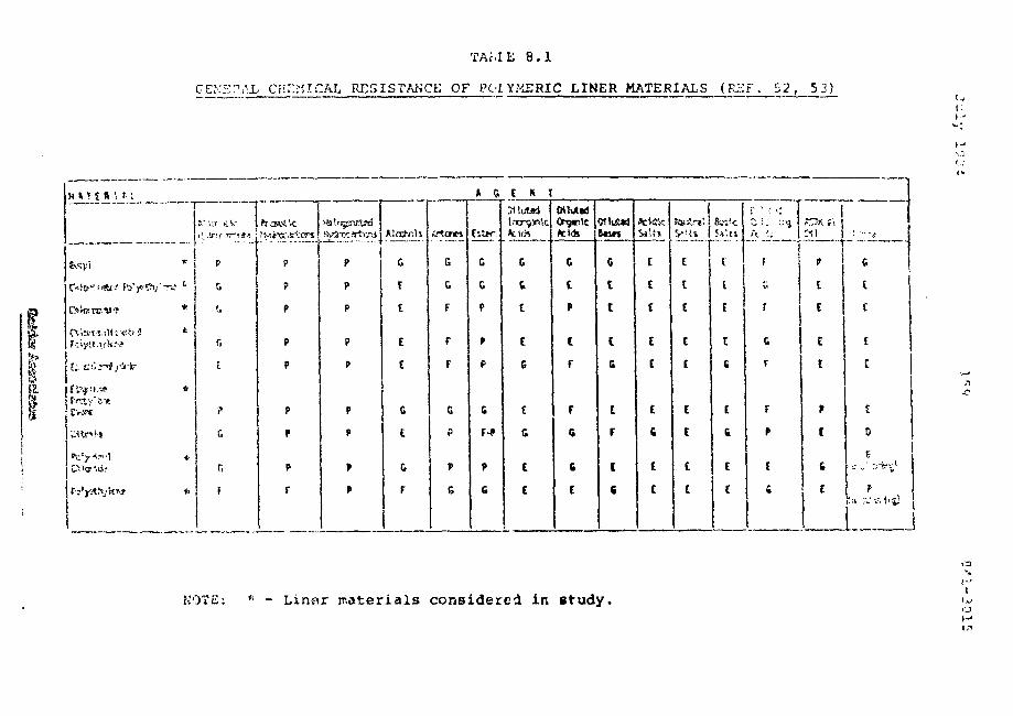
T A M E 8 . 1
C E K H P A L C H E M I C A L R E S I S T A N C E O F P O L Y M E R I C L I N E R M A T E R I A L S ( R K F . 5 2 , 5 3 )
W »T £ 9 1 M
i Cvs*
P
P
P
P
P
P
P
P
r
P
P
P
P
P
P
P
t
P
G
t
t
I
G
t
G
F
G
G
F
F
F
G
r
9
G
G
G
P
P
G
F-*
P
G
Ircr93nk
G
i
t
I
G
C
G
C
t
WUABS
G
t
P
C
F
F
G
G
e
9MU*JSotvn
G
t
I
I
G
E
F
C
c
fckftcS*Ui
ct
t
t
t
I
c
t
£
" IC
I
I
t
I
t
t
t
ft'.n
C
I
I
I
c
I
G
C
t
f
W
f
G
F
F
P
t
•
ci
c
E
c
NOTE: * - Linar materials considered in study.1
o
July 1984 16
colloeteJ fz'ca rsjnuf -icfcurecs and aupplier ••» of polyps, ie
l ine r s . Th« corapanie« which responded to tv-o questionnaires
inclijJe<l in appendix iJ and &r'? aun^aarized D
Lining Materi
Gundle Lining Systems Inc. - HOPE
Schlegel Lining Technology Inc. - HOPE
Kitersaver Company Inc. - Industrial Grade
Hypalon
CPE
PVC
The Gundle general cheaical information would indicate that
the Gundle HDPr. ir. generally unaffucted by inorganic acids
with the exception of chlorosulphucic acid, chromic acid and
concentrated sulphuric acid; unaffected by inorganic bases
and salts; and generally moderately to severely affected by
hydrocarbons. The Schlegel general chemical resistance
information indicates that Schlegel HOPE is satisfactory in
ths presence of most acids with the noticeable exception of
concentrated acetic acid, butylic acid, chromic acid,
hydrof IOUE: IC acid, nitric (oxidizing scid) and sulphuric
acid ( ')8 per cent concentration); most sulphides with the
notable exception o£ calcium sjiphide; and all sulphates
testod. Schleanl HOPE would b« eyp ?ctftd to bq aftectcci by
most hydrocarcor.s.
BaK*ti on a :evie-» o£ the oeneral chsraical rosistance c' t'i
auppliod by Watercsvet for Hypalon and CPE. the S'olicwinq
Cil-3315
general conmants are made related to chenical resistance
evaiufiteij ay xt.-mi.hion tosciny and W M u u n n q weight gains
after Gl days of testing:
i) Hypalon was relatively unaffected by 3 and
3 0 per cent so Hit ion of sulphuric acid
ii) CPE was effected by the 3 per cent solution
of sulphuric acid
iii) Hypalon showed superior resistance to sodium
carbonate and sodium chloride.
iv) all are significantly affected by kerosene
at 108 per cent concentration
!".'C •.-•" =•.•.= Ivz-trf by ~.zzr.z cf iaz:.±zz.i~i. L^wi..^ Zoc 28 days
with chemical resistance measured in terms of weight loss.
The Watersavec data »*ould indicate that of the chemicals or
agents likely to be encountered in tailings, PVC was
affacted significantly by concentrated sulphuric acid
but remained relatively unaffected by a 10 per cent
solution of sulphuric acid and concentrated sodium
chloride. The other acids used to evaluate PVC in the
Watersaver information included acetic, hydrochloric and
nitric acius. PVC was affected significantly by
concentrated nitric -scid.
a.3.2.2 Resistance to Uranium Tailings
Based on a :»viaw of Xitctature and conversations with
cepraas»nt&tiv^s of the? liner industry, it it co»clu«J*-"d that
to £<»tfc Pacific Bor tl>w«*st LiiboEci'coc ierji (C'biL) have ess.
July l5»U IC2
out the most detailc-d laboratory evaluations of polymeric
awbrsnas in tha pccronce or a sirjulacwi actuic ct^uiuii
tailings le.ochate ""' "* .
A FKL study completed in September 198 3 evaluated the
performance of 3 Kypalon '-.tropic in r.rt exposure column in
which aging was simulated by subj?fcting tha liner sample to
increased temperature, elevated oxygen partial pressures and
low pH. The Hypalon was evaluated in terms of effect on
perroeability and the exposure coluran test results indicated
an increase in permeability of from about 6 x 10⁻¹⁰
centimetres per second to 2 x 10 centimetres per second
for an exposure time of about 65 days. Oxygen partial
pressures during the test varied from 0 to 100 kilopascals,
r>R varied from 1.8 to b.9 and test temperatures wete heldo
for the most part at slightly above 50 C. The Hypalon
periaeability of the materials tested including asphalt,
asphalt/rubber, catalytic asphalt, bentonite, and natural
Additional testing presently underway at PNL includes
evaluation of HDPE and PVC membranes in the presence ot
simulated acidic uranium tailings leachate where pH is held
at 2 to 2.5 and controlled by addition of concentrated
sulphuric acid . To date, esposure periods of vp to 29
years have repottedly bean simulated by aging tha sample in
the lflachate at 78 C for 18 weeks . The liners ace being
evaluated in terms ot fchic^near,f density, tensile
cJon-gstiors, shear strength of. x~^.".fn"f »n<3 t«»<ir
Chsraic&l testing includes dis.rt:c*rantial r-cd;;nirv:jf cvsh-r ir»
Julv 1984 153 S41-3315
and di f fetent i<i I infrared spectr ^repny. irie PNL
conclusion" forced AS a result of tha testing carried oot to(54)
f* are:
i) Aging reactions ver-a not detected io th«i
HOPE snd physical properties wece not
adversely changed during exposure to the
simulated acidic leachute.
ii) Insufficient data was produced to draw
conclusions concerning PVC although some
chemical changes in the PVC were noted and
there was a 19 per cent decrease in the
strain measured at failure in the most aged
sarnie. Tensile strength and tear resistance
wei--- unaffected, puncture resistance declir.cr!
significantly and seam strength remained
relatively unaffected.
In addition to the test information noted above, some of the
liner suppliers/manufacturer's provided tev.t data associated
with liner compatibility testing in the presence of uranium
tailings leachate or "nuclear waste liquid". The results of
the testing are presented in Appendix D. The materials
tested included industrial grode Hypalon supplied by
Watersaver snd high darsaity poly«.:thylena supplic-J by GunalG
a no 3oiilt;qel. A Review of the results s£ tise tes'ciny
supplied by the liner suppliers would ^nSicate that tba
Hypalon and HOPE tested cemaineci relatively unchanged ia the
pror**nce of the wastes or that any changes recoedec: - i:<"
within accept&Dle limits. In all cases th<a evaln.'-Lions were
cacrieo out in tttcrus ot ciianqes in pu
a /?. 1 r. *• 8 4 1 ~ ? 1
0.3.2,3 Koaiyfc.v.p.ctt to Radiation
In gantcal, palyresi: ic ra.sfc'sriala are atfectc-d by both charc?s<l
[>r-r tides and ionisj.no radiation. Irradiation chusss
increase of crosslink density of tLateriala resulting in
hardening, decrease of the ultimate elongation and,
soaetiraes, increase of tensile strength.
The effect of gamma radiation on physical properties of a
number of liners is presented in Table 8.2 , based on
radiation levels thousands of times greater than encountered
in uranium tailings. Seven of the liners considered
in this study, PVC, HOPE, EPDM, Butyl, Neopreue, CSPE, and
CPE, are included in Table 8.2. Based on the information in
the following conclusions are drawn:
i) In terms of the modulus at 28C3 per cent
elongation, Neoprene, HDPE, PVC and EPDM
were least affected by gaiwna radiation.
CPE and Hypalon showed the largest increases
^nd butyl the largest decrease in modulus.
ii) In terms of the effect of gamma radiation
on tensile strength, EPDM remained relatively
unchanged; CPE, Hypalon and HDPE showed
increases, Neoprene and PVC SIIOWOG decreases
as did Butyl, which aiso tended to :V
July 19 84 • 165 C4.'.-3!U5
iii) In tarns of the effects on eicniation, SPDM
Keoprene and HOPE were the least affectad,
while Kyp&iou, Butyl, FVC, snu CPE reduced
elongation in descending order. However, at
higher exposures Butyl tended to degrade while
the others generally did not.
iv) Overall, it i3 considered that HDPE demon-
strated the least adverse a££ects, followed
closely by Hypalon and EP^M. CPE follows
next on the scale due to relatively poorer
performance in terms of elongation and then
Neoprene due to reduction in tensile strength.
PVC followed by Butyl 3how._d the most adverse
reaction to exposure to gamma radiation.
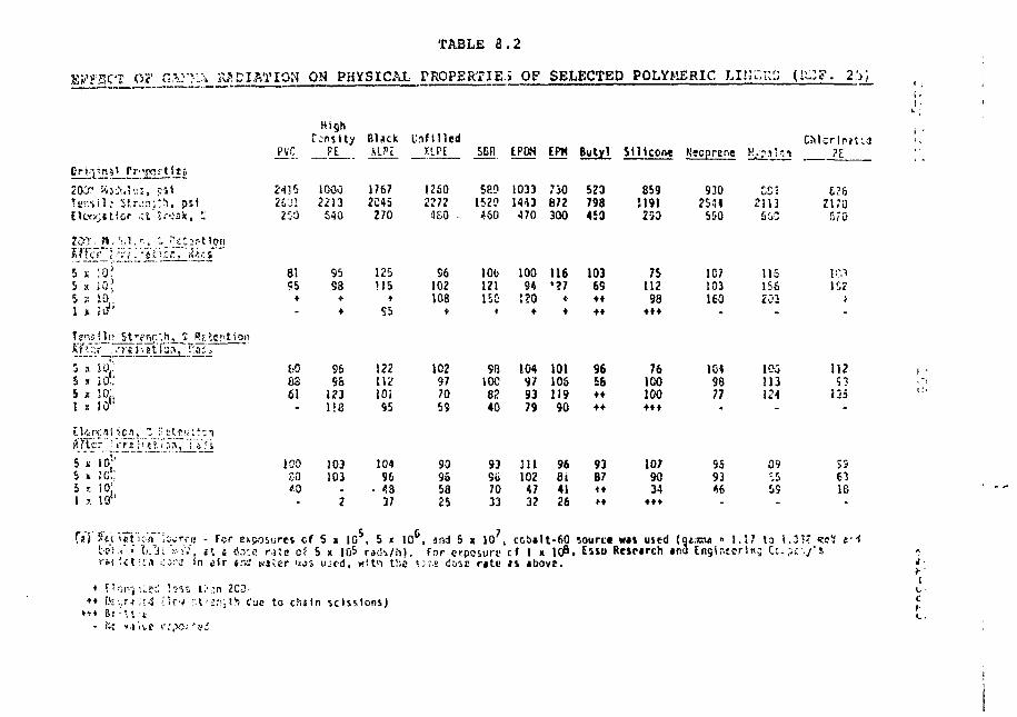
TABLE 8 . 2
EFFECT OF GA?TA_St?.EI&TION ON PHYSICAL PROPERTIED OF SELECTED POLYMERIC I'"!! (illZF. 2 !J )
200" M)J'.ii'.;i,Tsnsil.- Ur.:?.;, psf
241526 Dl200
HighTensity_ P j
10002213640
BlackXLPi
17672C45270
Infilledtin
12S02272KO •
SEII
5891520160
£PDN
10331443470
EPH
730672300
Butyl
520798450
Silicon*
859119125D
Keoprene
93025445SQ
CO 521135CC
i £
A'TTcr • Vr
5 x 10;'
s » so!:J x SO1'
2t ;o
5 s5 *5 s1 a
Ten-:
ST'."5 a5 xS J1 i;
!0
i°J10,-
;!!(? SWnr.'.h,
i ol-io,10 t !
'; ReientioiiT'ai -
8155
-
1.0&361
9598
•
9696123lie
125M5
•
S5
122IK'10195
96102103
< •
102977059
100121150<
98IOC8240
10094120•
104979379
116*?7*•
10110S11990
10369••••
9656••••
7S11298•••
76100100•••
1C7103ICO-
1049877
IIS15S203-
IK113124
1C1152>-
112S3135
1008040
103103
2
10496
• 43
37
90955825
939b7033
ill102«732
96814126
93B7
1079034
•••
959346
39-.559
5563IB
r e i ' e t i ; n \z* c f S x 1 0 , 5 * 1 0 , a n d 5 x 1 0 , c c b a l t - 6 0 s o u r c e w « l u s e d ( Q * , T C W » 1 . 1 7 t o ( . 3 ? ?5 8 E R e s e a r c h a E l l C '
i: - f o r ^ s i 10 , 5 10 , and 5 x 10 , c c b a t 6 0, i t j (Sa-.e nie of 5 x IO5 rach/h). For erposun- cf 1 x 10⁸,(n i i r «.ic W U T W S ujc-d, wit ' i t:-,e ;."s disc r*te * i *bove.
Englr.ecrlnj Cupcy's& • !
s t:\-n ZCD-U's.v,t?v Cue to chtfn scissions)
Additional infornatioi-. pertaining to the effects of
radiation en poiyncric lining nateriala revic-wad for this(56)
stu-ly includes inlocraation from Kays (1978 J and from(57)
Schlegel Lining Tochnololgy
Kavs suggests that polyrasric liners generally will absorb10
18 ergs of energy per gram of lining material before they
are destroyed. Uranium ores release relatively low amounts
of energy, in the 190 ergs per gram of lining material per
hour range. Based on the above assumptions a time to
destruction of 11,800 years is predicted
Technical information provided by Schlegel suggests that
the mechanical properties of polyethylene change at ai a
radiation dose of about 1« r?ds. For a period of 10fcO
years this would correspond to 27333 rads per day and forradiation averaging 0.5 Mev a radioactive concentration of
10•about 2 Ci/L would be required to produce a dose of 10C»7)rads . This activity is several orders of magnitude
higher than would be expected in the uranium tailings
considered in the study (se« Section 6.4).
Based on the above discussion related to the effect3 of
radiation on polymeric liners^ it would appear that the
polytaers addressed in this study and in particular HDPf:,
Hypalon, CPE, EFDM and Neoprene are reasonably resistant to
the medium t»rrr. effects of radiation {IS's of years). There
ia, liowavet, insufficient inforrc.-stian to provide even
preliminary coteraenfcs on the effects of long terra (i.e.
of ye«i:s3) exposure fco Eok
July 1934 168 841-3^15
3.3 Asphaltic Liners
8.3.3.1 General Chemical Resistance
There is significantly leas published information available
related to the geaecji.. chemical resistance of aaphaltic
membranes than for polymeric membranes. In ocder to address
general chemical resistance, reference is .nade to Section 5
cf this report. Based on information summarized in Section
5 and the anticipated uranium mill tailings environment to
which the asphaltic membrane would be exposed, the following
comments are considered applicable;
i) Asohalt in aeneral has excellent resistance
to inorganic acids.
ii) Asphalt is resistant to mineral salts and
alkalies up to concentrations of 33 per cent
in solution.
iix) Asphalt can be attacked by microbes if not
protected by biocides. fe•'••a
iv) Asphalt has poor resistance to hydrocarbons.
It is soluble in solutions of 5 per cent
hydrocarbons..-*
Ths above comments associated with the chemical resistance
of asphalt would suggest that, in general, asphalt is
resistant to the chemicals and ag&nf-.s anticipated in the
tailings environment with the exception of concentrations of
er"j. Hcwevr-r, as noted in Section 5, son>.e of the
July 19S4 169 841-31515
rubbers used in anphait/rjbber compounds tnav be susceptible(215)
to acid attack . This would appear r^t to be the case(43)
for SDR/asphalt compounds
8.3.3.2 Resistance to Uranium Tailings
The only known testing carried out to evaluate the effects
of acidic uranium tailings leachate on asphaltic membranes
has been conducted by Pacific Northwest Laboratories
(PNL). ' The nature of the simulated tailings i
leachate which had a pH of 1,5 to 2.0 is described in J-
Section 5. ]
i
An initial screening of catalytic airblown asphalt and .'
acphAih/rnHhor momhr^nes was rsrripd out in exoosure columns
dt elevated temperatures and partial oxygen pressures to ;(25) ;
simulate aging . The liners were evaluated in terms ofpermeability testing which indicated that the catalytic :
-10airblown asphalt had permeabilities ranging from 1 x 10 ,
to 1 x 10 centimetres per second. Based on these test I
cesults an anticipated field liner permeability of 7 x 10 %
centimetres oe: second was predicted. Permeabilities of 1" -8 -6 \
oetween 5 x 10 centimetres per second and 5 x 10 5
centimetres per second were measured for the asphalt/rubber j
membrane following 65 days of exposure. The relatively high j
permeability was considered to be associated with tears at |
the edge of the membrane caused by deflating the subsidence |
bladder in the column. ^Jrt
iMore detailed accelerated testing « 5 also carried out o:i 5the catalytic airblown asphalt using the simulated acidic J
leachate noted above at pK 1,5 to 2.0 • '. Tlie accelerated %
testing was carried out through the use of increased *|
1
July 19S4 170 B41-3G15
temperatures ar.c o>;yr-r»n concentrations. Theoreticalo
determinations indicated that for every increase of 10 C,
the reaction rate increased by a faccor of 2.3. The effect
of temperature increase and the increased exyjsa
concentration.-) ^ece considered to have produced an
equivalent aging effect of 7 years over a 3 month period.
Ic was aloo considered Lhat increased acidity nsd little
effect on aging. The results of the testing indicated that
during the 3 month exposure, aging reactions of the asphalt
membrane were limited to a penetration of the asphalt
surface of only 10 to 40 m which amounted to 3.1 to 8.5 per
cent of the total membrane thickness. By extrapolation, PNL
suggested the asoh«ltic membrane had a lifetime in excess of(41)
1000 years . More extensive testing would be required ho
i
8.3.3.3 Resistance to Radiation
PNL estimated the effect of gamma radiation on asphalt
liners by assuming a surface source for the tailings abo e
the liner was given by the relationship:
1/2 SV where: s = surfaca source
SV = volume source
= relaxation lengthf .1
The volume source used in the exposure calculation was
considerably higher than would b« expected frcra the uranium
tailings. The anticipated absorbed energy from gamma
radiation over a 10K0 year period was i(? rac". A. circular
sample of each of the asphalt Iinecs considered in the study ?.
(•-.:•• • ' • -
"J f
Julv l':-2< 171 R-t 1-3215
i u i r , i r r . * o i - u - . <i < r :>••» ? p o i n t s o u r c e o f c c b i i t - 6 0 w i t h 1 0 r-?<
-if. l : i o C . ' O - L - ' » , >'.'.? r .o p h v o i c i l a s U - c t . ; wc: : t i ( . ! ; > o c v e d o n t h e
1 l n e r rnati>r : .•>. t
8.4 Fjii 1 HLllJi'^-iilllisms
three major categories nH linec or dara seepage barrier
failure discussed in the following paragraphs are physical,
cherr.ical, and bioLogical.
8.4.1 Physical Failure
I)
ii)
iii)
iv)
v)
vi)
pu.,eture
tear
abras ion
cracking
over s r rossi ng
creep
Tiie first threa liy os o£ physical failures listed above are
grr/<-rally associated with installation or operational c-^age
to the liner by equipment, vandals, wildlife or piantlife.
It i.'s anticipated that caceCul base preparation, care during
installation ^nd the prevision of an a<3«=ci2ate soil cover as
discussed in Section 7 would minimize (.-.he potential for
these occurrences. Sterilization of! the subgrnde psior to
liner system installation and chemical a. physical barriers
to bur~owit>q animals and mammalc would clc;o reduce potential I
for these types of phvsical daroage. j
}
Julv I9S4
XT£
17 2 841-3015
Cracking, not associated with adverse chemical reaction or
resistance, would usually be related to climatic {notably
ozone), ultra-vioiet and temperature effects. It is
anticipated that the soil cover will reduce climatic effects
but sections of the basin liners in slopes (and dams) not
covered by substantial depths of soil or tailings would
still be subjected to thermal stresses and ffreeze-thaw
cycles possibly also aggravated by wet-dry cycles. It is
considered that all of the liners, asphalt in particular,
are susceptible to cracking due to climatic effects and
cyclic environmental loadings even when provided with
nominal soil cover.
Overstressing and creep failures would generally be related
to containment facility operation. For example, under
substantial depths of: tailings, deformations of susceptible
subgrades could occur in pcoportion to their compressibility
and the applied surcharge. Liners must be sufficiently
flexible to *cca.nnoil-jte these deformations. In addition,
whets abrupt differential or shear deformations occur under
loading due to abrupt changes in subgrade and/or basin
geometry, rapture of the liner duo to overstressiug is a
potential failure mechanism. This type of failure -mechanism
is particularly relevant for the northern Canadian
environment considered in this study where .significant
changes in bedrock surfaces occur over very short distances
and where depressions often contain peat or other highly
compressible organic material. Under these circumstances it
**ould be necy»s^cy to subexcovatc and replace tha more
compressible raateirials prior to liner installation since it
is considered that eveo flexible membranes cannot, in
gansral, withstand the larga potential strains. The ability
K -ii
r~1
.1i
F-4
m
July 1384 173 §41-3815 I
{ of the liner to tolerate these movements will be a function |
of the liner thickness ana flexibility at th2 discontinuity §
? relative to (.-.he magnitude of deformation. r,>;e to f
» resistance botwee?!. the tailings/:;oil cover/1 irser/subgrace ;|
• system it is doubtful whether significant areas of the liner J
I beyond the zones of deformation would contribute to liner |
resistance to failure through elongation. 3
ILiner materials placed on slopes and within dams would be
| subjected to shear stresses as tailings consolidate.
Similar concerns are applicable where soil cover is provided
I over a liner on an overly steep slope. Slopes must be
* designed to provide a balance bfetween shear stresses applied
r at th? •-*'1 »"""/rover/liner interface and shear resistance
I available at the liner/unJesrpad/subgrade interface toi
minimize shear failure. In a similar vein, while applied J
1 shear stresses on slopes may not reach levels required for |
shear failure, applied stresses should be suitably below
[ peak strength so that creep of the soil-liner system is
precluded. It is considered that soil-liner systems on
' slopes are susceptible to long terra creep failure under
relatively high applied shear stresses. As an additional
precaution liners should always be provided with a suitablei
underdrainage system in slopes and in dams to preclude the 1
detrimental effects of reduced effective sttess and thus I
shear resistance due to excess pore pressure development in i
the zone immediately beneath the liner. 1
Other sections of this repoct have assumed that tailings '
basin side slope? and dam membranes will be constructed at 3
horizontal to 1 vertical and that the granular iinec
underpad used for illustration purposes and cost estimates
July 19o4 174 641-3315
will provide sufficient liner stability. Hatinement of
these details due ing the design phase will require
laboratory and field tasting.
Liner overstressing .n*/ *lso occur aa a result of the jgeneration of excess hydrostatic pressure and/or, gas \
buildup. Excess hydrostatic pressure would occur where | -
local water levels are generally above the liner bottom and, ~
during operation, above the water levels within the
impounded tailings. Hydrostatic pressures would be
typically dealt with, either by installing a relatively
extensive underdrainage and pressure relief system or by
faroFni hr ot-sninn ;md <jr>h«»Hiil i ng imooundsn^nt ooeration.
This condition would be a common occurrence in northern
Canada where loc=il groundwater systems in valleys either I
correspond to the existing lake system or are above lake {'
level and would thus be above valley alluvial materials upon f
which the liner would be founded. In this case, the |r
alluvial materials would have to be satisfactorily dewatered j
to facilitate liner installation. Following installation I
and in order to avoid pressure relief sy;-t jjgs prior to f
maintaining a tailing;: liquid level equal to or higher than !
the local groundwater level, the lined tailings impoundment f
area could be flooded. •
j:Gas generation is usually associated with the degradation of -% *
organic materials such as neat left beneath the liner. In
this case an extensive under liner qas collection and venting
system similar to the pressure relive system discussed above i j
would b*» required. The alternative would be to resiove all
organic tiateci-als and to fchpn sterilise tho subgrode. In
fact, as discussed previously, it is doubtful whether a thin
July 1984 175 841-3fii.5
ij flexible mero'or-ane could be expected to perform
"* satisfactorily when placed over peat oc oti«i;C (.oppressive
•": deposits.
r5 8.4.2 Chemical Failure
yChemical failure of a liner system is very closely related
|j to liner compatibility to a waste material and would
represent an extreme case of incompatibility.
1Tji? common types of chemical failure for the liners being
R considered are:
i\ =u«ninn *nd extraction of olasticizers from
polymeric liners in the presence of waste;
ii) degradation of all liner types due to exposure ;
to ultra-violet light, oxygen, ozone an<3 heat. (
The node of chemical failure would likely be rupture due to j
embjri ttleraent/ shrinkage, loss of scrength, loss of puncture j
resistance, elongation, and/or creep and flow. !
** Tha tendency for different liner systems to degrade due to
M exposure to the elements has been reasonably well documented ;
H in publications and trade literature as aiscusseii in ,
m Sections 4 and 5. The susceptibility of the liner types to :
^ the remaining classes of chcrcicsl f?sil«re aill depend to a >
large extent on tho results of compestability testing. ;
» 19
July I9S4 17G S41-3215
A general discussion related to the compatibility of the
various li^iecs »:Lth the anticipated nature ot uranium mill
tailing* wan presented in Section 8.3.
8.4.3 Biological Failure
The Tiajor concern associated with biologic?! failure would ,
be the susceptibility of a liner system to rcicrobial attack •
where the liner is damaged and its structural integrity and '•.
seepage characteristics are affected. The plasticizers used
in some polymeric liners such as PVC are particularly
susceptible to biological attack.
" ' ' " * ' nrr\nart~i •»« nf t"h«* Y\ri 1i n Sliharadt* a s Well 3S
the waste to be contained will require investigation if
artificial liners are to be considered further. T'o-s
relative resistance of the liner systems unJet consideration
to biological attack nay be initially considered based on
the broad and very general associated information
in the lining industry literature and discussed in sections ;" \
4 and 5. f |
HBiological failure can generally be considered <»s a type of £.'.£
chemical failure due to their similarities i I iffeet on the \ M
mechanical pro.i rtie.;? of the liners. '
^•^ Mochanisms and Rat<?3 of Liner Degradation ,':. |
Lj.ner riegraclat ion, liner com^tibility, chemical failure and i.,
biolcqicil failutG are closely r«l-",ted and are difficult to ^4
separate. Linec degradatioii, as well 23 compatibility of f'~3
the liner with the contained wastes, is generally addressed p^i^ • • - ^
in terms of effect on physical properties with time. £||'
July 1384 277 841-3813
• !
Liner dag racist ion is acir ibi'Labl** to •* •io^ti ' of Kitchen i s «i?5
'•: K»ith the specific rcechani J, .1 d{?j>enu«nt c.i the typo cf l inerk l» membrane and the r inviror~ent in which i t i s pl&c»J, Some? of
t the known degrada t ion mechanisms with bciof e
jj follow:
ao Extraction of plasticizers. Some membranes
contain v-»nsidera'ole amounts of various
plasticizecs unjMcting flexibility to the
material. If the plasticizer migrates out
S of the membrane, hardening of the membrane
may occur. Some PVC compounds are notoriously
« susceotible to this mechanism.
_ o UV degradation. An exposed membrane, if not
t£ properly stabilized may be subject to the
damaging effect of the UV component of solar
y radiation. Surface cracking is a result of UV
degradation. All of the membranes would be
a susceptible to a degree but asphalt, PVC and
low density polyethylene would likely be the
ty most susceptible. Soil cover would probably
** alleviate this concern.
nE o Biological attack. Sorce components of liner
^ materials, for example plasticizers, may act *s
j| nutrients for various microorganisms. If the
liner docs not contain proper amounts of anti-
§ microbial additive, it may be subject to attack
by microorganisms. Change of colour, t'rabrittle-
B fflent and cracking may result.
J u l y 19E4 178 8-51-3G15 ii
Ozone attack. o"ne elastoicera, •.-•h ri stressed,
rac»y ix»' sabj«:oc to s':ts -A', ^y cr./i i.or.ive .t?.i o':'vn<-».
Surface cracking resul t s . Special £.Jd,.ti v--<s are
incorporate! in tne el^stotneLS to JTipi-ove ozone
resistance.
Radiation. ?olv™ieric materials aio affected by j
both charged particles and ionizing radiation. I
Irradiation causes increase of crosslink density t,
of taaterials resulting in hardening, decrease of
the ultimate elongation and, sometimes, increase
of tensile strength.
? '4
iio Stress cracking. Polyethylene when subjected to r. -
stress and certain ch-a-isical agents including fe
detergents will develop cracks. So .<* of th. j
strt-ss cracking agents will cause stress t 2C<- •.
ing when ocasent at very low concentrations. }
i -3r I
o Static and dynamic fatigue. Liner materials fwhen subjected to constant or cycling stresses s
due to soil movement or temperature changes may j, •:'
eventually fail. The failure may be by the \-
formation of major splits OK by creation of :
tnicropores and increased seepage. _ ».;".
r.-attempts at predicting rates of degradation of thin momb 1:5.0*5 r. •
liners have been approached from three directions: £,•.
i) theoretical analyses f.
ii) laboratory evaluation pJ~
iii) field testing j£
July 1584 179 841-3315
fj Tha rates of degradation of a liner material are believed tor depend on type of material, environment, stress and
>"| mechanism of degradation. Teraparaturci is considered to be
» significant in assessing degradation rates ecu polymeric and
™ asphalt tnesr.brarses. The effects of temperature are generally
y assessed utilizing the Arrhenius equation:
| dR/dt = A exp (-E/KT)
a where: - dR/dt is the change in property (eg. failure
stress) with respect to time
5 - A is a constant
- K is the gas constant
gl - T 13 absolute temperature
2 - S is activation energy
]g Similar, generalized and widely accepted relationships are
presently not available for othec factors affecting
Q degradation.
p Pacific Horthv/est Laboratories are presently undertaking
laboratory studies which include accelerated aging of
^ asphaltic and some polyroecic liners in the presence oC
E (25, 41)simulated uranium tailings . Aging is simulated by
?9 increasing temperature and partial oxygen pressure or oxygen
U content at the surface of the liner. The results of the
accelerated testin.c are used to pcedict rafces of degradation
^ <*n&, by extrapolation, line,; life. The results of these
tests have been discusse-.I e.'.sewhare In this report.
i (35, 29, 7}liatrecon has caccie-o ••••-. extensive tes t ing ot
l i n e r s raosciy in the presence or I . "<niii or hazardous waatw
leachates and often at elevated teiaj.> . aSrurea in attempts to
July 1934 18P 241-3015
predict long term performance. The resuli.3 of the.se tests
are widely published.
There1 would appear to be relatively little- published
associated with large scale field te3t programmes to
evaluate rates of liner degradation under actual field [
conditions. Some information has howevsr been obtained, \
most noteably the work carried out by the USBR at the Mt.(59)
Elbert Fotebay reservoir . A 6 by 30 metre test section
of ceinforced CPE was installed at this site in ccder to
investigate rates and mechanisms of degradation. Coupon
sampling of the test section has been carried out for three
years and is scheduled to continue for an additional 3 |jv
years. Degradation is being assessed in terms of effects on fe
physical properties. The results of the testing carried out g*
after 3 years burial are presented in Table 8.3. The most rs
significant observations made following 3 years exposure(59)
are:
i) A 9 to 15 per cent drop in Mullen
burst resistance, a measure of puncture
resistance.
ii) Ply adhesion showing strength if
CPE/Fabric/CPE bond dn
average 24.G per cent.
CPE/Fabric/CPE bond dnepped by an f
ji .
iii) Tha bonded seam shear strength arui ^
peel strength for the thermally bonded
factory seams was 22.3 to 54.5 per cent ,'
f than the original testing. ]
.7uly 1984 181 841-3815
iv) The adhesive seara peel tests shewed a
10.7 pet cent drop and adhesive seac;
shear strength dropped by an average
of 29.9 per cent.
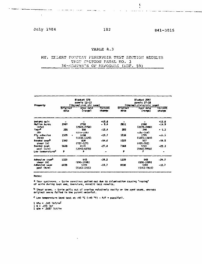
July 1934 182 841-3015
TA3LE 8.3
NT. EILERT FO.?J?EAV RESERVOIR TSST SECTIOK RESULTS1T.QT r^CTIOU PAMBL KO. 3
36~.fc:oKT;t?' s c r FIXPOSURS ( K S F . 59)
f ram tf
it»iiT»er*
IK)Pty *»«*««»
ftoatfstf ttntPfk«*r in)
BQ»4*4 sseaf*»l (K/'a)
lov tMBerjtur**-
Mhnln tatafrtS*tr (8)
*«Mr«f»* *•»»p » l (N/M)
dJtU
» * 7
355
IKS
134?
S6sa
p
1333
603S
•l«Pk«t I/Opmli 12-11
77M
300
• !i!S(1133-1225)
£0*[587-S271
*15D(39SJ-4270)
949r£90*!0?9)
5393(5163-SJISI
•»)PercentCllMM
: " : J-15.4
-1S.7
-w.e-J7.4
-
-a.i
-10.7
(thtn
****
an
asISSJ
lizs7368
P
133t
6038
ptMlf 27-21
Z3W
irre(UZ5-13SS)
557
f«as-5«i57Z3
15*40-5150)F
<W3I690-10W)
53*0<$!6J-5*1S»
x)
:" : *»
• S.3
-rt.S-S4.S
-K.3-
-10.7
not*>:
* t»trof tcrib Stetr
t . - Scrio 5'v«?ttA¥-; pa)1*4 aqt du« to&<r1i>j t « t M , th*mf»r«, »rr*tf£ tffSt rewilts.
cst ofpH N I fai1*4 <n t9
e Lett tnperttur* txtm) t« l t «t - * ) *C l-*Q *Fl - r/F • p i l l / f l i t .
1 » - .Z25 lDfI K/ii • .0057 16f/f*

<•*»•• • « - — _ . . ___
f July 1984 183 841-30153
i
, "" For the Mt. Elbert Forebay liner the major cause of drop in
• '"j ohear strength was water absorption of the CPE and as a
; '•* result the scrin-CPS bond within the CPE had deteriorated
j „ and was reflected in loss of mechanical propecties. Gas
: tj chromatography and mass spectrometry testing o£ the CPE
: following 36 months of exposure also indicated that some
! fji subtle changes in the CPE had occurred. These subtle
! changes were likely related to degradation of the polyir.er
a and/or effects of water absorption.
Considering the above discussion it is seen that research
both in the laboratory and in the field is being carried out
which addresses rate of linsr degradation. There is,
however, at this timf insufficient information available to
allow estimates of actual rates of > iner degradation in most
wastes, including uranium tailings leachate. However, most
of the flexible liners considered show reasonable cesistance
to degradation in anticipated uranium tailings environment
at least during periods of tir>e measured in 10' s of years.
Little can be concluded in terms of periods measured in
100"s of yeirs. The exceptions and concerns would include:
i) The apparent negative effects of acids on
Butyl and polyurethane.
ii) The PNL teat results which show simulated
leachate affected PVC and asphalt/rubber
ccmoounds.
July 1984 184 841-3015
iii) The poorer performance of PVC and Butyl v/hen
subjected to high levels of gairw.a cv'S "..'i; Loii,
i.v) The apparanfcly significant effects tf water
absorption by CPE on some physical properties
and in particular the scrim-CPE bond at the
Mt. Elbett test section.
July 19SM 185 841-3015
9• REStJLT." OF IMPUS7RY SURVEY
During earlier evaluation studies carried out for t'ne liner
industry a detailed list of producers, manufacturers,(66)
fabricators and installation contractors was prepared .
The list is included with this report as Appendix C. It
should be noted that this list was compiled in 1981 and is
not entirely current. Specific changes of which we are
aware are as follows:
i) Gundle Plastics, Inc., Dallas changed to
Gundle Lining Systems Inc*
vjuuui.6 KO&U
1340 East Richey Road ' -.
Houston, Texas
77373
ii) Gundle Lining Systems Ltd.
301-255 1st Street West
North Vancouver, British Columbia
V7M 3G8
iii) Synflex Industries, Inc., Vancouver
are no longer in business.
Or, the basis of &ppcn<3ix Ct a number of companies were
c ...'aoted by telephone and in writing and were requested to
:". in for nation package on iicec products. The
q w .; o^.--^ted to a total of IS companies as
identified in Appendix D-l. To date 5 of these companies
have responded and a summary of the information provided is
included in Appendix D-2.
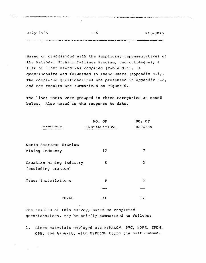
July 1S84 186 84.V-3S15
Based on discussions with the suppliers, representatives o£
the National i;r.anii:rn Tailings Program, and colleagues, a
list of liner users was compiled (Table 9.1). A
questionnaire was forwarded to these users (Appendix E-l).
The completed questionnaires are presented in Appendix E-2,
and the results are summarized on Figure 6.
The liner users were grouped in three categories as noted
below. Also noteC is the response to date.
NO. OF NO. OF
INSTALLATION'S REPLIES
North American Uranium
Mining Industry 17 7
Canadian Mining Industry 8 5
{excluding uranium)
Othar Installations 9 5
TOTAL 34 17
The results of this survey, based on
quest-.ionr>?.iros, r ay be briefly suntnariced as follows:
1. Liner materials employed ace HiPALON, PVC, HOPE, EPDrt,
CPE/ and Asphalt, with HVPALOM being the most enm

July 1934 187 841-3B15
2. The largest single installation is f.t^ Elbert Forebay,
Twin Lakes, Colorado where more than 1 million square
iretres of CPE was installed.
3. All installations are reported to be operating
successfully. It should also be noted, however, that
most of the liners have only been installed within
the last 5 years.
4. While many of the installations have monitoring
systems in place, sufficiently detailed information
to derive liner defects and release rates either does
r.a* o»io(- or hxsi not boon prnui I1CK3 with
5. The most frequently mentioned problems relate tn
installation fiiffioulties due to wind, rain, and
cold temperatures.
6. There is no reported indication of chemical
incompatibility between the liner and the waste.
Wo do not regard our survey of users as being statistically
representative to a significant confidence level. The
number of installations surveyed is small and to date only
half of them have replieJ. Furthermore, the majority of the
installations surveyed have been identified by the liner
suppliers; it is reasonable that they would direct us to
successes rather than failure1?. Finally, as has been
oar lice noted, most cf the case histories aro less than 5
years old; that is not « sufficient life span to start
projecting 10(38 year
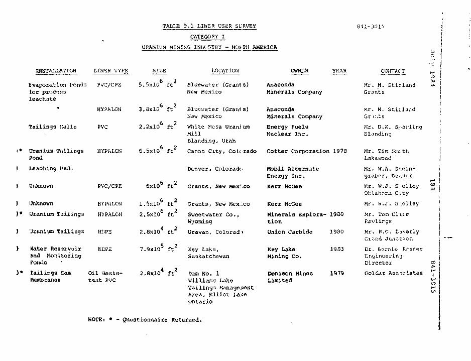
TABLE 9.1 LINER USER SURVEY O-U-JJOlb
CATEGORY I
URANIUM MINING INDUSTRY - NO? TH AMERICA
INSTALLATION LIH^B TYPE SIZE IOCATICW OWNER YEAR
Evaporation Ponds PtfC/CPSlor procss.sleachate
Tailings Calls
i* UraiUura Tai l ingsPond
t Leaching Pad-
( Unknown
HYPALQM
PVC
HYPALON
PVC/CPF.
) Unknown BYPALON
)* Uranium Ta i l i ngs HiPALON
) Jranium Ta i l i ngs HDP3
) Water Reservoir KDPEand Word t o z i n gPonfis
.)* Tail ings Paai Oil i les is -Harabranes ta.i t PVC
5.5x10 ft Bluewat-.er (Grants)New Mexico
6 23.8x.lO ft Bluewater (Grants)
N'aw Mexico
2.2x10 ft White Mesa UraniumMillBlar.ding, Utah
6.5x10 ft Canon City, CoU-rado
Denver, Colorado
6x10 ft Grants, New Mex:.co
ft Grants, New Hex.'.co
2.5x10 ft Sweetvater Co.,Wyoming
2.8x10 ft Uravan, Colored>
7.9xlO5 f t 2 Key Lake,Saskatchewan
2.8xl0 4 f t 2 Dam No. 1Wi l l i am LakeTai l ings Manage,i*antArea, E l l i o t LateOntario
AnacondaMinerals Company
AnacondaMinerals Cotrpany
Energy FuelsNuclear Inc.
Cotter Corporation 1978
Mobil AlternateEnergy Inc.
Kerr McGee
Kerr McG6e
Minerals Explora- 19S0tion
Union Carbide 19B0
Key Lake 19S3Mining Co.
Denison Mines 1979Limited
COtiTACT
Mr. M. Stirlai-.dGrants
Kr. M. S t t i l a adGr t:;tsKr. D.K. Sj-arlingBl^ndin:;
Mr. Tim Sat.thVakcwcod
Kr. W..\. Sv.Gln-grat-er, Oeiivr.r
Kr. W.J. S'.clloyOklahn-a City
Mr. H.J. S ;clley
Mr. Ton Clir.c
COO3
Kr. R.O. EavarlyGi.-.r.d Junction
Di. Bsrnie f--.-sr.er
Director
Gcldar Asociatca I
O
KOTE: * - Quastionnaire Returned.
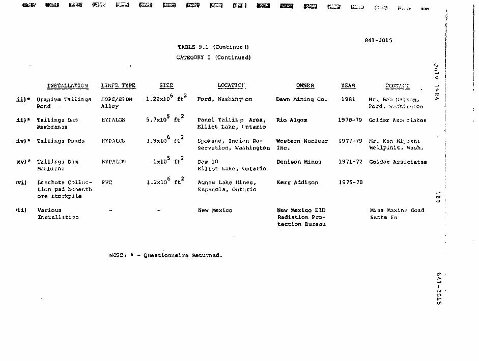
mm
TABLE 9.1 (Continue!)
CATEGORY I (Continued)
041-3015
* !
INSTALLATION LIKFR TYPE SIZE LOCATIOI OWNER YEAH
6 O
i i ) * Ur«niiiaTai.lir,ga K0PS/2f'DM 1.22x10 ft Ford, Washing on Dawn Mining Co. 1981 Kr.. Bob Kelson,Pond • Alloy
i i ) * Tailings D.vra HYIALON
J.v)* T a i U n g 3 Ponds
x v ) * T a i l i n g s D.im KVPALCt)
rvi) Lcachata Coll«c- FVCtion pa3 b-iief.thore fitoc
fii) Various
5.7xlO5 ft Panel Tailing! Area, Rio AlgomElliot Lake, Ontario
a.
Ford, w.ishiivjton
1978-79 Goldar Rs-< ciatoa
6 23.9x10 ft Spokane, Indian Be- Western Nuclear 1977-79 Mr. ton Ki;oshi
ixlO5 ft2 Dam 10
servation, Washington Inc. Kellpinit , Wash.
Denison Mines 1971-72 Goldor A3sociatosEll iot Lake, Ontario
Acjnew LaXe nines,Espanola, Ont-:irio
1.2x10 ft Acjnew LaXe nines, Kerr Addison 1S75-78
New Mexico Mew Mexico EIORadiation Pro-tection Bureau
on
MIBS Kaxinj GoadStnte Fe
HOTS: * - Questionnaire Returned.
i
o
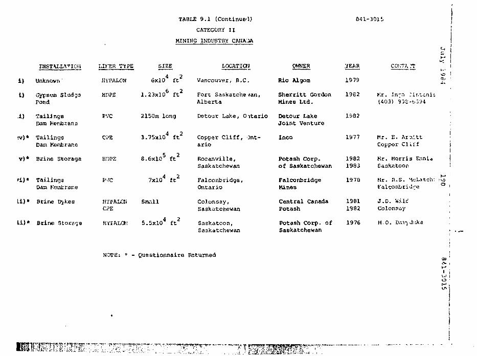
TABLE 9 . 1 ( C o n t i n u e d )
CATEGORY I I
MINING INDUSTRY CAI1AJA
641-301S
i )
t)
i )
rv)*
V ) *
* ) .
1 1 1 "
Li)*
T-NSTVLLVION
Unknown
Gyp&uoi SludgaPond
failingsDam Kembxana
TailingsDam Manfcranc
Brine Storage
TailingsDdsa Kosairsrie
Brine Dikes
Brine Storage
LIKSR TYPE
Hi'PALOM
HDP2
PVC
Ci'E
KDP2
PVC
H'/FALCKCi?E
HVFALOM
SIZE
6xlO4 f t 2
1.23X10⁶ f t 2
2150m long
3.75xl04 f t2
8.6xlQ5 ft2
7xlO4 ft2
Small
5.5xl04 ft2
LOCATiaj
Vancouver, B.C.
Fort Saskatchewan,Alberta
Datour Lake, Oitario
Copper Cliff, Ont-ario
Rocanvilla,Saskatchewan
Falconbridga,Cfritario
Colonsay,Saskatchewan
Saskatoon,Saskatchewan
OWNER
Rio Algom
Sherritt GordonMines Ltd.
Detour LakeJoint Venture
Inco
Potash Corp.of Saskatchewan
FalconbridgeMines
Central CanadaPotash
Potash Corp. ofSaskatchewan
YEAR
1979
1962
1902
1977
19821993
1970
19811992
1976
cctrr;, rr
Kr. In^o ^Ir.txnls(403) 9»S-t.3'i4
Mr. E. Ar;v'.ttCoppor Cliff
Mr. Morris EnniaEaskatooc
Mr. R . S . "SoLatch:
J.D. 'wileColonaay
H O . Dr»\T J:iKe
Ju
ly ;
o !a . •
i
°!
HOI'S: * - Questionnaire Returned a.. '
• i
O 't-*,in
" ' • / ^ " . T ^ 1 ^ r iT"-
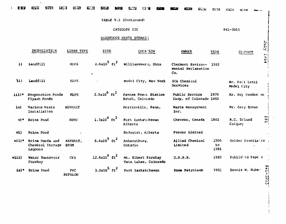
i c o ma: ESSJ $ac:3 ESS ETJS EJ&3 si&a
INSTALIATICN LINER TYPE
TABLE 9.1 (Continued)
CATEGORY III
HAZAP-'XWS KASTE STORAG
SIZE LOCA ?ION
841-3015
OWNER YEAR CONTACT
Ju
i) Landfill HDPS 2.6xlO5 ft2 Williemaburj, Ohio Clennont Environ- 1932mental ReclamationCo.
Landfill HOPS
iii)* Evaporation Fondg HDPSFlya3h Ponds
iv) Various Waste ASPHALTInetsJ.lation
v)* Brina Pond HDPf.
vi) Brine Por>d
vii)* Brina Ponds and ASPHALT,Chemical Storage E'PDHLagooin
viii) Water ReservoirForebfly
ix)* Brino Pond
CPS
PVCHyPALGtJ
Modol City, New York
2.9x10 ft Pawnee Powni StationBrush, Coloiddo
Hcrrisvillc, Perm.
4 21.3x10 ft Fort Saskatchewan
AXberta
Rodwater, Alberta
5 26.6x10 ft Amherstburq,
Ontario
12.6x10 ft Kt. Elbert rorobayTwin Lakes, Colorado
3.2xlO5 ft2 Fort Saskatchewan
SCA ChemicalServices
Public Service 1979Corp. of Colorado 19SO
Waste ManagsirentInc.
Chevron, Canada 1932
Procor Limited
Allied ChemicalLimited
U.S.B.R.
Dome Petroleum
1966to1981
Mr. Pad LatkiHodel City
Kr. Poy Henderson
Mr. Gaty Brown
R.C« Ec'lundCalgary
Hil
Colder As.<»ocia .58 »
I960 Publia! sd Pepe a
1981 Dennis W. Hube-- £in
Ji'.iy 1984 192 841-3315
10. RELEASE HECHAUISMS AND RATES
10.1 Release ttschaninrns
The mechanisms by which contaminant Clow and seepage occurs
through thin flexible polymeric and asphaltic membranes are:
i) Fluid passage through the intact membrane
by diffusion under vapour pressure differ-
ential, osmosis due to chemical gradients,
and absorption due to polymer and asphalt, u.,. (14, 60)
solubility.
ii) Fluid flow through defects including pifjholes,
punctures, tears, poor seams, or otherwise
damaged portions of the liner.
Mechanism ii) above is the most significant in terms of
liner field performance and seepage quantity. It is also
very difficult to quantify.
Similarly, predicting flow through intact linar materials
(release mechanism i) is also difficult to quantify. The
resistance of a geomembrane to fluid flow is typically
discussed in terms of hydraulic conductivity or pemeability.
The mschanism by which fluids pass through membranes is
different from the mechanism by which fluids pass through
soils and Darcy's law does not generally apply. Further.,
the hydraulic conductivity of small laboratory specimens
cannot be measured . Values for liner psrmeabilxcy
quoted in the literature are generally based on perm rating
or the amount of water vapour that passes through cne lining
July 1984 ' 193 841-3015
under a vapour pressure differential at constant
temperature. Permeability basod on a conversion from perm(14)
rating is not strictly correct
It is convenient to evaluate permeability of geomembranes
using coefficients originally defined for soils. Further,
apparent field or global hydraulic conductivity which
includes the effects of defects is considered to be a
reasonably valid concept. For a given hydraulic head, a
given liner thickness and area, and a known seepage quantity
over a period of time, the flow through tha liner can be
described in terras of coefficient of permeability or
hydraulic conductivity with units of length per unit time.
To remain consistent, for discussion purposes, the term
tjeirmeaL/ili <_ will be uaeo to aescriDe cne rate at which
seepage occurs through the liner.
The equivalent permeability of an intact polymeric or
asphaltic liner, accurately determined, would be extremely
low; probably lower than 10 centimetres per second for-10
most polymerics and lower than 18 centimetres per second
for asphaltic liners. Where permeabilities for polymerics-9
as high as 10 centimetres per second and for asphalt as
high as IB centimetres per second are quoted in the
literature it is likely that these values either represent
flaws in sample, leak?of? in the test apparatus or an attempt
by the author to predict field or apparent liner
permeability.
IP.? Release P.atas
Estimates of i«)«»;»««» r«*7 s or ths gusntity cf seepage which
flow3 through a lin«c may be mad« using generally accepted
July 1984 194 8*1-3815
flow equations. Information required includes knowledge of
the global or apparent permeability of the installed liner
and the hydiogeology of the impoundment site.
As noted ths permeability of the liner is largely dependent
on the type and density of liner defects and consequently,
is specific to liner, installer and site. If a perfect
liner system without defects were possible then seepage
quantities based on hydraulic conductivities in the order of-12 -10
10 and 10 centimetres per second or lower for
polymeric and asphaltic liners, respectively, could be
expected. It is not reasonable, however, to assume that
over large areas of liner installation (tens of hectares) a
perfect liner could be constructed. Nevertheless,
occurrence of defects ca« hs greatly reduced Dy carefully
following construction procedures outlined in Section 7,
since most serious defects occur during installation and go
undetected. It is also known that some liners by their
nature would tend to have more flaws than others,
sprayed-on asphalt liners for example are susceptible to
variable rates of application and discontinuities and for
single applications relatively higher field permeabilities
would be anticipated. Polymeric liners because they are
manufactured are of generally uniform thickness but are
susceptible to field seam flaws due to the great lengths of
seams required. Inspections and testing during
installation is, however, more readily .carried out for
polymeric liners and for this reason it should ba possible
to construct a relatively intact polymeric liner.
A rational approach to evaluating apparent or field liner
y*sLitnstxlji 1 i ties is through detailed monitor in 7 of existing
installations and back calculating apparent permeabilities
July 1984 195 841-3015
H based on measured seepage volumes, known hydraulic heads,J liner thicknesses and liner areas. In this way the - CCf-cts
••-? of both the waste on the liner and liner defects can be
iJ evaluated. Relatively small scale laboratory testing would
,_ typically only evaluate the effect of the leachate on liner
i4 permeability usually due to swelling. For the purpose of
this study an attempt was made to collect this type ofS3
m information in order to evaluate field permeabilities.
However, as noted in Section 9 and Appendix E insufficient
§ information was collected. This is a promising approach and
is worth pursuing in more detail.
"* In order to estimate seepage losses from uranium tailings
n impoundment sites for the purpose of this study it will be
u£ necessary to rely on published information for liner
permeability and to attempt a rational increase in the value
h to account for unavoidable flaws. Consideration is also
given to field hydraulic conductivities reported byB? (14, 60)ri others . For a polymeric liner with a defect free& -12
equivalent permeability of I x 10 centimetres per second,
p it is considered reasonable to assume that installed
permeability should not be significantly higher than 1 x-IB
m 19 centimetres per second assuming that the liner hasU been properly selected, designed, installed and inspected. A
«-, similar estimation for installed permeability of asphalt is
iji mote difficult. An installed permeability of 1 x 10
centimetres per second has been selected for asphalt for
|* purposes of analysis and to demonstrate the rolat'vn effects
of liner psrrseability ors release rates.
Site hydrogeolcgy is significant in that it will dictate the
55 nature and rate of seepage flow and ccntcminant transport
® from the underside of liner to the groundwater system. Flow
July 1984 196 841-3015
models which consider the nature of flow beneath tailings
impoundments «nd take into account criteria such as
unajiturated flow, movement of the wetting front, position of
the phreatic surface, and saturated flow following(61)
groundwater mounding have been presented by others
10.3 Elliot Lake
For the typical Elliot Lake sites described in Sections 6
and 11 and shown on Figures 7 to 10, it is anticipated that
significant hydrogeological and topographical conditions may
be summarized as follows:
i) Groundwater levels in topographical lows would
typically correspond to p^r^d ox lake levels-
ii) Groundwater levels in adjacent valley walls
would typically correspond to or be above lake
level.
iii) The soil immediately underlying the liners would
typically have permeabilities at least 4 orders
of magnitude (10,000 times) higher than tha liner
thus allowing the assumption that steady state
flow conditions prevail.
iv) Maximum height of tailings (and pore fluid) is
22 metres; average height is 11 metres.
6v) Araa of tailings basin 232 hectares (2.32 x 13
ffi )
July 1984 137 841-3815
p
vi) Representative permeability of tailings
'"• 1 x 13 centimetres per second.
p» vii) Tailings would be located in a recharge area
tJ with water levels typically 11 metres above
~ the base of the basin liner (see Section 6)
H and 11 metres belo-. the tailings surface.
5 Based on the results of the analyses presented or. figure 12
the following comments may be made:
§i) Seepage frcr.: an uniined basin is computed
IS to be 232 litres per second. Mora rigorous6 analyses for actual tailings b»sms
pj have indicated substrntially lower
U seepage volumes due to more favourable
hydrogeologi'Tal conditions than those assumed
H for the model. This numer is Celt to be
significant, not in absolute terms, but in
|! evaluating tha effect of liners on seepage
reduction.
S** ii) Based on conditions shown on Figure 12 an
asphalt membrane 8 millimetres (315 mils)
thick would reduce seepaga from the impound-
m'»nt by about 40 per cent from'the condition
where no liner is present beriuath the tailings.
iii) k pojyp-'jcic icQBibrane 1.5 millimetres (60 mils)
thick would reduce- seepage from the itspound-
kavrHw ujr luCCe t i tc in jv p £ r C£iT*t f«TC«u t«»G
condition where no liner is present.
ff
Tuly 1934 198 841-3215
IS.4 Southeastern Athabasca
The typical southeastern Athabasca site is described in
Sections 6 and 11. The anticipated significant
hydrogeological an£ topographical conditions may be
summarized as follows:
(i) Groundwater levels near ground surface.
(ii) Steady state flow conditions.
(iii) Average thickness of tailings (and pore
fluid) is 4.5 metres.
(iv) Area of tailings basin 36 hectares
(0.36 x 18 square metres).
(v) Representative permeability of tailings'
1 x 13 centimetres per second.
(vi) Tailings would be in a recharge area
with water levels typically below the
base of the tailings basin.
Based on the results of the analyses presented or. Figure 13,
the following comments may be rnad.e:
i) Seepage from an unlined basin is
computed to bs 36 litres pec
v i i On COiavJ i c A O M S ShGWH Oi> ITl^UCO +* 3?On COiavJ i c A O
asphalt membrane 8 millimetres (315 mils)
* •
u
- July 1984 199 841-3015
thick would reduce seepage from the impound-
inent by about 68 per crerit from the condition
where no liner is present beneath the tailings.
iii) A polymeric membrane 1,3 millimetres (60 mils)
rhick would reduce seepage from the impound-
ment by more than 9b per cent from the
condition where no liner is present.
I
!
r?
sis
p<
July 1984 200 841-3G15
11. LINKR COS'i'S
ii.l Elliot Lake
11.1.1 Generalf '• '.
I:
Consistent with the terms of reference, liner and related
costs have been estimated for the containment of 20 years of
uranium wastes. The costs are based on producing 2.27
million kilograms (5 million pounds} of I) o . Assuming a
low grade mineralogy (0.1 per cent of U 0 ), similar to3 8
Elliot Lake, the 20 year operation would produce 37 millionrnbic mpt-r^s of tai lings. ti-.v
Tha Quirke tailings basin of Elliot Lake has been chofen as j
typicai for this study and is outlined on Figure 7. Total ! •;
area of this basin is 2.32 million square metres. Costing i; '.¥•'•'•£
is based on draining the laKe, constructing dams as £"v=
indicated on Figure 7, and filling the basin to a maximum pj^
depth of about 22 metres and an average depth of about 11
metres over the 28 year project life. '*
Only the rrajor components of cost have been included in this
analysis. While the unit prices used are based en ongoing
experience in Elliot L3.kfi, they may be neither accurate or
current. Accordingly, the total tailings management coats
arc approximate and shoold be used for conceptual evaluation £.-:|
only. ,(\f
July 1984 201 341-3015
il11.1.2 DEdinaye
*~ The lake will regoire drainage. Approximately half the
f? total area occupied by the tailings basin shown on Figure 7
** is assumed to be occupied by lake and average lake depth is
„ estimated to be 2.5 metres. Based on dewatering at the rate
H of 300 litres per second (5080 g.p.ro.), a 3 month dewatering
period is anticipated at a cost of $270,000.
11.1.3 Site Preparation
ESite preparation will include clearing, grubbing.
If subexcavation, rock excavation and site grading as described
* below.
i As noted, half the area is assumed to be pond so the other
half will require clearing and grubbing. At $4,000 per
j£ hectare the cost is $460,($&0.
at
§ Subexcavation is based on removing and disposing of 1 metre
of lake sediments and organic soil over the entire pond
ff area. Elsewhere it is assumed that only 150 millimetres of
Isubexcavation is required.
Ia Total perimeter ot nfte tailings area is 8.3 kilometres and- rock excavation is .•.•iticipated (to obtain 3:1 slopes) over^ !
i. about 10 per cent of the lenuth. Furthermore, in the areas
of rock excavation, 380 cubic metres per linoal metre is j
| anticipated (Figures 8 and 9). Accordingly the total j
quantity of rock excavation is 249,000 cubic metres.
July 1S84 202
The final item of site preparation is site grading to
prepare a reasonably 33.00th and planar surfaco on which to
install a membrane. This will conai3t of removing
asperities and for the purpose of this computation we have
assumed 150 millimetres (cut or fill) over the entire ar^a
outside of the pend,
11.1.4 Dams
The locations where dams are required is shewn on Figure 7
and a total length of 3320 metres is indicated, h typical
dam section (for costing purposes) is shown on Figure 10.
Based on this section we have estimated the material
requirements as 43 per cent select granular and 63 per cent
inexpensive cote material.
11.1.5 Liners
Polymeric Membranes
Only limited response to the survey of suppliers was
obtained. The information pertaining to costs is summarised
on Figure 11. Also shown is information collected by Golder(66)
Associates in 1981 together with information published(63)
by Schmidt in 198 3 . Suggested ranges for installed
current costs of four of the more widely used polymeric
membranes are indicated. As reight be expected, prices for
the four classes of material shown vary linearly with
thickness of material.

Julv 1984 283 841-3015
Asphaitic Liners
Current costs were not obtained. Figures reported by Golder(66)
Associates in 1901 and Pacific Northwest Laboratories in(41)
1983 are noted below.
TYPEAPPLICATION INSTALLED INFORMATION
RATE COST SOURCE
(litres/m2) ($/n2)
Catalytic airblown 5.5 to 8 4.80 - 6.90 Golder 1931
asphalt
(66)
Catalytic airblown
asphalt
Asphalt - rubber 5.4
3.30
3.10
PNL 1983
PNL 1983
(41)
(41)
11.1.6 Soil Cover
Soil cover is necessary for some liners and desirable for
all. Similarly, prepared soil bedding is desirable. The
costs are based on providing 30£ millimetres of sand above
and below the liner (a total of 600 railliim-tres).
July 1984 204 841-3215
11.2 5out!ig»fi''<*':r> ftH-.;*h?r>ca
11.2.1 General
(67)Various documents, including the Kilborn/Meli3 report ,
indicate a Key Lake tailings basin in an area of low relief
and measuring about 653 metres square. This study assumes
that such a basin would be built using ring dykes
constructed from material excavated from the pond interior.
The high grade ore in Southeastern Athabasca (2.5 per cent
0 0 ) would yield only 4 per cent of the tailings generated3 8by Elliot Lake. Over a 20 year life 1.5 million cubicmetres of tailings would be generated. For the ib?«e noted
area, dykes of 6.5 metres would be sufficient to contain the
tailings and provide 2 metres free board. Optimization
studies would be required to determine the most economical
area of basin and height of dykes.
(67)The Kilborn/Kelis report notes Saskatchewan and Elliot
Lake 1384 labour rates to be $50 per hour and $35 per hour,
respectively. Thsse relative rstes have b«>er» used to derive
unit cost3 for Saskatchewan. The unit costs in Table 11.1
(Elliot Lake) have-bean increased by fciie ration 59:35 to
determine the unit costs in Table 11.2 (Southeastern
Athabasca).
July 1984 2»5 841-3015
11.2.2 Sits Preparation
Site preparation will include clearing, grubbing,
subexcavation and site grading in a siailar manner to that
discussed for Elliot Lake. It is? however, assumed that
there will be no requirement for pond drainage or rock
excavation,
11.2.3 Darns
It is assumed that an area measuring 650 metres will be
surrounded by ring dykes/dams. These dykes will be of
similar proportions to the dam section shown on Figure 10
but they will be much w.dler. The dykes will have 2:1 and
3:1 outside and inside slopes, respectively and will have a
maximum heignt of 6.5 metres from crest to pond bottom.
11.2.4 Liners
Based on information from various suppliers, it is
anticipated that the installed cost of polymeric liners in
Southeastern Athabasca would be about $1.00 per square metre
greater than those shown on Figure 11. This increase is
incorporated into Table 11.2 together v;ith a similar
increase for asphalt.
11.2.5 Soil Cover .
The cost estimate assumes 302 millimetres of soil bedding
and cover, below and above the lining.
J u l y 1984 28G £41-3015
11 .3 S mania r y '
The liner co3ts are summarized in Tables 11.1 and 11.2.
While costa are large ($15 million to $29 million for the
Elliot Lake and $3 million to $6 million for Southeastern
Athabasca) for the three candidate liners noted, they are
overshadowed by the coat of the related liner works. For
example, wit*. 36 mil reinforced Hypalon, total facility coat
is $61 uillion for Elliot Lake and $15 million for
Southeastern Athabasca; less than 30 per cent of that cost
is for supply and installation of the Hypalon. Similarly,
based on the rests noted, asphalt represents just over 20
per cent of a total cost of $71 million for Elliot Lake and
$14 million for Southeastern Athabasca. Similarly, KDPE
represents less than 35 per cent of total costs of $89
million and $17 million for Elliot Lake and Southeastern
Athabasca, reapecti'r^ly.
The terms of reference indicate a 20 year production of U o3 3
of 45,000 tonnes. Referring to Table 11.1, the coat of
tailings containment per tonne for the lining materials
noted would range from $16B0 to $2000 pe.-r tonne for Elliot
Lake. Corresponding costs for the higher grade ore in
Southeastern Athabasca are Ie3s than $403 par tonne.
Finally, it 3hould not be inferred that the three msrabrane
materials chosen for costing are totally equivalent to each
other with respect to performance, durability, etc. The
relative merits of these materials are discussed in other
sections of this report.
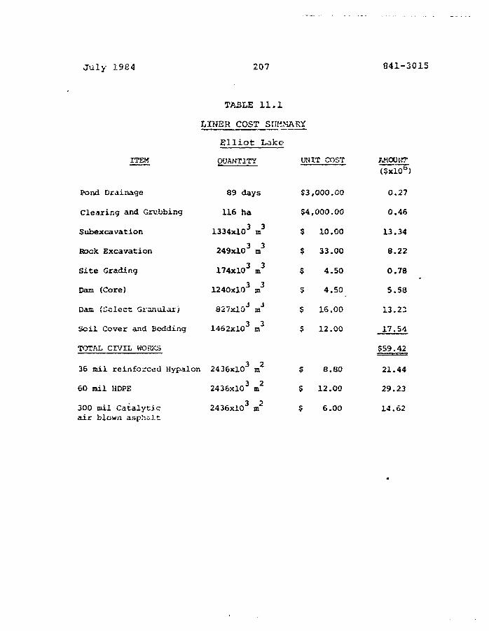
July 1984 207 841-3015
TA3LE 11.1
LINER COST SUMMARY
ITEM
Pond Dra inage
Clearing and Grubbing
Subexcavation
Rock Excavation
Si te Grading
Dam (Core)
Dam (Select Granular)
S o i l Cover and Bedding
TOTAL CIVIL KORXS
36 mil reinforced Hypalon
60 mil HDPE
300 mil Cata ly t i ca i r blown asphalt
Elliot Lake
QUANTITY
89 days
116 ha
1334xl03 m3
249xlO3 m3
174xl03 m3
1240xl03 m3
827xlOJ m"5
1462X103 m3
2436X103 m2
2436X103 m2
2436xlO3 m2
UNIT COST
$ 3 ,
54,
$
$
5
?
$
?
$
s
,000.00
,000.00
10.00
33.00
4.50
4.50
16.00
12.00
8.80
12.00
6.00
AMOUNT
0.27
0.46
13.34
8.22
0.78
5.58
13.23
17.54
$59.42
21.44
29.23
14.62
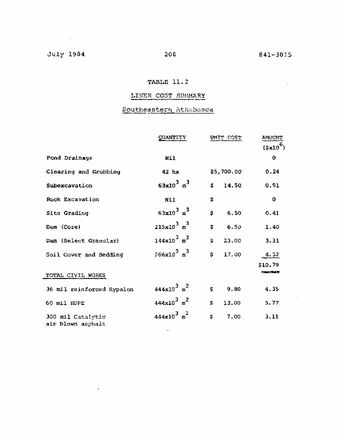
July 19S4 208 841-3015
TABLE 11 .2
LINER COST SUMMARY
Southeastern Atha
Pond Drainage
Clearing and Grubbing
Subexcavation
Rock Excavation
Site Grading
Dam (Core)
Dam (Select Granular)
Soil Cover and Bedding
TOTAL CIVIL WORKS
36 mil reinforced Kypalon
60 mi l HDPE
300 mil Catalytic
QUANTITY
N i l
42 ha
63xlO3 n 3
N i l
63xlO3 m3
215xlO3 a 3
144xl03 m3
566xl03 m3
444xlO3 xa2
444xlO3 m2
444xlO3 m2
baaca
UNIT COST
$5
s
$$
s
$
$
$
S
$
,700.00
14.50
6.50
6.50
23.00
17,00
9.80
13.00
7.00
AMOUNT
(5xl06)
0
0.24
o.si
0
0.41
1.40
3.31
4.52
510.79SKsn
4.35
5.77
3.11air blown asphalt

July 1984 209 841-3015
1 2 •
12.1 Polyn?ric Li.ng.gg
Most polymaric liner manufacturcsrs and fabricators have
standard warranty forms, examples of which are included in
Appendix E. In the past the typical warranty period has
been 20 years while current practice indicates shorter
warranties. However, manufacturers indicate flexibility in
negotiating special warranties for specific projects and
applications.
The actual terms of the standard warranties and the extent
of iiaDincy or cne manuracturers ana isoncacors are
generally uniform. Based on current submissions, as well as
a survey conducted in 1981, the following main clauses are
noted;
i) Material
The supplier warrants that the material supplied to be free
of any defects in materials and/or workmanship at the time
of sale. For this clause to be enforced it must be
demonstrated to the supplier's satisfaction that the defect
was present at the time of insta1lation.
In some caaaa the supplier also warrants that tha material
sold will meet or exceed the published ot agreed
specifications for the material.
July 1984 210 841-3015
i i)
The supplier warrants that the liner as supplied will have a
useful life from 'cha date of sale for a period of 29 years
(typical) under the normal uses and service for which it is
designed in any customary weather which may be encountered
and which is not customarily considered to be in the nature
of an act of God, casualty or catastrophe such as (but not
limited to) earthquake, flood, piercing hail, tornado, etc.
Normal use and service excludes among other things the
exposure of the liner to harmful chemicals, mechanical abuse
by machinery, equipment or people, or excessive pressures or
stresses from any source.
The supplier generally requires approval of the liner
design, the intended use and the nature of the stored
materials. Any substantial change in use or operation of
the containment facility without prior agreement with the
supplier would invalidate the terms of the warranty.
The warranty of one manufacturer requires that the liner be
covered with earth at all times and also requires the
maximum temperature and pH range of the stored material to
be specified in advance.
iii) Installation
A separate installation/workmanship warranty is also often
provided by the installing contractor. This normally covers
field ssa;i!s for a period of one tc two yeasa.
July 1984 211 841-3815
If the lin-sc is installed without the supplier's technical
supervision and/or control or if the installation is carried
out by a non-app'oved contractor, the material warranty
would not be enforceable.
iv) Rgp.iir or Replacement
Should defects or premature loss of use within the scope of
the warranty occur, the supplier will either repair or
replace defective materials, at his own discretion, on a
pro-tata basis at the then current price in such a manner as
to charge the purchaser for that portion of the warranged
life which has elapsed since purchase of the material. In
c^cliticr. zz" defect cr ^lair. fcr illc"2d brssch of warrant'*
must be made to the supplier within thirty days of the
alleged defect being first noted. In some cases if the
supplier o n deraonstrate that:
i) the defect occurred prior to thirty days
of it being reported to him and that;
ii) the purchaser under norcaal operations
should hava detected the defect prior to
that time;
this may invalidate this clause of che warranty.
Although not clearly specified in most standard warranties,
locating cf and access to ths defective portions of liner,
roust b*. provided by the purchaser at no cost to the
supplier.
July 1984 212 841-3315
v) Liability Limitations
The supplier's liability under the warranty shall in no
event exceed the amount of tha sale price o£ tha material
sold to the purchaser for the particular installation i.u
which it failed.
The supplier, under no ciccurastances shall accept any .
liability for any special, direct, indirect or consequential
damages arising from loss of production or any other losses
owing to failure of the material or installation.
vi) Repairs by Others
No allowance- will be made for repairs, replacen. mts or
alterations made by the purchaser unless with the supplier's
consent in writing.
]2.2 Asphalt
Typical warranties for thin, flexible asphalt liners were
not obtained during thi3 study. Warranties would likely be
negotiable with the manufacturer/supplier/installer, as is
the case for polymeric membranes. Furthermore, the warranty
format used for polymeric membranes would represent a
suitable starting point to develop a warranty tor asphalt
1inecs.
12,3
The social and financial implications of the failur** of any
wa3te facility ara high and because o£ this undue attention
July 19Q4 213 841-3315
i a soix× focused on warranties, Warranties will only
cover some portion of tha cost relating to supply and
insta] l«ation of the linet . They do not cover the
consequential costs of failure or the coats of related civil
works. These latter costs alone can exceed liner costs by 3
to 4 times (Section 11.7). Accordingly, while material and
installation warranties are both desirable and appropriate,
they do not preclude the need for sound design and reputable
and experienced suppliers and installers.
July 1964 214 B41-3Z15
13. TEST PROGRAM FOR THE LONG-TERH STABILITY Of
FLEXIBLE LI?Ji;.Vni- PHASE _ I I
13.1 Requirements of Test Program
This study (Phase I) comprises an in-depth evaluation cf S
polymeric lining materials and 3 asphaltic membranes. Each
of the materials has inherent advantages and disadvantages
and many of these have been identified, particularly with
respect to physical and chemical compatibility with various
substances. Nevertheless, detailed information is required
with regard to:
i) Compatibility with the specific «£3te to be
contained, and
ii) Long term degradation.
The materials bsing considered are all relatively new (less
than 2C years) to th» waste containment field. While it is
both desirable and essential that case histories be further
probsd, this must be accompanied by accelerated testing in
order to make projections for 10(210 year performance. The
accelerated program of testing is described in the following
paragraphs. The case history ^itjlyses will be continued in
a similar manner to that carried out in Fha3e I.
13.2 Aprvroach
Long term properties of materials may be evaluated based on
the Arrhenius cqustion:
July 1984 215 841-3015
dhv/dt " A exp (-E/KT) (1)
where dR/dt is the reduction in property with respect to
time, A is a constant, K is the gas constant, T is absolute
temperature, and E ia the activation energy. Integration of
the equation (1) results in:
Ln t • (E/K) 1/T + B (2)
A plot of Ln t versus 1/T is then a straight line of slope
E/K, and is known as an Arrhenius plot .
Te3t3 may be conducted at elevated temperature and the
results extrapolated to imbient temperature but first,
failure criteria itavo to be established. For s lir.er, thees
m/vy be based on degradation of mechanical properties and the
resultant increase of permeability. The liner may be
assumed to have failed, for example, if its tensile strengd
drops below 20 per cent of its original value and
permeability increases 180 per cent or more.
To determine the time to failure of a membrane exposed to
the tailings at 20 C. Samples of the membranes will be
exposed to the tailings in the laboratory at elevatedo
temperatures, 3ay 83, 73, 60, 53 C for a period of 1-1/2
years and their tensile strength would b« tested four tiroes.
The plot of tensi.la strength as a function of time is
plotted on semi-log acaph for thesa four temperatures as
shown on Figure 14(a). The lines are extrapolated to
establish tiro© to failure. From that graph, time to failure
is established tot four temperatures,.

July 19S4 216 341-3E15
As a second step, an Arrhenius plot of time to failure
versus teraperattiKe ia prepared as shown on Figure 5.4 (b) . By
extrapolation of that curve one can estimate the time too
failure of the membrane at 20 C. A 3irnilar exercise may be
carried out with regard to other properties.
13.3 Methodology
The proposed program will consist of. two parts. In Part 1/
six of the twelve linec materials will be selected and some
of their properties evaluated. Based on the results and the
other considerations outlined in this report, three liners
will be selected for testing in Part 2. The objective of
Fact 2 will be to estimate tires to failure of tha liners.
The methodology used will be based on the Arrhenius equation
discussed above. The time to failure will be established
both for the liners as well as for the "field seams"
prepared in the laboratory under controlled conditions.
frart 1 - Screening
The permeability, tensile strength, elongation and field
seam strength for the six preselected liners will be
determined. Short-teem compatibility with both Elliot Lake
and Southeastern Athabasca tailings will be established by
immersion in tailings in the laboratory. Tailirrg3 could be
obtained either fiel3 sampling from existing tailing ponds
or chemically siraulating the porewater of tailings ?nd
mixing in silica, sand for the solids in tha tailings. The
former, sampling oil actual tailings/ is raccttaiendud. after
two racntns exposure the samples wiii be recesceu. Saateo on
the test results and previously notfid considerations, threo
July 1S84 217 841-3015
linecE and one of the two tailings will be selected for
further testing in Part 2.
Part 2 - Detailed Touting
The first task in Pc*rt 2 will be to define appropriate
failure criteria in terms of the change in the permeability
and the mechanical properties. When the failure criteria
have been established, samples of the three selected liners
will be prepared "or the long-term stability testing
program. Large heated tanks of the selected tailings will
be set up at four different temperatures. Samples of tie
liners will be prepared on frames with 8, 5 and 10 per
cent strain. Samples of the field seams for each material
will also b* prepared. A set of samples from each linasr
would then be conditioned in one of each of the three heated
tailings tanks. At five separate time spans from two months
to two years, the time increment to be exponential, samples
from each material for the three different strain levels
will be removed from the tanks and te3ted for permeability,
tenable strength and elongation.
The resulting data would then be analysed and
tirao-to-failure established.
13.4 An t ijci o a tecj 0 e <j t&e of S uccess
The i&uthodology described above results in predictions of
moderate accuracy. The accuracy of the prediction decreases
with the increase of the extrapolated time. It is usually
not recommended to extrapolate mora than a factor of 13
(i.e. i y»ar to Iv years, its years to i«»S y«ars, etc.). The
results are only ssesningful if the aging rc&chanisitt is wall
July 1984 213 8*1-3315
reproduced. If the tests are run at too high a temperature,
the jcjiny cachanica a«y be changed producing m sledding
result3» Accuracy of the extrapolation will also decrease
with increase of the standard deviation of the results.
It is anticipated that the 2-1/2 year accelerated program
will permit prediction of the selected properties of the
linors after 20 year?. The results may be further
extrapolated to 200 years producing less accurate results.
Any further extrapolation will probably produce results
which are meaningless. The proposed program will deal with
normal deterioration of the liner and the seam subjected to
a tailings environment. Time to failure predictions will
not take into account accidental events such as soil
movement* attack by animals, installation damage, etc%
13.5 Program Costs
The approximate cost of the Phase II program, as outlined in
the foregoing paragraphs, is noted in Table 13.1. These
costs are based on a 2 month Part 1 program, a 24 month Part
2 program, and a 4 month collation and final report period.
The cost of the project is substantially influenced by the
number of conditions used in Part 2. The cost given in
Table 13.1 is based on testing of 3 membranes in 1 tailings
at threa strain conditions and 5 times. If only unstrained
membranes are tested at 4 tiroes th<? total cost woulu teauce
by about $100,000.
July 1984 219 841-3015
Finally, consideration might be given to postponing the
laboratory portion of Phase II until the industry survey is
complete. An exhaustive industry 3ucvey could be completed
for under $193,033.
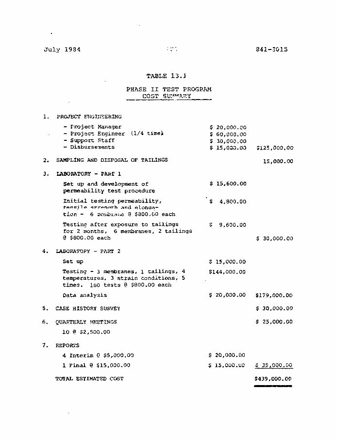
J u l y 1984 341-3015
TABLE 13.J
PRASE I I TEST PROGP/iMCOST SUM'-'fiJRY
1. PROJECT ENGINEERING
- Project Manager- Project Engineer (1/4 time);- Support Staff- Disbursements
2 . SAMPLING AND DISPOSAL OF TAILINGS
3 . LABORATORY - PAOT 1
Set up and development ofpermeability test procedure
Initial testing penaeability,
t i o n - 6 z<Oii<b£aj«e !? $300.00 each
Testing after exposure to tailingsfor 2 months, 6 membranes, 2 tailings@ $800.00 each
4. LABORATORY - PAKT 2
Set up
Testing - 3 raembranes, 1 tailings, 4temperatures, 3 strain conditions, 5tines. ISO tests @ $800.00 each
Data analysis
5 . CASE HISTORY SURVEY
6. QUARTERLY MEETINGS
10 @ 5 2 , 5 0 0 . 0 0
7. REPORTS
4 Inter im @ $ 5 , 0 0 0 . 0 0
1 F ina l @ 515 ,000 .00
$ 20 ,000 .00S 60,000.00$ 30,000.00$ 15,030.00 $125,000.00
15,000.00
$ 15,600.00
S 4,800.00
$ 9,600.00
$ 30,000.00
5 15,000.00
$144,000.00
$ 20,000.00 $179,000.00
$ 30,000.00
$ 25,000.00
$ 20,000.00
5 15,000.00 $ 35,000.00
TOTAL ESTIMATED COST $439,000.00
July 1934 221 841-3015
1 4• CO^CLUSIONG /'.NO RECOMMENDATIONS
Flexible liners show considerable promise for the
containment of waste materials including uranium tailings.
Nine polymeric linings and three types of sprayed asphalt
have been considered with respect to the physical and
chemical environment in the uranium producing areas of
Canada. All indicate good chemical resistance to uranium
wastes but are subject to installation problems.
High density Polyethylene, Hypalon, and Chlorinated
Polyethylene (HDPE, CSPE and CPE) all exhibit sufficiently
good characteristics to warrant further study. Furthermore
LlitJ^e i u a U n u i s n a v o u c c n oimivi j.u aiujOL j. i>5 v.c«x I-ZL i- .OTi^
throughout North America. Such experience i3 not available
for che asphaltic membranes but at least one should be
selected for further study. Information to date would
favour either catalytic airblown asphalt or one of the
asphaltic-elastomeric compounds.
The intact membranes (asphaltic or polymeric) have an
extrernely low permeability, probably less than 1 x 10
centimetres per second. However, the operative perraaability
is substantially higher and values which are typically used-8 -10
are 1 x 10 and 1 x 18 centimetres per second for
asphaltic and polymeric liners, respectively. These higher
values of parr.esbility reflect liner defects, installation
problems, and linar degradation.
Ccncspcual design of a tailings basin has been carried out
for both Elliot Lake and Southeastern Athabasca conditions
assusing the following portabilities:
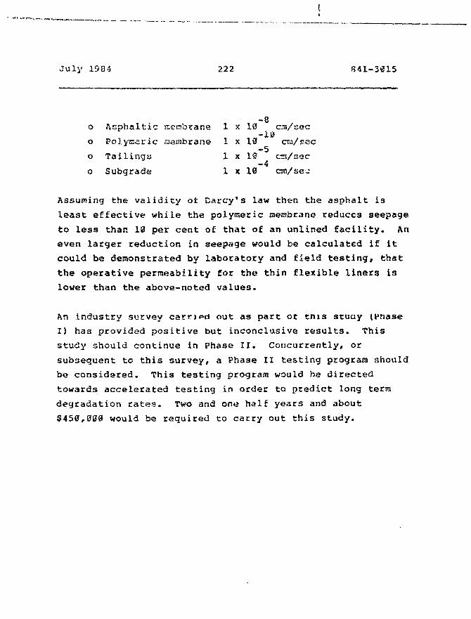
July 1904 222 841-3015
-8o ftsphaltic mcnbrane 1 x 10 cni/seco Polyearic raembrane 1 x 13 era/sec
o Tailings 1 x 10 era/sec-4
o Subgrade 1 x 10 ao/se^
Assuming the validity ot Darcy's law then the asphalt is
least effective while the polymeric membrane reduces seepage
to less than IB per cent of that of an unlined facility. An
even larger reduction in seepage would be calculated if it
could be demonstrated by laboratory and field testing, that
the operative permeability for the thin flexible liners is
lower than the above-noted values.
An industry survey carried out as part or tnis stuay (Pnase
I) has provided positive but inconclusive results. This
study should continue in Phase II. Concurrently, or
subsequent to this survey, a Phase II testing program should
be considered. This testing program would be directed
towards accelerated testing in order to predict long terra
degradation rates. Two and one half years and. about
$450,000 would be required to carry out this study.
July 1984 223 841-3G15
It ia our cecoraaiendation that Phase II should proceed but
that the details of th9 program be finalized only after
completion of an expanded survey of industrial users of
flexible liners.
GOLD«iR ASSOCIATES
Frederick"W. Firlotte, P. Eng.
R.A. Gould, P. Eng,
FWF/RAG/j1
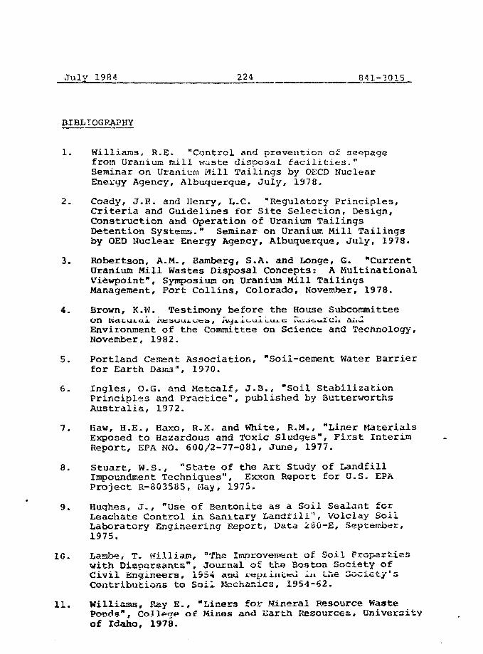
July 1984 224 841-3015
BIBLIOGRAPHY
1. Williams, R.E. "Control and prevention of seepagefrom Uranium mill waste disposal facilities."Seminar on Uranium Hill Tailings by OECD NuclearEnergy Agency, Albuquerque, July, 1978.
2. Coady, J.R. and Henry, L.C. "Regulatory Principles,Criteria and Guidelines for Site Selection, Design,Construction and Operation of Uranium TailingsDetention Systems." Seminar on Uranium Mill Tailingsby OED Nuclear Energy Agency, Albuquerque, July, 1978.
3. Robertson, A.M., Bamberg, S.A. and Longe, G. "CurrentUranium Mill Wastes Disposal Concepts: A MultinationalViewpoint", Symposium on Uranium Mill TailingsManagement, Fort Collins, Colorado, November, 1978.
4. Brown, K.W. Testimony before the House Subcommittee
Environment of the Committee on Science and Technology,November, 1982.
5. Portland Cement Association, "Soil-cement Water Barrierfor Earth Daics", 1970.
6. Ingles, O.G. and Metcalf, J.B., "Soil StabilizationPrinciples and Practice", published by ButterworthsAustralia, 1972.
7. Haw, H.E., Kaxo, R.X. and White, R.M., "Liner MaterialsExposed to Hazardous and Toxic Sludges", First InterimReport, EPA NO. 600/2-77-081, June, 1977.
8. Stuart, W.S., "State of the Art Study of LandfillImpoundment Techniques", Exxon Report for U.S. EPAProject R-8G3505, May, 1975.
9. Hughes, J., "Use of Bentonite as a Soil Sealant forLeachate Control in Sanitary Landfill", Volclay SoilLaboratory Enqineering Report, Data 280-E, September,1975.
10. Lambe, T. Wi.llia.rn, "Tha Impraveffisnt of Soil Propertieswith Dispersants", Journal of the Soston Society ofCivil Engineers, 1954 and teyriiiceu i.u Lhe Society'sContributions to Soil I>Sschanica, 1954-62.
11. Williams, Ray E., "Liners for Mineral Resource WastePond«". Con«g« of Mines and iiarth Resources, Universityof Idaho, 1978.
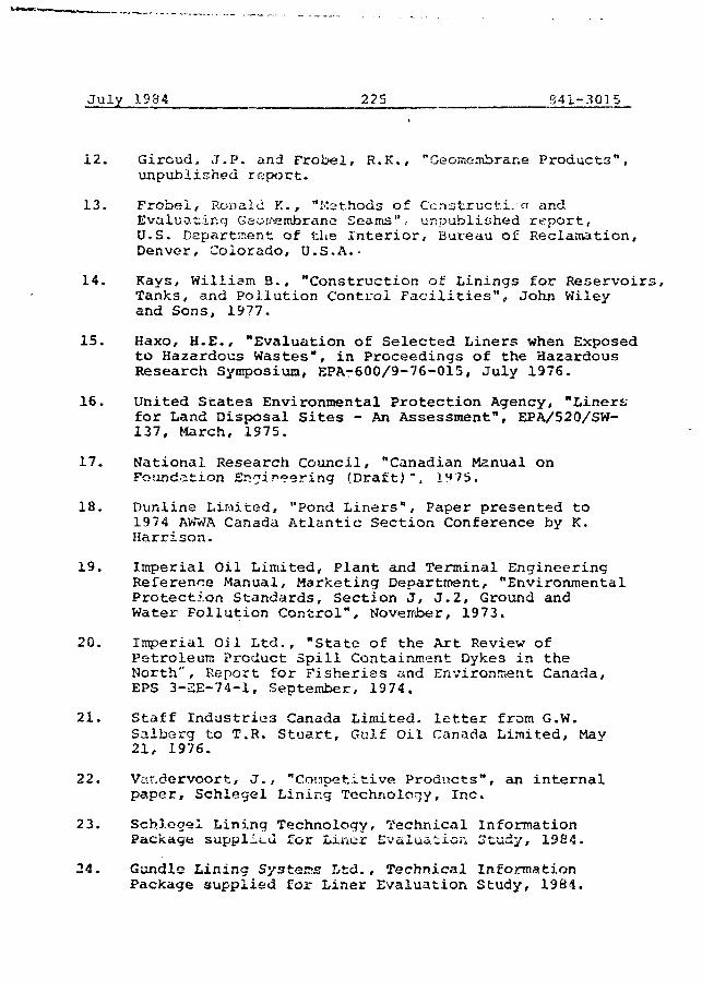
July 1984 225 841-3015
12. Giroud, J.P. and Frobel, R.K., "Gee-membrane Products",unpublished report.
13. Frobei, Ronald K., "Methods of Construct!, a andEvaluating Gearrembrane Seams", unpublished report,U.S. Department of the Interior, Bureau of Reclamation,Denver, Colorado, U.S.A.-
14. Kays, William B., "Construction of Linings for Reservoirs,Tanks, and Pollution Control Facilities", John Wileyand Sons, 1977.
15. Haxo, H.E., "Evaluation of Selected Liners when Exposedto Hazardous Wastes", in Proceedings of the HazardousResearch Symposium, EPA-600/9-76-015, July 1976.
16. United Scates Environmental Protection Agency, "Liners;for Land Disposal Sites - An Assessment", EPA/520/SW-137, March, 1975.
17. National Research Council, "Canadian Manual onFoundation Engineering (Draft)"4 1H75.
18. Dunline Limited, "Pond Liners", Paper presented to1974 AWWA Canada Atlantic Section Conference by K.Harrison.
19. Imperial Oil Limited, Plant and Terminal EngineeringReference Manual, Marketing Department, "EnvironmentalProtection Standards, Section J, J.2, Ground andWater Pollution Control", November, 1973.
20. Imperial Oil Ltd., "State of the Art Review ofPetroleum Product Spill Containment Dykes in theNorthr, Report for Fisheries and Environisent Canada,EPS 3-2E-74-1, September, 1974.
21. Staff Industries Canada Limited- letter from G.W.Salbsrg to T.R. Stuart, Gulf Oil Canada Limited, May21, 1976.
22. Var.dervoort, J. , "Cotroetitive Products", an internalpaper, Schlegel Lining Technology, Inc.
23. Schlegel Lining Technology, Technical InformationPackage supplied for Liner Evaluation Study, 1984.
24. Gundlo Lining Systems Ltd., Technical InformationPackage supplied for Liner Evaluation Study, 1984.
Julv IS84 226 841-3013
25. Euilt, J.L. (Pacific Northwest Laboratories), ""LinerEvaluation «»- 'Jnnium Mill Tailings: Final P-eport",prepared for the U.S. Dcpartcsnt or Llnergy imcte.rContract DE-AC0G-76RLOI830, Septeiribor, IH83.
26. Staff Industries Canada Limited, "Report on LiningHydraulic1 and Earthen Structures wix.h Staff FlexibleI rope i:;*; able Membranes", updated.
27. Annon, "Avoid These Storage Liner Mistakes", inPublic Works, February, 1977.
28. United States Environmental Protection Agency, "Liningof Waste Impoundment and Disposal Facilities", SW-870,September, 1980.
29. Haxo, H.E., "Assessing Synthetic and Admixed Materialsfor Lining Landfill3", in Gas and Leachates fromLandfills, EPA-600/9-76-004, March, 1976.
30. Owen, J., "Recommended Procedures for InstallingPonci unf>rs", in Materials Perioiiudiite, L«sucuii»e.i., lIsTC.
31. Stuart, W.S., 1^78, "State of the Art SLudy of LandImpoundment Techniques", EPA-6Q0/2-73-196, U.S.Enviror.ir.enta! Protection Agency, Cincinnati, Ohio76pp, pp291-881.
32. Fisher, G.E., "Selecting and Specifying Liner Membranes",in Materials Performance, December, 1976.
33. Dunline Limited, Letter from R.S. Anderson to D.E.Welch, Golder Associates, June 3, 1977.
34. Imperial Oil Ltd., "State of the Art Review ofPetroleum Product Spill Contaiar.rant Dykes in the North",Report for Fisheries and Environment Canada, EPS3-EE-74-1, September, 1974.
35. Burke Rubber Co. Brochure, "Flexible Membranes".
36. Haxo, H.E- Jr. and R.M. White, "Evaluation ot LinerMaterial E X D O S G Q to Leachate"f Second Interim Heport,EPA No. 600/2-76-226, September 1976, 57 pp.
37. Isperial Oil Lim>.'<:e<i, "Spill Retention v»ith PlasticFilms", Laboratory Report #L-4617-: by R.G. Auld,August, iy/4.
38. National Sanitation Foundation, "Standard 54 forFlexible Membrane Liners™, National Sanit-itxonFoundation, Ann Arbor; Michigan. November, 1!)B3.
Tulv I'ir'4 227
.39. The Asphalt institute, "Asphalt in HydraulicStructure:;", Mantiai Serie:.:\\o. 12 (M3-12) , 1961Fifth Printing, M.arch, 1965-
40. The Asphalt Institute, "Asphalt linings for SanitaryLandfills", Construction Leaflet Ua, 9, 1974.
41. Buelt, J.L. and Barnes, S.M., Pacific N'orthwe3tLaboratory, "Aging Teat Results of an Asphalt MembraneLiner", prepared for the U.S. Department of Energyunder Contract DE-ACGG-76RLO1830, July, 1983.
42. The Asphalt Institute, "Asphalt in Hydraulics",Manual Series No. 12, College Park, Maryland, 1976.
43. Chambers, Carlon C., "Seepage Control Using SBR/AsphaltHot Sprayed, Elastoraeric Membranes", in First Inter-national Conference on Uranium Mine Waste Disposal,Vancouver, British Columbia, Canada, Page 271-288,May, 1380.
44. The Asphalt Institute, "Mix Design rtethods for HotMix Asphalt Paving", Manual Series No. 2, 1974.
45. Robertson, A. Marg., Shepherd, ?.*i. , and Van Zyle, D. ,"Uranium Tailings Impoundment Site Selection",Symposium on Uranium Mill Tailings Management, FortCollins, Colorado, November 24-25, 1980.
46. Taylor, M.J., "Radicnuclide Movement in Seepage andits Control", First International Conference on UraniumMine Waste Disposal, Vancouver, British Columbia, lizy,1980.
47. Clifton, A.W., Barsi, R.G. and Melis, L.A., "UraniumMill Tailings Management Practices in Saskatchewan,Canada", Sixth Symposium on Uranium Mill TailingsManagement, Fore Collins, Colorado, Tcbruary 1~3, 1984.
48. Cherry, J.A. and Freeze, R.A., "Groundwatcr*, Prentice-Hall Inc., Englcwood Cliffs, Now Jersey 0/632, 1979.
49. Melis, L.A. , Fracer, K.S., and Lakshraanan, U.I., "TheMidwest Uranium Project - L-eveiopmunt of the HillingProcess".
50. Cherry, J.A. et ai. , "5ui>»uriTa*Jt: KyuiologyGeochemical Evaluation of Inactive Fyritic Tailingsin the Elliot Lake Uranium District, Canada",Symposium en Uranium Mill Tailings Management, Fort
iinR. <V>5"<*««<>.- Nov«niber 24-25.
July 1984 220 S-11-H'l?
51. F.nergy, Min>»3 and Resources Canada, correspondence!dated April -1, 1934.
52. Kltistorr.eric Materials: The International PlaoticsSelector, Coxdixrci Publications Inc. 1S77,
5 3. Extruding and Molding Grades 19"/8, Book B, CorduraPublications Inc. 1978.
54. Mitchell, D.H. (Pacific Northwest Laboratory), "AgingGecmembrar.es in Uranium Tailings Lsachate", Preprintto paper to be presented at the InternationalConference on Geomembranes, June 20-24, 1984, Denver,Colorado.
55. General Chemical Resistance Data provided by DunlopConstruction Products Inc.
56. Kays, William B. , "Lin.vng Systems for Seepage Controlin Uranium Mill Taiiingo Holding Ponds", Symposium
Colorado, November 1973.
57. Technical inforrrution provided in Schlegel LiningTechnology information package, letter to ElectricPower Research Institute from the Analytic SciencesCorp., dated December, 19S1.
58. Hanel, P., Howieson, J., "A Summary of the CanadianUranium Mill Tailings Situation", Symposium onManagement cf Wastes from Uranium Mining and Milling".Alburquerque, May, 1982.
59. Frobel, R.K. and Gray, E.W., "Performance of the FabricReinforced Geornenbrane at Mt. Elbert Forebay Reservoir",U.S.B.P.. Denver, Colorado, unpublished paper, 1934.
60. Folk c.v;, D.J., "Fifth Canadian G-eot echr.ic?.! Colloqnim:Control of Contaminant Migration by the Use of Liners",Canadian Geotechnical Journal; Vol. ID, r o. 3, August,1982.
61. McWhorter, D.B., and Nelson, J.D., "Ur.saturated FlowBeneath Taiiiagi IsxijjouiK-i -eatfe", ASCE Jour.iai oi theGeotacimicrt.1 Esiqineoriruj Divlsior., Vol. 105 No. GT.ll,
er, 1379.
62. Small, David M., "Establishing Installation and MaterialSelection Psraifleters", SvmpoBium on Uranium MillTailings Management. Fort Collins, Colorado, November,1980.
July 1934 229 841-3015
63. Schmidt, Richard K., "Specifications and ConstructionMethodn for Flexible Ktimbrane Liners in HazardousWaste Cor.tai.-Dent", presented to: Hazardous MaterialsManagement Conference, July, 198 3.
64. Dixon, R.R., IEEE Tran3. on Ele-ctw Ins. Vol. EI-15,August, 1980.
65. Watersaver Company, Inc., Technical InformationPackage for Liner Evaluation Study, 1984.
66. Golder Associates Report No. 786085 entitled "AnEvaluation of Six Common Liners", dated June, 1981.
67. Kilborn (Saskatchewan) Ltd. and Melis ConsultingEngineers Ltd., "Cost Study on Waste Management atThree Model Canadian Uranium Mines". Prepared forDepartment of Energy, Mines and Resources, CanadaCentre for Mineral and Energy Technology, NationalUranium Tailings Programme, March, 1984.
68. Energy, Manes and Resources Canada, unpublisnec dataprovided for the study, Hay, 1934.
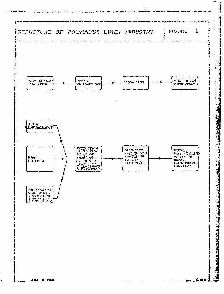
p—-——.———. . =\37PMCTUHE QF POLYMERIC LINER INDUSTRY FIGURE I.
fKOOUCZRSHF.ITI {FABRIC A70R
FABRICATESr£ETS IfiTOPANELS '•'•"ro trvFCST wtcc
tVST&U.
;4
1
1I
JUNC
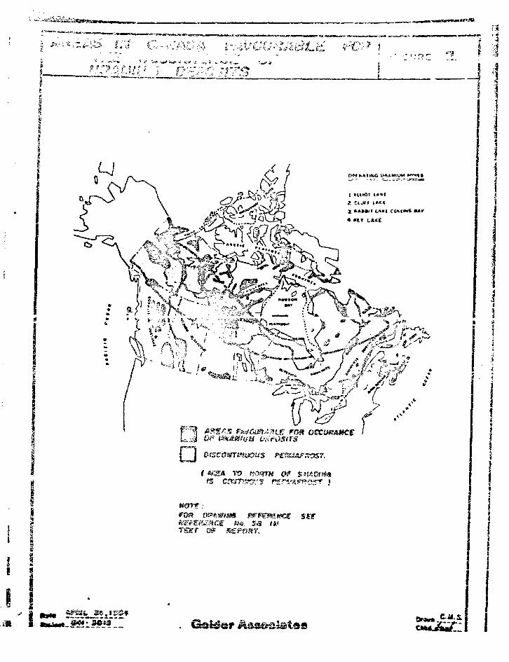
.-I i
ro
mzwm ivrpsmttcg set
TgJTT
£
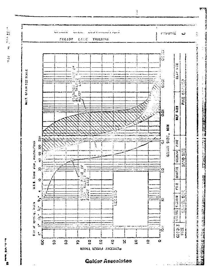
ZLLiOT
u«
f-f
! « 3o
i S
I ii I
15 TS3..J2SB —
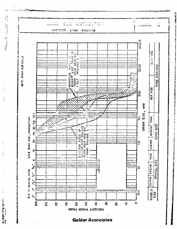
L 4ffg T&tUl'ZS
\ 33
s
j(LI
Vt
,55=.• . "I a
, , J- K «
•v I-.; :
vr Ui 3 : ft
1
1
.J
g& Wj
§3K_
A\Nrf\\\\N^rrr*^4 7:--'
i
1
1- 1
/
i
71 • / l
,
1
. si—i
k\T4
• l - A , ^ : j
1 4 tu
«?)
Z<DC
w O O
2
z {(Z i_Ju3 ! tJ
Is "H . <
' hi '
S lift
2.d
Ut
I
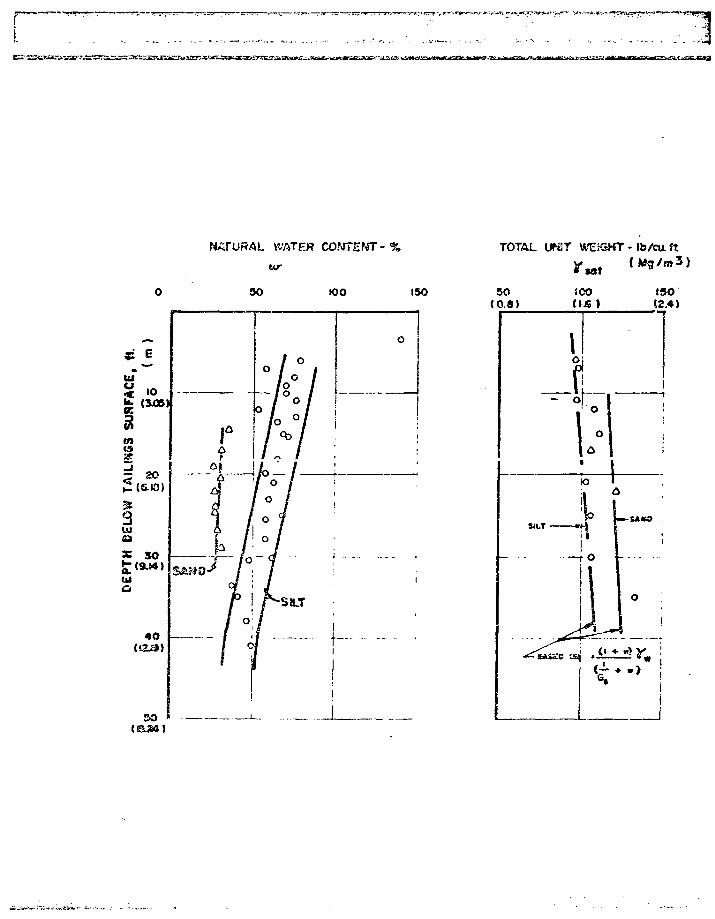
WATER
Mr
TOTAL ifriST WEKSKT - Ib/cu ft
30 K)0 150
•>-•-..•».**•» t- X.-- ' -
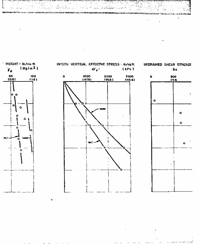
^
.. 3• -'fi.
WEtGHT- lb/cu.f».
SO iOO(OS)
VERTICAL EFFECTIVE STRESS -
o o
- I
I~l
(fePi )
3000(W3.6)
UMJRASNSO SHEAR
Su
O COO
0
:
O
O
O
i1
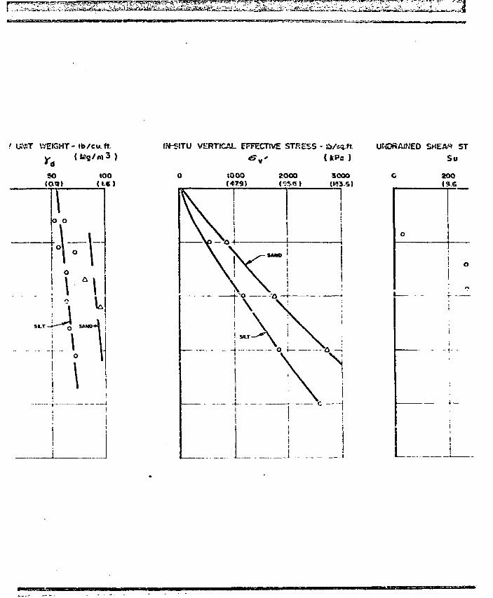
.' UMJT WEIGHT- Ib/cu.ft.
so 100
(to
o o
! ° l
-i - 1i I
ifi-SITU VERTICAL EFFECTIVE STRESS - &/sq.ft.)
ST
30OO(K3SI
_ 1
Su
zooIS.6
o
o
fea^S^^^&^^^i^^^Si^^i^i^&^^ ^
oemisouFIGURE
, tutor uwe
litI )
Qolder Associates
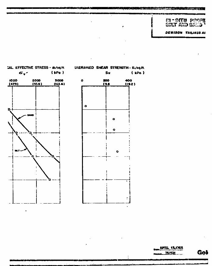
ocmisom
:AL EFFECTIVE STRESS - fc/sq.ft.
&„' (kPo )
UKGRAINED SHEAR STRENSTH -
Su ( fcPo )
IOOO1479)
iii1i
.1vv i X\ \
2000IS3-6)
-sue
I
sooo(K3.S)
!
too(9.6
4OO11*2)
I
0!
• i0 ;
•
•
1 0 •1
:1
: 1
11
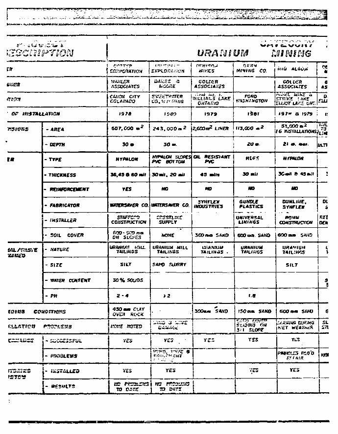
v ^ ^
URANIUM MINING[ * J CCrN^CflATIOS*
_ __ 1 Vl&SLERe & * t r { ASSOCIATES
* « »
Cr H3S7»U.AnaH
HStVZS
em
tu/mm
- A « E *
-DEPTH
- T Y P E
- THICKNESS
- TON-JRCE-TNT
- FABRICATOR
- IHSTALLcA
- SOIL COVER
- NATURE
- SIZE
- WATER CCNTENT
- PH
691 B3 C©a?eJTKBS3
cum* mnw
J
a
cutoH CITY
1378
607,000 a *
3 0 a
HVPALON
36.43 a 60 ai l
YES
WOTERSAVOT CO.
STAFFCTOCOHSTPIKTICM
6 0 0 - K D matOH SLC?u3
TAIUKSS
SILT
3 0 % SOUOS
2 - 4
430 sa CUV0V3» ROCK
, ^ «nro
TO DSTff
EXPi.0££<<'OM
1580
S O n
HmiLOM SLOPESpve eoTTcai
3Oail . 20 ail
NO
HKTER5AVER CO.
cr.zsn.KCSUPPLY
hQHE
UR&fHUH MILLTAILI.VSS
SAHO fiUffffY
T£S
ef.'KSS
COLDERASSOCJATe^
IVfLLIAtS LSKE
1979
2 , 6 0 0 B 2 LIMES
OIL RESISTANTPVC
43 ails
HO
5YNFUEXINDUSTRIES
3O3«a S&*iO
TArLINaS •
SOSui SAMS
V E 3
TO osrs j
«IV/K<» CO.
FOKOKU7NINCTD»
1*181 I
113.000 - 2
2 0 . .
HfrF*
30 a i ;
NO
6UN01EPLASTICS
UNIVERSALLIHIK6S
EDO s o . SAM)
URAHIUMTAILIUGS
1-8
iSOna SANO
S-" 1 £1.0?^
rrs
V£S
eoioenASSCC<*TTS
ElA)Sf"LAi;5 OKT.
6AS
D.
1 9 7 - 0 1979 i 1!
53.000 « * i ' ^ -
21 a. a«». |OLT1
H/PALON
30»tl 6 43 ai l
HO
OUNLIHE,SYNFLEV
•MUWCONSTRUCnCN
GOO mm S414O
URAVIUMTAIL.'IfSS
SILT
GOO mm SOS)
K'eT WtATXcR
P « * « ? - £ J PiO'OKTfAIH
YES
:
01i
OEM
1
S
6
SLS71
KOI
- —
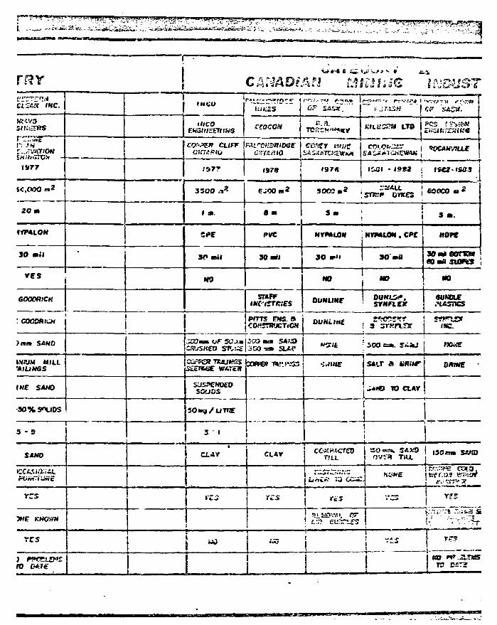
TRY
SIKSTRS
IHtUC" 5A.VS.
ceocca e.n.
t-JT&SH
KILBSCM LTD £??,
IS77
Ct/PF
1977 1978
cast
I97fi 1932
$-0,000 iss
20 a
3500 5002 isna^wites J»ot»-a
8 a 3 a 5 a.
4VP4LON
30 ail
ves
GOOORiCH
fan SAND
CPE PVC HTMLON ; NVMLON . CPC HOFC
3f» a i l 30 ail 3 0 30" aaflOailSUIKS
HO NO
STAFF OUNUNF
NO NO
O U M U ^ .SYNFL£X
SUMRE
PITTS PMS. »
iO?JSKEO STv:4£ 300 •*• a/e
OUHDrtt ! 3 SYKaSf I (9C.
; ZOO ca . 5iJaJ ! tXMS
MIUM MILLFILINGS WATtS
tVJ'JS SMHS » ' . T A fcff.HT omue
INC SAHO
3 0 % S"LIOS
3 - 9
SUSPENDEDSCUOS
SOing/UTFX
3 " 1
TO CLAV
sum CLAr CLAY COKft CTEOTJ S.L TSU.
l30re» SfiNO
u«{>>' 73
rzs
WE KHOHN
res
res
ro
«MB
13 BST£
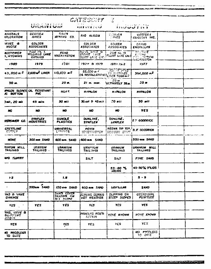
WUEJ d
I960
4 3 . 0 0 0 . *
30 m.
muni siofesK BOTTOM
Jmil. 2 0 mil
NO
(TERSAVER CO.
NONE
MWU.H MILLTAILI&6S
•IKD S WAVE
rrs •
WhlfxT*
YZS
GOLDSffASSOCIATES
Tt-iM f9. 1.WILLIASS MICE
1979
2.600m2 LINES
OIL RCSIS1ANTPVC
49 mil*
MO
SYNFIEXINDUSTRIES
300 mm SAND
UEAHIUUTA1LMGS •
3 0 0 S M SAND
YSS
MI1IUG CO.
FCHOWASHINGTON
ISOI
II3.CCO * 2
2Om.
Ht-f T
30 mi;
NO
6UN01EPLASTICS
UNIVERSAL
60S mm. SAW)
URANIUMTAlLfMGS
1.8
ISOmn SAKO
SLJ3BB3 OH3:1 Si (WT
V f S
res
-an ivf i .-.; *;»
RIO ALCOdt
GOt K BASSOCIATES
Rii-^'L tli-.a asmite* : /Areo t a r Lfl.-x c-r.
l9 /» a 1979 •
if > ii LJ1 4 ^
1971- I&.2
(6 »S7aLLATKJfS-;L'! ca"9j{O^£
21 m. wo».
HfPtLOH ,
Xiail ? 43 nil
NO
OUNLIME.
ROUit
GOO mm S«N0
SILT
600 sm SAK>
5 i f tt'CATHSK
YLS
r.rrsfs""
res
ULTfHiTTLr 3 3 A
H I ' M L O N
."0 ril
NO
ifWfLfjr
RFCMA TIP TOP,
[}P,AH:UUTAILINGS
SILT
50-80 %SOLIOS
S7SEP SLOPgS
res
,«Cf^ KH3&H
J ( t» »'
iyrr
3^5.000 r»z
2 0 m
MTPALON
3 0 mil
res
E T COOTRXK
3OSmm SANO
URAHIUM MILLTAILINGS
FINE SANO
«3-3O% S^tlDS
3 - 9
SANO
C P S H
YES
NOXE room
•
ii , .
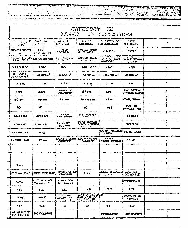
GTHESZ INSTALLATIONSTuTrs jus. .'KisrAci w j eo
tesa xi u £ oO U.S. 9.ft. KOMCV
^tvTisrs a 1992 I8O1 ( 9 6 6 - I9T7
SOOOOm2
" 3.3 • . 4.5 4.3
HOPSASPHAITICCOHCRVrt
CPOH CP€ PVC BOTTOMHYfMJOM SUJftS
00 mil mil SO • CS MU 45 mil 2Om», SSail
MO NC resm e MO I
Hrr*ion res
scHieaa. SCHLZGCL . -" i !^? .^ ' u:*...^j» • * i - — • - — - • * • ,
£. ConorTHUCKIHS
ZOO nm SAtB MOtff
BOTTOM ASH ^ /*L>ir!0fftfU21XD C'JXXH SJtIME
3 - :
__ j
€OO am CUr i S«S) (M3? ; ctorerrax
MCWf
rss
ttcne
VffS rrs
wrmiow
rrs
"V..-«,.-. ^ . •^r^i£^C£^£_UC^'i»WiiL=^JW--'cM \*V-< ' •*: . '*• ! ! ." ?Vt »->?•-•-.' '** . - • . I - - * . *
iwousrriwt&ft USERS
UOTCT
IMS OMVIMS IS ID K «E«OIN oomuttcrtom mmACCCMPANVBIB KCKWT.
34
2 • • .
1;i
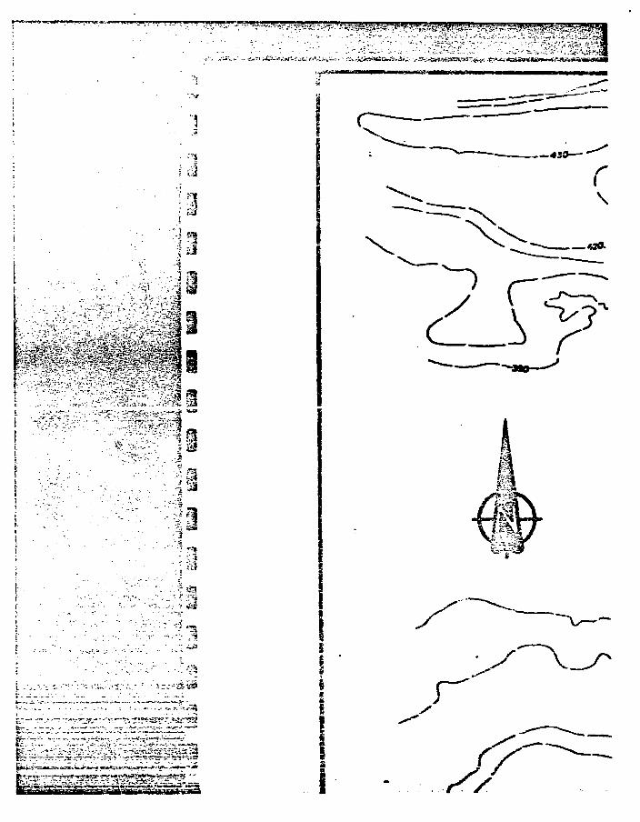
l - - . - > - • - - . . - . • - . .-. : :.-<~n.V,-3a
. . - • • • T - t ^ . J _3 r t - f f t T . . . :» . r J . | 1 . y t T | T | 1 ^
i
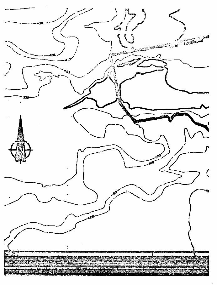
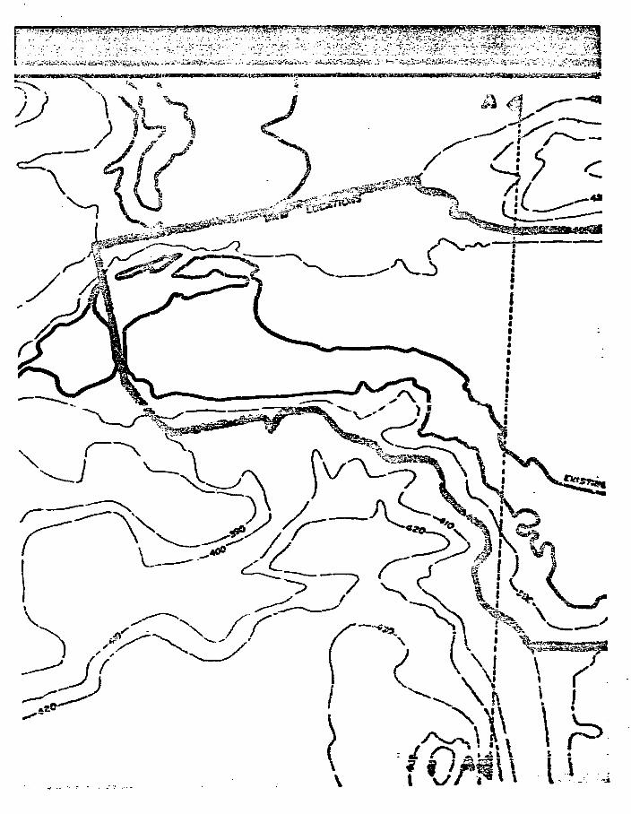
8/ • • - ? ? ? ^^^^ ; ^ ^ p ^ ^ 5?^?^^V^T^^;^^«^^^^^^rJ'j5*iw'*y^v
(
^W* h9 2 i
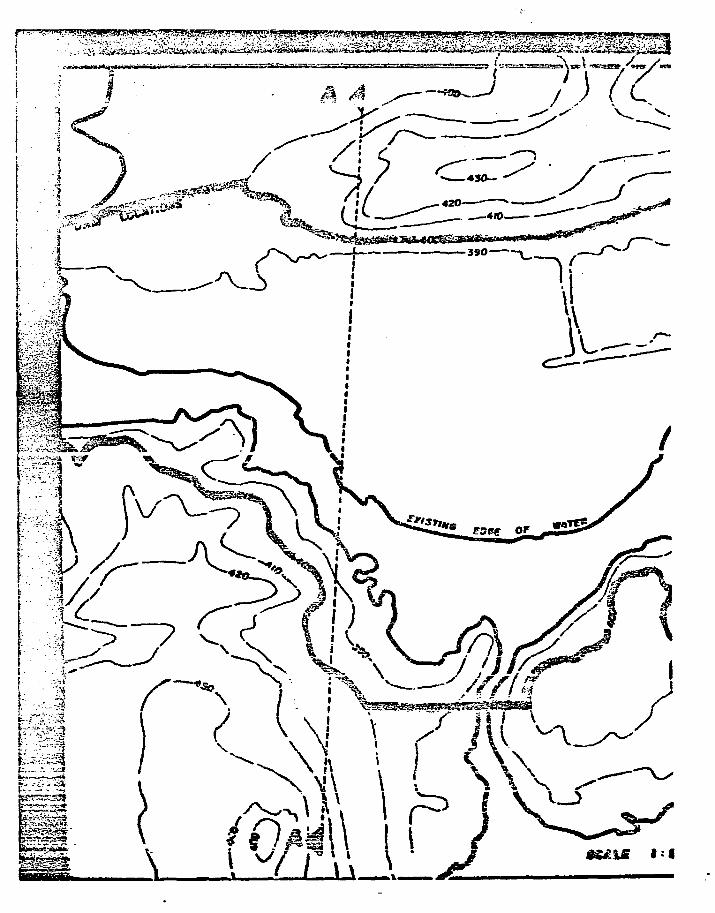
?s»>__
_ . rrri&
. 4 S 0 ^
.410.
-3SO-
>
l\
U.
\ \ \ ^
s. fW.\ i Ol_)
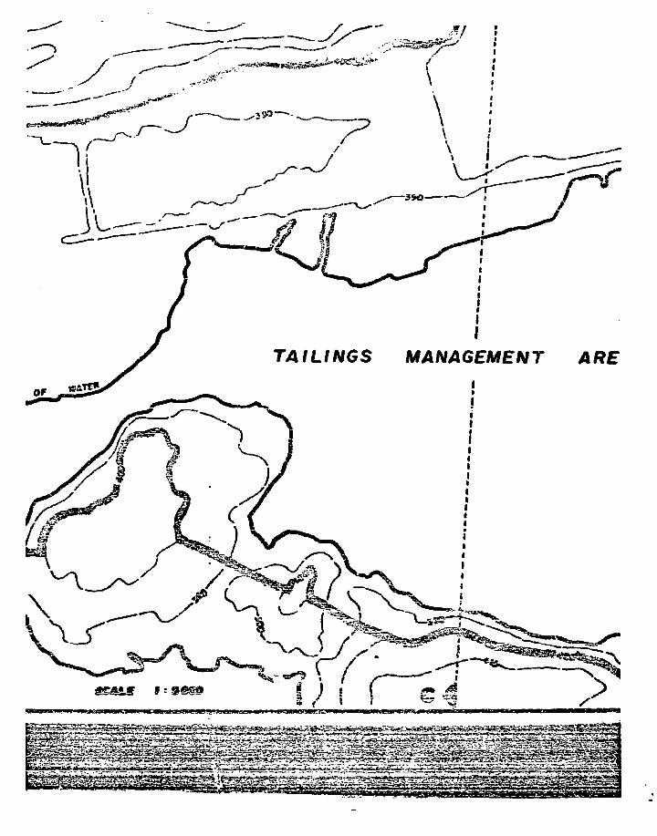
MANAGEMENT
SSSSJS 9
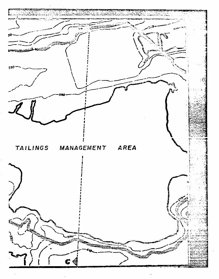
^j£^U^»'^^.-.Ji&i«*J.^>i.F'«it.'^^i -^.---t-.=^-: V*-
MANAGEMENT77WL/NGS
\J { I \t§0£?vi
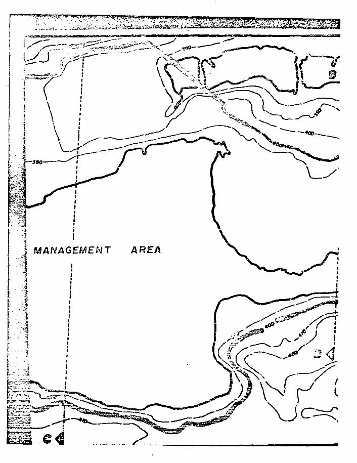
1 MANAGEMENT
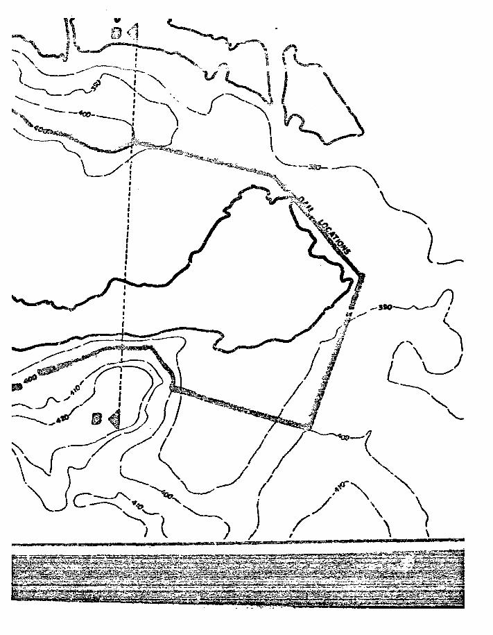
""V
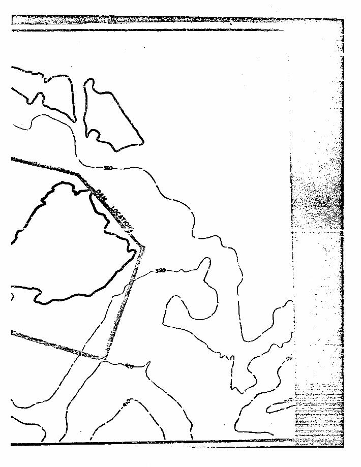
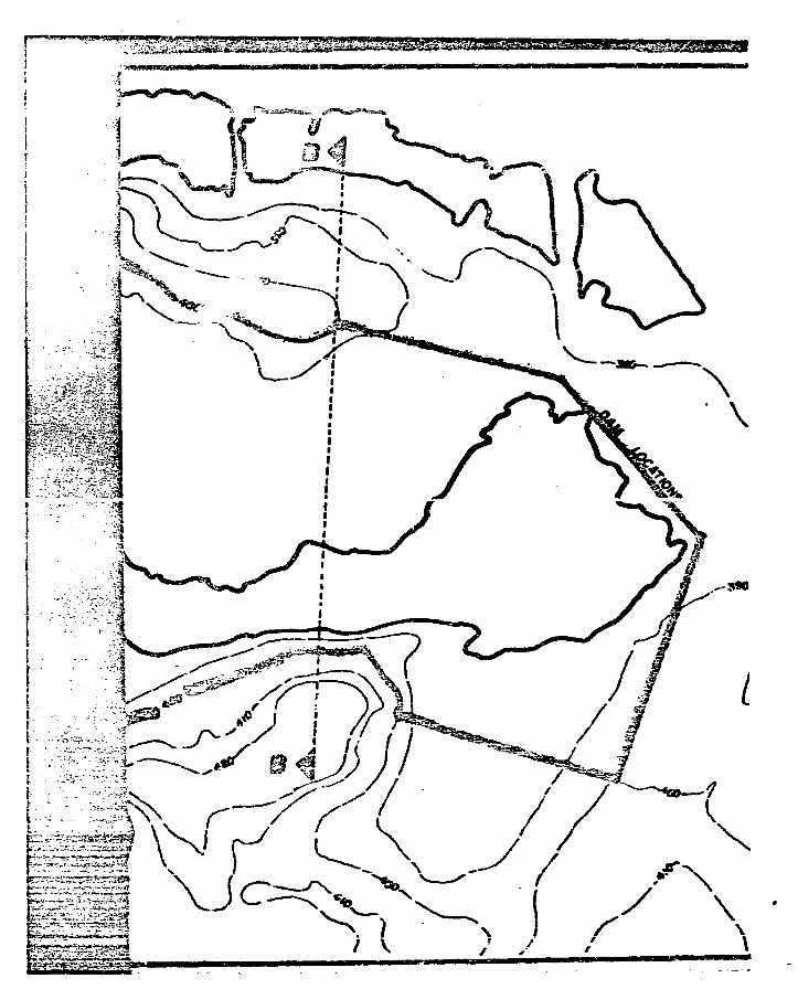
I
i - •-
^-*?-!^US??.'>™'vi«5*
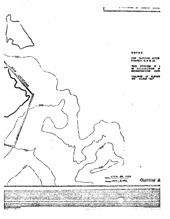
aorssFCS T-i.<
e.s a is.
THJS tsmzsmt r3 i
OM CL!sr a£v*n
ose-Gar

um IJILIJU IWLIILU.WIIUUH^IimvB^trrm
I R_4£J
f
• ores
«.»•!».I D
TWS IS T3
niuaes AT non CLOS?-our
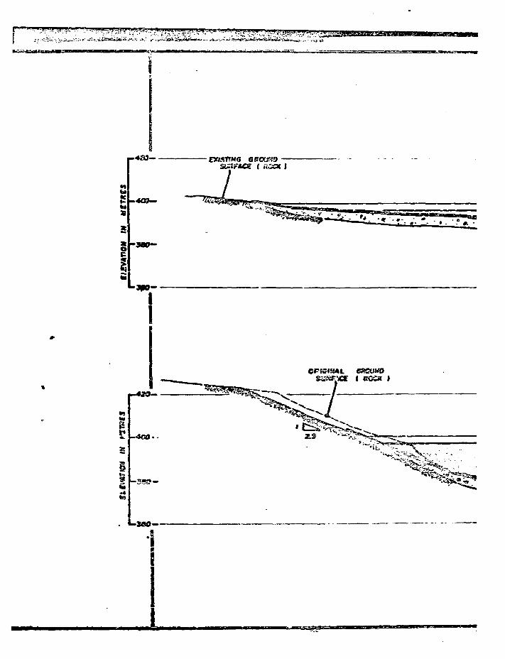
tFIhi
-4O9—
g

rnxrn >
HOCK
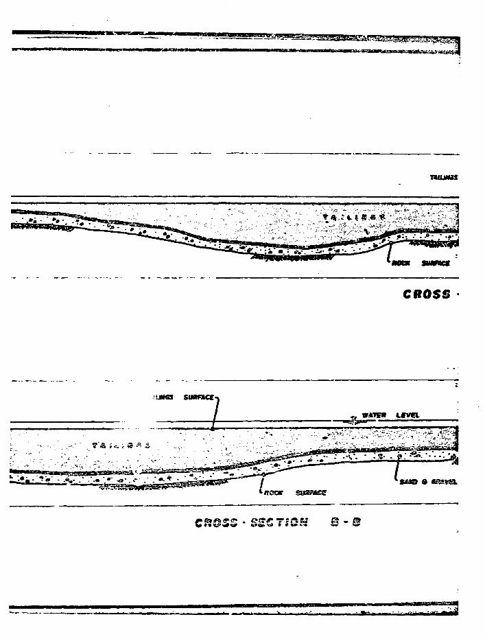
CROSS
v*rsm tffvei
CROSS • SSS T«OH © -
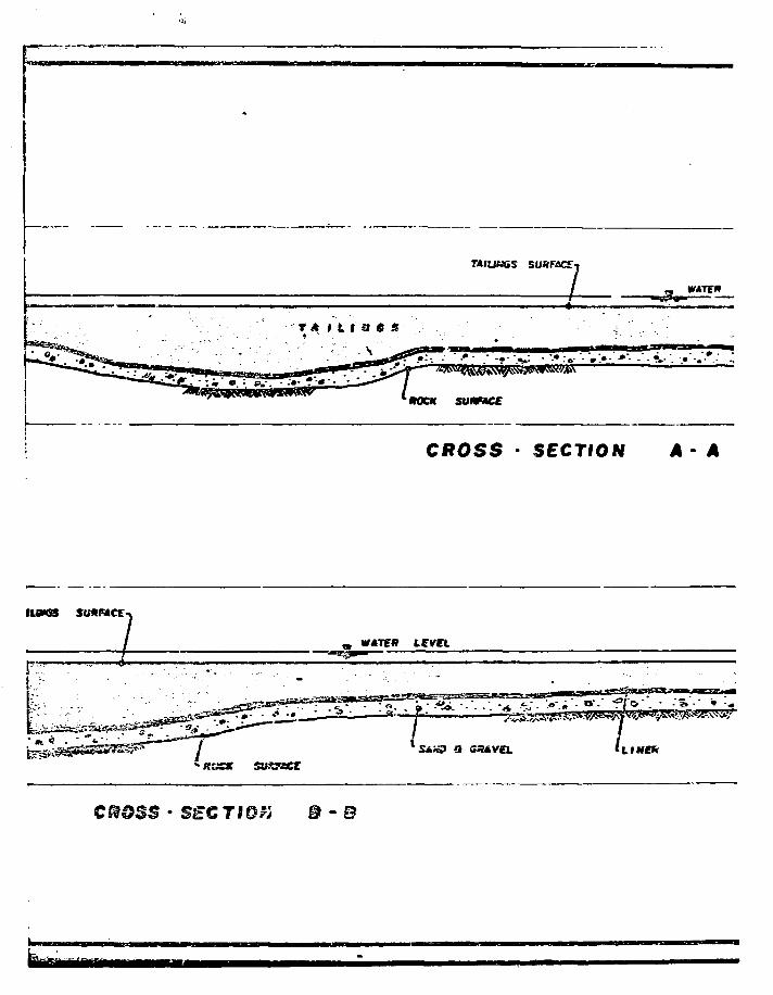
:;. •'•...:;; t * nt m 6 s ',. .
TAIUtidS
SUHMCE
SURFXE-]
•• . • t . -
. : • • o •
« W*TE»
CROSS - SECTION A • A
IUMS sunncc
LINffRr
•KSCK suasscr
SSC7IQK B - B
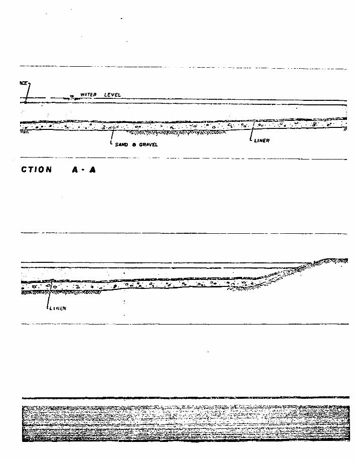
WATBf*
• : , - • . > - »•• . - . v . v - . - y .>.
SAND a GR*V£L
CTION A - A
c
*1 " 7
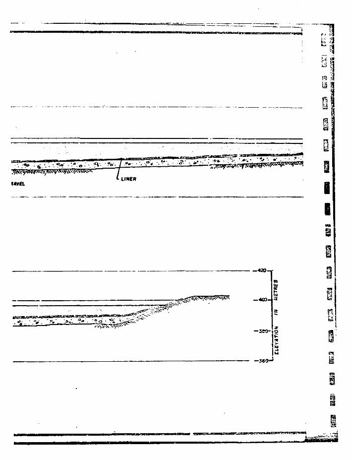
H i
. . . • . < • - • • * •
^ 7tAV£L
LINfR
IB
—420-1
—«C0-
—seo-iQ
u
m

ii
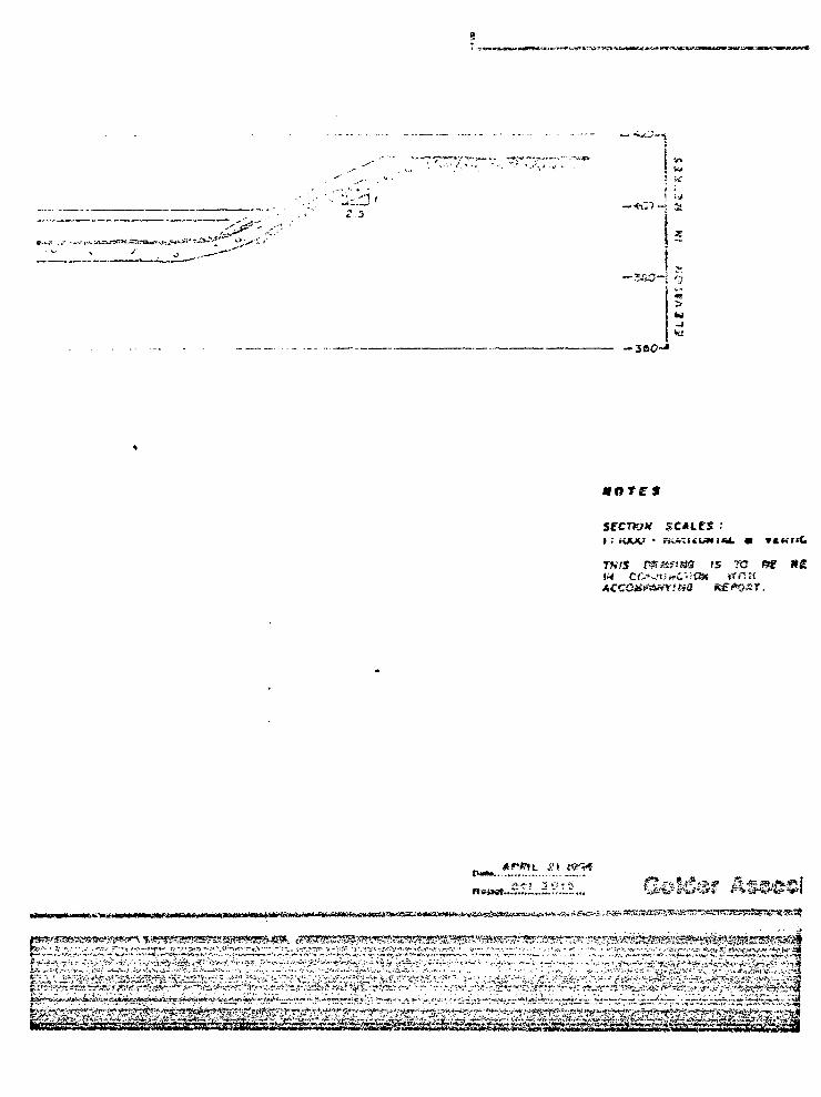
SfCTK?» SCACCS :
.'5 7O fitf
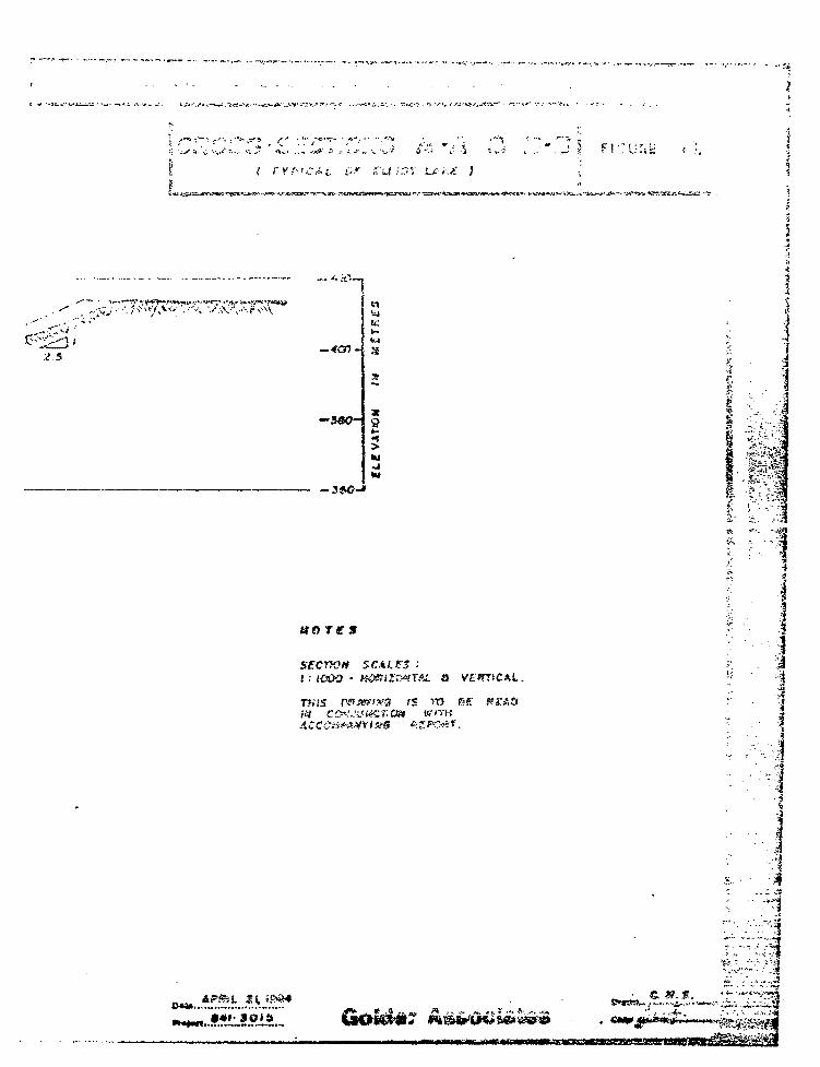
it'U ;:5 A' J
1
—39O-
ttfllfS
secnoii SCALPS ••i.- IOOO
TJitS
v£«rrtCAt..
c. ».*.
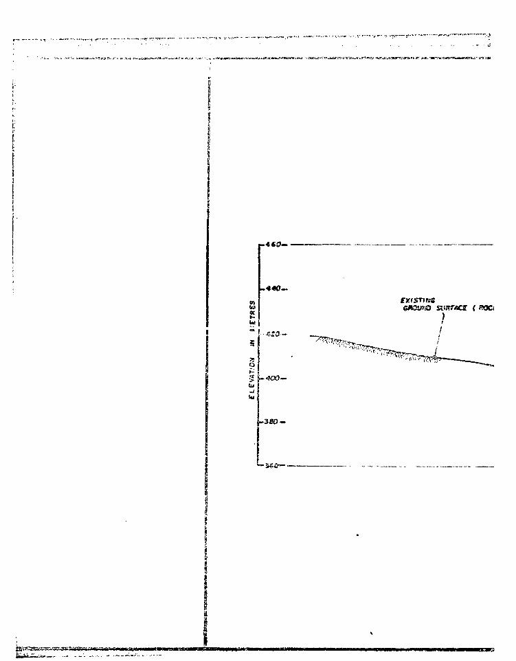
• - *-r- -ii rr n 'n I'IY v* " • iii.Tij"_iinr~-" n
. 4 CO— •
• • •s ro-
fJffSTIKS
•5S0—•
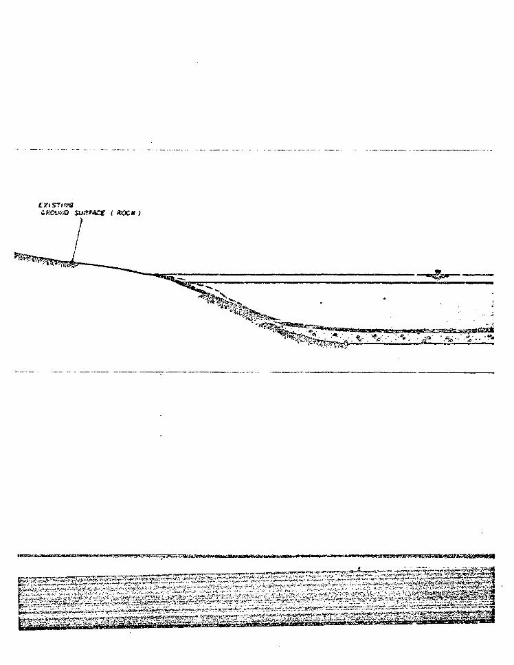
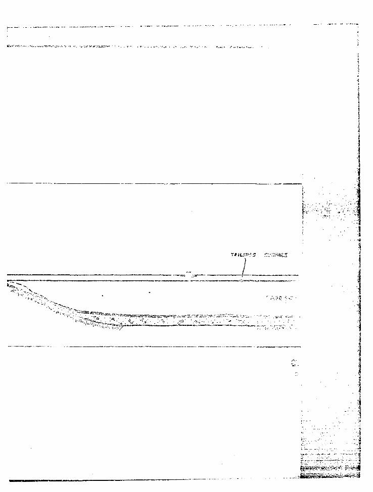
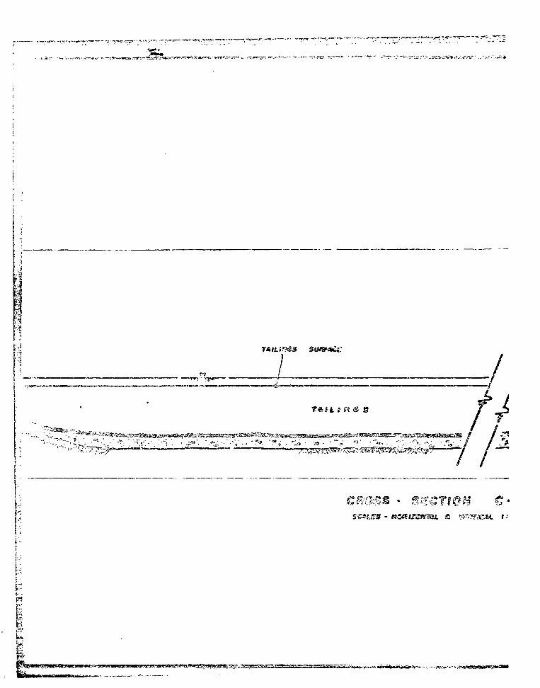
t •
i
>-.——- ' ; 7>*{r-T '^".L '*
.1
f R & S
L; fi ?si!:?r.ie*t. ' •
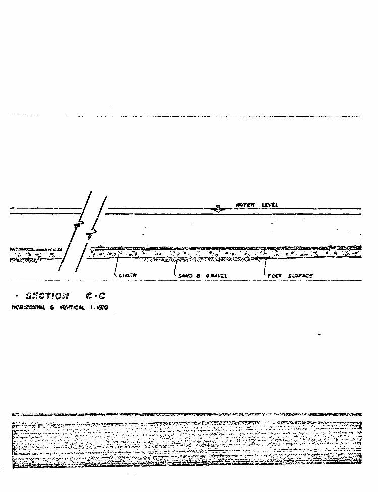
« «*TCT
/ / / fSCTWSt C-Q
Si VSMIOtL
^.^^•^.^^^^^^^^^^^s^^
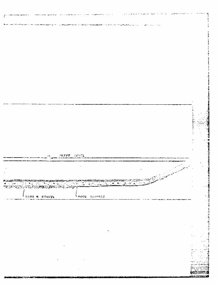
• •. * * • • • ' . • ' • • * • * - • * • „ • * • * • : . - . • • " • * X ' e / ; ' - ^ ; ^ ' . • • > • ' . * . . * • - ^ - f . • * • ' : ;
/ /
,*i
!
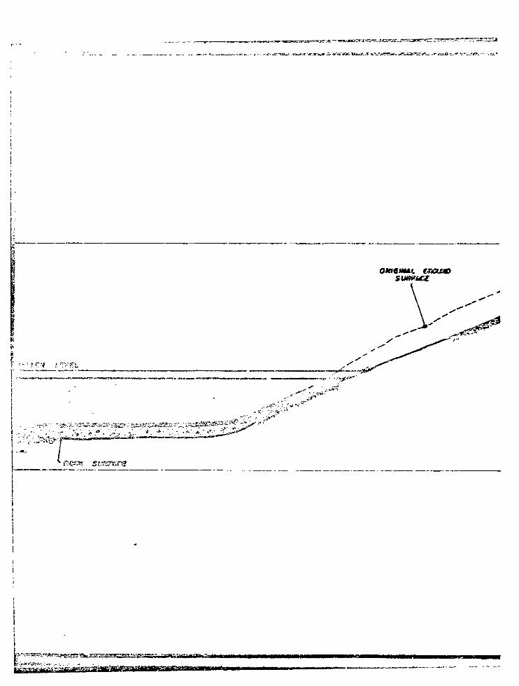
cssaao
<r.-H*
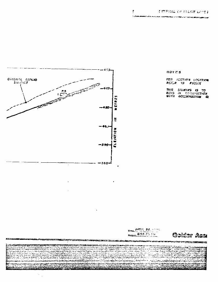
iiiST-ctlftirfi : i o *» j..?,o.-"Jv.-*~*-^^r—_Arnrr._ j .
- - J 5 O - ,
TK«3 ta&a&es is
0ir«
M^>^^^^yMH.?/ K r
iai*^*
aeras
ro as
id
—3CO-
B***..?:"
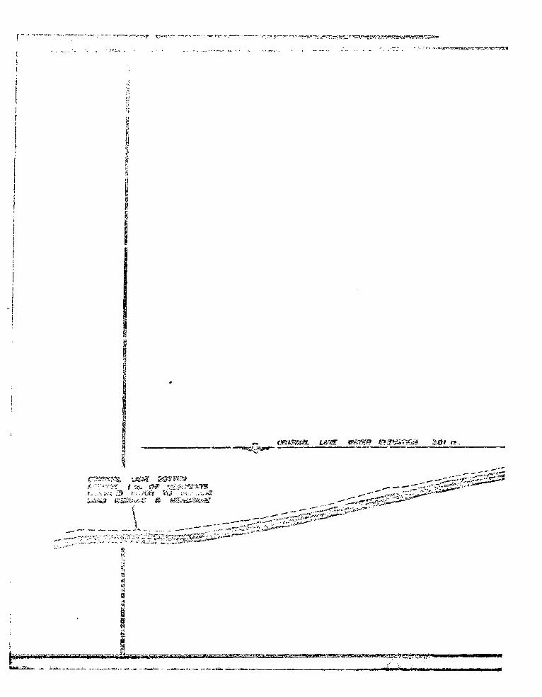
r.. ..^
•-X^Z.TrxZ
tt.^^-''
WkHl-n. , . . ^.,
I
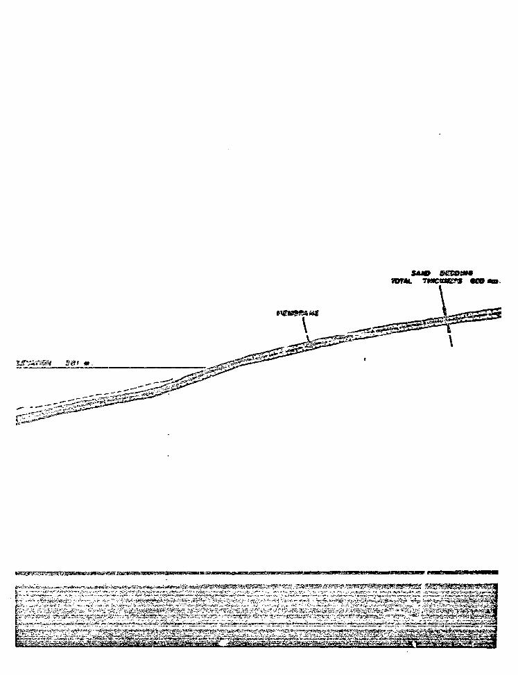
WML
v&gszzax
sur%r«®i B@I m.
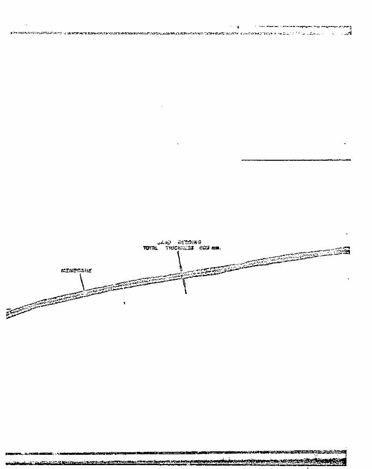
^ . . H ^
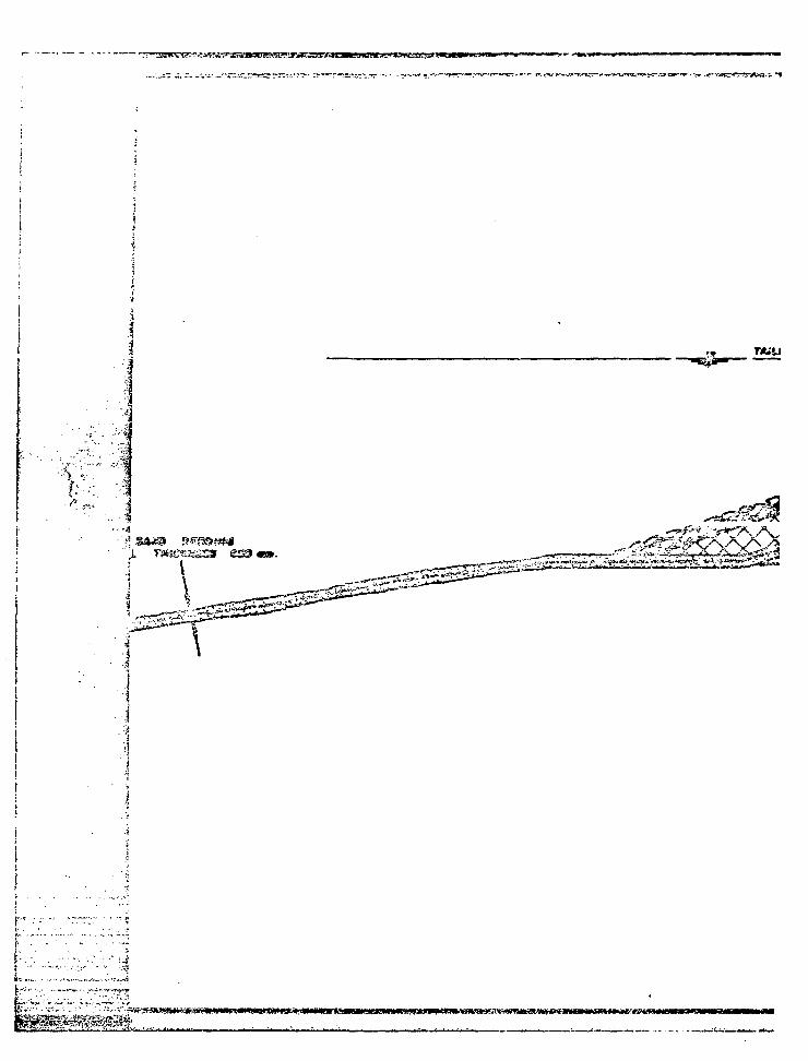
• • • V i '
(• • " • • - • • . .
i,...,£"-".••:. -
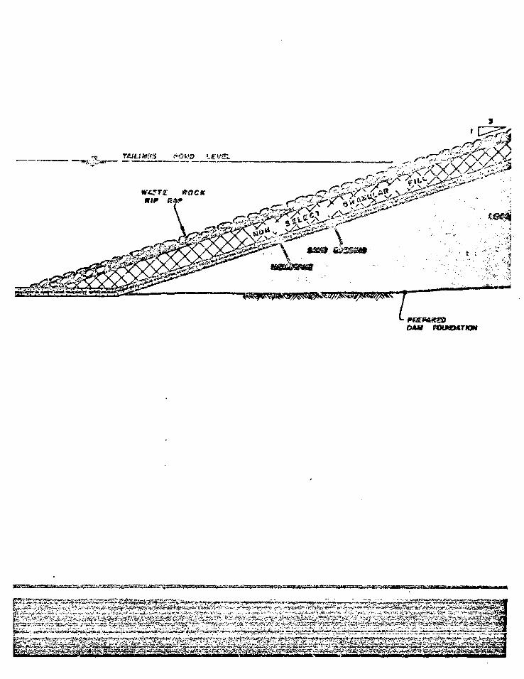
CAM PDUCMTKM
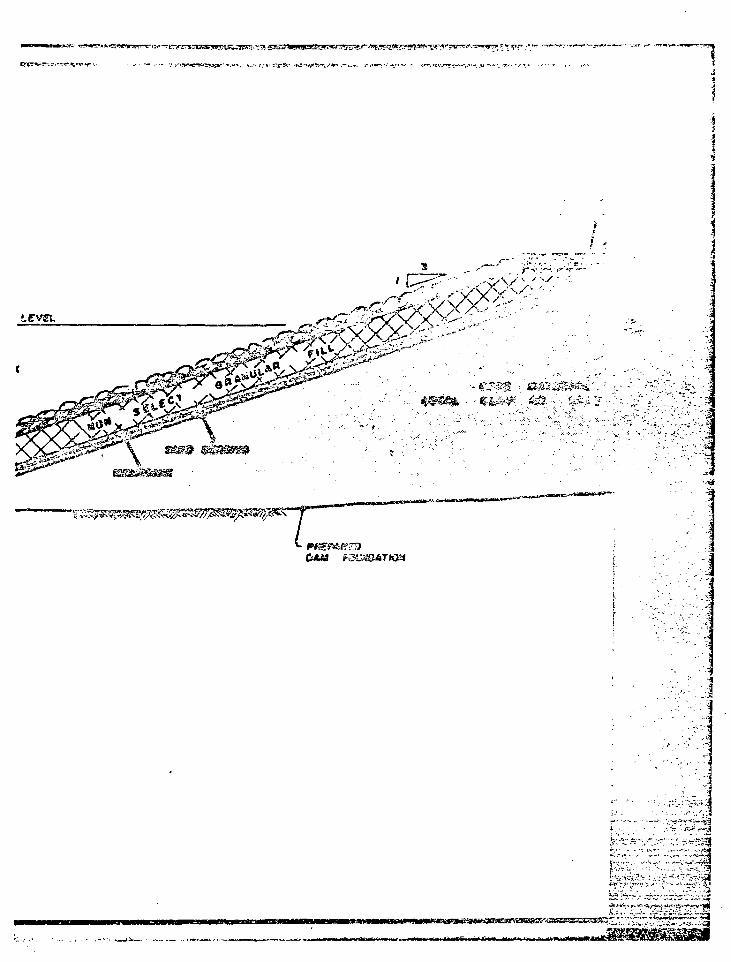
•••m
DAM
im£>
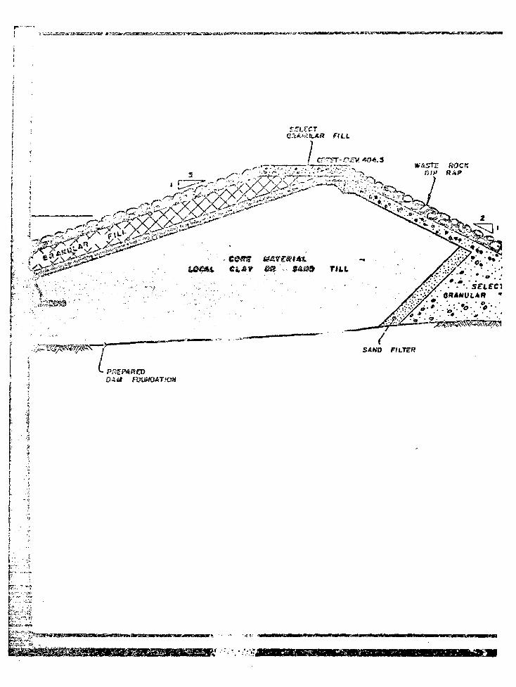
SZLVCTFILL
ROCKR;>» RAP
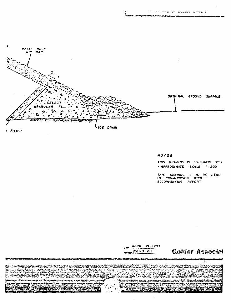
WA5TS ROCKRIP WAP
OR tQIH Al GROUKC SUftfACS
TOE 0ff4/N
THIS 0 RAW! MS (S SCKEWdTK Of LY- APPROXIMATE SCAtE / •' 200
THIS DRAWING IS TO BE READIN CONJUNCTION WttHACCOMPANYING REPORT.
APRIL 21,
941-3 IQS Gotdsr
*/*- A4
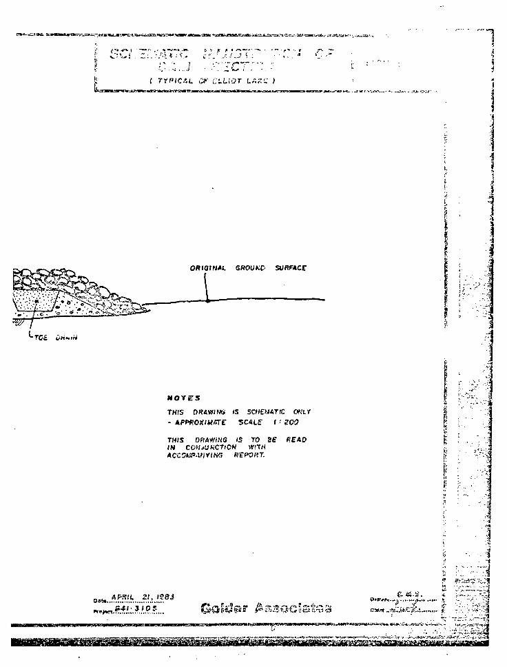
^
5Ml I • ! • IP ^ W I I I
f ryp»CAt. <;•.*• c t
1
GROUKC SUHP4CC
NOTES
THIS ORAWIfAi IS SCHEMATIC
THfS ORAWiNG IS TOIN COMJUKCTiOW WITH
RtPORT.
i ,
•rA-:.-3
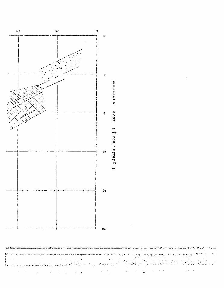
^J-^^^>VoV"'
' • ' \ s X
X So'
91
s
i- •j t ;
• . • T O - . - - - . <?P* v-v*-;"-;.'-:-.."-* . ' >* -J,: v'~i
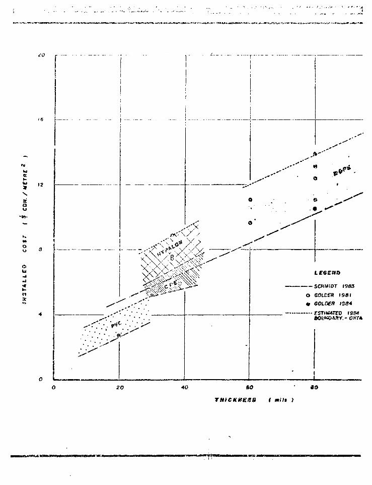
k i
au
•in-
12
ou.J
>^ N >-"
o
„!
SO
•
rf*
SCHMIDT 1983
O COi-Cfa 1981
H G010ER lt>S<
S V . - OftfT*
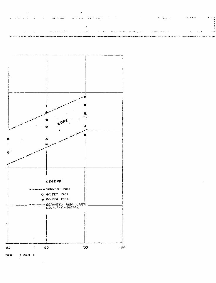
K ' ' - • " • — • - • a ' _ - . - . -
SCHhliOT 1903
O SOLVER (SSI
» GOLOSH IS84
ESTIMATED !*.?•* UFPTH
J" 'tt'VF. * '
m lev b~
M O T E S
TfsTS 03AI
t. COSTS f.!HIH5TALLATSITE PR£f
ISO
u n > m ' i M HIM • • • , p i i m
4 UU^kLtiy.—
P t
aorcst THIS DHAWIH6 IS TO 9 5 * f « D
IW COHJWiCTIOtt VlTHACCQUPAHYIM6 RFPOftT.
INSTALL AT I ON BUT DO HOT INCLUDESITE PREPARATION , SDIC CCWtS . ETC.
ivcCs^" ASSOCiStSS. 5 . . .
t J
r iuUnic e
Li
Li ,
COVER .< c fU :
l *
uir-1
t "
i ;

TA/UNGS
IT4TEH LEVEL IN POHO
LINER
GROUND SUWM
n£6K>NAL WATER L
T i l U S S S B 4 S f ( 9
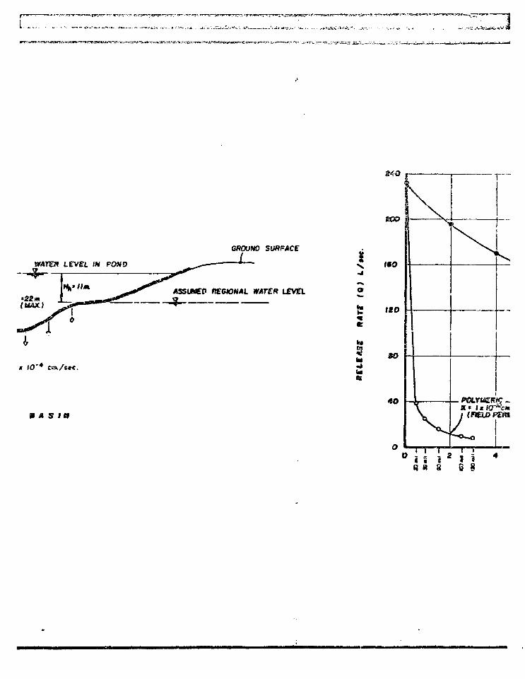
' j j>i.{(* t"jp*^x ••"«.•?««•
•>*..•..-cr. .——,*_^ i , * - • . . * -_• . ; . . . ^ . ^ ^»> iJL»;i
* I0'4 ctn.A«r.
I J I S I D
LCVEl
Is*
to
ft
8 « 8 s 8
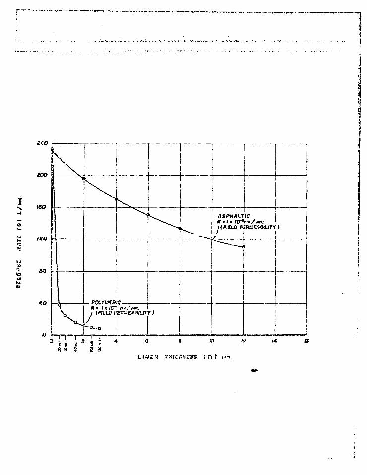
r~
TXtCKXSSS ( 7\ I mm.
13
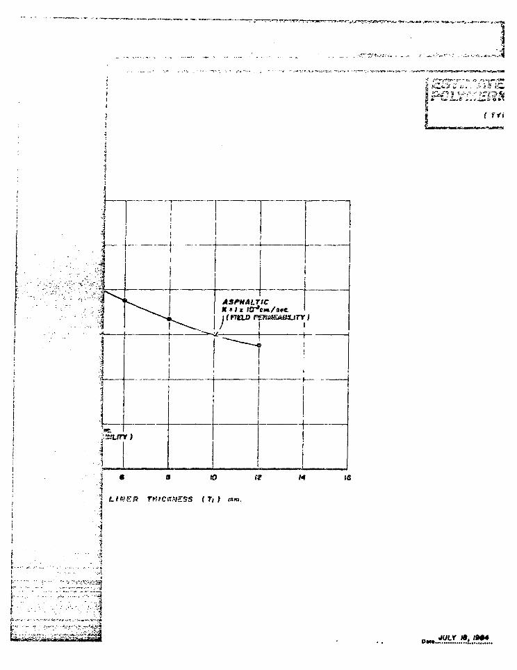
J,*V»K3|
iC^J C a.
f Tf l
ASP»ALTICIt * I * I£T*c»«./s«t
(S
TMtCKNSSS ( Tt ) mm.
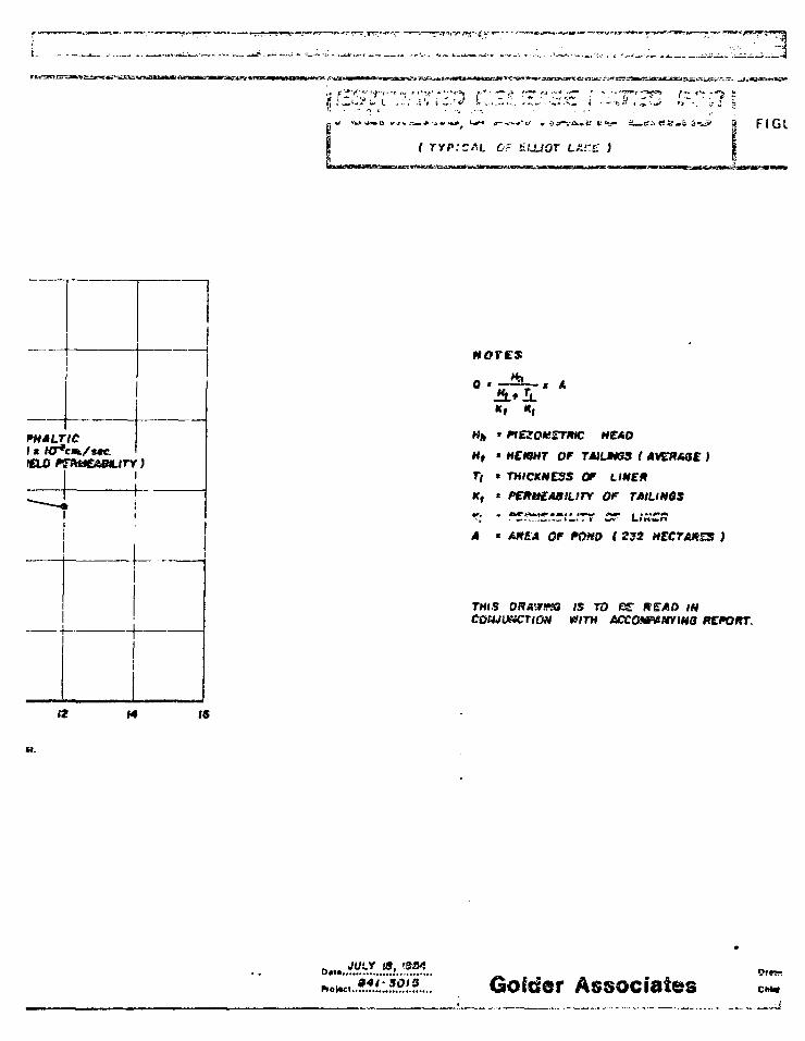
Mores
HCAO
H, t HCWHT OF r«i.MS5 f
Tt > THICKNESS Or LIKE*
K, > P€*t*£ABILITY Of TAILINGS
A « AKEA OF PQHD ( 232 HZCTAKSS )
THIS DRA&tffQ IS TO OffCQSWLf&CTlQtt V/ITH fiCCGWtlWIHB KKttT.
Notoct. AssociatesDfsw
FIGURE i ' i l
LAKC" )
* A
OK t
OF Li®€K
OF POHO i S32 M
IS TO G* R£AO INWITH ACCGXPfitSYIKO RSPQGT.
w. a r.>• ; /
f i
Li
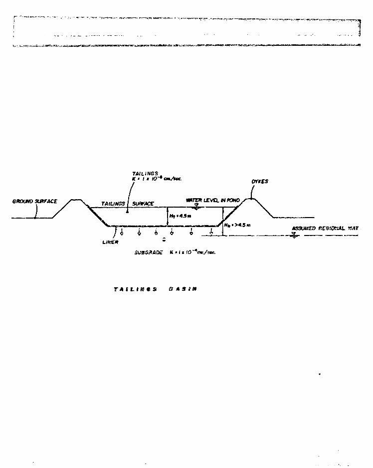
TAILINGSK * i M tcr*t*L/t*€.
QKXJHO SURFACE TAIUNSSl SUftFACC
orres
MRTCT LSVSX. N PONO
' >4.3 m
K « J K
T A C L I K C S 8 MS
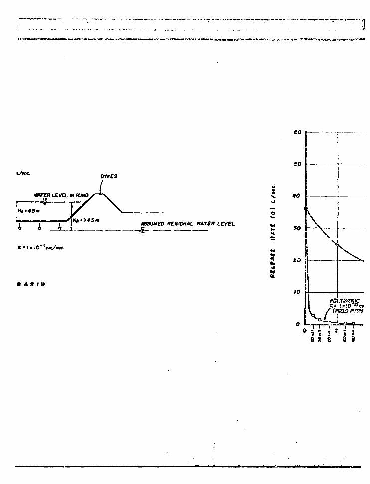
I— 1
soOYK£S
1 I _A
K * i *
m AS i »
ASSU*£O RCBlOfSAL *fAT€K
o
»
\
K>
8 S S S 8
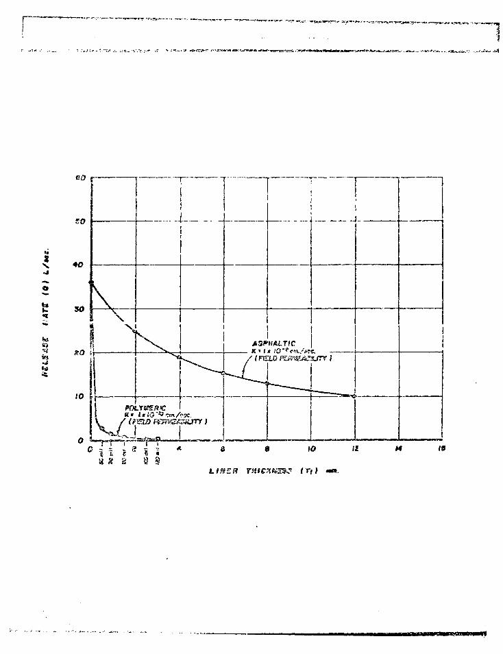
r~ 1»«.«*rp»*.wTj»yj^jst.-r<
h i
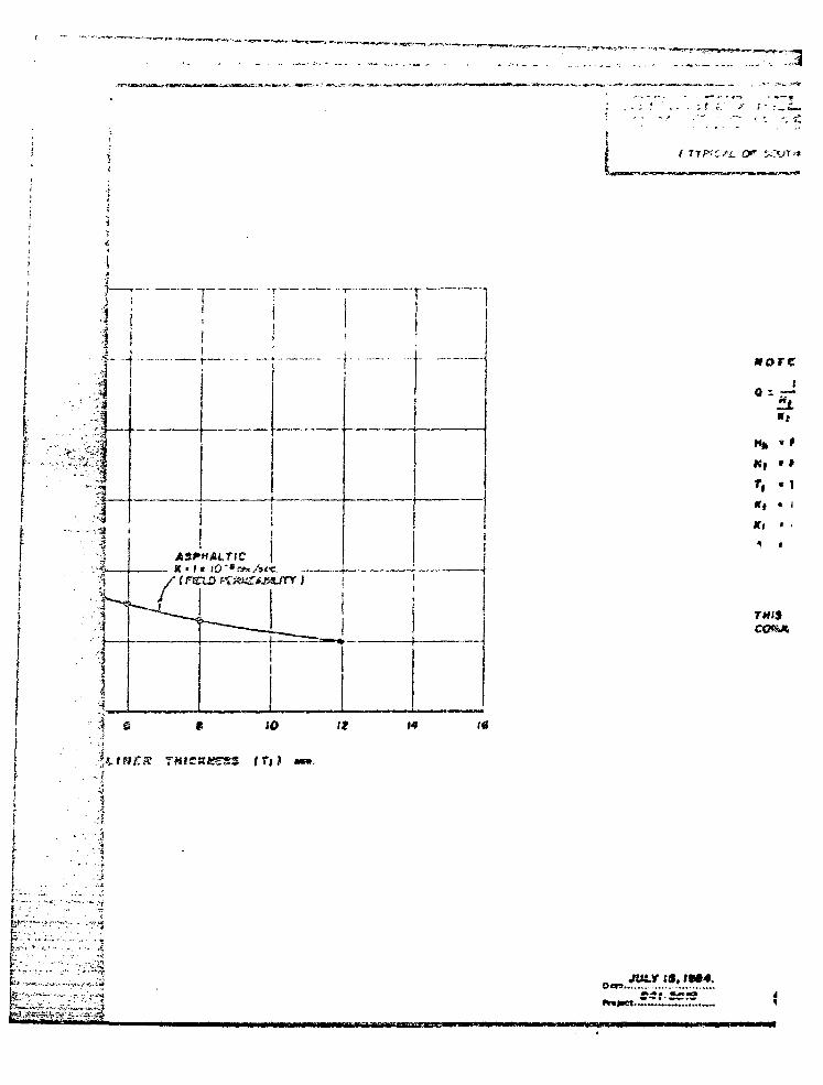
' . . - ; f ;." / ! • :_ L~
or
moreO S 5 T
• 1
THISCCtSA
•1 c « to It M («
• I
• •J
^utr f», if*4.
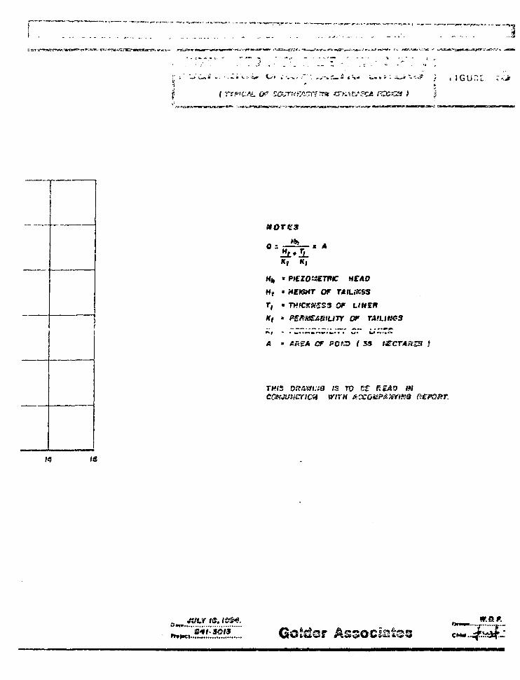
M0TG3
K, K,
HCAO
OF TASLSKSS
T, • THfCKXZSS Of UHSK
Kt * FSK&S&BtUTT Of TAILIHSS
• *•• » • w*
A • AR£A OF POfJD f 53
CM..
tmsLINER
lt.1
tH
•;3
W&P.
: • • . . • . • • • • • • • - j
i r ' ' . • •• • : . " i
L " . . • . , • „ • ; • • " ' ' ~ " : ' " ' . ' " • • " . . ' , : ' • . '.'::'~"z'%
r- ' . ,• • . - • • - • •• • • • - •• - • • • - . _ . » . . . . . , . - . , - * " T »
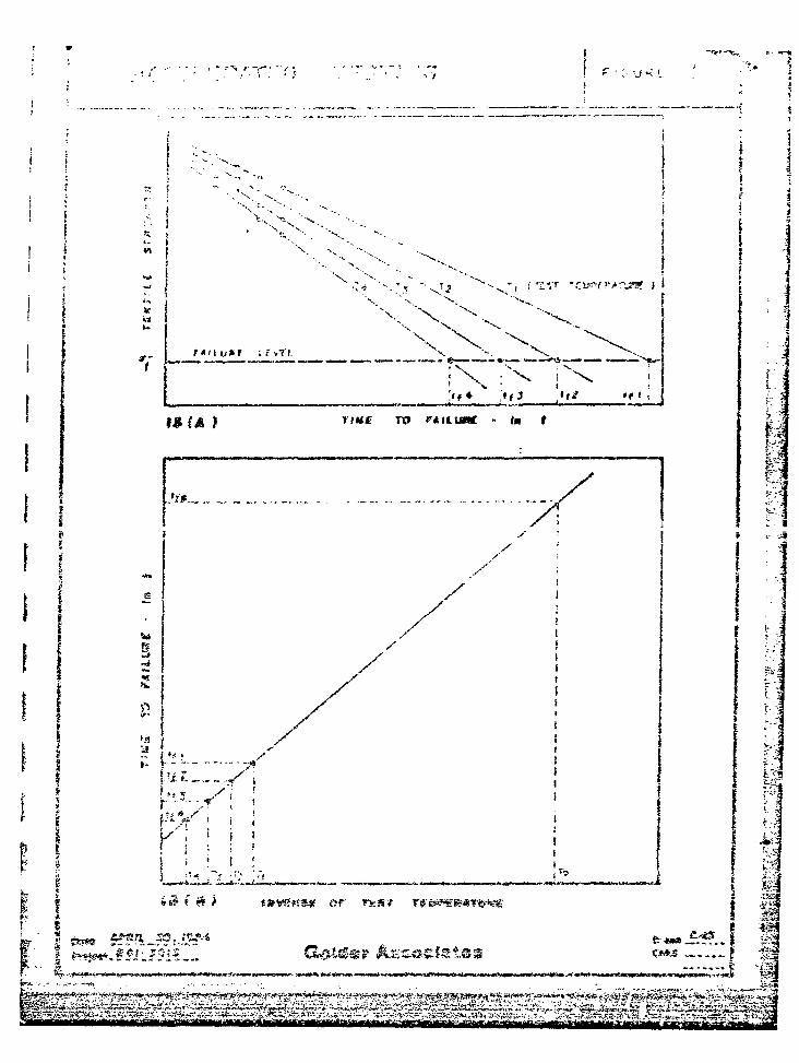
sr*-"t-. v.-
r * % - " * ~ t "
•J -; L.
i j
i \
* >
«
u*f ; f vTi.
IX (A )
or
rt . •t -
II
. ^
i V
5 1
\\ hUzs* f i n> >!
W i:.;^;,sm y
— 1
1 j - " / - ENERGY, ;; ,>iES AP4O. * ••;•*" RESOUKCE.S CA .ADA
CAHMET
RETORT NO.OSG23-
B sL
a n B s *IILL -
ERS AS LONG-TERMMIUM
PHASE 1 •v-3
VOLUME 2 OF 2
APPFNDICES
CONSUS.TINQ GKOlECKNICAt (-.NO MINING
MICROMEDIA
JULY 1984
r I
July 1084 fi4 1-3015
LIST OF A?PrNDTCr;.S
AFFEN'DIX A SLatenient of Work
!; B Polvincric Flexible Membrane Linerst, I Material Property Specifications and| e Special Test Methods and Tost ProceduresI National Sanitation Foundation (NSr\>I g Stanciard No. 54
I 'iC Representative List of Organizations
_ in L.iner Irulustry
D Liner Suppliers
I E Liner Users
F Typical Warranties
2
APPENDIX A
STATEMENT OP WORK
i
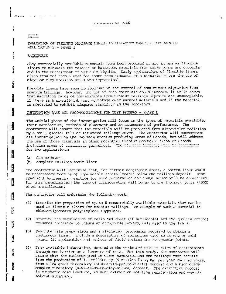
TIK
EVALUATION OF F I £ X I B I £ MEXBRA.NE LINERS AS LCN'G-TERM BARRIERS FOR UKAN'IUMMTU, TAJT.TK^ - m*s.E x
BACKGROUND
Many ccrrmercially available materials have been proposed or are in use as flexibleliners to minimize the release of hazardous materials fran waste j-.oia.is and c-.- ositsand in the containment of valuable liquids. Early applications of flexible linersoften restiitcd i'rcra a need for short-tern measures or u situation where the use ofclays or clay-modified soils was impractical.
Flexible liners have seen limited use in the control of contaminant migration fromuranium tailings. However, the use of such materials could increase if it is shewnthat migration rates of contaminants frcm uranium tailings deposits are unacceptable,if there is a significant cost advantage over natural ir iterials and if the materialis predicted to exhibit adequate stability in the long-term.
INFORMATION BASE AND RECOMMENDATIONS FOR TEST PROGRAM - PHASE I
The initial phase of the investigation will focus on the types of materials available,their manufacture, methods of placement and an assessment of performance. Thecontractor will assums that the materials will be protected from ultraviolet radiationby a soil, glacial till or saturated tailings cover. The contractor will concentratehis investigation on the two main uranium producing areas of Canada, but will addressthe use of these materials in other potential uranium-producing axeas of Canada
for two applications:
(a) dam mcjrbriine(b) corplete tailings basin liner
The contractor will recognize that, for certain geographic areas, a bottom lir.er wouldbe unnecessary because of irrperrreable strata located b=low the tailings deposit. Eestpractical engineering practice for s i te preparation and installation will be considered.For this investigation ttie time of consideration will be up to one thousand years (1000)after installation.
The contractor will undertake the foliating V/ork:
(1) Describe the properties of up to 8 commercially available materials that can beused as flexible liners for uranium tail ings. An exarnple of such a material ischlorosulphorat.ed polyethylene (!!ypalon) .
(2) Describe the rvsr.'dfacture of resin and r-heet (if a .p! iaible) and the c;.vTlity controlmeasures noc^ssary to ensure an acceptable prcxioct delivered to the field.
(3) Describe si te preparation and installation procedures requirrd to obtain acontinuous liner. lnclu:.?.e a descri.pt.ion of techniques used to cement or weldjoLntc (if applic.iblc) vsnd n&tbcds of field testing for scrcpt.ablp joints.
(4) Frcn available i:-.f a na t ion , dotoiwis-.s the o«-tLr«t.ed r->l ••—=.» ratPs of conf-wur^nt-sttirovjgh tr.p. rorrter as a fun-~t.it"n of ti^w. For this stivV, ti:*? contractor willassume that the tailings pond i s water-saturated and the tailings irass resultsfrom tlie production of 1.9 million Kg (5 "villion lb U3 Og) [)ex year ovtr 20 years,from a low grade mij^iralogy (biA-uie.riLc-jyritc-quartz) decosit aiv3 a high gradeoomplex mineralojy (U-Ni-As-Mo-Co-clay-silica) deposit. The extraction processis ^JI["^!jric a.cid 1 *-C} in'7, solvent •=rV.t-rc*i'ticn solvition rvir^fir*-?tirnn ^J>5 nnvinir*solvent stripping.
(5) DatCiTrJj'ja, flora avai lable lrifGriitii_Luji, the tooArci-.'U'u idiiuit* ffecnanisrrs andrate of degradation of the iintjr in the expected field conditions. Includea description of expected failure mechanisms of factory and field joints (ifapplicable).
(6) Estimate the installation costs of ench liner including site preparation forinstallation at tvo Canadian locations, in the southeastern Atbab-aska basinregion of Saskatchewan and Elliot Lake - Blind River area of Ontario.
(7) Prepare a technical proposal and co3t estimate for the Phase II test program.A preliminary description of Piiase II is included below.
PHASE II (INFORMATION ONLY)
TEST" PROGRAM FOR TOE LONG-TERM STABILITY OF FLEXIBLE LINERS AND ANALYSES:
(Brief description only)
Since available information on the use of flexible liners as barriers in the
test program is required to determine failure rrechanisrris, ceyraoation rates and"contaminant release rates through selected liners. The selection of linermaterials will be done in consultation with the Scientific Authority.
PLEASE NOIE THAT PHASE II IS NOT PART OF THE REQUIREMENT FOR THIS CONTPACT
H
B
":.;
I
p-
t:
II
APPENDIX B
POLYMERIC FLEXIBLE MEMBRANE LINERSMATERIAL PROPERTY SPECIFICATIONS AND
SPECIAL TEST METHODS AND TEST PROCEDURES
NATIONAL SANITATION FOUNDATION (NSF)STANDARD NO. 54
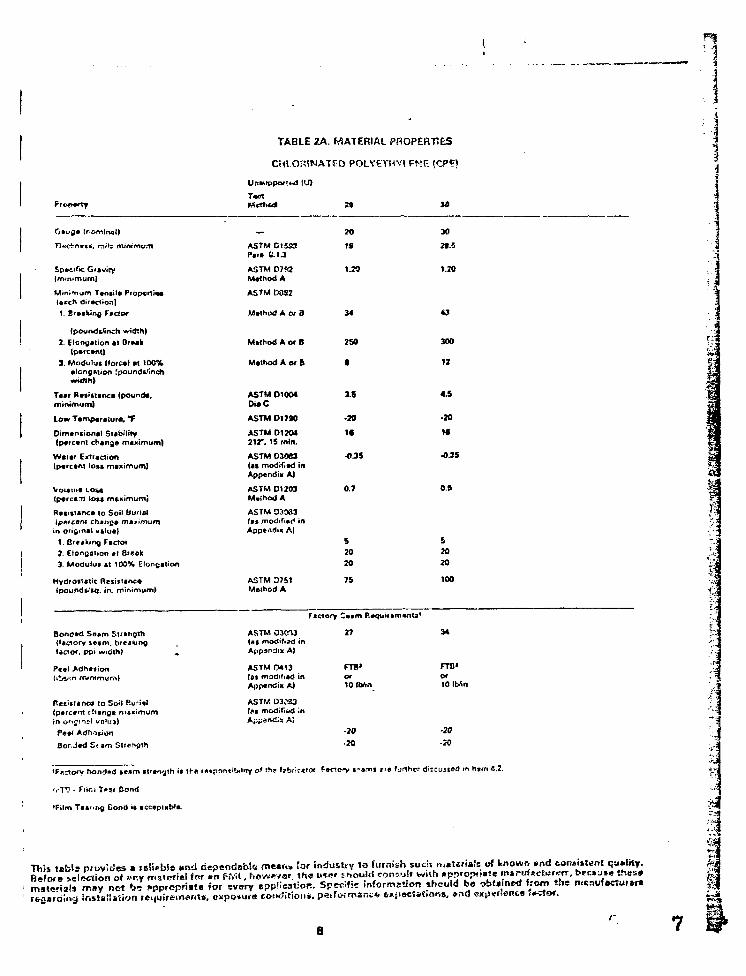
TABLE 2A. MATERIAL PROPERTIES
CHLORINATED POLY6THVI FNF. (
T « t
Gauge I
it, mitt rtummvm
£p«cif< Giaviey
MinrTium T«niul« Propcrii**l*ech dir*d*on)V Breaking factor
{pourMjrfnch width)2. Elongation at Brash
(p»fC»nt)3. Modulus (forca) at 100%
alcngntion [poundt'tnchwitfth)
T«»r Rvsittanct (pounds,mtnicnum}
Low Tamparaturti, *F
Dimensional Siabtitty(p«fcant change maximum)
W t u r Eviraciion(parcvni lo»* maximum)
Voiama Losaipcrca-tt lo«a mcximuRti
RtntTanca to Soil Burial
in original valua)1. Breaking Facrof2. Elongation at 8r«sk3. Moduiui at 100% Elongation
Hydrostatic ResiEtanc*;. in. minimum)
—
ASTM CI&S3Para 1.1J
ASTM D7S2MatnodA
ASTM D382
Method A of B
Method A or B
Method A of 6
ASTM 01004DieC
ASTM 01790
ASTM 01204212*. IS rnirt.
ASTM D3063(as modified inAppendix A)
ASTM 01203Meihori A
ASTM 03033tat modified inAppendix A)
ASTM D751Method A
70
IS
1.2S
34
250
a
3.5
•20
U
•02
0.7
S2020
75
30
2f.S
1.20
43
300
12
4.5
-20
If
-0.3S
05
S2020
100 I
Bontf*d Saam Strangth{factory i r t m . breakingfaaor. Dpi wi6th)
Peal >tihefion(ii*'.n minimum)
ResiFKncn to Soit 6u;*ial{parcant chinga rn«Kimu
ASTM 030-U(us modified inAppendix A)
ASTM 0*13(as modified inAppendix A)
ASTM D3083(£S modified MAppendis AJ
Factonr Ccam Rvquirementa'
27 34
Bor-Jad S< am
FTB« FTO1
Of Of
10 IbAn 10 IbAn
-20 -10
-20 -20
'F«rtory bon«l»<J »e»m stfength i
'rlV • Filr.i T»sr Bond
•Film Tearing Cond •• acceplnDla
o» this l?brir«tcx furthrr dir=uned in ll»rfi 4.2.
regar •tn jeijuireifKtrit*
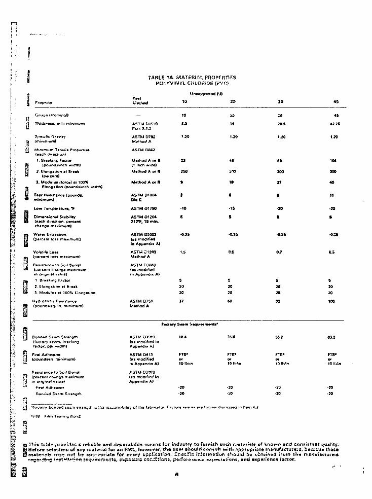
i TABLE 1A. MATERIAL PROPERTIESPOi.YVlNVL CHLORfDE (PVC?
MrthaNl 45
(Worrvrwsf)
vcs. mi In mirwrr.i»m
Q (minimum!
g Minimum Ts».»i.a Propf l iM
1. 8r*atir>£ F net of3 IpoundV.nch wttfth)
P| 2. Elongation at B'*»k•* ipafcvnt)
3. Modulus (fore*} Cl 100%m Elongation (pounds/inch «
| f T»ar Naiificncc [pounds,* • minimum)
Low Tart.paraiur*. "F
& Oimantional Stsbitrty0 (#ach ritraction, pvrcanl
chartga mtmimum}
j a Water Extractionfa (p«fcant (o i l maximum)
iLoaa
(p*rc«frt t
Rr»«st»rw:« to Soil Bur (at(percent chanpa maximum
Fsctor2. Elonp*non el Biock3. Modulus ai 100% EJong
HydrofrTCttC R»Bii^anc0(poun4f»q. in. minimum)
A5TM O15S3fare S.I J
A5TM D79J
ASTM0SS2
M«nod A or 0
10
1.20
20
Mxhod A of B(1 inch wid«)
Mtihod A of B
23
2M)
ASTM 01004DiaC
ASTM 01790
ASTM 01204212"F. IS mln.
ASTM 03083(Mt modifiedin App*ndix A)
tST™ £1203M.Ihod A
ASTM D30H(•f modifiedin Appendix A)
ASTM D7S1M«tt.od A
3
-10
s
•0.3
1.S
s20
20
37
iflO
II
8
-IS
%
•0.35
9.E
S2020
60
iO
1.20
6*
300
27
-20
I
-0 35
0.7
S
20
20
S2
*i
1.20
104
300
40
If
•29
I
-OSS
OS
s20
20
100
£ n
i'i
(fficiorv te*m. brtfactor, ppj width)
i'l ,pound»>»fi minimum)
fl«li*i«f>C» la Soil Sunai(p«rc<»M rh#r»^* minimum
ASTM O30S3(»c modified inAppamlix A)
ASTM 0413<«s modifiedin Appendix A)
ASTM 03033Us modified inAppendix A)
18.4
FTS'O f
10 Itvm
-20
-20
36 »
FTB>
-70
•JO
55 2
FTB"Of10 IMn
•20
-20
83.2
FT8"or1(1 Itrfn
•20-20
c •: • 1
'FTB tilm Ttinng Bond.
of the (
is i9 This tsSita providec s reliable «nd lieper.Jsbin rr.e*rts lor industry to furnish si/ch rrte<?ri«!» of Wnowo »rsd consistent quslity.% g Befwa selection of »ny msteriai for »n FMt., however, th« us»» shoulrl eontutt with spproprists m*na*»ctutsrs. beciiuic *ho4«5 S rn»tf>n?!r« rr>9« not be Eppropriata for way application. Specific Ir.fotmilior. sho^:d be ob»i.ifi»!<i from ihe ni*nifi«cturer»6 !«••»•».•••«•• rsq-.rirtmr.ts, csposur; ccr.^itiori, p»r!oiir:iiiit.g •>/•.}>«;{«Irons, end axperienca fscrfx.
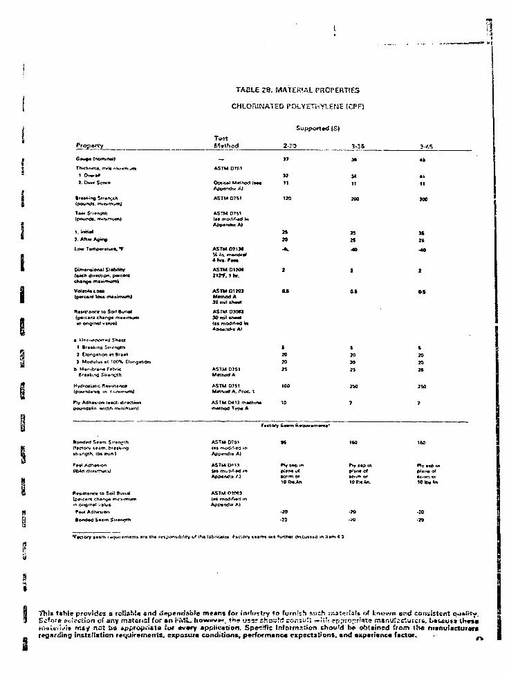
g
TADLE 2B. MATERIAL PROPERTIES
CHLORINATED POLYETHYLENE
Property
(pound*. rrwn*rm*m)
(pourdt. rruni
V Srwtifi*
7. Ahw A9in9
f •fur*. *f
(pawesnt toct miiimuni)
fUtitfanra lo Soil Burial(p«it«ru char^« mto oriQ«nftl w«Kt«l
2 Elonpttioa *1 Bt*»i
3 M o d u l i at ".00% Ctongation
(pour%d«-M). <n
Fly AdhtftiOft !••€*.
'Factory l>im i quii I I M M I art trw mp
Ttrat
Support»d (£)
2-?3 3-JS
17
ASTM 07C1
Optical Mathod ( > M
ASTM D751
ASTM 0741
ASTM D21H% in. mancWalilvi PM
ASTM 012042irf . 1 hr.
ASTM 01203Mat hod A
ASTM 030*3
tat modif*«d inAooamfc* A>
11
120
24
-*.
2
14IT
n2*
4>
11
1 *
J20
t20
ASTM 07S1Mat hod A
ASTM D7S1Method A. ("rot 1
ASTM 0413 mactitfim«thod Type A
ASTM D751tax modiiiM »nApp«ndia A)
ASTM OWM
ApptndK >.|
2025
ICO
« 10
Factory Stan R*OUM*m«p«
S6
pltnipfsefim n»
-29
-25
20
24
7
no
p^iin* cf
igcxin
•70
•»
20
n
2 U
7
ISO
*1y ace inDiana M
10 Iba «».
-20-20
Thti Ishie provides a reliable end dependable means for inffi/jtry to furnish r.uch rr.Atcriil. o( known end consistent qu*ltty.Ecfare »fe!e.«tis>n of any material for an HML. ko«ww» ««« •_•••» shsaW sc-.-.s .'; -rii't pppropriaTe m*nui;rtutef», L>»tsu*» thrs'arucilciift* rajy nat as «(>j>roj)ri»t« Sof every appiicstion. Specific information tSou'd b« ob!eir>td ttam the manufacturers
instnitation requirements, expotura conciitionn, performanca expectat'ortt, and eitpcricnca factor. • _.

i iTABLE 3. MATERIAL PROPERTIES
BUTYL RUDDER (Ita)
h
i.j
n
ti
PSi ;U
y
14S3
T>iidu>«ta. rrwts tntn
V Breaking Fret or
7. Etortg**ion at Bifl(p«*c*aC]
minimum)
Low T*mp«ratur*, •*
Dim«n*ion*4 Subiltty(«ach 0ir*ctic i percentChang* maximum)
flvtUtanc* to Soil Burial{ptewm Changs maximum In
V Brasking Factor
?. Elongation at Bra*k
DuroYnatar A Hoidrurm
Oton* Rensrinc«
Haat AQing
1. Elongation (pet-cent.rrunimum]
2. Braking FMGOT(pountjtjmch wtdih, minimum)
8on<tetf St»m Sir«ngth
ttctot, i
Oafrd Lcani
K rtnv ma^>fntjn^
c^»:S Secrri Slrcnfl-i
'f
tnmtrtot xo
ASTM 0417
ASTM 07!S
ASTM O417
30
77
60
I.JOt.Oi 1.20r.CS
ASTM 0824D I I C
ASTM 0 7 * *ProcKtuf B
ASTM 01204212*F. 7 d*y»
ASTM D30«3(as modifier! inAppandil A)
ASTU 0*1 i1S8T 1KB hours
ASTM 022*05 second fafr^in^
ASTM 011*9100 hourc, 50 pphm104>'. 70% cMionti.-Wi
ASTM D57S7 davi ft 2«CTT
3S.0
300
4
-40
2
10
20
60:10
No Cr»ckl7X
54.0
300
•
-40
2
10
70
4
60:10
MoOadta7X
72.0
300
•
-40
2
10
29
2
60,1
NoC7X
210 210
371
210
S0.4
Factf-ry $ * im Raquirvmcnta1
ASTM 03063{as modii'pd inAfjpendix A)
ASTM M 1 J(as modified in
s«>
2 I J 437 S7.C
rTB-or6 IMS
FTa*or5 \L'.r.
FTB'or
A)
f'.t.
-70
•24
>•?» (•an
-73•20
l »K» f•»!...--*.•.-
•FTB • Ci'.m Tstriru Sc-a!
p" ."n ts&ie prcviwvS a Fe!t&i:!a af><> tSepcttdahla meant for industry So furnish such msteriers of known end consistent quality.j-Ssfsra s,«i£ctior> of «ny n»«t«;6i for an FrVlt., however, th« t;»w rhouid consult \vtth »riorr.»3ri»!j» m»nijf*>-Tuff»*, b^friKij tf'frre
^ t i not t>« e^pfoprijt* fo» ovanrv «DBiicjirion. Sdeiivic itifnrmation din>>in *»• ~t»trr~e< ' ' 0 ^ ths rr::ru!;c^;rt,-sexposuio coriditiont, pvr>otii*>sr:r.* «Kpcct«tions, and experience factor.
10
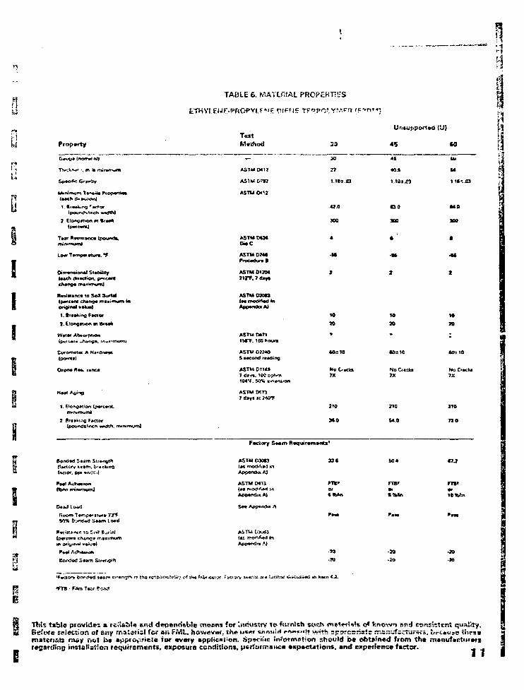
nTABLE 6. MATERIAL PRCPcKT'iS
u
u
I
I
TestPropwty
T»»» KwiQinca (pound*,minimum)
Lo* T»fnp**turv, "7
iac A Hcdn*»e(pert*)
1. C
2. mtn«mum|
t%aot. |
Dud l iw l
- Tvlm T»of Piw?
r,' cf tft* f
ASTU Ml?
ASTMDT*}
ASTMDtM
ASTMO7WFrocwlural
ASTM0I7M
45 SO
JO
27
DO
300
-3*
I
10
70
U.
u1 II-. O
MO
100
1
ASTMM71liTT. 165 houn
ASTM03M0
ASTMD1U*7 d«r«. 100 pphm104*f. 50% entntion
ASTMMTi
KoCckm7X
210
M.0
(Ox IE
7X
210
-
10=10
NoC'Kbs7X
210
7 2 0
ASTMO30U 3 3 * « 7 J
l I M n
AiTW DXiU
Appcndn .'J
-79
•TO
-20
- »
This tsblc provides a re.'iabta *r,d d«pendebte meens fof industry to f;s?nish swrf\ m*««-r!i»?s o* knovwn end consistint quality.Before selection ol any maierisf for or. FMJ.. howevw, th* u%.*t ijnnuni <-«r.«fii» i*.;*^ =psrE=riatc r:sr.yfsc^urs.-s. urc«i»s ui«i»materists may riot b» «ppio>:nele Tor avary Bppltcai>on. Sp«cnic in'ormstior should be obtained from tht m«nuf»ctur»fg
di installation retirements, exposura conditions, ptrtormsivco •xpeet«tioits. and experienc* factor. ^ .
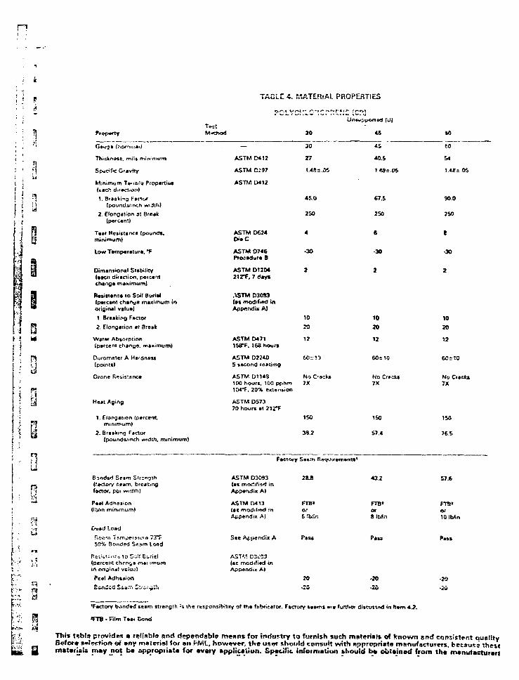
n
TAGLC 4. MATERIAL PROPERTIES
! i! i! ?!
ii
V Breaking Fscior
2. Elongation *r Break
Waff* Absorption(percent change, maximum}
Duromeler A H*rdnt«(pointtj
Oione R^sisianc*
Meat Agir>g
1. Efongarion (
2. Qf»iittnQ FactortpouridsJ>nch vw h. minimum)
150
39?
ISO
S7.4
*0
C u f . {nomine.)
Thick nc«t, milt mirvrrn/tn
SpwdOc Gravity
M:nimum TVnula Properti&a
(poundaJirKh wiJtM
2. f(onQjtion at Break(pftfcant.
minimum)
Low Temperature, °F
Dimtnsionul Subilny(••en direction, pcicantchange maximuml
Raxinanca 10 Soil Burial(percent chanye maximum inorigin*) value}
—
ASTM W I 2
ASTM D29?
AST?/ LM12
ASTM DM4Die C
ASTM D746Procedure B
ASTM 91104212*F. 7 days
ASTM D30S3let modified inAppendix A)
30
27
45 0
250
4
-30
2
«5
40.5
1*81.05
67.5
2 SO
6
-30
2
60
54
l . « i OS
90 0
t
-30
2
ASTM 04711S8*F. I63hourm
ASTM D224O5 second leading
ASTM D11«S100 hour*. 100 pf>hm104*F. 20% eidenuon
ASTM D57370 hour* »l 2 i rF
10
1?
60* ia
No C-scki7X
10
70
12
60*10
No Cf»ct»7X
10
30
12
60=: :0
No Citckx
ISO
76.S
fa
u
• ••:' <!}
E^nde<i Scam Stltrtory r.i.m.
J. poi widi
P»»l Adhtjion(tfin mintmurnj
SCf% Bonded S«»m lo*d
Rtttitit^.; jo Siif Suria)(p«rc«nt chrrx^i msi.imumin orisiniil vfi!u 3)
fcol Adhesion
S«rfs<J SSS.T. C:.-i.-^;h
ond»d »e»m
TTB • film T**i Bond
ASTM D3093(ai modified inAppendix A)
ASTM CM13(ac modified in
in A)
ASTM C3CE3(itc modified inAppsndic A)
2S.B
FTB»Of6 !»n
43.2
FTB»orSlWn
P*u
-20
57.6
lOIMn
•20
ij the leiponjibility ot th« fabritelof. F»aory »»d>n» *f« furthm di»o>ttnd in him 4.2.
This fsbls provides a refi«b!» and fiependsbie means for industry to furnish such materials of known end consistent dualityr>#for* Sfiertion of »ny material tor »n FML, however, the u ; n should eonswft with «ppropri«t« manufacturers, fcecsuss thesematari«>s may not t « appropriate for avsry application. Spacific information thouid b* obtained from th» manufacturari
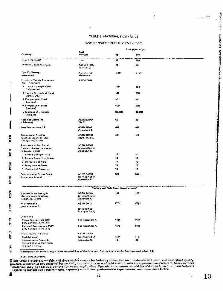
TA3LE 5. MATERIAL fKO?*".'-.TIES
HIGH DENSITY POLYtrHVXEVS (
T—«V<J
I min.mum
Crawly
crnnfftf. Yi«fc»
2.Tantiia Sircoglh at SraaI M n w-jth)
3 Elono* en al YiaW(oMC*ntl
4. Elongation a Brvvk(pwcitnt)
5. Modulua o* .Imidty(IHsqln)
Taar Rasittanc* (Ih,minimum)
tow Tamparafur*. * F
Dt/nansionai Stabilityla«ch duecTion. p«.-ca
A5TM D l i 3 i
ASTM D7S1Me?Hod A
ASTTjtDGSt
ASTM 01004DtoC
ASTM 0748Procadur* >
ASTM 01204
O.SM OKK
MO
120
10
soo
•0.000
40
-40
i:a
ISO
10
MO
to.ooo
so
•40
=3
IReftsTanca totpa'cam c.r\Angain onj,;..-.?" vaiui.)
2. Tan^ita Sltangth at Braak
3 Elonsatia.1 • ! Yidtt
4. Etongjtiort at BreaA
!L Modulus o< ElastloTy
Cnvironmanul S»«»f» Cfck(mtntmum, hcruraj
ASTMO30K)lak modified inAppendix A)
ASTM D1633{as rnod;fie4 tApparxfcx A)
10
10
10
;o10
MO
10
10
TO
10
soo
i Bon<)»<3 So»m
minimum)
land
S-BIMTl
ASTMOS0S3i*\ mrxfift«d inAppvrtoix Ai
ASTM041J
lairin App*r. jw AJ
ASTM OM83(aa m<Ki.rm( ii
.A)
10*
FTB«
Pam
Fib*
m
FTB»
Pat*
rTS'-20
1
•FTB - Film Taar
12 13
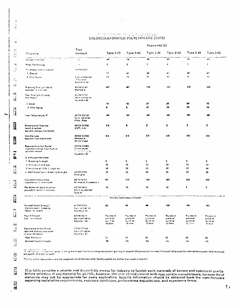
CHLORCSULKO.MATLO V OLYE rHYUNE (CSFE)
} '.:M<t;nod Typ* 1-30 Typ* Tfpo 2-3f Typr
36
1
T\-p» 3-36 Typ»3-«i>
5 7
11
*fA» n : OII.B^J in
Ap^r id . t AJ
10S
1 * IE
JOton
70
AS1M D71i»
AS1M 01734j ir t . i »w
40
ftafiMtrv^ 10 Soil Ruri
Cf.nm»l v«U-*«i
• U«*«opened *K»m
t 6i»(.king Sttenjth
, « t o n B . , . . . . , » , . . .
3 u l d u i u >n 'oov t
ASTM D130J
30 mil «r.»»l
AST M 01083
Appendix A)
ot OS D.t 01
A i l M D751
ASTM U?MM..lhod A. Pr^cedutc i
ASTM D413
T»f« A
5
70
«0
BO
10
s
70
10
&
70
VO
IS
1 6 0
10
b
70
7S
. N
10
«.
JO
70
70
: «
j
i
TO
J4
75C
I
10 I t*
JO 70•7J
This ta'ils j f rovir^ n reliable r.nd di-psn^i.blt maims fot industry to [urnir.li tucli muterisls of known »nd consistent qiBp-foro s*l*ction of Eny rr;Bt?ri3l lot an i-'ML, hownver, {he n«pr should consult wish nppioprinle intfiui/ictuicii. bec.iusemelerinU tn»y not be appropriate (or evory upplirdiion. Specific infrwmatioii ithvuld 'os obtninod (torn tho milregarding insUllMtion rpt-oircrrtents, exposure condiiione, pen'orrnenco expactationi. »nJ nxoi«ii»or. <-"<.~.
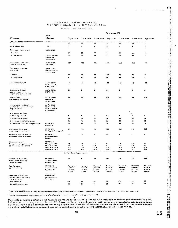
AOLt ion. IAATC.WAIL'-Oi'oAI-.'.n POL'r '• THYl f.vf. ICMT.-1.W)
:1*Ki (SI
Tyye 1-30 Type 2-3i Typ* 2-<S
—
-
ASTM OTI1
SO
1
JT
11
14
1
S I
11
U.11
J-3S Typ. J-t5 TyjveS-W
19I IP
109
40 n•an
•40
jirr. i dr.T.S
Ipottm chcr^i maair->un. In1st r*>or >r>a0 In
AS TV 074»( I f rr-.^-.r.-rf tAppando AJ
r - * t>f I A * ft*
j —. c-
; j
Wtmb'int F«b'-c B AS rW D?51
Method A. f.'KWJui
I
20
23
:s
K• 1
>
»
ft
20
20
1 5
I K
20
3O
19
7
JO
2 t
2V1
7H
1 1JO
IfJOJOOM O
It
MOKiC
1 I20
I t' 0M O50 0
1 17 0>0 0M O
I t3 0X>0x o
;1
15
r. 1
hi
APPENDIX A
Spocis! Test ?J5ethods and Revision of Standard Test Procedures
TABLE OF CONTENTS
Part 1 Water Extraction
Part 2 Bonded Seam Strength
Part 3 Soil Burial
Part 4 Peei Adhesion
Part 5 Tear Strength
Part 6 Thickness Over ScrimPart 7 /""harv^i^oirr^f-tr* -»r"^ O<-J p-
P3rt 8 Ply Adhesion
Part 9 Weather Resistance
Part 10 Dead Load Seam Strength
Part 11 Deed Load Seam Strength at Elevated Temperature
Part 12 Environmental Stress Crack Resistance
in

i1
Water txlrection
HMB
i i
5 ASTM p?r""? Ppit'irr'"^: 2.P ""'cdiTicd t? be::
A. Apparatus
j 1. Bnlence: An cr.aiyticsl b;:lfince
J2. Containers: Pint jars or cans withe diameter Gf at least 2.SJinchss ;6.5crn! (one container for
i each specimen)
* 3. Oven
I 4. Desiccator
B. Materials
| Water: Freshly prepared distillad or deionized water.
C. Test Specimens
The test specimens for plastic fiims shall be in the form of squares 50 ± 0.25 mm (2 inches) oneach side. At least three specimens of each sample shail be tested with each chemical r. agent.
I D. Conditioning
Condition ths test specimens at 73.4 ± 3.6°F(23 ± 2°C) in a desiccator for not less than one hour \"
' E. Procedure
I I. Maintain the water st the test temperature for at loast 4 hours before the specimens areimme:sed.
1 £12. After being weighed, immerse the specimens in ths water, one specimen to esch container.
I Each jar shall contain 400 ml. Suspend the specimen freely in a vertical position, but fullycovered by the liquid. To prevent each specimen from floating or curlinp, it may be necessary . jto attach small weights, such as paper clips. l *
!3. Cover the jars containing the specimens and koep at 122 ± 3.6*F for 24 hours.
F4. Remove tho specimens from the liquids and gently wipe with a soft cloth or absorbent tissue. N
I Dry tha specimens for 24 hours in a desiccaiyi ai 73.4 i 3.6".
5. It is realized that thera msy bs an incraace in weight of the test specimen due to waterabsorption. It is necessary to determine if a correction factor is needed, and the value of the j .*
( correction factor. Prepare 8nd condition control specimens in the same manner ss for the ? j
standard test, but expose them for only 5 rnintues find dry as spociHnd in Section E.5. If the [ :
contro! sample hes a weifjnt gain the calculated percent weight ucin oi the control is the f ' • * .• corr&c'uon tactor that is used to edjust tho vaiue obtaincci in ths i'.-at.• F. Calculations
!1. The percentage iocs in weight from extraction, sxprcsssd as pofccntsna vvoight loss com-
pared to tiie original specimen weight, shall be caiculeted ss follows:Vveigru ioss. percent = jWi - W:|/Wi K 100 where:
Wi =» weight of specimen after the conditioning period and. *»Wa = weight of specimen at the end of the iest. ^
j 2. The vrt!us5 obtsined for tho tiiree >puuiincMs Tor pcrcentags weight ioss shsli bs BveragcdI and this value reported ss the percentage weight ioss of the sample being tested. '
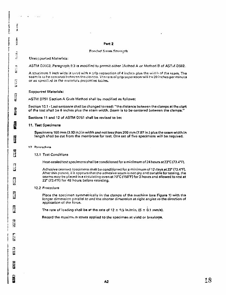
I & Part 2' -. f
'1
ASTM D3CS33, Paragraph 9.3 is moti'ii'iod to permit either Method A or Method 3 of AST;S> D382.
A specimen 1 inch wide is us-ftd with a fjrJp separation of A inches plus the width of the seam. Tnssaam is to bo ceninreo botwoen thscieinpa. 'ihoretoof grip separation will be 20 inches per minutaor as spflci'iocl in the materials properties teD
Support**) Malar ia!* :
«STM D751 Section A Grab Method shall bb modif ied as fo l lows:
Section 10.1 - Last sentence shall be changed to read: " the distance between the clamps at the startof the test shad be 6 inches plus the seam width. Seam is to be centered between the clamps."
Sections 11 and 12 of ASTM D751 shall be revised to be:
11. Test Specimens
Specimens 100 mm (3.93 in.) in width and not less than 200 mm (7.87 in.) plus the seam width inlength shall ba cut from the membrane for test. One set of five specimens will be required.
[ | 12.1 Test Condit ions
Heat-sealed test specimens shall be condit ioned for a m in imum of 24 hours at 23°C (73.4°F).
& Adhesive seamed sp3cimens shell be condit ioned for a m in imum of 12 days at 23* (73.4'F).After this period, if it appears that the adhesive seam 13 not dry and suitable for testing, the
„ seams may be placed in » circulating oven at 70°C (158°F) for 3 hours and allowed to rest at\A 23* (73.4°F) for 43 hours before retesting.
12.2 Procedure
• j Place the specimen symmetrically in the clamps of the machine (see Figure 1) w i th tha™ longer dimension parallel to and the shorter dimension at r ight angles vo the direction of
application of the forca.
g The rate of loading shall be a» tha rata of 12 ± 0.!i in./rr.in. (5 ± 0.1 rnm/s).
Record the maximi j .n struss applied to the specimen at yield or breakage.
A2 18
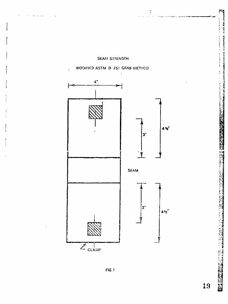
SEAM STRENGTH
WOOIRSD A5TM D 751 GRAB METHOD
4 V3 '
X J
SEAM
3"4V2 '
i-J
' .2
i
^s
r."
CLAMP
£vi
M
FIG.t
8 n
• Part 3
^ Soii tsuriai
* ASTM D3083, Paragraph 9.5 is modified to ba:
W, The test value of tha sftsr-exposura specimen shall be basad upon tho precut sample dimension.
The test method usod to determine beforo and nftar exposuro tansite properties shafl ba the testmethod specified in tha maloiit-Az properties tables for lha lensilo properties of tho material.
0y Specimens ere to be prepared and buriod vertically to a depth of 5 inches and exposed as specifed in
ASTM D30G3, Paragraph 9.5.
«S Tests for Unsupported Materials
a Testing shall be conducted on specimens prepared from the actual flexible membrane liner.
Tests for Supported Materials:
iB Fabric: Testing shall be conducted on specimens of the fabric used in the supported sheet Six
specimens (4 inches wide by 6 inches long) shall be preDared, three in the warp direction and thresin the fill direction. When testing the fabric by itself {no polymeric membrane costing) before and
£9 after soil burial, it will be necessary to make sure slippage does not occur. This can be done by| j using tape, sandpaper or cloth material, special jaws, etc.. It is also important to note that
consecutive fibers that are grabbed in one jaw correspond to exactly the same fibers grabbed inthe omer jaw.
tj Sheet Material: Testing shall be conducted on 30 mil unsupported sheet prepared from thesheeting or coating compound ussd to produce the supported flexible membrane liner.
; { Tbsts for Factory Seams
Testin.; shall be conducted on specimens prepared from actual flexible membrane liner factoryra fabricated seams with soaled edges.
y
[5 Port 4
Peel Adhesion
M ASTM D413 shall be modified to be:
iStrip specimen Typo A, 180° peel, modified to be 1 inch sample width pulled at a rsta of 2 inches/
ra rninuio. Usa bonding technique employed in ss3.n join! construction.
Part 5
Tear Strerejtft
A5TM D75S shall ba modified to be:
Te°r Etreny'.h of supported rr^tsriai: :hc!! bs dc:crrr.;r.&d uiirsg •'.'cthoc! 3 - Tong^o Tcif .MiiiiOu.Th$ teat specimen ihsll be 3 x 3 ittches. For oven lifting ioar strength, inilial values acid values afteraging in an oven at 212CF foe 30 days shall be determined.

PART 6
f."ATEP.!AL OVER SCfi'M \{SUPPG-BTS?»G FACRlCj 1
1
A. Scope 8nc: Application |
This is a method for measuring the thickness of 8 mombr«ns over the reinforcing fabric. ?
B. PrincipleThe thickness of membrane material over reinforcing fabric can bo observed with a standardreflectance microscope. -Measurement is made with a calibrated eyepiecs.
C. Accuracy
Measurements are accurate to ±0.5 mils when the thickness is about 20 mi's. yk
D. Apparatus
1. Microscope, 60X with reticle
2. Light source
If light source on the microscope is not adequate, a small tensor lamp can also be used.
3. Stage Micrometer (0.001 inch divisions)
E. Procedure
1. Calibration
a. Place a standard reflectance stage micrometer in the plane of the sample.
b. Turn on the microscope light source.
c. Position the reticle eyepiec > and the micrometer such that the scales are superimposed.Focus the reticle by turning the eyepiece. Focus the sample and reticle by turning thevertical adjustment knob.
d. Locate a point at which both scales line uo. Count the number of micrometer divisionsbetween that point and seva:al reticle divisions away. Pv.sasure to th« nearest 0.5 mil.
The calibration may be optimised by increasing the number of divisions measured.
e. Repeat the calibration three times and average tho rosuits.
2. SampSa Analysis
a. Corefuily center a sha.'p, single ed£8 razor or equivalent over the fiber intersectionsalong tha ;< - x HRQ.
21
11
iii1
1
i!!
g
PI
y
b. Make a clean bias cut completely through the linsr.
c. Remove the tazot cut socticn and mount in common putty with thfj cut surface facingupward.
d. Observe tho cut surface with the eyepieco reticle. Measure tha thickness ottha lin»r oneirhsr sids cr n-.s thread intersection by counting tho number of reiiclts divisions (to thenearest ono-haif division).
o. Sample two or three crsas of the liner snd averoge the results.
F. Calculations
1. Calibration
A calibration example is given below:
8 In the above example, 4.5 micrometer divisions (MD) are equal to 4 reticle divisions (RD).
m 4 (RD) = 4.5 (MD)§ 1 (RD) = 4.5/4 (MD)8 1 (RD) = 1.1 (MD)
jB One micrometer division is equal to one mil, therefore:
1 RD = 1.1 mils
p| This calculated value (1.1 mils in the example) is the calibration factor.
i 2. SampleI| P Multiply the number or reticle divisions by the calibration factor. Report results to the
% nearest 0.5 mil.
PART 7Chemical/Tosia and OdorA - Fk-viaw Procedures
for!n t»nd^ for f*SF listed
p> PotafcJa Water Formulation*
h& SECTION I. GENERALr* A. GENERAL: The- ingjedicnt review procedures detailed bstow include those for:
1. ACCEPTANCE of £> nsw ingrRriient1 and a genurically similar injjr^disnt*
. , fp 2. QUALIFiCATlON of a new compound or material or change in formulation
L: 3. WO.MTOniiMG of a lifted product
I ' *Nftv^ In^redisftt < £ny chernicAt or Eubstmcd not previously JKiCtfplAd for Uftd in pfcxiuct* i/tfthi<l*<i for appiicsoon in f\g. pi wetcr liner*.
';; o 'Gensricsily Similar InQrodisnt • an innrmj'ent thsit it not considetsd a "nay? ingrsdisnt" tnd whlia genericalty limilur io inscc9nl«i insredntnt it may vary in composition tiua Jo maniif.ctuiiog pfocotj, *ou<ca of fri«l»ti«it. (.xiteniiol ir«co coiittmi-
M. nania Mr
¥; m* I A6 OO
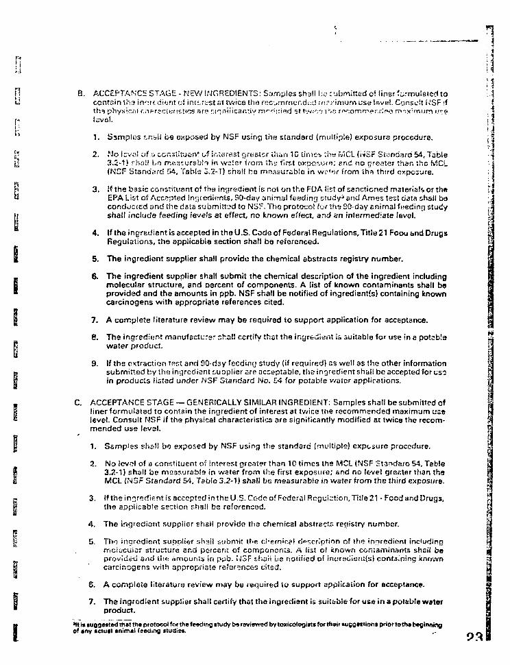
1
n B. ACCEPTANCE STAGE - NEW INGREDIENTS: Samples shall be cubmitted of liner formulated to '-..-d contain tft-3 in^rc riifsnt of ip.t:.r;vst fit twice the rRc^mrner.dtcf mrrirnurn use level. Consult NSF if
ths physical cnrrecici >s*ics ara mniiicanr.iy m»~/<::ied at tw;c: ths rfK-.omrppr.rJws maximum i.";e "j * level. [:
i; ik> 1. Samples f.hbli be exposed by NSF using the standard (multiple) exposure procedure. ;•
I" 2. No lsv«! of ,j ccr,3;itu«n* of interest ^raster uvaii 10 timc-s :iis fv'iCL (i*SF Standard 54, Tablei| 3.2-1) r.hoil Lfj rr.oasuriib!^ in watsr fi'om Sha first oxpo'ijff?; f*nci no greater than the fvSCL
(N2F Standard 54, Table 3.2-7) shell be m'tasurabla in wi'ttsr from tha third exposure.
h 3. !f the basic constituont of tha ingredient is noi on the FDA list of sanctioned materials or the \\« EPA List of Accepted Ingredients, SO-day an imal feeding study* and Ames test data shsl l bo
conduc ted and the data submi t ted to NSF. The protocol fc-r ths 20-day Enimal foedinr i studypj shal l inc lude feeding ieveis at effect, no k n o w n effect, and ztn in fermediate level.
4 . If the ingredient is accepted in the U.S. Code of Federal Regulat ions, T i t le 21 Foou &nd DrugsRegulat ions, the appl icable sect ion shall be referenced.
I 5. The ingredient suppl ier shall p rov ide the chemical abstracts registry number .
_ 6. The ingredient supplier shall submit the chemical descript ion of the ingredient including§ molecular structure, and percent of components. A list of known contaminants shall be" prov ided and the amounts in ppb. NSF shall be noti f ied of ingredient(s) containing known
carcinogens w i th appropriate references cited.
I 7. A complete l i terature review may be required to support application for acceptance.
8. The ingredient manufacturer r,ha!l certify thst the ingredient is suitable for use in a potable jj,p water product. i
9. If the extraction rest and 90-dsy feeding study {if required) ss well as the other information 1» submitted by the ingredient supplier are acceptable, the ingredient shall be accepted for uso |§ in products listed under NSF Standard No. 54 for potable water applications. |
. C. ACCEPTANCE STAGE —GENERICALLY SIMILAR INGREDIENT: Samples shall be submitted ofI liner formulated to contain the ingredient of interest 3t twice me recommended, maximum use& level. Consult NSF if the physical characteristics are significantly modified at twice the recom-
mended use level.
| 1. Samples shall bo exposed by NSF using the standard (multiple) exposure procedure.
2. No level of a constituent of intprest greater than 10 times the MCL {NSF Standard 54, Table |I 3.2-1) shall be maasurablo in water from the first exposure; snd no level greeter than thaI MCL {NSF Standard 54, Table 3.2-1) shall be measurable in water from the third exposure.
p 3. if the ingredient is accepted irs the U.S. Code of Federal Regulation, Title 21 - Food and Drugs, r-| the applicable section shall be referenced. £
4. The ingredient supplier shall provide tha chemical abstracts registry number. |
B 5, Tho ingredient supplier shail submit the chemical d^ncrlpfion of the ingredient incluriinfirricic-cuiar structure snd porcsri? of components. A list of known ccruaminants shell beprovided and ilie amounts in ppb. Ii3F i-hail be notified of inarsciieritjs! conta.ning known
I ' carcinogens with appropriate references citsd.
6. A complete literature review may be required to support application for acceptance. ;
I7. The ingredient supplier shall certify that the ingredient is suitable for use in a potebie water
product.
*tt is tuggettftd that the protocol for the feoding «turfy t>» raviewod by toxicologim forthmr *u£gtttian$ prior !o the beginningof »ny tctu»l animal feeding ttudio*. ,. _
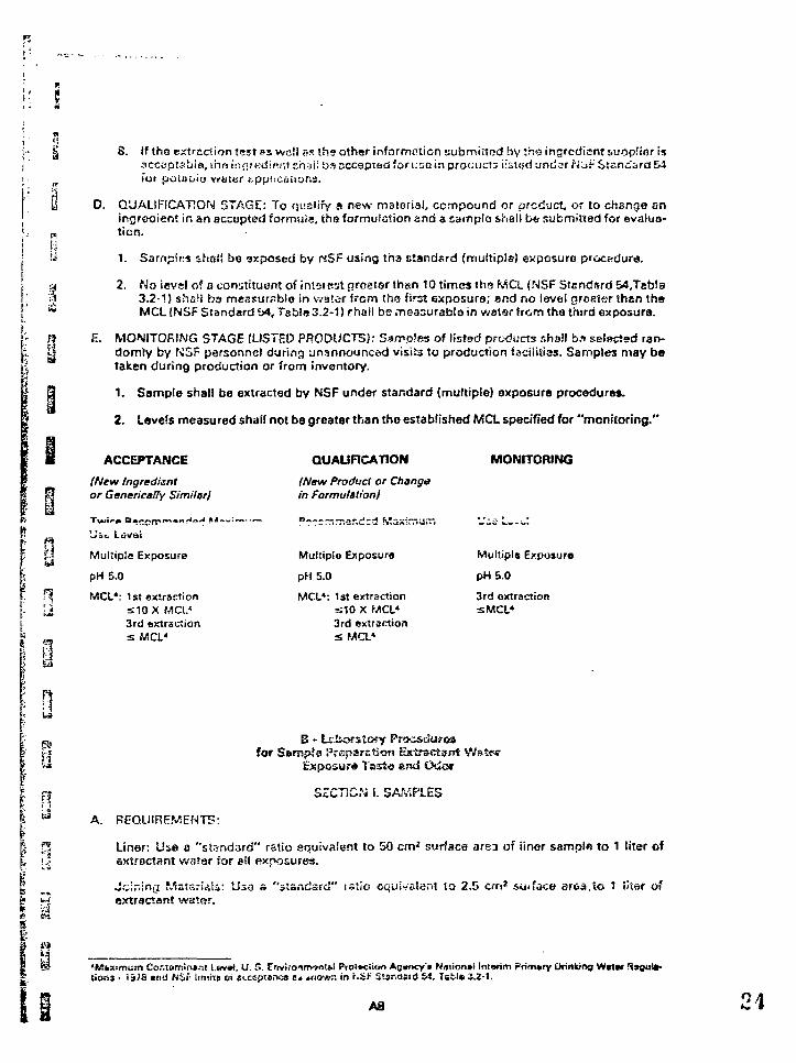
1
i
5 .
R
5n
w
i
V as
8
8. If tho extraction test »s vvali ss th9 othar information submitted by ihs ingredient suopiior isacceptable, the i:ifif edi«r,t shsii os accepted for uno in product; iissod und»r Koi- Standard &4fot poi&uiu w&ter
D. QUALIFICATION STAGE: To qualify a new material, compound or product, or to change eningrooient in &n accepted formula, the formulation and 3 sair»pla shell be stibmifiad for evalua-ticn.
1. Sarnpirs ahtsl! bo axposed by ttSP using tha standard (multipls) exposure
2. No icvel of a constituent of intotest greater than 10 times the MCL (NSF Standard &»,Tafa!a3.2-1) shali bo measurable in vva'.or from tho first exposure; and no level greater then thsMCL (NSF Standard b4, Tsbls 3.2-1) rhail be measurable in watar from tha third exposurs.
E. MONITORING STAGE (LISTED PRODUCTS): Samples of listed products shs.'l b?> selectad ran-domly by F>;SF personnel during unannounced visits to production facilities. Samples may betaken during production or from inventory.
1. Sample shall ba extracted by NSF under standard (multiple) exposure procedures.
2. Levels measured shall not be greater than tho established MCL specified for "monitoring."
3La
ACCEPTANCE
(New Ingredientor Genetically Simitar)
Multiple Exposure
pH5.0
MCL*: 1st extractions10X MCI.4
3rd extraction= MCL4
A. REQUIREMENTS:
QUAURCATION
(New Product or Changein formulation)
?~z:~-r,-ir,izi K'zximu~,
Multiple Exposure
pH 5.0
MCL4: 1st extractionS10 X MCL4
3rd extractions Ma*
MONITORING
Multipls Exposure
pH5.0
3rd extractionsMCL4
B - txborstofy Proceduresfor Sempta Proparction Extnsctant Wstt
Bsposur* Tasta er«d Odcsr
SECTION I. SAf/.PLES
Liner: Uae a "standard" ratio equivalent to 50 cm* surface area of iiner sample to 1 liter ofaxtractant water for ell exposures.
Joining Mstsrisia: Uso a "standard" rs'»io equivalent to 2,5 crn2 suifaoe aroa.to 1 iitar ofsxtractant water.
4•fcSixsmum Contaminant t.evat, U. S. Enviroim-jn!*! Prolfcciion AO»OCY'» Nmionni Intorim Prim*rv Orinkioa Wcter SsQUlt-Cioni' ii>7S cn<i NXir limixa oi «t,c«ptar»c« c* ariovrr. in f.Si- Stsnosid £4, Table 2.2-1.
AS
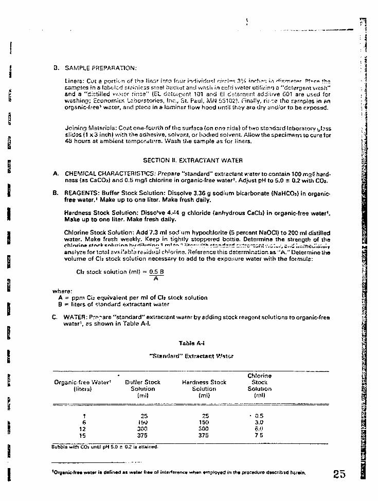
3. SAMPLE PREPARATION:
Liners: Cut a portion of t'n<s linar into four individual r i r r i "^ 3V4 inch?": <••> H;j>rr.p»»r P!^r» thesamples in s labeled rfuiniess steel bucket and wash in cc!d water utiiii-inq a "detergent v^ash"end a "distilled w>ior rirsse" (L:L dGteicen? 101 and £1 dstsrrjejrt sdditive G01 are used forwashing; Economics Laboratories, Inc., St. Pfcul, MN 55102). Pinally, rir.se the samples in enorganic-free1 weter, and piece in a laminar flow hood until thay are dry and/or to be erposac1.
Joining Materials: Coat ona-fourih of ths surface (on ono r.ide) of Vwo standsrd laboratory ^Insss!idos{1 x3 inch) with the adhesive, solvant, or bodied solvent. Allow the specimen-, to cure for43 hours at ambient temporuti'rs. Wash the sample as for Iiri6rs.
SECTION II. EXTRACTANT WATER
A. CHEMICAL CHARACTERISTICS: Prepare "standard" extractant water to contain 100 mg/l hard-ness (as CaCCb) and 0.5 rng/I chlorine in organic-free water1. Adjust pH to 5.0 ± 0.2 with CO2.
B. REAGENTS: Buffer Stock Solution: Dissolve 3.36 g sodium bicarbonate (NaHCCh) in orgsnic-free water.1 Make up to one liter. Make fresh daily.
Hardness Stock Solution: Disso've 4.^4 g chloride (anhydrous CaCb) in organic-free water1.Make up to one liter. Make fresh daily.
Chlorine Stock Solution: Add 7.3 ml sod urn hypochlorite (5 percent NaOCI) to 200 ml distilledwater. Make fresh weekly. Keep in tightly stoppered boitie. Determine the strength of thechlorine st«vir «r,itt»mr> K.»rfjinfirvr; t m\»«1;;.~-..-uk. r . ; ; r . -«= rJ ^rrtrc'tGntv.a;-.', zr,£ i,,.meJ!ai=iyanalyzu for total BV£.i!<ib!s residual ch'orina. Reference this determination as "A." Determine thevolume of CI2 stock solution necessary to add to the exposure water with the fotmulc:
Cb stock solution (ml) = 0.5 BA
where:A = ppm C12 equivalent per ml of Cb stock solutionB -• liters of standard extractant water
C. WATER: Prepare "standard" extraccant watar by adding stock reagent soiutions to organic-freewatar1, as shown in Tabla A-l.
I
Tabla A-i
"Standard" Extractant
Organic free Water'(liters)
61215
Duffer StockSoiution
(ml)
251W300375
Hardness StockSolution
(mi)
25150300375
ChlorineStock
Soiution(ml)
0.53.0K.n75
i!nBubble with COi until pH 5.0 ± 0.2 U etuinad.
'Organic-fra* wstcr ia dafinad at walar fre« of in(«rforonca whan tmployed in tha procedure d*scrib3d herein. 25
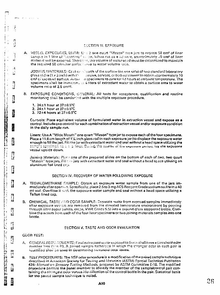
'•J L":£CT10N !!!. EXPOSURE
i -, A. VE5££L CXPCSUr;i£5, Lt.\T:R: U- •-. 2 one auzrt "Mason" type j;;:s to evpoza 50 cm' of tinsr' • I ianip.a in 1 liter of "t.tanopf-c" v.. :.-,r. Whan rut us a tn.i itn>r, anprorimiioly . 0 cm : of iinsr! - t ; rr.sternl will bacxp-o?o<i. Ihcrr. > <--•, iha volume of wafer uc-id must be determiosd to maintainI the rsqjirod 50 cm-i'.itar surfac : ••••'•a to waror volume -r;\;o.• ' A'{ ' i ! JOINING MATERIALS: CcEt cr • .>ijrth of the; surfacu !or> one side) of Vvvo standard laboratoryj ' w g'asrjslid.w (T * 3 inch) witiw!'' . ;ev.ive, solvent, or booi-s-J solvent to obtain crpproximately 10| cm1 c;'fc>;f'Oi«d surfaca. Anov/ a specimens to cure lor AJ hoars at i-imbiant temperature. Thej ; -^ specimens shall bo immerse :; 4 liters of extractant water to obtain a surface area to water| " [j volume ratio of 2.5 cm',1r
^ B. EXPOSURE CONDITIONS, GENERAL: All tests for acceptance, qualification and routinef5 monitoring ciiali be condu'-'/xi with the multiple exposure procedure.
1. 24*1 hour at37+0.b*C4 - 2. 24*1 hour at 37±0.b°C;* i 3. 72±4 hours at 37~G.5°C
Controls: Piace equivalent volume of formulated water in extraction vessel and expose as am control. Include one contro! for each combi nation of extraction vessel and'or exposure conditionm in the daily sample run.at
Liners: Use A "Wide Mouth" one quart "Mason" type jar to expose each of the four specimens.S Pisce a 11.6 cm length of 1 Vi inch glass rod in each exposure }ar (to displace the exposure water0! enough to fill the J3r). Fill the jar with extrsctant water end seal without a head space utilizing tho
-' ~ vess«si upside down.
jjjf Joining Materials: Pine • one of the prepared slides on the bottom of each of two, two quart"Mason" type jars. Fill * ^ jars with extractant water and seal without a head spacs utilizing analuminum foil lined cr.;j.
":! SECTION tV. RECOVERY OF WATER FOLLOWING EXPOSURE
7 fj A. TRiHALOMETHANE SAMPLE: Obtain an exposure water sample f rom one of the jars im-•-: « mediately sf :er oper •, ,q. Spacifically, place 2.5 to 3 mg ACS Reegant Grade sodium suifiTe in a 40
ml vial. Overflow it w i i - . the exposure water sample and seal without a head space util izing a'" Tjj Teflon Iin6d cap." i.'i
. ' u 8. CHEMICAL, TASTE / ?JD ODOR SAMPLE: Separate water from exposed samples immediatelyj sfter exposure ver.c-ls ara removed from the elevated temperature environment by pouringi- [ through fiitor paper (white, crerxs, '/'vVR Grad'j 6.G) into a cjtounrl glass stopporsd bottle. Com-I' y bine the waturs from each of the four liner Epecimens or tv.o joining materials samples into ons\.i bottle.
y\ y SECTION V. TASTE AND ODOR EVALUATION
jl ODOR TEST:I ' *' -i i=i A. GiIWEnALF?C0L';"cr«1ENT5: nnaSex*r3ciaMwci!or«fcpGs*rtf to i iwi-ssf iaHhavea l l i resholdodorR riiimhrrr tr*ss th=-n >r0. A p? ;rod «-?!T:p!'j t«jchrt:Cf!J9 in which the strongsr odcr in each pair is[^ ea iuu i i t i f i ad shai l i a used i n O6rerffi i i i ir>ti tj><'<ishoi6 tHio< ieveis.
F* *™ 8. TP.3TPHOCEDURES: The N'SF odor pfocedura is s modification of thi* paired sample trwhrtiqueS3. describe in Aiviarican 3oci«iy !or Teviiivj ami Mstvriiis (ASTMJ ?p««:!Bi Technicei Pubitntion| | ps 434: Manual on Sensory Tasting Methods, prepared by ASTM Committee E-T3. Tl-iS modif iedM \& procedure permits the panel rnemt>^r to identify the member of the ssmpie/control pair ccn-P taining the stronyest ocioi vorsus ideniificsiion of the control bottlo in the pair. Statistical basisu for tna paiica sarnpia tech>i>que is noted.
I I . A,0 2B
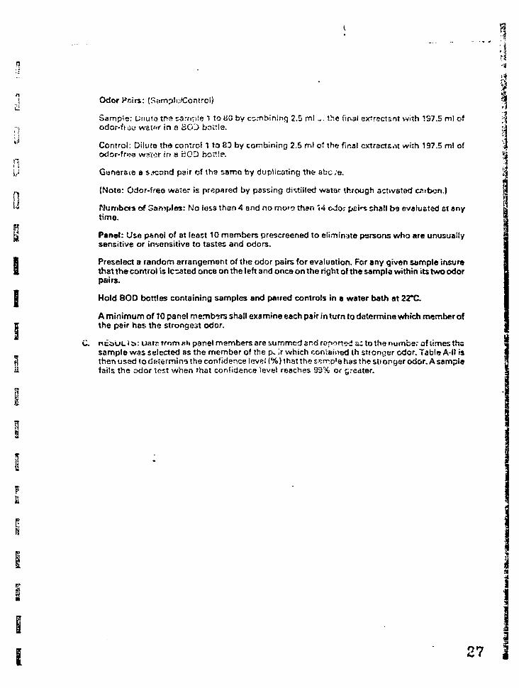
n
•5 Odor Pisirs: (Samplij/Contrc!)Sample: Unuta tr>e sample 1 to BO by combining 2.5 m! -. the final etfroctsnt with 1S7.5 ml of
••; odor-fijo wet^r in a BCO battla.
^ Control: Dilute the control 1 to 83 by combining 2.5 ml o" the final cxtracts.it with 197.5 ml of
odor-frea water in a BOD bottle.
\J Gunerato a s.icond pair of th» same by duplicating the abc .-a.
„ (Note: Odor-free water is prepared by passing distilled water through activated csftoon.)[|" Numbers of Samples: No iess than 4 and no more than 14 odor pai^ shall be evaluated et any
time.Rg Panel: Use panel of at least 10 members prescreened to eliminate persons who are unusually
sensitive or insensitive to tastes and odors.1 Preselect a random arrangement of the odor pairs for evaluation. For any given sample insureI that the control is legated once on the left and once on the right of the sampla within its two odor
pairs.
• Hold BOD bottles containing samples and paired controls in a water bath at 22*C
A minimum of 10 panel members shall examine each pair in turn to determine which member offf the pair has the strongest odor.
C. nci>uL i &: uatc from B\\ panel members are summed and reported sctothe number af times thasample was selected as the member of the p» > which contained th stronger odor. Table A-H is
I then used to determine the confidence level (%) that the ssnnp'e hes the sti onger odor. A sarnpisii fails the odor test when that confidence level reaches 93% or greater.
I•J
27
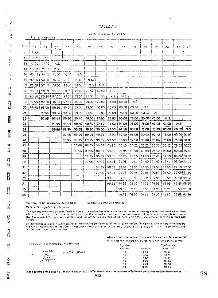
JAtsl'C AH
n
1:3
;•' 12 7 2 GO
1 3 { C-J.C3
•-;.cj
•j 15 ; Q7.ro
i s ?5.00
-; 17 ~5r,o
IS l&j S5
I '7
r.'.'j.
7 s a| 75 CJ
57 f.O
r-soo
C9.50
"« 19 i 0-3.0S j 03.U)
j M21
I 222 23
¥ 24
20
EJ?9
99 05 i 99.95
-i 1
! «i.v
| r.s* 26 ;
99.SS
09.55
1
t
4
<0.0O
\
1
7C £*7 j GO >3
75.00
r-o.M
95 M
< 37.50
39.M
09.50
99.50
S9.S5
99.95
99.95
75.1.-3
ro.c-oI 95.CO
(P7 50
05 CO
39 50
99.50
99 95
99.95
99 95
99 95
i •
!
. ; _
i
U.S.
f.',.CW
VS ' ' I
7'J.I.O
SO .00
95 M
99.00
S9 50
99.50
99.95
99.95
99.95nri ns
]
!
i
l
;
i1
N.5. j
ra.o/5 00
75.CO
90.00
95.00
9J.50
99.00
99.50
99 50
99.95
59 95cwi fte
£•9.95
93.05
19.35j
! N.S.
COCO
75 C-0
75.00
90 00
95.00
97.50
97.50
99 00
99.55
99.95no i r
'J9.'2S
99 S3
93 95
99 95
93.95 !
1
...
1
!
fJ'.»
s.S.
75.00
7i.C0
90.00
95.00
97.50
97.50
99 DO
69.50cm en
B3.9'j
59.C5
C'j.95 i
C'9.55 !
99.05 '
93 ^5 i
03.95
1
!
•
N.S.
GOOD
GO .00
75.00
90X10
95.00
97.50
97.50
59.00
~? r.?j
OT.55
TO 95
99.55
99 95
P5 55 i
99 55
"I!--
N.S.
60.00
&0.00
75.00
75X10
90.00
95 00
97.EO
• I
U9 DO
O'J.95
99.95
•J9 95 '
99 95
j 33 95 I 9?Q5i
99 .-"5 |
II
i f.n
i
I
j
it
, i
i
M.S.
so.co
60 00
75.00
75.00
50 00
95.00
„,.„
S9.00
?9.50
01 50
M M
39 95
99 35
93 C5
'rJ 95 j
99.95 j 99'Jb
—
At
I
i
N.S.
E0.00
60.00
75XO
90 : o
90 00
97.ro
S3_OOJ
N.S.
60.00
60.00
75.CO
7b 00
~Z.~Z
S5.00
97.50
99 50 I 97 50
fi3 SO j 05.50
99.50 i
99 95
P9.95
99.95
M S 5 I
09 50
09 50
99 95
59 95
S3 05 I
LJl!
N.S.
60.00
60.00
in .
N.S
60 00
75.00! 60.00„_!
90.00 75.00
95.00! ?O 00
07 50! 05.03
97 CO 97.50
S3.OO|97 50
09 50
99.50
99 00
99 W
ca.SOi ?9 :-0
09.05:93 bO
'Number of times *imp!<t ide^tift&d fr»
*N.S. * No fcignific- t differor**.
Theconfidfl^'ft levins c-iven in Tahi* A-li am cci correct iaarv.f.cJiKar* oi th« cor.trof. given •.Thai 1 p^rcont of *^P time, c\ le»»: tn* soociti*-i
i«! orfor in jisrr.pf,1? control p«if
s consrol r.
Ccr,firf?ncfi l«ivi*!s n
contjinmo i:• o wmn
e fsi A-H ar« ofciffju^rt from
and romtol.
h«n there 't no t
" f "
, t c»n t
nd
Th«e tm tne • r No ret ixinior. eo»j»! to 20 in T«bl* A l l . th«
A12
1«l o18171313
1.7."i.in? . «i S SJ.4S3.SI
nT»hl«A l l w r f
f) Uvet i%)SOOr.; 5wo33.&059.5053.55
iobts'r>edinrlikem
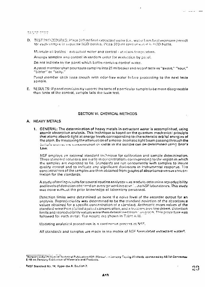
D. TEST r-'r'OCED'JP.LS: plsce 500 m! final i-xXnjclon' watsr (i.??.. woi>:r from 'aial exposure period:tor cbch sample i."< iupamte BOD bo'.iic:.. Pl.-jca 2CO ml control v.i>\ -r • r. uQD bottle.
Miintdin o!i boules • e.KiioCt:;nt wnti-r ond control - <-jt rcorri tc-mpe:aturo.
Arrange samples ana control in random order for evaloruicn by pai-e'.
Do not indionto to she panel which bottle contains control water.
Apsnel member chai! pour taste samples into 2fi ml banker end record taste as "sweet,1' "sour,""birt'er" or "salty."
PVincI member shall rinse rnouih with odor-free water before proceeding to the next testasample.
E. RESULTS: If pannl consistently mitortz tha taste of s particular sample to be more disagreeablethan taste of the control, sample tails tha taste test.
SECTION VI. CHEMICAL METHODS
A. HEAVY METALS
1. GENERAL: The determination of heavy metals in e*tractsnt water is accomplished, usingatomic absorption analysis. This technique is based on the quantum mech3nic£i principlethat atoms absorb light at energy levels corresponding to characteristic orb;t&! energies ofthe atom. By measuring the attenuation of a mono- hromaJic light beam passing through the;*,,v.H!u oiwt.u, Mm kuiibciiiibiion ot metal in sho sampse c*n De dftierminet) u?>n" Beer'sLaw.
NSF employs an external standard technique for caiibrasion end sample determination.Three stanoHid solutions are made in corcpntrations. corresppneinj to the tegion in whichthe samples arc expected to lie. it^ndards are run concurrently wi(h samples to insurequality control and to indicate sny significant deviations in instrumental resporae. T'.isconcentrations of the samples are th«n obtained from graphs of sbsorbanco versus conccr.-
for the standards.
A study of testing results for several routine analyses "A as made (o determine reproducibilityand lovelscf detf-ciion obt?in"d on averrgp working c;sv< ;.. aie NSF laborslones. This studywas clone v»ith^ut the prior knowledge oi Ijbor^'cry personnel.
Detection limits were detapmined as twice tf e noii<? lewsl of the recorder output for ananalysis. Reprodi'cibility was determined to be the standard deviation of the absorb3ncevalues ob-ained for a specific concentration of e s>;o-sdard. ArithmeJ'C mean values oi thostaririarrj were then plotted agnid'A concentration, in\6 << lca;i sru2rv% sine drawn. Detectionlimits and reproducibility values ware thendptnrmjr.no' frnr'i .n^nraph. This procp-iurpuyjjafollowed for each motel, TUP results sro shewn in Tjblr. A l l l .
Updating analyticril procedures is a continuous process ?t N?c .
All sta.tdaru's and c-arnples iire macse in this matrix of MS?' <orrn'jls;ed extr«ct9ot water*.
'Rr'erfnrn A.S1M Spr'.'is! Trchnics! f'-,ib!ir.Etir>n43-!: t.'.srmt!. •<» vnory Ta;t-ng Mrthodt. sponsoi etl by AS TMEO8 on Sfinayry rve!u*i:ion of MiMeriels find Trociucts.
*NSF Standard He 14, Appei-SM A. Ss^tion ?.
ATI
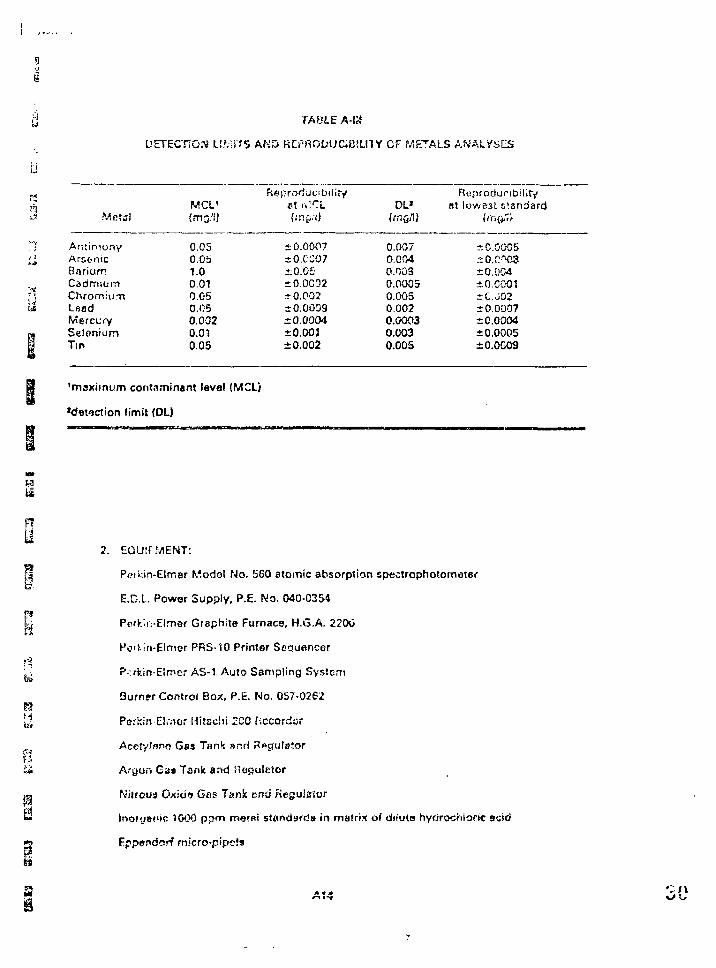
TABLE
DETECTION LIMi'fS AND CF METALS ANALYSES
Metal
AntimonyArse siteBariumCadmiumChromiumLsadMercerySeleniumTm
MCL'(ma.1!)
0.050.051.00.010.050.050.0020.010.05
fioproducit'ilitYet i\:0L.
±0.0007±0.0CO7iO.Ot±0.0002±0.002±0.0009±0.0004±0.00,1±0.002
DL*irr-tA}
0.007O.COJ0.0030.00050.0050.0020.00030.0O30.005
Ftoproclunbilitynt Iowe3i standard
±0.0005.tO.C'i03±0.004±0.0001iC..;02±0.0007±0.0004±0.0005±0.0009
'maximum contaminant level (MCL)
'dowction limit (DL)
i-a
FT
b.
2. EQU'fMENT:
Poikin-EImer Model No. 560 atomic absorption spectrophotometer
E.D.L. Power Supply, P.E. No. 040-0354
Perfclrs-Elmer Graphite Furnacs, H.G.A. 2200
PcKin-Elmor PRS-10 Printer Seauencer
Pcrkin-ESroer AS-1 Auto Sampling System
3urn?r Control Box, P.E. No. 057-0262
Perkin-Elrnor Hitachi 2C0 fiecordor
Acetylono Gas Tank »r:rl PoguleJor
Afyon Ga* Tank arid Reguletor
Nilrous Oxiiis Ges Tank end Regulator
Irtoryontc 1OO0 ppm mef«i standards in matrix of diiuls hydrochloric scid
rnicro-pipe!s
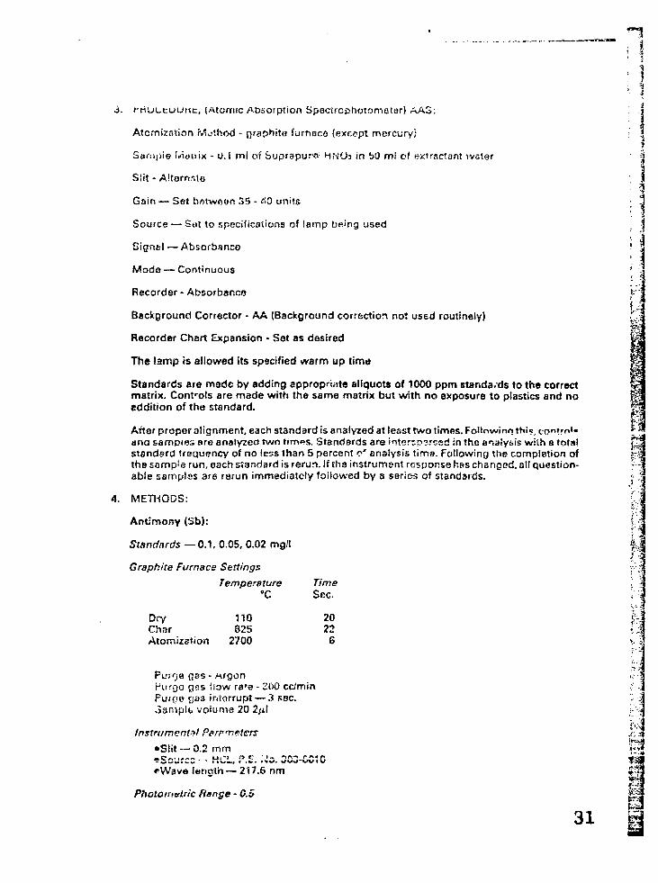
HI
j . rriUL-cuuMc, (Atomic Absorption Spectrcphotometer) AAS: . i
AtcmizfHion Method - fKaphite furnnco (exctpt mercury; : j
iSample f«nunix - u.i mi of Suprapurw HNCb in bt) ml of extractant water |
Slit - AltomrUa ; |
Gain — Set b.*)twf>«>n 35 - <30 units • J
Source — Sot to specifications of lamp being used ; |
Signel — Absorbanco 1
Mode — Continuous 'i
Recorder - Absorbsnca >Background Corrector - AA (Background correction not used routinely) •'"
Recorder Chart Expansion - Set as desired j
The lamp is allowed its specified warm up time ]
Standards are made by adding appropriate aliquots of 1000 ppm standa.ds to the correct 'matrix. Controts are made with the same matrix but with no exposure to plastics and no jeddition of the standard. :
After proper alignment, each standard is analyzed at least two times. Followinn th"?, co"?rn'« *"**ana samples are analyzed two tim«s. Standards are interrp^rssd in tho analysis with a tots! •standard frequency of no less than 5 percent c* analysis time. Following the completion of ;the sampie run, each standard is rerun. If tha instrument response has changed, all question-able samples ara rerun immediately followed by a series of standards. :
4. METHODS:
Antimony (Sb):
Standards — 0 . 1 ,
Graphite Furnace
DryCharAtomizstion
0.05, 0.02 mgll
Settings
Temoerature°C
110825
2700
TimeSec.
20226
; - HrgonPurge gas flow ra'o - 200 cefminPurpe rjaz interrupt — 3 sec.«>amplt voiume 20 2,ul
Instrumental Pprr meters
•Slit — 0.2 mm•sScjrcs - .U.CL, P.E. '.io. 3C3-0C!C*Wave length — 217.6 nm
Photorriatric flange - 0.5
31
'\r\
1
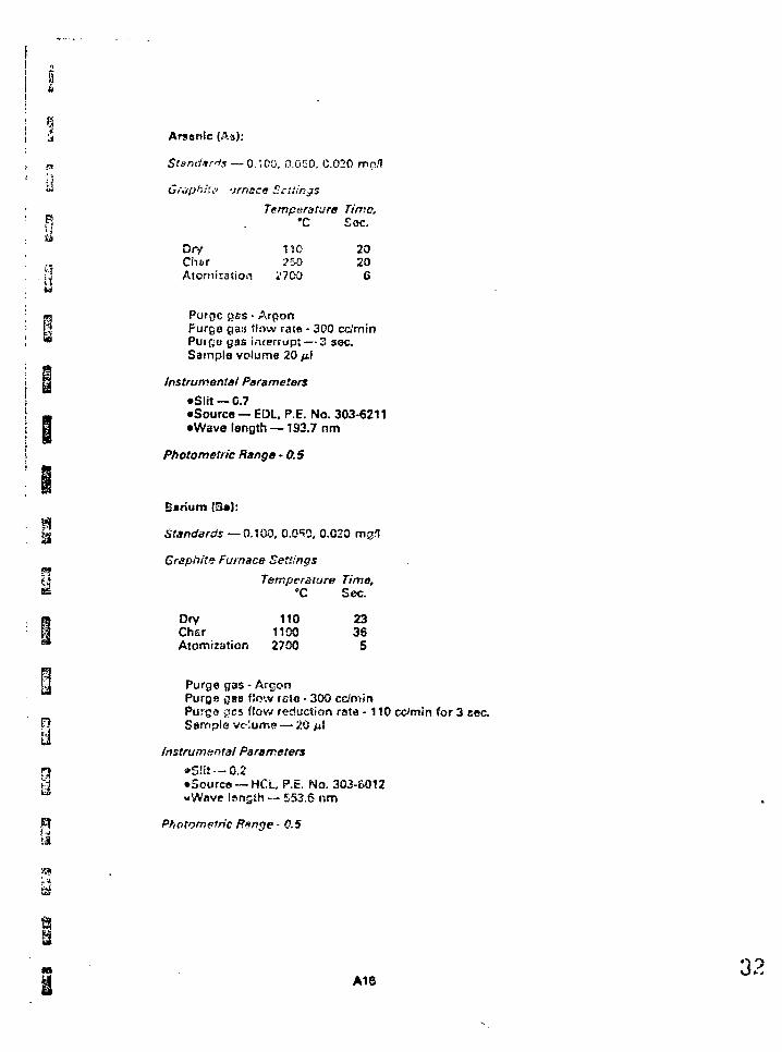
5
S 2
y
Utit
Arsenic (A3):
Slanctirrls — 0. "00, 0,050, C
Graphite -jmace Sellings
DryChtirAtomiration
.020 n\p.l\
Temperature Time,•C Sac.
•no250
2700
20206
Purge [jss - ArponPurge gas flow ratn - 300 cc/minPuree gas interrupt — 3 sec.Sample volume 20 >xi
Instrumental Parameters
•Slit —0.7•Source — EDL. P.E. No. 303-6211•Wave length —193.7 nm
Photometric Range -0.5
Barium (S»S:
Standards — 0.100, 0.050, 0.C20 mg.1
Graphite Furnace Settings
Temperature Time,»C Sec.
Dry 110 23Chsr 1100 36Atomizat ion 2700 5
H Purge Q3S - A r g o nPurQfl o»8 f l ow i s i a - 300 cc/mir»Purga gcs f l o w rectucJion rata - 1 1 0 cc/min fo r 3 sec.
£? Sarripfe vciume — 20 ti\
Instrumental Parameters
ra •S!it —0.2tf »3ource — HCL, P.E. No. 3OJ-SO12to -Wove length — ES3.6 nm
Bl Photometric fonge - 0.5
*3
is
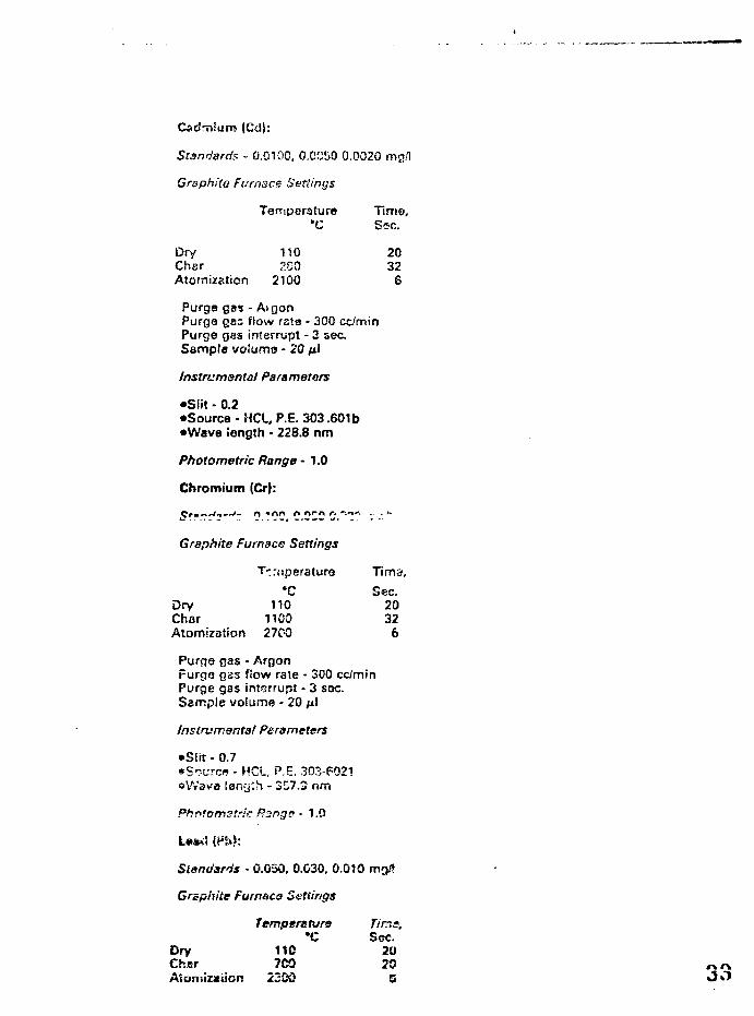
Cadmfurrc (CdJ:
Standard.* - 0.0100, 0.C0&0 0.0020 mg/l
GrBphito Furnace Settings
Tempsrature Tims,*C Sec.
Dry 110 20Cher 250 32Atornization 2100 6
Purge gas - AtgonPurge ges flow rata - 300 cc/minPurge gas interrupt - 3 sec.Sample voiumo - 20 M'
Instrumental Parameters
•Slit - 0.2•Source - HCL, P.E. 303.601b
•Wave length - 228.8 nm
Photometric Range • 1.0
Chromium (Cr):
Graphite Furnace Settings
T'.r(iperature Tima,
"C Sec.Dry 110 20Char 1100 32Atomization 27C-Q 6
Purfje gas - ArgonPurge gas flow rate - 300 cc/minPurge gas interrupt - 3 sec.Sample volume - 20 /xl
Instrumental Parameters
•Siit - 0.7•S--LTCW - HCL, P.E. 303-6021
!eny:h - 357.3 nm
Phrtomstric Rsnge • 1.0
Standards • 0.050, 0.G30, 0.010 mg/»
Graphite Furnace Settings
DryCherAtomizaiicn
Temperstvro•c
11C7C0
2300
Tirr.s,S«sc.
2020
Q
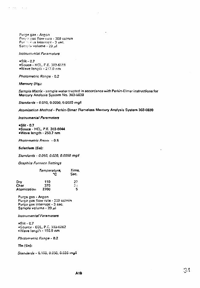
PUTQB gas - ArgonPurr-it f.'BS flow mia - 300 cc/minPur ' >• J3 int6rn.ir.it - 3 ser.Sar,->i!b volume - 20 >il
Instruments! Paramstors
•Slit - 0.7•Souca - HCL, r.E. 303-6111
•Wave )en{itii - 2)7.0 nm
Photometric Range - 0.2
Mercury (Kg»:Sample Matrix - ssrnpls water trested in accordance with Perkin-Elmer instructions forMercury Analysis Syslam No. 303-0320
Standards - 0.010, 0.0050, 0.0020 mg/l
Atomization Method - Perkin-Elmer Flarrteless Mercury Analysis System 303-0830
Instrumental Parameters
•Slit - 0.7•Souce - HCL, P.E. 303-6044
•Weve length - 253.7 nm
Photometric Ranm - 0.5
Scienium {Sa):
Standards - C.OSO, 0.020. 0.0050 mgll
Graphite Furnace Settings
Temperature, Time,•C Sec.
Dry 110 2PChar 370 20Atomization 2700 5
Purgs gas - ArgonPurge gss flow rate - 200 cc/minPurga gas interrupt - 3 sec.Sample vo'ums - 20 /il
Instruments?Parameters
»Siit - 0.7•Sourc« - EDL, P.E. 303-6262©Wave length - 1S3.0 nm
Photometric Rsngt> - 0.2
Tin fSn):
Slafiuiida - u.'iCG, C.C3C, C.C2C my/i
A18
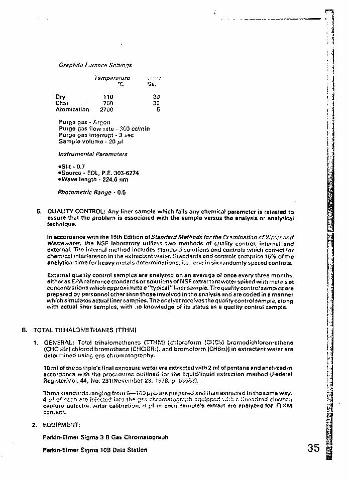
H
Graphite Fumoce Settings
Temperature*C St..
Dry 110 30Chsr • 700 32Atomization 270O 5
Purge gas - ArgonPurge gas flow rate - 300 cc/minPurge gas interrupt - 3 s«c ,Sample volume - 20 \i\ \ J
\ \Instrumental Parameters
•Slit - 0.7 {.:•Source - EDL, P.E. 303-6274•Wave length - 224.6 nm
Photometric Range - 0.5
5. QUALITY CONTROL: Any liner sample which fails any chemical parameter is retested toassure that tho problem is associated with the sample versus the analysis or analyticaltechnique.
In accordance with the 15th Edition of Standard Methods for the Hxsminstion cf'A'stcrend f-Westewater, the NSF laboratory utilizes two methods of quality control, internal andexternal. The interns! method includes standard solutions and controls which correct forchemical interference in the extractent vvatar. Standards and controls comprise 15% of theanalytical tima for heavy metals determinations; i.e., one in six randomly spaced controls.
External quality control samples are analyzed on *n average of once every three months,either as EPA reference standards or solutions of NSF extractant water spiked wiih metais atconcentrations which approximate a "typical" liner sample. Thoquaiity control samples are [. •prepared by personnel oth»»r than those involved in tho analysis and ere coded in a mann«r iwhich simulates ectua! liner samples. Thaenalyst receives the quality controf sample, along I'with actual lingr samples, with .10 knowledge of its status as a quality control sample. [.
i -
HB. TOTAL TRIHALDf^ETHANES (TTHM)
1. GENERAL: Totsl trihsiomothanes (TTKM) [chloroform (Cf!CS) bromodichloroffeihane(CHCbBr) chlorodibromothsne (CHCiBRj), and bromoform (CHBrj)J in extractant watsr sradetermined usiftCj gas chromstocirsphy.
10 mt of the sample's fins! exposure v/stor sre extrscted with 2 m! of pfrntnne »nd sns!y7»d inaccordance with the proewjufes outlined for the liquid/liciuid cxtrection method (FftderelRegister/Voi. 44, No. 231/Nov«itib©r 23, 1S7S. p. S26S3). ;
Throa standisrds canning froni ;'i—1 GO ppb see prepsf<tt-3 and lhan extracted in ths same woy. b4 .1 cf esch cro injsctcd ir.to th» g^s chromaienrsph equipped vviih a lir.iisrized s'ectrGricaptute oeiector. Artar csiibreiion, 4 {i\ of asch aampie'o owrec: arc ensured for TTKM
con.sr.t. ^
2. EQUIPMENT: t
Ferkin-Elmei Sigma 3 B G^* Cinematograph £
Perkin-Elmor Sigma 103 Data Ststion 3 5
Pcrkin Elmsr Auto Samplsr (AS-100)
Electron Cspturc Detector (S.C.D.)
Column - 4 mm 10 (8' v. V," OD) 10% Squalane Chrom W-AWSa'100 NOC
Nitrogen 4.5 grade
CoTipra339Ct air Groda E
40 ml screw cap vials with Teflon faced silicono septa. Pierce #13075 and #"3733
Sample vials with septs and aluminum seals for auto sampler
Extraction bottles and caps Sci/Spac #B 69110
Syringe*- 10. 25 and 100^1
- 5 and 10 cc with luer-lok tip
Gat stoppered volumetric - 25 and 100 ml
3. REAGENTS:
Pentana, suitable for TTHM GC analysis
Methanol, reagent grade
Chlorine reducing agent: Sodium thiosulfateStsndsrds
Chloroform, reagent gradeBromodichloromethana, reagent gradeChlorodibromomethane, rea{jsnt gradeBromoform, reagent gradeCarbon tetrachlorida, reagent grade
Organic-free watar1
4. INSTnUfVcNT PREPARATION:
Pneumatic SettingsCarrier gas:
Nitrogen - 30 psiAuto sampler:
Air • 40 psiNitrogen - 5 ps>
Temperature SettingsOven - QTCtrijetticn port - 1b0"CDetector - 350*C
Total en^iysi« time - 13 ra'>ruins
Flow rste through coiumn - 70 ca'min p'.us 5 cs makeup.
f t vvslw frsa of i
A20
1
5. ANALYTICAL PROCEDURE
TTHM and CCU arc measured in accordance with the methcri for "Anelysis ofTrirsaiomtttnsnes in ijrtnsiriq Wator by Liquio/Liquid txtrsction," Fscierai Wegistsr/Vc'uiTta44, No. 231/November 23, 1979, p. 0SC33.
C. OTHER CHEMICAL PARAMETERS
1. PHENOLS: Phar.oSs arc measured in accordance with Standard Methods for the Exam-ination of Water end Wastewater, 15th SEdhion, psgs biO <4-(imirioari,tipyrir;6 methodwith preliminary disfitistion stap).
2. TOTAL AVAILABLE f?ESiDUAL CHLORINE: Total available residual chlorine is measuredin nccordenca with tha mathod outlinod in Stsnc'ard Methods '.or the Examination ofWater and Wastewater. 15th Edition, page 286 (Arnpfiiometric Titration Method, Proce-dure 4c).
i!-•A
'- i
I
r".>
iin
37
Psrta
P1y Adhasioo
ASTMD413rJ(.'Ctior>fl!. Procedure, Parogrspli&.i Strip Specimens- Typo A, 180 degree psel-. . .Thanext s?n!snca shall bo dz\nzci cr;d substituted in its pi«5c.a:
Tno cut strip shall be 1 inch wide measured to fha nearest 0.01 inch.
ASTM D413 Section 12,Caicu!stions, Paragraph 12.2 shall bo modified to bs:
For the machine method th<j value of adhesion is tieterminod by taking tha average of tha fivehighest peaks shown on tha autographic chart and is reported as the adhesion value as follows:
N/m (It .n) = force/a^ua! width
M other thai* c * inch strip is tested show both the force and the actual width in the report.
Part 9
Accelerated Weathering Test
A. OCIXCHAL
The t?st will be the Equatorial Mount with Mirrors for Acceleration plus water spray (EM-MAQUA). Minimum specimen sizo will be 5 inches wide x 4 inches long. (Maximum widih is 5inches x 55 inches long within target area.)
Minimutn number of specimens will be ona for each FML type that is recommended for outdoorexposure.
The EM'/AQUA Test machine is covered by U. S. patents. The testing service is provided by:
Desert Sunshina Exposure Test Inc.Box 185Black Canyon StagePhoenix, Aiizona 85023
B. Exposure Rating Table
Tho following table rates th« stata of condition for tho FML r-f?<?r exposure cfus to erasing.
Crazing is tha phenomenon rrt3nif<»st?d by slight br^s('.s or checks in ttia surface. Tno breakshould baciiicd e "crack" if the underlying surface is vifiiblfl. Forj^r-cisionovgiuMirr^crsiirtgisdescribed ec microscopsc crsiing as observed with a stated magnification of 10 power.
A22
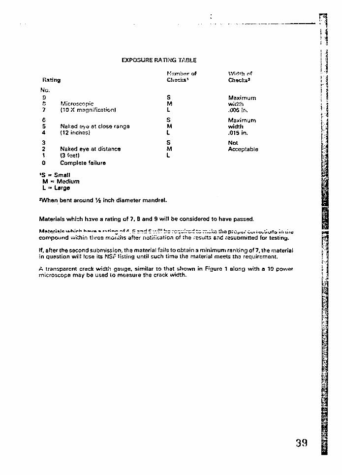
EXPOSURE RATING TAOLE
Rating
Nc.9f,7
654
3210
Microscopic(10 X magnification)
Naked &ye ot close range(12 inches)
Naked eye at distance(3 foot)Complete failure
'S = SmallM = MediumL => Large
r:arr>.;>r.r afChecks'
SML
SML
SML
VVW*h rfChsckt*
Maximumwidth.006 Er».
Maximumwidth.015 in.
NotAcceptable
1 -5
i I
*When bent around Vi inch diameter mandrel.
Materials which have a rating of 7, 8 and 9 will be considered to have passed.
M»teri»l«s i<uKi/-Ki • • » < • • «•*••!"•£ ?tA. 5 2nd 5 w!!! be ""•j:rc.^:crr.-!catnaprcK.o."Cuiit3compound within three mor.ihs after notification of ths results ar.d resubmitted for testing.
If, after the second submission, the material f3i!s to obtain a minimum ranking of 7, the materialin question will lose its NSr listing until such timo the material meets tha requirement.
A transparent crack width gauge, similar to that shown in Figure 1 along with a 10 powermicroscopa may be used to measure the crack width. i
B-l
"4
I
7
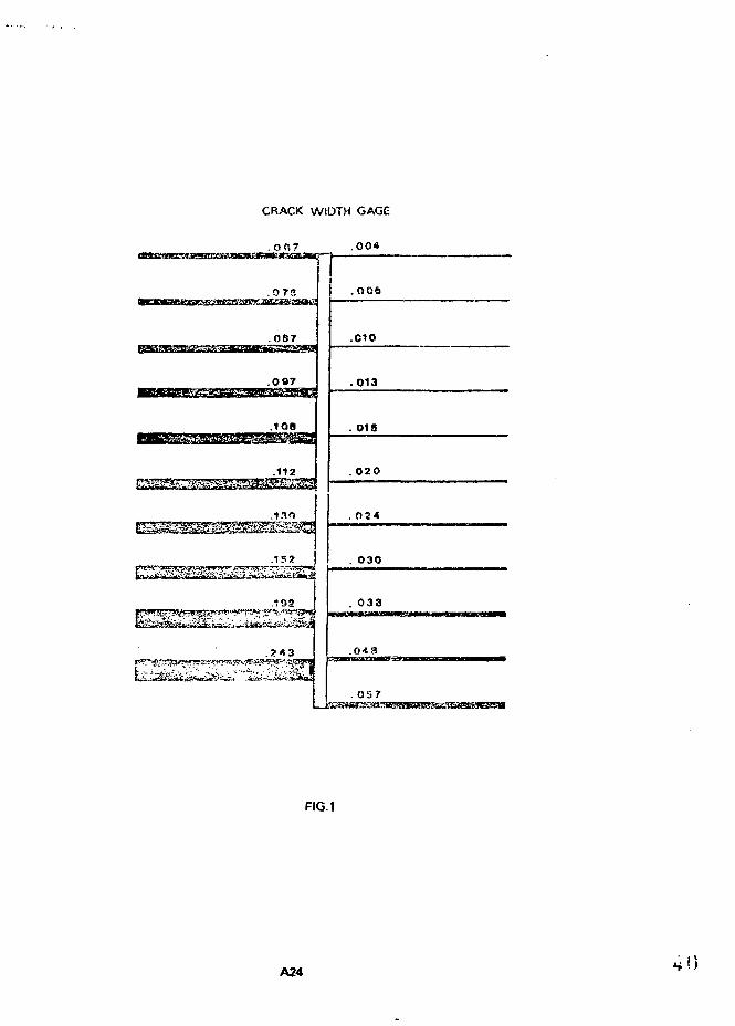
CRACK WIDTH GAGE
. 0 0 7 .004
.0 73
.087
.097
.108
.112
.130
.15?
.006
.010
.013
. O15
. 020
. 024
0 3 0
0 3 8
.o*a
. 057
FIG.1
A24
Pert 10
Dead Lo-sct Stusm &t?*r*r:h
A. Scopo
Tc determine (ho ability of factory team joints to withstand constant stress under load et rcorntemperature (73^).
B. Test Specimen
The supported specimen sizs shell ba a 4-inch width of ths sepm jc:nt end a 1?-ir,ch length,suirU.'ont. to fit in ths clamps of trio testing machine. Tho unsupported r.pacimen size shall be a 1inch width of the scam joint end an 8 inch lonrrth.
C. Procedure
Tho clamping mechanism will grip a 1 inch wide section ar.d should be centered in the width ofthe last specimen, above end below the seam joint Tho clamps shall not grip any portion of theoverlap area of the seam joint
1. Room Temperature Test: A designated toad shall be applied to seam joint after it is fastenedin the demos. This load shall be equal to a percentage of the Bonded Seam Stsength Vsluaindicated in the Materials Properties Tables. The load shall be maintained for 4 hours st e
' temperature of 73°F. The stressed sample must be closely observed. Excessive elongationmay require clamp adjustent to maintain consistent loading. When elongation reaches 5OScof the original jaw separation, no additional adjustment need be mede. Retain existing loadfor balance of test duration.
2. A ''failure" wiii be noted when the seam joint separates entirely
D. Reporting of Results
Tha results shall be reported by indicating tha designated load, tha temperature, the timeduration at the ta^t, the length of the overlap seam, and a "pass" or " fai l " designation.
PART 11
Daad Load Seam
A. Introduction
Sun exposure and hujh sir iftrripgratuf es. sometimes result in the portion or on exposed FMLcbova the water (or contained fluid) surface to r^nn tcmoflrsturei? over 12CPF. If seams nmimproperly rnarf" fr;d/or ;h« ir!v-"L rrr.tf»fi:>! forrriiir! v/:'\ r.tv fti'-w gocd strums to ho msde, thersthe lining msy sf"-cr>r>?ta «nri=?r T^-rifsj-rntiifo" nrid torers som^tirncs encounters', in cctustservice. The rioad Ic^d ^fftm strsnoth i'-v.l st elavstori tr-rrc.qfisturft is ri'-~;qnsd to id jntify sn»mswhid i are liicsly to i.c su^io-tico to failure under such conditions.
The temp;;r3T!jr& r;e!«;..!'!d tor tSs t ;«t should ha cor.iistsr.t with ffie thcimsl Dhytica'.'cham.. .!properties o< iiia r'-.'tL i-r:-J ':!;a snnciputrMd .'iorvii.i cc;:aii:on. iha iarncarutura and !O3Q givsjn in
changes in tne tost ccnuitions epps.ir spprcprtcts.
E. Tost Spocirnsn
Unsupported Materials: Tha spedman shall bs 1 inch v.idg. anrf at least S Enchas lorg. Tha ssamlhail ba located in the cenior of ?hn specimen and scro?<? tha «;!! wtffih of th«
Supported MMeriats: Tho specimen sha'! bs4- incht-s wida and e>l leesf 12 ioches !or.g. Tns scim 4 Xshall ha in the certior of iha specimen and acror.s tha M i width of ih« i
The clamping mech.-nlsm vv'll orip lha full 1-inch width of an unsupported specimen. The gripiPpar3iion shrill bn 4 jncMos P'IJS tha seam v/eih.
A 1-ir,ch wide sec'.'O'i o'. a supported specimen in '.ho contar of iht> v^dtn of !iv; t"?st specimenshould be pnpptxl The '•.np si'paiction shail t><; 6 inches plus the tc-am width. Tim clamps jhailnot grip any portion oi trie ovurlsp area of the soam joint.
Thn IcscI GQijol to "3 percent of lh« (t'qwired bended sp«im strength r.nouid bn applied to thescum joint pitor it ir fi>vt'-ned iT !n*» clomps. Tite lo<id bh -ii ba rnam'.nir.ad 'or -I fioj;? ot ;r;stemporuture specified in thfs table for the particulyr material.
Tho stressed sample must ba closely observed. Excessive elongation m-T/ require clamp aci-justmcr.i :o maintain consistent 'oacing. When eloncaticn reaches 50cerci:ni of V:e original jawseparation, no additional adjustment nc-sd be made. Retain existing load tor baianco of tostduration.
A "failure" will be noted when the seam joint separates entirely.
D. Reporting of Results
The results shall be reported by indicating the designated load, the temperature, the timeduration of the test, the length of tho overlap eeam, and a "pass" o' "fail" designation.
For example: 25 percent Bonded Seam Strength 158°FJ 4 hours, 4 inch seam length. Pass.
Part 12
Environmental Stress Crack Rosistsrtca
ASTM D1693 shall be modified to ba:
Condition C to bo used with 1OCCC using 100% Igepai. Samples shall ba 80 miis or finished product ifthicker.
A?.A26
sii.iU
APPENDIX C Hh
REPRESENTATIVE LIST OF ORGANIATIONS IN LINER INDUSTRY
POLYMERIC MEMBRANE LINEP.S
1. Polymer Producers 1:1
2. Manufacturers of Polymeric Membrane Sheeting T|
3. Fabricators of Liners |
4. Installation Contractors | i
h
43 1
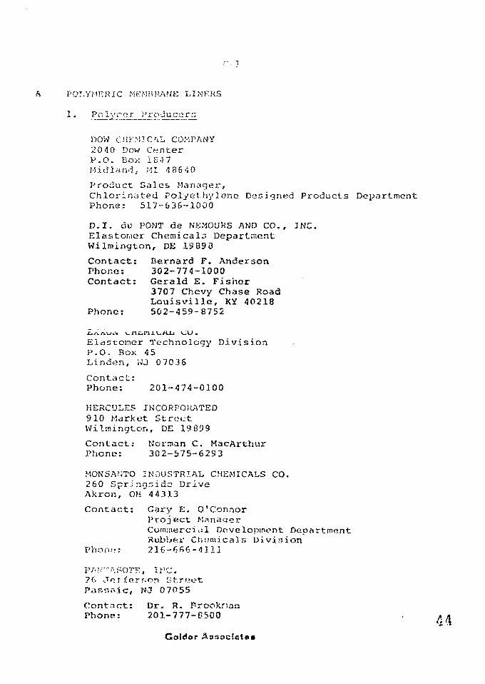
r. 7
A POLYMF.RIC MEMBRANE LINF.KS
1. PoIyi'ier i'roaucc-ra
DOW CHF.M.TCAL, COMPANY20 40 Dow CenterP.O. Box IB-5 7Midland, MI 48640
Product Sales Manager,Chlorinated Polyethylene Designed Products DepartmentPhone; 517-G36-1000
D.I. du PONT de NEMOURS AND CO., INC.Elastomer Chemicals DepartmentWilmington, DE 13890
Contact: Bernard F. AndersonPhone: 302-774-1000Contact: Gerald E. Fisher
3707 Chevy Chase RoadLouisville, KY 40218
Phone: 502-459-8752
Elastomer Technology DivisionP.O. Box 4 5Linden, WJ 0 70 36
Contact:Phone: 201--474-0100
HERCULES INCORPOJIATED910 Market StreetWilmington, DE 19 899
Contact: Norman C. MacArthurPhone: 302-575-6293
MONSANTO INDUSTRIAL CHEMICALS CO.260 Springsido DriveAkron, OH 44313
Contact: Gary E. O'ConnorProject I-ianaqerCoirunercirsl Dovelopmcnt DepartmentRubbei" Chemicals Division
Phorif.-: 236-665-4111
PA?•."-;.SOT?:, jvc.?f- jRf ferf;on StreetPassnic, NJ 07055
Contact: Dr. R. ProoknauPhone: 201-777-PSOO
Gotdor
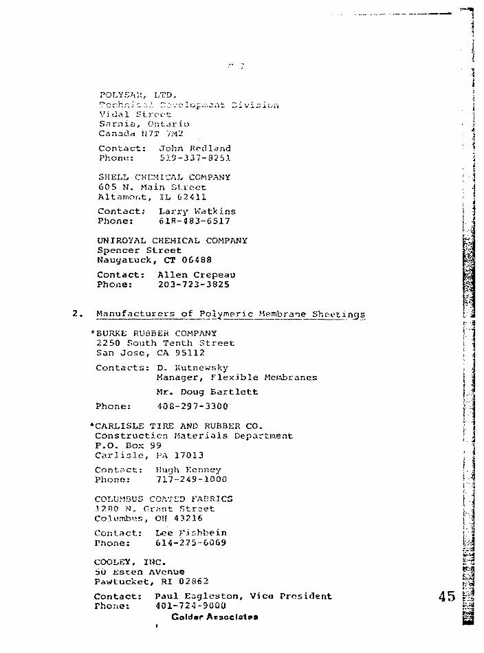
- • t
IPOLYSAi':, LTD. :
Vidal Street jSarnia, Ontario • jCanada U7T VM2 : 1
Contact: John Rod land *Phone: 519-337-8251 i
• iSHELL CHEMICAL COMPANY [ \60 5 N. Main Street 1Altarnont, IL 62411 '•' \Contact; Larry Katkins < |Phone: 61R-483-6517
UNIROYAL CHEMICAL COMPANYSpencer StreetNauyatuck, CT 0G488
Contact: Allen CrepeauPhone: 203-723-3825
2. Manufacturers of Polymeric Membrane Sheetings
*BURKE RUuBER COMPANY i2250 South Tenth Street ISan Jose, CA 95112 ;
Contacts: D. Kutnewsky ]
Manager, Flexible Mcrabranes |
Mr. Doug Bartlett {.i
Phone: 408-297-3300 i--'~\
•CARLISLE TIRE AND RUBBER CO.Construction Materials Department ; iP.O. Box 99Carlisle, PA 17013
Contact: Huqh KonneyPhone: 717--249-1000
COLUMBUS COATL'D FABRICS3 2BO N, Gr^nt Street i .-Columbus, OH 432.16 1:-;
Contact: Lee Fishbein jv'2Phone: 614-225-6069 yi
COOLKY, INC. $M50 esten AVcnae f:'%Pawtucket, RI 02862 f?p
Contact: Paul Eaglcston, Vica President 4 5 •''IPhone: 401-72^1-5000 | ^
Goldor Associate* &3
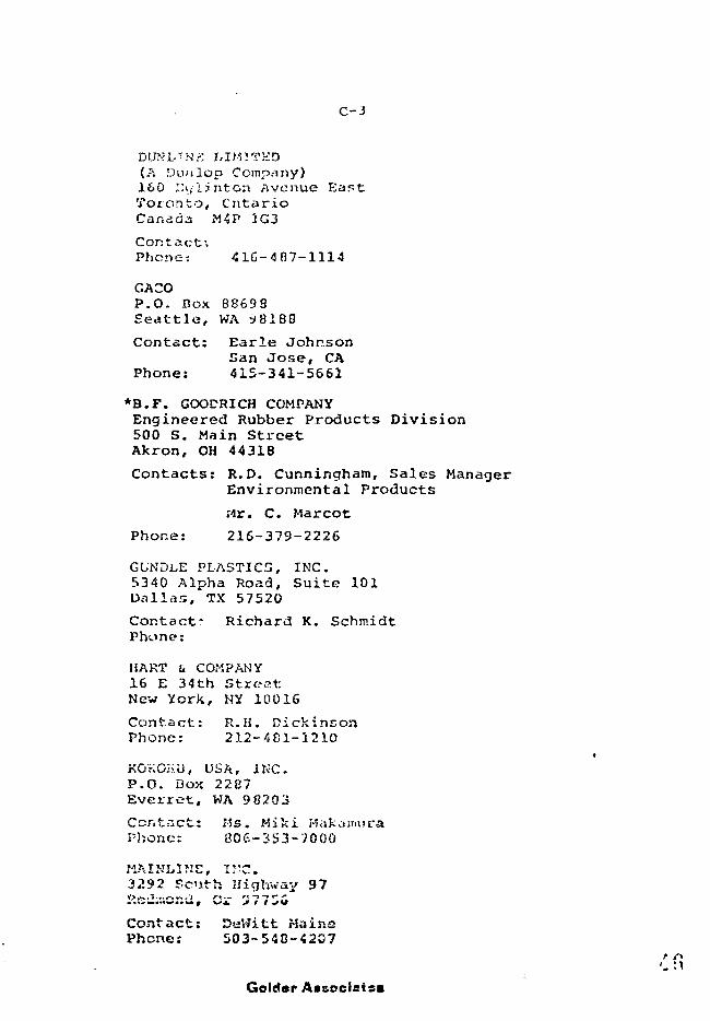
C - 3
,TNK MHITKD(A !Ji.mlop Company)160 I'ljlinton AvenueToronto, CntarioCanada M4P 1G3
Contact;Phone; 416-487-1114
GACOP.O. Box 8869SSeattle, WA 98188
Contact: Earle JohnsonSan Jose, CA
Phone: 415-341-5661
*B.F. GOODRICH COMPANYEngineered Rubber Products Division500 S. Main StreetAkron, OH 44318
Contacts: R.D. Cunningham, Sales ManagerEnvironmental Products
;ir. C. Marcot
Phor.e: 216-379-2226
GUNDL.E PLASTICS, INC.5340 Alpha Road, Suite 101Dallas, TX 57520
Contact- Richard K. SchmidtPhone:
HART U COMPANY16 E 34th StreetNew York, NY 10016
Contact: R.H. DickinsonPhone: 212-481-1210
KOKOiiU, USA, INC.P.O. Box 2287Ever re t , WA 9 8203
Contact: Ms. Miki HakamuraPhone: 806-353-7000
MAINLINE, I^C.3292 Scnth Highway 97KsiT.cr.ct, Cr 3 77S0
Contact: DeWitt MainePhone: 503-548-4207
'1 fiGolder Aaoociaiss
PANTAEOTS, INC.2b Oeitcrson StreetPassaic, UJ 070 55
Contact: Dr. R. Brookman201-777-8500
PLY/MOUTH RUBBER COMPANY10 4 Revere StreetCanton, MA 02021
Contact: Charles NeesePhone: 617-828-0220
REEVES BROS., INC.Vulcan Coated Fabrics DivisionP.O. Box 431Rutherford, NC 28139
Contact: Walter McEvilly, Vice PresidentSales and Marketing
Phone: 704-286-9101
•SCHLEGEL LINING TECHNOLOGY, TNC.P.O. Box 7730The Woodlands, TX 773Q0
Contact: Jamen M. Trice, PresidentMr. Morris Jett
Phone: 713-273-3066 (Conroe)713-350-1813 (Houston)
SEAMAN CORP.P.O. Box 11007Charlotte, NC 28209
Contact: Jack WatsonPhone:
SHELTER-RITE, INC.P.O. Box 331Millersburg, OH -34 654
Contnet: Dr. Bala Venkataranar., Vice PresidentResearch and Development
Phone: 216-S74-201(>
STAUFFHR CHEMICAL CO.44G7 S. C-IOKI Street
le, NJ CP620
Contact: Williara F. CliristieTecnnical Hanaqar
Phone: 201-545-6830
47Colder A»»oclat»t
C-5
* STEVEN'S EI.ASTCMKMC h F-LASTTCS PRODUCTS.. TN"C.2 7 Payson AvenueEasthanpton, MA 01073
Contact: Arnold G. PetersonPhone: 413-527-0700
TENNECO CHEMICALS, INC.P.O. Box 1G9Piscataway, NJ 0880b
Contact: Bob Hayes/Kent TurnerPhone: 2C'l-35'6-2550
UNIROYAL, INC.312 N. Hill StreetMishawaka, IN 46544
Contact: D.L. ZimmermanPhone: 219-256-8181
3. Fabricators of Liners
BROWN AND BROWNP.O. Drawer 2GSMobile, AL 36601
Contact: Sam Brown, PresidentPhone: 205-479-6581
ELECTRA TARP, INC.Park Centre7241 Whipple Avenue, N.W.North Canton, OH 4 4 720
Contact: Bob Fulraerr PresidentPhone: 216-497-1496
ENVIItONETICS, INC.9824 Industrial DriveBridgeview, IL 60455
Contact: Ray Winters, PresidentPhone: 312-5S5-6000
FAB RICO MTvNUrACTURIlJG CORP.1300 West Exchange AvenueChicago, IL 6CC09
Contact: Jay -Sabath, Sales KanagarPhone: 312-251-4211
Gaidar A*»ocl«t«s

MCKITTRICK MUD CO.
Bakers-field, CA 93305
Contact: Bill Wheele:;, PresidentPhone:. 805-325-5013
*PALCO LIUINGS, INC.7571 Santa Rita CircleP.O. Box 919Stanton, CA. 90680
Contacts: Richard Cain, Senior Vice PresidentMr. W. Bachelder
Phone: 714-898-0867
POLY-PLASTICSP.O. Box 299Springfield, OH 45501
Contact: Roland Harmer, PresidentPhone: 513-323-4625
PPROTECTIVE COATING, INC1602 Birchwood Avenue
L . t i i iyiiC) AIM
Contact: Elrao Murrell, PresidentPhone: 219-422-7503
M. PUTTLTJIAN ft CO.2221 West 43rd StreetChicago, IL 60609
Contact: A. Berman, PresidentPhone: 312-927-4120
> • ••;
I a
REVERE PLASTICS16 Industrial AvenueLittle r«rry, KJ 07643
Contact: Lirry Smith, PresidentPhone: ^01-641-0777
SOUTHWEST CANVAS MFG CO.Oklahoma City, OK
Contact. Richard C. Nslsoii, -*'. nagarPhono: 405-672-3355
*STAFF INDUSTRIES240 Chens StieetDetroit,- MI 4 8207
Contacts: Charles K. Staff, PresidentMr. R.G. MacDouald
Phone: 313-259-1820 n11
i.
i-f.:
Colder A».f.c»c!staa
*SYNFLEX INDUSTRIES INC.
Vancouver, British ColumbiaCanada V6E 2A9
Contacts; Gerald W. Salberg, PresidentMr. R.S. Atkinson
Phone: 604-682-3621
•WATERSAVER COMPANY, INC.P.O. Box 16A 65Denver, CO 80216
Contacts: Bill Slifer, Vice PresidentJames B. Bryan
Phone: 303-623-4111
MANUFACTURERS WHO ALSO FABRICATE
Burke Rubber CompanyCarlisle Tire and Rubber Co.B.F. GoodrichSchlegel Area Sealing Systems, Inc.
Contractors
CRESTLINE SUPPLY CORP.29 87 South and 300 WestSalt Lake City, UT 84115
Contact: Guy WoodwardPhone: 801-487-2233
ENVIROCLEAR, INC.P.O. Box 242Falls Village, C? 06031
Contact: Don Thompson, PresidentPhone: 212-997-0100
518-325-3332
AL GASTON CONSTRUCTION CO., INC.Gaston Containment SystemsP.O. Sex 1157El Dorado, XS 6704 2
Contact: John SaensPhone: 316-321-5140
*G'..-O-.'S LimtvGS, IMC.1901 East Wardlow RoadLong Beach, CA 90807
Contacts: William KaysMr. R, Webb
Gotdar A
Phone: 213-426-2587213-6-5-5315
GULF SEAL CORPORATION601 Jefferson534 Dresser TowerHouston, rjfX 77002
Contact: Howard S. Dial, Division Vice PresidentPhone: 713-722-9220
MAY EMTERPRISEr, INC.P.O. Box 6606Odessa, IX 79 760
Contact: Ken Stewart, PresidentPhone: 915-362-2363
MWM CONTRACTING CORP. |347 North Main Street §Milford, MI 48042 ||
Contact: Joe McCuliough ^Phone: 313-685-9350
313-685-1201
NATIONAL S2AL CO., INC.7701 East KelloggWichita, KS 67202
Contact: John W. OwenPhone: 316-681-1931
PACIFIC LININGS, INC.P.O. Drawer GGGGIndio, CA 92201
Contact: John Blatt, PresidentPhone: 714-347-0828
PLASTI-STEEL, INC.3588 West 13th StreetVickers-KSB&T BuildingWicb;.t:a, KS 6 7203
Contact: M.C. Gre^n, President-.Phone; 316-262-6861 r|
SCHLEGEL AR'ZA SYSTEMS, INC. '"tP.O. Box 2M97 \iRochester, Mi' 1465/2 t.-J
Cunuact: Jctrujs H. PricePhone: 71&-244-10C0
51 taColc'sr A«oocl*tao
C-b
ST.V-FLEZ CCTIT.
Greenland, HH 03840
Contact: Lou PeJoquin4917 New P.snssy CourtSan Jore, CA 9513S
Phone: 408-224-0604
THE TH'JRSTON VJALLCE CO.54 70 East Evans AvenueDenver, CO 80222
Contact: Hank Thurston, PresidentPhone: 303-758-2232
TRI STATE CONSTRUCTION959 108th Avenue, N.E.Belleview, WA 9 8004
Contact: Joe AgostinoPhone: 206-455-2570
UNIT LINER CO.P.O. Box 789
OK 74834
Contact: J.A. Hendershot, PresidentPhone: 405-275-4600
UNIVERSAL LININGS, INC.P.O. Box 315Haverford, PA 19041
Contact: David H. Small, PresidentPhone: 215-649-3600
FABRICATORS WHO ALSO INSTALL:
McKittrick MudSynflex Industries, Inc.
•A
f.'sI".
I
APPENDIX D
LINER SUPPLIERS
Ihna
I
Ml
#16iS|
i
APPENDIX D - l
Goldw Assodsts*
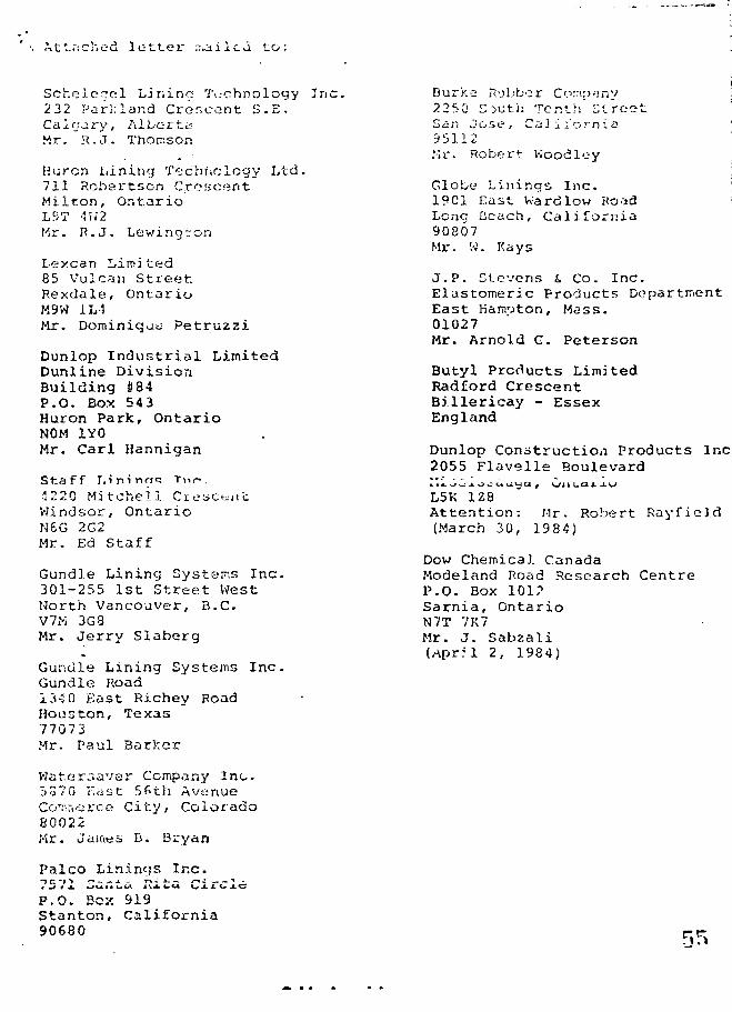
Attached letter mailed to:
Schelcqel Lining Technology Inc2 32 Parkland Crescent S.E.Calgary, Albert aMr. R.J. Thomson
Huron Lining Technology Ltd.711 Robertson CrescentMilton, OntarioLST -VU2Mr. R.J. Lewingron
Lexcan Limited85 Vulcan StreetRexdale, OntarioM9W 1L4Mr. Dominique Petruzzi
Dunlop Industrial LimitedDunline DivisionBuilding #84P.O. Box 543Huron Park, OntarioNOM 1Y0Mr. Carl Hannigan
Staff I.ininfT<; T»p.
1220 Mitchell CresctiiLWindsor, OntarioN6G 2G2Mr. Ed Staff
Gundle Lining Systems Inc.301-255 1st Street WestNorth Vancouver, B.C.V7M 3G8Mr. Jerry Siaberg
Gunclle Lining Systems Inc.Gundle Road13-2 0 East Richey RoadHouston, Texas77073Mr. Paul Barker
Waf.er^aver Company Inc.5S70 East 5fith AvenueCon;r.fcree City, Colorado80022Mr. Jawes B. Bryan
Palco Linings Inc.
Burke Rubber Company2250 C:>uth Tenth' StreetSan Jose, California95112Mr. Robert Koodley
Globe Linings Inc.1901 East Wardlow RoadLong Leach, California90807Mr. W. Kays
J.P. Stevens & Co. Inc. ;Elastomeric Products Department !East Hamoton, Mass. I01027 ' jMr. Arnold C. Peterson !
II
Butyl Products Limited jRadford CrescentBillericay - EssexEngland
Dunlop Construction Products Inc2055 Flavelle Boulevard
L5K 1Z8Attention: Mr. Robert Rayfield(March 30, 1984)
Dow Chemical CanadaModeland Road Research CentreP.O. Box 101?Sarnia, OntarioN7T 7K7Mr. J. Sabzali(April 2, 1984)
P.O. Box 919Stanton, California90680
April 2, 1984 Our ref: 841-3015
RE: FLEXIBLE MEMBRANE (POLYMERIC) LINERS
AS LONG-TERM BARKIERS FOR URANIUM MILL TAILINGS
Dear Sirs:
Colder Associates is conducting Phase I of an evaluationrsf f l o v i V i l p m a m ) - * *-.r* nf> "> i r» r * »- o f p *" »*•"•'"• 7 * ~ . »»--i- • - £ • _ * « - t — i l i ~ ~ C
pond liners and dam n.-tunbranes. The study is being carriedout for Energy, Mines and Resources, Canada as part of theNational Uranium Tailiiuis Program.Phase I of the study will be based on available publishedinformation, information from suppliers and infornvationfrom industrial users. Phase II of tho study, which is notyet approved, will involve a laboratory tf?st program toft :dy failure mechanisms, degradation rates and contaminantrelease rates through liners selected as a result of thePhase I study.
For the purpose of the study it will be assumed that theliners will be provided with soil cover and that the timeof consideration will be up to 1000 years followinginstallation.
The two main arn.is of Canada to be considered will be theKey Lake area oi Northern Saskatchewan and the Elliot Lakearea ot Ontario.
... 2
April 2, 1S<?4
At- present we an1
i inors:considering the following poly;:,.-, ric
i i ) Ci-Ci i i ) CCPE
iv) PVCV) IiPDM
(.liypalcn)
vi) PCvii) Butyl rubber
v i i i ) Ncopro r,:.'ix) Polvurethano
Please forward an up-f o-date information package ceirrespond-ing to the above; r.iiit.erials which you supply. Wo wouldspecifically n-ou'.s information corresponding t.o thecategories identified in the attached checklist. It isanticipated that sonie of the information would be includedin your standard brochures, however, additional informationwill likely be required.
Please note that we do not require detailed design or exactcost estimates at this time. The cost information requestedis to establish orders of magnitude to compare tho variousliner materials; it will not be used to compare the linerinanufacturers or suppliers. «.
Responses from manufacturers/suppliers will be incorporatedin the Phase I report.
Due to the project tuning constraints, we would appreciatea written response ti5 soon as possible.
Should you have any questions, please contact the under-signed in our London office.
Yours truly
GOL ASSOCIATES
Frederick W. Firlotte, P. Eny.Associate
KWF/jlA t t .

2 '
i
iiiiiivV
vivii
>))))))
viii)
CHEMICAL
t. e n s i 3 e r;puncturetear u>r.iabrasi ondimensionf: 1 e x i b i 1 icreep respernw.;abil
COMPATIB?:
trennthresistancestanceres istanceal stabilitytyistanceity
LITY
i) In contact with uranium tailings (if available).- extraction process is sulphuric acid leaching,
solvent extraction solution purification andammonia solvent stripping.
ii) oxidizing acid resistanceiii) mild acid resistanceiv) base resistancev) general chemical resistance
vi) resistance to hydrocarbons (aromatic andnon-aromati c)
bacterial resistance
PERFORMANCE CHARACTERISTICS
i) ozone resistanceii) ultraviolet resistanceiii) low tenperature performance including freeze-thawiv) high temperature performancev) potential for cracking
vi) provide any information on hand associatedwith design life (note uranium tailingsapplication)
4 ) INISTAJ'
i) describe recommended installation procedures andsi te prpi3-=; rat ion required
i i ) indicate effects of weather/climatei i ) indicate? roqui rcrt/reromr.tendoi3 field meaning
technique and coir.-vesit on rci i;s£>il i tyiv) comment on rflsiKfanri* to I' uiprruint: d.irr.a'.o
tlurLntj insjt.il Idtionv) indicate mAxitniim r«:'c.Titrij\v>n<:V.*d slcpa inclination
for liner instal lat ion
5)
i) indicate capabilitier-j and location of testingfacilities, if any
ii) describe routine quality control duringfabrication
iii) describe field seam testing techniques duringinutallation
iv) provide results of any compatibility testingincluding accelerated t.estino carried out andwhich is not confidential (not.e uranium tailingsapplication)
v) provide information associated with radiationdciraage to liner material (if available)
6) COMPANY INFORMATION
i) describe services offered (ie. resin manufacture,calendering/extrusion, installation)
ii) indicate your largest single sheet capabilityiii) indicate location of your plant facilitiesiv) indicate what quarantees or follow-up you
would typically provide
7) PREVIOUS EXPERIENCE
i) indicate previous experience with liners foruranium tailings anywhere in world includingCanada(size, location, owner, year installed, whatcontained, and any comnien".; dissociated withinstallation and performanceJ
ii) previous experience with liners for miningindistry in Canada (same information as7 i)) -v
iii) previous experience, with liners for hazardouswaste facilities in Canada (same informationas 7 i))
8)
i)
ii)
(Case Histories)
provide any information available associatedwith performance of liners based on monitoringof installations (contaminant release rates/quantities, line»r size, typ<? of p>onitoringsystem, material contained)provide anv inforinatinn a vail.** W e which describesperformance of lir.ers, in general, followinginstallation (note uranium tailings application)
Gokkw Associates
INFOItMATJON KKOtHT.KB (Cont-ri .) 3 P 51 - 3 ^ ; "
9) COSTS
i) estimate 1984 cost range for liners for thetwo areas of interest noted:
a) Elliot Lake-Blind River area of Ontario,Canada
b) Southeast Athabaska Region (Key Lake,Midwost I.'?Jke, Ciuff L*ike, Rabbit Lake-Collins Day} of northern Saskatchewan
ii) costs should represent installed cort persquare foot (or metre) for a large installation(say 1,000,000 ft 2). Please indicate ifearthworks and soil cover is included.
iii) If available we woujd be grateful for any ofthe component costs such as:
- sheet supply- shipping- f i e l d seaming
Goltter
APFENDIX D-2
KTTMMABY OP VJTTPPT.TPPC •
61

APPENDIX »•>-" -1
: CVCTPUC
i ; i
301-TSi 1i! Elre«l W«rai Te^nNorth Vjtncouver. GUHCLE-VCRQ Z Ctnao« C4-3S^StSV7V3SO Tel (CC-tj
CUNDLINE HIGH DENSITY POLYETHYLENE FLEXIBLE MEKERA.HES
We are pleased to submit information on Gundle Lining Systems products amiservices relating to the engineered flexible neiabrane lining industry.
For over seventeen years we have manufactured, furnished, or installed nostconaoaly known synthetic membrane naterials, ranging froa thin PVC throughnediua-strength synthetic rubber, to extra heavy duty Digh Density Polyethylene(HE?E) sheeting. We currently offer our CUHDTT>fE HD (High Density) Polyethylenesheeting in st&ndard widths of 22.5 feet without any factory seaas inthicknesses ranging frou 20 to 100 nils. Coxrm applications tor GUNDLINE
dispos.il areas» or <iay epplicouiou vhere c high-rsiiahility permanent barrieris required.
The Gundle Coartcay is fully integrated with respect to K&nufscturing, Researchand Davclcpiaent for special epplicationa, construction and supervisorycapabilities having installed over 70 million square feet of assorted liningmaterials during the ptst 17 years.
Gundle can efficiently meet your ccntztnnent needs with s chfraiciilly-coBpatiblematerial of suitable thickness, professionally installed to achieve a secureand cost effective containsient system.
We hope that you find the enclosed information of iattrest. Plea»«~ contact usfor additional information.
Sincerely,
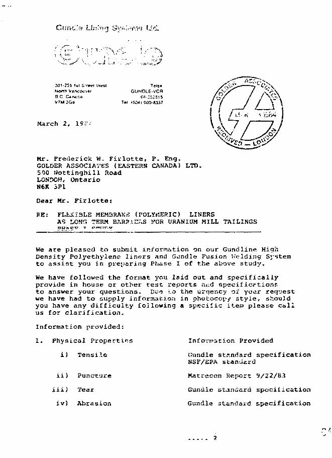
imt'S! Liir!«3 Si:'J-%;.-rT*r?J IJ.&.
\ •>.. ^
301-215 i»i Srwt -.Vest
V7M 3G«
Teis«GUNDIE-VCB
T«l i KM I eeo-8337
March 2, 19T
Mr. Frederick W. Firlotte, P. Eng.GOLDER ASSOCIATES (EASTERN CANADA) LTD.500 Hottinghill RoadLGSDCHc OntarioN6K 3P1
Dear Mr. Firlotte:
PE: FLEXIBLE MEMBRANE (POLYMERIC) LINERSA? LON'C; TERM BARS).nr.S FOR URANIUM MILL TAILINGS
We are pleased to submit information on our Gundline HighDensity Polyethylene liners and Gundle Fusion Welding Systemto assist you in preparing Phase I of the above study.
We have followed the format you laid out and specificallyprovide in house or other test reports ai:d specif ic?tior>p.to answer your questions. Due *.o the urqency of yoar reqvsestwe have had to supply information in photocopy style, shouldyou have any difficulty following a specific iteta please callus for clarification-
Information provided:
1. Physical Propsrtirs
i) Tensile
ii)
Hi)
iv)
Puncture
Tear
Abrasion
Inforation Provided
Gnndle standard specificationNSF/EPA standard
Matreccn Report S/22/83
Gundle star.ccrd specification
Gundle standard specification
n ',
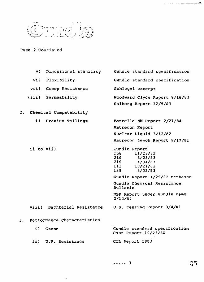
Page 2 Continued
v) Dimensional stability
vi) Flexibility
vii) Creep Resistance
viii) Permeability
2. Chemical Compatability
i) Uranium Tailings
Gundle standard specification
Gundle standard specification
Schlegel excerpt
Woodward Clyde Report 9/16/83
Salberg Report 12/5/83
Battelle NW Report 2/27/84
Matrecon Report
Nuclsar Liquid 3/12/82
Matrecon leacn Report 9/17/81
Gundle Report156 11/23/82210 3/23/83216 4/04/83111 10/27/G2185 3/02/83
Gundle Report 4/29/82 Matheson
Gundle Chemical ResistanceBulletin
RSF Report under Gundle mexao2/13/84
viii) Bachterial Resistance U.S. Testing Report 3/4/81
ii to vii)
3. Performance Characteristics
i) Ozone
ii) C.V. Resistance
Gundie standard specificationCase Report 1C/23/30
CIL Report 1S33
__-• i J •• 1 - : . i -
Page 3 Continued
iii) Lov; Temperature
iv) High Temperature
v) Cracking
vi) Coefficient of Friction
Gundle Lab Report Shrinkage 4/83
Gundle Lab Report 443
U.S. Testing Report 8/12/82
Gur.dlc Lab Reports145 10/17/82160 10/17/82
Gundle Lab Report 200 2/13/84
Gundle Lab Report 313A 10/3/83
R.K.S. Report 8/18/81
i) Recommended Procedure
ii) Effects Climate
iii)
iv)
Gundle standard specification
Gundle Technical Report 100 7/83
Min. installation periodtemperature for welding 0°C
(Installation only- operating temperatureservice ok all condition) ( n Q t P e l e v a n?, ^
Beaming
Damage
v) Slops Inclination
Shut down installation duringhigh winds 50 lunph, rain/snow
See Section 5
2.0-2.5HU« thick very resistantmechanical rizmaos - rubbertired equip£!ant can run over1.0-1*5 no recommended forvehicle traffic
Vertical to -*ny flatter slope
»»•<•« 4
II "• : 5 {]}'•* f^ \.; :.;iuf #
Page 4 Continued
5. Testing
i) Capabilities
ii) Quality Control
iii) Field Seaming
iv) Compatability
All tests as shown on standardspecification plus environ-mental chamber to -50° + 100°at Houston plant
Gundle QC manual Jan. 84
Gundle Fusion Welding manualWelding Institute report 1/9/84
NSF Report 2/13/84
6. Company Information
i) Services
ii) s;
iii) Lo
iv) Guarantees
R & D Engineering
Extrusions
Installation
Page 2 Gundle standard specification
Houston, Texas
Gundle Lining ReviewVol. 1 Ho. 1 Jan. 82Vol. 1 No. 2
Kansas reprint
Saudi report
Sample warranty 20 year pro-rata
• * * • • J
C»CK; 5 Continued
7. Previous Experience
i) Uranium Tailing Liner
ii) Mining Experience
iii) Other Experience
8. Monitoring
Rossing report 1974
Project reference listsCanada, U.S.A., South Africa
Gundle Lining ReviewVol. 1 No. 1 Dawn Mining
Project reference as in ii
Lavalin Report Jan. 8 4
Matrecon Report Feb. 81
No available information
9. Costs (Union Labour) - Tailing Dam Slope (Facing)
i (a) 2.0mm HDPE 1984 Installed
Elliot Lake Blind River S12.00 - 12.50 sq.m.
2.5mm HDPE $13.50 - 14.00 sq.m.
Tailing Floor or Water Reservoir
2.0mm HDPE $10.50 - 11.00 sq.m.
2.5mm HDPE $11.50 - 12.00 sq.ni.
N. Saskatchewan add 5%.
Ho earthwork or soil cover
K€<y Lake 2. 5mm actual $14.00 sq.n.
Federal Sales lax / Provincial Sales Tax included
•%' ;rs-- •?' V.-.-••,-;•• J : & [••.•\\.'JW-~' •'•.<%:• ••••t'.S
Page 6 Continued
By percentage:
Material - 63% including FST
Shipping - 4%
Field Installation - 33%
I trust the foregoing information is satisfactory, howeverif you should require any further information please do nothesitate to contact me.
Yours very truly,
CJMDJLIE i_r^z"C CVCTCI'C L T D .
\ v
G.W. $alberg, P. Eng.President
GWS/dljEnds.
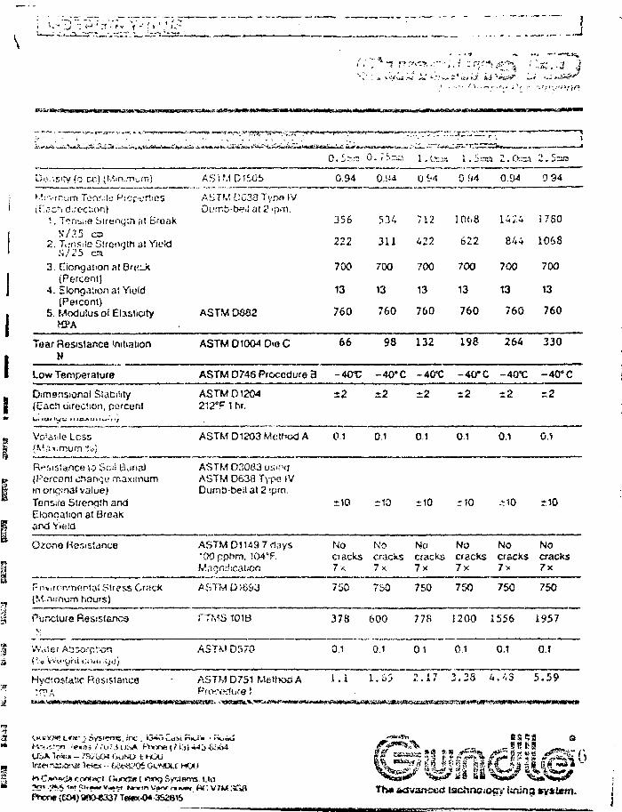
- • ' * .
A* *•.".: •** - * i t i *jf i»J **•***?
>H-»^«^^'^^CVt^aa-^-A*tiit.ftt.t*-J^»'j>p^ vLfiii''-vjr<«-xfc!--M
Do.-.sity (o-cr) (Mm.nnim) AS'i M D 150b 0.94 0 c-'4 0 UA 0.9/ 0 94
^il at 2^. Tcnuiifl bueng;n at Eroak
V/?.5 ca2. Ttjnsrle Slrcnqth at YieW
S/25 ca3. Eicngation al Ba^^X
(Percent)4. Elongation at YieW
(Peicenl)5. Modulus oi Elasticity
MPAASTM D882
356
222
700
13
760
534
311
700
13
760
712
422
700
13
760
1068
622
700
13
760
14 2. 4
844
700
13
760
1780
106S
700
13
760
Tear Resistance initiationN
Low Temperature
ASTM D1004 Die C
ASTM D746 Procedure 3
66
- 4 0 t :
98
-40* C
132
-40*0
198
-40*C
264
-40"€
330
-40° C
Dimensional Stability(Each direction, porceril
ASTM D1204212"F 1 hr.
=2
Less ASTM D1203 Method A 0.1 0.1 0.1 0.1 0.1
\o SciS Buna)(Percent chan-gt' maximumin ordinal value)Tensda Strength andElonqation at BroaKand Yield
ASTM 03083 USIPCJASTM D638 Typa IVDtim£>-bei! 3t 2 ipm.
Ozone ASTM Dl 149 7,lays"OOpphm, 104'F.
No No No No No Noctacks cracks cracks cracks cracks cracks7x 7x 7x 7x 7> 7x
i Stress Crack(f.'.asmum hours)
Puncture ResistencaV
ASTMOHJ&3 750 750 750 7S0 750 750
101B
Water A5so'pv>on D570
378 600 77S 1200 1556 1957
0.1 0.1 01 0.1 0.1 0.J
H>'c3fostatic Resistance ASTM D7S1 Method A 1.1 1.65 2 . 1 7 3 .28 4 . 4 3 5 . 5 9
Tha advanced tscftnsiocy lining tsytittti.

Olltth'S
enary Poiyeihyferie
. . . r* - • . . - '
was riesjpot*d ry«va(ic,"iHy far (!*po-:-«d corxii'joos. ft contains noi!:en» wracti can ofocia ttvs procjcl cr« ?f tinvj.
Cri'scai to t.!"«} si>oc»-?ss ci any (icxit to rmjiTityaria ioc-f is thfl josnaig tyssem. Guncfto'spau-nt'Jd f u:>K)!i Vvt oinq Prarcss ^ use<J to f>-«ri irx;:vvj^y pane-Hs c< GiJNiJLiNc-HO.Request your copy ul t:« umviJa Fusion Weirfaxj UiJlc'.m iof corrp«t«j bei-^ts.
CMEMJCAL NE-KD is resistant !o a wicie raiigoof chem<cals inducing acids, aitolts. safts,aico^vo!s. amines. CHS. and hyd.'ccartxxts. Sirica comb«n8t»o<"is of chemtcais of cliKef-ent corcenlrations and temperatures havo cMIereni cnaractenstrcs. consiit GurxJia(or speolic application details. Write tor GuncJie's ctemicaJ compstibi.'ity m«xmation.
SUPPLYSPECIFICATION
The following describes standard roi! dimen&ons for GUNDLINt-HD.
(mrf.)
2030t \ j
SO80
100
nun.
0.5075i.U
1.52025
ft.
22.S22.5
22.522.522.5
tn.
6.756.75o.o6.756.756.75
f t
12508406 iU420320250
m.
38125613812810076
tt.1
23.12518,900
9.4507,1455.S32
m.«
26131756rsbn878664519
to28002800t w o2S0028002800
kg.
1272127212A2127212721272
GUNDLINE-HDisroliedon 150ram ho l low c o r e s .Each roll is prowl*:*) witfi 2 siaics to s»J h a n d i ^ on m;o.
weights are approximate. Custom lengths avaiiabie on request.
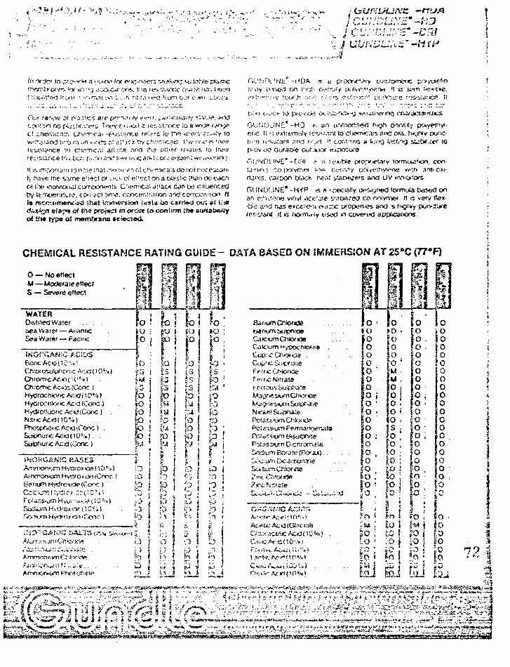
,.-1i.f*.i .) Jf. V ^
In •vrja 10 p'cv""'" a " I K V I tot pory-scrs v>?kiK; •-o'.S.?.'>'e pusjj>c Cil'.N'fX 'N t r - I ' D A w t pfopr-evry c.ftUOTse*c
Ouf rar^ni oi cv3:;!ic? ate (V".viJv tf**n. [i-sruri.ij.i/iy <;-«-'..<£. scc»".V-- no f.<Us!tire»s Trv/y £*•'•&! a N:*;.i;t."oce So s wii? r,»»o! cMefVi«:p.r. Uv-rrs-ai ie*J:."-?.nce fp^'S lo !^« is."<afr/<:!/=i<tY
'.o criofrcil ati.ir.k .ma it~.3 o!!>sf ffiuios >o uvtr [>ovoo Gufaoie ouMJSf «sfes'ousrice lo<.bct:'p'-'>'iar>t'lswfi.'.Kjarkii1.of.^ffjeMmMM.iwv] <"'i,sjni IMC* p,si -\ >.-».hi'» of<y«
h,' fvsve me same e'ltct c OCK ot oi'trc! on a c^as!«; \t\an do t^crt rtai~>;s. caroon C&TO. nesi riaWizws SIXJ UV io. IM» rfawtt^l corroonw!!, C i e m ^ l Jl'ack Mn w mnueociid G U N D ! . , N E « ,MP s „ S 9 e c i 3 i ! y oi^gnwl lormute bas*<J on
Is rec-c: nrr»*r>c.id it'.»t inwryeruion [ssia c>a csifrtitci r/U'! at ti
erf t i l * typa o! snembtsrta
• : . • • ' . . — • • r - • - ; . • • " . • •
GiJ'-OiJNr.* -HD r; »n g yCfj« li r; exiittTY-.dy r<:v-.i<ir,f (0 i3>i>mic.t5 ar>C Cms. hrjNy pur.C-I'-i i rcfcKant . iaj i.:,<i i; cof-!'";ns a k.vvj te.i.'vg sict^.^tf (o
con-
CI'I/IXKS vmyi HCC'^IP siaWireO co noiymef. II >s verys.'id has excc.'iefii ei.-i;iic pfcpefl'es and -s h<jiiiy
it ts fKxm.iiy usixl m coverod applications.
CHEMICAL RESISTANCE RATING
0 — No etieclM — Uodera le edeclS — Severe eftect
WATERDistinct Waieri>ea Water — AuoniicSeaVVaier — Faoie
OPCANiC ACIDS
CAWOSl)ip<!Ci .'C Acd (10c.'« )10 c't)
HyOrof hSw tc Acid (C<xv:.)
PnosjV-x ic Ac id [Cone) .SyipnurtcAcid(lO%). .Sustfturic Ac id (Cone )
INOHGANfC BASESA"VFT>On.>- KTi H\XUOI i<3S! * 0 •
F oi onsiLfri H >iji -; «.:-.»(IS5',
i-iir/Ti.': 1
^-s:)".'-! i .
iV WT! O " i 'VfV»
DATA BASED ON IMMERSION AT 25»C <77°F)
ColC'L'.TI HypoCfllCMIl
Potassium Dicn
!V(f.
[ ( * • • _ ^ » , . . . . . ... - h .
72a
_
k^^^i:..^^^^i."^y^/i^i<ii^^i;^'^v^^^i»ip^^v^^^
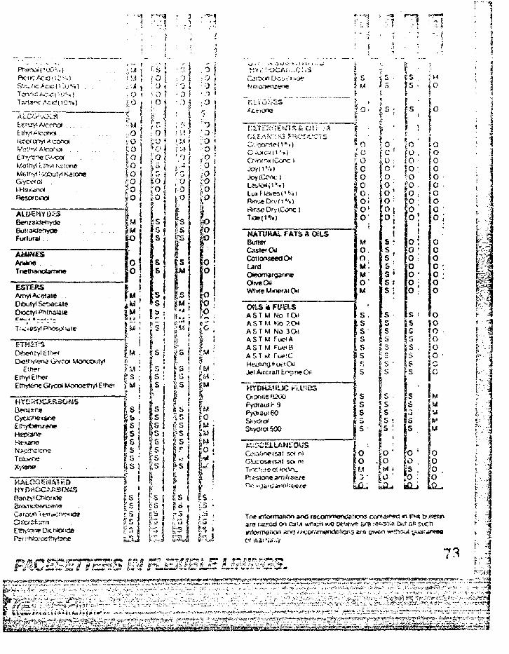
ALDSHYDKSBen/aKSstiyde
Furfursl . .
A£Uft£SAruhrw . .Tne!fwioi*T»ne
ESTERS
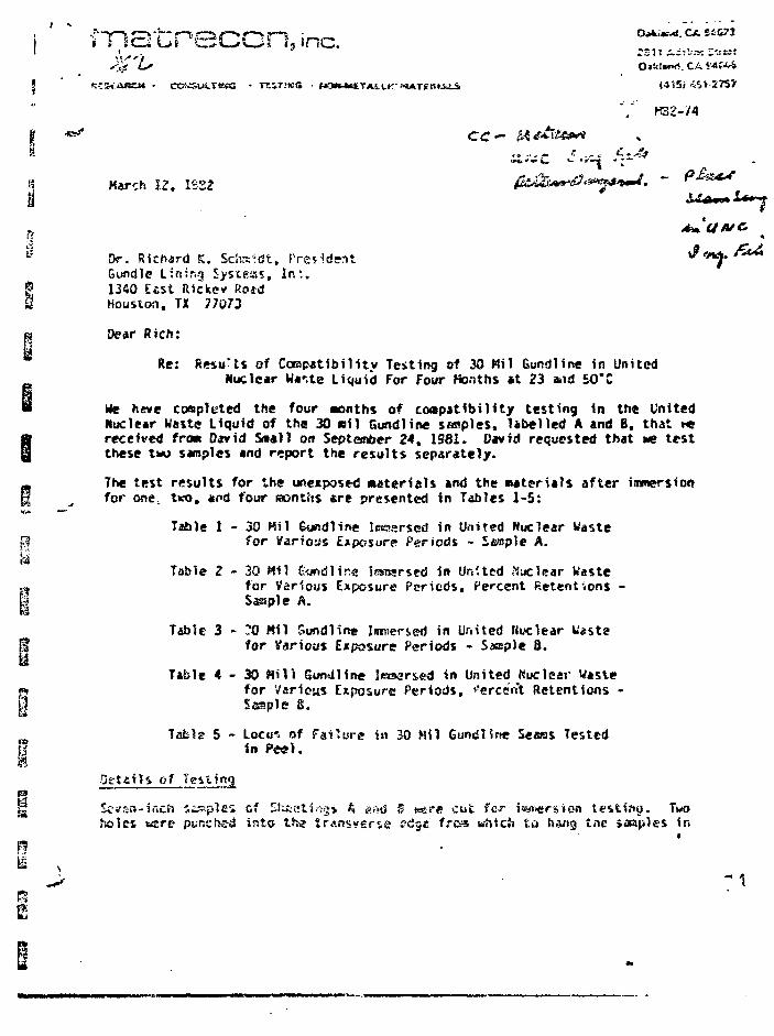
n
s
'A l5me. ,_ _...„.0tk\M>6. CA M?*i
TEIT.'KS • f»"»MatTAS.i.K' MiATSStAJJ. !4^5i •5S1 275?
5
8 Kar^h I? . 1S22
Y r32-/4
n **tS Dr. Richard K. Schaidt, PresidMt t^
Gundle Lining Jysteas, I n : .| 1340 E£St Ricksv Roidg Houston, TX 77073
a Dear Rich:
iRe: Resu'ts of Ccrapatibi i i ty Testing of 30 Mil Gundline in United
Nuclear W**,te Liquid For Four Months at 23 and 50"CK We heve conplcted the four •onths of coapatAbi l i ty test ing in th« United
Nuclear Waste Liquid of the 30 s i l Gundline sasples, label led A and B, that t «
S received froat David Snail on September 24 , 1581. David requested that Me tes t
these two samples and report the resu l ts separately .ra The test resul ts for the unexposed mater ia ls and the Mater ia ls a f t e r immersionH ^ for one, two, «fd four raontits «re presented in Tables 1-5:
Table I - 30 Mil &undline lewarscd in United Nuclear Wastep for Variows Exposure Periods - Sample A.
Table 2 - 30 Mil £« id l in« Icsnsrsed in United Nuclear Waste» tor Various Exposure Periods, Percent Retentions -h Sample A.
Table 3 - .0 Mil Sundiine Immersed in United Nuclear Wastejf for Various Exposure Periods - S«sple B.
Table 4 - 3 0 N i U 5un«Jline Ieraer&ed in United Kucicar Wastep for Various Exposure Periods, *'erce"«t Retentions -| | Staple S.
fTable 5 - Locu-s of Failure in 30 Mil Gundlfne Se«as Tested
In Peel.Detcils of
Scvsn-incft nipples cf SluislifVfj* A at>d ^ w«re cut for i<wiersion testift«j. Tvoteles usre pur.cheii into th« irAnsverss edge frca which tt} h 'tg tne saapies in
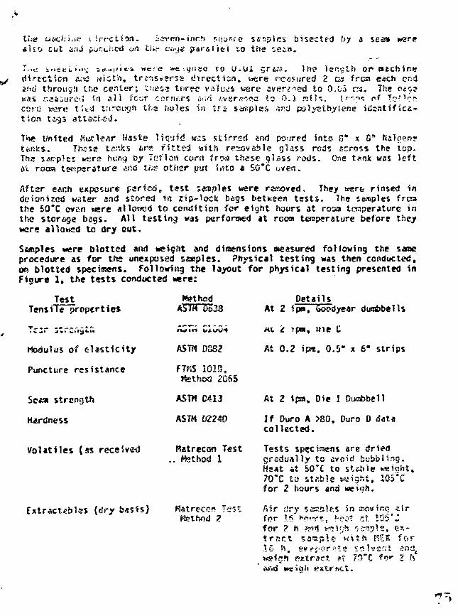
t<;<2 tiscisi.tt? i-irrctitn. iirrrri-inert sou'-re sctiples b isec ted by a sea» warea l s o cut and punciicd </H ti«- e<iyg p a r a l l e l to the ss&a.
M; ^ « | i i t i wc-e toe-.9ceo to U.UI . - r i a . 1 hs» length or&-is wic th , t r i n s t fwsa d i r e c t i o n , nere neasured 2 DS frca each
Sftii through the c e n t e r ; zuess t n rec values were swerved to Q.u5 ra. Th* car,?was r.^6iurc-.J <rs a l i lour corners 0:;ri ;;v£rn«sj to O.i s i H . tr".n«: r-f Tc"1 ':^cord were t It-si tfirough the holes in t f s saiipies -u'd polyet.hji'ier.e i d e n t i f i c a -t i o n t c^s 8tts-."f.-ed.
T»w United rfuc.1t?ar Waste !iq^iid wss s t i r red and poured into 8" x G"ttftfes. These tenks *re f i t ted v»ith reJiovable glass reds ccross the top.Ths samples wire hu.^ by 7cHen corci froo these glass rotJs. One tt.nk was leftat roosi temperature And tfts other put i«'!to « SO"C oven.
After each exposure f&ricd, t es t Simples were rcssoved. They wert rinsed indeitjnijrcd water and stored in zip-lock bags between t e s t s . The samples froathe 50*C oven vsre allowed to condition for eight ?iours at roan temperature inthe storage bsgs. AH test ing was performed at rooai teoperature before theywere allowed to dry out.
Ssxtpies were blotted and weight and dimensions »easured following the saraeprocedure as for tins unexpossd saeplss . ?hysic*l tes t ing was then conducted,on blotted specimens. Following the layout for physical testing presented inFigure 1, the t»s t s conducted were:
TestTensile pVopertie*
Modulus of elasticity
Puncture resistance
Sc«a strength
Hardness
Volatiles (ss received
fessis)
M?thodASTM D633
>w i n ifi.u%/"»
ASTP1 DS32
F1FS 1018,Method 2GS5
ASTM D413
ASTH D2240
Ratrecon Test. Method 1
Matreccn TestKsthod ?,
DetailsAt 2 ipn, Goodyear dirabbells
MI t ipoi, uie C
At 0.2 ipm, 0.5" x 6" str ips
At 2 ipa. Die I Dunbbeil
If Duro A >80, Duro D datacol lec ted .
Tests specimens sre driedgradually to avoid bubbling.Hsat fit 50*C to s t tb le weight.?0*C to stable waight, 105*Cfor 2 hours ana weirjh.
Air dry ssaolfts in moving s i rfor is"Kc-.'r*.t >-r:;* nt 105'Zfor ?. is «*•!* « V J ? J «:-<r?!?1e, e s -t r s c t s a m p l e vs i th HSK f o r16 h , evej-cr-vtc 5«K'£f;t ands
h e x t r a c t pt ?0"C *r?«- 2 h
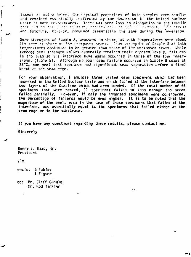
*1 notc-d b.'lrw, tft* r l-ivsicfll prnr^rX IPS cf both ^a^srilrs v?r»«nd regained essentially unaffected by the ittsucrsion in the UnitedUasts at both temperatures. There was scs*-s loss 'in elongation in the tensile
puncture, however, regained essentially the saner during the "Weer si on.IS*
Se?a %t7t>a\i\.ns of S^ple A, raasured in shear, at both temperatures were about
es conttaueci to be f>rsster than those of ths uncrxposed seaas. Wiilepeel strength valtr?$ f;eoercll.v retained their exposed levels, failures
in the s«aa it i*:s interface hiive Again occurred in three of the fcui -nKner-siens. (TeUle 5). Although fro pssi ssas fzilure occurred in Scsple B iesns at23*C, one peel test specimen had significant sessj sepflration before a final
fit the se&n
For your observation, I enclose three •sited sea*a specimens which had beenicxaer^ed in the Unit&d Uuc'i&zr baste and which failed at the interface betweentws> layers of the Gundline winch had been bonded. Of the total number of 56specimens that were tested, 11 specimens fai ieJ in this winner and sevenfailed partially, However, if only the immersed specimens were considered,the percentage of failures would t* even higher. It is to be noted that themagnitude of the peel, even in the case of those specimens that failed at theinterface, was essentially equal to the specimens that failed either at thes e » edge or in the substrate.
If you have any question* regarding these results, please contact «e.
Sincerely
Henry E. Haxo, }r.President
vim
ends . 5 Tebles1 Figure
cc: fir. CliffDr. Rod TinfcUr
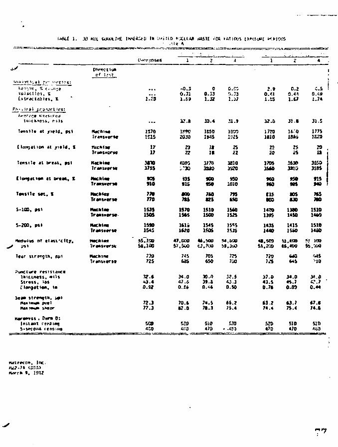
Lurtctsisiti, X
Ph-»if*J (_-»isfs-tie*:
tr.:cn.->3ik, r i l l
T»o»tlt «t jrtvld. pit
I.-,*.. «,..!...
(toMf«ti*n it ar«M, 1
Tantfic m , I
S-100. 9%\
5-203, (rti
toSuivt of t l M l ' d t y ,
Tftr tirgmgu. £$>»
ClOKfAt O*. * •
R I I W I * lK«ar
n«rawrtt . CKTO 0:
Trcnt*«rM
Tr«Nt*erM
RKhtac
NKhiat
Trantvtr**
HteMwTr«a**«rs«-
NackintTransvtTM
trawirw
NKIIM
iH'tl.iSil) 1*
>• •
1570IC15
1717
3CV3755
no77»770
15351505
ISM1543
sslioo
72»725
O.S?
72.377.3
• . - . l a *,
•O.50.31
32<S
1PWJ2030
?3
: '3O
•IS
•36
1570ISM
lili1K0
47.CQ05/.500
34.047.&
70.167.8
dASH 'OS
2
00.331.J3
39.4
ieso
uit
3770
900ISO
7WK5
15101500
15451505
705650
39.039.3
;*.&7B.3
S
ttSJOLrS
fj.;31.57
2 1 . *
jeoo
22
38103S70
sso1010
79SMO
15*01525
15551«S
54,600
775
0.50
75.4
1
J.9
32.6
I7M1U0
2?
370535M
MOMO
(15•03
147013*5
14351440
J7.043.50.7S
63.274.4
470
Z
0.2
i.a
31.1
lfc'O
25
36303JK0
* »
«JS130
13801450
1415
wsMS
34.044.7O.OT
43.775.«
510470
• •
4
c.sO.«91.74
31.5
1775
IS
K M
flS
7CSMO
1510
1510itfiO
•10
6?".7 'C.44
510
tutrKi*, Inc.
9.
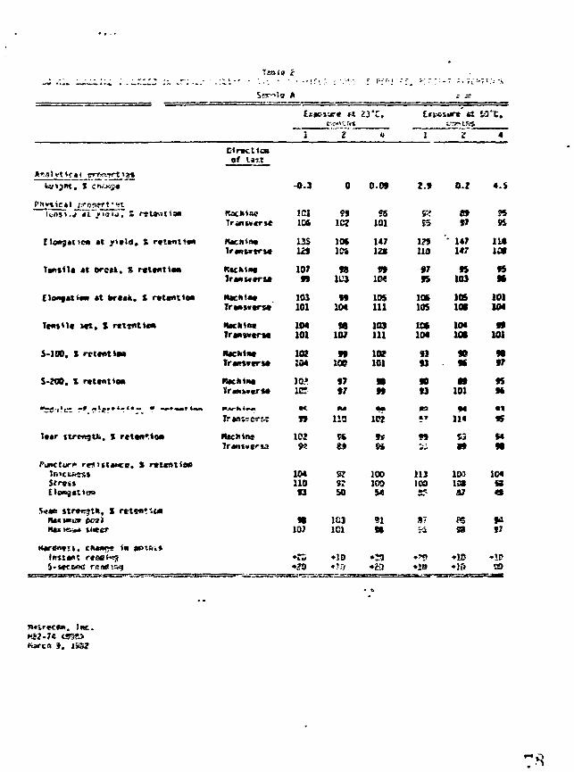
leate i
A
Ixpsi-jr* n 23"C.
i ~¥" «EirKtlcaof l«T,t
. J
j i t ic* it / i t l a . S r«t*nt««"
Ttniit* «t brcn. S rctvxttm
ClonfMiw) *t bruk. S rctmttM
Tcmtlc Mt. X rttsnttca
S-100, t rcttottM
S-200. X rctcntta*
T««r ttrtfqtfc, X rettft'.iaa
Puncture rp5itt*KC. J rtltalitm
i
HKItintIranwtrut
Irwuiru
•tacktfttTrw«*trM
-0.3
ICt
US
10799
103101
104101
102104
10*
ML
102
10411093
*107
0 0.09
1C7
981U3
99104
98107
99ioe9797
no
5250
1C31C1
• ID
58101
147
1M
105111
103111
102101
102
9*Si
100100M
•13•23
2.9
Vi
113
«795
lot105
lot104
9393
9093
113ICO
S?
•19
0.2
8»97
147147
95103
105lot
104IB
909f
10194
114
H
1031 357
PS38
•ID*1&
11*
101104
99101
9197
959t
95
S4
104S4t
S7
. Inc.
cuircn S.
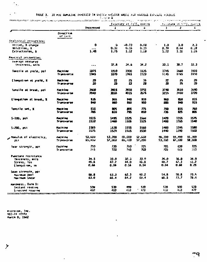
2. iD Kit GUKJLlai lt&£*iSS I * UsJTfJ n>CiJ.t& UASU H«5 f*^lU£ lii-jjCXi HfcJLvS:,:*.••• e s
tt *j
s«-t
(/ -o.es ei.ca • 1.9 3.0 »-30.31 O.ii 0.23 0.33 C.« O.r51-J5 1.12 l.£J l.JJ 1.21 i.£5
34.i 34.2 33.1 30.7 33.3
1&1S 1810 1800 1S3S 17«S l t*O JSJO1370 i»S 1523 1C4S 17U 1950
Slrerts.
mrenttl.
lbs
reel
r
i 0:tea
• t yi*\t, % PmeUim* 20 a 25 55 a 2S 20Trafttvar** 20 23 23 2t 20 25 20
T««titt * t tirctfc. Jrt« RKlinc 3X30 3flS 3f30 3751 3740 35103*40 3B45 401S £ 7 t 3215 2450 3720
«t fertrt. X HKktaa IX KS MO flO HO ISO flS\tm,uwrt* 940 MO HO 950 ttS MO flS
M t . X M4Cfei«l CIS 80* «eS 775 750 SIS 7UTrant.trM 7IS UC 7»S 810 735 825 105
S-1OD. •«« Itacktat ISIS 14«S 15JS 1»M 1420 13SS 1575TrantvarM 1S10 14*0 1595 1525 1400 1365 1M0
S-2O0. Pl« n«Ciiif!* 1565 i S » 1S5S 15*0 14*0 13M 15K1&7& 1520 1535 1533 l « « 0 13S0
-nomvm of »'«lt«c*ty. A*c*ti*« i3.t-C2 53,700 3),COO S2.&39 *8,2» 59.4C9 2.300--- Tr easier** i5.Ci=> 57.CG3 65.2C0 S7.2WJ 53.100 S7.100 5< C00
Tctr t t r e n s f - , ppi n«:fci%» 7S0 730 759 725 70S 630 725J*i 720 7*5 7G9 '/OS Cti M9
34.S 33.0 3?.i 33.0 K.O 34.0 34.0«5.t 47.7 44.0 *S.S O.7 e.3 «-!.?C.tt O.SS 0.S4 0.54 O.M O.M 0.23
tt.< C3.3 U.3 £9.2 S4.S E0.8 70.*£3.0 6S.4 S4.2 fci.4 tt.S 73.7 7E.4
£» 5S0 «S9 510 £38 SJS S3»&££ <S3 4S0 * 470 ti>fl *4^ *<T
f.
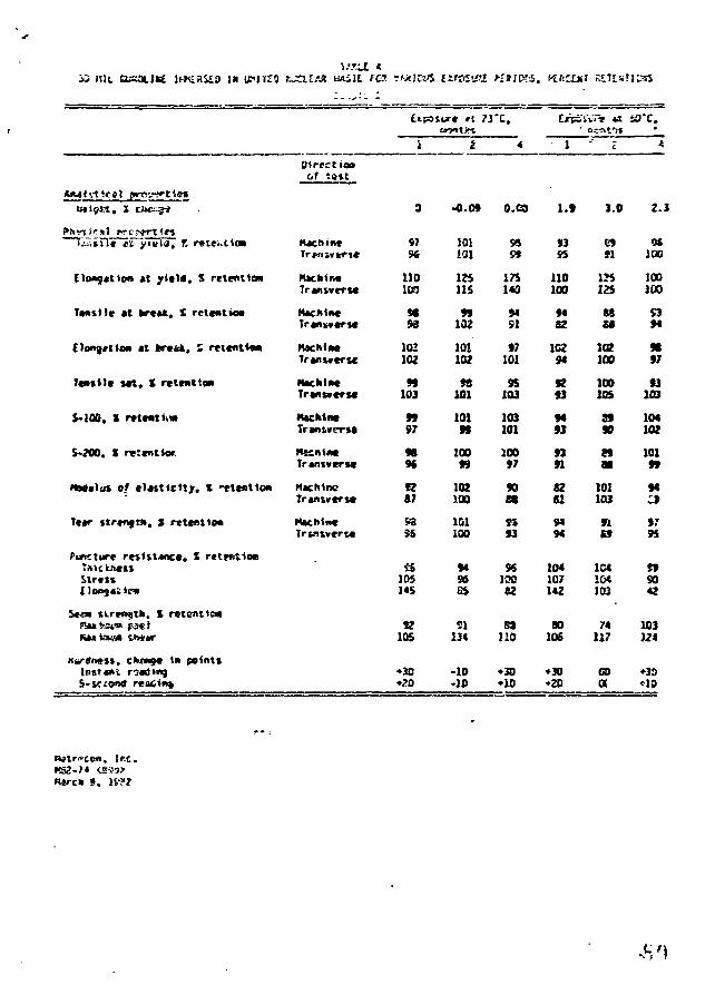
I-:)L (usance IN UMTZJ r~XUAS HASH f d ? MUCUS EIfOSl«l
Mien, i P»K
i.v.iD* el yittiS^ T. reie»ttM
Elaaftlicm at j r i i t l , S retention
Taasile «t prctt. X rclcatiea
£)o«9ttt(M «t ferefck, S mcnttwi
Tmii l * set. S retcat'.o*
$-100. S rttmttiw
S*?O0. S rvtcntioc
NMvlut of *I«sticUjr. X -etcsttoM
T««r ttrmgth, 1 rtltntitm
PttKttirt rnintect!, X rtt«i1o»
Strtu
l*tm ti-renftk. X retention
Nartfnefi. ctuwg* tn pointt
DirtctiaaOf tttVt
ruchin*
TranMcrsc
NachlMTrantvcrM
KachtntTranfcverM
HscnintTrant«eri«
H K M D CTrwiwcrM
Trtns»ert«
1
9
97
110lcrj
M93
102102
99103
9997
989ft
9287
SoSS
10514S
S2105
•JO•?D
2
-0.09
101
125115
99102
101102
98101
10199
10099
102100
101100
94esES
SI
-10•10
r e .
*
o.ca
9S
175140
94SI
97101
35103
103101
10097
9088
SS93
9S10062
S3
no
•30•10
1
1.9
93S5
110100
fit
1C294
92
9493
9391
82SI
9494
104107142
8010S
•30•20
0-t-r.t'it
z
3.0
s12S
BS£*
102100
100US
8990
n88
101103
91E9
104104103
74117
caa
sax.
2.:
9*100
100100
S394
9897
93103
104102
10199
94
J79S
S9SO42
103124
•33
, In.
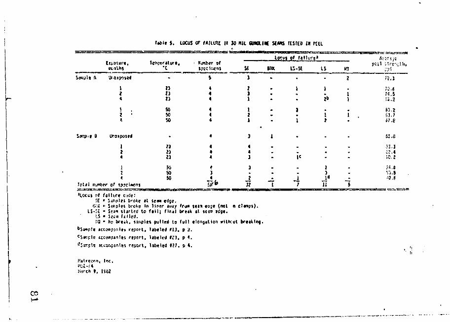
ut.it $. IOCUS of MIIIKE it M Nil omouK » w ttsreo m PUI
A Ur-u:jM»«i
8f*C tpsciacnj S£ 8SK IS>SC IS K'J
**
3*1
•2b
12
1I
i
1 23 4 ; .« » 4 J .« 23 4 1 - . 2& I 15.2
8 . SO 4 I2 • 50 4 2* 50 < 1
t
<*3ij»s«4 • 4 3 1 53.3
1 ?3 4 4 . . . . 33.J2 ?3 4 4 . . . . £>.44 23 4 3 • 1« tO, 21 $0 < 3 - . 1 . j«.»J M 3 . . . 3 - V3.9
< so _£ _2 _. _i j o _- /a.ef f t * ! ny»^?r of tpsciicns 5JJ""* 32 1 7 11 $
%*£ » Scspret broke in l iner t\af f r j a t « M t o j t (not n c t c a p t ) .t. 5 - - c " Se** Jlsrtcd to f i l l ; flnt) tiruk tt »ec3 tdjt .
K? brtik, 4SEspl(t pullrd to full elongation wlttvut brttkln^.
report, Ubeled >13. p J.uconptniet report, libeled i n , p 4.Ktsapsniei report, labeled I ? ' , p 4. ,,
v \\:n. Inc .
I , 1VQ2
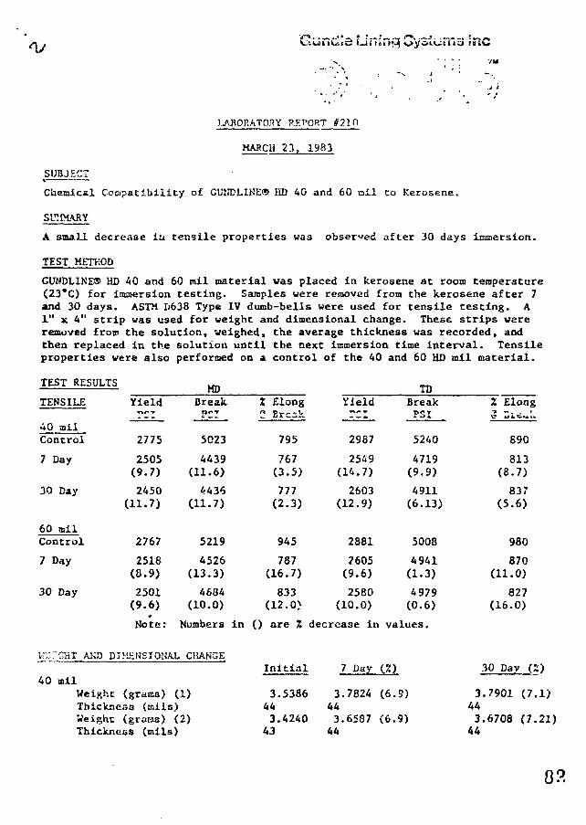
T.AJ10RAT03Y EXPORT
MARCH 23, 1983
SUBJECT
Chemical Cocipatibility of CUNDLIKE® HD 40 and 60 nil to Kerosene.
SUMMARY
A small decrease in tensile properties was observed after 30 days immersion.
TEST METHOD
GUNDLINE® HD 40 and 60 mil material was placed in kerosene at room temperature(23*C) for immersion testing. Samples were removed from the kerosene after 7and 30 days. ASTM D638 Type IV dumb-bells were used for tensile testing. A1" x 4" strip was used for weight and dimensional change. These strips wareremoved from the solution, weighed, the average thickness was recorded, andChen replaced in the solution until the next immersion time interval. Tensileproperties were also performed on a control of the 40 and 60 HD mil material.
TEST RESULTS
TENSILE
40 ailControl
7 Day
30 Day
60 milControl
7 Day
30 Day
Yield
2775
2505(9.7)
2450(11.7)
2767
2518(0.9)
2501(9.6)
Note:
MDBreakL _ _
5023
4439(11.6)
44360-1.7)
5219
4526(13.3)
4684(10.0)
Numbers in
W::"CKT AND DIMENSIONAL CiiANGE
40 milWeight (grams) (1)Thickneaa (nils)Weight (grams) (2)Thickness (mils)
Z ElongC Ercak
795
767(3.5)
777(2.3)
945
787(16.7)
833(12.0)
() are X
Initial
3.5386443.4240
43
Yield
2987
2549(1A.7)
2603(12.9)
2881
2605(9.6)
2580(10.0)
decrease in
7 Day
3.7824443.6587
44
TDBreakPSI
5240
4719(9.9)
4911(6.13)
5008
4941(1.3)
4979(0.6)
values.
(.7.)
(6.9)
(6.9)
344344
2 Elong"> *• - ., '
890
813(8.7)
837(5.6)
980
870(11.0)
827(16.0)
30 Day (2)
.7901 (7.1)
.6708 (7.21)
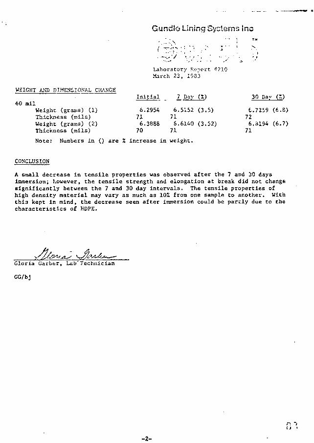
Gundle Lining Systems fnc
Laboratory Report ''?10•March 23, 1S83
WEIGHT AND DIMENSIONAL CHANCE
60 milWeight (grama) (1)Thickness (mils)Weight (grams) (2)Thickness (mils)
Initial
6.2954716.388870
671671
7 Day
.5152
.6140
11(3
(3
)
.5)
.52)
I72671
30 Day
.7259
.8194
(
(6
(6
X)
.8)
• 7)
Note: Numbers in () are % increase in weight.
CONCLUSION
A email decrease in tensile properties was observed after the 7 and 3sQ daysimmersion; however, the tensile strength and elongation at break did not changesignificantly between the 7 and 30 day intervals. The tensile properties ofhigh density material may vary as much as 10% from one sample to another. Withthi3 kept in mind, the decrease seen after immersion could be partly due to thecharacteristics of HDPE.
Gloria Garber, Lab'Technician
GG/bj
-2-
G'jr«ef!e Lining Systems Lid. j
/
3I -25'J HI S',i«M WW. fete*.
7V 3G6 •«; (604| 380-833/
December 5, 1983
Mr. Di'-k C=veKILuOR.I LIMITED2200 Lakesi-cr:. Blvd. Vest•rncn^ro, OntarioK8V 1A4
P-.-r Dick;
V»u will recall the conversation we h*d with restecc toperiueabi; \"y on the Dcnisra Potaean project. I &:a continuingtc review our records and reports that have beon prepared onthis sutjec an i .a ray recsat visit '.o Houston I took a copyof s hardwrittet j.f.port vnich w is prepared by Woodward Clydoon St'ptenber 16th with re»pect to the subject. WoodwardClycie di«l a .-.Uuis^iou fron water vapor Z.ransmission dataand S3 vou c&x. see .rcn f-he report, the permeability chuscalculated is 2.7 - If -13 To/sec. Thi"; is iu the saiae•sA. niruJ<* i. t'ie ptrmeat ility which we reported to Daverecently.
- I n addi . t r 'on t o t h e a ^ o v e , you a n u r o h i h f . y aware t n a t Ciah a s done a nun^ev o r a f i i i ^ a f o r ^faa L . P . A . , some c f whi -..• h a v *been done, in sodium chloride ajacswi solmiouo, 7'he conclcsiunffrom these raporta by both tne E.P.A. and Kaf U.S. Water l> ""owarServices is that for a l l infctn.-e purpoien. the meptrase racy beconsidered to !»«; liaperifluablri. Katrecou rnn tPf;s for Gundle in1981 with 5Z sodium chloride aqu ioc soluti&a and in an exposureperiod of 8 wetka there was uo i i iaurif isblc lc^s of cluid. Ti_suaaary, the information which in avai lable , both i.'. turn a l ly andfrota a.P.A., K.-trecop. and Water Hesearcb Centre inriic(»£eff thata ttsgnituda lit r.lie range of 10 -13 or 10 -14 id an a^ptopriatetheore t ica l figure but for a l l iotcnae purposes the material maj»be considered iiup«rt>ieahl«. As everyone has iden t i f i ed , and a&you have, the potuut ia l for mecuimiwcl uasagc cawsed by vsr .dr l i ; s
Continued - 2 -
animals or improper installation is a much u;ore rignificantconsideracion.
We hope that this; additional information will be of some valueto you. We intend to correspond with you in the next few dayswith regard to Lhe thickness specifications, howevsr, with thedescription of the tyoes of base preparation which we receivedfrom D/vve Clark and the head, we believe that thickness shouldbe Ir the aagpifuis of 1.5mm or greater. j
i
'/ours ver/ truly, jLINING SYSTEMS LTD, j
G.W. Salberg, ?. Ens.Managing Director
GUS/dljEnds.
c.c. Mr. Dave ClarhMr. R.P. Lewington

Guitdl.> Rr,nd Telex'.340 (•_ Hithsy R<i GUNOLE-WOUHouston, Tcx*s 77073 USA 732SO4T«i. (?13}443-«56<i Int I 6668205
STANDARD SPECIFICATIONS FOR CUKDLINE* HDPE(HO)
1 . 0 0
Tiiese specif icat ions describe Gurnile Lining Systems, -Hȣ "GUNULINE* LinirHembranea. The supply and inntc l lot ion of these icaterials shall be in staccordance vitn Che Engineer's spec i f icat ions ai.d engineering drawings arsuoject to Che Ceros aad conditions ot the contract.
2.00 MANUFACTUREPv'S EXPERIENCE
2.01 The manufacturer of the lining material described hereunder shall have?reviojsly demonstrated hit ability to produce this membrane by havingsuccessfully manufactured a minimum of ten million square feet of similarliner material for hydraulic lining installations.
2.02 Prs-Bid -,ut»mittalp ^
In order to juclify as »n approved material lining manufacturer, tl>*- ,?anufacturer o?i«l 1. subtnit lining material samples and minimum spec i f irat ionsrh£ Engineer J'60; days prior to the bid closing date for approval. The spefication aheeV shell give fwll details of aininium physical proprrti?s andraethoda used, site seaming ccethods, and a certificate confirming comjjl ianthe taaterial with the minimum »|j«cificaticnu. A list of similar projectspleted in which the aianufactured materiel ha* been successfully us^d sha!be submitted to the Engineer.
The lining manufacturer shall also submit a list of approved licensed insers who have been trained and who are qualified to install the mauufacturmaterial.
3. 00 U N IMC MATERIAL
3.01 The membrane liner shall consprise unsupported GUNDLINB® HD ra<iterial manuftared of new, first-quality products designed nnd nanufActured fpecificalfor the purpose o£ liquid conCaiiniaent in hydraulic structures.
3.02 The Contractor ehall, «t the titns of bidding, istshnit a certification froisthe nvinut'acturer of the sheeting, ctating th«t the sheeting meets physicaproperty rcouirenscnte for the intruded app
3.03 The l iner n>ati»i«i tliull be no ^i-oduced *a tu be free of hole*, b l i s t e r s ,undispersed raw tsflteriels, or any oian of contamination hy fn.-»igp trstt'rAny iiuch defect »W*11 be repaired ueirig the extrudate welding technique iaccordance with the namuftcturcr'i rpcoaoendations.
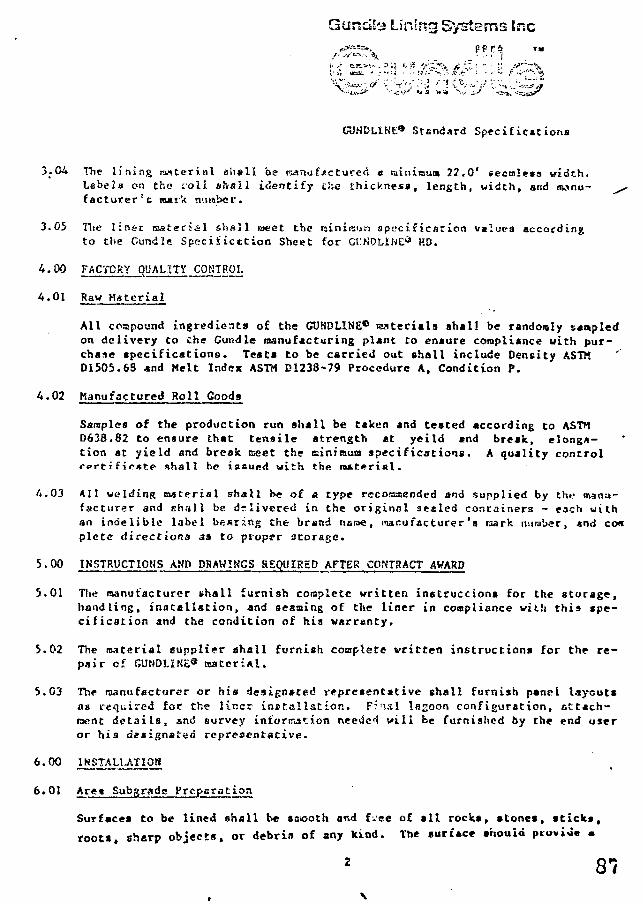
nciS'j Lining Systems toe
Stendard Specifications
3.04 The lining ranterial s'n«ll be ry»nuf«ctured « lainitaum 22.0' iecmltts width.Labela on the roll shall identify Che thickness, length, width, and iwnu- ^facturer'c nutrk tr.iraber.
3.05 The linsr mateci&l shall meet the raininun apocLfication values accordingto the Gundle Specifictcion Sheet for CCNDLINi:13 HO.
U.00 FACTORY QUALITY CONTROL
4.01 Raw Hatertal
All compound ingredients of the CUHDLINE® taaterials shall be randomly stapledon delivery to the Gundle manufacturing plant to ennure compliance with pur-chase apecifications. Tests to be carried out shall include Density ASTKD1505.68 and Melt Index ASTM D1238-79 Procedure A, Condition P.
A.02 Manufactured Roll Goods
Samples of the production run shall be taken and tested according to ASTMD638.82 to ensure that tensile strength *C yeild and break, elonga-tion at yield and break meet the ainitaum specifications. A quality controlfertificKte shall be issued with the material.
A.03 All welding material shall be of a type reeorassended and supplied by the manu-facturer and shall be. delivered in the original staled containers - each withan indelible label bearing the brand name, manufacturer's raark number, *nd cospletc directions 33 Co proper storage.
5. 00 INSTRUCTIONS AND DRAWINGS REQUIRED AFTER CONTRACT AWARD
5.01 The manufacturer shall furnish complete written instructions for the storage,handling, installation, and seaming of the liner in compliance with this spe-cification and the condition of hia vaxrenty.
5.02 The material supplier ehall furnish complete written instructions for the re-pair of CUNDLINE* tsateriAl.
5.03 The manufacturer or his designated representative shall furnish panel layouts«s required foe the lir.cr installation. F?'nsl lagoon configuration, sttach-taent details, and survey information needci will be furnished by the end useror his designated representative.
6'°° lHSTAU-ATIOH
6.01 Ar<t.« Subgradc Preparation
Surfaces to be lined shall be sasooth and f^ee of all rocks, stones, sticks,
roots, sharp objects, or debrin of any kind. The surface should id
Systems Inc
CUMDLIS.u3 Standard Sjx?citricot ions
firm, unyielding foundation for Che taesbrane with no sudden, sharp or abruptchartg 3 or bre*& in grace. Ko standing water or excessive moisture shall be
The installation contractor aha1Z certify in writing that the sur-face on which the seitbrnae is to be installed is acceptable before ccnasenc-ing work.
^k. ftoo v6.02 Soil Sterilization (If Mcceac&ry)
A local vegetation expert should determine the type* of vegetation in the areaand sugge*t a treatment to rid the site to be lined of vegetation. This naybe performed by the iratallation contractor, and the recommendations of thevegetation expert are to be followed.
The installation contractor shall h*ve oet the manufacturer's minimum re-quirements to becos** s licensed installer of the manufacturer's productusing the m-tnutacturer'« »t*ce-of-the-art equipuenf and welding icethods.The osnuracturer shall certify that the installer is licensed by Guridle.
6.04 Field Scomg
Individual panels at liner t*»ccri*i shell be laid out «nd overlapped by aminioua of 2 inches prior to welding. Extresc care shall be taken by theinstaller in the preparation of the areas to be welded. The area to be weldedshall be cleaned end prepared «ccordiug to the procedures laid down by thematerial Manufacturer. All sheeting s.iaU be welded together by ue.ins of ahomogeneous overlap extruasioa £'ijion_process which provides continuous dynaraicintegration of the |P¥i.L''i3i:-£—fe." d with the lining wsteri«l. The compositionof tWe~c"xtr'i;.date shall be identic«l to the lining tssterial. "
6.05 The w*laing c?q«ipiEent used shall b« capable of cqnj:_imtoualy cionitoring andcontrol lirts the *iffi!££f«£«rcs oi the CK errata and the Eoa5~of contacf:where t7ie~s5SchiR»? is -ciualiy f;i»i«g the ii^iag ruitcridl »o aa to ensurechanges in enviroiiisctiiL*! cenditioas viil not affect the integrity of theweld. Only v-eltHng pystrcr.a vhich utilize the eicCrusion process shall beused for bonding these lining oaceriala.
6.OS No "fish souths" sh«ll be allowed wirhin the seaa *rea. WJiere "fishsouths" GCCMr, the «*terial shell be cut, Oferi«ppc«i, HOQ «n overlap~e«-truaiou vxld shall be applied. A H %•*».«• on coo-plction of the vork shallbe tightly bGodtsd. Any Bsassbratt* erea showing injury das to excessive scuff-ing, puncture, or distress fror any cause sh^ll be replaced or icpaired withen' fidcitionAl piece ui dT"BI.T?;r* «?sbr«sc.
CUtlDLIHK9 Scanrfard So*c i f i c u t ion*
7.00 FIELD SEAM T£STIT!C/Qt?/iLITy COHHiOL
7.01
7.02
7.03
7.04
The installer ehall employ on-site phy«ical r.on-de«tructive tc«tir.g onall welds Co ensure ^jtertight hoaogeneous seeaa.
A quality-control technician shall inspect each sect*. Any area showinga defect shall be Marked and repaired in accordance with Gundle's repairprocedures.
A test weld three (3) feet long fro* each welding eachine shall be runeach day prior to liner velding and under the saoe conditions aa exist forthe liner -elding. The test veld shell be narked with date, anbient temp-erature, Situ welding sschine nueber. Samples of weld 1/4" to 1/2" vridc
be stronger than theZ^iaCerial. The veld ssciple shell be kept tor subsequenttesting on laboratory tensosaeter equipment in accordance with the applicableASTM testa. Randora weld e*«ple* e«y be retsaved froai the installed weldedsheeting at a frequency to be agreed (e£. 1/500' of wsld).
The end user company, or his designated representative, reserves the rightof access for inspection of any or all phases of this installation attheir expense.
6.00 WASKAKTY ABD GUARANTEE
8.01 The manufacturer/installer shall provide a written warranty stating aduration at titw during which the liner ssaterjals *nd workmanship speci-fically providsd or perfors^d undasr this project ehall b« free froa anysignificant defects. Said vxrrsnty shall apply to nor rial use and serviceby the owner and specifically excluded ssschanical abuae or puncture bylaachinery, equip««nt, or people1, e»,$x»«ure o£ Van litv^c to Ij^risful chcisic^.isor catastrophe doc to earthqueise, flocn?., or tornecio. Such written warrantyshall provide b r th* totsl *n<l cowplett repair or replaceieent of theor defective area citf lining oaC«?riala upon written not*Election *nd 6c:zort-stration by the cwnar of the specific noa~conic«?rsy5nc« at tha lining esor ingt«l?fiCioR wifb the nrojvct «pec£?icecio»8. Such defects or non-con-foriaance sh^il bs repaired or replaced ni.thiu « ree/;ufva6i6 period ot cirso«t no cost to £h=r C?WKS«T provided Vi&t portion rri fh.?> er<»a in <?u<"3fion h.iab«en isssde «ysiiebie Co the w.«nu(faccs5f«"r/in*ralier suti thai: cuch areas havebeen cleared of a l l liquids, sludges, d i r t , aana, or grcvei.
* * * # *
2.6/Gu
'T^:.6: a ^-" /*
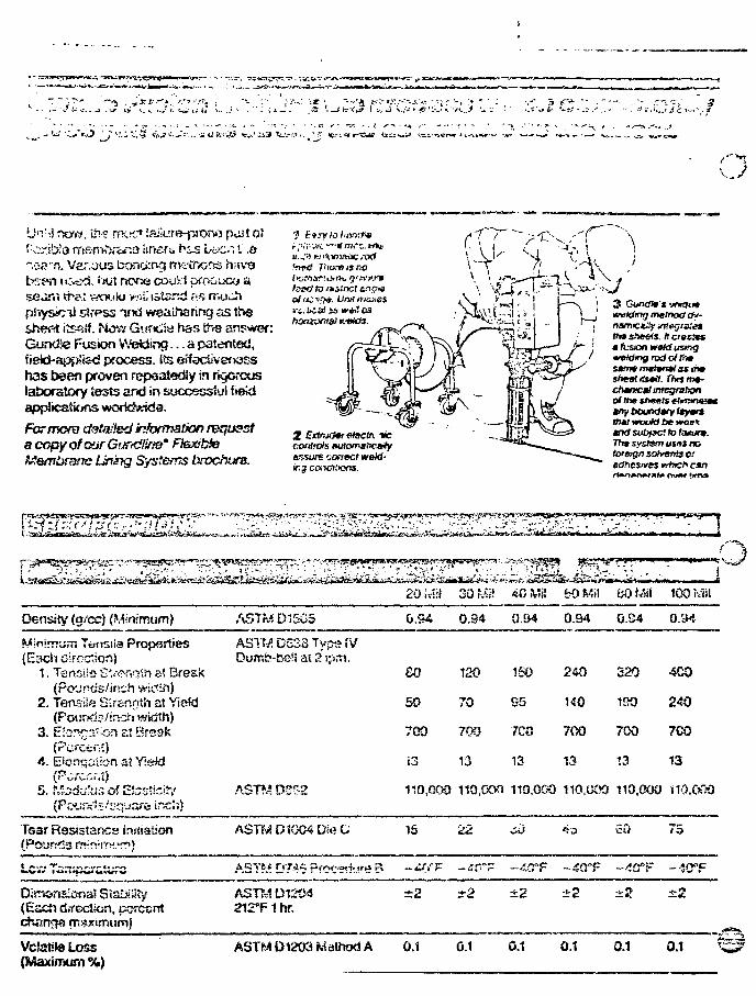
U'Vii now, ili? mur* i£i<<jre-piT>rw> ruut off :cr ib'o rrtRf5>?>.'&rcJ liners, h i3 Li-c.". 1 .&~o«rn. Var.uus bonciirvg rtv?itx-:en nied. tuft noots couV.1 ;
physicil stfpss irKi vyeairianrjg as tf>eshe^t iis^if. T4ow Guncfe fias t^-s answer:GundJe Fusion WeWing... a paientsd,iiekJ-ajjjjtJad process, its effacUvenasshas been proven repeatedly in rkjorcuslatxxstory tests and in successful fiekl
For more detailed inhrmation requesta copy of our GurtdBtie* Ftexibtete&nnbrane Unkyg Systems brochure.
nwWmj metnoti Oy-naritciLity itv.egr&etttn sheets, tt ctasteta fusion wofd usmgw&dmg rod ctfrr*s*rmmmtwn9tastrmsheatitstti. TNsmt-chtmcal integration0/the t/wmfs eiirtWMM*any boundary ttymrs
and subfsct to tonunt.Tht system usot noforeign solventi o:eahcsives <#htzh can
20i»?il 30 W. 40?v1i! frOMil 60 Mil 100 Mil
Density (g/cc) (Minimum)
Minimum Toiisiia Properties(Ead'i direction)
1. Tensiis S*.-«?ftnih at Break(Pounds/irtch wic<lh)
2. Tensiis Sirerinth at Yiekj(PotJrcj5/ir:-ii-( width)
3. E:;rvr:';or! at Bresl?(Percent)
4. Etonqciiiort 2! Y;«^d(Pcrccrd)
ASTrA D1505
ASTM DS33 Typs !VDumb-be?i a? 2 ipm.
AST»<« DS^2
0.S4
SO
a>700
i3
110,000
0.34
120
70
700
13
110,000
0.&4
150
95
700
13
110,000
0.94
240
140
700
13
110,000
0.G4
320
1SO
700
13
110,000
0.34
4K)
240
700
13
110.000
Tsar Resistancs initiation ASTM D1004 Oifl C 15
(Each direction, percentch«inf|8 maximum)
AST?-1! D745 Proc^Jye B -
ASTM D120421£°F 1 hr.
* 2 ±2
VciatiteLcfSS(Maximum %)
ASTM D1203 Method A 0.1 0.1 0.1 0.1 0.1
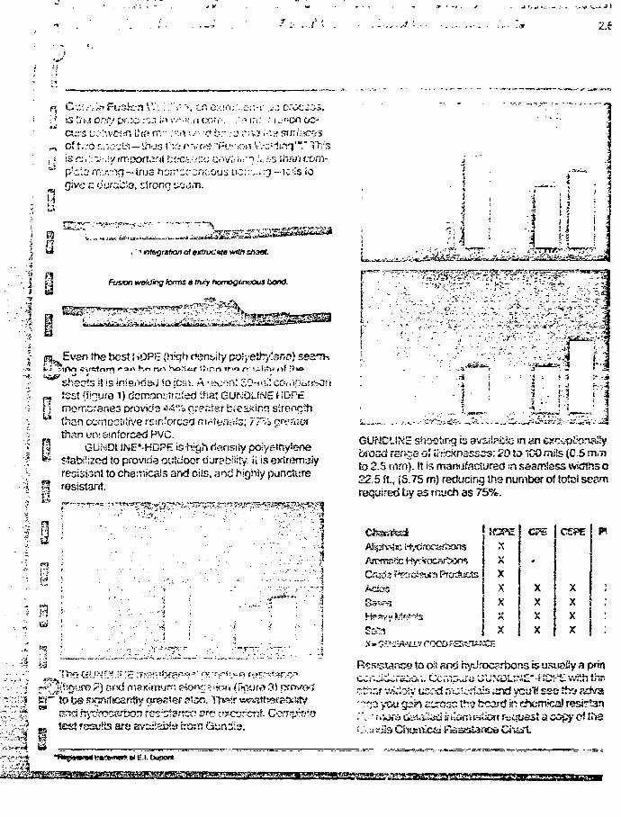
21
• \ is [in en?/ [>r.:c;'^; i;> •-••'• <".i• co?r-. .':a
ct.T5 L.;;-:'.ve<!n i? to rr.-..~ir. .••••? br.-c: r^ cf iv.-o jv.c-'jts — thus l:".2 n v r ; e "R-'>oi; j is .::.~.;r.:y frripoftarif f;oci'.<::'j any;.'i.r"" p-'cio m.,-.-:"K7~tnj3 horrcr^rcj-.oiis t c
give <*: ourc;i;'.3, strong scji"n.
r i : . : i" «*on cc-
V.-c^irsq""." Th:3? .vs-s in-yi.'.-&m--,..^ - i d s io
i ' ' mtogretoon of ex&uc'ife witrt stiaat.
Fusion tmUing forms a tnry hofnogtmsous bond.
Even the best iiOPtE (hkjh ren^ity poSyeyr/isnp) seaTcan ho nn hoMw t|t.~n ifvo rrii^li^ of 'ru»
PJ test (f iour e 1) demon^t! ated if sat GUNOUNE t f DP£f > moTibraneo provids 44% n:?ctsr breakinc? streiTcth
than cempctitive reinforced .TirtH,-ria;3; 77-/3 oresi£?fthan un; enforced PVC.
| | GUriOl iNE'-HDPE ishigh rtensiiy poiyethyiene•^ stabilized to provide outdoor d jr?bi!;!y. ii is extremaiy
resisi^nt to cheiiriicals and ciis, and highly punctureQ resistant.
I
nr . * *^~<:*ir' T'
^:2.^M<(yiC!'jTfi
u
and hj"iJrt>ca5fta3n ras-^anco are c?ctr::.cr;f.test results are av^iiabia tro:n Guni-iu.
.•>..;'V''>J
.3-1
!.3
GUNCl.t\'E sheeting is availabio in ybfosd range of thrcknsssss: 20 JD TCO miSs (C.S m,rtto 2.5 mm). It is manufactured :n sea.nr»Jes3 widths 022.5 f t , (6.75 rn) reducing the number of total seamrequired by ss much as 75%.
Acs
XXXXXXX
ere
-
XXXX
X
X iXX
v roco R£
s to oil and hydrocarbons is usisaiSy a prin
S^r VwiiMy uscrd ri":-:c-:ia:s and ycu'f! sss tha sdva
noxQ fcUi.'!is<i a ikin'i s.a(iort rfccjussj a copy c! tu3'tcaj Basstance Ciiart.
> e* E.I. bupect
''r1"*'*!!!^' .-*»TT jy

I ••.".- i:
. ^ . -.» f t ; , . ^ «. .;«..' i-
1 . GurKS&s'rx>ck>r>immu!tt1u>inqtjxj^'iscspc,i&a<pfc&JCKrj&&S^Ctt,GGGv^^em u:.iiy usec 40 m* GUNDUNE ior bmo pona e.aptexmn. Ox.'Urm tvnpffiftig^ m lisr, otpcisod s^^c&son e.<%XT;-scti9Ct f.t?-i20~i"(43-4itC). 3. Gundla has or>s of ttto most madam teixvalo-ws m tva vt^\jUr/ ccaz&a U p&iorrrjng a teaxxy of pny.ic*t erxi ct&m-cal res.s!tvice «ss£s. The iso is amulet)** tor customs/ t&a. 4. Gnrt{ia ottvs Va widest zaamiess HOPE shea! in f/w incksstiy. BoSs lira 225feef C S.75 m) wifts ami vary in length copcndmg en tnckrtess. Sieixiard ro£w&3lii is ZMO IO(1270 ltg).Ross tsatssy :oh^yco* inthefi^id.
If,
SDl
APPENDIX D-2-2
DUWLOP CONSTRUCTION PRODUCTS -INC.
O'\
-.^f. ILSr..s itvz
Anrif
K5r. Frotforick W. Firlutta, P. Eng.
Golctar Avsociaras500 Ncti-iiioh::! RoadLONDON, OnisrioN£K 3P1
Dear Rick:
Dunlop Construction Products, Inc. manufacture membranes of EPDM, CPE,Naoprene, Butyl and Hypalon. We started producing material in our newpiart, located in Huron Park, Ontario, in June/83. There is some con-fusion in the market piace about who manufactures Dunlop rnembrar.es -for pood reason. For years, membrano has been produced by DunlineDivision o* Dunlop Industrial Limited in their plant, also in Huron Park.Soth companies report to Dunfop Holdings p!c, U.K., though DunlopConstruction Products, Inc. has a major Canadian shareholder, Bitumar,i juu.i i ie sa msioiiy owsitu uy uuniop rtoioings pic, O.K.
A? a representative of Dunlop Construction Products, Inc., I am pleasedto provide any information that I can on the products we make andproducts that wiii be part of our standard range.
The enclosed information is fairi-, general - for morj specific ir 'orma-tion, please feel frsa to contact me at any time. I have followed yourformat reasonably closely, thus tho number will correspond to thenumbers on your quastionaire.
Very truly yours,
DUNLOP CONSTRUCTION PRODUCTS, INC.
Robart flayfie.'tf
Goomembranes & Containmont
End.
P.M. ino. On'.., C?o«c'?. L5K 1ZQ. Phone (41€) 823-32GO, Tele* 06-932445
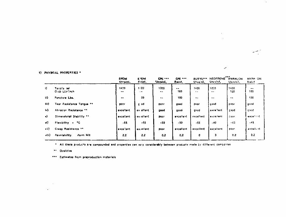
1) PHYSICAL PROPERTSE3 *
EPDM E t ) MUri'«l(>(. Rnlnf.
CPE«»« CPE • '•Jnr»lnt. R«lnf.
BUTYL*" WEOfflENE HYPALON HYP/»-CML'nre'nf. UnraW. Unrclr.f. H»l.-J
I) Jtr.il'.t yt\Q.-4b Ltj'.'nch
II) Punctur* Lbs.
III) Ttar RnliUnct Tongu* ••
Iv) Abraiion Rtjllttnc* **
v) Dlmemlonil Stability "
»I5 Flixlblllty - #C
v-.l) Cruip R»»intLnc» >'
flli) Ptrmlablllty Ptrm MM
1100
poor
fxctlltnt
• xctlltnt
-SS
• xctllant
2.2
1-100
00
C od
*i< tllgnt
«xi tll»nt
-55
ix< tlltnt
2.2
1700
pcor
good
poor
-50
poor
0.2
185
100
good
good
• icalltft
-50
0.2
1400
poor
good
-55
1500
jood
-40
1
H0O1iO
-
c-oor
food
f oar
-43
poor
0.2
16S
100
good
coed
-«S
J K C i l l l ' l t
0.2
* All tJitft pfodje'j »•» compoundvd *nd propirtlts c«n my conildtrtbly b«tw«*n products mads tv d!fftr«nl corrpcr<i»a
• • QL-«lltlv»
*** r i t l m i t u from prtproductlon material!
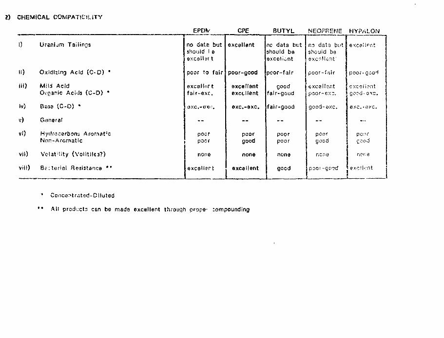
2) CHEMICAL COMPATlLiLiTY
1) Ursnljrn Tai l ing
ii) Oxidiiing Acid (C-D) •
iil) Mi l i AcidOrganic Acids (C-O) •
Iv) Baaa (C-O) •
v) Goneral
vl) Hydrocarbons Arorrtat'cNon-Afomatfc
vil) VolaHity {Voiitlk3?)
vii l) Bc i tor ia l Resistance • •
EPDV
no data butshould ! eexcellai t
poor to fair
exeellortfair-exc.
BXC.-BXC.
—
pocrpoor
none
excellert
CPE
excellent
poor-good
excellentexcellent
exc.-exc.
- -
poorgood
none
excellent
BUTYL
no data butshould beexcellent
pcor-fair
goodfair-good
fair-good
- -
poorpoor
none
good
NEOFRENE
no dat3 butshcuid beexcellent'
poor-fair
excellentpoor-ex;.
good-axc.
- -
pcorgood
ncno
pOOi-CD?d
HYP>iLON
excellent
poor-goci
excel Sentgood-oxc.
OXC.-OYC.
. . .
poorgood
none
8xcM-:nt
* Concerttrated-Clluted
*• All prodixts can be made excellent through prope* compounding
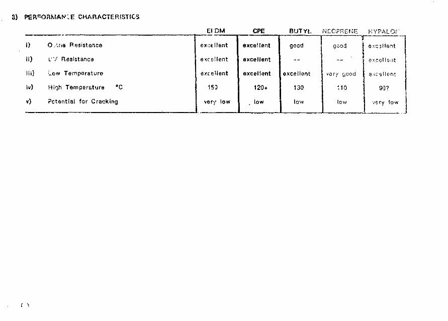
3) CHARACTERISTICS
EfDM CPE BUTYL NECFRENE HYPALOf
i)
l i)
Hi)
iv)
v)
O.vtia Resistance
i"J Resistance
Low Temperature
High Temperature °C
Potential for Cracking
excellent
excellent
excellent
150
very low
excellent
excellent
excellent
120+
low
good
- -
excellent
130
low
gcoci
- -
very yood
110
low
i
\
exc3llent
excellent
excellent
90?
very low
f •>
4) INSTALLATION
General:
a) Site preparation should bs according to standard practice for all membranes.b) Field seams can oniy bs made on dry membrane.c) Searns can be checked with a SO p.s.i. air blastd) Reinforced membranes are more resistant to equipment damage.e) Slope maximum is generally accepted to be 3:1. With proper design,
membranes can be used vertically.
EPCM
Field seams are made by either t*.pe or adhesive. The tape seam is fasterto make and more secure. Literature and samples are enclosed.
CPE
Heat welding should only be done in plant or on a smooth substrate - as• WUOVJI On oO.'tiu t w w i i " ^ o^^iICallf j i ' iS. r Of* id l ing sp^( tuu; iuno t luutk ip ic **
widths are facrory beat seamed Lo form sheets up to 10,000 sq. f t . Thesesheets are solvent welded or adhesive bonded on site, if reinforcement isexposed, a cap strip is recommendad.
Butyl and Neoprerie
Adhesive bonded in field. Temperatures above 10°C are recommended.
Hypalon
Hypalon is factory heat welded into large sheets. The large sheets aresolvent weided in the field. Generally a solvent with 10% Hypalon is used.Multiple layars of this solvent can be used to cap exposed scrim.Hypalon crosslinks with age which makes seaming muc'i more difficulton aged sheets.
5) TESTING
i) Q.C. tests on finished product are dono by Duniop Research Centre,Sheridan Park, Mississatjga, Ontario. Duniop Research Centre is likely thebest ruboer research facility in Canada, (Others in Cnnada with a groatdoal of expertise are: Polysar, Sarr.ia; Urtiroyal, Elmira; Goodyear, Torontoand NRC, Ottawa.) With tna exception of atomic radiation tests, anyconceivabiy useful test cari fan pyriormed or. ruhbsr memhrano at Dun I no.A full rsnga of physical and chermes! tosts are done regularly for DunfopCorisi.iui.liuH rruuuci.3, inc. Duniop Research aiso does sfriuent anaiysis,accelerated agoing tests, etc.
ii) Re-'tir-o Quality Control
f/f.terials
a) nil materials must be pporovedb) rhecmetric testing each mixc) rrsoonoy ovary 5th mixd) full physicals every 10th mixe) dispersion check every mix on thermoplastics
Caier.dar
a) guageb) widthc; profiled) each roil marked # and date for physical testing at labe) visual - sheet from the calendar shines. Any slight imperfection is
prominani. lmperfoct material is removed from the calendar.
Fabrication
a) visualsb) hardnessc) thicknessd) 12" x 12" sample removed for physical testing at labe) squarenessi) light tabls for pinholes
iii) Seams can be tested with air gun
iv) Testing for the compatibility of Hypaton in uranium tailings applicationswere done by Ounlop Research for Golden Associates, Toronto.
v) Dupont has a great deal of information on Hypaion in radiation, as wodiscussed.
6) COMPANY INFORMATION
i) Services Offered
a) membrrtneEPDMBUTYLCPENsopr;»neHypaion
b) Full rango of ssaming systams for abovec) Adhesives for aboved) Fixation harc'warae) Material recommendationsf) Design recommendationsg) Effluent analysish) Compatibility analysis
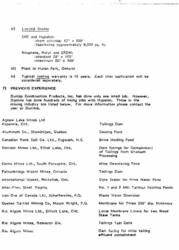
ii) Lnrgast Shoets
CPE and Hypalcn:-from calendar 62" x 500'-fabricated approximately 9,000 &q. f t .
Nooprono, Rutyl and EPDM:-standard 20' x 150'-maximum 20' x 300'
Hi) Plant in Huron Park, Ontario
Iv) Typical roofing warranty is 15 years. Each liner application will beconsidered separately.
7) PREVIOUS EXPERIENCE
Dunlop Construction Products, Inc. has done only one small job. However,Dunline has done hundreds of lining jobs with Hypalon. Those in themining industry are listed below. For more information please contact theuser or Dunline.
Agnow Lake Mines LtdEspanola, Ont.
Aluminum Co., Shawinigan, Quebec
Canadian Rock Salt Co. Ltd., Pugwash, N,S.
Denison Minos Ltd., Elliot Lake, Ont.
Domo Mines Ltd., South Porcupine, Ont.
FalconbridQe Nickel Mines, Ontario
Intarnation&l Nickel, Whiteflsh, Ont.
Intar-Prov. Stsel. Regina
Iron Ore of Canada Ltd, ScheffarvHIs, P.O.
Quebec Cartier Mining Co, Mount Wright, P.O.
Rio Algom Mir.ss Ltd., EtMett Lake, Ont.
Rio Algom Mines, Research Oiv.
Tailings Dam
Cooling Pond
Brine Holding Pond
Dam fecings for Containmentof Tailings from UraniumProcessing
Mine Oewatering Pond
Tailings Dam
Dyke Seaier for Wins Water Pond
No. 1 and 2 Mil! Tailing? Sottling Ponds
Waste Water Diversion
Mombran© for Threa 250' dia. thickness
Loc5« Membrane Linars for two WoodStav« Tanks
Tal l ies ls?st Cells
•ffluont containment
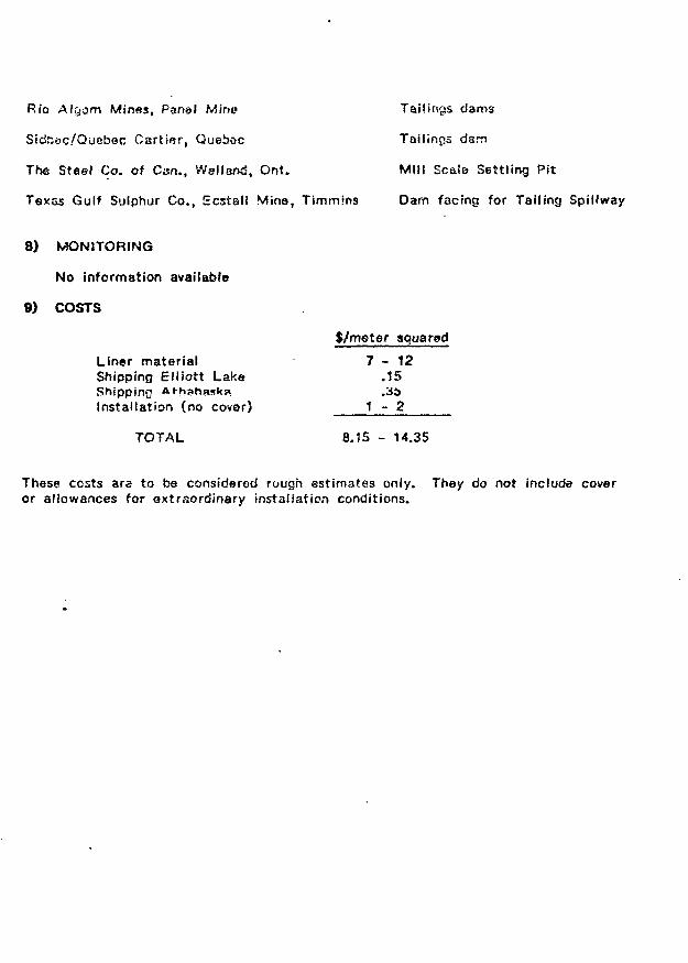
Rio AlQom Mines, Panal Mir>o Tailings dams
SidSac/Quebec Carter, Queboc Tailings darn
The Steel Co. of Can., WsllarxJ, Ont. Mill Scale Settling Pit
Texas Gulf Sulphur Co., Ecstall Mine, Timmins Dam facing for Tailing Spillway
8) MONITORING
No information available
9) COSTS
$/meter squared
Liner material 7 - 1 2Shipping Elliott Lake .15Shipping At-h3h?»sk» ,3;>Installation (no covar) 1 - 2
TOTAL 8.15 - 14.35
Those costs are to be considered rough estimates only. They do not include coveror allowances for Qxtraordinary installation conditions.
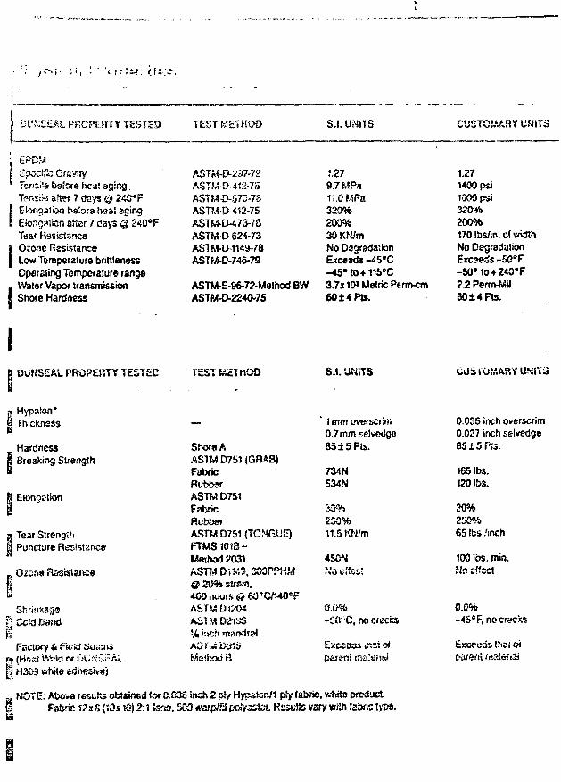
• • " i | C
3 Dl'.VSEAL PROPERTY TESTED TEST KETHOD S.I. li?-JSTS CUSTOMARY UMiTS
EpocrTa GravityTcnsi'a before heat aging.Ti?nsiks after 7 days © 240°FElongation tetofe heat agingEtongMisn after 7 days @ 240°FTear ResisisncoOzone ResistanceLow Temperature brittlenessOperating Temperature rangeWater Vapor transmissionShore Hardness
ASTM-CM12-75ASTM 0-57.1-73ASTM-D-412-75ASTM-D-473-7SASTM-D-624-73ASTM-D-1149-78ASTM-D-746-79
ASTM-E-96-72-Melhod BWASTM-O-224O-7S
J.279.7 MPa11.0 MPa320%200%30KM/mNo DagradattonExC«3Ck-45#C-45#to+116eC3.7x10* Metric Ptrm-cm6014FU.
1.271400 psiISOOpsi350%200%170 lbs/in, of widthNo DegradationExceeds -50"F-50»to + 240*F2.2 Perrn-Mii60±4F1s.
OONSEA5. PROPERTY TESTED
Hypaion*Thicknsss
Hardness• Breaking Strength
Elongation
I Tear Strength! Puncture Resistance
TEST feiEThOD
ShOf»AASTM D751 (Ga*3)FabricRubberASTM D751FabricRubberASTM D751 (TONGUE)R M S 1013-Weihod £031
@ 20% strain.400 nours © 6O*C/14O°FASTM U1204A S M D2'i3S
Meihod B
S.I. UNITS
' Immoverscrim0.7mm selvedge
85±5Pts.
734N534N
SD%250%11.5 KN/m
450NN'oCiiocJ
-SiTC, no cracks
Excesd& irtsi o*
Shrioksgop Ccid Band
Facsocy & f'vski Soamsf» (Host WiicW er DU:\:5cALM H303 vvtiiio £dh6£rv«~;
a NOTE: Abcva resajRs obtained tor C.C35 i.TCh 2 ply Hypaton/l p.»y fabrts. vrfwts product.I Fabric 12x6 (?0si0) 2A terra, 500 wsrp/T:! poiyssief. ResuSs vary wjih Jabric t>ps.
CUSIOMARY UNiTii
0.02S inch overscrim0.027 inch selvedgeB5±5f !3.
165 lbs.120I&S.
30%260%65 !bs./inch
100 IDS. min.Mo effect
0.0%-45sF.rK>cr<K:fcs
Esxcwis thai CMparent ni
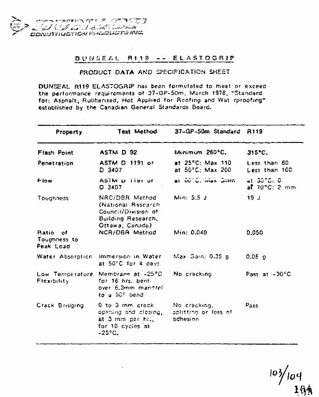
r?f -:' • „«
s ova.
SS At R 1 1 9 - - ELflSTOGRIP
PRODUCT DATA AN'D H?£CSF1CAT$GN SHEST
OUNSEAL R119 ELASTOGRIP has been formt-lated to meet or exceedthe performance requirements of 37-6P-5Qm. March 1978, "Standardfor: Asphait, Rubberized, Hot Applied for Roofing and Wat rproofing"established by the Canadian General Standards Board.
Property Test Method 37-GP-S0m Standard FU19
Flash Point
Penetration
Toughness
Ratio ofToughness toPeak Load
Water Absorption
Low TemperatureFlexibility
Crack Bridging
ASTM D 92
ASTM D 1191 orD 3407
ASTM u i i si orD 3407
NRC/DBR Method(National RssearchCouncil/Division ofBuilding Research,Ottawa, Csnade)NCR/DBR Method
Immersion in Waterat 50rC for 4 day:
Membrarv? at -25°Cfor 16 hrs. beniover 6.3mm mandrelto a 9Gr bend
0 to 3 mrri crackop?r,.ng and closing,at 3 rnrn per hr.,for 10 cycles at-2S°C.
Minimum 260°C.
at 25CC: Max 110at 50cC: Max 200
w. IVIO*
Min: 5.5 J
Mtn: 0.040
Wax 3am: 0.35 o
No crackma
No cracking,sphttsnn or loss ofadhesion
315°C.
Less than 60Less than 100
oX J U o . ua? 70"C: 2 mm
19 J
0.050
0.06 g
Pass at -30cC
Pass
APPENDIX D - 2 - 3
SCIiLEGEL LINING TECHNOLOGY, INC.
105
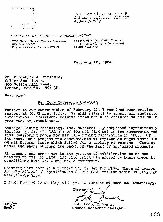
• &
L. .._
P.O. Box 9115, Station P
4O3-'2Q9-1?69 ~
~OO So-uth Trt«J*RO. Box 772OThs> 73SO
To): K!.O3) 273-3CS6 (Con.-c-»)[7113} 35C3-1L.13 (Houston)
February 20, 1984
Mr. Prederick W,, Pirlotte,Golder Associates,500 Nottinghill Road,London, Ontario. N6K 3P1
Dear Fred*
Re Your 6 -1-3015
Further to our conversation of February 1?, I received your writtenrequest at 10:>0 a.m. today, ^e will attempt to supply a l l requestedinformation. AUditionsl helpful items are also enclosed to assist inyour very important task.
Schlogal Lining T9chnolo£r$, Inc. siiccessfully completed approxisately800,000 sq. f t . (74J22 a*") of 100 mil (2.5 ES) in two reservoirs andfiva conitoring ponds for Key Lakss Mining Corporation in 1983- Ofinterest, this projeat was commissioned to replace an eight month o3d45 mil Hypalon l iner which failed for a variety of reasons. Contactnames and phone numbers are shown on the l i s t of installed projects.
At prsssnt our crews ars in tho proc?ss of mobilisation to do therapaim at the Key LaJis Kina site which was caused by huauan error inoverfilling both No. 1 and So. 2 reservoir.
Upeoaing vsrv aocn is a rcauost forirastoly ?,?2,000 ?s* cpacific^ t s 60 niHabb.it Lake Mine.
r for Elder Kines of approx-l (2.0 ca) for thoir Collins Bay
look forcKK-rt . to nseet-ir- wltr *:?s'u to further ciscucs 01
Sxnce^
RJW/gt
ur technology.
R.J. (BObTThomscn.Canada Accounts f-Ssn
ion
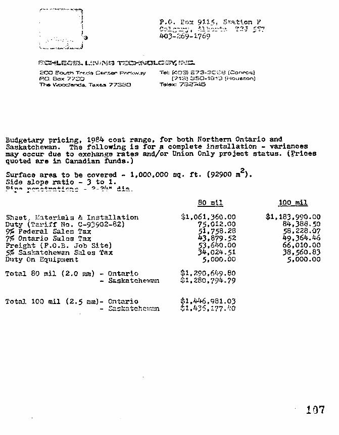
< -.-.i
•j
i
, J
P.O. Eos 95-5.5, 3f.ati.on
403-269-1769
SCO South Trr.cla Center Pf>r+cw>»yRQ EJox 773Q
WoocZanda. T»xe»s 773SO
Tel: f<5O3) £73-3Ci-:B (Conrocsj[713] 3SO-1B13 {i-!ou«r,on)
BudgetAry pricing, 1084 cost range, for both Northern Ontario andSaskatchewan. Tha following is for a coaplete installation - variancesmay occur due to exchange ratas and/or Union Only project status. (Pricesquoted are in Canadian funds.)
Surface araa to be covered - 1,000,000 sq. ft. (92900 m 2 ) .Side slope ratio - 3 to 1.
1 f
Sheetj Material3 h InstallationDuty (Tariff No. C-93902-82)9% Federal Sales Tax7% Ontario Sales TaxFreight (P.O.E. Job Sits)5% Saskatchewan Sales TaxDuty On Equipment
Total 80 rail (2.0 aa) - Ontario- Saskatchewan
80 mil
$1,061,360.0075,012.0051,758.28^3.879.5253.6*0.0034,024.515,000.00
$1,290,6^9.80$1,280,794.79
$1,
100 mil
183.990.0084,386.5058,228.0749.364.4566,010.0038,560.835,000.00
Total 100 mil (2.5 ma)- Ontario f.1,446,981.03$1,436.177.40
107
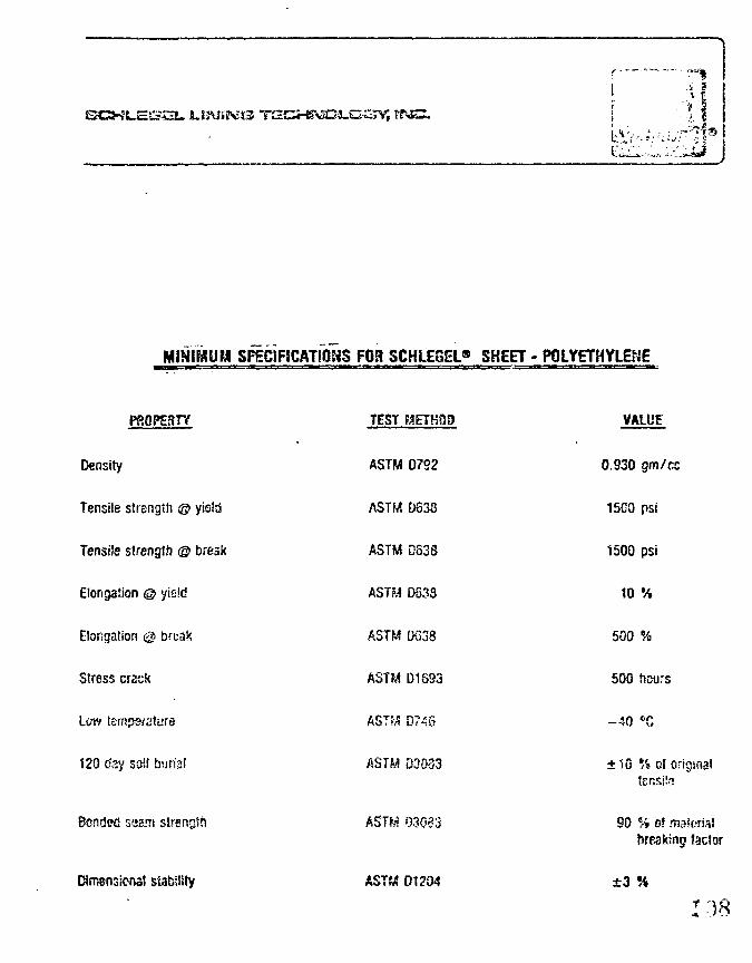
SCKL.EEK3U ENS.
tV
MINIMUM SPECIFICATIONS FGR SCHLEGEL® SHEET - POLYETHYLENE
PROPERTY
Density
Tensile strength © yield
Tensile strength © break
Elongation © yield
Elongation @ bruak
Stress crack
Lew temperature
120 day soil burial
Bonded seam strength
stability
TEST METHOD
ASTM D792
ASTM 0538
ASTM D63S
ASTM D638
ASTM D633
ASTM D1893
AST^ 07^6
ASTM D3083
AST^ 03033
ASTM O1?(M
VALUE
0.930 gm/cc
15C0 psi
1500 psi
10 %
500 %
500 hours
- 4 0 CG
±10 •/» oJ originaltensila
90 *•» of materialbreaking factor
±3
118
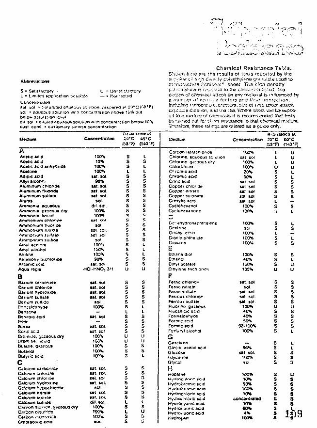
'••• ' - i • • . '••••' - . • : • 1
AirtwtvteUona
S» Sftit'nctrxyL » Limned sppl
U * UnrsJir.'rctory— « hid trtsts-d
Jil. &ol * Saturated BILMSOOS solution. ^r*psr(»a e*. I ' T C O ' f lSOJ = AOi>eotJE iOlu'.tOfl w*fn com;dntrfciion r-bova IC/A butbelow saturation !©v*.'idil sol " diluted cqiRit>u» solution win concentration below 10%cys! cone. * cuMcMn^ry :ts*v»c*> concentration
ChsmJcsl Rr?slsfsrrC» Tsi>!e.Shawn iu-ra pie H;3 r~3u!ts of tsva rc-acrto-j by ti'.afu ••; :-:p;7 c i h^:h c?.i'-:ty poryethyiM>e c'3"u!sle uiitxl tont'-nutscture rchio'.'Bi* shacr. Tr.3 i",ic^ denaitypJ.-.jii-,./.ta^> i"! f..'^.-;:srit to tlw cftw.i'Cfi'S lis'ftd. Tr.ad'K",r«s of crwrriKVJ attsch on any nv*':&ia> is iiHLfftncad hya fiijfT>i«ir >il vi . : : : ; !a factors fi"d ilirjir intsrattiof).
e;. p'K-yjrs. riTS cl j.-sa urx>^ «tt»/.*,i, a:w iiva I ke. VYrce s^seal wit bs t«.;xs>-
a1 !o a rriixtufa o< crK?rr.icjJs it i3 rs«jmr"ier<isd t'rtci t«jt^,txs '.-:.j'»od ou! lo: fJ".~fM rastatancs to that ctvarocal mmiuss.T^'-'oStsre. thiese raiirigs are offefed as a Ctu«» orrfy.
AAcetic ac>dAcetic acidAcetic acid anhyindeAcetoneAdipic acidAllyl alcotxsAluminum chlorideAluminum fhtondaAluminum lulfateAlumsAmmonia, eqiieousAmmonia, gaseous dryAmrnnnim lifiintf
ConcontraikNi
100%10%100%100%
sat. sol96%
sat. sol.sat sot.*at sol
sol.dil. sot.
100%irm.
sssLS
ssssss5
LsLLSsssssss
Carbon lBtrschiori<5eChlorine, xqueous solutionChlorine g^roous dryChloroformC> romic *cidChromic acidCitric acidCopper cnionoeCopper mtraieCoppftr sulphateCresyiic sadCyciohexanoiCydonex»none
Concentration
100%sat sol
100%100%20%50%
sat solsat solsat solsat solsat sol
100%100%
20* C
LLLUSsssssLsi
me* HSO'C
uuuuLLSsss
sL
Ammonium fluorideAmmonium mtrcte
Amy! ece'.itaA>n«l ulcohoiAnilineAntimony IAr&anic vcidAqu* rsgis
3Barium carbonat*B«num chlort<:«»Barium hydi oxtdeBarium tu.'itt*Cerium *ult»(J3
Sort*Boric 5C.dErcimi..a. gusaous dry
Butane.ButcnolButyric ecirj
c
Catcium nrtrtt*
Catijon rttow?*.Carbcn i^'j'^fh
SOI.sal solset sol
JO)1D0%100%100%so%
sat actHCI-HNO, 3/1
sat. so'.sat. solsat. sol.sal. sol
sol.100%
—
sat. sol
cat. sol.set. so!
100%100%100%100%100%
5«t EOl.tat tot.tai. sotsat. scl.
S&I.U t SOI.sat. sot.dil. so!.
100%100=*1C5T-sot.
Ssssssssssu
ssssssL
ssssuus
s
sssssssLsL
ss
ssssLLL
ssu
sssssLL
ssssuussL
ss3ssssL3Us
Dc- anydronaphti-.aieneDextnnaDiaihyl ct^ciDiociyiprtthalaie
EEthane dioiEtn«nolEthyl acetateEtnylsne tnchlonrto
FFeme chlond"Ftrric nitrateFornc lulliieFerious chlorideFerrous sullateFluorine, gaseousFluosiiicic *cidFormsianhydeFornrtic »cidFormic acidFurtury! Ucohol
G
GlucoseGlycanne
HHooUne
MytfrocMooc »cdHfJiOi.hlCinc tedHydrocysnic icidHydrc«;iKit>c ficidHydrofluoric acidKvtirciuftn
100%sol
100%100%100%
100%40%100%100%
sat solsol
sat solsat solsat sol.
100%40%40%50%
98-100%100%
96%sat. SOI.
100%sol
100%10%50%1iVj*i
10%concanirated
10%G0%4 %
100%
ssLSs
sssu
sssssusssss
sssss
sssft
sss5ss
Lst.s
sLuu
sssssusssst
LIss5
uss6sss
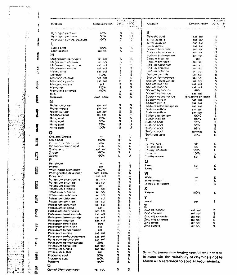
n
f
; .:
;i •
i.
F:'ir•v:
r ; :
ZL
• • i
i4
: . iI
• i
• • • : 4. ' . . • • • : - i
• . , . • . j j
- - . • - ^
".'..:••:?%
Hydic- jsn suitioV. gsssoi-'S
i.Lectic scidLeao acetate
Magnesium ct ' ionateM^Qnf^ium c r i 'oncl*MsQn<*SiuM nydroRicJeMS'JP^ISIUHI m'rii!i?
Wrlsic ac:dMercuryMeret/fi: chlorideMercuric cyanideMercuric nitratel/.ethsnoiMethyiene chlorideMilkMolasses
NNickel chlorideNickel nitrateNicke! sui'ateNicctmic acidNitric tcidNitric acidNitric scidNitric acid
oOils and GreaseO'eic acid
Oxalic acidOxygenOzone
PPetroleumPnenc!Pnoj.>norus trichloridePhof,§riphic developerPicnc acidPotassium bicarbonatePotassium bisuifatePotassium bisulfidePotassium bromstePotassium bromidePv tassrum carbonatePotassium chloratePotassium chiondePotassium chrcmatePotassium cynnidaPoiasiium dichromctaPotMium femcy*nrt>dePotjissium ierrocy»rnd«Pot«ss<um fluoridePotssstum hydrosidaPotajj'usn hv«irorK5«Pot»»num hypocrilondePotusiurn n:ira!«Potassium orthophosph*lePottss'iim r*rchlw«!ePotassium perm«ngarv»teP'.teiisu.'n p*f"Aitfe!ePotsss^'jffl su'^atcPwtfi5Ul***Tl ii lit ltdPro©tc«ie »ciclPrcpic-nrc tadPvrKjtft*
TOON
100^4sat sol.
»JI1 SOl
Sit SOls*s solSAt. SOlset 3ol
100%sat so!sat sol
soltoosICON
—cust cone
sat. solsat solsat soldil sol
25N50N7SN100S
—100%
sat sol100%100%
solICON
cult conesat solSBt SOlsat sol
solsat solsat solsat solsst solS«! SOlsat sol
SOI
sat. sol.tat solsat solsat. sol
10%SOl
solsat solsst solS2t JOl
20%sat. solsat set.
tot.50%K m100%
sEs
ss
ssssssssssL
ss
ssssssuu
ss5ssL
sssssssssssssssssss
ss5sssssssss
us
s—
sc;
ssssso
5s—ss
sss—suuu
LL
t,sLu
LsLs—sssssssssssssss5LsG
sssssLL
Ct>nc«ntr«!ic>r. •c v
QuincH »t sol.
sSalicylic acidSiiver acetaleSiivor cyarvGe
Sodium t)«!na!G2teEoOium bicarbonateSodium biptiosphsteSooium bisuifiteSorjium orormd«Sodium cart>onateSi^juim chiofOieSodium cMofideSodium cyai;(]eSc>dium fefricyantO?Sodium feriocyanideSodium (luorideSodium fluorideSodium hydromdeSodium hyGroxidfiSodium hypocmondeSodium rjtraieSodium m:r:ieSodium ontiopnospfiaieSodium sulla'eSodium suJfidoSuilur dioxide diySullur trioxideSultunc aodSuKunc acidSuKunc acidSiii'unc acidSullurous acid
Tlo::.".<U dwldI'ar.anc acidThiunyl chlorideTolueneTriethylamme
ISUreaUnne
wWaterWine vineg.vWines anrj iiauors
XXyiene
YYeast
zZinc carbonateZinc chloride£t;ic (III cnlondeZinc (IV| clilorideZinc oxideZ»nc suHate
sat solsat so'sat sol
sat so)sat solsat solsat sol
solsat solsat so!S3' SOlStt St i•_*l solsat -olSit solsat solsat sol
40*0sat sol
15°t active chlorinesat soisat soisat solsat solsat sol
100».100StO°35O«oW o
turning30°.
SOI
SO!
1O0rr100'cSOl
SOI—
_
—
100S
sol
921 SOiM t SOlsal so!sat solsat sotsat sot
Sss
sssJi
sssssssss
ssssssssusssus
b
sLLs
s1/1
sss
L.
s
sssss5
to ascerliin the suitability of chemicals not lisabove with reference to
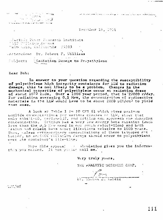
! Ifr. F.cbert T. "w
r Bob i
In answer to your question re&«.rdlii# the suaccptibtlttryof polyethylene hip.h integ-rtty ccmtainstrs for I.LJ» to riidlettotid«sjige( this i s DOC likely to bet * yroblcra. Chsujteff in theci(£ch«iiic*l piopertift* of polyethjleoe occur «t r«di»T.ton dosesof *u>eut 10'0 rudfi. Over « 1000 ystar p«x-iorf, that is '27D0D r/d«j.For' radiation avKreRi^g 0,,5 Kerv, tiie conrencr^dwi cf radioactiveKs-itieiriBln ia the LLW iroulcl liisve So be about 2CDO yCi/eraJ to ylald
ooie,
A look a r T.^blis 1 5 i 30 CFH 61 v h i c h e'»-v«s tr-ay.irj-.mi
orslv cnbe^.l-CD, ' s r J o-a-1 i7 , hnd t r l ; . . u s csi , AV>prf?aci)i ri,p cJvro^cenLi". ' tic-tK. 'Ix'i.ti'vn /i«s a v«ry it?w (r."s.-r^y b e t a f a E s i c )3.6-s* t h a n t h a J,i> ];<-v iss»:d i n o..;r rfM;;.-.h r«i.cc.1 " t i c n ) and br• j s i v K .'n-)A c o b a l t h*-»-^ r.;-.c>iC l t l f t - t i . ; - r a r e l s c i v e t o 1000 y rT h i ' i , i.:ilei»f frr.T»OTiV!t,»i-v conts ' i . t r a r . i cna of t h e s e t k T l o p e sL ' u i l r d , tio A ? ; icijs" jVJi ' sr ' icr ; i5srr.nf;« &hjuid vcc\iT t o p o l y e t ht>«ti i. he contrt i u s v * B 2.; /.e~ t;>:.-e.-
H-.-;pi* r:.h'« &pj>tc-x; ' * \ r u l a t i t m g i v e s you t h e i n f o n a a -ci^- i •/<•'- nf-.-iicd. I t n o t y~: -M<" c a l l » e . '
Vi ry t r u l y your s r
* • ?
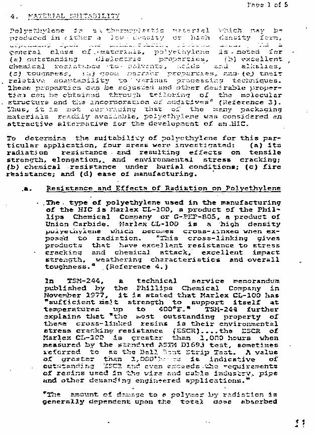
r.gs 5 of 5
KATER 7 AL SI? I TAB ILITY
i• s* s v t.h:-rn;-p; ftr.T.ic r-r t i r ic 1 v• hich r~..».y b•produced in c- irhiir a ;.cw • i.>.--ar.ix.y or 'iii.cn clan^ity fo-rr:,
(^sntrrsil ci£;ss ef .•ssatftsri.ui.s, JJD.• yetr.y.L<-.: a i s - noted for(*ij ot.'tstax^ding die lect r ic properties, (b> s-xccllcntcheiai.cK.1 rc-cl tMsTicrti -t.o- luvlvcnti;, ;.ci<ls .-i.r.u a lkal ies .
«.ci.apfcfiJ3i.£it;y tio ' vsriiias proceaiit;::a t-echpp&jreica criia is« Kdjusced and other deiiiriii>Iu
tie.it can i-*s cbtainutd through fciloxri.ruz of t±ia aioiecularstructure anci tiiia incorporation fii ^adi t ives 3 (Keierence 3) .
it: i s not: cur")r'.''.iririg 'that o;L' "Lb.e saa iy packagingrf.aclily avai^-^Jale, poIyetrhyXe-ne was c a n n i d s r e d an
a t t r a c t i v e alt.crx>.ative l o r 1±;e developracat of. an .HIC.
To detcrsir^a the eultabilivy of polyethylene for t h i s par-t i cu la r application, four areas were investigated: (a) i t sradiation resistance and resulting effects on tens i lestrength, elongation,, and environmental s t ress cracking;(i>) chesical resistance ur.der burial conditions; (c) f i reresistance; and (d) ease of Manufacturing.
.a. Resistance and Effects of Radiation on Polyethylene
• . The . type of polyethylene used in the manufacturingof the HIC i s Marlex CL-200, a product of the Phil-l ips Chemical Company or G-PEF-805, a product ofUnion Carbide. Marl ex C'L-100 i s a high density
J i y i e n e whicij oecouics cross-iinxca wnsn ex—V.o radist ion. BThis cross-linking gi%'cs
products that have excellent resistance to s t resscracking and chesaitrai attack, excellent impactstrength, veatherirsg characteristics!} and overalltoughness." .(Reference 4.)
In TSM-244, a technical service memorandumpublished by the Phil l ips Chemical Company inNoverrsber 1977, i t i.a stated tha t Karlex CL-100 ha*"sufficient rae}t strength to eupport i t s e l f at•temperatures rip to 400*Fo" TSM-244 furtheraxplains tiiat *tho tuost outstanding property o£Uiese cross-linked resins i s t he i r environmentalBtress cranking resistance (ESCR)....tha ESCR ofKarlex CZ.-2C0 i s greater thasj 1,000 hours whenmeasured by the *si;r.ncJ rd A3TM D169J t e s t , sometimesx/e£erred to ES the Bail ~J.ZT.X. S t r ip Test. A value
tha» S,OCD* >•>-••-:; ift ineUcative of"£EC?. c?ic1 ever, exceeds .'iha requirements
o£ resins usecj 5a -the vira end cable industry., pipeand ot!»«r dciaand'frjg engisi*ered applicat ions."
rTh« sunount c-f. dsjinge to p polyr.sr by sr.diEt.ien ioupon the t o t a i «io»c «b&orbed
/
of the typt of radiation" (l;rfer;nr,s 5).
rU" oa- a-/ cn-S s-
Reference -23 " discussjas t^.e veatherafcllit/ ofveriouts grrad^s cf Kax-Xcx CJJ-IOD. Grade CL-lto J2is- used for "zhn U1C. '"^iz relative cr&jisparcmcy oftJiArs a a t e n a l allows "tl*e detcrxninariun oflcveJ. wit.h .a I ack iitih'c.
The Kscjst; Biccurate inciication o£ srunli'ghti s tljia Atlas weathcr-oEaatar hour indicaticii. 2nthe- caao at CL-1C0 JZ, this value of Intense sun-light exposure prior to degradation is IS,000 hours.Wiiiie i t Xa difficult: to relxte t ins direct ly toactual sunlight exposure, s conservative ectixaateisay b« 2 - to . 4 years us indicated by Phil l ipsCheaic&l Company. Tins UV resistance of C-PEP-B05i s in excess of 5 years.
The HICs wil l be .stored indoors whenever possibleat both the manufacturer's location and the PeachBottom Si te ; in any carte, to allow f lexibi l i ty tothe burial s i t e operators, no container will be
priex ty £ i l l i»5 at; PSJJECJI Bettt-a vithsat dcscureaij-tat ioa verifying actual etorsge condition*.
The .date of manufacture 1» directly traceable bythe HIC'» unique container number. This containerage verif icat ion Is part; of the PECO plantprocedures concerned with the use of EICs a t PeachBoston.
b. Chemical
"Although only as very few chemicals will react withHarlex High Drnaitry Polyethylene (KHDPE), lack ofreactivity does not ascertain that a n»tcri&.l willnot be affected l?y itm environment. The pos-s ib i l i t y of rasterin! solubility remains and couldpossibly resul t i» Io*t» of strength and swelling ofthe polyethylene i f the chcjsical i s absorbed by thepolyethylene, or lose ol Rtrcngiih if thepolyethylene is soluble ia titm chtsreic«l. To definetli« eff«cfc8 of ivhia hature, ijmocrisioa tes t* havebeen performed tisirr-c » numbsr of chcnicwls whichreprejscnt most of the; types of liquids ia cewcoause" '{Reference 5) . At fsiapcratarsc of S 0 l 2

>?c- Z cf '
ISO^F, and &£ttsr exposure to these chemicals£e>r .'i r cnlUnn, !_'•>£• tens i le sst.rar15T.l1 .»nd elongationof Uftfi poiyethylRrse sj>oci»!t:»i» vre/. K- ^.u».,.u4tu '^c -.^.i:liT-any ch;iac;«s had occurred. The re suite presentedin KH-243 p u i y 2<J7S by Phi l l ips Chcralca! Company)*how«d« -thss caccllfcsi-s: chcaicai j e s i a t ance ofpolyethylene gl-ielarence 6 ) . Kosse .©£ t>.ei»e; &olv£rits
, The- -wasta r«sl>ia to 2MS sitorcd in tiit HICs, such a»p6lyst.'yrens Jbestis, are •noocorrosiva. Yet: when ir-radiated witb si^ni^icJEOit. closes o£ radiation,polystyrene gener*tes a ©as and suri aacici (HCL).Frcsa TSH-2B9, polyethyleae wata fouiid to performsatisfactorily witih various concentrations of BCi.liqjuids used &s reagents (Reference B).
While "the solvents listed in References 6 end 9 arecommon in certain industries, these soivents arenot common to the facility at which the HIC will beused. Administrative control (plant procedures andvendor QA program) do not allow for con-tainerisation or external cleaning of HZCe vith any
specification or aas approved by . Fhillips Cheraicai.Company or Uniors Carbide.
In addition "to chemiccl sresiEtance, polyethylenehas been fungus tested with no evidence ofdsterie/ration JReference 6 ) .
tinder burial site conditions,- polyethylene has beendemonstrated to S»e stable in many Mpplications.Th'JSs, polyethylene, particularly f5arle« CL-1O0 andC-PEP-SOS are extrewely clicsaical- andcorrc-sion-resistant ssaterials-
c. Fire Resistance
A iri«!wn«.bilS1:v "tejBt: VKJS performed by UnderwritersLaboratory <as 'o dctesrains tSxe £la«»snnbiXity e lpolyathylsne. Th<& -test., ca l led Arcing Igr>.;ltion,
# sujoje.-ctfi-.ct a uir.pls o£ raJvpthyl^ne to.40 appli.eAt.5i.cms pa" :?.i^«ta, for n wariravim of;S ainutffis, os an e l e c t r i c ax'C fecJ b -" a 33-amp cur-*xenx. £rOi« a 240-Voit poi.*er surpiy. "n^^e rasxj^tKare •LabaJ.s.tcd bcl&w (*=.!c«n frcs" tTSK-2 :?, .July 2975.Phi!l ip» Chemical Corspany, &».rtiesviliw,
int-ftncff of E'^ctro7-ro^i I?~JZ. "''^" - / — — ~
0
••- ' - ' •„ .- .
79-1.
70-2
B2
CO
Arcs i^
1/2• ' •
£•£ Is* also reported that t_ba hwrxs, ra te ofpo3.yet.hy leas,, should 11: ignites, .its X.D3 ' in /a ia .Tor. Slaasij iLtyaiuioa ef polyethylene t o weeur, -fclis
l &X5 £-<?.SaF, «ad for-tezar>«:ra<fcure would 3&e
Th« EIC la nade by -the rotational moldingtechnique* "ft method of powder raoldingr by which awide variety of large or asa&ll itena» axe producedIn a rotating n«old." The rotational' moldingprocess haes raany unique features that would causeI t to be selected over norae of the older, storewidely used molding processes. Soae of the snore
{1} Econosiy
(2) £ss« of Processing • "
(3) High Quality Parts
The absence of postive pressure in the powder wold-ing process* places certain liraits oss the typ* ofrecin that cen he \ia&&. The hSgh saoletnjslas- veightresins used for .blow jaoldin^ artsS sosscatiraastioa taolding cannot Ixa rotationally rxoldcdthi'sy do not: £low out iu "fcjie absence of preaswra toforxa a hoacgeaeous part. This OTJS liraitati&n Jiadaiftde it: difficult for rota'iionalli' moldedpolyethylene -to coaspets in certain applications.
Maries CL-100 aad G-FS?-80Sff polyntliylene resins,JiRve Jsisl.7' 5?. to overcrows this 5.:ir .t;.a1r£c!rs by nakln^i t possible for tJhc rotational colder to precHJcahigh 'quality parts, larga or amall, that v
resent s cSrynificnnt br^a^thrr\'^h since th^ytite f i r« t rotational saoiciisug resiw* wi*iii sufficient«$• j-».-.»rt. <fysc'jtin'jj s"<?si.s;'CETics aor severs ss rv iss , j°et;Still.
*In the rotational molding process a cold taoid i«filled %iit i a powdered resia. *5ie JscfitS i s p2*c«tdin an oven and rotated sifaultaneouB about two pmx-
pendieulsr soce&. During this stage, a uniformIr.ycr ©f recin i s ricpoaited on t.hs no id. Aft«r
r^^in, &nci Willie i t Ass ct;i.lS rctatin?, tJha sold i scooled. 'Xixis can foe accescolishcd with farced coolair , at«KM.ia.ed air-water tog., wates spray, or a coa- _wt-
p4a removed £ r a fcJi» sold iWii saes-e teaia ia erddaci
t-ba cycl« sgain.u {Reference 7)
r Q
c ^ v .:D
WECTERM RADUYtOM COMSW.fW-.TS. WC. ln&E»«J. f»fed»£4l,
Fert Drains. C^;
203-4S2-3323
July &t 1980
.:-: 1900
Denver, CO 80223
Attention*
, STATEMENT
Fee for Professional Service*
1. ,Prepataticu of an experiment to testadequacy of tJje Schlege.1 polyethylenei for tainistizing Hadon-222 diffusion.
TOTAL
Jr^
117
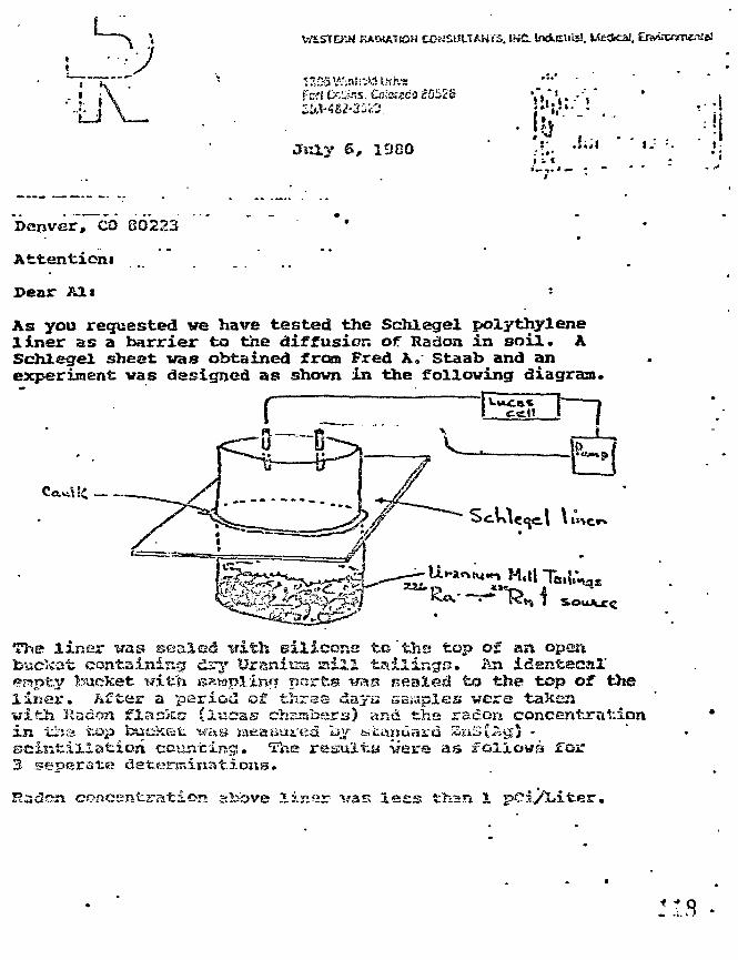
KACUATtOH CONSULTANTS. IXC tadusifis!. tfe<ical.
Fcrt tSciAis. Csiassea iQ52&
Jtrly 6, 1SJG0• ! ^ ' '
Denver, CO 80223
Attention*
Pear Alt :
As you requested ve have tested the Schlegel polythyleneliner as a barrier to the diffusion of Radon in soil. ASchlegel sheet was obtained from Fred A. Staab and anexperiment vas designed as shovn in the following diagraa.
a liner was scaled tfith silicons to "the top of an opent contaissdng dry Uraniua saill tailings. An idsntacal'
p y bucket with ssapiinf? ports w s sealed to the top of theliner. After a period of -fchrss days sasr.ples vers taKenwifch Radon flaslcs (lucas chambers) and the radon concentrationi n *jrsis tx»p buek&t. ti'&s jaeauui'ea l>v fciCftnaajra £aS{-rtiS$ -scintillation counting. The results iiere as follows Tor3 seperate determinations.
®n concEntration above linsr vas lesis than 1
July 6, 1980a 2 .
Radon Concentration without the linex- woulu be greaterthan 20G0 pCi/Liter. at. steady state conditions.
On the basis of the above results it is our ccncltsnicjj thatthe Sehlegal linar Is nui «;ceq«at.e barrier to prevent / ' •diffusion of Radoa. Tha Schlegel liner vill fc*i adequatefor the proposed new bstjilting c3ea|.sn if uccd in eonji:cfcionvith other standard techniques to prevent, radon diffusingf rcaa' tiia contaminated si>il fi*csu reaching any buildinginterior space above.
It should be pointed oufe that, the long-term characteristicsof the Schlegel liner are not known but perhaps may beinferred from other test data of Schlegel and Co.
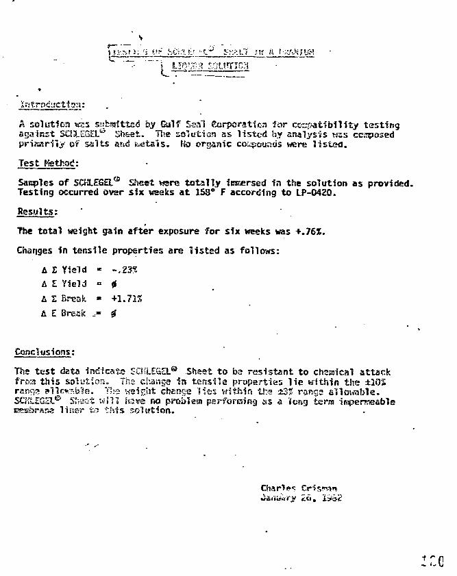
Ui A
A solution W25 swbsrftted by Gulf Seal Sorporaticn for compatibility testingagainst SCS3LEGDL'"'' i>?>£et. Use solution as l isted by analysis NSS composedpririarily of sal ts and r a t a l s . tk> organic co^ountis were l i s ted .
Test Efetbsd:
Sacples of SCKLEGEL® Sheet were tota l ly iniffirsed In the solution as provided.Testing occurred over six weeks a t 158° F according to LP-O42Q.
Results;
The total weight gain after exposure for six weeks was +.76%.
Changes in tensile properties are listed as follows:
A Z Yield - -.23*
A E Yield » 0
L I Break • +1.72%
A E Break .» 0
Conclusions:
The tes t data Indicate SCHLEGEL® Sheet to bs resistant to chemical attackfroa this solution. Tha change In tensile properties l i e within the ±IOSrangs 8»11fi*?.ble. Yh« weight chenga l ies within the ±3% ranga sllo\«ible.SCM.EGEie SJvsct will S sve no probleia pesf-foruiing as a 'long terra imperrseable
& liner fcr? this solution.
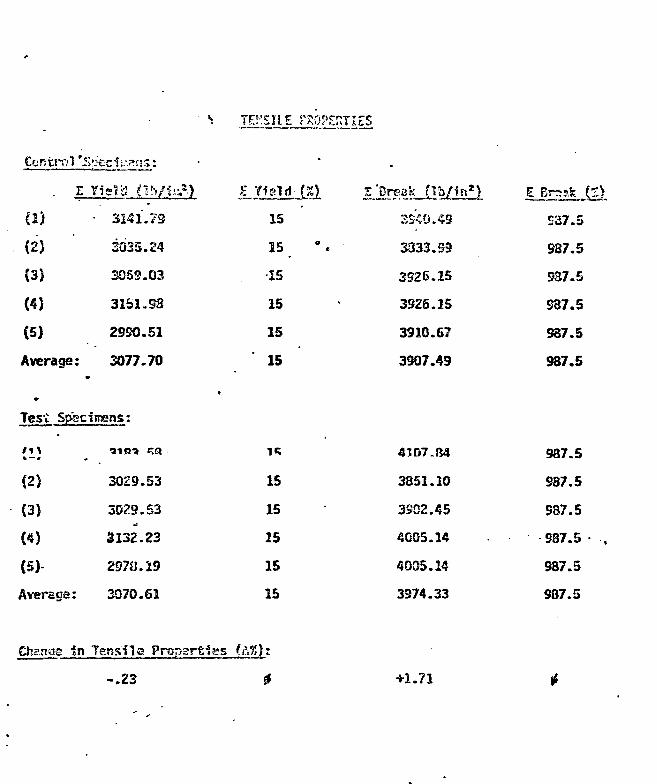
TOISIIE PROPERTIES
Control '5 ' ;^
r
C2)
(2)
(3)
(4J
(5)
Average:
Yield <lh/t«?.>
• 3241.79
3025.24
3OS9.03
31S1.S3
29SO.51
3077.70
E Yield-JX>
15
15 "
•15
15
15
15
3S4Q.49
3333.59
3926.15
3925.15
3910.67
3307.49
E Braafc.(S).
S37.5
987.5
S37.5
S87.5
937.5
987.5
Test Specimens:
(2)
(3)
(4)
(5)
Averaga:
Chance in
3029.53
3029.53
3132.23
297«.19
3070.SI
Tensile Propartiss (t
-.23
15
15
25
15
15
IX):
4
4107.84
3351.10
3SD2.45
4005.14
4005.14
3974.33
987.5
987.5
937.5
S87.5
987.5
987.5
+1.71
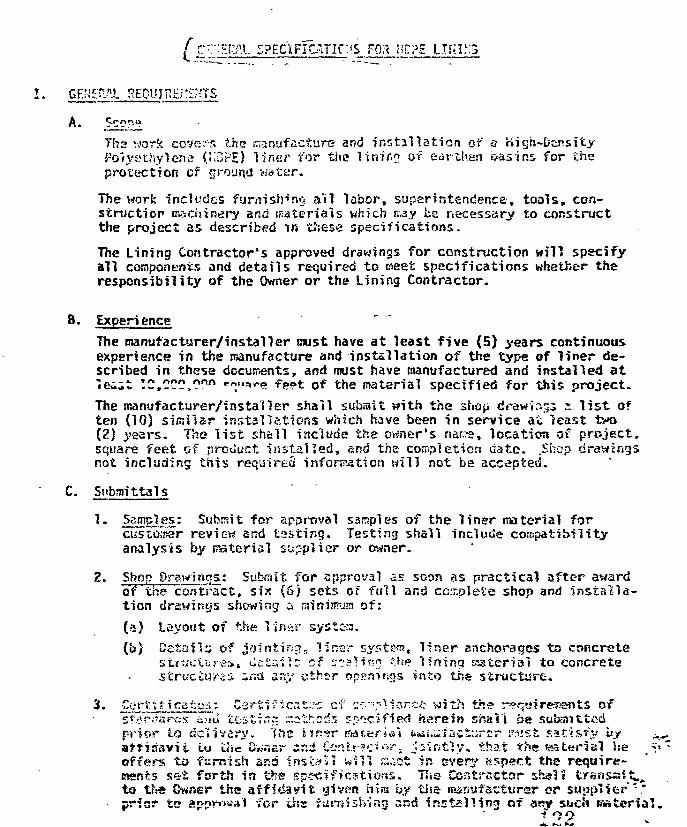
[ ?~";HS;£l 5PEaFICATIC:iS F03 HEPS
I . GEKEP/JL REQUIRE; :z;-:r.s
A.
Tha work covers the snanufacttire and installation of 3 High-DensityPolyethylene (K3PE) liner for the linir.? of earthen basins, for theprotection cf ground water.
The work includes furnishing a'il labor, superintendence, tools, con-struction machinery and materials which nay be necessary to constructthe project as described ir. tftese specifications.
The Lining Contractor's approved drawings for construction will specifyall components and details required to meet specifications whether theresponsibility of the Owner or the Lining Contractor.
B. ExperienceThe manufacturer/installer must have a t least five (5) years continuousexperience in the manufacture and installation of the type of l iner de-scribed in these docun^ents, and must have manufactured and installed a tTec-it TC,CCO,Onft ••««•*»•»» -Fppt of the material specified for this project.
The manufacturer/installer shall subasit with the shoo drawir.53 i l i s t often (10) similar installations which have been in service at least two(2) years. The l i s t shall include ths ovmer's nans, location of project,square feet cf product instal led, and the- completion date. .Shop drawingsnot including this required information will not bs accepted.
C. Snbnrittals
1. Samples: Submit for approval samples of the l iner material forcustoHser review and tast ing. Testing shall include compatibilityanalysis by material supplier or owner.
2- Shop Drawings: Submit for approval as soon as practical after awardof the contract, six (6) sets of full and complete shop and Ins ta l la-tion drawings snowing a rainimusi of:(a) Layout of the linar systcs.(b) Details of jointing, liner system!, l iner anchorages to concrete
stfuciuraSi Uct»i*~ of sc-^in? th$ lining sssterial to concretestructures inas any cthsr openings into the structure.
3- Cet"t.tf icataa: Zeriificat::;C cf c-""-;:1i-sr.'-.:: with the reqwiresents offsfarflanrJs c.ml te-stin^ r.othods r-p'scsffed herein shall ba submit ted
prior to delivery, ine iinsr ffasmri*! fens^ulactyrcr I'.isst satisfy by ^affiasvit tu u>«TOwner zv.z Ccntr?c'i<''?-. j i l n f i y . that the material he _S'offers to furnish ar.a install will scat in every aspect the require-ments set forth in the spectficstions. Tivs Contractor shais t r ansa*^ta the Owner the affidavit given mm by tlse msnufsctursr or supplier ".*prior to appr»-'«a1 for the furnishing and install ing of awy such material.
? '7 9
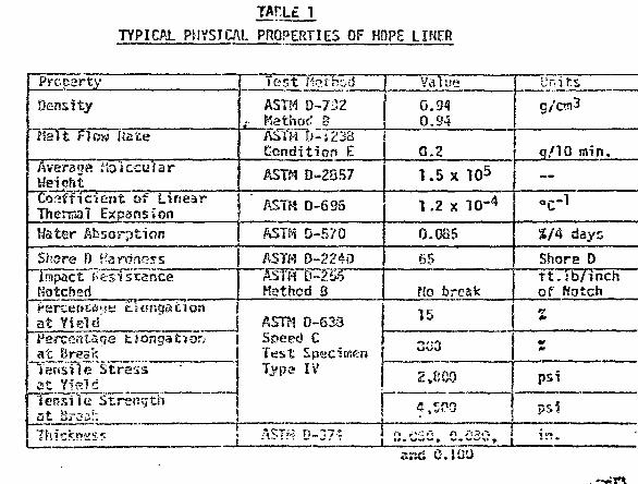
TAr.L£ 1
TYPICAL PHYSICAL PROPERTIES OF KDPE LINER
Property
Density
Hal t Flow Rate
Avera ••:> e hv 1 ecu "i a rWeichtCoefficient of LinearThermal ExpansionHater Absorption
Shore D Hardnessimpact ResistanceNotchedI'srcefstcS'.fK Ganqat ionat Yield" " |Percentage ttongat?ohat BreakTensile Stressat Yieldtensile Strengthat Braa!".
Test fferhod
ASTH D-732.- Kathod B
ASTH D-'s233Condit ion E
ASTM D-2357
ASTM D-695
ASTH D-570
ASTH D-22&0ASTH D-256Method 8
ASTH D-633Speed CTest SpecimenTypa IV
c t ! . ,.-..::.:.:• - . . - • • . i
Value
0.340.94
0.2
1.5 x 10⁵
1.2 x l O " 4
0.085
65
Uo break
15
2,1500
Units
g/c«3
q/10 nvin.
o C - l
S/4 days
Shore Dft. lb/ inchof Kotch
M
psi
S.CSS, Q.030, 1 i n .and O.JUt)
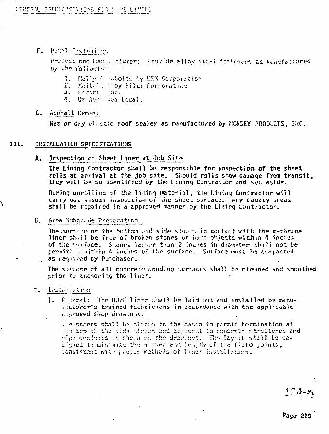
CFKEfl'l SPECIRCAYIC'S ?V*. \::">i
Product «nd Hi;;*... .ct.urer: Provide alloy steel f::*'r-ners as manufacturedDy thf? -foUowir;'::
1. felly ! -abolts f.y L!SM Corporation2. Kwifc-r-:.- ".: by h i l t i Corporation3. R^.-r.et. :.PIC.4. Or A"•;•;•.. ..ved Equal.
G. Asphalt Craneru
Wet or dry el. :A\c roof sealer as manufactured by HGN5EY PROOUCTS, INC.
III . IN5TALUTI0N SPECIFICATIONS
A. Inspection of Sheet Liner a t Job Site
The Lining Contractor s t a l l be responsible for inspection of the sheet,rolls a t arr ival a t the job s i t e . Should rol ls show damage fron t r a n s i t ,they will be so identified by the Lining Contractor and se t aside.
During unrolling of the lining material , the Lining Contractor will
shall be repaired in A approved manner by the Lining Contractor.
B. Area Subo •,-•<\<ie PrpparaticnThe surt<:•.•;e of the bottom and side slopes in contact with the ir.^j>hr>nel iner sfuil ba frt-e of broken stones or iidrrf objects witJurs 4 imcfiesof the v..irf?ce. Stones lartfer than Z inches in diameter shall not bepermit'r.. o within 4 inches of tiie surface. Surface must he compactedas required by Purchaser.
The surface of al l concrete bonding surfaces shall be cleaned and smoothedprior t,; anchoring the l iner .
" • Installation
1. £-c'"'T3l.~- ^-e ^f2- l iner shall he laid out end ins ta l led by manu-tac turcr ' s trained technicians in accordance witft the applicable-r.{.;>jroved shop dr<3'win<js.
T'ifi sheets shall be p.l?c'*-d in ths b's^in t.c» nf?nnjf. termination at'-';2 tcp of the n;rfi '.Irrpcs -~r;d cd.ir.crfit to concrete i true tares endpipe cor.rf!.:ifi as r-hc.'n en the drav.'ir:-?"">- Th? layout, shall be de-signed to B3jrii;n-«2o t^e number and lon^th of the f ield j o i n t s .'ciiti&i stznt. wi Li": f-vop^r E:eti:oi:; of 1 insr in:;taVlrft:J!>n.
219
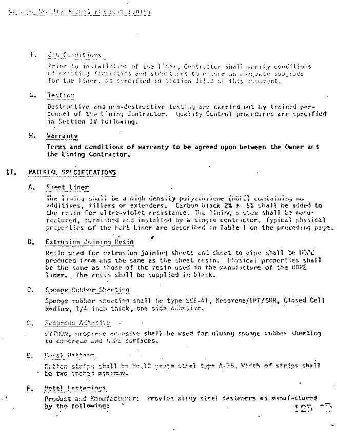
u: '•. • -.;. _.r T L i r i A.' .1 i ",'ij / i • < r.,.f"'t I i N i !';;j
P r ; c > r t o i r » \ l « » i i i". L I ' . ' H o { t r i e \ : ' , o r , C u : i f . r t ' . c t o r i h a i i v t - r i f _ y c o n o ' i l i o i : Sr . f «•• x 1 1 - 1 i t .-_j t V . c i i i l i c i a r d s i r j c l - . ; r : ? s t o c : v , u ; ? i n c.>•:=!, j r t t«-_- i u O ' j . ' i - J ef o r t . t e l i i n . T , . ; i ' . i v f c a f i i ' d i / i v ; - c t i o r » I l . ' . i j o f t i . i i d _ - ' . i - . T > j n t .
G. Tr s t. 1
Destructive An3 non-destructive tcsti .^j are carr ied out by trained p»r-sor.nel of t!ie Lining Conlrattur. Quality Control procedures arc spc-cifiec!in St-ction IV fol
H. Wa rra ntv
if:
and condjtior.s of warranty to be agreed upon between the Owner trithe Lining Contractor.
11 • ^I^I^^iEiIfner
Mn: t i n i t -j j i m i i us; >s iiiOii ufrOilCy f.vy i _ve i ;i>-; t_ I.TT V "«
, f i l l e r s or extenders. Carbon black Z% * iX shal l be mio^d tothe res in for u l t r a -v io l e t res i s tance. Hie linjrKi s sLt.-a shall be m-inu-fact»red. furnWs^d st.d installe<i by a sirtQie contractor . Typical physicalproper t ies of the t'-oi'L Liner are described in Table 1 on the preceding ps-je.
Extrusion Join ing Pesin
Resin used for e*tnjr.ion jainiri 'j s-heets and sheet to pipe shall b? V-U^Cproduced i'rrsm «r,d the same as the 'Jieet r f s in . I'hysicdi propert ies shallbe tise r.3ir«? as ?.hase of the resirt used in the Kanuf-jcture of the !.'DP£l i n e r . The resin shdl] be .supplied in bl«?dc.
C. ~J!2rf
Sponge rubber shoetirr? shall be t:<pe SCF-41, Heoprene/tPf/SBR, Closed Cella, 1/4 inch thick, one siac i-Jhciive.
PYTUON, n?oprrr« jt'iifsjvf shall be used for fjlumg sponge tvbbef sheetingto cor.crev^ and i.jf't sur
!x; two ipchss !sini?Ry-yi,
Product sr.d ^rajfict'.irt-r; frovfds alloy st«cl fasteners *s ^inuf-ctwrtrby the fc>n<?«'i«Mj: " •» o^,
« Ai *
SPECIFICATIONS FOR HDPf. LINING
Field Joints:
(a) Genera"': Field .joirsv.:, r:hall be made by overlapping adjacent"sheets a raini!i>um of cane (8) inches and extruding a ribbon .of extrusion joining resin no less than 1.5 inches in widthbetween the overlapped sheets or over the szutn between thesheets where hand weids are required.
Prior to extrusion welding of the seams, all areas which are tobecome seam interfaces shall be cleaned of dust and dirt. Theslick surfaces of the HDPE sheet which are to become seam inter-faces shall be roughened with a wire brush or other acceptablemeans before extrudate is placed between the overlapping sheetsor over a lapped seam.
Extrusion joining shall not take place unless tte sheet is dryand shall not take place unless the ambient temperature isabove 45°F and below 90°F.
(b) Field Joittta: Joints between the lining sheets shall be fieldwelded using tha manufacturer's extrusion joining equipment andtechniques. The joining procedure shall consist of softening theliner material by heated air. Tha temperature of the air imping-ing r ITS sheet for fchis purpose shjll range from 420°f- to 680°F.The i k. temperature used shall be determined by the installationsupe. •• Directly following the application of heat, a one andone-ha'l. inch mirjcium width strip of the same high density poly-ethylene resin from which the sheet is made shall be extrudedbetween the overlapped sheets. The temperature of the resin asit emerges from the extrusion die shall range from 428°F to 536&F.The overlapped sheets are then pressed together to form the ex-trusion joint.
(c) Penetrations of Liner Material: Penetrations through the linerfor pips flashings, patches, etc. snail he field weeded using anextrusion r.snd welder. The joining procedure shall consist ofsoftening tin* lirmr nwtprial by heated air ?s above described.Directly following i:ln» application of heat, a hot strip of thesame material frcm wntch the sheet is made will be extruded overthe ja1;:t to produce, tha oxt.rud;:d joint.
Any required repair af sm.il 1 hole* in the- 1 im-:r surfece shall hens&de with the extrusion hand welder. Liner material shall becleaceu uf ai'i dirt, duit and niiier foreign material, all smoothHDPE surfaces roughened, air heated to the prescribed temperature,and a strip of KDPE resin extruded over the hole to produce anextruded welded repair. • ?*
Seals around penetrations shall be roade as described below.

;:>'.'f.n.AL i ;!-rriF?r.crjr:{s J-CR r v c I. J N U ' S
A1"? pu.'_ pcnet ra t icns shall b.f: sloe-zed with V.uVf. pipe. Each
to prevent Isskarie. The basin "iiiict s-hasT b» anchored to «concrete c o i l s r surrounding the psriKtroticr.. An HOPE apronshall be extrusion welded to the pipe s ! swe and sh?11 toextrusion waJocd to t'.r? base .•crvj'jt outside of the area wherethe basr; sheet i s anc.ncred to t-^2 concrete c o l l a r .
OUALJTV CONTROL SPTCIFI CATION'S AND PPOCCD'JR S
A. Quality Control of K-nw Hateridi by i t s Hanufacture.rThe manufacturer of the HOPE rssin used in sheet production tests eachbatcfi before delivery to ensure a maximum consistency of raw materialquality'.The following tests are carried out by the producer of tbft rsw roaterialon each batch and the results forwarded to the sheet fabricator:
1. Density per ASTM Dasignation D-792-66: The density of the pvreflects tha degree of crystalliri l ty and thus serves «s an indirectcheck on mechanical qual i t ies such as hardness, stiffness, andtensile strength.
2- Carbon 5~!ar?c r.enter.* r-^r ASTK Dssi^intioR D-1CC3-7G: CiiLonpolyethvtp.ne serves prinarf )y as protection auainst thenaal agingand harmvul ul traviolet radiation, present "in outdoor .-'eathei'ing.Thus, quality control of the carbon black content ensures the goodweathering properties of pclyethyl ens.
helt Ir»riex per ASTM Designation D-7233-73: /> material's !r«;lt indexI s a measure oi i t s mean nolecwlar ve-.fjht and Theological properties.Thus, holding the melt index of the base material within a narrowrange is a criterion for uniform and opti-num HOPE liner production.
ffg)atJy-t^ol!lte Vif'CQ-'i't-yWX^H-l^?ignJ?t^oJ1P'3^3:;?7: This testmonitors a p las t ic ' s rcean oeaiee of polj^nerijation fl~r:a nean molecularsize - ensuring their consistency. As above, thss^i values affect theconsistency of procesiing and ciechanita! properties of the resultingproduct.
Bgll Ter,t p»r ASTM OesjZ^-.rJPH ®?j, f'!llzIP.'• E e ^ tcstincj is a relative)"fast rnetnoo at xnsziiio ?• rvsvena's !s rc^istsnce to stress crackino.This tes t evaluates a 'mater ia l ' s perfarr,jrit:e ur.cier r»«chan?cal stressinin ag
6. Moislure Cnnrt-nt per ASlrt C;?sionofcion n:S/D-rii: Kiintsinirr*j a cor»-s"t5n't"K:3TSturd' cc;.zr.Ht 'Vr:'"tr.c Z-.':- r-/^i.-.ri=;" Si"^~-J2issry tor prccessfnresulting in n parc-fr^z, biibblp-tra-; r;rcccc.t. £f^1cYi.»« cnily nstcriawitf* a poistore content in a n«r»w^ <-o}srsnce rsnjn Is ansthsr re-quircr.cn& for consistent pj*s?ivict quality. t 1*7
TOR
The d»td, determined is f/vsluafcea' by the manufacturer and, If deviatingfran tha enretd tolerance rar.oes, tin* tested batch is not delivered...s a result of this testing,, the namnacturer is guaranteed consistentbase rdateria* quality, essential in the light of the demanding condi-tions prevailing in the various applications of HOPE liners.
Quality Control cf the Incoming Raw Material by Sheet Manufacturer
The incoming raw material is again sampled and tested, this time ir> thelab facilities of the sheet manufacturer. As before, properties relativeto processing are determined, specifically:
Helt Index per ASTH Designation D-1238-73
Density per ASTM Designation D-792-66
Moisture Content per ASTH Designation D-570-63.
This testing provides further verification of consistent product quality,l to thi» maniifartiirpr'c rnrt
If the test results are positive, a sample of the batch is processedin manufacturing and evaluated as to melting behavior, forming behaviorand the product sheet's visual appearance.No batch is sent into production Lefor? positive results are obtained forthe incoming base material and the test processing. If negative resultsare obtained, the batch is excluded fron processing anJ returned to themanufacturer. „-
All properties determined in these tests are conpiled in the final sheetcertificate.
C. Quality Control cf Shpet Proriiiction
AutcT^tic control is a fosturc especially valued in the extrusion processand the successive processing stages. Important parameters >n all stagesof processing are controlled by auton^tic control systems and indicatedby pen reoorcers.
Three different qualities of the sheet are inspected continuously during
irq Process
At Isait three random samples art tskrn from each shetft roll and forwardedto t!se UL-oritcry for exterssive t&st1»5. 'tf.c satrpJc sites are distributedtc. ensure a representative evaluation of ine overall quality.
The following tests sre carried out for each sheet:- Tensile Testing per ASTM Designation D-6S3- Impact Tensile Testing per ASTM Resignation 0-63S- Thickness
- Stress Cracking Resistance {'Gall Test) per ASTM Designation D-1693-/
The following supplementary tes ts are carried out for sheet samples fromeach raw material batch:
- Melt Index per ASTM Designation D-l238-72- Thermal Shrinkage per ASTM Designation D-6S5- Density per ASTH Designation D-7S2-6S.
This testing effects a permanent surveillance of the production processand constant product quality.Narrow tolerance ranges ensure high quality in production. Productsdeviating from these ranges are removed and the cause determined.
D. Quality Control of InstallationSheet installation wyr* -i* ""-u-i «..* »-dcr psir.^tsk'.-.^ stipe, vUiuu upto and including project completion.The quality control is carried c j t by the on-site enginsers as well asoutside testing inst i tut ions.Quality control of installation can be divided into three areas:
1." Checking the sheets delivered to s i t e for transport damages, checkof sheet identification number with number on cer t i f ica te .
2. Inspection and continuous control of al l welding process parameters.3 . Testing of the completed weld seams.
On-site welding of the lin<;r is carried out by an extrusion welding proccs:This process guarantees consistent weld seem quality within a wide range oambient conditions. The control system of the welding machines are exten-sively automated to enable monitoring of the walding process by theoperat'ing personnel.
The welds era swde in one procedure by tssans of an automatic weldingiRSCbina, which pretests zhs welding surfaces to the desired temperature,injects a ribbon of molten KDPE nuierisl and then applies contact pressureto the seasn.The procedure for f i l l e t welds i s similar in that th* wrlding area ispreheated and tha welding material i s ssulten HOPE. Tiie necessary contact
f th i h t f th h d ldi «t i t l f ffJSp gpressure cranes frcra tha wsicht of the hind welding ys»«t i t sa l f . JtffJStt^.--*welds are used only for repair work ar.d special dasioins. -.*-v. •*;
GENERAL SPfXIF7CATie?iS FOR HOPE
Tftst Held? are run preceding al l extensive welding to assure r,vod weldquality yr.oer the prevailing s i t e conditions; Wtes? weld sarapies aresubsequently subjectea to mechanical testing.
1 • yiAH.?-I.J^~P&c>iryrt°f fo^sd Scan: The main prerequisite for tjoodBcnef;rcg fs~ continuous inonTfcarfng of the welding process parameters,such as hot a i r temperature, welding speed and contact pressure.This i s best carried out by specially trained personnel. Visualinspection of the welding surfaces, the welding process end thecompleted weld by experienced plastic welders allows a reliableevaluation of seam quality.
2. Quality Control of Welding Seams: Production of a quality welding seamstar t s witH~a preliminary t e s t weld. The machine settings, pretreat-Kent of the weld surfaces and adjustment to environmental effects areall. tested on a sample welding seam. A hand operable -ensile testingmachine enables en s i t s confirmation of the j o in t ' s tensile strengthncinn ct-r-in eanole.j%
After ins ta l la t ion, two major types of quality control ars availablefor testing the seams:
- destructive material tes ts of weld samples (spot check)- non-destructive material tes ts of a l l welding seasss.
3- Detgrmnation of Mechanical Strength
• (a) Tensile and Peal Tests: Because i t would be uneconomical toconduct destructive tes ts on all waid seasrsj destructive t e s t sare conducted only on a spot check basis, txtensive s i teexperience has shown that two samples daily are sufficient forevaluation purposes. These samples are then tested by QualityControl or Independently by official government testing agencies.
(b) Point *strr»'?s'*.r*2jj. Point stT^sing of the n^y produced weldTs suFTiclci'it zo locate areas of u\lUch'ion (> .e . , not fu*»ly
) ihjs is dens by running a s'-rcw driver or similarong Uw. rm'lii s<*nr,i b&'rtietm thu lortetr sheet a»d the
4. lestiiifjof; ggal^Cviitifj'-i-ity: After iniUsUtfLion, the lar^e s i^e of theiHtiijt u i e u l"ii'i£{" i-'vit.c«s DSTKi'tS t'.CStifiCj Oi'dy •. Xiift T.;'i£ Upper StwC* D« ».ijSl iner . This restriction cansidurably »-educes tha nus^ef of rel iablet c i w i i < « { . • ; O ^ e u u r e » . i r i w w e V r e r , \ m \ i i i u i i ' u o i r f u t . i . i v i t i f S i Obe used to verify the continuity {%atcrt*ghtBcss)
GFfT.TAL SPECIFK/VflCllS FOR WE LIN1HS
(a) y^cuwjJTprt: One snethod of testing the seal is vocmxn testing.'in'IJvls u s t t the wald seat;! is placed tinder ? vfieuua using aclevsr p"iBst";c suction cup attodted to a vacir..rs piar.p. Afoaaiirg cgo'it indicates the exact position of any "iRafesenccsunteresi.
(b) Ultrasonic Testing: Ultrasonic testing is just as railableas vsouua testing and in addition provides information onthe homogeneity of the welding se-2n. Easy haudling and agreater testing speed are further advantages of this method.
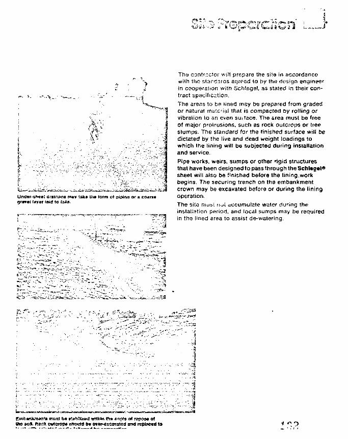
i
rUncJ»r-the*; ovstn&fla m«v tak» ti>» iorm of mp<na or agravel fjtyn- c»d to fsiim.
Tho contr.-ctor will prepare the si'e in accordancewith the stardruas acjreed to by the design engineerin cooperation wim Schiegel, as stated in their con-tract apatification.
The areas to be iined may be prepared from gradedor natural material that is compacted by rolling orvibration to an even suitace. The area must be freeOf major protrusions, such as rock outcrops or treestumps. The standard for the finished surface will bedictated by the live and dead weight loadings towhich the lining will be subjected during installationand service.
Pipe works, weirs, sumps or other rigid structuresthat have been designed to pass through the Schtogel*sheet will also be finished before the lining.workbegins. The securing trench on the embankmentcrown may be excavated before or during the liningoperation.
The site must not accumulate water dy ing theinstallation period, and local sumps may be requiredin the lined area to assist de-watering.
*«C\-' •'..'-I"'"
;-.-v-•.-s*....-
the aeJL hc=» cu^crop* trfxHS b» o»«r-«iim=!ad snd reptnetd 19
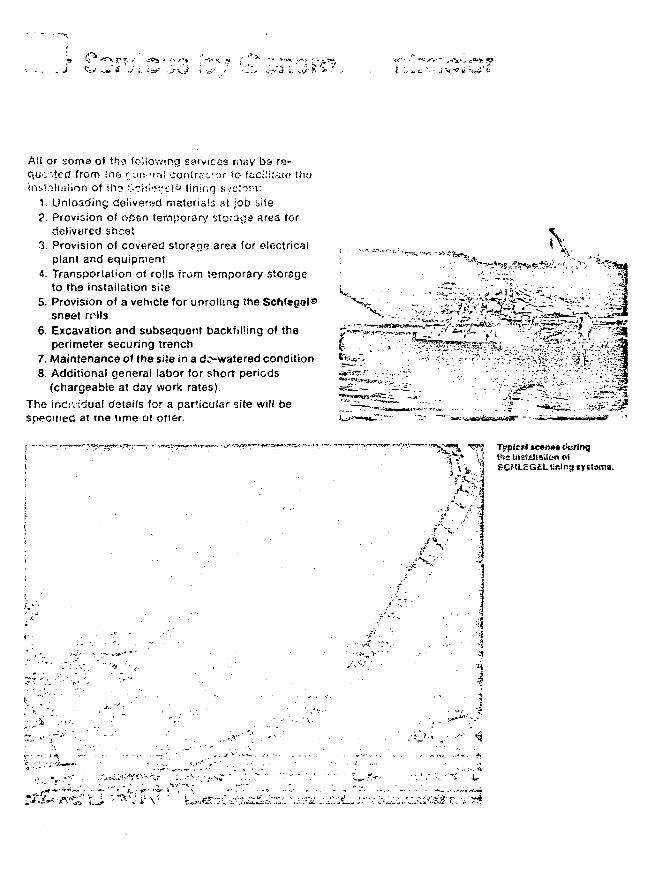
A!i or soma of thg following services may b& re-o,uc~ted from ih& r on 'tr,', oonlrnc-or io facilitate thoinsl.ilmiion of ihs fj.ohi--N"*.•)*> lining system:
1. Unloading doiivered materials at job aite2. Provision of oOen temporary storage area for
cielivarcc1 sheet3. Provision of covered storege ares for electrical
plant and equipment4. Transportation of rolls from temporary storage
to the installation site5. Provision of a vehicle for unrolling the Schi*ga(®
sneet rolls6. Excavation and subsequent backfilling of the
perimeter securing trench7. Maintenance of the site in a d^-watered condition8. Additional general labor for short periods
(chargeable at day work rates).The individual details for a particular site will bespecmec at me time ot oner.
tra
^ • • ;
TvpicM tc*n*t tkiring
. ••••A
• i . • - - .
v - • , -
1i
'-S*
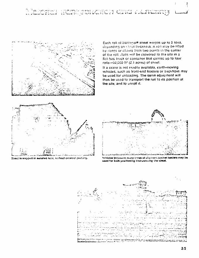
• i j * - ^ M £? 'is^a u. tf 15 *- •" '4
'<'-?;^i!'
Each roll of Scn!ifcsi« shear weigns up to 5 tons,depending or i : n::i-i thickness. A roii ifiify bo I'ftedby r.iinos or chains from \»o points in the centerof the roll, i^olis will bo cioiivered to \tvi site in aflal-bao truck or container that carriss up to fourrolis—52,000 h2 (2.1 acres) of shoet.If a crane is not roadily available, earth-rnovingvehicles, such as front-end loaders or backhoes maybe used for unloading. The same equipment willthen be used to transport the roll to its posi'.ion atthe site, and to unroll it.
L JK
u&ed tor bath fiO*SHo«!*i< t'»* vi>«»t
- •••••• :• J ™ ,
3.5
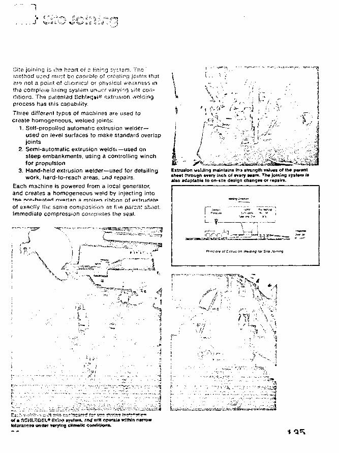
Gite joining is i.'is heart of ?. l ini ig system. Themethod u.*oct must bo csoablo of croatipo. joints thatarrj not a point of chemical or physical weakness intho conipleie lining system ur\oi:r varying bile con-ditions. The patented 5'>ch!sss%i» extrusion .voidingprocess has this capability.
Three different typos of machines are used tocreate homogeneous, welded joints:
1. Self-propsllod automatic extrusion welder-used on ie*el surfaces to make standard overlapjoints
2. Semi-automatic extrusion weidei —used onsteep embankments, using a controlling winchfor propulsion
3. Hand-held extrusion welder—used for detailingwork, hard-to-reach areas, and repairs.
Each machine is powered from a iocal generator,and creates a homogeneous weld by injecting into• ho nrA-h«atorl nvarlfln a mnlton rihbnn of pxtriiriat**of exactiy the same compositor* as tiie parent shoot.Immediate compression completes the seal.
I
Extrusion wftljlng maintain* if» tirtngth valucx o( th* parent>h««l through every inch of «v»ry scam. Th« joining aytttm It«I«o »dipl*bl« lo on-ilt« design changes or repair*.
04 a nCHLKGE!.* iiRi>s ere 'w. £>*! rrifl crania wWttn narrow
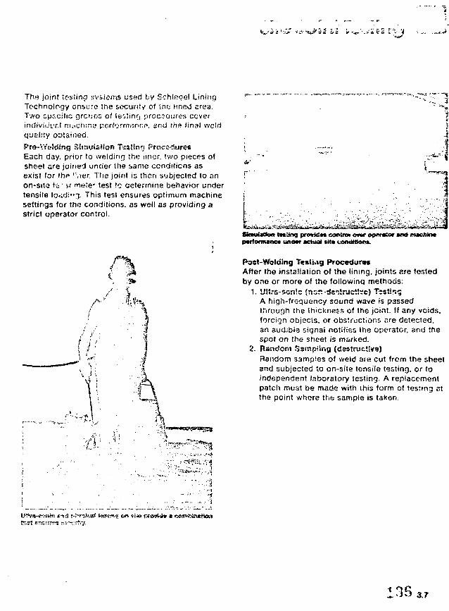
6 2 * '& '- a (1 t' £
The joint testing systems used by SchSoqel LiningTechnology ensure the secunt/ of trio linBO area.Two specific greens oi leolinrj procedures coverindivio'LTil muchins performance, and the final weldquality obtained.
Pra-Vrtslding Simulation Tttalltuj Procedure*Each day, prior to welding the nncr, two pieces ofsheet are joined under the same conditions asexis! for ihp 'Vier. The joint is then subjected to anon-site t i • it mere' test to determine behavior undertensile load:"}. This test ensures optimum machinesettings for the conditions, as well as providing astrict operator control.
- =9
StmubKfcm l«af>o prov*d*« eontrcn o*w opmator and mwMn*pvrformene* under actual *tt« conditions.
Post-Waldlng Testing Proc«dur«sAfter the installation of the lining, joints are testedby one or more of the following methods:
1. »J!irs-5or.!c $n:;r.-destructive) TestingA high-frequency sound wave is passedthrough the thickness of the joint. !f any voids.foreign objects, or obstructions are detected,an audibis signal notifies the operator, and thespot en the sheet is marked.
2. Random fjsmpilng (destrucMvs)Random samples of weld are cut from the sheetand subjected to on-site tensile testing, or toindependent laboratory testing. A replacementpatch must be made with this form of testing stthe point whore the sample is taken.
3.7
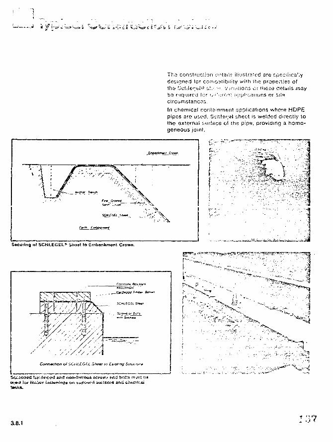
^ii
S«curing of SCKLEGEl,* Sfiiat to Embankment Crown.
Tha construction c'^tails illustrated are cpBCiiica'lydesigned for cojrioatibiiity with (h<3 properties ofth& f jc iWtrbi^ !,;•.••.:•'. v'jririiions or 'iie.se cetaiis mayb3 required (or fi.-'svroaf Oj.ipi'cynons or si'scircumstances.In chemical containment applications whore HDPEpipes are used. Schiejjel sheet is welded directly tothe external surface of the pips, providing a homo-geneous joint.
Ii
•>1l\-~
- • : - ' • -
• . s
1.••a
.- • - -,vf l f l (rt i
3.8.1
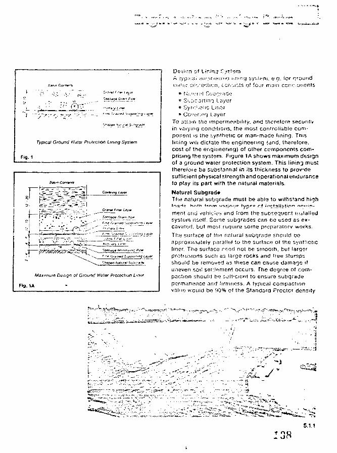
Maxi'r.um Deign 0/ Groonc' V<'aler Protection Un<:r
Fig. 1A
Dt-f.icrn of Lir.in^ S/rfftmA typ:Lii. di)','i(!<j<:rff(j lifung sysiem, e cj. for nr
\v^'f;r pro'eclicn, tor.-.,i^ts of four mam ccm;.o!ier.!s• N;.".-r.''l Si.;b'V''ido• Su,"->"'O.rti.'iT layer» Syri:'.o;!C Liricr• Co'-'f-'finrj layer
To ati.'ii("( the imparrnei'biliiy. and thcreforR securityin varying condttions. the most controllable com-ponent is the synihetic or man-made lining. Thislining will dictate the engineering (and. therefore.cost of the engineering) of other components com-prising the system. Figure 1A shows maximum designof a ground water protection system. This lining must(herefoie be substantial in its thickness to provdesufficient physical strength and operational enduranceto play its part with the natural materials.
Nature) Subgrad*The natural subgrade must be able to withstand high
men! arid vehicios arid from the subsequent tnataiietisystem itself Some subgrades can be used as ex-cavatwj. but most r&qutre some preparatory works.
The surface of fh« nntural subomae sriould oonpproxiciately paraiU:l to the surface of the syntheticliner The surface rood not t>e smooth, but largerprotrusions such as large rocks and tree slumpsshould bn removed as these can cause damage ifu.ieven soil sot:lement occurs The degree of com-paction shouirl bo soff-crent to ensure subgradepermanence and firmness. A typical compactionvalue would bo 90% of the Standard Procter density
5.1.1f no-..on
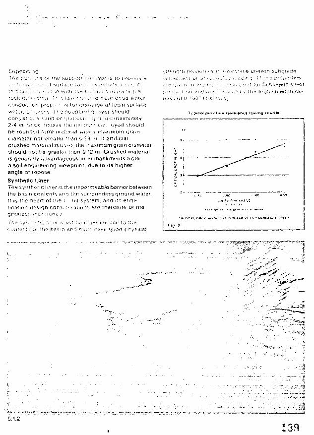
I . : - '••.•'•J.'i
<;r;jm
It ari:tic:iai
.*! <il t i l l - - s u e . " " . ) ! ' : i ; • ! i ' t y e r i s ! U i - f o . i . J - j
• : • . ! :u'LiC.<: '.:>' ' • •; • i , : ' . 1 Ni - - : ' .C . ! . • • • • . i l
! n " 3 : s ' ' ' . I ' ' •'. : L . O V V J K I I ' 1 . ' ; ? • . . ' . ' f . j i V i i r . M ' ! • ( i r:
rock Oi i l f I O ; V I | ! •' ', i .3> • - r •. <;v;0 r.aw c o o o vv n lcr.;.i!iC]uC..f. ri [>'<.•{.;• ' ' ":> lor ' jrSiM.i 'J'* o! lor:.'H ' iuri/tCv-».'''..;?, o r '..-'•'.<"i if1-!' r.opDcr'.^.rj U y t r i f ' f . 'OldCOf j iSt o l ;» •..Mir) (.ir ')r.:-!-.ul.ii ' i t -r t i 'O fOx imy ic l y2-4 in ti'.i',K U:'.:iiliv if>u if!': ! ' i ; r : i v - r . oy^ f i '..KouicJbo round'.--] .'orni (n,;!'.?r,al wi!c lameior noi qr';;ii(;r !!'an 0 -:crushed mnKidil is ir>'-;. I lie n iximum grain Cishould no; t.'o <jr»«u«t !n»n 0 ~<2 m. Cruiried materialis gefieraily advyniayeous in embankments Iroma soil engineering viewpoint, due So its higherangle of repose.
Synthfttlc LinerThe synihotic fmor r> !."•.« irnpftrmeabio harrier betweenlha Da.i.n conlprits anc inn sufrounOmg fjroufid water.II i i tho heart of th» i :nj r./"itern. ancl !)•. enrji-
:• ' ; < i i u > s nrt:1 : n e t e i a f « ; 0 1 r r ; e
r r : . j ' . ; r , ( , i ; ' j u o o ( i f i y s i c a
Uy Ui'_- i ron M'fjti"
i i of 0 i :r0" I 1>'X; Mm', i
• • ! >c ' i r , ; : r r r T : J ^ *
! t ! i ! " b f t i i • • " • a r
1
'r:£'
. £ J ; . . , , , • .. _ > • •
5.1.2
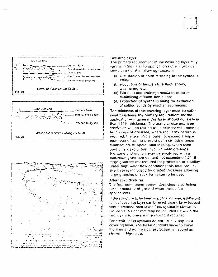
1
1
Fig. 2a
.C^ss/T^i, __ *ii''P Gnvistf St'p
na/ or River iiwng System
/O/u-'.g i ay»r
Basin Contents Primary Ltner
- , Fine CSnmod Layer
'•- ... . _ Shaped Si/!>9'a.f<>
Wafer Resen/o;r Lining System
i
The primary requirement of the covering layer n->._yvary with the lietailect applicat-on but v/'il providesome or ail of t itf foi'owing functions:
(a) Distiibutien ol point stressing to the syntheticI'ning:
(b) Reduction ot temperature fluctuations,weathering, etc.:
(c) Filtration and drainage mecid to assist inminimizing effluent contained;
(d) Protection of synthetic lining for extractionof settled solids Oy mechanised means.
The thickness of this covering layer must be suf'i-cieot to achieve the primary requirement for thoapplication—in general this layer should not be lessthan 12" in thickness. The yianular size and typeoirininvori will hfi rfiiated to its primary requirements.In th& case of drs.'oaoe. w^ere regularity of sire isrequired, the granules should no*, exceed a maxi-mum size of .8/' to prevent point stressing undercomwaction, w operational loading. When usedpurfiiy ns a pro.action layer, vanatiie gradings(I n sard and o,ravcl). may be employed with amaximum grain size content no'exceeding 1.?". If!arge granules are required for protection or stabilityunder high water flow conditions this total protec-tive loyer is increased t»y graded thickness allowinglarge granules or rock formation to he u»ed
yThe four-component system described is sui'icientfor thrt majoniv of ground water protectionapplications.•t the structure to be lined is a canai or river, a differentlypti of covering layer can bo used: a sand layer toppedwith a crusrteo rock layer. Thib system i:\ shown inFigure 2a. A Ubnr mat may be included botwt-on thotwo K.yers lo pri.'v«iu intermixing if required.Kosecvoir lining systems do not usually require acovering layoi. itrn basin contents seive to coverthe linoi and no physical protection is nsftiod asshown in Hgiiro .'o.
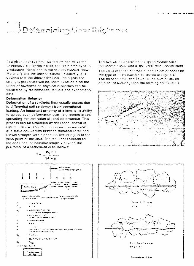
In a given liner system, two factors can r>« variedto op!nri!;e sue performance the rosin employed inpioduction (described in the section pnti'lnd "RawMaterial") and the liner Thickness Ir'ur.iive'.y. i! isorwious that the thicker the liner, 'he Ivcshei thestienptfi properties will be. More ex-act data on Iheeffect of thickness on physical oroperties can beillustrated by mathematical models and experimentaldata.
Deformation BohaviorDeformation of a synthetic liner usually occurs dueto differential soil settlenant from operationalloading. An important proporty of a liner is i*.s abilityto spread such deformation over neighboring areas,spreading concentration of local deformation. Thisprocess can lie simulated by the model shown inMgure j OPIOW. i ms rnuuui upo<utc;> on ,<n; u.jjis.of a static equilibrium between tncionai force andtensile strenrj'h with elongation occuirmcj up to tnoyieifl point o! the liner. Trie resultant wuiauon forihe additional delormatiie length x beyond theperimeter of a settlement is as follows"
ThB two vor;ut>!rt factors for o ouon system fiie t.the liner thicKfo:.-. and O. trv: torco trsnsler coefficient
TIIH vdlLe o) the (ore? uarislc-r cco'ficient depend? or.the type oi lorco tfnnj!fcr, es shown in f-'igure 4.The forco trjnstci coefficient is ihe sum or ihe co-efficient of iiiction \s and the tprming coefficient ' .
fy*~j*~Z
2A . a
'a 'fl'f'c"**1'^,'
* • t
T't.n. Hn\ii.''-
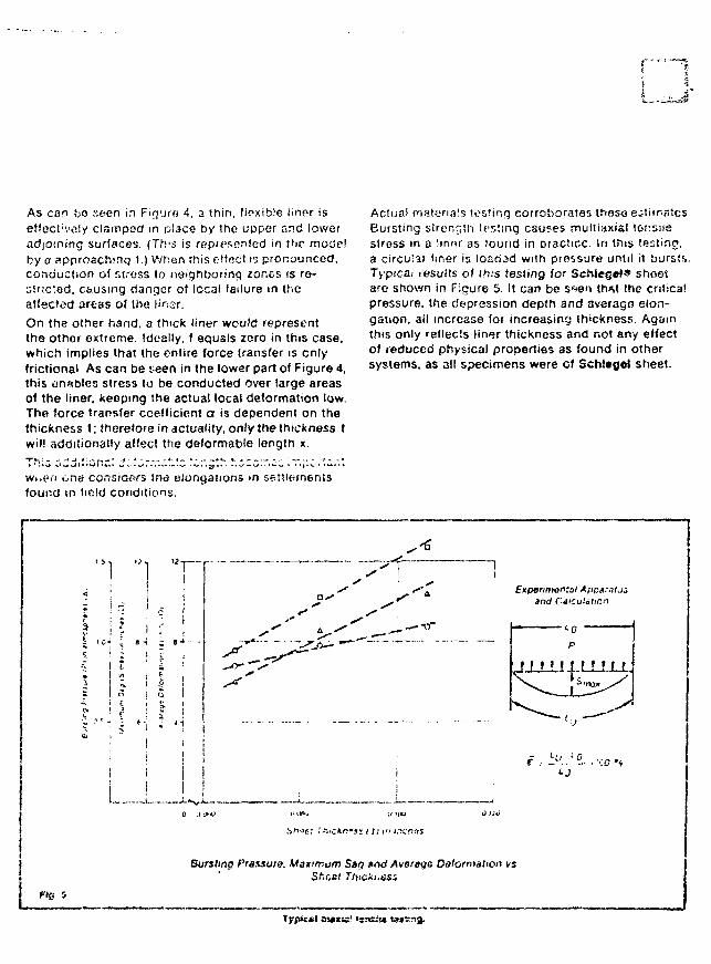
As can bo seen in Finute 4, a thin, flexible liner iseffect'voly clamped in place t>V the upper and loweradioining surfaces. (Tft's is rspn^onfcd in thr mode!by a approaching i.) When this effect i'j pronounced,conduction of stress to neighboring zones is re-suicted. c&using danger of local failure in theatfscted areas of the linor.
On tha other hand, a thick liner would representthe other extreme. Ideally, f equals zero in this case,which implies that the entire fores transfer is onlyfrictiona' As can be s een in the lower part of Figure 4,this arables stress to be conducted over large areasof the liner, keeping the actual local deformation low.The force transfer ccelficient or is dependent on thethickness t; therefore in actuality, only the thickness twill additionally affect the deformable length x.
w>,e>"i one consiaora trie eiongaiioos in settlementsfound in field conditions.
Actual r'lHttiriais testing corroborates those estimatesBursting strength testing causes multiaxial tonsnestress m a Sinnr as found in practice. In this testing,a circu'3< liner is loariad with pressure until it bursts.Typicai results of this testing for Scfciegef* shoe-tare shown in Figure 5. !t can be s*>en th*t the criticalpressure, the depression depth and averags elon-gation, ail increase for increasing thickness. Againthis only reflects lin*»r thickness and not any effectof reduced physical properties as found in othersystems, as all specimens were cf Schltgot sheet.
! n
8 -i ; »-4 -
• - _ ; ••; : < i
i i
Experimental Apparal.j.and Calculation
• " •0
p
M M I I I H M
isrt^c: ' fi.*ci!n*ss / f ^ cf i.^tTJi
Bursting Prazsura. Maximum S»Q »nd Average Deformation vs
e- s
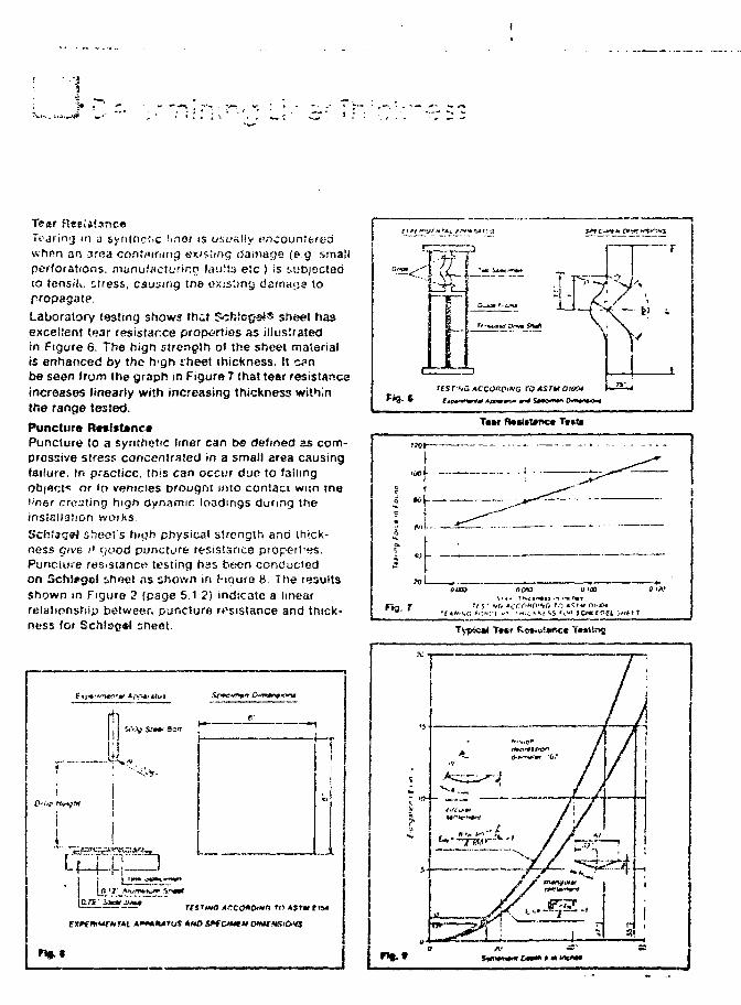
Tear Rssiiisnc*Todiicvj in a synthetic ftnor is usually ewhrrn an area containing existing (iamaoe (eg smallperforations, munutiicturir.p tauiis etc ) is subjectedto tensili. siress, causing tne existing damage topropagate.Laboratory tosting shows that Scfstegs*® sheet hasexcellent tear resistance properties as illustratedin Figure 6. The hign strength of the sheet materialis enhanced by the h'gh theet thickness. It c?nbe seen from the graph in Figure 7 that tear resistanceincreases linearly with increasing thickness withinthe range tested.
Puncture R*»lft#nc»Puncture to a synthetic liner can be defined as com-pressive stress concentrated in a small area causingfailure. In practice, this can occur due to fallingobject* or to vehicles Drougni into contact wnn met'ner creating high dynamic loadings during theinstallation worksSchiag^J sheet's hicjh physical strength and thick-ness Give ;' r;uod puncturfe resistance propert'es.Puncture resistance* testing has b«;cn conductedon Sch:#oel sheet ns shown in f-iqure 8. The resultsshown in Figure 2 (page 5.1.2) indicate a linearrelationship betweer. puncture resistance and thick-ness for Sch!s»g*! sheet.
f
|
i
1
*gfH
UMg $•'•* ten
tWO ACGQ*Oti*(l ro 4$rw i
I1
d
— s
iNTEROFFiCE CORRESPONDENCE
TO: fir. R.T.Clarke
FROM: H.J.Suerbeum/H'l
DATE: hsrch 4, 1532
SUbJECT: ''Cold Region Installaticn
I should like to give you in writing vhat was discussed betweenus on the phcr.e on March 3, 1932. The projects in Canada aresurely beautiful in size and we should find ways and techniquesto overcome the risks caused by low temperature application ofSCHLEGEL-She-et. '
My suggestions:
1. Use SCHLEGEL-Sheet 2,5 mm instead of 2,0 ma in this area.The reason: I t ' s more rugged and i t can be welded properly.When i t comes to low temperature i t i s most important thatthere is no weak spot in thi liner system. The liner t r iesto shrink in winter time.
&TxU* + 2 (J°C7 - 45°C x 1.5 y 10"Vc = 65°C x 1,5 xI D ' V c » IX that is Im/IOD*
We cannot allow shrinkage but the design of a basin canensure that the l i r^r takes everywhere this IS as stressand not that part of i t has to take nothing and the restall s tress.
The toes and the comers arv» the weak spots of an empty basisHere uplifting will happen. To avoid uplifting 2 precautionsare possible:
a) The client should 2gn?3 to a rain, waterlevel whichstays in the basin (for example 3 '} . That wouldavoid uplifting in the toe area.
b) In thff 4 comers of a basin the SCTiLEGEL-Sheet shoulbe covered. £ty suqgestion is kind of min. 2 n thicksand or graver layer which can also operate as entryexit raaeps for the basin.
3. Th« toe and the corner areas should be designed with a generodi
For the endfixircg of the SDJIEGEL-Shact on the crest severaldetails should be carried out csrevully. '
' 244
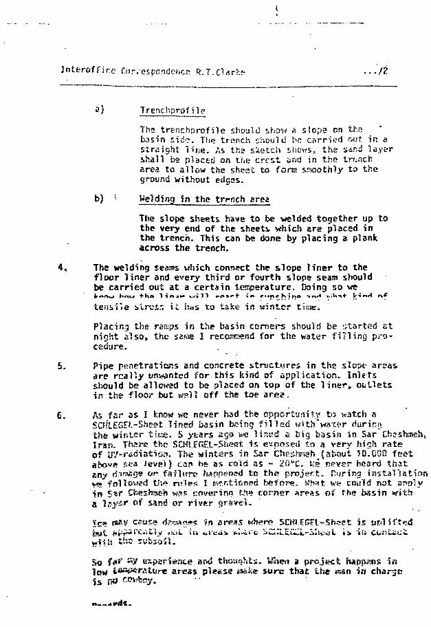
I n t e r o f f i c e CorvespcndtNice R.T. Clarr.?? ...it
a) Trenchprofile
Tb» trenchprcfile should show a siopa on thebasin sid?. The trench should be carr-ied out. in astraight line. As the sketch shows, the ssr:d layershall be placed on tr«e crest and jr. the trencharea to allow the sheet to form smoothly to theground without edges.
b) ; Welding in the trench area
The slope sheets have to be welded together up tothe very end of the sheets which are placed inthe trench. This can be done by placing a plankacross the trench.
4. The welding seams which connect the slope liner to thefloor liner and every third or fourth slope seam shouldbe carried out at a certain temperature. Doing so we
tensile stress it has to take in winter time.
Placing the ramps in the basin corners should be started atnight also, the sarae I recommend for the water filling pro-cedure.
5. Pipe penetrations and concrete structures in the slept1 areasare realty unwanted for this kind of application. Inletsshould be allowed to ba placed on top of the l iner , outletsin the floor but wall off the toe area.
6. As far as I know we never had the oppcrtimitr to watch sSCHLEGFL-Sheet lined basin being filled witb'watsr durir.ythe winter tiiss. 5 y^ars ago t»e lined a big basin in Sar CbeIran- There ths SCHLERtL-Sheet is exposed to a very high rateof UV-rfidiation. The winters in Sar Cheshsseh (about ?0.000 feotabove sea level) can ks as cold as - 20"C. Ws npver heard thatany d-V3fiS* * r failure {wppened tes th<» project, faring instaVsation'.•a foil owed thf» ni'Ses I p^r.tinnsd before. What w«? cou'id not SPOIVin S^r Cheshach wfl$ cover ing fcSi»! corner areas of the basin witha l.Tysr of sand or river gravel.
» P*«V cause <fc»<<«o*s -?n arras wherp SCHi.FGFl-Sheat isbill iippsrei'.tiy >&L in u) l i I E l i
h b
So f»*8' ^ espsriente ar«* thoughts. Uhen a project happens inlow tasp^ratore areas pleesff e ske sure that the man in chargein no coHfccy
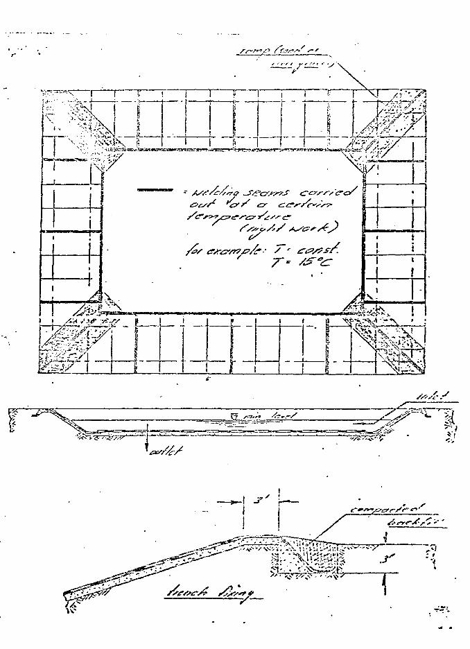
mm
r
Af*>£NDXX D - 2 - 4
STAFF INDUSTRIES, INC.

2.6/Sla
JV,
" L!H!?»G MATERIAL SELECTOR (Confirm suitability wilh Staff industries or Staff iepresentat<ves.)(Soe "Oi-scussion ot Materials", p. 11)
•1 POLYVINYL CHLORIDE (PVC) HYPALON. Heintoicett CFZ•J APPLICATION Sfs.'tij«frf Oil Hsirifnrced Industrie! f'oizbla Standard fie;nforc<H<_
S' lil™is ^ X X X X X
r* Btsck (.iquor X X X X^ Bnne Ponds X X X X^ X_
Buildinrj Waterproofing X X
flCafe's ~X X " X X ~ ~Xi " Pile Liners/Covers X X X X ~~ XCooling Pond3 X . X X X X*Covers, Floating
Potable waterIndustrial wastes
Sewage lagoonsCutoff CurtainsDam ft Levee CoversDecorative PondsEvaporation Ponds
XXXX
XX
X
XX
XXX
X
X
X
• X
i-arm Fonos A
m Fiiter Beds X~!,| Fire Poncis X6° Fi^PonOs_ XF
Fly As>h Pc-r:ds X71i |
Course PoncisIndustrial Wastes Ponds
_ Industrial wastesp;'<• 1 Ha7a>dous wastes^Landf i l l s
MunicipalH Industrial
' ^ i-caching PitsManure :
R;H Oi'-Sp»'i CC'ntai^Oxsdatton Pond
CcT.tain.~en} X X X° X°Ponds X X_ _ _ X _ X X X_
-«.?££2L^yai!i"lElir'H^ 5 ^ * 5_Li Recreaiiai--. P O P S ; X
JncSustiial X X 2: _ x
_ — X
_x _ x " x "X " ~ "" "" x ~ A
tj Tattings Pongj X X. X_ X" ' " x " X X K X "~~~ X~ X~
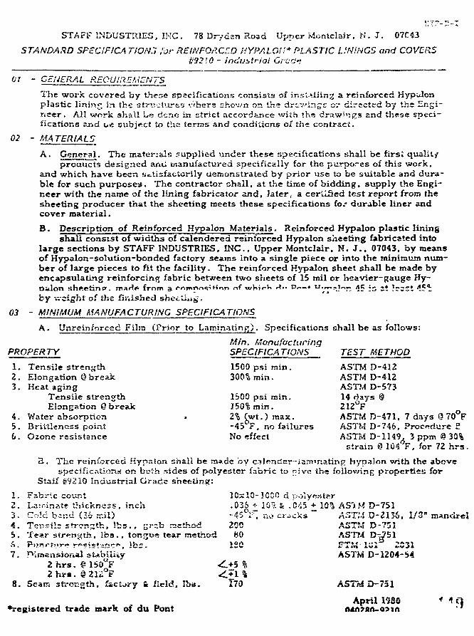
STAFF INDUSTRIES, INC. 78 Dryden Road Upper Montclair, N. J . 07C43
STANDARD SPECIFICATION.", lor REINFORCED HYPALOU* PLASTIC L.'N'NGS and COVERS#3210 - industrial GracJt
01 - GENERAL REQUiREMnNTS
The work covered by these spscifications consists of insi.*iiing a reinforced Hypilonplastic lining in the striictursy vhcre shown or. ths drcv-'ingc ov directed by the Engi-neer. All work shall Le dene in strict accordance with the drawings and these speci-fications sj-id L.e subject to ths terms and conditions of the contract.
02 - MATERIALS
A. General. The materials supplied under these specifications shall be first qualityproducts designed and manufactured specifically for the purposes of this work.
and which have been Sctisfactorily uemonstrated by prior use to be suitable and dura-ble for such purposes. The contractor shall, at the time of bidding, supply the Engi-neer with the name of the lining fabricator and, later, a certified test report from thesheeting producer that the sheeting meets these specifications for durable liner andcover material.
B. Description of Reinforced Hypalon Materials. Reinforced Hypalon plastic liningshall consist of widths of calendered reinforced Hypalon sheeting fabricated into
large sections by STAFF INDUSTRIES. INC., Upper Montclair. N. J . . 07043. by meansof Hypalon-solution-bonded factory seams into a single piece or into the minimum num-ber of large pieces to fit the facility. The reinforced Hypalon sheet shall be made byencapsulating reinforcing fabric between two sheets of 15 mil or heavier-gauge Hy-Di-lon shee t in tr . nur{i> from a rr»rnTM-i«;if-inn r>f wV.i«-V» »*• ^
by v;-cight of the finished sheeting.
03 - MINIMUM MA NUFA C TUR ING SPECIFICA TIONS
A. Unreinforced Film (Prior to Laminating). Specifications shall be as follows:
Min. ManufacturingPROPERTY SPECIFICATIONS ' TEST METHOD
1. Tensile strength2. Elongation @ break3. Heat aging
Tensile strengthElongation Q break
4. Water absorption5. Brittlencss point6. Ozone resistance No effect ASTM D-1149. 3 ppm g 30%
strain @ 1G4°F. for 72 h r s .
B. The reinforced Hypmlon shall be made by c.nlencter-iarfi'nating hypalon with the abovespecifications on both sides of polyester fabric to pive the following properties for
Staif Sr?2IQ Industrial Grade sheeting:
1. Fabric count 10x10-1GC0 d polyester2. Laminate thickness, inch .036 + 10vt & .0^5 + 10% AS1M D-7513. Cold bind (26 n.-.il) -45 F, no crocks AST!A D-2I36. 1/3" mandrel4. Tensils strength, lbss., gr-zb rsethod 200 ASTM D-7515. Tear strength, Iba., tongue tear method M0 ASTMA. Pnr>rt,,r~r«*ist-£*ir». lbs. ISO FTW17. n-linen&ional stability AS7"M D-1204-54
2 h r s . ° C
1500 psi min.300?, min.
1&00 psi rain.150% min.2% (wt.) max.-45 F, no failures
ASTM D-412ASTM D-412ASTM D-57314 days @212°FASTM D-471.ASTTvI D-746,
7 days 9 70°FProcrdure £
8. Seam strength, factory & field. Iba. 170 ASTM D-751
April 1930 MO*i-eK»stered trade mark of du Pont AIA?SA-O?IA ' '
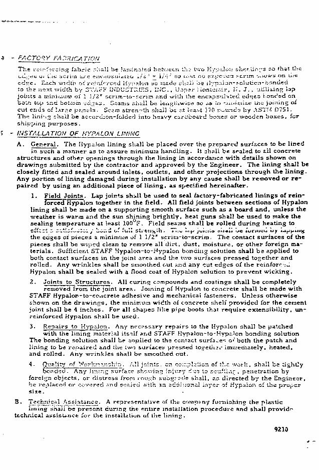
TION
The i-einfovcirif; fabric -hall be Jaiiiinaied between th? I'-vo KypaioT! &hef-.lir>. s t'-o that thet.ul,;i-ii ui Lie iiCiira a rc eHtausu i i t iu i / i ' : •*• i/'-'~ so i«>*ii m; ticuc-jea t e n r a •s,>o*'» on u.-e
edcrc. E .ch width o: ro^nici-ced Hyp a Ion so made s;'i;sii be il7p:-.lan-foiut:c'r)-br<ndedto the jiest width by GTAi-K uNL'USTIilKS, INC., Upper iiontciair. N. J , . -jtSliiiisg lapjoints a minjiiiut? of 1 1/2" scrim-to-Ecrim and witii the encapsulated edtjes i onc^td onboln top 'jzid b-ottoin ^clj^tj. Geanis shiiil be i«»j>ll»wiee so -JI U> 'luiiirnste u-.e joining o»cut ends of IATp.c pans-Is. Sci'ra strength shall be ;-.t Ica;»t )70 r ^ i n c s by ASTM D751.Th<? lini'.ig shall be accordion-folded into heavy cardbo-avd boxes or wooden boxes, forshipping purposes.
- INSTALLATION OF HYPALON LINING
A. General. The Hypalon lining shall be placed over the prepared surfaces to be linedin such a manner as to assure minimum handling. It ahall be sfaled to til concrete
structures and other openings through the lining in accordance with details shown ondrawings submitted by the contractor and approved by the Engineer. The lining shall beclosely fitted and sealed around inlets, outlets, and other projections through the lining.Any portion of lining damaged during installation by any cause shall be rennoved or re-paired by using an additional piece of lining, as specified hereinafter,
1. Field Joints. Lap joints shill be used to seal factory-fabricated linings of rein-forced Hypalon together in the field. All field joints between sections of Hypalon
lining shall be made on a supporting smooth surface such as a board and, unless theweather is warm and the sun shining brightly, heat guns shall be used to make thesealing temperature at least 100 F. Field seams shall be rolled during heating toeffc;l z zitizf:;c: / Lcr.d of full sti'fcn^Lh T>i< lc > juxciis ^n*i» uc lurmcu uy i ^ p m ^
the edges oi pieces a minimum of 1 1/2" scrira-to-scrim. The contact surfaces of thepieces shall be wiped clean to remove all dirt, dust, moisture, or other foreign ma-terials. Sufficient STAFF Hypalon-to-Hypalon bonding solution shall be applied toboth contact surfaces in the joint area and the Uvo surfaces pressed together androlled. Any wrinkles shall be smoothed out sjid any cut edges of the reinforr ;UHypalon shall be sealed with a flood coat of Hypalon solution to prevent wicking.
2. Joints to Structures. All curing compounds and coatings shall be completelyremoved from the joint area. Joining of Hypalon to concrete shall be made with
STAFF Hypalor-to-coacrete adhesive and mechanical fasteners. Unless otherwiseshown on the drawings, the minitr.utti width of concrete shelf provided for the cementjoint shall be 4 inches. For all shapes like p'pe boots that require extensibility, un-reinforccd Hypalon shall be used.
^" Repairs to Hypaioa. Any necessary repairs to the Hypalon shall be patchedwith the lining material itself and STAFF Hypalon-to-Hyp.-.lon bonding solution
The bonding solution shall be- aoplied to the contact surfa»e«* o* both the patch andlining to be repaired and the iwo surfaces pressed togeliiir immediately, heated,and rollsd. Any wrinkles shall b«* smoothed out.
of *Vorkn>!i-:h^. All joints: en cc;7:pl2licn of ',hc. work, shall be tightlybonded. Any limn.;; surface showing injury dirt to scufi'i.ir . penetration by
foreign objects, or distress from ipo«f.;b subgroeJe shall, as directed by the Engineer,be replaced or covered snd sealed with an adaiuorsil layer of Kypaion of the propersise.
B. Technical Assistance. A representative of the company furnishing the plasticlining shaJi be present during tne entire installation procedure and shall providei ! assisU>nee for the installation of the lining.
9210
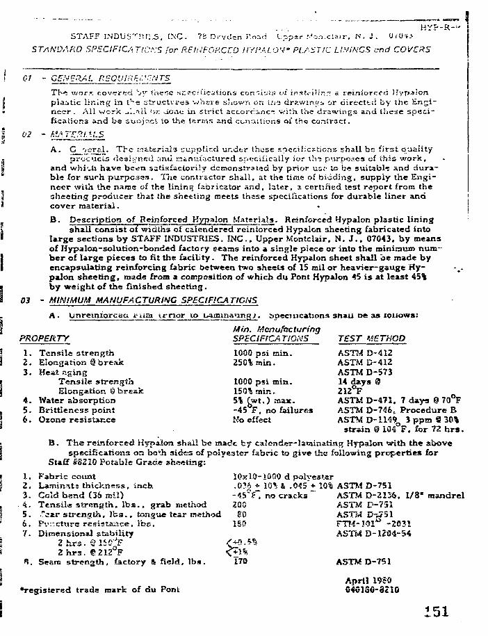
H Y F - - R - " »S T A F F I N D U S " r r U l ' . S . I N C . 7 8 D r v c l e n i ' . n i d U p p e r M a n . c i a j r . N . J . OlOii
STANDARD SPECIFICATIONS for REfilFORCCD HYPALOV PLASTIC LINiHGS end COVERS
Gl - GEN ERA I. REOUI.-i Ei. 'cN T5
Thi -j/orK covered '-jy t'cxer-a specifications coniist;? o£ irtaU-i'iinr. s rpiniorccd Hypaionplaatic lining in t^e structures where shown on if;-:; drawmos, or ciirecttci by the Engi-neer. Ail work i.IiS.11 >r,r. Uoti».- in strict accorrinc": v.'ith the drawings and these speci-fications and be sutsj'^ct to the lerr;-i.*; and ccnaitions oi the contract.
02 - ha.ATJ.P.i,\LS
A. Q_~>~T*^' The Materials supplied under those F-pccificstions shall be first qualityprocici-s designed and manufactured specifically for ih-s purpos.es of this work,
and vvhi-.n have bc<sn satisfactorily demonstrated by prior us;.1 to be suitable and dura-ble for such purposes. The contractor shall, at the time of bidding, suppiy the Engi-neer with the name of the lining fabricator and, later, a certified test report from thesheeting producer that the sheeting meets thase speciiications for durable liner andcover material. «
B. Description of Reinforced Hypalon Materials. Reinforced Hypalon plastic liningshall consist of widths of calendered reiniorced Hypalon sheeting fabricated into
large sections by STAFF INDUSTRIES, INC., Upper Montclair. N. J . . 07043. by meansof Hypalcn-solution-bonded factory seams into a single piece or into the mininaum num-ber of large pieces to fit the facility. The reinforced Hypalon sheet shall be made byencapsulating reinforcing fabric between two sheets of 15 mil or heavier-gauge Hy-palon sheeting, made from a composition of which du Pont Hypalon 45 i s at least 45%by weight of the finished sheeting.
03 - MINIMUM MANUFACTURING SPECIFICATIONS
A. Onreiniorcea earn irnqr to uammanngj. apecmcations snail De as rouows:
Min. ManufacturingSPECIFICA TIONS TEST METHOD1000 psi min. ASTM D-412250%tnin. ASTM D-412
ASTM D-5731000 psi min. 14 days @150% min. 212°F5% f^wt.) max. ASTM D-471. 7 days @ 70 F-45 F, no failures ASTM D-74fct Procedure BNo effect ASTM D-I149 3 ppm 9 304
strain © 104 F. for 72 h r s .
B. Th«s reinforced Hypaioa shall be made by calender-laminating Hypalon with the abovespecifications on bo^h sides of polyester fabric to give the following properties for
Staff #8220 Potable Grade sheeting:
1. Fabric count 10x10-1000 d polyester2. Lamin^ts thickness, inch .036 + 10% & .045 * 10% ASTM D-7513. Cold bend (36 mil) -45°F" no cracks ~ ASTM D-2136. 1/8" mandrel4. Tensile strength, l b s . , grab method 200 ASTM D-7515. ."aar strength, Tea., tongue tear method B0 ASTbl D-w516. Pv-cture resistance, lbs . 180 FTM-19I1* -20317. Dimensional stability ASTM D-1204-54
Zhra . eiSC^F2 hrs . ©212 F
R. Seam strength, factory & field, lbs . 170 ASTM D-751
April 1989•registered trade mark of du Pont 040130-3210
PROPERTY
1.2.3 .
4 .5.6.
Tensile strengthElongation @ breakHeat aging
Tensile strengthElongation § break
Water absorptionBrittleness pointOtone resistance
151
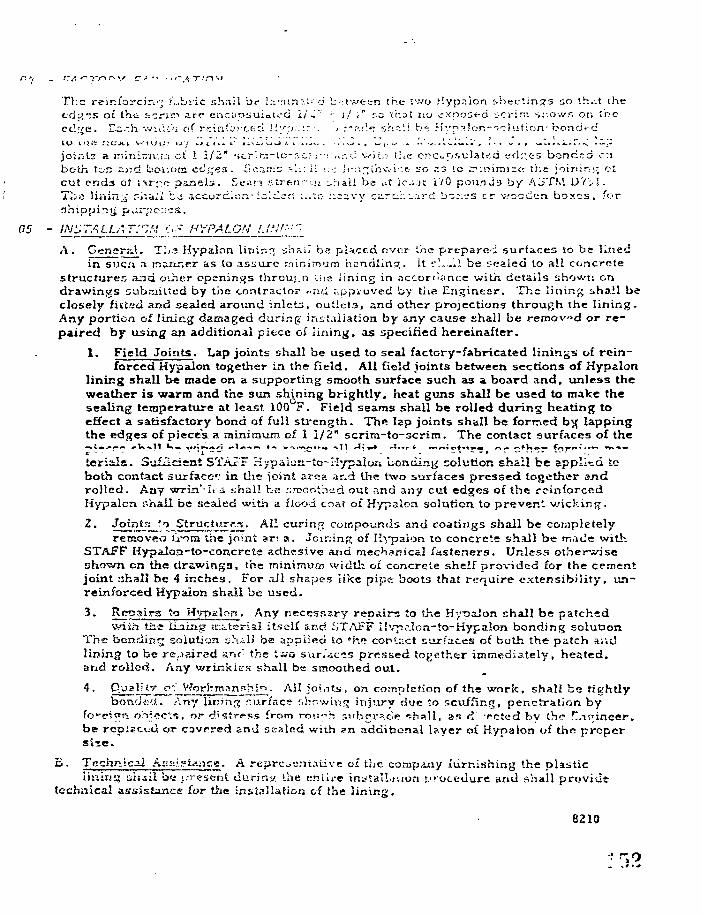
The reinforcing ?;.,bric sh.iil be l,v:un:.l- d b>twten the two Hypaion sheet ings so th.it thetdi-CiS of th t i-.zriv 3.rv enciiosuiaU'G 1/L~ '•• \l V r.c that no ^xpost-d 'jcrini si-.ows on :bcct!;ve. E~-h wn'u'-i of r.vliii'o; ced 'i'-'p:.:: •. J r.-r>.<'~ sh-:':i b~ H\'p->!on-'".o)ut:on- bonded
joiats a uiiniMv.iJi ot 1 1/2" scrlni-'.o-r.c; r•>. ;,.:-. c wit/: il.e encapsulated edp.es boncsd onboth top ^)?d bouom cd^cs . £io."irr:3 '-'.:- il •.: : ;i-:i^ih\vi''.e Lro .13 tc ^".niim;<: ii.t: joinirj? otcut ends of i-M' c- panels . Scam stren^nj ^riali be *U ic-js i /0 pounj.3 by A3TM DV'il.Ti;a linin^ i-i'sa;! bo 5ccord.c:i-•iwld^tl :.;':o ! : ; ;vy ca re : . ^ rc i b~:;---s cr wooden boxes , for
05 - IN'STALLAT^.'i 6-~ HYPALON I.IN!'••",
A. Gongr.-d. T^c Hypalon lininr; ibaw be placed over ihe prt-parci surfaces to be linedin suci .1 ir:&nr;rr a,s to assure Mininvjm hcndlint^. It r'..—»i be scaled to all concrete
structure;; and oihcr openings throu;.n tise lining in .-sccorfi3nt:e with details shown ondrawings subrailtcd by the contractor -ar-i ;-.ppiuved fay the Engineer. Tlie lining shall beclosely fitted and seaied around inlets, outlets, and other projections through the lining.Any portion of lining damaged during installation by any cause shall be reraovd or re-paired by using an additional piece of lining, as specified hereinafter.
1. Field Joints. Lap joints shall be used to seal factory-fabricated linings of rein-forced Hypalon together in the field. All field joints between sections of Hypalon
lining shall be made on a supporting smooth surface such a3 A board and, unless theweather is warm and the sun shining brightly, heat guns shall be used to make thesealing temperature at least 100 F. Field searas shall be rolled during heating toeffect a satisfactory bond of full strength. The lap joints shall be formed byj lappingthe edges of pieces, a mini mum of 1 1/2" scrira-to-scrim. The contact surfaces of the
ierials. Sisfiicisnt STAFF Hypaiuri-to-Kypaloa bonding solution shall be applied tcboth contact surface1: in t}ic ioint area ar.d the two surfaces pressed together ajidrolled. Any wrin'-.i. s uhall be smoothed out and 3xsy cut edges of the rc-inforccdHypalon r.hali be sealed with a flood coat of Hypalon solution to prevent v/icking.
Z. Joints to Structures. All curing compounds and coatings shall be completelyrecsovftcj U-oca Uie joint ar< n. JominR of "•j-paion 10 concrete shall be made witli
STAFF Hypaion-to-concrete adhesive und. mechanic&l fasteners. Unless otherwiseshown en the drawings, the minimum width 01 concrete shelf provided for the cementjoint shall be 4 inches. For all shapes iike pipe boots that require extensibility, un-reinforced Hypalon sViall be used.
3. Repairs to H'rpalori. Any necessary repairs to tJie Hypalon shall be patchedwith the LLiing rcittersai itself and STAFF II\7iaIon-to-Hypalon bonding solution
The bending Siilutian yhail be applied to *h<? contact surfaces of buth the patch a;\Jlining to be repaired anc- the two sur/acis pressed together immediately, heated,and rolled. Any wrinkles shall be smoothed out.
All joi.Tf.s, on completion of the work, shall be tightlyh
;:..,,?, .yp geO.. Any lining ?:urfac>? r.ho'wir;?; injury due to scuffing, penetration byy^c'in, or di'stres.'s from rou-h sub?r^c<e r-h .H, »«s d rcted by the
be repiscvd or cavpred and sexlnd with ?n ,-idditicnal I?>.yer of Hypalon of the propersi ie.
^ • Technical Ass-.»l.ijice. A representative of the company furnishing the plasticlining iih4il b<a ;.-rescnt during the en Lire inyta'l^uori procedure and shall provide
technical assistance for the installation of the lining.
8210
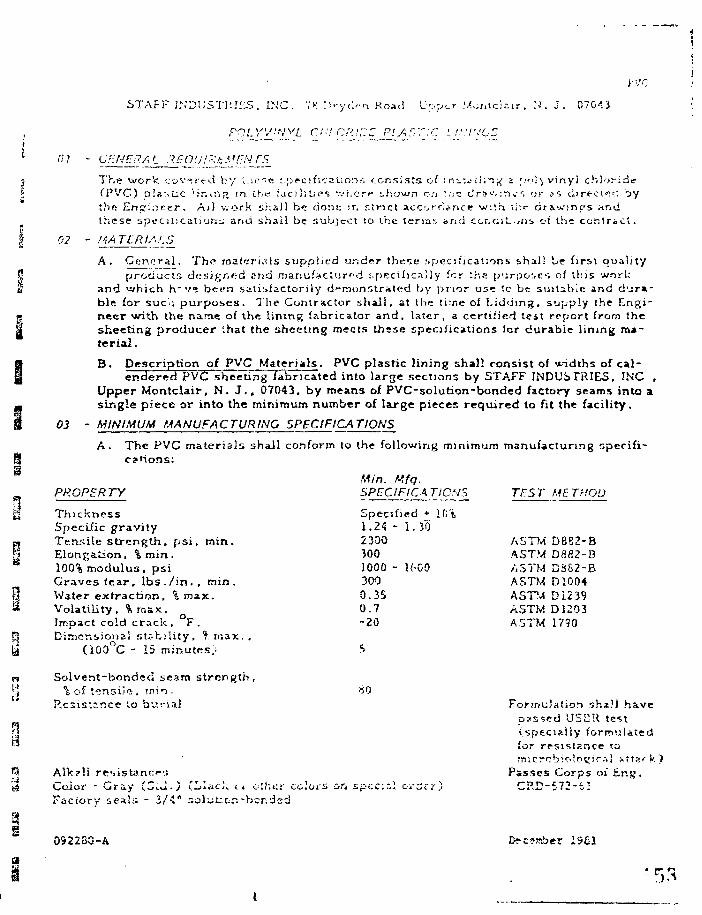
JVC
STAFF 2NDi;STi'.!::-S. INC. >J n*-yc>n Road l>;.p'_r M>.r.tc!^r, N'. j . 07G<S3
rOLYV:'<'vL d-'! C•'.)['.'Z P'.A'~T;C i/.'.7VGT
n
03
The work covered by l : i ce t-prcificaUon-i consists of inu".^ii;T^ * f.-oiy vinyl chloridefPVC) plastic 'Jr.in;> tn the facilities '.vhcrp shown o/i ':.£ drsv.-.n^i or ,is direel's^ aythe Enfr;:icer. A;l v.ork shall be done ir. r.trict accorrj^nce w:th ti-.-r drawings a.ndthese spiroiicaliouj and shall be subject to the terms and CGr«c;jL.,ns of the contract.
- !4ATLMM.5
A. Gen.gr al. The materials supplied under these .specifications shall be first qualityproducts designed sna manufactured :.pecil»ca51y for ihs purposes of this work
and •which hrv» been ,ss.ti'>iactori)y demonstrated by prior use to be suitable and d'jr«-ble for sue':; purposes. The Contractor shall, at the time of Lidding, supply the Engi-neer with the name of the lining fabricator and, later, a certified leit report trom thesheeting producer that the sheeting meets ihsse specifications for durable lining ma-terial .
^ ' Description of PVC Materials. PVC plastic lining shall consist of \*--idths of cal-endeTed PVC sheeting fabricated into large sections by STAFF INDUSTRIES, INC .
Upper Montclair, N. J . , 07043, by means of PVC-solution-bonded factory seams into asingle piece or into the minimum number of large pieces required to fit the facility.
- MINIMUM MANUFACTURING SPECIFICATIONS
A.cations:
PROPERTY
ThicknessSpecific gravityTensile strength, psi, min.Elongation, % min.100% modulus, psiGraves tear, lbs. /in. , min.Water extraction, % max.Volatility , % max .Impact cold crack , F .Dimensional stability, % max. ,
(iOO°C - 15 minutes.;
Solvent-bonded seam strength,% of tensile, inii-
Resistance to buria!
3 the following minimum
Min. Mfq.SPECIFIC A TIONS
Specified * 1G%1.24 - 1.3023003001000 - 16003000.350.7-20
manufacturing s]
TBST ME THOU
ASTM D882-BASTM DS82-BASTM DSS2-BASTM D1004fiSTA D12J9ASTM DJ203ASTM 1790
60
Color - Gray (CiJ.) CLlacl; u oiheFactory seals - 3/-1" r.olut:.or.-bor.dcd
Formulation shaH havepassed USDR test(specially formulatedfor resistance ttjrmcrob;o'o£''r-il *t.tsf k
Passes Corps of bnsj.
0922SQ-A
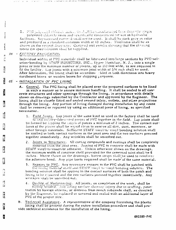
Ii
r? . - , - ' ' " . . '• . . V .- : . i . . ' . , . t - *. \> ~ , . / . .... ~ f - -, _ , 1 . - ' : ~ - . : * - ~ - r-.' '~J ' * ' V - ' ^ - ' ^ - * > « > . . ! - ^ - • * ' . * * . . « l l i L . f . ' . J > . . - . - ^ J » . , ^ . . . M l i W - i ^ . * . ! . • - - . — — - . - . . . • « - - - - - ~ ' ' - ff ' *
I polyvmvi -J'IU.T j-.i;- resin and specii; calty cniiiU'C-'-"!': t*d ror uje in hyd:-«uhcfacilities. Hor-vocc:".-it:tj r.i:»t-.-r" :".l kh.ul riot be used, it :;huli bu dark ft:-;.y :r. colorand produced in a stantJ.-srd juiniwum width o! h3 inches. Thickness shall b«- ss
S chovr. en the pr.'.jcct :h-L::\'r.•:.:•• C;.:rtii:cJ test rrrui ' .s sh^w:r.^ thai the sh'.-'.1ng» meets U<e spccocnl ions sho.il be suppl ied.
=. M ' FACTORY FA ^-'iCA r'lON
\'t Individual widlhii of PVC r.iateri.il«-. ;'ii;ill be fabricated into large sections by PVC-sol-urioTi-bondiny by STAFF INDUSTRIES. INC.. Upper Montc/;iir. N. J . , into a single
5. piece or into the minimum number oJ pieces, up to iOJ fret wide, as are required to?! lit the facilUy . l,,;p joints with a minimum joint width oi 3/4 inch shall he used." After fabrication, the lininp, shall be accordion- : Ided in both directions into heavy
cardboard boxes or wooden boxes for shipping ^t'rposes.
I 05 - INSTALLATION OF PVC LINING
A. General. The PVC lining shall be placed over the prepared surfaces to be linedg in such a manner as to assure minimum handling. It shall be sealed to all con-§ Crete structures and other openings through the lining, in accordance with details
showis on drawings, submitted by the Contractor and approved by the Engineer. The•B lining shall be closely fitted and sealed around inlets, outlets, a.na otwer projections| | through the lining. Any portion of lining damaged during installation by any cause
-hall br: removed or repaired tsy using an additional piece of lining, as specifiedhereinarter .
iti}j 1. Field Joints. Lap joints oi the v,Ame kind as used in the factory shall be usfid
to seal i.^cvory-fabricvited pirccs of PVC together in the field. Lap joints shall., be formed by Kipping (lie- <. cj;cs oi pieces a minimum of 2 inches. The contact sur-<:1 faces of the pi fires shall be wiped clean to remove ?A1 dirt, dust, moisture, or
other for.-:ic!n materials. Sufficient STAFF vinyl-lc-vinyl bonding solution shsHbe applied lo both contact surfaces in the joint area and the two surfacrs pressed
n together immediately. Any wrinkles shall be smoothed out.2. Joints to Structures . Ml curi.ip; compounds and coatings shall be completely
removed Irorn the jomt area. Joir.inft cf PVC to roncreic shall be made withK| STAFF vinyl-t'j-coricr;;te adhesive. Unless otherwise shown on the drawings,t J the minimum width of concrete shelf provided for the cemented joint shall be 6
•riches. Where shown on the drawings, batten strips sti.ill be used to rcinforci-T\ the adhesive bond. Any pipe bocts required .shall be made of the same material.
•*• Repairs to PVC. Any necessary repairs to the PVC shall be patched withtl-.o Ii.-.'iri, m^tcria! lUci.'imi STAFF vir.y 1 • to-vinyl bonding aoiuticti. The
; bonding solution shall be applied to she contact surfaces of both the patch andS lining lo be r. -paired -xnd the two surfaces; pt essed together immediately. Any
wns'ikiPS -shasi be .'smoothed out.
';,? 4. Quality of VVorknang.hip • All loints, on comyjl^tion of the work, shall betiiliit'y bonded. Any i'.ning sur'f.toe shovinp injury due t.o .'-.cuffinij, onTtt—
iration by foreign objects, or distress from ronnh r.ubgrade shall, as directed^ by the Eu^mccr, be s (.placed or covered anu ^crflcd with an aiiiiiuon»I ijyer ofEl PVC of the proper sire .
B . Techn2£.aj_ AjiSi£t5£5£- A representative of the company furnishing the plasticlining shali be presi-rnl during the enfire installation procedure and shall pro-
vid» technical assistance for the installation cf the lining.
092280-PVC
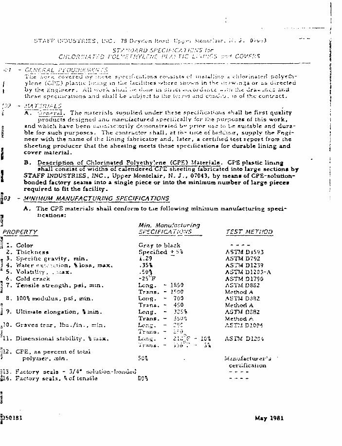
STAFF INDUSTRIES. l.NC. 78 D.-y«\-n Kn?ci V**.;:r: .v.&m.-.'air. W . j . 0'<•«.•.• 3
5 7/ '-OARD WLCihlCS, no:,'S forc:-::.CR!.l:ATr.D roz.v.r;'!J.YI.L,\--: PLASTIC Lr;!-:cs .••* CQVPPS
.;. / -Tiic .v.trrt. covered oy ::-.':ie s;\-c:f,c;.t^or,s cc.Mbts ofylcne (CPE) pla.'Ut iw,;:ij.; in i'.it' Ucihties 'vlicrc ^ii'.'wby the iinqincer. All "vurlv. sh.u.1 ."": u ,nf ui i.'ijci f.uiithf:.r! spccuu ' j t ions and £.hj*l be >ubj>?>:t to the U" ri3
aliiri',1 ^ i-hiorinsteri po!y«£i-n in the lit ;u-.n.^s or ^i> directed
mi cci-iu-U.-is of the contract .
A .
\03
Oi'nTcX The rri.itcri^li •juppiied unJer thj-se specificatiofm Khali be first qualityproducts desifjnccl ^;JO iriarjuiacturrd spcrciiicaliy for Ibc purpose* of this work,
and which have bec-n :^\it^c'.ozily d<l.!nonstr*i«:d bv ' pr ior u s : to be suitable and dura -ble for such pu rposes . The conti-.-.ctor .-.hall, at th- tu'-,e o: bir<c;r,«, supply th« Pnpi-neer with the name of the lining fabricator ar.d, later, a certified test report from thesheeting producer that the sheeting meets these specifications for dur&ble lining andcover material.
B. Description of Chlorinated PolyethyVne (CPE) Materiala. CPE plastic liningshall consist of widths of calendcredCFE sheeting fabricated into large sections by
STAFF INDUSTRIES, INC.. Upper Montclair, N. 5.. 07043, by roeans of CPE-solution-bonded factory seams into a single piece or into the minimum number of large piecesrequired to fit the facility.
- M'NMUM MANUFACTURING SPECIFICATIONS
A. The CPE materials shall conform to t.ie following minimum manufacturing speci-iic»tion»:
PROPERTYMin. ManufacturingSPECIFICATIONS
a] Jk •
2 .* 3 ..3 4 .* 5 .
6 .3 7 .
,10.I
ColorThicknesnSpecific gravity, min.Water rs'.v.ttion, %loss, max.Volatility , . :,;as.Cold crsck
Tensile strength, psi. min.
100% modulus, psi, min.
Ultin>ate elongation, % xaixi.
Graves tear, lbs. / in. , " in .
l stability, % asix.
Gray to blsckSpecifiedi.29.351*
• S 0 $
-25 FLong. -Trans. -Long.Trana. -Long. -Trans. -
Trar.a. -
Iran*. -
18-301500700450325%
TEST METHOD
ASUS Di593AST?.* D792AS7M D12^9A5T?^ D12Q3-AASTMD1790ASTtA DSS2Method AASTM DSS2Metiiod AAST>-i D282Methoci AAETT.! BIOC'S
ASTfA Dll'C-i
313.
CPU. as percent of totalpolymer, sain.
Factory 3CEis - 3/4* doTsctory seals. %, of tensile
ecriirication
69^
P501B1 M«y 1981
: 5 . <".']•'. c ! : l " r : - . . ' .'•-•<i j>o' y ! . 1 - y ! - n c r u l e : 1 o j s :.:.r.;l b e rr.zn j.:~ct\ircd f r o . " lioritesJiC v i r g ic h : ^ n n ; ; t r o •,.-: •; yc -my j r i r. i . - r m t i ' . i • •.•:•!_ I !:iv.i lv c o j . - o c u r i o c u :'or i'...* i n h y d r * - U i i c
: . r i ! | ' : ! - ^ . ; . • . . , . . . . . . „ . . „ . • . , . . . . . . . . . . , < • - : ' - • . -. . - , A . • ; . • • . . i ] ^ , . „ , > . • ' . . , . . . . , | . l r . - V
tL'j-.-r ind pro^.j- ; ;! in i ;.•.;;:•. ra r::r.;r-!'.:j.i v-.cai o! cl i;v:r-.ts. T.'iiCK'irsa sh^ii !;c £.3r,h.v*n en the ;.T-i..j<-ct cir.i v.-\:-. .~:i. Cc-rliiicci test r rsuhs showing ihat Ihe sheeting rrjccthe i.ncciijcalio:)^ !»haU be MJpiiii.^d.
Individual widths of CPE rr.a:f.rials sii-.ill be fabricated mio I^rive Eectionf by CPE-solu-lic!i-t.ond;nf{ by STAFF .'NnUSTKIr^. Inc . . Vpper Mor.tobir. N. J . , 07043, into t singlePiece, or into the- minimum nuinDer ot pieces, up to 100 fret wide, as required to fit the(aciijiy . L*p jo;;i!5 with a m in; in urn joint oi 2/1 inch sh i l . be used. After fabrication,the iimnc; L-i>a!i !"•«? accor-'lici-fakicd iii both directions into heavy ciidiiOird boxes orwooden boxes, for shipping purposes.
- INSTALLATION OF CPE LINING
A. Central. The CP2 lining shall be placed over the prepared surfaces to be lined insucTTa manner as tc assure minimum handling. It shall be sealed to all concrete
structures and other openings through the lining in accordance with details shown ondrawings submitted by the contractor and approved by the Engineer. The lining shallbe closely fitted and sealed around inlets, outlets, and other projections through thelining. Any portion of lining damaged during installation by any cause shall be re-moved or repaired by using an additional piece oi lining, *s specified hereinafter.
1. Field Joints. Lap joints shall be used to seal factory-fabricated pieces of CPEtogether in the field. Lap joints shall be formed by lapping the edges of piecec
a minimum of 2 inches. Tha contact surfaces of the pieces shall be wiped clean toretnovft al! dirt, rfust n-nJ«hn-»y .->»• «FI..- (, — z'-~z\z. Z:."-ticizi*l 'ZT.'ST CTCtc-CPE bonding soluu«« ahzU. be applied to Ixuh contact surfaces in the jolm areazr^d the two surfaces pressed together immediately. Any wrinkle* shall b*smoothed out.
?•. Joints to Structures. All curing compounds and coating* shall be completelyremoved Irom the joint ar?a. Joining: of CPE to concrete shall be made with
STAFF CPE-to-concrete adhesive and mechanical fastener*. Unles* otherwiseshown on the drawings, the minimum width of concrete shelf provided for tlmcemented joint shall be 4 inches. Where shown on the drawings, batten strips
• shall be uued to reinforce the adhesive bond. Any pipe boots required shall bemade of the saxue material.
' • ^*ya ir* t o 9^.* A n y "ecessary repairs to the CPE shall be patched with thelining issaicriai »t««lf suid STAFF CPE-to-CPE bonding solution. The bonding
solution shall be applied to the contact surfaces of both the patch and lining areato be repaired and the two surfaces pressed together immediately. Any wrinklesshall be sraoothnd out.
£• pli*li;Y of ^orVrr:an?hin. All joints, on eocr.p'ction of the work, shall be tightlybonded. Any lii-.unj iiul'we sHo«fiiig injui-y d"_;e tn scuffing, penetrstion by
foreign objects, or distress ft-ona rous-h subgrads shall, ae dirrttcd by the Engineer,be repUcc-a or covered *.nd tictled with an additions! layer of CPE of tha proper *»xe.
XH;!ill£5?.._fIii;ll!?. v v e of the con»p«\y f«s.mF«h5.iig the plestic liningahsJt be present during the entire installation procedure and tball provide technicall l U i i i oi the i
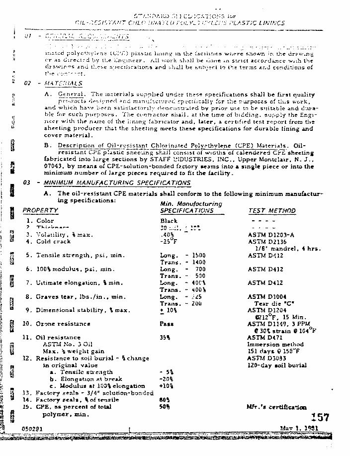
r.ti.-r.r-ZI^TAHT C.'ILO.il.'JATLO rOLYi.: ir-'i.£f:£ PLASTIC LIKINGS
ir-.-f.cd polye'-'-.ylrrie 1<J:'J~.) pi^-s:jc limns/ sn the facilities wi^crc sho*T. in the gcr s i direct rd by li.« iinuir.etr . All work shail i>e liont in strict icf.ordajice w*ih thedrawirrra *nd ti.cne s:>ccij«cauorj* and thall be su!>i~rt to the t-rr.-ns t.ri-d conditions cf
A .
and which havr
' s materials, supplied und;r tfcss* specifications shall be first quality.i'/.ne<x, ?nd nrAn'.if-.cs-jrt.-f- rpsc:iicsily for the r u r p o s t s cf this work,.t^r. satistactonly ( i rornssr i i fd by prior u^e to be suitable and dvira-
03
ble for such purpo&c-s. The ci>nrractor snail, at the time of bidding, supply the Er.gi-iiccr with the najirc of the i;ninjj fabricator and, later, a certified test report irota thtsheeting producer th&t the sheeting raeets these specifications for durable lining andcover material.
B . Description of Oil-r c i stint Chlor ina!«d Polyrthvlene (CPE) Materi *Vs. Oil -resistant CPE plastic shceung shall consist of widths of calendered CPE sheeting
fabricated into large sections by STAFF INDUSTRIES. INC., Upper Montclair. N. J - .07043, by means of CPE-solution-bonded factory seams into a single piece or into theminimum number of large pieces required to fit the facility.
- MINIMUM MANUFACTURING SPECIFICATIONS
A. The oil-resistant CPE materials shall conform to the following minimum manufactur-ing specifications: ... ., . ,
° r Mm. ManufacturingPROPERTY SPECIFICATIONS TEST METHOD
1. Color
3. Volatility. %max.
4. Cold crack
5. Tensile strength, psi , min.
6. 100% modulus, ps i , min.
7. Ultimate elongation, %roin.
8. Graves tear, l b s . / i n . , min.9. Dimenr-ional stability, %tnax.
10. Ozone resistance
11. Oil resistanceASTM No. 3 OilMax. to weight gain
12. Resistance to soii burial - h changein original value
a. Tensile strengthb. Elongation at breakc . Modulus *t 103% elongation
13. Factory seals - 3/414. F»ctory !?e*).B, % of tensile15. CPE, »* percent of toUl
polymer, mia.
Black20 :•-•.:!,.40%-25°F
Long.Trans.Long.Trans.Long.Trans.Long.Trans.+ 10%
, in*
"—
- lbOO- KOO- 700- 500- 40C\- 400\- US- 20U
- - - -
ASTM D1203-AASTM D2136
1/6P mandrel. 4 hrsASTM D112
ASTM D412
ASTM D412
ASTM D1004Tear die "C"
ASTM D1204
Pasx
35%
- 5 1-20%
50%
«B12°F, 15 Min.ASTM D1149. 3 PPM
e 301 strain 9 104°FASTM D471Immersion method151 days Q 158"FASTJ.4 D3033120-day coil burial
Ktfr.'s certificated
157u ~".zr.:
ii . CVi'. ch)arina.t:-d o« lyc thylcn- ; rxiiTi-:riyJs fha.il b? r.i.\i*\)l?.r l u r « d fr^nu cioreeciic v i r g i rr-hlorLrstEd poiYs-LiV.'itrjc rc?.;« sjici i;>cci;!C- «ly ci-^~-ou.rj. ca .o r u s e in hycir&uiie
shotvn c.i the p r o ' v c ! dovxtr jge . Cv.rU:j td ic«;t r-.r--Jis th.i-vurrj c'ixJ t h e ehee t jngt h e rpcci.acfsiionj! Ehjiii Dft su(">piif.d.
IndividnsJ widths ot Cl'E rr.atcriula r-hall be fabricst--d iwto ' . i rro a-ectiorxs by CP.I-solu-t ion-i^TuLis by ST/u-r Ls;i)U5Ti UII5, I n c . , Upper Hcr.ttlxir. N. J . . 07043. into c singlep iece , or into liie w.in;rovi3) number of pieces , uc to 10i» f^cf tri;1c, as requi red to fit txi<facility . Lap joints with a romirnu.ro loin: ci 3/4 inch shall b t used . Alter fabrication.the lining shall be 2ceoj.-cijon-folded in both directions into heavy c?.r<:board boxes orwooden boxes , for 1.2-appi.ng purpes t t s .
05 - INSTALLATION OF CPE LINING
A. General. The CPE lining shall be placed over the prepared surfaces to be lined insuch a manner as to assure minimum handling . It shall be se*led to all concrete
structures and other openings through the lining in accordance with details shown ondrawings submitted by the contractor and approved by the Engineer. The lining shallbe closely fitted and sealed around inlets, outlets, and other projections through thelining. Any portion oi lining damaged during installation by any cause shall be re-moved or repaired by using an additional piece of lining, as specified hereinafter.
i . neiq jotnss . Lap joints shall be used to ses! fsrfcry-fsbricit-d pircrs of CPEtogether in the field. Lap joints shall be formed by lipping the edges of pieces
a minimum of 2 inches. The contact surfaces of the pieces shall be wiped clean toremove all dirt, dust, moisture, or other foreign njatcri&ls. Sufficient STAFF CPE-t.o-CPH horidinp, solution shall be applied to both contact surfaces in the joint aresand the two surfaces pressed together immediately. Any wrinkles shall be
• smoothed out.
' • Joints to Structures. All curing compounds and coatings shall be completelyremoved irom the joint area. Joining of CFE to concrete ohill be made with
ST/FF CPE-to-concrels adhesive and mechanical faBteners. Unless otiierwisesbov.~n on the drawings, the minimum width of concrete shelf provided for thecemented joint shi.il be 4 inches. Where shown on the drawings, batten stripsshall be ustd to reinforce the adhesive bond. Any pipe boots required shall bstsade of tJhe saae material.
3 . Repairs J.o CPK. Any necessary renssirs to the CPE *hall he patched with the\w\n3~ny-M?r':l.)l*?zlf ':md ZT*S? C?Z.-lz-Cl~Z bcndi:;g solution . The bonding
solvtion shrill be spp l i r J *•:• i'>c csnt^ct surfaces of S>cui *5»-i patch and lining area*.n b*» Y-.->-»\T*'?. frA rhs two -vrfscc-s prcrscci ts^i'.'J'.c-i- ic;r/,;d:itcly. Any wrinklesEha!) b? erxv^th^d out.
i . Ci-i-atit-y j--f y ^ r ' ' ;v. .^••^ Ali jcii-.la, cn trcsspJclJOj; of the wc-rk, &hall be tightlybonncd. Ar«y i i n i r j «nr<5cc sho^'fDjj inivury d u : to scu£S.~g, pirsctrsticn hv
ol>j*cij«. or <-.'.- ir B* urota *r>»»«ij subsjraris shssi, »s directed by the Engineer.
B . TeciuucaJi Atfeifctgr.ca. A representat ive oi 1h& cor^psny burnishing the p.-astic liningSHll be pre»«n» durxing; the cofcire instsl l i t ioa procedure »nd fhsAl provide technical
for ihe in... tall at ion o' Use l in ing .
s
STAR- i;\!DU3Tf- .13 !.VC £-C0 C< -:*>:* S
. r^vrn-xm- r:.-',
98
-V.n;-^ '"•'-u liiafoctwJ :••«: Lr<r.v.i<>.r<v3 n s : , . . y'a* f.r.j! : j'c tviKjs iroparf i-v-t-jid. LJ./J?.! u-stiCiai>? tu w;. i a oi'! i j f«-l :•? !:T.; ^ t o to w^'uts cfin «rs :«•».•» r:'i':s3. Rt>r:*;is<« r<xvent u vuvptsoi for
ftg jectkwa in 11.x fsfiJ white s K usaaxrtf lo covw
We ttccatasai tbet tS Bom for ponds, ecrvosrt, taaocat, etc..be covered wiih rent) for mcduckal proucuoa froso tniiB&ta,men. cad we&tbcr. However, «hac ucscuwy. sad trbca they etabe property protected. linias nultmit wkh superior ouldoarduraeniky may be used u exps:«d mensbnuic*.
SuiT iBdvscnet fi.brk»U3 br|* linen for tue i* tfructuritt deugneduxi constructed bj cKben. Tb; foitowint i&afi sent ufor the use of Suff teepege prevention
1. S!TE P1EFARATJ0Nt nc uno'to wtiw «rsi
07
sea FZ, fcriovr, 1 AJI sh s, esti
or cov-crcd KSL5? T.TC noiL Area? (c.'<££i.t!ic-vi i;;-( £".tES Aftdl<j»*(;i J3~iws sih.iuii hs swr-i-iicd. FnE>3oi.-iy, tbs s/c* \o t<s coveredshould be rt^tei (o r/fea ccntpsctioa ted lasecxbias so a* tored-.' s: "joe?: Krctw* on liis RKmiiOtnE. Ai a« tints cart: iiwiiUJ betskoa to prrrcs* p^ac i^a j cf lia: bna tiaring icstiJ.s#(;tin ariif use.A perKS«t« trc»c& S u 12 iadact iquare, SSOFV? list wsicriirc is
reverse jkfe:.) Note Kssscsr UtE3««.
2. HfCJH WfATES TASi.£ Afx'O OfiSSY AREASIf ffnmi are i.r«n-.i«l over fte-cferwoas RiWrnsu* K»^I i«
ssi, bc j i , etc., w ta fcrr*s oJ" ('ucit^siss WS>J?T IBWSJ m-aid*
to we:a ssxi yae a» i the fscl End. va;fe? K-as*, lbs U3;T IL«3 verylitlte wc~?a. Wharr svcil ca*<tilki«s c>:*S4i mes . spaces fatcsa-
' ,.i<ii.<J!y ij-vioj" t;vs tjsir. /lisa, :* :'s ;'lrisi-.r.'.7 rx£-c^is~'.i^a lisa!?J w~y,-^t
ia w etna aj ,nciivo<ii.
?» fcitfcrf s-ri-3 first Irnnl ci-*:^. barter, osr
-j iSs srte c' Hit ro."ii-"w»_ If « r t * U> fcs iss'orrynrs-iv ;— er r'aaa a SJC?« psscc *-;2 ctwtr, SC-UORS tas
R is i3v; r«iJ w c -'-'cr any cria, rrjs--re'-r5. s f i jg .
jctvtcii*r>i.-"' K f i T ' i ! ."' x i J ft. ixicni u [••a-TCiusrly tui'st«.•••! v^a !.--i '/'-cd iW.-iTiT c-n Cry '.jae.v.5 or ca iu-r igr>.'.'-A 'l"be !ifia:d t>fl-«;j i*; ci.'i;»ia wit?! k 1/2 itch rtoi:id tbi< e«d V-VT.UJ Li u x ^ e i bo.-.!iii:t. A iUM: boliiKn tixl E t u < l t « m (.he top ai!»w» t- e Utkiaf M warning u rj,Tif.Utcd for i is lensib of Use ho^rd. We «J-vve. uii«$ Ui cijusvaJvjjt o<s. coucc tan iiUed "«;h *>o»'t 2-3 ixiictcf wSfcshie sod a 2" bririie bn ji . IIJJS Icicaj Ihc d/u 4.1 of tn ir»-•dveneut vjsiL After rc<^>tionis( (he to i>ejc4se4 ptxxis Iroffhtnuewe Bonniitfy «att ia tie cenier placing the board in Jecrr(trof«2to 4" purriip. Utcnf 1 bruth raoovc *3 itad froai urm jcdljacesl 10furfactt to be y&wed (a «t i res mi ht «ho be w e s u i y ) . Usinj mcraesieac overitp, piMe pestuoiac weights on both c x b anj ia(inter. Lift top fbp tuoufh u> re»tn wet brush acd wet both sor-fecet for <boal IS mc^x. Kub lightly at P.ru then apply more ngpruture. Kerp OOMTJ »>OSJ ressovi^ji CCBUT weijh' as you t<? by.Slop r-'xxit 2 ft. frr-fli CTV3 of board usd p;jil board abtad. KcnsmtpstJOeCarc. A5wxr4 have iheel pertcary ia iir.* t'fese KtrtiB5 pa-
u u >I w-.illowtrd wiigri yc« stiaiej " ire ixx «lk>ved w
After ihc IM3 a co;>-v5«.Ki. tfcr boadinn driven: «-iii hsv« tsmjedso ih*i il* i;.^rj ii<:^i SSJIIOQ csn be
«JXJ iacsf-x: «tci.;.a FC*hkJ!»sJ tnd b c ^ -«i. ':'s!H tucTgaJi (kvnop* in 5 to 15 nawia , l?as pwi i.rt£;iK -e-qu<rct sivcrti) deft for tosVcst c!iij;rrtt>oa. iWinvE sr.auM Jc carifu!-!y triipiciai, xfs^ * kslf fco«r or tntxz, to descct «sd rose! sayrot;* in i le wnsia.
lUfer to scsi^icsi inuruoJosa csa tlse febd of tbc m&cavc
«.Fcr
tiris sias. A;o»wS i.;p» vz Ks
c., s-r
t - .v^ ; i Us ".Lz o.-,r>rsr«S:i3 £hs* sS lifl-
«i«ia sasj
«3 feiias ww? no* t»5(e pfes*. A w « f 'sr
i
f5 <Ji Jsraiwjei' sseai-
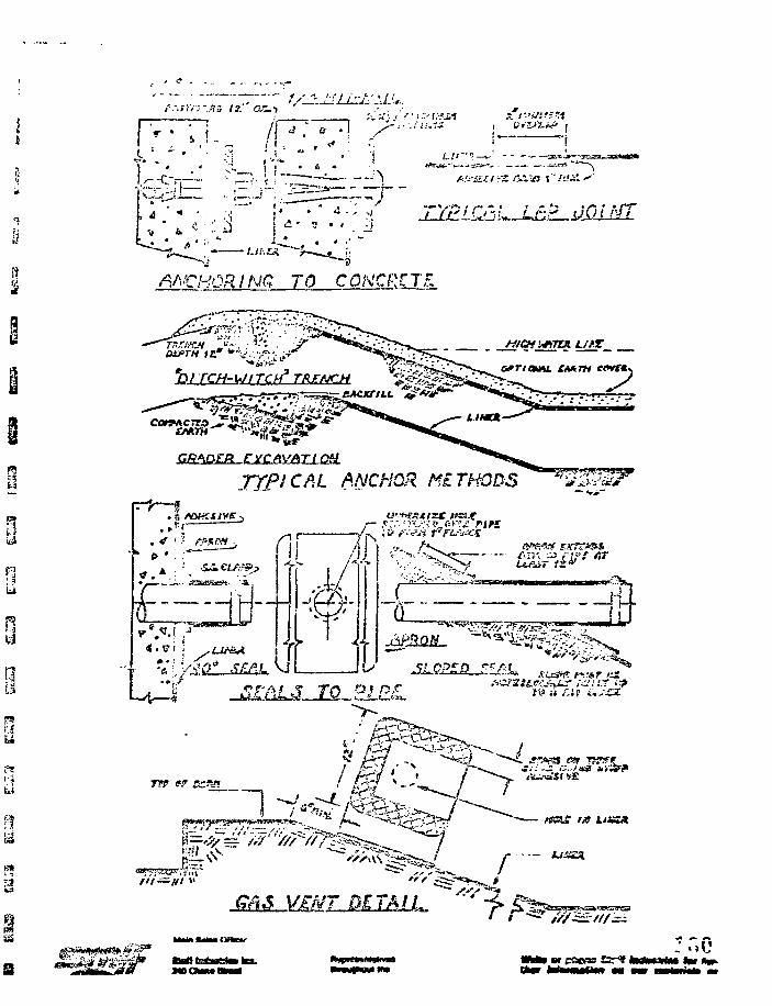
"5
Li
ANCHOR! NCI TO CONCRETE
^3/ TCH-WITCH* TRENCH
F*—f
. . • /
U. ANCHOR METHODS
or 41-CN.
-@-
• £-r-CT
73 i-ry^a i-.ta
01 - (g SSgTO?.Tpag StKFACZS
A. grgTwurfttloa of Efrth Subrange. He eurface of tee •ubjr/ra<3« »b»ll beprepared by exciTatijifl; aha triesalc^ the earth to elera.clooa mnii aectloaaaa abova on the 6,avl2g». The pxepared •ubsrad* fhavll b« free froclooe* eaxtfa, reck, cobble*a rubblah or other forel$a emterlala. Thesurface at tb* eoc^leted aubgrade thall be maoottt, unlfora asd free fro*ertktas cfc*B5»» in grade*
II. A» directed by the Sngia-1 ! i l ^o , la Uxt ''xtoibs ttrcs S tra grawai^/ cit'Jrlds cc=*sd?J J3.; Lsr»» c
or bo^LJeri cxia-fc, tbe^a eaterials tsbali be esea-ratisd ta a depth cf »_ BJnlsasi <s£ 3 ischra aiai t l« areea b&ckf ULLsd *£ i ccap«fct«d to grade wltis
<ri-psows
eatlra Biitf- rfflSs"iwali be ireed
fer iast»lla.tloa cd"
tfc a JO poussdsrallwr c4s«JJ. &«
by
p of the e«xth oub-roiler cs a E'Cc«l vti«el
iir.ear liict of drua vlstli. 3Voecceesible to tba
ZG c? P'l -j shall b«la a ecadltir^ o? the
S*
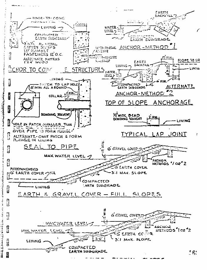
PN.CAO& - ME7H Q D _/
f-.^TCM TOfi>" JViSXs. ALL AROUPiO
/
0COLLAR-?-?SZ1
5ANCHOR-METHOD
TQPOfDlOPE ANCHORAGE.
BOHWHG SOtVEBTT am,
PATCH £ F O B M
SE.AL TO PI PLMAHWATSLR lXVt.L
TYPICAL LAP JO1MT r
©
I si
I a
1 3£ARTH ^ ..6.RAVLL COVPR — FULL SLOP5.5
APPENDIX D-2-5
WA7ERSAVER COMPANY, INC.
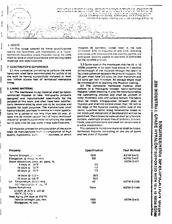
s ?T ? "* * " IT ' ?"*?• *L 1 i f ' ' ? ' ' ?**• "
1.1 Ti>«» scope cowffsd by ttwsscovsrs Uig fumishirKj ar.fl ir.siaiiation of & <r.Dric-rcinfOfcecl industrial rjr&c;^ Hypaion iinif^g. Alt «jorksrisfl be dona in strict accordance »itn tfte ersgirveersdrawings and specifications.
? CONTRACTOR'S EXPERIENCE2.1 Any contractor pronosirKj to partorm tha worts
nefCuod'Tr shell hava derrvonslrated his ability to dothe work hy having successfully installed ai leasttwo miliion square lost of reinforced membranelining.
X LINING MATERIAL3.1 The membrane lining material shall be fabric-
reinforced Hyoalon of new, first-quality productsdesigned and manufactured specificaily for thepurpose of this wrorfe, «nd shall have been satisfac-torily demonstrated by prior use to be suitable anddurfcbie for such purpesos. The manufacturer shallhave produced, and have in swvtcis in similar applica-tions tor a period of r>ot Scs t^sn one |1) year, atleast five (5) million square feet of tsbne-reinfofcedindustrial crade Hypaion matwia! utiiizirsg tf»s samesenm spat-il:ed for use urwler t ^ s e specificasions.
3.2 Hypslon utilized for encapsulation of the scrimShall bs manyfactured frrxn a composition of highQuality ingredients, suit:- ' -mounded, of which
Tensile StrcfKjth, v ', " ' in .Eloop*tioo, & Brs«k % min.Water Absorption, (max */t. gain), %
1«dsys© 73 °F
14 days © i:>3'(-30 rJays e? ii>6*F
Lo- Tem{>s!-cli!f», Co !d f "and,1/3" mantfro! (or 4 P..'s.. *F
104 T , 72 r.m.)Hsat Agifg, (14 days @ 212'F)
T6n3!l9 Strftrjjjth, psJ, min.Elongation, % min.
» synthetic iiiober resin is the soleel;:s'oinor. Zinc cc.-r.poiftKis of any kir^d. includingzinc cxicie, zinc sfKffrata and zmc liusimg agents, areproiiitHied. Ousting of)Gnt3 oi any kind of prohibitedon the tinishad pnxiuct.
3.3 Scrim used in the membrane shall be 10 x 10lOQOd polyester ot an open type weave ih.-t permitsstrike-through of the Hypalon through th» fabr^ tofac.iilale adhesion between the pl>es of Hypalon. Thefill yam must have 2.5 turns per inch maximum and2.0 turns per inch minimum. All selvage edges mustbe trimmed prior to applying the Hypaion coating.
3.4 The composite membrane material shallconsist of a thoroughly bonded, fabric-reinforcedHypalon rubber sheeting. It shall be manufactured bythe calendering process and shall be uniform incolor, thickness, size, and surface texture. The fabricshall be totally encapsulated between plies ofHypalon and shall not extend closer than 1/8 inch tothe edge of the Hypalon coating cither side of theiaonc. cxposea laoric along lonoituainai eoqes orroll stock and indications of delamination will not bepermitted. The composite malenal shall be a flexible,durable, watertight product free of pinholes, blisters,holes, and contaminants and shall not delaminate ina water environment.
The composite membrane material shall be fabric-reinforced Hyp^lon consisting of one ply of scrimand two plies of Hypalon.
Specif icat ion
1500300
1.01.01.0
30030.0
-45
Pass
1500160
Test Method
ASTM 0-*12ASTM D-412ASTM 0-471
ASTM D-213S
ASTM 0-1149
ASTM D-412
O
as
acCO
?c?33
m 2
x ™
si.
i f
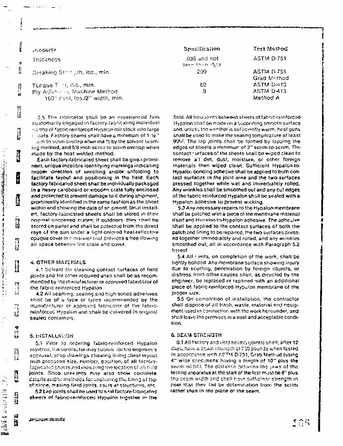
» Drsaking S i r : - _:ih, ibs., mirs.
f? Tongue T -r, ibs., mln.>; Ply A'j"! '"1-•••!. Machine Melhod
i&O" ro t ; i , lbs./2" width, min.
1
t i .
: jLi
i-
P
3.5 Th« i?bric3tor shall ba an expertencod fitmcuslomai ily engaged in (3Clory-iabfir.3img individualv.;.'th3 o! 1ab:ic-reinforced Hypaion roil stock into large• ,v3t3. Factory seams shall liavefc minimum of ^-Vs"
i:rr> to scrim cverlpp v/hen ma '•z by the solvent seam-ing method, and 5.'B inch scrim to sctim overlap whenmade by the heat welded method.
Each tactory-labricaied sheet shall be give.i promi-nent, unique indelible identifying markings indicatingnropof direction of unrolling and/or unfolding tofacilitate layout ana positioning in tho field. Eachfactory-fabricated sheet shall be individually packagedin a heavy cardboard or v;ooo>n crate fully enclosedand protected to prevent damage to it during shipment,prominently identified in the same fashion as the sheetwithin and showing the date of sh.pmont. UnUl install-ed, factory-fabricated sheets shall be stored in theiroriginal unopened cfatp**; if outdoors thpy '.haij bestored en pallet and sha'i be potectod from ths directrays of the sun under a light-colored heat-reflectiveopagua cover in .- mamier !.ia! provides a free-flowingair space betwoun the crate and cover.
4. OTHER MATERIALS4.1 Solvent lor cleaning coniact surfaces of field
joints end for oi^er re-quired u?es shall be as recom-mended by 'he manufacturer or approved fabricator ofthe fabiicreintorced Hypalon
4.2 Ail seaming, sealing and high-solids adhesivesshall bo of a type or types (ecornmanded by themanufacturer or approved faaricntor of the lahnc-reinforcec; Hypalon and shall bs Oclivere<j in originalsealed ccntainsrs.
5. INSTALLATION5.1 Prior la ordering fabric-reinforced Hypalon
rnsicrmi, liva co<tua^tof may suOrnii ior tiie eriginec-i sajipfovijt, shop drawings shoeing lining che-at layoutwilh proposal size, number, position, of all faciory-f2t?»ca!^ shoots rfrid irvdicaiing >.h» locsticn cf all fieldjoints. Shop o'ra^.inris may also show cotnnlfjtsCiCiiiia ar.Cor method* io; .ifici'iormo t.^u lining al topof slope. maNing field jo!"!3, sei is at structtft?s. <5tr..
5J2 Lap joints shall bs» used to s»sl facJory-frsbricatfvdshsots of fabfic-ioinforcwi Hy^dton iogether in llxs
Spsci f icat ion
.035 and not
2'DO
800
Test Method
AST?/ D-751
ASTM D-751Grad MothodASTM D-413ASTM D-413Method A
ItIT
•1
fiaid. All ficiJ join's beiween sheets of fah'ic-remforcedHypalon shall be made on a supporting smooth surfaceand, unlosi tne vts^ther is sufficiently warm, heat gunsshall be used to make the sealing temperature at least90*r. The lap joints shall be formed by lapp'ng theedges of sheets a minimun- ol 3" scrim-to-scrim. Thocontact ~urf3ces o! the sheets shall be wiped clean toremove a'l dirt, dust, moisture, or other foreignmaterials then wiped clean. Sufficient Hypalon-to-Hypalor. bonding adhesive shall be applied to both con-iact surfaces in the joint area and the two surfacespressed together while v«et and immediately rolled.Any wrinkles shall be smoothed out and any cut edgesof the fabric reinforced Hypalon shall be sealed with aHypalon adhesive (o provent wicking.
5.3 Any necessary repairs to the Hypalon membraneshall be patched witn a piece ol the membrane materialitself and Hvnaion-to-Hypalon adhesive. TP.e adheoivpshall be applied to the contact surfaces of both thepatch p.nd lining to be repaired, the two surfaces press-ed together immediately and rolled, and any wrinklessmoothed out, all in accordance with Paragraph 5.2hereof
5.4 All ' jints, on completion of the work, shall betightly bondad. Any membrane surface showing injuryd^'e to scuffing, penetration by foreign objects, ordistress from othsr causes shall, as directed by theengineer, be replaced er repaired "vith an additionalpiece of fabric-reinforced Hypalon membrane ol theproper size.
5.5 On comDlction of installation, the contractorshall dispor.e of all trar.h, waste, material and equip-ment used in connection with the work her«under, andshrill leave the premises in a neat and acceptable condi-tion.
0. S6.1 All t-sdory arid iicla seamr; (joints) shall, after 12
days, have a ; : am jj'.renyth at r:X3 pounds v.i"ten testedin accordance vvi'.h ASTM D-751, Crab Method (using4" vvirjB r,r.f>c:mens having n Inngth of 10" plos thoSB.irn wkiir.s. The rjisi^ncs intvvppn this jaws ol thetesting apparatus at tho start of the test must be 8" plus'.'no G?".T> tt'ioth and shnll h.?.vr> sutfic^ru s'.rsnjth inpeel 1hat they fail bv delamination from the scrimrather tnan in tno plane of the seam.
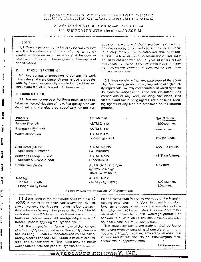
r X C
iSlfcVt.'Jii I^UUblHmL UHMUC—nirrtLU,« I J.045" SUPPORTED WITH 10x10 1C00D SCR!?,',
2. CONTRACTOR'S EXPERIENCE
2.1 Any conlraclor proposing to pcriorrn the wotkhereunder snail havfc demonstrated his ability to do thework by having successfully installed at Itast iwo ."nil-lion squars leet of reinforced inernDrane lining.
3. LINING MATERIAL
3.1 The membrane used for lining material shall befabric-reinforced Hypalon of new. first-quality productsdesigned and manufactured specifically for the pur-
1. SCCPc
1.1 The scope covered i v tr>er>e specifications cov-ers 1he furnishing; and installation of a fabrtc-i enforced hypsion lining. Ail woiK shail b-> done v\sine! accordance with !r,<> c-ncimeeri, drawings andSpc.'C!iica!i&dS.
pose of if.is wo.-*. nr:z) s'-.ail tiave bc- !"" saiAiaco^iydemonr.(ri:t-0 by V< or w.o !O De Su'ta^s sr-.d :U ra^efor sucn purposes. Tiiir manufaciL/rer shaii h:iv: pro-du'vjetj. I'ifKi (i<-vt in ia rv ic r i in sirr.iiai spp. ; . t« ! ;&" - •'-' ^pcrioo o! rio; less Uv--: on<; (1) year, a! leas! t-.-;i ( iGjnr.il.'ion squ.'if J U:':l 01 Sa'jcc-rcmfo'c&d Hyp.T'oi mate-rial u\;ii? og tne sair>e s ~.um specified (or use uncierthose speci^cat'ons.
3.2 Hypa'on utiii/reri ici encapsuianon of the senmshall be ma.nufacturb& uom a composition of highqjal-tty ingied^ents, suitably compounded, of wrvch Hypalon45 synthetic ,ubber retm is ihe sole elastomer. Zinccompounds ot any kind, including zinc oxide, zincstcarate and zinc dusting agents, are prohibited. Dust-ing agents of any fond are prohibited on the finishedproduct.
Properly
Tensile Slrength
E'Ongadon <^} Preak
Water Absorption
Cold Bend (36 mi!specimen, reinforced)
Briftleness Temp (30 milSpecimen, unieinlorced)
Ozone Resistance
Heat AgmgTens'ie StrengthElongation @ Break
Test Method
ASTM D-471(7 days (a 70'F)
ASTM D-213S(V«" mandrel)
ASTM D-746Procedure B
ASTM 0-1149 (3 ppm@ 30* o strain @104T — 72 hours)
ASTM D-412
Specification
1600 psi mm.
2% (w.1) max.
-<b'F. no cracks
-45'F. no failures
No effect
1500 psi min.150% mm.
AH lest values ar? based on 030' specimens.
3.3 Scrim usr>d in the memhrane shall be 10 x 1010000 polvf.'Rtor of an open type weave !h3t permitsstrikc-trirounitof <ne Hyoaton through the labrr; to facil-itate adhesion between the piies of Kypaion The fi.'ly.-irn must I~.C-.-G 2.5 turns p-jr inch rrajcmnTi ancf ? 0turns nei inch mminium. AH seivage edfji-'S must beiurnr.icd pfior :o a-plyi.ng ;!-o Hypalon conitng.
3.4 The CG.T.ooiilc rr.omljrans rnaltrist sl^a'l con' 'Stof a thoroughly bended, fafne-reirsforcsd Hypa'on rub-ber sheeting. It uhali be muriyiactuied by ihe calen-dering process and shall be vmiocri sn color, jhickness.size, and surface lextye. The f3i>nc shall be to!a*iyencapsulated between p;ies of Hypaion and siiaii .wi
extend closer than \* men so tne edge c' tne Hypaioncoaling e'.;ier cide s fabric. Exposed fabric along!onqiiuCin«ji i?dg'J5 ol 'O!t stock arid inoK^t'ons ol (is-laiTi'Dai'On WJ;! no', fce pe-rruitftii. The coniijosiie mate-rial :;i-ifiif *-<? r- ficxiWR durable, watertignt product Irecof pinfto.f,'?. t-l'Si&ri. iiOlus. ano conttim-riei'its and ilit'iinr.t tJe;^.,iin«ie in 3 wai-i-r e/ivifor.mij.-H.
The co.Tipo-itif .'Tiernbrano material sha!' b& tabtic-remtorcc-'l riypaion coriMsimy ui Otic pfy cJ ZC;»T, i " JJvvO jii.fcsol Kysilcn as manu'actureo by Stevens f-las-tcmenc Ar,d Piaslic Products inc.. ftasthampion. Mas-sechusc"s. or approved equal.
a .at-iPAMY. INC,
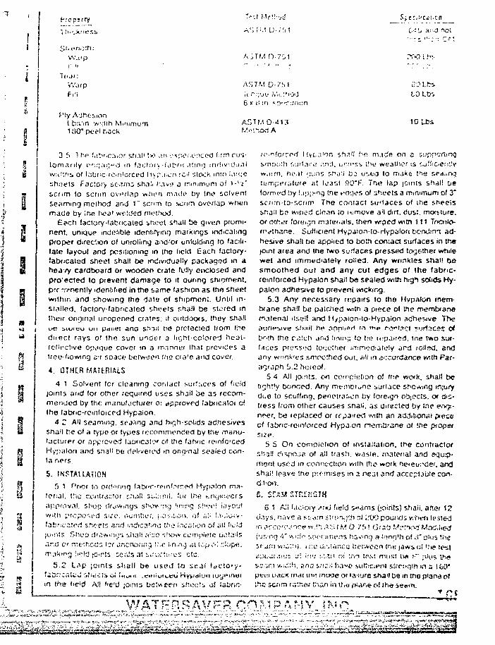
i
K'Opirry
W.np
7c jr:WjrpFill
Piy AdhesionLfcj-'in wr:i!h MinimumiaO* peel back
TV.) Mf'V-ju
AS V'.'. [_/'•<';> 1
A'iTM 0-701
AS7M O-?f>J
A5TW D-4KIr,'.,-•! hod A
tO Lb'»
tO Lbs
3 r> "! hf> fah'.ca.or shall !>? .u> oxivi ienced firm cus-
tomari ly iviq ,»c,.- d m If lclOry-KlfK. .Ming individual
\v;<"ins of l.'ibric-rciri'orced Hyf .i-cn ;c;il slock mso !.i-'c;e
sh.jels fac'.O'.y sc.urc sh.i!' I'.iv-.; j minimum of l-1 '*"
scrim (O scrnn overlap v«l>er» made by trie solventseaming method, and 1" scm lo scum overlap whenmade by ;r,e he a' welded method.
£?ch factory fabricated sheet shall be given promi-nent, unique indelible identifying markings indicalingproper direction of unrolling and/or unfolding to faoli-late layout and positioning in ilto («rid Each factory-fabricated sheet shall be individually packaged in aheavy cardboard or wooden crate fully enclosed andpro'ected to prevent damage to it during shipment.p?r -jvnently identified in the same fashion as tho sheetwithin and showing the dala of shipment. Until in-stalled, factory-fabricated sheets shall be stored intheir original unopened cralrs; if outdoors, they shallL>« iioicu on pdiiet ana snail v>& protected trom fnednfici rays of thr< sun uider a liCjht-ccJore'J hcat-rcfective opaque cover tn a manner that provides airct-"-flowing s'i space between fho cra'e and cover.
4. OTHER MATERIALS
4 1 Solvent (or cleaning contact surfaces oi fieldjoints and for other required uses snail be as recom-mended by trie manufacturer o: approved iabucatof c!the iabnc-rcinfoicrd Hypalon.
4.C A'l seaming, sealing and h^jh-solids adnesivessnail be ol a rype or types rccommendecJ by the manu-facturer or approved laoncalcy of the fahnc-remfo'cedHypalon and sh.aii be delivered m onqmal sealed con-
5. INSTALLATION
f> 1 Prior to orrWiog (abf'!*-r<>inf."irrfvi Hyjtnlon ma-!er:ai. the contractor s'vili suL-rmt. 'cir the t-.n<jinc-ersappfOv.ll. Sf'iop c'lowinys showng hn:t'9 f.hve! iayO'...'!with proposed s-lv. iTombef. (.os.IiOn. of <i'i i.ii.loiy-tab-r:czu?(! sheets sr.d utdica'.inr, u'O IncuUjn oi ai! f>cJd
(Offits Shoo 'J'Svmv^'i :>Ji3ii ZI'-JO «;!v.nv ccinpietc cii-tais
and c rr.t'thctiri tsr ar.chofi."'} !'•<? i.n.ng oi icpo.' :;U)fAi.
making !i/?!c! joir'ts Ec.l!5 at :..'x;C!;.-.'C'S etc.
5.? Lnp jomis shall be USPJ to SCJI
sn the de'd All f'e"J joints between she.:::, of ialir-.tz-
(O:n?orcod Hyr.a'or. sh.?'! t--e m.i ie on 2 syprKirfirsjsmc»-:i!h Ci'ji*.ii"iir .'.n'.t. u r i r -s^ the we3Uic?r is cufiiCie::"v
w. i i rn , he.i t cuns sha:i C J u s c o to m j k e the f.eaiin.3
lomppralufe at least f?O"F. The lap joints shall Deformed by ! j;jj>-ncj the ti-rj<jt>s of sheets a minimum of 3"scrim-lo-scnm The contact surfaces of the sheeisshall ba wiped ciean so i-jmcve ail dirt, dus:. moisture,or otfvr foreign m3fenals, then wiped witn 111 Incttlo-methane. Sufficient Hypalon-to-Hypalon borx i rn ad-hesive shall be applied to both contact surfaces in th«joint area and the two surfaces pressed together whilewet and immediately rolled. Any wrinkles shall besmoothed out and any cut edges of the fabric-reinforced Hypa.'on shall be sealed with h.-gh solids Hy-palon adhesive to prevent wscktng.
5.3 Any necessary repairs to the Hypalon mem-brane shall be patched wiin a piece of the membranematerial itself and H/palon-to-Hypaion adhesive. TrteaoriHsive sh,Til he anniioii '>"> ' " P ro^'.^Ct 5tjrf>ces O*b'-th the p,:!ch and iimnq lo tie impaired, toe two sur-faces pross'.'d toqether immod.'jtely a rd rollwl. andany wnnfc'es smoothed out. all in accordance with Par-agraph b.2 ricteof.
S 4 A)I joints, on ccmpieiiori of the week, shall betirjhily bonrted. Any mt'nibrurie surface shewing injuryduo to scuffing, penetration by fofe.gn objecss. Of dis-tress f.'om other causes snaii. as directed by the eryjs-nr-er. be replaced or repaired with an additional p*ecscf f3bric-rem'orced Hypj .cn nernbrane of the ptoperSUP.
5 5 On completion of installation, the contractors!-.-3l! c'l^po.jfl of all trash. v/<isle. material and equip-ment used in connection with trie work neiewdef, andshai! leave ihe prf-mises in a neat and acceptable con-d:t'cm.
£. S « M STRCKGTH
6 * A;I faciory <»;KJ field wams (:o;.rits) shaii. after 12days, nave a st-om i:.'un.;;h rsi ;.'00 pouiwJs when lesied
I'j^c.q 4" v, iri!-» saot.nr.rns h3»mg 3 lonq'h of i i " Bins Vies.'-jrn w!c::ii. 1 r.c tii'iiatKu tseiween tns-: jaws ol t.'t? testrtpku:.:;•_•£ J\ inn :-:.W. oi i m If\;s! must IV* t'' pH'S Ihtfsc;ir('. v.ioih. snci s.'iiii; h3«e iutlicit 'ol sirp!>g!h in s SfeO*pvvi uatx K M I nit; jnooe 01 lanure sha'i tie in the p'ana ofthe scxim rs'.ha.' I 'an in t. .o p i^n* o! ih« &«»m
i^^^^^ii^^^%i^ni^^^i^^^^3i;^^
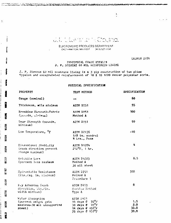
ei^M^^eXVi^^^^A^^iS^i*UiifS^xiSSSU<Si£mJ£S
ELAr.TOMCR'C PRODUCTS DEPARrviNTEAST MAM."'fOiV. MA 010?? f «!.•)( S27 W «
J . P . STEVEBSGHiDK BTP1LC3
KEIWFOBCO) L1KIJS3
UJJP5H 2/S5
J . P . Stevens 60 n i l sictabrane l i n i n g i s a 3 ply const ruct ion cf two p l i e sHypalon and encapsulated reinforceoient of 10 X 10 1P00 denjer polyester scr im.
PROPERTt
Gauge (noolnal)
Thickness f tails minimum
BreaJd.r.8 Strentrth-Fabrics
Tear St rength (pounds,raini.nsua)
Low Teapera ture , °F
Dimensional StabilityP (each direction percent™ change aaxiour:)
I VcUtil e Lor«g (percent loss aaxiaua
Hyi ' rostat ic Resistance(lb?. /3<j. i n . KiniRsias)
Vxy Adheaioa («.-ccbdirection, ibs./Ir..width iainiaus)
PHTSICAL SPECIFICATIOa
TEST HETHOD
—
ASTM D751
AJSTM D7S1Method A
ASTM D751
ASTM D2T?6
SPECIFICATIOK
60
55
90
-no1/8 in. mandrel1 l.rs., Pass
ASTM D120<*212°Ff 1 hr.
ASTM D1203Method fc30 ail sheet
ASTM 575'Method AProcedure 't
ASTMMaehJi.Type A
0.5
300
(yi«rc«ntmaxita>xa-3h*et)
H days30 dnya
7C°?70°!f
20 days 2
1.5
30.030.0
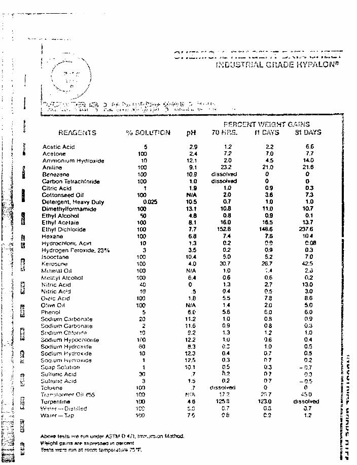
INDUSTRIAL GRADE KYPALON8
n
li1
I
REAGENTS
Actitic AcidAc8ton«Ammonium HydroxideAnilineBcnezeneCarbon TetrachlnrideCitric AcWCottonseed OilDeterflent. Heavy DutyDimethylformamkhJEthyl AlcoholEthyl AcetaieEthyl D'Ch!orid«HsxaneHydrochloric ACKIHydrogen Peroxida, 23TIsooctaneKero5or>ttMineral OilMeif-.yl AlcoholNitric AcidNitric Ac'dOi£ic AcidO!ivn OilPhenolSodium CasbonateSodium GarbonaieSodium ChlorideSodium HypocnlortteSodium HydroxirfsSodium Hydroxrcte
Soap SciutionSuit uric AcidSulnjftc AcidicludtiB'{r£n-^o;rtx>-r OilTurpantin*VV'--!*ff — Oisi.'Hs-dWa<er —Tap
% SOLL'PON
5100
100100100
1100
0.02510050
100100100103
1001001001004010
100100
5202
10100601011
303
too
100•'.00100
STW 0 </*!,oaf cent
M-Khod.
T^srs wsrs r-fi s! rovrr. t«n^e.-jtuiv
pH
2.92.4
12.19.1
10.91.01.9
N/A10.513.14.88.17.76.81.33.5
10.44.0
N/A6.40.5
1.8N/A6.C<
11.211.6S.2
12.28.3
12.312.510.1
.71.5
.7f\!fA4 6
75
PEF.CE7XS HR&.
1J2IS2.0
23.2dissolveddissolved
1.0ZO0.7
10.80.8
16.0152.8
7.4CJ2025.0
30.71.00.61.30.45.5145.61.00.91.31.00.30.40 30.5h.20.2
tSlSSOlvwi17.?
1258V.-'
08
fiT WEIGHTtt CAYS
2.27.04.5
21.0000.9361.0
11.00.9
16.51*8.6
7.8030.95.2
26.7:A0.6Z.70.57.82.06.0OS0.81.20.61.00.7n?0.30 70 70
?fs 7123.0
G.3CS
GAINSSI DAYS
6.67.7
14.021.6000.3731.0
10.70.1
13.7237.6
1040080.37 0
42.52.602.
13.03.08.6506.00.90.31.00.40.50.5
02 j- D . 7 j
-6.5 j0
d:ssolvod i0.7 |1.2 I
!
s1
1
•ry
4
CC
r
tat
3Z$3
•i
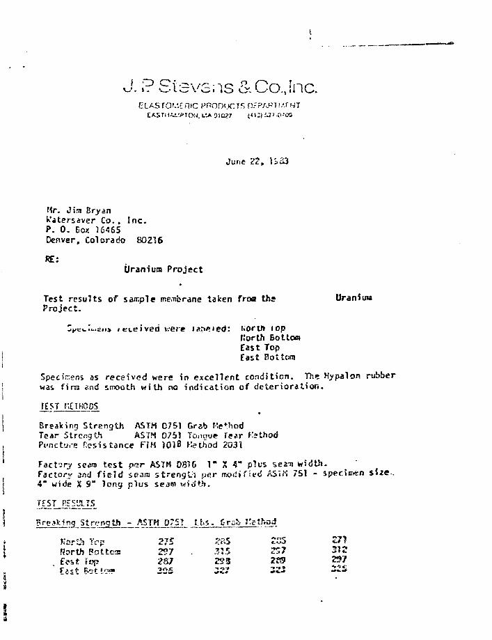
f O Ci."isvsns&CoJnc.
June 22, 1 £• 33
Mr. Jim BryanWatersaver Co., Inc.P. 0. Bo/. 16465Denver, Colorado 80216
RE:Uranium Project
Test results of sample me.ubrane taken froa the UraniumProject.
3^c«.I<..=ii> i c i e i v e d were iar>«ied: uortft fopt.'orth BottomEast TopEast Bottom
Specimens as rece ived were in exce l l en t condit ion. The l-typalon rubberwas finn end smooth wi th no indica t ion of d e t e r i o r a t i o n .
fEST METHODS
Breaking Strength ASTH 0751 Grab MethodTear Strength ASTH 0751 Tonuue Tear KsthodPi-nct-j.-e Resistance FIH 10)B Method 2031
Factory seam t e s t p<?r ASTM 0816 1" X A" plus seam width.Factory and f i e l d seara s t r eng th psr modified ASTK 751 - specimen4" wide X 9" long p lus seam width.
X1^3..Strength - ASTH 075? J . t s . C-rs-b f'etfvqd
Tcp 27E 2P,S 255 271Uorth Pot tea 257 . 315 257 312
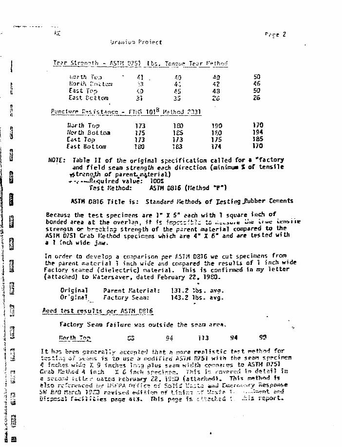
"Vce 2
11
li3
i'
i
•jratr
letr Strength - AST??
KorLh r!;"»ttcaf a s t To->cast Dottorn
PuncUirp n«sistance -
North TopNorth Bottomf.a<t TopEast Bottom
lui) Protect
D7S1 l b s .
•;3<;;)
31
FTfC 101s
173175173180
7cnv-u?
404:
25
H?lhod
ia»1ES173183
Tear f'pthod
4342482&
?H31
150ISO175174
5046502S
170194185170
NOTE: Table II of the original specification called for a "factoryand field seaa strength each direction (minimus I of tensile
lStreng4th of parent^m^terial)»-.--~.J?t?quired value; 100*
Test Kethod: ASTM 0816 (Kethod "P")
ASTM D816 Title i s : Standard Kethods of Jesting Rubber Cements
Because the tes t specimens are 1" I 5" each with 1 square inch ofbonded area at the overlap, it. f* ^r.pczz'.f.z to ...=««»* «« i-*uc «.en»iistrenotn or brscScir.a strength of the parent material cocpared to theASTH D751 Grab Kethod specinsns which are 4" X 6" and are tested witha 1 Jnch wide jaw.
In order to develop a comparison per AST/4 D816 we cist specijncns fromthe parent natcridl 1 inch wide end compared the results of 1 inch wideFactory seamed (dielectric) material. This is confirmed in my l e t t e r(attached) to Watarsaver, dated February 22, 1980.
Original Parent .Material: 131.2 ' .bs .Or'ginai Factory Seaa: 143.2 l b s . avg.
Aped tgs t r e s u l t s per ASTM DgiS
Factory Sea^a f s f l u r e was outs ide the spsra a r e a .
Trv? CS S | 1 U S4 9?
I t h^'i bs*en o^neraKy .icct'tiksd that s frssre r c s l f s t i c t«»?t !«?et.h«wf fortcstii-;-5 */ it'b*«s iis to use' < rod if icd A5V« 0751 with the ses« spfcipnen<? inches witie X 9 inchtGrab Ratted 4 in j sa st'cor.fj i'itLfs* ast£-5 febfuary Z2, tSt-Si Cattarhpdl . Thi*
Dfrpesal t*ii:J'j;£Jes page «E3. This p^g» i s ^^tschs-d •- .--«5 r e p o r t .
CW U 5 e it r . * J U I I J f f -a ^ ^ H M ><fjt » M J 1 « » > T ? C - 6 ^ - . .-.;••: 4 . - r — i . i
nehes 1r;,".g plus sea« width cp?^n>*tes to ASTH D751
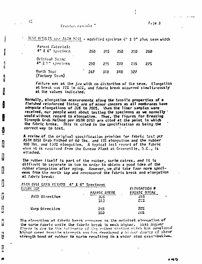
lt^lCiPAlJL.flItC_i^TJl^AL " modified spscirsn 4" 1 3" plus seam width
Parent Valeria]-:e r i a ] :| 4" X 6" spt'Ciw.n 260 255 250 250 260
Original 5es;s:S 4" X'1" «.p<?ciKer, 290 2DS 27» <S5 275uM
Korth Toji: ' 347 313 348 3279 (Factory
Failure was at the jj,w with no distortion of the seam. Elongationat break was 72* to 60S, and fabric break occurred simultaneouslyat the values indicated.
Normally, elongation sneasurements along the tensile properties of afinished reinforced lining are of minor concern as al l meribranes haveadequate elongations of 20S to 7005. When the liner samples werereceived, our people went about testing the specimens as we normally "would without rea&ni to elongation. Thus, the figures for BreakingStrength Grab Method per ASTH D7S1 ars cited at the point in whichthe fabric broke. This is cited in the specification as being thecorrect way to test.
A review of the original specification provides for fabric testASTH 0751 Crab Ksthod of 60 Tbs. and 15» elongation and the rubber100 lbs. and 1502 elongation. A typical tes t repor t of the fabricwhctn i t is received frees the Dunean Plant at Greenville. S.C., isattached.
The rubber i t se l f is part of the rubber, scrim tr.alrex, end i t isdifficult to separate to tea in ordsr to obtain a good idea of therubber elongation after aging. However, we.aid take four norn speci-mens froa thx north top ami rerasasured the fabric break and elongationat fabric break:
rsm D/51 GRA8 KTf^D 4" X S" Specumim tap ~ EIOHCAJion P
FABRIC BREAK FAS IC BR£MFill Direction ' 3SF '&%
Vfsrp Directicn 293 2CS
T?.itt p?f»afy'tfpo at fs^fic br«» ?! rmnar?* ?o thfi oriofnai elnntjalioft ofUse scrim fabric KSHS ih« fabric brsek is *««cJ'« ht&r»<sr. inis higher
hong of ru?>fi«?r to scri« rpsyit-frcg in a atcsr jo«a
•i no
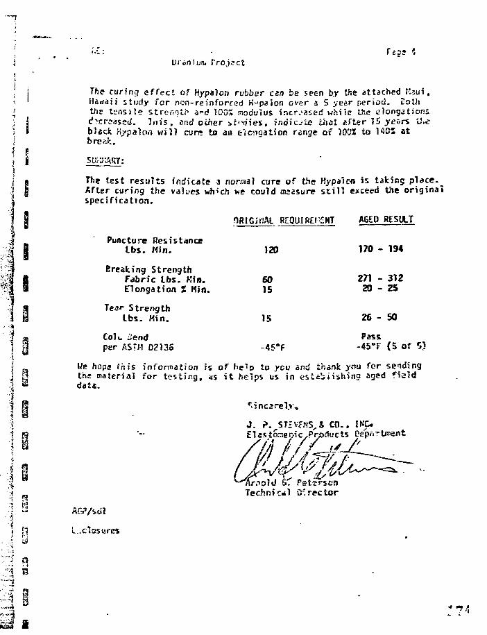
i I
' • • I : •
Proj.?ct
The curing effect of Hypa)on rubber cert be seen by the attached I'aui,Hawaii study fcr non-reinforced K^paion ever & 5 year period. Boththe tensi le strength c"d 100% modulus increased white the elongationscf"?cr?«ffd. 7u i s , «nd other i t ' - d i e s . indicate that «fter 15 yefirs U.eblack nypsion wil) cun* to an e'icngation range of 1022 to 1405 atbJ
test results indicate 3 normal cure of the Hypalon is taking place.^After coring the values wh'ch we could fiiaasure s t i l l exceed tlie originalspecification.
Puncture ResistanceLbs. Min.
Breaking StrengthFabric Lbs. Kin.Elongation £ Kin.
Tear StrengthLbs. Kin.
Colu o'endper ASTM 02135
ORIGiriAL RCOUlRE/'ilNT
120
6015
15
-45°F
AGED
170 -
271 -20 -
26 -
Pass-45°F
RESULT
194
31225
50
(5 ofII _ We hope fftis infonnation is of help to you and thank ;ysu for sending\ tf the material for t es t ing , as i t helps us in es tabi ishina aged f ield\ « data.
J . P. ST£VFNS,4 CO.. INC-£1 asto.-nei/ic,Products Dep»rtjnant
Technical Director
.» fi L..closures
I
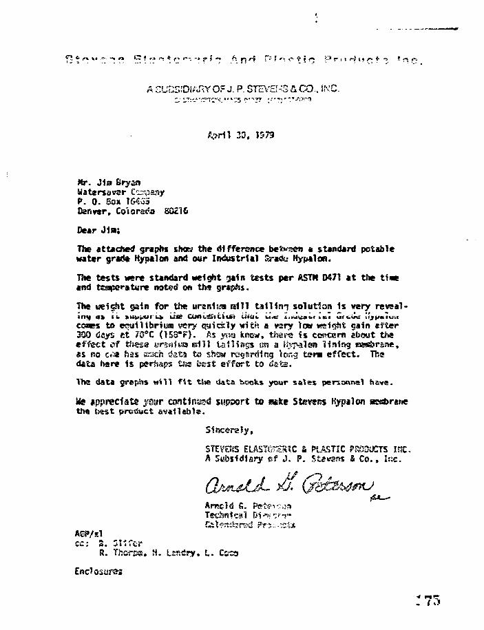
A SUCSiDiARY OF J. P. STcV£[^3 & CO.. IMC.
April 33.
Mr. Jia Bryan
P. 0. Box 16455Denver, Co'iorstfa
Dear J in;
The attached graphs shot? the difference be'tvzen a standard potablewater grad* Kypalan and our Industrial Sjra&i Hypalon.
The tests were standard weight gain tests per AST* D471 at the t i nand teaperature noted on ths graphs.
The weight gain for the uranitsa s i l l ta i l ing solution 1s wiy reveal-ing *% \i. >liu|Alf U iSa OJttL&lUxSi titai. i le i.-J^»i.< i«;T Grwirii; irjp«tuuceaes to ecuilibriyaj very quickly with a vary low «si§M gain efter300 dsys ct 7S°C (153*F). As vt«j kr»«a«, tl sips Is concern ebout theeffect of tfiesa ursnitaa ©i l l tailings on a Hypaicn liairtg B!«^>r£?»,as RO c<» has K-ach data to shew re§srdifjg Icr.g tsr« effect. Thedata here is perhap? t fa test effort to
Ths data yr*?^* trtl l f i t tJsa data boofcs your sales perse«n*t have.
Wa appreciate yoyr continue support to eiefee Stevens Kypalonthe b&st product aviflebls.
Sincerely,
PLASTIC PSC3UCTS IRC,A Sot>sid1firy ef J. P. .Stawsw & Co., I R C
Tsehsical Di
cc: S. Sl i ferR. Tfta-rest, H. Lssfiry, L. CCCD
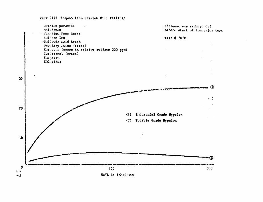
T23? £125 Mqucrt froa Uranium Kill Tailings
Uranium peroxide
4 Feat OxideIon
Effluent was reduced 6:1b«fori- start of tGmsrsion tcac
f 70*C
Teri:i«-ry tsiaa (trace)£2j«uir.a (trace in calciua «ulfat« 2GO ppa)l3cJt«csial (tries',
10
(1) Industrial Gradt Hyp*Ion
(7} Potebl« Grada Hypalon
ISO
DAYS IN IMMERSION
300

a
o
01
5
IT.
>
SMMOIBH
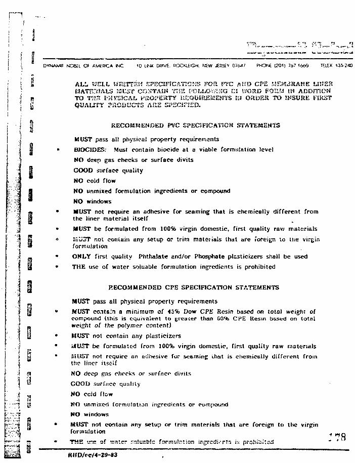
p~7
i ; 8
NO6H Of AMcPMCA »JC 10 Lf-JX DWVE. ROCKUiGH. NEW JERSEV 07647 PHONE (201) 767 1660 TELEX 13S240
M
\
II
• • -
: . • •
-i. *
i
1 j a ALL fe'EL-L WE1TTEH SPECIFICATtCilS FO3. PTC A»D CPE r.SE^^RAME LINER1 • ElATEStJALS SZl^S? CONTAIN THE FO?XQW!M<3 EM V3GRD FOH?J IH ADDmCH
| R TO Th>~. S'MYSSCAL fc*aOFEKT1f KIEQUIREMIENYS IM ORDER TO ENSURE FIRST'• g QUALITY ?aOOUCTS ARE SPECIF.'ED.
I | KECOKSMENDED PVC EPEC?FiCA-nON STATEMEWTS
MUST pass all physical property requirements
1 * BJOCIDES: Must contain biocide at a viable formulation level
NO deep gas checks or surface divits
* I GOOD surface quality
NO cold flow
B NO unmixed formulation ingredients or compound
• NO windows
m • MUST not require an adhesive for seaming that is chemically different fromS the liner material itself
• MUST be formulated from 100% virgin domestic, first quality raw materials
$ ta • &U3T not contaiM any setup or trim materials that are foreign to isie virgin
•I a formulation
?l -, • ONLY first quality Phthalste and/or Phospliate plasticizers shall be used
| § • THE use of water soluable formulation ingredients is prohibited
I | P.ECOMMENDED CPE SPECIHCATION STATEMENTS
1a MUST pass all physical property requirementsI I " MUST contain a minimum of 45% Dow CPE Resin based on total weight of1 compound (this is equivalent to greater than G0% CHE Resin based on total| _ weight of the po'ymer content)
I y • MUST not contain any plasticizers
.$ * iJlUST be formulated from 100% virgin domestic, first quality raw materials
j y • MUST not require en adhesive for seaming ihat is cl>emicaUy different from
I the liner itscif
NO deep gns checks or surface dtvits
GOOD surfjice quality
NO ccld flow
WO unmixed formuiation ingredients or eomiXwrKf
Dp-:-:"? NO windows
fc-. ^ & * MUST not contain any se tup or trim m«teriaL"t that ure foreign to the virpin| ; . - : 4 " formulation ^ _
KHD/w/4-29-83

But since, generally, cheaical resistance is the most iizportant. factor, one mustbe aware of the dlffprance thickness makes with re a'-d to chemical resistance.
PVC Manufacturers currently manufacturing a viable pond liner grade PVC : •-.eetingonly offer warrantees OQ material 20 nils in thickness or greater. '., a suitableapplication, 20 all FVC ce.u be warrantee^ for a period of up to 20 years.Although a 30 mil PVC in the sans application would ba expected to last a sign-ificantly longer period of tiaae, the state-of-the-art and the liuited experienceperiod (about 15-20 years) prevents FVC manufacturers from going beyond the20-year warrantee period for the 30-gauge product at this time.
R. H. Dickinson, Technical Marketing Manager
Dynamic. Nobel of America Inc.
179
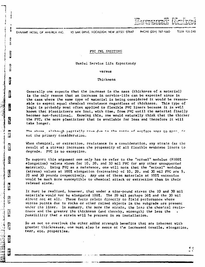
i * DYNAMff NO6EL Of AMciftCA tMC. 10 UNK DiJTVE. ROCKUISH. NEW JERS£V 07647 PHONE (201) 767-1660 T[LEX 135
E» PVC IKL SHEETING
1 •a Useful Service Life Expcctandy
" versus
9 Thickness
a Generally one expects that the increase in the mass (thickness of a material)|| is the only reason that an increase in service-life can be expected since in
the case where the same type of material is being considered it would be reason-•m able to expect equal chemical resistance regardless of thickness. This type ofB logic is probably most often applied to flexible PVC liners because it is well
known that plasticizers are lost, with time, from PVC until the material finallybecomes non-functional. Knowing this, one would naturally think that the thicker
B the PVC, the more plasticizer that is available for loss and therefore it will<3 take longer.
j y nut the primary consideration.
I ^ When chemical, or extraction, resistance is a consideration, any strain (as theI ti result of a stress) increases the propensity of all flexible membrane liners to•{ degrade. PVC is no exception.
;| M To support this argument one only has to refer to the "actual" modulus (@100%•% ® elongation) values shown for 10, 20, and 30 mil PVC (or any other unsupportedI material). Using PVC as a reference, one will note that the "actual" modulusf 9 (stress) values at 1002 elongation (extension) of 10, 20, and 30 mil PVC are 9,
• i H 20 and 30 pounds respectively. Any cne of these materials at 100X extensionI would be much more susceptible to chemical attack or extraction than in theirI ft relaxed state.1 lij It must be realized, however, that under a nine-pound stress the 20 and 30 milJ materials would not h«i elongated 100%. The 20 ail perhaps 502 and the 30 mil* p alncst not at all. These facts relate directly to field performance where3 "* strcs3 points due to rocks or other rai3ed objects in the subgrade are present
•f_ under ths linar. In summary, the more the strain, the less the chemical resis-•'i t | trusce nr.d the greater the thickness (and thereby, strength) the less thej te possibility th«t a strsin will be present in an installation.:-i
So as not to overlook the other added strength benefits that are inherent withgreater thicknesses, one must also be aware ot t\e increased tensile, elongation,tear, etc. properties.
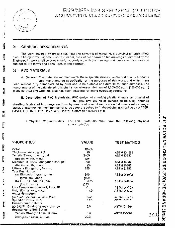
I' / /' \ .010 POLYVINYLCr.L;
01 - GENERAL REQUIREMENTS j
The work covered by these specifications consists of installing a polyviny! chloride (PVC) \plastic lininy in the (lagoon, reservoir, canal, etc.) where shown on the drawings or directed by the \Engineer. All work shall oe dons in strict accordance with the drawings and these specifications andsubject to the terms and conditions of tne contract.
02 - PVC MATERIALS
A. General. The materials supplied under these specifications ai.aii be first quality productsand manufactured specifically for the purposes of this work, and which have
been satisfactorily demonstrated by prior use to be suitable and durable for such purposes. Themanufacturer of the calendered rolls shall show where a minimum o? 2,000,000 sq. ft. (185,000 sq.m.)of its 76" (193 crn) wide material has been installed for lining hydraulic structures.
B. Description of PVC Matoiicafs. PVC (polyvi.iyt chloride) plastic lining shall consist of76" (193 cm) widths of calendered polyvinyl chloride
sheeting fabricated into large sections by means of special factory-bonded seams into a singlepanel, or into the minimum number of large paneis required to fit the jobsite as supplied by WATER-SAVER CO., INC., P.O. Box 164G5, Denver, Colorado (303-623-4111).
s\ O
1. Physical Characteristics - The PVC materials shali have the following physical i ~±characteristics. •;
i 6
VALUE TEST METHOD
Ozr-OoTO
o
ColorThickness, mils., ± 7%Tensile Strength, min., psi
(lbs./in. width, min.)Modulus & 100% Elongation rrin. psi
(Ibs./in. width, min.)Ultimate Elongation, % min.Tear Resistanco:
(a) Elmendorf, grams, rnin.(gms./rnll., min.)
(b) Graves Tear, ibs. min.(Ibs./in. m!n.)
Low Ternpsrature Impact, Pass, 'FVolatility, % !css, :r.:<x.Water Extraction(@ 104*F, 24 hrs.) Vi lost;*, max.Specific Gravity, min.Dimensional Sisbility(® 212*F, 15 min.) % max. changeResistance to Soil Burial:
Tensile Strength Loss, % max.c:Of)uyiii>fi Lose*, v'o i:iar..
Biack10
2400(24)900
0)250
1600(160)
3.25(325)
•101.59
0.45•1.23
5.0
5.0£G.O
ASTM D-15S3ASTM D-882
ASTM D-882ASTM D-882ASTto D-832
ASTM D-1922
ASTM D-1004
ASTM D-.7S0ASTM D-1203
ASTM D-1.239ASTM D-?!?2
ASTM D-1204
ASTM D-3083
7!
30
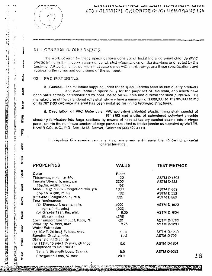
.U£3 HOLYVIWYL CHLORIDE (PVC) MEMGHAKE
v V.
' f
01 - GENERAL REQUIREMENTS
The work coveiod by ther.e specifications consists of installing a fjolyvinyl chloride (PVC)plastic lining in ihi> ;!.:ccc;.i, rsseivc/r, carol, etc.) ;:•>.&c ho/.Ti &n the drav/ings or diiECted by tnaEnpiiiccr. A)! wck sht:.;! bo donfj in f.fricl acr.yrdance vvith the dsawings and these specificatioas andsubject to thot icrrns ;md conditions of She.- contract.
02 - PVC MATERIALS
I%
A. General. The materials supplied under these specifications shall ha first quality productsand n<anufactursd specifically for the purposes of this work, and which have
been satisfactorily demonstrated by prior use to be suiiable and durable for such purposes. TKomanufacturer of Iha calendered roils shall show where a minimum of 2,000,000 sq. ft. (185,030 sq.m.)of its 76" (1S3 cm) wide material has been installed for lining hydraulic structures.
B. Description of PVC Mataricals. PVC (poiyvinyl chloride) plastic lining shali consist oi76" (193 cm) widths of calendered poiyvinyl chloride
sheeting fabricated into large sections by means of special factory-bonded seams into a singlepanel, or into the minimum numbar of large paneis required to fit the jobsite as supplied by WATER-SAVER CO., IMC, P.O. Box 16465. Denver. Colorado (303623-4111).
m|
•
II- §
j.;J «1
PROPERTIES
ColorThickness, mils.. ± 5%Tensiie Strength, min., psi
(Ibs./in. width, min.)Modulus © 100% Elongation min. psi
(ibs./in. width, min.)Uitin.ate Elongation, % min.Tear Resistance:
(a) Eimenciorf, grams, min.(gms./mii., min.)
(L>) Graves Tear, lbs. mfn.(ibs./'in. min.)
Low Temperature impacS, Pass, *FVolatility, % (os3. max.Water Extnction(© 10.4'r, 2& hrs.) % IOSD, mi?*.Specific Gravity, min.Dimensional Stability{<£> ?12*F, "5 n\\n.\ % ma*, chanrjoResistance to soil Burial:
Tensile Strength Loss, % max.Elongation Loss, % max.
characteristics.
VALUE
Black30
2200(66)
1000(30)
325
oOOO(200)
8.25(275)
•200.75
0.251.23
5.0
5.020.0
nave ine loiiowing
TEST METHOD
ASTM D-1593ASTM D-882
ASTM D-S82ASTM D-882ASTM O-SS2
ASTM D-1922
ASTM D-1004
ASTMASTM D-1203
ASTMASTM 0-792
ASTM D-1204
ASTM
3

n
'i
13
I
a
2. PVC materials shall be manufactured from domestic virgin polyvinyl chloride resinand specifically compounded for the use in hydraulic facilities. Reprocessed male-rial
shul! no! bo Uocti. II silo!! be iHiuiii.'! yiay to birtCK in ooiut and p.o'jucuo in s sianuara minimumwidth of at least 76" (193 cm). Thickness shall be as shown on l\,e drawings. Certification testresuhs showing that the sheeting meets the specifications shall be supplied on request.
03 - FACTORY FASRiCATIG?*Individual calender widths c! PVC shall be- factory fabricaic-d into large panels.The manufacturer of the calendered ro!is shall show whore a minimum cf 2,000.000 sq.ft.
(185,000 sq.m.) of its 76" (103 cm) wide material has been installed (or lining hydraulic structures.Lap joints with a minimum join! width of '/» inch (13 mm) shall be used. Factory made splices shallhave a strength of 80% of the specified sheet strength. After fabrication, the lining shall beaccordion folded in both directions and packaged for minimum handling in the field. Shipping boxesshall be substantial enough to prevent damage to contents.
04 - PLACING OF PVC LININGA. General • Installation shall be performed by a contractor that has previously installed
a minimum of 2,000,000 sq.ft. (185,000 sq.m.) of this material or by a contractorthat has a fabricator field representative in attendance. The surface (substrate) to receive the linershall be smooth, and free of sharp objects that could puncture the lining. All vegetation must beremoved. A soil slerilant may be required at the discretion of the Engineer. The PVC lining shall beplaced over the prepared surfaces to be line in such a manner as to assure minimum handling. Itshall be sealed to all concrete structures and other openings through the lining in accordance withdetails shown on the drawings submitted by the contractor and approved Dy the Engineer. The liningshall be closely fitted and sealed around inlets, outlets and ether projections through the lining. Anyp.~,.'.!w.< J< !i..!.,y uan.aycu iiuniiy n i i nil id 1 ion shah De lemyvea or reoairea ov using an additionalpiece oi lining as specified hereinafter.
I. Field Joints - Lap joints will be used to seal factory fabricated panels of PVC togetherin the field. Lap joints shall be formed by lapping the edges of panels a
minimum of 2 inches (50 mm). The contact surfaces of the panels shell be wipod clean to remove alldirt, dust or other foreign materials. Sufficient cold-applied vinyl to vinyl bonding adhesive shall beapplied to the contact surfaces in the joint area, and the two surfaces pressed together immediately.Any wrinkles shall be smoothed out. Field made splices shall have a strength of 80% of thespecified sheet strength.
2. Joints to Structures •_ All curing compounds and coatings shall be completely remov-ed from the joint area. Joining of PVC to concrete shall be made
with vinyl to concrete adhesive and mechanically fastened. Unless otherwise shown on the draw-ings, the minimum width of concrete to PVC jo'nt shall be 3 inches (20 cm).
3. Repairs to PVC • Any necessary repairs to the PVC shall be patched with the liningmaterial itself and coid applied vinyi to vinyl spiicmg adnesive. The
splicing adhesive shall be applied to the contact surfaces of both the patch and lining to berepaired, and the two surfaces pressed together immediately. Any wrinkles shall be smoothed out.
4. Quality oi Workmanship • AH joints, on completion of the work, shall be tightlybonded. Any lining surface showing injury due to scuffing,
penetration by foreign objects or distress from rough su&gracie shall, as directed by the Engineer, bereplaced or covered and :;-:-a!ed with an additional iayor of PVC of tnf. proper SITS A technicalService Representative will be made available to the sontracior if the contractor desires. The con-tractor w i " tear the cxpenss of iWia Te^iu'iiccti Sttivice fieuresenianve. Tne iecnnical ServiceRepresentative is not directly responsible for the quality of tho w c k involved; such responsibilitywill be solely that of the contractor.
n A
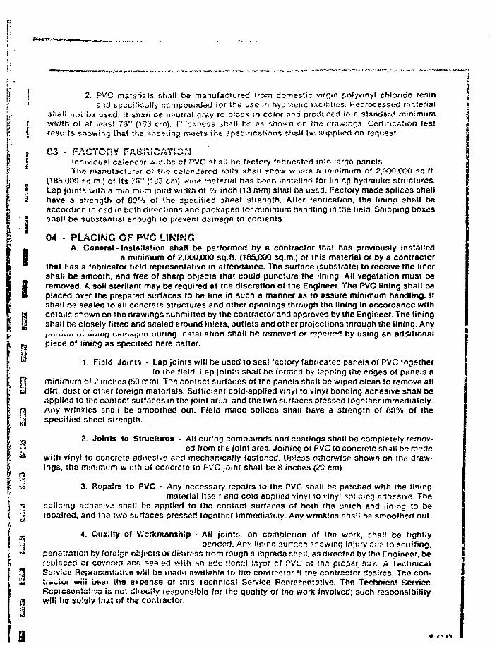
2. P^C materials shall b9 manufactured from domestic virrjin pofyvinyl chloride resin3nc! specifically ccmpcuiidsd for the use in hydraulic facilities. Reprocessed material
.s .ttli iioi ba us**d. it ahiifi ce neutral gray 10 nlscK tn color rind produced in a standard minimumwidth of at least 76" (1S3 cm). Thickness shall be as shown on trio drawings. Certification lestresults showing that the shesiing meets ins specifications shall be supplied on request.
03 - FACTORY FABRICATIONIndividual calendar widths ol PVC shaiS be factory fabricated into larrja panels.The manufacturer of the calendered rolls shall show where a minimum of 2,000,000 sq.ft.
(185,000 sq.m.) of Its 76" (193 cm) wide material has been installed for lining hydraulic structures.Lap joints vviih a minimum joint width of Vi inch (13 mm) shall be used. Factory made splices shallhave a strength of 60% of the specified sheet strength. Afier fabrication, the lininq shall beaccordion folded in both directions and packaged for minimum handling in the field. Shipping boxes
' S shall be substantial enough to prevent damage to contents.
04 - PLACING OF PVC LINING
SA. General - Installation shall be performed by a contractor that has previously installed
a minimum of 2,000,000 sq.ft. (185,000 sq.m.) of this material or by a contractorthat has a fabricator field representative in attendance. The surface (substrate) to receive the linershall be smooth, and free of sharp objects that could puncture the lining. All vegetation must be
S removed. A soil sterilant may be required at the discretion of the Engineer. The PVC lining shall beplaced over the prepared surfaces to be line in such a manner as to assure minimum handling, itshall be sealed to all concrete structures and other openings through the lining in accordance with
« details shown on the drawings submitted by the contractor and approved by the Engineer. The liningyj shall be closely fitted and sealed eround inlets, outlets and other projections through the lining. Any
^uiiiun ui liiiiny udmageu uuring installation snail be removed or repaired by using an additionalj j piece of lining as specilied hereinafter.
^ 1. Fiald Joints • Lap joints will be used to seal factory fabricated panels of PVC togetherin the field. Lap joints shall be formed by Sapping the edges of panels a
(| minimum of 2 inches (50 mm). The contact surfaces of the panels shall be wiped clean to remove ailui dirt, dust or other foreign materials. Sufficient cold-applied vinyl to vinyl bonding adhesive shall be
applied to the contact surfaces in the joint are-a, and the two surfaces pressed together immediately.r§ Any wrinkles shall be smoothed out. Field made splices shall have a strength of 80% of theyj specified sheet strength.
P,, 2. Joints to Structures • All curing compounds and coatings shall be completely remov-Fj ed from the joint area. Joining of PVC to concrete sh/ill be made** with vinyl to concrete adttesive and mechanically fastened. Unless otherwise shown on the draw-
ings, the minimum width of concrete to PVC joint shall be 8 inches (2C cm).
ii 3. P.epaire to PVC • Any necessary repairs to the PVC shall be patched with the liningmaterial itself and cold applied vinyl to vinyf splicing adhesive. The
f$ splicing adhesive shall be applied to the contact surfaces of both the patch and lining to bey| repaired, and tha two surfaces pressed togsthar immediately. Any wrinkles shall be smoothed out.
_ A. Quality of Workmanship • All joints, on completion of '.he work, shall bo tightlyU bonded. Any linino surface showing Injury tins to scuffing,•^ penetration by foreign objects or distress from rough subgrade shall, as directed by the Engineer, be
replaced or covnrwo ar>o <tga|gtf with an additional Isyor cf PVC of ttio prcpar siia. A Technicaljf! Service RepresentaSivo wiil be made available to the contractor :f !h» contractor desires. lt.a can-£ iracSor «*iii Imui ina expense of tnis technical Service Representative. The Technical Service
Representative is not directly responsible for the quality of trio work involved; such responsibility3 wlti bo ECioly that of the contractor.

<**?-*''" r ^ T
REAGANTSAcetic AcidAcetir: AcidBenzeneDiesel FuelEthylene GlycolGasolineHydrochloric AcidHydrochloric AcidJP-4 Jet FuelKeroseneMethanolMethanolMethanolSAE 30 Motor OilNitric AcidNitric Acid
Pr.enoiSodium Chloride (Aqueous)Sodium HydroxideSodium HydroxideSuifuric AcidSulfuric AcidTetrachloro EthyleneTolueneWater - Tap
% SOLUTSOM210100100100100concentrated10100100550100100concentrated10
100concentrated210concentrated10100100100
PERCEPT WEIGHT1 DAY
0.20.1
deteriorated6.50.4
23.0+ 1.9
0.12G.817.80.10.1
13.42.13.4
+ 0.2t>.2
deteriorated0.10.20.3
deteriorated0.4
deteriorateddeteriorated
0.1
7 DAYS0.10.1
11.61.1
24.0+ 0.5
0.120.017.70.1
+ 0.220.65.1
13.1+ 0.614./
0.10.40.8
0.2
0.2
t
LOSSES |23 DAYS
0.10.1
12.61.2
24.0+ 2.0
0.220.218.80.2
+ 0.524.08.7
16.1+ 1.9164
0.10.53.0
0.1
0.2
The above tests were run under ASTM D 47I, Immersion Method.Weight losses are expressed in percent.Tests were run at room temperature 75 *F.Above results were based on .030 thickness.
PVC - CROS: 02S2
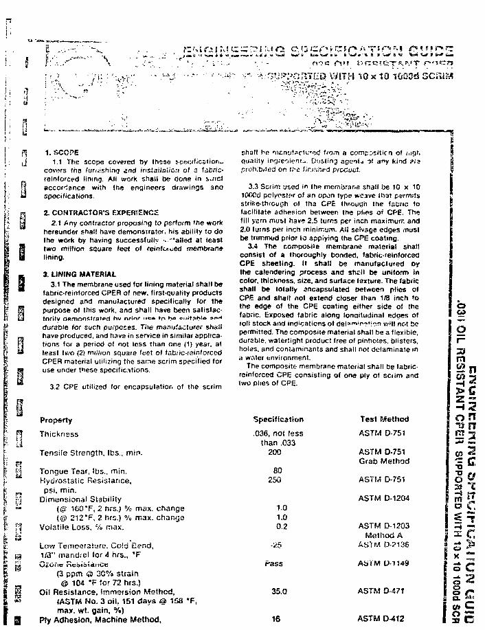
y
•r v - ••him^PCtillEQ. WITH 10 x 10 iGSOd SCRiitf
1. SCOPE1.1 The sccp« covered by these specification.,
covers the turaishinq snd insiailaiiori of s fabric-reinforced fining. All work shall be done in s>.,-ictaccordance wiih the engineers drawings anaspocifications.
2. CONTRACTOR'S EXPERIENCE2.1 Any contractor proposing lo perform 'he work
hereuntier shall have damonsiratet/ his ability to dothe work by having successfully > "'ailed at leasttwo million square feet ol reinfoiced membranelining.
3. LfNING MATERIAL3.1 The membrane used for lining material shall be
fabric-reinlorced CPER of new. first-quality productsdesigned and manufactured specifically for thepurpose of this work, and shall have been satisfac-tOrily 0«rflOnKtr3t«>rt hu nrinr • •« • In Ko enitflKlo »r><<durable for such purposes. Tiie manufacturer shafihave produced, and have in service in similar applica-tions for a period ol not less than one (1) year, atleast t«'O (2> million square feet of fsbiic-r»inforcedCPER material utilizing the sane scrim specified foruse under these specifications.
3.2 CPE utilized for encapsulation of the scrim
Property
Thickness
Tensile Strength, lbs., min.
Tongue Tear, lbs., min.Hydrostatic Resisiance,psi. min.
Dimensional Stability(@ 160*F, 2 hrs.) % max. change(© 212 *F, 2 hrs.) % max. change
Volatile Loss, % max.
Low Temoerature. Coici Bend,1/3" mandfol for 4 hrs., *F\j£Oim nc
shall r>e rn<:nu?acH.TetJ Uo.n a compositicrt of .-.ifjr.quality ingreoiem^.. Dusfing agenij of any kind ?:sproh.'biied on tl e fin.'ihfd ptocuct.
3.3 Scrim used in the membrane shall be 10 x 1010CCd pclyosier of an op^n type weave lhat permitsstrike-through of tha CPE through the fsfcrtc tofacilitate adhesion between the plies o< CPE. Thefill yarn must have 2.5 turns per inch maximum and2.0 turns per inch minimum. Al! selvsfle edges mustbe trirnmod prior to applying the CPE coating.
3.4 The composite membrane material shallconsist of a thoroughly bonded, fabric-reinforcadCPE sheeting. It shall be manufactured oythe calendering process and shell be uniform incolor, thickness, size, and surface texture. The fabricshall be totally encapsulated between plies ofCPE and shall not extend closer than 1/8 inch tothe edge of the CPE coating either side of thefabric. Exposed fabric along lonaitudinal edges ofroll stock and indications of delarT1 '^' f i^n will not bepermitted. The composite material shall be a flexible,durable, watertight product free of pinholes, blisters,holes, and contaminants and shall not detaminate ina water environment.
The composite membrane material shall be fabric-reinforced CPE consisting of one ply of scrim andtwo plies of CPE.
<3 ppm © 30% strain& 104 #F for 72 hrs.}
Oil Resisiance, Smmsfsion Method,(ASTM No. 3 oil. 151 days (3> 1max. wt. gain, %)
Ply Adhesion, Machine Method,
Specification
.036, not (essthan .033
200
80250
1.01.00.2
-25
Pass
35.0
16
Test Method
ASTM D-751
ASTM D-751Grab Method
ASTM D-751
ASTM D-1204
ASTM D-1203Method A
ASTM D-2138
ASfM O-7149
ASTM 0 471
ASTM 0-412
O
Oi-
rn
Z "
onrn ^
3 ^~» 17
35 The fabricator shall be an espeoer.rod firmcu3!orr.:ri(y entyiQotJ tn fa jtorytztxicatin.-, irvjivtriu*! w Kins of 1ab.'icr»ir>lofCK) CPS roll stork m?n h ' r? «.v°t5Factory seams shall have a minimum of t -Vi" scrim toscim avsrtao when made by ihe soiwsn! searrnrvg method.ar<j r*8 incn scrim »o senm overt, jp vvheo nvsoa by the heatwelded method.
Each fsc:wy-f.*i>ricat«i sheet shall bo fiivwi pioniiiier:!.unique in<j«Iible id.<;nt»ryin(3 markine^ iiKJioAimg properdnection r" unroilinq snr'Jcx unloki:n<j To i, jc'itate i-youland (.x»s''kvhf>g in the fwid. Each faciory-fab.icated sho<Mshall bs individually packaged in ;h<»av.'C3rd&c«rdorwooden craie I j l ly enclosed and or-.-teotfx) to prevemdamans lo it t-_ ~Tg shipment promirsentty kteitifiej in iiie\M>r& lusNon as the shed v.;thin arvi showing (he date ofshipment. U>rtii installed, factoy-fsu. iw.V.o.-! ?rvr?ts shall bestored in tf.sir oriqmal unopened crates, if outdoors. theyshall be stored on paliet and shail be potectod from thedirect rays of the sun under a light-colored heat-ref tectiveopague cover in a manner that provides a free-flowing airspace between the crate and cover.
4. OTHER MATERIALS4.1 Solvent for cleaning contact surfaces of field joints
and for other required uses shall be as recommendedmanufacturer or approved fabricator of the fabric-
42 All searRiivg. s*s;iit<; dno htohsoJids ac!5^es:veb shaiibe of a type or types recomrr«r»dej by She manuiacturer orapproved fabricator of the fabric-reinforced CPE aod shailbe delivered in original sealed containers.
5. INSTALLATION5.1 Prior to ordering fabric-reinfeced CPF material, the
contractor may sutrnit. for the engineer's approval. shc>pctra^-ings sixwing linirwj sheet layc"! with proposed size,number, position, of all factory-fabricated sheets andindicating the location of all fie'd joints. Shop 'irawinpsmay also show complete details andJer mn'hods foranchoring the lining at top of slope, making Held joints,seals at structures, etc.
5.2Lap jorr.ts shaii heuuxi to?.*3ifacion-fabTic?:^sr;;-ets of f? b'ic-"-:r.',vc?4 Cr i ! tog<-rh«r in trK" f:-;W AilI'.-'.- jC.nlU L-^*'.*'iL.\ I.'~^'.S \*t >u^i*^,-iuii >I*JI _•;'«; urf t- alloi*
08 nwis ori a 5>!poort.r-i srroo;h ^.vrlace arid, unless ihewcatfusf is SUl!'C!'rn!!v wnrm, t^cM c;jrn i^ail ^« i>se<3 .0rrtEJ;fl roe tizUrv^ iwrjMyali'ie at tea'; f/FF Tl-a la»> j.j»nt5c.k-."ifi be fr-m-M.. by '••w>"x3 "y;cc*7"s c>: £.*••?«» ? rna.mjmof T" sc'iTi-to-scnm 1 iv} corilaf t surfaces of the rhee's•Jvsll be w/irxrt clrar io <;• :K>.C: m' fiit. du^!. mos'.urs. Ofoil"iw (ore'^n matrtir.rs 11 -wi woed ri?3n SL'fiiC»snt C;'t-toO^E boncJirKj fe-ix.'s-.'e shall ty ?w^<? to fcoih =o.i«.actsuriaces in tl-tsioinf area rnd t ie two suifaces ijfssst-Cto<je»f)Of wiiile wet and imrr*dia!jly rolled. Any wr;nklcsshall L/e sn.ootiwd out and any cut <:<rc-S of the fabr:c-reinlorccd CPE Eha" fcD sc-'.ed with a CPE adhesive to
53 Any necessary repairs to Ihe CPE membrane shall bepatched with a piece of the membrane material itself andCPE-toCP£ adtiesiwe. The adhesive shall be applied to thecontact surfaces of both the patch and Itrung to be repaired,the two surfaces pressed together immediately and rolled,and any wrinkles smool.ied out, all in accordance withParagraph 5.2 hereof.
5.4 All joints, on completion of the work, shall be lightlybonded. Any membrane surface showing injury due toscuffing, penetration by foreign objects, or distress fromother causes shaJ!, as directed by the engineer, be replaced~f rep-irc- ..-!"...P. ~JJi;iw>.«.l K ^ C oi i'abni.-re.fiioiceaCPE membrane of the proper size.
5.5 On completion of installation, the contractor shalldispose of all trash, waste, material and equipment used inconnection with (he wort hereunder. and shall leave thepren,i->e:> in a neat ano acceptable condition.
6. SEAM STRENGTH6.1 All faciory 3nd tield seams (joints) snail, after ;2
dsys,ris«oe wctrn strcnrrth of <AJ pounds when tested in ac-cordance with ASTM D-/51. Grao Moihor1 (using <" widespsciiTwns having a fenglh of 10" sAr .rts sesm wtdifs). Tuedistsnes between tne jaws of tha ing spp;«atiiS ai thestart ot She l&st must be 8" plus t l * icam width and shallhave sufficient strength in peel thai they fail by cSelamina-tir«i ircwn the scrim rather than ir> the plane of the saam. t3
OFICPEJV.
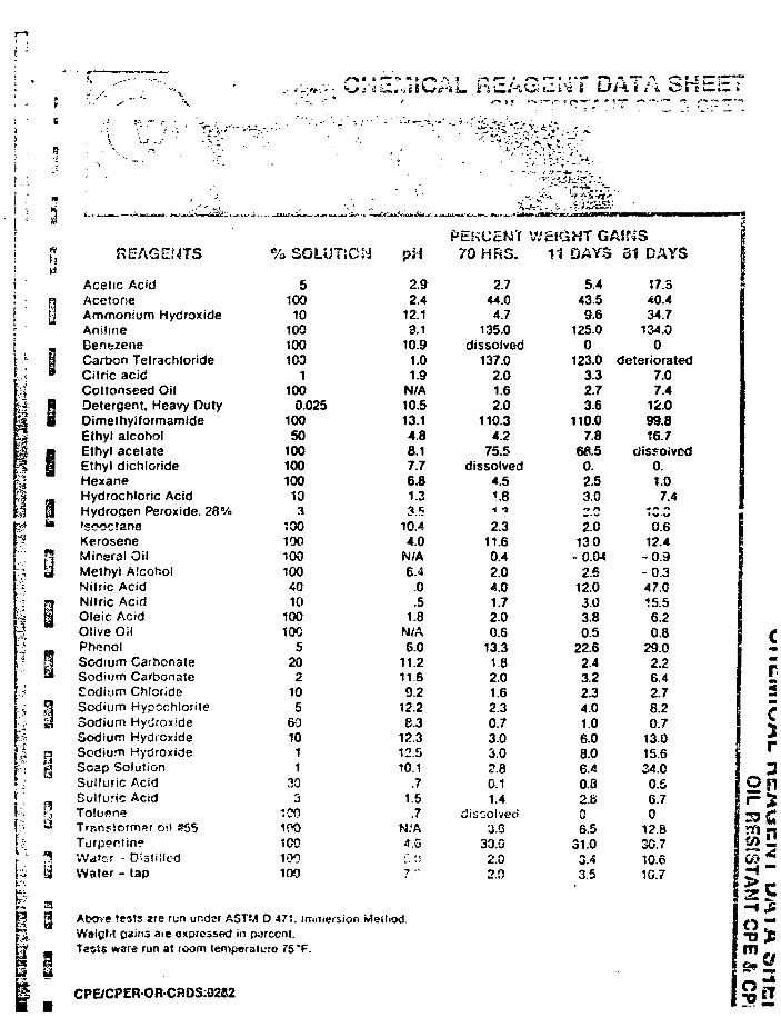
< * • * * •
i~i£.i-iiidriim Hii/J*Vi< tltM • L>/-\ t / i iJiTcultZ* ^ / • * . --v '
-T- -<\ v i . -
I
i
i •i
•
• •
- A
ii
5
•'S3
; ' ;
:"i
.^5
; /
1
j
=-.
':
I3
3
II
11BI
y
%
p
i
MM
1
REAGENTS
Acetic AcidAcetoneAmmonium HydroxideAnilineBenezeneCarbon TetrachlorideCitric acidCottonseed OilDetergent, Heavy DutyDimethyiformamideEthyl alcoholEthyl acetateEthyl dichlorideHexaneHydrochloric AcidHydroqen Peroxide. 28%'sooc'.zneKeroseneMineral OilMethyl AlcoholNitric AcidNitric AcidOleic AcidOlive OilPhenolSodium CarbonateSodium CarbonateEodium ChlorideSotJ'um HypcchloriteSodium HyJrox'deSodium HydioxideSodium HydroxideSoap SolutionSulfuric AcidSulfuric AcidTolupneTran«=tormi»r oil #55Turp?ptin?Water - D;-3tiiledWater - tap
Above tests are run under AWaigM oains aie expressed
% SOLUTiON
5100
10100100103
1100
0.02510050
100100100
10
1001001001004010
100100
520
2105
6010
11
305
1C0100100100too
STM D 477. im.TiefSior. M*in parccnt.
Tssis ware run at >oom temperaturo 75"F.
pH
2.92.4
12.19.1
10.91.01.9
N/A10.513.14.88.17.76.81.33.5
10.44.0
N/A6.4
.0
.51.8
N/A6.0
11.211.69.2
12.28.3
12.312.510.1
.71.5.7
N:A4.5L. :;?."
HliOd
PERCENT70 HRS.
2.744.04.7
135.0dissolved
137.02.01.62.0
110.34.2
75.5dissolved
4.5•».8
1 ?2.3
11.60.42.04.01.72.00.5
13.3182.01.62.30.73.03.02.80.11.4
dissolved3.6
30.02.02.0
WEIGHT GAINS |11 DAYS
5.443.59.6
125.00
123.03.32.736
110.07.8
68.50.2.53.0•» n
2.0130
-o.w2.6
12.03.03.80.5
22.62.43.22.34.01.06.06.06.40.02.806.5
31.03.43.5
81 DAYS
17.340.434.7
134.00
deteriorated7.07.4
12.099.816.7
cJissoivod0.1.07.4
•? C-G
0.612.4
-0.9-0.347.015.56.20.8
29.02.26.42.78.20.7
13.015.634.00.56.70
12.83C.710.610.7
CPE/CPER-OR-CRDS:02S2
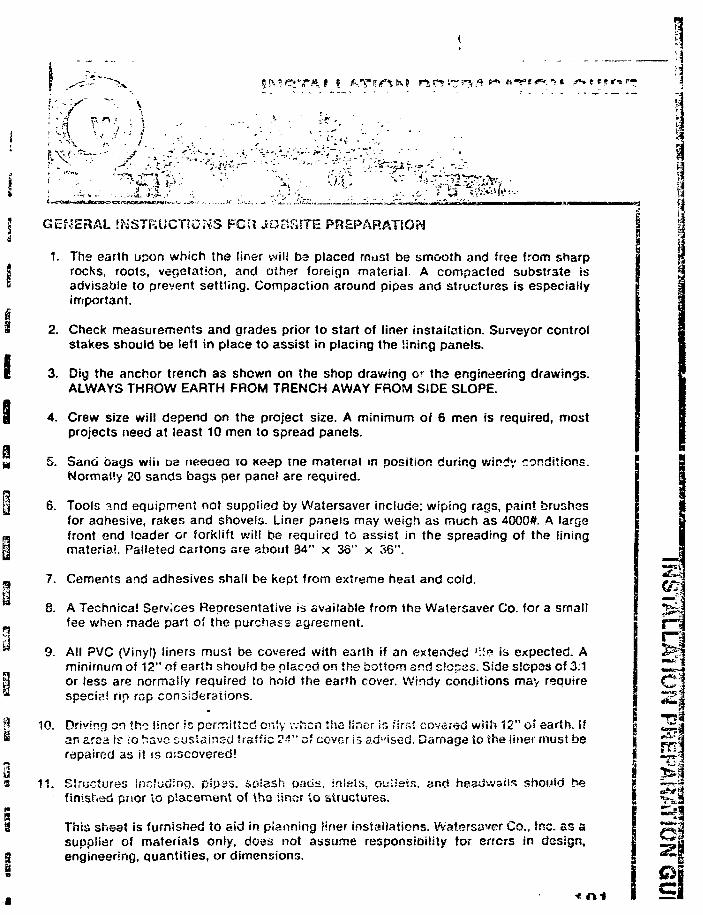
•1
i.
. - < •
p
re-;.' if
GENERAL INSTRUCTIONS FCU JOBfiiTE PREPARATEON
1. The earth Lipon which the liner will ba placed must be smooth and free from sharprocks, roots, vegetation, and other foreign material. A compacted substrate isadvisable to prevent settling. Compaction around pipes and structures is especiallyimportant.
2. Check measurements and grades prior to start of liner installation. Surveyor controlstakes should be left in place to assist in placing the lining panels.
3. Dig the anchor trench as shewn on the shop drawing or tho engineering drawings.ALWAYS THROW EARTH FROM TRENCH AWAY FROM SIDE SLOPE.
4. Crew size will depend on the project size. A minimum of 6 men is required, mostprojects need at least 10 men to spread panels.
5. Sand bays wiii oe neeaea 10 Keep me material in position during windy conditions.Normally 20 sands bags per pane! are required.
6. Tools and equipment not supplied by Walersaver include; wiping rags, paint brushesfor adhesive, rakes and shovels. Liner panels may weigh as much as 4000#. A largefront end loader or forklift will be required to assist in the spreading of the liningmaterial. Palleted cartons are about S4" x 36" x 35".
7. Cements and adhesives shall be kept from extreme heat and cold.
8. A Technical Services Representative is available from the Watersaver Co. for a smallfee when made part of the purchass agreement.
9. All PVC (Vinyl) liners must be covered with earth if an extended Mfe is expected. Aminimum of 12" of earth should be placed on the bottom and slopes. Side slopes of 3:1or less are normally required to hold the earth cover. Windy conditions may requirespecial rip rap considerations.
10. Driving on th-D liner !o permitted only when the liner in first covered wi«h 12" of earth, ifan area if io have susiainsd traffic 24" of cover Is sd-'ised. Damage to the iinec must berepaired as it is discovered!
11. Structures including, pipas. so!ash oao«. :r»!sis. oulisis. and headwaiis should hefinished prior to piacement of tha linar to structures.
This sheet is furnished to aid in planning liner installations. Watsrsaver Co., Snc. as asupplier of materials only, does not assume responsibility tor errors in design,engineering, quantities, or dimensions.
Ji
LINER USERS
APPENDIX E-l
QUESTIONNAIRE TO LINER USERS
NOTE: For distribution referto Table 9.1 in report.
a
I
a March 20, 1934 Our ref: 841-2015
ft
RE: FLEXIBLE MEMBRANE LINERS AS LONG-TERM
Dear Sirs:
Colder Associates has been retained by Department ofSupply and Services, Canada to conduct Phase I of anevaluation of flexible membrane liners for use as uraniumtailings pond liners and dam membranes. The study is beingcarried out for Energy, Mines .>nd Resources, Canada as partof the National Uranium Tailings Program.
Although the study vill fouus on x:> ners for uraniumtailings, information related *:o liner performance in themining industry in general, as well as in the hazardouswaste industry is also required.
Phase 1 of the study will be based on available publishedinformation, information fror. suppliers and informationfrom industrial users. We understand that you currentlyhave facilities in operation which utilize flexiblei..«nibrdne liners and v/e have therefore attached a question-naire which we would like ;, ou to complete ana return.
>'c aro presently considering polymeric liners such asHDPE, KYPALCK, CP2, PVC etc., as well as c^.phiit.Responses from industry users will be incorporated in
March 20, 1934 2 £41-30
The Phase I draft report is scheduled to be completedabout April 1, 1284. Due to project tinting constraintswe would ask you to complete and retorn the attachedquestionnaire as soon as possible, preferably .-rithintwo weeks.
Should you have any questions, please contact the undersigned in our London, Ontario office.
Yours truly
COLDER ASSOCIATES
Frederick W. Firlotte, P. Eng.
FWF/j1
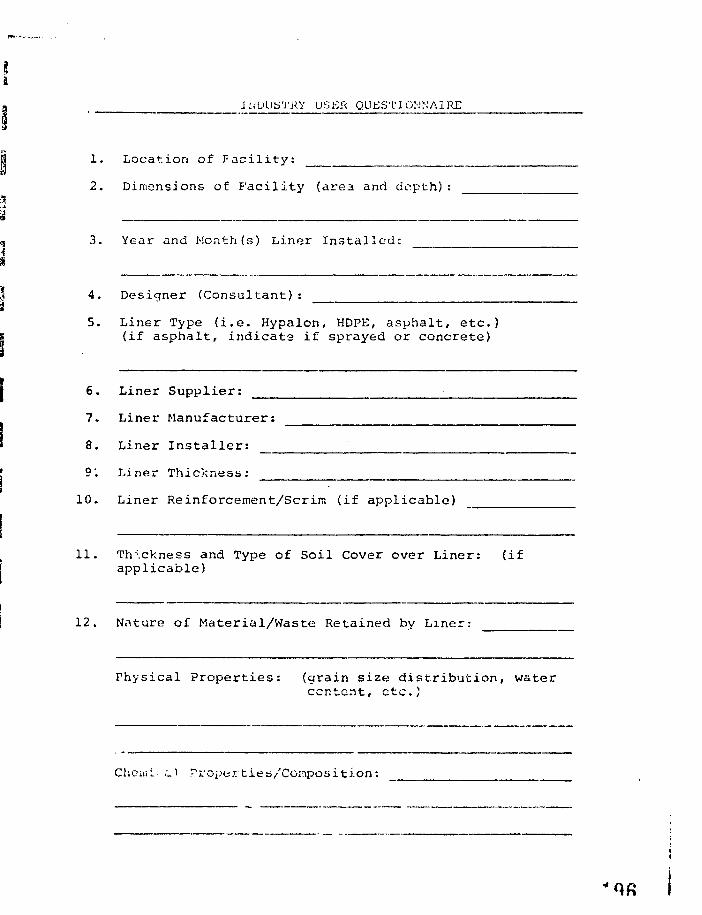
.INDUSTRY USER QUESTIONNAIRE
1. Location of Facility:
2. Dimensions of facility (area and depth)
3. Year and Month(s) Liner Installed:
4. Designer (Consultant):
5. Liner Type (i.e. Hypalon, HDPE, asphalt, etc.)(if asphalt, indicate if sprayed or concrete)
6. Liner Supplier:
7. Liner Manufacturer:
8. Liner Installer:
9'. Liner Thickness:
10. Liner Reinforcement/Scrim (if applicable)
11. Thickness and Type of Soil Cover over Liner: (ifapplicable)
12. Nature of Material/Waste Retained by Liner:
Physical Properties: (grain size distribution, watercontent, etc.)
Choiiii i.V Properties/Composition:
"Oft
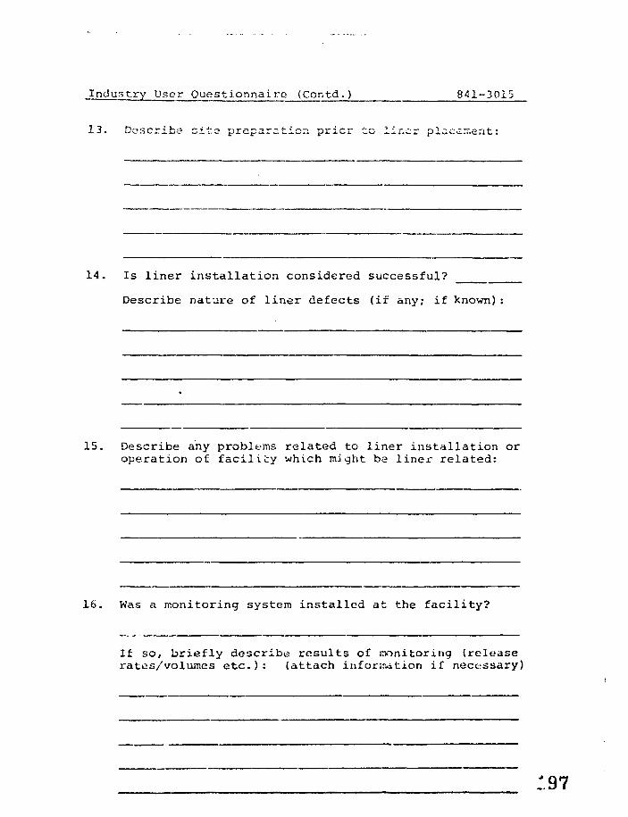
Industry User Questionnaire (Contd.) 841-3015
13. Describe site? preparation pricr to iir.cr placement:
14. Is liner installation considered successful?
Describe nature of liner defects (if any; if known):
15. Describe any problems related to liner installation oroperation of facility which might be liner related:
16. Was a monitoring system installed at the facility?
If so, briefly describe results of monitoring (releaserates/volumes etc.): (attach information if necessary)
Industry User Questionnaire (Contd. ) 841-3015
17. Was there any follow-up work carried out to evaluateperformance of liner system?
If so, briefly describe liner performance: (attachpublished case histories if available)
March 1, 1984 t f\c\Oil'OU
FWF/jl
APPENDIX E-2
COMPLETED USER QUESTIONNAIRES
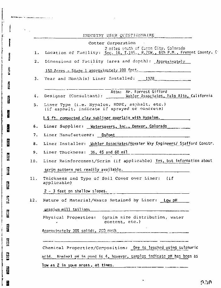
INDUSTRY USEfl QUESTIONNAIRE
Cotter Corporation2 miles so-jth of Carer; C;ty, Colorado
1 . L o c a t i o n of F a c i l i t y : Sec. 16, T.19S., R.7UW., 6th P.M., Fremont County, C
2 . D imens ions of F i i c i l i t y ( a r e a and d e p t h ) : Approximate!V
3 . Year and Month (s) L i n e r I n s t a l l e d : ____1_278_
Attn: Mr. Forrest Gifford4. Designer (Consultant): Wahier Associates, Palo Alto, California
5. Liner Type ( i . e . Hypalcn, HDPE, a spha l t , e t c . )(if a spha l t , ind ica te i f sprayed or concrete)
1.5 f t . compacted clay subliner overlain with Hypaion.
6. Liner Suppl ie r : Watersavers. Inc.. Denver, Colorado
7. Liner Manufacturer: DuPont
8. Liner I n s t a l l e r : Wahier Associates/jjgyater Way Engineers/ Stafford Coristr.
9. Liner Thickness: 36, 45 and 60 mil
10. L i n e r R e i n f o r c e m e n t / S c r i m ( i f a p p l i c a b l e ) Yes, but information about
scrim pattern not readily available.
1 1 . T h i c k n e s s and Type of S o i l Cover o v e r L i n e r : ( i fa p p l i c a b l e )
2 - 3 feet on shallow slopes.
12. Nature of Material/Wasts Retained by Liner: Low pH
uraniurn mill tailings
Physical Properties: (grain size distribution, watercontent, etc.)
Approximately 30% sol ids, 2C0 rr.g;h
Chemical P r o p e r t i e s / C o m p o s i t i o n : Ore Is leached using sulphuric
ar id . Nnmingi pH in pond is 4, however, samples indicate pH has beer. 2s
low as 2 in soiiie areas, at times.
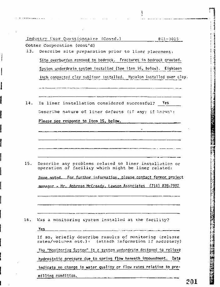
Industry User Questionnaire (Contd.) 841-3015
Cotter Corporation (cont'd)
13. Describe site preparation prior to liner placement:
Site overburden removed to bedrock. Fractures in bedrock grouted.
System underdrain system installed (See item l f i , below). Eighteen
inch compacted clay subliner installed. Hypalon -Installed over clay.
14. Is l iner ins ta l la t ion considered successful? Yes
Describe nature of l iner defects (if any; if !-:r-rwr. :
Please see response to Item 15, below.
15. Describe any problems related to liner installation oroperation of faci l i ty which might be liner related:
fipnf nni-prf. For further information t please contact former proiect
jnanagr>r - Mr. Amhrosp McCready, Lawson Associates (714) 833-799?
l a
16. Was a monitoring system installed at the facility?
_YgS
If so, briefly describe results of monitoring (releaserates/vol.vines etc.)* (attach information if necessary)
The "Monitoring S.y;ten" is a system undsrdrain designed to relieve
hydrostatic pressure due to spring flow beneath impoundment. Data
indicate no change in water quality or flow rates relative to pre-
eoi
industry User Questionnaire (Contc.) 841-3015
Cotter Corporation (cont'd)17. Was there any follow-up work carried out to evaluate
performance of l iner system? _Jf£3
If so, briefly describe l iner performance: (attachpublished case his tor ies if available)
Literature searches indicate Hypaion resistance to lengthy (i.e., 15 year)
^ of 1-0)
"arch 1, 1984
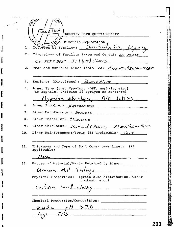
NDUSTRY USER QUESTIONKAI RE.:N'i5\~7 / /o
&/ Minerals Exploration
1. Loc<2ir*ry«""'b£ Facility: ^>ui * g- \'t±rJ^j\ C^o 0Jy^/^.:
2. Dimensions of Facility (area and depth):
3. Year and Month (s) Liner Installed:
4. Designer (Consultant): _j,
5. Liner Type (i.e. Hypalon, HDPE, asphalt, etc.)(if asphalt, indicate if sprayed or concrete)
P*-^ /VC6. Liner Supplier:
7. Liner Manufacturer: 5~}E
H. Liner Installer: (*2
9. L i n e r T h i c k n e s s : 2/ , n>u ?i!(: dcTTcm, 7<P JX./ //yps-eA. 5.7
10. L i n e r Re in fo rcemen t /Sc r im ( i f a p p l i c a b l e ) /t--<i"e
11. Thickness and Type of Soil Cover over Liner: (ifapplicable)
12. Nature of Material/Waste Retained by Liner:
A0\
Physical Properties: (grain size distribution, watercontent, etc.)
Chemical Properties/Conposition:
TD5
203
L %
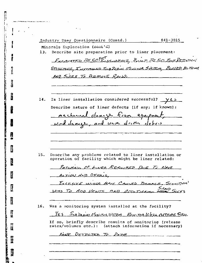
[1 _i *
•' I - •;; ij *
;,' . Industry User Questionnaire (Contd.) 841-3015
I; I Minerals Exploration (cont'd)• 13. Describe site preparation prior to liner placement:
I i - - - «*r\ 3
14. Is liner installation considered successful?
Describe nature of liner defects (if any; if known):
15. Describe any problems related to liner installation or\ n operation of facility which might be liner related:
H Ac Tt/OAJ
•iiVA
16. Was a monitoring system installed at the facility?
If so, briefly describe results of monitoring (releaseH rates/volumes etc.): (attach information if necessary)
iv —
Industry User Questionnaire {Contd. ) 841-3015 t;
Minerals Exploration (cont'd) \\17. Was there any follow-up work carried out to evaluate
performance of liner system?
If SO/ briefly describe liner performance: (attachpublished case histories if available)
March 1, 1984
ii
5?S
4
i
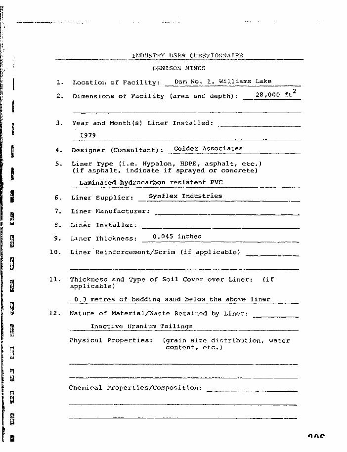
INDUSTRY USER QUESTIONNAIRE
DENISON MINES
1. Location of Facility: Dan No. 1, Williams Lake
2. Dimensions of Facility (area anc depth): 28,000 ft
3. Year and Month (s) Liner Installed:
1979
4. Designer (Consultant): Golder Associates
5. Liner Type (i.e. Hypalon, HOPE, asphalt, etc.)(if asphalt, indicate if sprayed or concrete)
Laminated hydrocarbon resistent PVC
6. Liner Supplier: Synflex Industries
7. Liner Manufacturer:
2. Liner Installer;
9. Liner Thickness: 0.045 inches
10. Liner Reinforcement/Scrim (if applicable)
11. Thickness and Type of Soil Cover over Liner: (ifapplicable)
0.3 metres of bedding sand below the above liner
12. Nature of Material/Waste Retained by Liner:
Inactive Uranium Tailings
Physical Properties: (grain size distribution, watercontent, etc.)
Chemical Properties/Composition:
B one
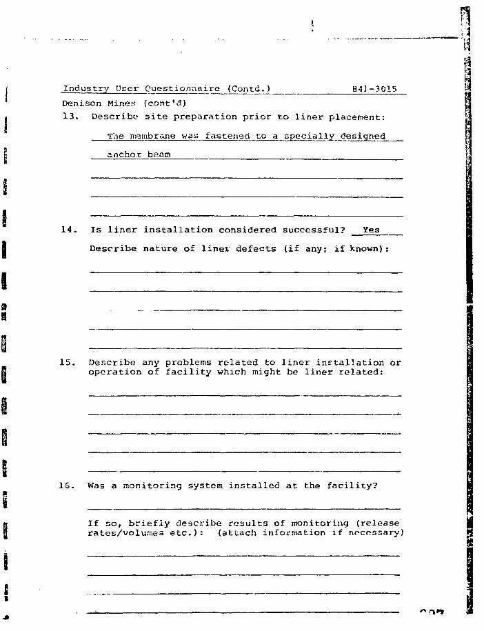
Industry User Questionnaire (Contd.) 841-3015
Denison Mines (cont'd)
13. Describe site preparation prior to liner placement:
The membrane was fastened to a specially designed
anchor beam
14. Is liner installation considered successful? Yes
Describe nature of liner defects (if any; if known)
15. Describe any problems related to liner installation oroperation of facility which might be liner related:
15. Was a monitoring system installed at the facility?
If so, briefly describe results of monitoring (release •rates/volu-.es etc.): (attach information if necessary) M
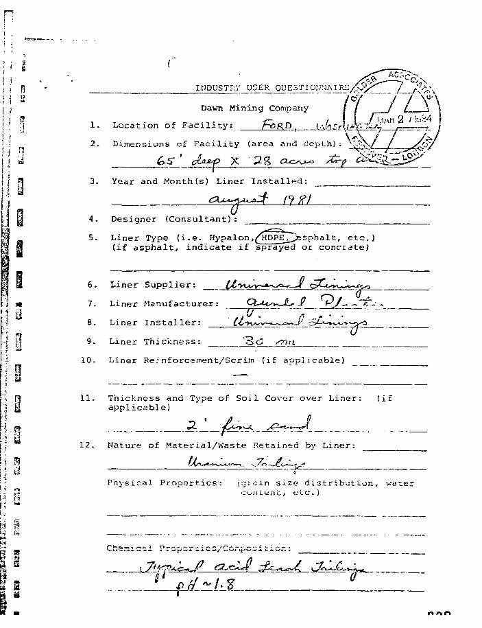
INDUSTRY USER QUESTIOHN'.M KL
1.
2.
Dawn Mining Company
Location of Facility: f-G&D
Dimensions of Facility (area and depth) : 1^QS/__/_
X3. Year and Month(s) Liner Installed:
4.
5.
Designer (Consultant):
Liner Type ( i . e . Hypalon,^HDPE_ijJesphalt> e t c . )(if a spha l t , i nd ica te i f sprayed or concrete)
6.
7.
8.
9.
10.
Liner Supplier:
Liner Manufacturer:
Liner Installer:
Liner Thickness:
-. ft - -
Liner Re: nforceinent/Scrim (if applicable)
11. Thickness and Type of Soil Cover over Liner: (ifapplicable)
i~-rA
12. Nature of Material/Waste Retained by Liner:
^-<.-^»v. K./<a •~JC.*^>-*.'i?
Physical Properties: {grdin size distribution, ware:con Lent, etc.)
Chsmicsi Propercicd/Ccr.pc^iticr.:
r» r\r\
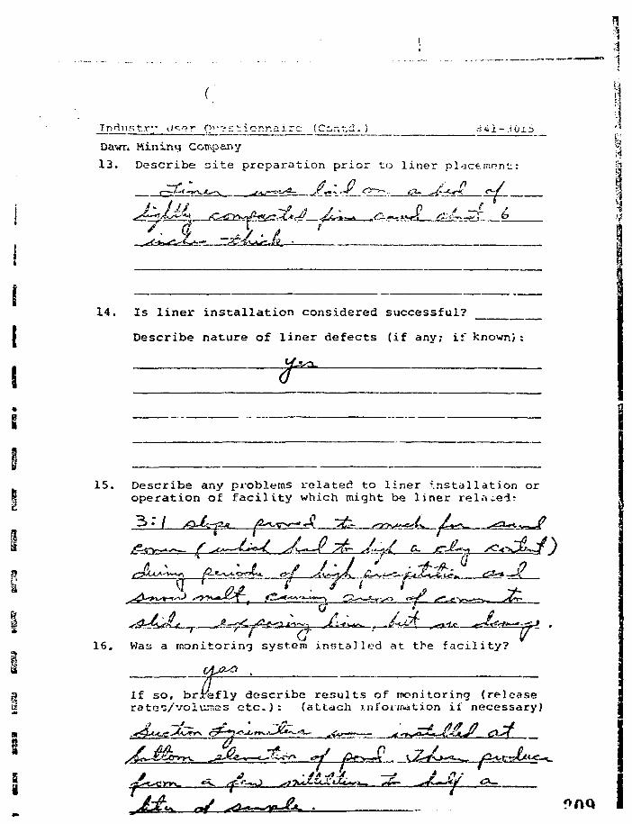
_Tndnstr" <.icaT O'^'^'jiornairc (Ccr.td.)
Dawn Mining Company
13. Describe cite preparation prior to liner placement;
14. Is liner installation considered successful?
Describe nature of liner defects (if any; if known)
15. Describe any problems related to liner installation oroperation of facility which might be liner related;
. J?
16. Was a monitoring system installed at the facility?
>, brieflyIf so, brrefly describe results of monitoring (releaseratcc/voiu.7,23 e t c . ) : (attach information if necessary)
It * J ft •
S
b-ii-3015
Dawn Mining Company \17. Was there any follow-up work carried out to cva1'ia*-e ;
performance of liner syst.em? /VG \
If so, briefly describe liner performance: (attach jpublished case histories if available) ;
i
March 1, 1984 Pi 0Ssi-3015FWF/jl
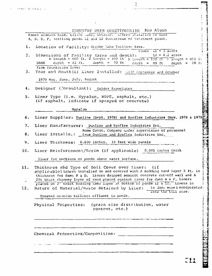
91 ij
ir.'DUS'PRY USER QUESTIONNAIRE Rio Algom 'Panel uranium mine, L l i j o t -..ake"~O!ii.ari"6T Liner:; Ir.uLaTl"i7a in ciJiiVs ;'A, B, D, F, .set t l ing ponds LI ar.d L2 (JcviiUtream of _rcatir>t:rst. p l an t . ;
1. Location of Faci l i ty : Strike Lahe Tailims Area. \iO'.iOij L,I = 3 ac re s i
2 . D i m e n s i o n s of F a c i l i t y ( a r e a and d e p t h ) : -2 = 4.2 acres ;A l e n g t h -• 600 f t . B lonrjth - 3cJ0 it. ri \,-. nc£R~=~T5i!rTt~~Fi"Tt;ngth = 030 li.
DAMS dep th = 42 f.t. depth = 70 f t depth = 49 f t depth •= 28 t v
from founda t ion l e v e l
3. Year and Month (s) Liner I n s t a l l ed : l^fLJilEL<in}ber ar.d October |
1979 May, June, July, Auyust j
4. Designer (Consul tant) : Colder Associates [
5. Liner Type ( i . e . Hynalon, HDPE, asphal t , e t c . )(if a spha l t , i nd ica t e if sprayed or concrete)
Pn
Hypalon
6. Liner S u p p l i e r : Dunlire (Sppt. 1978) and Synflex Industries (Nov. 197S & 1979
7. Liner Manufac tu re r : Dunline and Synflex Industries Inc_:
Ponon Const. Company under supervision of personnel8. Liner I n s t a l l e ~ : from Dunline and Synflex Industries Inc.
9. Liner T h i c k n e s s : 0.030 inches. 33 feet wide panels
10. Liner Reinforcemont /Scr im ( if a p p l i c a b l e ) 0.045 inches thick
liner for sections of ponds above water surface.
1 1 . Thickness a"nd Type of So i l Cover over L ine r : ( i f f"/•app l i cab le ) Liners installed on and covered with A bedding sand layer 2 ft. in j Vthickness for dams B « D. Liners dropped against concrete cut-off wall and A2ft thick chinuiey layer of sand placed agairut liner for dams A & f, Linersplaced~on~2 '~tiuck bodding~and layer ;-it bottom oi poTids L"l i L2. Liners in
12. Nature o£ Mater ial /Waste Retained by Lir.er: ir. jams were i ncorporatedinto the tTll core.
Treated uranium tailings effluent in ponds.
Physical Properties: (grain size distribution, watercontent, etc.) j
f
Chemical Properties/Conposition :
- pa
1 *
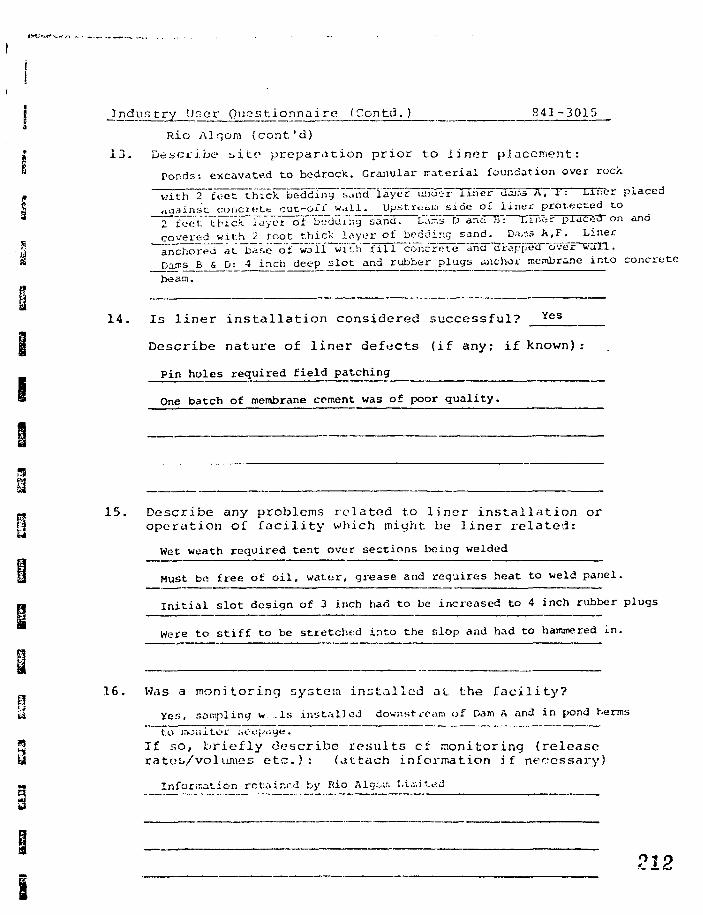
s t ry Ur. e r Ques t i o n na_i re (Contd . ) 841-3015
Rio A]gom {cont'd)
13. Describe s i t e preparat ion pr ior to l ine r placement:
Ponds: excavated to bedrock. Granular material foundation over rock
with 2™feet thlciTTJedd'inT'liaRcriaye'r uiitHFTIher dcur s A, t: Liner placed«aains't conciKte cut-off wall. Upst.rcai.-i side o£ i ine t protected to2 f^et'IFIc.k Tayc^T oi 'budlli:ig sand. Ui.- s D annis: Elr.fer plaCST on andcovered with_j toot thick l<iyer of bedding sand. D.«,:13 A.F. Liner
~anchor"ed~at~ba&e"o"tr~waTl vft.h~f i l l concrete and drappecT oveFTi'Sn .
Da.T.s B & D: 4 inch deep slot and rubber plugs uiiichor membrane into concrete
beam.
14. Is liner installation considered successful? Yes
D e s c r i b e n a t u r e o f l i n e r d e f e c t s ( i f any; i f known):
Pin holes required f ie ld patching
One batch of membrane cement was of poor qual i ty .
15. Describe any problems related to liner installation oroperation of facility which might be liner related:
Wet weath required tent over sections being welded
Must be; free of oi l , water, grease and requires heat to weld panel.
Initial slot design of 3 inch had to be increased to 4 inch rubber plugs
Were to stiff to be stretched into the Slop and had to hammered in.
_ 16. Was a monitoring system installed at the facility?
1» Yes, soniplincj w .Is instal led downstream of Dam A and in pond herms
to monitor iiOcpijye.
9 If so, briefly describe results ci monitoring (releasey rateb/volumes etc.): (attach information if necessary)
B Information rctair.r.d by Rio Alg;v>r. Li.v.itrid
212
1
Industry User Questionnaire (Contd.) 841-3015 ; \
Rio Algom (cont'd) ',. |
17. Wab there any ioiiow-up work carried out i.o evaluateperformance of: l iner system? Not by colder Associates
_ |
If so, briefly describe liner performancet (attach • :published case histories if available)
1
k. -•
I
B
\
t-i
March I , 1554 m841-3015 B
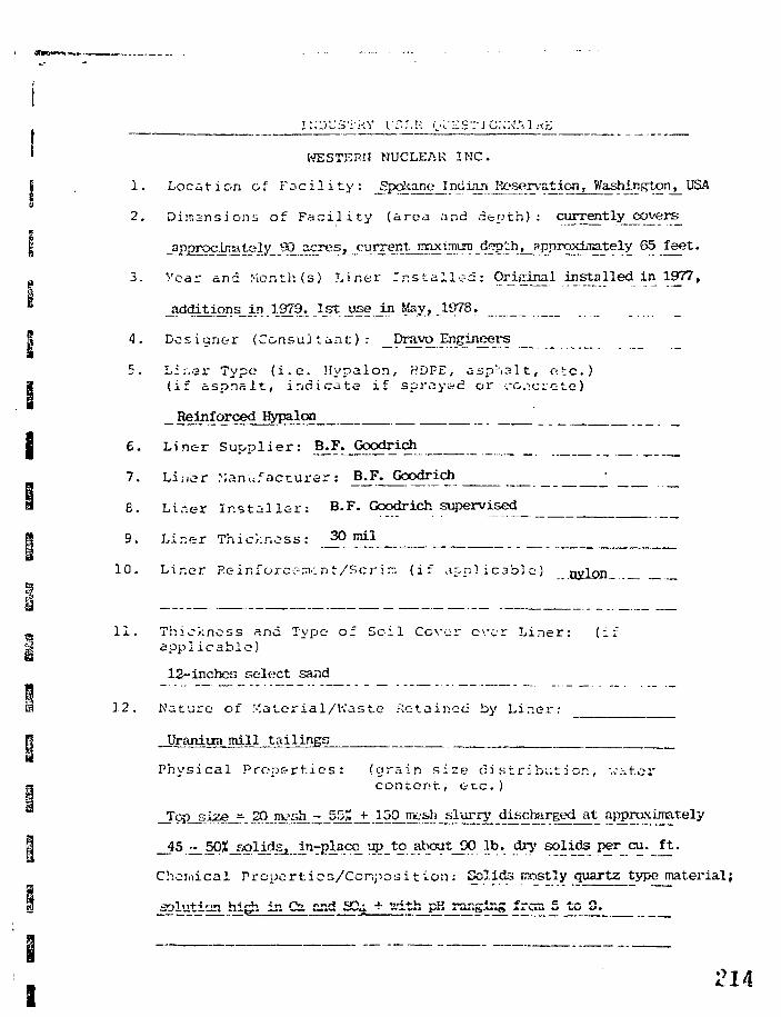
I
ii^vjS'iv.Y IT.'.P. <j\:zs".-ic;;u:•.!«?:
WESTJ2PIJ NUCLEAR INC.
1. Locat ion of F a c i l i t y : _Spcfea:ne_IndianJt^wa^ic^JYashington^USA
2. Di'nsnsions of F a c i l i t y (area nnd d e p t h ) : currently covers
_approcirrately__SO_acres/ current maximum dgpth, approximately 55 feet.
3. Year and Month (s) Liner I n s t a l l e d : Original installed in 1977,
_additions in 1979. 1st use JLn May, 1978.
4. Designer ( C o n s u l t a n t ) : Dravo Engineers ____
5. Lir.er Type ( i . e . Hypalon, HDFE, a s p h a l t , o.tc.)(if a s p h a l t , i n d i c a t e i f spray&d or •.•o.:c:cte)
Reinforced Hypalon
6. Liner S u p p l i e r : B.F. Goodrich
7. Li.-,er Manufac turer : B.F. Goodrich
6. Liner I n s t a l l e r : B.F. Goodrich supervised
9. Lir.er Thicknoss : 30 mil
10. Liner Rein force-me n t /Scrirr . ( i f a p p l i c a b l e ) nylon
_l 11 . Thickness and Type of S o i l Cover ever L iner : ( ify applicable)
12-inches select sand
b 12. Nature of Material/Waste Retained by Lir.er:
R Uranium mill tailings
Physical Proper t ies : (grain size ci s t r i bi;t ion, v.-;-.tercontent, e tc . )
Top size = 20 mesh - 55£ +_ 150 nsesh slurry discterged at approximately
_J5 ^^^^ i2^j .A n rPl a .^ I©_ t°- . J? ]^ t_? 0 ^b-. fby solids per cu._£t.
Chemical Propcrtics/Ccni^oaition: Spli&s mostly quartz type material;
solution hi^i in Ca and SD4 + ath pH ranging fror. 5 to 0.
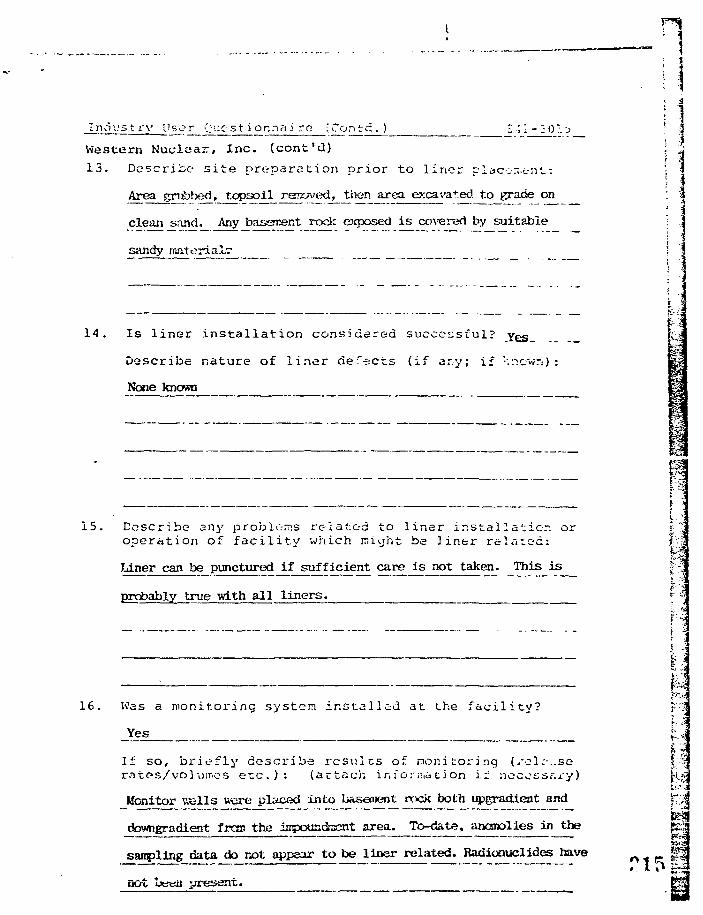
I n d u s t r y User Quest i or.nni re (Con t d . ) 1 •; 1 - 2 0 :. a
Western Nuclear, Inc. (cont'd)
13. Describe s i t e preparation prior to l iner piaccn.c-nt:
Area grubbed, topsoll removed, then area excavated, to grade on
clean sand. Any basement rock exposed is covered by suitable
sandy
14. Is l iner i n s t a l l a t i o n considered successful? yes
Describe nature of l i ne r defects (if ar.y; if '•'.nev;.-i) :
None known
WM
16. Vvas a monitoring system installed at the facility?
_Yes
It so , b r i e f l y descr ibe r e s u l t s o: nonitoring (.rcl:-..soiT.es e t c . ) : ( a t t ach inf orii.d t ion if noccsst.xy
Monitor ^ells were placed into basement rock both upgradient and
dewngradient frcm the icpoundracnt area. To-date, ancsnolies in the
sanpling data do not appear to be liner related. Radionuclides have
not !*?tai .present.
«r»
15. Describe any problc-ms rc-latc-d to l iner ins ta l l a t ion or IJ-operation of facilitv which niuht be liner related: |-;Ji
Liner can be punctured if sufficient care is not taken. This is ?" ?
probably true with all liners. *• "
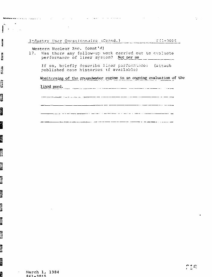
Ir^ustry User Qnosc) or:r.dirt (Cento. ) c 4 1 - 3 01 5
Western Nuclear Jnc. (cont'd)17. V.'as there any follow-up work carried out to evaluate
performance of liner systc-n? Not per ss
If so, briefly describe liner p^rrcr.- \,r:ce: (attachpublished case histories if available)
of the oundwater regiro J.^^_ongoj:n^e^a.luation_ of the
lined pond.
March 1, 1984
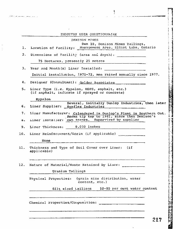
INDUSTRY USER QUESTIONNAIRE
DEN I SON MINESDam 10, Denison Mines Tailings,
1. Location of Facility: Management Area, Elliot Lake, Ontario
2, Dimensions of Facility (area and depth):
75 Hectares, presently 25 metres i
3. Year and Month (s) Liner Installed: \-
Initial installation, 1971-72, men raised annually since 1977. |
4. Designer (Consultant): Golder Associates t;
5. Liner Type (i.e. Hypalon, HDPE, asphalt, etc.)(if asphalt, indicate if sprayed or concrete)
Hypalort
6. Liner Supplier: Synflex IndustriesSeveral, initially Dunlop Industries, then later j?
7. Liner Manufacturer: Calendered in Dunlop's Plant in Southern Ont. iReema tip top to 1981, since then Denison's i-
o. iiiner installer: own torces. Supervised by supplier V.
r9. Liner Thickness: 0.030 inches [.
«... j
10. Liner Reinforcement/Scrim (if applicable)None
11. Thickness and Type of Soil Cover over Liner: (ifapplicable)
12. Nature of Material/Waste Retained by Liner: j-Uranium Tailings Iri
Physical Properties: (grain size distribution, water L Jcontent, etc.)
Silt sized tailings 50-80 per cent water content— —
Chemical Properties/Composition:
P17— — •
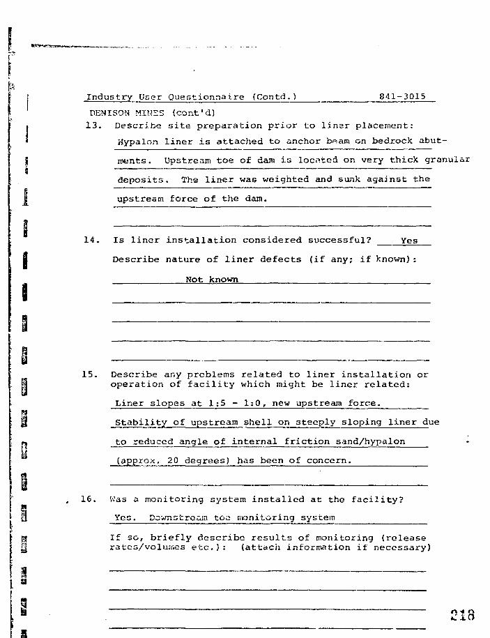
a
9la
Industry User Questionnaire (Contd.) 841-3015
DENISON MINES (cant'd)13. Describe .site preparation prior to liner placement:
Hypalon liner is attached to anchor beam on bedrock abut-
ments. Upstream toe of dam is located on very thick granular
deposits. The liner was weighted and sunk against the
upstream force of the dam.
14. Is liner installation considered successful? Yes
Describe nature of liner defects (if any; if known):
Not known
15. Describe any problems related to liner installation oroperation of facility which might be liner related:
Liner slopes at 1;5 - 1:0, new upstream force.
Stability of upstream shell on steeply sloping liner due
to reduced angle of internal friction sand/hypalon
(approx. 20 degrees) has been of concern.
16. Was a monitoring system installed at the facility?
Yes. Downstream too monitoring system
If so, briefly describe results of monitoring (releaserates/volumes etc.): (attach information if necessary)
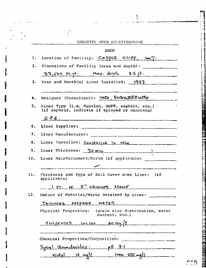
INDUSTRY USER QUESTIONNAIRE
IHCO
1. Location of Facility; do pp-g^ c u p p , ,
2. Dimensions of Facility (area and depth):
3. Year and Month (s) Liner Installed:
4. Designer (Consultant): INCo .
5. Liner Type (i.e. Hypalon, HDPE, asphalt, etc.)I (if asphalt, indicate if sprayed or concrete)
g 6. Liner Supplier:
I 7. Liner Manufacturer:
8. Liner Installer: Ctfu-rfiAt-ToS. Te
9. Liner Thickness: 3o
10. Liner Reinforcement/Scrim (if applicable)
11. Thickness and Type of Soil Cover over Liner: (ifapplicable)
12. Mature of Material/Waste Retained by Liner:
Physical Properties: (grain size distribution, watercontent, etc.)
S O fVj«
Chemical Properties/Conposition:
•Aick&l
n
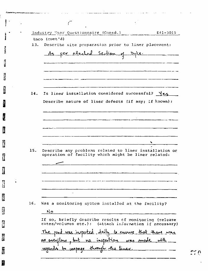
Industry ','ser Questionnaire (Contd.) 841-3015
Inco (cont'd)
13. Describe site preparation prior to liner placement:
.__si JM
14. Is liner installation considered successful?
Describe nature of liner defects (if any; if known):
15. Describe any problems related to liner installation oroperation of facility which might be liner related:
16. Was a monitoring system installed at the facility?
Mo
If so, briefly describe results cf ironitoring (releaserates/volumes etc . ) : (attach information if necessary)
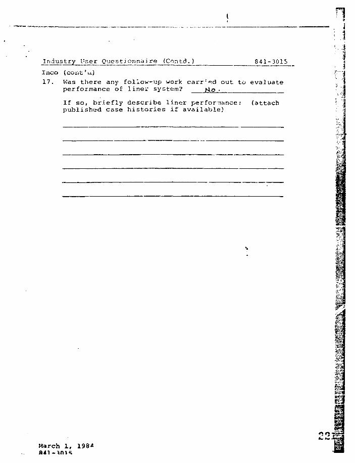
Industry User Questionnaire (Contd. ) 841-3015Ineo (cont'u)17. Was there any follow-up work carried out to evaluate
performance of liner system?
If so, briefly describe liner performance: (attachpublished case histories if available)
: . J
tern
m
March 1 , 198A
«•» e\ •
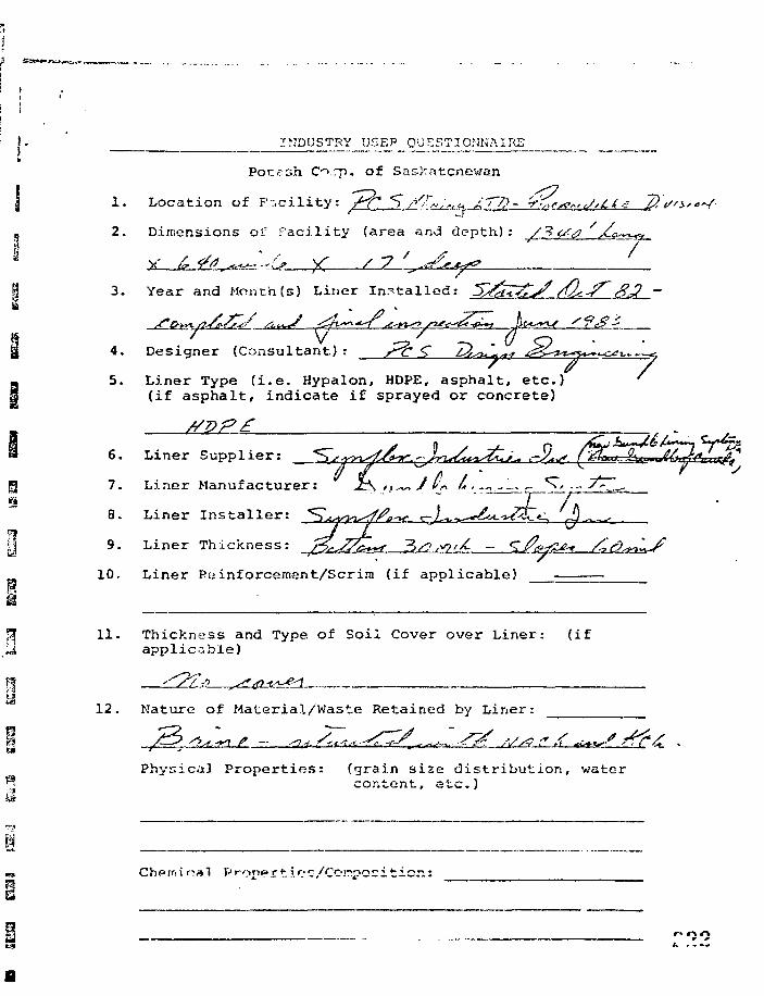
I - INDUSTRY USEP QUESTIONNAIREto
tih C >,rp. of Saskatchewan
1. Location of Facility: /f^ *$ />'£„;„« ATP- A » ^ ^ = ^'' ... ^ _ .
2. Dimensions of Facility (area and depth) : /J? /
3. Year and Month (s) Liner In-tailed:
4. Designer (Consultant) : j^c £ T%^uL**4 < g ^ ^ > ^ u , ^^^- ^ 7
5. Liner Type (i.e. Hypalon, HDPE, asphalt, etc.)(if asphalt, indicate if sprayed or concrete)
6. Liner Supplier:
7. Liner Manufacturer:
8. Liner Installer:
9. Liner Thickness: r^JZZ^f 3/0
10. Liner Painforcement/Scrira (if applicable)
11. Thickness and Type of Soil Cover over Liner: (ifapplicable)
12. Nature of Material/Waste Retained by Liner:
Physical Properties: (grain size distribution, watercontent, etc.)
Chipm \ rra 1 P rope r t i»? c/Coirpos i t i o n :
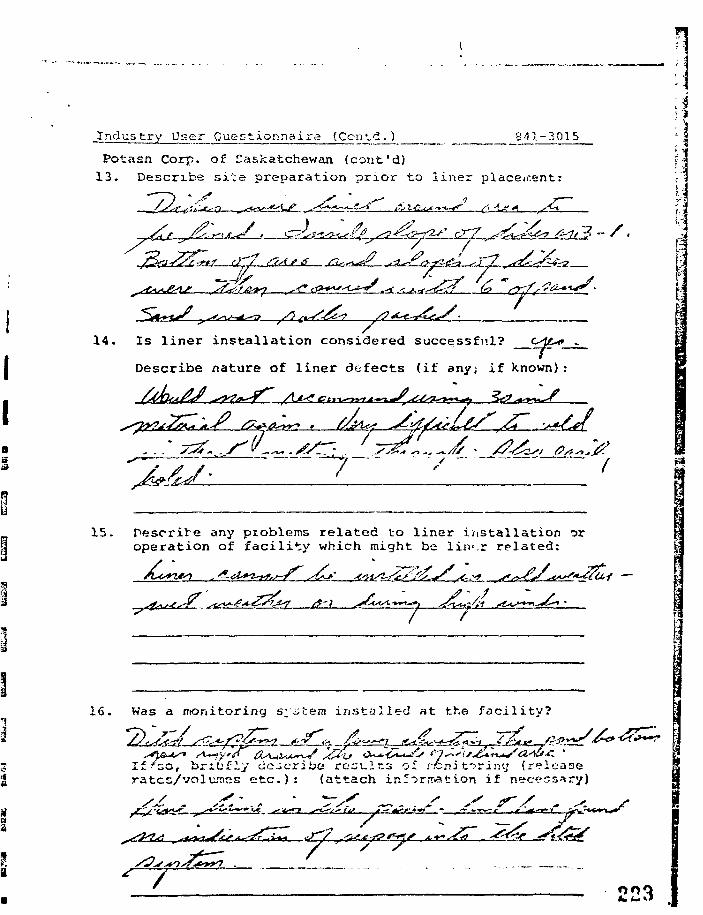
Industry User Questionnaire (Contd.) 841-3015
Potasn. Corp. of Saskatchewan (cont'd)13. Describe site preparation prior to liner placement:
1 4 .
I • * - • • - — • —y-
Is liner installation considered successful? _
Describe nature of liner defects (if any; if known):
:1
15. Describe any problems related to liner installation oroperation of facility which might be lirv.r related:
^*y ^C^J
i
16. Was a monitoring s;item installed at the facility?
y 0 i f /&& yO, briefly describe rcst-lns of rcni taring (release
rates/volumes etc .) : (attach inr^rnration if necess
/
223
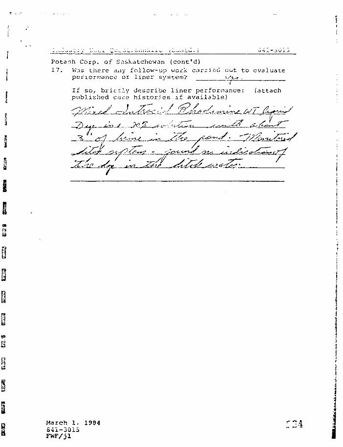
Potanh Corp. of Saskatchewan (cont'd)17. Was there aiiy follow-up work carried out to evaluate
periormance or liner system? tvV-j .i
If so, britt?.y describe liner performance: (attachpublished case histories if available)
March 1. 1984541-3015FWF/jl i

Falconbridge Mines
3 . Location of F arti lity : fA^<. < ,^,j *"..-/" •--'
2. Dimensions of Facility (area and depth)
3. Year and Montts (s) Liner Installed:
i
4. Designer (Consultant): fa ~(>c.<-^<v It
5. Liner Type (i.e. Hypalon, HDPE, asphalt, etc.) [•(if asphalt, indicate if sprayed or concrete) ^
/"V c6. Liner Supplier: S> TfiffT /\y /*>..>•., TC / £• •
1. Liner Manufacturer: " |_J
8. Liner Installer: P*, yr 1- J~'-J<•>-^--~"c/£ /*-/(• t
10. Liner Reinforceuient/Scrim (if applicable) ! <
j> . .<11. Thickness and Type of Soil Cover over Liner: (if
appii cable)
12. Nature of Material/Waste Retained by Liner: f
^A^J ?_ L .-:
Physical Properties: (grain size distribution, watercontent, etc.)
Ch'MnJc^l Proof >" t i c s / C o r v ' O s i t i o n : [•".._
BS.1vrt*r>
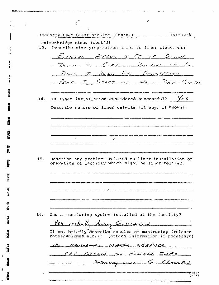
I
Industry User Que stionnaire (Cont a . )
Falconbridye Mines (cont'd)13. Describe site prppsration prior to liner placement:
f± 2IL: c t- /?y •_ /?<..J/.- /~,rs<. ,-
14. Is liner installation considered successful?
I Describe nature of liner defects (if any; if known):
1
15. Describe any problems related to liner installation oroperation of facility which might be liner related:
16. Was a monitoring system installed at the facility?
JIf so, briefly describe results of monitoring (relearerates/volumes etc.): (attach information if necessary)
Industry User Questionnaire (Contd.) 841-3015
Falconbridge Mines (cont'd)
17. iiiis there any follow-up work udititu out to evaluateperformance of liner system? _A_[p
If so, briefly describe iiner performance: (attachpublished case histories if available)
.-> rt *
841-3015
m
pm
N
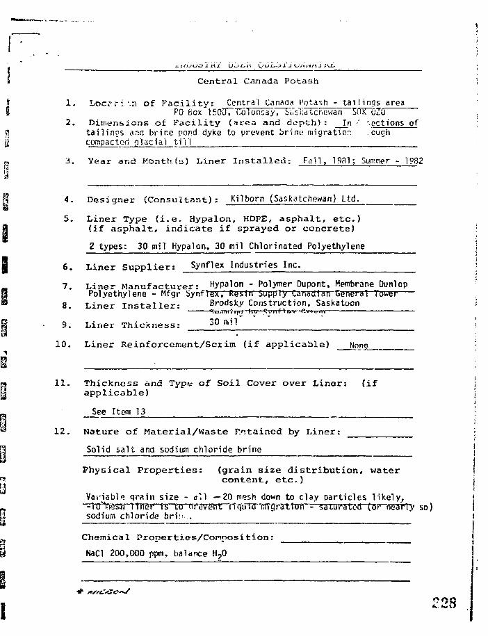
Central Canada Potash
1 . L o c i - i ' . n o f F a c i l i t y : Central Canada t'otasn - t a i l i n g s areaPO Box ISOUrToTonsayT^i'SKtitcncwan SftfCDZCT
2. Dimensions of Facility (irea and depth) : In •' sections oftailinos and brine pond dyke to prevent brine migration .cuohcompactcd glacial t i ' i i
3 . Y e a r a n d M o n t h ( s ) L i n e r I n s t a l l e d : F a l l , 1981; Summer - 1982
4. Designer (Consu l tan t ) : Kilborn (Saskatchewan? Ltd.
5. Liner Type ( i . e . Hypalon, HDPE, asphalt, etc.)(if asphalt, indicate i f sprayed or concrete) I
2 types: 30 mil Hypalon, 30 mil Chlorinated Polyethylene !
6. Liner Supplier: Synflex Industries Inc. ;
7. L ine r Manufacturer : Hypalon - Polymer Dupont, Membrane DunlopPolyethylene - Mfgr Synflex, Resin Supply Canadian CeneraT Tower
8 Liner Ins ta l l e r - Brodsky Construction, Saskatoon it?i-i., Ill i III I Iw I f f l f i u . P-rn,iM
S. Liner Thickness: 2 0 ni1#1
1 0 . L i n e r R e i n f o r c e m e n t / S c r i m ( i f a p p l i c a b l e ) None
11 . Thickness and Type of Soil Cover over Liner: (ifapplicable)
See Item 13
12. Nature of Material/Waste P.otained by Liner:
Solid salt and sodium chloride brine
Physical Properties: (grain size distribution, watercontent, etc.) j
Vanabig grain size - e l l —20 mesh down to clay particles l ikely, j-lTrVtssii i trie if is LG nrsvenT 'rfitjirnrTinTirTtToTr- satursrM-Tov nearly so) isodium chloride bri: :. !
. |
Chemical Properti.es/Conposition: j
NaCl 200,000 npm, balance H?0

15. Describe any pioblems related to liner installation oroperation of facility which might be liner related:
None of any account to date.
f*-?|
industry User Questionnaire .iConta.) 841-3015 { |
Central Canada Potash (corit'd) !• |
13. Describe site preparation prior to lir.ar placement: l J
Construct compacted t i l l dyke with suraothed inside face. 3:1 ?
slope. Compacted 6" f ine sand ua^'der l i ne r . V compacted f ine '
~sim'd~oVSr~Ti'n«fr;—?^trtstfe<tTt1^~f-i3r~2^-xrf^yrhv; uirer e i eiju i i ati-
for M V P art inn prnt.prtinn.
\
14. Is l iner ins ta l la t ion considered successful? Yes (See Below) I
Describe nature of l iner defects (if any; if known):
Don't know yet, will take some years to find out.
i-i
IS. Was a monitoring system installed at the facility?
Yes but not to monitor l i ne r performance pe• se monitors overallt a i l s area bshaviour.
If so, briefly describe results of monitoring (releaserates/ vol times etc.): (attach information if necessary)
No information of use to date. No change in background water ^
qua l i ty levels. t 'i_ _ _ . pug
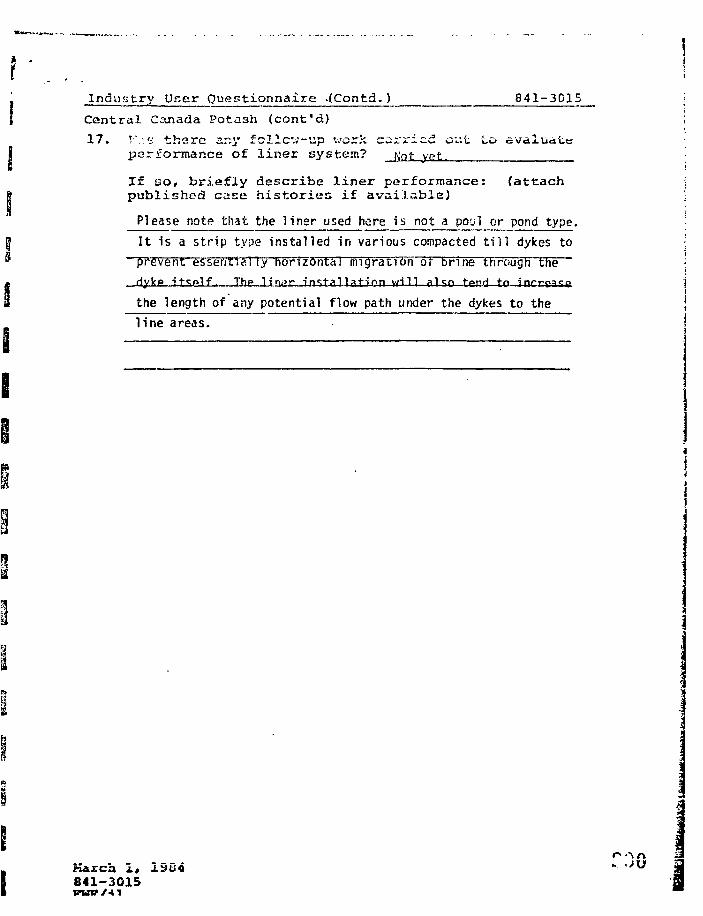
Industry User Questionnaire .(Contd. ) 841-3015
Central Canada Potash (cont'd)
17. i:.-.v there sr.y follcv-up work carried out to evaluateperformance of liner system? tot, ypt.
If no, briefly describe liner performance: (attachpublished case histories if available)
Please note that the liner used here is not a pool or pond type.I t is a strip type installed in various compacted t i l l dykes toprevent essentially horizontal migration or brine Cfirough theHyl<p it«;t>1f. Thp 11" n.ar i n s t a l l a f i rm yji 11 ft"|<:p ^gr>j t n ^HrrPaSP
the length of any potential flow path under the dykes to the Jline areas. I
Kirch i# 1504841-3015
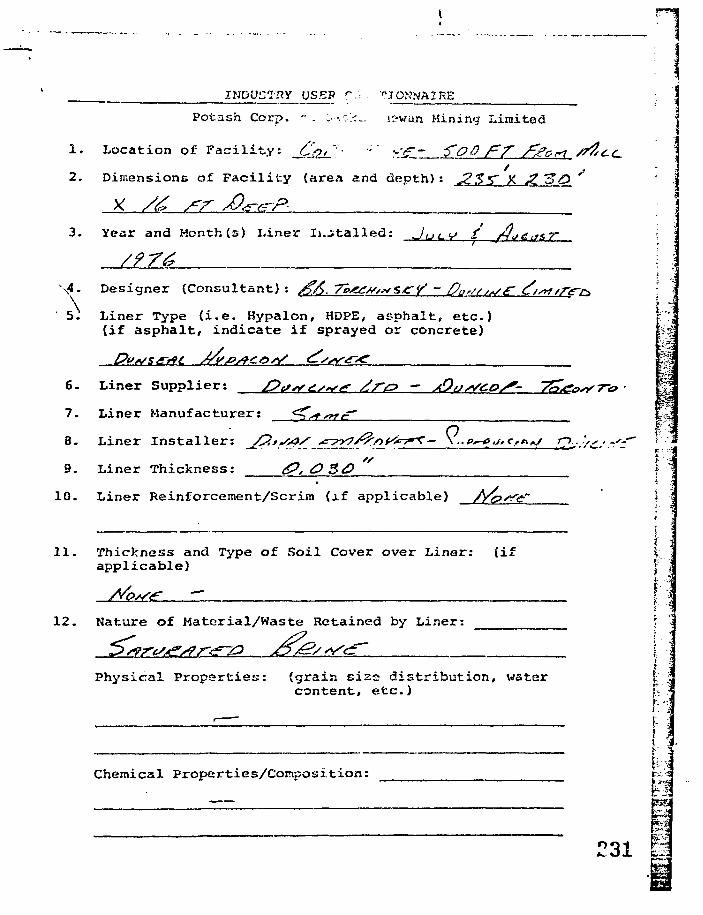
INDUSTRY USED r-< .Potash Corp. - . ;•-.•:;;•:... <i-\tun Mining Limited
1. Location of Facility: _£#/.'• ' >:£.' ToO f^f
2. Dimensions of Facility (area and depth) : J2S"S~ X JZ. "SO
3. Year and Month (s) Liner Ii.stalled:
4. Designer (Consultant): ^ > . 7h/X///*s CY - Pc/ss^e- <?/s»/r<rc>\5. Liner Type (i.e. Hypalon, HOPE, asphalt, etc.)
(if asphalt/ indicate if sprayed or concrete)
6. Liner Supplier: /?<s*>£s*s^ /?ro - A9,JS*COS'-
1. Liner Manufacturer:
8. Liner Installer: /P.tSseS ^c-^yy/^nf^^K'— \ ..p^e./. (**.*/~ * i • • • *
9. Liner Thickness: <£•?, 0 3d)
12. Nature of Material/Waste Retained by Liner:
Physical Properties: (grain size distribution, i<fatsrcontent, etc.)
Chemical Properties/Conposition:
> . *~
• ••10. Liner Reinforcement/Scrim (if applicable) /Yc?s<e~ *
11. Thickness and Type of Soil Cover over Liner: (ifapplicable)
h
'31
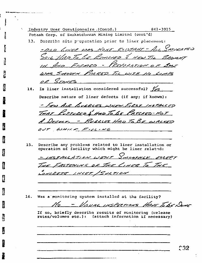
i
Industry User Questionnaire .(Contd.) 841-3015Potash Corp. of Saskatchewan Mining Limited (cont'd)
13. Describe site preparation prior to liriei- placement:
14. Is liner installation considered successful?
Describe nature of liner defects (if any; if known):
15. Describe any problems related to liner installation oroperation of facility which might be liner related:
fists' £/**<«•- ^V^g^r^W-^^/C ^/^ ^^<f~ tLssi'er-?^ /a ^rS*
16. Was a monitoring systera installed at tha facility?
If so, briefly describe results of monitoring {releaserates/volumes etc.): (attach information if necessary)
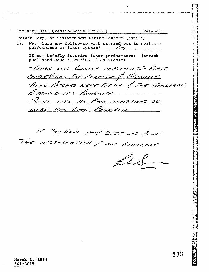
Industry User Questionnaire .(Contd.) 841-301S
Potash Corp. of Saskatchewan Mining Limited (cont'd)17. Was there any follow-up work carried, out to evaluate
performance of liner system?
If so, briefly describe liner performance: (attachpublished case histories if available)
"7*
- (b^ -see- s?7& SSa ^r.
1.3: 3i i
I I
i
IM
r
B
March 1, 1984841-3015
033 g
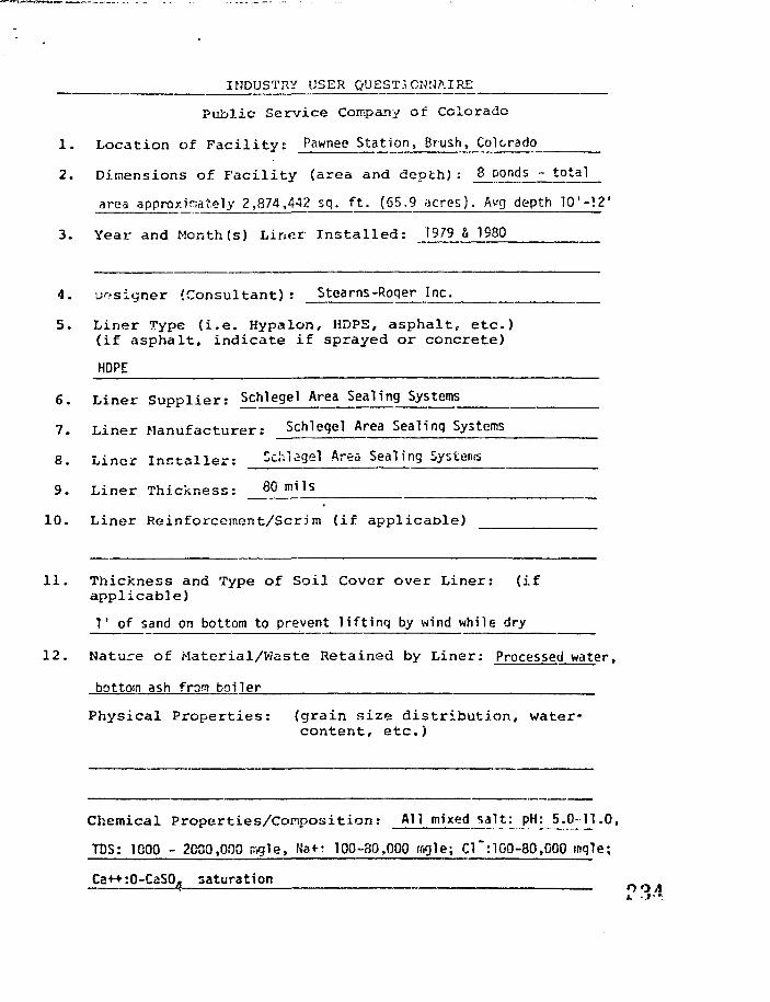
INDUSTRY USER QUESTIONNAIRE
Public Service Company of Colorado
1 . Locat ion of F a c i l i t y : Pawnee Station, Brush, Colorado
2. Dimensions of F a c i l i t y (area and depth) : 8 ponds - total
area approximately 2,874,442 sq. f t . (65.9 acres). Avg depth 10'-12'
3. Year and Month(s) Liner Instal led: 1979 & 1980
4. Designer (Consultant): Stearns-Roqer Inc.
5. Liner Type ( i . e . Hypalon, HDPS, asphalt, etc.)(if asphalt, indicate if sprayed or concrete)
HOPE
6 . L iner Suppl ie r : Schiegei Area Sealing Systems
7. L iner Manufacturer: Schleqel Area Sealing Systems
8. L iner I n s t a l l e r : Schiegel Area Sealing Systems
9. Liner Thickness: 8 0 m i l s
10. Liner Reinforcement/Scrim (if appl icable)
11 . Thickness and Type of Soil Cover over Liner: ( ifappl icable)
I 1 of sand on bottom to prevent l i f t i ng by wind while dry
12. Nature of Material/Waste Retained by Liner: Processed water,
bottom ash from boiler
Physical Properties: (grain size distribution, water-content, etc.)
Chemical Propert ies/Composi t ion: AH mixed salt: pH: 5.0-TI .0,
TDS: 1000 - 2000,000 tr^ie, Na+: 100-80,000 mgie; C1~:100-80,000 ingle;
Ca++:O-C-SO. saturation r>o A
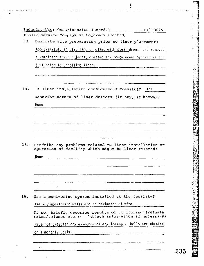
Industry User_Qujsstjj nnaJL££_ (Contd.) 841-3015
Public Service Company of Colorado 'cont'd)
13. Describe site preparation prior to liner placement:
Approximately 2' clay l iner, rolled with steel drum, hand removed
a remaining sharp objects, dressed any rougci ^reas by hand raking
just prior to Mnroilinq l iner.
14. Is l iner installation, considered successful? Yes
Describe nature of l iner defects (if any; if known):
None
15. Describe any problems related to l iner instal lat ion oroperation of fac i l i ty which might be l iner related:
None
: f16. Was a monitoring system instal led at the faci l i ty? T;"
Yes - 7 monitoring wells around perimeter of site ' ^
If so, briefly describe resul ts of rronitoring (release *fMrates/volumes e t c . ) : ^attach information if necessary) £|:;
Have not detected any evidence of any leakage. Wells are checked H |
on a monthly tosis.
235
1 Industry User Questionna j re (Contd. ) 8*11 3015
• P'liiiiic Sci'vicvi Company o£ Coj.oircido ico/it u)
u 17. Was there any follow-up work carried out to evaluate| performance of liner system?
nLi
1
I
•hi
If so, briefly describe liner performance: (attach^ published case histories if available)
aAl l seams were inspected and ul trasonical ly tes:ed.
a
Sample attached.
March 1, 1984841-3015
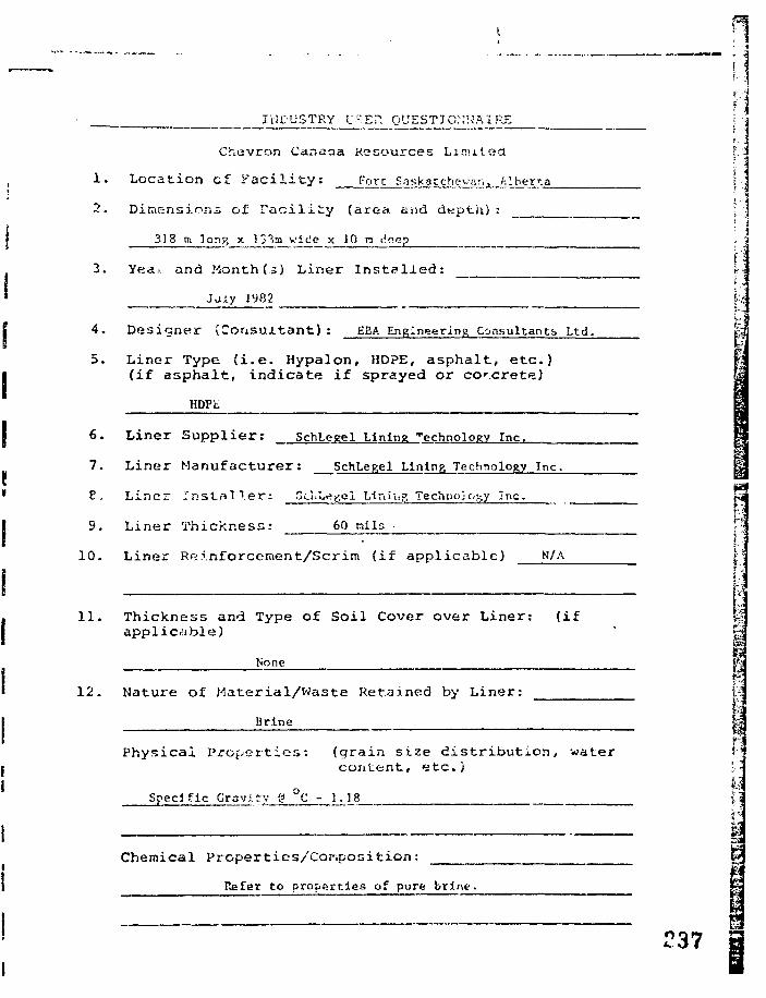
INDUSTRY L' .En QUESTIONNAIRE
Chevron Canaaa Resources Limited
1. Location cf F a c i l i t y : Fort Saskatchewan, Alherna
2. Dimensions of F a c i l i t y (area*, and depth) : |. j
318 m lon% x !3 m wide x 10 B deep
3. Yea., and .Month U) Liner I n s t a l l e d :
Jaiy 1982
4. Designer ( C o n s u l t a n t ) : EEA Engineering Consultants Ltd.
5. Liner Type (i.e. Hypalon, HDPE, asphalt, etc.)(if asphalt, indicate if sprayed or corcrete)
HDPE
6. Liner Suppl ie r : SchLegel Lining technology Inc.
7. Liner Manufacturer: SchLegel Lining Technology Inc.
P. Liner InstfllTer: Sci.Ley.el Llnlug Technology Inc.
9. Liner Thickness: 60 nils •
1 0 . L i n e r R e i n f o r c e m e n t / S c r i m ( i f a p p l i c a b l e ) N/A
11. Thickness and Type of Soil Cover over Liner: (ifapplicable)
None
12. Nature of Material/Waste Retained by Liner:
Brine
Physical Properties: (grain size distribution, watercontent, etc.)
Specific Gravity 0 C - 1.18 ?3
Chemical Properties/Cor.position:
Refer to properties of pure brine.
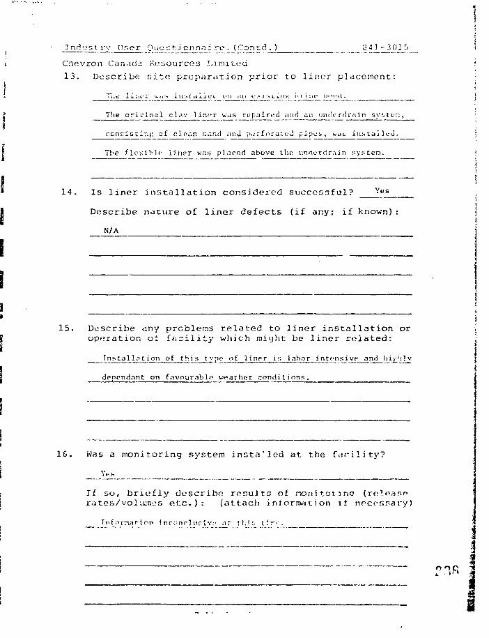
Jnd'.:r, V ry Uner Ciicstionnain*. (Contd.) S A} -301b
Chevron Canada resources Limited
13. Describe site preparation prior to liner placement:
" H i t - 1 J j - i i f i ' w , i : > i i l : > ( c i 1 1 t i l u l i < i l i « . ' . • . i :* I . j . 11 y ' . t i j i l t t t ' . J ' N ' O .
The or ig ina l cl.iv l iner was repaired ;md av. \jiuierdrnin sy.stc-::,
ccnnisciv.f, of cic-.r. send .uiu piirforat i:J pipes , WJJ in.scaili-d.
The f lexible l ine r w.-i.s pl.irod above the- unrtercir.-iin pystera.
14. Is l i n e r i n s t a l l a t i o n considered successful? Y e s
Describe nature of l i n e r defects (if ar.y; if known) :
N/A
1G. Was a monitoring system in s t a l l ed a t the f a c i l i t y ?
If so, briefly describe results of nonitonnoratcs/voluin-js e t c . ) : (attach i niormat j on if
15. Describe any problems re la ted to l i ne r i n s t a l l a t i o n or {operation ot facility which might be liner related: j
T n s t a l l . T t i o n o f t h i s t y p o o f l i n r r i s l a h o r i n t e n s i v c a n d h i g h l y ji
dopendanc on favourable w«arher condit ions.
f ornariop i nr:mcl'.irlv-- nf- !ht;. lin-. '.. .... . (

ANDUSTfO' USJ.:R C't'KSTKjMNAIRK : I
Al l i ed Chemical Limited '. %
1. Loca t ion of I W n l i t y : A 1 U c d c ! u i m i c a l i"'-"^-'* Anherstburg. Qnv. '. |
2. Dimensions of Facility (area and dep'.h^ : IJTiidf" • '
B J S S - 1 8 5 ' x 2 3 0 ' , V o p - 2 7 V x 3 2 0 ' , H e i g h t - I S ' : j
3 . Y e a r and M c n t h ( s ) I , i n e : I n s t . a l 1 e d : JJU 19GG, (2 «. 3) spring • ;j
1 9 7 1 , (4 ) Su.Tjnf.-r I'iTt • |_ _ • ^
4. D e s i g n e r ( C o n s u l t a n t ) : ; 1 ) Gilfcls As,soc. (2,3,4' Carr S Donald Assoc. I
5 . L i n e r Type ( i . e . Hypa lon , HOPE, a s p n d l t , e t c . ) [(if asphalt, indicate if sprayed or concrete) [r
(1) Royal Seal E.P.D.M., (2 - 4) E.P.D.K. 1_
6 . Liner S u p p l i e r : (2 s 3) Water Guidance Systems Inc., (4) Lexsuco Canada
7. Liner Manufacturer: (1) U.S. Rubber Co., (2 - 4) Uniroyal Co.(1) Supplier
8. L ine r I n s t a l l e r : (2 f. 3) Supplier, (4} Supplier s L. Bondy Excavating
L i n e r T h i c k n e s s : m n.n^a" (? K T. I / I P " IA\ .n mi i
1 0 . L i n e r R e i n f o r c e m e n t / S c r i i n ( i f a p p l i c a b l e ) _ j ; I
I
1 1 . Th ickness and Type of So i l Cover over L i n e r : ( i fa p p l i c a b l e )
12. Mature of M a t e r i a l / W a s t e Retained by L i n e r : L i c<u i d
Calcium Chloride
r •;
Physical Properties: (grain size distribution, water •content, etc.) \.
t
Chfmi ca .1 Prope r t i o s/Conpos i t i on : v>i r.->. Cl.
'39
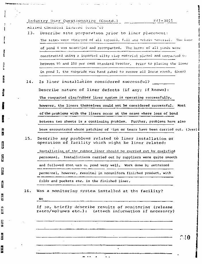
Industry User Questionnaire (Contd. ) F "• i - 3 0 1 1
13. Describe site preparation prior to liner placement:
The s i t e s were .'".tripped of a l l t . o p s o i l , f i l l .irni rn-t.rii; i u i u n < i l , Tin
of pond 4 was s c o r i f i e d and rc-compacted. The bmv.'J of a l l [iciniis wort-
14
constructed using a ir.-.ported silty clay material placed and compacted t'
between 9S and 100 per cent Standard Proctor. Prior to placing the liner
in pond 1, the su£>grade was hand raked to remove all loose earth, (Over)
Is liner installation considered successful?
D e s c r i b e n a t u r e of l i n e r d e f e c t s ( i f any; i f known) :
The compacted clay/rubber liner system is operating successfully,
however, the liners themselves could not be considered successful. Most
of the problems with the liners occur at the seams where loss of bond
between two sheets is a continuing problem. Further, problems have also
been encountered where patching of vips or tears have been carried out. (Over)
15. Describe any problems related to liner installation oroperation of facility which might be liner related:
_lnstallatior. of the rubber ]incr should be carried cut by qualified
personnel. Installations carried out by suppliers were quite smooth
and followed cont >urs oi pond very well. Work done by untrained
personnel, however, resulted in nonuniform finished product, with
folds and pockets etc. in the finished liner'.
16. Was a monitoring system Installed at the facility?
No
If JO, briefly describe results of inonitorinq (releaserates/volumes etc.): (attach information if necessary)
13. rocks, and cobbles, etc. Prior to placing the liner for2 to 4, inclusive, a layer of fine czivi cuvec.!! inches thick, wasplaced on the subejrade.
11. On the oldest liner slight surficial cracking cf the liner materialor deterioration of tlie material is evident, in sone areas. Thisis believed due to agincj and was called "ozoi:o depiction o£ theplasticizers" by one of the suppliers.
El
Industry User Questionnaire_(Contd.) 841-301
Allied Chemical Limited (cont'd)
17, Was there flny follow-up work carried out to evaluateperformance of liner system? NO_
If so, briefly describe liner performance: (attachpublished case histories if available)
March 1, 1981841-30FWF/jl841-3015 *-"•*•' |
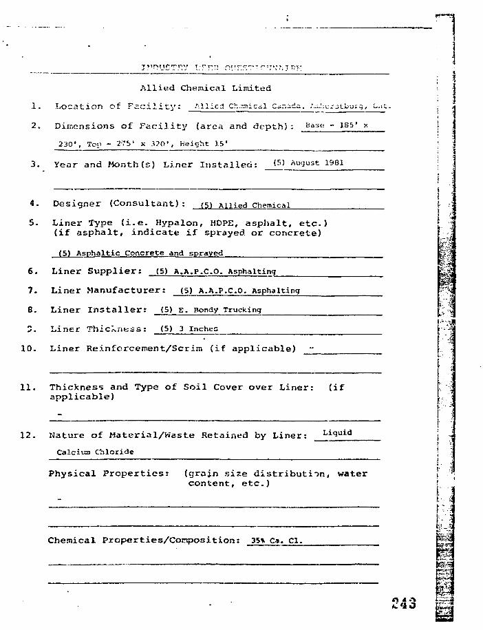
Allied Chemical Limited
1. Location of F a c i l i t y : Allied Ch-Tnic l c^r.ada. :-..:; e r 3 tliuig, O;
2. Dimensions of Faci l i ty (area and depth) : Bast; - 185' x
230 ' , Top - 275' x 3?0 ' , Height 15'
3 . Year and Month ( s ) L i n e r I n s t a l l e d : <5) August 1981
Liner Thickness: (S) 3 Inches
10. Liner Reinforcement/Scrim (if applicable)
11. Thickness and Type of Soil Cover over Liner: (ifapplicable)
4. Designer (Consultant): (5) Allied Chemical \
5. Liner Type ( i . e . Hypalon, HDPE, asphalt , e tc . ) [(if asphalt , indicate i f sprayed or concrete)
(5) Asphaltic Concrete and sprayed r
6. Liner Supplier: (S) A.A.P.CO. Asphalting
7. Liner Manufacturer: (5) A.A.P.CO. Asphalting
8. Liner I n s t a l l e r : (5) s. Bondy Trucking
34
i12. Nature of Material/Waste Retained by Liner: Liquid
:
i 1r
Calcium Chloride
Physical Properties: (grain size distribution, water I
content, etc.) J
Chemical Properties/Composition: 35% Ca. el.
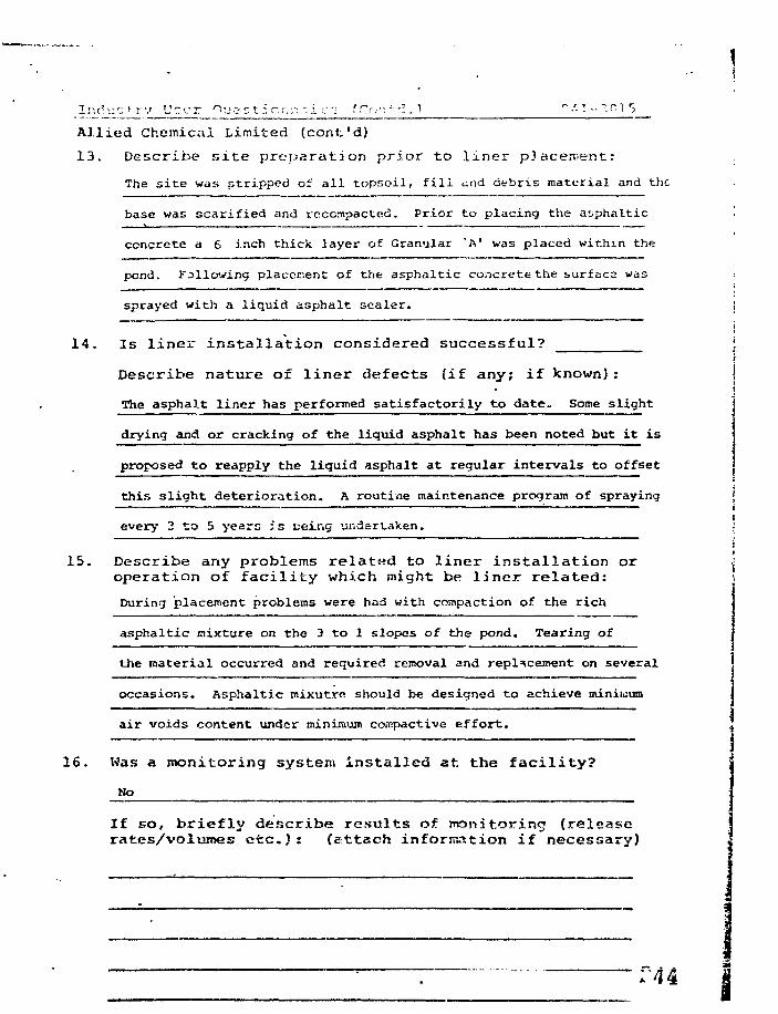
1 r, d'.:':. > r v L':or 1'JC-Ct:cr,;r-..ic" f Co".-T! . 1 "/-1 - "• ~ "I 5
Allied Chemical Limited (confc'd)
13. Describe site preparation prior to liner placement:
The si te was stripped of a l l topsoil, f i l l <.-.nd debris material and the
base was scarified and recempacted. Prior to placing the asphaltic
concrete a 6 inch thick layer of Granular "A* was placed within the
pond. Fallowing placement of the asphaltic concrete the surfaca was :
sprayed with a liquid asphalt sealer. i
i14. Is liner installation considered successful? j
Describe nature of liner defects (if any; if known): !
The asphalt liner has performed satisfactorily to date. Some slight j
drying and or cracking of the liquid asphalt has been noted but it is :
proposed to reapply the liquid asphalt at regular intervals to offset
this slight deterioration. A routine maintenance program of spraying ]
every 3 to 5 years is ceir.g undertaken. •• — — — — — — — — — — — — ;
i
15. Describe any problems related to liner installation or ioperation of facility which might be liner related: t
During placement problems were had with compaction of the rich
asphaltic mixture on the 3 to 1 slopes of the pond. Tearing of
the material occurred and required removal and replacement on several
occasions. Asphaltic mixutre should be designed to achieve minimum
air voids content under minimum corcpactive effort.
16. Was a monitoring system installed at the facility?
Ho
If so, briefly describe results of monitoring {releaserates/volumes etc.): (attach information if necessary)
T44

Ur.r>r OucM:i o:inn i re. (Co ".-:.;. 5 R ' - 3 r. 1 5
Allied Chemcial Limited (ccnt't)
17. Was there any follow-up work carried out to evaluateperformance of liner system? ^
If so, briefly describe liner performance: (attachpublished case histories if available)
March 1, 1994841-3015FWFAil
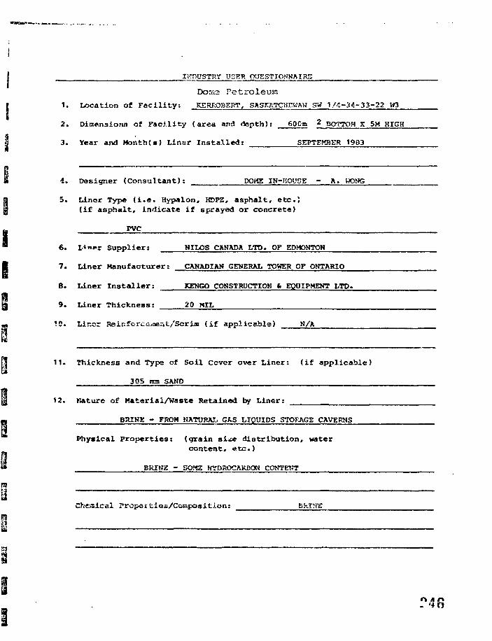
IWDOSTRY USER (yJESTICWKA I RE
Petrolevur.
1. Location of Facility: KERROSERT, SASKATCHKWAH SW 1/4-34-33-22 H3
2. Dimensions of Facility (area and depth): 600B 2 BOTTOM X 5K HIGH
3. Year and Month(s) Llnsr Installed: SEPTEMBER 1903
4. Designer (Consultant): DO«E IN-HOUSE - A. VX^G
5. Liner Type (i.e. Hypalon, KDPE, asphalt, etc.}(if asphalt, indicate if sprayed or concrete)
PVC
6. L*"»r Supplier: NILOS CANADA LTD. OF EDMONTON
7. Liner Manufacturer: CANADIAN GENERAL TOWER OF ONTARIO
8. Liner Installer: KENGO CONSTRUCTION 6 EQUIPMENT LTD.
9. Liner Thickness: 20 MIL
!C. Lir.cr Reinfcrct-.flest/Scrim (if applicable) N/'A
11. Thickness and Type of Soil Cover over Liner: (if applicable)
305 mm SAND
12. nature of Material/Waste Retained by Liner:
BRINK - FROM HATTOAI, GRS LIQUIDS STO?JVGE CAVERNS
Physical Properties: (grain si^« distribution, watercontent, etc.)
BRIMS - SOWS HYDROCARBON CONTEKT
Cheaical rrcjxssties/Cosiposition:
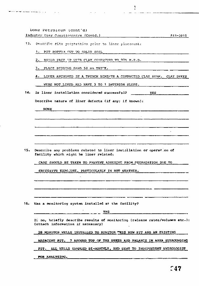
Dorne Petroleum (cont 'a)
Industry I'ser Qaest.ionrss.i.re (Contd. ) g41-3015
13. D^scribo ri te prcpyriticr. pricr to iir.cr plicOKiat:
1 . PIT BOTTOM CUT TO 5OLID SOIL
2_. B U I L D BB.Cn ' I ? WITH f t AY COMT'ACfPD TO <*!%. H . P . D .
3 . PLACE BEDDING SAKD 50 ITITS T H I T t ,
4 . LIFER ANCHORED IB A TRENCH EENEJ'TH A COMPACTED CLftY BEHK. CUtY DYKES
WERE NOT LINED AKD HAVE 3 TO 1 INTERIOR SLOPE.
14. Is liner installation considered successful? YES
Describe nature of l iner defects ( i f any; i f known):
NONE
15. Describe any problems related bo l iner i n s t a l l a t i o n or operation off a c i l i t y which might be l iner re lated:
CARE SHOULD BE TAKEN TO PREVENT ADHESIVE FROM PEGRADATION DUE TO
EXCESSIVE EXPOSURE, PARTICULARLY IN HOT WEATHER.
16. Was a monitoring system installed at the facil ity?
YES
II so , br i e f l y describe re su l t s of monitoring (re lease rates/voluaes e t c . ) :(ettach information if necessary)
2a woaiToa WSXX5 INSTALLED TO raraiToa - r a s KSW F I T RHO AW EXISTI;«;
ADJACENT P I T . 7 AJROOHP TOP Of THZ DTKES AKD BALABC2 IW KR3EA jj
PIT. MA WSIXS SAKPLSD ai-rtCWTKL?, RHP SEtTT TO IHDEPgKDBgjT. KYCSOL0GI5T .
POR
:47
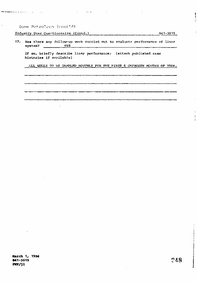
Dome Potro'eir-i (ront'.'l)
Inductry Ucer fluertionnairc (Contd. ) 841-3015
17. Wa» thare any follow-up work carried out to evaluate performance of linersystem? YES
If oo, b r i e f l y descr ibe lin«*r perforrrance: ( a t t a c h publ i shed casehistories if available)
ALL WELLS TO HE 3AKPLSD MO>JTHI-y FOR THE FIRST 6 UNFROZEN H9HTHS OF 1 9 3 4 .
lurch 1, 1934841-3015
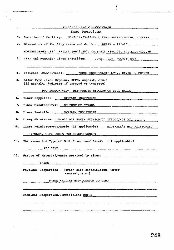
IKDLTC-T!>Y USER QUESTIONNAIRE
Dome Petroleum
1. location of Facility: B1/2-14-55-??-'-?.-.M. For-** s» rnT.*i:n
2. DimenBiona of Facility (area ar.d depth): DEPTH - 23*-0"
NORTHSIDg-621.33'- F»STSID3-6t2.«35' , £O'JSr,lSXVZ-5Q4. .05 , V-?ST5IDK-S30. T5
3. Year rjjd Month(s) Liner Installed: JUKE, JULY. ROGiJST 1901
4. Designer (Consultant): rCHEX COHSUT.TANTS T TD., DAVID J. FOOXES
5. Liner Type »i.e. Hypalon, HTPE, asphalt, etc.)(if asphalt, indicate if sprayed or concrete)
PVC BOTTOM WITH REINFORCED HYPOLON ON SIDE WALLS.
6. Liner Supplier: SYNFLEX INDUSTRIES
7. Liner Manufacturer: DU POMT OF cy.HADA
8. Liner Installer: SYNFLEX INDUSTRIES
10. Liner Reinforcement/Scrim (if applicable) SIDEW&LL'S HAO REIHFORCED
HYPOLON, WITH SCRIM FOR REINFORCEMENT
11. Thickness and Type of Soil Cover over Liner: (if applicable)
12" SAHD
12. Nature of Material/Waste Retained by Liner:
BRIHE
Physical Properties: (grain site distribution, watercontent, etc.)
BRIKE -SLIGHT HYDROCA>13OB C
Chemical Properties/Coasposltion: BRIHE
249
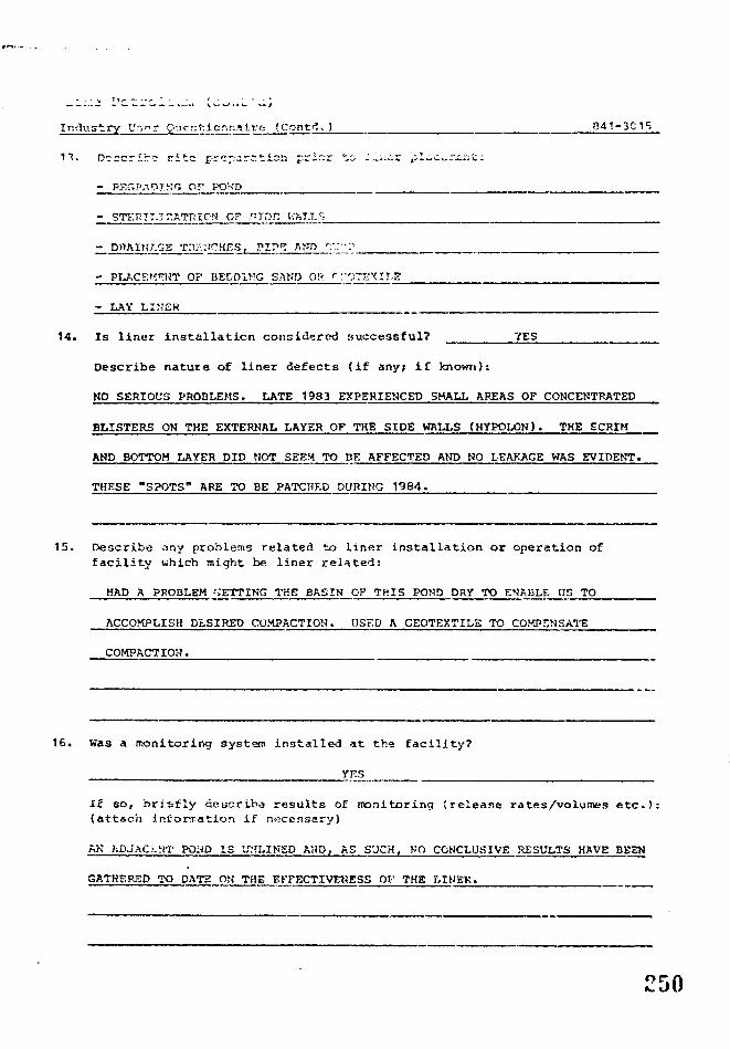
Industry Ur.nr g-jcrrtionnalrfe JCont< . ) 841-3015
13. Describe jrita preparation prior to : i ; . t r p L c ^ i r . t :
- PARADING Or POK'D
- STETUT.TZATRIOM OF r>TDr. V.-KIJ...S
- DHAIH/V3S Trtr::.'CHES, PIP1? flfTO r:""-"
- PLACEMENT 0 ? DEDD1MG SAND OS <~ :-OTEXir,
- LAY LINER
14. Is liner installation considered successful? YES
Describe nature of liner defects (if any; if known):
NO SERIOUS PROBLEMS• LATE 1983 EXPERIENCED SHALL AREAS OF CONCENTRATED
BLISTERS ON THE EXTERNAL LAYER OF THE SIDE WALLS (HYPOLON). THE SCRIM
AND BOTTOM LAYER DID NOT SEEM TO BE AFFECTED AND NO LEAKAGE WAS EVIDENT.
THESE "SPOTS" ARE TO BE PATCHED DURING 1984.
15. Describe any problems related to liner installation or operation offacility which might be liner related:
HAD A PROBLEM '.'ETTING THE BASIN
ACCOMPLISH DtSIRED COMPACTION.
COMPACTION.
OF THIS POND
USED A GEOTEX
DRY TO
TILE TO
ENABLE US TO
COMPENSATE
16. Was a monitoring system installed at the facility?
YES
I£ so, briefly aeucriba results of monitoring (release rates/volumes etc.):(attach Information if nocensary)
AK ADJAC-NT POND I S UrTLINSP AND, AS SUCH, KO CONCLUSIVE R E S E T S HAVE BEEN
GATHERED TO DATE ON TaE EFFECTIVENESS OF THE LINEK.
o r50
TYPICAL WARRANTIES
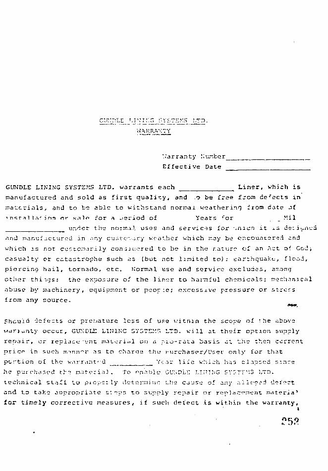
WARRANTY
'..'arranty Nur.ber
Effective Date
GUNDLE LINING SYST2.MS LTD. warrants each Liner, which is
manufactured and sold as first qualify, and .o be free from defects in
".accrials, and to be able to withstand normal weathering from date of
•inq^iisHnn or salf> for a jeriod of Years ^or "il
unccr the; norira.1. uses and servic-:s for .nicn it is deriv-.n-.ja
and manufactured in any cu3tc-...iry weather which :r,ay be encountered and
which is not eesco.'njrily conquered to be in the nature of an Act of GoJ i
casualty or catastrophe such as (but net limited to): earthquake, flood,
piercing hail, tornado, etc. liorm.il use and service excludes, arr.ong
other things: the exposure ol the liner to hai^ful chemicals; mechanical
abuse by machinery, equipment or peocie; excessive pressure or stress
from any source.
'jefects or prer.iature loss of use vitnan the scope of 'he above
y occur, G U A D L E HI11NC SV3TE.v'.r. LTD. will at their option supply
repair, or replace ~vnt mat-,:rial on a piu-ruti basis at the then current
n r i c in such mmn»r as to charoa thu t-urchaser/'Jser only for that
portion of the v.tr.rtint'-d Veav liie which h;;3 cl.ipsed since
he purchased th',» material. To enable GUNDLl! LIIJTNG SV"Tr'-!3 LTD.
technical staft to pio'ocily datc-rninr i.he cjuse of any _Iico->d defect
and t.o take appropriate slips to supply repair or replacement materia'
for timsly corrective measures,, if such detect is within the warranty,i
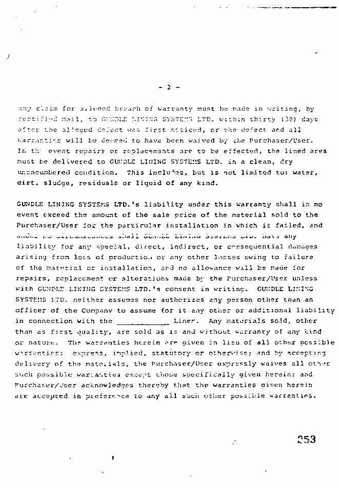
- 2 -
.iny clai:r. for ;i ± J t> a e d brcjrh of warranty r.ust be rr.acc in 'writing, by
rertifi-d :na i 1, t.o GV::n:X T.IN'Zt.T, SYSTEM" LTD. within thirty (20) cays
after the alleged deject wss. ^irct r/. tic.^, cr the do'eet: ar.d all
i.arra.-.ti'.r will b*» defirso to have been waived by che Purchaser/User.
In t!v event repairs cr replacements are to be effected, the lined area
must be delivered to GUKOLE LINING SYSTEMS LTD. in a clean, dry
ur.:ncaiibere<3 condition. This includes, but is not limited to: water,
dirt, sludge, residuals or liquid of any kind.
GUNDLE LINING SYSTEMS LTD.'s liability under this warranty shall in no
event exceed the amount of the sale price of the material sold to the
Purchaser/User for the particular installation in which it failed, and
liability for any special, direct, indirect, or consequential aanzazs
arising froa loss of productio.i or any other losses owing to failure
of the material or installation, ard no allowance will be n.arie for
repairs, replacement or alterations made by the Purchaser/User unless
with GUN'DM: LIKING SYSTEMS L T D . ' S consent in writing. CUKDLE LINING
SYSTEMS LTD. neither assumes nor authorizes any person other tnan an
officer of the Conpany to assume for it any other or additional liability
in connection with the Liner. Any materials sold, other
than as first quality, are sold as is and without warranty of any >:ir.d
or nature. Th? warranties htrein • T P aiven in lieu of all other possible
warranties: express, implied, statutory or othervise; and by accept..\r.g
delivery of the nateiials, the Purchaser/User expressly waives all otV.*r
such possible war:ar.t\a-» except those specifically given herein; and
Purchaser/Jser acknowledges thereby that the warranties given herein
die accepted in prefer*.**ce to any ail ssuch other possible warranties.
C53
r ,^E^U
WAHHAMTY MM LIABILITY LIMITATION
V t Seller wi f i jn ls t rut S C H U G U * JrierI wili. al I f* litre of u l e conlor-n 10 the specifications aqietd By the parties and ' Ics3 00Atiachmenl A II, within Iwo (?) ytau ot If? d.i!e 0! completion ol msiaiUlioo. Buyer Osmcnslrales Ic $el*r thai all w part oi 11*SCHLfcGLL* Srieel supplied iir-.^f the contiacl was rot. at ine tirr* of sale, m ccnJormance «nh tne jgieed speciVaicns andirul 5uCh non coniormance ruipi«it> impairs the perlwnunce ot Hie S C H U G U " Sheet undif is* uses aid iervxe w*O'l»nsloreseen by told parlies xi me ri-ne of sale. Seller will Wher rrpji ' w rjpuce. i t us option. Ifut oon.on of ihe S C M U G E L " Shetlsupplied under '.he lonujc; which was not in caritonntnce »iin I he j j ' r r t sprcifiuiions Sciici miKts no wjrrjniy witn irspectto goods, rruietuis c component pans wfuch aie not at its own nwnulaclure
b Seiter lurthef warrants that any SCHt ECEL* Sheet installation work it pfCMOes under the coriiact wilt os f ' fe tiom any sijniticanlflctecl in woikntansnip to» » peuoO 0.' Iwo (?) ytars I^wn Ihe dale of comptel'on ot instalialior II wilhm i«o (?| years ol thp cate dcompletion ol insu'Ution. Buyrr roj i lm Seller ol tne discovery ol any such delect. Seller will 'tcuir or replace that pon>on o< toeinstallation trork srtown by Buyer to be detective
C S e l f ' s pblitwlKMis in 1 a and 1 ft «;e con3;l>onrd on Buyer prnviamq Sf ' * r w in access to lr>e a>ta 10 De iepa"M or lea'acetfwiinou! cnarj i . in iuch minnti as 10 eniWe St'.ier '.0 ellect i prooef reoair or tcoiicrrrnx
0 !-.\ Me tvtr.l Sti-ei tills ;o supp.'y leoiir or tepUcemcnl rmteruis witnm a rejsnnabif <,me pursuant to its i&''CJ'"on m S.'::«" ' a .0* 10 ti'lec: a p;t<pcr repair 0: rc?iicen>:nl ol m'.a.ylion work wilhm a t ; jsonit ie time Durr-uant lo its bbiisaiicn ir 1 i> Se^'rrifiail insi?jto ifvni) MU1 poiiiCT :•! l ie lolal ccnliict puce wfiich re ales to Ine noncO'^crrmg rtyiC( , is or cetrci'.< " '5^ ii^onwork as l ie case niay be
2 !l SCriltGCL" S^cel is installed by o'ivr irun S»n»r ot a S?i>i ipprcvto insuiutian roii'acio' in KCO'CJ"!r. »:ti S r ' f s T M - U S -lions (when will inciuoe tne legmrcnfnl irval Selie' s t^pio-^ces prnorm tu to-nmq j i n cujuly comioi tu.'icr.jr.ii ne•tv me iVairjnty a\ Section 1 n c a^y clhet wanaify shaii be in enect or cniorcEaDif aoa^tsi Sener
j f Nc ;h!i fJ!»ni Jt1 tarn in !«;^«n 1 ,-rf n r l t i s m am! »r: ia ten d »9 vth«f cbl:g2t)M<s. wirrarttwi j«< k i M > t * l tt %t*n «tfU the csndi'.Kia is f^tiestanKt s» *CKlEutL" Sheit. mcteetn; l «b * t f tw ncnuqtnct m e t tubihty w icn w M^trwnr >*(! J> wi i -r jn 's t 0t Frinfss t v 1 pirircuUr purpcu «r r,)crcri3ni,tftl| n othtfwtss. t i p r t s i or implied HI U d w by ~ « . tctucH tit h»iet>»(jitcUinwd. Eeclidt 1 s'.JIes Sfis»i s rnl»r and eiduS-'vf ur>i'il> i>no Buye< s t«ciujiwe letnetiy <c any cla.-»i 01 Coinage m icnneciionwith Of tesuhino f'Orn i w r.ptw;i!K)n or p-?r;«marvce ol SCHif O H " Srvtt Delivered *nj msuued pursuant to tne conliacl Suienentsin jdvenissrTOfiis <x tilaic^s at oncnpiive only in} t-t not lo te rons-tlered *<rra«!ies
Jhaii (<3vt no lability in any even! lor any specm. indirect incidmui v consf^ucntial toss or damage
S The cirrapes. ptrunis-?. nvjennific^ncms USiMies. coi!s cv t«p!"'»sfs incuned Dyjjciief as a result of any i?.'uie Dy Se:'e' '0 meft <'.Surtt'f l t« contra:! or t\ Uw snali uooer
m re<r-*ct nj any suintp WTV ol •a'MMy 5irrh es p>U>y. piitnl in!;!r!i;f.^ieft|. inut.-timficjiiCHi t,r,<y.r hoi«. w ;ny Mher ryps ti l«&!rty. apiri t:om itx» iijad.ty incu"«t puiM/am to Scci on 1 at)c-,e fix* (.«:cc^! I ' J ' . I 0! ;ne
tola! CW!r*ct f»<«. «
6 C*ce«1 m j^arfgaw. atvjn From hj5»:<ry incurr«f p u r j u f l to Seclisn ) «bovj. !i-,f»R pet cent | t b H | 0! ine tciai f onirar! pj*-t. or
c F«c»-i(i h-i K * SQoitxuie. mtiwtfig Mwirty incwrrrt pu'M>am to J^<t>on 1 itx-sc ;ru! an othr: U J D - W ^ , urirtci <f* f (v-.!.*.l pr aib«n. i f * toi<< f» .n»ci pr-cs
6. Ttx {KD'»i»*5ft5 0? " u i tis.;oiwe sh»1 suocrsade j / r i gownn « i )« . 1 pipyniots oi the Agjeemsni set* f rn BU-N'T »nc Sei-t'hw purchaw. SJ«! *n<J mswflation 9) ST'H.f.Gf!.1' S.'i'St
. we. tut
Al 1 6Lir.f:iil "A"
A'!n LIARTLJTY t
Schlegel Lining Technology, Inc. ("Schlegel") warrants to Key LakeMining Corporation (the "Customer") that the one hundred mil (100 mil)thick SCHLEGEL© sheet lining system and/or a combination of one hundredrail (100 mil) and eighty rail (80 nil) thick SCHLEGEL© sheet liningsysLera sold and installed by Schlegel for the Key Lake Project,Contract C-169 (the "Project") will conform to the attached MinimumSpecifications at the time of sale and will, as installed, be fiee fromdefects at the time of completion of installation and withstand theeffect of normal weathering and usage for five (5; years thereafter.
Rer,edy if Schlegel Breaches The Warranty
If the CuStOfier notif ies Schlooel . in writ inn. Hurinn thp U;»rr*r>tv nprintiof a problem which it feels gives rise to z claim under this Warrunt^Schlegel wil? inspect the problem jointly with the Customer. If theCustomer's claim is covered by this Warranty, Schlegel will repair orreplace (et Schlerjsl's option, in the exercise of its best technicaljudepent) the defective- material and/or installation work. If the problemis net covered by this Warranty, the Customer will be responsible forSchlegel's inspection expenses and the expenses of any repair or replace-ment which Schlegel and the Customer agree to carry out.
Conditions of this Warranty
This Warranty and Schleqel's obligations under it are subject to the followingconditions:
That the Customer notifies Schlegel promptly of the discoveryof any problem which it feels gives rise to a claim under thisWarranty;
That the Customer provides Schlegel, without chsrqe, with fullznC tree access to the Warranty claim area Icl&iri and dry andwith fill &P6 overburden removed if necessary) in order to enaMe"Schlcgel to inspect the same and, if appropriate, mate b properrepair or replacement;
That the lining system has been used at all tisnes exclusivelyfor the purpose for wbien it was originally intended ami designedand in accordance with the normal uses and service conditionsspecified in the contract or the applicable Project specifications;
\\
O . l_rr-J!f\;c; T;i
t1
1I
-
J
That no repair to the linir.9 system (other than e.-ne r gen cyrepairs required to protect people or property) has been madeor attempted by other than Schlcgel's authorized personnelunless Schlegel has given its prior written consent;
That the Customer has used reasonable care in the management,operation and safeguarding of the lining system; and
That the Customer has paid Schlegel all amounts due underthe contract.
Damages Excluded
1 This Warranty does not apply to materials or components not manufacturedby Schlegel or to claims arisina fra-n- n»';1»^, -1*:r;t:^..J Lj Li.c Custoijie
' o. outers, stifiiurtace conditions, fdw'ti, biiikholes, subsidence, abnormali design, structural defects of under-or-over-burden, abuse by equipment,machinery, people or enimals, exposure of the sheet to harmful chemicals
; or alteration in the agreed or specified uses or service conditions, fire,[ flood, earthquake, hail, windstorm, explosion, tornado or other abnormalweather conditions, accident, vandalism or Acts of God.
In the event Schlegel fails to complete a proper repair* or replacement within£ reasonable tine after good faith attempts pursuant to U s obligations above,'the Customer will be entitled to a refund of that portion of the totalcontract price which relates to the nonconfonriing or defective materialslor installation work as the case nay be.
Exclusion of Other Liabilities
test results, sUte:nenis in advert i serpents or catalogs, etc., are descriptive'only and are not to bs considered warranties.) Schlenel's obligations ofrepair, replace«nent or credit as set forth above are also exclusive and inlie-J of oTl other obligations or If abilities (and constitute the Custcurer'sbxclusivs remedy) witb'respect to tha qu^ity, condition or performance?f SCHLECELC s?.e
\
es
-'/ is a; w
5**33
HI.25 !!"!|.4
I l i l s s t a t omen t was f i i r p f t ! w i t h r h i s ili f t.ha pa; ; f s o f Liic Joo i i ' u ' n t .-ir;1 l r : ; s" ' l s n t h i s ;U;>tcnt. ' ; i t 7 1: •;; duo X.o i)>opi)Otoj>,rapli ic q u a l i t y o f d i e rlo t- u:;n-nt .
irf \ IXT*.
H. A
" ^ f c _ ^ * ^ * , -