attachment 2 - icao
TRANSCRIPT
INTERNATIONAL CIVIL AVIATION ORGANIZATION
CAR/SAM REGIONAL PLANNING AND IMPLEMENTATION GROUP
(GREPECAS)
ATTACHMENT 2
TO THE REPORT OF THE FIFTH MEETING OF THE ATM/CNS SUBGROUP OF GREPECAS
“REPORT OF THE FIFTH MEETING OF THE CNS COMMITTEE
OF THE ATM/CNS SUBGROUP OF GREPECAS (CNS/COMM/5)”
Lima, Peru 13 to 17 November 2006
Prepared by the Secretariat November 2006

The designation employed and the presentation of material in this publication do not imply the expression of any opinion whatsoever on the part of ICAO concerning the legal status of any country, territory, city or area or of its authorities, or concerning the delimitation of its frontiers or boundaries.
CNS/COMM/5 i – Table of Contents i-1
INDEX Contents Page Index ........................................................................................................................................ i-1 Historical ........................................................................................................................................ ii-1
ii.1 Duration and site of the Meeting.................................................................................... ii-1 ii.2 Organization of the Meeting .......................................................................................... ii-1 ii.3 Working languages ........................................................................................................ ii-1 ii.4 Agenda ........................................................................................................................... ii-1 ii.5 List of Working Papers .................................................................................................. ii-2 ii.6 List of Information Papers ............................................................................................. ii-3 ii.7 Schedule and Work Mode.............................................................................................. ii-4 ii.8 Conclusions and Decisions ............................................................................................ ii-4 ii.9 List of Draft Conclusions ............................................................................................... ii-4 ii.10 List of Draft Decisions ................................................................................................... ii-5 ii.11 List of Decisions ............................................................................................................ ii-5
Report on Agenda Item 1 Communication systems developments .................................................................................. 1-1 Appendix 1A – Requirements for ATS oral voice and data service among CAR/SAM States/Territories and Organizations...................... 1A-1 Appendix 1B – MEVA II REDDIG Interconnection Diagrams ................................... 1B-1 Appendix 1C – GPI-17, Implementation of data link applications............................... 1C-1 Appendix 1D – Table CNS 2A, Aeronautical Mobile Service and AMSS ..................... 1D-1 Appendix 1E – Table CNS 1Ba, ATN routers regional plan ........................................ 1E-1 Appendix 1F – Table CNS 1Bb, ATN ground-ground applications plan, CAR............ 1F-1 Appendix 1G – Table CNS 1Bb, ATN ground-ground applications plan, SAM ........... 1G-1 Appendix 1H – EUR AMHS Documentation, PRMD and Addressing Registry ........... 1H-1 Appendix 1I – Work Programme................................................................................. 1I-1 Appendix 1J – AMHS Addressing ................................................................................ 1J-1 Appendix 1K – Table CNS 1Ba, ATN air-ground application plan.............................. 1K-1 Appendix 1L – AMHS implementation plans in the CAR and SAM Regions ............... 1L-1 Appendix 1M – FAA BUFR Code AMHS implementation plan.................................... 1M-1 Report on Agenda Item 2 Navigation systems developments........................................................................................... 2-1 Appendix 2A – Status of the SBAS augmentation systems studies according to the RLA/03/902 Project.................................................................... 2A-1 Appendix 2B – RLA/00/009 Project – GNSS Augmentation Tests ............................... 2B-1 Appendix 2C – Aeronautical Information Circular from Chile (Spanish only)............ 2C-1 Appendix 2D – Estado de los sistemas SBAS actuales (Spanish only) ......................... 2D-1 Appendix 2E – GNSS implementation in the CAR/SAM regions.................................. 2E-1 Appendix 2F – FAA Ground Based Augmentation System (GBAS) program status .... 2F-1 Appendix 2G – Ionospheric Effects on GNSS Aviation Operations.............................. 2G-1 Appendix 2H – Regional plan of deactivation of NDB stations.................................... 2H-1
i – Index i-2
Contents Page Report on Agenda Item 3 Surveillance systems developments ........................................................................................ 3-1 Appendix 3A – Preliminary elements for a regional strategy for surveillance systems ....................................................................... 3A-1 Appendix 3B – GPI-9, Situational awareness .............................................................. 3B-1 Appendix 3C – CAR/SAM Regional strategy for the ADS-C and ADS-B systems Implementation ........................................................... 3C-1 Appendix 3D – Potential air space to implement ADS-C and ADS-B considered by CAR/SAM States, Territories, and Intl. Organizations..................................................... 3D-1 Appendix 3E – Surveillance Task Force Terms of Reference and Work Programme .. 3E-1 Appendix 3F – Table CNS 4A, Surveillance Systems (updated)................................... 3F-1 Report on Agenda Item 4 Development and integration of the ATM Automated systems ............................................. 4-1 Appendix 4A – CAR/SAM ICD ..................................................................................... 4A-1 Appendix 4B – ATS Operational requirements for automated systems........................ 4B-1 Report on Agenda Item 5 Review of the deficiencies related to the CNS systems and other general issues.................. 5-1 Appendix 5A – Comments made by the Fifth Meeting of the CNS Committee regarding the CNS Deficiencies contained in Appendixes A, B, C, D; E, and F to WP/14..................... 5A-1 Report on Agenda Item 6 Terms of Reference and Work Programme of the CNS Committee...................................... 6-1 Appendix 6A – Terms of Reference and Work Programme of the CNS Committee .......................................................................... 6A-1 Report on Agenda Item 7 Other business ....................................................................................................................... 7-1

CNS/COMM/5 ii – Historical ii-1
History of the Meeting ii.1 Duration and site of the Meeting The Fifth Meeting of the CNS Committee (CNS/COM/5) of the GREPECAS ATM/CNS Subgroup (ATM/CNS/SG/5) was held at the Meliá Hotel, Lima, Peru. The Meeting commenced on 13 November and ended on 17 November 2006. The Report of the CNS/COMM/5 Meeting was reviewed and adopted by the ATM/CNS Subgroup on 17 November 2006. ii.2 Organization of the Meeting The Meeting held from 13 to 16 November 2006 was chaired by Mr. Ricardo Bordali (Chile), Chairman of the CNS Committee, assisted by Mrs. Veronica Ramdath (Trinidad and Tobago), Vice-chairwoman. Mr. Aldo Martínez, ICAO NACC Office CNS Regional Officer and Secretary of the CNS Committee, was assisted by Mr. Carlos Stehli, ICAO SAM Office Acting Regional Deputy Director, and Mr. Onofrio Smarrelli, ICAO SAM Office CNS Regional Officer. ii.3 Working Languages The working languages of the Meeting were English and Spanish. The documentation and the Report of the Meeting were issued in both languages. ii.4 Agenda The following agenda was adopted by the Meeting: Agenda Item 1: Communication systems developments
1.1 Review of the integration/interconnection and development status of the regional digital networks.
1.2 Review of the air-ground data links implementation plan. 1.3 Review of the ATN regional implementation plan. 1.4 Study of a communication system to support the migration towards the
meteorological messages interchange (METAR/SPECI y TAF) in BUFR format code.
Agenda Item 2: Navigation systems developments
2.1 Review of the results of the SBAS augmentation projects carried out in the CAR/SAM Regions.
2.2 Study of a SBAS/GBAS regional implementation system. Agenda Item 3: Surveillance systems developments
3.1 Follow-up to the development of surveillance systems and the regional implementation study of the SSR in Mode S.
3.2 Study of the regional ADS systems implementation.
ii-2 ii – Historical CNS/COMM/5
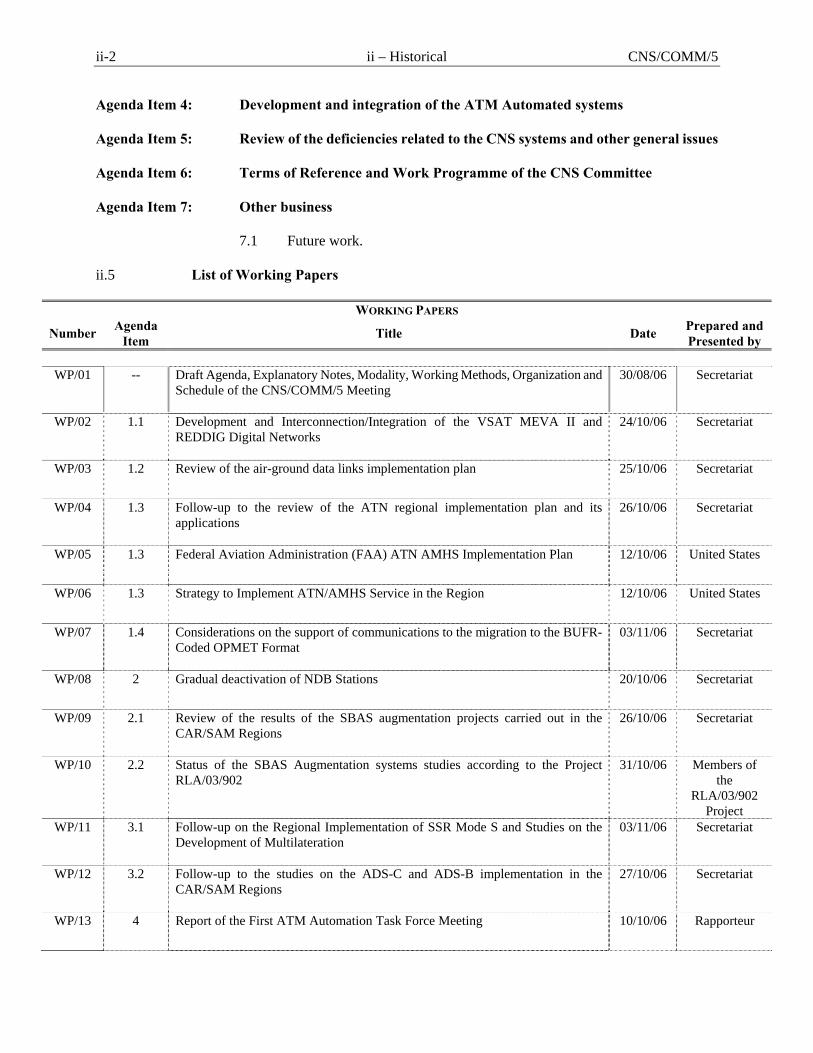
Agenda Item 4: Development and integration of the ATM Automated systems Agenda Item 5: Review of the deficiencies related to the CNS systems and other general issues Agenda Item 6: Terms of Reference and Work Programme of the CNS Committee Agenda Item 7: Other business 7.1 Future work. ii.5 List of Working Papers
WORKING PAPERS
Number Agenda Item Title Date Prepared and
Presented by
WP/01 -- Draft Agenda, Explanatory Notes, Modality, Working Methods, Organization and Schedule of the CNS/COMM/5 Meeting
30/08/06 Secretariat
WP/02 1.1 Development and Interconnection/Integration of the VSAT MEVA II and REDDIG Digital Networks
24/10/06 Secretariat
WP/03 1.2 Review of the air-ground data links implementation plan 25/10/06 Secretariat
WP/04 1.3 Follow-up to the review of the ATN regional implementation plan and its applications
26/10/06 Secretariat
WP/05 1.3 Federal Aviation Administration (FAA) ATN AMHS Implementation Plan 12/10/06 United States
WP/06 1.3 Strategy to Implement ATN/AMHS Service in the Region 12/10/06 United States
WP/07 1.4 Considerations on the support of communications to the migration to the BUFR-Coded OPMET Format
03/11/06 Secretariat
WP/08 2 Gradual deactivation of NDB Stations 20/10/06 Secretariat
WP/09 2.1 Review of the results of the SBAS augmentation projects carried out in the CAR/SAM Regions
26/10/06 Secretariat
WP/10 2.2 Status of the SBAS Augmentation systems studies according to the Project RLA/03/902
31/10/06 Members of the
RLA/03/902 Project
WP/11 3.1 Follow-up on the Regional Implementation of SSR Mode S and Studies on the Development of Multilateration
03/11/06 Secretariat
WP/12 3.2 Follow-up to the studies on the ADS-C and ADS-B implementation in the CAR/SAM Regions
27/10/06 Secretariat
WP/13 4 Report of the First ATM Automation Task Force Meeting 10/10/06 Rapporteur
CNS/COMM/5 ii – Historical ii-3
WORKING PAPERS
Number Agenda Item Title Date Prepared and
Presented by
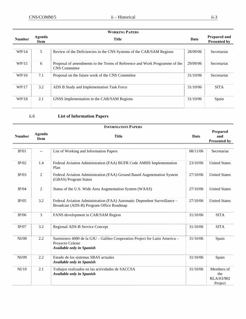
WP/14 5 Review of the Deficiencies in the CNS Systems of the CAR/SAM Regions 28/09/06 Secretariat
WP/15 6 Proposal of amendments to the Terms of Reference and Work Programme of the CNS Committee
29/09/06 Secretariat
WP/16 7.1 Proposal on the future work of the CNS Committee 31/10/06 Secretariat
WP/17 3.2 ADS B Study and Implementation Task Force 31/10/06 SITA
WP/18 2.1 GNSS Implementation in the CAR/SAM Regions 31/10/06 Spain
ii.6 List of Information Papers
INFORMATION PAPERS
Number Agenda Item Title Date
Prepared and
Presented by
IP/01 -- List of Working and Information Papers 08/11/06 Secretariat
IP/02 1.4 Federal Aviation Administration (FAA) BUFR Code AMHS Implementation Plan
23/10/06 United States
IP/03 2 Federal Aviation Administration (FAA) Ground Based Augmentation System (GBAS) Program Status
27/10/06 United States
IP/04 2 Status of the U.S. Wide Area Augmentation System (WAAS) 27/10/06 United States
IP/05 3.2 Federal Aviation Administration (FAA) Automatic Dependent Surveillance – Broadcast (ADS-B) Program Office Roadmap
27/10/06 United States
IP/06 3 FANS development in CAR/SAM Region 31/10/06 SITA
IP/07 3.2 Regional ADS-B Service Concept 31/10/06 SITA
NI/08 2.2 Suministro 4080 de la GJU – Galileo Cooperation Project for Latin America – Proyecto Celeste Available only in Spanish
31/10/06 Spain
NI/09 2.2 Estado de los sistemas SBAS actuales Available only in Spanish
31/10/06 Spain
NI/10 2.1 Trabajos realizados en las actividades de SACCSA Available only in Spanish
31/10/06 Members of the
RLA/03/902 Project
ii-4 ii – Historical CNS/COMM/5
INFORMATION PAPERS
Number Agenda Item Title Date
Prepared and
Presented by
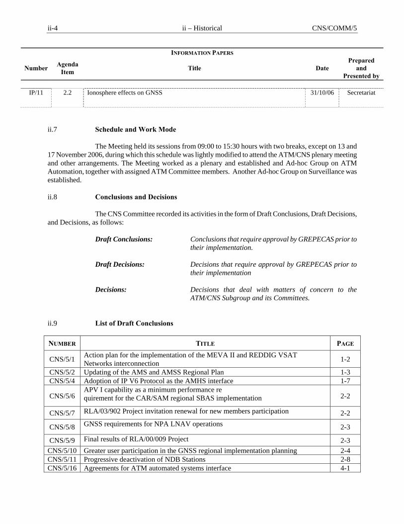
IP/11 2.2 Ionosphere effects on GNSS 31/10/06 Secretariat
ii.7 Schedule and Work Mode The Meeting held its sessions from 09:00 to 15:30 hours with two breaks, except on 13 and 17 November 2006, during which this schedule was lightly modified to attend the ATM/CNS plenary meeting and other arrangements. The Meeting worked as a plenary and established and Ad-hoc Group on ATM Automation, together with assigned ATM Committee members. Another Ad-hoc Group on Surveillance was established. ii.8 Conclusions and Decisions The CNS Committee recorded its activities in the form of Draft Conclusions, Draft Decisions, and Decisions, as follows:
Draft Conclusions: Conclusions that require approval by GREPECAS prior to
their implementation.
Draft Decisions: Decisions that require approval by GREPECAS prior to their implementation
Decisions: Decisions that deal with matters of concern to the
ATM/CNS Subgroup and its Committees. ii.9 List of Draft Conclusions NUMBER TITLE PAGE
CNS/5/1 Action plan for the implementation of the MEVA II and REDDIG VSAT Networks interconnection 1-2
CNS/5/2 Updating of the AMS and AMSS Regional Plan 1-3 CNS/5/4 Adoption of IP V6 Protocol as the AMHS interface 1-7
CNS/5/6 APV I capability as a minimum performance re quirement for the CAR/SAM regional SBAS implementation 2-2
CNS/5/7 RLA/03/902 Project invitation renewal for new members participation 2-2
CNS/5/8 GNSS requirements for NPA LNAV operations 2-3
CNS/5/9 Final results of RLA/00/009 Project 2-3 CNS/5/10 Greater user participation in the GNSS regional implementation planning 2-4 CNS/5/11 Progressive deactivation of NDB Stations 2-8 CNS/5/16 Agreements for ATM automated systems interface 4-1

CNS/COMM/5 ii – Historical ii-5
NUMBER TITLE PAGE CNS/5/17 Establishment of an action plan for the interface of ATM automated systems 4-2 ii.10 List of Draft Decisions NUMBER TITLE PAGE
CNS/5/5 Communication aspects for the migration towards the meteorological message exchange in BUFR code 1-11
CNS/5/12 Development of a Regional Plan for the progressive deactivation of NDB stations 2-8 CNS/5/13 Regional standard registry for aircraft equipped with transponders in Mode S 3-2 ii.11 List of Decisions NUMBER TITLE PAGE CNS/5/3 IP addressing Regional Plan for ATN and its application management 1-6
CNS/5/14 Unified regional strategy on the implementation of surveillance systems 3-3 CNS/5/15 Creation of a surveillance Task Force 3-4 CNS/5/18 Amendment to the terms of reference, work programme and composition of the
CNS Committee 6-1
CNS/COMM/5 Report on Agenda Item 1 1-1
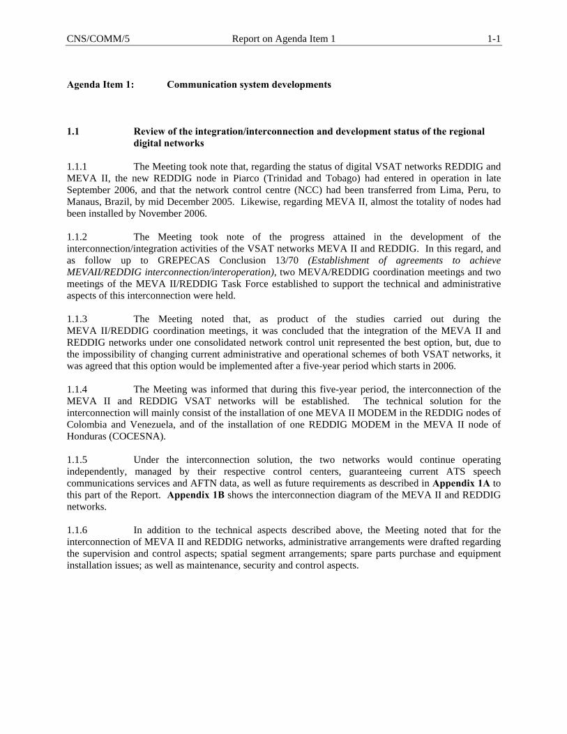
Agenda Item 1: Communication system developments 1.1 Review of the integration/interconnection and development status of the regional
digital networks 1.1.1 The Meeting took note that, regarding the status of digital VSAT networks REDDIG and MEVA II, the new REDDIG node in Piarco (Trinidad and Tobago) had entered in operation in late September 2006, and that the network control centre (NCC) had been transferred from Lima, Peru, to Manaus, Brazil, by mid December 2005. Likewise, regarding MEVA II, almost the totality of nodes had been installed by November 2006. 1.1.2 The Meeting took note of the progress attained in the development of the interconnection/integration activities of the VSAT networks MEVA II and REDDIG. In this regard, and as follow up to GREPECAS Conclusion 13/70 (Establishment of agreements to achieve MEVAII/REDDIG interconnection/interoperation), two MEVA/REDDIG coordination meetings and two meetings of the MEVA II/REDDIG Task Force established to support the technical and administrative aspects of this interconnection were held. 1.1.3 The Meeting noted that, as product of the studies carried out during the MEVA II/REDDIG coordination meetings, it was concluded that the integration of the MEVA II and REDDIG networks under one consolidated network control unit represented the best option, but, due to the impossibility of changing current administrative and operational schemes of both VSAT networks, it was agreed that this option would be implemented after a five-year period which starts in 2006. 1.1.4 The Meeting was informed that during this five-year period, the interconnection of the MEVA II and REDDIG VSAT networks will be established. The technical solution for the interconnection will mainly consist of the installation of one MEVA II MODEM in the REDDIG nodes of Colombia and Venezuela, and of the installation of one REDDIG MODEM in the MEVA II node of Honduras (COCESNA). 1.1.5 Under the interconnection solution, the two networks would continue operating independently, managed by their respective control centers, guaranteeing current ATS speech communications services and AFTN data, as well as future requirements as described in Appendix 1A to this part of the Report. Appendix 1B shows the interconnection diagram of the MEVA II and REDDIG networks. 1.1.6 In addition to the technical aspects described above, the Meeting noted that for the interconnection of MEVA II and REDDIG networks, administrative arrangements were drafted regarding the supervision and control aspects; spatial segment arrangements; spare parts purchase and equipment installation issues; as well as maintenance, security and control aspects.
1-2 Report on Agenda Item 1 CNS/COMM/5
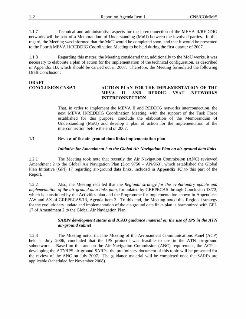
1.1.7 Technical and administrative aspects for the interconnection of the MEVA II/REDDIG networks will be part of a Memorandum of Understanding (MoU) between the involved parties. In this regard, the Meeting was informed that the MoU would be completed soon, and that it would be presented to the Fourth MEVA II/REDDIG Coordination Meeting to be held during the first quarter of 2007. 1.1.8 Regarding this matter, the Meeting considered that, additionally to the MoU works, it was necessary to elaborate a plan of action for the implementation of the technical configuration, as described in Appendix 1B, which should be carried out in 2007. Therefore, the Meeting formulated the following Draft Conclusion: DRAFT CONCLUSION CNS/5/1 ACTION PLAN FOR THE IMPLEMENTATION OF THE
MEVA II AND REDDIG VSAT NETWORKS INTERCONNECTION
That, in order to implement the MEVA II and REDDIG networks interconnection, the next MEVA II/REDDIG Coordination Meeting, with the support of the Task Force established for this purpose, conclude the elaboration of the Memorandum of Understanding (MoU) and develop a plan of action for the implementation of the interconnection before the end of 2007.
1.2 Review of the air-ground data links implementation plan Initiative for Amendment 2 to the Global Air Navigation Plan on air-ground data links 1.2.1 The Meeting took note that recently the Air Navigation Commission (ANC) reviewed Amendment 2 to the Global Air Navigation Plan (Doc 9750 – AN/963), which established the Global Plan Initiative (GPI) 17 regarding air-ground data links, included in Appendix 1C to this part of the Report. 1.2.2 Also, the Meeting recalled that the Regional strategy for the evolutionary update and implementation of the air-ground data links plan, formulated by GREPECAS through Conclusion 13/72, which is constituted by the Activities plan and the Programme for implementation shown in Appendices AW and AX of GREPECAS/13, Agenda item 3. To this end, the Meeting noted this Regional strategy for the evolutionary update and implementation of the air-ground data links plan is harmonized with GPI-17 of Amendment 2 to the Global Air Navigation Plan.
SARPs development status and ICAO guidance material on the use of IPS in the ATN air-ground subnet
1.2.3 The Meeting noted that the Meeting of the Aeronautical Communications Panel (ACP) held in July 2006, concluded that the IPS protocol was feasible to use in the ATN air-ground subnetworks. Based on this and on the Air Navigation Commission (ANC) requirement, the ACP is developing the ATN/IPS air-ground SARPs; the preliminary document of this topic will be presented for the review of the ANC on July 2007. The guidance material will be completed once the SARPs are applicable (scheduled for November 2008).
CNS/COMM/5 Report on Agenda Item 1 1-3
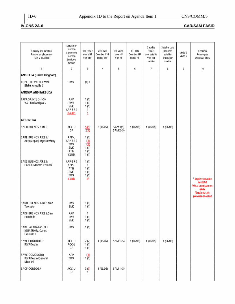
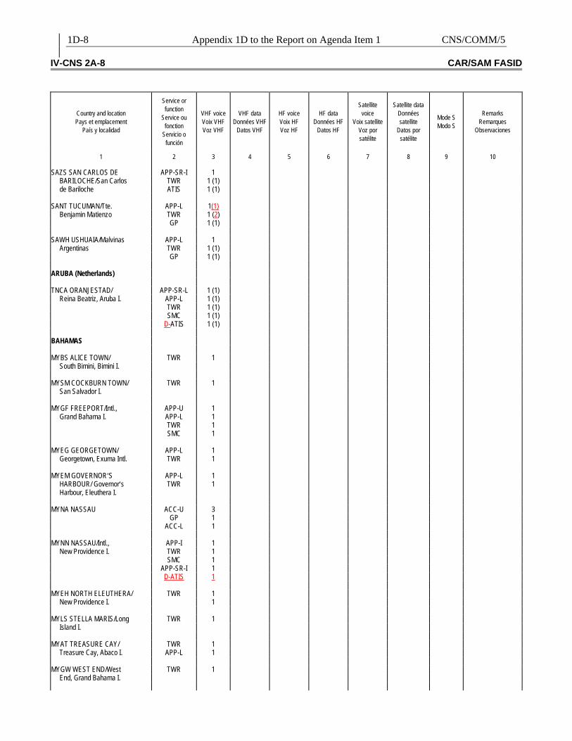
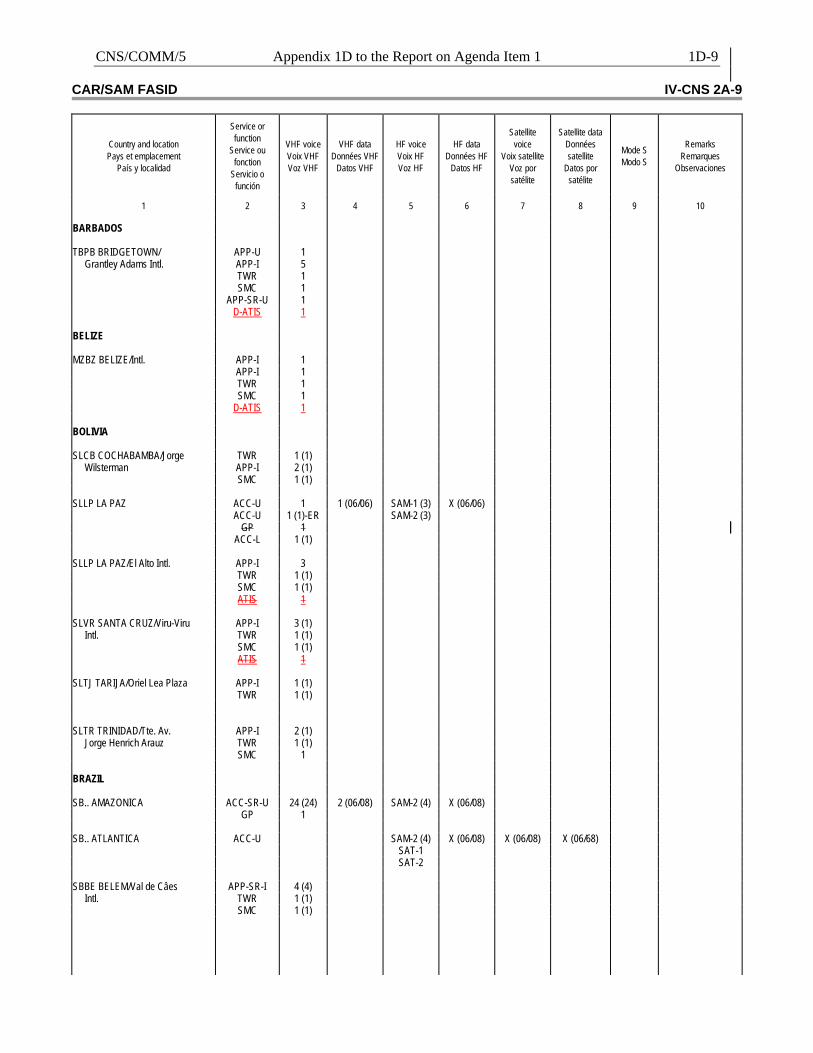
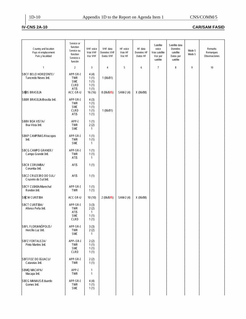
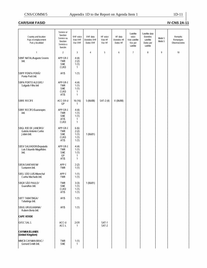
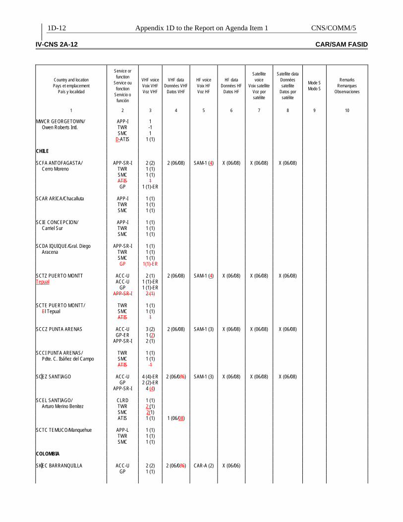
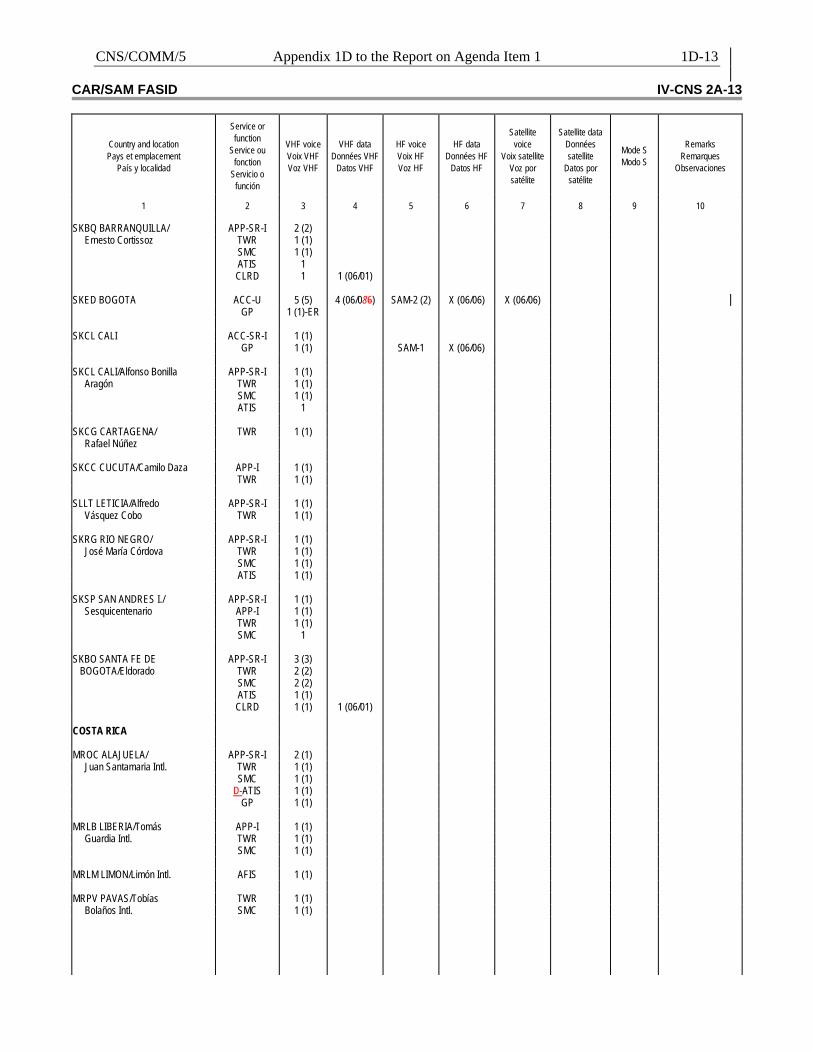
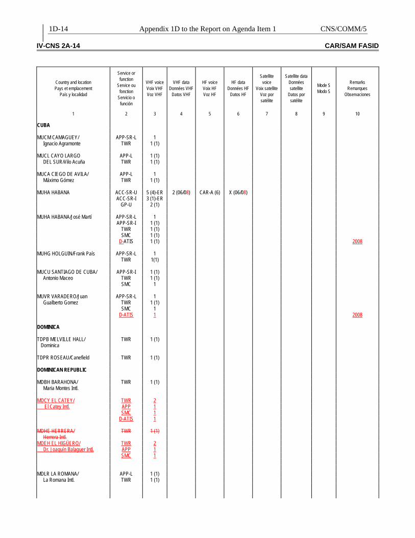
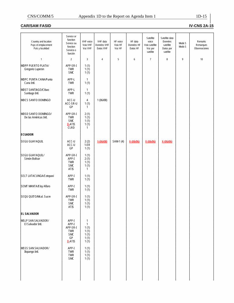
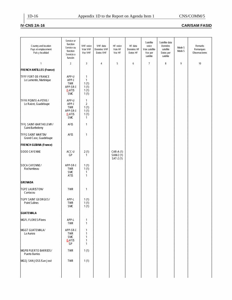
Review of the air-ground data links implementation plan 1.2.4 The Meeting reviewed the CAR/SAM Aeronautical Mobile Service (AMS) and the Aeronautical Mobile Satellite Service (AMSS) contained in Table CNS 2A of the CAR/SAM Air Navigation Plan, Doc 8733, Volume II (FASID), which includes the VHF, HF, satellite and Mode S data link voice and data requirements. 1.2.5 As a result of the follow up given to GREPECAS Conclusions 13/71 and 13/72, and also keeping in mind that the SARPs and guidance material on ATN/IPS air-ground subnetworks will be available for application in November 2008, as well as the pre-ATN capabilities, the Table CNS 2A of the FASID was updated and is presented in Appendix 1D to this part of the Report. The Table contains information available from the CAR and SAM Regions. This includes VHF, HF, satellite and Mode S data implementation requirements for ATC units. Consequently, the Meeting formulated the following Draft Conclusion: DRAFT CONCLUSION CNS/5/2 UPDATING OF THE AMS AND AMSS
REGIONAL PLAN
That ICAO amend the CAR/SAM Regional Plan for the Aeronautical Mobile Service (AMS) and the Aeronautical Mobile Satellite Service (AMSS) included in the Table CNS 2A of the FASID as presented in Appendix E to this part of the Report.
1.3 Review of the ATN regional implementation plan SARPs development status and ICAO guidance material on ATN 1.3.1 The Aeronautical Communications Panel (ACP), in June 2005 concluded that the use of the Internet Protocols (IPS) set for the ATN ground-ground subnetwork is feasible and in July 2006, as mentioned in paragraph 1.2.3, it concluded that it is also feasible to use IPS in the air-ground ATN subnetworks. Based on this and on the Air Navigation Commission’s (ANC) requirement, the ACP is currently developing SARPs for ground-ground and air-ground ATN links based on IPS, and the draft document will be presented for the review of the ANC in July 2007. The guidance material will be used as a Manual when the SARPs are effective (scheduled for November 2008). 1.3.2 The ACP is considering as the goal for the use of ATN, version 6 of the IPS (IPv6), taking into account that it provides several advantages: increase of Internet protocol address space, improvement of the service quality parameters, improvement of end-to-end safety, a more robust system management and other advantages. Also, ICAO is in the process of acquiring a bulk of IPv6 addresses for global implementation, both for the use of ground systems as well as airborne systems.
1-4 Report on Agenda Item 1 CNS/COMM/5
1.3.3 However, the United States Member provided the following information and additional clarification:
a) IPS means that the router does not need to carry the ATN protocol (IDRP) over the IP subnetwork. The IP subnetwork requires the ATN router to use the IP to “encapsulate” the IDRP. Considering that the CAR/SAM Regions have adopted the IPS approach, IP routers that are not compatible with the ATN router of the IP subnetwork will have to be used. For this reason, the ATN Task Force is developing the Message Transfer Agent Routing policy to resolve the incompatibility with Asia/Pacific with a non modification of equipment policy.
b) The IPS for air-ground also needs clarification of either IPS or ATN IP
subnetwork. In order to implement the ATN IP Subnetwork for the ATN air-ground service, the support of the aircraft manufacturers, airlines, and service providers in addition to Civil Aviation Authorities is critical. The term “feasible” for the ACP needs to be clarified in order to carry on with the planning. The issue of VDL Mode 2 and IP subnetwork compatibility is critical. The aircraft manufacturers (e.g. Airbus and Boeing) could support the IPv6 for the ATN air-ground subnetwork considering that the new Airbus A380 and Boeing 787 offer IPv4 for commercial use (cell phone and internet service).
1.3.4 Also, the IP voice use (VoIP) is being developed to send discreet voice packages in digital format over the same ATN network, which encompasses economic benefits. The VoIP use within the new generation of air-ground data links is being considered as a part of the future communications studies. 1.3.5 The United States delegate clarified that a dedicated channel has been assigned to most of the ATS operational voice circuits; this channel is also being compressed from 64 K to 8 K bandwidth or lower (2.4 kbps). The ATS operational voice service between adjacent FIRs is critical and always has priority over other AFS. The following is a comment on VoIP technology for ATS voice circuits.
a) both terminals require conversion equipment from analog to VoIP; b) it does not support the priority and non-blocking required by the ATS operational
voice service; c) increases the maintenance cost of the conversion equipment; and d) the cost saving is not materialized due to the fixed cost of the dedicated circuit
between member States in order to carry out other AFS 1.3.6 VoIP should be utilized when there is no other means or the communication infrastructure is unreliable and its use should be limited to public internet with equipment separated from the ATS operations equipment. This approach will allow communication without impact on or required modification of the ATS operations equipment. However, the ICAO Annex 10, Volume III, needs to be updated to relax recommendations and address other concerns such as security.
CNS/COMM/5 Report on Agenda Item 1 1-5
1.3.7 The United States also informed that the use of public internet for AFS would require that ICAO update Annex 10, Volume III to issue the recommendations (e.g. non-blocking, RMA, and other performance characteristics) as well as to identify impact, if any, to the service. Lastly, a cost benefit analysis should be considered to determine the initial investment and all recurring costs between private IPS networks versus IPS public internet service. It was noted that the current charge for a dedicated 64 kbps circuit between the United States and Japan is approximately $12K/year ($6K for US and $6K/year for Japan). This 64 kbps circuit is loaded with 4 separate voice channels (8K/channel) and 2 dedicated channels for AFTN and AIDC (9.6K each). 1.3.8 Regarding AIDC, it was informed that the AIDC that uses AFTN for its distribution is known as AFTN based on AIDC and it has 2 versions. The new AFTN based on Version 3 of the AIDC is being developed and should be in operation soon in the Asia/Pacific region and in the United States. This new version is compatible with the AFTN based on version 1. 1.3.9 The ATN based on AIDC as specified in ICAO Doc 9705 is based on OSI and it will be updated by the end of 2006 as ACP indicated to reflect the recommended change from the OPLINK panel. 1.3.10 The development of the ATN based on AIDC can be based either on TCP/IP or OSI protocols as long as the AMHS interface is IP. From the ATC operational point of view, the ATN based on AIDC should be treated as a User Agent within its domain. This approach is identical to the AFTN based on AIDC and allows ATC to centralize managing and monitor functions of both services in one facility. 1.3.11 The technical specifications detailed in the AIDC/OSI will be completed by the end of 2006 in order to be incorporated in Doc 9705. The technical specifications detailed for the AIDC based on TCP/IP will be completed between 2008 and 2009. ATN Routers and ground-ground applications Implementation Plans 1.3.12 Considering the format of Table CNS 1Ba – ATN Routers of CAR/SAM Regional Plan which is shown in Appendix 1E to this part of the report and which was formulated by GREPECAS Conclusion 13/74, it is expected that the ATN Task Force will develop the ATN Routers Plan. Since the CAR/SAM ATN Task Force has adopted the use of IPS for the ATN protocol, it is recommended to replace all references to ATN routers in the documents with IPS routers. This approach will make the CAR/SAM AMHS service compatible with the European region. Also, the mentioned Task Force will develop a procedure to address its AMHS compatibility with the Asia/Pacific region based on the ATN protocol (IDRP over X.25). 1.3.13 As a result of the responses received and of the follow-up made by the ICAO NACC and SAM Regional Offices to GREPECAS Conclusion 13/75, Appendix 1F to this part of the Report presents an update to Table CNS 1Bb of the FASID, which contains information on ground-ground applications implementation plans in the CAR Region. Appendix 1G presents similar information from the SAM Region. 1.3.14 The Meeting reviewed the information presented by Members on the corresponding programmes that are associated with the ATN/AMHS efforts in the CAR/SAM regions.
1-6 Report on Agenda Item 1 CNS/COMM/5
1.3.15 The Delegate from Argentina informed that the AMHS system has been installed in all domestic airports, meteorological units, etc., with a total of 164 stations implemented. The main MTA/MS (Message Transfer Agent / Message Storage) has been installed at the Ezeiza ACC. The Meeting was also informed about the type of protocol, software/hardware and MTA applications, which are based on CAAS. Argentina is using IP v4 protocol which can be upgraded to IP v6 protocol if necessary. 1.3.16 The Delegate from Argentina also indicated that an AMHS station has been installed in Lima, Peru through the RLA/03/901 Project in coordination with CORPAC. This station is connected to the MTA/MS in Ezeiza. Currently this station is operational and will remain so until ICAO deems it unnecessary. 1.3.17 The Meeting noted the concern expressed by the Delegate from Argentina regarding the needed coordination for the implementation of AMHS and its Addressing Codes. 1.3.18 Based on the above mentioned information and discussions, the Meeting drafted the following Decision: DECISION CNS/5/3 IP ADDRESSING REGIONAL PLAN FOR ATN AND ITS
APPLICATION MANAGEMENT That the ATN Task Force:
a) identify the specific requirements for Naming and ATN IP Addressing
Management; and b) propose an entity [Member State(s), Territory(ies) or Organization(s)] capable to
coordinate within the CAR/SAM Regions and other international entities (EuroControl for European region and AeroThai for Asia/Pacific Region) to implement the requirements mentioned in paragraph a) above.
1.3.19 The delegate from COCESNA indicated that they are carrying out the international provision of MTA / AMHS as well as domestic AFTN to each Central American State. It was also indicated that the domestic AMHS would be implemented by 2008 and that the MTA addressing scheme is XF and would be able to handle CAAS. 1.3.20 The delegate from Trinidad and Tobago informed that his State implemented an AMHS system by late 2004; however, up to this date they have not been able to perform trials with other States. Notwithstanding, conversations have been initiated with Argentina to perform trials, as well as with the United States to implement an AMHS connection link. 1.3.21 The delegate from Paraguay informed that his State has confirmed the acquisition of an AMHS.
CNS/COMM/5 Report on Agenda Item 1 1-7
1.3.22 The Delegate from the United States informed the Meeting that there is one facility in Salt Lake City, Utah that supports the Asia/Pacific connections; and another one in Atlanta, Georgia to support the connections for CAR/SAM and Europe. Both facilities will be integrated in the near future. The FAA is using an ATN router based on X.25. The United States will support the translated-forms (XF) as well as the Common AMHS Addressing Scheme (CAAS). However, based on the guidelines of the APANPIRG ATN Implementation Plan and on ICAO Doc 9705, Third Edition, the United States informed that in the future, they would prefer to use the CAAS addressing scheme only. 1.3.23 The FAA (United States) is planning to expand the AMHS service to the Atlanta (ATL) Center to support the facility and network diversification. This will ensure that the SLC and ATL Centers will be able to back each other up. ATL will support AMHS service to the European, South American and Caribbean regions in September 2007. 1.3.24 Based on the information presented and the discussions on ICAO Doc 9705 regarding AMHS implementation, the Meeting drafted the following Draft Conclusion: DRAFT CONCLUSION CNS/5/4 ADOPTION OF IP V6 PROTOCOL AS THE AMHS
INTERFACE
That CAR/SAM States/Territories/International Organizations adopt the IP v6 protocol as the AMHS interface between member states, as indicated in the new FASID Table CNS 1Ba, in accordance with ICAO guidelines on this issue.
1.3.25 The meeting reviewed the existing ATN Transition Plan including the documents approved by Recommendation 1/1 - Modification of the Initial CAR/SAM ATN Transition Plan of the ATN Task Force, which include the CAR/SAM Regional ATN G/G Transition Plan and the CAR/SAM ATN Implementation Plan and agreed that the Plan needs to be developed in coordination with other participating States. 1.3.26 The Meeting also noted information presented indicating that AeroThai has been designated by the ICAO Asia/Pacific Regional Office as the ATN Directory Service Regional Coordinator for AMHS addressing management and coordination with Eurocontrol. Eurocontrol has been designated as the global ATN Directory Service Coordinator. It is also the European Regional ATN Directory Service Coordinator. 1.3.27 The delegate from Spain, through AENA, informed the ATM/CNS Subgroup regarding the concern discussed at the European meetings regarding the proper coordination of the global implementation of AMHS electronic messaging systems, specially in two arenas:
• The AMHS addressing plan • The AMHS global address registry
1.3.28 Additionally, the delegate from Spain informed that for this reason, the European Air Navigation Planning Group (EANPG) corresponding contributory body (equivalent to GREPECAS in Europe) has requested Spain to forward this concern by sharing two documents prepared for Europe but that are considered to be transferable to the remaining ICAO Regions.
1-8 Report on Agenda Item 1 CNS/COMM/5
1.3.29 Spain presented for the consideration of the ATN Task Force two information papers: a) EUR/NAT AMHS PRMD Names and Addressing Plan Registry
This document presents the latest version available in the EUR Region of the Global AMHS Addressing. It presents the existing addressing types (CAAS and XF) and the associated tables. It expresses that in theory, ICAO Headquarters will be responsible to carry out the global AMHS address registration. However, as the decision is made (the mechanism is not activated yet) Europe needs to use some sort of official document, since an AMHS link between Madrid and Frankfurt has been activated. For this reason, in the EUR Region ICAO, through its AFSG (ATS Fixed Services Group), and, more specifically, the Planning Group (PG), is performing the registration tasks on a Regional level, even if the AMHS global addresses have to be included in the Registry, considering that traffic is sent to all Regions from Europe. The information developed by the AFSG is presented under Appendix 1H to this part of the Report. For this reason, it is interesting to present this document in the ATM/CNS Subgroup with two objectives: 1. to have the information gathered from the official replies from States worldwide to ICAO regarding the intentions about AMHS addressing; and 2. that the CAR/SAM Regions States can compare the collected information contained in this document that is related to States informing the possible errors or changes.
b) Global AMHS Address Registration This document shows the different possibilities being considered to accomplish the global AMHS address registration. This document was originally presented to the EANPG. This group is to Europe what GREPECAS is to the CAR/SAM regions. This is presented to the ATM/CNS Subgroup for information purposes only, as the ICAO Aeronautical Communications Panel (ACP) is the responsible group to define the final strategy.
1.3.30 The Meeting reviewed the Proposed Draft of the Caribbean/South American (CAR/SAM) Regional ATN Ground Transition Plan. The full review of this plan will be assigned to a State(s)/Territory(ies)/Organization(s) under the ATN Task Force Work Plan. During the preliminary review, the Meeting has already identified changes and/or updates that need to be carried out by the Task Force. 1.3.31 The Meeting agreed that most of the work could be accomplished before the next ATN Task Force Meeting. The FAA offered to host the next meeting tentatively scheduled in Miami, FL in early 2007. 1.3.32 The ATN Task Force work programme was reviewed and updated accordingly by the Meeting. It is shown in Appendix 1I to this part of the report.
CNS/COMM/5 Report on Agenda Item 1 1-9
AMHS Addressing Regional Plan 1.3.33 As a follow-up to ICAO State Letter Ref. SP 54/1-03/39, dated 30 May 2003, and based on the responses given by some States, ICAO Headquarters is developing the AMHS Addressing Global Plan. However, in accordance with GREPECAS Decision 13/76, an AMHS Addressing plan for the SAM Region has been developed and is presented in Appendix 1J to this part of the report. The AMHS Addressing Plan for the CAR Region is under development. Furthermore, the Secretariat is coordinating with ICAO Headquarters in order to harmonise these regional plans together with the mentioned global plan. Table format for the ATN air-ground applications regional plan 1.3.34 According to the guidance given by GREPECAS Decision 13/77, the Meeting prepared a Table format proposal for the ATN air-ground applications regional plan, which is presented in Appendix 1K to this part of the Report.
National plans to prioritise the AMHS and AIDC implementation contributing to ATM Automation
1.3.35 According to the information obtained by the Secretariat, some States, Territories and International Organizations from the CAR and SAM Regions have implemented or are in the process of implementing AMHS; others are setting plans for the AMHS and AIDC implementation. Taking into account the information provided to the Meeting, the AMHS implementation outlook in the CAR and SAM regions is shown in Appendix 1L to this part of the Report.
Analysis of the proposal to use the Argentinean AMHS and REDDIG network as the initial data communications infrastructure between ATFM units in the SAM Region
1.3.36 In accordance with GREPECAS Decision 13/80, as shown in Appendix to the Report on Agenda item 6 of this Meeting, it has been proposed to include in the CNS Committee Work Programme, the following task: “Study the use of the Argentinean AMHS and REDDIG network as the initial data communications infrastructure between ATFM units in the SAM Region”. Recognition of the work accomplished by the ATN Task Force 1.3.37 The Meeting congratulated the ATN Task Force and its Coordinator for the work accomplished. The Meeting also thanked the support being provided to the Group by the member States and Organizations. Also, the United States was thanked for the offering to be host of the next Meeting of the group and for the contribution of high level specialists. 1.4 Study of a communication system to support the migration towards the
meteorological messages exchange (METAR/SPECI and TAF) in BUFR format code
1.4.1 The Meeting noted that ICAO had determined two stages for the migration towards the meteorological messages exchange (METAR/SPECI and TAF) in BUFR code format; the first starting in 2007, in which the exchange of meteorological messages would operate in the traditional format based on alphanumeric codes as well as in BUFR code format; and the second stage, starting in 2015, when BUFR code format will be used exclusively.
1-10 Report on Agenda Item 1 CNS/COMM/5
1.4.2 The Meeting was informed that for the first stage of the transition, the transmission of meteorological messages in alphanumeric codes would be done through AFTN, and messages in BUFR code through AMHS systems. 1.4.3 In this regard, the Meeting took note that an AMHS system with basic service (Doc 9705, Version 2) would not be able to support the OPMET messages exchanged in BUFR code, which requires an AMHS system with extended service that considers file transference (use of FTBP – File Transfer Body Part). Technical specifications for this system would be included in the draft fourth edition of ICAO Doc 9705, which is being reviewed by the Task Force N of the Aeronautical Communications Panel (ACP). 1.4.4 The Meeting was informed that the AMHS systems would be implemented in the first stage to replace the AFTN systems in the CAR/SAM regions. Likewise, the Meeting took note that currently AMHS systems are installed in Argentina, COCESNA and Trinidad and Tobago, and that only the AMHS system in Argentina would have the capacity of supporting transmission of BUFR code messages. 1.4.5 The Meeting also noted that the use of terminals having interfaces with the capacity of coding/decoding BUFR codes to alphanumeric code would be recommended in meteorological stations in case there were no AMHS systems with extended services or if the OPMET messages were being exchanged in BUFR code in an environment that is not totally AMHS, i.e., in an environment with AMHS systems with an AMHS/AFTN gateway. 1.4.6 Likewise, the Meeting noted that in the second migration stage that will begin in 2015 it is expected that AMHS systems with extended services would be almost fully implemented in the CAR/SAM regions, reducing the need for terminals with BUFR format to alphanumeric format coding/decoding capacity. 1.4.7 Also, the Meeting took note that for the BUFR migration other aspects should be considered, such as the elaboration of an interface control document (ICD) that would define the necessary interface characteristics to integrate AMHS and MET systems, the establishment of standards on presentation systems, specifications for the conversion of templates, acceptance standards, conversion programmes and security aspects. 1.4.8 In this regard, the Meeting considered that all previously mentioned aspects should be analysed in depth by the ATN Task Force of the CNS Committee and by the COM/MET Task Force, the latter created by the AERMET Subgroup and the CNS Committee. In this regard, the Meeting formulated the following Draft Decision:
CNS/COMM/5 Report on Agenda Item 1 1-11
DRAFT DECISION CNS/5/5 COMMUNICATION ASPECTS FOR THE MIGRATION
TOWARDS THE METEOROLOGICAL MESSAGE EXCHANGE IN BUFR CODE
That, the ATN Task Force, as well as the COM/MET Task Force of AERMET Subgroup analyse in detail the following communication aspects considered necessary for the migration towards the meteorological message exchange in BUFR format in the CAR/SAM Regions for their possible implementation for the first and second transition stages: a) use of terminals with coding/decoding capacity; b) use of AMHS systems with extended service; and c) development of an interface control document (ICD) to integrate AMHS and
MET systems, establishment of standards for presentation systems, specification for the conversion of templates and security aspects.
1.4.9 Additionally, the United States, through IP/02 presented information on the FAA AMHS BUFR Code Implementation Plan. Information of this plan is being presented in Appendix 1M to this part of the Report.
CNS/COMM/5 Appendix 1A to the Report on Agenda Item 1 1A-1
APPENDIX 1A
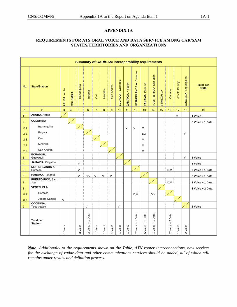
REQUIREMENTS FOR ATS ORAL VOICE AND DATA SERVICE AMONG CAR/SAM STATES/TERRITORIES AND ORGANIZATIONS
Summary of CAR/SAM interoperability requirements
No. State/Station
AR
UB
A, A
ruba
CO
LOM
BIA
B
arra
nqui
lla
B
ogot
a
C
ali
M
edel
lín
S
an A
ndré
s
ECU
AD
OR
, Gua
yaqu
il
JAM
AIC
A, K
ings
ton
NET
HER
LAN
DS
A. C
urac
ao
PAN
AM
Á, P
anam
á
PUER
TO R
ICO
, San
Jua
n
VEN
EZU
ELA
C
arac
as
J
osef
a C
amej
o
CO
CES
NA
, Teg
ucig
alpa
Total per State
1 2 3 4 5 6 7 8 9 10 11 12 13 14 15 16 17 18 19
1 ARUBA, Aruba V 1 Voice
2 COLOMBIA 8 Voice + 1 Data
2.1 Barranquilla V V V
2.2 Bogotá D,V V
2.3 Cali V
2.4 Medellín V
2.5 San Andrés V
3 ECUADOR, Guayaquil V 1 Voice
4 JAMAICA, Kingston V 1 Voice
5 NETHERLANDS A. Curacao V D,V 2 Voice + 1 Data
6 PANAMA, Panamá V D,V V V V 5 Voice + 1 Data
7 PUERTO RICO, San Juan D,V 1 Voice + 1 Data
8 VENEZUELA 3 Voice + 2 Data
8.1 Caracas D,V D,V
8.2 Josefa Camejo V
9 COCESNA, Tegucigalpa V V 2 Voice
Total per Station
1 V
oice
3 V
oice
2 V
oice
+ 1
Dat
a
1 V
oice
1 V
oice
1 V
oice
1 V
oice
1 V
oice
2 V
oice
+ 1
Dat
a
5 V
oice
+ 1
Dat
a
1 V
oice
+ 1
Dat
a
2 V
oice
+ 2
Dat
a
1 V
oice
2 V
oice
Note: Additionally to the requirements shown on the Table, ATN router interconnections, new services for the exchange of radar data and other communications services should be added, all of which still remains under review and definition process.
1A-2 Appendix 1A to the Report on Agenda Item 1 CNS/COMM/5
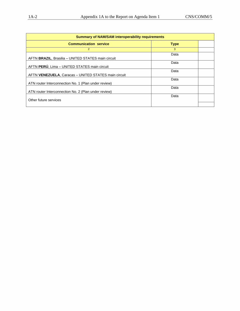
Summary of NAM/SAM interoperability requirements
Communication service Type 2 3
AFTN BRAZIL, Brasilia – UNITED STATES main circuit
Data AFTN PERÚ, Lima – UNITED STATES main circuit
Data AFTN VENEZUELA, Caracas – UNITED STATES main circuit
Data ATN router Interconnection No. 1 (Plan under review)
Data ATN router Interconnection No. 2 (Plan under review)
Data Other future services
Data
CNS/COMM/5 Appendix 1B to the Report on Agenda Item 1 1B-1
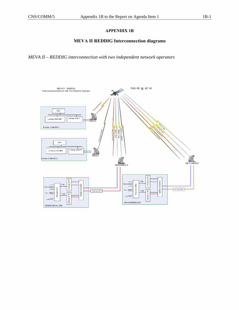
APPENDIX 1B
MEVA II REDDIG Interconnection diagrams
MEVA II – REDDIG interconnection with two independent network operators
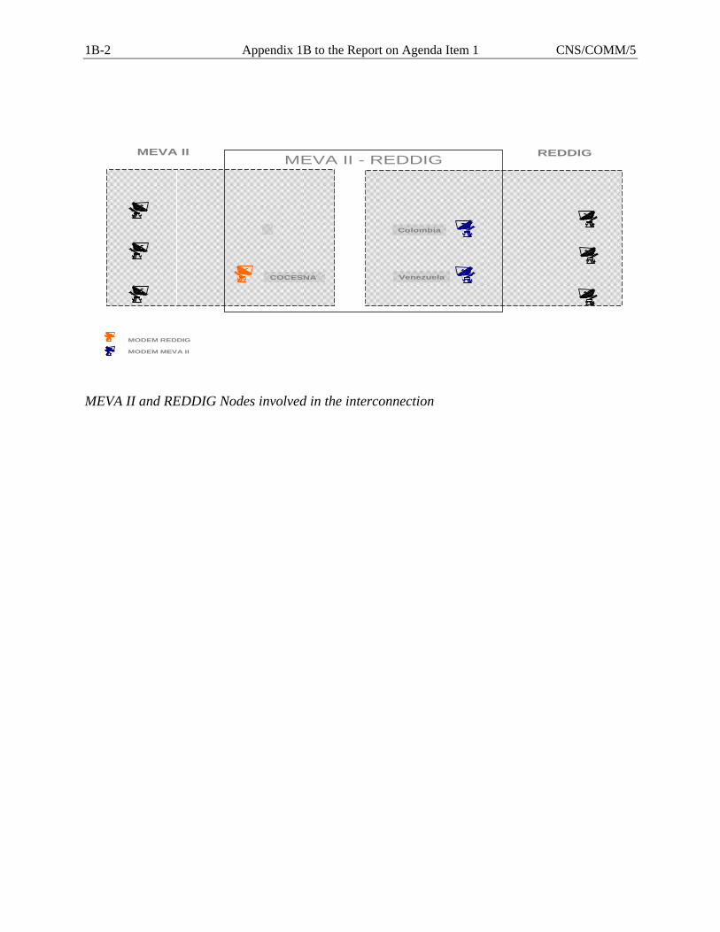
1B-2 Appendix 1B to the Report on Agenda Item 1 CNS/COMM/5
COCESNA
Colombia
Venezuela
MEVA II - REDDIGMEVA II REDDIG
MODEM REDDIG
MODEM MEVA II
MEVA II and REDDIG Nodes involved in the interconnection
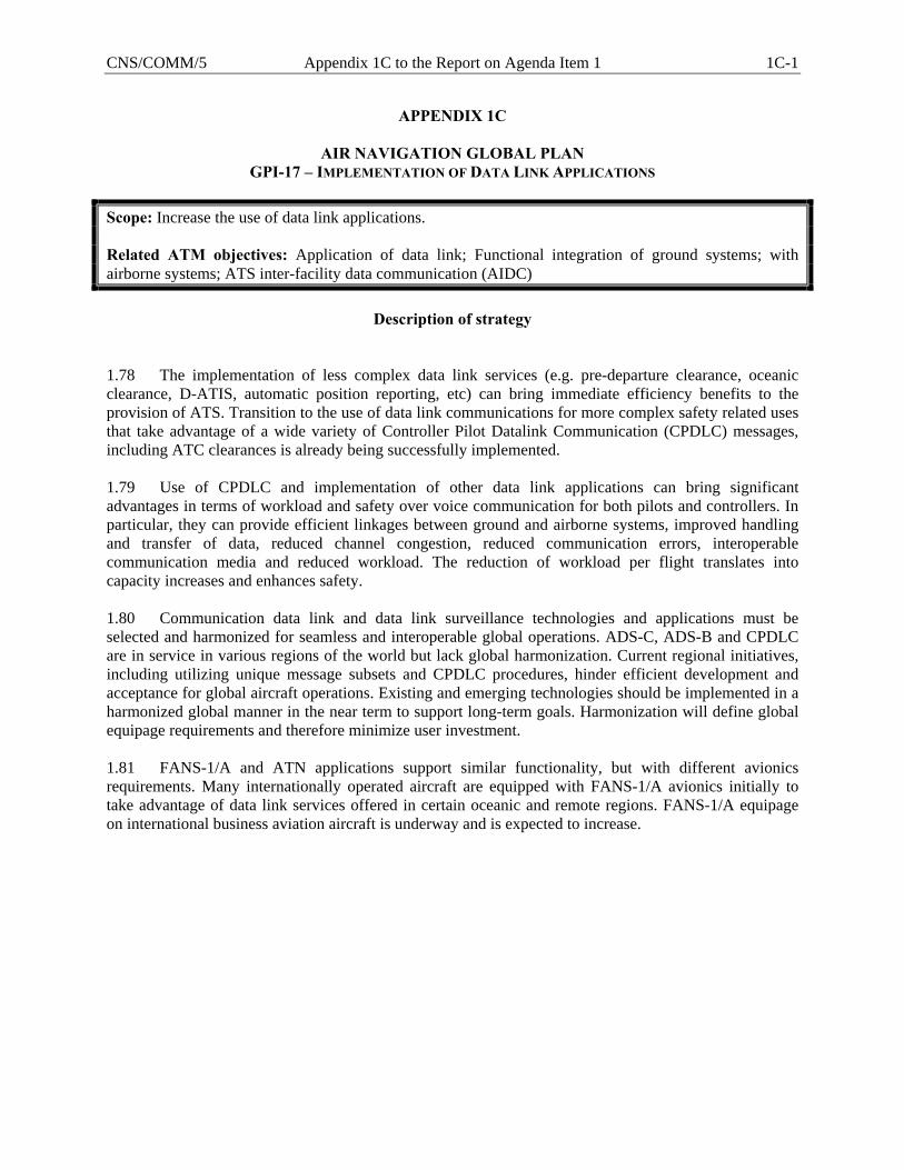
CNS/COMM/5 Appendix 1C to the Report on Agenda Item 1 1C-1
APPENDIX 1C
AIR NAVIGATION GLOBAL PLAN GPI-17 – IMPLEMENTATION OF DATA LINK APPLICATIONS
Scope: Increase the use of data link applications. Related ATM objectives: Application of data link; Functional integration of ground systems; with airborne systems; ATS inter-facility data communication (AIDC)
Description of strategy
1.78 The implementation of less complex data link services (e.g. pre-departure clearance, oceanic clearance, D-ATIS, automatic position reporting, etc) can bring immediate efficiency benefits to the provision of ATS. Transition to the use of data link communications for more complex safety related uses that take advantage of a wide variety of Controller Pilot Datalink Communication (CPDLC) messages, including ATC clearances is already being successfully implemented. 1.79 Use of CPDLC and implementation of other data link applications can bring significant advantages in terms of workload and safety over voice communication for both pilots and controllers. In particular, they can provide efficient linkages between ground and airborne systems, improved handling and transfer of data, reduced channel congestion, reduced communication errors, interoperable communication media and reduced workload. The reduction of workload per flight translates into capacity increases and enhances safety. 1.80 Communication data link and data link surveillance technologies and applications must be selected and harmonized for seamless and interoperable global operations. ADS-C, ADS-B and CPDLC are in service in various regions of the world but lack global harmonization. Current regional initiatives, including utilizing unique message subsets and CPDLC procedures, hinder efficient development and acceptance for global aircraft operations. Existing and emerging technologies should be implemented in a harmonized global manner in the near term to support long-term goals. Harmonization will define global equipage requirements and therefore minimize user investment. 1.81 FANS-1/A and ATN applications support similar functionality, but with different avionics requirements. Many internationally operated aircraft are equipped with FANS-1/A avionics initially to take advantage of data link services offered in certain oceanic and remote regions. FANS-1/A equipage on international business aviation aircraft is underway and is expected to increase.
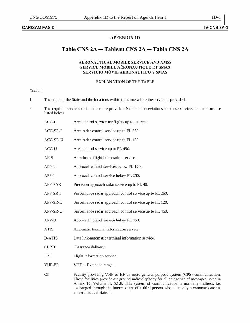
CNS/COMM/5 Appendix 1D to the Report on Agenda Item 1 1D-1 CAR/SAM FASID IV-CNS 2A-1
APPENDIX 1D
Table CNS 2A C Tableau CNS 2A C Tabla CNS 2A
AERONAUTICAL MOBILE SERVICE AND AMSS SERVICE MOBILE AÉRONAUTIQUE ET SMAS
SERVICIO MÓVIL AERONÁUTICO Y SMAS
EXPLANATION OF THE TABLE Column 1 The name of the State and the locations within the same where the service is provided. 2 The required services or functions are provided. Suitable abbreviations for these services or functions are
listed below. ACC-L Area control service for flights up to FL 250. ACC-SR-I Area radar control service up to FL 250. ACC-SR-U Area radar control service up to FL 450. ACC-U Area control service up to FL 450. AFIS Aerodrome flight information service. APP-L Approach control services below FL 120. APP-I Approach control service below FL 250. APP-PAR Precision approach radar service up to FL 40. APP-SR-I Surveillance radar approach control service up to FL 250. APP-SR-L Surveillance radar approach control service up to FL 120. APP-SR-U Surveillance radar approach control service up to FL 450. APP-U Approach control service below FL 450. ATIS Automatic terminal information service. D-ATIS Data link-automatic terminal information service. CLRD Clearance delivery. FIS Flight information service. VHF-ER VHF C Extended range.
GP Facility providing VHF or HF en-route general purpose system (GPS) communication. These facilities provide air-ground radiotelephony for all categories of messages listed in Annex 10, Volume II, 5.1.8. This system of communication is normally indirect, i.e. exchanged through the intermediary of a third person who is usually a communicator at an aeronautical station.
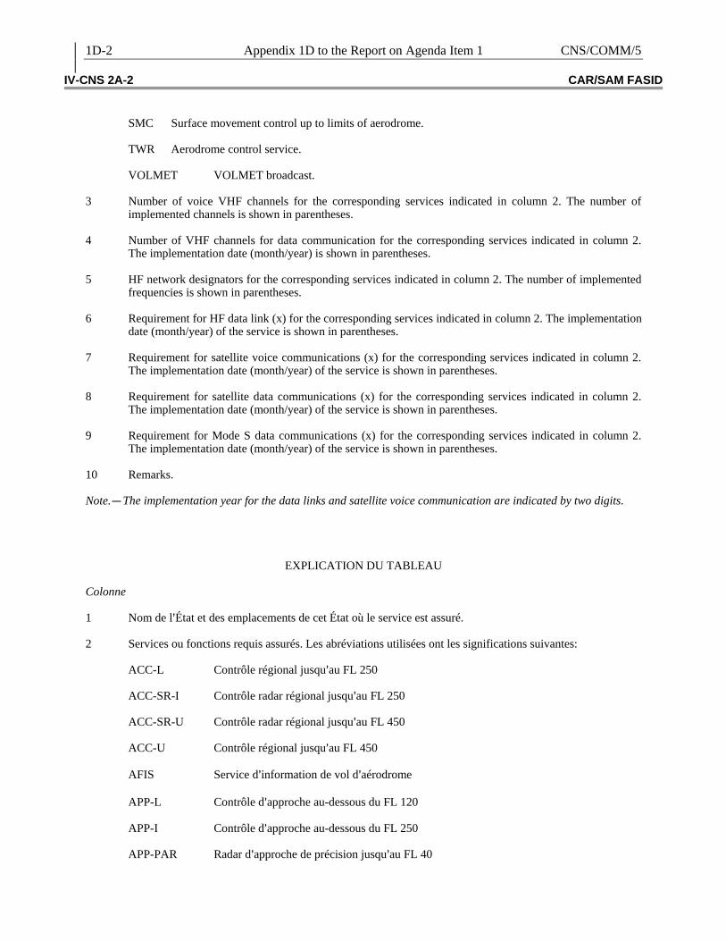
1D-2 Appendix 1D to the Report on Agenda Item 1 CNS/COMM/5 IV-CNS 2A-2 CAR/SAM FASID
SMC Surface movement control up to limits of aerodrome. TWR Aerodrome control service. VOLMET VOLMET broadcast. 3 Number of voice VHF channels for the corresponding services indicated in column 2. The number of
implemented channels is shown in parentheses. 4 Number of VHF channels for data communication for the corresponding services indicated in column 2.
The implementation date (month/year) is shown in parentheses. 5 HF network designators for the corresponding services indicated in column 2. The number of implemented
frequencies is shown in parentheses. 6 Requirement for HF data link (x) for the corresponding services indicated in column 2. The implementation
date (month/year) of the service is shown in parentheses. 7 Requirement for satellite voice communications (x) for the corresponding services indicated in column 2.
The implementation date (month/year) of the service is shown in parentheses. 8 Requirement for satellite data communications (x) for the corresponding services indicated in column 2.
The implementation date (month/year) of the service is shown in parentheses. 9 Requirement for Mode S data communications (x) for the corresponding services indicated in column 2.
The implementation date (month/year) of the service is shown in parentheses. 10 Remarks. Note.C The implementation year for the data links and satellite voice communication are indicated by two digits.
EXPLICATION DU TABLEAU Colonne 1 Nom de l=État et des emplacements de cet État où le service est assuré. 2 Services ou fonctions requis assurés. Les abréviations utilisées ont les significations suivantes: ACC-L Contrôle régional jusqu=au FL 250 ACC-SR-I Contrôle radar régional jusqu=au FL 250 ACC-SR-U Contrôle radar régional jusqu=au FL 450 ACC-U Contrôle régional jusqu=au FL 450 AFIS Service d=information de vol d=aérodrome APP-L Contrôle d=approche au-dessous du FL 120 APP-I Contrôle d=approche au-dessous du FL 250 APP-PAR Radar d=approche de précision jusqu=au FL 40

CNS/COMM/5 Appendix 1D to the Report on Agenda Item 1 1D-3 CAR/SAM FASID IV-CNS 2A-3
APP-SR-I Contrôle d=approche au radar de surveillance jusqu=au FL 250 APP-SR-L Contrôle d=approche au radar de surveillance jusqu=au FL 120 APP-SR-U Contrôle d=approche au radar de surveillance jusqu=au FL 450 APP-U Contrôle d=approche au-dessous du FL 450 ATIS Service automatique d=information de région terminale D-ATIS Service automatique d=information de région terminale par liaison de données CLRD Délivrance des autorisations FIS Service d=information de vol VHF-ER VHF à portée étendue
GP Installation de communications VHF ou HF en route d=emploi général (GP). Permet des communications radiotéléphoniques air-sol pour toutes les catégories de messages énumérées dans l=Annexe 10, Volume II, 5.1.8. Système normalement indirect, c=est-à-dire dans lequel les communications se font par l=intermédiaire d=un tiers, généralement un opérateur de télécommunications situé dans une station aéronautique.
SMC Contrôle des mouvements à la surface jusqu=aux limites de l=aérodrome TWR Contrôle d=aérodrome VOLMET Émissions VOLMET 3 Nombre de canaux vocaux VHF pour les services indiqués dans la colonne 2. Le nombre des canaux mis en
œuvre est indiqué entre parenthèses. 4 Nombre de canaux VHF pour les communications de données des services indiqués dans la colonne 2. La
date de mise en œuvre (mois/année) est indiquée entre parenthèses. 5 Identification du réseau HF pour les services indiqués dans la colonne 2. Le nombre de fréquences utilisées
est indiqué entre parenthèses. 6 Besoin d=une liaison de données HF (X) pour les services indiqués dans la colonne 2. La date de mise
œuvre (mois/année) est indiquée entre parenthèses. 7 Besoin de communications vocales par satellite (X) pour les services indiqués dans la colonne 2. La date de
mise en œuvre (mois/année) est indiquée entre parenthèses. 8 Besoin de communications de données par satellite (X) pour les services indiqués dans la colonne 2. La
date de mise en œuvre (mois/année) est indiquée entre parenthèses. 9 Besoin de communications de données mode S (X) pour les services indiqués dans la colonne 2. La date de
mise en œuvre (mois/année) est indiquée entre parenthèses. 10 Remarques Note.C L=année de mise en œuvre des liaisons de données et des communications vocales par satellite est indiquée par deux chiffres.
1D-4 Appendix 1D to the Report on Agenda Item 1 CNS/COMM/5 IV-CNS 2A-4 CAR/SAM FASID
EXPLICACIÓN DE LA TABLA
Columna 1 El nombre del Estado y de las localidades dentro del mismo donde se proporciona el servicio. 2 Se proporcionan los servicios o funciones que se requieren. Se enumeran a continuación las abreviaturas
correspondientes a estos servicios o funciones. ACC-L Servicio de control de área hasta el FL 250 ACC-SR-I Servicio de control de área radar hasta el FL 250 ACC-SR-U Servicio de control de área radar hasta el FL 450 ACC-U Servicio de control de área hasta el FL 450 AFIS Servicio de información de vuelo de aeródromo APP-L Servicio de control de aproximación por debajo del FL 120 APP-I Servicio de control de aproximación por debajo del FL 250 APP-PAR Servicio radar para la aproximación de precisión hasta el FL 40 APP-SR-I Servicio de aproximación de control con radar de vigilancia hasta el FL 250 APP-SR-L Servicio de aproximación de control con radar de vigilancia hasta el FL 120 APP-SR-U Servicio de aproximación de control con radar de vigilancia hasta el FL 450 APP-U Servicio de control de aproximación por debajo del FL 450 ATIS Servicio automático de información terminal D-ATIS Servicio automático de información terminal por enlace de datos CLRD Servicio de entrega de autorización de tránsito FIS Servicio de información de vuelo VHF-ER VHF CAlcance ampliado
GP Instalación que proporciona comunicaciones VHF o HF en ruta para fines generales (GPS). Estas instalaciones suministran transmisión radiotelefónica aeroterrestre en todas las categorías de mensajes citadas en el Anexo 10, Vol II, 5.1.8. En este sistema las comunicaciones son normalmente indirectas, es decir, que son intercambiadas por intermedio de un tercero que habitualmente es un operador de comunicaciones de una estación aeronáutica.
SMC Control del movimiento en la superficie hasta los límites del aeródromo. TWR Servicio de control de aeródromo. VOLMET Radiodifusiones VOLMET.

CNS/COMM/5 Appendix 1D to the Report on Agenda Item 1 1D-5 CAR/SAM FASID IV-CNS 2A-5
3 Número de canales VHF para comunicaciones orales para los correspondientes servicios indicados en la Columna 2. El número de canales implantados se indica entre paréntesis.
4 Número de canales VHF para comunicaciones en datos para los correspondientes servicios indicados en la
Columna 2. La fecha de implantación (mes/año) se indica entre paréntesis. 5 Designadores de red HF para comunicaciones orales para los correspondientes servicios indicados en la
Columna 2. El número de frecuencias implantados se indica entre paréntesis. 6 Requisito para enlace de datos HF (x) para los correspondientes servicios indicados en la Columna 2. La
fecha de implantación (mes/año) del servicio se indica entre paréntesis. 7 Requisito para comunicaciones orales por satélite (x) para los correspondientes servicios indicados en la
Columna 2. La fecha de implantación (mes/año) del servicio se indica entre paréntesis. 8 Requisito para comunicaciones de datos por satélite (x) para los correspondientes servicios indicados en la
Columna 2. La fecha de implantación (mes/año) del servicio se indica entre paréntesis. 9 Requisito para comunicaciones de datos en Modo S (x) para los correspondientes servicios indicados en la
Columna 2. La fecha de implantación (mes/año) del servicio se indica entre paréntesis. 10 Observaciones. Nota.C El año de implementación para los enlaces de datos y comunicaciones orales por satélite se indican en dos dígitos.
1D-6 Appendix 1D to the Report on Agenda Item 1 CNS/COMM/5 IV-CNS 2A-6 CAR/SAM FASID
Country and location Pays et emplacement
País y localidad
Service or function
Service ou fonction
Servicio o función
VHF voice Voix VHF Voz VHF
VHF data
Données VHF Datos VHF
HF voice Voix HF Voz HF
HF data
Données HF Datos HF
Satellite
voice Voix satellite
Voz por satélite
Satellite data
Données satellite
Datos por satélite
Mode S Modo S
Remarks
Remarques Observaciones
1
2
3
4
5
6
7
8
9
10
ANGUILLA (United Kingdom) TQPF THE VALLEY/Wall TWR (1) 1
Blake, Anguilla I. ANTIGUA AND BARBUDA TAPA SAINT JOHNS/ APP 1 (1)
V.C. Bird Antigua I. TWR 1 (1) SMC 1 (1) APP-SR-I 1 D-ATIS 1 ARGENTINA SAEU BUENOS AIRES ACC-U 5 (5) 2 (06/05) SAM-1(5) X (06/08) X (06/08) X (06/08) GP 2(1) SAM-2 (5) SABE BUENOS AIRES/ APP-L 1 (1)
Aeroparque Jorge Newbery APP-SR-I 1(1) TWR 1(1) SMC 1 (1) ATIS 1 (1) CLRD 1 (1) SAEZ BUENOS AIRES/ APP-SR-I 1 (1)
Ezeiza, Ministro Pistarini APP-L 1 ATIS 1 (1) SMC 1 (1) TWR 1 (1) CLRD 1* * Implementation
by 2002 *Mise en œuvre en
2002 *Implantación
prevista en 2002 SADD BUENOS AIRES/Don TWR 1 (1)
Torcuato SMC 1 (1) SADF BUENOS AIRES/San APP 1
Fernando TWR 1 (1) SMC 1 (1) SARI CATARATAS DEL TWR 1 (1)
IGUAZU/My. Carlos Eduardo K.
SAVF COMODORO ACC-U 2 (2) 1 (06/06) SAM-1 (5) X (06/08) X (06/08) X (06/08)
RIVADAVIA ACC-L 1 (1) GP 1 (1) SAVC COMODORO APP 1(1)
RIVADAVIA/General TWR 1 (1) Mosconi
SACF CORDOBA ACC-U 3 (3) 1 (06/06) SAM-1 (3) GP 1

CNS/COMM/5 Appendix 1D to the Report on Agenda Item 1 1D-7 CAR/SAM FASID IV-CNS 2A-7
Country and location Pays et emplacement
País y localidad
Service or function
Service ou fonction
Servicio o función
VHF voice Voix VHF Voz VHF
VHF data
Données VHF Datos VHF
HF voice Voix HF Voz HF
HF data
Données HF Datos HF
Satellite
voice Voix satellite
Voz por satélite
Satellite data
Données satellite
Datos por satélite
Mode S Modo S
Remarks
Remarques Observaciones
1
2
3
4
5
6
7
8
9
10
SACO CORDOBA/Ing. A. APP-SR-I 1(1)
Taravella TWR 1 (1) SMC 1 (1) SARF FORMOSA/Formosa APP-L 1(1) TWR 1 (1) SASJ JUJUY/Gobernador APP-SR-1 1(1) Guzmán TWR 1 (1) SAZM MAR DEL PLATA/ APP-SR-I 1 (1)
Brig. Gral. B. de la Colina TWR 1 (1) SMC 1 (1) ATIS 1 (1) SAMF MENDOZA ACC-U 3 (1) 1 (06/06) SAM-1 (3) GP 1 (1) SAME MENDOZA/El APP-SR-I 1
Plumerillo TWR 1 (2) SMC 1 (1) ATIS 1 (1) SAZN NEUQUEN/Presidente APP 1
Perón TWR 1 (1) SARP POSADAS/Libertador APP-L 1(1)
Gral. D. José de San Martín TWR 1 (1) SARR RESISTENCIA ACC-U 3 (4) 1 (06/06) SAM-1 (3) X (06/06) GP 1 (1) SARE RESISTENCIA/ APP-SR-I 1 (1)
Resistencia TWR 1 (1) ATIS 1 Implementation
by 2002 Mise en œuvre
en 2002 Implantación
prevista en 2002 SAWG RIO GALLEGOS/ APP-L 1 (1)
Piloto Civil N. Fernández TWR 1 (1) ATIS 1 (1) GP 1(2) SAWE RIO GRANDE/ APP 1
Rio Grande TWR 1 (2) SAAR ROSARIO/Rosario APP-L 1 TWR 1 (2) ATIS 1 Implementation
by 2002 Mise en œuvre
en 2002 Implantación
prevista en 2002 SASA SALTA/Salta APP-L 1(1) TWR 1 (1) GP 1 (1)
1D-8 Appendix 1D to the Report on Agenda Item 1 CNS/COMM/5 IV-CNS 2A-8 CAR/SAM FASID
Country and location Pays et emplacement
País y localidad
Service or function
Service ou fonction
Servicio o función
VHF voice Voix VHF Voz VHF
VHF data
Données VHF Datos VHF
HF voice Voix HF Voz HF
HF data
Données HF Datos HF
Satellite
voice Voix satellite
Voz por satélite
Satellite data
Données satellite
Datos por satélite
Mode S Modo S
Remarks
Remarques Observaciones
1
2
3
4
5
6
7
8
9
10
SAZS SAN CARLOS DE APP-SR-I 1
BARILOCHE/San Carlos TWR 1 (1) de Bariloche ATIS 1 (1)
SANT TUCUMAN/Tte. APP-L 1(1)
Benjamin Matienzo TWR 1 (2) GP 1 (1) SAWH USHUAIA/Malvinas APP-L 1
Argentinas TWR 1 (1) GP 1 (1) ARUBA (Netherlands) TNCA ORANJESTAD/ APP-SR-L 1 (1)
Reina Beatriz, Aruba I. APP-L 1 (1) TWR 1 (1) SMC 1 (1) D-ATIS 1 (1) BAHAMAS MYBS ALICE TOWN/ TWR 1
South Bimini, Bimini I. MYSM COCKBURN TOWN/ TWR 1
San Salvador I. MYGF FREEPORT/Intl., APP-U 1
Grand Bahama I. APP-L 1 TWR 1 SMC 1 MYEG GEORGETOWN/ APP-L 1
Georgetown, Exuma Intl. TWR 1 MYEM GOVERNOR=S APP-L 1
HARBOUR/ Governor=s TWR 1 Harbour, Eleuthera I.
MYNA NASSAU ACC-U 3 GP 1 ACC-L 1 MYNN NASSAU/Intl., APP-I 1
New Providence I. TWR 1 SMC 1 APP-SR-I 1 D-ATIS 1 MYEH NORTH ELEUTHERA/ TWR 1
New Providence I. 1 MYLS STELLA MARIS/Long TWR 1
Island I. MYAT TREASURE CAY/ TWR 1
Treasure Cay, Abaco I. APP-L 1 MYGW WEST END/West TWR 1
End, Grand Bahama I.
CNS/COMM/5 Appendix 1D to the Report on Agenda Item 1 1D-9 CAR/SAM FASID IV-CNS 2A-9
Country and location Pays et emplacement
País y localidad
Service or function
Service ou fonction
Servicio o función
VHF voice Voix VHF Voz VHF
VHF data
Données VHF Datos VHF
HF voice Voix HF Voz HF
HF data
Données HF Datos HF
Satellite
voice Voix satellite
Voz por satélite
Satellite data
Données satellite
Datos por satélite
Mode S Modo S
Remarks
Remarques Observaciones
1
2
3
4
5
6
7
8
9
10
BARBADOS TBPB BRIDGETOWN/ APP-U 1
Grantley Adams Intl. APP-I 5 TWR 1 SMC 1 APP-SR-U 1 D-ATIS 1 BELIZE MZBZ BELIZE/Intl. APP-I 1 APP-I 1 TWR 1 SMC 1 D-ATIS 1 BOLIVIA SLCB COCHABAMBA/Jorge TWR 1 (1)
Wilsterman APP-I 2 (1) SMC 1 (1) SLLP LA PAZ ACC-U 1 1 (06/06) SAM-1 (3) X (06/06) ACC-U 1 (1)-ER SAM-2 (3) GP 1 ACC-L 1 (1) SLLP LA PAZ/El Alto Intl. APP-I 3 TWR 1 (1) SMC 1 (1) ATIS 1 SLVR SANTA CRUZ/Viru-Viru APP-I 3 (1)
Intl. TWR 1 (1) SMC 1 (1) ATIS 1 SLTJ TARIJA/Oriel Lea Plaza APP-I 1 (1) TWR 1 (1) SLTR TRINIDAD/Tte. Av. APP-I 2 (1)
Jorge Henrich Arauz TWR 1 (1) SMC 1 BRAZIL SB.. AMAZONICA ACC-SR-U 24 (24) 2 (06/08) SAM-2 (4) X (06/08) GP 1 SB.. ATLANTICA ACC-U SAM-2 (4) X (06/08) X (06/08) X (06/68) SAT-1 SAT-2 SBBE BELEM/Val de Câes APP-SR-I 4 (4)
Intl. TWR 1 (1) SMC 1 (1)
1D-10 Appendix 1D to the Report on Agenda Item 1 CNS/COMM/5 IV-CNS 2A-10 CAR/SAM FASID
Country and location Pays et emplacement
País y localidad
Service or function
Service ou fonction
Servicio o función
VHF voice Voix VHF Voz VHF
VHF data
Données VHF Datos VHF
HF voice Voix HF Voz HF
HF data
Données HF Datos HF
Satellite
voice Voix satellite
Voz por satélite
Satellite data
Données satellite
Datos por satélite
Mode S Modo S
Remarks
Remarques Observaciones
1
2
3
4
5
6
7
8
9
10
SBCF BELO HORIZONTE/ APP-SR-I 4 (4)
Tancredo Neves Intl. TWR 1 (1) 1 (06/01) SMC 1 (1) CLRD 1 (1) ATIS 1 (1) SBBS BRASILIA ACC-SR-U 16 (16) 8 (06/085) SAM-2 (4) X (06/08) SBBR BRASILIA/Brasilia Intl. APP-SR-I 4 (3) TWR 1 (1) SMC 1 (1) CLRD 1 (1) 1 (06/01) ATIS 1 (1) SBBV BOA VISTA/ APP-I 1 (1)
Boa Vista Intl. TWR 2 (2) SMC 1 SBKP CAMPINAS/Viracopos APP-SR-I 1 (1)
Intl. TWR 1 (1) SMC 1 SBCG CAMPO GRANDE/ APP-SR-I 1 (1)
Campo Grande Intl. TWR 1 (1) ATIS 1 SBCR CORUMBA/ AFIS 1 (1)
Corumba Intl. SBCZ CRUZEIRO DO SUL/ AFIS 1 (1)
Cruzeiro do Sul Intl. SBCY CUIABA/Marechal APP-SR-I 1 (1)
Rondon Intl. TWR 1 (1) SBCW CURITIBA ACC-SR-U 10 (10) 2 (06/085) SAM-2 (4) X (06/08) SBCT CURITIBA/ APP-SR-I 3 (3)
Afonso Peña Intl. TWR 2 (2) ATIS 1 SMC 1 (1) CLRD 1 (1) SBFL FLORIANÓPOLIS/ APP-SR-I 3 (3)
Hercílio Luz Intl. TWR 2 (2) SMC 1 SBFZ FORTALEZA/ APPBSR-I 2 (2)
Pinto Martins Intl. TWR 1 (1) SMC 1 (1) CLRD 1 (1) SBFI FOZ DO IGUACU/ APP-SR-I 2 (2)
Cataratas Intl. TWR 1 (1) SBMQ MACAPA/ APP-I 1
Macapa Intl. TWR 1 SBEG MANAUS/Eduardo APP-SR-I 4 (4)
Gomes Intl. TWR 1 (1) SMC 1 (1)
CNS/COMM/5 Appendix 1D to the Report on Agenda Item 1 1D-11 CAR/SAM FASID IV-CNS 2A-11
Country and location Pays et emplacement
País y localidad
Service or function
Service ou fonction
Servicio o función
VHF voice Voix VHF Voz VHF
VHF data
Données VHF Datos VHF
HF voice Voix HF Voz HF
HF data
Données HF Datos HF
Satellite
voice Voix satellite
Voz por satélite
Satellite data
Données satellite
Datos por satélite
Mode S Modo S
Remarks
Remarques Observaciones
1
2
3
4
5
6
7
8
9
10
SBNT NATAL/Augusto Severo APP-SR-I 4 (4)
Intl. TWR 2 (2) SMC 1 (1) CLRD 1 SBPP PONTA PORÃ/ AFIS 1 (1)
Ponta Porã Intl. SBPA PORTO ALEGRE/ APP-SR-I 4 (4)
Salgado Filho Intl TWR 1 (1) SMC 1 (1) CLRD 1 ATIS 1 SBRE RECIFE ACC-SR-U 16 (16) 5 (06/08) SAT-2 (4) X (06/08) GP 1 SBRF RECIFE/Guararapes APP-SR-I 4 (4)
Intl. TWR 1 (1) SMC 1 (1) ATIS 1 CLRD 1 SBGL RIO DE JANEIRO/ APP-SR-I 6 (6)
Galeâo Antonio Carlos TWR 2 (2) Jobim Intl. SMC 1 (1) 1 (06/01)
CLRD 1 (1) ATIS 1 (1) SBSV SALVADOR/Deputado APP-SR-I 4 (4)
Luis Eduardo Magalhâes TWR 1 (1) Intl. SMC 1 (1) GP 1
ATIS 1 SBSN SANTAREM/ APP-I 2 (2)
Santarem Intl. TWR 1 (1) SBSL SÂO LUIS/Marechal APP-I 1 (1)
Cunha Machado Intl. TWR 1 (1) SBGR SÂO PAULO/ TWR 3 (3) 1 (06/01)
Guarulhos Intl. SMC 1 (1) CLRD 1 (1) ATIS 1 (1) SBTT TABATINGA/ AFIS 1 (1)
Tabatinga Intl. SBUG URUGUAIANA/ AFIS 1 (1)
Rubem Berta Intl. CAPE VERDE GVSC SAL I. ACC-U 2-ER SAT-1 ACC-L 1 SAT-2 CAYMAN ISLANDS (United Kingdom)
MWCB CAYMAN BRAC/ TWR 1 (1)
Gerrard Smith Intl. SMC 1
1D-12 Appendix 1D to the Report on Agenda Item 1 CNS/COMM/5 IV-CNS 2A-12 CAR/SAM FASID
Country and location Pays et emplacement
País y localidad
Service or function
Service ou fonction
Servicio o función
VHF voice Voix VHF Voz VHF
VHF data
Données VHF Datos VHF
HF voice Voix HF Voz HF
HF data
Données HF Datos HF
Satellite
voice Voix satellite
Voz por satélite
Satellite data
Données satellite
Datos por satélite
Mode S Modo S
Remarks
Remarques Observaciones
1
2
3
4
5
6
7
8
9
10
MWCR GEORGETOWN/ APP-I 1
Owen Roberts Intl. TWR -1 SMC 1 D-ATIS 1 (1) CHILE SCFA ANTOFAGASTA/ APP-SR-I 2 (2) 2 (06/08) SAM-1 (4) X (06/08) X (06/08) X (06/08)
Cerro Moreno TWR 1 (1) SMC 1 (1) ATIS 1 GP 1 (1)-ER SCAR ARICA/Chacalluta APP-I 1 (1) TWR 1 (1) SMC 1 (1) SCIE CONCEPCION/ APP-I 1 (1)
Carriel Sur TWR 1 (1) SMC 1 (1) SCDA IQUIQUE/Gral. Diego APP-SR-I 1 (1)
Aracena TWR 1 (1) SMC 1 (1) GP 1(1)-ER SCTZ PUERTO MONTT ACC-U 2 (1) 2 (06/08) SAM-1 (4) X (06/08) X (06/08) X (06/08) Tepual ACC-U 1 (1)-ER GP 1 (1)-ER APP-SR-I 2 (1) SCTE PUERTO MONTT/ TWR 1 (1)
El Tepual SMC 1 (1) ATIS 1 SCCZ PUNTA ARENAS ACC-U 3 (2) 2 (06/08) SAM-1 (3) X (06/08) X (06/08) X (06/08) GP-ER 1 (2) APP-SR-I 2 (1) SCCI PUNTA ARENAS/ TWR 1 (1)
Pdte. C. Ibáñez del Campo SMC 1 (1) ATIS 1 SCEZ SANTIAGO ACC-U 4 (4)-ER 2 (06/086) SAM-1 (3) X (06/08) X (06/08) X (06/08) GP 2 (2)-ER APP-SR-I 4 (4) SCEL SANTIAGO/ CLRD 1 (1)
Arturo Merino Benitez TWR 2 (1) SMC 2(1) ATIS 1 (1) 1 (06/08) SCTC TEMUCO/Manquehue APP-L 1 (1) TWR 1 (1) SMC 1 (1) COLOMBIA SKEC BARRANQUILLA ACC-U 2 (2) 2 (06/086) CAR-A (2) X (06/06) GP 1 (1)
CNS/COMM/5 Appendix 1D to the Report on Agenda Item 1 1D-13 CAR/SAM FASID IV-CNS 2A-13
Country and location Pays et emplacement
País y localidad
Service or function
Service ou fonction
Servicio o función
VHF voice Voix VHF Voz VHF
VHF data
Données VHF Datos VHF
HF voice Voix HF Voz HF
HF data
Données HF Datos HF
Satellite
voice Voix satellite
Voz por satélite
Satellite data
Données satellite
Datos por satélite
Mode S Modo S
Remarks
Remarques Observaciones
1
2
3
4
5
6
7
8
9
10
SKBQ BARRANQUILLA/ APP-SR-I 2 (2)
Ernesto Cortissoz TWR 1 (1) SMC 1 (1) ATIS 1 CLRD 1 1 (06/01) SKED BOGOTA ACC-U 5 (5) 4 (06/086) SAM-2 (2) X (06/06) X (06/06) GP 1 (1)-ER SKCL CALI ACC-SR-I 1 (1) GP 1 (1) SAM-1 X (06/06) SKCL CALI/Alfonso Bonilla APP-SR-I 1 (1)
Aragón TWR 1 (1) SMC 1 (1) ATIS 1 SKCG CARTAGENA/ TWR 1 (1)
Rafael Núñez SKCC CUCUTA/Camilo Daza APP-I 1 (1) TWR 1 (1) SLLT LETICIA/Alfredo APP-SR-I 1 (1)
Vásquez Cobo TWR 1 (1) SKRG RIO NEGRO/ APP-SR-I 1 (1)
José María Córdova TWR 1 (1) SMC 1 (1) ATIS 1 (1) SKSP SAN ANDRES I./ APP-SR-I 1 (1)
Sesquicentenario APP-I 1 (1) TWR 1 (1) SMC 1 SKBO SANTA FE DE APP-SR-I 3 (3) BOGOTA/Eldorado TWR 2 (2) SMC 2 (2) ATIS 1 (1) CLRD 1 (1) 1 (06/01) COSTA RICA MROC ALAJUELA/ APP-SR-I 2 (1)
Juan Santamaria Intl. TWR 1 (1) SMC 1 (1) D-ATIS 1 (1) GP 1 (1) MRLB LIBERIA/Tomás APP-I 1 (1)
Guardia Intl. TWR 1 (1) SMC 1 (1) MRLM LIMON/Limón Intl. AFIS 1 (1) MRPV PAVAS/Tobías TWR 1 (1)
Bolaños Intl. SMC 1 (1)
1D-14 Appendix 1D to the Report on Agenda Item 1 CNS/COMM/5 IV-CNS 2A-14 CAR/SAM FASID
Country and location Pays et emplacement
País y localidad
Service or function
Service ou fonction
Servicio o función
VHF voice Voix VHF Voz VHF
VHF data
Données VHF Datos VHF
HF voice Voix HF Voz HF
HF data
Données HF Datos HF
Satellite
voice Voix satellite
Voz por satélite
Satellite data
Données satellite
Datos por satélite
Mode S Modo S
Remarks
Remarques Observaciones
1
2
3
4
5
6
7
8
9
10
CUBA MUCM CAMAGUEY/ APP-SR-L 1
Ignacio Agramonte TWR 1 (1) MUCL CAYO LARGO APP-L 1 (1)
DEL SUR/Vilo Acuña TWR 1 (1) MUCA CIEGO DE AVILA/ APP-L 1
Máximo Gómez TWR 1 (1) MUHA HABANA ACC-SR-U 5 (4)-ER 2 (06/08) CAR-A (6) X (06/08) ACC-SR-I 3 (1)-ER GP-U 2 (1) MUHA HABANA/José Martí APP-SR-L 1 APP-SR-I 1 (1) TWR 1 (1) SMC 1 (1) D-ATIS 1 (1) 2008 MUHG HOLGUIN/Frank País APP-SR-L 1 TWR 1(1) MUCU SANTIAGO DE CUBA/ APP-SR-I 1 (1)
Antonio Maceo TWR 1 (1) SMC 1 MUVR VARADERO/Juan APP-SR-L 1
Gualberto Gomez TWR 1 (1) SMC 1 D-ATIS 1 2008 DOMINICA TDPB MELVILLE HALL/ TWR 1 (1) Dominica TDPR ROSEAU/Canefield TWR 1 (1) DOMINICAN REPUBLIC MDBH BARAHONA/ TWR 1 (1)
Maria Montes Intl. MDCY EL CATEY/ TWR 2 El Catey Intl. APP 1 SMC 1 D-ATIS 1 MDHE HERRERA/ TWR 1 (1)
Herrera Intl. MDEH EL HIGÜERO/ TWR 2 Dr. Joaquín Balaguer Intl. APP 1 SMC 1 MDLR LA ROMANA/ APP-L 1 (1)
La Romana Intl. TWR 1 (1)
CNS/COMM/5 Appendix 1D to the Report on Agenda Item 1 1D-15 CAR/SAM FASID IV-CNS 2A-15
Country and location Pays et emplacement
País y localidad
Service or function
Service ou fonction
Servicio o función
VHF voice Voix VHF Voz VHF
VHF data
Données VHF Datos VHF
HF voice Voix HF Voz HF
HF data
Données HF Datos HF
Satellite
voice Voix satellite
Voz por satélite
Satellite data
Données satellite
Datos por satélite
Mode S Modo S
Remarks
Remarques Observaciones
1
2
3
4
5
6
7
8
9
10
MDPP PUERTO PLATA/ APP-SR-I 1 (1)
Gregorio Luperon TWR 1 (1) SMC 1 (1) MDPC PUNTA CANA/Punta APP-L 1
Cana Intl. TWR 1 (1) MDST SANTIAGO/Cibao APP-L 1
Santiago Intl. TWR 1 (1) MDCS SANTO DOMINGO ACC-U 4 1 (06/08) ACC-SR-U 1 (1) GP 1 MDSD SANTO DOMINGO/ APP-SR-I 2 (1)
De las Américas Intl. TWR 1 (1) SMC 1 (1) D-ATIS 1 (1) CLRD 1 ECUADOR SEGU GUAYAQUIL ACC-U 2 (2) 1 (06/08) SAM-1 (4) X (06/06) X (06/06) X (06/06) ACC-U 1-ER GP 1 (1) SEGU GUAYAQUIL/ APP-SR-I 1 (1)
Simón Bolívar APP-I 2 (1) TWR 1 (1) SMC 1 (1) ATIS 1 SELT LATACUNGA/Cotopaxi APP-I 1 (1) TWR 1 (1) SEMT MANTA/Eloy Alfaro APP-I 1 (1) TWR 1 (1) SEQU QUITO/Mcal. Sucre APP-SR-I 1 (1) TWR 1 (1) SMC 1 (1) ATIS 1 (1) EL SALVADOR MSLP SAN SALVADOR/ APP-I 1
El Salvador Intl. APP-I 1 APP-SR-I 1 (1) TWR 1 (1) SMC 1 (1) GP 1 (1) D-ATIS 1 (1) MSSS SAN SALVADOR/ APP-I 1 (1)
Ilopango Intl. TWR 1 (1) TWR 1 (1) SMC 1 (1)
1D-16 Appendix 1D to the Report on Agenda Item 1 CNS/COMM/5 IV-CNS 2A-16 CAR/SAM FASID
Country and location Pays et emplacement
País y localidad
Service or function
Service ou fonction
Servicio o función
VHF voice Voix VHF Voz VHF
VHF data
Données VHF Datos VHF
HF voice Voix HF Voz HF
HF data
Données HF Datos HF
Satellite
voice Voix satellite
Voz por satélite
Satellite data
Données satellite
Datos por satélite
Mode S Modo S
Remarks
Remarques Observaciones
1
2
3
4
5
6
7
8
9
10
FRENCH ANTILLES (France) TFFF FORT-DE-FRANCE APP-U 1
Le Lamentin, Martinique APP-I 1 TWR 1 (1) APP-SR-I 1 (1) D-ATIS 1 (1) SMC 1 (1) TFFR POINTE-A-PITRE/ APP-U 1
Le Raizet, Guadeloupe APP-I 2 TWR 1 (1) APP-SR-I 1 (1) D-ATIS 1 (1) SMC 1 TFFJ SAINT-BARTHELEMY/ AFIS 1
Saint-Barthelemy TFFG SAINT MARTIN/ AFIS 1
Grand Case, Guadeloupe FRENCH GUIANA (France) SOOO CAYENNE ACC-U 2 (1) CAR-A (1) GP 1 SAM-2 (1) SAT-2 (1) SOCA CAYENNE/ APP-SR-I 1 (1)
Rochambeau TWR 1 (1) SMC 1 ATIS 1 GRENADA TGPZ LAURISTON/ TWR 1
Carriacou TGPY SAINT GEORGES/ APP-L 1 (1)
Point Salines TWR 1 (1) SMC 1 (1) GUATEMALA MGFL FLORES/Flores APP-L 1 TWR 1 MGGT GUATEMALA/ APP-SR-I 1
La Aurora TWR 1 SMC 1 D-ATIS 1 GP 1 MGPB PUERTO BARRIOS/ TWR 1 (1)
Puerto Barrios MGSJ SAN JOSE/San José TWR 1 (1)

CNS/COMM/5 Appendix 1D to the Report on Agenda Item 1 1D-17 CAR/SAM FASID IV-CNS 2A-17
Country and location Pays et emplacement
País y localidad
Service or function
Service ou fonction
Servicio o función
VHF voice Voix VHF Voz VHF
VHF data
Données VHF Datos VHF
HF voice Voix HF Voz HF
HF data
Données HF Datos HF
Satellite
voice Voix satellite
Voz por satélite
Satellite data
Données satellite
Datos por satélite
Mode S Modo S
Remarks
Remarques Observaciones
1
2
3
4
5
6
7
8
9
10
GUYANA SYGC GEORGETOWN ACC-U 1(1) 1 (06/08) CAR-A X (06/08) SAM-2 ACC-U 1-ER GPS 1 (1) ACC-L 1 SYCJ TIMEHRI/
Cheddi Jagan Intl. APP-L 1 TWR 1 (1) SMC 1 (1) HAITI MTCH CAP HAITIEN/Intl. APP-L 1 TWR 1 (1) MTEG PORT-AU-PRINCE ACC-SR-U 1 2(1) 1 (06/08) GP 1 MTPP PORT-AU-PRINCE/Intl. APP-SR-I 1 APP-I 1 (1) TWR 1 (1) SMC 1 D-ATIS 1 HONDURAS MHLC LA CEIBA/ APP-L 1
Golosón Intl. TWR 1 (1) SMC 1 MHRO COXEN HOLE/Juan TWR 1 (1) Manuel Gálvez Intl. SMC 1 (1) MHLM SAN PEDRO SULA/ APP-I 1 (1)
La Mesa Intl. TWR 1 (1) SMC 1 (1) GP 1 (1) D-ATIS 1 (1) MHTG TEGUCIGALPA ACC-SR-U 7 (4) 3 (06/08) CAR-A (6) X (06/08) X (06/08) X (06/08)
(CENAMER) SAM-1 (2) GP 1 MHTG TEGUCIGALPA/ APP-I 1 (1)
Toncontin TWR 1 (1) SMC 1 (1) GP 1 (1) D-ATIS 1 (1) JAMAICA MKJK KINGSTON ACC-SR-U 1 2 (06/068) X (06/068) X (06/068) X (06/068) ACC-U 5 (2) GP 1 MKJP KINGSTON/Norman APP-SR-1 1
Manley Intl. APP-I 1 (1) TWR 1 SMC 1 (1) D-ATIS 1

1D-18 Appendix 1D to the Report on Agenda Item 1 CNS/COMM/5 IV-CNS 2A-18 CAR/SAM FASID
Country and location Pays et emplacement
País y localidad
Service or function
Service ou fonction
Servicio o función
VHF voice Voix VHF Voz VHF
VHF data
Données VHF Datos VHF
HF voice Voix HF Voz HF
HF data
Données HF Datos HF
Satellite
voice Voix satellite
Voz por satélite
Satellite data
Données satellite
Datos por satélite
Mode S Modo S
Remarks
Remarques Observaciones
1
2
3
4
5
6
7
8
9
10
MKJS MONTEGO BAY/ APP-SR-I 1
Sangster Intl. APP-I 1 TWR 1 (1) SMC 1 (1) D-ATIS 1 MEXICO MMAA ACAPULCO/Gral. APP-SR-I 1 (1)
Juan Alvarez Intl. APP-SR-L 1 (1) D-ATIS 1 SMC 1 TWR 1 (1) GP 1 MMBT BAHIAS DE TWR 1 (1)
HUATULCO/ Bahías de Huatulco
MMCP CAMPECHE/Ignacio TWR 1 (1)
Alberto Acuña Ongay Intl. MMUN CANCUN/Cancún Intl. APP-L 1 (1) APP-I 1 (1) SMC 1 TWR 1 (1) D-ATIS 1 CLRD 1 GP 1 MMCM CHETUMAL/ TWR 1 (1)
Chetumal Intl. MMCU CHIHUAHUA/Gral. APP-I 1 (1)
Roberto Fierro Villalobos TWR 1 (1) Intl. D-ATIS 1
GP 1 MMMC CIUDAD ACUÑA/Intl. AFIS 1 (1) MMCS CIUDAD JUAREZ/ APP-I 1
Abraham González Intl. TWR 1 (1) MMCZ COZUMELCozumel/ Intl. TWR 1 (1) MMCL CULIACAN/Fidel APP-I 1 (1)
Bachigualato TWR 1 (1) GP 1 MMDO DURANGO/Pte. TWR 1 (1)
Guadalupe Victoria, Intl. MMGL GUADALAJARA/ APP-SR-I 1 (1)
Don Miguel Hidalgo y APP-SR-L 1 (1) Costilla Intl. D-ATIS 1 (1)
SMC 1 (1) TWR 1 (1) CLRD 1 GP 1
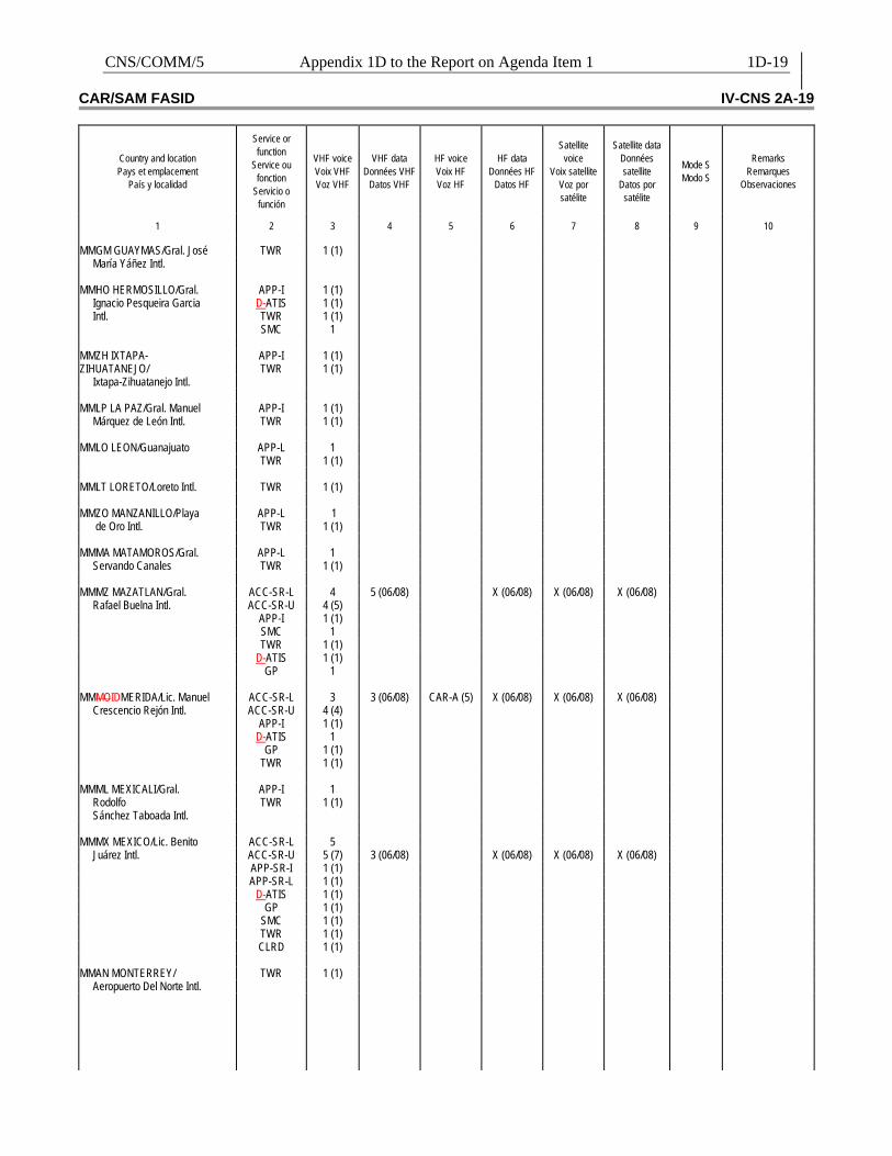
CNS/COMM/5 Appendix 1D to the Report on Agenda Item 1 1D-19 CAR/SAM FASID IV-CNS 2A-19
Country and location Pays et emplacement
País y localidad
Service or function
Service ou fonction
Servicio o función
VHF voice Voix VHF Voz VHF
VHF data
Données VHF Datos VHF
HF voice Voix HF Voz HF
HF data
Données HF Datos HF
Satellite
voice Voix satellite
Voz por satélite
Satellite data
Données satellite
Datos por satélite
Mode S Modo S
Remarks
Remarques Observaciones
1
2
3
4
5
6
7
8
9
10
MMGM GUAYMAS/Gral. José TWR 1 (1)
María Yáñez Intl. MMHO HERMOSILLO/Gral. APP-I 1 (1)
Ignacio Pesqueira Garcia D-ATIS 1 (1) Intl. TWR 1 (1)
SMC 1 MMZH IXTAPA- APP-I 1 (1) ZIHUATANEJO/ TWR 1 (1)
Ixtapa-Zihuatanejo Intl. MMLP LA PAZ/Gral. Manuel APP-I 1 (1)
Márquez de León Intl. TWR 1 (1) MMLO LEON/Guanajuato APP-L 1 TWR 1 (1) MMLT LORETO/Loreto Intl. TWR 1 (1) MMZO MANZANILLO/Playa APP-L 1
de Oro Intl. TWR 1 (1) MMMA MATAMOROS/Gral. APP-L 1
Servando Canales TWR 1 (1) MMMZ MAZATLAN/Gral. ACC-SR-L 4 5 (06/08) X (06/08) X (06/08) X (06/08)
Rafael Buelna Intl. ACC-SR-U 4 (5) APP-I 1 (1) SMC 1 TWR 1 (1) D-ATIS 1 (1) GP 1 MMMOIDMERIDA/Lic. Manuel ACC-SR-L 3 3 (06/08) CAR-A (5) X (06/08) X (06/08) X (06/08)
Crescencio Rejón Intl. ACC-SR-U 4 (4) APP-I 1 (1) D-ATIS 1 GP 1 (1) TWR 1 (1) MMML MEXICALI/Gral. APP-I 1
Rodolfo TWR 1 (1) Sánchez Taboada Intl.
MMMX MEXICO/Lic. Benito ACC-SR-L 5
Juárez Intl. ACC-SR-U 5 (7) 3 (06/08) X (06/08) X (06/08) X (06/08) APP-SR-I 1 (1) APP-SR-L 1 (1) D-ATIS 1 (1) GP 1 (1) SMC 1 (1) TWR 1 (1) CLRD 1 (1) MMAN MONTERREY/ TWR 1 (1)
Aeropuerto Del Norte Intl.

1D-20 Appendix 1D to the Report on Agenda Item 1 CNS/COMM/5 IV-CNS 2A-20 CAR/SAM FASID
Country and location Pays et emplacement
País y localidad
Service or function
Service ou fonction
Servicio o función
VHF voice Voix VHF Voz VHF
VHF data
Données VHF Datos VHF
HF voice Voix HF Voz HF
HF data
Données HF Datos HF
Satellite
voice Voix satellite
Voz por satélite
Satellite data
Données satellite
Datos por satélite
Mode S Modo S
Remarks
Remarques Observaciones
1
2
3
4
5
6
7
8
9
10
MMMY MONTERREY/Gral. ACC-SR-L 2
Mariano Escobedo Intl. ACC-SR-U 2 (3) 3 (06/08) X (06/08) X (06/08) X (06/08) APP-SR-I 1 (1) APP-SR-L 1 (1) D-ATIS 1 (1) GP 1 SMC 1 (1) TWR 1 (1) MMMM MORELIA/ APP-L 1
Gral. Francisco Mujica Intl. TWR 1 (1) MMNG NOGALES/Nogales Intl.
AFIS 1
MMNL NUEVO LAREDO/ APP-L 1
Quetzalcoatl Intl. TWR 1 (1) MMPG PIEDRAS D-ATIS 1 (1)
NEGRAS/Intl. MMPR PUERTO VALLARTA/ APP-SR-I 1 (1)
Lic. Gustavo Díaz Ordaz APP-SR-L 1 (1) Intl. D-ATIS 1
SMC 1 TWR 1 (1) MMRX REYNOSA/Gral. Lucio APP-L 1
Blanco Intl. TWR 1 (1) MMSF SAN FELIPE/ AFIS 1 (1)
San Felipe Intl. MMSD SAN JOSE DEL APP-I 1
CABO/San José del TWR 1 (1) Cabo Intl. GP 1
MMTM TAMPICO/Gral. APP-I 1 (1)
Francisco Javier Mina Intl. TWR 1 (1) GP 1 MMTP TAPACHULA/ Tapachula Intl.
TWR 1 (1)
MMTJ TIJUANA/ APP-SR-I 1 (1)
Gral. Abelardo APP-SR-L 1 (1) L. Rodríguez Intl. D-ATIS 1 (1)
GP 1 (1) TWR 1 (1) SMC 1 MMTO/TOLUCA/Lic. Adolfo TWR 1 (1)
Lopez Mateos GP 1 MMTC TORREON/Torreón APP-L 1 (1)
Intl. TWR 1 (1) MMVR VERACRUZ/Gral. APP-L 1 (1)
Heriberto Jara Intl. TWR 1 (1) MMVA VILLAHERMOSA/ APP-L 1
C.P.A. Carlos Rovirosa TWR 1 (1)
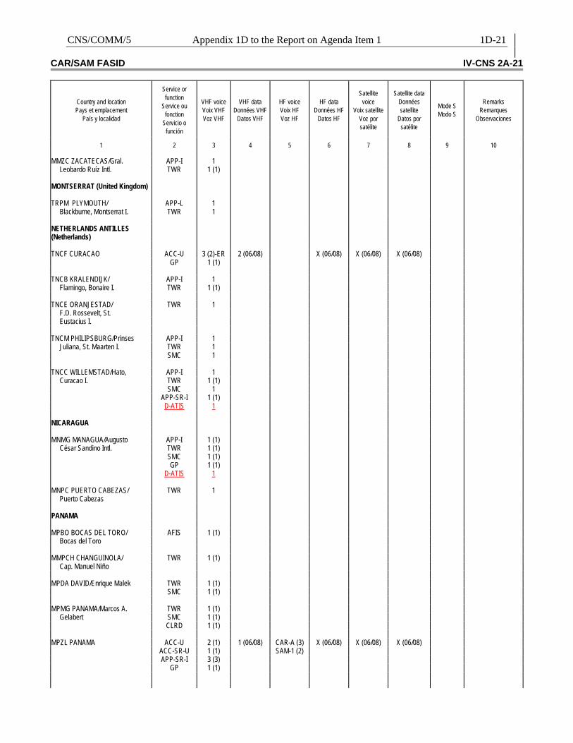
CNS/COMM/5 Appendix 1D to the Report on Agenda Item 1 1D-21 CAR/SAM FASID IV-CNS 2A-21
Country and location Pays et emplacement
País y localidad
Service or function
Service ou fonction
Servicio o función
VHF voice Voix VHF Voz VHF
VHF data
Données VHF Datos VHF
HF voice Voix HF Voz HF
HF data
Données HF Datos HF
Satellite
voice Voix satellite
Voz por satélite
Satellite data
Données satellite
Datos por satélite
Mode S Modo S
Remarks
Remarques Observaciones
1
2
3
4
5
6
7
8
9
10
MMZC ZACATECAS/Gral. APP-I 1
Leobardo Ruíz Intl. TWR 1 (1) MONTSERRAT (United Kingdom) TRPM PLYMOUTH/ APP-L 1
Blackburne, Montserrat I. TWR 1 NETHERLANDS ANTILLES (Netherlands)
TNCF CURACAO ACC-U 3 (2)-ER 2 (06/08) X (06/08) X (06/08) X (06/08) GP 1 (1) TNCB KRALENDIJK/ APP-I 1
Flamingo, Bonaire I. TWR 1 (1) TNCE ORANJESTAD/ TWR 1
F.D. Rossevelt, St. Eustacius I.
TNCM PHILIPSBURG/Prinses APP-I 1
Juliana, St. Maarten I. TWR 1 SMC 1 TNCC WILLEMSTAD/Hato, APP-I 1
Curacao I. TWR 1 (1) SMC 1 APP-SR-I 1 (1) D-ATIS 1 NICARAGUA MNMG MANAGUA/Augusto APP-I 1 (1)
César Sandino Intl. TWR 1 (1) SMC 1 (1) GP 1 (1) D-ATIS 1 MNPC PUERTO CABEZAS/ TWR 1
Puerto Cabezas PANAMA MPBO BOCAS DEL TORO/ AFIS 1 (1)
Bocas del Toro MMPCH CHANGUINOLA/ TWR 1 (1)
Cap. Manuel Niño MPDA DAVID/Enrique Malek TWR 1 (1) SMC 1 (1) MPMG PANAMA/Marcos A. TWR 1 (1)
Gelabert SMC 1 (1) CLRD 1 (1) MPZL PANAMA ACC-U 2 (1) 1 (06/08) CAR-A (3) X (06/08) X (06/08) X (06/08) ACC-SR-U 1 (1) SAM-1 (2) APP-SR-I 3 (3) GP 1 (1)
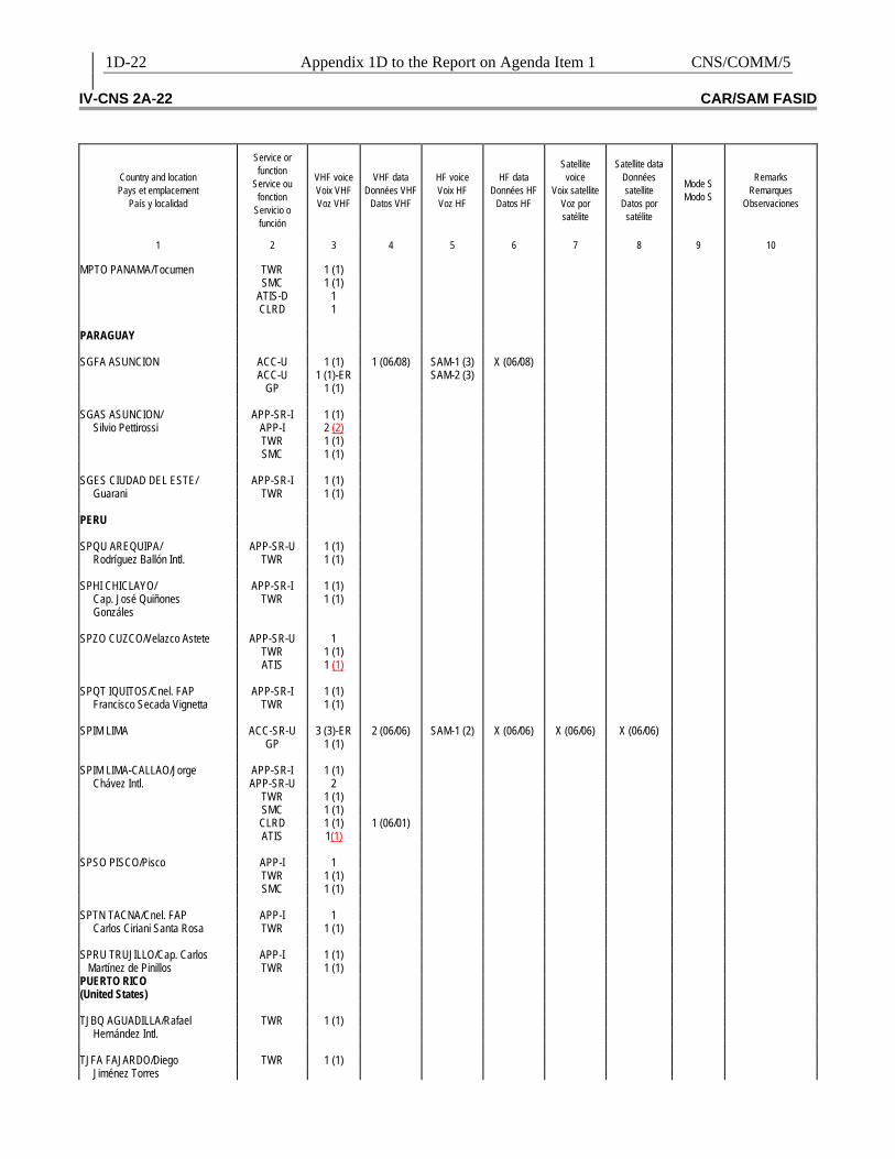
1D-22 Appendix 1D to the Report on Agenda Item 1 CNS/COMM/5 IV-CNS 2A-22 CAR/SAM FASID
Country and location Pays et emplacement
País y localidad
Service or function
Service ou fonction
Servicio o función
VHF voice Voix VHF Voz VHF
VHF data
Données VHF Datos VHF
HF voice Voix HF Voz HF
HF data
Données HF Datos HF
Satellite
voice Voix satellite
Voz por satélite
Satellite data
Données satellite
Datos por satélite
Mode S Modo S
Remarks
Remarques Observaciones
1
2
3
4
5
6
7
8
9
10
MPTO PANAMA/Tocumen TWR 1 (1) SMC 1 (1) ATIS-D 1 CLRD 1 PARAGUAY SGFA ASUNCION ACC-U 1 (1) 1 (06/08) SAM-1 (3) X (06/08) ACC-U 1 (1)-ER SAM-2 (3) GP 1 (1) SGAS ASUNCION/ APP-SR-I 1 (1)
Silvio Pettirossi APP-I 2 (2) TWR 1 (1) SMC 1 (1) SGES CIUDAD DEL ESTE/ APP-SR-I 1 (1)
Guarani TWR 1 (1) PERU SPQU AREQUIPA/ APP-SR-U 1 (1)
Rodríguez Ballón Intl. TWR 1 (1) SPHI CHICLAYO/ APP-SR-I 1 (1)
Cap. José Quiñones TWR 1 (1) Gonzáles
SPZO CUZCO/Velazco Astete APP-SR-U 1 TWR 1 (1) ATIS 1 (1) SPQT IQUITOS/Cnel. FAP APP-SR-I 1 (1)
Francisco Secada Vignetta TWR 1 (1) SPIM LIMA ACC-SR-U 3 (3)-ER 2 (06/06) SAM-1 (2) X (06/06) X (06/06) X (06/06) GP 1 (1) SPIM LIMA-CALLAO/Jorge APP-SR-I 1 (1)
Chávez Intl. APP-SR-U 2 TWR 1 (1) SMC 1 (1) CLRD 1 (1) 1 (06/01) ATIS 1(1) SPSO PISCO/Pisco APP-I 1 TWR 1 (1) SMC 1 (1) SPTN TACNA/Cnel. FAP APP-I 1
Carlos Ciriani Santa Rosa TWR 1 (1) SPRU TRUJILLO/Cap. Carlos APP-I 1 (1) Martínez de Pinillos TWR 1 (1) PUERTO RICO (United States)
TJBQ AGUADILLA/Rafael TWR 1 (1)
Hernández Intl. TJFA FAJARDO/Diego TWR 1 (1)
Jiménez Torres
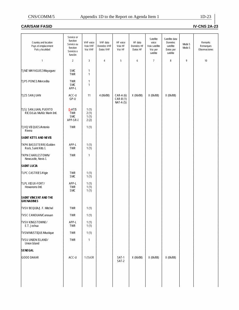
CNS/COMM/5 Appendix 1D to the Report on Agenda Item 1 1D-23 CAR/SAM FASID IV-CNS 2A-23
Country and location Pays et emplacement
País y localidad
Service or function
Service ou fonction
Servicio o función
VHF voice Voix VHF Voz VHF
VHF data
Données VHF Datos VHF
HF voice Voix HF Voz HF
HF data
Données HF Datos HF
Satellite
voice Voix satellite
Voz por satélite
Satellite data
Données satellite
Datos por satélite
Mode S Modo S
Remarks
Remarques Observaciones
1
2
3
4
5
6
7
8
9
10
TJMZ MAYAGUEZ/Mayaguez SMC 1 TWR 1 TJPS PONCE/Mercedita TWR 1 SMC 1 APP-L TJZS SAN JUAN ACC-U 11 4 (06/08) CAR-A (6) X (06/08) X (06/08) X (06/08) GP-U CAR-B (1) NAT-A (5) TJSJ SAN JUAN, PUERTO D-ATIS 1 (1)
RICO/Luis Muñóz Marin Intl. TWR 2 (1) SMC 1 (1) APP-SR-I 2 (2) TJVQ VIEQUES/Antonio TWR 1 (1)
Rivera SAINT KITTS AND NEVIS TKPK BASSETERRE/Golden APP-L 1 (1)
Rock, Saint Kitts I. TWR 1 (1) TKPN CHARLESTOWN/ TWR 1
Newcastle, Nevis I. SAINT LUCIA TLPC CASTRIES/Vigie TWR 1 (1) SMC 1 (1) TLPL VIEUX-FORT/ APP-L 1 (1)
Hewanorra Intl. TWR 1 (1) SMC 1 (1) SAINT VINCENT AND THE GRENADINES
TVSV BEQUIA/J. F. Mitchel TWR 1 (1) TVSC CANOUAN/Canouan TWR 1 (1) TVSV KINGSTOWNE/ APP-L 1 (1)
E.T. Joshua TWR 1 (1) TVSM MUSTIQUE/Mustique TWR 1 (1) TVSU UNION ISLAND/ TWR 1
Union Island SENEGAL GOOO DAKAR ACC-U 1 (1)-ER SAT-1 X (06/08) X (06/08) X (06/08) SAT-2
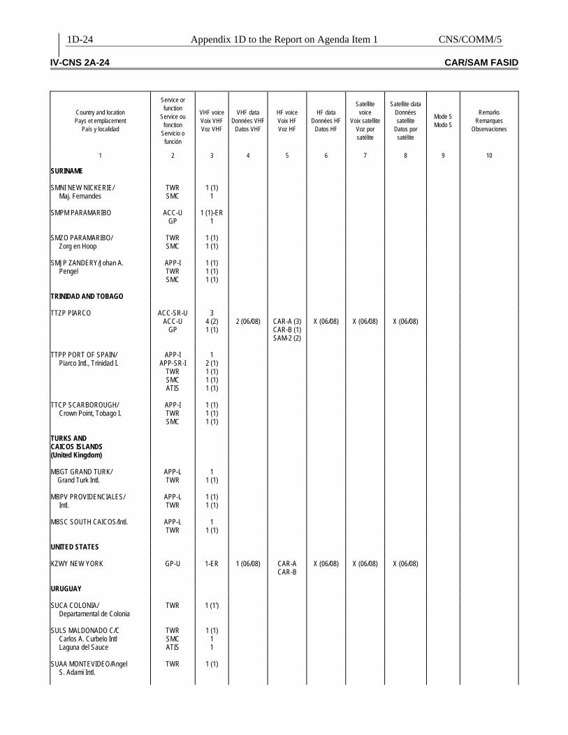
1D-24 Appendix 1D to the Report on Agenda Item 1 CNS/COMM/5 IV-CNS 2A-24 CAR/SAM FASID
Country and location Pays et emplacement
País y localidad
Service or function
Service ou fonction
Servicio o función
VHF voice Voix VHF Voz VHF
VHF data
Données VHF Datos VHF
HF voice Voix HF Voz HF
HF data
Données HF Datos HF
Satellite
voice Voix satellite
Voz por satélite
Satellite data
Données satellite
Datos por satélite
Mode S Modo S
Remarks
Remarques Observaciones
1
2
3
4
5
6
7
8
9
10
SURINAME SMNI NEW NICKERIE/ TWR 1 (1)
Maj. Fernandes SMC 1 SMPM PARAMARIBO ACC-U 1 (1)-ER GP 1 SMZO PARAMARIBO/ TWR 1 (1)
Zorg en Hoop SMC 1 (1) SMJP ZANDERY/Johan A. APP-I 1 (1)
Pengel TWR 1 (1) SMC 1 (1) TRINIDAD AND TOBAGO TTZP PIARCO ACC-SR-U 3 ACC-U 4 (2) 2 (06/08) CAR-A (3) X (06/08) X (06/08) X (06/08) GP 1 (1) CAR-B (1) SAM-2 (2) TTPP PORT OF SPAIN/ APP-I 1
Piarco Intl., Trinidad I. APP-SR-I 2 (1) TWR 1 (1) SMC 1 (1) ATIS 1 (1) TTCP SCARBOROUGH/ APP-I 1 (1)
Crown Point, Tobago I. TWR 1 (1) SMC 1 (1) TURKS AND CAICOS ISLANDS (United Kingdom)
MBGT GRAND TURK/ APP-L 1 Grand Turk Intl. TWR 1 (1) MBPV PROVIDENCIALES/ APP-L 1 (1)
Intl. TWR 1 (1) MBSC SOUTH CAICOS/Intl. APP-L 1 TWR 1 (1) UNITED STATES KZWY NEW YORK GP-U 1-ER 1 (06/08) CAR-A X (06/08) X (06/08) X (06/08) CAR-B URUGUAY SUCA COLONIA/ TWR 1 (1')
Departamental de Colonia SULS MALDONADO C/C TWR 1 (1)
Carlos A. Curbelo Intl SMC 1 Laguna del Sauce ATIS 1
SUAA MONTEVIDEO/Angel TWR 1 (1)
S. Adami Intl.
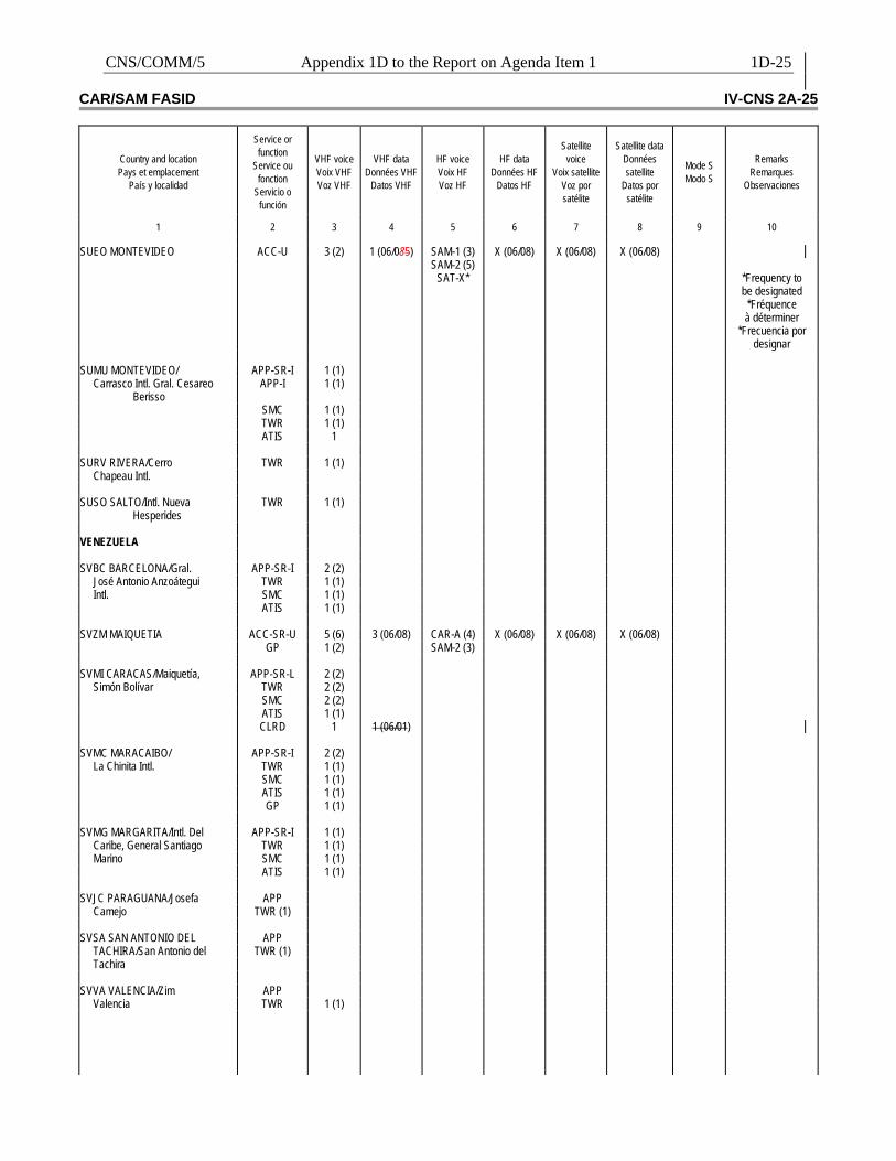
CNS/COMM/5 Appendix 1D to the Report on Agenda Item 1 1D-25 CAR/SAM FASID IV-CNS 2A-25
Country and location Pays et emplacement
País y localidad
Service or function
Service ou fonction
Servicio o función
VHF voice Voix VHF Voz VHF
VHF data
Données VHF Datos VHF
HF voice Voix HF Voz HF
HF data
Données HF Datos HF
Satellite
voice Voix satellite
Voz por satélite
Satellite data
Données satellite
Datos por satélite
Mode S Modo S
Remarks
Remarques Observaciones
1
2
3
4
5
6
7
8
9
10
SUEO MONTEVIDEO ACC-U 3 (2) 1 (06/085) SAM-1 (3) X (06/08) X (06/08) X (06/08) SAM-2 (5) SAT-X* *Frequency to
be designated *Fréquence à déterminer
*Frecuencia por designar
SUMU MONTEVIDEO/ APP-SR-I 1 (1)
Carrasco Intl. Gral. Cesareo Berisso
APP-I 1 (1)
SMC 1 (1) TWR 1 (1) ATIS 1 SURV RIVERA/Cerro TWR 1 (1)
Chapeau Intl. SUSO SALTO/Intl. Nueva
Hesperides TWR 1 (1)
VENEZUELA SVBC BARCELONA/Gral. APP-SR-I 2 (2)
José Antonio Anzoátegui TWR 1 (1) Intl. SMC 1 (1)
ATIS 1 (1) SVZM MAIQUETIA ACC-SR-U 5 (6) 3 (06/08) CAR-A (4) X (06/08) X (06/08) X (06/08) GP 1 (2) SAM-2 (3) SVMI CARACAS/Maiquetía, APP-SR-L 2 (2)
Simón Bolívar TWR 2 (2) SMC 2 (2) ATIS 1 (1) CLRD 1 1 (06/01) SVMC MARACAIBO/ APP-SR-I 2 (2)
La Chinita Intl. TWR 1 (1) SMC 1 (1) ATIS 1 (1) GP 1 (1) SVMG MARGARITA/Intl. Del APP-SR-I 1 (1)
Caribe, General Santiago TWR 1 (1) Marino SMC 1 (1)
ATIS 1 (1) SVJC PARAGUANA/Josefa APP
Camejo TWR (1) SVSA SAN ANTONIO DEL APP
TACHIRA/San Antonio del TWR (1) Tachira
SVVA VALENCIA/Zim APP
Valencia TWR 1 (1)
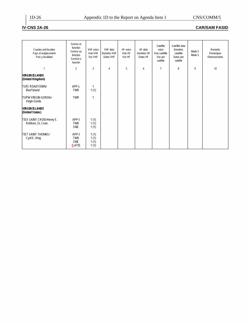
1D-26 Appendix 1D to the Report on Agenda Item 1 CNS/COMM/5 IV-CNS 2A-26 CAR/SAM FASID
Country and location Pays et emplacement
País y localidad
Service or function
Service ou fonction
Servicio o función
VHF voice Voix VHF Voz VHF
VHF data
Données VHF Datos VHF
HF voice Voix HF Voz HF
HF data
Données HF Datos HF
Satellite
voice Voix satellite
Voz por satélite
Satellite data
Données satellite
Datos por satélite
Mode S Modo S
Remarks
Remarques Observaciones
1
2
3
4
5
6
7
8
9
10
VIRGIN ISLANDS (United Kingdom)
TUPJ ROADTOWN/ APP-L 1
Beef Island TWR 1 (1) TUPW VIRGIN GORDA/ TWR 1
Virgin Gorda VIRGIN ISLANDS (United States)
TISX SAINT CROIX/Henry E. APP-I 1 (1)
Rohlsen, St. Croix TWR 1 (1) SMC 1 (1) TIST SAINT THOMAS/ APP-I 1 (1)
Cyril E. King TWR 1 (1) SMC 1 (1) D-ATIS 1 (1)

C
NS/C
OM
M/5
Appendix 1E to the R
eport on Agenda Item
1 1E-1
APPENDIX 1E
TABLE/TABLA CNS 1Ba – ATN ROUTERS REGIONAL PLAN / PLAN REGIONAL DE ENCAMINADORES ATN
Administration and Location/ Administración y Localidad
Type of Router / Tipo de
Encaminador
Type of Interconnection/
Tipo de interconexión
Connected Router- Encaminador
Conectado
Link Speed- Velocidad del
enlace
Link Protocol- Protocolo del
Enlace
Via Vía
Target Date / Fecha Meta
Remarks Observaciones
1 2 3 4 5 6 7 8 9

C
NS/C
OM
M/5
Appendix 1F to the R
eport on Agenda Item
1 1F-1
APPENDIX 1F
TABLE CNS 1BB – ATN GROUND-GROUND APPLICATIONS PLAN / TABLA CNS1 BB – PLAN DE APLICACIONES TIERRA-TIERRA ATN (CAR REGION / REGIÓN CAR)
ATN GROUND-GROUND APPLICATIONS PLAN / PLAN DE APLICACIONES TIERRA-TIERRA
Administration and Location/ Administración y localidad
Application Type/ Tipo de
Aplicación
Conneted with Administration & Location of/ Conectada con Administración y Localidad de
Used Standard /
Norma usada
Implementation Date/ Fecha de
Implementación
Remarks/ Observaciones
1 2 3 4 5 6 ARUBA, Aruba
AMHS
FAA-Atlanta
ATN
TBD/Por determinar
BAHAMAS, Nassau,
AMHS
FAA-Atlanta
ATN
TBD/Por determinar
CAYMAN ISLANDS, Grand Cayman ISLAS CAIMANES , Gran Caimán
AMHS
FAA-Atlanta
ATN
TBD/Por determinar
CUBA, Havana CUBA, La Habana
AMHS
FAA-Atlanta
ATN
2008
AIDC
TBD/Por determinar
ATN
TBD/Por determinar
DOMINICAN REPUBLIC, Santo Domingo/ REPÚBLICA DOMINICANA, Santo Domingo
AMHS
FAA-Atlanta
ATN
2008
AIDC
TBD/Por determinar
ATN
TBD/Por determinar
HAITI, Port-au-Prince/ HAITÍ, Puerto Príncipe,
AMHS
FAA-Atlanta
ATN
2008
HONDURAS, Tegucigalpa (COCESNA)
AMHS
FAA-Atlanta
ATN
2007
AIDC
TBD/Por determinar
ATN
TBD/Por determinar
JAMAICA, Kingston
AMHS
FAA-Atlanta
ATN
2008
AIDC
TBD/Por determinar
ATN
TBD/Por determinar

1F-2
Appendix 1F to the R
eport on Agenda Item
1 C
NS/C
OM
M/5
ATN GROUND-GROUND APPLICATIONS PLAN / PLAN DE APLICACIONES TIERRA-TIERRA Administration and Location/ Administración y localidad
Application Type/ Tipo de
Aplicación
Conneted with Administration & Location of/ Conectada con Administración y Localidad de
Used Standard /
Norma usada
Implementation Date/ Fecha de
Implementación
Remarks/ Observaciones
1 2 3 4 5 6 MEXICO, Mexico City MÉXICO, Ciudad de México
AMHS
FAA-Atlanta
ATN
TBD/Por determinar
AIDC
FAA- TBD/Por determinar
ATN
TBD/Por determinar
AIDC
TBD/Por determinar
ATN
TBD/Por determinar
NETHERLANDS ANTILLES (Curacao) / ANTILLAS NEERLANDESAS (Curazao)
AMHS
FAA-Atlanta
ATN
TBD/Por determinar
PANAMA, Panama City/ PANAMÁ, Ciudad de Panamá
AMHS
FAA-Atlanta
ATN
TBD/Por determinar
TRINIDAD AND TOBAGO, Piarco
AMHS
FAA-Atlanta
ATN
TBD/Por determinar
AIDC
TBD/Por determinar
ATN
TBD/Por determinar
UNITED STATES, Atlanta ESTADOS UNIDOS, Atlanta
AMHS
Aruba
ATN
TBD/Por determinar
03 2007 - USA Availability to connect to the CAR/SAM Regions/ Disponibilidad de conectar con las Regiones CAR/SAM
AMHS
Bahamas Nassau,
TBD/Por determinar
AMHS
Cayman Islands, Grand Cayman Islas Caimanes , Gran Caimán
TBD/Por determinar
AMHS
Cuba, Havana Cuba, La Habana
2008
AMHS
Dominican Republic, Santo Domingo/ República Dominicana, Santo Domingo
2008
AMHS
Haiti, Port-au-Prince/ Haití, Puerto Príncipe,
2008

C
NS/C
OM
M/5
Appendix 1F to the R
eport on Agenda Item
1 1F-3
ATN GROUND-GROUND APPLICATIONS PLAN / PLAN DE APLICACIONES TIERRA-TIERRA Administration and Location/ Administración y localidad
Application Type/ Tipo de
Aplicación
Conneted with Administration & Location of/ Conectada con Administración y Localidad de
Used Standard /
Norma usada
Implementation Date/ Fecha de
Implementación
Remarks/ Observaciones
1 2 3 4 5 6 AMHS Honduras, Tegucigalpa (COCESNA) 2007
AMHS Jamaica, Kingston
2008
AMHS
Mexico, Mexico
TBD/Por determinar
AMHS
Netherlands Antilles (Curacao) / Antillas Neerlandesas (Curazao)
TBD/Por determinar
AMHS
Panama, Panama City/ Panamá, Ciudad de Panamá
TBD/Por determinar
AMHS
Peru, Lima
TBD/Por determinar
AMHS
Trinidad and Tobago, Piarco
TBD/Por determinar
AMHS
Venezuela, Maiquetía
2009
UNITED STATES, TBD ESTADOS UNIDOS, Por determinar
AIDC
MEXICO, Por determinar
TBD/Por determinar
AIDC
TBD/Por determinar
TBD/Por determinar
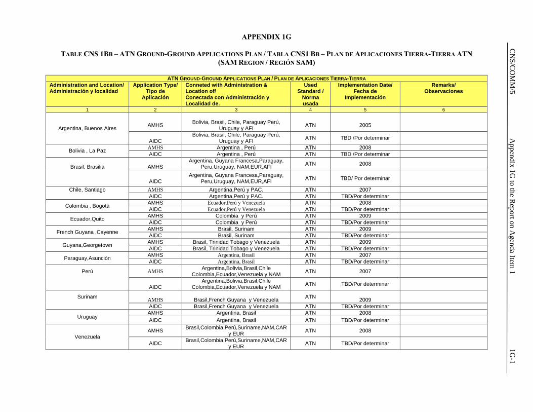
C
NS/C
OM
M/5
Appendix 1G
to the Report on A
genda Item 1
1G-1
APPENDIX 1G
TABLE CNS 1BB – ATN GROUND-GROUND APPLICATIONS PLAN / TABLA CNS1 BB – PLAN DE APLICACIONES TIERRA-TIERRA ATN (SAM REGION / REGIÓN SAM)
ATN GROUND-GROUND APPLICATIONS PLAN / PLAN DE APLICACIONES TIERRA-TIERRA
Administration and Location/ Administración y localidad
Application Type/ Tipo de
Aplicación
Conneted with Administration & Location of/ Conectada con Administración y Localidad de.
Used Standard /
Norma usada
Implementation Date/ Fecha de
Implementación
Remarks/ Observaciones
1 2 3 4 5 6
AMHS
Bolivia, Brasil, Chile, Paraguay Perú,
Uruguay y AFI
ATN
2005
Argentina, Buenos Aires
AIDC Bolivia, Brasil, Chile, Paraguay Perú,
Uruguay y AFI ATN TBD /Por determinar
AMHS Argentina , Perú ATN 2008 Bolivia , La Paz AIDC Argentina , Perú ATN TBD /Por determinar
Brasil, Brasilia
AMHS Argentina, Guyana Francesa,Paraguay,
Peru,Uruguay, NAM,EUR,AFI ATN 2008
AIDC
Argentina, Guyana Francesa,Paraguay, Peru,Uruguay, NAM,EUR,AFI ATN TBD/ Por determinar
Chile, Santiago AMHS Argentina,Perú y PAC. ATN 2007 AIDC Argentina,Perú y PAC. ATN TBD/Por determinar
AMHS Ecuador,Perú y Venezuela ATN 2008 Colombia , Bogotá AIDC Ecuador,Perú y Venezuela ATN TBD/Por determinar AMHS Colombia y Perú ATN 2009 Ecuador,Quito AIDC Colombia y Perú ATN TBD/Por determinar AMHS Brasil, Surinam ATN 2009 French Guyana ,Cayenne AIDC Brasil, Surinam ATN TBD/Por determinar AMHS Brasil, Trinidad Tobago y Venezuela ATN 2009 Guyana,Georgetown AIDC Brasil, Trinidad Tobago y Venezuela ATN TBD/Por determinar AMHS Argentina, Brasil ATN 2007 Paraguay,Asunción AIDC Argentina, Brasil ATN TBD/Por determinar
Perú AMHS Argentina,Bolivia,Brasil,Chile Colombia,Ecuador,Venezuela y NAM ATN 2007
AIDC
Argentina,Bolivia,Brasil,Chile Colombia,Ecuador,Venezuela y NAM ATN TBD/Por determinar
Surinam AMHS
Brasil,French Guyana y Venezuela ATN
2009
AIDC Brasil,French Guyana y Venezuela ATN TBD/Por determinar AMHS Argentina, Brasil ATN 2008
Uruguay AIDC Argentina, Brasil ATN TBD/Por determinar
AMHS Brasil,Colombia,Perú,Suriname,NAM,CAR y EUR ATN 2008
Venezuela AIDC Brasil,Colombia,Perú,Suriname,NAM,CAR
y EUR ATN TBD/Por determinar
CNS/COMM/5 Appendix 1H to the Report on Agenda Item 1 1H-1
EUR/NAT AMHS PRMD Names and Addressing Plan Registry ICAO
APPENDIX 1H EUR AMHS Documentation ICAO AFSG PG
EUR AMHS Documentation
PRMD and Addressing Registry
EUR/NAT AMHS PRMD Names and Addressing Plan Registry
Document Reference: EUR AMHS Documentation, PRMD and Addressing Registry
Author: ICAO AFSG PG
Revision Number: Version 0.11
Date: 28/08/06
Filename: EUR-AMHS-PRMD-and-Addressing-Registry_v0.11.doc
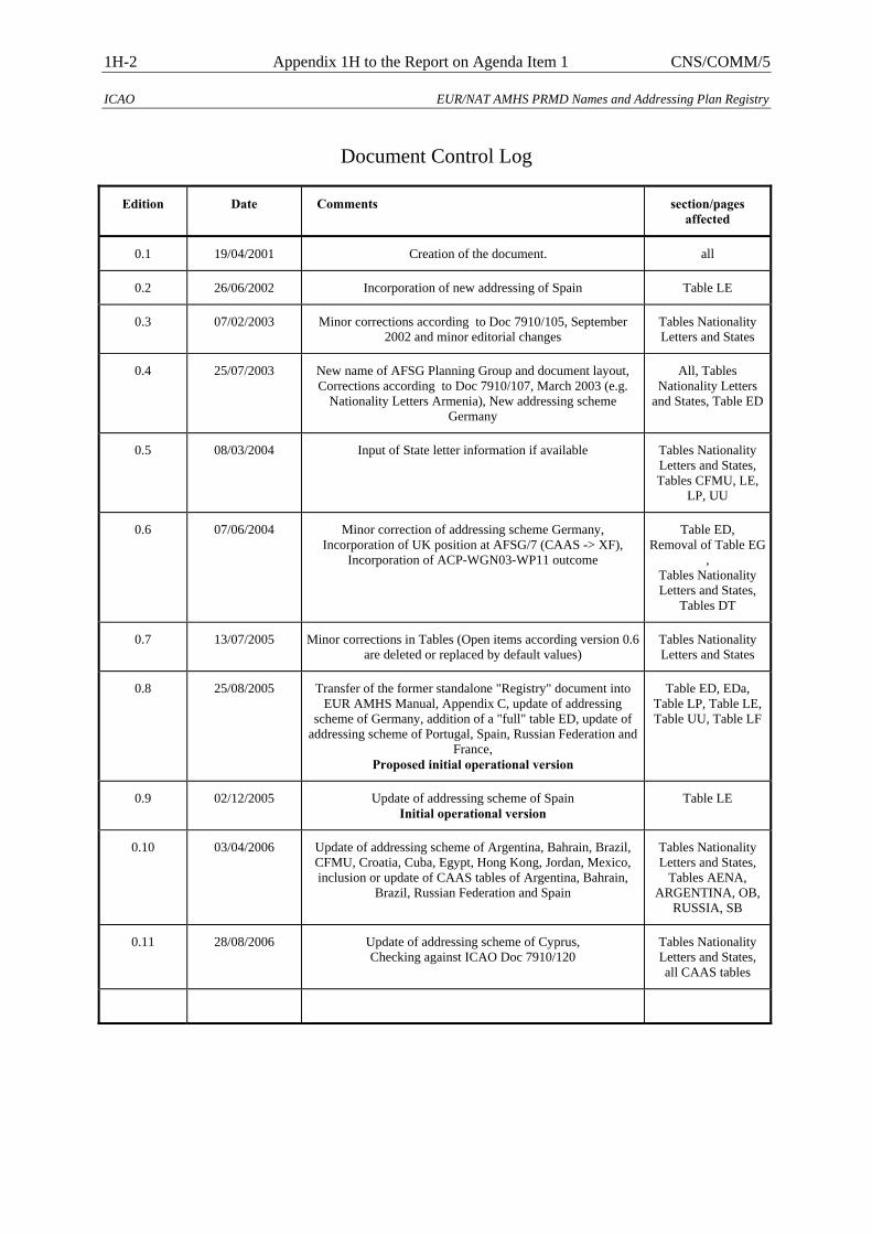
1H-2 Appendix 1H to the Report on Agenda Item 1 CNS/COMM/5
ICAO EUR/NAT AMHS PRMD Names and Addressing Plan Registry
Document Control Log
Edition Date Comments section/pages affected
0.1 19/04/2001 Creation of the document. all
0.2 26/06/2002 Incorporation of new addressing of Spain Table LE
0.3 07/02/2003 Minor corrections according to Doc 7910/105, September 2002 and minor editorial changes
Tables Nationality Letters and States
0.4 25/07/2003 New name of AFSG Planning Group and document layout, Corrections according to Doc 7910/107, March 2003 (e.g.
Nationality Letters Armenia), New addressing scheme Germany
All, Tables Nationality Letters
and States, Table ED
0.5 08/03/2004 Input of State letter information if available Tables Nationality Letters and States, Tables CFMU, LE,
LP, UU
0.6 07/06/2004 Minor correction of addressing scheme Germany, Incorporation of UK position at AFSG/7 (CAAS -> XF),
Incorporation of ACP-WGN03-WP11 outcome
Table ED, Removal of Table EG
, Tables Nationality Letters and States,
Tables DT
0.7 13/07/2005 Minor corrections in Tables (Open items according version 0.6 are deleted or replaced by default values)
Tables Nationality Letters and States
0.8 25/08/2005 Transfer of the former standalone "Registry" document into EUR AMHS Manual, Appendix C, update of addressing
scheme of Germany, addition of a "full" table ED, update of addressing scheme of Portugal, Spain, Russian Federation and
France, Proposed initial operational version
Table ED, EDa, Table LP, Table LE, Table UU, Table LF
0.9 02/12/2005 Update of addressing scheme of Spain Initial operational version
Table LE
0.10 03/04/2006 Update of addressing scheme of Argentina, Bahrain, Brazil, CFMU, Croatia, Cuba, Egypt, Hong Kong, Jordan, Mexico, inclusion or update of CAAS tables of Argentina, Bahrain,
Brazil, Russian Federation and Spain
Tables Nationality Letters and States,
Tables AENA, ARGENTINA, OB,
RUSSIA, SB
0.11 28/08/2006 Update of addressing scheme of Cyprus, Checking against ICAO Doc 7910/120
Tables Nationality Letters and States, all CAAS tables
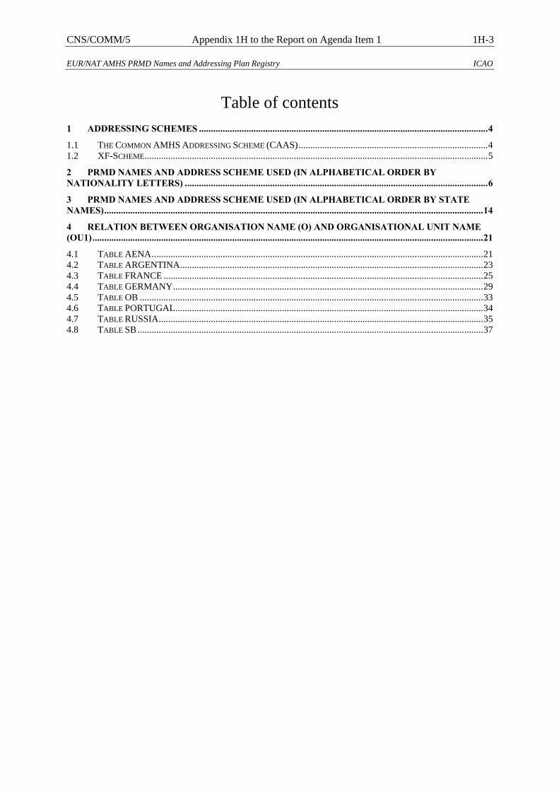
CNS/COMM/5 Appendix 1H to the Report on Agenda Item 1 1H-3
EUR/NAT AMHS PRMD Names and Addressing Plan Registry ICAO
Table of contents 1 ADDRESSING SCHEMES ..........................................................................................................................4 1.1 THE COMMON AMHS ADDRESSING SCHEME (CAAS)................................................................................4 1.2 XF-SCHEME.................................................................................................................................................5 2 PRMD NAMES AND ADDRESS SCHEME USED (IN ALPHABETICAL ORDER BY NATIONALITY LETTERS) ................................................................................................................................6 3 PRMD NAMES AND ADDRESS SCHEME USED (IN ALPHABETICAL ORDER BY STATE NAMES)................................................................................................................................................................14 4 RELATION BETWEEN ORGANISATION NAME (O) AND ORGANISATIONAL UNIT NAME (OU1).....................................................................................................................................................................21 4.1 TABLE AENA............................................................................................................................................21 4.2 TABLE ARGENTINA................................................................................................................................23 4.3 TABLE FRANCE .......................................................................................................................................25 4.4 TABLE GERMANY...................................................................................................................................29 4.5 TABLE OB .................................................................................................................................................33 4.6 TABLE PORTUGAL..................................................................................................................................34 4.7 TABLE RUSSIA.........................................................................................................................................35 4.8 TABLE SB..................................................................................................................................................37
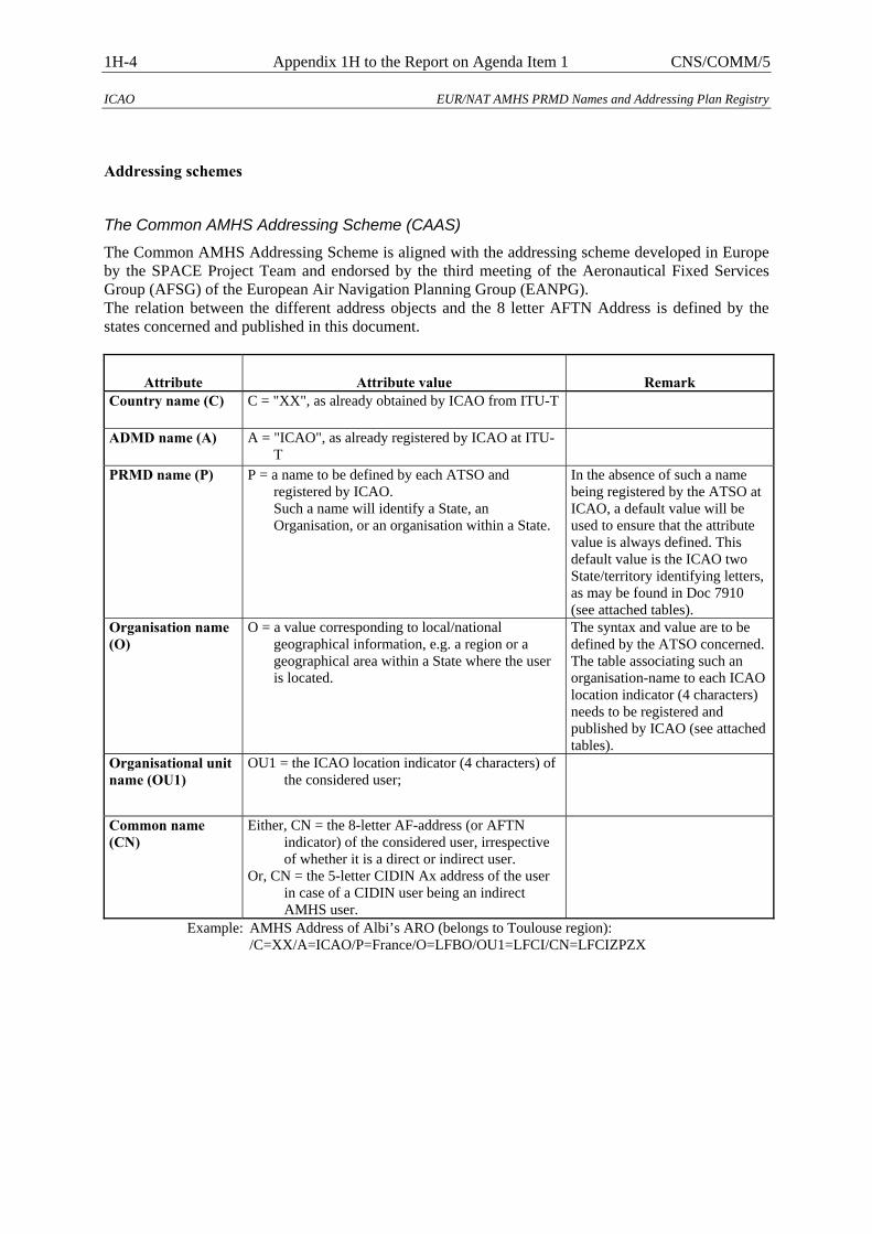
1H-4 Appendix 1H to the Report on Agenda Item 1 CNS/COMM/5
ICAO EUR/NAT AMHS PRMD Names and Addressing Plan Registry
Addressing schemes
The Common AMHS Addressing Scheme (CAAS)
The Common AMHS Addressing Scheme is aligned with the addressing scheme developed in Europe by the SPACE Project Team and endorsed by the third meeting of the Aeronautical Fixed Services Group (AFSG) of the European Air Navigation Planning Group (EANPG). The relation between the different address objects and the 8 letter AFTN Address is defined by the states concerned and published in this document.
Attribute Attribute value Remark Country name (C) C = "XX", as already obtained by ICAO from ITU-T
ADMD name (A) A = "ICAO", as already registered by ICAO at ITU-
T PRMD name (P) P = a name to be defined by each ATSO and
registered by ICAO. Such a name will identify a State, an Organisation, or an organisation within a State.
In the absence of such a name being registered by the ATSO at ICAO, a default value will be used to ensure that the attribute value is always defined. This default value is the ICAO two State/territory identifying letters, as may be found in Doc 7910 (see attached tables).
Organisation name (O)
O = a value corresponding to local/national geographical information, e.g. a region or a geographical area within a State where the user is located.
The syntax and value are to be defined by the ATSO concerned. The table associating such an organisation-name to each ICAO location indicator (4 characters) needs to be registered and published by ICAO (see attached tables).
Organisational unit name (OU1)
OU1 = the ICAO location indicator (4 characters) of the considered user;
Common name (CN)
Either, CN = the 8-letter AF-address (or AFTN indicator) of the considered user, irrespective of whether it is a direct or indirect user.
Or, CN = the 5-letter CIDIN Ax address of the user in case of a CIDIN user being an indirect AMHS user.
Example: AMHS Address of Albi’s ARO (belongs to Toulouse region): /C=XX/A=ICAO/P=France/O=LFBO/OU1=LFCI/CN=LFCIZPZX
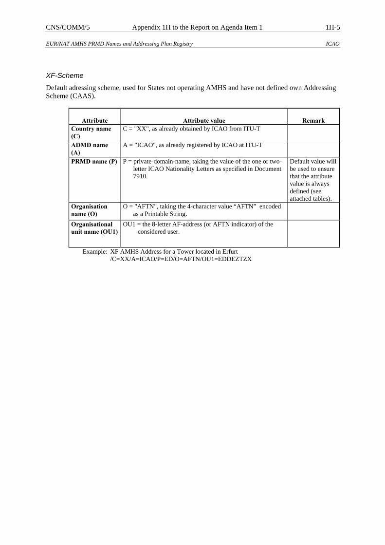
CNS/COMM/5 Appendix 1H to the Report on Agenda Item 1 1H-5
EUR/NAT AMHS PRMD Names and Addressing Plan Registry ICAO
XF-Scheme
Default adressing scheme, used for States not operating AMHS and have not defined own Addressing Scheme (CAAS).
Attribute Attribute value Remark Country name (C)
C = "XX", as already obtained by ICAO from ITU-T
ADMD name (A)
A = "ICAO", as already registered by ICAO at ITU-T
PRMD name (P) P = private-domain-name, taking the value of the one or two-letter ICAO Nationality Letters as specified in Document 7910.
Default value will be used to ensure that the attribute value is always defined (see attached tables).
Organisation name (O)
O = "AFTN", taking the 4-character value “AFTN” encoded as a Printable String.
Organisational unit name (OU1)
OU1 = the 8-letter AF-address (or AFTN indicator) of the considered user.
Example: XF AMHS Address for a Tower located in Erfurt
/C=XX/A=ICAO/P=ED/O=AFTN/OU1=EDDEZTZX
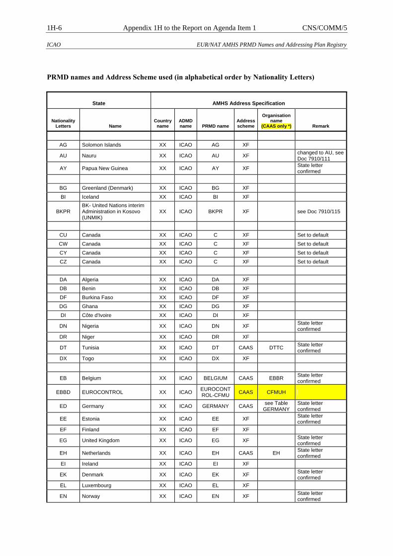
1H-6 Appendix 1H to the Report on Agenda Item 1 CNS/COMM/5
ICAO EUR/NAT AMHS PRMD Names and Addressing Plan Registry
PRMD names and Address Scheme used (in alphabetical order by Nationality Letters)
State AMHS Address Specification
Nationality Letters Name
Country name
ADMD name PRMD name
Address scheme
Organisation name
(CAAS only *) Remark
AG Solomon Islands XX ICAO AG XF
AU Nauru XX ICAO AU XF changed to AU, see Doc 7910/111
AY Papua New Guinea XX ICAO AY XF State letter confirmed
BG Greenland (Denmark) XX ICAO BG XF
BI Iceland XX ICAO BI XF
BKPR BK- United Nations interim Administration in Kosovo (UNMIK)
XX ICAO BKPR XF see Doc 7910/115
CU Canada XX ICAO C XF Set to default
CW Canada XX ICAO C XF Set to default
CY Canada XX ICAO C XF Set to default
CZ Canada XX ICAO C XF Set to default
DA Algeria XX ICAO DA XF
DB Benin XX ICAO DB XF
DF Burkina Faso XX ICAO DF XF
DG Ghana XX ICAO DG XF
DI Côte d'Ivoire XX ICAO DI XF
DN Nigeria XX ICAO DN XF State letter confirmed
DR Niger XX ICAO DR XF
DT Tunisia XX ICAO DT CAAS DTTC State letter confirmed
DX Togo XX ICAO DX XF
EB Belgium XX ICAO BELGIUM CAAS EBBR State letter confirmed
EBBD EUROCONTROL XX ICAO EUROCONT ROL-CFMU CAAS CFMUH
ED Germany XX ICAO GERMANY CAAS see Table GERMANY
State letter confirmed
EE Estonia XX ICAO EE XF State letter confirmed
EF Finland XX ICAO EF XF
EG United Kingdom XX ICAO EG XF State letter confirmed
EH Netherlands XX ICAO EH CAAS EH State letter confirmed
EI Ireland XX ICAO EI XF
EK Denmark XX ICAO EK XF State letter confirmed
EL Luxembourg XX ICAO EL XF
EN Norway XX ICAO EN XF State letter confirmed
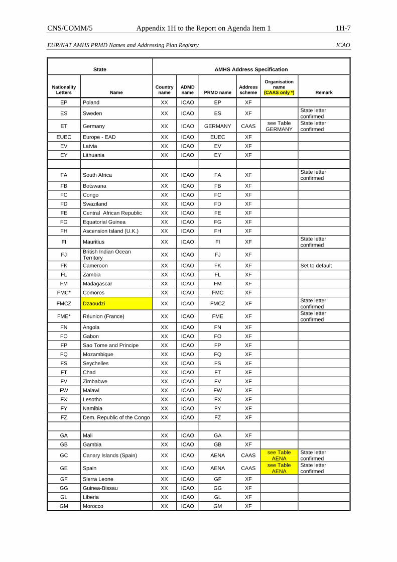
CNS/COMM/5 Appendix 1H to the Report on Agenda Item 1 1H-7
EUR/NAT AMHS PRMD Names and Addressing Plan Registry ICAO
State AMHS Address Specification
Nationality Letters Name
Country name
ADMD name PRMD name
Address scheme
Organisation name
(CAAS only *) Remark
EP Poland XX ICAO EP XF
ES Sweden XX ICAO ES XF State letter confirmed
ET Germany XX ICAO GERMANY CAAS see Table GERMANY
State letter confirmed
EUEC Europe - EAD XX ICAO EUEC XF
EV Latvia XX ICAO EV XF
EY Lithuania XX ICAO EY XF
FA South Africa XX ICAO FA XF State letter confirmed
FB Botswana XX ICAO FB XF
FC Congo XX ICAO FC XF
FD Swaziland XX ICAO FD XF
FE Central African Republic XX ICAO FE XF
FG Equatorial Guinea XX ICAO FG XF
FH Ascension Island (U.K.) XX ICAO FH XF
FI Mauritius XX ICAO FI XF State letter confirmed
FJ British Indian Ocean Territory XX ICAO FJ XF
FK Cameroon XX ICAO FK XF Set to default
FL Zambia XX ICAO FL XF
FM Madagascar XX ICAO FM XF
FMC* Comoros XX ICAO FMC XF
FMCZ Dzaoudzi XX ICAO FMCZ XF State letter confirmed
FME* Réunion (France) XX ICAO FME XF State letter confirmed
FN Angola XX ICAO FN XF
FO Gabon XX ICAO FO XF
FP Sao Tome and Principe XX ICAO FP XF
FQ Mozambique XX ICAO FQ XF
FS Seychelles XX ICAO FS XF
FT Chad XX ICAO FT XF
FV Zimbabwe XX ICAO FV XF
FW Malawi XX ICAO FW XF
FX Lesotho XX ICAO FX XF
FY Namibia XX ICAO FY XF
FZ Dem. Republic of the Congo XX ICAO FZ XF
GA Mali XX ICAO GA XF
GB Gambia XX ICAO GB XF
GC Canary Islands (Spain) XX ICAO AENA CAAS see Table AENA
State letter confirmed
GE Spain XX ICAO AENA CAAS see Table AENA
State letter confirmed
GF Sierra Leone XX ICAO GF XF
GG Guinea-Bissau XX ICAO GG XF
GL Liberia XX ICAO GL XF
GM Morocco XX ICAO GM XF

1H-8 Appendix 1H to the Report on Agenda Item 1 CNS/COMM/5
ICAO EUR/NAT AMHS PRMD Names and Addressing Plan Registry
State AMHS Address Specification
Nationality Letters Name
Country name
ADMD name PRMD name
Address scheme
Organisation name
(CAAS only *) Remark
GO Senegal XX ICAO GO XF
GQ Mauritania XX ICAO GQ XF
GS Western Sahara XX ICAO GS XF
GU Guinea XX ICAO GU XF
GV Cape Verde XX ICAO GV XF
HA Ethiopia XX ICAO HA XF
HB Burundi XX ICAO HB XF
HC Somalia XX ICAO HC XF
HD Djibouti XX ICAO HD XF
HE Egypt XX ICAO HE CAAS HECA State letter confirmed
HH Eritrea XX ICAO HH XF
HK Kenya XX ICAO HK XF Replied to State letter
HL Libyan Arab Jamahiriya XX ICAO HL XF
HR Rwanda XX ICAO HR XF
HS Sudan XX ICAO HS XF
HT United Republic of Tanzania XX ICAO HT XF
HU Uganda XX ICAO HU XF State letter confirmed
K* United States XX ICAO K XF State letter confirmed
LA Albania XX ICAO LA XF
LB Bulgaria XX ICAO LB XF
LC Cyprus XX ICAO CYPRUS CAAS LCCC State letter confirmed
LD Croatia XX ICAO LD CAAS LDZA State letter confirmed
LE Spain XX ICAO AENA CAAS see Table AENA
State letter confirmed
LF France XX ICAO FRANCE CAAS see Table FRANCE
State letter confirmed
LFPYZK* EUROCONTROL XX ICAO EUROCONT ROL-CFMU CAAS CFMUB
LFPYZM* EUROCONTROL XX ICAO EUROCONT ROL-CFMU CAAS CFMUB
LG Greece XX ICAO GREECE CAAS LGGG State letter confirmed
LH Hungary XX ICAO LH XF State letter confirmed
LI Italy XX ICAO LI XF
LJ Slovenia XX ICAO LJ XF State letter confirmed
LK Czech Republic XX ICAO LK XF
LL Israel XX ICAO LL XF
LM Malta XX ICAO LM XF
LN Monaco XX ICAO LN XF
LO Austria XX ICAO AUSTRIA CAAS LOVV State letter confirmed
LP Portugal (Madeira & Açores) XX ICAO PORTUGAL CAAS see Table
PORTUGAL State letter confirmed
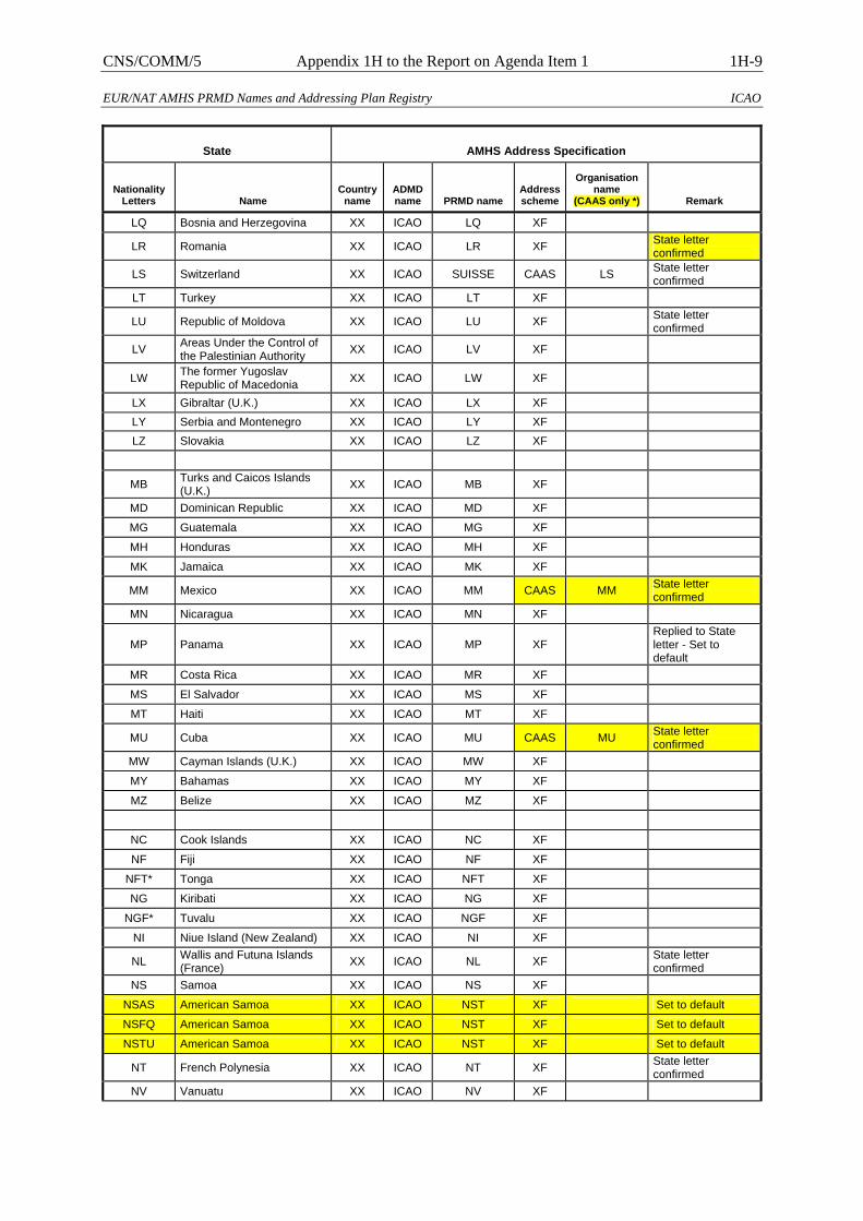
CNS/COMM/5 Appendix 1H to the Report on Agenda Item 1 1H-9
EUR/NAT AMHS PRMD Names and Addressing Plan Registry ICAO
State AMHS Address Specification
Nationality Letters Name
Country name
ADMD name PRMD name
Address scheme
Organisation name
(CAAS only *) Remark
LQ Bosnia and Herzegovina XX ICAO LQ XF
LR Romania XX ICAO LR XF State letter confirmed
LS Switzerland XX ICAO SUISSE CAAS LS State letter confirmed
LT Turkey XX ICAO LT XF
LU Republic of Moldova XX ICAO LU XF State letter confirmed
LV Areas Under the Control of the Palestinian Authority XX ICAO LV XF
LW The former Yugoslav Republic of Macedonia XX ICAO LW XF
LX Gibraltar (U.K.) XX ICAO LX XF LY Serbia and Montenegro XX ICAO LY XF LZ Slovakia XX ICAO LZ XF
MB Turks and Caicos Islands (U.K.) XX ICAO MB XF
MD Dominican Republic XX ICAO MD XF
MG Guatemala XX ICAO MG XF
MH Honduras XX ICAO MH XF
MK Jamaica XX ICAO MK XF
MM Mexico XX ICAO MM CAAS MM State letter confirmed
MN Nicaragua XX ICAO MN XF
MP Panama XX ICAO MP XF Replied to State letter - Set to default
MR Costa Rica XX ICAO MR XF
MS El Salvador XX ICAO MS XF
MT Haiti XX ICAO MT XF
MU Cuba XX ICAO MU CAAS MU State letter confirmed
MW Cayman Islands (U.K.) XX ICAO MW XF
MY Bahamas XX ICAO MY XF
MZ Belize XX ICAO MZ XF
NC Cook Islands XX ICAO NC XF
NF Fiji XX ICAO NF XF
NFT* Tonga XX ICAO NFT XF
NG Kiribati XX ICAO NG XF
NGF* Tuvalu XX ICAO NGF XF
NI Niue Island (New Zealand) XX ICAO NI XF
NL Wallis and Futuna Islands (France) XX ICAO NL XF State letter
confirmed NS Samoa XX ICAO NS XF
NSAS American Samoa XX ICAO NST XF Set to default
NSFQ American Samoa XX ICAO NST XF Set to default
NSTU American Samoa XX ICAO NST XF Set to default
NT French Polynesia XX ICAO NT XF State letter confirmed
NV Vanuatu XX ICAO NV XF
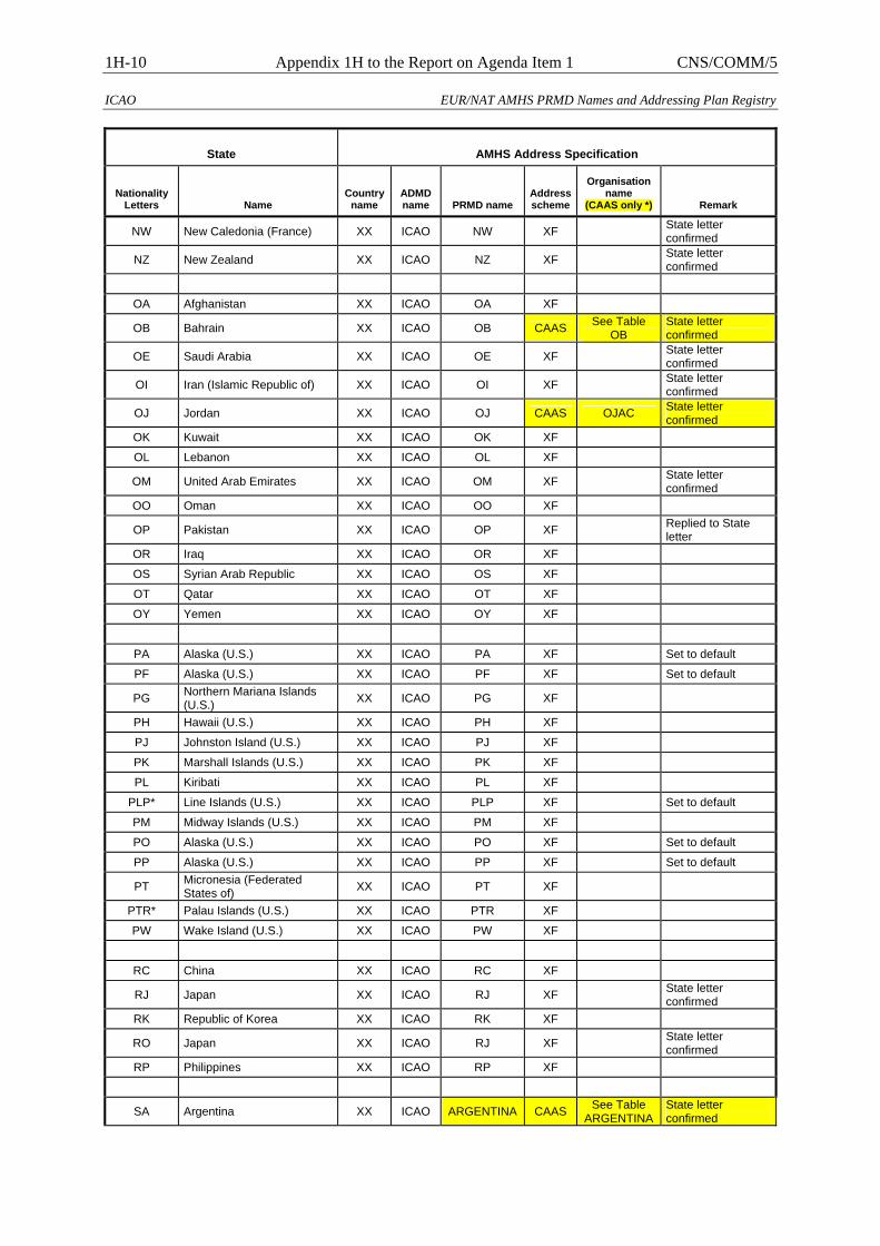
1H-10 Appendix 1H to the Report on Agenda Item 1 CNS/COMM/5
ICAO EUR/NAT AMHS PRMD Names and Addressing Plan Registry
State AMHS Address Specification
Nationality Letters Name
Country name
ADMD name PRMD name
Address scheme
Organisation name
(CAAS only *) Remark
NW New Caledonia (France) XX ICAO NW XF State letter confirmed
NZ New Zealand XX ICAO NZ XF State letter confirmed
OA Afghanistan XX ICAO OA XF
OB Bahrain XX ICAO OB CAAS See Table OB
State letter confirmed
OE Saudi Arabia XX ICAO OE XF State letter confirmed
OI Iran (Islamic Republic of) XX ICAO OI XF State letter confirmed
OJ Jordan XX ICAO OJ CAAS OJAC State letter confirmed
OK Kuwait XX ICAO OK XF
OL Lebanon XX ICAO OL XF
OM United Arab Emirates XX ICAO OM XF State letter confirmed
OO Oman XX ICAO OO XF
OP Pakistan XX ICAO OP XF Replied to State letter
OR Iraq XX ICAO OR XF
OS Syrian Arab Republic XX ICAO OS XF
OT Qatar XX ICAO OT XF
OY Yemen XX ICAO OY XF
PA Alaska (U.S.) XX ICAO PA XF Set to default
PF Alaska (U.S.) XX ICAO PF XF Set to default
PG Northern Mariana Islands (U.S.) XX ICAO PG XF
PH Hawaii (U.S.) XX ICAO PH XF
PJ Johnston Island (U.S.) XX ICAO PJ XF
PK Marshall Islands (U.S.) XX ICAO PK XF
PL Kiribati XX ICAO PL XF
PLP* Line Islands (U.S.) XX ICAO PLP XF Set to default
PM Midway Islands (U.S.) XX ICAO PM XF
PO Alaska (U.S.) XX ICAO PO XF Set to default
PP Alaska (U.S.) XX ICAO PP XF Set to default
PT Micronesia (Federated States of) XX ICAO PT XF
PTR* Palau Islands (U.S.) XX ICAO PTR XF
PW Wake Island (U.S.) XX ICAO PW XF
RC China XX ICAO RC XF
RJ Japan XX ICAO RJ XF State letter confirmed
RK Republic of Korea XX ICAO RK XF
RO Japan XX ICAO RJ XF State letter confirmed
RP Philippines XX ICAO RP XF
SA Argentina XX ICAO ARGENTINA CAAS See Table ARGENTINA
State letter confirmed
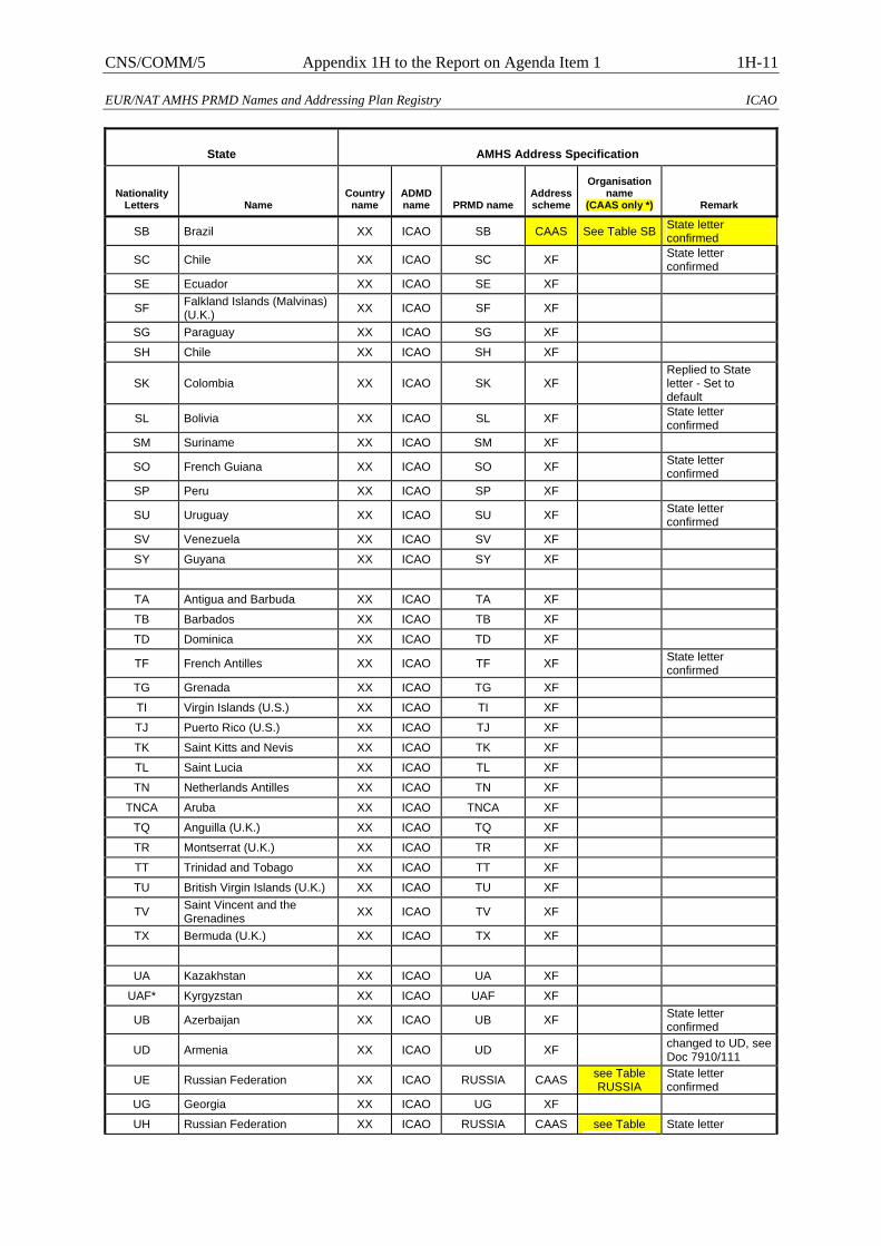
CNS/COMM/5 Appendix 1H to the Report on Agenda Item 1 1H-11
EUR/NAT AMHS PRMD Names and Addressing Plan Registry ICAO
State AMHS Address Specification
Nationality Letters Name
Country name
ADMD name PRMD name
Address scheme
Organisation name
(CAAS only *) Remark
SB Brazil XX ICAO SB CAAS See Table SB State letter confirmed
SC Chile XX ICAO SC XF State letter confirmed
SE Ecuador XX ICAO SE XF
SF Falkland Islands (Malvinas) (U.K.) XX ICAO SF XF
SG Paraguay XX ICAO SG XF
SH Chile XX ICAO SH XF
SK Colombia XX ICAO SK XF Replied to State letter - Set to default
SL Bolivia XX ICAO SL XF State letter confirmed
SM Suriname XX ICAO SM XF
SO French Guiana XX ICAO SO XF State letter confirmed
SP Peru XX ICAO SP XF
SU Uruguay XX ICAO SU XF State letter confirmed
SV Venezuela XX ICAO SV XF
SY Guyana XX ICAO SY XF
TA Antigua and Barbuda XX ICAO TA XF
TB Barbados XX ICAO TB XF
TD Dominica XX ICAO TD XF
TF French Antilles XX ICAO TF XF State letter confirmed
TG Grenada XX ICAO TG XF
TI Virgin Islands (U.S.) XX ICAO TI XF
TJ Puerto Rico (U.S.) XX ICAO TJ XF
TK Saint Kitts and Nevis XX ICAO TK XF
TL Saint Lucia XX ICAO TL XF
TN Netherlands Antilles XX ICAO TN XF
TNCA Aruba XX ICAO TNCA XF
TQ Anguilla (U.K.) XX ICAO TQ XF
TR Montserrat (U.K.) XX ICAO TR XF
TT Trinidad and Tobago XX ICAO TT XF
TU British Virgin Islands (U.K.) XX ICAO TU XF
TV Saint Vincent and the Grenadines XX ICAO TV XF
TX Bermuda (U.K.) XX ICAO TX XF
UA Kazakhstan XX ICAO UA XF
UAF* Kyrgyzstan XX ICAO UAF XF
UB Azerbaijan XX ICAO UB XF State letter confirmed
UD Armenia XX ICAO UD XF changed to UD, see Doc 7910/111
UE Russian Federation XX ICAO RUSSIA CAAS see Table RUSSIA
State letter confirmed
UG Georgia XX ICAO UG XF
UH Russian Federation XX ICAO RUSSIA CAAS see Table State letter
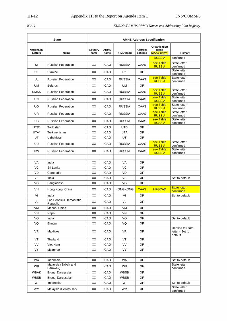
1H-12 Appendix 1H to the Report on Agenda Item 1 CNS/COMM/5
ICAO EUR/NAT AMHS PRMD Names and Addressing Plan Registry
State AMHS Address Specification
Nationality Letters Name
Country name
ADMD name PRMD name
Address scheme
Organisation name
(CAAS only *) Remark
RUSSIA confirmed
UI Russian Federation XX ICAO RUSSIA CAAS see Table RUSSIA
State letter confirmed
UK Ukraine XX ICAO UK XF State letter confirmed
UL Russian Federation XX ICAO RUSSIA CAAS see Table RUSSIA
State letter confirmed
UM Belarus XX ICAO UM XF
UMKK Russian Federation XX ICAO RUSSIA CAAS see Table RUSSIA
State letter confirmed
UN Russian Federation XX ICAO RUSSIA CAAS see Table RUSSIA
State letter confirmed
UO Russian Federation XX ICAO RUSSIA CAAS see Table RUSSIA
State letter confirmed
UR Russian Federation XX ICAO RUSSIA CAAS see Table RUSSIA
State letter confirmed
US Russian Federation XX ICAO RUSSIA CAAS see Table RUSSIA
State letter confirmed
UTD* Tajikistan XX ICAO UTD XF
UTA* Turkmenistan XX ICAO UTA XF
UT Uzbekistan XX ICAO UT XF
UU Russian Federation XX ICAO RUSSIA CAAS see Table RUSSIA
State letter confirmed
UW Russian Federation XX ICAO RUSSIA CAAS see Table RUSSIA
State letter confirmed
VA India XX ICAO VA XF
VC Sri Lanka XX ICAO VC XF
VD Cambodia XX ICAO VD XF
VE India XX ICAO VE XF Set to default
VG Bangladesh XX ICAO VG XF
VH Hong Kong, China XX ICAO HONGKONG CAAS HKGCAD State letter confirmed
VI India XX ICAO VI XF Set to default
VL Lao People's Democratic Republic XX ICAO VL XF
VM Macao, China XX ICAO VM XF
VN Nepal XX ICAO VN XF
VO India XX ICAO VO XF Set to default
VQ Bhutan XX ICAO VQ XF
VR Maldives XX ICAO VR XF Replied to State letter - Set to default
VT Thailand XX ICAO VT XF
VV Viet Nam XX ICAO VV XF
VY Myanmar XX ICAO VY XF
WA Indonesia XX ICAO WA XF Set to default
WB Malaysia (Sabah and Sarawak) XX ICAO WB XF State letter
confirmed WBAK Brunei Darussalam XX ICAO WBSB XF
WBSB Brunei Darussalam XX ICAO WBSB XF
WI Indonesia XX ICAO WI XF Set to default
WM Malaysia (Peninsular) XX ICAO WM XF State letter confirmed

CNS/COMM/5 Appendix 1H to the Report on Agenda Item 1 1H-13
EUR/NAT AMHS PRMD Names and Addressing Plan Registry ICAO
State AMHS Address Specification
Nationality Letters Name
Country name
ADMD name PRMD name
Address scheme
Organisation name
(CAAS only *) Remark
WP Timor-Leste XX ICAO WP XF
WR Indonesia XX ICAO WR XF Set to default
WS Singapore XX ICAO WS XF
Y* Australia XX ICAO Y XF
ZB China XX ICAO ZB XF State letter confirmed
ZG China XX ICAO ZB XF State letter confirmed
ZH China XX ICAO ZB XF State letter confirmed
ZJ China XX ICAO ZB XF State letter confirmed
ZK Dem. People's Rep. of Korea XX ICAO ZK XF
ZL China XX ICAO ZB XF State letter confirmed
ZM Mongolia XX ICAO ZM XF
ZP China XX ICAO ZB XF State letter confirmed
ZS China XX ICAO ZB XF State letter confirmed
ZT China XX ICAO ZB XF no location indicator
ZU China XX ICAO ZB XF State letter confirmed
ZW China XX ICAO ZB XF State letter confirmed
ZY China XX ICAO ZB XF State letter confirmed
(*) if only one organisation name is listed than it is allocated for all location indicators of the State concerned
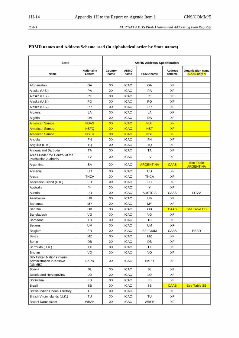
1H-14 Appendix 1H to the Report on Agenda Item 1 CNS/COMM/5
ICAO EUR/NAT AMHS PRMD Names and Addressing Plan Registry
PRMD names and Address Scheme used (in alphabetical order by State names)
State AMHS Address Specification
Name Nationality
Letters Country
name ADMD name PRMD name
Address scheme
Organisation name (CAAS only *)
Afghanistan OA XX ICAO OA XF
Alaska (U.S.) PA XX ICAO PA XF
Alaska (U.S.) PF XX ICAO PF XF
Alaska (U.S.) PO XX ICAO PO XF
Alaska (U.S.) PP XX ICAO PP XF
Albania LA XX ICAO LA XF
Algeria DA XX ICAO DA XF
American Samoa NSAS XX ICAO NST XF
American Samoa NSFQ XX ICAO NST XF
American Samoa NSTU XX ICAO NST XF
Angola FN XX ICAO FN XF
Anguilla (U.K.) TQ XX ICAO TQ XF
Antigua and Barbuda TA XX ICAO TA XF Areas Under the Control of the Palestinian Authority LV XX ICAO LV XF
Argentina SA XX ICAO ARGENTINA CAAS See Table ARGENTINA
Armenia UD XX ICAO UD XF
Aruba TNCA XX ICAO TNCA XF
Ascension Island (U.K.) FH XX ICAO FH XF
Australia Y* XX ICAO Y XF
Austria LO XX ICAO AUSTRIA CAAS LOVV
Azerbaijan UB XX ICAO UB XF
Bahamas MY XX ICAO MY XF
Bahrain OB XX ICAO OB CAAS See Table OB
Bangladesh VG XX ICAO VG XF
Barbados TB XX ICAO TB XF
Belarus UM XX ICAO UM XF
Belgium EB XX ICAO BELGIUM CAAS EBBR
Belize MZ XX ICAO MZ XF
Benin DB XX ICAO DB XF
Bermuda (U.K.) TX XX ICAO TX XF
Bhutan VQ XX ICAO VQ XF BK- United Nations interim Administration in Kosovo (UNMIK)
BKPR XX ICAO BKPR XF
Bolivia SL XX ICAO SL XF
Bosnia and Herzegovina LQ XX ICAO LQ XF
Botswana FB XX ICAO FB XF
Brazil SB XX ICAO SB CAAS See Table SB
British Indian Ocean Territory FJ XX ICAO FJ XF
British Virgin Islands (U.K.) TU XX ICAO TU XF
Brunei Darussalam WBAK XX ICAO WBSB XF
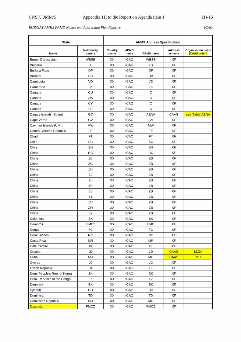
CNS/COMM/5 Appendix 1H to the Report on Agenda Item 1 1H-15
EUR/NAT AMHS PRMD Names and Addressing Plan Registry ICAO
State AMHS Address Specification
Name Nationality
Letters Country
name ADMD name PRMD name
Address scheme
Organisation name (CAAS only *)
Brunei Darussalam WBSB XX ICAO WBSB XF
Bulgaria LB XX ICAO LB XF
Burkina Faso DF XX ICAO DF XF
Burundi HB XX ICAO HB XF
Cambodia VD XX ICAO VD XF
Cameroon FK XX ICAO FK XF
Canada CU XX ICAO C XF
Canada CW XX ICAO C XF
Canada CY XX ICAO C XF
Canada CZ XX ICAO C XF
Canary Islands (Spain) GC XX ICAO AENA CAAS see Table AENA
Cape Verde GV XX ICAO GV XF
Cayman Islands (U.K.) MW XX ICAO MW XF
Central African Republic FE XX ICAO FE XF
Chad FT XX ICAO FT XF
Chile SC XX ICAO SC XF
Chile SH XX ICAO SH XF
China RC XX ICAO RC XF
China ZB XX ICAO ZB XF
China ZG XX ICAO ZB XF
China ZH XX ICAO ZB XF
China ZJ XX ICAO ZB XF
China ZL XX ICAO ZB XF
China ZP XX ICAO ZB XF
China ZS XX ICAO ZB XF
China ZT XX ICAO ZB XF
China ZU XX ICAO ZB XF
China ZW XX ICAO ZB XF
China ZY XX ICAO ZB XF
Colombia SK XX ICAO SK XF
Comoros FMC* XX ICAO FMC XF
Congo FC XX ICAO FC XF
Cook Islands NC XX ICAO NC XF
Costa Rica MR XX ICAO MR XF
Côte d'Ivoire DI XX ICAO DI XF
Croatia LD XX ICAO LD CAAS LDZA
Cuba MU XX ICAO MU CAAS MU
Cyprus LC XX ICAO LC XF
Czech Republic LK XX ICAO LK XF
Dem. People's Rep. of Korea ZK XX ICAO ZK XF
Dem. Republic of the Congo FZ XX ICAO FZ XF
Denmark EK XX ICAO EK XF
Djibouti HD XX ICAO HD XF
Dominica TD XX ICAO TD XF
Dominican Republic MD XX ICAO MD XF
Dzaoudzi FMCZ XX ICAO FMCZ XF
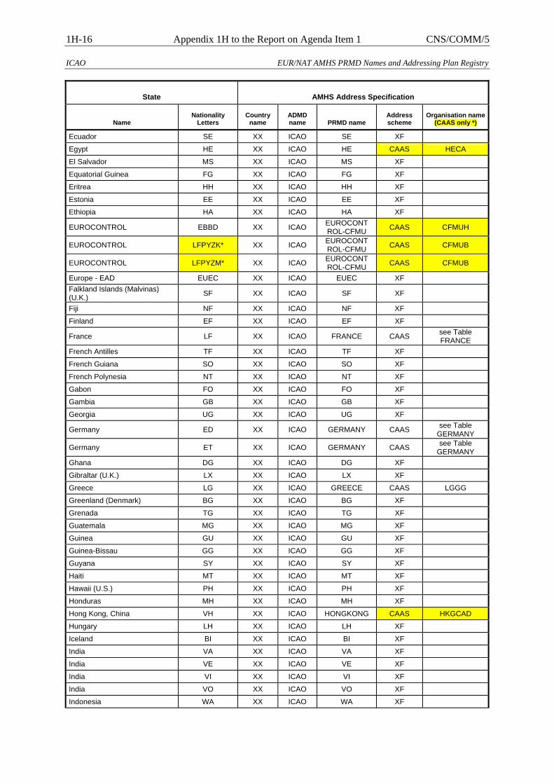
1H-16 Appendix 1H to the Report on Agenda Item 1 CNS/COMM/5
ICAO EUR/NAT AMHS PRMD Names and Addressing Plan Registry
State AMHS Address Specification
Name Nationality
Letters Country
name ADMD name PRMD name
Address scheme
Organisation name (CAAS only *)
Ecuador SE XX ICAO SE XF
Egypt HE XX ICAO HE CAAS HECA
El Salvador MS XX ICAO MS XF
Equatorial Guinea FG XX ICAO FG XF
Eritrea HH XX ICAO HH XF
Estonia EE XX ICAO EE XF
Ethiopia HA XX ICAO HA XF
EUROCONTROL EBBD XX ICAO EUROCONT ROL-CFMU CAAS CFMUH
EUROCONTROL LFPYZK* XX ICAO EUROCONT ROL-CFMU CAAS CFMUB
EUROCONTROL LFPYZM* XX ICAO EUROCONT ROL-CFMU CAAS CFMUB
Europe - EAD EUEC XX ICAO EUEC XF Falkland Islands (Malvinas) (U.K.) SF XX ICAO SF XF
Fiji NF XX ICAO NF XF
Finland EF XX ICAO EF XF
France LF XX ICAO FRANCE CAAS see Table FRANCE
French Antilles TF XX ICAO TF XF
French Guiana SO XX ICAO SO XF
French Polynesia NT XX ICAO NT XF
Gabon FO XX ICAO FO XF
Gambia GB XX ICAO GB XF
Georgia UG XX ICAO UG XF
Germany ED XX ICAO GERMANY CAAS see Table GERMANY
Germany ET XX ICAO GERMANY CAAS see Table GERMANY
Ghana DG XX ICAO DG XF
Gibraltar (U.K.) LX XX ICAO LX XF
Greece LG XX ICAO GREECE CAAS LGGG
Greenland (Denmark) BG XX ICAO BG XF
Grenada TG XX ICAO TG XF
Guatemala MG XX ICAO MG XF
Guinea GU XX ICAO GU XF
Guinea-Bissau GG XX ICAO GG XF
Guyana SY XX ICAO SY XF
Haiti MT XX ICAO MT XF
Hawaii (U.S.) PH XX ICAO PH XF
Honduras MH XX ICAO MH XF
Hong Kong, China VH XX ICAO HONGKONG CAAS HKGCAD
Hungary LH XX ICAO LH XF
Iceland BI XX ICAO BI XF
India VA XX ICAO VA XF
India VE XX ICAO VE XF
India VI XX ICAO VI XF
India VO XX ICAO VO XF
Indonesia WA XX ICAO WA XF
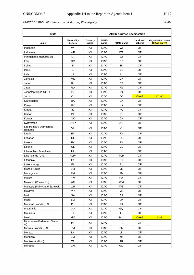
CNS/COMM/5 Appendix 1H to the Report on Agenda Item 1 1H-17
EUR/NAT AMHS PRMD Names and Addressing Plan Registry ICAO
State AMHS Address Specification
Name Nationality
Letters Country
name ADMD name PRMD name
Address scheme
Organisation name (CAAS only *)
Indonesia WI XX ICAO WI XF
Indonesia WR XX ICAO WR XF
Iran (Islamic Republic of) OI XX ICAO OI XF
Iraq OR XX ICAO OR XF
Ireland EI XX ICAO EI XF
Israel LL XX ICAO LL XF
Italy LI XX ICAO LI XF
Jamaica MK XX ICAO MK XF
Japan RJ XX ICAO RJ XF
Japan RO XX ICAO RJ XF
Johnston Island (U.S.) PJ XX ICAO PJ XF
Jordan OJ XX ICAO OJ CAAS OJAC
Kazakhstan UA XX ICAO UA XF
Kenya HK XX ICAO HK XF
Kiribati NG XX ICAO NG XF
Kiribati PL XX ICAO PL XF
Kuwait OK XX ICAO OK XF
Kyrgyzstan UAF* XX ICAO UAF XF Lao People's Democratic Republic VL XX ICAO VL XF
Latvia EV XX ICAO EV XF
Lebanon OL XX ICAO OL XF
Lesotho FX XX ICAO FX XF
Liberia GL XX ICAO GL XF
Libyan Arab Jamahiriya HL XX ICAO HL XF
Line Islands (U.S.) PLP* XX ICAO PLP XF
Lithuania EY XX ICAO EY XF
Luxembourg EL XX ICAO EL XF
Macao, China VM XX ICAO VM XF
Madagascar FM XX ICAO FM XF
Malawi FW XX ICAO FW XF
Malaysia (Peninsular) WM XX ICAO WM XF
Malaysia (Sabah and Sarawak) WB XX ICAO WB XF
Maldives VR XX ICAO VR XF
Mali GA XX ICAO GA XF
Malta LM XX ICAO LM XF
Marshall Islands (U.S.) PK XX ICAO PK XF
Mauritania GQ XX ICAO GQ XF
Mauritius FI XX ICAO FI XF
Mexico MM XX ICAO MM CAAS MM Micronesia (Federated States of) PT XX ICAO PT XF
Midway Islands (U.S.) PM XX ICAO PM XF
Monaco LN XX ICAO LN XF
Mongolia ZM XX ICAO ZM XF
Montserrat (U.K.) TR XX ICAO TR XF
Morocco GM XX ICAO GM XF

1H-18 Appendix 1H to the Report on Agenda Item 1 CNS/COMM/5
ICAO EUR/NAT AMHS PRMD Names and Addressing Plan Registry
State AMHS Address Specification
Name Nationality
Letters Country
name ADMD name PRMD name
Address scheme
Organisation name (CAAS only *)
Mozambique FQ XX ICAO FQ XF
Myanmar VY XX ICAO VY XF
Namibia FY XX ICAO FY XF
Nauru AU XX ICAO AU XF
Nepal VN XX ICAO VN XF
Netherlands EH XX ICAO EH CAAS EH
Netherlands Antilles TN XX ICAO TN XF
New Caledonia (France) NW XX ICAO NW XF
New Zealand NZ XX ICAO NZ XF
Nicaragua MN XX ICAO MN XF
Niger DR XX ICAO DR XF
Nigeria DN XX ICAO DN XF
Niue Island (New Zealand) NI XX ICAO NI XF
Northern Mariana Islands (U.S.) PG XX ICAO PG XF
Norway EN XX ICAO EN XF
Oman OO XX ICAO OO XF
Pakistan OP XX ICAO OP XF
Palau Islands (U.S.) PTR* XX ICAO PTR XF
Panama MP XX ICAO MP XF
Papua New Guinea AY XX ICAO AY XF
Paraguay SG XX ICAO SG XF
Peru SP XX ICAO SP XF
Philippines RP XX ICAO RP XF
Poland EP XX ICAO EP XF
Portugal (Madeira & Açores) LP XX ICAO PORTUGAL CAAS see Table PORTUGAL
Puerto Rico (U.S.) TJ XX ICAO TJ XF
Qatar OT XX ICAO OT XF
Republic of Korea RK XX ICAO RK XF
Republic of Moldova LU XX ICAO LU XF
Réunion (France) FME* XX ICAO FME XF
Romania LR XX ICAO LR XF
Russian Federation UE XX ICAO RUSSIA CAAS see Table RUSSIA
Russian Federation UH XX ICAO RUSSIA CAAS see Table RUSSIA
Russian Federation UI XX ICAO RUSSIA CAAS see Table RUSSIA
Russian Federation UL XX ICAO RUSSIA CAAS see Table RUSSIA
Russian Federation UMKK XX ICAO RUSSIA CAAS see Table RUSSIA
Russian Federation UN XX ICAO RUSSIA CAAS see Table RUSSIA
Russian Federation UO XX ICAO RUSSIA CAAS see Table RUSSIA
Russian Federation UR XX ICAO RUSSIA CAAS see Table RUSSIA
Russian Federation US XX ICAO RUSSIA CAAS see Table RUSSIA
Russian Federation UU XX ICAO RUSSIA CAAS see Table RUSSIA
Russian Federation UW XX ICAO RUSSIA CAAS see Table
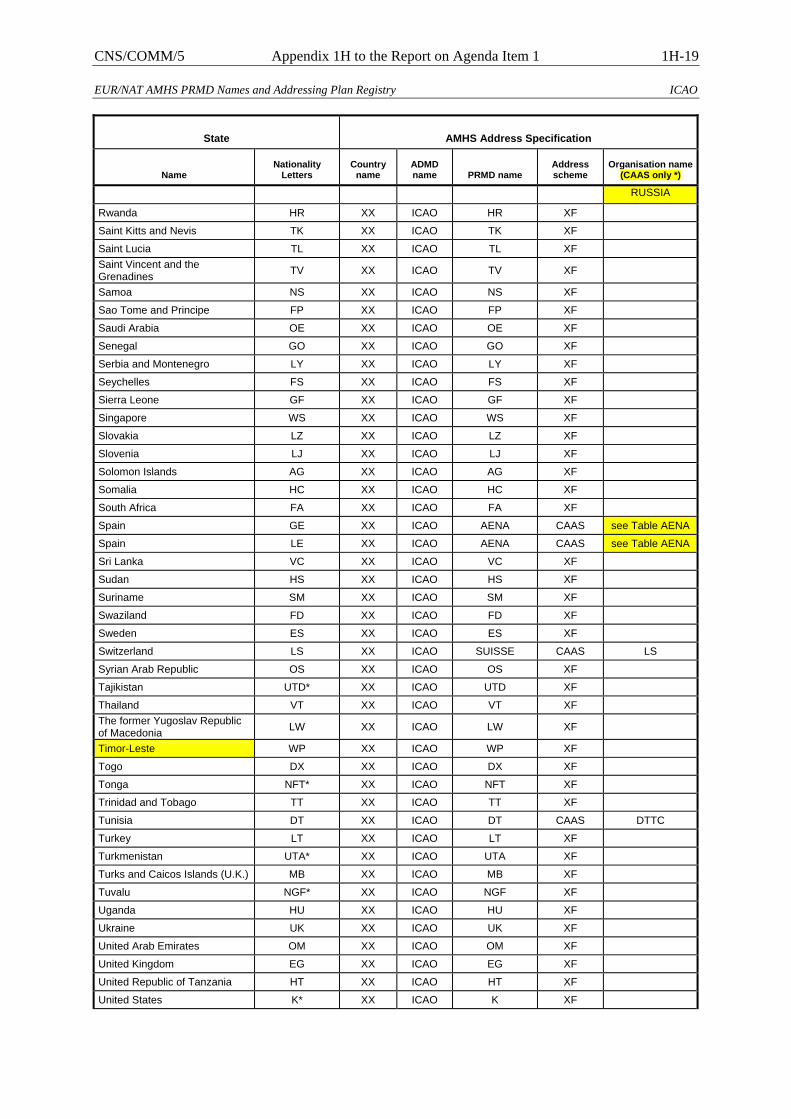
CNS/COMM/5 Appendix 1H to the Report on Agenda Item 1 1H-19
EUR/NAT AMHS PRMD Names and Addressing Plan Registry ICAO
State AMHS Address Specification
Name Nationality
Letters Country
name ADMD name PRMD name
Address scheme
Organisation name (CAAS only *)
RUSSIA
Rwanda HR XX ICAO HR XF
Saint Kitts and Nevis TK XX ICAO TK XF
Saint Lucia TL XX ICAO TL XF Saint Vincent and the Grenadines TV XX ICAO TV XF
Samoa NS XX ICAO NS XF
Sao Tome and Principe FP XX ICAO FP XF
Saudi Arabia OE XX ICAO OE XF
Senegal GO XX ICAO GO XF
Serbia and Montenegro LY XX ICAO LY XF
Seychelles FS XX ICAO FS XF
Sierra Leone GF XX ICAO GF XF
Singapore WS XX ICAO WS XF
Slovakia LZ XX ICAO LZ XF
Slovenia LJ XX ICAO LJ XF
Solomon Islands AG XX ICAO AG XF
Somalia HC XX ICAO HC XF
South Africa FA XX ICAO FA XF
Spain GE XX ICAO AENA CAAS see Table AENA
Spain LE XX ICAO AENA CAAS see Table AENA
Sri Lanka VC XX ICAO VC XF
Sudan HS XX ICAO HS XF
Suriname SM XX ICAO SM XF
Swaziland FD XX ICAO FD XF
Sweden ES XX ICAO ES XF
Switzerland LS XX ICAO SUISSE CAAS LS
Syrian Arab Republic OS XX ICAO OS XF
Tajikistan UTD* XX ICAO UTD XF
Thailand VT XX ICAO VT XF The former Yugoslav Republic of Macedonia LW XX ICAO LW XF
Timor-Leste WP XX ICAO WP XF
Togo DX XX ICAO DX XF
Tonga NFT* XX ICAO NFT XF
Trinidad and Tobago TT XX ICAO TT XF
Tunisia DT XX ICAO DT CAAS DTTC
Turkey LT XX ICAO LT XF
Turkmenistan UTA* XX ICAO UTA XF
Turks and Caicos Islands (U.K.) MB XX ICAO MB XF
Tuvalu NGF* XX ICAO NGF XF
Uganda HU XX ICAO HU XF
Ukraine UK XX ICAO UK XF
United Arab Emirates OM XX ICAO OM XF
United Kingdom EG XX ICAO EG XF
United Republic of Tanzania HT XX ICAO HT XF
United States K* XX ICAO K XF

1H-20 Appendix 1H to the Report on Agenda Item 1 CNS/COMM/5
ICAO EUR/NAT AMHS PRMD Names and Addressing Plan Registry
State AMHS Address Specification
Name Nationality
Letters Country
name ADMD name PRMD name
Address scheme
Organisation name (CAAS only *)
Uruguay SU XX ICAO SU XF
Uzbekistan UT XX ICAO UT XF
Vanuatu NV XX ICAO NV XF
Venezuela SV XX ICAO SV XF
Viet Nam VV XX ICAO VV XF
Virgin Islands (U.S.) TI XX ICAO TI XF
Wake Island (U.S.) PW XX ICAO PW XF Wallis and Futuna Islands (France) NL XX ICAO NL XF
Western Sahara GS XX ICAO GS XF
Yemen OY XX ICAO OY XF
Zambia FL XX ICAO FL XF
Zimbabwe FV XX ICAO FV XF
(*) if only one organisation name is listed than it is allocated for all location indicators of the State concerned
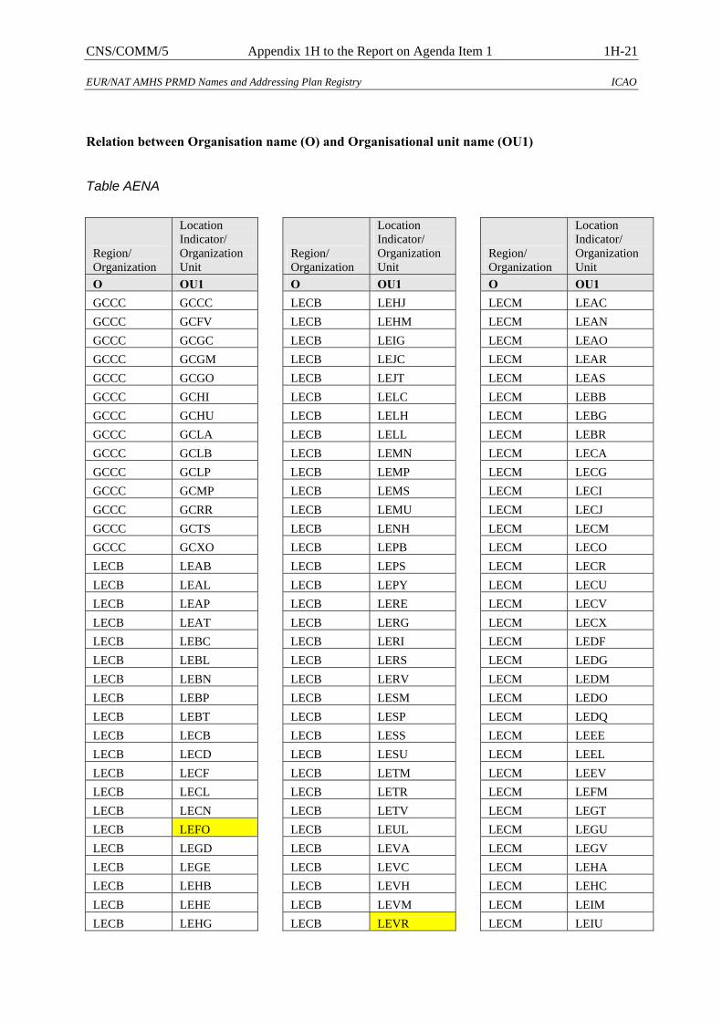
CNS/COMM/5 Appendix 1H to the Report on Agenda Item 1 1H-21
EUR/NAT AMHS PRMD Names and Addressing Plan Registry ICAO
Relation between Organisation name (O) and Organisational unit name (OU1)
Table AENA
Region/ Organization
Location Indicator/ Organization Unit
O OU1 GCCC GCCC GCCC GCFV GCCC GCGC GCCC GCGM GCCC GCGO GCCC GCHI GCCC GCHU GCCC GCLA GCCC GCLB GCCC GCLP GCCC GCMP GCCC GCRR GCCC GCTS GCCC GCXO LECB LEAB LECB LEAL LECB LEAP LECB LEAT LECB LEBC LECB LEBL LECB LEBN LECB LEBP LECB LEBT LECB LECB LECB LECD LECB LECF LECB LECL LECB LECN LECB LEFO LECB LEGD LECB LEGE LECB LEHB LECB LEHE LECB LEHG
Region/ Organization
Location Indicator/ Organization Unit
O OU1 LECB LEHJ LECB LEHM LECB LEIG LECB LEJC LECB LEJT LECB LELC LECB LELH LECB LELL LECB LEMN LECB LEMP LECB LEMS LECB LEMU LECB LENH LECB LEPB LECB LEPS LECB LEPY LECB LERE LECB LERG LECB LERI LECB LERS LECB LERV LECB LESM LECB LESP LECB LESS LECB LESU LECB LETM LECB LETR LECB LETV LECB LEUL LECB LEVA LECB LEVC LECB LEVH LECB LEVM LECB LEVR
Region/ Organization
Location Indicator/ Organization Unit
O OU1 LECM LEAC LECM LEAN LECM LEAO LECM LEAR LECM LEAS LECM LEBB LECM LEBG LECM LEBR LECM LECA LECM LECG LECM LECI LECM LECJ LECM LECM LECM LECO LECM LECR LECM LECU LECM LECV LECM LECX LECM LEDF LECM LEDG LECM LEDM LECM LEDO LECM LEDQ LECM LEEE LECM LEEL LECM LEEV LECM LEFM LECM LEGT LECM LEGU LECM LEGV LECM LEHA LECM LEHC LECM LEIM LECM LEIU
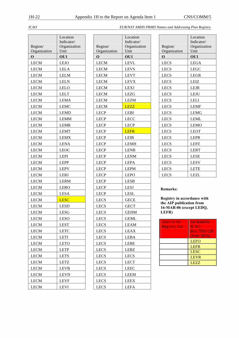
1H-22 Appendix 1H to the Report on Agenda Item 1 CNS/COMM/5
ICAO EUR/NAT AMHS PRMD Names and Addressing Plan Registry
Region/ Organization
Location Indicator/ Organization Unit
O OU1 LECM LEJO LECM LELA LECM LELM LECM LELN LECM LELO LECM LELT LECM LEMA LECM LEMC LECM LEMD LECM LEMM LECM LEMR LECM LEMT LECM LEMX LECM LENA LECM LEOC LECM LEPI LECM LEPP LECM LEPV LECM LERJ LECM LERM LECM LERO LECM LESA LECM LESC LECM LESD LECM LESG LECM LESO LECM LEST LECM LETC LECM LETI LECM LETO LECM LETP LECM LETS LECM LETZ LECM LEVB LECM LEVD LECM LEVF LECM LEVI
Region/ Organization
Location Indicator/ Organization Unit
O OU1 LECM LEVL LECM LEVS LECM LEVT LECM LEVX LECM LEXJ LECM LEZG LECM LEZM LECM LEZZ LECP LEBI LECP LECC LECP LECP LECP LEFR LECP LEIB LECP LEMH LECP LENB LECP LENM LECP LEPA LECP LEPM LECP LEPO LECP LESB LECP LESJ LECP LESL LECS GECE LECS GECT LECS GEHM LECS GEML LECS LEAM LECS LEAX LECS LEBA LECS LEBE LECS LEBZ LECS LECS LECS LECT LECS LEEC LECS LEEM LECS LEEX LECS LEFA
Region/ Organization
Location Indicator/ Organization Unit
O OU1 LECS LEGA LECS LEGC LECS LEGR LECS LEIZ LECS LEJR LECS LEJU LECS LELI LECS LEMF LECS LEMG LECS LEML LECS LEMO LECS LEOT LECS LEPR LECS LEPZ LECS LERT LECS LESE LECS LESV LECS LETE LECS LEZL
Remarks: Registry in accordance with the AIP publication from 16-MAR-06 (except LEDQ, LEFR) listed in the Registry, but
not listed in ICAO Doc 7910/120(June 2006)
LEFO LEFR LESC LEVR LEZZ
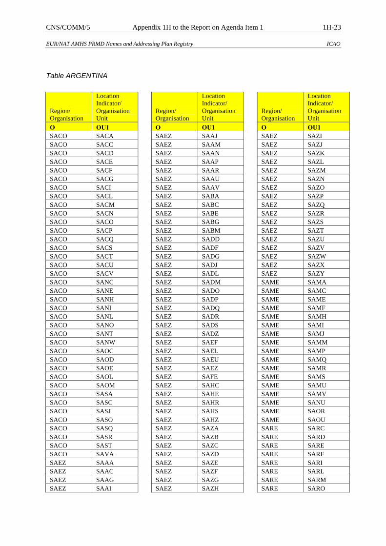
CNS/COMM/5 Appendix 1H to the Report on Agenda Item 1 1H-23
EUR/NAT AMHS PRMD Names and Addressing Plan Registry ICAO
Table ARGENTINA
Region/ Organisation
Location Indicator/ Organisation Unit
O OU1 SACO SACA SACO SACC SACO SACD SACO SACE SACO SACF SACO SACG SACO SACI SACO SACL SACO SACM SACO SACN SACO SACO SACO SACP SACO SACQ SACO SACS SACO SACT SACO SACU SACO SACV SACO SANC SACO SANE SACO SANH SACO SANI SACO SANL SACO SANO SACO SANT SACO SANW SACO SAOC SACO SAOD SACO SAOE SACO SAOL SACO SAOM SACO SASA SACO SASC SACO SASJ SACO SASO SACO SASQ SACO SASR SACO SAST SACO SAVA SAEZ SAAA SAEZ SAAC SAEZ SAAG SAEZ SAAI
Region/ Organisation
Location Indicator/ Organisation Unit
O OU1 SAEZ SAAJ SAEZ SAAM SAEZ SAAN SAEZ SAAP SAEZ SAAR SAEZ SAAU SAEZ SAAV SAEZ SABA SAEZ SABC SAEZ SABE SAEZ SABG SAEZ SABM SAEZ SADD SAEZ SADF SAEZ SADG SAEZ SADJ SAEZ SADL SAEZ SADM SAEZ SADO SAEZ SADP SAEZ SADQ SAEZ SADR SAEZ SADS SAEZ SADZ SAEZ SAEF SAEZ SAEL SAEZ SAEU SAEZ SAEZ SAEZ SAFE SAEZ SAHC SAEZ SAHE SAEZ SAHR SAEZ SAHS SAEZ SAHZ SAEZ SAZA SAEZ SAZB SAEZ SAZC SAEZ SAZD SAEZ SAZE SAEZ SAZF SAEZ SAZG SAEZ SAZH
Region/ Organisation
Location Indicator/ Organisation Unit
O OU1 SAEZ SAZI SAEZ SAZJ SAEZ SAZK SAEZ SAZL SAEZ SAZM SAEZ SAZN SAEZ SAZO SAEZ SAZP SAEZ SAZQ SAEZ SAZR SAEZ SAZS SAEZ SAZT SAEZ SAZU SAEZ SAZV SAEZ SAZW SAEZ SAZX SAEZ SAZY SAME SAMA SAME SAMC SAME SAME SAME SAMF SAME SAMH SAME SAMI SAME SAMJ SAME SAMM SAME SAMP SAME SAMQ SAME SAMR SAME SAMS SAME SAMU SAME SAMV SAME SANU SAME SAOR SAME SAOU SARE SARC SARE SARD SARE SARE SARE SARF SARE SARI SARE SARL SARE SARM SARE SARO

1H-24 Appendix 1H to the Report on Agenda Item 1 CNS/COMM/5
ICAO EUR/NAT AMHS PRMD Names and Addressing Plan Registry
Region/ Organisation
Location Indicator/ Organisation Unit
O OU1 SARE SARP SARE SARR SARE SARS SARE SARU SARE SATC SARE SATD SARE SATG SARE SATI SARE SATK SARE SATM SARE SATO SARE SATR SARE SATU SAVC SAVB SAVC SAVC SAVC SAVD SAVC SAVE SAVC SAVF SAVC SAVH SAVC SAVM SAVC SAVN SAVC SAVP SAVC SAVQ SAVC SAVR
Region/ Organisation
Location Indicator/ Organisation Unit
O OU1 SAVC SAVS SAVC SAVT SAVC SAVU SAVC SAVV SAVC SAVY SAVC SAWA SAVC SAWB SAVC SAWD SAVC SAWE SAVC SAWG SAVC SAWH SAVC SAWJ SAVC SAWM SAVC SAWP SAVC SAWR SAVC SAWS SAVC SAWT SAVC SAWU SAVC SAWZ SAVC SAYB SAVC SAYE SAVC SAYJ SAVC SAYO SAVC SAYS
Remarks: listed in the Registry, but
not listed in ICAO Doc 7910/120(June 2006)
SABG SAHS SAMC SAWA
Not listed in the Registry, but
listed in ICAO Doc 7910/120(June 2006)
SAEA SAET SAOS SARG SARV SAWC SAWO
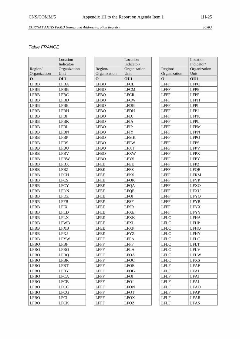
CNS/COMM/5 Appendix 1H to the Report on Agenda Item 1 1H-25
EUR/NAT AMHS PRMD Names and Addressing Plan Registry ICAO
Table FRANCE
Region/ Organization
Location Indicator/ Organization Unit
O OU1 LFBB LFBA LFBB LFBB LFBB LFBC LFBB LFBD LFBB LFBE LFBB LFBH LFBB LFBI LFBB LFBK LFBB LFBL LFBB LFBN LFBB LFBP LFBB LFBS LFBB LFBU LFBB LFBV LFBB LFBW LFBB LFBX LFBB LFBZ LFBB LFCH LFBB LFCS LFBB LFCY LFBB LFDN LFBB LFDZ LFBB LFFB LFBB LFIX LFBB LFLD LFBB LFLX LFBB LFWB LFBB LFXB LFBB LFXJ LFBB LFYW LFBO LFBF LFBO LFBO LFBO LFBQ LFBO LFBR LFBO LFBT LFBO LFBY LFBO LFCA LFBO LFCB LFBO LFCC LFBO LFCG LFBO LFCI LFBO LFCK
Region/ Organization
Location Indicator/ Organization Unit
O OU1 LFBO LFCL LFBO LFCM LFBO LFCR LFBO LFCW LFBO LFDB LFBO LFDH LFBO LFDJ LFBO LFIA LFBO LFIP LFBO LFIY LFBO LFMK LFBO LFPW LFBO LFXT LFBO LFXW LFBO LFYS LFEE LFEE LFEE LFFZ LFEE LFKS LFEE LFOK LFEE LFQA LFEE LFQE LFEE LFQI LFEE LFSF LFEE LFSR LFEE LFXE LFEE LFXK LFEE LFXL LFEE LFXP LFEE LFYZ LFFF LFFA LFFF LFFF LFFF LFLA LFFF LFOA LFFF LFOC LFFF LFOE LFFF LFOG LFFF LFOI LFFF LFOJ LFFF LFON LFFF LFOT LFFF LFOX LFFF LFOZ
Region/ Organization
Location Indicator/ Organization Unit
O OU1 LFFF LFPC LFFF LFPE LFFF LFPF LFFF LFPH LFFF LFPI LFFF LFPJ LFFF LFPK LFFF LFPL LFFF LFPM LFFF LFPN LFFF LFPO LFFF LFPS LFFF LFPV LFFF LFPX LFFF LFPY LFFF LFPZ LFFF LFQB LFFF LFRM LFFF LFVP LFFF LFXO LFFF LFXU LFFF LFYO LFFF LFYR LFFF LFYX LFFF LFYY LFLC LFHA LFLC LFHP LFLC LFHQ LFLC LFHY LFLC LFLC LFLC LFLT LFLC LFLV LFLC LFLW LFLC LFXS LFLF LFAF LFLF LFAI LFLF LFAJ LFLF LFAL LFLF LFAO LFLF LFAP LFLF LFAR LFLF LFAS
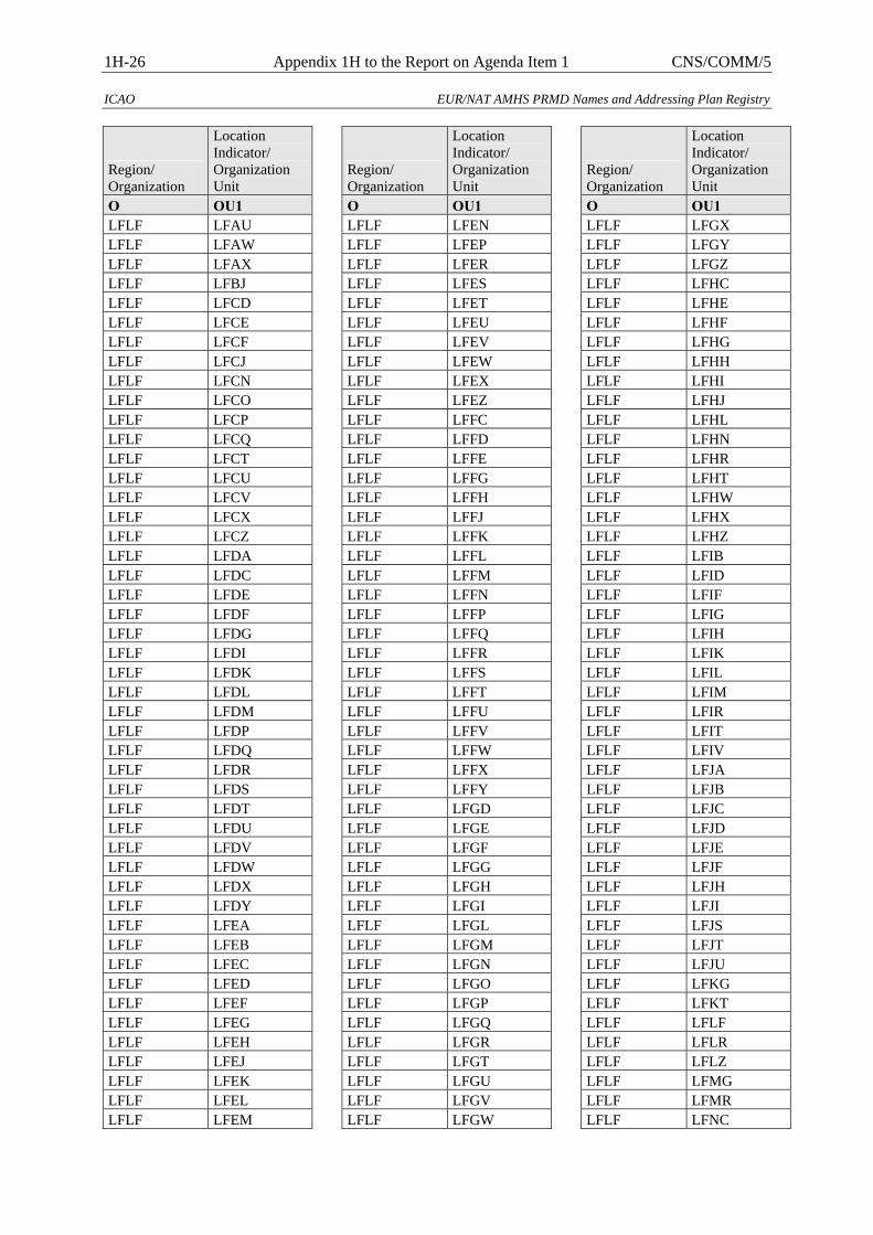
1H-26 Appendix 1H to the Report on Agenda Item 1 CNS/COMM/5
ICAO EUR/NAT AMHS PRMD Names and Addressing Plan Registry
Region/ Organization
Location Indicator/ Organization Unit
O OU1 LFLF LFAU LFLF LFAW LFLF LFAX LFLF LFBJ LFLF LFCD LFLF LFCE LFLF LFCF LFLF LFCJ LFLF LFCN LFLF LFCO LFLF LFCP LFLF LFCQ LFLF LFCT LFLF LFCU LFLF LFCV LFLF LFCX LFLF LFCZ LFLF LFDA LFLF LFDC LFLF LFDE LFLF LFDF LFLF LFDG LFLF LFDI LFLF LFDK LFLF LFDL LFLF LFDM LFLF LFDP LFLF LFDQ LFLF LFDR LFLF LFDS LFLF LFDT LFLF LFDU LFLF LFDV LFLF LFDW LFLF LFDX LFLF LFDY LFLF LFEA LFLF LFEB LFLF LFEC LFLF LFED LFLF LFEF LFLF LFEG LFLF LFEH LFLF LFEJ LFLF LFEK LFLF LFEL LFLF LFEM
Region/ Organization
Location Indicator/ Organization Unit
O OU1 LFLF LFEN LFLF LFEP LFLF LFER LFLF LFES LFLF LFET LFLF LFEU LFLF LFEV LFLF LFEW LFLF LFEX LFLF LFEZ LFLF LFFC LFLF LFFD LFLF LFFE LFLF LFFG LFLF LFFH LFLF LFFJ LFLF LFFK LFLF LFFL LFLF LFFM LFLF LFFN LFLF LFFP LFLF LFFQ LFLF LFFR LFLF LFFS LFLF LFFT LFLF LFFU LFLF LFFV LFLF LFFW LFLF LFFX LFLF LFFY LFLF LFGD LFLF LFGE LFLF LFGF LFLF LFGG LFLF LFGH LFLF LFGI LFLF LFGL LFLF LFGM LFLF LFGN LFLF LFGO LFLF LFGP LFLF LFGQ LFLF LFGR LFLF LFGT LFLF LFGU LFLF LFGV LFLF LFGW
Region/ Organization
Location Indicator/ Organization Unit
O OU1 LFLF LFGX LFLF LFGY LFLF LFGZ LFLF LFHC LFLF LFHE LFLF LFHF LFLF LFHG LFLF LFHH LFLF LFHI LFLF LFHJ LFLF LFHL LFLF LFHN LFLF LFHR LFLF LFHT LFLF LFHW LFLF LFHX LFLF LFHZ LFLF LFIB LFLF LFID LFLF LFIF LFLF LFIG LFLF LFIH LFLF LFIK LFLF LFIL LFLF LFIM LFLF LFIR LFLF LFIT LFLF LFIV LFLF LFJA LFLF LFJB LFLF LFJC LFLF LFJD LFLF LFJE LFLF LFJF LFLF LFJH LFLF LFJI LFLF LFJS LFLF LFJT LFLF LFJU LFLF LFKG LFLF LFKT LFLF LFLF LFLF LFLR LFLF LFLZ LFLF LFMG LFLF LFMR LFLF LFNC
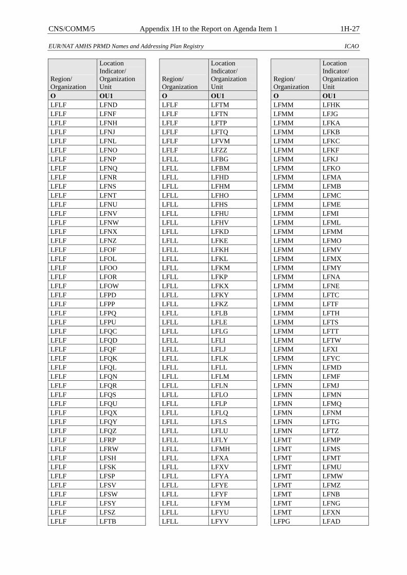
CNS/COMM/5 Appendix 1H to the Report on Agenda Item 1 1H-27
EUR/NAT AMHS PRMD Names and Addressing Plan Registry ICAO
Region/ Organization
Location Indicator/ Organization Unit
O OU1 LFLF LFND LFLF LFNF LFLF LFNH LFLF LFNJ LFLF LFNL LFLF LFNO LFLF LFNP LFLF LFNQ LFLF LFNR LFLF LFNS LFLF LFNT LFLF LFNU LFLF LFNV LFLF LFNW LFLF LFNX LFLF LFNZ LFLF LFOF LFLF LFOL LFLF LFOO LFLF LFOR LFLF LFOW LFLF LFPD LFLF LFPP LFLF LFPQ LFLF LFPU LFLF LFQC LFLF LFQD LFLF LFQF LFLF LFQK LFLF LFQL LFLF LFQN LFLF LFQR LFLF LFQS LFLF LFQU LFLF LFQX LFLF LFQY LFLF LFQZ LFLF LFRP LFLF LFRW LFLF LFSH LFLF LFSK LFLF LFSP LFLF LFSV LFLF LFSW LFLF LFSY LFLF LFSZ LFLF LFTB
Region/ Organization
Location Indicator/ Organization Unit
O OU1 LFLF LFTM LFLF LFTN LFLF LFTP LFLF LFTQ LFLF LFVM LFLF LFZZ LFLL LFBG LFLL LFBM LFLL LFHD LFLL LFHM LFLL LFHO LFLL LFHS LFLL LFHU LFLL LFHV LFLL LFKD LFLL LFKE LFLL LFKH LFLL LFKL LFLL LFKM LFLL LFKP LFLL LFKX LFLL LFKY LFLL LFKZ LFLL LFLB LFLL LFLE LFLL LFLG LFLL LFLI LFLL LFLJ LFLL LFLK LFLL LFLL LFLL LFLM LFLL LFLN LFLL LFLO LFLL LFLP LFLL LFLQ LFLL LFLS LFLL LFLU LFLL LFLY LFLL LFMH LFLL LFXA LFLL LFXV LFLL LFYA LFLL LFYE LFLL LFYF LFLL LFYM LFLL LFYU LFLL LFYV
Region/ Organization
Location Indicator/ Organization Unit
O OU1 LFMM LFHK LFMM LFJG LFMM LFKA LFMM LFKB LFMM LFKC LFMM LFKF LFMM LFKJ LFMM LFKO LFMM LFMA LFMM LFMB LFMM LFMC LFMM LFME LFMM LFMI LFMM LFML LFMM LFMM LFMM LFMO LFMM LFMV LFMM LFMX LFMM LFMY LFMM LFNA LFMM LFNE LFMM LFTC LFMM LFTF LFMM LFTH LFMM LFTS LFMM LFTT LFMM LFTW LFMM LFXI LFMM LFYC LFMN LFMD LFMN LFMF LFMN LFMJ LFMN LFMN LFMN LFMQ LFMN LFNM LFMN LFTG LFMN LFTZ LFMT LFMP LFMT LFMS LFMT LFMT LFMT LFMU LFMT LFMW LFMT LFMZ LFMT LFNB LFMT LFNG LFMT LFXN LFPG LFAD
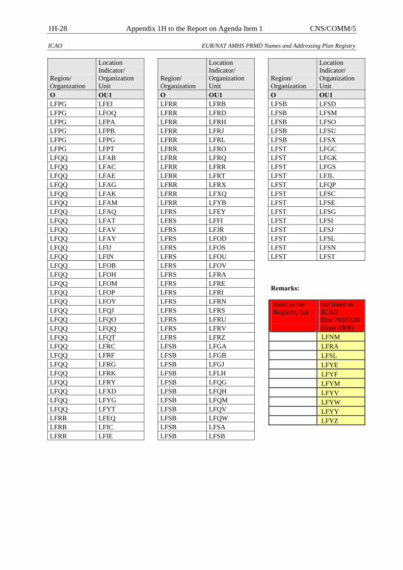
1H-28 Appendix 1H to the Report on Agenda Item 1 CNS/COMM/5
ICAO EUR/NAT AMHS PRMD Names and Addressing Plan Registry
Region/ Organization
Location Indicator/ Organization Unit
O OU1 LFPG LFEI LFPG LFOQ LFPG LFPA LFPG LFPB LFPG LFPG LFPG LFPT LFQQ LFAB LFQQ LFAC LFQQ LFAE LFQQ LFAG LFQQ LFAK LFQQ LFAM LFQQ LFAQ LFQQ LFAT LFQQ LFAV LFQQ LFAY LFQQ LFIJ LFQQ LFIN LFQQ LFOB LFQQ LFOH LFQQ LFOM LFQQ LFOP LFQQ LFOY LFQQ LFQJ LFQQ LFQO LFQQ LFQQ LFQQ LFQT LFQQ LFRC LFQQ LFRF LFQQ LFRG LFQQ LFRK LFQQ LFRY LFQQ LFXD LFQQ LFYG LFQQ LFYT LFRR LFEQ LFRR LFIC LFRR LFIE
Region/ Organization
Location Indicator/ Organization Unit
O OU1 LFRR LFRB LFRR LFRD LFRR LFRH LFRR LFRJ LFRR LFRL LFRR LFRO LFRR LFRQ LFRR LFRR LFRR LFRT LFRR LFRX LFRR LFXQ LFRR LFYB LFRS LFEY LFRS LFFI LFRS LFJR LFRS LFOD LFRS LFOS LFRS LFOU LFRS LFOV LFRS LFRA LFRS LFRE LFRS LFRI LFRS LFRN LFRS LFRS LFRS LFRU LFRS LFRV LFRS LFRZ LFSB LFGA LFSB LFGB LFSB LFGJ LFSB LFLH LFSB LFQG LFSB LFQH LFSB LFQM LFSB LFQV LFSB LFQW LFSB LFSA LFSB LFSB
Region/ Organization
Location Indicator/ Organization Unit
O OU1 LFSB LFSD LFSB LFSM LFSB LFSO LFSB LFSU LFSB LFSX LFST LFGC LFST LFGK LFST LFGS LFST LFJL LFST LFQP LFST LFSC LFST LFSE LFST LFSG LFST LFSI LFST LFSJ LFST LFSL LFST LFSN LFST LFST Remarks: listed in the Registry, but
not listed in ICAO Doc 7910/120(June 2006)
LFNM LFRA LFSL LFYE LFYF LFYM LFYV LFYW LFYY LFYZ
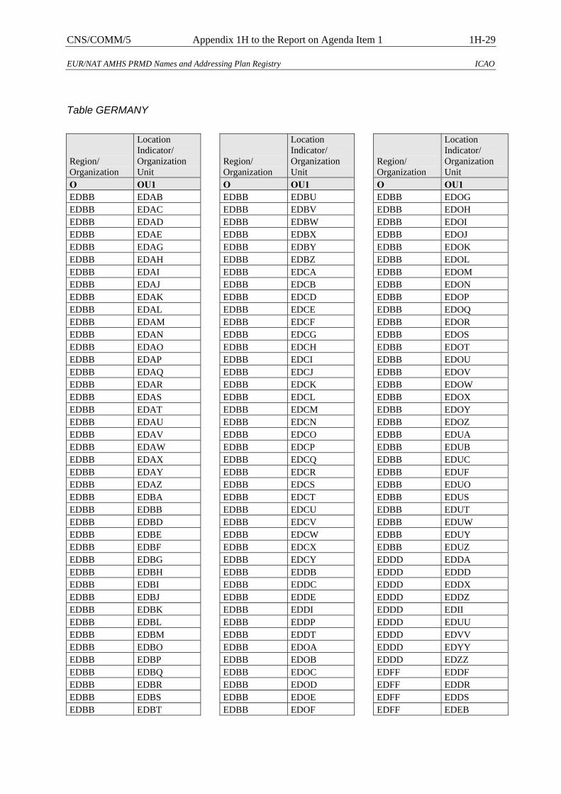
CNS/COMM/5 Appendix 1H to the Report on Agenda Item 1 1H-29
EUR/NAT AMHS PRMD Names and Addressing Plan Registry ICAO
Table GERMANY
Region/ Organization
Location Indicator/ Organization Unit
O OU1 EDBB EDAB EDBB EDAC EDBB EDAD EDBB EDAE EDBB EDAG EDBB EDAH EDBB EDAI EDBB EDAJ EDBB EDAK EDBB EDAL EDBB EDAM EDBB EDAN EDBB EDAO EDBB EDAP EDBB EDAQ EDBB EDAR EDBB EDAS EDBB EDAT EDBB EDAU EDBB EDAV EDBB EDAW EDBB EDAX EDBB EDAY EDBB EDAZ EDBB EDBA EDBB EDBB EDBB EDBD EDBB EDBE EDBB EDBF EDBB EDBG EDBB EDBH EDBB EDBI EDBB EDBJ EDBB EDBK EDBB EDBL EDBB EDBM EDBB EDBO EDBB EDBP EDBB EDBQ EDBB EDBR EDBB EDBS EDBB EDBT
Region/ Organization
Location Indicator/ Organization Unit
O OU1 EDBB EDBU EDBB EDBV EDBB EDBW EDBB EDBX EDBB EDBY EDBB EDBZ EDBB EDCA EDBB EDCB EDBB EDCD EDBB EDCE EDBB EDCF EDBB EDCG EDBB EDCH EDBB EDCI EDBB EDCJ EDBB EDCK EDBB EDCL EDBB EDCM EDBB EDCN EDBB EDCO EDBB EDCP EDBB EDCQ EDBB EDCR EDBB EDCS EDBB EDCT EDBB EDCU EDBB EDCV EDBB EDCW EDBB EDCX EDBB EDCY EDBB EDDB EDBB EDDC EDBB EDDE EDBB EDDI EDBB EDDP EDBB EDDT EDBB EDOA EDBB EDOB EDBB EDOC EDBB EDOD EDBB EDOE EDBB EDOF
Region/ Organization
Location Indicator/ Organization Unit
O OU1 EDBB EDOG EDBB EDOH EDBB EDOI EDBB EDOJ EDBB EDOK EDBB EDOL EDBB EDOM EDBB EDON EDBB EDOP EDBB EDOQ EDBB EDOR EDBB EDOS EDBB EDOT EDBB EDOU EDBB EDOV EDBB EDOW EDBB EDOX EDBB EDOY EDBB EDOZ EDBB EDUA EDBB EDUB EDBB EDUC EDBB EDUF EDBB EDUO EDBB EDUS EDBB EDUT EDBB EDUW EDBB EDUY EDBB EDUZ EDDD EDDA EDDD EDDD EDDD EDDX EDDD EDDZ EDDD EDII EDDD EDUU EDDD EDVV EDDD EDYY EDDD EDZZ EDFF EDDF EDFF EDDR EDFF EDDS EDFF EDEB
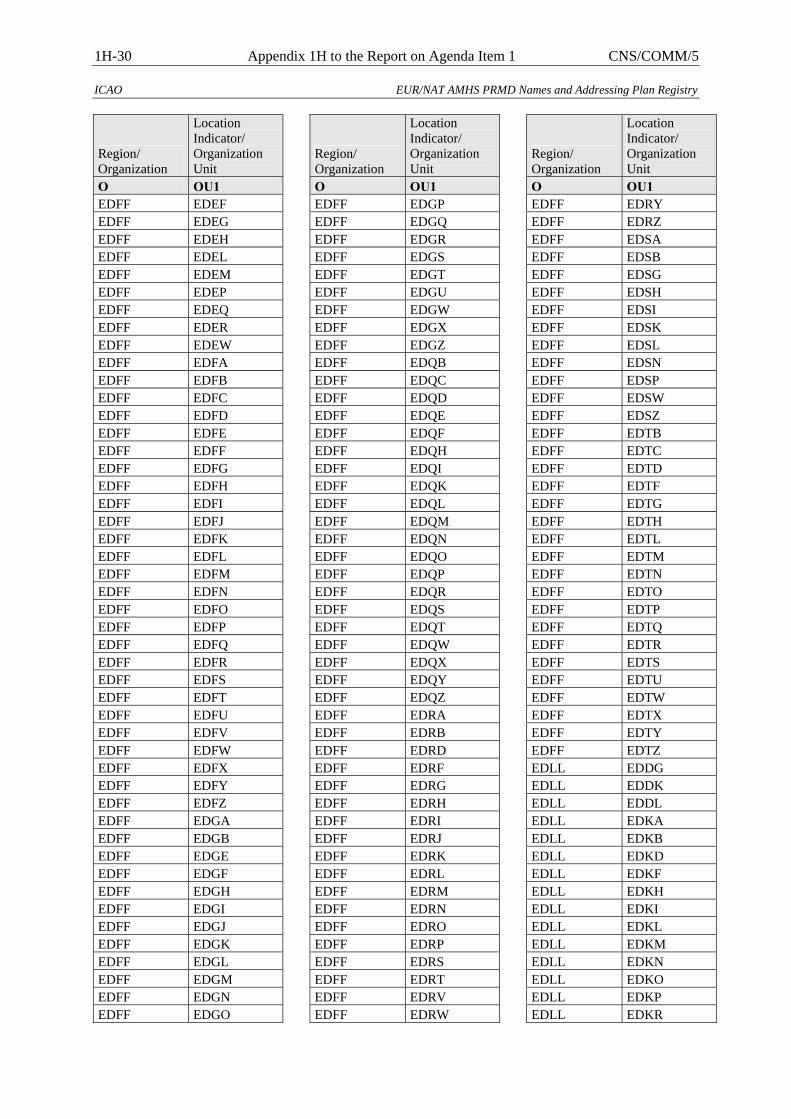
1H-30 Appendix 1H to the Report on Agenda Item 1 CNS/COMM/5
ICAO EUR/NAT AMHS PRMD Names and Addressing Plan Registry
Region/ Organization
Location Indicator/ Organization Unit
O OU1 EDFF EDEF EDFF EDEG EDFF EDEH EDFF EDEL EDFF EDEM EDFF EDEP EDFF EDEQ EDFF EDER EDFF EDEW EDFF EDFA EDFF EDFB EDFF EDFC EDFF EDFD EDFF EDFE EDFF EDFF EDFF EDFG EDFF EDFH EDFF EDFI EDFF EDFJ EDFF EDFK EDFF EDFL EDFF EDFM EDFF EDFN EDFF EDFO EDFF EDFP EDFF EDFQ EDFF EDFR EDFF EDFS EDFF EDFT EDFF EDFU EDFF EDFV EDFF EDFW EDFF EDFX EDFF EDFY EDFF EDFZ EDFF EDGA EDFF EDGB EDFF EDGE EDFF EDGF EDFF EDGH EDFF EDGI EDFF EDGJ EDFF EDGK EDFF EDGL EDFF EDGM EDFF EDGN EDFF EDGO
Region/ Organization
Location Indicator/ Organization Unit
O OU1 EDFF EDGP EDFF EDGQ EDFF EDGR EDFF EDGS EDFF EDGT EDFF EDGU EDFF EDGW EDFF EDGX EDFF EDGZ EDFF EDQB EDFF EDQC EDFF EDQD EDFF EDQE EDFF EDQF EDFF EDQH EDFF EDQI EDFF EDQK EDFF EDQL EDFF EDQM EDFF EDQN EDFF EDQO EDFF EDQP EDFF EDQR EDFF EDQS EDFF EDQT EDFF EDQW EDFF EDQX EDFF EDQY EDFF EDQZ EDFF EDRA EDFF EDRB EDFF EDRD EDFF EDRF EDFF EDRG EDFF EDRH EDFF EDRI EDFF EDRJ EDFF EDRK EDFF EDRL EDFF EDRM EDFF EDRN EDFF EDRO EDFF EDRP EDFF EDRS EDFF EDRT EDFF EDRV EDFF EDRW
Region/ Organization
Location Indicator/ Organization Unit
O OU1 EDFF EDRY EDFF EDRZ EDFF EDSA EDFF EDSB EDFF EDSG EDFF EDSH EDFF EDSI EDFF EDSK EDFF EDSL EDFF EDSN EDFF EDSP EDFF EDSW EDFF EDSZ EDFF EDTB EDFF EDTC EDFF EDTD EDFF EDTF EDFF EDTG EDFF EDTH EDFF EDTL EDFF EDTM EDFF EDTN EDFF EDTO EDFF EDTP EDFF EDTQ EDFF EDTR EDFF EDTS EDFF EDTU EDFF EDTW EDFF EDTX EDFF EDTY EDFF EDTZ EDLL EDDG EDLL EDDK EDLL EDDL EDLL EDKA EDLL EDKB EDLL EDKD EDLL EDKF EDLL EDKH EDLL EDKI EDLL EDKL EDLL EDKM EDLL EDKN EDLL EDKO EDLL EDKP EDLL EDKR
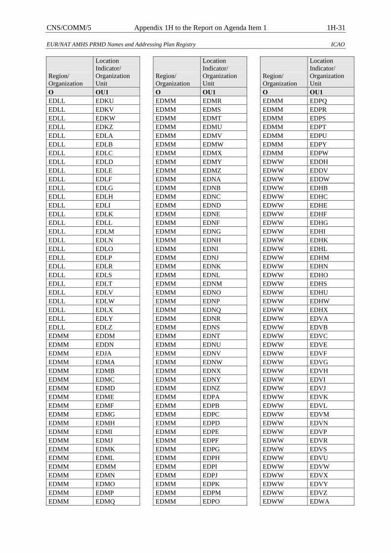
CNS/COMM/5 Appendix 1H to the Report on Agenda Item 1 1H-31
EUR/NAT AMHS PRMD Names and Addressing Plan Registry ICAO
Region/ Organization
Location Indicator/ Organization Unit
O OU1 EDLL EDKU EDLL EDKV EDLL EDKW EDLL EDKZ EDLL EDLA EDLL EDLB EDLL EDLC EDLL EDLD EDLL EDLE EDLL EDLF EDLL EDLG EDLL EDLH EDLL EDLI EDLL EDLK EDLL EDLL EDLL EDLM EDLL EDLN EDLL EDLO EDLL EDLP EDLL EDLR EDLL EDLS EDLL EDLT EDLL EDLV EDLL EDLW EDLL EDLX EDLL EDLY EDLL EDLZ EDMM EDDM EDMM EDDN EDMM EDJA EDMM EDMA EDMM EDMB EDMM EDMC EDMM EDMD EDMM EDME EDMM EDMF EDMM EDMG EDMM EDMH EDMM EDMI EDMM EDMJ EDMM EDMK EDMM EDML EDMM EDMM EDMM EDMN EDMM EDMO EDMM EDMP EDMM EDMQ
Region/ Organization
Location Indicator/ Organization Unit
O OU1 EDMM EDMR EDMM EDMS EDMM EDMT EDMM EDMU EDMM EDMV EDMM EDMW EDMM EDMX EDMM EDMY EDMM EDMZ EDMM EDNA EDMM EDNB EDMM EDNC EDMM EDND EDMM EDNE EDMM EDNF EDMM EDNG EDMM EDNH EDMM EDNI EDMM EDNJ EDMM EDNK EDMM EDNL EDMM EDNM EDMM EDNO EDMM EDNP EDMM EDNQ EDMM EDNR EDMM EDNS EDMM EDNT EDMM EDNU EDMM EDNV EDMM EDNW EDMM EDNX EDMM EDNY EDMM EDNZ EDMM EDPA EDMM EDPB EDMM EDPC EDMM EDPD EDMM EDPE EDMM EDPF EDMM EDPG EDMM EDPH EDMM EDPI EDMM EDPJ EDMM EDPK EDMM EDPM EDMM EDPO
Region/ Organization
Location Indicator/ Organization Unit
O OU1 EDMM EDPQ EDMM EDPR EDMM EDPS EDMM EDPT EDMM EDPU EDMM EDPY EDMM EDPW EDWW EDDH EDWW EDDV EDWW EDDW EDWW EDHB EDWW EDHC EDWW EDHE EDWW EDHF EDWW EDHG EDWW EDHI EDWW EDHK EDWW EDHL EDWW EDHM EDWW EDHN EDWW EDHO EDWW EDHS EDWW EDHU EDWW EDHW EDWW EDHX EDWW EDVA EDWW EDVB EDWW EDVC EDWW EDVE EDWW EDVF EDWW EDVG EDWW EDVH EDWW EDVI EDWW EDVJ EDWW EDVK EDWW EDVL EDWW EDVM EDWW EDVN EDWW EDVP EDWW EDVR EDWW EDVS EDWW EDVU EDWW EDVW EDWW EDVX EDWW EDVY EDWW EDVZ EDWW EDWA
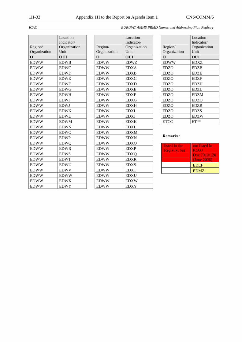
1H-32 Appendix 1H to the Report on Agenda Item 1 CNS/COMM/5
ICAO EUR/NAT AMHS PRMD Names and Addressing Plan Registry
Region/ Organization
Location Indicator/ Organization Unit
O OU1 EDWW EDWB EDWW EDWC EDWW EDWD EDWW EDWE EDWW EDWF EDWW EDWG EDWW EDWH EDWW EDWI EDWW EDWJ EDWW EDWK EDWW EDWL EDWW EDWM EDWW EDWN EDWW EDWO EDWW EDWP EDWW EDWQ EDWW EDWR EDWW EDWS EDWW EDWT EDWW EDWU EDWW EDWV EDWW EDWW EDWW EDWX EDWW EDWY
Region/ Organization
Location Indicator/ Organization Unit
O OU1 EDWW EDWZ EDWW EDXA EDWW EDXB EDWW EDXC EDWW EDXD EDWW EDXE EDWW EDXF EDWW EDXG EDWW EDXH EDWW EDXI EDWW EDXJ EDWW EDXK EDWW EDXL EDWW EDXM EDWW EDXN EDWW EDXO EDWW EDXP EDWW EDXQ EDWW EDXR EDWW EDXS EDWW EDXT EDWW EDXU EDWW EDXW EDWW EDXY
Region/ Organization
Location Indicator/ Organization Unit
O OU1 EDWW EDXZ EDZO EDZB EDZO EDZE EDZO EDZF EDZO EDZH EDZO EDZL EDZO EDZM EDZO EDZO EDZO EDZR EDZO EDZS EDZO EDZW ETCC ET** Remarks: listed in the Registry, but
not listed in ICAO Doc 7910/120(June 2006)
EDEF EDMZ

CNS/COMM/5 Appendix 1H to the Report on Agenda Item 1 1H-33
EUR/NAT AMHS PRMD Names and Addressing Plan Registry ICAO
Table OB
Region/ Organization
Location Indicator/ Organization Unit
O OU1 BAHRAIN DEFENCE FORCE OBBS CIVIL AVIATION AFFAIRS OBBB CIVIL AVIATION AFFAIRS OBBI
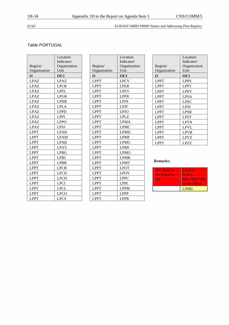
1H-34 Appendix 1H to the Report on Agenda Item 1 CNS/COMM/5
ICAO EUR/NAT AMHS PRMD Names and Addressing Plan Registry
Table PORTUGAL
Region/ Organization
Location Indicator/ Organization Unit
O OU1 LPAZ LPAZ LPAZ LPCR LPAZ LPFL LPAZ LPGR LPAZ LPHR LPAZ LPLA LPAZ LPPD LPAZ LPPI LPAZ LPPO LPAZ LPSJ LPPT LPAB LPPT LPAM LPPT LPAR LPPT LPAV LPPT LPBG LPPT LPBJ LPPT LPBR LPPT LPCB LPPT LPCD LPPT LPCH LPPT LPCI LPPT LPCL LPPT LPCO LPPT LPCS
Region/ Organization
Location Indicator/ Organization Unit
O OU1 LPPT LPCV LPPT LPER LPPT LPEV LPPT LPFR LPPT LPIN LPPT LPJF LPPT LPJO LPPT LPLZ LPPT LPMA LPPT LPMC LPPT LPMD LPPT LPMF LPPT LPMG LPPT LPMI LPPT LPMO LPPT LPMR LPPT LPMT LPPT LPOT LPPT LPOV LPPT LPPC LPPT LPPL LPPT LPPM LPPT LPPP LPPT LPPR
Region/ Organization
Location Indicator/ Organization Unit
O OU1 LPPT LPPS LPPT LPPT LPPT LPPV LPPT LPSA LPPT LPSC LPPT LPSI LPPT LPSR LPPT LPST LPPT LPTN LPPT LPVL LPPT LPVR LPPT LPVZ LPPT LPZZ
Remarks: Not listed in the Registry, but
listed in ICAO Doc 7910/120(June 2006)
LPMU
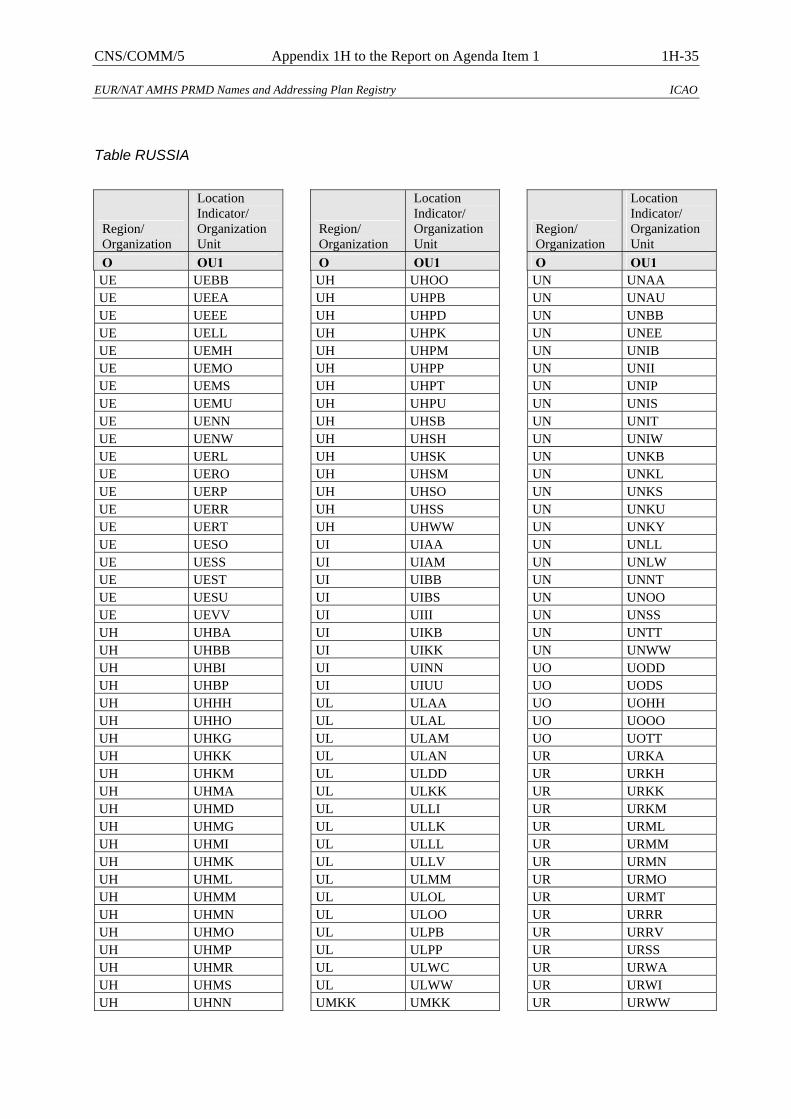
CNS/COMM/5 Appendix 1H to the Report on Agenda Item 1 1H-35
EUR/NAT AMHS PRMD Names and Addressing Plan Registry ICAO
Table RUSSIA
Region/ Organization
Location Indicator/ Organization Unit
O OU1 UE UEBB UE UEEA UE UEEE UE UELL UE UEMH UE UEMO UE UEMS UE UEMU UE UENN UE UENW UE UERL UE UERO UE UERP UE UERR UE UERT UE UESO UE UESS UE UEST UE UESU UE UEVV UH UHBA UH UHBB UH UHBI UH UHBP UH UHHH UH UHHO UH UHKG UH UHKK UH UHKM UH UHMA UH UHMD UH UHMG UH UHMI UH UHMK UH UHML UH UHMM UH UHMN UH UHMO UH UHMP UH UHMR UH UHMS UH UHNN
Region/ Organization
Location Indicator/ Organization Unit
O OU1 UH UHOO UH UHPB UH UHPD UH UHPK UH UHPM UH UHPP UH UHPT UH UHPU UH UHSB UH UHSH UH UHSK UH UHSM UH UHSO UH UHSS UH UHWW UI UIAA UI UIAM UI UIBB UI UIBS UI UIII UI UIKB UI UIKK UI UINN UI UIUU UL ULAA UL ULAL UL ULAM UL ULAN UL ULDD UL ULKK UL ULLI UL ULLK UL ULLL UL ULLV UL ULMM UL ULOL UL ULOO UL ULPB UL ULPP UL ULWC UL ULWW UMKK UMKK
Region/ Organization
Location Indicator/ Organization Unit
O OU1 UN UNAA UN UNAU UN UNBB UN UNEE UN UNIB UN UNII UN UNIP UN UNIS UN UNIT UN UNIW UN UNKB UN UNKL UN UNKS UN UNKU UN UNKY UN UNLL UN UNLW UN UNNT UN UNOO UN UNSS UN UNTT UN UNWW UO UODD UO UODS UO UOHH UO UOOO UO UOTT UR URKA UR URKH UR URKK UR URKM UR URML UR URMM UR URMN UR URMO UR URMT UR URRR UR URRV UR URSS UR URWA UR URWI UR URWW
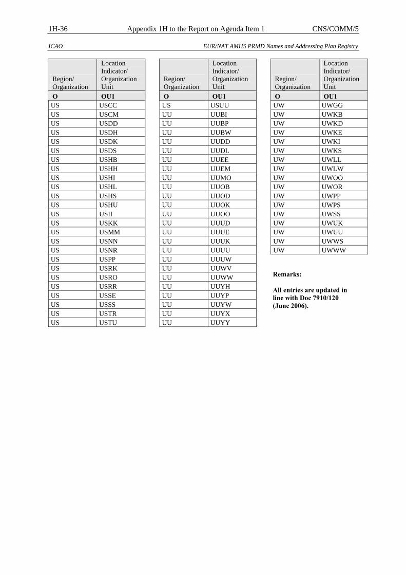
1H-36 Appendix 1H to the Report on Agenda Item 1 CNS/COMM/5
ICAO EUR/NAT AMHS PRMD Names and Addressing Plan Registry
Region/ Organization
Location Indicator/ Organization Unit
O OU1 US USCC US USCM US USDD US USDH US USDK US USDS US USHB US USHH US USHI US USHL US USHS US USHU US USII US USKK US USMM US USNN US USNR US USPP US USRK US USRO US USRR US USSE US USSS US USTR US USTU
Region/ Organization
Location Indicator/ Organization Unit
O OU1 US USUU UU UUBI UU UUBP UU UUBW UU UUDD UU UUDL UU UUEE UU UUEM UU UUMO UU UUOB UU UUOD UU UUOK UU UUOO UU UUUD UU UUUE UU UUUK UU UUUU UU UUUW UU UUWV UU UUWW UU UUYH UU UUYP UU UUYW UU UUYX UU UUYY
Region/ Organization
Location Indicator/ Organization Unit
O OU1 UW UWGG UW UWKB UW UWKD UW UWKE UW UWKI UW UWKS UW UWLL UW UWLW UW UWOO UW UWOR UW UWPP UW UWPS UW UWSS UW UWUK UW UWUU UW UWWS UW UWWW Remarks: All entries are updated in line with Doc 7910/120 (June 2006).
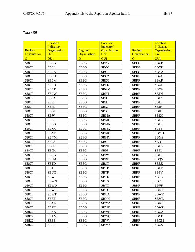
CNS/COMM/5 Appendix 1H to the Report on Agenda Item 1 1H-37
Table SB
Region/ Organisation
Location Indicator/ Organisation Unit
O OU1 SBCT SBBG SBCT SBBI SBCT SBCA SBCT SBCH SBCT SBCM SBCT SBCO SBCT SBCT SBCT SBCW SBCT SBCX SBCT SBFI SBCT SBFL SBCT SBGU SBCT SBJV SBCT SBLJ SBCT SBLO SBCT SBMG SBCT SBNF SBCT SBNM SBCT SBPA SBCT SBPF SBCT SBPK SBCT SBRG SBCT SBSM SBCT SBTD SBCT SBTL SBCT SBUG SBCT SBWI SBCT SBWN SBCT SBWO SBCT SBWP SBCT SBWT SBCT SBXF SBCT SBXL SBCT SBXO SBEG SBAA SBEG SBAM SBEG SBBE SBEG SBBL
Region/ Organisation
Location Indicator/ Organisation Unit
O OU1 SBEG SBBV SBEG SBCC SBEG SBCJ SBEG SBCZ SBEG SBEG SBEG SBEK SBEG SBGM SBEG SBHT SBEG SBIC SBEG SBIH SBEG SBIZ SBEG SBJC SBEG SBMA SBEG SBMD SBEG SBMN SBEG SBMQ SBEG SBMU SBEG SBMY SBEG SBOL SBEG SBPH SBEG SBPJ SBEG SBPV SBEG SBRB SBEG SBSN SBEG SBTB SBEG SBTF SBEG SBTK SBEG SBTS SBEG SBTT SBEG SBTU SBEG SBUA SBEG SBVH SBEG SBWA SBEG SBWB SBEG SBWN SBEG SBWQ SBEG SBWV SBEG SBWX
Region/ Organisation
Location Indicator/ Organisation Unit
O OU1 SBEG SBXB SBEG SBXH SBEG SBYA SBRF SBAO SBRF SBAR SBRF SBCI SBRF SBCV SBRF SBFN SBRF SBFZ SBRF SBIL SBRF SBJP SBRF SBJU SBRF SBKG SBRF SBLE SBRF SBLP SBRF SBLS SBRF SBMO SBRF SBMS SBRF SBNT SBRF SBPB SBRF SBPL SBRF SBPS SBRF SBQV SBRF SBRE SBRF SBRF SBRF SBSV SBRF SBTC SBRF SBTE SBRF SBUF SBRF SBWF SBRF SBWK SBRF SBWL SBRF SBWS SBRF SBWZ SBRF SBXA SBRF SBXE SBRF SBXM SBRF SBXS
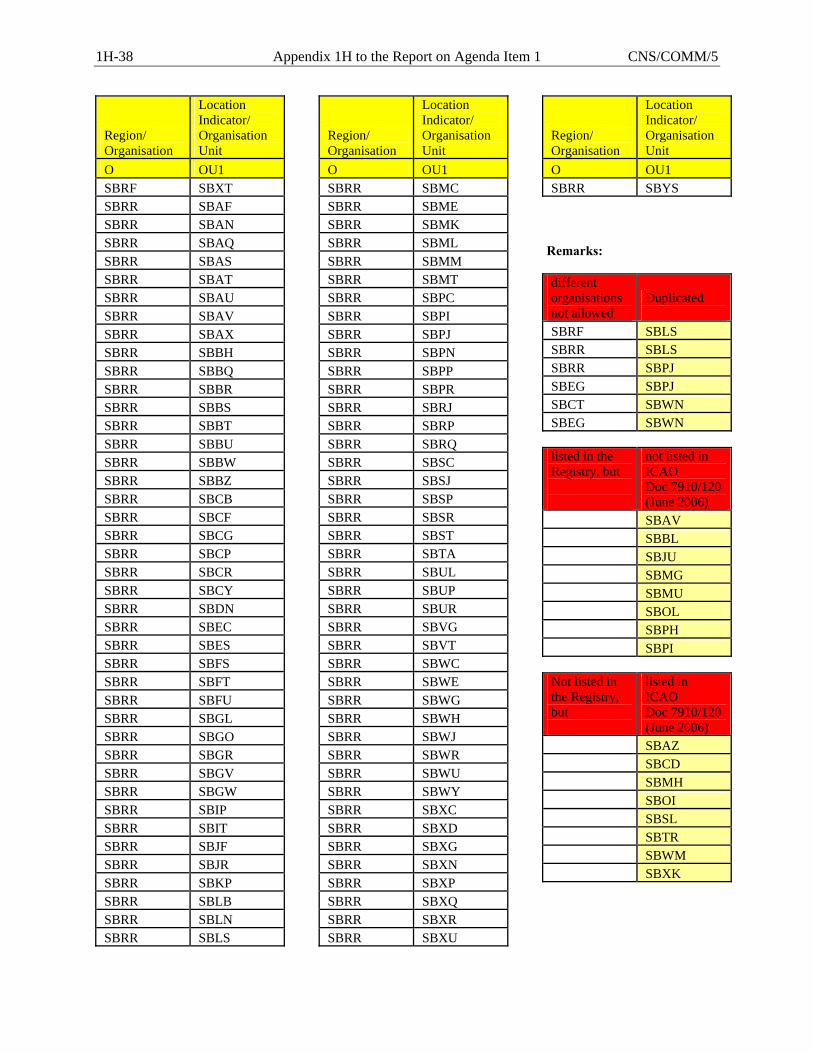
1H-38 Appendix 1H to the Report on Agenda Item 1 CNS/COMM/5
Region/ Organisation
Location Indicator/ Organisation Unit
O OU1 SBRF SBXT SBRR SBAF SBRR SBAN SBRR SBAQ SBRR SBAS SBRR SBAT SBRR SBAU SBRR SBAV SBRR SBAX SBRR SBBH SBRR SBBQ SBRR SBBR SBRR SBBS SBRR SBBT SBRR SBBU SBRR SBBW SBRR SBBZ SBRR SBCB SBRR SBCF SBRR SBCG SBRR SBCP SBRR SBCR SBRR SBCY SBRR SBDN SBRR SBEC SBRR SBES SBRR SBFS SBRR SBFT SBRR SBFU SBRR SBGL SBRR SBGO SBRR SBGR SBRR SBGV SBRR SBGW SBRR SBIP SBRR SBIT SBRR SBJF SBRR SBJR SBRR SBKP SBRR SBLB SBRR SBLN SBRR SBLS
Region/ Organisation
Location Indicator/ Organisation Unit
O OU1 SBRR SBMC SBRR SBME SBRR SBMK SBRR SBML SBRR SBMM SBRR SBMT SBRR SBPC SBRR SBPI SBRR SBPJ SBRR SBPN SBRR SBPP SBRR SBPR SBRR SBRJ SBRR SBRP SBRR SBRQ SBRR SBSC SBRR SBSJ SBRR SBSP SBRR SBSR SBRR SBST SBRR SBTA SBRR SBUL SBRR SBUP SBRR SBUR SBRR SBVG SBRR SBVT SBRR SBWC SBRR SBWE SBRR SBWG SBRR SBWH SBRR SBWJ SBRR SBWR SBRR SBWU SBRR SBWY SBRR SBXC SBRR SBXD SBRR SBXG SBRR SBXN SBRR SBXP SBRR SBXQ SBRR SBXR SBRR SBXU
Region/ Organisation
Location Indicator/ Organisation Unit
O OU1 SBRR SBYS
Remarks: different organisations not allowed
Duplicated
SBRF SBLS SBRR SBLS SBRR SBPJ SBEG SBPJ SBCT SBWN SBEG SBWN
listed in the Registry, but
not listed in ICAO Doc 7910/120(June 2006)
SBAV SBBL SBJU SBMG SBMU SBOL SBPH SBPI
Not listed in the Registry, but
listed in ICAO Doc 7910/120(June 2006)
SBAZ SBCD SBMH SBOI SBSL SBTR SBWM SBXK
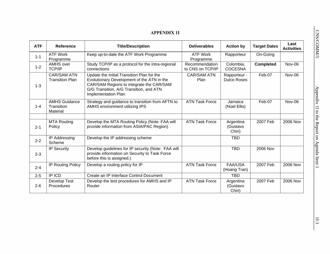
C
NS/C
OM
M/5
Appendix 1I to the R
eport on Agenda Item
1 1I-1
APPENDIX 1I
ATF Reference Title/Description Deliverables Action by Target Dates Last Activities
1-1 ATF Work Programme
Keep up-to-date the ATF Work Programme ATF Work Programme
Rapporteur On-Going
1-2 AMHS over TCP/IP
Study TCP/IP as a protocol for the intra-regional connections
Recommendation to CNS on TCP/IP
Colombia, COCESNA
Completed Nov-06
1-3
CAR/SAM ATN Transition Plan
Update the Initial Transition Plan for the Evolutionary Development of the ATN in the CAR/SAM Regions to integrate the CAR/SAM G/G Transition, A/G Transition, and ATN Implementation Plan
CAR/SAM ATN Plan
Rapporteur - Dulce Roses
Feb-07 Nov-06
1-4 AMHS Guidance Transition Material
Strategy and guidance to transition from AFTN to AMHS environment utilizing IPS
ATN Task Force Jamaica (Noel Ellis)
Feb-07 Nov-06
2-1 MTA Routing Policy
Develop the MTA Routing Policy (Note: FAA will provide information from ASIA/PAC Region)
ATN Task Force Argentina (Gustavo
Chiri)
2007 Feb 2006 Nov
2-2 IP Addressing Scheme
Develop the IP addressing scheme TBD
2-3 IP Security Develop guidelines for IP security (Note: FAA will
provide information on Security to Task Force before this is assigned.)
TBD 2006 Nov
2-4 IP Routing Policy Develop a routing policy for IP ATN Task Force FAA/USA
(Hoang Tran) 2007 Feb 2006 Nov
2-5 IP ICD Create an IP Interface Control Document TBD
2-6 Develop Test Procedures
Develop the test procedures for AMHS and IP Router
ATN Task Force Argentina (Gustavo
Chiri)
2007 Feb 2006 Nov
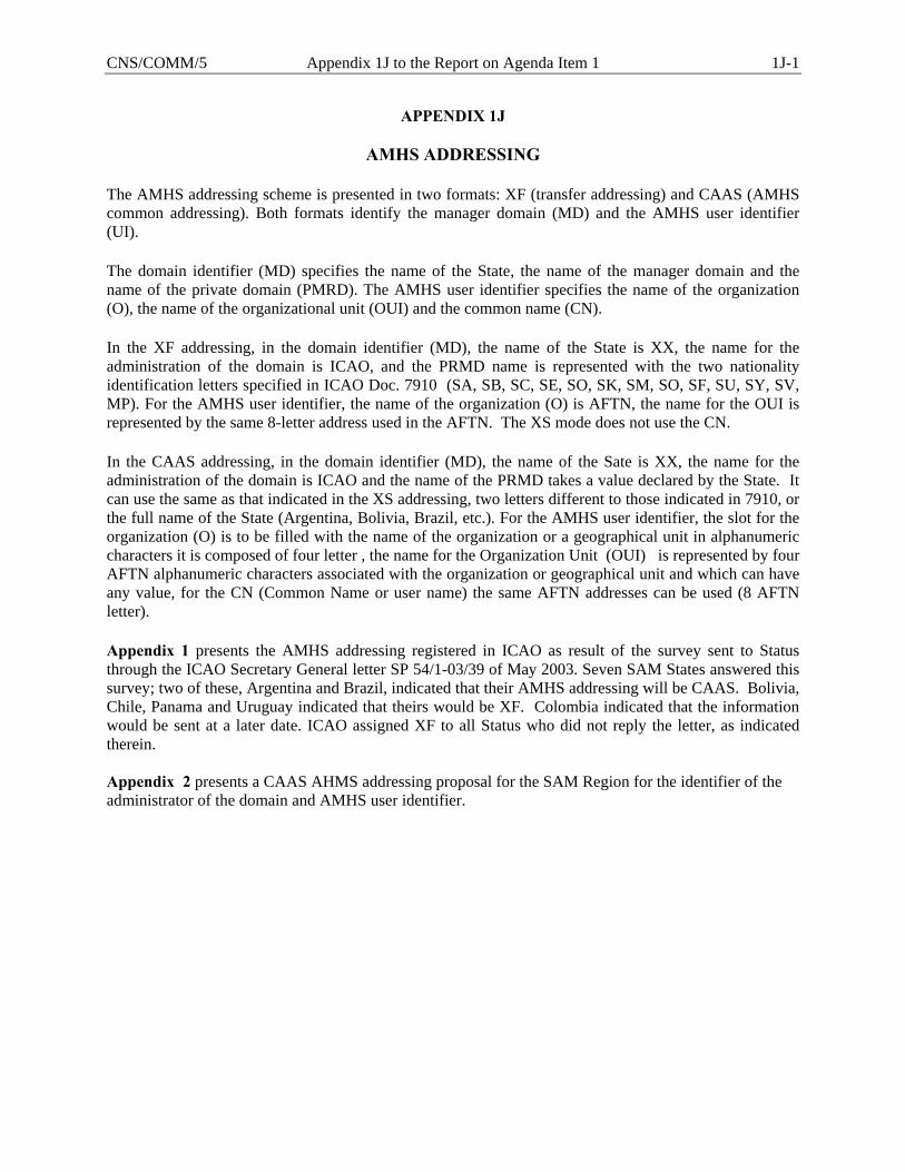
CNS/COMM/5 Appendix 1J to the Report on Agenda Item 1 1J-1
APPENDIX 1J
AMHS ADDRESSING The AMHS addressing scheme is presented in two formats: XF (transfer addressing) and CAAS (AMHS common addressing). Both formats identify the manager domain (MD) and the AMHS user identifier (UI). The domain identifier (MD) specifies the name of the State, the name of the manager domain and the name of the private domain (PMRD). The AMHS user identifier specifies the name of the organization (O), the name of the organizational unit (OUI) and the common name (CN). In the XF addressing, in the domain identifier (MD), the name of the State is XX, the name for the administration of the domain is ICAO, and the PRMD name is represented with the two nationality identification letters specified in ICAO Doc. 7910 (SA, SB, SC, SE, SO, SK, SM, SO, SF, SU, SY, SV, MP). For the AMHS user identifier, the name of the organization (O) is AFTN, the name for the OUI is represented by the same 8-letter address used in the AFTN. The XS mode does not use the CN. In the CAAS addressing, in the domain identifier (MD), the name of the Sate is XX, the name for the administration of the domain is ICAO and the name of the PRMD takes a value declared by the State. It can use the same as that indicated in the XS addressing, two letters different to those indicated in 7910, or the full name of the State (Argentina, Bolivia, Brazil, etc.). For the AMHS user identifier, the slot for the organization (O) is to be filled with the name of the organization or a geographical unit in alphanumeric characters it is composed of four letter , the name for the Organization Unit (OUI) is represented by four AFTN alphanumeric characters associated with the organization or geographical unit and which can have any value, for the CN (Common Name or user name) the same AFTN addresses can be used (8 AFTN letter). Appendix 1 presents the AMHS addressing registered in ICAO as result of the survey sent to Status through the ICAO Secretary General letter SP 54/1-03/39 of May 2003. Seven SAM States answered this survey; two of these, Argentina and Brazil, indicated that their AMHS addressing will be CAAS. Bolivia, Chile, Panama and Uruguay indicated that theirs would be XF. Colombia indicated that the information would be sent at a later date. ICAO assigned XF to all Status who did not reply the letter, as indicated therein. Appendix 2 presents a CAAS AHMS addressing proposal for the SAM Region for the identifier of the administrator of the domain and AMHS user identifier.
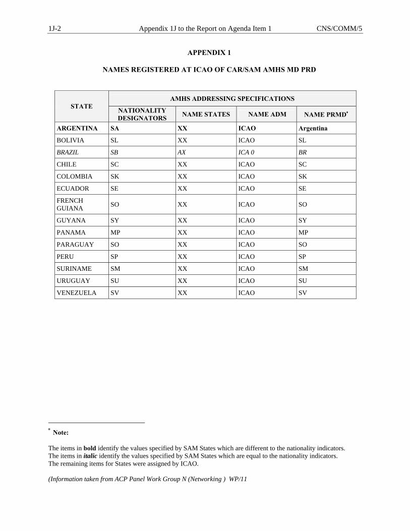
1J-2 Appendix 1J to the Report on Agenda Item 1 CNS/COMM/5
APPENDIX 1
NAMES REGISTERED AT ICAO OF CAR/SAM AMHS MD PRD
AMHS ADDRESSING SPECIFICATIONS STATE NATIONALITY
DESIGNATORS NAME STATES NAME ADM NAME PRMD∗
ARGENTINA SA XX ICAO Argentina
BOLIVIA SL XX ICAO SL
BRAZIL SB AX ICA 0 BR
CHILE SC XX ICAO SC
COLOMBIA SK XX ICAO SK
ECUADOR SE XX ICAO SE
FRENCH GUIANA SO XX ICAO SO
GUYANA SY XX ICAO SY
PANAMA MP XX ICAO MP
PARAGUAY SO XX ICAO SO
PERU SP XX ICAO SP
SURINAME SM XX ICAO SM
URUGUAY SU XX ICAO SU
VENEZUELA SV XX ICAO SV
∗ Note: The items in bold identify the values specified by SAM States which are different to the nationality indicators. The items in italic identify the values specified by SAM States which are equal to the nationality indicators. The remaining items for States were assigned by ICAO. (Information taken from ACP Panel Work Group N (Networking ) WP/11
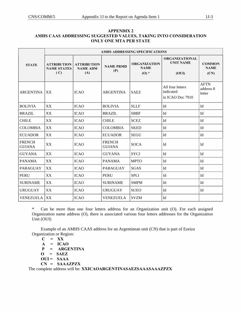
CNS/COMM/5 Appendix 1J to the Report on Agenda Item 1 1J-3
APPENDIX 2 AMHS CAAS ADDRESSING SUGGESTED VALUES, TAKING INTO CONSIDERATION
ONLY ONE MTA PER STATE
AMHS ADDRESSING SPECIFICATIONS
STATE ATTRIBUTION NAME STATES
( C)
ATTRIBUTION NAME ADM
(A)
NAME PRMD (P)
ORGANIZATION NAME (O) *
ORGANIZATIONAL UNIT NAME
(OUI)
COMMON NAME (CN)
ARGENTINA XX ICAO ARGENTINA SAEZ All four letters indicated in ICAO Doc 7910
AFTN address 8 letter
BOLIVIA XX ICAO BOLIVIA SLLF Id Id
BRAZIL XX ICAO BRAZIL SBBF Id Id
CHILE XX ICAO CHILE SCEZ Id Id
COLOMBIA XX ICAO COLOMBIA SKED Id Id
ECUADOR XX ICAO ECUADOR SEGU Id Id
FRENCH GUIANA XX ICAO FRENCH
GUIANA SOCA Id Id
GUYANA XX ICAO GUYANA SYCJ Id Id
PANAMA XX ICAO PANAMA MPTO Id Id
PARAGUAY XX ICAO PARAGUAY SGAS Id Id
PERU XX ICAO PERU SPLI Id Id
SURINAME XX ICAO SURINAME SMPM Id Id
URUGUAY XX ICAO URUGUAY SUEO Id Id
VENEZUELA XX ICAO VENEZUELA SVZM Id * Can be more than one four letters address for an Organization unit (O). For each assigned
Organization name address (O), there is associated various four letters addresses for the Organization Unit (OUI)
Example of an AMHS CAAS address for an Argentinean unit (CN) that is part of Ezeiza
Organization or Region: C = XX A = ICAO P = ARGENTINA O = SAEZ OUI = SAAA CN = SAAAZPZX The complete address will be: XXICAOARGENTINASAEZSAAASAAAZPZX
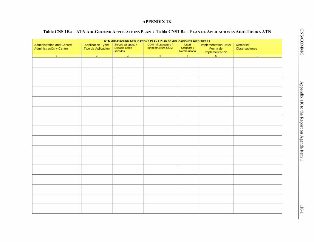
C
NS/C
OM
M/5
Appendix 1K
to the Report on A
genda Item 1
1K-1
APPENDIX 1K
Table CNS 1Ba – ATN AIR-GROUND APPLICATIONS PLAN / Tabla CNS1 Ba – PLAN DE APLICACIONES AIRE-TIERRA ATN
ATN AIR-GROUND APPLICATIONS PLAN / PLAN DE APLICACIONES AIRE-TIERRA Administration and Center/ Administración y Centro
Application Type/ Tipo de Aplicación
Served air space / Espacio aéreo servidos
COM Infrastructure / Infraestructura COM
Used Standard /
Norma usada
Implementation Date/ Fecha de
Implementación
Remarks/ Observaciones
1 2 3 4 5 6 7

CNS/COMM/5 Appendix 1L to the Report on Agenda Item 1 1L-1
APPENDIX 1L
AMHS IMPLEMENTATION PLANS IN THE CAR AND SAM REGIONS AMHS Implementation Plans in the CAR Region Date Management
Implemented COCESNA and Central American States
2007 Atlanta (United States), Puerto Rico and Trinidad and Tobago
2008 Cuba, Jamaica, Haiti and Dominican Republic
2009 Others AMHS Implementation Plans in the SAM Region Date Management
Implemented Argentina
2007 Chile, Paraguay and Peru
2008 Bolivia, Brazil, Colombia, Uruguay y Venezuela
2009 Ecuador, Guyana, French Guiana, Suriname, Uruguay and Panama
CNS/COMM/5 Appendix 1M to the Report on Agenda Item 1 1M-1
APPENDIX 1M
FEDERAL AVIATION ADMINISTRATION (FAA) BUFR CODE AMHS IMPLEMENTATION PLAN
SUMMARY
This paper conveys the background information of Binary Universal Form Representation (BUFR) code that will be used on Aeronautical Telecommunications Network/Air Traffic Service Message Handling System (ATN/AMHS) service. The FAA supports the use of User Agent Interface (IAU) to support the BUFR Coded Attachment through ATN/AMHS as depicted. The FAA continues to investigate the operational impact to adopt BUFR coded format messages, however this paper is limited to the interface between ATN/AMHS and BUFR coded messages generated system.
1. Introduction 1.1 Based on Doc7475: working arrangements between International Civil Aviation Organization (ICAO) and World Meteorological Organization (WMO), the Meteorological (MET) codes are the prerogatives of the WMO and ICAO is obliged to follow them. 1.2 Transition from Traditional Alphanumeric Code (TAC) to BUFR for Operational Meteorological Message (OPMET) was generated during the ICAO Met Division Meeting in 2002. 1.3 It is driven by the WMO plan, endorsed by at its 14th Congress in May 2003, for transition of all types of meteorological information. 1.4 Time frame, as defined by WMO, to replace the alphanumeric codes with binary code is 2007-2015. 2. Discussion 2.1 ICAO Aerodrome Meteorological Observing Systems Study Group (AMOSSG) held a meeting in April 2005 to address the adoption of the BUFR coded messages. 2.2 Aeronautical Communications Panel (ACP) was invited to develop a plan or guidance for a uniform global approach for the transition; a suggested outline of a global transition plan is as follows: 2.2.1 End of year 2007: complete Amendment 74 to Annex 3 to allow the use of BUFR code OPMET in addition to TAC between States 2.2.2 Year of 2010: complete Amendment 75 to Annex 3 to exchange/distribute BUFR data between OPMET databanks including Regional OPMET Data Banks (RODBs) sites. These provisions would be presented as Recommended Practices (RP). 2.2.3 Year of 2013: complete Amendment 76 to Annex 3 approving that the above RP becomes a standard and all states issue OPMET data in BUFR coded format to the OPMET databank as a recommended practice.
1M-2 Appendix 1M to the Report on Agenda Item 1 CNS/COMM/5
2.2.4 Year of 2016: approve Amendment 77 to Annex 3 as the recommend standard and fully implement the BUFR coded format. 2.2.5 Necessary amendments to other ICAO Docs such as Doc9705 will be require 2.2.6 Asia/Pacific Region – The ATN Implementation Co-Ordination Group has been tasked to develop the communication support for BUFR code over ATN/AMHS. APANPIRG has indicated the need to migrate to BUFR code by 2010, for use between the five OPMET data banks (Bangkok, Brisbane, Nadi, Singapore and Tokyo) in the ASIA/ PAC region (). They also acknowledged that the Basic ATN/AMHS may not be able to support BUFR coded format without modification. 2.2.7 Europe – establish a BUFR Transition Assessment Task Force (TF) in response toDecision 45/13 of the European Air Navigation Planning Group (EANPG). European region has postponed their communication planning to support BUFR code pending the final configuration of BUFR code generated system. 2.3 WMO developed a very informative paper on BUFR-coded OPMET considerations, prepared by the ICAO METG, for the upcoming Commission for Aeronautical Meteorology meeting to be held in Geneva in November this year. ICAO will also be represented at the meeting. The following are possible approaches toward implementing the BUFR coded format. 2.3.1 The OPMET text and data will be preset in a BUFR data definition table by WMO, which will be loaded and updated to the user terminals for decoding into text tokens. 2.3.2 A BUFR-coded message will contain a set of data table entries for reference to the WMO-maintained BUFR Table. Each message type is associated with a BUFR template. A decoder program and/or user application software is required for decoding and formatting the display in text. 2.3.3 The decoder program is available in source code free of charge from the WMO website. The decoder converts the BUFR table references into text. Customization of the decoder software (using the source code) for specific applications such as OPMET will be required. 2.3.4 For each type of OPMET message, WMO will develop a BUFR template with the preset data set up in the centrally maintained BUFR table. 2.3.5 Only the METAR template has been developed by WMO. Templates for AIRREP, TAF etc. would unlikely be developed by end of 2007 (Hence would not meet our program of having operational BUFR support on AMHS in 2007). 2.3.6 Even if the OPMET templates are developed on time, standardization will be required to define how the OPMET data should be converted into text format, in particular the accuracy/decimal places to be presented. This work will be substantial, but it appears that very little work, if any, has been done in this area. 2.4 The FAA believes the BUFR transition strategy, can provide support for the existing OPMET user and implementation of BUFR code using the BUFR coded attachment through the IUA and AMHS. The existing weather messages based on Aeronautical Fixed Telecommunication Network (AFTN) will continue to be supported while the BUFR coded messages will be supported by AMHS. It is envisioned that a centralized BUFR coded message decoder/encoder will be required for the processing of OPMET data to avoid incurring extraordinary costs of having a decoder/processor on each platform requiring OPMET data. The figure below depicts the ATN/AMHS configuration to distribute BUFR

CNS/COMM/5 Appendix 1M to the Report on Agenda Item 1 1M-3
coded messages. The FAA is still in the process of formulating how OPMET data in a BUFR coded message will be processed and disseminated within the National Airspace System (NAS). 3. Conclusion 3.1 The meeting is invited to note the information provided in this paper. The FAA believes the ICAO should consider adopting a standard of interface between ATN/AMHS and BUFR coded generated system. This will avoid a costly modification of ATN/AMHS needed to support BUFR Coded messages in the future.
AFTN W/S
D* D* D* D*
D*
T*
T*
T* T*
AMHS MTA
T*
AFTN System
ATN MET System
AFTNAFTN System
AMHS MTA
D* - BUFR-coded OPMET Data delivered as FTBP
T* - OPMET text message
Separate OPMET Messaging Support on AMHS and AFTN
IUA
AFTN PrinterUA
(BUFR Decode)
CNS/COMM/5 Report on Agenda Item 2 2-1
Agenda Item 2: Navigation system developments 2.1 Review of the results of the SBAS augmentation trials carried out in the CAR/SAM
regions 2.1.1 Based on the Report of the Second Meeting of the GNSS Task Force, held in Lima, Peru, from 11 to 12 November 2006, which included the review and coordination of the activities of the Projects RLA/00/009 and RLA/03/902, the Meeting considered that the GNSS implementation, including SBAS and GBAS, will have to be based on operational requirements, as well as on technical and cost/benefit analyses, that support the decision making process for this implementation. 2.1.2 The decision making on this matter has to be carried out from a common perspective, where the political aspects acquire a vital importance, mainly taking into account that the commitments of States, Territories and International Organizations who provide facilities must be firm, especially from the point of view of the legal responsibilities associated with the installation of a specific SBAS element in a determined State. 2.1.3 GNSS implementation must take into account the concept at a global level and not focus on every one of its elements separately (GPS, GBAS, SBAS, ABAS, etc). To do this, it will be necessary to add the study of the operations with the above mentioned system and contingency plans in case of local degradation of service performance. Results of the Project RLA/03/902 activities 2.1.4 The Meeting noted the information related to the Project RLA/03/902 - SACCSA, preliminary analysis results and of the network topology proposal. The Project presented the SBAS architecture and a preliminary analysis, which was based on the POLARIS tool, using nominal and flat ionosphere models. A summary of this analysis is shown in Appendix 2A to this part of the Report. 2.1.5 Also, the Meeting noted that it is necessary to announce the project to other potential, non–aeronautical users in order to analyze if their requirements can be met with SBAS implementation.
2.1.6 After the discussion and based on the SBAS solution with APV I performances that is being studied by SACCSA, the Meeting agreed that this is a technically feasible project for the CAR/SAM Regions. 2.1.7 Based on these considerations, the Meeting drafted the following Draft Conclusion:
2-2 Report on Agenda Item 2 CNS/COMM/5
DRAFT CONCLUSION CNS/5/6 APV I CAPABILITY AS A MINIMUM PERFORMANCE
REQUIREMENT FOR THE CAR/SAM REGIONAL SBAS IMPLEMENTATION
SBAS solutions proposed by the CAR/SAM Regions must be oriented to achieve at least
APV I capability. 2.1.8 Additionally, the Meeting noted that the SACCSA Project has developed the following web page: www.rlasaccsa.com. This page contains the project’s activities and results. 2.1.9 Based on the SACCSA project preliminary results and the benefit it represents for the CAR/SAM Regions, the Meeting proposed the following Draft Conclusion: DRAFT CONCLUSION CNS/5/7 RLA/03/902 PROJECT INVITATION RENEWAL FOR
NEW MEMBERS’ PARTICIPATION
All States/Territories/International organizations that have not done so are invited to: a) join Project RLA/03/902 - SACCSA, in order to obtain full benefits from the
Project; and
b) visit the following web page of SACCSA Project: www.rlasaccsa.com. 2.1.10 The Meeting took note that the Member of Chile announced during the Task Force Meeting the decision of his State to sign and participate in the RLA/03/902 – SACCSA project. Also, the Meeting was informed that Dominican Republic and Venezuela announced during the RCC/4 Meeting of this project, carried out in Lima, Peru, on September 2006, their respective decisions to join this project. 2.1.11 The Meeting was also informed that the SACCSA has finished the first package of three projects, including the collection of performance and requirement information, the definition of system requirements and the studies for the development of a regional SBAS. Appendix 2A to this part of the Report includes a summary of the work performed under the SACCSA activities.
Final results of RLA/00/009 Project 2.1.12 When analyzing the RLA/00/009 Project preliminary final report, the Meeting considered that it contemplated important aspects such as the availability of the data collected through the CAR/SAM augmentation test bed (CSTB), as well as the GNSS procedures analysis for non-precision operations by lateral navigation (LNAV). 2.1.13 The Meeting took note that the data was collected from the thirteen reference stations (TRS) that form the CSTB augmentation test bed and was transmitted to the FAA Technological Center in Atlantic City through the CSTB communications bed.
CNS/COMM/5 Report on Agenda Item 2 2-3
2.1.14 The data was collected for a three-year period from 2002 to 2005. Figures 24 to 29 of Chapter 3 of RLA/00/009 preliminary report present all the available data collected during the three year period. Appendix 2B to this agenda item contains the Final Report of the RLA/00/009 project. 2.1.15 The data is stored on DVDs in the FAA Technological Center in Atlantic City and is available upon request for States/Organizations participating in RLA/00/009 project, as well as for other participants in the GREPECAS mechanism. GNSS procedures analysis for Non-Precision Approach for LNAV Operations 2.1.16 The Meeting noted the results of the studies for GNSS procedures for Non-Precision Approach (NPA) for Lateral Navigation (LNAV) Operations which were summarized in three alternatives as follows:
• GPS use with integrity autonomous surveillance in the receptor, or RAIM (ABAS)
• Use of the space signal of the United States WAAS • Development and use of a CAR/SAM independent SBAS system
2.1.17 When analyzing the three alternatives, the Meeting considered that for GNSS procedures for LNAV operations, the use of GPS with RAIM and the use of the space signal would be almost feasible, while the development and use of an independent SBAS system for LNAV Operations would not be advisable due to its high cost. 2.1.18 Therefore, the Meeting formulated the following Draft Conclusion: DRAFT CONCLUSION CNS/5/8 GNSS REQUIREMENTS FOR NPA-LNAV OPERATIONS
That CAR/SAM States/Territories/International Organizations when implementing Non-Precision Approach (NPA) – Lateral navigation (LNAV) procedures with GNSS, should initially use the GPS with RAIM or the United States’ WAAS signal in space or those of other SBAS systems available.
2.1.19 Based on the analysis and on the results reflected in the final report of project RLA/00/009, the Meeting formulated the following Draft Conclusion:
DRAFT CONCLUSION CNS/5/9 FINAL RESULTS OF RLA/00/009 PROJECT
The final results of the RLA/00/009 Project should be considered by CAR/SAM States/Territories/International Organizations when making Regional/State GNSS implementation decisions.

2-4 Report on Agenda Item 2 CNS/COMM/5
2.1.20 The Meeting pointed out that project RLA/00/009 had initially contemplated the execution of a flight trial using CSTB to evaluate, among other parameters, precision and non-precision procedures in terminal areas of selected airports, as well as SID and STAR tests in some locations in order to demonstrate the overall capability from departure to landing. 2.1.21 From the first flight trials carried out in 2002 in Brazil, and subsequently in Argentina, Bolivia, Peru and Chile in 2003, the effect of the ionosphere on the GPS signal did not guarantee NPA approximations with the vertical precision requirement therefore, many of the flight trials described above were not executed. 2.1.22 As result of the abovementioned, the project RLA/00/009 was reoriented towards data collection of reference stations in order to be able to use the data to study the ionosphere behavior under GPS signals. 2.1.23 Likewise, the Meeting took note that the project RLA/00/009 had reached its final stage and that during its four-year run it had worked hard to implement a trial platform, to carry out trials and to provide support and training to member States/Territories/International Organizations. 2.2 Other aspects of the SBAS/GBAS regional implementation system studies 2.2.1 In addition to the results obtained by the aforementioned regional projects that are related to the implementation of the SBAS and GBAS augmentation, the Meeting analyzed other aspects related to the implementation of the mentioned augmentations which are summarized below. 2.2.2 The Meeting was informed on the ATA, IATA, AEA and AAPA’s position (representing 94% of the world airlines) presented at the last NSP Meeting in which they requested that any fees, taxes or charges generated by their members are not to be used for future development, operation nor maintenance of any current or future SBAS. Other means of funding should be sought to support this technology including current users. In their position, the mentioned Associations committed to operate in an environment where user requirements help dictate the performance requirements of the system. Therefore, the Meeting formulated the following Draft Conclusion:
DRAFT CONCLUSION CNS/5/10 GREATER USER PARTICIPATION IN THE GNSS
REGIONAL IMPLEMENTATION PLANNING
In order to ensure that users’ requirements are being met, the ICAO Regional Offices, in the name of the GNSS Task Force, should invite IATA to participate in future Meetings of the GNSS Task Force.
2.2.3 In addition, Chile presented an AIC published by them approving RNAV/GNSS for standard approach and departure procedures. The Meeting took note of the information and considered that this experience could benefit other States/Territories in their decision making, publication process, and obtaining early benefits from the GNSS. This AIC is presented in Appendix 2C to this part of the Report.

CNS/COMM/5 Report on Agenda Item 2 2-5
2.2.4 Brazil informed that they are considering the implementation of a future GBAS network in order to improve the capacity of some terminal areas, as well as to manage in a cost-efficient manner the conventional navigation aids obsolescence.
2.2.5 The purpose of the trials is to guarantee that the GBAS can work properly in the peculiar Brazilian ionosphere environment and to acquire knowledge about the system’s behavior in the geomagnetic equatorial zone, in order provide guidance material to support implementations in similar regions. 2.2.6 The Meeting was informed through IP/08, presented by Spain, about the CELESTE Project (GALILEO cooperation Project for Latin America) activities. The industry consortium in charge of this Project is formed by AENA, ALCATEL, ATECH, BCI, INDRA LA, HISPAMAR, INECO DB, Petrobras, GMV and Telespazio Argentina. The project and the proposed tasks are also related to non-aeronautical GNSS users. This initiative is in accordance with the need to have other potential users involved in the GNSS implementation. The results of the CELESTE technical analysis will be incorporated as part of the Project RLA/03/902 results.
2.2.7 Furthermore, based on IP/09, also presented by Spain, the Meeting was updated with information on the progress of other SBAS initiatives being applied in other regions, including the EGNOS, GAGAN, MSAS and WAAS systems. Regarding WAAS, the Meeting received detailed information of the WAAS progress, and taking into account that the WAAS space signal coverage area also includes the CAR/SAM Regions, this is important information for both Regions. Therefore, it was agreed to include this information in Appendix 2D to this part of the report. The current status of the SBAS systems’ information was considered to be very useful for the Meeting’s knowledge. 2.2.8 Additionally, Spain, through its WP/18, presented a study about advantages, possibilities and guidelines for the GNSS implementation in the CAR/SAM Regions. The Meeting considered that this study is quite useful and that it should be taken into account in other studies being carried out by the CNS Committee. The study is contained in Appendix 2E to this part of the Report. 2.2.9 Moreover, the United States delegate, through IP/03, presented information to the Meeting regarding the status of the technology research and development of the ground-based augmentation system (GBAS). Considering that some States in the CAR/SAM Regions would be implementing this system, the Meeting considered that this information is very useful for the CAR/SAM regions, and it is therefore contained in Appendix 2F to this part of the Report. 2.2.10 Finally, the Meeting reviewed IP/11 which contained the preliminary report of the ionosphere effects which was prepared by the Ad Hoc Group of the ICAO Navigations System Panel (NSP). The Meeting, taking into account the importance of the impact of the ionosphere effects, recommended reading the referred report and to refer to the studies for the GNSS regional implementation. The NSP Final Report is presented as Appendix 2G to this part of the Report.
2-6 Report on Agenda Item 2 CNS/COMM/5
2.2.11 The Meeting congratulated the GNSS Task Force and its Rapporteur for the excellent work carried out. It also recognized and thanked the important contributions that Brazil, Spain, the United States as well as other States and international organizations are doing for the GNSS implementation in the CAR/SAM Regions, based on international cooperation and coordination. 2.3 Progressive deactivation of NDB Stations 2.3.1 The Meeting recalled that Annex 10, Vol. I, paragraph 2.1 – Aids to approach, landing and departure and specifically paragraph 2.1.1, which establishes that “The standard non-visual aids to precision approach and landing shall be: a) the instrument landing system (ILS) conforming to the Standards contained in
Chapter 3, 3.1; b) the microwave landing system (MLS) conforming to the Standards contained in
Chapter 3, 3.11; and c) the global navigation satellite system (GNSS) conforming to the Standards
contained in Chapter 3, 3.7.” 2.3.2 Paragraph 2.2.1 related to Short-distance aids establishes that “In localities and along routes where conditions of traffic density and low visibility necessitate a ground-based short-distance radio aid to navigation for the efficient exercise of air traffic control, or where such short-distance aid is required for the safe and efficient conduct of aircraft operations, the standard aid shall be the VHF omnidirectional radio range (VOR) of the continuous wave phase comparison type conforming to the Standards contained in Chapter 3, 3.3”. Therefore, it is important to bear in mind that the VOR is the mandatory aid. 2.3.3 Additionally, paragraph 2.2.2 of the mentioned Annex establishes that “At localities where for operational reasons, or because of air traffic control reasons such as air traffic density or proximity of routes, there is a need for a more precise navigation service than that provided by VOR, distance measuring equipment (DME) (conforming to the Standards in Chapter 3, 3.5) shall be installed and maintained in operation as a complement to VOR.” 2.3.4 Paragraph 68, Part I – Basic Operational Requirements and Planning Criteria (BORPC) contained in the Basic ANP, Volume I (Doc 8733) establishes that “[…] Whenever possible, VORs should be located and operated so that they can serve both the requirements for en-route and terminal navigation guidance, including holding. Where the provision of VORs for the holding is not practicable, NDBs can be used for this purpose. […]”. 2.3.5 The Eleventh Air Navigation Conference (AN-Conf/11), held in Montreal from 22 September to 3 October 2003, under its Agenda Item 6 – Aeronautical navigation issues, among other aspects, analysed the GNSS function in the provision of air navigation services and the considerations related to the transition strategy, under which some States presented plans for the progressive elimination of NDB stations services while the airborne equipment of the operating fleet in a determined region develops and the satellite navigation dependency evolves.
CNS/COMM/5 Report on Agenda Item 2 2-7
2.3.6 Regarding the transition to satellite-based navigation and the GNSS vulnerability, the AN-Conf/11 formulated Recommendation 6/1 – Transition to satellite-based air navigation, which, among other aspects, urges ICAO to continue to develop as necessary provisions which would support seamless GNSS guidance for all phases of flight and facilitate transition to satellite-based sole navigation service; as well as Recommendation 6/2 – Guidelines on mitigation of GNSS vulnerabilities. 2.3.7 Furthermore, the Meeting recalled that GREPECAS, through its Conclusion 12/45 amended the “Regional Guidelines for the Transition to the Global Navigation Satellite Systems (GNSS)” and the “Regional Strategy for the introduction and application of non visual aids to approach, landing and departure”, which are included as Appendices S and T to the Report of the GREPECAS/12 Meeting. Essentially, the strategy is to maintain the ILS and implement the GNSS, i.e. the NDB is not contemplated in the strategy. 2.3.8 Amendment 2 to the Global Air Navigation Plan (Doc 9750), under GPI 21 – Navigation Systems oriented the progressive introduction of performance-based navigation, which must be supported by an appropriate navigation infrastructure consisting of an appropriate combination of global navigation satellite systems (GNSS), self-contained navigation systems (inertial navigation system) and conventional ground-based navigation aids. Thus, the ultimate goal is a transition to GNSS that would eliminate the requirement for ground-based aids, although the vulnerability of GNSS to interference may require the retention of some ground aids in specific areas. Near-term applications of GNSS are intended to enable the early introduction of satellite-based area navigation without any infrastructure investment. 2.3.9 The Meeting indicated that conventional navigation systems, like NDB and VOR, are not part of the new strategy in the Global Air Navigation Plan, therefore, it is foreseen to have a progressive deactivation in the transition process to the GNSS. However, this deactivation has to be coordinated and orderly in order to avoid affecting the safety of air operations in all flight phases. 2.3.10 In short, regarding the deactivation of NDB stations, air navigation services providers and airspace users must analyse together the service provided by each NDB station, its function, the procedural existence with other aids such as VOR/DME, GNSS-RNAV, as well as the aircraft capability/development that operate in the area. Also, it must be taken into account that some States have chosen the position to deactivate those NDB stations that are considered unnecessary and to maintain the NDB stations that support air navigation until the end of their useful lives. 2.3.11 As a result of the analysis made in the above paragraphs, the Meeting agreed about the need to develop a plan for the progressive deactivation of NDB stations, using the format presented in the Appendix 2H to this part of the report. Therefore, the Meeting formulated the following Draft Conclusion:

2-8 Report on Agenda Item 2 CNS/COMM/5
DRAFT CONCLUSION CNS/5/11 PROGRESSIVE DEACTIVATION OF NDB STATIONS
That in order to develop a progressive deactivation of NDB Stations without affecting safety, States, Territories, International Organizations and airspace users: a) analyse the service provided by each NDB station, its function, procedural
existence with other aids such as VOR/DME, GNSS-RNAV, as well as the aircraft capacity/development that operate in serviced airspace;
b) based on the analysis described in item a) above and in the Table format included
in the Appendix 2H to this part of the Report, develop a plan for the progressive deactivation of NDB stations; and
c) inform the corresponding ICAO NACC or SAM Regional Office regarding their
respective plan for the progressive deactivation of NDB stations before 30 November 2007.
2.3.12 Furthermore, the Meeting noted that the development of the deactivation plan of NDB stations described in the previous Conclusion could be supported by air navigation task forces that carry out activities in the sub regions of the CAR Region; for example, the Eastern Caribbean Working Group (E/CAR WG). 2.3.13 Likewise, the CNS Committee should follow-up on the development of a regional plan for the deactivation of NDB stations, taking into account the responses received from States/Territories/International Organizations and airspace users to Draft Conclusion CNS 5/11. This Plan would have an impact on Table CNS 3 – Table of Radio Navigation Aids of the FASID. Therefore, the Meeting formulated the following Draft Decision: DRAFT DECISION CNS/5/12 DEVELOPMENT OF A REGIONAL PLAN FOR THE
PROGRESSIVE DEACTIVATION OF NDB STATIONS That the CNS Committee:
a) prepare a regional plan for the progressive deactivation of NDB stations, taking into account the responses received from States, Territories, International Organizations and airspace users to Draft Conclusion CNS/5/11 and the Table presented in the Appendix 2H to this part of the Report; and
b) based on the results of item a) above, propose the corresponding amendments to
Table CNS 3 of the FASID.

CNS/COMM/5 Appendix 2A to the Report on Agenda Item 2 2A-1
APPENDIX 2A
STATUS OF THE SBAS AUGMENTATION SYSTEM STUDIES FOR THE CAR/SAM REGIONS ACCORDING TO THE RLA/03/902 PROJECT - SACCSA
1. Introduction 1.1 The Project RLA/03/902, was launched as a result of the following facts: 1.1.1 The Third Meeting of the ATM/CNS/SG Subgroup, held in Rio de Janeiro in March 2004, proposed to develop the Project RLA/03/902 with the aim of:
“Development and pacification the technical, financial, operational and institutional aspects of an SBAS system for the CAR/SAM Regions”
1.1.2 GREPECAS Conclusions 12/45 and 12/46 established the beginning of the RLA/02/903 and invited States/Territories/International Organizations to participate in it. 1.2 From the beginning, the Project has been subscribed by COCESNA, Colombia, Cuba and Spain. Chile, Dominican Republic and Venezuela recently announced their subscription to the Project. 2. SACCSA Solution 2.1 SACCSA appears as response to the conclusions of GREPECAS tackling in his exposition technical, financial, institutional and organizational aspects with what it includes in the only project all the aspects that influence the matter. 2.2 For it, it tries to complement each other and give new ideas and expositions along with other projects realized in the regions CAR/SAM, but with a perspective of system definition, that is to say, industrialist and the R+D. 2.3 For it, solutions will be analyzed for the resolution or mitigation of problems from a technical and system point of view. For example, the ionosphere, on the base of scientific / academic studies, will be a question of solving with the development of algorithms of mitigation, extrapolation and reduction of not desired effects, complemented with operational concepts at system and user level. 2.4 As for the reference performances, APV I has been taken as reference, with a view to the new proposals of the USA on CAT I, presented in the last ANP. 3. SACCSA Description 3.1 SACCSA has been structured around 12 WPs:
1. Collect information from the services providers and users. 2. Define system requirements. 3. Study of the independent SBAS solution 4. Ionosphere model analysis 5. Independent SBAS Specifications. 6. SBAS model MSAS specifications (if budget available)
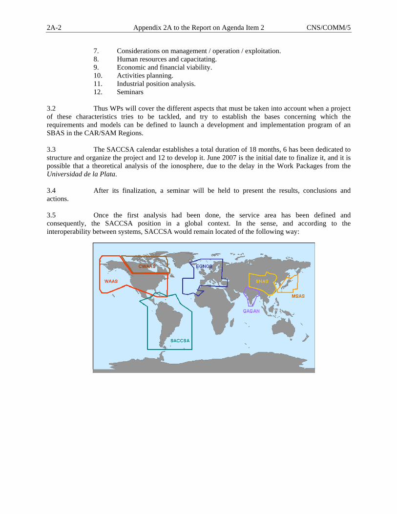
2A-2 Appendix 2A to the Report on Agenda Item 2 CNS/COMM/5
7. Considerations on management / operation / exploitation. 8. Human resources and capacitating. 9. Economic and financial viability. 10. Activities planning. 11. Industrial position analysis. 12. Seminars
3.2 Thus WPs will cover the different aspects that must be taken into account when a project of these characteristics tries to be tackled, and try to establish the bases concerning which the requirements and models can be defined to launch a development and implementation program of an SBAS in the CAR/SAM Regions. 3.3 The SACCSA calendar establishes a total duration of 18 months, 6 has been dedicated to structure and organize the project and 12 to develop it. June 2007 is the initial date to finalize it, and it is possible that a theoretical analysis of the ionosphere, due to the delay in the Work Packages from the Universidad de la Plata. 3.4 After its finalization, a seminar will be held to present the results, conclusions and actions. 3.5 Once the first analysis had been done, the service area has been defined and consequently, the SACCSA position in a global context. In the sense, and according to the interoperability between systems, SACCSA would remain located of the following way:

CNS/COMM/5 Appendix 2A to the Report on Agenda Item 2 2A-3
3.6 In reference to the service area, comprising both the oceanic area with a ranging improvement and the continental one with performance improvement, it will be: 3.7 The system architecture will be the one used for any SBAS system, being configured in the next way:
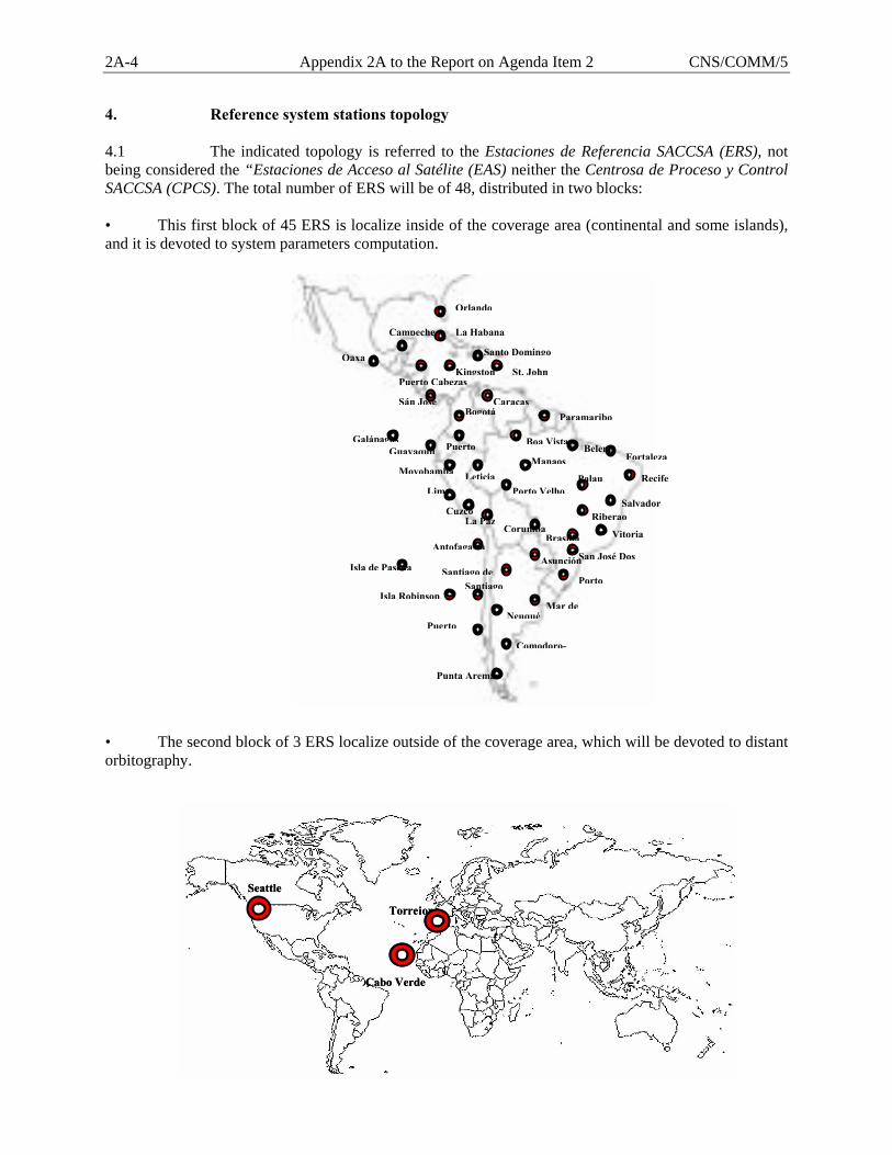
2A-4 Appendix 2A to the Report on Agenda Item 2 CNS/COMM/5
4. Reference system stations topology 4.1 The indicated topology is referred to the Estaciones de Referencia SACCSA (ERS), not being considered the “Estaciones de Acceso al Satélite (EAS) neither the Centrosa de Proceso y Control SACCSA (CPCS). The total number of ERS will be of 48, distributed in two blocks: • This first block of 45 ERS is localize inside of the coverage area (continental and some islands), and it is devoted to system parameters computation. • The second block of 3 ERS localize outside of the coverage area, which will be devoted to distant orbitography.
Puerto
Mar deNeuqué
Porto
San José Dos
Salvador
Santo Domingo
St. John
Paramaribo
Belem
Recife
La Habana
CorumbaBrasilia
Galápagos
Orlando
Boa Vista
Porto Velho
Manaos
Palau
Asunción
Bogotá
Kingston
Lima
Puerto
Caracas
CuzcoLa Paz
SantiagoSantiago de
Antofagasta
Sán José
Guayaquil
Moyobamba
Puerto Cabezas
Campeche
Oaxa
Punta Aremas
Comodoro-
Isla de Pascua
Isla Robinson
Leticia
Riberao
Vitoria
Fortaleza
Torrejon
Seattle
Cabo Verde
Torrejon
Seattle
Cabo Verde
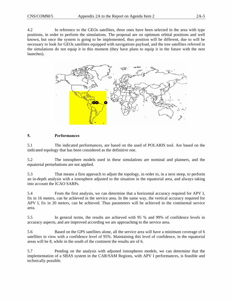
CNS/COMM/5 Appendix 2A to the Report on Agenda Item 2 2A-5
4.2 In reference to the GEOs satellites, three ones have been selected in the area with type positions, in order to perform the simulations. The proposal are on optimum orbital positions and well known, but once the system is going to be implemented, thus position will be different, due to will be necessary to look for GEOs satellites equipped with navigations payload, and the tree satellites referred in the simulations do not equip it in this moment (they have plans to equip it in the future with the nest launches). 5. Performances 5.1 The indicated performances, are based on the used of POLARIS tool. Are based on the indicated topology that has been considered as the definitive one. 5.2 The ionosphere models used in these simulations are nominal and planners, and the equatorial perturbations are not applied. 5.3 That means a first approach to adjust the topology, in order to, in a next steep, to perform an in-depth analysis with a ionosphere adjusted to the situation in the equatorial area, and always taking into account the ICAO SARPs. 5.4 From the first analysis, we can determine that a horizontal accuracy required for APV I, fix in 16 meters, can be achieved in the service area. In the same way, the vertical accuracy required for APV I, fix in 20 meters, can be achieved. Thus parameters will be achieved in the continental service area. 5.5 In general terms, the results are achieved with 95 % and 99% of confidence levels in accuracy aspects, and are improved according we are approaching to the service area. 5.6 Based on the GPS satellites alone, all the service area will have a minimum coverage of 6 satellites in view with a confidence level of 95%. Maintaining this level of confidence, in the equatorial areas will be 8, while in the south of the continent the results are of 6. 5.7 Pending on the analysis with adjusted ionospheres models, we can determine that the implementation of a SBAS system in the CAR/SAM Regions, with APV I performances, is feasible and technically possible.
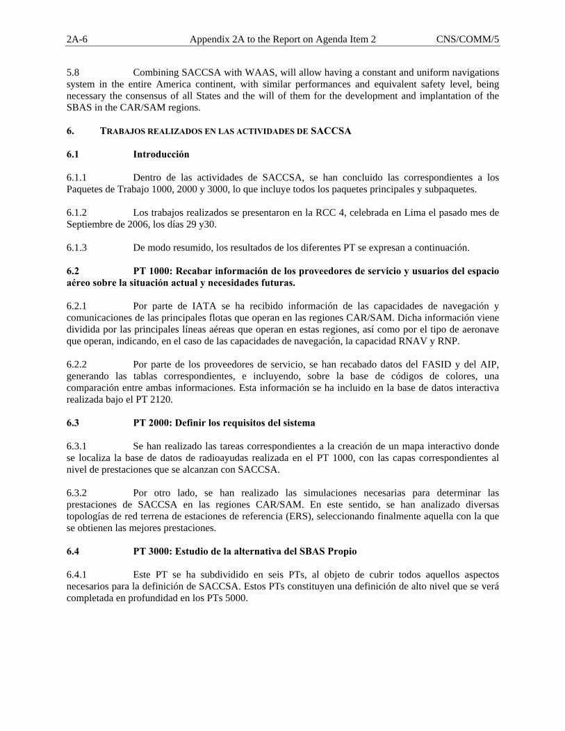
2A-6 Appendix 2A to the Report on Agenda Item 2 CNS/COMM/5
5.8 Combining SACCSA with WAAS, will allow having a constant and uniform navigations system in the entire America continent, with similar performances and equivalent safety level, being necessary the consensus of all States and the will of them for the development and implantation of the SBAS in the CAR/SAM regions. 6. TRABAJOS REALIZADOS EN LAS ACTIVIDADES DE SACCSA 6.1 Introducción 6.1.1 Dentro de las actividades de SACCSA, se han concluido las correspondientes a los Paquetes de Trabajo 1000, 2000 y 3000, lo que incluye todos los paquetes principales y subpaquetes. 6.1.2 Los trabajos realizados se presentaron en la RCC 4, celebrada en Lima el pasado mes de Septiembre de 2006, los días 29 y30. 6.1.3 De modo resumido, los resultados de los diferentes PT se expresan a continuación. 6.2 PT 1000: Recabar información de los proveedores de servicio y usuarios del espacio aéreo sobre la situación actual y necesidades futuras. 6.2.1 Por parte de IATA se ha recibido información de las capacidades de navegación y comunicaciones de las principales flotas que operan en las regiones CAR/SAM. Dicha información viene dividida por las principales líneas aéreas que operan en estas regiones, así como por el tipo de aeronave que operan, indicando, en el caso de las capacidades de navegación, la capacidad RNAV y RNP. 6.2.2 Por parte de los proveedores de servicio, se han recabado datos del FASID y del AIP, generando las tablas correspondientes, e incluyendo, sobre la base de códigos de colores, una comparación entre ambas informaciones. Esta información se ha incluido en la base de datos interactiva realizada bajo el PT 2120. 6.3 PT 2000: Definir los requisitos del sistema 6.3.1 Se han realizado las tareas correspondientes a la creación de un mapa interactivo donde se localiza la base de datos de radioayudas realizada en el PT 1000, con las capas correspondientes al nivel de prestaciones que se alcanzan con SACCSA. 6.3.2 Por otro lado, se han realizado las simulaciones necesarias para determinar las prestaciones de SACCSA en las regiones CAR/SAM. En este sentido, se han analizado diversas topologías de red terrena de estaciones de referencia (ERS), seleccionando finalmente aquella con la que se obtienen las mejores prestaciones. 6.4 PT 3000: Estudio de la alternativa del SBAS Propio 6.4.1 Este PT se ha subdividido en seis PTs, al objeto de cubrir todos aquellos aspectos necesarios para la definición de SACCSA. Estos PTs constituyen una definición de alto nivel que se verá completada en profundidad en los PTs 5000.
CNS/COMM/5 Appendix 2A to the Report on Agenda Item 2 2A-7
6.5 PT 3110: Descripción Global. 6.5.1 Se ha realizado una descripción global de SACCSA, indicando cada uno de los elementos que componen el mismo, con un análisis de alto nivel de cada uno de los componentes, de forma que sirvan como base a los trabajos posteriores a realizar en los siguientes PTs que componen el PT 3000. 7 3120: Data Procesing 7.1 Centro de Proceso y Control 7.1.1 El Centro de Proceso y Control SACCSA (CPCS) está diseñado para generar periódicamente las correcciones del sistema SBAS además de chequear la integridad del sistema sobre todo el área de servicio. Posteriormente, estas correcciones son encapsuladas dentro del llamado “mensaje operacional”, que se generará periódicamente y será enviado al satélite geoestacionario a través de la EAS. 7.1.2 En éste mensaje, además de enviar las correcciones de efemérides, correcciones ionosféricas y cotas de error de ionosfera (información independiente del satélite al que va dirigido), se incluyen también las correcciones de reloj y cotas de error de reloj, que son información dependiente de dicho satélite geoestacionario. 7.1.3 En un mismo sistema SBAS puede haber más de un Centro de Proceso y Control SACCSA (CPCS) con el objetivo de aumentar la redundancia. Todos los CPCS en funcionamiento proveerán a cada EAS de mensajes operacionales a transmitir, pero sólo uno será enviado. Aquel Centro de Proceso y Control SACCSA (CPCS) cuyos mensajes son enviados se denomina como el CPCS elegido y los demás son conocidos como CPCS de soporte. El CPCS elegido debe enviar a la EAS todos los tipos de mensajes mientras que los Centros de Procesamiento de Datos de soporte sólo se encarga de enviar a las ERS información de integridad. 7.1.4 La Estación de Acceso al Satélite (EAS) es la encargada de decidir cual de los Centros de Proceso y Control SACCSA (CPCS) es el elegido. Para ello la Estación de Acceso al Satélite (EAS) utiliza la información de Calidad de Servicio que cada Centro de Proceso y Control SACCSA (CPCS) le proporciona asociada a su mensaje operacional. Cada Centro de Proceso y Control SACCSA (CPCS) calcula su Calidad de Servicio usando la información de integridad calculada por él mismo y los demás Centros de Proceso y Control SACCSA (CPCS). 7.1.5 Unidad Central de Procesamiento 7.1.5.1 La Unidad Central de Procesamiento (UCP) es el corazón computacional de un sistema SBAS. Es el lugar donde se generan las correcciones y la información de integridad que serán trasmitidas sobre el área de servicio del sistema SBAS. El centro de procesamiento debe generar información de acuerdo a los requisitos definidos en ICAO SARPS requisitos de la señal en el espacio. 7.1.5.2 Para un sistema SBAS puede haber más de una Unidad Central de Procesamiento. La Unidad Central de Procesamiento además deberá monitorizar los otros satélites SBAS visibles en la región del sistema y proporcionar información de integridad para ellos.
2A-8 Appendix 2A to the Report on Agenda Item 2 CNS/COMM/5
7.1.5.3 La UCP genera: • Correcciones diferenciales de área ancha para las constelaciones para las cuales
el sistema SBAS esté definido. • Información acerca del retraso ionosférica. • Información de integridad acerca de las correcciones de órbitas y relojes para
cada uno de los satélites. • Información de integridad para las correcciones ionosféricas. • Alarmas (para satélites individualmente y puntos de la malla ionosférica). • Posición para el satélite geoestacionario (GEO efemérides). • Parámetros de tiempo propio del sistema SBAS/diferencia con el tiempo UTC.
7.1.5.4 La Unidad Central de Procesamiento se divide en:
• Centro de Computación Se encarga de calcular y generar cada segundo el mensaje SBAS con las correcciones e información de integridad
• Centro de Chequeo Se encarga de verificar la exactitud de los mensajes SACCSA generados en el centro de procesamiento
7.1.6 Centro de Computación 7.1.6.1 El Centro de Cálculo es el módulo central del centro de computación. En este módulo son calculadas todas las correcciones y la información de integridad. Esto incluye correcciones de orbita y reloj para los satélites de las constelaciones en uso así como correcciones de ionosfera para los puntos de la malla ionosférica. También en este módulo el tiempo interno del sistema es calculado, así como su diferencia con el tiempo UTC para ser proporcionada al usuario final. 7.1.6.2 Además de todas las correcciones anteriores este módulo calcula las diferentes cotas de error para las correcciones anteriores, incluyendo la cota para las correcciones orbitales/ de reloj para los satélites y las correcciones ionosféricas para los puntos de la malla ionosférica. 7.1.6.3 Dada la complejidad de las operaciones realizadas en este módulo, este módulo se puede dividir en los siguientes submódulos:
• Modulo de Relojes: Encargado de la supervisión y del cálculo de los errores de los relojes de los satélites y de las estaciones de referencia. Las correcciones de los relojes son separadas en dos partes, a saber, correcciones rápidas que son proporcionadas al usuario con relativa frecuencia y correcciones lentas, proporcionadas al usuario con menos frecuencia que las anteriores.
• Modulo de Órbitas: Encargado del cálculo de los errores orbitales de los satélites. Este módulo es también el encargado de calcular la órbita del satélite geoestacionario que está siendo usado para enviar al usuario la información del sistema.
• Modulo de Cotas de Reloj y Orbita: En este módulo se genera para cada satélite al que se está proporcionando correcciones una cota (UDRE) de los errores residuales a las correcciones.
• Modulo de Ionosfera: En este módulo se calculan las correcciones ionosféricas para los puntos de la malla ionosférica (GIVD) así como una cota del error residual (GIVE).7.1.7 Centro de Chequeo
7.1.7.1 Verifica los mensajes SACCSA generados en el centro de procesamiento:
CNS/COMM/5 Appendix 2A to the Report on Agenda Item 2 2A-9
• Correcciones de satélites • Correcciones de ionosfera
con sus respectivas cotas de error. 7.1.7.2 Usa los mensajes SBAS como si fuera un usuario final, calculando la posición de las estaciones de referencia (basado en medidas recibidas)
• Calcula el error (estadísticas) en esas estimaciones y compara con PL. 7.1.7.3 Tiene dos partes bien diferenciadas:
• Chequeo Posterior. • Chequeo Anterior7.1.8 Principales riesgos tecnológicos.
7.1.8.1 Elementos con riesgo dentro de la UPC:
• Modelo ionosférico. • Calculo de correcciones de orbita y relojes de los satélites. • Provisión de integridad sobre las correcciones generadas por el sistema (de
satélite y de ionosfera). • Aspectos de fiabilidad y seguridad del sistema en su conjunto.
7.1.8.2 El Modelo ionosférico es altamente dependiente de la latitud del área de cobertura del sistema SBAS;
• Necesidad de estudiar el comportamiento de la Ionosfera en la Región (PT4200) 8 PT 3130: Comunicaciones 8.1 Se han realizado las siguientes actividades:
• Definición de los requisitos preliminares que han de cumplir las comunicaciones a establecer entre los diferentes elementos del sistema que se desplegarían para proporcionar las prestaciones requeridas en el área CAR/SAM.
• Identificación de la infraestructura de telecomunicaciones existente y prevista en el área durante el despliegue del sistema, con el fin de poder identificar a su vez las alternativas para la implementación de las comunicaciones.
• Identificación de las alternativas existentes que serán analizadas en próximos paquetes de trabajo y que, desde un punto de vista técnico, mejor pudieran cumplir los requisitos de comunicaciones de SACCSA.
• Recopilación de información de infraestructura de comunicaciones (operadores de sistemas de comunicaciones por satélite, operadores comerciales de redes de comunicaciones, redes digitales aeronáuticas) existente en Latinoamérica.
• Se ha completado la definición preliminar de requisitos de la red de comunicaciones e identificado las posibles alternativas de implementación de la red.
9. PT 3140: Satélite 9.1 Se han identificado los diferentes escenarios de posibles configuraciones de la carga de navegación a bordo de un satélite GEO:
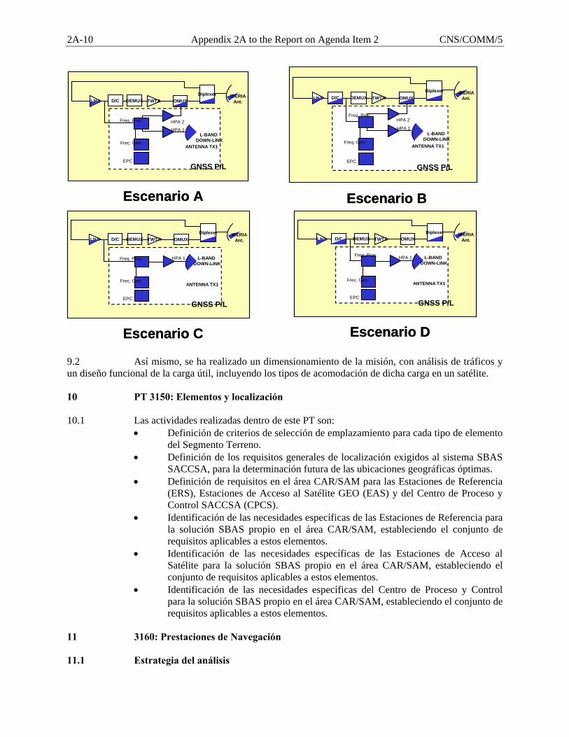
2A-10 Appendix 2A to the Report on Agenda Item 2 CNS/COMM/5
9.2 Así mismo, se ha realizado un dimensionamiento de la misión, con análisis de tráficos y un diseño funcional de la carga útil, incluyendo los tipos de acomodación de dicha carga en un satélite. 10 PT 3150: Elementos y localización 10.1 Las actividades realizadas dentro de este PT son:
• Definición de criterios de selección de emplazamiento para cada tipo de elemento del Segmento Terreno.
• Definición de los requisitos generales de localización exigidos al sistema SBAS SACCSA, para la determinación futura de las ubicaciones geográficas óptimas.
• Definición de requisitos en el área CAR/SAM para las Estaciones de Referencia (ERS), Estaciones de Acceso al Satélite GEO (EAS) y del Centro de Proceso y Control SACCSA (CPCS).
• Identificación de las necesidades específicas de las Estaciones de Referencia para la solución SBAS propio en el área CAR/SAM, estableciendo el conjunto de requisitos aplicables a estos elementos.
• Identificación de las necesidades específicas de las Estaciones de Acceso al Satélite para la solución SBAS propio en el área CAR/SAM, estableciendo el conjunto de requisitos aplicables a estos elementos.
• Identificación de las necesidades específicas del Centro de Proceso y Control para la solución SBAS propio en el área CAR/SAM, estableciendo el conjunto de requisitos aplicables a estos elementos.
11 3160: Prestaciones de Navegación 11.1 Estrategia del análisis
Escenario C
LNA D/C DEMUX TWTA OMUXDiplexer
L-BAND DOWN-LINK
HPA 1Freq. Proc.
Frec. Gen.
EPC
ANTENNA TX1
GNSS P/L
IBERIAAnt.
Escenario C
LNA D/C DEMUX TWTA OMUXDiplexer
L-BAND DOWN-LINK
HPA 1Freq. Proc.
Frec. Gen.
EPC
ANTENNA TX1
GNSS P/L
IBERIAAnt.
Escenario D
LNA D/C DEMUX TWTA OMUXDiplexer
L-BAND DOWN-LINK
HPA 1Freq. Proc.
Frec. Gen.
EPC
ANTENNA TX1
GNSS P/L
IBERIAAnt.
Escenario D
LNA D/C DEMUX TWTA OMUXDiplexer
L-BAND DOWN-LINK
HPA 1Freq. Proc.
Frec. Gen.
EPC
ANTENNA TX1
GNSS P/L
IBERIAAnt.
Escenario A
LNA D/C DEMUX TWTA OMUXDiplexer
L-BAND DOWN-LINK
HPA 2
HPA 1
Freq. Proc.
Frec. Gen.
EPC
ANTENNA TX1
GNSS P/L
IBERIAAnt.
Escenario A
LNA D/C DEMUX TWTA OMUXDiplexer
L-BAND DOWN-LINK
HPA 2
HPA 1
Freq. Proc.
Frec. Gen.
EPC
ANTENNA TX1
GNSS P/L
IBERIAAnt.
Escenario B
LNA D/C DEMUX TWTA OMUXDiplexer
L-BAND DOWN-LINK
HPA 2
HPA 1
Freq. Proc.
Freq. Gen.
EPC
ANTENNA TX1
GNSS P/L
IBERIAAnt.
Escenario B
LNA D/C DEMUX TWTA OMUXDiplexer
L-BAND DOWN-LINK
HPA 2
HPA 1
Freq. Proc.
Freq. Gen.
EPC
ANTENNA TX1
GNSS P/L
IBERIAAnt.
CNS/COMM/5 Appendix 2A to the Report on Agenda Item 2 2A-11
11.1.1 Evaluación de las Prestaciones del Sistema SACCSA 11.1.1.1 Las prestaciones de los sistemas SBAS son definidas con respecto a un nivel de servicio proporcionado. La mayoría de los análisis que caracterizan las prestaciones de sistema son proporcionadas respecto al nivel de usuario, donde los principales conceptos pueden ser medidos de forma simple en base a las siguientes características:
1. Disponibilidad: se difunde la suficiente información por el sistema para calcular una solución de navegación y los niveles de protección horizontal y vertical (HPL/VPL) no exceden los niveles de alarma (HAL y VAL) para el nivel de servicio correspondiente.
2. Precisión: diferencias entre la posición de usuario estimada y la real. 3. Continuidad: nivel de servicio disponible durante toda la operación. 4. Integridad: el error de la solución de navegación no excede los límites de alarma
(HAL/VAL) y si se exceden el sistema es capaz de mandar una alarma.. 11.1.1.2 Por tanto, la evaluación de prestaciones del SBAS a nivel de pseudorango es definida como sigue:
1. Disponibilidad: los valores de UDRE y GIVE no exceden determinados márgenes que hagan que su contribución a los límites de protección horizontal y vertical (HPL/VPL) superen los niveles de alarma (HAL/VAL). En este sentido, el objetivo es transmitir valores de UDRE y GIVE lo más bajo posible, de forma que su contribución a los niveles de protección hagan la solución de navegación de usuario disponible a la vez que la integridad queda preservada. Los valores de UDRE considerados en este análisis serán aquellos transmitidos en los mensajes de navegación de tipo 2 a 4 y en el mensaje 24 (los mensajes de tipo 28 no serán considerados).
2 Precisión: diferencias entre el valor real y estimado de los relojes y órbitas de los
satélites (SREW) y los retardos por ionosfera (GIVD error) una vez aplicadas las correcciones de navegación.
3. Continuidad: servicio disponible a lo largo de la operación, asumiendo que el
sistema se encontraba disponible al comienzo de la operación. Normalmente es interpretado a nivel de transmisión como la continuidad en la monitorización de los satélites e IGPs. En este sentido, la monitorización de los satélites y de los IGPs será mostrada como parte de las prestaciones del sistema a nivel de transmisión.
4.º Integridad: El valor de UDRE acota el valor de SREW una vez aplicadas las
correcciones de satélite y el valor de GIVE acota el valor de error de GIVD después de aplicar las correcciones ionosféricas para el nivel de confianza definido. Hay que remarcar que los valores de UDRE tienen que acotar los errores de satélite (órbitas y relojes) para todos los usuarios que se encuentren dentro del área de servicio y, en particular, para el “peor usuario”.
11.1.1.3 Estas características (propias del dominio de la posición) no son fácilmente traducibles al dominio del pseudo-rango, en donde se difunden las correcciones actuales. A continuación se definirá la aproximación tomada para interpretar estas prestaciones en el dominio de la pseudo-rango. Las prestaciones de ionosfera y satélites son identificadas como fuentes que contribuyen a las prestaciones de usuario y son expresadas por medio de los siguientes términos:
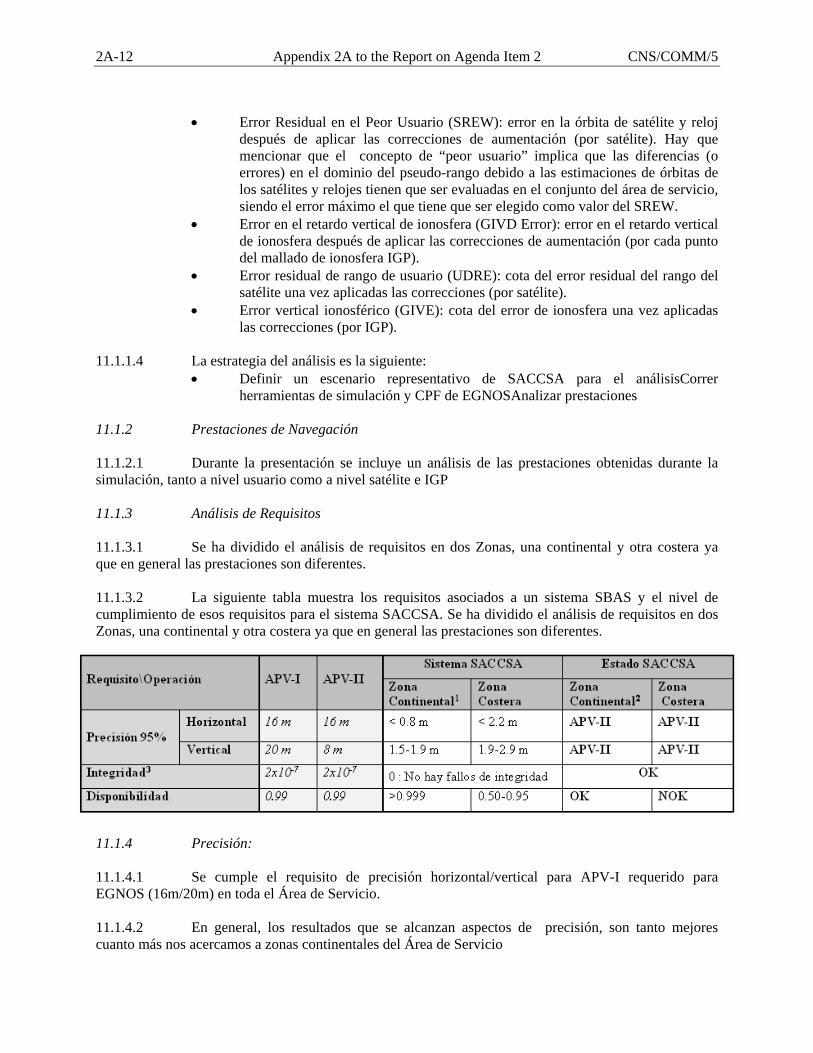
2A-12 Appendix 2A to the Report on Agenda Item 2 CNS/COMM/5
• Error Residual en el Peor Usuario (SREW): error en la órbita de satélite y reloj
después de aplicar las correcciones de aumentación (por satélite). Hay que mencionar que el concepto de “peor usuario” implica que las diferencias (o errores) en el dominio del pseudo-rango debido a las estimaciones de órbitas de los satélites y relojes tienen que ser evaluadas en el conjunto del área de servicio, siendo el error máximo el que tiene que ser elegido como valor del SREW.
• Error en el retardo vertical de ionosfera (GIVD Error): error en el retardo vertical de ionosfera después de aplicar las correcciones de aumentación (por cada punto del mallado de ionosfera IGP).
• Error residual de rango de usuario (UDRE): cota del error residual del rango del satélite una vez aplicadas las correcciones (por satélite).
• Error vertical ionosférico (GIVE): cota del error de ionosfera una vez aplicadas las correcciones (por IGP).
11.1.1.4 La estrategia del análisis es la siguiente:
• Definir un escenario representativo de SACCSA para el análisisCorrer herramientas de simulación y CPF de EGNOSAnalizar prestaciones
11.1.2 Prestaciones de Navegación 11.1.2.1 Durante la presentación se incluye un análisis de las prestaciones obtenidas durante la simulación, tanto a nivel usuario como a nivel satélite e IGP 11.1.3 Análisis de Requisitos 11.1.3.1 Se ha dividido el análisis de requisitos en dos Zonas, una continental y otra costera ya que en general las prestaciones son diferentes. 11.1.3.2 La siguiente tabla muestra los requisitos asociados a un sistema SBAS y el nivel de cumplimiento de esos requisitos para el sistema SACCSA. Se ha dividido el análisis de requisitos en dos Zonas, una continental y otra costera ya que en general las prestaciones son diferentes.
11.1.4 Precisión: 11.1.4.1 Se cumple el requisito de precisión horizontal/vertical para APV-I requerido para EGNOS (16m/20m) en toda el Área de Servicio. 11.1.4.2 En general, los resultados que se alcanzan aspectos de precisión, son tanto mejores cuanto más nos acercamos a zonas continentales del Área de Servicio
CNS/COMM/5 Appendix 2A to the Report on Agenda Item 2 2A-13
11.1.5 Disponibilidad: 11.1.5.1 Se cumplen los requisitos de Disponibilidad (> 99%) para las zonas Continentales y Caribe. 11.1.5.2 En la mayor parte de la zona de Latino América se observa unas prestaciones excelentes en términos de Disponibilidad (> 99%) llegando a APV-II y APV-I. 11.1.5.3 En las zonas costeras y especialmente en la zona de Brasil y Sur de Argentina, se observa una degradación en la disponibilidad llegando a valores significativamente degradados 11.1.6 Integridad: 11.1.6.1 Se cumplen los requisitos de Integridad en toda el Área de Servicio 11.1.6.2 El sistema es integro a nivel pseudorango, de ionosfera y a nivel usuario:
• Los UDREs son mayores que los SREWs para todos los satélites. • Los GIVDs son mayores que los GIVEs para todos los IGPs. • Los PLs para todos los usuarios son mayores que los errores de posición.
11.1.6.3 Notar que sólo se han analizado 3 días 11.2 Conclusiones y Recomendaciones 11.2.1 La causa más relevante de la degradación de las prestaciones de disponibilidad en algunas zonas se debe a la Ionosfera. El problema no es tanto que no hay una buena precisión en la estimación de las ionosfera si no que existe un problema de monitorización de ésta. Para monitorizar la Ionosfera (IGP), tal y como están los algoritmos de ionosfera en la actualidad, se necesitan al menos 3 IPPs en las cercanías de cada IGP, por lo que en algunas zonas estas condiciones no se cumplen. Notar que el centelleo no se ha tenido en cuenta. 11.2.2 A priori existen dos formas de mejorar las prestaciones en estas zonas (costeras):
• Optimizar la configuración de la Red de Estaciones => Introducir más estaciones en las zonas con problemas para mejorar la monitorización de la Ionosfera en las zonas costeras.
• Modificar los algoritmos del CPF para mejorar la disponibilidad o (Iono) Relajar las condiciones de monitorización de la Ionosfera (peligro
de degradación de Integridad) o Modificar el manejo del Área de Servicio para ajustarla a Latino
América. 12 PT 4000: Recolección de datos y análisis para modelo ionosférico 12.1 Se han recogido datos de ionosfera en la Antártida durante la campaña 2004-2005, realizada en la Base Gabriel de Castilla de la FFAA Españolas. 12.2 Actualmente este paquete de trabajo está en proceso. 12.3 Los objetivos de las actividades de GMV son:

2A-14 Appendix 2A to the Report on Agenda Item 2 CNS/COMM/5
• Investigación del comportamiento ionosférico en la región (basado en análisis de datos reales (IGS))
• Analizar las implicaciones de este comportamiento en la implantación de sistemas SBAS (correcciones e integridad)
12.3.1 Análisis de los niveles de prestación alcanzables, con especial énfasis en la integridad y continuidad del servicio.
13. ACTIVIDADES DE SACCSA EN CURSO 14 PT3160 14.1.1 Como parte de este paquete de trabajo se actualizarán las prestaciones que tendría un sistema SBAS propio en las regiones CAR/SAM, teniendo en cuenta los siguientes factores:
o Nueva Red de Estaciones como consecuencia de los análisis efectuados anteriormente.
o Salidas del PT4200, donde se ha definido un nuevo escenario Ionosférico representativo de la zona.
14.1.2 Estado actual: Se ha definido el escenario representativo y estamos actualmente ejecutando las herramientas de simulación que permiten hacer el análisis 14.2 PT4200 14.2.1 El objetivo del PT4200 es hacer un análisis de la Ionosfera en la zona CAR/SAM, de modo que sirva como input al PT3600 dónde se hace una estimación de las prestaciones que se obtendrían con un sistema SBAS propio en la zona. 14.2.2 Para conseguir este objetivo, se han realizado las siguientes actividades:
• Obtención de datos en la zona. Debido a que se necesita una gran cantidad de datos, extendidos tanto en tiempo como en localización se decidió utilizar datos IGS como input al análisis. El periodo de los datos analizados es 6 años para un total de unas 20-30 estaciones en media (hasta un total de 42 estaciones). Se ha decidido utilizar 6 años de datos para al menos analizar un máximo solar.
• Análisis de la Ionosfera: Este análisis se basa en la caracterización de los siguientes fenómenos ionosféricos: o Anomalía ecuatorial o Scintillations o Concepto de Mapping Function
• Definición de escenario Ionosférico: Teniendo en cuenta el análisis anterior se define un escenario ionosférico para estimar las prestaciones dentro del PT3160.
• Extrapolación de resultados: Una vez obtenida la caracterización de la Ionosfera en la zona, hemos hecho una extrapolación de los resultados obtenidos en el PT3160 teniendo en cuanta las características de la ionosfera y el impacto de ella en un sistema SBAS.
14.2.3 Estado actual: 14.2.3.1 El estado actual de este paquete de trabajo es el siguiente:
o Hemos obtenido los datos necesarios como input para el análisis
CNS/COMM/5 Appendix 2A to the Report on Agenda Item 2 2A-15
o Hemos corrido las herramientas necesarias para el análisis. o Estamos analizando los resultados, y estamos haciendo scripts para automatizar el
análisis. o Hemos definido el escenario necesario como input para el PT3160
14.3 Paquetes de trabajo 5000
14.3.1 PT5100: 14.3.1.1 El objetivo de este paquete de trabajo es proporcionar las especificaciones preliminares para los siguientes elementos:
o PT5110: UCP (Unidad Central de Proceso) o PT5120: Segmento de Apoyo.
14.3.1.2 El input para este paquete de trabajo ha sido la descripción de los elementos como parte del PT3120. 14.3.1.3 El documento de especificaciones para cada uno de los elementos (UCP y Segmento de Apoyo) contiene lo siguiente:
• Descripción de alto nivel de la UCP y el segmento de apoyo respectivamente • Requerimientos del sistema incluyendo:
o Descripción funcional o Características y prestaciones o Diseño e implementación o Personal y Entrenamiento o Consideraciones sobre Aseguramiento de Calidad
14.3.1.4 Estado actual: Ya se han entregado las primeras versiones tanto del PT5110 y PT5120.
14.3.2 PT 5210
14.3.2.1 El objetivo de este paquete de trabajo es de dar la Especificación del Segmento de Control, analiza los requisitos de misión y sistema aplicables a este subsistema y a partir de ellos:
• Especifica los requisitos funcionales de todo el segmento de control para la supervisión de la misión, la monitorización y el control de todos los elementos del segmento terreno, la planificación de las operaciones, el archivo de los datos, el soporte a la operación, el control de la configuración, la supervisión de las comunicaciones y la interfaz con el ATC.
• Define la arquitectura funcional del segmento de control, estableciendo de una manera descendente las funciones que el Segmento de Control ha de realizar, y que posteriormente se ubicarán tanto en la Unidad Central de Control del Centro de Control SACCSA, como en los elementos remotos para el control local de éstos.
• Define la arquitectura física preliminar de la Unidad Central de Control, ubicando las funciones en los elementos físicos que la componen. La arquitectura de los elementos de control de las estaciones remotas se especifica junto con el resto del elemento en los PT correspondientes.
2A-16 Appendix 2A to the Report on Agenda Item 2 CNS/COMM/5
14.3.3 PT 5300
14.3.3.1 El objetivo de este paquete de trabajo es de dar la Especificación de las Estaciones Terrenas, analiza los requisitos de misión y sistema aplicables a este subsistema y a partir de ellos:
• Especifica los requisitos preliminares, funcionales y técnicos, de las Estaciones de Referencia SACCSA (ERS), para la recepción y monitorización de las señales GPS y su envío a los Centros de Control Master.
• Especifica los requisitos preliminares, funcionales y técnicos, de las Estaciones de Acceso al Satélite (EAS), que se encargan de la generación y envío al satélite de la señal GPS-like y la transmisión de la información de integridad del sistema.
• Define la arquitectura lógica de las Estaciones de Referencia SACCSA (ERS) y de Acceso al Satélite (EAS), identificando las funcionalidades dentro del sistema y en los elementos del mismo.
• Define la arquitectura física de las Estaciones de Referencia SACCSA (ERS) y de Acceso al Satélite (EAS), y las principales características de los componentes que lo forman de manera que se cumplan las especificaciones del sistema.
14.3.4 PT 5400
14.3.4.1 El objetivo de este paquete de trabajo es de dar la Especificación de la Red de Comunicaciones de SACCSA, analiza los requisitos de misión y sistema aplicables a este subsistema, junto con la información de sistemas de comunicaciones existentes y disponibles en Latinoamérica, y a partir de ellos:
• Especifica los requisitos preliminares de la Red de Comunicaciones, requisitos generales, de prestaciones y específicos de los enlaces entre elementos del Segmento Terreno.
• Especifica la estructura de la red de comunicaciones, para que la solución propuesta satisfaga las prestaciones exigidas, tanto de capacidad de transmisión de datos, como de disponibilidad.
• Especificar los requisitos exigibles a los diferentes elementos que compondrían la red. • Analiza y define posibles topologías de la red de comunicaciones y alternativas de
implementación en la región, según la infraestructura existente y las soluciones probables identificadas.
14.3.5 PT 5500
14.3.5.1 Durante este periodo se están llevando a cabo los análisis finales para obtener la solución más optima de diseño, a partir de la diversidad de soluciones potenciales identificadas en durante la fase de estudio anterior, que se adapte mejor al cumplimiento de los requisitos de servicio y a la implementación de una carga útil GNSS a implementar en el satélite en este estudio de la alternativa de SBAS propio para la zona CAR/SAM, en sus acepciones de carga integrada y de carga añadida, para ello se han definido y desarrollado una serie de actividades que dan como resultado el diseño de carga útil, su integración en satélite, los costes, y las interfaces correspondientes a la solución. 14.3.5.2 A modo de resumen, la misión SBAS tendrá cobertura global para las frecuencias L1 y L5 y cobertura específica para las áreas CAR/SAM proporcionando a partir de la señal que se emite al satélite desde la correspondiente Estación de Acceso al Satélite para su posterior tratamiento y radiodifusión en los tres enlaces descendientes uno para la estación de control del sistema y las otras dos para los usuarios del mismo.
CNS/COMM/5 Appendix 2A to the Report on Agenda Item 2 2A-17
14.3.5.3 Para los modelos de costes se están terminando de ultimar los detalles que involucran al segmento espacial para la solución seleccionada para el segmento espacial.
14.3.6 PT 5600
14.3.6.1 El objetivo de este paquete de trabajo es el de dar Otras Opciones de Satélite, analiza los requisitos de misión y sistema aplicables, junto con la información de misiones de navegación similares a SACCSA existentes en otras áreas del globo, y a partir de ellos:
• Identifica los requisitos aplicables a una carga de navegación embarcada en un satélite diferente a uno de comunicaciones.
• Identifica de misiones gubernamentales o pertenecientes a agencias públicas o estatales en América, que siendo de comunicaciones o no, fuesen capaces de albergar cargas de navegación con los requisitos establecidos para esta solución SBAS propio.
• Identifica las misiones que tienen prevista la puesta en órbita de uno o varios satélites en los próximos años, seleccionando entre ellos los que pudieran proporcionar cobertura sobre Latinoamérica si albergaran una carga de navegación.
14.3.6.2 Analiza las alternativas potenciales que puedan permitir la ubicación de la carga de navegación de SACCSA en las misiones identificadas 14.4 PT 8000 RECURSOS HUMANOS Y CAPACITACIÓN 14.4.1 PT 8100, Análisis de necesidades y niveles de capacitación en GNSS 14.4.1.1 El objetivo de este PT es la Definición del nivel de capacitación actual del personal candidato a desempeñar las tareas de mantenimiento y operación del futuro SACCSA, tanto de responsables como técnicos. A partir de esto se desarrollará un mapa teórico de las diferentes necesidades formativas en las regiones CAR/SAM. 14.4.1.2 Se han finalizado las siguientes tareas:
• Petición, recepción y análisis de documentación e información. • Elaboración de un cuestionario de determinación de necesidades de formación. • Establecer los contactos pertinentes. • Envío de los cuestionarios pertinentes.
14.4.1.3 Las tareas en curso en este momento son:
• Verificación (una vez recibido los cuestionarios cumplimentados) de los niveles de capacitación detectados.
• Contraste entre niveles de capacitación a alcanzar en relación con las necesidades detectadas y niveles de capacitación actuales.
• Establecimiento de los recorridos formativos requeridos en base al resultado de dicho contraste.
14.4.2 PT 8300, Definición de la red de centros de entrenamiento, capacitación y demostración 14.4.2.1 El objetivo de este PT es la definición de una red de centros de entrenamiento, capacitación y demostración, que cumpla con las capacidades técnicas necesarias para poder asumir los diferentes tipos de formación, capacitación y demostración requeridos. Dicha red deberá tener en cuenta los medios y centros ya existentes en las regiones CAR/SAM, y deberá lograr el objetivo de maximizar
2A-18 Appendix 2A to the Report on Agenda Item 2 CNS/COMM/5
eficiencia y minimizar el gasto teniendo en cuenta la amplia dispersión geográfica de la región CAR/SAM y el establecimiento, formación y demostración para la que cada centro definido en el paquete 8310 estaría en condiciones de ofertar, teniendo en cuenta sus capacidades técnicas, ubicación y otra serie de factores. Esta actividad será complementada con un posible estudio de impacto económico en el caso de la necesidad de instaurar un nuevo centro o de dotar de nuevas capacidades a un centro existente. 14.4.2.2 Las tareas finalizadas son:
• Definición de los parámetros de calidad necesarios para la evaluación de los centros de formación, capacitación y demostración.
14.4.2.3 Las tareas en curso son:
• Recopilación de información sobre los centro de entrenamiento y formación existentes en las regiones CAR/SAM.
• Elaboración de una tabla de características de los distintos centros candidatos. • Análisis tendente a la asignación previa de actividades formativas o de capacitación a los
diferentes centros. • Elaboración de una lista de comprobación como método de evaluación. • Elaboración de un mapa definitivo de los centros.
14.4.3 PT 8400, Modalidades reentrenamiento, on-line y presencial 14.4.3.1 Los objetivos de este PT son la definición de qué cursos y/o entrenamientos pudieran realizarse en modo on-line, teniendo en cuenta las capacidades técnicas de los centros de formación, capacitación y demostración establecidos en el PT 8300, así como de los posibles centros o medios de apoyo y la Definición de qué cursos y/o entrenamientos pudieran realizarse en modo presencial, teniendo en cuenta las capacidades técnicas de los centros de formación, capacitación y demostración establecidos en el PT 8300, así como de los posibles centros o medios de apoyo. 14.4.3.2 Las tareas en curso son:
• Análisis de las necesidades formativas detectadas en el PT 8120, y la posibilidad de desarrollar para las mismas de un programa de formación a distancia.
• Análisis de los centros propuestos en el PT8320, y su capacidad para ofertar o participar de esta modalidad de entrenamiento.
• Análisis de las necesidades formativas detectadas en el PT 8120, y la posibilidad de desarrollar para las mismas de un programa de formación presencial.
• Análisis de los centros propuestos en el PT8320, y su capacidad para ofertar o participar de esta modalidad de entrenamiento.
• Estimación de costes
CNS/COMM/5 Appendix 2A to the Report on Agenda Item 2 2A-19
14.5 PT 9000 – ESTUDIO DE VIABILIDAD ECONÓMICA Y FINANCIERA 14.5.1 El Paquete de Trabajo (PT) 9000 “Estudio de Viabilidad Económica y Financiera” se compone a su vez de una serie de subpaquetes entre los que cabe destacar el PT 9200 y PT 9400 en base a los cuales se han elaborado dos documentos:
1. “Modelos de recuperación de costes” 2. “Modelos de financiación”
14.5.2 En el documento “Modelo de recuperación de costes” se analiza la recuperación de costes de un sistema SBAS, que servirá para dar servicio a multitud de usuarios, además del aeronáutico, lo que exige analizar las vías posibles en las regiones CAR/SAM donde se pretende que este sistema sea implantado. 14.5.3 Para ello en el estudio se han contemplado dos tipos de modelos de recuperación de costes de SACCSA:
1. SACCSA concebido como un consorcio de Proveedores de Servicios de Navegación Aérea (ANSPs) junto con otras instituciones y organizaciones del sector aeronáutico. La recuperación de costes se haría mediante el pago de una cuota fija periódica a cambio de las prestaciones del servicio proporcionado por el sistema SACCSA.
2. SACCSA concebido como una entidad privada e independiente que obtenga la inversión
necesaria para financiar el proyecto, y posteriormente comercializarlo. La recuperación de costes se haría mediante el establecimiento de un sistema de tarificación de los ANSPs en los que se impondría una tasa por el uso de las señales que suministra el sistema, en función de distintos criterios como peso o distancias recorridas por las aeronaves que empleen estas señales.
14.5.4 Independientemente del modelo empleado, hay que tener en cuenta que los servicios que prestaría SACCSA podrían resultar muy beneficiosos para una multitud de usuarios, por lo que, constituirían bienes públicos y los Estados deberían asumir parte de los costes, o la totalidad de los mismos. 14.5.5 El documento “Modelos de financiación” se centra en analizar si es posible financiar el proyecto, esto es, estudiar si es posible conseguir el capital necesario para poder hacer frente a la inversión que se requiere para llevarlo a cabo, y en tal caso, encontrar el medio de financiación óptimo que permita asumir los costes que implicarían su implantación. A la hora de seleccionar el instrumento de financiación más adecuado se debe tener en cuenta el coste, el plazo de reembolso y la finalidad del proyecto. 14.5.6 Dentro de los diferentes tipos de financiación disponibles en el mercado, la más apropiada para el proyecto SACCSA sea, probablemente, la financiación ajena, ya sea pública o privada, dado que la financiación con recursos propios únicamente está disponible para empresas consolidadas en el mercado, que cuentan con reservas monetarias que les permiten abordar determinadas actividades a través de sus fondos propios. 14.5.7 La financiación ajena permite a una empresa desarrollar un proyecto, a pesar de no disponer del dinero en ese preciso instante a costa de devolverlo posteriormente con un pago adicional de intereses, además de los gastos o comisiones que resulten de la operación. 14.5.8 Los principales mecanismos de financiación ajena para el proyecto SACCSA que se han analizado en el documento han sido los siguientes:
2A-20 Appendix 2A to the Report on Agenda Item 2 CNS/COMM/5
A. Financiación pública:
1. Organismos internacionales: Unión Europea, EUROCONTROL, COCESNA. 2. Bancos multilaterales: Banco Mundial, Banco Interamericano de Desarrollo. 3. Estados (préstamos a países a través de convenios bilaterales).
B. Financiación público privada:
1. COFIDES (Compañía Española de Financiación del Desarrollo, S.A)
C. Financiación privada: 1. Banca privada: prestatarios, prestatarios sindicales. 2. Sociedades de capital riesgo.
14.5.9 En cada uno de los casos de financiación tanto público, privada como público-privada se han descrito las condiciones que imponen cada una de las instituciones y el método a seguir para solicitar la financiación. 14.6 PT 9100 – ANÁLISIS PRELIMINAR COSTE BENEFICIO 14.6.1 Objetivos • Primera valoración del sistema SACCSA en la zona CAR / SAM
– Comparación con la tecnología terrestre actual – Análisis de Costes y Beneficios del Proveedor SACCSA – Aproximación a un análisis en términos económicos de los stakeholders
• Recomendaciones y nuevas líneas de trabajos para futuros Análisis Coste Beneficio de SACCSA 14.6.2 Tareas
Describir el escenario (geográfico) dónde se implantará SACCSA y del escenario dónde se hará el estudio (tomando asunciones si fuera necesario).
Definir una Línea Base clara que refleje la situación actual y la evolución de los Sistemas Aeronáuticos en el escenario de estudio.
Generar el Modelo económico de estudio siguiendo las Metodologías: EMOSIA (European Model for Strategic ATM investment analysis y MEDINA (Modelo Económico de Inversiones de Navegación Aérea)
Creación de una dinámica de recogida de datos Costes – Beneficios mediante reuniones y la máxima participación de los partners del proyecto así como el apoyo de los stakeholders (países miembros del CAR-SAM, líneas aéreas, Proveedores de Navegación Aérea, etc...)
14.6.3 Resultados 14.6.3.1 Resultados del análisis económico. Coste Beneficio del proyecto SACCSA según los criterios de valoración1:
o VAN (Valor Actual Neto) o TIR (Tasa Interna de Retorno) o Pay- Back (Plazo de recuperación de la inversión)
CNS/COMM/5 Appendix 2A to the Report on Agenda Item 2 2A-21
14.6.3.2 Estos tres criterios, en principio estándar, se tendrán en cuenta en el estudio, prestando mas atención a los que información económica ofrezcan, y desestimando si fuera necesario los que ofrezcan información pobre del mismo.
Análisis de Sensibilidad: Nos permitirá conocer las variables más críticas y por lo tanto todas aquéllas a las que deberemos prestar más atención (volver a revisar las estimaciones, valoraciones previas, etc...)
14.6.3.3 Análisis de Riesgo: Nos ofrecerá la probabilidad de analizar el valor obtenido (por ejemplo el VAN) de una inversión, opción o alternativa; esto es, nos indicará la probabilidad de que dicho valor sea cierto. 14.6.3.4 PT9100a 14.6.3.4.1 Dentro de este paquete de trabajo las actividades se centran en dar una contribución a para la estimación de costes de la UCP y del Segmento de Apoyo, así como las hipótesis utilizadas en la estimación.
14.6.3.5 PT 9100b 14.6.3.5.1 Estimación de Costes, es la contribución a la estimación preliminar de los costes de SACCSA, aportando la estimación del Segmento Terreno de Control, de las Estaciones Terrenas, ERS y EAS, y de la Red de Comunicaciones, además de la colaboración con el resto de los componentes del proyecto para la elaboración de los costes del sistema SACCSA.
0
RLA/00/009
INTERNATIONAL CIVIL AVIATION ORGANIZATION
RLA/00/009 PROJECT – GNSS AUGMENTATION TESTS
DRAFT FINAL REPORT
June 2006
CNS/COMM/5 Appendix 2B to the Report on Agenda Item 2 2B-1

2B-2 Appendix 2B to the Report on Agenda Item 2 CNS/COMM/5
RLA/00/009 Index i-1
INDEX Summary ....................................................................................................................................................ii-1 Chapter 1 ANALYSIS OF NAVIGATION REQUIREMENTS IN THE CAR/SAM REGIONS
Current navigation systems planning in accordance with CAR/SAM air navigation plan...........1-1 Conventional navigation equipment .............................................................................................1-1 GNSS systems ..............................................................................................................................1-1 Aircraft Based Augmentation Systems (ABAS)...........................................................................1-2 Satellite Based Augmentation System. (SBAS) ...........................................................................1-3 Ground Based Augmentation Systems (GBAS) ...........................................................................1-3 Analysis of GNSS system implementation as support to air navigation operations in the CAR/SAM Regions ......................................................................................................................1-4 GNSS for terminal area applications ............................................................................................1-5 GNSS for Non-Precision and Precision approach and landings...................................................1-5 GNSS considerations and comments related to the use of GNSS for NPA operations ................1-5 Planning for the implementation of performance based navigation (PBN)..................................1-6 Benefit of the performance based navigation ...............................................................................1-6 Considerations on the implementation of performance based navigation ....................................1-7
Chapter 2 SBAS TYPE WAAS TEST BED (CSTB)
Introduction to WAAS type SBAS satellite-based augmentation systems...................................2-1 WAAS type SBAS operation concept ..........................................................................................2-1 Requirements of a SBAS system WAAS type..............................................................................2-2 Elements composing the SBAS WAAS type trial platform in the CAR/SAM Regions (CSTB) .2-3 Test Bed Reference Station (TRS)...............................................................................................2-3 Installation requirements in a reference station ............................................................................2-4 Test Bed Master Station (TMS)...................................................................................................2-6 Avionics segment..........................................................................................................................2-6 Communications segments ...........................................................................................................2-6 Structure of the SBAS type WAAS test bed in the CAR/SAM Regions (CSTB) ........................2-8 CSTB navigation messages...........................................................................................................2-9
Chapter 3 ANALYSIS OF THE DATA COLECTED
Description of CSTB data collection and analysis........................................................................3-1 Description of ionosphere problems and its influence over GNSS systems .................................3-2 Analysis of the data collected .....................................................................................................3-13 Data collected from each TRS ....................................................................................................3-14
Chapter 4 GNSS SYTEM IMPLEMENTATION OPTIONS IN THE CAR/SAM REGIONS
GNSS implementation options in the CAR/SAM Regions...........................................................4-1 Scintillation effect.......................................................................................................................4-11 Estimated Cost for CAR/SAM SBAS system.............................................................................4-13
CNS/COMM/5 Appendix 2B to the Report on Agenda Item 2 2B-3
RLA/00/009 Summary ii-1
SUMMARY
Satellite-based Global Navigation Satellite System (GNSS) technologies are being developed for use in civil aviation operations. A key feature of GNSS is that accurate navigation can be provided globally.
The United States Federal Aviation Administration (FAA), for example, developed the
Wide Area Augmentation System (WAAS) which enhances the Global Positioning System (GPS) by improving system accuracy, integrity, and availability to meet requirements for en route through precision approach navigation.
To provide a platform for WAAS development, the FAA established the National
Satellite Test Bed (NSTB). The NSTB is a prototype WAAS with ground infrastructure located throughout the United States and internationally.
With the aim of establishing a trial platform for the development of a WAAS type SBAS
system in the CAR/SAM Regions, a Memorandum of Understanding (MOU) was established between ICAO and the FAA. The memorandum was signed on 2 June 2001.
As a consequence, the RLA/00/009 UNDP/ICAO technical cooperation project was
created, to which the following States and International Organizations adhered to: Argentina, Bolivia, Brazil, Chile, Colombia, Ecuador, Panama, Peru, United States, Venezuela and COCESNA.
The CAR/SAM satellite platform test bed, implemented through RLA/00/009 project was
named CAR/SAM Test Bed (CSTB). It was designed on the basis of the NSTB. Both CSTB and NTSB are connected through a dedicated communications circuit.
This communications circuit, initially implemented between Santiago, Chile (CSTB) and
Atlantic City, United States (FAA Technical Center (NSTB)), consists in a link between Rio de Janeiro (CSTB) and the Atlantic City FAA Technical Center (NSTB).
The regional approach to demonstrate the objectives of this plan was carried out to help
in illustrating the manner in which this regional system could benefit the whole region, and not only those actively participating in it.
The CSTB was established to facilitate the efforts destined towards the collection,
development, purchase and implementation of an air navigation operational system based on GPS and WAAS type SBAS technologies.
The CSTB was implemented to support a standardized GPS implementation along the
CAR/SAM Regions, create a regional cadre of technical experts and include an initial wide area augmentation system test platform, to be later complemented with an augmentation area capacity specific to each country.
The testing platform was implemented to reduce operational implementation costs
through the development of a trial infrastructure that could be applied to the operational environment (i.e., site selection and preparation, safe ground communications links, operational procedures development, aircraft certification, training, etc.).
2B-4 Appendix 2B to the Report on Agenda Item 2 CNS/COMM/5
ii-2 Summmary RLA/00/009
Initially, the Project had considered the execution of a flight test plan using the CSTB.
The objective of the regional flight trials included:
a) Demonstrate efforts toward seamless GNSS operation. b) Demonstrate expansion of service volume through international participation. c) Demonstrate that international GNSS compatibility is technically achievable. d) Demonstrate that, with vertical guidance, precision approaches can be performed in
Caribbean and South America using GPS-augmented signals broadcast from a wide area augmentation system.
e) Measure the system accuracy and message performance via ground and flight tests in each participating State, for the following applications, as appropriate: i. Long term performance data at local reference stations
ii. Precision approaches at selected airport iii. Vertical guidance precision and non-precision approaches iv. Category I approaches v. Category I approaches at a country where there is no reference station (closed
curve test) vi. Terminal area maneuvers at selected airports
vii. En route land areas viii. En route oceanic areas.
f) Test SIDS and STARS at some selected locations to demonstrate a seamless takeoff to landing capability.
g) Increase international understanding for sharing information between independent GPS augmentation systems, and the shared use of communication satellites.
h) Promote international acceptance and use of augmented GPS in civil aviation applications.
i) Collect and analyze operational performance of the wide area augmentation system with focus on feasibility of using a Wide Area Differential GPS System in the CAR/SAM region.
j) Foster international cooperation and contribute to the safety of the global transportation system through sharing of information, technologies, data, technical assistance, and training between countries and non-governmental agencies.
k) Encourage future Satellite-Based Augmentation System (SBAS) flight tests.
As result of the first flight trials carried out in 2002 in Brazil, and later in Argentina, Bolivia, Chile and Peru, it was proven that the ionosphere effect over the GPS signal did not guarantee NPA approaches with vertical precision requirements, therefore, many of the afore mentioned scheduled flight trials were not carried out.
The CSTB platform included the implementation of a ground satellite station in charge of
transmitting the GPS signal’s augmentation, its implementation had been planned by Brazil, but due to its high cost and the flight trial limitations caused by the effect of the ionosphere over the GPS signal in the Equatorial zone, this was never carried out, and the augmentation trials that were carried out were irradiated through a VHF transceiver.
Due to the above, project RLA/00/009 was re-oriented towards data collection from the
reference stations, plus their respective processing. Chapter 3 shows the analysis of the data collected.
CNS/COMM/5 Appendix 2B to the Report on Agenda Item 2 2B-5

RLA/00/009 Summary ii-3
This report includes in Chapter 1, an analysis of operational navigation requirements in the CAR/SAM Regions, in Chapter 2, the technical aspects related with the WAAS type SBAS trial platform, as well as the equipment it is composed of. Chapter 3 analyzes the data collected from the reference stations, describing the software tools used for data processing, the ionosphere problems and its influence over GPS signals, and Chapter 4 presents GNSS systems implementation alternatives, their costs, and their benefits.
2B-6 Appendix 2B to the Report on Agenda Item 2 CNS/COMM/5
RLA/00/009 Chapter 1 1-1
CHAPTER 1
ANALYSIS OF NAVIGATION REQUIREMENTS IN THE CAR/SAM REGIONS Current navigation systems planning in accordance with CAR/SAM air navigation plan Conventional navigation equipment 1.1 Currently, air navigation requriements in the CAR/SAM Regions are defined in Fasid Table CNS 3, which is shown in Appendix A to this Chapter. 1.2 Table CNS 3 indicates conventional navigation systems requirements (NDB, VOR, DME, ILS) to guarantee air navigation operations in all phases (route, non-precision approaches, precision approaches). In addition, as a result of an initial Global Navigation Satellite System (GNSS) implementation analysis, FASID Table CNS 3 indicates GNSS requirements (SBAS GBAS) in support of air navigation operations. 1.3 This Table indicates that, for Category I, II and III precision approaches, the Ground Based Augmentation System (GBAS) of the Global Positioning System (GPS) will be used, whilst for non-precision approaches (NPA), the GPS Satellite Based Augmentation System (SBAS) will be used. 1.4 In accordance with Table CNS 3, VOR/DME represents the backbone of the air navigation systems. This system will continue providing navigation phases from the en-route phase up to the non-precision approach, during the entire transition period to satellite navigation. 1.5 Table CNS 3 does not specify a target date for the transition towards the GNSS system, but it is expected that gradual elimination of VHF Omnidirectional Range (VOR)/Distance Measuring Equipment (DME) start on the second decade of this Century, alter which it will be necessary to keep some basic conventional systems for any contingencies. 1.6 The Instrument Landing System (ILS) is the main system in support of CAR/SAM precision approaches and landings. Most ILS requirements are in Categories I and II, very few airports in the region have Category III requirements. The use of ILS systems will decrease as performance and availability of GNSS based systems improve. Gradual ILS elimination in favor of GBAS is expected to also start in the second half of the 21st Century. Again, some basic conventional approach and landing systems will be kept for contingency measures. 1.7 Non-directional Radio Beacon (NDB) is used at small aerodromes as an autonomous aid for non-precision approaches, and as a compass beacon localizer, generally located near an ILS exterior radio beacon, to help pilots enter the ILS course in a non-radar environment. 1.8 NDB elimination is being gradually made. At the moment, CAR/SAM policy is that once the equipment’s lifespan is over, it is not replaced. GNSS systems 1.9 GNSS is the generic term that includes all the elements used in the provision and use of satellite navigation systems. Following is a brief description of the elements composing the GNSS system, as well as considerations on implementation plans in the CAR/SAM Regions.
CNS/COMM/5 Appendix 2B to the Report on Agenda Item 2 2B-7
1-2 Chapter 1 RLA/00/009
Aircraft Based Augmentation Systems (ABAS) 1.10 The purpose of ABAS is to augment and/or integrate information obtained from the space segment of GNSS with onboard information. This information or integration is required to ensure that technical performance meets the requirements of Annex 10, Volume I, Chapter 3, Table 3.7.2.4-1. Appendix B to this chapter presents the characteristics that GPS signals must have in space for various operations in accordance with Annex 10, Volume I, Chapter 3, Table 3.7.2.4-1. 1.11 In addition, Annex 10, Volume I, Chapter 3, Section 3.7.3.3 and Attachment D, Section 5, has information and guidelines for the application of standards and recommended practices (SARPS) regarding the ABAS system. 1.12 ABAS requires the use of one of the following two processing schemes to meet aviation operational requirements and it is either:
a) The use of Receiver Autonomous Integrity Monitoring (RAIM) which uses GNSS information exclusively; or
b) Aircraft Autonomous Integrity Monitoring (AAIM) which uses information from additional onboard sensors such as barometric altimeter, multi-sensor RNAV, inertial navigation and/or a precise clock plus the GNSS information.
Receiver Autonomous Integrity Monitoring (RAIM) 1.13 Avionics certification standards require the RAIM function to detect faulty satellite signals and warn the pilot. The availability of RAIM is determined by the number of satellites in view and their geometry, receiver mask angle, phase of flight and particular algorithm used. To accomplish this task, more than five satellites must be visible allowing at least four good computations. The use of barometric altimeter aiding will improve RAIM availability. 1.14 The equipment performance standards developed by the RTCA and EUROCAE indicate that in order to perform GNSS-based NPAs the aircraft must be equipped with avionics that include Aircraft Based Augmentation system (ABAS) and meeting Technical Standard Order (TSO) 129A Levels 1 or 3. 1.15 Fault detection and exclusion (FDE) goes beyond RAIM by excluding a failed satellite and permitting interrupted GNSS navigation. FDE requires 6 or more satellite in view. Aircraft Integrity Monitoring (AAIM) 1.16 AAIM uses the redundancy of position estimates from multiple sensors including GNSS. The integrity performance of AAIM must be at least equivalent to RAIM. AAIM avionics must meet TSO C-115A standards. Basic GNSS receivers 1.17 Basic GNSS receivers must comply to TSO C-119 (Ed 72A) and provide 100m (95 %) horizontal accuracy supported by GPS/SPS.
2B-8 Appendix 2B to the Report on Agenda Item 2 CNS/COMM/5
RLA/00/009 Chapter 1 1-3
Satellite Based Augmentation System. (SBAS) 1.18 Satellite based augmentation systems are composed of numerous ground reference stations monitoring the ranging signals received from the navigation satellites and master stations that not only process the data received from the reference stations but also computes the necessary corrections and prepares appropriate correction message to be up-linked to the geostationary satellite for subsequent broadcast to aircraft (users). The channel used for the broadcast of integrity information also includes a ranging signal and as such, higher availability of SBAS and associated corrections, can support approaches with vertical guidance (APV) and possibly Category I precision approaches to aircraft equipped with SBAS avionics. 1.19 Information and orientation text for the application of SARPS son the SBAS system are found in Annex 10, Volume I, Chapter 3, Section 3.7.3.4, and in Attachment D, Section 6. SBAS avionics 1.20 The Minimum Operational Performance Standards for GPS and WAAS are described in RTCA DO-229B and thee avionics certification standards in TSO C-145. SBAS will include FDE and support en-route applications, Non-Precision Approach, Approach with Vertical Guidance (APV) and possibly Cat I precision approach. 1.21 There are two APV categories (APV1 and APV2). APV 1 can be flown using either SBAS or Barometric VNAV for vertical guidance. APV 2 has lower minima and requires SBAS. 1.22 SBAS availability levels will allow operators to take advantage of SBAS instrument approach minima when designating an alternate airport since an SBAS approach does not require an SBAS infrastructure at an airport therefore, improving airport usability at minimal cost. 1.23 En-route SBAS can also support en-route RNAV operations therefore supporting the present RNAV program in the CAR/SAM regions and permit the gradual retirement/reduction of ground navaids used for en-route operations. 1.24 Even though the SBAS program is still in development phase, the inclusion of this augmentation option is indeed found in the CAR/SAM Regions implementation plans, as mentioned before. 1.25 The coverage area of the SBAS system is determined by the footprint of the geostationary broadcasting satellite, which unfortunately does not cover very well high latitude polar regions. Considering the above, States can define service areas where approved SBAS-based operations are approved or supported. 1.26 Recognizing that the State is responsible for the services provided within a service area, appropriate institutional arrangements, while still maintaining a certain level of control, could significantly increase service areas at minimal cost through the sharing of resources. Furthermore, with appropriate arrangements the cost can also be shared with other user community such as marine, ground transportation community such as trucking, railway, ambulance etc. This arrangement will likely require the provision of notices to all concern relating the availability and quality of the augmentation signals. Ground Based Augmentation Systems (GBAS) 1.27 Information and guideline material for the application of GNSS Standards and Recommended Practices (SARPs) are found in Annex 10, Volume I, Chapter 3, Section 3.7.3.5.1 and in Attachment D, Section 7.
CNS/COMM/5 Appendix 2B to the Report on Agenda Item 2 2B-9

1-4 Chapter 1 RLA/00/009
1.28 The Ground Based Augmentation System (GBAS) is a system composed of ground and aircraft elements. A ground subsystem (ground station) can provide support to all aircraft subsystems within its coverage, providing the aircraft with approach, corrective and seamless information data for in sight GNSS satellite, through VHF data dissemination (VDB). 1.29 The GBAS ground subsystems provide two services: precision approach and GBAS position determination. The precision approach service provides a deviation guideline for final approach segments, while the GBAS position determination service provides information on the horizontal position to provide support to RNAV operations at terminal areas. Analysis of GNSS system implementation as support to air navigation operations in the CAR/SAM Regions Analysis of GNSS systems to support en route, approach, landing and take-off operations 1.30 In the CAR/SAM Regions, where operation efficiency improvement is being taken under consideration, an immediate advantage of GNSS would represent an optimization of en route operations, upon permitting pilots direct flights to their destinies, at preferred altitudes, without having to follow routes that depend on ground based navigation aids. Again, the use of GNSS will greatly simplify the development of parallel routes to satisfy traffic demands. In addition, GNSS will ease NPA introduction at many airports, where costs of traffic volume would not justify a big investment. The low cost associated with the GNSS/WAAS receivers makes this innovation accessible and encourages the use of a navigation reference. 1.31 The lack of conventional navigation and surveillance aids in the oceanic airspace has forced the establishment of higher separation minima, with the aim of satisfying the desired safety level. With GNSS, greater navigation accuracy and better data link availability can be achieved to transmit position reports, so as to reduce the separation minima and carry out a greater number of optimum altitude flights. 1.32 The CAR/SAM Regions have great oceanic areas of low traffic density, where it World be impossible or too costly to offer appropriate navigation and surveillance capability. Again, important operational improvements can be obtained through the use of GNSS and the gradual elimination of conventional navigation aids. 1.33 To use GNSS as primary means of navigation in en-route and oceanic areas, the avionics must have the ability to identify and exclude a faulty satellite signal and continue to provide guidance. This is called “Fault Detection and Exclusion” (FDE). Under this approval, aircraft must carry dual systems and operators must perform pre-flight predictions to ensure that there will be enough satellites in view to support the planned flight. This approval allows operators to use aircraft without costly inertial navigation systems in oceanic and remote airspace. 1.34 Annex 15 requires that Notice to Airmen (NOTAM) service be provided for navigation systems in order to inform users about forecasted satellite outages. Considerations should be given to the establishment of a regional NOTAM advisory systems to inform pilots when the RAIM function is or will not be available. 1.35 As an additional value, many operators use GPS as an aid to VFR navigation. As long as pilots rely on map reading and visual contact with the ground. This use of GPS can increase efficiency and safety. In some States, aircraft must be equipped with IFR-certified GPS avionics for night VFR and VFR on top.
2B-10 Appendix 2B to the Report on Agenda Item 2 CNS/COMM/5
RLA/00/009 Chapter 1 1-5
GNSS for terminal area applications 1.36 While there will be some economic and operational advantages associated with the non-replacement of VOR/DME en-route, the bulk of the savings and operational improvements for States could come from the elimination of VOR/DMEs used for terminal area operations. Considering the more complex environment and the need for improved accuracy, integrity, continuity and availability, satellite-based and or ground-based augmentation systems will be required. As a result of recent events, there will likely be a need for backup for contingency measures. This will significantly affect the expected savings for States since, in addition to the retention of a minimum operational network of conventional navaids, facilities for maintenance and calibration of those navaids will need to be maintained. Considering the reduced number of installations, some reduction in cost could be achieved through the sharing of, for example, flight inspection and calibration units. GNSS for Non-Precision and Precision approach and landings 1.37 The use of GNSS with appropriate augmentation will provide non-precision and precision approach and landing capability especially at airports that either because of siting problems or where the installation of an ILS could not be financially justified. . GNSS-based precision approach and landing systems is an important consideration since it would have the advantage of providing these capabilities to all runway ends of one airport. In the case of GBAS, distance and terrain permitting, precision approach can also be provided to other airport in the vicinity (Within approximately 20 nautical miles). GNSS considerations and comments related to the use of GNSS for NPA operations 1.38 While GNSS has the potential to support better approaches to more runway ends at relatively low cost, approach minima also depend on aerodrome physical characteristics and on infrastructure such as lighting. States must therefore, consider the cost of meeting aerodrome standards when planning new approaches. 1.39 Technical Standard Order 129 (TSO C129), which defines the conditions under which GNSS can be used as a “supplemental means” of navigation for en-route and non-precision approach, has been available since 1992. The availability of low cost TSO C129 GNSS receivers, and procedures makes possible the immediate implementation of GNSS-based NPA. 1.40 Safe GNSS navigation also depends on the accuracy of airborne navigation databases. Therefore, States must ensure data integrity when creating new procedures. Additionally, data management procedures and systems must be in place to ensure the integrity of the data as they are processed for use by the avionics. 1.41 GNSS technology and operation are not as simple to operate as traditional avionics. States therefore, need to mandate pilot training programs to ensure the safety of GNSS operation. 1.42 The bulk of the work related to the introduction of GNSS-based NPA will be focus on:
a) An accurate survey of each airport. b) The development of a systematic approach to the development and maintenance
of related databases. c) The development of procedures and ways to monitor their compliance. d) The development of an approval process.
CNS/COMM/5 Appendix 2B to the Report on Agenda Item 2 2B-11
1-6 Chapter 1 RLA/00/009
Planning for the implementation of Performance Based Navigation (PBN) PBN concept 1.43 Performance based navigation specifies performance requirements for aircraft operating along an ATS route, on an instrument approach procedure or in an airspace. Information on performance based navigation is found in ICAO Document 9613 – Manual on Required Navigation Performance (RNP). 1.44 Performance requirements are defined in terms of accuracy, integrity, continuity, availability and functionality needed for the proposed operation in the context of a particular airspace concept. Performance requirements are identified in navigation specifications, which also identify which navigation sensors, and equipment may be used to meet the performance requirement. 1.45 There are both RNP specifications and RNAV specifications. A RNP specification includes a requirement for onboard performance monitoring and alerting and is designated as a RNP X. An RNAV specification does not have such requirements and is designated as RNAV X. Performance based navigation therefore depends on:
a) The RNAV system and installation on the aircraft being approved to meet the performance and functional requirements of the navigation specification prescribed for RNAV operations in an airspace;
b) Air crew satisfying the operating requirements set out by the regulator for
RNAV operations;
c) A defined airspace concept which includes RNAV operations; and
d) An available navigation aid infrastructure. Benefit of the performance based navigation 1.46 To avoid unnecessary constraints upon the airspace users it is necessary to avoid specifying how the navigation requirements are to be met but only what Navigation Performance and Functionality is required from the RNAV system. Under PBN, generic navigation requirements are defined based on the operational requirements. Operators are then able to evaluate options in respect of available technologies and navigation services that could allow these requirements to be met. The chosen solution would be the most cost effective for the operator rather than a solution being imposed as part of the operational requirements. Technologies can evolve over time without requiring the operation itself to be revisited as long as the requisite performance is provided by the RNAV system. 1.47 Thus, PBN offers a number of advantages over the sensor-specific method of developing airspace and obstacle clearance criteria: 1.48 The cost of maintaining sensor-specific routes and procedures can be significant. For example, moving or reassigning a single VOR ground facility can impact dozens of procedures, as that VOR can be used on routes, VOR approaches, as part of missed approaches, etc. Adding new sensor-specific procedures will compound this cost, and the rapid growth in available navigation systems (see below) would soon make system-specific routes and procedures unaffordable. 1.49 Aircraft and avionics manufacturers have adopted on-board performance monitoring and alerting capabilities to manage multi-sensor RNAV systems. In these systems, the achieved performance varies depending on the navigation sensors in use, the supporting navigation (Navaid) infrastructure, and whether or not there are any failures.
2B-12 Appendix 2B to the Report on Agenda Item 2 CNS/COMM/5
RLA/00/009 Chapter 1 1-7
1.50 The expansion of satellite navigation services is expected to contribute to the continued diversity of RNAV systems in different aircraft. The original Basic GNSS equipment is evolving due to the augmentations of SBAS, GBAS and GNSS Regional Augmentation System (GRAS), while the expected introduction of Galileo and planned modernization of GPS and GLONASS will further improve performance. The use of GNSS/inertial integration is expanding. Developing system-specific operations with each new evolution would be cost-prohibitive. 1.51 Within an airspace concept, PBN requirements will be affected by the communication, surveillance and ATM environment as well as the Navaid infrastructure and what the functional and operational capabilities are needed to meet the ATM application. PBN performance requirements will also depend on what reversionary, non-RNAV means of navigation are available and hence what degree of redundancy is required to ensure an adequate continuity of function. 1.52 The development of the Performance Based Navigation Concept recognizes that advanced aircraft RNAV systems are achieving a predictable level of navigation performance accuracy, which together with an appropriate level of functionality, allows a more efficient use of available airspace to be realized. It also takes account of the fact that RNAV systems have developed over a 40-year period and as a result there are a large variety of implementations. Identifying navigation requirements rather than on the means of meeting the requirements will allow use of all RNAV systems meeting these requirements irrespective of the means by which these are met. Considerations on the implementation of performance based navigation Short term (up to 2010) En route operations 1.53 Taking into account air traffic low density in oceanic airspaces, no significant changes are expected in the present airspace structure that will demand changes in applied RNAV values. The only exception will be RNP-10 application in the WATRS Region, which will demand a significant change in the CAR Region airspace structure. In airspaces where RNP-10 is applied (EUR/SAM Corridor, Lima-Santiago de Chile Routes and South Atlantic Random Routes System), no short-term changes are expected. 1.54 In the continental airspace, RNAV-5 implementation in selected airspaces is expected, where possible to obtain operational benefits and available CNS infrastructure is able to support it. TMA operations (SIDs and STARs) 1.55 The application of RNAV-1 in State-selected TMAs, in radar environments, with ground navigation infrastructure is expected, which permits DME/DME and DME/DME/INS operations. In this phase mixed operations (equipped and non-equipped) will be admitted, and RNAV-1 operations shall be initiated when an adequate percentage of air operations are approved. 1.56 In non-radar environments and/or in environments that do not count with adequate ground navigation infrastructure, the application of RNP-1 is expected in State-selected TMAs with exclusive application of GNSS, whenever an adequate percentage of air operations are approved. In this TMA will also be admitted approved and non-approved aircrafts. The application of overlay procedures or exclusive RNP procedures will depend on air traffic complexity and density.
CNS/COMM/5 Appendix 2B to the Report on Agenda Item 2 2B-13
1-8 Chapter 1 RLA/00/009
IFR approaches 1.56.1.1 The application of RNP 0,3 approach procedures (basic GNSS) is expected in the maximum possible of State-selected airports, principally in international airports, maintaining conventional approach procedures for non-equipped aircraft. 1.56.1.2 The application of RNP AR approach procedures is expected in State-selected airports, where obvious operational benefits can be obtained, based on the existence of significant obstacles.
Short Term (until 2010)
Airspace RNAV or RNP Value Route (Oceanic o Remote) RNP 10 Corridor EUR/SAM and
Santiago/Lima/AORRA/WATRS Route (Continental) RNAV 5 in selected airspaces
RNAV-1 in radar environment and with adequate ground navigation infrastructure.
TMA
RNP 1 – No radar environment and/or without appropriate DME coverage.
Approach RNP 0,3 in most possible airports and in all international airports. RNP AR in airport where there are obvious operational benefits.
• Non compulsory installation of RNAV equipment on board of non equipped aircraft in TMA and APP
• Mixed Operations (equipped and non equipped aircraft) in TMA and APP • Required RNAV 2 equipment above FL350 for flights to/from United States.
Medium term (2011-2015) En-route operations 1.57 The application of RNP 4 in the oceanic airspace in EUR/SAM corridor is expected, with utilization of ADS/CPDLC, in order to permit the use of lateral and longitudinal separation of 30 NM. This application will depend on the evolution of the aircraft fleet flying in the airspace. 1.58 In this phase, the application of RNP-2 is expected in selected areas of the continental airspace, with high air traffic density and exclusive application of GNSS, depending on the analysis of ground infrastructure, which will indicate whether it is possible to use RNAV applications. The establishment of a backup system will be necessary as well as the development of contingency procedures in the event of GNSS failure. The application of RNP-2 will facilitate the PBN application is non surveillance airspace. With the exclusive application of GNSS more control of the GNSS signal is needed, through GPS Monitoring Systems that include NOTAM, FDE, etc. TMA operations 1.59 In this phase, it is expected to extend the application of RNAV (RNP) 2/1 in State-selected TMAs, depending of ground infrastructure and of aircrafts navigation capacity. In TMAs of high air traffic complexity and movement (excluding airspaces), the use of RNAV or RNP 1 equipments will be mandatory. In TMAs of less air traffic complexity, mixed operations will be admitted (equipped or non-equipped).
2B-14 Appendix 2B to the Report on Agenda Item 2 CNS/COMM/5

RLA/00/009 Chapter 1 1-9
IFR approaches 1.60 In this phase the extended application of procedures RNP 0.3 and RNP AR in selected airports is expected. Also, the initiation of application of GLS procedure is expected to guarantee a smooth transition between TMA phase and the approximation ´has, basically using GNSS for the two phases.
Medium Term (2011-2015)
Airspace RNAV or RNP Value Route (Oceanic or Remote) RNP 4 in EUR/SAM Corridor and Santiago/Lima Route (Continental) RNP 2 in selected airspaces TMA (SID/STAR)
Expansion of RNAV-1 or RNP-1 application Compulsory RNAV 1 or RNP 1 approval for aircraft operating in greater air traffic density TMAs (exclusionary airspace)
Approach Expansion of RNP 0,3 and RNP AR application Application of GLS procedures
• RNP2 required equipment over FL290 for flights to/from United States.
CNS/COMM/5 Appendix 2B to the Report on Agenda Item 2 2B-15
RLA/00/009 Appendix A to Chapter 1 / Apéndice A al Capítulo 1 1A-1
APPENDIX A / APENDICE A
TABLE CNS 3 - TABLA CNS 3
TABLE OF RADIO NAVIGATION AIDS - TABLA DE AYUDAS PARA LA RADIONAVEGACIÓN EXPLANATION OF THE TABLE Column 1 Name of the country, city and aerodrome and, for route aids, the location of the installation. 2 The designator number and runway type: NINST C Visual flight runway NPA C Non precision approach runway PA1 C Precision approach runway, Category I PA2 C Precision approach runway, Category II PA3 C Precision approach runway, Category III 3 The functions carried out by the aids appear in columns 4 to 8 and 10 to 12. A/L C Approach and landing T C Terminal E C En route 4 ILS CInstrument landing system. Roman numerals I, II and III indicate the acting category of the ILS I, II or III.
(I) indicates that the facility is implemented. The letter AD@ indicates a DME requirement to serve as a substitute for a marker beacon component of an ILS. Note.C Indication of the category refers to the performance standard to be achieved and maintained, in
accordance with pertinent specifications in ICAO Annex 10, and not to specifications of the ILS equipment, since both specifications are not necessarily the same.
An asterisk (*) indicates that the ILS requires a Category II signal, but without the reliability and availability
which redundant equipment and automatic switching provide. 5 Radio beacon localizer, be it associated with an ILS or to be used as an approach aid at an aerodrome. 6 Radiotelemetrical equipment. When an AX@ appears in column 6 in line with the VOR in column 7, this
indicates the need that the DME be installed at a common site with the VOR. 7 VOR C VHF omnidirectional radio range. 8 NDB C Non-directional radio beacon. 9 The distances and altitude to which the VOR or VOR/DME signals are required, indicated in nautical miles
(NM) or thousands of feet, or the nominal coverage recommended of the NDB, indicated in nautical miles. 10, 11 GNSS C global navigation satellite system (includes GBAS and SBAS). GBAS (ground-based augmentation system) implementation planned to be used in precision approach and
landing CAT I, CAT II, CAT III.
2B-16 Appendix 2B to the Report on Agenda Item 2 CNS/COMM/5

1A-2 Appendix A to Chapter 1 / Apéndice A al Capítulo 1 RLA/00/009
SBAS (satellite-based augmentation system) implementation planned to be used for route navigation, for terminal, for non precision approach and landing. An AX@ indicates service availability; exact location of installation will be determined.
Note. C GPS receiver is under standard rules and ABAS (aircraft-based augmentation system). 12 Remarks Note.C Columns 5 to 12 use the following symbols: D C DME required but not implemented. DI C DME required and implemented. X C Required but not implemented. XI C Required and implemented.
CNS/COMM/5 Appendix 2B to the Report on Agenda Item 2 2B-17
1A-3 Appendix A to Chapter 1 / Apéndice A al Capítulo 1 RLA/00/009
EXPLICACIÓN DE LA TABLA Columna 1 Nombre del país, ciudad y aeródromo y, para las ayudas en ruta, el emplazamiento de la instalación. 2 Número de designador y tipo de pista: NINST C Pista de vuelo visual NPA C Pista de aproximación que no es de precisión PA1 C Pista de aproximación de precisión, Categoría I PA2 C Pista de aproximación de precisión, Categoría II PA3 C Pista de aproximación de precisión, Categoría III 3 La función efectuada por las ayudas figura en las Columnas 4 a 8 y 10 a 12. A/L C Aproximación y aterrizaje T C Terminal E C En ruta 4 ILS C Sistema de aterrizaje por instrumentos. Los números romanos I, II y III indican la categoría de actuación del ILS, I, II o III. (I) indican que la instalación está en servicio. La letra AD@ indica que se requiere un DME para sustituir a un componente de radiobaliza de un ILS. Nota.C La indicación de la categoría se refiere a la norma de performance que ha de alcanzarse y
mantenerse, de conformidad con las especificaciones pertinentes del Anexo 10 de la OACI, y no con las especificaciones del equipo ILS, ya que ambas especificaciones no son necesariamente las mismas.
Un asterisco (*) indica que el ILS requiere una señal de Categoría II, pero sin la fiabilidad y disponibilidad que
proporcionan el equipo de reserva y la conmutación automática. 5 Localizador de radiofaro, asociado a un ILS o para utilizarlo como ayuda de aproximación en un aeródromo. 6 Equipo radiotelemétrico. Cuando figura una AX@ en la Columna 6 junto con el VOR de la Columna 7, quiere
decir que el DME debe instalarse en un sitio común con el VOR. 7 VOR C Radiofaro omnidireccional en VHF. 8 NDB C Radiofaro no direccional. 9 Las distancias y altitud a las cuales se requieren señales VOR o VOR/DME indicadas en millas marinas (NM) o
miles de pies, o la cobertura nominal recomendada del NDB indicada en millas marinas. 10, 11 GNSS C sistema mundial de navegación por satélite (incluye GBAS y SBAS). GBAS (sistema de aumentación basado en tierra) según lo previsto se utilizará en las aproximaciones y
aterrizajes de precisión de CAT I, CAT II y CAT III. SBAS (sistema de aumentación basado en satélites) según lo previsto, se utilizará en navegación en ruta,
terminal, y aproximaciones y aterrizajes que no son de precisión. La AX@ indica disponibilidad de servicio; se determinará el emplazamiento exacto de la instalación.
Nota.C El receptor GPS se ajusta a reglas uniformes y ABAS (sistema de aumentación basado en la
aeronave).
2B-18 Appendix 2B to the Report on Agenda Item 2 CNS/COMM/5

1A-4 Appendix A to Chapter 1 / Apéndice A al Capítulo 1 RLA/00/009
12 Observaciones Nota.C En las Columnas 5 a 12 se utilizan los símbolos siguientes: D C DME requerido pero no en servicio. DI C DME requerido y en servicio. X C Requerido pero no en servicio. XI C Requerido y en servicio.
CNS/COMM/5 Appendix 2B to the Report on Agenda Item 2 2B-19
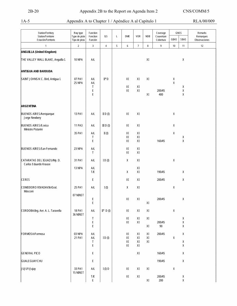
1A-5 Appendix A to Chapter 1 / Apéndice A al Capítulo 1 RLA/00/009
GNSS
Station/Territory Station/Territoire
Estación/Territorio
Rwy type
Type de piste Tipo de pista
Function Fonction Función
ILS
L
DME
VOR
NDB
Coverage
Couverture Cobertura
GBAS
SBAS
Remarks
Remarques Observaciones
1
2
3
4
5
6
7
8
9
10
11
12
ANGUILLA (United Kingdom) THE VALLEY WALL BLAKE, Anguilla I. 10 NPA A/L XI X ANTIGUA AND BARBUDA SAINT JOHNS/V.C. Bird, Antigua I. 07 PA1 A/L II* D XI XI XI X 25 NPA A/L X T XI XI X E XI XI 200/45 X E XI 400 X ARGENTINA BUENOS AIRES/Aeroparque Jorge Newbery
13 PA1 A/L II D (I) XI XI X
BUENOS AIRES/Ezeiza Ministro Pistarini
11 PA3 A/L III D (I) XI XI X
35 PA1 A/L II (I) XI XI X T XI XI X E XI XI 160/45 X BUENOS AIRES/San Fernando 23 NPA A/L XI XI T XI XI CATARATAS DEL IGUAZU/My. D. Carlos Eduardo Krause
31 PA1 A/L I D (I) X XI X
13 NPA A/L XI T/E X XI 190/45 X CERES E XI XI 200/45 X COMODORO RIVADAVIA/Gral. Mosconi
25 PA1 A/L I (I) X XI X
07 NINST E XI XI 200/45 X E XI CORDOBA/Ing. Aer. A. L. Taravella 18 PA1 A/L II* D (I) XI XI XI X 36 NINST T XI XI XI X E XI XI 200/45 X E XI 90 X FORMOSA/Formosa 03 NPA A/L XI XI XI 200/45 X 21 PA1 A/L I D (I) XI XI XI X T XI XI XI X E XI XI X GENERAL PICO E XI 160/45 X GUALEGUAYCHU E 190/45 X JUJUY/Jujuy 33 PA1 A/L I (I) D XI XI XI X 15 NINST T/E XI XI 200/45 X E XI 200 X
2B-20 Appendix 2B to the Report on Agenda Item 2 CNS/COMM/5
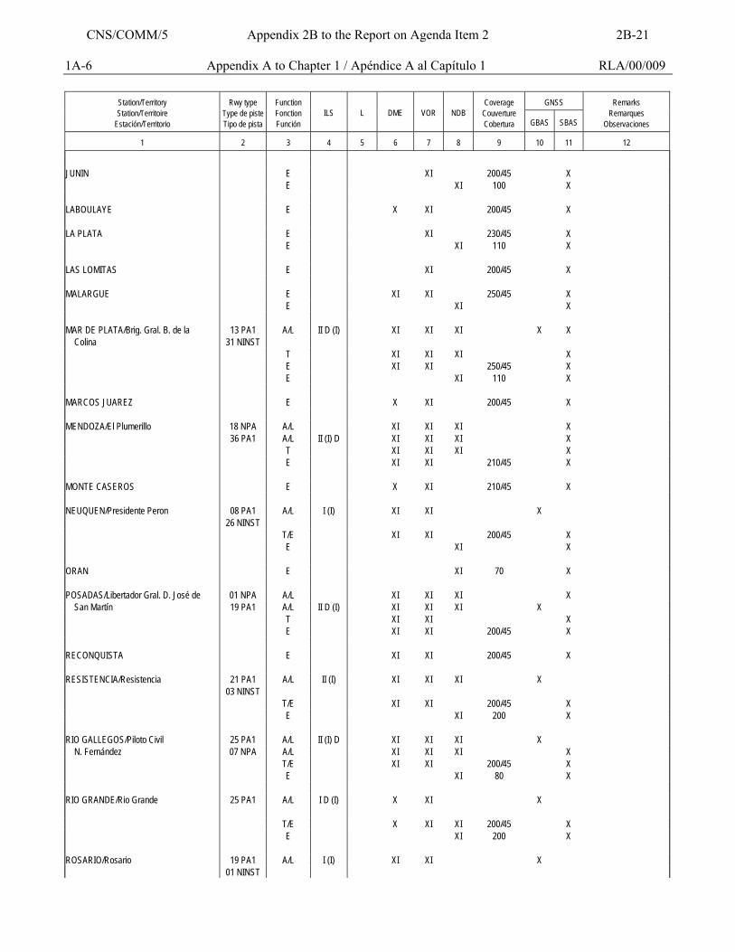
1A-6 Appendix A to Chapter 1 / Apéndice A al Capítulo 1 RLA/00/009
GNSS
Station/Territory Station/Territoire
Estación/Territorio
Rwy type
Type de piste Tipo de pista
Function Fonction Función
ILS
L
DME
VOR
NDB
Coverage
Couverture Cobertura
GBAS
SBAS
Remarks
Remarques Observaciones
1
2
3
4
5
6
7
8
9
10
11
12
JUNIN E XI 200/45 X E XI 100 X LABOULAYE E X XI 200/45 X LA PLATA E XI 230/45 X E XI 110 X LAS LOMITAS E XI 200/45 X MALARGUE E XI XI 250/45 X E XI X MAR DE PLATA/Brig. Gral. B. de la 13 PA1 A/L II D (I) XI XI XI X X Colina 31 NINST T XI XI XI X E XI XI 250/45 X E XI 110 X MARCOS JUAREZ E X XI 200/45 X MENDOZA/El Plumerillo 18 NPA A/L XI XI XI X 36 PA1 A/L II (I) D XI XI XI X T XI XI XI X E XI XI 210/45 X MONTE CASEROS E X XI 210/45 X NEUQUEN/Presidente Peron 08 PA1 A/L I (I) XI XI X 26 NINST T/E XI XI 200/45 X E XI X ORAN E XI 70 X POSADAS/Libertador Gral. D. José de 01 NPA A/L XI XI XI X San Martín 19 PA1 A/L II D (I) XI XI XI X T XI XI X E XI XI 200/45 X RECONQUISTA E XI XI 200/45 X RESISTENCIA/Resistencia 21 PA1 A/L II (I) XI XI XI X 03 NINST T/E XI XI 200/45 X E XI 200 X RIO GALLEGOS/Piloto Civil 25 PA1 A/L II (I) D XI XI XI X N. Fernández 07 NPA A/L XI XI XI X T/E XI XI 200/45 X E XI 80 X RIO GRANDE/Rio Grande 25 PA1 A/L I D (I) X XI X T/E X XI XI 200/45 X E XI 200 X ROSARIO/Rosario 19 PA1 A/L I (I) XI XI X 01 NINST
CNS/COMM/5 Appendix 2B to the Report on Agenda Item 2 2B-21
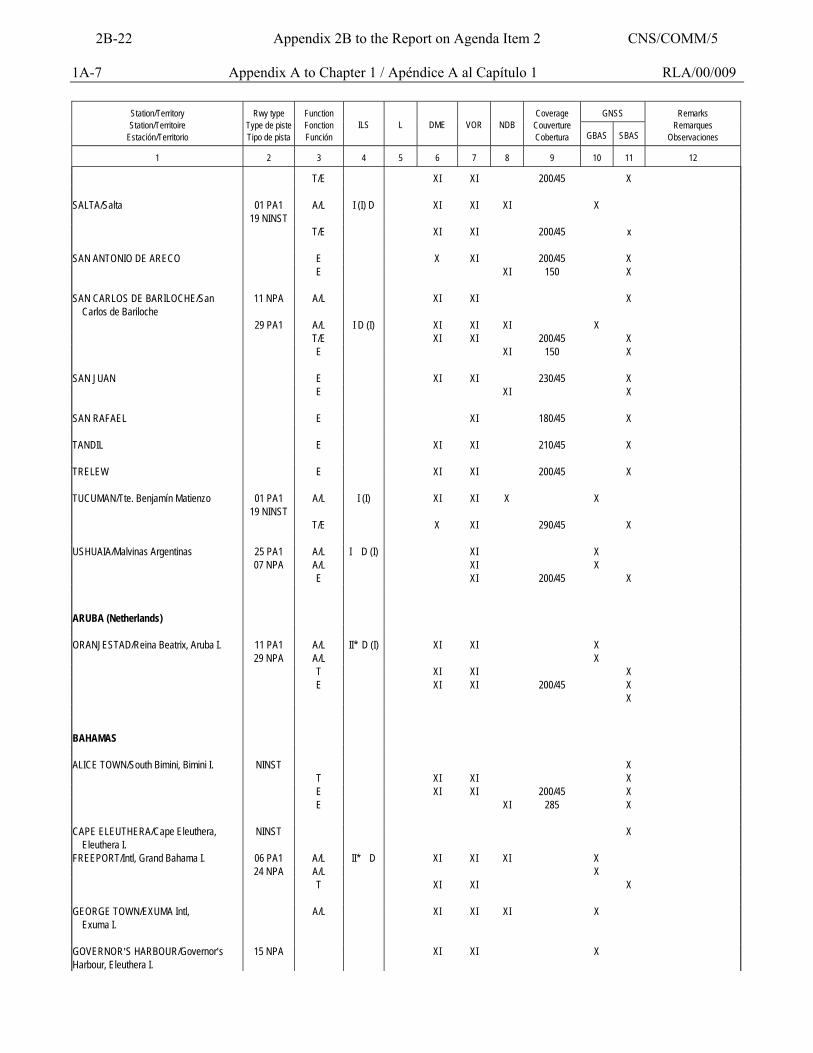
1A-7 Appendix A to Chapter 1 / Apéndice A al Capítulo 1 RLA/00/009
GNSS
Station/Territory Station/Territoire
Estación/Territorio
Rwy type
Type de piste Tipo de pista
Function Fonction Función
ILS
L
DME
VOR
NDB
Coverage
Couverture Cobertura
GBAS
SBAS
Remarks
Remarques Observaciones
1
2
3
4
5
6
7
8
9
10
11
12
T/E XI XI 200/45 X SALTA/Salta 01 PA1 A/L I (I) D XI XI XI X 19 NINST T/E XI XI 200/45 x SAN ANTONIO DE ARECO E X XI 200/45 X E XI 150 X SAN CARLOS DE BARILOCHE/San Carlos de Bariloche
11 NPA A/L XI XI X
29 PA1 A/L I D (I) XI XI XI X T/E XI XI 200/45 X E XI 150 X SAN JUAN E XI XI 230/45 X E XI X SAN RAFAEL E XI 180/45 X TANDIL E XI XI 210/45 X TRELEW E XI XI 200/45 X TUCUMAN/Tte. Benjamín Matienzo 01 PA1
19 NINST A/L I (I) XI XI X X
T/E X XI 290/45 X USHUAIA/Malvinas Argentinas 25 PA1 A/L I D (I) XI X 07 NPA A/L XI X E XI 200/45 X ARUBA (Netherlands) ORANJESTAD/Reina Beatrix, Aruba I. 11 PA1 A/L II* D (I) XI XI X 29 NPA A/L X T XI XI X E XI XI 200/45 X X BAHAMAS ALICE TOWN/South Bimini, Bimini I. NINST X T XI XI X E XI XI 200/45 X E XI 285 X CAPE ELEUTHERA/Cape Eleuthera, Eleuthera I.
NINST X
FREEPORT/Intl, Grand Bahama I. 06 PA1 A/L II* D XI XI XI X 24 NPA A/L X T XI XI X GEORGE TOWN/EXUMA Intl, Exuma I.
A/L XI XI XI X
GOVERNOR=S HARBOUR/Governor=s Harbour, Eleuthera I.
15 NPA XI XI X
2B-22 Appendix 2B to the Report on Agenda Item 2 CNS/COMM/5
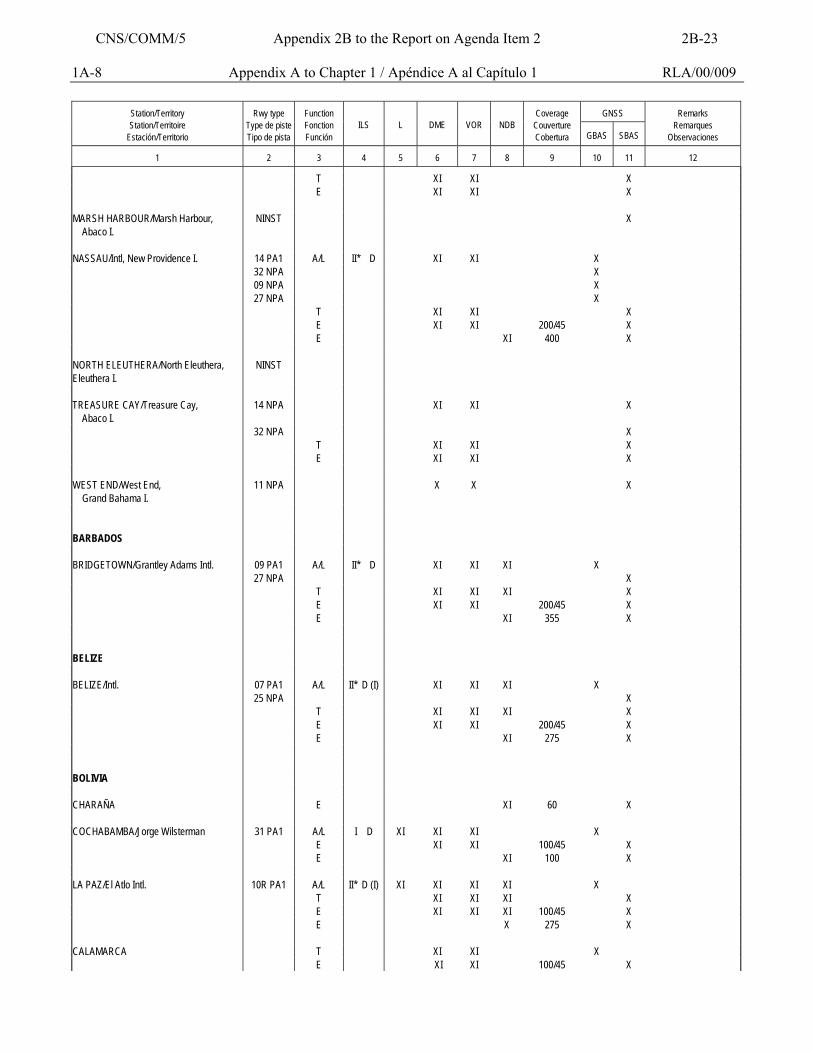
1A-8 Appendix A to Chapter 1 / Apéndice A al Capítulo 1 RLA/00/009
GNSS
Station/Territory Station/Territoire
Estación/Territorio
Rwy type
Type de piste Tipo de pista
Function Fonction Función
ILS
L
DME
VOR
NDB
Coverage
Couverture Cobertura
GBAS
SBAS
Remarks
Remarques Observaciones
1
2
3
4
5
6
7
8
9
10
11
12
T XI XI X E XI XI X MARSH HARBOUR/Marsh Harbour, Abaco I.
NINST X
NASSAU/Intl, New Providence I. 14 PA1 A/L II* D XI XI X 32 NPA X 09 NPA X 27 NPA X T XI XI X E XI XI 200/45 X E XI 400 X NORTH ELEUTHERA/North Eleuthera, Eleuthera I.
NINST
TREASURE CAY/Treasure Cay, Abaco I.
14 NPA XI XI X
32 NPA X T XI XI X E XI XI X WEST END/West End, Grand Bahama I.
11 NPA X X X
BARBADOS BRIDGETOWN/Grantley Adams Intl. 09 PA1 A/L II* D XI XI XI X 27 NPA X T XI XI XI X E XI XI 200/45 X E XI 355 X BELIZE BELIZE/Intl. 07 PA1 A/L II* D (I) XI XI XI X 25 NPA X T XI XI XI X E XI XI 200/45 X E XI 275 X BOLIVIA CHARAÑA E XI 60 X COCHABAMBA/Jorge Wilsterman 31 PA1 A/L I D XI XI XI X E XI XI 100/45 X E XI 100 X LA PAZ/El Atlo Intl. 10R PA1 A/L II* D (I) XI XI XI XI X T XI XI XI X E XI XI XI 100/45 X E X 275 X CALAMARCA T XI XI X E XI XI 100/45 X
CNS/COMM/5 Appendix 2B to the Report on Agenda Item 2 2B-23
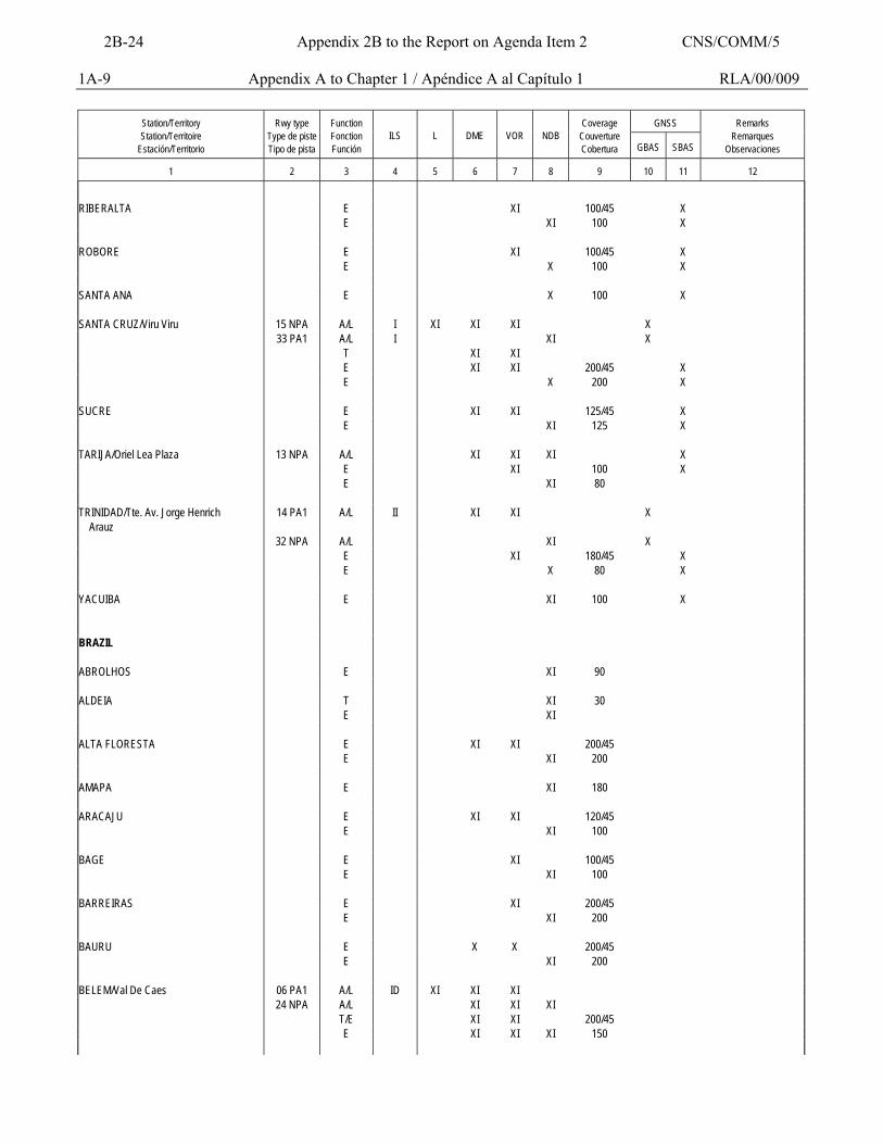
1A-9 Appendix A to Chapter 1 / Apéndice A al Capítulo 1 RLA/00/009
GNSS
Station/Territory Station/Territoire
Estación/Territorio
Rwy type
Type de piste Tipo de pista
Function Fonction Función
ILS
L
DME
VOR
NDB
Coverage
Couverture Cobertura
GBAS
SBAS
Remarks
Remarques Observaciones
1
2
3
4
5
6
7
8
9
10
11
12
RIBERALTA E XI 100/45 X E XI 100 X ROBORE E XI 100/45 X E X 100 X SANTA ANA E X 100 X SANTA CRUZ/Viru Viru 15 NPA A/L I XI XI XI X 33 PA1 A/L I XI X T XI XI E XI XI 200/45 X E X 200 X SUCRE E XI XI 125/45 X E XI 125 X TARIJA/Oriel Lea Plaza 13 NPA A/L XI XI XI X E XI 100 X E XI 80 TRINIDAD/Tte. Av. Jorge Henrich Arauz
14 PA1 A/L II XI XI X
32 NPA A/L XI X E XI 180/45 X E X 80 X YACUIBA E XI 100 X BRAZIL ABROLHOS E XI 90 ALDEIA T XI 30 E XI ALTA FLORESTA E XI XI 200/45 E XI 200 AMAPA E XI 180 ARACAJU E XI XI 120/45 E XI 100 BAGE E XI 100/45 E XI 100 BARREIRAS E XI 200/45 E XI 200 BAURU E X X 200/45 E XI 200 BELEM/Val De Caes 06 PA1 A/L ID XI XI XI 24 NPA A/L XI XI XI T/E XI XI 200/45 E XI XI XI 150
2B-24 Appendix 2B to the Report on Agenda Item 2 CNS/COMM/5
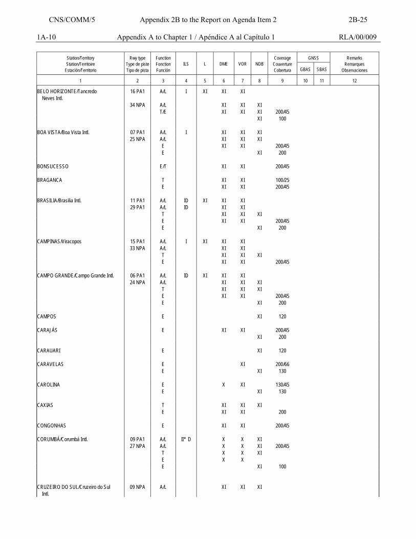
1A-10 Appendix A to Chapter 1 / Apéndice A al Capítulo 1 RLA/00/009
GNSS
Station/Territory Station/Territoire
Estación/Territorio
Rwy type
Type de piste Tipo de pista
Function Fonction Función
ILS
L
DME
VOR
NDB
Coverage
Couverture Cobertura
GBAS
SBAS
Remarks
Remarques Observaciones
1
2
3
4
5
6
7
8
9
10
11
12
BELO HORIZONTE/Tancredo Neves Intl.
16 PA1 A/L I XI XI XI
34 NPA A/L XI XI XI T/E XI XI XI 200/45 XI 100 BOA VISTA/Boa Vista Intl. 07 PA1 A/L I XI XI XI 25 NPA A/L XI XI XI E XI XI 200/45 E XI 200 BONSUCESSO E/T XI XI 200/45 BRAGANCA T XI XI 100/25 E XI XI 200/45 BRASILIA/Brasilia Intl. 11 PA1 A/L ID XI XI XI 29 PA1 A/L ID XI XI T XI XI XI E XI XI 200/45 E XI 200 CAMPINAS/Viracopos 15 PA1 A/L I XI XI XI 33 NPA A/L XI XI T XI XI XI E XI XI 200/45 CAMPO GRANDE/Campo Grande Intl. 06 PA1 A/L ID XI XI XI 24 NPA A/L XI XI XI T XI XI XI E XI XI 200/45 E XI 200 CAMPOS E XI 120 CARAJÁS E XI XI 200/45 XI 200 CARAUARI E XI 120 CARAVELAS E XI 200/66 E XI 130 CAROLINA E X XI 130/45 E XI 130 CAXIAS T XI XI XI E XI XI 200 CONGONHAS E XI XI 200/45 CORUMBÁ/Corumbá Intl. 09 PA1 A/L II* D X X XI 27 NPA A/L X X XI 200/45 T X X XI E X X E XI 100 CRUZEIRO DO SUL/Cruzeiro do Sul Intl.
09 NPA A/L XI XI XI
CNS/COMM/5 Appendix 2B to the Report on Agenda Item 2 2B-25
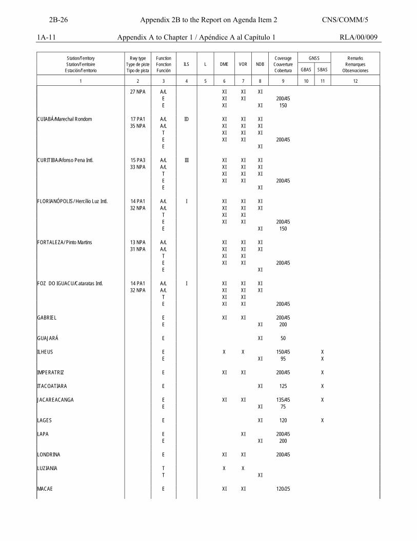
1A-11 Appendix A to Chapter 1 / Apéndice A al Capítulo 1 RLA/00/009
GNSS
Station/Territory Station/Territoire
Estación/Territorio
Rwy type
Type de piste Tipo de pista
Function Fonction Función
ILS
L
DME
VOR
NDB
Coverage
Couverture Cobertura
GBAS
SBAS
Remarks
Remarques Observaciones
1
2
3
4
5
6
7
8
9
10
11
12
27 NPA A/L XI XI XI E XI XI 200/45 E XI XI 150 CUIABÁ/Marechal Rondom 17 PA1 A/L ID XI XI XI 35 NPA A/L XI XI XI T XI XI XI E XI XI 200/45 E XI CURITIBA/Afonso Pena Intl. 15 PA3 A/L III XI XI XI 33 NPA A/L XI XI XI T XI XI XI E XI XI 200/45 E XI FLORIANÓPOLIS/ Hercílio Luz Intl. 14 PA1 A/L I XI XI XI 32 NPA A/L XI XI XI T XI XI E XI XI 200/45 E XI 150 FORTALEZA/ Pinto Martins 13 NPA A/L XI XI XI 31 NPA A/L XI XI XI T XI XI E XI XI 200/45 E XI FOZ DO IGUACU/Cataratas Intl. 14 PA1 A/L I XI XI XI 32 NPA A/L XI XI XI T XI XI E XI XI 200/45 GABRIEL E XI XI 200/45 E XI 200 GUAJARÁ E XI 50 ILHEUS E X X 150/45 X E XI 95 X IMPERATRIZ E XI XI 200/45 X ITACOATIARA E XI 125 X JACAREACANGA E XI XI 135/45 X E XI 75 LAGES E XI 120 X LAPA E XI 200/45 E XI 200 LONDRINA E XI XI 200/45 LUZIANIA T X X T XI MACAE E XI XI 120/25
2B-26 Appendix 2B to the Report on Agenda Item 2 CNS/COMM/5
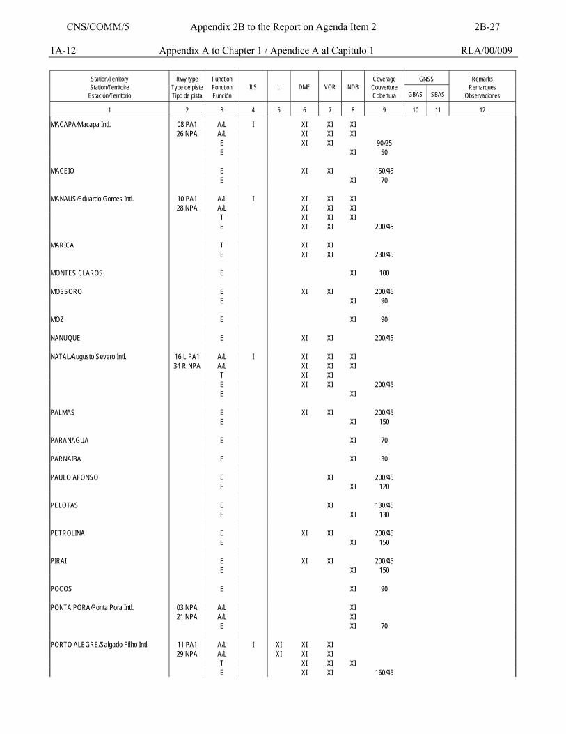
1A-12 Appendix A to Chapter 1 / Apéndice A al Capítulo 1 RLA/00/009
GNSS
Station/Territory Station/Territoire
Estación/Territorio
Rwy type
Type de piste Tipo de pista
Function Fonction Función
ILS
L
DME
VOR
NDB
Coverage
Couverture Cobertura
GBAS
SBAS
Remarks
Remarques Observaciones
1
2
3
4
5
6
7
8
9
10
11
12
MACAPA/Macapa Intl. 08 PA1 A/L I XI XI XI 26 NPA A/L XI XI XI E XI XI 90/25 E XI 50 MACEIO E XI XI 150/45 E XI 70 MANAUS/Eduardo Gomes Intl. 10 PA1 A/L I XI XI XI 28 NPA A/L XI XI XI T XI XI XI E XI XI 200/45 MARICA T XI XI E XI XI 230/45 MONTES CLAROS E XI 100 MOSSORO E XI XI 200/45 E XI 90 MOZ E XI 90 NANUQUE E XI XI 200/45 NATAL/Augusto Severo Intl. 16 L PA1 A/L I XI XI XI 34 R NPA A/L XI XI XI T XI XI E XI XI 200/45 E XI PALMAS E XI XI 200/45 E XI 150 PARANAGUA E XI 70 PARNAIBA E XI 30 PAULO AFONSO E XI 200/45 E XI 120 PELOTAS E XI 130/45 E XI 130 PETROLINA E XI XI 200/45 E XI 150 PIRAI E XI XI 200/45 E XI 150 POCOS E XI 90 PONTA PORA/Ponta Pora Intl. 03 NPA A/L XI 21 NPA A/L XI E XI 70 PORTO ALEGRE/Salgado Filho Intl. 11 PA1 A/L I XI XI XI 29 NPA A/L XI XI XI T XI XI XI E XI XI 160/45
CNS/COMM/5 Appendix 2B to the Report on Agenda Item 2 2B-27
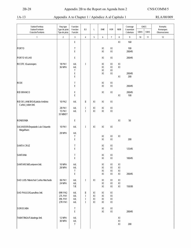
1A-13 Appendix A to Chapter 1 / Apéndice A al Capítulo 1 RLA/00/009
GNSS
Station/Territory Station/Territoire
Estación/Territorio
Rwy type
Type de piste Tipo de pista
Function Fonction Función
ILS
L
DME
VOR
NDB
Coverage
Couverture Cobertura
GBAS
SBAS
Remarks
Remarques Observaciones
1
2
3
4
5
6
7
8
9
10
11
12
E XI 160 PORTO T XI XI 100 E XI XI 200/45 PORTO VELHO E XI XI 200/45 RECIFE /Guararapes 18 PA1 A/L I XI XI XI 36 NPA A/L XI XI XI T XI XI E XI XI 200/45 E XI 200 REDE T XI XI E XI XI 200/45 RIO BRANCO E XI XI 200/45 E XI 100 RIO DE JANEIRO/Galeão Antônio Carlos Jobim Intl.
10 PA2 A/L II XI XI XI
28 PA1 A/L I XI XI XI 15 PA1 A/L I XI XI XI 33 NINST RONDONIA E XI 50 SALVADOR/Deputado Luis Eduardo Magalhaes
10 PA1 A/L I XI XI XI
28 NPA A/L T XI XI XI E XI XI 200 SANTA CRUZ T XI XI E XI XI 125/45 SANTANA T XI XI E XI XI 100/45 SANTAREM/Santarem Intl. 10 NPA A/L XI XI XI 28 NPA A/L XI XI XI T XI XI XI E XI XI XI 200/45 SAO LUIS/ Marechal Cunha Machado 06 PA1 A/L I XI XI XI XI 24 NPA A/L XI XI XI T/E XI XI XI 150/30 SAO PAULO/Guarulhos Intl. 09R PA2 A/L II XI XI XI 27L PA1 A/L I XI XI XI 09L PA1 A/L I XI XI XI 27R PA1 A/L I XI XI XI SOROCABA T XI XI E XI XI 200/45 TABATINGA/Tabatinga Intl. 12 NPA A/L XI 30 NPA A/L XI T XI 200
2B-28 Appendix 2B to the Report on Agenda Item 2 CNS/COMM/5
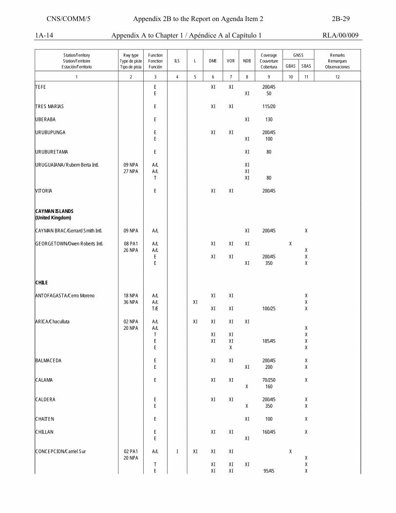
1A-14 Appendix A to Chapter 1 / Apéndice A al Capítulo 1 RLA/00/009
GNSS
Station/Territory Station/Territoire
Estación/Territorio
Rwy type
Type de piste Tipo de pista
Function Fonction Función
ILS
L
DME
VOR
NDB
Coverage
Couverture Cobertura
GBAS
SBAS
Remarks
Remarques Observaciones
1
2
3
4
5
6
7
8
9
10
11
12
TEFE E XI XI 200/45 E XI 50 TRES MARIAS E XI XI 115/20 UBERABA E XI 130 URUBUPUNGA E XI XI 200/45 E XI 100 URUBURETAMA E XI 80 URUGUAIANA/ Rubem Berta Intl. 09 NPA A/L XI 27 NPA A/L XI T XI 80 VITORIA E XI XI 200/45 CAYMAN ISLANDS (United Kingdom)
CAYMAN BRAC/Gerrard Smith Intl. 09 NPA A/L XI 200/45 X GEORGETOWN/Owen Roberts Intl. 08 PA1 A/L XI XI XI X 26 NPA A/L X E XI XI 200/45 X E XI 350 X CHILE ANTOFAGASTA/Cerro Moreno 18 NPA A/L XI XI X 36 NPA A/L XI X T/E XI XI 100/25 X ARICA/Chaculluta 02 NPA A/L XI XI XI XI 20 NPA A/L X T XI XI X E XI XI 185/45 X E X X BALMACEDA E XI XI 200/45 X E XI 200 X CALAMA E XI XI 70/250 X X 160 CALDERA E XI XI 200/45 X E X 350 X CHAITEN E XI 100 X CHILLAN E XI XI 160/45 X E XI CONCEPCION/Carriel Sur 02 PA1 A/L I XI XI XI X 20 NPA X T XI XI XI X E XI XI 95/45 X
CNS/COMM/5 Appendix 2B to the Report on Agenda Item 2 2B-29
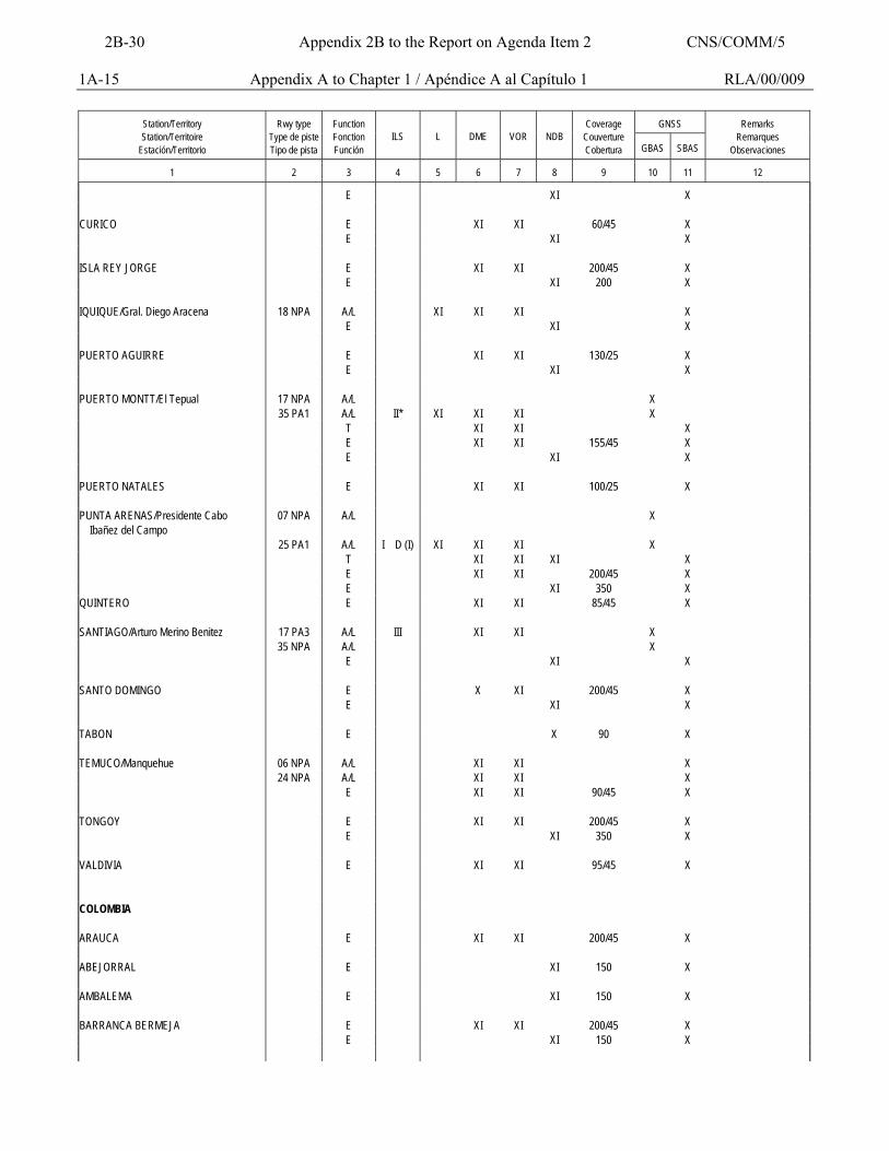
1A-15 Appendix A to Chapter 1 / Apéndice A al Capítulo 1 RLA/00/009
GNSS
Station/Territory Station/Territoire
Estación/Territorio
Rwy type
Type de piste Tipo de pista
Function Fonction Función
ILS
L
DME
VOR
NDB
Coverage
Couverture Cobertura
GBAS
SBAS
Remarks
Remarques Observaciones
1
2
3
4
5
6
7
8
9
10
11
12
E XI X CURICO E XI XI 60/45 X E XI X ISLA REY JORGE E XI XI 200/45 X E XI 200 X IQUIQUE/Gral. Diego Aracena 18 NPA A/L XI XI XI X E XI X PUERTO AGUIRRE E XI XI 130/25 X E XI X PUERTO MONTT/El Tepual 17 NPA A/L X 35 PA1 A/L II* XI XI XI X T XI XI X E XI XI 155/45 X E XI X PUERTO NATALES E XI XI 100/25 X PUNTA ARENAS/Presidente Cabo Ibañez del Campo
07 NPA A/L X
25 PA1 A/L I D (I) XI XI XI X T XI XI XI X E XI XI 200/45 X E XI 350 X QUINTERO E XI XI 85/45 X SANTIAGO/Arturo Merino Benitez 17 PA3 A/L III XI XI X 35 NPA A/L X E XI X SANTO DOMINGO E X XI 200/45 X E XI X TABON E X 90 X TEMUCO/Manquehue 06 NPA A/L XI XI X 24 NPA A/L XI XI X E XI XI 90/45 X TONGOY E XI XI 200/45 X E XI 350 X VALDIVIA E XI XI 95/45 X COLOMBIA ARAUCA E XI XI 200/45 X ABEJORRAL E XI 150 X AMBALEMA E XI 150 X BARRANCA BERMEJA E XI XI 200/45 X E XI 150 X
2B-30 Appendix 2B to the Report on Agenda Item 2 CNS/COMM/5
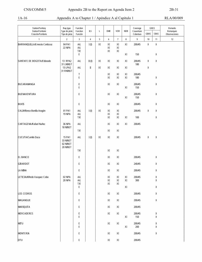
1A-16 Appendix A to Chapter 1 / Apéndice A al Capítulo 1 RLA/00/009
GNSS
Station/Territory Station/Territoire
Estación/Territorio
Rwy type
Type de piste Tipo de pista
Function Fonction Función
ILS
L
DME
VOR
NDB
Coverage
Couverture Cobertura
GBAS
SBAS
Remarks
Remarques Observaciones
1
2
3
4
5
6
7
8
9
10
11
12
BARRANQUILLA/Ernesto Cortissoz 04 PA1 A/L I (I) XI XI XI XI 200/45 X X 22 NPA A/L XI XI T/E XI XI E XI 150 X SANTAFE DE BOGOTA/Eldorado 13 RPA2 A/L II (I) XI XI XI XI 200/45 X X 31 LNINST 180 13 LPA2 A/L II XI XI XI XI X 31 RNINST T XI XI XI 200/45 E XI XI XI 180 X BUCARAMANGA E XI XI 200/45 X E XI 150 BUENAVENTURA E XI XI 200/45 X XI 150 BUVIS E XI XI 200/45 X CALI/Alfonso Bonilla Aragón 01 PA1 A/L I (I) XI XI XI 200/45 X X 19 NPA A/L XI XI T/E XI XI XI 100 X CARTAGENA/Rafael Nuñez 36 NPA A/L XI XI XI 200/45 18 NINST T/E XI XI CUCUTA/Camilo Daza 15 PA1 A/L I (I) XI XI XI 200/45 X X 33 NINST 02 NINST 20 NINST T/E XI XI EL BANCO E XI XI 200/45 X GIRARDOT E XI XI 240/45 X LA MINA E XI XI 200/45 X LETICIA/Alfredo Vasquez Cobo 02 NPA A/L XI XI XI 200/45 X 20 NPA A/L XI XI XI 300 X T/E XI XI E XI X LOS CEDROS E XI XI 200/45 X MAGANGUE E XI XI 200/45 X MARIQUITA E XI XI 200/45 MERCADERES E XI XI 200/45 X E XI 150 X MITU E XI XI 200/45 X E XI 200 X MONTERIA E XI XI 200/45 X OTU E XI XI 200/45
CNS/COMM/5 Appendix 2B to the Report on Agenda Item 2 2B-31
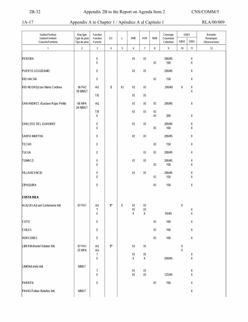
1A-17 Appendix A to Chapter 1 / Apéndice A al Capítulo 1 RLA/00/009
GNSS
Station/Territory Station/Territoire
Estación/Territorio
Rwy type
Type de piste Tipo de pista
Function Fonction Función
ILS
L
DME
VOR
NDB
Coverage
Couverture Cobertura
GBAS
SBAS
Remarks
Remarques Observaciones
1
2
3
4
5
6
7
8
9
10
11
12
PEREIRA E XI XI 200/45 X E XI 100 X PUERTO LEGUIZAMO E XI XI 200/45 X RIO HACHA E XI 150 X RIO NEGRO/Jose Maria Cordova 36 PA2 A/L II XI XI XI 200/45 X X 18 NINST X T/E XI XI SAN ANDRES /Gustavo Rojas Pinilla 06 NPA A/L XI XI XI 200/45 X 24 NINST T/E XI XI XI E XI 200 X SAN JOSE DEL GUAVIARE E XI XI 200/45 X E XI 160 X SANTA MARTHA E XI XI 200/45 X TECHO E XI 150 X TULUA E XI XI 200/45 X TUMACO E XI XI 200/45 X E XI 150 X VILLAVICENCIO E XI XI 200/45 X E XI 150 X ZIPAQUIRA E XI 150 X COSTA RICA ALAJUELA/Juan Santamaria Intl. 07 PA1 A/L II* X XI XI X T XI XI X E X X 95/45 X COTO E XI 100 X CHILES E XI 100 X HORCONES E XI 100 X LIBERIA/Daniel Oduber Intl. 07 PA1 A/L II* XI XI X 25 NPA A/L X T XI XI X E X X 200/45 X LIMON/Limón Intl. NINST T XI XI X E XI XI 125/45 X PARRITA E XI 100 X PAVAS/Tobias Bolaños Intl. NINST X
2B-32 Appendix 2B to the Report on Agenda Item 2 CNS/COMM/5
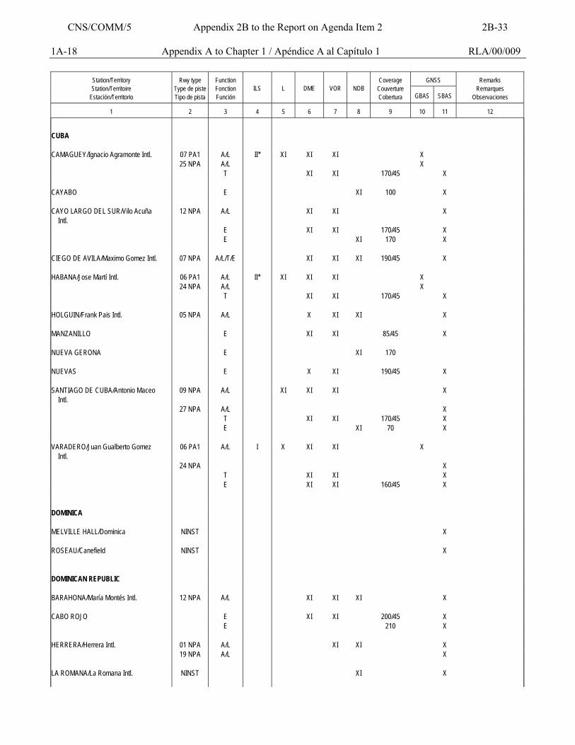
1A-18 Appendix A to Chapter 1 / Apéndice A al Capítulo 1 RLA/00/009
GNSS
Station/Territory Station/Territoire
Estación/Territorio
Rwy type
Type de piste Tipo de pista
Function Fonction Función
ILS
L
DME
VOR
NDB
Coverage
Couverture Cobertura
GBAS
SBAS
Remarks
Remarques Observaciones
1
2
3
4
5
6
7
8
9
10
11
12
CUBA CAMAGUEY/Ignacio Agramonte Intl. 07 PA1 A/L II* XI XI XI X 25 NPA A/L X T XI XI 170/45 X CAYABO E XI 100 X CAYO LARGO DEL SUR/Vilo Acuña Intl.
12 NPA A/L XI XI X
E XI XI 170/45 X E XI 170 X CIEGO DE AVILA/Maximo Gomez Intl. 07 NPA A/L/T/E XI XI XI 190/45 X HABANA/Jose Martí Intl. 06 PA1 A/L II* XI XI XI X 24 NPA A/L X T XI XI 170/45 X HOLGUIN/Frank Pais Intl. 05 NPA A/L X XI XI X MANZANILLO E XI XI 85/45 X NUEVA GERONA E XI 170 NUEVAS E X XI 190/45 X SANTIAGO DE CUBA/Antonio Maceo Intl.
09 NPA A/L XI XI XI X
27 NPA A/L X T XI XI 170/45 X E XI 70 X VARADERO/Juan Gualberto Gomez Intl.
06 PA1 A/L I X XI XI X
24 NPA X T XI XI X E XI XI 160/45 X DOMINICA MELVILLE HALL/Dominica NINST X ROSEAU/Canefield NINST X DOMINICAN REPUBLIC BARAHONA/María Montés Intl. 12 NPA A/L XI XI XI X CABO ROJO E XI XI 200/45 X E 210 X HERRERA/Herrera Intl. 01 NPA A/L XI XI X 19 NPA A/L X LA ROMANA/La Romana Intl. NINST XI X
CNS/COMM/5 Appendix 2B to the Report on Agenda Item 2 2B-33
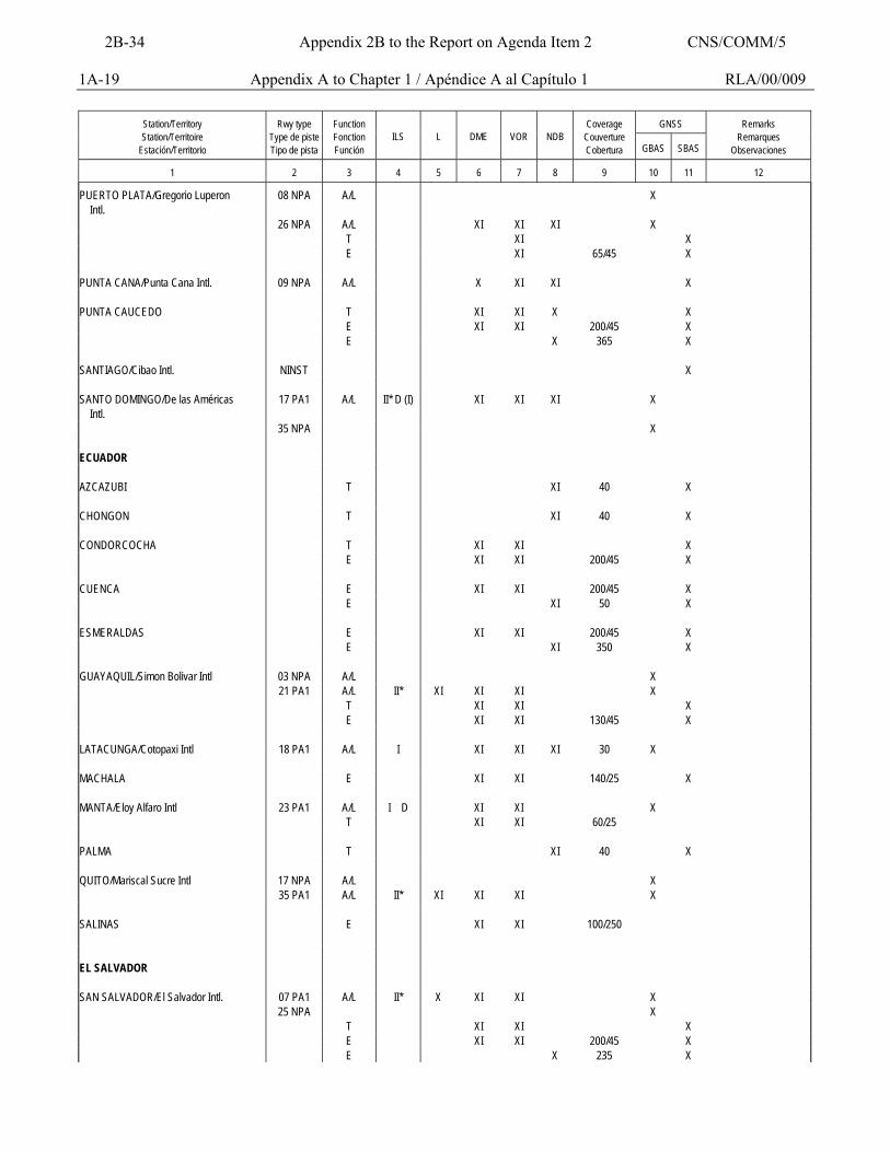
1A-19 Appendix A to Chapter 1 / Apéndice A al Capítulo 1 RLA/00/009
GNSS
Station/Territory Station/Territoire
Estación/Territorio
Rwy type
Type de piste Tipo de pista
Function Fonction Función
ILS
L
DME
VOR
NDB
Coverage
Couverture Cobertura
GBAS
SBAS
Remarks
Remarques Observaciones
1
2
3
4
5
6
7
8
9
10
11
12
PUERTO PLATA/Gregorio Luperon Intl.
08 NPA A/L X
26 NPA A/L XI XI XI X T XI X E XI 65/45 X PUNTA CANA/Punta Cana Intl. 09 NPA A/L X XI XI X PUNTA CAUCEDO T XI XI X X E XI XI 200/45 X E X 365 X SANTIAGO/Cibao Intl. NINST X SANTO DOMINGO/De las Américas Intl.
17 PA1 A/L II* D (I) XI XI XI X
35 NPA X ECUADOR AZCAZUBI T XI 40 X CHONGON T XI 40 X CONDORCOCHA T XI XI X E XI XI 200/45 X CUENCA E XI XI 200/45 X E XI 50 X ESMERALDAS E XI XI 200/45 X E XI 350 X GUAYAQUIL/Simon Bolivar Intl 03 NPA A/L X 21 PA1 A/L II* XI XI XI X T XI XI X E XI XI 130/45 X LATACUNGA/Cotopaxi Intl 18 PA1 A/L I XI XI XI 30 X MACHALA E XI XI 140/25 X MANTA/Eloy Alfaro Intl 23 PA1 A/L I D XI XI X T XI XI 60/25 PALMA T XI 40 X QUITO/Mariscal Sucre Intl 17 NPA A/L X 35 PA1 A/L II* XI XI XI X SALINAS E XI XI 100/250 EL SALVADOR SAN SALVADOR/El Salvador Intl. 07 PA1 A/L II* X XI XI X 25 NPA X T XI XI X E XI XI 200/45 X E X 235 X
2B-34 Appendix 2B to the Report on Agenda Item 2 CNS/COMM/5
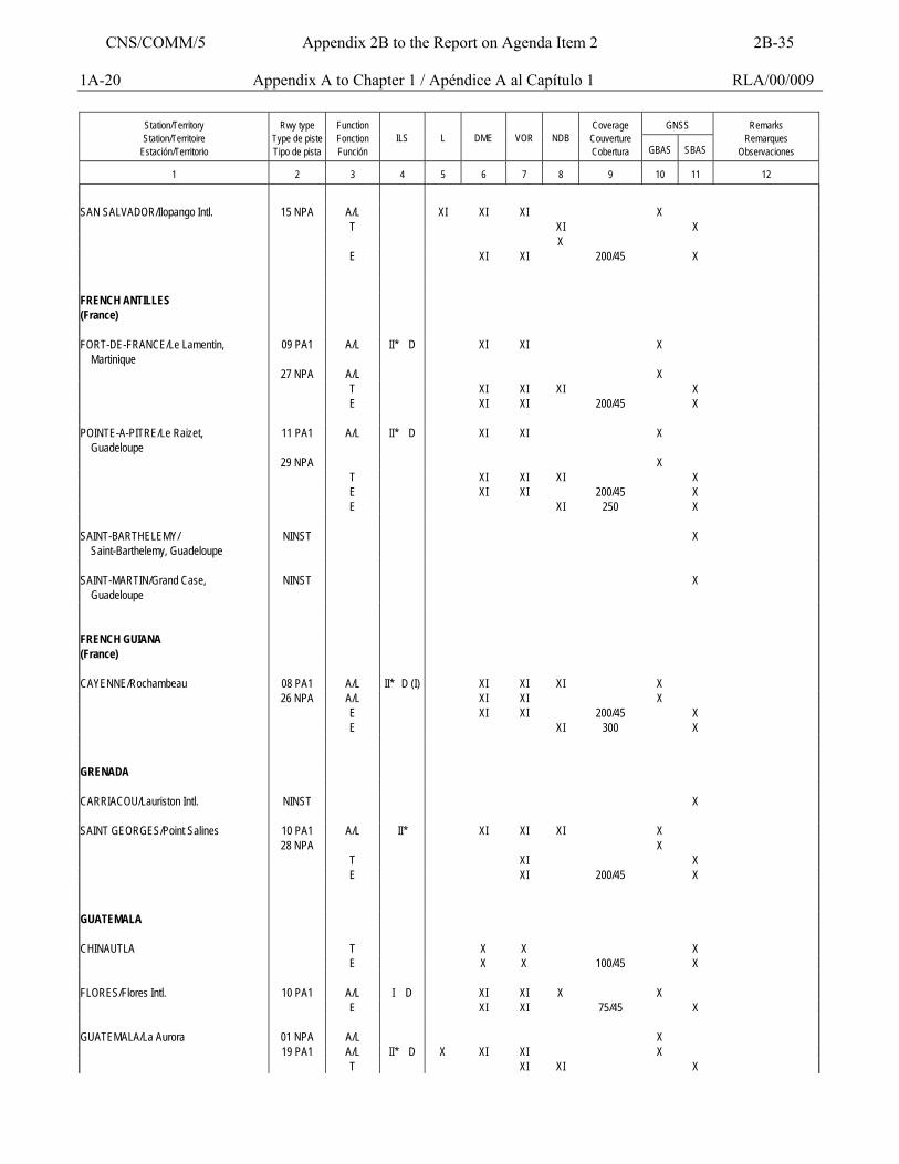
1A-20 Appendix A to Chapter 1 / Apéndice A al Capítulo 1 RLA/00/009
GNSS
Station/Territory Station/Territoire
Estación/Territorio
Rwy type
Type de piste Tipo de pista
Function Fonction Función
ILS
L
DME
VOR
NDB
Coverage
Couverture Cobertura
GBAS
SBAS
Remarks
Remarques Observaciones
1
2
3
4
5
6
7
8
9
10
11
12
SAN SALVADOR/Ilopango Intl. 15 NPA A/L XI XI XI X T XI X X E XI XI 200/45 X FRENCH ANTILLES (France)
FORT-DE-FRANCE/Le Lamentin, Martinique
09 PA1 A/L II* D XI XI X
27 NPA A/L X T XI XI XI X E XI XI 200/45 X POINTE-A-PITRE/Le Raizet, Guadeloupe
11 PA1 A/L II* D XI XI X
29 NPA X T XI XI XI X E XI XI 200/45 X E XI 250 X SAINT-BARTHELEMY/ Saint-Barthelemy, Guadeloupe
NINST X
SAINT-MARTIN/Grand Case, Guadeloupe
NINST X
FRENCH GUIANA (France)
CAYENNE/Rochambeau 08 PA1 A/L II* D (I) XI XI XI X 26 NPA A/L XI XI X E XI XI 200/45 X E XI 300 X GRENADA CARRIACOU/Lauriston Intl. NINST X SAINT GEORGES/Point Salines 10 PA1 A/L II* XI XI XI X 28 NPA X T XI X E XI 200/45 X GUATEMALA CHINAUTLA T X X X E X X 100/45 X FLORES/Flores Intl. 10 PA1 A/L I D XI XI X X E XI XI 75/45 X GUATEMALA/La Aurora 01 NPA A/L X 19 PA1 A/L II* D X XI XI X T XI XI X
CNS/COMM/5 Appendix 2B to the Report on Agenda Item 2 2B-35
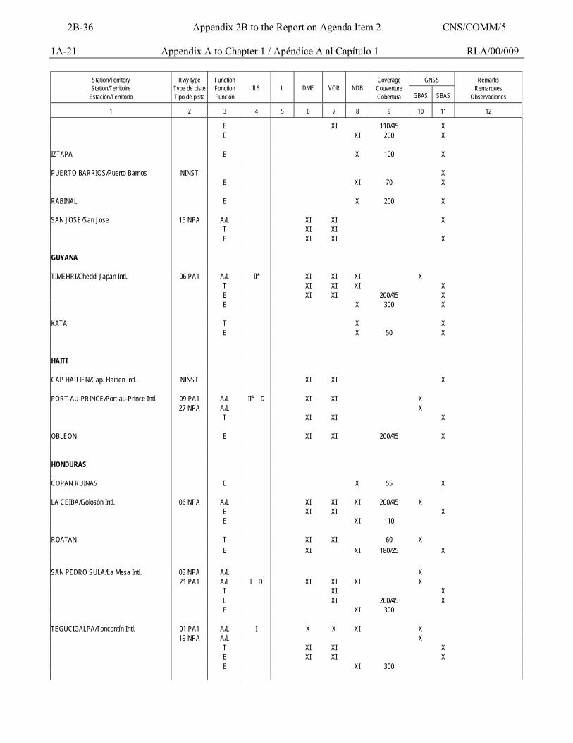
1A-21 Appendix A to Chapter 1 / Apéndice A al Capítulo 1 RLA/00/009
GNSS
Station/Territory Station/Territoire
Estación/Territorio
Rwy type
Type de piste Tipo de pista
Function Fonction Función
ILS
L
DME
VOR
NDB
Coverage
Couverture Cobertura
GBAS
SBAS
Remarks
Remarques Observaciones
1
2
3
4
5
6
7
8
9
10
11
12
E XI 110/45 X E XI 200 X IZTAPA E X 100 X PUERTO BARRIOS/Puerto Barrios NINST X E XI 70 X RABINAL E X 200 X SAN JOSE/San Jose 15 NPA A/L XI XI X T XI XI E XI XI X GUYANA TIMEHRI/Cheddi Japan Intl. 06 PA1 A/L II* XI XI XI X T XI XI XI X E XI XI 200/45 X E X 300 X KATA T X X E X 50 X HAITI CAP HAITIEN/Cap. Haitien Intl. NINST XI XI X PORT-AU-PRINCE/Port-au-Prince Intl. 09 PA1 A/L II* D XI XI X 27 NPA A/L X T XI XI X OBLEON E XI XI 200/45 X HONDURAS . COPAN RUINAS E X 55 X LA CEIBA/Golosón Intl. 06 NPA A/L XI XI XI 200/45 X E XI XI X E XI 110 ROATAN T XI XI 60 X E XI XI 180/25 X SAN PEDRO SULA/La Mesa Intl. 03 NPA A/L X 21 PA1 A/L I D XI XI XI X T XI X E XI 200/45 X E XI 300 TEGUCIGALPA/Toncontín Intl. 01 PA1 A/L I X X XI X 19 NPA A/L X T XI XI X E XI XI X E XI 300
2B-36 Appendix 2B to the Report on Agenda Item 2 CNS/COMM/5
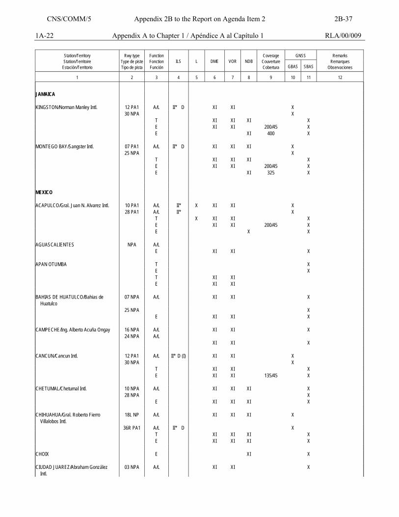
1A-22 Appendix A to Chapter 1 / Apéndice A al Capítulo 1 RLA/00/009
GNSS
Station/Territory Station/Territoire
Estación/Territorio
Rwy type
Type de piste Tipo de pista
Function Fonction Función
ILS
L
DME
VOR
NDB
Coverage
Couverture Cobertura
GBAS
SBAS
Remarks
Remarques Observaciones
1
2
3
4
5
6
7
8
9
10
11
12
JAMAICA KINGSTON/Norman Manley Intl. 12 PA1 A/L II* D XI XI X 30 NPA X T XI XI XI X E XI XI 200/45 X E XI 400 X MONTEGO BAY/Sangster Intl. 07 PA1 A/L II* D XI XI XI X 25 NPA X T XI XI XI X E XI XI 200/45 X E XI 325 X MEXICO ACAPULCO/Gral. Juan N. Alvarez Intl. 10 PA1 A/L II* X XI XI X 28 PA1 A/L II* X T X XI XI X E XI XI 200/45 X E X X AGUASCALIENTES NPA A/L E XI XI X APAN OTUMBA T X E X T XI XI E XI XI BAHIAS DE HUATULCO/Bahias de Huatulco
07 NPA A/L XI XI X
25 NPA X E XI XI X CAMPECHE/Ing. Alberto Acuña Ongay 16 NPA A/L XI XI X 24 NPA A/L XI XI X CANCUN/Cancun Intl. 12 PA1 A/L II* D (I) XI XI X 30 NPA X T XI XI X E XI XI 135/45 X CHETUMAL/Chetumal Intl. 10 NPA A/L XI XI XI X 28 NPA X E XI XI XI X CHIHUAHUA/Gral. Roberto Fierro Villalobos Intl.
18L NP A/L XI XI XI X
36R PA1 A/L II* D X T XI XI XI X E XI XI XI X CHOIX E XI X CIUDAD JUAREZ/Abraham González Intl.
03 NPA A/L XI XI X
CNS/COMM/5 Appendix 2B to the Report on Agenda Item 2 2B-37
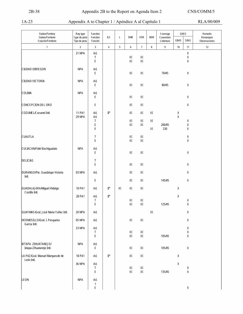
1A-23 Appendix A to Chapter 1 / Apéndice A al Capítulo 1 RLA/00/009
GNSS
Station/Territory Station/Territoire
Estación/Territorio
Rwy type
Type de piste Tipo de pista
Function Fonction Función
ILS
L
DME
VOR
NDB
Coverage
Couverture Cobertura
GBAS
SBAS
Remarks
Remarques Observaciones
1
2
3
4
5
6
7
8
9
10
11
12
21 NPA A/L X T XI XI X E XI XI X CIUDAD OBREGON NPA A/L E XI XI 70/45 X CIUDAD VICTORIA NPA A/L E XI XI 80/45 X COLIMA NPA A/L E XI XI X CONCEPCION DEL ORO E XI XI X COZUMEL/Cozumel Intl. 11 PA1 A/L II* XI XI XI X 29 NPA A/L X T XI XI XI X E XI XI 200/45 X E XI 230 X CUAUTLA T XI XI X E XI XI X CULIACAN/Fidel Bachigualato NPA A/L E XI XI X DELICIAS T E XI XI X DURANGO/Pte. Guadalupe Victoria Intl.
03 NPA A/L XI XI X
E XI XI 145/45 X GUADALAJARA/Miguel Hidalgo Costilla Intl.
10 PA1 A/L II* XI XI XI X
28 PA1 A/L II* X T XI XI X E XI XI 125/45 X GUAYMAS/Gral. José Maria Yañez Intl. 20 NPA A/L XI X HERMOSILLO/Gral. I. Pesqueira Garcia Intl.
05 NPA A/L XI XI X
23 NPA A/L X T XI XI X E XI XI 105/45 X IXTAPA -ZIHUATANEJO/ NPA A/L Ixtapa-Zihuatanejo Intl. E XI XI 105/45 X LA PAZ/Gral. Manuel Marquesde de León Intl.
18 PA1 A/L II* XI XI X
36 NPA A/L X T XI XI X E XI XI 135/45 X LEON NPA A/L t E X
2B-38 Appendix 2B to the Report on Agenda Item 2 CNS/COMM/5
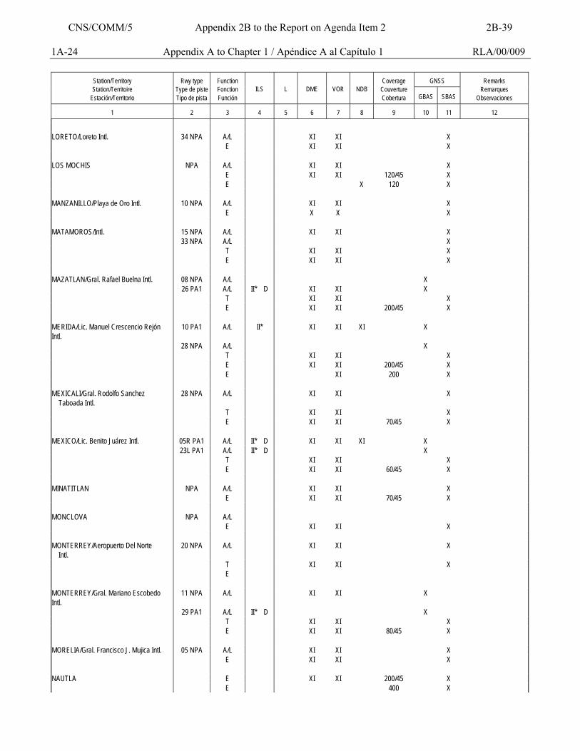
1A-24 Appendix A to Chapter 1 / Apéndice A al Capítulo 1 RLA/00/009
GNSS
Station/Territory Station/Territoire
Estación/Territorio
Rwy type
Type de piste Tipo de pista
Function Fonction Función
ILS
L
DME
VOR
NDB
Coverage
Couverture Cobertura
GBAS
SBAS
Remarks
Remarques Observaciones
1
2
3
4
5
6
7
8
9
10
11
12
LORETO/Loreto Intl. 34 NPA A/L XI XI X E XI XI X LOS MOCHIS NPA A/L XI XI X E XI XI 120/45 X E X 120 X MANZANILLO/Playa de Oro Intl. 10 NPA A/L XI XI X E X X X MATAMOROS/Intl. 15 NPA A/L XI XI X 33 NPA A/L X T XI XI X E XI XI X MAZATLAN/Gral. Rafael Buelna Intl. 08 NPA A/L X 26 PA1 A/L II* D XI XI X T XI XI X E XI XI 200/45 X MERIDA/Lic. Manuel Crescencio Rejón Intl.
10 PA1 A/L II* XI XI XI X
28 NPA A/L X T XI XI X E XI XI 200/45 X E XI 200 X MEXICALI/Gral. Rodolfo Sanchez Taboada Intl.
28 NPA A/L XI XI X
T XI XI X E XI XI 70/45 X MEXICO/Lic. Benito Juárez Intl. 05R PA1 A/L II* D XI XI XI X 23L PA1 A/L II* D X T XI XI X E XI XI 60/45 X MINATITLAN NPA A/L XI XI X E XI XI 70/45 X MONCLOVA NPA A/L E XI XI X MONTERREY/Aeropuerto Del Norte Intl.
20 NPA A/L XI XI X
T XI XI X E MONTERREY/Gral. Mariano Escobedo Intl.
11 NPA A/L XI XI X
29 PA1 A/L II* D X T XI XI X E XI XI 80/45 X MORELIA/Gral. Francisco J. Mujica Intl. 05 NPA A/L XI XI X E XI XI X NAUTLA E XI XI 200/45 X E 400 X
CNS/COMM/5 Appendix 2B to the Report on Agenda Item 2 2B-39
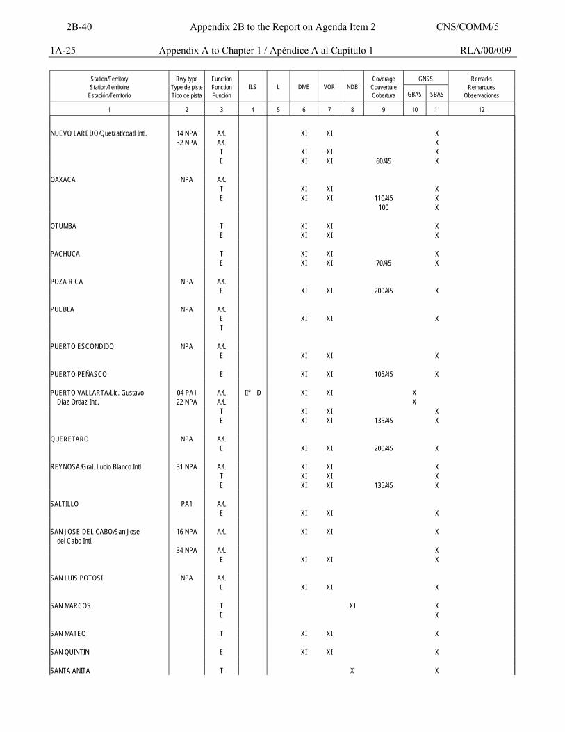
1A-25 Appendix A to Chapter 1 / Apéndice A al Capítulo 1 RLA/00/009
GNSS
Station/Territory Station/Territoire
Estación/Territorio
Rwy type
Type de piste Tipo de pista
Function Fonction Función
ILS
L
DME
VOR
NDB
Coverage
Couverture Cobertura
GBAS
SBAS
Remarks
Remarques Observaciones
1
2
3
4
5
6
7
8
9
10
11
12
NUEVO LAREDO/Quetzatlcoatl Intl. 14 NPA A/L XI XI X 32 NPA A/L X T XI XI X E XI XI 60/45 X OAXACA NPA A/L T XI XI X E XI XI 110/45 X 100 X OTUMBA T XI XI X E XI XI X PACHUCA T XI XI X E XI XI 70/45 X POZA RICA NPA A/L E XI XI 200/45 X PUEBLA NPA A/L E XI XI X T PUERTO ESCONDIDO NPA A/L E XI XI X PUERTO PEÑASCO E XI XI 105/45 X PUERTO VALLARTA/Lic. Gustavo 04 PA1 A/L II* D XI XI X Díaz Ordaz Intl. 22 NPA A/L X T XI XI X E XI XI 135/45 X QUERETARO NPA A/L E XI XI 200/45 X REYNOSA/Gral. Lucio Blanco Intl. 31 NPA A/L XI XI X T XI XI X E XI XI 135/45 X SALTILLO PA1 A/L E XI XI X SAN JOSE DEL CABO/San Jose del Cabo Intl.
16 NPA A/L XI XI X
34 NPA A/L X E XI XI X SAN LUIS POTOSI NPA A/L E XI XI X SAN MARCOS T XI X E X SAN MATEO T XI XI X SAN QUINTIN E XI XI X SANTA ANITA T X X
2B-40 Appendix 2B to the Report on Agenda Item 2 CNS/COMM/5
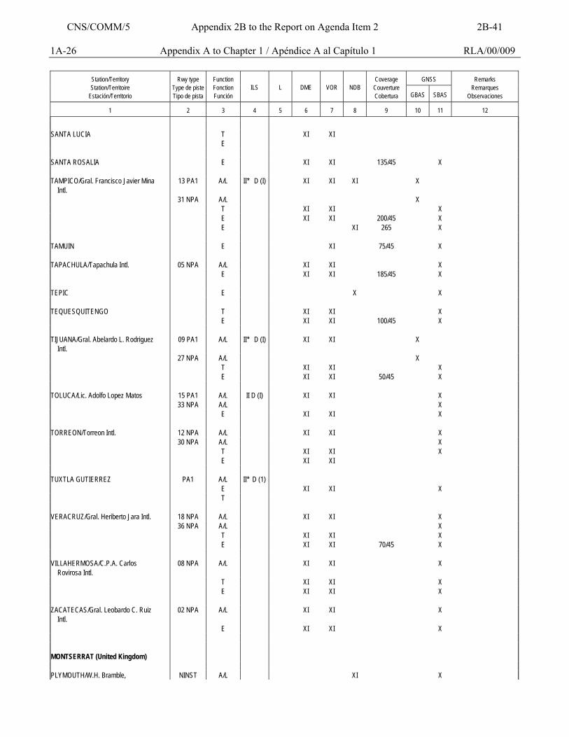
1A-26 Appendix A to Chapter 1 / Apéndice A al Capítulo 1 RLA/00/009
GNSS
Station/Territory Station/Territoire
Estación/Territorio
Rwy type
Type de piste Tipo de pista
Function Fonction Función
ILS
L
DME
VOR
NDB
Coverage
Couverture Cobertura
GBAS
SBAS
Remarks
Remarques Observaciones
1
2
3
4
5
6
7
8
9
10
11
12
SANTA LUCIA T XI XI E SANTA ROSALIA E XI XI 135/45 X TAMPICO/Gral. Francisco Javier Mina Intl.
13 PA1 A/L II* D (I) XI XI XI X
31 NPA A/L X T XI XI X E XI XI 200/45 X E XI 265 X TAMUIN E XI 75/45 X TAPACHULA/Tapachula Intl. 05 NPA A/L XI XI X E XI XI 185/45 X TEPIC E X X TEQUESQUITENGO T XI XI X E XI XI 100/45 X TIJUANA/Gral. Abelardo L. Rodriguez Intl.
09 PA1 A/L II* D (I) XI XI X
27 NPA A/L X T XI XI X E XI XI 50/45 X TOLUCA/Lic. Adolfo Lopez Matos 15 PA1 A/L II D (I) XI XI X 33 NPA A/L X E XI XI X TORREON/Torreon Intl. 12 NPA A/L XI XI X 30 NPA A/L X T XI XI X E XI XI TUXTLA GUTIERREZ PA1 A/L II* D (1) E XI XI X T VERACRUZ/Gral. Heriberto Jara Intl. 18 NPA A/L XI XI X 36 NPA A/L X T XI XI X E XI XI 70/45 X VILLAHERMOSA/C.P.A. Carlos Rovirosa Intl.
08 NPA A/L XI XI X
T XI XI X E XI XI X ZACATECAS/Gral. Leobardo C. Ruiz Intl.
02 NPA A/L XI XI X
E XI XI X MONTSERRAT (United Kingdom) PLYMOUTH/W.H. Bramble, NINST A/L XI X
CNS/COMM/5 Appendix 2B to the Report on Agenda Item 2 2B-41
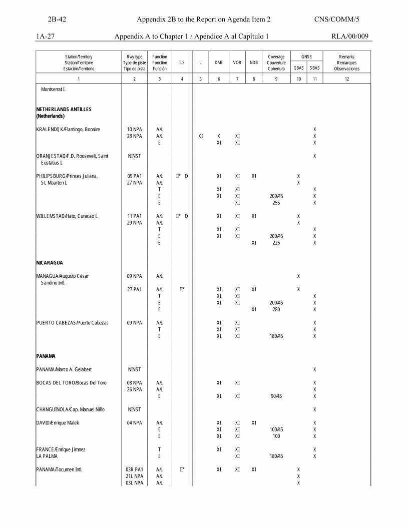
1A-27 Appendix A to Chapter 1 / Apéndice A al Capítulo 1 RLA/00/009
GNSS
Station/Territory Station/Territoire
Estación/Territorio
Rwy type
Type de piste Tipo de pista
Function Fonction Función
ILS
L
DME
VOR
NDB
Coverage
Couverture Cobertura
GBAS
SBAS
Remarks
Remarques Observaciones
1
2
3
4
5
6
7
8
9
10
11
12
Montserrat I. NETHERLANDS ANTILLES (Netherlands)
KRALENDIJK/Flamingo, Bonaire 10 NPA A/L X 28 NPA A/L XI X XI X E XI XI X ORANJESTAD/F.D. Roosevelt, Saint Eustatius I.
NINST X
PHILIPSBURG/Prinses Juliana, 09 PA1 A/L II* D XI XI XI X St. Maarten I. 27 NPA A/L X T XI XI X E XI XI 200/45 X E XI 255 X WILLEMSTAD/Hato, Curacao I. 11 PA1 A/L II* D XI XI XI X 29 NPA A/L X T XI XI X E XI XI 200/45 X E XI 225 X NICARAGUA MANAGUA/Augusto César Sandino Intl.
09 NPA A/L X
27 PA1 A/L II* XI XI XI X T XI XI X E XI XI 200/45 X E XI 280 X PUERTO CABEZAS/Puerto Cabezas 09 NPA A/L XI XI X T XI XI X E XI XI 180/45 X PANAMA PANAMA/Marco A. Gelabert NINST X BOCAS DEL TORO/Bocas Del Toro 08 NPA A/L XI XI X 26 NPA A/L X E XI XI 90/45 X CHANGUINOLA/Cap. Manuel Niño NINST X DAVID/Enrique Malek 04 NPA A/L XI XI XI X E XI XI 100/45 X E XI XI 100 X FRANCE/Enrique Jimnez T XI XI X LA PALMA E XI 180/45 X PANAMA/Tocumen Intl. 03R PA1 A/L II* XI XI XI X 21L NPA A/L X 03L NPA A/L X
2B-42 Appendix 2B to the Report on Agenda Item 2 CNS/COMM/5
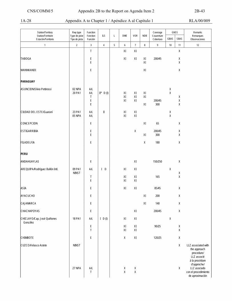
1A-28 Appendix A to Chapter 1 / Apéndice A al Capítulo 1 RLA/00/009
GNSS
Station/Territory Station/Territoire
Estación/Territorio
Rwy type
Type de piste Tipo de pista
Function Fonction Función
ILS
L
DME
VOR
NDB
Coverage
Couverture Cobertura
GBAS
SBAS
Remarks
Remarques Observaciones
1
2
3
4
5
6
7
8
9
10
11
12
T XI XI X TABOGA E XI XI XI 200/45 X E XI X WANNKANDI E XI X PARAGUAY ASUNCION/Silvio Pettirossi 02 NPA A/L X 20 PA1 A/L II* D (I) XI XI XI X T XI XI XI X E XI XI 200/45 X E XI 300 X CIUDAD DEL ESTE/Guaraní 23 PA1 A/L II XI XI X 05 NPA A/L XI XI X CONCEPCION E XI 65 X ESTIGARRIBIA E X 200/45 X E XI 300 X FILADELFIA E X 180 X PERU ANDAHUAYLAS E XI 150/250 X AREQUIPA/Rodríguez Ballón Intl. 09 PA1 A/L I D XI XI X NINST X T XI XI 165 X E XI XI ASIA E XI XI 85/45 X AYACUCHO E XI 200 X CAJAMARCA E XI 140 X CHACHAPOYAS E XI 200/45 X CHICLAYO/Cap. José Quiñones González
18 PA1 A/L I D (I) XI XI X
E XI XI 90/25 X T XI XI X CHIMBOTE E X XI 120/25 X CUZCO/Velasco Astete NINST X LLZ associated with
the approach procedure/
LLZ associé à la procédure d=approche/
27 NPA A/L T
X X
X X
X LLZ asociado con el procedimiento
de aproximación
CNS/COMM/5 Appendix 2B to the Report on Agenda Item 2 2B-43
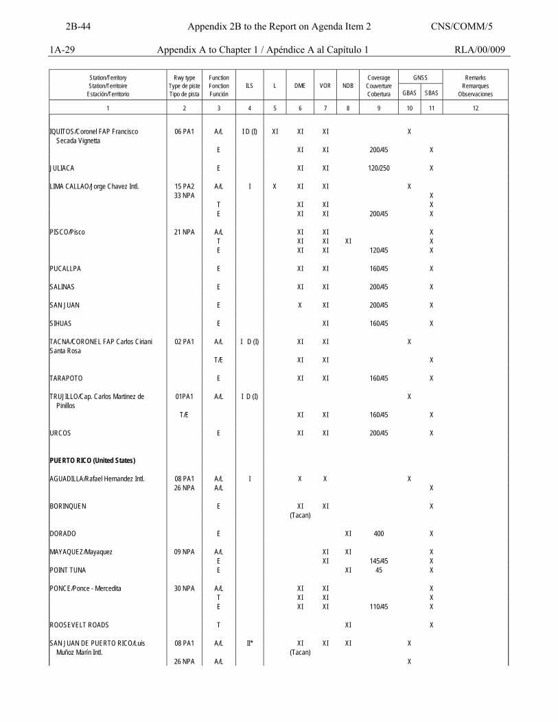
1A-29 Appendix A to Chapter 1 / Apéndice A al Capítulo 1 RLA/00/009
GNSS
Station/Territory Station/Territoire
Estación/Territorio
Rwy type
Type de piste Tipo de pista
Function Fonction Función
ILS
L
DME
VOR
NDB
Coverage
Couverture Cobertura
GBAS
SBAS
Remarks
Remarques Observaciones
1
2
3
4
5
6
7
8
9
10
11
12
IQUITOS/Coronel FAP Francisco Secada Vignetta
06 PA1 A/L I D (I) XI XI XI X
E XI XI 200/45 X JULIACA E XI XI 120/250 X LIMA CALLAO/Jorge Chavez Intl. 15 PA2 A/L I X XI XI X 33 NPA X T XI XI X E XI XI 200/45 X PISCO/Pisco 21 NPA A/L XI XI X T XI XI XI X E XI XI 120/45 X PUCALLPA E XI XI 160/45 X SALINAS E XI XI 200/45 X SAN JUAN E X XI 200/45 X SIHUAS E XI 160/45 X TACNA/CORONEL FAP Carlos Ciriani Santa Rosa
02 PA1 A/L I D (I) XI XI X
T/E XI XI X TARAPOTO E XI XI 160/45 X TRUJILLO/Cap. Carlos Martinez de Pinillos
01PA1 A/L I D (I) X
T/E XI XI 160/45 X URCOS E XI XI 200/45 X PUERTO RICO (United States) AGUADILLA/Rafael Hernandez Intl. 08 PA1 A/L I X X X 26 NPA A/L X BORINQUEN E XI
(Tacan) XI X
DORADO E XI 400 X MAYAQUEZ/Mayaquez 09 NPA A/L XI XI X E XI 145/45 X POINT TUNA E XI 45 X PONCE/Ponce - Mercedita 30 NPA A/L XI XI X T XI XI X E XI XI 110/45 X ROOSEVELT ROADS T XI X SAN JUAN DE PUERTO RICO/Luis Muñoz Marín Intl.
08 PA1 A/L II* XI (Tacan)
XI XI X
26 NPA A/L X
2B-44 Appendix 2B to the Report on Agenda Item 2 CNS/COMM/5
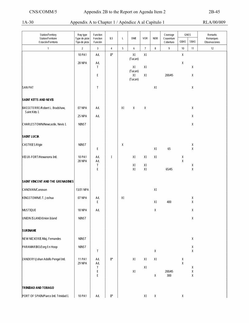
1A-30 Appendix A to Chapter 1 / Apéndice A al Capítulo 1 RLA/00/009
GNSS
Station/Territory Station/Territoire
Estación/Territorio
Rwy type
Type de piste Tipo de pista
Function Fonction Función
ILS
L
DME
VOR
NDB
Coverage
Couverture Cobertura
GBAS
SBAS
Remarks
Remarques Observaciones
1
2
3
4
5
6
7
8
9
10
11
12
10 PA1 A/L II* XI (Tacan)
XI X
28 NPA A/L X T XI
(Tacan) XI X
E XI (Tacan)
XI 200/45 X
SAN PAT T XI X SAINT KITTS AND NEVIS BASSETERRE/Robert L. Bradshaw, Saint Kitts I.
07 NPA A/L XI X X X
25 NPA A/L X CHARLESTOWN/Newcastle, Nevis I. NINST X SAINT LUCIA CASTRIES/Vigie NINST X X E XI 65 X VIEUX-FORT/Hewanorra Intl. 10 PA1 A/L I XI XI XI X 28 NPA A/L X T XI XI X E XI XI 65/45 X SAINT VINCENT AND THE GRENADINES CANOVAN/Canovan 13/31 NPA XI KINGSTOWN/E.T. Joshua 07 NPA A/L XI X E XI 400 X MUSTIQUE 18 NPA A/L X X UNION ISLAND/Union Island NINST X SURINAME NEW NICKERIE/Maj. Fernandes NINST X PARAMARIBO/Zorg En Hoop NINST X T X X ZANDERY/Johan Adolfo Pengel Intl. 11 PA1 A/L II* XI XI XI X 29 NPA A/L X T XI X E XI 200/45 X E X 300 X TRINIDAD AND TOBAGO PORT OF SPAIN/Piarco Intl. Trinidad I. 10 PA1 A/L II* XI X X
CNS/COMM/5 Appendix 2B to the Report on Agenda Item 2 2B-45
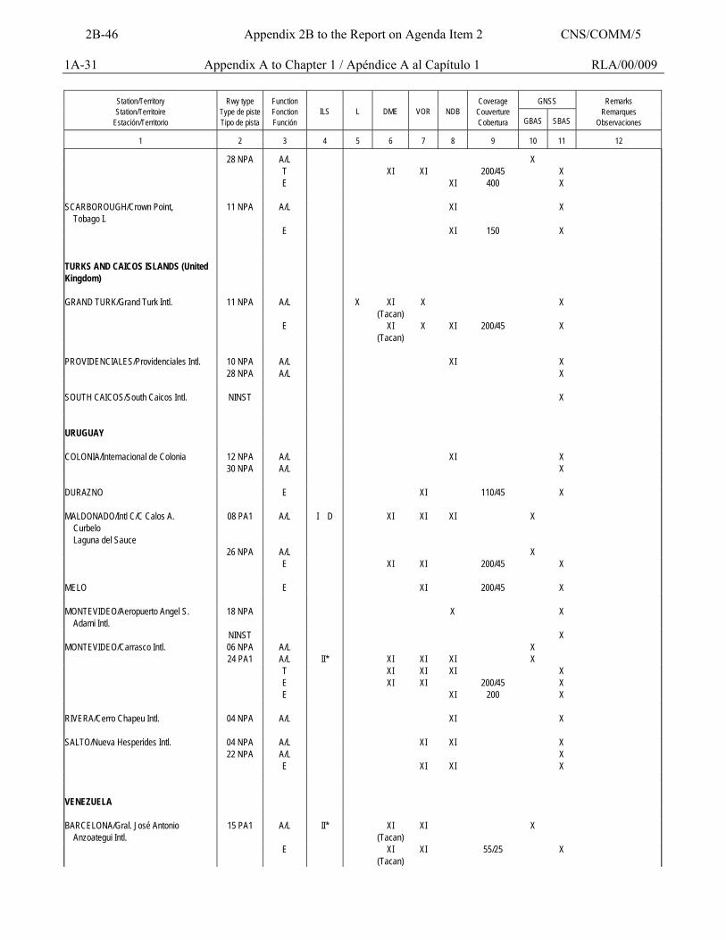
1A-31 Appendix A to Chapter 1 / Apéndice A al Capítulo 1 RLA/00/009
GNSS
Station/Territory Station/Territoire
Estación/Territorio
Rwy type
Type de piste Tipo de pista
Function Fonction Función
ILS
L
DME
VOR
NDB
Coverage
Couverture Cobertura
GBAS
SBAS
Remarks
Remarques Observaciones
1
2
3
4
5
6
7
8
9
10
11
12
28 NPA A/L X T XI XI 200/45 X E XI 400 X SCARBOROUGH/Crown Point, Tobago I.
11 NPA A/L XI X
E XI 150 X TURKS AND CAICOS ISLANDS (United Kingdom)
GRAND TURK/Grand Turk Intl. 11 NPA A/L X XI
(Tacan) X X
E XI (Tacan)
X XI 200/45 X
PROVIDENCIALES/Providenciales Intl. 10 NPA A/L XI X 28 NPA A/L X SOUTH CAICOS/South Caicos Intl. NINST X URUGUAY COLONIA/Internacional de Colonia 12 NPA A/L XI X 30 NPA A/L X DURAZNO E XI 110/45 X MALDONADO/Intl C/C Calos A. Curbelo Laguna del Sauce
08 PA1 A/L I D XI XI XI X
26 NPA A/L X E XI XI 200/45 X MELO E XI 200/45 X MONTEVIDEO/Aeropuerto Angel S. Adami Intl.
18 NPA X X
NINST X MONTEVIDEO/Carrasco Intl. 06 NPA A/L X 24 PA1 A/L II* XI XI XI X T XI XI XI X E XI XI 200/45 X E XI 200 X RIVERA/Cerro Chapeu Intl. 04 NPA A/L XI X SALTO/Nueva Hesperides Intl. 04 NPA A/L XI XI X 22 NPA A/L X E XI XI X VENEZUELA BARCELONA/Gral. José Antonio Anzoategui Intl.
15 PA1 A/L II* XI (Tacan)
XI X
E XI (Tacan)
XI 55/25 X
2B-46 Appendix 2B to the Report on Agenda Item 2 CNS/COMM/5
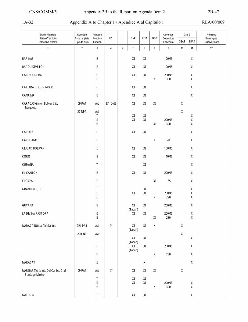
1A-32 Appendix A to Chapter 1 / Apéndice A al Capítulo 1 RLA/00/009
GNSS
Station/Territory Station/Territoire
Estación/Territorio
Rwy type
Type de piste Tipo de pista
Function Fonction Función
ILS
L
DME
VOR
NDB
Coverage
Couverture Cobertura
GBAS
SBAS
Remarks
Remarques Observaciones
1
2
3
4
5
6
7
8
9
10
11
12
BARINAS E XI XI 100/25 X BARQUISIMETO E XI XI 190/35 X CABO CODERA E XI XI 200/45 X E X 300 X CAICARA DEL ORINOCO E XI XI X CANAIMA E XI XI X CARACAS/Simon Bolivar Intl., Maiquetia
09 PA1 A/L II* D (I) XI XI XI X
27 NPA A/L X T XI XI X E XI XI 200/45 X E XI 300 X CARORA E XI XI X CARUPANO E X 70 X CIUDAD BOLIVAR E XI XI 100/45 X CORO E XI XI 110/45 X CUMANA T XI X EL CANTON E XI XI 200/45 X ELORZA E XI 165 X GRAND ROQUE T XI X E XI XI 200/45 X E X 220 X GUYANA E XI
(Tacan) XI 200/45 X
LA DIVINA PASTORA E XI XI 200/45 X E XI 280 X MARACAIBO/La Chinita Intl. 02L PA1 A/L II* XI
(Tacan) XI X X
20R NP A/L X T XI
(Tacan) XI X
E XI (Tacan)
XI 200/45 X
E X 280 X MARACAY E X X MARGARITA I./ Intl. Del Caribe, Gral. Santiago Marino
09 PA1 A/L II* XI XI XI X
T XI XI E XI XI 200/45 X E X 300 X MATURIN T XI XI X
CNS/COMM/5 Appendix 2B to the Report on Agenda Item 2 2B-47
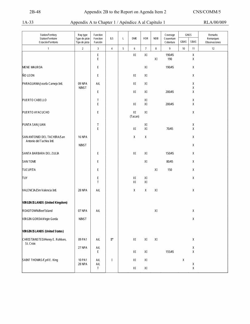
1A-33 Appendix A to Chapter 1 / Apéndice A al Capítulo 1 RLA/00/009
GNSS
Station/Territory Station/Territoire
Estación/Territorio
Rwy type
Type de piste Tipo de pista
Function Fonction Función
ILS
L
DME
VOR
NDB
Coverage
Couverture Cobertura
GBAS
SBAS
Remarks
Remarques Observaciones
1
2
3
4
5
6
7
8
9
10
11
12
E XI XI 190/45 X E XI 190 X MENE MAUROA E XI 190/45 X ÑO LEON E XI XI X PARAGUANA/Josefa Camejo Intl. 09 NPA A/L XI XI X NINST X E XI XI 200/45 X PUERTO CABELLO T XI X E XI XI 200/45 X PUERTO AYACUCHO E XI
(Tacan) XI X
PUNTA SAN JUAN T XI X E XI XI 70/45 X SAN ANTONIO DEL TACHIRA/San Antonio del Tachira Intl.
16 NPA X X X
NINST X SANTA BARBARA DEL ZULIA E XI XI 150/45 X SAN TOME E XI 80/45 X TUCUPITA E XI 150 X TUY E XI XI X T XI XI VALENCIA/Zim Valencia Intl. 28 NPA A/L X X XI X VIRGIN ISLANDS (United Kingdom) ROADTOWN/Beef Island 07 NPA A/L XI X VIRGIN GORDA/Virgin Gorda NINST X VIRGIN ISLANDS (United States) CHRISTIANSTED/Henry E. Rohlsen, St. Croix
09 PA1 A/L II* XI XI XI X
27 NPA A/L X E XI XI 155/45 X SAINT THOMAS/Cyril E. King 10 PA1 A/L I XI XI X 28 NPA A/L X T XI XI X
2B-48 Appendix 2B to the Report on Agenda Item 2 CNS/COMM/5
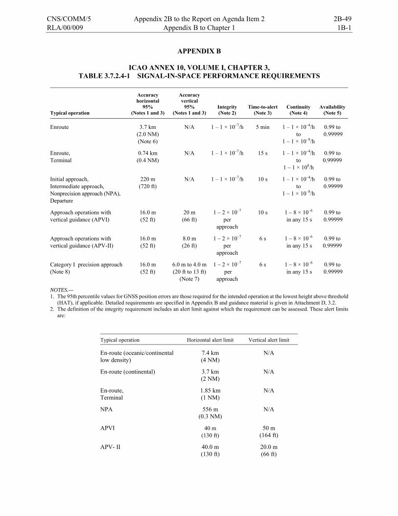
RLA/00/009 Appendix B to Chapter 1 1B-1
APPENDIX B
ICAO ANNEX 10, VOLUME I, CHAPTER 3, TABLE 3.7.2.4-1 SIGNAL-IN-SPACE PERFORMANCE REQUIREMENTS
Typical operation
Accuracy horizontal
95% (Notes 1 and 3)
Accuracy vertical
95% (Notes 1 and 3)
Integrity (Note 2)
Time-to-alert (Note 3)
Continuity (Note 4)
Availability (Note 5)
Enroute 3.7 km (2.0 NM) (Note 6)
N/A 1 – 1 × 10⁻⁷/h 5 min 1 – 1 × 10⁻⁴/h to
1 – 1 × 10⁻⁸/h
0.99 to 0.99999
Enroute, Terminal
0.74 km (0.4 NM)
N/A 1 – 1 × 10⁻⁷/h 15 s 1 – 1 × 10⁻⁴/h to
1 – 1 × 10⁸/h
0.99 to 0.99999
Initial approach, Intermediate approach, Nonprecision approach (NPA), Departure
220 m (720 ft)
N/A 1 – 1 × 10⁻⁷/h 10 s 1 – 1 × 10⁻⁴/h to
1 – 1 × 10⁻⁸/h
0.99 to 0.99999
Approach operations with vertical guidance (APVI)
16.0 m (52 ft)
20 m (66 ft)
1 – 2 × 10⁻⁷
per approach
10 s 1 – 8 × 10⁻⁶
in any 15 s 0.99 to
0.99999
Approach operations with vertical guidance (APV-II)
16.0 m (52 ft)
8.0 m (26 ft)
1 – 2 × 10⁻⁷
per approach
6 s 1 – 8 × 10⁻⁶
in any 15 s 0.99 to 0.99999
Category I precision approach (Note 8)
16.0 m (52 ft)
6.0 m to 4.0 m (20 ft to 13 ft)
(Note 7)
1 – 2 × 10⁻⁷
per approach
6 s 1 – 8 × 10⁻⁶
in any 15 s 0.99 to
0.99999
NOTES.— 1. The 95th percentile values for GNSS position errors are those required for the intended operation at the lowest height above threshold
(HAT), if applicable. Detailed requirements are specified in Appendix B and guidance material is given in Attachment D, 3.2. 2. The definition of the integrity requirement includes an alert limit against which the requirement can be assessed. These alert limits
are:
Typical operation Horizontal alert limit Vertical alert limit
En-route (oceanic/continental low density)
7.4 km (4 NM)
N/A
En-route (continental) 3.7 km (2 NM)
N/A
En-route, Terminal
1.85 km (1 NM)
N/A
NPA 556 m (0.3 NM)
N/A
APVI 40 m (130 ft)
50 m (164 ft)
APV- II 40.0 m (130 ft)
20.0 m (66 ft)
CNS/COMM/5 Appendix 2B to the Report on Agenda Item 2 2B-49
1B-2 Appendix B to Chapter 1 RLA/00/009
Category I precision approach 40.0 m (130 ft)
15.0 m to 10.0 m (50 ft to 33 ft)
A range of vertical limits for Category I precision approach relates to the range of vertical accuracy requirements. 3. The accuracy and time-to-alert requirements include the nominal performance of a fault-free receiver. 4. Ranges of values are given for the continuity requirement for en-route, terminal, initial approach, NPA and departure operations, as this
requirement is dependent upon several factors including the intended operation, traffic density, complexity of airspace and availability of alternative navigation aids. The lower value given is the minimum requirement for areas with low traffic density and airspace complexity. The higher value given is appropriate for areas with high traffic density and airspace complexity (see Attachment D, 3.4).
5. A range of values is given for the availability requirements as these requirements are dependent upon the operational need which is based upon several factors including the frequency of operations, weather environments, the size and duration of the outages, availability of alternate navigation aids, radar coverage, traffic density and reversionary operational procedures. The lower values given are the minimum availabilities for which a system is considered to be practical but are not adequate to replace non-GNSS navigation aids. For en-route navigation, the higher values given are adequate for GNSS to be the only navigation aid provided in an area. For approach and departure, the higher values given are based upon the availability requirements at airports with a large amount of traffic assuming that operations to or from multiple runways are affected but reversionary operational procedures ensure the safety of the operation (see Attachment D, 3.5).
6. This requirement is more stringent than the accuracy needed for the associated RNP types but it is well within the accuracy performance achievable by GNSS.
7. A range of values is specified for Category I precision approach. The 4.0 metres (13 feet) requirement is based upon ILS specifications and represents a conservative derivation from these specifications (see Attachment D, 3.2.7).
8. GNSS performance requirements for Category II and III precision approach operations are under review and will be included at a later date.
9. The terms APV-I and APV-II refer to two levels of GNSS approach and landing operations with vertical guidance (APV) and these terms are not necessarily intended to be used operationally.
2B-50 Appendix 2B to the Report on Agenda Item 2 CNS/COMM/5
RLA/00/009 Chapter 2 2-1
CHAPTER 2
SBAS AUGMENTATION TEST BED (CSTB) BASED ON WAAS
Introduction to SBAS Augmentation Test Bed based on WAAS SBAS operation concept 2.1 A SBAS augmentation system based on WAAS disseminates clock (synchronism), events, and ionosphere corrections. Aeronautical user equipment apply corrections to Global Positioning System (GPS) satellites measured and also convert the error margins in position domains. 2.2 Operations through a SBAS system may only be carried out when horizontal and vertical position errors are contained within some margins, which values depend on the flight phase. 2.3 A SBAS system would be supporting en-route operations, terminal, non-precision approach (NPA) and non-precision approaches with vertical guidance (APV). 2.4 A SBAS augmentation system based on WAAS provides the following functions using signal radio broadcastings through a geo-stationary communications satellite.
a) GPS signal additional to the constellation of existing GPS; b) Correction vector to GPS signals in the space including components for ionosphere,
clock and error events; and
c) Integrity monitoring function to inform users on tolerance condition in time terms. 2.5 The operation concept of a SBAS system based on WAAS is briefly described hereunder: 2.6 Wide area reference stations (WRS) are installed along a territory in order to measure pseudo-ranges and carrier phase to frequency L1 (1575.42 Mhz) and L2 (1227.2Mhz) from all visible GPS satellites. 2.7 Wide area reference stations send these measures to wide area master stations (WMS), which calculate clock and event corrections for each GPS satellite, event information of each geo-stationary communications satellite (GEO) and vertical delays in a grid. A grid consists in fixed ionospheric grid points (IGP – ionospheric grid points) located at a height of 350 Km over the earth surface. The space of a grid is 5º x 5º. 2.8 In addition to the corrections, wide area master stations calculate error limits for ionosphere corrections, corrections named GIVE (Grid Ionosphere Vertical Errors) to each fixed ionosphere grid point (IGP) and the error limits combined for clock corrections and events for each visible GPS satellite (UDRE – User Differential Rate Error). 2.9 The master station sends these corrections and error limits to users (Aircraft) through a geo-stationary communications satellite (For example, Inmarsat III) at a 250 bits/sec. speed.
CNS/COMM/5 Appendix 2B to the Report on Agenda Item 2 2B-51
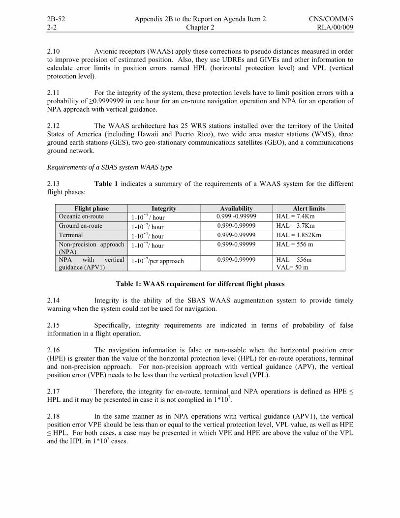
2-2 Chapter 2 RLA/00/009
2.10 Avionic receptors (WAAS) apply these corrections to pseudo distances measured in order to improve precision of estimated position. Also, they use UDREs and GIVEs and other information to calculate error limits in position errors named HPL (horizontal protection level) and VPL (vertical protection level). 2.11 For the integrity of the system, these protection levels have to limit position errors with a probability of ≥0.9999999 in one hour for an en-route navigation operation and NPA for an operation of NPA approach with vertical guidance. 2.12 The WAAS architecture has 25 WRS stations installed over the territory of the United States of America (including Hawaii and Puerto Rico), two wide area master stations (WMS), three ground earth stations (GES), two geo-stationary communications satellites (GEO), and a communications ground network. Requirements of a SBAS system WAAS type 2.13 Table 1 indicates a summary of the requirements of a WAAS system for the different flight phases:
Flight phase Integrity Availability Alert limits Oceanic en-route 1-107 / hour 0.999 -0.99999 HAL = 7.4Km Ground en-route 1-107/ hour 0.999-0.99999 HAL = 3.7Km Terminal 1-107/ hour 0.999-0.99999 HAL = 1.852Km Non-precision approach (NPA)
1-107/ hour 0.999-0.99999 HAL = 556 m
NPA with vertical guidance (APV1)
1-107/per approach 0.999-0.99999 HAL = 556m VAL= 50 m
Table 1: WAAS requirement for different flight phases
2.14 Integrity is the ability of the SBAS WAAS augmentation system to provide timely warning when the system could not be used for navigation. 2.15 Specifically, integrity requirements are indicated in terms of probability of false information in a flight operation. 2.16 The navigation information is false or non-usable when the horizontal position error (HPE) is greater than the value of the horizontal protection level (HPL) for en-route operations, terminal and non-precision approach. For non-precision approach with vertical guidance (APV), the vertical position error (VPE) needs to be less than the vertical protection level (VPL). 2.17 Therefore, the integrity for en-route, terminal and NPA operations is defined as HPE ≤ HPL and it may be presented in case it is not complied in 1*107.
2.18 In the same manner as in NPA operations with vertical guidance (APV1), the vertical position error VPE should be less than or equal to the vertical protection level, VPL value, as well as HPE ≤ HPL. For both cases, a case may be presented in which VPE and HPE are above the value of the VPL and the HPL in 1*107 cases.
2B-52 Appendix 2B to the Report on Agenda Item 2 CNS/COMM/5
RLA/00/009 Chapter 2 2-3
2.19 The availability is the time percentage in which the service is usable. The service is usable when HPL ≤ HAL (HAL represents the radio of a circle in a horizontal plane, with center in the real position that describes the region to which it is required to contain the indicated horizontal position with a probability of 1*07 per flight hour) for en-route operations, terminal and NPA. 2.20 For NPA operations with vertical guidance, the service is usable when HPL ≤ HAL and VPL ≤ VAL (VAL is half the length of a segment in the vertical axe, which center is the real position which describes the region to which it is required to contain the indicated vertical position with a probability of 1*07 per NPA approaches with vertical guidance (APV). Elements composing the SBAS augmentation test bed based on WAAS in the CAR/SAM Regions (CSTB)
2.21 Before implementing a SBAS augmentation system, a trial platform or testbed is generally implemented. In the case of WAAS, the testbed is called the National Satellite Test Bed, or NSTB. The trial platform for the SBAS Augmentation testbed in the CAR/SAM Region is called CSTB (CAR/SAM Test Bed). Both are composed by testbed reference stations (TRS), testbed master stations (TMS), avionic segment, and a communications segment. Testbed Reference Station (TRS) 2.22 A reference station is composed by the following equipment:
a) Novatel Novatel Millennium or Trimble Receptor series 4000 and antenna sub-system
b) Rubidium Oscilator Efratom PRFS; c) RISC base IBM processor d) Remote power supply Sentry R 1000 e) CISCO 2516 Router f) Remote power administrador g) UPS Smart Universal; h) Hub; and i) Digiboard.
GPS Novatel Millenium Receptor 2.23 It tracks from 1 to 10 satellites in frequency L1 (1575.42 MHz) and L2 (1227.2 MHz) and tracks GEO satellites fitted out for WAAS in a solution position. It also responds to user commands already determined. The receptor is equipped with a GPS 600 antenna. GPS-600 Antenna 2.24 Designed for a variety of cinematic positioning applications. The radome (superior part of the antenna) permits it to be used in several marine and weather applications, and adverse means. It is portable and light. It operates in frequencies L1 and L2. The reception elements are connected to a low noise amplifier (LNA). Optimized to receive polarized signals in circles clockwise. Trimble 4000 receptor
CNS/COMM/5 Appendix 2B to the Report on Agenda Item 2 2B-53
2-4 Chapter 2 RLA/00/009
2.25 Tracks 9 or more satellites in frequency L1 1575.42 MHz) or L1/L2 (1227.2Mhz). Fitted for WAAS in a solution position. Responds to already determined user commands. The receptor is equipped with a Trimble antenna model 23903-00. Rubidium Oscillator 2.26 Provides an extremely stable and pure signal to the receptor. It improves the GPS signal performance. The oscillator optimizes the operation of the system because it has a very stable clock signal, achieving a better synchronization of the system clock with the GPS satellites clocks. The equipment installed is model Efratom PRFS. Processing Central Unit: Alpha DEC 2.27 Is the system’s CPU operating with UNIX operative system. It processes the data from the receptor creating a binary type file automatically and daily for its further analysis. Sentry Remote power administrator (Source) 2.28 Located in the reference station. It has 8 connection modules. Through Telnet it has the capacity to be turned off or reinitiated. It is the feeding source of the reference station. Router: Cisco 2501 2.29 Requests primary access from and to the TRS. It delivers and relieves data from two synchronic serial ports (DB60). Central access port to the system (RJ45). Auxiliary port for remote access to the system using MODEM. Great variety of commands to be able to be configured. UPS Smart Universa 2.30 Maximum load of 950 Watts. Transference time from 2 to 4 milliseconds. Six plugs. Hub 2.31 Network repeater. Provides local access point to the network. May provide a data Chain for their collection processing. Digi Board 2.32 Four (4) to eight (8) communication expansive ports of asynchronic serial interphase. Is the interphase between the GPS receptor and the CPU DEC Alpha. 2.33 Figure 1 shows the block diagram of a typical reference station of the CSTB. Installation requirements in a reference station 2.34 All equipment in each one of the reference stations were installed in each one of the stations and connected keeping in mind the following requirements
2B-54 Appendix 2B to the Report on Agenda Item 2 CNS/COMM/5
RLA/00/009 Chapter 2 2-5
Installation GPS antenna 2.35 The antenna should be located as far as possible from lakes, puddles, buildings, trees and surrounding vehicles. The antenna position should be indicated in WGS-84 format (World Geodetic System 1984) with a precision better than 10 cm. in the three axes. That is to say, it should not move more than 10 cm in any of their positions (x, y, z). The antenna must be located as far as possible from any reflecting plane bigger than one square meter. The presence of any other physical object with a flat surface bigger than 0.1 m2 should be avoided in 20 m2 a radius of 10 m 1 m below the choke-ring plane. If there are many antennas presents in a 5 m radius, the antenna must be installed in such a way that the distance between antennas be an odd multiple of 5 cm (λ/4). The length of the antenna cable to the reference station receptor should be less than 30 m due to RG58 cable losses, which joins the antenna with the receptor. 2.36 The variations of the antenna positions should be smaller, of 1 cm for winds with speeds of less than 200 km/h. The connection between the antenna and the cable must be isolated against water penetration, preferably using impermeable vulcanized tape. The antenna and its LNA should be isolated from the antenna post. The location of the antenna should provide a mask angle not greater than 5° of elevation; that is to say, no obstruction should exist above 5°. For the installation of the TRS GPS antenna all protection should be available regarding security of equipment. Figure 2 shows photos of antennas in some CSTB TRS stations. Figure 3 shows photos of equipment in CSTB TRS stations. Installation of reference station 2.37 The GPS antenna is connected to the receptor through a 50 Ohms RG58 impedance cable connected to the antenna is TNC type (thread) and the metal part exposed to the environment is isolated with tape so that water and other factors do not alter the most important characteristics of the antenna. The receptor port COM1 is connected to the Digiboard port COM1, which is an extensor to ports connecting the GPS receptor to the CPU. COM2 is a serial port used to access the receptor through a laptop. When connecting the laptop, the receptor is configured with software named Winsat, which also serves to observe within space in real time (SIS, Signal in Space). The rubidium oscillator is connected to the entrance ExtRef of the receptor. The oscillator has several exists if required or more receptor must be connected. 2.38 The Digiboard ports extensor has 8 ports, from which COM1 port is connected to the GPS receptor (COM1 port) to serve as link between Rx and the CPU. The DEC Alpha (CPU) is connected to the Digiboard EBI port. It has a network point exit to the hub in order to carry out entelnet in a remote manner from other office (with network point). Another Alpha (connector RJ45) DEC exit is connected to the Cisco router AUI0 port. The COM1 is connected to the source and has another additional port, which communicates with the RS232 of the source to shut down the equipment through telnet. The router AUI1 port is connected to a hub port and the AUX port with the RS232 of the source. The router is used for the REDDIG links through VSAT. 2.39 The hub is the network connector. It has eight ports, one used to join itself with the network point located in the site and the rest, to link the equipment necessary with the network. The Sentry feeding source provides 110V (AC) to the devices. Nevertheless, a port has a voltage adaptor of 14.7 volts DC to 2,25 Amp. at the entry of the 10-36 V DC receiver. The source is connected to the UPS, and some devices go connected directly to the UPS. This also has a voltage adapter going to the hub and, finally, it is connected to the building’s main AC power (110V AC).
CNS/COMM/5 Appendix 2B to the Report on Agenda Item 2 2B-55
2-6 Chapter 2 RLA/00/009
Testbed Master Station (TMS) 2.40 A master station is composed of the following equipment:
a) Alpha DEC processor; b) Operation and maintenance monitor; c) WAAS information dissemination server (WIB); d) Recording device; and e) CISCO router.
Avionics segment 2.41 The aircraft can be self-owned or rented for flight trials, but an important requirement is that a GPS/WAAS antenna be installed in the aircraft, and that arrival signals can be fed to three subsystems within the aerotransported avionics. 2.42 The three aerotransported subsystems are:
a) CSTB User Platform (CUP) - GPS/WAAS receiver, - Processor, - Fixed and removable storage devices, - Software for the collection of data and their remittance to other subsystems
within the aerotransported avionics.
b) CSTB Real Reference (CTR) - Two differential GPS (DGPS) receivers, one in the aircraft, the other in the
ground.
c) CSTB navigation platform and data purchasing (NAVDAC) - Regulation source, - Processor, - Fixed and removable storage devices, - Processing and integration software, - Interfaces towards aircraft data bases.
Communications segments 2.43 The communications platform permitting information transportation from the trial reference stations to the master stations is mainly carried out on a VSAT digital network named REDDIG (South American Digital Network). Segments from the Brazilian and Colombian VSAT networks complete the communications platform. REDDIG VSAT digital communications network 2.44 The REDDIG has fifteen (15) nodes established in thirteen (13) SAM status and one (1) CAR State. The locations and coordinates where REDDIG nodes are found are described in Table 2.
2B-56 Appendix 2B to the Report on Agenda Item 2 CNS/COMM/5
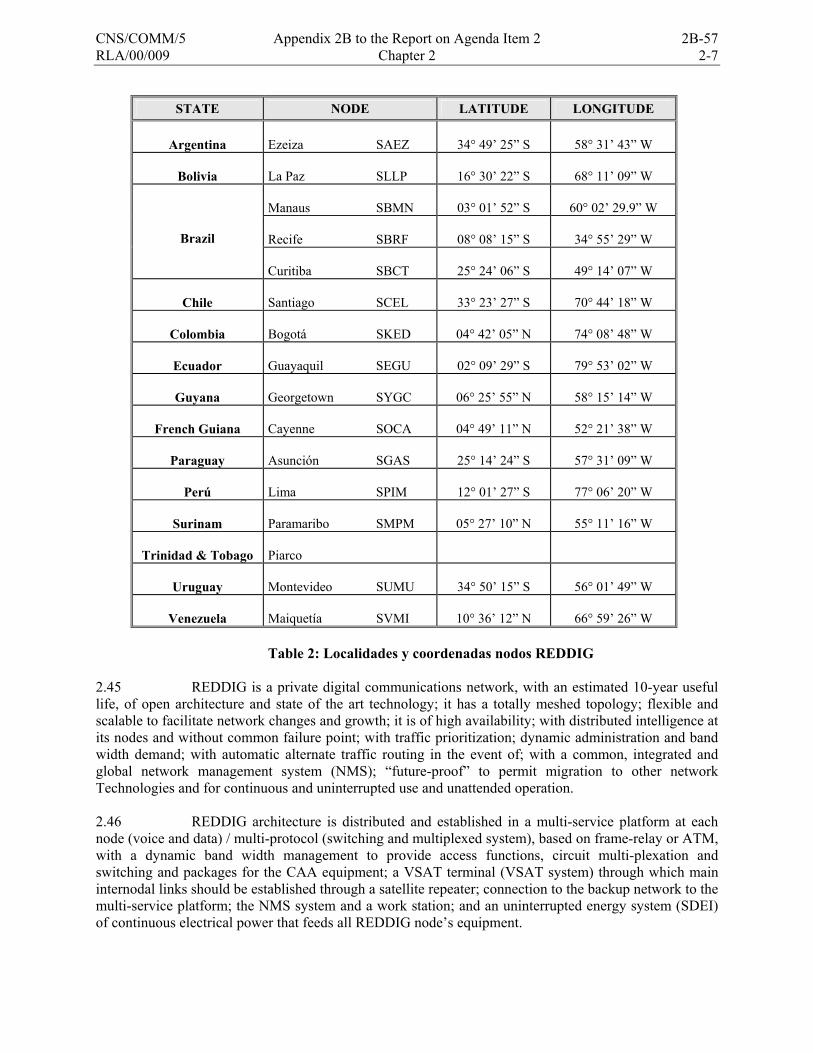
RLA/00/009 Chapter 2 2-7
STATE NODE LATITUDE LONGITUDE
Argentina Ezeiza SAEZ
34° 49’ 25” S
58° 31’ 43” W
Bolivia
La Paz SLLP
16° 30’ 22” S
68° 11’ 09” W
Manaus SBMN
03° 01’ 52” S
60° 02’ 29.9” W
Recife SBRF
08° 08’ 15” S
34° 55’ 29” W
Brazil
Curitiba SBCT
25° 24’ 06” S
49° 14’ 07” W
Chile Santiago SCEL
33° 23’ 27” S
70° 44’ 18” W
Colombia
Bogotá SKED
04° 42’ 05” N
74° 08’ 48” W
Ecuador
Guayaquil SEGU
02° 09’ 29” S
79° 53’ 02” W
Guyana
Georgetown SYGC
06° 25’ 55” N
58° 15’ 14” W
French Guiana
Cayenne SOCA
04° 49’ 11” N
52° 21’ 38” W
Paraguay
Asunción SGAS
25° 14’ 24” S
57° 31’ 09” W
Perú
Lima SPIM
12° 01’ 27” S
77° 06’ 20” W
Surinam
Paramaribo SMPM
05° 27’ 10” N
55° 11’ 16” W
Trinidad & Tobago
Piarco
Uruguay
Montevideo SUMU
34° 50’ 15” S
56° 01’ 49” W
Venezuela
Maiquetía SVMI
10° 36’ 12” N
66° 59’ 26” W
Table 2: Localidades y coordenadas nodos REDDIG
2.45 REDDIG is a private digital communications network, with an estimated 10-year useful life, of open architecture and state of the art technology; it has a totally meshed topology; flexible and scalable to facilitate network changes and growth; it is of high availability; with distributed intelligence at its nodes and without common failure point; with traffic prioritization; dynamic administration and band width demand; with automatic alternate traffic routing in the event of; with a common, integrated and global network management system (NMS); “future-proof” to permit migration to other network Technologies and for continuous and uninterrupted use and unattended operation. 2.46 REDDIG architecture is distributed and established in a multi-service platform at each node (voice and data) / multi-protocol (switching and multiplexed system), based on frame-relay or ATM, with a dynamic band width management to provide access functions, circuit multi-plexation and switching and packages for the CAA equipment; a VSAT terminal (VSAT system) through which main internodal links should be established through a satellite repeater; connection to the backup network to the multi-service platform; the NMS system and a work station; and an uninterrupted energy system (SDEI) of continuous electrical power that feeds all REDDIG node’s equipment.
CNS/COMM/5 Appendix 2B to the Report on Agenda Item 2 2B-57

2-8 Chapter 2 RLA/00/009
Structure of the SBAS Augmentation Testbed based on WAAS in the CAR/SAM Regions (CSTB) 2.47 The CSTB is composed of 13 reference stations (TRS) and two master stations (TMS). The TRS are installed at the following locations:
Argentina Ezeiza International airport Bolivia El Alto International airport Brazil Río de Janeiro International airport Recife Airport Brasilia Airport Curitiba Airport Manaus Airport Colombia Bogota CEA (Centro de Entrenamiento Aeronáutico) Chile Santiago Cerro Colorado (Santiago ACC) Balmaceda Airport Antofagasta Airport Peru Lima International airport Honduras Tegucigalpa International airport
2.48 The TMS are installed in:
Brazil Río de Janeiro International airport Chile Santiago Cerro Colorado (Santiago ACC)
2.49 The Ezeiza, El Alto and Lima reference stations (TRS) are connected to the router of the Santiago master station (TMS) through REDDIG frame relay permanent virtual circuits. From Santiago, the afore mentioned reference stations circuits, together with information from the Santiago, Balmaceda and Antofagasta reference stations, are connected to the Rio de Janeiro master station (TMS). The connection between Santiago and Río de Janeiro is composed of a segment (Santiago-Curitiba) through a REDDIG frame relay virtual permanent circuit, followed by a Brazilian VSAT network virtual permanent circuit between Curitiba and Río de Janeiro. In addition, the information of the Curitiba TRS is connected to the Rio TMS router through the Brazilian VSAT virtual permanent circuit. 2.50 On the other hand, the Tegucigalpa (Honduras–COCESNA) TRS station router is connected to the Bogota (Colombia) reference station router through the Colombian VSAT network. In Bogota, the information from the Bogota reference station is connected with information from the Tegucigalpa TRS to the Bogota TRS router, from here, the information from both stations is connected to the Bogota REDDIG node with a frame relay virtual permanent circuit connected to the Curitiba REDDIG node. From Curitiba, the information from the Bogota and Tegucigalpa TRS are connected to Rio through the Brazilian VSAT. 2.51 The Brasilia, Recife and Manaos TRS stations arrive to Rio through the Brazilian VSAT network. 2.52 The information between the TRS and the TMS is transmitted at 19.2 kbits/sec; between TMS stations, it is transmitted at 64 kbits/seg. 2.53 A 64 Kbits/sec. digital dedicated circuit was established between Rio de Janeiro and the FAA technological centre in Atlantic City. This circuit’s purpose is to carry all data collected from each of the reference stations to the technological centre for their storage and processing.
2B-58 Appendix 2B to the Report on Agenda Item 2 CNS/COMM/5
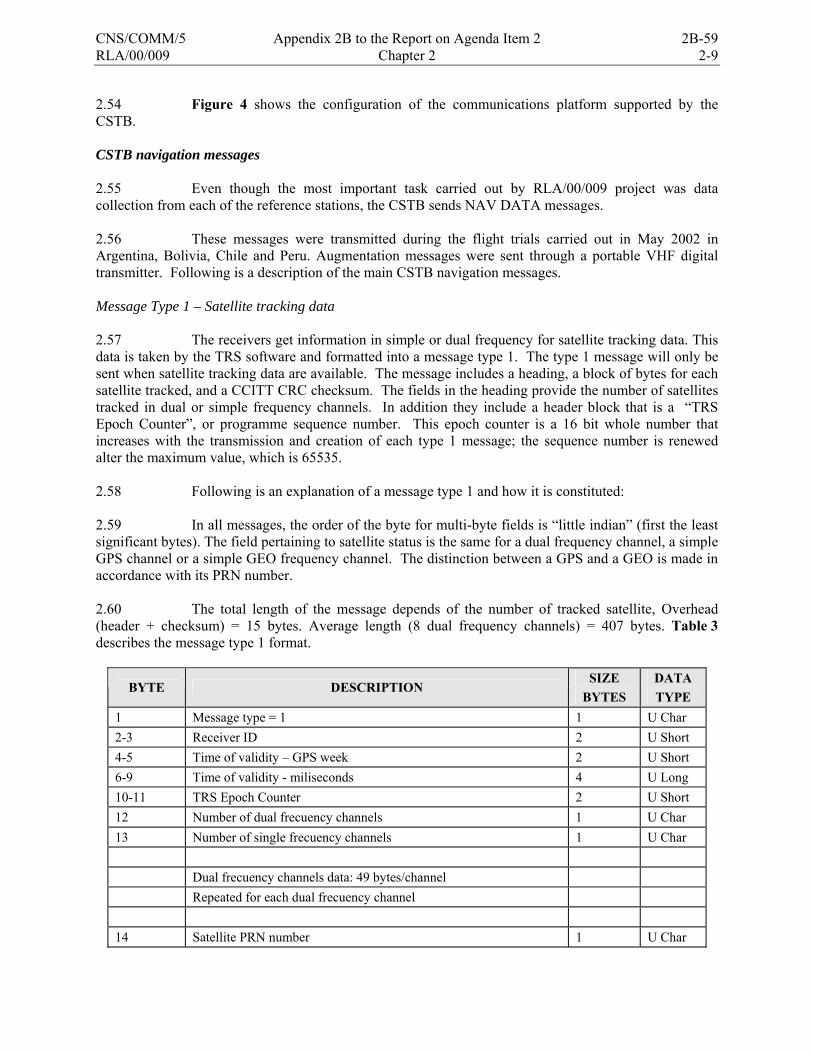
RLA/00/009 Chapter 2 2-9
2.54 Figure 4 shows the configuration of the communications platform supported by the CSTB. CSTB navigation messages 2.55 Even though the most important task carried out by RLA/00/009 project was data collection from each of the reference stations, the CSTB sends NAV DATA messages. 2.56 These messages were transmitted during the flight trials carried out in May 2002 in Argentina, Bolivia, Chile and Peru. Augmentation messages were sent through a portable VHF digital transmitter. Following is a description of the main CSTB navigation messages. Message Type 1 – Satellite tracking data 2.57 The receivers get information in simple or dual frequency for satellite tracking data. This data is taken by the TRS software and formatted into a message type 1. The type 1 message will only be sent when satellite tracking data are available. The message includes a heading, a block of bytes for each satellite tracked, and a CCITT CRC checksum. The fields in the heading provide the number of satellites tracked in dual or simple frequency channels. In addition they include a header block that is a “TRS Epoch Counter”, or programme sequence number. This epoch counter is a 16 bit whole number that increases with the transmission and creation of each type 1 message; the sequence number is renewed alter the maximum value, which is 65535. 2.58 Following is an explanation of a message type 1 and how it is constituted: 2.59 In all messages, the order of the byte for multi-byte fields is “little indian” (first the least significant bytes). The field pertaining to satellite status is the same for a dual frequency channel, a simple GPS channel or a simple GEO frequency channel. The distinction between a GPS and a GEO is made in accordance with its PRN number. 2.60 The total length of the message depends of the number of tracked satellite, Overhead (header + checksum) = 15 bytes. Average length (8 dual frequency channels) = 407 bytes. Table 3 describes the message type 1 format.
SIZE DATA BYTE DESCRIPTION
BYTES TYPE 1 Message type = 1 1 U Char 2-3 Receiver ID 2 U Short 4-5 Time of validity – GPS week 2 U Short 6-9 Time of validity - miliseconds 4 U Long 10-11 TRS Epoch Counter 2 U Short 12 Number of dual frecuency channels 1 U Char 13 Number of single frecuency channels 1 U Char Dual frecuency channels data: 49 bytes/channel Repeated for each dual frecuency channel 14 Satellite PRN number 1 U Char
CNS/COMM/5 Appendix 2B to the Report on Agenda Item 2 2B-59
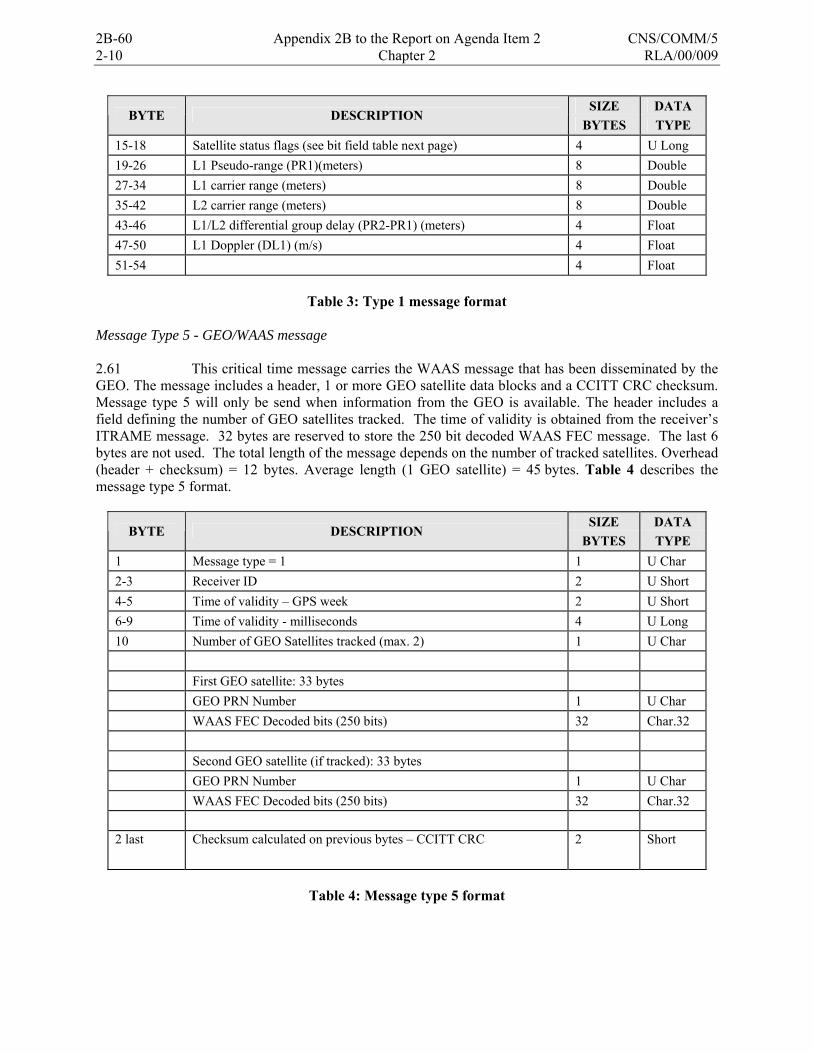
2-10 Chapter 2 RLA/00/009
SIZE DATA BYTE DESCRIPTION
BYTES TYPE 15-18 Satellite status flags (see bit field table next page) 4 U Long 19-26 L1 Pseudo-range (PR1)(meters) 8 Double 27-34 L1 carrier range (meters) 8 Double 35-42 L2 carrier range (meters) 8 Double 43-46 L1/L2 differential group delay (PR2-PR1) (meters) 4 Float 47-50 L1 Doppler (DL1) (m/s) 4 Float 51-54 4 Float
Table 3: Type 1 message format
Message Type 5 - GEO/WAAS message 2.61 This critical time message carries the WAAS message that has been disseminated by the GEO. The message includes a header, 1 or more GEO satellite data blocks and a CCITT CRC checksum. Message type 5 will only be send when information from the GEO is available. The header includes a field defining the number of GEO satellites tracked. The time of validity is obtained from the receiver’s ITRAME message. 32 bytes are reserved to store the 250 bit decoded WAAS FEC message. The last 6 bytes are not used. The total length of the message depends on the number of tracked satellites. Overhead (header + checksum) = 12 bytes. Average length (1 GEO satellite) = 45 bytes. Table 4 describes the message type 5 format.
SIZE DATA BYTE DESCRIPTION
BYTES TYPE 1 Message type = 1 1 U Char 2-3 Receiver ID 2 U Short 4-5 Time of validity – GPS week 2 U Short 6-9 Time of validity - milliseconds 4 U Long 10 Number of GEO Satellites tracked (max. 2) 1 U Char First GEO satellite: 33 bytes GEO PRN Number 1 U Char WAAS FEC Decoded bits (250 bits) 32 Char.32 Second GEO satellite (if tracked): 33 bytes GEO PRN Number 1 U Char WAAS FEC Decoded bits (250 bits) 32 Char.32 2 last Checksum calculated on previous bytes – CCITT CRC 2 Short
Table 4: Message type 5 format
2B-60 Appendix 2B to the Report on Agenda Item 2 CNS/COMM/5

RLA/00/009 Chapter 2 2-11
Message Type 20 - GPS ephemeris data 2.62 GPS receivers provide ephemeris data to the TRS processor, for their formatting into a message type 20. This message contains ephemeris data from only one tracked satellite. In addition, the TRS processes one message per second, until all ephemeris data are sent. This message is sent every 30 seconds for each tracked satellite. If the satellite is in “bad health”, data from the next message type 20 is taken. The message includes a header, a block of ephemeris data and a CCITT CRC checksum. The time of validity fields have the same values as the time of validity of the last message type 1 sent. Overhead (header + checksum) = 11 bytes. Length of message type 20 = 77 bytes. Table 5 shows the format of message type 20.
SIZE DATA BYTE DESCRIPTION
BYTES TYPE 1 Message type = 1 1 U Char 2-3 Receiver ID 2 U Short 4-5 Time of validity – GPS week 2 U Short 6-9 Time of validity - milliseconds 4 U Long Ephemeris data for one satellite: 10 Satellite PRN Number 1 U Char 11-14 Time navigation message was received (Absolute GPS time in seconds
of week) 4 U Long
15 URA User range accuracy 1 U Char 16 SV Health Satellite health (discrete) 1 U Char 17-18 IODC Issue of Data, Clock 2 U Short 19 TGD Estimated group delay differential (sec) 1 Char 20-21 Clock data reference time (sec) 2 U Short 22 Clock data coefficient (sec/sec2) 1 Char 23-24 Clock data coefficient (sec/sec) 2 Short 25-28 Clock data coefficient (sec) 4 Long 29-32 Mean anomaly at reference time (semi-circles)/sec) 4 Long 33-34 Mean motion difference from computed value (semi-circles)/sec) 2 Short
35-38 Eccentricity (dimensionless) 4 U Long 39-42 (A)1/2Square root of semi-major axis (meters1/2) 4 U Long 43-46 Longitude of ascending node of orbit plane at weekly epoch (semi-
circles) 4 Long
47-50 Inclination angle at reference time (semi-circles) 4 Long 51-54 ω e 4 55-58 IDOT rate of right ascension (semi-circles/sec) 4 Long
59-60 IDOT rate of inclination angle (semi-circles/sec) 2 Short 61-62 Cuc Amplitude of cosine harmonic correction term to argument of
latitude (rad) 2 Short
CNS/COMM/5 Appendix 2B to the Report on Agenda Item 2 2B-61
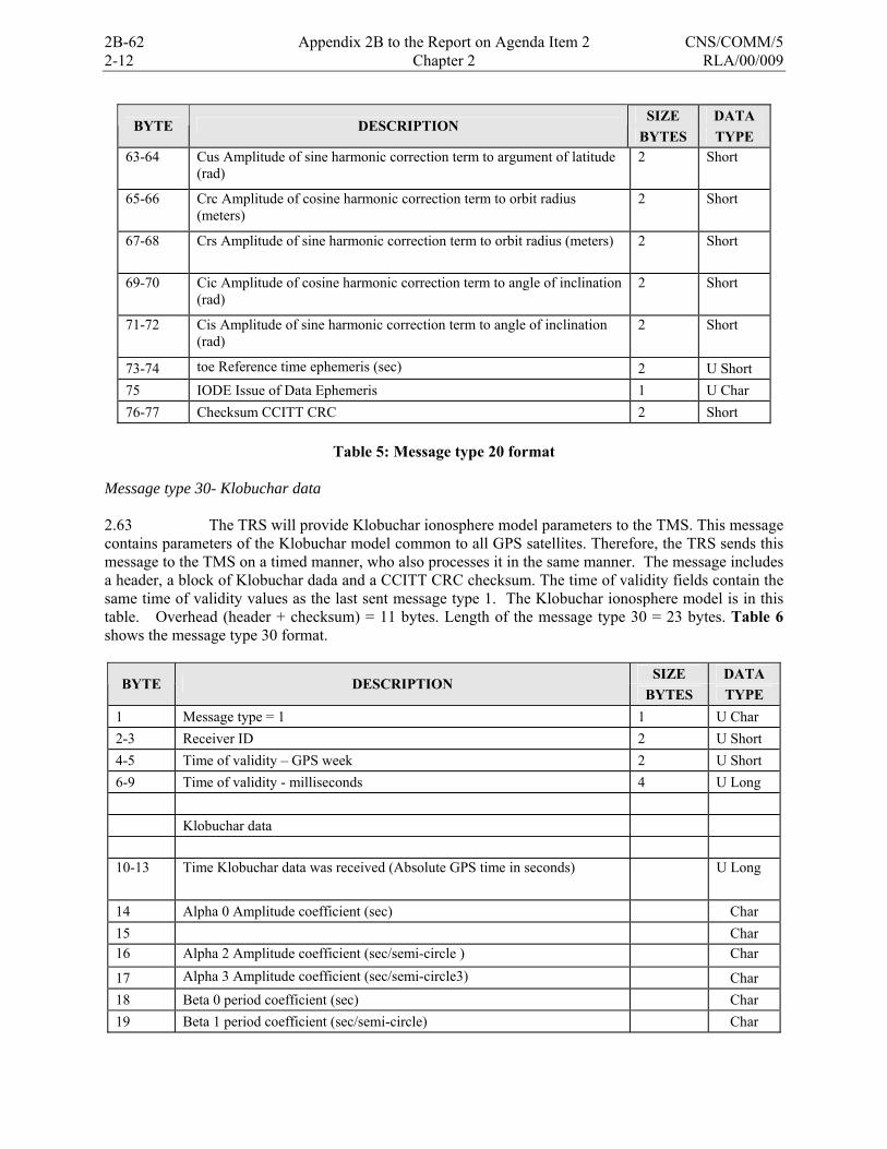
2-12 Chapter 2 RLA/00/009
SIZE DATA BYTE DESCRIPTION
BYTES TYPE 63-64 Cus Amplitude of sine harmonic correction term to argument of latitude
(rad) 2 Short
65-66 Crc Amplitude of cosine harmonic correction term to orbit radius (meters)
2 Short
67-68 Crs Amplitude of sine harmonic correction term to orbit radius (meters) 2 Short
69-70 Cic Amplitude of cosine harmonic correction term to angle of inclination (rad)
2 Short
71-72 Cis Amplitude of sine harmonic correction term to angle of inclination (rad)
2 Short
73-74 toe Reference time ephemeris (sec) 2 U Short 75 IODE Issue of Data Ephemeris 1 U Char 76-77 Checksum CCITT CRC 2 Short
Table 5: Message type 20 format
Message type 30- Klobuchar data 2.63 The TRS will provide Klobuchar ionosphere model parameters to the TMS. This message contains parameters of the Klobuchar model common to all GPS satellites. Therefore, the TRS sends this message to the TMS on a timed manner, who also processes it in the same manner. The message includes a header, a block of Klobuchar dada and a CCITT CRC checksum. The time of validity fields contain the same time of validity values as the last sent message type 1. The Klobuchar ionosphere model is in this table. Overhead (header + checksum) = 11 bytes. Length of the message type 30 = 23 bytes. Table 6 shows the message type 30 format.
SIZE DATA BYTE DESCRIPTION
BYTES TYPE 1 Message type = 1 1 U Char 2-3 Receiver ID 2 U Short 4-5 Time of validity – GPS week 2 U Short 6-9 Time of validity - milliseconds 4 U Long Klobuchar data 10-13 Time Klobuchar data was received (Absolute GPS time in seconds) U Long
14 Alpha 0 Amplitude coefficient (sec) Char 15 Char 16 Alpha 2 Amplitude coefficient (sec/semi-circle ) Char
17 Alpha 3 Amplitude coefficient (sec/semi-circle3) Char 18 Beta 0 period coefficient (sec) Char 19 Beta 1 period coefficient (sec/semi-circle) Char
2B-62 Appendix 2B to the Report on Agenda Item 2 CNS/COMM/5
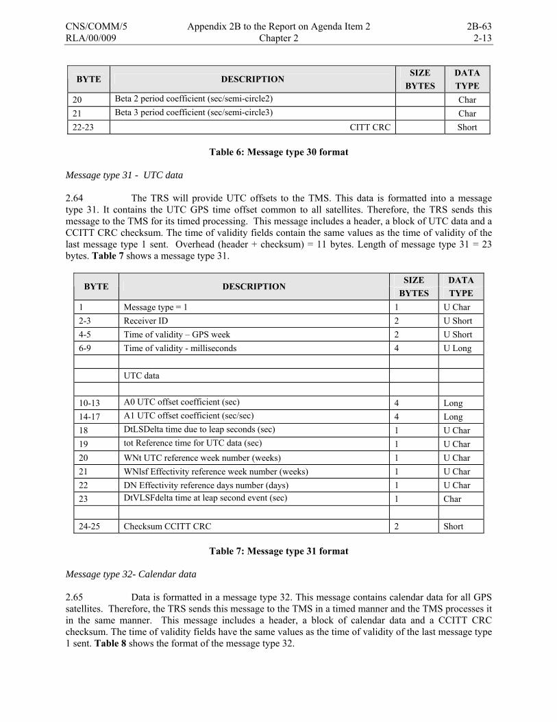
RLA/00/009 Chapter 2 2-13
SIZE DATA BYTE DESCRIPTION
BYTES TYPE 20 Beta 2 period coefficient (sec/semi-circle2) Char 21 Beta 3 period coefficient (sec/semi-circle3) Char 22-23 CITT CRC Short
Table 6: Message type 30 format
Message type 31 - UTC data 2.64 The TRS will provide UTC offsets to the TMS. This data is formatted into a message type 31. It contains the UTC GPS time offset common to all satellites. Therefore, the TRS sends this message to the TMS for its timed processing. This message includes a header, a block of UTC data and a CCITT CRC checksum. The time of validity fields contain the same values as the time of validity of the last message type 1 sent. Overhead (header + checksum) = 11 bytes. Length of message type 31 = 23 bytes. Table 7 shows a message type 31.
SIZE DATA BYTE DESCRIPTION
BYTES TYPE 1 Message type = 1 1 U Char 2-3 Receiver ID 2 U Short 4-5 Time of validity – GPS week 2 U Short 6-9 Time of validity - milliseconds 4 U Long UTC data 10-13 A0 UTC offset coefficient (sec) 4 Long 14-17 A1 UTC offset coefficient (sec/sec) 4 Long 18 DtLSDelta time due to leap seconds (sec) 1 U Char 19 tot Reference time for UTC data (sec) 1 U Char 20 WNt UTC reference week number (weeks) 1 U Char 21 WNlsf Effectivity reference week number (weeks) 1 U Char 22 DN Effectivity reference days number (days) 1 U Char 23 DtVLSFdelta time at leap second event (sec) 1 Char 24-25 Checksum CCITT CRC 2 Short
Table 7: Message type 31 format
Message type 32- Calendar data 2.65 Data is formatted in a message type 32. This message contains calendar data for all GPS satellites. Therefore, the TRS sends this message to the TMS in a timed manner and the TMS processes it in the same manner. This message includes a header, a block of calendar data and a CCITT CRC checksum. The time of validity fields have the same values as the time of validity of the last message type 1 sent. Table 8 shows the format of the message type 32.
CNS/COMM/5 Appendix 2B to the Report on Agenda Item 2 2B-63
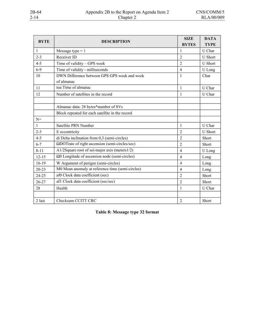
2-14 Chapter 2 RLA/00/009
SIZE DATA
BYTE DESCRIPTION BYTES TYPE
1 Message type = 1 1 U Char 2-3 Receiver ID 2 U Short 4-5 Time of validity – GPS week 2 U Short 6-9 Time of validity - milliseconds 4 U Long 10 DWN Difference between GPS GPS week and week 1 Char of almanac
11 toa Time of almanac 1 U Char 12 Number of satellites in the record 1 U Char Almanac data: 28 bytes*number of SVs Block repeated for each satellite in the record N+ 1 Satellite PRN Number 1 U Char 2-3 E eccentricity 2 U Short 4-5 di Delta inclination from 0,3 (semi-circles) 2 Short 6-7 ΩDOTrate of right ascension (semi-circles/sec) 2 Short 8-11 A1/2Square root of sei-major axis (meters1/2) 4 U Long 12-15 Ω0 Longitude of ascension node (semi-circles) 4 Long 16-19 W Argument of perigee (semi-circles) 4 Long 20-23 M0 Mean anomaly at reference time (semi-circles) 4 Long 24-25 af0 Clock data coefficient (sec) 2 Short 26-27 af1 Clock data coefficient (sec/sec) 2 Short 28 Health 1 U Char 2 last Checksum CCITT CRC 2 Short
Table 8: Message type 32 format
2B-64 Appendix 2B to the Report on Agenda Item 2 CNS/COMM/5

RLA/00/009 Figure 1 to Chapter 2
FIGURE 1
TRS STATION BLOCK DIAGRAMME
Rack Fans
Maintenance Laptop
Rubidium Frequency Standard
Alpha Workstation
Cisco2514 RouterEthernet HUB
APC UPS
220-110 Transformer
E1/10.59.20.11
S0/10.59.11.02
Power Controller1 2 3 4
AUX
COM1
tu1/10.59.20.1
Digi module1 2 3 4
10Mhz
TrimblePower Supply
Trimble 4000 SSIReceiver
Ext Ref
Com1
Antenna
Com2
GPS L1/L2Antenna
CSU/DSU
E0/10.59.20.99
CARSAM REFERENCE STATIONARGENTINA SITE # 59
RFPower
Serial ComEthernet
TRS S/N : ARG 001-59FAATC : 1 609 485 0732
COM OUT
COM IN
5 6 7 8
tu0/10.59.10.1
E0/10.59.10.11
CNS/COMM/5 Appendix 2B to the Report on Agenda Item 2 2B-65
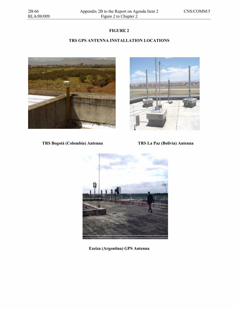
RLA/00/009 Figure 2 to Chapter 2
FIGURE 2
TRS GPS ANTENNA INSTALLATION LOCATIONS
TRS Bogotá (Colombia) Antenna TRS La Paz (Bolivia) Antenna
Ezeiza (Argentina) GPS Antenna
2B-66 Appendix 2B to the Report on Agenda Item 2 CNS/COMM/5
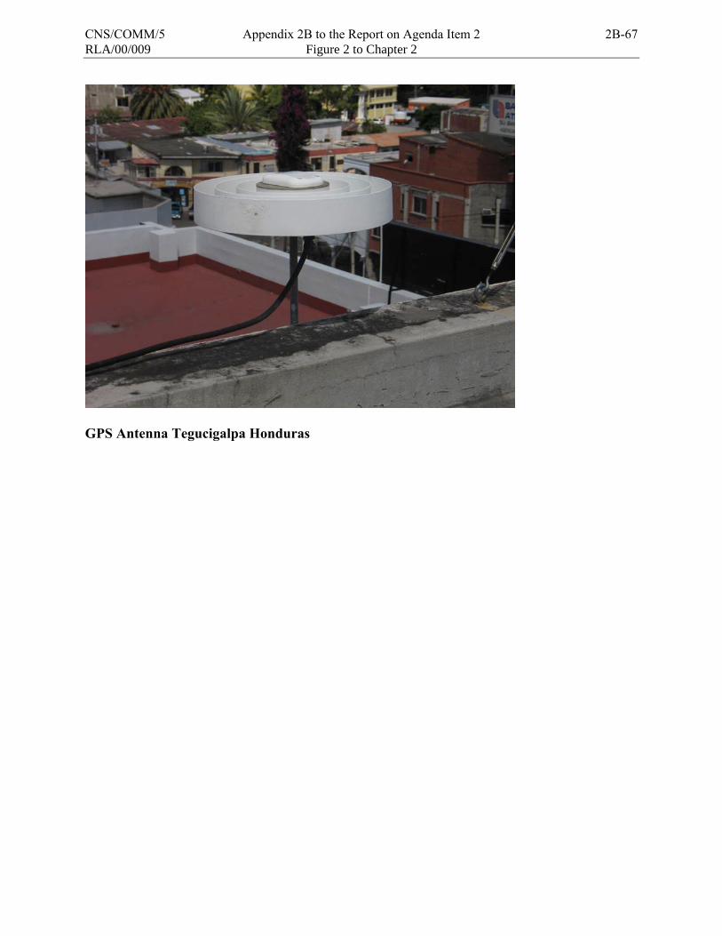
RLA/00/009 Figure 2 to Chapter 2
GPS Antenna Tegucigalpa Honduras
CNS/COMM/5 Appendix 2B to the Report on Agenda Item 2 2B-67

RLA/00/009 Figure 3 to Chapter 2
FIGUR E 3
PHOTOGRAPHS OF CSTB TRS EQUIPMENT
GPS Trimble Receiver GPS Millenium Receiver
TRS Processor Power Manager System
Rubidium Oscillator Digibord
2B-68 Appendix 2B to the Report on Agenda Item 2 CNS/COMM/5
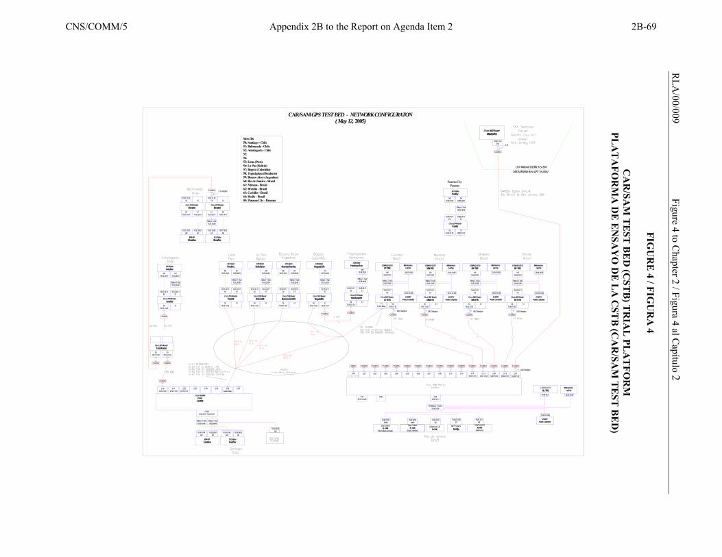
R
LA/00/009 Figure 4 to C
hapter 2 / Figura 4 al Capítulo 2
FIG
UR
E 4 / FIG
UR
A 4
C
AR
/SAM
TE
ST B
ED
(CST
B) T
RIA
L PL
AT
FOR
M
PLA
TA
FOR
MA
DE
EN
SAY
O D
E L
A C
STB
(CA
R/SA
M T
EST
BE
D)
CSU/DSU
S2/5
CSU/DSU
S2/7
CSU/DSU
S2/4
CSU/DSU
S010.51.11.02
Cisco 2514 RouterTorreRouter
CSU/DSU
S010.51.21.02
S2/1
E3/110.52.14.2/29
E0/0
S1Frame Relay
CSU/DSU
Panama CityPanama
DECAlphaPanDec
tu110.85.20.01
10Base-T Hub10.85.20.00
S110.85.21.02
10.85.20.11E1
Cisco 2514 RouterPanRtr
tu010.85.10.01
10.85.10.11E0
S010.85.11.02
10.50.20.01tu1
10.50.10.01tu0
10.50.20.02tu1
10.50.10.02tu0
IBM 43PSantIbm
DECAlphaSantDec
S1/6Frame Relay
10Base-T Hub10.50.20.00
FE0/010.50.20.11 10.50.10.11
10Base-T Hub10.50.10.00
S1/4 S1/5 S1/7
Sites IDs50: Santiago - Chile51: Balmaceda - Chile52: Antofagasta - Chile53: 54: 55: Lima (Peru)56: La Paz (Bolivia)57: Bogota (Colombia)58: Tegucigalpa (Honduras)59: Buenos Aires (Argentina)60: Rio de Janeiro - Brazil61: Manaus - Brazil62: Brasilia - Brazil63: Curitiba - Brazil64: Recife - Brazil85: Panama City - Panama
S1/3
Cisco 2620XM Router
SantRtr
CSU/DSU
10.51.10.01tu0
IBM 43PBlmaIbm
10.51.11.02S0
E010.51.10.11
Cisco 2516 RouterBlmaRtr
V.35 Interface
10.51.10.02tu0
DECAlphaBlmaDec
Cisco 2514 RouterBlmaRtr
E010.51.10.11
E110.51.20.11
10.51.20.01tu1
S1
E110.51.20.11
10Base-T Hub10.51.20.00
10.51.20.02tu1
10.51.11.02S0 S1
10Base-T Hub10.52.20.00
CSU/DSU
S1/010.51.21.01
S1/110.52.11.01
S1/210.53.11.01
Cisco 2514 RouterAntoRtr
S010.52.11.02
CSU/DSU
10.52.10.11E0
10.52.20.11E1
S1
DECAlphaAntoDec
tu010.52.10.01
tu110.52.20.01
10.50.20.03tu0
CSU/DSU
S1/1 S1/510.63.11.01
S1/710.60.11.02
CSU/DSU CSU/DSU
Cisco 3660 RouterMasterRtr
10.60.11.01S1/0
CSU/DSU
E3/010.60.10.11
10/100Base-T Switch10.60.10.00
COMPAQ DS10RJ-TRS
10.60.10.04hme0
USA National Satellite Test BedCAR/SAM Wide Area GPS Test Bed
V.35
10.60.10.01tu0
COMPAQ ES 40RioTMS
10.60.10.230E0
NTP ServerRioNtp
10.60.10.05hme0
COMPAQ DS10RioWib
(WibServer)
10.60.10.3tu0
S1 / 610.64.11.01
S1/410.62.11.01
S1 / 310.61.11.01
S1/2
CSU/DSU
S010.63.11.02
Cisco 2501 RouterCT-RTR
10.63.10.11E0
tu010.63.10.01
COMPAQ DS10CT-TRS
10Base-T Hub10.63.10.00
CSU/DSU
S010.64.11.02
Cisco 2501 RouterRF-RTR
10.64.10.11E0
S1
tu010.64.10.01
COMPAQ DS10RF-TRS
10Base-T Hub10.64.10.00
CSU/DSU
S010.62.11.02
Cisco 2501 RouterBR-RTR
10.62.10.11E0
S1
tu010.62.10.01
COMPAQ DS10BR-TRS
10Base-T Hub10.62.10.00
CSU/DSU
S010.61.11.02
Cisco 2501 RouterMN-RTR
10.61.10.11E0
S1
tu010.61.10.01
COMPAQ DS10MN-TRS
10Base-T Hub10.61.10.00
CSU/DSUCSU/DSUCSU/DSUCSU/DSUCSU/DSU
DB25 Interface
DB25 Interface DB25 InterfaceDB25 InterfaceDB25 Interface
Modem CSU/DSU
S2/0
CSU/DSU
S2/2
CSU/DSU
S2/3
CSU/DSU
S2/6
Cisco 2514 RouterHondurasRtr
S010.58.11.02
CSU/DSU
10.58.10.11E0
S1
10Base-T Hub10.58.20.00
10.58.20.11E1
SUN BladeHondurasSun
eri010.58.20.03
S010.57.11.02
Cisco 2514 RouterBogotaRtr
10.57.20.11E1
S110.58.11.01
10Base-T Hub10.57.20.00
tu110.57.20.03
SUN BladeBogotaSUN
Cisco 2514 RouterPeruRtr
S010.55.11.02
10.55.10.11E0
S1
10Base-T Hub10.55.20.00
10.55.20.11E1
DECAlphaPeruDec
tu010.55.10.01
tu110.55.20.01
Cisco 2514 RouterBuenosAiresRtrS0
10.59.11.02
10.59.10.11E0
S1
10Base-T Hub10.59.20.00
10.59.20.11E1
DECAlphaBuenosAiresDectu0
10.59.10.01tu1
10.59.20.01
Cisco 2514 RouterBoliviaRtr
S010.56.11.02
10.56.10.11E0
CAR/SAM GPS TEST BED - NETWORK CONFIGURATON( May 12, 2005)
S1/0
S1
10Base-T Hub10.56.20.00
10.56.20.11E1
SUN BladeBoliviaSun
eri010.56.20.03
SENTRYPower Controller
10.61.10.100
MaintenanceLapTop
10.61.10.99
SENTRYPower Controller
10.62.10.100
10.62.10.99
MaintenanceLapTop
SENTRYPower Controller
10.64.10.100
10.64.10.99
MaintenanceLapTop
10.63.10.100
10.63.10.99
SENTRYPower Controller
MaintenanceLapTop
Sparc StationRJ-OM1
(Data Collection)
Sparc StationRJ-OM2
(Net Status/Coverage)
10.60.10.100
10.60.10.99
SENTRYPower Controller
MaintenanceLapTop
10.60.10.2
CNS/COMM/5 Appendix 2B to the Report on Agenda Item 2 2B-69
RLA/00/009 Chapter 3 3-1
CHAPTER 3
ANALYSIS OF THE DATA COLECTED Description of CSTB data collection and analysis Data Collection 3.1 The CARSAM Testbed was configured primarily for data collection. The Testbed Reference Stations (TRS) were configured to either send data to the Testbed Master Station or to collect the data locally. The measurements consisted primarily of GPS receiver satellite measurement data and collection of ephemeris messages. The TRS, which contained a Millenium receiver also collected the WAAS GEO measurement data and broadcast WAAS messages. The data was archived onto DVDs. Data Analysis 3.2 Data for several information papers and reports was processed using the GPS Solution Post Process software tool. This tool uses the raw GPS measurement and ephemeris data as inputs and produces position and accuracy information in a text file called a .PDF file. 3.3 When the receiver is receiving a valid SBAS GEO message (which includes valid ionospheric data), the software can produce both accuracy and bounding information. For example, in the United States, this information is used to analyze the accuracy, integrity, and availability of WAAS. The analysis consists of the following: Accuracy 3.4 The output of the GPS Solution Post Process software tool produces columns of the East, North, and Up error. This error is the difference between the computed position and the surveyed position of the TRS antenna. This data can be statistically analyzed or plotted to show the accuracy of the GPS-only or WAAS-corrected position. Integrity 3.5 The output of the GPS Solution Post Process software tool produces columns of the Vertical Protection Level (VPL) and the Horizontal Protection Level (HPL), in addition to the columns of accuracy. The most basic determination of integrity is to use this data to confirm that the errors in the vertical and horizontal direction do not exceed the magnitude of the VPL and HPL. In order for this data to constitute a valid test, the SBAS master station software should have been certified to produce safe correction signals under all possible conditions; otherwise the test can give misleading results. The result of the bounding of the position error by the protection level can be analyzed statistically or plotted.
2B-70 Appendix 2B to the Report on Agenda Item 2 CNS/COMM/5
3-2 Chapter 3 RLA/00/009
Availability 3.6 The output of the GPS Solution Post Process software tool produces columns of the Vertical Protection Level (VPL) and the Horizontal Protection Level (HPL); this data can be combined with the “Alert Level” for the specific operation under test (e.g., LNAV/VNAV) to determine whether the operation would have been available or whether the pilot would have been warned by the receiver to not continue the operation. As an example, under LNAV/VNAV, the Vertical Alert Limit (VAL) requirement is 50 meters. If the VPL went above 50 meters, the certified SBAS aircraft receiver would have generated a flag to warn the pilot to discontinue the approach, so the system would have been unavailable for that time. In order for this data to constitute a valid test, the SBAS master station software should have been certified to produce safe correction signals under all possible conditions; otherwise, the test can give misleading results. The result of the bounding of the protection level by the alert level can be analyzed statistically or plotted. Data Display 3.7 Several plots were made using commercial GNUPLOT software to illustrate the data analysis concepts above. Ionospheric Data 3.8 Analysis of the effects of the ionosphere on GPS and SBAS are performed in several ways. The effects of the disturbed ionosphere are to cause scintillation which causes receiver C/No fluctuations and occasional receiver dropouts, and these can be observed to effect position accuracy as discussed above. The raw C/No data can be plotted to observe strong scintillation and receiver dropouts on specific GPS or SBAS satellites. The receiver C/No is a column in an output file of the GPS Solution Post Process software tool. 3.9 Another effect of the disturbed ionosphere is to produce rapid changes in code or carrier range, and these can be plotted from the GpsSolutionPostProcess software tool. Several examples were provided in the paper of the severely disturbed features called “Depletions” which exist, at times, in areas near the geomagnetic equator. Description of ionospheric problems and its influence over GPS systems 3.10 At the 11th Air Navigation Conference (ANConf/11) a recommendation was made to develop a worldwide ionospheric mitigation roadmap. The intent of the roadmap was to address technical concerns associated with Satellite Based Augmentation System (SBAS) performance in the equatorial regions. In response to this recommendation, the FAA established an initiative within its FAA Flight Plan 2004-2008 to establish the roadmap. Background 3.11 An SBAS is capable of providing navigation services ranging from enroute, terminal to approach operations. For the US developed SBAS, known as the Wide-Area Augmentation System (WAAS), service availability extends from enroute down to what is called LPV (vertically guided approaches down to a 250 foot minimum) operations. One of the limiting factors WAAS must deal with is the ionosphere. The limitations associated with the ionosphere exist at a global level and will need to be addressed by those areas of the world that plan to implement an SBAS. Over the next several years, a number of SBAS will become operational and it’s envisioned that satellite based navigation will eventually become a global reality (See Figure 1).
CNS/COMM/5 Appendix 2B to the Report on Agenda Item 2 2B-71
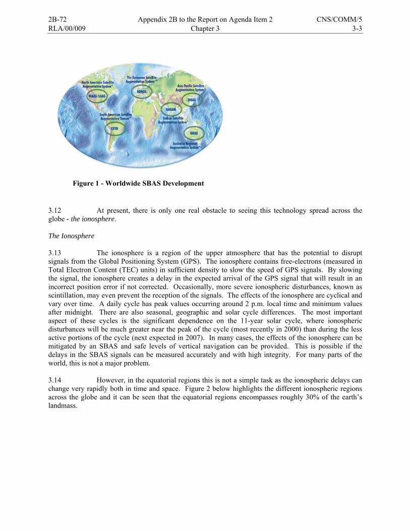
RLA/00/009 Chapter 3 3-3
3.12 At present, there is only one real obstacle to seeing this technology spread across the globe - the ionosphere. The Ionosphere 3.13 The ionosphere is a region of the upper atmosphere that has the potential to disrupt signals from the Global Positioning System (GPS). The ionosphere contains free-electrons (measured in Total Electron Content (TEC) units) in sufficient density to slow the speed of GPS signals. By slowing the signal, the ionosphere creates a delay in the expected arrival of the GPS signal that will result in an incorrect position error if not corrected. Occasionally, more severe ionospheric disturbances, known as scintillation, may even prevent the reception of the signals. The effects of the ionosphere are cyclical and vary over time. A daily cycle has peak values occurring around 2 p.m. local time and minimum values after midnight. There are also seasonal, geographic and solar cycle differences. The most important aspect of these cycles is the significant dependence on the 11-year solar cycle, where ionospheric disturbances will be much greater near the peak of the cycle (most recently in 2000) than during the less active portions of the cycle (next expected in 2007). In many cases, the effects of the ionosphere can be mitigated by an SBAS and safe levels of vertical navigation can be provided. This is possible if the delays in the SBAS signals can be measured accurately and with high integrity. For many parts of the world, this is not a major problem. 3.14 However, in the equatorial regions this is not a simple task as the ionospheric delays can change very rapidly both in time and space. Figure 2 below highlights the different ionospheric regions across the globe and it can be seen that the equatorial regions encompasses roughly 30% of the earth’s landmass.
Figure 1 - Worldwide SBAS Development
2B-72 Appendix 2B to the Report on Agenda Item 2 CNS/COMM/5

3-4 Chapter 3 RLA/00/009
Figure 2 - Ionospheric Regions of the World
3.15 To support the implementation of SBAS in the near-equatorial regions of the world, the FAA has been supporting and conducting research focused on fully characterizing and then mitigating the effects of the ionosphere. The most recent effort has been to coordinate with international researchers in establishing a work plan for resolving issues associated with implementing an SBAS in the equatorial region. A major portion of this effort is in the establishment of a roadmap for mitigation of ionospheric effects to include the equatorial, mid-latitudes and auroral regions of the world. 3.16 The following information is the compilation of many years of research but it is of interest to note that there is still a significant level of work ahead for making SBAS a reality in the near-equatorial regions. It is very challenging to provide useful ionospheric corrections to these regions, but it is also very important as roughly 30% of population lie in these regions along with roughly 15% of the airports. Findings to Date
3.17 The Global Positioning System (GPS) has been providing Position, Navigation and Time (PNT) to navigation users for nearly a decade. For those users using only GPS the ionosphere has not been shown to be a serious problem. 3.18 The RLA/00/009 project has invested a substantial amount of effort in developing data GPS collection from the TRS in order to verify the augmentation requirements for single frequency (L1) GPS receiver to account for range error due to ionospheric delay and to provide a bound for the remaining ionospheric error. 3.19 SBAS type WAAS transmits a grid of spatial vertical ionospheric delay information, which the user receiver interpolates and applies to each GPS range measurement. WAAS also generates an error bound for each grid point, called the Grid Ionospheric Vertical Error. The user receiver incorporates this error bound in his computation of the Vertical protection Level (VPL) and Horizontal Protection level (HPL) for the aircraft. The WAAS system assures the safety of the user by bounding the expected position error with the protection levels – and if the protection level exceeds the Alert Limit, then the pilot is warned to not continue the approach (if the runway is not in sight) [1].
CNS/COMM/5 Appendix 2B to the Report on Agenda Item 2 2B-73
RLA/00/009 Chapter 3 3-5
3.20 WAAS informs the user receiver of ionospheric delay using a form of planar approximation. The system utilizes a bound for the possible ionospheric error resulting from potential irregularity in the ionosphere. The safety and availability SBAS systems, therefore, need to be considered when the ionosphere is disturbed and spatial delay becomes non-planar. 3.21 During the course of WAAS Initial Operational Capability (IOC) development, the FAA learned that the three-dimensional structure of the ionosphere in the aurora, polar cap, and mid-latitude regions can be well represented with a simplified two-dimensional model the majority of the time. This simplified model is used to condense the information so that it may be broadcast to users by means of a low data rate using geostationary satellites. Very rarely, near the peak of the 11-year solar cycle, significant disturbances occur in these regions that are not well modeled in two dimensions or that may escape detection altogether. WAAS has implemented an “irregularity detector” to identify times and locations where the ionosphere may not be well modeled. During these times, vertical guidance becomes unavailable. In addition, WAAS always inflates its broadcast confidence values to account for ionospheric disturbances that may be present, but not detected by the system. 3.22 This section overviews the GPS system augmentation features related to the ionosphere, and document several of the “bad” features and effects of the ionosphere that have been observed in the CONUS by the WAAS system, and in the CAR/SAM Region by the CSTB. GNSS augmentation safety features related to ionospheric delay 3.23 The WAAS system continually tests the planar model of the ionosphere on which its safety depends; if any condition is detected over a radius of at least 800 km from a grid point which shows that ionospheric delay is not well represented by a smooth plane, then the GIVE for that grid point is set to 45 m, effectively removing it from use 3.24 Medium and large geomagnetic storms have been observed to create an irregular ionosphere over the continental United States, and the impact on WAAS has been to disable vertical guidance during these conditions. The system assures safety with a tradeoff in availability, and users of the system will either use an alternate landing aid, or conduct a Non-Precision Approach using WAAS or stand-alone GPS to land. Fortunately, the number of geomagnetic storms which are expected to disrupt the vertical guidance service of the WAAS system over a large area, are expected to be rare (perhaps zero, one or two per year), at the mid-latitude location of CONUS. Ionospheric features at different latitudes 3.25 Unfortunately for the goal of worldwide standardization, ionospheric conditions differ substantially from the region near the geomagnetic equator (+/- roughly 20 degrees), and mid latitude locations. Mid-latitude areas may experience irregular ionospheric conditions relatively rarely, while the geomagnetic equator may see, at times, irregular conditions almost daily, due to two primary features – the equatorial anomaly and depletions The equatorial anomaly creates a bulge of ionospheric delay north and south of the geomagnetic equator during the day and seasonally, in the evening. The second and more extreme factor is depletions, which appear as elongated regions of decreased TEC on the order or hundreds of kilometers wide, or less.
2B-74 Appendix 2B to the Report on Agenda Item 2 CNS/COMM/5
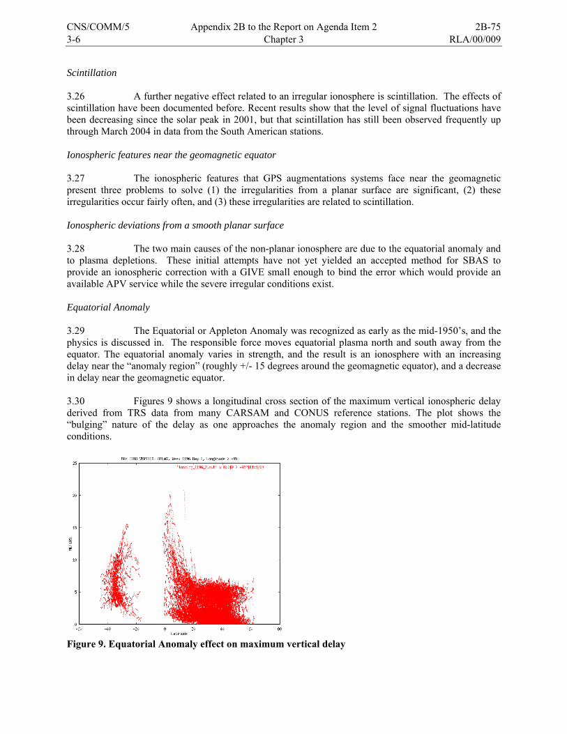
3-6 Chapter 3 RLA/00/009
Scintillation 3.26 A further negative effect related to an irregular ionosphere is scintillation. The effects of scintillation have been documented before. Recent results show that the level of signal fluctuations have been decreasing since the solar peak in 2001, but that scintillation has still been observed frequently up through March 2004 in data from the South American stations. Ionospheric features near the geomagnetic equator 3.27 The ionospheric features that GPS augmentations systems face near the geomagnetic present three problems to solve (1) the irregularities from a planar surface are significant, (2) these irregularities occur fairly often, and (3) these irregularities are related to scintillation. Ionospheric deviations from a smooth planar surface 3.28 The two main causes of the non-planar ionosphere are due to the equatorial anomaly and to plasma depletions. These initial attempts have not yet yielded an accepted method for SBAS to provide an ionospheric correction with a GIVE small enough to bind the error which would provide an available APV service while the severe irregular conditions exist. Equatorial Anomaly 3.29 The Equatorial or Appleton Anomaly was recognized as early as the mid-1950’s, and the physics is discussed in. The responsible force moves equatorial plasma north and south away from the equator. The equatorial anomaly varies in strength, and the result is an ionosphere with an increasing delay near the “anomaly region” (roughly +/- 15 degrees around the geomagnetic equator), and a decrease in delay near the geomagnetic equator. 3.30 Figures 9 shows a longitudinal cross section of the maximum vertical ionospheric delay derived from TRS data from many CARSAM and CONUS reference stations. The plot shows the “bulging” nature of the delay as one approaches the anomaly region and the smoother mid-latitude conditions.
Figure 9. Equatorial Anomaly effect on maximum vertical delay
CNS/COMM/5 Appendix 2B to the Report on Agenda Item 2 2B-75
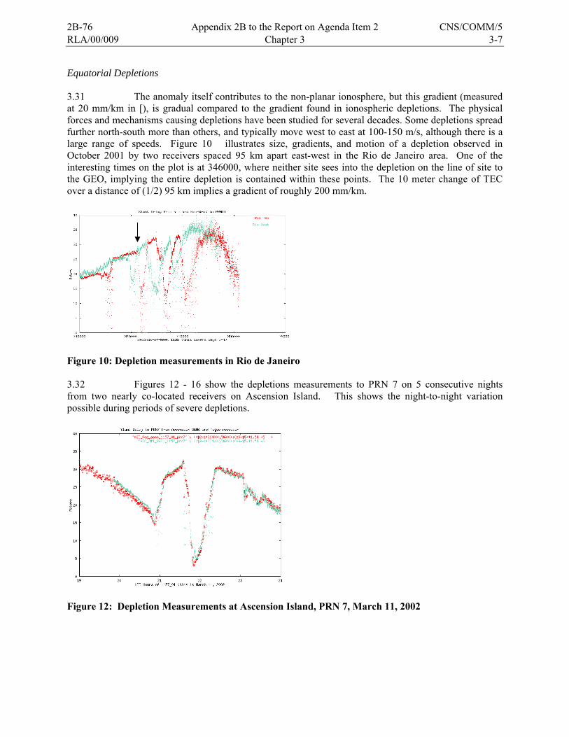
RLA/00/009 Chapter 3 3-7
Equatorial Depletions 3.31 The anomaly itself contributes to the non-planar ionosphere, but this gradient (measured at 20 mm/km in [), is gradual compared to the gradient found in ionospheric depletions. The physical forces and mechanisms causing depletions have been studied for several decades. Some depletions spread further north-south more than others, and typically move west to east at 100-150 m/s, although there is a large range of speeds. Figure 10 illustrates size, gradients, and motion of a depletion observed in October 2001 by two receivers spaced 95 km apart east-west in the Rio de Janeiro area. One of the interesting times on the plot is at 346000, where neither site sees into the depletion on the line of site to the GEO, implying the entire depletion is contained within these points. The 10 meter change of TEC over a distance of (1/2) 95 km implies a gradient of roughly 200 mm/km.
Figure 10: Depletion measurements in Rio de Janeiro 3.32 Figures 12 - 16 show the depletions measurements to PRN 7 on 5 consecutive nights from two nearly co-located receivers on Ascension Island. This shows the night-to-night variation possible during periods of severe depletions.
Figure 12: Depletion Measurements at Ascension Island, PRN 7, March 11, 2002
2B-76 Appendix 2B to the Report on Agenda Item 2 CNS/COMM/5
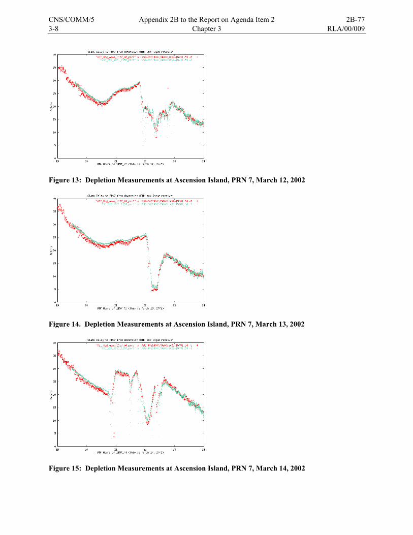
3-8 Chapter 3 RLA/00/009
Figure 13: Depletion Measurements at Ascension Island, PRN 7, March 12, 2002
Figure 14. Depletion Measurements at Ascension Island, PRN 7, March 13, 2002
Figure 15: Depletion Measurements at Ascension Island, PRN 7, March 14, 2002
CNS/COMM/5 Appendix 2B to the Report on Agenda Item 2 2B-77
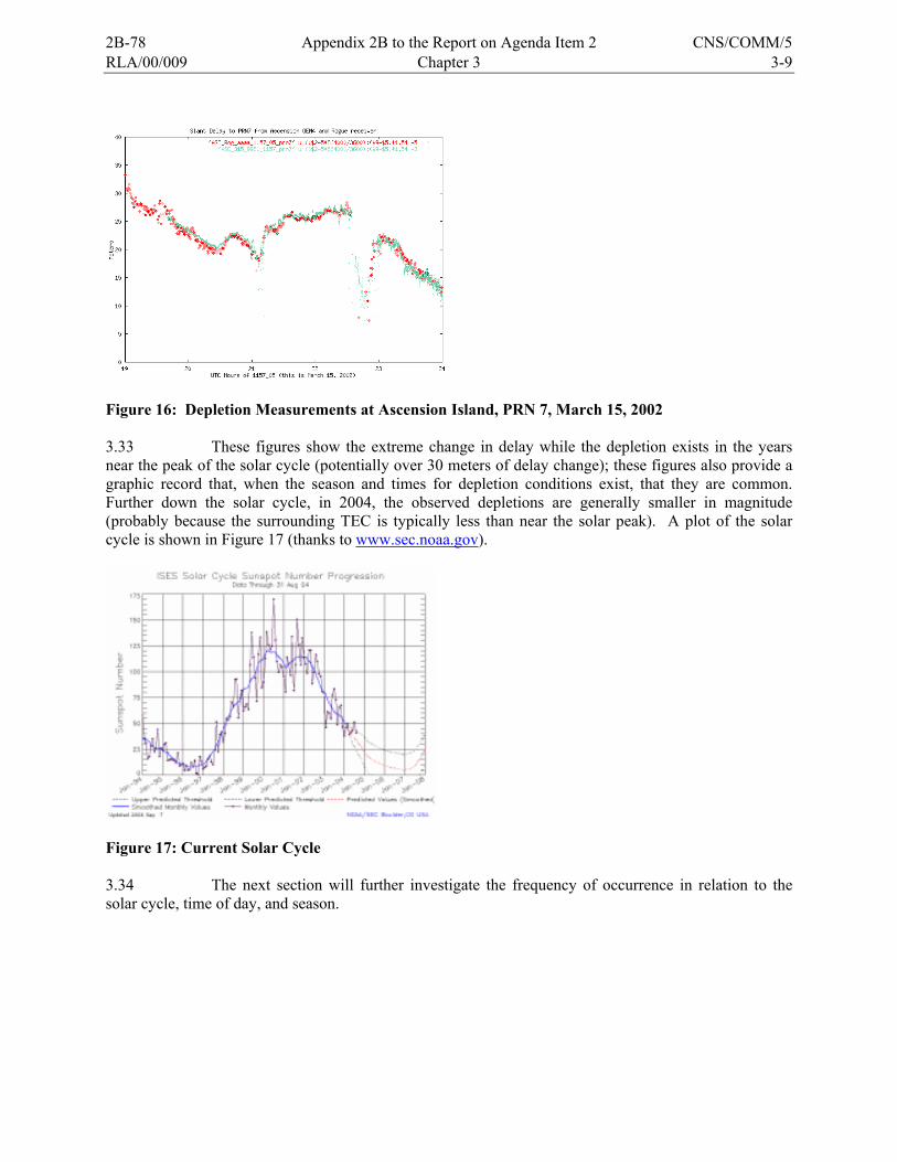
RLA/00/009 Chapter 3 3-9
Figure 16: Depletion Measurements at Ascension Island, PRN 7, March 15, 2002 3.33 These figures show the extreme change in delay while the depletion exists in the years near the peak of the solar cycle (potentially over 30 meters of delay change); these figures also provide a graphic record that, when the season and times for depletion conditions exist, that they are common. Further down the solar cycle, in 2004, the observed depletions are generally smaller in magnitude (probably because the surrounding TEC is typically less than near the solar peak). A plot of the solar cycle is shown in Figure 17 (thanks to www.sec.noaa.gov).
Figure 17: Current Solar Cycle 3.34 The next section will further investigate the frequency of occurrence in relation to the solar cycle, time of day, and season.
2B-78 Appendix 2B to the Report on Agenda Item 2 CNS/COMM/5
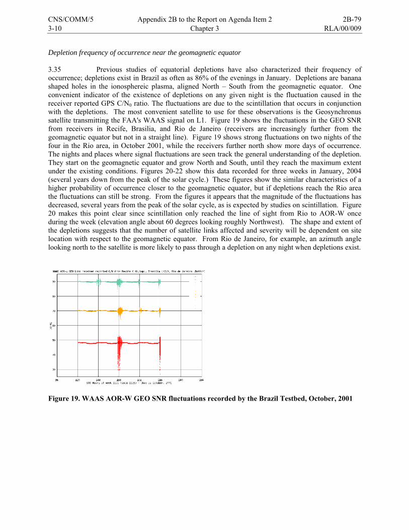
3-10 Chapter 3 RLA/00/009
Depletion frequency of occurrence near the geomagnetic equator 3.35 Previous studies of equatorial depletions have also characterized their frequency of occurrence; depletions exist in Brazil as often as 86% of the evenings in January. Depletions are banana shaped holes in the ionosphereic plasma, aligned North – South from the geomagnetic equator. One convenient indicator of the existence of depletions on any given night is the fluctuation caused in the receiver reported GPS C/N0 ratio. The fluctuations are due to the scintillation that occurs in conjunction with the depletions. The most convenient satellite to use for these observations is the Geosynchronus satellite transmitting the FAA's WAAS signal on L1. Figure 19 shows the fluctuations in the GEO SNR from receivers in Recife, Brasilia, and Rio de Janeiro (receivers are increasingly further from the geomagnetic equator but not in a straight line). Figure 19 shows strong fluctuations on two nights of the four in the Rio area, in October 2001, while the receivers further north show more days of occurrence. The nights and places where signal fluctuations are seen track the general understanding of the depletion. They start on the geomagnetic equator and grow North and South, until they reach the maximum extent under the existing conditions. Figures 20-22 show this data recorded for three weeks in January, 2004 (several years down from the peak of the solar cycle.) These figures show the similar characteristics of a higher probability of occurrence closer to the geomagnetic equator, but if depletions reach the Rio area the fluctuations can still be strong. From the figures it appears that the magnitude of the fluctuations has decreased, several years from the peak of the solar cycle, as is expected by studies on scintillation. Figure 20 makes this point clear since scintillation only reached the line of sight from Rio to AOR-W once during the week (elevation angle about 60 degrees looking roughly Northwest). The shape and extent of the depletions suggests that the number of satellite links affected and severity will be dependent on site location with respect to the geomagnetic equator. From Rio de Janeiro, for example, an azimuth angle looking north to the satellite is more likely to pass through a depletion on any night when depletions exist.
Figure 19. WAAS AOR-W GEO SNR fluctuations recorded by the Brazil Testbed, October, 2001
CNS/COMM/5 Appendix 2B to the Report on Agenda Item 2 2B-79

RLA/00/009 Chapter 3 3-11
Figure 20. WAAS AOR-W GEO SNR fluctuations recorded by the Brazil Testbed, Jan 11-17, 2004
Figure 21. WAAS AOR-W GEO SNR fluctuations recorded by the Brazil Testbed, Jan 18-24, 2004
Figure 22. WAAS AOR-W GEO SNR fluctuations recorded by the Brazil Testbed, Jan 24-31, 2004
2B-80 Appendix 2B to the Report on Agenda Item 2 CNS/COMM/5
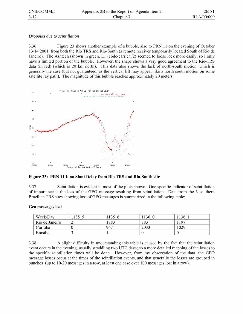
3-12 Chapter 3 RLA/00/009
Dropouts due to scintillation 3.36 Figure 23 shows another example of a bubble, also to PRN 11 on the evening of October 13/14 2001, from both the Rio TRS and Rio-South (a remote receiver temporarily located South of Rio de Janeiro). The Ashtech (shown in green, L1 (code-carrier)/2) seemed to loose lock more easily, so I only have a limited portion of the bubble. However, the shape shows a very good agreement to the Rio-TRS data (in red) (which is 20 km north). This data also shows the lack of north-south motion, which is generally the case (but not guaranteed, as the vertical lift may appear like a north south motion on some satellite ray path). The magnitude of this bubble reaches approximately 20 meters.
Figure 23: PRN 11 Iono Slant Delay from Rio TRS and Rio-South site 3.37 Scintillation is evident in most of the plots shown. One specific indicator of scintillation of importance is the loss of the GEO message resulting from scintillation. Data from the 3 southern Brazilian TRS sites showing loss of GEO messages is summarized in the following table: Geo messages lost
Week/Day 1135_5 1135_6 1136_0 1136_1 Rio de Janeiro 2 1783 783 1197 Curitiba 0 967 2033 1029 Brasilia 3 1 0 0
3.38 A slight difficulty in understanding this table is caused by the fact that the scintillation event occurs in the evening, usually straddling two UTC days; so a more detailed mapping of the losses to the specific scintillation times will be done. However, from my observation of the data, the GEO message losses occur at the times of the scintillation events, and that generally the losses are grouped in bunches (up to 10-20 messages in a row, at least one case over 100 messages lost in a row).
CNS/COMM/5 Appendix 2B to the Report on Agenda Item 2 2B-81

RLA/00/009 Chapter 3 3-13
Continuing research 3.39 Research is continuing on how to solve the problems of safe interpolation/extrapolation of ionopsheric delay from GPS augmentations systems to L1-only airborne users. The worst irregularities or non-planar features are formed in the ionosphere by geomagnetic storms in mid-latitudes and, more commonly, by Earth’s ionospheric physics in areas near the geomagnetic equator. The ultimate answer is the use of dual frequencies, such as L5 - the second civil frequency, in GPS. This will permit the aircraft to directly measure the ionospheric delay and compensate for it, instead of trying to have the augmentation system estimate what ionospheric delay the aircraft's measurements might be experiencing. The additional civil frequency will not completely solve the problem of dropouts due to scintillation, however, so further research and specification in this area may be needed. Analysis of the data collected 3.40 All data collected are stored in DVD at the FAA William J. Hughes Technical Center (WJHTC) in Atlantic City, New Jersey, USA. The data collection started in 2002 and ended in November 2005. 3.41 Data without processing from the TRS and recorded in the Atlantic City data base is available to Project RLA/00/009 participants upon requirement. 3.42 To obtain CSTB data, contact should be made with Mr. Tom Dehel ([email protected]). In addition, the data collected by the NSTB during the last weeks to the date of access can be found at the following Web page: http://www.nstb.tc.faa.gov/ 3.43 Non-aviation civil users will be the first group able to conduct dual frequency measurements on ionospheric delay with the introduction of the new L2C signal. L2C will not be available for civil aviation safety-of-life uses since it is not in a frequency band protected for aviation safety-of-life applications. 3.44 The L5 signal is a robust new signal designed to meet the needs of aviation users. It provides greater resistance to interference and improved acquisition properties. The data message will be new, and is designed to meet the accuracy needs and provide flexibility required by future users. The addition of this third civil frequency will provide worldwide, continuous availability of ionospheric measurement to all civil users. 3.45 Full capability of these signals will be provided when sufficient satellites are launched to provide adequate global coverage, and the GPS Control Segment is enhanced to monitor and control them. Initial operating capability (IOC) for L2C is approximately 2010, with full operating capability (FOC) in 2012. L5 IOC is approximated for 2013 with FOC in 2015. These schedules are approximate and therefore subject to change. 3.46 Satellite navigation for aviation provides an almost quantum leap in capability above conventional navigation aids, and the effects of the ionosphere on services like en route navigation and non-precision approach are almost nil. The use of satellite navigation for precision vertical guidance, however, requires precise correction and bounding of ionospheric delay estimation errors.
2B-82 Appendix 2B to the Report on Agenda Item 2 CNS/COMM/5
3-14 Chapter 3 RLA/00/009
3.47 WAAS has already experienced major geomagnetic storms where vertical guidance has been automatically disabled for periods lasting several hours over the United States. Ionospheric features that exist often in areas near the geomagnetic equator continue to be studied, but a solution using a single-frequency SBAS system to provide vertical guidance has not yet been defined, at least for times when these severe features exist.
Data collected from the TRS 3.48 Figures 24 to 29 show the amount of data received per week at the FAA technological centre in Atlantic City, from each CSTB TRS (using day 3 of the week). The graphics were Developer using the tool named gnuplot. All these data are available at the afore indicated site. 3.49 In the figures, the axis shows the number of messages measured per site. One message per second would have to be received, one perfect collection day would have to have 86400 messages. 3.50 The figures show that great amount of data were received, but the problems encountered can be noted (hardware failure, untimely installation of communications lines, occasional failures of same, etc.). 3.51 The great amount of data collected reflects that the objective of the project, related with data collection, was complied with and that same would be providing information for the investigation (ionosphere). 3.52 The graphics’ X axis indicate the number of weeks per a tour-year period. The conversión from weeks to perids (months, years) is shown as follows: Week 1150 - January, 2002 Week 1200 - January, 2003 Week 1250 - December, 2003 Week 1300 - December, 2004 Week 1350 - December 2005
CNS/COMM/5 Appendix 2B to the Report on Agenda Item 2 2B-83
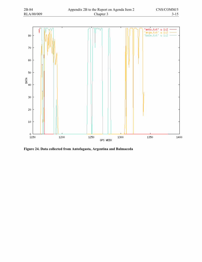
RLA/00/009 Chapter 3 3-15
Figure 24. Data collected from Antofagasta, Argentina and Balmaceda
2B-84 Appendix 2B to the Report on Agenda Item 2 CNS/COMM/5

3-16 Chapter 3 RLA/00/009
Figure 25. Data collected from Bogotá and Honduras
CNS/COMM/5 Appendix 2B to the Report on Agenda Item 2 2B-85
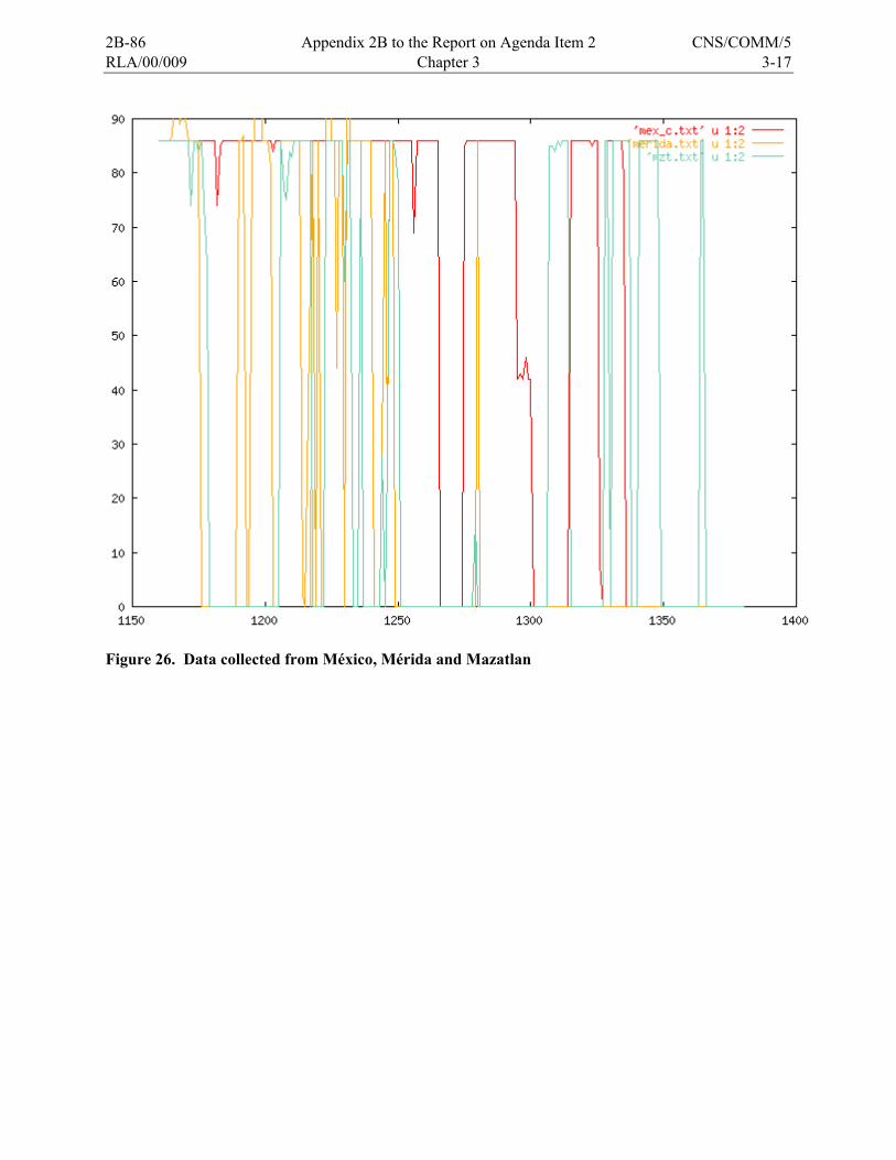
RLA/00/009 Chapter 3 3-17
Figure 26. Data collected from México, Mérida and Mazatlan
2B-86 Appendix 2B to the Report on Agenda Item 2 CNS/COMM/5
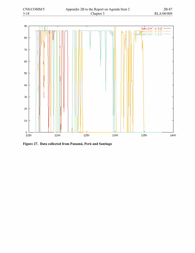
3-18 Chapter 3 RLA/00/009
Figure 27. Data collected from Panamá, Perú and Santiago
CNS/COMM/5 Appendix 2B to the Report on Agenda Item 2 2B-87
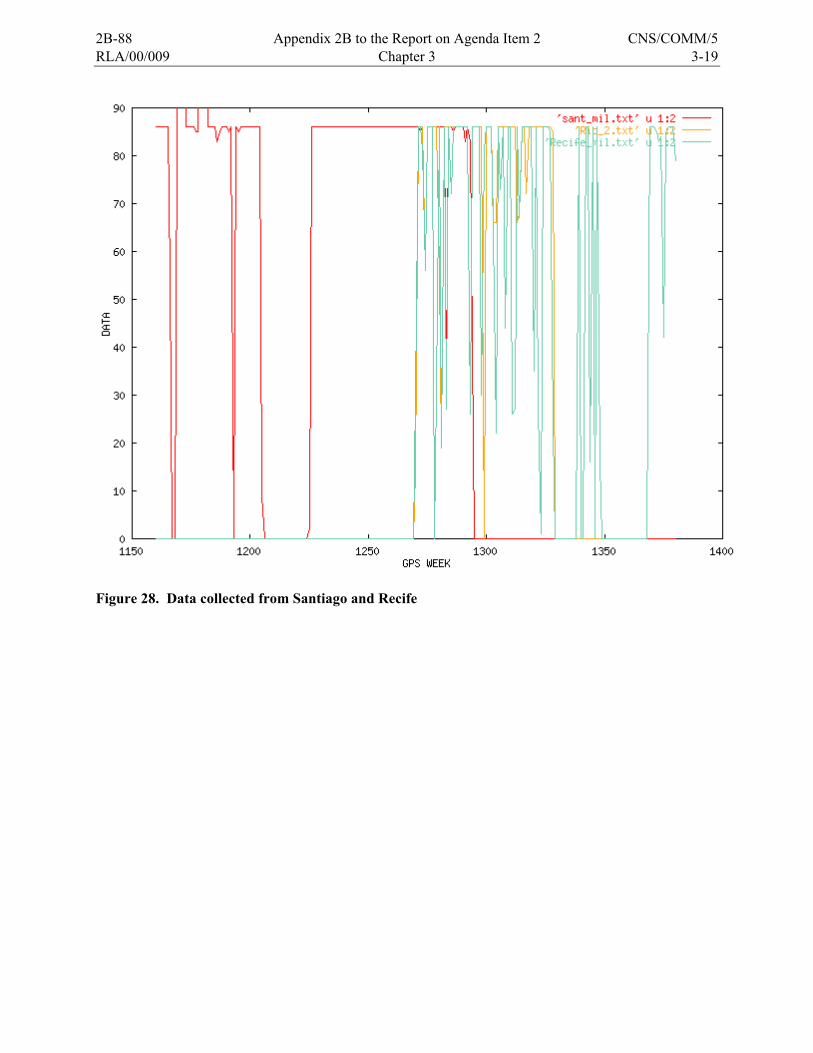
RLA/00/009 Chapter 3 3-19
Figure 28. Data collected from Santiago and Recife
2B-88 Appendix 2B to the Report on Agenda Item 2 CNS/COMM/5
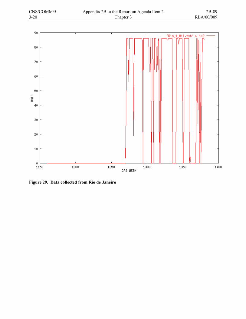
3-20 Chapter 3 RLA/00/009
Figure 29. Data collected from Río de Janeiro
CNS/COMM/5 Appendix 2B to the Report on Agenda Item 2 2B-89
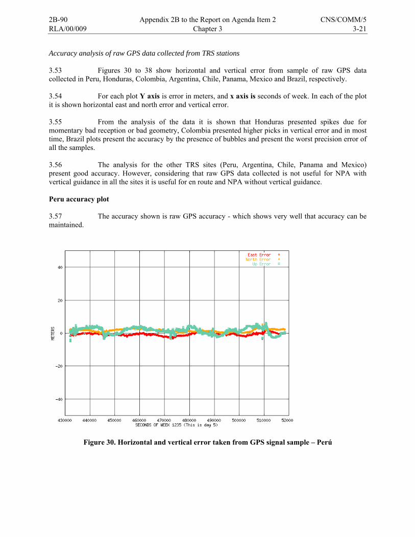
RLA/00/009 Chapter 3 3-21
Accuracy analysis of raw GPS data collected from TRS stations 3.53 Figures 30 to 38 show horizontal and vertical error from sample of raw GPS data collected in Peru, Honduras, Colombia, Argentina, Chile, Panama, Mexico and Brazil, respectively. 3.54 For each plot Y axis is error in meters, and x axis is seconds of week. In each of the plot it is shown horizontal east and north error and vertical error. 3.55 From the analysis of the data it is shown that Honduras presented spikes due for momentary bad reception or bad geometry, Colombia presented higher picks in vertical error and in most time, Brazil plots present the accuracy by the presence of bubbles and present the worst precision error of all the samples. 3.56 The analysis for the other TRS sites (Peru, Argentina, Chile, Panama and Mexico) present good accuracy. However, considering that raw GPS data collected is not useful for NPA with vertical guidance in all the sites it is useful for en route and NPA without vertical guidance. Peru accuracy plot 3.57 The accuracy shown is raw GPS accuracy - which shows very well that accuracy can be maintained.
Figure 30. Horizontal and vertical error taken from GPS signal sample – Perú
2B-90 Appendix 2B to the Report on Agenda Item 2 CNS/COMM/5
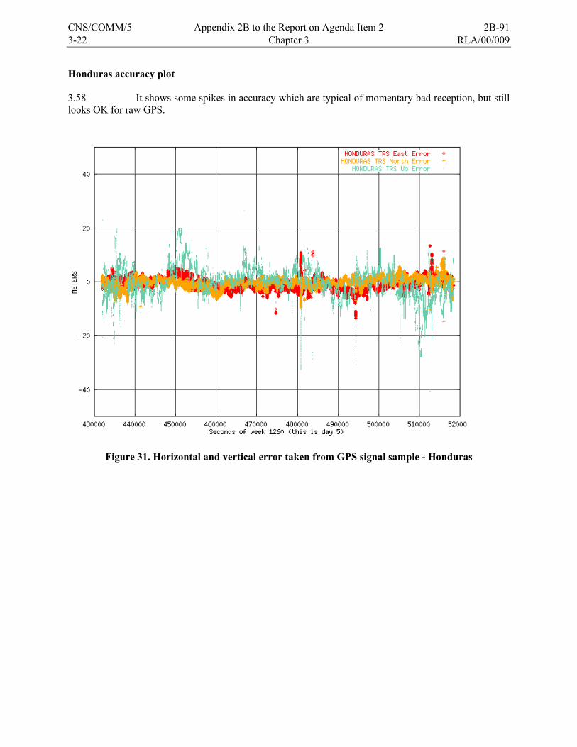
3-22 Chapter 3 RLA/00/009
Honduras accuracy plot 3.58 It shows some spikes in accuracy which are typical of momentary bad reception, but still looks OK for raw GPS.
Figure 31. Horizontal and vertical error taken from GPS signal sample - Honduras
CNS/COMM/5 Appendix 2B to the Report on Agenda Item 2 2B-91
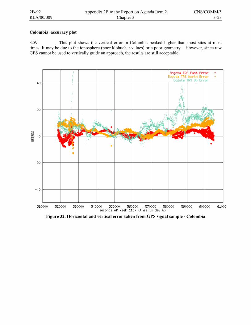
RLA/00/009 Chapter 3 3-23
Colombia accuracy plot 3.59 This plot shows the vertical error in Colombia peaked higher than most sites at most times. It may be due to the ionosphere (poor klobuchar values) or a poor geometry. However, since raw GPS cannot be used to vertically guide an approach, the results are still acceptable.
Figure 32. Horizontal and vertical error taken from GPS signal sample - Colombia
2B-92 Appendix 2B to the Report on Agenda Item 2 CNS/COMM/5
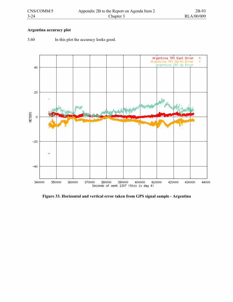
3-24 Chapter 3 RLA/00/009
Argentina accuracy plot 3.60 In this plot the accuracy looks good.
Figure 33. Horizontal and vertical error taken from GPS signal sample - Argentina
CNS/COMM/5 Appendix 2B to the Report on Agenda Item 2 2B-93
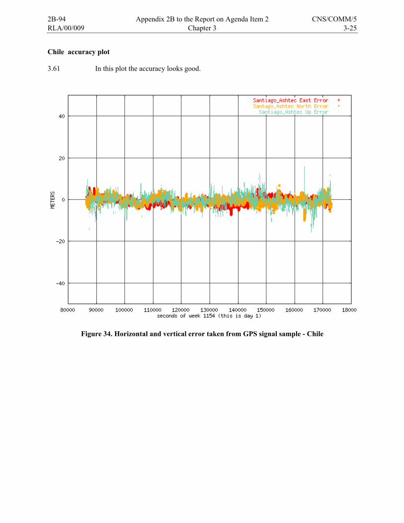
RLA/00/009 Chapter 3 3-25
Chile accuracy plot 3.61 In this plot the accuracy looks good.
Figure 34. Horizontal and vertical error taken from GPS signal sample - Chile
2B-94 Appendix 2B to the Report on Agenda Item 2 CNS/COMM/5
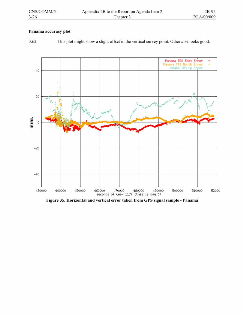
3-26 Chapter 3 RLA/00/009
Panama accuracy plot 3.62 This plot might show a slight offset in the vertical survey point. Otherwise looks good.
Figure 35. Horizontal and vertical error taken from GPS signal sample - Panamá
CNS/COMM/5 Appendix 2B to the Report on Agenda Item 2 2B-95
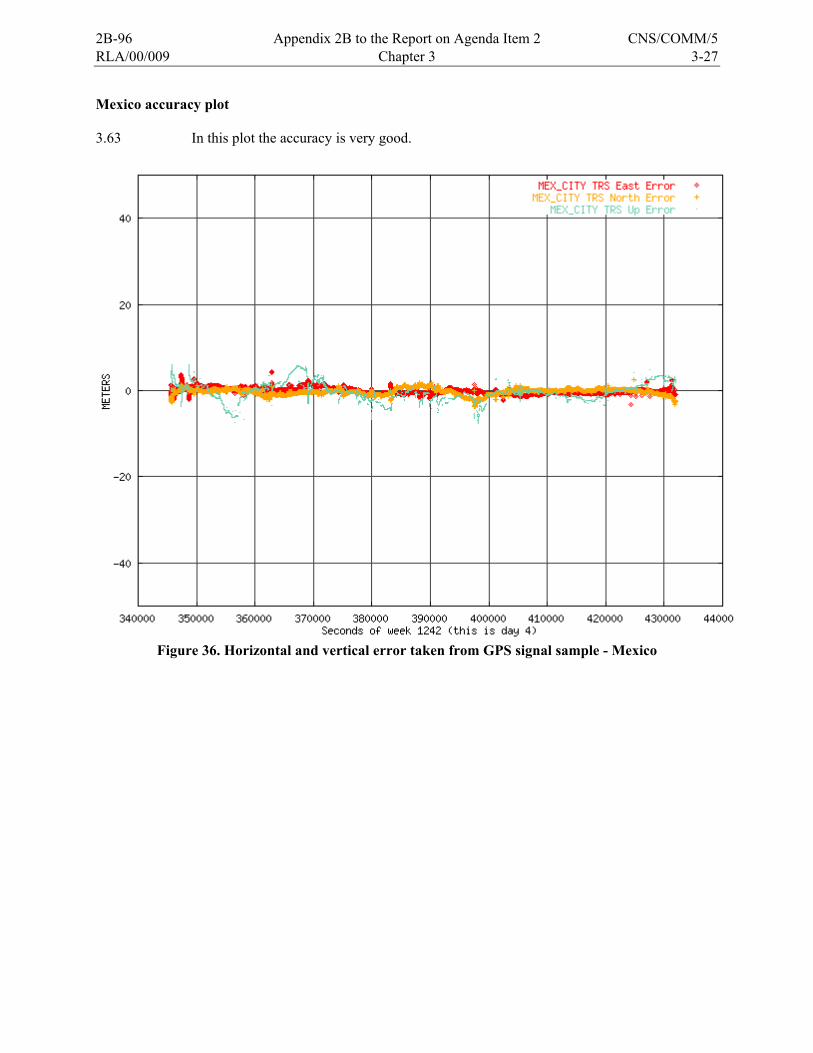
RLA/00/009 Chapter 3 3-27
Mexico accuracy plot 3.63 In this plot the accuracy is very good.
Figure 36. Horizontal and vertical error taken from GPS signal sample - Mexico
2B-96 Appendix 2B to the Report on Agenda Item 2 CNS/COMM/5
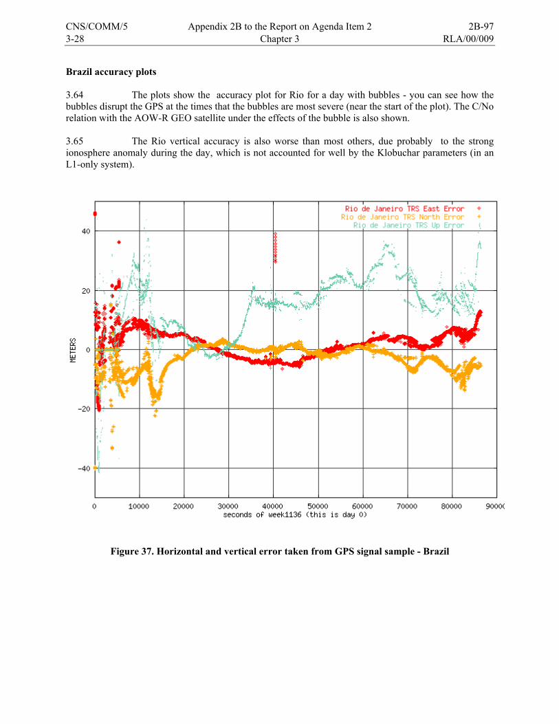
3-28 Chapter 3 RLA/00/009
Brazil accuracy plots 3.64 The plots show the accuracy plot for Rio for a day with bubbles - you can see how the bubbles disrupt the GPS at the times that the bubbles are most severe (near the start of the plot). The C/No relation with the AOW-R GEO satellite under the effects of the bubble is also shown. 3.65 The Rio vertical accuracy is also worse than most others, due probably to the strong ionosphere anomaly during the day, which is not accounted for well by the Klobuchar parameters (in an L1-only system).
Figure 37. Horizontal and vertical error taken from GPS signal sample - Brazil
CNS/COMM/5 Appendix 2B to the Report on Agenda Item 2 2B-97
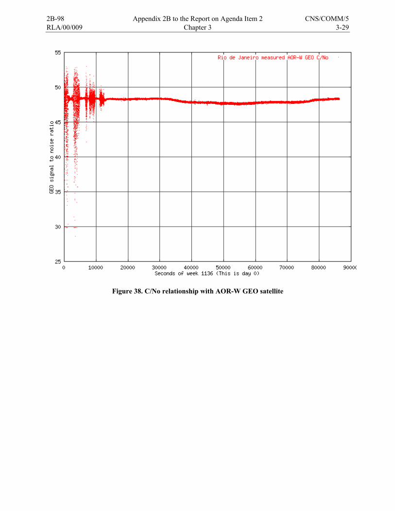
RLA/00/009 Chapter 3 3-29
Figure 38. C/No relationship with AOR-W GEO satellite
2B-98 Appendix 2B to the Report on Agenda Item 2 CNS/COMM/5

RLA/00/009 Chapter 4 4-1
CHAPTER 4
GNSS IMPLEMENTATION OPTIONS IN THE CAR/SAM REGION 4.1 The ICAO Regional Project for Latin America (RLA/00/009), which established a prototype Wide Area Augmentation System (WAAS) test bed capability throughout Central and South America (CSTB), has been conducting tests and trials since 2002. As a result of the tests completed and the ionosphere conditions that were uncovered as a result of initial tests, the RLA/00/009 project must recommend the most viable path forward for the Caribbean and South American (CAR/SAM) region for implementation of GNSS systems (GPS, WAAS/SBAS, and LAAS/GBAS). 4.2 Because of the severity of the ionosphere conditions in the geomagnetic equatorial region (and +/- 20° degrees around equator line) it is recommended that the CAR/SAM region only look at the possible implementation of an SBAS for Lateral Navigation (LNAV) or Non-Precision Approach (NPA). 4.3 The future precision approach services based on GNSS in the region will be provided in the future after the availability of either Category I capable Ground Based Augmentation System (GBAS) or the global availability of a second civil GPS signal at L5. At this time the ionosphere situation basically goes away. Also, the planned implementation of new satellite constellations such as Galileo and the continued modernization of the U.S. Global Positioning System (GPS) will contribute to this improvement in GNSS precision approach capability. . Short Term GNSS Alternative implementation 4.4 Three GNSS alternatives were considered to cover NPA operations in the CAR/SAM Region for a short term:
a) Use of GPS with Receiver Autonomous Integrity Monitoring, or RAIM (ABAS)
b) Use of the U.S. WAAS system
c) The development and use of an independent CAR/SAM regional SBAS system 4.5 For each alternative, a Service Volume Module (SVM) was made showing the availability of these options to provide NPA or lateral navigation (LNAV) services to the CAR/SAM region. For the SVM, the following assumptions were made for the modelling:
Two constellation were assumed
24 GPS standard constellation • IFOR failure probabilities for GPS • 24 hours with samples at 5 minutes intervals
29 GPS as of June 04,2006 with PRN 25 out of service (28 working GPS satellites) • No GPS satellite failures (other than PRN 25) • 24 HOURS at 1 minute intervals.
WAAS GEO at 107 W and 133 w; SAAS GEO ; SAAS GEO at 54 W NO GEO failures UDRE =4.5M for WAAS GEOs ,15m for SAAS GEO
CNS/COMM/5 Appendix 2B to the Report on Agenda Item 2 2B-99
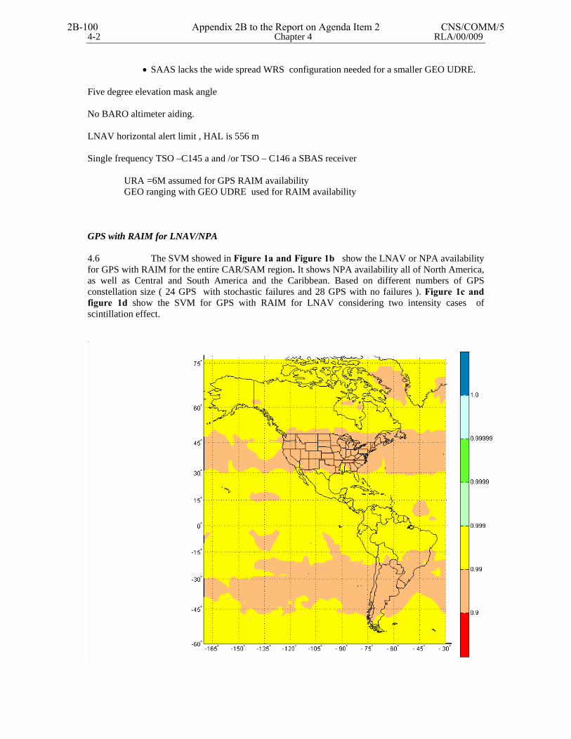
4-2 Chapter 4 RLA/00/009
• SAAS lacks the wide spread WRS configuration needed for a smaller GEO UDRE. Five degree elevation mask angle No BARO altimeter aiding. LNAV horizontal alert limit , HAL is 556 m Single frequency TSO –C145 a and /or TSO – C146 a SBAS receiver URA =6M assumed for GPS RAIM availability GEO ranging with GEO UDRE used for RAIM availability
GPS with RAIM for LNAV/NPA 4.6 The SVM showed in Figure 1a and Figure 1b show the LNAV or NPA availability for GPS with RAIM for the entire CAR/SAM region. It shows NPA availability all of North America, as well as Central and South America and the Caribbean. Based on different numbers of GPS constellation size ( 24 GPS with stochastic failures and 28 GPS with no failures ). Figure 1c and figure 1d show the SVM for GPS with RAIM for LNAV considering two intensity cases of scintillation effect.
2B-100 Appendix 2B to the Report on Agenda Item 2 CNS/COMM/5
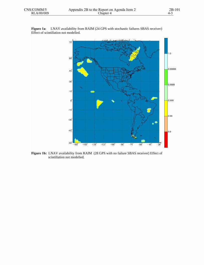
RLA/00/009 Chapter 4 4-3
Figure 1a: LNAV availability from RAIM (24 GPS with stochastic failures SBAS receiver) Effect of scintillation not modelled.
Figure 1b: LNAV availability from RAIM (28 GPS with no failure SBAS receiver) Effect of scintillation not modelled.
CNS/COMM/5 Appendix 2B to the Report on Agenda Item 2 2B-101
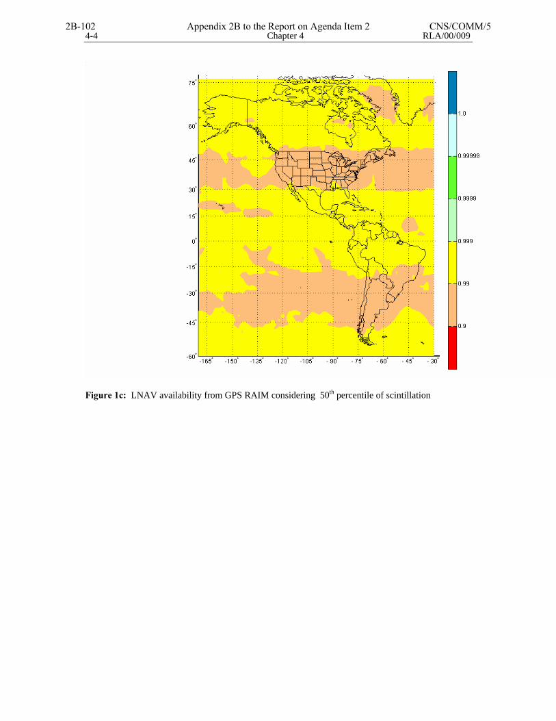
4-4 Chapter 4 RLA/00/009
Figure 1c: LNAV availability from GPS RAIM considering 50th percentile of scintillation
2B-102 Appendix 2B to the Report on Agenda Item 2 CNS/COMM/5
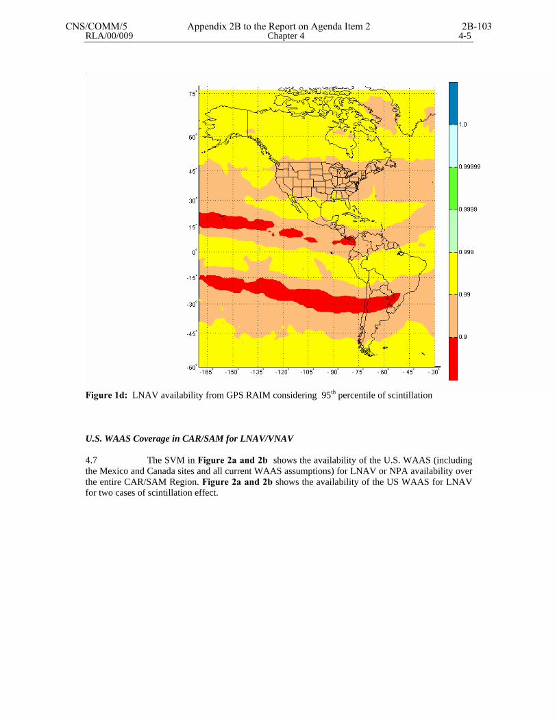
RLA/00/009 Chapter 4 4-5
Figure 1d: LNAV availability from GPS RAIM considering 95th percentile of scintillation U.S. WAAS Coverage in CAR/SAM for LNAV/VNAV 4.7 The SVM in Figure 2a and 2b shows the availability of the U.S. WAAS (including the Mexico and Canada sites and all current WAAS assumptions) for LNAV or NPA availability over the entire CAR/SAM Region. Figure 2a and 2b shows the availability of the US WAAS for LNAV for two cases of scintillation effect.
CNS/COMM/5 Appendix 2B to the Report on Agenda Item 2 2B-103
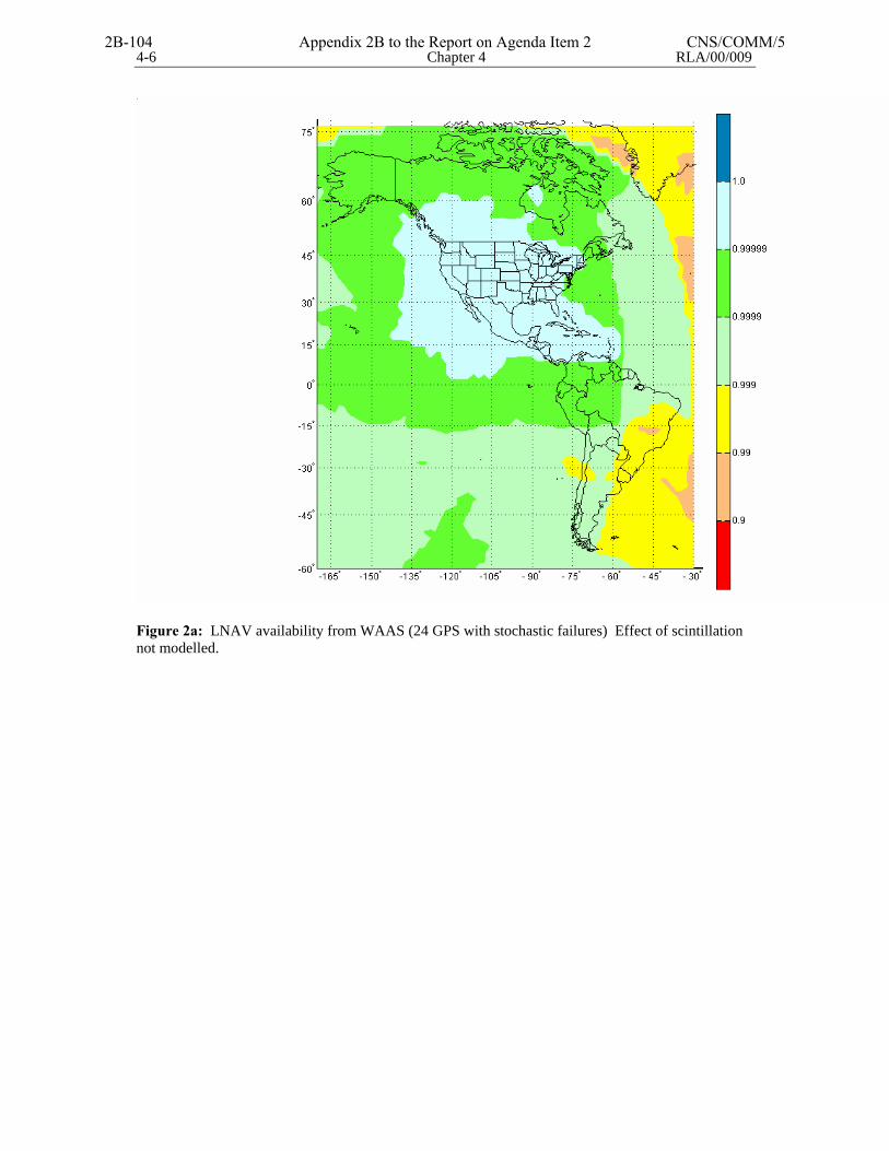
4-6 Chapter 4 RLA/00/009
Figure 2a: LNAV availability from WAAS (24 GPS with stochastic failures) Effect of scintillation not modelled.
2B-104 Appendix 2B to the Report on Agenda Item 2 CNS/COMM/5
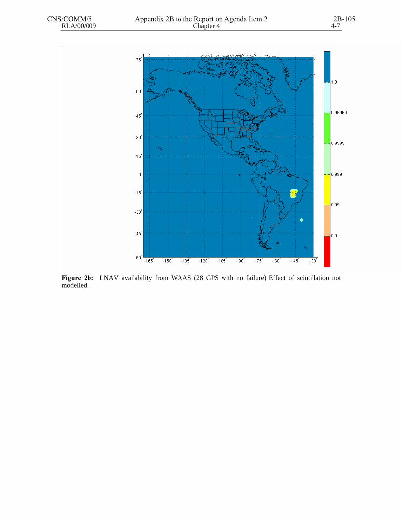
RLA/00/009 Chapter 4 4-7
Figure 2b: LNAV availability from WAAS (28 GPS with no failure) Effect of scintillation not modelled.
CNS/COMM/5 Appendix 2B to the Report on Agenda Item 2 2B-105
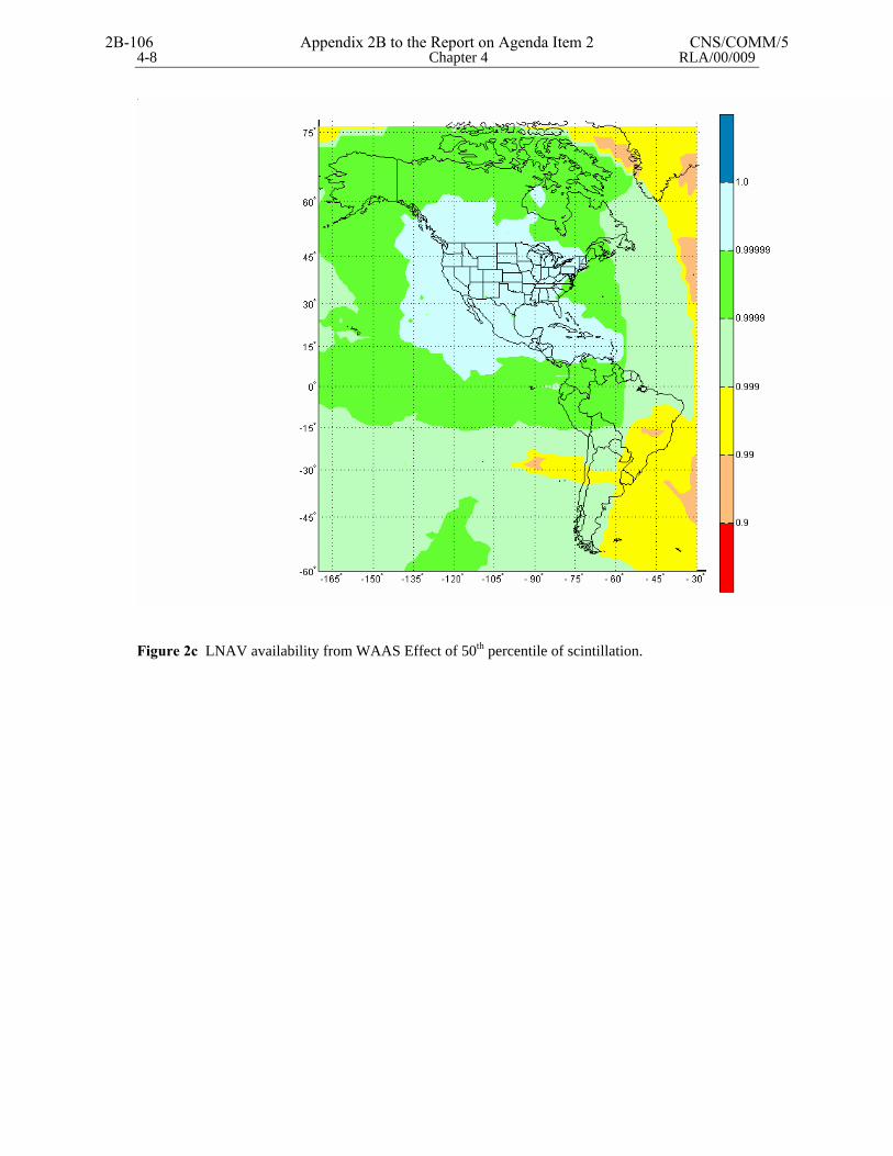
4-8 Chapter 4 RLA/00/009
Figure 2c LNAV availability from WAAS Effect of 50th percentile of scintillation.
2B-106 Appendix 2B to the Report on Agenda Item 2 CNS/COMM/5
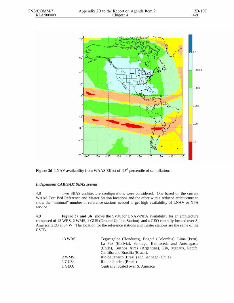
RLA/00/009 Chapter 4 4-9
Figure 2d LNAV availability from WAAS Effect of 95th percentile of scintillation. Independent CAR/SAM SBAS system 4.8 Two SBAS architecture configurations were considered: One based on the current WAAS Test Bed Reference and Master Station locations and the other with a reduced architecture to show the “minimal” number of reference stations needed to get high availability of LNAV or NPA service. 4.9 Figure 3a and 3b shows the SVM for LNAV/NPA availability for an architecture composed of 13 WRS, 2 WMS, 1 GUS (Ground Up link Station) and a GEO centrally located over S. America GEO at 54 W . The location for the reference stations and master stations are the same of the CSTB.
13 WRS: Tegucigalpa (Honduras), Bogotá (Colombia), Lima (Peru), La Paz (Bolivia), Santiago, Balmaceda and Antofagasta (Chile), Buenos Aires (Argentina), Rio, Manaus, Recife, Curitiba and Brasilia (Brazil).
2 WMS: Rio de Janeiro (Brazil) and Santiago (Chile) 1 GUS: Rio de Janeiro (Brazil) 1 GEO: Centrally located over S. America
CNS/COMM/5 Appendix 2B to the Report on Agenda Item 2 2B-107
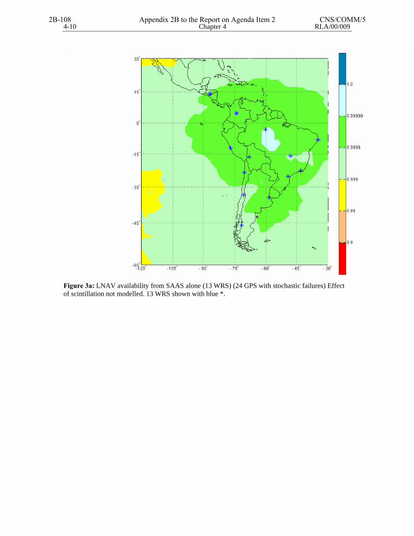
4-10 Chapter 4 RLA/00/009
Figure 3a: LNAV availability from SAAS alone (13 WRS) (24 GPS with stochastic failures) Effect of scintillation not modelled. 13 WRS shown with blue *.
2B-108 Appendix 2B to the Report on Agenda Item 2 CNS/COMM/5
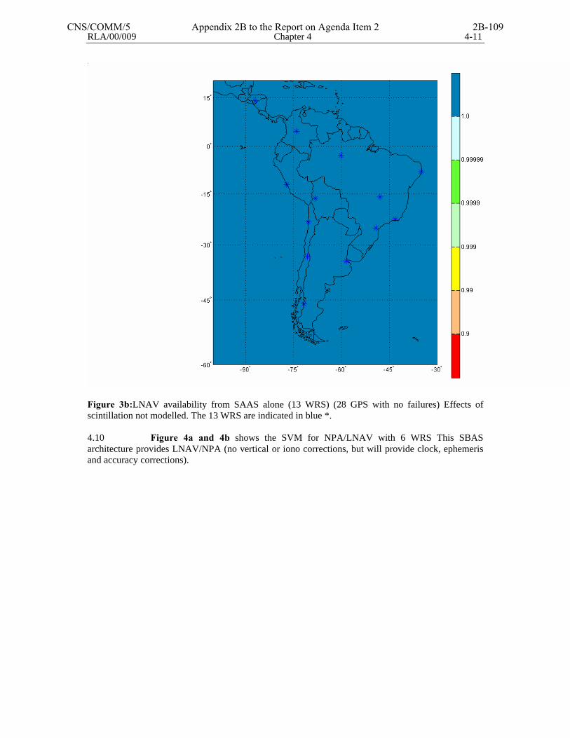
RLA/00/009 Chapter 4 4-11
Figure 3b:LNAV availability from SAAS alone (13 WRS) (28 GPS with no failures) Effects of scintillation not modelled. The 13 WRS are indicated in blue *. 4.10 Figure 4a and 4b shows the SVM for NPA/LNAV with 6 WRS This SBAS architecture provides LNAV/NPA (no vertical or iono corrections, but will provide clock, ephemeris and accuracy corrections).
CNS/COMM/5 Appendix 2B to the Report on Agenda Item 2 2B-109
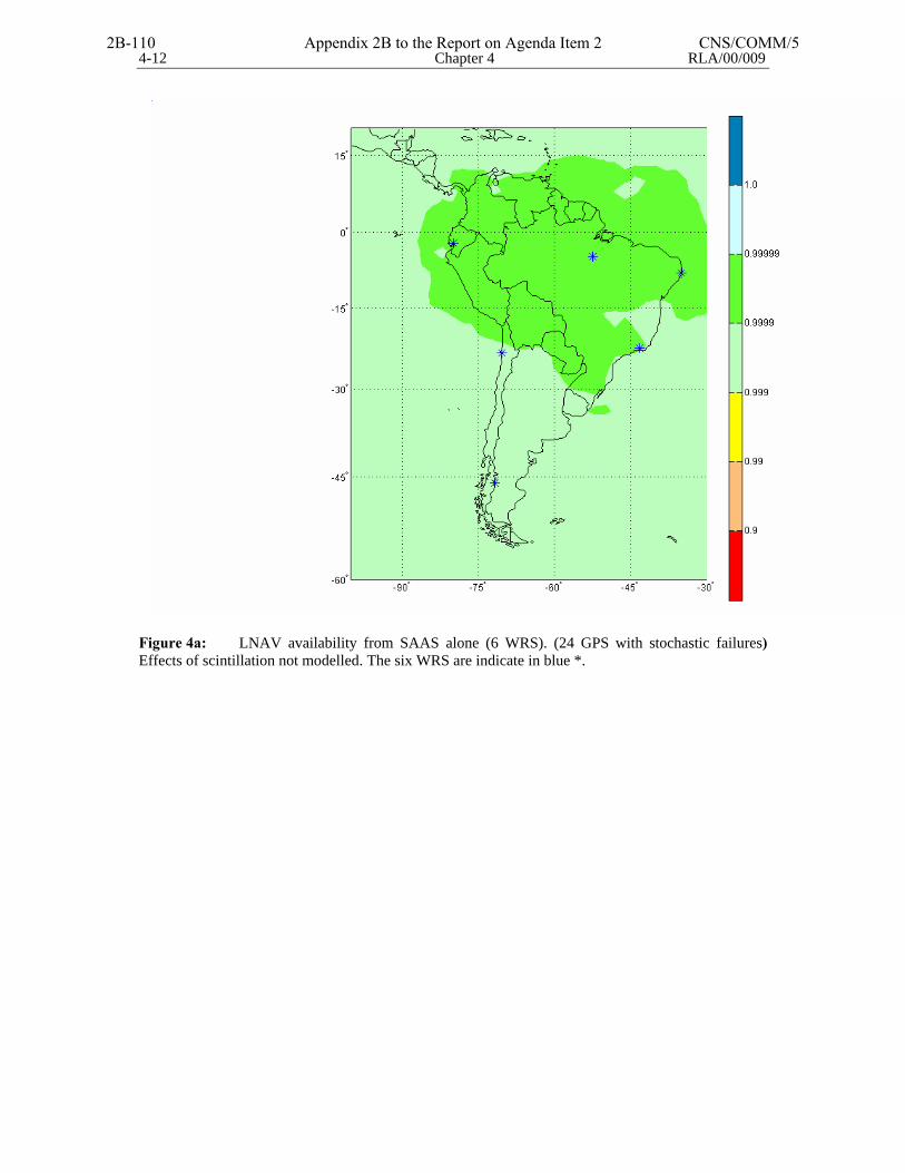
4-12 Chapter 4 RLA/00/009
Figure 4a: LNAV availability from SAAS alone (6 WRS). (24 GPS with stochastic failures) Effects of scintillation not modelled. The six WRS are indicate in blue *.
2B-110 Appendix 2B to the Report on Agenda Item 2 CNS/COMM/5

RLA/00/009 Chapter 4 4-13
Figure 4b: LNAV availability from SAAS alone (6 WRS) (28 GPS with no failures) Effects of scintillation not modelled. The 6 WRS are indicated in blue *. 4.11 The configuration for this alternative will be:
6 WRS Quito, Lima, Balmaceda , Manaus , Recife y Curitiba. 1 WMS Rio de Janeiro (Brazil) 1 GUS Rio de Janeiro (Brazil) 1 GEO Centrally located over S. America
4.12 Figure 5a and 5b shows the SVM for NPA/LNAV with 8 WRS This SBAS architecture provides LNAV/NPA (no vertical or iono corrections, but will provide clock, ephemeris and accuracy corrections).
CNS/COMM/5 Appendix 2B to the Report on Agenda Item 2 2B-111
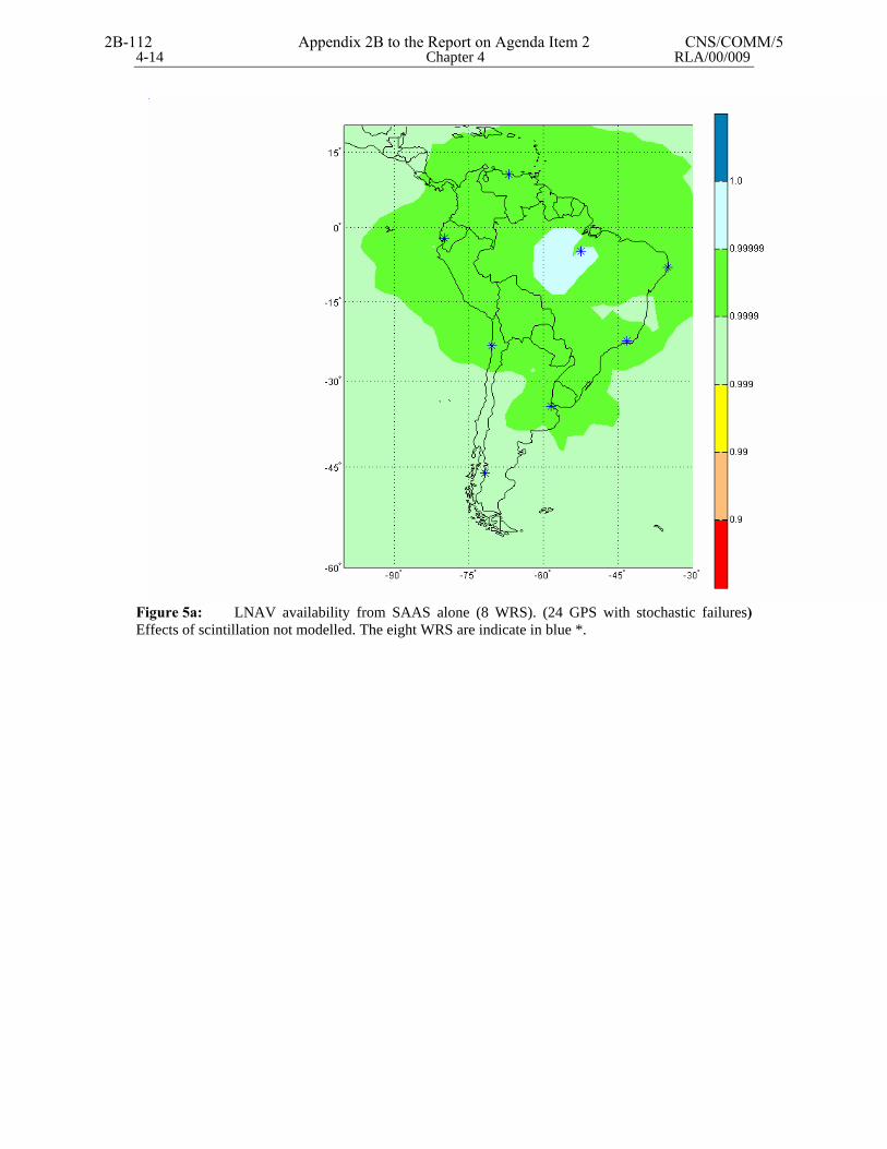
4-14 Chapter 4 RLA/00/009
Figure 5a: LNAV availability from SAAS alone (8 WRS). (24 GPS with stochastic failures) Effects of scintillation not modelled. The eight WRS are indicate in blue *.
2B-112 Appendix 2B to the Report on Agenda Item 2 CNS/COMM/5
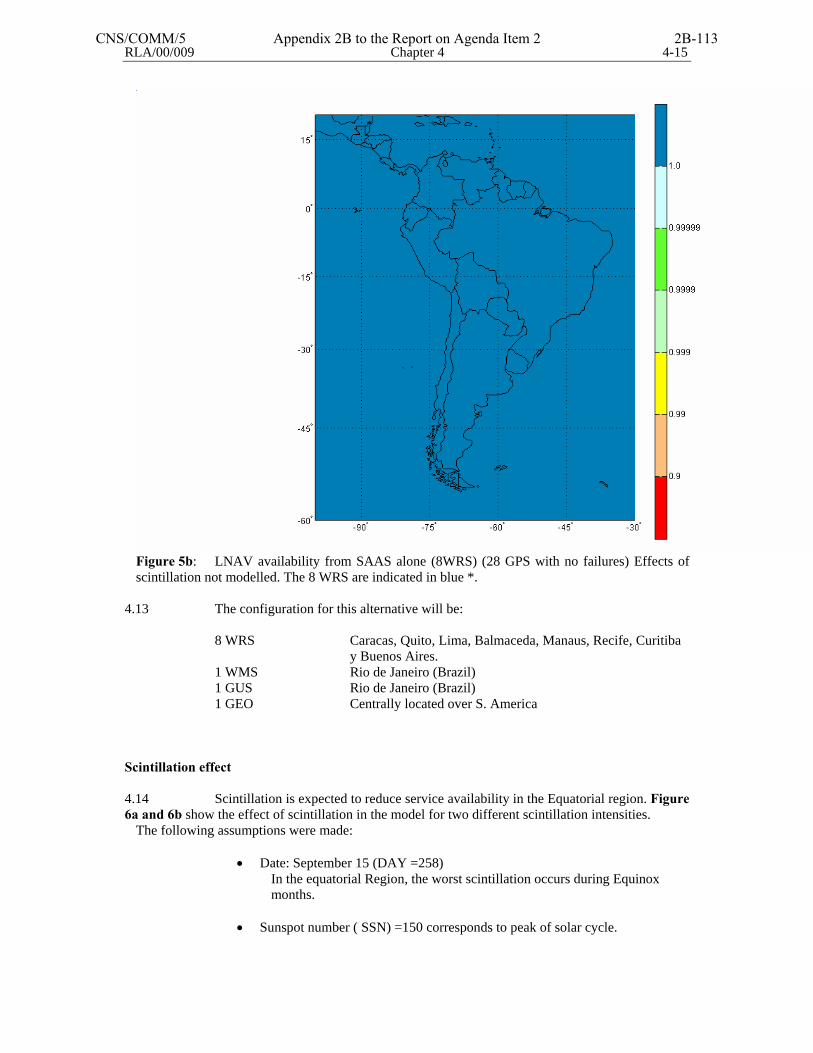
RLA/00/009 Chapter 4 4-15
Figure 5b: LNAV availability from SAAS alone (8WRS) (28 GPS with no failures) Effects of scintillation not modelled. The 8 WRS are indicated in blue *.
4.13 The configuration for this alternative will be:
8 WRS Caracas, Quito, Lima, Balmaceda, Manaus, Recife, Curitiba y Buenos Aires.
1 WMS Rio de Janeiro (Brazil) 1 GUS Rio de Janeiro (Brazil) 1 GEO Centrally located over S. America
Scintillation effect 4.14 Scintillation is expected to reduce service availability in the Equatorial region. Figure 6a and 6b show the effect of scintillation in the model for two different scintillation intensities.
The following assumptions were made:
• Date: September 15 (DAY =258) In the equatorial Region, the worst scintillation occurs during Equinox
months. • Sunspot number ( SSN) =150 corresponds to peak of solar cycle.
CNS/COMM/5 Appendix 2B to the Report on Agenda Item 2 2B-113
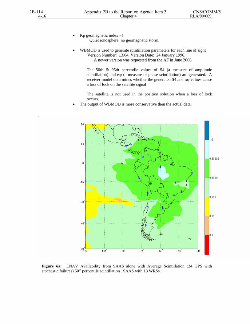
4-16 Chapter 4 RLA/00/009
• Kp geomagnetic index =1
Quiet ionosphere; no geomagnetic storm.
• WBMOD is used to generate scintillation parameters for each line of sight Version Number: 13.04, Version Date: 24 January 1996.
A newer version was requested from the AF in June 2006
The 50th & 95th percentile values of S4 (a measure of amplitude scintillation) and σφ (a measure of phase scintillation) are generated. A receiver model determines whether the generated S4 and σφ values cause a loss of lock on the satellite signal The satellite is not used in the position solution when a loss of lock occurs.
• The output of WBMOD is more conservative then the actual data.
Figure 6a: LNAV Availability from SAAS alone with Average Scintillation (24 GPS with stochastic failures) 50th percentile scintillation . SAAS with 13 WRSs.
2B-114 Appendix 2B to the Report on Agenda Item 2 CNS/COMM/5
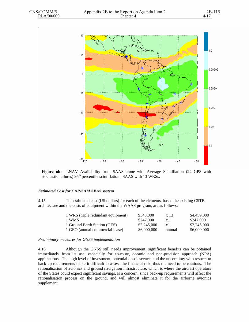
RLA/00/009 Chapter 4 4-17
Figure 6b: LNAV Availability from SAAS alone with Average Scintillation (24 GPS with stochastic failures) 95th percentile scintillation . SAAS with 13 WRSs.
Estimated Cost for CAR/SAM SBAS system 4.15 The estimated cost (US dollars) for each of the elements, based the existing CSTB architecture and the costs of equipment within the WAAS program, are as follows:
1 WRS (triple redundant equipment) $343,000 x 13 $4,459,000 1 WMS $247,000 x1 $247,000 1 Ground Earth Station (GES) $2,245,000 x1 $2,245,000 1 GEO (annual commercial lease) $6,000,000 annual $6,000,000
Preliminary measures for GNSS implementation 4.16 Although the GNSS still needs improvement, significant benefits can be obtained immediately from its use, especially for en-route, oceanic and non-precision approach (NPA) applications. The high level of investment, potential obsolescence, and the uncertainty with respect to back-up requirements make it difficult to assess the financial risk; thus the need to be cautious. The rationalisation of avionics and ground navigation infrastructure, which is where the aircraft operators of the States could expect significant savings, is a concern, since back-up requirements will affect the rationalisation process on the ground, and will almost eliminate it for the airborne avionics supplement.
CNS/COMM/5 Appendix 2B to the Report on Agenda Item 2 2B-115
4-18 Chapter 4 RLA/00/009
4.17 Considering the need to minimise risk and optimise benefits, the following implementation steps are suggested. These steps could be started immediately. Activities include those related to the development of GPS non-precision and precision approaches. The following paragraphs and charts show the milestones and timetables related to these steps. Introduction of GNSS-based non-precision approach 4.18 The main tasks associated to the gradual implementation of NPA are:
a) obstacle survey; b) conversion of all coordinates to the WGS-84 system; c) creation of data bases; and d) establishment of regulations and procedures (NOTAM), etc.
4.19 Taking into account the complexity involved in the drafting of procedures, ICAO should organise a workshop to make the rules and procedures that govern the development of procedures known, and to inform about the tools that are available to assist in said process. 4.20 Through investigations to extend WAAS capability to South America, the FAA has learned that the two-dimensional model frequently fails to adequately model the true ionospheric behavior in the region over Brazil. The features that limit WAAS capability in this region are best described as holes or depletions in an otherwise dense ionosphere. In the Brazilian region, depletions occur in the evening hours and are most apparent between the months of October and April, with peak activity occurring in January. Between the months of May and September, depletion activity is much less frequent. Other near-equatorial regions are similarly affected by depletion activity. However, there are known longitudinal differences in the frequency and seasonal dependence of these features. Depletions are a severe threat to integrity. Simple changes to the information broadcast to the user to help better capture these disturbances (smaller focus area, more rapid update frequency, etc.) will not solve these issues. As a result, more significant changes have been proposed; however, none have yet been proven to be both practical and effective. Actions to Meet the Challenges 4.21 In the SBAS Systems implementation, the following actions should be taken:
a) Develop Algorithm Changes and Field Additional International Reference Stations. This will lessen the impact of unobserved ionospheric threats to WAAS.
b) Develop a Catalog of Threatening Features. Like other SBAS threats, we desire
to develop a universal threat model. Unfortunately, the exact magnitude of the threat depends on the specific implementation. Instead, we will identify a catalog of threatening features:
- For mid-latitudes, we can identify every major ionospheric storm for the last
solar maximum period and highlight observations of North American threats. - For equatorial regions we will identify periods of time when threats are
likely to be greatest, and provide examples of very significant ones, but these threats cannot be confined to a list of just a few days or events.
- In all cases, the available data will also be provided. All service providers should be aware of features that may be present in their service area and be confident that they treat them adequately.
To do this, data from other regions from the last solar maximum must be collected and analyzed to assess impact in all parts of the globe.
2B-116 Appendix 2B to the Report on Agenda Item 2 CNS/COMM/5
RLA/00/009 Chapter 4 4-19
c) Use L1 and L5 Airborne Frequencies as the Long-Term Solution to Both Severe Storms and the Unobserved Ionospheric Threats
d) Continue to Study Scintillation in Greater Detail. Scintillation is the dominant
limitation to the use of two frequencies for vertical guidance. If it proves to be a significant impediment to operations, several forms of mitigation may be investigated, such as:
- Receiver tracking loop modifications, possibly including integration with
inexpensive inertials - Integration of a baro-altimeter for VNAV - Additional ranging sources such as Galileo
Expected Performance1
a) For all regions, combined L1/L5 users are expected to achieve Category I service greater than 99% of the time.
b) For all regions, single frequency users are expected to achieve NPA service greater than 99.999% of the time.
c) For polar-cap, auroral and mid-latitude regions, single frequency users are expected to achieve LPV service greater than 99% of the time.
1 The ability to reduce the effects of the ionosphere has a direct impact on type of navigation service that can be reliably achieved. Additionaly, the use of multiple frequencies can help reduce the effects of the ionosphere to achieve higher levels of service.
Long Range Vision 4.22 The current 11-year solar cycle is approximately 4 years past its peak. Absolute TEC values and the occurrence and severity of scintillation and depletions are expected to be much lower for the next several years. When a full constellation of satellites with L5 becomes available (2015-2020), the TEC related problems will be solved. In addition, availability of an L2 civil signal will provide increased robustness for monitoring the ionosphere by the ground stations. 4.23 This roadmap will be coupled with the FAA’s efforts to standardize future GPS and SBAS signals. It is expected that this ionospheric research will take place over the next 3-5 years and the outputs from this work will be critical in defining those necessary changes to current SBAS standards in order to support use of SBAS anywhere on the globe. 4.24 And that this same architecture, with the future availability of a 2nd civil frequency (either L5 or Galileo or a combination), would theoretically be able to provide a level of vertical guidance potentially down to LPV since the iono corrections could be done in real-time in the cockpit. The envisioned CAR/SAM LNAV-only SBAS would be built as an investment banking on a future capability upgrade to APV/LPV when L5 or Galileo becomes a reality. 4.25 In looking at the several SVM charts for the various CSTB configurations of 13, 8, and 6 reference stations, one can summarize the following general points:
• Building an independent SBAS for the CAR/SAM region will be an expensive endeavor. This is based not so much on the cost of the WRS and WMS, but the required satellite uplink stations and the annual lease costs for commercial satellites.
• Utilizing the existing U.S. WAAS service for LNAV in the region would drastically reduce implementation costs. Some sort of monitoring capability
CNS/COMM/5 Appendix 2B to the Report on Agenda Item 2 2B-117
4-20 Chapter 4 RLA/00/009
would need to be established to generate NOTAMs, but the use of basic GPS with RAIM and/or U.S. WAAS provides very good LNAV availability to most of the CAR/SAM region.
• If an independent SBAS is the desired choice of the region, several options were analysed in order to determine the least expensive implementation option for the region.
• A 13 WRS configuration does not provide much better regional LNAV availability than a 6 WRS or 8 WRS configuration.
• There are only slight differences between the 6 WRS and 8 WRS configurations, and probably not enough regionally to justify the extra expense.
• Based on the models performed, a configuration of 6 WRSs would provide good availability of LNAV service throughout the region, and be the most economical choice.
• Further SVM models could be completed to determine if a lesser number of WRSs could also achieve similar availability.
• Given the general costs of the satellite segment of an SBAS system, and the general uncertainty of the ionosphere situation at the geomagnetic equator, the CAR/SAM region needs to make a decision on whether to
o Implement a simple SBAS for LNAV service that will be able to provide precision approach services once a 2nd civil frequency is available, or
o Utilize existing technologies (basic GPS with RAIM, basic GPS with baro VNAV, and/or the U.S. WAAS) to provide LNAV and limited precision approach capability. Precision approach capability can then be accomplished with a CAT-I GBAS system or the 2nd civil GPS frequency.
2B-118 Appendix 2B to the Report on Agenda Item 2 CNS/COMM/5
CNS/COMM/5 Appendix 2C to the Report on Agenda Item 2 2C-1
APPENDIX 2C
C H I L E CIRCULAR DE INFORMACION AERONAUTICA AERONAUTICAL INFORMATION CIRCULAR AIC Nº 5 23 NOV 2006 Dirección General de Aeronáutica Civil Departamento Aeródromos y Servicios Aeronáuticos Subdepartamento Servicios de Tránsito Aéreo Sección AIS/MAP Dirección Comercial- Postal Avda. San Pablo 8381 - Pudahuel Santiago – Chile
UTILIZACIÓN DEL SISTEMA DE NAVEGACIÓN DE ÁREA (RNAV/ GNSS) EN PROCEDIMIENTOS NORMALIZADOS DE LLEGADA Y SALIDA POR INSTRUMENTOS Y EN PROCEDIMIENTOS DE APROXIMACIÓN POR INSTRUMENTOS DE NO PRECISIÓN
1. PROPÓSITO
El propósito de esta circular es establecer los criterios operacionales de utilización del sistema de navegación de área (RNAV/ GNSS) en procedimientos normalizados de llegada y salida por instrumentos y en procedimientos de aproximación por instrumentos de no precisión en Áreas Terminales en que se proporcione Servicio Radar, en el espacio aéreo nacional. 2. MATERIA: 2.1 CONCEPTOS RELACIONADOS CON LA UTILIZACIÓN DE EQUIPO RNAV (GNSS).
Los siguientes conceptos están directamente relacionados con la utilización de equipo RNAV(GNSS) y para los efectos de la presente circular tienen los significados que se indican a continuación: - Comprobación autónoma de la integridad en el receptor (RAIM) Técnica mediante la cual un receptor / procesador GPS de a bordo comprueba de manera autónoma la integridad de las señales de navegación provenientes de los satélites GPS (mínimo cinco satélites). - Función de Detección de Fallos y Exclusión (FDE) Función del receptor GPS de a bordo que permite detectar el fallo de un satélite que afecte a la capacidad de navegación y excluirlo automáticamente del cálculo de la solución de navegación. Se requiere al menos un satélite adicional a los necesarios para disponer de la función RAIM.
2C-2 Appendix 2C to the Report on Agenda Item 2 CNS/COMM/5
- Navegación de Área Método de navegación que permite la operación de aeronaves en cualquier trayectoria de vuelo deseada, dentro de la cobertura de las ayudas para la navegación referidas a la estación, o dentro de los límites de las posibilidades de las ayudas autónomas o de una combinación de ambas. - Navegación en Área Terminal. Aquella fase de la navegación en la que las aeronaves siguen rutas normalizadas de salida o llegada (SIDs o STARs) o cualquier otra operación entre el último punto significativo en ruta y el punto de referencia de la Aproximación Inicial (IAF). - Navegación Vertical Barométrica (Baro-VNAV). Es un sistema de navegación que presenta al piloto una guía vertical calculada en referencia a un ángulo de trayectoria vertical especificada (VPA), nominalmente de 3°. La guía vertical calculada por el computador se basa en la altitud barométrica y se especifica como ángulo de trayectoria vertical desde la altura del punto de referencia (RDH) para procedimientos de aproximación con guiado vertical (APV) y procedimientos de aproximación de precisión.(PA) - Procedimientos de Aproximación de No Precisión (NPA) Procedimiento de aproximación por instrumentos en el que se utiliza guía lateral pero no guía vertical. - Procedimientos de Aproximación con guía vertical (APV) Procedimiento de aproximación por instrumentos en el que se utiliza guía lateral y vertical, pero que no satisface los requisitos establecidos para las operaciones de aproximación y aterrizaje de precisión. Las aproximaciones LNAV / VNAV corresponden a procedimientos de aproximación con guía vertical (APV). - Procedimientos de Aproximación baro-VNAV Procedimiento de aproximación por instrumentos en el que se utiliza guía vertical y se clasifican como procedimientos por instrumentos en apoyo a operaciones de aproximación y aterrizaje con guía vertical (APV) - Sistema Mundial de Navegación por satélite (GNSS) El GNSS es un sistema mundial de determinación de la posición y la hora, que incluye una o más constelaciones de satélites, receptores de aeronaves y vigilancia de la integridad del sistema, y que se puede aumentar, según sea necesario, en apoyo de la performance de navegación requerida durante la fase de operación en curso. - Sistema Mundial de Determinación de la Posición (GPS) El sistema mundial de determinación de la posición (GPS) es un sistema de radionavegación por satélite que se sirve de mediciones precisas de distancia desde los satélites del GPS para determinar con precisión en cualquier parte del mundo la posición y la hora.
CNS/COMM/5 Appendix 2C to the Report on Agenda Item 2 2C-3
2.2 UTILIZACIÓN DEL GNSS
La Dirección General de Aeronáutica Civil (DGAC) autoriza la utilización del sistema GNSS en el espacio aéreo chileno, en las siguientes condiciones: 2.2.1 El Estado de Chile no adquiere responsabilidad alguna por los efectos derivados de errores o falta de exactitud, integridad, disponibilidad y continuidad de las emisiones satelitales que pudieran traducirse en un mal funcionamiento de los equipos receptores RNAV (GNSS), del uso inadecuado de éstos y al incumplimiento de la normativa dispuesta en la reglamentación nacional. 3 REQUISITOS PARA OPERACIONES RNAV (GNSS) EN ESPACIOS AÉREOS CON
SERVICIO RADAR. 3.1 Operaciones RNAV (GNSS) en Áreas Terminales. 3.1.1 Las operaciones RNAV (GNSS) en procedimientos Normalizados de Llegada y Salida por Instrumentos podrán efectuarse en Áreas Terminales con Servicio Radar, bajo cumplimiento de los siguientes requisitos:
a) Los operadores y sus aeronaves deberán poseer la certificación correspondiente emitida por el Departamento de Seguridad Operacional. b) Los procedimientos normalizados de salida y llegada por instrumentos deberán estar disponibles y actualizados en la base de datos de navegación de a bordo.
c) La aeronave deberá contar con un equipo de navegación convencional instalado y operativo para volar las rutas normalizadas o volar rutas alternativas si la capacidad de utilización del sistema RNAV(GNSS) disminuye o se degrada. d) A menos que así se especifique en el Manual de Vuelo de la aeronave, no se requiere que el piloto monitoree radioayudas terrestres y podrá efectuar operaciones RNAV(GNSS) en Áreas Terminales servidas por Radar cuando las radioayudas se encuentren temporalmente fuera de servicio.
3.2 Operaciones RNAV(GNSS) en Procedimientos de Aproximación por Instrumentos de No Precisión.
a) Para efectuar operaciones RNAV(GNSS) en procedimientos de aproximación de no precisión, los operadores y sus aeronaves deberán contar con la certificación correspondiente emitida por el Departamento de Seguridad Operacional. b) Los procedimientos deberán estar disponibles y actualizados en la base de datos de navegación a bordo. c) Los procedimientos instrumentales de aproximación de no precisión serán publicados como RNAV(GNSS) RWY XX, señalando con ello que el GPS deberá utilizarse en la aproximación.

2C-4 Appendix 2C to the Report on Agenda Item 2 CNS/COMM/5
d) En las comunicaciones piloto-controlador, se usará el prefijo “RNAV” seguido de la identificación de la pista asociada al procedimiento, para solicitar o aprobar estas aproximaciones. (Ej. RNAV RWY 17R) e) Algunas aproximaciones RNAV(GNSS) especifican mínimos con VNAV. Estos procedimientos se basan en el uso del GPS para navegación lateral (LNAV) y en datos barométricos para la navegación vertical (VNAV). Los mínimos de aproximación de estos procedimientos se especifican en dos columnas, identificados como LNAV/VNAV y LNAV.
f) Para efectuar aproximaciones LNAV/VNAV, la aeronave deberá contar con el equipamiento adecuado, en caso contrario, cumplirá con los mínimos LNAV. g) El piloto notificará al ATC, tan pronto como sea posible, cuando el equipo a bordo que predice la RAIM indique que ésta no se encontrará disponible a la hora estimada de inicio de la aproximación, incluyendo las intenciones y condiciones para efectuar la aproximación. h) Si se presenta una alerta de RAIM cuando la aeronave se encuentre establecida en el tramo de aproximación final, el piloto no continuará la aproximación utilizando la guía GPS y procederá de acuerdo a lo indicado por el ATC. i) Si se requiere un aeródromo alternativo, la aproximación RNAV(GNSS) podrá planificarse en el aeródromo de destino siempre y cuando el aeródromo de alternativa cuente con un procedimiento de aproximación convencional, aprobado y publicado. El mismo requisito deberá cumplirse, cuando se considere algún aeródromo de alternativa de despegue o en ruta. Las radioayudas para la navegación y aproximación en el aeródromo de alternativa, además, deberán estar en situación de servicio operativo. j) Si no se requiere un aeródromo alternativo, en el aeródromo de destino deberá estar disponible un procedimiento de aproximación convencional aprobado y publicado.
3.3 La utilización del sistema RNAV(GNSS) en aproximaciones de precisión no está permitida, en ninguna circunstancia. 4. Los operadores nacionales deben contactar con la DGAC, Departamento de Seguridad Operacional para recibir información sobre el proceso de aprobación para la utilización del sistema de navegación de área (RNAV / GNSS) en procedimientos normalizados de llegada y salida por instrumentos y en procedimientos de aproximación por instrumentos de no precisión. Se podrá obtener información adicional en: Dirección General de Aeronáutica Civil Departamento de Seguridad Operacional, Subdepartamento Transporte Público. -------------------------------------------------------------------------------------------------------
CNS/COMM/5 Appendix 2D to the Report on Agenda Item 2 2D-1
APPENDIX 2D
ESTADO DE LOS SISTEMAS SBAS ACTUALES
1. Introducción 1.1 Actualmente se están desarrollando, o están en pleno proceso de implantación operacional, cuatro sistemas SBAS en el mundo, estos son (en orden alfabético):
• EGNOS • GAGAN • MSAS • WAAS
1.2 En la presente nota de estudio, veremos el estado de dichos sistemas, los cuales se encuentran en diferente fase de desarrollo y/o implantación y a los que en un futuro pretende unirse SACCSA. 2. EGNOS 2.1 En el año 2005 se entregó la primera versión del sistema EGNOS para la revisión operacional del diseño y el paso a las siguientes fases de desarrollo. Desde entonces, se han realizado cinco pasos intermedios que culminarán en Marzo del 2007 con la versión V2.1 para su completa validación en el “System Qualification Review”. Tras dicha revisión, y al objeto de adaptar EGNOS a las ultimas versiones de los SARPs de la OACI, será necesario realizar una serie de cambios en el sistema con el objetivo de entregar a principios del 2008 la llamada versión V2.2, totalmente “SARPs Compliant” y lista para su validación operacional y certificación para uso SoL. 2.2 En paralelo al diseño del sistema, se está en el proceso de validación de la operación de EGNOS, para lo cual, la ESA, dentro del llamado IOP (Initial Operational Phase) está en el proceso de validación de las operaciones de EGNOS con el objetivo de:
• Confirmar que todos los procesos y procedimientos de operación han sido definidos y están adecuadamente validados.
• Confirmar que las operaciones de EGNOS están en posición de ser cualificadas para el OQR (Operational Qualification Review).
• Confirmar que los aspectos de seguridad y confiabilidad del producto, así como el sistema de gestión de garantía de calidad, han sido implementados.
3. GAGAN 3.1 Dada la situación de la India, muy cerca del ecuador geomagnético, se ha tenido que decidir recurrir a un único modelo regional Iono-Tropo en base a los resultados de los datos recogidos por 20 estaciones TEC, habiendo sido necesario incluir otras 7 estaciones para poder cubrir las anomalías inherentes a la región ecuatorial.
2D-2 Appendix 2D to the Report on Agenda Item 2 CNS/COMM/5
3.2 En estos momentos se han instalado 8 estaciones de referencia y una estación de control. Por otro lado, están instaladas las 20 estaciones GPS TEC para continuar con la monitorización ionosférica, y se está estudiando la localización óptima de las otras 7 necesarias. El satélite que se utilizará es el GSAT-4 (82º E), que incorporará una carga de navegación bifrecuencia L1/L5, estando previsto su lanzamiento para Julio del 2007. 3.3 Con los elementos indicados, se constituye el denominado Sistema de demostración Tecnológica (TDS), que servirá para asegurar que el diseño del sistema cumple con los SARPs de la OACI. Posteriormente, GAGAN irá madurando, para ir entrando en las fases de certificación y validación, estando previsto que esté completo a lo largo del año 2007. 4. MSAS 4.1 El MSAS se sustentará en los satélites MTSAT, lanzados el 26 de Febrero del 2005 y 18 de Febrero 2006. Actualmente, se está emitiendo de forma intermitente la señal MSAS para integración del sistema y optimización. Los PRN asignados son el 129 y 137. 4.2 La integración del sistema está realizada prácticamente, empezando las pruebas operacionales y de evaluación el pasado mes de Septiembre, estando prevista la realización de varias pruebas para garantizar que el MSAS cumple con los SARPs de la OACI. 5. WAAS 5.1 En estos momentos WAAS es el sistema SBAS más avanzado. Fue entregado el 10 de Julio del 2003 para su uso en todas las fases de navegación, habiendo demostrado unas prestaciones de 1 metro en horizontal y 1.5 metros en vertical, dando a los usuarios la capacidad de volar aproximaciones de precisión con guiado vertical en todo el área US NAS. 5.2 Actualmente se han publicado 900 procedimientos LNAV/VNAV en procedimientos de aproximación con guiado vertical y unos mínimos nominales de 350 ft de altura de decisión con visibilidad de 1.5 NM, teniendo un límite de alerta horizontal de 556 metros (VAL) y 50 metros de límite de alerta vertical (VAL). Actualmente se están implementando nuevos procedimientos sobre la base de prestaciones mejoradas, con alturas de decisión de 250 ft con una visibilidad de ¾ de NM, un HAL de 40 metros y un VAL de 50 metros, existiendo en la actualidad unos 500 procedimientos con estas características. 5.3 Actualmente WAAS está en el proceso de extender su área de servicio a Alaska, Canadá y México, estando operativo para el año 2007. 5.4 Los satélites usados hasta ahora han sido los INMARSAT, estando previsto incorporar los PanAmSat (133ºW9 y el Telesat (107ºW). 5.5 Actualmente, WAAS está en el proceso de extender el guiado vertical a aproximaciones instrumentales hasta 200 ft con ½ NM de visibilidad, con lo que se podrá obtener capacidades operacionales similares a las de un ILS donde exista la infraestructura aeroportuaria necesaria (luces), con el consiguiente ahorro en la infraestructura terrestre. Está previsto tener los primeros procedimientos para el año 2007. 5.6 Para finales del 2008 está previsto que se haya completado la LPV, estando previsto a partir de esta fecha, el inicio del desarrollo sobre la segunda frecuencia civil L5 (1176.45 Mhz).
CNS/COMM/5 Appendix 2E to the Report on Agenda Item 2 2E-1
APPENDIX 2E
GNSS IMPLEMENTATION IN THE CAR/SAM REGIONS
SUMMARY The possibilities and advantages to implement GNSS systems in the CAR/SAM Regions are indicated.
1. Introduction 1.1 The CAR/SAM Regions, due to its geographical characteristics, with wide isolated areas, mountainous zones, maritime areas and airport dispersion, constitute an excellent example of suitability to implement GNSS systems for air navigation in the different phases of flight, having for this porpoise, to interrelate the different possibilities of augmentation, that is to say, in addition to the base systems (GPS), will use augmentation systems, like SBAS and GBAS 1.2 This becomes even more clear if we have in mind the difficulty of implantation, maintenance and update of the necessary network of ground navaids, for all that the extension of the territories demands a numerous number of stations (NDB, VOR, DME), which sometimes are very difficult to install and maintain (zones of high mountain, forest), and even of planning its suitable position. 1.3 In the other hand, the modernisation of commercial flits of aircraft, jointly with the corporative fleets, makes that the avionics are prepare for the new systems, and in the case of light aircrafts or old ones, the availability of low cost avionics, that integrate conventional systems with the new GNSS (like for example Garmin 480), allow a rapid adaptation the new needs. 2. Advantages of the GNSS 2.1 The GNSS transition plans, are being perform all over the world under different criteria, but all of them are based in the fact than moderns aircrafts used it as primary means of navigation jointly with others elements, basically the INS and DNE/DME navigation. 2.2 In a typical flight analysis, the main advantages to implement GNSS affect all phases of flight,
• Departure, where the procedures can be optimize due to the flexibility in the design.
• Route, where to have a high accurate system and with high integrity will allow to unsure it.
• Descend, where the design of continuous descent procedures will allow saving a significant quantity of fuel.
• TMA, where it is possible to achieve an increase of the capacity of the air space. • Approach and landing, where the APV procedures implementation will increase
security and safety, in edition to make possible to increase the number of operations in airports where it is not possible to implement an ILS, or where the meteorological conditions demand to apply restrictions due to lack of guided. If the new definition fro CAT I go away for SBAS systems, it is clear the added
2E-2 Appendix 2E to the Report on Agenda Item 2 CNS/COMM/5
value that this will imply. With the GBAS implementation, CATII and III will be achieved.
2.3 Also, the flexibility that it is possible to obtain in the air space, redounds to other aspects such as those of type,
• Ecological, due to it is possible to avoid protected areas or thus where the noise impact will affect to populated areas.
• Economical, due to it is possible to reduce flight time in some procedures. • Safety, due to GNSS systems can improve it in the operations, mainly on thus
based on navaids that are difficult to maintain or deploy. • Cost optimisation, due to the implementation of guaranteed SoL systems will
impact in a renegotiation of insurance policies by the airlines companies. 3. GNSS Implementation 3.1 The GNSS implementation in a region, will have to be subject to the ICAO recommendations and the needs of the air space, as well as the situation of the NAVAIDS, especially having in mind the need of reposition of it, implantation of new ones and the costs or difficulty of maintenance. 3.2 Furthermore, the considerations to be taken into account before the decision to implement a concrete augmentation, it is different based on the functionality of such augmentation, so, SBAS is a regional decision that will affect to several States and will required a high investment that just can be assumed from the multistate optics and multimodal applications, although it is true that, compared with the global cost of navaids as VOR and NDB, this cost can be well-taken. If on the contrary, we refer to GBAS systems, its implantation is of local character, and in consequence it is a decision at airport level and it will be based on the services of approach (CAT I, the II or III) and the traffic that they move. It is necessary to emphasize that, in case of CAT I or Superior, it is necessary to consider the cost of the approaching lights and runways inside the investing local plan of an airport. 3.3 For all this, the implantation of procedures based on GNSS, as well as systems like SBAS and GBAS, will have to be based on financial and cost / benefit analyses, that allow to establish the temporary rule for his implantation, quite on the base of a common plan of the regions CAR/AM, due to are decisions that will affect to both regions. 3.4 The decision making process on this matter, has to be realized from a perspective of common approach, where the political aspects acquire a vital importance, mainly taking into account that the commitments of the States hosting facilities must be solid, especially from the point of view of the legal Responsibilities associated with the installation of a certain element in a concrete State. 4. Implementation Phases 4.1 Once the decision to implement the system has been taken, it is clear that it is not possible to implement it in a complete way, but it is necessary to act based on phases that will be an evolution of one on the other one. This is what is defined as the implantation of a prototype that will evolve towards the definitive system. 4.2 It is clear, that the current SBAS systems (WAAS and EGNOS), cannot be settled per se in the CAR/SAM regions, due to it will be necessary to include modifications in the lines of process and

CNS/COMM/5 Appendix 2E to the Report on Agenda Item 2 2E-3
computation to adapt them to the special circumstances that meet in the above mentioned regions, especially from the ionosphere point of view. This is the reason way it will be necessary to identify a region, complete one or split between Caribbean and South America (more expensive and complex option) for the installation of the prototype and from this one; all the system will be extended based on the installation of new stations. 4.3 In implantation for phases, it is necessary to study the air space and the category of the different airports. It is necessary to have in mind that SACCSA would give services LPV I (at present in analysis made by the FAA they are trying to demonstrate it is possible to adapt this category to CAT I), which will allow safety operations in all the airports, but in those who are going to operate in CAT I, the II or III, will be necessary to support the ILS and later the GBAS. This makes that will be necessary to include operational aspects in the definitions of operations with SBAS, due to the impact of a reduction of the services performances for local effects (like ionosphere one) could be reduced using local stations where necessary, implying in the rest of the airfields a reduction of the type of operation up to the recovery of the nominal services levels 4.4 Due to it, the analysis of GNSS implementation must take into account the concept at global level and not to focus in every one of its elements separately (GPS, GBAS, SBAS, ABAS, etc). To it, it will be necessary to add the study of the operations with the above mentioned system and the actions to take before possible reductions of the service.
CNS/COMM/5 Appendix 2F to the Report on Agenda Item 2 2F-1
APPENDIX 2F
FEDERAL AVIATION ADMINISTRATION (FAA) GROUND BASED AUGMENTATION SYSTEM (GBAS) PROGRAM STATUS
(Presented by the United States)
SUMMARY
The FAA is continuing to pursue research and development of GBAS technology. In 2006, the FAA will continue to support modification of an existing GBAS system in Memphis, Tennessee USA. Flight and ground tests are currently underway at this site to demonstrate integrity, and the general performance of this GBAS system under Visual Flight Rule (VFR) landing conditions. The FAA is supporting applicant requests for GBAS system design approval within the National Airspace (NAS). International cooperation on GBAS development, system, and operational approval are also key objectives of the GBAS program.
1. Introduction 1.1 This paper describes the activities and priorities of interest to ICAO and the international community as a whole on U.S. Federal Aviation Administration (FAA) Ground Based Augmentation System (GBAS) program. 1.2 Note that internally the FAA has referred to its GBAS program as the Local Area Augmentation System (LAAS). 2. “Provably Safe Prototype” Progress 2.1 Development of integrity monitors and detailed design are the goals for the FAA CAT-I GBAS program. A developmental system installed at Memphis, Tennessee in the USA is being updated using new integrity designs developed jointly between the FAA and Honeywell. The LAAS Integrity Panel (LIP), a joint group of Honeywell engineers, FAA key technical advisors, and FAA personnel, have agreed to a number of software and hardware changes within Honeywell’s “baseline” design that will improve its ability to meet CAT-I integrity and performance requirements. Among these, a number of algorithm description documents are being finalized and implemented within the Memphis system. These documents contain the details on specific monitors and outline most of the integrity case for the system. 2.2 In September 2006, Honeywell and the FAA program office completed the development of the algorithm description documents. Honeywell will implement these in several software updates in the prototype at Memphis International Airport. The FAA successfully conducted flight tests at Memphis in September 2006 to validate technical and operational performance of the prototype CAT-I GBAS facility at Memphis. The FAA will continue to use the prototype facility in Memphis to validate operational implementation criteria and procedures for GBAS to reduce delays for an operational approval.

2F-2 Appendix 2F to the Report on Agenda Item 2 CNS/COMM/5
2.3 The Honeywell Corporation has submitted an application for system design approval to the FAA. The FAA supports these requests as part of its obligation to regulate non-federal navigation aids within the U.S. National Airspace System, or NAS. 2.4 Flight testing of the prototype is scheduled for late 2006 to validate the technical and operational performance of the Memphis prototype. Eight (8) LAAS instrument approaches have been developed for the Memphis flight test program. 3. International Cooperation for GBAS Development 3.1 The FAA is continuing to support international development of Global Navigation Satellite System (GNSS) augmentations including GBAS. In February 2006, the FAA signed a Memorandum of Cooperation (MOC) with Airservices Australia (AsA) to support regulatory approval of an Australian GBAS implementing the LIP approved algorithms. The system developed under the AsA contract will be SARPS-compliant and will be implemented in Sydney. Honeywell and FedEx plan to implement CAT-I GBAS in Memphis under FAA Non-Fed Approval process (FAR Part 171) for privately installed, owned and operated navigation systems. 3.2 The FAA continues to participate in the International GBAS Working Group meetings coordinated by several national navigation service providers and EUROCONTROL. Additional MOCs between the FAA and Spain, and FAA and Germany are in progress to further the cooperation between service providers interested in implementing GBAS technology. 4. Terminal Area Procedure (TAP) 4.1 The FAA has conducted research flight tests for complex approaches to a precision approach in VFR conditions. These tests, conducted in the Spring/Summer of 2006 on-board the FAA Boeing 727-100, demonstrated that the FAA GBAS ground station can successfully broadcast the necessary information for performing an area navigation (RNAV) procedure, and that the Rockwell-Collins GNLU 930 Multi-mode Receiver (MMR) is capable of receiving the corrections and terminal area path (TAP) data, and then providing guidance to a basic course deviation indicator (CDI). 4.2 This test was the first GBAS demonstration using highly accurate global positioning system (GPS) correction data that providing TAP points that allowed for a series of RNAV legs of different types, including curved path, leading to a straight-in final for a precision approach and landing. 4.3 An earlier test was performed at the FAA William J. Hughes Technical Center (WJHTC) where the TAP points were hard-coded directly into the MMR, but was done as a preliminary assessment of the receiver capability. These tests represent the first to incorporate the standards found in RTCA DO-246C LAAS Interface Control Document, and DO-245A, LAAS Minimum Aviation System Performance Standard. The test results from this test flight will soon be available in an FAA report 5. GSL-D Research and Development 5.1 GSL-D continues to be the FAA’s leading option for supporting near-term CAT II/III operations. Current efforts focus on developing practical requirements for GNSS based technology and assessing the feasibility of today’s GBAS technologies’ ability to meet those requirements. The ICAO Navigation Systems Panel’s (NSP) advice and support in these near-term efforts is an integral part of assuring equivalent levels of safety and performance to current systems. GSL-D provides a transitional stage and mitigation measure for end-state multi-frequency GNSS navigation capability. This initial stage

CNS/COMM/5 Appendix 2F to the Report on Agenda Item 2 2F-3
in the “life cycle” of GNSS CAT II/III operations could also provide a platform for mitigating unforeseen integrity and/or operational issues in future stages of multi-frequency development. 6. Conclusion 6.1 The meeting is requested to note the material presented in this information paper, and consider its contribution to the implementation of a global satellite-based navigation system. 6.2 Attendees are invited to visit the FAA’s GPS Product Team’s website at http://gps.faa.gov for up-to-date LAAS/GBAS program information.
CNS/COMM/5 Appendix 2G to the Report on Agenda Item 2 2G-1
APPENDIX 2G
INTERNATIONAL CIVIL AVIATION ORGANIZATION NAVIGATION SYSTEMS PANEL (NSP)
Ionospheric Effects on GNSS Aviation Operations
December 2006
Summary This paper discusses ionospheric effects on GNSS. It was written by an ad hoc group of experts from the Navigation Systems Panel (NSP), appointed during the NSP working group meeting in Montreal, Canada, 11-21 October 2005. It was then reviewed by the NSP during its working group meeting in Brussels, Belgium, 8-19 May 2006. It was approved for distribution by the NSP during the working group of the whole meeting in Montreal, 10-20 October 2006, subject to final comments by NSP members by 15 November 2006. The present version takes into account the comments received, and reflects the current panel knowledge of ionospheric effect on GNSS operations. While our understanding of the ionosphere and of its effects on GNSS has grown remarkably over the past decade, much work still needs to be done in order to obtain a more complete characterization of these effects. The initial focus of much of the initial research on ionospheric effects on GNSS was on the mid-latitude regions. There is therefore a greater understanding and better characterization of these effects as they are experienced in mid-latitude regions than in other regions, in particular the equatorial region. This situation is however slowly changing, given new research being conducted in various states as part of their planning activities for future GNSS implementations. NSP is thus planning to update this paper in the next few years in order to capture the increased understanding that will be gained from the various on-going or planned research efforts. Executive summary Global Navigation Satellite Systems (GNSS) are standardized in ICAO Annex 10 and various industry standards such as those published by RTCA and EUROCAE. GNSS includes three different types of systems: Airborne-Based Augmentation Systems (ABAS), Satellite-Based Augmentation Systems (SBAS) and Ground-Based Augmentation Systems/Ground-based Regional Augmentation Systems (GBAS/GRAS). All of these systems are affected by the ionosphere, a layer of the upper atmosphere that affects the propagation of radio signals because it contains free electrons created by ionization.
2G-2 Appendix 2G to the Report on Agenda Item 2 CNS/COMM/5
The ionosphere affects signals broadcast by GNSS (core satellite constellations and SBAS geostationary satellites) in two ways: it delays the propagation of the modulation (i.e., the code carried by the signal from which pseudorange measurements are made) and, in some regions, it can cause rapid fluctuations in the power and phase of the received signal. The first effect is known as “group delay”, the second as “scintillation”. While the errors in pseudorange measurements caused by group delay are typically of the order a few tenths of meter, they can exceed 100 m on rare occasions. Because of this, the standards do not allow the use of pseudorange measurements that are not corrected for ionospheric delays for operations during which vertical guidance is provided to the aircraft (APV and Category I/II/III precision approach). The behavior of the ionosphere, as far as its observable effects on radio signals are concerned, varies with time and location. Since the ionization of the upper atmosphere (i.e., the ionosphere) is caused by radiations from the sun, the density and altitude distribution of the free electrons it contains vary with the 11-year solar cycle, the season of the year, and time of day. They also vary as a function of geomagnetic latitude. Finally, they can be severely perturbed by rare geomagnetic (ionospheric) storms caused by powerful energetic emissions from the sun. In general ionospheric effects in mid-latitude regions are mild: variations in ionospheric delays are gradual and scintillation virtually inexistent. This may not be true during severe ionospheric (geomagnetic) storms, but such storms are very rare, and their effects can be detected, and sometimes corrected, by augmentation systems. In low-latitude regions, ionospheric effects are more severe: large variations ionospheric delays and patches causing intense amplitude and phase scintillation are frequent, particularly during the local evening hours during years near a peak of the solar cycle. Furthermore, steep ionospheric delay gradients can occur at the edges of deep ionospheric depletions, also known as ionospheric bubbles. In high-latitude regions, ionospheric effects are more severe than in mid-latitude regions, but less severe than in low-latitude regions. This is due to the magnitudes of ionospheric delays, which, while fairly variable, tend to be much smaller than in low-latitude regions. Scintillation can also occur in high-latitude regions, particularly during periods of increased ionospheric activity. It mostly occurs in the form of phase scintillation in these regions. The different GNSS systems use different approaches to correcting for ionospheric delays. Current ABAS avionics systems, which are limited to using the GPS L1 frequency, use simple models and associated sets of parameters broadcast by core constellation satellites. These models provide an adequate representation of ionospheric delay variations on the average, but are unable to account for localized effects such as might be caused by ionospheric storms, or by the formation of crests in ionospheric delays known as “anomalies” in equatorial regions, for example. This approach to correcting for ionospheric delays is adequate for phases of flight from en route navigation to non precision approach, but is not adequate for any form of approach operation during which vertical guidance is provided. Furthermore, a loss of navigation can occur if an ABAS receiver loses track one or several a critical satellites as a result of scintillation. Single-frequency SBAS avionics systems use ionospheric corrections updated in real-time by the SBAS ground system and broadcast by the SBAS satellites. Current SBAS ground systems use dual-frequency pseudorange and carrier phase measurements to obtain ionospheric delay measurements. They use semi-codeless tracking techniques in order to track the GPS L2 signal (in addition to the GPS L1 signal). These techniques are not sufficiently robust to dynamic motion to be used in aviation receivers. They are also quite sensitive to scintillation, which means that they may not be able to maintain track on satellite signals affected by moderate to high levels of scintillation. The approach to correcting for ionospheric delays used by single-frequency SBAS avionics systems is adequate for Approaches with Vertical Guidance (APV), in addition to being adequate for phases of flight from en route navigation to non precision approach. The navigation service from an SBAS receiver is less sensitive to scintillation than

CNS/COMM/5 Appendix 2G to the Report on Agenda Item 2 2G-3
that from an ABAS receiver because the former receiver requires fewer satellites than the latter one in order to continue to provide service. Single-frequency GBAS avionics systems correct for the combined effects of multiple sources of errors simultaneously, including satellite clock and ephemeris errors, ionospheric delay errors, and tropospheric delay errors, using the differential corrections broadcast by a GBAS ground station. This approach to correcting for ionospheric delays is adequate for Category I precision approach operations. (The role that this approach can play in order to provide Category II/III service is still under study and is therefore not discussed in this paper.) Single-frequency GRAS avionics systems use an extension of this approach to provide en route through non-precision approach services and APV service over wide service areas. Within the next decade, new and modernized core constellations will appear that broadcast civil signals on two or more aeronautical frequencies. GNSS avionics systems capable of tracking multiple frequencies will then become commercially available, and they will likely become predominant as time passes. Using dual-frequency measurements, these avionics systems will be able to compute pseudorange measurements that are free of ionospheric delay. This will be a welcome development that will essentially reduce the ionosphere from a major to a minor contributing source of navigation error for GNSS-based navigation services. Receiver capable of tracking the GPS L5 and/or GALILEO E5 signals will be much more robust to scintillation effects than SBAS ground system receivers tracking the GPS L2 signal using semi-codeless techniques. Nevertheless, in some regions during periods of intense scintillation, the possibility of losing track on signals from low elevation satellites that are affected by scintillation will continue to exist. However, the operational impact of such loses will likely be very small when the receiver is capable of tracking the signals from multiple core constellations simultaneously.
2G-4 Appendix 2G to the Report on Agenda Item 2 CNS/COMM/5
December 2006
Ionospheric Effects on GNSS Aviation Operations
1. Introduction This paper provides a high-level discussion of ionospheric effects on Global Navigation Satellite Systems (GNSS) standardized in ICAO Annex 10 and various industrial standards [ICAO, 2005; RTCA 1993, 2000, 2001a, 2001b]. It is intended to provide initial insight into the issues raised by the ionosphere to aviation decision makers and navigation engineers working on GNSS implementation programs. The various forms of GNSS implementation are covered, including Airborne-Based Augmentation Systems (ABAS1), Satellite-Based Augmentation Systems (SBAS) and Ground-Based Augmentation Systems/Ground-based Regional Augmentation Systems (GBAS/GRAS). The material in this paper reflects the experience acquired over several years of research and development activities in support of GNSS implementation. The discussion covers such issues as signal propagation delays and their effects on pseudorange measurements, and scintillation and its effects on signal tracking. It also covers a few more, but perhaps less well-known, ionospheric phenomena such as ionospheric (geomagnetic) storms, equatorial anomalies and depletions. The existence of these phenomena cannot be ignored when considering GNSS implementation because their effects on GNSS can be significant [SBAS Ionospheric WG, White Paper, 2003]. The discussion covers the various parts of the world. However, it does not do so to a uniform extent and depth because much understanding is yet to be gained in some regions of the world, particularly those regions where ionospheric effects on GNSS are more complex and more severe. These regions are also those where GNSS implementation efforts are still in their early stages. 1.1 Scope This paper is intended to highlight ionospheric effects that are relevant to GNSS, and outline correction and mitigation techniques. It provides a high-level discussion of the ionosphere and is not intended to explore the physics of the ionosphere. Material on these topics can be found in a few specialized textbooks as well as in numerous research papers [Davies, 1990; Hargreaves, 1995; Kelley, 1989]. This paper discusses augmentation systems but does not provide detailed technical information on system designs, nor describe the algorithms that have been developed to correct or mitigate ionospheric effects. Detailed information on such topics can be found in numerous research papers presented to the International Ionospheric Effects Symposium, the Institute of Navigation (www.ion.org), the Royal Institute of Navigation (http://www.rin.org.uk), the International Union for Radio Science (URSI) (http://www.ursi.org), and other technical forums. The reference section lists some of these papers.
1 As defined in Annex 10, Section 3.7.1, ABAS includes a variety of designs depending on the degree to which other information available on board the aircraft (e.g., from and Inertial Navigation System) is integrated into the position solution. In this paper, the terminology ABAS is used to refer to a receiver that relies exclusively on GNSS signals to calculate position and has a Fault Detection and Exclusion function to ensure the integrity of the solution.

CNS/COMM/5 Appendix 2G to the Report on Agenda Item 2 2G-5
1.2 Operational Categories For the purposes of this discussion, the range of levels of service can be divided into three major categories: en route through non-precision approach (ER/NPA), approach with vertical guidance (APV); and (Category I/II/III) precision approach (PA). 1.3 Primary Focus For reasons to be discussed later, the current airborne receiver technology is limited to single-frequency equipment. Therefore, while the future of the satellite navigation technology resides in dual-frequency, multi-constellation receiver designs, the discussion in this paper will be primarily, although not exclusively, oriented toward single-frequency users of GPS signals and GPS augmentations. 1.4 Organization This paper covers the various topics briefly outlined above in the following order. Section 2 discusses the ionosphere and its main effects on GNSS including propagation delays and scintillation. Section 3 discusses differences between ionospheric effects in equatorial, mid-latitude, and auroral regions. It includes brief discussions of ionospheric (geomagnetic) storm effects, scintillation and other phenomena of interest. Section 4 discusses the impact of the ionosphere on operational service. Much experience that is relevant to this discussion will only be gained in the next few years as new GNSS implementations become operational. Therefore, the discussion in this paper only amounts to a brief, partial introduction to this subject. Section 5 discusses correction and mitigation techniques for the effects described in Sections 2 and 3. The discussion includes mitigation techniques that have been used in existing GNSS implementations as well as other potential mitigation techniques. Section 6 discusses past and current research efforts aimed at better understanding these effects and more precisely assessing their impact on GNSS performance. 2. The Ionosphere and its Main Effects on GNSS The ionosphere is a layer of the upper atmosphere located roughly between 50 km and 1000 to 1200 km above the Earth’s surface, which has been ionized by solar extreme ultraviolet (EUV) and other emissions from the sun. While the densities of atoms at these altitudes are very small, this medium has noticeable electromagnetic properties due to the small fraction of these atoms (< 1%) that are disassociated into ions and free electrons. In particular, the presence of free electrons affects the propagation of radio signals in different ways depending on their frequencies. The ionosphere is composed of several overlapping layers corresponding to changes in the chemical composition of the atmosphere (Oxygen and Nitrogen in the lower altitudes, Hydrogen, then Helium in the higher altitudes) and the depth of penetration of the solar radiations responsible for the ionization (hard x-rays, Lyman α radiation, soft x-rays or extreme ultraviolet radiation, EUV). Four layers are specifically identified, which are labeled D, E, F1 and F2 [Klobuchar, 1996]. The D, E, and F1 layers are located at the lower heights (from 50 km to about 210 km); these layers normally disappear during the
2G-6 Appendix 2G to the Report on Agenda Item 2 CNS/COMM/5
local night. The F2 layer occupies the higher heights (from about 210 km to about 1000 km where it becomes indistinguishable from a region of ionized hydrogen called the protonosphere). Among the various layers, the F2 layer has the greatest concentration of free electrons with a peak density at a height that varies between 250 km and 400 km. The F2 layer is present during the night as well as during the day, although ion recombination causes the concentration of free electrons to decrease during the night. This layer has the greatest effect on the propagation of radio signals, in particular GNSS signals (L-band). It is also the most variable and the least predictable. The structure of the ionosphere is not constant but is continually varying in response to changes in the intensities of solar radiations. It is also affected by the solar wind (gaseous ionized material ejected from the sun’s corona that carries magnetic clouds) and its effects on the Earth's magnetic field. It follows that delays in the propagation of GNSS signals from satellite to receiver due to the ionosphere vary with time as well as with the locations of the receiver and the satellite. Some delay variations that are due to the latitude of a receiver as well as to diurnal and seasonal changes in the incidence of sun rays are predictable to a limited extent. Other delay variations are unpredictable such as, for example, those associated with solar events (e.g. solar flares) resulting in geomagnetic (ionospheric) storms2. The main causes of large scale variations in ionospheric delays are related to the 11-year solar cycle, seasonal changes, day-to-day changes, and diurnal changes. Delays are larger near the peak of the solar cycle than near its minimum; they are larger toward the middle of the day (local time) than at night; and they tend to be larger around the equinoxes. Major causes of both large and small scale irregularities in the distribution of free electrons in the ionosphere are related to ionospheric storms, as well as large plasma drifts causing the displacement of large masses of free electrons both in altitude and latitude. Such a transport of ionization characterizes the ionosphere over the magnetic equator and the low latitudes region. It is responsible for the development of crests of electron content known as Appleton anomalies causing large horizontal and vertical gradients of electron density in these regions. Figure 1 illustrates the solar cycle as indicated by the Sun Spot Number (SSN). The last solar cycle peak occurred in 2000-2001. The next peak is expected to occur in 2011-2012. GNSS data collected near a solar cycle peak is highly desirable in order to evaluate the full effect of the ionosphere on potential GNSS implementations.
2 Similarly to the terminology used in meteorology, storms are essentially defined as departures from the normal. Geomagnetic storms (also sometimes called magnetic storms) correspond to atypical variations in the magnetic field of the Earth. Ionospheric storms correspond to atypical distributions of free electrons in the upper atmosphere, in particular in the F-region. Geomagnetic and ionospheric storms are closely related and typically occur together. While these terms may have slightly different meanings in the scientific community, they are often used interchangeably by the GNSS community. Geomagnetic storms may last from a few hours to several days and evolve in three phases: a usually short “initial phase” during which the electric field and the concentration of electrons increase above normal, a longer “main phase” during which they decrease below normal, and an even longer “recovery phase” during which they gradually return to normal [Davies, 1990].
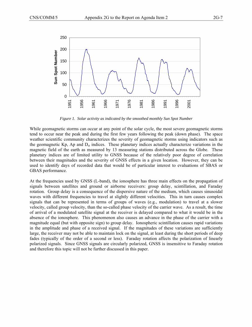
CNS/COMM/5 Appendix 2G to the Report on Agenda Item 2 2G-7
0
50
100
150
200
250
1951
1956
1961
1966
1971
1976
1981
1986
1991
1996
2001
Sun
Spo
t Num
ber
Figure 1. Solar activity as indicated by the smoothed monthly Sun Spot Number
While geomagnetic storms can occur at any point of the solar cycle, the most severe geomagnetic storms tend to occur near the peak and during the first few years following the peak (down phase). The space weather scientific community characterizes the severity of geomagnetic storms using indicators such as the geomagnetic Kp, Ap and Dst indices. These planetary indices actually characterize variations in the magnetic field of the earth as measured by 13 measuring stations distributed across the Globe. These planetary indices are of limited utility to GNSS because of the relatively poor degree of correlation between their magnitudes and the severity of GNSS effects in a given location. However, they can be used to identify days of recorded data that would be of particular interest to evaluations of SBAS or GBAS performance. At the frequencies used by GNSS (L-band), the ionosphere has three main effects on the propagation of signals between satellites and ground or airborne receivers: group delay, scintillation, and Faraday rotation. Group delay is a consequence of the dispersive nature of the medium, which causes sinusoidal waves with different frequencies to travel at slightly different velocities. This in turn causes complex signals that can be represented in terms of groups of waves (e.g., modulation) to travel at a slower velocity, called group velocity, than the so-called phase velocity of the carrier wave. As a result, the time of arrival of a modulated satellite signal at the receiver is delayed compared to what it would be in the absence of the ionosphere. This phenomenon also causes an advance in the phase of the carrier with a magnitude equal (but with opposite sign) to group delay. Ionospheric scintillation causes rapid variations in the amplitude and phase of a received signal. If the magnitudes of these variations are sufficiently large, the receiver may not be able to maintain lock on the signal, at least during the short periods of deep fades (typically of the order of a second or less). Faraday rotation affects the polarization of linearly polarized signals. Since GNSS signals are circularly polarized, GNSS is insensitive to Faraday rotation and therefore this topic will not be further discussed in this paper.

2G-8 Appendix 2G to the Report on Agenda Item 2 CNS/COMM/5
2.1 Group Delay The amount of delay affecting a particular signal is proportional to the total number of free electrons along the propagation path between satellite and receiver. A frequently used measure of that number is called the Total Electron Content (TEC). TEC represents the number of free electrons in an imaginary column with a cross-sectional area of one square meter along the propagation path. There are two versions of that measure: one refers to the TEC along a vertical path3, the other to the TEC along an oblique (or slant) path4. In a good, first order approximation, the amount of delay affecting a signal in the band of frequencies used by GNSS is inversely proportional to the square of its carrier frequency but proportional to TEC (i.e., the integral of the electron density) along the ray path. The following formula expresses this delay as a distance corresponding to the apparent increase in path length:
TECfKdsn
fKd R
S eI 22 == ∫ (1)
where dI is in meters, K is a constant equal to 40.3 m3s-2, f is the carrier frequency of the signal (Hz), en is the electron density (el/m3), and the integration is from the satellite (S) to the receiver (R). TEC is frequently measured in terms of TEC units (TECUs). One TECU corresponds to 1×10-16 el/m2. At the GPS L1 frequency of 1.57542 GHz, 1.0 TECU is equivalent to a delay of 0.542 nanoseconds (ns), or an apparent increase in the path length of 0.163 m [Klobuchar, 1996]. 2.2 Scintillation Irregularities in the distribution of free electrons along the propagation path due to small structures in the ionosphere can cause rapid fluctuations in the amplitude and phase of received signals, a phenomenon known as ionospheric scintillation. There are two types of scintillations: amplitude scintillation and phase scintillation. The amplitude and phase fluctuations are characterized by two parameters known as S4 and σφ. The amplitude scintillation parameter, S4, is defined as the ratio of the standard deviation of the signal intensity (or power) to its mean value. The phase parameter, σφ, is defined as the standard deviation of signal phase variations. These parameters can be measured with specially designed GNSS receivers sometimes called ionospheric scintillation monitors (ISMs). GNSS receiver performance is relatively insensitive to values of S4 that remain at or below 0.5 for carrier-to-noise density ratio (C/N0) above 30 dB-Hz and values of σφ that remain at or below 0.15 radians for C/N0 above 30 dB-Hz. It should be noted that S4 is proportional with 1/f1.5 and σφ is proportional to 1/f, where f is the carrier frequency of the signal so that scintillation effects are stronger on lower frequencies (i.e., GPS L5 and GALILEO E5 as compared to GPS L1).
3 This version corresponds to the original definition of TEC, which is commonly used by scientists of the ionosphere. 4 This version is an adaptation of the original measure that is commonly used when GNSS signals are used to obtain TEC measurements.

CNS/COMM/5 Appendix 2G to the Report on Agenda Item 2 2G-9
3. Ionospheric Effects as a Function of (Magnetic) Latitude From the perspective of ionospheric effects on GNSS, the world can be divided into three main regions: 1) the low-latitude regions which include the equatorial and equatorial “anomaly” regions (shown as one band between 20º N and 20º S of magnetic latitudes in Figure 2), 2) the mid-latitude regions, and 3) the high-latitude regions which include the auroral and polar cap regions. Each of these major regions can be further broken down into sub-regions5, but, for the purpose of this paper, it is sufficient to consider these three main regions. Figure 2 illustrates the approximate geographic extent of each of these main regions. During typical geomagnetic conditions, the mid-latitude regions include the transitional regions. During disturbed geomagnetic conditions, the auroral regions can expand toward equator to include all or part the transitional regions, thus reducing the width of the mid-latitude regions.
Figure 2. Ionospheric regions [SBAS Iono WG, 2003]
The polar regions are generally thought of as being at magnetic latitudes greater than about 75°. They are not illustrated in Figure 2 due to the distortion of the Mercator map projection, which overemphasizes the extent of the high latitude regions. The largest region is the equatorial and equatorial anomaly region, which covers a band of latitudes of about 20° on each side of the magnetic equator. Most of the continents of South America and Africa are located in this region as are large portions of South Asia. The nature of the ionospheric effects affecting a GNSS receiver is not a simple function of the location of that receiver, but of the geographic extent of the regions crossed by the lines of sight to the satellites in view. In particular, GNSS receivers located in the lower mid-latitudes can be affected by the ionosphere in the equatorial region when they track GNSS satellites at relatively low elevation angles while looking generally toward the equator from their location. (Receivers in Southern Japan for example can see portions of the equatorial ionosphere.) Likewise, receivers in the higher mid-latitude regions can be affected by the ionosphere of the nearest auroral region. As a result, the ionosphere of the low and high-latitude regions can affect GNSS beyond the boundaries of these regions shown in Figure 2.
5 For example, there are known differences between the mid-latitude ionosphere of Europe and that of the coterminous United States and also between the equatorial ionosphere of Brazil and that of India. It is believed that these differences are related to the location of the magnetic poles and to an anomaly in the magnetic field of the Earth in the South Atlantic.
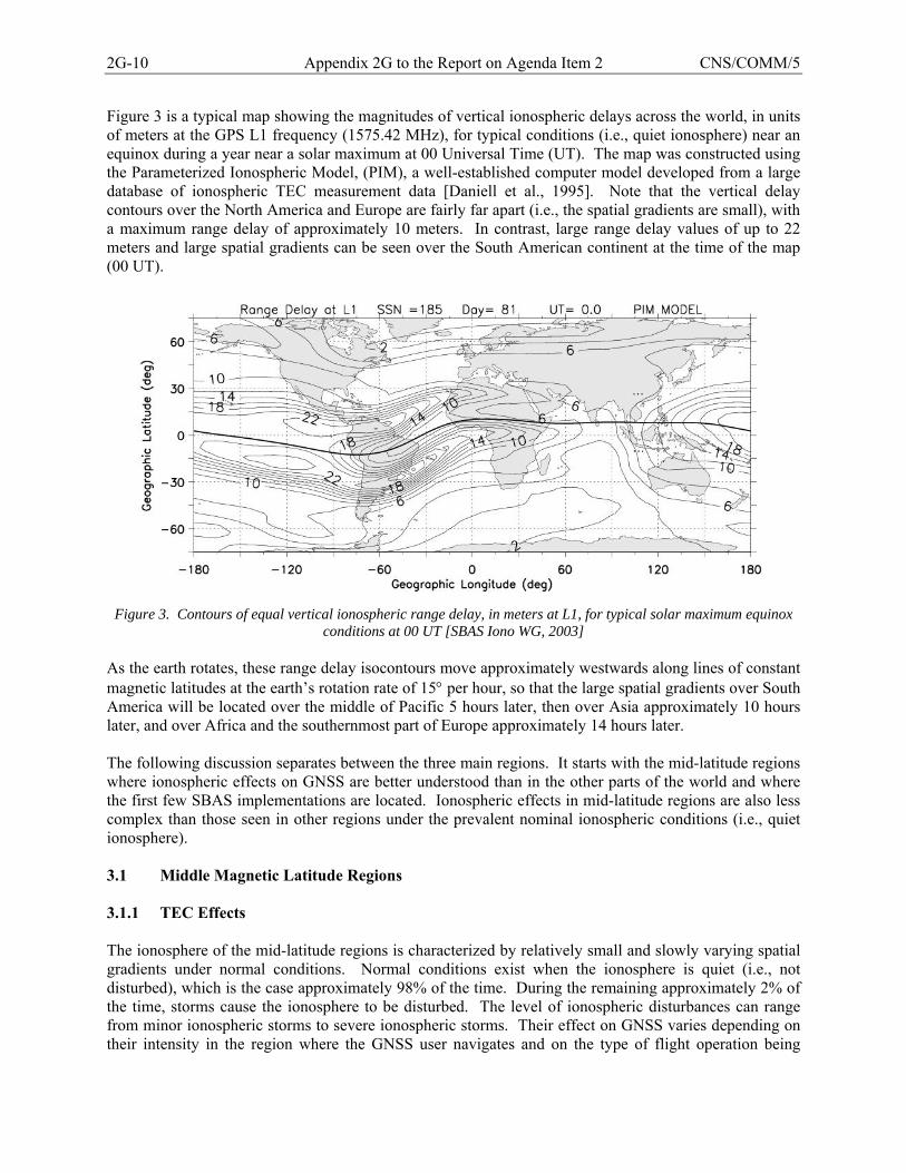
2G-10 Appendix 2G to the Report on Agenda Item 2 CNS/COMM/5
Figure 3 is a typical map showing the magnitudes of vertical ionospheric delays across the world, in units of meters at the GPS L1 frequency (1575.42 MHz), for typical conditions (i.e., quiet ionosphere) near an equinox during a year near a solar maximum at 00 Universal Time (UT). The map was constructed using the Parameterized Ionospheric Model, (PIM), a well-established computer model developed from a large database of ionospheric TEC measurement data [Daniell et al., 1995]. Note that the vertical delay contours over the North America and Europe are fairly far apart (i.e., the spatial gradients are small), with a maximum range delay of approximately 10 meters. In contrast, large range delay values of up to 22 meters and large spatial gradients can be seen over the South American continent at the time of the map (00 UT).
Figure 3. Contours of equal vertical ionospheric range delay, in meters at L1, for typical solar maximum equinox
conditions at 00 UT [SBAS Iono WG, 2003] As the earth rotates, these range delay isocontours move approximately westwards along lines of constant magnetic latitudes at the earth’s rotation rate of 15° per hour, so that the large spatial gradients over South America will be located over the middle of Pacific 5 hours later, then over Asia approximately 10 hours later, and over Africa and the southernmost part of Europe approximately 14 hours later. The following discussion separates between the three main regions. It starts with the mid-latitude regions where ionospheric effects on GNSS are better understood than in the other parts of the world and where the first few SBAS implementations are located. Ionospheric effects in mid-latitude regions are also less complex than those seen in other regions under the prevalent nominal ionospheric conditions (i.e., quiet ionosphere). 3.1 Middle Magnetic Latitude Regions 3.1.1 TEC Effects The ionosphere of the mid-latitude regions is characterized by relatively small and slowly varying spatial gradients under normal conditions. Normal conditions exist when the ionosphere is quiet (i.e., not disturbed), which is the case approximately 98% of the time. During the remaining approximately 2% of the time, storms cause the ionosphere to be disturbed. The level of ionospheric disturbances can range from minor ionospheric storms to severe ionospheric storms. Their effect on GNSS varies depending on their intensity in the region where the GNSS user navigates and on the type of flight operation being
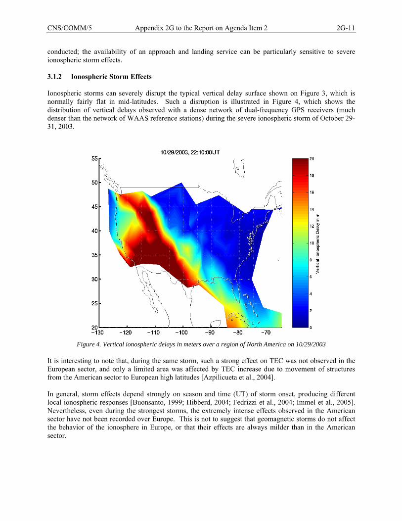
CNS/COMM/5 Appendix 2G to the Report on Agenda Item 2 2G-11
conducted; the availability of an approach and landing service can be particularly sensitive to severe ionospheric storm effects. 3.1.2 Ionospheric Storm Effects Ionospheric storms can severely disrupt the typical vertical delay surface shown on Figure 3, which is normally fairly flat in mid-latitudes. Such a disruption is illustrated in Figure 4, which shows the distribution of vertical delays observed with a dense network of dual-frequency GPS receivers (much denser than the network of WAAS reference stations) during the severe ionospheric storm of October 29-31, 2003.
Figure 4. Vertical ionospheric delays in meters over a region of North America on 10/29/2003
It is interesting to note that, during the same storm, such a strong effect on TEC was not observed in the European sector, and only a limited area was affected by TEC increase due to movement of structures from the American sector to European high latitudes [Azpilicueta et al., 2004]. In general, storm effects depend strongly on season and time (UT) of storm onset, producing different local ionospheric responses [Buonsanto, 1999; Hibberd, 2004; Fedrizzi et al., 2004; Immel et al., 2005]. Nevertheless, even during the strongest storms, the extremely intense effects observed in the American sector have not been recorded over Europe. This is not to suggest that geomagnetic storms do not affect the behavior of the ionosphere in Europe, or that their effects are always milder than in the American sector.
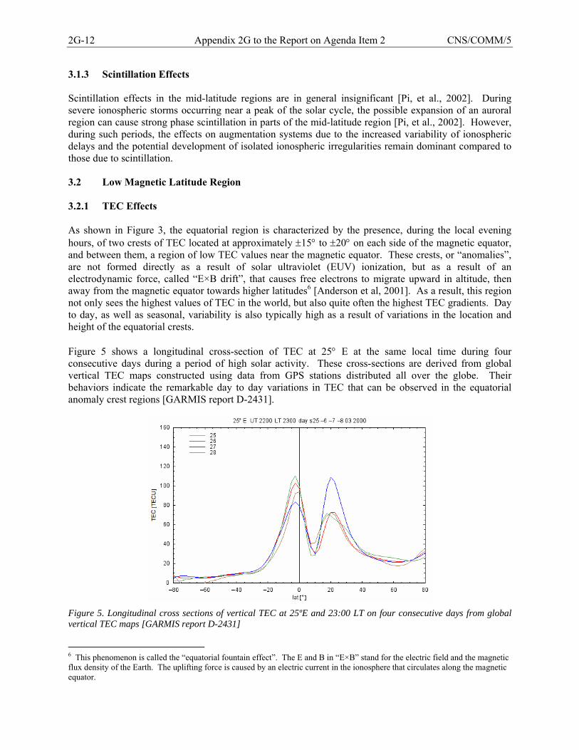
2G-12 Appendix 2G to the Report on Agenda Item 2 CNS/COMM/5
3.1.3 Scintillation Effects Scintillation effects in the mid-latitude regions are in general insignificant [Pi, et al., 2002]. During severe ionospheric storms occurring near a peak of the solar cycle, the possible expansion of an auroral region can cause strong phase scintillation in parts of the mid-latitude region [Pi, et al., 2002]. However, during such periods, the effects on augmentation systems due to the increased variability of ionospheric delays and the potential development of isolated ionospheric irregularities remain dominant compared to those due to scintillation. 3.2 Low Magnetic Latitude Region 3.2.1 TEC Effects As shown in Figure 3, the equatorial region is characterized by the presence, during the local evening hours, of two crests of TEC located at approximately ±15° to ±20° on each side of the magnetic equator, and between them, a region of low TEC values near the magnetic equator. These crests, or “anomalies”, are not formed directly as a result of solar ultraviolet (EUV) ionization, but as a result of an electrodynamic force, called “E×B drift”, that causes free electrons to migrate upward in altitude, then away from the magnetic equator towards higher latitudes6 [Anderson et al, 2001]. As a result, this region not only sees the highest values of TEC in the world, but also quite often the highest TEC gradients. Day to day, as well as seasonal, variability is also typically high as a result of variations in the location and height of the equatorial crests. Figure 5 shows a longitudinal cross-section of TEC at 25° E at the same local time during four consecutive days during a period of high solar activity. These cross-sections are derived from global vertical TEC maps constructed using data from GPS stations distributed all over the globe. Their behaviors indicate the remarkable day to day variations in TEC that can be observed in the equatorial anomaly crest regions [GARMIS report D-2431].
Figure 5. Longitudinal cross sections of vertical TEC at 25ºE and 23:00 LT on four consecutive days from global vertical TEC maps [GARMIS report D-2431]
6 This phenomenon is called the “equatorial fountain effect”. The E and B in “E×B” stand for the electric field and the magnetic flux density of the Earth. The uplifting force is caused by an electric current in the ionosphere that circulates along the magnetic equator.
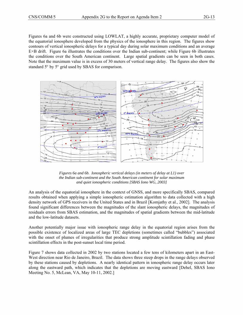
CNS/COMM/5 Appendix 2G to the Report on Agenda Item 2 2G-13
Figures 6a and 6b were constructed using LOWLAT, a highly accurate, proprietary computer model of the equatorial ionosphere developed from the physics of the ionosphere in this region. The figures show contours of vertical ionospheric delays for a typical day during solar maximum conditions and an average E×B drift. Figure 6a illustrates the conditions over the Indian sub-continent; while Figure 6b illustrates the conditions over the South American continent. Large spatial gradients can be seen in both cases. Note that the maximum value is in excess of 30 meters of vertical range delay. The figures also show the standard 5° by 5° grid used by SBAS for comparison.
Figures 6a and 6b. Ionospheric vertical delays (in meters of delay at L1) over the Indian sub-continent and the South American continent for solar maximum
and quiet ionospheric conditions [SBAS Iono WG, 2003] An analysis of the equatorial ionosphere in the context of GNSS, and more specifically SBAS, compared results obtained when applying a simple ionospheric estimation algorithm to data collected with a high density network of GPS receivers in the United States and in Brazil [Komjathy et al., 2002]. The analysis found significant differences between the magnitudes of the slant ionospheric delays, the magnitudes of residuals errors from SBAS estimation, and the magnitudes of spatial gradients between the mid-latitude and the low-latitude datasets. Another potentially major issue with ionospheric range delay in the equatorial region arises from the possible existence of localized areas of large TEC depletions (sometimes called “bubbles”) associated with the onset of plumes of irregularities that produce strong amplitude scintillation fading and phase scintillation effects in the post-sunset local time period. Figure 7 shows data collected in 2002 by two stations located a few tens of kilometers apart in an East-West direction near Rio de Janeiro, Brazil. The data shows three steep drops in the range delays observed by these stations caused by depletions. A nearly identical pattern in ionospheric range delay occurs later along the eastward path, which indicates that the depletions are moving eastward [Dehel, SBAS Iono Meeting No. 5, McLean, VA, May 10-11, 2002.]
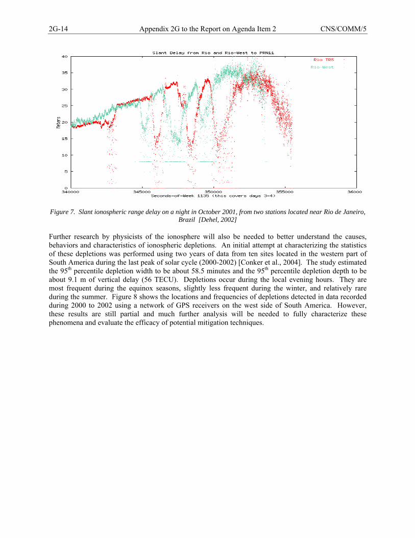
2G-14 Appendix 2G to the Report on Agenda Item 2 CNS/COMM/5
Figure 7. Slant ionospheric range delay on a night in October 2001, from two stations located near Rio de Janeiro,
Brazil [Dehel, 2002] Further research by physicists of the ionosphere will also be needed to better understand the causes, behaviors and characteristics of ionospheric depletions. An initial attempt at characterizing the statistics of these depletions was performed using two years of data from ten sites located in the western part of South America during the last peak of solar cycle (2000-2002) [Conker et al., 2004]. The study estimated the 95th percentile depletion width to be about 58.5 minutes and the 95th percentile depletion depth to be about 9.1 m of vertical delay (56 TECU). Depletions occur during the local evening hours. They are most frequent during the equinox seasons, slightly less frequent during the winter, and relatively rare during the summer. Figure 8 shows the locations and frequencies of depletions detected in data recorded during 2000 to 2002 using a network of GPS receivers on the west side of South America. However, these results are still partial and much further analysis will be needed to fully characterize these phenomena and evaluate the efficacy of potential mitigation techniques.
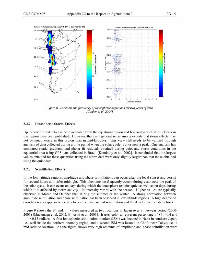
CNS/COMM/5 Appendix 2G to the Report on Agenda Item 2 2G-15
Figure 8. Location and frequency of ionospheric depletions for two years of data
[Conker et al, 2004] 3.2.2 Ionospheric Storm Effects Up to now limited data has been available from the equatorial region and few analyses of storm effects in this region have been published. However, there is a general sense among experts that storm effects may not be much worse in this region than in mid-latitudes. This view still needs to be verified through analysis of data collected during a time period when the solar cycle is at or near a peak. One analysis has compared spatial gradients and planar fit residuals obtained during quiet and storm conditions in the equatorial area using GPS data collected in Brazil [Komjathy et al., 2002]. It concluded that the largest values obtained for these quantities using the storm data were only slightly larger than that those obtained using the quiet data. 3.2.3 Scintillation Effects In the low latitude regions, amplitude and phase scintillations can occur after the local sunset and persist for several hours until after midnight. This phenomenon frequently occurs during years near the peak of the solar cycle. It can occur on days during which the ionosphere remains quiet as well as on days during which it is affected by storm activity. Its intensity varies with the season. Higher values are typically observed in March and October than during the summer or the winter. A strong correlation between amplitude scintillation and phase scintillation has been observed in low latitude regions. A high degree of correlation also appears to exist between the existence of scintillation and the development of depletions. Figure 9 shows the S4 and values measured at two locations in Japan over a two-year period (2000-2001) [Matsunaga et al, 2002, El-Arini et al, 2003]. It uses color to represent percentage of S4 > 0.4 and > 0.15 radians. A first ionospheric scintillation monitor (ISM) was located in Naha in southern Japan, i.e., well inside the northern anomaly region, and a second ISM was located in Chofu near Tokyo, i.e., a mid-latitude location. As the figure shows very high amounts of amplitude and phase scintillation were
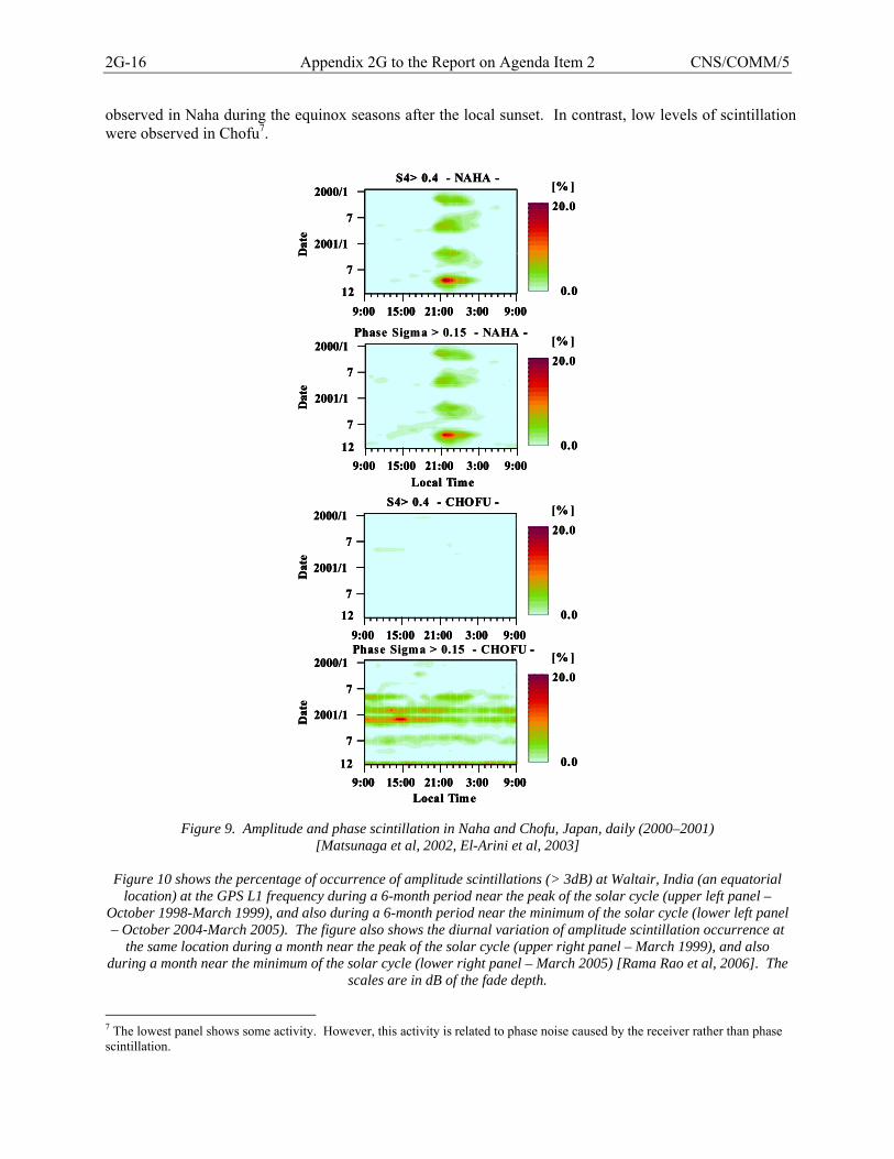
2G-16 Appendix 2G to the Report on Agenda Item 2 CNS/COMM/5
observed in Naha during the equinox seasons after the local sunset. In contrast, low levels of scintillation were observed in Chofu7.
9:00 15:00 21:00 3:00 9:00
2000/1
7
2001/1
7
Local Time
12D
ate
S4> 0.4 - NAHA -
0.0
20.0[% ]
9:00 15:00 21:00 3:00 9:00
2000/1
7
2001/1
7
Local Time
12
Dat
e
Phase Sigma > 0.15 - NAHA -
0.0
20.0[% ]
9:00 15:00 21:00 3:00 9:00
2000/1
7
2001/1
7
Local Time
12
Dat
e
S4> 0.4 - CHOFU -
0.0
20.0[% ]
9:00 15:00 21:00 3:00 9:00
2000/1
7
2001/1
7
Local Time
12
Dat
e
Phase Sigma > 0.15 - CHOFU -
0.0
20.0[% ]
9:00 15:00 21:00 3:00 9:00
2000/1
7
2001/1
7
Local Time
12D
ate
S4> 0.4 - NAHA -
0.0
20.0[% ]
9:00 15:00 21:00 3:00 9:00
2000/1
7
2001/1
7
Local Time
12D
ate
S4> 0.4 - NAHA -
0.0
20.0[% ]
9:00 15:00 21:00 3:00 9:00
2000/1
7
2001/1
7
Local Time
12
Dat
e
Phase Sigma > 0.15 - NAHA -
0.0
20.0[% ]
9:00 15:00 21:00 3:00 9:00
2000/1
7
2001/1
7
Local Time
12
Dat
e
Phase Sigma > 0.15 - NAHA -
0.0
20.0[% ]
9:00 15:00 21:00 3:00 9:00
2000/1
7
2001/1
7
Local Time
12
Dat
e
S4> 0.4 - CHOFU -
0.0
20.0[% ]
9:00 15:00 21:00 3:00 9:00
2000/1
7
2001/1
7
Local Time
12
Dat
e
S4> 0.4 - CHOFU -
0.0
20.0[% ]
9:00 15:00 21:00 3:00 9:00
2000/1
7
2001/1
7
Local Time
12
Dat
e
Phase Sigma > 0.15 - CHOFU -
0.0
20.0[% ]
9:00 15:00 21:00 3:00 9:00
2000/1
7
2001/1
7
Local Time
12
Dat
e
Phase Sigma > 0.15 - CHOFU -
0.0
20.0[% ]
Figure 9. Amplitude and phase scintillation in Naha and Chofu, Japan, daily (2000–2001)
[Matsunaga et al, 2002, El-Arini et al, 2003]
Figure 10 shows the percentage of occurrence of amplitude scintillations (> 3dB) at Waltair, India (an equatorial location) at the GPS L1 frequency during a 6-month period near the peak of the solar cycle (upper left panel –
October 1998-March 1999), and also during a 6-month period near the minimum of the solar cycle (lower left panel – October 2004-March 2005). The figure also shows the diurnal variation of amplitude scintillation occurrence at
the same location during a month near the peak of the solar cycle (upper right panel – March 1999), and also during a month near the minimum of the solar cycle (lower right panel – March 2005) [Rama Rao et al, 2006]. The
scales are in dB of the fade depth.
7 The lowest panel shows some activity. However, this activity is related to phase noise caused by the receiver rather than phase scintillation.
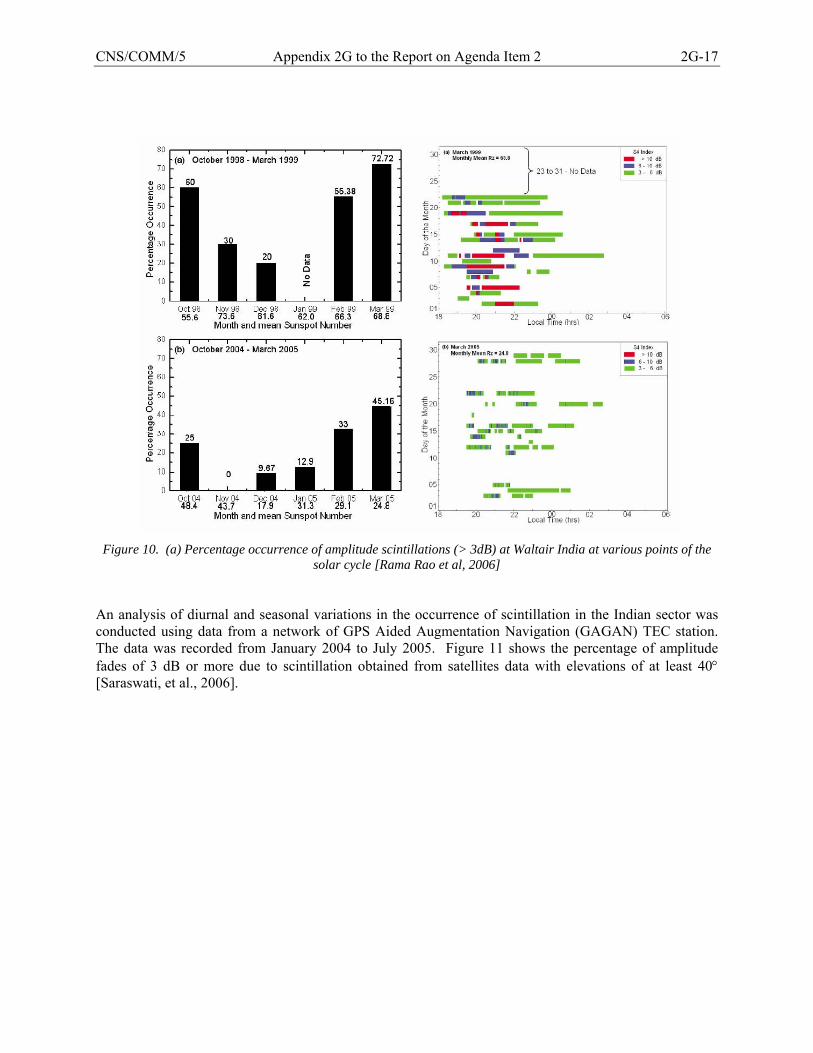
CNS/COMM/5 Appendix 2G to the Report on Agenda Item 2 2G-17
Figure 10. (a) Percentage occurrence of amplitude scintillations (> 3dB) at Waltair India at various points of the
solar cycle [Rama Rao et al, 2006] An analysis of diurnal and seasonal variations in the occurrence of scintillation in the Indian sector was conducted using data from a network of GPS Aided Augmentation Navigation (GAGAN) TEC station. The data was recorded from January 2004 to July 2005. Figure 11 shows the percentage of amplitude fades of 3 dB or more due to scintillation obtained from satellites data with elevations of at least 40° [Saraswati, et al., 2006].
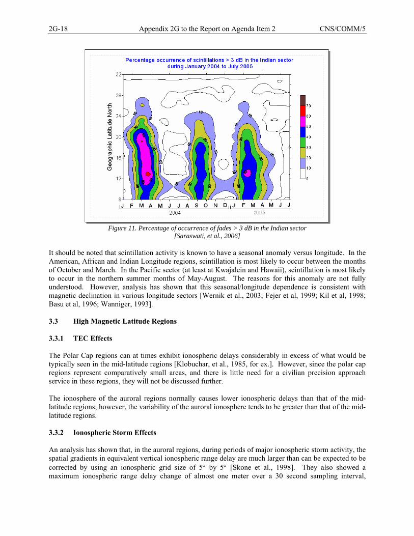
2G-18 Appendix 2G to the Report on Agenda Item 2 CNS/COMM/5
Figure 11. Percentage of occurrence of fades > 3 dB in the Indian sector
[Saraswati, et al., 2006] It should be noted that scintillation activity is known to have a seasonal anomaly versus longitude. In the American, African and Indian Longitude regions, scintillation is most likely to occur between the months of October and March. In the Pacific sector (at least at Kwajalein and Hawaii), scintillation is most likely to occur in the northern summer months of May-August. The reasons for this anomaly are not fully understood. However, analysis has shown that this seasonal/longitude dependence is consistent with magnetic declination in various longitude sectors [Wernik et al., 2003; Fejer et al, 1999; Kil et al, 1998; Basu et al, 1996; Wanniger, 1993]. 3.3 High Magnetic Latitude Regions 3.3.1 TEC Effects The Polar Cap regions can at times exhibit ionospheric delays considerably in excess of what would be typically seen in the mid-latitude regions [Klobuchar, et al., 1985, for ex.]. However, since the polar cap regions represent comparatively small areas, and there is little need for a civilian precision approach service in these regions, they will not be discussed further. The ionosphere of the auroral regions normally causes lower ionospheric delays than that of the mid-latitude regions; however, the variability of the auroral ionosphere tends to be greater than that of the mid-latitude regions. 3.3.2 Ionospheric Storm Effects An analysis has shown that, in the auroral regions, during periods of major ionospheric storm activity, the spatial gradients in equivalent vertical ionospheric range delay are much larger than can be expected to be corrected by using an ionospheric grid size of 5° by 5° [Skone et al., 1998]. They also showed a maximum ionospheric range delay change of almost one meter over a 30 second sampling interval,
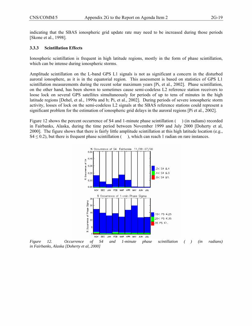
CNS/COMM/5 Appendix 2G to the Report on Agenda Item 2 2G-19
indicating that the SBAS ionospheric grid update rate may need to be increased during those periods [Skone et al., 1998]. 3.3.3 Scintillation Effects Ionospheric scintillation is frequent in high latitude regions, mostly in the form of phase scintillation, which can be intense during ionospheric storms. Amplitude scintillation on the L-band GPS L1 signals is not as significant a concern in the disturbed auroral ionosphere, as it is in the equatorial region. This assessment is based on statistics of GPS L1 scintillation measurements during the recent solar maximum years [Pi, et al., 2002]. Phase scintillation, on the other hand, has been shown to sometimes cause semi-codeless L2 reference station receivers to loose lock on several GPS satellites simultaneously for periods of up to tens of minutes in the high latitude regions [Dehel, et al., 1999a and b; Pi, et al., 2002]. During periods of severe ionospheric storm activity, losses of lock on the semi-codeless L2 signals at the SBAS reference stations could represent a significant problem for the estimation of ionospheric grid delays in the auroral regions [Pi et al., 2002]. Figure 12 shows the percent occurrence of S4 and 1-minute phase scintillation () (in radians) recorded in Fairbanks, Alaska, during the time period between November 1999 and July 2000 [Doherty et al, 2000]. The figure shows that there is fairly little amplitude scintillation at this high latitude location (e.g., S4 ≤ 0.2), but there is frequent phase scintillation (), which can reach 1 radian on rare instances.
Figure 12. Occurrence of S4 and 1-minute phase scintillation () (in radians) in Fairbanks, Alaska [Doherty et al, 2000]
2G-20 Appendix 2G to the Report on Agenda Item 2 CNS/COMM/5
4. Impact of the Ionosphere on Operational Service This section provides a summary of the expected impact of the ionosphere on GNSS navigation services. Uncorrected ionospheric delays can cause position errors of several tens of meters even during quiet ionospheric conditions. Such errors, while undesirable, are not intolerable for en route (ER) and terminal area navigation, or for non-precision approach (NPA) operations, because of the comparatively large alert limits associated with these operations. In contrast, errors of such magnitudes cannot be tolerated for approach operations during which vertical guidance is provided to the aircraft such as Approach with Vertical Guidance (APV) and Precision Approach (PA) operations. As a result, corrections for ionospheric delays are recommended, but not required, for ER/NPA operations, while they are required for APV and PA operations. The operational impact of irregularities in ionospheric delay caused by storm activity on ER/NPA navigation is negligible. ER/NPA navigation using unaugmented GPS and Fault Detection and Exclusion (FDE) is quite robust against ionospheric storms because the integrity bounds computed by FDE have sufficient margin to tolerate the larger pseudorange measurement errors caused by storms. On the other hand, the operational impact of storm activity on APV/PA navigation can be significant on rare occasions. These flight operations cannot tolerate large pseudorange measurement errors, and as a result, they depend on accurate ionospheric corrections and require relatively small integrity bounds, i.e., small GIVEs of the order of 6.0 m or less in the case of SBAS. As noted above, it may not be possible for an SBAS to continue to broadcast small GIVEs during severe ionospheric conditions, even when the SBAS operates in a mid-latitude region. For example, since the commissioning of WAAS in July 2003, APV service has been severely curtailed on a few occasions in response to severe ionospheric storms such as those of October 29-31, 2003 and November 20-21, 2003 [Fee, IP5 from NSP meeting in St Petersburg, 2004]. Further study is needed in order to characterize these effects more fully, such as for example in terms of a percentage of time during which service may be disrupted. The loss of a few critical satellites due to scintillation can also cause disruption to APV and PA services. This effect will be mostly felt in the equatorial area during the evening hours, especially during the spring and fall seasons of years near the peak of the solar cycle. 4.1 ER/NPA The main impact of the ionosphere on ER/NPA service is expected to be related to scintillation, but the loss of service is not expected to be severe under most circumstances. Some degradation of service availability may however occur during the evening hours in low latitude regions and during disturbed ionospheric conditions in high latitude regions caused by simultaneous losses of lock on multiple satellites. This effect has been observed during data collection campaigns, but the severity of the service degradation as a function of solar activity, geographical region and number of core constellation satellites, has yet to be extensively evaluated. It is expected however that ABAS service will be more sensitive to this effect than SBAS service because ABAS receivers rely on a Fault Detection and Exclusion (FDE) function to guarantee the integrity of the position solution, and therefore can less afford the loss of one or two satellite signals than SBAS receivers operating within the service area of an SBAS. 4.2 APV APV performance is expected to be generally good in mid-latitudes. However, partial losses of APV service may be experienced during severe ionospheric storm conditions. In some rare cases, particularly severe ionospheric storms may even cause temporary loss of APV service over large portions of the SBAS APV service area. Figure 13 illustrates that during non-storm days, WAAS (Initial Operating

CNS/COMM/5 Appendix 2G to the Report on Agenda Item 2 2G-21
Capability) generally maintained 95% availability over 95% of the CONUS region. During the extremely disturbed days of October 29-30 and November 20, 2003, however, the APV service was unavailable over the entire CONUS region for periods of approximately 15 and 10 hours respectively.
Figure 13. Example response of the WAAS APV service to geomagnetic activity
In equatorial regions, providing APV service with high integrity, availability and continuity, particularly during the local afternoon and evening hours of years near the peak of the solar cycle when the equatorial anomalies create large spatial variations in ionospheric delays, will likely present a difficult engineering problem. The potential for the formation of depletions will add further difficulty to resolving this problem. Scintillation will also often be a perturbing factor during these time periods. The actual achievable availabilities of APV service in equatorial regions are uncertain and currently under assessment. Of specific interest is the on-going study conducted by the European Space Agency (ESA) regarding the possible implementation of an EGNOS SBAS extension system over the African continent. Preliminary results under simulated nominal and worst ionospheric conditions are expected to be available by the end of 2006.
4.3 CAT I Present day research and acquisition efforts are focused on developing a GBAS technology aimed at supporting CAT I operations. Analysis of ionospheric storm effects on GBAS service must be conducted using local-area assumptions given the requirements for PA. Characterizing the impact on ionospheric effects on integrity has been found to present challenges. Sufficient data is not readily available to characterize the problem of local-area ionosphere decorrelation in all desired regions. The level of characterization of ionospheric delay variations needed for GBAS requires a high degree of measurement resolution, i.e., a locally dense network of GPS receivers. Without direct observations, educated assumptions must be made about atypical ionospheric behaviors between observation points (i.e., pierce points of lines of sight from receivers to satellites). Due to the high level of integrity needed for CAT I operation, these assumptions must be conservative in nature.
2G-22 Appendix 2G to the Report on Agenda Item 2 CNS/COMM/5
Today’s understanding of the ionosphere in the local environment indicates that GBAS can effectively support CAT I operations with an availability of approximately 99% in mid-latitudes. Further effort is required to add resolution to analyses of ionospheric effects in the local area in order to reduce the conservatism in the current ionospheric “threat models”, and thereby ensure better overall availability and continuity performance. 4.4 CAT II/III Again, this operation is local area in nature with higher required levels of accuracy and integrity. Also, a mandatory continuity requirement will add an extra level of difficulty beyond simply hardening ground station hardware to lower failure probabilities. In this case, understanding of ionosphere effects in the local area is even more critical. 5. Mitigation Techniques Two types of ionospheric effects are discussed in Sections 2 and 3: (1) ionospheric conditions (e.g., mid-latitude storms or equatorial anomalies) resulting in a reduction in the accuracy with which the delay along a given line of sight can be predicted and therefore corrected, and (2) amplitude and phase scintillation effects affecting the ability of a receiver to maintain lock on GNSS signals. Mitigation techniques can be used to moderate these effects and, more importantly, to ensure that service integrity continues to meet the requirement when these effects occur. The main techniques will be briefly discussed in this section. 5.1 Mitigation Techniques for Ionospheric Delays Accurate pseudorange measurements require the application of corrections for the increase in signal travel time from satellite to receiver, or group delay, caused by the ionosphere. ABAS, SBAS, GBAS/GRAS use different methods for generating, transmitting and applying such corrections. Independently of the method used by GNSS to correct pseudorange measurements for ionospheric delays, residual errors will remain in the corrected pseudoranges. These residual range errors, which will vary in magnitude depending on the ionospheric conditions, must be accounted for when evaluating the accuracy, integrity, availability and continuity performance of GNSS navigation solutions. 5.1.1 Current GNSS (Single-frequency receivers) Current GNSS airborne receivers were designed to track the Coarse Acquisition (C/A) code broadcast by GPS satellites on the L1 frequency. They do not track the GPS signal broadcast on the L2 frequency, which only carries an encrypted code. Single-frequency GNSS airborne receivers need to correct for ionospheric delays on the L1 signals in order to compute accurate position solutions. They use one of the following three methods to obtain the necessary ionospheric corrections. ABAS avionics [RTCA DO-208, 1993], and SBAS receivers outside the SBAS service area, compute ionospheric corrections using a simple delay model and a set of model coefficients broadcast by core constellation satellites. A related model is used to compute integrity bounds (or more precisely conservative standard deviations for the residual errors). This correction method is adequate for ER/NPA, but it does not yield integrity bounds that meet the requirements for APV or PA. Further details on this method are provided in 5.1.1.1.
CNS/COMM/5 Appendix 2G to the Report on Agenda Item 2 2G-23
SBAS avionics inside the SBAS APV service area [ICAO, 2005; RTCA DO-229C, 2001] compute ionospheric range delays and integrity bounds using real-time information broadcast by SBAS. This correction method is designed to support approach and landing operations known as Approach with Vertical Guidance (APV-I and APV-II). However, the level of service that can be supported in practice will vary from one region of the world to another and one time period to another. SBAS ionospheric corrections can also provide high-availability support to ER/NPA navigation when available. Further details on this method are provided in 5.1.1.2. The ionospheric correction information broadcast by an SBAS consists of vertical ionospheric delays and associated residual error bounds called Grid Ionospheric Vertical Errors (GIVEs) at the nodes, or Ionospheric Grid Points (IGPs), of a pre-defined ionospheric grid. The SBAS ground system estimates these corrections using ionospheric delay values derived from dual-frequency pseudorange and carrier phase measurements from a network of reference stations. (The receivers in these reference stations use a semi-codeless technique in order to track the GPS L2 signal. They also track the code and phase of the L1 C/A signal.) Further details on the SBAS ionospheric estimation function are provided in 5.1.1.3. GBAS avionics apply corrections broadcast from a single ground station. These corrections are intended to eliminate, or at least greatly reduce, common pseudorange errors between the aircraft and the reference station, including ionospheric and tropospheric delays. They are specific to the satellites in view of the reference station [ICAO, 2005; RTCA, DO-253a, 2001]. Information broadcast by GBAS also allows the receiver to compute integrity bounds. This correction method is adequate for Category I (and perhaps also for Category II/III8) approach and landing operations. This method is further explained in 5.1.1.4. GRAS avionics use an extension of the method used by GBAS avionics to extend the service to ER/NPA as well as APV-I/II and terminal area navigation. However, the latter services may not be available throughout the GRAS service area depending on the density and configuration of reference and broadcast stations.
The potential for deep ionospheric depletions in some regions could severely limit the ability of GBAS, GRAS and SBAS to provide precise corrections during time periods when such depletions could occur. Rapid and deep localized changes in slant ionospheric range delay such as shown in Figure 7 could not be detected with a very high degree of confidence by a single GBAS reference station or a reasonably sized network of SBAS reference stations. Communicating the sizes and locations of such depletions to SBAS users using a 5° by 5° grid would be equally problematic. In the absence of a highly reliable detection mechanism, the integrity bounds broadcast to the users would have to be sized under the assumption that some users could be affected by depletions that are not detected by the augmentation system, which would severely limit service. It should be noted, however, that neither the statistics of such depletions, nor their effects on potential GBAS, GRAS and SBAS approach services have been studied in detail so far.
5.1.1.1 Correction Method used by ABAS Receivers ABAS receivers can approximately correct for ionospheric delays using a delay model and a few coefficients broadcast by core constellation satellites [RTCA DO-208, 1993]. This method is also used by SBAS and GRAS receivers outside the SBAS/GRAS service area. It can also be used by SBAS/GRAS receivers inside the SBAS/GRAS service area, when conducting ER/NPA operations. Currently, these receivers use GPS as a source of ranging signals, and thus, they compute ionospheric corrections using the GPS single-frequency ionospheric delay model. In the future, these receivers will 8 Standards for GBAS to support Category II/III operations are still under developments.
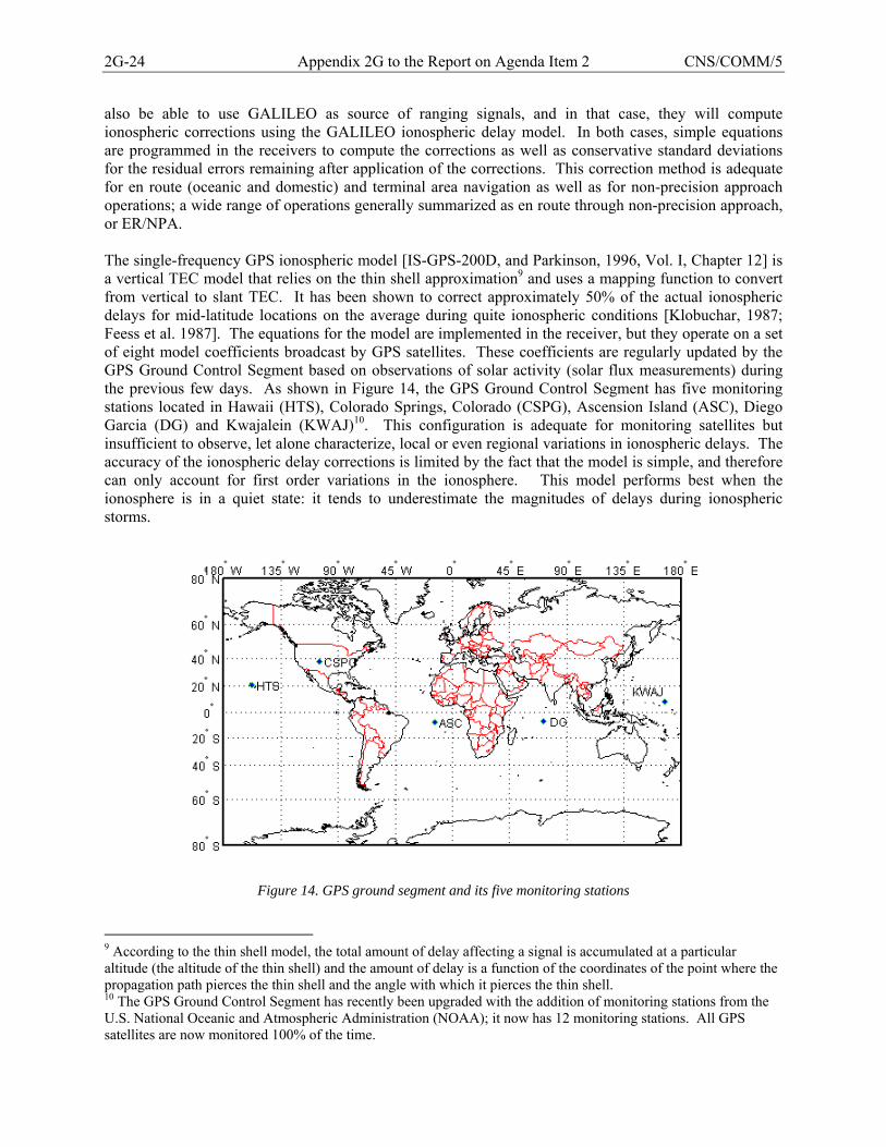
2G-24 Appendix 2G to the Report on Agenda Item 2 CNS/COMM/5
also be able to use GALILEO as source of ranging signals, and in that case, they will compute ionospheric corrections using the GALILEO ionospheric delay model. In both cases, simple equations are programmed in the receivers to compute the corrections as well as conservative standard deviations for the residual errors remaining after application of the corrections. This correction method is adequate for en route (oceanic and domestic) and terminal area navigation as well as for non-precision approach operations; a wide range of operations generally summarized as en route through non-precision approach, or ER/NPA. The single-frequency GPS ionospheric model [IS-GPS-200D, and Parkinson, 1996, Vol. I, Chapter 12] is a vertical TEC model that relies on the thin shell approximation9 and uses a mapping function to convert from vertical to slant TEC. It has been shown to correct approximately 50% of the actual ionospheric delays for mid-latitude locations on the average during quite ionospheric conditions [Klobuchar, 1987; Feess et al. 1987]. The equations for the model are implemented in the receiver, but they operate on a set of eight model coefficients broadcast by GPS satellites. These coefficients are regularly updated by the GPS Ground Control Segment based on observations of solar activity (solar flux measurements) during the previous few days. As shown in Figure 14, the GPS Ground Control Segment has five monitoring stations located in Hawaii (HTS), Colorado Springs, Colorado (CSPG), Ascension Island (ASC), Diego Garcia (DG) and Kwajalein (KWAJ)10. This configuration is adequate for monitoring satellites but insufficient to observe, let alone characterize, local or even regional variations in ionospheric delays. The accuracy of the ionospheric delay corrections is limited by the fact that the model is simple, and therefore can only account for first order variations in the ionosphere. This model performs best when the ionosphere is in a quiet state: it tends to underestimate the magnitudes of delays during ionospheric storms.
Figure 14. GPS ground segment and its five monitoring stations
9 According to the thin shell model, the total amount of delay affecting a signal is accumulated at a particular altitude (the altitude of the thin shell) and the amount of delay is a function of the coordinates of the point where the propagation path pierces the thin shell and the angle with which it pierces the thin shell. 10 The GPS Ground Control Segment has recently been upgraded with the addition of monitoring stations from the U.S. National Oceanic and Atmospheric Administration (NOAA); it now has 12 monitoring stations. All GPS satellites are now monitored 100% of the time.
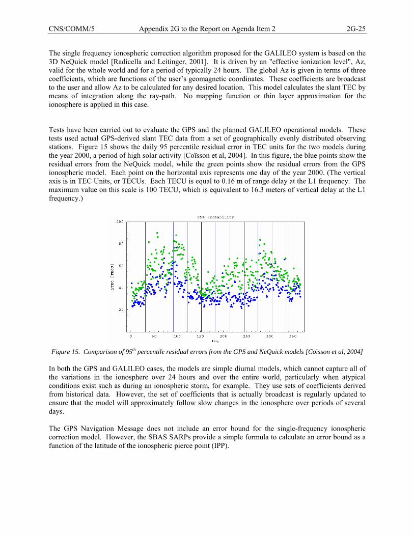
CNS/COMM/5 Appendix 2G to the Report on Agenda Item 2 2G-25
The single frequency ionospheric correction algorithm proposed for the GALILEO system is based on the 3D NeQuick model [Radicella and Leitinger, 2001]. It is driven by an "effective ionization level", Az, valid for the whole world and for a period of typically 24 hours. The global Az is given in terms of three coefficients, which are functions of the user’s geomagnetic coordinates. These coefficients are broadcast to the user and allow Az to be calculated for any desired location. This model calculates the slant TEC by means of integration along the ray-path. No mapping function or thin layer approximation for the ionosphere is applied in this case.
Tests have been carried out to evaluate the GPS and the planned GALILEO operational models. These tests used actual GPS-derived slant TEC data from a set of geographically evenly distributed observing stations. Figure 15 shows the daily 95 percentile residual error in TEC units for the two models during the year 2000, a period of high solar activity [Coïsson et al, 2004]. In this figure, the blue points show the residual errors from the NeQuick model, while the green points show the residual errors from the GPS ionospheric model. Each point on the horizontal axis represents one day of the year 2000. (The vertical axis is in TEC Units, or TECUs. Each TECU is equal to 0.16 m of range delay at the L1 frequency. The maximum value on this scale is 100 TECU, which is equivalent to 16.3 meters of vertical delay at the L1 frequency.)
Figure 15. Comparison of 95th percentile residual errors from the GPS and NeQuick models [Coïsson et al, 2004]
In both the GPS and GALILEO cases, the models are simple diurnal models, which cannot capture all of the variations in the ionosphere over 24 hours and over the entire world, particularly when atypical conditions exist such as during an ionospheric storm, for example. They use sets of coefficients derived from historical data. However, the set of coefficients that is actually broadcast is regularly updated to ensure that the model will approximately follow slow changes in the ionosphere over periods of several days. The GPS Navigation Message does not include an error bound for the single-frequency ionospheric correction model. However, the SBAS SARPs provide a simple formula to calculate an error bound as a function of the latitude of the ionospheric pierce point (IPP).
2G-26 Appendix 2G to the Report on Agenda Item 2 CNS/COMM/5
5.1.1.2 Correction Method used by SBAS Receivers SBAS receivers inside the SBAS APV service area can correct for ionospheric delays more accurately than ABAS receivers because they can use the SBAS corrections, which are derived from real-time ionospheric delay measurements. User receivers obtain information on the estimated vertical delays and estimated standard deviations of residual errors11 at the nodes, or grid points, of a standardized ionospheric grid directly from the SBAS broadcast data [ICAO, 2005; RTCA DO-229C, 2001]. The SBAS ionospheric grid is located 350 km above the surface of the Earth and has latitude and longitude cell widths of 5 degrees for most of the inhabited world12. However, a given SBAS will only provide ionospheric corrections for a small portion of that worldwide grid that corresponds to its APV service volume. The SBAS ground system obtains real-time measurements from a network of reference stations and uses them to estimate the vertical delays at the nodes, or ionospheric grid points (IGPs), of the standardized ionospheric grid. For each line of sight to a satellite, a user receiver interpolates between the nearest IGPs to the location of the ionospheric pierce point (IPP), then converts the interpolated vertical delay to a range (or slant) delay by applying a standardized “obliquity factor” that accounts for the angle at which the line of sight pierces the ionospheric thin shell. Similar calculations are performed for the delays and for obtaining conservative estimates of the standard deviations of the residual range errors. With this type of augmentation, the accuracy of the corrections is limited by (1) the relatively sparse sampling of the ionosphere available to the SBAS ionospheric delay estimation process, (2) the SBAS ionosphere model which estimates ionospheric delays from a two-dimensional model (ionospheric grid) and a fixed one-to-one mapping between vertical delays and range (slant) delays; and (3) time delays between the collection of ionospheric delay measurements by the SBAS ground infrastructure, the broadcast of ionospheric grid information by the SBAS satellites, and the application of the corrections by the SBAS receiver. To illustrate the much denser sampling of the ionosphere performed by an SBAS as compared to the GPS Ground Segment, the network of reference stations that will be used by the U.S. WAAS once the current upgrade is completed (end of 2008) is shown in Figure 16. Despite the denser network of reference stations, the sampling of the ionosphere performed by an SBAS is still limited, and therefore it may fail to capture certain narrow structures in the ionosphere. The GIVE integrity algorithm used by SBAS has to account for this limitation.
11 These standard deviations are actually communicated in the form of 3.29σ bounds called, Grid Ionospheric Vertical Errors (GIVEs). The corresponding values in the range domain obtained after interpolation and domain conversion are known as User Ionospheric Range Errors (UIREs). 12 Cell widths are larger than 5 by 5 degrees at the higher northern and southern latitudes.
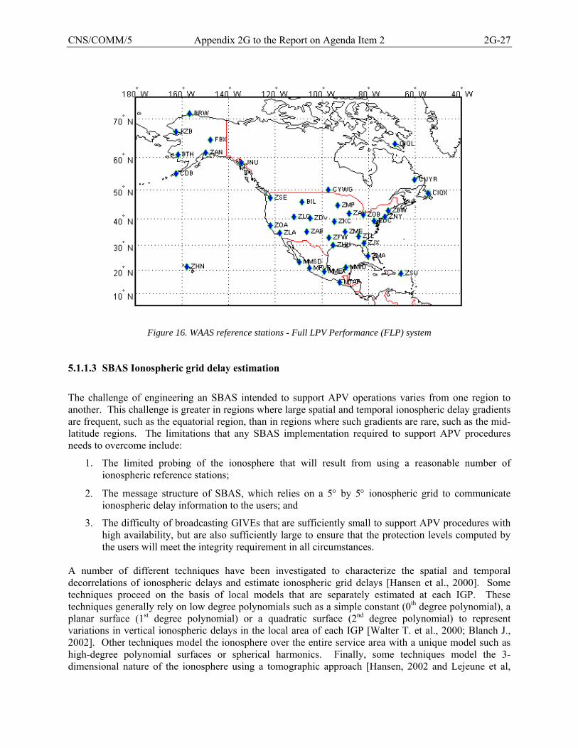
CNS/COMM/5 Appendix 2G to the Report on Agenda Item 2 2G-27
Figure 16. WAAS reference stations - Full LPV Performance (FLP) system
5.1.1.3 SBAS Ionospheric grid delay estimation
The challenge of engineering an SBAS intended to support APV operations varies from one region to another. This challenge is greater in regions where large spatial and temporal ionospheric delay gradients are frequent, such as the equatorial region, than in regions where such gradients are rare, such as the mid-latitude regions. The limitations that any SBAS implementation required to support APV procedures needs to overcome include:
1. The limited probing of the ionosphere that will result from using a reasonable number of ionospheric reference stations;
2. The message structure of SBAS, which relies on a 5° by 5° ionospheric grid to communicate ionospheric delay information to the users; and
3. The difficulty of broadcasting GIVEs that are sufficiently small to support APV procedures with high availability, but are also sufficiently large to ensure that the protection levels computed by the users will meet the integrity requirement in all circumstances.
A number of different techniques have been investigated to characterize the spatial and temporal decorrelations of ionospheric delays and estimate ionospheric grid delays [Hansen et al., 2000]. Some techniques proceed on the basis of local models that are separately estimated at each IGP. These techniques generally rely on low degree polynomials such as a simple constant (0th degree polynomial), a planar surface (1st degree polynomial) or a quadratic surface (2nd degree polynomial) to represent variations in vertical ionospheric delays in the local area of each IGP [Walter T. et al., 2000; Blanch J., 2002]. Other techniques model the ionosphere over the entire service area with a unique model such as high-degree polynomial surfaces or spherical harmonics. Finally, some techniques model the 3-dimensional nature of the ionosphere using a tomographic approach [Hansen, 2002 and Lejeune et al,
2G-28 Appendix 2G to the Report on Agenda Item 2 CNS/COMM/5
2004]. Current SBAS implementations rely on low degree polynomial surfaces that are separately estimated at each IGP. These techniques have been found to be effective, relatively simple to implement, and about as accurate as more complex techniques. For example, it does not appear difficult to imagine based on the vertical delay surface shown in Figure 3 that in mid-latitudes the vertical grid delays at the Ionospheric Grid Points (IGDs) could be estimated from local planar approximations to that surface. In fact, the U.S. Wide Area Augmentation System (WAAS) uses this approach to compute both the vertical delay and the GIVE at each IGP in its APV service volume. This technique is simple and effective when the ionosphere is quiet; its accuracy may however deteriorate during severe ionospheric storms. For this reason, WAAS applies a check (loosely referred to as a “storm detector”) to verify the validity of the planar fit at each IGP, and sets the GIVE at an IGP to its maximum value whenever the check fails. When it succeeds, WAAS calculates the GIVE using a formula that accounts for the number of measurements used in computing the vertical grid delay at the IGP, the variability of the ionospheric decorrelation during “worst case” quiet ionospheric conditions (i.e., “when the conditions approach the tripping point of the storm detector), and the limited sampling of the ionosphere represented by the ionospheric delay measurements used to compute the vertical ionospheric grid delay at the IGP. Of course, other mitigation techniques against the effects of severely disturbed ionospheric conditions are possible. However, no matter what mitigation techniques are used, analysis will be needed to verify that the design guarantees the integrity of the broadcast GIVEs under the full range of conditions that could occur in the geographic area of the SBAS. Developing such an analysis has been found to be the most demanding part of the engineering challenge outlined above. As noted in 5.1.1.2, SBAS uses a standard formula to convert between vertical and slant delays and vice versa. The errors due to this conversion are normally fairly small (≤ 0.3 m). However, they can become much larger (up to several meters) when large variations in the vertical distribution of free electrons exist in the local ionosphere. Such conditions occur during severe ionospheric storms and also when the equatorial anomalies are present. They are associated with large spatial and temporal gradients in vertical ionospheric delays. The Grid Ionospheric Vertical Errors (GIVEs) at the IGPs in areas affected by such conditions should be sufficiently increased in order to ensure that the integrity requirement continue to be met. As an additional mitigation technique against sudden variations in ionospheric delays, SBAS can generate alert messages to increase the GIVEs in order to protect the users against the potential effects of such variations. The need for alert messages will however depend on the design architecture of the SBAS ionospheric function and its monitor, and the associated risk of possibly broadcasting GIVEs that may not adequately characterize the users’ residual errors under certain ionospheric conditions. The limitations of the techniques briefly outlined above when used in an equatorial region were highlighted in few preliminary analyses of the expected performance of an SBAS ionospheric algorithm similar to that of WAAS in low latitude regions [Lejeune et al., 2002; Lejeune et al. 2003]. This analysis did not even address the challenge raised by depletions, which as noted in 3.2.1, present a particularly difficult challenge. 5.1.1.4 Correction Method used by GBAS/GRAS Receivers The VHF Data Broadcast function of GBAS and GRAS broadcasts messages that contain pseudorange corrections for all satellites in view. When applied, these corrections eliminate, or at least greatly reduce, the majority of common errors (e.g., ionospheric delay) between the ground and the aircraft. In addition, the messages also carry parameters characterizing the uncertainties in these corrections. Equations
CNS/COMM/5 Appendix 2G to the Report on Agenda Item 2 2G-29
implemented in the avionics rely on these parameters to calculate protection levels. These protection levels are then compared to the maximum alert limits for that station and the desired flight operation. A key limitation on the GBAS corrections is the spatial separation between the GBAS ground station and the GBAS aircraft user, since the corrections broadcast to the aircraft can only correct common errors. The main issue here relates to the ionospheric delay, which can vary as a function of distance. This difference tends to be small over small distances typical of the local area under nominal ionospheric conditions in the mid-latitudes. (This is not necessarily the case, however, in the equatorial area where variations can be large even in a local area). Conditions associated with severe mid-latitude ionospheric storms present a different case. In this case, delay magnitudes can vary quite rapidly over short distances and thus may not be adequately mitigated even after the corrections from the GBAS ground station are applied. This presents significant challenges for meeting CAT I requirements and major design issues for CAT II/III, given the more stringent accuracy and integrity requirements that apply to these operations. The main challenge is to adequately demonstrate that the system will be able to meet the integrity and availability requirements during severe ionospheric storms when ionospheric delays can potentially vary rapidly both in time and space. This requires analysis of the delay magnitude variations that can occur under the full range of ionospheric conditions and at all locations around the globe where GBAS stations could potentially be implemented. The type and amount of data that is available for such analysis dictates the level of modeling accuracy that can be attained. Achieving a high-level of accuracy is particularly difficult in the local area (~ 100 km2 area) operational environment of CAT I/II/III. An example of this type of modeling effort was outlined in WP 15 [Burns, WP 15, Montreal 2004]. GRAS uses a similar approach to GBAS to transmit corrections and integrity information. However, unlike GBAS, its intended service area is not limited to the terminal area. Therefore, corrections may be transmitted from VHF Data Broadcast (VDB) stations located outside the perimeter of the terminal area in order to support en route navigation. The cost of this expanded coverage resides in the increased risk of unobserved ionospheric irregularities. This risk needs to be taken into account in the broadcast integrity information. Given the level of service supported by GRAS and the wide area over which GRAS services can be provided, the impact of the ionosphere on GRAS will be similar to that on SBAS. 5.1.2 Future GNSS (Dual-frequency Receivers) Within the next decade, new and modernized GNSS core constellations will appear that broadcast civil signals on two or more aeronautical frequencies. GNSS receivers capable of tracking multiple frequencies will then become available, and will likely become predominant as time passes. While some of these receivers may track more than two frequencies, two frequencies are sufficient to either accurately estimate ionospheric delays or directly obtain pseudorange measurements that are free of ionospheric delays (ionosphere-free pseudoranges). Accurate estimates of ionospheric range delay at a given L-band frequency (or TEC) along the line of sight between a receiver and a satellite are possible using two signals with different L-band frequencies because the amount of delay affecting a particular signal is inversely proportional to the square of the frequency of that signal. The theoretical accuracy of the resulting TEC estimates can be very high (of the order of 0.163 m at the L1 frequency or about one TECU). However, the accuracy obtained in practice depends on the magnitudes of residual errors associated with satellite inter-frequency biases and multipath corrections. This method of removing ionospheric delay effects is currently used by authorized GPS receivers, which have the capability of tracking the encrypted, or P(Y), code transmitted on both the GPS L1 and L2 signals.
2G-30 Appendix 2G to the Report on Agenda Item 2 CNS/COMM/5
This method is also used by receivers used in SBAS reference stations. In this case, however, the receivers must rely on one of several codeless or semi-codeless techniques in order to track the GPS L2 signal. These techniques result in a loss of signal-to-noise density ratio of at least 10 dB-Hz, and for some techniques the loss can be much greater [Woo, 2000]. They are very sensitive to dynamic motion, multipath errors and scintillation effects, and as a result, are not appropriate for airborne receivers. The future implementation of GNSS core constellations that broadcast dual-frequency signals for use by civil aviation will be a welcomed development, which will essentially reduce the ionosphere from a major to a minor contributing source of navigation errors (as long as the signals from both frequencies are available and tracked). Following this development, dual-frequency receivers will be able to provide a high availability of ER/NPA navigation in most of the world using only a receiver-based Fault Detection and Exclusion function to ensure the integrity of the navigation solution. Dual-frequency, multi-constellation receivers may also be capable of supporting APV approach procedures without augmentation. However, this is a topic of active research, and it is currently too early to tell whether it will be possible to meet the integrity requirement under scenarios of multiple satellite faults using receiver-based techniques exclusively. This development will also be beneficial to SBAS-based navigation. It will likely make SBAS-based Cat I Precision Approach possible anywhere in the world, provided of course that the approach is within the service area of an SBAS. Furthermore, as the need to provide ionospheric correction deceases, it will become possible to consider SBAS implementations with reduced ground infrastructures since the main role of SBAS will then be to monitor the satellites and provide satellite integrity information. (Of course, the SBAS ionospheric function may still be of value to continue to provide service to users equipped with legacy single-frequency receivers, and also as a fallback solution to maintain APV service when users equipped with dual-frequency receivers are unable to receive one of the frequencies due to interference or severe scintillation on only one frequency.) Finally, this development will also be beneficial to GBAS-based navigation since it will eliminate the risk of potential integrity failures due to sharp differences in the ionospheric delays seen by the aircraft and those seen by the GBAS stations. 5.2 Mitigation Techniques for Scintillation Effects Both amplitude scintillation and phase scintillation can cause a receiver to lose lock on the affected signal, particularly when they occur simultaneously. GNSS receivers are generally able to maintain lock on signals affected by low to moderate levels of scintillation when they can track the signals using a code-based tracking technique. However, any receiver, whether airborne of in a reference station, is likely to lose lock on the GPS L1 signal of satellites for which the received C/N0 drops below 30 dB-Hz during periods of intense amplitude scintillation. The probability of loss of lock has been calculated for various levels of C/N0 and compared to that obtained from measurements as illustrated in Figure 17 [Béniguel].
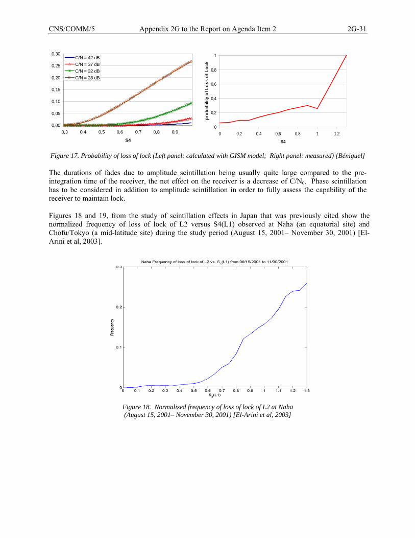
CNS/COMM/5 Appendix 2G to the Report on Agenda Item 2 2G-31
0,00
0,05
0,10
0,15
0,20
0,25
0,30
0,3 0,4 0,5 0,6 0,7 0,8 0,9
S4
C/N = 42 dBC/N = 37 dBC/N = 32 dBC/N = 28 dB
Figure 17. Probability of loss of lock (Left panel: calculated with GISM model; Right panel: measured) [Béniguel] The durations of fades due to amplitude scintillation being usually quite large compared to the pre-integration time of the receiver, the net effect on the receiver is a decrease of C/N0. Phase scintillation has to be considered in addition to amplitude scintillation in order to fully assess the capability of the receiver to maintain lock. Figures 18 and 19, from the study of scintillation effects in Japan that was previously cited show the normalized frequency of loss of lock of L2 versus S4(L1) observed at Naha (an equatorial site) and Chofu/Tokyo (a mid-latitude site) during the study period (August 15, 2001– November 30, 2001) [El-Arini et al, 2003].
Figure 18. Normalized frequency of loss of lock of L2 at Naha (August 15, 2001– November 30, 2001) [El-Arini et al, 2003]
0
0,2
0,4
0,6
0,8
1
0 0,2 0,4 0,6 0,8 1 1,2
S4
prob
abili
ty o
f Los
s of
Loc
k
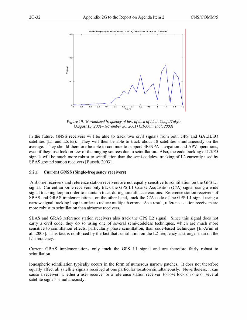
2G-32 Appendix 2G to the Report on Agenda Item 2 CNS/COMM/5
Figure 19. Normalized frequency of loss of lock of L2 at Chofu/Tokyo (August 15, 2001– November 30, 2001) [El-Arini et al, 2003]
In the future, GNSS receivers will be able to track two civil signals from both GPS and GALILEO satellites (L1 and L5/E5). They will then be able to track about 18 satellites simultaneously on the average. They should therefore be able to continue to support ER/NPA navigation and APV operations, even if they lose lock on few of the ranging sources due to scintillation. Also, the code tracking of L5/E5 signals will be much more robust to scintillation than the semi-codeless tracking of L2 currently used by SBAS ground station receivers [Butsch, 2003]. 5.2.1 Current GNSS (Single-frequency receivers) Airborne receivers and reference station receivers are not equally sensitive to scintillation on the GPS L1 signal. Current airborne receivers only track the GPS L1 Coarse Acquisition (C/A) signal using a wide signal tracking loop in order to maintain track during aircraft accelerations. Reference station receivers of SBAS and GRAS implementations, on the other hand, track the C/A code of the GPS L1 signal using a narrow signal tracking loop in order to reduce multipath errors. As a result, reference station receivers are more robust to scintillation than airborne receivers. SBAS and GRAS reference station receivers also track the GPS L2 signal. Since this signal does not carry a civil code, they do so using one of several semi-codeless techniques, which are much more sensitive to scintillation effects, particularly phase scintillation, than code-based techniques [El-Arini et al., 2003]. This fact is reinforced by the fact that scintillation on the L2 frequency is stronger than on the L1 frequency. Current GBAS implementations only track the GPS L1 signal and are therefore fairly robust to scintillation. Ionospheric scintillation typically occurs in the form of numerous narrow patches. It does not therefore equally affect all satellite signals received at one particular location simultaneously. Nevertheless, it can cause a receiver, whether a user receiver or a reference station receiver, to lose lock on one or several satellite signals simultaneously.
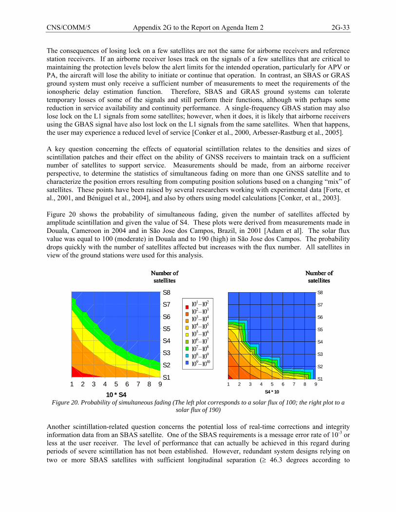
CNS/COMM/5 Appendix 2G to the Report on Agenda Item 2 2G-33
The consequences of losing lock on a few satellites are not the same for airborne receivers and reference station receivers. If an airborne receiver loses track on the signals of a few satellites that are critical to maintaining the protection levels below the alert limits for the intended operation, particularly for APV or PA, the aircraft will lose the ability to initiate or continue that operation. In contrast, an SBAS or GRAS ground system must only receive a sufficient number of measurements to meet the requirements of the ionospheric delay estimation function. Therefore, SBAS and GRAS ground systems can tolerate temporary losses of some of the signals and still perform their functions, although with perhaps some reduction in service availability and continuity performance. A single-frequency GBAS station may also lose lock on the L1 signals from some satellites; however, when it does, it is likely that airborne receivers using the GBAS signal have also lost lock on the L1 signals from the same satellites. When that happens, the user may experience a reduced level of service [Conker et al., 2000, Arbesser-Rastburg et al., 2005]. A key question concerning the effects of equatorial scintillation relates to the densities and sizes of scintillation patches and their effect on the ability of GNSS receivers to maintain track on a sufficient number of satellites to support service. Measurements should be made, from an airborne receiver perspective, to determine the statistics of simultaneous fading on more than one GNSS satellite and to characterize the position errors resulting from computing position solutions based on a changing “mix” of satellites. These points have been raised by several researchers working with experimental data [Forte, et al., 2001, and Béniguel et al., 2004], and also by others using model calculations [Conker, et al., 2003]. Figure 20 shows the probability of simultaneous fading, given the number of satellites affected by amplitude scintillation and given the value of S4. These plots were derived from measurements made in Douala, Cameroon in 2004 and in São Jose dos Campos, Brazil, in 2001 [Adam et al]. The solar flux value was equal to 100 (moderate) in Douala and to 190 (high) in São Jose dos Campos. The probability drops quickly with the number of satellites affected but increases with the flux number. All satellites in view of the ground stations were used for this analysis.
1 2 3 4 5 6 7 8 9S1
S2
S3
S4
S5
S6
S7
S8
10 * S41 2 3 4 5 6 7 8 9
S1
S2
S3
S4
S5
S6
S7
S8
S4 * 10
-20--10-30--20-40--30-50--40-60--50-70--60-80--70-90--80-100--90
10-1 – 10-2
10-2 – 10-3
10-3 – 10-4
10-4 – 10-5
10-5 – 10-6
10-6 – 10-7
10-7 – 10-8
10-8 – 10-9
10-9–10-10
Number of satellites
Number of satellites
Figure 20. Probability of simultaneous fading (The left plot corresponds to a solar flux of 100; the right plot to a
solar flux of 190) Another scintillation-related question concerns the potential loss of real-time corrections and integrity information data from an SBAS satellite. One of the SBAS requirements is a message error rate of 10-3 or less at the user receiver. The level of performance that can actually be achieved in this regard during periods of severe scintillation has not been established. However, redundant system designs relying on two or more SBAS satellites with sufficient longitudinal separation (≥ 46.3 degrees according to
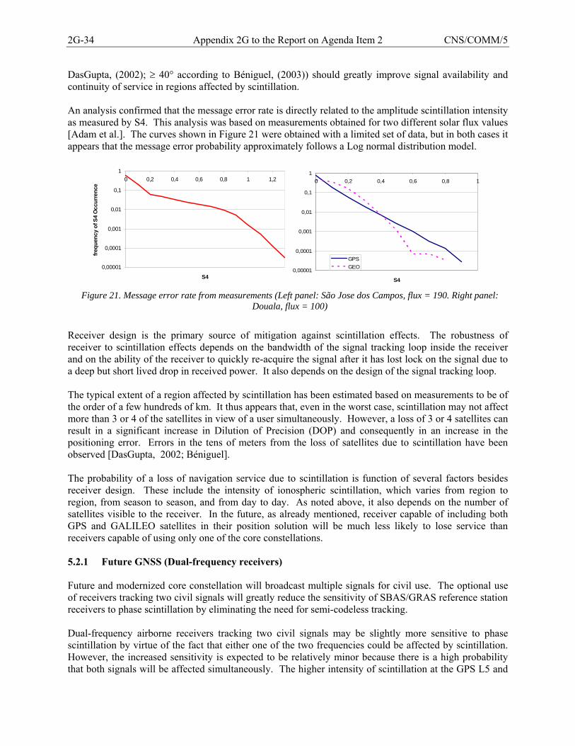
2G-34 Appendix 2G to the Report on Agenda Item 2 CNS/COMM/5
DasGupta, (2002); ≥ 40° according to Béniguel, (2003)) should greatly improve signal availability and continuity of service in regions affected by scintillation. An analysis confirmed that the message error rate is directly related to the amplitude scintillation intensity as measured by S4. This analysis was based on measurements obtained for two different solar flux values [Adam et al.]. The curves shown in Figure 21 were obtained with a limited set of data, but in both cases it appears that the message error probability approximately follows a Log normal distribution model.
0,00001
0,0001
0,001
0,01
0,1
10 0,2 0,4 0,6 0,8 1 1,2
S4
frequ
ency
of S
4 O
ccur
renc
e
0,00001
0,0001
0,001
0,01
0,1
10 0,2 0,4 0,6 0,8 1
S4
GPSGEO
Figure 21. Message error rate from measurements (Left panel: São Jose dos Campos, flux = 190. Right panel:
Douala, flux = 100)
Receiver design is the primary source of mitigation against scintillation effects. The robustness of receiver to scintillation effects depends on the bandwidth of the signal tracking loop inside the receiver and on the ability of the receiver to quickly re-acquire the signal after it has lost lock on the signal due to a deep but short lived drop in received power. It also depends on the design of the signal tracking loop. The typical extent of a region affected by scintillation has been estimated based on measurements to be of the order of a few hundreds of km. It thus appears that, even in the worst case, scintillation may not affect more than 3 or 4 of the satellites in view of a user simultaneously. However, a loss of 3 or 4 satellites can result in a significant increase in Dilution of Precision (DOP) and consequently in an increase in the positioning error. Errors in the tens of meters from the loss of satellites due to scintillation have been observed [DasGupta, 2002; Béniguel]. The probability of a loss of navigation service due to scintillation is function of several factors besides receiver design. These include the intensity of ionospheric scintillation, which varies from region to region, from season to season, and from day to day. As noted above, it also depends on the number of satellites visible to the receiver. In the future, as already mentioned, receiver capable of including both GPS and GALILEO satellites in their position solution will be much less likely to lose service than receivers capable of using only one of the core constellations. 5.2.1 Future GNSS (Dual-frequency receivers) Future and modernized core constellation will broadcast multiple signals for civil use. The optional use of receivers tracking two civil signals will greatly reduce the sensitivity of SBAS/GRAS reference station receivers to phase scintillation by eliminating the need for semi-codeless tracking. Dual-frequency airborne receivers tracking two civil signals may be slightly more sensitive to phase scintillation by virtue of the fact that either one of the two frequencies could be affected by scintillation. However, the increased sensitivity is expected to be relatively minor because there is a high probability that both signals will be affected simultaneously. The higher intensity of scintillation at the GPS L5 and
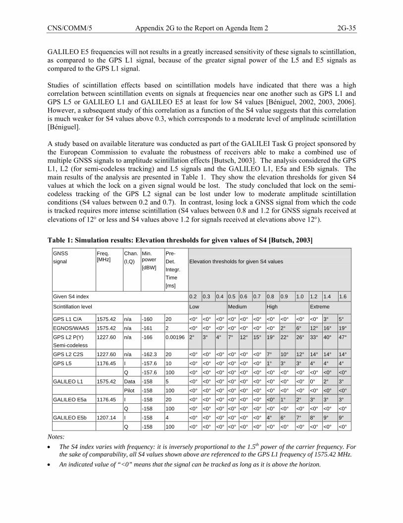
CNS/COMM/5 Appendix 2G to the Report on Agenda Item 2 2G-35
GALILEO E5 frequencies will not results in a greatly increased sensitivity of these signals to scintillation, as compared to the GPS L1 signal, because of the greater signal power of the L5 and E5 signals as compared to the GPS L1 signal. Studies of scintillation effects based on scintillation models have indicated that there was a high correlation between scintillation events on signals at frequencies near one another such as GPS L1 and GPS L5 or GALILEO L1 and GALILEO E5 at least for low S4 values [Béniguel, 2002, 2003, 2006]. However, a subsequent study of this correlation as a function of the S4 value suggests that this correlation is much weaker for S4 values above 0.3, which corresponds to a moderate level of amplitude scintillation [Béniguel]. A study based on available literature was conducted as part of the GALILEI Task G project sponsored by the European Commission to evaluate the robustness of receivers able to make a combined use of multiple GNSS signals to amplitude scintillation effects [Butsch, 2003]. The analysis considered the GPS L1, L2 (for semi-codeless tracking) and L5 signals and the GALILEO L1, E5a and E5b signals. The main results of the analysis are presented in Table 1. They show the elevation thresholds for given S4 values at which the lock on a given signal would be lost. The study concluded that lock on the semi-codeless tracking of the GPS L2 signal can be lost under low to moderate amplitude scintillation conditions (S4 values between 0.2 and 0.7). In contrast, losing lock a GNSS signal from which the code is tracked requires more intense scintillation (S4 values between 0.8 and 1.2 for GNSS signals received at elevations of 12° or less and S4 values above 1.2 for signals received at elevations above 12°).
Table 1: Simulation results: Elevation thresholds for given values of S4 [Butsch, 2003]
GNSS signal
Freq. [MHz]
Chan. (I,Q)
Min. power [dBW]
Pre- Det. Integr. Time [ms]
Elevation thresholds for given S4 values
Given S4 index 0.2 0.3 0.4 0.5 0.6 0.7 0.8 0.9 1.0 1.2 1.4 1.6
Scintillation level Low Medium High Extreme
GPS L1 C/A 1575.42 n/a -160 20 <0° <0° <0° <0° <0° <0° <0° <0° <0° <0° 3° 5°
EGNOS/WAAS 1575.42 n/a -161 2 <0° <0° <0° <0° <0° <0° <0° 2° 6° 12° 16° 19°
GPS L2 P(Y) Semi-codeless
1227.60 n/a -166 0.00196 2° 3° 4° 7° 12° 15° 19° 22° 26° 33° 40° 47°
GPS L2 C2S 1227.60 n/a -162.3 20 <0° <0° <0° <0° <0° <0° 7° 10° 12° 14° 14° 14°
GPS L5 1176.45 I -157.6 10 <0° <0° <0° <0° <0° <0° 1° 3° 3° 4° 4° 4°
Q -157.6 100 <0° <0° <0° <0° <0° <0° <0° <0° <0° <0° <0° <0°
GALILEO L1 1575.42 Data -158 5 <0° <0° <0° <0° <0° <0° <0° <0° <0° 0° 2° 3°
Pilot -158 100 <0° <0° <0° <0° <0° <0° <0° <0° <0° <0° <0° <0°
GALILEO E5a 1176.45 I -158 20 <0° <0° <0° <0° <0° <0° <0° 1° 2° 3° 3° 3°
Q -158 100 <0° <0° <0° <0° <0° <0° <0° <0° <0° <0° <0° <0°
GALILEO E5b 1207.14 I -158 4 <0° <0° <0° <0° <0° <0° 4° 6° 7° 8° 9° 9°
Q -158 100 <0° <0° <0° <0° <0° <0° <0° <0° <0° <0° <0° <0°
Notes: • The S4 index varies with frequency: it is inversely proportional to the 1.5th power of the carrier frequency. For
the sake of comparability, all S4 values shown above are referenced to the GPS L1 frequency of 1575.42 MHz. • An indicated value of “<0” means that the signal can be tracked as long as it is above the horizon.
2G-36 Appendix 2G to the Report on Agenda Item 2 CNS/COMM/5
5.3 Other Mitigations The availability and continuity of GNSS-based ER/NPA service is not expected to be greatly affected by the ionosphere, except to the extent that lock on multiple satellite signals could be lost to scintillation during periods of intense scintillation. The equatorial area will thus be mostly affected: during periods of intense scintillation, some users may not be able to continuously track a sufficient number of satellites with a good geometry in order to maintain service. ABAS receivers will be more prone to such losses of ER/NPA service than SBAS receivers. Indeed, when FDE is the source of integrity, a larger number of satellites are generally needed in order to maintain service than when SBAS is the source of the integrity. It is not clear that a non-GNSS form of mitigation is needed for potential losses of ER/NPA service; however, if one was needed, it could be based on the maintenance of a limited number of ground-based radio-navigation systems. High-end users equipped with avionics using integrated GPS and Inertial Navigation System (INS) solutions will likely be much less sensitive to such effects than low-end users equipped with simple GNSS receivers. In most regions, the ionosphere will affect APV service from single-frequency receivers at least some of the time. Even in mid-latitudes where ionospheric effects are comparatively mild, ionospheric disturbances can cause losses of service availability and continuity. In the most extreme cases, these losses can be sufficiently severe to deny APV service over large areas for several hours. An obvious mitigation to this problem is to maintain a sufficient number of Instrument Landing System (ILS) installations, particularly at busy airports. In fact, the ILS approach is likely to remain the approach procedure of choice at busy airports in the near future because of its lower decision height, its greater reliability (ILS is not affected by the ionosphere and radio interference effects can only have a local impact) and legacy avionics in high-end aircraft. For airplanes not equipped with ILS receivers, there is a high likelihood that a GNSS-based NPA approach will be possible when APV service is not available. Mitigation against losses of SBAS-based APV service due to unusual ionospheric conditions can also be provided through the rules concerning the use or SBAS navigation equipment. For example, the U.S. rules require that pilots who plan to conduct an LPV approach (an approach corresponding to APV performance) at their destination airport file an alternate airport with an LNAV (non-precision) approach and verify that the weather conditions at that alternate airport will allow an LNAV approach, if landing at the alternate airport is needed. 6. Research Efforts Past efforts are summarized in Section 6.1; current and planned efforts in Section 6.2. 6.1 Past Efforts An initial assessment of the characteristics of the equatorial anomalies and their potential effects on SBAS was performed in 2001 [Klobuchar, et al., 2001]. The assessment showed that the difference between the actual slant ionospheric range delay values obtained from a 3D ionospheric model and those obtained by the standard SBAS technique of interpolating vertical delays between Ionospheric Grid Points (IGPs) on a five-by-five-degree grid and then converting to equivalent slant range delay could be as large as 27 meters for a GPS satellite at a low elevation. These results were confirmed in parallel investigations [Nava, 2000; Hochegger, et al., 2000]. An investigation based on the 3D NeQuick ionospheric model showed that even at low mid-latitudes and for low elevation angles, the combined effect of the equatorial anomaly and the large spatial gradient near sunset introduced substantial
CNS/COMM/5 Appendix 2G to the Report on Agenda Item 2 2G-37
differences between the actual slant delay values and those obtained with the standard SBAS conversion technique [Nava, 2000]. The results of a more recent South American analysis [Klobuchar et al. 2002] indicate that the engineering challenge outlined in Section 2.2.1 may be difficult to meet. Even if the absence of steep depletions can be assumed, slant-to-vertical (and vertical-to-slant) conversion errors remain a significant problem. Indeed, these errors can be relatively large in the equatorial region, depending on the orientation of lines of sight. This is really a problem associated with the thin shell model of the ionosphere used by SBAS, more than it is a problem related to the SBAS grid spacing or to the number of reference stations in the SBAS configuration.
Techniques that work well in mid-latitude regions such as the planar fit approach to estimating vertical grid delays [Walter, et al., 2000], and the simple obliquity factor which converts from slant to vertical delays, then back from vertical to slant delays, may not perform adequately well to ensure a high availability of APV service in the equatorial region. New techniques that are more tolerant of the large spatial and temporal variations in TEC illustrated in Figures 6a and 6b could perhaps be developed. Also, collecting ionospheric data with a high-density network of reference stations would alleviate some of these problems. However, the deep equatorial depletions will remain a problem for single-frequency SBAS, GRAS and GBAS no matter what estimation technique is used by the augmentation system because the spatial density of measurements will, in all likelihood, remain insufficient to ensure a very low probability of misdetection of narrow depletion structures, which can as narrow as a few hundreds of kilometers but as long as one thousand kilometers or more in length.
Spatial and temporal changes in the ionosphere that cannot be adequately represented by simple models (such as the planar model mentioned above) driven by relatively dispersed measurements, combined with the possible presence of narrow ionospheric structures that may develop between those measurements, will almost certainly limit the accuracy of the SBAS ionospheric delay corrections broadcast to the users. An SBAS faced with these problems will have to generate and broadcast large ionospheric integrity bounds, or Grid Ionospheric Vertical Errors (GIVEs), which, at various times and places, may be large enough to severely limit the availability of APV service. The integrity requirements imposed on SBAS are very stringent. Designing ionospheric algorithms that can be shown to meet these integrity requirements is a difficult task. Such a task requires detailed analyses of the various integrity threats, including those that cannot be addressed by the real-time estimation algorithm, and sufficient padding has to be built into the GIVE formulation to ensure that the broadcast GIVE will protect all users against the effects of all ionospheric threats (and particularly potentially undetected threats) with the required level of confidence.
The nominal ionospheric delay environment for GBAS was characterized using a prescribed model [RTCA/MOPS] and has been updated more recently using NGS/CORS data. During finalization of requirements and the start of system acquisition in the U.S., it was found that ionospheric conditions other than nominal might exist in the local area for mid-latitude regions. Analysis began in earnest to isolate these conditions and characterize them to the extent possible. The current GBAS ionospheric threat model (finalized in January 2006) lays down the initial foundation for characterizing anomalous ionosphere [Pullen, 2006]. The approach is based on SBAS research, in particular post-processed WAAS data, as well as on data from others networks of dual frequency receivers from the National Oceanic and Atmospheric Administration (NOAA) in the United States.

2G-38 Appendix 2G to the Report on Agenda Item 2 CNS/COMM/5
6.2 Current and Planned Efforts A scintillation measurement campaign is currently in progress under an ESA initiative. It uses receivers deployed both in the low latitudes (South America, Africa, Vietnam, Indonesia) and at high latitudes (Sweden). A data bank is being constituted for both raw data files (50 Hz) and processed data files. Two years of data will be collected during this campaign. As a part of the GARMIS project supported by the GALILEO Joint Undertaking (GJU), the European Ionospheric Experts Team (IET) is undertaking a number of research activities. They include the preparation of a database of GPS derived slant TEC data for ionospheric model validation, the analysis of existing ionospheric models particularly for GNSS operational use, the study of the equatorial ionosphere with particular emphasis on the electron density gradients during quiet and disturbed conditions over Africa, and equatorial and high latitudes scintillations and their impact on GNSS operation. Through the agreement between the GJU and the Chinese National Remote Sensing Centre, special ionospheric studies for the GALILEO regional augmentation services will be carried out with the participation of research groups from China and also the European IET. Today for GBAS, there is some agreement on how to deal with these ionospheric storm threats for CAT I [IDR Report, Sept. 2005]. U.S. validation and implementation is being conducted in a new prototype effort in Memphis, TN. Research is continuing to refine threats and improve system design to maximize performance. The FAA GBAS program is also continuing to participate in a cooperative data collection and analysis campaign of equatorial ionosphere anomalies with Brazil. This effort continues to yield more information about equatorial ionosphere impact to GBAS corrections and PA operations. 6.3 SBAS Iono Working Group In 1999, the SBAS Interoperability Working Group (IWG) established a Working Group composed of international ionospheric experts. This “SBAS Iono working group” was charged with providing all information necessary for assessing ionospheric threats to SBAS systems. The research concerning integrity threats focused on storms leading to large temporal and spatial gradients as well as Traveling Ionospheric Disturbances (TIDs). The research concerning threats to continuity and availability of service focused on scintillation. The working group, which has about twenty active members, has met on average twice a year (in the future this might be reduced to once per year) and has collaborated on issues such as modeling, data exchange and joint definition of experiments. In February 2003, the group produced a White Paper on key ionospheric research issues for SBAS [SBAS Iono WG, 2003], from which this paper has borrowed a certain amount of material. The group is still active and, in recent years, has focused its primary effort on the effects of scintillation. A secondary effort aims at evaluating the integrity threat represented by depletions. The SBAS Iono group is also studying receiver-based mitigation techniques. 6.4 WAAS Integrity Performance Panel (WIPP) In the US, the FAA established the WAAS Integrity Performance Panel (WIPP) in 2001 to review the integrity design of the Wide Area Augmentation System (WAAS) and more specifically the design of its integrity algorithms. The WIPP agreed on a 2-step methodology: (1) identify all integrity threats (i.e., circumstances or events that could lead to inadequate residual error bounds also called misleading information); and (2), for each identified threat, either mitigate its effect by use of a monitor or develop an assertion that the threat represents a negligible risk of misleading information.
CNS/COMM/5 Appendix 2G to the Report on Agenda Item 2 2G-39
A dedicated monitor was developed to address the integrity threat due to variations in ionospheric delays. Studies were conducted to characterize the spatial and temporal decorrelation of the ionosphere under both quiet and disturbed ionospheric conditions. The planar fit model was adopted as a means to model spatial ionospheric variations during quiet ionospheric conditions. The statistics of residual errors were found to provide a good indicator of the state of the ionosphere in the vicinity of the IGP as well as information on the magnitude of the GIVE that is needed in order to keep the probability of misleading information within the allocated integrity requirement of the monitor. Two states were identified. The “nominal state” is a state in which the estimation model is considered to be valid and the magnitude of the GIVE is set according to a formula that accounts for the sizes of the residual and the limited sampling (or undersampling) of the local ionosphere. This state is by far the most common. The “storm state” is a rare state in which the estimation model is considered to be invalid and the magnitude of the GIVE is set to a safely large numeric value. More recently, the WIPP recommended the addition of a second storm state to protect the user during the end phase of extreme ionospheric storms. These storms are not expected to occur more than once or twice during a solar cycle. They are considered extreme because of the extremely high levels of ionization that can occur during the “initial phase” of the storm and the intense isolated irregularities that can be generated during the “recovery phase” of the storm when the regular storm detector may no longer detect significant storm activity. When such an extreme storm is detected, WAAS will deny APV service over the entire APV service area for a period of time long enough to ensure that the ionosphere has returned to its normal state before resuming service. 6.5 LAAS Integrity Panel (LIP) The LIP was conceived under an initial FAA acquisition program for a CAT I GBAS system. It was then reorganized and formalized into a more research oriented working group during 2003. One of the main focuses of the group was to agree on a characterization of ionospheric storm effects on GBAS in the local area, and then to derive detailed design alternatives to mitigate these effects. Today, the LIP is the primary GBAS group addressing CAT I mid-latitude ionospheric storm threats in the United States. As outlined previously, the GBAS CAT II/III service will present additional challenges concerning the ionosphere. The analysis conducted by the LIP will need to continue in some fashion, not only for GBAS, but for any GNSS system or augmentation intended to support PA operations. A continuation of LIP activities in some new form is most likely necessary to achieve this. 6.6 Current and Planned Research in Japan In Japan, ionospheric research related to GNSS is being performed by the Electronic Navigation Research Institute (ENRI). The research program covers ionospheric effects on both SBAS and GBAS. In the area of SBAS research, the ionospheric delay estimation and storm detection algorithms currently used in MSAS, as well as other new techniques, are being evaluated using MSAS test bed equipment and data from the GPS Earth Observation Network (GEONET). (GEONET has more than 1,000 GPS receivers located throughout Japan with a typical separation of about 20 km.) [Sakai, 2005] Scintillation effects are being observed using scintillation monitors located in the southern islands (Okinawa). The objectives of the analysis are to evaluate seasonal and diurnal occurrences of scintillation and characterize the number of GPS signals simultaneously affected by scintillation [Imamura, 2004]. In the area of GBAS research, the distribution function of the various spatial ionospheric delay gradients and its seasonal variation from the middle geomagnetic latitude regions to the equatorial region are evaluated using GEONET data [Imamura, 2004; Yoshihara, 2004, 2005]. Deterioration of ionospheric delay caused by plasma bubbles (depletions) and ionospheric scintillation associated with plumes of irregularities has been
2G-40 Appendix 2G to the Report on Agenda Item 2 CNS/COMM/5
observed at Okinawa [Imamura, 2005]. Further observations of this effect are being planned using several types of GPS receivers as well as an air glow imager (to help detecting plasma bubbles) in Okinawa Island [Imamura, 2005]. The purpose of this research is to characterize the plasma bubble phenomenon and analyze low latitude effects on both SBAS and GBAS. 7. References Adam J.-P., Béniguel Y., De Paula E., Arbesser-Rastburg B. “analysis of scintillation data recorded at low latitudes”, Radio Science, To be Published. Altshuler E. S., R. M. Fries, L. Sparks, “The WAAS Ionospheric Spatial Threat Model”, Proceedings of the ION GPS Meeting, Salt Lake City, UT, Sept 11-14, 2001. Anderson, D., A. Anghel, K. Yumoto, M. Ishitsuka, and E. Kudeki, “Estimating Daytime, Vertical ExB Drift Velocities in the Equatorial F-region using Ground-Based Magnetometer Observations,” presented at the International Beacon Satellite Symposium (BSS), Boston College, Boston, June 2001. Arbesser-Rastburg B., Beniguel Y., “The Effects of Scintillations in the Equatorial Regions on the Positioning Errors”, IES, 3-5 May 2005. Azpilicueta, F. , S.M. Radicella and C. Brunini, "VTEC behavior based on GPS observations in the North Pole region during 2003 magnetic storms", proceedings of the International Beacon Satellite Symposium 2004, Trieste 18-22 October 2004. Basu, S. et al., "Scintillations, plasma drifts, and neutral winds in the equatorial ionosphere after sunset", J. Geophys. Res., 101, 26795-26809, 1996. Beniguel, Y., “Statistical properties of signals affected by ionospheric scintillation”, presented to the 6th SBAS Iono. Working Group meeting, Maastricht, the Netherlands, August 2002. Beniguel, Y., J. P. Adam, “Ionospheric Scintillation and System Availability and Accuracy in the African Zone”, presented to the 7th SBAS Iono. Working Group meeting, Graz, Austria, April 2003. Béniguel Y., Adam J-P, Geiswiller J. “Characterization of ionosphere scintillations, PLL and DLL errors at receiver level”, Proc. of the Atmos. Remote Sensing Conference, Matera, Italy, 2003. Béniguel Y., Adam J.-P., Arbesser-Rastburg B., Pita J. “Analysis of scintillation data recorded in Africa at low latitudes”, Beacon Symposium, Trieste, Italy, October 2004. Béniguel Y., “How to cope with scintillations”, presented at the SBAS Iono meeting, Mc Lean, Virginia, May 2005. Beniguel Y., Adam J.P., “Scintilation Parameters Obtained from Measurement Data”, SBAS-Iono Meeting # 12, Boston, June 1-2, 2006. Blanch J., T. Walter, P. Enge, “Ionospheric Threat Model Methodology for WAAS”, Proceedings of the ION 57th Annual Meeting, Albuquerque, NM, June 11-13, 2001. Blanch J., “An Ionosphere Estimation Algorithm for WAAS Based on Kriging”, ION-GPS-2002. Buonsanto, M.J., "Ionospheric storms - A review", Space Science Reviews 88, 563-601, 1999.
CNS/COMM/5 Appendix 2G to the Report on Agenda Item 2 2G-41
Burns, J., “Ionospheric Storm Effects on GBAS Services,” WP15, Joint WG1/WG2 meeting in Montreal, 12-21 October 2004. Butsch, F., “Analysis of Potential Ionospheric Common Failure Modes”, technical note of the GALILEI project, GALILEO Joint Undertaking, GAL-DFS-TN2, March 2003. Chao Y., Y. Tsai, T. Walter, C. Kee, P Enge, B. Parkinson, “An algorithm for Inter-frequency Bias Calibration and Application to WAAS Ionosphere Modeling”, ION-GPS-95, Palm Springs, CA. Coïsson, P., Radicella, S.M., Ciraolo L., and Nava B., “Global performances of TEC models during high solar activity”, Proceedings of 2nd ESA Workshop on Satellite Navigation Use Equipment Technologies, Navitec 2004, 8-10 December 2004, ESTEC pp 344-349. Conker, R., M. B. El-Arini, C. H. Hegarty, T. Hsiao, “Modeling the Effects of Ionospheric Scintillation on GPS/SBAS Availability”, Proc. ION 56th Annual Meeting, San Diego, 26-28 June 2000. Conker, R. S., M. B. El-Arini, R. Lejeune, P. Doherty, and C. Valladares, “Description of a Real-Time Algorithm for Detecting Ionospheric Depletions for SBAS and the Statistics of Depletions in South America During the Peak of the Current Solar Cycle”, Beacon Satellite Symposium (BSS), Trieste, Italy, October 2004. Daniell, R. E., L. D. Brown, D. N. Anderson, M. W., Fox, P. H. Doherty, D. T. Decker, J. J. Sojka, and R. W. Schunk, “Parameterized Ionospheric Model: A Global Ionospheric Parameterization based on First Principles Models,” pp. 1499-1510, Volume 30, Number 5, Radio Science, September-October 1995. DasGupta, A., Ray, S., Paul A. “Estimation of Minimum Separation of Geostationary Satellites for Satellite-Based Augmentation System (SBAS) from Equatorial Ionospheric Scintillation Observations”, Ionospheric Effects Symposium, Alexandria, Virginia, 2002. Davies, Kenneth, “Ionospheric Radio”, Peter Peregrinus LTD, London, United Kingdom, 1990. Dehel, T., “Ionospheric Scintillation Effects on SBAS at the Geomagnetic Equator,” presented at the SBAS Iono Meeting, McLean, VA, May 10-11, 2002. Dehel, T., presented at the SBAS Ionospheric working group meeting No. 5, McLean, VA, May 10-11, 2002. Dehel, T., Pham, K., Sheftic, J, and Nelthropp, D., “National Satellite Test Bed (NSTB) Observations of the Effects of Ionospheric Storms on a Prototype Wide Area Augmentation System”, Proceedings of the 1999 National Technical Meeting, Institute of Navigation, pp. 779-788, January 25-27, 1999. Available from The Institute of Navigation, Alexandria, VA 22314. Dehel, T., Pham, K., Sheftic, J, and Nelthropp, D., “National Satellite Test Bed (NSTB) Recent Observations of the Effects of Ionospheric Storms on a Prototype Wide Area Augmentation System”, pp. 239-246, Proceedings of the 1999 Ionospheric Effects Symposium, 4-6 May 1999, available from JMG Associates, Alexandria, VA 22308, 1999. Doherty, P. H., S. H. Delay, C. E. Valladares and J. A. Klobuchar, “Ionospheric Scintillation Effects in the Equatorial and Auroral Regions,” pp. 662-671, ION-GPS-2000, Salt Lake City, UT, September 19-22, 2000.

2G-42 Appendix 2G to the Report on Agenda Item 2 CNS/COMM/5
El-Arini, M. B., R. S. Conker, S. D. Ericson, K. W. Bean, F. Niles, K. Matsunaga, and K. Hoshinoo, “Analysis of the Effects of Ionospheric Scintillation on GPS L2 in Japan,” ION-GPS-2003, Portland, OR, September 2003. Fedrizzi, M., E. R. de Paula, I.J. Kantor, R.B. Langley, A. Komjathy, Eduardo A. Araujo-Pradere, T.J. Fuller-Rowell, "Investigation of Ionospheric Response to Severe Magnetic Storms Using GPS Total Electron Content Measurements", proceedings of the International Beacon Satellite Symposium 2004, Trieste 18-22 October 2004. Fee J., “Ionospheric activity and its effects on WAAS”, IP5, meeting of the NSP Working Group of the Whole in St Petersburg, 25 May to 4 June 2004. Feess, W. A. and S. C. Stephens, “Evaluation of GPS Ionospheric Time-Delay Model”, IEEE Transactions on Aerospace and Electronic Systems, Vol. AES-23, No. 1, May 1987. Fejer, B.G., L. Scherliss, and E.R. de Paula, "Effects of the veritcal plasma drift velocity on the generation and evolution of equatorial spread F, J. Geophys. Res., 104, 19859-19860, 1999. Forte, B., Radicella, S. M. and Ezquer, R. G., “A Different Approach to the Analysis of GPS Scintillations Data”, Adbus Salam ICTP, IC/2001/29, 2001 Forte, B., and S. M. Radicella, “Analysis of Problems That Could Arise with GPS Ionospheric Scintillation Measurements”, presented at the URSI XXNII General Assembly, Maastricht, August 2002. GARMIS Report D-2431, Ionospheric conditions in the equatorial region, 2006. Hansen A., J. Blanch, T. Walter, P Enge, “Ionospheric Correlation Analysis for WAAS” Quiet and Stormy”, ION-GPS-2000. Hansen A., “Tomographic Estimation of the Ionosphere Using Terrestrial GPS Sensors”, PhD Dissertation, Stanford University, 2002. Hargreaves, John Keith, “The Solar-Terrestrial Environment: An Introduction to Geospace – the Science of the Terrestrial Upper Atmosphere, Ionosphere and Magnetosphere”, Cambridge Atmospheric and Space Science Series, 1995. Hibberd, F.H. , "Positive and Negative Ionosphere Storms" proceedings of the International Beacon Satellite Symposium 2004, Trieste 18-22 October 2004. Hochegger, G., Nava, B., Radicella, S., Leitinger, R., “A Family of Ionospheric Models for Different Uses”, Physics and Chemistry of the Earth, Part C, Volume 25, Number 4, pp 307-310, 2000.
ICAO, International Civil Aviation Organization (ICAO), International Standards and Recommended Practices (SARPs), Aeronautical Communications, Annex 10, Vol. I, Appendix B, Montreal, Canada, 5th Edition, July 1996, Amendment 80, 2005. ICAO, “GNSS Vulnerability and Mitigation Methods Including Terrestrial, Airborne and Procedural Solutions”, draft presented at GNSSP/4, 23 April to 2 May 2003, final presented at the 11th Air Navigation Conference, 23 September to 3 October 2004.

CNS/COMM/5 Appendix 2G to the Report on Agenda Item 2 2G-43
Imamura J., K. Hoshinoo, K Matsunaga, “Ionospheric Scintillation and its Effects on GNSS in Japan”, IP-07, Working Group of the Whole Meeting in Montreal, 12th to 22nd October 2004. Imamura J., N. Fujii, T. Yoshihara, “Analytical results of spatial gradient of ionospheric delay”, IP06, Working Group of the Whole Meeting in Montreal, 12th to 22nd October 2004. Imamura J., K. Mastunaga, K Hoshinoo, “Observation of Ionospheric Plasma Bubble and its Effects on GNSS in Japan”, IP-33, Working Group Meeting in Montreal, 11th to 21st October 2005. Immel, T. J., J. C. Foster, A. J. Coster, S. B. Mende, H. U. Frey (2005), "Global storm time plasma redistribution imaged from the ground and space", Geophys. Res. Lett., 32, L03107, doi:10.1029/2004GL021120. Kelley, M. C., The Earth’s Ionosphere Plasma Physics and Electrodynamics, Vol. 43 in the International Geophysics Series, Academic Press, Inc. New York, N. Y., 1989. Kil, H., and R.A. Heelis, "Global distribution of density irregularities in the equatorial ionosphere", J. Geophys. Res., 103, p 407-418, 1998. Kim, T., R. S. Conker, M. B. El-Arini, S. D. Ericson, C. J. Hegarty, and M. Tran, “Preliminary Evaluation of the Effects of Scintillation on L5 GPS and SBAS Receivers Using a Frequency Domain Scintillation Model and Simulated and Analytical Receiver Models,” ION-NTM-2003, Anaheim, CA, January, 2003. Klobuchar, J. A., G. J. Bishop and P. H. Doherty, “Total Electron Content and L-Band Amplitude and Phase Scintillation Measurements in the Polar Cap Ionosphere”, AGARD-CPP-382, May 1985. Klobuchar, J. A., “Ionospheric Time-Delay Algorithm for Single-Frequency GPS Users”, IEEE Transactions on Aerospace and Electronic Systems, Vol. AES-23, No. 1, May 1987. Klobuchar. J. A., “Ionospheric Effects on GPS,” Chapter 12, Volume I, Global Positioning System: Theory and Applications, Edited by B. W. Parkinson, and J. J. Spilker, Volume 163, Progress in Astronautics and Aeronautics, AIAA, Inc., Washington, D.C., 1996. Klobuchar, J. A., P. H. Doherty, A. Das Gupta, M. R. Sivaraman and A. D. Sarma, “Equatorial Anomaly Gradient Effects on a Space-Based Augmentation System”, presented at the Beacon Satellite Studies Symposium, BSS-2001, available from Boston College Institute for Scientific Research, Newton, MA, 2001. Klobuchar, J. A., P. H. Doherty, M. B. El-Arini, R. Lejeune, T. Dehel, E. R. de Paula, F. S. Rodrigues, “Ionospheric Issues for a SBAS in the Equatorial Region,” presented at the Ionospheric Effect Symposium (IES) held at Alexandria, VA, USA, May 6-9, 2002. Lejeune R., M. B. El-Arini, J.A. Klobuchar, P. H. Doherty, Adequacy of the SBAS Ionospheric Grid Concept for Precision Approach in the Equatorial Region, ION-GPS-2002. Lejeune R., M. B. El-Arini, P. Doherty, J. Klobuchar, E De Paula, F. Rodrigues, A. Canavitsas, “Performance of SBAS Ionospheric Estimation in the Equatorial Region”, ION-GPS-2003. Lejeune, R., M. B. El-Arini, “Performance of a Tomographic Approach to SBAS Ionospheric Estimation in the Equatorial Region,” pp. 512-523, ION-NTM-2004, San Diego, CA, January 26-28, 2004.

2G-44 Appendix 2G to the Report on Agenda Item 2 CNS/COMM/5
Mannucci, A.J. , B.D. Wilson, C.D. Edwards, “A New Method for Monitoring the Earth’s Ionospheric Total Electron Content Using the GPS Global Network”, ION-GPS-93, Salt Lake City, UT. Matsunaga, K., K. Hoshinoo, “Observation of Ionospheric Scintillation on GPS Signals in Japan,” ION-NTM-2002, San Diego, CA, Jan 28-30, 2002. Nakagami, M., The m-Distribution—A General Formula of Intensity Distribution of Rapid Fading, Published in Statistical Methods in Radio Wave Propagation, Edited by W. C. Hoffman, Pergamon Press, New York, NY, 1960. Nava, B., “Modello di Densita Elettronica della Ionosfera Applicato alla Navigazione Satellitare”, Thesis at the Università degli Studi di Trieste, 2000. Parkinson, B. W. and Spilker J. J. (Editors), “Global Positioning System: Theory and Applications”, Volume I, American Institute of Aeronautics and Astronautics, 1996. Pi, X., S. Nandi, B. M. Boulat, D. A. Stowers, and A. J. Mannucci, “Development of Ionospheric Scintillation Monitoring System Using IGS GPS Receivers and Analysis of Effects of Scintillation on GPS Signals”, JPL Technical Report to the FAA, Pasadena, CA, April 2002. Pullen, S., M. Luo, J. Lee, G. Zhang, P. Enge, “Update on Mitigation of Ionosphere Spatial Anomaly threat to GBAS”, presentation to RTCA SC-159, WG4, 22-23 march 2006. Radicella, S.M. and R. Leitinger, The Evolution of the DGR Approach to Model Electron Density Profiles, Advanced Space Research, Vol. 27, No. 1, 35-40, 2001 Rama Rao, P. V. S., S. Tulasi Ram, S. Gopi Krishna, K. Niranjan, and D. S. V. V. D. Prasad, “Morphological and Spectral Charactersitics of L-Band and VHF Scintillations and their Impact on Trans-Ionospheric Communications,” pp. 895-904, Vol. 58, Earth Planets Space, 2006. RTCA, Inc., “Minimum Operational Performance Standards for Airborne Supplemental Navigation Equipment Using Global Positioning System”, DO-208 July 12, 1991 and DO-208 Change 1, September 21, 1993. RTCA, Inc., “Minimum Operational Performance Standards for GPS Local Area Augmentation System Airborne Equipment,” DO-253a, Washington, D.C., November 28, 2001. RTCA, Inc., “Minimum Operational Performance Standards for Global Positioning System/Wide Area Augmentation System Airborne Equipment,” DO-229C, Washington, D.C., November 28, 2001. Sakai, T., K. Matsunaga, K. Hoshinoo, T. Walter, “Improving Availability of Ionospheric Corrections in the Low Magnetic Latitude Region”, Proc. ION National Technical Meeting, pp. 569-579, San Diego, CA, Jan. 2005. Saraswati, S.K., V. Panwar, A. Singh, G. Sasibhushana Rao and K.Ramalingam, “L-band Scintillation Characteristics over the Indian Subcontinent”, WP30, Joint WG1/WG2 meeting in Brussels, Belgium, May 8-19, 2006.
CNS/COMM/5 Appendix 2G to the Report on Agenda Item 2 2G-45
Sardon E., A. Rius, N. Zarroa, “Estimation of the transmitter and receiver differential biases and the ionospheric total electron content from Global Positioning System observations, Radio Science, Vol. 29, Number 3, May-June 1994. SBAS Iono WG, “Ionospheric Research Issues for SBAS – A White Paper”, 2003, (available as NSP IP39, Joint WG1/WG2 meeting in Montreal, 11-21 October 2005). Skone, S. and M. E. Cannon, “Auroral Zone Ionospheric Considerations for WADGPS, pp. 117-127, NAVIGATION, Journal of The Institute of Navigation, Vol. 45, No., 2, Summer 1998. Skone S., M.E. Cannon, “Detailed Analysis of Auroral Zone WADGPS Ionospheric Grid Accuracies during Magnerospheric Substorm Event”, ION-GPS-98, Nashville, TN. Sparks, L., A. Komjathy, A. J. Mannucci, and E. Altshuler, T. Walter, J. Blanch, M. B. El-Arini, R. Lejeune, "Extreme Ionospheric Storms and Their Impact on WAAS," Paper no. 4A-2, presented at the Ionospheric Effects Symposium (IES2005), held at Alexandria, VA, May 3-5, 2005. Walter, T. et al., “Robust Detection of Ionospheric Irregularities,” presented at the ION-GPS-2000 Meeting, Salt Lakes City, UT, September 2000. Wilson, B.D. and A.J. Mannucci, “Instrumental Biases in Ionospheric Measurements Derived from GPS Data”, ION-GPS-93, Salt Lake City, UT. Yinger, C.Y., W.A. Feess, R. Di Esposti, A. Chasko, B. Cosentina, D. Syse, B. Wilson, B. Wheaton, “GPS Satellite Interfrequency Biases”, ION-NTM-99, Cambridge, MA. Yoshihara, T. et al., “A Study of the lonospheric Effect on GBAS Using Nation-Wide GPS Network in Japan”, ION-NTM, San Diego CA., January 2004. Yoshihara, T. et al., “An Investigation of Local-Scale Spatial Gradient of Ionospheric Delay Using the Nation-Wide GPS Network Data in Japan”, ION-NTM, San Diego CA., January 2005. Wanniger, L., "Effects of the Equatorial Ionosphere on GPS", GPS World, Vol. 4, No. 7, July 1993. Wernik, A.W., J.A. Secan, and E.J. Fremouw, "Ionospheric Irregularities and Scintillation", pp 971-981, Col.31, No. 4, Adv. Space Res., 2003. Woo K. T., “Optimum Semi-codeless Carrier-Phase Tracking of L2”, Navigation, Journal of the Institute of Navigation, Vol. 47, No. 2, Summer 2000. 8 Other References 8.1 NSP Papers Since GNSSP/4 Flament P., P. Nisner and E. Chatre, “Single frequency ionoshperic R&D”, IP24, Joint WG1/WG2 meeting in Montreal, 11-21 October 2005. Flament P., P. Nisner and E. Chatre, “Ionospheric R&D in the equatorial and auroral regions”, IP25, Joint WG1/WG2 meeting in Montreal, 11-21 October 2005.
2G-46 Appendix 2G to the Report on Agenda Item 2 CNS/COMM/5
Flament P., ESA EGNOS Project Office, “SBAS ionospheric assessment in the Africa region - EGNOS project office ongoing actions”, IP26, Joint WG1/WG2 meeting in Montreal, 11-21 October 2005. Imamura J., K. Matsunaga, K. Hoshinoo “Observation of Ionospheric Plasma Bubble and its Effects on GNSS in Japan”, IP33, Joint WG1/WG2 meeting in Montreal, 11-21 October 2005. Panwar, V., “Preliminary Results of Ionospheric Studies carried out over Indian Equatorial Anomaly Region”, IP28, Joint WG1/WG2 meeting in Montreal, 11-21 October 2005. Ramalingam, K., S.K.Saraswati, and G.Sasibhushana Rao “Ionospheric effects for low latitude regions - presentation of WP53”, IP40, Joint WG1/WG2 meeting in Montreal, 11-21 October 2005. Ramalingam, K., S.K.Saraswati, and G.Sasibhushana Rao, “Ionospheric error corrections for Low Latitude Regions”, WP53, Joint WG1/WG2 meeting in Montreal, 11-21 October 2005. 8.2 Conference Papers on Ionospheric Effects at Low Latitudes A. Komjathy, L. Sparks, T. Mannucci, X. Pi, “An alternative Ionospheric Correction Algorithm for Satellite-Based Augmentation Systems in Low-Latitude Region”, ION-GNSS-2003. S. Skone, Wide Area Ionosphere Modeling in the Equatorial Region during a magnetic Storm Event, ION NTM 2000. A. Komjathy, L. Sparks, A Mannucci, X Pi, “An Assessment of the Current WAAS Ionospheric Correction Algorithm in the South American Region”, ION-GPS-2002. 8.3 Conference Papers on Ionospheric Effects at High Latitude S. Skone, M.E. Cannon, “Ionospheric Limitations and Specifications in the Auroral Zone”, ION-GPS-97, Kansas City, Mo. S. Skone, M.E. Cannon, “An Adaptive WADGPS Ionospheric Grid Model for the Auroral Region”, ION-GPS-98, Nashville, TN. 8.4 Conference Papers on WAAS Algorithm Development Altshuler, E., D. Cormier, H. Go, “Improvements to the WAAS Ionospheric Algorithms”, ION-GPS-2002. Lejeune, R., M. B. El-Arini, Eric Altshuler, Todd Walter, "Trade Study of Improvements to the WAAS Ionospheric Integrity Function for GNSS Landing System (GLS)", Proceedings of the ION 57th Annual Meeting, Albuquerque, NM, June 11-13, 2001. 8.5 Other Papers of Interest Basu, S., Mackenzie, E., and Basu, Su., "Ionospheric constraints on VHF/UHF communications links during solar maximum and minimum periods", Radio Science, Vol. 23, No. 3, pp 363-378, May-June 1988. Béniguel, Y., “Global Ionospheric Propagation Model (GIM): A propagation model for scintillations of transmitted signals”, Radio Science, May-June 2002.
CNS/COMM/5 Appendix 2G to the Report on Agenda Item 2 2G-47
Bothmer, V. (Ed.), “Space Weather : Physics and Effects”, Springer Verlag, 2006. Conker, R., M.B. El-Arini, “A Novel Approach for an Ionospheric Obliquity Process Responsive to Azimuthal Variation”, ION-GPS-98, Nashville, TN. Goad, C.C. , “Optimal Filtering of Pseudoranges and Phases from Single-Frequency GPS Receivers”, Navigation, Journal of the Institute of Navigation, Vol. 37. No. 3, Fall 1990. Komjathi, A., B.D. Wilson, T.F. Runge, B.M. Boulat, L. Sparks and M.J. Reyes, “A New Ionospheric Model for Wide Area Differential GPS: the Multiple Shell Approach”, ION-NTM-2002, San Diego, CA. Kumar, R. and P. Munjal, “GPA/WAAS Enhancement with Novel Estimators Involving Parallel Kalman Filters” ION-GPS-96, Kansas City, Mo. Mannucci, A.J. , B.D. Wilson, D.N. Yuan, C.H. Ho, U.J. Lindqwister, “A global mapping technique for GPS-derived ionospheric total electron content measurements”, Radio Science, Volume 33, Number 3, pp 565-582, May-June 1998. Mannucci, A.J. , B.A. Iijima, B.D. Wilson, “Wide Area Ionospheric Delay Corrections Under Ionospheric Storm Conditions”, ION-GPS-97, Kansas City, Mo. Mueller, T. and P. Davis, “Real-Time WADGPS Ionospheric Correction Filter”, ION-NTM-98. Nava, B. and S.M. Radicella, "Use of “Supertruth” data to analyse ionosphere behavior during geomagnetic disturbed periods", Proceedings of Atmospheric Remote Sensing using Satellite navigation Systems, Special Symposium of the URSI Joint Working Group FG, Matera, Italy, 63-68, 2003. 9. Acknowledgements Some material in this paper was reproduced from the excellent but more narrowly focused White Paper produced by the SBAS Iono Working Group.

CNS/COMM/5 Appendix 2H to the Report on Agenda Item 2 2H-1
APPENDIX 2H
REGIONAL PLAN OF DEACTIVATION OF NDB STATIONS PLAN REGIONAL DE DESACTIVACIÓN DE ESTACIONES NDB
Administration/ Location Administración/ Lugar
Identification Identificación
Function Función
Deactivation date / Fecha de desactivación
Remarks Observaciones
1 2 3 4 5

CNS/COMM/5 Report on Agenda Item 3 3-1
Agenda Item 3: Surveillance system developments 3.1 Follow-up to the development of surveillance systems and the regional
implementation study of the SSR in Mode S 3.1.1 The Meeting, as a follow-up to the surveillance systems development, took note of the information presented regarding the development of the multilateration and its growing number of world wide installations for the surveillance of vehicles and aircraft at airports, as well as in terminal and en-route areas. 3.1.2 The Meeting was also informed that multilateration would have the potential of fulfilling many roles for aeronautical surveillance, such as:
• main surveillance systems for ATM within a specific airspace/airport (en route, approach and ground);
• alternate surveillance system where another surveillance technology, like ADS-B, is used as the primary surveillance system; and
• to validate the ADS-B information in order to confirm the correct position of aircraft.
3.1.3 Likewise, the Meeting noted that currently, ICAO does not have SARPs regarding the multilateration system, but a high-level standard proposal for review and acceptance would be treated in the Aeronautical Surveillance Panel (ASP), and, if accepted by the ASP and approved by the Air Navigation Commission, the development of the standards might be initiated in 2007. 3.1.4 In this regard, the Meeting considered that the CNS Committee should follow-up the ICAO progress on activities, as well as any other information from the industry and States throughout the world that are planning or implementing multilateration systems. 3.1.5 The Meeting took note that the ground implementation of Mode S secondary surveillance radars (SSR) should be prioritized at the en-route and terminal areas with high traffic density and that each State/Territory/International Organization should assess current traffic density in their respective terminal and en-route areas, as well as that expected for the next ten years, and the useful life of the SSR currently installed in terminal areas. 3.1.6 Likewise, the Meeting took note that low traffic density terminal and en-route areas would use secondary surveillance monopulse radar adaptable to Mode S and that the Mode S implementation would be carried out once the air traffic volume justifies it.
3-2 Report on Agenda Item 3 CNS/COMM/5
3.1.7 Regarding the Mode S transponder capability of aircraft operating in the CAR/SAM Regions, the Meeting noted that States/Territories/International Organizations of both Regions apply the procedure established by ICAO for aircraft identification (24-bit address allocation according to the indications given in Annex 10, Volume III, Part I, Appendix to Chapter 9 [A World-wide Scheme for the Allocation, Assignment and Application of Aircraft Addresses]). 3.1.8 The Meeting considered that, even if the 24-bit address allocation was applied in the CAR/SAM Regions according to the guidelines established by ICAO, it still would be beneficial to implement a national database with standardized information of aircraft having 24-bit addresses; this would facilitate the CAR/SAM surveillance services providers having updated information of aircraft identification, specially in radar processing systems. 3.1.9 In this regard, the Meeting considered the need to establish a new task in the work programme of the CNS Committee, and for this reason formulated the following Draft Decision: DRAFT DECISION CNS/5/13 REGIONAL STANDARD REGISTRY FOR AIRCRAFT
EQUIPPED WITH MODE S TRANSPONDERS
That, in order to assist CAR/SAM States, Territories and International Organizations in the standardization of the 24-bit address allocation to identify aircraft using Mode S transponders, the CNS Committee incorporate a new task related to this issue within its work programme.
3.1.10 The Meeting took note that Mode S transponders are oriented towards the ACAS II application and that in order to reply to Mode S queries, an expanded capability of these systems would be required. 3.1.11 The Meeting considered that in order to continue developing the update of the regional implementation plan, including SSR in Mode S, as well as the use of Mode S for ADS-B applications, and to follow-up on the studies of the multilateration system and contribute to the necessary coordination, further actions should be proposed by the ATM/CNS Subgroup and its Committees. These actions could be integrated with the strategy for the implementation of ADS-C and ADS-B and a general surveillance plan containing all the required surveillance applications could be developed and harmonised with the Global Air Navigation Plan. Appendix 3A to this part of the report contains preliminary elements in order to develop a regional consolidated strategy for the implementation of surveillance systems. Therefore, the Meeting formulated the following Decision:
CNS/COMM/5 Report on Agenda Item 3 3-3
DECISION CNS/5/14 UNIFIED REGIONAL STRATEGY ON THE IMPLEMENTATION OF SURVEILLANCE SYSTEMS
That, in order to have a CAR/SAM regional unified strategy for the implementation of surveillance systems, the CNS Committee review and integrate the elements of the surveillance strategy contained in Appendix 3A with the ADS-C and ADS-B implementation strategy indicated in paragraph 3.2.2 of this part of the Report.
3.2 Study of the regional ADS systems’ implementation Initiative of the Global Air Navigation Plan on data link-based surveillance 3.2.1 The Meeting took note that the Second amendment to the Global Air Navigation Plan (Doc 9750 – AN/963), related to data link-based surveillance (ADS-C, ADS-B and SSR in Mode S), established Global Plan Initiative GPI-09 – Situational awareness, which is presented in Appendix 3B to this part of the Report. Revised strategy for ADS-C and ADS-B deployment 3.2.2 As a follow-up to the work performed by the CNS Committee on this issue, and considering GREPECAS Decision 13/54, and based on the guidelines set forth in the Global Air Navigation Plan, specifically GPI 09, Appendix 3C to this part of the Report presents the revision to the CAR/SAM Regional Strategy for the ADS-C and ADS-B Systems Implementation in the short, medium and long terms. When reviewing this strategy, the Meeting agreed it would be convenient to integrate the elements into a unified regional strategy for surveillance systems implementation. ADS-C and ADS-B Implementation Initiatives 3.2.3 Considering the potential airspaces for the ADS-C and ADS-B implementation which were identified by the GREPECAS/13 Meeting and which are included in Appendix BI to the Report on Agenda Item 3 of the mentioned Meeting, as well as other recent initiatives by CAR/SAM States, Territories and International Organizations, the Meeting updated the table of initiatives for the ADS-C and ADS-B deployment in the CAR/SAM Regions and it is presented in Appendix 3D to this part of the Report. ADS-B Trials Programme in the CAR/SAM Regions 3.2.4 The Meeting recalled that GREPECAS, through Conclusion 13/87, oriented States/Territories/International Organizations, in collaboration with air space users, to establish and execute an ADS-B trials programme using available services and technology, in order to improve the knowledge on ADS-B and to assess the benefits for Air Traffic Management in the CAR/SAM Regions.
3-4 Report on Agenda Item 3 CNS/COMM/5
3.2.5 Additionally, the Meeting agreed that the proposed task should involve different activities and that the representatives of International Organizations and Industry need to interact in order to carry out the technical and operational assessments to establish optimized solutions for implementation options. The goal of these trials is to provide more accurate information about the operational use of ADS-B as a support for surveillance, giving a new perspective for the States’ implementation plans. These trials and the related aspects (necessary infrastructure, specific ATC procedures, applied technologies, statistics, etc) should be monitored under an established project methodology in order to provide results that can be assessed and presented through a formal report to the GREPECAS mechanism. 3.2.6 The Meeting noted that according to the experience in the Asia/Pacific region of promoting the development of ADS-B, it has been shown that the significant results achieved by the States in that region came from the adoption of clear deadlines for the implementation as well as the creation of a dedicated Task Force to evaluate all aspects connected to this development. The Fifth Meeting of the ADS-B Task Force of the Asia/Pacific region was held in New Delhi, India, in April 2006. In this regard, the Meeting agreed that the CAR/SAM Regions can obtain full benefits from this experience, since many implementation issues have already been addressed by them. However, the Meeting agreed that the creation of a Surveillance Task Force would be more appropriate for the CAR/SAM Regions. 3.2.7 Based on the expressions of the last paragraph, the Meeting created the Surveillance Task Force and taking into account the deliberations made by the Ad Hoc Group created for this purpose, the Meeting also agreed on the Terms of Reference, Work Programme and Composition of the Surveillance Task Force which are presented in Appendix 3E to this part of the report. Consequently, the Meeting formulated the following Decision: DECISION CNS/5/15 CREATION OF A SURVEILLANCE TASK FORCE
That, a Surveillance Task Force be created according to the Terms of Reference, Work Programme and Composition presented in Appendix 3E to this part of the Report.
3.2.8 Likewise, the Meeting was informed through IP/07 presented by SITA about the regional ADS-B Service Concept. Furthermore, the Meeting received information about FANS developments in the CAR/SAM Regions which is contained in IP/06 presented by SITA. 3.2.9 Additionally, through IP/05, the United States presented detailed information about their plan for the Automatic Dependent Surveillance – Broadcast (ADS-B) programme. 3.2.10 Cuba informed that they are performing reception trials of ADS-B signals from aircraft operating in the Habana FIR.
CNS/COMM/5 Report on Agenda Item 3 3-5
Updating of the Regional Surveillance Plan 3.2.11 The delegate from IATA informed the Meeting that member airlines are providing support for the implementation of ADS-B. He also presented a format table to request information on aircraft capability for ADS-B, GNSS and others. In this regard, he also indicated that they have included the request to obtain information on fleet capability according to the routes operating in the CAR/SAM Regions. 3.2.12 Considering the implementation initiatives for ADS-C and ADS-B systems, as well as the results of the study on the Regional implementation of other surveillance systems, the Meeting updated Table CNS 4A of the FASID – Surveillance Systems. Appendix 3F to this part of the report presents the results as a proposal for amendment.
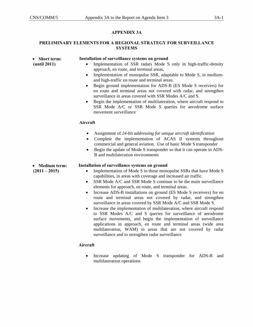
CNS/COMM/5 Appendix 3A to the Report on Agenda Item 3 3A-1
APPENDIX 3A
PRELIMINARY ELEMENTS FOR A REGIONAL STRATEGY FOR SURVEILLANCE SYSTEMS
• Short term: (until 2011)
Installation of surveillance systems on ground • Implementation of SSR radars Mode S only in high-traffic-density
approach, en route, and terminal areas, • Implementation of monopulse SSR, adaptable to Mode S, in medium-
and high-traffic en route and terminal areas. • Begin ground implementation for ADS-B (ES Mode S receivers) for
en route and terminal areas not covered with radar, and strengthen surveillance in areas covered with SSR Modes A/C and S.
• Begin the implementation of multilateration, where aircraft respond to SSR Mode A/C or SSR Mode S queries for aerodrome surface movement surveillance
Aircraft
• Assignment of 24-bit addressing for unique aircraft identification • Complete the implementation of ACAS II systems throughout
commercial and general aviation. Use of basic Mode S transponder • Begin the update of Mode S transponder so that it can operate in ADS-
B and multilateration environments
• Medium term: (2011 – 2015)
Installation of surveillance systems on ground • Implementation of Mode S in those monopulse SSRs that have Mode S
capabilities, in areas with coverage and increased air traffic. • SSR Mode A/C and SSR Mode S continue to be the main surveillance
elements for approach, en route, and terminal areas. • Increase ADS-B installations on ground (ES Mode S receivers) for en
route and terminal areas not covered by radar, and strengthen surveillance in areas covered by SSR Mode A/C and SSR Mode S.
• Increase the implementation of multilateration, where aircraft respond to SSR Modes A/C and S queries for surveillance of aerodrome surface movements, and begin the implementation of surveillance applications in approach, en route and terminal areas (wide area multilateration, WAM) in areas that are not covered by radar surveillance and to strengthen radar surveillance
Aircraft
• Increase updating of Mode S transponder for ADS-B and multilateration operations
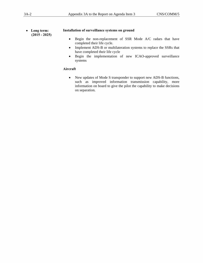
3A-2 Appendix 3A to the Report on Agenda Item 3 CNS/COMM/5
• Long term: (2015 - 2025)
Installation of surveillance systems on ground
• Begin the non-replacement of SSR Mode A/C radars that have completed their life cycle.
• Implement ADS-B or multilateration systems to replace the SSRs that have completed their life cycle
• Begin the implementation of new ICAO-approved surveillance systems
Aircraft
• New updates of Mode S transponder to support new ADS-B functions, such as improved information transmission capability, more information on board to give the pilot the capability to make decisions on separation.
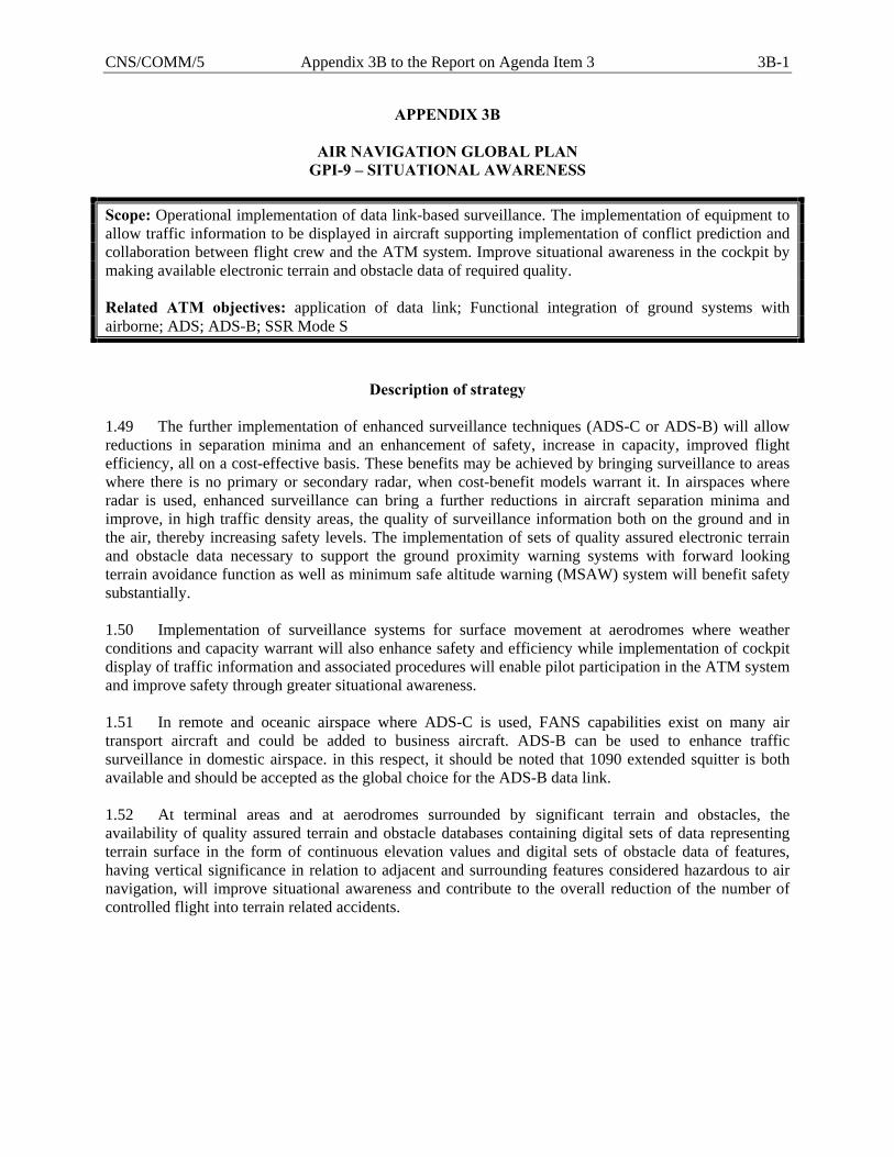
CNS/COMM/5 Appendix 3B to the Report on Agenda Item 3 3B-1
APPENDIX 3B
AIR NAVIGATION GLOBAL PLAN GPI-9 – SITUATIONAL AWARENESS
Scope: Operational implementation of data link-based surveillance. The implementation of equipment to allow traffic information to be displayed in aircraft supporting implementation of conflict prediction and collaboration between flight crew and the ATM system. Improve situational awareness in the cockpit by making available electronic terrain and obstacle data of required quality. Related ATM objectives: application of data link; Functional integration of ground systems with airborne; ADS; ADS-B; SSR Mode S
Description of strategy 1.49 The further implementation of enhanced surveillance techniques (ADS-C or ADS-B) will allow reductions in separation minima and an enhancement of safety, increase in capacity, improved flight efficiency, all on a cost-effective basis. These benefits may be achieved by bringing surveillance to areas where there is no primary or secondary radar, when cost-benefit models warrant it. In airspaces where radar is used, enhanced surveillance can bring a further reductions in aircraft separation minima and improve, in high traffic density areas, the quality of surveillance information both on the ground and in the air, thereby increasing safety levels. The implementation of sets of quality assured electronic terrain and obstacle data necessary to support the ground proximity warning systems with forward looking terrain avoidance function as well as minimum safe altitude warning (MSAW) system will benefit safety substantially. 1.50 Implementation of surveillance systems for surface movement at aerodromes where weather conditions and capacity warrant will also enhance safety and efficiency while implementation of cockpit display of traffic information and associated procedures will enable pilot participation in the ATM system and improve safety through greater situational awareness. 1.51 In remote and oceanic airspace where ADS-C is used, FANS capabilities exist on many air transport aircraft and could be added to business aircraft. ADS-B can be used to enhance traffic surveillance in domestic airspace. in this respect, it should be noted that 1090 extended squitter is both available and should be accepted as the global choice for the ADS-B data link. 1.52 At terminal areas and at aerodromes surrounded by significant terrain and obstacles, the availability of quality assured terrain and obstacle databases containing digital sets of data representing terrain surface in the form of continuous elevation values and digital sets of obstacle data of features, having vertical significance in relation to adjacent and surrounding features considered hazardous to air navigation, will improve situational awareness and contribute to the overall reduction of the number of controlled flight into terrain related accidents.
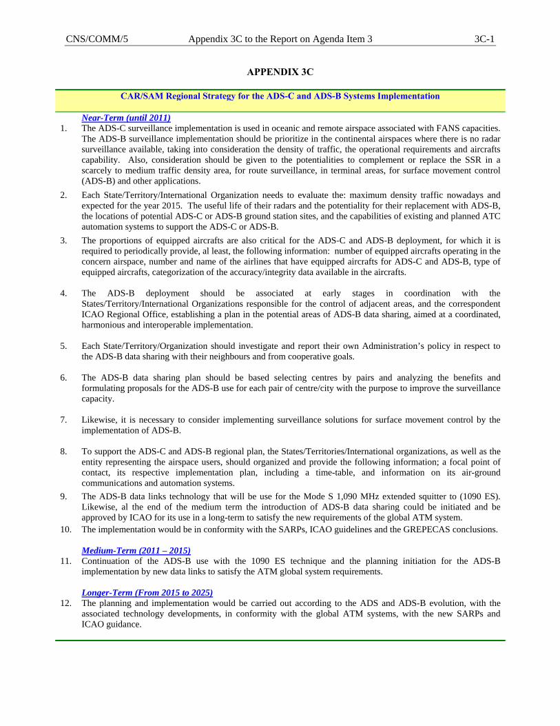
CNS/COMM/5 Appendix 3C to the Report on Agenda Item 3 3C-1
APPENDIX 3C
CAR/SAM Regional Strategy for the ADS-C and ADS-B Systems Implementation Near-Term (until 2011) 1. The ADS-C surveillance implementation is used in oceanic and remote airspace associated with FANS capacities.
The ADS-B surveillance implementation should be prioritize in the continental airspaces where there is no radar surveillance available, taking into consideration the density of traffic, the operational requirements and aircrafts capability. Also, consideration should be given to the potentialities to complement or replace the SSR in a scarcely to medium traffic density area, for route surveillance, in terminal areas, for surface movement control (ADS-B) and other applications.
2. Each State/Territory/International Organization needs to evaluate the: maximum density traffic nowadays and expected for the year 2015. The useful life of their radars and the potentiality for their replacement with ADS-B, the locations of potential ADS-C or ADS-B ground station sites, and the capabilities of existing and planned ATC automation systems to support the ADS-C or ADS-B.
3. The proportions of equipped aircrafts are also critical for the ADS-C and ADS-B deployment, for which it is required to periodically provide, al least, the following information: number of equipped aircrafts operating in the concern airspace, number and name of the airlines that have equipped aircrafts for ADS-C and ADS-B, type of equipped aircrafts, categorization of the accuracy/integrity data available in the aircrafts.
4. The ADS-B deployment should be associated at early stages in coordination with the States/Territory/International Organizations responsible for the control of adjacent areas, and the correspondent ICAO Regional Office, establishing a plan in the potential areas of ADS-B data sharing, aimed at a coordinated, harmonious and interoperable implementation.
5. Each State/Territory/Organization should investigate and report their own Administration’s policy in respect to the ADS-B data sharing with their neighbours and from cooperative goals.
6. The ADS-B data sharing plan should be based selecting centres by pairs and analyzing the benefits and formulating proposals for the ADS-B use for each pair of centre/city with the purpose to improve the surveillance capacity.
7. Likewise, it is necessary to consider implementing surveillance solutions for surface movement control by the implementation of ADS-B.
8. To support the ADS-C and ADS-B regional plan, the States/Territories/International organizations, as well as the entity representing the airspace users, should organized and provide the following information; a focal point of contact, its respective implementation plan, including a time-table, and information on its air-ground communications and automation systems.
9. The ADS-B data links technology that will be use for the Mode S 1,090 MHz extended squitter to (1090 ES). Likewise, al the end of the medium term the introduction of ADS-B data sharing could be initiated and be approved by ICAO for its use in a long-term to satisfy the new requirements of the global ATM system.
10. The implementation would be in conformity with the SARPs, ICAO guidelines and the GREPECAS conclusions.
Medium-Term (2011 – 2015) 11. Continuation of the ADS-B use with the 1090 ES technique and the planning initiation for the ADS-B
implementation by new data links to satisfy the ATM global system requirements.
Longer-Term (From 2015 to 2025) 12. The planning and implementation would be carried out according to the ADS and ADS-B evolution, with the
associated technology developments, in conformity with the global ATM systems, with the new SARPs and ICAO guidance.
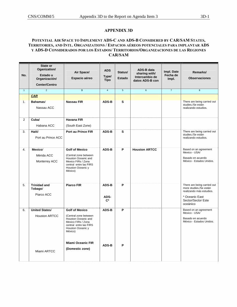
CNS/COMM/5 Appendix 3D to the Report on Agenda Item 3 3D-1
APPENDIX 3D
POTENTIAL AIR SPACE TO IMPLEMENT ADS-C AND ADS-B CONSIDERED BY CAR/SAM STATES, TERRITORIES, AND INTL. ORGANIZATIONS / ESPACIOS AÉREOS POTENCIALES PARA IMPLANTAR ADS
Y ADS-D CONSIDERADOS POR LOS ESTADOS/ TERRITORIOS/ORGANIZACIONES DE LAS REGIONES CAR/SAM
No.
State or Oganization/
Estado u Organización/
Center/Centro
Air Space/
Espacio aéreo
ADS
Type/ Tipo
Status/
Estado
ADS-B data sharing with/
Intercambio de datos ADS-B con
Impl. Date Fecha de
Impl.
Remarks/
Observaciones
1 2 3 4 5 6 7 8
CAR
1. Bahamas/
Nassau ACC
Nassau FIR ADS-B S There are being carried out studies./Se están realizando estudios.
2 Cuba/
Habana ACC
Havana FIR
(South East Zone)
3. Haiti/
Port au Prince ACC
Port au Prince FIR
ADS-B S There are being carried out studies./Se están realizando estudios.
4. Mexico/
Mérida ACC
Monterrey ACC
Golf of Mexico
(Central zone between Houston Oceanic and Mexico FIRs / Zona central entre las FIRS Houston Oceanic y México)
ADS-B P Houston ARTCC
Based on an agreement Mexico - USA/
Basado en acuerdo México - Estados Unidos.
5. Trinidad and Tobago/
Piarco ACC
Piarco FIR
ADS-B
ADS-C*
P There are being carried out more studies./Se están realizando más estudios.
* Oceanic East Sector/Sector Este oceánico
6. United States/
Houston ARTCC
Miami ARTCC
Golf of Mexico
(Central zone between Houston Oceanic and Mexico FIRs / Zona central entre las FIRS Houston Oceanic y México)
Miami Oceanic FIR
(Domestic zone)
ADS-B
ADS-B
P
P
Based on an agreement Mexico - USA/
Basado en acuerdo México - Estados Unidos.
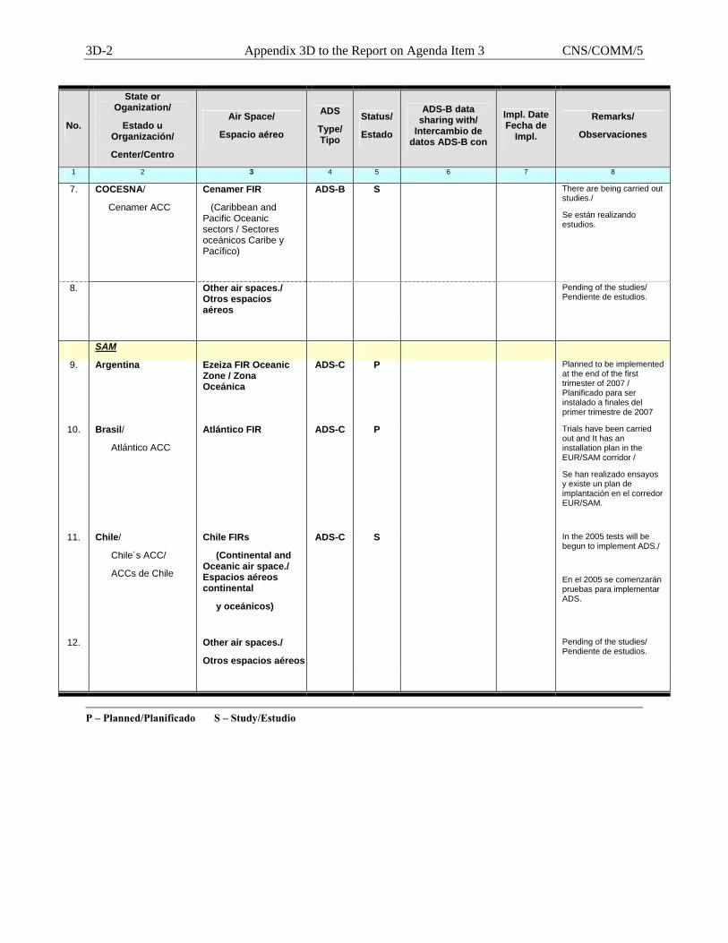
3D-2 Appendix 3D to the Report on Agenda Item 3 CNS/COMM/5
No.
State or Oganization/
Estado u Organización/
Center/Centro
Air Space/
Espacio aéreo
ADS
Type/ Tipo
Status/
Estado
ADS-B data sharing with/
Intercambio de datos ADS-B con
Impl. Date Fecha de
Impl.
Remarks/
Observaciones
1 2 3 4 5 6 7 8
7. COCESNA/
Cenamer ACC
Cenamer FIR
(Caribbean and Pacific Oceanic sectors / Sectores oceánicos Caribe y Pacífico)
ADS-B S There are being carried out studies./
Se están realizando estudios.
8. Other air spaces./ Otros espacios aéreos
Pending of the studies/ Pendiente de estudios.
SAM
9. Argentina Ezeiza FIR Oceanic Zone / Zona Oceánica
ADS-C P Planned to be implemented at the end of the first trimester of 2007 / Planificado para ser instalado a finales del primer trimestre de 2007
10. Brasil/
Atlántico ACC
Atlántico FIR
ADS-C P Trials have been carried out and It has an installation plan in the EUR/SAM corridor /
Se han realizado ensayos y existe un plan de implantación en el corredor EUR/SAM.
11. Chile/
Chile´s ACC/
ACCs de Chile
Chile FIRs
(Continental and Oceanic air space./ Espacios aéreos continental
y oceánicos)
ADS-C S In the 2005 tests will be begun to implement ADS./
En el 2005 se comenzarán pruebas para implementar ADS.
12. Other air spaces./
Otros espacios aéreos
Pending of the studies/ Pendiente de estudios.
P – Planned/Planificado S – Study/Estudio
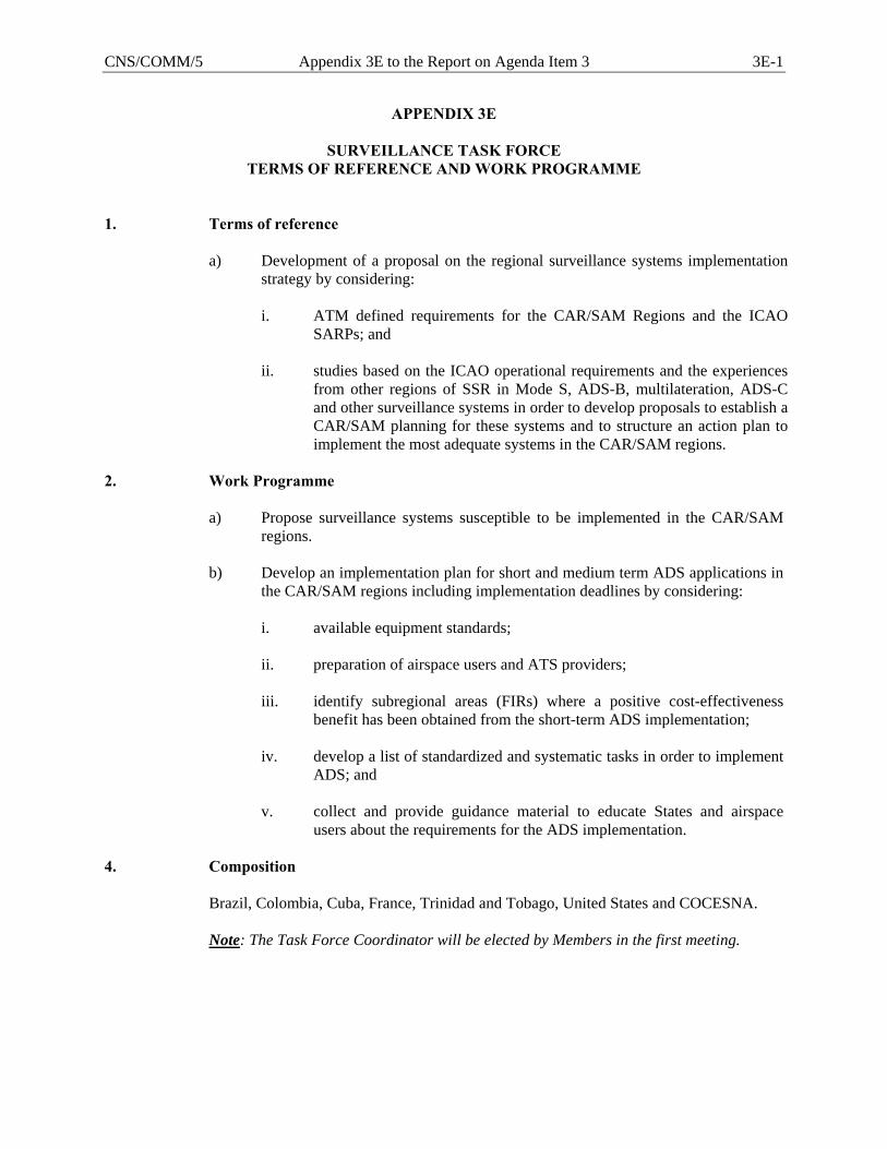
CNS/COMM/5 Appendix 3E to the Report on Agenda Item 3 3E-1
APPENDIX 3E
SURVEILLANCE TASK FORCE TERMS OF REFERENCE AND WORK PROGRAMME
1. Terms of reference
a) Development of a proposal on the regional surveillance systems implementation strategy by considering: i. ATM defined requirements for the CAR/SAM Regions and the ICAO
SARPs; and ii. studies based on the ICAO operational requirements and the experiences
from other regions of SSR in Mode S, ADS-B, multilateration, ADS-C and other surveillance systems in order to develop proposals to establish a CAR/SAM planning for these systems and to structure an action plan to implement the most adequate systems in the CAR/SAM regions.
2. Work Programme
a) Propose surveillance systems susceptible to be implemented in the CAR/SAM regions.
b) Develop an implementation plan for short and medium term ADS applications in
the CAR/SAM regions including implementation deadlines by considering:
i. available equipment standards; ii. preparation of airspace users and ATS providers; iii. identify subregional areas (FIRs) where a positive cost-effectiveness
benefit has been obtained from the short-term ADS implementation; iv. develop a list of standardized and systematic tasks in order to implement
ADS; and v. collect and provide guidance material to educate States and airspace
users about the requirements for the ADS implementation.
4. Composition Brazil, Colombia, Cuba, France, Trinidad and Tobago, United States and COCESNA.
Note: The Task Force Coordinator will be elected by Members in the first meeting.

CNS/COMM/5 Appendix 3F to the Report on Agenda Item 3 3F-1
APPENDIX/APENDICE 3F
Table CNS 4A - SURVEILLANCE SYSTEMS (Updated) Tabla CNS 4A - SISTEMAS DE VIGILANCIA (Actualizada)
State(Territory)/Location ATS Unite Served PSR SSR ADS Remarks
Estado(Territorio)/Ubicación Unidad ATS Servida Funtion Coverage Status Funtion Modes Coverage Status Type Status Observaciones
Función Cobertura Impl. Función Modos Cobertura Impl. Tipo Impl.
(NM) Estado (A,C& S) (NM) Estado Estado1 3 4 5 6 7 8 9 10 11 12 13
ANGUILA (UK)NP
ANTIGUA & BARBUDA
Airport (4 NM North) V.C. Bird APP T A/C 180 I* * MSSR
ARGENTINA
Aeroparque Jorge Newbery Ezeiza ACC T 60 P E A/C 220 P* * MSSR Aeroparque APP
Bahía Blanca, Airport Ezeiza ACC T 60 P E A/C 220 P* * MSSR
Bahía Blanca APP
Bolívar, Airport Ezeiza ACC E A/C/S 220 P* * MSSR
Colonia Catriel, Airport Ezeiza ACC E A/C 220 P* * MSSR
Córdoba, Airport Córdoba ACC T 60 I E/T A/C 180 I/P* C y B P * MSSR
Ezeiza ACC
Córdoba APP
Ezeiza, Airport Ezeiza ACC T 90 I E A/C 220 I* C y B P * MSSR
Buenos Aires APP
Jujuy, Airport Córdoba ACC E A/C/S 220 p* * MSSR
La Rioja, Airport Córdoba ACC E A/C 220 p* * MSSR
Las Lomitas, Airport Ezeiza ACC E A/C 220 p* * MSSR
Córdoba ACC
Mar de Plata, Airport Ezeiza ACC T 60 I E A/C 220 I* * MSSR
Mar del Plata APP Monte Quemado , Santiago del Estero Ezeiza ACC E A/C/S 220 P* * MSSR
Cordoba ACC
Mendoza, Airport Cordoba ACC T 60 I E A/C 180 I* * MSSR
Mendoza APP
Merlo (Buenos Aires) Ezeiza ACC T 220 P E A/C/S 220 P* * MSSR
Paraná, Airport Ezeiza ACC E A/C 220 I* * MSSR
Córdoba ACC
Posadas Airport Ezeiza ACC E A/C 220 P* * MSSR
Reconquista Airport Ezeiza ACC E A/C 220 P* * MSSR
Córdoba ACC
Resistencia, Airport Ezeiza ACC T 60 P E A/C 220 P* * MSSR
Córdoba APP
Resistencia APP
Neuquen Airport Ezeiza ACC E A/C/S 220 P* * MSSR
Neuquen TMA APP
Las Lomitas Airport Ezeiza ACC E 220 P E A/C/S 220 P* * MSSR
Cordoba ACC
La Boulaye Airport Ezeiza ACC E A/C/S 220 P* * MSSR
Cordoba ACC
San Carlos de Bariloche, Ezeiza ACC T 60 P E/T A/C 220 P* * MSSR
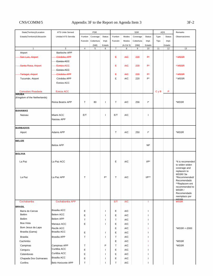
CNS/COMM/5 Appendix 3F to the Report on Agenda Item 3 3F-2
State(Territory)/Location ATS Unite Served PSR SSR ADS Remarks
Estado(Territorio)/Ubicación Unidad ATS Servida Funtion Coverage Status Funtion Modes Coverage Status Type Status Observaciones
Función Cobertura Impl. Función Modos Cobertura Impl. Tipo Impl.
(NM) Estado (A,C& S) (NM) Estado Estado1 3 4 5 6 7 8 9 10 11 12 13
Airport Bariloche APP
San Luis, Airport Córdoba APP E A/C 220 P* * MSSR
Ezeiza ACC
Santa Rosa, Airport Ezeiza ACC E A/C 220 P* * MSSR
Ezeiza ACC
Tartagal, Airport Córdoba APP E A/C 220 P* * MSSR
Tucumán, Airport Córdoba APP E A/C 220 P* * MSSR
Ezeiza ACC
Comodoro Rivadavia Ezeiza ACC C y B PARUBA (Kingdom of the Netherlands)
Reina Beatrix APP T 80 I T A/C 256 I* *MSSR
BAHAMAS
Nassau Miami ACC E/T I E/T A/C I
Nassau APP
BARBADOS
Aiport Adams APP T A/C 250 I* *MSSR
BELIZE
Belize APP NP
BOLIVIA
La Paz La Paz ACC E A/C I/P* *It is recomended to widen widen coverage and replacem to MSSR/ Se
La Paz La Paz APP T P* T A/C I/P** *Recommended/Recomendado **Replacem ent recommended to MSSR / Recomendado reemplazo por MSSR
Cochabamba Cochabamba APP E/T A/C I MSSR
BRASIL
Barra do Carcas Brasilia ACC E I E A/C I Belém Belem ACC E I E A/C I Belém Belem APP T I T A/C I Boa Vista Manaus ACC E I E A/C I Bom Jesus da Lapa Recife ACC E A/C I *MSSR <-2000 Brasilia (Gama) Brasilia ACC E I E A/C I
Brasilia Brasilia APP T I T A/C I
Cachimbo E A/C I *MSSR
Campinas Campinas APP T P T A/C I *MSSR
Cangucu Curitiba ACC E I E A/C I
Catanduvas Curitiba ACC E I E A/C I
Chapada Dos Guimaraes Brasilia ACC E I E A/C I
Confins Belo Horizonte APP T I T A/C I
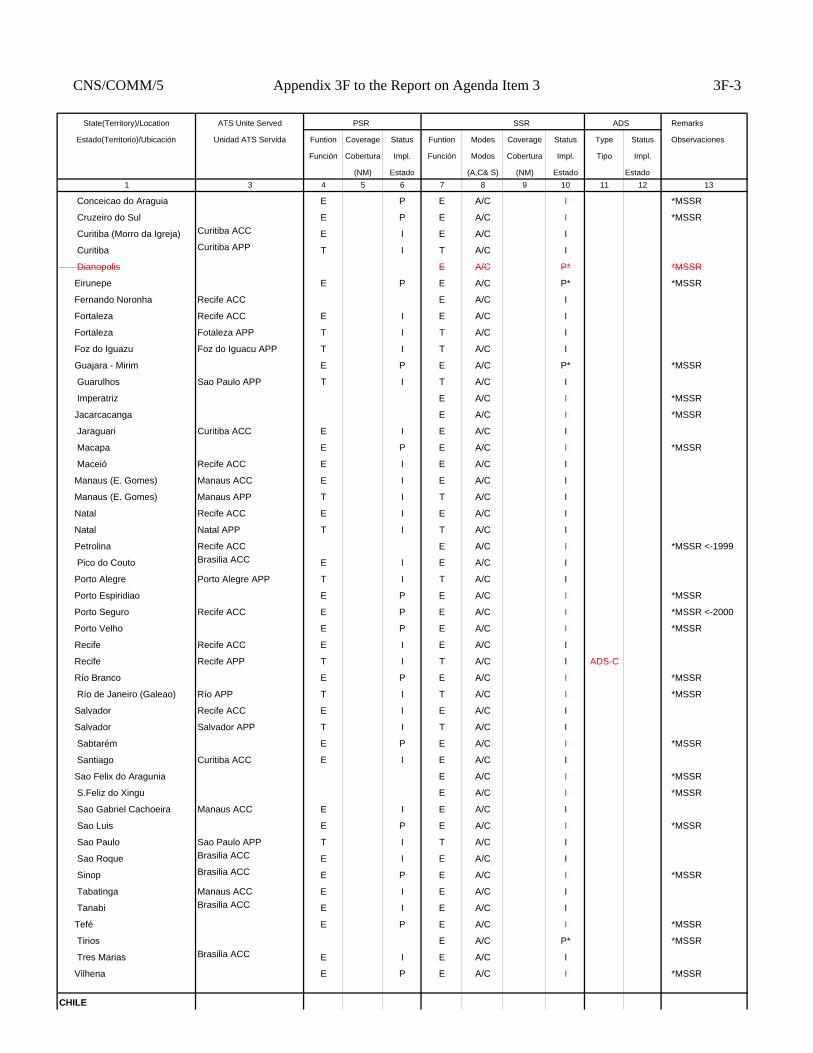
CNS/COMM/5 Appendix 3F to the Report on Agenda Item 3 3F-3
State(Territory)/Location ATS Unite Served PSR SSR ADS Remarks
Estado(Territorio)/Ubicación Unidad ATS Servida Funtion Coverage Status Funtion Modes Coverage Status Type Status Observaciones
Función Cobertura Impl. Función Modos Cobertura Impl. Tipo Impl.
(NM) Estado (A,C& S) (NM) Estado Estado1 3 4 5 6 7 8 9 10 11 12 13
Conceicao do Araguia E P E A/C I *MSSR
Cruzeiro do Sul E P E A/C I *MSSR
Curitiba (Morro da Igreja) Curitiba ACC E I E A/C I
Curitiba Curitiba APP T I T A/C I
Dianopolis E A/C P* *MSSR
Eirunepe E P E A/C P* *MSSR
Fernando Noronha Recife ACC E A/C I
Fortaleza Recife ACC E I E A/C I
Fortaleza Fotaleza APP T I T A/C I
Foz do Iguazu Foz do Iguacu APP T I T A/C I
Guajara - Mirim E P E A/C P* *MSSR
Guarulhos Sao Paulo APP T I T A/C I
Imperatriz E A/C I *MSSR
Jacarcacanga E A/C I *MSSR
Jaraguari Curitiba ACC E I E A/C I
Macapa E P E A/C I *MSSR
Maceió Recife ACC E I E A/C I
Manaus (E. Gomes) Manaus ACC E I E A/C I
Manaus (E. Gomes) Manaus APP T I T A/C I
Natal Recife ACC E I E A/C I
Natal Natal APP T I T A/C I
Petrolina Recife ACC E A/C I *MSSR <-1999
Pico do Couto Brasilia ACC E I E A/C I
Porto Alegre Porto Alegre APP T I T A/C I
Porto Espiridiao E P E A/C I *MSSR
Porto Seguro Recife ACC E P E A/C I *MSSR <-2000
Porto Velho E P E A/C I *MSSR
Recife Recife ACC E I E A/C I
Recife Recife APP T I T A/C I ADS-C
Río Branco E P E A/C I *MSSR
Río de Janeiro (Galeao) Río APP T I T A/C I *MSSR
Salvador Recife ACC E I E A/C I
Salvador Salvador APP T I T A/C I
Sabtarém E P E A/C I *MSSR
Santiago Curitiba ACC E I E A/C I
Sao Felix do Aragunia E A/C I *MSSR
S.Feliz do Xingu E A/C I *MSSR
Sao Gabriel Cachoeira Manaus ACC E I E A/C I
Sao Luis E P E A/C I *MSSR
Sao Paulo Sao Paulo APP T I T A/C I
Sao Roque Brasilia ACC E I E A/C I
Sinop Brasilia ACC E P E A/C I *MSSR
Tabatinga Manaus ACC E I E A/C I
Tanabi Brasilia ACC E I E A/C I
Tefé E P E A/C I *MSSR
Tirios E A/C P* *MSSR
Tres Marias Brasilia ACC E I E A/C I
Vilhena E P E A/C I *MSSR
CHILE
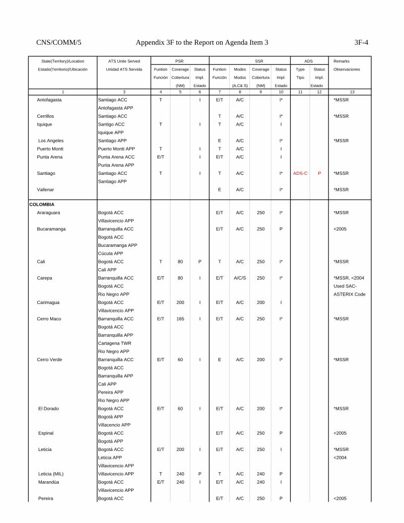
CNS/COMM/5 Appendix 3F to the Report on Agenda Item 3 3F-4
State(Territory)/Location ATS Unite Served PSR SSR ADS Remarks
Estado(Territorio)/Ubicación Unidad ATS Servida Funtion Coverage Status Funtion Modes Coverage Status Type Status Observaciones
Función Cobertura Impl. Función Modos Cobertura Impl. Tipo Impl.
(NM) Estado (A,C& S) (NM) Estado Estado1 3 4 5 6 7 8 9 10 11 12 13
Antofagasta Santiago ACC T I E/T A/C I* *MSSR
Antofagasta APP
Cerrillos Santiago ACC T A/C I* *MSSR
Iquique Santigo ACC T I T A/C I
Iquique APP
Los Angeles Santiago APP E A/C I* *MSSR
Puerto Montt Puerto Montt APP T I T A/C I
Punta Arena Punta Arena ACC E/T I E/T A/C I
Punta Arena APP
Santiago Santiago ACC T I T A/C I* ADS-C P *MSSR
Santiago APP
Vallenar E A/C I* *MSSR
COLOMBIA
Araraguara Bogotá ACC E/T A/C 250 I* *MSSR
Villavicencio APP
Bucaramanga Barranquilla ACC E/T A/C 250 P <2005
Bogotá ACC
Bucaramanga APP
Cúcuta APP
Cali Bogotá ACC T 80 P T A/C 250 I* *MSSR
Cali APP
Carepa Barranquilla ACC E/T 80 I E/T A/C/S 250 I* *MSSR, <2004
Bogotá ACC Used SAC-
Rio Negro APP ASTERIX Code
Carimagua Bogotá ACC E/T 200 I E/T A/C 200 I
Villavicencio APP
Cerro Maco Barranquilla ACC E/T 165 I E/T A/C 250 I* *MSSR
Bogotá ACC
Barranquilla APP
Cartagena TWR
Rio Negro APP
Cerro Verde Barranquilla ACC E/T 60 I E A/C 200 I* *MSSR
Bogotá ACC
Barranquilla APP
Cali APP
Pereira APP
Rio Negro APP
El Dorado Bogotá ACC E/T 60 I E/T A/C 200 I* *MSSR
Bogotá APP
Villacencio APP
Espinal Bogotá ACC E/T A/C 250 P <2005
Bogotá APP
Leticia Bogotá ACC E/T 200 I E/T A/C 250 I *MSSR
Leticia APP <2004
Villavicencio APP
Leticia (MIL) Villavicencio APP T 240 P T A/C 240 P
Marandúa Bogotá ACC E/T 240 I E/T A/C 240 I
Villavicencio APP
Pereira Bogotá ACC E/T A/C 250 P <2005
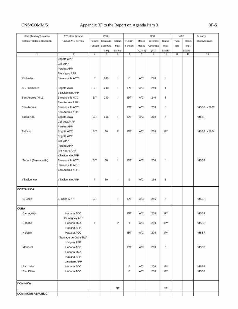
CNS/COMM/5 Appendix 3F to the Report on Agenda Item 3 3F-5
State(Territory)/Location ATS Unite Served PSR SSR ADS Remarks
Estado(Territorio)/Ubicación Unidad ATS Servida Funtion Coverage Status Funtion Modes Coverage Status Type Status Observaciones
Función Cobertura Impl. Función Modos Cobertura Impl. Tipo Impl.
(NM) Estado (A,C& S) (NM) Estado Estado1 3 4 5 6 7 8 9 10 11 12 13
Bogotá APP
Cali APP
Pereira APP
Rio Negro APP
Ríohacha Barranquilla ACC E 240 I E A/C 240 I
S. J. Guaviare Bogotá ACC E/T 240 I E/T A/C 240 I
Villavicencio APP
San Andrés (MIL) Barranquilla ACC E/T 240 I E/T A/C 240 I
San Andrés APP
San Andrés Barranquilla ACC E/T A/C 250 I* *MSSR, <2007
San Andrés APP
Santa Ana Bogotá ACC E/T 165 I E/T A/C 250 I* *MSSR
Cali ACC/APP
Pereira APP
Tablazo Bogotá ACC E/T 80 P E/T A/C 250 I/P* *MSSR, <2004
Bogotá APP
Cali APP
Pereira APP
Rio Negro APP
Villavicencio APP
Tubará (Barranquilla) Barranquilla ACC E/T 80 I E/T A/C 250 I* *MSSR
Barranquilla APP
San Andrés APP
Villavicencio Villavicencio APP T 80 I E A/C 150 I
COSTA RICA
El Coco El Coco APP E/T I E/T A/C 245 I* *MSSR
CUBA
Camagüey Habana ACC E/T A/C 200 I/P* *MSSR
Camagüey APP
Habana Habana TMA T P T A/C 200 I/P* *MSSR
Habana APP
Holguín Habana ACC E/T A/C 200 I/P* *MSSR
Santiago de Cuba TMA
Holguín APP
Menocal Habana ACC E/T A/C 200 I* *MSSR
Habana TMA
Habana APP
Varadero APP
San Julián Habana ACC E A/C 200 I/P* *MSSR
Sta. Clara Habana ACC E A/C 200 I/P* *MSSR
DOMINICA
NP NP
DOMINICAN REPUBLIC

CNS/COMM/5 Appendix 3F to the Report on Agenda Item 3 3F-6
State(Territory)/Location ATS Unite Served PSR SSR ADS Remarks
Estado(Territorio)/Ubicación Unidad ATS Servida Funtion Coverage Status Funtion Modes Coverage Status Type Status Observaciones
Función Cobertura Impl. Función Modos Cobertura Impl. Tipo Impl.
(NM) Estado (A,C& S) (NM) Estado Estado1 3 4 5 6 7 8 9 10 11 12 13
Barahona Barahona APP T 70 I
Puerto Plata Puerto Plata APP T 70 I
Punta Cana Santo Domingo ACC T 70 P E/T A/C 250 P* *MSSR
Punta Cana APP
Santo Domingo Santo Domingo ACC E/T 70 I E/T A/C 250 I* *MSSR
Santo Domingo APP
ECUADOR
Guayaquil Guayaquil ACC E/T E A/C 200 I*
Guayaquil APP
Quito APP Quito APP T I T A/C I/P* * 2000
EL SALVADOR
El Salvador El Salvador APP T I T A/C 200 I* *MSSR
FRENCH ANTILLES
Fort-de-France Fort-de-France APP T A/C 250 I* *MSSR
Point-à-Pitre Point-à-Pitre APP T A/C 250 I* *MSSR
GRENADA
Point Salines APP N/P
GUATEMALA
C. Guatemala La Aurora APP T I T A/C 250 I* *MSSR
GUYANA
Georgetown ACC N/P
HAITI
Port-au-Prince ACC E/T A/C P* *MSSR
Port-au-Prince APP T A/C P* *MSSR
HONDURAS
San Pedro Sula La Mesa APP T I T A/C 250 I* *MSSR
JAMAICA
Kingston Kingston APP T 60 I E/T A/C 250 I* *MSSR
Montego Bay Montego Bay APP T 60 I T A/C 250 I* *MSSR
Mount Denham Kingston ACC E 120 I E A/C 250 I* *MSSR
MEXICO
Acapulco Acapulco APP T I T A/C 240 I* *MSSR
Bajio Gto México ACC E/T A/C, S 240 I* *MSSR
Bajio APP
Cancún Mérida ACC E/T 60 I E/T A/C 240 I* *MSSR
Cancún APP
Cerro Potosi Monterrey ACC E A/C 240 I* *MSSR
México ACC
Cerro Rusias Mazatlán ACC E A/C 240 I* *MSSR
México ACC
Monterrey ACC

CNS/COMM/5 Appendix 3F to the Report on Agenda Item 3 3F-7
State(Territory)/Location ATS Unite Served PSR SSR ADS Remarks
Estado(Territorio)/Ubicación Unidad ATS Servida Funtion Coverage Status Funtion Modes Coverage Status Type Status Observaciones
Función Cobertura Impl. Función Modos Cobertura Impl. Tipo Impl.
(NM) Estado (A,C& S) (NM) Estado Estado1 3 4 5 6 7 8 9 10 11 12 13
Cerro Los Gallos Mazatlán ACC E A/C 240 I* *MSSR
México ACC
Monterrey ACC
Cerro Santa Eulalia Monterrey ACC E/T A/C 240 I* *MSSR
Chihuaha APP
Guadalajara Guadalajara APP T 80 I T A/C 240 I* *MSSR
Hermosillo Mazatlán ACC E/T A/C 240 I* *MSSR
Hermosillo APP
Tijuana APP
Los Mochis Mazatlán ACC E A/C 240 I* *MSSR
Mazatlán Mazatlán ACC E A/C 240 I* *MSSR
Mérida Mérida ACC E/T I E/T A/C 240 I* *MSSR
Mérida APP
Cerro Sordo México ACC E A/C 240 I* *MSSR
Monterrey ACC
Monterrey Monterrey ACC E/T 80 I E/T A/C 240 I* *MSSR
Monterrey APP
Peñón México APP E A/C 240 I* *MSSR
Puerto Peñasco Mazatlán ACC E A/C 240 I* *MSSR
Puerto Vallarta Puerto Vallarta APP T A/C 240 I* *MSSR
San José del Cabo Mazatlán ACC E A/C, S 240 I* *MSSR
Tampico México ACC E A/C, S 240 I* *MSSR
Mérida ACC
Monterrey ACC
Tijuana Tijuana APP T A/C 240 I* *MSSR
Toluca México ACC E/T 80 I E/T A/C 240 I* *MSSR
Toluca APP
Veracruz México ACC E A/C 240 I* *MSSR
Mérida ACC
Villahermosa México ACC E A/C, S 240 I* *MSSR
Mérida ACC
MONTSERRAT (United
Kingdom) N/P
NETHERLANDS ANTILLES (Netherlands)
Willemstad Curaçao ACC E/T 120 I E/T A/C 256 I* *MSSR
Curaçao APP
Saint Maarten Juliana APP T 60 I T A/C 256 I* *MSSR
NICARAGUA
Managua Managua APP T P T A/C 250 P* *MSSR
Bluefields Bluefields TWR T A/C 250 N/I
PANAMA
Panamá Panamá ACC T 60 I E/T A/C I* *MSSR
Panamá APP
PARAGUAY
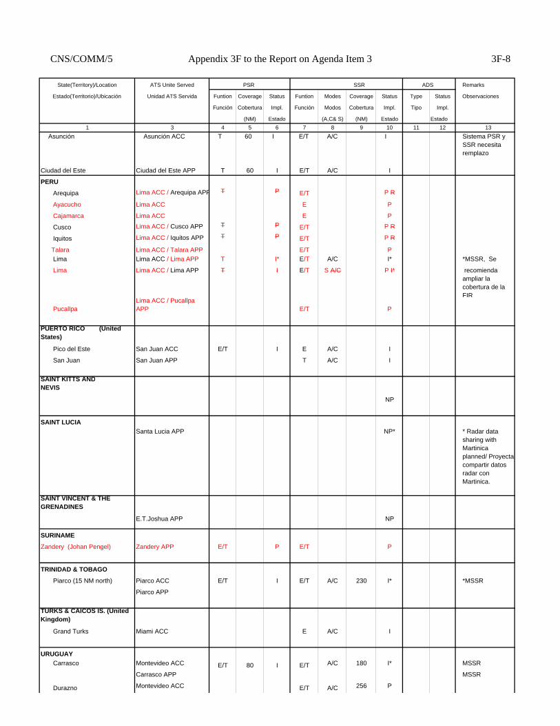
CNS/COMM/5 Appendix 3F to the Report on Agenda Item 3 3F-8
State(Territory)/Location ATS Unite Served PSR SSR ADS Remarks
Estado(Territorio)/Ubicación Unidad ATS Servida Funtion Coverage Status Funtion Modes Coverage Status Type Status Observaciones
Función Cobertura Impl. Función Modos Cobertura Impl. Tipo Impl.
(NM) Estado (A,C& S) (NM) Estado Estado1 3 4 5 6 7 8 9 10 11 12 13
Asunción Asunción ACC T 60 I E/T A/C I Sistema PSR y SSR necesita remplazo
Ciudad del Este Ciudad del Este APP T 60 I E/T A/C I
PERU
Arequipa Lima ACC / Arequipa APP T P E/T P R
Ayacucho Lima ACC E P
Cajamarca Lima ACC E P
Cusco Lima ACC / Cusco APP T P E/T P R
Iquitos Lima ACC / Iquitos APP T P E/T P R
Talara Lima ACC / Talara APP E/T P Lima Lima ACC / Lima APP T I* E/T A/C I* *MSSR, Se
Lima Lima ACC / Lima APP T I E/T S A/C P I* recomienda ampliar la cobertura de la FIR
PucallpaLima ACC / Pucallpa APP E/T P
PUERTO RICO (United States)
Pico del Este San Juan ACC E/T I E A/C I
San Juan San Juan APP T A/C I
SAINT KITTS ANDNEVIS
NP
SAINT LUCIASanta Lucia APP NP* * Radar data
sharing with Martinica planned/ Proyecta compartir datos radar con Martinica.
SAINT VINCENT & THE GRENADINES
E.T.Joshua APP NP
SURINAME
Zandery (Johan Pengel) Zandery APP E/T P E/T P
TRINIDAD & TOBAGO
Piarco (15 NM north) Piarco ACC E/T I E/T A/C 230 I* *MSSR
Piarco APP
TURKS & CAICOS IS. (United Kingdom)
Grand Turks Miami ACC E A/C I
URUGUAY Carrasco Montevideo ACC E/T 80 I E/T A/C 180 I* MSSR
Carrasco APP MSSR
Durazno Montevideo ACC E/T A/C 256 P
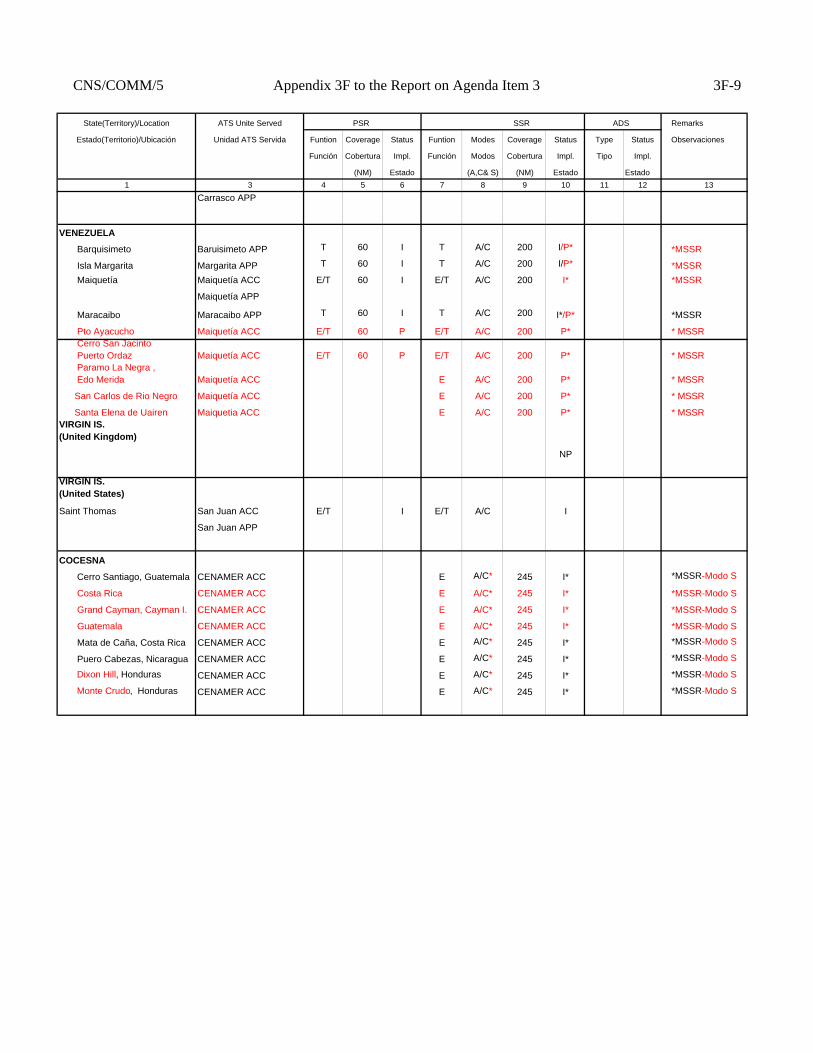
CNS/COMM/5 Appendix 3F to the Report on Agenda Item 3 3F-9
State(Territory)/Location ATS Unite Served PSR SSR ADS Remarks
Estado(Territorio)/Ubicación Unidad ATS Servida Funtion Coverage Status Funtion Modes Coverage Status Type Status Observaciones
Función Cobertura Impl. Función Modos Cobertura Impl. Tipo Impl.
(NM) Estado (A,C& S) (NM) Estado Estado1 3 4 5 6 7 8 9 10 11 12 13
Carrasco APP
VENEZUELA
Barquisimeto Baruisimeto APP T 60 I T A/C 200 I/P* *MSSR
Isla Margarita Margarita APP T 60 I T A/C 200 I/P* *MSSR Maiquetía Maiquetía ACC E/T 60 I E/T A/C 200 I* *MSSR
Maiquetía APP
Maracaibo Maracaibo APP T 60 I T A/C 200 I*/P* *MSSR
Pto Ayacucho Maiquetía ACC E/T 60 P E/T A/C 200 P* * MSSR Cerro San Jacinto Puerto Ordaz Maiquetía ACC E/T 60 P E/T A/C 200 P* * MSSR Paramo La Negra , Edo Merida Maiquetía ACC E A/C 200 P* * MSSR
San Carlos de Rio Negro Maiquetía ACC E A/C 200 P* * MSSR
Santa Elena de Uairen Maiquetia ACC E A/C 200 P* * MSSRVIRGIN IS.(United Kingdom)
NP
VIRGIN IS. (United States)
Saint Thomas San Juan ACC E/T I E/T A/C I
San Juan APP
COCESNA
Cerro Santiago, Guatemala CENAMER ACC E A/C* 245 I* *MSSR-Modo S
Costa Rica CENAMER ACC E A/C* 245 I* *MSSR-Modo S
Grand Cayman, Cayman I. CENAMER ACC E A/C* 245 I* *MSSR-Modo S
Guatemala CENAMER ACC E A/C* 245 I* *MSSR-Modo S
Mata de Caña, Costa Rica CENAMER ACC E A/C* 245 I* *MSSR-Modo S
Puero Cabezas, Nicaragua CENAMER ACC E A/C* 245 I* *MSSR-Modo S
Dixon Hill, Honduras CENAMER ACC E A/C* 245 I* *MSSR-Modo S
Monte Crudo, Honduras CENAMER ACC E A/C* 245 I* *MSSR-Modo S
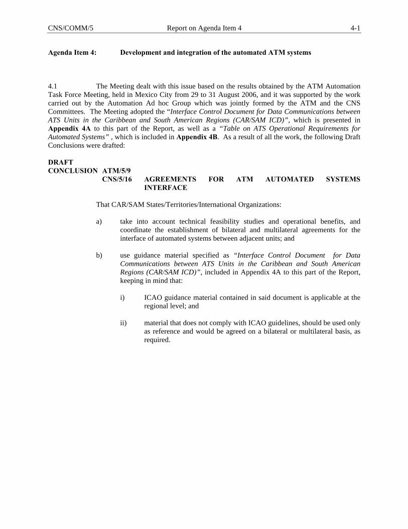
CNS/COMM/5 Report on Agenda Item 4 4-1
Agenda Item 4: Development and integration of the automated ATM systems 4.1 The Meeting dealt with this issue based on the results obtained by the ATM Automation Task Force Meeting, held in Mexico City from 29 to 31 August 2006, and it was supported by the work carried out by the Automation Ad hoc Group which was jointly formed by the ATM and the CNS Committees. The Meeting adopted the “Interface Control Document for Data Communications between ATS Units in the Caribbean and South American Regions (CAR/SAM ICD)”, which is presented in Appendix 4A to this part of the Report, as well as a “Table on ATS Operational Requirements for Automated Systems” , which is included in Appendix 4B. As a result of all the work, the following Draft Conclusions were drafted: DRAFT CONCLUSION ATM/5/9 CNS/5/16 AGREEMENTS FOR ATM AUTOMATED SYSTEMS
INTERFACE That CAR/SAM States/Territories/International Organizations: a) take into account technical feasibility studies and operational benefits, and
coordinate the establishment of bilateral and multilateral agreements for the interface of automated systems between adjacent units; and
b) use guidance material specified as “Interface Control Document for Data
Communications between ATS Units in the Caribbean and South American Regions (CAR/SAM ICD)”, included in Appendix 4A to this part of the Report, keeping in mind that:
i) ICAO guidance material contained in said document is applicable at the
regional level; and ii) material that does not comply with ICAO guidelines, should be used only
as reference and would be agreed on a bilateral or multilateral basis, as required.
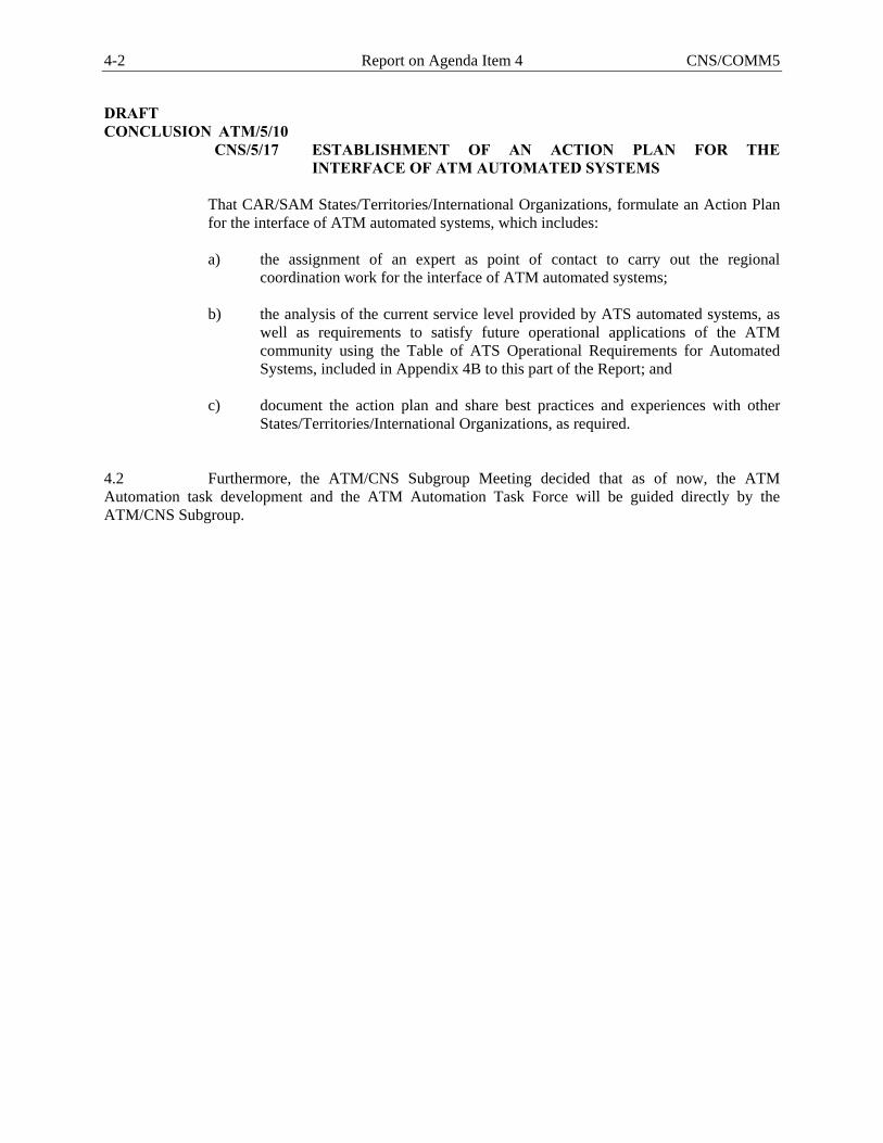
4-2 Report on Agenda Item 4 CNS/COMM5
DRAFT CONCLUSION ATM/5/10 CNS/5/17 ESTABLISHMENT OF AN ACTION PLAN FOR THE
INTERFACE OF ATM AUTOMATED SYSTEMS
That CAR/SAM States/Territories/International Organizations, formulate an Action Plan for the interface of ATM automated systems, which includes: a) the assignment of an expert as point of contact to carry out the regional
coordination work for the interface of ATM automated systems; b) the analysis of the current service level provided by ATS automated systems, as
well as requirements to satisfy future operational applications of the ATM community using the Table of ATS Operational Requirements for Automated Systems, included in Appendix 4B to this part of the Report; and
c) document the action plan and share best practices and experiences with other
States/Territories/International Organizations, as required. 4.2 Furthermore, the ATM/CNS Subgroup Meeting decided that as of now, the ATM Automation task development and the ATM Automation Task Force will be guided directly by the ATM/CNS Subgroup.
INTERNATIONAL CIVIL AVIATION ORGANIZATION
INTERFACE CONTROL DOCUMENT FOR
DATA COMMUNICATIONS BETWEEN ATS UNITS IN THE
CARIBBEAN AND SOUTH AMERICAN REGIONS
(CAR/SAM ICD)
Version Draft 0.2 Date 13 November 2006
CNS/COMM/5 Appendix 4A to the Report on Agenda Item 4 4A-1

(ii)
FOREWORD The Interface Control Document (ICD) for Data Communications between ATS Units in the Caribbean and South American Regions (CAR/SAM ICD) is published by the ATM/CNS Subgroup of the Caribbean/South American Regional Planning and Implementation Group (GREPECAS). It describes a process and protocols for exchanging data between multiple States/Territories/International Organizations within and across regions. Copies of the CAR/SAM ICD can be obtained by contacting:
ICAO NORTH AMERICAN, CARIBBEAN, AND CENTRAL AMERICAN OFFICE MEXICO CITY, MEXICO E-mail : [email protected] Web site : www.icao.int/nacc Fax : +5255 5203-2757 Mail : P. O. Box 5377, México 5 D. F., México Point of contact E-mail : [email protected] [email protected]
ICAO SOUTH AMERICAN OFFICE LIMA, PERU E-mail : [email protected] Web site : www.lima.icao.int Fax : +511 575-0974 / 575-1479 Mail : P. O. Box 4127, Lima 100, Peru Point of contact E-mail : [email protected] [email protected] [email protected]
4A-2 Appendix 4A to the Report on Agenda Item 4 CNS/COMM/5

CAR/SAM ICD - Draft version 0.2
(iii)
AMENDMENTS TO THE DOCUMENT The present edition (Draft Version 0.2) includes all revisions and modifications until November 2006. Subsequent amendments and corrigenda will be indicated in the Record of Amendment and Corrigenda Table. Proposals for amendments to the document may be submitted to either of the ICAO Regional Offices for coordination and processing. The GREPECAS and its contributory bodies will issue revised editions of the Document as required. The publication of amendments and corrigenda is regularly announced through correspondence with States, and the ICAO web site, which holders of this publication should consult. The space below is provided to keep a record of such amendments.
RECORD OF AMENDMENTS AND CORRIGENDA
AMENDMENTS CORRIGENDA
No. Date applicable Date entered Entered by No. Date
applicable Date entered Entered by
CNS/COMM/5 Appendix 4A to the Report on Agenda Item 4 4A-3

4A-4 Appendix 4A to the Report on Agenda Item 4 CNS/COMM/5

CAR/SAM ICD - Draft version 0.2
(v)
Table of Contents
INTRODUCTION................................................................................................................................................. 1 HISTORICAL ..................................................................................................................................................... 1 GLOSSARY........................................................................................................................................................ 2 LIST OF ACRONYMS....................................................................................................................................... 5 REFERENCES.................................................................................................................................................... 7
1. PART I – PURPOSE, POLICY, AND UNITS OF MEASUREMENT .................................................... 8 1.1 PURPOSE ............................................................................................................................................... 8 1.2 POLICY .................................................................................................................................................. 8 1.3 UNITS OF MEASUREMENT AND DATA CONVENTIONS............................................................. 9
2. PART II –ATS COORDINATION MESSAGES ..................................................................................... 12 2.1 INTRODUCTION................................................................................................................................. 12 2.2 MESSAGE FIELDS.............................................................................................................................. 12 2.3 CORE MESSAGE SET ........................................................................................................................ 16
3. PART III – COMMUNICATIONS AND SUPPORT MECHANISMS ................................................. 28 3.1 INTRODUCTION................................................................................................................................. 28 3.2 TELECOMMUNICATIONS REQUIREMENTS AND CONSTRAINTS .......................................... 28 3.3 ENGINEERING CONSIDERATIONS ................................................................................................ 29 3.4 SECURITY CONSIDERATIONS........................................................................................................ 30 3.5 TEST CONSIDERATIONS.................................................................................................................. 30 3.6 PERFORMANCE CONSIDERATIONS.............................................................................................. 31
APPENDIX A – ERROR CODES ................................................................................................................... A-1
APPENDIX B – IMPLEMENTATION GUIDANCE MATERIAL............................................................. B-1 B.1 USE OF THE CORE MESSAGE SET............................................................................................... B-1 B.2 DEVELOPMENT OF FIELD CONTENT......................................................................................... B-5 B.3 SUMMARY OF EXPECTED RESPONSES TO MESSAGES ......................................................... B-7
APPENDIX C – MODEL OF COMMON BOUNDARY AGREEMENT ................................................... C-1 C.1 INTRODUCTION .............................................................................................................................. C-1 C.2 MESSAGE IMPLEMENTATION AND USE ................................................................................... C-1 C.3 PHYSICAL INTERFACE.................................................................................................................. C-3
- - - END - - -
CNS/COMM/5 Appendix 4A to the Report on Agenda Item 4 4A-5

4A-6 Appendix 4A to the Report on Agenda Item 4 CNS/COMM/5
CAR/SAM ICD - Draft version 0.2
1
INTRODUCTION
HISTORICAL Air Traffic Services providers in several regions have identified the requirement to exchange flight plan and radar data information between adjacent ATC facilities utilizing automated methods. This requirement stems from the increasing traffic levels crossing FIR boundaries and the need to improve efficiency and accuracy for the ATC providers. Developing a harmonized process and protocols for exchanging data between multiple States/Territories/International Organizations within and across regions is critical to satisfying this requirement. As ATS providers develop their automation systems, consideration should be given to meeting the capabilities identified within this Interface Control Document (ICD). The CAR/SAM ICD is based on the North American Common Coordination Interface Control Document used by Canada, the United States and Mexico. The NAM region has advanced to the level of initial implementation of flight plan data exchange. Experience gained by the NAM region during their development process is incorporated here. The GREPECAS/12 meeting held in Cuba, 07 – 11 June 2004 concluded that the CAR/SAM States/Territories/International Organizations should define an action plan for the application of a regional strategy for the integration of ATM automated systems. This document provides the basis for interfacing those ATM automation systems in the CAR/SAM regions. The Interface Control Document for Data Communications between ATS Units in the Caribbean and South American Regions (CAR/SAM ICD) content is as follows: Part I- Purpose, Policy, and Units of Measurement This section provides an overall philosophical view of the Interface Control Document (ICD) and general information concerning the measurement units that are used. It also describes the process by which changes to this document are to be managed. Part II- ATS Coordination Messages This section describes in detail all the messages that may be used to exchange ATS data between Air Traffic Services (ATS) Units. In this version of the document, flight plan and radar handover messages have been defined. Part III- Communications and Support Mechanisms This section describes the technical and other requirements needed to support ATS message exchange. Appendices Appendix A includes a list of error messages. Appendix B contains Implementation Guidance Material for the message sets. Appendix C is a model describing a specific Common Boundary Agreement to be followed by ATS providers, noting the level of the interface that is supported and any deviations from the core message definitions.
CNS/COMM/5 Appendix 4A to the Report on Agenda Item 4 4A-7
CAR/SAM ICD - Draft version 0.2
2
GLOSSARY Active Flight A flight that has departed but has not yet landed. Note: This ICD assumes any
flight with an entered actual departure time in the flight plan is active.
Adapted Route A route whose significant points are defined in an automation system and associated with a name for reference purposes. Adapted routes normally include all ATS routes, plus non-published routes applied to flights by the system or by controllers.
Adapted Route Segment Two significant points and the name of the adapted route connecting them.
Aircraft ID A group of letters, numerics or combination thereof which is either identical to, or the coded equivalent of, aircraft callsign to be used in air-ground communication, and which is used to identify the aircraft in a ground-ground ATS communication.
Air Traffic Services Provider For the purposes of this ICD means the responsible to provide air traffic services in the jurisdiction of State/Territory, such as own State, Agency or International Organization.
Airway A route that is defined and published for purposes of air navigation.
Altitude The vertical distance of a level measured from mean sea level (MSL).
Area Control Center/ Centre An Air Traffic Services unit established to provide air traffic control service to controlled flights in control areas under its jurisdiction.
Assigned SSR Code A SSR code that has been assigned by an ATC facility to a flight. The flight may or may not be squawking this code. See Established SSR Code.
ATS Route A specified route designed for channeling the flow of traffic as necessary for the provision of air traffic services.
Boundary Crossing Point An intersection point between a route of flight and a control boundary.
Boundary Crossing Time The time at which a flight is predicted to reach its Boundary Crossing Point.
Boundary Point An agreed point on or near the control boundary at which time and altitude information is provided for purposes of coordination.
Character A letter from A-Z or number from 0-9.
Control Boundary The boundary of the Area Control Center (ACC) as defined in the local automation system. This is typically close to, but not the same as, the FIR boundary.
Direct Route Segment A route segment defined solely by two significant points. The path between the points is implied, and depends on the navigation system used.
4A-8 Appendix 4A to the Report on Agenda Item 4 CNS/COMM/5
CAR/SAM ICD - Draft version 0.2
3
Element Within a numbered field of an ICAO message there may be several sub-fields, called elements. These are referred to by sequential letters a, b, c, etc. For example Field 03 has elements a, b, and c.
Established SSR Code The SSR code that a flight is now squawking.
Field A numbered logical portion of a message. All references to fields in this document are to message fields defined in ICAO Doc 4444 unless otherwise specified.
Fix-radial-distance A method of specifying a geographic point. It includes the name of a fix, followed by a direction from the fix in degrees and then a distance in nautical miles.
Flight ID The combination of aircraft ID (from Field 07) and most recent message number (from ICAO Field 03(b)) which uniquely identify a flight.
Flight Level A surface of constant atmospheric pressure which is related to a specific pressure datum of 1,013.2 hPa (29.92 inches of mercury), and is separated from other such surfaces by specific pressure intervals (see Annex 11). Each is stated in three digits that represent hundreds of feet. For example, flight level 250 represents a barometric altimeter indication of 25,000 feet with the altimeter set to 29.92.
Letter A letter from A-Z.
Numeric A number from 0-9.
Off-Block Time The time at which an aircraft expects to push back or has pushed back from the gate.
Proposed Flight A flight which has a flight plan but which has not departed.
Reject When this term is used, it means that an incoming message is not to be processed further and should be output to a specified location (either the message source, or a local adapted device or position). The message must be re-entered in total (after correction) in order for it to be processed.
Reported Altitude The latest valid Mode C altitude received from an aircraft, or the latest reported altitude received from a pilot.
Route A defined path consisting of one or more ordered route segments with successive segments sharing a common end/start point. (See also Adapted Route, Direct Route, Flight Plan (or Filed) Route, Route Segment, Direct Route Segment, Adapted Route Segment).
Route Segment Two significant points and the path between them, the order of the points indicating the direction of flight. (See adapted and direct route segments.)
Selective Calling System Techniques, or procedures, applied to radio communications for calling only one of several receiving stations guarding the same frequency (SELCAL).
CNS/COMM/5 Appendix 4A to the Report on Agenda Item 4 4A-9
CAR/SAM ICD - Draft version 0.2
4
Service In the context of this interface, a service refers to type of interface service provided: message transfer, file transfer, data base query, etc.
SSR Code A transponder code consisting of four octal digits.
Standard Arrival Route A published route from a designated significant point to an aerodrome.
Standard Departure Route A published route from an aerodrome to the first significant point on a route.
Significant Point A specified geographical location used in defining an ATS route or the flight path of an aircraft and for other navigation and ATS purposes.
Symbol Any of the symbols used within messages, including space “ ” oblique stroke “/”, single hyphen “-”, plus “+”, open bracket “(” , closed bracket “)”.
Transaction The exchange of a message and a response.
4A-10 Appendix 4A to the Report on Agenda Item 4 CNS/COMM/5
CAR/SAM ICD - Draft version 0.2
5
LIST OF ACRONYMS ACC Area Control Center/Centre ACID Aircraft ID - the three to seven character callsign or registration number of an aircraft
(e.g. MEX123) ACP Acceptance Message ADF Automatic Direction Finder AFTN Aeronautical Fixed Telecommunications Network AIFL Air filed - substitutes for departure aerodrome in flight plan Field 13 when IFR
clearance is granted to airborne VFR aircraft ARTCC Air Route Traffic Control Center (see Area Control Center) ATM Air Traffic Management ATN Aeronautical Telecommunications Network ATS Air Traffic Services Bps Bits Per Second CAR ICAO Caribbean Region CHG Modification message for Proposed Flight Plan CNL Flight Plan Cancellation message CNS Communications, Navigation and Surveillance CPL Current Flight Plan message EST Estimate message FDP Flight Data Processing FIR Flight Information Region FPL Filed Flight Plan message FSAS Flight Services Automation System FSS Flight Service Station ICD Interface Control Document ICAO International Civil Aviation Organization ID Identification IFR Instrument Flight Rules ILS Instrument Landing System IRQ Initialization Request message IRS Initialization Response message ISO International Standards Organization Kb Kilobyte (= 1024 bytes)
CNS/COMM/5 Appendix 4A to the Report on Agenda Item 4 4A-11
CAR/SAM ICD - Draft version 0.2
6
LAM Logical Acknowledgement message LRM Logical Rejection message MIS Miscellaneous Information message MOD Modification message for Active Flight Plan MSN Message Switched Network NACC ICAO North American, Central American and Caribbean Regional Office NAM ICAO North American Region (and Mexico) NAT ICAO North Atlantic Region PAC ICAO Pacific Region PANS Procedures for Air Navigation Services PSN Packet Switched Network (synonymous with PSDN) PSDN Packet Switched Data Network (synonymous with PSN) RDP Radar Data Processing RLA Radar Logical Acknowledgement RNP Required Navigation Performance RTF Radio Telephone RTA Radar Transfer Accept RTI Radar Transfer Initiate RTU Radar Track Update RVSM Reduced Vertical Separation Minimum SAM ICAO South American Region SELCAL Selective Calling System SID Standard Instrument Departure SSR Secondary Surveillance Radar STAR Standard Arrival Route TBD To Be Determined TRQ Termination Request message TRS Termination Response message UTC Universal Time Coordinated VFR Visual Flight Rules VHF Very High Frequency VOR VHF Omnidirectional Range VSP Variable System Parameter
4A-12 Appendix 4A to the Report on Agenda Item 4 CNS/COMM/5
CAR/SAM ICD - Draft version 0.2
7
REFERENCES
Document ID Document Name Date/ Version
ICAO Doc 4444 Air Traffic Management, Doc 4444 PANS-ATM/501
Always use latest version
ICAO Annex 10, Volume II Aeronautical Telecommunications. Communication, Procedures including those with PANS status.
Always use latest version
ICAO Annex 11 Air Traffic Services Always use latest version
ICAO Doc 8643 Aircraft Type Designators Always use latest version
ICAO Doc 7910 Location Indicators Always use latest version
ICAO Doc 9705 Manual of Technical Provisions for Aeronautical Telecommunications Network
Always use latest version
ICAO Doc 9426 ATS Planning Manual Always use latest version
CNS/COMM/5 Appendix 4A to the Report on Agenda Item 4 4A-13
CAR/SAM ICD - Draft version 0.2
8
1. PART I – PURPOSE, POLICY, AND UNITS OF MEASUREMENT
1.1 PURPOSE The purpose of this document is to ensure that data interchange between ATS units providing Air Traffic Services in the CAR and SAM Regions conforms to a common standard, and to provide a means to centrally coordinate changes to the standard.
1.2 POLICY
1.2.1 CONFIGURATION MANAGEMENT
The contents of this ICD must be approved by the GREPECAS. Proposed changes to this document will be submitted through the GREPECAS mechanism. The ICAO secretariat will coordinate review through the GREPECAS mechanism. When all parties have agreed to a change, the document will be amended and distributed by the secretariat. This document identifies the standards to be followed when the defined messages are implemented. A separate Common Boundary Agreement between each pair of ATS providers shall define which message sets are currently implemented.
1.2.2 SYSTEM PHILOSOPHY
The automation of flight data exchange between neighboring Air Traffic Services units will follow the standards set by ICAO Documents referenced above. In constructing the interface it is recognized that the ICAO standards address neither all required messages nor all required details of message content, and that existing ATS procedures and automation systems are not always fully compatible with parts of the ICAO standard. Therefore this document supplements ICAO Doc 4444 as needed to meet the requirements of the ATS providers in the CAR/SAM Regions. This document addresses messages exchanged between Area Control Centers (ACCs) and any other applicable facilities (e.g. Terminal or ATFM Units). Note that a message (e.g. FPL) from a user or operator to an ACC may have different requirements than those sent from ACC to ACC or ACC to ATFM Unit. This document defines the ATM messages that are needed for complete flight plan coordination. Each pair of ATS providers planning to implement data communications shall select the applicable message sets from those defined below. By implementing only those message sets necessary to meet the current needs and capabilities of the automation systems, the ATS providers can obtain benefits on an incremental basis.
1.2.2.1 FLIGHT PLAN DATA COORDINATION
The interface automates only the exchange of flight plan data agreed between the specific ATS providers involved. Additional to those messages contained in Doc 4444, the following messages defined in this document may be used:
4A-14 Appendix 4A to the Report on Agenda Item 4 CNS/COMM/5
CAR/SAM ICD - Draft version 0.2
9
• Active flight modification (MOD) • Miscellaneous Information (MIS) • Logical Rejection (LRM) • Initialization Request (IRQ) • Initialization Response (IRS) • Termination Request (TRQ) • Termination Response (TRS)
1.2.2.2 ATFM COORDINATION MESSAGES
As the requirement to coordinate ATFM information arises, specific messages may need to be developed and incorporated into this document.
1.2.2.3 RADAR HANDOVER
Transfer of Control includes the capability to perform a radar handover, using the messages defined in this ICD.
• Radar Transfer Initiate (RTI) • Radar Track Update (RTU) • Radar Transfer Accept (RTA) • Radar Logical Acknowledgement (RLA)
The format of these messages is consistent with ICAO standards. The RLA message was introduced as a logical acknowledgement to an RTI, instead of LAM, because it needs to transmit information back to the sender.
1.2.2.4 ADS HANDOVER
As ADS surveillance is implemented and the requirement to perform ADS handovers arises, additional messages may need to be developed and incorporated into this document.
1.3 UNITS OF MEASUREMENT AND DATA CONVENTIONS
1.3.1 TIME AND DATE
All times shall normally be expressed in UTC as four digits, with midnight expressed as 0000. The first two digits must not exceed 23, and the last two digits must not exceed 59. If higher precision is needed, then a field specification may designate additional digits representing seconds and then fractions of seconds (using decimal numbers) may be added. For example, 092236 is 9 hours, 22 minutes, and 36 seconds.
11133678 is 11 hours, 13 minutes, and 36.78 seconds. When used, dates shall be expressed in the form YYMMDD where YY are the last two digits of the year (e.g. 01 is 2001), MM is the month (e.g. 05 for May), and DD is the day of the month (e.g. 29).
CNS/COMM/5 Appendix 4A to the Report on Agenda Item 4 4A-15
CAR/SAM ICD - Draft version 0.2
10
1.3.2 GEOGRAPHIC POSITION INFORMATION
Geographic position information shall be expressed in one of the following forms.
• Items a) through d) are consistent with ICAO Doc 4444 PANS-ATM/501 Appendix 3, section 1.6.3; and,
• item e) was added because the standard ICAO definition of Latitude/Longitude did not provide enough precision for exchange of radar identification.
a) A two to five character significant point designator.
b) Four numerics describing latitude in degrees and minutes, followed by “N” (North) or “S” (South),
followed by five numerics describing longitude in degrees and minutes, followed by “E” (East) or “W” (West). The correct number of numerics is to be made up, where necessary, by the insertion of zeros, e.g. “4620N07805W”.
c) Two numerics describing latitude in degrees, followed by “N” (North) or “S” (South), followed by three
numerics describing longitude in degrees, followed by “E” (East) or “W” (West). Again, the correct number of numerics is to be made up, where necessary, by the insertion of zeros, e.g. “46N078W”.
d) Two to three characters being the coded identification of a navigation aid (normally a VOR), followed by
three decimal numerics giving the bearing from the point in degrees magnetic followed by three decimal numerics giving the distance from the point in nautical miles. The correct number of numerics is to be made up, where necessary, by the insertion of zeros, e.g. a point at 180° magnetic at a distance of 40 nautical miles from VOR “FOJ” would be expressed as “FOJ180040”.
e) When surveillance information with higher precision is necessary, use six numerics describing latitude in
degrees, minutes, and seconds, followed by “N” (North) or “S” (South), followed by seven numerics describing longitude in degrees, minutes, and seconds followed by “E” (East) or “W” (West). The correct number of numerics is to be made up, where necessary, by the insertion of zeros, e.g. “462033N0780556W”.
1.3.3 ROUTE INFORMATION
All published ATS routes shall be expressed as two to seven characters, being the coded designator assigned to the route to be flown.
1.3.4 ALTITUDE/LEVEL INFORMATION
All altitude information shall be specified as flight level(s) or altitude(s) in one of the following formats (per ICAO Doc 4444 PANS-ATM/501, Appendix 3, Section 1.6.2):
• F followed by three decimal numerics, indicating a Flight Level number. • A followed by three decimal numerics, indicating altitude in hundreds of feet.
Each message description identifies which of these formats may be used. Note: If adjacent FIRs have different transition altitudes, agreement may be reached between the ATS Units on specific use of F versus A with the agreed upon solution documented in their Common Boundary Agreement.
4A-16 Appendix 4A to the Report on Agenda Item 4 CNS/COMM/5
CAR/SAM ICD - Draft version 0.2
11
1.3.5 SPEED INFORMATION
Speed information shall be expressed as true airspeed or as a Mach number, in one of the following formats (ICAO Doc 4444 PANS-ATM/501 Appendix 3):
• N followed by four numerics indicating the true airspeed in knots (e.g. N0485). • M followed by three numerics giving the Mach Number to the nearest hundredth of unit Mach (e.g.
M082).
1.3.6 HEADING INFORMATION
Heading information shall be expressed as degrees and hundredths of degrees relative to true north using five digits, and inserting zeros as necessary to make up five digits, e.g. “00534” is 5.34 degrees relative to true north.
1.3.7 FUNCTIONAL ADDRESSES
A functional address, which refers to a function or position (e.g. Supervisor position) within an ATS Unit, may be substituted in the MIS message for the aircraft identification found in Field 07. The functional address shall contain between one and six characters and shall be preceded by an oblique stroke (/), for a total length of two through seven characters (e.g. /S1) .
1.3.8 FACILITY DESIGNATORS
Facility designators shall consist of four letters. The ICAO Doc 7910 location identifier for the facility shall be used. Any exceptions shall be incorporated into the Common Boundary Agreement between the two affected ATS Units.
CNS/COMM/5 Appendix 4A to the Report on Agenda Item 4 4A-17
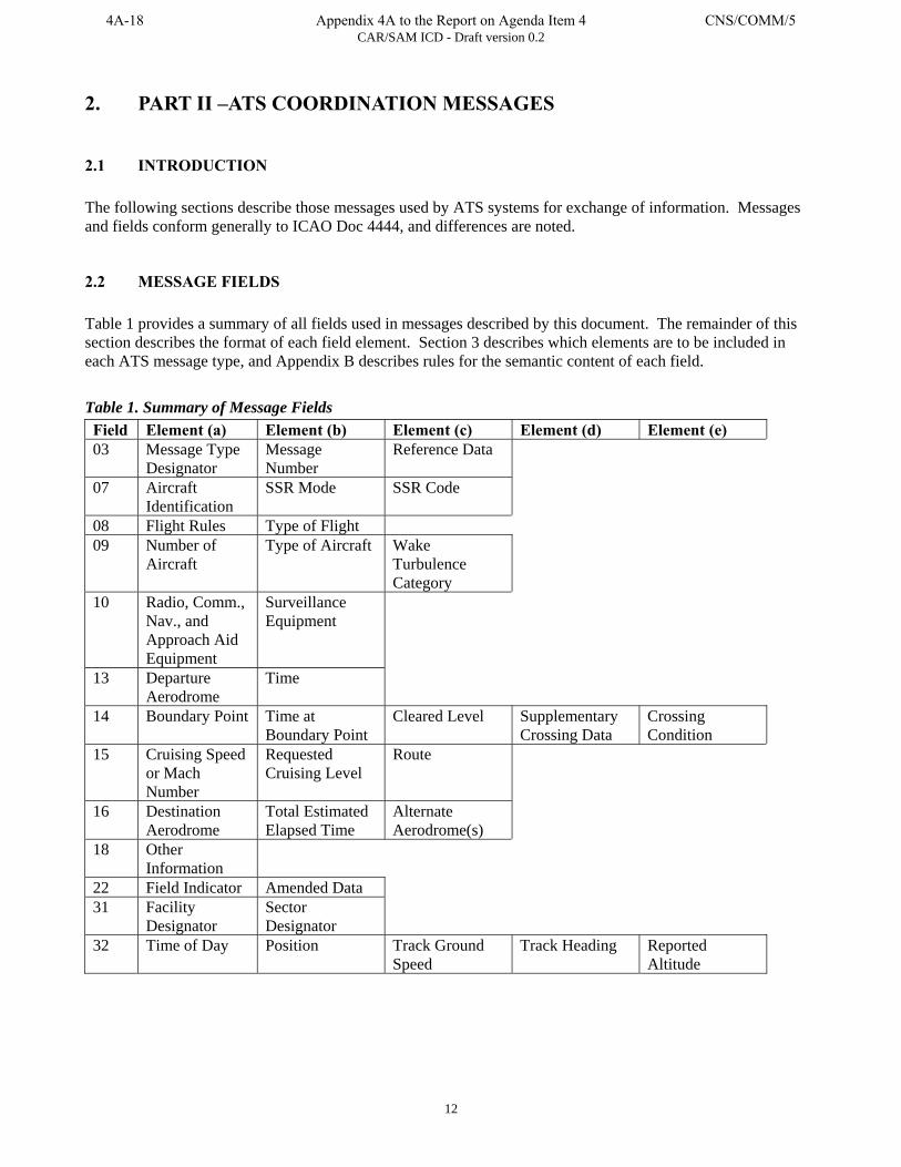
CAR/SAM ICD - Draft version 0.2
12
2. PART II –ATS COORDINATION MESSAGES
2.1 INTRODUCTION The following sections describe those messages used by ATS systems for exchange of information. Messages and fields conform generally to ICAO Doc 4444, and differences are noted.
2.2 MESSAGE FIELDS Table 1 provides a summary of all fields used in messages described by this document. The remainder of this section describes the format of each field element. Section 3 describes which elements are to be included in each ATS message type, and Appendix B describes rules for the semantic content of each field. Table 1. Summary of Message Fields Field Element (a) Element (b) Element (c) Element (d) Element (e) 03 Message Type
Designator Message Number
Reference Data
07 Aircraft Identification
SSR Mode SSR Code
08 Flight Rules Type of Flight 09 Number of
Aircraft Type of Aircraft Wake
Turbulence Category
10 Radio, Comm., Nav., and Approach Aid Equipment
Surveillance Equipment
13 Departure Aerodrome
Time
14 Boundary Point Time at Boundary Point
Cleared Level Supplementary Crossing Data
Crossing Condition
15 Cruising Speed or Mach Number
Requested Cruising Level
Route
16 Destination Aerodrome
Total Estimated Elapsed Time
Alternate Aerodrome(s)
18 Other Information
22 Field Indicator Amended Data 31 Facility
Designator Sector Designator
32 Time of Day Position Track Ground Speed
Track Heading Reported Altitude
4A-18 Appendix 4A to the Report on Agenda Item 4 CNS/COMM/5
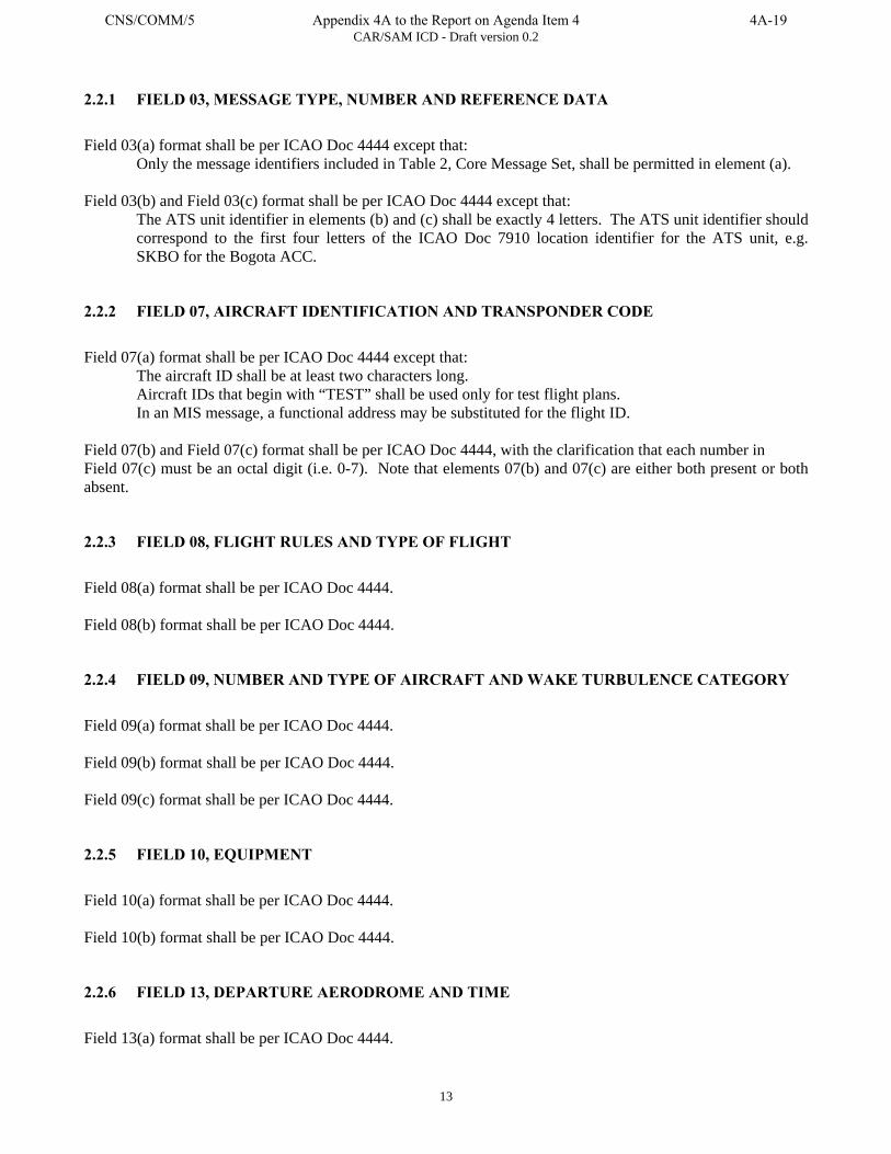
CAR/SAM ICD - Draft version 0.2
13
2.2.1 FIELD 03, MESSAGE TYPE, NUMBER AND REFERENCE DATA
Field 03(a) format shall be per ICAO Doc 4444 except that:
Only the message identifiers included in Table 2, Core Message Set, shall be permitted in element (a). Field 03(b) and Field 03(c) format shall be per ICAO Doc 4444 except that:
The ATS unit identifier in elements (b) and (c) shall be exactly 4 letters. The ATS unit identifier should correspond to the first four letters of the ICAO Doc 7910 location identifier for the ATS unit, e.g. SKBO for the Bogota ACC.
2.2.2 FIELD 07, AIRCRAFT IDENTIFICATION AND TRANSPONDER CODE
Field 07(a) format shall be per ICAO Doc 4444 except that:
The aircraft ID shall be at least two characters long. Aircraft IDs that begin with “TEST” shall be used only for test flight plans. In an MIS message, a functional address may be substituted for the flight ID.
Field 07(b) and Field 07(c) format shall be per ICAO Doc 4444, with the clarification that each number in Field 07(c) must be an octal digit (i.e. 0-7). Note that elements 07(b) and 07(c) are either both present or both absent.
2.2.3 FIELD 08, FLIGHT RULES AND TYPE OF FLIGHT
Field 08(a) format shall be per ICAO Doc 4444. Field 08(b) format shall be per ICAO Doc 4444.
2.2.4 FIELD 09, NUMBER AND TYPE OF AIRCRAFT AND WAKE TURBULENCE CATEGORY
Field 09(a) format shall be per ICAO Doc 4444. Field 09(b) format shall be per ICAO Doc 4444. Field 09(c) format shall be per ICAO Doc 4444.
2.2.5 FIELD 10, EQUIPMENT
Field 10(a) format shall be per ICAO Doc 4444. Field 10(b) format shall be per ICAO Doc 4444.
2.2.6 FIELD 13, DEPARTURE AERODROME AND TIME
Field 13(a) format shall be per ICAO Doc 4444.
CNS/COMM/5 Appendix 4A to the Report on Agenda Item 4 4A-19

CAR/SAM ICD - Draft version 0.2
14
Field 13(b) format shall be per ICAO Doc 4444.
2.2.7 FIELD 14, ESTIMATE DATA
Field 14(a) format shall be per ICAO Doc 4444. Field 14(b) format shall be per ICAO Doc 4444. Field 14(c) format shall be per ICAO Doc 4444. Field 14(d) format shall be per ICAO Doc 4444. Field 14(e) format shall be per ICAO Doc 4444.
2.2.8 FIELD 15, ROUTE
Field 15(a) format shall be per ICAO Doc 4444 except that:
The designator “K” used for kilometers per hour will not be permitted. Field 15(b) format shall be per ICAO Doc 4444 except that:
The designators “S” and “M” used for metric altitude will not be permitted. Field 15(c) format shall be per ICAO Doc 4444.
(Note that even though metric speed and altitude information is not permitted in other fields, it is permissible in elements (c4) and (c6).
2.2.9 FIELD 16, DESTINATION AERODROME AND TOTAL ESTIMATED ELAPSED TIME, ALTERNATE AERODROME(S)
Field 16(a) format shall be per ICAO Doc 4444. Field 16(b) format shall be per ICAO Doc 4444. Field 16(c) format shall be per ICAO Doc 4444.
2.2.10 FIELD 18, OTHER INFORMATION
Field 18(a) format shall be per ICAO Doc 4444, except that:
Indicators other than those shown in ICAO Doc 4444 may be used; however these indicators may not be processed correctly by all ATS units and/or may cause flight plans to reject. This reflects the reality that flight plans are filed with indicators other than those defined by ICAO (e.g. DOF/000112 to identify date of flight is commonly filed) some of which may be mandated by other ICAO regions.
4A-20 Appendix 4A to the Report on Agenda Item 4 CNS/COMM/5

CAR/SAM ICD - Draft version 0.2
15
Multiple instances of the indicator RMK/ may be used. ICAO Doc 4444 does not address the validity/invalidity of this; however instances of filed plans which use the same indicator multiple times have been identified. For example, “RMK/AGCS EQUIPPED RMK/TCAS EQUIPPED RMK/RTE 506”. The same may be true for some other indicators (e.g. STS/, NAV/ or COM/). It must be noted that certain other indicators, for example DEP/, must only be used once to ensure successful processing of the flight plan.
2.2.11 FIELD 22, AMENDMENT
Field 22(a) format shall be per ICAO Doc 4444. Field 22(b) format shall be per ICAO Doc 4444.
2.2.12 FIELD 31—FACILITY AND SECTOR DESIGNATORS
Field 31(a) shall contain a four-letter designator of the destination facility that is to receive the handover.
Note that this facility ID can be for a terminal facility that the parent en route system provides routing for. The four-letter designator should be the location identifier for the facility (from ICAO Doc 7910) if one exists. If a location identifier does not exist, one should be assigned by mutual agreement between the implementing ATS providers and submitted to ICAO for inclusion in ICAO Doc 7910.
Field 31(b) shall contain a two-character designator of the sector that is to receive the handover.
If 00 is designated, or the field element is not included then the receiving system is to determine the appropriate sector. Example: MDCS00
2.2.13 FIELD 32—AIRCRAFT POSITION AND VELOCITY VECTOR
Each element of field 32 is fixed length; there is no separator between elements. Field 32(a) shall contain time of day that the position is valid for, expressed in eight digits: HHMMSSDD where HH is hours from 00 to 23; MM is minutes from 00 to 59; SS is seconds from 00 to 59 and DD is hundredths of seconds from 00 to 99. Field 32(b) shall contain the position of the referent flight expressed in Latitude/Longitude to the nearest second, in ICAO Doc 4444 format extended to include seconds (e.g. 462034N0780521W). Field 32(c) shall contain the ground speed of the flight expressed in knots, per ICAO Doc 4444 format (e.g. N0456). Field 32(d) shall contain the heading of the flight expressed in degrees and hundredths of a degree using five digits, from 00000 to 35999 relative to true north. Field 32(e) shall contain the reported altitude expressed in ICAO Doc 4444 format (e.g. A040, F330).
CNS/COMM/5 Appendix 4A to the Report on Agenda Item 4 4A-21
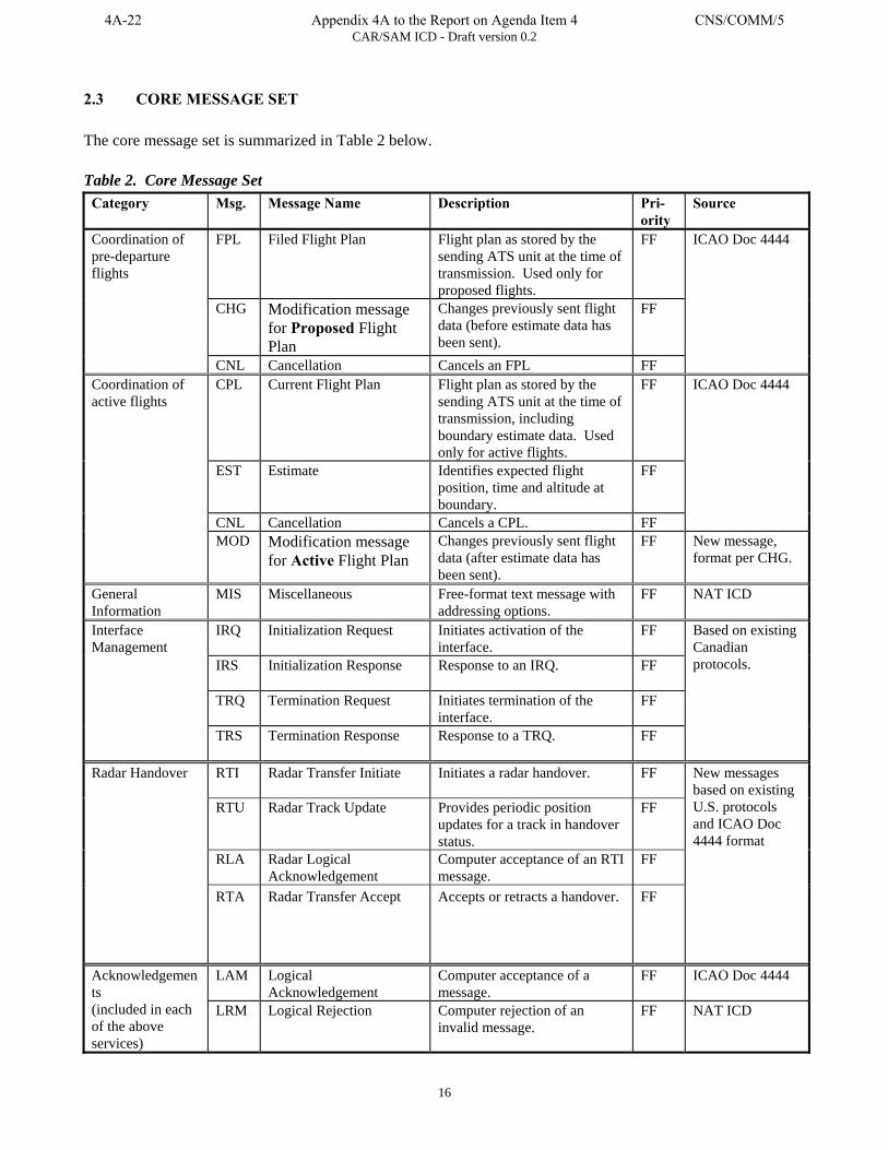
CAR/SAM ICD - Draft version 0.2
16
2.3 CORE MESSAGE SET The core message set is summarized in Table 2 below. Table 2. Core Message Set
Category Msg. Message Name Description Pri- ority
Source
FPL Filed Flight Plan Flight plan as stored by the sending ATS unit at the time of transmission. Used only for proposed flights.
FF
CHG Modification message for Proposed Flight Plan
Changes previously sent flight data (before estimate data has been sent).
FF
Coordination of pre-departure flights
CNL Cancellation Cancels an FPL FF
ICAO Doc 4444
CPL Current Flight Plan Flight plan as stored by the sending ATS unit at the time of transmission, including boundary estimate data. Used only for active flights.
FF
EST Estimate Identifies expected flight position, time and altitude at boundary.
FF
CNL Cancellation Cancels a CPL. FF
ICAO Doc 4444 Coordination of active flights
MOD Modification message for Active Flight Plan
Changes previously sent flight data (after estimate data has been sent).
FF New message, format per CHG.
General Information
MIS Miscellaneous Free-format text message with addressing options.
FF NAT ICD
IRQ Initialization Request Initiates activation of the interface.
FF
IRS Initialization Response Response to an IRQ.
FF
TRQ Termination Request Initiates termination of the interface.
FF
Interface Management
TRS Termination Response Response to a TRQ.
FF
Based on existing Canadian protocols.
RTI Radar Transfer Initiate Initiates a radar handover.
FF
RTU Radar Track Update Provides periodic position updates for a track in handover status.
FF
RLA Radar Logical Acknowledgement
Computer acceptance of an RTI message.
FF
Radar Handover
RTA Radar Transfer Accept Accepts or retracts a handover.
FF
New messages based on existing U.S. protocols and ICAO Doc 4444 format
LAM Logical Acknowledgement
Computer acceptance of a message.
FF ICAO Doc 4444 Acknowledgements (included in each of the above services)
LRM Logical Rejection Computer rejection of an invalid message.
FF NAT ICD
4A-22 Appendix 4A to the Report on Agenda Item 4 CNS/COMM/5
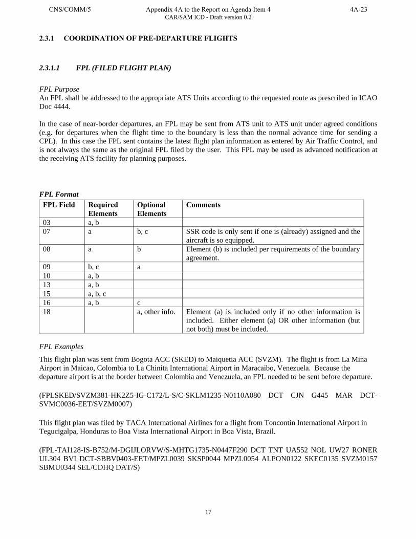
CAR/SAM ICD - Draft version 0.2
17
2.3.1 COORDINATION OF PRE-DEPARTURE FLIGHTS
2.3.1.1 FPL (FILED FLIGHT PLAN)
FPL Purpose An FPL shall be addressed to the appropriate ATS Units according to the requested route as prescribed in ICAO Doc 4444. In the case of near-border departures, an FPL may be sent from ATS unit to ATS unit under agreed conditions (e.g. for departures when the flight time to the boundary is less than the normal advance time for sending a CPL). In this case the FPL sent contains the latest flight plan information as entered by Air Traffic Control, and is not always the same as the original FPL filed by the user. This FPL may be used as advanced notification at the receiving ATS facility for planning purposes. FPL Format FPL Field Required
Elements Optional Elements
Comments
03 a, b 07 a b, c SSR code is only sent if one is (already) assigned and the
aircraft is so equipped. 08 a b Element (b) is included per requirements of the boundary
agreement. 09 b, c a 10 a, b 13 a, b 15 a, b, c 16 a, b c 18 a, other info. Element (a) is included only if no other information is
included. Either element (a) OR other information (but not both) must be included.
FPL Examples
This flight plan was sent from Bogota ACC (SKED) to Maiquetia ACC (SVZM). The flight is from La Mina Airport in Maicao, Colombia to La Chinita International Airport in Maracaibo, Venezuela. Because the departure airport is at the border between Colombia and Venezuela, an FPL needed to be sent before departure. (FPLSKED/SVZM381-HK2Z5-IG-C172/L-S/C-SKLM1235-N0110A080 DCT CJN G445 MAR DCT-SVMC0036-EET/SVZM0007) This flight plan was filed by TACA International Airlines for a flight from Toncontin International Airport in Tegucigalpa, Honduras to Boa Vista International Airport in Boa Vista, Brazil. (FPL-TAI128-IS-B752/M-DGIJLORVW/S-MHTG1735-N0447F290 DCT TNT UA552 NOL UW27 RONER UL304 BVI DCT-SBBV0403-EET/MPZL0039 SKSP0044 MPZL0054 ALPON0122 SKEC0135 SVZM0157 SBMU0344 SEL/CDHQ DAT/S)
CNS/COMM/5 Appendix 4A to the Report on Agenda Item 4 4A-23
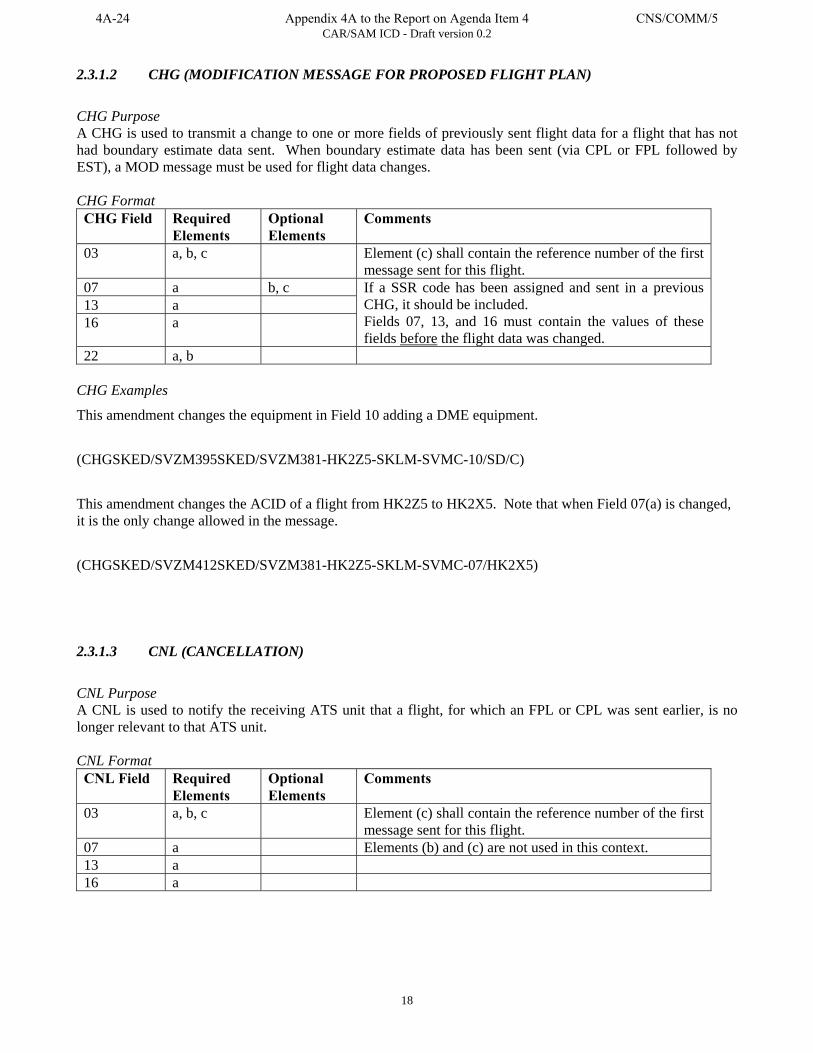
CAR/SAM ICD - Draft version 0.2
18
2.3.1.2 CHG (MODIFICATION MESSAGE FOR PROPOSED FLIGHT PLAN)
CHG Purpose A CHG is used to transmit a change to one or more fields of previously sent flight data for a flight that has not had boundary estimate data sent. When boundary estimate data has been sent (via CPL or FPL followed by EST), a MOD message must be used for flight data changes. CHG Format CHG Field Required
Elements Optional Elements
Comments
03 a, b, c Element (c) shall contain the reference number of the first message sent for this flight.
07 a b, c 13 a 16 a
If a SSR code has been assigned and sent in a previous CHG, it should be included. Fields 07, 13, and 16 must contain the values of these fields before the flight data was changed.
22 a, b CHG Examples
This amendment changes the equipment in Field 10 adding a DME equipment. (CHGSKED/SVZM395SKED/SVZM381-HK2Z5-SKLM-SVMC-10/SD/C) This amendment changes the ACID of a flight from HK2Z5 to HK2X5. Note that when Field 07(a) is changed, it is the only change allowed in the message. (CHGSKED/SVZM412SKED/SVZM381-HK2Z5-SKLM-SVMC-07/HK2X5)
2.3.1.3 CNL (CANCELLATION)
CNL Purpose A CNL is used to notify the receiving ATS unit that a flight, for which an FPL or CPL was sent earlier, is no longer relevant to that ATS unit. CNL Format CNL Field Required
Elements Optional Elements
Comments
03 a, b, c Element (c) shall contain the reference number of the first message sent for this flight.
07 a Elements (b) and (c) are not used in this context. 13 a 16 a
4A-24 Appendix 4A to the Report on Agenda Item 4 CNS/COMM/5
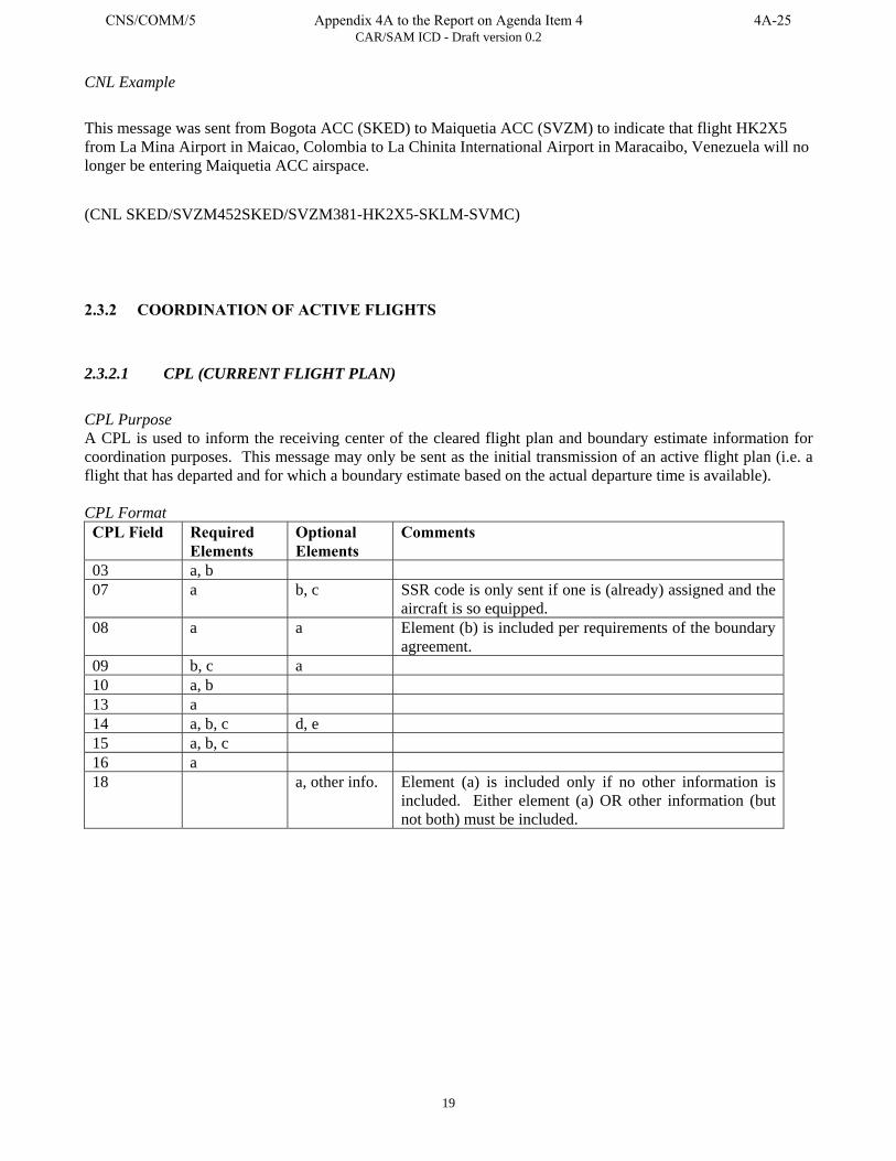
CAR/SAM ICD - Draft version 0.2
19
CNL Example
This message was sent from Bogota ACC (SKED) to Maiquetia ACC (SVZM) to indicate that flight HK2X5 from La Mina Airport in Maicao, Colombia to La Chinita International Airport in Maracaibo, Venezuela will no longer be entering Maiquetia ACC airspace. (CNL SKED/SVZM452SKED/SVZM381-HK2X5-SKLM-SVMC)
2.3.2 COORDINATION OF ACTIVE FLIGHTS
2.3.2.1 CPL (CURRENT FLIGHT PLAN)
CPL Purpose A CPL is used to inform the receiving center of the cleared flight plan and boundary estimate information for coordination purposes. This message may only be sent as the initial transmission of an active flight plan (i.e. a flight that has departed and for which a boundary estimate based on the actual departure time is available). CPL Format CPL Field Required
Elements Optional Elements
Comments
03 a, b 07 a b, c SSR code is only sent if one is (already) assigned and the
aircraft is so equipped. 08 a a Element (b) is included per requirements of the boundary
agreement. 09 b, c a 10 a, b 13 a 14 a, b, c d, e 15 a, b, c 16 a 18 a, other info. Element (a) is included only if no other information is
included. Either element (a) OR other information (but not both) must be included.
CNS/COMM/5 Appendix 4A to the Report on Agenda Item 4 4A-25
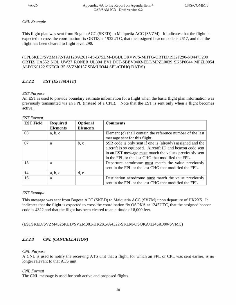
CAR/SAM ICD - Draft version 0.2
20
CPL Example
This flight plan was sent from Bogota ACC (SKED) to Maiquetia ACC (SVZM). It indicates that the flight is expected to cross the coordination fix ORTIZ at 1932UTC, that the assigned beacon code is 2617, and that the flight has been cleared to flight level 290.
(CPLSKED/SVZM172-TAI128/A2617-IS-B752/M-DGIJLORVW/S-MHTG-ORTIZ/1932F290-N0447F290 ORTIZ UA552 NOL UW27 RONER UL304 BVI DCT-SBBV0403-EET/MPZL0039 SKSP0044 MPZL0054 ALPON0122 SKEC0135 SVZM0157 SBMU0344 SEL/CDHQ DAT/S)
2.3.2.2 EST (ESTIMATE)
EST Purpose An EST is used to provide boundary estimate information for a flight when the basic flight plan information was previously transmitted via an FPL (instead of a CPL). Note that the EST is sent only when a flight becomes active. EST Format EST Field Required
Elements Optional Elements
Comments
03 a, b, c Element (c) shall contain the reference number of the last message sent for this flight.
07 a b, c SSR code is only sent if one is (already) assigned and the aircraft is so equipped. Aircraft ID and beacon code sent in an EST message must match the values previously sent in the FPL or the last CHG that modified the FPL.
13 a Departure aerodrome must match the value previously sent in the FPL or the last CHG that modified the FPL.
14 a, b, c d, e 16 a Destination aerodrome must match the value previously
sent in the FPL or the last CHG that modified the FPL. EST Example
This message was sent from Bogota ACC (SKED) to Maiquetia ACC (SVZM) upon departure of HK2X5. It indicates that the flight is expected to cross the coordination fix OSOKA at 1245UTC, that the assigned beacon code is 4322 and that the flight has been cleared to an altitude of 8,000 feet.
(ESTSKED/SVZM452SKED/SVZM381-HK2X5/A4322-SKLM-OSOKA/1245A080-SVMC)
2.3.2.3 CNL (CANCELLATION)
CNL Purpose A CNL is used to notify the receiving ATS unit that a flight, for which an FPL or CPL was sent earlier, is no longer relevant to that ATS unit. CNL Format The CNL message is used for both active and proposed flights.
4A-26 Appendix 4A to the Report on Agenda Item 4 CNS/COMM/5
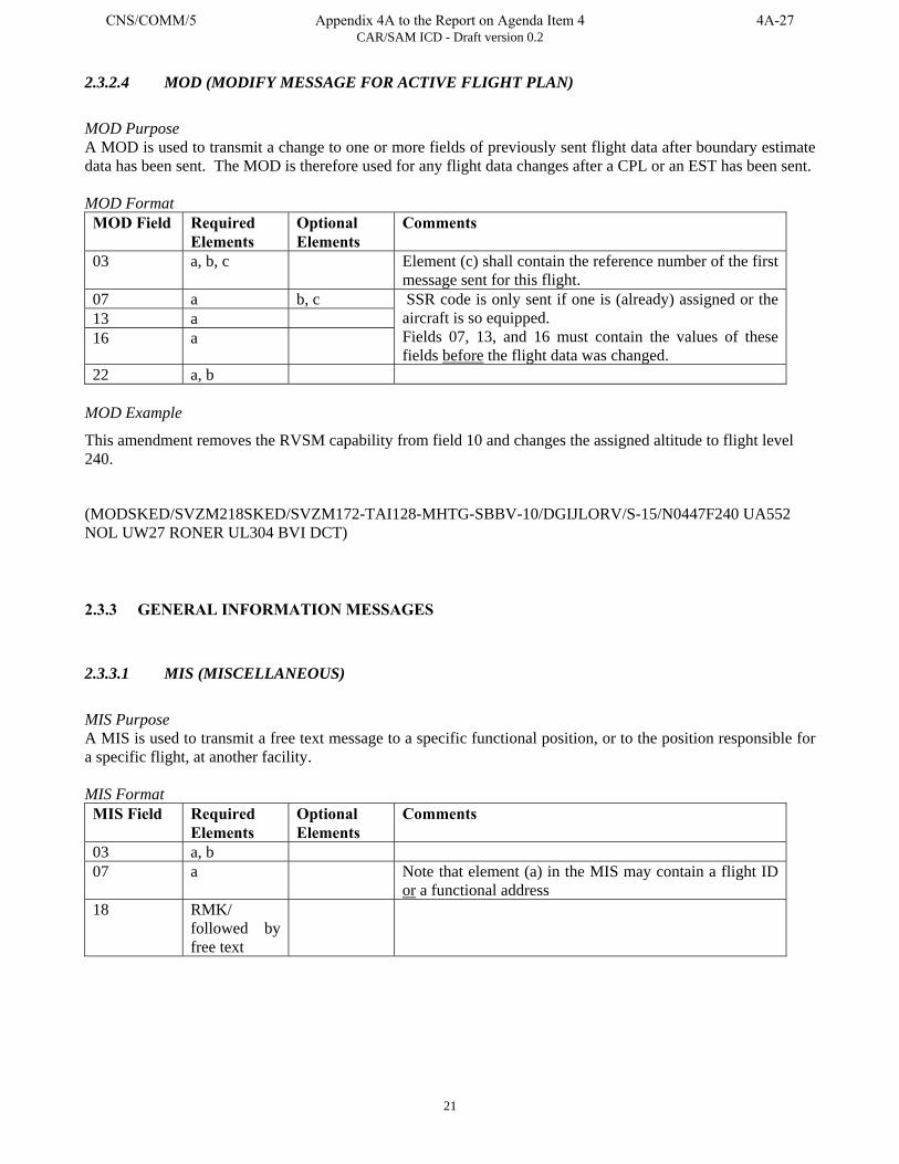
CAR/SAM ICD - Draft version 0.2
21
2.3.2.4 MOD (MODIFY MESSAGE FOR ACTIVE FLIGHT PLAN)
MOD Purpose A MOD is used to transmit a change to one or more fields of previously sent flight data after boundary estimate data has been sent. The MOD is therefore used for any flight data changes after a CPL or an EST has been sent. MOD Format MOD Field Required
Elements Optional Elements
Comments
03 a, b, c Element (c) shall contain the reference number of the first message sent for this flight.
07 a b, c 13 a 16 a
SSR code is only sent if one is (already) assigned or the aircraft is so equipped. Fields 07, 13, and 16 must contain the values of these fields before the flight data was changed.
22 a, b MOD Example
This amendment removes the RVSM capability from field 10 and changes the assigned altitude to flight level 240.
(MODSKED/SVZM218SKED/SVZM172-TAI128-MHTG-SBBV-10/DGIJLORV/S-15/N0447F240 UA552 NOL UW27 RONER UL304 BVI DCT)
2.3.3 GENERAL INFORMATION MESSAGES
2.3.3.1 MIS (MISCELLANEOUS)
MIS Purpose A MIS is used to transmit a free text message to a specific functional position, or to the position responsible for a specific flight, at another facility. MIS Format MIS Field Required
Elements Optional Elements
Comments
03 a, b 07 a Note that element (a) in the MIS may contain a flight ID
or a functional address 18 RMK/
followed by free text
CNS/COMM/5 Appendix 4A to the Report on Agenda Item 4 4A-27

CAR/SAM ICD - Draft version 0.2
22
MIS Example
In this example, Bogota ACC (SKED) informs Maiquetia ACC (SVZM) that TACA flight 128 has lost its RVSM capability.
(MISSKED/SVZM221-TAI128-RMK/TACA128 HAS LOST RVSM CAPABILITY)
2.3.4 INTERFACE MANAGEMENT MESSAGES
2.3.4.1 IRQ (INITIALIZATION REQUEST)
IRQ Purpose An IRQ is used to request transition of an interface from a non-operational to an operational state. IRQ Format IRQ Field Required
Elements Optional Elements
Comments
03 a, b IRQ Example
In this example, Bogota ACC (SKED) has sent a request to Maiquetia ACC (SVZM) to initialize the interface.
(IRQSKED/SVZM266)
2.3.4.2 IRS (INITIALIZATION RESPONSE)
IRS Purpose An IRS is used as a response to an IRQ message. IRS Format IRS Field Required
Elements Optional Elements
Comments
03 a, b, c Element (c) should contain the reference number of the previously sent IRQ.
IRS Example
In this example, Maiquetia ACC (SVZM) has responded to Bogota ACC's (SKED) request to initialize the interface.
(IRSSVZM/SKED817SKED/SVZM266)
4A-28 Appendix 4A to the Report on Agenda Item 4 CNS/COMM/5
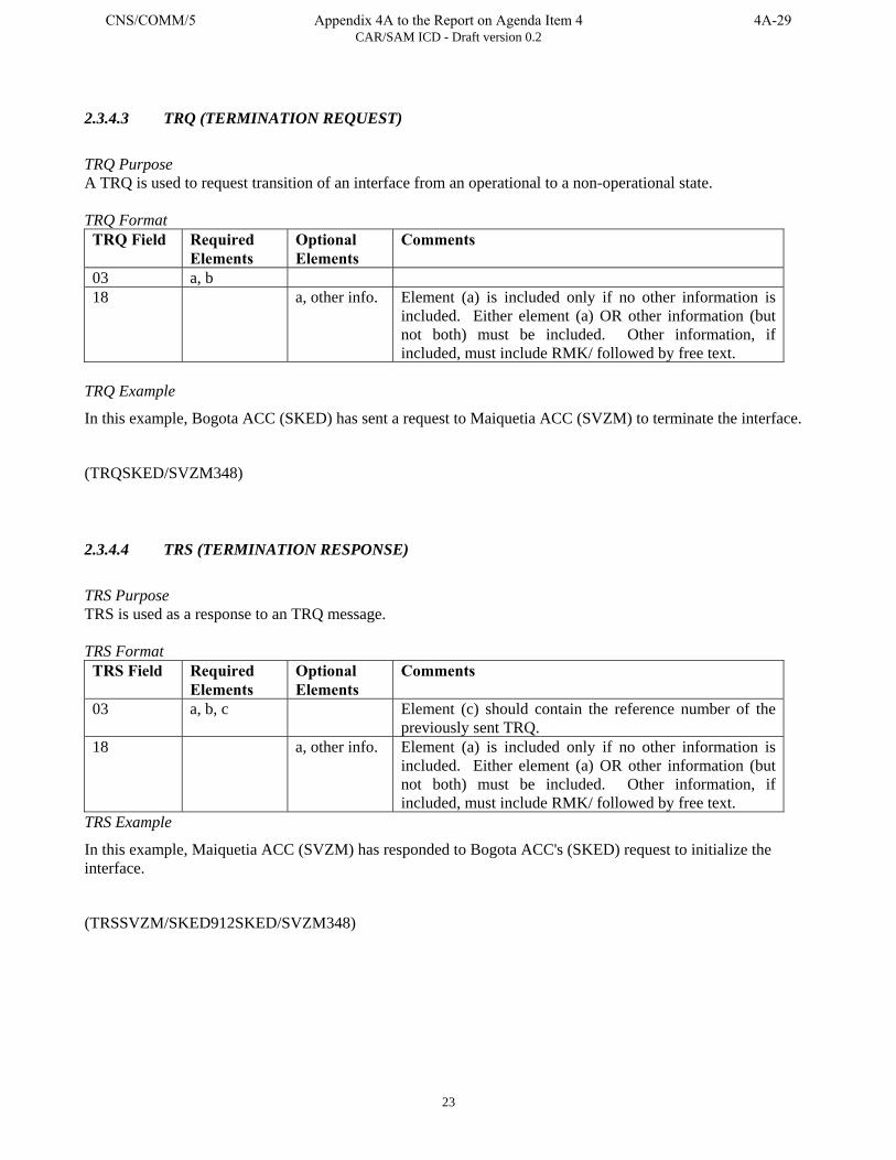
CAR/SAM ICD - Draft version 0.2
23
2.3.4.3 TRQ (TERMINATION REQUEST)
TRQ Purpose A TRQ is used to request transition of an interface from an operational to a non-operational state. TRQ Format TRQ Field Required
Elements Optional Elements
Comments
03 a, b 18 a, other info. Element (a) is included only if no other information is
included. Either element (a) OR other information (but not both) must be included. Other information, if included, must include RMK/ followed by free text.
TRQ Example
In this example, Bogota ACC (SKED) has sent a request to Maiquetia ACC (SVZM) to terminate the interface.
(TRQSKED/SVZM348)
2.3.4.4 TRS (TERMINATION RESPONSE)
TRS Purpose TRS is used as a response to an TRQ message. TRS Format TRS Field Required
Elements Optional Elements
Comments
03 a, b, c Element (c) should contain the reference number of the previously sent TRQ.
18 a, other info. Element (a) is included only if no other information is included. Either element (a) OR other information (but not both) must be included. Other information, if included, must include RMK/ followed by free text.
TRS Example
In this example, Maiquetia ACC (SVZM) has responded to Bogota ACC's (SKED) request to initialize the interface.
(TRSSVZM/SKED912SKED/SVZM348)
CNS/COMM/5 Appendix 4A to the Report on Agenda Item 4 4A-29
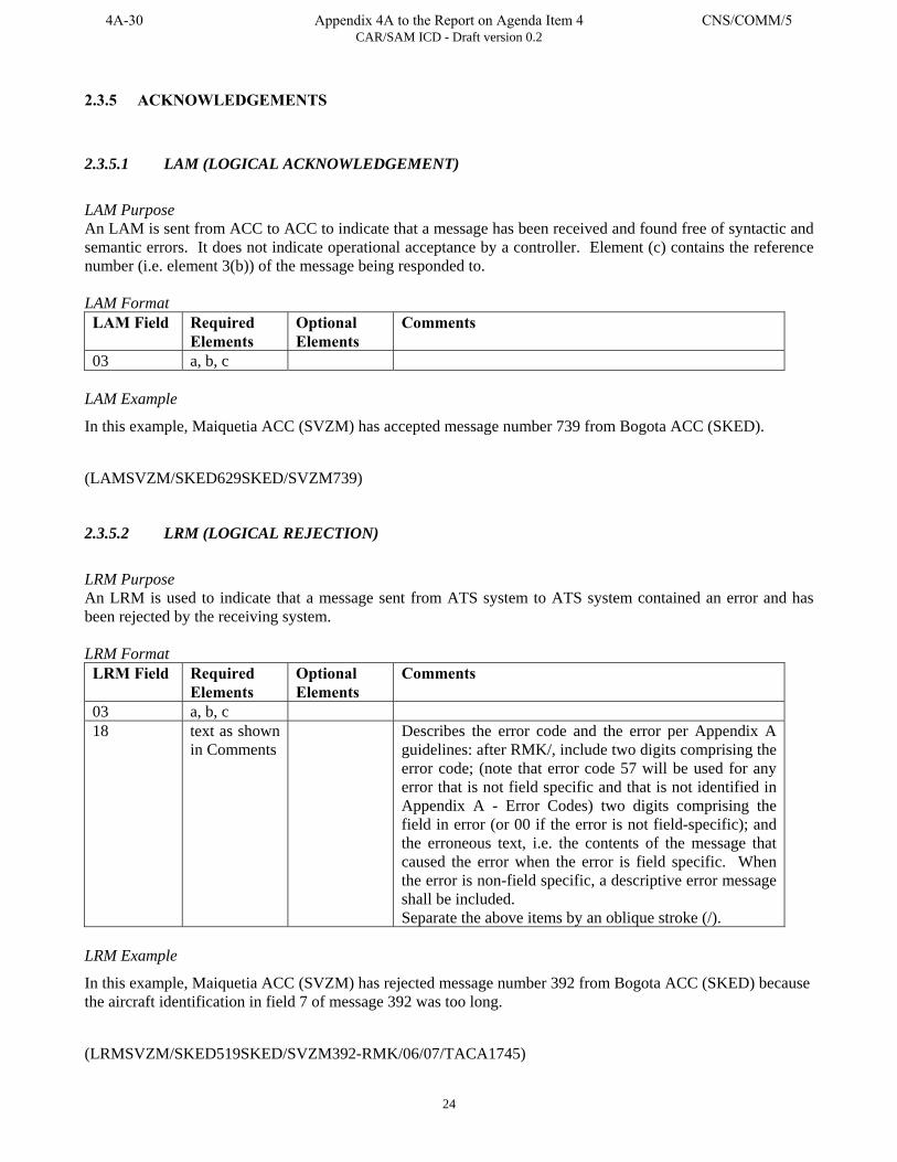
CAR/SAM ICD - Draft version 0.2
24
2.3.5 ACKNOWLEDGEMENTS
2.3.5.1 LAM (LOGICAL ACKNOWLEDGEMENT)
LAM Purpose An LAM is sent from ACC to ACC to indicate that a message has been received and found free of syntactic and semantic errors. It does not indicate operational acceptance by a controller. Element (c) contains the reference number (i.e. element 3(b)) of the message being responded to. LAM Format LAM Field Required
Elements Optional Elements
Comments
03 a, b, c LAM Example
In this example, Maiquetia ACC (SVZM) has accepted message number 739 from Bogota ACC (SKED).
(LAMSVZM/SKED629SKED/SVZM739)
2.3.5.2 LRM (LOGICAL REJECTION)
LRM Purpose An LRM is used to indicate that a message sent from ATS system to ATS system contained an error and has been rejected by the receiving system. LRM Format LRM Field Required
Elements Optional Elements
Comments
03 a, b, c 18 text as shown
in Comments Describes the error code and the error per Appendix A
guidelines: after RMK/, include two digits comprising the error code; (note that error code 57 will be used for any error that is not field specific and that is not identified in Appendix A - Error Codes) two digits comprising the field in error (or 00 if the error is not field-specific); and the erroneous text, i.e. the contents of the message that caused the error when the error is field specific. When the error is non-field specific, a descriptive error message shall be included. Separate the above items by an oblique stroke (/).
LRM Example
In this example, Maiquetia ACC (SVZM) has rejected message number 392 from Bogota ACC (SKED) because the aircraft identification in field 7 of message 392 was too long.
(LRMSVZM/SKED519SKED/SVZM392-RMK/06/07/TACA1745)
4A-30 Appendix 4A to the Report on Agenda Item 4 CNS/COMM/5
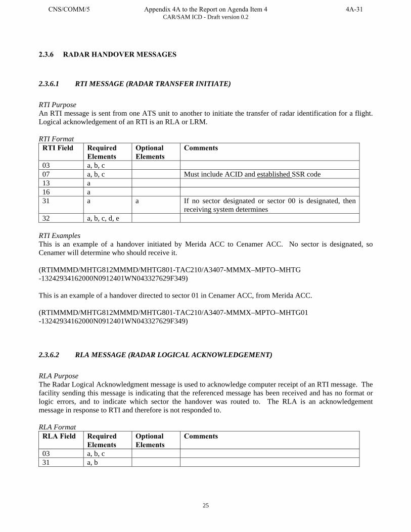
CAR/SAM ICD - Draft version 0.2
25
2.3.6 RADAR HANDOVER MESSAGES
2.3.6.1 RTI MESSAGE (RADAR TRANSFER INITIATE)
RTI Purpose An RTI message is sent from one ATS unit to another to initiate the transfer of radar identification for a flight. Logical acknowledgement of an RTI is an RLA or LRM. RTI Format RTI Field Required
Elements Optional Elements
Comments
03 a, b, c 07 a, b, c Must include ACID and established SSR code 13 a 16 a 31 a a If no sector designated or sector 00 is designated, then
receiving system determines 32 a, b, c, d, e
RTI Examples This is an example of a handover initiated by Merida ACC to Cenamer ACC. No sector is designated, so Cenamer will determine who should receive it. (RTIMMMD/MHTG812MMMD/MHTG801-TAC210/A3407-MMMX–MPTO–MHTG -13242934162000N0912401WN043327629F349) This is an example of a handover directed to sector 01 in Cenamer ACC, from Merida ACC. (RTIMMMD/MHTG812MMMD/MHTG801-TAC210/A3407-MMMX–MPTO–MHTG01 -13242934162000N0912401WN043327629F349)
2.3.6.2 RLA MESSAGE (RADAR LOGICAL ACKNOWLEDGEMENT)
RLA Purpose The Radar Logical Acknowledgment message is used to acknowledge computer receipt of an RTI message. The facility sending this message is indicating that the referenced message has been received and has no format or logic errors, and to indicate which sector the handover was routed to. The RLA is an acknowledgement message in response to RTI and therefore is not responded to. RLA Format RLA Field Required
Elements Optional Elements
Comments
03 a, b, c 31 a, b
CNS/COMM/5 Appendix 4A to the Report on Agenda Item 4 4A-31
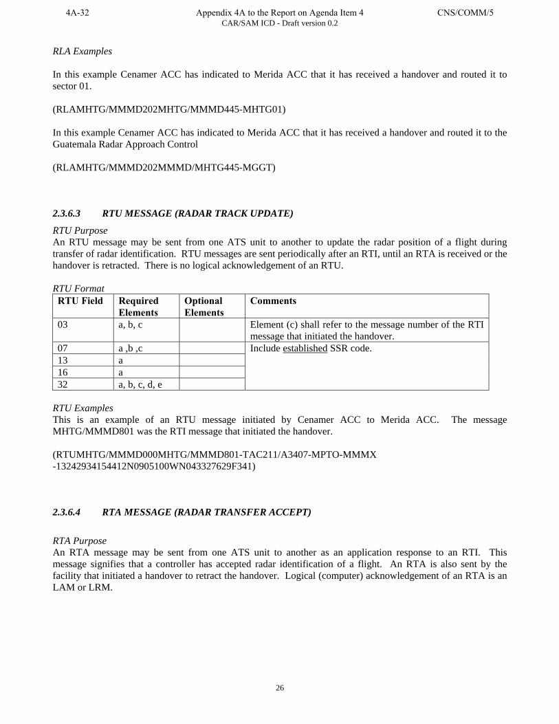
CAR/SAM ICD - Draft version 0.2
26
RLA Examples In this example Cenamer ACC has indicated to Merida ACC that it has received a handover and routed it to sector 01. (RLAMHTG/MMMD202MHTG/MMMD445-MHTG01) In this example Cenamer ACC has indicated to Merida ACC that it has received a handover and routed it to the Guatemala Radar Approach Control (RLAMHTG/MMMD202MMMD/MHTG445-MGGT)
2.3.6.3 RTU MESSAGE (RADAR TRACK UPDATE)
RTU Purpose An RTU message may be sent from one ATS unit to another to update the radar position of a flight during transfer of radar identification. RTU messages are sent periodically after an RTI, until an RTA is received or the handover is retracted. There is no logical acknowledgement of an RTU. RTU Format RTU Field Required
Elements Optional Elements
Comments
03 a, b, c Element (c) shall refer to the message number of the RTI message that initiated the handover.
07 a ,b ,c 13 a 16 a 32 a, b, c, d, e
Include established SSR code.
RTU Examples This is an example of an RTU message initiated by Cenamer ACC to Merida ACC. The message MHTG/MMMD801 was the RTI message that initiated the handover. (RTUMHTG/MMMD000MHTG/MMMD801-TAC211/A3407-MPTO-MMMX -13242934154412N0905100WN043327629F341)
2.3.6.4 RTA MESSAGE (RADAR TRANSFER ACCEPT)
RTA Purpose An RTA message may be sent from one ATS unit to another as an application response to an RTI. This message signifies that a controller has accepted radar identification of a flight. An RTA is also sent by the facility that initiated a handover to retract the handover. Logical (computer) acknowledgement of an RTA is an LAM or LRM.
4A-32 Appendix 4A to the Report on Agenda Item 4 CNS/COMM/5
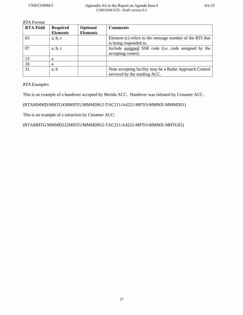
CAR/SAM ICD - Draft version 0.2
27
RTA Format RTA Field Required
Elements Optional Elements
Comments
03 a, b, c Element (c) refers to the message number of the RTI that is being responded to.
07 a, b, c Include assigned SSR code (i.e. code assigned by the accepting center).
13 a 16 a 31 a, b Note accepting facility may be a Radar Approach Control
serviced by the sending ACC. RTA Examples This is an example of a handover accepted by Merida ACC. Handover was initiated by Cenamer ACC. (RTAMMMD/MHTG438MHTG/MMMD812-TAC211/A4222-MPTO-MMMX-MMMD01) This is an example of a retraction by Cenamer ACC: (RTAMHTG/MMMD222MHTG/MMMD812-TAC211/A4222-MPTO-MMMX-MHTG01)
CNS/COMM/5 Appendix 4A to the Report on Agenda Item 4 4A-33
CAR/SAM ICD - Draft version 0.2
28
3. PART III – COMMUNICATIONS AND SUPPORT MECHANISMS
3.1 INTRODUCTION The communications protocols and physical path are not dictated by this ICD. This ICD addresses only the application message content.
3.2 TELECOMMUNICATIONS REQUIREMENTS AND CONSTRAINTS Telecommunication requirements and constraints should be carried out bilaterally or multilaterally and incorporated into applicable bilateral or multilateral agreements.
3.2.1 USE OF AERONAUTICAL FIXED TELECOMMUNICATIONS NETWORK (AFTN)
AFTN may be used as a flight plan data interface, subject to verification of performance. Any interface exchanging radar position data, including radar handovers, shall not use AFTN. When AFTN is used as the communications mechanism: a) The AFTN IA-5 Header as described in ICAO Annex 10, vol. 2 will be used for exchange of
messages. b) ATS messages will be addressed to each ATS unit using an eight-character facility address
where the first four characters are the appropriate location indicator from ICAO Doc 7910, and the last four characters are routing indicators defined by the ATS unit in accordance with ICAO Annex 10, vol. 2.
Each message shall be sent with the priority indicated in Table 2 of Part II.
3.2.2 USE OF A WIDE-AREA NETWORK
Use of existing wide-area networks (e.g. X.25 or Frame Relay packet-switched network) may be used if the speed, capacity, and security characteristics are verified as adequate to support the interface.
3.2.3 USE OF DIRECT LINES
In cases where speed, capacity, and/or security require it, a direct line interface may be used between facilities.
3.2.4 CHARACTER SET
The IA-5 character set shall be used for all application message content. Certain characters have special meaning and must only be used as indicated below: Open parenthesis “(”and close parenthesis “)” shall be used only to begin and terminate the application message.
4A-34 Appendix 4A to the Report on Agenda Item 4 CNS/COMM/5
CAR/SAM ICD - Draft version 0.2
29
A single hyphen “-” shall be used only as a field separator and shall not be used within any field.
3.3 ENGINEERING CONSIDERATIONS
3.3.1 ASSOCIATED AUTOMATION FUNCTIONALITY
Each ATS service provider participating in this interface must have a supporting automation system. The supporting automation shall:
• Error check all inbound messages for proper format and logical consistency.
• Ensure only messages from authorized senders are accepted and processed.
• As required, alert the responsible controller(s) of flight data that has been received.
• Notify the responsible personnel when any message sent is rejected or not acknowledged within a variable system parameter (VSP) period of time (see 4.5.1 Response time).
3.3.2 FAILURE AND RECOVERY SOLUTIONS
Automation systems may have different failure avoidance and failure recovery mechanisms. Each participating system shall have the following characteristics:
• If the recovery process preserves the current message number in the sequence with each facility, no notification is necessary.
• If the recovery process requires reset of the sequence number to 000, a means of notifying the receiving
facility that the message numbers have been reset is required. This may be procedural rather than automated.
The recovery process shall not automatically re-send any CPL for which an LAM had been received. This is relevant if the system was able to recover state information about which flight plans have been coordinated, and did not need to reset the message sequence numbers.
3.3.3 DATA REQUIREMENTS
Certain data must be defined and maintained to support all features of the interface. Depending on the data, it should be coordinated on a Regional, National, or Local (facility) basis. Data requirements are identified in Table 3 below.
CNS/COMM/5 Appendix 4A to the Report on Agenda Item 4 4A-35

CAR/SAM ICD - Draft version 0.2
30
Table 3. Summary of Data Definitions Needed to Support the Interface Field Data Purpose Source Coordination 03 Facility Identifiers Identify the sending/receiving
facility. ICAO Doc 7910 (first four characters) and local definition (second four characters)
Local
07 Functional Address Agree on functional addresses to be used in MIS messages.
Local Data Local
10 Equipment Codes Identify ATS-specified equipment qualifiers that are not specified in ICAO Doc 4444.
ICAO Doc 7030 CAR and SAM Supplements
Regional
14 Boundary Point Identify the coordination fixes to be sent for each airway.
Local Data Local
15 Adapted Routes and Fixes
Identify airway and fix information that is adapted by both systems.
Local Data Local
18 Requirements for other data to be included
Identify any requirements for data that must be included in Field 18.
ICAO Doc 7030 CAR and SAM Supplements
Regional
3.4 SECURITY CONSIDERATIONS
3.4.1 PRIVACY
This ICD does not define mechanisms that guarantee privacy. It should be assumed that any data sent over this interface may be seen by unintended third parties either through interception of the message or through disclosure at the receiving facility. Any communications requiring privacy must be identified and appropriate communications and procedures defined.
3.4.2 AUTHENTICATION
Each system shall authenticate that messages received are from the source that is identified in Field 03.
3.4.3 ACCESS CONTROL
Each system participating in the interface shall implement eligibility checks to ensure that the source of the message is eligible to send the message type and is the appropriate authority for the referenced flight.
3.5 TEST CONSIDERATIONS Before an automated flight data interface becomes operational between any two facilities, the following set of tests shall be completed:
4A-36 Appendix 4A to the Report on Agenda Item 4 CNS/COMM/5
CAR/SAM ICD - Draft version 0.2
31
Test of the telecommunications system and addressing: Off-line tests using development or test (i.e. non-operational) systems. These may include test systems at non-operational facilities, and/or operational systems that are in an off-line mode. Note: If off-line testing is not possible, extreme care should be used when conducting first round testing on operational systems.
Test of non-operational message sets:
Tests using the operational systems in off-line (recommended) or operational mode in which TEST messages are exchanged. (Note: If off-line testing is not possible, extreme care should be used when conducting second round testing on operational systems.)
Test of operational message sets:
Tests using the operational systems in operational mode in which manual coordination verifies each flight data message sent.
Before each test, a document specifying purpose, procedures and data to be collected, must be agreed to by both/all facilities. To ensure success/failure is clearly defined, specific criteria should be included in the document. Data transmitted during test phases should include both correct and incorrect formats/data fields to verify that correct data is processed correctly and incorrect data is rejected. For diagnostic purposes, each side of the interface should be able to isolate the source of interface problems.
3.6 PERFORMANCE CONSIDERATIONS
3.6.1 RESPONSE TIME
For flight planning messages, controllers require indication of an unsuccessful message transmission within 60 seconds of the message being sent. Therefore, the response time from the time a message is sent until an LAM (or LRM) is received shall be under 60 seconds at least 99% of the time under normal operations. A faster response time is desirable, and will result in operations that are more efficient. For messages involving transfer of control and surveillance data (e.g. RTI, RTA, and RTU) the data must be transmitted in time for the receiving system to display the track position with acceptable accuracy. Communication across the interface shall be less than six seconds maximum.
3.6.2 AVAILABILITY / RELIABILITY
The hardware and software resources required for providing service on the CAR/SAM interfaces should be developed such that the inherent reliability will support interface availability which is at least equal to the end systems of that interface (e.g. 99.7% availability for end systems that both operate with 99.7% reliability).
CNS/COMM/5 Appendix 4A to the Report on Agenda Item 4 4A-37

CAR/SAM ICD - Draft version 0.2
32
3.6.3 CAPACITY AND GROWTH
Before implementing this interface between two ACCs, an analysis of the traffic expected between the centers shall be performed and the proposed communications links verified for appropriate capacity. Traffic estimates should consider current and future expected traffic levels. For initial planning purposes the following estimates of message size and messages per flight are provided. Table 4. Expected Message Rates and Sizes
Message Avg. per Flight
Avg. Size Max Size Comments
Messages per near-border departure flight: FPL 1 275 2,000
CHG 0.5 160 1,000 Assumed 1 of 2 flights amended after coordination, before departure.
EST 1 120 200
MOD 2 120 1,000 Assumed each flight has an average of one change after coordination due to amendment and two time updates.
Messages per non near-border departure flight: CPL 1 275 2,000
MOD 2 120 1,000 Assumed each flight has an average of one change after coordination due to amendment and two time updates.
Messages per every flight: CNL 0.01 100 150 Assumed 1 in 100 flight plans are cancelled. RTI 1 150 200 RTU 5 140 200 Assumed 1 RTU every 6 seconds for 30 seconds. RTA 1 110 160 MIS 0.1 130 625 Responses (not per flight):
LAM/RLA
Sum of all above except RTU
80 130
LRM 100 230 The hardware and software developed for the interfaces shall be capable of asynchronously exchanging the messages defined in Part III, Table 2 simultaneously with all adjacent automated systems.
4A-38 Appendix 4A to the Report on Agenda Item 4 CNS/COMM/5
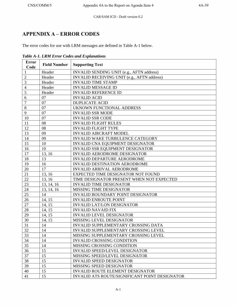
CAR/SAM ICD - Draft version 0.2
A-1
APPENDIX A – ERROR CODES The error codes for use with LRM messages are defined in Table A-1 below. Table A-1. LRM Error Codes and Explanations
Error Code Field Number Supporting Text
1 Header INVALID SENDING UNIT (e.g., AFTN address) 2 Header INVALID RECEIVING UNIT (e.g., AFTN address) 3 Header INVALID TIME STAMP 4 Header INVALID MESSAGE ID 5 Header INVALID REFERENCE ID 6 07 INVALID ACID 7 07 DUPLICATE ACID 8 07 UKNOWN FUNCTIONAL ADDRESS 9 07 INVALID SSR MODE 10 07 INVALID SSR CODE 11 08 INVALID FLIGHT RULES 12 08 INVALID FLIGHT TYPE 13 09 INVALID AIRCRAFT MODEL 14 09 INVALID WAKE TURBULENCE CATEGORY 15 10 INVALID CNA EQUIPMENT DESIGNATOR 16 10 INVALID SSR EQUIPMENT DESIGNATOR 17 13, 16 INVALID AERODROME DESIGNATOR 18 13 INVALID DEPARTURE AERODROME 19 16 INVALID DESTINATION AERODROME 20 17 INVALID ARRIVAL AERODROME 21 13, 16 EXPECTED TIME DESIGNATOR NOT FOUND 22 13, 16 TIME DESIGNATOR PRESENT WHEN NOT EXPECTED 23 13, 14, 16 INVALID TIME DESIGNATOR 24 13, 14, 16 MISSING TIME DESIGNATOR 25 14 INVALID BOUNDARY POINT DESIGNATOR 26 14, 15 INVALID ENROUTE POINT 27 14, 15 INVALID LAT/LON DESIGNATOR 28 14, 15 INVALID NAVAID FIX 29 14, 15 INVALID LEVEL DESIGNATOR 30 14, 15 MISSING LEVEL DESIGNATOR 31 14 INVALID SUPPLEMENTARY CROSSING DATA 32 14 INVALID SUPPLEMENTARY CROSSING LEVEL 33 14 MISSING SUPPLEMENTARY CROSSING LEVEL 34 14 INVALID CROSSING CONDITION 35 14 MISSING CROSSING CONDITION 36 15 INVALID SPEED/LEVEL DESIGNATOR 37 15 MISSING SPEED/LEVEL DESIGNATOR 38 15 INVALID SPEED DESIGNATOR 39 15 MISSING SPEED DESIGNATOR 40 15 INVALID ROUTE ELEMENT DESIGNATOR 41 15 INVALID ATS ROUTE/SIGNIFICANT POINT DESIGNATOR
CNS/COMM/5 Appendix 4A to the Report on Agenda Item 4 4A-39

CAR/SAM ICD - Draft version 0.2
A-2
Error Code Field Number Supporting Text
42 15 INVALID ATS ROUTE DESIGNATOR 43 15 INVALID SIGNFICANT POINT DESIGNATOR 44 15 FLIGHT RULES INDICATOR DOES NOT FOLLOW SIGNIFICANT POINT 45 15 ADDITIONAL DATA FOLLOWS TRUNCATION INDICATOR 46 15 INCORRECT CRUISE CLIMB FORMAT 47 15 CONFLICTING DIRECTION 48 18 INVALID OTHER INFORMATION ELEMENT 49 19 INVALID SUPPLEMENTARY INFORMATION ELEMENT 50 22 INVALID AMENDMENT FIELD DATA 51 MISSING FIELD nn 52 MORE THAN ONE FIELD MISSING 53 MESSAGE LOGICALLY TOO LONG 54 SYNTAX ERROR IN FIELD nn 55 INVALID MESSAGE LENGTH 56 NAT ERRORS 57 INVALID MESSAGE 58 MISSING PARENTHESIS 59 MESSAGE NOT APPLICABLE TO zzzz ACC 60 INVALID MESSAGE MNEMONIC (i.e., 3 LETTER IDENTIFIER) 61 Header INVALID CRC 62 MESSAGE REJECTED, MANUAL COORDINATION REQUIRED 63-255 Reserved for future use.
Error Code 57 shall be used for any error that is not field-specific and is not identified in the table. Each ATS provider may propose additional error codes as needed and submit them through the GREPECAS mechanism for approval and inclusion in this Table.
4A-40 Appendix 4A to the Report on Agenda Item 4 CNS/COMM/5
CAR/SAM ICD - Draft version 0.2
B-1
APPENDIX B – IMPLEMENTATION GUIDANCE MATERIAL
B.1 USE OF THE CORE MESSAGE SET
B.1.1 FILED FLIGHT PLAN (FPL) MESSAGES
A user must file a filed flight plan message (FPL) with the initial ATS unit that will service the flight as well as with the ATS unit for each FIR that the flight will cross. The format and content of this FPL is subject to the rules of the receiving country and is not defined by this ICD. It is expected that an FPL will be filed by an airspace user, and a subsequent CPL will be received from an adjacent ATS unit. It is the responsibility of each country to design their automation to ensure that an FPL or CPL from an adjacent ATS unit always takes precedence over a user-filed FPL for the flight so that second-order flight data messages are applied to the ATS unit-supplied flight plan and not the user-filed flight plan.
B.1.2 COORDINATION OF ACTIVE FLIGHTS (CPL)
Normally, an agreed upon number of minutes before a flight reaches a control boundary the sending ATS unit will send a CPL message to the receiving ATS unit. The normal computer response to a CPL is an LAM sent by the receiving automation system to signify that the plan was found to be free of syntactic or semantic errors. Controller acceptance is implied (i.e. the ACP message defined in ICAO Doc 4444 is not implemented). This is permitted per ICAO Doc 4444, Part IX, section 4.2.3.5.1 and Part VIII, section 3.2.5. If the receiving computer cannot process a CPL then an LRM will be returned if that message has been implemented. Alternatively, no response will be generated. ICAO Doc 4444 states, in Part IX, section 4.2.3.2.5 “A CPL message shall include only information concerning the flight from the point of entry into the next control area or advisory airspace to the destination aerodrome”. However ICAO Doc 4444 provides no guidelines for choosing the exact point at which the CPL should start. The nature of ATC automation systems is that they have differing requirements for the starting point of a route relative to the facility boundary, necessitating some agreement on allowable route tailoring. The relationship between the start of the route in Field 15 and the coordination fix in Field 14 must also be established so that the receiving center can accurately process the route. Agreements on these points are provided in the attached boundary agreements for each ATS provider.
B.1.3 CHANGES AFTER COORDINATION
Any change to a flight plan after initial coordination requires a message that can be mapped to the correct flight plan. Every message sent after an initial CPL should have the same Aircraft ID, departure point, and destination point. The message reference data should point to the previous message in the sequence for this flight. For example, if the CPL is message number KZMP/CZWG035 then the reference data for the first MOD sent after the CPL should be KZMP/CZWG035. The second MOD sent for that flight should refer to the message number of the original CPL.. The messages that represent valid changes to the original flight plan include CHG, EST, MOD, RTI, and RTA (when used for retraction; see Section B.1.8).
CNS/COMM/5 Appendix 4A to the Report on Agenda Item 4 4A-41
CAR/SAM ICD - Draft version 0.2
B-2
If a flight for which a CPL has been sent will no longer enter the recipient’s airspace, a CNL message should be sent. After acceptance of a CNL message, the receiving system should not accept any changes regarding the subject flight. Any change to flight data for a flight that has been coordinated (i.e. a CPL or EST has been sent) must be forwarded via a MOD message. The MOD message is identical to the ICAO CDN message in format and content, but does not require an ACP response (only LAM or LRM). The expected computer response to a CNL, CHG, EST, or MOD is an LAM or LRM (if the latter has been implemented). Each system should implement rules as to whether an amendment on a particular flight should be accepted from a neighboring ACC. For example, an amendment from the sending ACC typically is not accepted once transfer of control has been initiated. It is expected that the content of a field sent in a flight data change message (e.g. CHG or MOD) will completely replace the content of the field currently stored in the receiving center. So, for example, if Field 18 is amended the entire contents of the field should be sent and not only the changed elements. An aircraft placed into a hold should result in a MOD message being sent with new Field 14 Estimate Data (boundary time) based on the Expect Further Clearance (EFC) time. If no EFC time is established by ATC, an agreed upon default EFC time may be used (e.g. 2 hours) to ensure the flight plan data is maintained by the receiving facility. If necessary, a second MOD message should be sent with the revised Estimate Data time once it is known. Upon acceptance of an RTI message the receiving system should accept only an RTA, RTU, or MIS message for the flight. If an RTA signifying retraction is accepted, then the system may once again accept a MOD message. Upon receipt of a logical acknowledgement to an RTA message signifying handover acceptance, the sender of the RTA should not accept any messages regarding the subject flight.
B.1.4 NEAR-BORDER DEPARTURES
ATS units implementing automated coordination for near-border departures may also exchange FPLs to coordinate flights pre-departure when the flight time from the departure point to the boundary point is less than the normal CPL notification time. ATS units will send an FPL message pre-departure followed by an EST message upon departure. Additional coordination procedures may be defined in an inter-facility Letter of Agreement. If an FPL has been sent and changes are subsequently made, then a CHG message should be used to modify the changed fields. Only the ATS unit that sent an FPL message may send a CHG message (i.e. the receiving unit cannot send a CHG back to the sending unit). Once an EST message is sent, a MOD must be used instead of a CHG for transmission of flight data changes. The expected computer response to an FPL is an LAM or LRM. If a previously sent FPL is to be cancelled, a CNL message should be sent.
4A-42 Appendix 4A to the Report on Agenda Item 4 CNS/COMM/5
CAR/SAM ICD - Draft version 0.2
B-3
B.1.5 INTERFACE MANAGEMENT
ATS units implementing a data communications interface will nominally be expected to accept messages at any time when the system is available. Each system is responsible for providing the capability of inhibiting received messages, if needed. Each system is expected to be able to inhibit outgoing messages. Manual coordination between facilities may be needed for one facility to request the other to inhibit messages. ATS units which implement data communication interfaces may exchange messages to request initialization or termination of the interface via automated messages. Only when an initialization request has been sent and responded to affirmatively will each system be expected to accept messages. Any message received when the interface is not initialized shall be ignored (i.e. not processed and not responded to), except for IRQ. To request initialization one system shall send an IRQ message to the other. The IRQ may be repeated a predetermined number of times if no response is received, with each repeated IRQ receiving the same message number. If the receiving system is ready to communicate (i.e. it has already sent an IRQ) when it receives an IRQ, it shall send an IRS in response. There is no LAM or LRM response to an IRQ. The reference number in Field 03 should refer to the message number of the IRQ being responded to. Each system becomes active when it receives an IRS from the other system. There is no response to an IRS. If no response to an IRQ is received and the maximum number of retries exceeded, the interface is considered failed by the initiating system. A system requests orderly termination of the interface by sending a TRQ message. After sending a TRQ, a system shall accept only a TRS or TRQ message. There is no LAM or LRM response to a TRQ. Upon receipt of a TRS the interface shall be deactivated. There is no response to a TRS. Upon receipt of a TRQ the system shall respond with a TRS and deactivate the interface immediately (even if a TRQ is outstanding). When messages are exchanged between two ATS units that cause successful termination of the interface, the two systems shall not send or accept any messages on the interface until a successful initialization transaction has been completed.
B.1.7 ERROR CHECKING, RESPONSES, AND RESENDS
Upon receiving a message, the receiving system shall check that the format and content of each field are in accordance with this ICD. Other logic checks may be performed per the rules defined by the ATS provider. Whenever a message is received and passes all syntactic and semantic checks an LAM (or RLA for handover initiation) shall be returned to the sender for those messages designated for LAM/LRM responses. ATS units implementing only LAM acknowledgement messages will not send any response to the sender when a message fails a syntactic or semantic check. The sending ATS Unit must infer message rejection by failure to receive an LAM. Agreement on one minute as a maximum operationally acceptable time-out value (from the time a message is sent to receipt of an LAM) is recommended. ATS units implementing only LAM acknowledgement messages cannot productively use message resend as a technique, since the lack of an LAM may infer a lost message or message rejection. Therefore use of message resends after timeout of an LAM receipt is not recommended.
CNS/COMM/5 Appendix 4A to the Report on Agenda Item 4 4A-43
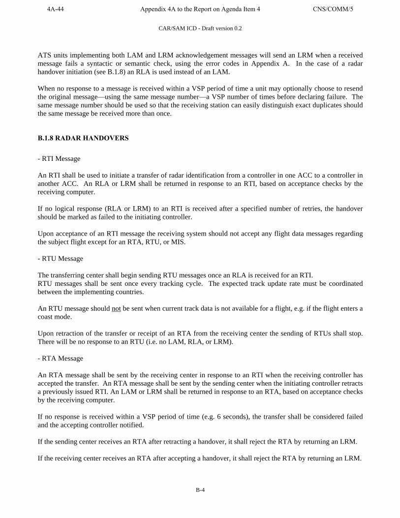
CAR/SAM ICD - Draft version 0.2
B-4
ATS units implementing both LAM and LRM acknowledgement messages will send an LRM when a received message fails a syntactic or semantic check, using the error codes in Appendix A. In the case of a radar handover initiation (see B.1.8) an RLA is used instead of an LAM. When no response to a message is received within a VSP period of time a unit may optionally choose to resend the original message—using the same message number—a VSP number of times before declaring failure. The same message number should be used so that the receiving station can easily distinguish exact duplicates should the same message be received more than once.
B.1.8 RADAR HANDOVERS
- RTI Message An RTI shall be used to initiate a transfer of radar identification from a controller in one ACC to a controller in another ACC. An RLA or LRM shall be returned in response to an RTI, based on acceptance checks by the receiving computer. If no logical response (RLA or LRM) to an RTI is received after a specified number of retries, the handover should be marked as failed to the initiating controller. Upon acceptance of an RTI message the receiving system should not accept any flight data messages regarding the subject flight except for an RTA, RTU, or MIS. - RTU Message The transferring center shall begin sending RTU messages once an RLA is received for an RTI. RTU messages shall be sent once every tracking cycle. The expected track update rate must be coordinated between the implementing countries. An RTU message should not be sent when current track data is not available for a flight, e.g. if the flight enters a coast mode. Upon retraction of the transfer or receipt of an RTA from the receiving center the sending of RTUs shall stop. There will be no response to an RTU (i.e. no LAM, RLA, or LRM). - RTA Message An RTA message shall be sent by the receiving center in response to an RTI when the receiving controller has accepted the transfer. An RTA message shall be sent by the sending center when the initiating controller retracts a previously issued RTI. An LAM or LRM shall be returned in response to an RTA, based on acceptance checks by the receiving computer. If no response is received within a VSP period of time (e.g. 6 seconds), the transfer shall be considered failed and the accepting controller notified. If the sending center receives an RTA after retracting a handover, it shall reject the RTA by returning an LRM. If the receiving center receives an RTA after accepting a handover, it shall reject the RTA by returning an LRM.
4A-44 Appendix 4A to the Report on Agenda Item 4 CNS/COMM/5
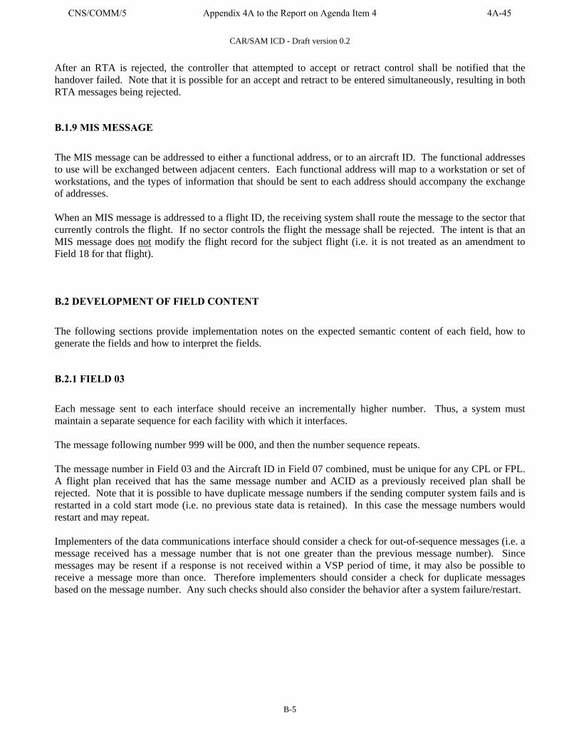
CAR/SAM ICD - Draft version 0.2
B-5
After an RTA is rejected, the controller that attempted to accept or retract control shall be notified that the handover failed. Note that it is possible for an accept and retract to be entered simultaneously, resulting in both RTA messages being rejected.
B.1.9 MIS MESSAGE
The MIS message can be addressed to either a functional address, or to an aircraft ID. The functional addresses to use will be exchanged between adjacent centers. Each functional address will map to a workstation or set of workstations, and the types of information that should be sent to each address should accompany the exchange of addresses. When an MIS message is addressed to a flight ID, the receiving system shall route the message to the sector that currently controls the flight. If no sector controls the flight the message shall be rejected. The intent is that an MIS message does not modify the flight record for the subject flight (i.e. it is not treated as an amendment to Field 18 for that flight).
B.2 DEVELOPMENT OF FIELD CONTENT
The following sections provide implementation notes on the expected semantic content of each field, how to generate the fields and how to interpret the fields.
B.2.1 FIELD 03
Each message sent to each interface should receive an incrementally higher number. Thus, a system must maintain a separate sequence for each facility with which it interfaces. The message following number 999 will be 000, and then the number sequence repeats. The message number in Field 03 and the Aircraft ID in Field 07 combined, must be unique for any CPL or FPL. A flight plan received that has the same message number and ACID as a previously received plan shall be rejected. Note that it is possible to have duplicate message numbers if the sending computer system fails and is restarted in a cold start mode (i.e. no previous state data is retained). In this case the message numbers would restart and may repeat. Implementers of the data communications interface should consider a check for out-of-sequence messages (i.e. a message received has a message number that is not one greater than the previous message number). Since messages may be resent if a response is not received within a VSP period of time, it may also be possible to receive a message more than once. Therefore implementers should consider a check for duplicate messages based on the message number. Any such checks should also consider the behavior after a system failure/restart.
CNS/COMM/5 Appendix 4A to the Report on Agenda Item 4 4A-45
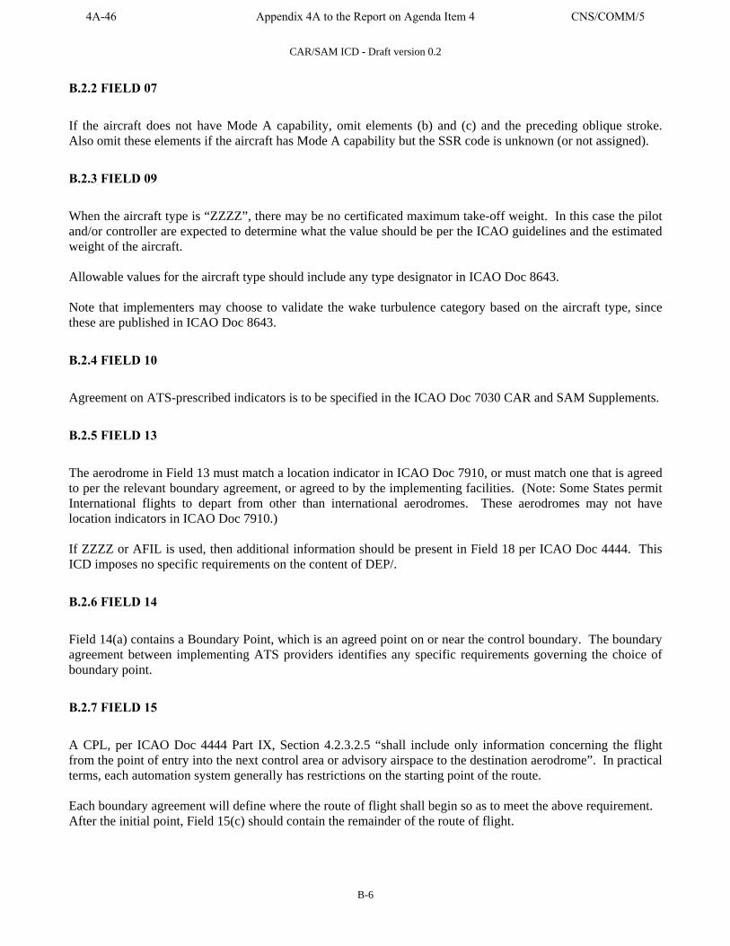
CAR/SAM ICD - Draft version 0.2
B-6
B.2.2 FIELD 07 If the aircraft does not have Mode A capability, omit elements (b) and (c) and the preceding oblique stroke. Also omit these elements if the aircraft has Mode A capability but the SSR code is unknown (or not assigned). B.2.3 FIELD 09 When the aircraft type is “ZZZZ”, there may be no certificated maximum take-off weight. In this case the pilot and/or controller are expected to determine what the value should be per the ICAO guidelines and the estimated weight of the aircraft. Allowable values for the aircraft type should include any type designator in ICAO Doc 8643. Note that implementers may choose to validate the wake turbulence category based on the aircraft type, since these are published in ICAO Doc 8643. B.2.4 FIELD 10 Agreement on ATS-prescribed indicators is to be specified in the ICAO Doc 7030 CAR and SAM Supplements. B.2.5 FIELD 13 The aerodrome in Field 13 must match a location indicator in ICAO Doc 7910, or must match one that is agreed to per the relevant boundary agreement, or agreed to by the implementing facilities. (Note: Some States permit International flights to depart from other than international aerodromes. These aerodromes may not have location indicators in ICAO Doc 7910.) If ZZZZ or AFIL is used, then additional information should be present in Field 18 per ICAO Doc 4444. This ICD imposes no specific requirements on the content of DEP/. B.2.6 FIELD 14 Field 14(a) contains a Boundary Point, which is an agreed point on or near the control boundary. The boundary agreement between implementing ATS providers identifies any specific requirements governing the choice of boundary point. B.2.7 FIELD 15 A CPL, per ICAO Doc 4444 Part IX, Section 4.2.3.2.5 “shall include only information concerning the flight from the point of entry into the next control area or advisory airspace to the destination aerodrome”. In practical terms, each automation system generally has restrictions on the starting point of the route. Each boundary agreement will define where the route of flight shall begin so as to meet the above requirement. After the initial point, Field 15(c) should contain the remainder of the route of flight.
4A-46 Appendix 4A to the Report on Agenda Item 4 CNS/COMM/5
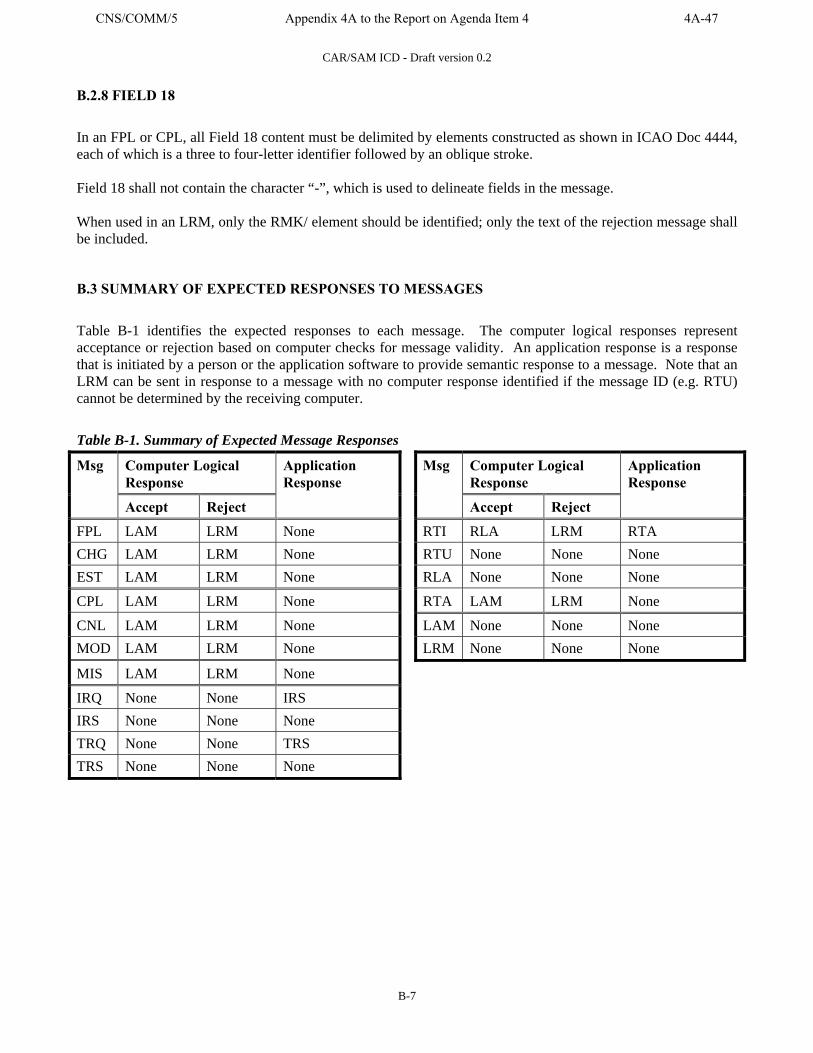
CAR/SAM ICD - Draft version 0.2
B-7
B.2.8 FIELD 18
In an FPL or CPL, all Field 18 content must be delimited by elements constructed as shown in ICAO Doc 4444, each of which is a three to four-letter identifier followed by an oblique stroke. Field 18 shall not contain the character “-”, which is used to delineate fields in the message. When used in an LRM, only the RMK/ element should be identified; only the text of the rejection message shall be included.
B.3 SUMMARY OF EXPECTED RESPONSES TO MESSAGES
Table B-1 identifies the expected responses to each message. The computer logical responses represent acceptance or rejection based on computer checks for message validity. An application response is a response that is initiated by a person or the application software to provide semantic response to a message. Note that an LRM can be sent in response to a message with no computer response identified if the message ID (e.g. RTU) cannot be determined by the receiving computer. Table B-1. Summary of Expected Message Responses
Computer Logical Response
Computer Logical Response
Msg
Accept Reject
Application Response
Msg
Accept Reject
Application Response
FPL LAM LRM None RTI RLA LRM RTA CHG LAM LRM None RTU None None None EST LAM LRM None RLA None None None
CPL LAM LRM None RTA LAM LRM None
CNL LAM LRM None LAM None None None MOD LAM LRM None LRM None None None
MIS LAM LRM None
IRQ None None IRS IRS None None None TRQ None None TRS TRS None None None
CNS/COMM/5 Appendix 4A to the Report on Agenda Item 4 4A-47

4A-48 Appendix 4A to the Report on Agenda Item 4 CNS/COMM/5

CAR/SAM ICD - Draft version 0.2
C-1
APPENDIX C – MODEL OF COMMON BOUNDARY AGREEMENT
C.1 INTRODUCTION
This section documents the data communications interface planned between (…XXX and XXX...) automation systems. The initial interface may have limited message capability. Future evolutions may include additional messages.
C.2 MESSAGE IMPLEMENTATION AND USE
C.2.1 MESSAGES IMPLEMENTED
The data communications interface between the (…XXX and XXX...) automation systems will include CPL and LAM. A CPL will be sent when a flight departs, or when it is within a VSP flying time from the boundary, whichever occurs later. Each CPL that is received and successfully checked for syntactic and semantic correctness will be responded to with an LAM.
C.2.2 ERROR HANDLING
An LAM will be sent in response to each CPL unless the receiving automation system detects an error. The automation system that sent the CPL will wait a VSP period of time for an LAM, and if none is received within the time parameter, it will notify the appropriate position that a failure occurred. Automatic retransmission of the message will not be attempted.
C.2.3 CHANGES TO A CPL
All changes to a previously sent CPL will be coordinated manually between the sending and receiving sectors.
C.2.4 FIELD 08, FLIGHT RULES AND TYPE OF FLIGHT
Regardless of the value in Field 08(a), all CPLs sent on this interface will be assumed to be IFR at the boundary between (…XXX and XXX...) airspace. Each center is only to send flight plans for flights that are IFR at the boundary.
C.2.5 FIELD 09, NUMBER AND TYPE OF AIRCRAFT AND WAKE TURBULENCE CATEGORY
When a specific aircraft type is used, the wake turbulence indicator sent to (XXX) must match the value stored for the aircraft type in the (XXX) database. When “ZZZZ” is used as the aircraft type, the wake turbulence category may be H, M, or L as appropriate.
CNS/COMM/5 Appendix 4A to the Report on Agenda Item 4 4A-49

CAR/SAM ICD - Draft version 0.2
C-2
C.2.6 FIELD 13, DEPARTURE AERODROME AND TIME
Field 13(b), normally only present in FPLs, will be allowed as an optional element for CPLs on this interface. (XXX) expects to include this element in messages; the (XXX) does not.
C.2.7 FIELD 14, ESTIMATE DATA
If a flight is on an adapted route segment when it crosses the control boundary, Field 14(a) will reference the last significant point in the sending center’s airspace. If a flight is on a direct route segment when it crosses the control boundary Field 14(a) will reference the last significant point in the sending center’s airspace. If there is no significant point between the departure aerodrome and the boundary, the departure aerodrome will appear in Field 14(a). All flights are expected to cross the boundary in level flight, at the altitude in Field 14(c). Elements (d) and (e) will not be used, and manual coordination will be required for any flight not in level flight at the boundary.
For flights from ….. to …..: If a flight is on an adapted route segment when it crosses the control boundary, Field 14(a) will reference the first significant point in the receiving center’s airspace. If a flight is on a non-adapted direct route segment when it crosses the control boundary Field 14(a) will reference the intersection of the route with the control boundary.
C.2.8 FIELD 15, ROUTE
Element type (c6) will not be used on this interface. Element 15(c) will be constructed the same way whether the flight is from ….or from ….: If a flight is on an adapted route segment when it crosses the control boundary then Field 15(c) will begin with the same significant point as is in Field 14(a). If a flight is on a direct route segment when it crosses the control boundary then Field 15(c) will begin with the last significant point in the sending center’s airspace, if one exists. If there is no significant point between the departure aerodrome and the boundary then Field 15(c) will begin with “DCT”. After the initial point, Field 15(c) will contain the remainder of the route of flight.
C.2.9 FIELD 16, DESTINATION AERODROME AND TOTAL ESTIMATED ELAPSED TIME, ALTERNATE AERODROME(S)
Fields 16(b) and (c), normally only present in FPLs, will be allowed as optional elements on this interface.
4A-50 Appendix 4A to the Report on Agenda Item 4 CNS/COMM/5
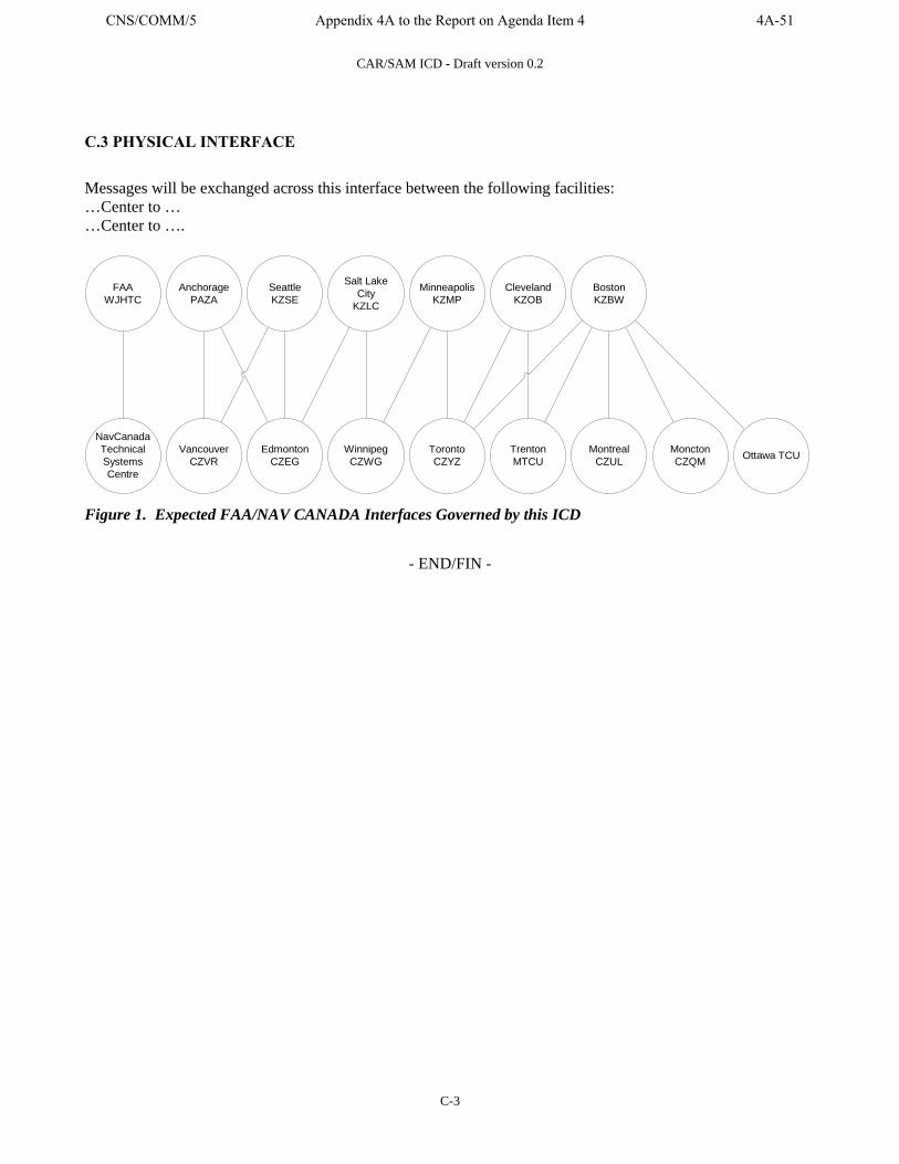
CAR/SAM ICD - Draft version 0.2
C-3
C.3 PHYSICAL INTERFACE
Messages will be exchanged across this interface between the following facilities: …Center to … …Center to ….
VancouverCZVR
SeattleKZSE
Salt LakeCity
KZLC
WinnipegCZWG
MinneapolisKZMP
TorontoCZYZ
MontrealCZUL
MonctonCZQM
NavCanadaTechnicalSystemsCentre
FAAWJHTC
EdmontonCZEG
AnchoragePAZA
ClevelandKZOB
TrentonMTCU
BostonKZBW
Ottawa TCU
Figure 1. Expected FAA/NAV CANADA Interfaces Governed by this ICD
- END/FIN -
CNS/COMM/5 Appendix 4A to the Report on Agenda Item 4 4A-51
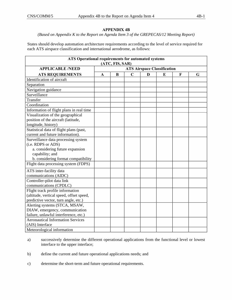
CNS/COMM/5 Appendix 4B to the Report on Agenda Item 4 4B-1
APPENDIX 4B (Based on Appendix K to the Report on Agenda Item 3 of the GREPECAS/12 Meeting Report)
States should develop automation architecture requirements according to the level of service required for each ATS airspace classification and international aerodrome, as follows:
ATS Operational requirements for automated systems (ATC, FIS, SAR)
APPLICABLE /NEED ATS Airspace Classification ATS REQUIREMENTS A B C D E F G
Identification of aircraft Separation Navigation guidance Surveillance Transfer Coordination Information of flight plans in real time Visualization of the geographical position of the aircraft (latitude, longitude, history)
Statistical data of flight plans (past, current and future information).
Surveillance data processing system (i.e. RDPS or ADS)
a. considering future expansion capability; and b. considering format compatibility
Flight data processing system (FDPS)
ATS inter-facility data communications (AIDC)
Controller-pilot data link communications (CPDLC)
Flight track profile information (altitude, vertical speed, offset speed, predictive vector, turn angle, etc.)
Alerting systems (STCA, MSAW, DIAW, emergency, communication failure, unlawful interference, etc.)
Aeronautical Information Services (AIS) Interface
Meteorological information a) successively determine the different operational applications from the functional level or lowest
interface to the upper interface; b) define the current and future operational applications needs; and c) determine the short-term and future operational requirements.
CNS/COMM/5 Report on Agenda Item 5 5-1
Agenda Item 5: Review of the deficiencies related to the CNS systems and other general
issues
Review of the deficiencies in the CNS systems 5.1 The Meeting recalled that in conformity with the standardized methodology for the identification, evaluation and notification of the air navigation deficiencies, the ICAO Regional Offices, and the GREPECAS and its contributory bodies should maintain updated the list of deficiencies and recommend solutions for each of them. 5.2 Likewise, the Meeting took note that the Sixth Meeting of the GREPECAS Aviation Safety Board (ASB) held in Santiago, Chile, on 13 November 2005, reviewed the list of deficiencies and identified those having a greater impact on air operations safety, considering that they required urgent solutions, and thus they were assigned “U” priority, developing action plans in order to resolve them as soon as possible. 5.3 The Meeting reviewed the list of deficiencies in the CNS Field in the CAR/SAM Regions classified with priority “U”, “A” and “B”. When examining Appendices E and F to WP/14, the Meeting noted that there has been progress in the solution of CNS deficiencies in the CAR and SAM regions. Appendix 5A to this part of the Report contains the results of the review carried out by the Meeting in respect to the information contained in the Appendices A, B, C, D, E and F to WP/14 presented in this Meeting.
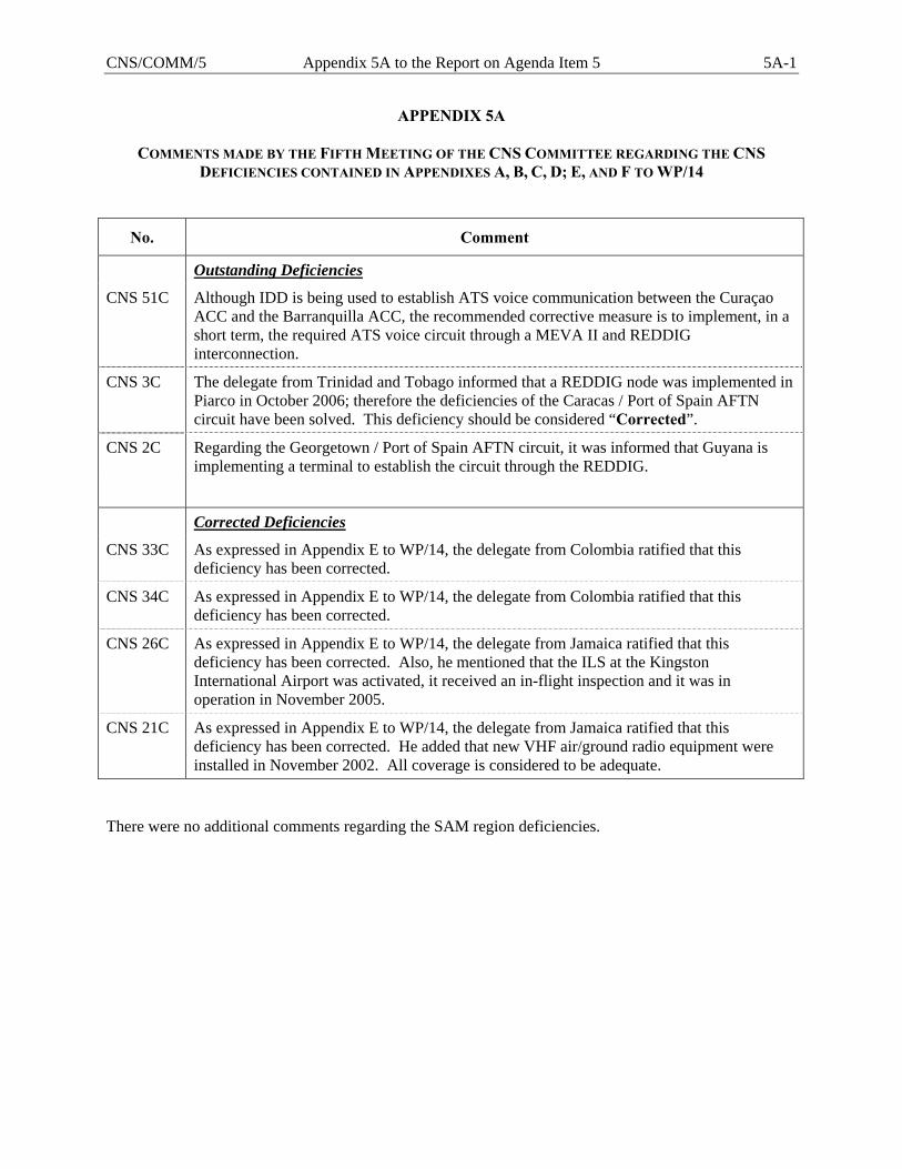
CNS/COMM/5 Appendix 5A to the Report on Agenda Item 5 5A-1
APPENDIX 5A
COMMENTS MADE BY THE FIFTH MEETING OF THE CNS COMMITTEE REGARDING THE CNS DEFICIENCIES CONTAINED IN APPENDIXES A, B, C, D; E, AND F TO WP/14
No. Comment
Outstanding Deficiencies
CNS 51C Although IDD is being used to establish ATS voice communication between the Curaçao ACC and the Barranquilla ACC, the recommended corrective measure is to implement, in a short term, the required ATS voice circuit through a MEVA II and REDDIG interconnection.
CNS 3C The delegate from Trinidad and Tobago informed that a REDDIG node was implemented in Piarco in October 2006; therefore the deficiencies of the Caracas / Port of Spain AFTN circuit have been solved. This deficiency should be considered “Corrected”.
CNS 2C Regarding the Georgetown / Port of Spain AFTN circuit, it was informed that Guyana is implementing a terminal to establish the circuit through the REDDIG.
Corrected Deficiencies
CNS 33C As expressed in Appendix E to WP/14, the delegate from Colombia ratified that this deficiency has been corrected.
CNS 34C As expressed in Appendix E to WP/14, the delegate from Colombia ratified that this deficiency has been corrected.
CNS 26C As expressed in Appendix E to WP/14, the delegate from Jamaica ratified that this deficiency has been corrected. Also, he mentioned that the ILS at the Kingston International Airport was activated, it received an in-flight inspection and it was in operation in November 2005.
CNS 21C As expressed in Appendix E to WP/14, the delegate from Jamaica ratified that this deficiency has been corrected. He added that new VHF air/ground radio equipment were installed in November 2002. All coverage is considered to be adequate.
There were no additional comments regarding the SAM region deficiencies.
CNS/COMM/5 Report on Agenda Item 6 6-1
Agenda Item 6: Terms of Reference and Work Programme of the CNS Committee 6.1 The Meeting reviewed the Terms of Reference and Work Programme of the CNS Committee, based on the review made by the GREPECAS/13 and ACG/6 Meetings, and taking into account the considerations of the Meeting. When carrying out the review, the CNS Committee determined those tasks that were finalized, as well as those that could also be finalized, suggesting their deletion in the work programme. The Meeting also updated the composition of the Committee. The Terms of Reference, Work Programme and the Composition of the CNS Committee, as reviewed by the Meeting, are presented in the Appendix 6A to this part of the Report. Therefore, the Meeting formulated the following Decision: DECISION CNS/5/18 AMENDMENT TO THE TERMS OF REFERENCE, WORK
PROGRAMME AND COMPOSITION OF THE CNS COMMITTEE
That the Terms of Reference, Work Programme and Composition of the CNS Committee as presented in Appendix to this part of the Report be approved.
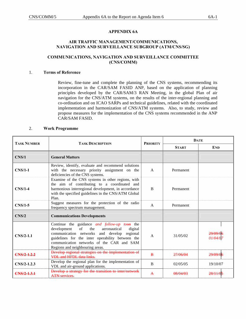
CNS/COMM/5 Appendix 6A to the Report on Agenda Item 6 6A-1
APPENDIX 6A
AIR TRAFFIC MANAGEMENT/COMMUNICATIONS, NAVIGATION AND SURVEILLANCE SUBGROUP (ATM/CNS/SG)
COMMUNICATIONS, NAVIGATION AND SURVEILLANCE COMMITTEE
(CNS/COMM)
1. Terms of Reference
Review, fine-tune and complete the planning of the CNS systems, recommending its incorporation in the CAR/SAM FASID ANP, based on the application of planning principles developed by the CAR/SAM/3 RAN Meeting, in the global Plan of air navigation for the CNS/ATM systems, on the results of the inter-regional planning and co-ordination and on ICAO SARPs and technical guidelines, related with the coordinated implementation and harmonization of CNS/ATM systems. Also, to study, review and propose measures for the implementation of the CNS systems recommended in the ANP CAR/SAM FASID.
2. Work Programme
DATE TASK NUMBER TASK DESCRIPTION PRIORITY
START END
CNS/1 General Matters
CNS/1-1 Review, identify, evaluate and recommend solutions with the necessary priority assignment on the deficiencies of the CNS systems.
A Permanent
CNS/1-4
Examine of the CNS systems in other regions, with the aim of contributing to a coordinated and harmonious interregional development, in accordance with the specified guidelines in the CNS/ATM Global Plan.
B Permanent
CNS/1-5 Suggest measures for the protection of the radio frequency spectrum management. A Permanent
CNS/2 Communications Developments
CNS/2-1.1
Continue the guidance and follow-up toon the development of the aeronautical digital communication networks and develop regional guidelines for the inter operability between the communication networks of the CAR and SAM Regions and neighbouring areas.
A 31/05/02 29/09/06 01/04/07
CNS/2-1.2.2 Develop regional strategies on the implementation of VDL and HFDL data links. B 27/06/04 29/09/06
CNS/2-1.2.3 Develop the regional plan for the implementation of VDL and air-ground applications. B 02/05/05 19/10/07
CNS/2-1.3.1 Develop a strategy for the transition to inter/network ATN services. A 08/04/03 28/11/05
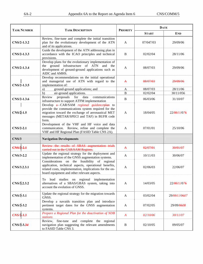
6A-2 Appendix 6A to the Report on Agenda Item 6 CNS/COMM/5
DATE TASK NUMBER TASK DESCRIPTION PRIORITY
START END
CNS/2-1.3.2 Review, fine-tune and complete the initial transition plan for the evolutionary development of the ATN and of its applications.
A 07/047/03 29/09/06
CNS/2-1.3.3 Guide the development of the ATN addressing plan in accordance with the ICAO principles and technical provisions.
B 02/02/04 28/11/06
CNS/2-1.3.4
Develop plans for the evolutionary implementation of the ground infrastructure of ATN and the development of ground-ground applications such as AIDC and AMHS.
A 08/07/03 29/09/06
Develop recommendations on the initial operational and managerial use of ATN with regard to the implementation of:
A 08/07/03 29/09/06
a) ground-ground applications; and A 08/07/03 28/11/06 CNS/2-1.3.5
b) air-ground applications. B 02/02/04 30/11/056
CNS/2-1.3.6 Review proposals for data communications infrastructure to support ATFM implementation B 06/03/06 31/10/07
CNS/2-1.5
Develop a CAR/SAM regional guidanceplan to provide the communications system required for the migration toward the exchange of aeronautical MET messages (METAR/SPECI and TAF) in BUFR code form.
A 18/04/05 22/0911/076
CNS/2-2.1 Development of the VHF and HF voice and data communication. Review, refine and complete the VHF and HF Regional Plan (FASID Table CNS 2A).
A 07/01/01 25/10/06
CNS/3 Navigation Developments
CNS/3-2.1 Review the results of SBAS augmentation trials carried out in the CAR/SAM Regions. A 02/07/01 30/01/07
CNS/3-2.2 Update the regional strategy for the deployment and implementation of the GNSS augmentation systems. A 10/11/03 30/06/07
CNS/3.2.3.1
Considerations on the feasibility of regional application, technical aspects, operational benefits, related costs, implementation, implications for the on-board equipment and other relevant aspects.
A 02/06/03 22/06/07
CNS/3.2.3.2 To lead studies on regional implementation alternatives of a SBAS/GBAS system, taking into account the evolution of GNSS.
A 14/03/05 22/0911/076
CNS/3-3.1 Update the regional strategy for the migration towards GNSS. A 03/02/04 29/0911/0607
CNS/3-3.2 Develop a navaids transition plan and introduce pertinent target dates for the GNSS augmentation systems.
A 07/02/05 29/09/0608
CNS/3-3.3 Prepare a Regional Plan for the deactivation of NDB stations A 02/10/06 30/11/07
CNS/3-3.34 Review, fine-tune and complete the regional navigation plan suggesting the relevant amendments to FASID Table CNS 3.
B 02/10/05 09/05/07
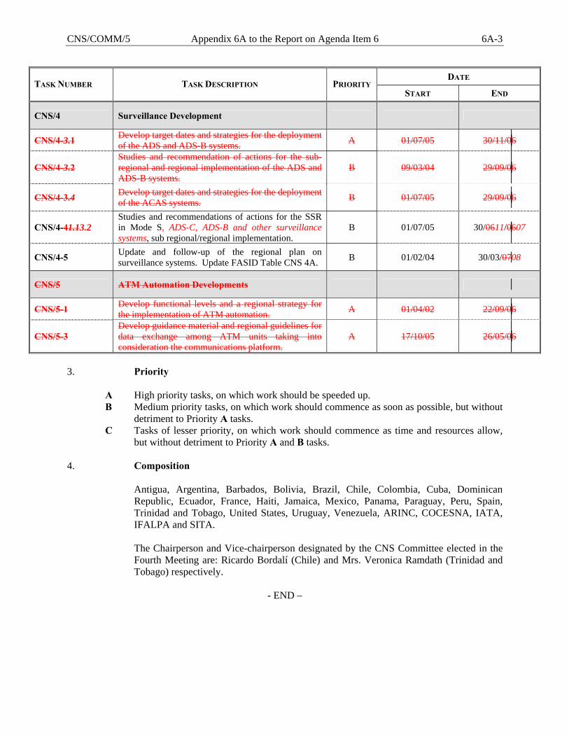
CNS/COMM/5 Appendix 6A to the Report on Agenda Item 6 6A-3
DATE TASK NUMBER TASK DESCRIPTION PRIORITY
START END
CNS/4 Surveillance Development
CNS/4-3.1 Develop target dates and strategies for the deployment of the ADS and ADS-B systems. A 01/07/05 30/11/06
CNS/4-3.2 Studies and recommendation of actions for the sub-regional and regional implementation of the ADS and ADS-B systems.
B 09/03/04 29/09/06
CNS/4-3.4 Develop target dates and strategies for the deployment of the ACAS systems. B 01/07/05 29/09/06
CNS/4-41.13.2 Studies and recommendations of actions for the SSR in Mode S, ADS-C, ADS-B and other surveillance systems, sub regional/regional implementation.
B 01/07/05 30/0611/0607
CNS/4-5 Update and follow-up of the regional plan on surveillance systems. Update FASID Table CNS 4A. B 01/02/04 30/03/0708
CNS/5 ATM Automation Developments
CNS/5-1 Develop functional levels and a regional strategy for the implementation of ATM automation. A 01/04/02 22/09/06
CNS/5-3 Develop guidance material and regional guidelines for data exchange among ATM units taking into consideration the communications platform.
A 17/10/05 26/05/06
3. Priority A High priority tasks, on which work should be speeded up. B Medium priority tasks, on which work should commence as soon as possible, but without
detriment to Priority A tasks. C Tasks of lesser priority, on which work should commence as time and resources allow,
but without detriment to Priority A and B tasks. 4. Composition
Antigua, Argentina, Barbados, Bolivia, Brazil, Chile, Colombia, Cuba, Dominican Republic, Ecuador, France, Haiti, Jamaica, Mexico, Panama, Paraguay, Peru, Spain, Trinidad and Tobago, United States, Uruguay, Venezuela, ARINC, COCESNA, IATA, IFALPA and SITA. The Chairperson and Vice-chairperson designated by the CNS Committee elected in the Fourth Meeting are: Ricardo Bordalí (Chile) and Mrs. Veronica Ramdath (Trinidad and Tobago) respectively.
- END –
CNS/COMM/5 Report on Agenda Item 7 7-1
Agenda Item 7: Other matters 7.1 Future work 7.1 Bearing in mind the task execution status, the Meeting determined that the following tasks could be developed during the immediate stage up until the Sixth Meeting of the CNS Committee, which is almost one year away. Development of the communication systems
• Development of guidelines to achieve the interconnection of the regional and subregional digital communication networks.
• Regional development on the air-ground data links implementation. • Follow-up the implementation of the ATN regional plan and its ground-ground
and air-ground applications. • Continuation of a system’s development for the MET exchange messages in
BUFR code format. • Review the proposals for data communications infrastructure to support the
ATFM implementation. Development of the air navigation systems • Follow-up the studies and results on the regional SBAS/GBAS augmentation. • Update the regional strategy for the deployment of GNSS augmentation systems. • Update and refine the air navigation regional plan (FASID Table CNS 3).
Development of the surveillance systems
• Development of a regional strategy of integrated surveillance. • Refinement and follow-up to the implementation of the regional surveillance
plan, FASID Table 4A. • Development of a standardised regional registry of aircraft equipped with Mode
S transponders.