aspirebook_sum17_web.pdf - aspire bridge magazine
TRANSCRIPT
T H E C O N C R E T E B R I D G E M A G A Z I N E
ww
w.a
sp
ire
br
id
ge
.o
rg
S U M M E R 2 0 1 7
Presorted StandardPostage Paid
Lebanon Junction, KYPermit No. 567
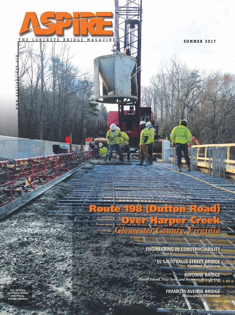
Route 198 (Dutton Road) Over Harper Creek
Gloucester County, Virginia
ENGINEERING IN CONSTRUCTABILITY
EL SALTO FALLS STREET BRIDGE Carlsbad, California
BAYONNE BRIDGEStaten Island, New York, and Bayonne, New Jerssey
FRANKLIN AVENUE BRIDGE Minneapolis, Minnesota
ASPIRE Spring 2016 | 1
Creatin
gBridges
As
Art
®
www.figgbridge.com | 1 80
0 358
3444
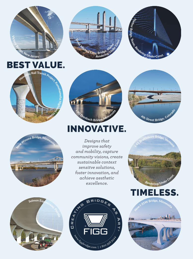
BEST VALUE.
INNOVATIVE.
TIMELESS.
Designs that improve safety
and mobility, capture community visions, create
sustainable context sensitve solutions,
foster innovation, and achieve aesthetic
excellence.
Harb
or
Brid
ge
,Te
xas, R
endering/Under Const.
4th Street Bridge, Colora
doI-90
Dresbach Bridge, Minneso
ta
Honolulu Rail Transit Project, K
ame
ham
eh
aH
igh
way,H
awaii
Vic
tory
Bridge, New Jersey Rendering/Under
Co
nst
.Sa
rah
M
ildred Long Bridge, Main
e
I-91
Brattleboro Bridge, Verm
ont
Rendering/Under Const.
New
I-35W Bridge, Minnesota
New
Winona Bridge, Minnesota
Selmon Expressway, Flo
rida
Anderson Hydra Platforms . . . . . . . . . . .35
DRL . . . . . . . . . . . . . . . . . . . . . . . . . . . . .47
DSI/DYWIDAG-Systems Int’l. USA . . . . .15
FIGG . . . . . . . . . . . . . . . . Inside Front Cover
HDR . . . . . . . . . . . . . . . . Inside Back Cover
LARSA . . . . . . . . . . . . . . . . . . . .Back Cover
MAX USA . . . . . . . . . . . . . . . . . . . . . . . . .31
PCI . . . . . . . . . . . . . . . . . . . . . . . 23, 34, 43
Pedelta. . . . . . . . . . . . . . . . . . . . . . . . . . . .3
Safway . . . . . . . . . . . . . . . . . . . . . . . . . . .37
Skako . . . . . . . . . . . . . . . . . . . . . . . . . . . . .5
STV . . . . . . . . . . . . . . . . . . . . . . . . . . . . . .41
Advertisers’ Index
ASPIRE Summer 2017 | 1
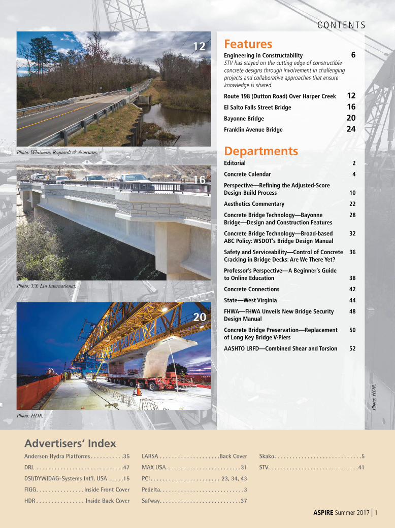
CON T EN T S
Photo: HDR.
Pho
to: H
DR
.
Photo: T.Y. Lin International.
Photo: Whitman, Requardt & Associates.
FeaturesEngineering in Constructability 6STV has stayed on the cutting edge of constructible concrete designs through involvement in challenging projects and collaborative approaches that ensure knowledge is shared.
Route 198 (Dutton Road) Over Harper Creek 12
El Salto Falls Street Bridge 16
Bayonne Bridge 20
Franklin Avenue Bridge 24
DepartmentsEditorial 2
Concrete Calendar 4
Perspective—Refi ning the Adjusted-ScoreDesign-Build Process 10
Aesthetics Commentary 22
Concrete Bridge Technology—Bayonne 28Bridge—Design and Construction Features
Concrete Bridge Technology—Broad-based 32ABC Policy: WSDOT’s Bridge Design Manual
Safety and Serviceability—Control of Concrete 36 Cracking in Bridge Decks: Are We There Yet?
Professor’s Perspective—A Beginner’s Guide to Online Education 38
Concrete Connections 42
State—West Virginia 44
FHWA—FHWA Unveils New Bridge Security 48Design Manual
Concrete Bridge Preservation—Replacement 50of Long Key Bridge V-Piers
AASHTO LRFD—Combined Shear and Torsion 52
20
12
16
Portland Cement Association
2 | ASPIRE Summer 2017
Looking Down the Organizational StovepipeCould the short-term results be obscuring good long-term vision?William Nickas, Editor-in-ChiefP
hoto
: P
CI.
EDITORIAL
Editor-in-Chief William N. Nickas • [email protected]
Managing Technical Editor Dr. Reid W. Castrodale
Technical Editor Dr. Kris M. Brown
Program Manager Nancy Turner • [email protected]
Associate Editor Emily B. Lorenz • [email protected]
Copy Editors Rory Cleveland, Laura Vidale
Layout Design Melissa Gocek, Dorothy Ryan
Editorial Advisory Board William Nickas, Precast/Prestressed Concrete Institute Dr. Reid Castrodale, Castrodale Engineering Consultants PC William R. Cox, American Segmental Bridge Institute Wes Miller, Epoxy Interest Group Ted Neff, Post-Tensioning Institute Alpa Swinger, Portland Cement Association
Cover Deck placement using Virginia Department of Transportation Class A4 all lightweight concrete with stainless-steel reinforcement. Photo: Bryant Contracting.
Ad SalesJim Oestmann Phone: (847) 838-0500 • Cell: (847) 924-5497 Fax: (847) 838-0555 • [email protected]
Reprints Lisa Scacco • [email protected]
Publisher Precast/Prestressed Concrete Institute Bob Risser, PresidentPostmaster: Send address changes to ASPIRE, 200 W. Adams St., Suite 2100, Chicago, IL 60606. Standard postage paid at Chicago, IL, and additional mailing offices.
ASPIRE (Vol. 11, No. 3), ISSN 1935-2093 is published quarterly by the Precast/Prestressed Concrete Institute.
Copyright 2017, Precast/Prestressed Concrete Institute.
If you have a suggestion for a project or topic to be considered for ASPIRE, please send an email to [email protected]
A mazing for me to think that this is my 20th editorial on these pages. One of my themes over the years has been
to share stories that challenge bridge professionals to expand their thinking about business and professional needs. These messages included topics such as teamwork, staying engaged with the profession, and encouraging them to look into who or what causes change in the industry and our profession. A recent conversation with a former colleague falls under this same theme: how do we encourage employees to be experts but not stunt their professional growth.
My former colleague was urgently searching for qualified concrete design engineers. We discussed how long it takes before their engineers-in-training and young professional engineers “move forward” to become project managers. It usually happens quickly, and we agreed that the time is much too short. Generally, companies need to nurture their young engineers and reward “technocratic growth.” As used here, “technocracy” is a system of management where decision-makers are selected based on technological knowledge and expertise. However, as I thought about the conversation, I realized that the issue at this company was not unique.
Are companies pursuing management practices and/or organizational structures to encourage cross-training early at the expense of more thoroughly developing future subject-matter experts in their fields? Vertical movement within the organization can be a detriment to highly skilled technicians and designers who might otherwise love the technical work they do if they had other opportunities for recognition and reward beyond a move up the corporate ladder.
The Corporate Stovepipe
Word Spy defines stovepipe organization as “An organizational model in which departments, managers, and employees have a narrow and rigid set of responsibilities.” A frequent challenge in these types of organizations is to maintain internal communication across departments. However, in working to maintain or develop good internal communications, extreme care must be exercised to not override or even compete with the development of a strong component of subject-matter experts.
Management expert E.J. Muller said, “One of the first things company executives confronted was the failure of the traditional ‘stovepipe organization’ to generate greater responsiveness to customers. . . That realization led
management to examine ‘pipeline,’ rather than stovepipe, management concepts.” These organizations work to grow leaders through the pipeline and reward employees that identify areas of focused expertise.
The business concept to break down internal stovepipes started as an effort to create better internal communication with the end results focused on customer service. However, it may have, in fact, created a work place environment that diminishes the growth and development of subject-matter experts. We must develop pragmatic, tangible business solutions to avoid the reasons people and organizations drift back to stovepipes, without losing the pipeline to developing our skilled technical experts.
What is your experience with the effective development of technical experts in your company or others you’ve worked for? Are gifted engineers asked to take on too much to enhance their earning potential, to the detriment of the engineering department? Do you agree that we still need the wizards and not everyone needs or wants to be the creative one? I’d appreciate hearing your experienceson this topic.
There are generally five organizational structures:
functional, divisional, matrix, team, and network.
Functional— organized by broad business activities—Executive leadership, Finance, Marketing, HR, and Production. Very organized chain of command so that workers can easily communicate within their unit. Interdepartmental coordination and communication suffers.
Divisional—work groups that align according to customers or geography. Some duplicative functions and less efficiency and economy. May cause interdivisional rivalries. Advantage is it serves the customer better.
Matrix—combines divisional into functional. Teams benefit from the expertise of the members while the functional hierarchy evaluates the business activities. Disadvantage is everyone has two bosses.
Team—company operates without chain of command. Virtually flat organizational chart. Without a hierarchy oversight, the risk is employee control. Staff must be trained for broad challenges.
Network—company employs fewer subject-matter experts and relies on a cadre of outside companies to fill business functions.
American Segmental Bridge Institute Epoxy Interest Group Expanded Shale Clay and Slate Institute
Precast/Prestressed Concrete InstitutePost-Tensioning Institute
2000 Ponce de Leon Blvd., Suite 608Coral Gables, Florida 33134, USA
T: 305 648 00 10 F: 305 443 16 03
100 Richmond Street West, Suite 421Toronto ON, Canada M5H 3K6
T: 416 363 70 00 F: 647 344 73 73
Over 2,000 bridge designs aroundthe world, working for ownersand contractors
4 | ASPIRE Summer 2016
CONCRETE CALENDAR 2017–2019
July 11, 2017 FHWA UHPC Implementation Stories WebinarRegister at http://tinyurl.com/j2hqu7a
July 24–28, 2017PCA Professors’ WorkshopPCA Campus Skoki, Ill.
August 2–4, 2017PTI Level 1 & 2 Bonded PT Field Specialist Training and CertificationSeattle, Wash.
August 6–10, 2017 AASHTO Subcommittee on Materials Annual MeetingSheraton Grand Phoenix Phoenix, Ariz.
August 21–22, 20172017 New York City Bridge ConferenceNew York Marriott East Side New York, N.Y.
September 6–8, 20172017 Western Bridge Engineers’ SeminarPortland Marriott Waterfront Portland, Ore.
September 13–15, 2017PTI Level 1 & 2 Bonded PT Field Specialist Training and CertificationPittsburgh, Pa.
September 17–20, 2017AREMA 2017 Annual ConferenceIndiana Convention Center Indianapolis, Ind.
October 2–4, 20173rd International Symposium on Ultra-High Performance Fibre-Reinforced ConcreteMontpellier, France
October 4–6, 20172017 PTI Committee DaysCasaMagna Marriott Cancun ResortCancun, Mexico
October 4–7, 2017PCI Committee Days and Membership ConferenceLoews Chicago O’Hare Rosemont, lll.
October 15–19, 2017ACI Fall 2017 Concrete Convention and Exposition Disneyland Hotel Anaheim, Calif.
October 24–25, 2017ASBI 29th Annual ConventionNew York Marriott Marquis on Times Square New York, N.Y.
December 7–8, 20172017 National Accelerated Bridge Construction ConferenceHyatt Regency Miami Miami, Fla.
January 7–11, 2018Transportation Research Board 97th Annual MeetingWalter E. Washington Convention Center Washington, D.C.
February 20–24, 2018PCI Convention and National Bridge ConferenceColorado Convention Center Denver, Colo.
April 9, 2018 ASBI 2018 Grouting Certification TrainingJ.J. Pickle Research Center Austin, Tex.
June 2–5, 20192nd International Interactive Symposium on Ultra-High-Performance ConcreteHilton Albany Albany, N.Y.
For links to websites, email addresses, or telephone numbers for these events, go to www.aspirebridge.org and select “EVENTS.”
Thomas A. Andres is the assistant state structures design engineer for the Florida Department of Transportation in Tallahassee, Fla.
Dr. Oguzhan Bayrak is a professor at the University of Texas at Aus-tin. Bayrak received the University of Texas System Board of Regents’ outstanding teaching award in 2012 and was
inducted into the university’s Academy of Distinguished Teachers in 2014.
Steve Ernst is an engineer with the Federal Highway Administration. He is currently responsible for bridge technology programs, including policies, procedures,
standards, and practices related to safety and security in bridge structures engineering.
Frederick Gottemoeller is an engineer and architect who specializes in the aesthetic aspects of bridges and highways. He is the author of Bridgescape, a reference book on aesthetics, and was deputy administra-
tor of the Maryland State Highway Adminis-tration.
Dr. Michelle Rambo-Roddenberry is associate professor at the Florida A&M – Florida State University College of Engineering in Tallahassee. Before joining the
university in 2006, she was a consulting bridge engineer for seven years.
CONTRIBUTING AUTHORS
4 | ASPIRE Summer 2017
On page 27 of the Spring 2017 issue of ASPIRE, we incorrectly used the wrong advertisement for LARSA. We regret this error.
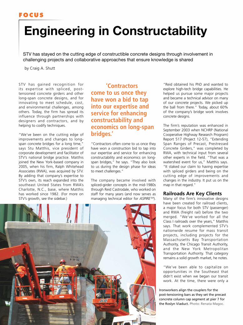
STV has gained recognit ion for i ts expert ise with spl iced, post-tensioned concrete girders and other long-span concrete designs, and for innovating to meet schedule, cost, and environmental challenges, among others. Today, the firm has spread its influence through partnerships with designers and contractors, and by helping to codify techniques.
“We’ve been on the cutting edge of improvements and changes to long-span concrete bridges for a long time,” says Stu Matthis, vice president of corporate development and facilitator of STV’s national bridge practice. Matthis joined the New York-based company in 2005, when his firm, Ralph Whitehead Associates (RWA), was acquired by STV. By adding that company’s expertise to STV’s own, its reach expanded into the southeast United States from RWA’s Charlotte, N.C., base, where Matthis has worked since 1982. (For more on STV’s growth, see the sidebar.)
‘Contractors come to us once they have won a bid to tap into our expertise and service for enhancing constructability and economics on long-span bridges.’
“Contractors often come to us once they have won a construction bid to tap into our expertise and service for enhancing constructability and economics on long-span bridges,” he says. “They also look to us during the design phase for ideas to meet challenges.”
The company became involved with spliced-girder concepts in the mid-1980s through Reid Castrodale, who worked on staff for many years (and now serves as managing technical editor for ASPIRE SM).
“Reid obtained his PhD and wanted to explore high-tech bridge capabilities. He helped us pursue some major projects and became a technical advisor on many of our concrete projects. We picked up the ball from there.” Today, about 60% of the company’s bridge work involves concrete designs.
The firm’s reputation was enhanced in September 2003 when NCHRP (National Cooperative Highway Research Program) Report 517 (Project 12-57), “Extending Span Ranges of Precast, Prestressed Concrete Girders,” was completed by RWA, with technical input from several other experts in the field. “That was a watershed event for us,” Matthis says. “It staked our claim to having expertise with spliced girders and being on the cutting edge of improvements and changes in the industry. It put us on the map in that regard.”
Railroads Are Key ClientsMany of the firm’s innovative designs have been created for railroad clients, a major focus for both STV (passenger) and RWA (freight rail) before the two merged. “We’ve worked for all the Class I railroads over the years,” Matthis says. That work complemented STV’s nationwide resume for mass transit projects, including projects for the Massachusetts Bay Transportation Authority, the Chicago Transit Authority, and the New York Metropol itan Transportation Authority. That category remains a solid growth market, he notes.
“We’ve been able to capitalize on opportunities in the Southeast that didn’t exist when we began our transit work. At the time, there were only a
FOCUS
Engineering in Constructability
STV has stayed on the cutting edge of constructible concrete designs through involvement in
challenging projects and collaborative approaches that ensure knowledge is shared
by Craig A. Shutt
Ironworkers align the couplers for the
post-tensioning bars as they set the precast
concrete column cap segment at pier 7 for
the Roslyn Viaduct. Photo: Renata Magoc.
.few lines in the region, such as Atlanta and Miami. Now, we’ve worked on lines in Charlotte, Raleigh, Hampton, Va., and other areas.”
Such work, while typically providing more flexibility for design solutions, presents different challenges than other transportation projects. State depa r tment s o f t r anspor ta t ion (DOTs) often have structured design requirements, including their own manuals and software. Priorities often are different too.
“Rai l roads are motivated mostly by scheduling and safety, due to their vulnerabilities and the potential nature of accidents. Precast concrete’s production schedules and speed of erection are major benefits.”
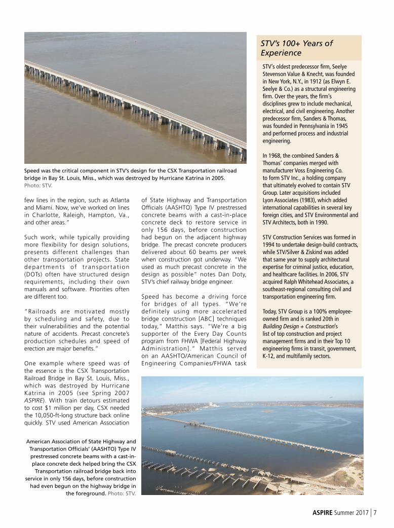
One example where speed was of the essence is the CSX Transportation Railroad Bridge in Bay St. Louis, Miss., which was destroyed by Hurricane Katrina in 2005 (see Spring 2007 ASPIRE). With train detours estimated to cost $1 million per day, CSX needed the 10,050-ft-long structure back online quickly. STV used American Association
of State Highway and Transportation Officials (AASHTO) Type IV prestressed concrete beams with a cast-in-place concrete deck to restore service in only 156 days, before construction had begun on the adjacent highway bridge. The precast concrete producers delivered about 60 beams per week when construction got underway. “We used as much precast concrete in the design as possible” notes Dan Doty, STV’s chief railway bridge engineer.
Speed has become a driving force for bridges of al l types. “We’re definitely using more accelerated bridge construction [ABC] techniques today,” Matthis says. “We’re a big supporter of the Every Day Counts program from FHWA [Federal Highway Administrat ion].” Matthis served on an AASHTO/American Council of Engineering Companies/FHWA task
Speed was the critical component in STV’s design for the CSX Transportation railroad
bridge in Bay St. Louis, Miss., which was destroyed by Hurricane Katrina in 2005.
Photo: STV.
STV’s oldest predecessor firm, Seelye Stevenson Value & Knecht, was founded in New York, N.Y., in 1912 (as Elwyn E. Seelye & Co.) as a structural engineering firm. Over the years, the firm’s disciplines grew to include mechanical, electrical, and civil engineering. Another predecessor firm, Sanders & Thomas, was founded in Pennsylvania in 1945 and performed process and industrial engineering.
In 1968, the combined Sanders & Thomas’ companies merged with manufacturer Voss Engineering Co. to form STV Inc., a holding company that ultimately evolved to contain STV Group. Later acquisitions included Lyon Associates (1983), which added international capabilities in several key foreign cities, and STV Environmental and STV Architects, both in 1990.
STV Construction Services was formed in 1994 to undertake design-build contracts, while STV/Silver & Ziskind was added that same year to supply architectural expertise for criminal justice, education, and healthcare facilities. In 2006, STV acquired Ralph Whitehead Associates, a southeast-regional consulting civil and transportation engineering firm.
Today, STV Group is a 100% employee-owned firm and is ranked 20th in Building Design + Construction’s list of top construction and project management firms and in their Top 10 engineering firms in transit, government, K-12, and multifamily sectors.
STV’s 100+ Years of Experience
American Association of State Highway and
Transportation Officials’ (AASHTO) Type IV
prestressed concrete beams with a cast-in-
place concrete deck helped bring the CSX
Transportation railroad bridge back into
service in only 156 days, before construction
had even begun on the highway bridge in
the foreground. Photo: STV.
ASPIRE Summer 2017 | 7
8 | ASPIRE Summer 2017
force on ABC, which took a high-level approach to the concept. “Our goal was to streamline environmental permitting and allow construction to begin quicker and be more efficient,” he says. “Permitting is a key part of the scheduling process.”
Permitting often goes faster when bridges can span waterways with fewer piers, he notes, leading to longer concrete spans. “Agencies typically want to avoid water obstructions whenever possible, and DOTs are definitely looking at new ways to complete bridges faster and more economically. Those elements often can be helped by more streamlined permitting.”
ABC aided the design and construction of the U.S. Route 29/70 bridge over the Yadkin River, part of a larger $140 mil-lion design-build project for the North Carolina DOT that replaced deteriorated northbound lanes in a tight, environ-mentally sensitive area. With the south-bound bridge on one side carrying four separate phone/cable lines, and a major overhead transmission line and freight railroad bridge on the other, there was little room to operate.
The new 873-ft-long bridge features seven spans of prestressed concrete bulb-tee girders made continuous for live load. The superstructure was con-structed by moving a crane along each span as it was completed, using a top-down approach. “We came up with a concept that wasn’t contemplated in the environmental documentation,” he says. “It assumed you had to get
beside the bridge to build it. We found it would be much quicker to avoid that and work from the top down.”
‘We came up with a concept that wasn’t contemplated in the environmental docu-mentation.’
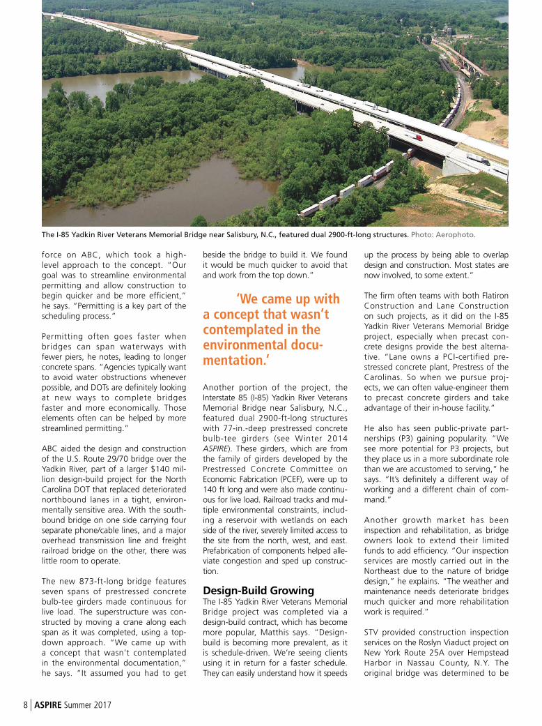
Another portion of the project, the Interstate 85 (I-85) Yadkin River Veterans Memorial Bridge near Salisbury, N.C., featured dual 2900-ft-long structures with 77-in.-deep prestressed concrete bulb-tee girders (see Winter 2014 ASPIRE). These girders, which are from the family of girders developed by the Prestressed Concrete Committee on Economic Fabrication (PCEF), were up to 140 ft long and were also made continu-ous for live load. Railroad tracks and mul-tiple environmental constraints, includ-ing a reservoir with wetlands on each side of the river, severely limited access to the site from the north, west, and east.Prefabrication of components helped alle-viate congestion and sped up construc-tion.
Design-Build GrowingThe I-85 Yadkin River Veterans Memorial Bridge project was completed via a design-build contract, which has become more popular, Matthis says. “Design-build is becoming more prevalent, as it is schedule-driven. We’re seeing clients using it in return for a faster schedule. They can easily understand how it speeds
up the process by being able to overlap design and construction. Most states are now involved, to some extent.”
The firm often teams with both Flatiron Construction and Lane Construction on such projects, as it did on the I-85 Yadkin River Veterans Memorial Bridge project, especially when precast con-crete designs provide the best alterna-tive. “Lane owns a PCI-certified pre-stressed concrete plant, Prestress of the Carolinas. So when we pursue proj-ects, we can often value-engineer them to precast concrete girders and take advantage of their in-house facility.”
He also has seen public-private part-nerships (P3) gaining popularity. “We see more potential for P3 projects, but they place us in a more subordinate role than we are accustomed to serving,” he says. “It’s definitely a different way of working and a different chain of com-mand.”
Another growth market has been inspection and rehabilitation, as bridge owners look to extend their limited funds to add efficiency. “Our inspection services are mostly carried out in the Northeast due to the nature of bridge design,” he explains. “The weather and maintenance needs deteriorate bridges much quicker and more rehabilitation work is required.”
STV provided construction inspection services on the Roslyn Viaduct project on New York Route 25A over Hempstead Harbor in Nassau County, N.Y. The original bridge was determined to be
The I-85 Yadkin River Veterans Memorial Bridge near Salisbury, N.C., featured dual 2900-ft-long structures. Photo: Aerophoto.
too deteriorated to renovate, so a new structure, featuring precast concrete haunched box girders, was designed (see Fall 2009 ASPIRE).
Stakeholder Input IncreasingW i t h b o t h re h a b i l i t a t i o n a n d replacement projects , gather ing and incorporating feedback from all stakeholders has become a key consideration. “People are savvier today and know how to influence designs to suit their needs,” Matthis says. Organizat ions such as the Southern Environmental Law Center influence many designs and bring up issues that must be addressed. “They’re concerned that states are building too many infrastructure projects and not paying close enough attention to environmental issues.” Such factors create a delicate balance between speeding up projects to reduce user costs and ensuring all environmental concerns are met.
‘The level of stake-holder involvement is much higher compared to 20 years ago.’
The firm’s engineers often take part in stakeholder-coordination programs through meetings, workshops, online reviews, and other formats. “Feedback
programs have become much more robust, especially on larger projects,” he says. “The level of stakeholder involvement is much higher compared to 20 years ago.” These programs often are client-driven, he notes. “But if we show we can facilitate them, it’s a positive for our consideration in the project. Owners expect this input today and want the team to be sensitive to these needs.”
The I-85 Yadkin River Veterans Memorial Bridge, for instance, required input from the owner, local citizens, the U.S. Army Corps of Engineers, North Carolina Division of Water Quality, Duke Energy, Norfolk Southern Railway, North Carolina Railroad, and the Federal Energy Regulatory Commission.
On the Cutting EdgeThis range of needs and challenges motivates STV’s designers to stay abreast of new developments with concrete materials. “We try to stay on the cutting edge and are always interested in new techniques,” Matthis says. “We were one of the first to use lightweight concrete in North Carolina on a routine basis for bridge decks. We expect it will be used in girders soon, too. Any use will benefit where there is a sizable dead load.”
Span lengths also will increase, he says. “We’re definitely looking to concrete for longer spans. We’re
already pushing the limits on concrete strength. People chuckle at the notion of 5 ksi today, but that used to be standard. Now, with the addition of materials like fiber reinforcement, post-tensioning techniques, epoxy-coated reinforcement, and corrosion inhibitors, more improvements are possible.”
STV also intends to continue to expand via mergers, like the one with RWA, which added new expertise and regional coverage. “We’re definitely looking for acquisitions throughout our divisions on an active basis,” he says. “We’re looking at more all the time.” Those mergers will help the company remainon the cutting edge and extend its experience so it can innovate as new challenges arise.
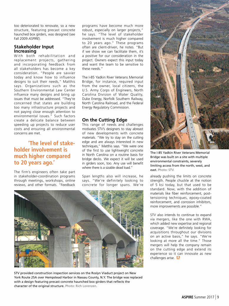
The I-85 Yadkin River Veterans Memorial
Bridge was built on a site with multiple
environmental constraints, severely
limiting access from the north, west, and
east. Photo: STV.
STV provided construction inspection services on the Roslyn Viaduct project on New
York Route 25A over Hempstead Harbor in Nassau County, N.Y. The bridge was replaced
with a design featuring precast concrete haunched box girders that reflects the
character of the original structure. Photo: Rich Lorenzen.
ASPIRE Summer 2017 | 9
PERSPECTIVE
10 | ASPIRE Summer 2017
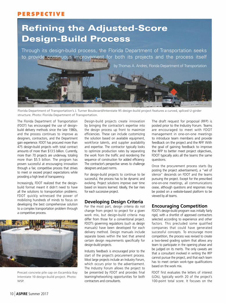
The Florida Department of Transportation (FDOT) has encouraged the use of design-build delivery methods since the late 1980s, and the process continues to improve as designers, contractors, and the Department gain experience. FDOT has procured more than 475 design-build projects with total contract amounts of more than $13.5 billion. Currently, more than 70 projects are underway, totaling more than $5.5 billion. The program has proven successful at encouraging innovation through a fair, competitive process that strives to meet or exceed project expectations while providing a high level of transparency.
Increasingly, FDOT realized that the design-build format meant it didn’t need to have all the solutions to transportation problems. FDOT quickly witnessed the power of mobilizing hundreds of minds to focus on developing the best comprehensive solution to a complex transportation problem through a competitive process.
Design-build projects create innovation by bringing the contractor’s expertise into the design process up front to maximize efficiencies. These can include customizing the solution based on available equipment, workforce talents, and supplier availability and expertise. The contractor typically looks to optimize production rates by separating the work from the traffic and reordering the sequence of construction for added efficiency. The contractor’s perspective serves to challenge designers and past norms.
For design-build projects to continue to be successful, the process has to be dynamic and evolving. Project solutions improve over time based on lessons learned. Ideally, the bar rises for each successive project.
Developing Design CriteriaFor the most part, design criteria do not change from project to project for a given work mix, but design-build criteria may differ from those for a conventional project. FDOT’s governing regulations (such as designmanuals) have been developed for each delivery method. Design manuals include separate boxes within the text that amendcertain design requirements specifically for design-build projects.
Industry feedback is encouraged prior to the start of the project’s procurement process. Most large projects include an Industry Forum, which occurs prior to the advertisement. The Industry Forum allows the project to be presented by FDOT and provides final teaming/networking opportunities for both contractors and consultants.
The draft request for proposal (RFP) is posted prior to the Industry Forum. Teams are encouraged to meet with FDOT management in one-on-one meetings to introduce team members and provide feedback on the project and the RFP. With the goal of gaining feedback to improve the RFP to better meet project objectives, FDOT typically asks all the teams the same questions.
Once the procurement process starts (by posting the project advertisement), a “veil of silence” descends on FDOT and the teams pursuing the project. Except for the prescribed one-on-one meetings, all communications cease, although questions and responses may be posted on a website-based platform to be viewed by all teams.
Encouraging CompetitionFDOT’s design-build program was initially fairly rigid, with a shortlist of approved contractors selected according to experience and other factors. This precluded some qualified companies that could have generated successful concepts. To encourage more competition, the process was revised to create a two-tiered grading system that allows any team to participate in the opening phase and be judged on its merits. The only caveats are that a consultant involved in writing the RFP cannot pursue the project, and that each team has to meet certain work-type qualifications based on the work mix.
FDOT first evaluates the letters of interest (LOIs), typically worth 20 of the project’s 100-point total score. It focuses on the
Refining the Adjusted-Score
Design-Build Process
Through its design-build process, the Florida Department of Transportation seeks
to provide continuous improvement for both its projects and the process itself
by Thomas A. Andres, Florida Department of Transportation
Florida Department of Transportation’s J. Turner Boulevard/Interstate 95 design-build project features a curved, spliced U-girder
structure. Photo: Florida Department of Transportation.
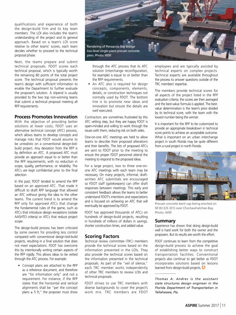
Precast concrete pile cap on Escambia Bay
Interstate 10 design-build project. Photo:
WSP.
ASPIRE Summer 2017 | 11
qualifications and experience of both the design-build firm and its key team members. The LOI also includes the team’s understanding of the project and its general approach. Based on a team’s LOI score relative to other teams’ scores, each team decides whether to proceed to the technical proposal phase.
Next, the teams prepare and submit technical proposals. FDOT scores each technical proposal, which is typically worth the remaining 80 points of the total project score. The technical proposal presents the team’s design with sufficient information to enable the Department to further evaluate the proposer’s solution. A stipend is usually provided to the two top non-winning teams that submit a technical proposal meeting all RFP requirements.
Process Promotes InnovationWith the objective of providing better solutions at lower costs, FDOT uses an alternative technical concept (ATC) process, which allows teams to develop concepts and manage risks that FDOT would assume to be unrealistic on a conventional design-bid-build project. Any deviation from the RFP is by definition an ATC. A proposed ATC must provide an approach equal to or better than the RFP requirements, with no reduction in scope, quality, performance, or reliability. The ATCs are kept confidential prior to the final selection.
In the past, FDOT tended to amend the RFP based on an approved ATC. That made it difficult to draft RFP language that allowed an ATC without giving the idea to the other teams. The current trend is to amend the RFP only for approved ATCs that change the fundamental rules of the game, such as ATCs that introduce design exceptions (violate AASHTO criteria) or ATCs that reduce project scope.
The design-build process has been criticized by some owners for providing less control compared with conventional design-bid-build projects, resulting in a final solution that does not meet expectations. FDOT has overcome this by intentionally writing certain aspects of the RFP rigidly. This allows ideas to be vetted through the ATC process. For example:
• Concept plans are attached to the RFP as a reference document, and therefore are “for information only” and not a requirement. For instance, if the RFP states that the horizontal and vertical alignments shall be “per the concept plans ± 5 ft,” the proposer must show
through the ATC process that its ATC solution (interchange reconfiguration, for example) is equal to or better than the RFP requirements.
• An ATC also is required for design concepts, components, elements, details, or construction techniques not normally used by FDOT. The bottom line is to promote new ideas and innovation but ensure the details are well executed.
Contractors are sometimes frustrated by this ATC vetting step, but they are happy FDOT is open-minded and willing to work through the issues with them, reducing risk on both sides.
One-on-one ATC meetings are held to allow teams to describe their proposed alterations and their benefits. The lists of proposed ATCs are sent to FDOT prior to the meeting to ensure the proper FDOT personnel attend the meeting to respond to the proposed ideas.
For a large project, two to three one-on-one ATC meetings with each team may be necessary. On many projects, informal, draft-written ATC submittals are encouraged so FDOT staff (gatekeepers) can offer draft responses between meetings. This early and consistent feedback allows the teams to better understand FDOT’s intentions and expectations and is focused on achieving an ATC that will eventually be approved by FDOT.
FDOT has approved thousands of ATCs on hundreds of design-build projects, resulting in hundreds of millions of dollars in savings, shorter construction times, and added value.
Scoring FactorsTechnical review committee (TRC) members provide the technical scores based on the information presented in the LOIs. They also provide the technical scores based onthe information presented in the technical proposals. As part of the “veil of silence,”each TRC member works independently of other TRC members to review LOIs andtechnical proposals.
FDOT strives to use TRC members with diverse backgrounds to cover the project’s work mix. TRC members are FDOT
employees and are typically assisted by technical experts on complex projects. Technical experts are available throughout the process to answer questions outside of the TRC members’ expertise.
The members provide technical scores for all aspects of the project listed in the RFP evaluation criteria; the scores are then averaged and the best-value formula is applied. The best-value determination is the team’s price divided by its technical score, with the team with the lowest number being the winner.
It is important for the RFP to be customized to provide an appropriate breakdown in technical score points to achieve an acceptable outcome. What is important on an urban interchange project in south Florida may be quite different from a rural project in north Florida.
SummaryExperience has shown that doing design-build well is hard work for both the owner and the proposers. But its results are worth the effort.
FDOT continues to learn from the competitive design-build process to achieve the goal of establishing better ways to construct transportation facilities. Conventional projects also continue to get better as FDOT incorporates solutions based on lessons learned from design-build projects._____________
Thomas A. Andres is the assistant
state structures design engineer in the
Florida Department of Transportation in
Tallahassee, Fla.
Rendering of Pensacola Bay Bridge
low-level single-piece precast concrete
piers. Photo: WSP.
Precast concrete bent cap being erected on
SR 83 (US 331) over Choctawhatchee Bay.
Photo: WSP.
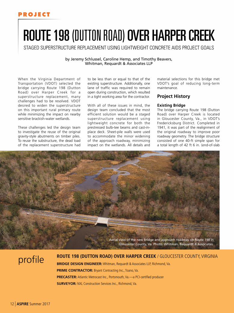
When the Virginia Department of Transportation (VDOT) selected the bridge carrying Route 198 (Dutton Road) over Harper Creek for a superstructure replacement, many challenges had to be resolved. VDOT desired to widen the superstructure on this important rural primary route while minimizing the impact on nearby sensitive brackish-water wetlands.
These challenges led the design team to investigate the reuse of the original gravity-style abutments on timber piles. To reuse the substructure, the dead load of the replacement superstructure had
to be less than or equal to that of the existing superstructure. Additionally, one lane of traffic was required to remain open during construction, which resulted in a tight working area for the contractor.
With all of these issues in mind, the design team concluded that the most efficient solution would be a staged superstructure replacement using lightweight concrete for both the prestressed bulb-tee beams and cast-in-place deck. Sheet-pile walls were used to accommodate the minor widening of the approach roadway, minimizing impact on the wetlands. All details and
material selections for this bridge met VDOT’s goal of reducing long-term maintenance.
Project History
Existing BridgeThe bridge carrying Route 198 (Dutton Road) over Harper Creek is located in Gloucester County, Va., in VDOT’s Fredericksburg District. Completed in 1941, it was part of the realignment of the original roadway to improve poor roadway geometry. The bridge structure consisted of one 40-ft simple span for a total length of 42 ft 6 in. (end-of-slab
profileROUTE 198 (DUTTON ROAD) OVER HARPER CREEK / GLOUCESTER COUNTY, VIRGINIA
BRIDGE DESIGN ENGINEER: Whitman, Requardt & Associates LLP, Richmond, Va.
PRIME CONTRACTOR: Bryant Contracting Inc., Toano, Va.
PRECASTER: Atlantic Metrocast Inc., Portsmouth, Va.—a PCI-certified producer
SURVEYOR: NXL Construction Services Inc., Richmond, Va.
by Jeremy Schlussel, Caroline Hemp, and Timothy Beavers, Whitman, Requardt & Associates LLP
ROUTE 198 (DUTTON ROAD) OVER HARPER CREEKSTAGED SUPERSTRUCTURE REPLACEMENT USING LIGHTWEIGHT CONCRETE AIDS PROJECT GOALS
Aerial view of the new bridge and approach roadway on Route 198 in
Gloucester County, Va. Photo: Whitman, Requardt & Associates.
12 | ASPIRE Summer 2017
PROJECT
to end-of-slab) and was on a tangent alignment with a 0% gradient.
The superstructure was 27 ft 4 in. wide (out-to-out), which included a roadway width of 24 ft from curb to curb and a 1-ft 8-in. combination curb/concrete rail. The superstructure consisted of four haunched cast-in-place reinforced concrete T-beams with a reinforced concrete deck, which was placed integrally with the T-beams. The reinforced concrete deck had an asphalt overlay of approximately 2½ in. The existing superstructure did not have bearing pads, per the original plans.
The bridge substructure units are parallel to each other and perpendicular to the centerline. The abutments are concrete gravity-style with minimal reinforcement supported on timber piles approximately 35 ft in length. Connecting the two abutments are three reinforced concrete struts below the waterline. The wingwalls are oriented 45 degrees to the backwall.
Need for RehabilitationIn 2011 the bridge structure was identified as requiring maintenance. The bridge safety report revealed the general condition of the existing concrete deck to be structurally deficient due to delaminations up to 2½ in. deep throughout the concrete deck, with the bottom of the deck also having delaminations and cracks. In addition, the concrete slab overhangs and railings had delaminated and spalled, exposing corroded reinforcing steel. It was also noted that the exterior beams had cracks, delaminations, and spalls along the sides and bottoms. After preliminary discussions with VDOT, a full bridge replacement was determined not to be a viable option due to its location within existing wetlands and the necessary permits required for such an extensive project. VDOT concluded that the most appropriate solution to rehabilitate
the 70-year-old bridge structure was a superstructure replacement.
An in-depth field investigation of the existing substructure was conducted to determine its condition and suitability to support the new superstructure. All of the visible concrete on the abutments was hammer sounded to record areas of delaminated and spalled concrete. A probing rod was used to determine the extent of features that were under water, such as the concrete struts.
Design AspectsVarious superstructure replacement options were evaluated, including prestressed hollow-core slabs with a reinforced concrete deck, VDOT precast concrete bulb-tee beams with a reinforced concrete deck, and galvanized structural steel girders with a reinforced concrete deck. To determine the most appropriate solution, several factors were evaluated, including geometry, final conditions, maintenance of traffic, environmental issues, and structural design. Ultimately, the final decision centered on which option would not increase the dead load applied to the existing abutments while providing the best long-term, low-maintenance solution.
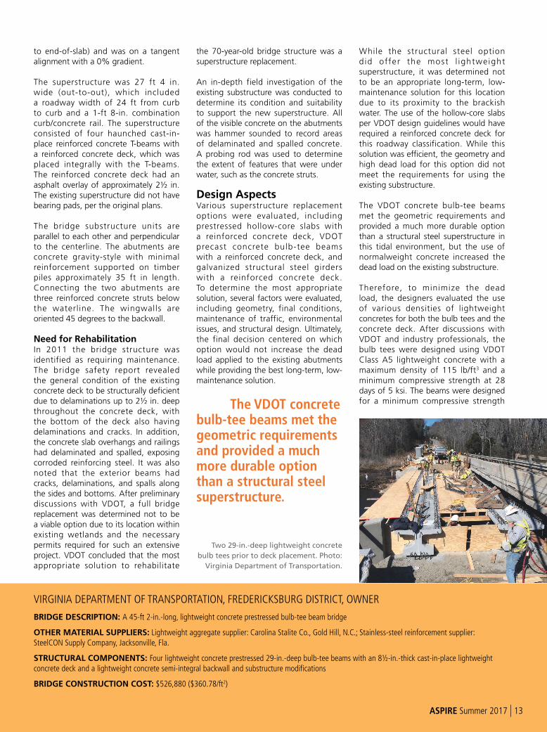
The VDOT concrete bulb-tee beams met the geometric requirements and provided a much more durable option than a structural steel superstructure.
While the structural steel option d id offer the most l ightweight superstructure, it was determined not to be an appropriate long-term, low-maintenance solution for this location due to its proximity to the brackish water. The use of the hollow-core slabs per VDOT design guidelines would have required a reinforced concrete deck for this roadway classification. While this solution was efficient, the geometry and high dead load for this option did not meet the requirements for using the existing substructure.
The VDOT concrete bulb-tee beams met the geometric requirements and provided a much more durable option than a structural steel superstructure in this tidal environment, but the use of normalweight concrete increased the dead load on the existing substructure.
Therefore, to minimize the dead load, the designers evaluated the use of various densities of lightweight concretes for both the bulb tees and the concrete deck. After discussions with VDOT and industry professionals, the bulb tees were designed using VDOT Class A5 lightweight concrete with a maximum density of 115 lb/ft3 and a minimum compressive strength at 28 days of 5 ksi. The beams were designed for a minimum compressive strength
VIRGINIA DEPARTMENT OF TRANSPORTATION, FREDERICKSBURG DISTRICT, OWNER
BRIDGE DESCRIPTION: A 45-ft 2-in.-long, lightweight concrete prestressed bulb-tee beam bridge
OTHER MATERIAL SUPPLIERS: Lightweight aggregate supplier: Carolina Stalite Co., Gold Hill, N.C.; Stainless-steel reinforcement supplier: SteelCON Supply Company, Jacksonville, Fla.
STRUCTURAL COMPONENTS: Four lightweight concrete prestressed 29-in.-deep bulb-tee beams with an 8½-in.-thick cast-in-place lightweight concrete deck and a lightweight concrete semi-integral backwall and substructure modifications
BRIDGE CONSTRUCTION COST: $526,880 ($360.78/ft2)
Two 29-in.-deep lightweight concrete
bulb tees prior to deck placement. Photo:
Virginia Department of Transportation.
ASPIRE Summer 2017 | 13
at the time of transfer of 4 ksi. The deck, semi-integral backwalls, parapets, and subst ructure modi f i ca t ions were designed using VDOT Class A4 lightweight concrete with a maximum density of 105 lb/ft3.
To reach these lower densities, the concrete mixture proportions for the beams required the use of lightweight coarse aggregates, while the concrete deck contained both lightweight coarse and fine aggregates. Fly ash and silica fume were also incorporated into the beam concrete mixture proportions. The only pozzolan included in the deck concrete was fly ash.
The concrete test results indicated permeability values of less than 900 coulombs for the reinforced deck concrete. According to ASTM C1202, these results correspond to a “very low” permeability. This added benefit of the lightweight concrete will provide protection to the reinforcing steel from chloride attack. Low-permeability concrete will, in turn, contribute to the long-term low-maintenance of the structure. Tests on the beams’ concrete revealed another benefit: although the design required a 28-day compressive strength of 5 ksi, on average the concrete of the beams had compressive strengths between 8 and 9 ksi at 28 days.
In addition to the lightweight concretes, corrosion-resistant reinforcing steel was used throughout the project, following VDOT design procedures. The mild reinforcing steel located in the bulb tees and substructure modifications was designated as Class I (ASTM A1035, low-carbon/chromium reinforcing steel) and the reinforcing steel located in the superstructure, including the semi-
integral backwall, was designated as Class II (stainless-steel clad deformed). However, because these bars are not domestically produced, the project used Class I I I (ASTM A955, solid stainless-steel) bars for concrete reinforcement.
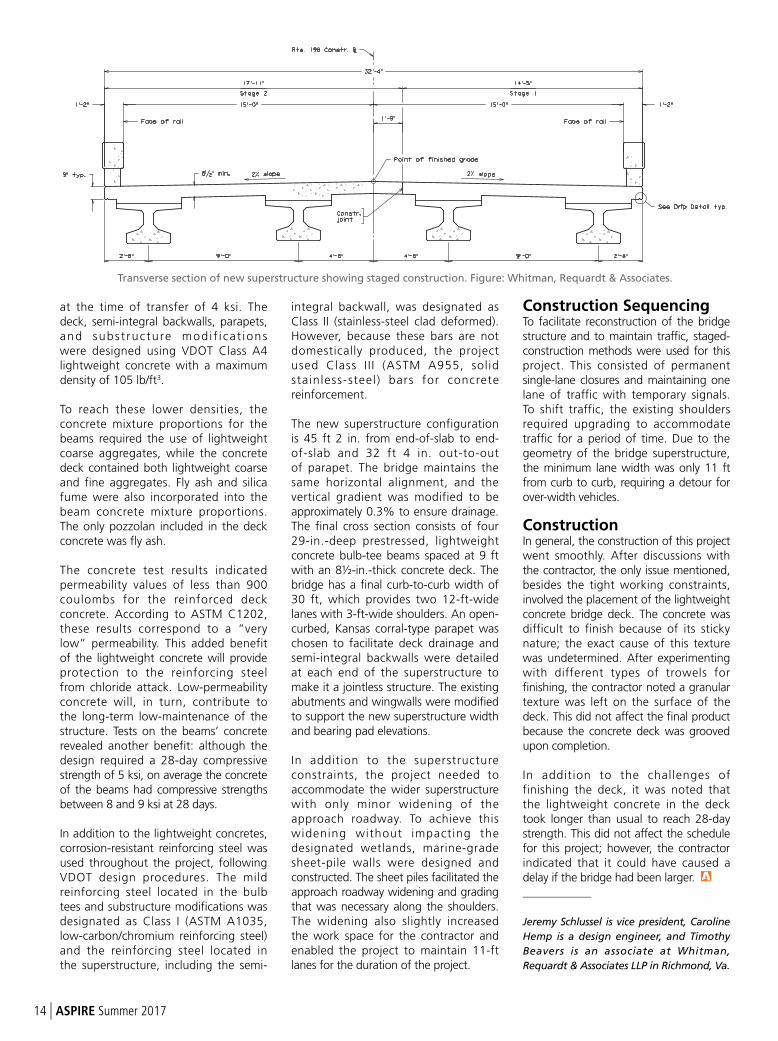
The new superstructure configuration is 45 ft 2 in. from end-of-slab to end-of-slab and 32 ft 4 in. out-to-out of parapet. The bridge maintains the same horizontal alignment, and the vertical gradient was modified to be approximately 0.3% to ensure drainage. The final cross section consists of four 29-in.-deep prestressed, lightweight concrete bulb-tee beams spaced at 9 ft with an 8½-in.-thick concrete deck. The bridge has a final curb-to-curb width of 30 ft, which provides two 12-ft-wide lanes with 3-ft-wide shoulders. An open-curbed, Kansas corral-type parapet was chosen to facilitate deck drainage and semi-integral backwalls were detailed at each end of the superstructure to make it a jointless structure. The existing abutments and wingwalls were modified to support the new superstructure width and bearing pad elevations.
In addition to the superstructure constraints, the project needed to accommodate the wider superstructure with only minor widening of the approach roadway. To achieve this widening without impacting the designated wetlands, marine-grade sheet-pile walls were designed and constructed. The sheet piles facilitated the approach roadway widening and grading that was necessary along the shoulders. The widening also slightly increased the work space for the contractor and enabled the project to maintain 11-ft lanes for the duration of the project.
Construction SequencingTo facilitate reconstruction of the bridge structure and to maintain traffic, staged-construction methods were used for this project. This consisted of permanent single-lane closures and maintaining one lane of traffic with temporary signals. To shift traffic, the existing shoulders required upgrading to accommodate traffic for a period of time. Due to the geometry of the bridge superstructure, the minimum lane width was only 11 ft from curb to curb, requiring a detour for over-width vehicles.
ConstructionIn general, the construction of this project went smoothly. After discussions with the contractor, the only issue mentioned, besides the tight working constraints, involved the placement of the lightweight concrete bridge deck. The concrete was difficult to finish because of its sticky nature; the exact cause of this texture was undetermined. After experimenting with different types of trowels for finishing, the contractor noted a granular texture was left on the surface of the deck. This did not affect the final product because the concrete deck was grooved upon completion.
In addition to the challenges of finishing the deck, it was noted that the lightweight concrete in the deck took longer than usual to reach 28-day strength. This did not affect the schedule for this project; however, the contractor indicated that it could have caused a delay if the bridge had been larger.
_____________
Jeremy Schlussel is vice president, Caroline
Hemp is a design engineer, and Timothy
Beavers is an associate at Whitman,
Requardt & Associates LLP in Richmond, Va.
Transverse section of new superstructure showing staged construction. Figure: Whitman, Requardt & Associates.
14 | ASPIRE Summer 2017
Grade 100 Reinforcement
Less Steel – More Strength
www.dsiamerica.com
Local Presence – Global Competence
DYWIDAG THREADBAR® Grade 100
ASPIRE Summer 2017 | 15
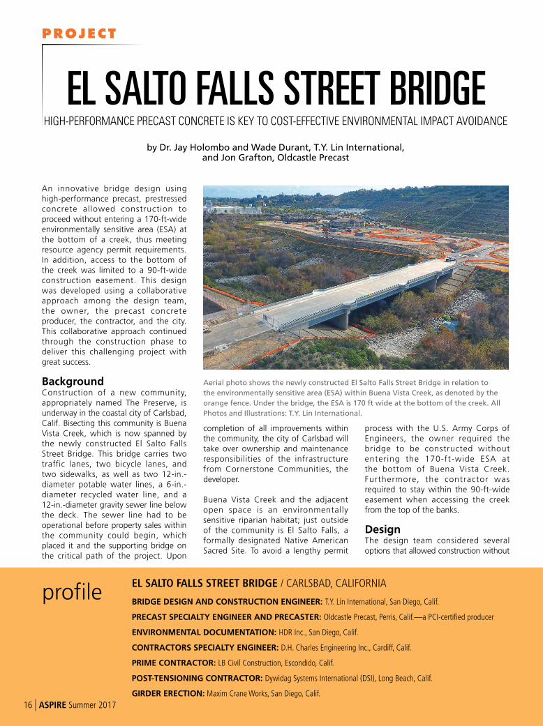
An innovative bridge design using high-performance precast, prestressed concrete allowed construction to proceed without entering a 170-ft-wide environmentally sensitive area (ESA) at the bottom of a creek, thus meeting resource agency permit requirements. In addition, access to the bottom of the creek was limited to a 90-ft-wide construction easement. This design was developed using a collaborative approach among the design team, the owner, the precast concrete producer, the contractor, and the city. This collaborative approach continued through the construction phase to deliver this challenging project with great success.
BackgroundConstruction of a new community, appropriately named The Preserve, is underway in the coastal city of Carlsbad, Calif. Bisecting this community is Buena Vista Creek, which is now spanned by the newly constructed El Salto Falls Street Bridge. This bridge carries two traffic lanes, two bicycle lanes, and two sidewalks, as well as two 12-in.-diameter potable water lines, a 6-in.-diameter recycled water line, and a 12-in.-diameter gravity sewer line below the deck. The sewer line had to be operational before property sales within the community could begin, which placed it and the supporting bridge on the critical path of the project. Upon
completion of all improvements within the community, the city of Carlsbad will take over ownership and maintenance responsibilities of the infrastructure from Cornerstone Communities, the developer.
Buena Vista Creek and the adjacent open space is an environmentally sensitive riparian habitat; just outside of the community is El Salto Falls, a formally designated Native American Sacred Site. To avoid a lengthy permit
process with the U.S. Army Corps of Engineers, the owner required the bridge to be constructed without entering the 170-ft-wide ESA at the bottom of Buena Vista Creek. Furthermore, the contractor was required to stay within the 90-ft-wide easement when accessing the creek from the top of the banks.
DesignThe design team considered several options that allowed construction without
profileEL SALTO FALLS STREET BRIDGE / CARLSBAD, CALIFORNIA
BRIDGE DESIGN AND CONSTRUCTION ENGINEER: T.Y. Lin International, San Diego, Calif.
PRECAST SPECIALTY ENGINEER AND PRECASTER: Oldcastle Precast, Perris, Calif.—a PCI-certified producer
ENVIRONMENTAL DOCUMENTATION: HDR Inc., San Diego, Calif.
CONTRACTORS SPECIALTY ENGINEER: D.H. Charles Engineering Inc., Cardiff, Calif.
PRIME CONTRACTOR: LB Civil Construction, Escondido, Calif.
POST-TENSIONING CONTRACTOR: Dywidag Systems International (DSI), Long Beach, Calif.
GIRDER ERECTION: Maxim Crane Works, San Diego, Calif.
by Dr. Jay Holombo and Wade Durant, T.Y. Lin International, and Jon Grafton, Oldcastle Precast
EL SALTO FALLS STREET BRIDGEHIGH-PERFORMANCE PRECAST CONCRETE IS KEY TO COST-EFFECTIVE ENVIRONMENTAL IMPACT AVOIDANCE
Aerial photo shows the newly constructed El Salto Falls Street Bridge in relation to
the environmentally sensitive area (ESA) within Buena Vista Creek, as denoted by the
orange fence. Under the bridge, the ESA is 170 ft wide at the bottom of the creek. All
Photos and Illustrations: T.Y. Lin International.
16 | ASPIRE Summer 2017
PROJECT
entering the ESA. These included steel girder, steel truss, and high-performance precast concrete options. Long lead times and estimated higher costs precluded steel alternatives. Inspired by the ASPIRESM
Winter 2008 article “Precast Enables Total Environmental Avoidance” about the Daggett Road Bridge, the design team selected a high-performance precast concrete spliced-girder bridge option, where the center span girder segments are erected from previously constructed end spans.
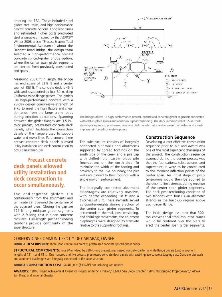
Measuring 288.6 ft in length, the bridge has end spans of 52.8 ft and a center span of 183 ft. The concrete deck is 46 ft wide and is supported by four 84-in.-deep California wide-flange girders. The girders use high-performance concrete with a 28-day design compressive strength of 9 ksi to meet the high flexure and shear demands from the large crane loads during erection operations. Spanning between the girder flanges are 3.5-in.-thick precast, prestressed concrete deck panels, which facilitate the connection details of the hangers used to support water and sewer lines. Furthermore, these precast concrete deck panels allowed utility installation and deck construction to occur simultaneously.
Precast concrete deck panels allowed utility installation and deck construction to occur simultaneously.
Th e en d - s egmen t g i rde r s r un continuously from the abutments and terminate 29 ft beyond the centerline of the adjacent piers. Closing the gap are 121-ft-long midspan girder segments with 2-ft-long cast-in-place concrete closures. Full-length post-tensioning tendons provide continuity of the superstructure.
The substructure consists of integrally connected pier walls and abutments supported by spread footings on the south side of the creek and a pile cap with drilled-hole, cast-in-place pile foundations on the north side. To minimize the width of the footing and proximity to the ESA boundary, the pier walls are pinned to their footings with a single row of reinforcement.
The integrally connected abutment diaphragms are relatively massive, with depths exceeding 18 ft and a thickness of 5 ft. These elements served as counterweights during erection of the center span girder segments. To accommodate thermal, post-tensioning, and shrinkage movements, the abutment diaphragms were designed to translate relative to the supporting footings.
Construction SequenceDeveloping a cost-effective construction sequence prior to bid and award was one of the most significant challenges of the project. The construction sequence assumed during the design process was that the foundations, substructures, and superstructure were to be constructed to the moment inflection points of the center span. An initial stage of post-tensioning would then be applied to the deck to limit stresses during erection of the center span girder segments. The deck post-tensioning consisted of two tendons with four 0.6-in.-diameter strands in the build-up regions above each girder flange.
The initial design assumed that 300-ton conventional track-mounted cranes would be centered over the piers to erect the center span girder segments.
CORNERSTONE COMMUNITIES/CITY OF CARLSBAD, OWNERBRIDGE DESCRIPTION: Three-span continuous precast, prestressed concrete spliced-girder bridge
STRUCTURAL COMPONENTS: Four 84-in.-deep by 288-ft-long precast, prestressed concrete California wide-flange girders (cast in segment lengths of 121 ft and 78 ft). One hundred and five precast, prestressed concrete deck panels with cast-in-place concrete topping slab. Concrete pier walls and abutment diaphragms are integrally connected to the superstructure.
BRIDGE CONSTRUCTION COST: $4,400,000 ($332/ft2) not including wet utilities
AWARDS: “2016 Project Achievement Award for Projects under $17 million,” CMAA San Diego Chapter; “2016 Outstanding Project Award,” APWA San Diego and Imperial Chapter
The bridge utilizes 12 high-performance precast, prestressed concrete girder segments connected
with cast-in-place splices and continuous post-tensioning. The deck is comprised of 3.5-in.-thick
stay-in-place precast, prestressed concrete deck panels that span between the girders and a cast-
in-place reinforced concrete topping.
ASPIRE Summer 2017 | 17
Fully assembled, each crane weighs 640,000 lb, compared to the notional design truck (HL-93), which weighs 72,000 lb. The combined weight of the track-mounted crane and the supported girder equaled the weight of span 3 and the cantilever bridge deck and girders. Crane loads were the controlling load case for the shear reinforcement near the piers. Pretensioning strands at both the top and bottom of the girder controlled stresses during transport, e rect ion, and subsequent deck construction. Girder post-tensioning provides continuity and load resistance of the completed bridge.
A key assumption was that the cranes would be fully assembled prior to driving onto the newly completed end spans of the bridge. Consequently, significant lateral surcharge pressures on the tall abutment diaphragms were anticipated when the cranes
traveled over the bridge approaches. It was also assumed that these lateral surcharge pressures would be resisted with deadman anchors that would be subsequently removed in later phases of the construction process.
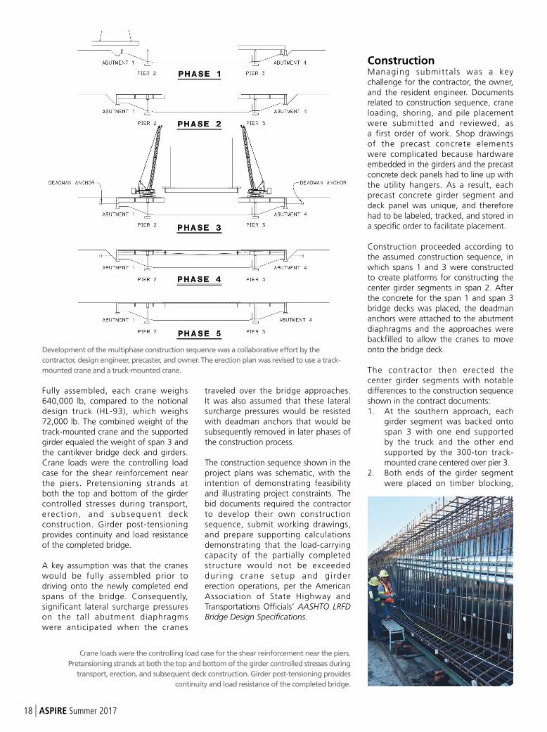
The construction sequence shown in the project plans was schematic, with the intention of demonstrating feasibility and illustrating project constraints. The bid documents required the contractor to develop their own construction sequence, submit working drawings, and prepare supporting calculations demonstrating that the load-carrying capacity of the partially completed structure would not be exceeded dur ing c rane setup and g i rder erection operations, per the American Association of State Highway and Transportations Officials’ AASHTO LRFD Bridge Design Specifications.
ConstructionManaging submittals was a key challenge for the contractor, the owner, and the resident engineer. Documents related to construction sequence, crane loading, shoring, and pile placement were submitted and reviewed, as a first order of work. Shop drawings of the precast concrete elements were complicated because hardware embedded in the girders and the precast concrete deck panels had to line up with the utility hangers. As a result, each precast concrete girder segment and deck panel was unique, and therefore had to be labeled, tracked, and stored in a specific order to facilitate placement.
Construction proceeded according to the assumed construction sequence, in which spans 1 and 3 were constructed to create platforms for constructing the center girder segments in span 2. After the concrete for the span 1 and span 3 bridge decks was placed, the deadman anchors were attached to the abutment diaphragms and the approaches were backfilled to allow the cranes to move onto the bridge deck.
The contractor then erected the center girder segments with notable differences to the construction sequence shown in the contract documents: 1. At the southern approach, each
girder segment was backed onto span 3 with one end supported by the truck and the other end supported by the 300-ton track-mounted crane centered over pier 3.
2. Both ends of the girder segment were placed on timber blocking,
Crane loads were the controlling load case for the shear reinforcement near the piers.
Pretensioning strands at both the top and bottom of the girder controlled stresses during
transport, erection, and subsequent deck construction. Girder post-tensioning provides
continuity and load resistance of the completed bridge.
Development of the multiphase construction sequence was a collaborative effort by the
contractor, design engineer, precaster, and owner. The erection plan was revised to use a track-
mounted crane and a truck-mounted crane.
18 | ASPIRE Summer 2017
where strongback brackets were attached to the ends. Upon erection, these brackets temporarily supported the center girder segments and the closure concrete until the continuous post-tensioning was applied.
3. After attaching the leads to both ends of the girder segment, the track-mounted crane lifted the girder segment over the creek.
4. Leads from a 500-ton truck-mounted hydraulic crane centered over pier 2 were then attached to the north end of the girder segment. Load was released from the 300-ton crane as the south end was lowered onto timber blocking near pier 3.
5. The leads from the 300-ton crane were then attached to the south end, which allowed the girder segment to be positioned and lowered into place with both cranes.
The contractor’s choice of erecting the center segments with only one 300-ton track-mounted crane significantly reduced set-up time and cost. Analysis from the contractor’s specialty engineer demonstrated that additional shear reinforcement in these girder segments was required in a critical location as a result of this choice.
Closure-pour concrete and subsequent post-tensioning were completed prior to construction of the deck in the center of span 2. Unconvinced by the designer’s
claim that the girders would not buckle during post-tensioning operations, the contractor installed timber bracing and metal straps at frequent intervals along the unsupported length of the girders. The bracing and straps were removed after deck placement.
Rolling platforms supported by the bottom flanges of the girders were used to install the suspended wet utility lines without entering the ESA. Installation, testing, and in-service use of the gravity sewer line were completed on time to allow the subsequent phases of the project to proceed on schedule.
SummaryThe design team faced the significant challenge of developing a cost-effective design that could be constructed without entering the 170-ft-wide ESA,
within a tight schedule and with limited access. An innovative design using high-performance precast, prestressed concrete girders was developed based on a collaborative effort of the design team, the owner, the precast concrete producer, and the city. This collaborative approach continued into the construction phase, where the contractor further refined the concept with an alternative crane setup and erection plan for the center girder segments. The resulting bridge was delivered on time and with great success.
______________
Dr. Jay Holombo is a senior project manager
and Wade Durant is a senior bridge
engineer, both with T.Y. Lin International in
San Diego, Calif. Jon Grafton is the western
region business development manager of
Oldcastle Precast in Perris, Calif.
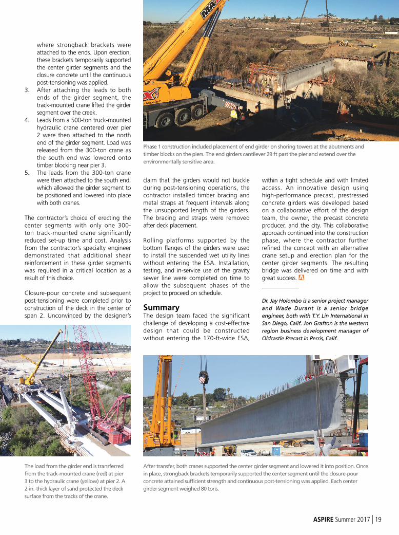
Phase 1 construction included placement of end girder on shoring towers at the abutments and
timber blocks on the piers. The end girders cantilever 29 ft past the pier and extend over the
environmentally sensitive area.
After transfer, both cranes supported the center girder segment and lowered it into position. Once
in place, strongback brackets temporarily supported the center segment until the closure-pour
concrete attained sufficient strength and continuous post-tensioning was applied. Each center
girder segment weighed 80 tons.
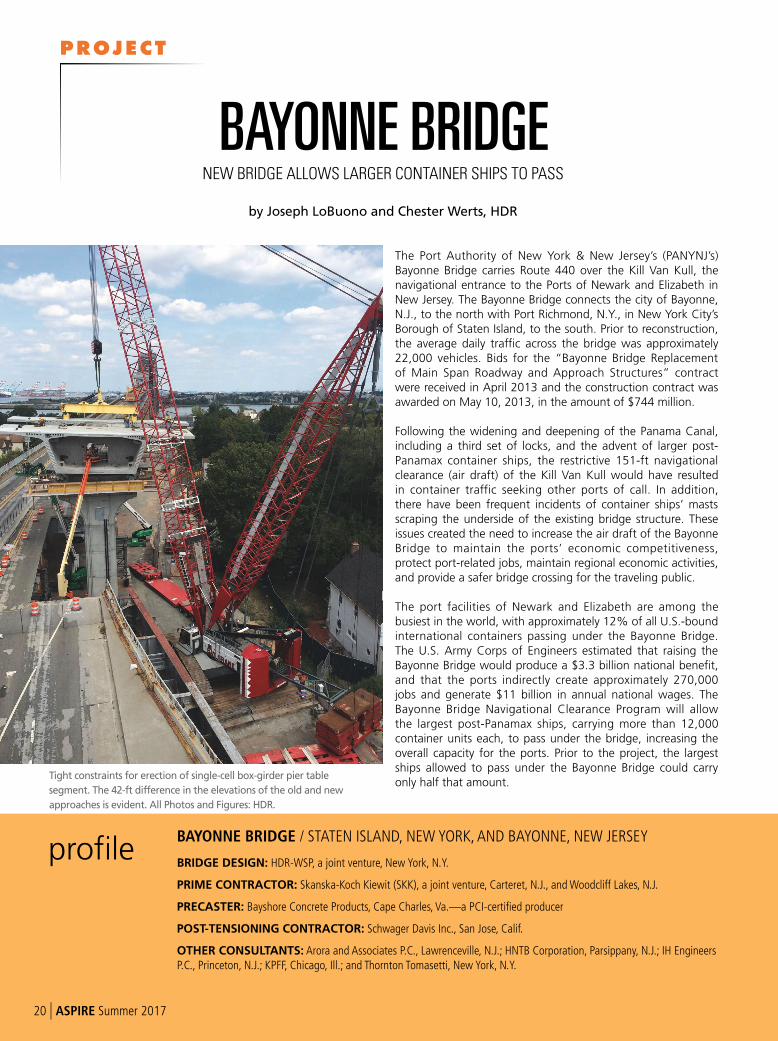
The load from the girder end is transferred
from the track-mounted crane (red) at pier
3 to the hydraulic crane (yellow) at pier 2. A
2-in.-thick layer of sand protected the deck
surface from the tracks of the crane.
ASPIRE Summer 2017 | 19
The Port Authority of New York & New Jersey’s (PANYNJ’s) Bayonne Bridge carries Route 440 over the Kill Van Kull, the navigational entrance to the Ports of Newark and Elizabeth in New Jersey. The Bayonne Bridge connects the city of Bayonne, N.J., to the north with Port Richmond, N.Y., in New York City’s Borough of Staten Island, to the south. Prior to reconstruction, the average daily traffic across the bridge was approximately 22,000 vehicles. Bids for the “Bayonne Bridge Replacement of Main Span Roadway and Approach Structures” contract were received in April 2013 and the construction contract was awarded on May 10, 2013, in the amount of $744 million.
Following the widening and deepening of the Panama Canal, including a third set of locks, and the advent of larger post-Panamax container ships, the restrictive 151-ft navigational clearance (air draft) of the Kill Van Kull would have resulted in container traffic seeking other ports of call. In addition, there have been frequent incidents of container ships’ masts scraping the underside of the existing bridge structure. These issues created the need to increase the air draft of the Bayonne Bridge to maintain the ports’ economic competitiveness, protect port-related jobs, maintain regional economic activities, and provide a safer bridge crossing for the traveling public.
The port facilities of Newark and Elizabeth are among the busiest in the world, with approximately 12% of all U.S.-bound international containers passing under the Bayonne Bridge. The U.S. Army Corps of Engineers estimated that raising the Bayonne Bridge would produce a $3.3 billion national benefit, and that the ports indirectly create approximately 270,000 jobs and generate $11 billion in annual national wages. The Bayonne Bridge Navigational Clearance Program will allow the largest post-Panamax ships, carrying more than 12,000 container units each, to pass under the bridge, increasing the overall capacity for the ports. Prior to the project, the largest ships allowed to pass under the Bayonne Bridge could carry only half that amount.
profileBAYONNE BRIDGE / STATEN ISLAND, NEW YORK, AND BAYONNE, NEW JERSEY
BRIDGE DESIGN: HDR-WSP, a joint venture, New York, N.Y.
PRIME CONTRACTOR: Skanska-Koch Kiewit (SKK), a joint venture, Carteret, N.J., and Woodcliff Lakes, N.J.
PRECASTER: Bayshore Concrete Products, Cape Charles, Va.—a PCI-certified producer
POST-TENSIONING CONTRACTOR: Schwager Davis Inc., San Jose, Calif.
OTHER CONSULTANTS: Arora and Associates P.C., Lawrenceville, N.J.; HNTB Corporation, Parsippany, N.J.; IH Engineers P.C., Princeton, N.J.; KPFF, Chicago, Ill.; and Thornton Tomasetti, New York, N.Y.
by Joseph LoBuono and Chester Werts, HDR
BAYONNE BRIDGENEW BRIDGE ALLOWS LARGER CONTAINER SHIPS TO PASS
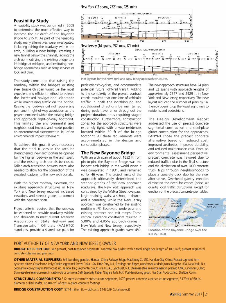
Tight constraints for erection of single-cell box-girder pier table
segment. The 42-ft difference in the elevations of the old and new
approaches is evident. All Photos and Figures: HDR.
20 | ASPIRE Summer 2017
PROJECT
Feasibility StudyA feasibility study was performed in 2008 to determine the most effective way to increase the air draft of the Bayonne Bridge to 215 ft. As part of the feasibility study, many alternatives were investigated, including raising the roadway within the arch, building a new bridge, creating a new tunnel below the channel, jacking the arch up, modifying the existing bridge to a lift bridge at midspan, and instituting non-bridge alternatives such as ferry services or lock and dam.
The study concluded that raising the roadway within the bridge’s existing steel truss-arch span would be the most expedient and efficient method to achieve the increased navigational clearance while maintaining traffic on the bridge. Raising the roadway did not require any permanent right-of-way acquisition as the project remained within the existing bridge and approach right-of-way footprint. This limited the environmental and neighborhood impacts and made possible an environmental assessment in lieu of an environmental impact statement.
To achieve this goal, it was necessary that the steel trusses in the arch be strengthened, new arch portals be opened for the higher roadway in the arch span, and the existing arch portals be closed. Taller arch-transition towers were also needed to allow for the connection of the elevated roadway to the new arch portals.
With the higher roadway elevation, the existing approach structures in New York and New Jersey required increased elevations and steeper grades to connect with the new arch span.
Project criteria required that the roadway be widened to provide roadway widths and shoulders to meet current American Association of State Highway and Transportation Officials (AASHTO) standards, provide a shared-use path for
pedestrians/bicyclists, and accommodate potential future light-rail transit. Adding to the complexity of the project, contract criteria required that one lane of vehicular traffic in both the northbound and southbound directions be maintained during peak travel times throughout the project duration, thus requiring staged construction. Furthermore, construction zones for the approach structures were extremely tight, with private residences located within 30 ft of the bridge footprint. All these requirements were accommodated in the design and construction phases.
The New Bayonne BridgeWith an arch span of about 1652 ft from pin-to-pin, the Bayonne Bridge was the longest arch bridge in the world when it was completed in 1931, and remained so for 46 years. The project limits of the approach ultimately determined the steeper grades of the new approach roadways. The New York approach was constrained by the Walker Street overpass, large retaining walls, a school, a church, and a cemetery, while the New Jersey approach was constrained by the existing multilane JFK Boulevard underpass and existing entrance and exit ramps. These vertical clearance constraints resulted in 5.00% and 4.85% approach grades in New York and New Jersey, respectively. The existing approach grades were 4%.
The new approach structures have 24 piers and 52 spans with approach lengths of approximately 2377 and 2929 ft in New York and New Jersey, respectively. The new layout reduced the number of piers by 14, thereby opening up the visual sight lines to residents and pedestrians.
The Design Development Report addressed the use of precast concrete segmental construction and steel-plate girder construction for the approaches. PANYNJ chose the precast concrete alternative based on reduced cost, improved aesthetics, improved durability, and reduced maintenance cost. From an environmental assessment perspective, precast concrete was favored due to reduced traffic noise in the final structure and the elimination of over 1000 concrete truck trips through neighborhoods to place a concrete deck slab for the steel alternative. Overhead gantry erection eliminated the need for cranes (noise, air quality, local traffic disruption), except for erection of the precast concrete pier tables.
PORT AUTHORITY OF NEW YORK AND NEW JERSEY, OWNERBRIDGE DESCRIPTION: Twin precast, post-tensioned segmental concrete box girders with a total single box length of 10,614 ft; precast segmental concrete columns and pier caps
OTHER MATERIAL SUPPLIERS: Self-launching gantries: Handan China Railway Bridge Machinery Co LTD, Handan City, China; Precast segment form systems: Ninive, Casseforme, Italy; Onsite segmental forms: Doka USA, Little Ferry, N.J.; Bearings and finger joints/modular deck joints: Mageba USA, New York, N.Y.; Segmental epoxy: Pilgrim Permocoat Inc., Tampa, Fla.; Segmental grout: Sika U.S.A., Lyndhurst, N.J.; Stainless-steel reinforcement in precast: CMC, Cincinnati, Ohio; Stainless-steel reinforcement in cast-in-place concrete: Salit Specialty Rebar, Niagara Falls, N.Y.; Post-tensioning grout: Five Star Products Inc., Shelton, Conn.
STRUCTURAL COMPONENTS: 512 precast concrete substructure segments, 1079 precast concrete superstructure segments, 5179 ft of 60-in.-diameter drilled shafts, 12,484 yd3 of cast-in-place concrete footings
BRIDGE CONSTRUCTION COST: $744 million (low-bid cost); $1430/ft2 (total project)
Location of the Bayonne Bridge over the
Kill Van Kull.
Pier layouts for the New York and New Jersey approach structures.
ASPIRE Summer 2017 | 21
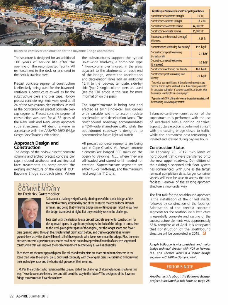
The structure is designed for an additional 100 years of service life after the opening of the reconstructed facility. All reinforcement in the deck or anchored in the deck is stainless steel.
Precast concrete segmental construction is effectively being used for the balanced-cantilever superstructure as well as for the substructure piers and pier caps. Hollow precast concrete segments were used at all 24 of the two-column pier locations, as well as the post-tensioned precast concrete pier-cap segments. Precast concrete segmental construction was used for all 52 spans of the New York and New Jersey approach superstructures. All designs were in accordance with the AASHTO LRFD Bridge Design Specifications, 6th edition.
Approach Design and ConstructionThe design of the hollow precast concrete columns and arched precast concrete pier caps included aesthetics and architectural face treatments to complement the existing architecture of the original 1931 Bayonne Bridge approach piers. Where
the substructures support the typical 36-ft-wide roadway, a combined Type 1 two-column pier is used. In the areas adjacent to the abutments on each endof the bridge, where the acceleration and deceleration lanes add an additional 12 ft to the roadway template, side-by-side Type 2 single-column piers are used (see the CBT article in this issue for more information on the piers).
The superstructure is being cast and erected as twin single-cell box girders with variable width to accommodate acceleration and deceleration lanes. The northbound roadway accommodates a 12-ft-wide shared-use path, while the southbound roadway is designed to accommodate future light-rail transit.
All precast concrete segments are being cast in Cape Charles, Va. Precast concrete elements are barged 300 miles on the ocean to Bayonne, N.J., where they are off-loaded and stored until needed for erection. Superstructure segments are either 10- or 14-ft-deep, and the maximum haul weight is 112 tons.
Balanced-cantilever construction of the superstructure is performed with the use of overhead self-launching gantries. Superstructure erection is performed at night with the existing bridge closed to traffic, while the permanent post-tensioning is installed and stressed during daytime hours.
Construction StatusOn February 20, 2017, two lanes of northbound traffic were transferred onto the new upper roadway. Demolition of the existing suspended-arch floor system has commenced, with June as the target removal completion date. Larger container vessels will then be able to access the port facilities. Removal of the existing approach structure is now under way.
The first task for the southbound approach is the installation of the drilled shafts, followed by construction of the footings. Fabrication of the precast concrete segments for the southbound substructure is essentially complete and casting of the superstructure elements was approximately 65% complete as of April. It is anticipated that construction of the southbound structure will be completed in 2019. _____________
Joseph LoBuono is vice president and major
bridge technical director with HDR in Newark,
N.J., and Chester Werts is a senior bridge
engineer with HDR in Olympia, Wash.
Talk about a challenge: significantly altering one of the iconic bridges of the twentieth century, designed by one of the century’s master builders, Othmar Amman, and doing that while the bridge is in continuous use! I don’t know how the design team slept at night. But they certainly rose to the challenge.
Let’s start with the decision to use precast concrete segmental construction for the approach spans. It significantly changes the look of the bridge in comparison to the steel-plate girder spans of the original, but the longer spans and fewer
piers open up views through the structure that didn’t exist before, and create opportunities for new ground-level activities that will benefit all of those people who live or work near the bridge. Plus, the more massive concrete superstructure absorbs road noise, an underappreciated benefit of concrete segmental construction that will improve the local environment aesthetically as well as physically.
Then there are the new approach piers. The taller and wider piers are more prominent elements in the scene than were the original piers, but visual continuity with the original piers is established by borrowing their arched pier caps and the horizontal grooves of their columns.
I. M. Pei, the architect who redesigned the Louvre, stated the challenge of altering famous structures this way: “How do we make history live, and still point the way to the future?” The designers of the Bayonne Bridge reconstruction have shown how.
Balanced-cantilever construction for the Bayonne Bridge approaches.
Key Design Parameters and Principal Quantities
Superstructure concrete strength 10 ksi
Substructure concrete strength 8.5 ksi
Superstructure concrete volume 44,900 yd
Substructure concrete volume 15,600 yd
Superstructure theoretical (average) thickness
2.33 ft
Superstructure reinforcing bar density2 192 lb/yd
Superstructure post-tensioning (longitudinal)
5.1 lb/ft
Superstructure post-tensioning (transverse)
1.0 lb/ft
Substructure reinforcing bar density 160 lb/yd
Substructure post-tensioning steel density
70 lb/yd
1 Theoretical average thickness is the volume of superstructure concrete divided by the total deck area. It is a helpful parameter for conceptual estimation of concrete quantities as it varies with the average span length for a given project.
2 Approximately 70% of the reinforcement was stainless steel, and the remaining 30% was epoxy coated.
EDITOR’S NOTE
Another article about the Bayonne Bridge
project is included in this issue on page 28.
22 | ASPIRE Summer 2017
Photo courtesy of USC/Gus Ruelas.
The Precast/Prestressed Concrete Institute’s (PCI) certification is the industry’s
most proven, comprehensive, trusted, and specified certification program. The
PCI Plant Certification program is now accredited by the International Accreditation
Service (IAS) which provides objective evidence that an organization operates at
the highest level of ethical, legal, and technical standards. This accreditation demon-
strates compliance to ISO/IEC 17021-1.
PCI certification offers a complete regimen covering personnel, plant, and field
operations. This assures owners, specifiers, and designers that precast concrete
products are manufactured and installed by companies who subscribe to nationally
accepted standards and are audited to ensure compliance.
To learn more about PCI Certification, please visit
www.pci.org/cer t i f icat ion
SPECIFY PCI CERTIFICATIONT H E R E I S N O E Q U I V A L E N T
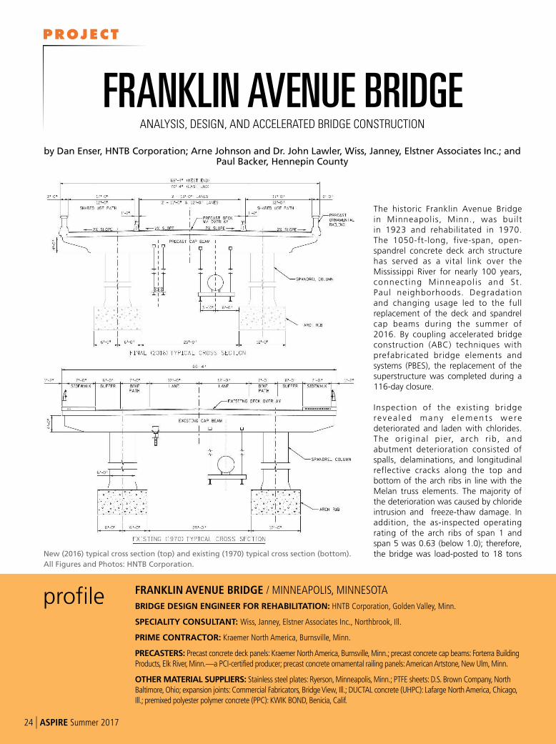
The historic Franklin Avenue Bridge in Minneapolis, Minn., was built in 1923 and rehabilitated in 1970. The 1050-ft-long, five-span, open-spandrel concrete deck arch structure has served as a vital link over the Mississippi River for nearly 100 years, connect ing Minneapol is and St. Paul neighborhoods. Degradation and changing usage led to the full replacement of the deck and spandrel cap beams during the summer of 2016. By coupling accelerated bridge construction (ABC) techniques with prefabricated bridge elements and systems (PBES), the replacement of the superstructure was completed during a 116-day closure.
Inspection of the existing bridge revea l ed many e l ement s we re deteriorated and laden with chlorides. The or iginal pier, arch r ib, and abutment deterioration consisted of spalls, delaminations, and longitudinal reflective cracks along the top and bottom of the arch ribs in line with the Melan truss elements. The majority of the deterioration was caused by chloride intrusion and freeze-thaw damage. Inaddition, the as-inspected operating rating of the arch ribs of span 1 and span 5 was 0.63 (below 1.0); therefore, the bridge was load-posted to 18 tons
profile FRANKLIN AVENUE BRIDGE / MINNEAPOLIS, MINNESOTA
BRIDGE DESIGN ENGINEER FOR REHABILITATION: HNTB Corporation, Golden Valley, Minn.
SPECIALITY CONSULTANT: Wiss, Janney, Elstner Associates Inc., Northbrook, Ill.
PRIME CONTRACTOR: Kraemer North America, Burnsville, Minn.
PRECASTERS: Precast concrete deck panels: Kraemer North America, Burnsville, Minn.; precast concrete cap beams: Forterra Building Products, Elk River, Minn.—a PCI-certified producer; precast concrete ornamental railing panels: American Artstone, New Ulm, Minn.
OTHER MATERIAL SUPPLIERS: Stainless steel plates: Ryerson, Minneapolis, Minn.; PTFE sheets: D.S. Brown Company, North Baltimore, Ohio; expansion joints: Commercial Fabricators, Bridge View, Ill.; DUCTAL concrete (UHPC): Lafarge North America, Chicago, Ill.; premixed polyester polymer concrete (PPC): KWIK BOND, Benicia, Calif.
by Dan Enser, HNTB Corporation; Arne Johnson and Dr. John Lawler, Wiss, Janney, Elstner Associates Inc.; and Paul Backer, Hennepin County
FRANKLIN AVENUE BRIDGE ANALYSIS, DESIGN, AND ACCELERATED BRIDGE CONSTRUCTION
New (2016) typical cross section (top) and existing (1970) typical cross section (bottom).
All Figures and Photos: HNTB Corporation.
24 | ASPIRE Summer 2017
PROJECT
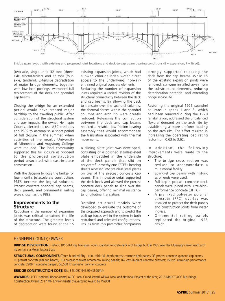
(two-axle, single-unit), 32 tons (three-axle, tractor-trailer), and 32 tons (four-axle, tandem). Extensive degradation of major bridge elements, together with low load postings, warranted full replacement of the deck and spandrel cap beams.
Closing the bridge for an extended period would have created major hardship to the traveling public. After consideration of the structural system and user impacts, the owner, Hennepin County, elected to use ABC methods and PBES to accomplish a short period of full closure in the summer, when activities at the nearby University of Minnesota and Augsburg College were reduced. The local community supported this full closure as opposed to the p ro longed cons t ruc t ion period associated with cast-in-place construction.
With the decision to close the bridge for four months to accelerate construction, PBES became the logical solution. Precast concrete spandrel cap beams, deck panels, and ornamental railing were chosen as the PBES.
Improvements to the StructureReduction in the number of expansion joints was critical to extend the life of the structure. The greatest levels of degradation were found at the 15
existing expansion joints, which had allowed chloride-laden water direct access to the underlying, non-air-entrained original concrete elements.Reducing the number of expansion joints required a radical revision of the structural connectivity between the deck and cap beams. By allowing the deck to translate over the spandrel columns, the thermal forces within the spandrel columns and arch rib were greatly reduced. Releasing the connection between the deck and cap beams required a reliable, low-friction bearing assembly that would accommodate the translation associated with thermal movements.
A sliding-plate joint was developed, consisting of a polished stainless-steel plate embedded in the underside of the deck panels that s l id on polytetrafluoroethylene (PTFE) bearing sheets recessed into stainless steel plates on top of the precast concrete cap beams. This innovative detail supported the deck loads and allowed the precast concrete deck panels to slide over the cap beams, offering minimal resistance to longitudinal translation.
Detai led structural models were developed to evaluate the outcome of the proposed approach and to predict the built-up forces within the system in both restrained and released configurations. Results from this parametric comparison
strongly supported releasing the deck from the cap beams. While 15 of the existing expansion joints were removed, six were installed away from the substructure elements, reducing deterioration potential and extending bridge service life.
Restoring the original 1923 spandrel columns in spans 1 and 5, which had been removed during the 1970 rehabilitation, addressed the unbalanced flexural demand on the arch ribs by establishing a more uniform loading on the arch ribs. The effort resulted in increasing the operating load rating factor from 0.63 to 3.62.
I n a d d i t i o n , t h e f o l l o w i n g improvements were made to the structure:• The bridge cross section was
rev i sed to accommodate a multimodal facility.
• Spandrel cap beams with historic scroll ends were used.
• Full-depth precast concrete deck panels were joined with ultra-high-performance concrete (UHPC).
• A premixed polyester polymer concrete (PPC) over lay was installed to protect the deck panels and construction joints from water ingress.
• O r n a m e n t a l r a i l i n g p a n e l s repl icated the or ig inal 1923 design.
HENNEPIN COUNTY, OWNER
BRIDGE DESCRIPTION: Historic 1050-ft-long, five-span, open-spandrel concrete deck arch bridge built in 1923 over the Mississippi River; each arch rib contains a Melan lattice truss.
STRUCTURAL COMPONENTS: Three-hundred-fifty 14-in.-thick full-depth precast concrete deck panels; 33 precast concrete spandrel cap beams; 10 precast concrete pier cap beams; 163 precast concrete ornamental railing panels; 167 cast-in-place concrete pilasters; 350 yd3 ultra-high-performance concrete; 2200 ft concrete parapet, 66,500 ft2 polyester polymer concrete
BRIDGE CONSTRUCTION COST: Bid: $43,097,946.99 ($590/ft2)
AWARDS: ACEC National Honor Award; ACEC Local Grand Award; APWA Local and National Project of the Year; 2016 MnDOT AGC MN Bridge Construction Award; 2017 MN Environmental Stewardship Award by MnDOT
Bridge span layout with existing and proposed joint locations and deck-to-cap beam bearing conditions (E = expansion; F = fixed).
ASPIRE Summer 2017 | 25
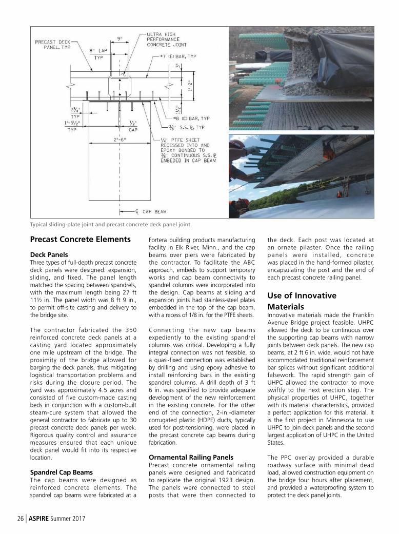
Precast Concrete Elements
Deck PanelsThree types of full-depth precast concrete deck panels were designed: expansion, sliding, and fixed. The panel length matched the spacing between spandrels, with the maximum length being 27 ft 11½ in. The panel width was 8 ft 9 in., to permit off-site casting and delivery to the bridge site.
The contractor fabricated the 350 reinforced concrete deck panels at a casting yard located approximately one mile upstream of the bridge. The proximity of the bridge allowed for barging the deck panels, thus mitigating logistical transportation problems and risks during the closure period. The yard was approximately 4.5 acres and consisted of five custom-made casting beds in conjunction with a custom-built steam-cure system that allowed the general contractor to fabricate up to 30 precast concrete deck panels per week. Rigorous quality control and assurance measures ensured that each unique deck panel would fit into its respective location.
Spandrel Cap Beams The cap beams were designed as reinforced concrete elements. The spandrel cap beams were fabricated at a
Fortera building products manufacturing facility in Elk River, Minn., and the cap beams over piers were fabricated by the contractor. To facilitate the ABC approach, embeds to support temporary works and cap beam connectivity to spandrel columns were incorporated into the design. Cap beams at sliding and expansion joints had stainless-steel plates embedded in the top of the cap beam, with a recess of 1/8 in. for the PTFE sheets.
Connecting the new cap beams expediently to the existing spandrel columns was critical. Developing a fully integral connection was not feasible, so a quasi-fixed connection was established by drilling and using epoxy adhesive to install reinforcing bars in the existing spandrel columns. A drill depth of 3 ft 6 in. was specified to provide adequate development of the new reinforcement in the existing concrete. For the other end of the connection, 2-in.-diameter corrugated plastic (HDPE) ducts, typically used for post-tensioning, were placed in the precast concrete cap beams during fabrication.
Ornamental Railing PanelsPrecast concrete ornamental railing panels were designed and fabricated to replicate the original 1923 design. The panels were connected to steel posts that were then connected to
the deck. Each post was located at an ornate pilaster. Once the railing panels were insta l led, concrete was placed in the hand-formed pilaster, encapsulating the post and the end of each precast concrete railing panel.
Use of Innovative
MaterialsInnovative materials made the Franklin Avenue Bridge project feasible. UHPC allowed the deck to be continuous over the supporting cap beams with narrow joints between deck panels. The new cap beams, at 2 ft 6 in. wide, would not have accommodated traditional reinforcement bar splices without significant additional falsework. The rapid strength gain of UHPC allowed the contractor to move swiftly to the next erection step. The physical properties of UHPC, together with its material characteristics, provided a perfect application for this material. It is the first project in Minnesota to use UHPC to join deck panels and the second largest application of UHPC in the United States.
The PPC overlay provided a durable roadway surface with minimal dead load, allowed construction equipment on the bridge four hours after placement, and provided a waterproofing system to protect the deck panel joints.
Typical sliding-plate joint and precast concrete deck panel joint.
26 | ASPIRE Summer 2017
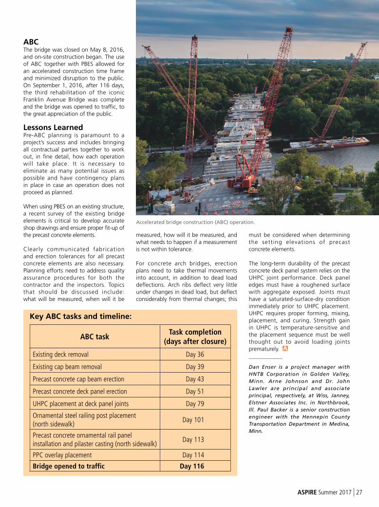
ABCThe bridge was closed on May 8, 2016, and on-site construction began. The use of ABC together with PBES allowed for an accelerated construction time frame and minimized disruption to the public. On September 1, 2016, after 116 days, the third rehabilitation of the iconic Franklin Avenue Bridge was complete and the bridge was opened to traffic, to the great appreciation of the public.
Lessons Learned Pre-ABC planning is paramount to a project’s success and includes bringing all contractual parties together to work out, in fine detail, how each operation will take place. It is necessary to eliminate as many potential issues as possible and have contingency plans in place in case an operation does not proceed as planned.
When using PBES on an existing structure, a recent survey of the existing bridge elements is critical to develop accurate shop drawings and ensure proper fit-up of the precast concrete elements.
Clearly communicated fabrication and erection tolerances for all precast concrete elements are also necessary. Planning efforts need to address quality assurance procedures for both the contractor and the inspectors. Topics that should be discussed include: what will be measured, when will it be
measured, how will it be measured, and what needs to happen if a measurement is not within tolerance.
For concrete arch bridges, erection plans need to take thermal movements into account, in addition to dead load deflections. Arch ribs deflect very little under changes in dead load, but deflect considerably from thermal changes; this
must be considered when determining the setting elevations of precast concrete elements.
The long-term durability of the precast concrete deck panel system relies on the UHPC joint performance. Deck panel edges must have a roughened surface with aggregate exposed. Joints must have a saturated-surface-dry condition immediately prior to UHPC placement. UHPC requires proper forming, mixing, placement, and curing. Strength gain in UHPC is temperature-sensitive and the placement sequence must be well thought out to avoid loading joints prematurely.
_____________
Dan Enser is a project manager with
HNTB Corporation in Golden Valley,
Minn. Arne Johnson and Dr. John
Lawler are principal and associate
principal, respectively, at Wiss, Janney,
Elstner Associates Inc. in Northbrook,
Ill. Paul Backer is a senior construction
engineer with the Hennepin County
Transportation Department in Medina,
Minn.
ABC taskTask completion
(days after closure)
Existing deck removal Day 36
Existing cap beam removal Day 39
Precast concrete cap beam erection Day 43
Precast concrete deck panel erection Day 51
UHPC placement at deck panel joints Day 79
Ornamental steel railing post placement(north sidewalk)
Day 101
Precast concrete ornamental rail panel installation and pilaster casting (north sidewalk)
Day 113
PPC overlay placement Day 114
Bridge opened to traffic Day 116
Key ABC tasks and timeline:
Accelerated bridge construction (ABC) operation.
ASPIRE Summer 2017 | 27
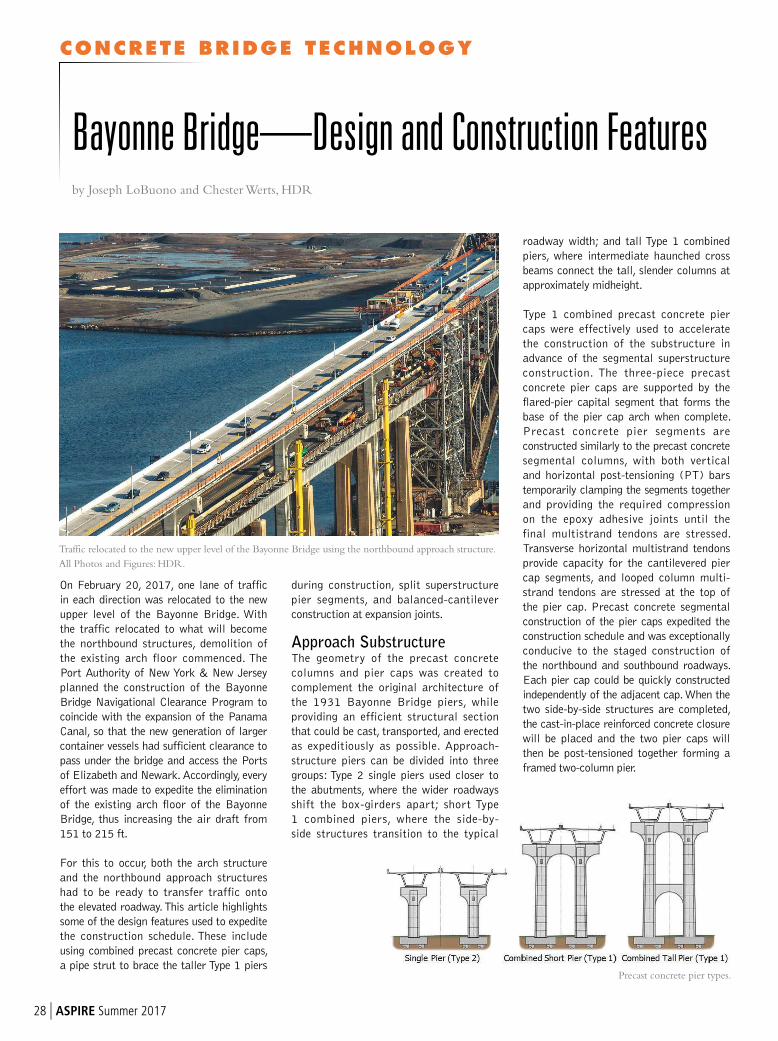
CONCRETE BRIDGE TECHNOLOGY
28 | ASPIRE Summer 2017
On February 20, 2017, one lane of traffic
in each direction was relocated to the new
upper level of the Bayonne Bridge. With
the traffic relocated to what will become
the northbound structures, demolition of
the existing arch floor commenced. The
Port Authority of New York & New Jersey
planned the construction of the Bayonne
Bridge Navigational Clearance Program to
coincide with the expansion of the Panama
Canal, so that the new generation of larger
container vessels had sufficient clearance to
pass under the bridge and access the Ports
of Elizabeth and Newark. Accordingly, every
effort was made to expedite the elimination
of the existing arch floor of the Bayonne
Bridge, thus increasing the air draft from
151 to 215 ft.
For this to occur, both the arch structure
and the northbound approach structures
had to be ready to transfer traffic onto
the elevated roadway. This article highlights
some of the design features used to expedite
the construction schedule. These include
using combined precast concrete pier caps,
a pipe strut to brace the taller Type 1 piers
Bayonne Bridge—Design and Construction Featuresby Joseph LoBuono and Chester Werts, HDR
Traffic relocated to the new upper level of the Bayonne Bridge using the northbound approach structure.
All Photos and Figures: HDR.
Precast concrete pier types.
during construction, split superstructure
pier segments, and balanced-cantilever
construction at expansion joints.
Approach SubstructureThe geometry of the precast concrete
columns and pier caps was created to
complement the original architecture of
the 1931 Bayonne Bridge piers, while
providing an efficient structural section
that could be cast, transported, and erected
as expeditiously as possible. Approach-
structure piers can be divided into three
groups: Type 2 single piers used closer to
the abutments, where the wider roadways
shift the box-girders apart; short Type
1 combined piers, where the side-by-
side structures transition to the typical
roadway width; and tall Type 1 combined
piers, where intermediate haunched cross
beams connect the tall, slender columns at
approximately midheight.
Type 1 combined precast concrete pier
caps were effectively used to accelerate
the construction of the substructure in
advance of the segmental superstructure
construction. The three-piece precast
concrete pier caps are supported by the
flared-pier capital segment that forms the
base of the pier cap arch when complete.
Precast concrete pier segments are
constructed similarly to the precast concrete
segmental columns, with both vertical
and horizontal post-tensioning (PT) bars
temporarily clamping the segments together
and providing the required compression
on the epoxy adhesive joints until the
final multistrand tendons are stressed.
Transverse horizontal multistrand tendons
provide capacity for the cantilevered pier
cap segments, and looped column multi-
strand tendons are stressed at the top of
the pier cap. Precast concrete segmental
construction of the pier caps expedited the
construction schedule and was exceptionally
conducive to the staged construction of
the northbound and southbound roadways.
Each pier cap could be quickly constructed
independently of the adjacent cap. When the
two side-by-side structures are completed,
the cast-in-place reinforced concrete closure
will be placed and the two pier caps will
then be post-tensioned together forming a
framed two-column pier.
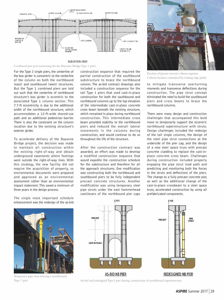
ASPIRE Summer 2017 | 29
For the Type 2 single piers, the centerline of
the box girder is concentric to the centerline
of the column on both the northbound
(east) and southbound (west) structures.
But the Type 1 combined piers are laid
out such that the centerline of northbound
structure’s box girder is eccentric to the
associated Type 1 column section. This
7.7-ft eccentricity is due to the additional
width of the northbound structure, which
accommodates a 12-ft-wide shared-use
path and an additional pedestrian barrier.
There is also the constraint on the column
location due to the existing structure’s
exterior girder.
To accelerate delivery of the Bayonne
Bridge project, the decision was made
to maintain all construction within
the existing right-of-way and obtain
underground easements where footings
went outside the right-of-way lines. With
this strategy, the new facility did not
require the acquisition of property, so
environmental documents were prepared
and approved as an environmental
assessment rather than an environmental
impact statement. This saved a minimum of
three years in the design process.
The single most important schedule
enhancement was the redesign of the as-bid
construction sequence that required the
partial construction of the southbound
substructure to brace the northbound
column. The as-bid contract drawings also
included a construction sequence for the
tall Type 1 piers that used cast-in-place
construction for both the southbound and
northbound columns up to the top elevation
of the intermediate cast-in-place concrete
cross beam beneath the existing structure,
which remained in place during northbound
construction. This intermediate cross
beam provided stability to the northbound
piers and reduced the overall lateral
movements in the columns during
construction, and would continue to do so
throughout the life of the structure.
After the construction contract was
awarded, an effort was made to develop
a modified construction sequence that
would expedite the construction schedule
for the substructure and therefore for all
the approach structures. One modification
was constructing both the northbound and
southbound piers to be fully independent
precast concrete structures. Another
modification was using temporary steel
pipe struts under the east hammerhead
cantilevers of the northbound pier caps
to mitigate transverse overturning
moments and transverse deflections during
construction. The pipe strut concept
eliminated the need to build the southbound
piers and cross beams to brace the
northbound columns.
There were many design and construction
challenges that accompanied this bold
move to temporarily support the eccentric
northbound superstructure with struts.
Design challenges included the redesign
of the tall single columns, the design of
the steel pipe strut connections at the
underside of the pier cap, and the design
of a new steel space truss with precast
concrete cladding to replace the cast-in-
place concrete cross beam. Challenges
during construction included properly
engaging the pipe strut load path and
predicting and monitoring both the forces
in the struts and deflections of the piers.
The change to a fully precast concrete pier,
as well as the additional change of the
cast-in-place crossbeam to a steel space
truss, accelerated construction by using all
prefabricated components.
Erection of precast concrete column segment.
Column location constrained by existing edge girder.
Combined pier post-tensioning for the Bayonne Bridge Type 1 piers.
As-bid and redesigned Type I pier during construction of northbound superstructure.
Temporary pipe strut bracing a northbound
Type 1 pier.
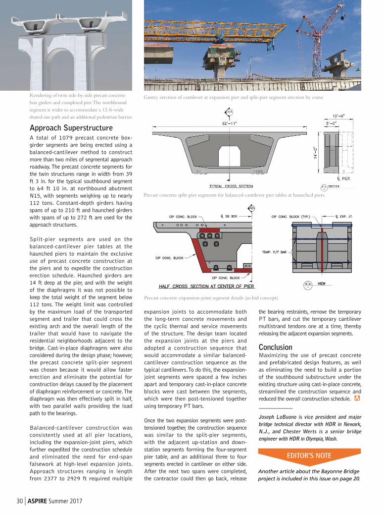
30 | ASPIRE Summer 2017
Approach SuperstructureA total of 1079 precast concrete box-
girder segments are being erected using a
balanced-cantilever method to construct
more than two miles of segmental approach
roadway. The precast concrete segments for
the twin structures range in width from 39
ft 3 in. for the typical southbound segment
to 64 ft 10 in. at northbound abutment
N15, with segments weighing up to nearly
112 tons. Constant-depth girders having
spans of up to 210 ft and haunched girders
with spans of up to 272 ft are used for the
approach structures.
Split-pier segments are used on the
balanced-cantilever pier tables at the
haunched piers to maintain the exclusive
use of precast concrete construction at
the piers and to expedite the construction
erection schedule. Haunched girders are
14 ft deep at the pier, and with the weight
of the diaphragms it was not possible to
keep the total weight of the segment below
112 tons. The weight limit was controlled
by the maximum load of the transported
segment and trailer that could cross the
existing arch and the overall length of the
trailer that would have to navigate the
residential neighborhoods adjacent to the
bridge. Cast-in-place diaphragms were also
considered during the design phase; however,
the precast concrete split-pier segment
was chosen because it would allow faster
erection and eliminate the potential for
construction delays caused by the placement
of diaphragm reinforcement or concrete. The
diaphragm was then effectively split in half,
with two parallel walls providing the load
path to the bearings.
Balanced-cantilever construction was
consistently used at all pier locations,
including the expansion-joint piers, which
further expedited the construction schedule
and eliminated the need for end-span
falsework at high-level expansion joints.
Approach structures ranging in length
from 2377 to 2929 ft required multiple
expansion joints to accommodate both
the long-term concrete movements and
the cyclic thermal and service movements
of the structure. The design team located
the expansion joints at the piers and
adopted a construction sequence that
would accommodate a similar balanced-
cantilever construction sequence as the
typical cantilevers. To do this, the expansion-
joint segments were spaced a few inches
apart and temporary cast-in-place concrete
blocks were cast between the segments,
which were then post-tensioned together
using temporary PT bars.
Once the two expansion segments were post-
tensioned together, the construction sequence
was similar to the split-pier segments,
with the adjacent up-station and down-
station segments forming the four-segment
pier table, and an additional three to four
segments erected in cantilever on either side.
After the next two spans were completed,
the contractor could then go back, release
the bearing restraints, remove the temporary
PT bars, and cut the temporary cantilever
multistrand tendons one at a time, thereby
releasing the adjacent expansion segments.
ConclusionMaximizing the use of precast concrete
and prefabricated design features, as well
as eliminating the need to build a portion
of the southbound substructure under the
existing structure using cast-in-place concrete,
streamlined the construction sequence and
reduced the overall construction schedule.
_____________
Joseph LoBuono is vice president and major
bridge technical director with HDR in Newark,
N.J., and Chester Werts is a senior bridge
engineer with HDR in Olympia, Wash.
Gantry erection of cantilever at expansion pier and split-pier segment erection by crane.
Precast concrete expansion-joint segment details (as-bid concept).
Precast concrete split-pier segments for balanced-cantilever pier tables at haunched piers.
Rendering of twin side-by-side precast concrete
box girders and completed pier. The northbound
segment is wider to accommodate a 12-ft-wide
shared-use path and an additional pedestrian barrier.
EDITOR’S NOTE
Another article about the Bayonne Bridge
project is included in this issue on page 20.
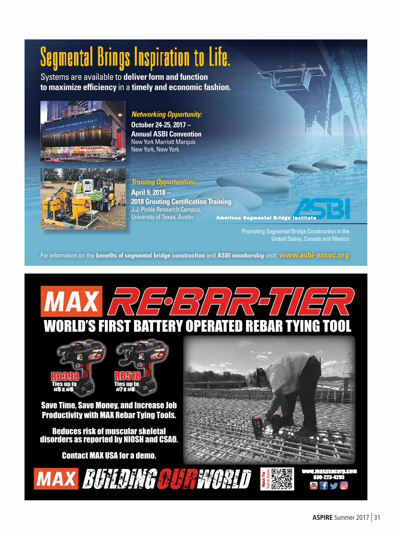
ASPIRE Summer 2017 | 31
American Segmental Br idge Inst i tute
Promoting Segmental Bridge Construction in the
United States, Canada and Mexico
Segmental Br ings Inspirat ion to L i fe.Systems are available to deliver form and function to maximize efficiency in a timely and economic fashion.
For information on the benefits of segmental bridge construction and ASBI membership visit: www.asbi-assoc.org
Networking Opportunity:
October 24-25, 2017 –
Annual ASBI Convention New York Marriott Marquis New York, New York
American Segmental Br idge Inst i tute
Training Opportunities:
April 9, 2018 –
2018 Grouting Certification Training J.J. Pickle Research Campus, University of Texas, Austin
WORLD’S FIRST BATTERY OPERATED REBAR TYING TOOL
Ties up to #7 x #8
Ties up to #5 x #6 #7 x #8 #7 x #8 #5 x #6 #5 x #6
Save Time, Save Money, and Increase Job
Productivity with MAX Rebar Tying Tools.
Reduces risk of muscular skeletal disorders as reported by NIOSH and CSAO.
Contact MAX USA for a demo.
Wa
tch
Th
e
To
ol in
Ac
tio
n
Wa
tch
Th
e www.maxusacorp.comwww.maxusacorp.com
800-223-4293800-223-4293
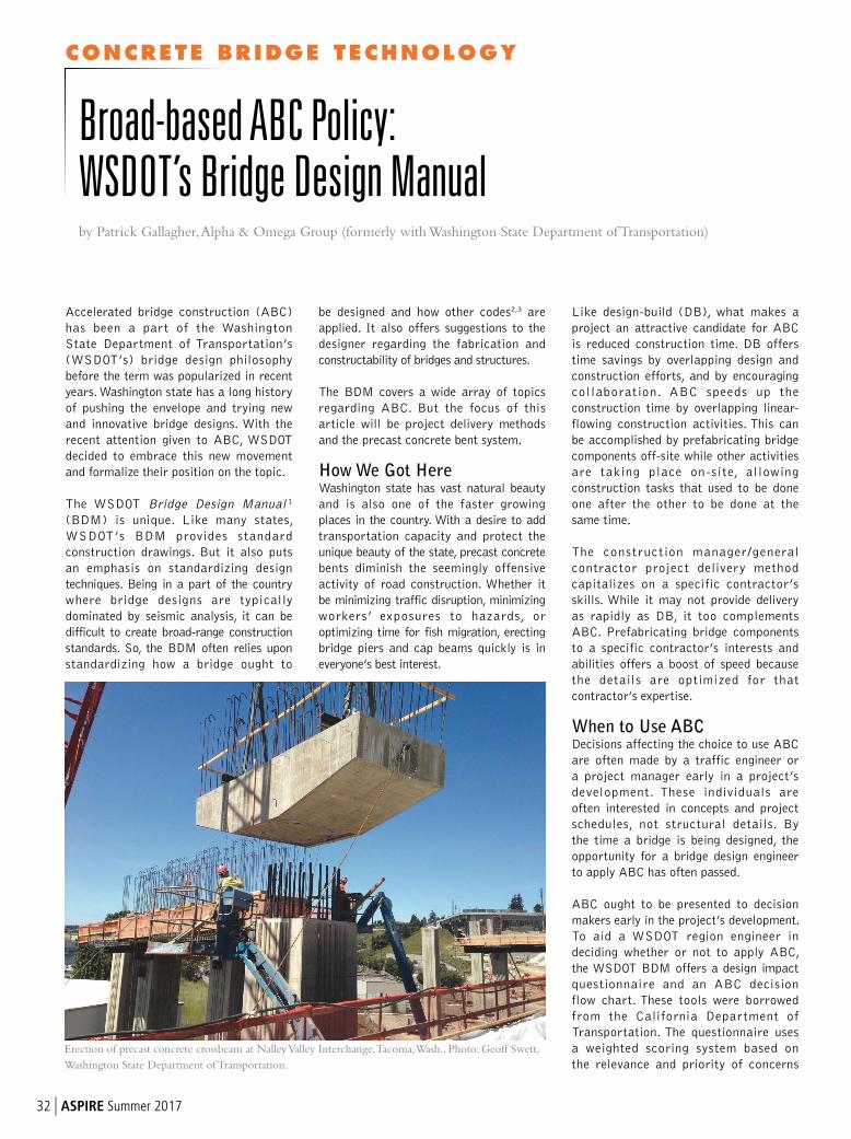
CONCRETE BRIDGE TECHNOLOGY
32 | ASPIRE Summer 2017
be designed and how other codes2,3 are
applied. It also offers suggestions to the
designer regarding the fabrication and
constructability of bridges and structures.
The BDM covers a wide array of topics
regarding ABC. But the focus of this
article will be project delivery methods
and the precast concrete bent system.
How We Got HereWashington state has vast natural beauty
and is also one of the faster growing
places in the country. With a desire to add
transportation capacity and protect the
unique beauty of the state, precast concrete
bents diminish the seemingly offensive
activity of road construction. Whether it
be minimizing traffic disruption, minimizing
workers’ exposures to hazards, or
optimizing time for fish migration, erecting
bridge piers and cap beams quickly is in
everyone’s best interest.
Like design-build (DB), what makes a
project an attractive candidate for ABC
is reduced construction time. DB offers
time savings by overlapping design and
construction efforts, and by encouraging
collaboration. ABC speeds up the
construction time by overlapping linear-
flowing construction activities. This can
be accomplished by prefabricating bridge
components off-site while other activities
are taking place on-site, allowing
construction tasks that used to be done
one after the other to be done at the
same time.
The construction manager/general
contractor project delivery method
capitalizes on a specific contractor’s
skills. While it may not provide delivery
as rapidly as DB, it too complements
ABC. Prefabricating bridge components
to a specific contractor’s interests and
abilities offers a boost of speed because
the details are optimized for that
contractor’s expertise.
When to Use ABCDecisions affecting the choice to use ABC
are often made by a traffic engineer or
a project manager early in a project’s
development. These individuals are
often interested in concepts and project
schedules, not structural details. By
the time a bridge is being designed, the
opportunity for a bridge design engineer
to apply ABC has often passed.
ABC ought to be presented to decision
makers early in the project’s development.
To aid a WSDOT region engineer in
deciding whether or not to apply ABC,
the WSDOT BDM offers a design impact
questionnaire and an ABC decision
flow chart. These tools were borrowed
from the California Department of
Transportation. The questionnaire uses
a weighted scoring system based on
the relevance and priority of concerns
Accelerated bridge construction (ABC)
has been a part of the Washington
State Department of Transportation’s
(WSDOT’s) bridge design philosophy
before the term was popularized in recent
years. Washington state has a long history
of pushing the envelope and trying new
and innovative bridge designs. With the
recent attention given to ABC, WSDOT
decided to embrace this new movement
and formalize their position on the topic.
The WSDOT Bridge Design Manual 1
(BDM) is unique. Like many states,
WSDOT’s BDM provides standard
construction drawings. But it also puts
an emphasis on standardizing design
techniques. Being in a part of the country
where bridge designs are typically
dominated by seismic analysis, it can be
difficult to create broad-range construction
standards. So, the BDM often relies upon
standardizing how a bridge ought to
Broad-based ABC Policy: WSDOT’s Bridge Design Manualby Patrick Gallagher, Alpha & Omega Group (formerly with Washington State Department of Transportation)
Erection of precast concrete crossbeam at Nalley Valley Interchange, Tacoma, Wash.. Photo: Geoff Swett,
Washington State Department of Transportation.
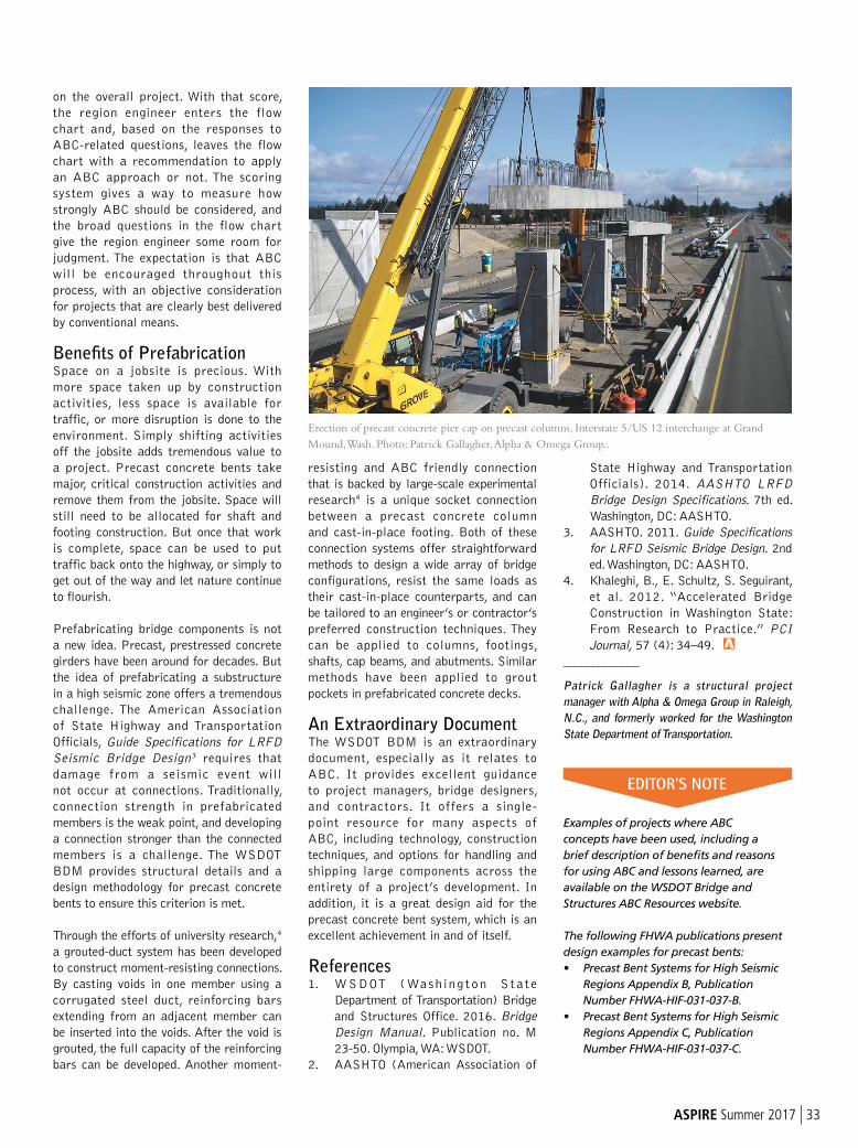
ASPIRE Summer 2017 | 33
resisting and ABC friendly connection
that is backed by large-scale experimental
research4 is a unique socket connection
between a precast concrete column
and cast-in-place footing. Both of these
connection systems offer straightforward
methods to design a wide array of bridge
configurations, resist the same loads as
their cast-in-place counterparts, and can
be tailored to an engineer’s or contractor’s
preferred construction techniques. They
can be applied to columns, footings,
shafts, cap beams, and abutments. Similar
methods have been applied to grout
pockets in prefabricated concrete decks.
An Extraordinary DocumentThe WSDOT BDM is an extraordinary
document, especially as it relates to
ABC. It provides excellent guidance
to project managers, bridge designers,
and contractors. It offers a single-
point resource for many aspects of
ABC, including technology, construction
techniques, and options for handling and
shipping large components across the
entirety of a project’s development. In
addition, it is a great design aid for the
precast concrete bent system, which is an
excellent achievement in and of itself.
References1. WSDOT (Washing ton S ta t e
Department of Transportation) Bridge
and Structures Office. 2016. Bridge
Design Manual. Publication no. M
23-50. Olympia, WA: WSDOT.
2. AASHTO (American Association of
State Highway and Transportation
Officials). 2014. AASHTO LRFD
Bridge Design Specifications. 7th ed.
Washington, DC: AASHTO.
3. AASHTO. 2011. Guide Specifications
for LRFD Seismic Bridge Design. 2nd
ed. Washington, DC: AASHTO.
4. Khaleghi, B., E. Schultz, S. Seguirant,
et al. 2012. “Accelerated Bridge
Construction in Washington State:
From Research to Practice.” PCI
Journal, 57 (4): 34–49.
_____________
Patrick Gallagher is a structural project
manager with Alpha & Omega Group in Raleigh,
N.C., and formerly worked for the Washington
State Department of Transportation.
Examples of projects where ABC
concepts have been used, including a
brief description of benefits and reasons
for using ABC and lessons learned, are
available on the WSDOT Bridge and
Structures ABC Resources website.
The following FHWA publications present
design examples for precast bents:
• Precast Bent Systems for High Seismic
Regions Appendix B, Publication
Number FHWA-HIF-031-037-B.
• Precast Bent Systems for High Seismic
Regions Appendix C, Publication
Number FHWA-HIF-031-037-C.
on the overall project. With that score,
the region engineer enters the flow
chart and, based on the responses to
ABC-related questions, leaves the flow
chart with a recommendation to apply
an ABC approach or not. The scoring
system gives a way to measure how
strongly ABC should be considered, and
the broad questions in the flow chart
give the region engineer some room for
judgment. The expectation is that ABC
will be encouraged throughout this
process, with an objective consideration
for projects that are clearly best delivered
by conventional means.
Benefits of PrefabricationSpace on a jobsite is precious. With
more space taken up by construction
activities, less space is available for
traffic, or more disruption is done to the
environment. Simply shifting activities
off the jobsite adds tremendous value to
a project. Precast concrete bents take
major, critical construction activities and
remove them from the jobsite. Space will
still need to be allocated for shaft and
footing construction. But once that work
is complete, space can be used to put
traffic back onto the highway, or simply to
get out of the way and let nature continue
to flourish.
Prefabricating bridge components is not
a new idea. Precast, prestressed concrete
girders have been around for decades. But
the idea of prefabricating a substructure
in a high seismic zone offers a tremendous
challenge. The American Association
of State Highway and Transportation
Officials, Guide Specifications for LRFD
Seismic Bridge Design3 requires that
damage from a seismic event will
not occur at connections. Traditionally,
connection strength in prefabricated
members is the weak point, and developing
a connection stronger than the connected
members is a challenge. The WSDOT
BDM provides structural details and a
design methodology for precast concrete
bents to ensure this criterion is met.
Through the efforts of university research,4
a grouted-duct system has been developed
to construct moment-resisting connections.
By casting voids in one member using a
corrugated steel duct, reinforcing bars
extending from an adjacent member can
be inserted into the voids. After the void is
grouted, the full capacity of the reinforcing
bars can be developed. Another moment-
Erection of precast concrete pier cap on precast columns, Interstate 5/US 12 interchange at Grand
Mound, Wash. Photo: Patrick Gallagher, Alpha & Omega Group..
EDITOR’S NOTE

Registration now open: Visit www.pci.org/committeedays
for more information, registration details, and the full schedule of events.
Join us for new and exciting events.
Make the most of your membership!

803-366-8195 inspectabridge.com ©2017 Anderson Hydra Platforms. All rights reserved.
TM
Safe, Sound & SimpleUnder-Bridge Access
TM
HP35
35' Trailer Model
HPT66HPT43
HPT38
38' Truck Model
66' Truck Model43' Truck Model
Four Models for Purchase or Rental
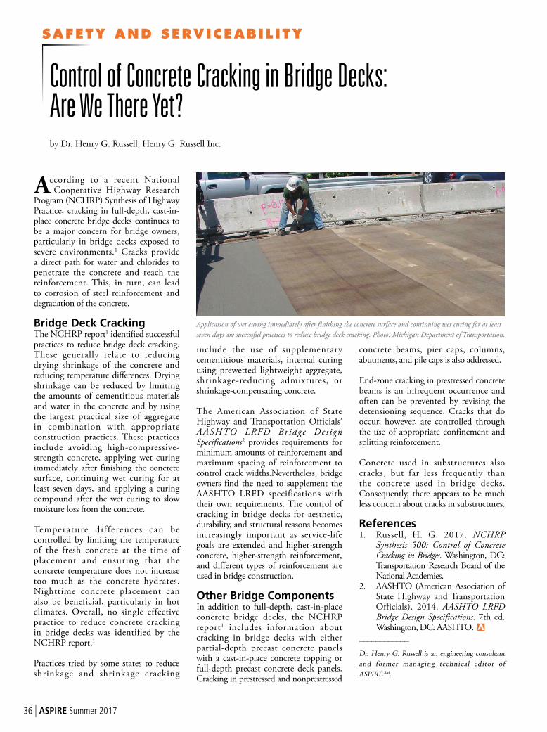
SAFETY AND SERVICEABIL ITY
36 | ASPIRE Summer 2017
According to a recent National Cooperative Highway Research
Program (NCHRP) Synthesis of Highway Practice, cracking in full-depth, cast-in-place concrete bridge decks continues to be a major concern for bridge owners, particularly in bridge decks exposed to severe environments.1 Cracks provide a direct path for water and chlorides to penetrate the concrete and reach the reinforcement. This, in turn, can lead to corrosion of steel reinforcement and degradation of the concrete.
Bridge Deck Cracking The NCHRP report1 identified successful practices to reduce bridge deck cracking. These generally relate to reducing drying shrinkage of the concrete and reducing temperature differences. Drying shrinkage can be reduced by limiting the amounts of cementitious materials and water in the concrete and by using the largest practical size of aggregate in combination with appropriate construction practices. These practices include avoiding high-compressive-strength concrete, applying wet curing immediately after finishing the concrete surface, continuing wet curing for atleast seven days, and applying a curing compound after the wet curing to slow moisture loss from the concrete.
Temperature dif ferences can be controlled by limiting the temperature of the fresh concrete at the time of placement and ensuring that the concrete temperature does not increase too much as the concrete hydrates. Nighttime concrete placement can also be beneficial, particularly in hotclimates. Overall, no single effective practice to reduce concrete cracking in bridge decks was identified by the NCHRP report.1
Practices tried by some states to reduce shrinkage and shrinkage cracking
include the use of supplementary cementitious materials, internal curing using prewetted lightweight aggregate, shrinkage-reducing admixtures, or shrinkage-compensating concrete.
The American Association of State Highway and Transportation Officials’ AASHTO LRFD Br idge De s i gn Specifications2 provides requirements for minimum amounts of reinforcement and maximum spacing of reinforcement to control crack widths.Nevertheless, bridge owners find the need to supplement the AASHTO LRFD specifications with their own requirements. The control of cracking in bridge decks for aesthetic, durability, and structural reasons becomes increasingly important as service-life goals are extended and higher-strength concrete, higher-strength reinforcement, and different types of reinforcement are used in bridge construction.
Other Bridge Components In addition to full-depth, cast-in-place concrete bridge decks, the NCHRP report1 includes information about cracking in bridge decks with either partial-depth precast concrete panels with a cast-in-place concrete topping or full-depth precast concrete deck panels. Cracking in prestressed and nonprestressed
concrete beams, pier caps, columns, abutments, and pile caps is also addressed.
End-zone cracking in prestressed concrete beams is an infrequent occurrence and often can be prevented by revising the detensioning sequence. Cracks that do occur, however, are controlled through the use of appropriate confinement and splitting reinforcement.
Concrete used in substructures also cracks, but far less frequently than the concrete used in bridge decks. Consequently, there appears to be much less concern about cracks in substructures.
References1. Russell, H. G. 2017. NCHRP
Synthesis 500: Control of Concrete Cracking in Bridges. Washington, DC: Transportation Research Board of the National Academies.
2. AASHTO (American Association of State Highway and Transportation Officials). 2014. AASHTO LRFD Bridge Design Specifications. 7th ed. Washington, DC: AASHTO.
____________
Dr. Henry G. Russell is an engineering consultant
and former managing technical editor of
ASPIRE SM.
Control of Concrete Cracking in Bridge Decks: Are We There Yet?by Dr. Henry G. Russell, Henry G. Russell Inc.
Application of wet curing immediately after finishing the concrete surface and continuing wet curing for at least
seven days are successful practices to reduce bridge deck cracking. Photo: Michigan Department of Transportation.
37 | ASPIRE Summer 2016
Spider®Standard and custom access solutions for all phases of bridge work, including cable access equipment for CABLE DEHUMIDIFICATION.
Work baskets, swing stages and custom float platforms.
QuikDeck® SuspendedAccess SystemProvides factory-floor-like work conditions.Load capacities from 122 to 366 kg/m2 with 4-to-1 safety factor.
Modular components. Easy assembly. No special tools needed.
QuikShield® SuspendedAccess SystemA lighter weight, lower-cost rental option.
From construction to maintenance, inspection or cable dehumidification, Safway’s Infrastructure Services Group has the WIDEST RANGE of the BEST SOLUTIONS to save you time and money – while increasing safety – on any bridge project.
Only from Safway. From bridges, railroads, airports, shipping ports and other transportation systems, to power plants and large public venues, Safway’s Infrastructure Services Group delivers safe, time-saving and high-performing solutions at the lowest installed cost.
Contact us today for a free quote.Infrastructure Services Toll-Free: (800) 582-9391
www.spiderstaging.com and www.quikdeck.com
YOUR BRIDGE ACCESS ADVANTAGE
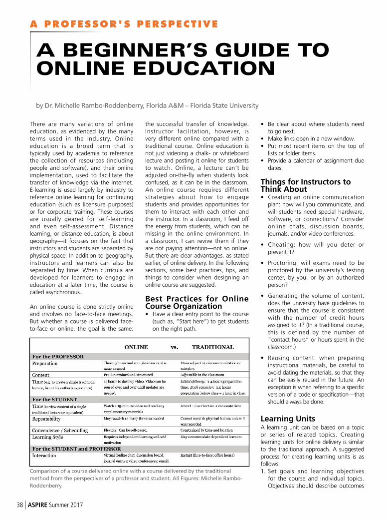
A PROFESSOR'S PERSPECTIVE
38 | ASPIRE Summer 2017
There are many variations of online education, as evidenced by the many terms used in the industry. Online education is a broad term that is typically used by academia to reference the collection of resources (including people and software), and their online implementation, used to facilitate the transfer of knowledge via the internet. E-learning is used largely by industry to reference online learning for continuing education (such as licensure purposes) or for corporate training. These courses are usually geared for self-learning and even self-assessment. Distance learning, or distance education, is about geography—it focuses on the fact that instructors and students are separated by physical space. In addition to geography, instructors and learners can also be separated by time. When curricula are developed for learners to engage in education at a later time, the course is called asynchronous.
An online course is done strictly online and involves no face-to-face meetings. But whether a course is delivered face-to-face or online, the goal is the same:
the successful transfer of knowledge. Instructor facilitation, however, is very different online compared with a traditional course. Online education is not just videoing a chalk- or whiteboard lecture and posting it online for students to watch. Online, a lecture can’t be adjusted on-the-fly when students look confused, as it can be in the classroom. An online course requires different strategies about how to engage students and provides opportunities for them to interact with each other and the instructor. In a classroom, I feed off the energy from students, which can be missing in the online environment. In a classroom, I can revive them if they are not paying attention—not so online. But there are clear advantages, as stated earlier, of online delivery. In the following sections, some best practices, tips, and things to consider when designing anonline course are suggested.
Best Practices for Online Course Organization• Have a clear entry point to the course
(such as, “Start here”) to get students on the right path.
• Be clear about where students need to go next.
• Make links open in a new window.• Put most recent items on the top of
lists or folder items.• Provide a calendar of assignment due
dates.
Things for Instructors to Think About• Creating an online communication
plan: how will you communicate, and will students need special hardware, software, or connections? Consider online chats, discussion boards, journals, and/or video conferences.
• Cheating: how will you deter or prevent it?
• Proctoring: will exams need to be proctored by the university’s testing center, by you, or by an authorized person?
• Generating the volume of content: does the university have guidelines to ensure that the course is consistent with the number of credit hours assigned to it? (In a traditional course, this is defined by the number of “contact hours” or hours spent in the classroom.)
• Reusing content: when preparing instructional materials, be careful to avoid dating the materials, so that they can be easily reused in the future. An exception is when referring to a specific version of a code or specification—that should always be done.
Learning UnitsA learning unit can be based on a topic or series of related topics. Creating learning units for online delivery is similar to the traditional approach. A suggested process for creating learning units is as follows:1. Set goals and learning objectives
for the course and individual topics. Objectives should describe outcomes
A BEGINNER’S GUIDE TO
ONLINE EDUCATION
by Dr. Michelle Rambo-Roddenberry, Florida A&M – Florida State University
Comparison of a course delivered online with a course delivered by the traditional
method from the perspectives of a professor and student. All Figures: Michelle Rambo-
Roddenberry.
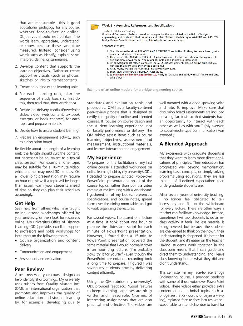
ASPIRE Summer 2017 | 39
that are measurable—this is good educational pedagogy for any course, whether face-to-face or online. Objectives should not contain the words learn, appreciate, understand, or know, because these cannot be measured. Instead, consider using words such as identify, explain, solve, interpret, define, or summarize.
2. Develop content that supports the learning objectives. Gather or create supportive visuals (such as photos, sketches, or links to internet content).
3. Create an outline of the learning units.
4. For each learning unit, plan the sequence of study (such as first do this, then read that, then watch this)
5. Decide on delivery media (PowerPoint slides, video, web content, textbook excerpts, or book chapters) for each topic and prepare materials.
6. Decide how to assess student learning.
7. Prepare an engagement activity, such as a discussion board.
Be flexible about the length of a learning unit; the length should suit the content, not necessarily be equivalent to a typical class session. For example, one topic may be suitable for a 10-minute video, while another may need 30 minutes. Or, a PowerPoint presentation may require an hour of review. If a topic will be longer than usual, warn your students ahead of time so they can plan their schedules accordingly.
Get HelpSeek help from others who have taught online, attend workshops offered by your university, or even look for resources online. My university’s Office of Distance Learning (ODL) provides excellent support to professors and holds workshops for instructors on the following topics:• Course organization and content
delivery
• Communication and engagement
• Assessment and evaluation
Peer ReviewA peer review of your course design can help identify shortcomings. My university uses rubrics from Quality Matters Inc. (QM), an international organization that promotes and improves the quality of online education and student learning by, for example, developing quality
standards and evaluation tools and procedures. QM has a faculty-centered peer-review process that is designed to certify the quality of online and blended courses. It focuses on course design and the student learning experience, not on faculty performance or delivery. The QM rubrics assess items such as course learning objectives, assessment and measurement, instructional materials, and learner interaction and engagement.
My ExperienceTo prepare for the facilitation of my first online course, I attended workshops on online learning held by my university’s ODL. I decided to prepare scripted, voice-over PowerPoint presentations on all of the course topics, rather than point a video camera at me lecturing with a whiteboard. I gathered all of my books, references, specifications, and course notes, spread them over the dining room table, and got to work organizing the lectures.
For several weeks, I prepared one lecture at a time. It took about one hour to prepare the slides and script for each minute of PowerPoint presentation. However, I found that a 15-minute PowerPoint presentation covered the same material that I would normally cover in an hour-long lecture. (I’m probably slow; try it for yourself.) Even though the PowerPoint-presentation recording took a long time to prepare, I figured I was saving my students time by delivering content efficiently.
Using the QM rubrics, my university’s ODL provided feedback: “Good features to keep: Learning objectives are nicely written and measurable. Nice mix of interesting assignments that are also practical and effective. The videos are
well narrated with a good speaking voice and rate. To improve: Make sure that discussion board assignments are included on a regular basis so that students have an opportunity to interact with each other as well as with you.” (My aversion to social-media-type communication was exposed.)
A Blended Approach
My experience with graduate students is that they want to learn more direct appli-cations of principles. Their education has progressed well beyond memorization, learning basic concepts, or simply solving problems using equations. They are less tolerant of ill-defined expectations than undergraduate students are.
After several years of university teaching, I no longer feel obligated to talk incessantly and fill up the whiteboard for every lecture. There are other ways a teacher can facilitate knowledge. Instead, sometimes I will ask students to do an in-class activity. It feels like less material is being covered, but because the students are challenged to think on their own, their understanding is deepened. It’s better for the student, and it’s easier on the teacher. Having students work together in the classroom means that I can guide and direct them to understanding, and I leave class knowing better what they did and didn’t understand.
This semester, in my face-to-face Bridge Engineering course, I provided students with some of those voice-over PowerPoint videos. These videos either provided extra content on nontechnical topics such as bridge aesthetics (worthy of pajama view-ing), replaced face-to-face lectures when I was unable to attend class due to travel for
Example of an online module for a bridge engineering course.
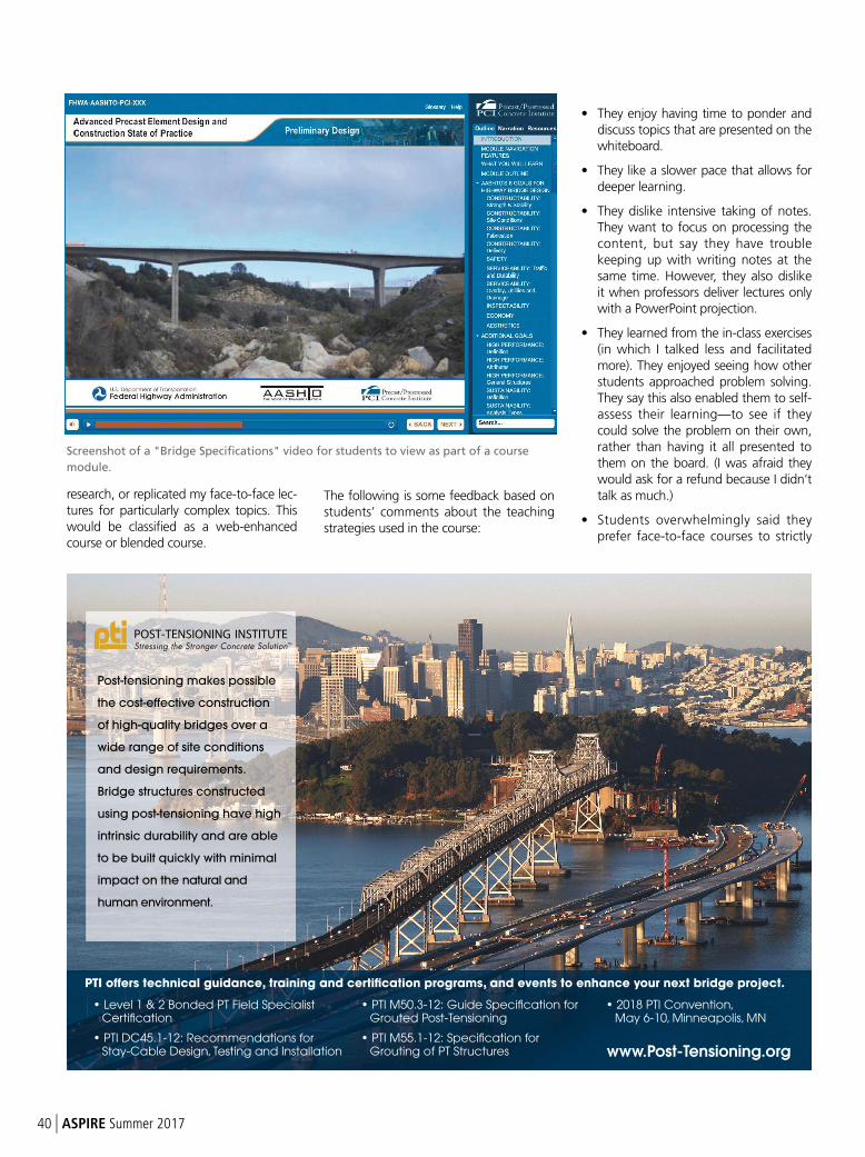
40 | ASPIRE Summer 2017
research, or replicated my face-to-face lec-tures for particularly complex topics. This would be classified as a web-enhanced course or blended course.
The following is some feedback based on students’ comments about the teaching strategies used in the course:
• They enjoy having time to ponder and discuss topics that are presented on the whiteboard.
• They like a slower pace that allows for deeper learning.
• They dislike intensive taking of notes. They want to focus on processing the content, but say they have trouble keeping up with writing notes at the same time. However, they also dislike it when professors deliver lectures only with a PowerPoint projection.
• They learned from the in-class exercises (in which I talked less and facilitated more). They enjoyed seeing how other students approached problem solving. They say this also enabled them to self-assess their learning—to see if they could solve the problem on their own, rather than having it all presented to them on the board. (I was afraid they would ask for a refund because I didn’t talk as much.)
• Students overwhelmingly said they prefer face-to-face courses to strictly
Screenshot of a "Bridge Specifications" video for students to view as part of a course
module.
Post-tensioning makes possible
the cost-effective construction
of high-quality bridges over a
wide range of site conditions
and design requirements.
Bridge structures constructed
using post-tensioning have high
intrinsic durability and are able
to be built quickly with minimal
impact on the natural and
human environment.
• Level 1 & 2 Bonded PT Field Specialist Certification
• PTI DC45.1-12: Recommendations for Stay-Cable Design, Testing and Installation
• PTI M50.3-12: Guide Specification for Grouted Post-Tensioning
• PTI M55.1-12: Specification for Grouting of PT Structures
• 2018 PTI Convention, May 6-10, Minneapolis, MN
PTI offers technical guidance, training and certification programs, and events to enhance your next bridge project.
www.Post-Tensioning.org
ASPIRE Summer 2017 | 41
TRANSPORTATION &
INFRASTRUCTURE
BUILDINGS &
FACILITIES
CONSTRUCTION
MANAGEMENT
ENERGY
SERVICES
An employee-owned firm
Offices nationwide
Toll-free: 877-395-5459
www.stvinc.com
Reaching the century mark isn’t easy – you have to be
quality-driven, client-focused, and have a vision for the future.
At 100 years, STV is looking ahead. As an employee-owned fi rm,
our planners, architects, engineers and construction managers
have a stake in the business, and are committed to quality
performance. We provide personal attention and timely solutions,
with an eye toward sustainability. And with more than 40 offi ces,
we are a local fi rm with national resources.
When it comes to getting your project delivered right,
choose the fi rm that has the drive and vision to be the best.
Enduring. Driven. Visionary.
online courses for several reasons. They can ask questions on-the-spot, as soon as they come to mind. They reported a tendency to procrastinate a lot more with online classes. Rather than participating in online discussion boards, such as commenting on other students’ work, they would rather work together in class.
• They very much enjoyed having a face-to-face lecture along with a prepared video lecture. The repetition, especially on complex topics, was helpful.
• They prefer videos that are 30 minutes or less.
• They did not watch videos for which I did not give an assignment. I don’t know why that surprised me. (I’m blessed that my students are honest with me, but cursed because now I know the truth: ignorance really can be bliss.)
Tips for Preparing Voice-Over PowerPoint Lectures
Having now prepared many voice-over PowerPoint lectures, I offer the following tips:• Spend time creating a well-prepared
script before recording. This can great ly improve the learner ’s experience. To avoid sounding scripted during narration, I pretend that I’m talking to a student sitting beside me—the kind of student who would normally sit in the front of the class and ask thoughtful questions.
• Use a good microphone (I use a Blue Yeti USB microphone). Consider using a pop filter: it won’t rid you of a southern accent, but it will improve sound quality. Don’t use a karaoke mic; those never sound good.
• Make sure that crickets aren’t chirping or dogs aren’t barking outside during recordings.
• Avoid recording late in the day when your voice is tired. Drink water before narration and during pauses.
• Smile while narrating the script. Research shows that you can hear a smile.
• Invest in a good screen-capture software such as Camtasia. I use it to capture PowerPoint slides and transitions, as well as audio. Camtasia is easy to use and it converts files to a video format.
• If you want to go whole hog and create a professional module that includes embedded quizzes, outlines, narration text, and student interactivity features (such as clickable objects and pop-up windows), consider using software such as Adobe Captivate or Articulate Storyline to develop your modules. This can help enhance student engagement.
The preparation for teaching or facilitating an online course is different than for tradit ional face-to-face classroom delivery. Many of my tips can be applied to video conferences, professional presentations, or meetings with clients. As with many things, organization and preparation are key elements for a successful online teaching experience.
CONCRETE CONNECTIONS
42 | ASPIRE Summer 2017
http://www.nap.edu/download/24689 This is a link to download a PDF of Control of Concrete Cracking in Bridges, a synthesis report recently published by the National Cooperative Highway Research Program (NCHRP), and referenced in the Safety and Serviceability article on best practices to reduce cracking in bridge decks.
http://www.earthcam.net/projects/bayonnebridge/?cam=pano This is a link to a panoramic view of the Bayonne Bridge project that shows the difference in elevations of the old and new approaches. The Bayonne Bridge is featured in both a Project article on page 20 and a Concrete Bridge Technology article on page 28.
http://www.gcpci.org/index.cfm/technical/pcef This is a link to the website of the Precast Concrete Economical Fabrication (PCEF) Committee that has information on materials, cross sections, and projects using PCEF bridge elements. PCEF elements are mentioned in the article on page 6 featuring STV.
http://www.enr.com/articles/12218-yadkin-river-bridge-project-delivers-timely-replacement-of-aging-structure This is a link to an online article about the Yadkin River Bridge that appeared in ENR. The bridge was designed by STV, the engineering firm featured in an article on page 6.
http://www.aspiremagazinebyengineers.com/i/306966-winter-2008/43 This is a direct link to the ASPIRE SM Winter 2008 article “Precast Enables Environmental Avoidance,” that inspired the solution to the site challenges of the El Salto Falls Street Bridge that is featured in the Project article on page 16.
http://www.aspiremagazinebyengineers.com/i/768999-winter-2017/13 This is a direct link to “Long Key Bridge Pier Replacement,” that appeared in a Project article of the ASPIRE Winter 2017 issue. Details of the V-pier replacement are in the Concrete Bridge Preservation article on page 50.
http://www.wsdot.wa.gov/publications/manuals/fulltext/M23-50/BDM.pdf This is a direct link a pdf of the Washington DOT Bridge Design Manual (LRFD) which contains a chapter solely dedicated to accelerated bridge construction methods, techniques, and design details. This document is featured in a Construction Bridge Technology article on page 32.
http://www.pci.org/uploadedFiles/Siteroot/Publications/PCI_Journal/2012/DOI_Articles/JL-Fall-2012-8.pdf This is a direct link to the Fall 2012 PCI Journal article “Accelerated bridge construction in Washington State,” which describes the development and implementation of the precast concrete bent system that appears in the Construction Bridge Technology article on page 32.
https://www.nap.edu/catalog/22971/blast-resistant-highway-bridges-design-and-detailing-guidelines This is a link to the NCHRP Report 645 Blast-Resistant Highway Bridges: Design and Detailing Guidelines. Guidance on the design
of bridge elements and materials to lessen probable damage from terrorist attacks is the topic of the FHWA article on page 48.
http://www.startribune.com/franklin-avenue-bridge-makeover-and-detours-expected-to-end-by-labor-day-weekend/378903411/# This is a link to an article that appeared in the Minneapolis StarTribune describing the importance of the Franklin Avenue bridge renovation to the local neighborhood and the accelerated construction methods used. The Franklin Avenue bridge is featured in a Project article on page 24.
OTHER INFORMATION
http://www.astmnewsroom.org/default.aspx?pageid=4250This is a link to information on the revision of ASTM A416/A416M, Specification for Low-Relaxation, Seven-Wire Steel Strand for Prestressed Concrete.
http://nap.edu/24779 This is a link to the recently published NCHRP Research Report 848: Inspection Guidelines for Bridge Post-Tensioning and Stay Cable Systems Using NDE Methods. The report describes nondestructive evaluation methods for assessing the condition, including corrosion, section loss, breakage, grout conditions, voids, and water infiltration, of in-service post-tensioning and stay cable systems.
https://bookstore.transportation.org/collection_detail.aspx?ID=149 This is a link to the table of contents and information on ordering and updates for the publication Standard Specifications for Transportation Materials and Methods of Sampling and Testing, and AASHTO Provisional Standards. This is now a web-based publication and no longer available as a printed book.
http://www.trb.org/Main/Blurbs/175864.aspx This is a link to the final report for NCHRP Innovations Deserving Exploratory Analysis (IDEA) Project 174, Enhanced Performance Zinc Coating for Steel in Concrete. A reinforcing bar with a thermal zinc-diffusion coating was evaluated for corrosion protection.
http://www.dot.state.mn.us/research/TS/2017/201701TS.pdf This is a link to a technical summary released by the Minnesota Department of Transportation on a system that analyzes accelerometer data from sensors on the I-35W St Anthony Falls Bridge. The data shows how the concrete structure bends and deforms in response to traffic loads, wind, and temperature changes.
http://www.register.extension.iastate.edu/uhpc2016/attendance/interactivesThis is a link to the Interactive Panel Final Reports issued from the First International Interactive Symposium on Ultra-High-Performance Concrete, held in 2016. The next symposium will be held in 2019 in Albany, New York.
Concrete Connections is an annotated list of websites where information is available about concrete bridges. Links and other information are prov ided at www.aspirebridge.org.
IN THIS ISSUE
43 | ASPIRE Summer 201643 | ASPIRE Summer 2016
W W W . P C I . O R G
Haymarket Pedestrian Bridge Project
Lincoln, Nebraska
Photos: Upper photo courtesy of Dimensional Innovations,
lower photo courtesy of ITD Staff.
the search for
EXCELLENCE.
2018 marks the 55th Annual PCI Design Awards and the submission site is open for entries.
Join us in our search for excellence and submit your projects electronically by September 18, 2017.
Visit the PCI website and click on “2018 Design Awards” for more information and submission details.
SH-55 over North Fork Payette River
McCall, Idaho
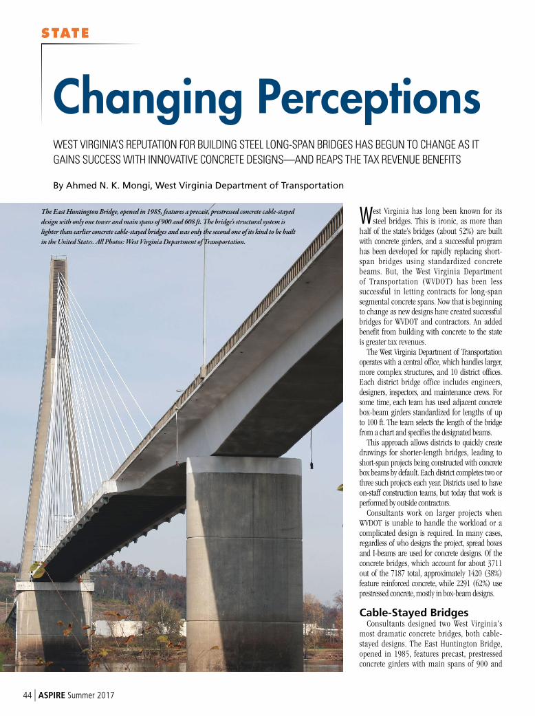
STATE
44 | ASPIRE Summer 2017
West Virginia has long been known for its steel bridges. This is ironic, as more than
half of the state’s bridges (about 52%) are built with concrete girders, and a successful program has been developed for rapidly replacing short-span bridges using standardized concrete beams. But, the West Virginia Department of Transportation (WVDOT) has been less successful in letting contracts for long-span segmental concrete spans. Now that is beginning to change as new designs have created successful bridges for WVDOT and contractors. An added benefit from building with concrete to the state is greater tax revenues.
The West Virginia Department of Transportation operates with a central office, which handles larger, more complex structures, and 10 district offices. Each district bridge office includes engineers, designers, inspectors, and maintenance crews. For some time, each team has used adjacent concrete box-beam girders standardized for lengths of up to 100 ft. The team selects the length of the bridge from a chart and specifies the designated beams.
This approach allows districts to quickly create drawings for shorter-length bridges, leading to short-span projects being constructed with concrete box beams by default. Each district completes two or three such projects each year. Districts used to have on-staff construction teams, but today that work is performed by outside contractors.
Consultants work on larger projects when WVDOT is unable to handle the workload or a complicated design is required. In many cases, regardless of who designs the project, spread boxes and I-beams are used for concrete designs. Of the concrete bridges, which account for about 3711 out of the 7187 total, approximately 1420 (38%) feature reinforced concrete, while 2291 (62%) use prestressed concrete, mostly in box-beam designs.
Cable-Stayed BridgesConsultants designed two West Virginia's
most dramatic concrete bridges, both cable-stayed designs. The East Huntington Bridge, opened in 1985, features precast, prestressed concrete girders with main spans of 900 and
Changing Perceptions
By Ahmed N. K. Mongi, West Virginia Department of Transportation
WEST VIRGINIA’S REPUTATION FOR BUILDING STEEL LONG-SPAN BRIDGES HAS BEGUN TO CHANGE AS IT
GAINS SUCCESS WITH INNOVATIVE CONCRETE DESIGNS—AND REAPS THE TAX REVENUE BENEFITS
The East Huntington Bridge, opened in 1985, features a precast, prestressed concrete cable-stayed
design with only one tower and main spans of 900 and 608 ft. The bridge's structural system is
lighter than earlier concrete cable-stayed bridges and was only the second one of its kind to be built
in the United States. All Photos: West Virginia Department of Transportation.
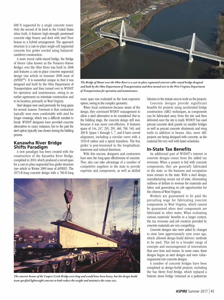
ASPIRE Summer 2017 | 45
608 ft supported by a single concrete tower. Only the second of its kind in the United States when built, it features high-strength prestressed concrete edge beams and deck with steel floor beams in a hybrid arrangement. The approach structure is a cast-in-place single-cell segmental concrete box girder erected using balanced-cantilever construction.
A more recent cable-stayed bridge, the Bridge of Honor (also known as the Pomeroy-Mason Bridge) over the Ohio River was built in 2008 and features a cast-in-place concrete segmental design (see article in Summer 2008 issue of ASPIRE
SM). It is somewhat unique in that it was designed and built by the Ohio Department of Transportation and then turned over to WVDOT for operation and maintenance, owing to an earlier agreement on interstate construction and to its location, primarily in West Virginia.
Steel designs were used previously for long spans for several reasons. Foremost is that contractors typically were more comfortable with steel for longer crossings, which was a difficult mindset to break. WVDOT designers have provided concrete alternatives in many instances, but in the past the steel option typically was chosen during the bidding process.
Kanawha River Bridge Shifts Paradigm
A new paradigm has been created with the construction of the Kanawha River Bridge, completed in 2010, which produced a record span for a cast-in-place segmental box-girder structure (see article in Winter 2009 issue of ASPIRE). The 2975-ft-long concrete design with a 760-ft-long
main span was evaluated as the least expensive option, owing to the complex geometry.
When local contractors became aware of the design, they convinced WVDOT management to allow a steel alternative to be considered. But in the bidding stage, the concrete design still won because it was more cost-effective. It features spans of 144, 247, 295, 295, 460, 760, 540, and 209 ft. Spans 1 through 5, 7, and 8 have curved alignment, including a circular curve with a 1910-ft radius and a spiral transition. The box girder is post-tensioned in the longitudinal, transverse and vertical directions.
With this success, designers and contractors have seen the long-span effectiveness of concrete. They also can take advantage of a number of competitive suppliers in the state to provide expertise and components, as well as skilled
laborers in the tristate area to work on the projects.Concrete designs provide s ignif icant
benefits for projects using accelerated bridge construction (ABC) techniques, as components can be fabricated away from the site and then delivered once the site is ready. WVDOT has used precast concrete deck panels on smaller bridges as well as precast concrete abutments and wing walls in addition to beams. Also, more ABC projects are being designed with concrete, as the material fits very well with faster schedules.
In-State Tax BenefitsAn additional part of WVDOT’s interest in
concrete designs comes from the added tax revenues. When a project is bid with concrete components, they are generally fabricated in the state, so the business and occupation taxes remain in the state. With a steel design, manufacturing occurs out of state, eliminating millions of dollars in revenue for materials and labor, and generating no job opportunities for the citizens of West Virginia.
Workers are guaranteed to be paid the prevailing wage for fabricating concrete components in West Virginia, which cannot be guaranteed when steel components are fabricated in other states. When evaluating various materials’ benefits in a larger context, the tax revenues and job creation provided by concrete materials are very compelling.
Concrete designs also were aided by changes to state laws approximately nine years ago, which allowed design-build delivery methods to be used. This led to a broader range of concepts and encouragement of innovations that save time and money. In some cases, these designs began as steel designs and were value-engineered into concrete designs.
A number of concrete bridges have been completed as design-build projects, including the Van Metre Ford Bridge, which replaced a historic stone bridge (retained as a pedestrian
The Bridge of Honor over the Ohio River is a cast-in-place segmental concrete cable-stayed bridge designed
and built by the Ohio Department of Transportation and then turned over to the West Virginia Department
of Transportation for operation and maintenance.
The concrete beams of the Coopers Creek Bridge were long and would have been heavy, but the design-build
team specified lightweight concrete to both reduce the weight and minimize the crane size.
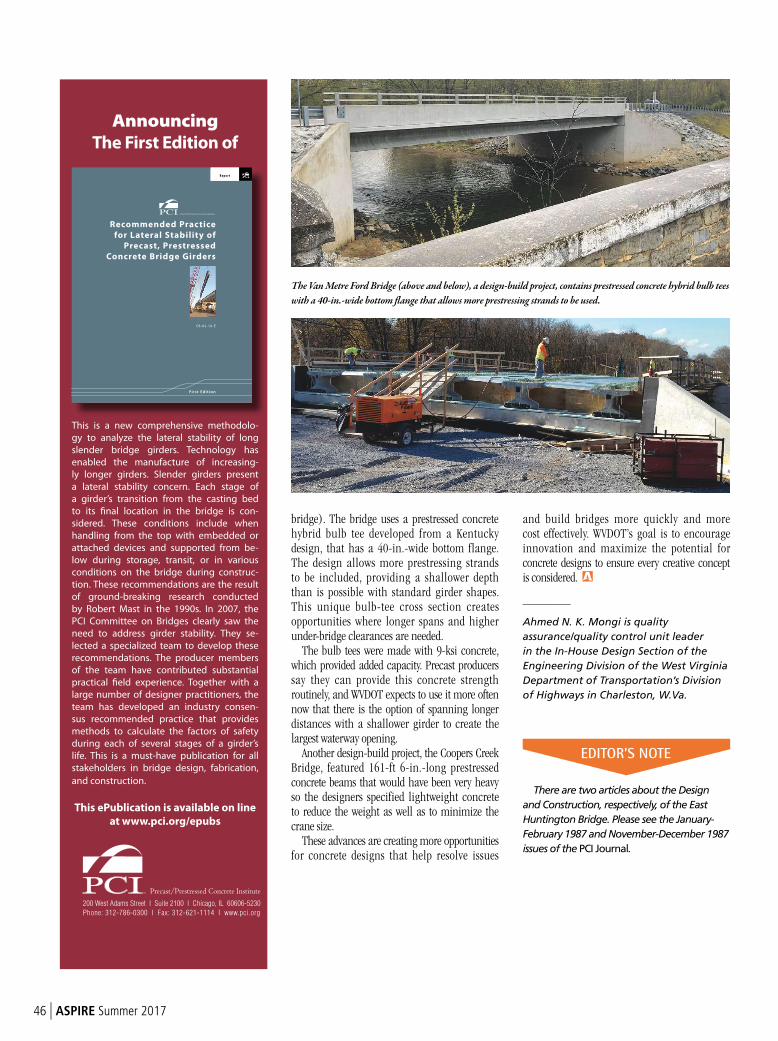
46 | ASPIRE Summer 2017
bridge). The bridge uses a prestressed concrete hybrid bulb tee developed from a Kentucky design, that has a 40-in.-wide bottom flange. The design allows more prestressing strands to be included, providing a shallower depth than is possible with standard girder shapes. This unique bulb-tee cross section creates opportunities where longer spans and higher under-bridge clearances are needed.
The bulb tees were made with 9-ksi concrete, which provided added capacity. Precast producers say they can provide this concrete strength routinely, and WVDOT expects to use it more often now that there is the option of spanning longer distances with a shallower girder to create the largest waterway opening.
Another design-build project, the Coopers Creek Bridge, featured 161-ft 6-in.-long prestressed concrete beams that would have been very heavy so the designers specified lightweight concrete to reduce the weight as well as to minimize the crane size.
These advances are creating more opportunities for concrete designs that help resolve issues
and build bridges more quickly and more cost effectively. WVDOT’s goal is to encourage innovation and maximize the potential for concrete designs to ensure every creative concept is considered.
_________
Ahmed N. K. Mongi is quality
assurance/quality control unit leader
in the In-House Design Section of the
Engineering Division of the West Virginia
Department of Transportation’s Division
of Highways in Charleston, W.Va.
There are two articles about the Design
and Construction, respectively, of the East
Huntington Bridge. Please see the January-
February 1987 and November-December 1987
issues of the PCI Journal.
The Van Metre Ford Bridge (above and below), a design-build project, contains prestressed concrete hybrid bulb tees
with a 40-in.-wide bottom flange that allows more prestressing strands to be used.
EDITOR’S NOTE
Announcing
The First Edition of
Repor t
Recommended Practice
for Lateral Stability of
Precast, Prestressed
Concrete Bridge Girders
CB-02-16-E
First Edit ion
This is a new comprehensive methodolo-
gy to analyze the lateral stability of long
slender bridge girders. Technology has
enabled the manufacture of increasing-
ly longer girders. Slender girders present
a lateral stability concern. Each stage of
a girder’s transition from the casting bed
to its final location in the bridge is con-
sidered. These conditions include when
handling from the top with embedded or
attached devices and supported from be-
low during storage, transit, or in various
conditions on the bridge during construc-
tion. These recommendations are the result
of ground- breaking research conducted
by Robert Mast in the 1990s. In 2007, the
PCI Committee on Bridges clearly saw the
need to address girder stability. They se-
lected a specialized team to develop these
recommendations. The producer members
of the team have contributed substantial
practical field experience. Together with a
large number of designer practitioners, the
team has developed an industry consen-
sus recommended practice that provides
methods to calculate the factors of safety
during each of several stages of a girder’s
life. This is a must- have publication for all
stakeholders in bridge design, fabrication,
and construction.
This ePublication is available on line
at www.pci.org/epubs
200 West Adams Street I Suite 2100 I Chicago, IL 60606-5230
Phone: 312-786-0300 I Fax: 312-621-1114 I www.pci.org
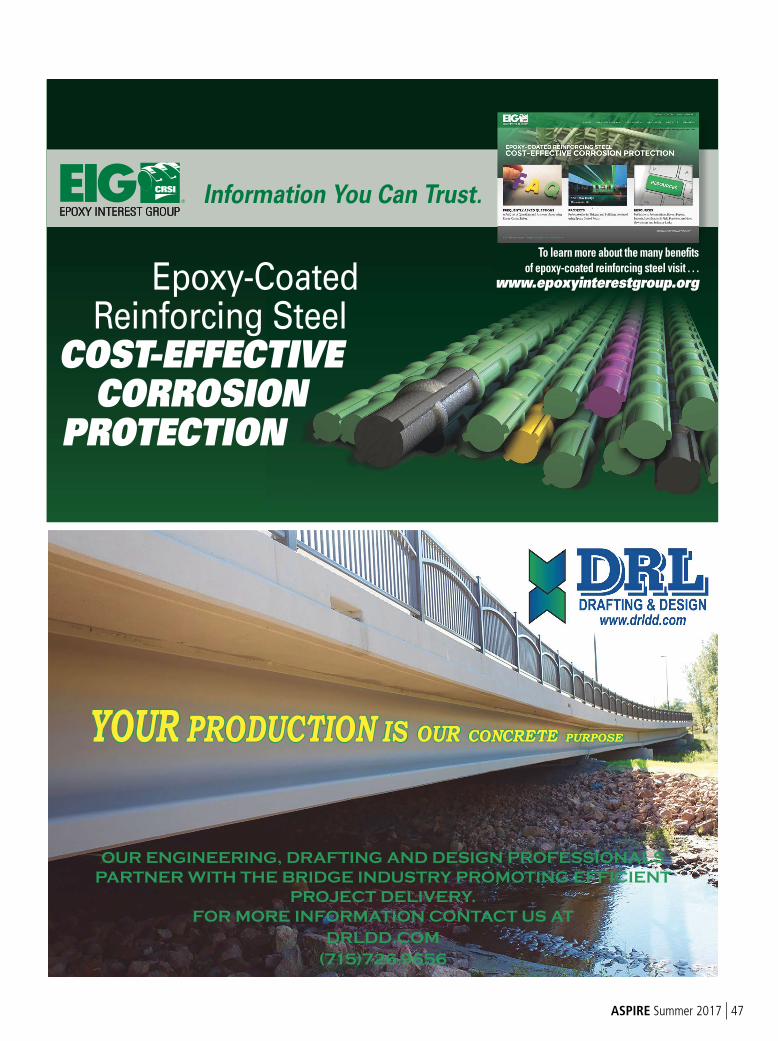
ASPIRE Summer 2017 | 47
EPOXY INTEREST GROUP
® Information You Can Trust.
To learn more about the many benefits
of epoxy-coated reinforcing steel visit . . .
www.epoxyinterestgroup.org Epoxy-Coated Reinforcing Steel COST-EFFECTIVE CORROSION PROTECTION
YOUR PRODUCTION IS OUR CONCRETE PURPOSE
OUR ENGINEERING, DRAFTING AND DESIGN PROFESSIONALS
PARTNER WITH THE BRIDGE INDUSTRY PROMOTING EFFICIENT
PROJECT DELIVERY.
FOR MORE INFORMATION CONTACT US AT
DRLDD.COM
(715)726-9656
FHWA
48 | ASPIRE Summer 2017
The Federal Highway Administration (FHWA) recently completed the first edition of its Bridge Security Design Manual.1 The manual was developed through an FHWA indefinite delivery, indefinite quantity contract with HDR Engineering and written by subcontractor PEC Engineering. It is available on the FHWA website.
The manual provides information for structural engineers, planners, owners, and others to incorporate effective strategies in bridge projects and make highway systems resilient against terrorist threats. These threats
have been a growing concern in the United States since the September 11, 2001, attacks, and it has been shown by the Mineta Institute2
and others that transportation structures are among the most popular targets for terrorist organizations. While previous infrastructure security research and practice have focused primarily on buildings, the limited bridge-specific design guidance suggests that bridges may not be well protected against the common loadings these terrorist threats can impart to bridge components. “The primary objective of this bridge security design manual is to present state-of-the-art guidance on bridge-
specific security planning, extreme loading phenomenology and characterization, and protective design strategies to be used by the highway bridge community in terrorist threat vulnerability assessments of existing bridges, resilient design of new bridge construction, and emergency planning efforts.”1
The manual covers a broad range of topics, including security planning, material performance, blast phenomenology, mechanics of structural elements, dynamic response of structures, protective design guidance, example designs for several component types (such as concrete towers), and the use of the software tool, Anti-terrorism Planner for Bridges (ATP-Bridge). The chapters covering these topics are fairly well self-contained. For example, the reader who is interested in understanding protective design for a concrete tower can use that chapter and relevant sections on loading, materials, mechanics, and response to gain a reasonable understanding of how to design a resilient tower.
Of particular interest to those who are new to this topic may be the chapters on planning, materials, and blast phenomenology. This information explores these topics from the bridge designer’s point of view and provides background and fundamental principles that are carried forward into specific examples of protective design.
The chapter on ATP-Bridge stands alone to describe the use of the software design tool developed by the U.S. Department of Homeland Security and the authors of the manual. ATP-Bridge is a practical, engineering-level software program capable of predicting the response and anticipated damage of critical bridge components subjected to a variety of threat scenarios. ATP-Bridge features flexible software architecture designed to be continuously updated with state-of-the-art research and intuitive, user-friendly functionality that aligns with practice. The protective measures described in the manual use
FHWA Unveils New Bridge Security Design Manual
by Steve Ernst, Federal Highway Administration
Table of contents from the Bridge Security Design Manual. All Figures and Photos: Federal Highway Administration.
• 1.0 INTRODUCTION
– History of Terrorist Events Involving Transportation Infrastructure
• 2.0 SECURITY PLANNING FOR HIGHWAY BRIDGES
– Threat Mitigation Strategies
• 3.0 MATERIALS PERFORMANCE
Explosives
• 4.0 BLAST PHENOMENOLOGY
– Types of Explosions
• 5.0 MECHANICS OF STRUCTURAL ELEMENTS
– Conventional Reinforced Concrete Elements
• 6.0 DYNAMIC RESPONSE OF STRUCTURES
– Dynamic Analysis Process
• 7.0 DESIGN GUIDANCE FOR REINFORCED CONCRETE COLUMNS
• 8.0 DESIGN GUIDANCE FOR STEEL CELLULAR TOWERS
• 9.0 DESIGN GUIDANCE FOR REINFORCED CONCRETE TOWERS
• 10.0 DESIGN GUIDANCE FOR HIGH-STRENGTH STEEL CABLES
• 11.0 DESIGN GUIDANCE FOR OTHER BRIDGE COMPONENTS
• 12.0 ANTI-TERRORIST PLANNER FOR BRIDGES (ATP-BRIDGE) SOFTWARE
– Dynamic Analysis of Reinforced Concrete Columns
– Dynamic Analysis of Steel Cellular Tower Panels
– High-Strength Steel Cables
Table of Contents
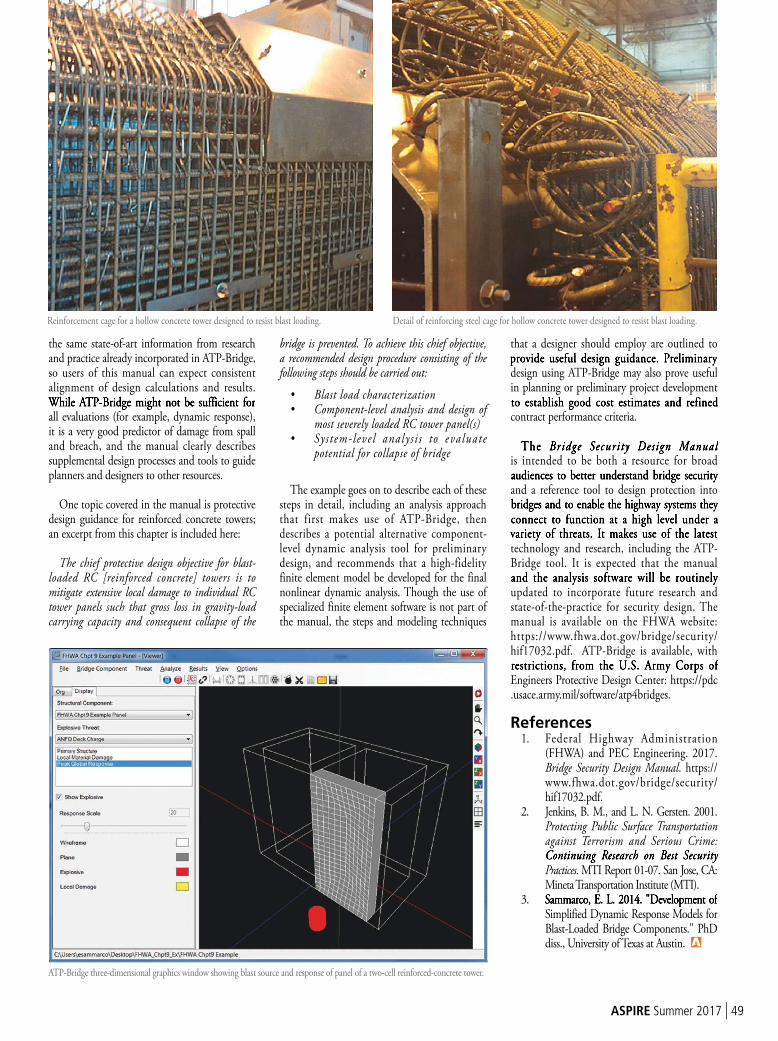
ASPIRE Summer 2017 | 49
the same state-of-art information from research and practice already incorporated in ATP-Bridge, so users of this manual can expect consistent alignment of design calculations and results. While ATP-Bridge might not be sufficient for all evaluations (for example, dynamic response), it is a very good predictor of damage from spall and breach, and the manual clearly describes supplemental design processes and tools to guide planners and designers to other resources.
One topic covered in the manual is protective design guidance for reinforced concrete towers; an excerpt from this chapter is included here:
The chief protective design objective for blast-loaded RC [reinforced concrete] towers is to mitigate extensive local damage to individual RC tower panels such that gross loss in gravity-load carrying capacity and consequent collapse of the
bridge is prevented. To achieve this chief objective, a recommended design procedure consisting of the following steps should be carried out:
• Blast load characterization• Component-level analysis and design of
most severely loaded RC tower panel(s)• Sy s t em-leve l analy s i s to eva luate
potential for collapse of bridge
The example goes on to describe each of these steps in detail, including an analysis approach that first makes use of ATP-Bridge, then describes a potential alternative component-level dynamic analysis tool for preliminary design, and recommends that a high-fidelity finite element model be developed for the final nonlinear dynamic analysis. Though the use of specialized finite element software is not part of the manual, the steps and modeling techniques
that a designer should employ are outlined to provide useful design guidance. Preliminary design using ATP-Bridge may also prove useful in planning or preliminary project development to establish good cost estimates and refined contract performance criteria.
The Bridge Security Design Manual is intended to be both a resource for broad audiences to better understand bridge security and a reference tool to design protection into bridges and to enable the highway systems they connect to function at a high level under a variety of threats. It makes use of the latest technology and research, including the ATP-Bridge tool. It is expected that the manual and the analysis software will be routinely updated to incorporate future research and state-of-the-practice for security design. The manual is available on the FHWA website: https://www.fhwa.dot.gov/bridge/security/hif17032.pdf. ATP-Bridge is available, with restrictions, from the U.S. Army Corps of Engineers Protective Design Center: https://pdc.usace.army.mil/software/atp4bridges.
References1. Federal Highway Administration
(FHWA) and PEC Engineering. 2017. Bridge Security Design Manual. https://www.fhwa.dot.gov/bridge/security/hif17032.pdf.
2. Jenkins, B. M., and L. N. Gersten. 2001. Protecting Public Surface Transportation against Terrorism and Serious Crime: Continuing Research on Best Security Practices. MTI Report 01-07. San Jose, CA: Mineta Transportation Institute (MTI).
3. Sammarco, E. L. 2014. "Development of Simplified Dynamic Response Models for Blast-Loaded Bridge Components." PhD diss., University of Texas at Austin.
Reinforcement cage for a hollow concrete tower designed to resist blast loading.
ATP-Bridge three-dimensional graphics window showing blast source and response of panel of a two-cell reinforced-concrete tower.
Detail of reinforcing steel cage for hollow concrete tower designed to resist blast loading.
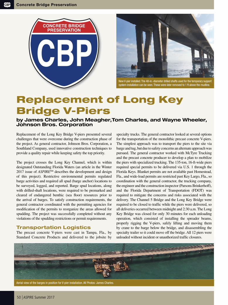
50 | ASPIRE Summer 2017
CBP Concrete Bridge Preservation
Replacement of Long Key
Bridge V-Piersby James Charles, John Meagher,Tom Charles, and Wayne Wheeler, Johnson Bros. Corporation
Replacement of the Long Key Bridge V-piers presented several
challenges that were overcome during the construction phase of
the project. As general contractor, Johnson Bros. Corporation, a
Southland Company, used innovative construction techniques to
provide a quality repair while keeping safety the top priority.
The project crosses the Long Key Channel, which is within
designated Outstanding Florida Waters (an article in the Winter
2017 issue of ASPIRESM describes the development and design
of this project). Restrictive environmental permits regulated
barge activities and required all spud (barge anchor) locations to
be surveyed, logged, and reported. Barge spud locations, along
with drilled-shaft locations, were required to be premarked and
cleared of endangered benthic (sea fl oor) resources prior to
the arrival of barges. To satisfy construction requirements, the
general contractor coordinated with the permitting agencies for
modifi cation of the permits to reorganize the areas allowed for
spudding. The project was successfully completed without any
violations of the spudding restrictions or permit requirements.
Transportation LogisticsThe precast concrete V-piers were cast in Tampa, Fla., by
Standard Concrete Products and delivered to the jobsite by
specialty trucks. The general contractor looked at several options
for the transportation of the monolithic precast concrete V-piers.
The simplest approach was to transport the piers to the site via
barge and tug, but due to safety concerns an alternate approach was
pursued. The general contractor worked with McTyre Trucking
and the precast concrete producer to develop a plan to mobilize
the piers with specialized trucking. The 135-ton, 16-ft-wide piers
required special permits to be delivered via U.S. 1 through the
Florida Keys. Blanket permits are not available past Homestead,
Fla., and wide-load permits are restricted past Key Largo, Fla., so
coordination with the general contractor, the trucking company,
the engineer and the construction inspector (Parsons Brinkerhoff),
and the Florida Department of Transportation (FDOT) was
required to mitigate the concerns and risks associated with the
delivery. The Channel 5 Bridge and the Long Key Bridge were
required to be closed to traffi c while the piers were delivered, so
all deliveries occurred between midnight and 2:30 a.m. The Long
Key Bridge was closed for only 30 minutes for each unloading
operation, which consisted of installing the spreader beams,
properly rigging the V-piers, safely lifting and moving them
by crane to the barge below the bridge, and disassembling the
specialty trailer so it could move off the bridge. All 12 piers were
unloaded without incident or unauthorized traffi c closures.
CBP
CONCRETE BRIDGE
PRESERVATION
Aerial view of the barges in position for V-pier installation. All Photos: James Charles.
New V-pier installed. The 48-in.-diameter drilled shafts used for the temporary support
system installation can be seen. These were later removed to 1 ft above the mudline.
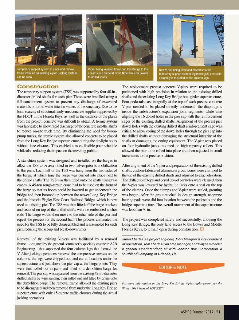
ASPIRE Summer 2017 | 51
Construction
The temporary support system (TSS) was supported by four 48-in.-
diameter drilled shafts for each pier. These were installed using a
full-containment system to prevent any discharge of excavated
materials or turbid water into the waters of the sanctuary. Due to the
local scarcity of structural ready-mix concrete suppliers approved by
the FDOT in the Florida Keys, as well as the distance of the plants
from the project, concrete was difficult to obtain. A tremie system
was fabricated to allow rapid discharge of the concrete into the shafts
to reduce on-site truck time. By eliminating the need for boom-
pump trucks, the tremie system also allowed concrete to be placed
from the Long Key Bridge superstructure during the daylight hours
without lane closures. This enabled a more flexible pour schedule
while also reducing the impact on the traveling public.
A stanchion system was designed and installed on the barges to
allow the TSS to be assembled in two halves prior to mobilization
to the piers. Each half of the TSS was hung from the two sides of
the barge, at which time the barge was pushed into place next to
the drilled shafts. The TSS was then lifted onto the shafts using two
cranes. A 45-ton rough-terrain crane had to be used on the front of
the barge so that its boom could be lowered to get underneath the
bridge and then boomed up between the newer Long Key Bridge
and the historic Flagler East Coast Railroad Bridge, which is now
used as a fishing pier. The TSS was then lifted off the barge brackets
and secured on top of the drilled shafts with the embedded anchor
rods. The barge would then move to the other side of the pier and
repeat the process for the second half. This process eliminated the
need for the TSS to be fully disassembled and reassembled for each
pier, reducing the set-up and break-down times.
Removal of the existing V-piers was facilitated by a removal
frame—designed by the general contractor’s specialty engineer, A2B
Engineering—that supported the four column legs that formed the
V. After jacking operations removed the compressive stresses on the
columns, the legs were chipped out, and cut at locations under the
superstructure and just above the pier cap at the hinge points. They
were then rolled out in pairs and lifted to a demolition barge for
removal. The pier cap was separated from the existing 42-in.-diameter
drilled shafts by wire sawing, then rolled out and lifted by crane onto
the demolition barge. The removal frame allowed the existing piers
to be disengaged and then removed from under the Long Key Bridge
superstructure with only 15-minute traffic closures during the actual
jacking operations.
The replacement precast concrete V-piers were required to be
positioned with high precision in relation to the existing drilled
shafts and the existing Long Key Bridge box-girder superstructure.
Four pedestals cast integrally at the top of each precast concrete
V-pier needed to be placed directly underneath the diaphragms
inside the substructure’s expansion joint segments, while also
aligning the 16 dowel holes in the pier cap with the reinforcement
cages of the existing drilled shafts. Alignment of the precast pier
dowel holes with the existing drilled shaft reinforcement cage was
critical to allow coring of the dowel holes through the pier cap into
the drilled shafts without damaging the structural integrity of the
shafts or damaging the coring equipment. The V-pier was placed
on four hydraulic jacks mounted on high-capacity rollers. This
allowed the pier to be rolled into place and then adjusted in small
increments to the precise position.
After alignment of the V-pier and preparation of the existing drilled
shafts, custom-fabricated aluminum grout forms were clamped to
the top of the existing drilled shafts and adjusted to exact elevation.
The drilled shaft tops and cored dowel bar holes were cleaned, then
the V-pier was lowered by hydraulic jacks onto a seal on the top
of the clamps. Once the clamps and V-pier were sealed, grouting
was begun. After the grout reached its design strength, neoprene
bearing pads were slid into location between the pedestals and the
bridge superstructure. The overall movement of the superstructure
was less than 1/8 in.
The project was completed safely and successfully, allowing the
Long Key Bridge, the only land access to the Lower and Middle
Florida Keys, to remain open during construction.
_____________
James Charles is a project engineer, John Meagher is vice-president
of operations, Tom Charles is an area manager, and Wayne Wheeler
is general superintendent, all with Johnson Bros. Corporation, a
Southland Company, in Orlando, Fla.
For more information on the Long Key Bridge V-pier replacement, see the
Winter 2017 issue of ASPIRESM.
V-pier being lowered from Long Key Bridge to the
construction barge at night. Note holes for dowels
to drilled shafts.
Temporary support system in place and removal
frame installed on existing V-pier. Jacking system
can be seen.
New V-pier being lifted and placed onto the
temporary support system. Hydraulic jack and roller
assembly is mounted on the column legs.
EDITOR’S NOTE
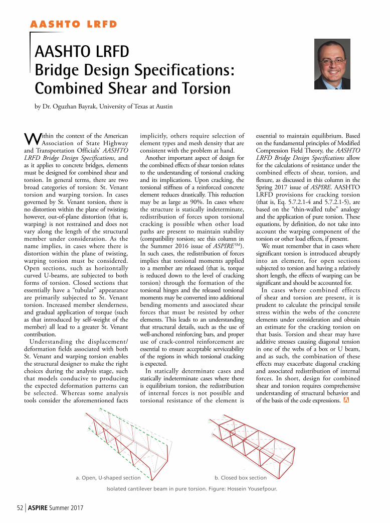
a. Open, U-Shaped Section
AASHTO LRFD
52 | ASPIRE Summer 2017
b. Closed, Box Section
Within the context of the American Association of State Highway
and Transportation Officials’ AASHTO LRFD Bridge Design Specifications, and as it applies to concrete bridges, elements must be designed for combined shear and torsion. In general terms, there are two broad categories of torsion: St. Venant torsion and warping torsion. In cases governed by St. Venant torsion, there is no distortion within the plane of twisting; however, out-of-plane distortion (that is, warping) is not restrained and does not vary along the length of the structural member under consideration. As the name implies, in cases where there is distortion within the plane of twisting, warping torsion must be considered. Open sections, such as horizontally curved U-beams, are subjected to both forms of torsion. Closed sections that essentially have a “tubular” appearance are primarily subjected to St. Venant torsion. Increased member slenderness, and gradual application of torque (such as that introduced by self-weight of the member) all lead to a greater St. Venant contribution.
Understanding the displacement/deformation fields associated with both St. Venant and warping torsion enables the structural designer to make the right choices during the analysis stage, such that models conducive to producing the expected deformation patterns can be selected. Whereas some analysis tools consider the aforementioned facts
implicitly, others require selection of element types and mesh density that are consistent with the problem at hand.
Another important aspect of design for the combined effects of shear torsion relates to the understanding of torsional cracking and its implications. Upon cracking, the torsional stiffness of a reinforced concrete element reduces drastically. This reduction may be as large as 90%. In cases where the structure is statically indeterminate, redistribution of forces upon torsional cracking is possible when other load paths are present to maintain stability (compatibility torsion; see this column in the Summer 2016 issue of ASPIRE SM). In such cases, the redistribution of forces implies that torsional moments applied to a member are released (that is, torque is reduced down to the level of cracking torsion) through the formation of the torsional hinges and the released torsional moments may be converted into additional bending moments and associated shear forces that must be resisted by other elements. This leads to an understanding that structural details, such as the use of well-anchored reinforcing bars, and proper use of crack-control reinforcement are essential to ensure acceptable serviceability of the regions in which torsional cracking is expected.
In statically determinate cases and statically indeterminate cases where there is equilibrium torsion, the redistribution of internal forces is not possible and torsional resistance of the element is
essential to maintain equilibrium. Based on the fundamental principles of Modified Compression Field Theory, the AASHTO LRFD Bridge Design Specifications allow for the calculations of resistance under the combined effects of shear, torsion, and flexure, as discussed in this column in the Spring 2017 issue of ASPIRE. AASHTO LRFD provisions for cracking torsion (that is, Eq. 5.7.2.1-4 and 5.7.2.1-5), are based on the “thin-walled tube” analogy and the application of pure torsion. These equations, by definition, do not take into account the warping component of the torsion or other load effects, if present.
We must remember that in cases where significant torsion is introduced abruptly into an element, for open sections subjected to torsion and having a relatively short length, the effects of warping can be significant and should be accounted for.
In cases where combined effects of shear and torsion are present, it is prudent to calculate the principal tensile stress within the webs of the concrete elements under consideration and obtain an estimate for the cracking torsion on that basis. Torsion and shear may have additive stresses causing diagonal tension in one of the webs of a box or U beam, and as such, the combination of these effects may exacerbate diagonal cracking and associated redistribution of internal forces. In short, design for combined shear and torsion requires comprehensive understanding of structural behavior and of the basis of the code expressions.
by Dr. Oguzhan Bayrak, University of Texas at Austin
AASHTO LRFD Bridge Design Specifications: Combined Shear and Torsion
Isolated cantilever beam in pure torsion. Figure: Hossein Yousefpour.
a. Open, U-shaped section b. Closed box section
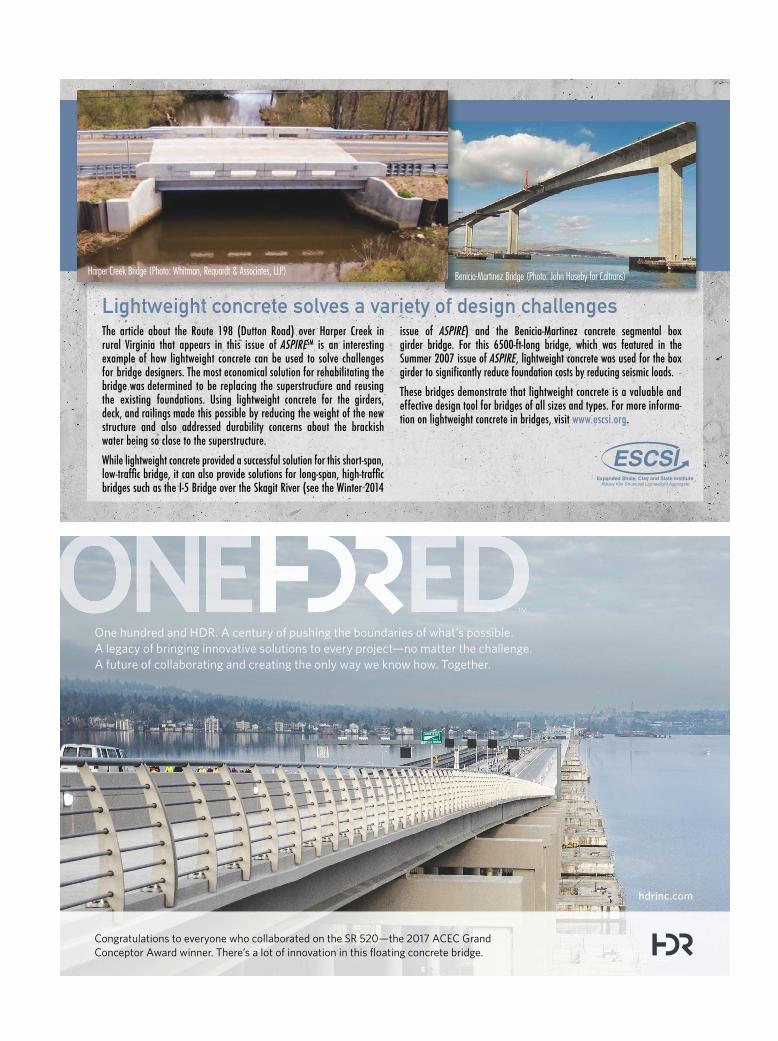
The article about the Route 198 (Dutton Road) over Harper Creek in rural Virginia that appears in this issue of ASPIRESM is an interesting example of how lightweight concrete can be used to solve challenges for bridge designers. The most economical solution for rehabilitating the bridge was determined to be replacing the superstructure and reusing the existing foundations. Using lightweight concrete for the girders, deck, and railings made this possible by reducing the weight of the new structure and also addressed durability concerns about the brackish water being so close to the superstructure.
While lightweight concrete provided a successful solution for this short-span, low-traffic bridge, it can also provide solutions for long-span, high-traffic bridges such as the I-5 Bridge over the Skagit River (see the Winter 2014
issue of ASPIRE) and the Benicia-Martinez concrete segmental box girder bridge. For this 6500-ft-long bridge, which was featured in the Summer 2007 issue of ASPIRE, lightweight concrete was used for the box girder to significantly reduce foundation costs by reducing seismic loads.
These bridges demonstrate that lightweight concrete is a valuable and effective design tool for bridges of all sizes and types. For more informa-tion on lightweight concrete in bridges, visit www.escsi.org.
Lightweight concrete solves a variety of design challenges
Benicia-Martinez Bridge (Photo: John Huseby for Caltrans)Harper Creek Bridge (Photo: Whitman, Requardt & Associates, LLP)
hdrinc.com
One hundred and HDR. A century of pushing the boundaries of what’s possible.
A legacy of bringing innovative solutions to every project—no matter the challenge.
A future of collaborating and creating the only way we know how. Together.
Congratulations to everyone who collaborated on the SR 520—the 2017 ACEC Grand
Conceptor Award winner. There’s a lot of innovation in this floating concrete bridge.