asme part pg
TRANSCRIPT

ASME B&PVC sec1$$$$u5 06-04-99 08:04:18 pd: sec1 Rev 14.04
PART PG
GeneralPG-1 Scope. . . . . . . . . . . . . . . . . . . . . . . . . . . . . . . . . . . . . . . . . . . . . . . . . . . . . . . . . . . . . . . . . . . . . . 5PG-2 Service Limitations. . . . . . . . . . . . . . . . . . . . . . . . . . . . . . . . . . . . . . . . . . . . . . . . . . . . . . . . . . 5PG-3 Referenced Standards. . . . . . . . . . . . . . . . . . . . . . . . . . . . . . . . . . . . . . . . . . . . . . . . . . . . . . . . 5
MaterialsPG-5 General. . . . . . . . . . . . . . . . . . . . . . . . . . . . . . . . . . . . . . . . . . . . . . . . . . . . . . . . . . . . . . . . . . . . 5PG-6 Plate. . . . . . . . . . . . . . . . . . . . . . . . . . . . . . . . . . . . . . . . . . . . . . . . . . . . . . . . . . . . . . . . . . . . . . . 6PG-7 Forgings. . . . . . . . . . . . . . . . . . . . . . . . . . . . . . . . . . . . . . . . . . . . . . . . . . . . . . . . . . . . . . . . . . . 6PG-8 Castings. . . . . . . . . . . . . . . . . . . . . . . . . . . . . . . . . . . . . . . . . . . . . . . . . . . . . . . . . . . . . . . . . . . . 6PG-9 Pipes, Tubes, and Pressure Containing Parts. . . . . . . . . . . . . . . . . . . . . . . . . . . . . . . . . . . 7PG-10 Material Identified With or Produced to a Specification Not Permitted by
This Section, and Material Not Fully Identified. . . . . . . . . . . . . . . . . . . . . . . . . . . . . . 8PG-11 Miscellaneous Pressure Parts. . . . . . . . . . . . . . . . . . . . . . . . . . . . . . . . . . . . . . . . . . . . . . . . . 10PG-12 Gage Glass Body and Connector Materials. . . . . . . . . . . . . . . . . . . . . . . . . . . . . . . . . . . . 11PG-13 Stays. . . . . . . . . . . . . . . . . . . . . . . . . . . . . . . . . . . . . . . . . . . . . . . . . . . . . . . . . . . . . . . . . . . . . . 11
DesignPG-16 General. . . . . . . . . . . . . . . . . . . . . . . . . . . . . . . . . . . . . . . . . . . . . . . . . . . . . . . . . . . . . . . . . . . . 11PG-17 Fabrication by a Combination of Methods. . . . . . . . . . . . . . . . . . . . . . . . . . . . . . . . . . . . . 12PG-18 Hydrostatic Deformation Test. . . . . . . . . . . . . . . . . . . . . . . . . . . . . . . . . . . . . . . . . . . . . . . . 12PG-19 Cold Forming of Austenitic Materials. . . . . . . . . . . . . . . . . . . . . . . . . . . . . . . . . . . . . . . . . 12PG-21 Maximum Allowable Working Pressure. . . . . . . . . . . . . . . . . . . . . . . . . . . . . . . . . . . . . . . 12.2PG-22 Loadings. . . . . . . . . . . . . . . . . . . . . . . . . . . . . . . . . . . . . . . . . . . . . . . . . . . . . . . . . . . . . . . . . . . 13PG-23 Stress Values for Calculation Formulas. . . . . . . . . . . . . . . . . . . . . . . . . . . . . . . . . . . . . . . . 13PG-25 Quality Factors for Steel Castings. . . . . . . . . . . . . . . . . . . . . . . . . . . . . . . . . . . . . . . . . . . . 13PG-27 Cylindrical Components Under Internal Pressure. . . . . . . . . . . . . . . . . . . . . . . . . . . . . . . . 15PG-28 Welded Access or Inspection Openings Under External Pressure. . . . . . . . . . . . . . . . . 17PG-29 Dished Heads. . . . . . . . . . . . . . . . . . . . . . . . . . . . . . . . . . . . . . . . . . . . . . . . . . . . . . . . . . . . . . . 17PG-30 Stayed Dished Heads. . . . . . . . . . . . . . . . . . . . . . . . . . . . . . . . . . . . . . . . . . . . . . . . . . . . . . . . 19PG-31 Unstayed Flat Heads and Covers. . . . . . . . . . . . . . . . . . . . . . . . . . . . . . . . . . . . . . . . . . . . . 19
Openings and CompensationPG-32 Openings in Shells, Headers, and Heads. . . . . . . . . . . . . . . . . . . . . . . . . . . . . . . . . . . . . . . 23PG-33 Compensation Required for Openings in Shells and Formed Heads. . . . . . . . . . . . . . . 24PG-34 Flanged-in Openings in Formed Heads. . . . . . . . . . . . . . . . . . . . . . . . . . . . . . . . . . . . . . . . 27PG-35 Compensation Required for Openings in Flat Heads. . . . . . . . . . . . . . . . . . . . . . . . . . . . 27PG-36 Limits of Metal Available for Compensation. . . . . . . . . . . . . . . . . . . . . . . . . . . . . . . . . . . 28PG-37 Strength of Compensation. . . . . . . . . . . . . . . . . . . . . . . . . . . . . . . . . . . . . . . . . . . . . . . . . . . . 29PG-38 Compensation for Multiple Openings. . . . . . . . . . . . . . . . . . . . . . . . . . . . . . . . . . . . . . . . . . 31PG-39 Methods of Attachment of Pipe and Nozzle Necks to Vessel Walls. . . . . . . . . . . . . . 31PG-42 General Requirements for Fittings, Flanges, and Valves. . . . . . . . . . . . . . . . . . . . . . . . . 33
1 A99

ASME B&PVC sec1$$$$u5 06-04-99 08:04:18 pd: sec1 Rev 14.04
PG-43 Nozzle Neck Thickness. . . . . . . . . . . . . . . . . . . . . . . . . . . . . . . . . . . . . . . . . . . . . . . . . . . . . . 36PG-44 Inspection Openings. . . . . . . . . . . . . . . . . . . . . . . . . . . . . . . . . . . . . . . . . . . . . . . . . . . . . . . . . 36PG-46 Stayed Surfaces. . . . . . . . . . . . . . . . . . . . . . . . . . . . . . . . . . . . . . . . . . . . . . . . . . . . . . . . . . . . . 36PG-47 Staybolts. . . . . . . . . . . . . . . . . . . . . . . . . . . . . . . . . . . . . . . . . . . . . . . . . . . . . . . . . . . . . . . . . . . 37PG-48 Location of Staybolts. . . . . . . . . . . . . . . . . . . . . . . . . . . . . . . . . . . . . . . . . . . . . . . . . . . . . . . . 37PG-49 Dimensions of Staybolts. . . . . . . . . . . . . . . . . . . . . . . . . . . . . . . . . . . . . . . . . . . . . . . . . . . . . 39PG-52 Ligaments. . . . . . . . . . . . . . . . . . . . . . . . . . . . . . . . . . . . . . . . . . . . . . . . . . . . . . . . . . . . . . . . . . 39PG-53 Ligaments. . . . . . . . . . . . . . . . . . . . . . . . . . . . . . . . . . . . . . . . . . . . . . . . . . . . . . . . . . . . . . . . . . 40PG-55 Supports and Attachment Lugs. . . . . . . . . . . . . . . . . . . . . . . . . . . . . . . . . . . . . . . . . . . . . . . 41
Boiler External Piping and Boiler Proper ConnectionsPG-58 Outlets and External Piping. . . . . . . . . . . . . . . . . . . . . . . . . . . . . . . . . . . . . . . . . . . . . . . . . . 41PG-59 Application Requirements for the Boiler Proper. . . . . . . . . . . . . . . . . . . . . . . . . . . . . . . . 45
Design and ApplicationPG-60 Requirements for Miscellaneous Pipe, Valves, and Fittings. . . . . . . . . . . . . . . . . . . . . . 47PG-61 Feedwater Supply. . . . . . . . . . . . . . . . . . . . . . . . . . . . . . . . . . . . . . . . . . . . . . . . . . . . . . . . . . . 50
Safety Valves and Safety Relief ValvesPG-67 Boiler Safety Valve Requirements. . . . . . . . . . . . . . . . . . . . . . . . . . . . . . . . . . . . . . . . . . . . 51PG-68 Superheater and Reheater Safety Valve Requirements. . . . . . . . . . . . . . . . . . . . . . . . . . . 55PG-69 Certification of Capacity of Safety and Safety Relief Valves. . . . . . . . . . . . . . . . . . . . 55PG-70 Capacity of Safety Valves. . . . . . . . . . . . . . . . . . . . . . . . . . . . . . . . . . . . . . . . . . . . . . . . . . . 58PG-71 Mounting. . . . . . . . . . . . . . . . . . . . . . . . . . . . . . . . . . . . . . . . . . . . . . . . . . . . . . . . . . . . . . . . . . 58PG-72 Operation. . . . . . . . . . . . . . . . . . . . . . . . . . . . . . . . . . . . . . . . . . . . . . . . . . . . . . . . . . . . . . . . . . 59PG-73 Minimum Requirements for Safety and Safety Relief Valves. . . . . . . . . . . . . . . . . . . . 59
FabricationPG-75 General. . . . . . . . . . . . . . . . . . . . . . . . . . . . . . . . . . . . . . . . . . . . . . . . . . . . . . . . . . . . . . . . . . . . 62PG-76 Cutting Plates and Other Stock. . . . . . . . . . . . . . . . . . . . . . . . . . . . . . . . . . . . . . . . . . . . . . . 62PG-77 Plate Identification. . . . . . . . . . . . . . . . . . . . . . . . . . . . . . . . . . . . . . . . . . . . . . . . . . . . . . . . . . 62PG-78 Repairs of Defects in Materials. . . . . . . . . . . . . . . . . . . . . . . . . . . . . . . . . . . . . . . . . . . . . . . 62PG-79 Tube Holes and Ends. . . . . . . . . . . . . . . . . . . . . . . . . . . . . . . . . . . . . . . . . . . . . . . . . . . . . . . 62PG-80 Permissible Out-of-Roundness of Cylindrical Shells. . . . . . . . . . . . . . . . . . . . . . . . . . . . . 63PG-81 Tolerance for Formed Heads. . . . . . . . . . . . . . . . . . . . . . . . . . . . . . . . . . . . . . . . . . . . . . . . . 63PG-82 Holes for Stays. . . . . . . . . . . . . . . . . . . . . . . . . . . . . . . . . . . . . . . . . . . . . . . . . . . . . . . . . . . . . 63
Inspection and TestsPG-90 General. . . . . . . . . . . . . . . . . . . . . . . . . . . . . . . . . . . . . . . . . . . . . . . . . . . . . . . . . . . . . . . . . . . . 63PG-91 Qualification of Inspectors. . . . . . . . . . . . . . . . . . . . . . . . . . . . . . . . . . . . . . . . . . . . . . . . . . . 65PG-99 Hydrostatic Test. . . . . . . . . . . . . . . . . . . . . . . . . . . . . . . . . . . . . . . . . . . . . . . . . . . . . . . . . . . . 65PG-100 Hydrostatic Deformation Test. . . . . . . . . . . . . . . . . . . . . . . . . . . . . . . . . . . . . . . . . . . . . . . . 66
Certification by Stamping and Data ReportsPG-101 Heating Surface Computation. . . . . . . . . . . . . . . . . . . . . . . . . . . . . . . . . . . . . . . . . . . . . . . . . 66PG-104 General. . . . . . . . . . . . . . . . . . . . . . . . . . . . . . . . . . . . . . . . . . . . . . . . . . . . . . . . . . . . . . . . . . . . 66PG-105 Code Symbol Stamps. . . . . . . . . . . . . . . . . . . . . . . . . . . . . . . . . . . . . . . . . . . . . . . . . . . . . . . . 67PG-106 Stamping of Boilers. . . . . . . . . . . . . . . . . . . . . . . . . . . . . . . . . . . . . . . . . . . . . . . . . . . . . . . . . 69PG-107 Field Assembly. . . . . . . . . . . . . . . . . . . . . . . . . . . . . . . . . . . . . . . . . . . . . . . . . . . . . . . . . . . . . 71
2

ASME B&PVC sec1$$$$u5 06-04-99 08:04:18 pd: sec1 Rev 14.04
PG-108 Stamping for Field Assembled Boilers. . . . . . . . . . . . . . . . . . . . . . . . . . . . . . . . . . . . . . . . 71PG-109 Stamping of Pressure Piping. . . . . . . . . . . . . . . . . . . . . . . . . . . . . . . . . . . . . . . . . . . . . . . . . 71PG-110 Stamping of Safety Valves. . . . . . . . . . . . . . . . . . . . . . . . . . . . . . . . . . . . . . . . . . . . . . . . . . . 72PG-111 Location of Stampings. . . . . . . . . . . . . . . . . . . . . . . . . . . . . . . . . . . . . . . . . . . . . . . . . . . . . . . 72PG-112 Manufacturers’ Data Report Forms. . . . . . . . . . . . . . . . . . . . . . . . . . . . . . . . . . . . . . . . . . . . 73PG-113 Master Data Report Form. . . . . . . . . . . . . . . . . . . . . . . . . . . . . . . . . . . . . . . . . . . . . . . . . . . . 74
FiguresPG-19 Illustration of Cold Forming Operations for Flaring, Swaging, and Upsetting of
Tubing. . . . . . . . . . . . . . . . . . . . . . . . . . . . . . . . . . . . . . . . . . . . . . . . . . . . . . . . . . . . . . . . . . . 12.2PG-28 Maximum Internal Projection of Welded Access or Inspection Openings. . . . . . . . . . 17.1PG-31 Some Acceptable Types of Unstayed Flat Heads and Covers. . . . . . . . . . . . . . . . . . . . 20PG-32 Chart Showing Limits of Sizes of Openings With Inherent Compensation
in Cylindrical Shells. . . . . . . . . . . . . . . . . . . . . . . . . . . . . . . . . . . . . . . . . . . . . . . . . . . . . . 25PG-33 Chart for Determining Value ofF . . . . . . . . . . . . . . . . . . . . . . . . . . . . . . . . . . . . . . . . . . . . 27PG-36 Limits of Reinforcement for Typical Openings. . . . . . . . . . . . . . . . . . . . . . . . . . . . . . . . . 28PG-36.4 Some Representative Configurations Describing thete Reinforcement
Dimension. . . . . . . . . . . . . . . . . . . . . . . . . . . . . . . . . . . . . . . . . . . . . . . . . . . . . . . . . . . . . . . 30PG-38 Illustrations of the Rule Given in PG-38.4. . . . . . . . . . . . . . . . . . . . . . . . . . . . . . . . . . . . 31PG-42.1 Welding End Transitions Maximum Envelope. . . . . . . . . . . . . . . . . . . . . . . . . . . . . . . . . . 35PG-46.2 Acceptable Proportions for Ends of Through-Stays. . . . . . . . . . . . . . . . . . . . . . . . . . . . . 37PG-52.1 Diagram for Determining the Efficiency of Longitudinal and Diagonal
Ligaments Between Openings in Cylindrical Shells. . . . . . . . . . . . . . . . . . . . . . . . . . . 38PG-52.2 Example of Tube Spacing With Pitch of Holes Equal in Every Row. . . . . . . . . . . . . 39PG-52.3 Example of Tube Spacing With Pitch of Holes Unequal in Every Second
Row. . . . . . . . . . . . . . . . . . . . . . . . . . . . . . . . . . . . . . . . . . . . . . . . . . . . . . . . . . . . . . . . . . . . . 39PG-52.4 Example of Tube Spacing With Pitch of Holes Varying in Every Second
and Third Row. . . . . . . . . . . . . . . . . . . . . . . . . . . . . . . . . . . . . . . . . . . . . . . . . . . . . . . . . . . 39PG-52.5 Example of Tube Spacing With Tube Holes on Diagonal Lines. . . . . . . . . . . . . . . . . 40PG-52.6 Diagram for Determining Equivalent Longitudinal Efficiency of Diagonal
Ligaments Between Openings in Cylindrical Shells. . . . . . . . . . . . . . . . . . . . . . . . . . . 42PG-58.3.1 Code Jurisdictional Limits for Piping — Drum Type Boilers. . . . . . . . . . . . . . . . . . . . 43PG-58.3.2 Code Jurisdictional Limits for Piping — Forced-Flow Steam Generator
With No Fixed Steam or Waterline. . . . . . . . . . . . . . . . . . . . . . . . . . . . . . . . . . . . . . . . . 44PG-59.1 Typical Boiler Bushings. . . . . . . . . . . . . . . . . . . . . . . . . . . . . . . . . . . . . . . . . . . . . . . . . . . . . 46PG-60 Typical Arrangement of Steam and Water Connections for a Water
Column. . . . . . . . . . . . . . . . . . . . . . . . . . . . . . . . . . . . . . . . . . . . . . . . . . . . . . . . . . . . . . . . . . 50PG-67.4 Requirements for Pressure Relief Forced-Flow Steam Generator. . . . . . . . . . . . . . . . . . 53PG-80 Maximum Permissible Deviation From a Circular Forme for Cylindrical
Parts Under External Pressure. . . . . . . . . . . . . . . . . . . . . . . . . . . . . . . . . . . . . . . . . . . . . . 64PG-105.1 Official Symbols for Stamps to Denote The American Society of
Mechanical Engineers’ Standard for Boilers. . . . . . . . . . . . . . . . . . . . . . . . . . . . . . . . . . 67PG-105.2 Official Symbol for Stamp to Denote The American Society of
Mechanical Engineers’ Standard for Assembly. . . . . . . . . . . . . . . . . . . . . . . . . . . . . . . 67PG-105.3 Official Symbol for Stamp to Denote The American Society of
Mechanical Engineers’ Standard for Welded Piping. . . . . . . . . . . . . . . . . . . . . . . . . . . 67PG-105.4 Official Symbol for Stamp to Denote The American Society of
Mechanical Engineers’ Standard for Safety Valves. . . . . . . . . . . . . . . . . . . . . . . . . . . 67PG-106 Form of Stamping. . . . . . . . . . . . . . . . . . . . . . . . . . . . . . . . . . . . . . . . . . . . . . . . . . . . . . . . . . 69
TablePG-19 Post Cold-Forming Strain Limits and Heat-Treatment Requirements. . . . . . . . . . . . . . 12.1PG-39 Minimum Number of Threads per Connection. . . . . . . . . . . . . . . . . . . . . . . . . . . . . . . . . 32
3 A99

ASME B&PVC sec1$$$$u5 06-04-99 08:04:18 pd: sec1 Rev 14.04
PART PGGENERAL REQUIREMENTS FOR ALL
METHODS OF CONSTRUCTION
GENERAL
PG-1 SCOPE
The requirements of Part PG apply to power boilersand high pressure, high-temperature water boilers andto parts and appurtenances thereto and shall be usedin conjunction with the specific requirements in theapplicable Parts of this Section that pertain to themethods of construction used.
PG-2 SERVICE LIMITATIONS
PG-2.1 The rules of this Section are applicable tothe following services:
(a) boilers in which steam or other vapor is generatedat a pressure of more than 15 psig (103 kPa);
(b) high-temperature water boilers intended for opera-tion at pressures exceeding 160 psig (1100 kPa) and/ortemperatures exceeding 250°F (121°C).
PG-2.2 For services below those specified in PG-2.1 it is intended that rules of Section IV apply;however, boilers for such services may be constructedand stamped in accordance with this Section providedall applicable requirements are met.
PG-2.3 Coil-type hot water boilers where the watercan flash into steam when released directly to theatmosphere through a manually operated nozzle maybe exempted from the rules of this Section providedthe following conditions are met.
(a) There is no drum, header, or other steam space.(b) No steam is generated within the coil.(c) Tubing outside diameter does not exceed 1 in.
(25 mm).(d) Pipe size does not exceed NPS3⁄4 (DN 20).(e) Nominal water capacity does not exceed 6
gal. (23 l).
5
(f) Water temperature does not exceed 350°F(177°C).
(g) Adequate safety relief valves and controls areprovided.
PG-3 REFERENCED STANDARDS
Specific editions of standards referenced in this Sec-tion are shown in Appendix A-360.
MATERIALS
PG-5 GENERAL
PG-5.1 Material subject to stress due to pressureshall conform to one of the specifications given inSection II and shall be limited to those that are listedin the Tables of Section II, Part D, except as otherwisepermitted in PG-8.2, PG-8.3, PG-10, and PG-11. Materi-als shall not be used at temperatures above those forwhich stress values are limited, for Section I construc-tion, in the Tables of Section II, Part D. Specificadditional requirements described in PG-5 through PG-13 shall be met as applicable.
PG-5.2 Material covered by specifications in SectionII is not restricted as to the method of productionunless so stated in the specification, and as long asthe product complies with the requirements of thespecification.
PG-5.3 If, in the development of the art of boilerconstruction, it is desired to use materials other thanthose herein described, data should be submitted to theBoiler and Pressure Vessel Committee in accordancewith the requirements of Appendix 5 of Section II,Part D. Material not completely identified with anyapproved Code specifications may be used in the con-
98

ASME B&PVC sec1$$$$u5 06-04-99 08:04:18 pd: sec1 Rev 14.04
98
A99
PG-5.3 1998 SECTION I PG-8.3
struction of boilers under the conditions outlined inPG-10.
PG-5.4 Materials outside the limits of size or thick-ness given in the title or scope clause of any specificationin Section II may be used if the material is in compliancewith the other requirements of the specification, and nosimilar limitation is given in the rules for construction.
PG-5.5 The use of austenitic stainless steel ispermitted for boiler pressure parts which are steamtouched in normal operation. However, the use of suchsteel for boiler pressure parts which are water wettedin normal service is prohibited except as specificallyprovided in PG-12 and PEB-5.3.1
PG-6 PLATE
PG-6.1 Steel plates for any part of a boiler subjectto pressure, whether or not exposed to the fire orproducts of combustion, shall be of pressure vesselquality in accordance with one of the following specifi-cations:SA-202 Pressure Vessel Plates, Alloy Steel, Chro-
mium-Manganese-SiliconSA-204 Pressure Vessel Plates, Alloy Steel, Molyb-
denumSA-240 (Type 405 only) Pressure Vessel Plates, Alloy
Steel (Ferritic Stainless), ChromiumSA-285 Pressure Vessel Plates, Carbon Steel, Low-
and Intermediate-Tensile StrengthSA-299 Pressure Vessel Plates, Carbon Steel, Manga-
nese-SiliconSA-302 Pressure Vessel Plates, Alloy Steel, Manga-
nese-Molybdenum and Manganese-Molybdenum-Nickel
SA-387 Pressure Vessel Plates, Alloy Steel, Chro-mium-Molybdenum
SA-515 Pressure Vessel Plates, Carbon Steel, for Inter-mediate- and Higher-Temperature Service
SA-516 Pressure Vessel Plates, Carbon Steel, for Mod-erate- and Lower-Temperature Service
1 Austenitic alloys are susceptible to intergranular corrosion and stresscorrosion cracking when used in boiler applications in water wettedservice. Factors which affect the sensitivity to these metallurgicalphenomena are applied or residual stress and water chemistry. Suscep-tibility to attack is usually enhanced by using the material in astressed condition with a concentration of corrosive agents (e.g.,chlorides, caustic, or reduced sulfer species). For successful operationin water environments, residual and applied stresses must be mini-mized and careful attention must be paid to continuous control ofwater chemistry.
6
PG-7 FORGINGS
PG-7.1Seamless steel drum forgings made in accord-ance with SA-266 for Carbon-Steel and SA-336 forAlloy Steel may be used for any part of a boiler forwhich pressure vessel quality is specified or permitted.
PG-7.2 Forged flanges, fittings, nozzles, valves, andother pressure parts of the boiler shall be of materialthat conforms to one of the forging specifications aslisted in PG-9.
PG-7.3 Drums, shells, or domes may be of seamlessdrawn construction, with or without integral heads,provided the material conforms to the requirements ofthe Code for shell material.
PG-8 CASTINGS
PG-8.1Except for the limited usage permitted by PG-8.2 and PG-8.3, cast material used in the construction ofvessels and vessel parts shall conform to one of thespecifications listed in PG-9 for which maximum allow-able stress values are given in Tables 1A and 1B ofSection II, Part D. The allowable stress values shallbe multiplied by the applicable casting quality factorgiven in PG-25 for all cast materials except cast iron.
When cast iron is used as allowed in PG-11.1 forstandard pressure parts, it shall conform to one of thesestandards:
ASME B16.1, Cast Iron Pipe Flanges and FlangedFittings
ASME B16.4, Cast Iron Threaded Fittings
Material conforming to ASTM A 126 may be usedsubject to all requirements of the particular standard.Such usage is subject also to all the requirements forthe use of cast iron given in PG-8.2 and other paragraphsof this Section.
PG-8.2 Cast IronPG-8.2.1 Cast iron shall not be used for nozzles
or flanges attached directly to the boiler for any pressureor temperature.
PG-8.2.2Cast iron as designated in SA-278, GrayIron Castings for Pressure-Containing Parts for Temper-atures up to 650°F (343°C) may be used for boilerand superheater connections under pressure, such aspipe fittings, water columns, valves and their bonnets,for pressures up to 250 psi (1720 kPa), provided thesteam temperature does not exceed 450°F (232°C).
PG-8.3 Cast Nodular Iron. Cast nodular iron asdesignated in SA-395 may be used for boiler andsuperheater connections under pressure, such as pipe

ASME B&PVC sec1$$$$u5 06-04-99 08:04:18 pd: sec1 Rev 14.04
98
PG-8.3 PART PG — GENERAL REQUIREMENTS PG-9.2
fittings, water columns, and valves and their bonnets,for pressures not to exceed 350 psi (2410 kPa), providedthe steam temperature does not exceed 450°F (232°C).
PG-8.4 Nonferrous. Bronze castings shall conformto SB-61 and SB-62 and may be used only for thefollowing:
PG-8.4.1 For flanges and flanged or threadedfittings complying with the pressure and temperaturerequirements of ANSI B16.15 or B16.24, except thatsuch fittings shall not be used where steel or othermaterial is specifically required. Threaded fittings shallnot be used where flanged types are specified.
PG-8.4.2.1For valves at allowable stress valuesnot to exceed those given in Table 1B of Section II,Part D, with maximum allowable temperatures of 550°F(288°C) for SB-61 and 406°F (208°C) for SB-62.
PG-8.4.2.2For parts of safety valves or safetyrelief valves subject to limitations of PG-67.7.
PG-9 PIPES, TUBES, AND PRESSURECONTAINING PARTS
Pipes, tubes, and pressure containing parts used inboilers shall conform to one of the specifications listedin this paragraph for which maximum allowable stressesare given in Tables 1A and 1B of Section II, Part D.The stress values given in these tables include theapplicable joint efficiency factor for welded pipesand tubes.
Open-hearth, electric furnace, or basic oxygen steelshall be used for boiler pressure parts exposed to thefire or products of combustion. When used for internalpressure, the material stress and dimensions shall meetthe appropriate requirements of PG-27 and Part PWand be in accordance with the following:
PG-9.1 Boiler parts shall be of the following speci-fications only:SA-53 Welded and Seamless Steel Pipe (excluding
galvanized)SA-105 Forgings, Carbon Steel, for Piping Compo-
nentsSA-106 Seamless Carbon Steel Pipe for High-Temper-
ature ServiceSA-178 Electric-Resistance-Welded Carbon Steel
Boiler TubesSA-181 Forged or Rolled Steel Pipe Flanges, Forged
Fittings, and Valves and Parts for General Service
7
SA-182 Forged or Rolled Alloy-Steel Pipe Flanges,Forged Fittings, and Valves and Parts for High-Temperature Service (ferritic only)
SA-192 Seamless Carbon Steel Boiler Tubes for HighPressure Service
SA-209 Seamless Carbon-Molybdenum Alloy-SteelBoiler and Superheater Tubes
SA-210 Seamless Medium Carbon Steel Boiler andSuperheater Tubes
SA-213 Seamless Ferritic and Austenitic Alloy-SteelBoiler, Superheater and Heat Exchanger Tubes (fer-ritic only)
SA-216 Carbon Steel Castings Suitable for FusionWelding for High-Temperature Service
SA-217 Alloy-Steel Castings for Pressure-ContainingParts Suitable for High-Temperature Service
SA-226 Electric-Resistance-Welded Carbon SteelBoiler and Superheater Tubes for High-PressureService
SA-234 Piping Fittings of Wrought Carbon Steel andAlloy Steel for Moderate and Elevated Temperatures
SA-250 Electric-Resistance-Welded Carbon-Molybde-num Alloy Steel Boiler and Superheater Tubes
SA-266 Carbon Steel Seamless Drum ForgingsSA-268 Seamless and Welded Ferritic Stainless Steel
Tubing for General ServiceSA-335 Seamless Ferritic Alloy Steel Pipe for High-
Temperature ServiceSA-336 Alloy Steel Seamless Drum Forgings (fer-
ritic only)SA-423 Seamless and Electric Welded Low Alloy
Steel TubesSA-660 Centrifugally Cast Carbon Steel Pipe for High-
Temperature ServiceSA-731 Seamless, Welded Ferritic, and Martensitic
Stainless Steel Pipe
PG-9.2 Superheater parts shall be of any one of theabove specifications or one of the following:SA-182 Forged or Rolled Alloy-Steel Pipe Flanges,
Forged Fittings, and Valves and Plates for High-Temperature Service
SA-213 Seamless Ferritic and Austenitic Alloy SteelBoiler, Superheater and Heat Exchanger Tubes
SA-240 Stainless and Heat-Resisting Chromium andChromium-Nickel Steel Plates, Sheet and Strip forFusion-Welded Unfired Pressure Vessels
SA-249 Welded Austenitic Steel Boiler, Superheater,Heat Exchanger, and Condenser Tubes
SA-268 Seamless and Welded Ferritic Stainless SteelTubing for General Service
SA-312 Seamless and Welded Austenitic StainlessSteel Pipe
98
A99

ASME B&PVC sec1$$$$u5 06-04-99 08:04:18 pd: sec1 Rev 14.04
PG-9.2 1998 SECTION I PG-10.1.2.1
SA-336 Alloy Steel Seamless Drum ForgingsSA-351 Ferritic and Austenitic Steel Castings for
High-Temperature ServiceSA-369 Ferritic Alloy Steel Forged and Bored Pipe
for High-Temperature ServiceSA-376 Seamless Austenitic Steel Pipe for High-Tem-
perature Central-Station ServiceSA-731 Seamless, Welded Ferritic, and Martensitic
Stainless Steel PipeSB-163 Seamless Nickel and Nickel Alloy Condenser
and Heat Exchanger TubesSB-407 Nickel-Iron-Chromium Alloy Seamless Pipe
and TubeSB-408 Nickel-Iron-Chromium Alloy Rod and BarSB-409 Nickel-Iron-Chromium Alloy Plate, Sheet,
and StripSB-423 Nickel-Iron-Chromium-Molybdenum Seam-
less Pipe and TubeSB-424 Nickel-Iron-Chromium-Molybdenum-Copper
Alloy Plate, Sheet, and StripSB-425 Nickel-Iron-Chromium-Molybdenum-Copper
Alloy Rod and BarSA-430 Austenitic Steel Forged and Bored Pipe for
High-Temperature ServiceSA-479 Stainless and Heat-Resisting Steel Bars and
Shapes for Use in Boilers and Other Pressure VesselsSB-514 Welded Nickel-Iron-Chromium Alloy PipeSB-515 Welded Nickel-Iron-Chromium Alloy TubesSB-564 Nickel Alloy Forgings
PG-9.3 Except for the nonferrous materials listed inPG-9.2, nonferrous pipe or tubes shall not be used inthe boiler proper for any service where the temperatureexceeds 406°F (208°C). Where permitted, copper andcopper alloys shall be seamless, having a thickness notless than ANSI Schedule 40 standard pipe, and shallcomply to one of the following specifications: SB-42,Seamless Copper Pipe, Standard Sizes; SB-43, SeamlessRed Brass Pipe, Standard Sizes; SB-75, Seamless Cop-per Tube; or SB-111, Copper and Copper-Alloy Seam-less Condenser Tubes and Ferrule Stock.
PG-9.4 Bimetallic tubes, having a core of an accept-able boiler and superheater material, and having anexternal cladding of another metal alloy, may be usedprovided the requirements of PG-27.2.1.5 are met forestablishing minimum thickness of the core. The permis-sible variation in wall thickness tolerance of SA-450or SB-163, as applicable, shall apply to the total wallthickness. The thickness and over and undertolerancesof the cladding shall be included in the ordering informa-tion. Marking of the bimetallic tubular product shallmeet the specification requirements of the core material,but shall also suitably identify the cladding alloy.
8
PG-10 MATERIAL IDENTIFIED WITH ORPRODUCED TO A SPECIFICATIONNOT PERMITTED BY THISSECTION, AND MATERIAL NOTFULLY IDENTIFIED
PG-10.1 Identified With Complete CertificationFrom the Material Manufacturer. Material identifiedwith a specification not permitted by this Section, ormaterial procured to chemical composition requirementsand identified to a single production lot as requiredby a permitted specification may be accepted as satis-fying the requirements of a specification permitted bythis Section provided the conditions set forth in PG-10.1.1 or PG-10.1.2 are satisfied.
PG-10.1.1Recertification by an organization otherthan the boiler or part manufacturer:
PG-10.1.1.1All requirements, including but notlimited to, melting method, melting practice, deoxida-tion, quality, and heat treatment, of the specificationpermitted by this Section, to which the material is tobe recertified, have been demonstrated to have been met.
PG-10.1.1.2A copy of the certification by the ma-terial manufacturer of the chemical analysis required bythe permitted specification, with documentation showingthe requirements to which the material was produced andpurchased, and which demonstrates that there is no conflictwith the requirements of the permitted specification, hasbeen furnished to the boiler or part manufacturer.
PG-10.1.1.3 A certification that the materialwas manufactured and tested in accordance with therequirements of the specification to which the materialis recertified, excluding the specific marking require-ments, has been furnished to the boiler or part manufac-turer, together with copies of all documents and testreports pertinent to the demonstration of conformanceto the requirements of the permitted specification.
PG-10.1.1.4 The material, and the Certificateof Compliance or the Material Test Report have beenidentified with the designation of the specification towhich the material is recertified and with the notation“Certified per PG-10.”
PG-10.1.2 Recertification by the boiler or partmanufacturer:
PG-10.1.2.1A copy of the certification by thematerial manufacturer of the chemical analysis requiredby the permitted specification, with documentationshowing the requirements to which the material wasproduced and purchased, which demonstrates that there

ASME B&PVC sec1$$$$u5 06-04-99 08:04:18 pd: sec1 Rev 14.04
PG-10.1.2.1 PART PG — GENERAL REQUIREMENTS PG-10.3.2.1
is no conflict with the requirements of the permittedspecification, is available to the Inspector.
PG-10.1.2.2For applications in which the maxi-mum allowable stresses are subject to a note of Table1A of Section II, Part D, requiring the use of killedsteel, documentation is available to the Inspector whichestablishes that the material is a killed steel.
PG-10.1.2.3Documentation is available to theInspector which demonstrates that the metallurgicalstructure, mechanical property, and hardness require-ments of the permitted specification have been met.
PG-10.1.2.4For material recertified to a permittedspecification which requires a fine austenitic grain size orwhich requires that a fine grain practice be used duringmelting, documentation is available to the Inspector whichdemonstrates that the heat treatment requirements of thepermitted specification have been met, or will be met dur-ing fabrication.
PG-10.1.2.5The material has marking, accept-able to the Inspector, for identification to the documen-tation.
PG-10.1.2.6When the conformance of the mate-rial with the permitted specification has been established,the material has been marked as required by the permit-ted specification.
PG-10.2 Material Identified to a Particular Pro-duction Lot as Required by a Specification Permittedby This Section but Which Cannot Be QualifiedUnder PG-10.1.Any material identified to a particularproduction lot as required by a specification permitted bythis Section, but for which the documentation required inPG-10.1 is not available, may be accepted as satisfyingthe requirements of the specification permitted by thisSection provided that the conditions set forth beloware satisfied.
PG-10.2.1Recertification by an organization otherthan the boiler or part manufacturer — not permitted.
PG-10.2.2 Recertification by the boiler or partmanufacturer.
PG-10.2.2.1 Chemical analyses are made ondifferent pieces from the lot to establish a mean analysiswhich is to be accepted as representative of the lot.The pieces chosen for analyses shall be selected atrandom from the lot. The number of pieces selectedshall be at least 10% of the number of pieces in thelot, but not less than three. For lots of three pieces orless, each piece shall be analyzed. Each individual
9
analysis in the permitted specification and the meanfor each element shall conform to the heat analysislimits of that specification. Analyses need to be madefor only those elements required by the permittedspecification. However, consideration should be givento making analyses for elements not specified in thespecification but which would be deleterious if presentin excessive amounts.
PG-10.2.2.2Mechanical property tests are madein accordance with the requirements of the permittedspecification and the results of the tests conform tothe specified requirements.
PG-10.2.2.3For applications in which the maxi-mum allowable stresses are subject to a note of Table1A of Section II, Part D, requiring the use of killedsteel, documentation is available to the Inspector whichestablishes that the material is a killed steel.
PG-10.2.2.4When the requirements of the per-mitted specification include metallurgical structure re-quirements (i.e., fine austenitic grain size), tests aremade and the results are sufficient to establish thatthose requirements of the specification have been met.
PG-10.2.2.5When the requirements of the per-mitted specification include heat treatment, the materialis heat treated in accordance with those requirements,either prior to or during fabrication.
PG-10.2.2.6When the conformance of the mate-rial with the permitted specification has been established,the material has been marked as required by the permit-ted specification.
PG-10.3 Material Not Fully Identified. Materialwhich cannot be qualified under the provisions of eitherPG-10.1 or PG-10.2, such as material not fully identifiedas required by the permitted specification or as unidenti-fied material, may be accepted as satisfying the require-ments of a specification permitted by this Sectionprovided that the conditions set forth below are satisfied.
PG-10.3.1Qualification by an organization otherthan the boiler or part manufacturer — not permitted.
PG-10.3.2Qualification by the boiler or part manu-facturer:
PG-10.3.2.1Each piece is tested to show thatit meets the chemical composition for product analysisand the mechanical properties requirements of the per-mitted specification. Chemical analyses need only bemade for those elements required by the permittedspecification. However, consideration shall be given to

ASME B&PVC sec1$$$$u5 06-04-99 08:04:18 pd: sec1 Rev 14.04
A99
PG-10.3.2.1 1998 SECTION I PG-11.2
making analyses for elements not specified in thespecification but which would be deleterious if presentin excessive amounts. For plates, when the directionof final rolling is not known, both a transverse and alongitudinal tension test specimen shall be taken fromeach sampling location designated in the permittedspecification. The results of both tests shall conformto the minimum requirements of the specification, butthe tensile strength of only one of the two specimensneed conform to the maximum requirement.
PG-10.3.2.2The provisions of PG-10.2.2.3, PG-10.2.2.4, and PG-10.2.2.5 are met.
PG-10.3.2.3 When the identity of the materialwith the permitted specification has been established inaccordance with PG-10.3.2.1 and PG-10.3.2.2, each piece(or bundle, etc., if permitted in the specification) ismarked with a marking giving the permitted specificationnumber and grade, type, or class as applicable and aserial number identifying the particular lot of material.A suitable report, clearly marked as being a “Report onTests of Nonidentified Material,” shall be completed andcertified by the boiler or part manufacturer. This report,when accepted by the Inspector, shall constitute authorityto use the material in lieu of material procured to therequirements of the permitted specification.
PG-11 MISCELLANEOUS PRESSUREPARTS
Prefabricated or preformed pressure parts for boilerswhich are subject to allowable working stresses dueto internal or external pressure in the boiler and whichare furnished by other than the shop of the Manufacturerresponsible for the completed boiler shall conform toall applicable requirements of the Code for the com-pleted boiler, including inspection in the shop of theparts manufacturer and the furnishing of Manufacturer’sPartial Data Reports as provided for in PG-112.2.4except as permitted in PG-11.1, PG-11.2, and PG-11.3.
PG-11.1 Cast, Forged, Rolled, or Die FormedStandard Pressure Parts
PG-11.1.1 Pressure parts such as pipe fittings,valves, flanges, nozzles, welding necks, welding caps,manhole frames and covers, and casings of pumps thatare part of a boiler circulating system that are whollyformed by casting, forging, rolling, or die forming shallnot require inspection, mill test reports, or Partial DataReports. Standard pressure parts that comply with some
10
ASME Standard2 shall be made of materials permittedby this Section or of materials specifically listed in anASME product standard listed elsewhere in this Sectionbut not of materials specifically prohibited or beyonduse limitations listed in this Section. Standard pressureparts which comply with a manufacturer’s standard3,4
shall be made of materials permitted by this Section.Such parts shall be marked with the name or trademarkof the parts manufacturer and such other markings asare required by the standard. Such markings shall beconsidered as the parts manufacturer’s certification thatthe product complies with the material specificationsand standards indicated and is suitable for service atthe rating indicated. The intent of the paragraph willhave been met if, in lieu of the detailed marking onthe part itself, the parts described herein have beenmarked in any permanent or temporary manner thatwill serve to identify the part with the parts manufactur-er’s written listing of the particular items and suchlistings are available for examination by the Inspector.
PG-11.1.2 Parts of small size falling within thiscategory for which it is difficult or impossible to obtainidentified material or which may be stocked and forwhich mill test reports or certificates cannot be economi-cally obtained and are not customarily furnished, andwhich do not appreciably affect the safety of the vessel,may be used for relatively unimportant part or partsstressed to not more than 50% of the stress valuepermitted by this Section, and listed in Tables 1A and1B of Section II, Part D, provided they are suitablefor the purpose intended and meet the approval of theInspector. The Manufacturer of the completed vesselshall satisfy himself that the part is suitable for thedesign conditions specified for the completed vessel.
PG-11.2 Cast, Forged, Rolled, or Die FormedNonstandard Pressure Parts.Pressure parts such asshells, heads, removable and access opening coverplates, that are wholly formed by casting, forging,rolling, or die forming, may be supplied basically asmaterials. All such parts shall be made of materialspermitted under this Section, and the manufacturer ofthe part shall furnish mill test reports or other acceptable
A992 These are pressure parts which comply with some ASME productstandard accepted by reference in PG-42. The ASME product standardestablishes the basis for the pressure–temperature rating and marking.3 These are pressure parts which comply with a parts manufacturer’sstandard which defines the pressure–temperature rating marked onthe part and described in the parts manufacturer’s literature. TheManufacturer of the completed vessel shall satisfy himself that thepart is suitable for the design conditions of the completed vessel.
A994 Pressure parts may be in accordance with an ASME product standardnot covered by footnote 3, but such parts shall satisfy the requirementsapplicable to a parts manufacturer’s standard and footnote 4.

ASME B&PVC sec1$$$$u5 06-04-99 08:04:18 pd: sec1 Rev 14.04
A99
A99
PG-11.2 PART PG — GENERAL REQUIREMENTS PG-16.2.1
evidence to that effect. Such parts shall be markedwith the name or trademark of the parts manufacturerand with such other markings as will serve to identifythe particular parts with accompanying material identi-fication. The Manufacturer of the completed boiler shallsatisfy himself that the part is suitable for the designconditions specified for the completed boiler.
PG-11.3 Welded Standard Pressure Parts for UseOther Than the Shell of a Vessel.5 Pressure partssuch as welded standard pipe fittings, caps, valves, andflanges that are fabricated by one of the weldingprocesses recognized by this Section shall not requireinspection, mill test reports, or Manufacturers’ PartialData Reports provided.6
PG-11.3.1Standard pressure parts which complywith some ASME product standard3 shall be made ofmaterials permitted by this Section or of materialsspecifically listed in an ASME product standard acceptedand listed elsewhere in this Section but not of materialsspecifically prohibited or beyond use limitations listedin this Section. Standard pressure parts which complywith a manufacturer’s standard3,4 shall be made ofmaterials permitted by this Section.
PG-11.3.2Welding for pressure parts which com-ply with a manufacturer’s standard3,4 shall comply withthe requirements of PW-26 through PW-39. Weldingfor pressure parts which comply with some ASMEproduct standard2 shall comply with the requirementsof PW-26 through PW-39 or, as a minimum, maycomply with the welding requirements of SA-234.Markings where applicable, or certification by the partsmanufacturer where markings are not applicable shallbe accepted as evidence of compliance with the abovewelding requirements. Such parts shall be marked asrequired by PG-11.1.1.
PG-11.3.3 If radiographic examination or heattreatment is required by the applicable rules of thisSection, it may be performed either in the plant of theparts manufacturer or in the plant of the Manufacturerof the completed vessel.
If the radiographic examination is done under thecontrol of the parts manufacturer, the completed radio-graphs, properly identified, with a radiographic inspec-tion report, shall be forwarded to the vessel manufacturerand shall be available to the Authorized Inspector.
5 Fusion welded pipe for use as the shell of the vessel shall besubject to the same requirements as a shell fabricated from plate,including inspection at the point of manufacture and Manufacturers’Partial Data Reports.6 For requirements for welded water columns, see PW-42.
11
PG-11.3.4 If heat treatment is performed at theplant of the parts manufacturer, certification by theparts manufacturer that such treatment was performedshall be accepted as evidence of compliance withapplicable Code paragraphs. This certification shall beavailable to the Authorized Inspector. The Manufacturerof the completed vessel shall satisfy himself that thepart is suitable for the design conditions specified forthe completed vessel.
PG-12 GAGE GLASS BODY ANDCONNECTOR MATERIALS
Gage glass body and connector materials shall complywith a Manufacturer’s standard which defines the pres-sure–temperature rating marked on the unit. The materi-als used may include austenitic stainless steel.
PG-13 STAYS
Threaded stays shall be of steel complying with SA-36 or SA-675.
Seamless steel tubes for threaded stays shall complywith SA-192 or SA-210.
Staybolts, stays, through-rods, or stays with ends forattachment by fusion welding shall comply with SA-36 or SA-675.
DESIGN
PG-16 GENERAL
PG-16.1The design of power boilers, high-tempera-ture water boilers, and other pressure parts includedwithin the scope of these rules shall conform to thegeneral design requirements in the following paragraphsand in addition to the specific requirements for designgiven in the applicable Parts of this Section that pertainto the methods of construction used.
PG-16.2 When the pressure parts of a forced-flowsteam generator with no fixed steam and waterline aredesigned for different pressure levels as permitted inPG-21.2, the owner shall provide or cause to be provideda boiler pressure system design diagram, certified bya Professional Engineer experienced in the mechanicaldesign of power plants, which supplies the followinginformation.
PG-16.2.1 The relative location of the variouspressure parts within the scope of Section I, with respectto the path of water-steam flow.

ASME B&PVC sec1$$$$u5 06 04 99 08:04:18 pd: sec1 Rev 14 04
PG-16.2.2 1998 SECTION I PG-19
PG-16.2.2A line showing the expected maximumsustained pressure as described in PG-21.2, indicatingthe expected variation in pressure along the path ofwater-steam flow.
PG-16.2.3The maximum allowable working pres-sure of the various pressure parts.
PG-16.2.4 The location and set pressure of theoverpressure protection devices.
Copy of this diagram shall be attached to the MasterData Report per PG-113.
PG-16.3 Minimum Thicknesses. The minimumthickness of any boiler plate under pressure shall be1⁄4 in. (6 mm) except for electric boilers constructedunder the rules of Part PEB. The minimum thicknessof plates to which stays may be applied in other thancylindrical outer shell plates shall be5⁄16 (8 mm) in.When pipe over NPS 5 (DN 125) is used in lieu ofplate for the shell of cylindrical components underpressure, its minimum wall shall be1⁄4 in. (6 mm).
PG-16.4 Undertolerance on Plates.Plate materialthat is not more than 0.01 in. (0.3 mm) thinner thanthat calculated from the formula may be used in Codeconstructions provided the material specification permitssuch plate to be furnished not more than 0.01 in.(0.3 mm) thinner than ordered.
PG-16.5 Undertolerance on Pipe and Tubes.Pipeor tube material shall not be ordered thinner than thatcalculated from the applicable formula of this Section.The ordered material shall include provision for theallowed manufacturing undertolerance as given in Sec-tion II in the applicable pipe or tube specification.
PG-17 FABRICATION BY ACOMBINATION OF METHODS
A boiler and parts thereof may be designed andfabricated by a combination of the methods of fabrica-tion given in this Section, provided the rules applyingto the respective methods of fabrication are followedand the boiler is limited to the service permitted bythe method of fabrication having the most restrictiverequirements.
PG-18 HYDROSTATIC DEFORMATIONTEST
Where no rules are given and it is impossible tocalculate with a reasonable degree of accuracy thestrength of a boiler structure or any part thereof, afull-sized sample shall be built by the Manufacturer
12
and tested in accordance with the Standard Practicefor Making a Hydrostatic Test on a Boiler PressurePart to Determine the Maximum Allowable WorkingPressure, given in A-22 or in such other manner asthe Committee may prescribe.
PG-19 COLD FORMING OF AUSTENITICMATERIALS
The cold formed areas of pressure-retaining compo-nents manufactured of austenitic alloys shall be heattreated for twenty minutes per thickness or for tenminutes, whichever is greater, at the temperatures givenin Table PG-19 under the following conditions:
(a) The finishing-forming temperature is below theminimum heat-treating temperature given in Table PG-19; and
(b) The design metal temperature and the formingstrains exceed the limits shown in Table PG-19.
Forming strains shall be calculated as follows:(a) Cylinders formed from plate:
%Strainp50t
Rf11 −
Rf
Ro)
(b) Spherical or dished heads formed from plate:
%Strainp75t
Rf11 −
Rf
Ro)
(c) Tube and pipe bends; the larger of:
%Strainp100r
R
or:
%Strainp 1tA − tBtA )100
(d) Tube or pipe flares, swages, or upsets (seeFig. PG-19); the larger of either the O.D. or I.D. hoopstrain, the axial strain, or the radial strain. The absolutevalue of the largest strain is to be used as the basisfor evaluation.
O.D. hoop strain:
%Strainp(D − Df)
D100
I.D. hoop strain:
A99

ASME B&PVC sec1$$$$u5 06 04 99 08:04:18 pd: sec1 Rev 14 04
PG-19 PART PG — GENERAL REQUIREMENTS PG-19.1
A99TABLE PG-19 POST COLD-FORMING STRAIN LIMITS AND HEAT-TREATMENT REQUIREMENTS
Limitations in HigherMinimum Heat-TreatmentLimitations in Lower Temperature Range Temperature RangeTemperature When DesignTemperature and FormingFor Design Temperature
And Forming For Design And Forming Strain Limits areUNS But Less Than Strains Temperature Strains Exceeded
Grade Number Exceeding or Equal to Exceeding Exceeding Exceeding [Notes (3) and (4)]
304 S30400 1075°F 1250°F 20% 1250°F 10% 1900°F304H S30409 1075°F 1250°F 20% 1250°F 10% 1900°F304N S30451 1075°F 1250°F 15% 1250°F 10% 1900°F309S S30908 1075°F 1250°F 20% 1250°F 10% 2000°F310H S31009 1075°F 1250°F 20% 1250°F 10% 2000°F310S S31008 1075°F 1250°F 20% 1250°F 10% 2000°F316 S31600 1075°F 1250°F 20% 1250°F 10% 1900°F316H S31609 1075°F 1250°F 20% 1250°F 10% 1900°F316N S31651 1075°F 1250°F 15% 1250°F 10% 1900°F321 S32100 1000°F 1250°F 15% [Note (5)] 1250°F 10% 1900°F321H S32109 1000°F 1250°F 15% [Note (5)] 1250°F 10% 2000°F347 S34700 1000°F 1250°F 15% 1250°F 10% 1900°F347H S34709 1000°F 1250°F 15% 1250°F 10% 2000°F348 S34800 1000°F 1250°F 15% 1250°F 10% 1900°F348H S34809 1000°F 1250°F 15% 1250°F 10% 2000°F800 N08800 1100°F 1250°F 15% 1250°F 10% 1800°F800H N08810 1100°F 1250°F 15% 1250°F 10% 2050°F
GENERAL NOTE. The limits shown are for cylinders formed from plates, spherical or dished heads formed from plate, and tube and pipe bends.For flares, swages, and upsets, the forming strain limits shall be half those tabulated in this Table. When the forming strains cannot be calculatedas shown in PG-19, the forming strain limits shall be half those tabulated in this Table (see PG-19.1).NOTES:(1) Rate of cooling from heat-treatment temperature not subject to specific control limits.(2) While minimum heat-treatment temperatures are specified, it is recommended that the heat-treatment temperature range be limited to
150°F above that minimum (250°F temperature range for 347, 347H, 348, and 348H).(3) For simple bends of tubes or pipes whose outside diameter is less than 3.5 in., this limit is 20%.
%Strainp(d − df)
d100
Axial strain:
%Strainp(L − Lf)
L100
Radial strain:
%Strainp(t − t f)
t100
wheret p nominal thickness of the plate, pipe, or tube
before formingtf p nominal thickness of the cylindrical portion
after formingRo p original radius (equal to infinity for a flat plate)R p nominal bending radius to centerline of pipe
or tube
12.1
r p nominal outside radius of pipe or tubetA p measured average wall thickness of pipe or tubetB p measured minimum wall thickness of the extra-
dos of the bendD p original O.D. of the pipe or tubeDf p O.D. of the pipe or tube after formingd p original I.D. of the pipe or tubedf p I.D. of the pipe or tube after formingL p original length of the “constant volume process
zone” for the tube or pipe in flaring, swaging,or upsetting forming operations
Lf p final length of the “constant volume processzone” for the tube or pipe in flaring, swaging,or upsetting forming operations
V p volume of the cylindrical process zone prior toforming; V p (p ⁄4)(D2 − d2)
Vf p volume of the cylindrical process zone afterforming; Vf p (p ⁄4)(Df
2 − df2)
V p Vf , i.e., forming is a constant volume process
PG-19.1 When the forming strains cannot be calcu-lated as shown in PG-19, the manufacturer shall have

ASME B&PVC sec1$$$$u5 06 04 99 08:04:18 pd: sec1 Rev 14 04
PG-19.1 1998 SECTION I PG-21.1
FIG. PG-19 COLD FORMING OPERATIONS FOR FLARING, SWAGING, AND UPSETTING OF TUBINGA99
(The Above Illustrations Are Diagrammatic Only)
the responsibility to determine the maximum formingstrain. In such instances, the forming limits for flares,swages, or upsets in Table PG-19 shall apply.
PG-21 MAXIMUM ALLOWABLEWORKING PRESSURE
The maximum allowable working pressure is thepressure determined by employing the allowable stress
12.2
values, design rules, and dimensions designated in thisSection.
Whenever the term maximum allowable workingpressure is used in this Section of the Code, it refersto gage pressure, or the pressure above atmosphere inpounds per square inch.
PG-21.1No boiler, except a forced-flow steam gener-ator with no fixed steam and water line that meets thespecial provisions of PG-67, shall be operated at a

ASME B&PVC sec1$$$$u5 06 04 99 08:04:18 pd: sec1 Rev 14 04
PG-21.1 PART PG — GENERAL REQUIREMENTS PG-21.2
pressure higher than the maximum allowable workingpressure except when the safety valve or safety reliefvalve or valves are discharging, at which time themaximum allowable working pressure shall not beexceeded by more than 6%.
PG-21.2 In a forced-flow steam generator with nofixed steam and waterline it is permissible to designthe pressure parts for different pressure levels alongthe path of water-steam flow. The maximum allowableworking pressure of any part shall be not less thanthat required by the rules of Part PG for the expectedmaximum sustained conditions7 of pressure and temper-ature to which that part is subjected except when oneor more of the overpressure protection devices coveredby PG-67.4 is in operation.
7 “Expected maximum sustained conditions of pressure and tempera-ture” are intended to be selected sufficiently in excess of any expectedoperating conditions (not necessarily continuous) to permit satisfactoryboiler operation without operation of the overpressure protectiondevices.
12.3

ASME B&PVC sec1$$$$u5 06-04-99 08:04:18 pd: sec1 Rev 14.04
PG-22 PART PG — GENERAL REQUIREMENTS PG-25.2.1.2.2
PG-22 LOADINGS
PG-22.1 Stresses due to hydrostatic head shall betaken into account in determining the minimum thick-ness required unless noted otherwise. Additional stressesimposed by effects other than working pressure or statichead which increase the average stress by more than10% of the allowable working stress shall also be takeninto account. These effects include the weight of thecomponent and its contents, and the method of support.
PG-22.2 Loading on structural attachments — referto PW-43.
PG-23 STRESS VALUES FORCALCULATION FORMULAS
PG-23.1 The maximum allowable stress values inTables 1A and 1B of Section II, Part D, are the unitstresses to be used in the formulas of this Section tocalculate the minimum required thickness or the maxi-mum allowable working pressure of the pressure part(see Appendix 7 of Section II, Part D).
PG-23.2 The yield strength values for use in PFT-51 may be found in Table Y-1 of Section II, Part D.
PG-25 QUALITY FACTORS FOR STEELCASTINGS
A quality factor as specified below shall be appliedto the allowable stresses for steel casting materialsgiven in Table 1A of Section II, Part D.
PG-25.1A factor not to exceed 80% shall be appliedwhen a casting is inspected only in accordance withthe minimum requirements of the specification for thematerial, except when the special methods of examina-tion prescribed by the selected specification are fol-lowed, thus permitting the use of the applicable higherfactor in this paragraph.
PG-25.2A factor not to exceed 100% shall be appliedwhen the casting meets the following requirements.
PG-25.2.1 All steel castings 41⁄2 in. (114 mm)nominal body thickness or less, other than steel flangesand fittings complying with ASME B16.5, and valvescomplying with ASME B16.34, shall be inspected asfollows:
PG-25.2.1.1 All critical areas, including thejunctions of all gates, risers, and abrupt changes insection or direction and weld-end preparations, shallbe radiographed in accordance with Article 2 of Section
13
V, and the radiographs shall conform to the requirementsof SE-446, Standard Reference Radiographs for SteelCastings Up to 2 in. (51 mm) in Thickness, or SE-186, Standard Reference Radiographs for Heavy Walled[2 in. to 41⁄2 in. (51 mm to 114 mm)] Steel Castings,depending upon the section thickness. The maximumacceptable severity level for 100% quality factorshall be:
For SE-446 [castings up to 2 in. (51 mm) thickness]:
Severity Level
Up to andIncluding Greater Than
Imperfection Category 1 in. Thick 1 in. Thick
A 1 2B 2 3C Types 1, 2, 3, and 4 1 3D, E, F, and G None None
acceptable acceptable
For SE-186 [castings 2 in. to 41⁄2 in. (51 mm to114 mm) thickness]:
Imperfection Category Severity Level
A and B, Types 1 and 2 of C 2Type 3 of C 3D, E, and F None acceptable
PG-25.2.1.2All surfaces of each casting, includ-ing machined gasket seating surfaces, shall be examinedafter heat treatment by the magnetic particle methodin accordance with PG-25.2.1.2.1 or by the liquidpenetrant method in accordance with PG-25.2.1.2.2.
PG-25.2.1.2.1The technique for magnetic parti-cle examination shall be in accordance with Article 7of Section V. Imperfections causing magnetic particleindications exceeding degree 1 of Type I, degree 2 ofType II, and degree 3 of Type III, and exceedingdegree 1 of Types IV and V of ASTM E 125, StandardReference Photographs for Magnetic Particle Indicationson Ferrous Castings, are unacceptable.
PG-25.2.1.2.2The technique for liquid penetrantexamination shall be in accordance with Article 6 ofSection V. Surface indications determined by liquidpenetrant examination are unacceptable if they exceedthe following:
(a) all cracks and hot tears;(b) any group of more than six linear indications
other than those in (a) in any rectangular area of 11⁄2in. × 6 in. (38 mm × 152 mm) or less, or any circulararea having a diameter of 31⁄2 in. (89 mm) or less,

ASME B&PVC sec1$$$$u5 06-04-99 08:04:18 pd: sec1 Rev 14.04
PG-25.2.1.2.2 1998 SECTION I PG-25.2.4
these areas being taken in the most unfavorable locationrelative to the indications being evaluated;
(c) other linear indications more than1⁄4 in. (6 mm)long for thicknesses up to3⁄4 in. (19 mm) inclusive,more than one-third of the thickness in length forthicknesses from3⁄4 in. to 21⁄4 in. (19 mm to 57 mm),and more than3⁄4 in. (19 mm) long for thicknessesover 21⁄4 in. (57 mm). (Aligned acceptable indicationsseparated from one another by a distance equal to thelength of the longer indication are acceptable.);
(d) all indications of nonlinear imperfections whichhave any dimension exceeding3⁄16 in. (4.8 mm).
PG-25.2.1.3Where more than one casting of aparticular design is produced, each of the first fivecastings shall be inspected as above. Where more thanfive castings are being produced, the examination shallbe performed on the first five plus one additionalcasting to represent each five additional castings. Ifthis additional casting proves to be unacceptable, eachof the remaining castings in the group shall be inspected.
PG-25.2.1.4Any indications in excess of themaximum permitted in PG-25.2.1.1 and PG-25.2.1.2shall be cause for rejection unless the casting is repairedby welding after the base metal has been inspected toensure that the imperfection has been removed orreduced to an acceptable size. The completed repairshall be subject to reinspection by the same methodas was used in the original inspection and the repairedcasting shall be postweld heat treated.
PG-25.2.1.5 All welding shall be performedusing welding procedures qualified in accordance withSection IX. The procedure qualification shall be per-formed on test specimens of cast material of the samespecification and subjected to the same heat treatmentbefore and after welding as will be applied to thework. All welders and operators performing this weldingshall also be qualified in accordance with Section IX.
PG-25.2.2All steel castings having a body greaterthan 41⁄2 in. (114 mm) nominal thickness shall beinspected as follows:
PG-25.2.2.1All surfaces of each casting, includ-ing machined gasket seating surfaces, shall be examinedafter heat treatment by the magnetic particle methodin accordance with PG-25.2.1.2.1 or liquid penetrantmethod in accordance with PG-25.2.1.2.2.
PG-25.2.2.2All parts of castings shall be sub-jected to complete radiographic inspection in accordancewith Article 2 of Section V, and the radiographsshall conform to the requirements of SE-280, Standard
14
Reference Radiographs for Heavy Walled [41⁄2 in. to12 in. (114 mm to 305 mm)] Steel Castings.
The maximum acceptable severity level for a 100%quality factor shall be:
Imperfection Category Severity Level
A, B, and Types 1, 2, and 3 of C 2D, E, and F None acceptable
PG-25.2.2.3Any indications in excess of themaximum permitted in PG-25.2.2.1 and PG-25.2.2.2are unacceptable. The casting may be repaired bywelding after the base metal has been magnetic particleor dye penetrant inspected to ensure that the imperfec-tion has been removed or reduced to an acceptable size.
PG-25.2.2.4All weld repairs of depth exceeding1 in. (25 mm) or 20% of the section thickness, whicheveris less, shall be inspected by radiography in accordancewith PG-25.2.2.2 and by magnetic particle or dyepenetrant inspection of the finished weld surface. Allweld repairs of depth less than 20% of the sectionthickness, or 1 in. (25 mm), whichever is less, and allweld repairs of sections which cannot be effectivelyradiographed shall be examined by magnetic particleor dye penetrant inspection of the first layer, of each1⁄4 in. (6 mm) thickness of deposited weld metal andof the finished weld surface. Magnetic particle or dyepenetrant testing of the finished weld surface shall bedone after postweld heat treatment.
PG-25.2.2.5When repair welding is done afterheat treatment of the casting, the casting shall bepostweld heat treated.
PG-25.2.2.6 All welding shall be performedusing welding procedures qualified in accordance withSection IX. The procedure qualification shall be per-formed on test specimens of cast material of the samespecification and subjected to the same heat treatmentbefore and after welding as will be applied to thework. All welders and operators performing this weldingshall also be qualified in accordance with Section IX.
PG-25.2.3 Identification and Marking. Each cast-ing to which a quality factor greater than 80% isapplied shall be marked with the name, trademark, orother traceable identification of the manufacturer andthe casting identification, including the casting qualityfactor and material designation.
PG-25.2.4 Personnel performing radiographic,magnetic particle, or liquid penetrant examinations underthis paragraph shall be qualified in accordance with

ASME B&PVC sec1$$$$u5 06-04-99 08:04:18 pd: sec1 Rev 14.04
PG-25.2.4 PART PG — GENERAL REQUIREMENTS PG-27.3
their employer’s written practice. SNT-TC-1A8 or CP-189 shall be used as a guideline for employers toestablish their written practice for qualification andcertification of their personnel.
When personnel have been certified according totheir employer’s written practice based upon an editionof SNT-TC-1A or CP-189 earlier than that referencedin A-360, their certification shall be valid for performingnondestructive examination required by this Sectionuntil their next scheduled recertification. Any recertifi-cations, reexaminations, or new examinations shall beperformed to the employer’s written practice based onthe edition of SNT-TC-1A or CP-189 referenced inA-360.
PG-27 CYLINDRICAL COMPONENTSUNDER INTERNAL PRESSURE
PG-27.1 General.The formulas under this paragraphshall be used to determine the minimum required thick-ness or the maximum allowable working pressure ofpiping, tubes, drums, and headers in accordance withthe appropriate dimensional categories as given in PG-27.2.1, PG-27.2.2, and PG-27.2.3 for temperatures notexceeding those given for the various materials listedin Tables 1A and 1B of Section II, Part D.
The calculated and ordered thickness of materialmust include the requirements of PG-16.2, PG-16.3, andPG-16.4. Stress calculations must include the loadings asdefined in PG-22 unless the formula is noted otherwise.
When required by the provisions of this Code, allow-ance must be provided in material thickness for thread-ing and minimum structural stability. (See PWT-9.2and PG-27.4, Notes 3 and 5.)
PG-27.2 Formulas for CalculationPG-27.2.1 Tubing — Up to and Including 5 in.
(127 mm) Outside Diameter
t pPD
2S + P+ 0.005D + e
P p S 3 2t − 0.01D − 2e
D −(t − 0.005D − e )4
See PG-27.4, Notes 2, 4, 8, and 10.
8 SNT-TC-1A and CP-189 are published by the American Societyfor Nondestructive Testing, 1711 Arlingate Lane, PO Box 28518,Columbus, OH 43228-0518.
15
PG-27.2.1.1For tubes of the materials listed inits title, Table PWT-10 may be used in lieu of theformula for determining the minimum wall thicknessof tubes where expanded into drums or headers, providedthe maximum mean wall temperature does not exceed700°F (371°C).
PG-27.2.1.2The wall thickness of the ends oftubes strength-welded to headers or drums need notbe made greater than the run of the tube as determinedby this formula.
PG-27.2.1.3The wall thickness of the ends oftubes permitted to be attached by threading under thelimitations of PWT-9.2 shall be not less thant asdetermined by this formula, plus 0.8/n, wheren equalsthe number of threads per inch.
PG-27.2.1.4A tube in which a fusible plug isto be installed shall be not less than 0.22 in. (5.6 mm)in thickness at the plug in order to secure four fullthreads for the plug (see also A-20).
PG-27.2.1.5 Bimetallic tubes meeting the re-quirements of PG-9.4 shall use as an outside diameterD in the equation in PG-27.2.1 no less than thecalculated outside diameter of the core material. Theoutside diameter of the core material shall be determinedby subtracting the minimum thickness of the claddingfrom the outside diameter of the bimetallic tube, includ-ing the maximum plus tolerance. The minimum requiredthicknesst shall apply only to the core material.
PG-27.2.2 Piping, Drums, and Headers.(Basedon strength of weakest course)
t pPD
2SE+ 2 yP+ C or
PR
SE− (1 − y)P+ C
P p2SE(t − C)
D − 2y (t − C)or
SE( t − C)
R + (1 − y)( t− C)
See PG-27.4, Notes 1, 3, and 5 through 9.
PG-27.2.3 Thickness Greater Than One-Halfthe Inside Radius of the Component.The maximumallowable working pressure for parts of boilers ofcylindrical cross section, designed for temperatures upto that of saturated steam at critical pressure [705.4°F(374.1°C)], shall be determined by the formulas inA-125.
PG-27.3 Symbols.Symbols used in the precedingformulas are defined as follows:

ASME B&PVC sec1$$$$u5 06-04-99 08:04:18 pd: sec1 Rev 14.04
A99
PG-27.3 1998 SECTION I PG-27.4
tp minimum required thickness, in. (see PG-27.4,Note 7)
Pp maximum allowable working pressure, psi (seePG-21)
Dp outside diameter of cylinder, in.Rp inside radius of cylinder, in.Ep efficiency (see PG-27.4, Note 1)Sp maximum allowable stress value at the design
temperature of the metal, as listed in the tablesspecified in PG-23, psi (see PG-27.4, Note 2)
Cp minimum allowance for threading and structuralstability, in. (see PG-27.4, Note 3)
ep thickness factor for expanded tube ends (seePG-27.4, Note 4)
yp temperature coefficient (see PG-27.4, Note 6)
PG-27.4 Notes.Notes referenced in the precedingformulas are as follows:
Note 1:Ep 1.00 for seamless or welded cylindersp the efficiency from PG-52 or PG-53 for liga-
ments between openings
Note 2:For tubes the temperature of the metal for selecting theS
value shall be not less than the maximum expected mean walltemperature (sum of outside and inside surface temperaturedivided by 2) of the tube wall, which in no case shall be takenas less than 700°F for tubes absorbing heat. For tubes whichdo not absorb heat, the metal temperature may be taken as thetemperature of the fluid within the tube but not less than thesaturation temperature.
Note 3:Any additive thickness represented by the general termC
may be considered to be applied on the outside, the inside, orboth. It is the responsibility of the designer using these formulasto make the appropriate selection of diameter or radius to corre-spond to the intended location and magnitude of this addedthickness. The pressure- or stress-related terms in the formulashould be evaluated using the diameter (or radius) and theremaining thickness which would exist if the “additive” thick-ness had not been applied or is imagined to have been entirelyremoved.
The values ofC below do not include any allowance forcorrosion and/or erosion, and additional thickness should beprovided where they are expected. Likewise, this allowance forthreading and minimum structural stability is not intended toprovide for conditions of misapplied external loads or for me-chanical abuse.
16
Type of Pipe Value ofCb, in.
Threaded steel, or nonferrous pipea
3⁄4 in. nominal, and smaller 0.0651 in. nominal and larger Depth of threadhc
Plain endd steel, or nonferrous pipe31/2 in., nominal and smaller 0.0654 in., nominal and larger 0
(a) Steel or nonferrous pipe lighter than Schedule40 of ASME B36.10M, Welded and Seamless WroughtSteel Pipe, shall not be threaded.
(b) The values ofC stipulated above are such thatthe actual stress due to internal pressure in the wallof the pipe is no greater than the values ofS givenin Table 1A of Section II, Part D, as applicable inthe formulas.
(c) The depth of threadh in in. may be determinedfrom the formulah p 0.8/n, where n is the numberof threads per inch or from the following:
n h
8 0.100111⁄2 0.0696
(d) Plain-end pipe includes pipe jointed by flaredcompression couplings, lap (Van Stone) joints, and bywelding, i.e., by any method which does not reducethe wall thickness of pipe at the joint.
Note 4:ep 0.04 over a length at least equal to the length
of the seat plus 1 in. for tubes expanded intotube seats, except
p 0 for tubes expanded into tube seats providedthe thickness of the tube ends over a length ofthe seat plus 1 in. is not less than the following:0.095 in. for tubes 11⁄4 in. O.D. and smaller0.105 in. for tubes above 11⁄4 in. O.D. and up
to 2 in. O.D., incl.0.120 in. for tubes above 2 in. O.D. and up to
3 in. O.D., incl.0.135 in. for tubes above 3 in. O.D. and up to
4 in. O.D., incl.0.150 in. for tubes above 4 in. O.D. and up to
5 in. O.D., incl.p 0 for tubes strength-welded to headers and
drums
Note 5:While the thickness given by the formula is theoretically
ample to take care of both bursting pressure and material re-moved in threading, when steel pipe is threaded and used forsteam pressures of 250 psi and over, it shall be seamless and
PG-27.4 PART PG — GENERAL REQUIREMENTS PG-29.5
of a weight at least equal to Schedule 80 in order to furnishadded mechanical strength.
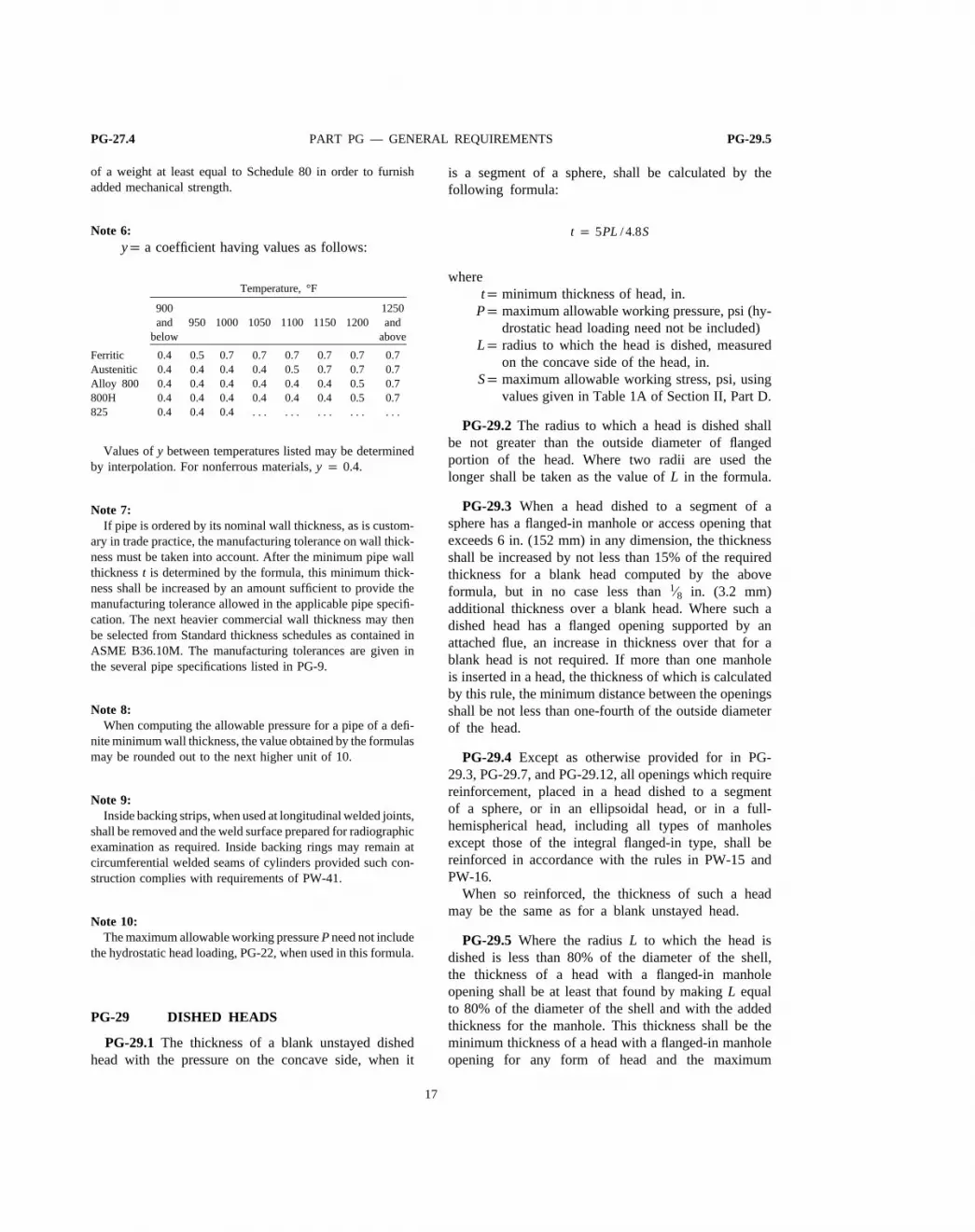
Note 6:yp a coefficient having values as follows:
Temperature, °F
900 1250and 950 1000 1050 1100 1150 1200 and
below above
Ferritic 0.4 0.5 0.7 0.7 0.7 0.7 0.7 0.7Austenitic 0.4 0.4 0.4 0.4 0.5 0.7 0.7 0.7Alloy 800 0.4 0.4 0.4 0.4 0.4 0.4 0.5 0.7800H 0.4 0.4 0.4 0.4 0.4 0.4 0.5 0.7825 0.4 0.4 0.4 . . . . . . . . . . . . . . .
Values ofy between temperatures listed may be determinedby interpolation. For nonferrous materials,y p 0.4.
Note 7:If pipe is ordered by its nominal wall thickness, as is custom-
ary in trade practice, the manufacturing tolerance on wall thick-ness must be taken into account. After the minimum pipe wallthicknesst is determined by the formula, this minimum thick-ness shall be increased by an amount sufficient to provide themanufacturing tolerance allowed in the applicable pipe specifi-cation. The next heavier commercial wall thickness may thenbe selected from Standard thickness schedules as contained inASME B36.10M. The manufacturing tolerances are given inthe several pipe specifications listed in PG-9.
Note 8:When computing the allowable pressure for a pipe of a defi-
nite minimum wall thickness, the value obtained by the formulasmay be rounded out to the next higher unit of 10.
Note 9:Inside backing strips, when used at longitudinal welded joints,
shall be removed and the weld surface prepared for radiographicexamination as required. Inside backing rings may remain atcircumferential welded seams of cylinders provided such con-struction complies with requirements of PW-41.
Note 10:The maximum allowable working pressurePneed not include
the hydrostatic head loading, PG-22, when used in this formula.
PG-29 DISHED HEADS
PG-29.1 The thickness of a blank unstayed dishedhead with the pressure on the concave side, when it
17
is a segment of a sphere, shall be calculated by thefollowing formula:
t p 5PL / 4.8S
wheretp minimum thickness of head, in.
Pp maximum allowable working pressure, psi (hy-drostatic head loading need not be included)
Lp radius to which the head is dished, measuredon the concave side of the head, in.
Sp maximum allowable working stress, psi, usingvalues given in Table 1A of Section II, Part D.
PG-29.2 The radius to which a head is dished shallbe not greater than the outside diameter of flangedportion of the head. Where two radii are used thelonger shall be taken as the value ofL in the formula.
PG-29.3 When a head dished to a segment of asphere has a flanged-in manhole or access opening thatexceeds 6 in. (152 mm) in any dimension, the thicknessshall be increased by not less than 15% of the requiredthickness for a blank head computed by the aboveformula, but in no case less than1⁄8 in. (3.2 mm)additional thickness over a blank head. Where such adished head has a flanged opening supported by anattached flue, an increase in thickness over that for ablank head is not required. If more than one manholeis inserted in a head, the thickness of which is calculatedby this rule, the minimum distance between the openingsshall be not less than one-fourth of the outside diameterof the head.
PG-29.4 Except as otherwise provided for in PG-29.3, PG-29.7, and PG-29.12, all openings which requirereinforcement, placed in a head dished to a segmentof a sphere, or in an ellipsoidal head, or in a full-hemispherical head, including all types of manholesexcept those of the integral flanged-in type, shall bereinforced in accordance with the rules in PW-15 andPW-16.
When so reinforced, the thickness of such a headmay be the same as for a blank unstayed head.
PG-29.5 Where the radiusL to which the head isdished is less than 80% of the diameter of the shell,the thickness of a head with a flanged-in manholeopening shall be at least that found by makingL equalto 80% of the diameter of the shell and with the addedthickness for the manhole. This thickness shall be theminimum thickness of a head with a flanged-in manholeopening for any form of head and the maximum

PG-29.5 1998 SECTION I PG-29.13
allowable working stress shall not exceed the valuesgiven in Table 1A of Section II, Part D.
PG-29.6 No head, except a full-hemispherical head,shall be of a lesser thickness than that required for aseamless shell of the same diameter.
PG-29.7 A blank head of a semiellipsoidal form inwhich half the minor axis or the depth of the head isat least equal to one-quarter of the inside diameter ofthe head shall be made at least as thick as the requiredthickness of a seamless shell of the same diameter asprovided in PG-27.2.2. If a flanged-in manhole whichmeets the Code requirements is placed in an ellipsoidalhead, the thickness of the head shall be the same asfor a head dished to a segment of a sphere (see PG-29.1 and PG-29.5) with a dish radius equal to eight-tenths the diameter of the shell and with the addedthickness for the manhole as specified in PG-29.3.
PG-29.8 When heads are made to an approximateellipsoidal shape, the inner surface of such heads mustlie outside and not inside of a true ellipse drawn withthe major axis equal to the inside diameter of the headand one-half the minor axis equal to the depth of thehead. The maximum variation from this true ellipseshall not exceed 0.0125 times the inside diameter ofthe head.
PG-29.9 Unstayed dished heads with the pressureon the convex side shall have a maximum allowableworking pressure equal to 60% of that for headsof the same dimensions with the pressure on theconcave side.
Head thicknesses obtained by using the formulas inPG-29.11 for hemispherical heads and PG-29.7 forblank semiellipsoidal heads do not apply to heads withpressure on the convex side.
PG-29.10When a flange of an unstayed dished headis machined to make a close and accurate fit into oronto the shell, the thickness shall not be reduced toless than 90% of that required for a blank head.
PG-29.11 The thickness of a blank unstayed full-hemispherical head with the pressure on the concaveside shall be calculated by the following formulas:
t pPL
1.6S(1)
t pPL
2S − 0.2P(2)
18
wheretp minimum thickness of head, in.
Pp maximum allowable working pressure, psiLp radius to which the head was formed, measured
on the concave side of the head, in.Sp maximum allowable working stress, psi, using
values given in Table 1A of Section II, Part D
Use Formula 1; however, Formula 2 may be used forheads exceeding1⁄2 in. (13 mm) in thickness that areto be used with shells or headers designed under theprovisions of PG-27.2.2 and that are integrally formedon seamless drums or are attached by fusion welding,and do not require staying. Where Formula 2 is used,the other requirements of both of these paragraphs shallalso apply.
The above formulas shall not be used when therequired thickness of the head given by these formulasexceeds 35.6% of the inside radius, and instead, thefollowing formula shall be used:
t p L(Y1⁄3 − 1)
where
Y p2(S + P )
2S − P
Joints in full-hemispherical heads including the jointto the shell shall be governed by and meet all therequirements for longitudinal joints in cylindrical shells,except that in a buttwelded joint attaching a head toa shell the middle lines of the plate thicknesses neednot be in alignment.
PG-29.12 If a flanged-in manhole which meets theCode requirements is placed in a full-hemisphericalhead, the thickness of the head shall be the same asfor a head dished to a segment of a sphere (see PG-29.1 and PG-29.5), with a dish radius equal to eight-tenths the diameter of the shell and with the addedthickness for the manhole as specified in PG-29.3.
PG-29.13 The corner radius of an unstayed dishedhead measured on the concave side of the head shallbe not less than three times the thickness of the materialin the head; but in no case less than 6% of the diameterof the shell. In no case shall the thinning-down dueto the process of forming, of the knuckle portion ofany dished head consisting of a segment of a sphereencircled by a part of a torus constituting the knuckleportion (torispherical), exceed 10% of the thicknessrequired by the formula in PG-29.1. Other types of

PG-29.13 PART PG — GENERAL REQUIREMENTS PG-31.3.1
heads shall have a thickness after forming of not lessthan that required by the applicable formula.
PG-30 STAYED DISHED HEADS
PG-30.1 When dished heads are of a thickness lessthan called for by PG-29, they shall be stayed as flatsurfaces, no allowance being made in such staying forthe holding power due to the spherical form unless allof the following conditions are met:
PG-30.1.1That they be at least two-thirds as thickas called for by the rules for unstayed dished heads.
PG-30.1.2 That they be at least7⁄8 in. (22 mm)in thickness.
PG-30.1.3That through-stays be used attached tothe dished head by outside and inside nuts.
PG-30.1.4That the maximum allowable workingpressure shall not exceed that calculated by the rulesfor an unstayed dished head plus the pressure corres-ponding to the strength of the stays or braces securedby the formula for braced or stayed surfaces given inPG-46, using 1.3 for the value ofC.
PG-30.2 If a dished head concave to pressure isformed with a flattened spot or surface, the diameterof the flat spot shall not exceed that allowable for flatheads as given by the formula in PG-31, usingC p 0.25.
PG-31 UNSTAYED FLAT HEADS ANDCOVERS
PG-31.1 The minimum thickness of unstayed flatheads, cover plates, and blind flanges shall conformto the requirements given in this paragraph. Theserequirements apply to both circular and noncircular9
heads and covers. Some acceptable types of flat headsand covers are shown in Fig. PG-31. In this figure,the dimensions of the welds are exclusive of extrametal required for corrosion allowance.
PG-31.2 The notations used in this paragraph andin Fig. PG-31 are defined as follows:
Cp a factor depending on the method of attachmentof head and on the shell, pipe, or header dimen-sions, and other items as listed in PG-31.4 be-low, dimensionless. The factors for welded cov-ers also include a factor of 0.667 which
9 Special consideration shall be given to the design of shells, nozzlenecks, or flanges to which noncircular heads or covers are attached(see Preamble, second paragraph).
19
effectively increases the allowable stress forsuch constructions to 1.5S.
Dp long span of noncircular heads or covers mea-sured perpendicular to short span, in.
dp diameter, or short span, measured as indicatedin Fig. PG-31, in.
hgp gasket moment arm, equal to the radial distancefrom the center line of the bolts to the line ofthe gasket reaction, as shown in Fig. PG-31,sketches (j) and (k), in.
Lp perimeter of noncircular bolted head measuredalong the centers of the bolt holes, in.
lp length of flange of flanged heads, measuredfrom the tangent line of knuckle, as indicatedin Fig. PG-31, sketches (a) and (c), in.
mp the ratiotr /ts, dimensionlessPp maximum allowable working pressure, psirp inside corner radius on a head formed by flang-
ing or forging, in.Sp maximum allowable stress value, psi, using val-
ues given in Table 1A of Section II, Part Dtp minimum required thickness of flat head or
cover, in.tep minimum distance from beveled end of drum,
pipe, or headers, before welding, to outer faceof head, as indicated in Fig. PG-31, sketch (i), in.
tfp actual thickness of the flange on a forged head,at the large end, as indicated in Fig. PG-31,sketch (b), in.
thp actual thickness of flat head or cover, in.trp thickness required for pressure of seamless
shell, pipe, or header, in.tsp actual thickness of shell, pipe, or header, in.twp thickness through the weld joining the edge of
a head to the inside of a drum, pipe, or header,as indicated in Fig. PG-31, sketch (g), in.
tlp throat dimension of the closure weld, as indi-cated in Fig. PG-31, sketch (r), in.
Wp total bolt load, lb, as further defined in PG-31.3.2
Zp a factor for noncircular heads and covers thatdepends on the ratio of short span to long span,as given in PG-31.3, dimensionless
PG-31.3The thickness of flat unstayed heads, covers,and blind flanges shall conform to one of the followingthree requirements.10
PG-31.3.1Circular blind flanges of ferrous materi-als conforming to ANSI B16.5-1981 shall be acceptable
10The formulas provide safe construction as far as stress is concerned.Greater thicknesses may be necessary if deflection would causeleakage at threaded or gasketed joints.

Fig. PG-31 1998 SECTION I
FIG. PG-31 SOME ACCEPTABLE TYPES OF UNSTAYED FLAT HEADS AND COVERSThe Above Illustrations Are Diagrammatic Only.
Other Designs Which Meet the Requirements of PG-31 Will Be Acceptable.
20

PG-31.3.1 PART PG — GENERAL REQUIREMENTS PG-31.4
for the diameters and pressure–temperature ratings inTable 2 of that Standard when of the types shown inFig. PG-31, sketches (j) and (k).
PG-31.3.2The minimum required thickness of flatunstayed circular heads, covers, and blind flanges shallbe calculated by the following equation:
t p d √ CP/ S (1)
except when the head, cover, or blind flange is attachedby bolts causing an edge moment [Fig. PG-31, sketches(j) and (k)] in which case the thickness shall becalculated by the following equation:
t p d √ CP/ S + 1.9Whg / Sd3 (2)
When using Formula (2) the thicknesst shall becalculated for both design conditions and gasket seating,and the greater of the two values shall be used. Fordesign conditions, the value ofP shall be the maximumallowable working pressure, the value ofS at designtemperature shall be used, andW shall be the sum ofthe bolt loads required to resist the end pressure loadand to maintain tightness of the gasket. For gasketseating,P equals zero, the value ofS at atmospherictemperature shall be used, andW shall be the averageof the required bolt load and the load available fromthe bolt area actually used.
PG-31.3.3 Flat unstayed heads, covers, or blindflanges may be square, rectangular, elliptical, obround,segmental, or otherwise noncircular. Their requiredthickness shall be calculated by the following formula:
t p d √ ZCP/ S (3)
where
Z p 3.4 −2.4d
D(4)
with the limitation thatZ need not be greater than 21⁄2.Formula (3) does not apply to noncircular heads,
covers, or blind flanges attached by bolts causing abolt edge moment [Fig. PG-31, sketches (j) and (k)].For noncircular heads of this type, the required thicknessshall be calculated by the following formula:
t p d √ ZCP/ S + 6Whg / SLd2 (5)
When using Formula (5), the thicknesst shall be
21
calculated in the same way as specified above forFormula (2).
PG-31.4For the types of construction shown in Fig.PG-31, the minimum values ofC to be used in Formulas(1), (2), (3) and (5) are:11
Fig. PG-31, sketch (a):C p 0.17 for flanged circularand noncircular heads forged integral with or buttweldedto the shell, pipe, or header, with an inside cornerradius not less than three times the required headthickness, with no special requirement with regard tolength of flange, and where the welding meets all therequirements for circumferential joints given in Part PW.
C p 0.10 for circular heads, where the flangelength for heads of the above design is not less than
l p 11.1 − 0.8ts2
th22 √ dth (6)
When C p 0.10 is used, the slope of the taperedsections shall be no greater than 1:3.
Fig. PG-31, sketch (b):C p 0.17 for circular andnoncircular heads forged integral with or buttweldedto the shell, pipe, or header, where the corner radiuson the inside is not less than three times the thicknessof the flange and where the welding meets all therequirements for circumferential joints given in Part PW.
Fig. PG-31, sketch (c):C p 0.30 for circular flangedplates screwed over the end of the shell, pipe, orheader, with inside corner radius not less than 3t, inwhich the design of the threaded joint against failureby shear, tension, or compression, resulting from theend force due to pressure, is based on a factor ofsafety of at least 4, and the threaded parts are at leastas strong as the threads for standard piping of thesame diameter. Seal welding may be used, if desired.
Fig. PG-31, sketch (d):C p 0.13 for integral flatcircular heads when the dimensiond does not exceed24 in., the ratio of thickness of the head to the dimensiond is not less than 0.05 nor greater than 0.25, the headthicknessth is not less than the shell thicknessts, theinside corner radius is not less than 0.25t, and theconstruction is obtained by special techniques of upset-ting and spinning the end of the shell, pipe, or header,such as are employed in closing header ends.
Fig. PG-31, sketches (e), (f), and (g):C p 0.33mbut not less than 0.20 for circular plates welded to theinside of a drum, pipe, or header, and otherwise meetingthe requirements for the respective types of weldedboiler drums, including postweld heat treatment when
11Radiographic examination is not required for any of the weldjoints shown in Fig. PG-31, sketches (e), (f), (g), (i), (r), and (s).

PG-31.4 1998 SECTION I PG-31.4
required for the drum, but omitting radiographic exami-nation. If a value ofm less than 1 is used in calculatingt, the shell thicknessts shall be maintained along adistance inwardly from the inside face of the head
equal to at least 2√dts. The throat thickness of thefillet welds in sketches (e) and (f) shall be at least 0.7ts. The size of the weldtw in sketch (g) shall be notless than two times the required thickness of a seamlessshell nor less than 1.25 times the nominal shell thicknessbut need not be greater than the head thickness; theweld shall be deposited in a welding groove with theroot of the weld at the inner face of the head as shownin the figure.
C p 0.33 for noncircular plates, welded to the insideof a drum, pipe, or header, and otherwise meeting therequirements for the respective types of welded boilerdrums, including postweld heat treatment when requiredfor the drum, but omitting radiographic examination.The throat thickness of the fillet welds in sketches (e)and (f) shall be at least 0.7ts. The size of the weldtwin sketch (g) shall be not less than two times therequired thickness of a seamless shell nor less than1.25 times the nominal shell thickness but need notbe greater than the head thickness; the weld shall bedeposited in a welding groove with the root of theweld at the inner face of the head as shown in thefigure.
Fig. PG-31, sketch (i):C p 0.33m but not less than0.20 for circular plates welded to the end of the drum,pipe, or header, when an inside weld with minimumthroat thickness of 0.7ts is used, and when the beveledend of the drum, pipe, or header is located at a distancenot less than 2tr nor less than 1.25ts from the outerface of the head. The width at the bottom of thewelding groove shall be at least equal tots but neednot be over1⁄4 in. (6 mm).
Fig. PG-31, sketches (j) and (k):C p 0.3 for circularand noncircular heads and covers bolted to the shell,flange, or side plate as indicated in the figures. Notethat Eq. (2) or (5) shall be used because of the extramoment applied to the cover by the bolting. When thecover plate is grooved for a peripheral gasket, as shownin sketch (k) the net cover plate thickness under thegroove or between the groove and the outer edge ofthe cover plate shall be not less than
d √1.9Whg / Sd3
for circular heads and covers, not less than
22
d √6Whg / SLd2
for noncircular heads and covers.Fig. PG-31, sketches (m), (n), and (o):C p 0.3 for
a circular plate inserted into the end of a shell, pipe,or header and held in place by a positive mechanicallocking arrangement, and when all possible means offailure either by shear, tension, compression, or radialdeformation, including flaring, resulting from pressureand differential thermal expansion, are resisted with afactor of safety of at least 4. Seal welding may beused, if desired.
Fig. PG-31, sketch (p):C p 0.25 for circular andnoncircular covers bolted with a full-face gasket toshell, flanges, or side plates.
Fig. PG-31, sketch (q):C p 0.75 for circular platesscrewed into the end of a shell, pipe, or header havingan inside diameterd not exceeding 12 in. (305 mm);or for heads having an integral flange screwed overthe end of a shell, pipe, or header having an insidediameterd not exceeding 12 in. (152 mm); and whenthe design of the threaded joint against failure by shear,tension, compression, or radial deformation, includingflaring, resulting from pressure and differential thermalexpansion, is based on a factor of safety of at least4. If a tapered pipe thread is used, the requirementsof Table PG-39 shall be met. Seal welding may beused, if desired.
Fig. PG-31, sketch (r):C p 0.33 for circular plateshaving a dimensiond not exceeding 18 in. (457 mm)inserted into the shell, pipe, or header and welded asshown, and otherwise meeting the requirements forwelded boiler drums including postweld heat treatmentbut omitting radiographic examination. The end of theshell, pipe, or header shall be crimped over at least30 deg., but not more than 45 deg. The crimping maybe done cold only when this operation will not injurethe metal. The throat of the weld shall be not lessthan the thickness of the flat head or the shell, pipe,or header, whichever is greater.
Fig. PG-31, sketch (s):C p 0.33 for circular beveledplates having a diameterd not exceeding 18 in.(457 mm) inserted into a shell, pipe, or header, theend of which is crimped over at least 30 deg., but notmore than 45 deg., and when the undercutting forseating leaves at least 80% of the shell thickness. Thebeveling shall be not less than 75% of the headthickness. The crimping shall be done when the entirecircumference of the cylinder is uniformly heated tothe proper forging temperature for the material used.For this construction, the ratiots /d shall be not lessthan the ratioP/S nor less than 0.05. The maximum

PG-31.4 PART PG — GENERAL REQUIREMENTS PG-32.1.4.4
allowable working pressure for this construction shallnot exceedPpS/5d.
OPENINGS AND COMPENSATION 12
PG-32 OPENINGS IN SHELLS, HEADERS,AND HEADS
PG-32.1 Scope
PG-32.1.1The rules for openings and compensa-tion in PG-32 through PG-39 shall apply to all openingsin shells, headers, and heads except as otherwise pro-vided in PG-29.3, PG-29.7, PG-29.12, PG-32.1.2, PG-32.1.3.1, PG-32.1.4 and PG-32.1.5.
PG-32.1.2Openings in a definite pattern, such astube holes, may be designed in accordance with therules for ligaments in PG-52, provided the diameter ofthe largest hole in the group does not exceed thatpermitted by the chart in Fig. PG-32.
The notation used in Fig. PG-32 is defined as follows:Pp maximum allowable working pressure, psidp maximum allowable diameter of openings, in.Dp outer diameter of the shell, in.tp actual thickness of the shell, in.Sp maximum allowable stress value, psi, taken
from Tables 1A and 1B of Section II, Part D
K pPD
1.82St
PG-32.1.3.1 No calculation need be made todetermine the availability of compensation for a singleopening, not covered by PG-38 or PG-52, in shells,headers, or formed heads whose inside diameter is notless than four times the diameter of the opening andwhich satisfies the following conditions:
PG-32.1.3.1.1Welded connections not largerthan NPS 2 attached in accordance with the applica-ble rules.
PG-32.1.3.1.2Threaded, studded, or expandedconnections in which the diameter of the hole in thevessel wall is not greater than NPS 2.
12The rules governing openings as given in this Code are based onthe stress intensification created by the existence of a hole in anotherwise symmetrical section. They are based on experience withvessels designed with safety factors of 4 and 5 applied to thespecified minimum tensile strength of the shell material. Externalloadings such as those due to thermal expansion or to unsupportedweight of connecting piping have not been evaluated. These factorsshould be given attention in unusual designs or under conditions ofcyclic loading.
23
PG-32.1.3.2No calculations need be made todemonstrate compliance with PG-33 for single openingsnot covered in PG-32.1.3.1 when the diameter of theopening in the shell or header does not exceed thatpermitted in Fig. PG-32.
PG-32.1.4No calculation need be made to deter-mine the availability of compensation for a singleopening in a formed head which satisfies the followingconditions.
PG-32.1.4.1The minimum center-to-center dis-tance between adjacent openings shall not be less thanL as determined by the following equation:
L pA + B
2(1 − K)
whereKp PD/1.82StLp the distance between centers of the two open-
ings measured on the surface of the formedhead, in.
A, Bp the outside diameter of each opening respec-tively, in.
Pp the maximum allowable working pressure, psigDp the outside diameter of the formed head, in.tp the actual thickness of the head, in.Sp the maximum allowable stress value of the head
material, as taken from Tables 1A and 1B ofSection II, Part D, psi
PG-32.1.4.2The edge of the opening shall comeno closer to the line bounding the spherical or ellipsoidalportion of the formed head, or around a flanged-inmanhole, than a distance equal to the thickness of thehead, and in no case, except for water column connec-tions, shall the opening come within the part formedby the corner radius of a dished head.
PG-32.1.4.3The maximum allowable diameterof any opening in a formed head, except in a full-hemispherical head, shall not exceed that permitted inPG-32.1.3.1 for an equivalent shell. The equivalentshell shall be of the same material as the head; of thesame outside diameter as the outside diameter of theflange of the head; and of the same maximum allowableworking pressure as the head.
PG-32.1.4.4The maximum allowable diameterof any opening in a full-hemispherical head shall complywith the requirements in PG-32.1.4.3 except that thevalue of K used in PG-32.1.4.1 and the chart in Fig.

PG-32.1.4.4 1998 SECTION I PG-33.2
PG-32 shall be one-half the value given by the equationin PG-32.1.4.1.
PG-32.1.5No calculation need be made to demon-strate compliance with PG-33 for single openings notcovered in PG-32.1.4 when the diameter of the openingin the formed head does not exceed that permitted inFig. PG-32.
PG-32.2 Shape of Openings13
PG-32.2.1Openings in cylindrical portions of ves-sels or in formed heads shall preferably be circular,elliptical, or obround.14
When the long dimension of an elliptical or obroundopening exceeds twice the short dimension, the compen-sation across the short dimension shall be increased asnecessary to provide against excessive distortion dueto twisting moment.
PG-32.2.2Openings may be of other shapes thanthose given in PG-32.2.1, and all corners shall beprovided with a suitable radius. When the openingsare of such proportions that their strength cannot becomputed with assurance of accuracy, or when doubtexists as to the safety of a vessel with such openings,the part of the vessel affected shall be subjected to aproof hydrostatic test as prescribed in PG-100.
PG-32.3 Size of OpeningsPG-32.3.1Properly reinforced openings in cylindri-
cal and spherical shells are not limited as to size andshall comply with the provisions which follow, andwith the additional provisions given under PG-32.3.2.
PG-32.3.2The rules given herein for compensationapply to openings not exceeding the following dimen-sions:
For vessels 60 in. (1520 mm) in diameter and less:1⁄2 the vessel diameter but not over 20 in. (508 mm).
For vessels over 60 in. (1520 mm) in diameter:1⁄3the vessel diameter but not over 40 in. (1000 mm).
PG-32.3.3Larger openings should be given specialattention and may be provided with compensation inany suitable manner that complies with the intent ofthe Code rules. It is recommended that the compensationprovided be distributed close to the opening. (A provi-sion of about two-thirds of the required compensationwithin a distance of one-fourth of the nozzle diameteron each side of the finished opening is suggested.)
13The opening made by a pipe or a circular nozzle, the axis ofwhich is not perpendicular to the vessel wall or head, may beconsidered an elliptical opening for design purposes.14An obround opening is one which is formed by two parallel sidesand semicircular ends.
24
Special consideration should be given to the fabricationdetails used and the inspection employed on criticalopenings; compensation often may be advantageouslyobtained by use of a thicker shell plate for a vesselcourse or inserted locally around the opening; weldsmay be ground to concave contour and the insidecorners of the opening rounded to a generous radiusto reduce stress concentrations. Appropriate proof testingmay be advisable in extreme cases of large openingsapproaching full vessel diameter, openings of unusualshape, etc.
PG-33 COMPENSATION REQUIREDFOR OPENINGS IN SHELLSAND FORMED HEADS
PG-33.1 General. The rules in this subparagraphapply to all openings other than flanged-in openingsin formed heads covered by PG-29.3, PG-29.7, andPG-29.12; openings in flat heads covered by PG-35;and openings covered within PG-32.1.2, PG-32.1.3.1,PG-32.1.3.2, PG-32.1.4, and PG-32.1.5.
Compensation shall be provided in such amount anddistribution that the requirements for area of compensa-tion are satisfied for all planes through the center ofthe opening and normal to the vessel surface. For acircular opening in a cylindrical shell, the plane con-taining the axis of the shell is the plane of greatestloading due to pressure.
PG-33.2 Area Required. The total cross-sectionalarea of compensation,A, required in any given planefor a vessel under internal pressure shall be not less than
A p d × tr × F
wheredp the diameter in the given plane of the finished
opening, in. (see Figs. PG-36 and PW-16.1)Fp a correction factor which compensates for the
variation in pressure stresses on different planeswith respect to the axis of a vessel. A value of1.00 shall be used for all configurations exceptthat Fig. PG-33 may be used for integrally rein-forced openings in cylindrical shells.
trp the required thickness of a seamless shell orhead computed by the rules of the Code for thedesignated pressure, in., except that:

ASME B&PVC sec1$$$$u5 06-04-99 08:04:18 pd: sec1 Rev 14.04
PG-33.2.1 PART PG — GENERAL REQUIREMENTS PG-35.3
FIG. PG-33 CHART FOR DETERMININGVALUE OF F
(Determine value of F as required in PG-33.2)
PG-33.2.1When the opening and its compensationare in a torispherical head and are entirely within thespherical portion,tr is the thickness required for aseamless hemispherical head of the same radius as thatof the spherical portion.
PG-33.2.2When the opening and its compensationare in an ellipsoidal head in which one-half of theminor axis is equal to one-fourth of the inside diameter,and are located entirely within a circle the center ofwhich coincides with the center of the head and thediameter of which is equal to 80% of the shell insidediameter, tr is the thickness required for a seamlesshemispherical head of radius equal to 90% of the insidediameter of the shell.
27
PG-34 FLANGED-IN OPENINGS INFORMED HEADS
PG-34.1 All openings in torispherical, ellipsoidal,and hemispherical heads shall be provided with rein-forcement in accordance with PG-33, except for headswhich meet the requirements in PG-34.2 and PG-29.3,PG-29.7, and PG-29.13.
PG-34.2 A flanged-in manhole opening in a dishedhead shall be flanged to a depth of not less than threetimes the required thickness of the head for plate upto 11⁄2 in. (38 mm) in thickness. For plate exceeding11⁄2 in. (38 mm) in thickness, the depth shall be thethickness of the plate plus 3 in. (76 mm). The depthof flange shall be determined by placing a straightedge across the outside opening along the major axisand measuring from the straight edge to the edgeof the flanged opening. A manhole opening may becompensated by a manhole ring or other attachmentin place of flanging in accordance with PG-33.
PG-35 COMPENSATION REQUIRED FOROPENINGS IN FLAT HEADS
PG-35.1 General.The rules in this paragraph applyto all openings other than small openings covered byPG-32.1.3.1.
PG-35.2 Flat heads that have an opening with adiameter that does not exceed one-half of the headdiameter or shortest span, as defined in PG-31, shallhave a total cross-sectional area of compensation notless than that given by the formula:
A p 0.5d × t
wheredp the diameter in the given plane of the finished
opening (Fig. PG-36 and Fig. PW-16.1), in.tp minimum required thickness of flat head, in.
As an alternative, the thickness may be increasedto provide the necessary openings compensation asfollows:
PG-35.2.1 By using 2C or 0.75 in place ofC,whichever is less, in Formula (1) or (3) for calculatinghead thickness in PG-31.3; or
PG-35.2.2 In Formula (2) or (5) by doubling thequantity under the square root sign.
PG-35.3 Flat heads that have an opening with adiameter that exceeds one-half of the head diameteror shortest span, as defined in PG-31.3, shall be designed
A99

ASME B&PVC sec1$$$$u5 06-04-99 08:04:18 pd: sec1 Rev 14.04
PG-35.3 1998 SECTION I PG-36.3
FIG. PG-36 LIMITS OF REINFORCEMENT FOR TYPICAL OPENINGS
as a flange in accordance with accepted Rules forBolted Flange Connections.
PG-36 LIMITS OF METAL AVAILABLEFOR COMPENSATION
PG-36.1 The boundaries of the cross-sectional areain any plane normal to the vessel wall and passingthrough the center of the opening within which areametal must be located in order to have value ascompensation are designated as the limits of compensa-tion for that plane. (See Fig. PG-36.)
28
PG-36.2The limits of compensation, measured paral-lel to the vessel wall, shall be at a distance, on eachside of the axis of the opening, equal to the greaterof the following:
PG-36.2.1The diameter of the finished opening.
PG-36.2.2The radius of the finished opening plusthe thickness of the vessel wall, plus the thickness ofthe nozzle wall.
PG-36.3The limits of compensation, measured nor-mal to the vessel wall, shall conform to the contour

ASME B&PVC sec1$$$$u5 06-04-99 08:04:18 pd: sec1 Rev 14.04
A99
PG-36.3 PART PG — GENERAL REQUIREMENTS PG-37.2
of the surface at a distance from each surface equalto the smaller of the following:
PG-36.3.121⁄2 times the nominal shell thickness.
PG-36.3.221⁄2 times the nozzle-wall thickness plusthe thickness of any added compensation, exclusive ofweld metal on the side of the shell under consideration.
PG-36.4 Metal within the limits of reinforcementthat may be considered to have reinforcing value shallinclude the following:
PG-36.4.1Metal in the vessel wall over and abovethe thickness required to resist pressure. The area ofthe vessel wall available as compensation is the largerof the values ofA1 given by the formulas:
A1 p (t − Ftr )d
or
A1 p 2(t − Ftr ) (t + tn)
PG-36.4.2 Metal over and above the thicknessrequired to resist pressure in that part of a nozzle wallextending outside the vessel wall. The maximum areain the nozzle wall available as compensation is thesmaller of the values ofA2 given by the formulas:
A2 p (tn − trn)5t
A2 p (tn − trn)(5tn + 2te)
All metalin the nozzle wall extending inside the vesselwall may be included. No allowance shall be takenfor the fact that a differential pressure on an inwardlyextending nozzle may cause opposing stress to that ofthe stress in the shell around the opening.
PG-36.4.3Metal added as compensation (continu-ously about the nozzle) when welded to both the vesseland nozzle, and metal provided in attachment welds.
PG-36.4.4The notation used in this paragraph isdefined as follows:
A1p area in excess thickness in the vessel wall avail-able for compensation, sq in. (see PG-36.4.1)
A2p area in excess thickness in the nozzle wall avail-able for compensation, sq in. (see PG-36.4.2)
tep thickness of attached reinforcing pad or heightof the largest 60 deg. right triangle supported bythe vessel and nozzle outside diameter projectedsurfaces and lying completely within the areaof integral reinforcement, in. (see Fig. PG-36.4)
tp thickness of the vessel wall, in.
29
trp required thickness of a seamless shell or headas defined in PG-33, in.
tnp nominal thickness of nozzle wall, in.trnp required thickness of seamless nozzle wall, in.;
found by the formula used fortr for the shell,omitting the C factor (the value ofS used indetermining trn shall be based on the nozzlematerial). The value oftrn shall be taken as zerofor the entire wall of manhole and handholerings projecting internally with the cover on theinside.
dp diameter in the plane under consideration of thefinished opening, in. (see Fig. PG-36, Fig. PG-36.4, and Fig. PW-16.1)
dp the maximum diameter of the threads, in theplane under consideration, in the finished open-ing, for inside tapped NPT fittings, in.
Fp factor from PG-33 and Fig. PG-33
PG-36.5 Typical examples of the application of theabove rules are presented in A-65 through A-69.
PG-37 STRENGTH OF COMPENSATION
PG-37.1 Material used for compensation shall havean allowable stress value equal to or greater than thatof the material in the vessel wall, except that materialof lower strength may be used provided the area ofcompensation is increased in inverse proportion to theratio of the allowable stress values of the two materialsto compensate for the lower allowable stress value ofthe compensation. No credit may be taken for theadditional strength of any compensation having a higherallowable stress value than that of the vessel wall.Deposited weld metal outside of either the vessel wallor any reinforcing pad used as reinforcement shall becredited with an allowable stress value equivalent tothe weaker of the materials connected by the weld.Vessel-to-nozzle or pad-to-nozzle attachment weld metalwithin the vessel wall or within the pad may be creditedwith a stress value equal to that of the vessel wall orpad, respectively.
PG-37.2 The minimum required strength of eachload-carrying path, as defined in PW-15 and Fig. PW-16, through the welded nozzle attachment shall be atleast equal to the smallest of the values ofW asdetermined by the following equations:
W p dtr S (1)
W p (dltr − [(2d − dl) (t − tr )]+As)S (2)

ASME B&PVC sec1$$$$u5 06-04-99 08:04:18 pd: sec1 Rev 14.04
Fig. PG-36.4 1998 SECTION I
FIG. PG-36.4 SOME REPRESENTATIVE CONFIGURATIONS DESCRIBING THE te REINFORCEMENT DIMENSION
30

PG-37.2 PART PG — GENERAL REQUIREMENTS PG-39.1
W p (dltr − [2t(t − tr )] + As)S (3)
PG-37.2.1 The notations used in PG-37.2 aredefined as follows:
Asp two times the stud hole depth by the stud holewidth when the stud holes are tapped directlyinto the vessel wall, sq in.
dp see definition in PG-36.4.4dlp the diameter of the unfinished opening in the
plane of consideration prior to the nozzle instal-lation, in.
tp see definition in PG-36.4.4tnp see definition in PG-36.4.4trp see definition in PG-36.4.4Sp the maximum allowable stress value of the ves-
sel material, as taken from Tables 1A and 1Bof Section II, Part D, psi
Wp the required minimum strength to be providedby the combined strength of the load-carryingelements through each load-carrying path, lb (IfW is determined to be negative in value, thenW should be considered as zero.)
PG-37.3 The strength of the attachment joint shallbe considered for its entire length on each side of theplane defined in PG-36.
PG-37.4 Manhole frames on shells or drums shallhave the proper curvature and shall be attached bywelding provided the requirements of Part PW, omittingthe radiographic examination, and PG-32 are met.
PG-37.5For detailed requirements for compensationattached by welding, see the appropriate paragraphs inPW-15.
PG-38 COMPENSATION FORMULTIPLE OPENINGS
PG-38.1 When any two adjacent openings whichrequire compensation are spaced at less than two timesthe distance defined in PG-36.2 and PG-36.3 so thattheir limits of compensation overlap, the two openings(or similarly for any larger group of openings) shallbe compensated in accordance with PG-33 with acompensation that has an area equal to the combinedarea of the compensation required for the separateopenings. No portion of the cross section shall beconsidered as applying to more than one opening, orbe evaluated more than once in a combined area.
PG-38.2Two adjacent openings shall have a distancebetween centers not less than 11⁄3 times their averagediameter.
31
FIG. PG-38 ILLUSTRATIONS OF THE RULE GIVENIN PG-38.4
PG-38.3When a group of openings is provided withcompensation by a thicker section buttwelded into theshell or head, the edges of the inserted section shallbe tapered as prescribed in PW-9.3.
PG-38.4When a shell or drum has a series of holesin a definite pattern, the net cross-sectional area betweenany two finished openings within the limits of the actualshell wall, excluding the portion of the compensation notfused to the shell wall, shall equal at least 0.7F ofthe cross-sectional area obtained by multiplying thecenter-to-center distance of the openings by the requiredthickness of a seamless shell, where the factorF istaken from Fig. PG-33 for the plane under consideration.(See Fig. PG-38.)
PG-39 METHODS OF ATTACHMENT OFPIPE AND NOZZLE NECKS TOVESSEL WALLS
PG-39.1 General.Except as limited in PG-32, noz-zles may be attached to the shell or head of a vessel

PG-39.1 1998 SECTION I PG-39.7
TABLE PG-39MINIMUM NUMBER OF THREADS PER CONNECTION
Pressure up to and including 300 psi
Size of pipe connection (NPS) 1 & 11⁄4 11⁄2 & 2 21⁄2 to 4 5 & 6 8 10 12Threads engaged 4 5 7 8 10 12 13Min. plate thickness required (NPS) 0.348 0.435 0.875 1.0 1.25 1.5 1.625
Pressures above 300 psi
Size of pipe connection, in. 1⁄2 & 3⁄4 1 to 11⁄2 2 21⁄2 & 3 4 to 6 8 10 12Threads engaged 6 7 8 8 10 12 13 14Min. plate thickness, required, in. 0.43 0.61 0.70 1.0 1.25 1.5 1.62 1.75
by any of the methods of attachment given in thisparagraph.
PG-39.2 Welded Connections.Attachment by weld-ing shall be in accordance with the requirements ofPW-15 and PW-16.
PG-39.4 Studded Connections.Connections may bemade by means of bolt studs. The vessel shall havea flat surface machined on the shell, or on a built-uppad, or on a properly attached plate or fitting. Drilledholes to be tapped for straight threads shall not penetratewithin one-fourth of the wall thickness from the insidesurface of the vessel, unless at least the minimumthickness required as above is maintained by addingmetal to the inside surface of the vessel. Where tappedholes are provided for studs, the threads shall be fulland clean and shall engage the stud for a length notless than the larger ofds or
0.75ds ×
Maximum allowable stress value ofstud material at design temperature
Maximum allowable stress value oftapped material at design temperature
in which ds is the diameter of the stud, except thatthe thread engagement need not exceed 11⁄2ds. Studdedconnections shall meet the requirements for compensa-tion. No credit for compensation shall be allowed forany areas attached by studs only.
PG-39.5 Threaded ConnectionsPG-39.5.1Where a threaded connection is to be
made to a boiler component it shall be into a threadedhole. The threads shall conform to the requirements ofANSI B1.20.1 and provide for the pipe to engage theminimum number of threads specified in Table PG-39after allowance has been made for curvature of thevessel wall. A built-up pad or properly attached plate
32
or fitting may be used to provide the metal thicknessand number of threads required in Table PG-39, or tofurnish compensation when required.
PG-39.5.2Threaded joints for boiler connectionsfor external piping shall be in accordance with thefollowing size and pressure limitations and shall notbe used where the temperature exceeds 925°F.
Maximum MaximumSize (NPS) Pressure, psi
3 4002 6001 1200
3⁄4 and smaller 1500
PG-39.5.3Threaded connections for plug closuresused for inspection openings, end closures, and similarpurposes may be used within the size and pressurelimitations of Table PG-39.
PG-39.6 Expanded Connections.Provided the re-quirements for compensation are met, a pipe, tube, orforging not exceeding 6 in. (152 mm) in outside diametermay be attached to shells, heads, headers, or fittingsby inserting through an opening and expanding inaccordance with the rules for tube attachment in PartsPWT and PFT, whichever is applicable.
The sharp edges left in drilling tube holes shall beremoved on both sides of the plate with a file or othertool. The inner surface of the tube hole in any formof attachment may be grooved or chamfered.
PG-39.7 All welded connections shall be postweldheat treated after attachment unless specifically allowedotherwise.

98
PG-42 PART PG — GENERAL REQUIREMENTS PG-42.4.1
PG-42 GENERAL REQUIREMENTS FORFITTINGS, FLANGES, ANDVALVES
PG-42.1 Applicable American National Standards.Except when supplied as miscellaneous pressure partsunder the provisions of PG-11, all fittings, flanges, andvalves shall meet the requirements of the followingAmerican National Standards, including the restrictionscontained within the standards, and any noted as partof this Code. The product standard establishes the basisfor pressure–temperature rating and marking.
PG-42.1.1ASME B16.1, Cast Iron Pipe Flangesand Flanged Fittings15
PG-42.1.3ASME B16.3, Malleable Iron ThreadedFittings, Classes 150 and 300
PG-42.1.4ASME B16.4, Gray Iron Threaded Fit-tings
PG-42.1.5ASME B16.5, Pipe Flanges and FlangedFittings (see PG-42.2)
PG-42.1.5.1Pressure–Temperature Ratings perTable 2
PG-42.1.5.2Facing Dimensions (other than ring-joint) per Table 4
PG-42.1.5.3Facing Dimensions for Ring-JointFlanges per Table 5
PG-42.1.5.4Dimensions of Flanges for PressureRating Classes per Tables 8 through 28
PG-42.1.6 ASME B16.9, Factory-Made WroughtSteel Buttwelding Fittings
When pressure ratings are established under theprovisions of para. 2.1 of ASME B16.9 they shall becalculated as for straight seamless pipe in accordancewith ASME B31.1.
PG-42.1.7ASME B16.11, Forged Fittings, Socket-Welding and Threaded (see PG-42.2)
PG-42.1.8ASME B16.15, Cast Bronze ThreadedFittings, Classes 125 and 250 (see PG-8.4 and PG-4.11)
PG-42.1.9ANSI B16.20, Ring-Joint Gaskets andGrooves for Steel Pipe Flanges
PG-42.1.10 ASME B16.24, Cast Copper AlloyPipe Flanges and Flanged Fittings (see PG-8.4)
PG-42.1.11ASME B16.25, Buttwelding Ends
15Classes 25 and 800 are not applicable to Section I.
33
PG-42.1.12 ASME B16.34, Valves — Flanged,Threaded, and Welding End (see PG-42.2 and PG-42.4.3)
PG-42.1.13ASME B16.28, Wrought Steel Butt-welding Short Radius Elbows and Returns
PG-42.1.14 ASME B16.42, Ductile Iron PipeFlanges and Flanged Fittings, Classes 150 and 300 (seePG-8.3)
PG-42.2 Marking. All valves and fittings shall bemarked with the name, trademark, or other identificationof the manufacturer and the primary service pressurerating except that the pressure rating marking may beomitted from:
PG-42.2.1 Cast iron threaded fittings for Class125 working pressure
PG-42.2.2Malleable iron threaded fittings for Class150 working pressure
PG-42.2.3Nonferrous threaded fittings for Classes125 and 250 working pressure
PG-42.2.4 Cast iron and nonferrous companionflanges
PG-42.2.5 Additional markings for buttweldingfittings, as called for by several Code Standards forall valves and fittings, are recommended if the sizeand shape of the valve or fitting permit.
PG-42.3 Flange Materials.Flanges shall be madeof materials permitted by this Section or of materialsspecifically listed in the applicable product standardslisted in PG-42.1, but not of materials specificallyprohibited or beyond the use limitations listed in thisSection. Rolled or forged flanges may be made frommaterial conforming to any forging specification amongthese permitted materials, except that SA-181 shall notbe used for flanges whose pressure rating is higherthan Class 300. Hub-type flanges shall not be cut ormachined from plate material.
PG-42.4 Additional Requirements. Flanges madeof other materials permitted under this Section shallbe at least equal to the strength requirements, and thefacing dimensions and bolt circles shall agree with theStandard otherwise required.
PG-42.4.1 The thickness of all fitting and valvebodies subject to pressure shall be not less than thatrequired by the applicable American National Standardlisted in PG-42.1 for the corresponding maximum allow-able working pressure and temperature for the materialused. The cylindrical ends of cast steel welding end
98

ASME B&PVC sec1$$$$u5 06-04-99 08:04:18 pd: sec1 Rev 14.04
A99
PG-42.4.1 1998 SECTION I PG-42.4.11
and fittings conforming to ASME B16.5 or B16.34may be proportioned with a casting quality factor of100% provided these areas are finish-machined bothinside and outside, are carefully inspected, and that thecontour of the welding end transition complies withPG-42.4.2.
PG-42.4.2The welding ends of component bodiessuch as fittings and valves, whether constructed of castproducts, wrought products, or any other fabricationprocess acceptable under the Code, shall provide agradual change in thickness from that of the adjoiningpipe to that of the component body. Any configurationof weld end transition which lies entirely within theenvelope shown in Fig. PG-42.1 is acceptable pro-vided that:
(a) the wall thickness in the transition region is notless than the smaller of the fitting or valve thicknessrequired by PG-42.4.1 or the minimum value of thepipe thicknesstmin defined under Fig. PG-42.1;
(b) the transition region including the weld jointshall avoid sharp reentrant angles and abrupt changesin slope. When the included angle between any twoadjoining surfaces of a taper transition is less than 150deg., the intersection or corner (except for the weldreinforcement) shall be provided with a radius of atleast 0.05tmin.
The configurations and tolerances suggested by suchweld end standards as ASME B16.9 and ASME B16.25are acceptable only to the extent that the resultingproduct and weld joint will comply with these require-ments of PG-42.4.2. In Fig. PG-42.1 the thickness inthe plane at the end of the fitting or valve shall notbe less thantmin and shall not exceed a maximum ofeither: the greater of (tmin + 0.15 in.) or 1.15tmin whenordered on a minimum wall basis, or the greater of(tmin + 0.15 in.) or 1.10tnom when ordered on a nominalwall basis.
PG-42.4.3 Fittings in which there are minorchanges in the center-to-face dimensions or in whichthe angles of elbows differ from those given in anASME Standard in PG-42.1 may be considered to fallwithin the scope of the standard provided the otherrequirements for materials, dimensions, and thicknessare met.
PG-42.4.4 Flanges and flanged fittings meetingthe requirements of ASME B16.5 or valves meetingthe requirements of ASME B16.34 may be used atthe pressure–temperature ratings established by thosestandards. Standard Class, Special Class, or LimitedClass valves may be used, provided that all parts ofthe valves are suitable for the pressure–temperature
34
conditions at which they are to be used. Valves ofintermediate rating or class, as described in ASMEB16.34, are permitted.
PG-42.4.5When the service requirements exceedthe permissible values given in ASME B16.5 or ASMEB16.34, the requirements of the Code will be met ifthe bolting material, flange thickness, and/or bodythickness are increased so that the deflection limits areno greater and the factor of safety is no less than thatof the nearest Pressure Rating Class in ASME B16.5or ASME B16.34.
PG-42.4.6Steel buttwelding fittings may be usedprovided they are at least equal to the requirements ofASME B16.9.
PG-42.4.7 ASME Standard slip-on flanges shallnot exceed NPS 4 (DN 100). Attachment of slip-onflanges shall be by double fillet welds. The throats ofthe fillet welds shall not be less than 0.7 times thethickness of the part to which the flange is attached.
PG-42.4.8ASME Standard socket welded flangesmay be used in piping or boiler nozzles provided thedimensions do not exceed NPS 3 (DN 80) for Class600 and lower, and NPS 21⁄2 (DN 65) in Classes 900and 1500.
PG-42.4.9Threaded fittings of cast iron or mallea-ble iron conforming to the requirements of the ASMEStandards for Classes 125, 150, 250, and 300 pressuremay be used except where otherwise specifically prohib-ited or where flanged fittings are specifically required.They shall not be used for temperatures over 450°F(232°C).
PG-42.4.10Cast- or forged-steel threaded fittingsor valves that are at least equal to the strength require-ments of the ASME Standard fittings which wouldotherwise be required may be used in all cases exceptwhere flanged fittings are specifically required.
PG-42.4.11The casting quality factors given inPG-25 do not apply to ASME Standard cast steelfittings whose dimensions and ratings are incorporatedin the Code.
Bronze threaded or flanged type fittings or valvesmay be used provided they are at least equal to thestrength requirements of ASME B16.1 cast iron fittingswhich would otherwise be required. Bronze threadedfittings may be used if they comply with ASME B16.15.The material shall comply with PG-8.4 and the allowableworking stresses are not to exceed the values given inTable 1B of Section II, Part D, except as provided in
98
A99
A99
A99
A99
A99

PART PG — GENERAL REQUIREMENTS Fig. PG-42.1
FIG. PG-42.1 WELDING END TRANSITIONS MAXIMUM ENVELOPE
35

PG-42.4.11 1998 SECTION I PG-46.1
PG-67.7. Bronze shall not be used where steel or othermaterial is specifically required. Threaded type fittingsshall not be used where flanged types are specified.
PG-43 NOZZLE NECK THICKNESS
The thickness of a nozzle neck used in a compensatedopening shall not be less than the thickness requiredfor the applicable loadings, but in no case less thanthe smaller of the following:
PG-43.1 The thickness of a seamless shell or headto which it is attached.
PG-43.2The thickness of standard-wall pipe for pipenozzles or the required minimum thickness of a tubenipple based on 600 psi (4140 kPa) internal pressure.
PG-44 INSPECTION OPENINGS
PG-44.1All boilers or parts thereof shall be providedwith suitable manhole, handhole, or other inspectionopenings for examination or cleaning, except for specialtypes of boilers where such openings are manifestlynot needed or used.
Specific requirements for access openings in certaintypes of boilers appear in other paragraphs.
An elliptical manhole opening shall be not less than12 in. × 16 in. (152 mm × 406 mm) in size.
A circular manhole opening shall be not less than15 in. (381 mm) in diameter.
A handhole opening in a boiler drum or shell shallbe not less than 23⁄4 in. × 31⁄2 in. (70 mm × 89 mm),but it is recommended that, where possible, larger sizesbe used.
Manhole, handhole, inspection, and washout openingsin a shell or unstayed head shall be designed inaccordance with the rules of PG-32 to PG-42.
When a threaded opening is to be used for inspectionor washout purposes, it shall be not less than 1 in.(25 mm) pipe size. The closing plug or cap shall beof nonferrous material except for pressures of over 250psi (1720 kPa).
The thread shall be a standard tapered pipe thread,except that a straight thread of equal strength may beused if other sealing surfaces to prevent leakage areprovided.
PG-44.2 Manhole and handhole cover plates shallbe of rolled, forged or cast steel except that for pressuresnot exceeding 250 psi (1720 kPa), and/or temperaturesnot exceeding 450°F (232°C), handhole cover platesmay be made of cast iron complying with SA-278.
36
Yokes, if used, shall be made of rolled, forged, orcast steel.
The strength of all such parts together with the boltsand yokes, if any, shall be proportioned for the servicefor which they are used.
PG-44.3The minimum width of bearing surface fora gasket on a manhole opening shall be11⁄16 in. (18 mm).No gasket for use on a manhole or handhole of anyboiler shall have a thickness greater than1⁄4 in. (6 mm),when compressed.
PG-46 STAYED SURFACES
PG-46.1 The minimum thickness and maximum al-lowable working pressure for stayed flat plates andthose parts which, by these rules, require staying asflat plates with stays or staybolts of uniform diametersymmetrically spaced, shall be calculated by the follow-ing formulas:
t p p ! P
SC(1)
P pt2SC
p2(2)
wheretp minimum thickness of plate, in.
Pp maximum allowable working pressure, psiSp maximum allowable stress given in Table 1A
of Section II, Part D, psipp maximum pitch measured between straight lines
passing through the centers of the staybolts inthe different rows, which lines may be hori-zontal and vertical, or radial and circumferen-tial, in.
Cp 2.1 for welded stays or stays screwed throughplates not over7⁄16 in. in thickness with endsriveted over
Cp 2.2 for welded stays or stays screwed throughplates over7⁄16 in. in thickness with ends riv-eted over
Cp 2.5 for stays screwed through plates and fittedwith single nuts outside of plate, or with insideand outside nuts, omitting washers
Cp 2.8 for stays with heads not less than 1.3 timesthe diameter of the stays screwed through platesor made a taper fit and having the heads formedon the stay before installing them, and not riv-

PG-46.1 PART PG — GENERAL REQUIREMENTS PG-48.2
FIG. PG-46.2 ACCEPTABLE PROPORTIONS FORENDS OF THROUGH-STAYS
eted over, said heads being made to have a truebearing on the plate
Cp 3.2 for stays fitted with inside and outside nutsand outside washers where the diameter ofwashers is not less than 0.4p and thickness notless thant
PG-46.2 The minimum thickness of plates to whichstays may be applied, in other than cylindrical orspherical outer shell plates, shall be5⁄16 in. (8 mm)except for welded construction covered by PW-19.
PG-46.3 When two plates are connected by staysand only one of these plates requires staying, the valueof C shall be governed by the thickness of the platerequiring staying.
PG-46.4 Acceptable proportions for the ends ofthrough-stays with washers are indicated in Fig. PG-46.2.
PG-46.5 The maximum pitch shall be 81⁄2 in.(216 mm) except that for welded-in staybolts the pitchmay be greater provided it does not exceed 15 timesthe diameter of the staybolt.
For the application of PG-48 and PFT-26, see Fig.A-8.
PG-46.6Where the staybolting of shells is unsymmet-rical by reason of interference with butt straps or otherconstruction, it is permissible to consider the loadcarried by each staybolt as the area calculated by takingthe distance from the center of the spacing on oneside of the bolt to the center of the spacing on theother side.
PG-46.7The ends of stays fitted with nuts shall notbe exposed to the direct radiant heat of the fire.
PG-46.8 Stays exceeding 120 diameters in lengthshall be supported at intervals not exceeding 120 diame-
37
ters, or the cross-sectional area of the stay shall beincreased by not less than 15% of its required area.
PG-47 STAYBOLTS
PG-47.1 The ends of staybolts or stays screwedthrough the plate shall extend beyond the plate notless than two threads when installed, after which theyshall be riveted over or upset by an equivalent processwithout excessive scoring of the plates; or they shallbe fitted with threaded nuts through which the bolt orstay shall extend. The outside ends of solid staybolts8 in. (203 mm) and less in length, if of uniformdiameter throughout their length, shall be drilled withtelltale holes at least3⁄16 in. (4.8 mm) in diameter toa depth extending at least1⁄2 in. (13 mm) beyond theinside of the plate. If such staybolts are reduced insection between their ends below their diameter at theroot of the thread, the telltale holes shall extend atleast 1⁄2 in. (13 mm) beyond the point where thereduction in section commences. Hollow staybolts maybe used in place of solid staybolts with drilled ends.Solid staybolts over 8 in. (203 mm) long and flexiblestaybolts of either the jointed or ball-and-socket typeneed not be drilled. Staybolts used in waterlegs ofwatertube boilers shall be hollow or drilled at bothends, in accordance with the requirements above stated,irrespective of their length. All threaded staybolts notnormal to the stayed surface shall have not less thanthree engaging threads of which at least one shall bea full thread, but if the thickness of the material inthe boiler is not sufficient to give one full engagingthread, the plates shall be sufficiently reinforced onthe inside by a steel plate welded thereto. Telltale holesare not required in staybolts attached by welding.
PG-47.2 The ends of steel stays upset for threadingshall be fully annealed after upsetting.
PG-47.3 Requirements for welded-in staybolts aregiven in PW-19.
PG-48 LOCATION OF STAYBOLTS
PG-48.2 When the edge of a flat stayed plate isflanged, the distance from the center of the outermoststays to the inside of the supporting flange shall notbe greater than the pitch of the stays plus the insideradius of the flange.

Fig. PG-52.1 1998 SECTION I
FIG. PG-52.1 DIAGRAM FOR DETERMINING THE EFFICIENCY OFLONGITUDINAL AND DIAGONAL LIGAMENTS BETWEEN
OPENINGS IN CYLINDRICAL SHELLS
38

PG-49 PART PG — GENERAL REQUIREMENTS PG-52.2.2
FIG. PG-52.2 EXAMPLE OF TUBE SPACING WITHPITCH OF HOLES EQUAL IN EVERY ROW
PG-49 DIMENSIONS OF STAYBOLTS
PG-49.1The required area of a staybolt at its mini-mum cross section shall be obtained by dividing theload on the staybolt, computed in accordance with PFT-26, by the allowable stress value in accordance withTable 1A of Section II, Part D, and multiplying theresults by 1.10.
PG-49.2The diameter of a screw stay shall be takenat the bottom of the thread or wherever it is of theleast diameter.
PG-52 LIGAMENTS
PG-52.1The rules of this paragraph apply to groupsof openings which form a definite pattern in pressureparts. (For patterns not definite see PG-53.) The effi-ciency of the ligament between the tube holes shallbe determined as follows.
PG-52.2 Openings Parallel to Vessel AxisPG-52.2.1When the pitch of the tubes on every
tube row is equal (as in Fig. PG-52.2), the formula is:
E pp − d
p
Example: Pitch of tube holes in the drum as shownin Fig. PG-52.2p 51⁄4 in. Diameter of tubep 31⁄4in. Diameter of tube holesp 39⁄32 in.
p − d
pp
5.25 − 3.281
5.25
p 0.375 efficiency of ligament
PG-52.2.2 When the pitch of the tube holes on
39
FIG. PG-52.3 EXAMPLE OF TUBE SPACING WITHPITCH OF HOLES UNEQUAL IN EVERY SECOND
ROW
FIG. PG-52.4 EXAMPLE OF TUBE SPACING WITHPITCH OF HOLES VARYING IN EVERY SECOND
AND THIRD ROW
any one row is unequal (as in Fig. PG-52.3 or PG-52.4), the formula is:
E pp1 − nd
p1
Example:Spacing shown in Fig. PG-52.3. Diameter oftube holesp 39⁄32 in.
p1 − nd
p1
p12 − 2 ×3.281
12
p 0.453 efficiency of ligament
Example:Spacing shown in Fig. PG-52.4. Diameter oftube holesp 39⁄32 in.
p1 − nd
p1
p29.25 − 5 × 3.281
29.25
p 0.439 efficiency of ligament

PG-52.3 1998 SECTION I PG-53.2
FIG. PG-52.5 EXAMPLE OF TUBE SPACING WITHTUBE HOLES ON DIAGONAL LINES
PG-52.3 Openings Transverse to Vessel Axis.Thestrength of those ligaments between the tube holeswhich are subjected to a longitudinal stress shall beat least one-half the required strength of those ligamentswhich come between the tube holes which are subjectedto a circumferential stress.
PG-52.4 Holes Along a Diagonal.When a shell ordrum is drilled for tube holes as shown in Fig. PG-52.5, the efficiency of these ligaments shall be thatgiven by the diagram in Fig. PG-52.1. The abscissa(p − d) /p and the ratiop′ /p shall be computed. Withthese values the efficiency may be read off the ordinate.Should the point fall above the curve of equal efficiencyfor the diagonal and longitudinal ligaments, the longitu-dinal ligaments will be the weaker, in which case theefficiency is computed from the following equation:
p − d
p(1)
Example:(1) Diagonal pitch of tube holes in drum as shown
in Fig. PG-52.5p 6.42 in. Diameter of holesp 41⁄32
in. Longitudinal pitch of tube holesp 111⁄2 in.
p − d
pp
11.5 − 4.031
11.5p 0.649 (2)
p′p
p6.42
11.5p 0.558 (3)
The point corresponding to thesevalues is shown at Aon the diagram in Fig. PG-52.1, and the corresponding
40
efficiency is 37.0%. As the point falls below the curveof equal efficiency for the diagonal and longitudinalligaments, the diagonal ligament is the weaker.
(2) Diagonal pitch of tube holes in drump 635⁄64
in. Diameter of tube holesp 41⁄64 in. Longitudinalpitch of tube holesp 7 in.
p − d
pp
7 − 4.0156
7p 0.426 (4)
p′p
p6.547
7p 0.935
The point corresponding to these values is shown atB on the diagram in Fig. PG-52.1, and it will be seenthat it falls above the line of equal efficiency for thediagonal and longitudinal ligaments, in which case theefficiency is computed from Eq. (1). Applying Eq. (1),we have:
7 − 4.0156
7p 0.426, efficiency of ligament, or 42.6%
PG-52.5 When tubes or holes are arranged in adrum or shell in symmetrical groups along lines parallelto the axis and the same spacing is used for eachgroup, the efficiency for one of the groups shall benot less than the efficiency on which the maximumallowable working pressure is based.
PG-52.6The symbols defined below are used in theformulas of this paragraph:
pp longitudinal pitch of adjacent openings, in.p′p diagonal pitch of adjacent openings, in.p1p pitch between corresponding openings in a se-
ries of symmetrical groups of openings, in.dp diameter of openings, in.np number of openings in lengthp1
Ep efficiency of ligament
The pitch shall be measured either on the flat platebefore rolling or on the median surface after rolling.
PG-53 LIGAMENTS
PG-53.1The rules in this paragraph apply to groupsof openings which do not form a definite pattern inpressure parts. (For definite patterns see PG-52.) Theefficiency of the ligament between tube holes shall bedetermined as follows:
PG-53.2 When tubes or holes are unsymmetricallyspaced, the average ligament efficiency shall be not

PG-53.2 PART PG — GENERAL REQUIREMENTS PG-58.3.1
less than that given by the following rules, which applyto ligaments between tube holes, and not to singleopenings. This procedure may give lower efficienciesin some cases than those for symmetrical groups whichextend a distance greater than the inside diameter ofthe shell as covered under PG-52. When this occurs,the efficiencies computed by the rules under PG-52shall be used.
PG-53.2.1For a length equal to the inside diameterof the drum for the position which gives the minimumefficiency, the efficiency shall be not less than that onwhich the maximum allowable working pressure isbased. When the diameter of the drum exceeds 60 in.(1520 mm), the length shall be taken as 60 in. (1520 mm)in applying this rule.
PG-53.2.2For a length equal to the inside radiusof the drum for the position which gives the minimumefficiency, the efficiency shall be not less than 80%of that on which the maximum allowable workingpressure is based. When the radius of the drum exceeds30 in. (762 mm), the length shall be taken as 30 in.(762 mm) in applying this rule.
PG-53.3 For holes placed longitudinally along adrum but which do not come in a straight line, theabove rules for calculating efficiency shall hold exceptthat the equivalent longitudinal width of a diagonalligament shall be used. To obtain the equivalent widththe longitudinal pitch of the two holes having a diagonalligament shall be multiplied by the efficiency of thediagonal ligament. The efficiency to be used for thediagonal ligaments is given in Fig. PG-52.6.
PG-55 SUPPORTS AND ATTACHMENTLUGS
PG-55.1 Lugs or hangers when used to support aboiler of any type shall be properly fitted to the surfacesto which they are attached.
PG-55.2Lugs, hangers, or brackets may be attachedby fusion welding provided the welding meets therequirements of Part PW, including stress relieving butomitting radiographic examination and provided theyare attached by full penetration welds, combinationgroove and fillet welds, or by fillet welds along theentire periphery or contact edges. Some acceptableforms of welds for lugs, hangers, or brackets are shownin Fig. PW-16.2. The materials for lugs, hangers, orbrackets are not limited to those listed in Tables 1Aand 1B of Section II, Part D, but shall be of weldablequality. The allowable load on the fillet welds shall
41
equal the product of the weld area based on minimumleg dimension, the allowable stress value in tension ofthe material being welded, and the factor 0.55. Whenusing welded pipe, the stress values given in Table1A of Section II, Part D, may be increased to thatof the basic material by eliminating the stated weldefficiencies.
BOILER EXTERNAL PIPINGAND BOILER PROPER
CONNECTIONS
PG-58 OUTLETS AND EXTERNAL PIPING
PG-58.1 General. The rules of this subparagraphapply to the boiler external piping as defined in thePreamble.
PG-58.2 Boiler External Piping Connections toBoilers. All boiler external piping connected to a boilerfor any purpose shall be attached to one of the typesof joints listed in PG-59.1.1.1, PG-59.1.1.2, and PG-59.1.1.3.
PG-58.3 Boiler External Piping. The following de-fines the Code Jurisdictional Limits of the boiler externalpiping systems, including general requirements, valves,and inspection. The limits are also shown in Fig.PG-58.3.1 and Fig. PG-58.3.2. The materials, design,fabrication, installation, and testing shall be in accord-ance with ASME B31.1, Power Piping.
PG-58.3.1 The steam piping connected to theboiler drum or to the superheater outlet header shallextend up to and including the first stop valve in eachconnection, except as required by PG-58.3.2. In thecase of a single boiler and prime mover installation,the stop valve required herein may be omitted providedthe prime mover throttle valve is equipped with anindicator to show whether the valve is open or closedand is designed to withstand the required hydrostaticpressure test of the boiler.
For an isolable or separately fired superheater whichdischarges steam directly to a process stream, the stopvalve required by this paragraph and the safety valve(s)required by PG-68 may be omitted provided the follow-ing conditions are satisfied:
(a) The boiler is a drum-type boiler in a single-boiler installation.
(b) The steam discharge passes through the processstream to the atmosphere with no intervening valves.
(c) The system shall be designed so that the processstream through which the steam discharge passes cannotbe obstructed in such a way as to cause the pressure
98

Fig. PG-52.6 1998 SECTION I
FIG. PG-52.6 DIAGRAM FOR DETERMINING EQUIVALENTLONGITUDINAL EFFICIENCY OF DIAGONAL LIGAMENTS
BETWEEN OPENINGS IN CYLINDRICAL SHELLS
42

PART PG — GENERAL REQUIREMENTS Fig. PG-58.3.1
FIG. PG-58.3.1 CODE JURISDICTIONAL LIMITS FOR PIPING — DRUM TYPE BOILERS
43
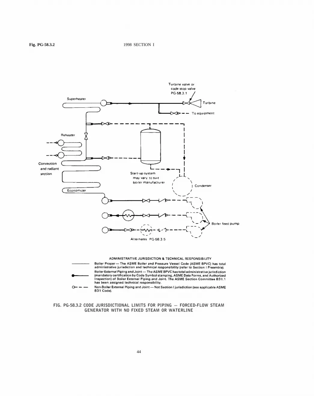
Fig. PG-58.3.2 1998 SECTION I
FIG. PG-58.3.2 CODE JURISDICTIONAL LIMITS FOR PIPING — FORCED-FLOW STEAMGENERATOR WITH NO FIXED STEAM OR WATERLINE
44

PG-58.3.1 PART PG — GENERAL REQUIREMENTS PG-59.1.1.1
in the superheater to exceed that permitted by PG-67.2, with maximum steam flow from the boiler to thesuperheater. Flow and pressure calculations demonstra-ting that the superheater will not be overpressurizedunder any steam flow conditions shall be documentedand made available to the Inspector. These calculationsshall be certified by a Professional Engineer experiencedin the mechanical design of power plants.
(d) There is no valve on the discharge side of thesuperheater.
(e) Section I jurisdiction shall include the pressureparts between the superheater inlet and the outlet at:
(1) the first circumferential joint for welding endconnections; or
(2) the face of the first flange in bolted flangeconnections; or
(3) the first threaded joint in that type of con-nection.
PG-58.3.2When two or more boilers are connectedto a common steam header, or when a single boileris connected to a header having another steam source(e.g., a turbine extraction line), the connection fromeach boiler having a manhole opening shall be fittedwith two stop valves having an ample free-blow drainbetween them. The boiler external piping includes allpiping from the boiler proper up to and including thesecond stop valve and the free-blow drain valve.
PG-58.3.3 The feedwater piping for all boilers,except high-temperature water boilers and forced-flowsteam generators complying with PG-58.3.5, shall ex-tend through the required stop valve and up to andincluding the check valve except as required by PG-58.3.4. On a single boiler-turbine unit installation theboiler feed shutoff valve may be located upstream fromthe boiler feed check valve.
If a feedwater heater or heaters meeting the require-ments of Part PFH are installed between the requiredstop valve and the boiler, and are fitted with isolationand bypass valves, provisions must be made to preventthe feedwater pressure from exceeding the maximumallowable working pressure of the piping or feedwaterheater, whichever is less. Control and interlock systemsare permitted in order to prevent overpressure.
PG-58.3.4When two or more boilers are fed froma common source, the piping shall be up to andincluding a globe or regulating valve located betweenthe check valve required in PG-58.3.3 and the sourceof supply. If the regulating valve is equipped with anisolation valve and a bypass valve, the piping shall beup to and including both the isolation valve downstream
45
from the regulating valve and the shutoff valve in thebypass.
PG-58.3.5The feedwater piping for a forced-flowsteam generator with no fixed steam and waterline mayterminate up to and including the stop valve near theboiler and omitting the check valve near the boiler,provided that a check valve having a pressure ratingno less than the boiler inlet design pressure is installedat the discharge of the boiler feed pump or elsewherein the feedline between the feed pump and the feedstop valve. If the feedwater heater(s) is fitted withisolation and bypass valves, the applicable requirementsof PG-58.3.3 must be met.
PG-58.3.6 The blowoff piping for all boilers,except forced-flow steam generators with no fixed steamand waterline, high-temperature water boilers, and thoseused for traction and/or portable purposes, when themaximum allowable working pressure exceeds 100 psi(690 kPa) shall extend through and including the secondvalve. The blowoff piping for all traction and/or portableboilers and for forced circulation and electric boilershaving a normal water content not exceeding 100 galare required to extend through only one valve.
PG-58.3.7The miscellaneous piping shall includethe piping for such items as drains, vents, surface-blow-off, steam and water piping for water columns,gage glasses and pressure gages, and the recirculationreturn line for a high-temperature water boiler. Whena drain is not intended for blowoff purposes (whenthe boiler is under pressure) a single valve is acceptable,otherwise two valves in series are required except aspermitted by PG-58.3.6.
PG-58.3.8Welded piping in PG-58.3.1, PG-58.3.2,PG-58.3.3, PG-58.3.4, PG-58.3.5, PG-58.3.6, and PG-58.3.7 is also subject to the requirements of PG-104for proper Code certification.
PG-59 APPLICATION REQUIREMENTSFOR THE BOILER PROPER
PG-59.1 Common to Steam, Feedwater, Blowoff,and Drain Systems
PG-59.1.1Outlets of a boiler to which piping isto be attached for any purpose, and which pipingcomes within the Code requirements, shall meet therequirements of PG-39 and shall be:
PG-59.1.1.1A tapped opening.

PG-59.1.1.2 1998 SECTION I PG-59.3.1
FIG. PG-59.1 TYPICAL BOILER BUSHINGS
PG-59.1.1.2 Bolted flanged joints includingthose of the Van Stone type.
PG-59.1.1.3Welding ends of the butt or socketwelding type.
PG-59.1.1.4Piping within the boiler proper maybe expanded into grooved holes, seal welded if desired.Blowoff piping of firetube boilers shall be attached bythreading into a tapped opening with a threaded fittingor valve at the other end if exposed to products ofcombustion, or by PG-59.1.1.1 or PG-59.1.1.2 if notso exposed (see PFT-49).
PG-59.1.2 Steam Mains.Provisions shall be madefor the expansion and contraction of steam mainsconnected to boilers, by providing substantial anchorageat suitable points, so that there shall be no undue straintransmitted to the boiler. Steam reservoirs shall be usedon steam mains when heavy pulsations of the steamcurrents cause vibration of the boiler shell plates.
PG-59.1.3Figure PG-59.1 illustrates a typical formof connection for use on boiler shells for passing throughpiping such as feed, surface blowoff connections, etc.,and which permits the pipes’ being threaded in solidfrom both sides in addition to the reinforcing of the
46
opening of the shell. The pipes shall be attached asprovided in PG-59.1.1.
In these and other types of boilers where both internaland external pipes making a continuous passage areemployed, the boiler bushing or its equivalent shallbe used.
PG-59.2 Requirements for Feedwater Connections.The feedwater shall be introduced into a boiler in sucha manner that the water will not be discharged directlyagainst surfaces exposed to gases of high temperatureor to direct radiation from the fire. For pressures of400 psi or over, the feedwater inlet through the drumshall be fitted with shields, sleeves, or other suitablemeans to reduce the effects of temperature differentialsin the shell or head. Feedwater, other than condensatereturns as provided for in PG-59.3.6, shall not beintroduced through the blowoff.
PG-59.3 Requirements for BlowoffsPG-59.3.1A blowoff as required herein is defined
as a pipe connection provided with valves located inthe external piping through which the water in theboiler may be blown out under pressure, exceptingdrains such as are used on water columns, gage glasses,or piping to feedwater regulators, etc., used for the

ASME B&PVC sec1$$$$u5 06-04-99 08:04:18 pd: sec1 Rev 14.04
PG-59.3.1 PART PG — GENERAL REQUIREMENTS PG-60.1.1
purpose of determining the operating condition of suchequipment. Piping connections used primarily for contin-uous operation, such as deconcentrators on continuousblowdown systems, are not classed as blowoffs but thepipe connections and all fittings up to and includingthe first shutoff valve shall be equal at least to thepressure requirements for the lowest set pressure ofany safety valve on the boiler drum and with thecorresponding saturated-steam temperature.
PG-59.3.2A surface blowoff connection shall notexceed NPS 21⁄2 (DN 65), and the internal pipe andthe terminal connection for the external pipe, whenused, shall form a continuous passage, but with clearancebetween their ends and arranged so that the removalof either will not disturb the other. A properly designedsteel bushing, similar to or the equivalent of thoseshown in Fig. PG-59.1, or a flanged connection shallbe used.
PG-59.3.3 Each boiler except forced-flow steamgenerators with no fixed steam and waterline and high-temperature water boilers shall have a bottom blowoffoutlet in direct connection with the lowest water spacepracticable for external piping conforming to PG-58.3.6.
PG-59.3.4All waterwalls and water screens whichdo not drain back into the boiler, and all integraleconomizers, shall be equipped with outlet connectionsfor a blowoff or drain line and conform to the require-ments of PG-58.3.6 or PG-58.3.7.
PG-59.3.5Except as permitted for miniature boilersin Part PMB, the minimum size of blowoff connectionsshall be NPS 1 (DN 25), and the maximum size shallbe NPS 21⁄2 (DN 65), except that for boilers with 100sq ft (9.3 m2) of heating surface or less, the minimumsize of blowoff connections may be NPS3⁄4 (DN 20).
PG-59.3.6 Condensate return connections of thesame size or larger than the size herein specified maybe used, and the blowoff may be connected to them.In such case the blowoff shall be so located that theconnection may be completely drained.
PG-59.3.7A bottom blowoff pipe when exposedto direct furnace heat shall be protected by firebrickor other heat resisting material which is so arrangedthat the pipe may be inspected.
PG-59.3.8An opening in the boiler setting for ablowoff pipe shall be arranged to provide free expansionand contraction.
47
PG-59.4 Requirements for DrainsPG-59.4.1Ample drain connections shall be pro-
vided where required to permit complete drainage of allpiping, superheaters, waterwalls, water screens, integraleconomizers, high-temperature water boilers, and allother boiler components in which water may collect.Piping shall conform to the requirements of PG-58.3.6or PG-58.3.7.
PG-59.4.1.1Each superheater shall be equippedwith at least one drain connection so located as tomost effectively provide for the proper operation ofthe apparatus.
PG-59.4.1.2Each high-temperature water boilershall have a bottom drain connection of at least NPS1 (DN 25) in direct connection with the lowest waterspace practical for external piping conforming to PG-58.3.7.
PG-59.5 Requirements for Valves and Fittings.The following requirements apply to the use of valvesand fittings in the boiler proper.
PG-59.5.1 Steam Stop ValvesPG-59.5.1.1If a shutoff valve is used between
the boiler and its superheater, the safety valve capacityon the boiler shall comply with the requirements ofPG-67.2 and PG-70, except as provided for in PG-59.5.1.2, no credit being taken for the safety valve onthe superheater, and the superheater must be equippedwith safety valve capacity as required by PG-68. Astop valve is not required at the inlet or the outlet ofa reheater or separately fired superheater.
PG-59.5.1.2When stop valves are installed inthe water-steam flow path between any two sectionsof a forced-flow steam generator with no fixed steamand waterline, the safety valves shall satisfy the require-ments of PG-67.4.4.
DESIGN AND APPLICATION
PG-60 REQUIREMENTS FORMISCELLANEOUS PIPE,VALVES, AND FITTINGS
Piping referred to in this paragraph shall be designedin accordance with the applicable requirements ofASME B31.1.
PG-60.1 Water Level IndicatorsPG-60.1.1 Boiler with an MAWP of 400 psi or
less and electric boilers of the electrode type, requireat least one gage glass. Except for electric boilers of
A99

ASME B&PVC sec1$$$$u5 06-04-99 08:04:18 pd: sec1 Rev 14.04
A99
PG-60.1.1 1998 SECTION I PG-60.2.4
the electrode type, boilers with an MAWP over 400psi require at least two gage glasses. Forced flow steamgenerators with no fixed steam and waterline, and high-temperature water boilers of the forced circulation type,do not require a gage glass.
When two gage glasses are required, one of the gageglasses may be replaced by two independent remotelevel indicators. When both remote level indicators areoperating reliably, the remaining gage glass may beshut off, but shall be maintained in serviceable condition.When fitted with two gage glasses, both gage glassesmay be connected to a single water column or directlyto the drum.
At least one gage glass shall be readily visible tothe operator in the area where immediate control actionsare initiated. Alternately, two dependable indirect indica-tions shall be provided, either by transmission of thegage glass image or by remote level indicators. A gageglass image transmitted to the operator’s working areaby means of a fiber optic cable, with no electricalmodification of the optic signal, is considered to providedirect reading of the gage glass water level.
The lowest visible part of the water gage glass shallbe at least 2 in. (51 mm) above the lowest permissiblewater level, as determined by the boiler Manufacturer.When remote level indication is provided for the opera-tor in lieu of the gage glass, the same minimum levelreference shall be clearly marked.
Tubular or transparent gages that rely on observingthe steam–water interface and consist of multiple sec-tions, shall have a minimum of 1 in. (25 mm) overlapof the visible portions. Segmented gages, such as portedgages or end-connected strip gages, shall be equippedto afford obvious visual discrimination between theappearance of water or vapor in the individual sections.
PG-60.1.2 DELETED
PG-60.1.4Boilers of the horizontal firetube typeshall be so set that when the water is at the lowestreading in the water gage glass there shall be at least3 in. (76 mm) of water over the highest point of thetubes, flues, or crown sheets.
PG-60.1.5 Boilers of locomotives shall have atleast one water glass provided with top and bottomshutoff cocks and lamp.
The lowest reading of water glass shall not be lessthan 2 in. (51 mm) above the highest point of crownsheet on boilers 36 in. (914 mm) in diameter and
48
under, nor less than 3 in. (76 mm) for boilers over36 in. (914 mm) in diameter. These are minimumdimensions, and on large locomotives and those op-erating on steep grades, the height should be increased,if necessary, to compensate for change of water levelon descending grades.
The bottom mounting for water glass and for watercolumn if used must extend not less than 11⁄2 in.(38 mm) inside the boiler and beyond any obstacleimmediately above it, and the passage therein must bestraight and horizontal.
Tubular water glasses must be equipped with aprotecting shield.
PG-60.1.6All connections on the gage glass shallbe not less than NPS1⁄2 (DN 15). Each water gageglass shall be fitted with a drain cock or valve havingan unrestricted drain opening of not less than1⁄4 (6 mm)in. diameter to facilitate cleaning. When the boileroperating pressure exceeds 100 psi (690 kPa) the glassshall be furnished with a connection to install a valveddrain to the ash pit or other safe discharge point.
Each water gage glass shall be equipped with atop and a bottom shutoff valve of such through-flowconstruction as to prevent stoppage by deposits ofsediments. If the lowest valve is more than 7 ft (2.1 m)above the floor or platform from which it is operated,the operating mechanism shall indicate by its positionwhether the valve is open or closed. The pressure–temperature rating shall be at least equal to that of thelowest set pressure of any safety valve on the boilerdrum and the corresponding saturated-steam temper-ature.
Straight-run globe valves shall not be used on suchconnections.
Automatic shutoff valves, if permitted to be used,shall conform to the requirements given in A-18.
PG-60.2 Water ColumnsPG-60.2.1The water column shall be so mounted
that it will maintain its correct position relative to thenormal waterline under operating conditions.
PG-60.2.3 The water column shall be fitted witha connection for a drain cock or drain valve to installa pipe of at least NPS3⁄4 (DN 20) to the ash pit orother safe point of discharge.
PG-60.2.4 The design and material of a watercolumn shall comply with the requirements of PG-42.Water column made of cast iron in accordance withSA-278 may be used for maximum boiler pressuresnot exceeding 250 psi (1720 kPa). Water columns made

PG-60.2.4 PART PG — GENERAL REQUIREMENTS PG-60.5
of ductile iron in accordance with SA-395 may beused for maximum boiler pressures not exceeding 350psi (2410 kPa). For higher pressures, steel constructionshall be used.
PG-60.3 ConnectionsPG-60.3.1Gage glasses that are required by PG-
60.1 shall be connected directly to the shell or drumof the boiler or to an intervening water column.
PG-60.3.2The lower edge of the steam connectionto a water column or gage glass in the boiler shallnot be below the highest visible water level in thewater gage glass. There shall be no sag or offset inthe piping which will permit the accumulation of water.
PG-60.3.3The upper edge of the water connectionto a water column or gage glass and the boiler shallnot be above the lowest visible water level in the gageglass. No part of this pipe connection shall be abovethe point of connection at the water column.
PG-60.3.4Connections from the boiler to the watercolumn shall be at least NPS 1 (DN 25). Connectionsfor gage glasses connected directly to the boiler shallbe at least NPS1⁄2 (DN 15). Connections from theboiler to the remote level indicator shall be at leastNPS 3⁄4 (DN 20) to and including the isolation valveand from there to the remote level indicator at least1⁄2 in. (13 mm) O.D. tubing. These connections shallbe completely independent of other connections for anyfunction other than water level indication.
PG-60.3.5 For pressures of 400 psi (2800 kPa)or over, lower connections to drums for water columnsand remote level indicators shall be provided withshields, sleeves, or other suitable means to reduce theeffect of temperature differentials in the shells or heads.
PG-60.3.6The steam and water connections to awater column or a water gage glass shall be such thatthey are readily accessible for internal inspection andcleaning. Some acceptable methods of meeting thisrequirement are by providing a cross or fitting with aback outlet at each right-angle turn to permit inspectionand cleaning in both directions, or by using pipe bendsor fittings of a type which does not leave an internalshoulder or pocket in the pipe connection and with aradius of curvature which will permit the passage ofa rotary cleaner. Screwed plug closures using threadedconnections as allowed by PG-39.5.3 are acceptablemeans of access for this inspection and cleaning. Forboilers with all drum safety valves set at or above 400psig, socket-welded plugs may be used for this purposein lieu of screwed plugs. If the water connection to
49
the water column has a rising bend or pocket whichcannot be drained by means of the water-column drain,an additional drain shall be placed on this connectionin order that it may be blown off to clear any sedimentfrom the pipe.
PG-60.3.7Shutoff valves shall not be used in thepipe connections between a boiler and a water columnor between a boiler and the shutoff valves requiredfor the gage glass (PG-60.1.6), unless they are eitheroutside-screw-and-yoke or lever-lifting type gate valvesor stopcocks with lever permanently fastened theretoand marked in line with their passage, or of such otherthrough-flow construction as to prevent stoppage bydeposits of sediment, and to indicate by the positionof the operating mechanism whether they are in openor closed position; and such valves or cocks shall belocked or sealed open. Where stopcocks are used theyshall be of a type with the plug held in place by aguard or gland.
The lock or seal open requirement may be waivedif the following additional conditions are met.
(1) MAWP shall not exceed 250 psig (1720 kPa).(2) The boiler shall not be hand fired or fired with
solid fuel not in suspension.(3) Interlocks between the valve and the burner con-
trol system shall stop fuel supply and prevent firingwhenever the valve between the drum and the watercolumn is not in the fully open position.
(4) Provision shall be made in the valve body topermit cleaning and rodding of horizontal and verticallegs of attached pipe when the boiler is out of service.
(5) The minimum valve size shall be NPS 1 (DN 25).(6) The valve shall indicate by its position whether
it is open or closed.
PG-60.3.8No outlet connections, except for controldevices (such as damper regulators and feedwater regula-tors), drains, steam gages, or apparatus of such formas does not permit the escape of an appreciable amountof steam or water therefrom shall be placed on thepiping connecting a water column or gage glass to aboiler.
PG-60.3.9 An acceptable arrangement is shownin Fig. PG-60.
PG-60.4 Gage Cocks.Not required.
PG-60.5 Water Fronts. Each boiler fitted with awater jacketed boiler-furnace mouth protector, or similarappliance having valves on the pipes connecting themto the boiler shall have these valves locked or sealedopen. Such valves, when used, shall be of thestraightway type.

PG-60.6 1998 SECTION I PG-61.2
FIG. PG-60 TYPICAL ARRANGEMENT OF STEAMAND WATER CONNECTIONS FOR A WATER
COLUMN
PG-60.6 Pressure GagesPG-60.6.1Each boiler shall have a pressure gage
so located that it is easily readable. The pressure gageshall be installed so that it shall at all times indicatethe pressure in the boiler. Each steam boiler shall havethe pressure gage connected to the steam space or tothe water column or its steam connection. A valve orcock shall be placed in the gage connection adjacentto the gage. An additional valve or cock may be locatednear the boiler providing it is locked or sealed in theopen position. No other shutoff valves shall be locatedbetween the gage and the boiler. The pipe connectionshall be of ample size and arranged so that it may becleared by blowing out. For a steam boiler the gageor connection shall contain a syphon or equivalentdevice which will develop and maintain a water sealthat will prevent steam from entering the gage tube.Pressure gage connections shall be suitable for themaximum allowable working pressure and temperature,but if the temperature exceeds 406°F (208°C), brassor copper pipe or tubing shall not be used. The connec-tions to the boiler, except the syphon, if used, shallnot be less than NPS1⁄4 but where steel or wroughtiron pipe or tubing is used, they shall not be less than1⁄2 in. (13 mm) inside diameter. The minimum size ofa syphon, if used, shall be1⁄4 in. (6 mm) inside diameter.
50
The dial of the pressure gage shall be graduated toapproximately double the pressure at which the safetyvalve is set, but in no case to less than 11⁄2 times thispressure.
PG-60.6.2Each forced-flow steam generator withno fixed steam and waterline shall be equipped withpressure gages or other pressure measuring deviceslocated as follows:
PG-60.6.2.1At the boiler or superheater outlet(following the last section which involves absorptionof heat), and
PG-60.6.2.2At the boiler or economizer inlet(preceding any section which involves absorption ofheat), and
PG-60.6.2.3 Upstream of any shutoff valvewhich may be used between any two sections of theheat absorbing surface.
PG-60.6.3 Each boiler shall be provided with avalve connection at least NPS1⁄4 for the exclusivepurpose of attaching a test gage when the boiler is inservice, so that the accuracy of the boiler pressuregage can be ascertained.
PG-60.6.4Each high-temperature water boiler shallhave a temperature gage so located and connected thatit shall be easily readable. The temperature gage shallbe installed so that it at all times indicates the tempera-ture in degrees Fahrenheit of the water in the boiler,at or near the outlet connection.
PG-61 FEEDWATER SUPPLY
PG-61.1Except as provided for in PG-61.2 and PG-61.4, boilers having more than 500 sq ft (47 m2) ofwater-heating surface shall have at least two means offeeding water. Except as provided for in PG-61.3, PG-61.4, and PG-61.5, each source of feeding shall becapable of supplying water to the boiler at a pressureof 3% higher than the highest setting of any safetyvalve on the boiler. For boilers that are fired with solidfuel not in suspension, and for boilers whose settingor heat source can continue to supply sufficient heatto cause damage to the boiler if the feed supply isinterrupted, one such means of feeding shall not besusceptible to the same interruption as the other, andeach shall provide sufficient water to prevent damageto the boiler.
PG-61.2Except as provided for in PG-61.1, a boilerfired by gaseous, liquid, or solid fuel in suspension

PG-61.2 PART PG — GENERAL REQUIREMENTS PG-67.3
may be equipped with a single means of feeding waterprovided means are furnished for the shutting off ofits heat input prior to the water level reaching thelowest permissible level established by PG-60.
PG-61.3 For boilers having a water-heating surfaceof not more than 100 sq ft (9.3 m2) the feed connectionto the boiler shall not be smaller than NPS1⁄2 (DN 15).For boilers having a water-heating surface more than100 sq ft (9.3 m2) the feed connection to the boilershall not be less than NPS3⁄4 (DN 20).
PG-61.4 High-temperature water boilers shall beprovided with means of adding water to the boiler orsystem while under pressure.
PG-61.5A forced-flow steam generator with no fixedsteam and waterline shall be provided with a sourceof feeding capable of supplying water to the boiler ata pressure not less than the expected maximum sustainedpressure at the boiler inlet, as determined by the boilerManufacturer, corresponding to operation at maximumdesigned steaming capacity with maximum allowableworking pressure at the superheater outlet.
SAFETY VALVES AND SAFETYRELIEF VALVES 16
PG-67 BOILER SAFETY VALVEREQUIREMENTS
PG-67.1 Each boiler shall have at least one safetyvalve or safety relief valve and if it has more than500 sq ft (47 m2) of bare tube water-heating surface,or if an electric boiler has a power input more than1100 kW, it shall have two or more safety valves orsafety relief valves. For a boiler with combined baretube and extended water-heating surface exceeding 500sq ft (47 m2), two or more safety valves or safetyrelief valves are required only if the design steamgenerating capacity of the boiler exceeds 4000 lb/hr(1800 kg/hr). Organic fluid vaporizer generators requirespecial consideration as given in Part PVG.
16Safety Valve: An automatic pressure relieving device actuated bythe static pressure upstream of the valve and characterized by full-opening pop action. It is used for gas or vapor service.
Relief Valve: An automatic pressure relieving device actuated bythe static pressure upstream of the valve which opens further withthe increase in pressure over the opening pressure. It is used primarilyfor liquid service.
Safety Relief Valve: An automatic pressure-actuated relievingdevice suitable for use either as a safety valve or relief valve,depending on application.
Unless otherwise defined, the definitions relating to pressure reliefdevices in Appendix I of ASME PTC 25-1994, Pressure ReliefDevices, shall apply.
51
PG-67.2 The safety valve or safety relief valvecapacity for each boiler (except as noted in PG-67.4)shall be such that the safety valve, or valves willdischarge all the steam that can be generated by theboiler without allowing the pressure to rise more than6% above the highest pressure at which any valve isset and in no case to more than 6% above the maximumallowable working pressure.
PG-67.2.1The minimum required relieving capac-ity of the safety valves or safety relief valves for alltypes of boilers shall not be less than the maximumdesigned steaming capacity as determined by the Manu-facturer and shall be based on the capacity of all thefuel burning equipment as limited by other boilerfunctions.
PG-67.2.2The minimum required relieving capac-ity for a waste heat boiler shall be determined by theManufacturer. When auxiliary firing is to be used incombination with waste heat recovery, the maximumoutput as determined by the boiler Manufacturer shallinclude the effect of such firing in the total requiredcapacity. When auxiliary firing is to be used in placeof waste heat recovery, the minimum required relievingcapacity shall be based on auxiliary firing or wasteheat recovery, whichever is higher.
PG-67.2.3The minimum required relieving capac-ity for electric boilers shall be in accordance withPEB-15.
PG-67.2.4 The minimum required relieving capac-ity in lb /hr for a high-temperature water boiler shallbe determined by dividing the maximum output inBtu/hr at the boiler nozzle, produced by the highestheating value fuel for which the boiler is designed,by 1000.
PG-67.2.5The minimum required relieving capac-ity for organic fluid vaporizers shall be in accordancewith PVG-12.
PG-67.2.6 Any economizer which may be shutoff from the boiler, thereby permitting the economizerto become a fired pressure vessel, shall have one ormore safety relief valves with a total discharge capacity,in lbs/hr, calculated from the maximum expected heatabsorption in Btu/hr, as determined by the Manufac-turer, divided by 1000. This absorption shall be statedin the stamping (PG-106.4).
PG-67.3 One or more safety valves on the boilerproper shall be set at or below the maximum allowableworking pressure (except as noted in PG-67.4). Ifadditional valves are used the highest pressure setting

PG-67.3 1998 SECTION I PG-67.4.3.2.3
shall not exceed the maximum allowable working pres-sure by more than 3%. The complete range of pressuresettings of all the saturated-steam safety valves on aboiler shall not exceed 10% of the highest pressure towhich any valve is set. Pressure setting of safety reliefvalves on high-temperature water boilers17 may exceedthis 10% range.
PG-67.4 For a forced-flow steam generator with nofixed steam and waterline, equipped with automaticcontrols and protective interlocks responsive to steampressure, safety valves may be provided in accordancewith the above paragraphs or the following protectionagainst overpressure shall be provided:
PG-67.4.1 One or more power-actuated pressurerelieving valves18 shall be provided in direct communi-cation with the boiler when the boiler is under pressureand shall receive a control impulse to open when themaximum allowable working pressure at the superheateroutlet, as shown in the master stamping (PG-106.3),is exceeded. The total combined relieving capacity ofthe power-actuated relieving valves shall be not lessthan 10% of the maximum design steaming capacityof the boiler under any operating condition as deter-mined by the Manufacturer. The valve or valves shallbe located in the pressure part system where they willrelieve the overpressure.
An isolating stop valve of the outside-screw-and-yoke type may be installed between the power-actuatedpressure relieving valve and the boiler to permit repairsprovided an alternate power-actuated pressure relievingvalve of the same capacity is so installed as to be indirect communication with the boiler in accordancewith the requirements of this paragraph.
Power-actuated pressure relieving valves dischargingto intermediate pressure and incorporated into bypassand/or startup circuits by the boiler Manufacturer neednot be capacity certified. Instead, they shall be markedby the valve manufacturer with a capacity rating at a setof specified inlet pressure and temperature conditions.
17Safety relief valves in hot water service are more susceptible todamage and subsequent leakage, than safety valves relieving steam.It is recommended that the maximum allowable working pressureof the boiler and the safety relief valve setting for high-temperaturewater boilers be selected substantially higher than the desired operatingpressure so as to minimize the times the safety relief valve must lift.18The power-actuated pressure relieving valve is one whose move-ments to open or close are fully controlled by a source of power(electricity, air, steam, or hydraulic). The valve may discharge toatmosphere or to a container at lower pressure. The discharge capacitymay be affected by the downstream conditions, and such effectsshall be taken into account. If the power-actuated pressure relievingvalves are also positioned in response to other control signals, thecontrol impulse to prevent overpressure shall be responsive only topressure and shall override any other control function.
52
Power-actuated pressure relieving valves dischargingdirectly to atmosphere shall be capacity certified. Thiscapacity certification shall be conducted in accordancewith the provisions of PG-69.3. The valves shall bemarked in accordance with the provisions of PG-69.4and PG-69.5.
PG-67.4.2 Spring-loaded safety valves shall beprovided, having a total combined relieving capacity,including that of the power-actuated pressure relievingcapacity installed under PG-67.4.1, of not less than100% of the maximum designed steaming capacity ofthe boiler, as determined by the Manufacturer, exceptthe alternate provisions of PG-67.4.3 are satisfied. Inthis total, no credit in excess of 30% of the totalrequired relieving capacity shall be allowed for thepower-actuated pressure relieving valves actually in-stalled. Any or all of the spring-loaded safety valvesmay be set above the maximum allowable workingpressure of the parts to which they are connected, butthe set pressures shall be such that when all of thesevalves (together with the power-actuated pressure reliev-ing valves) are in operation the pressure will not risemore than 20% above the maximum allowable workingpressure of any part of the boiler, except for the steampiping between the boiler and the prime mover.
PG-67.4.3 The total installed capacity of spring-loaded safety valves may be less than the requirementsof PG-67.4.2 provided all of the following conditionsare met.
PG-67.4.3.1 The boiler shall be of no lesssteaming capacity than 1,000,000 lb/hr (450,000 kg/hr)and installed in a unit system for power generation (i.e.,a single boiler supplying a single turbine-generator unit).
PG-67.4.3.2The boiler shall be provided withautomatic devices, responsive to variations in steampressure, which include no less than all the following:
PG-67.4.3.2.1A control capable of maintainingsteam pressure at the desired operating level and ofmodulating firing rates and feedwater flow in proportionto a variable steam output; and
PG-67.4.3.2.2A control which overrides PG-67.4.3.2.1 by reducing the fuel rate and feedwaterflow when the steam pressure exceeds the maximumallowable working pressure as shown in the masterstamping (PG-106.3) by 10%; and
PG-67.4.3.2.3A direct-acting overpressure-trip-actuating mechanism, using an independent pressuresensing device, that will stop the flow of fuel and

PART PG — GENERAL REQUIREMENTS Fig. PG-67.4
FIG. PG-67.4 REQUIREMENTS FOR PRESSURE RELIEF FORCED-FLOW STEAM GENERATOR
53

PG-67.4.3.2.3 1998 SECTION I PG-67.7
feedwater to the boiler, at a pressure higher than theset pressure of PG-67.4.3.2.2, but less than 20% abovethe maximum allowable working pressure as shown inthe master stamping (PG-106.3).
PG-67.4.3.3There shall be not less than twospring-loaded safety valves and the total rated relievingcapacity of the spring-loaded safety valves shall be notless than 10% of the maximum designed steamingcapacity of the boiler as determined by the Manufacturer.These spring-loaded safety valves may be set abovethe maximum allowable working pressure of the partsto which they are connected but shall be set such thatthe valves will lift at a pressure no higher than 20%above the maximum allowable working pressure asshown in the master stamping (PG-106.3).
PG-67.4.3.4At least two of these spring-loadedsafety valves shall be equipped with a device thatdirectly transmits the valve stem lift action to controlsthat will stop the flow of fuel and feedwater to theboiler. The control circuitry to accomplish this shallbe arranged in a “fail-safe” manner (see Note).
NOTE: “Fail-safe” shall mean a circuitry arranged as either of thefollowing:
(1) Energize to trip:There shall be at least two separate andindependent trip circuits served by two power sources, to initiateand perform the trip action. One power source shall be a continuouslycharged dc battery. The second source shall be an ac-to-dc converterconnected to the dc system to charge the battery and capable ofperforming the trip action. The trip circuits shall be continuouslymonitored for availability.
It is not mandatory to duplicate the mechanism that actuallystops the flow of fuel and feedwater.
(2) De-energize to trip:If the circuits are arranged in such away that a continuous supply of power is required to keep thecircuits closed and operating and such that any interruption of powersupply will actuate the trip mechanism, then a single trip circuitand single power supply will be enough to meet the requirementsof this subparagraph.
PG-67.4.3.5The power supply for all controlsand devices required by PG-67.4.3 shall include at leastone source contained within the same plant as theboiler and which is arranged to actuate the controlsand devices continuously in the event of failure orinterruption of any other power sources.
PG-67.4.4 When stop valves are installed in thewater-steam flow path between any two sections of aforced-flow steam generator with no fixed steam andwaterline:
PG-67.4.4.1The power-actuated pressure reliev-ing valve(s) required by PG-67.4.1 shall also receivea control impulse to open when the maximum allowableworking pressure of the component, having the lowest
54
pressure level upstream to the stop valve, is exceeded;and
PG-67.4.4.2 The spring-loaded safety valvesshall be located to provide the pressure protectionrequirements in PG-67.4.2 or PG-67.4.3.
PG-67.4.5 A reliable pressure-recording deviceshall always be in service and records kept to provideevidence of conformity to the above requirements.
PG-67.5 All safety valves or safety relief valvesshall be so constructed that the failure of any partcannot obstruct the free and full discharge of steamand water from the valve. Safety valves shall be ofthe direct spring-loaded pop type, with seat inclinedat any angle between 45 deg. and 90 deg., inclusive,to the center line of the spindle. The coefficient ofdischarge of safety valves shall be determined by actualsteam flow measurements at a pressure not more than3% above the pressure at which the valve is set toblow and when adjusted for blowdown in accordancewith PG-72. The valves shall be credited with capacitiesas determined by the provisions of PG-69.2.
Safety valves or safety relief valves may be usedwhich give any opening up to the full discharge capacityof the area of the opening of the inlet of the valve(see PG-69.5), provided the movement of the steamsafety valve is such as not to induce lifting of waterin the boiler.
Deadweight or weighted lever safety valves or safetyrelief valves shall not be used.
For high-temperature water boilers safety relief valvesshall be used. Such valves shall have a closed bonnet.For purposes of selection the capacity rating of suchsafety relief valves shall be expressed in terms of actualsteam flow determined on the same basis as for safetyvalves. In addition the safety relief valves shall becapable of satisfactory operation when relieving waterat the saturation temperature corresponding to the pres-sure at which the valve is set to blow.
PG-67.6 A safety valve or safety relief valve overNPS 3 (DN 80), used for pressures greater than 15psig (103 kPa), shall have a flanged inlet connectionor a weld-end inlet connection. The dimensions offlanges subjected to boiler pressure shall conform tothe applicable American National Standards as givenin PG-42. The facing shall be similar to those illustratedin the Standard.
PG-67.7 Safety valves or safety relief valves mayhave bronze parts complying with either SB-61 orSB-62, provided the maximum allowable stresses andtemperatures do not exceed the values given in Table

98
98
PG-67.7 PART PG — GENERAL REQUIREMENTS PG-69.1.3
1B of Section II, Part D, and shall be marked toindicate the class of material used. Such valves shallnot be used on superheaters delivering steam at atemperature over 450°F (232°C) and 306°F (152°C)respectively, and shall not be used for high-temperaturewater boilers.
PG-68 SUPERHEATER AND REHEATERSAFETY VALVE REQUIREMENTS
PG-68.1 Except as permitted in PG-58.3.1, everyattached superheater shall have one or more safetyvalves in the steam flow path between the superheateroutlet and the first stop valve. The location shall besuitable for the service intended and shall provide theoverpressure protection required. The pressure dropupstream of each safety valve shall be considered inthe determination of set pressure and relieving capacityof that valve. If the superheater outlet header has afull, free steam passage from end to end and is soconstructed that steam is supplied to it at practicallyequal intervals throughout its length so that there is auniform flow of steam through the superheater tubesand the header, the safety valve, or valves, may belocated anywhere in the length of the header.
PG-68.2The discharge capacity of the safety valve,or valves, on an attached superheater may be includedin determining the number and size of the safety valvesfor the boiler, provided there are no intervening valvesbetween the superheater safety valve and the boiler,and provided the discharge capacity of the safety valve,or valves, on the boiler, as distinct from the superheateris at least 75% of the aggregate valve capacity required.
PG-68.3 Every separately fired superheater whichmay be shut off from the boiler and permit the super-heater to become a fired pressure vessel shall have oneor more safety valves having a discharge capacity equalto 6 lb of steam per hour per square foot of superheatersurface measured on the side exposed to the hot gases.As an alternative the Manufacturer may also calculatethe minimum safety valve discharge capacity in lbs.of steam per hour from the maximum expected heatabsorption (as determined by the Manufacturer) inBtu/hr, divided by 1,000. In the case of electricallyheated superheaters, the safety valve capacity shall bebased upon 31⁄2 lb /hr /kW input. The number of safetyvalves installed shall be such that the total capacity isat least equal to that required.
PG-68.4Every reheater shall have one or more safetyvalves, such that the total relieving capacity is at leastequal to the maximum steam flow for which the heater
55
is designed. The capacity of the reheater safety valvesshall not be included in the required relieving capacityfor the boiler and superheater.
One or more valves with a combined relieving capac-ity not less than 15% of the required total shall belocated along the steam flow path between the reheateroutlet and the first stop valve. The pressure dropupstream of the valves on the outlet side of the reheatershall be considered in determining their set pressure.
PG-68.5 A soot blower connection may be attachedto the same outlet from the superheater or reheaterthat is used for the safety valve connection.
PG-68.6 Every safety valve used on a superheateror reheater discharging superheated steam at a tempera-ture over 450°F (232°C) shall have a casing, includingthe base, body, and bonnet and spindle, of steel, steelalloy, or equivalent heat-resisting material.
The valve shall have a flanged inlet connection, ora weld-end inlet connection. It shall have the seat anddisk of suitable heat erosive and corrosive resistingmaterial, and the spring fully exposed outside of thevalve casing so that it shall be protected from contactwith the escaping steam.
PG-69 CERTIFICATION OF CAPACITYOF SAFETY AND SAFETY RELIEFVALVES
PG-69.1 Before the Code symbol is applied to anysafety or safety relief valve, the valve manufacturershall have the relieving capacity of his valves certifiedin accordance with the provisions of this paragraph.
PG-69.1.1Capacity certification tests shall be con-ducted using dry saturated steam. The limits for testpurposes shall be 98% minimum quality and 20°F(11°C) maximum superheat. Correction from withinthese limits may be made to the dry saturated condition.
PG-69.1.2 Tests shall be conducted at a placewhich meets the requirements of Appendix A-312.
PG-69.1.3 Capacity test data reports for eachvalve design and size, signed by the manufacturer andAuthorized Observer witnessing the tests, together withdrawings showing the valve construction, shall be sub-mitted to the ASME designee for review and ac-ceptance.19
19Valve capacities are published in “Pressure Relief Device Certifica-tions.” This publication may be obtained from the National Boardof Boiler and Pressure Vessel Inspectors, 1055 Crupper Ave., Colum-bus, OH 43229.

98
PG-69.1.4 1998 SECTION I PG-69.2.3
PG-69.1.4Capacity certification tests shall be con-ducted at a pressure which does not exceed the setpressure by 3% or 2 psi, whichever is greater. Safetyand safety relief valves shall be adjusted so that theblowdown does not exceed 4% of the set pressure.For valves set at or below 100 psi (690 kPa), theblowdown shall be adjusted so as not to exceed 4 psi(28 kPa). Safety valves used on forced-flow steamgenerators with no fixed steam and waterline, and safetyrelief valves used on high-temperature water boilersshall be adjusted so that the blowdown does not exceed10% of the set pressure. The reseating pressure shallbe noted and recorded.
PG-69.2 Relieving capacities shall be determinedusing one of the following methods.
PG-69.2.1 Three Valve Method.A capacity certi-fication test is required on a set of three valves foreach combination of size, design, and pressure setting.The capacity of each valve of the set shall fall withina range of65% of the average capacity. If one ofthe three valves tested falls outside this range, it shallbe replaced by two valves, and a new average shallbe calculated based on all four valves, excluding thereplaced valve. Failure of any of the four capacitiesto fall within a range of65% of the new averageshall be cause to refuse certification of that particularvalve design.
The rated relieving capacity for each combinationof design, size, and test pressure shall be 90% of theaverage capacity.
PG-69.2.2 Slope Method.If a Manufacturer wishesto apply the Code Symbol to a design of pressurerelief valves, four valves of each combination of pipesize and orifice size shall be tested. These four valvesshall be set at pressures which cover the approximaterange of pressures for which the valve will be usedor covering the range available at the certified testfacility that shall conduct the tests. The capacities basedon these four tests shall be as follows:
(a) The slopeW/P of the actual measured capacityversus the flow pressure for each test point shall becalculated and averaged:
slopepW
Pp
measured capacity
absolute flow rating pressure, psia
All values derived from the testing must fall within65% of the average value:
56
minimum slopep 0.95 × average slope
maximum slopep 1.05 × average slope
If the values derived from the testing do not fallbetween the minimum and maximum slope values, theAuthorized Observer shall require that additional valvesbe tested at the rate of two for each valve beyond themaximum and minimum values with a limit of fouradditional valves.
The relieving capacity to be stamped on the valveshall not exceed 90% of the average slope times theabsolute accumulation pressure:
rated slopep 0.90 × average slope
stamped capacity≤ rated slope (1.03 × set pressure
+ 14.7) or (set pressure + 2 psi
+ 14.7), whichever is greater
PG-69.2.3 Coefficient of Discharge Method.Acoefficient of discharge for the design,K, may beestablished for a specific valve design according to thefollowing procedure.
(a) For each design, the safety or safety relief valvemanufacturer shall submit for test at least three valvesfor each of three different sizes (a total of nine valves).Each valve of a given size shall be set at a differentpressure, covering the range of pressures for which thevalve will be used or the range available at the facilitywhere the tests are conducted.
(b) Tests shall be made on each safety or safetyrelief valve to determine its lift at capacity, popping,and blowdown pressures, and actual relieving capacity.An individual coefficient,KD, shall be established foreach valve as follows:
KD pactual flow
theoretical flowp individual coefficient of discharge
Where actual flow is determined by test and theoreti-cal flow, WT is calculated by one of the followingequations:
For 45 deg. seat
WT p 51.5 × pDLP × 0.707
For flat seat
98

ASME B&PVC sec1$$$$u5 06-04-99 08:04:18 pd: sec1 Rev 14.04
PG-69.2.3 PART PG — GENERAL REQUIREMENTS PG-69.4
WT p 51.5 × pDLP
For nozzle
WT p 51.5 AP
where
WTp theoretical flow, lb /hrAp nozzle throat area, sq in.Pp (1.03 × set pressure + 14.7), orp (set pressure + 2 + 14.7), whichever is
greater, psiaLp lift pressure atP, in.Dp seat diameter, in.
The average of the coefficientsKD of the nine testsrequired shall be multiplied by 0.90, and this productshall be taken as the coefficientK of that design. Allindividual coefficients of discharge,KD, shall fall withina range of65% of the average coefficient found. Ifa valve fails to meet this requirement, the AuthorizedObserver shall require two additional valves to be testedas replacements for each valve having an individualcoefficient, KD, outside the65% range, with a limitof four additional valves. Failure of a coefficient,KD,to fall within 65% of the new average value, excludingthe replaced valve(s), shall be cause to refuse certifica-tion of that particular valve design.
The rated relieving capacity of all sizes and setpressures of a given design, for whichK has beenestablished under the provision of this paragraph, shallbe determined by the equation:
W ≤ WT × K
where
Wp rated relieving capacity, lb /hrWTp theoretical flow, defined by the same equation
used to determineKD, lb /hrKp coefficient of discharge for the design
The coefficient of discharge for the design shall notbe greater than 0.878 (the product of 0.9 × 0.975).The coefficient shall not be applied to valves whosebeta ratio (ratio of valve throat to inlet diameter) liesoutside the range of 0.15 to 0.75, unless tests havedemonstrated that the individual coefficient of discharge,KD, for valves at the extreme ends of a larger range,is within 65% of the average coefficient,KD.
For designs where the lift is used to determine theflow area, all valves shall have the same nominal liftto seat diameter ratio (L/D).
57
For pressures over 1500 psig and up to 3200 psig,the value ofW shall be multiplied by the correctionfactor:
0.1906P − 1000
0.2292P − 1061
PG-69.3 If a manufacturer wishes to apply the Codesymbol to a power-actuated pressure relieving valveunder PG-67.4.1, one valve of each combination ofinlet pipe size and orifice size to be used with thatinlet pipe size shall be tested. The valve shall becapacity tested at four different pressures approximatelycovering the range of the certified test facility on whichthe tests are conducted. The capacities, as determinedby these four tests, shall be plotted against the absoluteflow test pressure and a line drawn through these fourtest points. All points must lie within65% in capacityvalue of the plotted line and must pass through 0-0.From the plotted line, the slope of the linedW/dPshall be determined and a factor of (0.90/51.45)×(dW/dP) shall be applied to capacity computations inthe supercritical region at elevated pressures by meansof the isentropic flow equation.
W p 1135.80.90
51.45×
dW
dP ! P
v
whereWpcapacity, lb of steam/hrPpabsolute inlet pressure, psiavpinlet specific volume, cu ft /lb
dW/dPprate of change of measured capacity withrespect to absolute pressure
NOTE: The constant 1135.8 is based on ag factor of 1.30 whichis accurate for superheated steam at temperature above approximately800°F. In interest of accuracy, other methods of capacity computationsmust be used at temperatures below 800°F at supercritical pressures.
PG-69.4 Power-actuated pressure relieving valves,having capacities certified in accordance with the provi-sion of PG-69.3 and computed in accordance with theformula contained therein, shall be marked as requiredby PG-110 with the computed capacity, correspondingto 3% above the full load operating pressure andtemperature conditions at the valve inlet when the valveis operated by the controller, and they shall also bestamped with the set pressure of the controller. Whenthe valve is marked as required by this paragraph, itshall be the guarantee by the manufacturer that thevalve also conforms to the details of construction hereinspecified.

ASME B&PVC sec1$$$$u5 06-04-99 08:04:18 pd: sec1 Rev 14.04
A99
PG-69.6 1998 SECTION I PG-71.7
PG-69.6 When changes are made in the design ofa safety or safety relief valve in such a manner as toaffect the flow path, lift, or performance characteristicsof the valve, new tests in accordance with this Sectionshall be performed.
PG-70 CAPACITY OF SAFETY VALVES
PG-70.1 Subject to the minimum number requiredby PG-67.1, the number of safety valves or safetyrelief valves required shall be determined on the basisof the maximum designed steaming capacity, as deter-mined by the boiler Manufacturer, and the relievingcapacity marked on the valves by the manufacturer.
PG-71 MOUNTING
PG-71.1 When two or more safety valves are usedon a boiler, they may be mounted either separately oras twin valves made by placing individual valves onY-bases, or duplex valves having two valves in thesame body casing. Twin valves made by placing individ-ual valves on Y-bases, or duplex valves having twovalves in the same body, shall be of approximatelyequal capacity.
When not more than two valves of different sizesare mounted singly the relieving capacity of the smallervalve shall be not less than 50% of that of the largervalve.
PG-71.2 The safety valve or safety relief valve orvalves shall be connected to the boiler independent ofany other connection, and attached as close as possibleto the boiler or the normal steam flow path, without anyunnecessary intervening pipe or fitting. Such interveningpipe or fitting shall be not longer than the face-to-facedimension of the corresponding tee fitting of the samediameter and pressure under the applicable ASMEStandard listed in PG-42 and shall also comply withPG-8 and PG-39. Every safety valve or safety reliefvalve shall be connected so as to stand in an uprightposition, with spindle vertical. On high-temperaturewater boilers of the watertube forced-circulation type,the valve shall be located at the boiler outlet.
PG-71.3 The opening or connection between theboiler and the safety valve or safety relief valve shallhave at least the area of the valve inlet. No valve ofany description shall be placed between the requiredsafety valve or safety relief valve or valves and theboiler, nor on the discharge pipe between the safetyvalve or safety relief valve and the atmosphere. Whena discharge pipe is used, the cross-sectional area shall
58
be not less than the full area of the valve outlet orof the total of the areas of the valve outlets, dischargingthereinto. It shall be as short and straight as possibleand so arranged as to avoid undue stresses on thevalve or valves.
All safety valve or safety relief valve dischargesshall be so located or piped as to be carried clear fromrunning boards or platforms. Ample provision for gravitydrain shall be made in the discharge pipe at or neareach safety valve or safety relief valve, and wherewater of condensation may collect. Each valve shallhave an open gravity drain through the casing belowthe level of the valve seat. For iron- and steel-bodiedvalves exceeding NPS 21⁄2 (DN 65), the drain holeshall be tapped not less than NPS3⁄8 (DN 10).
Discharge piping from safety relief valves on high-temperature water boilers shall be provided with ade-quate provisions for water drainage as well as thesteam venting.
The installation of cast iron bodied safety reliefvalves for high-temperature water boilers is prohibited.
PG-71.4 If a muffler is used on a safety valve orsafety relief valve, it shall have sufficient outlet areato prevent back pressure from interfering with theproper operation and discharge capacity of the valve.The muffler plates or other devices shall be so con-structed as to avoid a possibility of restriction of thesteam passages due to deposit. Mufflers shall not beused on high-temperature water boiler safety reliefvalves.
When a safety valve or safety relief valve is exposedto outdoor elements which may affect operation of thevalve, it is permissible to shield the valve with asatisfactory cover. The shield or cover shall be properlyvented and arranged to permit servicing and normaloperation of the valve.
PG-71.5 When a boiler is fitted with two or moresafety valves or safety relief valves on one connection,this connection to the boiler shall have a cross-sectionalarea not less than the combined areas of inlet connec-tions of all the safety valves or safety relief valves withwhich it connects and shall also meet the requirements ofPG-71.3.
PG-71.6Safety valves may be attached to drums orheaders by welding provided the welding is done inaccordance with Code requirements.
PG-71.7Every boiler shall have proper outlet connec-tions for the required safety valve, or safety reliefvalve, or valves, independent of any other outside steamconnection, the area of opening to be at least equal

98
98
PG-71.7 PART PG — GENERAL REQUIREMENTS PG-73.1.3
to the aggregate areas of inlet connections of all ofthe safety valves or safety relief valves to be attachedthereto. An internal collecting pipe, splash plate, orpan may be used, provided the total area for inlet ofsteam thereto is not less than twice the aggregate areasof the inlet connections of the attached safety valves.The holes in such collecting pipes shall be at least1⁄4in. (6 mm) in diameter and the least dimension in anyother form of opening for inlet of steam shall be1⁄4in. (6 mm).
Such dimensional limitations to operation for steamneed not apply to steam scrubbers or driers providedthe net free steam inlet area of the scrubber or drieris at least 10 times the total area of the boiler outletsfor the safety valves.
PG-71.8 If safety valves are attached to a separatesteam drum or dome, the opening between the boilerproper and the steam drum or dome shall be not lessthan required by PG-71.7.
PG-72 OPERATION
PG-72.1 Safety valves shall be designed and con-structed to operate without chattering and to attain fulllift at a pressure no greater than 3% above their setpressure. After blowing down, all valves set at pressuresof 375 psi or greater shall close at a pressure notlower than 96% of their set pressure, except that alldrum valves installed on a single boiler may be setto reseat at a pressure not lower than 96% of the setpressure of the lowest set drum valve. All valves setat pressures below 375 psi shall have a blowdown notgreater than that specified in the following table:
Set Pressure, psi Maximum Blowdown
< 67 4 psi≥ 67 and ≤ 250 6% of set pressure> 250 and < 375 15 psi
The minimum blowdown for all safety or safetyrelief valves shall be 2 psi (13.8 kPa) or 2% of theset pressure, whichever is greater.
Safety valves used on forced-flow steam generatorswith no fixed steam and waterline, and safety reliefvalves used on high-temperature water boilers may beset and adjusted to close after blowing down not morethan 10% of the set pressure. The valves for thesespecial uses must be so adjusted and marked by themanufacturer.
PG-72.2 The popping point tolerance plus or minusshall not exceed that specified in the following table:
59
Tolerance, plus or minusSet Pressure, psi from set pressure
≤ 70 2 psi> 70 and ≤ 300 3% of set pressure> 300 and ≤ 1000 10 psi> 1000 1% of set pressure
PG-72.3The spring in a safety valve or safety reliefvalve shall not be reset for any pressure more than5% above or below that for which the valve is markedunless the new setting is within the spring design rangeestablished by the manufacturer or is determined to beacceptable to the manufacturer.
If the set pressure is to be adjusted within the limitsspecified above, the adjustment shall be performed bythe manufacturer, his authorized representative, or anassembler. An additional valve data tag identifying thenew set pressure, capacity, and date shall be furnishedand installed, and the valve shall be resealed.
PG-72.4 If the set pressure of a valve is changedso as to require a new spring, the spring shall beacceptable to the manufacturer. The spring installationand valve adjustment shall be performed by the manu-facturer, his authorized representative, or an assembler.A new nameplate as described in PG-110 shall befurnished and installed, and the valve shall be resealed.
PG-73 MINIMUM REQUIREMENTSFOR SAFETY AND SAFETYRELIEF VALVES
PG-73.1 Mechanical Requirements
PG-73.1.1 The design shall incorporate guidingarrangements necessary to insure consistent operationand tightness.
PG-73.1.2 The spring shall be designed so thatthe full lift spring compression shall be no greater than80% of the nominal solid deflection. The permanentset of the spring (defined as the difference betweenthe free height and height measured 10 min after thespring has been compressed solid three additional timesafter presetting at room temperature) shall not exceed0.5% of the free height.
PG-73.1.3 To provide a means for verifyingwhether it is free, each safety valve or safety reliefvalve shall have a substantial lifting device, whichwhen activated will release the seating force on thedisk when the valve is subjected to pressure of at least75% of the set pressure. The lifting device shall besuch that it cannot lock or hold the valve disk in lifted

PG-73.1.3 1998 SECTION I PG-73.3.3
position when the exterior lifting force is released.Disks of safety relief valves used on high-temperaturewater boilers shall not be lifted while the temperatureof the water exceeds 200°F (93°C). If it is desired tolift the valve disk to assure that it is free, this shallbe done when the valve is subjected to a pressure ofat least 75% of the set pressure. For high-temperaturewater boilers, the lifting mechanism shall be sealedagainst leakage.
PG-73.1.4 The seat of a safety valve shall befastened to the body of the valve in such a way thatthere is no possibility of the seat lifting.
PG-73.1.5A body drain below seat level shall beprovided in the valve and this drain shall not be pluggedduring or after field installation. For valves exceedingNPS 21⁄2 (DN 65), the drain hole or holes shall betapped not less than NPS3⁄8 (DN 10). For valves ofNPS 21⁄2 (DN 65) or smaller, the drain hole shall notbe less than1⁄4 in. (6 mm) in diameter.
PG-73.1.6In the design of the body of the valve,consideration shall be given to minimizing the effectsof water deposits.
PG-73.1.7 Valves having screwed inlet or outletconnections shall be provided with wrenching surfacesto allow for normal installation without damaging op-erating parts.
PG-73.1.8Means shall be provided in the designof all valves for use under this Section, for sealing allexternal adjustments. Seals shall be installed by themanufacturer, his authorized representative, or an assem-bler at the time of the initial adjustment. After springreplacement and/or subsequent adjustment, the valveshall be resealed. Seals shall be installed in such amanner as to prevent changing the adjustment withoutbreaking the seal and, in addition, shall serve as ameans of identifying the manufacturer, his authorizedrepresentative, or the assembler making the adjustment.
PG-73.2 Material Selections
PG-73.2.1Cast iron seats and disks are not per-mitted.
PG-73.2.2Adjacent sliding surfaces such as guidesand disks or disk holders shall both be of corrosionresistant material. Springs of corrosion resistant materialor having a corrosion resistant coating are required.The seats and disks of safety valves or safety reliefvalves shall be of suitable material to resist corrosionby the lading fluid.
60
NOTE: The degree of corrosion resistance, appropriate to the intendedservice, shall be a matter of agreement between the manufacturerand the purchaser.
PG-73.2.3 Materials used in bodies and bonnetsor yokes shall be listed in Section II, Parts A and B,and identfied in Tables 1A and 1B of Section II, PartD, as permitted for Section I construction. Materialsused in nozzles, disks, and other parts contained withinthe external structure of the safety or safety reliefvalves shall be one of the following categories:
(1) listed in ASME Section II;(2) listed in ASTM Specifications (see Note
below);(3) controlled by the manufacturer of the safety
or safety relief valve by a specification insuring controlof chemical and physical properties and quality at leastequivalent to ASTM Standards (see Note below).
NOTE: It shall be the manufacturer’s responsibility to insure thatthe allowable stresses at temperature meet the requirements of SectionII, Part D, Appendix 1, Nonmandatory Basis for Establishing StressValues in Tables 1A and 1B.
PG-73.3 Inspection of Manufacturing and/or As-sembly
PG-73.3.1 A manufacturer shall demonstrate tothe satisfaction of an ASME designee that his manufac-turing, production, and test facilities and quality controlprocedures will insure close agreement between theperformance of random production samples and theperformance of those valves submitted for capacitycertification.
PG-73.3.2 Manufacturing, assembly, inspection,and test operations including capacity, are subject toinspections at any time by an ASME designee.
PG-73.3.3 A Manufacturer or assembler may begranted permission to apply the V Code Symbol toproduction pressure relief valves capacity-certified inaccordance with PG-69, provided the following testsare successfully completed. This permission shall expireon the fifth anniversary of the date it is initially granted.This permission may be extended for 5 year periodsif the following tests are successfully repeated withinthe 6 month period before expiration.
(1) Two sample production pressure relief valvesof a size and capacity within the capability of anASME accepted laboratory shall be selected by anASME designee.
(2) Operational and capacity tests shall be con-ducted in the presence of an ASME designee at anASME accepted laboratory. The valve manufacturer orassembler shall be notified of the time of the test andmay have representatives present to witness the test.

ASME B&PVC sec1$$$$u5 06-04-99 08:04:18 pd: sec1 Rev 14.04
98
A99
PG-73.3.3 PART PG — GENERAL REQUIREMENTS PG-73.5
(3) Should any valve fail to relieve at or aboveits certified capacity or should it fail to meet performancerequirements of this Section, the test shall be repeatedat the rate of two replacement valves, selected inaccordance with PG-73.3.3(1), for each valve that failed.
(4) Failure of any of the replacement valves tomeet capacity or the performance requirements of thisSection shall be cause for revocation within 60 daysof the authorization to use the Code symbol on thatparticular type of valve. During this period, the Manu-facturer or assembler shall demonstrate the cause ofsuch deficiency and the action taken to guard againstfuture occurrence, and the requirements of PG-73.3.3above shall apply.
PG-73.3.4Use of the Code Symbol Stamp by anassembler indicates the use of original unmodifiedparts in strict accordance with the instructions of themanufacturer of the valve. However, an assembler mayconvert original finished parts by machining to anotherfinished part for a specific application under the follow-ing conditions:
(a) Conversions shall be specified by the Manufac-turer. Drawings and/or written instructions used forpart conversion shall be obtained from the Manufacturerand shall include a drawing or description of theconverted part before and after machining.
(b) The Assembler’s quality control system, as ac-cepted by a representative from an ASME designatedorganization, must describe in detail the conversion oforiginal parts, provisions for inspection and acceptance,personnel training, and control of current Manufacturer’sdrawings and/or written instructions.
(c) The Assembler must document each use of aconverted part.
(d) The Assembler must demonstrate to the Manufac-turer the ability to perform each type of conversion.The Manufacturer shall document all authorizationsgranted to perform part conversions. The Manufacturerand Assembler shall maintain a file of such authoriza-tions.
(e) At least annually a review shall be performedby the Manufacturer of an Assembler’s system andmachining capabilities. The Manufacturer shall docu-ment the results of these reviews. A copy of thisdocumentation shall be kept on file by the Assembler.The review results shall be made available to a represen-tative from an ASME designated organization.
PG-73.3.5In addition to the requirements of PG-110, the same plate marking shall include the nameof the Manufacturer and the assembler. The CodeSymbol Stamp shall be that of the assembler.
61
NOTE: Within the requirements of PG-73.3 and PG-73.4, amanufac-turer is defined as a person or organization who is completelyresponsible for design, material selection, capacity certification, manu-facture of all component parts, assembly, testing, sealing, and shippingof safety and safety relief valves certified under this Section.
An assembleris defined as a person or organization who purchasesor receives from a manufacturer the necessary component parts orvalves and assembles, adjusts, tests, seals, and ships safety or safetyrelief valves certified under this Section at a geographical locationother than and using facilities other than those used by the manufac-turer.
PG-73.4 Testing by Manufacturers or Assemblers
PG-73.4.1 Valves exceeding 1 in. (DN 25) inletsize or 300 psig (2070 kPa) set pressure shall meetthe following requirements. Primary pressure containingcast and welded parts of pressure relief valves shallbe tested at a pressure at 1.5 times the design pressureof the parts. These tests shall be conducted after allmachining operations to the parts have been completed.There shall be no visible signs of leakage.
Closed bonnet pressure relief valves designed fordischarge to a closed system shall be tested with aminimum of 30 psig (207 kPa) air or other gas in thesecondary pressure zone. There shall be no visible signsof leakage.
PG-73.4.2Every valve shall be tested with steamby the manufacturer or assembler to demonstrate thepopping point, blowdown, tightness, and pressure con-taining integrity. Valves beyond the capability of pro-duction test facilities may be shop tested with air,provided required field tests and applicable adjustmentsare made.
PG-73.4.3A seat tightness test shall be conductedat maximum expected operating pressure, but at apressure not exceeding the reseating pressure of thevalve. When being tested, a valve exhibiting no visiblesigns of leakage shall be considered adequately tight.
PG-73.4.4A manufacturer or assembler shall havea documented program for the application, calibration,and maintenance of test gages.
PG-73.4.5Testing time on steam valves shall besufficient to assure that test results are repeatable andrepresentative of field performance.
PG-73.4.6 Test fixtures and test drums, whereapplicable, shall be of adequate size and capacity toassure that the observed set pressure is consistent withthe stamped set pressure within the tolerance requiredby PG-72.2.
PG-73.5 Design Requirements.At the time of sub-mission of valves for capacity certification or testingin accordance with PG-69, the ASME designee has

ASME B&PVC sec1$$$$u5 06-04-99 08:04:18 pd: sec1 Rev 14.04
PG-73.5 1998 SECTION I PG-79
the authority to review design for conformity with therequirements of this Section and to reject or requiremodification of designs which do not conform, priorto capacity testing.
FABRICATION
PG-75 GENERAL
The fabrication of boilers and parts thereof shallconform to the general fabrication requirements in thefollowing paragraphs and in addition to the specificrequirements for fabrication in the Parts of this Sectionthat pertain to the methods of construction used.
PG-76 CUTTING PLATES AND OTHERSTOCK
PG-76.1Plates may be cut by machining, punching,shearing, or cutting by the electric arc or gas process,providing enough metal is left at any unfinished edgesto meet the requirements of PG-79.
PG-76.2When end faces of nozzle or manhole necksare to remain unwelded in the completed vessel, theseend faces shall not be cut by shearing unless at least1⁄8 in. (3.2 mm) of additional metal is removed by anymethod that will produce a smooth finish.
PG-77 PLATE IDENTIFICATION
PG-77.1 When the boiler is completed, there shallremain visible on shell plates, furnace sheets, and heads,one group of the plate manufacturer’s stamps, consistingof the manufacturer’s name, plate identification number,material specification number with grade, class, andtype as appropriate, except that heads containing tubeholes and buttstraps shall have visible at least a sufficientportion of such stamps for identification.
PG-77.2It is permissible for an authorized representa-tive of the boiler Manufacturer to transfer the markingson the plate provided a record is made of such transfer.In lieu of the above and PG-77.1, identification maybe by applying a coded marking traceable to the originalrequired markings or by recording the required markingsusing methods such as material tabulations or as builtsketches which assure identification of each piece ofmaterial during fabrication and subsequent identificationin the completed boiler. Such transfers of markingsshall be made prior to cutting, except that the Manufac-turer may transfer markings immediately after cutting,
62
provided the control of these transfers is describedin his written Quality Control System (A-300). Theprocedure for making such transfer shall be acceptableto the Authorized Inspector.
PG-77.3 An authorized representative of the platemanufacturer may duplicate the required stamping onany material wherever located.
PG-77.4When plate specification heat treatments arenot performed by the mill, they shall be performed byor under the control of the fabricator, who shall thenplace the letter “T” following the letter “G” in themill plate marking (see SA-20) to indicate that thematerial specification heat treatments have been per-formed. The fabricator shall also show by a supplementto the appropriate Mill Test Report that the specifiedheat treatment has been performed.
PG-78 REPAIRS OF DEFECTS INMATERIALS
Defects in material may be repaired by the boilerManufacturer provided acceptance by the Inspector isfirst obtained for the method and extent of repairs.Material that cannot be satisfactorily repaired shall berejected.
PG-79 TUBE HOLES AND ENDS
Tube holes shall be drilled full size from the solidplate, or they may be punched at least1⁄2 in. (13 mm)smaller in diameter than full size, and then drilled,reamed, or finished full size with a rotating cutter. Thethermal- or plasma-arc cut holes, when made, shall besufficiently smaller in diameter than full size, such thatsubsequent machining to full size shall completelyremove all metal whose mechanical and metallurgicalproperties have been affected as a result of the thermal-or plasma-arc cutting. Tube holes may be counterboredwhere the metal is thicker than that required to get aproper bearing by expanding, so as to form narrowseats into which the tube ends can be properly expanded,provided there is space available to permit a properamount of flare of the tube end.
The sharp edges of tube holes shall be taken off onboth sides of the plate with a file or other tool.

PG-80 PART PG — GENERAL REQUIREMENTS PG-90.1.8
PG-80 PERMISSIBLE OUT-OF-ROUNDNESS OF CYLINDRICALSHELLS
PG-80.1 Internal Pressure.The cylinder or barrelof a drum or shell shall be circular at any sectionwithin a limit of 1% of the mean diameter, based onthe differences between the maximum and minimummean diameters at any section, and if necessary tomeet this requirement shall be reheated, rerolled, orreformed. To determine the difference in diameters,measurements may be made on the inside or the outside,and when the cylinder or barrel is made of plates ofunequal thicknesses, the measurements shall be cor-rected for the plate thicknesses as they may apply, todetermine the diameters at the middle line of the platethickness.
PG-80.2 External Pressure.Welded cylindrical fur-naces and other cylindrical parts subjected to externalpressure shall be rolled to practically a true circle witha maximum plus or minus deviation not to exceed thefollowing:
(a) For components greater than 24 in. (610 mm)O.D., the maximum permissible deviation, “e,” shallbe obtained from Fig. PG-80. The symbolsL, DO, andtS are as defined in PFT-51.1.1.
(b) For components equal to or less than 24 in.(610 mm) O.D., the maximum deviation shall notexceed 1% of the O.D.
PG-81 TOLERANCE FOR FORMEDHEADS
When heads are made to an approximate ellipsoidalshape, the inner surface of such heads must lie outsideand not inside of a true ellipse drawn with the majoraxis equal to the inside diameter of the head and one-half the minor axis equal to the depth of the head.The maximum variation from this true ellipse shall notexceed 0.0125 times the inside diameter of the head.
PG-82 HOLES FOR STAYS
PG-82.1 Holes for threaded stays shall be drilledfull size or punched and subsequently drilled or reamed.Punched holes shall not exceed1⁄4 in. (6 mm) lessthan full diameter for plates over5⁄16 in. (8 mm) or1⁄8 in. (3.2 mm) less than full diameter for plates notexceeding5⁄16 in. (8 mm) thickness prior to finisheddrilling or reaming. Threaded holes shall be tappedfair and true with a full thread.
63
PG-82.2 Holes for welded stays shall be cut andprepared in accordance with PW-29.
INSPECTION AND TESTS
PG-90 GENERAL
PG-90.1Each boiler, superheater, waterwall, or steeleconomizer shall be inspected during construction andafter completion by an Authorized Inspector (AI). TheAI may perform inspections at other stages of the workas he may designate. (PW-46.2) Each Manufacturer orAssembler is required to arrange for the services ofAuthorized Inspectors (see Forweord and PG-91) toperform inspections on all of his work within the scopeof this Section, whether performed in the shop or inthe field. Duties of the AI are described elsewhere inthis Section and include the following:
PG-90.1.1Verifying that the Manufacturer or As-sembler has a valid ASME Certificate of Authorizationcovering the scope of his Code activities. (PG-104.2.1,PG-105.5)
PG-90.1.2 Monitoring compliance with the ac-cepted Quality Control Program and verifying that anychanges meet the requirements of this Section. (PG-105.4, PEB-18, A-300)
PG-90.1.3 Verifying that the Certificate Holderhas the necessary Code books, Addenda, and CodeCases to cover the work being performed.
PG-90.1.4 Reviewing a selected number of theManufacturer’s design calculations to verify compliancewith Section I. (PG-90.3)
PG-90.1.5 Witnessing and approving proof teststo establish Maximum Allowable Working Pressure(MAWP). (A-22)
PG-90.1.6 Verifying that the Certificate Holderhas sufficient material control to assure that materialused for construction complies with the applicablerequirements of this Section. (PG-10, PG-11, PG-105.4,A-302.4)
PG-90.1.7 When cutting plate material into twoor more pieces is necessary, verifying that the CertificateHolder’s controls provide a positive means of identifica-tion to maintain traceability of materials. (PG-77.2, A-302.4)
PG-90.1.8Verifying that the Certificate Holder’spersonnel are examining cut edges before welding.(PW-29.3)
98

PG-90.1.9 1998 SECTION I PG-90.1.15
FIG. PG-80 MAXIMUM PERMISSIBLE DEVIATION FROM A CIRCULAR FORM e FOR CYLINDRICAL PARTSUNDER EXTERNAL PRESSURE
PG-90.1.9 Verifying that all welding procedurespecifications, procedure qualification records, welderand welding operator qualification records conform tothe requirements of this Section. (PW-1.2, PW-28, PW-40.2, PW-47, PW-48, PW-53)
PG-90.1.10 If welded repairs are necessary, ac-cepting the method and extent of repairs and verifyingthat only qualified welding procedures, welders, andwelding operators are used. (PG-78, PW-40.2, PW-54.2)
PG-90.1.11Verifying that all required heat treat-ments have been performed and are properly docu-mented. (PW-11.3.4, PW-39, PW-49)
64
PG-90.1.12Verifying that required nondestructiveexaminations and tests have been performed by qualifiedpersonnel and that the results are properly documented.(PG-25.2, PW-11, PW-51, PW-52)
PG-90.1.13 Performing the required inspectionsand witnessing hydrostatic tests. (PG-99, PW-54)
PG-90.1.14Verifying that the responsible represen-tative of the Certificate Holder has signed the DataReport and that it is correct before being signed. (PG-104, PG-112, PG-113, PW-1.2.5)
PG-90.1.15Prior to stamping, verifying that theitem is in compliance with the requirements of this

ASME B&PVC sec1$$$$u5 06-04-99 08:04:18 pd: sec1 Rev 14.04
98
98
A99
PG-90.1.15 PART PG — GENERAL REQUIREMENTS PG-99.4.2
Section. After stamping, verifying that the stamping iscorrect and that the nameplate, if used, has been properlyattached. (PG-106, PG-108, PG-109, PW-1.2.5)
PG-90.3 The Manufacturer is responsible for thepreparation of design calculations to show compliancewith the rules of Section I and his signature on theManufacturers’ Data Report Form shall be consideredto include certification that has been done. The Manufac-turer shall make available such design calculations asthe Authorized Inspector may request. The AuthorizedInspector has the duty to review a selected numberof the Manufacturer’s design calculations to verifycompliance with Section I.
PG-91 QUALIFICATION OF INSPECTORS
The inspection required by this Section shall beby an Inspector employed by an ASME accreditedAuthorized Inspection Agency,20 that is, the inspectionorganization of a state or municipality of the UnitedStates, a Canadian province, or of an insurance companyauthorized to write boiler and pressure vessel insurance.These Inspectors shall have been qualified by writtenexamination under the rules of any state of the UnitedStates or province of Canada which has adopted theCode.
PG-99 HYDROSTATIC TEST
Hydrostatic testing of the completed boiler unit shallbe conducted in accordance with the following require-ments:
After a boiler has been completed (see PG-104), itshall be subjected to pressure tests using water at noless than ambient temperature, but in no case less than70°F (21°C). At no time during the hydrostatic testshall any part of the boiler be subjected to a generalprimary membrane stress greater than 90% of its yieldstrength (0.2% offset) at test temperature. The primarymembrane stress to which the boiler components aresubjected during hydrostatic testing shall be taken intoaccount when designing the components. When theboiler is completed in the Manufacturer’s shop withoutboiler external piping, subsequent hydrostatic testingof the boiler external piping shall be the responsibilityof any holder of a valid “S,” “A,” or “PP” stamp. Thesafety valves need not be included in the hydrostatictest. The tests shall be made in two stages in thissequence:
20WheneverAuthorized Inspection Agencyor AIA is used in thisCode, it shall mean an ASME Accredited Authorized InspectionAgency.
65
PG-99.1 Hydrostatic pressure tests shall be appliedby raising the pressure gradually to 11⁄2 times themaximum allowable working pressure as shown on thedata report to be stamped on the boiler. The pressureshall be under proper control at all times so that therequired test pressure is never exceeded by more than6%. Close visual inspection for leakage is not requiredduring this stage.
PG-99.2 The hydrostatic test pressure may then bereduced to the maximum allowable working pressure,as shown on the Data Report, to be stamped on theboiler and maintained at this pressure while the boileris carefully examined. The metal temperature shall notexceed 120°F (49°C) during the close examination.
PG-99.3 A completed forced-flow steam generatorwith no fixed steam and waterline, having pressureparts designed for different pressure levels along thepath of water-steam flow, shall be subjected to ahydrostatic pressure test by the above procedure (PG-99.1 and PG-99.2) based upon:
PG-99.3.1 For the first stage test (PG-99.1) ahydrostatic test pressure of not less than 11⁄2 times themaximum allowable working pressure at the superheateroutlet as shown in the master stamping (PG-106.3) butno less than 11⁄4 times the maximum allowable workingpressure of any part of the boiler.
PG-99.3.2For the second stage test (PG-99.2) thehydrostatic test pressure may be reduced to not lessthan the maximum allowable working pressure at thesuperheater outlet.
A99PG-99.3.3 DELETED
PG-99.4 Test Gages
PG-99.4.1An indicating gage, visible to the opera-tor controlling the pressure applied, shall be connectedto the pressure parts. Hydrostatic head on the gage shallbe considered depending on the location of the gage.
PG-99.4.2Dial pressure gages used in testing shallpreferably have dials graduated over their entire rangeof about double the intended maximum test pressure,but in no case shall the range be less than 11⁄2 timesthat pressure. The spacing between graduations shallbe such that the inspector and the operator controllingthe test shall be able to determine when the requiredtest pressure has been applied. Digital pressure gageshaving a wider range of pressure readings may be usedprovided the readings give the same or greater degreeof accuracy as obtained with dial pressure gages.

ASME B&PVC sec1$$$$u5 06-04-99 08:04:18 pd: sec1 Rev 14.04
98
PG-100 1998 SECTION I PG-104.2.4
PG-100 HYDROSTATIC DEFORMATIONTEST
Where no rules are given and it is impossible tocalculate with a reasonable degree of accuracy thestrength of a boiler structure or any part thereof, afull-sized sample shall be built by the Manufacturerand tested in accordance with the Standard Practicefor Making a Hydrostatic Test on a Boiler PressurePart to Determine the Maximum Allowable WorkingPressure, given in A-22 or in such other manner asthe Committee may prescribe.
CERTIFICATION BY STAMPING ANDDATA REPORTS
PG-101 HEATING SURFACECOMPUTATION
PG-101.1For the stamping required by PG-106, theheating surface shall be computed as follows:
PG-101.1.1Heating surface, as part of a circulatingsystem in contact on one side with water or wet steambeing heated and on the other side with gas or refractorybeing cooled, shall be measured on the side receiv-ing heat.
PG-101.1.2Boiler heating surface and other equiv-alent surface outside the furnace shall be measuredcircumferentially plus any extended surface.
PG-101.1.3Waterwall heating surface and otherequivalent surface within the furnace shall be measuredas the projected tube area (diameter × length) plus anyextended surface on the furnace side. In computing theheating surface for this purpose, only the tubes, fire-boxes, shells, tubesheets, and the projected area ofheaders need to be considered, except that for verticalfiretube steam boilers only that portion of the tubesurface up to the middle of the gage glass is to becomputed.
PG-104 GENERAL
PG-104.1 The completed boiler unit includes allpiping and piping components as defined in the Pre-amble.
The Manufacturer (see Note 1 below) of any completeboiler unit to be stamped with the Code symbol hasthe responsibility of assuring through proper Codecertification that all work performed by him or othersresponsible to him complies with all requirements ofthe Code, including design, construction, materials, and
66
workmanship. With the exception of field installedboiler external piping, when some portions of a completeboiler unit are supplied by, or Code work is performedby others not responsible to the Manufacturer, theManufacturer has the duty of obtaining from theseother organizations their proper Code certification, cov-ering such portions of work.
When the Manufacturer furnishes a shop assembledboiler which is complete except for boiler externalpiping, and the boiler has been hydrostatically testedin the shop and properly stamped with the Manufactur-er’s “S” symbol, the subsequent installation in the fieldof the external piping within the scope of Section I isnot by itself considered “field assembly of the boiler”(see Note 2 below).
No Manufacturer or assembler may accept Coderesponsibility for work which falls within the scope ofthe Code, that is performed by workmen employed byany other organization, except through proper Codecertification. The responsibilities set forth herein relateonly to Code compliance and are not to be construedas involving contractual relations or legal liabilities.
NOTE 1: Boiler Manufacturer or Manufacturer as used in PG-104 orother paragraphs referenced to this Note may also be an Engineering-Contractor organization with or without fabricating facilities, buthaving the capability of providing a design specification that estab-lishes the pressure and temperature conditions for each componentof a complete boiler unit and of assembling the fabricated parts inthe field with authorization from the Society to use the Code symbolstamp “S” in accordance with the Code provisions in PG-105.3.
NOTE 2: When boiler external piping within the scope of SectionI is furnished by other than the boiler Manufacturer, the boilerManufacturer is not responsible for the Code certification of suchpiping. The organizations which furnish and which install suchexternal piping by welding shall furnish proper Code certification(PG-104.2) for such piping including Manufacturer’s Data ReportForm P-4A as required by PG-112.2.5 and PG-112.3.
PG-104.2 Proper Code certification refers to thefurnishing of stamping and Data Reports as evidenceto establish the following.
PG-104.2.1The organization which performed thatportion of the work held an appropriate Certificate ofAuthorization.
PG-104.2.2By signing and furnishing the appro-priate data report, that organization certified compliancewith Code rules for that portion of the work.
PG-104.2.3 By proper use of the Code symbolstamp, that organization identified the portions of thework covered by its Data Report Form.
PG-104.2.4By countersignature on the same DataReport a qualified Inspector confirmed that portion ofthe work complied with applicable Code rules.

PG-105 PART PG — GENERAL REQUIREMENTS PG-105.2
FIG. PG-105.1 OFFICIAL SYMBOLS FOR STAMPSTO DENOTE THE AMERICAN SOCIETY OF
MECHANICAL ENGINEERS’ STANDARDFOR BOILERS
FIG. PG-105.2 OFFICIALSYMBOL FOR STAMP TODENOTE THE AMERICAN
SOCIETY OF MECHANICALENGINEERS’ STANDARD
FOR ASSEMBLY
FIG. PG-105.3 OFFICIALSYMBOL FOR STAMP TODENOTE THE AMERICAN
SOCIETY OF MECHANICALENGINEERS’ STANDARD
FOR WELDED PIPING
FIG. PG-105.4 OFFICIALSYMBOL FOR STAMP TODENOTE THE AMERICAN
SOCIETY OF MECHANICALENGINEERS’ STANDARD
FOR SAFETY VALVES
PG-105 CODE SYMBOL STAMPS
PG-105.1 Authorization. Except as permitted inPG-105.6, no organization may assume responsibilityfor Code construction without having first receivedfrom the ASME a Certificate of Authorization to useone of the Code symbol stamps shown in Figs. PG-105.1 through PG-105.4. There are six such stamps,defined as follows:
S — power boiler symbolstamp . . . . . . . . . . . . . . . . . . . seeFig. PG-105.1
M — miniature boiler symbolstamp . . . . . . . . . . . . . . . . . . . seeFig. PG-105.1
E — electric boiler symbolstamp . . . . . . . . . . . . . . . . . . . seeFig. PG-105.1
67
A — boiler assembly symbolstamp . . . . . . . . . . . . . . . . . . . seeFig. PG-105.2
PP — pressure piping symbolstamp . . . . . . . . . . . . . . . . . . . seeFig. PG-105.3
V — safety valve symbolstamp . . . . . . . . . . . . . . . . . . . seeFig. PG-105.4
Stamps for applying the Code symbol shall be ob-tained from the Society. Each boiler, superheater,waterwall, economizer, or boiler part to which a Codesymbol is to be applied shall be fabricated by aManufacturer who is in possession of an appropriateCode symbol stamp. A Certificate of Authorization touse the Code symbol “S,” “M,” “E,” “A,” “PP,” or“V” stamp will be granted by the Society pursuant tothe provisions of these paragraphs.
PG-105.2 Application for Certificate of Authoriza-tion. Any organization desiring a Certificate of Authori-zation shall apply to the Boiler and Pressure VesselCommittee of the Society, on forms issued by theSociety, specifying the stamp desired and the scope ofCode activities to be performed. When an organizationintends to build Code items in plants in more thanone geographical area, separate applications for eachplant or a single application listing the addresses ofall such plants may be submitted. Each applicationshall identify the Authorized Inspection Agency provid-ing Code inspection at each plant. A separate Certificateof Authorization will be prepared and a separate feecharged by the Society for each plant.
Each applicant must agree that each Certificate ofAuthorization and each Code symbol stamp are at alltimes the property of the Society, that they will beused according to the rules and regulations of thisSection of the Code, and that they will be promptlyreturned to the Society upon demand, or when theapplicant discontinues the Code activities covered byhis certificate, or when the Certificate of Authorizationhas expired and no new certificate has been issued.The holder of a Code symbol stamp shall not allowany other organization to use it.
Authorization to use Code symbol stamps may begranted or withheld by the Society in its absolutediscretion. If authorization is granted, and the properadministrative fee paid, a Certificate of Authorizationevidencing permission to use any such symbol, expiringon the triennial anniversary date thereafter, will beforwarded to the applicant. Each such certificate willidentify the Code symbol to be used, and the type ofshop and/or field operations for which authorization isgranted. (See Appendix A-370.) The certificate will besigned by the Chairman of the Boiler and PressureVessel Committee and the Director of Accreditation.

PG-105.2 1998 SECTION I PG-105.4
Six months prior to the date of expiration of any suchcertificate, the applicant must apply for a renewal ofsuch authorization and the issuance of a new certificate.The Society reserves the absolute right to cancel orrefuse to renew such authorization returningpro rata,fees paid for the unexpired term.
PG-105.3 Agreement With Authorized InspectionAgency. As a condition of obtaining and maintaininga Certificate of Authorization to use the “S,” “M,” “E,”“A,” or “PP” Code symbol stamps, the Manufacturer orAssembler must have in force at all times, an inspectioncontract or agreement with an Authorized InspectionAgency as defined in PG-91 to provide inspectionservices. This inspection contract is a written agreementbetween the Manufacturer or Assembler and the inspec-tion agency which specifies the terms and conditionsunder which the inspection services are to be furnishedand which states the mutual responsibilities of theManufacturer or Assembler and the Authorized Inspec-tors. The certificate holder shall notify the Societywhenever its agreement with an Authorized InspectionAgency is cancelled or changed to another AuthorizedInspection Agency.
Manufacturers or assemblers of safety valves are notrequired to have an inspection agreement with anAuthorized Inspection Agency. A Certificate of Authori-zation may be granted to a manufacturer or assemblerof safety valves to use the safety valve symbol stampproviding such stamp is applied only to safety valvesthat have been capacity certified in accordance withthe requirements of this Section.
PG-105.4 Quality Control System.Any Manufac-turer or Assembler holding or applying for a Certificateof Authorization to use the “S,” “M,” “E,” “A,” “PP,”or “V” stamp shall have, and demonstrate, a qualitycontrol system to establish that all Code requirementsincluding material, design, fabrication, examination (bythe Manufacturer), and inspection for boilers and boilerparts (by the Authorized Inspector) will be met. Thequality control system shall be in accordance with therequirements of Appendix A-300.
Before issuance or renewal of a Certificate of Authori-zation for use of the “S,” “M,” “E,” “A,” or “PP”stamps, the Manufacturer’s facilities and organizationare subject to a joint review by a representative of hisinspection agency and an individual certified as anASME designeee who is selected by the concernedlegal jurisdiction. When the jurisdiction assumes respon-sibility for leading the review, it shall have certifiedthat its representative has met ASME criteria. A writtendescription or checklist of the quality control systemwhich identifies what documents and what procedures
68
the Manufacturer will use to produce a Code item shallbe available for review. The purpose of the review isto evaluate the applicant’s quality control system andits implementation. The applicant shall demonstratesufficient administrative and fabrication functions ofthe system to show that he has the knowledge andability to produce the Code items covered by hisquality control system. Fabrication functions may bedemonstrated using current work, a mock-up, or acombination of the two. A written report to the Societyshall be made jointly by the jurisdiction and the inspec-tion agency employed by the Manufacturer to do hisCode inspection. This report is then reviewed by theSubcommittee on Boiler and Pressure Vessel Accredita-tion, which will either issue a Certificate of Authoriza-tion or notify the applicant of deficiencies revealed bythe review. In such a case, the applicant will be givenan opportunity to explain or correct these deficiencies.
Certificates of Authorization will be endorsed toindicate the scope of activity authorized. Authorizationmay include field operations if the review team deter-mines that these operations are adequately describedin the quality control manual, and this determinationis accepted by the Society.
Before issuance or renewal of a Certificate of Authori-zation for use of the “V” stamp, the valve manufacturer’sor assembler’s facilities and organization are subjectto a review by an ASME designee. A written descriptionor checklist of the quality control system, which identi-fies the documents and procedures the manufacturer orassembler will use to produce Code safety and safetyrelief valves, shall be available for review. The ASMEdesignee shall make a written report to the Society,where the Subcommittee on Boiler and Pressure VesselAccreditation will act on it as described above.
The Manufacturer may at any time make changesin the quality control system concerning the methodsof achieving results subject to acceptance by the Author-ized Inspector. For manufacturers and assemblers of“V” stamped safety or safety relief valves, such accept-ance shall be by the ASME designee.
For those areas where there is no jurisdiction orwhere a jurisdiction does not choose to select anASME designee to review a vessel or vessel partsmanufacturer’s facility, that function shall be performedby an ASME designee selected by ASME. In eithercase, the ASME designee shall certify its representativehas met ASME criteria. Where the jurisdiction is theManufacturer’s inspection agency, the joint review andjoint report shall be made by the jurisdiction and anotherrepresentative designated by the Society.

PG-105.5 PART PG — GENERAL REQUIREMENTS PG-106.4.2
PG-105.5 Code Construction Before Receipt ofCertificate of Authorization. When used to demon-strate his quality control system, a Manufacturer maystart fabricating Code items before receipt of a Certifi-cate of Authorization to use a Code symbol stampunder the following conditions.
(1) The fabrication is done with the participation ofthe Authorized Inspector and is subject to his acceptance.
(2) The activity shall have been performed in confor-mance with the applicant’s accepted quality controlsystem.
(3) The item is stamped with the appropriate Codesymbol and certified once the applicant receives hisCertificate of Authorization from the Society.
PG-105.6 Regulations on Use of Code SymbolStamps. The Boiler and Pressure Vessel Committeemay at any time make such regulations concerning theissuance and use of Code symbol stamps as it deemsappropriate, and all such regulations shall become bind-ing upon the holders of any valid Certificates of Authori-zation.
PG-106 STAMPING OF BOILERS
PG-106.1The Manufacturer shall stamp each boiler,superheater, waterwall, or steel economizer constructedin compliance with this Section in the presence of theAuthorized Inspector, after the hydrostatic test, in theshop of the Manufacturer, except that in cases whereboilers, superheaters, waterwalls, or steel economizersare not completed and hydrostatically tested beforeshipment, proper stamping shall be applied at the shopand the data reports required in PG-112 and PG-113shall be signed by the same or different Inspectorswho shall indicate the portions of the inspections madeat the shop and the field. The stamping shall consistof the appropriate Code symbol shown in Fig. PG-105.1 which shall be put on each piece of equipmentlisted above in the locations specified in PG-111, exceptas provided in PG-106.2.
PG-106.2 When the watertube boiler is arrangedintegrally with its economizer, superheater and/orwaterwalls, the stamping required in PG-106.1 for suchparts as are fabricated by the Manufacturer of the boilermay be combined into asingle stamping located asspecified in PG-111.5. Identifying marks shall be placedon all headers as required in PG-111.10, PG-111.11,and PG-111.12.
PG-106.3For forced-flow steam generators with nofixed steam and waterline, consisting of groups ofpressure parts or components designed at several differ-
69
FIG. PG-106 FORM OF STAMPING
ent levels of maximum allowable working pressures(PG-21), the stamping, required in PG-106.1 for suchparts as are fabricated by the Manufacturer of theboiler, shall be combined into a single stamping. Inaddition, whichever Manufacturer (see PG-104, Note1) has the responsibility for assurance of Code certifica-tion for a completed boiler unit, that Manufacturer shallprovide a master stamping for the complete unit whichshall show the maximum allowable working (minimumdesign) pressure at the superheater outlet as determinedby the Manufacturer as item PG-106.4.1(3). In no caseshall the master stamping pressure be more than themaximum allowable working pressure of any part ofthe unit, excluding the steam piping between the boilerand the prime mover. The master stamping shall belocated as required in PG-111.5.2.
PG-106.4 In addition to the symbol, the followingitems shall also be stamped with letters and figures atleast5⁄16 in. (8 mm) high [5⁄32 in. (4 mm) on miniatureboilers if necessary], arranged as shown in Fig. PG-106.
PG-106.4.1 Items on Boilers(1) Manufacturer’s serial number(2) Certified by (Name of Manufacturer)(3) Maximum allowable working pressure when
built(4) Heating surface (or kilowatt power input for
electric boilers)(5) Year built(6) Maximum designed steaming capacity, lb /hr
(or, for high-temperature water boilers, maximum de-signed output, Btu/hr)
PG-106.4.2 Items on Waterwalls, Superheaters,or Steel Economizers
(1) Manufacturer’s serial number

PG-106.4.2 1998 SECTION I PG-106.12.4
(2) Certified by (Name of Manufacturer)(3) Maximum allowable working pressure when
built(4) Heating surface in square feet (not required
for integral superheaters) (rated Btu per hour absorptionfor an isolable economizer)
(5) For independently fired superheaters, heatingsurface in square feet or the minimum safety valvedischarge capacity in lbs. of steam per hour calculatedfrom the maximum expected heat absorption (as deter-mined by the Manufacturer) in Btu/hr, divided by 1,000.
PG-106.5For boilers with no pressure retaining partlarger than 16 in. (406 mm) O.D., or for equipmentoperating at temperatures above 800°F (427°C), a cast,etched, or stamped metallic nameplate may be used toprovide the data required by PG-106 instead of stampingdirectly on the pressure retaining material. This plateshall be securely attached to the item it describes. Ifthe attachment is by welding, the welding shall meetthe requirements of this Section. The Authorized Inspec-tor shall witness the stamping of the Code symbol andverify that the nameplate has been attached.
PG-106.6Each Manufacturer shall furnish, in addi-tion, a metallic plate or plates on which the abovedata are reproduced for all the items manufactured byhim, except when the original stampings are so locatedon the completed (or assembled) boiler unit that allwill be readily visible from one place on the operatingfloor or platform. These plates, if used, shall be locatedas specified in PG-111.13. All data on such additionalplates, including the Code symbol, shall be cast, etched,or stamped and this marking need not be witnessedby an Authorized Inspector. The letters and figureson these nameplates shall be not less than5⁄32 in.(4 mm) high.
PG-106.7When the Manufacturer is an EngineeringContractor (see PG-104, Note 1), the Engineering Con-tractor shall provide a metallic master stamping plateor plates. The letters and figures on this plate shall benot less than5⁄32 in. (4 mm) high. This plate shallinclude, in addition to the Code symbol, all the datarequired by PG-106.4. Such data, except the Codesymbol, may be cast, etched, or stamped on this plate.The Code symbol shall be stamped. The stamping ofthe master stamping plate with the Code symbol shallbe in the presence of the Authorized Inspector afterthe Inspector has examined the Design Specificationfor the complete boiler unit, verified the plate data,and is satisfied that the Engineering Contractor hasprovided for the construction of a complete boiler
70
unit. The Inspector shall then sign the Certification ofEngineering Contractor portion of Form P-3A.
The master stamping plate shall be located on theboiler as specified in PG-111.13 by the boiler Assemblerin the presence of and when authorized by the fieldInspector after the required inspections and the hydro-static test of the completed unit. The Certificate ofField Assembly Inspection portion of Form P-3A shallthen be signed by the field Inspector.
PG-106.8When only a part of the boiler is suppliedand the data are recorded on Form P-4, Manufacturers’Partial Data Report (see PG-112.2.4), the part shall bestamped with:
(1) ASME Code Symbol above the word “part”(2) Certified by (Name of Manufacturer)(3) Manufacturer’s serial number of the part(4) Year built
Parts may be stamped with the ASME Code Symbolwithout being pressure tested prior to shipment.
PG-106.9 No accessory or part of a boiler may bemarked “ASME” or “ASME Std.” unless so specifiedin the Code.
PG-106.10 Shell plates, furnace sheets, and headsshall have identification stamping in conformance withPG-77.
PG-106.11 The American Society of MechanicalEngineers’ standard symbols and the boiler builder’sstamps shall not be covered permanently by insulatingor other material.
PG-106.12Multiple Pressure Steam Generators con-sisting of several sections of heat exchange surfacedesigned for different pressure levels may be consideredas a single boiler and the Manufacturer’s stampingrequired by PG-106.1 combined into a single stampingprovided:
PG-106.12.1The different circuits of the boiler arenot intended to be operated separately or independently.
PG-106.12.2The extent and design of the boilerexternal piping for each circuit shall be established inaccordance with PG-58.3.
PG-106.12.3The various circuits shall be separatedfrom each other by providing a stop valve and a checkvalve in the feedwater piping leading to each circuit,in accordance with PG-58.3.3.
PG-106.12.4Each circuit shall be given a hydro-static test corresponding to its MAWP, as required byPG-99.

PG-106.12.5 PART PG — GENERAL REQUIREMENTS PG-109.1
PG-106.12.5Each circuit shall be stamped withthe information required by PG-106.4. The stampingshall be located in accordance with PG-111.
PG-106.12.6The Manufacturer shall furnish, inaddition, a single metallic plate on which the abovedata are reproduced for all of the circuits. This plateshall be located in accordance with PG-111.13. Alldata on such plates shall be cast, etched or stamped.The Code symbol shall be stamped on this plate andshall be witnessed by an Authorized Inspector. Theletter and figures on these nameplates shall be no lessthan 5⁄32 in. high.
PG-107 FIELD ASSEMBLY
Code responsibility for a completed boiler unit thatis field assembled (excluding the shop assembled boilerwith field installed piping, see PG-104, Note 2) maybe assumed only under the following conditions:
PG-107.1 By the boiler Manufacturer (see PG-104,Note 1) provided:
PG-107.1.1Assembly work is performed by work-men employed by the boiler Manufacturer.
PG-107.1.2Any work performed by others, suchas erection of piping, that falls within the scope ofthe Code, is handled by proper Code certification.
PG-107.1.3The completed boiler unit is properlystamped with the Manufacturer’s “S” symbol in accord-ance with PG-108.1.
PG-107.1.4Data Reports are prepared in accord-ance with PG-113.1.
PG-107.2 Jointly by the boiler Manufacturer (seePG-104, Note 1) and the assembler provided:
PG-107.2.1Assembly work is performed by work-men employed by the assembler.
PG-107.2.2The assembler uses his own properlyqualified welding procedures, welders and/or weldingoperators.
PG-107.2.3Any work performed in the field byothers, such as erection of piping, that falls withinthe scope of the Code, is handled by proper CodeCertification.
PG-107.2.4The completed boiler unit is properlystamped with the Manufacturer’s “S” symbol and theassembler’s “A” symbol in accordance with PG-108.2.
71
PG-107.2.5Data Reports are prepared in accord-ance with PG-113.2 and such Data Reports clearlydefine the work completed by the Manufacturer andthe assembler.
PG-108 STAMPING FOR FIELDASSEMBLED BOILERS
Field assembly of a completed boiler unit may bemade by anyone possessing a valid Certificate of Autho-rization for a power boiler stamp or an assembly stampprovided responsibility is assumed in accordance withthe requirements of PG-107. Stamping for field assem-bled boiler units shall be completed as follows.
PG-108.1 When responsibility for the completedboiler unit is assumed under PG-107.1, no additionalstamping beyond that required by PG-106 is necessary.
PG-108.2 When responsibility for the completedboiler unit is assumed under PG-107.2, the Manufactur-er’s (see PG-104, Note 1) stamping shall be supple-mented with the assembler’s stamp, together with thename of the assembler or an acceptable abbreviation.This supplementary stamping shall be applied in thefield on the boiler near the stamping called for by PG-106 when authorized by the field Inspector after therequired inspections and the hydrostatic test of thecompleted boiler unit. This supplementary stampingshall also be reproduced on a nameplate as requiredby PG-106.6 or PG-106.7.
PG-109 STAMPING OF PRESSURE PIPING
PG-109.1 Boiler external piping, as defined in thePreamble, may be fabricated by a manufacturer otherthan the Manufacturer of the boiler, provided that themanufacturer has been issued a Certificate of Authoriza-tion to use the “S” or “PP” symbol stamp. Boilerexternal piping may be installed by welding by amanufacturer or contractor other than the Manufacturerof the boiler, provided such an organization has beenissued a Certificate of Authorization to use the “S,”“PP,” or “A” symbol stamp. When boiler externalpiping is installed by welding, the welding, includingthe qualification of welding procedures, welders, andwelding operators, shall be done in accordance withthe applicable rules of ASME B31.1. The welding shallbe inspected by an Authorized Inspector at such stagesof the work as he may elect. The organizations whichfabricate or install such piping shall furnish proper codecertification (PG-104.2) for it including a Manufacturers’

98
PG-109.1 1998 SECTION I PG-111.6
Data Report Form P-4A as required by PG-112.2.5and PG-112.3.
PG-109.2 Welded boiler external piping includedwithin the scope of this Code, over NPS 2 (DN 50),shall be stamped with a Code symbol, together withthe manufacturer’s or contractor’s name and serialnumber. Such stamping shall be on the pipe, valve, orfitting adjacent to the welded joint farthest from theboiler. For piping operating at temperatures above 800°F(427°C) the symbol may be stamped on a nameplatewhich is irremovably attached by welding, providedsuch welding is postweld heat treated, or on a circularmetal band at least1⁄4 in. (6 mm) thick. This bandaround the pipe shall be secured in such a manner asto prevent it from slipping off during handling andinstallation.
Welded piping NPS 2 (DN 50) or less includedwithin the scope of this Code shall be marked with anidentification acceptable to the Inspector and traceable tothe required Data Report. Such marking shall be of atype that will remain visible until the piping has beeninstalled.
PG-109.3 Parts of boilers, such as superheater,waterwall, or economizer headers, or any constructioninvolving only welding as covered by PW-41, may befabricated by a manufacturer in possession of the pres-sure piping symbol stamp, and so stamped and reportedon a Manufacturers’ Partial Data Report Form (FormP-4) as called for in PG-112.2.4.
PG-109.4 Mechanically assembled boiler externalpiping which contains no pressure boundary welds doesnot require stamping, and as such may be assembledby a non-stamp holder. Note that the responsibility fordocumentation and hydrostatic testing of a mechanicallyassembled boiler external piping must be assumed bya holder of a valid “S,” “A,” or “PP” stamp (see PG-112.2.5).
PG-110 STAMPING OF SAFETY VALVES
Each safety valve shall be plainly marked with therequired data by the Manufacturer or Assembler (seePG-73.3.4) in such a way that the marking will notbe obliterated in service. The marking shall be placedon the valve or on a nameplate securely fastened tothe valve. The Code “V” symbol shall be stamped onthe valve or nameplate, but the other required datamay be stamped, etched, impressed, or cast on thevalve or nameplate. The marking shall include thefollowing:
72
(1) the name (or an acceptable abbreviation) ofthe Manufacturer and Assembler;
(2) Manufacturer’s design or type number;(3) NPS (the nominal pipe size of the valve inlet);(4) set pressure psi;(5) capacity lb /hr (in accordance with PG-
67.5 and with the valve adjusted for the blowdownpermitted by PG-72);
(6) year built, or alternatively, a coding may bemarked on the valve such that the valve manufactureror assembler can identify the year the valve wasassembled and tested;
(7) ASME symbol as shown in Fig. PG-105.4.
PG-111 LOCATION OF STAMPINGS
The location of the required stampings shall be aslisted below. These stampings shall be left uncoveredor an easily removable marked cover may be providedover the stamping when a boiler is covered withinsulation, or jacketed. No piping, boiler appliance, orother obstructions shall interfere with reading of thestamping.
PG-111.1Horizontal-return tubular boilers — on thefront head above the central rows of tubes.
PG-111.2 Horizontal-flue boilers — on the fronthead above the flues.
PG-111.3Traction, portable, or stationary boilers ofthe locomotive type or Star watertube boilers — onthe furnace end above the handhole. Or on tractionboilers of the locomotive type — on the left wrappersheet forward of the driving wheel.
PG-111.4 Vertical firetube and vertical submergedtube boilers — on the shell above the firedoor andhandhole opening.
PG-111.5 Watertube Boilers
PG-111.5.1Drum type — on a head of the steamoutlet drum near and above the manhole.
PG-111.5.2Forced-flow steam generator with nofixed steam and waterline — the master stamping (PG-106.3) shall be located on a major pressure part, locatednear the main operating floor where readily visible.The Data Report Form shall record the location of themaster stamping.
PG-111.6 Scotch marine boilers — on either sideof the shell near the normal water level line and asnear as practical to the front tubesheet.

PG-111.7 PART PG — GENERAL REQUIREMENTS PG-112.2.4
PG-111.7 Economic boilers — on the front head,above the center row of tubes.
PG-111.8Miniature and electric boilers — on someconspicuous and accessible place on the boiler proper,or on a stamping plate at least3⁄64 in. (1.2 mm)thick, permanently fastened (adhesives prohibited) tothe boiler.
PG-111.9 On any of the above types where thereis not sufficient space in the place designated, and forother types and new designs — in a conspicuous placeon the boiler proper. The Data Report Form shall recordthe location of the required stamping.
PG-111.10 Superheaters — on superheater headernear the outlet. Other headers shall carry identifyingmarks.
PG-111.11Economizers — at a handy location onwater inlet header or drums. Other headers shall carryidentifying marks.
PG-111.12 Waterwalls — on one end of a lowerheader. Other headers shall carry identifying marks.
PG-111.13 When required by PG-106.6 and PG-106.7, the Manufacturer (see PG-104, Note 1) shallfurnish a nameplate or plates on which the appropriateCode Symbol and design data for the scope of hisresponsibility are permanently imprinted. The nameplateshall be securely attached to the front of the boiler,its setting or casing, at a place readily visible fromthe operating floor or platform.
PG-112 MANUFACTURERS’ DATAREPORT FORMS
PG-112.1Eight types of Manufacturers’ Data ReportForms are shown in the Appendix under the heading“Data Report Forms and Guides” at the end of thisSection. These forms shall be used by the Manufacturer(see PG-104, Note 1) to record all the items of acomplete boiler unit, in accordance with the provisionsof PG-112.2. When the certification of the completeboiler unit is accomplished by more than one DataReport, the principal Data Report (P-2, P-2A, P-3, P-3A, or P-5) shall be designated as the Master DataReport (see PG-113).
For forced-flow steam generators with no fixed steamand waterline, consisting of groups of pressure partsor components designed at several different pressurelevels, a separate Manufacturers’ Data Report shallclearly identify the pressure parts at each pressure leveland show the maximum allowable working pressure.
73
These several Data Reports shall be attached to a MasterData Report (PG-113) which shall clearly identify eachcomponent as part of the complete unit.
PG-112.2 Types of Data Report Forms.The typesof Data Report Forms and the purposes for which theyare to be used are as follows:
PG-112.2.1Form P-2, Manufacturers’ Data Reportfor All Types of Boilers Except Watertube and Electric,shall be used to record all types of boilers other thanwatertube boiler units and parts thereof which areincluded under Form P-3.
PG-112.2.1.1Form P-2A, Manufacturers’ DataReport for All Types of Electric Boilers, shall be usedto record all types of electric boilers.
PG-112.2.2Form P-3, Manufacturers’ Data Reportfor Watertube Boilers, Superheaters, Waterwalls, andEconomizers, shall be used to record all of the itemscomprising a watertube boiler.
The Form P-3 shall also be used to record a super-heater, waterwall, or economizer when the design ofsuch an item is certified by a manufacturer other thanthe boiler Manufacturer, or when such an item is tobe added to an existing boiler. The item shall bestamped with the ASME “S” symbol and the additionalinformation, as applicable, shown in PG-106.4.2.
Item 10 on Form P-3 shall be used to record otherparts connected at the openings listed in Item 11 ifsuch parts are fabricated of materials or by processesthat require Code inspection. If such parts have notbeen connected prior to the hydrostatic test, a notationshall be made under Item 10 reading: “No parts con-nected to the openings listed in Item 11 except asnoted.”
PG-112.2.3 Form P-3A, Engineering-ContractorData Report for a Complete Boiler Unit, shall be usedwhen such an organization assumes the Manufacturer’sCode responsibility as provided for by PG-104, Note1. This form shall be used to certify Code responsibilityfor the design specification of the complete boiler unit,of which the components are individually certified bytheir individual manufacturers in accordance with theCode rules. This form also provides for field assemblycertification.
PG-112.2.4Form P-4, Manufacturers’ Partial DataReport, shall be used to record boiler parts requiringinspection and stamping under this Section which arefurnished by other than the Manufacturer responsiblefor the completed boiler, superheater, waterwall, oreconomizer.

98
PG-112.2.4 1998 SECTION I PG-113.1
(1) Except as provided in (2) below, Form P-4shall be used only to provide supporting data for theinformation given on the Master Data Report (see PG-113) or on the Form P-3 used to record a superheater,waterwall, or economizer.
(2) When used to record parts furnished to theuser of an existing boiler as replacement or repairparts, Form P-4 is sufficient and need not support aMaster Data Report. A copy of the parts Manufacturers’Form P-4 shall be forwarded to the purchaser.
(3) The parts manufacturer shall indicate under“remarks” the extent to which he has performed thedesign functions. When the parts manufacturer per-formed only a portion of the design, he shall statewhich portion of the design he has performed.
PG-112.2.5Form P-4A, Manufacturers’ Data forFabricated Piping, shall be used to record all shop orfield-welded piping which falls within the scope of thisSection but is not furnished by the boiler Manufacturer.Form P-4B, Manufacturers’ Data Report for Field In-stalled Mechanically Assembled Piping, shall be usedto record all field installed mechanically assembledboiler external piping. Form P-4B shall be used onlyfor piping which contains no welded joints.
PG-112.2.6Form P-5, Summary Data Report forProcess Steam Generators, shall be used by the Manufac-turer (see PG-104, Note 1) to record all items of field-assembled process steam generators of the waste heator heat recovery type, comprising one or more drumsand one or more arrays of heat exchange surface.All such component items shall be constructed to theapplicable rules of the Code and shall be certified byindividual Data Report Forms executed by the compo-nent manufacturer and the Authorized Inspector. TheSummary Data Report Form P-5 shall collect andlist all the properly executed Data Report Forms forcomponents comprising the complete process steamgenerator unit.
PG-112.2.7Form P-6, Manufacturers’ Data ReportSupplementary Sheet, shall be used to record additionaldata where space was insufficient on a Data ReportForm. This Manufacturers’ Data Report SupplementarySheet will be attached to the Manufacturers’ DataReport Form where used.
PG-112.2.8Form P-7, Manufacturers’ Data Reportfor Safety Valves, shall be used to record requiredsafety valves. Form P-7 shall be used as supportingdata for Form P-2, P-3, P-3A, or P-5. Form P-7 isnot required for boilers certified on Form P-2A, or forboilers with a single safety valve when the safety valve
74
size, set pressure, and capacity (lb/hr) are included inthe remarks section of Form P-2 or P-3.
PG-112.3Manufacturers’ Data Reports and all associ-ated Partial Data Reports shall be furnished to thepurchaser, the inspection agency, and the state, munici-pal, or provincial authority at the place of installation.Partial Data Reports for pressure parts requiring inspec-tion under this Section, and which are furnished byother than the Manufacturer having Code responsibilityfor the boiler or the superheater, waterwall, or econo-mizer, shall be executed by the parts manufacturer andthe Inspector in accordance with the requirements ofthis Section.
Except as provided in PG-112.2.4(2), the PartialData Reports shall be forwarded, in duplicate, to theManufacturer of the boiler or the superheater, waterwall,or economizer. These Partial Data Reports, togetherwith his own inspection, shall be the final Inspector’sauthority to witness the application of the Code symbolto the boiler or the superheater, waterwall, or econo-mizer. The Partial Data Reports shall be attached tothe associated Form P-2, P-2A, P-3, or P-5 by theManufacturer having Code responsibility for the boileror the superheater, waterwall, or economizer.
PG-112.4 Appendix A-350 includes nonmandatoryguides to aid in the completion and certification of theManufacturers’ Data Report Forms.
PG-112.5Multiple Pressure Steam Generators shallbe documented as follows:
PG-112.5.1Master Data Report Form P-3, P-3A,or P-5 shall be used by the Manufacturer as a SummaryData Report to record all items of a steam generatorof the waste heat or heat recovery type, comprisingone or more circuits of heat exchange surface designedfor different pressure levels. The Summary Data Reportshall list all of the properly executed data report formsfor the items comprising the complete steam genera-tor unit.
PG-112.5.2Other forms such as P-3, P-4, P-4A,and P-6 shall be used as necessary to provide supportinginformation for the Summary Data Report.
PG-113 MASTER DATA REPORT FORM
PG-113.1The Master Data Report (using Manufactur-ers’ Data Report Form P-2, P-2A, P-3, P-3A, or P-5,as applicable) shall be used by the boiler Manufacturer(see PG-104, Note 1) to fully document all parts of acomplete boiler unit (excluding boiler external piping;see PG-104, Note 2) as having Code certification in

PG-113.1 PART PG — GENERAL REQUIREMENTS PG-113.4
accordance with the Code requirements for design,construction, and workmanship.
PG-113.2 When a field-assembled boiler unit isdocumented by Data Forms from manufacturers otherthan the Manufacturer (see PG-104, Note 1) responsiblefor the complete boiler unit, the boiler Manufacturershall complete the applicable Master Data Report Formby recording the required data from all supporting DataReport Forms that are required for the complete boilerunit. All Data Forms shall be securely attached to theMaster Data Report. The Data Reports shall clearlyseparate shop fabrication from field assembly and inthe case of large units, supplemental sheets may beused to record the information. The certificate of shopinspection block and the certificate of field assemblyblock shall clearly designate the items to be certifiedby the Inspector in the shop and those to be certified
75
by the Inspector in the field. The certified Data Reportsfurnished by the several manufacturers shall be the shopor field Inspector’s authority to accept the componentsfabricated by the other manufacturers and included inthe construction of the complete boiler unit.
PG-113.3The boiler Manufacturer (see PG-104, Note1) shall have the responsibility for distributing copiesof the complete Master Data Report Form (Data ReportForm P-2, P-2A, P-3, P-3A, or P-5, as applicable) tothe inspection agency and the required number of properauthorities.
PG-113.4 When boiler external piping is furnishedby an organization not contractually responsible to theManufacturer (see PG-104, Note 1), the organizationresponsible for the fabrication and installation of thispiping shall have the responsibility for distributingcopies of Form P-4A to the inspection agency andproper authorities.