aruba instant 8.10.0.0 user guide
TRANSCRIPT
Aruba Instant 8.10.0.0User Guide

Copyright Information
© Copyright 2022 Hewlett Packard Enterprise Development LP.
Open Source Code
This product includes code licensed under the GNU General Public License, the GNU LesserGeneral Public License, and/or certain other open source licenses. A complete machine-readablecopy of the source code corresponding to such code is available upon request. This offer is validto anyone in receipt of this information and shall expire three years following the date of the finaldistribution of this product version by Hewlett Packard Enterprise Company. To obtain suchsource code, send a check or money order in the amount of US $10.00 to:
Hewlett Packard Enterprise Company6280 America Center DriveSan Jose, CA 95002USA
Contents
Contents
Contents 3
Revision History 9
About this Guide 10Intended Audience 10Related Documents 10Conventions 10Terminology Change 11Contacting Support 11
About Aruba Instant 13Aruba Instant Overview 13What is New in the Release 15
Setting up an Instant AP 18Setting up Instant Network 18
Connecting to a Provisioning Wi-Fi Network 20Instant AP Cluster 20Disabling the Provisioning Wi-Fi Network 20Disabling Activate Communication with Instant AP for Provisioning 21
Logging in to the Instant UI 24Accessing the Instant CLI 25Instant AP Degraded State 27
Automatic Retrieval of Configuration 29Managed Mode Operations 29Prerequisites 29Configuring Managed Mode Parameters 29Verifying the Configuration 31
Instant New User Interface 32Login Screen 32Home Page 32
Initial Configuration Tasks 42Configuring System Parameters (Old WebUI) 42Configuring System Parameters (New WebUI) 51Changing Password 54
Customizing Instant AP Settings 56Discovery Logic 56Modifying the Instant AP Host Name 62Configuring Zone Settings on an Instant AP 62Disabling AP Factory Reset 65AP USB Management 65Specifying a Method for Obtaining IP Address 69Configuring External Antenna 70Configuring Radio Settings for an Instant AP 71
Aruba Instant 8.10.0.0 User Guide 3
Contents | 4
Enabling Flexible Radio 73Enabling Low Power Mode 73Dual 5 GHz Radio Mode 74Split 5 GHz Radio for 550 Series Access Points 74Air Slice 77Support for Input-Filter on BLE Devices 79Configuring Uplink VLAN for an Instant AP 79Changing the Instant AP Installation Mode 80Changing USB Port Status 80Conductor Election and Virtual Controller 81Adding an Instant AP to the Network 83Removing an Instant AP from the Network 83Support for BLE Asset Tracking 83Intelligent Power and Temperature Monitoring (IPTM) 84Transmit Power Calculation 88Hardware Offloading for Increased Transmission Performance 88
VLAN Configuration 90VLAN Pooling 90Uplink VLAN Monitoring and Detection on Upstream Devices 90Multiple Management Interface 90
IPv6 Support 92IPv6 Notation 92Enabling IPv6 Support for Instant AP Configuration 92Firewall Support for IPv6 94GRE Backup Tunnel 94Debugging Commands 95
Wireless Network Profiles 96Configuring Wireless Network Profiles 96
Points to Remember 113MPSK Cache 113
Wi-Fi 6E (6 GHz Networks) 116Fast Roaming for Wireless Clients 119Configuring Modulation Rates on a WLAN SSID 123Multi-User-MIMO 123Management Frame Protection 125High Efficiency WLAN (HEW) 125Multi Band Operation (MBO) 126Disabling Short Preamble for Wireless Client 127Disabling a WLAN SSID Profile 127Editing a WLAN SSID Profile 128Deleting a WLAN SSID Profile 128Enhancements to WLAN SSID Configuration 128Wireless Client Bridge 130
Wired Profiles 131Configuring a Wired Profile 131Assigning a Profile to Ethernet Ports 136Enabling 802.3az Energy Efficient Ethernet Standard 137Editing a Wired Profile 137Deleting a Wired Profile 137LACP 137Understanding Hierarchical Deployment 139Loop Protection 140
Aruba Instant 8.10.0.0 User Guide 5
Captive Portal for Guest Access 142Understanding Captive Portal 142Configuring a WLAN SSID for Guest Access 143Configuring Wired Profile for Guest Access 149IGMP 150Configuring Internal Captive Portal for Guest Network 151Configuring External Captive Portal for a Guest Network 154Configuring External Captive Portal Authentication Using ClearPass Guest 158Configuring Facebook Login 160Configuring Facebook Express Wi-Fi 161Configuring Guest Logon Role and Access Rules for Guest Users 165Configuring Captive Portal Roles for an SSID 166Configuring Walled Garden Access 168Disabling Captive Portal Authentication 169
Authentication and User Management 170Overview of Instant AP Users 170Supported Authentication Methods 175Supported EAP Authentication Frameworks 185Supported Authentication Servers 186Configuring Authentication Servers 191Supported Encryption Types 201Authentication Survivability 202WPA3 Security 205802.1X Supplicant Support 209Denylisting Clients 211Authentication Certificates 213
Roles and Policies 219Firewall Policies 219Content Filtering 231Configuring User Roles 234Configuring Derivation Rules 238Downloadable User Roles 248
DHCP Configuration 249Configuring DHCP Scopes 249
Sample XML Format 257XML File Parameters 258Configuring XML Based DHCP Option 82 Specification 259Configuring ALU Based DHCP Option 82 Specification 259
Configuring the Default DHCP Scope for Client IP Assignment 262DHCP Reporting 263
Configuring Time-Based Services 265Time Range Profiles 265Configuring a Time Range Profile 266Applying a Time Range Profile to a WLAN SSID 267Verifying the Configuration 267Applying a Time Range Profile to a Role 267
IoT 269IoT Concepts 269IoT Configuration 281IoT User Case Sample Configuration 303
Contents | 6
VPN Configuration 313Understanding VPN Features 313Configuring a Tunnel from an Instant AP to a Mobility Controller 315Configuring Routing Profiles 323
IAP-VPN Deployment 324Understanding IAP-VPN Architecture 324Configuring Instant AP and Controller for IAP-VPN Operations 328IAP-VPN Deployment Scenarios 338
Adaptive Radio Management 361ARM Overview 361Configuring ARM Features on an Instant AP 362Configuring Radio Profiles 368Zero-Wait DFS 374
DPI and Application Visibility 375DPI 375Enabling Application Visibility 375Application Visibility 376Enabling URL Visibility 376Configuring ACL Rules for Application and Application Categories 377Configuring Web Policy Enforcement Service 380
Voice and Video 385WMM Traffic Management 385Media Classification for Voice and Video Calls 388WebRTC Prioritization 389Enabling Enhanced Voice Call Tracking 389Wi-Fi Calling 390Unified Communications Manager 391
Services 393Configuring AirGroup 393Configuring an Instant AP for RTLS Support 401Configuring an Instant AP for ALE Support 403Clarity Live 404Dynamic DNS Registration 406Deny Intra-VLAN Traffic 410Integrating an Instant AP with Palo Alto Networks Firewall 412Integrating an Instant AP with an XML API Interface 413CALEA Integration and Lawful Intercept Compliance 416Support for 802.11mc 421
SDN 422Functionalities of SDN 422OpenFlow for WLAN 422Clickstream Analysis 423Wildcard ACL Support 424
Cluster Security 425Cluster Security Using DTLS 425Locked Mode Member Instant AP 425Enabling Cluster Security 426ZTP with Cluster Security 426Low Assurance Devices 427
Aruba Instant 8.10.0.0 User Guide 7
Cluster Security Debugging Logs 428Verifying the Configuration 428
Instant AP Management and Monitoring 430Managing an Instant AP from AirWave 430Managing Instant AP from Aruba Central 440WebSocket Connection 444Support for REST API 444
Uplink Configuration 445Uplink Interfaces 445Ethernet Uplink 445Cellular Uplink 450Wi-Fi Uplink 454Uplink Preferences and Switching 457
Intrusion Detection 462Detecting and Classifying Rogue APs 462OS Fingerprinting 462Configuring WIP and Detection Levels 463Configuring IDS 467Ghost Tunnel Attack Detection 469
Mesh Instant AP Configuration 471Mesh Network Overview 471Setting up Instant Mesh Network 473Configuring Wired Bridging on Ethernet 0 for Mesh Point 474Mesh Cluster Function 475Radio Selection for Mesh Links 477Fast Roaming in Mesh Networks 477Mesh Scanning 478
Mobility and Client Management 480Layer-3 Mobility Overview 480Configuring Layer-3 Mobility 481
Spectrum Monitor 483Understanding Spectrum Data 483In the WebUI 483Configuring Spectrum Monitors and Hybrid Instant APs 488
Instant AP Maintenance 491Generating Default Certificates 491Certificate Enrollment Using EST 492Backing up and Restoring Instant AP Configuration Data 493Converting an Instant AP to a Remote AP and Campus AP 495Converting an Instant AP to Stand-Alone Mode 498Converting an Instant AP to Single AP Mode 499Resetting a Remote AP or Campus AP to an Instant AP 500Rebooting the Instant AP 501DRT Upgrade 501Release Type Identifier 502
Monitoring Devices and Logs 503Configuring SNMP 503Configuring Syslog Servers 506Configuring TFTP Dump Server 507
Contents | 8
Running Debug Commands 508Uplink Bandwidth Monitoring 511WAN Link Health Monitoring 512
Hotspot Profiles 515Understanding Hotspot Profiles 515Configuring Hotspot Profiles 517
Downloading Icon Files to Instant AP 524Configuring OSU Provider Profile Parameters 524
Sample Configuration 534
Mobility Access Switch Integration 538Mobility Access Switch Overview 538Configuring Instant APs for Mobility Access Switch Integration 539
ClearPass Guest Setup 540Configuring ClearPass Guest 540Verifying ClearPass Guest Setup 545Troubleshooting 545
Glossary of Terms 547

Aruba Instant 8.10.0.0 User Guide 9
Revision HistoryThe following table lists the revisions of this document.
Revision Change Description
Revision 01 Initial release.
Table 1: Revision History
Chapter 1About this Guide
About this GuideThis User Guide describes the features supported by Aruba Instant and provides detailed instructionsfor setting up and configuring the Instant network.
Intended AudienceThis guide is intended for administrators who configure and use Instant APs.
Related DocumentsIn addition to this document, the Instant AP product documentation includes the following:
n Aruba Instant Access Point Installation Guidesn Aruba Instant CLI Reference Guiden Aruba Instant Quick Start Guiden Aruba Instant Release Notesn Aruba Instant REST API Guide
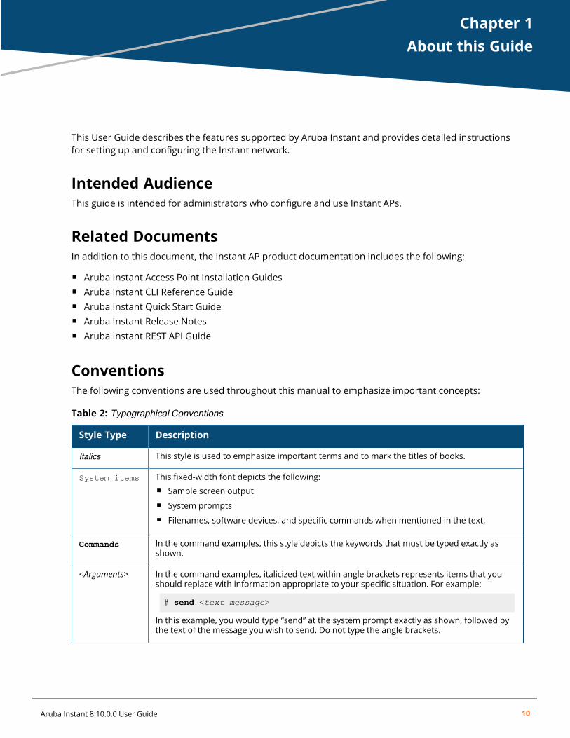
ConventionsThe following conventions are used throughout this manual to emphasize important concepts:
Style Type Description
Italics This style is used to emphasize important terms and to mark the titles of books.
System items This fixed-width font depicts the following:n Sample screen outputn System promptsn Filenames, software devices, and specific commands when mentioned in the text.
Commands In the command examples, this style depicts the keywords that must be typed exactly asshown.
<Arguments> In the command examples, italicized text within angle brackets represents items that youshould replace with information appropriate to your specific situation. For example:
# send <text message>
In this example, you would type “send” at the system prompt exactly as shown, followed bythe text of the message you wish to send. Do not type the angle brackets.
Table 2: Typographical Conventions
Aruba Instant 8.10.0.0 User Guide 10
About this Guide | 11
Style Type Description
[Optional] Command examples enclosed in square brackets are optional. Do not type the squarebrackets.
{Item A |Item B}
In the command examples, items within curly brackets and separated by a vertical barrepresent the available choices. Enter only one choice. Do not type the curly brackets or bars.
Table 2: Typographical Conventions
The following informational icons are used throughout this guide:
Indicates helpful suggestions, pertinent information, and important things to remember.
Indicates a risk of damage to your hardware or loss of data.
Indicates a risk of personal injury or death.
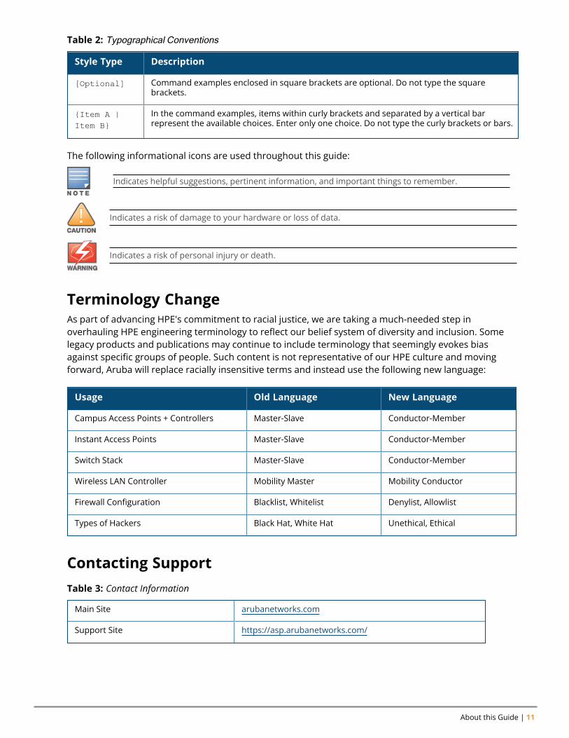
Terminology ChangeAs part of advancing HPE's commitment to racial justice, we are taking a much-needed step inoverhauling HPE engineering terminology to reflect our belief system of diversity and inclusion. Somelegacy products and publications may continue to include terminology that seemingly evokes biasagainst specific groups of people. Such content is not representative of our HPE culture and movingforward, Aruba will replace racially insensitive terms and instead use the following new language:
Usage Old Language New Language
Campus Access Points + Controllers Master-Slave Conductor-Member
Instant Access Points Master-Slave Conductor-Member
Switch Stack Master-Slave Conductor-Member
Wireless LAN Controller Mobility Master Mobility Conductor
Firewall Configuration Blacklist, Whitelist Denylist, Allowlist
Types of Hackers Black Hat, White Hat Unethical, Ethical
Contacting Support
Main Site arubanetworks.com
Support Site https://asp.arubanetworks.com/
Table 3: Contact Information

Aruba Instant 8.10.0.0 User Guide 12
Airheads Social Forums and KnowledgeBase
community.arubanetworks.com
North American Telephone 1-800-943-4526 (Toll Free)1-408-754-1200
International Telephone arubanetworks.com/support-services/contact-support/
Software Licensing Site lms.arubanetworks.com
End-of-life Information arubanetworks.com/support-services/end-of-life/
Security Incident Response Team Site: arubanetworks.com/support-services/security-bulletins/Email: [email protected]
Chapter 2About Aruba Instant
About Aruba InstantThis chapter provides the following information:
n Aruba Instant Overview on page 13n What is New in the Release on page 15
Aruba Instant OverviewAruba Instant virtualizes Aruba Mobility Controller capabilities on 802.1 capable access points creating afeature-rich enterprise-grade WLAN that combines affordability and configuration simplicity.
Instant is a simple, easy to deploy turnkey WLAN solution consisting of one or more Instant APs. AnEthernet port with routable connectivity to the Internet or a self-enclosed network is used for deployingan Instant Wireless Network. An Instant AP can be installed at a single site or deployed across multiplegeographically dispersed locations. Designed specifically for easy deployment and proactivemanagement of networks, Instant is ideal for small customers or remote locations without requiring anyon-site IT administrator.
An Instant AP cluster consists of member Instant APs and a conductor Instant AP in the same VLAN, asthey communicate with broadcast messages. A virtual controller is a combination of the whole cluster,as the member Instant APs and conductor Instant AP coordinate to provide a controllerless Instantsolution. In an Instant deployment scenario, the first Instant AP that comes up becomes the conductorInstant AP. All other Instant APs joining the cluster after that Instant AP, become the member InstantAPs.
In an Instant deployment scenario, only the first Instant AP or the conductor Instant AP needs to beconfigured. The other Instant APs download configurations from the first Instant AP that is configured.The Instant solution constantly monitors the network to determine the Instant AP that must function asa conductor Instant AP at a given time. The conductor Instant AP may change as necessary from oneInstant AP to another without impacting network performance.
Each Instant AP model has a minimum required software version. When a new Instant AP is added intoan existing cluster, it can join the cluster only if the existing cluster is running at least the minimumrequired version of that Instant AP. If the existing cluster is running a version prior to the minimumrequired version of the new Instant AP, the new Instant AP will not come up and may reboot with thereason Image sync fail. To recover from this condition, upgrade the existing cluster to at least theminimum required version of the new Instant AP first, and add the new Instant AP. For moreinformation about supported Instant AP platforms, refer to the Aruba Instant Release Notes.
Aruba recommends that networks with more than 128 Instant APs be designed as multiple, smallervirtual controller networks with Layer-3 mobility enabled between these networks.
Aruba APs are available in the following variants:
n US (United States)n JP (Japan)n IL (Israel)
Aruba Instant 8.10.0.0 User Guide 13
About Aruba Instant | 14
n EG (Egypt)n RW (Rest of the World)
Aruba APs supported with Aruba Instant 8.10.0.x versions are available in all of the variants mentionedabove.
For information on regulatory domains and the list of countries supported by the Instant AP-###-RWtype, see the Specifying Country Code section in Logging in to the Instant UI on page 24.
Instant WebUIThe Instant WebUI provides a standard web-based interface that allows you to configure and monitor aWi-Fi network. Instant is accessible through a standard web browser from a remote managementconsole or workstation and can be launched using the following browsers:
n Microsoft Internet Explorer 11 on Windows 7 and Windows 8n Microsoft Edge (Microsoft Edge 38.14393.0.0 and Microsoft EdgeHTML 14.14393) on Windows 10n Mozilla Firefox 48 or later on Windows 7, Windows 8, Windows 10, and macOSn Apple Safari 8.0 or later on MacOSn Google Chrome 67 or later on Windows 7, Windows 8, Windows 10, and macOS
If the Instant UI is launched through an unsupported browser, a warning message is displayed alongwith a list of recommended browsers. However, the users are allowed to log in using the Continuelogin link on the Login page.
To view the Instant UI, ensure that JavaScript is enabled on the web browser.
The Instant UI logs out automatically if the window is inactive for 15 minutes.
Instant CLIThe Instant CLI is a text-based interface that is accessible through an SSH session.
SSH access requires that you configure an IP address and a default gateway on the Instant AP andconnect the Instant AP to your network. This is typically performed when the Instant network on anInstant AP is set up.
Aruba Instant 8.10.0.0 User Guide 15
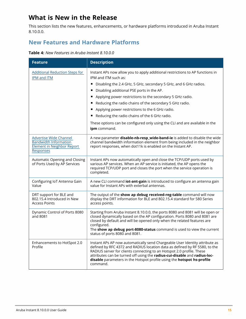
What is New in the ReleaseThis section lists the new features, enhancements, or hardware platforms introduced in Aruba Instant8.10.0.0.
New Features and Hardware Platforms
Feature Description
Additional Reduction Steps forIPM and ITM
Instant APs now allow you to apply additional restrictions to AP functions inIPM and ITM such as:n Disabling the 2.4 GHz, 5 GHz, secondary 5 GHz, and 6 GHz radios.n Disabling additional PSE ports in the AP.n Applying power restrictions to the secondary 5 GHz radio.n Reducing the radio chains of the secondary 5 GHz radio.n Applying power restrictions to the 6 GHz radio.n Reducing the radio chains of the 6 GHz radio.
These options can be configured only using the CLI and are available in theipm command.
Advertise Wide ChannelBandwidth InformationElement in Neighbor ReportResponses
A new parameter disable-nb-resp_wide-band-ie is added to disable the widechannel bandwidth information element from being included in the neighborreport responses, when dot11k is enabled on the Instant AP.
Automatic Opening and Closingof Ports Used by AP Services
Instant APs now automatically open and close the TCP/UDP ports used byvarious AP services. When an AP service is initiated, the AP opens therequired TCP/UDP port and closes the port when the service operation iscompleted.
Configuring IoT Antenna GainValue
A new CLI command iot-ant-gain is introduced to configure an antenna gainvalue for Instant APs with exterbal antennas.
DRT support for BLE and802.15.4 Introduced in NewAccess Points
The output of the show ap debug received-reg-table command will nowdisplay the DRT information for BLE and 802.15.4 standard for 580 Seriesaccess points.
Dynamic Control of Ports 8080and 8081
Starting from Aruba Instant 8.10.0.0, the ports 8080 and 8081 will be open orclosed dynamically based on the AP configuration. Ports 8080 and 8081 areclosed by default and will be opened only when the related features areconfigured.The show ap debug port-8080-status command is used to view the currentstatus of ports 8080 and 8081.
Enhancements to HotSpot 2.0Profile
Instant APs AP now automatically send Chargeable User Identity attribute asdefined by RFC 4372 and RADIUS location data as defined by RF 5580, to theRADIUS server for clients connecting to an Hotspot 2.0 profile. Theseattributes can be turned off using the radius-cui-disable and radius-loc-disable parameters in the Hotspot profile using the hotspot hs-profilecommand.
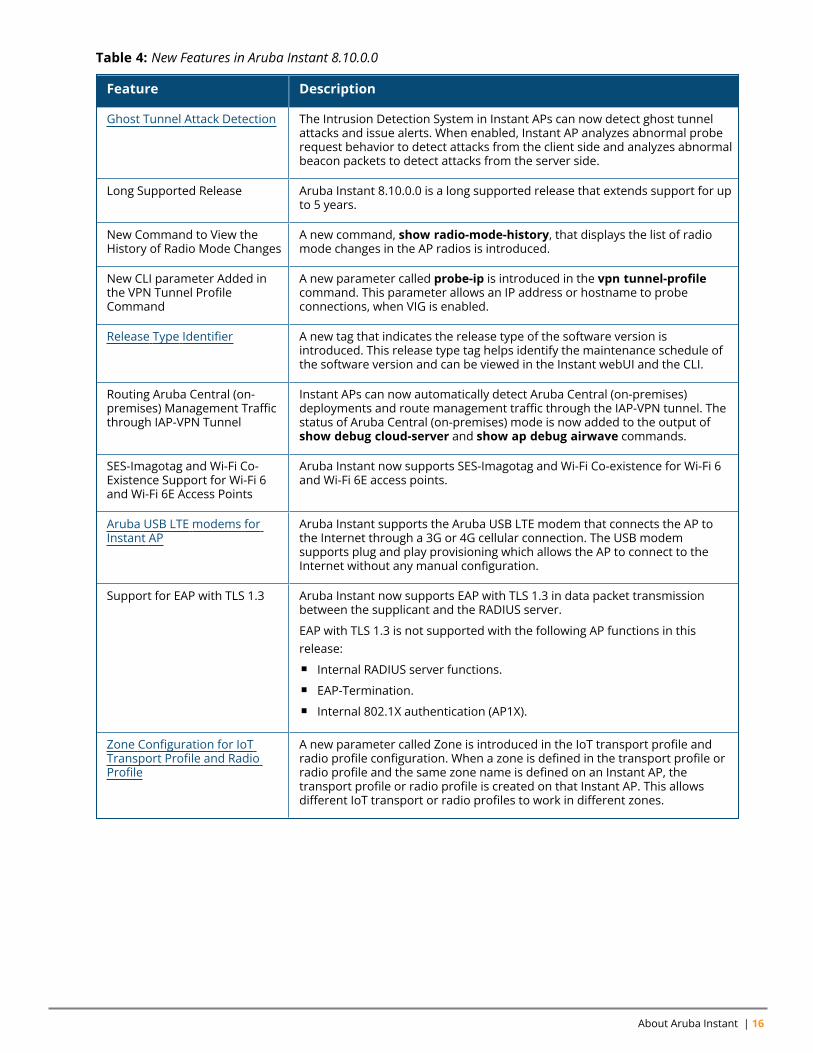
Table 4: New Features in Aruba Instant 8.10.0.0
About Aruba Instant | 16
Feature Description
Ghost Tunnel Attack Detection The Intrusion Detection System in Instant APs can now detect ghost tunnelattacks and issue alerts. When enabled, Instant AP analyzes abnormal proberequest behavior to detect attacks from the client side and analyzes abnormalbeacon packets to detect attacks from the server side.
Long Supported Release Aruba Instant 8.10.0.0 is a long supported release that extends support for upto 5 years.
New Command to View theHistory of Radio Mode Changes
A new command, show radio-mode-history, that displays the list of radiomode changes in the AP radios is introduced.
New CLI parameter Added inthe VPN Tunnel ProfileCommand
A new parameter called probe-ip is introduced in the vpn tunnel-profilecommand. This parameter allows an IP address or hostname to probeconnections, when VIG is enabled.
Release Type Identifier A new tag that indicates the release type of the software version isintroduced. This release type tag helps identify the maintenance schedule ofthe software version and can be viewed in the Instant webUI and the CLI.
Routing Aruba Central (on-premises) Management Trafficthrough IAP-VPN Tunnel
Instant APs can now automatically detect Aruba Central (on-premises)deployments and route management traffic through the IAP-VPN tunnel. Thestatus of Aruba Central (on-premises) mode is now added to the output ofshow debug cloud-server and show ap debug airwave commands.
SES-Imagotag and Wi-Fi Co-Existence Support for Wi-Fi 6and Wi-Fi 6E Access Points
Aruba Instant now supports SES-Imagotag and Wi-Fi Co-existence for Wi-Fi 6and Wi-Fi 6E access points.
Aruba USB LTE modems forInstant AP
Aruba Instant supports the Aruba USB LTE modem that connects the AP tothe Internet through a 3G or 4G cellular connection. The USB modemsupports plug and play provisioning which allows the AP to connect to theInternet without any manual configuration.
Support for EAP with TLS 1.3 Aruba Instant now supports EAP with TLS 1.3 in data packet transmissionbetween the supplicant and the RADIUS server.
EAP with TLS 1.3 is not supported with the following AP functions in thisrelease:n Internal RADIUS server functions.n EAP-Termination.n Internal 802.1X authentication (AP1X).
Zone Configuration for IoTTransport Profile and RadioProfile
A new parameter called Zone is introduced in the IoT transport profile andradio profile configuration. When a zone is defined in the transport profile orradio profile and the same zone name is defined on an Instant AP, thetransport profile or radio profile is created on that Instant AP. This allowsdifferent IoT transport or radio profiles to work in different zones.
Table 4: New Features in Aruba Instant 8.10.0.0
Aruba Instant 8.10.0.0 User Guide 17
Hardware Description
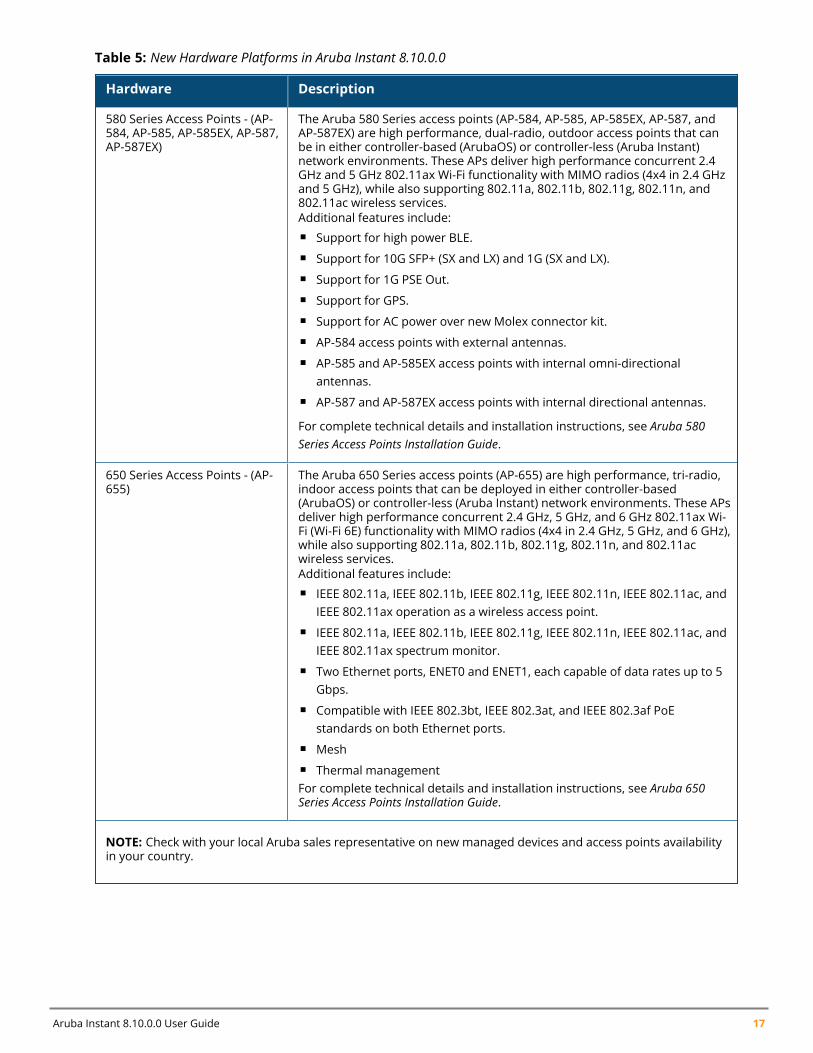
580 Series Access Points - (AP-584, AP-585, AP-585EX, AP-587,AP-587EX)
The Aruba 580 Series access points (AP-584, AP-585, AP-585EX, AP-587, andAP-587EX) are high performance, dual-radio, outdoor access points that canbe in either controller-based (ArubaOS) or controller-less (Aruba Instant)network environments. These APs deliver high performance concurrent 2.4GHz and 5 GHz 802.11ax Wi-Fi functionality with MIMO radios (4x4 in 2.4 GHzand 5 GHz), while also supporting 802.11a, 802.11b, 802.11g, 802.11n, and802.11ac wireless services.Additional features include:n Support for high power BLE.n Support for 10G SFP+ (SX and LX) and 1G (SX and LX).n Support for 1G PSE Out.n Support for GPS.n Support for AC power over new Molex connector kit.n AP-584 access points with external antennas.n AP-585 and AP-585EX access points with internal omni-directional
antennas.n AP-587 and AP-587EX access points with internal directional antennas.
For complete technical details and installation instructions, see Aruba 580Series Access Points Installation Guide.
650 Series Access Points - (AP-655)
The Aruba 650 Series access points (AP-655) are high performance, tri-radio,indoor access points that can be deployed in either controller-based(ArubaOS) or controller-less (Aruba Instant) network environments. These APsdeliver high performance concurrent 2.4 GHz, 5 GHz, and 6 GHz 802.11ax Wi-Fi (Wi-Fi 6E) functionality with MIMO radios (4x4 in 2.4 GHz, 5 GHz, and 6 GHz),while also supporting 802.11a, 802.11b, 802.11g, 802.11n, and 802.11acwireless services.Additional features include:n IEEE 802.11a, IEEE 802.11b, IEEE 802.11g, IEEE 802.11n, IEEE 802.11ac, and
IEEE 802.11ax operation as a wireless access point.n IEEE 802.11a, IEEE 802.11b, IEEE 802.11g, IEEE 802.11n, IEEE 802.11ac, and
IEEE 802.11ax spectrum monitor.n Two Ethernet ports, ENET0 and ENET1, each capable of data rates up to 5
Gbps.n Compatible with IEEE 802.3bt, IEEE 802.3at, and IEEE 802.3af PoE
standards on both Ethernet ports.n Meshn Thermal managementFor complete technical details and installation instructions, see Aruba 650Series Access Points Installation Guide.
NOTE: Check with your local Aruba sales representative on new managed devices and access points availabilityin your country.
Table 5: New Hardware Platforms in Aruba Instant 8.10.0.0
Chapter 3Setting up an Instant AP
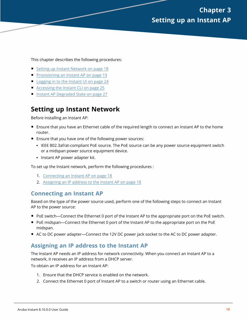
Setting up an Instant APThis chapter describes the following procedures:
n Setting up Instant Network on page 18n Provisioning an Instant AP on page 19n Logging in to the Instant UI on page 24n Accessing the Instant CLI on page 25n Instant AP Degraded State on page 27
Setting up Instant NetworkBefore installing an Instant AP:
n Ensure that you have an Ethernet cable of the required length to connect an Instant AP to the homerouter.
n Ensure that you have one of the following power sources:l IEEE 802.3af/at-compliant PoE source. The PoE source can be any power source equipment switchor a midspan power source equipment device.
l Instant AP power adapter kit.
To set up the Instant network, perform the following procedures :
1. Connecting an Instant AP on page 182. Assigning an IP address to the Instant AP on page 18
Connecting an Instant APBased on the type of the power source used, perform one of the following steps to connect an InstantAP to the power source:
n PoE switch—Connect the Ethernet 0 port of the Instant AP to the appropriate port on the PoE switch.n PoE midspan—Connect the Ethernet 0 port of the Instant AP to the appropriate port on the PoE
midspan.n AC to DC power adapter—Connect the 12V DC power jack socket to the AC to DC power adapter.
Assigning an IP address to the Instant APThe Instant AP needs an IP address for network connectivity. When you connect an Instant AP to anetwork, it receives an IP address from a DHCP server.
To obtain an IP address for an Instant AP:
1. Ensure that the DHCP service is enabled on the network.2. Connect the Ethernet 0 port of Instant AP to a switch or router using an Ethernet cable.
Aruba Instant 8.10.0.0 User Guide 18
Setting up an Instant AP | 19
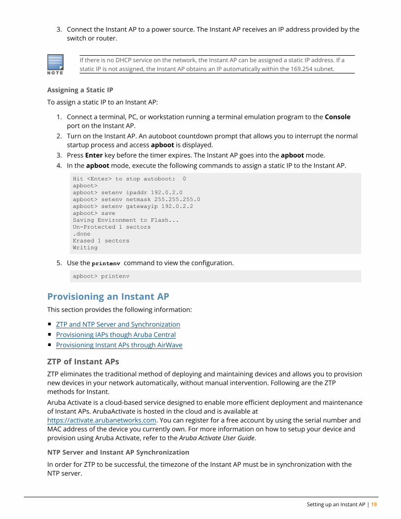
3. Connect the Instant AP to a power source. The Instant AP receives an IP address provided by theswitch or router.
If there is no DHCP service on the network, the Instant AP can be assigned a static IP address. If astatic IP is not assigned, the Instant AP obtains an IP automatically within the 169.254 subnet.
Assigning a Static IP
To assign a static IP to an Instant AP:
1. Connect a terminal, PC, or workstation running a terminal emulation program to the Consoleport on the Instant AP.
2. Turn on the Instant AP. An autoboot countdown prompt that allows you to interrupt the normalstartup process and access apboot is displayed.
3. Press Enter key before the timer expires. The Instant AP goes into the apbootmode.4. In the apbootmode, execute the following commands to assign a static IP to the Instant AP.
Hit <Enter> to stop autoboot: 0apboot>apboot> setenv ipaddr 192.0.2.0apboot> setenv netmask 255.255.255.0apboot> setenv gatewayip 192.0.2.2apboot> saveSaving Environment to Flash...Un-Protected 1 sectors.doneErased 1 sectorsWriting
5. Use the printenv command to view the configuration.
apboot> printenv
Provisioning an Instant APThis section provides the following information:
n ZTP and NTP Server and Synchronizationn Provisioning IAPs though Aruba Centraln Provisioning Instant APs through AirWave
ZTP of Instant APsZTP eliminates the traditional method of deploying and maintaining devices and allows you to provisionnew devices in your network automatically, without manual intervention. Following are the ZTPmethods for Instant.
Aruba Activate is a cloud-based service designed to enable more efficient deployment and maintenanceof Instant APs. ArubaActivate is hosted in the cloud and is available athttps://activate.arubanetworks.com. You can register for a free account by using the serial number andMAC address of the device you currently own. For more information on how to setup your device andprovision using Aruba Activate, refer to the Aruba Activate User Guide.
NTP Server and Instant AP Synchronization
In order for ZTP to be successful, the timezone of the Instant AP must be in synchronization with theNTP server.
Aruba Instant 8.10.0.0 User Guide 20
To facilitate ZTP using the AMP, Central, or Activate, you must configure the firewall and wiredinfrastructure to either allow the NTP traffic to pool.ntp.org, or provide alternative NTP serversunder DHCP options. For more information on configuring an NTP server, see NTP Server.
In a scenario where the NTP server is unreachable, the connection between the Instant AP and Activatewill fall back to the unsecured status. The NTP client process running in the back end will continuouslyattempt to reconnect to the NTP server until a secure connection is established. The NTP client processreceives a response from the NTP server on successfully establishing a connection and notifies theCLI process which runs a series of checks to ensure the NTP server is reachable.
Connecting to a Provisioning Wi-Fi Network
The Instant APs boot with factory default configuration and try to provision automatically. If theautomatic provisioning is successful, the Instant SSID will not be available. If AirWave and Activate arenot reachable and the automatic provisioning fails, the Instant SSID becomes available and the userscan connect to a provisioning network by using the Instant SSID.
To connect to a provisioning Wi-Fi network:
1. Ensure that the client is not connected to any wired network.2. Connect a wireless-enabled client to a provisioning Wi-Fi network: for example, Instant.3. If the Windows operating system is used:
a. Click the wireless network connection icon in the system tray. TheWireless NetworkConnection window is displayed.
b. Click the Instant network and then click Connect.
4. If the Mac operating system is used:
a. Click the AirPort icon. A list of available Wi-Fi networks is displayed.
b. Click the instant network.
The Instant SSIDs are broadcast in 2.4 GHz only.
The provisioning SSID for all APs running Instant 6.5.2.0 onwards, including legacy Instant APs isSetMeUp-xx:xx:xx.
Instant AP Cluster
Instant APs in the same VLAN automatically find each other and form a single functioning networkmanaged by a virtual controller.
Moving anInstant AP from one cluster to another requires a factory reset of the Instant AP.
Disabling the Provisioning Wi-Fi Network
The provisioning network is enabled by default. Instant provides the option to disable the provisioningnetwork through the console port. Use this option only when you do not want the default SSID Instantto be broadcast in your network.
To disable the provisioning network:
Setting up an Instant AP | 21
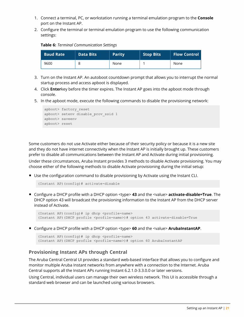
1. Connect a terminal, PC, or workstation running a terminal emulation program to the Consoleport on the Instant AP.
2. Configure the terminal or terminal emulation program to use the following communicationsettings:
Baud Rate Data Bits Parity Stop Bits Flow Control
9600 8 None 1 None
Table 6: Terminal Communication Settings
3. Turn on the Instant AP. An autoboot countdown prompt that allows you to interrupt the normalstartup process and access apboot is displayed.
4. Click Enterkey before the timer expires. The Instant AP goes into the apboot mode throughconsole.
5. In the apboot mode, execute the following commands to disable the provisioning network:
apboot> factory_resetapboot> setenv disable_prov_ssid 1apboot> saveenvapboot> reset
Disabling Activate Communication with Instant AP for Provisioning
Some customers do not use Activate either because of their security policy or because it is a new siteand they do not have internet connectivity when the Instant AP is initially brought up. These customersprefer to disable all communications between the Instant AP and Activate during initial provisioning.
Under these circumstances, Aruba Instant provides 3 methods to disable Activate provisioning. You maychoose either of the following methods to disable Activate provisioning during the initial setup:
n Use the configuration command to disable provisioning by Activate using the Instant CLI.
(Instant AP)(config)# activate-disable
n Configure a DHCP profile with a DHCP option <type> 43 and the <value> activate-disable=True. TheDHCP option 43 will broadcast the provisioning information to the Instant AP from the DHCP serverinstead of Activate.
(Instant AP)(config)# ip dhcp <profile-name>(Instant AP)(DHCP profile <profile-name>)# option 43 activate-disable=True
n Configure a DHCP profile with a DHCP option <type> 60 and the <value> ArubaInstantAP.
(Instant AP)(config)# ip dhcp <profile-name>(Instant AP)(DHCP profile <profile-name>)# option 60 ArubaInstantAP
Provisioning Instant APs through CentralThe Aruba Central Central UI provides a standard web-based interface that allows you to configure andmonitor multiple Aruba Instant networks from anywhere with a connection to the Internet. ArubaCentral supports all the Instant APs running Instant 6.2.1.0-3.3.0.0 or later versions.
Using Central, individual users can manage their own wireless network. This UI is accessible through astandard web browser and can be launched using various browsers.
Aruba Instant 8.10.0.0 User Guide 22
Central supports automatic ZTP and manual provisioning. There are three different methods of manualprovisioning.
n By providing the Activate credentials of the customer.n By providing cloud activation key and MAC address of the Instant AP.n By providing the serial number and MAC address of the Instant AP.
For provisioning Instant APs through Central, the Instant APs must obtain the cloud activation key.
Prerequisites for Obtaining the Cloud Activation Key
To ensure that the Instant APs obtain the cloud activation key from the Aruba Activate server, performthe following checks:
n The serial number or the MAC address of the Instant AP is registered in the Activate database.n The Instant AP is operational and is able to connect to the Internet.n Instant AP has received a DNS server address through DHCP or static configuration.n Instant AP is able to configure time zone using an NTP server.n The required firewall ports are open. Most of the communication between devices on the remote site
and the Central server in the cloud is carried out through HTTPS (TCP 443). However, you may needto configure the following ports:l TCP port 443 for configuration and management of devices.l TCP port 80 for image upgrade.l UDP port 123 for NTP server to configure timezone when factory default Instant AP comes up.l TCP port 2083 for RADIUS authentication for guest management. If 2083 port is blocked, the HTTPSprotocol is used.
If a cloud activation key is not obtained, perform the following checks:
n If the Instant AP IP address is assigned from the DHCP server, ensure that the DNS server isconfigured.
n If the Instant AP is assigned a static IP address, manually configure the DNS server IP address. Formore information, see Specifying a Method for Obtaining IP Address.
Viewing the Cloud Activation Key Using the Old WebUI
If Instant AP has already obtained the activation key, complete the following steps:
1. Connect to the Instant SSID and type http://instant.arubanetworks.com in the web browser.2. Log in to the website by using the default username admin and the default password which is the
Serial Number of the Instant AP.3. In the Instant AP WebUI, navigate toMaintenance > About and copy the cloud activation key.4. To view the MAC address of the conductor Instant AP, click the device name under the Access
Points tab of the main window. The MAC address will be displayed in the Info section.
Viewing the Cloud Activation Key Using the New WebUI
If Instant AP has already obtained the activation key, complete the following steps:
1. Connect to the Instant SSID and type http://instant.arubanetworks.com in the web browser.2. Log in to the website by using the default username admin and the default password which is the
Serial Number of the Instant AP.
Setting up an Instant AP | 23
3. In the Instant AP WebUI, navigate toMaintenance > About. You can view the cloud activationkey in the Cloud Activation Key field.
4. To view the MAC address of the conductor Instant AP, navigate to Dashboard > Overview andselect the device from the Dashboard > Access Points. The MAC address will be displayed underOverview > Info. Alternatively, go to Dashboard > Access Points and select the device from thelist of Access Points. The MAC address will be displayed under Overview > Info.
You can also check the cloud activation key of an Instant AP by running the show about and showactivate status commands. For more information on these commands, refer to the Aruba InstantCLI Reference Guide.
If the Instant AP is deployed in the cluster mode, the member Instant APs do not obtain theactivation key. You must use the cloud activation key and MAC address of the conductor Instant APfor provisioning through Central.
Support for Alternate Image Server When Provisioning an Instant AP
AP provisioning is either done through a mandatory upgrade or image sync through Aruba Activate.Typically, Aruba Activate returns the default image URL as a HTTPS body payload, and the AP uses thisURL to download and upgrade the image. However, in some scenarios, the default URL returned byAruba Activate can be unreachable, because users configure a firewall that only allow specific URLs orstatic IP addresses; but the default URL is served with a dynamic IP address. Starting from Aruba Instant8.9.0.0, Instant introduces an alternative image URL service function which supplies a reachable imageURL from the cache list when the conductor or member APs report a mismatch. The AP will then use thereachable image URL to download the image and provision the AP.
Provisioning AP1X Certificates through Aruba Central or AirWave
Aruba Instant supports provisioning of AP1X certificates through AirWave or Central. A common AP1Xcertificate can now be applied to all Instant APs in the cluster by executing the following CLI command:
(Instant AP)(config) # wlan cert-assignment-profile(Instant AP) (cert assignment) # pki-cert-assign application ap1x cert-type TrustedCAcertname <cert_name>
If an AP1X common cert already exists in the Instant AP and needs to be replaced with a per-deviceAP1X certificate, you must first remove the common cert uploaded through Central or AirWave andthen re-upload the per-device cert. This is because the common certificate has a higher priority thanthe per-device certificate, the per-device cert will not be used if the common is removed.
The following CLI commands are used to remove the common AP1X CA certificate installed throughAirWave or Central:
(Instant AP)# clear-cert ap1x-common-cert(Instant AP)# clear-cert ap1x-common-ca
Provisioning Instant APs through AirWaveAirWave is a powerful platform and easy-to-use network operations system that manages Arubawireless, wired, and remote access networks, as well as wired and wireless infrastructures from a widerange of third-party manufacturers. With its easy-to-use interface, AirWave provides real-timemonitoring, proactive alerts, historical reporting, as well as fast and efficient troubleshooting. It alsooffers tools that manage RF coverage, strengthen wireless security, and demonstrate regulatorycompliance.
Aruba Instant 8.10.0.0 User Guide 24
For information on provisioning Instant APs through AirWave, refer to the AirWave Deployment Guide.
Logging in to the Instant UILaunch a web browser and enter http://instant.arubanetworks.com. In the login screen, enter thefollowing credentials:
n Username—adminn Password—Enter the Serial Number of the Instant AP
When you use a provisioning Wi-Fi network to connect to the Internet, all browser requests are directedto the Instant UI. For example, if you enter www.example.com in the address bar, you are directed tothe Instant UI. You can change the default login credentials after the first login.
If an Instant AP does not obtain an IP address, it assigns itself 169.x.x.x as the IP address. In thiscase, DNS requests from clients on a provisioning SSID will not receive a response because of lack ofnetwork connectivity. Hence, automatic redirection to the Instant UI instant.arubanetworks.com willfail. In such a case, you must manually open instant.arubanetworks.com on your browser to accessthe Instant WebUI.
Regulatory DomainsThe IEEE 802.11, 802.11b, 802.11g, or 802.11n Wi-Fi networks operate in the 2.4 GHz spectrum and IEEE802.11a or 802.11n operate in the 5 GHz spectrum. The spectrum is divided into channels. The 2.4 GHzspectrum is divided into 14 overlapping, staggered 20 MHz wireless carrier channels. These channelsare spaced 5 MHz apart. The 5 GHz spectrum is divided into more channels. The channels that can beused in a particular country vary based on the regulations of that country.
The initial Wi-Fi setup requires you to specify the country code for the country in which the Instant APoperates. This configuration sets the regulatory domain for the radio frequencies that the Instant APsuse. Within the regulated transmission spectrum, a HT 802.11ac, 802.11a, 802.11b, 802.11g, or 802.11nradio setting can be configured. The available 20 MHz, 40 MHz, or 80 MHz channels are dependent onthe specified country code.
You cannot change a country code for Instant APs in regulatory domains such as Japan and Israel.However, for Instant AP-US and Instant AP-RW variants, you can select from the list of supportedregulatory domains. If the supported country code is not in the list, contact your Aruba Support team toknow if the required country code is supported and obtain the software that supports the requiredcountry code.
Improper country code assignments can disrupt wireless transmissions. Most countries imposepenalties and sanctions on operators of wireless networks with devices set to improper countrycodes.
To view the country code information, run the show country-codes command.
Specifying Country CodeThe Country Code window is displayed for the Instant AP-US and Instant AP-RW variants when youlogin to the Instant AP UI for the first time. The Please Specify the Country Code drop-down listdisplays only the supported country codes. If the Instant AP cluster consists of multiple Instant APplatforms, the country codes supported by the conductor Instant AP is displayed for all other Instant
Setting up an Instant AP | 25
APs in the cluster. Select a country code from the list and click OK. The Instant AP operates in theselected country code domain.
Country code once set, cannot be changed in the Instant UI. It can be changed only by using thevirtual-controller-country command in the Instant CLI.
Member Instant APs obtain country code configuration settings from the conductor Instant AP.
You can also view the list of supported country codes for the Instant AP-US and Instant AP-RW variantsby using the show country-codes command.
Accessing the Instant CLIInstant supports the use of CLI for scripting purposes. When you make configuration changes on aconductor Instant AP in the CLI, all associated Instant APs in the cluster inherit these changes andsubsequently update their configurations. By default, you can access the CLI from the serial port orfrom an SSH session. You must explicitly enable Telnet access on the Instant AP to access the CLIthrough a Telnet session.
For information on enabling SSH and Telnet access to the Instant AP CLI, see Terminal access on page48.
Connecting to a CLI SessionOn connecting to a CLI session, the system displays its host name followed by the login prompt. Use theadministrator credentials to start a CLI session. For example:
Username: admin
If the login is successful, the privileged command mode is enabled and a command prompt is displayed.For example:
(Instant AP)#
The privileged EXEC mode provides access to show, clear, ping, traceroute, and commit commands.The configuration commands are available in the config mode. To move from Privileged EXEC mode tothe Configuration mode, enter the following command at the command prompt:
(Instant AP)# configure terminal
The configure terminal command allows you to enter the basic configuration mode and the commandprompt is displayed as follows:
(Instant AP)(config)#
The Instant CLI allows CLI scripting in several other subcommand modes to allow the users to configureindividual interfaces, SSIDs, access rules, and security settings.
You can use the question mark (?) to view the commands available in a privileged EXEC mode,configuration mode, or subcommand mode.
Although automatic completion is supported for some commands such as configure terminal, thecomplete exit and end commands must be entered at command prompt.
Applying Configuration Changes
Aruba Instant 8.10.0.0 User Guide 26
Each command processed by the virtual controller is applied on all the members in a cluster. Thechanges configured in a CLI session are saved in the CLI context. The CLI does not support theconfiguration data exceeding the 4K buffer size in a CLI session. Therefore, it is recommended that youconfigure fewer changes at a time and apply the changes at regular intervals.
To apply and save the configuration changes at regular intervals, execute the following command in theprivileged EXEC mode:
(Instant AP)# commit apply
To apply the configuration changes to the cluster without saving the configuration, execute the followingcommand in the privileged EXEC mode:
(Instant AP)# commit apply no-save
To view the changes that are yet to be applied, execute the following command in the privileged EXECmode:
(Instant AP)# show uncommitted-config
To revert to the earlier configuration, execute the following command in the privileged EXEC mode.
(Instant AP)# commit revert
Example:
To apply and view the configuration changes:
(Instant AP)(config)# rf dot11a-radio-profile
(Instant AP)# show uncommitted-config
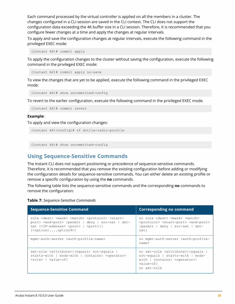
Using Sequence-Sensitive CommandsThe Instant CLI does not support positioning or precedence of sequence-sensitive commands.Therefore, it is recommended that you remove the existing configuration before adding or modifyingthe configuration details for sequence-sensitive commands. You can either delete an existing profile orremove a specific configuration by using the no commands.
The following table lists the sequence-sensitive commands and the corresponding no commands toremove the configuration:
Sequence-Sensitive Command Corresponding no command
rule <dest> <mask> <match> <protocol> <start-port> <end-port> {permit | deny | src-nat | dst-nat {<IP-address> <port> | <port>}}[<option1....option9>]
no rule <dest> <mask> <match><protocol> <start-port> <end-port>{permit | deny | src-nat | dst-nat}
mgmt-auth-server <auth-profile-name> no mgmt-auth-server <auth-profile-name>
set-role <attribute>{{equals| not-equals |starts-with | ends-with | contains} <operator><role> | value-of}
no set-role <attribute>{{equals |not-equals | starts-with | ends-with | contains} <operator>|value-of}no set-role
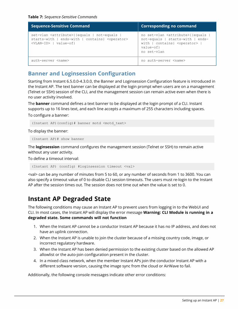
Table 7: Sequence-Sensitive Commands
Setting up an Instant AP | 27
Sequence-Sensitive Command Corresponding no command
set-vlan <attribute>{{equals | not-equals |starts-with | ends-with | contains} <operator><VLAN-ID> | value-of}
no set-vlan <attribute>{{equals |not-equals | starts-with | ends-with | contains} <operator> |value-of}no set-vlan
auth-server <name> no auth-server <name>
Table 7: Sequence-Sensitive Commands
Banner and Loginsession ConfigurationStarting from Instant 6.5.0.0-4.3.0.0, the Banner and Loginsession Configuration feature is introduced inthe Instant AP. The text banner can be displayed at the login prompt when users are on a management(Telnet or SSH) session of the CLI, and the management session can remain active even when there isno user activity involved.
The banner command defines a text banner to be displayed at the login prompt of a CLI. Instantsupports up to 16 lines text, and each line accepts a maximum of 255 characters including spaces.
To configure a banner:
(Instant AP)(config)# banner motd <motd_text>
To display the banner:
(Instant AP)# show banner
The loginsession command configures the management session (Telnet or SSH) to remain activewithout any user activity.
To define a timeout interval:
(Instant AP) (config) #loginsession timeout <val>
<val> can be any number of minutes from 5 to 60, or any number of seconds from 1 to 3600. You canalso specify a timeout value of 0 to disable CLI session timeouts. The users must re-login to the InstantAP after the session times out. The session does not time out when the value is set to 0.
Instant AP Degraded StateThe following conditions may cause an Instant AP to prevent users from logging in to the WebUI andCLI. In most cases, the Instant AP will display the error messageWarning: CLI Module is running in adegraded state. Some commands will not function
1. When the Instant AP cannot be a conductor Instant AP because it has no IP address, and does nothave an uplink connection.
2. When the Instant AP is unable to join the cluster because of a missing country code, image, orincorrect regulatory hardware.
3. When the Instant AP has been denied permission to the existing cluster based on the allowed APallowlist or the auto-join configuration present in the cluster.
4. In a mixed class network, when the member Instant APs join the conductor Instant AP with adifferent software version, causing the image sync from the cloud or AirWave to fail.
Additionally, the following console messages indicate other error conditions:

Aruba Instant 8.10.0.0 User Guide 28
n 4-0 Authentication server failure: Incorrect username or password.n 5-0 Authentication server timeout - no response from RADIUS server.n 7-0: Indicates PAPI errors within the Instant AP. The Instant AP log messages provide details on
the error condition. Consult Aruba Technical Support for further assistance.n 8-0: Indicates an authentication failure or an incomplete synchronization of a swarm
configuration.
An example of one of the above mentioned console messages is Internal error 7-0, please contactsupport.
Chapter 4Automatic Retrieval of Configuration
Automatic Retrieval of ConfigurationThis chapter provides the following information:
n Managed Mode Operations on page 29n Prerequisites on page 29n Configuring Managed Mode Parameters on page 29n Verifying the Configuration on page 31
Managed Mode OperationsInstant APs support managed mode operations to retrieve the configuration file from a server throughthe FTP or FTPS, and automatically update the Instant AP configuration.
The server details for retrieving configuration files are stored in the basic configuration of the InstantAPs. The basic configuration of an Instant AP includes settings specific to an Instant AP, for example,host name, static IP, and radio configuration settings. When an Instant AP boots up, it performs a GEToperation to retrieve the configuration (.cfg) file from the associated server using the specified downloadmethod.
After the initial configuration is applied to the Instant APs, the configuration can be changed at anypoint. You can configure a polling mechanism to fetch the latest configuration by using an FTP or FTPSclient periodically. If the remote configuration is different from the one running on the Instant AP and ifa difference in the configuration file is detected by the Instant AP, the new configuration is applied. Atany given time, Instant APs can fetch only one configuration file, which may include the configurationdetails specific to an Instant AP. For configuring polling mechanism and downloading configuration files,the users are required to provide credentials (username and password). However, if automatic mode isenabled, the user credentials required to fetch the configuration file are automatically generated. Toenable automatic configuration of the Instant APs, configure the managed mode command parameters.
PrerequisitesPerform the following checks before configuring the managed mode command parameters:
n Ensure that the Instant AP is running Instant 6.2.1.0-3.4 or later versions.n When the Instant APs are in the managed mode, ensure that the Instant APs are not managed by
AirWave.
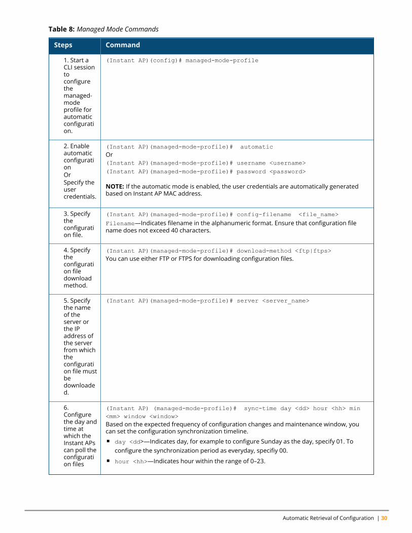
Configuring Managed Mode ParametersTo enable the automatic configuration, perform the steps described in the following table:
Aruba Instant 8.10.0.0 User Guide 29
Automatic Retrieval of Configuration | 30
Steps Command
1. Start aCLI sessiontoconfigurethemanaged-modeprofile forautomaticconfiguration.
(Instant AP)(config)# managed-mode-profile
2. EnableautomaticconfigurationOrSpecify theusercredentials.
(Instant AP)(managed-mode-profile)# automaticOr(Instant AP)(managed-mode-profile)# username <username>(Instant AP)(managed-mode-profile)# password <password>
NOTE: If the automatic mode is enabled, the user credentials are automatically generatedbased on Instant AP MAC address.
3. Specifytheconfiguration file.
(Instant AP)(managed-mode-profile)# config-filename <file_name>
Filename—Indicates filename in the alphanumeric format. Ensure that configuration filename does not exceed 40 characters.
4. Specifytheconfiguration filedownloadmethod.
(Instant AP)(managed-mode-profile)# download-method <ftp|ftps>You can use either FTP or FTPS for downloading configuration files.
5. Specifythe nameof theserver orthe IPaddress ofthe serverfrom whichtheconfiguration file mustbedownloaded.
(Instant AP)(managed-mode-profile)# server <server_name>
6.Configurethe day andtime atwhich theInstant APscan poll theconfiguration files
(Instant AP) (managed-mode-profile)# sync-time day <dd> hour <hh> min<mm> window <window>Based on the expected frequency of configuration changes and maintenance window, youcan set the configuration synchronization timeline.n day <dd>—Indicates day, for example to configure Sunday as the day, specify 01. To
configure the synchronization period as everyday, specifiy 00.n hour <hh>—Indicates hour within the range of 0–23.
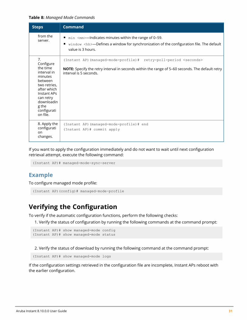
Table 8: Managed Mode Commands
Aruba Instant 8.10.0.0 User Guide 31
Steps Command
from theserver.
n min <mm>—Indicates minutes within the range of 0–59.n window <hh>—Defines a window for synchronization of the configuration file. The default
value is 3 hours.
7.Configurethe timeinterval inminutesbetweentwo retries,after whichInstant APscan retrydownloading theconfiguration file.
(Instant AP)(managed-mode-profile)# retry-poll-period <seconds>
NOTE: Specify the retry interval in seconds within the range of 5–60 seconds. The default retryinterval is 5 seconds.
8. Apply theconfigurationchanges.
(Instant AP)(managed-mode-profile)# end(Instant AP)# commit apply
Table 8: Managed Mode Commands
If you want to apply the configuration immediately and do not want to wait until next configurationretrieval attempt, execute the following command:
(Instant AP)# managed-mode-sync-server
ExampleTo configure managed mode profile:
(Instant AP)(config)# managed-mode-profile
Verifying the ConfigurationTo verify if the automatic configuration functions, perform the following checks:
1. Verify the status of configuration by running the following commands at the command prompt:
(Instant AP)# show managed-mode config(Instant AP)# show managed-mode status
2. Verify the status of download by running the following command at the command prompt:
(Instant AP)# show managed-mode logs
If the configuration settings retrieved in the configuration file are incomplete, Instant APs reboot withthe earlier configuration.
Chapter 5Instant New User Interface
Instant New User InterfaceThis chapter describes the following sections:
n Login Screen on page 32n Home Page on page 32
Login ScreenThe Instant login page allows you to perform the following tasks:
n View Instant Network Connectivity summaryn View the WebUI in a specific languagen Log in to the WebUI
Viewing Connectivity SummaryThe login page also displays the connectivity status to the Instant network. The users can view asummary that indicates the status of the Internet availability, uplink, cellular modem and signal strength,VPN, and AirWave configuration details before logging in to the WebUI.
LanguageThe Language drop-down list contains the available languages and allows users to select their preferredlanguage before logging in to the WebUI. A default language is selected based on the languagepreferences in the client desktop operating system or browser. If Instant cannot detect the language,then English is used as the default language.
You can also select the required language option from the Languages drop-down list located on theInstant main window.
Logging into the WebUITo log in to the WebUI, enter the following credentials:
n Username—adminn Password—Enter the Serial Number of the Instant AP.
If the Instant AP is currently operating in FIPS mode, the login credentials are Username: adminPassword: admindefault.
The WebUI main window is displayed.
When you log in to an Instant AP with the factory default settings, a popup box displays an option to signup for the Aruba cloud solution and enable Instant AP management through Central. To sign up for afree 90-day trial of Central, click here.
Home Page
Aruba Instant 8.10.0.0 User Guide 32
Instant New User Interface | 33
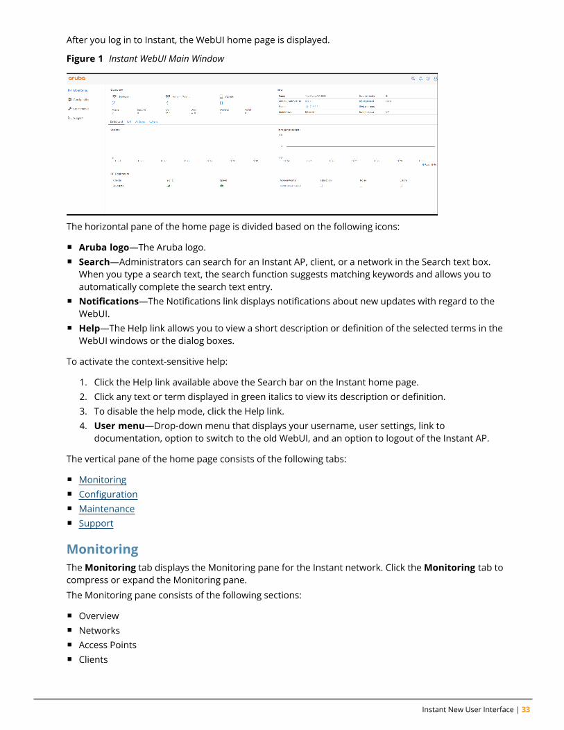
After you log in to Instant, the WebUI home page is displayed.
Figure 1 Instant WebUI Main Window
The horizontal pane of the home page is divided based on the following icons:
n Aruba logo—The Aruba logo.n Search—Administrators can search for an Instant AP, client, or a network in the Search text box.
When you type a search text, the search function suggests matching keywords and allows you toautomatically complete the search text entry.
n Notifications—The Notifications link displays notifications about new updates with regard to theWebUI.
n Help—The Help link allows you to view a short description or definition of the selected terms in theWebUI windows or the dialog boxes.
To activate the context-sensitive help:
1. Click the Help link available above the Search bar on the Instant home page.2. Click any text or term displayed in green italics to view its description or definition.3. To disable the help mode, click the Help link.4. User menu—Drop-down menu that displays your username, user settings, link to
documentation, option to switch to the old WebUI, and an option to logout of the Instant AP.
The vertical pane of the home page consists of the following tabs:
n Monitoringn Configurationn Maintenancen Support
MonitoringTheMonitoring tab displays the Monitoring pane for the Instant network. Click theMonitoring tab tocompress or expand the Monitoring pane.
The Monitoring pane consists of the following sections:
n Overviewn Networksn Access Pointsn Clients
Aruba Instant 8.10.0.0 User Guide 34
OverviewThis section displays the following sections:
n Overview—This section displays the number of configured networks, access points, and clientsn Info—This section displays information about the access point name, country code, virtual controller
IP address, management, conductor Instant AP IP address, IPv6 address, uplink type, and uplinkstatus.
n Clients—The Clients graph displays the number of clients that were associated with the virtualcontroller in the last 15 minutes.
n Throughput—The Throughput Graph shows the throughput of the selected client for the last 15minutes.l Out—Throughput for the outgoing traffic is displayed in blue.l In—Throughput for the incoming traffic is displayed in orange. To see an enlarged view, click thegraph. To see the exact throughput at a particular time, move the cursor over the graph line.
n RF Dashboard—This section displays the Instant APs that exceed the utilization, noise, or errorthreshold. It also shows the clients with low speed or signal strength in the network and the RFinformation for the Instant AP to which the client is connected.
The Instant AP names are displayed as links. When an Instant AP is clicked, the Instant AP configurationinformation is displayed on the Instant home page.
The following table describes the parameters available on the RF Dashboard pane:
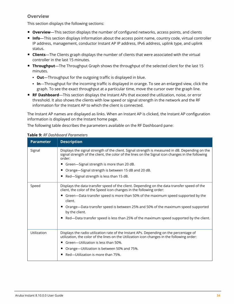
Parameter Description
Signal Displays the signal strength of the client. Signal strength is measured in dB. Depending on thesignal strength of the client, the color of the lines on the Signal icon changes in the followingorder:n Green—Signal strength is more than 20 dB.n Orange—Signal strength is between 15 dB and 20 dB.n Red—Signal strength is less than 15 dB.
Speed Displays the data transfer speed of the client. Depending on the data transfer speed of theclient, the color of the Speed icon changes in the following order:n Green—Data transfer speed is more than 50% of the maximum speed supported by the
client.n Orange—Data transfer speed is between 25% and 50% of the maximum speed supported
by the client.n Red—Data transfer speed is less than 25% of the maximum speed supported by the client.
Utilization Displays the radio utilization rate of the Instant APs. Depending on the percentage ofutilization, the color of the lines on the Utilization icon changes in the following order:n Green—Utilization is less than 50%.n Orange—Utilization is between 50% and 75%.n Red—Utilization is more than 75%.
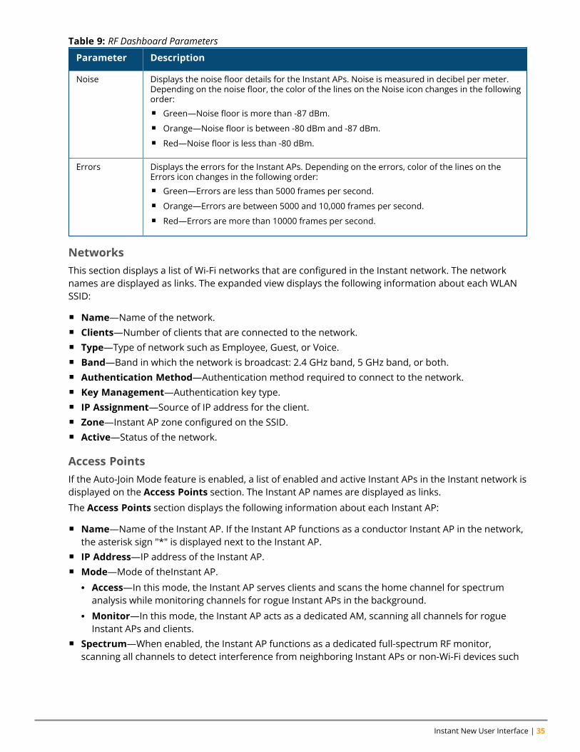
Table 9: RF Dashboard Parameters
Instant New User Interface | 35
Parameter Description
Noise Displays the noise floor details for the Instant APs. Noise is measured in decibel per meter.Depending on the noise floor, the color of the lines on the Noise icon changes in the followingorder:n Green—Noise floor is more than -87 dBm.n Orange—Noise floor is between -80 dBm and -87 dBm.n Red—Noise floor is less than -80 dBm.
Errors Displays the errors for the Instant APs. Depending on the errors, color of the lines on theErrors icon changes in the following order:n Green—Errors are less than 5000 frames per second.n Orange—Errors are between 5000 and 10,000 frames per second.n Red—Errors are more than 10000 frames per second.
Table 9: RF Dashboard Parameters
NetworksThis section displays a list of Wi-Fi networks that are configured in the Instant network. The networknames are displayed as links. The expanded view displays the following information about each WLANSSID:
n Name—Name of the network.n Clients—Number of clients that are connected to the network.n Type—Type of network such as Employee, Guest, or Voice.n Band—Band in which the network is broadcast: 2.4 GHz band, 5 GHz band, or both.n Authentication Method—Authentication method required to connect to the network.n Key Management—Authentication key type.n IP Assignment—Source of IP address for the client.n Zone—Instant AP zone configured on the SSID.n Active—Status of the network.
Access PointsIf the Auto-Join Mode feature is enabled, a list of enabled and active Instant APs in the Instant network isdisplayed on the Access Points section. The Instant AP names are displayed as links.
The Access Points section displays the following information about each Instant AP:
n Name—Name of the Instant AP. If the Instant AP functions as a conductor Instant AP in the network,the asterisk sign "*" is displayed next to the Instant AP.
n IP Address—IP address of the Instant AP.n Mode—Mode of theInstant AP.
l Access—In this mode, the Instant AP serves clients and scans the home channel for spectrumanalysis while monitoring channels for rogue Instant APs in the background.
l Monitor—In this mode, the Instant AP acts as a dedicated AM, scanning all channels for rogueInstant APs and clients.
n Spectrum—When enabled, the Instant AP functions as a dedicated full-spectrum RF monitor,scanning all channels to detect interference from neighboring Instant APs or non-Wi-Fi devices such
Aruba Instant 8.10.0.0 User Guide 36
as microwaves and cordless phones. When Spectrum is enabled, the Instant AP does not provideaccess services to clients.
n Clients—Number of clients that are currently associated to the Instant AP.n Type—Model number of the Instant AP.n Mesh Role—Role of the Instant AP as a mesh portal or mesh point.n Zone—Instant AP zone.n Serial number—Serial number of the device.
ClientsThis section displays a list of clients that are connected to the Instant network. The client names aredisplayed as links. The client view displays the following information about each client:
n Name—User name of the client or guest users if available.n IP Address—IP address of the client.n MAC address—MAC address of the client.n OS—Operating system that runs on the client.n ESSID—ESSID to which the client is connected.n Access Point—Instant AP to which the client is connected.n Channel—The client operating channel.n Type—Type of the Wi-Fi client.n Role—Role assigned to the client.n IPv6 Address—IPv6 address assigned to the client.n Signal—Current signal strength of the client, as detected by the Instant AP.n Speed (Mbps)—Current speed at which data is transmitted. When the client is associated with an
Instant AP, it constantly negotiates the speed of data transfer. A value of 0 means that the Instant APhas not heard from the client for some time.
ConfigurationThe following configurations allow you to configure various features for the Instant network:
n Networksn Access Pointsn Systemn RFn Securityn IDSn Routingn Tunnelingn Servicesn DHCP Server
NetworksThe Networks section displays the following tabs:
Instant New User Interface | 37
n Name—Displays the name of a WLAN or a wired network profile.n Type—Shows whether the configured network profile is a WLAN or a wired profile.n Clients—Shows the number of clients associated with the network profile.
You can add, edit, or delete a network profile by clicking the corresponding icons.
Access PointsThe Access Points section displays the following tabs:
n Name—Name of the Instant AP. If the Instant AP functions as a conductor Instant AP in the network,the asterisk sign "*" is displayed next to the Instant AP.
n IP Address—IP address of the Instant AP.n Mode—Mode of theInstant AP.
l Access—In this mode, the Instant AP serves clients and scans the home channel for spectrumanalysis while monitoring channels for rogue Instant APs in the background.
l Monitor—In this mode, the Instant AP acts as a dedicated AM, scanning all channels for rogueInstant APs and clients.
n Spectrum—When enabled, the Instant AP functions as a dedicated full-spectrum RF monitor,scanning all channels to detect interference from neighboring Instant APs or non-Wi-Fi devices suchas microwaves and cordless phones. When Spectrum is enabled, the Instant AP does not provideaccess services to clients.
n Clients—Number of clients that are currently associated to the Instant AP.n Type—Model number of the Instant AP.n Mesh Role—Role of the Instant AP as a mesh portal or mesh point.n Zone—Instant AP zone.n Serial number—Serial number of the device.
To edit a network profile, select the access point.
SystemThis System section displays the following tabs:
Use the Show/Hide Advanced option of the System window to view or hide the advanced options.
The System section displays the following tabs:
n General—Allows you to configure, view, or edit the Name, IP address, NTP Server, and other InstantAP settings for the virtual controller.
n Admin—Allows you to configure administrator credentials for access to the virtual controllermanagement UI. You can also configure AirWave in this tab. For more information on managementinterface and AirWave configuration, see Overview of Instant AP Users on page 170 and Managing anInstant AP from AirWave on page 430, respectively.
n Uplink—Allows you to view or configure uplink settings. See Uplink Configuration on page 445 formore information.
n L3 Mobility—Allows you to view or configure the Layer-3 mobility settings. See Configuring Layer-3Mobility on page 481 for more information.
Aruba Instant 8.10.0.0 User Guide 38
n Monitoring—Allows you to view or configure the following details:l Syslog—Allows you to view or configure Syslog server details for sending syslog messages to theexternal servers. See Configuring Syslog Servers on page 506 for more information.
l TFTP Dump—Allows you to view or configure a TFTP dump server for core dump files. SeeConfiguring TFTP Dump Server on page 507 for more information.
l SNMP—Allows you to view or configure SNMP agent settings. See Configuring SNMP on page 503for more information.
n WISPr—Allows you to view or configure the WISPr settings. See WISPr Authentication on page 182 formore information.
n Proxy—Allows you to configure HTTP proxy on anInstant AP. Refer to the ArubaInstant Release Notesfor more information.
n Time Based Services—Allows you to configure a time profile which can be assigned to theSSID configured on the Instant AP. See Configuring Time-Based Services on page 265
RFThe RF section displays a window for configuring ARM and Radio features.
n ARM—Allows you to view or configure channel and power settings for all the Instant APs in thenetwork. For information on ARM configuration, see ARM Overview on page 361.
n Radio—Allows you to view or configure radio settings for 2.4 GHz and the 5 GHz radio profiles. Forinformation on Radio, see Configuring Radio Profiles on page 368.
SecurityThe Security section displays a window with the following tabs:
n Authentication Servers—Use this tab to configure an external RADIUS server for a wirelessnetwork. For more information, see Configuring an External Server for Authentication on page 192.
n Users—Use this tab to populate the system’s internal authentication server with users. This list isused by networks for which per-user authorization is specified using the internal authenticationserver of the virtual controller. For more information on users, see Overview of Instant AP Users onpage 170.
n Roles —Use this tab to view the roles defined for all the Networks. The Access Rules part allows youto configure permissions for each role. For more information, see Configuring User Roles on page234 and Configuring ACL Rules for Network Services on page 220.
n Denylisting—Use this tab to denylist clients. For more information, see Denylisting Clients on page211.
n Firewall Settings—Use this tab to enable or disable ALG supporting address and port translation forvarious protocols and to configure protection against wired attacks. For more information, seeConfiguring ALG Protocols on page 225 and Configuring Firewall Settings for Protection from ARPAttacks on page 226
n Inbound Firewall—Use this tab to enhance the inbound firewall by allowing the configuration ofinbound firewall rules, management subnets, and restricted corporate access through an uplinkswitch. For more information, see Managing Inbound Traffic on page 227.
n External Captive Portal—Use this tab to configure external captive portal profiles. For moreinformation, see Configuring External Captive Portal for a Guest Network on page 154.
n Custom Blocked Page URL—Use this tab to create a list of URLs that can be blocked using an ACLrule. For more information, see Creating Custom Error Page for Web Access Blocked by AppRFPolicies on page 233.
Instant New User Interface | 39
IDSThe IDS section displays a list of foreign Instant APs and foreign clients that are detected in the network.It consists of the following sections:
n Detection—Lists the threats for the Instant AP to detect.l Infrastructure—Specifies the policy for detecting wireless attacks on access points.l Cients—Specifies the policy for detecting wireless attacks on clients.
n Protection—Lists the threats for the Instant AP to protect.l Infrastructure—Specifies the policy for protecting clients from wireless attacks.l Cients—Prevents unauthorized stations from connecting to your Instant network.
For more information on the intrusion detection feature, see Intrusion Detection on page 462.
Routing
The Routing section displays the following list of parameters:
n Destination— Lists the destination network that is reachable through the VPN tunnel.
n Netmask—Lists the subnet mask to the destination.
n Gateway—Lists the gateway to which the traffic must be routed.
n Metric—Lists a metric value for the datapath route.
TunnelingThe Tunneling section displays the following list of parameters:
n Controller—Allows you to configure VPN protocols for remote access. See Understanding VPNFeatures on page 313 for more information.
n Enterprise Domains—Allows you to view or configure the DNS domain names that are valid in theenterprise network. See Configuring Enterprise Domains on page 232 for more information.
ServicesThe Services window consists of the following tabs:
n AirGroup—Allows you to configure the AirGroup and AirGroup services. For more information, seeConfiguring AirGroup on page 393.
n RTLS—Allows you to integrate AMP or third-party RTLS such as Aeroscout RTLS with Instant. Formore information, see Configuring an Instant AP for RTLS Support on page 401.
n The RTLS tab also allows you to integrate Instant AP with the ALE. For more information aboutconfiguring an Instant AP for ALE integration, see Configuring an Instant AP for ALE Support on page403.
n CALEA—Allows you configure support for CALEA server integration, thereby ensuring compliancewith Lawful Intercept and CALEA specifications. For more information, see CALEA Integration andLawful Intercept Compliance on page 416.
n Network Integration—Allows you to configure an Instant AP for integration with Palo Alto NetworksFirewall and XML API server. For more information on Instant AP integration with PAN, seeIntegrating an Instant AP with Palo Alto Networks Firewall on page 412and Integrating an Instant APwith an XML API Interface on page 413.
n Dynamic DNS—Allows you to configure dynamic DNS on Distributed L3 clients. For moreinformation on Dynamic DNS, see Dynamic DNS Registration on page 406.
Aruba Instant 8.10.0.0 User Guide 40
n Clarity—Allows you to configure Clarity Live for generating inline monitoring statistics. For moreinformation, see Clarity Live on page 404.
n Openflow—Allows you to configure OpenFlow services on the Instant AP. For more information, seeSDN on page 422.
n IoT—Allows you to configure IoT endpoints on the Instant AP. For more information, see IoT on page269.
DHCP ServerThe DHCP Servers window allows you to configure various DHCP modes. For more information, seeDHCP Configuration on page 249.
MaintenanceTheMaintenance tab displays a window that allows you to maintain the Wi-Fi network. TheMaintenance tab consists of the following sections:
n About—Displays the name of the product, build time, Instant AP model name, the Instant version,website address of Aruba Networks , copyright information, and the cloud activation key.
n Firmware—Displays the current firmware version and provides various options to upgrade to a newfirmware version. For more information, refer to the ArubaInstant Release Notes.
n Configuration—Displays the following details:l Current Configuration—Displays the current configuration details.l Clear Configuration—Allows you to clear the current configuration details of the network. Selectthe Remove all configurations including per-AP settings and certificates checkbox to removethe per-AP settings and certificates as well.
The Remove all configurations including per-AP settings and certificates option isapplicable only to clear configurations. It is not applicable to backup and restore configurations.
l Backup Configuration—Allows you to back up local configuration details. The backed upconfiguration data is saved in the file named instant.cfg.
l Restore Configuration—Allows you to restore the backed up configuration. After restoring theconfiguration, the Instant AP must be rebooted for the changes to take effect.
n Certificates—Displays information about the certificates installed on the Instant AP. You can alsoupload new certificates to the Instant AP database. For more information, see AuthenticationCertificates on page 213.
n Reboot—Displays the Instant APs in the network and provides an option to reboot the requiredInstant AP or all Instant APs. For more information, refer to the Aruba Instant Release Notes.
n Convert—Provides an option to convert an Instant AP to a Mobility Controller managed Remote APor Campus AP, or to the default virtual controller mode. For more information, see Converting anInstant AP to a Remote AP and Campus AP on page 495.
n DRT—Displays the DRT version running in an Instant AP. The DRT window contains the followingsections:l Manual—Displays the current DRT version of the Instant AP. You can manually upgrade the DRTversion by uploading a DRT file or by entering the URL.
l Reset—Resets the DRT version.l Automatic—Enables an automatic DRT version upgrade.
Support
Instant New User Interface | 41
The Support tab consists of the following details:
n Command—Allows you to select a support command for execution.n Target—Displays a list of Instant APs in the network.n Run—Allows you to execute the selected command for a specific Instant AP or all Instant APs and
view logs.n Auto Run—Allows you to configure a schedule for automatic execution of a support command for a
specific Instant AP or all Instant APs.n Filter—Allows you to filter the contents of a command output.n Clear—Clears the command output that is displayed after a command is executed.n Save—Allows you to save the support command logs as an HTML or text file.
For more information on support commands, see Running Debug Commands on page 508.
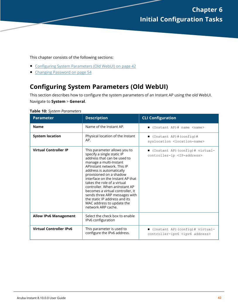
Chapter 6Initial Configuration Tasks
Initial Configuration TasksThis chapter consists of the following sections:
n Configuring System Parameters (Old WebUI) on page 42n Changing Password on page 54
Configuring System Parameters (Old WebUI)This section describes how to configure the system parameters of an Instant AP using the old WebUI.
Navigate to System > General.
Parameter Description CLI Configuration
Name Name of the Instant AP. n (Instant AP)# name <name>
System location Physical location of the InstantAP.
n (Instant AP)#(config)#syslocation <location-name>
Virtual Controller IP This parameter allows you tospecify a single static IPaddress that can be used tomanage a multi-InstantAPInstant network. This IPaddress is automaticallyprovisioned on a shadowinterface on the Instant AP thattakes the role of a virtualcontroller. When anInstant APbecomes a virtual controller, itsends three ARP messages withthe static IP address and itsMAC address to update thenetwork ARP cache.
n (Instant AP)(config)# virtual-controller-ip <IP-address>
Allow IPv6 Management Select the check box to enableIPv6 configuration
Virtual Controller IPv6 This parameter is used toconfigure the IPv6 address.
n (Instant AP)(config)# virtual-controller-ipv6 <ipv6 address>
Table 10: System Parameters
Aruba Instant 8.10.0.0 User Guide 42
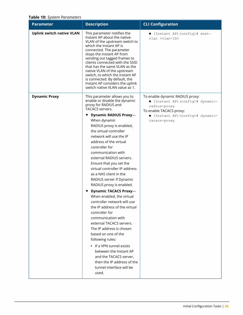
Initial Configuration Tasks | 43
Parameter Description CLI Configuration
Uplink switch native VLAN This parameter notifies theInstant AP about the native-VLAN of the upstream switch towhich the Instant AP isconnected. The parameterstops the Instant AP fromsending out tagged frames toclients connected with the SSIDthat has the same VLAN as thenative VLAN of the upstreamswitch, to which the Instant APis connected. By default, theInstant AP considers the uplinkswitch native VLAN value as 1.
n (Instant AP)(config)# enet-vlan <vlan-ID>
Dynamic Proxy This parameter allows you toenable or disable the dynamicproxy for RADIUS andTACACS servers.n Dynamic RADIUS Proxy—
When dynamicRADIUS proxy is enabled,the virtual controllernetwork will use the IPaddress of the virtualcontroller forcommunication withexternal RADIUS servers.Ensure that you set thevirtual controller IP addressas a NAS client in theRADIUS server if DynamicRADIUS proxy is enabled.
n Dynamic TACACS Proxy—When enabled, the virtualcontroller network will usethe IP address of the virtualcontroller forcommunication withexternal TACACS servers.The IP address is chosenbased on one of thefollowing rules:
l If a VPN tunnel existsbetween the Instant APand the TACACS server,then the IP address of thetunnel interface will beused.
To enable dynamic RADIUS proxy:n (Instant AP)(config)# dynamic-radius-proxy
To enable TACACS proxy:n (Instant AP)(config)# dynamic-tacacs-proxy
Table 10: System Parameters
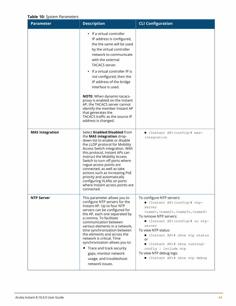
Aruba Instant 8.10.0.0 User Guide 44
Parameter Description CLI Configuration
l If a virtual controllerIP address is configured,the the same will be usedby the virtual controllernetwork to communicatewith the externalTACACS server.
l If a virtual controller IP isnot configured, then theIP address of the bridgeinterface is used.
NOTE: When dynamic-tacacs-proxy is enabled on the InstantAP, the TACACS server cannotidentify the member Instant APthat generates theTACACS traffic as the source IPaddress is changed.
MAS Integration Select Enabled/Disabled fromtheMAS integration drop-down list to enable or disablethe LLDP protocol for MobilityAccess Switch integration. Withthis protocol, Instant APs caninstruct the Mobility AccessSwitch to turn off ports whererogue access points areconnected, as well as takeactions such as increasing PoEpriority and automaticallyconfiguring VLANs on portswhere Instant access points areconnected.
n (Instant AP)(config)# mas-integration
NTP Server This parameter allows you toconfigure NTP servers for theInstant AP. Up to four NTPservers can be configured forthe AP, each one separated bya comma. To facilitatecommunication betweenvarious elements in a network,time synchronization betweenthe elements and across thenetwork is critical. Timesynchronization allows you to:n Trace and track security
gaps, monitor networkusage, and troubleshootnetwork issues.
To configure NTP servers:n (Instant AP)(config)# ntp-server<name>,<name2>,<name3>,<name4>
To remove NTP servers:n (Instant AP)(config)# no ntp-server
To view NTP status:n (Instant AP)# show ntp statusorn (Instant AP)# show running-config | include ntp
To view NTP debug logs:n (Instant AP)# show ntp debug
Table 10: System Parameters
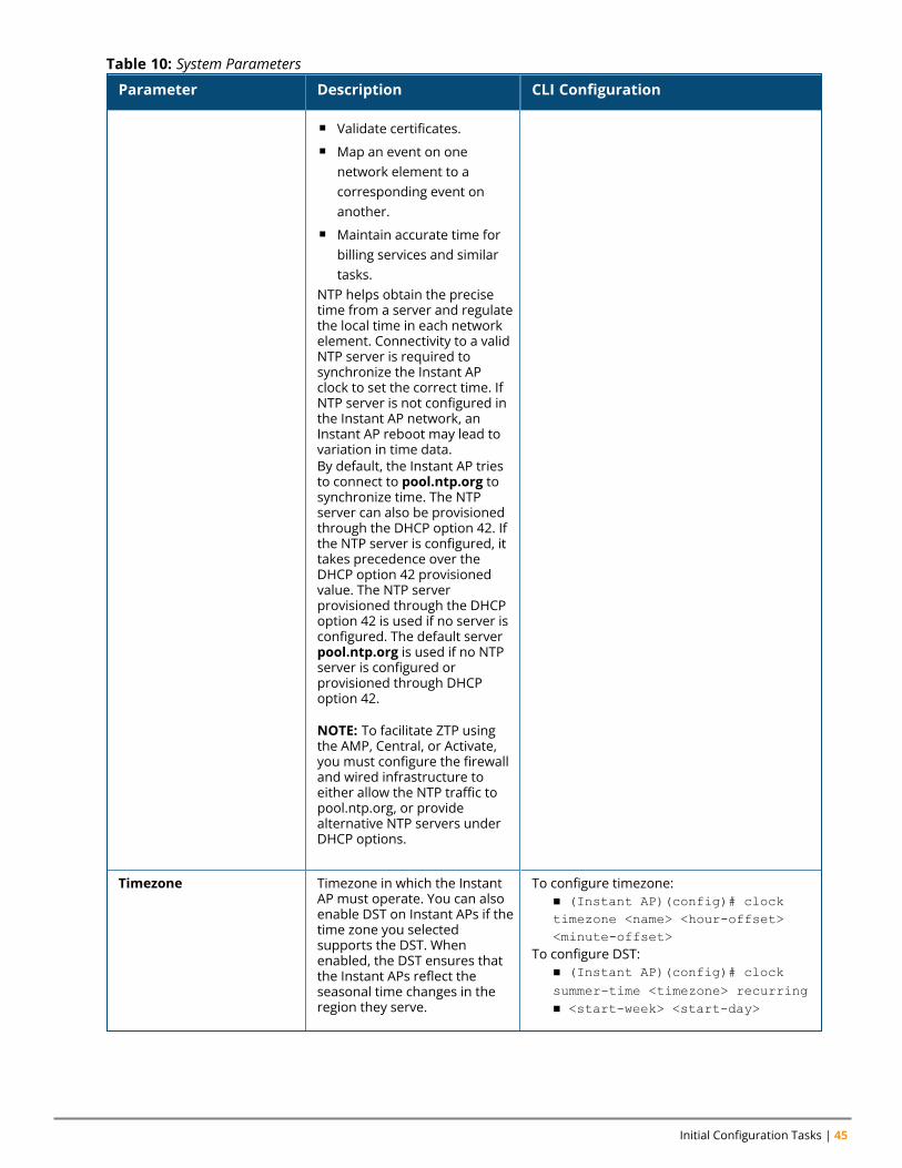
Initial Configuration Tasks | 45
Parameter Description CLI Configuration
n Validate certificates.n Map an event on one
network element to acorresponding event onanother.
n Maintain accurate time forbilling services and similartasks.
NTP helps obtain the precisetime from a server and regulatethe local time in each networkelement. Connectivity to a validNTP server is required tosynchronize the Instant APclock to set the correct time. IfNTP server is not configured inthe Instant AP network, anInstant AP reboot may lead tovariation in time data.By default, the Instant AP triesto connect to pool.ntp.org tosynchronize time. The NTPserver can also be provisionedthrough the DHCP option 42. Ifthe NTP server is configured, ittakes precedence over theDHCP option 42 provisionedvalue. The NTP serverprovisioned through the DHCPoption 42 is used if no server isconfigured. The default serverpool.ntp.org is used if no NTPserver is configured orprovisioned through DHCPoption 42.
NOTE: To facilitate ZTP usingthe AMP, Central, or Activate,you must configure the firewalland wired infrastructure toeither allow the NTP traffic topool.ntp.org, or providealternative NTP servers underDHCP options.
Timezone Timezone in which the InstantAP must operate. You can alsoenable DST on Instant APs if thetime zone you selectedsupports the DST. Whenenabled, the DST ensures thatthe Instant APs reflect theseasonal time changes in theregion they serve.
To configure timezone:n (Instant AP)(config)# clocktimezone <name> <hour-offset><minute-offset>
To configure DST:n (Instant AP)(config)# clocksummer-time <timezone> recurringn <start-week> <start-day>
Table 10: System Parameters
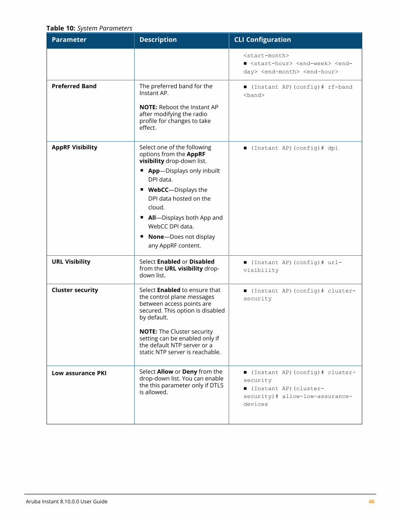
Aruba Instant 8.10.0.0 User Guide 46
Parameter Description CLI Configuration
<start-month>n <start-hour> <end-week> <end-day> <end-month> <end-hour>
Preferred Band The preferred band for theInstant AP.
NOTE: Reboot the Instant APafter modifying the radioprofile for changes to takeeffect.
n (Instant AP)(config)# rf-band<band>
AppRF Visibility Select one of the followingoptions from the AppRFvisibility drop-down list.n App—Displays only inbuilt
DPI data.n WebCC—Displays the
DPI data hosted on thecloud.
n All—Displays both App andWebCC DPI data.
n None—Does not displayany AppRF content.
n (Instant AP)(config)# dpi
URL Visibility Select Enabled or Disabledfrom the URL visibility drop-down list.
n (Instant AP)(config)# url-visibility
Cluster security Select Enabled to ensure thatthe control plane messagesbetween access points aresecured. This option is disabledby default.
NOTE: The Cluster securitysetting can be enabled only ifthe default NTP server or astatic NTP server is reachable.
n (Instant AP)(config)# cluster-security
Low assurance PKI Select Allow or Deny from thedrop-down list. You can enablethe this parameter only if DTLSis allowed.
n (Instant AP)(config)# cluster-securityn (Instant AP)(cluster-security)# allow-low-assurance-devices
Table 10: System Parameters
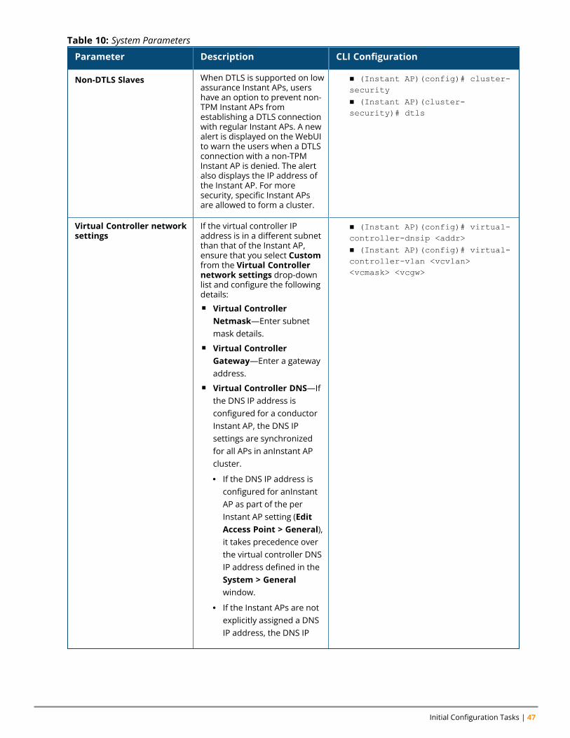
Initial Configuration Tasks | 47
Parameter Description CLI Configuration
Non-DTLS Slaves When DTLS is supported on lowassurance Instant APs, usershave an option to prevent non-TPM Instant APs fromestablishing a DTLS connectionwith regular Instant APs. A newalert is displayed on the WebUIto warn the users when a DTLSconnection with a non-TPMInstant AP is denied. The alertalso displays the IP address ofthe Instant AP. For moresecurity, specific Instant APsare allowed to form a cluster.
n (Instant AP)(config)# cluster-securityn (Instant AP)(cluster-security)# dtls
Virtual Controller networksettings
If the virtual controller IPaddress is in a different subnetthan that of the Instant AP,ensure that you select Customfrom the Virtual Controllernetwork settings drop-downlist and configure the followingdetails:n Virtual Controller
Netmask—Enter subnetmask details.
n Virtual ControllerGateway—Enter a gatewayaddress.
n Virtual Controller DNS—Ifthe DNS IP address isconfigured for a conductorInstant AP, the DNS IPsettings are synchronizedfor all APs in anInstant APcluster.
l If the DNS IP address isconfigured for anInstantAP as part of the perInstant AP setting (EditAccess Point > General),it takes precedence overthe virtual controller DNSIP address defined in theSystem > Generalwindow.
l If the Instant APs are notexplicitly assigned a DNSIP address, the DNS IP
n (Instant AP)(config)# virtual-controller-dnsip <addr>n (Instant AP)(config)# virtual-controller-vlan <vcvlan><vcmask> <vcgw>
Table 10: System Parameters
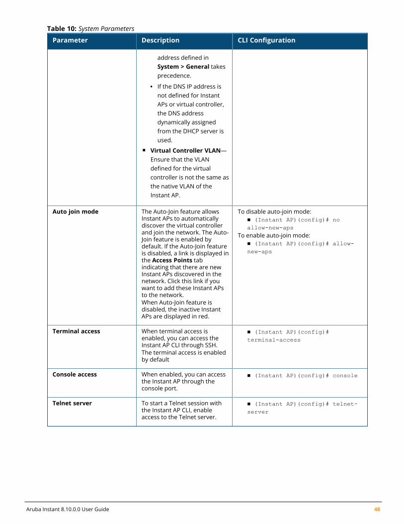
Aruba Instant 8.10.0.0 User Guide 48
Parameter Description CLI Configuration
address defined inSystem > General takesprecedence.
l If the DNS IP address isnot defined for InstantAPs or virtual controller,the DNS addressdynamically assignedfrom the DHCP server isused.
n Virtual Controller VLAN—Ensure that the VLANdefined for the virtualcontroller is not the same asthe native VLAN of theInstant AP.
Auto join mode The Auto-Join feature allowsInstant APs to automaticallydiscover the virtual controllerand join the network. The Auto-Join feature is enabled bydefault. If the Auto-Join featureis disabled, a link is displayed inthe Access Points tabindicating that there are newInstant APs discovered in thenetwork. Click this link if youwant to add these Instant APsto the network.When Auto-Join feature isdisabled, the inactive InstantAPs are displayed in red.
To disable auto-join mode:n (Instant AP)(config)# noallow-new-aps
To enable auto-join mode:n (Instant AP)(config)# allow-new-aps
Terminal access When terminal access isenabled, you can access theInstant AP CLI through SSH.The terminal access is enabledby default
n (Instant AP)(config)#terminal-access
Console access When enabled, you can accessthe Instant AP through theconsole port.
n (Instant AP)(config)# console
Telnet server To start a Telnet session withthe Instant AP CLI, enableaccess to the Telnet server.
n (Instant AP)(config)# telnet-server
Table 10: System Parameters
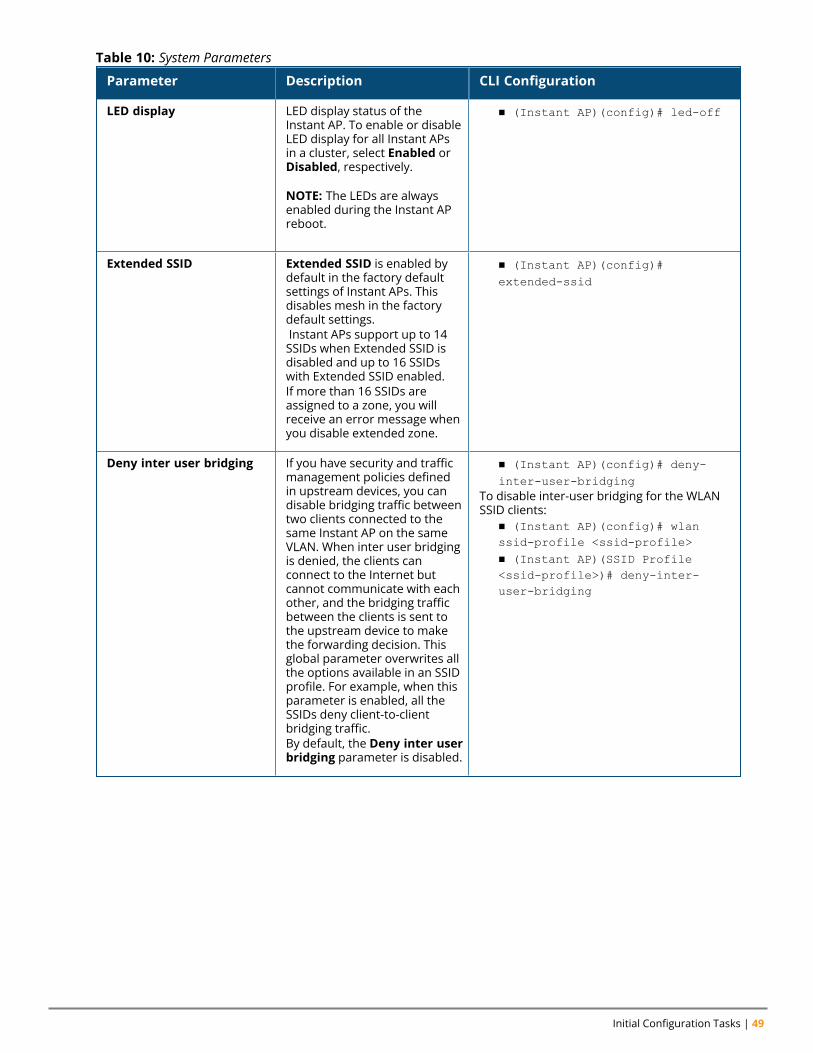
Initial Configuration Tasks | 49
Parameter Description CLI Configuration
LED display LED display status of theInstant AP. To enable or disableLED display for all Instant APsin a cluster, select Enabled orDisabled, respectively.
NOTE: The LEDs are alwaysenabled during the Instant APreboot.
n (Instant AP)(config)# led-off
Extended SSID Extended SSID is enabled bydefault in the factory defaultsettings of Instant APs. Thisdisables mesh in the factorydefault settings.Instant APs support up to 14SSIDs when Extended SSID isdisabled and up to 16 SSIDswith Extended SSID enabled.If more than 16 SSIDs areassigned to a zone, you willreceive an error message whenyou disable extended zone.
n (Instant AP)(config)#extended-ssid
Deny inter user bridging If you have security and trafficmanagement policies definedin upstream devices, you candisable bridging traffic betweentwo clients connected to thesame Instant AP on the sameVLAN. When inter user bridgingis denied, the clients canconnect to the Internet butcannot communicate with eachother, and the bridging trafficbetween the clients is sent tothe upstream device to makethe forwarding decision. Thisglobal parameter overwrites allthe options available in an SSIDprofile. For example, when thisparameter is enabled, all theSSIDs deny client-to-clientbridging traffic.By default, the Deny inter userbridging parameter is disabled.
n (Instant AP)(config)# deny-inter-user-bridging
To disable inter-user bridging for the WLANSSID clients:
n (Instant AP)(config)# wlanssid-profile <ssid-profile>n (Instant AP)(SSID Profile<ssid-profile>)# deny-inter-user-bridging
Table 10: System Parameters
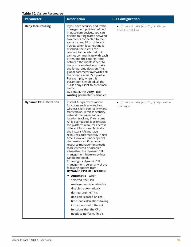
Aruba Instant 8.10.0.0 User Guide 50
Parameter Description CLI Configuration
Deny local routing If you have security and trafficmanagement policies definedin upstream devices, you candisable routing traffic betweentwo clients connected to thesame Instant AP on differentVLANs. When local routing isdisabled, the clients canconnect to the Internet butcannot communicate with eachother, and the routing trafficbetween the clients is sent tothe upstream device to makethe forwarding decision. Thisglobal parameter overwrites allthe options in an SSID profile.For example, when thisparameter is enabled, all theSSIDs deny client-to-client localtraffic.By default, the Deny localrouting parameter is disabled.
n (Instant AP)(config)# deny-local-routing
Dynamic CPU Utilization Instant APs perform variousfunctions such as wired andwireless client connectivity andtraffic flows, wireless security,network management, andlocation tracking. If anInstantAP is overloaded, it prioritizesthe platform resources acrossdifferent functions. Typically,the Instant APs manageresources automatically in realtime. However, under specialcircumstances, if dynamicresource management needsto be enforced or disabledaltogether, the dynamic CPUmanagement feature settingscan be modified.To configure dynamic CPUmanagement, select any of thefollowing options fromDYNAMIC CPU UTILIZATION.n Automatic—When
selected, the CPUmanagement is enabled ordisabled automaticallyduring runtime. Thisdecision is based on real-time load calculations takinginto account all differentfunctions that the CPUneeds to perform. This is
n (Instant AP)(config)# dynamic-cpu-mgmt
Table 10: System Parameters
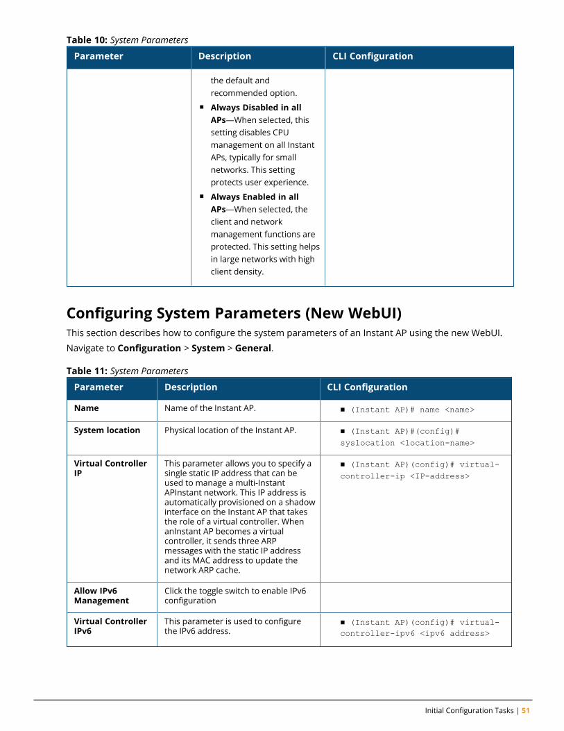
Initial Configuration Tasks | 51
Parameter Description CLI Configuration
the default andrecommended option.
n Always Disabled in allAPs—When selected, thissetting disables CPUmanagement on all InstantAPs, typically for smallnetworks. This settingprotects user experience.
n Always Enabled in allAPs—When selected, theclient and networkmanagement functions areprotected. This setting helpsin large networks with highclient density.
Table 10: System Parameters
Configuring System Parameters (New WebUI)This section describes how to configure the system parameters of an Instant AP using the new WebUI.
Navigate to Configuration > System > General.
Parameter Description CLI Configuration
Name Name of the Instant AP. n (Instant AP)# name <name>
System location Physical location of the Instant AP. n (Instant AP)#(config)#syslocation <location-name>
Virtual ControllerIP
This parameter allows you to specify asingle static IP address that can beused to manage a multi-InstantAPInstant network. This IP address isautomatically provisioned on a shadowinterface on the Instant AP that takesthe role of a virtual controller. WhenanInstant AP becomes a virtualcontroller, it sends three ARPmessages with the static IP addressand its MAC address to update thenetwork ARP cache.
n (Instant AP)(config)# virtual-controller-ip <IP-address>
Allow IPv6Management
Click the toggle switch to enable IPv6configuration
Virtual ControllerIPv6
This parameter is used to configurethe IPv6 address.
n (Instant AP)(config)# virtual-controller-ipv6 <ipv6 address>
Table 11: System Parameters
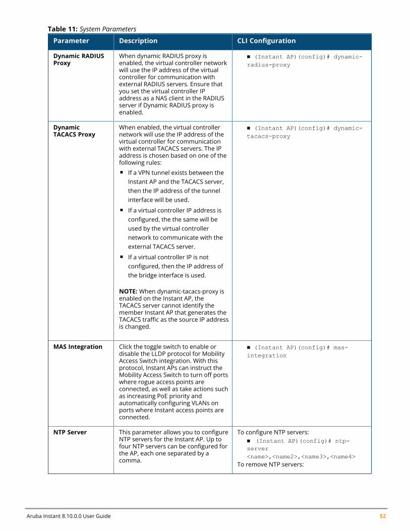
Aruba Instant 8.10.0.0 User Guide 52
Parameter Description CLI Configuration
Dynamic RADIUSProxy
When dynamic RADIUS proxy isenabled, the virtual controller networkwill use the IP address of the virtualcontroller for communication withexternal RADIUS servers. Ensure thatyou set the virtual controller IPaddress as a NAS client in the RADIUSserver if Dynamic RADIUS proxy isenabled.
n (Instant AP)(config)# dynamic-radius-proxy
DynamicTACACS Proxy
When enabled, the virtual controllernetwork will use the IP address of thevirtual controller for communicationwith external TACACS servers. The IPaddress is chosen based on one of thefollowing rules:n If a VPN tunnel exists between the
Instant AP and the TACACS server,then the IP address of the tunnelinterface will be used.
n If a virtual controller IP address isconfigured, the the same will beused by the virtual controllernetwork to communicate with theexternal TACACS server.
n If a virtual controller IP is notconfigured, then the IP address ofthe bridge interface is used.
NOTE: When dynamic-tacacs-proxy isenabled on the Instant AP, theTACACS server cannot identify themember Instant AP that generates theTACACS traffic as the source IP addressis changed.
n (Instant AP)(config)# dynamic-tacacs-proxy
MAS Integration Click the toggle switch to enable ordisable the LLDP protocol for MobilityAccess Switch integration. With thisprotocol, Instant APs can instruct theMobility Access Switch to turn off portswhere rogue access points areconnected, as well as take actions suchas increasing PoE priority andautomatically configuring VLANs onports where Instant access points areconnected.
n (Instant AP)(config)# mas-integration
NTP Server This parameter allows you to configureNTP servers for the Instant AP. Up tofour NTP servers can be configured forthe AP, each one separated by acomma.
To configure NTP servers:n (Instant AP)(config)# ntp-server<name>,<name2>,<name3>,<name4>
To remove NTP servers:
Table 11: System Parameters
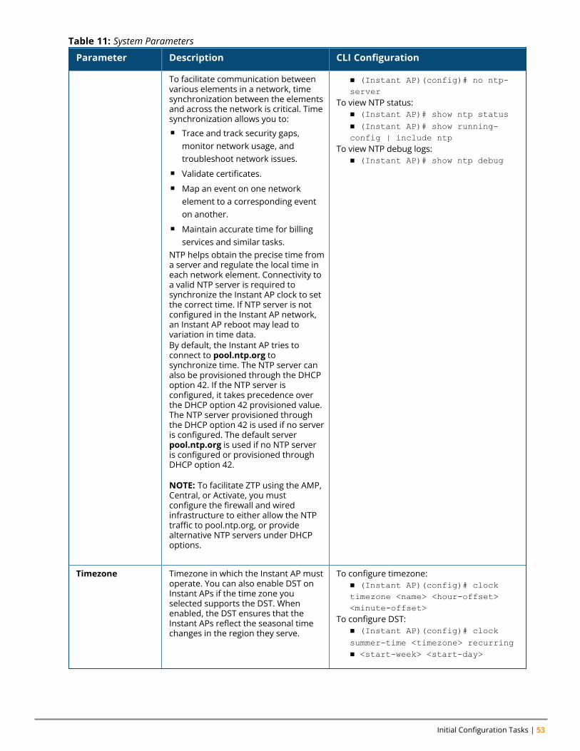
Initial Configuration Tasks | 53
Parameter Description CLI Configuration
To facilitate communication betweenvarious elements in a network, timesynchronization between the elementsand across the network is critical. Timesynchronization allows you to:n Trace and track security gaps,
monitor network usage, andtroubleshoot network issues.
n Validate certificates.n Map an event on one network
element to a corresponding eventon another.
n Maintain accurate time for billingservices and similar tasks.
NTP helps obtain the precise time froma server and regulate the local time ineach network element. Connectivity toa valid NTP server is required tosynchronize the Instant AP clock to setthe correct time. If NTP server is notconfigured in the Instant AP network,an Instant AP reboot may lead tovariation in time data.By default, the Instant AP tries toconnect to pool.ntp.org tosynchronize time. The NTP server canalso be provisioned through the DHCPoption 42. If the NTP server isconfigured, it takes precedence overthe DHCP option 42 provisioned value.The NTP server provisioned throughthe DHCP option 42 is used if no serveris configured. The default serverpool.ntp.org is used if no NTP serveris configured or provisioned throughDHCP option 42.
NOTE: To facilitate ZTP using the AMP,Central, or Activate, you mustconfigure the firewall and wiredinfrastructure to either allow the NTPtraffic to pool.ntp.org, or providealternative NTP servers under DHCPoptions.
n (Instant AP)(config)# no ntp-server
To view NTP status:n (Instant AP)# show ntp statusn (Instant AP)# show running-config | include ntp
To view NTP debug logs:n (Instant AP)# show ntp debug
Timezone Timezone in which the Instant AP mustoperate. You can also enable DST onInstant APs if the time zone youselected supports the DST. Whenenabled, the DST ensures that theInstant APs reflect the seasonal timechanges in the region they serve.
To configure timezone:n (Instant AP)(config)# clocktimezone <name> <hour-offset><minute-offset>
To configure DST:n (Instant AP)(config)# clocksummer-time <timezone> recurringn <start-week> <start-day>
Table 11: System Parameters
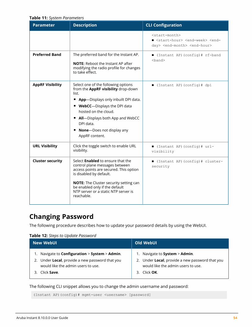
Aruba Instant 8.10.0.0 User Guide 54
Parameter Description CLI Configuration
<start-month>n <start-hour> <end-week> <end-day> <end-month> <end-hour>
Preferred Band The preferred band for the Instant AP.
NOTE: Reboot the Instant AP aftermodifying the radio profile for changesto take effect.
n (Instant AP)(config)# rf-band<band>
AppRF Visibility Select one of the following optionsfrom the AppRF visibility drop-downlist.n App—Displays only inbuilt DPI data.n WebCC—Displays the DPI data
hosted on the cloud.n All—Displays both App and WebCC
DPI data.n None—Does not display any
AppRF content.
n (Instant AP)(config)# dpi
URL Visibility Click the toggle switch to enable URLvisibility.
n (Instant AP)(config)# url-visibility
Cluster security Select Enabled to ensure that thecontrol plane messages betweenaccess points are secured. This optionis disabled by default.
NOTE: The Cluster security setting canbe enabled only if the defaultNTP server or a static NTP server isreachable.
n (Instant AP)(config)# cluster-security
Table 11: System Parameters
Changing PasswordThe following procedure describes how to update your password details by using the WebUI.
New WebUI Old WebUI
1. Navigate to Configuration > System > Admin.
2. Under Local, provide a new password that youwould like the admin users to use.
3. Click Save.
1. Navigate to System > Admin.
2. Under Local, provide a new password that youwould like the admin users to use.
3. Click OK.
Table 12: Steps to Update Password
The following CLI snippet allows you to change the admin username and password:
(Instant AP)(config)# mgmt-user <username> [password]
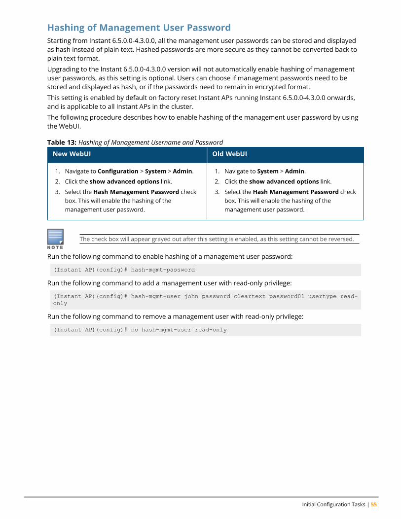
Initial Configuration Tasks | 55
Hashing of Management User PasswordStarting from Instant 6.5.0.0-4.3.0.0, all the management user passwords can be stored and displayedas hash instead of plain text. Hashed passwords are more secure as they cannot be converted back toplain text format.
Upgrading to the Instant 6.5.0.0-4.3.0.0 version will not automatically enable hashing of managementuser passwords, as this setting is optional. Users can choose if management passwords need to bestored and displayed as hash, or if the passwords need to remain in encrypted format.
This setting is enabled by default on factory reset Instant APs running Instant 6.5.0.0-4.3.0.0 onwards,and is applicable to all Instant APs in the cluster.
The following procedure describes how to enable hashing of the management user password by usingthe WebUI.
New WebUI Old WebUI
1. Navigate to Configuration > System > Admin.
2. Click the show advanced options link.
3. Select the Hash Management Password checkbox. This will enable the hashing of themanagement user password.
1. Navigate to System > Admin.
2. Click the show advanced options link.
3. Select the Hash Management Password checkbox. This will enable the hashing of themanagement user password.
Table 13: Hashing of Management Username and Password
The check box will appear grayed out after this setting is enabled, as this setting cannot be reversed.
Run the following command to enable hashing of a management user password:
(Instant AP)(config)# hash-mgmt-password
Run the following command to add a management user with read-only privilege:
(Instant AP)(config)# hash-mgmt-user john password cleartext password01 usertype read-only
Run the following command to remove a management user with read-only privilege:
(Instant AP)(config)# no hash-mgmt-user read-only
Chapter 7Customizing Instant AP Settings
Customizing Instant AP SettingsThis chapter describes the procedures for configuring settings that are specific to an Instant AP in thecluster.
n Discovery Logic on page 56n Modifying the Instant AP Host Name on page 62n Configuring Zone Settings on an Instant AP on page 62n Specifying a Method for Obtaining IP Address on page 69n Configuring External Antenna on page 70n Configuring Radio Settings for an Instant AP on page 71n Air Slice on page 77n Enabling Flexible Radio on page 73n Configuring Uplink VLAN for an Instant AP on page 79n Changing the Instant AP Installation Mode on page 80n Changing USB Port Status on page 80n Conductor Election and Virtual Controller on page 81n Adding an Instant AP to the Network on page 83n Removing an Instant AP from the Network on page 83n Support for BLE Asset Tracking on page 83n Intelligent Power and Temperature Monitoring (IPTM) on page 84n Transmit Power Calculation on page 88n Hardware Offloading for Increased Transmission Performance on page 88
Discovery LogicIn the previous Instant releases, access points were predefined as either controller-based Campus APsor controller-less Instant APs. Each legacy Instant AP was shipped with an Instant image that enabled theInstant AP to act as its own virtual controller or to join an existing Instant cluster.
Starting with Instant 6.5.2.0, the new access points introduced in this release or following releases canrun on both controller-based mode and controller-less mode. Based on the selected mode, the AP runsa corresponding image:
n Controller mode will run ArubaOS image.n Controller-less mode will run Instant image.
Each access point is shipped with either a limited functionality manufacturing image or an Instant image.An access point with either of the limited functionality manufacturing image or the Instant image will runthe full discovery logic. Based on that, it will download the ArubaOS or Instant image and convert to thecorresponding mode.
Starting from Instant 6.5.4.5, the Cloud First principle is applied to the AP discovery feature. In thisprinciple, the AP, regardless of whether it is factory reset or configured, retrieves provisioning rules fromActivate after it boots up.
Aruba Instant 8.10.0.0 User Guide 56
Customizing Instant AP Settings | 57
The Instant AP acts as a DHCP server for wired clients if both the Ethernet ports of the Instant AP areconnected to the uplink switch. This occurs when LACP is not configured on the uplink switch.Therefore it is recommended to not connect both the Ethernet ports of the Instant AP to the uplinkswitch if LACP is not configured.
Preference RoleUsers can predefine the AP mode by configuring the preference role using the WebUI or the CLI.
In the ArubaOS WebUITo set the AP preference role to controller-less in the WebUI:
1. Navigate toMaintenance > Access Point > Convert to instant mode in the WebUI.2. Select the AP(s) on which you want to set the preference role to controller-less.3. Click Convert to instant mode.
In the CLITo set the AP preference role to controller-less in the CLI, execute the following commands:
(host) #ap redeploy controller-lessallap-groupap-nameip-addrip6-addrwired-mac
Discovery Logic Workflow
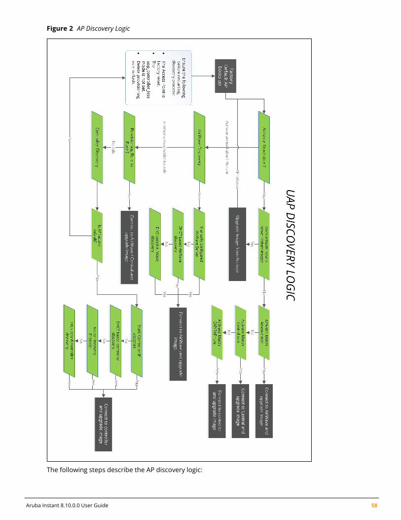
Aruba Instant 8.10.0.0 User Guide 58
Figure 2 AP Discovery Logic
The following steps describe the AP discovery logic:
Customizing Instant AP Settings | 59
1. When an AP boots up, it connects to Activate to obtain a provisioning rule.2. If provisioning is already done by AirWave or Central, verify if a provisioning rule exists. If yes, the
provisioning rule is saved in the flash memory. Compare the saved provisioning rule with the rulein Activate. If the rule in Activate is new, save the new provisioning rule in flash. For example, ifthe conductor and member Instant APs obtain different AirWave addresses or if the conductorand member Instant APs obtain a different AirWave or Central rule, the conductor Instant AP ruletakes higher precedence.
Only the conductor Instant AP can apply provisioning rules to the Instant AP cluster.
3. If the rule is to perform a mandatory upgrade of the Instant AP, ensure to upgrade the Instant APto the desired version. The conductor Instant AP executes the upgrade after a cluster is formed.
4. If the rule is to convert the Instant AP to Campus AP or Remote AP, the conversion takes effect forevery Instant AP regardless of whether it is a conductor or a member. This requires a manualregistration of every conductor and member Instant AP with Activate.
5. If there is no rule from Activate or if conversion to Campus AP or Remote AP fails, the conductorAP conducts local provisioning detection to check the local AirWave configuration.n If the AirWave server is configured and is in the configuration file, apply the server details.
Otherwise, conduct a DHCP based AirWave or Central detection.n If DHCP-based AirWave is not found and the Instant AP is in factory default status, perform a
DNS based AirWave discovery.n If none of the above methods can detect the AirWave server and if the Instant AP cannot
connect to Activate, use the provisioning rule in flash.
6. If the AirWave or Central server is not found, or if the Instant AP is a member, verify if thefollowing conditions for local controller discovery are met:n The Instant AP is factory reset.n The uap_controller_lessmode is not set.n There is no provision rule saved in flash.
7. If the controller is found, the Instant AP sends a hello message to the controller and converts to aCampus AP.
8. When a conductor failover happens, the new conductor Instant AP connects to Activate toretrieve the provisioning rule. If the new conductor successfully obtains the provisioning rule, itapplies this rule to the cluster.
Manual UpgradeAPs running in unprovisioned mode broadcast a special provisioning SSID to which users can connect toupgrade the AP manually. Upon connecting, users can access a local provisioning page in the WebUI toupgrade the AP to an ArubaOS or Instant image. For more information on upgrading APs manually,refer to the following scenarios:
n Controller-based AP over Manual Campus AP or Remote AP Conversion in the ArubaOS User Guide.n Controller-less AP over Manual Instant AP Conversion in the ArubaOS User Guide.
The provisioning SSID for all APs running Instant 6.5.2.0 onwards, including legacy Instant APs isSetMeUp-xx:xx:xx.
Aruba Instant 8.10.0.0 User Guide 60
Deployment ScenariosThis section describes the controller-less AP deployment and hybrid deployment scenarios:
Controller-less AP DeploymentsThe following sections describe controller-less AP deployment scenarios.
Controller-less AP in an Instant Network
Users can deploy APs directly into a running Instant network, which consists of an Instant AP cluster anda virtual controller that manages the network. In this scenario, there is an actively running Instantnetwork with a conductor Instant AP.
The AP is able to successfully discover the Instant Virtual Controller and join the cluster. Themanufacturing image image in the AP is upgraded to the Instant image of the virtual controller and theconfiguration is synchronized from the Virtual Controller to the newly added Instant AP.
For more information on electing a conductor in an Instant network, see Conductor Election and VirtualController on page 81.
Controller-less AP over Activate, AirWave, or Central
In this scenario, there is no cluster deployed in the subnet but AirWave, Activate, and Central can bereached over the network.
In this deployment scenario, Activate,AirWave, or Central must be accessible to the AP.
APs are upgraded to the Instant image through AirWave, Activate, and Central in the following steps:
1. The AP boots up with the limited functionality manufacturing image or the Instant image andattempts to locate Activate.
2. If the AP locates Activate, it receives pre-configured provisioning rules to connect to AirWave orCentral or convert into a Campus AP or Remote AP. If Activate is unreachable, the AP attemps tolocate a virtual controller, AirWave, or Central.
APs that connect to Activate are automatically upgraded from the manufacturing image to thelatest Instant or Instant image. Refer to the latest Aruba Activate User Guide for more details onconfiguring provisioning rules.
3. If the AP locates AirWave, it can be upgraded to the Instant image. If an enforced image upgraderule is configured in AirWave, the AP is upgraded to the Instant image that is configured for theenforced upgrade rule. If no enforced upgrade rule is configured, the AP is upgraded to the latestInstant image in AirWave. After the AP is upgraded, it reboots in controller-less mode. Refer to thelatest AirWave User Guide for details on AP image upgrade.
All firmware must be uploaded to AirWave before the AP connects and downloads the Instant image.Refer to the latest AirWave Deployment Guide for details on firmware upload.
4. If the AP locates Central, it can be upgraded to the Instant image through theMaintenance >Firmware page in the Central WebUI. After the AP is upgraded, it reboots in controller-less mode.Refer to the latest Central User Guide for more details on AP image upgrade.
Central synchronizes with Aruba Activate to retrieve the latest Instant image.
Customizing Instant AP Settings | 61
5. After the AP is upgraded to controller-less mode, it forms a new Instant AP cluster and convertsinto the conductor. Other APs which are not deployed can join the cluster and upgrade to theInstant image.
Controller-less AP over Manual Instant AP Conversion.
If the AP cannot be upgraded into an Instant AP through a virtual controller, Activate, AirWave, orCentral, users can connect to a special provisioning SSID broadcasted by the unprovisioned AP tomanually convert the AP to an Instant AP through the WebUI. Refer to the Controller-less AP in an InstantNetwork section and the Controller-less AP over Activate, AirWave, or Central section in the ArubaOS UserGuide for details on upgrading an AP to the Instant image using a virtual controller, Activate, AirWave, orCentral.
To manually convert an AP to an Instant AP in the WebUI:
1. Log in to your virtual controller.
2. Connect to the following provisioning SSID broadcasted by the unprovisioned AP: SetMeUp-xx:xx:xx.
3. Open a web browser and then navigate to the following URL:
https://setmeup.arubanetworks.com
4. Under Access Point Setup, select Image File or Image URL to upload the Instant image.
n If you selected Image File, click Browse to locate and select an Instant image file from your local fileexplorer.
n If you selected Image URL, enter the web address of the Instant image under URL.
5. Click Save.
After the AP is upgraded, it reboots in the controller-less mode.
Behavior of Default Provisioning SSIDStarting with Instant 8.5.0.0, The AP will stop broadcast of default SetMeUp SSID when it discovers thecontroller IP through Activate, DHCP server or DNS server.
The AP in its factory default state scans for the controller IP every 1 second. During the scan if the APdiscovers the controller IP, it disables the default SetMeUp SSID. The SetMeUp SSID is disabled as the APattempts to connect to the controller and remains disabled even if it is unable to connect to thecontroller. The default SetMeUp SSID will be disabled if the Instant AP receives any of the following:
n DHCP option 43/60n DHCPv6 option 52n DHCP option 43/60 (IPv4) and DHCP 52 (IPv6) for dual stack environmentn Activate provisioning rule to convert IAP-to-CAP (IPv4)
To re-enable the default SetMeUp SSID, remove the controller IP from Activate, DHCP server and DNSserver. When the AP scans for the controller IP again, it does not discover the IP and the defaultSetMeUp SSID starts broadcasting.
AP Deployments in Hybrid Controller-Instant NetworksUsers can deploy APs into hybrid networks, which contain both controller-based and controller-less APs.APs in hybrid networks are upgraded to the ArubaOS or Instant image using the same methods as APsin pure controller or Instant networks. However, the following items must be in place before deployingAPs in a hybrid network:
Aruba Instant 8.10.0.0 User Guide 62
n Controller-based APs and controller-less APs must run on different subnets (for example, acontroller-based AP subnet and a separate controller-less AP subnet).
n Different discovery methods should be used for controller-based APs and controller-less APs, as thecontroller discovery process and Instant AirWave discovery process share the same DHCP or DNSdiscovery methods. For example, controller-based APs can use a DHCP server to discover acontroller, while controller-less APs can use a DNS server on AirWave.
n If the same discovery method must be used for both controller-based APs and controller-less APs, itis recommended that you use DHCP-based discovery. DHCP servers can respond to DHCP requestsbased on the AP’s subnet and vendor ID. DNS servers do not have a subnet limit and this can causethe APs that share a DNS server to be upgraded on the wrong AP subnet.
Modifying the Instant AP Host NameThe following procedure is used to modify the host name of an Instant AP through the WebUI:
1. Navigate to Configuration > Access Points.2. Select the Instant AP to rename and click Edit.3. Expand General and enter the new name in the Name field. You can specify a name of up to 128
ASCII characters.4. Click Save.
The following CLI command is used to change the host name of an Instant AP:
(Instant AP)# hostname <system_name>
As a best practice, It is recommended to configure the hostname by using only a-z, A-Z, 0-9, ‘.’, ‘-‘, ‘:’, ‘_’ ,but not special characters such as “#$%”.
Configuring Zone Settings on an Instant APStarting from Instant 8.3.0.0, Instant APs can be assigned RF zones and SSID zones to enhance thewireless network environment. RF zones enable the creation of custom RF environments for Instant APsand SSID zones enable the creation of Wi-Fi zones to service multiple sets of clients in different zones ofthe wireless environment. RF zones and SSID zones are independent of each other and are configuredseparately.
RF zonesRF zones enable the creation of RF environments for individual APs. RF zones are configured using radioprofiles. Radio profiles allow the creation of additional radio profiles which can be associated to one ormore APs using their zone name. Each radio profile has a zone parameter which can be configuredexcept for the default radio profile and each AP can be assigned a single RF zone. Instant supports up to10 radio profiles each for both 2.4 GHz radio and 5 GHz radio in an Instant cluster. A single RF zone canbe configured on multiple APs and all APs should be configured to a RF zone. If no RF zone is assigned toan AP, the default radio profile will be used.
Customizing Instant AP Settings | 63
Two radio profiles can have the same zone name given that the profiles are in different bands, i.e, A2.4 GHz radio profile and a 5 GHz radio profile can have the same zone name. Using the same zonename for a 2.4 GHz profile and a 5 GHz profile brings the two radio profiles under one RF zone, whichcan then be applied to the AP using the zone name. This enables you to apply radio profiles to boththe radios of the AP. However, two radio profiles in the same band cannot have the same zone name.
Configuring RF Zones for Instant APRF zones are created by configuring radio profiles with a zone name and then attaching them to theInstant AP using the same zone name. Only one RF zone can be applied to an AP and if no specific zoneis assigned to an AP then the default radio profile will be used. The radio profile assigned to the AP willuse the following priority: assigned RF zone > default radio profile > ARM profile.
The following procedure configures an RF zone using the WebUI:
1. Configure a radio profile and specify a name for the zone in the zone field. For configuring radioprofile, see Configuring Radio Profiles. To configure an RF zone with profiles for both 2.4 GHz and5 GHz radio use the same zone name in the two radio profiles.
2. Attach the configured radio profile to the Instant AP using the zone name. Use the followingprocedure to configure an RF zone to an Instant AP:
3. Navigate to the Configuration > Access Points page.4. Select the Instant AP from the Access Points list and click Edit.5. Expand General and specify the Instant AP zone in the RF zone field.6. Click Save.
The following CLI commands are used to configure an RF zone:
1. Configure radio settings using rf dot11a-radio-profile and rf dot11g-radio-profile commandsfor 5 GHz and 2.4 GHz radio respectively and specify a name for the zone using the zone <zonename> parameter. To configure an RF zone with profiles for both 2.4 GHz and 5 GHz radio usethe same zone name in the two radio profiles. The following is the syntax to configure zone namefor 2.4 GHz and 5 GHz radio profile.
a. To configure zone name in a 2.4 GHz radio profile:
InstantAP (config) # rf dot11g-radio-profile <profile name>InstantAP (RF dot11g Radio Profile "<profile name>") # zone <zone name>
b. To configure zone name in a 5 GHz radio profile:
InstantAP (config) # rf dot11a-radio-profile <profile name>InstantAP (RF dot11a Radio Profile "<profile name>") # zone <zone name>
2. Attach the specific RF zone and the associated radio profile to the AP using the rf-zone <zonename> command. This is a per-ap setting and should configured on the respective AP. Thefollowing is the syntax to attach a radio profile to the AP:
rf-zone <zone name>
To view the radio profile used by the AP, use the show radio profile command. The active profile islisted in the Zone column.
SSID Zones
Aruba Instant 8.10.0.0 User Guide 64
SSID zones enables the creation of Wi-Fi zones with different SSIDs to service different sets of clients.SSID zones are created using WLAN SSID profile. Traditionally only one zone can be configured to anInstant AP but starting from Instant 8.3.0.0, Instant APs can be assigned multiple SSID zones to servedifferent set of clients in different zones of the Wi-Fi environment. In the previous releases, commaswere a part of the zone name. Commas configured in ArubaInstant 6.5.4.x or prior versions will be usedas delimiters when Instant APs are upgraded to ArubaInstant 8.3.0.x or later.
You can configure up to six SSID zones per AP, and up to 32 SSID zones per ssid-profile. However, it isstrongly recommended not to configure multiple zones in per-AP and per-SSID profiles at the sametime.
Configuring SSID zones for Instant APSSID zones are created by configuring WLAN SSID profiles with a zone and attaching them to theAP using the zone name. A maximum of 6 SSID zones can be assigned to an AP and if no specific zone isassigned, the AP will broadcast only the SSIDs configured on the AP or the Instant cluster. SSID zonescan be configured using the WebUI, CLI, AirWave or Central.
The following procedure configures an SSID zone using the WebUI:
1. Configure a WLAN SSID profile and specify a name for the zone in the zone field. For configuringWLAN SSID profiles, see Configuring WLAN Settings for an SSID Profile.
2. Attach the configured WLAN SSID profile to the Instant AP using the zone name. Use the followingprocedure to configure an SSID zone to an Instant AP:
a. Navigate to the Configuration > Access Points page.
b. Select the Instant AP from the Access Points list and click Edit.
c. Expand General and specify the Instant AP zone in the Zone field.
3. Click Save.
The following CLI command is used to configure an SSID Zone:
1. Configure WLAN settings for the SSID settings usingwlan ssid-profile command and specify aname for the zone using the zone <zone name> parameter. The following is the syntax toconfigure zone name for a wlan ssid profile.
a. To configure zone name in a wlan ssid profile:
InstantAP (config) # wlan ssid-profile <profile name>InstantAP (SSID Profile "<profile name>") # zone <zone name>
2. Attach the specific SSID zone and the associated SSID profile to the AP using the zonename<zone name> command. A maximum of 6 SSID zones can be assigned to an AP and the differentzones are separated using commas. This is a per-ap setting and should configured on therespective AP. The following is the syntax to attach an SSID zone to the AP:
zonename <zone1 name, zone2 name>
Configuring Zone Names for IoT Transport and Radio ProfilesAruba Instant supports configuring zone settings for IoT transport or radio profiles. When a zone isdefined in the IoT transport or radio profile and the same zone name is defined on an Instant AP, an IoTtransport or radio profile is created on that Instant AP. You can enter multiple zone names as comma-
Customizing Instant AP Settings | 65
separated values. For more information on configuring IoT transport and radio profiles, see IoTConfiguration.
Disabling AP Factory ResetAn AP can be reset to factory default configuration by pressing its reset button for more than 5 secondswhile the AP is operational. Aruba Instant allows you to disable AP factory reset while the AP isoperational.
The AP factory reset is enabled by default; which means, an AP may be reset to factory defaultconfiguration by pressing its reset button for more than 5 seconds while the AP is operational.
The following CLI command disables the AP factory reset feature while the AP is operational:
(Instant AP)(Config)# disable-factory-reset
The following CLI command enables the AP factory reset feature while the AP is operational:
(Instant AP)(Config)# no disable-factory-reset
AP USB ManagementAruba Instant supports new infrastructure to manage any USB device that is plugged to an AP. Theinfrastructure allows describing a USB device through either CLI configuration or by using predefineddescriptors. The infrastructure allows USB device management through USB ACLs. The infrastructurealso supports plugin for USB devices. A plugin can perform further identification or perform normallogical interaction with the USB device. The infrastructure supports sending notification to otherprocesses. For example: USB device plug-in or unplug notifications are sent to the IoT daemon. Theinfrastructure also supports sending script-based notifications. The USB ACLs are applied to theUSB Management Daemon (UDMD) process and when a USB device is plugged in to an AP, theUSB device walks through all USB ACL rules sequentially. Instant supports USB devices only from Arubaapproved vendors. The following vendors are approved:
n Alcatel-L800n Amberbox-detectorn Amberbox-gatewayn C-motech-CNU-680n EpiValley-SEC-8089n Fraklin-u770-u772n Franklin-U300n Franklin-U301n Franklin-U600n Fujisoftn Globetrotter-ICON-225n Globetrotter-ICON-322n HanShown Huawei-3276s-150n Huawei-D41HWn Huawei-E1552

Aruba Instant 8.10.0.0 User Guide 66
n Huawei-E157n Huawei-E160n Huawei-E169-E180-E220n Huawei-E170-E272-E220n Huawei-E173n Huawei-E1731-177DT06n Huawei-E1750n Huawei-E176-E176G-E1553n Huawei-E1762n Huawei-E180n Huawei-E180-E1692-E1762n Huawei-E1820en Huawei-E220n Huawei-E261n Huawei-E3131n Huawei-E3272s-153n Huawei-E3276n Huawei-E3276s-500n Huawei-E3372n Huawei-E3372h-153-hilinkn Huawei-E3372h-153-modemn Huawei-E352s-5n Huawei-E353n Huawei-E353-E1750-E367n Huawei-E367n Huawei-E3765n Huawei-E392n Huawei-e398n Huawei-E8372n Huawei-EC150n Huawei-EC167n Huawei-HWD12-LTEn Huawei-K3770n Huawei-K3772n Huawei-K4505n Huawei-K4510n Huawei-K4605n Huawei-K5150n Huawei-K5160n Huawei-KDDI-DATA07n Icon-452n Longcheer-WM72n Netgear-340u

Customizing Instant AP Settings | 67
n Netgear-341un Novatel-MC545n Novatel-MC551Ln Novatel-MiFi-2200n Novatel-Ovation-U727n Novatel-U620Ln Novatel-U720n Novatel-U727n Novatel-U760-Sprintn Novatel-U760-Virginn NTT-DoCoMo-L-02An NTT-DoCoMo-L-02Cn NTT-DoCoMo-L-05An NTT-DoCoMo-L-08Cn Pantech-UM150n Pantech-UM175n Pantech-UM190n Pantech-UML290n Pantech-UML295n Pantech-UML295-coldn Qualcomm-SXC-1080n SES-Imagotag-021n Sierra-250Un Sierra-305-308n Sierra-306-308-503-312Un Sierra-313un Sierra-320Un Sierra-330Un Sierra-598n Sierra-881Un Sierra-885n Sierra-Compass-597n Sierra-Compass-885n Sierra-Tstick-C597n SIMTechn Solu-M-SLG-DM101n UGM1831n UMG181n Utstarcom-UM100Cn ZTE-3565n ZTE-AC2726n ZTE-AC2736n ZTE-AC3781
Aruba Instant 8.10.0.0 User Guide 68
n ZTE-Fivespotn ZTE-K4505-zn ZTE-MF110n ZTE-MF180-HSDPAn ZTE-MF190-Egyptn ZTE-MF190-Indian ZTE-MF190-Thailandn ZTE-MF591n ZTE-MF633-MF636n ZTE-MF637-MF656n ZTE-MF668n ZTE-MF683-HSDPAn ZTE-MF79Sn ZTE-MF820n ZTE-MF820Dn ZTE-MF823n ZTE-MF825Cn ZTE-MF831n ZTE-MF832Sn ZTE-MF832Un ZTE-MF832U-Zero
USB ACL ProfileAruba Instant supports definition of up to 16 USB ACL profiles. A USB ACL profile is a vendor-productname with one action (permit, deny, reset). You cannot configure vendor ID in the USB descriptor, butcan configure the name and action. When a USB ACL is applied to an AP group, all APs in that AP groupinherit the USB ACL rules. When a USB device is described using a predefined descriptor, they arepermitted by default.
When there is no USB ACL configuration but a USB profile is pushed, the UDMD process applies permit-all by default. If there is configured USB ACL, the SAPD or CLI process automatically adds deny-all rule atthe end of the pushed rule list. That is, when UDMD does not find the matched USB ACL rule from theconfiguration, it applies the deny-all rule by default.
The following CLI command creates a USB ACL profile named sample-usb-acl-profile with rule to permitUSB devices from HanShow:
(Instant AP)(config)# usb acl-profile sample-usb-acl-profile(Instant AP)(AP USB ACL Profile "sample-usb-acl-profile") #rule HanShow permit
The following CLI command creates a USB ACL profile named sample-usb-acl-profile with rule to denyUSB devices from HanShow:
(Instant AP)(config)# usb acl-profile sample-usb-acl-profile(Instant AP)(AP USB ACL Profile "sample-usb-acl-profile") #rule HanShow deny
The following CLI command creates a USB ACL profile named sample-usb-acl-profile with no rule topermit USB devices from HanShow:
(Instant AP)(config)# usb acl-profile sample-usb-acl-profile(Instant AP)(AP USB ACL Profile "sample-usb-acl-profile") #no rule HanShow permit
Customizing Instant AP Settings | 69
The following CLI command creates a USB ACL profile named sample-usb-acl-profile with no rule todeny USB devices from HanShow:
(Instant AP)(config)# usb acl-profile sample-usb-acl-profile(Instant AP)(AP USB ACL Profile "sample-usb-acl-profile") #no rule HanShow deny
The following CLI command creates an AP USB profile named sample-ap-usb-profile and applies aUSB ACL profile named sample-usb-acl-profile to it:
(Instant AP)(config)# usb-profile sample-ap-usb-profile(Instant AP)(AP USB profile "sample-ap-usb-profile") #usb-acl-profile sample-usb-acl-profile
The following CLI command binds an AP USB profile named sample-usb-profile:
(Instant AP)(config)# usb-profile-binding sample-usb-profile
The following CLI command resets the USB device:
(Instant AP)# usb-device-mgmt reset device <device ID>
The following CLI command shows the USB profile:
(Instant AP)# show usb profile
The following CLI command shows the details of a specific USB profile based on its profile name:
(Instant AP)# show usb-profile sample-ap-usb-profile
The following command shows the USB ACL profile:
(Instant AP)# show usb acl-profile
The following CLI command shows the details of a specific USB ACL profile based on its profile name:
(Instant AP)# show usb-acl-prof sample-ap-usb-acl-profile
The following command shows the details of the devices connected to the Instant AP:
(Instant AP)# show usb devices
The following CLI command shows the list of supported vendor USB products:
(Instant AP)# show usb supported vendor-product
The following CLI command shows the USB cellular status:
(Instant AP)# show usb status
Specifying a Method for Obtaining IP AddressYou can either specify a static IP address or allow the Instant AP to obtain an IP address from the DHCPserver. By default, the Instant APs obtain IP address from the DHCP server. The following procedureconfigures a static IP address:
The following procedures configures a static IP address for the Instant AP:
1. Navigate to the Configuration > Access Points page. Select the Instant AP from the AccessPoints list and click Edit.
2. Under General, for the IP address for Access Point option, select Specify statically and entervalues for the following:
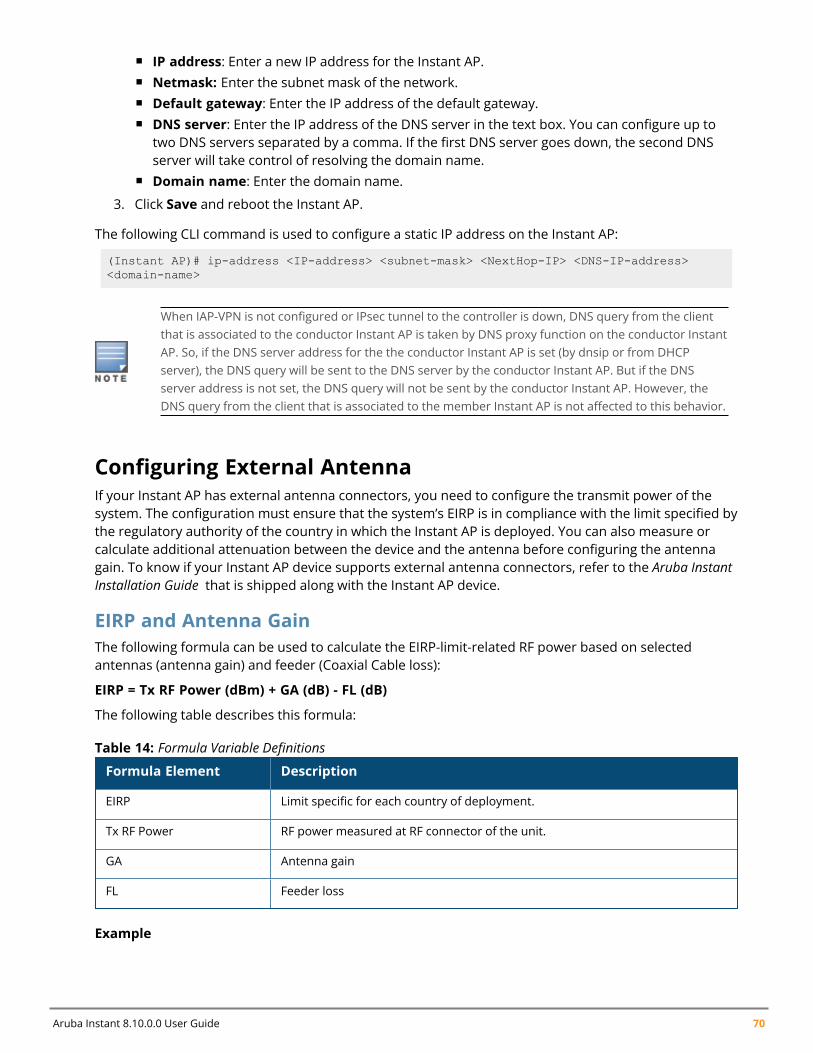
Aruba Instant 8.10.0.0 User Guide 70
n IP address: Enter a new IP address for the Instant AP.n Netmask: Enter the subnet mask of the network.n Default gateway: Enter the IP address of the default gateway.n DNS server: Enter the IP address of the DNS server in the text box. You can configure up to
two DNS servers separated by a comma. If the first DNS server goes down, the second DNSserver will take control of resolving the domain name.
n Domain name: Enter the domain name.
3. Click Save and reboot the Instant AP.
The following CLI command is used to configure a static IP address on the Instant AP:
(Instant AP)# ip-address <IP-address> <subnet-mask> <NextHop-IP> <DNS-IP-address><domain-name>
When IAP-VPN is not configured or IPsec tunnel to the controller is down, DNS query from the clientthat is associated to the conductor Instant AP is taken by DNS proxy function on the conductor InstantAP. So, if the DNS server address for the the conductor Instant AP is set (by dnsip or from DHCPserver), the DNS query will be sent to the DNS server by the conductor Instant AP. But if the DNSserver address is not set, the DNS query will not be sent by the conductor Instant AP. However, theDNS query from the client that is associated to the member Instant AP is not affected to this behavior.
Configuring External AntennaIf your Instant AP has external antenna connectors, you need to configure the transmit power of thesystem. The configuration must ensure that the system’s EIRP is in compliance with the limit specified bythe regulatory authority of the country in which the Instant AP is deployed. You can also measure orcalculate additional attenuation between the device and the antenna before configuring the antennagain. To know if your Instant AP device supports external antenna connectors, refer to the Aruba InstantInstallation Guide that is shipped along with the Instant AP device.
EIRP and Antenna GainThe following formula can be used to calculate the EIRP-limit-related RF power based on selectedantennas (antenna gain) and feeder (Coaxial Cable loss):
EIRP = Tx RF Power (dBm) + GA (dB) - FL (dB)
The following table describes this formula:
Formula Element Description
EIRP Limit specific for each country of deployment.
Tx RF Power RF power measured at RF connector of the unit.
GA Antenna gain
FL Feeder loss
Table 14: Formula Variable Definitions
Example
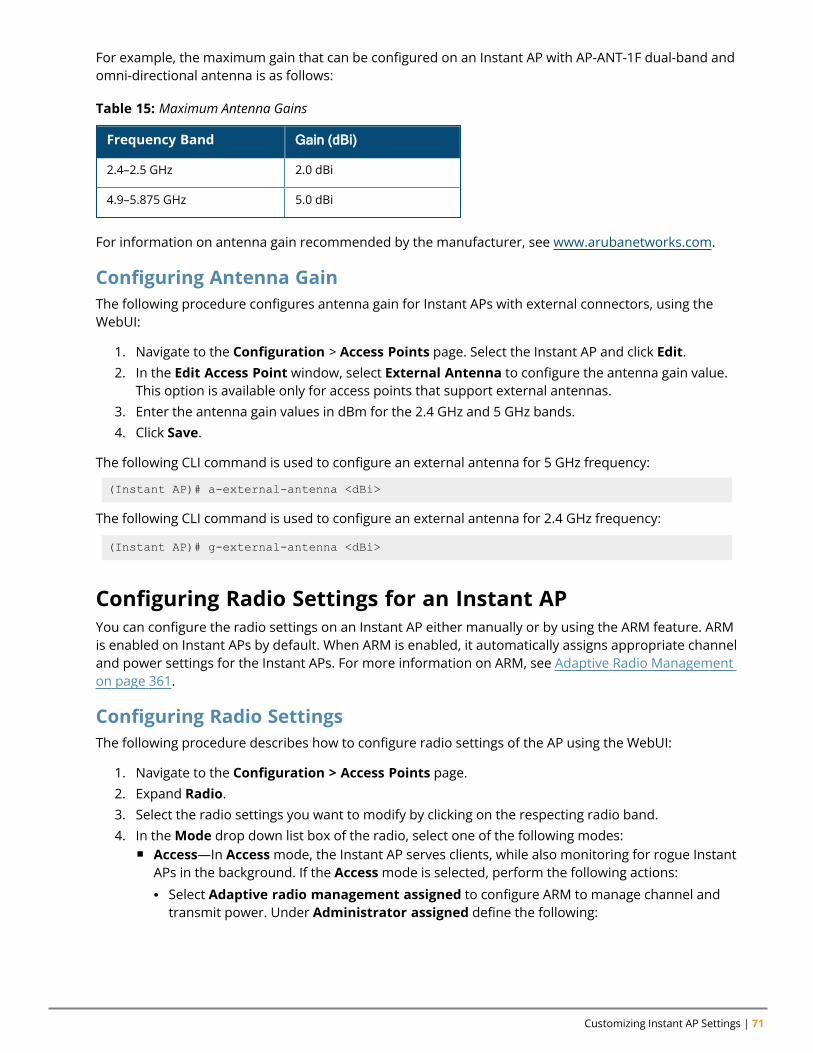
Customizing Instant AP Settings | 71
For example, the maximum gain that can be configured on an Instant AP with AP-ANT-1F dual-band andomni-directional antenna is as follows:
Frequency Band Gain (dBi)
2.4–2.5 GHz 2.0 dBi
4.9–5.875 GHz 5.0 dBi
Table 15: Maximum Antenna Gains
For information on antenna gain recommended by the manufacturer, see www.arubanetworks.com.
Configuring Antenna GainThe following procedure configures antenna gain for Instant APs with external connectors, using theWebUI:
1. Navigate to the Configuration > Access Points page. Select the Instant AP and click Edit.2. In the Edit Access Point window, select External Antenna to configure the antenna gain value.
This option is available only for access points that support external antennas.3. Enter the antenna gain values in dBm for the 2.4 GHz and 5 GHz bands.4. Click Save.
The following CLI command is used to configure an external antenna for 5 GHz frequency:
(Instant AP)# a-external-antenna <dBi>
The following CLI command is used to configure an external antenna for 2.4 GHz frequency:
(Instant AP)# g-external-antenna <dBi>
Configuring Radio Settings for an Instant APYou can configure the radio settings on an Instant AP either manually or by using the ARM feature. ARMis enabled on Instant APs by default. When ARM is enabled, it automatically assigns appropriate channeland power settings for the Instant APs. For more information on ARM, see Adaptive Radio Managementon page 361.
Configuring Radio SettingsThe following procedure describes how to configure radio settings of the AP using the WebUI:
1. Navigate to the Configuration > Access Points page.2. Expand Radio.3. Select the radio settings you want to modify by clicking on the respecting radio band.4. In theMode drop down list box of the radio, select one of the following modes:
n Access—In Accessmode, the Instant AP serves clients, while also monitoring for rogue InstantAPs in the background. If the Accessmode is selected, perform the following actions:l Select Adaptive radio management assigned to configure ARM to manage channel andtransmit power. Under Administrator assigned define the following:
Aruba Instant 8.10.0.0 User Guide 72
l Select Administrator assigned if you want to configure the channel and transmit powermanually.o Select appropriate channel number from the Channel drop-down list.o Enter appropriate transmit power value in the Transmit power text box .
If the transmit power is set to 0, the Instant AP is assigned the last transmitted powervalue set by the ARM.
n Monitor—InMonitormode, the Instant AP acts as a dedicated monitor, scanning all channelsfor rogue Instant APs and clients. You can set one radio on the Monitor mode and the otherradio on the access mode, so that the clients can use one radio when the other one is in the AirMonitor mode.
n Spectrum Monitor—In Spectrum Monitormode, the Instant AP functions as a dedicated full-spectrum RF monitor, scanning all channels to detect interference, whether from theneighboring Instant APs or from non-WiFi devices such as microwaves and cordless phones.
In this mode, Instant APs do not provide access services to clients.
5. Click Save.
When radio settings are assigned manually by the administrator, ARM is disabled.
By default, the channel and power for an Instant AP are optimized dynamically using ARM. You canoverride ARM on the 2.4 GHz and 5 GHz bands and set the channel and power manually if desired.
The following CLI commands are used to configure the radio channel and transmit power settings:
(Instant AP)# radio0-channel(Instant AP)# radio1-channel(Instant AP)# radio2-channel
The following CLI commands are used to configure the radio mode:
(Instant AP)# wifi0-mode {<access> | <monitor> | <spectrum>}(Instant AP)# wifi1-mode {<access> | <monitor> | <spectrum>}(Instant AP)# wifi2-mode {<access> | <monitor> | <spectrum>}
If the access mode is configured, run the following commands to configure the channel andtransmission power:
(Instant AP)# a-channel <channel> <tx-power>(Instant AP)# g-channel <channel> <tx-power>
For more information, see Aruba Instant 8.x CLI Reference Guide.
Configuring Maximum Clients on SSID Radio ProfilesYou can set the maximum number of clients in every individual Instant AP for SSID profiles operating onthe 2.4 GHz and 5 GHz radios. This is a per-AP and per-Radio configuration. This configuration is notpersistent and is lost once the Instant AP is rebooted.
Run the following commands to configure maximum clients for an SSID radio profile in the privilegedexec mode:
Customizing Instant AP Settings | 73
(Instant AP)# a-max-clients <ssid_profile> <max-clients>(Instant AP)# g-max-clients <ssid_profile> <max-clients>
Run the following commands to view the maximum clients allowed for an SSID profile:
(Instant AP)# show a-max-clients <ssid_profile>(Instant AP)# show g-max-clients <ssid_profile>
You can also set the maximum clients when configuring SSID profiles using theMax ClientsThreshold parameter in the WebUI andmax-clients-threshold parameter in the Instant CLI. Formore information, see Configuring WLAN Settings for an SSID Profile on page 97.
If the maximum clients setting is configured multiple times, using either the configuration mode orPrivileged EXEC mode, the latest configuration takes precedence.
Enabling Flexible RadioThis feature allows the AP to seamlessly switch between modes where the radio resources are eithercombined in a single 2x2 radio or separated into two 1x1 radios.
Flexible Radio is only supported on 203H Series and 203R Series access points.
You can configure the flexible radio in the following modes:
n 5 GHz mode: acts as a single radio operating on 5 GHz bandn 2.4 GHz mode: acts as a single radio operating on 2.4 GHz bandn 2.4 GHz and 5 GHz mode: acts as two radio interfaces, one operating on 5 GHz band, and the other
on the 2.4 GHz band. By default, the flexible radio is set to this mode.
AP-203H, AP-203R, and AP-203RP access points have one radio each, wherein each radio operates ontwo bands. When the flexible radio mode is at 2.4 GHz or 5 GHz, the radio operates on one band andthe Instant AP broadcasts 16 different SSIDs. However, when the flexible radio mode is at 2.4 GHz and 5GHz, the radio operates on both the bands and the Instant AP broadcasts only 8 SSIDs for each band,even if more than 8 SSIDs are configured. The SSIDs with an index value from 0 to 7 will be broadcasted.You can configure the Flexible Radio parameter using the WebUI or the CLI.
The following procedure configures flexible radio:
1. Navigate to Configuration > Access Points.2. Click the Instant AP to edit.3. Click the Flexible Radio tab.4. Specify theMode from the drop-down list.5. Click Save and reboot the Instant AP.
The following CLI command is used to configure the flexible radio mode:
(Instant AP)# flex-radio-mode <mode>
Enabling Low Power ModeThe Instant CLI allows you to enable or disable the low power mode feature on an Instant AP. Enablingthe low power mode feature results in the USB and POE-PSE capabilities, if applicable, on the AP to be
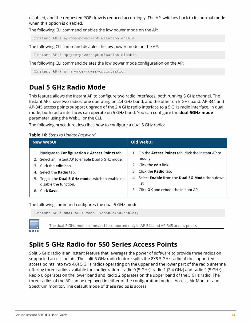
Aruba Instant 8.10.0.0 User Guide 74
disabled, and the requested POE draw is reduced accordingly. The AP switches back to its normal modewhen this option is disabled.
The following CLI command enables the low power mode on the AP:
(Instant AP)# ap-poe-power-optimization enable
The following CLI command disables the low power mode on the AP:
(Instant AP)# ap-poe-power-optimization disable
The following CLI command deletes the low power mode configuration on the AP:
(Instant AP)# no ap-poe-power-optimization
Dual 5 GHz Radio ModeThis feature allows the Instant AP to configure two radio interfaces, both running 5 GHz channel. TheInstant APs have two radios, one operating on 2.4 GHz band, and the other on 5 GHz band. AP-344 andAP-345 access points support upgrade of the 2.4 GHz radio interface to a 5 GHz radio interface. In dualmode, both radio interfaces can operate on 5 GHz band. You can configure the dual-5GHz-modeparameter using the WebUI or the CLI.
The following procedure describes how to configure a dual 5 GHz radio:
New WebUI Old WebUI
1. Navigate to Configuration > Access Points tab.
2. Select an Instant AP to enable Dual 5 GHz mode.
3. Click the edit icon.
4. Select the Radio tab.
5. Toggle the Dual 5 GHz mode switch to enable ordisable the function.
6. Click Save.
1. On the Access Points tab, click the Instant AP tomodify.
2. Click the edit link.
3. Click the Radio tab.
4. Select Enable from the Dual 5G Mode drop-downlist.
5. Click OK and reboot the Instant AP.
Table 16: Steps to Update Password
The following command configures the dual-5 GHz-mode:
(Instant AP)# dual-5GHz-mode {<enable><disable>}
The dual-5 GHz-mode command is supported only in AP-344 and AP-345 access points.
Split 5 GHz Radio for 550 Series Access PointsSplit 5 GHz radio is an Instant feature that leverages the power of software to provide three radios onsupported access points. The split 5 GHz radio feature splits the 8X8 5 GHz radio of the supportedaccess points into two 4X4 5 GHz radios operating on the upper and the lower part of the radio antennaoffering three radios available for configuration - radio 0 (5 GHz), radio 1 (2.4 GHz) and radio 2 (5 GHz).Radio 0 operates on the lower band and Radio 2 operates on the upper band of the 5 GHz radio. Thethree radios of the AP can be deployed in either of the configuration modes- Access, Air Monitor andSpectrum monitor. The default mode of these radios is access.
Customizing Instant AP Settings | 75
The dot11a-secondary-radio-profile is the configuration profile for radio 2. This profile is active whentri-radio is enabled on the AP. The dot11a-radio-profile, profile of radio 0, will be used as default by thedot11a-secondary -radio-profile, radio 2, when split 5 GHz radio is enabled. The secondary radio profilesupports all configurations available in dot11a-radio-profile including RF zones.
Certain existing configuration parameters do not apply when split 5 GHz-radio is configured. The a-channel and g-channel configuration to set channel power of the radio no longer takes effect. In theirplace radio-0-channel, radio-1-channel and radio-2-channel commands are used to configure thechannel and transmission power of the respective radios.
Feature Limitationsn Mesh is supported but only radio0 can be used as the mesh radio.n Split 5 GHz mode is only supported with APs powered by DC, PoE BT or dual shared PoE AT power
supply.n Access points require reboot to enable or disable Split 5 GHz radio mode in mesh deployments.
The following procedure configures the split 5 GHz radio mode on the Instant AP,
1. Navigate to Configuration> Access Points page and select the Access Point > edit > Radioaccordion.
2. Select Enable from the Split 5GHz mode drop down list box to enable the split 5 GHz radiomode. To disable the feature, select Disable from the Split 5GHz mode. The default option isdisabled.
3. The Radio 2 settings are now available for configuration under the Radio 2 accordion.4. Choose a radio mode from theMode drop-down list box.5. Select a channel assignment method
n Adaptive Radio Management assigned - If this option is selected the channels for the radiois intelligently assigned by the access point.
n Administrator Assigned - If this option is selected, select the channel and the transmit Powerin the Channel and Transmit power fields.
6. Click Save.
To configure split 5 GHz radio mode for all supported APs in the network cluster.
1. Navigate to Configuration> Networks page and select Show advanced options.2. Under General, toggle the Split 5GHz mode switch to enable or disable Split 5 GHz mode
globally for supported APs in the network. The default option is disabled.3. Click Save.
To configure the radio profile settings for the secondary 5 GHz radio,
1. Navigate to Configuration > RF > Show advanced options>Radio accordion.2. Click + in the Secondary 5GHz band table and define the radio settings for the secondary 5 GHz
radio. For information on configuration parameters for the radio profile, see Configuring RadioProfiles on page 368.
3. Click OK.
The following configurations do not require an AP reboot to take effect.
Configuring Split 5 GHz Radio
Aruba Instant 8.10.0.0 User Guide 76
The following command is a global configuration and a per-ap command. When configured globally, allsupported APs will work in the split 5 GHz mode. To disable split 5 GHz radio on selected APs overridethe global setting using the per-ap command. The per-ap command takes priority over the globalconfiguration. The default value for this command is disabled.
To enable the split 5 GHz feature, use the split-5ghz-mode enabled command.
(Instant AP) # split-5ghz-mode enabled
To disable the split 5 GHz feature, use the split-5ghz-mode disabled or no split-5ghz-mode command.
(Instant AP) # split-5ghz-mode disabled(Instant AP) # no split-5ghz-mode
To configure radio profile settings of radio2, use the rf dot11a-secondary-radio-profile <name>command. The secondary profile is active only when split 5 GHz radio is enabled on the AP. The valuesof the dot11a-radio-profile is used as default by the secondary radio profile.
(Instant AP) # rf dot11a-secondary-radio-profile <name>
See Aruba Instant 8.x CLI Reference Guide for information on configurable parameters.
Enabling/ Disabling radiosWhen split 5 GHz radio is enabled, use the radio-0-disable, radio-1-disable and radio-2-disablecommands to disable the respective radios.
(Instant AP) # radio-1-disable(Instant AP) # radio-2-disable
Radio Channel and Transmission PowerWhen tri-radio is enabled, use the radio-0-channel, radio-1-channel and radio-2-channel to configurethe static channel and transmission power for the respective radios. Please note radio0 and radio2supports 5 GHz channels and radio1 supports 2.4 GHz channels.
(Instant AP) # radio-0-channel <36-64>(Instant AP) # radio-1-channel <1-11>(Instant AP) # radio-2-channel <100-161>
Radio ModeWhen split 5 GHz radio is enabled, thewifi2-mode command is available to configure the mode forradio2. This command is a per-ap setting.
(Instant AP) # wifi2-mode <monitor | spectrum | access>
WLAN SSID profilesTo control SSIDs being created in the 5 GHz radio, use the allowed-5ghz-radio parameter under theparticular wlan ssid-profile command to specify under which 5 GHz radio the SSID should bebroadcasted. The default value for the command is all.
(Instant AP) #wlan ssid-profile <name>(Instant AP) # allowed-5ghz-radio <first-dot11a-radio-only | second-dot11a-radio-only| all>
To view the view configuration information of radios, use the following show commands:
n Show apsn Show radio config
Customizing Instant AP Settings | 77
n Show radio profilen Show ids radio
To troubleshoot radios and view debug information, use the following troubleshooting commands:
n Show ap debug radio-stats radio-idn Show ap debug radio-info radio-idn Show ap debug power-table radio-id
Air SliceAruba's key RF differentiation, Air Slice, designed for 11ax APs optimizes user experience and assuresQoA to enterprise applications. Air Slice combines AppRF and UCC for classifying applications and it alsosupports custom flow definitions. Air Slice uses a combination of priority queuing, dynamic WMMboosting, and 11ax based radio resource scheduling to prioritize enterprise applications in the presenceof competing background traffic flows to meet latency and bandwidth requirements. Air Slice solutionbuilt on OFDMA, MU-MIMO, and TWT constructs offer the following services:
n Guaranteed bit raten Battery life extensionn Bounded latency and jitter
Air Slice supports multiple services like gaming, IoT, voice and video, and so on. Air Slice support isavailable for all AP clients. However, 802.11ax clients have enhanced benefits due to efficient uplink anddownlink traffic scheduling of 802.11ax standard. Air Slice also allows network administrators to select alist of applications to be prioritized.
Air Slice is supported only on 500 Series, 510 Series, 530 Series, 570 Series, and AP-555 access points.It is mandatory to enable DPI on the AP before configuring Air Slice, else an error will be reported.
If Air Slice is enabled in tunnel forwarding mode, low-priority flows are dropped to 0 Mbps. Thisoccurs when high-priority flows are enabled. Hence, it is recommended not to enable Air Slice intunnel forwarding mode.
The following procedure configures Air Slice Policy and Application Monitoring on an Instant AP:
1. Navigate to Configuration > System > General.2. Click the Show advanced options tab.3. Slide the toggle switch next to AirSlice policy, to the right, to enable the feature.4. Slide the toggle switch next to Application monitoring, to the right, to enable the feature.5. Click Save.
The following CLI command configures Air Slice policy on the AP:
(Instant AP)(config)# airslice-policy
The following CLI command configures Application Monitoring on the AP:
(Instant AP)(config)# application-monitoring
The following CLI command is used to view the Application Monitoring list:
(Instant AP)# show app-monitoring list
The following CLI command is used to view the client statistics based on the MAC ID:
Aruba Instant 8.10.0.0 User Guide 78
(Instant AP)#show ap debug airslice client-stats <mac>
ACL Rule ModificationsThe session acl list and acl rule list are modified based on the network configuration. When rule actionis permitted, the rule can configure the new optionmarkapp with custom appid. Instant allowsmultiple rules to configure the same custom name, and once the ACL is active, the action takes effectwith the custom application ID on the session.
The following procedure configures a custom application ID in the access rule:
1. Navigate to Configuration > Security > Roles. The settings in the Roles tab are displayed.
2. Select the role for which you want to configure access rules.
3. In the Access rules section, click + to add a new rule. The New rule window is displayed.
4. Ensure that the rule type is set to Access Control.
5. Select Network under the Service category.6. Under Options, select theMark Application checkbox.7. Select one of the custom values from the drop-down list.8. Click OK.
Alternatively, you can configure access rules for a wired or wireless client through the WLAN wizard orthe Wired Profile window.
The following CLI command configures a session ACL with a custom application ID:(Instant AP)(config)# wlan access-list session ses-acl(Instant AP)(Session-ACL "ses-acl")# rule 10.1.1.1 255.255.255.255 20.1.1.1255.255.255.255 match 17 0-65535 0-65535 permit markapp custom1(Instant AP)(Session-ACL "ses-acl")#end
The following CLI command configures a with a rule ACL with a custom application ID:
(Instant AP)(config)# wlan access-rule WirelessRule(Instant AP)(Access Rule "WirelessRule")# rule 10.1.1.1 255.255.255.255 match 17 0-65535 0-65535 permit markapp custom1(Instant AP)(Access Rule "WirelessRule")# access-list session ses-acl
The following CLI command displays the custom appid configured on the rule ACL:
(Instant AP)# show access-rule WirelessRule
The following CLI command displays the custom appid confifured on the session ACL:
(Instant AP)#show access-list ses-acl
In addition to the custom applications, Air Slice is supported only for the applications listed below:
n Zoomn Slackn Skypen Lync Onlinen ALG Skype for Businessn WebExn GoToMeeting
Customizing Instant AP Settings | 79
n Office365n Dropboxn Amazon AWSn Githubn Micrsoft Excel Onlinen Onedriven Outlookn Microsoft Plannern Microsoft Powerpoint Onlinen Microsoft SharePoint Onlinen Microsoft Swayn Microsoft Teamsn Microsoft Word Onlinen Yammern ALG Wifi-Calling
Support for Input-Filter on BLE DevicesWhen IoT transport profiles are configured, BLE-devices are filtered based on the IoT transport profileswhich may include device class, UUID, or vendor filters. Only BLE devices that should be reported arestored in the BLE-table and data loss is avoided.
The following CLI command enables the entry filter:
(Instant AP)# ble-init-action input-filter-enable
The following CLI command disables the entry filter:
(Instant AP)# ble-init-action input-filter-disable
The following command is used to view the latest filtered BLE-device
(Instant AP)#show ap debug ble-input-filter-stats
Configuring Uplink VLAN for an Instant APInstant supports a management VLAN for the uplink traffic on an Instant AP. You can configure anuplink VLAN when an Instant AP needs to be managed from a non-native VLAN. After an Instant AP isprovisioned with the uplink management VLAN, all management traffic sent from the Instant AP istagged with the management VLAN.
Ensure that the native VLAN of the Instant AP and uplink are not the same.
The following procedure describes how to configure the uplink management VLAN on an Instant AP:
1. In the Access Points tab, select the Instant AP to modify and click edit.2. Select the Uplink tab.3. In the Uplink Management VLAN text box, specify the VLAN.4. Click OK.5. Reboot the Instant AP.
Aruba Instant 8.10.0.0 User Guide 80
The following CLI command configures an uplink management VLAN:
(Instant AP)# uplink-vlan <VLAN-ID>
The following CLI command is used to view the uplink VLAN status:
(Instant AP)# show uplink-vlanUplink Vlan Current :0Uplink Vlan Provisioned :1
Changing the Instant AP Installation ModeBy default, all Instant AP models initially ship with an indoor or outdoor installation mode. This meansthat Instant APs with an indoor installation mode are normally placed in enclosed, protectedenvironments and those with an outdoor installation mode are used in outdoor environments andexposed to harsh elements.
In most countries, there are different channels and power that are allowed for indoor and outdooroperation. You may want to change an Instant AP’s installation mode from indoor to outdoor or viceversa.
The following procedure configures an installation mode for the Instant AP:
1. To configure the installation mode for an Instant AP:2. Navigate to the Configuration > Access Points page.3. Select the Instant AP from the Access Points list and click Edit.4. Expand Installation Type and select one of the three installation options - Default, Indoor or
Outdoor.5. Click Save6. Reboot the Instant AP.
By default, the Defaultmode is selected. This means that the Instant AP installation type is based onthe Instant AP model.
The following CLI command configures the Installation Mode for an Instant AP:
(Instant AP)# ap-installation <type[default|indoor|outdoor]>
The following CLI command is used to view the installation type of the Instant APs:
(Instant AP)# show ap allowed-channels
Changing USB Port StatusThe USB port can be enabled or disabled based on your uplink preferences. If you do not want to usethe cellular uplink or 3G/4G modem in your current network setup, you can set the USB port status todisabled. By default, the USB port status is enabled.
The following procedure configures the USB port status:
1. Navigate to the Configuration > Access Points page.2. Select the Instant AP from the Access Points list and click Edit.3. Expand Uplink.4. Toggle the USB port switch to enable or disable the USB port.
Customizing Instant AP Settings | 81
5. Click Save.6. Reboot the Instant AP.
The following CLI command disables the USB port:
(Instant AP)# usb-port-disable
The following CLI command enables the USB port:
(Instant AP)# no usb-port-disable
The following CLI command is used to view the USB port status:
(Instant AP)# show ap-envAntenna Type:Externalusb-port-disable:1
Conductor Election and Virtual ControllerInstant does not require an external Mobility Controller to regulate and manage the Wi-Fi network.Instead, every Instant AP in the same broadcast domain automatically organizes together to create avirtual controller for the network. The virtual controller represents a single pane of glass that regulatesand manages a Wi-Fi network at a single installation location, performing configuration and firmwaremanagement of all its member access points. The virtual controller architecture also ensures that asingle AP sets up and manages the VPN tunnel to a mobility controller in the data center, if configured,and allows client traffic from all member APs to share the VPN tunnel.
The main capabilities supported by the virtual controller are listed below:
n Acts as a central point of configuration. The configuration is distributed to other Instant APs in anetwork.
n Provides DHCP servers to the cluster.n Provides VPN tunnels to a Mobility Controller.n Provides Central, AirWave, and Activate interaction.
Conductor Election ProtocolThe Conductor Election Protocol enables the Instant network to dynamically elect an Instant AP to takeon a virtual controller role and allow graceful failover to a new virtual controller when the existingvirtual controller is not available. The election beacons are broadcast and unicast L2 frames are usedbetween the virtual controller and the member Instant APs. This protocol ensures stability of thenetwork during initial startup or when the virtual controller goes down by allowing only one Instant APto self-elect as a virtual controller. When an existing virtual controller is down, a new virtual controller iselected by the conductor election protocol. This protocol is initiated by any non-virtual controller InstantAP that no longer receives beacon frames from an active virtual controller.
An Instant AP is elected as a conductor by one of the following methods:
1. Enforced—In this method, Instant APs in preferred, 3G/4G uplink, mesh portal, or stand-alonemode are elected as the conductor. However Instant APs in mesh point, or hierarchy down sidemode are not elected as the conductor.
2. Random Intervals—In this method, a quick Instant AP election takes place when the Instant APsboot. A re-election takes place when the existing conductor Instant AP is down. This results inrandom election of a conductor Instant AP.
Aruba Instant 8.10.0.0 User Guide 82
3. Versus Policy—This is a method by which multiple Instant APs in a cluster are competing witheach other to become a conductor. The Instant AP with higher priority, higher uptime or a biggerMAC address becomes the conductor. The Instant AP with lesser priority, lesser uptime or asmaller MAC address becomes the member.
Preference to an Instant AP with 3G/4G CardThe Conductor Election Protocol prefers the Instant AP with a 3G/4G card when electing a virtualcontroller for the Instant network during the initial setup.
The virtual controller is selected based on the following criteria:
n If there is more than one Instant AP with 3G/4G cards, one of these Instant APs is dynamically electedas the virtual controller.
n When an Instant AP without 3G/4G card is elected as the virtual controller but is up for less than 5minutes, another Instant AP with 3G/4G card in the network is elected as the virtual controller toreplace it and the previous virtual controller reboots.
n When an Instant AP without 3G/4G card is already elected as the virtual controller and is up for morethan 5 minutes, the virtual controller will not be replaced until it goes down.
Preference to an Instant AP with Non-Default IPThe Conductor Election Protocol prefers an Instant AP with non-default IP when electing a virtualcontroller for the Instant network during initial startup. If there are more than one Instant APs with non-default IPs in the network, all Instant APs with default IP will automatically reboot and the DHCP processis used to assign new IP addresses.
Viewing Conductor Election DetailsThe following CLI command is used to verify the status of an Instant AP and conductor election details:
(Instant AP)# show election statistics(Instant AP)# show summary support
Manual Provisioning of Conductor Instant APIn most cases, the conductor election process automatically determines the best Instant AP that canperform the role of virtual controller, which will apply its image and configuration to all other InstantAPs in the same Instant AP management VLAN. When the virtual controller goes down, a new virtualcontroller is elected.
Provisioning an Instant AP as a Conductor Instant APThe following procedure describes how to provision an Instant AP as a conductor Instant AP:
1. Navigate to the Configuration > Access Points page.2. Select the Instant AP from the Access Points list and click Edit.3. Expand General.4. Toggle the Preferred conductorswitch to enable or disable the option.5. Click Save.
The following CLI command provisions an Instant AP as a conductor Instant AP:
(Instant AP)# iap-conductor
The following CLI command is verifies if the Instant AP is provisioned as conductor Instant AP:
Customizing Instant AP Settings | 83
(Instant AP)# show ap-envAntenna Type:InternalIap_conductor:1
Only one Instant AP in a cluster can be configured as the preferred conductor.
Adding an Instant AP to the NetworkTo add an Instant AP to the Instant network, assign an IP address. For more information, see Assigningan IP address to the Instant AP on page 18.
After an Instant AP is connected to the network, if the Auto-Join feature is enabled, the Instant APinherits the configuration from the virtual controller and is listed in the Access Points tab.
The following procedure describes how to manually add an Instant AP to the network:
1. Navigate to the Configuration > Access Points page.2. Click + in the Access Points table.3. In the New Access Point window, enter the MAC address for the new Instant AP.4. Click OK.
Removing an Instant AP from the NetworkThe following procedure describes how to manually remove an Instant AP from the network:
1. Navigate to the Configuration > Access Points page.2. Select the Instant AP from the Access Points list and click Delete.3. Click OK to confirm the deletion.
The deleted Instant APs cannot join the Instant network anymore and are not displayed in the WebUI.However, the master Instant AP details cannot be deleted from the virtual controller database.
Support for BLE Asset TrackingStarting from Instant 6.5.2.0, Instant APs can monitor BLE asset tags to track the location of time-sensitive, high-value assets embedded with BLE tags.
BLE tags are located through the following steps:
1. Instant AP beacons scan the network for BLE tags.2. When a tag is detected, the Instant AP beacon sends information about the tag to the Instant AP,
including the MAC address and RSSI of the tag. This data is maintained in a list by the BLEdaemon process on the Instant AP.
3. The list of tags is sent from the BLE daemon process on the Instant AP to the BLE relay process onthe Instant AP.
4. The Instant AP opens a secure WebSocket connection with the designated WebSocket endpointon the management server, such as the Meridian editor.
5. After receiving the list of tags from the Instant AP, the management server calculates the locationof each tag by triangulating the tag’s RSSI data on a floor plan.
Aruba Instant 8.10.0.0 User Guide 84
Each BLE tag must be heard by at least three Instant AP beacons for triangulation.
The following CLI command is used to view the list of BLE tags discovered and reported by the InstantAP.
(Instant AP)# show ap debug ble-table assettags
The following CLI command is used to manage BLE tag reporting and logging.
(Instant AP) (config)# ble_relay mgmt-server type ws <ws-endpoint>
The following CLI commands are used to view BLE tag data:
(Instant AP)# show ap debug ble-relay tag-report(Instant AP)# show ap debug ble-relay disp-attr(Instant AP)# show ap debug ble-relay ws-log(Instant AP)# show ap debug ble-relay iot-profile(Instant AP)# show ap debug ble-relay jobs(Instant AP)# show ap debug ble-relay report
Intelligent Power and Temperature Monitoring (IPTM)Intelligent Power and Temperature Monitoring (IPTM) is a combination of Intelligent Power Monitoring(IPM) and Intelligent Thermal Management (ITM) features that optimize AP operations in changingpower and temperature conditions. These features adapt the performance of the AP to provideconsistent network experience according to the power usage and operating temperatute of the AP.
To manage this optimization, a set of reduction steps may be configured and associated with a priorityvalue. When triggered, IPTM applies the sequence of reduction steps as defined by the priority definitionuntil the AP is functioning within the power budget and threshold temperature. This happensdynamically as IPTM constantly monitors the power consumption and temperature of the AP andapplies the corresponding reduction steps.
IPM and ITM must be enabled separately using the CLI. However, the reduction steps applied for IPMand ITM are the same and are configured using the ipm-power-reduction-step-prio ipm-step<reduction step> priority <priority value> parameter in the ipm command. The IPM and ITM settingsconfigured for the AP can be viewed using the show running configuration command.
Important Points to Remembern By default, IPM and ITM are disabled.n IPM must be enabled for ITM to function.n ITM must be disabled before disabling IPM.
n By default, IPM and ITM do not apply any restrictions on the AP. The reduction steps must beexplicitly configured using the ipm-power-reduction-step-prio ipm-step <reduction step> priority<priority value> parameter in the ipm command.
n Initally, all functionalities of the AP are turned on by IPM and ITM. The reduction steps are triggeredonly when the power consumption of the AP exceeds the threshold associated with the powerbudget or when the temperature of the AP goes beyond the threshold value.
n IPM and ITM do not override pre-existing settings that restrict AP functionality. For example, whenthe USB port is disabled in the provisioning profile, the AP will not enable the functionality when thereduction steps are retracted.
Intelligent Power Management
Customizing Instant AP Settings | 85
Intelligent Power Management (IPM) measures the power utilization of the AP and dynamically adaptsto the power budget. IPM dynamically limits the power requirement of the AP as per the availablepower resources. This is in contrast to the existing static power management method where the powerprofiles such as POE-AF, POE-AT, PoE-DC, or LLDP are hard-coded for each AP.
IPM is supported on all AP platforms except 203H Series, 203R Series, 207 Series, 303 Series, 303PSeries, 318 Series, 320 Series, 360 Series, and 370 Series access points.
Disable ITM before disabling IPM.
The following CLI command enables IPM:
(Instant AP)(config)# ipm(Instant AP)(ipm)# enable
Reporting Power Values to CentralInstant APs can measure and periodically report their power information such as current, average,minimum, and maximum power consumption values sampled over the previous one minute and reportthe same to Aruba Central. When Instant APs measure the power values, they send the information tothe conductor Instant AP over a PAPI message. This information is saved and sent to Central.
This functionality is not supported on 203H Series, 203R Series, 207 Series, 303 Series, 303P Series,320 Series, 360 Series, 500 Series, 500H Series access points.
The following CLI command is used to view the power monitoring information:
(Instant AP) #show aps power-monitor
Intelligent Thermal ManagementIntelligent Thermal Management (ITM) measures the internal temperature of the AP and dynamicallyadapts operations to reduce the internal temperature. The operations of the AP are throttled downwhen the internal temperature exceeds the maximum threshold temperature. The reduction stepsapplied to control the temperature are defined using the ipm-power-reduction-step-prio ipm-stepparameter in the ipm command.
ITM is not supported on 203H Series, 203R Series, 207 Series, 300 Series, 303 Series, 303H Series, 310Series, 318 Series, 320 Series, 330 Series, 340 Series, 370 Series, 370EX Series, AP-387, 500 Series,500H Series, 510 Series, 530 Series, 550 Series, and 630 Series access points.
IPM must be enabled for ITM to function.
The following CLI command enables ITM:
(Instant AP)(config)# itm
Configuring Reduction StepsThe reduction steps and their order is configured using the ipm-power-reduction-step-prio ipm-step<reduction step> priority <priority value> parameter in the ipm command. The priority values rangefrom 1-16, with 1 being the highest and 16 being the lowest. When triggered, the reduction steps are
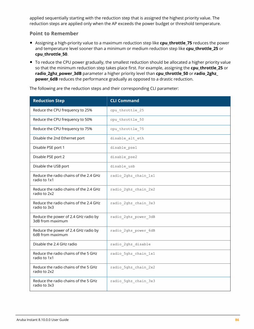
Aruba Instant 8.10.0.0 User Guide 86
applied sequentially starting with the reduction step that is assigned the highest priority value. Thereduction steps are applied only when the AP exceeds the power budget or threshold temperature.
Point to Remember
n Assigning a high-priority value to a maximum reduction step like cpu_throttle_75 reduces the powerand temperature level sooner than a minimum or medium reduction step like cpu_throttle_25 orcpu_throttle_50.
n To reduce the CPU power gradually, the smallest reduction should be allocated a higher priority valueso that the minimum reduction step takes place first. For example, assigning the cpu_throttle_25 orradio_2ghz_power_3dB parameter a higher priority level than cpu_throttle_50 or radio_2ghz_power_6dB reduces the performance gradually as opposed to a drastic reduction.
The following are the reduction steps and their corresponding CLI parameter:
Reduction Step CLI Command
Reduce the CPU frequency to 25% cpu_throttle_25
Reduce the CPU frequency to 50% cpu_throttle_50
Reduce the CPU frequency to 75% cpu_throttle_75
Disable the 2nd Ethernet port disable_alt_eth
Disable PSE port 1 disable_pse1
Disable PSE port 2 disable_pse2
Disable the USB port disable_usb
Reduce the radio chains of the 2.4 GHzradio to 1x1
radio_2ghz_chain_1x1
Reduce the radio chains of the 2.4 GHzradio to 2x2
radio_2ghz_chain_2x2
Reduce the radio chains of the 2.4 GHzradio to 3x3
radio_2ghz_chain_3x3
Reduce the power of 2.4 GHz radio by3dB from maximum
radio_2ghz_power_3dB
Reduce the power of 2.4 GHz radio by6dB from maximum
radio_2ghz_power_6dB
Disable the 2.4 GHz radio radio_2ghz_disable
Reduce the radio chains of the 5 GHzradio to 1x1
radio_5ghz_chain_1x1
Reduce the radio chains of the 5 GHzradio to 2x2
radio_5ghz_chain_2x2
Reduce the radio chains of the 5 GHzradio to 3x3
radio_5ghz_chain_3x3
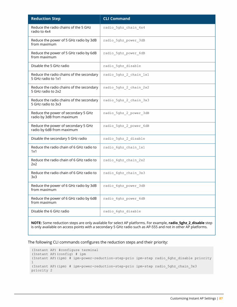
Customizing Instant AP Settings | 87
Reduction Step CLI Command
Reduce the radio chains of the 5 GHzradio to 4x4
radio_5ghz_chain_4x4
Reduce the power of 5 GHz radio by 3dBfrom maximum
radio_5ghz_power_3dB
Reduce the power of 5 GHz radio by 6dBfrom maximum
radio_5ghz_power_6dB
Disable the 5 GHz radio radio_5ghz_disable
Reduce the radio chains of the secondary5 GHz radio to 1x1
radio_5ghz_2_chain_1x1
Reduce the radio chains of the secondary5 GHz radio to 2x2
radio_5ghz_2_chain_2x2
Reduce the radio chains of the secondary5 GHz radio to 3x3
radio_5ghz_2_chain_3x3
Reduce the power of secondary 5 GHzradio by 3dB from maximum
radio_5ghz_2_power_3dB
Reduce the power of secondary 5 GHzradio by 6dB from maximum
radio_5ghz_2_power_6dB
Disable the secondary 5 GHz radio radio_5ghz_2_disable
Reduce the radio chain of 6 GHz radio to1x1
radio_6ghz_chain_1x1
Reduce the radio chain of 6 GHz radio to2x2
radio_6ghz_chain_2x2
Reduce the radio chain of 6 GHz radio to3x3
radio_6ghz_chain_3x3
Reduce the power of 6 GHz radio by 3dBfrom maximum
radio_6ghz_power_3dB
Reduce the power of 6 GHz radio by 6dBfrom maximum
radio_6ghz_power_6dB
Disable the 6 GHz radio radio_6ghz_disable
NOTE: Some reduction steps are only available for select AP platforms. For example, radio_5ghz_2_disable stepis only available on access points with a secondary 5 GHz radio such as AP-555 and not in other AP platforms.
The following CLI commands configures the reduction steps and their priority:
(Instant AP) #configure terminal(Instant AP)(config) # ipm(Instant AP)(ipm) # ipm-power-reduction-step-prio ipm-step radio_6ghz_disable priority1(Instant AP)(ipm) # ipm-power-reduction-step-prio ipm-step radio_5ghz_chain_3x3priority 2
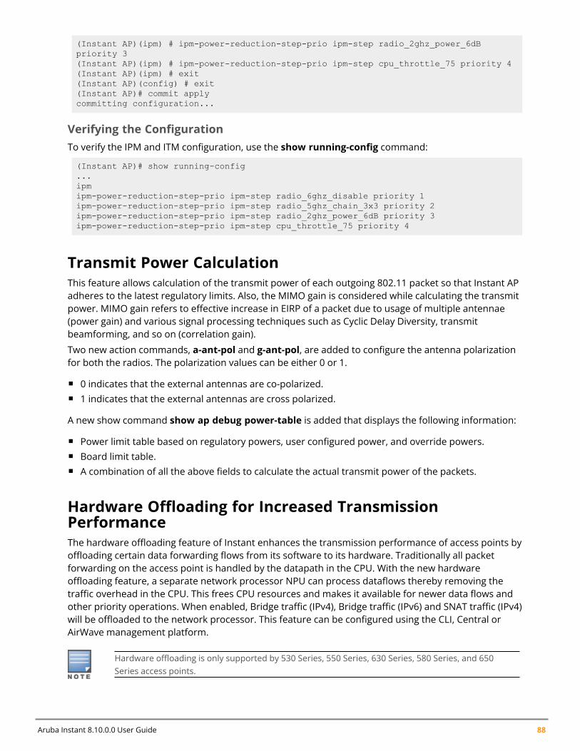
Aruba Instant 8.10.0.0 User Guide 88
(Instant AP)(ipm) # ipm-power-reduction-step-prio ipm-step radio_2ghz_power_6dBpriority 3(Instant AP)(ipm) # ipm-power-reduction-step-prio ipm-step cpu_throttle_75 priority 4(Instant AP)(ipm) # exit(Instant AP)(config) # exit(Instant AP)# commit applycommitting configuration...
Verifying the ConfigurationTo verify the IPM and ITM configuration, use the show running-config command:
(Instant AP)# show running-config...ipmipm-power-reduction-step-prio ipm-step radio_6ghz_disable priority 1ipm-power-reduction-step-prio ipm-step radio_5ghz_chain_3x3 priority 2ipm-power-reduction-step-prio ipm-step radio_2ghz_power_6dB priority 3ipm-power-reduction-step-prio ipm-step cpu_throttle_75 priority 4
Transmit Power CalculationThis feature allows calculation of the transmit power of each outgoing 802.11 packet so that Instant APadheres to the latest regulatory limits. Also, the MIMO gain is considered while calculating the transmitpower. MIMO gain refers to effective increase in EIRP of a packet due to usage of multiple antennae(power gain) and various signal processing techniques such as Cyclic Delay Diversity, transmitbeamforming, and so on (correlation gain).
Two new action commands, a-ant-pol and g-ant-pol, are added to configure the antenna polarizationfor both the radios. The polarization values can be either 0 or 1.
n 0 indicates that the external antennas are co-polarized.n 1 indicates that the external antennas are cross polarized.
A new show command show ap debug power-table is added that displays the following information:
n Power limit table based on regulatory powers, user configured power, and override powers.n Board limit table.n A combination of all the above fields to calculate the actual transmit power of the packets.
Hardware Offloading for Increased TransmissionPerformanceThe hardware offloading feature of Instant enhances the transmission performance of access points byoffloading certain data forwarding flows from its software to its hardware. Traditionally all packetforwarding on the access point is handled by the datapath in the CPU. With the new hardwareoffloading feature, a separate network processor NPU can process dataflows thereby removing thetraffic overhead in the CPU. This frees CPU resources and makes it available for newer data flows andother priority operations. When enabled, Bridge traffic (IPv4), Bridge traffic (IPv6) and SNAT traffic (IPv4)will be offloaded to the network processor. This feature can be configured using the CLI, Central orAirWave management platform.
Hardware offloading is only supported by 530 Series, 550 Series, 630 Series, 580 Series, and 650Series access points.

Customizing Instant AP Settings | 89
Configuring Hardware OffloadingThe following CLI command enables hardware offloading:
(Instant AP) # config(Instant AP) (config) # flow-offload
The following CLI command disables hardware offloading:
(Instant AP) # config(Instant AP) (config) # no flow-offload
The following CLI command is used to view the status of flow offloading:
(Instant AP) # show flow-offload status
Chapter 8VLAN Configuration
VLAN ConfigurationThis chapter explains the following topics:
n VLAN Poolingn Uplink VLAN Monitoring and Detection on Upstream Devicesn Multiple Management Interface
VLAN configuration is required for networks with more devices and broadcast traffic on a WLAN SSID orwired profile. Based on the network type and its requirements, you can configure the VLANs for a WLANSSID or wired port profile.
For more information on VLAN configuration for a WLAN SSID and wired port profile, see ConfiguringVLAN Settings for a WLAN SSID Profile on page 102 and Configuring VLAN for a Wired Profile on page132, respectively.
VLAN PoolingIn a single Instant AP cluster, a large number of clients can be assigned to the same VLAN. Using thesame VLAN for multiple clients can lead to a high level of broadcasts in the same subnet. To manage thebroadcast traffic, you can partition the network into different subnets and use L3-mobility betweenthose subnets when clients roam. However, if a large number of clients need to be in the same subnet,you can configure VLAN pooling, in which each client is randomly assigned a VLAN from a pool of VLANson the same SSID. Thus, VLAN pooling allows automatic partitioning of a single broadcast domain ofclients into multiple VLANs.
Uplink VLAN Monitoring and Detection on UpstreamDevicesIf a client connects to an SSID or a wired interface with VLAN that is not allowed on the upstream device,the client will not be assigned an IP address and thus cannot connect to the Internet. In such a scenario,the WebUI displays an alert. To prevent this issue from recurring, ensure that there is no mismatch inthe VLAN configuration.
Multiple Management InterfaceUsers have an option to create multiple VLAN interfaces on conductor Instant APs. This option is notsupported on member Instant APs due to the following reasons:
n Only the conductor AP can implement NATing.n VLAN features such as guest VLAN, DRP VLAN, VC VLAN, local DHCP VLAN, and so on are
implemented only on the conductor AP.
Aruba Instant 8.10.0.0 User Guide 90

VLAN Configuration | 91
Instant APs can report downlink wired port VLAN port information to Central. Using this information,Central can build a topology view of the user’s network.
Chapter 9IPv6 Support
IPv6 SupportThis chapter includes the following topics:
n IPv6 Notation on page 92n Enabling IPv6 Support for Instant AP Configuration on page 92n Firewall Support for IPv6 on page 94n GRE Backup Tunnel on page 94n Debugging Commands on page 95
IPv6 NotationIPv6 is the latest version of IP that is suitable for large-scale IP networks. IPv6 supports a 128-bit addressto allow 2128, or approximately 3.4×1038 addresses while IPv4 supports only 232 addresses.
The IP address of the IPv6 host is always represented as eight groups of four hexadecimal digitsseparated by colons. For example 2001:0db8:0a0b:12f0:0000:0000:0000:0001. However, the IPv6notation can be abbreviated to compress one or more groups of zeroes or to compress leading ortrailing zeroes.
The following examples show various representations of the address2001:0db8:0a0b:12f0:0000:0000:0000:0001
n Valid format—2001:db8:a0b:12f0::0:0:1
n Invalid format—2001:db8:a0b:12f0::::0:1. The “::” sign appears only once in an address.n With leading zeros omitted—2001:db8:a0b:12f0:0:0:0:1
n Switching from upper to lower case—2001:DB8:A0B:12f0:0:0:0:1
IPv6 uses a "/" notation which describes the number of bits in netmask as in IPv4.2001:db8::1/128 – Single Host2001:db8::/64 – Network
Enabling IPv6 Support for Instant AP ConfigurationInstant APs support IPv6 address mode for the following features:
n Supported IP modesn Configuring IPv6 Address for an Instant APn RADIUS over IPv6n SNMP Over IPv6n SNTP Over IPv6 on page 94
Supported IP modesInstant supports two modes of IP address configuration:
Aruba Instant 8.10.0.0 User Guide 92
IPv6 Support | 93
n V4-only—The Instant AP would allow IPv6 clients to pass-through just like the previous Instantrelease.
n V4-prefer—Supports both IPv4 and IPv6 addresses. If the Instant AP gets both IPv4 and IPv6responses for a DNS query, then the Instant AP would prefer the IPv4 DNS address instead of theIPv6 DNS address.
When the IP mode is set to v4-prefer mode, the Instant AP derives a link local IPv6 address and attemptsto acquire a routable IPv6 address by monitoring RA packets. Instant AP assigns itself to both SLAAC andDHCPv6 client address. Instant APs also support IPv6 DNS server addresses and use these for DNSresolution.
The following CLI command enables IPv4 mode or dual stack mode:
(Instant AP)(config)# ip-mode {v4-only|v4-prefer}
Configuring IPv6 Address for an Instant APThe following procedure describes how to enable the IPv6 mode on the Instant AP and also configure avirtual controller IPv6 address:
1. Navigate to the Configuration > System page.2. Under General, toggle the Allow IPv6 Management switch to enable.3. Enter the IPv6 address in the Virtual Controller IPv6 address text box.4. Click Save.
The following CLI command configures an IPv6 address for an Instant AP:
(Instant AP)(config)# virtual-controller-ipv6 <ipv6 address>
The virtual controller IPv6 address can be configured only after enabling the v4-prefer mode in theInstant CLI.
RADIUS over IPv6With the address mode set to v4-prefer, the Instant AP supports an IPv6 IP address for the RADIUSserver. The authentication server configuration can also include the NAS IPv6 address (that defaults tothe routable IPv6 address when not configured). RADIUS server supports hostname configuration usingIP or FQDN configurations also.
The following CLI command configures an IPv6 address for the RADIUS server:
(Instant AP)(config)# wlan auth-server radiusIPv6(Instant AP)(Auth Server "radiusIPv6")# ip <host>(Instant AP)(Auth Server "radiusIPv6")# nas-ip <ip_ipv6>
SNMP Over IPv6In this release, you can configure a community string to authenticate messages sent between the virtualcontroller and the SNMP agent, where the IPv6 address will be used as the virtual controller address.Formore information on configuring SNMP parameters, see Configuring SNMP on page 504.
The following CLI command is used to view the SNMP configuration:
(Instant AP)# show running-config|include snmpsnmp-server community e96a5ff136b5f481b6b55af75d7735c16ee1f61ba082d7eesnmp-server host 2001:470:20::121 version 2c aruba-string inform
Aruba Instant 8.10.0.0 User Guide 94
SNTP Over IPv6The following CLI command is used to view the SNTP configuration:
(Instant AP)# show running-config|include ntpntp-server 2001:470:20::121
This feature is supported only on global IPv6 addresses. It is not supported on link local IPv6addresses.
Firewall Support for IPv6For a given client, a single ACL is used to firewall both IPv4 and IPv6 rules. A rule any any match anyany any permit in the access rule configuration will expand to two different ACL entries:
n any any any P6n any any any P4
Similarly, if any IPv6 specific rule is added. For example, if any DHCPv6 or FTPv6 rule is added, the ACEwould be expanded as follows:
any 2002::/64 17 0-65535 546-547 6—destined to network 2002::/64 DHCPv6 is denied.any 2001::10/128 6 0-65535 20-21 6—destined to host 2001::10 FTP is denied.For all ACLs the Instant AP will have an implicit IPv4 and IPv6 allow all acl rule.
GRE Backup TunnelInstant supports configuring a GRE tunnel over IPv6 between an Instant AP and a GRE terminatingdevice such as a wireless access gateway or a controller. Starting from Aruba Instant 8.4.0.0, everyInstant AP in a cluster is able to establish a GRE tunnel over IPv6. Each Instant AP can support a primarytunnel and a backup tunnel configuration. However, only one of these tunnels can be active at any giventime under manual GRE configuration. This feature also introduces GRE tunnel failover, wherein if theprimary GRE tunnel is not reachable, the Instant APs will automatically failover to the backup GREtunnel. The Instant AP uses icmp pings to detect reachability of the primary and backup tunnelendpoints. At any point of time, only one GRE tunnel can stay active.
If a controller is used as the GRE tunnel endpoint, you must manually configure the GRE tunnel inthe controller while using manual GRE in the Instant AP.
Configuring GRE Backup Tunnel ParametersThe following CLI command configures a primary GRE tunnel endpoint:
(Instant AP)(config)# gre primary <name>
The following CLI command configures a backup GRE tunnel endpoint:
(Instant AP)(config)# gre backup <name>
The following CLI command removes the backup or primary GRE tunnel configuration
(Instant AP)(config)# no gre backup | no gre primary
The following CLI command removes the entire GRE configuration:
IPv6 Support | 95
(Instant AP)(config)# no gre backup(Instant AP)(config)# no gre primary
The following CLI command prevents the SSID from being disabled during a GRE tunnel failover orrecovery:
(Instant AP)(config)# gre disable-reconnect-user-on-failover
The following CLI command configures the timer after which the SSIDs should come up once the tunnelstatus is UP:
(Instant AP)(config)# gre reconnect-time-on-failover <Time in secs>
The following CLI command configures the number of ping packets to be missed to mark the tunnelstatus as DOWN:
(Instant AP)(config)# gre ping-retry-count <new_count>
The following CLI command configures the time interval at which a ping probe packet needs to be sent:
(Instant AP)(config)# gre ping-frequency <time_in_secs>
The following CLI command disables the hold on timer from running on the Instant AP:
(Instant AP)(config)# gre disable-preemption
The following CLI command configures the hold down time interval before tunnel recovery from backupto primary:
(Instant AP)(config)# gre hold-time <time_in_secs>
Verifying the ConfigurationThe following CLI command is used to view the various parameters configured for the GRE tunnel onthe Instant AP:
(Instant AP)# show gre config
The following CLI command displays the various parameters that indicate the status of the GRE tunnel:
(Instant AP)# show gre status
Debugging CommandsThe following CLI commands are used to troubleshoot issues pertaining to IPv6 configuration:
n show ipv6 interface brief and show ipv6 interface details— displays the configured IPv6address, and any duplicate addresses.
n show ipv6 route—displays the IPv6 routing information.n show datapath ipv6 session—displays IPv6 sessions.n show datapath ipv6 user—displays IPv6 client details.n show clients and show clients debug—displays the details about Instant AP clients.
Chapter 10Wireless Network Profiles
Wireless Network ProfilesA wireless (Wi-Fi) network profile contains the SSID (network name), password key, and securityinformation to be able to connect to a wireless network. During start up, a wireless client searches forradio signals or beacon frames that originate from the nearest Instant AP. After locating the Instant AP,the following transactions take place between the client and the Instant AP:
n Authentication—The Instant AP communicates with a RADIUS server to validate or authenticate theclient.
n Wi-Fi Connection—After successful authentication, the client establishes a Wi-Fi connection with theInstant AP.
This chapter provides the following information:
n Configuring Wireless Network Profiles on page 96n Fast Roaming for Wireless Clients on page 119n Configuring Modulation Rates on a WLAN SSID on page 123n Disabling Short Preamble for Wireless Client on page 127n Multi-User-MIMO on page 123n Management Frame Protection on page 125n High Efficiency WLAN (HEW) on page 125n Multi Band Operation (MBO) on page 126n Disabling a WLAN SSID Profile on page 127n Editing a WLAN SSID Profile on page 128n Deleting a WLAN SSID Profile on page 128n Wireless Client Bridge on page 130
Configuring Wireless Network ProfilesInstant wireless networks are categorized as:
n Employee network—An Employee network is a classic Wi-Fi network. This network type is used bythe employees in an organization and it supports passphrase-based or 802.1X-based authenticationmethods. Employees can access the protected data of an enterprise through the employee networkafter successful authentication. The employee network is selected by default during a network profileconfiguration.
n Voice network—This Voice network type allows you to configure a network profile for devices thatprovide only voice services—for example, devices such as handsets or applications that require voicetraffic prioritization.
n Guest network—The Guest wireless network is created for guests, visitors, contractors, and any non-employee users who use the enterprise Wi-Fi network. The virtual controller assigns the IP addressfor the guest clients. Captive portal or passphrase-based authentication methods can be set for thiswireless network. Typically, a guest network is an unencrypted network. However, you can specify theencryption settings when configuring a guest network.
Aruba Instant 8.10.0.0 User Guide 96
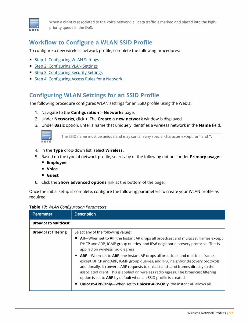
Wireless Network Profiles | 97
When a client is associated to the Voice network, all data traffic is marked and placed into the high-priority queue in the QoS.
Workflow to Configure a WLAN SSID ProfileTo configure a new wireless network profile, complete the following procedures:
n Step 1: Configuring WLAN Settingsn Step 2: Configuring VLAN Settingsn Step 3: Configuring Security Settingsn Step 4: Configuring Access Rules for a Network
Configuring WLAN Settings for an SSID ProfileThe following procedure configures WLAN settings for an SSID profile using the WebUI:
1. Navigate to the Configuration > Networks page.2. Under Networks, click +. The Create a new network window is displayed.3. Under Basic option, Enter a name that uniquely identifies a wireless network in the Name field.
The SSID name must be unique and may contain any special character except for ' and ".
4. In the Type drop-down list, selectWireless.5. Based on the type of network profile, select any of the following options under Primary usage:
n Employeen Voicen Guest
6. Click the Show advanced options link at the bottom of the page.
Once the initial setup is complete, configure the following parameters to create your WLAN profile asrequired:
Parameter Description
Broadcast/Multicast
Broadcast filtering Select any of the following values:n All—When set to All, the Instant AP drops all broadcast and multicast frames except
DHCP and ARP, IGMP group queries, and IPv6 neighbor discovery protocols. This isapplied on wireless radio egress
n ARP—When set to ARP, the Instant AP drops all broadcast and multicast framesexcept DHCP and ARP, IGMP group queries, and IPv6 neighbor discovery protocols;additionally, it converts ARP requests to unicast and send frames directly to theassociated client. This is applied on wireless radio egress. The broadcast filteringoption is set to ARP by default when an SSID profile is created.
n Unicast-ARP-Only—When set to Unicast-ARP-Only, the Instant AP allows all
Table 17: WLAN Configuration Parameters
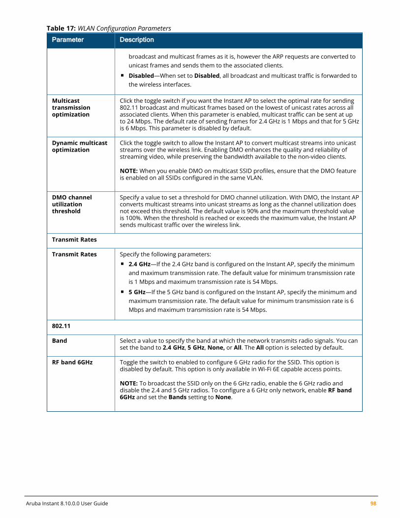
Aruba Instant 8.10.0.0 User Guide 98
Parameter Description
broadcast and multicast frames as it is, however the ARP requests are converted tounicast frames and sends them to the associated clients.
n Disabled—When set to Disabled, all broadcast and multicast traffic is forwarded tothe wireless interfaces.
Multicasttransmissionoptimization
Click the toggle switch if you want the Instant AP to select the optimal rate for sending802.11 broadcast and multicast frames based on the lowest of unicast rates across allassociated clients. When this parameter is enabled, multicast traffic can be sent at upto 24 Mbps. The default rate of sending frames for 2.4 GHz is 1 Mbps and that for 5 GHzis 6 Mbps. This parameter is disabled by default.
Dynamic multicastoptimization
Click the toggle switch to allow the Instant AP to convert multicast streams into unicaststreams over the wireless link. Enabling DMO enhances the quality and reliability ofstreaming video, while preserving the bandwidth available to the non-video clients.
NOTE: When you enable DMO on multicast SSID profiles, ensure that the DMO featureis enabled on all SSIDs configured in the same VLAN.
DMO channelutilizationthreshold
Specify a value to set a threshold for DMO channel utilization. With DMO, the Instant APconverts multicast streams into unicast streams as long as the channel utilization doesnot exceed this threshold. The default value is 90% and the maximum threshold valueis 100%. When the threshold is reached or exceeds the maximum value, the Instant APsends multicast traffic over the wireless link.
Transmit Rates
Transmit Rates Specify the following parameters:n 2.4 GHz—If the 2.4 GHz band is configured on the Instant AP, specify the minimum
and maximum transmission rate. The default value for minimum transmission rateis 1 Mbps and maximum transmission rate is 54 Mbps.
n 5 GHz—If the 5 GHz band is configured on the Instant AP, specify the minimum andmaximum transmission rate. The default value for minimum transmission rate is 6Mbps and maximum transmission rate is 54 Mbps.
802.11
Band Select a value to specify the band at which the network transmits radio signals. You canset the band to 2.4 GHz, 5 GHz, None, or All. The All option is selected by default.
RF band 6GHz Toggle the switch to enabled to configure 6 GHz radio for the SSID. This option isdisabled by default. This option is only available in Wi-Fi 6E capable access points.
NOTE: To broadcast the SSID only on the 6 GHz radio, enable the 6 GHz radio anddisable the 2.4 and 5 GHz radios. To configure a 6 GHz only network, enable RF band6GHz and set the Bands setting to None.
Table 17: WLAN Configuration Parameters
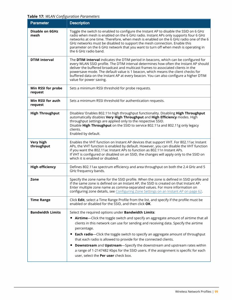
Wireless Network Profiles | 99
Parameter Description
Disable on 6GHzmesh
Toggle the switch to enabled to configure the Instant AP to disable the SSID on 6 GHzradio when mesh is enabled on the 6 GHz radio. Instant APs only supports four 6 GHznetworks at one time. Therefore, when mesh is enabled on the 6 GHz radio one of the 6GHz networks must be disabled to support the mesh connection. Enable thisparameter on the 6 GHz network that you want to turn off when mesh is operating inthe 6 GHz radio band.
DTIM interval The DTIM interval indicates the DTIM period in beacons, which can be configured forevery WLAN SSID profile. The DTIM interval determines how often the Instant AP shoulddeliver the buffered broadcast and multicast frames to associated clients in thepowersave mode. The default value is 1 beacon, which means the client checks forbuffered data on the Instant AP at every beacon. You can also configure a higher DTIMvalue for power saving.
Min RSSI for proberequest
Sets a minimum RSSI threshold for probe requests.
Min RSSI for authrequest
Sets a minimum RSSI threshold for authentication requests.
High Throughput Disables/ Enables 802.11n high throughput functionality. Disabling High Throughputautomatically disables Very High Throughput and High Efficiencymodes. Highthroughput settings are applied only to the respective SSID.Disable High Throughput on the SSID to service 802.11a and 802.11g only legacyclients.Enabled by default.
Very highthroughput
Enables the VHT function on Instant AP devices that support VHT. For 802.11ac InstantAPs, the VHT function is enabled by default. However, you can disable the VHT functionif you want the 802.11ac Instant APs to function as 802.11n Instant APs.If VHT is configured or disabled on an SSID, the changes will apply only to the SSID onwhich it is enabled or disabled.
High efficiency Defines 802.11ax spectrum efficiency and area throughput on both the 2.4 GHz and 5GHz frequency bands.
Zone Specify the zone name for the SSID profile. When the zone is defined in SSID profile andif the same zone is defined on an Instant AP, the SSID is created on that Instant AP.Enter multiple zone name as comma-separated values. For more information onconfiguring zone details, see Configuring Zone Settings on an Instant AP on page 62.
Time Range Click Edit, select a Time Range Profile from the list, and specify if the profile must beenabled or disabled for the SSID, and then click OK.
Bandwidth Limits Select the required options under Bandwidth Limits:n Airtime—Click the toggle switch and specify an aggregate amount of airtime that all
clients in this network can use for sending and receiving data. Specify the airtimepercentage.
n Each radio—Click the toggle switch to specify an aggregate amount of throughputthat each radio is allowed to provide for the connected clients.
n Downstream and Upstream—Specify the downstream and upstream rates withina range of 1-2147482 Kbps for the SSID users. If the assignment is specific for eachuser, select the Per user check box.
Table 17: WLAN Configuration Parameters
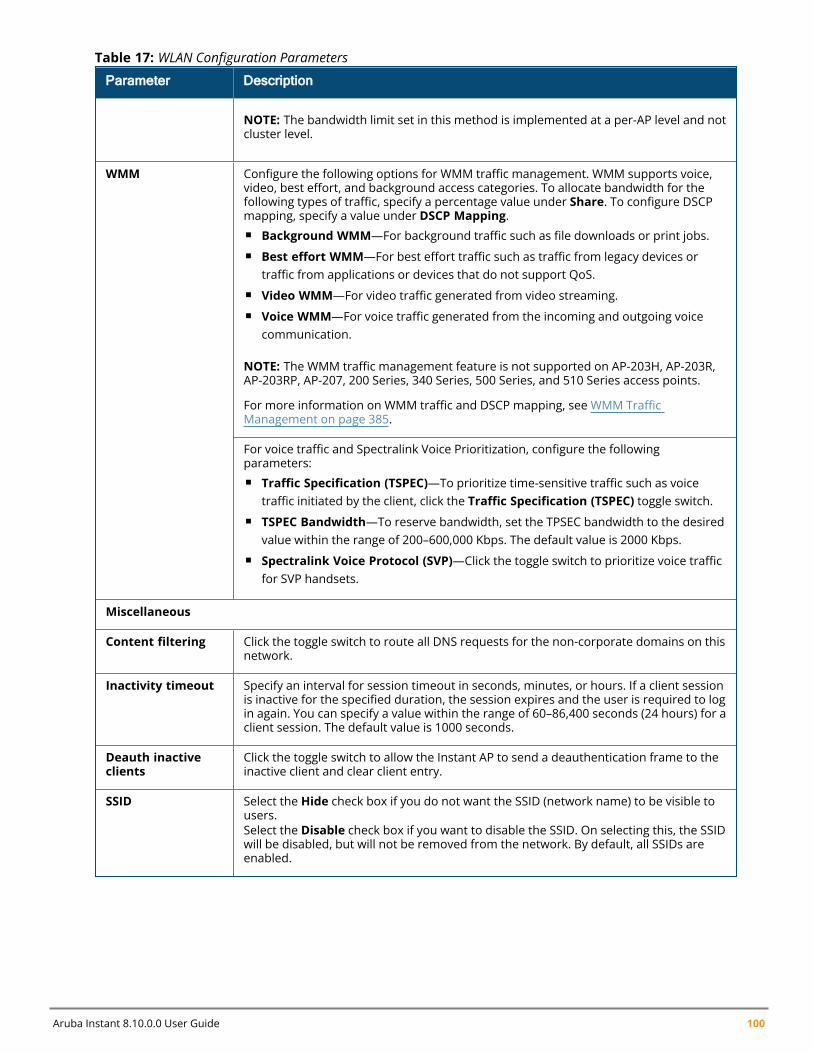
Aruba Instant 8.10.0.0 User Guide 100
Parameter Description
NOTE: The bandwidth limit set in this method is implemented at a per-AP level and notcluster level.
WMM Configure the following options for WMM traffic management. WMM supports voice,video, best effort, and background access categories. To allocate bandwidth for thefollowing types of traffic, specify a percentage value under Share. To configure DSCPmapping, specify a value under DSCP Mapping.n Background WMM—For background traffic such as file downloads or print jobs.n Best effort WMM—For best effort traffic such as traffic from legacy devices or
traffic from applications or devices that do not support QoS.n Video WMM—For video traffic generated from video streaming.n Voice WMM—For voice traffic generated from the incoming and outgoing voice
communication.
NOTE: The WMM traffic management feature is not supported on AP-203H, AP-203R,AP-203RP, AP-207, 200 Series, 340 Series, 500 Series, and 510 Series access points.
For more information on WMM traffic and DSCP mapping, see WMM TrafficManagement on page 385.
For voice traffic and Spectralink Voice Prioritization, configure the followingparameters:n Traffic Specification (TSPEC)—To prioritize time-sensitive traffic such as voice
traffic initiated by the client, click the Traffic Specification (TSPEC) toggle switch.n TSPEC Bandwidth—To reserve bandwidth, set the TPSEC bandwidth to the desired
value within the range of 200–600,000 Kbps. The default value is 2000 Kbps.n Spectralink Voice Protocol (SVP)—Click the toggle switch to prioritize voice traffic
for SVP handsets.
Miscellaneous
Content filtering Click the toggle switch to route all DNS requests for the non-corporate domains on thisnetwork.
Inactivity timeout Specify an interval for session timeout in seconds, minutes, or hours. If a client sessionis inactive for the specified duration, the session expires and the user is required to login again. You can specify a value within the range of 60–86,400 seconds (24 hours) for aclient session. The default value is 1000 seconds.
Deauth inactiveclients
Click the toggle switch to allow the Instant AP to send a deauthentication frame to theinactive client and clear client entry.
SSID Select the Hide check box if you do not want the SSID (network name) to be visible tousers.Select the Disable check box if you want to disable the SSID. On selecting this, the SSIDwill be disabled, but will not be removed from the network. By default, all SSIDs areenabled.
Table 17: WLAN Configuration Parameters
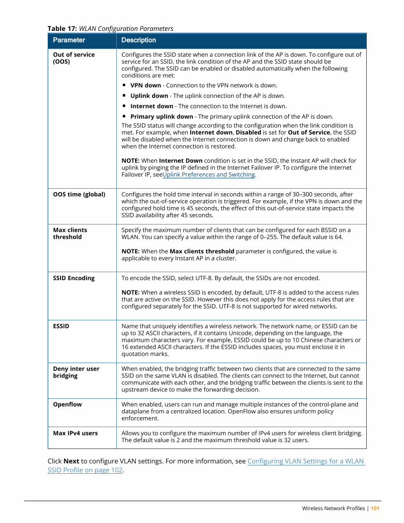
Wireless Network Profiles | 101
Parameter Description
Out of service(OOS)
Configures the SSID state when a connection link of the AP is down. To configure out ofservice for an SSID, the link condition of the AP and the SSID state should beconfigured. The SSID can be enabled or disabled automatically when the followingconditions are met:n VPN down - Connection to the VPN network is down.n Uplink down - The uplink connection of the AP is down.n Internet down - The connection to the Internet is down.n Primary uplink down - The primary uplink connection of the AP is down.The SSID status will change according to the configuration when the link condition ismet. For example, when Internet down, Disabled is set for Out of Service, the SSIDwill be disabled when the Internet connection is down and change back to enabledwhen the Internet connection is restored.
NOTE: When Internet Down condition is set in the SSID, the Instant AP will check foruplink by pinging the IP defined in the Internet Failover IP. To configure the InternetFailover IP, seeUplink Preferences and Switching.
OOS time (global) Configures the hold time interval in seconds within a range of 30–300 seconds, afterwhich the out-of-service operation is triggered. For example, if the VPN is down and theconfigured hold time is 45 seconds, the effect of this out-of-service state impacts theSSID availability after 45 seconds.
Max clientsthreshold
Specify the maximum number of clients that can be configured for each BSSID on aWLAN. You can specify a value within the range of 0–255. The default value is 64.
NOTE: When theMax clients threshold parameter is configured, the value isapplicable to every Instant AP in a cluster.
SSID Encoding To encode the SSID, select UTF-8. By default, the SSIDs are not encoded.
NOTE: When a wireless SSID is encoded, by default, UTF-8 is added to the access rulesthat are active on the SSID. However this does not apply for the access rules that areconfigured separately for the SSID. UTF-8 is not supported for wired networks.
ESSID Name that uniquely identifies a wireless network. The network name, or ESSID can beup to 32 ASCII characters, if it contains Unicode, depending on the language, themaximum characters vary. For example, ESSID could be up to 10 Chinese characters or16 extended ASCII characters. If the ESSID includes spaces, you must enclose it inquotation marks.
Deny inter userbridging
When enabled, the bridging traffic between two clients that are connected to the sameSSID on the same VLAN is disabled. The clients can connect to the Internet, but cannotcommunicate with each other, and the bridging traffic between the clients is sent to theupstream device to make the forwarding decision.
Openflow When enabled, users can run and manage multiple instances of the control-plane anddataplane from a centralized location. OpenFlow also ensures uniform policyenforcement.
Max IPv4 users Allows you to configure the maximum number of IPv4 users for wireless client bridging.The default value is 2 and the maximum threshold value is 32 users.
Table 17: WLAN Configuration Parameters
Click Next to configure VLAN settings. For more information, see Configuring VLAN Settings for a WLANSSID Profile on page 102.
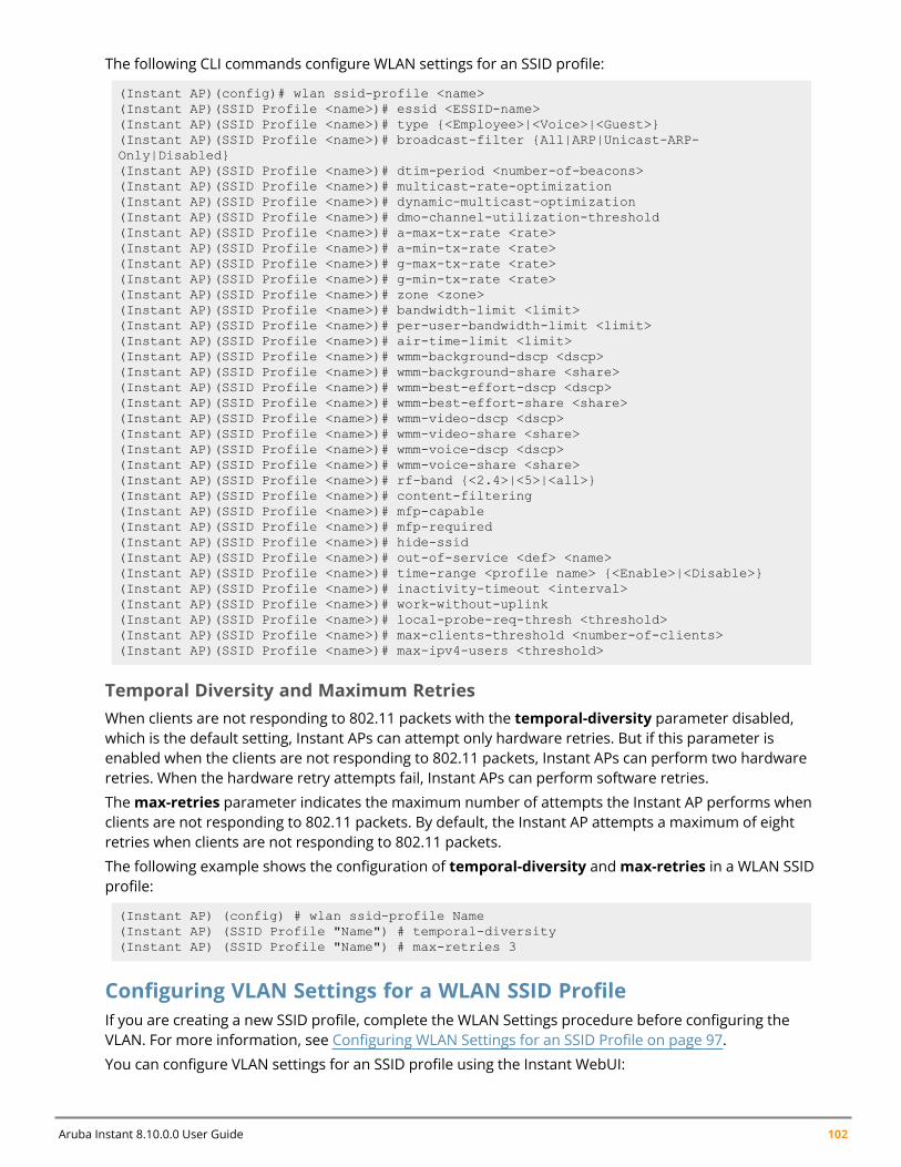
Aruba Instant 8.10.0.0 User Guide 102
The following CLI commands configure WLAN settings for an SSID profile:
(Instant AP)(config)# wlan ssid-profile <name>(Instant AP)(SSID Profile <name>)# essid <ESSID-name>(Instant AP)(SSID Profile <name>)# type {<Employee>|<Voice>|<Guest>}(Instant AP)(SSID Profile <name>)# broadcast-filter {All|ARP|Unicast-ARP-Only|Disabled}(Instant AP)(SSID Profile <name>)# dtim-period <number-of-beacons>(Instant AP)(SSID Profile <name>)# multicast-rate-optimization(Instant AP)(SSID Profile <name>)# dynamic-multicast-optimization(Instant AP)(SSID Profile <name>)# dmo-channel-utilization-threshold(Instant AP)(SSID Profile <name>)# a-max-tx-rate <rate>(Instant AP)(SSID Profile <name>)# a-min-tx-rate <rate>(Instant AP)(SSID Profile <name>)# g-max-tx-rate <rate>(Instant AP)(SSID Profile <name>)# g-min-tx-rate <rate>(Instant AP)(SSID Profile <name>)# zone <zone>(Instant AP)(SSID Profile <name>)# bandwidth-limit <limit>(Instant AP)(SSID Profile <name>)# per-user-bandwidth-limit <limit>(Instant AP)(SSID Profile <name>)# air-time-limit <limit>(Instant AP)(SSID Profile <name>)# wmm-background-dscp <dscp>(Instant AP)(SSID Profile <name>)# wmm-background-share <share>(Instant AP)(SSID Profile <name>)# wmm-best-effort-dscp <dscp>(Instant AP)(SSID Profile <name>)# wmm-best-effort-share <share>(Instant AP)(SSID Profile <name>)# wmm-video-dscp <dscp>(Instant AP)(SSID Profile <name>)# wmm-video-share <share>(Instant AP)(SSID Profile <name>)# wmm-voice-dscp <dscp>(Instant AP)(SSID Profile <name>)# wmm-voice-share <share>(Instant AP)(SSID Profile <name>)# rf-band {<2.4>|<5>|<all>}(Instant AP)(SSID Profile <name>)# content-filtering(Instant AP)(SSID Profile <name>)# mfp-capable(Instant AP)(SSID Profile <name>)# mfp-required(Instant AP)(SSID Profile <name>)# hide-ssid(Instant AP)(SSID Profile <name>)# out-of-service <def> <name>(Instant AP)(SSID Profile <name>)# time-range <profile name> {<Enable>|<Disable>}(Instant AP)(SSID Profile <name>)# inactivity-timeout <interval>(Instant AP)(SSID Profile <name>)# work-without-uplink(Instant AP)(SSID Profile <name>)# local-probe-req-thresh <threshold>(Instant AP)(SSID Profile <name>)# max-clients-threshold <number-of-clients>(Instant AP)(SSID Profile <name>)# max-ipv4-users <threshold>
Temporal Diversity and Maximum RetriesWhen clients are not responding to 802.11 packets with the temporal-diversity parameter disabled,which is the default setting, Instant APs can attempt only hardware retries. But if this parameter isenabled when the clients are not responding to 802.11 packets, Instant APs can perform two hardwareretries. When the hardware retry attempts fail, Instant APs can perform software retries.
Themax-retries parameter indicates the maximum number of attempts the Instant AP performs whenclients are not responding to 802.11 packets. By default, the Instant AP attempts a maximum of eightretries when clients are not responding to 802.11 packets.
The following example shows the configuration of temporal-diversity andmax-retries in a WLAN SSIDprofile:
(Instant AP) (config) # wlan ssid-profile Name(Instant AP) (SSID Profile "Name") # temporal-diversity(Instant AP) (SSID Profile "Name") # max-retries 3
Configuring VLAN Settings for a WLAN SSID ProfileIf you are creating a new SSID profile, complete the WLAN Settings procedure before configuring theVLAN. For more information, see Configuring WLAN Settings for an SSID Profile on page 97.
You can configure VLAN settings for an SSID profile using the Instant WebUI:
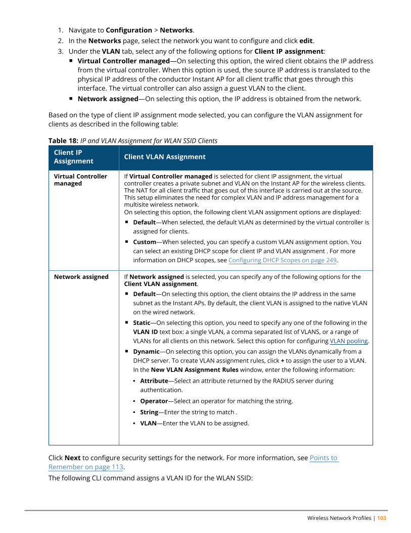
Wireless Network Profiles | 103
1. Navigate to Configuration > Networks.2. In the Networks page, select the network you want to configure and click edit.3. Under the VLAN tab, select any of the following options for Client IP assignment:
n Virtual Controller managed—On selecting this option, the wired client obtains the IP addressfrom the virtual controller. When this option is used, the source IP address is translated to thephysical IP address of the conductor Instant AP for all client traffic that goes through thisinterface. The virtual controller can also assign a guest VLAN to the client.
n Network assigned—On selecting this option, the IP address is obtained from the network.
Based on the type of client IP assignment mode selected, you can configure the VLAN assignment forclients as described in the following table:
Client IPAssignment Client VLAN Assignment
Virtual Controllermanaged
If Virtual Controller managed is selected for client IP assignment, the virtualcontroller creates a private subnet and VLAN on the Instant AP for the wireless clients.The NAT for all client traffic that goes out of this interface is carried out at the source.This setup eliminates the need for complex VLAN and IP address management for amultisite wireless network.On selecting this option, the following client VLAN assignment options are displayed:n Default—When selected, the default VLAN as determined by the virtual controller is
assigned for clients.n Custom—When selected, you can specify a custom VLAN assignment option. You
can select an existing DHCP scope for client IP and VLAN assignment . For moreinformation on DHCP scopes, see Configuring DHCP Scopes on page 249.
Network assigned If Network assigned is selected, you can specify any of the following options for theClient VLAN assignment.n Default—On selecting this option, the client obtains the IP address in the same
subnet as the Instant APs. By default, the client VLAN is assigned to the native VLANon the wired network.
n Static—On selecting this option, you need to specify any one of the following in theVLAN ID text box: a single VLAN, a comma separated list of VLANS, or a range ofVLANs for all clients on this network. Select this option for configuring VLAN pooling.
n Dynamic—On selecting this option, you can assign the VLANs dynamically from aDHCP server. To create VLAN assignment rules, click + to assign the user to a VLAN.In the New VLAN Assignment Rules window, enter the following information:
l Attribute—Select an attribute returned by the RADIUS server duringauthentication.
l Operator—Select an operator for matching the string.
l String—Enter the string to match .
l VLAN—Enter the VLAN to be assigned.
Table 18: IP and VLAN Assignment for WLAN SSID Clients
Click Next to configure security settings for the network. For more information, see Points toRemember on page 113.
The following CLI command assigns a VLAN ID for the WLAN SSID:
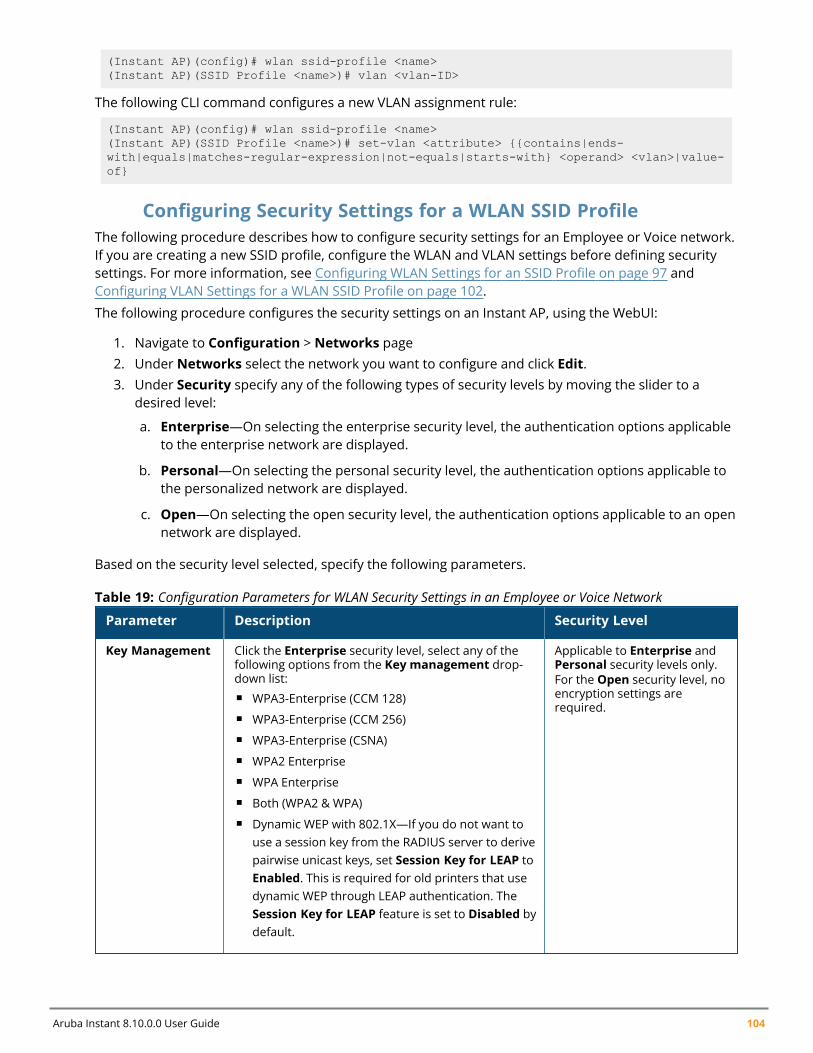
Aruba Instant 8.10.0.0 User Guide 104
(Instant AP)(config)# wlan ssid-profile <name>(Instant AP)(SSID Profile <name>)# vlan <vlan-ID>
The following CLI command configures a new VLAN assignment rule:
(Instant AP)(config)# wlan ssid-profile <name>(Instant AP)(SSID Profile <name>)# set-vlan <attribute> {{contains|ends-with|equals|matches-regular-expression|not-equals|starts-with} <operand> <vlan>|value-of}
Configuring Security Settings for a WLAN SSID ProfileThe following procedure describes how to configure security settings for an Employee or Voice network.If you are creating a new SSID profile, configure the WLAN and VLAN settings before defining securitysettings. For more information, see Configuring WLAN Settings for an SSID Profile on page 97 andConfiguring VLAN Settings for a WLAN SSID Profile on page 102.
The following procedure configures the security settings on an Instant AP, using the WebUI:
1. Navigate to Configuration > Networks page2. Under Networks select the network you want to configure and click Edit.3. Under Security specify any of the following types of security levels by moving the slider to a
desired level:
a. Enterprise—On selecting the enterprise security level, the authentication options applicableto the enterprise network are displayed.
b. Personal—On selecting the personal security level, the authentication options applicable tothe personalized network are displayed.
c. Open—On selecting the open security level, the authentication options applicable to an opennetwork are displayed.
Based on the security level selected, specify the following parameters.
Parameter Description Security Level
Key Management Click the Enterprise security level, select any of thefollowing options from the Key management drop-down list:n WPA3-Enterprise (CCM 128)n WPA3-Enterprise (CCM 256)n WPA3-Enterprise (CSNA)n WPA2 Enterprisen WPA Enterprisen Both (WPA2 & WPA)n Dynamic WEP with 802.1X—If you do not want to
use a session key from the RADIUS server to derivepairwise unicast keys, set Session Key for LEAP toEnabled. This is required for old printers that usedynamic WEP through LEAP authentication. TheSession Key for LEAP feature is set to Disabled bydefault.
Applicable to Enterprise andPersonal security levels only.For the Open security level, noencryption settings arerequired.
Table 19: Configuration Parameters for WLAN Security Settings in an Employee or Voice Network
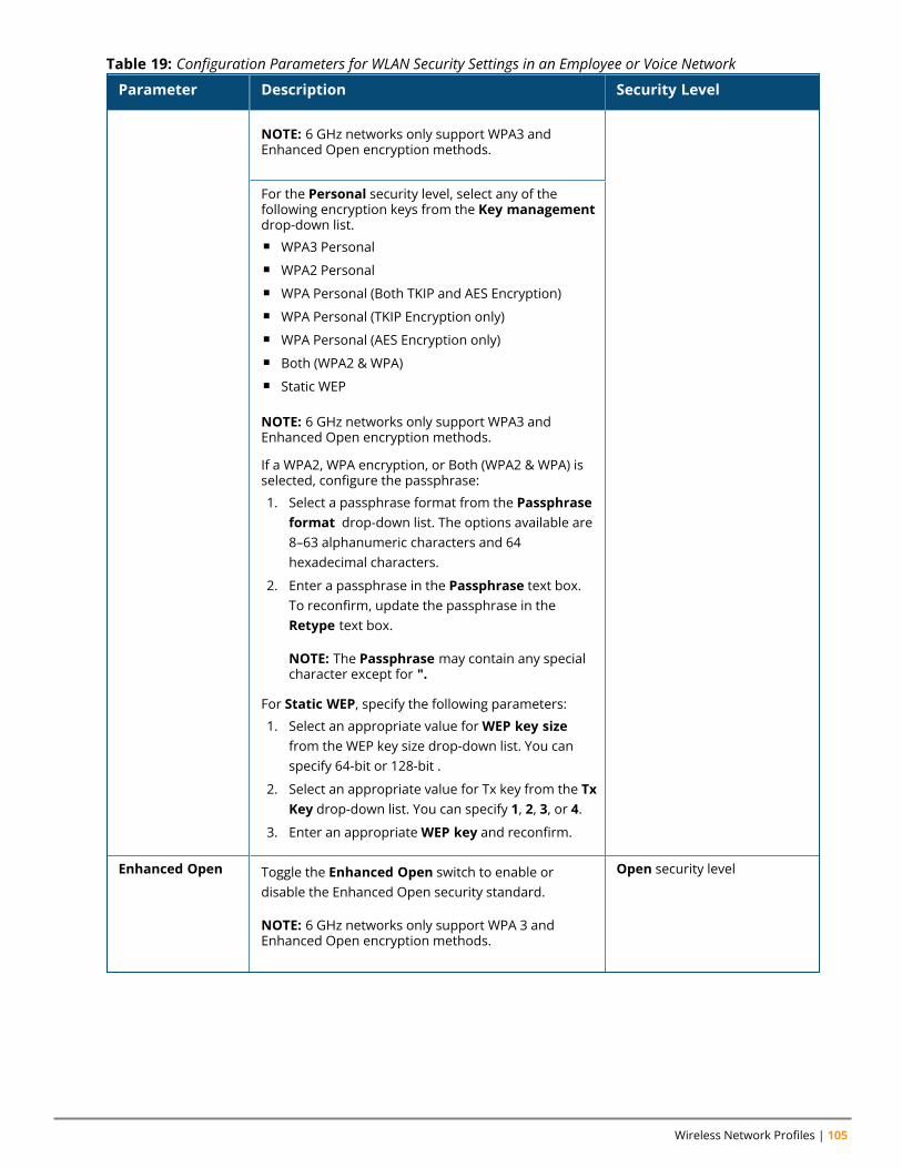
Wireless Network Profiles | 105
Parameter Description Security Level
NOTE: 6 GHz networks only support WPA3 andEnhanced Open encryption methods.
For the Personal security level, select any of thefollowing encryption keys from the Key managementdrop-down list.n WPA3 Personaln WPA2 Personaln WPA Personal (Both TKIP and AES Encryption)n WPA Personal (TKIP Encryption only)n WPA Personal (AES Encryption only)n Both (WPA2 & WPA)n Static WEP
NOTE: 6 GHz networks only support WPA3 andEnhanced Open encryption methods.
If a WPA2, WPA encryption, or Both (WPA2 & WPA) isselected, configure the passphrase:
1. Select a passphrase format from the Passphraseformat drop-down list. The options available are8–63 alphanumeric characters and 64hexadecimal characters.
2. Enter a passphrase in the Passphrase text box.To reconfirm, update the passphrase in theRetype text box.
NOTE: The Passphrase may contain any specialcharacter except for ".
For Static WEP, specify the following parameters:
1. Select an appropriate value forWEP key sizefrom the WEP key size drop-down list. You canspecify 64-bit or 128-bit .
2. Select an appropriate value for Tx key from the TxKey drop-down list. You can specify 1, 2, 3, or 4.
3. Enter an appropriateWEP key and reconfirm.
Enhanced Open Toggle the Enhanced Open switch to enable ordisable the Enhanced Open security standard.
NOTE: 6 GHz networks only support WPA 3 andEnhanced Open encryption methods.
Open security level
Table 19: Configuration Parameters for WLAN Security Settings in an Employee or Voice Network
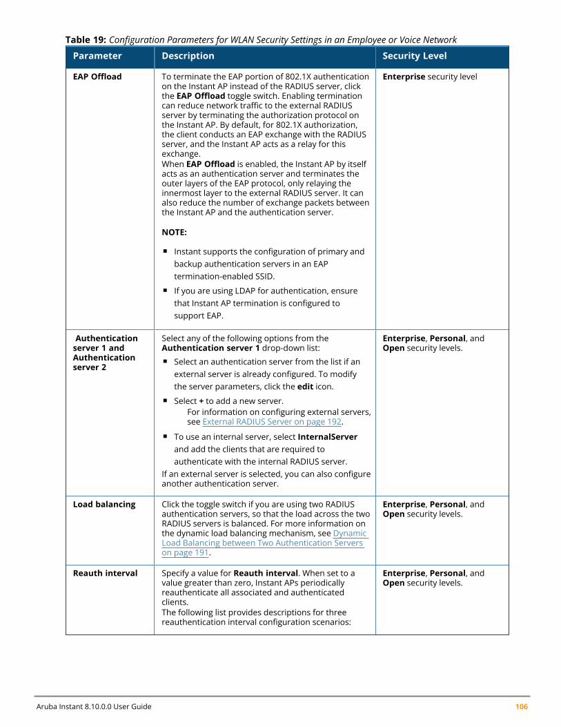
Aruba Instant 8.10.0.0 User Guide 106
Parameter Description Security Level
EAP Offload To terminate the EAP portion of 802.1X authenticationon the Instant AP instead of the RADIUS server, clickthe EAP Offload toggle switch. Enabling terminationcan reduce network traffic to the external RADIUSserver by terminating the authorization protocol onthe Instant AP. By default, for 802.1X authorization,the client conducts an EAP exchange with the RADIUSserver, and the Instant AP acts as a relay for thisexchange.When EAP Offload is enabled, the Instant AP by itselfacts as an authentication server and terminates theouter layers of the EAP protocol, only relaying theinnermost layer to the external RADIUS server. It canalso reduce the number of exchange packets betweenthe Instant AP and the authentication server.
NOTE:
n Instant supports the configuration of primary andbackup authentication servers in an EAPtermination-enabled SSID.
n If you are using LDAP for authentication, ensurethat Instant AP termination is configured tosupport EAP.
Enterprise security level
Authenticationserver 1 andAuthenticationserver 2
Select any of the following options from theAuthentication server 1 drop-down list:n Select an authentication server from the list if an
external server is already configured. To modifythe server parameters, click the edit icon.
n Select + to add a new server.For information on configuring external servers,see External RADIUS Server on page 192.
n To use an internal server, select InternalServerand add the clients that are required toauthenticate with the internal RADIUS server.
If an external server is selected, you can also configureanother authentication server.
Enterprise, Personal, andOpen security levels.
Load balancing Click the toggle switch if you are using two RADIUSauthentication servers, so that the load across the twoRADIUS servers is balanced. For more information onthe dynamic load balancing mechanism, see DynamicLoad Balancing between Two Authentication Serverson page 191.
Enterprise, Personal, andOpen security levels.
Reauth interval Specify a value for Reauth interval. When set to avalue greater than zero, Instant APs periodicallyreauthenticate all associated and authenticatedclients.The following list provides descriptions for threereauthentication interval configuration scenarios:
Enterprise, Personal, andOpen security levels.
Table 19: Configuration Parameters for WLAN Security Settings in an Employee or Voice Network
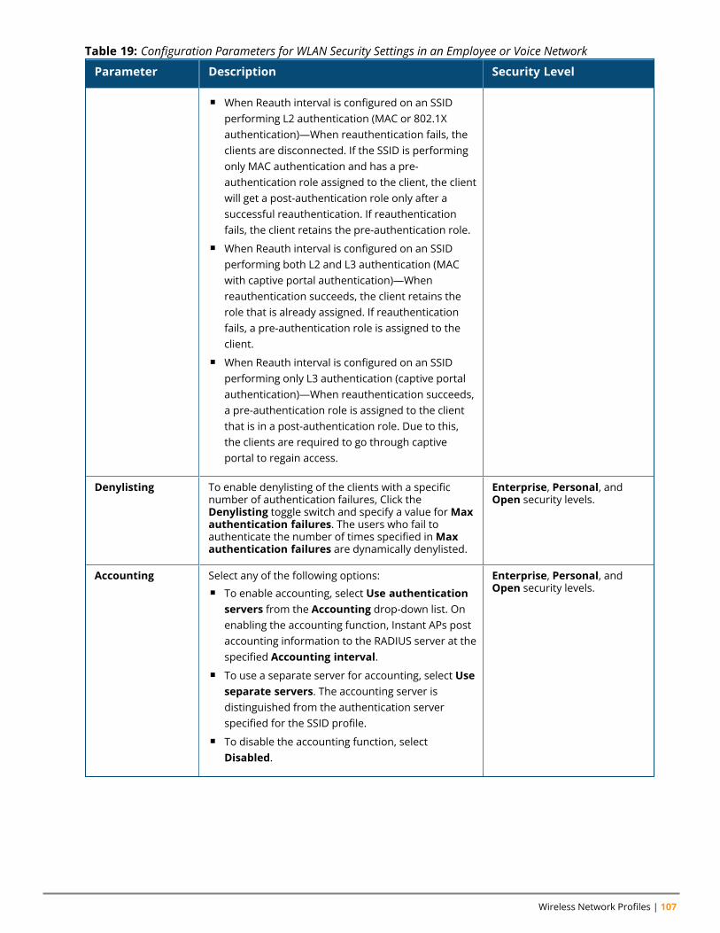
Wireless Network Profiles | 107
Parameter Description Security Level
n When Reauth interval is configured on an SSIDperforming L2 authentication (MAC or 802.1Xauthentication)—When reauthentication fails, theclients are disconnected. If the SSID is performingonly MAC authentication and has a pre-authentication role assigned to the client, the clientwill get a post-authentication role only after asuccessful reauthentication. If reauthenticationfails, the client retains the pre-authentication role.
n When Reauth interval is configured on an SSIDperforming both L2 and L3 authentication (MACwith captive portal authentication)—Whenreauthentication succeeds, the client retains therole that is already assigned. If reauthenticationfails, a pre-authentication role is assigned to theclient.
n When Reauth interval is configured on an SSIDperforming only L3 authentication (captive portalauthentication)—When reauthentication succeeds,a pre-authentication role is assigned to the clientthat is in a post-authentication role. Due to this,the clients are required to go through captiveportal to regain access.
Denylisting To enable denylisting of the clients with a specificnumber of authentication failures, Click theDenylisting toggle switch and specify a value forMaxauthentication failures. The users who fail toauthenticate the number of times specified inMaxauthentication failures are dynamically denylisted.
Enterprise, Personal, andOpen security levels.
Accounting Select any of the following options:n To enable accounting, select Use authentication
servers from the Accounting drop-down list. Onenabling the accounting function, Instant APs postaccounting information to the RADIUS server at thespecified Accounting interval.
n To use a separate server for accounting, select Useseparate servers. The accounting server isdistinguished from the authentication serverspecified for the SSID profile.
n To disable the accounting function, selectDisabled.
Enterprise, Personal, andOpen security levels.
Table 19: Configuration Parameters for WLAN Security Settings in an Employee or Voice Network
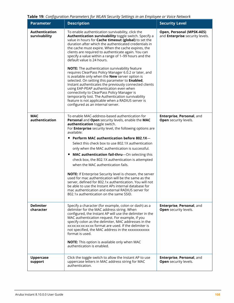
Aruba Instant 8.10.0.0 User Guide 108
Parameter Description Security Level
Authenticationsurvivability
To enable authentication survivability, click theAuthentication survivability toggle switch. Specify avalue in hours for Cache timeout (global) to set theduration after which the authenticated credentials inthe cache must expire. When the cache expires, theclients are required to authenticate again. You canspecify a value within a range of 1–99 hours and thedefault value is 24 hours.
NOTE: The authentication survivability featurerequires ClearPass Policy Manager 6.0.2 or later, andis available only when the New server option isselected. On setting this parameter to Enabled,Instant authenticates the previously connected clientsusing EAP-PEAP authentication even whenconnectivity to ClearPass Policy Manager istemporarily lost. The Authentication survivabilityfeature is not applicable when a RADIUS server isconfigured as an internal server.
Open, Personal (MPSK-AES)and Enterprise security levels.
MACauthentication
To enable MAC-address-based authentication forPersonal and Open security levels, enable theMACauthentication toggle switch.For Enterprise security level, the following options areavailable:n Perform MAC authentication before 802.1X—
Select this check box to use 802.1X authenticationonly when the MAC authentication is successful.
n MAC authentication fail-thru—On selecting thischeck box, the 802.1X authentication is attemptedwhen the MAC authentication fails.
NOTE: If Enterprise Security level is chosen, the serverused for mac authentication will be the same as theserver, defined for 802.1x authentication. You will notbe able to use the Instant APs internal database formac authentication and external RADIUS server for802.1x authentication on the same SSID.
Enterprise, Personal, andOpen security levels.
Delimitercharacter
Specify a character (for example, colon or dash) as adelimiter for the MAC address string. Whenconfigured, the Instant AP will use the delimiter in theMAC authentication request. For example, if youspecify colon as the delimiter, MAC addresses in thexx:xx:xx:xx:xx:xx format are used. If the delimiter isnot specified, the MAC address in the xxxxxxxxxxxxformat is used.
NOTE: This option is available only when MACauthentication is enabled.
Enterprise, Personal, andOpen security levels.
Uppercasesupport
Click the toggle switch to allow the Instant AP to useuppercase letters in MAC address string for MACauthentication.
Enterprise, Personal, andOpen security levels.
Table 19: Configuration Parameters for WLAN Security Settings in an Employee or Voice Network
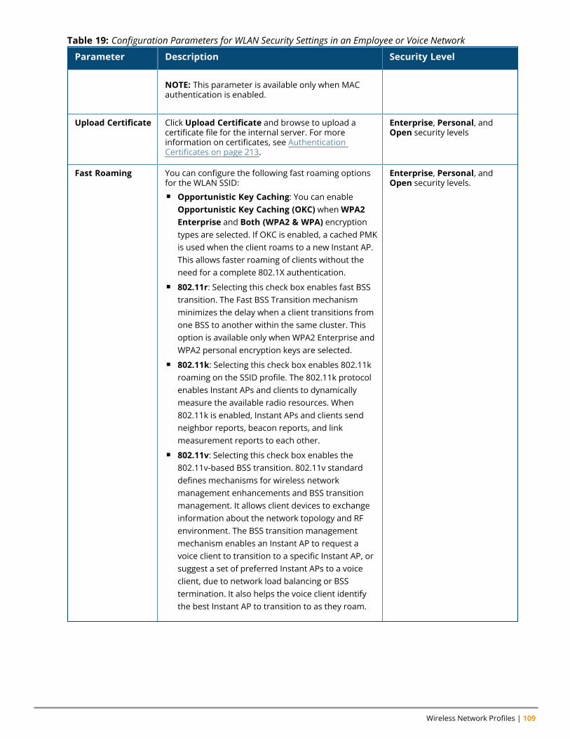
Wireless Network Profiles | 109
Parameter Description Security Level
NOTE: This parameter is available only when MACauthentication is enabled.
Upload Certificate Click Upload Certificate and browse to upload acertificate file for the internal server. For moreinformation on certificates, see AuthenticationCertificates on page 213.
Enterprise, Personal, andOpen security levels
Fast Roaming You can configure the following fast roaming optionsfor the WLAN SSID:n Opportunistic Key Caching: You can enable
Opportunistic Key Caching (OKC) whenWPA2Enterprise and Both (WPA2 & WPA) encryptiontypes are selected. If OKC is enabled, a cached PMKis used when the client roams to a new Instant AP.This allows faster roaming of clients without theneed for a complete 802.1X authentication.
n 802.11r: Selecting this check box enables fast BSStransition. The Fast BSS Transition mechanismminimizes the delay when a client transitions fromone BSS to another within the same cluster. Thisoption is available only when WPA2 Enterprise andWPA2 personal encryption keys are selected.
n 802.11k: Selecting this check box enables 802.11kroaming on the SSID profile. The 802.11k protocolenables Instant APs and clients to dynamicallymeasure the available radio resources. When802.11k is enabled, Instant APs and clients sendneighbor reports, beacon reports, and linkmeasurement reports to each other.
n 802.11v: Selecting this check box enables the802.11v-based BSS transition. 802.11v standarddefines mechanisms for wireless networkmanagement enhancements and BSS transitionmanagement. It allows client devices to exchangeinformation about the network topology and RFenvironment. The BSS transition managementmechanism enables an Instant AP to request avoice client to transition to a specific Instant AP, orsuggest a set of preferred Instant APs to a voiceclient, due to network load balancing or BSStermination. It also helps the voice client identifythe best Instant AP to transition to as they roam.
Enterprise, Personal, andOpen security levels.
Table 19: Configuration Parameters for WLAN Security Settings in an Employee or Voice Network
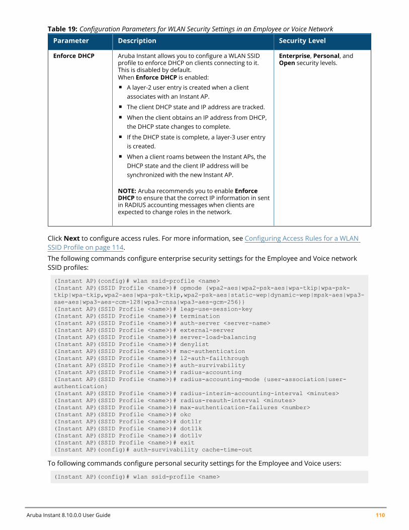
Aruba Instant 8.10.0.0 User Guide 110
Parameter Description Security Level
Enforce DHCP Aruba Instant allows you to configure a WLAN SSIDprofile to enforce DHCP on clients connecting to it.This is disabled by default.When Enforce DHCP is enabled:n A layer-2 user entry is created when a client
associates with an Instant AP.n The client DHCP state and IP address are tracked.n When the client obtains an IP address from DHCP,
the DHCP state changes to complete.n If the DHCP state is complete, a layer-3 user entry
is created.n When a client roams between the Instant APs, the
DHCP state and the client IP address will besynchronized with the new Instant AP.
NOTE: Aruba recommends you to enable EnforceDHCP to ensure that the correct IP information in sentin RADIUS accounting messages when clients areexpected to change roles in the network.
Enterprise, Personal, andOpen security levels.
Table 19: Configuration Parameters for WLAN Security Settings in an Employee or Voice Network
Click Next to configure access rules. For more information, see Configuring Access Rules for a WLANSSID Profile on page 114.
The following commands configure enterprise security settings for the Employee and Voice networkSSID profiles:
(Instant AP)(config)# wlan ssid-profile <name>(Instant AP)(SSID Profile <name>)# opmode {wpa2-aes|wpa2-psk-aes|wpa-tkip|wpa-psk-tkip|wpa-tkip,wpa2-aes|wpa-psk-tkip,wpa2-psk-aes|static-wep|dynamic-wep|mpsk-aes|wpa3-sae-aes|wpa3-aes-ccm-128|wpa3-cnsa|wpa3-aes-gcm-256}}(Instant AP)(SSID Profile <name>)# leap-use-session-key(Instant AP)(SSID Profile <name>)# termination(Instant AP)(SSID Profile <name>)# auth-server <server-name>(Instant AP)(SSID Profile <name>)# external-server(Instant AP)(SSID Profile <name>)# server-load-balancing(Instant AP)(SSID Profile <name>)# denylist(Instant AP)(SSID Profile <name>)# mac-authentication(Instant AP)(SSID Profile <name>)# l2-auth-failthrough(Instant AP)(SSID Profile <name>)# auth-survivability(Instant AP)(SSID Profile <name>)# radius-accounting(Instant AP)(SSID Profile <name>)# radius-accounting-mode {user-association|user-authentication}(Instant AP)(SSID Profile <name>)# radius-interim-accounting-interval <minutes>(Instant AP)(SSID Profile <name>)# radius-reauth-interval <minutes>(Instant AP)(SSID Profile <name>)# max-authentication-failures <number>(Instant AP)(SSID Profile <name>)# okc(Instant AP)(SSID Profile <name>)# dot11r(Instant AP)(SSID Profile <name>)# dot11k(Instant AP)(SSID Profile <name>)# dot11v(Instant AP)(SSID Profile <name>)# exit(Instant AP)(config)# auth-survivability cache-time-out
To following commands configure personal security settings for the Employee and Voice users:
(Instant AP)(config)# wlan ssid-profile <name>
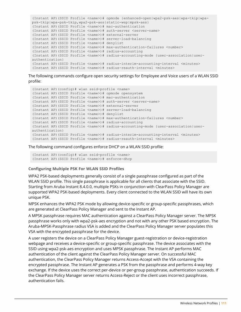
Wireless Network Profiles | 111
(Instant AP)(SSID Profile <name>)# opmode {enhanced-open|wpa2-psk-aes|wpa-tkip|wpa-psk-tkip|wpa-psk-tkip,wpa2-psk-aes|static-wep|mpsk-aes}(Instant AP)(SSID Profile <name>)# mac-authentication(Instant AP)(SSID Profile <name>)# auth-server <server-name>(Instant AP)(SSID Profile <name>)# external-server(Instant AP)(SSID Profile <name>)# server-load-balancing(Instant AP)(SSID Profile <name>)# denylist(Instant AP)(SSID Profile <name>)# max-authentication-failures <number>(Instant AP)(SSID Profile <name>)# radius-accounting(Instant AP)(SSID Profile <name>)# radius-accounting-mode {user-association|user-authentication}(Instant AP)(SSID Profile <name>)# radius-interim-accounting-interval <minutes>(Instant AP)(SSID Profile <name>)# radius-reauth-interval <minutes>
The following commands configure open security settings for Employee and Voice users of a WLAN SSIDprofile:
(Instant AP)(config)# wlan ssid-profile <name>(Instant AP)(SSID Profile <name>)# opmode opensystem(Instant AP)(SSID Profile <name>)# mac-authentication(Instant AP)(SSID Profile <name>)# auth-server <server-name>(Instant AP)(SSID Profile <name>)# external-server(Instant AP)(SSID Profile <name>)# server-load-balancing(Instant AP)(SSID Profile <name>)# denylist(Instant AP)(SSID Profile <name>)# max-authentication-failures <number>(Instant AP)(SSID Profile <name>)# radius-accounting(Instant AP)(SSID Profile <name>)# radius-accounting-mode {user-association|user-authentication}(Instant AP)(SSID Profile <name>)# radius-interim-accounting-interval <minutes>(Instant AP)(SSID Profile <name>)# radius-reauth-interval <minutes>
The following command configures enforce DHCP on a WLAN SSID profile:
(Instant AP)(config)# wlan ssid-profile <name>(Instant AP)(SSID Profile <name>)# enforce-dhcp
Configuring Multiple PSK For WLAN SSID Profiles
WPA2 PSK-based deployments generally consist of a single passphrase configured as part of theWLAN SSID profile. This single passphrase is applicable for all clients that associate with the SSID.Starting from Aruba Instant 8.4.0.0, multiple PSKs in conjunction with ClearPass Policy Manager aresupported WPA2 PSK-based deployments. Every client connected to the WLAN SSID will have its ownunique PSK.
MPSK enhances the WPA2 PSK mode by allowing device-specific or group-specific passphrases, whichare generated at ClearPass Policy Manager and sent to the Instant AP.
A MPSK passphrase requires MAC authentication against a ClearPass Policy Manager server. The MPSKpassphrase works only with wpa2-psk-aes encryption and not with any other PSK based encryption. TheAruba-MPSK-Passphrase radius VSA is added and the ClearPass Policy Manager server populates thisVSA with the encrypted passphrase for the device.
A user registers the device on a ClearPass Policy Manager guest-registration or device-registrationwebpage and receives a device-specific or group-specific passphrase. The device associates with theSSID using wpa2-psk-aes encryption and uses MPSK passphrase. The Instant AP performs MACauthentication of the client against the ClearPass Policy Manager server. On successful MACauthentication, the ClearPass Policy Manager returns Access-Accept with the VSA containing theencrypted passphrase. The Instant AP generates a PSK from the passphrase and performs 4-way keyexchange. If the device uses the correct per-device or per-group passphrase, authentication succeeds. Ifthe ClearPass Policy Manager server returns Access-Reject or the client uses incorrect passphrase,authentication fails.
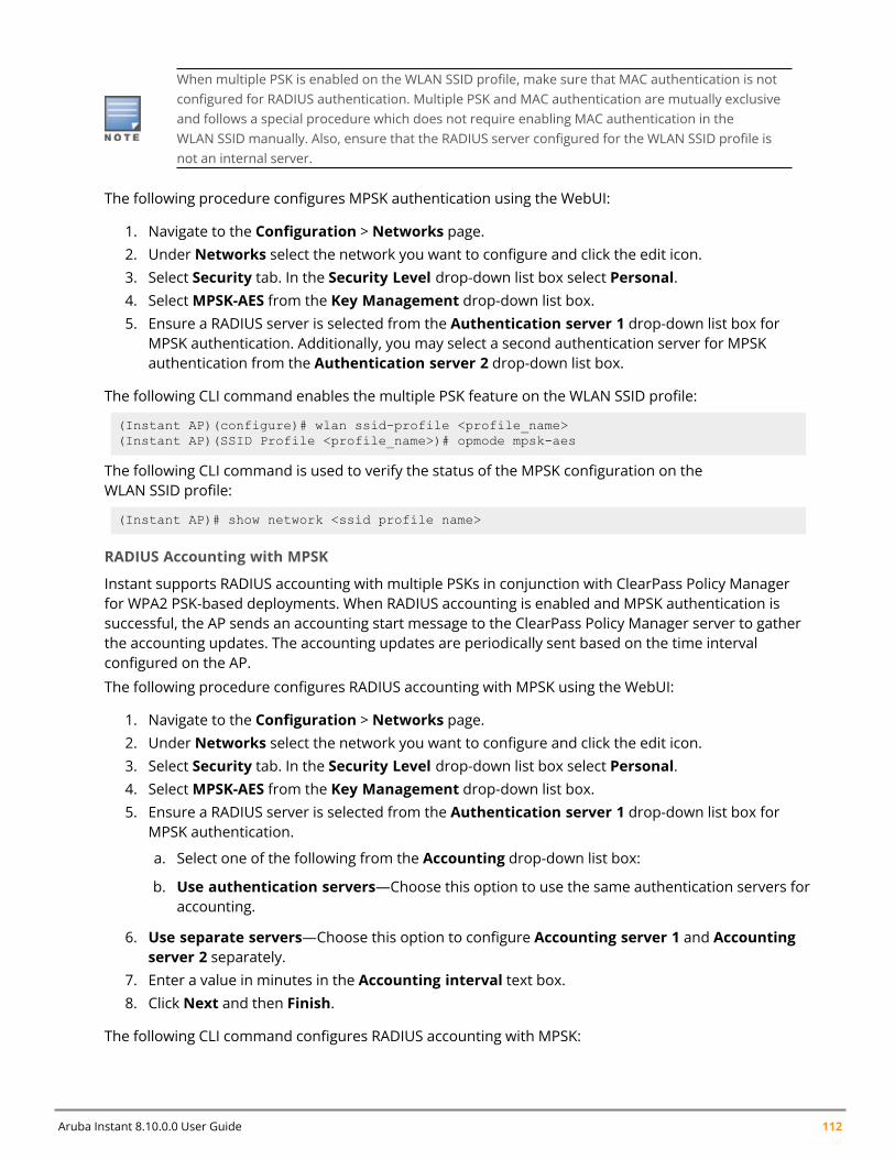
Aruba Instant 8.10.0.0 User Guide 112
When multiple PSK is enabled on the WLAN SSID profile, make sure that MAC authentication is notconfigured for RADIUS authentication. Multiple PSK and MAC authentication are mutually exclusiveand follows a special procedure which does not require enabling MAC authentication in theWLAN SSID manually. Also, ensure that the RADIUS server configured for the WLAN SSID profile isnot an internal server.
The following procedure configures MPSK authentication using the WebUI:
1. Navigate to the Configuration > Networks page.2. Under Networks select the network you want to configure and click the edit icon.3. Select Security tab. In the Security Level drop-down list box select Personal.4. SelectMPSK-AES from the Key Management drop-down list box.5. Ensure a RADIUS server is selected from the Authentication server 1 drop-down list box for
MPSK authentication. Additionally, you may select a second authentication server for MPSKauthentication from the Authentication server 2 drop-down list box.
The following CLI command enables the multiple PSK feature on the WLAN SSID profile:
(Instant AP)(configure)# wlan ssid-profile <profile_name>(Instant AP)(SSID Profile <profile_name>)# opmode mpsk-aes
The following CLI command is used to verify the status of the MPSK configuration on theWLAN SSID profile:
(Instant AP)# show network <ssid profile name>
RADIUS Accounting with MPSK
Instant supports RADIUS accounting with multiple PSKs in conjunction with ClearPass Policy Managerfor WPA2 PSK-based deployments. When RADIUS accounting is enabled and MPSK authentication issuccessful, the AP sends an accounting start message to the ClearPass Policy Manager server to gatherthe accounting updates. The accounting updates are periodically sent based on the time intervalconfigured on the AP.
The following procedure configures RADIUS accounting with MPSK using the WebUI:
1. Navigate to the Configuration > Networks page.2. Under Networks select the network you want to configure and click the edit icon.3. Select Security tab. In the Security Level drop-down list box select Personal.4. SelectMPSK-AES from the Key Management drop-down list box.5. Ensure a RADIUS server is selected from the Authentication server 1 drop-down list box for
MPSK authentication.
a. Select one of the following from the Accounting drop-down list box:
b. Use authentication servers—Choose this option to use the same authentication servers foraccounting.
6. Use separate servers—Choose this option to configure Accounting server 1 and Accountingserver 2 separately.
7. Enter a value in minutes in the Accounting interval text box.8. Click Next and then Finish.
The following CLI command configures RADIUS accounting with MPSK:
Wireless Network Profiles | 113
(Instant AP)(configure)# wlan ssid-profile <profile-name>(Instant AP)(WLAN SSID Profile "name")# opmode mpsk-aes(Instant AP)(WLAN SSID Profile "name")# radius-accounting
The following CLI command configures an accounting interval:
(Instant AP)(configure)# wlan ssid-profile <profile-name>(Instant AP)(WLAN SSID Profile "name")# radius-interim-accounting-interval <minutes>
Points to Remember
The following configurations are mutually exclusive with MPSK for the WLAN SSID profile and does notrequire to be configured manually:
n MPSK and MAC authenticationn MPSK and Denylistingn MPSK and internal RADIUS server
MPSK Cache
The Instant AP stores the MPSK passphrase in its local cache for client roaming. The cache is sharedbetween all the Instant APs within a single cluster. The cache can also be shared with standalone InstantAPs in a different cluster provided the APs belong to the same multicast VLAN. Each Instant AP will firstsearch the local cache for the MPSK information. If the local cache has the correspondingmPSK passphrase, the Instant AP skips the mac authentication procedure, and provides access to theclient. If the MPSK passphrase is not found in the local cache, you must manually configure theMPSK passphrase as shown in the above section.
The cached MPSK passphrase can be used only if the client connects to the same WLAN SSID. The entireMPSK local cache is erased in the following scenarios:
n If the cached MPSK does not work.n The client is manually disconnectedn The client is disconnected from the CoA.
The MPSK passphrase in the local cache automatically expires if the client disconnects and does notconnect again during the inactivity-timeout window.
To view the details of the MPSK local cache:
(Instant AP)# show ap mpskcache
Local Multiple PSK Operating Mode
In the Local MPSK operating mode, you can define upto 24 pre-shared keys per SSID on the gateway orthe Instant AP without actually requiring an external policy engine like ClearPass Policy Manager. Theselocal PSKs would serve as an extension of the base pre-shared key functionality. Local MPSK onlysupports passphrases in the form of strings. It does not support passphrases in the form of hex. Thelocal MPSK is currently supported only on an employee type and personal sercurity level SSID.Additionally, you may also configure a user role for each passphrase from which the user VLAN andaccess rules can be derived.
The following CLI commands configure a local MPSK profile:
(Instant AP)(config)# wlan-mpsk-local <profile_name>
Aruba Instant 8.10.0.0 User Guide 114
(Instant AP)(MPSK Local "profile_name")# mpsk-local-passphrase <key_name> <key> [role_name]
Configuring Access Rules for a WLAN SSID ProfileThe following procedure configures access rule settings for Employee and Voice networks only.If you arecreating a new SSID profile, complete the WLAN settings and configure VLAN and security parameters,before defining access rules. For more information, see Configuring WLAN Settings for an SSID Profileon page 97, Configuring VLAN Settings for a WLAN SSID Profile on page 102, and Points to Remember onpage 113.Captive Portal for Guest Access.
You can configure up to 128 access rules for an Employee, Voice , or Guest network using the Instant UIor the CLI.
The following procedure describes how to configure access rules on an Instant AP, using the WebuI:
1. Navigate to Configuration > Networks.2. Under Networks select the network you want to configure and click Edit.3. Select Access tab. In the Access Rules drop-down list box select one of the following type:
n Unrestricted—Select this option to set unrestricted access to the network.n Network-based—Select this option to set common rules for all users in a network. The Allow
any to all destinations access rule is enabled by default. This rule allows traffic to alldestinations.
4. To define an access rule:
a. Click +.
b. Select appropriate options in the New Rule window.
c. Click OK.
n Role-based—Select this option to enable access based on user roles. For role-based access control:l Create a user role if required. For more information, see Configuring User Roles.l Create access rules for a specific user role. For more information, see Configuring ACL Rules forNetwork Services on page 220. You can also configure an access rule to enforce captive portalauthentication for an SSID that is configured to use 802.1X authentication method. For moreinformation, see Configuring Captive Portal Roles for an SSID on page 166.
l Create a role assignment rule. For more information, see Configuring Derivation Rules on page238.
n Enforce Machine Authentication— Select this check box to configure access rights to clients basedon whether the client device supports machine authentication.
5. Click Finish.
The following CLI command configures access control rules for a WLAN SSID:
(Instant AP)(config)# wlan access-rule <name>(Instant AP)(Access Rule <name>)# rule <dest> <mask> <match> {<protocol> <start-port><end-port> {permit|deny|src-nat [vlan <vlan_id>|tunnel]|dst-nat{<IP-address><port>|<port>}}| app <app> {permit|deny}| appcategory <appgrp>|webcategory <webgrp>{permit|deny}| webreputation <webrep> [<option1....option9>]
The following CLI command configures access control rules based on the SSID:
(Instant AP)(config)# wlan ssid-profile <name>(Instant AP)(SSID Profile <name>)# set-role-by-ssid
Wireless Network Profiles | 115
The following CLI command configures role assignment rules:
(Instant AP)(config)# wlan ssid-profile <name>(Instant AP)(SSID Profile <name>)# set-role <attribute>{{equals|not-equals|starts-with|ends-with|contains|matches-regular-expression}<operator><role>|value-of}
The following CLI command configures a pre-authentication role:
(Instant AP)(config)# wlan ssid-profile <name>(Instant AP)(SSID Profile <name>)# set-role-pre-auth <role>
The following CLI command configures machine and user authentication roles:
(Instant AP)(config)# wlan ssid-profile <name>(Instant AP)(SSID Profile <name>)# set-role-machine-auth <machine_only> <user_only>
The following CLI command configures unrestricted access:
(Instant AP)(config)# wlan ssid-profile <name>(Instant AP)(SSID Profile <name>)# set-role-unrestricted
Example
The following example configures access rules for the wireless network:
(Instant AP)(config)# wlan access-rule WirelessRule
ESSID and VLAN ConfigurationIn addition to the WLAN SSID, you can set a unique ESSID and also configure a unique a VLAN for eachInstant AP in a cluster. Clients will be able to connect to the defined SSIDs and can configure the definedVLANs in the Instant AP cluster.
You can configure the ESSID and VLAN settings by using the Instant CLI.
The following CLI command configures ESSID and VLAN settings in a WLAN profile:
(Instant AP)(config)# wlan ssid-profile TechPubsAP(Instant AP)(SSID Profile "TechPubsAP")# essid $per-ap-ssid(Instant AP)(SSID Profile "TechPubsAP")# vlan $per-ap-vlan
The following CLI command configure a unique ESSID:
(Instant AP)# per-ap-ssid pcap
To configure VLAN settings:
(Instant AP)# per-ap-vlan 123
To verify the ESSID and VLAN configurations:
(Instant AP)# show ap-envAntenna Type:InternalNeed USB field:Yesper_ap_ssid:pcapper_ap_vlan:123installation_type:indooruap_controller_less:1flex_radio_mode:2.4ghzap2xx_prestandard_poeplus_detection:1
For information on configuring a native VLAN on a wired profile, see Configuring VLAN for a WiredProfile on page 132.
Aruba Instant 8.10.0.0 User Guide 116
Wi-Fi 6E (6 GHz Networks)Wi-Fi 6E is the standard introduced by the Wi-Fi alliance that enables access points to operate in the 6GHz band of the wireless spectrum. Wi-Fi 6E capable access points can operate in the 6 GHz radio bandin addition to 2.4 GHz and 5 GHz radio bands. The inclusion of 6 GHz spectrum adds fourteen 80 MHzchannels and seven 160 MHz channels for wireless services. Being a new radio spectrum there are lessclients and more bandwidth space available for use in the 6 GHz spectrum space. In addition to this, all6 GHz channels are non-overlapping channels and provide better wireless experience and services.
Points to Remembern AP-635 access points are Wi-Fi 6E capable access points.n Instant APs support up to four 6 GHz networks. When mesh is enabled on the 6 GHz radio, the
number of 6 GHz networks that can be configured is reduced to three as one network is allocated forthe mesh function. Therefore disable a 6 GHz network when mesh is configured on the 6 GHz radio.The Disable on 6GHz mesh option allows you to configure the 6 GHz SSID that should be disabledwhen mesh is active on the 6 GHz radio.
n Wi-Fi 6E networks are only supported with Enhanced Open and WPA3 encryption methods.n Wi-Fi uplink is not supported in AP-635 access points.
Configuring Wi-Fi 6EThe addition of the 6 GHz radio brings enhancements to various Instant AP configurations. The followingare Instant AP configurations for 6 GHz radio:
n Configuring Wireless Networks on the 6 GHz Radio Bandn Configuring Radio Settings for 6 GHz Radion Configuring ARM Features for 6 GHz Radion Configuring Radio Profiles for 6 GHz Radio
Configuring Wireless Networks on the 6 GHz Radio BandWLAN SSIDs are not broadcast on the 6 GHz radio by default. The 6 GHz radio band options must beturned on in the respective SSID profile. Up to four 6 GHz networks can be created on an Instant AP andthree 6 GHz networks when mesh is enabled on the 6 GHz radio band.
To enable 6 GHz radio band for SSIDs using the WebUI:
1. Navigate to the Configuration > Networks page in the in the WebUI. For detailed informationabout creating/modifying WLAN SSID profiles, see Configuring WLAN Settings for an SSID Profile.
2. In the Basic tab, click on Show Advanced Options.3. Under 802.11 settings, toggle the RF band 6 GHz option to enabled.
To create a 6 GHz only SSID, enable the RF band 6 GHz option and set the Band option tonone. The SSID will be broadcast only on the 6 GHz radio band.
4. Toggle the Disable on 6GHz mesh to enabled if you want to disable the 6 GHz radio band for theSSID when mesh is enabled on the 6 GHz band. Instant APs support only four 6 GHz networks.When mesh is enabled on 6 GHz radio, one 6 GHz network is used for mesh functions. Enablingthis parameter disables the 6 GHz network when mesh is operational in the 6 GHz radio band.
5. Click Save to apply the configuration. The SSID is broadcast on the 6 GHz radio band.
Wireless Network Profiles | 117
To enable 6 GHz radio for SSIDs using the CLI, enable the rf-band-6ghz parameter in thewlan ssid-profile command.
(Instant AP)(config) # wlan ssid-profile 6GHzNetwork(Instant AP)(SSID Profile "6GHzNetwork") # rf-band-6ghz
To enable disable on 6 GHz mesh option using the CLI, enable the disable-on-6ghz-mesh parameter inthewlan ssid-profile command. When enabled, the SSID will stop broadcast on 6 GHz radio whenmesh is enabled on the 6 GHz radio.
(Instant AP)(config) # wlan ssid-profile 6GHzNetwork(Instant AP)(SSID Profile "6GHzNetwork") # disable-on-6ghz-mesh
To enable SSIDs to operate only on the 6 GHz band using the CLI, enable the rf-band-6ghz parameterand set the rf-band parameter to none in thewlan ssid-profile command.
(Instant AP)(config) # wlan ssid-profile 6GHzNetworkOnly(Instant AP)(SSID Profile "6GHzNetworkOnly") # rf-band-6ghz(Instant AP)(SSID Profile "6GHzNetworkOnly") # rf-band none
For more information, see Aruba Instant 8.x CLI Reference Guide.
Configuring Radio Settings for 6 GHz RadioSimilar to the 2.4 GHz and 5 GHz radios, the channel and transmit power settings of the 6 GHz radio caneither be assigned by the ARM or can be manually configured. To configure the radio settings of the 6GHz radio using the WebUI:
1. Navigate to the Configuration > Access Points page in the in the WebUI. For detailedinformation about modifying radio settings, see Configuring Radio Settings for an Instant AP.
2. Select 6 GHz under Radio settings.3. Select the mode and configure the channel and transmit power settings of the radio as required.4. Click Save to apply the configuration.
To configure the Wi-Fi operation mode of the 6 GHz radio using the CLI, use thewifi2-mode command.
(Instant AP)# wifi2-mode {access | monitor | spectrum}
To configure the channel and transmit power settings of the 6 GHz radio using the CLI, use the radio2-channel command.
(Instant AP)# radio2-channel <channel> <transmit power>
Configuring ARM Features for 6 GHz RadioAdditional options are added to band steering, wide bands, and customize valid channel settings inARM to manage the 6 GHz radio.
Band Steering for 6 GHz Clients
The band steering function of Client Match is extended to Wi-Fi 6E clients. New options are introducedin the band steering settings to steer 6 GHz clients to capable radios. To configure band steering for 6GHz clients using the WebUI:
1. Navigate to the Configuration > RF > ARM section in the WebUI. For detailed information aboutmodifying band steering settings, see Band Steering .
Aruba Instant 8.10.0.0 User Guide 118
2. Select any of the following options in Band steering mode to configure 6 GHz band steering:n Force 6 GHz - Select this option to enforce 6 GHz band steering mode on the Instant APs.
When enabled, 6 GHz clients are only accepted by the 6 GHz radio and are blocked on the 2.4GHz and 5 GHz radio.
n Prefer Higher Band - Select this option to use band steering in the 6 GHz and 5 GHz bands onthe Instant APs. On selecting this, the Instant AP steers the 6 GHz clients to the 6 GHz band (ifthe client is 6 GHz-capable), but allows the client connection on the 5 GHz band if the clientpersistently attempts for 5 GHz association. Similarly, the Instant AP steers the client to the 5GHz band (if the client is 5 GHz-capable), but allows the client connection on the 2.4 GHz bandif the client persistently attempts for 2.4 GHz association.
3. Click Save to apply the configuration.
To configure band steering for 6 GHz clients using the CLI, use the band-steering-mode parameter inthe arm command.
(Instant AP)(config)# arm(Instant AP)(ARM)# band-steering-mode {balance-bands|prefer-5ghz| force-5ghz| disable|prefer-higher-band| force-6ghz}
Wide Band Settings for 6 GHz Radio Channel
Wide band setting is extended to 6 GHz radio band. To configure wide bands on the 6 GHz radio bandusing the WebUI:
1. Navigate to the Configuration > RF > Show advanced options > ARM > Access Point Controlsection in the WebUI. For detailed information about configuring wide bands setting, see AccessPoint Control.
2. Select the 6 GHz checkbox inWide channel bands to configure wide channel bands on the 6GHz radio. This can be selected in combination with other radio bands.
3. Click Save to apply the configuration.
To configure wide bands on the 6 GHz radio using the CLI, use thewide-bands parameter in the armcommand.
(Instant AP)(config)# arm(Instant AP)(ARM)# wide-bands {none| all| 24ghz| 5 ghz| 6ghz| 24ghz,5ghz| 24ghz,6ghz|5ghz,6ghz}
Customizing Valid Channels in the 6 GHz Radio Band
To customize the list of valid channels in the 6 GHz band using the WebUI:
1. Navigate to the Configuration > RF > Show advanced options > ARM > Access Point Controlsection in the WebUI. For detailed information about configuring wide bands setting, see AccessPoint Control.
2. Toggle the Customize valid channels switch to enabled to customize channels on the 6 GHzradio.
3. Click on Edit besides the list of Valid 6 GHz channels and select the required channels.4. Click OK.5. Click Save to apply the configuration.
To customize valid channels in 6 GHz band using the CLI, use the allowed-channels parameter in the rfdot11-6ghz-radio-profile command.
(Instant AP)(config)# rf dot11-6ghz-radio-profile 6GHz
Wireless Network Profiles | 119
(Instant AP)((RF 6GHz Radio Profile "6GHz")# allowed-channels
Configuring Radio Profiles for 6 GHz RadioTo configure a 6 GHz radio profile using the WebUI:
1. Navigate to the Configuration > RF > Show advanced options > Radio section in the WebUI.For detailed information about configuring radio profiles, see Configuring Radio Profiles.
2. In the 6 GHz band table, click on + to create a new 6 GHz radio profile or click on edit icon tomodify an existing radio profile.
3. Specify the radio profile parameters for the 6 GHz radio and click OK.4. Click Save to apply the configuration.
To configure a 6 GHz radio profile using the CLI, use the rf dot11-6ghz-radio-profile command.
(Instant AP)(config)# rf dot11-6ghz-radio-profile 6GHz
Fast Roaming for Wireless ClientsInstant supports the following features that enable fast roaming of clients:
n Opportunistic Key Cachingn Fast BSS Transition (802.11r Roaming)n Radio Resource Management (802.11k)n BSS Transition Management (802.11v)n Fast Roaming for Wireless Clients
Opportunistic Key CachingInstant supports OKC-based roaming. In OKC-based roaming, the Instant AP stores one PMK per client,which is derived from the last 802.1X authentication completed by the client in the network. The PMKcache is used to identify authenticated clients when it roams to a new Instant AP. This allows fasterroaming of clients between the Instant APs in a cluster, without requiring a complete 802.1Xauthentication. The ageout period of client entries in the PMK cache is 8 hours, after which the cliententry is deleted and the client must re-authenticate into the network.
OKC roaming (when configured in the 802.1X Authentication profile) is supported on WPA2 clients. Ifthe wireless client (the 802.1X supplicant) does not support this feature, a complete 802.1Xauthentication is required whenever a client roams to a new Instant AP.
Configuring an Instant AP for OKC RoamingThe following procedure describes how to enable OKC roaming on a WLAN SSID by using the InstantWebUI:
1. Navigate to Configuration > Networks page2. Under Networks select the network you want to configure and click Edit.3. Select the Security tab.4. In the Security Level drop-down list box, select Enterprise.5. In the Key management drop-down list box, selectWPA2 Enterprise or Both (WPA2 & WPA).
Aruba Instant 8.10.0.0 User Guide 120
6. Under Fast Roaming, toggle the Opportunistic Key Caching (OKC) switch to enable.7. Click Next and then Finish.
The following CLI command enables OKC roaming on a WLAN SSID:
(Instant AP)(config)# wlan ssid-profile <name>(Instant AP)(SSID Profile "<name>")# opmode {wpa2-aes| wpa-tkip,wpa-aes,wpa2-tkip,wpa2-aes}(Instant AP)(SSID Profile "<name>")# okc
The following CLI command disables OKC roaming on a WLAN SSID:
(Instant AP)(config)# wlan ssid-profile <name>(Instant AP)(SSID Profile "<name>")# opmode {wpa2-aes|wpa-tkip,wpa-aes,wpa2-tkip,wpa2-aes}(Instant AP)(SSID Profile "<name>")# no okc
The following CLI command displays the client entries in the PMK cache:
(Instant AP)# show ap pmkcache
Configuring the Ageout Time for PMK Cache EntriesThe PMK cache stores the details of connected clients for authenticating clients roaming betweendifferent APs. By default, the client details in the PMK cache is stored for about 8 hours after the clientdisconnects or gets timed out from the network. However, client entries in the PMK cache can bedeleted immediately after a client disconnects or gets timed out from the network. This is configured inthe WLAN SSID profile by enabling the delete-pmkcache parameter using the CLI.
The following CLI command deletes the client details in the PMK cache immediately after clientdisconnection or timeout:
(Instant AP)(config)# wlan ssid-profile <name>(Instant AP)(SSID Profile "<name>")# delete-pmkcache
Fast BSS Transition (802.11r Roaming)802.11r is a roaming standard defined by IEEE. When enabled, 802.11r reduces roaming delay by pre-authenticating clients with multiple target Instant APs before a client roams to an Instant AP. With802.11r implementation, clients pre-authenticate with multiple Instant APs in a cluster.
As part of the 802.11r implementation, Instant supports the Fast BSS Transition protocol. The Fast BSSTransition mechanism reduces client roaming delay when a client transitions from one BSS to anotherwithin the same cluster. This minimizes the time required to resume data connectivity when a BSStransition happens.
Fast BSS Transition is operational only if the wireless client supports 802.11r standard. If the clientdoes not support 802.11r standard, it falls back to the normal WPA2 authentication method.
Configuring an Instant AP for 802.11r supportThe following procedure describes how to configure 802.11r support for a WLAN SSID by using theInstant WebUI:
1. Navigate to Configuration > Networks page2. Under Networks select the network you want to configure and click Edit.3. Select the Security tab.
Wireless Network Profiles | 121
4. Under Fast Roaming, toggle the 802.11r switch to enable.5. Click Next and then Finish.
The following CLI command enables 802.11r roaming on a WLAN SSID:
(Instant AP)(config)# wlan ssid-profile <name>(Instant AP)(SSID Profile <name>)# dot11r
Mobility Domain IdentifierIn a network of standalone Instant APs within the same management VLAN, 802.11r roaming does notwork. This is because the mobility domain identifiers do not match across Instant APs. They are auto-generated based on a virtual controller key. Instant introduces a an option for users to set a mobilitydomain identifier for 802.11r SSIDs. For standalone Instant APs in the same management VLAN, 802.11rroaming works only when the mobility domain identifier is configured with the same value.
You can configure a mobility domain identifier by using the Instant WebUI:
1. Navigate to Configuration > Networks page2. Under Networks select the network you want to configure and click Edit.3. Select the Security tab.4. Under Fast Roaming, toggle the 802.11r switch to enable.5. In theMDID text box, enter the mobility domain identifier.6. Click Next and then Finish.
The following CLI command enables MDID on a WLAN SSID:
(Instant AP)(config)# wlan ssid-profile <name>(Instant AP)(SSID Profile <name>)# mdid <Mobility domain ID>
Radio Resource Management (802.11k)The 802.11k standard provides mechanisms for Instant APs and clients to dynamically measure theavailable radio resources and enables stations to query and manage their radio resources. In an802.11k-enabled network, Instant APs and clients can share radio and link measurement information,neighbor reports, and beacon reports with each other. This allows the WLAN network infrastructuralelements and clients to assess resources and make optimal mobility decisions to ensure QoS andseamless continuity.
Instant supports the following radio resource management information elements with 802.11k supportenabled:
n Power Constraint IE—The power constraint element contains the information necessary to allow aclient to determine the local maximum transmit power in the current channel.
n AP Channel Report IE—The Instant AP channel report element contains a list of channels in aregulatory class where a client is likely to find an Instant AP, including the Instant AP transmitting theInstant AP channel report.
n Radio Resource Management Enabled Capabilities IE—The RRM-enabled capabilities elementsignals support for radio measurements in a device. The clients use this IE to specify their radiomeasurement capabilities.
n BSS Load Element—The BSS load element contains information on the density of clients and trafficlevels in the QBSS.
n TPC Report IE—The TPC IE contains transmit power and link margin information.
Aruba Instant 8.10.0.0 User Guide 122
n Quiet IE: The Quiet IE defines an interval during which no transmission occurs in the currentchannel. This interval may be used to assist in making channel measurements without interferencefrom other stations in the BSS.
n Extended Capabilities IE—The extended capabilities IE carries information about the capabilities ofan IEEE 802.11 station.
Beacon Report Requests and Probe ResponsesThe beacon request frame is sent by an Instant AP to request a client to report the list of beaconsdetected by the client on all channels.
n The beacon request is sent using the radio measurement request action frame.n It is sent only to those clients that have the capability to generate beacon reports. The clients indicate
their capabilities through the RRM enabled capabilities IE sent in the association request frames.n By default, the beacon request frames are sent at a periodicity of 60 seconds.
Configuring a WLAN SSID for 802.11k SupportThe following procedure describes how to enable 802.11k support on a WLAN SSID by using the InstantWebUI:
1. Navigate to Configuration > Networks page2. Under Networks select the network you want to configure and click Edit.3. Select the Security tab.4. Under Fast Roaming, toggle the 802.11k switch to enable.5. Click Next and then Finish.
To allow the Instant AP and clients to exchange neighbor reports, ensure that Client Match is enabledthrough RF > ARM > Client match > Enabled in the WebUI or by executing the client-matchcommand in the arm configuration sub-command mode.
The following CLI command enables the 802.11k profile:
(Instant AP)(config)# wlan ssid-profile <name>(Instant AP)(SSID Profile <name>)# dot11k
The following CLI command is used to view the beacon report details:
(Instant AP)# show ap dot11k-beacon-report <mac>
The following CLI command is used to view the neighbor details:
(Instant AP)# show ap dot11k-nbrs
Example
(Instant AP)(config)# wlan ssid-profile dot11k-profile(Instant AP)(SSID Profile "dot11k-profile")# dot11k
BSS Transition Management (802.11v)The 802.11v standard provides Wireless Network Management enhancements to the IEEE 802.11 MACand PHY. It extends radio measurements to define mechanisms for wireless network management ofstations including BSS transition management.
Instant APs support the generation of the BSS transition management request frames to the 802.11kclients when a suitable Instant AP is identified for a client through Client Match.
Wireless Network Profiles | 123
Configuring a WLAN SSID for 802.11v SupportThe following procedure describes how to enable 802.11v support on a WLAN SSID by using the InstantWebUI:
1. Navigate to Configuration > Networks page2. Under Networks select the network you want to configure and click Edit.3. Select the Security tab.4. Under Fast Roaming, toggle the 802.11v switch to enable.5. Click Next and then Finish.
The following CLI command enables the 802.11v profile:
(Instant AP)(config)# wlan ssid-profile <name>(Instant AP)(SSID Profile <name>)# dot11v
Example
(Instant AP)(config)# wlan ssid-profile dot11v-profile(Instant AP)(SSID Profile "dot11v-profile")# dot11v
Configuring Modulation Rates on a WLAN SSIDInstant APs allow you to enable or disable modulation rates for a radio band; HT MCS set; and VHT MCSrates set, when configuring a WLAN SSID profile. For example, the 802.11g band supports themodulation rate including 1, 2, 5, 6, 9, 11, 12, 18, 24, 36, 48, 54 Mbps and 802.11a band supports amodulation rate set including 6, 9, 12, 18, 24, 36, 48, 54 Mbps.
The 802.11 radio profiles support basic modulation and transmission rates. The 802.11g basicmodulation rates determine the 802.11b or 802.11g rates for the data that are advertised in beaconframes and probe response and 802.11g transmission rates determine the 802.11b or 802.11g rates atwhich the Instant AP can transmit data.
For 802.11n clients, you can now configure an HT MCS rate set so that the SSID does not broadcast thedisabled MCS rates list.
For 802.11ac clients, only 10 MCS rates supported in the 802.11ac mode and Instant APs use acombination of VHT MCSs and spatial streams to convey the supported MCS rates.
In the Instant 6.4.3.4-4.2.1.0 release, the modulation rates can be configured only through the InstantAP CLI.
The following CLI command is used to configure modulation rates:
(Instant AP)# config terminal(Instant AP)(config)# wlan ssid-profile <ssid_profile>(Instant AP)(SSID Profile "<ssid_profile>")# a-basic-rates 6 9 12 18(Instant AP)(SSID Profile "<ssid_profile>")# a-tx-rates 36 48 54(Instant AP)(SSID Profile "<ssid_profile>")# supported-mcs-set 1,3,6,7(Instant AP)(SSID Profile "<ssid_profile>")# vht-support-mcs-map 7, 9, 8
Multi-User-MIMOThe MU-MIMO feature allows the 802.11ac Wave 2 Instant APs to send multiple frames to multipleclients simultaneously over the same frequency spectrum. With MU-MIMO, Instant APs can supportsimultaneous directional RF links and up to four simultaneous full-rate Wi-Fi connections (for example,smart phone, tablet, laptop, multimedia player, or other client device).
Aruba Instant 8.10.0.0 User Guide 124
The MU-MIMO feature is enabled by default on WLAN SSIDs to allow Instant APs to use the MUbeamformer bit in beacon frames to broadcast to clients. When disabled, the MU beamformer bit is setto unsupported.
Enabling or Disabling MU-MIMOThe MU-MIMO feature is enabled by default on a WLAN SSID profile. The following CLI commanddisables this feature:
(host)(config)# wlan ssid-profile <ssid_profile>(host)(SSID Profile "<ssid_profile>")# vht-mu-txbf-disable
The following CLI command re-enables MU-MIMO on a WLAN SSID profile:
(host)(config)# wlan ssid-profile <ssid_profile>(host)(SSID Profile "<ssid_profile>")# no vht-mu-txbf-disable
RTS/CTS Flow ControlThe RTS/CTS mechanism allows devices to reserve the RF medium and minimize the frame collisionsintroduced by hidden stations. When RTS is enabled, a higher number of retransmissions occurring onthe WLAN triggers the RTS/CTS handshake and the transmitter station sends an RTS frame to thereceiver station. The receiver station responds with a CTS frame. The RTS/CTS frames are sent onlywhen the packet size exceeds the RTS threshold. By default, the RTS threshold is set to 2333 octets.
Configuring RTS/CTS ThresholdYou can set the RTS/CTS threshold value within the range of 0–2347 octets. By default, the RTS/CTSthreshold is set to 2333.
The following CLI command configures the RTS/CTS threshold:
(Instant AP)(config)# wlan ssid-profile <ssid_profile>(Instant AP)(SSID Profile "<ssid_profile>")# rts-threshold <threshold>
To disable RTS/CTS, set the RTS threshold value to 0.
Uplink MU-MIMO TransmissionAruba Instant 8.8.0.0 and later versions support the uplink MU-MIMO transmission of 802.11axprotocol. Prior to Instant 8.8.0.0, MU-MIMO allowed to send data frames only between access pointsand clients. Now, the uplink MU-MIMO transmission allows to send multiple frames from multipleclients simultaneously to the AP over the same frequency spectrum.. It also helps in achievingthroughput gains when applications need to upload large amount of data. It also enables the multiplespatially separated clients to access the channel at the same time and it is also useful in scenarios wherestations have limited number of antennas. The uplink MU MIMO transmission is supported in 5 GHz and6 GHz bands.
Only AP-535, AP-555, and AP-655 access points support uplink MU MIMO transmission.
The following CLI command is used to enable uplink MU-MIMO:(Instant AP)(config)# wlan ssid-profile he_ssid_test(Instant AP)(SSID Profile "he_ssid_test")# he-ul-mu-mimo(Instant AP)(SSID Profile "he_ssid_test")# end(Instant AP)# commit apply
The following CLI command is used to disable uplink MU-MIMO:(Instant AP)(config)# wlan ssid-profile he_ssid_test(Instant AP)(SSID Profile "he_ssid_test")# no he-ul-mu-mimo
Wireless Network Profiles | 125
(Instant AP)(SSID Profile "he_ssid_test")# end(Instant AP)# commit apply
The following CLI commands are used to view the status of the uplink MU-MIMO configuration:(Instant AP)# show running-config(Instant AP)# show network <profile_name>
Management Frame ProtectionInstant supports the IEEE 802.11w standard, also known as Management Frame Protection. TheManagement Frame Protection increases the security by providing data confidentiality of managementframes. Management Frame Protection uses 802.11i framework that establishes encryption keysbetween the client and Instant AP.
The following command is used to enable Management Frame Protection on the Instant AP:
(Instant AP)(config)# wlan ssid-profile myAP(Instant AP)(SSID Profile "myAP")# mfp-capable(Instant AP)(SSID Profile "myAP")# mfp-required
If themfp-required parameter is enabled, the SSID supports only the clients that exhibit theManagement Frame Protection functionality.
If themfp-capable parameter enabled, the SSID supports Management Frame Protection capable clientsand non-Management Frame Protection clients.
The Management Frame Protection configuration is a per-SSID configuration.
Management Frame Protection can be enabled only on WPA2-PSK and WPA2-enterprise SSIDs. The802.11r fast roaming option will not take effect when MFP is enabled.
High Efficiency WLAN (HEW)Instant supports the IEEE 802.11ax standard, also known as High-Efficiency WLAN (HEW). HEW improvesspectrum efficiency and area throughput in dense deployment scenarios of APs or stations in bothindoor and outdoor environments. HEW enhances the 802.11 PHY and MAC channels on both 2.4 GHzand 5 GHz frequency bands.
HEW includes the following key features:
n Backward compatible with 802.11a/b/g/n/ac.n Better power management for longer battery life.
Configuring High Efficiency on a WLAN SSIDMost deployments do not require manual configuration of the high-efficiency SSID profile as this optionis enabled by default. However, you can configure advanced high-efficiency SSID profile settings ormodify default SSID profile values using the Instant WebUI or CLI.
The following procedure describes how to enable or disable High Efficiency on a WLAN SSID:
1. Navigate to the Configuration > Networks page.2. Under Networks select the WLAN network you want to configure and click the edit icon.3. Click Show advanced options at the bottom of the window.
Aruba Instant 8.10.0.0 User Guide 126
4. Under the 802.11 group, slide the High efficiency toggle switch to the right to enable the highefficiency function, or slide the toggle switch to the left if you want to disable high efficiency onthe WLAN SSID.
5. Click Next and then Finish.
The following CLI command enables High Efficiency on a WLAN SSID:
(Instant AP)(config)# wlan ssid-profile <profile_name>(Instant AP)(SSID Profile "<profile_name>")# high-efficiency-enable
The following CLI command disables High Efficiency on a WLAN SSID:
(Instant AP)(config)# wlan ssid-profile <profile_name>(Instant AP)(SSID Profile "<profile_name>")# high-efficiency-disable
Multi Band Operation (MBO)The MBO feature enables the WLAN network to utilize the available spectrum efficiently, and helps inoptimizing the connectivity experience for end-users. MBO, also known as Agile Multiband is a pre-requisite for 802.11ax certification, therefore any AP or STA that supports 802.11ax has the MBOcapabilities.
MBO allows the APs and STAs exchange information and facilitates efficient use of multiple frequencybands or channels that are available in the APs and the STAs.
MBO is supported only on 802.11ax access points.
Enablingmbo-enable on the WLAN SSID profile will automatically enable the following:
n mfp-capable and dot11k functionalities on the SSID profile.n advertise-enabled-capabilities-ie and country-ie parameters in the rrm-ie-profile.n interworking-enable in the hotspot profile if not enabled.
MBO on Instant APs can only be configured using the CLI. Use thembo-enable command underwlanssid-profile to enable MBO.
The following CLI command enables MBO on a WLAN SSID profile.
(Instant AP) (config) # wlan ssid-profile <profile name>(Instant AP) (wlan ssid-profile <profile name>) #mbo-enable
To enable Cellular Data Capability attribute of MBO on the Instant AP, use the cdc-enable command inthe WLAN SSID profile. This feature will only take effect if Multi Band Operation is enabled on the WLANSSID.
The following CLI command enables Cellular Data Capability on the SSID.
(Instant AP) (config) # wlan ssid-profile <profile name>(Instant AP) (wlan ssid-profile <profile name>) #cdc-enable
Configuring 802.11k ProfileThe 802.11k protocol provides mechanisms for APs and clients to dynamically measure the availableradio resources. In an 802.11k enabled network, APs and clients can send neighbor reports, beaconreports, and link measurement reports to each other. This allows the APs and clients to takeappropriate connection actions.
Wireless Network Profiles | 127
The dot11k-profile configures attributes for information exchange between the peers. A defaultdot11k-profile will be used for MBO if no dot11k-profile is configured. A dot11k profile can beconfigured using the dot11k-profile command. The configured dot11k-profile should be attached tothe respectivewlan ssid-profile using the dot11k-profile <profile name> parameter. For informationon configuring dot11k-profile, see dot11k-profile command in the Aruba Instant 8.x CLI Reference Guide.The wide channel bandwidth information element is included in the neighbor report responses bydefault, when the dot11k setting is enabled on the Instant AP as part of the dot11k-profileconfiguration. The disable-nb-resp_wide-band-ie parameter in the dot11k-profile command can beused to disable the setting when dot11k is enabled and stop the wide channel bandwidth informationelement from being included in the neighbor report responses.
Radio Resource Management Information ElementsAruba Instant supports the following radio resource management (RRM) information elements for APswith 802.11k support enabled. These settings can be enabled the CLI. The rrm-ie-profile configuredshould be attached to the dot11k-profile command using the rrm-ie-profile <profile-name>command.
By default the advertise-enabled-capabilities-ie and country-ie parameters are enabled in the rrm-ie-profile. To disable these parameters use the rrm-ie-profile command. For information on configuringrrm-ie-profile, see rrm-ie-profile command in the Aruba Instant 8.x CLI Reference Guide.
Beacon Report RequestsThe beacon report requests are sent only to 802.11k-compliant clients that advertise Beacon ReportCapability in their RRM Enabled Capabilities IE. The beacon request frames are sent every 60 seconds.The content of the report requests can be defined in the Beacon Report Request profile using the CLI.The beacon report request profile configured should be attached to the dot11k-profile command usingthe bcn-rpt-req-profile <profile-name> command.
The beacon report request profile is configured using the bcn-rpt-req-profile command. To configure abcn-rpt-req-profile, see bcn-rpt-req-profile command in the Aruba Instant 8.x CLI Reference Guide.
Disabling Short Preamble for Wireless ClientTo improve the network performance and communication between the Instant AP and its clients, youcan enable or disable the transmission and reception of short preamble frames. If the short preamble isoptional for the wireless devices connecting to an SSID, you can disable short preamble through theInstant AP CLI. Short preamble is enabled by default.
The following CLI command disables the short preamble on a WLAN SSID:
(Instant AP)(config)# wlan ssid-profile <ssid_profile>(Instant AP)(SSID Profile "<ssid_profile>")# short-preamble-disable
Disabling a WLAN SSID ProfileThe following procedure describes how to disable an SSID profile in the Instant WebUI:
1. Navigate to Configuration > Networks page2. Under Networks select the network you want to configure and click Edit.3. Under Basic click Show advanced options at the bottom of the page.
Aruba Instant 8.10.0.0 User Guide 128
4. In the SSID field underMiscellaneous, select the Disable check box to disable the SSID. The SSIDis enabled by default.
5. Click Next until Finish to save the setting.
The following CLI command disables a WLAN SSID:
(Instant AP)(config)# wlan ssid-profile <name>(Instant AP)(SSID Profile <name>)# disable
The following CLI command enables a WLAN SSID:
(Instant AP)(config)# wlan ssid-profile <name>(Instant AP)(SSID Profile <name>)# enable
Editing a WLAN SSID ProfileThe following procedure describes how to edit a WLAN SSID profile by using the Instant WebUI:
1. Navigate to Configuration > Networks page2. Under Networks select the network you want to configure and click Edit.3. Modify the settings as required under the respective tabs.4. Click Next until Finish to save the setting.
Deleting a WLAN SSID ProfileThe following procedure describes how to delete a WLAN SSID profile by using the Instant WebUI:
1. Navigate to Configuration > Networks page2. Under Networks select the WLAN SSID you want to delete and click Delete.3. Modify the settings as required under the respective tabs. Click Delete Now to confirm deletion.
Enhancements to WLAN SSID ConfigurationInstant 8.4.0.0 introduces support for configuration of up to 32 SSID profiles for cluster-based InstantAPs. When an SSID profile is created, an access rule with the same name is created.
Pre-Authentication and Post-Authentication RoleWhen you configure captive-portal authentication, two post-authentication ACLs with the same and apre-authentication role are created in the Instant AP datapath. Therefore, you cannot drasticallyincrease the count of the SSID profile.
Mapping WLAN Index and Virtual APPrior to the introduction of this enhancement, the mapping method of WLAN SSID profile and virtual APwas determined by the WLAN index. But this mapping method is not supported when 32 SSID profilesare configured. To support this mapping, Instant introduces the advanced-zone feature. The benefit ofthis feature is that the same ESSIDs can be broadcast on Instant APs that are part of the same Instant APzone in a cluster.
Wireless Network Profiles | 129
When the advanced-zone feature is enabled and a zone is already configured with 16 SSIDs, ensureto remove the zone from two WLAN SSID profiles if you want to disable extended SSID. This actioncan be performed only when extended SSID is disabled.
The following CLI command configures the advanced-zone feature:
(Instant AP)# advanced-zone
Extended SSIDWhen extended SSID is disabled, the maximum count of zones in an SSID profile reduces to 14. This isbecause, the first two virtual APs are reserved for mesh. The show ap debug network-bssid commanddisplays the mapping relationship between WLAN SSID profile and virtual APs.
DPIDPI manager gathers session data periodically from the Instant AP datapath. Data is chunked every timea CLI command is executed to display per-AP statistics. It shows a complete cluster view that can displayapps, app category, web category, and web reputation. To show a per-SSID view display, users mustcollect DPI manager’s statistics data from an Instant AP to its master. The master adds the data anddisplays the statistics.
When data path sends the statistics data to the DPI manager, it is aware of the virtual AP ID but not theWLAN index. The DPI manager computes the statistics with the WLAN index. So except for theconfigured WLAN SSID, the Instant AP datapath must be aware of the mapping relationship of the WLANindex and virtual AP ID.
The following CLI command is used to view the mapping of the WLAN index and BSSID:
(Instant AP)# show ap debug network-bssid
Time-Range and Out of ServiceThe following features make the WLAN SSID profile dynamically inactive even if the SSID zone matcheswith Instant AP zone:
n Time-rangen Out of service
To avoid the flapping of the WLAN index and virtual AP mapping, the WLAN SSID profile is disabledbecause of either time-range or out of service. The virtual AP status is set to inactive and not unused.
AirWave or Central ImpactAirWave or Central servers can view the WLAN index and BSSID mapping when Instant APs (master andslave) send WLAN information to the servers.
802.11mc SupportInstant APs support 802.11mc standard also known as Wi-Fi Round Trip Time. This enables the AP torespond to Fine Timing Measurement (FTM) requests initiated by 802.11mc capable devices. Thisfeature is only supported on 500 Series, 500H Series, 510 Series, AP-518, 530 Series, 550 Series, 560Series, and 570 Series access points. 802.11mc is configured on WLAN SSIDs using the CLI.
To enable the AP to respond to FTM requests on a WLAN SSID, use the ftm-responder-enableparameter in the WLAN SSID profile.
Aruba Instant 8.10.0.0 User Guide 130
(Instant AP)# (config) wlan ssid-profile <profile name>(Instant AP)(wlan ssid-profile"<profile name>")# ftm-responder-enable
Wireless Client BridgeA wireless client bridge connects two wired networks together over Wi-Fi. The wireless bridge acts as aclient, logging in to the primary router and getting an Internet connection, which it passes on to thedevices connected to its LAN Jacks. A wireless client can typically receive one IP address at a time from aDHCP server. However, the wireless bridge acting as a client can obtain multiple IPv4 address from thedevices connected to it. Instant supports the Aruba 501 Wireless Client Bridge which enables you toeasily integrate devices with no native wireless support into a WLAN network. It provides strongenterprise-class layered security features, including an IEEE 802.1X supplicant, to protect the networkfrom intrusions. The Aruba 501 Wireless Client Bridge can bridge up to 15 Ethernet client devicesrunning a legacy networking protocol to the WLAN – extending wireless network access to a wide rangeof protocols. This bridge provides the benefits of wireless mobility for devices like electronic cashregisters, scales, servers, printers, medical equipment and other devices. It can be deployed in anylocation where a WLAN signal is available – saving the time and expense of installing Ethernet cables forwired network access.
Configuring Wireless Client BridgeThe wired client devices connected to the client bridge have different IPv4 address which might beconfigured statically or assigned by DHCP server dynamically. The Aruba 501 wireless client bridgechanges the client mac address in DHCP request sent from its wired client devices. The DHCP serverthen offers different IPs for these requests. The client bridge will then forward the offers to real clientdevices. The source MAC address of the client devices will be changed to the MAC address of thewireless client bridge. Hence, from the AP view, one MAC will have multiple IP addresses.
The following procedure configures a wireless client bridge:
1. Navigate to the Configuration > Networks page.2. Under Networks select the WLAN network for which you want to configure the wireless client
bridge.3. Click Show advanced options at the bottom of the window.4. Under theMiscellaneous group, enter the maximum number of IPv4 users in theMax IPv4
users text box. The default number of IPv4 users is 2, and the maximum threshold limit is 32users.
5. Click Next and then Finish.
The following CLI command configures wireless client bridging on a WLAN SSID:
(Instant AP)(config)# wlan ssid-profile <profile_name>(Instant AP)(SSID Profile "<profile_name>")# max-ipv4-users <threshold>
The following CLI command disables wireless client bridging on a WLAN SSID:
(Instant AP)(config)# wlan ssid-profile <profile_name>(Instant AP)(SSID Profile "<profile_name>")# no max-ipv4-users
The following CLI command is used to view the maximum number of IPv4 users configured on aWLAN SSID:
(Instant AP)# show network <ssid-profile-name>
Chapter 11Wired Profiles
Wired ProfilesThis chapter describes the following procedures:
n Configuring a Wired Profile on page 131n Assigning a Profile to Ethernet Ports on page 136n Enabling 802.3az Energy Efficient Ethernet Standard on page 137n Editing a Wired Profile on page 137n Deleting a Wired Profile on page 137n LACP on page 137n Understanding Hierarchical Deployment on page 139n Loop Protection on page 140
Configuring a Wired ProfileThe Ethernet ports allow third-party devices such as VoIP phones or printers (which support only wiredconnections) to connect to the wireless network. You can also configure an ACL for additional security onthe Ethernet downlink.
The wired profile configuration for Employee network involves the following procedures:
1. Configuring Wired Settings on page 1312. Configuring VLAN for a Wired Profile on page 1323. Configuring Security Settings for a Wired Profile on page 1334. Configuring Access Rules for a Wired Profile on page 135
For information on creating a wired profile for guest network, see Captive Portal for Guest Access.
Configuring Wired SettingsThe following procedure configures the settings for a wired profile using the Instant WebUI:
1. Navigate to the Configuration > Networks.2. Under Networks, click + to create a new network.3. Under Name & Usage, selectWired from the Type drop-down list box.4. Configure the following parameters:
a. Name—Specify a name for the profile.
b. Primary usage—Select Employee or Guest.
c. POE— Toggle the POE switch to enable PoE.
d. Admin status—Ensure that an appropriate value is selected. The Admin status indicates ifthe port is up or down.
Aruba Instant 8.10.0.0 User Guide 131
Wired Profiles | 132
5. Click Show advanced options and configure the following parameters as required:
a. Speed/Duplex—Ensure that appropriate values are selected for Speed/Duplex. Contactyour network administrator if you need to assign speed and duplex parameters.
b. Content filtering—Select Enabled for Content filtering.
c. Uplink—Enable the Uplink option to configure uplink on this wired profile. If this option isenabled and this network profile is assigned to a specific port, the port will be enabled asUplink port. For more information on assigning a wired network profile to a port, seeAssigning a Profile to Ethernet Ports on page 136.
d. Spanning Tree—Enable the Spanning Tree option to enable STP on the wired profile. STPensures that there are no loops in any bridged Ethernet network and operates on alldownlink ports, regardless of forwarding mode. STP will not operate on the uplink port and issupported only on Instant APs with three or more ports. By default, Spanning Tree is disabledon wired profiles.
e. Inactivity Timeout—Specify the time out interval within the range of 60–86,400 seconds forinactive wired clients. The default interval is 1000 seconds.
6. Click Next. The VLAN tab details are displayed.7. Configure VLAN for the wired profile. For more information, see Configuring VLAN for a Wired
Profile on page 132.
The following CLI commands configure the settings for a wired profile:
(Instant AP)(config)# wired-port-profile <name>(Instant AP)(wired ap profile <name>)# type {<employee>|<guest>}(Instant AP)(wired ap profile <name>)# speed {10|100|1000|auto}(Instant AP)(wired ap profile <name>)# duplex {half|full|auto}(Instant AP)(wired ap profile <name>)# no shutdown(Instant AP)(wired ap profile <name>)# poe(Instant AP)(wired ap profile <name>)# uplink-enable(Instant AP)(wired ap profile <name>)# content-filtering(Instant AP)(wired ap profile <name>)# spanning-tree
Configuring VLAN for a Wired Profile
If you are creating a new wired profile, complete the Wired Settings procedure before configuring theVLAN settings. For more information, see Configuring Wired Settings on page 131.
The following procedure configures the VLAN for a wired profile using the Instant WebUI:
1. In the VLAN tab, enter the following information.
a. Mode—You can specify any of the following modes:n Access—Select this mode to allow the port to carry a single VLAN specified as the native
VLAN.n Trunk—Select this mode to allow the port to carry packets for multiple VLANs specified as
allowed VLANs.
b. Specify any of the following values for Client IP Assignment:n Virtual Controller managed: Select this option to allow the virtual controller to assign IP
addresses to the wired clients. When the virtual controller assignment is used, the sourceIP address is translated to the physical IP address of the master Instant AP for all client
Aruba Instant 8.10.0.0 User Guide 133
traffic that goes through this interface. The virtual controller can also assign a guest VLANto a wired client.
n Network assigned: Select this option to allow the clients to receive an IP address from thenetwork to which the virtual controller is connected. On selecting this option, the Newbutton to create a VLAN is displayed. Create a new VLAN if required.
c. If the Trunkmode is selected:n Specify the VLAN in Allowed VLANs, enter a list of comma separated digits or ranges, for
example, 1,2,5 or 1–4, or all. The Allowed VLAN refers to the VLANs carried by the port inAccess mode.
n If Client IP assignment is set to Network assigned, specify a value for Native VLAN. AVLAN that does not have a VLAN ID tag in the frames is referred to as Native VLAN. Youcan specify a value within the range of 1–4093.
d. If the Accessmode is selected:n If Client IP assignment is set to Virtual Controller managed, proceed to step 2.n If Client IP assignment is set to Network assigned, specify a value for Access VLAN to
indicate the VLAN carried by the port in the Accessmode.
2. Client VLAN assignment—You can specify any of the following options.n Default—Select this option to set the default VLAN.n Custom—Select this option to configure a custom VLAN.
3. Click Next. The Security tab details are displayed.4. Configure security settings for the wired profile. For more information, see Configuring Security
Settings for a Wired Profile on page 133.
The following CLI commands configure VLAN settings for a wired profile:
(Instant AP)(config)# wired-port-profile <name>(Instant AP)(wired ap profile <name>)# switchport-mode {trunk|access}(Instant AP)(wired ap profile <name>)# allowed-vlan <vlan>(Instant AP)(wired ap profile <name>)# native-vlan {<guest|1…4095>}
The following CLI commands configure a new VLAN assignment rule:
(Instant AP)(config)# wired-port-profile <name>(Instant AP)(wired ap profile <name>)# set-vlan <attribute>{equals|not-equals|starts-with| ends-with|contains| matches-regular-expression} <operator> <VLAN-ID>|value-of}
Configuring Security Settings for a Wired Profile
If you are creating a new wired profile, complete the Wired Settings and VLAN procedures beforespecifying the security settings. For more information, see Configuring Wired Settings on page 131and Configuring VLAN Settings for a WLAN SSID Profile on page 102.
Configuring Security Settings for a Wired Employee Network
The following procedure configures security parameters for the Employee wired network using theInstant WebUI:
1. Configure the following parameters in the Configuration > Networks > Security tab.
Wired Profiles | 134
Port type—To support trusted ports in an Instant AP, select Trusted. When the Port type istrusted, MAC and 802.1X authentication parameters cannot be configured. The Port Type isUntrusted by default.
In a trusted mode, Instant APs will not create any user entry. A predefined ACL is applied to thetrusted port in order to control the client traffic that needs to be source NATed.n MAC authentication—Click the toggle switch to enable MAC authentication. The
MAC authentication is disabled by default.n 802.1X authentication—Click the toggle switch to enable 802.1X authentication. The 802.1X
authentication is disabled by default.n MAC authentication fail-thru—Click the toggle switch to enable authentication fail-thru.
When this feature is enabled, 802.1X authentication is attempted when MAC authenticationfails. TheMAC authentication fail-thru option is displayed only when bothMACauthentication and 802.1X authentication parameters are enabled.
Select an existing RADIUS authentication server or + in the Authentication server 1 drop-downlist. When+ is selected, an external RADIUS server must be configured to authenticate the users.For information on configuring an external server, see External RADIUS Server on page192.Authentication and User Management on page 170n Internal server— If an internal server is selected, add the clients that are required to
authenticate with the internal RADIUS server. Click the Users link to add users. For informationon adding a user, see Overview of Instant AP Users on page 170.
Accounting—Select any of the following options.n Disabled—Disables accounting.n Use authentication servers—When selected, the authentication servers configured for the
wired profile are used for accounting purposes.n Use separate servers—Allows you to configure separate accounting servers.n Accounting interval—Allows you set an accounting interval within the range of 0–60 minutes
for sending interim accounting information to the RADIUS server.n Reauth interval—Specify the interval at which all associated and authenticated clients must
be reauthenticated.
Load balancing—Click the toggle switch if you are using two RADIUS authentication servers, sothat the load across the two RADIUS servers is balanced. For more information on the dynamicload balancing mechanism, see Dynamic Load Balancing between Two Authentication Servers onpage 191
The Accounting parameter does not appear if the Internal serveroption is selected as theauthentication server.
2. Click Next. The Access tab details are displayed.
The following CLI commands configure security settings for an employee wired network:
(Instant AP)(config)# wired-port-profile <name>(Instant AP)(wired ap profile <name>)# mac-authentication(Instant AP)(wired ap profile <name>)# l2-auth-failthrough(Instant AP)(wired ap profile <name>)# auth-server <name>(Instant AP)(wired ap profile <name>)# server-load-balancing(Instant AP)(wired ap profile <name>)# radius-accounting(Instant AP)(wired ap profile <name>)# radius-accounting-mode {user-association|user-authentication}(Instant AP)(wired ap profile <name>)# radius-interim-accounting-interval <minutes>
Aruba Instant 8.10.0.0 User Guide 135
(Instant AP)(wired ap profile <name>)# radius-reauth-interval <Minutes>(Instant AP)(wired ap profile <name>)# trusted
Configuring Access Rules for a Wired ProfileThe Ethernet ports allow third-party devices such as VoIP phones or printers (that support only wiredconnections) to connect to the wireless network. You can also configure an ACL for additional securityon the Ethernet downlink.
If you are creating a new wired profile, complete the Wired Settings and configure the VLAN andsecurity parameters before defining access rules. For more information, see Configuring WiredSettings on page 131, Configuring VLAN for a Wired Profile on page 132, and Configuring SecuritySettings for a Wired Profile on page 133.
The following procedure configures access rules for the wired employee network using the InstantWebUI:
1. In the Access tab, configure the following access rule parameters.
a. In the Access Rules drop-down list box, select any of the following types of access control:n Role-based—Allows the users to obtain access based on the roles assigned to them.n Network-based—Allows the users to be authenticated based on access rules specified for
a network.n Unrestricted—Allows the users to obtain unrestricted access on the port.
b. If the Role-based access control is selected, perform the following steps:n Under Roles, select an existing role for which you want to apply the access rules, or click +
and add the required role. The list of roles defined for all networks is displayed underRoles.
The default role with the same name as the network is automatically defined for eachnetwork. The default roles cannot be modified or deleted.
n Select the access rule associated with a specific role and modify if required. To add a newaccess rule, click + in the Access Rules for <network> window. You can configure up to64 access rules. For more information on configuring access rules, see Configuring ACLRules for Network Services on page 220.
n Configure rules to assign roles for an authenticated client. You can also configure rules toderive VLANs for the wired network profile. For more information on role assignment rulesand VLAN derivation rules, see Configuring Derivation Rules on page 238 and ConfiguringVLAN Derivation Rules on page 244.
n In the Role Assignment Rules window, click the Enforce Machine Authentication toggleswitch to configure access rights to clients based on whether the client device supportsmachine authentication. Select theMachine auth only and User auth only rules.Machine Authentication is only supported on Windows devices and devices such as iPads.
n Toggle the Enforce MAC auth only role switch to specify roles for only MACauthenticated users.
If Enforce Machine Authentication is enabled, both the device and the user must beauthenticated for the role assignment rule to apply.
Wired Profiles | 136
2. Click Next.3. In the Assignment tab, click Finish. For more information, refer to Assigning a Profile to Ethernet
Ports on page 136
The following CLI command configures access rules for a wired profile:
(Instant AP)(config)# wired-port-profile <name>(Instant AP)(wired ap profile <name>)# access-rule-name <name>
The following CLI command configures role assignment rules:
(Instant AP)(config)# wired-port-profile <name>(Instant AP)(wired ap profile <name>)# set-role <attribute>{{equals|not-equal|starts-with| ends-with|contains|matches-regular-expression}<operator> <role>|value-of}
The following CLI command configures a pre-authentication role:
(Instant AP)(config)# wired-port-profile <name>(Instant AP)(wired ap profile <name>)# set-role-pre-auth <role>
The following CLI command configures machine and user authentication roles:
(Instant AP)(config)# wired-port-profile <name>(Instant AP)(wired ap profile <name>)# set-role-machine-auth <machine_only> <user-only>
The following CLI command configures unrestricted access:
(Instant AP)(config)# wired-port-profile <name>(Instant AP)(wired ap profile <name>)# set-role-unrestricted
Assigning a Profile to Ethernet PortsThe following procedure assigns wired profiles to Ethernet ports:
1. Navigate to the Configuration > Networks page.2. Select the wired network profile to which you want to assign Ethernet ports and click Edit.3. Go to the Assignment tab.4. To assign an Ethernet downlink profile to Ethernet 0 port:
a. Ensure that the wired bridging on the port is enabled. For more information, see ConfiguringWired Bridging on Ethernet 0 for Mesh Point on page 474.
b. Select and assign a profile from the 0/0 drop-down list.
c. To assign a wired profile to Ethernet 0/1 port, select the profile from the 0/1 drop-down list.
d. If the Instant AP supports Ethernet 2, Ethernet 3, and Ethernet 4 ports, assign profiles toother Ethernet ports by selecting a profile from the 0/2, 0/3, and 0/4 drop-down lists.
5. Click Finish.
The following CLI commands assign profiles to Ethernet ports:
(Instant AP)(config)# enet0-port-profile <name>(Instant AP)(config)# enet1-port-profile <name>(Instant AP)(config)# enet2-port-profile <name>(Instant AP)(config)# enet3-port-profile <name>(Instant AP)(config)# enet4-port-profile <name>
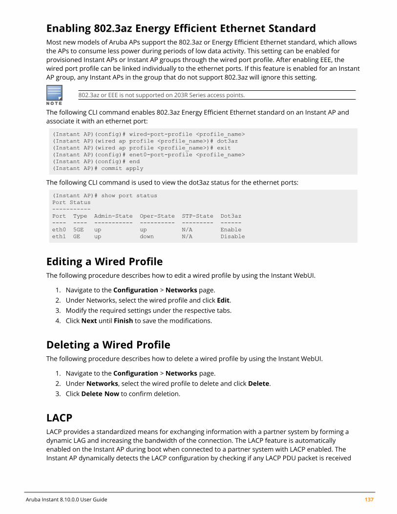
Aruba Instant 8.10.0.0 User Guide 137
Enabling 802.3az Energy Efficient Ethernet StandardMost new models of Aruba APs support the 802.3az or Energy Efficient Ethernet standard, which allowsthe APs to consume less power during periods of low data activity. This setting can be enabled forprovisioned Instant APs or Instant AP groups through the wired port profile. After enabling EEE, thewired port profile can be linked individually to the ethernet ports. If this feature is enabled for an InstantAP group, any Instant APs in the group that do not support 802.3az will ignore this setting.
802.3az or EEE is not supported on 203R Series access points.
The following CLI command enables 802.3az Energy Efficient Ethernet standard on an Instant AP andassociate it with an ethernet port:
(Instant AP)(config)# wired-port-profile <profile_name>(Instant AP)(wired ap profile <profile_name>)# dot3az(Instant AP)(wired ap profile <profile_name>)# exit(Instant AP)(config)# enet0-port-profile <profile_name>(Instant AP)(config)# end(Instant AP)# commit apply
The following CLI command is used to view the dot3az status for the ethernet ports:
(Instant AP)# show port statusPort Status-----------Port Type Admin-State Oper-State STP-State Dot3az---- ---- ----------- ---------- --------- ------eth0 5GE up up N/A Enableeth1 GE up down N/A Disable
Editing a Wired ProfileThe following procedure describes how to edit a wired profile by using the Instant WebUI.
1. Navigate to the Configuration > Networks page.2. Under Networks, select the wired profile and click Edit.3. Modify the required settings under the respective tabs.4. Click Next until Finish to save the modifications.
Deleting a Wired ProfileThe following procedure describes how to delete a wired profile by using the Instant WebUI.
1. Navigate to the Configuration > Networks page.2. Under Networks, select the wired profile to delete and click Delete.3. Click Delete Now to confirm deletion.
LACPLACP provides a standardized means for exchanging information with a partner system by forming adynamic LAG and increasing the bandwidth of the connection. The LACP feature is automaticallyenabled on the Instant AP during boot when connected to a partner system with LACP enabled. TheInstant AP dynamically detects the LACP configuration by checking if any LACP PDU packet is received
Wired Profiles | 138
on the Ethernet interface from the partner system. LACP is supported on 802.11ac and 802.11ax accesspoints with two Ethernet ports and is based on the IEEE standard 802.3ad.
If a controller in the cluster has the LACP capability, the Ethernet 0 and Ethernet 1 interfaces of theaccess point can be combined using LAG to form a single logical interface (port-channel). Port-channelscan be used to increase bandwidth or configure link redundancy between the two devices. Instant APssupport link aggregation using either standard port-channel (configuration based) or LACP (protocolsignaling based). You can deploy supported access points with LACP to utilize the high throughput(greater than 1 Gbps) capabilities of the AP radios.
To configure LACP, connect only the eth0 port of the Access Point to the controller. Allow the AP toreceive its full configuration , reboot the AP and then connect the eth1 port of the AP to the controller.This is because the eth1 port of 320 Series, 330 Series, 340 Series, 510 Series, 530 Series, and 550Series access points is a downlink port by default.
LACP is supported by Instant APs with two or more Ethernet ports.
Enabling Port-Channel on a Switch
1. Creating a port-channel and applying a switching-profile to a port-channel Profile:
(host) (config) #interface port-channel <0-63>(host) (port-channel "1") #switching-profile <profile name>
2. Creating and Applying a Dynamic Port-Channel Profile to an Interface:
(host)(config)# interface-profile lacp-profile <profile-name>group-id <0-63>mode active(host)(config)# interface gigabitethernet <slot/module/port>lacp-profile <profile-name>
Verifying LACP Configuration on the Instant APThere is no configuration required on the Instant AP for enabling LACP support. However, you can viewthe status of LACP on Instant APs by using the following command:
(Instant AP)# show lacp statusAP LACP Status--------------Link Status LACP Rate Num Ports Actor Key Partner Key Partner MAC----------- --------- --------- --------- ----------- -----------Up slow 2 17 3 00:1a:1e:1e:8c:40Member Interface Status----------------------Member I/f Name Permanent MAC Addr Link Status Member of LAG Link Fail Count-------------- ------------------ ----------- ------------- ---------------eth0 70:3a:0e:cd:5e:d6 Up Yes 1eth1 70:3a:0e:cd:5e:d7 Up Yes 1
Enabling Static LACP ConfigurationInstant APs support dynamic LACP configuration managed by the partner device. When the partnerdevice is LACP enabled, the AP inherits LACP configurations from the partner device and establishesthe connection. LACP can also be configured to be managed by the AP by configuring static LACP. Ifstatic LACP is configured, the AP will boot with this LACP configuration.
To enable or disable static LACP configuration, use the following commands in the CLI:
Aruba Instant 8.10.0.0 User Guide 139
To enable the static LACP mode on Instant APs:
(Instant AP)# lacp-mode enable
To disable the static LACP mode on Instant APs:
(Instant AP)# lacp-mode disable
Verifying Static LACP ModeTo verify the static LACP configuration, execute the following command in the Instant AP CLI:
(Instant AP)# show ap-envAntenna Type:Internalname:TechPubsAPper_ap_ssid:1234per_ap_vlan:abclacp_mode:enable
Understanding Hierarchical DeploymentAn Instant AP with more than one wired port can be connected to the downlink wired port of anotherInstant AP. An Instant AP with a single Ethernet port can be provisioned to use Ethernet bridging, so thatEthernet 0 port is converted to a downlink wired port.
You can also form an Instant AP network by connecting the downlink port of an Instant AP to otherInstant APs. Only one Instant AP in the network uses its downlink port to connect to the other InstantAPs. This Instant AP (called the root Instant AP) acts as the wired device for the network, provides DHCPservice and an L3 connection to the ISP uplink with NAT. The root Instant AP is always the conductor ofthe Instant network. In a single Ethernet port platform deployment, the root Instant AP must beconfigured to use the 3G uplink.
A typical hierarchical deployment consists of the following:
n A direct wired ISP connection or a wireless uplink.n One or more DHCP pools for private VLANs.n One downlink port configured on a private VLAN without authentication for connecting to member
Instant APs. Ensure that the downlink port configured in a private VLAN is not used for any wiredclient connection. Other downlink ports can be used for connecting to the wired clients.
The following figure illustrates a hierarchical deployment scenario:
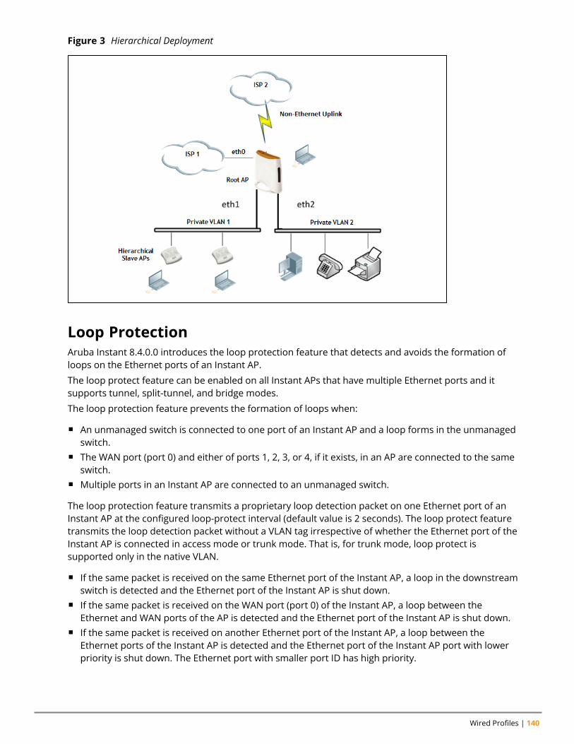
Wired Profiles | 140
Figure 3 Hierarchical Deployment
Loop ProtectionAruba Instant 8.4.0.0 introduces the loop protection feature that detects and avoids the formation ofloops on the Ethernet ports of an Instant AP.
The loop protect feature can be enabled on all Instant APs that have multiple Ethernet ports and itsupports tunnel, split-tunnel, and bridge modes.
The loop protection feature prevents the formation of loops when:
n An unmanaged switch is connected to one port of an Instant AP and a loop forms in the unmanagedswitch.
n The WAN port (port 0) and either of ports 1, 2, 3, or 4, if it exists, in an AP are connected to the sameswitch.
n Multiple ports in an Instant AP are connected to an unmanaged switch.
The loop protection feature transmits a proprietary loop detection packet on one Ethernet port of anInstant AP at the configured loop-protect interval (default value is 2 seconds). The loop protect featuretransmits the loop detection packet without a VLAN tag irrespective of whether the Ethernet port of theInstant AP is connected in access mode or trunk mode. That is, for trunk mode, loop protect issupported only in the native VLAN.
n If the same packet is received on the same Ethernet port of the Instant AP, a loop in the downstreamswitch is detected and the Ethernet port of the Instant AP is shut down.
n If the same packet is received on the WAN port (port 0) of the Instant AP, a loop between theEthernet and WAN ports of the AP is detected and the Ethernet port of the Instant AP is shut down.
n If the same packet is received on another Ethernet port of the Instant AP, a loop between theEthernet ports of the Instant AP is detected and the Ethernet port of the Instant AP port with lowerpriority is shut down. The Ethernet port with smaller port ID has high priority.
Aruba Instant 8.10.0.0 User Guide 141
The Ethernet port of the Instant AP that is shut down because of loop protection is marked with statusLoop-ERR. A user can either the recover the shut down port from the Instant AP with manualintervention or enable automatic recovery mode and configure a automatic recovery interval. At theexpiry of the automatic recovery interval, the Loop-ERR status of the Ethernet port is cleared and theEthernet port is re-enabled automatically.
To prevent the downstream switch from dropping the loop detection packet, for example duringbroadcast storm state, if the Instant AP takes longer time, or if the Instant AP fails to detect a loop, abroadcast storm-control mechanism is provided as part of the loop protection feature. Duringbroadcast-storm control, an Instant AP counts the broadcast packets received on each of its Ethernetport and determines the packet rate in an interval. If the broadcast packet rate on one Ethernet portexceeds the configured threshold (default value is 2000 packets per second), the Ethernet port is shutdown.
Configuring Loop ProtectionTo configure loop protection for the wired profile:
(Instant AP)(config)# wired-port-profile <name>(Instant AP)(wired ap profile <name>)# loop-protect(Instant AP)(wired ap profile <name>)# loop-detection-interval 5
To configure automatic recovery for a wired profile:
(Instant AP)(config)# wired-port-profile <name>(Instant AP)(wired ap profile <name>)# auto-recovery(Instant AP)(wired ap profile <name>)# auto-recovery-interval 50
To configure broadcast storm control:
(Instant AP)(config)# wired-port-profile <name>(Instant AP)(wired ap profile <name>)# storm-control-broadcast(Instant AP)(wired ap profile <name>)# storm-control-threshold 110
Chapter 12Captive Portal for Guest Access
Captive Portal for Guest AccessThis chapter provides the following information:
n Understanding Captive Portal on page 142n Configuring a WLAN SSID for Guest Access on page 143n Configuring Wired Profile for Guest Access on page 149n IGMP on page 150n Configuring Internal Captive Portal for Guest Network on page 151n Configuring External Captive Portal for a Guest Network on page 154n Configuring Facebook Login on page 160n Configuring Guest Logon Role and Access Rules for Guest Users on page 165n Configuring Captive Portal Roles for an SSID on page 166n Configuring Walled Garden Access on page 168n Disabling Captive Portal Authentication on page 169
Understanding Captive PortalInstant supports the captive portal authentication method, where a web page is presented to the guestusers when they try to access the Internet from hotels, conference centers, or Wi-Fi hotspots. The webpage also prompts the guest users to authenticate or accept the usage policy and terms. Captive portalsare used at many Wi-Fi hotspots and can be used to control wired access as well.
The Instant captive portal solution consists of the following:
n The captive portal web login page hosted by an internal or external server.n The RADIUS authentication or user authentication against Instant AP's internal database.n The SSID broadcast by the Instant AP.
Using Instant, the administrators can create a wired or WLAN guest network based on captive portalauthentication for guests, visitors, contractors, and any non-employee users who can use the enterpriseWi-Fi network. The administrators can also create guest accounts and customize the captive portal pagewith organization-specific logo, terms, and usage policy. With captive portal authentication and guestprofiles, the devices that connect to the guest SSID are assigned IP addresses and an initial role. When aguest user tries to access a URL through HTTP or HTTPS, the captive portal web page prompting the userto authenticate with a username and password is displayed.
Types of Captive PortalInstant supports the following types of captive portal authentication:
n Internal captive portal—For Internal captive portal authentication, an internal server is used forhosting the captive portal service. It supports the following types of authentication:l Internal Authenticated—When Internal Authenticated is enabled, a guest user mustauthenticate in the captive portal page to access the Internet. The guest users who are required to
Aruba Instant 8.10.0.0 User Guide 142
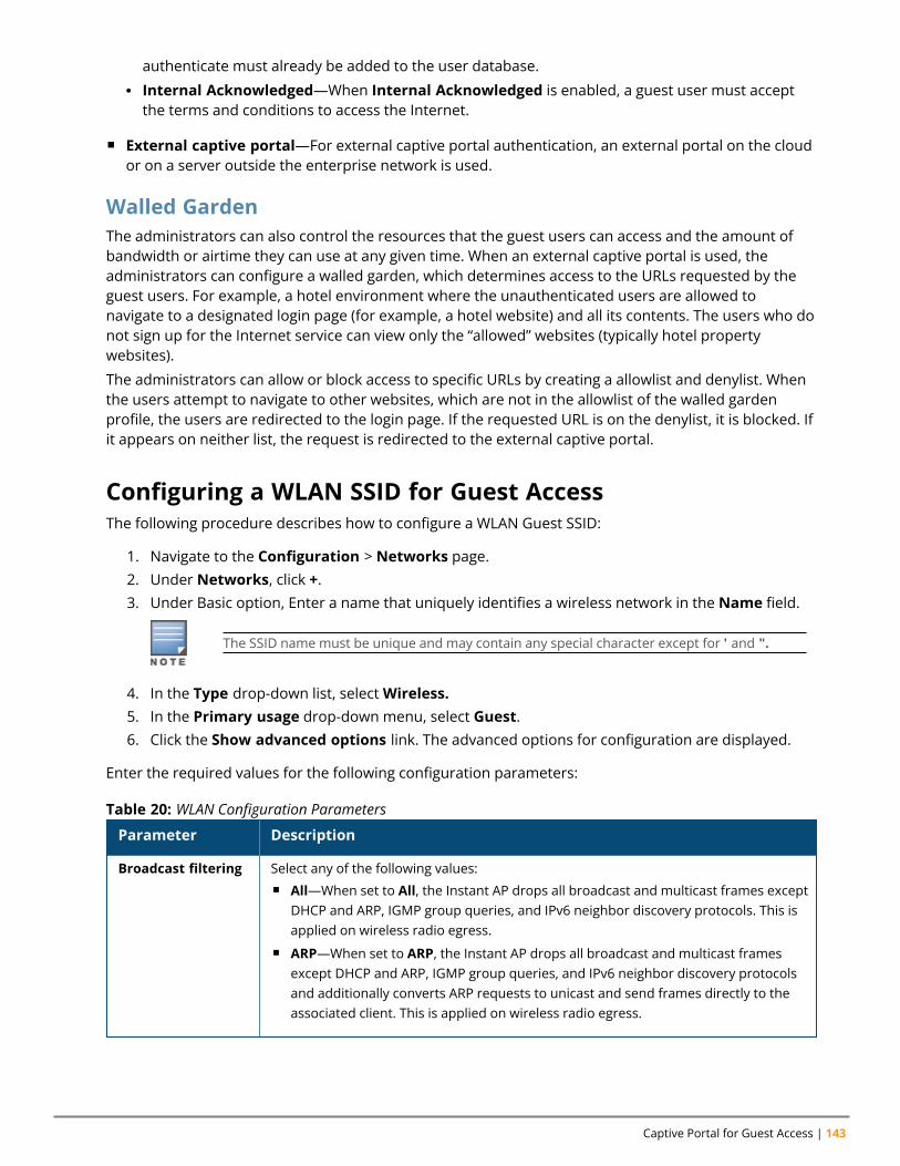
Captive Portal for Guest Access | 143
authenticate must already be added to the user database.l Internal Acknowledged—When Internal Acknowledged is enabled, a guest user must acceptthe terms and conditions to access the Internet.
n External captive portal—For external captive portal authentication, an external portal on the cloudor on a server outside the enterprise network is used.
Walled GardenThe administrators can also control the resources that the guest users can access and the amount ofbandwidth or airtime they can use at any given time. When an external captive portal is used, theadministrators can configure a walled garden, which determines access to the URLs requested by theguest users. For example, a hotel environment where the unauthenticated users are allowed tonavigate to a designated login page (for example, a hotel website) and all its contents. The users who donot sign up for the Internet service can view only the “allowed” websites (typically hotel propertywebsites).
The administrators can allow or block access to specific URLs by creating a allowlist and denylist. Whenthe users attempt to navigate to other websites, which are not in the allowlist of the walled gardenprofile, the users are redirected to the login page. If the requested URL is on the denylist, it is blocked. Ifit appears on neither list, the request is redirected to the external captive portal.
Configuring a WLAN SSID for Guest AccessThe following procedure describes how to configure a WLAN Guest SSID:
1. Navigate to the Configuration > Networks page.2. Under Networks, click +.3. Under Basic option, Enter a name that uniquely identifies a wireless network in the Name field.
The SSID name must be unique and may contain any special character except for ' and ".
4. In the Type drop-down list, selectWireless.5. In the Primary usage drop-down menu, select Guest.6. Click the Show advanced options link. The advanced options for configuration are displayed.
Enter the required values for the following configuration parameters:
Parameter Description
Broadcast filtering Select any of the following values:n All—When set to All, the Instant AP drops all broadcast and multicast frames except
DHCP and ARP, IGMP group queries, and IPv6 neighbor discovery protocols. This isapplied on wireless radio egress.
n ARP—When set to ARP, the Instant AP drops all broadcast and multicast framesexcept DHCP and ARP, IGMP group queries, and IPv6 neighbor discovery protocolsand additionally converts ARP requests to unicast and send frames directly to theassociated client. This is applied on wireless radio egress.
Table 20: WLAN Configuration Parameters
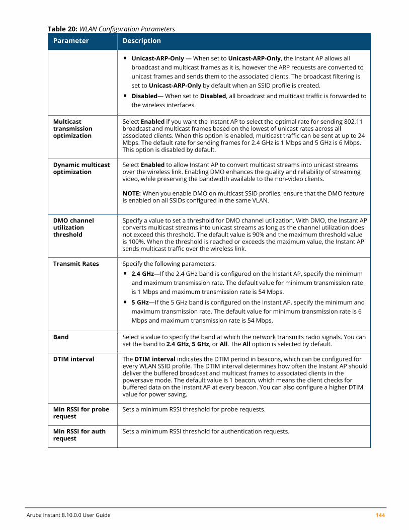
Aruba Instant 8.10.0.0 User Guide 144
Parameter Description
n Unicast-ARP-Only—When set to Unicast-ARP-Only, the Instant AP allows allbroadcast and multicast frames as it is, however the ARP requests are converted tounicast frames and sends them to the associated clients. The broadcast filtering isset to Unicast-ARP-Only by default when an SSID profile is created.
n Disabled—When set to Disabled, all broadcast and multicast traffic is forwarded tothe wireless interfaces.
Multicasttransmissionoptimization
Select Enabled if you want the Instant AP to select the optimal rate for sending 802.11broadcast and multicast frames based on the lowest of unicast rates across allassociated clients. When this option is enabled, multicast traffic can be sent at up to 24Mbps. The default rate for sending frames for 2.4 GHz is 1 Mbps and 5 GHz is 6 Mbps.This option is disabled by default.
Dynamic multicastoptimization
Select Enabled to allow Instant AP to convert multicast streams into unicast streamsover the wireless link. Enabling DMO enhances the quality and reliability of streamingvideo, while preserving the bandwidth available to the non-video clients.
NOTE: When you enable DMO on multicast SSID profiles, ensure that the DMO featureis enabled on all SSIDs configured in the same VLAN.
DMO channelutilizationthreshold
Specify a value to set a threshold for DMO channel utilization. With DMO, the Instant APconverts multicast streams into unicast streams as long as the channel utilization doesnot exceed this threshold. The default value is 90% and the maximum threshold valueis 100%. When the threshold is reached or exceeds the maximum value, the Instant APsends multicast traffic over the wireless link.
Transmit Rates Specify the following parameters:n 2.4 GHz—If the 2.4 GHz band is configured on the Instant AP, specify the minimum
and maximum transmission rate. The default value for minimum transmission rateis 1 Mbps and maximum transmission rate is 54 Mbps.
n 5 GHz—If the 5 GHz band is configured on the Instant AP, specify the minimum andmaximum transmission rate. The default value for minimum transmission rate is 6Mbps and maximum transmission rate is 54 Mbps.
Band Select a value to specify the band at which the network transmits radio signals. You canset the band to 2.4 GHz, 5 GHz, or All. The All option is selected by default.
DTIM interval The DTIM interval indicates the DTIM period in beacons, which can be configured forevery WLAN SSID profile. The DTIM interval determines how often the Instant AP shoulddeliver the buffered broadcast and multicast frames to associated clients in thepowersave mode. The default value is 1 beacon, which means the client checks forbuffered data on the Instant AP at every beacon. You can also configure a higher DTIMvalue for power saving.
Min RSSI for proberequest
Sets a minimum RSSI threshold for probe requests.
Min RSSI for authrequest
Sets a minimum RSSI threshold for authentication requests.
Table 20: WLAN Configuration Parameters
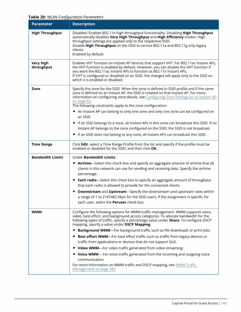
Captive Portal for Guest Access | 145
Parameter Description
High Throughput Disables/ Enables 802.11n high throughput functionality. Disabling High Throughputautomatically disables Very High Throughput and High Efficiencymodes. Highthroughput settings are applied only to the respective SSID.Disable High Throughput on the SSID to service 802.11a and 802.11g only legacyclients.Enabled by default.
Very highthroughput
Enables VHT function on Instant AP devices that support VHT. For 802.11ac Instant APs,the VHT function is enabled by default. However, you can disable the VHT function ifyou want the 802.11ac Instant APs to function as 802.11n Instant APs.If VHT is configured or disabled on an SSID, the changes will apply only to the SSID onwhich it is enabled or disabled.
Zone Specify the zone for the SSID. When the zone is defined in SSID profile and if the samezone is defined on an Instant AP, the SSID is created on that Instant AP. For moreinformation on configuring zone details, see Configuring Zone Settings on an Instant APon page 62.The following constraints apply to the zone configuration:n An Instant AP can belong to only one zone and only one zone can be configured on
an SSID.n If an SSID belongs to a zone, all Instant APs in this zone can broadcast this SSID. If no
Instant AP belongs to the zone configured on the SSID, the SSID is not broadcast.n If an SSID does not belong to any zone, all Instant APs can broadcast this SSID.
Time Range Click Edit, select a Time Range Profile from the list and specify if the profile must beenabled or disabled for the SSID, and then click OK.
Bandwidth Limits Under Bandwidth Limits:n Airtime—Select this check box and specify an aggregate amount of airtime that all
clients in this network can use for sending and receiving data. Specify the airtimepercentage.
n Each radio—Select this check box to specify an aggregate amount of throughputthat each radio is allowed to provide for the connected clients.
n Downstream and Upstream—Specify the downstream and upstream rates withina range of 1 to 2147482 Kbps for the SSID users. If the assignment is specific foreach user, select the Peruser check box.
WMM Configure the following options for WMM traffic management. WMM supports voice,video, best effort, and background access categories. To allocate bandwidth for thefollowing types of traffic, specify a percentage value under Share. To configure DSCPmapping, specify a value under DSCP Mapping.n Background WMM—For background traffic such as file downloads or print jobs.n Best effort WMM—For best effort traffic such as traffic from legacy devices or
traffic from applications or devices that do not support QoS.n Video WMM—For video traffic generated from video streaming.n Voice WMM— For voice traffic generated from the incoming and outgoing voice
communication.For more information on WMM traffic and DSCP mapping, see WMM TrafficManagement on page 385
Table 20: WLAN Configuration Parameters
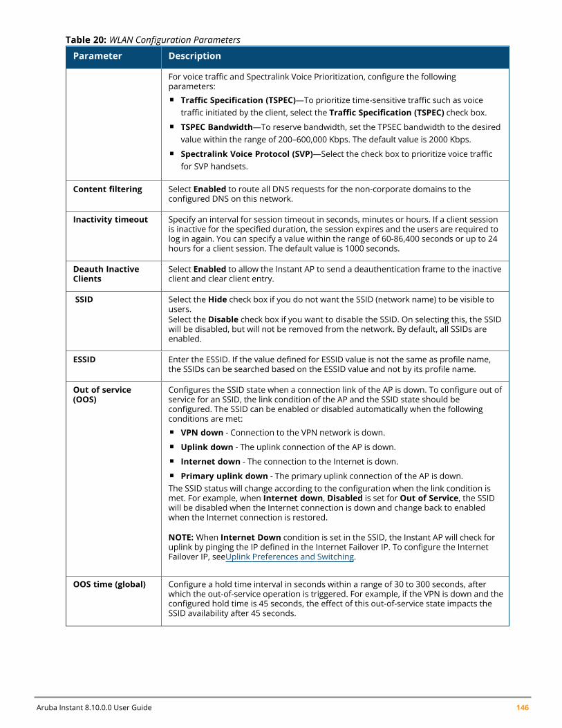
Aruba Instant 8.10.0.0 User Guide 146
Parameter Description
For voice traffic and Spectralink Voice Prioritization, configure the followingparameters:n Traffic Specification (TSPEC)—To prioritize time-sensitive traffic such as voice
traffic initiated by the client, select the Traffic Specification (TSPEC) check box.n TSPEC Bandwidth—To reserve bandwidth, set the TPSEC bandwidth to the desired
value within the range of 200–600,000 Kbps. The default value is 2000 Kbps.n Spectralink Voice Protocol (SVP)—Select the check box to prioritize voice traffic
for SVP handsets.
Content filtering Select Enabled to route all DNS requests for the non-corporate domains to theconfigured DNS on this network.
Inactivity timeout Specify an interval for session timeout in seconds, minutes or hours. If a client sessionis inactive for the specified duration, the session expires and the users are required tolog in again. You can specify a value within the range of 60-86,400 seconds or up to 24hours for a client session. The default value is 1000 seconds.
Deauth InactiveClients
Select Enabled to allow the Instant AP to send a deauthentication frame to the inactiveclient and clear client entry.
SSID Select the Hide check box if you do not want the SSID (network name) to be visible tousers.Select the Disable check box if you want to disable the SSID. On selecting this, the SSIDwill be disabled, but will not be removed from the network. By default, all SSIDs areenabled.
ESSID Enter the ESSID. If the value defined for ESSID value is not the same as profile name,the SSIDs can be searched based on the ESSID value and not by its profile name.
Out of service(OOS)
Configures the SSID state when a connection link of the AP is down. To configure out ofservice for an SSID, the link condition of the AP and the SSID state should beconfigured. The SSID can be enabled or disabled automatically when the followingconditions are met:n VPN down - Connection to the VPN network is down.n Uplink down - The uplink connection of the AP is down.n Internet down - The connection to the Internet is down.n Primary uplink down - The primary uplink connection of the AP is down.The SSID status will change according to the configuration when the link condition ismet. For example, when Internet down, Disabled is set for Out of Service, the SSIDwill be disabled when the Internet connection is down and change back to enabledwhen the Internet connection is restored.
NOTE: When Internet Down condition is set in the SSID, the Instant AP will check foruplink by pinging the IP defined in the Internet Failover IP. To configure the InternetFailover IP, seeUplink Preferences and Switching.
OOS time (global) Configure a hold time interval in seconds within a range of 30 to 300 seconds, afterwhich the out-of-service operation is triggered. For example, if the VPN is down and theconfigured hold time is 45 seconds, the effect of this out-of-service state impacts theSSID availability after 45 seconds.
Table 20: WLAN Configuration Parameters
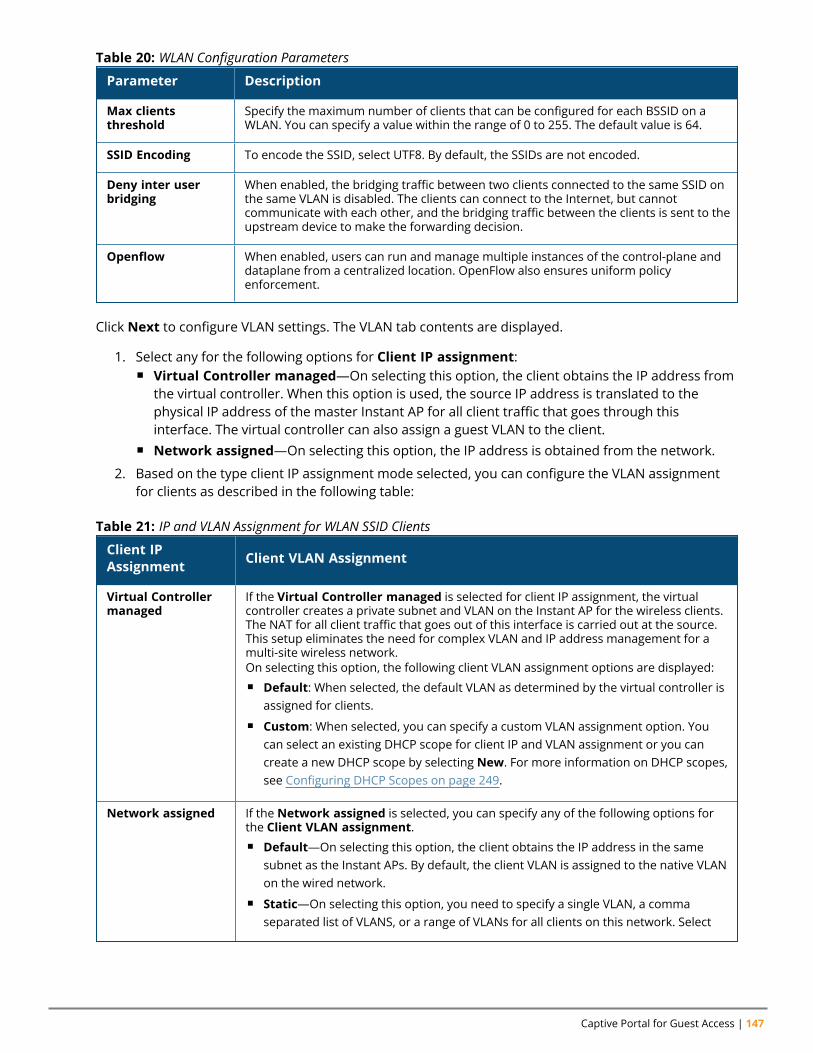
Captive Portal for Guest Access | 147
Parameter Description
Max clientsthreshold
Specify the maximum number of clients that can be configured for each BSSID on aWLAN. You can specify a value within the range of 0 to 255. The default value is 64.
SSID Encoding To encode the SSID, select UTF8. By default, the SSIDs are not encoded.
Deny inter userbridging
When enabled, the bridging traffic between two clients connected to the same SSID onthe same VLAN is disabled. The clients can connect to the Internet, but cannotcommunicate with each other, and the bridging traffic between the clients is sent to theupstream device to make the forwarding decision.
Openflow When enabled, users can run and manage multiple instances of the control-plane anddataplane from a centralized location. OpenFlow also ensures uniform policyenforcement.
Table 20: WLAN Configuration Parameters
Click Next to configure VLAN settings. The VLAN tab contents are displayed.
1. Select any for the following options for Client IP assignment:n Virtual Controller managed—On selecting this option, the client obtains the IP address from
the virtual controller. When this option is used, the source IP address is translated to thephysical IP address of the master Instant AP for all client traffic that goes through thisinterface. The virtual controller can also assign a guest VLAN to the client.
n Network assigned—On selecting this option, the IP address is obtained from the network.
2. Based on the type client IP assignment mode selected, you can configure the VLAN assignmentfor clients as described in the following table:
Client IPAssignment Client VLAN Assignment
Virtual Controllermanaged
If the Virtual Controller managed is selected for client IP assignment, the virtualcontroller creates a private subnet and VLAN on the Instant AP for the wireless clients.The NAT for all client traffic that goes out of this interface is carried out at the source.This setup eliminates the need for complex VLAN and IP address management for amulti-site wireless network.On selecting this option, the following client VLAN assignment options are displayed:n Default: When selected, the default VLAN as determined by the virtual controller is
assigned for clients.n Custom: When selected, you can specify a custom VLAN assignment option. You
can select an existing DHCP scope for client IP and VLAN assignment or you cancreate a new DHCP scope by selecting New. For more information on DHCP scopes,see Configuring DHCP Scopes on page 249.
Network assigned If the Network assigned is selected, you can specify any of the following options forthe Client VLAN assignment.n Default—On selecting this option, the client obtains the IP address in the same
subnet as the Instant APs. By default, the client VLAN is assigned to the native VLANon the wired network.
n Static—On selecting this option, you need to specify a single VLAN, a commaseparated list of VLANS, or a range of VLANs for all clients on this network. Select
Table 21: IP and VLAN Assignment for WLAN SSID Clients
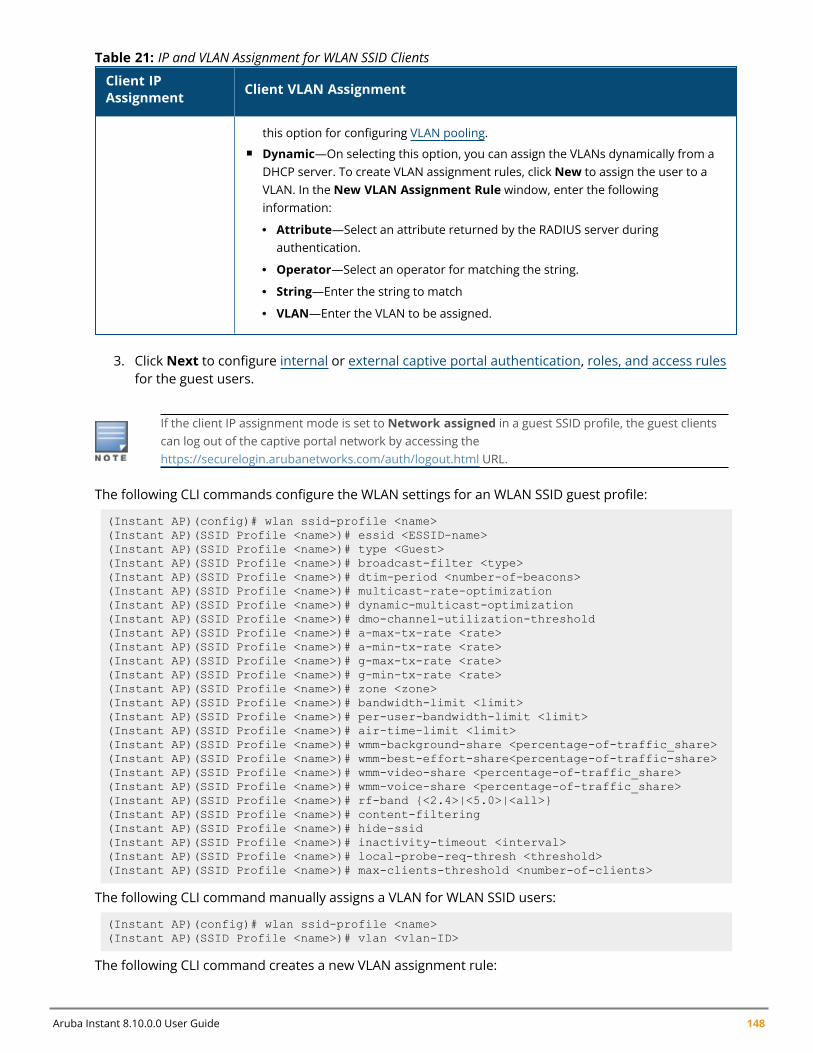
Aruba Instant 8.10.0.0 User Guide 148
Client IPAssignment Client VLAN Assignment
this option for configuring VLAN pooling.n Dynamic—On selecting this option, you can assign the VLANs dynamically from a
DHCP server. To create VLAN assignment rules, click New to assign the user to aVLAN. In the New VLAN Assignment Rule window, enter the followinginformation:
l Attribute—Select an attribute returned by the RADIUS server duringauthentication.
l Operator—Select an operator for matching the string.
l String—Enter the string to match
l VLAN—Enter the VLAN to be assigned.
Table 21: IP and VLAN Assignment for WLAN SSID Clients
3. Click Next to configure internal or external captive portal authentication, roles, and access rulesfor the guest users.
If the client IP assignment mode is set to Network assigned in a guest SSID profile, the guest clientscan log out of the captive portal network by accessing thehttps://securelogin.arubanetworks.com/auth/logout.html URL.
The following CLI commands configure the WLAN settings for an WLAN SSID guest profile:
(Instant AP)(config)# wlan ssid-profile <name>(Instant AP)(SSID Profile <name>)# essid <ESSID-name>(Instant AP)(SSID Profile <name>)# type <Guest>(Instant AP)(SSID Profile <name>)# broadcast-filter <type>(Instant AP)(SSID Profile <name>)# dtim-period <number-of-beacons>(Instant AP)(SSID Profile <name>)# multicast-rate-optimization(Instant AP)(SSID Profile <name>)# dynamic-multicast-optimization(Instant AP)(SSID Profile <name>)# dmo-channel-utilization-threshold(Instant AP)(SSID Profile <name>)# a-max-tx-rate <rate>(Instant AP)(SSID Profile <name>)# a-min-tx-rate <rate>(Instant AP)(SSID Profile <name>)# g-max-tx-rate <rate>(Instant AP)(SSID Profile <name>)# g-min-tx-rate <rate>(Instant AP)(SSID Profile <name>)# zone <zone>(Instant AP)(SSID Profile <name>)# bandwidth-limit <limit>(Instant AP)(SSID Profile <name>)# per-user-bandwidth-limit <limit>(Instant AP)(SSID Profile <name>)# air-time-limit <limit>(Instant AP)(SSID Profile <name>)# wmm-background-share <percentage-of-traffic_share>(Instant AP)(SSID Profile <name>)# wmm-best-effort-share<percentage-of-traffic-share>(Instant AP)(SSID Profile <name>)# wmm-video-share <percentage-of-traffic_share>(Instant AP)(SSID Profile <name>)# wmm-voice-share <percentage-of-traffic_share>(Instant AP)(SSID Profile <name>)# rf-band {<2.4>|<5.0>|<all>}(Instant AP)(SSID Profile <name>)# content-filtering(Instant AP)(SSID Profile <name>)# hide-ssid(Instant AP)(SSID Profile <name>)# inactivity-timeout <interval>(Instant AP)(SSID Profile <name>)# local-probe-req-thresh <threshold>(Instant AP)(SSID Profile <name>)# max-clients-threshold <number-of-clients>
The following CLI command manually assigns a VLAN for WLAN SSID users:
(Instant AP)(config)# wlan ssid-profile <name>(Instant AP)(SSID Profile <name>)# vlan <vlan-ID>
The following CLI command creates a new VLAN assignment rule:
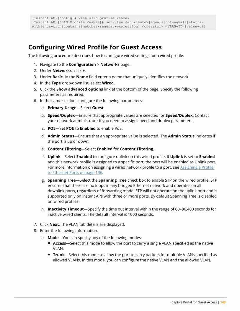
Captive Portal for Guest Access | 149
(Instant AP)(config)# wlan ssid-profile <name>(Instant AP)(SSID Profile <name>)# set-vlan <attribute>{equals|not-equals|starts-with|ends-with|contains|matches-regular-expression} <operator> <VLAN-ID>|value-of}
Configuring Wired Profile for Guest AccessThe following procedure describes how to configure wired settings for a wired profile:
1. Navigate to the Configuration > Networks page.2. Under Networks, click +.3. Under Basic, In the Name field enter a name that uniquely identifies the network.4. In the Type drop-down list, selectWired.5. Click the Show advanced options link at the bottom of the page. Specify the following
parameters as required.6. In the same section, configure the following parameters:
a. Primary Usage—Select Guest.
b. Speed/Duplex—Ensure that appropriate values are selected for Speed/Duplex. Contactyour network administrator if you need to assign speed and duplex parameters.
c. POE—Set POE to Enabled to enable PoE.
d. Admin Status—Ensure that an appropriate value is selected. The Admin Status indicates ifthe port is up or down.
e. Content Filtering—Select Enabled for Content Filtering.
f. Uplink—Select Enabled to configure uplink on this wired profile. If Uplink is set to Enabledand this network profile is assigned to a specific port, the port will be enabled as Uplink port.For more information on assigning a wired network profile to a port, see Assigning a Profileto Ethernet Ports on page 136.
g. Spanning Tree—Select the Spanning Tree check box to enable STP on the wired profile. STPensures that there are no loops in any bridged Ethernet network and operates on alldownlink ports, regardless of forwarding mode. STP will not operate on the uplink port and issupported only on Instant APs with three or more ports. By default Spanning Tree is disabledon wired profiles.
h. Inactivity Timeout—Specify the time out interval within the range of 60–86,400 seconds forinactive wired clients. The default interval is 1000 seconds.
7. Click Next. The VLAN tab details are displayed.8. Enter the following information.
a. Mode—You can specify any of the following modes:n Access—Select this mode to allow the port to carry a single VLAN specified as the native
VLAN.n Trunk—Select this mode to allow the port to carry packets for multiple VLANs specified as
allowed VLANs. In this mode, you can configure the native VLAN and the allowed VLAN.
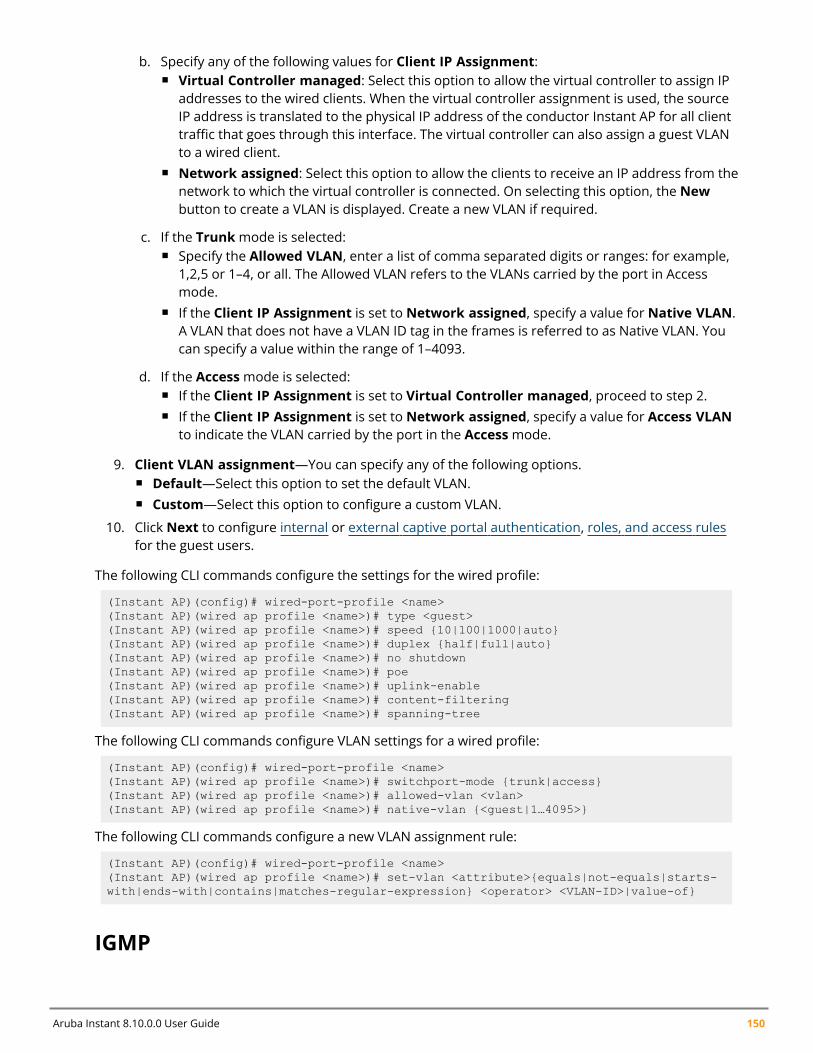
Aruba Instant 8.10.0.0 User Guide 150
b. Specify any of the following values for Client IP Assignment:n Virtual Controller managed: Select this option to allow the virtual controller to assign IP
addresses to the wired clients. When the virtual controller assignment is used, the sourceIP address is translated to the physical IP address of the conductor Instant AP for all clienttraffic that goes through this interface. The virtual controller can also assign a guest VLANto a wired client.
n Network assigned: Select this option to allow the clients to receive an IP address from thenetwork to which the virtual controller is connected. On selecting this option, the Newbutton to create a VLAN is displayed. Create a new VLAN if required.
c. If the Trunkmode is selected:n Specify the Allowed VLAN, enter a list of comma separated digits or ranges: for example,
1,2,5 or 1–4, or all. The Allowed VLAN refers to the VLANs carried by the port in Accessmode.
n If the Client IP Assignment is set to Network assigned, specify a value for Native VLAN.A VLAN that does not have a VLAN ID tag in the frames is referred to as Native VLAN. Youcan specify a value within the range of 1–4093.
d. If the Accessmode is selected:n If the Client IP Assignment is set to Virtual Controller managed, proceed to step 2.n If the Client IP Assignment is set to Network assigned, specify a value for Access VLAN
to indicate the VLAN carried by the port in the Accessmode.
9. Client VLAN assignment—You can specify any of the following options.n Default—Select this option to set the default VLAN.n Custom—Select this option to configure a custom VLAN.
10. Click Next to configure internal or external captive portal authentication, roles, and access rulesfor the guest users.
The following CLI commands configure the settings for the wired profile:
(Instant AP)(config)# wired-port-profile <name>(Instant AP)(wired ap profile <name>)# type <guest>(Instant AP)(wired ap profile <name>)# speed {10|100|1000|auto}(Instant AP)(wired ap profile <name>)# duplex {half|full|auto}(Instant AP)(wired ap profile <name>)# no shutdown(Instant AP)(wired ap profile <name>)# poe(Instant AP)(wired ap profile <name>)# uplink-enable(Instant AP)(wired ap profile <name>)# content-filtering(Instant AP)(wired ap profile <name>)# spanning-tree
The following CLI commands configure VLAN settings for a wired profile:
(Instant AP)(config)# wired-port-profile <name>(Instant AP)(wired ap profile <name>)# switchport-mode {trunk|access}(Instant AP)(wired ap profile <name>)# allowed-vlan <vlan>(Instant AP)(wired ap profile <name>)# native-vlan {<guest|1…4095>}
The following CLI commands configure a new VLAN assignment rule:
(Instant AP)(config)# wired-port-profile <name>(Instant AP)(wired ap profile <name>)# set-vlan <attribute>{equals|not-equals|starts-with|ends-with|contains|matches-regular-expression} <operator> <VLAN-ID>|value-of}
IGMP
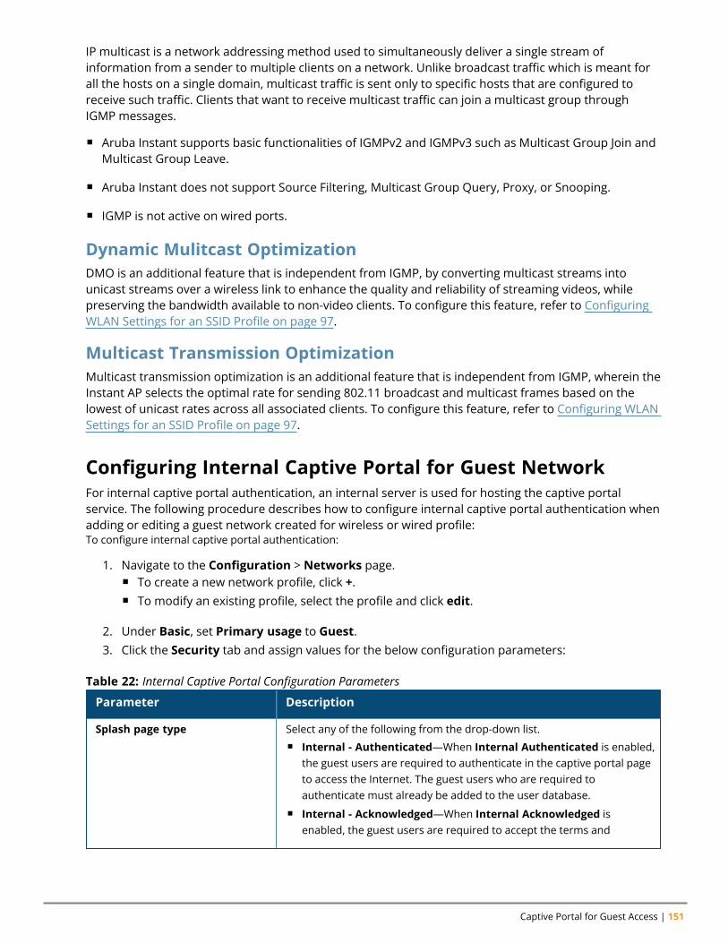
Captive Portal for Guest Access | 151
IP multicast is a network addressing method used to simultaneously deliver a single stream ofinformation from a sender to multiple clients on a network. Unlike broadcast traffic which is meant forall the hosts on a single domain, multicast traffic is sent only to specific hosts that are configured toreceive such traffic. Clients that want to receive multicast traffic can join a multicast group throughIGMP messages.
n Aruba Instant supports basic functionalities of IGMPv2 and IGMPv3 such as Multicast Group Join andMulticast Group Leave.
n Aruba Instant does not support Source Filtering, Multicast Group Query, Proxy, or Snooping.
n IGMP is not active on wired ports.
Dynamic Mulitcast OptimizationDMO is an additional feature that is independent from IGMP, by converting multicast streams intounicast streams over a wireless link to enhance the quality and reliability of streaming videos, whilepreserving the bandwidth available to non-video clients. To configure this feature, refer to ConfiguringWLAN Settings for an SSID Profile on page 97.
Multicast Transmission OptimizationMulticast transmission optimization is an additional feature that is independent from IGMP, wherein theInstant AP selects the optimal rate for sending 802.11 broadcast and multicast frames based on thelowest of unicast rates across all associated clients. To configure this feature, refer to Configuring WLANSettings for an SSID Profile on page 97.
Configuring Internal Captive Portal for Guest NetworkFor internal captive portal authentication, an internal server is used for hosting the captive portalservice. The following procedure describes how to configure internal captive portal authentication whenadding or editing a guest network created for wireless or wired profile:To configure internal captive portal authentication:
1. Navigate to the Configuration > Networks page.n To create a new network profile, click +.n To modify an existing profile, select the profile and click edit.
2. Under Basic, set Primary usage to Guest.3. Click the Security tab and assign values for the below configuration parameters:
Parameter Description
Splash page type Select any of the following from the drop-down list.n Internal - Authenticated—When Internal Authenticated is enabled,
the guest users are required to authenticate in the captive portal pageto access the Internet. The guest users who are required toauthenticate must already be added to the user database.
n Internal - Acknowledged—When Internal Acknowledged isenabled, the guest users are required to accept the terms and
Table 22: Internal Captive Portal Configuration Parameters
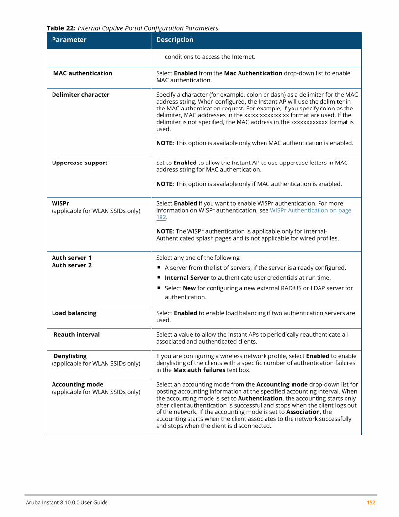
Aruba Instant 8.10.0.0 User Guide 152
Parameter Description
conditions to access the Internet.
MAC authentication Select Enabled from theMac Authentication drop-down list to enableMAC authentication.
Delimiter character Specify a character (for example, colon or dash) as a delimiter for the MACaddress string. When configured, the Instant AP will use the delimiter inthe MAC authentication request. For example, if you specify colon as thedelimiter, MAC addresses in the xx:xx:xx:xx:xx:xx format are used. If thedelimiter is not specified, the MAC address in the xxxxxxxxxxxx format isused.
NOTE: This option is available only when MAC authentication is enabled.
Uppercase support Set to Enabled to allow the Instant AP to use uppercase letters in MACaddress string for MAC authentication.
NOTE: This option is available only if MAC authentication is enabled.
WISPr(applicable for WLAN SSIDs only)
Select Enabled if you want to enable WISPr authentication. For moreinformation on WISPr authentication, see WISPr Authentication on page182.
NOTE: The WISPr authentication is applicable only for Internal-Authenticated splash pages and is not applicable for wired profiles.
Auth server 1Auth server 2
Select any one of the following:n A server from the list of servers, if the server is already configured.n Internal Server to authenticate user credentials at run time.n Select New for configuring a new external RADIUS or LDAP server for
authentication.
Load balancing Select Enabled to enable load balancing if two authentication servers areused.
Reauth interval Select a value to allow the Instant APs to periodically reauthenticate allassociated and authenticated clients.
Denylisting(applicable for WLAN SSIDs only)
If you are configuring a wireless network profile, select Enabled to enabledenylisting of the clients with a specific number of authentication failuresin theMax auth failures text box.
Accounting mode(applicable for WLAN SSIDs only)
Select an accounting mode from the Accounting mode drop-down list forposting accounting information at the specified accounting interval. Whenthe accounting mode is set to Authentication, the accounting starts onlyafter client authentication is successful and stops when the client logs outof the network. If the accounting mode is set to Association, theaccounting starts when the client associates to the network successfullyand stops when the client is disconnected.
Table 22: Internal Captive Portal Configuration Parameters
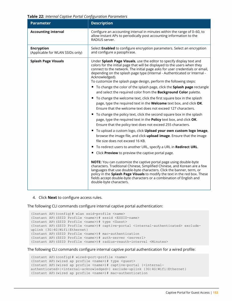
Captive Portal for Guest Access | 153
Parameter Description
Accounting interval Configure an accounting interval in minutes within the range of 0–60, toallow Instant APs to periodically post accounting information to theRADIUS server.
Encryption(Applicable for WLAN SSIDs only)
Select Enabled to configure encryption parameters. Select an encryptionand configure a passphrase.
Splash Page Visuals Under Splash Page Visuals, use the editor to specify display text andcolors for the initial page that will be displayed to the users when theyconnect to the network. The initial page asks for user credentials or email,depending on the splash page type (Internal - Authenticated or Internal -Acknowledged).To customize the splash page design, perform the following steps:n To change the color of the splash page, click the Splash page rectangle
and select the required color from the Background Color palette.n To change the welcome text, click the first square box in the splash
page, type the required text in theWelcome text box, and click OK.Ensure that the welcome text does not exceed 127 characters.
n To change the policy text, click the second square box in the splashpage, type the required text in the Policy text box, and click OK.Ensure that the policy text does not exceed 255 characters.
n To upload a custom logo, click Upload your own custom logo Image,browse the image file, and click upload image. Ensure that the imagefile size does not exceed 16 KB.
n To redirect users to another URL, specify a URL in Redirect URL.n Click Preview to preview the captive portal page.
NOTE: You can customize the captive portal page using double-bytecharacters. Traditional Chinese, Simplified Chinese, and Korean are a fewlanguages that use double-byte characters. Click the banner, term, orpolicy in the Splash Page Visuals to modify the text in the red box. Thesefields accept double-byte characters or a combination of English anddouble-byte characters.
Table 22: Internal Captive Portal Configuration Parameters
4. Click Next to configure access rules.
The following CLI commands configure internal captive portal authentication:
(Instant AP)(config)# wlan ssid-profile <name>(Instant AP)(SSID Profile <name>)# essid <ESSID-name>(Instant AP)(SSID Profile <name>)# type <Guest>(Instant AP)(SSID Profile <name>)# captive-portal <internal-authenticated> exclude-uplink {3G|4G|Wifi|Ethernet}(Instant AP)(SSID Profile <name>)# mac-authentication(Instant AP)(SSID Profile <name>)# auth-server <server1>(Instant AP)(SSID Profile <name>)# radius-reauth-interval <Minutes>
The following CLI commands configure internal captive portal authentication for a wired profile:
(Instant AP)(config)# wired-port-profile <name>(Instant AP)(wired ap profile <name>)# type <guest>(Instant AP)(wired ap profile <name>)# captive-portal {<internal-authenticated>|<internal-acknowledged>} exclude-uplink {3G|4G|Wifi|Ethernet}(Instant AP)(wired ap profile <name>)# mac-authentication
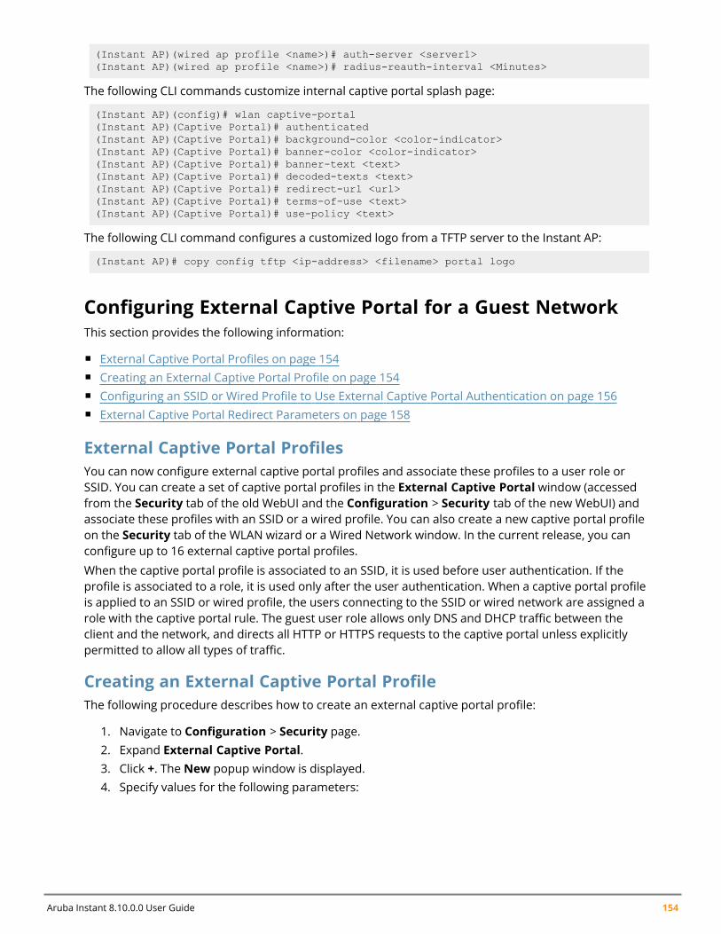
Aruba Instant 8.10.0.0 User Guide 154
(Instant AP)(wired ap profile <name>)# auth-server <server1>(Instant AP)(wired ap profile <name>)# radius-reauth-interval <Minutes>
The following CLI commands customize internal captive portal splash page:
(Instant AP)(config)# wlan captive-portal(Instant AP)(Captive Portal)# authenticated(Instant AP)(Captive Portal)# background-color <color-indicator>(Instant AP)(Captive Portal)# banner-color <color-indicator>(Instant AP)(Captive Portal)# banner-text <text>(Instant AP)(Captive Portal)# decoded-texts <text>(Instant AP)(Captive Portal)# redirect-url <url>(Instant AP)(Captive Portal)# terms-of-use <text>(Instant AP)(Captive Portal)# use-policy <text>
The following CLI command configures a customized logo from a TFTP server to the Instant AP:
(Instant AP)# copy config tftp <ip-address> <filename> portal logo
Configuring External Captive Portal for a Guest NetworkThis section provides the following information:
n External Captive Portal Profiles on page 154n Creating an External Captive Portal Profile on page 154n Configuring an SSID or Wired Profile to Use External Captive Portal Authentication on page 156n External Captive Portal Redirect Parameters on page 158
External Captive Portal ProfilesYou can now configure external captive portal profiles and associate these profiles to a user role orSSID. You can create a set of captive portal profiles in the External Captive Portal window (accessedfrom the Security tab of the old WebUI and the Configuration > Security tab of the new WebUI) andassociate these profiles with an SSID or a wired profile. You can also create a new captive portal profileon the Security tab of the WLAN wizard or a Wired Network window. In the current release, you canconfigure up to 16 external captive portal profiles.
When the captive portal profile is associated to an SSID, it is used before user authentication. If theprofile is associated to a role, it is used only after the user authentication. When a captive portal profileis applied to an SSID or wired profile, the users connecting to the SSID or wired network are assigned arole with the captive portal rule. The guest user role allows only DNS and DHCP traffic between theclient and the network, and directs all HTTP or HTTPS requests to the captive portal unless explicitlypermitted to allow all types of traffic.
Creating an External Captive Portal ProfileThe following procedure describes how to create an external captive portal profile:
1. Navigate to Configuration > Security page.2. Expand External Captive Portal.3. Click +. The New popup window is displayed.4. Specify values for the following parameters:
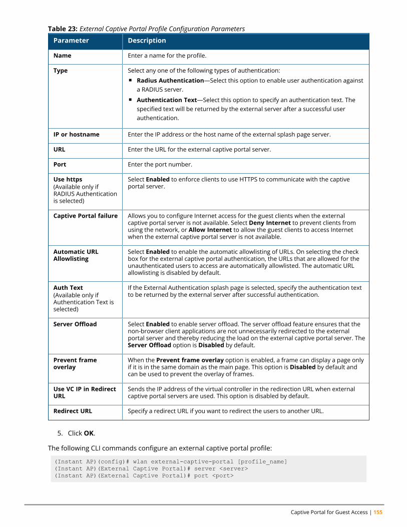
Captive Portal for Guest Access | 155
Parameter Description
Name Enter a name for the profile.
Type Select any one of the following types of authentication:n Radius Authentication—Select this option to enable user authentication against
a RADIUS server.n Authentication Text—Select this option to specify an authentication text. The
specified text will be returned by the external server after a successful userauthentication.
IP or hostname Enter the IP address or the host name of the external splash page server.
URL Enter the URL for the external captive portal server.
Port Enter the port number.
Use https(Available only ifRADIUS Authenticationis selected)
Select Enabled to enforce clients to use HTTPS to communicate with the captiveportal server.
Captive Portal failure Allows you to configure Internet access for the guest clients when the externalcaptive portal server is not available. Select Deny Internet to prevent clients fromusing the network, or Allow Internet to allow the guest clients to access Internetwhen the external captive portal server is not available.
Automatic URLAllowlisting
Select Enabled to enable the automatic allowlisting of URLs. On selecting the checkbox for the external captive portal authentication, the URLs that are allowed for theunauthenticated users to access are automatically allowlisted. The automatic URLallowlisting is disabled by default.
Auth Text(Available only ifAuthentication Text isselected)
If the External Authentication splash page is selected, specify the authentication textto be returned by the external server after successful authentication.
Server Offload Select Enabled to enable server offload. The server offload feature ensures that thenon-browser client applications are not unnecessarily redirected to the externalportal server and thereby reducing the load on the external captive portal server. TheServer Offload option is Disabled by default.
Prevent frameoverlay
When the Prevent frame overlay option is enabled, a frame can display a page onlyif it is in the same domain as the main page. This option is Disabled by default andcan be used to prevent the overlay of frames.
Use VC IP in RedirectURL
Sends the IP address of the virtual controller in the redirection URL when externalcaptive portal servers are used. This option is disabled by default.
Redirect URL Specify a redirect URL if you want to redirect the users to another URL.
Table 23: External Captive Portal Profile Configuration Parameters
5. Click OK.
The following CLI commands configure an external captive portal profile:
(Instant AP)(config)# wlan external-captive-portal [profile_name](Instant AP)(External Captive Portal)# server <server>(Instant AP)(External Captive Portal)# port <port>
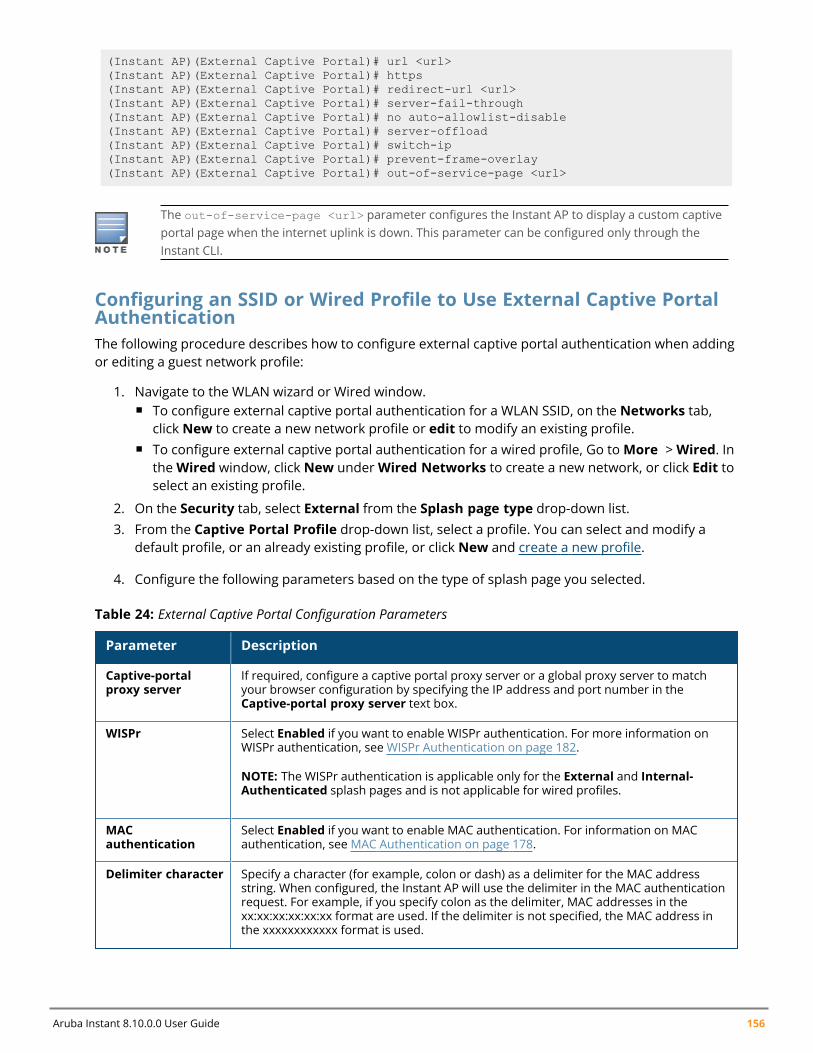
Aruba Instant 8.10.0.0 User Guide 156
(Instant AP)(External Captive Portal)# url <url>(Instant AP)(External Captive Portal)# https(Instant AP)(External Captive Portal)# redirect-url <url>(Instant AP)(External Captive Portal)# server-fail-through(Instant AP)(External Captive Portal)# no auto-allowlist-disable(Instant AP)(External Captive Portal)# server-offload(Instant AP)(External Captive Portal)# switch-ip(Instant AP)(External Captive Portal)# prevent-frame-overlay(Instant AP)(External Captive Portal)# out-of-service-page <url>
The out-of-service-page <url> parameter configures the Instant AP to display a custom captiveportal page when the internet uplink is down. This parameter can be configured only through theInstant CLI.
Configuring an SSID or Wired Profile to Use External Captive PortalAuthenticationThe following procedure describes how to configure external captive portal authentication when addingor editing a guest network profile:
1. Navigate to the WLAN wizard or Wired window.n To configure external captive portal authentication for a WLAN SSID, on the Networks tab,
click New to create a new network profile or edit to modify an existing profile.n To configure external captive portal authentication for a wired profile, Go toMore >Wired. In
theWired window, click New underWired Networks to create a new network, or click Edit toselect an existing profile.
2. On the Security tab, select External from the Splash page type drop-down list.3. From the Captive Portal Profile drop-down list, select a profile. You can select and modify a
default profile, or an already existing profile, or click New and create a new profile.
4. Configure the following parameters based on the type of splash page you selected.
Parameter Description
Captive-portalproxy server
If required, configure a captive portal proxy server or a global proxy server to matchyour browser configuration by specifying the IP address and port number in theCaptive-portal proxy server text box.
WISPr Select Enabled if you want to enable WISPr authentication. For more information onWISPr authentication, see WISPr Authentication on page 182.
NOTE: The WISPr authentication is applicable only for the External and Internal-Authenticated splash pages and is not applicable for wired profiles.
MACauthentication
Select Enabled if you want to enable MAC authentication. For information on MACauthentication, see MAC Authentication on page 178.
Delimiter character Specify a character (for example, colon or dash) as a delimiter for the MAC addressstring. When configured, the Instant AP will use the delimiter in the MAC authenticationrequest. For example, if you specify colon as the delimiter, MAC addresses in thexx:xx:xx:xx:xx:xx format are used. If the delimiter is not specified, the MAC address inthe xxxxxxxxxxxx format is used.
Table 24: External Captive Portal Configuration Parameters
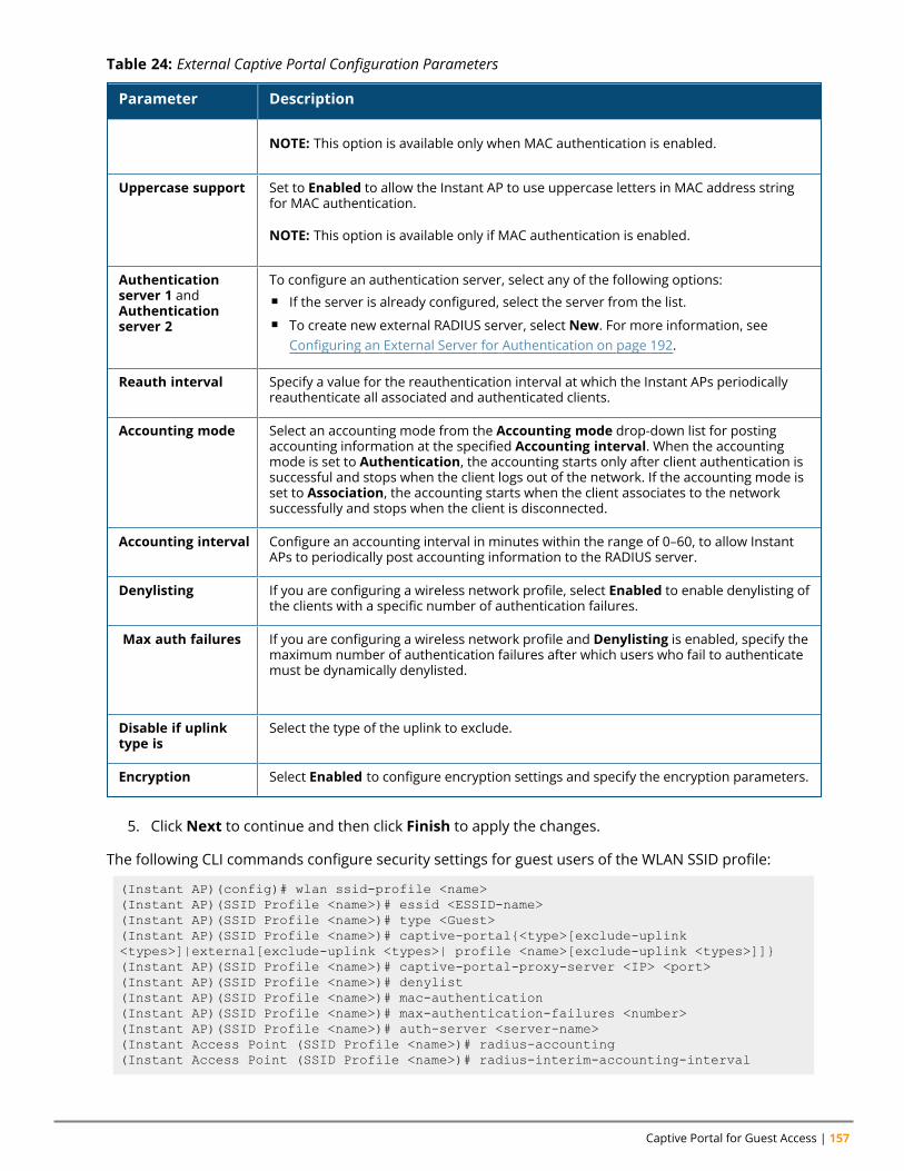
Captive Portal for Guest Access | 157
Parameter Description
NOTE: This option is available only when MAC authentication is enabled.
Uppercase support Set to Enabled to allow the Instant AP to use uppercase letters in MAC address stringfor MAC authentication.
NOTE: This option is available only if MAC authentication is enabled.
Authenticationserver 1 andAuthenticationserver 2
To configure an authentication server, select any of the following options:n If the server is already configured, select the server from the list.n To create new external RADIUS server, select New. For more information, see
Configuring an External Server for Authentication on page 192.
Reauth interval Specify a value for the reauthentication interval at which the Instant APs periodicallyreauthenticate all associated and authenticated clients.
Accounting mode Select an accounting mode from the Accounting mode drop-down list for postingaccounting information at the specified Accounting interval. When the accountingmode is set to Authentication, the accounting starts only after client authentication issuccessful and stops when the client logs out of the network. If the accounting mode isset to Association, the accounting starts when the client associates to the networksuccessfully and stops when the client is disconnected.
Accounting interval Configure an accounting interval in minutes within the range of 0–60, to allow InstantAPs to periodically post accounting information to the RADIUS server.
Denylisting If you are configuring a wireless network profile, select Enabled to enable denylisting ofthe clients with a specific number of authentication failures.
Max auth failures If you are configuring a wireless network profile and Denylisting is enabled, specify themaximum number of authentication failures after which users who fail to authenticatemust be dynamically denylisted.
Disable if uplinktype is
Select the type of the uplink to exclude.
Encryption Select Enabled to configure encryption settings and specify the encryption parameters.
Table 24: External Captive Portal Configuration Parameters
5. Click Next to continue and then click Finish to apply the changes.
The following CLI commands configure security settings for guest users of the WLAN SSID profile:
(Instant AP)(config)# wlan ssid-profile <name>(Instant AP)(SSID Profile <name>)# essid <ESSID-name>(Instant AP)(SSID Profile <name>)# type <Guest>(Instant AP)(SSID Profile <name>)# captive-portal{<type>[exclude-uplink<types>]|external[exclude-uplink <types>| profile <name>[exclude-uplink <types>]]}(Instant AP)(SSID Profile <name>)# captive-portal-proxy-server <IP> <port>(Instant AP)(SSID Profile <name>)# denylist(Instant AP)(SSID Profile <name>)# mac-authentication(Instant AP)(SSID Profile <name>)# max-authentication-failures <number>(Instant AP)(SSID Profile <name>)# auth-server <server-name>(Instant Access Point (SSID Profile <name>)# radius-accounting(Instant Access Point (SSID Profile <name>)# radius-interim-accounting-interval
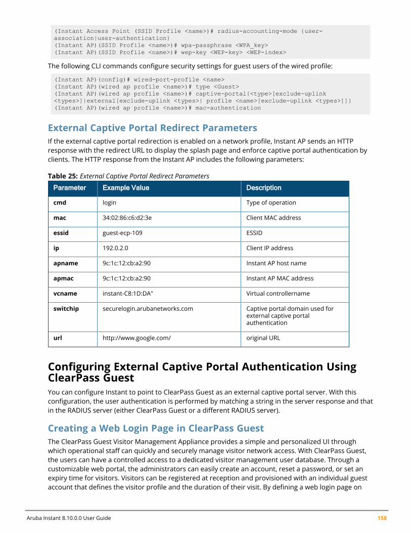
Aruba Instant 8.10.0.0 User Guide 158
(Instant Access Point (SSID Profile <name>)# radius-accounting-mode {user-association|user-authentication}(Instant AP)(SSID Profile <name>)# wpa-passphrase <WPA_key>(Instant AP)(SSID Profile <name>)# wep-key <WEP-key> <WEP-index>
The following CLI commands configure security settings for guest users of the wired profile:
(Instant AP)(config)# wired-port-profile <name>(Instant AP)(wired ap profile <name>)# type <Guest>(Instant AP)(wired ap profile <name>)# captive-portal{<type>[exclude-uplink<types>]|external[exclude-uplink <types>| profile <name>[exclude-uplink <types>]]}(Instant AP)(wired ap profile <name>)# mac-authentication
External Captive Portal Redirect ParametersIf the external captive portal redirection is enabled on a network profile, Instant AP sends an HTTPresponse with the redirect URL to display the splash page and enforce captive portal authentication byclients. The HTTP response from the Instant AP includes the following parameters:
Parameter Example Value Description
cmd login Type of operation
mac 34:02:86:c6:d2:3e Client MAC address
essid guest-ecp-109 ESSID
ip 192.0.2.0 Client IP address
apname 9c:1c:12:cb:a2:90 Instant AP host name
apmac 9c:1c:12:cb:a2:90 Instant AP MAC address
vcname instant-C8:1D:DA" Virtual controllername
switchip securelogin.arubanetworks.com Captive portal domain used forexternal captive portalauthentication
url http://www.google.com/ original URL
Table 25: External Captive Portal Redirect Parameters
Configuring External Captive Portal Authentication UsingClearPass GuestYou can configure Instant to point to ClearPass Guest as an external captive portal server. With thisconfiguration, the user authentication is performed by matching a string in the server response and thatin the RADIUS server (either ClearPass Guest or a different RADIUS server).
Creating a Web Login Page in ClearPass GuestThe ClearPass Guest Visitor Management Appliance provides a simple and personalized UI throughwhich operational staff can quickly and securely manage visitor network access. With ClearPass Guest,the users can have a controlled access to a dedicated visitor management user database. Through acustomizable web portal, the administrators can easily create an account, reset a password, or set anexpiry time for visitors. Visitors can be registered at reception and provisioned with an individual guestaccount that defines the visitor profile and the duration of their visit. By defining a web login page on
Captive Portal for Guest Access | 159
the ClearPass Guest Visitor Management Appliance, you can to provide a customized graphical loginpage for visitors accessing the network.
For more information on setting up the RADIUS web login page, refer to the RADIUS Services section inthe ClearPass Guest Deployment Guide
Configuring an External RADIUS Server for Captive PortalAuthenticationThe following procedure describes how to configure Instant to point to ClearPass Guest as an external captiveportal server:
1. Select the WLAN SSID for which you want to enable external captive portal authentication withClearPass Policy Manager. You can also configure the RADIUS server when configuring a new SSIDprofile.
a. Navigate to the Configuration > Networks page.
b. Select the WLAN SSID profile from the Networks list and click edit.
2. Select the Security tab and select External from the Splash page type drop-down list.3. Select + from the Captive portal profile drop-down list to create a captive portal profile, and
configure the following:
a. In the Name text box, enter the name of the profile .
b. In the Type drop-down list, select the authentication type.
c. In the IP or hostname text box, enter the IP address of the ClearPass Guest server. Obtainthe ClearPass Guest IP address from your system administrator.
d. In the URL text box enter /page_name.php. This URL must correspond to the Page Nameconfigured in the ClearPass Guest RADIUS Web Login page. For example, if the Page Name isAruba, the URL should be /Aruba.php in the WebUI.
e. Enter the Port number (generally should be 80). The ClearPass Guest server uses this port forHTTP services.
f. Click OK.
4. To create an external RADIUS server, select +from the Authentication server 1 drop-down list.For information on authentication server configuration parameters, see Configuring an ExternalServer for Authentication on page 192.
5. Click Next and until Finish.6. To verify, connect the updated SSID.7. Open any browser and type any URL. Instant redirects the URL to ClearPass Guest login page.8. Log in to the network with the username and password specified while configuring the RADIUS
server.
Configuring RADIUS Attribute for ClearPass Policy Manager ServerLoad BalancingStarting from Instant 6.4.3.4-4.2.1.0, the administrators can configure a RADIUS server IP address as oneof the parameters on ClearPass Policy Manager server for external captive portal user authentication.Configuring a RADIUS server attribute for guest user authentication allows the administrators tobalance the load on the ClearPass Policy Manager servers.
When the RADIUS server IP address is configured under Extra Fields in the ClearPass Guest login page,the RADIUS server IP parameter is submitted to the server as part of the HTTP or HTTPS POST data
Aruba Instant 8.10.0.0 User Guide 160
when the guest users initiate an HTTP or HTTPS request. The Instant AP intercepts this information toperform the actual RADIUS authentication with the server IP defined in the POST message. For moreinformation on guest registration customization on ClearPass Guest, refer to the ClearPass Guest UserGuide.
Configuring Facebook LoginInstant supports the Facebook Wi-Fi feature that allows the captive portal clients using a Facebookaccount to authenticate on an Instant AP. You can configure a guest network to use a customizedFacebook page as an external captive portal URL and allow the Instant AP to redirect clients to aFacebook page when it receives an HTTP request. The users can select the appropriate option toauthenticate and access the Internet. By configuring the Facebook login feature, businesses can pairtheir network with the Facebook Wi-Fi service, so that the users logging into Wi-Fi hotspots arepresented with a business page, before gaining access to the network.
The Facebook Wi-Fi integration with the Instant AP includes the following procedures:
n Setting up a Facebook Pagen Configuring an SSIDn Configuring the Facebook Portal Pagen Accessing the Portal Page
Setting up a Facebook PageTo enable integration with the Instant AP, ensure that you have a Facebook page created as a localbusiness with a valid location.
n For more information on creating a Facebook page, see the online help available athttps://www.facebook.com/help.
n For more information on setting up and using Facebook Wi-Fi service, seehttps://www.facebook.com/help/126760650808045.
Configuring an SSIDThe following procedure describes how to configure guest network profile and enable Facebook login:
1. Navigate to the Configuration > Networks page.2. Under Networks, click +.3. Enter a name for the SSID.4. In the Primary usage drop-down list, select Guest.5. Configure other required parameters under Basic and VLAN tabs.6. Under Security, select Facebook from the Splash page type drop-down list.7. Configure the required settings.8. Click Next until Finish.9. The SSID with the Facebook option is created. After the SSID is created, the Instant AP
automatically registers with Facebook. If the Instant AP registration is successful, the Facebookconfiguration link is displayed in the Security tab of the WLAN wizard.
The following CLI command configures an account for captive portal authentication:
(Instant AP)(config)# wlan ssid-profile <name>
Captive Portal for Guest Access | 161
(Instant AP)(SSID Profile <name>)# captive-portal {<type>[exclude-uplink<types>]|external [exclude-uplink <types>|profile <name>[exclude-uplink <types>]]}
Example
The following example configures a Facebook account for captive portal authentication:
(Instant AP)(config)# wlan ssid-profile guestNetwork(Instant AP)(SSID Profile "guestNetwork")# captive-portal facebook
Configuring the Facebook Portal PageThe following procedure describes how to bind the virtual controller with the Facebook portal:
1. Open the SSID with the Facebook option enabled, navigate to the Security tab and click theFacebook configuration link. The Facebook page is displayed.
NOTE: The Facebook configuration link is displayed only if the Instant AP is successfully registered with Facebook.
2. Log in with your Facebook credentials. The Facebook Wi-Fi Configuration page is displayed.3. Select the Facebook page.4. Under Bypass Mode, select any of the following options:
n Skip Check-in link—When selected, the users are not presented with your business Facebookpage, but are allowed to access the Internet by clicking the Skip Check-in link.
n Require Wi-Fi code—When selected, the users are assigned a Wi-Fi code to gain access to theFacebook page.
5. Customize the session length and terms of service if required.6. Click Save Settings.
Accessing the Portal PageThe following procedure describes how to access the Facebook Portal page using the WebUI:
1. Connect to the SSID with the Facebook option enabled.2. Launch a web browser. The browser opens the Facebook Wi-Fi page. If the Wi-Fi-code based login
is enabled, the users are prompted to enter the Wi-FI code. If the Skip Check-in link is displayed,click the link to skip checking in to the Facebook business page and proceed to access theInternet.
3. If you want to check in the business page, click Check In and provide your credentials. Afterchecking in, click Continue Browsing to access the web page that was originally requested.
Configuring Facebook Express Wi-Fi
The Facebook Express Wi-Fi feature will no longer be supported after Aruba Instant 8.10.0.0. For moreinformation, read the official statement by Meta (formerly Facebook).
Aruba Instant APs support Facebook Express Wi-Fi feature that enables you to create wireless networkfor Facebook Wi-Fi and use internet services. When a user connects to the Facebook Express Wi-Fi SSID,they are assigned the base role defined in facebook-xwf-role parameter in thewlan ssid-profile. Inaddition to the traffic allowed in the base role, the user also inherits access to traffic defined in the
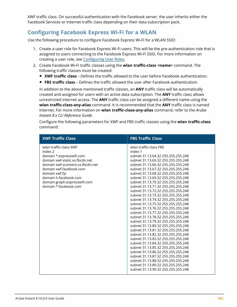
Aruba Instant 8.10.0.0 User Guide 162
XWF traffic class. On successful authentication with the Facebook server, the user inherits either theFacebook Services or Internet traffic class depending on their data subscription pack.
Configuring Facebook Express Wi-Fi for a WLANUse the following procedure to configure Facebook Express Wi-Fi for a WLAN SSID:
1. Create a user role for Facebook Express Wi-Fi users. This will be the pre-authentication role that isassigned to users connecting to the Facebook Express Wi-Fi SSID. For more information oncreating a user role, see Configuring User Roles.
2. Create Facebook Wi-Fi traffic classes using thewlan traffic-class <name> command. Thefollowing traffic classes must be created:n XWF traffic class – Defines the traffic allowed to the user before Facebook authentication.n FBS traffic class – Defines the traffic allowed the user after Facebook authentication.
In addition to the above mentioned traffic classes, an ANY traffic class will be automaticallycreated and assigned for users with an active data subscription. The ANY traffic class allowsunrestricted internet access. The ANY traffic class can be assigned a different name using thewlan traffic-class-any-alias command. It is recommended that the ANY traffic class is namedInternet. For more information onwlan traffic-class-any-alias command, refer to the ArubaInstant 8.x CLI Reference Guide.Configure the following parameters for XWF and FBS traffic classes using thewlan traffic-classcommand:
XWF Traffic Class FBS Traffic Class
wlan traffic-class XWFindex 2domain *.expresswifi.comdomain xwf-static.xx.fbcdn.netdomain xwf-scontent.xx.fbcdn.netdomain xwf.facebook.comdomain xwf.fyidomain h.facebook.comdomain graph.expresswifi.comdomain *.facebook.com
wlan traffic-class FBSindex 1subnet 31.13.64.32 255.255.255.248subnet 31.13.65.32 255.255.255.248subnet 31.13.66.32 255.255.255.248subnet 31.13.67.32 255.255.255.248subnet 31.13.68.32 255.255.255.248subnet 31.13.69.32 255.255.255.248subnet 31.13.70.32 255.255.255.248subnet 31.13.71.32 255.255.255.248subnet 31.13.72.32 255.255.255.248subnet 31.13.73.32 255.255.255.248subnet 31.13.74.32 255.255.255.248subnet 31.13.75.32 255.255.255.248subnet 31.13.76.32 255.255.255.248subnet 31.13.77.32 255.255.255.248subnet 31.13.78.32 255.255.255.248subnet 31.13.79.32 255.255.255.248subnet 31.13.80.32 255.255.255.248subnet 31.13.81.32 255.255.255.248subnet 31.13.82.32 255.255.255.248subnet 31.13.83.32 255.255.255.248subnet 31.13.84.32 255.255.255.248subnet 31.13.85.32 255.255.255.248subnet 31.13.86.32 255.255.255.248subnet 31.13.87.32 255.255.255.248subnet 31.13.88.32 255.255.255.248subnet 31.13.89.32 255.255.255.248subnet 31.13.90.32 255.255.255.248
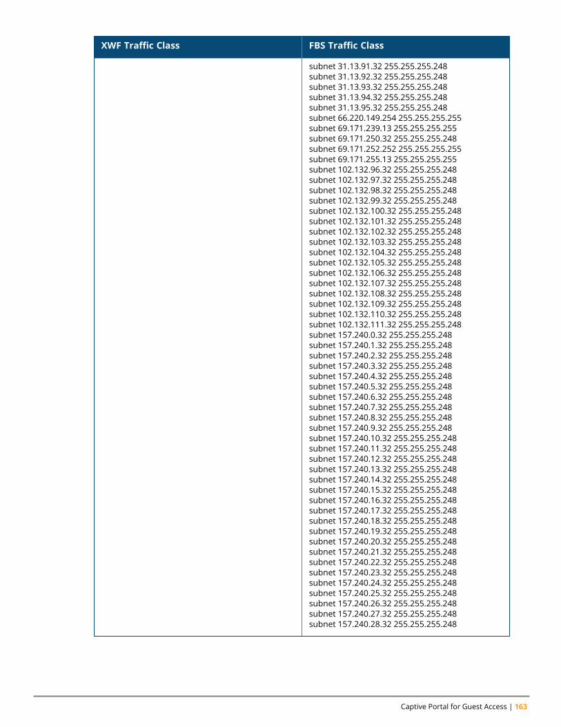
Captive Portal for Guest Access | 163
XWF Traffic Class FBS Traffic Class
subnet 31.13.91.32 255.255.255.248subnet 31.13.92.32 255.255.255.248subnet 31.13.93.32 255.255.255.248subnet 31.13.94.32 255.255.255.248subnet 31.13.95.32 255.255.255.248subnet 66.220.149.254 255.255.255.255subnet 69.171.239.13 255.255.255.255subnet 69.171.250.32 255.255.255.248subnet 69.171.252.252 255.255.255.255subnet 69.171.255.13 255.255.255.255subnet 102.132.96.32 255.255.255.248subnet 102.132.97.32 255.255.255.248subnet 102.132.98.32 255.255.255.248subnet 102.132.99.32 255.255.255.248subnet 102.132.100.32 255.255.255.248subnet 102.132.101.32 255.255.255.248subnet 102.132.102.32 255.255.255.248subnet 102.132.103.32 255.255.255.248subnet 102.132.104.32 255.255.255.248subnet 102.132.105.32 255.255.255.248subnet 102.132.106.32 255.255.255.248subnet 102.132.107.32 255.255.255.248subnet 102.132.108.32 255.255.255.248subnet 102.132.109.32 255.255.255.248subnet 102.132.110.32 255.255.255.248subnet 102.132.111.32 255.255.255.248subnet 157.240.0.32 255.255.255.248subnet 157.240.1.32 255.255.255.248subnet 157.240.2.32 255.255.255.248subnet 157.240.3.32 255.255.255.248subnet 157.240.4.32 255.255.255.248subnet 157.240.5.32 255.255.255.248subnet 157.240.6.32 255.255.255.248subnet 157.240.7.32 255.255.255.248subnet 157.240.8.32 255.255.255.248subnet 157.240.9.32 255.255.255.248subnet 157.240.10.32 255.255.255.248subnet 157.240.11.32 255.255.255.248subnet 157.240.12.32 255.255.255.248subnet 157.240.13.32 255.255.255.248subnet 157.240.14.32 255.255.255.248subnet 157.240.15.32 255.255.255.248subnet 157.240.16.32 255.255.255.248subnet 157.240.17.32 255.255.255.248subnet 157.240.18.32 255.255.255.248subnet 157.240.19.32 255.255.255.248subnet 157.240.20.32 255.255.255.248subnet 157.240.21.32 255.255.255.248subnet 157.240.22.32 255.255.255.248subnet 157.240.23.32 255.255.255.248subnet 157.240.24.32 255.255.255.248subnet 157.240.25.32 255.255.255.248subnet 157.240.26.32 255.255.255.248subnet 157.240.27.32 255.255.255.248subnet 157.240.28.32 255.255.255.248
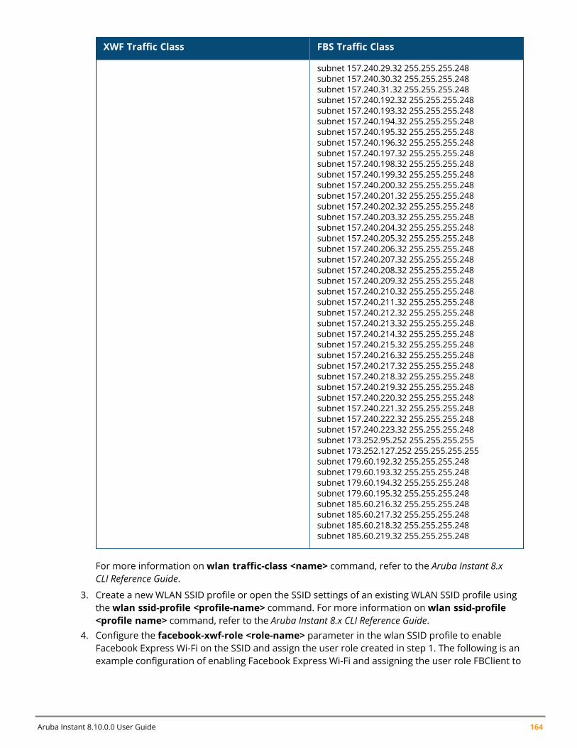
Aruba Instant 8.10.0.0 User Guide 164
XWF Traffic Class FBS Traffic Class
subnet 157.240.29.32 255.255.255.248subnet 157.240.30.32 255.255.255.248subnet 157.240.31.32 255.255.255.248subnet 157.240.192.32 255.255.255.248subnet 157.240.193.32 255.255.255.248subnet 157.240.194.32 255.255.255.248subnet 157.240.195.32 255.255.255.248subnet 157.240.196.32 255.255.255.248subnet 157.240.197.32 255.255.255.248subnet 157.240.198.32 255.255.255.248subnet 157.240.199.32 255.255.255.248subnet 157.240.200.32 255.255.255.248subnet 157.240.201.32 255.255.255.248subnet 157.240.202.32 255.255.255.248subnet 157.240.203.32 255.255.255.248subnet 157.240.204.32 255.255.255.248subnet 157.240.205.32 255.255.255.248subnet 157.240.206.32 255.255.255.248subnet 157.240.207.32 255.255.255.248subnet 157.240.208.32 255.255.255.248subnet 157.240.209.32 255.255.255.248subnet 157.240.210.32 255.255.255.248subnet 157.240.211.32 255.255.255.248subnet 157.240.212.32 255.255.255.248subnet 157.240.213.32 255.255.255.248subnet 157.240.214.32 255.255.255.248subnet 157.240.215.32 255.255.255.248subnet 157.240.216.32 255.255.255.248subnet 157.240.217.32 255.255.255.248subnet 157.240.218.32 255.255.255.248subnet 157.240.219.32 255.255.255.248subnet 157.240.220.32 255.255.255.248subnet 157.240.221.32 255.255.255.248subnet 157.240.222.32 255.255.255.248subnet 157.240.223.32 255.255.255.248subnet 173.252.95.252 255.255.255.255subnet 173.252.127.252 255.255.255.255subnet 179.60.192.32 255.255.255.248subnet 179.60.193.32 255.255.255.248subnet 179.60.194.32 255.255.255.248subnet 179.60.195.32 255.255.255.248subnet 185.60.216.32 255.255.255.248subnet 185.60.217.32 255.255.255.248subnet 185.60.218.32 255.255.255.248subnet 185.60.219.32 255.255.255.248
For more information onwlan traffic-class <name> command, refer to the Aruba Instant 8.xCLI Reference Guide.
3. Create a new WLAN SSID profile or open the SSID settings of an existing WLAN SSID profile usingthewlan ssid-profile <profile-name> command. For more information onwlan ssid-profile<profile name> command, refer to the Aruba Instant 8.x CLI Reference Guide.
4. Configure the facebook-xwf-role <role-name> parameter in the wlan SSID profile to enableFacebook Express Wi-Fi on the SSID and assign the user role created in step 1. The following is anexample configuration of enabling Facebook Express Wi-Fi and assigning the user role FBClient to
Captive Portal for Guest Access | 165
facebook-xwf-role:
# wlan ssid-profile Express WiFi(Instant AP)(SSID Profile "guestNetwork")# facebook-xwf-role FBClient
Configuring Guest Logon Role and Access Rules for GuestUsersFor captive portal profile, you can create any the following types of roles:
n A pre-authenticated role—This role is assigned before the captive portal authentication. The user canonly access certain destinations with this role.
n A guest role—This role is assigned after user authentication.n A captive-portal role—This role can be assigned to any network such as Employee, Voice, or Guest.
When the user is assigned with this role, a splash page is displayed after opening a browser and theusers may need to authenticate.
You can configure up to 128 access rules for guest user roles through the Instant WebUI or the CLI. Thefollowing procedure describes how to configure access rules for a guest SSID:
1. Navigate to the Configuration > Networks and select the guest network you want to configureand click edit.
2. Select the Access tab, select any of the following types of access control from the Access Rulesdrop-down list:n Unrestricted—Select this to set unrestricted access to the network.n Network-based—Select this to set common rules for all users in a network. The Allow any to
all destinations access rule is enabled by default. This rule allows traffic to all destinations. Todefine an access rule:
a. Click +.b. Select appropriate options in the New rule window.c. Click OK.
n Role-based—Select this to enable access based on user roles.n For role-based access control:n Create a user role if required. For more information, see Configuring User Roles.n Create access rules for a specific user role. For more information, see Configuring ACL Rules
for Network Services on page 220. You can also configure an access rule to enforce captiveportal authentication for an SSID with the 802.1X authentication method. For moreinformation, see Configuring Captive Portal Roles for an SSID on page 166.
n Create a role assignment rule. For more information, see Configuring Derivation Rules on page238. Instant supports role derivation based on the DHCP option for captive portalauthentication. When the captive portal authentication is successful, a new user role isassigned to the guest users based on DHCP option configured for the SSID profile instead ofthe pre-authenticated role.
3. Click Finish.
The following CLI command configures access control rules for a WLAN SSID:
(Instant AP)(config)# wlan access-rule <name>
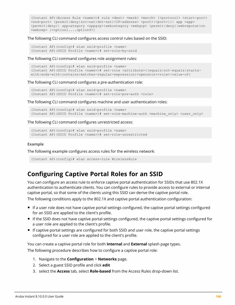
Aruba Instant 8.10.0.0 User Guide 166
(Instant AP)(Access Rule <name>)# rule <dest> <mask> <match> {<protocol> <start-port><end-port> {permit|deny|src-nat|dst-nat{<IP-address> <port>|<port>}}| app <app>{permit|deny}| appcategory <appgrp>|webcategory <webgrp> {permit|deny}|webreputation<webrep> [<option1....option9>]
The following CLI command configures access control rules based on the SSID:
(Instant AP)(config)# wlan ssid-profile <name>(Instant AP)(SSID Profile <name>)# set-role-by-ssid
The following CLI command configures role assignment rules:
(Instant AP)(config)# wlan ssid-profile <name>(Instant AP)(SSID Profile <name>)# set-role <attribute>{{equals|not-equals|starts-with|ends-with|contains|matches-regular-expression}<operator><role>|value-of}
The following CLI command configures a pre-authentication role:
(Instant AP)(config)# wlan ssid-profile <name>(Instant AP)(SSID Profile <name>)# set-role-pre-auth <role>
The following CLI command configures machine and user authentication roles:
(Instant AP)(config)# wlan ssid-profile <name>(Instant AP)(SSID Profile <name>)# set-role-machine-auth <machine_only> <user_only>
The following CLI command configures unrestricted access:
(Instant AP)(config)# wlan ssid-profile <name>(Instant AP)(SSID Profile <name>)# set-role-unrestricted
Example
The following example configures access rules for the wireless network:
(Instant AP)(config)# wlan access-rule WirelessRule
Configuring Captive Portal Roles for an SSIDYou can configure an access rule to enforce captive portal authentication for SSIDs that use 802.1Xauthentication to authenticate clients. You can configure rules to provide access to external or internalcaptive portal, so that some of the clients using this SSID can derive the captive portal role.
The following conditions apply to the 802.1X and captive portal authentication configuration:
n If a user role does not have captive portal settings configured, the captive portal settings configuredfor an SSID are applied to the client's profile.
n If the SSID does not have captive portal settings configured, the captive portal settings configured fora user role are applied to the client's profile.
n If captive portal settings are configured for both SSID and user role, the captive portal settingsconfigured for a user role are applied to the client's profile.
You can create a captive portal role for both Internal and External splash page types.
The following procedure describes how to configure a captive portal role:
1. Navigate to the Configuration > Networks page.2. Select a guest SSID profile and click edit3. select the Access tab, select Role-based from the Access Rules drop-down list.
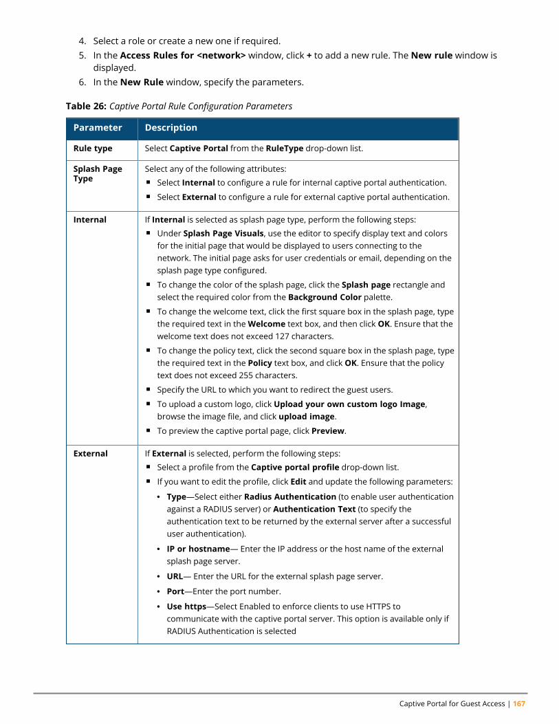
Captive Portal for Guest Access | 167
4. Select a role or create a new one if required.5. In the Access Rules for <network> window, click + to add a new rule. The New rule window is
displayed.6. In the New Rule window, specify the parameters.
Parameter Description
Rule type Select Captive Portal from the RuleType drop-down list.
Splash PageType
Select any of the following attributes:n Select Internal to configure a rule for internal captive portal authentication.n Select External to configure a rule for external captive portal authentication.
Internal If Internal is selected as splash page type, perform the following steps:n Under Splash Page Visuals, use the editor to specify display text and colors
for the initial page that would be displayed to users connecting to thenetwork. The initial page asks for user credentials or email, depending on thesplash page type configured.
n To change the color of the splash page, click the Splash page rectangle andselect the required color from the Background Color palette.
n To change the welcome text, click the first square box in the splash page, typethe required text in theWelcome text box, and then click OK. Ensure that thewelcome text does not exceed 127 characters.
n To change the policy text, click the second square box in the splash page, typethe required text in the Policy text box, and click OK. Ensure that the policytext does not exceed 255 characters.
n Specify the URL to which you want to redirect the guest users.n To upload a custom logo, click Upload your own custom logo Image,
browse the image file, and click upload image.n To preview the captive portal page, click Preview.
External If External is selected, perform the following steps:n Select a profile from the Captive portal profile drop-down list.n If you want to edit the profile, click Edit and update the following parameters:
l Type—Select either Radius Authentication (to enable user authenticationagainst a RADIUS server) or Authentication Text (to specify theauthentication text to be returned by the external server after a successfuluser authentication).
l IP or hostname— Enter the IP address or the host name of the externalsplash page server.
l URL— Enter the URL for the external splash page server.
l Port—Enter the port number.
l Use https—Select Enabled to enforce clients to use HTTPS tocommunicate with the captive portal server. This option is available only ifRADIUS Authentication is selected
Table 26: Captive Portal Rule Configuration Parameters
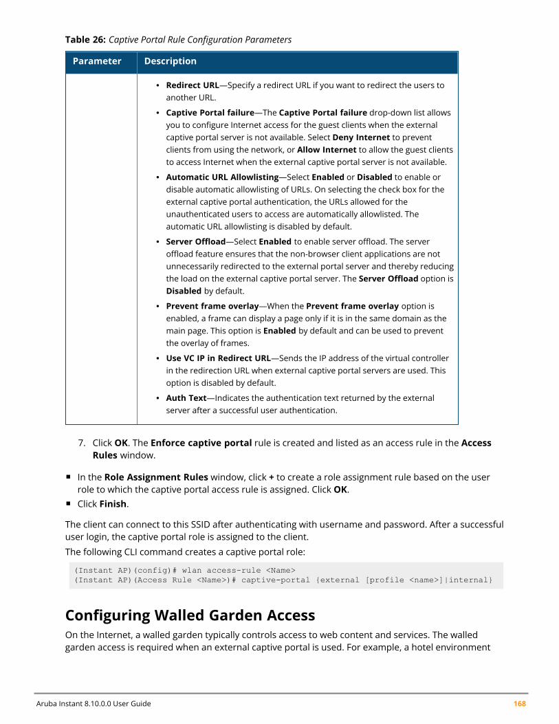
Aruba Instant 8.10.0.0 User Guide 168
Parameter Description
l Redirect URL—Specify a redirect URL if you want to redirect the users toanother URL.
l Captive Portal failure—The Captive Portal failure drop-down list allowsyou to configure Internet access for the guest clients when the externalcaptive portal server is not available. Select Deny Internet to preventclients from using the network, or Allow Internet to allow the guest clientsto access Internet when the external captive portal server is not available.
l Automatic URL Allowlisting—Select Enabled or Disabled to enable ordisable automatic allowlisting of URLs. On selecting the check box for theexternal captive portal authentication, the URLs allowed for theunauthenticated users to access are automatically allowlisted. Theautomatic URL allowlisting is disabled by default.
l Server Offload—Select Enabled to enable server offload. The serveroffload feature ensures that the non-browser client applications are notunnecessarily redirected to the external portal server and thereby reducingthe load on the external captive portal server. The Server Offload option isDisabled by default.
l Prevent frame overlay—When the Prevent frame overlay option isenabled, a frame can display a page only if it is in the same domain as themain page. This option is Enabled by default and can be used to preventthe overlay of frames.
l Use VC IP in Redirect URL—Sends the IP address of the virtual controllerin the redirection URL when external captive portal servers are used. Thisoption is disabled by default.
l Auth Text—Indicates the authentication text returned by the externalserver after a successful user authentication.
Table 26: Captive Portal Rule Configuration Parameters
7. Click OK. The Enforce captive portal rule is created and listed as an access rule in the AccessRules window.
n In the Role Assignment Rules window, click + to create a role assignment rule based on the userrole to which the captive portal access rule is assigned. Click OK.
n Click Finish.
The client can connect to this SSID after authenticating with username and password. After a successfuluser login, the captive portal role is assigned to the client.
The following CLI command creates a captive portal role:
(Instant AP)(config)# wlan access-rule <Name>(Instant AP)(Access Rule <Name>)# captive-portal {external [profile <name>]|internal}
Configuring Walled Garden AccessOn the Internet, a walled garden typically controls access to web content and services. The walledgarden access is required when an external captive portal is used. For example, a hotel environment
Captive Portal for Guest Access | 169
where the unauthenticated users are allowed to navigate to a designated login page (for example, ahotel website) and all its contents.
The users who do not sign up for the Internet service can view the allowed websites (typically hotelproperty websites). The website names must be DNS-based and support the option to define wildcards.When a user attempts to navigate to other websites that are not in the allowlist of the walled gardenprofile, the user is redirected to the login page. Instant AP supports walled garden only for the HTTPrequests. For example, if you add yahoo.com in walled garden allowlist and the client sends an HTTPSrequest (https://yahoo.com), the requested page is not displayed and the users are redirected to thecaptive portal login page.
In addition, a denylisted walled garden profile can also be configured to explicitly block theunauthenticated users from accessing some websites.
The following CLI command configures walled garden access:
(Instant AP)(config)# wlan walled-garden(Instant AP)(Walled Garden)# white-list <domain>(Instant AP)(Walled Garden)# black-list <domain>
Disabling Captive Portal AuthenticationThe following procedure describes how to disable captive portal authentication:To disable captive portal authentication:
1. Navigate to the Configuration > Networks tab.2. Select a wireless guest or a wired guest profile and click Edit.
You can also customize splash page visuals on the Security tab of New WLAN (WLANwizard) and New Wired Network (wired profile window) when configuring a new profile.
3. Select the Security tab.4. Select None from the Splash page type drop-down list. Although the splash page is disabled,
you can enable MAC authentication, configure authentication servers, set accounting parameters,denylist clients based on MAC authentication failures, and configure encryption keys forauthorized access.
5. If required, configure the security parameters.6. Click Next and until Finish to apply the changes.
7. Click Next and until Finish to apply the changes.
Chapter 13Authentication and User Management
Authentication and User ManagementThis chapter provides the following information:
n Overview of Instant AP Users on page 170n Supported Authentication Methods on page 175n Supported EAP Authentication Frameworks on page 185n Configuring Authentication Servers on page 191n Supported Encryption Types on page 201n Authentication Survivability on page 202n 802.1X Authentication on page 176n 802.1X Supplicant Support on page 209n MAC Authentication on page 178n MAC Authentication with 802.1X Authentication on page 179n MAC Authentication with Captive Portal Authentication on page 181n WISPr Authentication on page 182n Denylisting Clients on page 211n Authentication Certificates on page 213
Overview of Instant AP UsersThe Instant AP users can be classified as follows:
n Administrator—An admin user who creates SSIDs, wired profiles, and DHCP server configurationparameters; and manages the local user database. The admin users can access the virtual controllerManagement UI.
n Guest administrator—A guest interface management user who manages guest users added in thelocal user database.
n Administrator with read-only access—The read-only admin user does not have access to the InstantCLI. The WebUI will be displayed in the read-only mode for these users.
n Employee users—Employees who use the enterprise network for official tasks.n Guest users—Visiting users who temporarily use the enterprise network to access the Internet.
The user access privileges are determined by Instant AP management settings in the AirWaveManagement client and Aruba Central, and the type of the user. The following table outlines the accessprivileges defined for the admin user, guest management interface admin, and read-only users.
Aruba Instant 8.10.0.0 User Guide 170
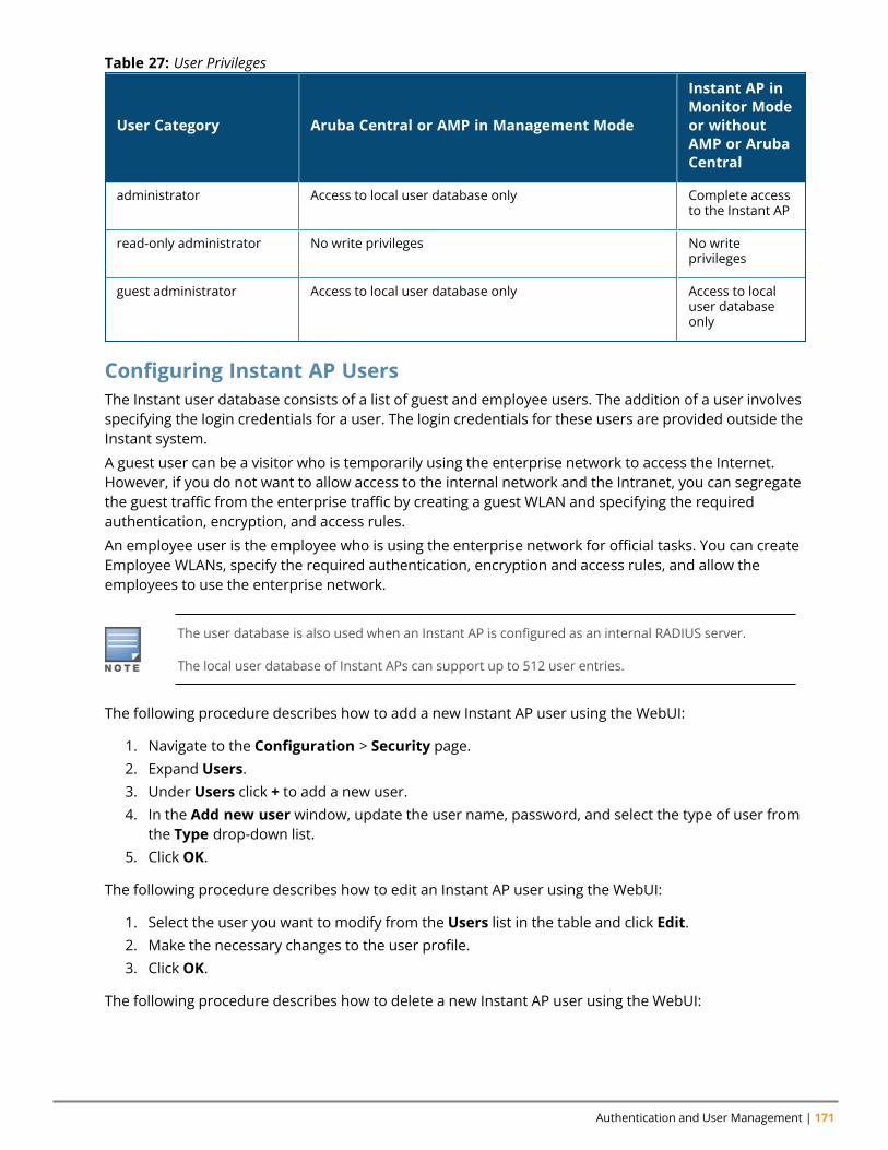
Authentication and User Management | 171
User Category Aruba Central or AMP in Management Mode
Instant AP inMonitor Modeor withoutAMP or ArubaCentral
administrator Access to local user database only Complete accessto the Instant AP
read-only administrator No write privileges No writeprivileges
guest administrator Access to local user database only Access to localuser databaseonly
Table 27: User Privileges
Configuring Instant AP UsersThe Instant user database consists of a list of guest and employee users. The addition of a user involvesspecifying the login credentials for a user. The login credentials for these users are provided outside theInstant system.
A guest user can be a visitor who is temporarily using the enterprise network to access the Internet.However, if you do not want to allow access to the internal network and the Intranet, you can segregatethe guest traffic from the enterprise traffic by creating a guest WLAN and specifying the requiredauthentication, encryption, and access rules.
An employee user is the employee who is using the enterprise network for official tasks. You can createEmployee WLANs, specify the required authentication, encryption and access rules, and allow theemployees to use the enterprise network.
The user database is also used when an Instant AP is configured as an internal RADIUS server.
The local user database of Instant APs can support up to 512 user entries.
The following procedure describes how to add a new Instant AP user using the WebUI:
1. Navigate to the Configuration > Security page.2. Expand Users.3. Under Users click + to add a new user.4. In the Add new user window, update the user name, password, and select the type of user from
the Type drop-down list.5. Click OK.
The following procedure describes how to edit an Instant AP user using the WebUI:
1. Select the user you want to modify from the Users list in the table and click Edit.2. Make the necessary changes to the user profile.3. Click OK.
The following procedure describes how to delete a new Instant AP user using the WebUI:
Aruba Instant 8.10.0.0 User Guide 172
1. Select the user you want to delete from the Users list in the table and click Delete.2. To delete all or multiple users at a time, click Delete All.
Deleting a user only removes the user record from the user database, and will not disconnect theonline user associated with the user name.
The following CLI snippet allows you to configure an employee user:
(Instant AP)(config)# user <username> <password> radius
The following CLI snippet allows you to configure a guest user:
(Instant AP)(config)# user <username> <password> portal
Configuring Management UsersInternal, RADIUS, or TACACS authentication servers can be configured to authenticate and authorizemanagement users of an Instant AP. The authentication servers determine if the user has access toadministrative interface. The privilege level for different types of management users is defined on theRADIUS or TACACS server instead of the Instant AP. The Instant APs map the management users to thecorresponding privilege level and provide access to the users based on the attributes returned by theRADIUS or TACACS server.
The following procedure describes how to configure authentication parameters for local admin, read-only, and guest management administrator account settings through the WebUI:
1. Navigate to the Configuration > System page.2. Expand Admin.3. Configure the settings defined in the Authentication Parameters for Management Users table
below.4. Click Save.
Type of User Authentication Options Steps to Follow
LocalAdministrator
Internal Select Internal Authentication if you want to specifya single set of user credentials. If using an internalauthentication server:
1. Select Internal in the Authentication drop-downlist.
2. Specify the Username and Password.
3. Retype the password to confirm.
Authentication Server Select Authentication server if you want to use anAuthentication server to authenticate themanagement user.
1. Select Authentication server in theAuthentication drop-down list. You can add upto 2 authentication servers.
2. Auth server 1 and Auth server 2—Specify the
Table 28: Authentication Parameters for Management Users
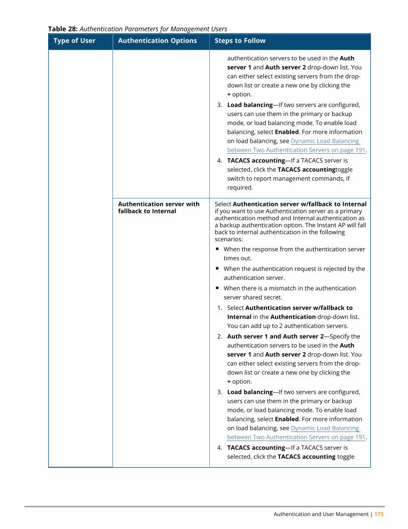
Authentication and User Management | 173
Type of User Authentication Options Steps to Follow
authentication servers to be used in the Authserver 1 and Auth server 2 drop-down list. Youcan either select existing servers from the drop-down list or create a new one by clicking the+ option.
3. Load balancing—If two servers are configured,users can use them in the primary or backupmode, or load balancing mode. To enable loadbalancing, select Enabled. For more informationon load balancing, see Dynamic Load Balancingbetween Two Authentication Servers on page 191.
4. TACACS accounting—If a TACACS server isselected, click the TACACS accountingtoggleswitch to report management commands, ifrequired.
Authentication server withfallback to Internal
Select Authentication server w/fallback to Internalif you want to use Authentication server as a primaryauthentication method and Internal authentication asa backup authentication option. The Instant AP will fallback to internal authentication in the followingscenarios:n When the response from the authentication server
times out.n When the authentication request is rejected by the
authentication server.n When there is a mismatch in the authentication
server shared secret.
1. Select Authentication server w/fallback toInternal in the Authentication drop-down list.You can add up to 2 authentication servers.
2. Auth server 1 and Auth server 2—Specify theauthentication servers to be used in the Authserver 1 and Auth server 2 drop-down list. Youcan either select existing servers from the drop-down list or create a new one by clicking the+ option.
3. Load balancing—If two servers are configured,users can use them in the primary or backupmode, or load balancing mode. To enable loadbalancing, select Enabled. For more informationon load balancing, see Dynamic Load Balancingbetween Two Authentication Servers on page 191.
4. TACACS accounting—If a TACACS server isselected, click the TACACS accounting toggle
Table 28: Authentication Parameters for Management Users
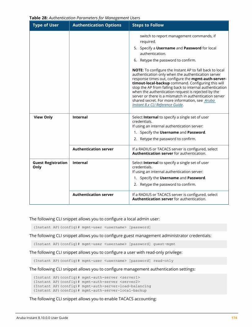
Aruba Instant 8.10.0.0 User Guide 174
Type of User Authentication Options Steps to Follow
switch to report management commands, ifrequired.
5. Specify a Username and Password for localauthentication.
6. Retype the password to confirm.
NOTE: To configure the Instant AP to fall back to localauthentication only when the authentication serverresponse times out, configure themgmt-auth-server-timout-local-backup command. Configuring this willstop the AP from falling back to internal authenticationwhen the authentication request is rejected by theserver or there is a mismatch in authentication servershared secret. For more information, see ArubaInstant 8.x CLI Reference Guide.
View Only Internal Select Internal to specify a single set of usercredentials.If using an internal authentication server:
1. Specify the Username and Password.
2. Retype the password to confirm.
Authentication server If a RADIUS or TACACS server is configured, selectAuthentication server for authentication.
Guest RegistrationOnly
Internal Select Internal to specify a single set of usercredentials.If using an internal authentication server:
1. Specify the Username and Password.
2. Retype the password to confirm.
Authentication server If a RADIUS or TACACS server is configured, selectAuthentication server for authentication.
Table 28: Authentication Parameters for Management Users
The following CLI snippet allows you to configure a local admin user:
(Instant AP)(config)# mgmt-user <username> [password]
The following CLI snippet allows you to configure guest management administrator credentials:
(Instant AP)(config)# mgmt-user <username> [password] guest-mgmt
The following CLI snippet allows you to configure a user with read-only privilege:
(Instant AP)(config)# mgmt-user <username> [password] read-only
The following CLI snippet allows you to configure management authentication settings:
(Instant AP)(config)# mgmt-auth-server <server1>(Instant AP)(config)# mgmt-auth-server <server2>(Instant AP)(config)# mgmt-auth-server-load-balancing(Instant AP)(config)# mgmt-auth-server-local-backup
The following CLI snippet allows you to enable TACACS accounting:
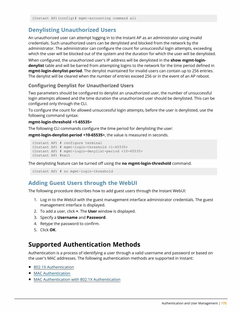
Authentication and User Management | 175
(Instant AP)(config)# mgmt-accounting command all
Denylisting Unauthorized UsersAn unauthorized user can attempt logging in to the Instant AP as an administrator using invalidcredentials. Such unauthorized users can be denylisted and blocked from the network by theadministrator. The administrator can configure the count for unsuccessful login attempts, exceedingwhich the user will be blocked out of the system and the duration for which the user will be denylisted.
When configured, the unauthorized user's IP address will be denylisted in the show mgmt-login-denylist table and will be barred from attempting logins to the network for the time period defined inmgmt-login-denylist-period. The denylist maintained for invalid users can contain up to 256 entries.The denylist will be cleared when the number of entries exceed 256 or in the event of an AP reboot.
Configuring Denylist for Unauthorized UsersTwo parameters should be configured to denylist an unauthorized user, the number of unsuccessfullogin attempts allowed and the time duration the unauthorized user should be denylisted. This can beconfigured only through the CLI.
To configure the count for allowed unsuccessful login attempts, before the user is denylisted, use thefollowing command syntax:
mgmt-login-threshold <1-65535>
The following CLI commands configure the time period for denylisting the user:
mgmt-login-denylist-period <10-65535>, the value is measured in seconds.
(Instant AP) # configure terminal(Instant AP) # mgmt-login-threshold <1-65535>(Instant AP) # mgmt-login-denylist-period <10-65535>(Instant AP) #exit
The denylisting feature can be turned off using the no mgmt-login-threshold command.
(Instant AP) # no mgmt-login-threshold
Adding Guest Users through the WebUIThe following procedure describes how to add guest users through the Instant WebUI:
1. Log in to the WebUI with the guest management interface administrator credentials. The guestmanagement interface is displayed.
2. To add a user, click +. The User window is displayed.3. Specify a Username and Password.4. Retype the password to confirm.5. Click OK.
Supported Authentication MethodsAuthentication is a process of identifying a user through a valid username and password or based onthe user's MAC addresses. The following authentication methods are supported in Instant:
n 802.1X Authenticationn MAC Authenticationn MAC Authentication with 802.1X Authentication
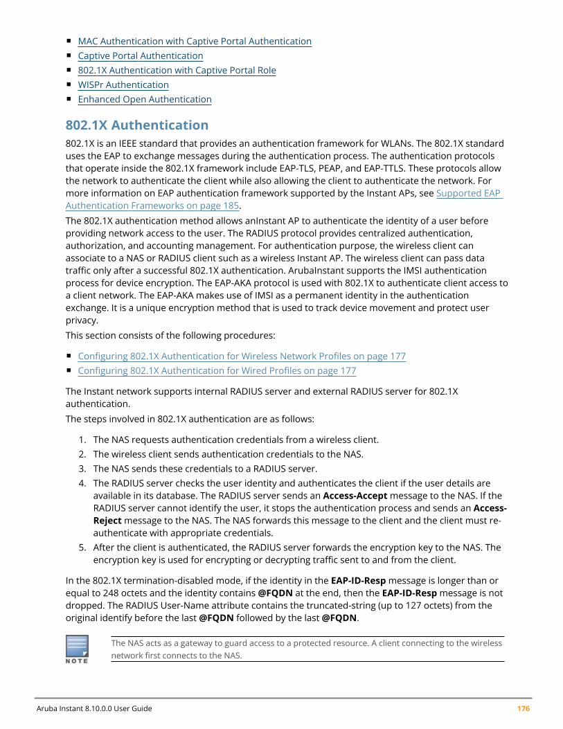
Aruba Instant 8.10.0.0 User Guide 176
n MAC Authentication with Captive Portal Authenticationn Captive Portal Authenticationn 802.1X Authentication with Captive Portal Rolen WISPr Authenticationn Enhanced Open Authentication
802.1X Authentication802.1X is an IEEE standard that provides an authentication framework for WLANs. The 802.1X standarduses the EAP to exchange messages during the authentication process. The authentication protocolsthat operate inside the 802.1X framework include EAP-TLS, PEAP, and EAP-TTLS. These protocols allowthe network to authenticate the client while also allowing the client to authenticate the network. Formore information on EAP authentication framework supported by the Instant APs, see Supported EAPAuthentication Frameworks on page 185.
The 802.1X authentication method allows anInstant AP to authenticate the identity of a user beforeproviding network access to the user. The RADIUS protocol provides centralized authentication,authorization, and accounting management. For authentication purpose, the wireless client canassociate to a NAS or RADIUS client such as a wireless Instant AP. The wireless client can pass datatraffic only after a successful 802.1X authentication. ArubaInstant supports the IMSI authenticationprocess for device encryption. The EAP-AKA protocol is used with 802.1X to authenticate client access toa client network. The EAP-AKA makes use of IMSI as a permanent identity in the authenticationexchange. It is a unique encryption method that is used to track device movement and protect userprivacy.
This section consists of the following procedures:
n Configuring 802.1X Authentication for Wireless Network Profiles on page 177n Configuring 802.1X Authentication for Wired Profiles on page 177
The Instant network supports internal RADIUS server and external RADIUS server for 802.1Xauthentication.
The steps involved in 802.1X authentication are as follows:
1. The NAS requests authentication credentials from a wireless client.2. The wireless client sends authentication credentials to the NAS.3. The NAS sends these credentials to a RADIUS server.4. The RADIUS server checks the user identity and authenticates the client if the user details are
available in its database. The RADIUS server sends an Access-Acceptmessage to the NAS. If theRADIUS server cannot identify the user, it stops the authentication process and sends an Access-Rejectmessage to the NAS. The NAS forwards this message to the client and the client must re-authenticate with appropriate credentials.
5. After the client is authenticated, the RADIUS server forwards the encryption key to the NAS. Theencryption key is used for encrypting or decrypting traffic sent to and from the client.
In the 802.1X termination-disabled mode, if the identity in the EAP-ID-Resp message is longer than orequal to 248 octets and the identity contains @FQDN at the end, then the EAP-ID-Resp message is notdropped. The RADIUS User-Name attribute contains the truncated-string (up to 127 octets) from theoriginal identify before the last @FQDN followed by the last @FQDN.
The NAS acts as a gateway to guard access to a protected resource. A client connecting to the wirelessnetwork first connects to the NAS.
Authentication and User Management | 177
Configuring 802.1X Authentication for Wireless Network Profiles
The following procedure describes how to configure 802.1X authentication for a wireless network profileusing the WebUI:
1. In the Configuration > Networks page, click + to create a new WLAN network profile or select anexisting profile for which you want to enable 802.1X authentication and click edit.
2. Ensure that all required WLAN and VLAN attributes are defined, and then click Next.3. Under Security tab, specify the following parameters for the Enterprise security level:4. Select any of the following options from the Key management drop-down list.
n WPA2 Enterprisen WPA Enterprisen Both (WPA2 & WPA)n Dynamic WEP with 802.1x. If you do not want to use a session key from the RADIUS server to
derive pairwise unicast keys, select the Use Session Key for LEAP check-box.
5. To terminate the EAP portion of 802.1X authentication on the Instant AP instead of the RADIUSserver, toggle the EAP Offload switch.
6. By default, for 802.1X authentication, the client conducts an EAP exchange with the RADIUSserver, and the Instant AP acts as a relay for this exchange. When EAP Offload is enabled, theInstant AP by itself acts as an authentication server and terminates the outer layers of the EAPprotocol, only relaying the innermost layer to the external RADIUS server.
7. Specify the type of authentication server to use and configure other required parameters. Youcan also configure two different authentication servers to function as primary and backup serverswhen EAP Offload is enabled. For more information on RADIUS authentication configurationparameters, see External RADIUS Server on page 192.
8. Click Next to define access rules, and then click Finish to apply the changes.
The following CLI commands configures 802.1X authentication for a wireless network:
(Instant AP)(config)# wlan ssid-profile <name>(Instant AP)(SSID Profile <name>)# type {<Employee>|<Voice>}(Instant AP)(SSID Profile <name>)# opmode {wpa2-aes|wpa-tkip|wpa-tkip,wpa2-aes|dynamic-wep}(Instant AP)(SSID Profile <name>)# leap-use-session-key(Instant AP)(SSID Profile <name>)# termination(Instant AP)(SSID Profile <name>)# auth-server <server1>(Instant AP)(SSID Profile <name>)# auth-server <server2>(Instant AP)(SSID Profile <name>)# radius-reauth-interval <minutes>(Instant AP)(SSID Profile <name>)# auth-survivability(Instant AP)(SSID Profile <name>)# exit(Instant AP)(config)# auth-survivability cache-time-out <hours>
Configuring 802.1X Authentication for Wired Profiles
The following procedure describes how to configure 802.1X authentication for a wired profile using theWebUI:
1. Go to the Configuration > Networks page.2. Click + under the Networks window to create a new network or select an existing profile for
which you want to enable 802.1X authentication and then click +.3. Under the Basic tab ensure that the required Wired and VLAN attributes are defined, and then
click Next.4. In the Security tab, toggle the 802.1X authentication switch to enable.
Aruba Instant 8.10.0.0 User Guide 178
5. Specify the type of authentication server to use and configure other required parameters. Formore information on configuration parameters, see Configuring Security Settings for a WiredProfile on page 133.
6. Click Next to define access rules and then click Finish to apply the changes.7. Assign the profile to an Ethernet port. For more information, see Assigning a Profile to Ethernet
Ports on page 136.
The following CLI commands configures 802.1X authentication for a wired profile:
(Instant AP)(config)# wired-port-profile <name>(Instant AP)(wired ap profile <name>)# type {<employee>|<guest>}(Instant AP)(wired ap profile <name>)# dot1x(Instant AP)(wired ap profile <name>)# auth-server <server1>(Instant AP)(wired ap profile <name>)# auth-server <server2>(Instant AP)(wired ap profile <name>)# server-load-balancing(Instant AP)(wired ap profile <name>)# radius-reauth-interval <Minutes>
MAC AuthenticationMAC authentication is used for authenticating devices based on their physical MAC addresses. MACauthentication requires that the MAC address of a machine matches a manually defined list ofaddresses. This authentication method is not recommended for scalable networks and the networksthat require stringent security settings.
MAC authentication can be used alone or it can be combined with other forms of authentication such asWEP authentication. However, it is recommended that you do not use the MAC-based authentication.The following MAC authentication combinations can be configured for a wired or wireless networkprofile.
n Configuring MAC Authentication for Wireless Network Profiles on page 178n Configuring MAC Authentication for Wired Network Profiles on page 179
Configuring MAC Authentication for Wireless Network Profiles
The following procedure describes how to configure MAC authentication for a wired profile using theWebUI:
1. In the Configuration > Networks page, click + to create a new network profile or select anexisting profile for which you want to enable MAC authentication and click Edit.
2. Ensure that all required WLAN and VLAN attributes are defined, and then click Next.3. In the Security tab, toggle theMAC authentication switch for the Personal or the Open security
level.4. In the Authentication server 1 drop-down list, specify the type of authentication server to use.5. To allow the Instant AP to use a delimiter in the MAC authentication request, specify a character
(for example, colon or dash) as a delimiter for the MAC address string in the Delimiter charactertext box. For example, if you specify colon as the delimiter, MAC addresses in the xx:xx:xx:xx:xx:xxformat are used. If the delimiter is not specified, the MAC address in the xxxxxxxxxxxx format isused.
6. To allow the Instant AP to use uppercase letters in the MAC address string, toggle the Uppercasesupport switch to enable.
The Delimiter character and Uppercase support parameters are displayed only when MACauthentication is enabled.
Authentication and User Management | 179
7. Configure other parameters as required.8. Click Next to define access rules, and then click Finish to apply the changes.
The following CLI commands configure MAC-address based authentication with external server:
(Instant AP)(config)# wlan ssid-profile <name>(Instant AP)(SSID Profile <name>)# type {<Employee>|<Voice>|<Guest>}(Instant AP)(SSID Profile <name>)# mac-authentication(Instant AP)(SSID Profile <name>)# mac-authentication-delimiter <delim>(Instant AP)(SSID Profile <name>)# mac-authentication-upper-case(Instant AP)(SSID Profile <name>)# external-server(Instant AP)(SSID Profile <name>)# auth-server <server-name1>(Instant AP)(SSID Profile <name>)# auth-server <server-name2>(Instant AP)(SSID Profile <name>)# server-load-balancing(Instant AP)(SSID Profile <name>)# radius-reauth-interval <minutes>
The following CLI command adds users for MAC authentication based on internal authentication server:
(Instant AP)(config)# user <username> [<password>] [portal|radius]
Configuring MAC Authentication for Wired Network Profiles
The following procedure describes how to configure MAC authentication for a wired profile using theWebUI:
1. In the Configuration > Networks page, click + to create a new network profile or select anexisting profile for which you want to enable MAC authentication and click Edit.
2. Ensure that all required wired and VLAN attributes are defined, and then click Next.3. Under Security tab, toggle theMAC authentication switch to enable.4. In the Authentication server 1 drop-down list, specify the type of authentication server to use.5. Configure other parameters as required.6. Click Next to define access rules, and then click Finish to apply the changes.
The following CLI commands configure MAC-address-based authentication with external server:
(Instant AP)(config)# wired-port-profile <name>(Instant AP)(wired ap profile <name>)# type {<employee>|<guest>}(Instant AP)(wired ap profile <name>)# mac-authentication(Instant AP)(wired ap profile <name>)# auth-server <server-1>(Instant AP)(wired ap profile <name>)# auth-server <server-2>(Instant AP)(wired ap profile <name>)# server-load-balancing(Instant AP)(wired ap profile <name>)# radius-reauth-interval <Minutes>
The following CLI command adds users for MAC authentication based on internal authentication server:
(Instant AP)(config)# user <username> [<password>] [portal|radius]
MAC Authentication with 802.1X AuthenticationMAC Authentication with 802.1X Authentication method has the following features:
n MAC authentication precedes 802.1X authentication—The administrators can enable MACauthentication for 802.1X authentication. MAC authentication shares all the authentication serverconfigurations with 802.1X authentication. If a wireless or wired client connects to the network, MACauthentication is performed first. If MAC authentication fails, 802.1X authentication does not trigger.If MAC authentication is successful, 802.1X authentication is attempted. If 802.1X authentication issuccessful, the client is assigned an 802.1X authentication role. If 802.1X authentication fails, theclient is assigned a deny-all role ormac-auth-only role.
Aruba Instant 8.10.0.0 User Guide 180
n MAC authentication only role—Allows you to create amac-auth-only role to allow role-based accessrules when MAC authentication is enabled for 802.1X authentication. Themac-auth-only role isassigned to a client when the MAC authentication is successful and 802.1X authentication fails. If802.1X authentication is successful, themac-auth-only role is overwritten by the final role. Themac-auth-only role is primarily used for wired clients.
n L2 authentication fall-through—Allows you to enable the l2-authentication-fallthroughmode.When this option is enabled, the 802.1X authentication is allowed even if the MAC authenticationfails. If this option is disabled, 802.1X authentication is not allowed. The l2-authentication-fallthroughmode is disabled by default.
n For more information on configuring anInstant AP to use MAC as well as 802.1X authentication, see802.1X Authentication on page 176.
This section consists of the following procedures:
n Configuring MAC and 802.1X Authentications for Wireless Network Profilesn Configuring MAC and 802.1X Authentications for Wireless Network Profiles
Configuring MAC and 802.1X Authentications for Wireless Network ProfilesThe following procedure describes how to configure MAC and 802.1x authentication for wirelessnetwork profiles:
1. In the Configuration > Networks section, click + to create a new network profile or select anexisting profile for which you want to enable MAC and 802.1X authentications and click Edit.
2. Ensure that all required WLAN and VLAN attributes are defined, and then click Next.3. Under Security tab, select Enterprise from the Security Level drop-down list. Ensure that the
required parameters for MAC authentication and 802.1X authentication are configured.4. Select the Perform MAC authentication before 802.1X check box to use 802.1X authentication
only when the MAC authentication is successful.5. Select theMAC authentication fail-thru check box to use 802.1X authentication even when the
MAC authentication fails.6. Click Next and until Finish to apply the changes.
The following CLI commands configure MAC and 802.1X Authentications for a Wireless Network profile:
(Instant AP)(config)# wlan ssid-profile <name>(Instant AP)(SSID Profile <name>)# type {<Employee>|<Voice>|<Guest>}(Instant AP)(SSID Profile <name>)# mac-authentication(Instant AP)(SSID Profile <name>)# l2-auth-failthrough(Instant AP)(SSID Profile <name>)# auth-server <server-name1>(Instant AP)(SSID Profile <name>)# radius-reauth-interval <minutes>(Instant AP)(SSID Profile <name>)# auth-survivability(Instant AP)(SSID Profile <name>)# exit(Instant AP)(config)# auth-survivability cache-time-out <hours>
Configuring MAC and 802.1X Authentications for Wired Network ProfilesThe following procedure describes how to configure MAC and 802.1X authentications for a wired profilein the WebUI:
1. In the Configuration > Networks section, click + to create a new network profile or select anexisting profile for which you want to enable MAC and 802.1X authentications and click Edit.
2. Ensure that all required WLAN and VLAN attributes are defined, and then click Next.
Authentication and User Management | 181
3. Under Security tab, perform the following steps:
a. Toggle theMAC authentication switch to enable.
b. Toggle the 802.1X authentication switch to enable.
c. Toggle theMAC authentication fail-thru switch to enable.
4. In the Authentication server 1 drop-down list, specify the type of authentication server to useand configure other required parameters. For more information on configuration parameters,see Configuring Security Settings for a Wired Profile on page 133.
5. Click Next to define access rules, and then click Finish to apply the changes.
The following CLI commands enable MAC and 802.1X authentications for a wired profile:
(Instant AP)(config)# wired-port-profile <name>(Instant AP)(wired ap profile "<name>")# type {<employee>|<guest>}(Instant AP)(wired ap profile "<name>")# mac-authentication(Instant AP)(wired ap profile "<name>")# dot1x(Instant AP)(wired ap profile "<name>")# l2-auth-failthrough(Instant AP)(wired ap profile "<name>")# auth-server <name>(Instant AP)(wired ap profile "<name>")# server-load-balancing(Instant AP)(wired ap profile "<name>")# radius-reauth-interval <Minutes>
MAC Authentication with Captive Portal AuthenticationYou can enforce MAC authentication for captive portal clients. The following configuration conditionsapply to MAC and captive portal authentication method:
n If the captive portal splash page type is Internal-Authenticated or External-RADIUS Server, MACauthentication reuses the server configurations.
n If the captive portal splash page type is Internal-Acknowledged or External-Authentication Textand MAC authentication is enabled, a server configuration page is displayed.
Configuring MAC Authentication with Captive Portal AuthenticationThe following procedure describes how to configure the MAC authentication with captive portalauthentication for a network profile using the WebUI:
1. In the Configuration > Networks section, click + to create a new network profile or select anexisting profile for which you configure internal captive portal authentication for a WLAN SSID ora wired profile and click Edit.
To enable MAC authentication with captive portal authentication on a new WLAN SSID or wiredprofile, click the Security tab on the New WLAN window and the New Wired Networkwindow.
2. Select the Security tab and specify the following parameters:
a. Toggle theMAC authentication switch to enable MAC authentication for captive portalusers. If the MAC authentication fails, the captive portal authentication role is assigned to theclient.
b. In case of a wired profile for employee access, toggle the 802.1X authentication switch toenable. This is in addition to enabling MAC authentication.
Aruba Instant 8.10.0.0 User Guide 182
c. In case of a wired profile for guess access, select a profile from the Captive portal profiledrop-down list. This is in addition to enabling MAC authentication.
d. To enforce MAC authentication, go to the Access tab, select Role-based from the AccessRules drop-down list, and toggle the Enforce MAC auth only role switch to enable.
3. Click Next and then click Finish to apply the changes.
The Enforce MAC auth only role parameter is not supported on a WLAN profile for employeeaccess.
The following CLI commands configure MAC authentication with captive portal authentication for awireless profile:
(Instant AP)(config)# wlan ssid-profile <name>(Instant AP)(SSID Profile <name>)# type <guest>(Instant AP)(SSID Profile <name>)# mac-authentication(Instant AP)(SSID Profile <name>)# captive-portal {<type> [exclude-uplink<types>]|external [Profile <name>] [exclude-uplink <types>]}(Instant AP)(SSID Profile <name>)# set-role-mac-auth <mac-only>
The following CLI commands configure MAC authentication with captive portal authentication for awired profile:
(Instant AP)(config)# wired-port-profile <name>(Instant AP)(wired ap profile <name>)# type <guest>(Instant AP)(wired ap profile <name>)# mac-authentication(Instant AP)(wired ap profile <name>)# captive-portal <type>(Instant AP)(wired ap profile <name>)# captive-portal {<type> [exclude-uplink<types>]|external [Profile <name>] [exclude-uplink <types>]}(Instant AP)(wired ap profile <name>)# set-role-mac-auth <mac-only>
Captive Portal AuthenticationCaptive portal authentication is used for authenticating guest users. For more information on captiveportal authentication, see Captive Portal for Guest Access
802.1X Authentication with Captive Portal RoleThis authentication mechanism allows you to configure different captive portal settings for clients onthe same SSID. For example, you can configure an 802.1X SSID and create a role for captive portalaccess, so that some of the clients using the SSID derive the captive portal role. You can configure rulesto indicate access to external or internal captive portal, or none. For more information on configuringcaptive portal roles for an SSID with 802.1X authentication, see Configuring Captive Portal Roles for anSSID on page 166.
WISPr AuthenticationWISPr authentication allows the smart clients to authenticate on the network when they roam betweenWISP even if the wireless hotspot uses an ISP with whom the client may not have an account.
If a hotspot is configured to use WISPr authentication in a specific ISP and a client attempts to access theInternet at that hotspot, the WISPr AAA server configured for the ISP authenticates the client directlyand allows the client to access the network. If the client only has an account with a partner ISP, theWISPr AAA server forwards the client’s credentials to the partner ISP’s WISPr AAA server forauthentication. When the client is authenticated on the partner ISP, it is also authenticated on thehotspot’s own ISP as per their service agreements. The Instant AP assigns the default WISPr user role tothe client when the client's ISP sends an authentication message to the Instant AP.
Authentication and User Management | 183
Configuring WISPr Authentication
Instant supports the following smart clients:
n iPassn Boingo
These smart clients enable client authentication and roaming between hotspots by embedding iPassGeneric Interface Specification redirect, authentication, and logoffmessages within HTML messages thatare sent to the Instant AP.
WISPr authentication is supported only for the Internal - Authenticated and External captive portalauthentication. Select the Internal – Authenticated or the External option from the Splash pagetype drop-down list to configure WISPr authentication for a WLAN profile.
The following procedure describes how to configure WISPr authentication using the WebUI:
1. Navigate to the Configuration > System page.2. Click Show advanced options at the bottom of the page.3. ExpandWISPr.4. In the ISO country code text box enter the ISO Country Code for the WISPr Location ID.5. In the E.164 country code text box enter the E.164 Country Code for the WISPr Location ID.6. In the E.164 area code text box enter the E.164 Area Code for the WISPr Location ID.7. In the SSID/Zone text box enter the SSID or the zone name for the WISPr Location ID.8. In the Operator name text box enter the operator name of the hotspot.9. In the Location name text box enter the name of the Hotspot location. If no name is defined, the
name of the Instant AP to which the user is associated is used.10. Click Save to apply the changes.
The WISPr RADIUS attributes and configuration parameters are specific to the RADIUS server used byyour ISP for the WISPr authentication. Contact your ISP to determine these values. You can find a list ofISO and ITU country and area codes at the ISO and ITU websites (www.iso.org and http://www.itu.int).
A Boingo smart client uses a NAS identifier in the <CarrierID>_<VenueID> format for locationidentification. To support Boingo clients, ensure that you configure the NAS identifier parameter inthe RADIUS server profile for the WISPr server.
The following CLI commands configure WISPr authentication:
(Instant AP)(config)# wlan wispr-profile(Instant AP)(WISPr)# wispr-location-id-ac(Instant AP)(WISPr)# wispr-location-id-cc(Instant AP)(WISPr)# wispr-location-id-isocc(Instant AP)(WISPr)# wispr-location-id-network(Instant AP)(WISPr)# wispr-location-name-location(Instant AP)(WISPr)# wispr-location-name-operator-name
Enhanced Open AuthenticationEnhanced open provides improved data encryption in open Wi-Fi networks and protects data fromsniffing. Enhanced open replaces open system as the default option. With enhanced open, the clientand WLAN perform Diffie-Hellman key exchange during the access procedure and use the resultingpairwise key with a 4-way handshake.
Aruba Instant 8.10.0.0 User Guide 184
Aruba Instant supports the following Enhanced Open authentication types:
n Enhanced Open without PMK cachingn Enhanced Open with PMK cachingn Enhanced Open transition mode
Enhanced Open Without PMK CachingIn the Enhanced Open opmode without PMK caching, the 802.11 beacon, probe response frame, andauthentication request or response frame are generic. However, 802.11 association request or responseare specific for enhanced open that does not include PMK caching.
Aruba Instant advertises support for enhanced open by using an AKM suite selector in all beacons andprobe response frames. Besides, PMF is set to required (MFPR=1). Authentication request andauthentication response use open authentication.
A client that wishes to perform data encryption in an open Wi-Fi network using enhanced open,indicates enhanced open AKM in the 802.11 association request with PMF is required (MFPR=1). TheDHPE contains group and the Diffie-Hellman public Key from the client. Instant supports Diffie-Hellman256-bit Elliptic Curve groups 19, 20, and 21.
Instant includes the enhanced open AKM and DHPE in the 802.11 association response after agreeing toenhanced open with PME is required (MFPR=1). The DHPE contains group and the Diffie-Hellman publickey from Instant. If Instant does not support the group indicated in the received 802.11 associationrequest, it responds with an 802.11 association response having the status code 77. A status code 77indicates unsupported finite cyclic group.
After completing the 802.11 association, PMK and its associated PMKID are created. Instant initiates a 4-way handshake with the client using the generated PMK. The result of the 4-way handshake is theencryption key to protect bulk unicast data and broadcast data between the client and Instant.
Enhanced Open With PMK CachingIf enhanced open has been established earlier, a client that wishes to perform enhanced open with PMKcaching includes a PMKID in its 802.11 association request in addition to the enhanced open AKM,DHPE, and PMF is required(MFPR=1). If Aruba Instant has cached the PMK identified by that PMKID, itincludes the PMKID in its 802.11 association response but does not include the DHPE. If Instant has notcached the PMK identified by that PMKID, it ignores the PMKID and proceeds with enhanced openassociation by including a DHPE. The 4-way handshake is initiated subsequently.
Enhanced Open Transition ModeThe enhanced open transition mode enables a seamless transition from open unencrypted WLANconnections without adversely impacting the end user experience. It provides the ability for enhancedopen and non-enhanced open clients to connect to the same open system virtual AP.
Two different SSIDs are created for each configured 802.11 open system virtual AP, one for enhancedopen authentication and another for open networks. Both SSIDs operate either in the same band andchannel or the band and channel of the other SSID (the enhanced open transition mode informationelement includes the band and channel information). Aruba Instant always uses the same band andchannel.
802.11 beacon and probe response frames of the open BSS include an enhanced open transition modeinformation element to encapsulate BSSID and SSID of the enhanced open BSS.
802.11 beacon and probe response frames from the enhanced open BSS include an enhanced opentransition mode information element to encapsulate the BSSID and SSID of the open BSS. Besides, thebeacon frame from the enhanced open BSS has zero length SSID and indicates enhanced open in robustsecurity network element.
Authentication and User Management | 185
In enhanced open transition mode, Aruba Instant uses more virtual APs than configured . The numberof virtual APs pushed depends on multizone parameters, if configured (maximum SSIDs per zone).During enhanced open transition mode, depending on the available VAP slots, Instant will either pushboth open and enhanced open virtual APs or only enhanced-open virtual APs. There will be no impacton other virtual APs configured. An additional enhanced-open virtual AP will be pushed to an AP only ifit has an available extra slot.
During transition, if there are many enhanced-open enabled virtual APs, based on the availability ofslots, the AP will choose to transition all enhanced-open virtual APs or configure them as enhanced-open-only virtual APs. That is, if there are 2 enhanced-open virtual APs and 4 available slots, the AP willcreate 2 enhanced-open-only virtual APs and 2 open virtual APs. If the available slots are 3, the AP willcreate 2 enhanced-open-only virtual APs and no open virtual APs.
Configuring Enhanced OpenThe following procedure describes how to enable enhanced open security using the New WebUI:
1. Navigate to the WLAN wizard (To add a new profile, go to Configuration > Networks and click +.To modify an existing profile, go to Configuration > Networks , select a WLAN SSID from the listof networks to edit.
2. Click the Security tab.3. Select Open from the Security Level drop-down list. The authentication options applicable to the
Open network are displayed.4. The Enhanced Open toggle switch is disabled by default. Slide the toggle switch to the right-side
to enable the enhanced open function.
The following CLI commands enable enhanced open:
(Instant AP)(config)# wlan ssid-profile <profile_name>(Instant AP)(SSID Profile "<profile_name>")# opmode enhanced-open
The following CLI commands disable enhanced open:
(Instant AP)(config)# wlan ssid-profile <profile_name>(Instant AP)(SSID Profile "<profile_name>")# no opmode
The following CLI commands enable opmode transition:
(Instant AP)(config)# wlan ssid-profile <profile_name>(Instant AP)(SSID Profile "<profile_name>")# opmode-transition
The following CLI commands disable opmode transition:
(Instant AP)(config)# wlan ssid-profile <profile_name>(Instant AP)(SSID Profile "<profile_name>")# opmode-transition-disable
Supported EAP Authentication FrameworksThe following EAP authentication frameworks are supported in the Instant network:
n EAP-TLS—The EAP-TLS method supports the termination of EAP-TLS security using the internalRADIUS server . The EAP-TLS requires both server and CA certificates installed on the Instant AP. Theclient certificate is verified on the virtual controller (the client certificate must be signed by a knownCA) before the username is verified on the authentication server.
n EAP-TTLS —The EAP-TTLS method uses server-side certificates to set up authentication betweenclients and servers. However, the actual authentication is performed using passwords.
Aruba Instant 8.10.0.0 User Guide 186
n EAP-PEAP—EAP-PEAP is an 802.1X authentication method that uses server-side public key certificatesto authenticate clients with server. The PEAP authentication creates an encrypted SSL/TLS tunnelbetween the client and the authentication server. Exchange of information is encrypted and stored inthe tunnel ensuring the user credentials are kept secure.
n LEAP—LEAP uses dynamic WEP keys for authentication between the client and authentication server.
To use the Instant AP’s internal database for user authentication, add the usernames and passwords ofthe users to be authenticated.
Aruba does not recommend the use of LEAP authentication, because it does not provide anyresistance to network attacks.
Authentication Termination on Instant APInstant APs support EAP termination for enterprise WLAN SSIDs. The EAP termination can reduce thenumber of exchange packets between the Instant AP and the authentication servers. Instant allows EAPtermination for PEAP-GTC and PEAP-MS-CHAV2. PEAP-GTC termination allows authorization against aLDAP server and external RADIUS server while PEAP-MS-CHAV2 allows authorization against an externalRADIUS server.
This allows the users to run PEAP-GTC termination with their username and password to a localMicrosoft Active Directory server with LDAP authentication.
n EAP-GTC—This EAP method permits the transfer of unencrypted usernames and passwords from theclient to the server. The main uses for EAP-GTC are procuring one-time token cards such as SecureIDand using LDAP or RADIUS as the user authentication server. You can also enable caching of usercredentials on the Instant AP to an external authentication server for user data backup.
n EAP-MSCHAPv2—This EAP method is widely supported by Microsoft clients. A RADIUS server must beused as the back-end authentication server.
Supported Authentication ServersInstant supports the following server types for client authentication:
n Internal RADIUS Server on page 186n External RADIUS Server on page 186n TACACS Servers on page 191
Instant supports load balancing between two authentication servers to maximize efficiency by switchingbetween the configured authentication servers without the intervention of the administrator. To knowmore, read Dynamic Load Balancing between Two Authentication Servers.
Internal RADIUS ServerEach Instant AP has an instance of free RADIUS server operating locally. When you enable the internalRADIUS server option for the network, the client on the Instant AP sends a RADIUS packet to the local IPaddress. The internal RADIUS server listens and replies to the RADIUS packet. Instant serves as aRADIUS server for 802.1X authentication. However, the internal RADIUS server can also be configured asa backup RADIUS server for an external RADIUS server.
External RADIUS Server
Authentication and User Management | 187
In the external RADIUS server, the IP address of the virtual controller is configured as the NAS IPaddress. Instant RADIUS is implemented on the virtual controller and this eliminates the need toconfigure multiple NAS clients for every Instant AP on the RADIUS server for client authentication.Instant RADIUS dynamically forwards all the authentication requests from a NAS to a remote RADIUSserver. The RADIUS server responds to the authentication request with an Access-Accept or Access-Reject message, and the clients are allowed or denied access to the network depending on theresponse from the RADIUS server. When you enable an external RADIUS server for the network, theclient on the Instant AP sends a RADIUS packet to the local IP address. The external RADIUS server thenresponds to the RADIUS packet.
Instant supports the following external authentication servers:
n RADIUSn LDAPn ClearPass Policy Manager Server for AirGroup CoA
To use an LDAP server for user authentication, configure the LDAP server on the virtual controller, andconfigure user IDs and passwords. To use a RADIUS server for user authentication, configure theRADIUS server on the virtual controller.
RADIUS Server Authentication with VSAAn external RADIUS server authenticates network users and returns to the Instant AP the VSA thatcontains the name of the network role for the user. The authenticated user is placed into themanagement role specified by the VSA.
Instant supports the following VSAs for user role and VLAN derivation rules:
n AP-Groupn AP-Namen ARAP-Featuresn ARAP-Securityn ARAP-Security-Datan ARAP-Zone-Accessn Acct-Authenticn Acct-Delay-Timen Acct-Input-Gigawordsn Acct-Input-Octetsn Acct-Input-Packetsn Acct-Interim-Intervaln Acct-Link-Countn Acct-Multi-Session-Idn Acct-Output-Gigawordsn Acct-Output-Octetsn Acct-Output-Packetsn Acct-Session-Idn Acct-Session-Timen Acct-Status-Typen Acct-Terminate-Causen Acct-Tunnel-Packets-Lost

Aruba Instant 8.10.0.0 User Guide 188
n Add-Port-To-IP-Addressn Aruba-AP-Groupn Aruba-AP-IP-Addressn Aruba-AS-Credential-Hashn Aruba-AS-User-Namen Aruba-Admin-Pathn Aruba-Admin-Rolen Aruba-AirGroup-Device-Typen Aruba-AirGroup-Shared-Groupn Aruba-AirGroup-Shared-Rolen Aruba-AirGroup-Shared-Usern Aruba-AirGroup-User-Namen Aruba-AirGroup-Versionn Aruba-Auth-SurvMethodn Aruba-Auth-Survivabilityn Aruba-CPPM-Rolen Aruba-Calea-Server-Ipn Aruba-Device-Typen Aruba-Essid-Namen Aruba-Framed-IPv6-Addressn Aruba-Location-Idn Aruba-Mdps-Device-Iccidn Aruba-Mdps-Device-Imein Aruba-Mdps-Device-Namen Aruba-Mdps-Device-Productn Aruba-Mdps-Device-Profilen Aruba-Mdps-Device-Serialn Aruba-Mdps-Device-Udidn Aruba-Mdps-Device-Versionn Aruba-Mdps-Max-Devicesn Aruba-Mdps-Provisioning-Settingsn Aruba-Named-User-Vlann Aruba-Network-SSO-Tokenn Aruba-No-DHCP-Fingerprintn Aruba-Port-Bounce-Hostn Aruba-Port-Idn Aruba-Priv-Admin-Usern Aruba-Template-Usern Aruba-User-Groupn Aruba-User-Rolen Aruba-User-Vlann Aruba-WorkSpace-App-Namen Authentication-Sub-Type

Authentication and User Management | 189
n Authentication-Typen CHAP-Challengen Callback-Idn Callback-Numbern Chargeable-User-Identityn Cisco AV-Pairn Classn Connect-Infon Connect-Raten Crypt-Passwordn DB-Entry-Staten Digest-Responsen Domain-Namen EAP-Messagen Error-Causen Event-Timestampn Exec-Programn Exec-Program-Waitn Expirationn Fall-Throughn Filter-Idn Framed-AppleTalk-Linkn Framed-AppleTalk-Networkn Framed-AppleTalk-Zonen Framed-Compressionn Framed-IP-Addressn Framed-IP-Netmaskn Framed-IPX-Networkn Framed-IPv6-Pooln Framed-IPv6-Prefixn Framed-IPv6-Routen Framed-Interface-Idn Framed-MTUn Framed-Protocoln Framed-Routen Framed-Routingn Full-Namen Groupn Group-Namen Hintn Huntgroup-Namen Idle-Timeoutn Location-Capable

Aruba Instant 8.10.0.0 User Guide 190
n Location-Datan Location-Informationn Login-IP-Hostn Login-IPv6-Hostn Login-LAT-Noden Login-LAT-Portn Login-LAT-Servicen Login-Servicen Login-TCP-Portn Menun Message-Authn NAS-IPv6-Addressn NAS-Port-Typen Operator-Namen Passwordn Password-Retryn Port-Limitn Prefixn Promptn Rad-Authenticatorn Rad-Coden Rad-Idn Rad-Lengthn Reply-Messagen Requested-Location-Infon Revoke-Textn Server-Groupn Server-Namen Service-Typen Session-Timeoutn Simultaneous-Usen Staten Strip-User-Namen Suffixn Termination-Actionn Termination-Menun Tunnel-Assignment-Idn Tunnel-Client-Auth-Idn Tunnel-Client-Endpointn Tunnel-Connection-Idn Tunnel-Medium-Typen Tunnel-Preferencen Tunnel-Private-Group-Id
Authentication and User Management | 191
n Tunnel-Server-Auth-Idn Tunnel-Server-Endpointn Tunnel-Typen User-Categoryn User-Namen User-Vlann Vendor-Specificn fw_moden dhcp-optionn dot1x-authentication-typen mac-addressn mac-address-and-dhcp-options
TACACS ServersYou can now configure a TACACS server as the authentication server to authenticate and authorize alltypes of management users, and account user sessions. When configured, the TACACS server allows aremote access server to communicate with an authentication server to determine if the user has accessto the network. The Instant AP users can create several TACACS server profiles and associate theseprofiles to the user accounts to enable authentication of the management users.
TACACS supports the following types of authentication:
n ASCIIn PAPn CHAPn ARAPn MS-CHAP
The TACACS server cannot be attributed to any SSID or wired profile in general as the authenticationserver and is configured only for the Instant AP management users.
Dynamic Load Balancing between Two Authentication ServersTwo authentication servers can be configured to serve as a primary and backup RADIUS server andenable load balancing between these servers. Load balancing of authentication servers ensures that theauthentication load is split across multiple authentication servers and enables the Instant APs toperform load balancing of authentication requests destined to authentication servers such as RADIUSor LDAP.
The load balancing in Instant AP is performed based on outstanding authentication sessions. If thereare no outstanding sessions and if the rate of authentication is low, only primary server will be used.The secondary is used only if there are outstanding authentication sessions on the primary server. Withthis, the load balance can be performed across RADIUS servers of asymmetric capacity without the needto obtain inputs about the server capabilities from the administrators.
Configuring Authentication ServersThis section describes the following procedures:
Aruba Instant 8.10.0.0 User Guide 192
n Configuring an External Server for Authentication on page 192n Enabling RADIUS Communication over TLS (RadSec) on page 197n Configuring Dynamic RADIUS Proxy Parameters on page 199
External RADIUS ServerIn the external RADIUS server, the IP address of the virtual controller is configured as the NAS IPaddress. Instant RADIUS is implemented on the virtual controller and this eliminates the need toconfigure multiple NAS clients for every Instant AP on the RADIUS server for client authentication.Instant RADIUS dynamically forwards all the authentication requests from a NAS to a remote RADIUSserver. The RADIUS server responds to the authentication request with an Access-Accept or Access-Reject message, and the clients are allowed or denied access to the network depending on theresponse from the RADIUS server. When you enable an external RADIUS server for the network, theclient on the Instant AP sends a RADIUS packet to the local IP address. The external RADIUS server thenresponds to the RADIUS packet.
Instant supports the following external authentication servers:
n RADIUSn LDAPn ClearPass Policy Manager Server for AirGroup CoA
To use an LDAP server for user authentication, configure the LDAP server on the virtual controller, andconfigure user IDs and passwords. To use a RADIUS server for user authentication, configure theRADIUS server on the virtual controller.
Configuring an External Server for Authentication
The following procedure describes how to configure RADIUS, TACACS, LDAP, and ClearPass PolicyManager servers using the WebUI:
1. Navigate to the Configuration > Security page.2. Expand Authentication Servers.3. To create a new server, click +. The New Authentication Server window for specifying details for
the new server is displayed.4. Configure parameters based on the type of sever.
n RADIUS—To configure a RADIUS server, specify the attributes described in the RADIUS ServerConfiguration Parameters table below. To assign the RADIUS authentication server to anetwork profile, select the newly added server when configuring security settings for a wirelessor wired network profile.
You can also add an external RADIUS server by selecting the New option when configuringa WLAN or wired profile. For more information, see Points to Remember on page 113 andConfiguring Security Settings for a Wired Profile on page 133.
n LDAP—To configure an LDAP server, select the LDAP option and configure the attributesdescribed in the LDAP Server Configuration Parameters table below.
n TACACS—To configure TACACS server, select the TACACS option and configure the attributesdescribed in the TACACS Server Configuration parameters table below.
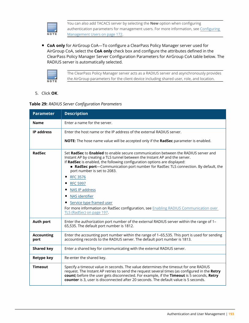
Authentication and User Management | 193
You can also add TACACS server by selecting the New option when configuringauthentication parameters for management users. For more information, see ConfiguringManagement Users on page 172.
n CoA only for AirGroup CoA—To configure a ClearPass Policy Manager server used forAirGroup CoA, select the CoA only check box and configure the attributes defined in theClearPass Policy Manager Server Configuration Parameters for AirGroup CoA table below. TheRADIUS server is automatically selected.
The ClearPass Policy Manager server acts as a RADIUS server and asynchronously providesthe AirGroup parameters for the client device including shared user, role, and location.
5. Click OK.
Parameter Description
Name Enter a name for the server.
IP address Enter the host name or the IP address of the external RADIUS server.
NOTE: The hose name value will be accepted only if the RadSec parameter is enabled.
RadSec Set RadSec to Enabled to enable secure communication between the RADIUS server andInstant AP by creating a TLS tunnel between the Instant AP and the server.If RadSec is enabled, the following configuration options are displayed:
n RadSec port—Communication port number for RadSec TLS connection. By default, theport number is set to 2083.
n RFC 3576n RFC 5997n NAS IP addressn NAS identifiern Service type framed userFor more information on RadSec configuration, see Enabling RADIUS Communication overTLS (RadSec) on page 197.
Auth port Enter the authorization port number of the external RADIUS server within the range of 1–65,535. The default port number is 1812.
Accountingport
Enter the accounting port number within the range of 1–65,535. This port is used for sendingaccounting records to the RADIUS server. The default port number is 1813.
Shared key Enter a shared key for communicating with the external RADIUS server.
Retype key Re-enter the shared key.
Timeout Specify a timeout value in seconds. The value determines the timeout for one RADIUSrequest. The Instant AP retries to send the request several times (as configured in the Retrycount) before the user gets disconnected. For example, if the Timeout is 5 seconds, Retrycounter is 3, user is disconnected after 20 seconds. The default value is 5 seconds.
Table 29: RADIUS Server Configuration Parameters
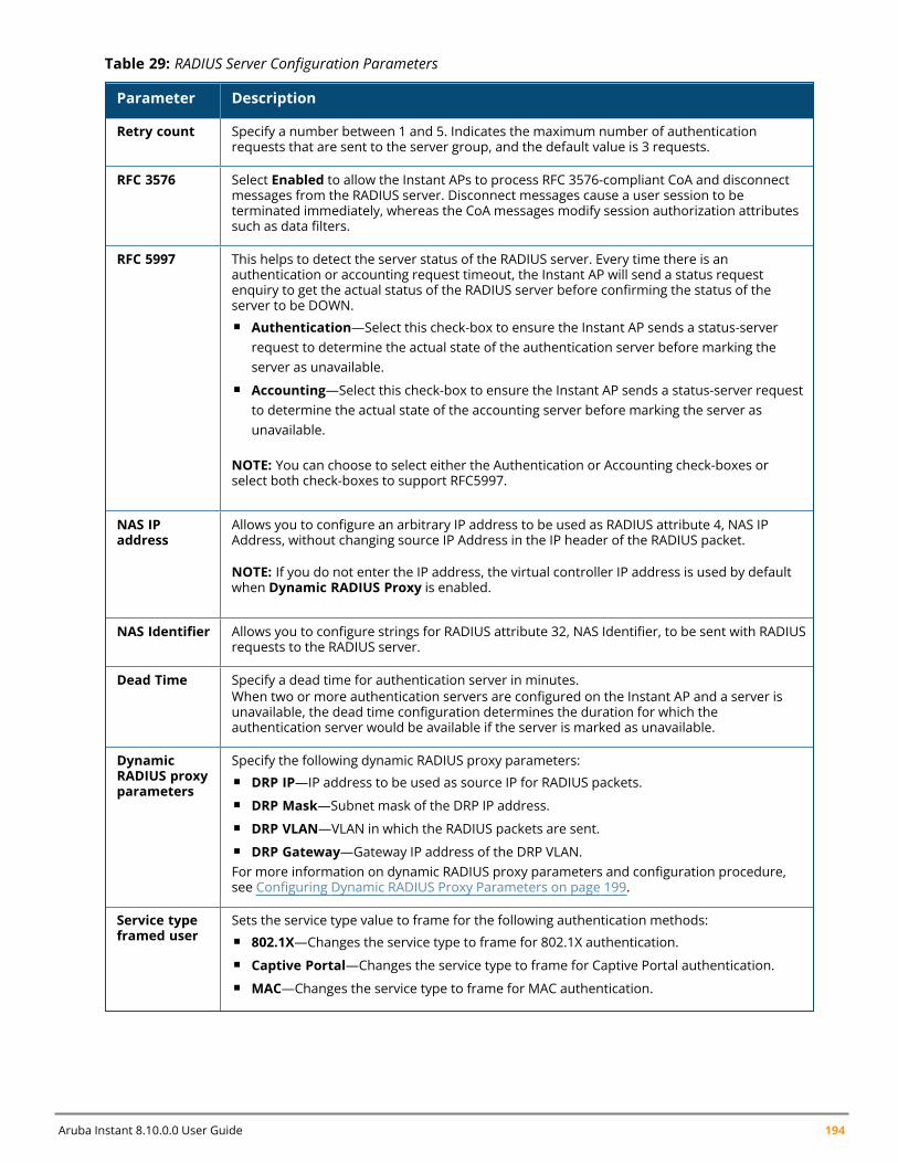
Aruba Instant 8.10.0.0 User Guide 194
Parameter Description
Retry count Specify a number between 1 and 5. Indicates the maximum number of authenticationrequests that are sent to the server group, and the default value is 3 requests.
RFC 3576 Select Enabled to allow the Instant APs to process RFC 3576-compliant CoA and disconnectmessages from the RADIUS server. Disconnect messages cause a user session to beterminated immediately, whereas the CoA messages modify session authorization attributessuch as data filters.
RFC 5997 This helps to detect the server status of the RADIUS server. Every time there is anauthentication or accounting request timeout, the Instant AP will send a status requestenquiry to get the actual status of the RADIUS server before confirming the status of theserver to be DOWN.n Authentication—Select this check-box to ensure the Instant AP sends a status-server
request to determine the actual state of the authentication server before marking theserver as unavailable.
n Accounting—Select this check-box to ensure the Instant AP sends a status-server requestto determine the actual state of the accounting server before marking the server asunavailable.
NOTE: You can choose to select either the Authentication or Accounting check-boxes orselect both check-boxes to support RFC5997.
NAS IPaddress
Allows you to configure an arbitrary IP address to be used as RADIUS attribute 4, NAS IPAddress, without changing source IP Address in the IP header of the RADIUS packet.
NOTE: If you do not enter the IP address, the virtual controller IP address is used by defaultwhen Dynamic RADIUS Proxy is enabled.
NAS Identifier Allows you to configure strings for RADIUS attribute 32, NAS Identifier, to be sent with RADIUSrequests to the RADIUS server.
Dead Time Specify a dead time for authentication server in minutes.When two or more authentication servers are configured on the Instant AP and a server isunavailable, the dead time configuration determines the duration for which theauthentication server would be available if the server is marked as unavailable.
DynamicRADIUS proxyparameters
Specify the following dynamic RADIUS proxy parameters:n DRP IP—IP address to be used as source IP for RADIUS packets.n DRP Mask—Subnet mask of the DRP IP address.n DRP VLAN—VLAN in which the RADIUS packets are sent.n DRP Gateway—Gateway IP address of the DRP VLAN.For more information on dynamic RADIUS proxy parameters and configuration procedure,see Configuring Dynamic RADIUS Proxy Parameters on page 199.
Service typeframed user
Sets the service type value to frame for the following authentication methods:n 802.1X—Changes the service type to frame for 802.1X authentication.n Captive Portal—Changes the service type to frame for Captive Portal authentication.n MAC—Changes the service type to frame for MAC authentication.
Table 29: RADIUS Server Configuration Parameters
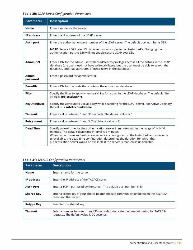
Authentication and User Management | 195
Parameter Description
Name Enter a name for the server.
IP address Enter the IP address of the LDAP server.
Auth port Enter the authorization port number of the LDAP server. The default port number is 389.
NOTE: Secure LDAP over SSL is currently not supported on Instant APs. Changing theauthentication port to 636 will not enable secure LDAP over SSL.
Admin-DN Enter a DN for the admin user with read/search privileges across all the entries in the LDAPdatabase (the user need not have write privileges, but the user must be able to search thedatabase, and read attributes of other users in the database).
Adminpassword
Enter a password for administrator.
Base-DN Enter a DN for the node that contains the entire user database.
Filter Specify the filter to apply when searching for a user in the LDAP database. The default filterstring is (objectclass=*).
Key Attribute Specify the attribute to use as a key while searching for the LDAP server. For Active Directory,the value is sAMAccountName
Timeout Enter a value between 1 and 30 seconds. The default value is 5.
Retry count Enter a value between 1 and 5. The default value is 3.
Dead Time Specify a dead time for the authentication server in minutes within the range of 1–1440minutes. The default dead time interval is 5 minutes.When two or more authentication servers are configured on the Instant AP and a server isunavailable, the dead time configuration determines the duration for which theauthentication server would be available if the server is marked as unavailable.
Table 30: LDAP Server Configuration Parameters
Parameter Description
Name Enter a name for the server.
IP address Enter the IP address of the TACACS server.
Auth Port Enter a TCPIP port used by the server. The default port number is 49.
Shared Key Enter a secret key of your choice to authenticate communication between the TACACS+client and the server.
Retype Key Re-enter the shared key.
Timeout Enter a number between 1 and 30 seconds to indicate the timeout period for TACACS+requests. The default value is 20 seconds.
Table 31: TACACS Configuration Parameters
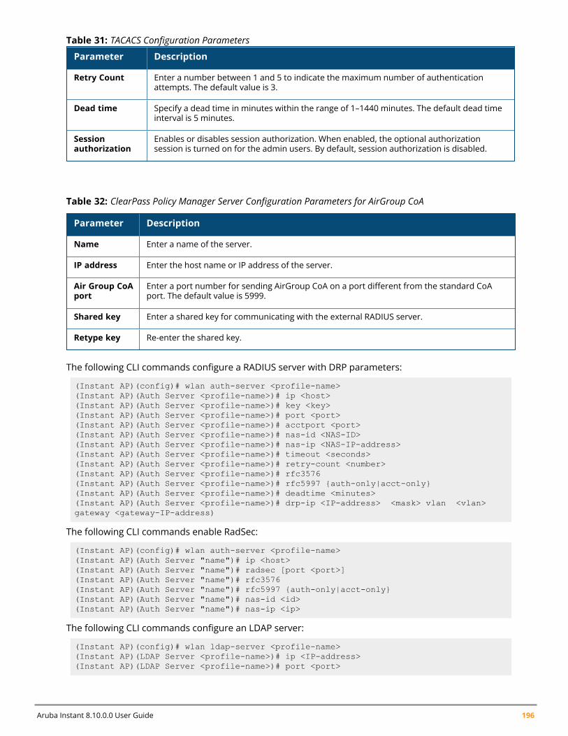
Aruba Instant 8.10.0.0 User Guide 196
Parameter Description
Retry Count Enter a number between 1 and 5 to indicate the maximum number of authenticationattempts. The default value is 3.
Dead time Specify a dead time in minutes within the range of 1–1440 minutes. The default dead timeinterval is 5 minutes.
Sessionauthorization
Enables or disables session authorization. When enabled, the optional authorizationsession is turned on for the admin users. By default, session authorization is disabled.
Table 31: TACACS Configuration Parameters
Parameter Description
Name Enter a name of the server.
IP address Enter the host name or IP address of the server.
Air Group CoAport
Enter a port number for sending AirGroup CoA on a port different from the standard CoAport. The default value is 5999.
Shared key Enter a shared key for communicating with the external RADIUS server.
Retype key Re-enter the shared key.
Table 32: ClearPass Policy Manager Server Configuration Parameters for AirGroup CoA
The following CLI commands configure a RADIUS server with DRP parameters:
(Instant AP)(config)# wlan auth-server <profile-name>(Instant AP)(Auth Server <profile-name>)# ip <host>(Instant AP)(Auth Server <profile-name>)# key <key>(Instant AP)(Auth Server <profile-name>)# port <port>(Instant AP)(Auth Server <profile-name>)# acctport <port>(Instant AP)(Auth Server <profile-name>)# nas-id <NAS-ID>(Instant AP)(Auth Server <profile-name>)# nas-ip <NAS-IP-address>(Instant AP)(Auth Server <profile-name>)# timeout <seconds>(Instant AP)(Auth Server <profile-name>)# retry-count <number>(Instant AP)(Auth Server <profile-name>)# rfc3576(Instant AP)(Auth Server <profile-name>)# rfc5997 {auth-only|acct-only}(Instant AP)(Auth Server <profile-name>)# deadtime <minutes>(Instant AP)(Auth Server <profile-name>)# drp-ip <IP-address> <mask> vlan <vlan>gateway <gateway-IP-address)
The following CLI commands enable RadSec:
(Instant AP)(config)# wlan auth-server <profile-name>(Instant AP)(Auth Server "name")# ip <host>(Instant AP)(Auth Server "name")# radsec [port <port>](Instant AP)(Auth Server "name")# rfc3576(Instant AP)(Auth Server "name")# rfc5997 {auth-only|acct-only}(Instant AP)(Auth Server "name")# nas-id <id>(Instant AP)(Auth Server "name")# nas-ip <ip>
The following CLI commands configure an LDAP server:
(Instant AP)(config)# wlan ldap-server <profile-name>(Instant AP)(LDAP Server <profile-name>)# ip <IP-address>(Instant AP)(LDAP Server <profile-name>)# port <port>
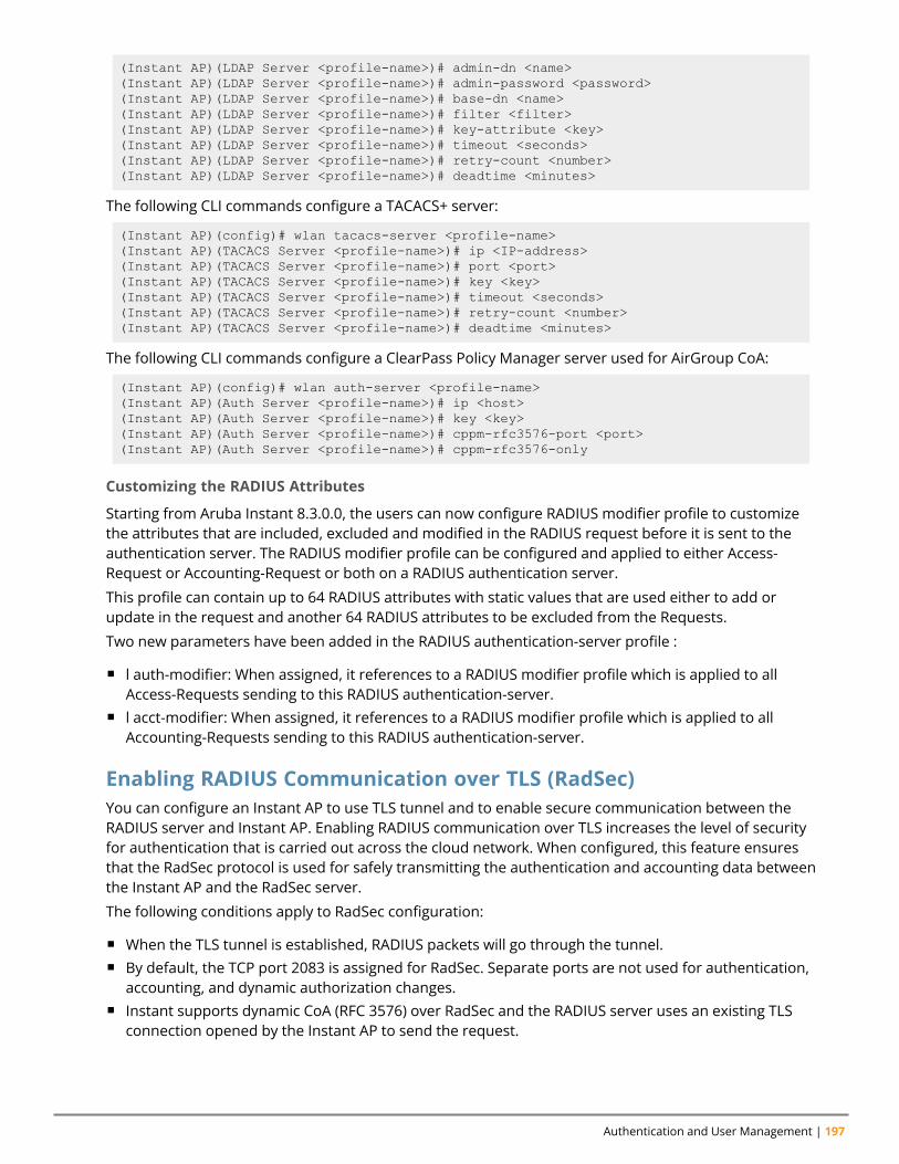
Authentication and User Management | 197
(Instant AP)(LDAP Server <profile-name>)# admin-dn <name>(Instant AP)(LDAP Server <profile-name>)# admin-password <password>(Instant AP)(LDAP Server <profile-name>)# base-dn <name>(Instant AP)(LDAP Server <profile-name>)# filter <filter>(Instant AP)(LDAP Server <profile-name>)# key-attribute <key>(Instant AP)(LDAP Server <profile-name>)# timeout <seconds>(Instant AP)(LDAP Server <profile-name>)# retry-count <number>(Instant AP)(LDAP Server <profile-name>)# deadtime <minutes>
The following CLI commands configure a TACACS+ server:
(Instant AP)(config)# wlan tacacs-server <profile-name>(Instant AP)(TACACS Server <profile-name>)# ip <IP-address>(Instant AP)(TACACS Server <profile-name>)# port <port>(Instant AP)(TACACS Server <profile-name>)# key <key>(Instant AP)(TACACS Server <profile-name>)# timeout <seconds>(Instant AP)(TACACS Server <profile-name>)# retry-count <number>(Instant AP)(TACACS Server <profile-name>)# deadtime <minutes>
The following CLI commands configure a ClearPass Policy Manager server used for AirGroup CoA:
(Instant AP)(config)# wlan auth-server <profile-name>(Instant AP)(Auth Server <profile-name>)# ip <host>(Instant AP)(Auth Server <profile-name>)# key <key>(Instant AP)(Auth Server <profile-name>)# cppm-rfc3576-port <port>(Instant AP)(Auth Server <profile-name>)# cppm-rfc3576-only
Customizing the RADIUS Attributes
Starting from Aruba Instant 8.3.0.0, the users can now configure RADIUS modifier profile to customizethe attributes that are included, excluded and modified in the RADIUS request before it is sent to theauthentication server. The RADIUS modifier profile can be configured and applied to either Access-Request or Accounting-Request or both on a RADIUS authentication server.
This profile can contain up to 64 RADIUS attributes with static values that are used either to add orupdate in the request and another 64 RADIUS attributes to be excluded from the Requests.
Two new parameters have been added in the RADIUS authentication-server profile :
n l auth-modifier: When assigned, it references to a RADIUS modifier profile which is applied to allAccess-Requests sending to this RADIUS authentication-server.
n l acct-modifier: When assigned, it references to a RADIUS modifier profile which is applied to allAccounting-Requests sending to this RADIUS authentication-server.
Enabling RADIUS Communication over TLS (RadSec)You can configure an Instant AP to use TLS tunnel and to enable secure communication between theRADIUS server and Instant AP. Enabling RADIUS communication over TLS increases the level of securityfor authentication that is carried out across the cloud network. When configured, this feature ensuresthat the RadSec protocol is used for safely transmitting the authentication and accounting data betweenthe Instant AP and the RadSec server.
The following conditions apply to RadSec configuration:
n When the TLS tunnel is established, RADIUS packets will go through the tunnel.n By default, the TCP port 2083 is assigned for RadSec. Separate ports are not used for authentication,
accounting, and dynamic authorization changes.n Instant supports dynamic CoA (RFC 3576) over RadSec and the RADIUS server uses an existing TLS
connection opened by the Instant AP to send the request.
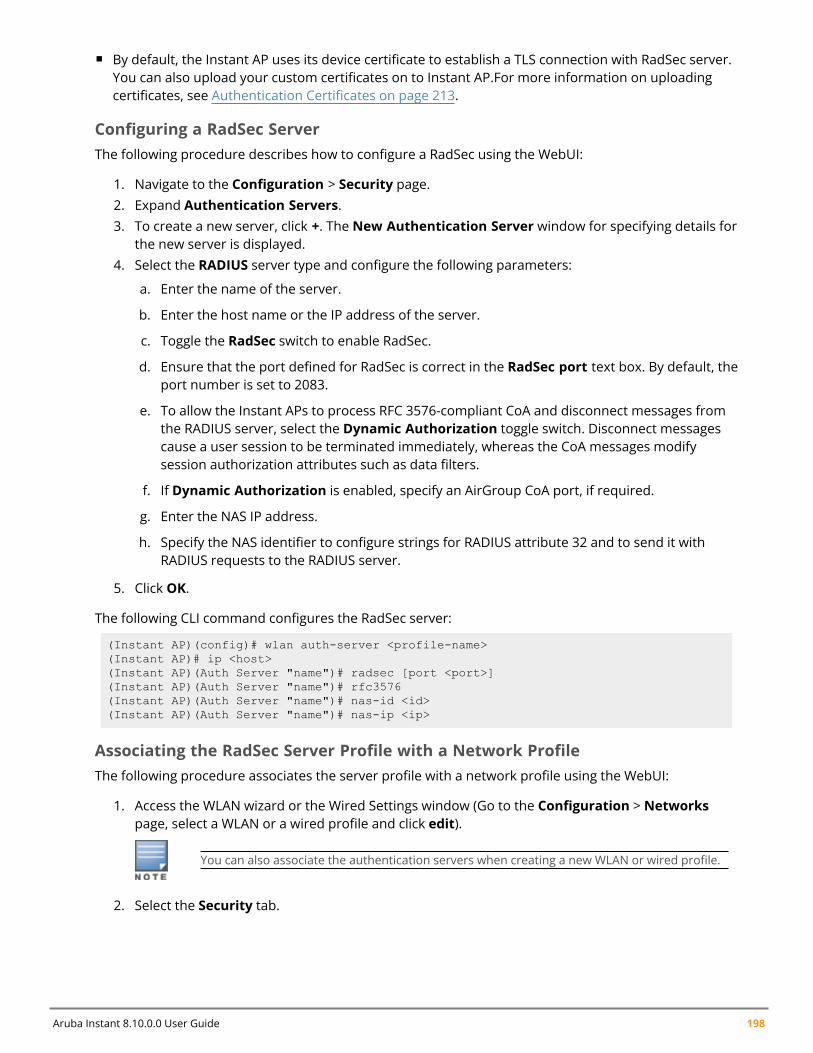
Aruba Instant 8.10.0.0 User Guide 198
n By default, the Instant AP uses its device certificate to establish a TLS connection with RadSec server.You can also upload your custom certificates on to Instant AP.For more information on uploadingcertificates, see Authentication Certificates on page 213.
Configuring a RadSec ServerThe following procedure describes how to configure a RadSec using the WebUI:
1. Navigate to the Configuration > Security page.2. Expand Authentication Servers.3. To create a new server, click +. The New Authentication Server window for specifying details for
the new server is displayed.4. Select the RADIUS server type and configure the following parameters:
a. Enter the name of the server.
b. Enter the host name or the IP address of the server.
c. Toggle the RadSec switch to enable RadSec.
d. Ensure that the port defined for RadSec is correct in the RadSec port text box. By default, theport number is set to 2083.
e. To allow the Instant APs to process RFC 3576-compliant CoA and disconnect messages fromthe RADIUS server, select the Dynamic Authorization toggle switch. Disconnect messagescause a user session to be terminated immediately, whereas the CoA messages modifysession authorization attributes such as data filters.
f. If Dynamic Authorization is enabled, specify an AirGroup CoA port, if required.
g. Enter the NAS IP address.
h. Specify the NAS identifier to configure strings for RADIUS attribute 32 and to send it withRADIUS requests to the RADIUS server.
5. Click OK.
The following CLI command configures the RadSec server:
(Instant AP)(config)# wlan auth-server <profile-name>(Instant AP)# ip <host>(Instant AP)(Auth Server "name")# radsec [port <port>](Instant AP)(Auth Server "name")# rfc3576(Instant AP)(Auth Server "name")# nas-id <id>(Instant AP)(Auth Server "name")# nas-ip <ip>
Associating the RadSec Server Profile with a Network ProfileThe following procedure associates the server profile with a network profile using the WebUI:
1. Access the WLAN wizard or the Wired Settings window (Go to the Configuration > Networkspage, select a WLAN or a wired profile and click edit).
You can also associate the authentication servers when creating a new WLAN or wired profile.
2. Select the Security tab.
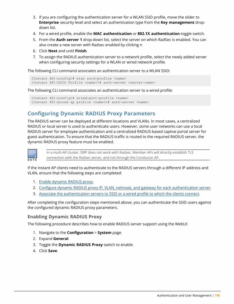
Authentication and User Management | 199
3. If you are configuring the authentication server for a WLAN SSID profile, move the slider toEnterprise security level and select an authentication type from the Key management drop-down list.
4. For a wired profile, enable theMAC authentication or 802.1X authentication toggle switch.5. From the Auth server 1 drop-down list, select the server on which RadSec is enabled. You can
also create a new server with Radsec enabled by clicking +.6. Click Next and until Finish.7. To assign the RADIUS authentication server to a network profile, select the newly added server
when configuring security settings for a WLAN or wired network profile.
The following CLI command associates an authentication server to a WLAN SSID:
(Instant AP)(config)# wlan ssid-profile <name>(Instant AP)(SSID Profile <name>)# auth-server <server-name>
The following CLI command associates an authentication server to a wired profile:
(Instant AP)(config)# wired-port-profile <name>(Instant AP)(wired ap profile <name>)# auth-server <name>
Configuring Dynamic RADIUS Proxy ParametersThe RADIUS server can be deployed at different locations and VLANs. In most cases, a centralizedRADIUS or local server is used to authenticate users. However, some user networks can use a localRADIUS server for employee authentication and a centralized RADIUS-based captive portal server forguest authentication. To ensure that the RADIUS traffic is routed to the required RADIUS server, thedynamic RADIUS proxy feature must be enabled.
In a multi-AP cluster, DRP does not work with Radsec. Member APs will directly establish TLSconnection with the Radsec server, and not through the Conductor AP.
If the Instant AP clients need to authenticate to the RADIUS servers through a different IP address andVLAN, ensure that the following steps are completed:
1. Enable dynamic RADIUS proxy.2. Configure dynamic RADIUS proxy IP, VLAN, netmask, and gateway for each authentication server.3. Associate the authentication servers to SSID or a wired profile to which the clients connect.
After completing the configuration steps mentioned above, you can authenticate the SSID users againstthe configured dynamic RADIUS proxy parameters.
Enabling Dynamic RADIUS ProxyThe following procedure describes how to enable RADIUS server support using the WebUI:
1. Navigate to the Configuration > System page.2. Expand General.3. Toggle the Dynamic RADIUS Proxy switch to enable.4. Click Save.
Aruba Instant 8.10.0.0 User Guide 200
When dynamic RADIUS proxy is enabled, the virtual controller network uses the IP Address of thevirtual controller for communication with external RADIUS servers. Ensure that the virtual controller IPAddress is set as a NAS IP when configuring RADIUS server attributes with dynamic RADIUS proxyenabled. For more information on configuring RADIUS server attributes, see External RADIUS Serveron page 192.
In case of VPN deployments, the tunnel IP received when establishing a VPN connection is used as theNAS IP. In such cases, the virtual controller IP need not be configured for the external RADIUS servers.
The following CLI command enables the dynamic RADIUS proxy feature:
(Instant AP)(config)# dynamic-radius-proxy
Configuring Dynamic RADIUS Proxy Parameters
The following procedure describes how to configure DRP parameters for the authentication server byusing the WebUI:
1. Navigate to the Configuration > Security page.2. Expand Authentication Servers.3. To create a new server, click + and configure the required RADIUS server parameters as described
in Table 29.4. Ensure that the following dynamic RADIUS proxy parameters are configured:
a. DRP IP—IP address to be used as source IP for RADIUS packets.
b. DRP Mask—Subnet mask of the DRP IP address.
c. DRP Vlan—VLAN in which the RADIUS packets are sent.
d. DRP Gateway—Gateway IP address of the DRP VLAN.
5. Click OK.
The following CLI commands configures a dynamic RADIUS proxy parameters:
(Instant AP)(config)# wlan auth-server <profile-name>(Instant AP)(Auth Server <profile-name>)# ip <IP-address>(Instant AP)(Auth Server <profile-name>)# key <key>(Instant AP)(Auth Server <profile-name>)# port <port>(Instant AP)(Auth Server <profile-name>)# acctport <port>(Instant AP)(Auth Server <profile-name>)# nas-id <NAS-ID>(Instant AP)(Auth Server <profile-name>)# nas-ip <NAS-IP-address>(Instant AP)(Auth Server <profile-name>)# timeout <seconds>(Instant AP)(Auth Server <profile-name>)# retry-count <number>(Instant AP)(Auth Server <profile-name>)# deadtime <minutes>(Instant AP)(Auth Server <profile-name>)# drp-ip <IP-address> <mask> vlan <vlan>gateway <gateway-IP-address>
Associate DRP Server Profile to a Network ProfileThe following procedure describes how to associate the DRP server profiles with a network profile byusing the WebUI:
1. Access the WLAN wizard or the Wired Settings window (Go to the Configuration > Networks,select a WLAN or a wired profile and click Edit).
NOTE: You can also associate the authentication servers when creating a new WLAN or wired profile.
Authentication and User Management | 201
2. Select the Security tab.3. If you are configuring the authentication server for a WLAN SSID profile, move the slider to
Enterprise security level and select an authentication type from the Key management drop-down list.
4. For a wired profile, enable theMAC authentication or 802.1X authentication toggle switch.5. From the Auth server 1 drop-down list, select the server name on which dynamic RADIUS proxy
parameters are enabled. You can also create a new server with dynamic RADIUS proxyparameters enabled by selecting +.
6. Click Next and until Finish.7. To assign the RADIUS authentication server to a network profile, select the newly added server
when configuring security settings for a WLAN or wired network profile.
You can also add an external RADIUS server by selecting New for Authentication Server whenconfiguring a WLAN or wired profile. For more information, see Points to Remember on page 113 andConfiguring Security Settings for a Wired Profile on page 133.
The following CLI commands associates an authentication server to a WLAN SSID:
(Instant AP)(config)# wlan ssid-profile <name>(Instant AP)(SSID Profile <name>)# auth-server <server-name>
The following CLI commands associates an authentication server to a wired profile:
(Instant AP)(config)# wired-port-profile <name>(Instant AP)(wired ap profile <name>)# auth-server <name>
Supported Encryption TypesEncryption is the process of converting data into a cryptic format or code when it is transmitted on anetwork. Encryption prevents unauthorized use of the data.
Instant supports the following types of encryption:
n WEP—WEP is an authentication method where all users share the same key. WEP is not as secure asother encryption types such as TKIP.
n TKIP—TKIP uses the same encryption algorithm as WEP. However, TKIP is more secure and has anadditional message integrity check.
n AES—The AES encryption algorithm is a widely supported encryption type for all wireless networksthat contain any confidential data. AES in Wi-Fi leverages 802.1X or PSKs to generate per-station keysfor all devices. AES provides a high level of security like IPsec clients.
WEP and TKIP are limited to WLAN connection speed of 54 Mbps. The 802.11n connection supportsonly AES encryption. Aruba recommends AES encryption. Ensure that all devices that do not supportAES are upgraded or replaced with the devices that support AES encryption.
WPA and WPA2WPA is created based on the draft of 802.11i, which allowed users to create more secure WLANs. WPA2encompasses the full implementation of the 802.11i standard. WPA2 is a superset that encompassesthe full WPA feature set.
The following table summarizes the differences between the two certifications:
Aruba Instant 8.10.0.0 User Guide 202
Certification Authentication Encryption
WPA n PSKn IEEE 802.1X withEAP
TKIP with message integrity check
WPA2 n PSKn IEEE 802.1X withEAP
AES—Counter Mode with Cipher Block ChainingMessage Authentication Code
Table 33: WPA and WPA2 Features
WPA and WPA2 can be further classified as follows:
n Personal—Personal is also called PSK. In this type, a unique key is shared with each client in thenetwork. Users have to use this key to securely log in to the network. The key remains the same untilit is changed by authorized personnel. You can also configure key change intervals .
n Enterprise—Enterprise is more secure than WPA Personal. In this type, every client automaticallyreceives a unique encryption key after securely logging in to the network. This key is automaticallyupdated at regular intervals. WPA uses TKIP and WPA2 uses the AES algorithm.
Recommended Authentication and Encryption CombinationsThe following table summarizes the recommendations for authentication and encryption combinationsfor the Wi-Fi networks.
Network Type Authentication Encryption
Employee 802.1X AES
Guest Network Captive portal None
Voice Network orHandheld devices
802.1X or PSK as supportedby the device
AES if possible, TKIP or WEP ifnecessary (combine with securitysettings assigned for a user role).
Table 34: Recommended Authentication and Encryption Combinations
Supported Encryption types for Instant AP AuthenticationInstant supports the following encryption types to authenticate wired Instant APs for 802.1X supplicants,Mesh and Wi-Fi uplink stations.
n TLS_DHE_RSA_WITH_AES_256_CBC_SHA256n TLS_DHE_RSA_WITH_AES_256_CBC_SHAn TLS_DHE_RSA_WITH_AES_128_CBC_SHA256n TLS_DHE_RSA_WITH_AES_128_CBC_SHAn TLS_DHE_RSA_WITH_3DES_EDE_CBC_SHA
Authentication SurvivabilityThe authentication survivability feature supports a survivable authentication framework against anyremote link failures when working with external authentication servers. When enabled, this featureallows the Instant APs to authenticate the previously connected clients against the cached credentials if
Authentication and User Management | 203
the connection to the authentication server is temporarily lost. This feature is now available forWLAN SSIDs with open, personal (MPSK-AES) and enterprise security levels.
Instant supports the following authentication standards for authentication survivability:
n EAP-MSCHAPv2: The PEAP, also known as Protected EAP, is a protocol that encapsulates EAP withina potentially encrypted and authenticated TLS tunnel.
n EAP-TLS: EAP-TLS is an IETF open standard that uses the TLS protocol.n MAC Authentication: MAC-based authentication is a standard that authenticates devices based on
their physical media access control (MAC) address.
When the authentication survivability feature is enabled, the following authentication process is used:
1. Upon successful authentication, the associated Instant AP caches the authentication credentialsof the connected clients for the configured duration. The cache expiry duration for authenticationsurvivability can be set within the range of 1–99 hours, with 24 hours being the default cachetimeout duration.
2. If the client roams or tries to reconnect to the Instant AP and the remote link fails due to theunavailability of the authentication server, the Instant AP uses the cached credentials in theinternal authentication server to authenticate the user. However, if the client tries to reconnectafter the cache expiry, the authentication fails.
3. When the authentication server is available and if the client tries to reconnect, the Instant APdetects the availability of server and allows the client to authenticate to the server. Uponsuccessful authentication, the Instant AP cache details are refreshed.
Starting from Aruba Instant 8.4.0.0, access credentials, user roles, and other key attributes are cachedwhen clients are authenticated by an external authentication server.
Below are the cached RADIUS attributes:
n ARUBA_NAMED_VLANn ARUBA_NO_DHCP_FINGERPRINTn ARUBA_ROLEn ARUBA_VLANn MS_TUNNEL_MEDIUM_TYPEn MS_TUNNEL_PRIVATE_GROUP_IDn MS_TUNNEL_TYPEn PW_SESSION_TIMEOUTn PW_USER_NAME
Important Points to Remembern Any client connected through ClearPass Policy Manager and authenticated through Instant AP
remains authenticated with the Instant AP even if the client is removed from the ClearPass PolicyManager server during the ClearPass Policy Manager downtime.
n Do not make any changes to the authentication survivability cache timeout duration when theauthentication server is down.
n For EAP-PEAP authentication, ensure that the ClearPass Policy Manager 6.0.2 or later version is usedfor authentication. For EAP-TLS authentication, any external or third-party server can be used.
Aruba Instant 8.10.0.0 User Guide 204
n For EAP-TLS authentication, ensure that the server and CA certificates from the authenticationservers are uploaded on the Instant AP. For more information, see Authentication Certificates onpage 213.
n Authentication cache will be lost if the Instant AP on which the user credentials are cached, isrebooted.
n EAP-PEAP authentication survivability is supported on Aruba CPPM Server version 6.0.2 or laterversions.
LimitationsAuthentication survivability is not supported under the following conditions:
1. When EAP Termination is enabled.2. When the RadSec server is used as an authentication server.3. When the internal server is used as a secondary authentication server.
Enabling Authentication SurvivabilityThe following procedure describes how to enable authentication survivability for a wireless networkprofile through the WebUI:
1. In the Configuration > Networks page,
a. Click + to create a new WLAN SSID profile, or
b. Select an existing profile for which you want to enable authentication survivability and clickedit.
2. Ensure that the required WLAN and VLAN attributes are defined under Basic and VLAN tabs.3. Under Security tab, select Open, Personal (MPSK-AES) or Enterprise in Security Level list box.4. Select an existing authentication server or create a new server by clicking +.5. To enable authentication survivability, toggle the Authentication survivability switch. On
enabling this, the Instant AP authenticates the previously connected clients using EAP-PEAP, EAP-TLS, and MAC authentication when connection to the external authentication server istemporarily lost.
6. In the Cache timeout (global) text box, specify the cache timeout duration, after which thecached details of the previously authenticated clients expire. You can specify a value within therange of 1–99 hours and the default cache timeout duration is 24 hours.
7. Click Next and until Finish to apply the changes.
The following CLI commands configures authentication survivability for a wireless network:
(Instant AP)(config)# wlan ssid-profile <name>(Instant AP)(SSID Profile <name>)# type {<Employee>|<Voice>|<Guest>}(Instant AP)(SSID Profile <name>)# auth-server <server-name1>(Instant AP)(SSID Profile <name>)# auth-survivability(Instant AP)(SSID Profile <name>)# exit(Instant AP)(config)# auth-survivability cache-time-out <hours>
The following CLI command shows the cache expiry duration:
(Instant AP)# show auth-survivability time-out
The following CLI command shows information on auth-survivability cached by the Instant AP:
(Instant AP)# show auth-survivability cached-info
Authentication and User Management | 205
The following CLI command shows logs for debugging:
(Instant AP)# show auth-survivability debug-log
Priority for Local Cache AuthenticationPriority for Local Cache Authentication for wireless networks is based on the Authentication Survivabilityframework of Aruba Instant. When Priority for Local Cache Authentication is enabled, the Instant AP firstattempts to authenticate clients with the local cache data maintained for authentication survivabilityand uses the RADIUS server to authenticate only those clients whose data is not available in the localcache. This feature can be used only if Authentication Survivability is enabled.
Configuring Priority for Local Cache AuthenticationPriority for Local Cache Authentication is only available for clients authenticated through MAC and802.1x authentication.
The following procedure describes how to prioritize local cache for authentication using the NewWebUI:
1. Select the network for which you want to enable local authentication in the Configuration>Networks page and click edit.
2. Navigate to the Security Tab.3. Enable Authentication Survivability.4. Toggle the Priority for Local Cache Authentication button to enable or disable the feature.5. Click Next to configure Access settings for the WLAN network and click Finish.
The following CLI commands enables Priority for Local Cache Authentication for an WLAN SSID profileusing the CLI:
(Instant AP)(config)# wlan ssid-profile <profile name>(Instant AP)(SSID Profile "<profile name>")# auth-survivability(Instant AP)(SSID Profile "<profile name>")# priority-use-local-cache-auth
The following CLI commands disables Priority for Local Cache Authentication for an WLAN SSID profile:
(Instant AP)(config)# wlan ssid-profile <profile name>(Instant AP)(SSID Profile "<profile name>")# no priority-use-local-cache-auth
WPA3 SecurityAruba Instant supports WPA3 security improvements that include:
n Simultaneous Authentication of Equals (SAE)—Replaces WPA2-PSK with password-basedauthentication that is resistant to dictionary attacks.
n WPA3-Enterprise— Aruba Instant supports WPA3-Enterprise authentication modes which includesSuite-B 192-bit security suite that is aligned with Commercial National Security Algorithm (CNSA) forenterprise network. SAE-based keys are not based on PSK and are therefore pairwise and uniquebetween clients and the AP. Suite B restricts the deployment to one of two options:l 128-bit securityl 192-bit security without the ability to mix-and-match ciphers, Diffie-Hellman groups, hashfunctions, and signature modes
SAE
Aruba Instant 8.10.0.0 User Guide 206
SAE replaces the less-secure WPA2-PSK authentication. Instead of using the PSK as the PMK, SAE arrivesat a PMK, by mapping the PSK to an element of a finite cyclic group, PassWord Element (PWE), doing FCGoperations on it, and exchanging it with the peer.
Aruba Instant supports:
n SAE without PMK cachingn SAE with PMK cachingn SAE or WPA2-PSK mixed mode
SAE Without PMK CachingInstant advertises support for SAE by using an AKM suite selector for SAE in all beacons and proberesponse frames. Besides, PMF is set to required (MFPR=1).
A client that wishes to perform SAE sends an 802.11 authentication request with authenticationalgorithm set to value 3 (SAE). This frame contains a well-formed commit message, that is,authentication transaction sequence set to 1, an FCG, commit-scalar, and commit-element.
Instant supports group 19, a 256-bit Elliptic Curve group. Instant responds with an 802.11 authenticationcontaining its own commit message.
Instant and the client compute the PMK and send the confirm message to each other using anauthentication frame with authentication transaction sequence set to 2.
The client sends an association request with the AKM suite set to SAE and Instant sends an associationresponse.
Instant initiates a 4-way key handshake with the client to derive the PTK.
SAE With PMK CachingIf SAE has been established earlier, a client that wishes to perform SAE with PMK caching sends anauthentication frame with authentication algorithm set to open. Instant sends an authenticationresponse and the client sends a reassociation request with AKM set to SAE and includes the previouslyderived PMKID.
Instant checks if the PMKID is valid and sends an association response with the status code success.
Instant initiates a 4-way key handshake with the client to derive the PTK.
SAE or WPA2-PSK Mixed ModeSAE or WPA2-PSK mixed mode allows both SAE clients and clients that can only perform WPA2-PSK toconnect to the same BSSID. In this mode, the beacon or probe responses contain a AKM list whichcontains both PSK (00-0F-AC:2) and SAE (00-0F-AC:8). Clients that support SAE send an authenticationframe with SAE payload and connect to the BSSID.
Clients that support only WPA2-PSK send an authentication frame with authentication algorithm set toopen.
Instant initiates a 4-way key handshake similar to WPA2.
WPA3-EnterpriseWPA3-Enterprise enforces top secret security standards for an enterprise Wi-Fi in comparison to secretsecurity standards. Top secret security standards includes:
n Deriving at least 384-bit PMK/MSK using Suite B compatible EAP-TLS.n Securing pairwise data between STA and authenticator using AES-GCM-256.
Authentication and User Management | 207
n Securing group addressed data between STA and authenticator using AES-GCM-256.n Securing group addressed management frames using BIP-GMAC-256
WPA3-Enterprise compatible 802.1X authentication occurs between STA and the RADIUS server.
The WPA3-Enterprise CSNA (192-bit) mode requires a compatible EAP server (such as Aruba ClearPassPolicy Manager 6.8 or later versions) and requires EAP-TLS.
WPA3-Enterprise advertises or negotiates the following capabilities in beacons, probes response, or802.11 association:
n AKM Suite Selector as 00-0F-AC:12n Pairwise Cipher Suite Selector as 00-0F-AC:9n Group data cipher suite selector as 00-0F-AC:9n Group management cipher suite (MFP) selector as 00-0F-AC:12
If WPA3-Enterprise is enabled, STA is successfully associated only if it uses one of the four suiteselectors for AKM selection, pairwise data protection, group data protection, and group managementprotection. If a STA mismatches any one of the four suite selectors, the STA association fails.
WPA3 OpmodesAruba Instant supports the WPA3-AES-CCM-128, WPA3-CNSA, WPA3-AES-CCM-256, and WPA3-SAE-AESopmodes.
WPA3 opmodes are not supported in 203H Series, 203R Series, and 207 Series access points.
Before using the WPA3-SAE-AES opmode, disable opmode-transition and configure a WPA hexkey orWPA passphrase as a pre-shared key. Use the WPA3 with SAE and PSK mode for SAE mixed modeoperation during transition. The opmode-transition is not applicable to WPA3-AES-CCM-128 and WPA3-CNSA opmodes.
WPA2-PSK-AES virtual APs will be not be automatically upgraded to WPA3-SAE-AES virtual APs. Hence,WPA2-PSK-AES virtual APs will not automatically work in mixed mode. Configure a WPA3-SAE-AES virtualAP with opmode-transition for the virtual AP to operate in mixed mode.
Configuring WPA3To support WPA3, configure the opmode and opmode-transition parameters under thewlan ssid-profile command.
The opmode-transition parameter is enabled by default and provides backward compatibility forauthentication and WPA3-SAE-AES opmode. Use the opmode-transition parameter as a fallback optionif a client faces connectivity issues on the enhanced open authentication or WPA3-SAE-AES transitionmode virtual APs.
The following CLI commands disable opmode transition:
(Instant AP)(config)# wlan ssid-profile <profile_name>(Instant AP)(SSID Profile "<profile_name>")# opmode-transition-disable
The following CLI commands enable opmode transition:
(Instant AP)(config)# wlan ssid-profile <profile_name>(Instant AP)(SSID Profile "<profile_name>")# opmode-transition
Aruba Instant 8.10.0.0 User Guide 208
The following procedure describes how to configure WPA3 for Enterprise using the WebUI:
1. Navigate to the WLAN wizard (To add a new profile, go to Configuration > Networks and click +.To modify an existing profile, go to Configuration > Networks , select a WLAN SSID from the listof networks to edit.
2. Click the Security tab.3. Select Enterprise from the Security Level drop-down list. The authentication options applicable
to the Enterprise network are displayed.4. Select one of the following from the Key Management drop-down list:
a. WPA3-Enterprise (CNSA)—WPA3 with AES GCM-256 encryption using CNSA (192-bit). TheWPA3-Enterprise (CSNA) mode requires a compatible EAP server (such as Aruba ClearPassPolicy Manager 6.8 or later versions) and requires EAP-TLS.
b. WPA3-Enterprise (CCM 128)—WPA3 with AES CCM encryption and dynamic keys using802.1X.
c. WPA3-Enterprise (GCM 256)—WPA3 with AES GCM-256 encryption.
5. Click Next and the click Finish.
The following CLI commands configure WPA3 opmode for Enterprise security:
(Instant AP)(config)# wlan ssid-profile wpa3_mode(Instant AP)(SSID Profile "wpa3_mode")# opmode wpa3-aes-ccm-128(Instant AP)(SSID Profile "wpa3_mode")# opmode wpa3-cnsa
The following procedure describes how to configure WPA3 opmode for Personal security using theWebUI:
1. Navigate to the WLAN wizard (To add a new profile, go to Configuration > Networks and click +.To modify an existing profile, go to Configuration > Networks, select a WLAN SSID from the listof networks to edit.
2. Click the Security tab.3. Select Personal from the Security Level drop-down list. The authentication options applicable to
the Personal network are displayed.4. SelectWPA3 Personal from the Key Management drop-down list.5. Click Next and the click Finish.
The following CLI commands configure WPA3 opmode for Personal security:
(Instant AP)(config)# wlan ssid-profile wpa3_mode(Instant AP)(SSID Profile "wpa3_mode")# opmode wpa3-sae-aes
Using the WPA3-SAE-AES opmode requires a pre-shared key. Configure either a WPA hexkey or WPApassphrase as a pre-shared key.
The following CLI commands disable WPA3 opmode:
(Instant AP)(config)# wlan ssid-profile wpa3_mode(Instant AP)(SSID Profile "wpa3_mode")# no opmode
Fast BSS Transition Support for WPA3Aruba Instant supports Fast BSS Transition (802.1r) for the following WPA3 modes in both tunnel-forwarding and decrypt-tunnel modes for all APs which support WPA3:
Authentication and User Management | 209
n WPA3-Personal – SAEn WPA3-Personal – SAE/WPA2-PSK Mixed moden WPA3-Enterprise Basic optionn WPA3-Enterprise 192-bit Security optionn WPA3-Enterprise non-CNSA mode with GCMP-256 Cipher Suite
n WPA3-Enterprise CNSA (WPA3-AES-GCM-256)
802.1X Supplicant SupportThe 802.1X authentication protocol prevents unauthorized clients from gaining access to the networkthrough publicly accessible ports. If the ports to which the Instant APs are connected are configured touse the 802.1X authentication method, ensure that you configure the Instant APs to function as an802.1X client or supplicant. If the network requires all wired devices to authenticate using PEAP orTLS protocol, you need to configure the Instant AP uplink ports for 802.1X authentication, so that theswitch grants access to the Instant AP only after completing the authentication as a valid client.
To enable the 802.1X supplicant support on an Instant AP, ensure that the 802.1X authenticationparameters are configured on all Instant APs in the cluster and are stored securely in the Instant APflash.
The 802.1X supplicant support feature is not supported with mesh and Wi-Fi uplink deployments.
Configuring an Instant AP for 802.1X Authentication Using theWebUIComplete the below procedures to configure 802.1X supplicant support on an Instant AP :
1. Configure the 802.1X authentication mode.2. Configure the uplink port for 802.1X authentication.
Configuring the 802.1X authentication modeThere are two 802.1X authentication modes on an Instant AP. Choose either one of these methods for802.1X authentication based on the controller configuration:
n PEAP Authenticationn Certificate Authentication
PEAP Authentication
In PEAP based authentication, the Instant AP is validated by verifying its username and passwordagainst the uplink controller. The following procedure describes how to configure PEAP based 802.1Xauthentication using the WebUI:
1. In the Configuration > Access Points page, select the Instant AP for which you want to configure802.1X authentication, and click on Edit.
2. In the Edit Access Point <access point> page, expand the Uplink tab.3. Expand PEAP User.4. Enter the Username and Password for PEAP authentication. The Instant AP stores the username
and password in its flash and uses the credentials for 802.1X authentication. When the Instant APboots, the /tmp/ap1xuser and /tmp/ap1xpassword files are created based on these credentials.
Aruba Instant 8.10.0.0 User Guide 210
The default inner authentication protocol for PEAP is MS-CHAPV2.
5. To validate the authentication server, upload the CA certificate for AP1X on the Instant AP. Toupload CA certificate for AP1X, use the following procedure:
Aruba recommends that a CA certificate is uploaded to the Instant AP to verify the identity ofthe authentication server.
a. Expand Upload Certificates.
b. Enter the URL of the CA certificate in the URL field.
c. Set the Certificate type to CA.
d. Click on Upload Certificate.
6. Click Save.
The following CLI command sets username and password used by the PEAP protocol-based 802.1Xauthentication:
(Instant AP)# ap1x-peap-user <ap1xuser> <password>
The following CLI command installs the CA certificate that is used to validate the authentication server:
(Instant AP)# download-cert ap1xca <url> format pem
Certificate Authentication
In certificate based 802.1X authentication, a certificate is uploaded to the Instant AP which is used bythe controller to the validate the AP. The following procedure describes how to configure certificate-based 802.1X authentication:
1. In the Configuration > Access Points page, select the Instant AP on which you want to configurecertificate based 802.1X authentication, and click Edit.
2. In the Edit Access Point <access point> page, expand the Uplink tab.3. Select Upload Certificate tab.4. Specify the URL of the certificate in the URL field.5. Set the Certificate type to Cert.6. Enter the password for the certificate in the Passphrase and Retype passphrase fields.7. Click on Upload certificate to save the certificate on the AP.8. To validate the authentication server used for 802.1X authentication, upload the CA certificate to
the Instant AP. To upload the CA certificate, use the following procedure:
Aruba recommends that a CA certificate is uploaded to the Instant AP to verify the identity ofthe authentication server.
a. Expand Upload Certificates.b. Enter the URL of the CA certificate in the URL field.c. Set the Certificate type to CA.d. Click on Upload Certificate.
9. Click Save.
Authentication and User Management | 211
The following CLI commands downloads user certificates from a TFTP, FTP, or web server for 802.1Xauthentication:
(Instant AP)# download-cert ap1x <url> format pem [psk <psk>]
The following CLI command installs the CA certificate that is used to validate the authentication server:
(Instant AP)# download-cert ap1xca <url> format pem
Configuring Uplink Port for 802.1X AuthenticationTo configure 802.1X authentication on the uplink port of the Instant AP, complete the following steps:
1. Go to Configuration > System page.2. Click Show advanced options at the bottom of the page and expand Uplink.3. Under AP1X, select PEAP or TLS in the AP1X type drop-down list. When TLS is selected, the
certificate type changes to User by default. The User type certificate is the Cert type certificateuploaded on the AP for certificate based 802.1X authentication.
4. To validate the server credentials, toggle the Validate server switch to enable. Ensure that theCA certificate for validating server credentials is uploaded to Instant AP database. TheCA certificate for 802.1X authentication is uploaded in the Configuration > Access Point page ofthe Instant AP.
5. Click Save.6. Reboot the Instant AP.
The following CLI command sets the 802.1X authentication type to PEAP:
(Instant AP)(config)# ap1x peap [validate-server]
The following CLI command sets 802.1X authentication type to TLS:
(Instant AP)(config)# ap1x tls <user> [validate-server]
The following CLI command sets the authentication timeout interval for the 802.1X authentication:
(Instant AP)(config)# ap1x-timeout <seconds>
The following CLI command shows the certificate details for 802.1X:
(Instant AP)# show ap1xcert
The verify the 802.1X configuration, use any of the following commands:
n show ap1x confign show ap1x debug-logsn show ap1x status
For more information on the commands, refer to the Aruba Instant 8.x CLI Reference Guide.
Denylisting ClientsA denylisted is not allowed to associate with an Instant AP in the network. If a client is connected to thenetwork when it is denylisted, a deauthentication message is sent to force client disconnection.
This section describes the following procedures:
Aruba Instant 8.10.0.0 User Guide 212
n Denylisting Clients Manually on page 212n Denylisting Clients Dynamically on page 212
Denylisting Clients ManuallyManual denylisting adds the MAC address of a client to the denylist. These clients are added into apermanent denylist. These denylisted clients are not allowed to connect to the network unless they areremoved from the denylist.
The following procedure describes how to add a client to the denylist manually using the WebUI:
1. Navigate to the Configuration > Security page.2. Expand Denylisting.3. UnderManual Denylisting, click +.4. Enter the MAC address of the client to be denylisted in theMAC address to add text box.
For the denylisting to take effect on the MAC address, you must enable denylisting in the SSIDprofile. For more information, see Denylisting on page 107.
5. Click OK. The Denylisted Since column in theManual Denylisting window displays the time atwhich the current denylisting has started for the client.
6. To delete a client from the manual denylist, select the MAC Address of the client under theManual Denylisting window and click Delete.
7. Click Save.
The following CLI command denylists a client:
(Instant AP)(config)# denylist-client <MAC-Address>
The following CLI commands enable denylisting in the SSID profile:
(Instant AP)(config)# wlan ssid-profile <name>(Instant AP)(SSID Profile <name>)# denylist
The following CLI command shows the denylisted clients:
(Instant AP)# show denylist-clientDenylisted Clients-------------------MAC Reason Timestamp Remaining time(sec) AP name--- ------ --------- ------------------- -------00:1c:b3:09:85:15 user-defined 17:21:29 Permanent -
Denylisting Clients DynamicallyThe clients can be denylisted dynamically when they exceed the authentication failure threshold orwhen a denylisting rule is triggered as part of the authentication process. Users can be denylisted by thefollowing methods:
n Authentication Failure Denylisting - When a client takes time to authenticate and exceeds theconfigured failure threshold, it is automatically denylisted by an Instant AP.
n Session Firewall-Based Denylisting - In session firewall-based denylisting, an ACL rule is used toenable the option for dynamic denylisting. When the ACL rule is triggered, it sends out denylistinformation and the client is denylisted.
Configuring Denylist Duration
Authentication and User Management | 213
The following procedure describes how to set the denylist duration using the WebUI:
1. Navigate to the Configuration > Security page.2. Expand Denylisting.3. Expand Dynamic Denylisting.4. In the Auth failure denylist time field enter the duration after which the clients must be
denylisted.5. In the PEF rule denylist time field enter the duration after which the clients can be denylisted
due to an ACL rule trigger.6. Click Save.
To enable session-firewall-based denylisting, click + in the Configuration > Networks tab, navigate tothe Basic > VLAN > Security > Access window, click + under Access Rules for <network> and clickthe Denylist check box in the New rule window.
You can configure a maximum number of authentication failures by the clients, after which a clientmust be denylisted. For more information on configuring maximum authentication failure attempts,see Points to Remember on page 113.
The following CLI commands dynamically denylists clients:
(Instant AP)(config)# auth-failure-denylist-time <seconds>(Instant AP)(config)# denylist-time <seconds>
The following CLI commands enable denylisting in the SSID profile:
(Instant AP)(config)# wlan ssid-profile <name>(Instant AP)(SSID Profile <name>)# denylist
The following CLI commands show the denylisted clients:
(Instant AP)# show denylist-client configDenylist Time :60Auth Failure Denylist Time :60Manually Denylisted Clients----------------------------MAC Time--- ----Dynamically Denylisted Clients-------------------------------MAC Reason Timestamp Remaining time(sec) AP IP--- ------ --------- ------------------- -----Dyn Denylist Count :0
Authentication CertificatesA certificate is a digital file that certifies the identity of the organization or products of the organization.It is also used to establish your credentials for any web transactions. It contains the organization name,a serial number, expiration date, a copy of the certificate-holder's public key, and the digital signature ofthe certificate-issuing authority so that a recipient can ensure that the certificate is real.
There is a default server certificate installed in the controller to demonstrate the authentication of thecontroller for Captive Portal and WebUI management access. However, this certificate does notguarantee security in production networks. Aruba strongly recommends that you replace the defaultcertificate with a custom certificate issued for your site or domain by a trusted CA.
Instant supports the following certificate types in either PEM or DER format:
Aruba Instant 8.10.0.0 User Guide 214
n Public Certificaten Server Certificaten Trusted CA Certificaten Client Certificate
Uploading Public CertificatesPublic certificates must be bundled with the intermediate certificate, root certificate, and the private keyissued by the certificate authority to be supported by the Instant AP. The system will reject the publiccertificate if it is not bundled with the supporting certificates and the private key. Use the followingprocedure to bundle public certificates for Instant APs:
1. Open the certificate file using a text editor.2. Copy and paste the Intermediate certificate, root certificate, and the private key below the
certificate in the following order:
a. Certificate
b. Intermediate certificate
c. Root certificate
d. Private key
3. Save the certificate file.
Ensure that there are no blank spaces or blank lines in the certificate file.
Installing Certificates on the Instant APStarting from Aruba Instant 8.7.0.0, certificates must be imported and assigned to an application to takeeffect. This allows you to install and use third party certificates for specific applications. This feature iscurrently available only in Instant networks that are managed locally and is not supported in Central, orAirWave deployments.
Certificates can be assigned to applications using the new WebUI or CLI. The old WebUI does not allowapplication assignment. Applications can be configured with one or more certificates, if required. Incluster configurations, certificate import and assignment can be carried out only on the conductor AP.
Central and AirWave deployments will continue to use the legacy method of installing certificates.
Since Central does not support this feature, ensure that thewlan cert-assignment-profile and theinstalled certificates are removed on the AP before connecting it to Central. The AP might fail toprovision if the application assignment and certificates are not removed.
This section contains the following procedures:
n Managing Certificates in the WebUI on page 214n Managing Certificates in the CLI on page 216n Loading Certificates Through AirWave on page 216
Managing Certificates in the WebUI
Authentication and User Management | 215
The following procedures describe how to import, assign and remove certificates on the Instant APusing the WebUI:
1. To import certificates to the Instant AP:
a. Navigate to theMaintenance > Certificates page.
b. To upload a certificate, click Upload New Certificate. The New Certificate window isdisplayed.
c. Click Browse and select the appropriate certificate file you want to upload.
d. Enter a name for the certificate in the Certificate name text box.
e. Select the certificate type from the Certificate type drop-down list. You can select any of thefollowing certificate types:
i. Public—Public key certificate
ii. Server—Server certificate
iii. Trusted CA— CA certificate to validate the identity of the client.
iv. Client—Client certificate
f. Select the certificate format from the Certificate format drop-down list.
g. If you have selected Public, Server, or Client as the Certificate Type, enter a passphrase inPassphrase and confirm the passphrase in the Retype Passphrase field. If the certificatedoes not include a passphrase, there is no passphrase required.
h. Click Upload Certificate to complete the certificate upload.
2. To assign certificate for an application:
a. Navigate to theMaintenance > Certificates page.
b. Click on Certificate Usage.
c. Click on add icon to assign certificates to an application. The New Certificate Assignmentwindow is displayed.
d. Select the application you want to assign a certificate from the Application drop-down list.
e. Select the certificate type from the Certificate type drop-down list.
f. Select the certificate name from the Certificate name drop-down list.
g. Click OK to assign the certificate to the application.
3. To delete a certificate assigned to an application:
a. Navigate to theMaintenance > Certificates page.
b. Click on Certificate Usage.
c. Select the certificate assignment you want to delete and click on delete.
d. Click OK to delete the certificate assignment.
Aruba Instant 8.10.0.0 User Guide 216
The Instant AP database can have only one authentication server certificate and one captive portalserver certificate at any point in time.
When a Captive Portal server certificate is uploaded with theWebUI option selected, the defaultmanagement certificate on the Instant WebUI is also replaced by the Captive portal server certificate.
Certificates cannot be removed if they are assigned to an application. Therefore, ensure that youdisassociate the certificate from an application before removing it.
Managing Certificates in the CLIThe following CLI command imports a certificate to the AP:
(Instant AP)#crypto pki-import
The following CLI command assigns certificates for an application:
(Instant AP)(config)#wlan cert-assignment-profile
The following CLI command removes a certificates on an AP:
(Instant AP)#crypto pki-remove
The following CLI command shows certificates installed on the AP:
(Instant AP)#show cert assignment
Loading Certificates Through AirWaveYou can manage certificates using AirWave. The AMP directly provisions the certificates and performsbasic certificate verification (such as certificate type, format, version, serial number, and so on) beforeaccepting the certificate and uploading to an Instant AP network. The AMP packages the text of thecertificate into an HTTPS message and sends it to the virtual controller. After the virtual controllerreceives this message, it draws the certificate content from the message, converts it to the right format,and saves it on the RADIUS server.
To load a certificate in AirWave:
1. Navigate to Device Setup > Certificates and then click Add to add a new certificate. TheCertificate window is displayed.
2. Enter the certificate Name, and click Choose File to browse and upload the certificate.3. Select the appropriate Format that matches the certificate filename.4. Select Server Cert for certificate Type, and provide the passphrase if you want to upload a server
certificate.5. Select either Intermediate CA or Trusted CA certificate Type, if you want to upload a CA
certificate.6. After you upload the certificate, navigate to Groups, click the Instant Group and then select
Basic. The Group name is displayed only if you have entered the Organization name in theWebUI. For more information, see Configuring Organization String on page 433 for furtherinformation.
The Virtual Controller Certificate section displays the certificates (CA cert and Server).
7. Click Save to apply the changes only to AirWave. Click Save and Apply to apply the changes tothe Instant AP.
8. To clear the certificate options, click Revert.
Loading Customized Certificates from AirWave
Authentication and User Management | 217
AirWave also provides users with the option of uploading customized certificates on the Instant AP. Thecustomized certificate is uploaded on AirWave and then pushed to the Instant AP from the AirWave UI.
n Before uploading the new customized certificate, ensure that you uninstall any existing customizedcertificates on the Instant AP:
(Instant AP)# clear-cert-airwaveca
n Upload the customized certificate to AirWave and push it to the Instant AP. Refer to LoadingCertificates Through AirWave on page 216
n Once the new customized certficate is uploaded to the Instant AP, verify the certfication installationusing the following command:
(Instant AP)# show ap checksum
Perform these steps after you have verified that the new customized certificate is successfully installedon the Instant AP:
1. Delete PSK configuration from the Instant AP using the following command:
(Instant AP)(config)# no ams-key
2. Add a DNS server and link the AMP IP address with the domain name of the new customizedcertificate.
3. Configure the AMP IP address
(Instant AP)(config)# ams-ip <domain_name>
4. In the AirWave UI, navigate to AMP Setup > General > Aruba Instant Options > ChangeSSL Change and click Change. Ensure you delete the ams-key for cert-only mode or cert andpsk mode.
5. Add the Instant AP to AMP again.
Automatic Update of CA Certificate BundleStarting from Instant 8.7.0.0, the CA certificate bundle on the AP is updated automatically when a newversion of CA certificate bundle is available on Activate. In addition to automatic update, a newCLI command is introduced to manually trigger the update. The CA certificate bundle update can onlybe triggered using the CLI.
The CA certificate bundle download will be triggered automatically if the SSL handshake between theAP and Activate or Aruba Central fails because of certificate error.
The following CLI command triggers the CA certificate bundle upgrade on the AP:
(Instant AP)# ca-bundle update
The following CLI command displays the version details of CA certificate bundle on the AP:
(Instant AP)# show ca-bundle version
The following CLI command displays the upgrade status of the CA certificate bundle:
(Instant AP)# show ca-bundle upgrade status
The following CLI command resets the CA certificate bundle to the factory default version:

Aruba Instant 8.10.0.0 User Guide 218
(Instant AP)# ca-bundle reset
Chapter 14Roles and Policies
Roles and PoliciesThis chapter describes the procedures for configuring user roles, role assignment, and firewall policies.
n Firewall Policies on page 219n Content Filtering on page 231n Configuring User Roles on page 234n Configuring Derivation Rules on page 238n Using Advanced Expressions in Role and VLAN Derivation Rules on page 245
Firewall PoliciesInstant firewall provides identity-based controls to enforce application-layer security, prioritization,traffic forwarding, and network performance policies for wired and wireless networks. Using Instantfirewall, you can enforce network access policies that define access to the network, areas of the networkthat users may access, and the performance thresholds of various applications.
Instant supports a role-based stateful firewall. Instant firewall recognizes flows in a network and keepstrack of the state of sessions. Instant firewall manages packets according to the first rule that matchesthe packet. The firewall logs on the Instant APs are generated as syslog messages.
ACL RulesYou can use ACL rules to either permit or deny data packets passing through the Instant AP. You canalso limit packets or bandwidth available to a set of user roles by defining access rules. By addingcustom rules, you can block or allow access based on the service or application, source or destination IPaddresses.
You can create access rules to allow or block data packets that match the criteria defined in an accessrule. You can create rules for either inbound traffic or outbound traffic. Inbound rules explicitly allow orblock the inbound network traffic that matches the criteria in the rule. Outbound rules explicitly allow orblock the network traffic that matches the criteria in the rule. For example, you can configure a rule toexplicitly block outbound traffic to an IP address through the firewall.
The Instant AP clients are associated with user roles, that determine the client’s network privileges andthe frequency at which clients re-authenticate.
Instant supports the following types of ACLs:
n ACLs that permit or deny traffic based on the source IP address of the packet.n ACLs that permit or deny traffic based on the source or destination IP address, and the source or
destination port number.n ACLs that permit or deny traffic based on network services, application, application categories, web
categories, and security ratings.
Aruba Instant 8.10.0.0 User Guide 219
Roles and Policies | 220
n You can configure up to 512 access control entries in an ACL for a user role.
n The maximum configurable universal role is 2048.
Configuring ACL Rules for Network ServicesThis section describes the procedure for configuring ACLs to control access to network services.
n For information on configuring access rules based on application and application categories, seeConfiguring ACL Rules for Application and Application Categories on page 377.
n For information on configuring access rules based on web categories and web reputation, seeConfiguring Web Policy Enforcement Service on page 380.
The following procedure describes how to configure ACL rules for a user roles using the WebUI:
1. Navigate to Configuration > Security > Roles. The Roles tab contents are displayed.
Alternatively, you can configure access rules for a wired or wireless client through the WLANwizard or the Wired Profile window.
a. To configure access rules for a wired or wireless client, go to Configuration > Networks tab.Click + to create a new network or select the network profile to modify an existing profile.
b. Go to the Access tab.
2. Select the role for which you want to configure access rules.3. In the Access rules section, click + to add a new rule. The New rule window is displayed.4. Ensure that the rule type is set to Access Control.5. To configure a rule to control access to network services, select Network under the Service
category and specify the parameters described in the Access Rule Configuration Parameters tablebelow.
6. Click OK in the New Rule window and then click Save.
NOTE:
n The maximum roles configurable on an Instant AP is 64.n The maximum ACL entries supported is 2048.n The maximum ACL entries for each role is 512.
ServiceCategory Description
Network Select a service from the list of available services. You can allow or deny access to any orall of the services based on your requirement:n any—Access is allowed or denied to all services.n custom—Available protocols are TCP, UDP, ethernet, and Other. If you select the TCP
or UDP protocol, enter appropriate port numbers. If you select the Other option, enterthe appropriate ID. If you select the ethernet option, specify the ethernet type.
Table 35: Access Rule Configuration Parameters
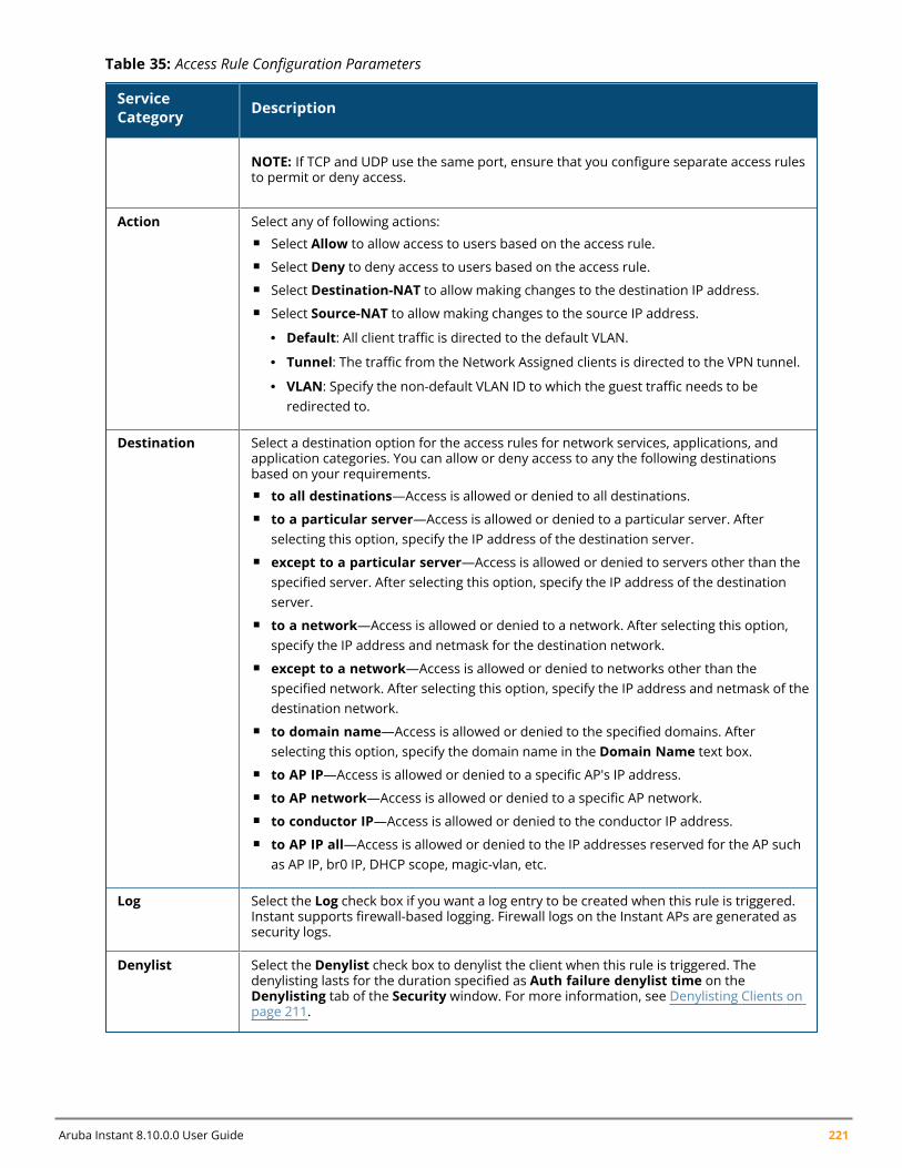
Aruba Instant 8.10.0.0 User Guide 221
ServiceCategory Description
NOTE: If TCP and UDP use the same port, ensure that you configure separate access rulesto permit or deny access.
Action Select any of following actions:n Select Allow to allow access to users based on the access rule.n Select Deny to deny access to users based on the access rule.n Select Destination-NAT to allow making changes to the destination IP address.n Select Source-NAT to allow making changes to the source IP address.
l Default: All client traffic is directed to the default VLAN.
l Tunnel: The traffic from the Network Assigned clients is directed to the VPN tunnel.
l VLAN: Specify the non-default VLAN ID to which the guest traffic needs to beredirected to.
Destination Select a destination option for the access rules for network services, applications, andapplication categories. You can allow or deny access to any the following destinationsbased on your requirements.n to all destinations—Access is allowed or denied to all destinations.n to a particular server—Access is allowed or denied to a particular server. After
selecting this option, specify the IP address of the destination server.n except to a particular server—Access is allowed or denied to servers other than the
specified server. After selecting this option, specify the IP address of the destinationserver.
n to a network—Access is allowed or denied to a network. After selecting this option,specify the IP address and netmask for the destination network.
n except to a network—Access is allowed or denied to networks other than thespecified network. After selecting this option, specify the IP address and netmask of thedestination network.
n to domain name—Access is allowed or denied to the specified domains. Afterselecting this option, specify the domain name in the Domain Name text box.
n to AP IP—Access is allowed or denied to a specific AP's IP address.n to AP network—Access is allowed or denied to a specific AP network.n to conductor IP—Access is allowed or denied to the conductor IP address.n to AP IP all—Access is allowed or denied to the IP addresses reserved for the AP such
as AP IP, br0 IP, DHCP scope, magic-vlan, etc.
Log Select the Log check box if you want a log entry to be created when this rule is triggered.Instant supports firewall-based logging. Firewall logs on the Instant APs are generated assecurity logs.
Denylist Select the Denylist check box to denylist the client when this rule is triggered. Thedenylisting lasts for the duration specified as Auth failure denylist time on theDenylisting tab of the Security window. For more information, see Denylisting Clients onpage 211.
Table 35: Access Rule Configuration Parameters
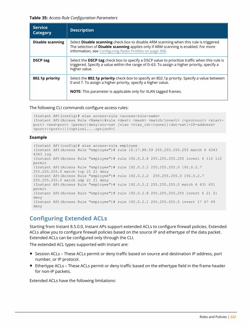
Roles and Policies | 222
ServiceCategory Description
Disable scanning Select Disable scanning check box to disable ARM scanning when this rule is triggered.The selection of Disable scanning applies only if ARM scanning is enabled. For moreinformation, see Configuring Radio Profiles on page 368.
DSCP tag Select the DSCP tag check box to specify a DSCP value to prioritize traffic when this rule istriggered. Specify a value within the range of 0–63. To assign a higher priority, specify ahigher value.
802.1p priority Select the 802.1p priority check box to specify an 802.1p priority. Specify a value between0 and 7. To assign a higher priority, specify a higher value.
NOTE: This parameter is applicable only for VLAN tagged frames.
Table 35: Access Rule Configuration Parameters
The following CLI commands configure access rules:
(Instant AP)(config)# wlan access-rule <access-rule-name>(Instant AP)(Access Rule <Name>)#rule <dest> <mask> <match/invert> {<protocol> <start-port> <end-port> {permit|deny|src-nat [vlan <vlan_id>|tunnel]|dst-nat{<IP-address><port>|<port>}}[<option1....option9>]
Example
(Instant AP)(config)# wlan access-rule employee(Instant AP)(Access Rule "employee")# rule 10.17.88.59 255.255.255.255 match 6 43434343 log(Instant AP)(Access Rule "employee")# rule 192.0.2.8 255.255.255.255 invert 6 110 110permit(Instant AP)(Access Rule "employee")# rule 192.0.2.2 255.255.255.0 192.0.2.7255.255.255.0 match tcp 21 21 deny(Instant AP)(Access Rule "employee")# rule 192.0.2.2 255.255.255.0 192.0.2.7255.255.255.0 match udp 21 21 deny(Instant AP)(Access Rule "employee")# rule 192.0.2.2 255.255.255.0 match 6 631 631permit(Instant AP)(Access Rule "employee")# rule 192.0.2.8 255.255.255.255 invert 6 21 21deny(Instant AP)(Access Rule "employee")# rule 192.0.2.1 255.255.255.0 invert 17 67 69deny
Configuring Extended ACLsStarting from Instant 8.5.0.0, Instant APs support extended ACLs to configure firewall policies. ExtendedACLs allow you to configure firewall policies based on the source IP and ethertype of the data packet.Extended ACLs can be configured only through the CLI.
The extended ACL types supported with Instant are:
n Session ACLs – These ACLs permit or deny traffic based on source and destination IP address, portnumber, or IP protocol.
n Ethertype ACLs – These ACLs permit or deny traffic based on the ethertype field in the frame headerfor non-IP packets.
Extended ACLs have the following limitations:
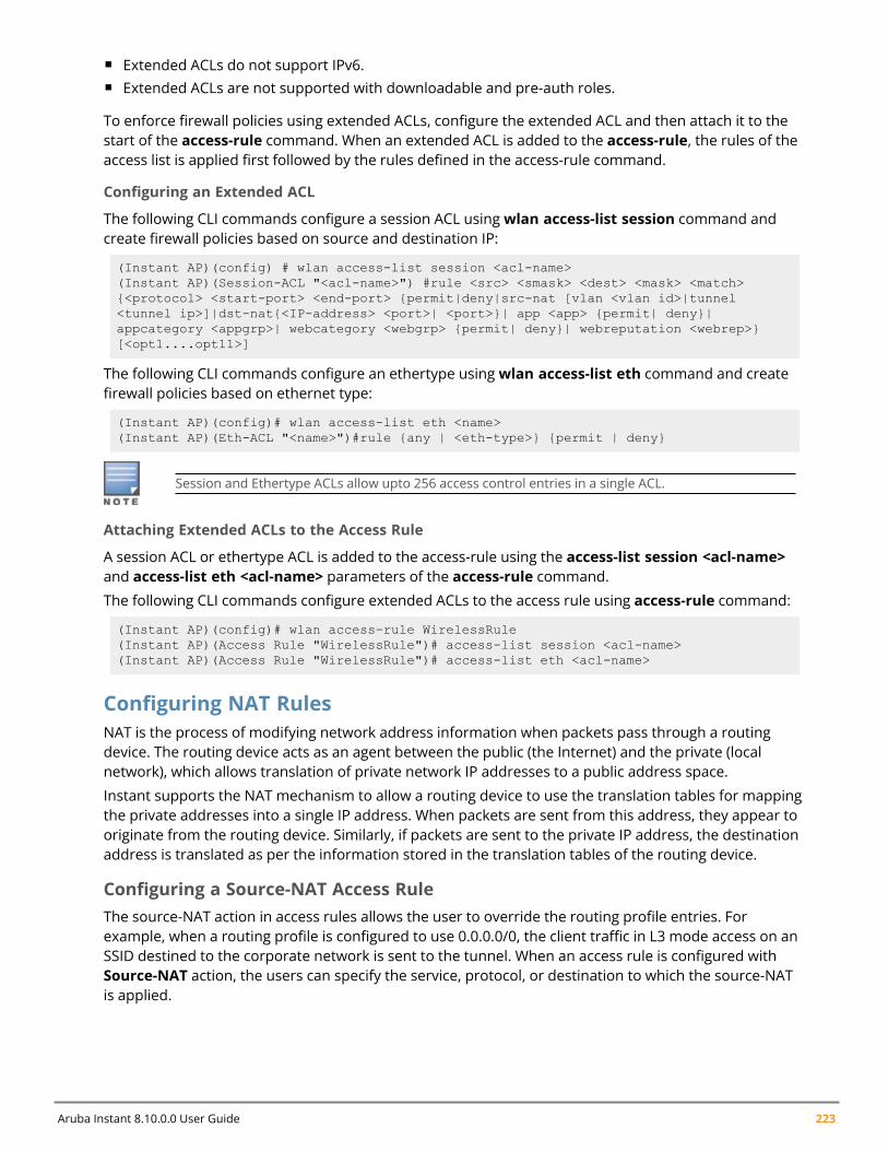
Aruba Instant 8.10.0.0 User Guide 223
n Extended ACLs do not support IPv6.n Extended ACLs are not supported with downloadable and pre-auth roles.
To enforce firewall policies using extended ACLs, configure the extended ACL and then attach it to thestart of the access-rule command. When an extended ACL is added to the access-rule, the rules of theaccess list is applied first followed by the rules defined in the access-rule command.
Configuring an Extended ACL
The following CLI commands configure a session ACL usingwlan access-list session command andcreate firewall policies based on source and destination IP:
(Instant AP)(config) # wlan access-list session <acl-name>(Instant AP)(Session-ACL "<acl-name>") #rule <src> <smask> <dest> <mask> <match>{<protocol> <start-port> <end-port> {permit|deny|src-nat [vlan <vlan id>|tunnel<tunnel ip>]|dst-nat{<IP-address> <port>| <port>}| app <app> {permit| deny}|appcategory <appgrp>| webcategory <webgrp> {permit| deny}| webreputation <webrep>}[<opt1....opt11>]
The following CLI commands configure an ethertype usingwlan access-list eth command and createfirewall policies based on ethernet type:
(Instant AP)(config)# wlan access-list eth <name>(Instant AP)(Eth-ACL "<name>")#rule {any | <eth-type>} {permit | deny}
Session and Ethertype ACLs allow upto 256 access control entries in a single ACL.
Attaching Extended ACLs to the Access Rule
A session ACL or ethertype ACL is added to the access-rule using the access-list session <acl-name>and access-list eth <acl-name> parameters of the access-rule command.
The following CLI commands configure extended ACLs to the access rule using access-rule command:
(Instant AP)(config)# wlan access-rule WirelessRule(Instant AP)(Access Rule "WirelessRule")# access-list session <acl-name>(Instant AP)(Access Rule "WirelessRule")# access-list eth <acl-name>
Configuring NAT RulesNAT is the process of modifying network address information when packets pass through a routingdevice. The routing device acts as an agent between the public (the Internet) and the private (localnetwork), which allows translation of private network IP addresses to a public address space.
Instant supports the NAT mechanism to allow a routing device to use the translation tables for mappingthe private addresses into a single IP address. When packets are sent from this address, they appear tooriginate from the routing device. Similarly, if packets are sent to the private IP address, the destinationaddress is translated as per the information stored in the translation tables of the routing device.
Configuring a Source-NAT Access RuleThe source-NAT action in access rules allows the user to override the routing profile entries. Forexample, when a routing profile is configured to use 0.0.0.0/0, the client traffic in L3 mode access on anSSID destined to the corporate network is sent to the tunnel. When an access rule is configured withSource-NAT action, the users can specify the service, protocol, or destination to which the source-NATis applied.
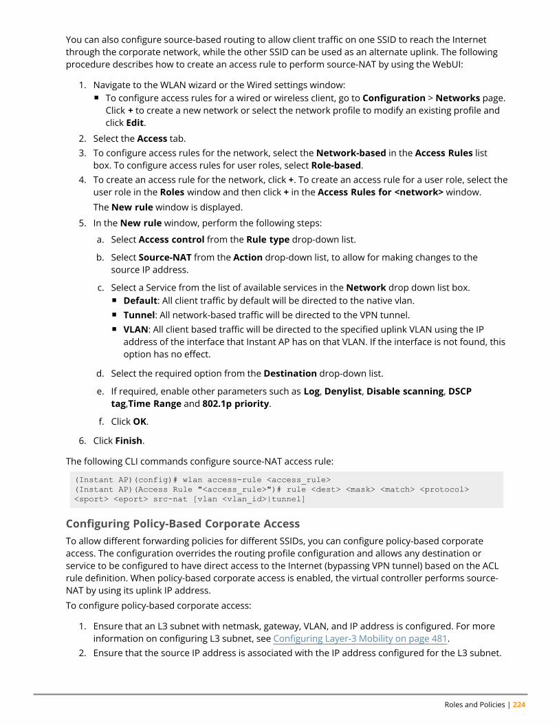
Roles and Policies | 224
You can also configure source-based routing to allow client traffic on one SSID to reach the Internetthrough the corporate network, while the other SSID can be used as an alternate uplink. The followingprocedure describes how to create an access rule to perform source-NAT by using the WebUI:
1. Navigate to the WLAN wizard or the Wired settings window:n To configure access rules for a wired or wireless client, go to Configuration > Networks page.
Click + to create a new network or select the network profile to modify an existing profile andclick Edit.
2. Select the Access tab.3. To configure access rules for the network, select the Network-based in the Access Rules list
box. To configure access rules for user roles, select Role-based.4. To create an access rule for the network, click +. To create an access rule for a user role, select the
user role in the Roles window and then click + in the Access Rules for <network> window.
The New rule window is displayed.
5. In the New rule window, perform the following steps:
a. Select Access control from the Rule type drop-down list.
b. Select Source-NAT from the Action drop-down list, to allow for making changes to thesource IP address.
c. Select a Service from the list of available services in the Network drop down list box.n Default: All client traffic by default will be directed to the native vlan.n Tunnel: All network-based traffic will be directed to the VPN tunnel.n VLAN: All client based traffic will be directed to the specified uplink VLAN using the IP
address of the interface that Instant AP has on that VLAN. If the interface is not found, thisoption has no effect.
d. Select the required option from the Destination drop-down list.
e. If required, enable other parameters such as Log, Denylist, Disable scanning, DSCPtag,Time Range and 802.1p priority.
f. Click OK.
6. Click Finish.
The following CLI commands configure source-NAT access rule:
(Instant AP)(config)# wlan access-rule <access_rule>(Instant AP)(Access Rule "<access_rule>")# rule <dest> <mask> <match> <protocol><sport> <eport> src-nat [vlan <vlan_id>|tunnel]
Configuring Policy-Based Corporate AccessTo allow different forwarding policies for different SSIDs, you can configure policy-based corporateaccess. The configuration overrides the routing profile configuration and allows any destination orservice to be configured to have direct access to the Internet (bypassing VPN tunnel) based on the ACLrule definition. When policy-based corporate access is enabled, the virtual controller performs source-NAT by using its uplink IP address.
To configure policy-based corporate access:
1. Ensure that an L3 subnet with netmask, gateway, VLAN, and IP address is configured. For moreinformation on configuring L3 subnet, see Configuring Layer-3 Mobility on page 481.
2. Ensure that the source IP address is associated with the IP address configured for the L3 subnet.
Aruba Instant 8.10.0.0 User Guide 225
3. Create an access rule for the SSID profile with Source-NAT action as described in Configuring aSource-NAT Access Rule on page 223. The source-NAT pool is configured and corporate accessentry is created.
Configuring a Destination NAT Access RuleInstant supports configuration of the destination NAT rule, which can be used to redirect traffic to thespecified IP address and destination port. The destination NAT configuration is supported only in thebridge mode without VPN.
The following procedure describes how to configure a destination NAT access rule by using the WebUI:
1. Navigate to the WLAN wizard or the Wired settings window:n To configure access rules for a wired or wireless client, go to Configuration > Networks tab.
Click + to create a new network or select the network profile to modify an existing profile andclick Edit.
2. Select the Access tab.3. To configure access rules for the network, select the Network-based in the Access Rules list box.
To configure access rules for user roles, select Role-based.4. To create an access rule for the network, click +. To create an access rule for a user role, select the
user role in the Roles window and then click + in the Access Rules for <network> window. TheNew rule window is displayed.
5. In the New rule window, perform the following steps:
a. Select Access control from the Rule type drop-down list.
b. Select destination-NAT from the Action drop-down list, to allow for making changes to thesource IP address.
c. Specify the IP address and port details.
d. Select a Service from the list of available services in the Network drop down list box.
e. Select the required option from the Destination drop-down list.
f. If required, enable other parameters such as Log, Denylist, Disable scanning, DSCP tag,Time Range and 802.1p priority.
g. Click OK.
6. Click Finish.
The following CLI commands configure destination NAT access rule:
(Instant AP)(config)# wlan access-rule <access_rule>(Instant AP)(Access Rule "<access_rule>")# rule <dest> <mask> <match> <protocol><sport> <eport> dst-nat ip <IP-address> [<port>]
Configuring ALG ProtocolsThe following procedure describes how to enable or disable protocols for ALG using the WebUI:
1. Go to Configuration > Security.2. Expand Firewall Settings.3. Under Application Layer Gateway Algorithms, the SIP, VOCERA, Alcatel NOE, and Cisco
Skinny protocols are enabled by default. To disable a specific protocol, toggle the corresponding
Roles and Policies | 226
switch to disable.4. Click Save.
When the protocols for ALG are set to Disabled, the changes are not applied until the existing usersessions expire. Reboot the Instant AP and the client, or wait for a few minutes to view the changes.
The following CLI commands configure protocols for ALG:
(Instant AP)(config)# alg(Instant AP)(ALG)# sccp-disable(Instant AP)(ALG)# no sip-disable(Instant AP)(ALG)# no ua-disable(Instant AP)(ALG)# no vocera-disable
The following CLI command shows the ALG configuration:
(Instant AP)# show alg
Configuring Firewall Settings for Protection from ARP AttacksThe following procedure describes how to configure firewall settings to protect the network against ARPattacks using the WebUI:
1. Go to Configuration > Security.2. Expand Firewall Settings.3. To configure protection against security attacks, under Protection against wired attacks select
the following check boxes:n Toggle the Drop bad ARP switch to enable the Instant AP to drop the fake ARP packets.n Toggle the Fix malformed DHCP switch to enable the Instant AP to fix the malformed DHCP
packets.n Toggle the ARP poison check switch to enable the Instant AP to trigger alerts about ARP
poisoning that may have been caused by rogue Instant APs. ARP poisoning detection triggersalerts when a known client on the Instant AP spoofs the base MAC address of the Instant AP.
4. Click Save.
The following CLI commands configure firewall settings to prevent attacks:
(Instant AP)(config)# attack(Instant AP)(ATTACK)# drop-bad-arp-enable(Instant AP)(ATTACK)# fix-dhcp-enable(Instant AP)(ATTACK)# no(Instant AP)(ATTACK)# poison-check-enable
The following CLI command shows the configuration status:
(Instant AP)# show attack configCurrent Attack--------------Attack Status------ ------drop-bad-arp Enabledfix-dhcp Enabledpoison-check Enabled
The following CLI command shows the attack statistics:
(Instant AP)# show attack stats
Aruba Instant 8.10.0.0 User Guide 227
attack counters--------------------------------------Counter Value------- -------arp packet counter 0drop bad arp packet counter 0dhcp response packet counter 0fixed bad dhcp packet counter 0send arp attack alert counter 0send dhcp attack alert counter 0arp poison check counter 0garp send check counter 0
Auto Topology RulesAuto Topology is a feature that automatically adds ACL rules into the firewall. This ensures that any kindof control-plane messages required for the automatic cluster formation are never blocked. By default,this feature is enabled. However, this feature can be disabled when customers prefer full control on thesecurity policy rather than accepting automatic ACL rules. This feature governs all the ACLs and impactsall the traffic that is hit by the ACLs.
Configuring Firewall Settings to Disable Auto Topology Rules
You can disable the rules by configuring firewall settings in the Instant AP.
In order to deny auto topology communication outside the Instant AP subnet, the inbound firewallsettings must be enabled.
When the inbound firewall settings are enabled:
n ACEs must be configured to block auto topology messages, as there is no default rule at the top ofpredefined ACLs.
n ACEs must be configured to override the guest VLAN auto-expanded ACEs. In other words, the userdefined ACEs take higher precedence over guest VLAN ACEs.
For more information on inbound firewall settings, see Managing Inbound Traffic on page 227
The priority of a particular ACE is determined based on the order in which it is programmed. Ensurethat you do not accidentally override the guest VLAN ACEs.
The following procedure describes how to change the status of auto topology rules by using the WebUI:
1. Go to Configuration > Security.2. Expand Firewall Settings.3. Under Firewall, The Auto topology rules setting is enabled by default. To disable this setting,
toggle the switch.4. Click Save.
The following CLI commands disable auto topology rules:
(Instant AP)(config)# firewall(Instant AP)(firewall)# disable-auto-topology-rules
The following CLI command shows the configuration status:
(Instant AP) # show firewall
Managing Inbound Traffic
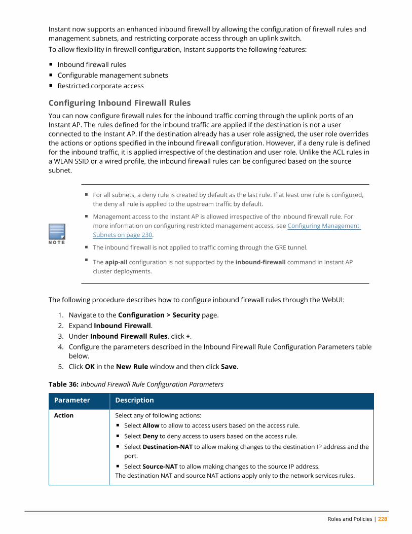
Roles and Policies | 228
Instant now supports an enhanced inbound firewall by allowing the configuration of firewall rules andmanagement subnets, and restricting corporate access through an uplink switch.
To allow flexibility in firewall configuration, Instant supports the following features:
n Inbound firewall rulesn Configurable management subnetsn Restricted corporate access
Configuring Inbound Firewall RulesYou can now configure firewall rules for the inbound traffic coming through the uplink ports of anInstant AP. The rules defined for the inbound traffic are applied if the destination is not a userconnected to the Instant AP. If the destination already has a user role assigned, the user role overridesthe actions or options specified in the inbound firewall configuration. However, if a deny rule is definedfor the inbound traffic, it is applied irrespective of the destination and user role. Unlike the ACL rules ina WLAN SSID or a wired profile, the inbound firewall rules can be configured based on the sourcesubnet.
n For all subnets, a deny rule is created by default as the last rule. If at least one rule is configured,the deny all rule is applied to the upstream traffic by default.
n Management access to the Instant AP is allowed irrespective of the inbound firewall rule. Formore information on configuring restricted management access, see Configuring ManagementSubnets on page 230.
n The inbound firewall is not applied to traffic coming through the GRE tunnel.
n The apip-all configuration is not supported by the inbound-firewall command in Instant APcluster deployments.
The following procedure describes how to configure inbound firewall rules through the WebUI:
1. Navigate to the Configuration > Security page.2. Expand Inbound Firewall.3. Under Inbound Firewall Rules, click +.4. Configure the parameters described in the Inbound Firewall Rule Configuration Parameters table
below.5. Click OK in the New Rule window and then click Save.
Parameter Description
Action Select any of following actions:n Select Allow to allow to access users based on the access rule.n Select Deny to deny access to users based on the access rule.n Select Destination-NAT to allow making changes to the destination IP address and the
port.n Select Source-NAT to allow making changes to the source IP address.The destination NAT and source NAT actions apply only to the network services rules.
Table 36: Inbound Firewall Rule Configuration Parameters
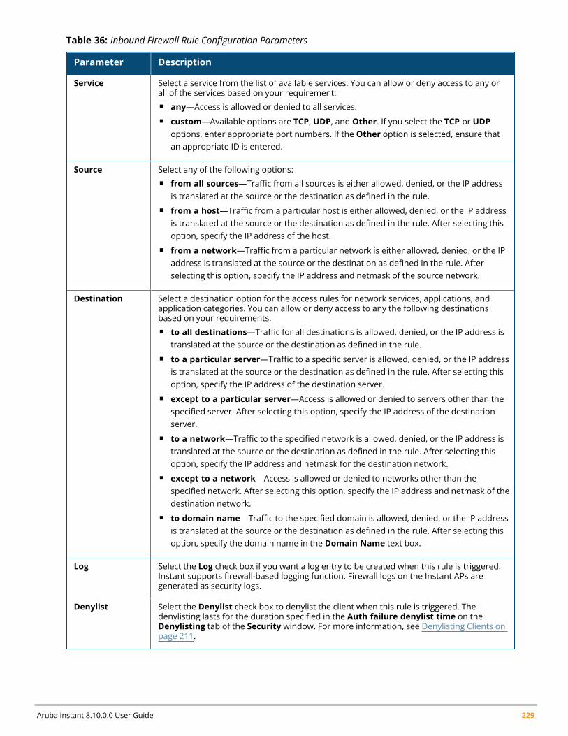
Aruba Instant 8.10.0.0 User Guide 229
Parameter Description
Service Select a service from the list of available services. You can allow or deny access to any orall of the services based on your requirement:n any—Access is allowed or denied to all services.n custom—Available options are TCP, UDP, and Other. If you select the TCP or UDP
options, enter appropriate port numbers. If the Other option is selected, ensure thatan appropriate ID is entered.
Source Select any of the following options:n from all sources—Traffic from all sources is either allowed, denied, or the IP address
is translated at the source or the destination as defined in the rule.n from a host—Traffic from a particular host is either allowed, denied, or the IP address
is translated at the source or the destination as defined in the rule. After selecting thisoption, specify the IP address of the host.
n from a network—Traffic from a particular network is either allowed, denied, or the IPaddress is translated at the source or the destination as defined in the rule. Afterselecting this option, specify the IP address and netmask of the source network.
Destination Select a destination option for the access rules for network services, applications, andapplication categories. You can allow or deny access to any the following destinationsbased on your requirements.n to all destinations—Traffic for all destinations is allowed, denied, or the IP address is
translated at the source or the destination as defined in the rule.n to a particular server—Traffic to a specific server is allowed, denied, or the IP address
is translated at the source or the destination as defined in the rule. After selecting thisoption, specify the IP address of the destination server.
n except to a particular server—Access is allowed or denied to servers other than thespecified server. After selecting this option, specify the IP address of the destinationserver.
n to a network—Traffic to the specified network is allowed, denied, or the IP address istranslated at the source or the destination as defined in the rule. After selecting thisoption, specify the IP address and netmask for the destination network.
n except to a network—Access is allowed or denied to networks other than thespecified network. After selecting this option, specify the IP address and netmask of thedestination network.
n to domain name—Traffic to the specified domain is allowed, denied, or the IP addressis translated at the source or the destination as defined in the rule. After selecting thisoption, specify the domain name in the Domain Name text box.
Log Select the Log check box if you want a log entry to be created when this rule is triggered.Instant supports firewall-based logging function. Firewall logs on the Instant APs aregenerated as security logs.
Denylist Select the Denylist check box to denylist the client when this rule is triggered. Thedenylisting lasts for the duration specified in the Auth failure denylist time on theDenylisting tab of the Security window. For more information, see Denylisting Clients onpage 211.
Table 36: Inbound Firewall Rule Configuration Parameters
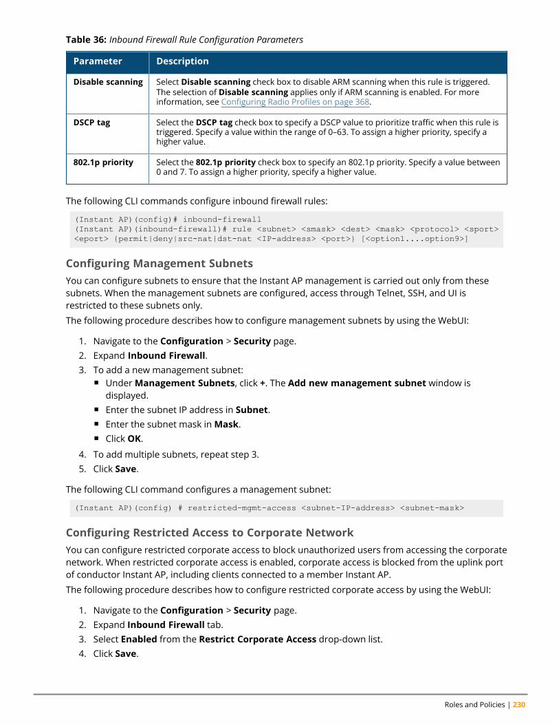
Roles and Policies | 230
Parameter Description
Disable scanning Select Disable scanning check box to disable ARM scanning when this rule is triggered.The selection of Disable scanning applies only if ARM scanning is enabled. For moreinformation, see Configuring Radio Profiles on page 368.
DSCP tag Select the DSCP tag check box to specify a DSCP value to prioritize traffic when this rule istriggered. Specify a value within the range of 0–63. To assign a higher priority, specify ahigher value.
802.1p priority Select the 802.1p priority check box to specify an 802.1p priority. Specify a value between0 and 7. To assign a higher priority, specify a higher value.
Table 36: Inbound Firewall Rule Configuration Parameters
The following CLI commands configure inbound firewall rules:
(Instant AP)(config)# inbound-firewall(Instant AP)(inbound-firewall)# rule <subnet> <smask> <dest> <mask> <protocol> <sport><eport> {permit|deny|src-nat|dst-nat <IP-address> <port>} [<option1....option9>]
Configuring Management SubnetsYou can configure subnets to ensure that the Instant AP management is carried out only from thesesubnets. When the management subnets are configured, access through Telnet, SSH, and UI isrestricted to these subnets only.
The following procedure describes how to configure management subnets by using the WebUI:
1. Navigate to the Configuration > Security page.2. Expand Inbound Firewall.3. To add a new management subnet:
n UnderManagement Subnets, click +. The Add new management subnet window isdisplayed.
n Enter the subnet IP address in Subnet.n Enter the subnet mask inMask.n Click OK.
4. To add multiple subnets, repeat step 3.5. Click Save.
The following CLI command configures a management subnet:
(Instant AP)(config) # restricted-mgmt-access <subnet-IP-address> <subnet-mask>
Configuring Restricted Access to Corporate NetworkYou can configure restricted corporate access to block unauthorized users from accessing the corporatenetwork. When restricted corporate access is enabled, corporate access is blocked from the uplink portof conductor Instant AP, including clients connected to a member Instant AP.
The following procedure describes how to configure restricted corporate access by using the WebUI:
1. Navigate to the Configuration > Security page.2. Expand Inbound Firewall tab.3. Select Enabled from the Restrict Corporate Access drop-down list.4. Click Save.
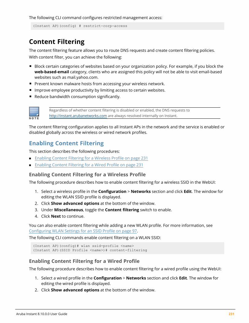
Aruba Instant 8.10.0.0 User Guide 231
The following CLI command configures restricted management access:
(Instant AP)(config) # restrict-corp-access
Content FilteringThe content filtering feature allows you to route DNS requests and create content filtering policies.
With content filter, you can achieve the following:
n Block certain categories of websites based on your organization policy. For example, if you block theweb-based-email category, clients who are assigned this policy will not be able to visit email-basedwebsites such as mail.yahoo.com.
n Prevent known malware hosts from accessing your wireless network.n Improve employee productivity by limiting access to certain websites.n Reduce bandwidth consumption significantly.
Regardless of whether content filtering is disabled or enabled, the DNS requests tohttp://instant.arubanetworks.com are always resolved internally on Instant.
The content filtering configuration applies to all Instant APs in the network and the service is enabled ordisabled globally across the wireless or wired network profiles.
Enabling Content FilteringThis section describes the following procedures:
n Enabling Content Filtering for a Wireless Profile on page 231
n Enabling Content Filtering for a Wired Profile on page 231
Enabling Content Filtering for a Wireless ProfileThe following procedure describes how to enable content filtering for a wireless SSID in the WebUI:
1. Select a wireless profile in the Configuration > Networks section and click Edit. The window forediting the WLAN SSID profile is displayed.
2. Click Show advanced options at the bottom of the window.3. UnderMiscellaneous, toggle the Content filtering switch to enable.4. Click Next to continue.
You can also enable content filtering while adding a new WLAN profile. For more information, seeConfiguring WLAN Settings for an SSID Profile on page 97.
The following CLI commands enable content filtering on a WLAN SSID:
(Instant AP)(config)# wlan ssid-profile <name>(Instant AP)(SSID Profile <name>)# content-filtering
Enabling Content Filtering for a Wired ProfileThe following procedure describes how to enable content filtering for a wired profile using the WebUI:
1. Select a wired profile in the Configuration > Networks section and click Edit. The window forediting the wired profile is displayed.
2. Click Show advanced options at the bottom of the window.
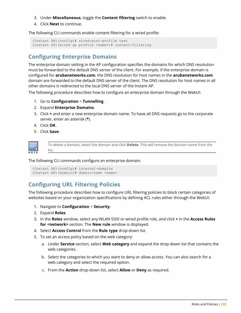
Roles and Policies | 232
3. UnderMiscellaneous, toggle the Content filtering switch to enable.4. Click Next to continue.
The following CLI commands enable content filtering for a wired profile:
(Instant AP)(config)# wired-port-profile test(Instant AP)(wired ap profile <name>)# content-filtering
Configuring Enterprise DomainsThe enterprise domain setting in the AP configuration specifies the domains for which DNS resolutionmust be forwarded to the default DNS server of the client. For example, if the enterprise domain isconfigured for arubanetworks.com, the DNS resolution for host names in the arubanetworks.comdomain are forwarded to the default DNS server of the client. The DNS resolution for host names in allother domains is redirected to the local DNS server of the Instant AP.
The following procedure describes how to configure an enterprise domain through the WebUI:
1. Go to Configuration > Tunnelling .2. Expand Enterprise Domains.3. Click + and enter a new enterprise domain name. To have all DNS requests go to the corporate
server, enter an asterisk (*).4. Click OK .5. Click Save.
To delete a domain, select the domain and click Delete. This will remove the domain name from thelist.
The following CLI commands configure an enterprise domain:
(Instant AP)(config)# internal-domains(Instant AP)(domain)# domain-name <name>
Configuring URL Filtering PoliciesThe following procedure describes how to configure URL filtering policies to block certain categories ofwebsites based on your organization specifications by defining ACL rules either through the WebUI:
1. Navigate to Configuration > Security.2. Expand Roles.3. In the Roles window, select any WLAN SSID or wired profile role, and click + in the Access Rules
for <network> section. The New rule window is displayed.4. Select Access Control from the Rule type drop-down list.5. To set an access policy based on the web category:
a. Under Service section, selectWeb category and expand the drop-down list that contains theweb categories.
b. Select the categories to which you want to deny or allow access. You can also search for aweb category and select the required option.
c. From the Action drop-down list, select Allow or Deny as required.
Aruba Instant 8.10.0.0 User Guide 233
6. To filter access based on the security ratings of the website:
a. SelectWeb reputation under Service.
b. Move the slider to the required security rating level.
c. From the Action drop-down list, select Allow or Deny as required.
7. To set a bandwidth limit based on web category or web reputation score, select the ApplicationThrottling check box and specify the downstream and upstream rates in Kbps. For example, youcan set a higher bandwidth for trusted sites and a low bandwidth rate for high-risk sites.
8. Click OK to save the rules.9. Click Save to save the changes to the role for which you defined ACL rules.
The following CLI commands control access based on web categories and security ratings:
(Instant AP)(config)# wlan access-rule <access_rule>(Instant AP)(Access Rule "<access-rule>")# rule <dest> <mask> <match> webcategory<webgrp> {permit| deny}[<option1....option9>](Instant AP)(Access Rule "<access-rule>")# rule <dest> <mask> <match> webreputation<webrep> {permit|deny}[<option1....option9>]
Creating Custom Error Page for Web Access Blocked by AppRFPoliciesYou can create a list of URLs to which the users are redirected when they access blocked websites. Youcan define an access rule to use these redirect URLs and assign the rule to a user role in the WLANnetwork.
Creating a List of Error Page URLsThe following procedure describes how to create a list of custom URLs and ACL rules for blockedwebsites either through the WebUI:
1. Navigate to Configuration > Security > Custom Blocked Page URL.2. Click + and enter the URL that you want to block.3. Repeat the procedure to add more URLs. You can add up to 8 URLs to the blocked page list.4. Click OK in the URL window.5. Click Save.
The following CLI command creates a list of error page URLs:
(Instant AP)(config)# dpi-error-page-url <idx> <url>
Configuring ACL Rules to Redirect Blocked HTTP Websites to a Custom ErrorPage URLThe following procedure describes how to redirect blocked HTTP websites to a custom error page URL:
1. Navigate to Configuration > Security > Roles.2. In the Roles window, select any WLAN SSID or Wired profile role, and click + in the Access Rules
for <network> section.3. In the New rule window, select the rule type as Redirect Page URL.4. Select the URLs from the existing list of custom redirect URLs and click OK.5. Click Save.
Roles and Policies | 234
The following CLI commands configure an ACL rule to redirect blocked HTTP websites to a custom errorpage URL:
(Instant AP)(config)# wlan access-rule <access_rule_name>(Instant AP) (Access Rule "<access_rule_name>")# dpi-error-page-url <idx>
Configuring ACL Rules to Redirect Blocked HTTPS Websites to a Custom BlockedPage URL
Before you configure an ACL rule for a specific WLAN SSID or Wired profile to redirect HTTPSwebsites to a custom error page, you must ensure that the Blocked Page URL rule is configured forthe HTTP websites blocked for the same WLAN SSID or Wired profile. In this scenario, all the blockedHTTP and HTTPS websites will be redirected to the custom error page URL.
The following procedure describes how to redirect blocked HTTPS websites to a custom error page URL:
1. Navigate to Configuration > Security > Roles.2. Select any WLAN SSID or Wired profile role, and click + in the Access Rules for <network>
section.3. In the New Rule window, select the rule type as Redirect Blocked HTTPS.4. Click OK in the New rule window..5. Click Save.
The following CLI commands configure an ACL rule to redirect blocked HTTPS to a custom error pageURL:
(Instant AP)(config)# wlan access-rule <access_rule_name>(Instant AP) (Access Rule "<access_rule_name>")# dpi-error-page-url <idx>(Instant AP) (Access Rule "<access_rule_name>")# redirect-blocked-https-traffic
Configuring User RolesEvery client in the Instant network is associated with a user role that determines the network privilegesfor a client, the frequency of reauthentication, and the applicable bandwidth contracts.
Instant allows you to configure up to 64 user roles. If the number of roles exceed 64, an errormessage is displayed.
The user role configuration on an Instant AP involves the following procedures:
n Creating a User Role on page 234n Assigning Bandwidth Contracts to User Roles on page 235n Configuring Machine and User Authentication Roles on page 236n Configuring Downloadable User Roles (DUR) on page 237n ClearPass Policy Manager Certificate Validation for Downloadable User Roles (DUR) on page 238
Creating a User RoleThe following procedure describes how to create a user role by using the WebUI:
1. Go to Configuration > Security.2. Click the Roles tab. The Roles tab contents are displayed.
Aruba Instant 8.10.0.0 User Guide 235
3. Under Roles, click +.4. Enter a name for the new role and click OK.5. Click Save in the Roles tab.
You can also create a user role when configuring wireless or wired network profiles. For moreinformation, see Configuring Access Rules for a WLAN SSID Profile on page 114 and ConfiguringAccess Rules for a Wired Profile on page 135.
The following CLI commands configure user roles and access rules:
(Instant AP)(config)# wlan access-rule <access-rule-name>(Instant AP)(Access Rule <Name>)# rule <dest> <mask> <match> <protocol> <start-port><end-port> {permit|deny|src-nat [vlan <vlan_id>|tunnel]|dst-nat {<IP-address><port>|<port>}}[<option1…option9>]
Assigning Bandwidth Contracts to User RolesThe administrators can manage bandwidth utilization by assigning either maximum bandwidth rates, orbandwidth contracts to user roles. The administrator can assign a bandwidth contract configured inKbps to upstream (client to the Instant AP) or downstream (Instant AP to clients) traffic for a user role.
By default, all users that belong to the same role share a configured bandwidth rate for upstream ordownstream traffic. The assigned bandwidth will be served and shared among all the users. You canalso assign bandwidth rate per user to provide every user a specific bandwidth within a range of 1–65,535 Kbps. If there is no bandwidth contract specified for a traffic direction, unlimited bandwidth isallowed.
In the earlier releases, bandwidth contract could be assigned per SSID. In the current release, thebandwidth contract can also be assigned for each SSID user. If the bandwidth contract is assigned foran SSID in the Instant 6.2.1.0-3.4.0.0 version, and when the Instant AP is upgraded to a later releaseversion, the bandwidth configuration per SSID will be treated as a per-user downstream bandwidthcontract for that SSID.
The bandwidth contract for a user role can be applied to an Instant AP or to a cluster.
Example
In a cluster of 5 Instant APs with an upstream WAN limit of 100 Mbps, you must set the WAN limit to 20Mbps for each Instant AP, in order to meet the requirement of maintaining the WAN limit of 100 Mbps.However, clients cannot exceed 20 Mbps when needed, even if the cluster output is less then 100 Mbps.
If you want to add more Instant APs, you must re-calculate the WAN limit and manually apply it. It isrecommended that you apply the WAN limit at cluster level as it is more flexible. Also, there is no needto manually re-calculate the WAN limit if additional Instant APs are added or removed, in order to meetthe upstream WAN constraints.
The following procedure describes how to assign bandwidth contracts to user roles using the WebUI:
1. Go to Configuration > Security.2. Expand Roles tab.3. Create a new role (see Creating a User Role on page 234) or select an existing role.4. Under Access Rules, click +. The New rule window is displayed.5. Select Bandwidth Contract from the Rule type drop-down list.
Roles and Policies | 236
6. Specify the downstream and upstream rates in Kbps. If the assignment is specific for each user,select the Per user check box.
7. Click OK.8. Click Save.9. To associate the user role to a WLAN SSID or a wired profile, navigate to the WLAN wizard or
Wired window.n Go to Configuration > Networks and select a network profile to modify and click Edit.n Select Access tab. Select Role-based in the Access Rules drop-down list.n Under Role Assignment Rules, click +.n Select the user role from the Role drop-down list and then click OK.n Click Finish.
The following CLI commands assign a bandwidth contract:
(Instant AP)(config)# wlan access-rule <name>(Instant AP) (Access Rule <name>)# bandwidth-limit {downstream <kbps>|upstream<kbps>|peruser {downstream <kbps>| upstream <kbps>}}
The following CLI commands associate the access rule to a wired profile:
(Instant AP)(config)# wired-port-profile <name>(Instant AP)(wired ap profile <name>)# access-rule-name <access-rule-name>
Configuring Machine and User Authentication RolesYou can assign different rights to clients based on whether their hardware device supports machineauthentication. Machine authentication is only supported on Windows devices, so that this can be usedto distinguish between Windows devices and other devices such as iPads.
You can create any of the following types of rules:
n Machine Auth only role—This indicates a Windows machine with no user logged in. The devicesupports machine authentication and has a valid RADIUS account, but a user has not yet logged inand authenticated.
n User Auth only role—This indicates a known user or a non-Windows device. The device does notsupport machine authentication or does not have a RADIUS account, but the user is logged in andauthenticated.
When a device does both machine and user authentication, the user obtains the default role or thederived role based on the RADIUS attribute.
The following procedure describes how to configure machine authentication with role-based accesscontrol using the WebUI:
1. Go to Configuration > Networks. To modify an existing network profile, select the profile andclick Edit. To create a new network, click +.
2. Select the Access tab.3. Select Role-based from the Access Rules drop-down list.4. Toggle the Enforce Machine Authentication switch to enable.5. Configure access rules for these roles by selecting the roles in theMachine auth only and User
auth only drop-down lists. For more information on configuring access rules, see ConfiguringACL Rules for Network Services on page 220.
Aruba Instant 8.10.0.0 User Guide 237
6. Click Next and then click Finish to apply these changes.7. Click Finish.
The following CLI commands configure machine and user authentication roles for a WLAN SSID:
(Instant AP)(config)# wlan ssid-profile <name>(Instant AP)(SSID Profile <name>)# set-role-machine-auth <machine_only> <user_only>
The following CLI commands configure machine and user authentication roles for a wired profile:
(Instant AP)(config)# wired-port-profile <name>(Instant AP)(wired ap profile <name>)# set-role-machine-auth <machine_only> <user_only>
Configuring Downloadable User Roles (DUR)Aruba Instant and ClearPass Policy Manager include support for centralized policy definition anddistribution. When ClearPass Policy Manager successfully authenticates a user, the user is assigned arole by ClearPass Policy Manager. If the role is not defined on the Instant AP, the role attributes can alsobe downloaded automatically.
In order to provide highly granular per-user level access, user roles can be created when a user hasbeen successfully authenticated. During the configuration of a policy enforcement profile in ClearPassPolicy Manager, the administrator can define a role that should be assigned to the user after successfulauthentication. In RADIUS authentication, when ClearPass Policy Manager successfully authenticates auser, the user is assigned a role by ClearPass Policy Manager. If the role is not defined on the Instant AP,the role attributes can also be downloaded automatically. This feature supports roles obtained by thefollowing authentication methods:
n 802.1X (WLAN and wired users)n MAC authenticationn Captive Portal
The following procedure enables role download on a SSID using the WebUI:
1. Go to Configuration > Networks. To modify an existing network profile, select the profile andclick Edit. To create a new network, click +.
2. Select the Access tab.3. Slide the toggle switch next to Download roles, to the right, to enable user role download on the
SSID.
The following CLI commands enable role download:
(Instant AP)(config)# wlan ssid-profile <profile_name>(Instant AP)(SSID Profile <profile_name>)# download-role(Instant AP)(SSID Profile <profile_name>)# end(Instant AP)# commit apply
The following CLI commands configure a ClearPass Policy Manager username and password forRADIUS authentication:
(Instant AP)(config)# wlan auth-server <profile_name>(Instant AP)(Auth Server <profile_name>)# cppm {username <username> password<password>}(Instant AP)(Auth Server <profile_name>)# end(Instant AP)# commit apply
The following CLI command checks if role download is enabled on the network profile:
Roles and Policies | 238
(Instant AP)# show network <profile_name>
ClearPass Policy Manager Certificate Validation for DownloadableUser Roles (DUR)When a ClearPass Policy Manager server is configured as the domain for RADIUS authentication fordownloading user roles, in order to validate the ClearPass Policy Manager server certificate, Instant willautomatically download the root CA for the HTTPS server from the well-known URI (http://<clearpass-fqdn>/.well-known/aruba/clearpass/https-root.pem). The <clearpass-fqdn> is automatically filledwith the name that is configured in the radius server configuration as IP address. This means that theFQDN should be entered as the IP Address, otherwise the certificate cannot be validated.
Upon configuring the domain of the ClearPass Policy Manager server for RADIUS authentication alongwith a username and password, the Instant AP tries to retrieve the CA from the above well-known URIand store it in flash memory.
The following CLI command shows the current ClearPass Policy Manager CA uploaded on the Instant AP:
(Instant AP)# show clearpassca
The following CLI command shows the ClearPass Policy Manager CA count in the AP checksum:
(Instant AP)# show ap checksum
The following CLI command clears the ClearPass Policy Manager CA from the Instant AP:
(Instant AP)# clear-cert clearpassca
Configuring Derivation RulesInstant allows you to configure role and VLAN derivation-rules. You can configure these rules to assign auser role or a VLAN to the clients connecting to an SSID or a wired profile.
Understanding Role Assignment RuleWhen an SSID or a wired profile is created, a default role for the clients connecting to this SSID or wiredprofile is assigned. You can assign a user role to the clients connecting to an SSID by any of the followingmethods. The role assigned by some methods may take precedence over the roles assigned by theother methods.
RADIUS VSA Attributes
The user role can be derived from Aruba VSA for RADIUS server authentication. The role derived froman Aruba VSA takes precedence over roles defined by other methods.
MAC-Address Attribute
The first three octets in a MAC address are known as OUI, and are purchased from the IEEE,Incorporated RA. This identifier uniquely identifies a vendor, manufacturer, or other organization(referred to by the IEEE as the “assignee”) globally and effectively reserves a block of each possible typeof derivative identifier (such as MAC addresses) for the exclusive use of the assignee.
Instant APs use the OUI part of a MAC address to identify the device manufacturer and can beconfigured to assign a desired role for users who have completed 802.1X authentication and MACauthentication. The user role can be derived from the user attributes after a client associates with anInstant AP. You can configure rules to assign a user role to clients that match a MAC-address-basedcriteria. For example, you can assign a voice role to any client with a MAC address starting with a0:a1:a2.
Roles Based on Client Authentication
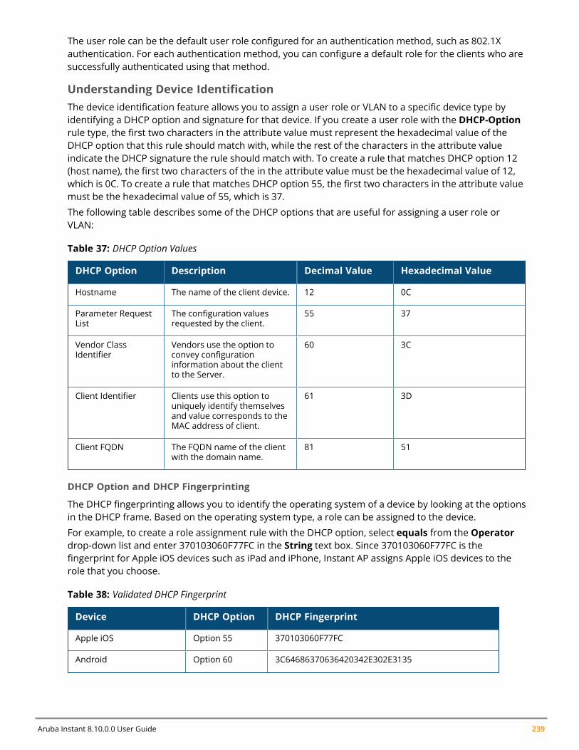
Aruba Instant 8.10.0.0 User Guide 239
The user role can be the default user role configured for an authentication method, such as 802.1Xauthentication. For each authentication method, you can configure a default role for the clients who aresuccessfully authenticated using that method.
Understanding Device IdentificationThe device identification feature allows you to assign a user role or VLAN to a specific device type byidentifying a DHCP option and signature for that device. If you create a user role with the DHCP-Optionrule type, the first two characters in the attribute value must represent the hexadecimal value of theDHCP option that this rule should match with, while the rest of the characters in the attribute valueindicate the DHCP signature the rule should match with. To create a rule that matches DHCP option 12(host name), the first two characters of the in the attribute value must be the hexadecimal value of 12,which is 0C. To create a rule that matches DHCP option 55, the first two characters in the attribute valuemust be the hexadecimal value of 55, which is 37.
The following table describes some of the DHCP options that are useful for assigning a user role orVLAN:
DHCP Option Description Decimal Value Hexadecimal Value
Hostname The name of the client device. 12 0C
Parameter RequestList
The configuration valuesrequested by the client.
55 37
Vendor ClassIdentifier
Vendors use the option toconvey configurationinformation about the clientto the Server.
60 3C
Client Identifier Clients use this option touniquely identify themselvesand value corresponds to theMAC address of client.
61 3D
Client FQDN The FQDN name of the clientwith the domain name.
81 51
Table 37: DHCP Option Values
DHCP Option and DHCP Fingerprinting
The DHCP fingerprinting allows you to identify the operating system of a device by looking at the optionsin the DHCP frame. Based on the operating system type, a role can be assigned to the device.
For example, to create a role assignment rule with the DHCP option, select equals from the Operatordrop-down list and enter 370103060F77FC in the String text box. Since 370103060F77FC is thefingerprint for Apple iOS devices such as iPad and iPhone, Instant AP assigns Apple iOS devices to therole that you choose.
Device DHCP Option DHCP Fingerprint
Apple iOS Option 55 370103060F77FC
Android Option 60 3C64686370636420342E302E3135
Table 38: Validated DHCP Fingerprint
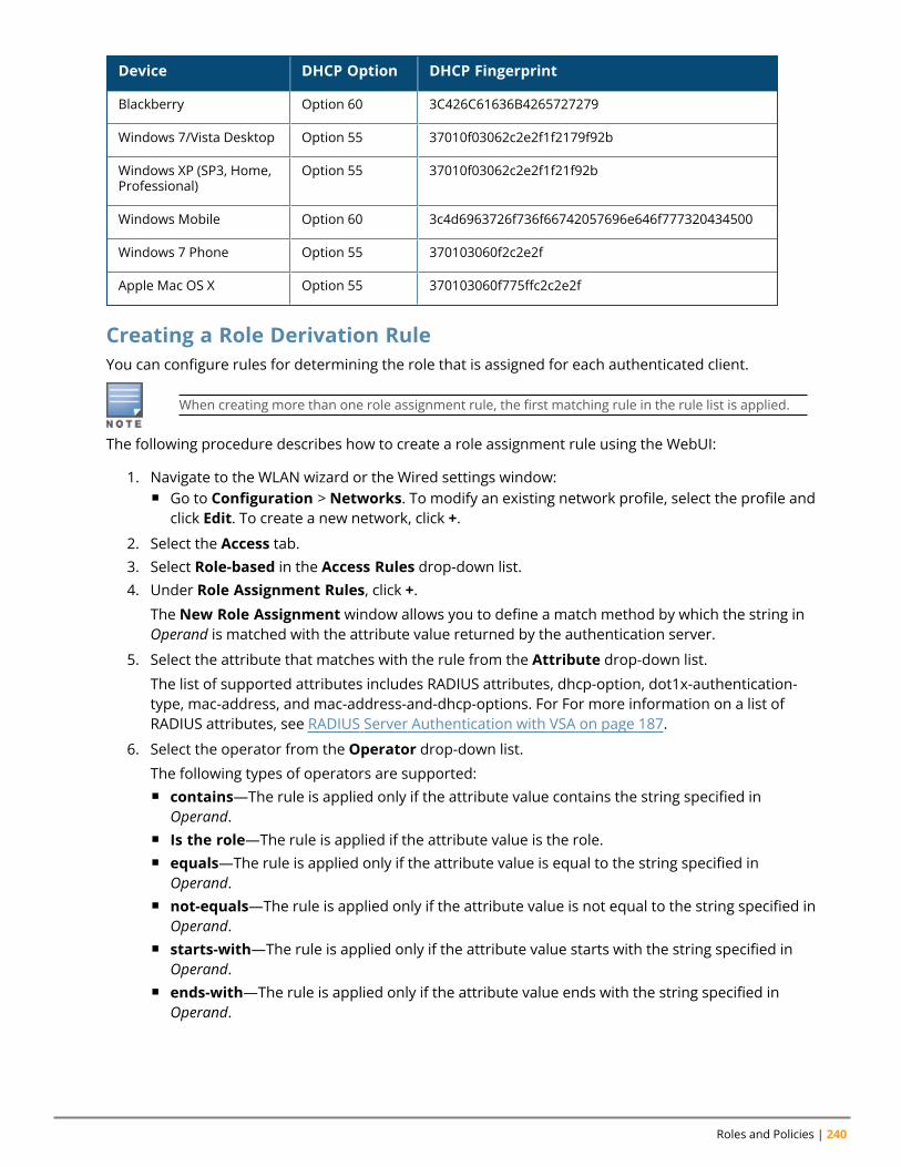
Roles and Policies | 240
Device DHCP Option DHCP Fingerprint
Blackberry Option 60 3C426C61636B4265727279
Windows 7/Vista Desktop Option 55 37010f03062c2e2f1f2179f92b
Windows XP (SP3, Home,Professional)
Option 55 37010f03062c2e2f1f21f92b
Windows Mobile Option 60 3c4d6963726f736f66742057696e646f777320434500
Windows 7 Phone Option 55 370103060f2c2e2f
Apple Mac OS X Option 55 370103060f775ffc2c2e2f
Creating a Role Derivation RuleYou can configure rules for determining the role that is assigned for each authenticated client.
When creating more than one role assignment rule, the first matching rule in the rule list is applied.
The following procedure describes how to create a role assignment rule using the WebUI:
1. Navigate to the WLAN wizard or the Wired settings window:n Go to Configuration > Networks. To modify an existing network profile, select the profile and
click Edit. To create a new network, click +.
2. Select the Access tab.3. Select Role-based in the Access Rules drop-down list.4. Under Role Assignment Rules, click +.
The New Role Assignment window allows you to define a match method by which the string inOperand is matched with the attribute value returned by the authentication server.
5. Select the attribute that matches with the rule from the Attribute drop-down list.
The list of supported attributes includes RADIUS attributes, dhcp-option, dot1x-authentication-type, mac-address, and mac-address-and-dhcp-options. For For more information on a list ofRADIUS attributes, see RADIUS Server Authentication with VSA on page 187.
6. Select the operator from the Operator drop-down list.
The following types of operators are supported:n contains—The rule is applied only if the attribute value contains the string specified in
Operand.n Is the role—The rule is applied if the attribute value is the role.n equals—The rule is applied only if the attribute value is equal to the string specified in
Operand.n not-equals—The rule is applied only if the attribute value is not equal to the string specified in
Operand.n starts-with—The rule is applied only if the attribute value starts with the string specified in
Operand.n ends-with—The rule is applied only if the attribute value ends with the string specified in
Operand.
Aruba Instant 8.10.0.0 User Guide 241
n matches-regular-expression—The rule is applied only if the attribute value matches theRegex pattern specified in Operand. This operator is available only if themac-address-and-dhcp-options attribute is selected in the Attribute drop-down list. Themac-address-and-dhcp-options attribute andmatches-regular-expression are applicable only for the WLANclients.
7. The following types of operators are supported:n contains—The rule is applied only if the attribute value contains the string specified in
Operand.n Is the role—The rule is applied if the attribute value is the role.n equals—The rule is applied only if the attribute value is equal to the string specified in
Operand.n not-equals—The rule is applied only if the attribute value is not equal to the string specified in
Operand.n starts-with—The rule is applied only if the attribute value starts with the string specified in
Operand.n ends-with—The rule is applied only if the attribute value ends with the string specified in
Operand.n matches-regular-expression—The rule is applied only if the attribute value matches the
Regex pattern specified in Operand. This operator is available only if themac-address-and-dhcp-options attribute is selected in the Attribute drop-down list. Themac-address-and-dhcp-options attribute andmatches-regular-expression are applicable only for the WLANclients.
8. Enter the string to match the attribute in the String text box.9. Select the appropriate role from the Role drop-down list.10. Click OK.11. Click Finish.
n When Enforce Machine Authentication is enabled, both the device and the user must beauthenticated for the role assignment rule to apply.
n Each device type may not have a unique DHCP fingerprint signature. For example, devices fromdifferent manufacturers may use vendor class identifiers that begin with similar strings. If youcreate a DHCPOption rule that uses the starts-with condition instead of the equals condition, therule may assign a role or VLAN to more than one device type.
The following CLI commands configure role assignment rules for a WLAN SSID:
(Instant AP)(config)# wlan ssid-profile <name>(Instant AP)(SSID Profile <name>)# set-role <attribute>{{equals|not-equals|starts-with|ends-with|contains|matches-regular-expression} <operator><role>|value-of}
The following CLI commands configure role assignment rules for a wired profile:
(Instant AP)(config)# wired-port-profile <name>(Instant AP)(wired ap profile <name>)# set-role <attribute>{{equals|not-equal|starts-with| ends-with|contains}<operator> <role>|value-of}
Example
(Instant AP)(config)# wlan ssid-profile Profile1
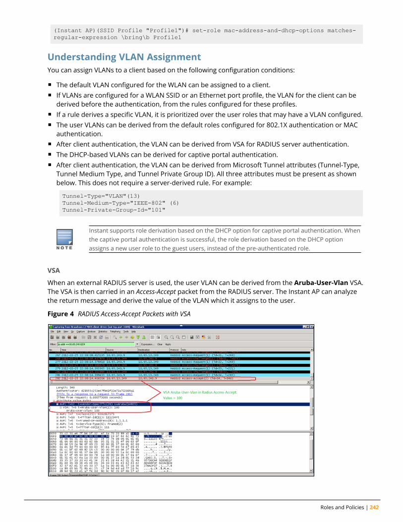
Roles and Policies | 242
(Instant AP)(SSID Profile "Profile1")# set-role mac-address-and-dhcp-options matches-regular-expression \bring\b Profile1
Understanding VLAN AssignmentYou can assign VLANs to a client based on the following configuration conditions:
n The default VLAN configured for the WLAN can be assigned to a client.n If VLANs are configured for a WLAN SSID or an Ethernet port profile, the VLAN for the client can be
derived before the authentication, from the rules configured for these profiles.n If a rule derives a specific VLAN, it is prioritized over the user roles that may have a VLAN configured.n The user VLANs can be derived from the default roles configured for 802.1X authentication or MAC
authentication.n After client authentication, the VLAN can be derived from VSA for RADIUS server authentication.n The DHCP-based VLANs can be derived for captive portal authentication.n After client authentication, the VLAN can be derived from Microsoft Tunnel attributes (Tunnel-Type,
Tunnel Medium Type, and Tunnel Private Group ID). All three attributes must be present as shownbelow. This does not require a server-derived rule. For example:
Tunnel-Type="VLAN"(13)Tunnel-Medium-Type="IEEE-802" (6)Tunnel-Private-Group-Id="101"
Instant supports role derivation based on the DHCP option for captive portal authentication. Whenthe captive portal authentication is successful, the role derivation based on the DHCP optionassigns a new user role to the guest users, instead of the pre-authenticated role.
VSA
When an external RADIUS server is used, the user VLAN can be derived from the Aruba-User-Vlan VSA.The VSA is then carried in an Access-Accept packet from the RADIUS server. The Instant AP can analyzethe return message and derive the value of the VLAN which it assigns to the user.
Figure 4 RADIUS Access-Accept Packets with VSA
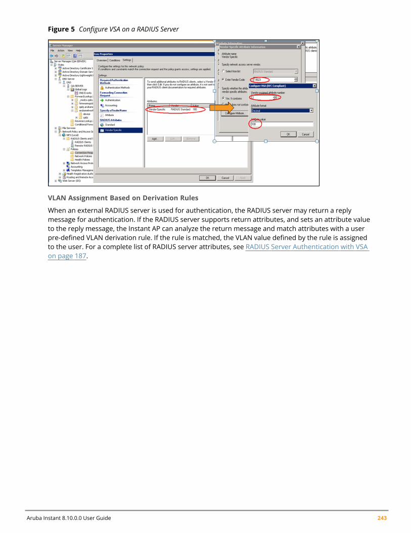
Aruba Instant 8.10.0.0 User Guide 243
Figure 5 Configure VSA on a RADIUS Server
VLAN Assignment Based on Derivation Rules
When an external RADIUS server is used for authentication, the RADIUS server may return a replymessage for authentication. If the RADIUS server supports return attributes, and sets an attribute valueto the reply message, the Instant AP can analyze the return message and match attributes with a userpre-defined VLAN derivation rule. If the rule is matched, the VLAN value defined by the rule is assignedto the user. For a complete list of RADIUS server attributes, see RADIUS Server Authentication with VSAon page 187.
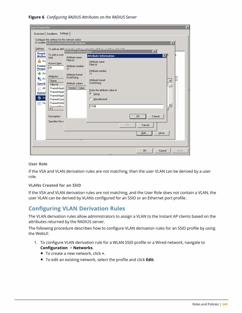
Roles and Policies | 244
Figure 6 Configuring RADIUS Attributes on the RADIUS Server
User Role
If the VSA and VLAN derivation rules are not matching, then the user VLAN can be derived by a userrole.
VLANs Created for an SSID
If the VSA and VLAN derivation rules are not matching, and the User Role does not contain a VLAN, theuser VLAN can be derived by VLANs configured for an SSID or an Ethernet port profile.
Configuring VLAN Derivation RulesThe VLAN derivation rules allow administrators to assign a VLAN to the Instant AP clients based on theattributes returned by the RADIUS server.
The following procedure describes how to configure VLAN derivation rules for an SSID profile by usingthe WebUI:
1. To configure VLAN derivation rule for a WLAN SSID profile or a Wired network, navigate toConfiguration > Networks.n To create a new network, click +.n To edit an existing network, select the profile and click Edit.
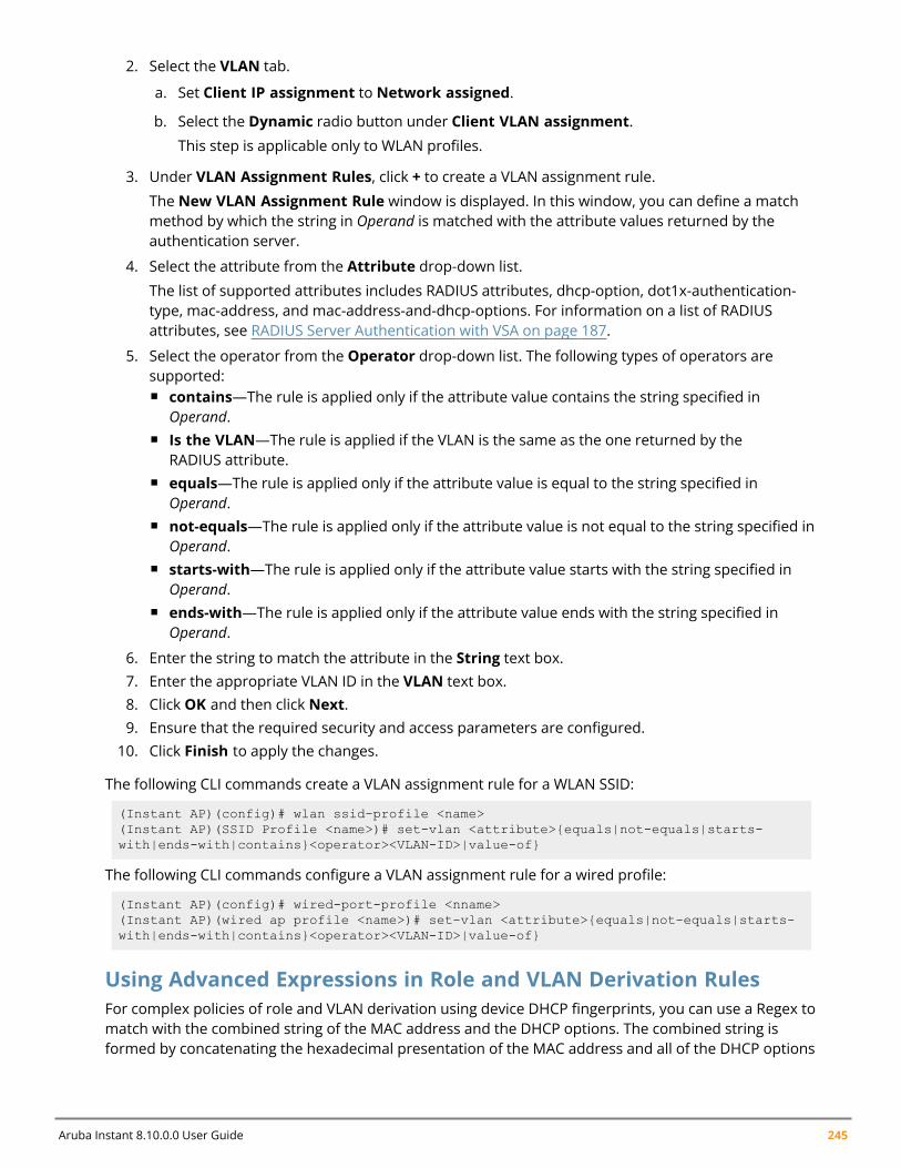
Aruba Instant 8.10.0.0 User Guide 245
2. Select the VLAN tab.
a. Set Client IP assignment to Network assigned.
b. Select the Dynamic radio button under Client VLAN assignment.
This step is applicable only to WLAN profiles.
3. Under VLAN Assignment Rules, click + to create a VLAN assignment rule.
The New VLAN Assignment Rule window is displayed. In this window, you can define a matchmethod by which the string in Operand is matched with the attribute values returned by theauthentication server.
4. Select the attribute from the Attribute drop-down list.
The list of supported attributes includes RADIUS attributes, dhcp-option, dot1x-authentication-type, mac-address, and mac-address-and-dhcp-options. For information on a list of RADIUSattributes, see RADIUS Server Authentication with VSA on page 187.
5. Select the operator from the Operator drop-down list. The following types of operators aresupported:n contains—The rule is applied only if the attribute value contains the string specified in
Operand.n Is the VLAN—The rule is applied if the VLAN is the same as the one returned by the
RADIUS attribute.n equals—The rule is applied only if the attribute value is equal to the string specified in
Operand.n not-equals—The rule is applied only if the attribute value is not equal to the string specified in
Operand.n starts-with—The rule is applied only if the attribute value starts with the string specified in
Operand.n ends-with—The rule is applied only if the attribute value ends with the string specified in
Operand.
6. Enter the string to match the attribute in the String text box.7. Enter the appropriate VLAN ID in the VLAN text box.8. Click OK and then click Next.9. Ensure that the required security and access parameters are configured.10. Click Finish to apply the changes.
The following CLI commands create a VLAN assignment rule for a WLAN SSID:
(Instant AP)(config)# wlan ssid-profile <name>(Instant AP)(SSID Profile <name>)# set-vlan <attribute>{equals|not-equals|starts-with|ends-with|contains}<operator><VLAN-ID>|value-of}
The following CLI commands configure a VLAN assignment rule for a wired profile:
(Instant AP)(config)# wired-port-profile <nname>(Instant AP)(wired ap profile <name>)# set-vlan <attribute>{equals|not-equals|starts-with|ends-with|contains}<operator><VLAN-ID>|value-of}
Using Advanced Expressions in Role and VLAN Derivation RulesFor complex policies of role and VLAN derivation using device DHCP fingerprints, you can use a Regex tomatch with the combined string of the MAC address and the DHCP options. The combined string isformed by concatenating the hexadecimal presentation of the MAC address and all of the DHCP options
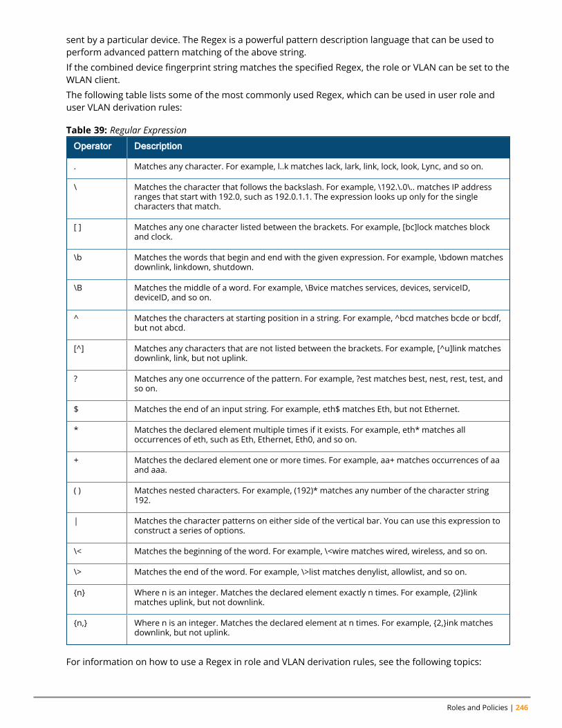
Roles and Policies | 246
sent by a particular device. The Regex is a powerful pattern description language that can be used toperform advanced pattern matching of the above string.
If the combined device fingerprint string matches the specified Regex, the role or VLAN can be set to theWLAN client.
The following table lists some of the most commonly used Regex, which can be used in user role anduser VLAN derivation rules:
Operator Description
. Matches any character. For example, l..k matches lack, lark, link, lock, look, Lync, and so on.
\ Matches the character that follows the backslash. For example, \192.\.0\.. matches IP addressranges that start with 192.0, such as 192.0.1.1. The expression looks up only for the singlecharacters that match.
[ ] Matches any one character listed between the brackets. For example, [bc]lock matches blockand clock.
\b Matches the words that begin and end with the given expression. For example, \bdown matchesdownlink, linkdown, shutdown.
\B Matches the middle of a word. For example, \Bvice matches services, devices, serviceID,deviceID, and so on.
^ Matches the characters at starting position in a string. For example, ^bcd matches bcde or bcdf,but not abcd.
[^] Matches any characters that are not listed between the brackets. For example, [^u]link matchesdownlink, link, but not uplink.
? Matches any one occurrence of the pattern. For example, ?est matches best, nest, rest, test, andso on.
$ Matches the end of an input string. For example, eth$ matches Eth, but not Ethernet.
* Matches the declared element multiple times if it exists. For example, eth* matches alloccurrences of eth, such as Eth, Ethernet, Eth0, and so on.
+ Matches the declared element one or more times. For example, aa+ matches occurrences of aaand aaa.
( ) Matches nested characters. For example, (192)* matches any number of the character string192.
| Matches the character patterns on either side of the vertical bar. You can use this expression toconstruct a series of options.
\< Matches the beginning of the word. For example, \<wire matches wired, wireless, and so on.
\> Matches the end of the word. For example, \>list matches denylist, allowlist, and so on.
{n} Where n is an integer. Matches the declared element exactly n times. For example, {2}linkmatches uplink, but not downlink.
{n,} Where n is an integer. Matches the declared element at n times. For example, {2,}ink matchesdownlink, but not uplink.
Table 39: Regular Expression
For information on how to use a Regex in role and VLAN derivation rules, see the following topics:
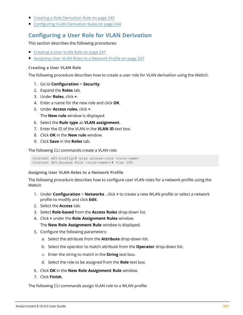
Aruba Instant 8.10.0.0 User Guide 247
n Creating a Role Derivation Rule on page 240n Configuring VLAN Derivation Rules on page 244
Configuring a User Role for VLAN DerivationThis section describes the following procedures:
n Creating a User VLAN Role on page 247n Assigning User VLAN Roles to a Network Profile on page 247
Creating a User VLAN Role
The following procedure describes how to create a user role for VLAN derivation using the WebUI:
1. Go to Configuration > Security.2. Expand the Roles tab.3. Under Roles, click +.4. Enter a name for the new role and click OK.5. Under Access rules, click +.
The New rule window is displayed.
6. Select the Rule type as VLAN assignment.7. Enter the ID of the VLAN in the VLAN ID text box.8. Click OK in the New rule window.9. Click Save in the Roles tab.
The following CLI commands create a VLAN role:
(Instant AP)(config)# wlan access-rule <rule-name>(Instant AP)(Access Rule <rule-name>)# vlan 200
Assigning User VLAN Roles to a Network Profile
The following procedure describes how to configure user VLAN roles for a network profile using theWebUI:
1. Under Configuration > Networks , click + to create a new WLAN profile or select a networkprofile to modify and click Edit.
2. Select the Access tab.3. Select Role-based from the Access Rules drop-down list.4. Click + under the Role Assignment Rules window.
The New Role Assignment Rule window is displayed.
5. Configure the following parameters:
a. Select the attribute from the Attribute drop-down list.
b. Select the operator to match attribute from the Operator drop-down list.
c. Enter the string to match in the String text box.
d. Select the role to be assigned from the Role text box.
6. Click OK in the New Role Assignment Rule window.7. Click Finish.
The following CLI commands assign VLAN role to a WLAN profile:
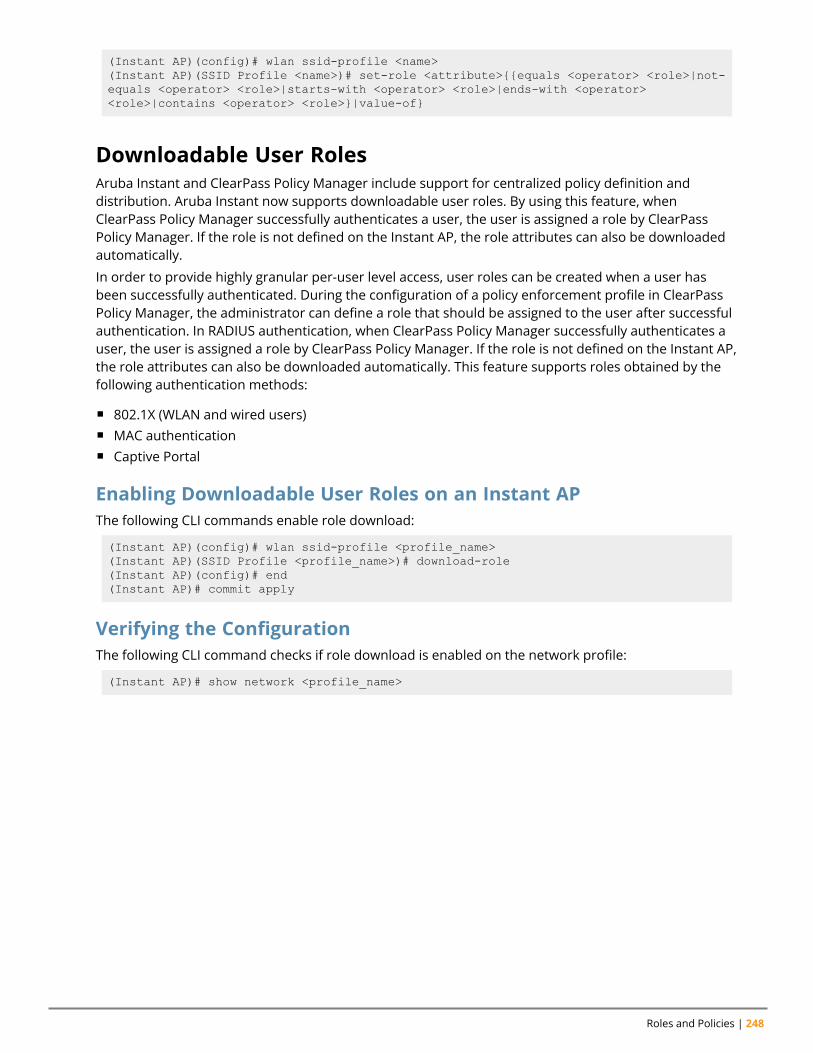
Roles and Policies | 248
(Instant AP)(config)# wlan ssid-profile <name>(Instant AP)(SSID Profile <name>)# set-role <attribute>{{equals <operator> <role>|not-equals <operator> <role>|starts-with <operator> <role>|ends-with <operator><role>|contains <operator> <role>}|value-of}
Downloadable User RolesAruba Instant and ClearPass Policy Manager include support for centralized policy definition anddistribution. Aruba Instant now supports downloadable user roles. By using this feature, whenClearPass Policy Manager successfully authenticates a user, the user is assigned a role by ClearPassPolicy Manager. If the role is not defined on the Instant AP, the role attributes can also be downloadedautomatically.
In order to provide highly granular per-user level access, user roles can be created when a user hasbeen successfully authenticated. During the configuration of a policy enforcement profile in ClearPassPolicy Manager, the administrator can define a role that should be assigned to the user after successfulauthentication. In RADIUS authentication, when ClearPass Policy Manager successfully authenticates auser, the user is assigned a role by ClearPass Policy Manager. If the role is not defined on the Instant AP,the role attributes can also be downloaded automatically. This feature supports roles obtained by thefollowing authentication methods:
n 802.1X (WLAN and wired users)n MAC authenticationn Captive Portal
Enabling Downloadable User Roles on an Instant APThe following CLI commands enable role download:
(Instant AP)(config)# wlan ssid-profile <profile_name>(Instant AP)(SSID Profile <profile_name>)# download-role(Instant AP)(config)# end(Instant AP)# commit apply
Verifying the ConfigurationThe following CLI command checks if role download is enabled on the network profile:
(Instant AP)# show network <profile_name>
Chapter 15DHCP Configuration
DHCP ConfigurationThis chapter provides the following information:
n Configuring DHCP Scopes on page 249n Configuring the Default DHCP Scope for Client IP Assignment on page 262
Configuring DHCP ScopesThe virtual controller supports different modes of DHCP address assignment. With each DHCP addressassignment mode, various client traffic forwarding modes are associated. For more information on clienttraffic forwarding modes for IAP-VPN, see IAP-VPN Forwarding Modes on page 325.
When using a local DHCP scope in anInstant AP cluster, ensure that the VLANs configured for thisDHCP scope is allowed in the uplink switch.
In a single Instant AP network, when using a client DHCP scope for wired clients, ensure that clientVLAN is not added in the allowed VLAN list for the port to which the Instant AP Ethernet 0 port isconnected.
This section describes the following procedures:
n Configuring Local DHCP Scopes on page 249n Configuring Distributed DHCP Scopes on page 252n Enabling DHCP Relay Agent Information Option (Option 82) on page 257
Configuring Local DHCP ScopesYou can configure Local, Local L2, and Local L3 DHCP scopes using the WebUI or the CLI.
n Local—In this mode, the virtual controller acts as both the DHCP server and the default gateway. Theconfigured subnet and the corresponding DHCP scope are independent of the subnets configured inother Instant AP clusters. The virtual controller assigns an IP address from a local subnet andforwards traffic to both corporate and non-corporate destinations. The network address istranslated appropriately and the packet is forwarded through the IPsec tunnel or through the uplink.This DHCP assignment mode is used in the NAT forwarding mode.
n Local, L2—In this mode, the virtual controller acts as a DHCP server and the gateway located outsidethe Instant AP.
n Local, L3—This DHCP assignment mode is used with the L3 forwarding mode. In this mode, thevirtual controller acts as a DHCP server and the gateway, and assigns an IP address from the localsubnet. The Instant AP routes the packets sent by clients on its uplink. The Local L3 subnets canaccess corporate network through the IPsec tunnel. The network address for all client traffic, which isgenerated in the Local L3 subnets and destined to the corporate network, is translated at the sourcewith the tunnel inner IP. However, if corporate access to Local L3 is not required, you can configureACL rules to deny access.
Aruba Instant 8.10.0.0 User Guide 249
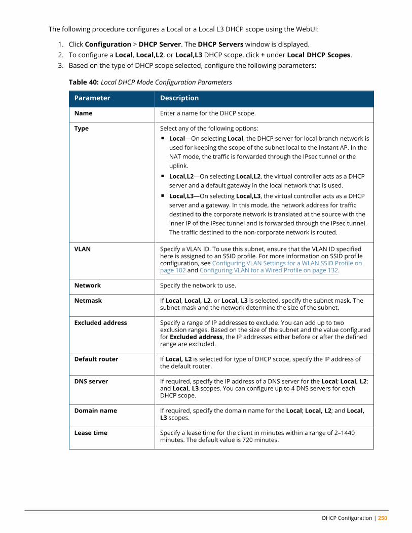
DHCP Configuration | 250
The following procedure configures a Local or a Local L3 DHCP scope using the WebUI:
1. Click Configuration > DHCP Server. The DHCP Servers window is displayed.2. To configure a Local, Local,L2, or Local,L3 DHCP scope, click + under Local DHCP Scopes.3. Based on the type of DHCP scope selected, configure the following parameters:
Parameter Description
Name Enter a name for the DHCP scope.
Type Select any of the following options:n Local—On selecting Local, the DHCP server for local branch network is
used for keeping the scope of the subnet local to the Instant AP. In theNAT mode, the traffic is forwarded through the IPsec tunnel or theuplink.
n Local,L2—On selecting Local,L2, the virtual controller acts as a DHCPserver and a default gateway in the local network that is used.
n Local,L3—On selecting Local,L3, the virtual controller acts as a DHCPserver and a gateway. In this mode, the network address for trafficdestined to the corporate network is translated at the source with theinner IP of the IPsec tunnel and is forwarded through the IPsec tunnel.The traffic destined to the non-corporate network is routed.
VLAN Specify a VLAN ID. To use this subnet, ensure that the VLAN ID specifiedhere is assigned to an SSID profile. For more information on SSID profileconfiguration, see Configuring VLAN Settings for a WLAN SSID Profile onpage 102 and Configuring VLAN for a Wired Profile on page 132.
Network Specify the network to use.
Netmask If Local, Local, L2, or Local, L3 is selected, specify the subnet mask. Thesubnet mask and the network determine the size of the subnet.
Excluded address Specify a range of IP addresses to exclude. You can add up to twoexclusion ranges. Based on the size of the subnet and the value configuredfor Excluded address, the IP addresses either before or after the definedrange are excluded.
Default router If Local, L2 is selected for type of DHCP scope, specify the IP address ofthe default router.
DNS server If required, specify the IP address of a DNS server for the Local; Local, L2;and Local, L3 scopes. You can configure up to 4 DNS servers for eachDHCP scope.
Domain name If required, specify the domain name for the Local; Local, L2; and Local,L3 scopes.
Lease time Specify a lease time for the client in minutes within a range of 2–1440minutes. The default value is 720 minutes.
Table 40: Local DHCP Mode Configuration Parameters
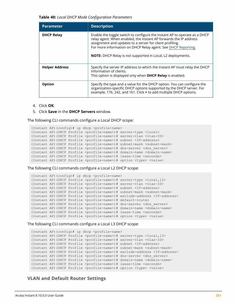
Aruba Instant 8.10.0.0 User Guide 251
Parameter Description
DHCP Relay Enable the toggle switch to configure the Instant AP to operate as a DHCPrelay agent. When enabled, the Instant AP forwards the IP addressassignment and updates to a server for client profiling.For more information on DHCP Relay agent. See DHCP Reporting.
NOTE: DHCP Relay is not supported in Local, L2 deployments.
Helper Address Specify the server IP address to which the Instant AP must relay the DHCPinformation of clients.This option is displayed only when DHCP Relay is enabled.
Option Specify the type and a value for the DHCP option. You can configure theorganization-specific DHCP options supported by the DHCP server. Forexample, 176, 242, and 161. Click + to add multiple DHCP options.
Table 40: Local DHCP Mode Configuration Parameters
4. Click OK.5. Click Save in the DHCP Servers window.
The following CLI commands configure a Local DHCP scope:
(Instant AP)(config)# ip dhcp <profile-name>(Instant AP)(DHCP Profile <profile-name>)# server-type <local>(Instant AP)(DHCP Profile <profile-name>)# server-vlan <vlan-ID>(Instant AP)(DHCP Profile <profile-name>)# subnet <IP-address>(Instant AP)(DHCP Profile <profile-name>)# subnet-mask <subnet-mask>(Instant AP)(DHCP Profile <profile-name>)# dns-server <dns_server>(Instant AP)(DHCP Profile <profile-name>)# domain-name <domain-name>(Instant AP)(DHCP Profile <profile-name>)# lease-time <seconds>(Instant AP)(DHCP Profile <profile-name>)# option <type> <value>
The following CLI commands configure a Local L2 DHCP scope:
(Instant AP)(config)# ip dhcp <profile-name>(Instant AP)(DHCP Profile <profile-name>)# server-type <local,l2>(Instant AP)(DHCP Profile <profile-name>)# server-vlan <vlan-ID>(Instant AP)(DHCP Profile <profile-name>)# subnet <IP-address>(Instant AP)(DHCP Profile <profile-name>)# subnet-mask <subnet-mask>(Instant AP)(DHCP Profile <profile-name>)# exclude-address <IP-address>(Instant AP)(DHCP Profile <profile-name>)# default-router(Instant AP)(DHCP Profile <profile-name>)# dns-server <dns_server>(Instant AP)(DHCP Profile <profile-name>)# domain-name <domain-name>(Instant AP)(DHCP Profile <profile-name>)# lease-time <seconds>(Instant AP)(DHCP Profile <profile-name>)# option <type> <value>
The following CLI commands configure a Local L3 DHCP scope:
(Instant AP)(config)# ip dhcp <profile-name>(Instant AP)(DHCP Profile <profile-name>)# server-type <local,l3>(Instant AP)(DHCP Profile <profile-name>)# server-vlan <vlan-ID>(Instant AP)(DHCP Profile <profile-name>)# subnet <IP-address>(Instant AP)(DHCP Profile <profile-name>)# subnet-mask <subnet-mask>(Instant AP)(DHCP Profile <profile-name>)# exclude-address <IP-address>(Instant AP)(DHCP Profile <profile-name>)# dns-server <dns_server>(Instant AP)(DHCP Profile <profile-name>)# domain-name <domain-name>(Instant AP)(DHCP Profile <profile-name>)# lease-time <seconds>(Instant AP)(DHCP Profile <profile-name>)# option <type> <value>
VLAN and Default Router Settings
DHCP Configuration | 252
Instant supports DHCP scopes in which both, the DHCP server and the default gateway on a virtualcontroller can configure a default gateway IP address. For the Centralized, L3, Local, Local, L2, and Local,L3 scopes, an option is introduced to configure a VLAN IP address to the existing service VLAN of aDHCP pool. This feature can prevent changes that may occur in DHCP range exclusions.
The following procedure configures a default router and VLAN parameters in a local DHCP profile usingthe WebUI:
1. Click Configuration > DHCP Server. The DHCP Servers window is displayed.2. To configure a local DHCP scope, click + under Local DHCP Scopes. The New DHCP Scope
window is displayed.3. Specify the type of the DHCP scope in the Type drop-down list and configure the parameters
available in the WebUI. The Default router parameter can be set on Local and Local L3 profiles.The VLAN IP and VLAN mask parameters can be set only on the Local L2 profile.
4. Click OK.
The following CLI command configures a VLAN IP in a Local DHCP profile:
(Instant AP)(config)# ip dhcp <profile-name>(Instant AP)(DHCP Profile <profile-name>)# vlan-ip <VLAN_IP> mask <VLAN mask>
The following CLI command configures a default router in a Local DHCP profile:
(Instant AP)(config)# ip dhcp <profile-name>(Instant AP)(DHCP Profile <profile-name>)# default-router <default_router>
The value of the VLAN IP and default router for the Local or Local, L3 profile must be the same.
Configuring Distributed DHCP ScopesInstant allows you to configure the DHCP address assignment for the branches connected to thecorporate network through VPN. You can configure the range of DHCP IP addresses used in thebranches and the number of client addresses allowed per branch. You can also specify the IP addressesthat must be excluded from those assigned to clients, so that they are assigned statically.
Instant supports the following distributed DHCP scopes:
n Distributed, L2—In this mode, the virtual controller acts as the DHCP server, but the defaultgateway is in the data center. Based on the number of clients specified for each branch, the range ofIP addresses is divided. Based on the IP address range and client count configuration, the DHCPserver in the virtual controller controls a scope that is a subset of the complete IP address range forthe subnet distributed across all the branches. This DHCP assignment mode is used with the L2forwarding mode.
n Distributed, L3—In this mode, the virtual controller acts as the DHCP server and the defaultgateway. Based on the number of clients specified for each branch, the range of IP addresses isdivided. Based on the IP address range and client count configuration, the DHCP server in the virtualcontroller is configured with a unique subnet and a corresponding scope.
The following procedure configures distributed DHCP scopes such as Distributed L2 or Distributed L3using the WebUI:
1. Click Configuration > DHCP Server. The DHCP Servers window is displayed.2. To configure a distributed DHCP mode, click + under Distributed DHCP Scopes. The New DHCP
Scope window is displayed.3. Based on the type of distributed DHCP scope, configure the following parameters in the Network
tab:
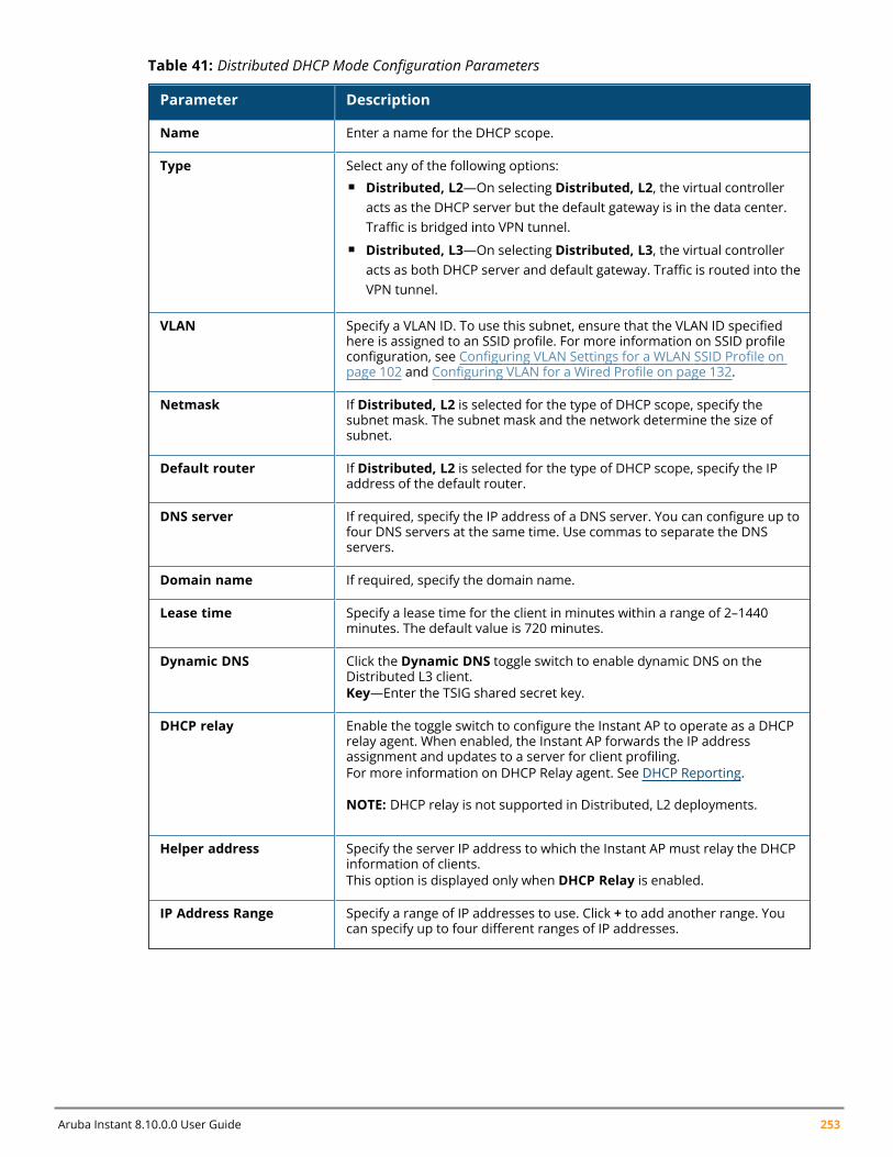
Aruba Instant 8.10.0.0 User Guide 253
Parameter Description
Name Enter a name for the DHCP scope.
Type Select any of the following options:n Distributed, L2—On selecting Distributed, L2, the virtual controller
acts as the DHCP server but the default gateway is in the data center.Traffic is bridged into VPN tunnel.
n Distributed, L3—On selecting Distributed, L3, the virtual controlleracts as both DHCP server and default gateway. Traffic is routed into theVPN tunnel.
VLAN Specify a VLAN ID. To use this subnet, ensure that the VLAN ID specifiedhere is assigned to an SSID profile. For more information on SSID profileconfiguration, see Configuring VLAN Settings for a WLAN SSID Profile onpage 102 and Configuring VLAN for a Wired Profile on page 132.
Netmask If Distributed, L2 is selected for the type of DHCP scope, specify thesubnet mask. The subnet mask and the network determine the size ofsubnet.
Default router If Distributed, L2 is selected for the type of DHCP scope, specify the IPaddress of the default router.
DNS server If required, specify the IP address of a DNS server. You can configure up tofour DNS servers at the same time. Use commas to separate the DNSservers.
Domain name If required, specify the domain name.
Lease time Specify a lease time for the client in minutes within a range of 2–1440minutes. The default value is 720 minutes.
Dynamic DNS Click the Dynamic DNS toggle switch to enable dynamic DNS on theDistributed L3 client.Key—Enter the TSIG shared secret key.
DHCP relay Enable the toggle switch to configure the Instant AP to operate as a DHCPrelay agent. When enabled, the Instant AP forwards the IP addressassignment and updates to a server for client profiling.For more information on DHCP Relay agent. See DHCP Reporting.
NOTE: DHCP relay is not supported in Distributed, L2 deployments.
Helper address Specify the server IP address to which the Instant AP must relay the DHCPinformation of clients.This option is displayed only when DHCP Relay is enabled.
IP Address Range Specify a range of IP addresses to use. Click + to add another range. Youcan specify up to four different ranges of IP addresses.
Table 41: Distributed DHCP Mode Configuration Parameters
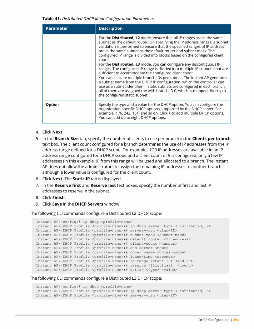
DHCP Configuration | 254
Parameter Description
For the Distributed, L2mode, ensure that all IP ranges are in the samesubnet as the default router. On specifying the IP address ranges, a subnetvalidation is performed to ensure that the specified ranges of IP addressare in the same subnet as the default router and subnet mask. Theconfigured IP range is divided into blocks based on the configured clientcount.For the Distributed, L3mode, you can configure any discontiguous IPranges. The configured IP range is divided into multiple IP subnets that aresufficient to accommodate the configured client count.You can allocate multiple branch IDs per subnet. The Instant AP generatesa subnet name from the DHCP IP configuration, which the controller canuse as a subnet identifier. If static subnets are configured in each branch,all of them are assigned the with branch ID 0, which is mapped directly tothe configured static subnet.
Option Specify the type and a value for the DHCP option. You can configure theorganization-specific DHCP options supported by the DHCP server. Forexample, 176, 242, 161, and so on. Click + to add multiple DHCP options.You can add up to eight DHCP options.
Table 41: Distributed DHCP Mode Configuration Parameters
4. Click Next.5. In the Branch Size tab, specify the number of clients to use per branch in the Clients per branch
text box. The client count configured for a branch determines the use of IP addresses from the IPaddress range defined for a DHCP scope. For example, if 20 IP addresses are available in an IPaddress range configured for a DHCP scope and a client count of 9 is configured, only a few IPaddresses (in this example, 9) from this range will be used and allocated to a branch. The InstantAP does not allow the administrators to assign the remaining IP addresses to another branch,although a lower value is configured for the client count.
6. Click Next. The Static IP tab is displayed.7. In the Reserve first and Reserve last text boxes, specify the number of first and last IP
addresses to reserve in the subnet.8. Click Finish.9. Click Save in the DHCP Servers window.
The following CLI commands configure a Distributed L2 DHCP scope:
(Instant AP)(config)# ip dhcp <profile-name>(Instant AP)(DHCP Profile <profile-name>)# ip dhcp server-type <Distributed,L2>(Instant AP)(DHCP Profile <profile-name>)# server-vlan <vlan-ID>(Instant AP)(DHCP Profile <profile-name>)# subnet-mask <subnet-mask>(Instant AP)(DHCP Profile <profile-name>)# default-router <IP-address>(Instant AP)(DHCP Profile <profile-name>)# client-count <number>(Instant AP)(DHCP Profile <profile-name>)# dns-server <name>(Instant AP)(DHCP Profile <profile-name>)# domain-name <domain-name>(Instant AP)(DHCP Profile <profile-name>)# lease-time <seconds>(Instant AP)(DHCP Profile <profile-name>)# ip-range <start-IP> <end-IP>(Instant AP)(DHCP Profile <profile-name>)# reserve {first|last} <count>(Instant AP)(DHCP Profile <profile-name>)# option <type> <value>
The following CLI commands configure a Distributed L3 DHCP scope:
(Instant AP)(config)# ip dhcp <profile-name>(Instant AP)(DHCP Profile <profile-name>)# ip dhcp server-type <Distributed,L3>(Instant AP)(DHCP Profile <profile-name>)# server-vlan <vlan-ID>
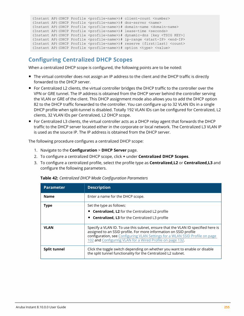
Aruba Instant 8.10.0.0 User Guide 255
(Instant AP)(DHCP Profile <profile-name>)# client-count <number>(Instant AP)(DHCP Profile <profile-name>)# dns-server <name>(Instant AP)(DHCP Profile <profile-name>)# domain-name <domain-name>(Instant AP)(DHCP Profile <profile-name>)# lease-time <seconds>(Instant AP)(DHCP Profile <profile-name>)# dynamic-dns [key <TSIG KEY>](Instant AP)(DHCP Profile <profile-name>)# ip-range <start-IP> <end-IP>(Instant AP)(DHCP Profile <profile-name>)# reserve {first|last} <count>(Instant AP)(DHCP Profile <profile-name>)# option <type> <value>
Configuring Centralized DHCP ScopesWhen a centralized DHCP scope is configured, the following points are to be noted:
n The virtual controller does not assign an IP address to the client and the DHCP traffic is directlyforwarded to the DHCP server.
n For Centralized L2 clients, the virtual controller bridges the DHCP traffic to the controller over theVPN or GRE tunnel. The IP address is obtained from the DHCP server behind the controller servingthe VLAN or GRE of the client. This DHCP assignment mode also allows you to add the DHCP option82 to the DHCP traffic forwarded to the controller. You can configure up to 32 VLAN IDs in a singleDHCP profile when split-tunnel is disabled. Totally 192 VLAN IDs can be configured for Centralized, L2clients, 32 VLAN IDs per Centralized, L2 DHCP scope.
n For Centralized L3 clients, the virtual controller acts as a DHCP relay agent that forwards the DHCPtraffic to the DHCP server located either in the corporate or local network. The Centralized L3 VLAN IPis used as the source IP. The IP address is obtained from the DHCP server.
The following procedure configures a centralized DHCP scope:
1. Navigate to the Configuration > DHCP Server page.2. To configure a centralized DHCP scope, click + under Centralized DHCP Scopes.3. To configure a centralized profile, select the profile type as Centralized,L2 or Centralized,L3 and
configure the following parameters.
Parameter Description
Name Enter a name for the DHCP scope.
Type Set the type as follows:n Centralized, L2 for the Centralized L2 profilen Centralized, L3 for the Centralized L3 profile
VLAN Specify a VLAN ID. To use this subnet, ensure that the VLAN ID specified here isassigned to an SSID profile. For more information on SSID profileconfiguration, see Configuring VLAN Settings for a WLAN SSID Profile on page102 and Configuring VLAN for a Wired Profile on page 132.
Split tunnel Click the toggle switch depending on whether you want to enable or disablethe split tunnel functionality for the Centralized L2 subnet.
Table 42: Centralized DHCP Mode Configuration Parameters
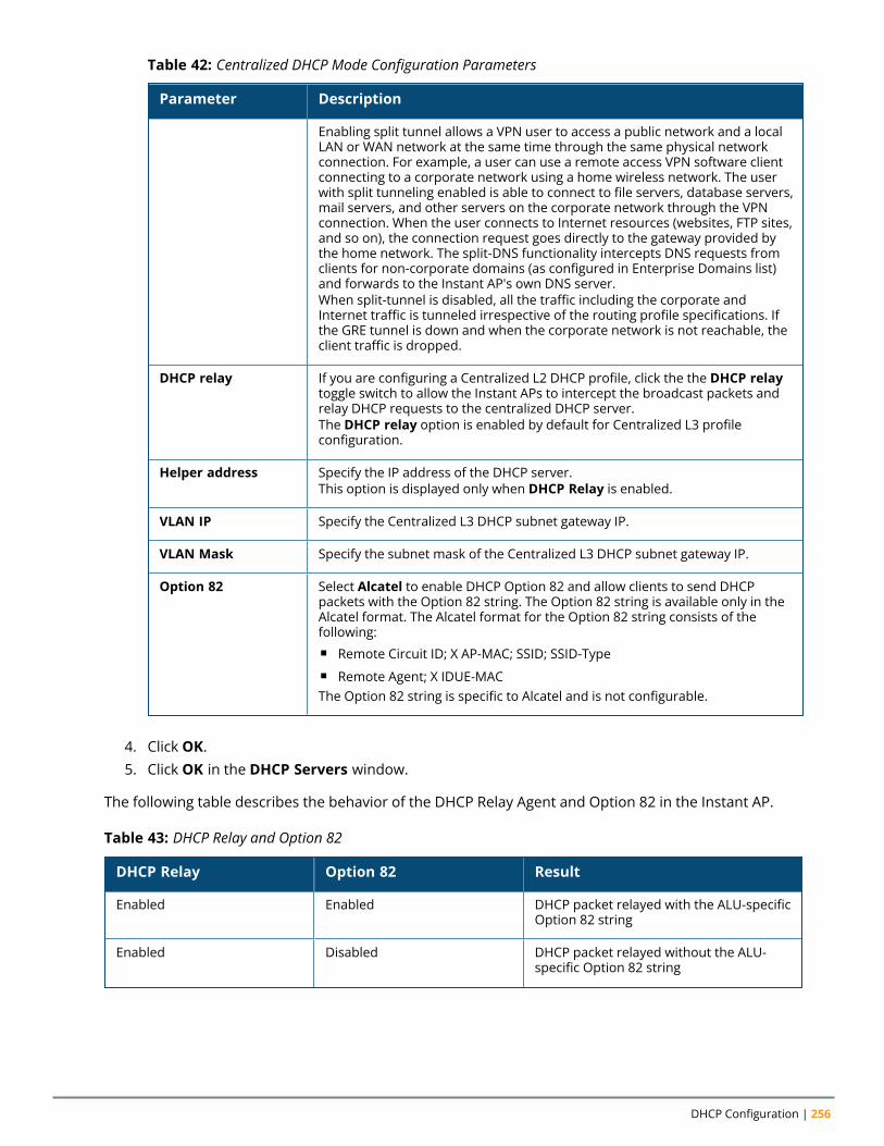
DHCP Configuration | 256
Parameter Description
Enabling split tunnel allows a VPN user to access a public network and a localLAN or WAN network at the same time through the same physical networkconnection. For example, a user can use a remote access VPN software clientconnecting to a corporate network using a home wireless network. The userwith split tunneling enabled is able to connect to file servers, database servers,mail servers, and other servers on the corporate network through the VPNconnection. When the user connects to Internet resources (websites, FTP sites,and so on), the connection request goes directly to the gateway provided bythe home network. The split-DNS functionality intercepts DNS requests fromclients for non-corporate domains (as configured in Enterprise Domains list)and forwards to the Instant AP's own DNS server.When split-tunnel is disabled, all the traffic including the corporate andInternet traffic is tunneled irrespective of the routing profile specifications. Ifthe GRE tunnel is down and when the corporate network is not reachable, theclient traffic is dropped.
DHCP relay If you are configuring a Centralized L2 DHCP profile, click the the DHCP relaytoggle switch to allow the Instant APs to intercept the broadcast packets andrelay DHCP requests to the centralized DHCP server.The DHCP relay option is enabled by default for Centralized L3 profileconfiguration.
Helper address Specify the IP address of the DHCP server.This option is displayed only when DHCP Relay is enabled.
VLAN IP Specify the Centralized L3 DHCP subnet gateway IP.
VLAN Mask Specify the subnet mask of the Centralized L3 DHCP subnet gateway IP.
Option 82 Select Alcatel to enable DHCP Option 82 and allow clients to send DHCPpackets with the Option 82 string. The Option 82 string is available only in theAlcatel format. The Alcatel format for the Option 82 string consists of thefollowing:n Remote Circuit ID; X AP-MAC; SSID; SSID-Typen Remote Agent; X IDUE-MACThe Option 82 string is specific to Alcatel and is not configurable.
Table 42: Centralized DHCP Mode Configuration Parameters
4. Click OK.5. Click OK in the DHCP Servers window.
The following table describes the behavior of the DHCP Relay Agent and Option 82 in the Instant AP.
DHCP Relay Option 82 Result
Enabled Enabled DHCP packet relayed with the ALU-specificOption 82 string
Enabled Disabled DHCP packet relayed without the ALU-specific Option 82 string
Table 43: DHCP Relay and Option 82
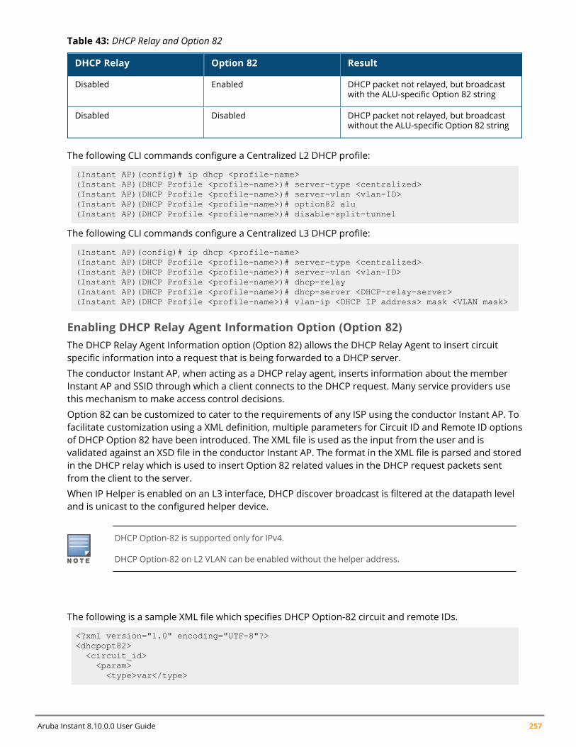
Aruba Instant 8.10.0.0 User Guide 257
DHCP Relay Option 82 Result
Disabled Enabled DHCP packet not relayed, but broadcastwith the ALU-specific Option 82 string
Disabled Disabled DHCP packet not relayed, but broadcastwithout the ALU-specific Option 82 string
Table 43: DHCP Relay and Option 82
The following CLI commands configure a Centralized L2 DHCP profile:
(Instant AP)(config)# ip dhcp <profile-name>(Instant AP)(DHCP Profile <profile-name>)# server-type <centralized>(Instant AP)(DHCP Profile <profile-name>)# server-vlan <vlan-ID>(Instant AP)(DHCP Profile <profile-name>)# option82 alu(Instant AP)(DHCP Profile <profile-name>)# disable-split-tunnel
The following CLI commands configure a Centralized L3 DHCP profile:
(Instant AP)(config)# ip dhcp <profile-name>(Instant AP)(DHCP Profile <profile-name>)# server-type <centralized>(Instant AP)(DHCP Profile <profile-name>)# server-vlan <vlan-ID>(Instant AP)(DHCP Profile <profile-name>)# dhcp-relay(Instant AP)(DHCP Profile <profile-name>)# dhcp-server <DHCP-relay-server>(Instant AP)(DHCP Profile <profile-name>)# vlan-ip <DHCP IP address> mask <VLAN mask>
Enabling DHCP Relay Agent Information Option (Option 82)The DHCP Relay Agent Information option (Option 82) allows the DHCP Relay Agent to insert circuitspecific information into a request that is being forwarded to a DHCP server.
The conductor Instant AP, when acting as a DHCP relay agent, inserts information about the memberInstant AP and SSID through which a client connects to the DHCP request. Many service providers usethis mechanism to make access control decisions.
Option 82 can be customized to cater to the requirements of any ISP using the conductor Instant AP. Tofacilitate customization using a XML definition, multiple parameters for Circuit ID and Remote ID optionsof DHCP Option 82 have been introduced. The XML file is used as the input from the user and isvalidated against an XSD file in the conductor Instant AP. The format in the XML file is parsed and storedin the DHCP relay which is used to insert Option 82 related values in the DHCP request packets sentfrom the client to the server.
When IP Helper is enabled on an L3 interface, DHCP discover broadcast is filtered at the datapath leveland is unicast to the configured helper device.
DHCP Option-82 is supported only for IPv4.
DHCP Option-82 on L2 VLAN can be enabled without the helper address.
Sample XML Format
The following is a sample XML file which specifies DHCP Option-82 circuit and remote IDs.
<?xml version="1.0" encoding="UTF-8"?><dhcpopt82><circuit_id><param>
<type>var</type>
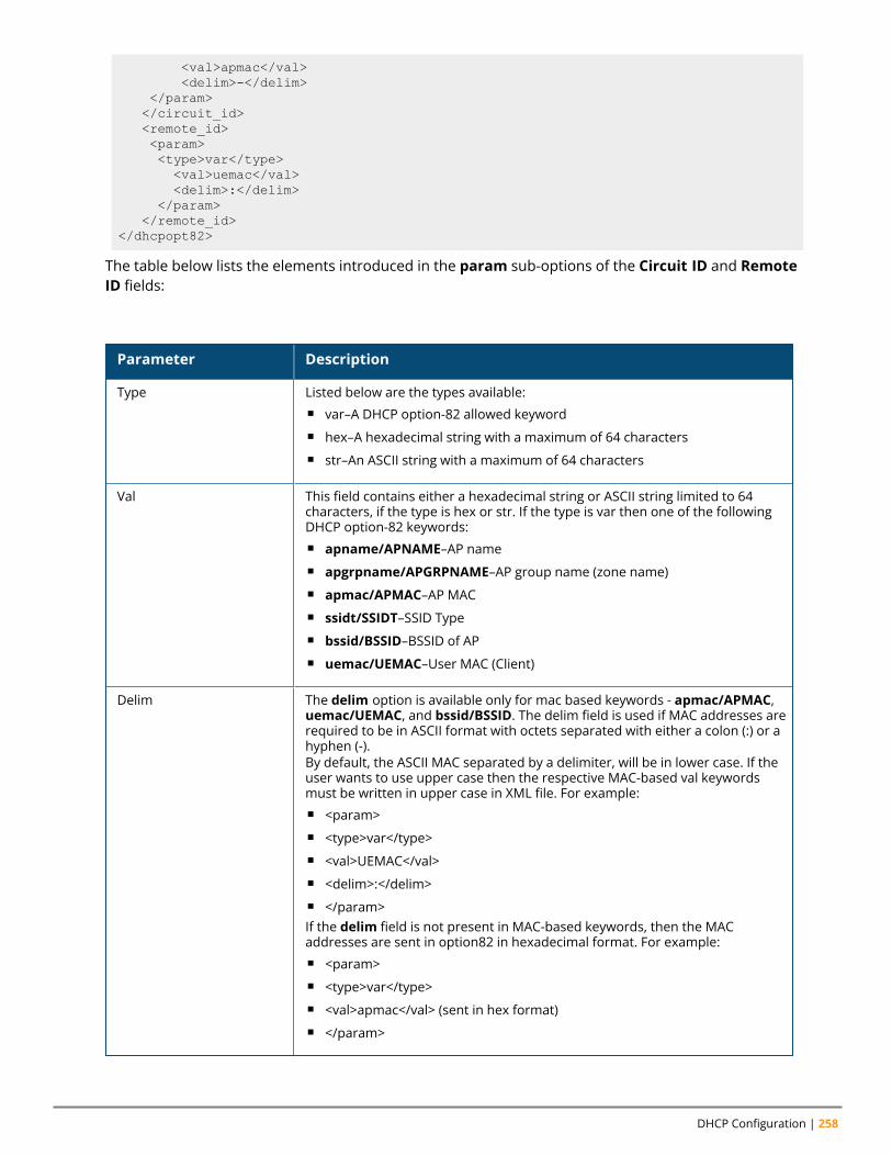
DHCP Configuration | 258
<val>apmac</val><delim>-</delim>
</param></circuit_id><remote_id><param><type>var</type><val>uemac</val><delim>:</delim>
</param></remote_id>
</dhcpopt82>
The table below lists the elements introduced in the param sub-options of the Circuit ID and RemoteID fields:
XML File Parameters
Parameter Description
Type Listed below are the types available:n var–A DHCP option-82 allowed keywordn hex–A hexadecimal string with a maximum of 64 charactersn str–An ASCII string with a maximum of 64 characters
Val This field contains either a hexadecimal string or ASCII string limited to 64characters, if the type is hex or str. If the type is var then one of the followingDHCP option-82 keywords:n apname/APNAME–AP namen apgrpname/APGRPNAME–AP group name (zone name)n apmac/APMAC–AP MACn ssidt/SSIDT–SSID Typen bssid/BSSID–BSSID of APn uemac/UEMAC–User MAC (Client)
Delim The delim option is available only for mac based keywords - apmac/APMAC,uemac/UEMAC, and bssid/BSSID. The delim field is used if MAC addresses arerequired to be in ASCII format with octets separated with either a colon (:) or ahyphen (-).By default, the ASCII MAC separated by a delimiter, will be in lower case. If theuser wants to use upper case then the respective MAC-based val keywordsmust be written in upper case in XML file. For example:n <param>n <type>var</type>n <val>UEMAC</val>n <delim>:</delim>n </param>If the delim field is not present in MAC-based keywords, then the MACaddresses are sent in option82 in hexadecimal format. For example:n <param>n <type>var</type>n <val>apmac</val> (sent in hex format)n </param>
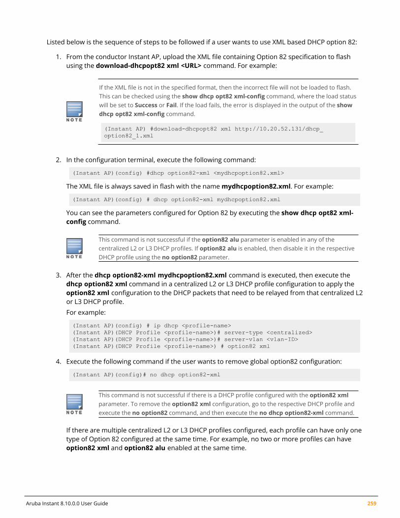
Aruba Instant 8.10.0.0 User Guide 259
Configuring XML Based DHCP Option 82 Specification
Listed below is the sequence of steps to be followed if a user wants to use XML based DHCP option 82:
1. From the conductor Instant AP, upload the XML file containing Option 82 specification to flashusing the download-dhcpopt82 xml <URL> command. For example:
If the XML file is not in the specified format, then the incorrect file will not be loaded to flash.This can be checked using the show dhcp opt82 xml-config command, where the load statuswill be set to Success or Fail. If the load fails, the error is displayed in the output of the showdhcp opt82 xml-config command.
(Instant AP) #download-dhcpopt82 xml http://10.20.52.131/dhcp_option82_1.xml
2. In the configuration terminal, execute the following command:
(Instant AP)(config) #dhcp option82-xml <mydhcpoption82.xml>
The XML file is always saved in flash with the namemydhcpoption82.xml. For example:
(Instant AP)(config) # dhcp option82-xml mydhcpoption82.xml
You can see the parameters configured for Option 82 by executing the show dhcp opt82 xml-config command.
This command is not successful if the option82 alu parameter is enabled in any of thecentralized L2 or L3 DHCP profiles. If option82 alu is enabled, then disable it in the respectiveDHCP profile using the no option82 parameter.
3. After the dhcp option82-xml mydhcpoption82.xml command is executed, then execute thedhcp option82 xml command in a centralized L2 or L3 DHCP profile configuration to apply theoption82 xml configuration to the DHCP packets that need to be relayed from that centralized L2or L3 DHCP profile.
For example:
(Instant AP)(config) # ip dhcp <profile-name>(Instant AP)(DHCP Profile <profile-name>)# server-type <centralized>(Instant AP)(DHCP Profile <profile-name>)# server-vlan <vlan-ID>(Instant AP)(DHCP Profile <profile-name>) # option82 xml
4. Execute the following command if the user wants to remove global option82 configuration:
(Instant AP)(config)# no dhcp option82-xml
This command is not successful if there is a DHCP profile configured with the option82 xmlparameter. To remove the option82 xml configuration, go to the respective DHCP profile andexecute the no option82 command, and then execute the no dhcp option82-xml command.
If there are multiple centralized L2 or L3 DHCP profiles configured, each profile can have only onetype of Option 82 configured at the same time. For example, no two or more profiles can haveoption82 xml and option82 alu enabled at the same time.
Configuring ALU Based DHCP Option 82 Specification
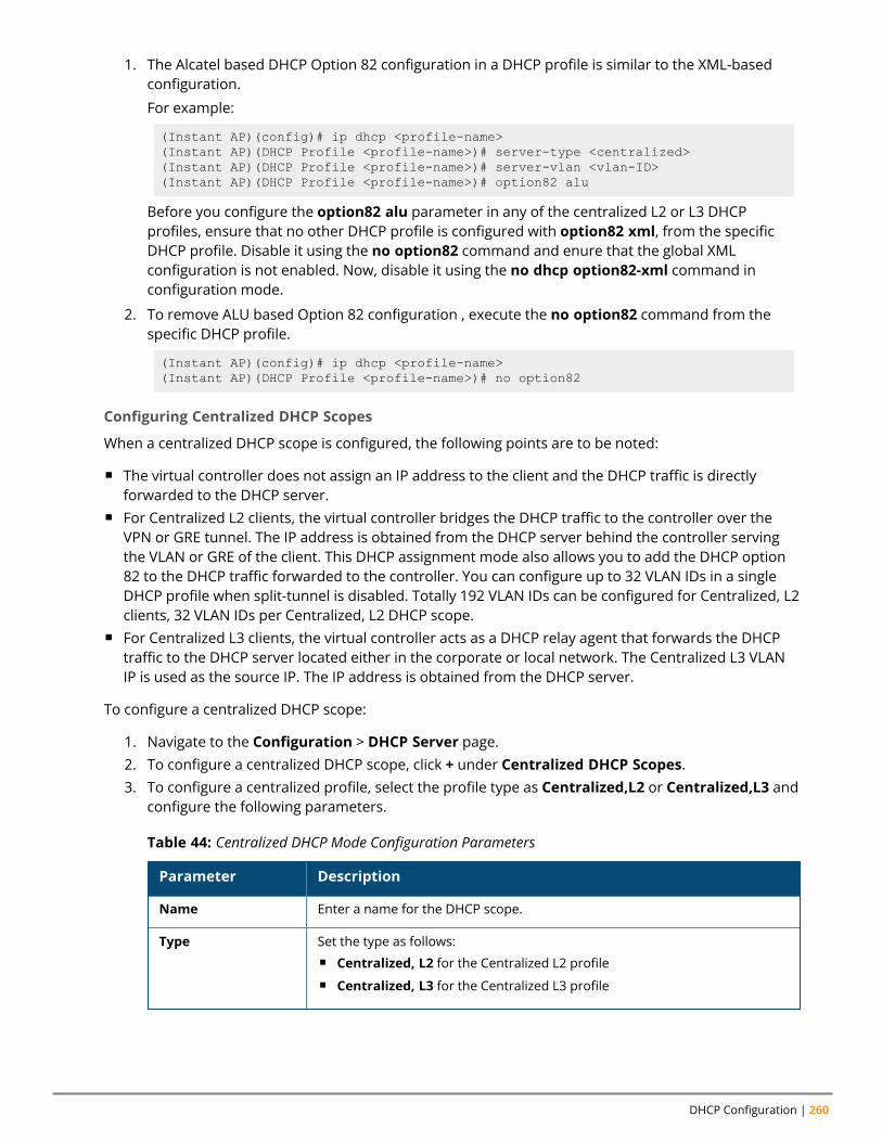
DHCP Configuration | 260
1. The Alcatel based DHCP Option 82 configuration in a DHCP profile is similar to the XML-basedconfiguration.
For example:
(Instant AP)(config)# ip dhcp <profile-name>(Instant AP)(DHCP Profile <profile-name>)# server-type <centralized>(Instant AP)(DHCP Profile <profile-name>)# server-vlan <vlan-ID>(Instant AP)(DHCP Profile <profile-name>)# option82 alu
Before you configure the option82 alu parameter in any of the centralized L2 or L3 DHCPprofiles, ensure that no other DHCP profile is configured with option82 xml, from the specificDHCP profile. Disable it using the no option82 command and enure that the global XMLconfiguration is not enabled. Now, disable it using the no dhcp option82-xml command inconfiguration mode.
2. To remove ALU based Option 82 configuration , execute the no option82 command from thespecific DHCP profile.
(Instant AP)(config)# ip dhcp <profile-name>(Instant AP)(DHCP Profile <profile-name>)# no option82
Configuring Centralized DHCP Scopes
When a centralized DHCP scope is configured, the following points are to be noted:
n The virtual controller does not assign an IP address to the client and the DHCP traffic is directlyforwarded to the DHCP server.
n For Centralized L2 clients, the virtual controller bridges the DHCP traffic to the controller over theVPN or GRE tunnel. The IP address is obtained from the DHCP server behind the controller servingthe VLAN or GRE of the client. This DHCP assignment mode also allows you to add the DHCP option82 to the DHCP traffic forwarded to the controller. You can configure up to 32 VLAN IDs in a singleDHCP profile when split-tunnel is disabled. Totally 192 VLAN IDs can be configured for Centralized, L2clients, 32 VLAN IDs per Centralized, L2 DHCP scope.
n For Centralized L3 clients, the virtual controller acts as a DHCP relay agent that forwards the DHCPtraffic to the DHCP server located either in the corporate or local network. The Centralized L3 VLANIP is used as the source IP. The IP address is obtained from the DHCP server.
To configure a centralized DHCP scope:
1. Navigate to the Configuration > DHCP Server page.2. To configure a centralized DHCP scope, click + under Centralized DHCP Scopes.3. To configure a centralized profile, select the profile type as Centralized,L2 or Centralized,L3 and
configure the following parameters.
Parameter Description
Name Enter a name for the DHCP scope.
Type Set the type as follows:n Centralized, L2 for the Centralized L2 profilen Centralized, L3 for the Centralized L3 profile
Table 44: Centralized DHCP Mode Configuration Parameters
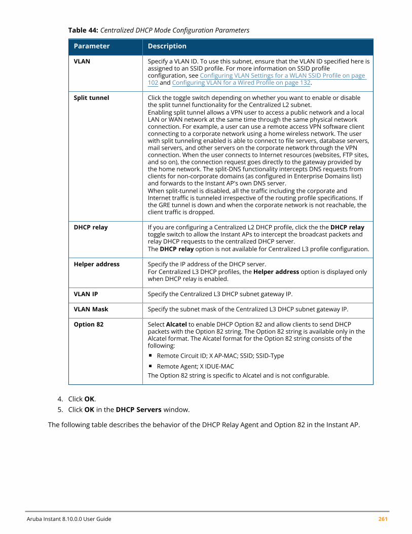
Aruba Instant 8.10.0.0 User Guide 261
Parameter Description
VLAN Specify a VLAN ID. To use this subnet, ensure that the VLAN ID specified here isassigned to an SSID profile. For more information on SSID profileconfiguration, see Configuring VLAN Settings for a WLAN SSID Profile on page102 and Configuring VLAN for a Wired Profile on page 132.
Split tunnel Click the toggle switch depending on whether you want to enable or disablethe split tunnel functionality for the Centralized L2 subnet.Enabling split tunnel allows a VPN user to access a public network and a localLAN or WAN network at the same time through the same physical networkconnection. For example, a user can use a remote access VPN software clientconnecting to a corporate network using a home wireless network. The userwith split tunneling enabled is able to connect to file servers, database servers,mail servers, and other servers on the corporate network through the VPNconnection. When the user connects to Internet resources (websites, FTP sites,and so on), the connection request goes directly to the gateway provided bythe home network. The split-DNS functionality intercepts DNS requests fromclients for non-corporate domains (as configured in Enterprise Domains list)and forwards to the Instant AP's own DNS server.When split-tunnel is disabled, all the traffic including the corporate andInternet traffic is tunneled irrespective of the routing profile specifications. Ifthe GRE tunnel is down and when the corporate network is not reachable, theclient traffic is dropped.
DHCP relay If you are configuring a Centralized L2 DHCP profile, click the the DHCP relaytoggle switch to allow the Instant APs to intercept the broadcast packets andrelay DHCP requests to the centralized DHCP server.The DHCP relay option is not available for Centralized L3 profile configuration.
Helper address Specify the IP address of the DHCP server.For Centralized L3 DHCP profiles, the Helper address option is displayed onlywhen DHCP relay is enabled.
VLAN IP Specify the Centralized L3 DHCP subnet gateway IP.
VLAN Mask Specify the subnet mask of the Centralized L3 DHCP subnet gateway IP.
Option 82 Select Alcatel to enable DHCP Option 82 and allow clients to send DHCPpackets with the Option 82 string. The Option 82 string is available only in theAlcatel format. The Alcatel format for the Option 82 string consists of thefollowing:n Remote Circuit ID; X AP-MAC; SSID; SSID-Typen Remote Agent; X IDUE-MACThe Option 82 string is specific to Alcatel and is not configurable.
Table 44: Centralized DHCP Mode Configuration Parameters
4. Click OK.5. Click OK in the DHCP Servers window.
The following table describes the behavior of the DHCP Relay Agent and Option 82 in the Instant AP.
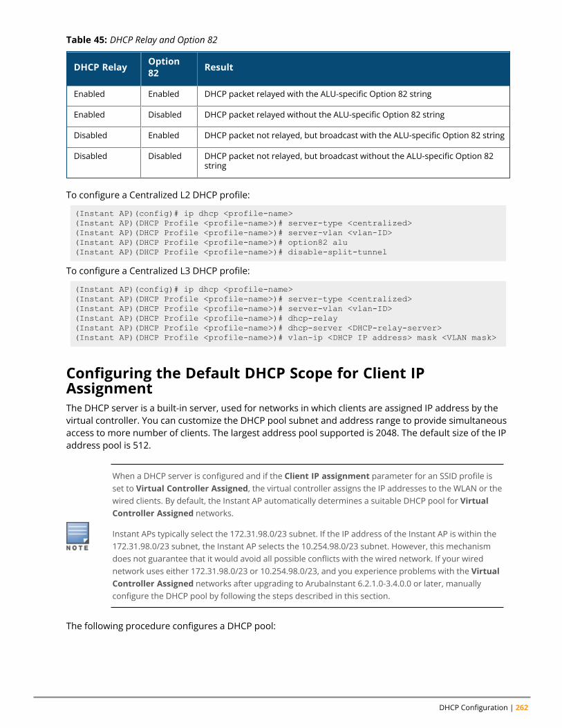
DHCP Configuration | 262
DHCP Relay Option82 Result
Enabled Enabled DHCP packet relayed with the ALU-specific Option 82 string
Enabled Disabled DHCP packet relayed without the ALU-specific Option 82 string
Disabled Enabled DHCP packet not relayed, but broadcast with the ALU-specific Option 82 string
Disabled Disabled DHCP packet not relayed, but broadcast without the ALU-specific Option 82string
Table 45: DHCP Relay and Option 82
To configure a Centralized L2 DHCP profile:
(Instant AP)(config)# ip dhcp <profile-name>(Instant AP)(DHCP Profile <profile-name>)# server-type <centralized>(Instant AP)(DHCP Profile <profile-name>)# server-vlan <vlan-ID>(Instant AP)(DHCP Profile <profile-name>)# option82 alu(Instant AP)(DHCP Profile <profile-name>)# disable-split-tunnel
To configure a Centralized L3 DHCP profile:
(Instant AP)(config)# ip dhcp <profile-name>(Instant AP)(DHCP Profile <profile-name>)# server-type <centralized>(Instant AP)(DHCP Profile <profile-name>)# server-vlan <vlan-ID>(Instant AP)(DHCP Profile <profile-name>)# dhcp-relay(Instant AP)(DHCP Profile <profile-name>)# dhcp-server <DHCP-relay-server>(Instant AP)(DHCP Profile <profile-name>)# vlan-ip <DHCP IP address> mask <VLAN mask>
Configuring the Default DHCP Scope for Client IPAssignmentThe DHCP server is a built-in server, used for networks in which clients are assigned IP address by thevirtual controller. You can customize the DHCP pool subnet and address range to provide simultaneousaccess to more number of clients. The largest address pool supported is 2048. The default size of the IPaddress pool is 512.
When a DHCP server is configured and if the Client IP assignment parameter for an SSID profile isset to Virtual Controller Assigned, the virtual controller assigns the IP addresses to the WLAN or thewired clients. By default, the Instant AP automatically determines a suitable DHCP pool for VirtualController Assigned networks.
Instant APs typically select the 172.31.98.0/23 subnet. If the IP address of the Instant AP is within the172.31.98.0/23 subnet, the Instant AP selects the 10.254.98.0/23 subnet. However, this mechanismdoes not guarantee that it would avoid all possible conflicts with the wired network. If your wirednetwork uses either 172.31.98.0/23 or 10.254.98.0/23, and you experience problems with the VirtualController Assigned networks after upgrading to ArubaInstant 6.2.1.0-3.4.0.0 or later, manuallyconfigure the DHCP pool by following the steps described in this section.
The following procedure configures a DHCP pool:
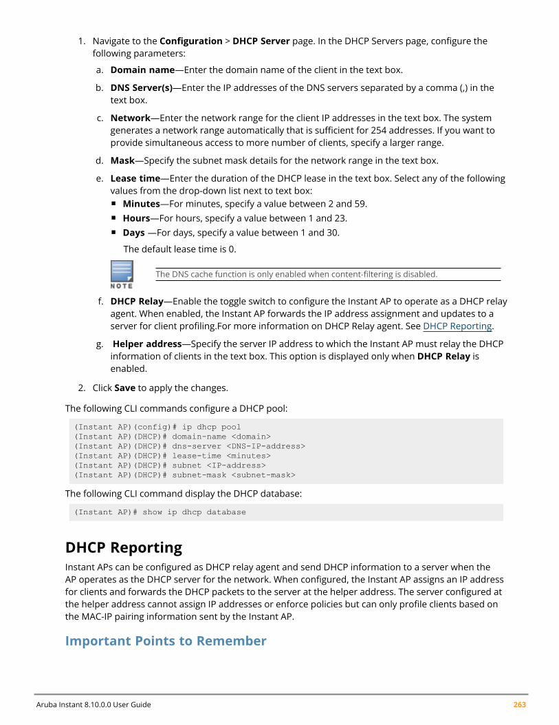
Aruba Instant 8.10.0.0 User Guide 263
1. Navigate to the Configuration > DHCP Server page. In the DHCP Servers page, configure thefollowing parameters:
a. Domain name—Enter the domain name of the client in the text box.
b. DNS Server(s)—Enter the IP addresses of the DNS servers separated by a comma (,) in thetext box.
c. Network—Enter the network range for the client IP addresses in the text box. The systemgenerates a network range automatically that is sufficient for 254 addresses. If you want toprovide simultaneous access to more number of clients, specify a larger range.
d. Mask—Specify the subnet mask details for the network range in the text box.
e. Lease time—Enter the duration of the DHCP lease in the text box. Select any of the followingvalues from the drop-down list next to text box:n Minutes—For minutes, specify a value between 2 and 59.n Hours—For hours, specify a value between 1 and 23.n Days —For days, specify a value between 1 and 30.
The default lease time is 0.
The DNS cache function is only enabled when content-filtering is disabled.
f. DHCP Relay—Enable the toggle switch to configure the Instant AP to operate as a DHCP relayagent. When enabled, the Instant AP forwards the IP address assignment and updates to aserver for client profiling.For more information on DHCP Relay agent. See DHCP Reporting.
g. Helper address—Specify the server IP address to which the Instant AP must relay the DHCPinformation of clients in the text box. This option is displayed only when DHCP Relay isenabled.
2. Click Save to apply the changes.
The following CLI commands configure a DHCP pool:
(Instant AP)(config)# ip dhcp pool(Instant AP)(DHCP)# domain-name <domain>(Instant AP)(DHCP)# dns-server <DNS-IP-address>(Instant AP)(DHCP)# lease-time <minutes>(Instant AP)(DHCP)# subnet <IP-address>(Instant AP)(DHCP)# subnet-mask <subnet-mask>
The following CLI command display the DHCP database:
(Instant AP)# show ip dhcp database
DHCP ReportingInstant APs can be configured as DHCP relay agent and send DHCP information to a server when theAP operates as the DHCP server for the network. When configured, the Instant AP assigns an IP addressfor clients and forwards the DHCP packets to the server at the helper address. The server configured atthe helper address cannot assign IP addresses or enforce policies but can only profile clients based onthe MAC-IP pairing information sent by the Instant AP.
Important Points to Remember
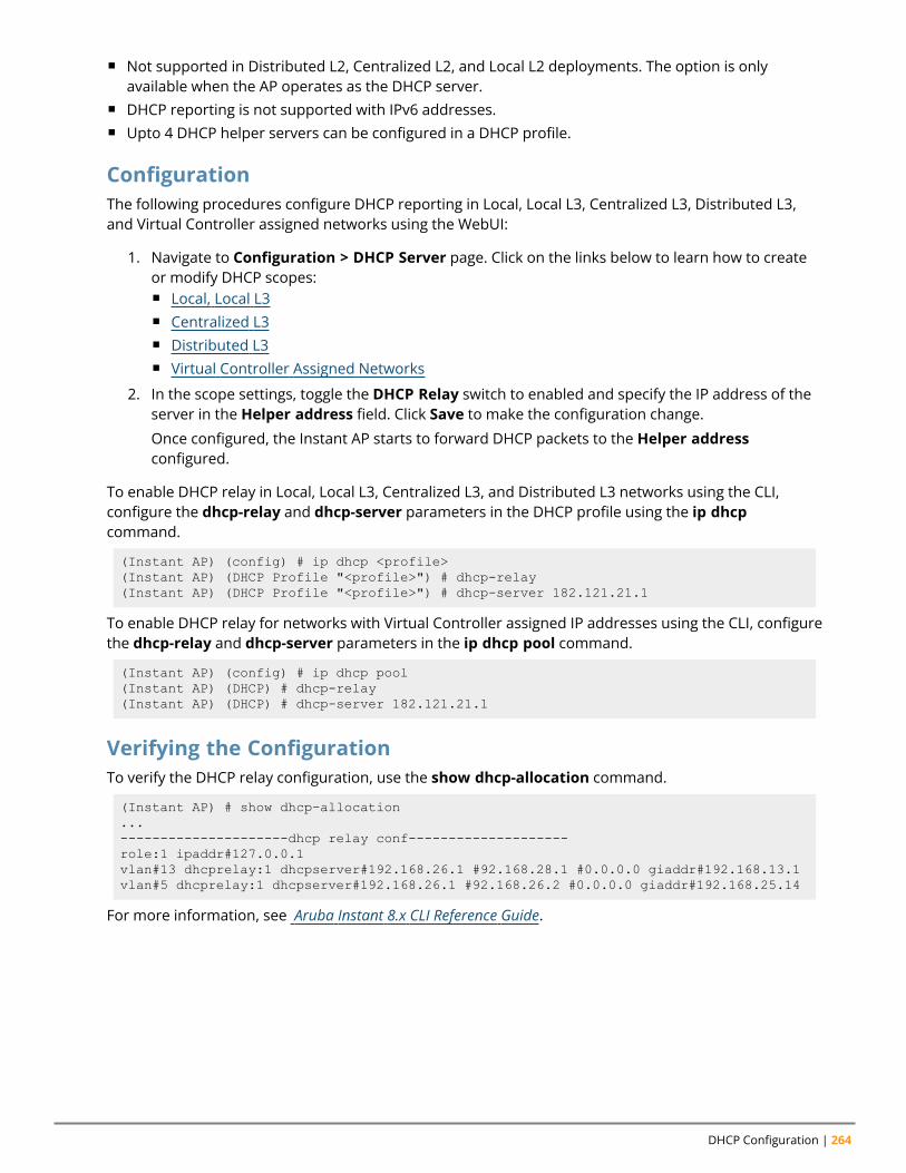
DHCP Configuration | 264
n Not supported in Distributed L2, Centralized L2, and Local L2 deployments. The option is onlyavailable when the AP operates as the DHCP server.
n DHCP reporting is not supported with IPv6 addresses.n Upto 4 DHCP helper servers can be configured in a DHCP profile.
ConfigurationThe following procedures configure DHCP reporting in Local, Local L3, Centralized L3, Distributed L3,and Virtual Controller assigned networks using the WebUI:
1. Navigate to Configuration > DHCP Server page. Click on the links below to learn how to createor modify DHCP scopes:n Local, Local L3n Centralized L3n Distributed L3n Virtual Controller Assigned Networks
2. In the scope settings, toggle the DHCP Relay switch to enabled and specify the IP address of theserver in the Helper address field. Click Save to make the configuration change.
Once configured, the Instant AP starts to forward DHCP packets to the Helper addressconfigured.
To enable DHCP relay in Local, Local L3, Centralized L3, and Distributed L3 networks using the CLI,configure the dhcp-relay and dhcp-server parameters in the DHCP profile using the ip dhcpcommand.
(Instant AP) (config) # ip dhcp <profile>(Instant AP) (DHCP Profile "<profile>") # dhcp-relay(Instant AP) (DHCP Profile "<profile>") # dhcp-server 182.121.21.1
To enable DHCP relay for networks with Virtual Controller assigned IP addresses using the CLI, configurethe dhcp-relay and dhcp-server parameters in the ip dhcp pool command.
(Instant AP) (config) # ip dhcp pool(Instant AP) (DHCP) # dhcp-relay(Instant AP) (DHCP) # dhcp-server 182.121.21.1
Verifying the ConfigurationTo verify the DHCP relay configuration, use the show dhcp-allocation command.
(Instant AP) # show dhcp-allocation...---------------------dhcp relay conf--------------------role:1 ipaddr#127.0.0.1vlan#13 dhcprelay:1 dhcpserver#192.168.26.1 #92.168.28.1 #0.0.0.0 giaddr#192.168.13.1vlan#5 dhcprelay:1 dhcpserver#192.168.26.1 #92.168.26.2 #0.0.0.0 giaddr#192.168.25.14
For more information, see Aruba Instant 8.x CLI Reference Guide.
Chapter 16Configuring Time-Based Services
Configuring Time-Based ServicesThis chapter describes time range profiles and the procedure for configuring time-based services. Itincludes the following topics:
n Time Range Profiles on page 265n Configuring a Time Range Profile on page 266n Applying a Time Range Profile to a WLAN SSID on page 267n Applying a Time Range Profile to a Role on page 267n Verifying the Configuration on page 267
Time Range ProfilesStarting from Instant 6.4.3.4-4.2.1.0, Instant APs allow you to enable or disable an SSID for users at aparticular time of the day. You can now create a time range profile and assign it to a WLAN SSID, so thatuser access to the Internet or network is restricted during a specific time period.
Instant APs support the configuration of both absolute and periodic time range profiles. You canconfigure an absolute time range profile to execute during a specific timeframe or create a periodicprofile to execute at regular intervals based on the periodicity specified in the configuration.
The following configuration conditions apply to the time-based services:
n Time-based services require an active NTP server connection. Instant APs use the default NTP serverfor time synchronization. However, the administrators can also configure an NTP server on theInstant AP. To verify the time synchronization between the NTP server and the Instant AP, execute theshow time-range command and check if the time on the NTP server is in synchronization with thelocal time. For more information on NTP server configuration, see NTP Server.
n For a time range profile configured to enable an SSID on the Instant AP:l When the timer starts, if the current time is greater than the start time and lesser than the endtime, the SSID will be broadcast in the list of available networks by the AP. If an ACL rule is linked tothe time profile, it is re-programmed and the rule which is time-based is applied. All the usersessions having this role assigned will be deleted.
l When the timer ends, if the current time is greater than the end time, the SSID is disabled. If theSSID is already disabled, then there is no effect on the SSID.
l If the SSID profile itself is disabled using the following configuration, then it will remain disabledand not be broadcast according to time range profile configuration.(Instant AP)(SSID Profile "<profile_name>")# wlan ssid-profile <profile_name>(Instant AP)(SSID Profile "<profile_name>")# disable(Instant AP)(SSID Profile "<profile_name>")# time-range <profile_name> enable
In the above example, the time-range configuration will be accepted, but there will be no impact onthe SSID and will continue to remain disabled.
Aruba Instant 8.10.0.0 User Guide 265
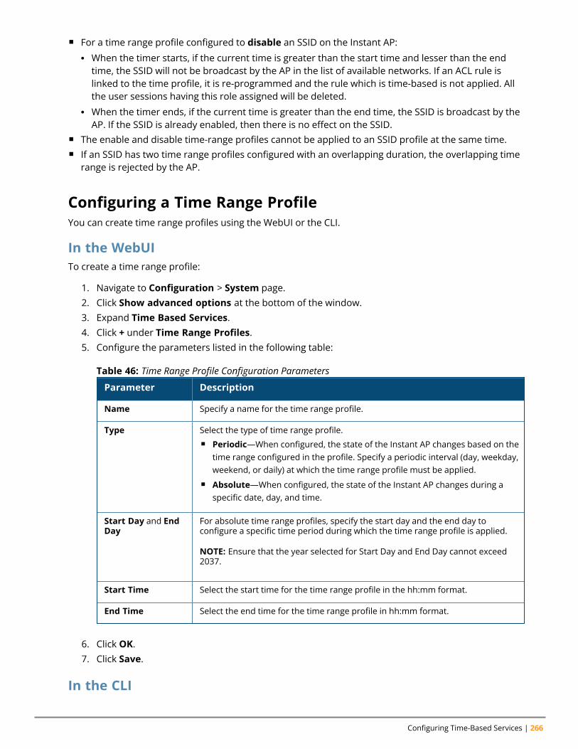
Configuring Time-Based Services | 266
n For a time range profile configured to disable an SSID on the Instant AP:l When the timer starts, if the current time is greater than the start time and lesser than the endtime, the SSID will not be broadcast by the AP in the list of available networks. If an ACL rule islinked to the time profile, it is re-programmed and the rule which is time-based is not applied. Allthe user sessions having this role assigned will be deleted.
l When the timer ends, if the current time is greater than the end time, the SSID is broadcast by theAP. If the SSID is already enabled, then there is no effect on the SSID.
n The enable and disable time-range profiles cannot be applied to an SSID profile at the same time.n If an SSID has two time range profiles configured with an overlapping duration, the overlapping time
range is rejected by the AP.
Configuring a Time Range ProfileYou can create time range profiles using the WebUI or the CLI.
In the WebUITo create a time range profile:
1. Navigate to Configuration > System page.2. Click Show advanced options at the bottom of the window.3. Expand Time Based Services.4. Click + under Time Range Profiles.5. Configure the parameters listed in the following table:
Parameter Description
Name Specify a name for the time range profile.
Type Select the type of time range profile.n Periodic—When configured, the state of the Instant AP changes based on the
time range configured in the profile. Specify a periodic interval (day, weekday,weekend, or daily) at which the time range profile must be applied.
n Absolute—When configured, the state of the Instant AP changes during aspecific date, day, and time.
Start Day and EndDay
For absolute time range profiles, specify the start day and the end day toconfigure a specific time period during which the time range profile is applied.
NOTE: Ensure that the year selected for Start Day and End Day cannot exceed2037.
Start Time Select the start time for the time range profile in the hh:mm format.
End Time Select the end time for the time range profile in hh:mm format.
Table 46: Time Range Profile Configuration Parameters
6. Click OK.7. Click Save.
In the CLI
Aruba Instant 8.10.0.0 User Guide 267
To create an absolute time range profile:(Instant AP)(config)# time-range <name> absolute start <startday> <starttime> end<endday> <endtime>
To configure a periodic time range profile:(Instant AP)(config)# time-range <name> periodic {<startday>|daily|weekday|weekend}<starttime> to <endtime>
Applying a Time Range Profile to a WLAN SSIDYou can apply a time range profile to a WLAN SSID using the WebUI.
In the WebUIApplying a time range profile:
1. Navigate to the WLAN SSID profile configuration wizard.
a. Go to Configuration > Networks.
b. Click + to add a new profile or select an existing WLAN SSID profile and click Edit.
2. Click Show advanced options at the bottom of the page.3. In the Time Range section, click Edit for Time Range Profiles, select a time range profile from
the list, then select a value from the Status drop-down list, and then click OK.n When a time range profile is enabled on an SSID, the SSID is made available to the users for
the configured time range. For example, if the specified time range is 12:00–13:00, the SSIDbecomes available only between 12 PM and 1 PM on a given day.
n If a time range is disabled, the SSID becomes unavailable for the configured time range. Forexample, if the configured time range is 14:00–17:00, the SSID is made unavailable from 2 PMto 5 PM on a given day.
4. Click Next until Finish.
In the CLITo enable an SSID during a specific time-range:(Instant AP)(config)# wlan ssid-profile <profile_name>(Instant AP)(SSID Profile "<name>")# time-range <profile_name> enable
To disable an SSID during a specific time-range:(Instant AP)(config)# wlan ssid-profile <profile_name>(Instant AP)(SSID Profile "<name>")# time-range <profile_name> disable
Verifying the ConfigurationTo view the time range profiles created on an Instant AP:(Instant AP) # show time-range
To view the list of time range profiles configured on an Instant AP:(Instant AP)# show time-profile
Applying a Time Range Profile to a RoleYou can apply a time range profile to a rule using the WebUI and the CLI.
In the WebUI
Configuring Time-Based Services | 268
Applying a time range profile:
1. Navigate to Configuration > Security > Roles.
a. Click Roles > + and create a new role or
b. Select an existing role under Roles and click Access Rules for <Role> > New.
2. Select Time Range and select a time range from the drop-down list.3. Click OK.
n When a time range profile is enabled on a role, the role is made available to the users for theconfigured time range. For example, if the specified time range is 12:00–13:00, the rolebecomes available only between 12 PM and 1 PM on a given day.
n If a time range is disabled, the role becomes unavailable for the configured time range. Forexample, if the configured time range is 14:00–17:00, the role is made unavailable from 2 PMto 5 PM on a given day.
In the CLITo enable a role during a specific time-range:(Instant AP)(config)# wlan access-rule <profile_name>(Instant AP)(SSID Profile "<name>")# rule ... time-range <profile_name>
To disable a role during a specific time-range:(Instant AP)(config)# wlan access-rule <profile_name>(Instant AP)(SSID Profile "<name>")# no rule ... time-range <profile_name>
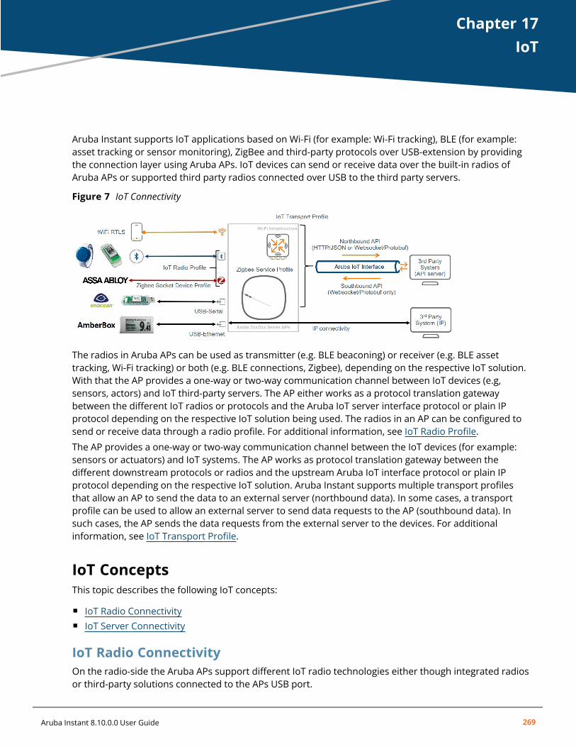
Chapter 17IoT
IoTAruba Instant supports IoT applications based on Wi-Fi (for example: Wi-Fi tracking), BLE (for example:asset tracking or sensor monitoring), ZigBee and third-party protocols over USB-extension by providingthe connection layer using Aruba APs. IoT devices can send or receive data over the built-in radios ofAruba APs or supported third party radios connected over USB to the third party servers.
Figure 7 IoT Connectivity
The radios in Aruba APs can be used as transmitter (e.g. BLE beaconing) or receiver (e.g. BLE assettracking, Wi-Fi tracking) or both (e.g. BLE connections, Zigbee), depending on the respective IoT solution.With that the AP provides a one-way or two-way communication channel between IoT devices (e.g,sensors, actors) and IoT third-party servers. The AP either works as a protocol translation gatewaybetween the different IoT radios or protocols and the Aruba IoT server interface protocol or plain IPprotocol depending on the respective IoT solution being used. The radios in an AP can be configured tosend or receive data through a radio profile. For additional information, see IoT Radio Profile.
The AP provides a one-way or two-way communication channel between the IoT devices (for example:sensors or actuators) and IoT systems. The AP works as protocol translation gateway between thedifferent downstream protocols or radios and the upstream Aruba IoT interface protocol or plain IPprotocol depending on the respective IoT solution. Aruba Instant supports multiple transport profilesthat allow an AP to send the data to an external server (northbound data). In some cases, a transportprofile can be used to allow an external server to send data requests to the AP (southbound data). Insuch cases, the AP sends the data requests from the external server to the devices. For additionalinformation, see IoT Transport Profile.
IoT ConceptsThis topic describes the following IoT concepts:
n IoT Radio Connectivityn IoT Server Connectivity
IoT Radio ConnectivityOn the radio-side the Aruba APs support different IoT radio technologies either though integrated radiosor third-party solutions connected to the APs USB port.
Aruba Instant 8.10.0.0 User Guide 269
IoT | 270
Wi-FiThe Aruba AP Wi-Fi radios can be used to forward associated or unassociated client information andRTLS data for Wi-Fi based tracking use cases. Wi-Fi client and RTLS data is encapsulated in the Aruba IoTserver interface protocol and forwarded to the IoT third-party server.
The Wi-Fi and RTLS data forwarding via IoT transport profiles described in this section is differentfrom the RTLS configuration in Chapter 23: Services which is used to send RTLS information to theAMP or a third-party RTLS server such as Aeroscout RTLS server.
Aruba IoT radioAn Aruba IoT radio is an additional internal or external radio in the Aruba 3xx or 5xx Series APs that canbe leveraged for IoT connectivity.
A single Aruba 3xx or 5xx Series AP can support up to two IoT radios—one internal and one external.For example: BLE on one radio and Zigbee on the other radio concurrently.
The AP adds or removes the radio specific headers from or to IoT devices (Example: BLE or ZigBee andforwards or receives the data payload encapsulated in the Aruba IoT server interface protocol to andfrom the IoT third-party server).
Internal Radio
Aruba 3xx or 5xx Series APs provide an integrated Aruba IoT radio for IoT connectivity supporting thefollowing radio technologies:
n 3xx Series Access Points: BLE4 (Gen 1)n 5xx Series Access Points: BLE5 or 802.15.4 (Gen2). Example: ZigBee.
BLE Wi-Fi Co-Existence—This feature is enabled by default on the internal radio and improves theoverall WLAN and BLE receiver performance and prevents inter-modulation by coordinating WLAN andBLE traffic and avoiding simultaneous WLAN and BLE transmissions.
BLE Wi-Fi Co-Existence is only supported on Aruba 53x, 55x Series APs, and Wi-Fi 6 and 6E APs for theinternal Aruba IoT Gen2 radio. The Aruba AP-505H hospitality AP series has some internal HW-basedfiltering to compensate local interference that works differently to the BLE Wi-Fi Co-Existence feature.
External Radio
In addition to the internal IoT radio Aruba also provides an IoT expansion radio that supports the sameradio technologies as the Aruba 5xx Series AP internal IoT radio:
n Aruba IoT Expansion Radio = BLE5 or 802.15.4 (Gen2). Example: Zigbee
The purpose of the Aruba IoT expansion radio is to add the 802.15.4 (ZigBee) capability to the Aruba 3xxseries access points.
Aruba Instant 8.10.0.0 User Guide 271
n The internal and the expansion BLE5/802.15.4 (Gen2) IoT radio can be configured to run BLE andZigBee concurrently. But in this configuration, the IoT radio can only transmit but not receive BLEpackets, while the ZigBee communication works bi-directional. This allows enabling the APs BLEconsole as well as BLE beaconing (iBeacon) for indoor navigation use cases in parallel to ZigBeeuse cases. But BLE tracking uses cases like asset tracking are not supported in this case.
n In order to support BLE tracking or bi-directional use cases concurrently to ZigBee uses cases onthe same APs, two Aruba IoT radios Gen2, one internal and one external, are required. Theexternal radio should be used as ZigBee radio in this case. Therefore this scenario is currently onlysupported on the Aruba 5xx Series APs.
USB or Third-Party IoT RadiosAruba supports the expansion of Aruba APs using the AP's USB port with supported third-party radiosolutions. Depending on the particular solution the integration uses one of the following methods:
n USB-to-Serialn USB-to-Ethernet
In all cases the USB connected host system adds or removes the radio specific headers or protocolsfrom and to IoT devices and forwards/receives the data payload to the access point using one of theUSB methods.
Supported USB connected devices does not require a specific configuration, except for vendor specificimplementations, but it can be controlled which USB devices are allowed to connect to an access points.This can be controlled using the AP USB device management.
USB-to-Serial
The third-party solutions using the USB-to-Serial method forwards the data payload to and from the AP.The Aruba AP encapsulates the serial-data payload in the Aruba IoT server interface protocol to or fromthe IoT third-party server.
No specific configuration is required for USB-to-Serial devices. Serial data is only forwarded thoughthe Aruba IoT server interface, if enabled in the server-side configuration.
USB-to-Ethernet
The third- party solutions using the USB-to-Ethernet method provide ethernet or IP connectivity to theconnected USB host system. The USB host system is connected to the AP in the same way as a wiredethernet client. No data processing is done by the access point and ethernet or IP data packets form theUSB host system is forwarded like any other ethernet or IP traffic.
IoT Server ConnectivityOn the server-side IoT data payloads are either forwarded directly by USB-to-Ethernet connecteddevices using IP transport or using the Aruba IoT server interface providing different transport protocolsand data encapsulations.
USB-to-Ethernet connectivity only requires applying a Wired-Port profile to the APs USB port to give theUSB host system ethernet or IP access. The benefit of this approach is that USB host system's networkaccess can be separated from the AP management networks, by assigning a different VLAN and can becontrolled using the AP integrated firewall like any other wired ethernet client connected to the AP. The
IoT | 272
USB host system uses its own IP stack with a separate IP address for its communication to the remoteIoT system.
Vendor specific USB implementations like SES Imagotag Electronic Shelf Labels (ESL) are using IPtransport with a vendor specific configuration.
Aruba IoT Server InterfaceThe Aruba IoT server interface is an Aruba proprietary server-side connectivity interface to connect toIoT servers using the Aruba AP's or Aruba controller's management IP address. The interface providesmultiple transport protocol and data encapsulation options and is specified in the Aruba IoT WebsocketInterface Guide.
All Aruba IoT server interface related aspects are configured in an IoT transport profile.
Up to four IoT transport profiles can be concurrently enabled per Aruba Instant AP or ArubaOS APgroup. This allows to run up to four IoT applications concurrently on an Aruba AP. For example: ArubaMeridian Beacon Management + Aruba Meridian Asset Tracking + Third-Party BLE Asset Tracking +EnOcean.
The following sections describe the Aruba IoT server interface related options and services.
Server Connection TypesThe Aruba IoT server interface supports vendor specific and generic server connection types.
The following generic connection types allow IoT data forwarding for the different IoT RadioConnectivity options previously described.
Telemetry-Websocket
The Telemetry-Websocket connection type can be used for all supported IoT transport servicesproviding a bi-directional communication channel though a web socket (ws) or secure web socket (wss)connection.
Communication through the Telemetry-Websocket connection is encoded using the Google ProtocolBuffers serialization protocol. Supported messages types (northbound or southbound API) and theencoding and decoding of the data payloads is defined in the Aruba IoT Protobuf Specification.
This connection type enables the full set of IoT connection capabilities of an Aruba infrastructure.
Azure-IoT-Hub
The Azure-IoTHub connection type can be use to send or receive BLE data forwarding or Serial-datadirectly to Azure IoT Hub by using the AMPQ over websocket protocol.
With this connection type Aruba controllers or Aruba Instant APs work as a protocol translation gatewayto send data to Azure IoT Hub on behalf of connected IoT devices.
For more information, see Aruba Instant Azure IoT Hub Interface Guide and ArubaOS Azure IoT HubInterface Guide.
Telemetry-Https
The Telemetry-Https connection type can be used to send BLE telemetry reports in one direction only;from the radio-side to the server-side, using HTTP POST requests.
This connection type can be used for BLE-based asset tracking or sensor monitoring use cases usingeasily consumable JSON data. The used JSON data structure is defined in the Aruba IoT Telemetry JSONSchema.
Aruba Instant 8.10.0.0 User Guide 273
n Telemetry-Https is only meant to be used for low throughput applications or use cases with a lowamount of APs (<20) and a high report interval (>60 s). Trying to use Telemetry-Https for lowlatency or high toughput use cases may result in BLE messages being dropped or delayed. It isrecommended to only use Telemetry-Websocket for low latency or high throughput use cases.
n Starting with ArubaOS or Aruba Instant 8.6.0.0 or higher versions, no new BLE device classes willbe added to be used with Telemetry-Https.
Server Connection EncryptionAruba recommends to use only encrypted connections to remote IoT systems, even if un-encryptedHTTP or web socket connectivity is supported by the Aruba IoT server interface,
In order to establish secure web socket (wss) or HTTPS connections the remote server's self-signedcertificate or root CA certificate has to be added to the Aruba Controller or Aruba Instant AP trusted CAlist.
If the IoT server certificate is un-trusted the server connection will not be established. For moreinformation, see Uploading Certificates on an Instant AP and Importing Certificates on an ArubaOSController.
Authentication and AuthorizationDepending on the Aruba IoT server connection type, different authentication and authorizationmethods are required to establish server-side connections.
Following are the supported authentication and authorization methods:
n Static access tokenn Username or Passwordn Client ID or Secret
For more information on the different authentication methods, see Aruba IoT Websocket InterfaceGuide.
Connection ManagementServer connections are established from every single Aruba Instant access point, in case of a controller-less setup, or from every Aruba controller in case of a controller-based setup.
For example, in a controller cluster setup with four controllers, every controller will establish aconnection to the remote server.
n In an ArubaOS controller setup the number of server connections equals the number ofcontrollers.
n In an Aruba Instant setup the number of server connections equals the number of APs.
In a controller-based setup IoT data is forwarded to and from the remote IoT server only through theAPs active controller. In case of a failover, the IoT communication will also failover to the backupcontroller's IoT interface connection.
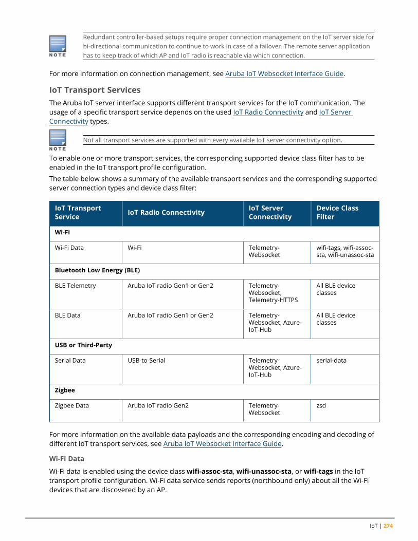
IoT | 274
Redundant controller-based setups require proper connection management on the IoT server side forbi-directional communication to continue to work in case of a failover. The remote server applicationhas to keep track of which AP and IoT radio is reachable via which connection.
For more information on connection management, see Aruba IoT Websocket Interface Guide.
IoT Transport ServicesThe Aruba IoT server interface supports different transport services for the IoT communication. Theusage of a specific transport service depends on the used IoT Radio Connectivity and IoT ServerConnectivity types.
Not all transport services are supported with every available IoT server connectivity option.
To enable one or more transport services, the corresponding supported device class filter has to beenabled in the IoT transport profile configuration.
The table below shows a summary of the available transport services and the corresponding supportedserver connection types and device class filter:
IoT TransportService IoT Radio Connectivity IoT Server
ConnectivityDevice ClassFilter
Wi-Fi
Wi-Fi Data Wi-Fi Telemetry-Websocket
wifi-tags, wifi-assoc-sta, wifi-unassoc-sta
Bluetooth Low Energy (BLE)
BLE Telemetry Aruba IoT radio Gen1 or Gen2 Telemetry-Websocket,Telemetry-HTTPS
All BLE deviceclasses
BLE Data Aruba IoT radio Gen1 or Gen2 Telemetry-Websocket, Azure-IoT-Hub
All BLE deviceclasses
USB or Third-Party
Serial Data USB-to-Serial Telemetry-Websocket, Azure-IoT-Hub
serial-data
Zigbee
Zigbee Data Aruba IoT radio Gen2 Telemetry-Websocket
zsd
For more information on the available data payloads and the corresponding encoding and decoding ofdifferent IoT transport services, see Aruba IoT Websocket Interface Guide.
Wi-Fi Data
Wi-Fi data is enabled using the device classwifi-assoc-sta,wifi-unassoc-sta, orwifi-tags in the IoTtransport profile configuration. Wi-Fi data service sends reports (northbound only) about all the Wi-Fidevices that are discovered by an AP.
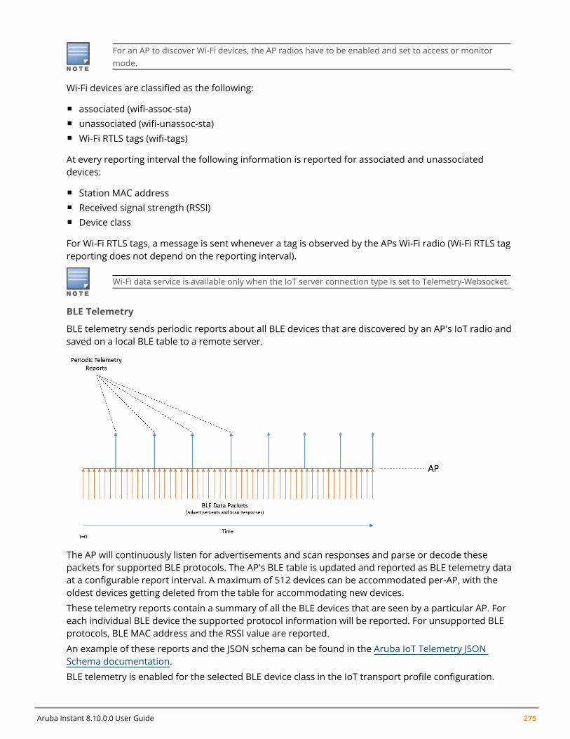
Aruba Instant 8.10.0.0 User Guide 275
For an AP to discover Wi-Fi devices, the AP radios have to be enabled and set to access or monitormode.
Wi-Fi devices are classified as the following:
n associated (wifi-assoc-sta)n unassociated (wifi-unassoc-sta)n Wi-Fi RTLS tags (wifi-tags)
At every reporting interval the following information is reported for associated and unassociateddevices:
n Station MAC addressn Received signal strength (RSSI)n Device class
For Wi-Fi RTLS tags, a message is sent whenever a tag is observed by the APs Wi-Fi radio (Wi-Fi RTLS tagreporting does not depend on the reporting interval).
Wi-Fi data service is available only when the IoT server connection type is set to Telemetry-Websocket.
BLE Telemetry
BLE telemetry sends periodic reports about all BLE devices that are discovered by an AP's IoT radio andsaved on a local BLE table to a remote server.
The AP will continuously listen for advertisements and scan responses and parse or decode thesepackets for supported BLE protocols. The AP's BLE table is updated and reported as BLE telemetry dataat a configurable report interval. A maximum of 512 devices can be accommodated per-AP, with theoldest devices getting deleted from the table for accommodating new devices.
These telemetry reports contain a summary of all the BLE devices that are seen by a particular AP. Foreach individual BLE device the supported protocol information will be reported. For unsupported BLEprotocols, BLE MAC address and the RSSI value are reported.
An example of these reports and the JSON schema can be found in the Aruba IoT Telemetry JSONSchema documentation.
BLE telemetry is enabled for the selected BLE device class in the IoT transport profile configuration.
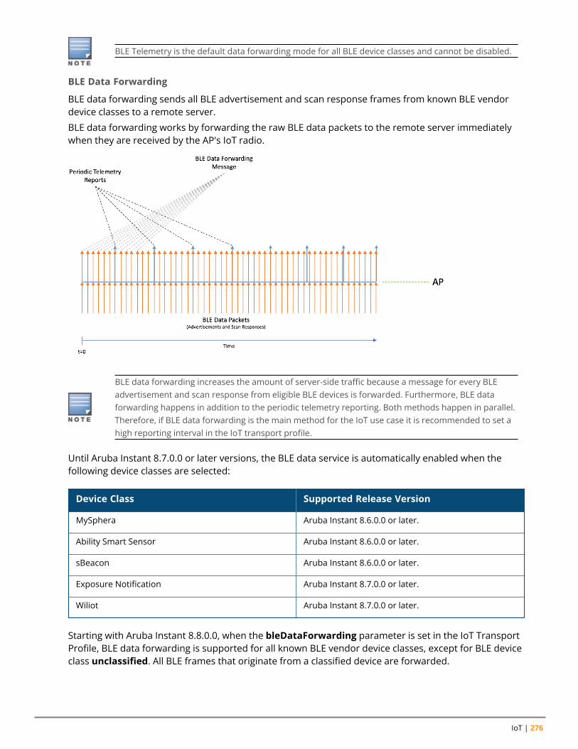
IoT | 276
BLE Telemetry is the default data forwarding mode for all BLE device classes and cannot be disabled.
BLE Data Forwarding
BLE data forwarding sends all BLE advertisement and scan response frames from known BLE vendordevice classes to a remote server.
BLE data forwarding works by forwarding the raw BLE data packets to the remote server immediatelywhen they are received by the AP's IoT radio.
BLE data forwarding increases the amount of server-side traffic because a message for every BLEadvertisement and scan response from eligible BLE devices is forwarded. Furthermore, BLE dataforwarding happens in addition to the periodic telemetry reporting. Both methods happen in parallel.Therefore, if BLE data forwarding is the main method for the IoT use case it is recommended to set ahigh reporting interval in the IoT transport profile.
Until Aruba Instant 8.7.0.0 or later versions, the BLE data service is automatically enabled when thefollowing device classes are selected:
Device Class Supported Release Version
MySphera Aruba Instant 8.6.0.0 or later.
Ability Smart Sensor Aruba Instant 8.6.0.0 or later.
sBeacon Aruba Instant 8.6.0.0 or later.
Exposure Notification Aruba Instant 8.7.0.0 or later.
Wiliot Aruba Instant 8.7.0.0 or later.
Starting with Aruba Instant 8.8.0.0, when the bleDataForwarding parameter is set in the IoT TransportProfile, BLE data forwarding is supported for all known BLE vendor device classes, except for BLE deviceclass unclassified. All BLE frames that originate from a classified device are forwarded.
Aruba Instant 8.10.0.0 User Guide 277
The perFrameFiltering parameter modifies the BLE data forwarding behavior by forwarding BLEframes that match the configured device class and generic filters in the IoT transport profile. Any frameoriginating from the classified device that does not match the profile filters is not forwarded.
BLE data forwarding is enabled for the selected BLE device class in the IoT transport profileconfiguration.
BLE Connections
BLE connections provide functions to connect and interact with BLE devices remotely through the ArubaIoT server interface using the BLE GATT profile.
This allows IoT server applications to connect to BLE devices through the AP's IoT radio using asouthbound API. For more information, see Aruba IoT Websocket Interface Guide. This service is genericand is available to all classified BLE devices and is not limited to a specific device class.
An AP can connect to one BLE device at a time using BLE connect. Before connecting to another BLEdevice an existing connections has to be disconnected.
n BLE connections using the southbound API is only supported using the internal IoT radio.
n Starting with ArubaOS or Aruba Instant 8.8.0.0, BLE security encryption is added to the BLEconnect service. BLE security is only supported on the AP-5xx BLE5/802.15.4 (Gen2) IoT radio.
For details about the available BLE connections service, see Aruba IoT Websocket Interface Guide.
BLE connections is enabled for the selected BLE device class in the IoT transport profile configurationand requires the server connection type Telemetry-Websocket to be selected.
Serial Data
Serial data forwarding is used to support third-party IoT radio solutions connected through the AP USBport. When the third-party IoT radio is plugged into the USB port, it presents itself as a USB-to-serialdevice to the AP.
The serial data sent by the third-party radio to the AP is encapsulated in the Aruba IoT server interfaceprotocol to and from the IoT backend system. The server also sends serial data to the AP, which isforwarded to the third-party device.
Serial-data forwarding is available only when the IoT server connection type is set to Telemetry-Websocket.
Serial data forwarding is enabled using the device class serial-data in the Iot transport profileconfiguration.
Zigbee Data
ZigBee Data service is a generic approach used for enabling ZigBee applications using the Aruba IoTradio Gen2.
Sending or receiving ZigBee application data using the ZigBee Data service requires the configuration ofone or more ZigBee socket device profiles, which define the inbound and outbound sockets used by therespective ZigBee application.
n Inbound Sockets
IoT | 278
l Defines Zigbee application protocol layer (APL) packets received by the AP from ZigBee devices viathe ZigBee radio.
l Data is forwarded to the remote ZigBee application server through the Aruba IoT interface.n Outbound Sockets
l Defines Zigbee application protocol layer (APL) packets received by the AP form the ZigBeeapplication server through the Aruba IoT interface.
l Data is forwarded to ZigBee devices via the ZigBee radio.
A ZigBee socket profile definition consists of four items:
n Source endpointn Destination endpointn Profile IDn Cluster ID
Different ZigBee Data services have different socket definitions, including inbound and outboundconnections.
Only the Aruba IoT radios Gen2 supports the ZigBee protocol and provides the coordinator function toestablish a ZigBee network. The ZigBee service profile defines the respective ZigBee networkparameters.
ZigBee Data service is enabled using the device class zsd in the IoT transport profile configuration. Inaddition one or more ZigBee socket device profiles have to be defined and assigned in the IoT transportprofile configuration.
The Zigbee Data service is available only when the IoT server connection type is set to Telemetry-Websocket.
For more information of how to configure a Zigbee profile, see Zigbee Configuration.
Device Class FilterDevice class filters are used to enable specific IoT transport services over an IoT server connection andto control the amount of IoT data transferred on an Aruba infrastructure by using input or outputfiltering. Multiple supported device classes can be enabled in the IoT transport profile configuration toenable multiple IoT transport services over a single server connection. Each device class filter has aspecific implementation to enable classification for that device type.
A maximum of 16 devices classes can be enabled per IoT transport profile.
Device class filters are grouped into the following categories.
BLE Device Class Filter
For every supported BLE device vendor, identified by the Bluetooth SIG member list, a dedicated BLEdevice class is defined. One or more BLE device classes can be selected in an IoT transport profile toenable IoT transport services for the respective BLE vendor.
The special device class unclassified enables BLE telemetry reporting for unknown or unsupported BLEvendor devices.
Wi-Fi device class filterThe device classwifi-assoc-sta,wifi-unassoc-sta,wifi-tags enables the Wi-Fi Data transport service.
Aruba Instant 8.10.0.0 User Guide 279
USB or third-party device class filterThe device class serial-data (along with the usbSerialDeviceTypeFilter parameter) enables the serialdata forwarding to support third-party IoT radio solutions.
ZigBee socket device class filterThe device class zsd enables the ZigBee socket device transport service to enable ZigBee applications.
Generic FiltersStarting with Aruba Instant 8.9.0.0, a new class of generic filters are added to classify new BLE deviceswithout a device-specific implementation like in the case of BLE device class filters described previously.These filters operate on device data characteristics which are common to most BLE devices as follows:
n Company Identifier Filter
It is a 2-byte hexadecimal number, for example, "011B" for Hewlett Packard Enterprise or "0x004C"for Apple, that corresponds to the Bluetooth SIG registered company identifier which is part of theBLE packet payload under the manufacturer specific advertising data field. An extra byte indicatingthe subtype can also be included, for example: 004C02 would select Apple iBeacon whereas 004C03would select Apple AirPrint beacons.sors.
n Service UUID Filter
It is a 2-byte hexadecimal number as shown in the 16-bit UUID Numbers Document available fromthe Bluetooth SIG (https://www.bluetooth.com/specifications/assigned-numbers/). For example:Google Eddystone packets can be identified by the value 0xFEAA in the 16-bit Service Class UUIDsadvertising data field.
n Local Name Filter
The Local Name Filter will only report devices that contain at least one of the configured sub-stringvalues to the local name advertising data field in a BLE device’s advertisements or scan responsepacket payloads.
n MAC OUI Filter
User can input the 3-byte MAC OUI values for their device of interest (should not include “:” or anyother separator between the bytes of the MAC OUI). This filter will only allow a device wherein itsMAC address has the same MAC OUI as that in the list of configured values.Only public MAC address(non-randomized) are considered. For example: 60C0BF is MAC OUI for Blyott devices.
Up to 10 generic filters of each of the aforementioned types can be configured in the IoT Transportprofile.
Data Content FiltersIn addition to filter for specific device classes, it is possible to filter the forwarded IoT data contentbefore being sent to the remote IoT system.
General Data filter
n Data Filter
This is a list of data fields to be suppressed in the telemetry reports. The data filter is a string that is acomma separated list of index-paths. Each index path refers to the field numbers in the Aruba IoTProtobuf Specification. For example, the value “3.3, 3.12” would suppress the reported.model fieldand the reported.beacons field in the telemetry reports.
n Device Count
IoT | 280
Only sends the count of device types. For example: iBeacon,Wi-Fi clients, seen by an AP in thetelemetry reports, but not the actual device information of those devices. Supported device countsare defined in the Aruba IoT Protobuf Specification.
BLE Data Filter
n RSSI Reporting Format
For the BLE RSSI values being sent in the telemetry reports, the following five different RSSI reportingformats are supported:l Average - The average RSSI over the reporting interval will be reported.l Last - Only the last RSSI value that was seen by the device will be reported.l Max - The max RSSI value that was seen over the reporting interval will be reported only. This maxvalue resets each telemetry reporting interval and will be updated accordingly.
l Bulk - The last 20 RSSI values that were seen by the device since the previous telemetry report willbe reported in an array format.
l Smooth - A single smoothed out RSSI value will be reported for each telemetry report. This is doneby attempting to remove outliers from the RSSI values received by the AP.
n Environment Type
Five different pre-defined environment types are supported to help adjust RSSI based distancecalculation to better fit the environment in which the BLE devices are operating in. For best results,the value that closest corresponds to the environment in which BLE is operating should be chosen.l auditoriuml officel outdoorl shipboardl warehousel custom (see custom fading factor for details)
n Custom Fading Factor
If the pre-defined environment type offsets do not properly fit the environment, a custom fadingfactor can be configured by setting the environment type to custom. This field accepts integer valuesin the range of 10 to 40.
n Cell Size Filter
A proximity-based filter that will only report devices that are found to be within an xmeter radiusaround the access point. This distance is calculated with an algorithm based off the RSSI value. Thedefault value for this field is 0, which translates to the cell size filter being disabled. This field acceptsinteger values from 2 to 100 and the units are meters.
n Movement Filter
This filter is active when the cell size filter is also configured. When this filter is enabled, devices willonly be reported if the difference between their current and prior distance is more than theconfigured filter value. For example, if the movement filter is configured to be 2 meters, a device thatis calculated to have moved 1 meter will not be reported, while a device that moves 5 meters will bereported. The default value for this field is 0, which corresponds to the movement filter beingdisabled. This field accepts integer values from 2 to 30, and the units are meters.
n Age Filter
The Age Filter is used to only report devices the AP has received an update (either BLE advertisementor scan response) in the configured time. For instance, if the age filter is set to 30 seconds, only
Aruba Instant 8.10.0.0 User Guide 281
devices which have been heard in the last 30 seconds will be reported. If there is a device thatreceived an update 45 seconds before, this device will not be reported. The default value for this fieldis 0, which corresponds to the age filter being disabled. This field accepts integer values from 30 to3600, and the units are seconds.
n BLE Vendor Filter
The BLE Vendor Filter allows to input Bluetooth SIG Vendor IDs and freeform vendor name strings,which will be used to filter the devices being reported. If this is configured, the only devices that willbe reported are the devices that match the configured Vendor ID or Vendor Name.
The vendor ID is a 2-byte hexadecimal value preceding with 0x in 0xABCD format. The vendor nameis a string that can be either a full vendor name (example:Aruba) or a substring of the actual vendorname (example:Aru) and can be case-insensitive.
The vendor filter accepts up to five combinations of vendor names or vendorIDs separated bycommas, for example:l Aruba,Favendo,HanVit,SoluM,ABBl 0xABCD,0xBCDE,0xCDEF,0xDEF0,0xEF01l Aruba,0xABCD,Favendo,0xBCDE,HanVit
If more than one vendor name or vendorID is configured, then any of the matching vendor names orvendorIDs in the vendor filter is applied. A device is reported only if the vendor data or vendor namefield is not empty and matches the vendor information configured. If the vendor field is notpopulated for the devices, the IoT devices are reported because there is not matching vendor filter inthe IoT transport profile.
n UUID Filter (iBeacon)
A list of UUIDs to filter the devices included in the reports. Applies only to iBeacon devices.n UID Namespace Filter (Eddystone)
A list of UID namespaces to filter devices included in the reports. Applies only Eddystone-UID devicesn URL Filter (Eddystone)
A list of URL strings to filter devices included in the reports. Applies only Eddystone-URL devices. Thestring listed here can be a partial URL strings.
n BLE data forwarding
When BLE data forwarding is enabled, the raw payload contained within a BLE packet is forwarded tothe configured server. The per frame filtering knob is a modifier on top of the BLE data forwardingparameter. When only BLE data forwarding is enabled, all BLE packets for a device having a knowndevice class filter label are forwarded.
For example: If a device advertises an iBeacon frame and an Eddystone frame and in the transportprofile the iBeacon device class has been selected only, then for this device both iBeacon andEddystone frames are forward.
n Per Frame filtering
If per frame filtering is enabled in addition to BLE data forwarding , then in the aforementionedexample only the raw payloads from the iBeacon frames would be forwarded.
IoT ConfigurationThis section describes the Aruba Instant configuration steps to setup the Aruba infrastructure for IoTsolutions.
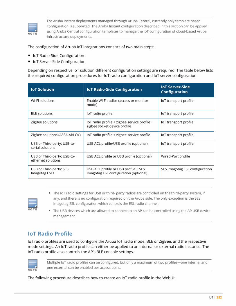
IoT | 282
For Aruba Instant deployments managed through Aruba Central, currently only template basedconfiguration is supported. The Aruba Instant configuration described in this section can be appliedusing Aruba Central configuration templates to manage the IoT configuration of cloud-based Arubainfrastructure deployments.
The configuration of Aruba IoT integrations consists of two main steps:
n IoT Radio-Side Configurationn IoT Server-Side Configuration
Depending on respective IoT solution different configuration settings are required. The table below liststhe required configuration procedures for IoT radio configuration and IoT server configuration.
IoT Solution IoT Radio-Side Configuration IoT Server-SideConfiguration
Wi-Fi solutions Enable Wi-Fi radios (access or monitormode)
IoT transport profile
BLE solutions IoT radio profile IoT transport profile
ZigBee solutions IoT radio profile + zigbee service profile +zigbee socket device profile
IoT transport profile
ZigBee solutions (ASSA-ABLOY) IoT radio profile + zigbee service profile IoT transport profile
USB or Third-party: USB-to-serial solutions
USB ACL profile/USB profile (optional) IoT transport profile
USB or Third-party: USB-to-ethernet solutions
USB ACL profile or USB profile (optional) Wired-Port profile
USB or Third-party: SESImagotag ESLs
USB ACL profile or USB profile + SESImagotag ESL configuration (optional)
SES Imagotag ESL configuration
n The IoT radio settings for USB or third- party radios are controlled on the third-party system, ifany, and there is no configuration required on the Aruba side. The only exception is the SESImagotag ESL configuration which controls the ESL radio channel.
n The USB devices which are allowed to connect to an AP can be controlled using the AP USB devicemanagement.
IoT Radio ProfileIoT radio profiles are used to configure the Aruba IoT radio mode, BLE or ZigBee, and the respectivemode settings. An IoT radio profile can either be applied to an internal or external radio instance. TheIoT radio profile also controls the AP's BLE console settings.
Multiple IoT radio profiles can be configured, but only a maximum of two profiles—one internal andone external can be enabled per access point.
The following procedure describes how to create an IoT radio profile in the WebUI:
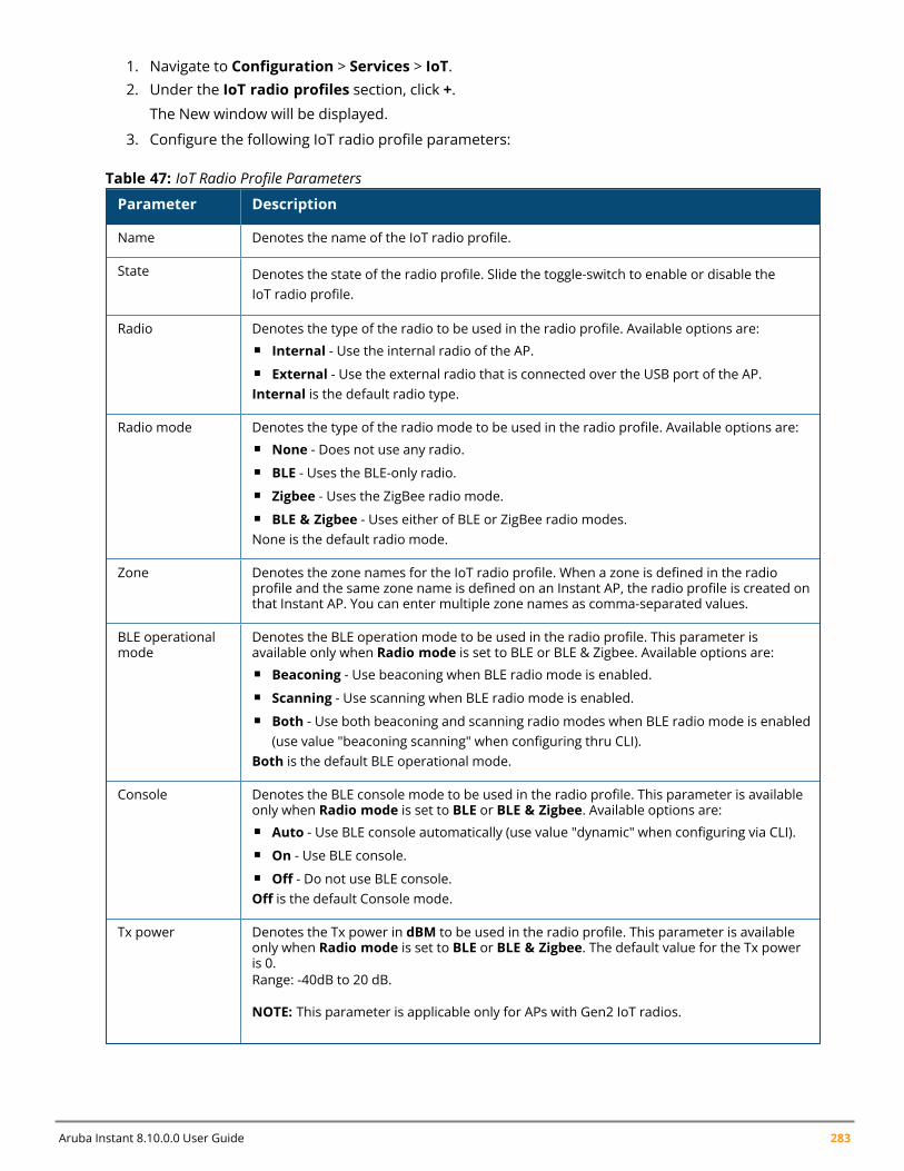
Aruba Instant 8.10.0.0 User Guide 283
1. Navigate to Configuration > Services > IoT.2. Under the IoT radio profiles section, click +.
The New window will be displayed.
3. Configure the following IoT radio profile parameters:
Parameter Description
Name Denotes the name of the IoT radio profile.
State Denotes the state of the radio profile. Slide the toggle-switch to enable or disable theIoT radio profile.
Radio Denotes the type of the radio to be used in the radio profile. Available options are:n Internal - Use the internal radio of the AP.n External - Use the external radio that is connected over the USB port of the AP.Internal is the default radio type.
Radio mode Denotes the type of the radio mode to be used in the radio profile. Available options are:n None - Does not use any radio.n BLE - Uses the BLE-only radio.n Zigbee - Uses the ZigBee radio mode.n BLE & Zigbee - Uses either of BLE or ZigBee radio modes.None is the default radio mode.
Zone Denotes the zone names for the IoT radio profile. When a zone is defined in the radioprofile and the same zone name is defined on an Instant AP, the radio profile is created onthat Instant AP. You can enter multiple zone names as comma-separated values.
BLE operationalmode
Denotes the BLE operation mode to be used in the radio profile. This parameter isavailable only when Radio mode is set to BLE or BLE & Zigbee. Available options are:n Beaconing - Use beaconing when BLE radio mode is enabled.n Scanning - Use scanning when BLE radio mode is enabled.n Both - Use both beaconing and scanning radio modes when BLE radio mode is enabled
(use value "beaconing scanning" when configuring thru CLI).Both is the default BLE operational mode.
Console Denotes the BLE console mode to be used in the radio profile. This parameter is availableonly when Radio mode is set to BLE or BLE & Zigbee. Available options are:n Auto - Use BLE console automatically (use value "dynamic" when configuring via CLI).n On - Use BLE console.n Off - Do not use BLE console.Off is the default Console mode.
Tx power Denotes the Tx power in dBM to be used in the radio profile. This parameter is availableonly when Radio mode is set to BLE or BLE & Zigbee. The default value for the Tx poweris 0.Range: -40dB to 20 dB.
NOTE: This parameter is applicable only for APs with Gen2 IoT radios.
Table 47: IoT Radio Profile Parameters
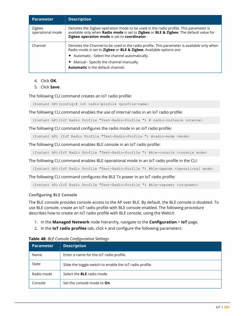
IoT | 284
Parameter Description
Zigbeeoperational mode
Denotes the Zigbee operation mode to be used in the radio profile. This parameter isavailable only when Radio mode is set to Zigbee or BLE & Zigbee. The default value forZigbee operation mode is set to coordinator.
Channel Denotes the Channel to be used in the radio profile. This parameter is available only whenRadio mode is set to Zigbee or BLE & Zigbee. Available options are:n Automatic - Select the channel automatically.n Manual - Specify the channel manually.Automatic is the default channel.
4. Click OK.5. Click Save.
The following CLI command creates an IoT radio profile:
(Instant AP)(config)# iot radio-profile <profile-name>
The following CLI command enables the use of internal radio in an IoT radio profile:
(Instant AP)(IoT Radio Profile "Test-Radio-Profile ") # radio-instance internal
The following CLI command configures the radio mode in an IoT radio profile:
(Instant AP) (IoT Radio Profile "Test-Radio-Profile ") #radio-mode <mode>
The following CLI command enables BLE console in an IoT radio profile:
(Instant AP)(IoT Radio Profile "Test-Radio-Profile ") #ble-console <console mode>
The following CLI command enables BLE operational mode in an IoT radio profile in the CLI:
(Instant AP)(IoT Radio Profile "Test-Radio-Profile ") #ble-opmode <operational mode>
The following CLI command configures the BLE Tx power in an IoT radio profile:
(Instant AP)(IoT Radio Profile "Test-Radio-Profile ") #ble-txpower <tx-power>
Configuring BLE Console
The BLE console provides console access to the AP over BLE. By default, the BLE console is disabled. Touse BLE console, create an IoT radio profile with BLE console enabled. The following proceduredescribes how to create an IoT radio profile with BLE console, using the WebUI:
1. In theManaged Network node hierarchy, navigate to the Configuration > IoT page.2. In the IoT radio profiles tab, click + and configure the following parameters:
Parameter Description
Name Enter a name for the IoT radio profile.
State Slide the toggle-switch to enable the IoT radio profile.
Radio mode Select the BLE radio mode.
Console Set the console mode to On.
Table 48: BLE Console Configuration Settings
Aruba Instant 8.10.0.0 User Guide 285
3. Click OK.4. Click Save.
The following CLI commands describe how to create an IoT radio profile with BLE console enabled:
(Instant AP)(config) #iot radio-profile BLE-Console
(Instant AP)(IoT Radio Profile "BLE-Console") #radio-mode ble
(Instant AP)(IoT Radio Profile "BLE-Console") #ble-console on
The following commands describe how to view the status of BLE console in an IoT radio profile in theCLI:
(Instant AP) #show iot radio-profile BLE-Console
IoT Transport ProfileAn IoT transport profile defines the IoT server connectivity settings using the Aruba IoT server interface.Aruba Instant allows a maximum of 4 concurrent transport profiles to be applied to an AP.
Components of a Transport ProfileA transport profile consists of:
n Server type—Defines the type of connection used with an external server. Server Type is denoted bythe keyword endpointType in the CLI configuration. The following transport types are available:l Websocket—A bi-directional, full-duplex, stateful protocol to send and receive data.l HTTP—A uni-directional, stateless protocol to send and receive data. A HTTP connection is closedafter a request-reponse is complete. A new request-response requires a new HTTP connection.
l Azure IoT Hub—The Azure IoT Hub transport type allows secure, bi-directional communicationbetween IoT devices and the Azure cloud through an Aruba Instant AP that acts as a gateway usingAMQP over Websocket protocol.
l Assa-Abloy—Vendor-specific transport type.l Meridian
o Asset trackingo Beacon management
n Proxy—Defines the details of the proxy server if a proxy server is used instead of an external server.The details of the proxy server are:l IP address—The IP address of the proxy server.l Port—The port on the proxy server.l Username—The username to use when authenticating with the proxy server.l Password—The password to use when authenticating with the proxy server.
n Authentication—Defines the authentication method and associated details to use when connectingto an external server. The authentication methods are:l Use credentials—Use the predefined credentials. The predefined credentials include theauthentication URL, username, password, and client ID.
l Use token—Use the access token with client ID.l Client credentials—Use the predefined client credentials. The predefined client credentials includethe authentication URL, client secret and client ID.
IoT | 286
n Input filter—Defines the type of data that is received by an AP from the devices or sensors.l Device class filters can be used to filter the input data. For example, when a BLE radio is enabled inan AP, the AP learns all bluetooth devices within its range. If a device class filter is set to iBeacon,then only the entries of the bluetooth devices matching iBeacon are stored in the BLE table of theAP.
An AP can store up to 512 entries of bluetooth devices within its range. To store a new entry, theoldest entry is removed.
l The following device class filters are available for use as input filters:o ability-smart-sensor—Filters BLE data matching ABB ability smart sensoro aruba-beacons—Filters BLE data matching Aruba beaconso aruba-sensors—Filters BLE data matching Aruba sensorso aruba-tags—Filters BLE data matching Aruba tagso assa-abloy—Filters ZigBee data matching Assa Abloyo blyott—Filters BLE data matching Blyotto diract—Filters BLE data matching DirActo eddystone—Filters BLE data matching eddystoneo enocean-sensors—Filters BLE data matching EnOcean sensorso enocean-switches—Filters BLE data matching EnOcean switcheso exposure-notification—Filters BLE data matching Exposure Notificationo google—Filters BLE data matching Googleo gwahygiene—Filters BLE data matching Gwahygieneo iBeacon—Filters BLE data matching ibeacono minew—Filters BLE data matching Minewo mysphera—Filters BLE data matching MySpherao onity—Filters BLE data matching Onityo polestar—Filters BLE data matching Polestaro sbeacon—Filters BLE data matching sbeacono serial-data—Filters all serial datao unclassified—Filters BLE data from unknown vendorswifi-assoc-sta- Filters Wi-Fi data matching
associated deviceso wifi-tags—Filters Wi-Fi data matching Wi-Fi tagso wifi-unassoc-sta—Filters Wi-Fi data matching unassociated deviceso wiliot—Filters BLE data matching Wilioto zf-tags—Filters BLE data matching ZF tagso zsd—Filters ZigBee data from matching ZSD
l Up to 16 devices class filters can be selected in an IoT transport profile.
If more than one device class filter is selected, the AP will forward the data based on the selecteddevice class filters. For example, ifwifi-assoc-sta,wifi-tags, andwifi-unassoc-sta device classfilters are selected, the AP receives all Wi-Fi data.
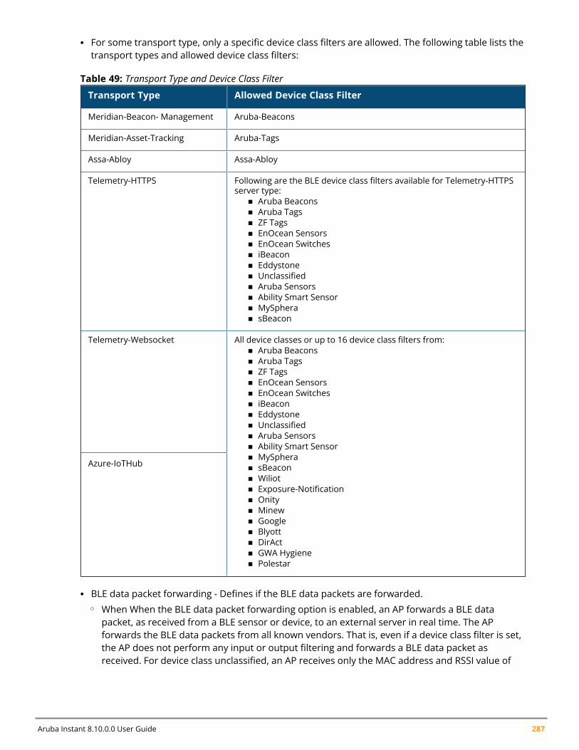
Aruba Instant 8.10.0.0 User Guide 287
l For some transport type, only a specific device class filters are allowed. The following table lists thetransport types and allowed device class filters:
Transport Type Allowed Device Class Filter
Meridian-Beacon- Management Aruba-Beacons
Meridian-Asset-Tracking Aruba-Tags
Assa-Abloy Assa-Abloy
Telemetry-HTTPS Following are the BLE device class filters available for Telemetry-HTTPSserver type:
n Aruba Beaconsn Aruba Tagsn ZF Tagsn EnOcean Sensorsn EnOcean Switchesn iBeaconn Eddystonen Unclassifiedn Aruba Sensorsn Ability Smart Sensorn MySpheran sBeacon
Telemetry-Websocket All device classes or up to 16 device class filters from:n Aruba Beaconsn Aruba Tagsn ZF Tagsn EnOcean Sensorsn EnOcean Switchesn iBeaconn Eddystonen Unclassifiedn Aruba Sensorsn Ability Smart Sensorn MySpheran sBeaconn Wiliotn Exposure-Notificationn Onityn Minewn Googlen Blyottn DirActn GWA Hygienen Polestar
Azure-IoTHub
Table 49: Transport Type and Device Class Filter
l BLE data packet forwarding - Defines if the BLE data packets are forwarded.o When When the BLE data packet forwarding option is enabled, an AP forwards a BLE data
packet, as received from a BLE sensor or device, to an external server in real time. The APforwards the BLE data packets from all known vendors. That is, even if a device class filter is set,the AP does not perform any input or output filtering and forwards a BLE data packet asreceived. For device class unclassified, an AP receives only the MAC address and RSSI value of
IoT | 288
the sensor or device in the BLE data packet and the AP forwards this BLE data packet to anexternal server. The AP forwards the BLE data packets immediately without waiting for thereporting interval. At the reporting interval, a report comprising of all BLE devices within thatreporting interval is sent in parallel to any BLE data packet that may be received at the reportinginterval.
When BLE data packet forwarding is enabled, set the reporting interval to a high value. Thisallows an external server to receive and process the BLE data packets in real time and not relyon the report that is sent at the reporting interval to compute and offer real time locationservices.
l Reporting interval - Defines how often and what is included in the report.o When the reporting interval is configured, a report of all BLE devices within that reporting
interval is sent to an external server. The report may be configured to include only aggregatedata. For example, send only device counts.
When BLE data packet forwarding is enabled, set the reporting interval to a high value. Thisallows an external server to receive and process the BLE data packets in real time and not relyon the report that is sent at the reporting interval to compute and offer real time locationservices.
l RSSI reporting format - Defines how the RSSI information is reported.l Environment type - Defines the environment type. For custom environment, fading factor may bedefined.
l Device filter - Defines if the report includes estimated location data of the devices.o Based on the RSSI value of a device, the AP estimates the location of the BLE devices near it. The
device class filters may be configured to report BLE devices that:o Are within n meters of the beacon. The range for n is 2 meters to 100 meters. If a BLE device is
outside the defined distance, the AP does not include that BLE device in the report.o Have moved more than n meters since the BLE device was last reported. The range for n is 2
meters to 30 meters. If a BLE device has not moved the defined distance since it was lastreported, the AP does not include that BLE device in the report.
o Had activity within the last n seconds or minutes. The range for n is 30 seconds to 3600seconds or 1 minute to 60 minutes. If the AP has not received any BLE data packet from a BLEdevice within the defined time period, it does not include that BLE device in the report.
o The device filters are disabled by default. Hence, an AP includes all devices that are within itsrange and irrespective of whether the devices have moved or sent BLE data packets in thereport.
If an active BLE device is removed or moved out of the range of an AP, the AP reports the deviceuntil the entry of the device is stored in the AP.
o If the device class is iBeacon or Eddystone, additional device filters can be defined. Theseadditional filters are based on the parameters in the header of the beacons from iBeacon orEddystone devices. The additional filters are:o Universal Unique Identifier (UUID)- The UUID provides identity information of the ibeacono Unique Identifier (UID) - The UID provides identity information of the Eddystone beacon
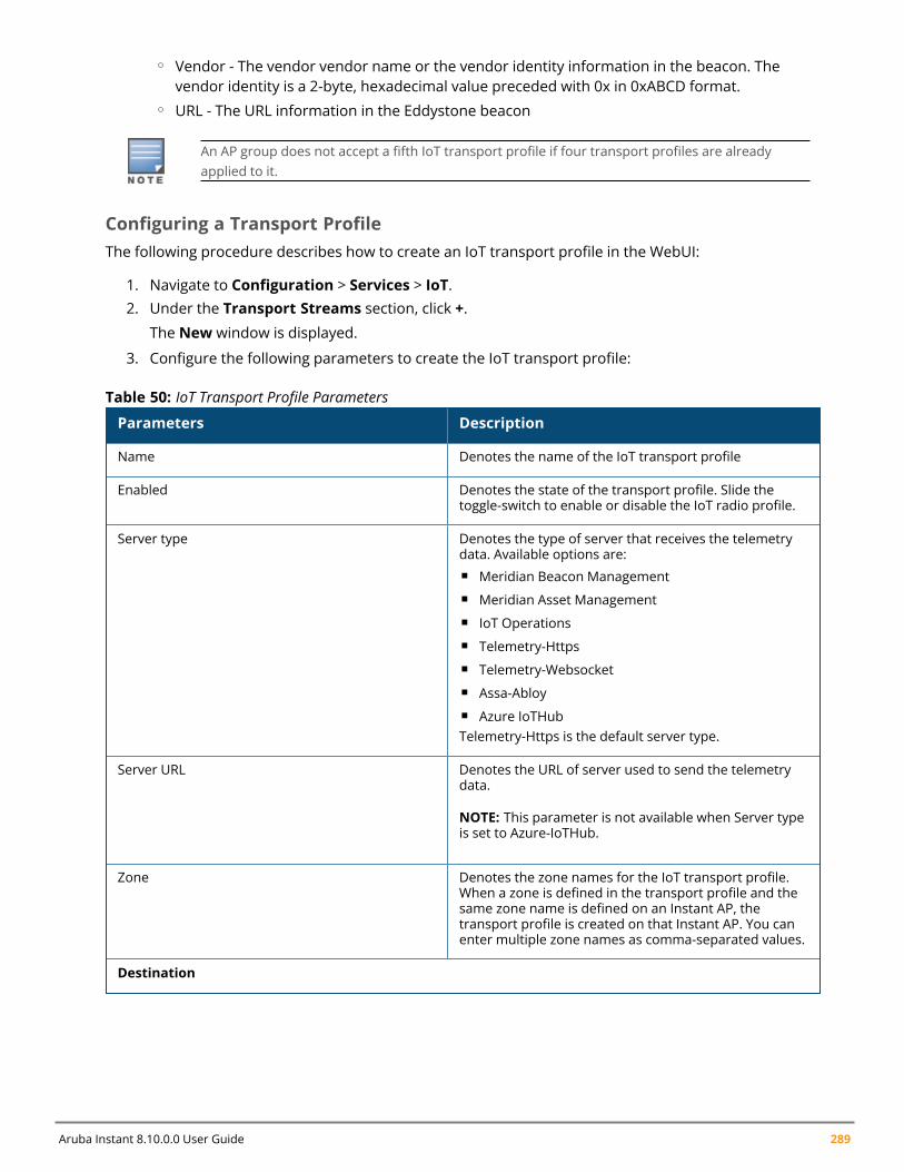
Aruba Instant 8.10.0.0 User Guide 289
o Vendor - The vendor vendor name or the vendor identity information in the beacon. Thevendor identity is a 2-byte, hexadecimal value preceded with 0x in 0xABCD format.
o URL - The URL information in the Eddystone beacon
An AP group does not accept a fifth IoT transport profile if four transport profiles are alreadyapplied to it.
Configuring a Transport ProfileThe following procedure describes how to create an IoT transport profile in the WebUI:
1. Navigate to Configuration > Services > IoT.2. Under the Transport Streams section, click +.
The New window is displayed.
3. Configure the following parameters to create the IoT transport profile:
Parameters Description
Name Denotes the name of the IoT transport profile
Enabled Denotes the state of the transport profile. Slide thetoggle-switch to enable or disable the IoT radio profile.
Server type Denotes the type of server that receives the telemetrydata. Available options are:n Meridian Beacon Managementn Meridian Asset Managementn IoT Operationsn Telemetry-Httpsn Telemetry-Websocketn Assa-Abloyn Azure IoTHubTelemetry-Https is the default server type.
Server URL Denotes the URL of server used to send the telemetrydata.
NOTE: This parameter is not available when Server typeis set to Azure-IoTHub.
Zone Denotes the zone names for the IoT transport profile.When a zone is defined in the transport profile and thesame zone name is defined on an Instant AP, thetransport profile is created on that Instant AP. You canenter multiple zone names as comma-separated values.
Destination
Table 50: IoT Transport Profile Parameters
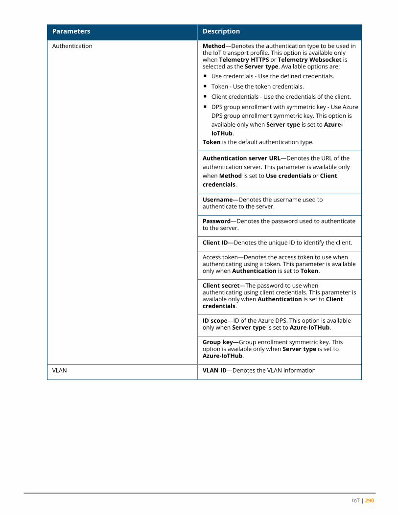
IoT | 290
Parameters Description
Authentication Method—Denotes the authentication type to be used inthe IoT transport profile. This option is available onlywhen Telemetry HTTPS or Telemetry Websocket isselected as the Server type. Available options are:n Use credentials - Use the defined credentials.n Token - Use the token credentials.n Client credentials - Use the credentials of the client.n DPS group enrollment with symmetric key - Use Azure
DPS group enrollment symmetric key. This option isavailable only when Server type is set to Azure-IoTHub.
Token is the default authentication type.
Authentication server URL—Denotes the URL of theauthentication server. This parameter is available onlywhenMethod is set to Use credentials or Clientcredentials.
Username—Denotes the username used toauthenticate to the server.
Password—Denotes the password used to authenticateto the server.
Client ID—Denotes the unique ID to identify the client.
Access token—Denotes the access token to use whenauthenticating using a token. This parameter is availableonly when Authentication is set to Token.
Client secret—The password to use whenauthenticating using client credentials. This parameter isavailable only when Authentication is set to Clientcredentials.
ID scope—ID of the Azure DPS. This option is availableonly when Server type is set to Azure-IoTHub.
Group key—Group enrollment symmetric key. Thisoption is available only when Server type is set toAzure-IoTHub.
VLAN VLAN ID—Denotes the VLAN information
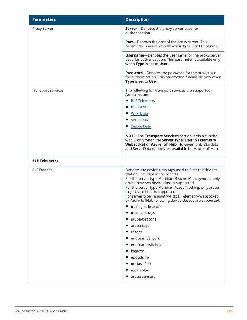
Aruba Instant 8.10.0.0 User Guide 291
Parameters Description
Proxy Server Server—Denotes the proxy server used forauthentication.
Port—Denotes the port of the proxy server. Thisparameter is available only when Type is set to Server.
Username—Denotes the username for the proxy serverused for authentication. This parameter is available onlywhen Type is set to User.
Password—Denotes the password for the proxy usedfor authentication. This parameter is available only whenType is set to User.
Transport Services The following IoT transport services are supported inAruba Instant:n BLE Telemetryn BLE Datan Wi-Fi Datan Serial Datan Zigbee Data
NOTE: The Transport Services section is visible in thewebUI only when the Server type is set to TelemetryWebsocket or Azure IoT Hub. However, only BLE dataand Serial Data options are available for Azure IoT Hub.
BLE Telemetry
BLE Devices Denotes the device class tags used to filter the devicesthat are included in the reports.For the server type Meridian-Beacon-Management, onlyaruba-beacons device class is supported.For the server type Meridian-Asset-Tracking, only aruba-tags device class is supported.For server type Telemetry-Https, Telemetry-Websocket,or Azure-IoTHub following device classes are supported:n managed-beaconsn managed-tagsn aruba-beaconsn aruba-tagsn zf-tagsn enocean-sensorsn enocean-switchesn ibeaconn eddystonen unclassifiedn assa-abloyn aruba-sensors
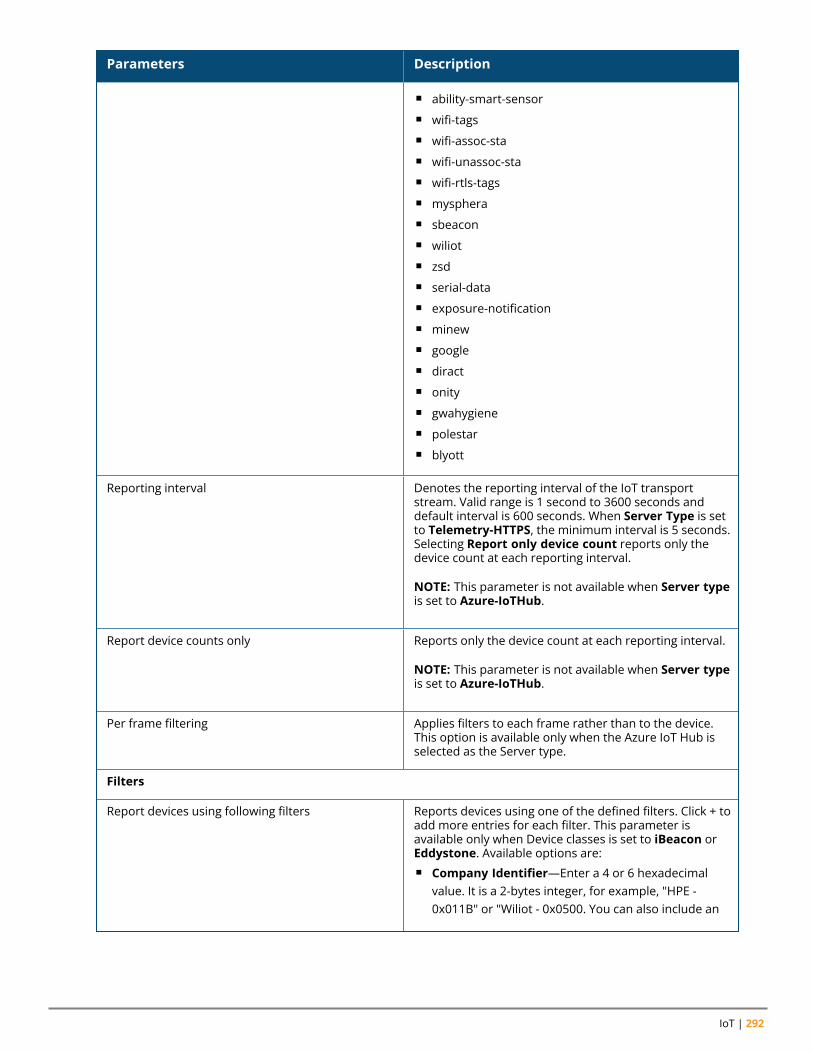
IoT | 292
Parameters Description
n ability-smart-sensorn wifi-tagsn wifi-assoc-stan wifi-unassoc-stan wifi-rtls-tagsn myspheran sbeaconn wiliotn zsdn serial-datan exposure-notificationn minewn googlen diractn onityn gwahygienen polestarn blyott
Reporting interval Denotes the reporting interval of the IoT transportstream. Valid range is 1 second to 3600 seconds anddefault interval is 600 seconds. When Server Type is setto Telemetry-HTTPS, the minimum interval is 5 seconds.Selecting Report only device count reports only thedevice count at each reporting interval.
NOTE: This parameter is not available when Server typeis set to Azure-IoTHub.
Report device counts only Reports only the device count at each reporting interval.
NOTE: This parameter is not available when Server typeis set to Azure-IoTHub.
Per frame filtering Applies filters to each frame rather than to the device.This option is available only when the Azure IoT Hub isselected as the Server type.
Filters
Report devices using following filters Reports devices using one of the defined filters. Click + toadd more entries for each filter. This parameter isavailable only when Device classes is set to iBeacon orEddystone. Available options are:n Company Identifier—Enter a 4 or 6 hexadecimal
value. It is a 2-bytes integer, for example, "HPE -0x011B" or "Wiliot - 0x0500. You can also include an
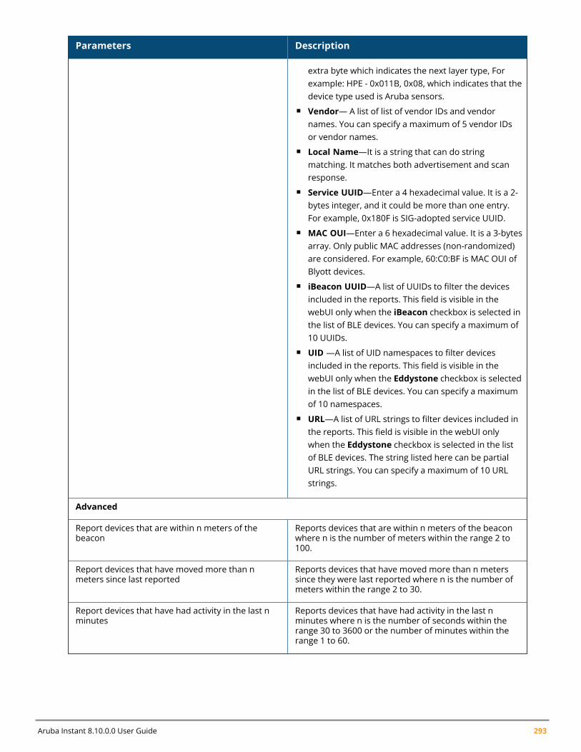
Aruba Instant 8.10.0.0 User Guide 293
Parameters Description
extra byte which indicates the next layer type, Forexample: HPE - 0x011B, 0x08, which indicates that thedevice type used is Aruba sensors.
n Vendor— A list of list of vendor IDs and vendornames. You can specify a maximum of 5 vendor IDsor vendor names.
n Local Name—It is a string that can do stringmatching. It matches both advertisement and scanresponse.
n Service UUID—Enter a 4 hexadecimal value. It is a 2-bytes integer, and it could be more than one entry.For example, 0x180F is SIG-adopted service UUID.
n MAC OUI—Enter a 6 hexadecimal value. It is a 3-bytesarray. Only public MAC addresses (non-randomized)are considered. For example, 60:C0:BF is MAC OUI ofBlyott devices.
n iBeacon UUID—A list of UUIDs to filter the devicesincluded in the reports. This field is visible in thewebUI only when the iBeacon checkbox is selected inthe list of BLE devices. You can specify a maximum of10 UUIDs.
n UID —A list of UID namespaces to filter devicesincluded in the reports. This field is visible in thewebUI only when the Eddystone checkbox is selectedin the list of BLE devices. You can specify a maximumof 10 namespaces.
n URL—A list of URL strings to filter devices included inthe reports. This field is visible in the webUI onlywhen the Eddystone checkbox is selected in the listof BLE devices. The string listed here can be partialURL strings. You can specify a maximum of 10 URLstrings.
Advanced
Report devices that are within n meters of thebeacon
Reports devices that are within n meters of the beaconwhere n is the number of meters within the range 2 to100.
Report devices that have moved more than nmeters since last reported
Reports devices that have moved more than n meterssince they were last reported where n is the number ofmeters within the range 2 to 30.
Report devices that have had activity in the last nminutes
Reports devices that have had activity in the last nminutes where n is the number of seconds within therange 30 to 3600 or the number of minutes within therange 1 to 60.
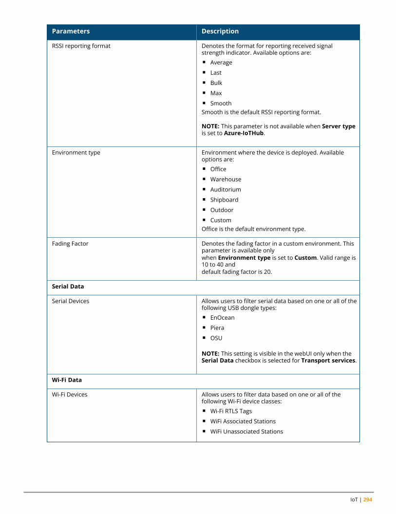
IoT | 294
Parameters Description
RSSI reporting format Denotes the format for reporting received signalstrength indicator. Available options are:n Averagen Lastn Bulkn Maxn SmoothSmooth is the default RSSI reporting format.
NOTE: This parameter is not available when Server typeis set to Azure-IoTHub.
Environment type Environment where the device is deployed. Availableoptions are:n Officen Warehousen Auditoriumn Shipboardn Outdoorn CustomOffice is the default environment type.
Fading Factor Denotes the fading factor in a custom environment. Thisparameter is available onlywhen Environment type is set to Custom. Valid range is10 to 40 anddefault fading factor is 20.
Serial Data
Serial Devices Allows users to filter serial data based on one or all of thefollowing USB dongle types:n EnOceann Pieran OSU
NOTE: This setting is visible in the webUI only when theSerial Data checkbox is selected for Transport services.
Wi-Fi Data
Wi-Fi Devices Allows users to filter data based on one or all of thefollowing Wi-Fi device classes:n Wi-Fi RTLS Tagsn WiFi Associated Stationsn WiFi Unassociated Stations
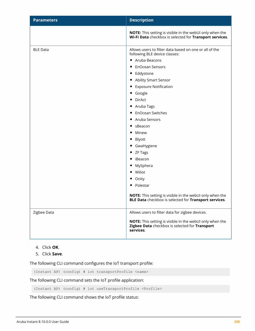
Aruba Instant 8.10.0.0 User Guide 295
Parameters Description
NOTE: This setting is visible in the webUI only when theWi-Fi Data checkbox is selected for Transport services.
BLE Data Allows users to filter data based on one or all of thefollowing BLE device classes:n Aruba Beaconsn EnOcean Sensorsn Eddystonen Ability Smart Sensorn Exposure Notificationn Googlen DirActn Aruba Tagsn EnOcean Switchesn Aruba Sensorsn sBeaconn Minewn Blyottn GwaHygienen ZF Tagsn iBeaconn MySpheran Wiliotn Onityn Polestar
NOTE: This setting is visible in the webUI only when theBLE Data checkbox is selected for Transport services.
Zigbee Data Allows users to filter data for zigbee devices.
NOTE: This setting is visible in the webUI only when theZigbee Data checkbox is selected for Transportservices.
4. Click OK.5. Click Save.
The following CLI command configures the IoT transport profile:
(Instant AP) (config) # iot transportProfile <name>
The following CLI command sets the IoT profile application:
(Instant AP) (config) # iot useTransportProfile <Profile>
The following CLI command shows the IoT profile status:
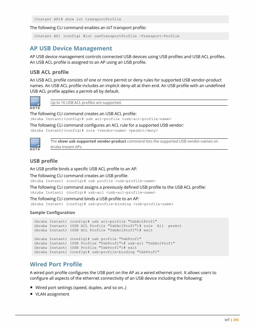
IoT | 296
(Instant AP)# show iot transportProfile
The following CLI command enables an IoT transport profile:
(Instant AP) (config) #iot useTransportProfile -Transport-Profile
AP USB Device ManagementAP USB device management controls connected USB devices using USB profiles and USB ACL profiles.An USB ACL profile is assigned to an AP using an USB profile.
USB ACL profileAn USB ACL profile consists of one or more permit or deny rules for supported USB vendor-productnames. An USB ACL profile includes an implicit deny-all at then end. An USB profile with an undefinedUSB ACL profile applies a permit-all by default.
Up to 16 USB ACL profiles are supported.
The following CLI command creates an USB ACL profile:(Aruba Instant)(config)# usb acl-profile <usb-acl-profile-name>
The following CLI command configures an ACL rule for a supported USB vendor:(Aruba Instant)(config)# rule <vendor-name> <permit/deny>
The show usb supported vendor-product command lists the supported USB vendor-names onAruba Instant APs.
USB profileAn USB profile binds a specific USB ACL profile to an AP.
The following CLI command creates an USB profile:(Aruba Instant) (config)# usb profile <usb-profile-name>
The following CLI command assigns a previously defined USB profile to the USB ACL profile:(Aruba Instant) (config)# usb-acl <usb-acl-profile-name>
The following CLI command binds a USB profile to an AP:(Aruba Instant) (config)# usb-profile-binding <usb-profile-name>
Sample Configuration
(Aruba Instant) (config)# usb acl-profile "UsbAclProf1"(Aruba Instant) (USB ACL Profile "UsbAclProf1")# rule All permit(Aruba Instant) (USB ACL Profile "UsbAclProf1")# exit
(Aruba Instant) (config)# usb profile "UsbProf1"(Aruba Instant) (USB Profile "UsbProf1")# usb-acl "UsbAclProf1"(Aruba Instant) (USB Profile "UsbProf1")# exit(Aruba Instant) (config)# usb-profile-binding "UsbProf1"
Wired Port ProfileA wired port profile configures the USB port on the AP as a wired ethernet port. It allows users toconfigure all aspects of the ethernet connectivity of an USB device including the following:
n Wired port settings (speed, duplex, and so on..)n VLAN assignment
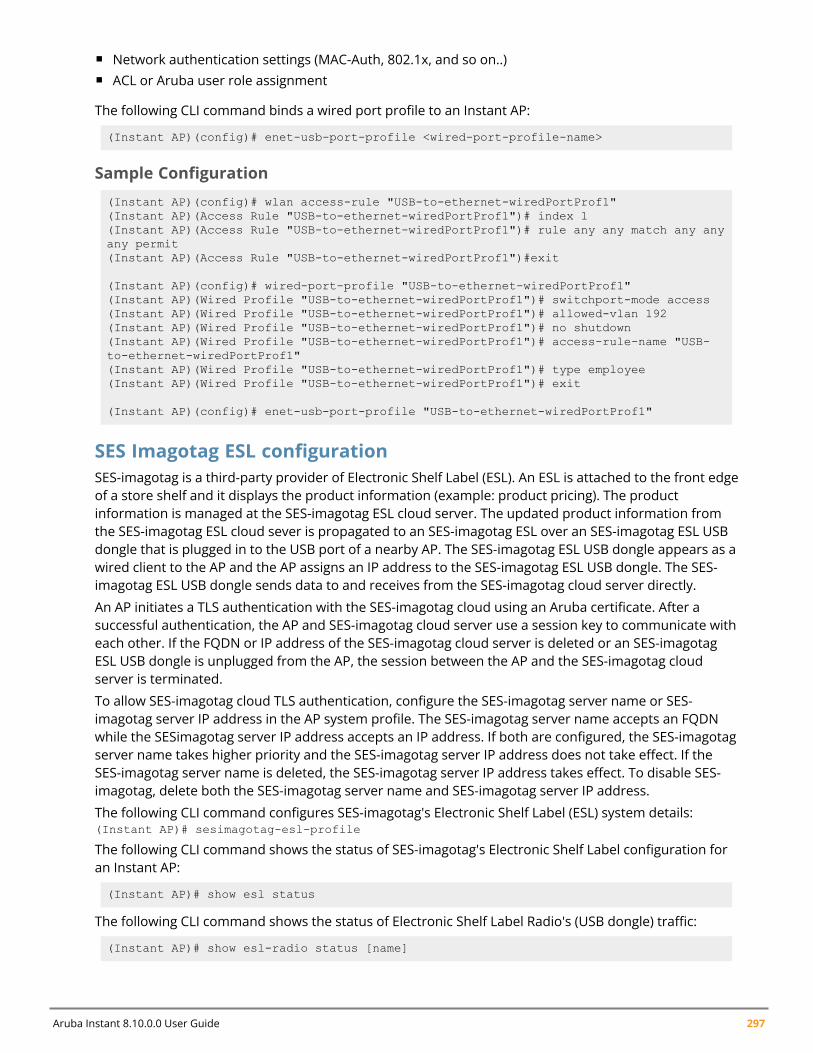
Aruba Instant 8.10.0.0 User Guide 297
n Network authentication settings (MAC-Auth, 802.1x, and so on..)n ACL or Aruba user role assignment
The following CLI command binds a wired port profile to an Instant AP:
(Instant AP)(config)# enet-usb-port-profile <wired-port-profile-name>
Sample Configuration
(Instant AP)(config)# wlan access-rule "USB-to-ethernet-wiredPortProf1"(Instant AP)(Access Rule "USB-to-ethernet-wiredPortProf1")# index 1(Instant AP)(Access Rule "USB-to-ethernet-wiredPortProf1")# rule any any match any anyany permit(Instant AP)(Access Rule "USB-to-ethernet-wiredPortProf1")#exit
(Instant AP)(config)# wired-port-profile "USB-to-ethernet-wiredPortProf1"(Instant AP)(Wired Profile "USB-to-ethernet-wiredPortProf1")# switchport-mode access(Instant AP)(Wired Profile "USB-to-ethernet-wiredPortProf1")# allowed-vlan 192(Instant AP)(Wired Profile "USB-to-ethernet-wiredPortProf1")# no shutdown(Instant AP)(Wired Profile "USB-to-ethernet-wiredPortProf1")# access-rule-name "USB-to-ethernet-wiredPortProf1"(Instant AP)(Wired Profile "USB-to-ethernet-wiredPortProf1")# type employee(Instant AP)(Wired Profile "USB-to-ethernet-wiredPortProf1")# exit
(Instant AP)(config)# enet-usb-port-profile "USB-to-ethernet-wiredPortProf1"
SES Imagotag ESL configurationSES-imagotag is a third-party provider of Electronic Shelf Label (ESL). An ESL is attached to the front edgeof a store shelf and it displays the product information (example: product pricing). The productinformation is managed at the SES-imagotag ESL cloud server. The updated product information fromthe SES-imagotag ESL cloud sever is propagated to an SES-imagotag ESL over an SES-imagotag ESL USBdongle that is plugged in to the USB port of a nearby AP. The SES-imagotag ESL USB dongle appears as awired client to the AP and the AP assigns an IP address to the SES-imagotag ESL USB dongle. The SES-imagotag ESL USB dongle sends data to and receives from the SES-imagotag cloud server directly.
An AP initiates a TLS authentication with the SES-imagotag cloud using an Aruba certificate. After asuccessful authentication, the AP and SES-imagotag cloud server use a session key to communicate witheach other. If the FQDN or IP address of the SES-imagotag cloud server is deleted or an SES-imagotagESL USB dongle is unplugged from the AP, the session between the AP and the SES-imagotag cloudserver is terminated.
To allow SES-imagotag cloud TLS authentication, configure the SES-imagotag server name or SES-imagotag server IP address in the AP system profile. The SES-imagotag server name accepts an FQDNwhile the SESimagotag server IP address accepts an IP address. If both are configured, the SES-imagotagserver name takes higher priority and the SES-imagotag server IP address does not take effect. If theSES-imagotag server name is deleted, the SES-imagotag server IP address takes effect. To disable SES-imagotag, delete both the SES-imagotag server name and SES-imagotag server IP address.
The following CLI command configures SES-imagotag's Electronic Shelf Label (ESL) system details:(Instant AP)# sesimagotag-esl-profile
The following CLI command shows the status of SES-imagotag's Electronic Shelf Label configuration foran Instant AP:
(Instant AP)# show esl status
The following CLI command shows the status of Electronic Shelf Label Radio's (USB dongle) traffic:
(Instant AP)# show esl-radio status [name]
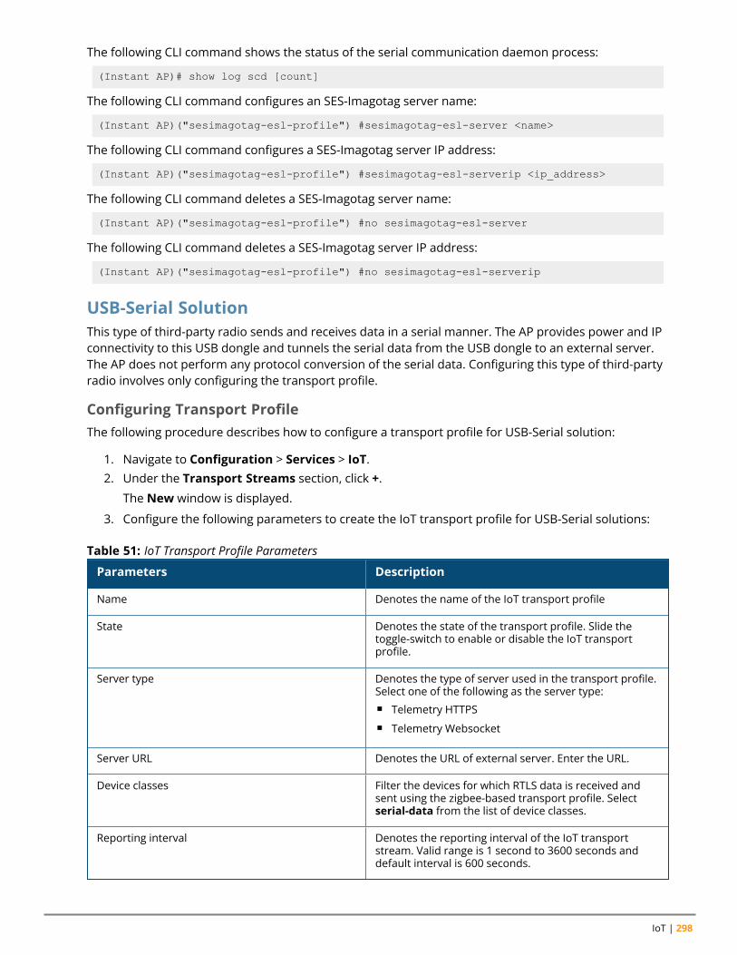
IoT | 298
The following CLI command shows the status of the serial communication daemon process:
(Instant AP)# show log scd [count]
The following CLI command configures an SES-Imagotag server name:
(Instant AP)("sesimagotag-esl-profile") #sesimagotag-esl-server <name>
The following CLI command configures a SES-Imagotag server IP address:
(Instant AP)("sesimagotag-esl-profile") #sesimagotag-esl-serverip <ip_address>
The following CLI command deletes a SES-Imagotag server name:
(Instant AP)("sesimagotag-esl-profile") #no sesimagotag-esl-server
The following CLI command deletes a SES-Imagotag server IP address:
(Instant AP)("sesimagotag-esl-profile") #no sesimagotag-esl-serverip
USB-Serial SolutionThis type of third-party radio sends and receives data in a serial manner. The AP provides power and IPconnectivity to this USB dongle and tunnels the serial data from the USB dongle to an external server.The AP does not perform any protocol conversion of the serial data. Configuring this type of third-partyradio involves only configuring the transport profile.
Configuring Transport ProfileThe following procedure describes how to configure a transport profile for USB-Serial solution:
1. Navigate to Configuration > Services > IoT.2. Under the Transport Streams section, click +.
The New window is displayed.
3. Configure the following parameters to create the IoT transport profile for USB-Serial solutions:
Parameters Description
Name Denotes the name of the IoT transport profile
State Denotes the state of the transport profile. Slide thetoggle-switch to enable or disable the IoT transportprofile.
Server type Denotes the type of server used in the transport profile.Select one of the following as the server type:n Telemetry HTTPSn Telemetry Websocket
Server URL Denotes the URL of external server. Enter the URL.
Device classes Filter the devices for which RTLS data is received andsent using the zigbee-based transport profile. Selectserial-data from the list of device classes.
Reporting interval Denotes the reporting interval of the IoT transportstream. Valid range is 1 second to 3600 seconds anddefault interval is 600 seconds.
Table 51: IoT Transport Profile Parameters
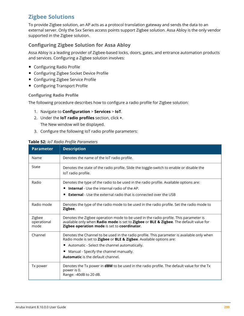
Aruba Instant 8.10.0.0 User Guide 299
Zigbee SolutionsTo provide Zigbee solution, an AP acts as a protocol translation gateway and sends the data to anexternal server. Only the 5xx Series access points support Zigbee solution. Assa Abloy is the only vendorsupported in the Zigbee solution.
Configuring Zigbee Solution for Assa AbloyAssa Abloy is a leading provider of Zigbee-based locks, doors, gates, and entrance automation productsand services. Configuring a Zigbee solution involves:
n Configuring Radio Profilen Configuring Zigbee Socket Device Profilen Configuring Zigbee Service Profilen Configuring Transport Profile
Configuring Radio Profile
The following procedure describes how to configure a radio profile for Zigbee solution:
1. Navigate to Configuration > Services > IoT.2. Under the IoT radio profiles section, click +.
The New window will be displayed.
3. Configure the following IoT radio profile parameters:
Parameter Description
Name Denotes the name of the IoT radio profile.
State Denotes the state of the radio profile. Slide the toggle-switch to enable or disable theIoT radio profile.
Radio Denotes the type of the radio to be used in the radio profile. Available options are:n Internal - Use the internal radio of the AP.n External - Use the external radio that is connected over the USB
Radio mode Denotes the type of the radio mode to be used in the radio profile. Set the radio mode toZigbee.
Zigbeeoperationalmode
Denotes the Zigbee operation mode to be used in the radio profile. This parameter isavailable only when Radio mode is set to Zigbee or BLE & Zigbee. The default value forZigbee operation mode is set to coordinator.
Channel Denotes the Channel to be used in the radio profile. This parameter is available only whenRadio mode is set to Zigbee or BLE & Zigbee. Available options are:n Automatic - Select the channel automatically.n Manual - Specify the channel manually.Automatic is the default channel.
Tx power Denotes the Tx power in dBM to be used in the radio profile. The default value for the Txpower is 0.Range: -40dB to 20 dB.
Table 52: IoT Radio Profile Parameters
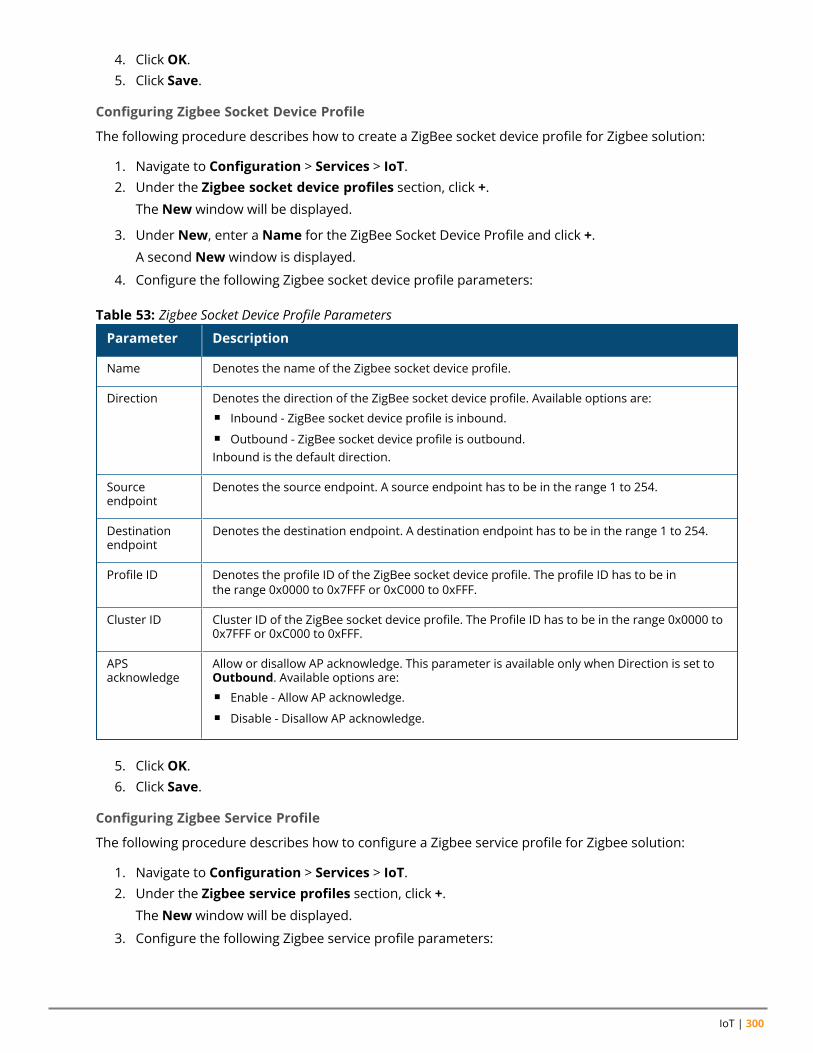
IoT | 300
4. Click OK.5. Click Save.
Configuring Zigbee Socket Device Profile
The following procedure describes how to create a ZigBee socket device profile for Zigbee solution:
1. Navigate to Configuration > Services > IoT.2. Under the Zigbee socket device profiles section, click +.
The New window will be displayed.
3. Under New, enter a Name for the ZigBee Socket Device Profile and click +.
A second New window is displayed.
4. Configure the following Zigbee socket device profile parameters:
Parameter Description
Name Denotes the name of the Zigbee socket device profile.
Direction Denotes the direction of the ZigBee socket device profile. Available options are:n Inbound - ZigBee socket device profile is inbound.n Outbound - ZigBee socket device profile is outbound.Inbound is the default direction.
Sourceendpoint
Denotes the source endpoint. A source endpoint has to be in the range 1 to 254.
Destinationendpoint
Denotes the destination endpoint. A destination endpoint has to be in the range 1 to 254.
Profile ID Denotes the profile ID of the ZigBee socket device profile. The profile ID has to be inthe range 0x0000 to 0x7FFF or 0xC000 to 0xFFF.
Cluster ID Cluster ID of the ZigBee socket device profile. The Profile ID has to be in the range 0x0000 to0x7FFF or 0xC000 to 0xFFF.
APSacknowledge
Allow or disallow AP acknowledge. This parameter is available only when Direction is set toOutbound. Available options are:n Enable - Allow AP acknowledge.n Disable - Disallow AP acknowledge.
Table 53: Zigbee Socket Device Profile Parameters
5. Click OK.6. Click Save.
Configuring Zigbee Service Profile
The following procedure describes how to configure a Zigbee service profile for Zigbee solution:
1. Navigate to Configuration > Services > IoT.2. Under the Zigbee service profiles section, click +.
The New window will be displayed.
3. Configure the following Zigbee service profile parameters:
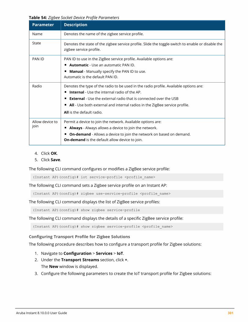
Aruba Instant 8.10.0.0 User Guide 301
Parameter Description
Name Denotes the name of the zigbee service profile.
State Denotes the state of the zigbee service profile. Slide the toggle-switch to enable or disable thezigbee service profile.
PAN ID PAN ID to use in the ZigBee service profile. Available options are:n Automatic - Use an automatic PAN ID.n Manual - Manually specify the PAN ID to use.Automatic is the default PAN ID.
Radio Denotes the type of the radio to be used in the radio profile. Available options are:n Internal - Use the internal radio of the AP.n External - Use the external radio that is connected over the USBn All - Use both external and internal radios in the ZigBee service profile.
All is the default radio.
Allow device tojoin
Permit a device to join the network. Available options are:n Always - Always allows a device to join the network.n On-demand - Allows a device to join the network on based on demand.On-demand is the default allow device to join.
Table 54: Zigbee Socket Device Profile Parameters
4. Click OK.5. Click Save.
The following CLI command configures or modifies a ZigBee service profile:
(Instant AP)(config)# iot service-profile <profile_name>
The following CLI command sets a Zigbee service profile on an Instant AP:
(Instant AP)(config)# zigbee use-service-profile <profile_name>
The following CLI command displays the list of ZigBee service profiles:
(Instant AP)(config)# show zigbee service-profile
The following CLI command displays the details of a specific ZigBee service profile:
(Instant AP)(config)# show zigbee service-profile <profile_name>
Configuring Transport Profile for Zigbee Solutions
The following procedure describes how to configure a transport profile for Zigbee solutions:
1. Navigate to Configuration > Services > IoT.2. Under the Transport Streams section, click +.
The New window is displayed.
3. Configure the following parameters to create the IoT transport profile for Zigbee solutions:
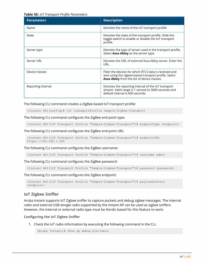
IoT | 302
Parameters Description
Name Denotes the name of the IoT transport profile
State Denotes the state of the transport profile. Slide thetoggle-switch to enable or disable the IoT transportprofile.
Server type Denotes the type of server used in the transport profile.Select Assa Abloy as the server type.
Server URL Denotes the URL of external Assa Abloy server. Enter theURL.
Device classes Filter the devices for which RTLS data is received andsent using the zigbee-based transport profile. SelectAssa Abloy from the list of device classes.
Reporting interval Denotes the reporting interval of the IoT transportstream. Valid range is 1 second to 3600 seconds anddefault interval is 600 seconds.
Table 55: IoT Transport Profile Parameters
The following CLI command creates a ZigBee-based IoT transport profile:
(Instant AP)(config)# iot transportProfile Sample-Zigbee-Transport
The following CLI command configures the ZigBee end point type:
(Instant AP)(IoT Transport Profile "Sample-Zigbee-Transport")# endpoinType <endpoint>
The following CLI command configures the ZigBee end point URL:
(Instant AP)(IoT Transport Profile "Sample-Zigbee-Transport")# endpointURLhttps://192.168.1.200
The following CLI command configures the ZigBee username:
(Instant AP)(IoT Transport Profile "Sample-Zigbee-Transport")# username admin
The following CLI command configures the ZigBee password:
(Instant AP)(IoT Transport Profile "Sample-Zigbee-Transport")# password <password>
The following CLI command configures the ZigBee endpoint:
(Instant AP)(IoT Transport Profile "Sample-Zigbee-Transport")# payloadcontent<endpoint>
IoT Zigbee SnifferAruba Instant supports IoT Zigbee sniffer to capture packets and debug zigbee messages. The internalradio and external USB dongle radio supported by the Instant AP can be used as zigbee sniffers.However, the internal or external radio type must be Nordic-based for this feature to work.
Configuring the IoT Zigbee Sniffer
1. Check the IoT radio information by executing the following command in the CLI.
(Aruba Instant)# show ap debug ble-table
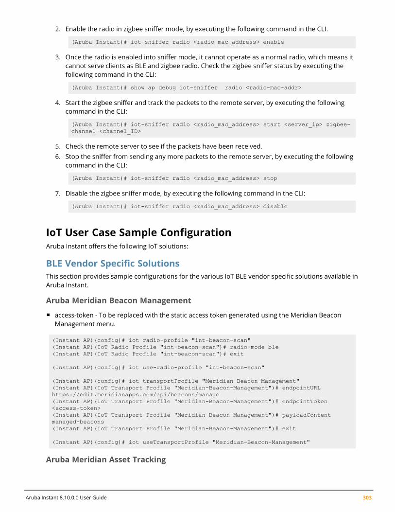
Aruba Instant 8.10.0.0 User Guide 303
2. Enable the radio in zigbee sniffer mode, by executing the following command in the CLI.
(Aruba Instant)# iot-sniffer radio <radio_mac_address> enable
3. Once the radio is enabled into sniffer mode, it cannot operate as a normal radio, which means itcannot serve clients as BLE and zigbee radio. Check the zigbee sniffer status by executing thefollowing command in the CLI:
(Aruba Instant)# show ap debug iot-sniffer radio <radio-mac-addr>
4. Start the zigbee sniffer and track the packets to the remote server, by executing the followingcommand in the CLI:
(Aruba Instant)# iot-sniffer radio <radio_mac_address> start <server_ip> zigbee-channel <channel_ID>
5. Check the remote server to see if the packets have been received.6. Stop the sniffer from sending any more packets to the remote server, by executing the following
command in the CLI:
(Aruba Instant)# iot-sniffer radio <radio_mac_address> stop
7. Disable the zigbee sniffer mode, by executing the following command in the CLI:
(Aruba Instant)# iot-sniffer radio <radio_mac_address> disable
IoT User Case Sample ConfigurationAruba Instant offers the following IoT solutions:
BLE Vendor Specific SolutionsThis section provides sample configurations for the various IoT BLE vendor specific solutions available inAruba Instant.
Aruba Meridian Beacon Management
n access-token - To be replaced with the static access token generated using the Meridian BeaconManagement menu.
(Instant AP)(config)# iot radio-profile "int-beacon-scan"(Instant AP)(IoT Radio Profile "int-beacon-scan")# radio-mode ble(Instant AP)(IoT Radio Profile "int-beacon-scan")# exit
(Instant AP)(config)# iot use-radio-profile "int-beacon-scan"
(Instant AP)(config)# iot transportProfile "Meridian-Beacon-Management"(Instant AP)(IoT Transport Profile "Meridian-Beacon-Management")# endpointURLhttps://edit.meridianapps.com/api/beacons/manage(Instant AP)(IoT Transport Profile "Meridian-Beacon-Management")# endpointToken<access-token>(Instant AP)(IoT Transport Profile "Meridian-Beacon-Management")# payloadContentmanaged-beacons(Instant AP)(IoT Transport Profile "Meridian-Beacon-Management")# exit
(Instant AP)(config)# iot useTransportProfile "Meridian-Beacon-Management"
Aruba Meridian Asset Tracking
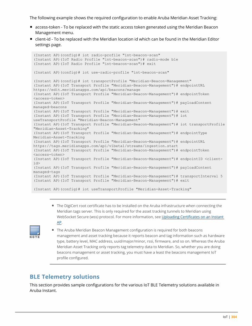
IoT | 304
The following example shows the required configuration to enable Aruba Meridian Asset Tracking:
n access-token - To be replaced with the static access token generated using the Meridian BeaconManagement menu.
n client-id - To be replaced with the Meridian location id which can be found in the Meridian Editorsettings page.
(Instant AP)(config)# iot radio-profile "int-beacon-scan"(Instant AP)(IoT Radio Profile "int-beacon-scan")# radio-mode ble(Instant AP)(IoT Radio Profile "int-beacon-scan")# exit
(Instant AP)(config)# iot use-radio-profile "int-beacon-scan"
(Instant AP)(config)# iot transportProfile "Meridian-Beacon-Management"(Instant AP)(IoT Transport Profile "Meridian-Beacon-Management")# endpointURLhttps://edit.meridianapps.com/api/beacons/manage(Instant AP)(IoT Transport Profile "Meridian-Beacon-Management")# endpointToken<access-token>(Instant AP)(IoT Transport Profile "Meridian-Beacon-Management")# payloadContentmanaged-beacons(Instant AP)(IoT Transport Profile "Meridian-Beacon-Management")# exit(Instant AP)(IoT Transport Profile "Meridian-Beacon-Management")# iotuseTransportProfile "Meridian-Beacon-Management"(Instant AP)(IoT Transport Profile "Meridian-Beacon-Management")# iot transportProfile"Meridian-Asset-Tracking"(Instant AP)(IoT Transport Profile "Meridian-Beacon-Management")# endpointTypeMeridian-Asset-Tracking(Instant AP)(IoT Transport Profile "Meridian-Beacon-Management")# endpointURLhttps://tags.meridianapps.com/api/v1beta1/streams/ingestion.start(Instant AP)(IoT Transport Profile "Meridian-Beacon-Management")# endpointToken<access-token>(Instant AP)(IoT Transport Profile "Meridian-Beacon-Management")# endpointID <client-id>(Instant AP)(IoT Transport Profile "Meridian-Beacon-Management")# payloadContentmanaged-tags(Instant AP)(IoT Transport Profile "Meridian-Beacon-Management")# transportInterval 5(Instant AP)(IoT Transport Profile "Meridian-Beacon-Management")# exit
(Instant AP)(config)# iot useTransportProfile "Meridian-Asset-Tracking"
n The DigiCert root certificate has to be installed on the Aruba infrastructure when connecting theMeridian tags server. This is only required for the asset tracking tunnels to Meridian usingWebSocket Secure (wss) protocol. For more information, see Uploading Certificates on an InstantAP.
n The Aruba Meridian Beacon Management configuration is required for both beaconsmanagement and asset tracking because it reports beacon and tag information such as hardwaretype, battery level, MAC address, uuid/major/minor, rssi, firmware, and so on. Whereas the ArubaMeridian Asset Tracking only reports tag telemetry data to Meridian. So, whether you are doingbeacons management or asset tracking, you must have a least the beacons management IoTprofile configured.
BLE Telemetry solutionsThis section provides sample configurations for the various IoT BLE Telemetry solutions available inAruba Instant.
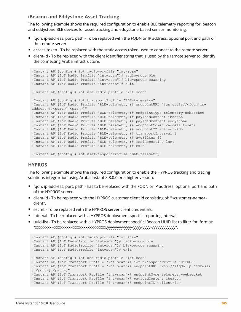
Aruba Instant 8.10.0.0 User Guide 305
iBeacon and Eddystone Asset TrackingThe following example shows the required configuration to enable BLE telemetry reporting for ibeaconand eddystone BLE devices for asset tracking and eddystone-based sensor monitoring:
n fqdn, ip-address, port, path - To be replaced with the FQDN or IP address, optional port and path ofthe remote server.
n access-token - To be replaced with the static access token used to connect to the remote server.n client-id - To be replaced with the client identifier string that is used by the remote server to identify
the connecting Aruba infrastructure.
(Instant AP)(config)# iot radio-profile "int-scan"(Instant AP)(IoT Radio Profile "int-scan")# radio-mode ble(Instant AP)(IoT Radio Profile "int-scan")# ble-opmode scanning(Instant AP)(IoT Radio Profile "int-scan")# exit
(Instant AP)(config)# iot use-radio-profile "int-scan"
(Instant AP)(config)# iot transportProfile "BLE-telemetry"(Instant AP)(IoT Radio Profile "BLE-telemetry")# endpointURL "[ws|wss]://<fqdn|ip-address>[:<port>][<path>]"(Instant AP)(IoT Radio Profile "BLE-telemetry")# endpointType telemetry-websocket(Instant AP)(IoT Radio Profile "BLE-telemetry")# payloadContent ibeacon(Instant AP)(IoT Radio Profile "BLE-telemetry")# payloadContent eddystone(Instant AP)(IoT Radio Profile "BLE-telemetry")# endpointToken <access-token>(Instant AP)(IoT Radio Profile "BLE-telemetry")# endpointID <client-id>(Instant AP)(IoT Radio Profile "BLE-telemetry")# transportInterval 1(Instant AP)(IoT Radio Profile "BLE-telemetry")# ageFilter 30(Instant AP)(IoT Radio Profile "BLE-telemetry")# rssiReporting last(Instant AP)(IoT Radio Profile "BLE-telemetry")# exit
(Instant AP)(config)# iot useTransportProfile "BLE-telemetry"
HYPROSThe following example shows the required configuration to enable the HYPROS tracking and tracingsolutions integrartion using Aruba Instant 8.8.0.0 or a higher version:
n fqdn, ip-address, port, path - has to be replaced with the FQDN or IP address, optional port and pathof the HYPROS server.
n client-id - To be replaced with the HYPROS customer client id consisting of: "<customer-name>-client".
n secret - To be replaced with the HYPROS server client credentials.n interval - To be replaced with a HYPROS deployment specific reporting interval.n uuid-list - To be replaced with a HYPROS deployment specific iBeacon UUID list to filter for, format:
"xxxxxxxx-xxxx-xxxx-xxxx-xxxxxxxxxxxx,yyyyyyyy-yyyy-yyyy-yyyy-yyyyyyyyyyyy".
(Instant AP)(config)# iot radio-profile "int-scan"(Instant AP)(IoT RadioProfile "int-scan")# radio-mode ble(Instant AP)(IoT RadioProfile "int-scan")# ble-opmode scanning(Instant AP)(IoT RadioProfile "int-scan")# exit
(Instant AP)(config)# iot use-radio-profile "int-scan"(Instant AP)(IoT Transport Profile "int-scan")# iot transportProfile "HYPROS"(Instant AP)(IoT Transport Profile "int-scan")# endpointURL "wss://<fqdn|ip-address>[:<port>][<path>]"(Instant AP)(IoT Transport Profile "int-scan")# endpointType telemetry-websocket(Instant AP)(IoT Transport Profile "int-scan")# payloadContent ibeacon(Instant AP)(IoT Transport Profile "int-scan")# endpointID <client-id>
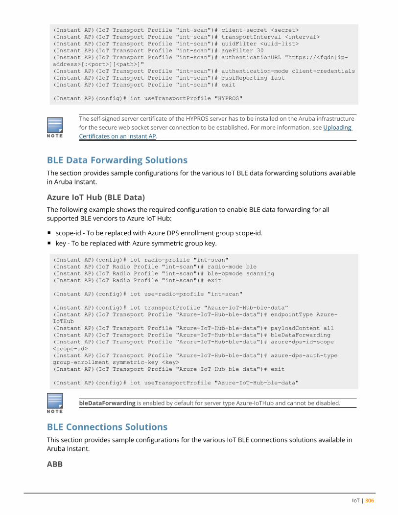
IoT | 306
(Instant AP)(IoT Transport Profile "int-scan")# client-secret <secret>(Instant AP)(IoT Transport Profile "int-scan")# transportInterval <interval>(Instant AP)(IoT Transport Profile "int-scan")# uuidFilter <uuid-list>(Instant AP)(IoT Transport Profile "int-scan")# ageFilter 30(Instant AP)(IoT Transport Profile "int-scan")# authenticationURL "https://<fqdn|ip-address>[:<port>][<path>]"(Instant AP)(IoT Transport Profile "int-scan")# authentication-mode client-credentials(Instant AP)(IoT Transport Profile "int-scan")# rssiReporting last(Instant AP)(IoT Transport Profile "int-scan")# exit
(Instant AP)(config)# iot useTransportProfile "HYPROS"
The self-signed server certificate of the HYPROS server has to be installed on the Aruba infrastructurefor the secure web socket server connection to be established. For more information, see UploadingCertificates on an Instant AP.
BLE Data Forwarding SolutionsThe section provides sample configurations for the various IoT BLE data forwarding solutions availablein Aruba Instant.
Azure IoT Hub (BLE Data)The following example shows the required configuration to enable BLE data forwarding for allsupported BLE vendors to Azure IoT Hub:
n scope-id - To be replaced with Azure DPS enrollment group scope-id.n key - To be replaced with Azure symmetric group key.
(Instant AP)(config)# iot radio-profile "int-scan"(Instant AP)(IoT Radio Profile "int-scan")# radio-mode ble(Instant AP)(IoT Radio Profile "int-scan")# ble-opmode scanning(Instant AP)(IoT Radio Profile "int-scan")# exit
(Instant AP)(config)# iot use-radio-profile "int-scan"
(Instant AP)(config)# iot transportProfile "Azure-IoT-Hub-ble-data"(Instant AP)(IoT Transport Profile "Azure-IoT-Hub-ble-data")# endpointType Azure-IoTHub(Instant AP)(IoT Transport Profile "Azure-IoT-Hub-ble-data")# payloadContent all(Instant AP)(IoT Transport Profile "Azure-IoT-Hub-ble-data")# bleDataForwarding(Instant AP)(IoT Transport Profile "Azure-IoT-Hub-ble-data")# azure-dps-id-scope<scope-id>(Instant AP)(IoT Transport Profile "Azure-IoT-Hub-ble-data")# azure-dps-auth-typegroup-enrollment symmetric-key <key>(Instant AP)(IoT Transport Profile "Azure-IoT-Hub-ble-data")# exit
(Instant AP)(config)# iot useTransportProfile "Azure-IoT-Hub-ble-data"
bleDataForwarding is enabled by default for server type Azure-IoTHub and cannot be disabled.
BLE Connections SolutionsThis section provides sample configurations for the various IoT BLE connections solutions available inAruba Instant.
ABB
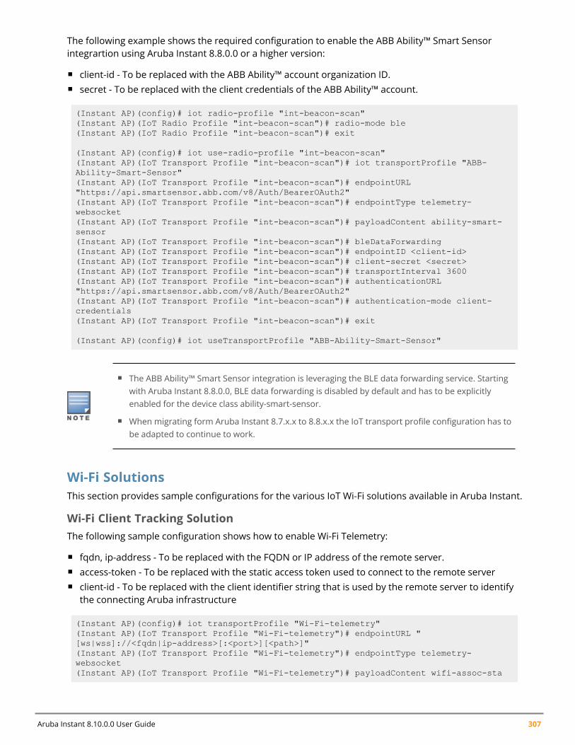
Aruba Instant 8.10.0.0 User Guide 307
The following example shows the required configuration to enable the ABB Ability™ Smart Sensorintegrartion using Aruba Instant 8.8.0.0 or a higher version:
n client-id - To be replaced with the ABB Ability™ account organization ID.n secret - To be replaced with the client credentials of the ABB Ability™ account.
(Instant AP)(config)# iot radio-profile "int-beacon-scan"(Instant AP)(IoT Radio Profile "int-beacon-scan")# radio-mode ble(Instant AP)(IoT Radio Profile "int-beacon-scan")# exit
(Instant AP)(config)# iot use-radio-profile "int-beacon-scan"(Instant AP)(IoT Transport Profile "int-beacon-scan")# iot transportProfile "ABB-Ability-Smart-Sensor"(Instant AP)(IoT Transport Profile "int-beacon-scan")# endpointURL"https://api.smartsensor.abb.com/v8/Auth/BearerOAuth2"(Instant AP)(IoT Transport Profile "int-beacon-scan")# endpointType telemetry-websocket(Instant AP)(IoT Transport Profile "int-beacon-scan")# payloadContent ability-smart-sensor(Instant AP)(IoT Transport Profile "int-beacon-scan")# bleDataForwarding(Instant AP)(IoT Transport Profile "int-beacon-scan")# endpointID <client-id>(Instant AP)(IoT Transport Profile "int-beacon-scan")# client-secret <secret>(Instant AP)(IoT Transport Profile "int-beacon-scan")# transportInterval 3600(Instant AP)(IoT Transport Profile "int-beacon-scan")# authenticationURL"https://api.smartsensor.abb.com/v8/Auth/BearerOAuth2"(Instant AP)(IoT Transport Profile "int-beacon-scan")# authentication-mode client-credentials(Instant AP)(IoT Transport Profile "int-beacon-scan")# exit
(Instant AP)(config)# iot useTransportProfile "ABB-Ability-Smart-Sensor"
n The ABB Ability™ Smart Sensor integration is leveraging the BLE data forwarding service. Startingwith Aruba Instant 8.8.0.0, BLE data forwarding is disabled by default and has to be explicitlyenabled for the device class ability-smart-sensor.
n When migrating form Aruba Instant 8.7.x.x to 8.8.x.x the IoT transport profile configuration has tobe adapted to continue to work.
Wi-Fi SolutionsThis section provides sample configurations for the various IoT Wi-Fi solutions available in Aruba Instant.
Wi-Fi Client Tracking SolutionThe following sample configuration shows how to enable Wi-Fi Telemetry:
n fqdn, ip-address - To be replaced with the FQDN or IP address of the remote server.n access-token - To be replaced with the static access token used to connect to the remote servern client-id - To be replaced with the client identifier string that is used by the remote server to identify
the connecting Aruba infrastructure
(Instant AP)(config)# iot transportProfile "Wi-Fi-telemetry"(Instant AP)(IoT Transport Profile "Wi-Fi-telemetry")# endpointURL "[ws|wss]://<fqdn|ip-address>[:<port>][<path>]"(Instant AP)(IoT Transport Profile "Wi-Fi-telemetry")# endpointType telemetry-websocket(Instant AP)(IoT Transport Profile "Wi-Fi-telemetry")# payloadContent wifi-assoc-sta
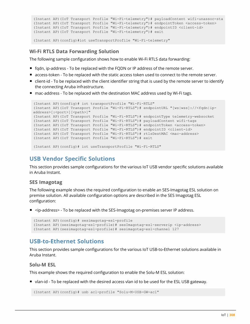
IoT | 308
(Instant AP)(IoT Transport Profile "Wi-Fi-telemetry")# payloadContent wifi-unassoc-sta(Instant AP)(IoT Transport Profile "Wi-Fi-telemetry")# endpointToken <access-token>(Instant AP)(IoT Transport Profile "Wi-Fi-telemetry")# endpointID <client-id>(Instant AP)(IoT Transport Profile "Wi-Fi-telemetry")# exit
(Instant AP)(config)#iot useTransportProfile "Wi-Fi-telemetry"
Wi-Fi RTLS Data Forwarding SolutionThe following sample configuration shows how to enable Wi-Fi RTLS data forwarding:
n fqdn, ip-address - To be replaced with the FQDN or IP address of the remote server.n access-token - To be replaced with the static access token used to connect to the remote server.n client-id - To be replaced with the client identifier string that is used by the remote server to identify
the connecting Aruba infrastructure.n mac-address - To be replaced with the destination MAC address used by Wi-Fi tags.
(Instant AP)(config)# iot transportProfile "Wi-Fi-RTLS"(Instant AP)(IoT Transport Profile "Wi-Fi-RTLS")# endpointURL "[ws|wss]://<fqdn|ip-address>[:<port>][<path>]"(Instant AP)(IoT Transport Profile "Wi-Fi-RTLS")# endpointType telemetry-websocket(Instant AP)(IoT Transport Profile "Wi-Fi-RTLS")# payloadContent wifi-tags(Instant AP)(IoT Transport Profile "Wi-Fi-RTLS")# endpointToken <access-token>(Instant AP)(IoT Transport Profile "Wi-Fi-RTLS")# endpointID <client-id>(Instant AP)(IoT Transport Profile "Wi-Fi-RTLS")# rtlsDestMAC <mac-address>(Instant AP)(IoT Transport Profile "Wi-Fi-RTLS")# exit
(Instant AP)(config)# iot useTransportProfile "Wi-Fi-RTLS"
USB Vendor Specific SolutionsThis section provides sample configurations for the various IoT USB vendor specific solutions availablein Aruba Instant.
SES ImagotagThe following example shows the required configuration to enable an SES-Imagotag ESL solution onpremise solution. All available configuration options are described in the SES Imagotag ESLconfiguration:
n <ip-address> - To be replaced with the SES-Imagotag on-premises server IP address.
(Instant AP)(config)# sesimagotag-esl-profile(Instant AP)(sesimagotag-esl-profile)# sesImagotag-esl-serverip <ip-address>(Instant AP)(sesimagotag-esl-profile)# sesimagotag-esl-channel 127
USB-to-Ethernet SolutionsThis section provides sample configurations for the various IoT USB-to-Ethernet solutions available inAruba Instant.
Solu-M ESLThis example shows the required configuration to enable the Solu-M ESL solution:
n vlan-id - To be replaced with the desired access vlan id to be used for the ESL USB gateway.
(Instant AP)(config)# usb acl-profile "Solu-M-USB-GW-acl"
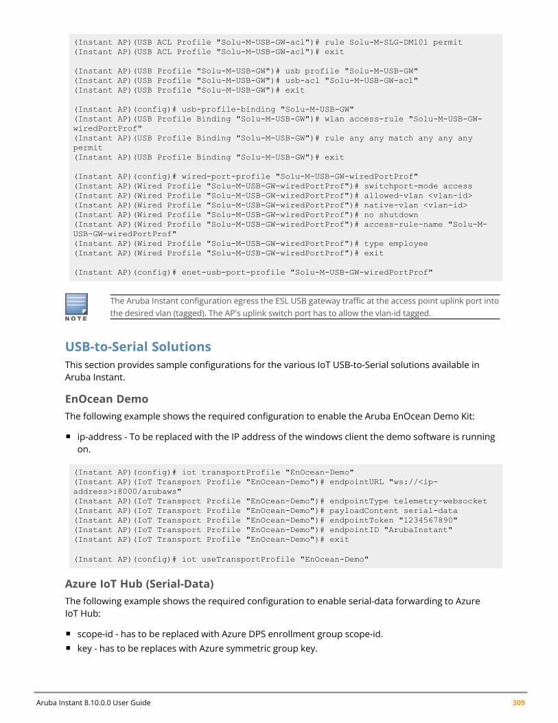
Aruba Instant 8.10.0.0 User Guide 309
(Instant AP)(USB ACL Profile "Solu-M-USB-GW-acl")# rule Solu-M-SLG-DM101 permit(Instant AP)(USB ACL Profile "Solu-M-USB-GW-acl")# exit
(Instant AP)(USB Profile "Solu-M-USB-GW")# usb profile "Solu-M-USB-GW"(Instant AP)(USB Profile "Solu-M-USB-GW")# usb-acl "Solu-M-USB-GW-acl"(Instant AP)(USB Profile "Solu-M-USB-GW")# exit
(Instant AP)(config)# usb-profile-binding "Solu-M-USB-GW"(Instant AP)(USB Profile Binding "Solu-M-USB-GW")# wlan access-rule "Solu-M-USB-GW-wiredPortProf"(Instant AP)(USB Profile Binding "Solu-M-USB-GW")# rule any any match any any anypermit(Instant AP)(USB Profile Binding "Solu-M-USB-GW")# exit
(Instant AP)(config)# wired-port-profile "Solu-M-USB-GW-wiredPortProf"(Instant AP)(Wired Profile "Solu-M-USB-GW-wiredPortProf")# switchport-mode access(Instant AP)(Wired Profile "Solu-M-USB-GW-wiredPortProf")# allowed-vlan <vlan-id>(Instant AP)(Wired Profile "Solu-M-USB-GW-wiredPortProf")# native-vlan <vlan-id>(Instant AP)(Wired Profile "Solu-M-USB-GW-wiredPortProf")# no shutdown(Instant AP)(Wired Profile "Solu-M-USB-GW-wiredPortProf")# access-rule-name "Solu-M-USB-GW-wiredPortProf"(Instant AP)(Wired Profile "Solu-M-USB-GW-wiredPortProf")# type employee(Instant AP)(Wired Profile "Solu-M-USB-GW-wiredPortProf")# exit
(Instant AP)(config)# enet-usb-port-profile "Solu-M-USB-GW-wiredPortProf"
The Aruba Instant configuration egress the ESL USB gateway traffic at the access point uplink port intothe desired vlan (tagged). The AP's uplink switch port has to allow the vlan-id tagged.
USB-to-Serial SolutionsThis section provides sample configurations for the various IoT USB-to-Serial solutions available inAruba Instant.
EnOcean DemoThe following example shows the required configuration to enable the Aruba EnOcean Demo Kit:
n ip-address - To be replaced with the IP address of the windows client the demo software is runningon.
(Instant AP)(config)# iot transportProfile "EnOcean-Demo"(Instant AP)(IoT Transport Profile "EnOcean-Demo")# endpointURL "ws://<ip-address>:8000/arubaws"(Instant AP)(IoT Transport Profile "EnOcean-Demo")# endpointType telemetry-websocket(Instant AP)(IoT Transport Profile "EnOcean-Demo")# payloadContent serial-data(Instant AP)(IoT Transport Profile "EnOcean-Demo")# endpointToken "1234567890"(Instant AP)(IoT Transport Profile "EnOcean-Demo")# endpointID "ArubaInstant"(Instant AP)(IoT Transport Profile "EnOcean-Demo")# exit
(Instant AP)(config)# iot useTransportProfile "EnOcean-Demo"
Azure IoT Hub (Serial-Data)The following example shows the required configuration to enable serial-data forwarding to AzureIoT Hub:
n scope-id - has to be replaced with Azure DPS enrollment group scope-id.n key - has to be replaces with Azure symmetric group key.
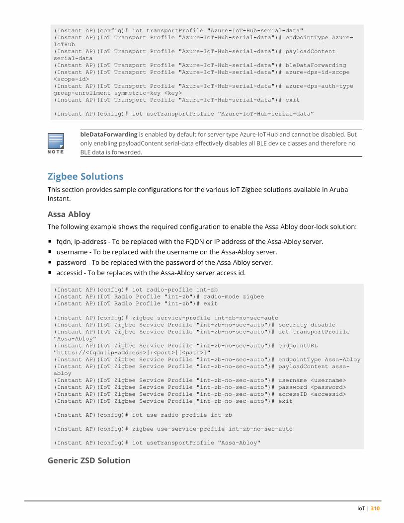
IoT | 310
(Instant AP)(config)# iot transportProfile "Azure-IoT-Hub-serial-data"(Instant AP)(IoT Transport Profile "Azure-IoT-Hub-serial-data")# endpointType Azure-IoTHub(Instant AP)(IoT Transport Profile "Azure-IoT-Hub-serial-data")# payloadContentserial-data(Instant AP)(IoT Transport Profile "Azure-IoT-Hub-serial-data")# bleDataForwarding(Instant AP)(IoT Transport Profile "Azure-IoT-Hub-serial-data")# azure-dps-id-scope<scope-id>(Instant AP)(IoT Transport Profile "Azure-IoT-Hub-serial-data")# azure-dps-auth-typegroup-enrollment symmetric-key <key>(Instant AP)(IoT Transport Profile "Azure-IoT-Hub-serial-data")# exit
(Instant AP)(config)# iot useTransportProfile "Azure-IoT-Hub-serial-data"
bleDataForwarding is enabled by default for server type Azure-IoTHub and cannot be disabled. Butonly enabling payloadContent serial-data effectively disables all BLE device classes and therefore noBLE data is forwarded.
Zigbee SolutionsThis section provides sample configurations for the various IoT Zigbee solutions available in ArubaInstant.
Assa AbloyThe following example shows the required configuration to enable the Assa Abloy door-lock solution:
n fqdn, ip-address - To be replaced with the FQDN or IP address of the Assa-Abloy server.n username - To be replaced with the username on the Assa-Abloy server.n password - To be replaced with the password of the Assa-Abloy server.n accessid - To be replaces with the Assa-Abloy server access id.
(Instant AP)(config)# iot radio-profile int-zb(Instant AP)(IoT Radio Profile "int-zb")# radio-mode zigbee(Instant AP)(IoT Radio Profile "int-zb")# exit
(Instant AP)(config)# zigbee service-profile int-zb-no-sec-auto(Instant AP)(IoT Zigbee Service Profile "int-zb-no-sec-auto")# security disable(Instant AP)(IoT Zigbee Service Profile "int-zb-no-sec-auto")# iot transportProfile"Assa-Abloy"(Instant AP)(IoT Zigbee Service Profile "int-zb-no-sec-auto")# endpointURL"httts://<fqdn|ip-address>[:<port>][<path>]"(Instant AP)(IoT Zigbee Service Profile "int-zb-no-sec-auto")# endpointType Assa-Abloy(Instant AP)(IoT Zigbee Service Profile "int-zb-no-sec-auto")# payloadContent assa-abloy(Instant AP)(IoT Zigbee Service Profile "int-zb-no-sec-auto")# username <username>(Instant AP)(IoT Zigbee Service Profile "int-zb-no-sec-auto")# password <password>(Instant AP)(IoT Zigbee Service Profile "int-zb-no-sec-auto")# accessID <accessid>(Instant AP)(IoT Zigbee Service Profile "int-zb-no-sec-auto")# exit
(Instant AP)(config)# iot use-radio-profile int-zb
(Instant AP)(config)# zigbee use-service-profile int-zb-no-sec-auto
(Instant AP)(config)# iot useTransportProfile "Assa-Abloy"
Generic ZSD Solution
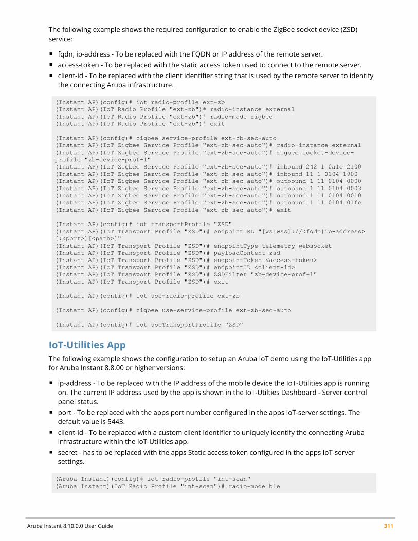
Aruba Instant 8.10.0.0 User Guide 311
The following example shows the required configuration to enable the ZigBee socket device (ZSD)service:
n fqdn, ip-address - To be replaced with the FQDN or IP address of the remote server.n access-token - To be replaced with the static access token used to connect to the remote server.n client-id - To be replaced with the client identifier string that is used by the remote server to identify
the connecting Aruba infrastructure.
(Instant AP)(config)# iot radio-profile ext-zb(Instant AP)(IoT Radio Profile "ext-zb")# radio-instance external(Instant AP)(IoT Radio Profile "ext-zb")# radio-mode zigbee(Instant AP)(IoT Radio Profile "ext-zb")# exit
(Instant AP)(config)# zigbee service-profile ext-zb-sec-auto(Instant AP)(IoT Zigbee Service Profile "ext-zb-sec-auto")# radio-instance external(Instant AP)(IoT Zigbee Service Profile "ext-zb-sec-auto")# zigbee socket-device-profile "zb-device-prof-1"(Instant AP)(IoT Zigbee Service Profile "ext-zb-sec-auto")# inbound 242 1 0a1e 2100(Instant AP)(IoT Zigbee Service Profile "ext-zb-sec-auto")# inbound 11 1 0104 1900(Instant AP)(IoT Zigbee Service Profile "ext-zb-sec-auto")# outbound 1 11 0104 0000(Instant AP)(IoT Zigbee Service Profile "ext-zb-sec-auto")# outbound 1 11 0104 0003(Instant AP)(IoT Zigbee Service Profile "ext-zb-sec-auto")# outbound 1 11 0104 0010(Instant AP)(IoT Zigbee Service Profile "ext-zb-sec-auto")# outbound 1 11 0104 01fc(Instant AP)(IoT Zigbee Service Profile "ext-zb-sec-auto")# exit
(Instant AP)(config)# iot transportProfile "ZSD"(Instant AP)(IoT Transport Profile "ZSD")# endpointURL "[ws|wss]://<fqdn|ip-address>[:<port>][<path>]"(Instant AP)(IoT Transport Profile "ZSD")# endpointType telemetry-websocket(Instant AP)(IoT Transport Profile "ZSD")# payloadContent zsd(Instant AP)(IoT Transport Profile "ZSD")# endpointToken <access-token>(Instant AP)(IoT Transport Profile "ZSD")# endpointID <client-id>(Instant AP)(IoT Transport Profile "ZSD")# ZSDFilter "zb-device-prof-1"(Instant AP)(IoT Transport Profile "ZSD")# exit
(Instant AP)(config)# iot use-radio-profile ext-zb
(Instant AP)(config)# zigbee use-service-profile ext-zb-sec-auto
(Instant AP)(config)# iot useTransportProfile "ZSD"
IoT-Utilities AppThe following example shows the configuration to setup an Aruba IoT demo using the IoT-Utilities appfor Aruba Instant 8.8.00 or higher versions:
n ip-address - To be replaced with the IP address of the mobile device the IoT-Utilities app is runningon. The current IP address used by the app is shown in the IoT-Utilties Dashboard - Server controlpanel status.
n port - To be replaced with the apps port number configured in the apps IoT-server settings. Thedefault value is 5443.
n client-id - To be replaced with a custom client identifier to uniquely identify the connecting Arubainfrastructure within the IoT-Utilities app.
n secret - has to be replaced with the apps Static access token configured in the apps IoT-serversettings.
(Aruba Instant)(config)# iot radio-profile "int-scan"(Aruba Instant)(IoT Radio Profile "int-scan")# radio-mode ble

IoT | 312
(Aruba Instant)(IoT Radio Profile "int-scan")# ble-opmode scanning(Aruba Instant)(IoT Radio Profile "int-scan")# exit
(Aruba Instant)(IoT Radio Profile "int-scan")# iot use-radio-profile "int-scan"
(Aruba Instant)(config)# iot transportProfile "IoT-Utilities-App"(Aruba Instant)(IoT Transport Profile "IoT-Utilities-App")# endpointURL "wss://<ip-address>:<port>/telemetry"(Aruba Instant)(IoT Transport Profile "IoT-Utilities-App")# endpointType telemetry-websocket(Aruba Instant)(IoT Transport Profile "IoT-Utilities-App")# authentication-modeclient-credentials(Aruba Instant)(IoT Transport Profile "IoT-Utilities-App")# authenticationURL"https://<ip-address>:<port>/auth"(Aruba Instant)(IoT Transport Profile "IoT-Utilities-App")# endpointID <client-id>(Aruba Instant)(IoT Transport Profile "IoT-Utilities-App")# client-secret <secret>(Aruba Instant)(IoT Transport Profile "IoT-Utilities-App")# payloadContent all(Aruba Instant)(IoT Transport Profile "IoT-Utilities-App")# payloadContentunclassified(Aruba Instant)(IoT Transport Profile "IoT-Utilities-App")# payloadContent serial-data(Aruba Instant)(IoT Transport Profile "IoT-Utilities-App")# payloadContent wifi-tags(Aruba Instant)(IoT Transport Profile "IoT-Utilities-App")# payloadContent wifi-assoc-sta(Aruba Instant)(IoT Transport Profile "IoT-Utilities-App")# payloadContent wifi-unassoc-sta(Aruba Instant)(IoT Transport Profile "IoT-Utilities-App")# transportInterval 30(Aruba Instant)(IoT Transport Profile "IoT-Utilities-App")# ageFilter 30(Aruba Instant)(IoT Transport Profile "IoT-Utilities-App")# bleDataForwarding(Aruba Instant)(IoT Transport Profile "IoT-Utilities-App")# rssiReporting last(Aruba Instant)(IoT Transport Profile "IoT-Utilities-App")# exit
(Aruba Instant)(config)# iot useTransportProfile "IoT-Utilities-App"
Chapter 18VPN Configuration
VPN ConfigurationThis chapter describes the following VPN configuration procedures:
n Understanding VPN Features on page 313n Configuring a Tunnel from an Instant AP to a Mobility Controller on page 315n Configuring Routing Profiles on page 323
Understanding VPN FeaturesAs Instant APs use a virtual controller architecture, the Instant AP network does not require a physicalcontroller to provide the configured WLAN services. However, a physical controller is required forterminating VPN tunnels from the Instant AP networks at branch locations to data centers, where theAruba controller acts as a VPN concentrator.
When a VPN is configured, the Instant AP acting as the virtual controller creates a VPN tunnel to anAruba Mobility Controller in your corporate office. The controller acts as a VPN endpoint and does notsupply the Instant AP with any configuration.
The VPN features are recommended for the following setups:
n Enterprises with many branches that do not have a dedicated VPN connection to the corporate office.n Branch offices that require multiple Instant APs.n Individuals working from home and, connecting to the VPN.
The survivability feature of Instant APs with the VPN connectivity of Remote APs allows you to providecorporate connectivity on non-corporate networks.
Supported VPN ProtocolsInstant supports the following VPN protocols for remote access:
VPN Protocol Description
Aruba IPsec IPsec is a protocol suite that secures IP communications by authenticating and encryptingeach IP packet of a communication session.You can configure an IPsec tunnel to ensure that the data flow between the networks isencrypted. However, you can configure a split-tunnel to encrypt only the corporate traffic.When IPsec is configured, ensure that you add the Instant AP MAC addresses to theallowlist database stored on the controller or an external server. IPsec supports Local, L2,and L3 modes of IAP-VPN operations.
NOTE: The Instant APs support IPsec only with Aruba Controllers.
Layer-2 GRE GRE is a tunnel protocol for encapsulating multicast, broadcast, and L2 packets between aGRE-capable device and an endpoint. Instant APs support the configuration of L2 GREtunnel with an Aruba controller to encapsulate the packets sent and received by the InstantAP.
Table 56: VPN Protocols
Aruba Instant 8.10.0.0 User Guide 313
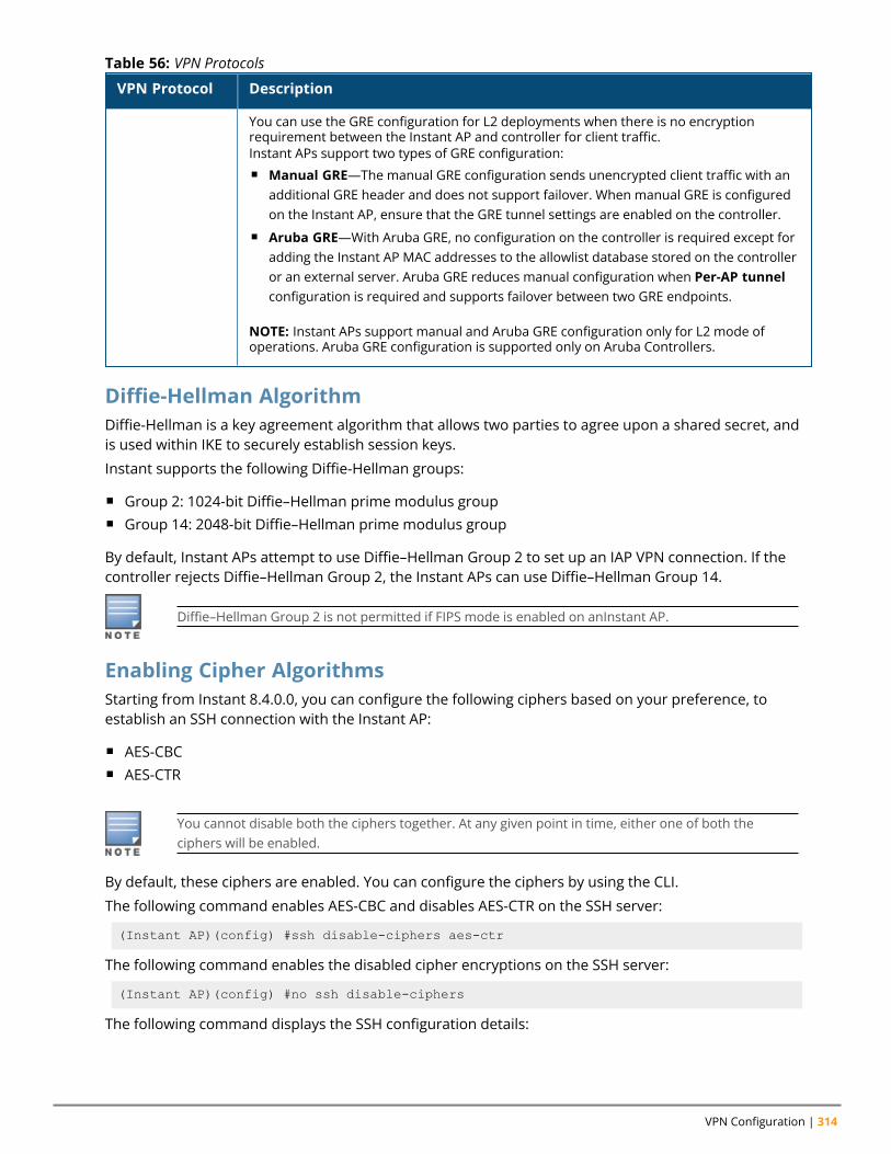
VPN Configuration | 314
VPN Protocol Description
You can use the GRE configuration for L2 deployments when there is no encryptionrequirement between the Instant AP and controller for client traffic.Instant APs support two types of GRE configuration:n Manual GRE—The manual GRE configuration sends unencrypted client traffic with an
additional GRE header and does not support failover. When manual GRE is configuredon the Instant AP, ensure that the GRE tunnel settings are enabled on the controller.
n Aruba GRE—With Aruba GRE, no configuration on the controller is required except foradding the Instant AP MAC addresses to the allowlist database stored on the controlleror an external server. Aruba GRE reduces manual configuration when Per-AP tunnelconfiguration is required and supports failover between two GRE endpoints.
NOTE: Instant APs support manual and Aruba GRE configuration only for L2 mode ofoperations. Aruba GRE configuration is supported only on Aruba Controllers.
Table 56: VPN Protocols
Diffie-Hellman AlgorithmDiffie-Hellman is a key agreement algorithm that allows two parties to agree upon a shared secret, andis used within IKE to securely establish session keys.
Instant supports the following Diffie-Hellman groups:
n Group 2: 1024-bit Diffie–Hellman prime modulus groupn Group 14: 2048-bit Diffie–Hellman prime modulus group
By default, Instant APs attempt to use Diffie–Hellman Group 2 to set up an IAP VPN connection. If thecontroller rejects Diffie–Hellman Group 2, the Instant APs can use Diffie–Hellman Group 14.
Diffie–Hellman Group 2 is not permitted if FIPS mode is enabled on anInstant AP.
Enabling Cipher AlgorithmsStarting from Instant 8.4.0.0, you can configure the following ciphers based on your preference, toestablish an SSH connection with the Instant AP:
n AES-CBCn AES-CTR
You cannot disable both the ciphers together. At any given point in time, either one of both theciphers will be enabled.
By default, these ciphers are enabled. You can configure the ciphers by using the CLI.
The following command enables AES-CBC and disables AES-CTR on the SSH server:
(Instant AP)(config) #ssh disable-ciphers aes-ctr
The following command enables the disabled cipher encryptions on the SSH server:
(Instant AP)(config) #no ssh disable-ciphers
The following command displays the SSH configuration details:
Aruba Instant 8.10.0.0 User Guide 315
(Instant AP) #show ssh
Configuring a Tunnel from an Instant AP to a MobilityControllerInstant AP supports the configuration of tunneling protocols such as GRE and IPsec. This sectiondescribes the procedure for configuring VPN host settings on an Instant AP to enable communicationwith a controller in a remote location:
n Configuring an IPSec Tunnel on page 315n Configuring an L2-GRE Tunnel on page 316
Configuring an IPSec TunnelAn IPSec tunnel is configured to ensure that the data flow between the networks is encrypted. Whenconfigured, the IPSec tunnel to the controller secures corporate data.
You can configure an IPSec tunnel from the virtual controller using the WebUI or the CLI.
In the WebUITo configure a tunnel for IPSec protocol:
1. Go to the Configuration > Tunneling page.2. Under Controller, select Aruba IPSec from the Protocol drop-down list.3. In the Primary host text box, enter the IP address or FQDN for the primary VPN or IPSec
endpoint.4. In the Backup host text box, enter the IP address or FQDN for the backup VPN or IPSec endpoint.
This entry is optional. When you specify both the primary and backup host details, the followingoptions are displayed:
a. Preemption—Toggle the switch to enable to allow the VPN tunnel to switch back to theprimary host when it becomes available again. This setting is optional.
b. Hold time—Specify the time after which the VPN tunnel switches to the primary host, afterthe primary host becomes available. The default hold time is 600 seconds. This option isdisplayed only when preemption is enabled.
Aruba Instant also allows you to a configure a schedule for preemption to occur. Whenconfigured the preemption will occur only during the specified period. This can only beconfigured through the CLI. To configure a VPN preemption schedule, see Configuring aSchedule for VPN Preemption.
c. Fast failover—Toggle the switch to enable to allow the Instant AP to create a backup VPNtunnel to the controller along with the primary tunnel, and maintain both the primary andbackup tunnels separately. When fast failover is enabled and if the primary tunnel fails, theInstant AP can switch the data stream to the backup tunnel. This reduces the total failovertime to less than one minute.
d. Reconnect User On Failover—Toggle the switch to enable to disconnect all wired andwireless users when the system switches during VPN tunnel transition from primary tobackup and backup to primary.
VPN Configuration | 316
e. Reconnect Time On Failover—Specify a time interval during which the wired and wirelessusers are disconnected from the network during a VPN tunnel switch. Specify a value inseconds within a range of 30–900 seconds. By default, the reconnection duration is set to 60seconds. This option is displayed only when reconnect time on failover option is enabled.
5. Secs between test packets—Specify a value in seconds. Based on the configured frequency, theInstant AP can verify if an active VPN connection is available. The default value is 5 seconds, whichmeans that the Instant AP sends one packet to the controller every 5 seconds.
6. Max allowed test packet loss—Specify the number for lost packets allowed before the InstantAP can determine that the VPN connection is unavailable. The default value is 2.
7. Click Save.
In the CLITo configure an IPSec VPN tunnel:
(Instant AP)(config)# vpn primary <name>(Instant AP)(config)# vpn backup <name>(Instant AP)(config)# vpn fast-failover(Instant AP)(config)# vpn hold-time <seconds>(Instant AP)(config)# vpn preemption(Instant AP)(config)# vpn monitor-pkt-send-freq <frequency>(Instant AP)(config)# vpn monitor-pkt-lost-cnt <count>(Instant AP)(config)# vpn reconnect-user-on-failover(Instant AP)(config)# vpn reconnect-time-on-failover <down_time>
Example
(Instant AP)(config)# vpn primary 192.0.2.18(Instant AP)(config)# vpn backup 192.0.2.20(Instant AP)(config)# vpn fast-failover(Instant AP)(config)# vpn preemption
(Instant AP)(config)# ip dhcp distl2(Instant AP)(DHCP Profile "distL2")# server-type Distributed,L2(Instant AP)(DHCP Profile "distL2")# server-vlan 2(Instant AP)(DHCP Profile "distL2")# ip-range 10.15.205.0 10.15.205.255(Instant AP)(DHCP Profile "distL2")# subnet-mask 255.255.255.0(Instant AP)(DHCP Profile "distL2")# lease-time 86400(Instant AP)(DHCP Profile "distL2")# default-router 10.15.205.254(Instant AP)(DHCP Profile "distL2")# dns-server 10.13.6.110,10.1.1.50(Instant AP)(DHCP Profile "distL2")# domain-name arubanetworks.com(Instant AP)(DHCP Profile "distL2")# client-count 5
(Instant AP)(config)# ip dhcp local(Instant AP)(DHCP Profile "local")# server-type Local(Instant AP)(DHCP Profile "local")# server-vlan 200(Instant AP)(DHCP Profile "local")# subnet 172.16.200.1(Instant AP)(DHCP Profile "local")# subnet-mask 255.255.255.0(Instant AP)(DHCP Profile "local")# lease-time 86400(Instant AP)(DHCP Profile "local")# dns-server 10.13.6.110,10.1.1.50(Instant AP)(DHCP Profile "local")# domain-name arubanetworks.com
To view the VPN configuration:
(Instant AP)# show vpn config
Configuring an L2-GRE TunnelThis section describes the following procedures:
Aruba Instant 8.10.0.0 User Guide 317
n Configuring Manual GRE Parametersn Configuring Aruba GRE Parameters
Configuring Manual GRE ParametersYou can configure a GRE tunnel between the Instant AP and the controller using either the virtualcontroller IP or the Instant AP IP, based on the following Instant AP settings:
n If a virtual controller IP is configured and if Per-AP tunnel is disabled, use virtual controller IP.n If a virtual controller IP is not configured or if Per-AP tunnel is enabled, use the Instant AP IP.
For information on the GRE tunnel configuration on the controller, refer to the ArubaOS User Guide.
In the WebUI
To configure a GRE tunnel:
1. Go to the Configuration > Tunneling page.2. Expand the Controller section, selectManual GRE from the Protocol drop-down list.3. Specify the following parameters:
a. Primary host— Enter an IP address or an FQDN for the main VPN or GRE endpoint in thetext box.
b. GRE type—Enter a value in the text box.
c. Per-AP tunnel—Toggle the switch to enable to create a GRE tunnel from each Instant AP tothe VPN or GRE endpoint rather than the tunnels created just from the conductor Instant AP.When enabled, the traffic to the corporate network is sent through a Layer-2 GRE tunnel fromthe Instant AP itself and need not be forwarded through the conductor Instant AP. By default,this parameter is disabled.
4. Click Save.
In the CLI
To configure a manual GRE VPN tunnel:
(Instant AP)(config)# gre primary <name>(Instant AP)(config)# gre type <type>(Instant AP)(config)# gre per-ap-tunnel
To view VPN configuration details:
(Instant AP)# show vpn config
To configure GRE tunnel on the controller:
(Instant AP)(config)# interface tunnel <Number>(Instant AP)(config-tunnel)# description <Description>(Instant AP)(config-tunnel)# tunnel mode gre <ID>(Instant AP)(config-tunnel)# tunnel source <controller-IP>(Instant AP)(config-tunnel)# tunnel destination <AP-IP>(Instant AP)(config-tunnel)# trusted(Instant AP)(config-tunnel)# tunnel vlan <allowed-VLAN>
Configuring Aruba GRE ParametersThe Aruba GRE feature uses the IPsec connection between the Instant AP and the controller to send thecontrol information for setting up a GRE tunnel. When Aruba GRE configuration is enabled, a single IPsectunnel between the Instant AP cluster and the controller, and one or several GRE tunnels are created
VPN Configuration | 318
based on the Per-AP tunnel configuration on the Instant AP. For Aruba GRE, no manual configuration isrequired on the controller to create the GRE tunnel.
Aruba GRE is supported on Aruba Controllers running ArubaOS 6.4.x.x or later versions.
Instant APs can send IPsec and GRE heartbeat packets to Aruba Controllers. By default, Instant APsverify the status of heartbeat messages every 5 seconds, and look for lost packets 6 times beforemarking down the IPsec tunnel. However, these time intervals can be modified.
In the WebUI
To configure Aruba GRE:
1. Go to the Configuration > Tunneling page.2. Expand Controller.3. Select Aruba GRE from the Protocol drop-down list.4. In the Primary host text box, enter the IP address or FQDN for the primary VPN or IPSec
endpoint.5. In the Backup host text box, enter the IP address or FQDN for the backup VPN or IPSec endpoint.
This entry is optional. When you specify both the primary and backup host details, the followingoptions are displayed:
a. Preemption—Toggle the switch to enable to allow the VPN tunnel to switch back to theprimary host when it becomes available again. This setting is optional.
b. Hold time—Specify the time after which the VPN tunnel switches to the primary host, afterthe primary host becomes available. The default hold time is 600 seconds. This option isdisplayed only when preemption is enabled.
Aruba Instant also allows you to a configure a schedule for preemption to occur. Whenconfigured the preemption will occur only during the specified period. This can only beconfigured through the CLI. To configure a VPN preemption schedule, see Configuring aSchedule for VPN Preemption.
c. Fast failover—Toggle the switch to enable to allow the Instant AP to create a backup VPNtunnel to the controller along with the primary tunnel, and maintain both the primary andbackup tunnels separately. When fast failover is enabled and if the primary tunnel fails, theInstant AP can switch the data stream to the backup tunnel. This reduces the total failovertime to less than one minute.
d. Reconnect User On Failover—Toggle the switch to enable to disconnect all wired andwireless users when the system switches during VPN tunnel transition from primary tobackup and backup to primary.
e. Reconnect Time On Failover—Specify a time interval during which the wired and wirelessusers are disconnected from the network during a VPN tunnel switch. Specify a value inseconds within a range of 30–900 seconds. By default, the reconnection duration is set to 60seconds. This option is displayed only when reconnect time on failover option is enabled.
6. Secs between test packets—Specify a value in seconds. Based on the configured frequency, theInstant AP can verify if an active VPN connection is available. The default value is 5 seconds, whichmeans that the Instant AP sends one packet to the controller every 5 seconds.
Aruba Instant 8.10.0.0 User Guide 319
7. Max allowed test packet loss—Specify the number for lost packets allowed before the InstantAP can determine that the VPN connection is unavailable. The default value is 2.
8. Per-AP tunnel—Toggle the switch to enable to create a GRE tunnel from each Instant AP to theVPN or GRE endpoint rather than the tunnels created just from the conductor Instant AP. Whenenabled, the traffic to the corporate network is sent through a Layer-2 GRE tunnel from theInstant AP and need not be forwarded through the conductor Instant AP.
9. Click Save.
In the CLI
To enable Aruba GRE tunnel:
(Instant AP)(config)# vpn gre-outside(Instant AP)(config)# vpn primary <name/IP-address>(Instant AP)(config)# vpn backup <<name/IP-address>>(Instant AP)(config)# vpn fast-failover(Instant AP)(config)# vpn hold-time <seconds>(Instant AP)(config)# vpn preemption(Instant AP)(config)# vpn preemption absolute-time <profile>(Instant AP)(config)# vpn monitor-pkt-send-freq <frequency>(Instant AP)(config)# vpn monitor-pkt-lost-cnt <count>(Instant AP)(config)# vpn reconnect-user-on-failover(Instant AP)(config)# vpn reconnect-time-on-failover <down_time>
To view VPN configuration details:
(Instant AP)# show vpn config
For more information, see Aruba Instant 8.x CLI Reference Guide.
Support for IAP-VPN Termination on Mobility Controller VirtualApplianceStarting from Aruba Instant 8.3.0.0, IAP-VPN is supported on Mobility Controller Virtual Appliance byusing default self-signed certificate (Aruba PKI). For Instant AP to establish IPsec connection withMobility Controller Virtual Appliance, the controller presents a default self-signed certificate which isuploaded on the Instant AP using Activate.
Mobility Conductors (Mobility Conductor Hardware Appliance, Mobility Conductor Virtual Appliance,and conductor Controller Mode) do not support any AP termination including Campus APs, RemoteAPs and IAP-VPN tunnels.
Through Activate, you can push only one default self-signed certificate to Instant AP which can beused to establish IPsec tunnel with Mobility Controller Virtual Appliance.
VPN features are ideal for:
n Enterprises with many branches that do not have a dedicated VPN connection to the Head Quarter.n Branch offices that require multiple APs.n Individuals working from home, connecting to the VPN.
This new architecture and form factor seamlessly adds the survivability feature of Instant APs with theVPN connectivity of RAPs — providing corporate connectivity to branches.
Configuring Multiple Active Tunnels
VPN Configuration | 320
Starting from Aruba Instant 8.4.0.0, you can configure multiple active VPN tunnels on an Instant AP. Youcan configure up to four pairs of Primary and Backup VPN tunnels, out of which one pair is consideredthe default tunnel and the other three pairs as non-default tunnels. Only one IPsec tunnel can beselected for each VPN primary and backup pair and a default VPN tunnel must be configured if you wishto keep more than one active VPN tunnel to pass Centralized, L2 traffic.
This feature is currently not supported for IPv6.
LimitationsFollowing are some of the limitations observed when configuring multiple active tunnels:
n Multiple active tunnels are not supported in shared VPN mode. Only per AP tunnels are supported.n Multiple active tunnels are supported with GRE data tunnels only. No IPsec data tunnel support is
provided.n Multiple active tunnels supported in Centralized,L2 VPN mode only.n Multiple active tunnels need to be in full tunnel mode and not split tunnel mode.
Configuring a Default VPN TunnelThe following example configures a default VPN tunnel:
(Instant AP)(config)# vpn primary <IP address or domain name>(Instant AP)(config)# vpn backup <IP address or domain name>(Instant AP)(config)# vpn fast-failover(Instant AP)(config)# vpn gre-outside(Instant AP)(config)# gre per-ap-tunnel(Instant AP)(config)# vpn hold-time <seconds>(Instant AP)(config)# vpn preemption(Instant AP)(config)# vpn monitor-pkt-send-freq <frequency>(Instant AP)(config)# vpn monitor-pkt-lost-cnt <count>(Instant AP)(config)# end(Instant AP)# commit apply
Configuring a non-default VPN TunnelThe following example configures a non-default VPN tunnel profile:
(Instant AP)(config)# vpn tunnel-profile <profile_name>(Instant AP)(VPN Tunnel Profile "<profile_name>")# primary <IP address or domain name>(Instant AP)(VPN Tunnel Profile "<profile_name>")# backup <IP address or domain name>(Instant AP)(VPN Tunnel Profile "<profile_name>")# gre-outside(Instant AP)(VPN Tunnel Profile "<profile_name>")# per-ap-tunnel(Instant AP)(VPN Tunnel Profile "<profile_name>")# fast-failover(Instant AP)(VPN Tunnel Profile "<profile_name>")# hold-time <seconds>(Instant AP)(VPN Tunnel Profile "<profile_name>")# preemption(Instant AP)(VPN Tunnel Profile "<profile_name>")# monitor-pkt-send-freq <frequency>(Instant AP)(VPN Tunnel Profile "<profile_name>")# monitor-pkt-lost-cnt <count>(Instant AP)(VPN Tunnel Profile "<profile_name>")# end(Instant AP)# commit apply
Configuring Centralized, L2 DHCP Scopes to use Default VPN TunnelThe following example configures a Centralized, L2 DHCP scope to use a default VPN tunnel:
(Instant AP)(config)# ip dhcp <profile_name>(Instant AP)(DHCP Profile "<profile_name>")# server-type Centralized,L2(Instant AP)(DHCP Profile "<profile_name>")# server-vlan <VLAN ID or VLAN List>(Instant AP)(DHCP Profile "<profile_name>")# disable-split-tunnel
Aruba Instant 8.10.0.0 User Guide 321
(Instant AP)(DHCP Profile "<profile_name>")# end(Instant AP)# commit apply
Configuring Centralized, L2 DHCP Scopes to use a Non-Default VPN TunnelThe following example configures a Centralized, L2 DHCP scope to use a non-default VPN tunnel:
(Instant AP)(config)# ip dhcp <profile_name>(Instant AP)(DHCP Profile "<profile_name>")# server-type Centralized,L2(Instant AP)(DHCP Profile "<profile_name>")# server-vlan <VLAN ID or VLAN List>(Instant AP)(DHCP Profile "<profile_name>")# disable-split-tunnel(Instant AP)(DHCP Profile "<profile_name>")# tunnel-profile <profile_name>(Instant AP)(DHCP Profile "<profile_name>")# end(Instant AP)# commit apply
Configure Customized Certificate for IPsec TunnelThe following example configures an IPsec tunnel to use a customized certificate:
(Instant AP)(config)# vpn tunnel-profile <profile_name>(Instant AP)(VPN Tunnel Profile "<profile_name>")# use-custom-cert(Instant AP)(VPN Tunnel Profile "<profile_name>")# primary <IP address or domain name>(Instant AP)(VPN Tunnel Profile "<profile_name>")# backup <IP address or domain name>(Instant AP)(VPN Tunnel Profile "<profile_name>")# fast-failover(Instant AP)(VPN Tunnel Profile "<profile_name>")# hold-time <seconds>(Instant AP)(VPN Tunnel Profile "<profile_name>")# preemption(Instant AP)(DHCP Profile "<profile_name>")# end(Instant AP)# commit apply
DebuggingUse the following command to check the IPsec tunnel status:
(Instant AP)(config)# show vpn status
Use the following command to check the VPN registration status:
(Instant AP)(config)# show vpn tunnels
Use the following command to check the VPN logs:
(Instant AP)(config)# show log vpn-tunnel
Use the following command to view the Centralized,L2 configuration:
(Instant AP)(config)# show dhcps
Configuring a Schedule for VPN PreemptionAruba Instant enables you to configure a schedule for VPN preemption. Earlier, the VPN preemptionwas controlled by the Hold time setting, after which the Instant AP switches from the backup VPN tunnelto the primary VPN tunnel when it becomes stable and available. The absolute-time setting enablesyou to set a schedule for the Instant AP to switch from the backup VPN tunnel to the primary VPN tunnelafter a failover. When configured, the Instant AP will switch from the backup tunnel to the primarytunnel only during the scheduled period. This helps you to schedule preemption at less active hours inthe network and reduce the downtime caused by the switch from backup tunnel to the primaryVPN tunnel.
Important Points to Remember
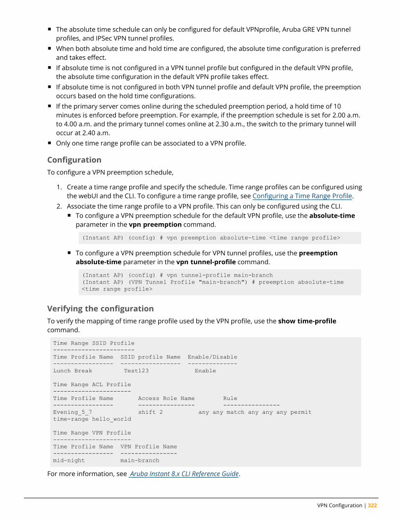
VPN Configuration | 322
n The absolute time schedule can only be configured for default VPNprofile, Aruba GRE VPN tunnelprofiles, and IPSec VPN tunnel profiles.
n When both absolute time and hold time are configured, the absolute time configuration is preferredand takes effect.
n If absolute time is not configured in a VPN tunnel profile but configured in the default VPN profile,the absolute time configuration in the default VPN profile takes effect.
n If absolute time is not configured in both VPN tunnel profile and default VPN profile, the preemptionoccurs based on the hold time configurations.
n If the primary server comes online during the scheduled preemption period, a hold time of 10minutes is enforced before preemption. For example, if the preemption schedule is set for 2.00 a.m.to 4.00 a.m. and the primary tunnel comes online at 2.30 a.m., the switch to the primary tunnel willoccur at 2.40 a.m.
n Only one time range profile can be associated to a VPN profile.
ConfigurationTo configure a VPN preemption schedule,
1. Create a time range profile and specify the schedule. Time range profiles can be configured usingthe webUI and the CLI. To configure a time range profile, see Configuring a Time Range Profile.
2. Associate the time range profile to a VPN profile. This can only be configured using the CLI.n To configure a VPN preemption schedule for the default VPN profile, use the absolute-time
parameter in the vpn preemption command.
(Instant AP) (config) # vpn preemption absolute-time <time range profile>
n To configure a VPN preemption schedule for VPN tunnel profiles, use the preemptionabsolute-time parameter in the vpn tunnel-profile command.
(Instant AP) (config) # vpn tunnel-profile main-branch(Instant AP) (VPN Tunnel Profile "main-branch") # preemption absolute-time<time range profile>
Verifying the configurationTo verify the mapping of time range profile used by the VPN profile, use the show time-profilecommand.
Time Range SSID Profile-----------------------Time Profile Name SSID profile Name Enable/Disable----------------- ----------------- --------------Lunch Break Test123 Enable
Time Range ACL Profile----------------------Time Profile Name Access Role Name Rule----------------- ---------------- ----------------Evening_5_7 shift 2 any any match any any any permittime-range hello_world
Time Range VPN Profile----------------------Time Profile Name VPN Profile Name----------------- ----------------mid-night main-branch
For more information, see Aruba Instant 8.x CLI Reference Guide.
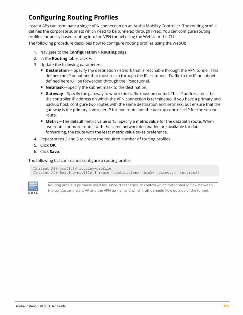
Aruba Instant 8.10.0.0 User Guide 323
Configuring Routing ProfilesInstant APs can terminate a single VPN connection on an Aruba Mobility Controller. The routing profiledefines the corporate subnets which need to be tunneled through IPsec. You can configure routingprofiles for policy based routing into the VPN tunnel using the WebUI or the CLI.
The following procedure describes how to configure routing profiles using the WebUI:
1. Navigate to the Configuration > Routing page.2. In the Routing table, click +.3. Update the following parameters:
n Destination— Specify the destination network that is reachable through the VPN tunnel. Thisdefines the IP or subnet that must reach through the IPsec tunnel. Traffic to the IP or subnetdefined here will be forwarded through the IPsec tunnel.
n Netmask—Specify the subnet mask to the destination.n Gateway—Specify the gateway to which the traffic must be routed. This IP address must be
the controller IP address on which the VPN connection is terminated. If you have a primary andbackup host, configure two routes with the same destination and netmask, but ensure that thegateway is the primary controller IP for one route and the backup controller IP for the secondroute.
n Metric—The default metric value is 15. Specify a metric value for the datapath route. Whentwo routes or more routes with the same network destination are available for dataforwarding, the route with the least metric value takes preference.
4. Repeat steps 2 and 3 to create the required number of routing profiles.5. Click OK.6. Click Save.
The following CLI commands configure a routing profile:
(Instant AP)(config)# routing-profile(Instant AP)(Routing-profile)# route <destination> <mask> <gateway> {<metric>}
Routing profile is primarily used for IAP-VPN scenarios, to control which traffic should flow betweenthe conductor Instant AP and the VPN tunnel, and which traffic should flow outside of the tunnel.
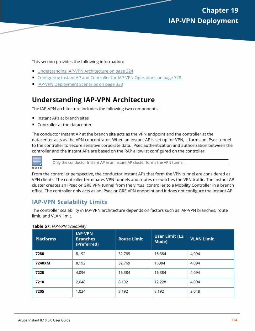
Chapter 19IAP-VPN Deployment
IAP-VPN DeploymentThis section provides the following information:
n Understanding IAP-VPN Architecture on page 324n Configuring Instant AP and Controller for IAP-VPN Operations on page 328n IAP-VPN Deployment Scenarios on page 338
Understanding IAP-VPN ArchitectureThe IAP-VPN architecture includes the following two components:
n Instant APs at branch sitesn Controller at the datacenter
The conductor Instant AP at the branch site acts as the VPN endpoint and the controller at thedatacenter acts as the VPN concentrator. When an Instant AP is set up for VPN, it forms an IPsec tunnelto the controller to secure sensitive corporate data. IPsec authentication and authorization between thecontroller and the Instant APs are based on the RAP allowlist configured on the controller.
Only the conductor Instant AP in anInstant AP cluster forms the VPN tunnel.
From the controller perspective, the conductor Instant APs that form the VPN tunnel are considered asVPN clients. The controller terminates VPN tunnels and routes or switches the VPN traffic. The Instant APcluster creates an IPsec or GRE VPN tunnel from the virtual controller to a Mobility Controller in a branchoffice. The controller only acts as an IPsec or GRE VPN endpoint and it does not configure the Instant AP.
IAP-VPN Scalability LimitsThe controller scalability in IAP-VPN architecture depends on factors such as IAP-VPN branches, routelimit, and VLAN limit.
PlatformsIAP-VPNBranches(Preferred)
Route Limit User Limit (L2Mode) VLAN Limit
7280 8,192 32,769 16,384 4,094
7240XM 8,192 32,769 16384 4,094
7220 4,096 16,384 16,384 4,094
7210 2,048 8,192 12,228 4,094
7205 1,024 8,192 8,192 2,048
Table 57: IAP-VPN Scalability
Aruba Instant 8.10.0.0 User Guide 324
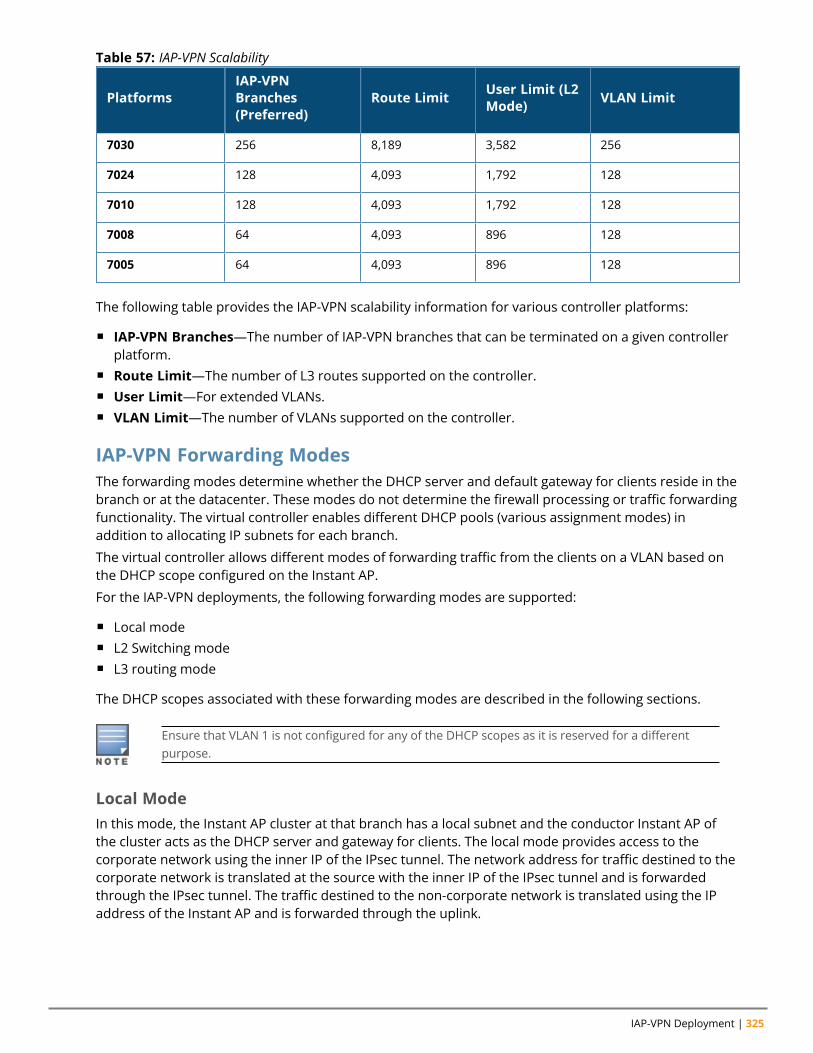
IAP-VPN Deployment | 325
PlatformsIAP-VPNBranches(Preferred)
Route Limit User Limit (L2Mode) VLAN Limit
7030 256 8,189 3,582 256
7024 128 4,093 1,792 128
7010 128 4,093 1,792 128
7008 64 4,093 896 128
7005 64 4,093 896 128
Table 57: IAP-VPN Scalability
The following table provides the IAP-VPN scalability information for various controller platforms:
n IAP-VPN Branches—The number of IAP-VPN branches that can be terminated on a given controllerplatform.
n Route Limit—The number of L3 routes supported on the controller.n User Limit—For extended VLANs.n VLAN Limit—The number of VLANs supported on the controller.
IAP-VPN Forwarding ModesThe forwarding modes determine whether the DHCP server and default gateway for clients reside in thebranch or at the datacenter. These modes do not determine the firewall processing or traffic forwardingfunctionality. The virtual controller enables different DHCP pools (various assignment modes) inaddition to allocating IP subnets for each branch.
The virtual controller allows different modes of forwarding traffic from the clients on a VLAN based onthe DHCP scope configured on the Instant AP.
For the IAP-VPN deployments, the following forwarding modes are supported:
n Local moden L2 Switching moden L3 routing mode
The DHCP scopes associated with these forwarding modes are described in the following sections.
Ensure that VLAN 1 is not configured for any of the DHCP scopes as it is reserved for a differentpurpose.
Local ModeIn this mode, the Instant AP cluster at that branch has a local subnet and the conductor Instant AP ofthe cluster acts as the DHCP server and gateway for clients. The local mode provides access to thecorporate network using the inner IP of the IPsec tunnel. The network address for traffic destined to thecorporate network is translated at the source with the inner IP of the IPsec tunnel and is forwardedthrough the IPsec tunnel. The traffic destined to the non-corporate network is translated using the IPaddress of the Instant AP and is forwarded through the uplink.
Aruba Instant 8.10.0.0 User Guide 326
When the local mode is used for forwarding client traffic, hosts on the corporate network cannotestablish connections to the clients on the Instant AP, because the source addresses of the clientsare translated.
Local, L2 ModeIn this mode, the Instant AP cluster at that branch has a local subnet and the conductor Instant AP ofthe cluster acts as the DHCP server. The default gateway is located outside the Instant AP and thenetwork address for the client traffic is not translated at source. In the Local, L2 mode, access to thecorporate network is supported only in a single Instant AP cluster. The traffic to the non-corporatenetwork is locally bridged.
Local, L3 ModeIn this mode, the network address for traffic destined to the corporate network is translated at thesource with the inner IP of the IPsec tunnel and is forwarded through the IPsec tunnel. The trafficdestined to the non-corporate network is routed.
Distributed, L2 ModeIn this mode, the Instant AP assigns an IP address from the configured subnet and forwards traffic toboth corporate and non-corporate destinations. Clients receive the corporate IP with virtual controlleras the DHCP server. The default gateway for the client still resides in the datacenter and hence thismode is an L2 extension of corporate VLAN to remote site. Either the controller or an upstream routercan be the gateway for the clients. Client traffic destined to datacenter resources is forwarded by theconductor Instant AP (through the IPsec tunnel) to the client's default gateway in the datacenter.
When an Instant AP registers with the controller, the controller automatically adds the VPN tunnelassociated to this Instant AP into the VLAN multicast table. This allows the clients connecting to the L2mode VLAN to be part of the same L2 broadcast domain on the controller.
Distributed, L3 ModeThe Distributed, L3 mode contains all broadcast and multicast traffic to a branch. The Distributed, L3mode reduces the cost and eliminates the complexity associated with the classic site-to-site VPN.However, this mode is very similar to a classic site-to-site IPsec VPN where two VPN endpoints connectindividual networks together over a public network.
In Distributed, L3 mode, each branch location is assigned a dedicated subnet. The conductor Instant APin the branch manages the dedicated subnet and acts as the DHCP server and gateway for clients. Clienttraffic destined to datacenter resources is routed to the controller through the IPsec tunnel, which thenroutes the traffic to the appropriate corporate destinations.
When an Instant AP registers with the controller, the controller adds a route to enable the routing oftraffic from the corporate network to clients on this subnet in the branch.
Centralized, L2 ModeThe Centralized, L2 mode extends the corporate VLAN or broadcast domain to remote branches. TheDHCP server and the gateway for the clients reside in the datacenter. Either the controller or anupstream router can be the gateway for the clients. For DHCP services in Centralized, L2 mode, Arubarecommends using an external DHCP server and not the DHCP server on the controller. Client trafficdestined to datacenter resources is forwarded by the conductor Instant AP (through the IPsec tunnel) tothe client's default gateway in the datacenter.
Centralized, L3 Mode
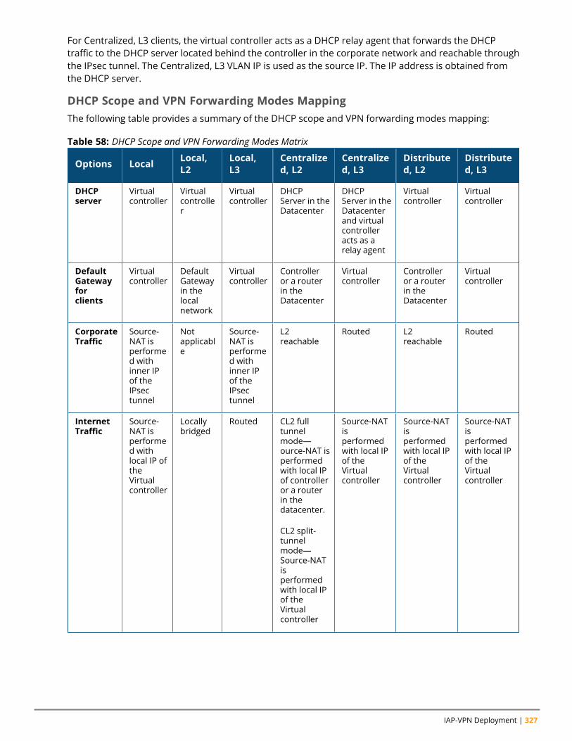
IAP-VPN Deployment | 327
For Centralized, L3 clients, the virtual controller acts as a DHCP relay agent that forwards the DHCPtraffic to the DHCP server located behind the controller in the corporate network and reachable throughthe IPsec tunnel. The Centralized, L3 VLAN IP is used as the source IP. The IP address is obtained fromthe DHCP server.
DHCP Scope and VPN Forwarding Modes MappingThe following table provides a summary of the DHCP scope and VPN forwarding modes mapping:
Options Local Local,L2
Local,L3
Centralized, L2
Centralized, L3
Distributed, L2
Distributed, L3
DHCPserver
Virtualcontroller
Virtualcontroller
Virtualcontroller
DHCPServer in theDatacenter
DHCPServer in theDatacenterand virtualcontrolleracts as arelay agent
Virtualcontroller
Virtualcontroller
DefaultGatewayforclients
Virtualcontroller
DefaultGatewayin thelocalnetwork
Virtualcontroller
Controlleror a routerin theDatacenter
Virtualcontroller
Controlleror a routerin theDatacenter
Virtualcontroller
CorporateTraffic
Source-NAT isperformed withinner IPof theIPsectunnel
Notapplicable
Source-NAT isperformed withinner IPof theIPsectunnel
L2reachable
Routed L2reachable
Routed
InternetTraffic
Source-NAT isperformed withlocal IP oftheVirtualcontroller
Locallybridged
Routed CL2 fulltunnelmode—ource-NAT isperformedwith local IPof controlleror a routerin thedatacenter.
CL2 split-tunnelmode—Source-NATisperformedwith local IPof theVirtualcontroller
Source-NATisperformedwith local IPof theVirtualcontroller
Source-NATisperformedwith local IPof theVirtualcontroller
Source-NATisperformedwith local IPof theVirtualcontroller
Table 58: DHCP Scope and VPN Forwarding Modes Matrix
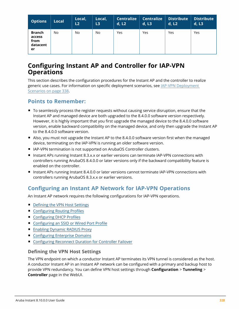
Aruba Instant 8.10.0.0 User Guide 328
Options Local Local,L2
Local,L3
Centralized, L2
Centralized, L3
Distributed, L2
Distributed, L3
Branchaccessfromdatacenter
No No No Yes Yes Yes Yes
Configuring Instant AP and Controller for IAP-VPNOperationsThis section describes the configuration procedures for the Instant AP and the controller to realizegeneric use cases. For information on specific deployment scenarios, see IAP-VPN DeploymentScenarios on page 338.
Points to Remember:n To seamlessly process the register requests without causing service disruption, ensure that the
Instant AP and managed device are both upgraded to the 8.4.0.0 software version respectively.However, it is highly important that you first upgrade the managed device to the 8.4.0.0 softwareversion, enable backward compatibility on the managed device, and only then upgrade the Instant APto the 8.4.0.0 software version.
n Also, you must not upgrade the Instant AP to the 8.4.0.0 software version first when the manageddevice, terminating on the IAP-VPN is running an older software version.
n IAP-VPN termination is not supported on ArubaOS Controller clusters.n Instant APs running Instant 8.3.x.x or earlier versions can terminate IAP-VPN connections with
controllers running ArubaOS 8.4.0.0 or later versions only if the backward compatibility feature isenabled on the controller.
n Instant APs running Instant 8.4.0.0 or later versions cannot terminate IAP-VPN connections withcontrollers running ArubaOS 8.3.x.x or earlier versions.
Configuring an Instant AP Network for IAP-VPN OperationsAn Instant AP network requires the following configurations for IAP-VPN operations.
n Defining the VPN Host Settingsn Configuring Routing Profilesn Configuring DHCP Profilesn Configuring an SSID or Wired Port Profilen Enabling Dynamic RADIUS Proxyn Configuring Enterprise Domainsn Configuring Reconnect Duration for Controller Failover
Defining the VPN Host SettingsThe VPN endpoint on which a conductor Instant AP terminates its VPN tunnel is considered as the host.A conductor Instant AP in an Instant AP network can be configured with a primary and backup host toprovide VPN redundancy. You can define VPN host settings through Configuration > Tunneling >Controller page in the WebUI.
IAP-VPN Deployment | 329
You can configure the following VPN profiles for the IAP-VPN operations. For more information, seeConfiguring a Tunnel from an Instant AP to a Mobility Controller on page 315.
n Aruba IPsecn L2TPv3n Manual GREn Aruba GRE
Configuring Routing ProfilesThe routing profile on the Instant AP determines whether the traffic destined to a subnet must betunneled through IPsec or bridged locally. If the routing profile is empty, the client traffic will always bebridged locally. For example, if the routing profile is configured to tunnel 10.0.0.0 /8, the traffic destinedto 10.0.0.0 /8 will be forwarded through the IPsec tunnel and the traffic to all other destinations isbridged locally.
You can also configure a routing profile with 0.0.0.0 as gateway to allow both the client and Instant APtraffic to be routed through a non-tunnel route. If the gateway is in the same subnet as uplink IPaddress, it is used as a static gateway entry. A static route can be added to all conductor and memberInstant APs for these destinations. The VPN traffic from the local subnet of Instant AP or the Virtualcontroller IP address in the local subnet is not routed to tunnel, but will be switched to the relevantVLAN. For example, when a 0.0.0.0/0.0.0.0 routing profile is defined, to bypass certain IPs, you can add aroute to the IP by defining 0.0.0.0 as the destination, thereby forcing the traffic to be routed through thedefault gateway of the Instant AP.
You can configure routing profiles through Configuration > Routing page in the WebUI. For step-by-step procedural information on configuring routing profile, see Configuring Routing Profiles on page323.
The Instant AP network has only one active tunnel even when fast failover is enabled. At any giventime, traffic can be tunneled only to one VPN host.
Configuring DHCP ProfilesYou can create DHCP profiles to determine the IAP-VPN mode of operation. An Instant AP network canhave multiple DHCP profiles configured for different modes of IAP-VPN. You can configure up to eightDHCP profiles. For more information on the IAP-VPN modes of operation, see IAP-VPN ForwardingModes on page 325.
You can create any of the following types of DHCP profiles for the IAP-VPN operations:
n Localn Local, L2n Local, L3n Distributed, L2n Distributed, L3n Centralized, L2n Centralized, L3
For more information on configuring DHCP profiles, see Configuring DHCP Scopes on page 249.
Aruba Instant 8.10.0.0 User Guide 330
A Centralized, L2 or Distributed, L2 VLAN or subnet cannot be used to serve Instant APs in ahierarchical mode of deployment. Ensure that the physical IP of the Instant APs connecting to theconductor Instant AP in hierarchical mode of deployment is not on a VLAN or subnet that is inCentralized, L2 or Distributed, L2 mode of operation. For information on hierarchical mode ofdeployment, see Understanding Hierarchical Deployment on page 139.
Configuring an SSID or Wired Port ProfileFor a client to connect to the IAP-VPN network, an SSID or wired port profile on an Instant AP must beconfigured with appropriate IAP-VPN mode of operation. The VLAN configuration in an SSID or wiredport profile determines whether an SSID or wired port is configured for the IAP-VPN operations.
To configure an SSID or wired port for a specific IAP-VPN mode, the VLAN ID defined in the SSID or wiredport profile must match the VLAN ID defined in the DHCP profile configuration. If the VLAN assignmentfor an SSID or wired port profile is set to Virtual controller assigned, custom, or a static VLAN ID thatdoes not match the VLAN ID configured in the DHCP profiles, the IAP-VPN operations are affected. Forexample, if a local DHCP profile is configured with a VLAN ID of 200, the VLAN configuration on the SSIDmust be set to a static VLAN ID 200.
Ensure that the VLAN assignment for an SSID or wired port profile is not set to default as the VPNtunnel is not supported on the default VLAN.
An Instant AP will not send a registration request to the controller if SetMeUp is configured on theInstant AP.
For information on how to configure an SSID or wired port profile, see Wireless Network Profiles onpage 96 and Configuring a Wired Profile on page 131, respectively.
Enabling Dynamic RADIUS ProxyThe RADIUS server can be deployed at different locations and VLANs. In most cases, a centralizedRADIUS or local server is used to authenticate users. However, some user networks can use a localRADIUS server for employee authentication and a centralized RADIUS-based captive portal server forguest authentication. To ensure that the RADIUS traffic is routed to the required RADIUS server, thedynamic RADIUS proxy feature must be enabled. When enabled, dynamic RADIUS proxy ensures that allthe RADIUS traffic is sourced from the Virtual controller IP or inner IP of the Instant AP IPsec tunneldepending on the RADIUS server IP and routing profile.
Ensure that a static Virtual controller IP is configured before enabling dynamic RADIUS proxy inorder to tunnel the RADIUS traffic to the central RADIUS server in the datacenter.
For information on enabling dynamic RADIUS proxy, see Configuring Dynamic RADIUS Proxy Parameterson page 199.
Configuring Enterprise DomainsBy default, all the DNS requests from a client are forwarded to the client's DNS server. In a typicalInstant AP deployment without VPN configuration, client DNS requests are resolved by the DNS serverof clients. For the IAP-VPN scenario, the enterprise domain settings on the Instant AP are used todetermine how client DNS requests are routed.
The enterprise domain setting in the AP configuration specifies the domains for which DNS resolutionmust be forwarded to the default DNS server of the client. For example, if the enterprise domain is
IAP-VPN Deployment | 331
configured for arubanetworks.com, the DNS resolution for host names in the arubanetworks.comdomain are forwarded to the default DNS server of the client. The DNS resolution for host names in allother domains is redirected to the local DNS server of the Instant AP.
The following procedure describes how to configure an enterprise domain through the WebUI:
1. Go to Configuration > Tunnelling .2. Expand Enterprise Domains.3. Click + and enter a new enterprise domain name. To have all DNS requests go to the corporate
server, enter an asterisk (*).4. Click OK .5. Click Save.
To delete a domain, select the domain and click Delete. This will remove the domain name from thelist.
The following CLI commands configure an enterprise domain:
(Instant AP)(config)# internal-domains(Instant AP)(domain)# domain-name <name>
Configuring Reconnect Duration for Controller FailoverThe connectivity of IAP-VPN connections is monitored using a heartbeat between the IAP and theterminating controller. The IAP sends a heartbeat to the controller every second. By default, the IAP failsover to the backup controller. When the heartbeat is not heard for 30 seconds, the connectivity to thecontrolleris considered broken and the Instant AP failovers to the backup controller.
The number of seconds the IAP attempts to reconnect to the controller can be configured using the vpnreconnect duration command. This duration takes effect only when fast failover is not enabled on theInstant AP and applies to non-default VPN profiles.This is a configuration mode command and canconfigured only using the CLI.
Use the following syntax to configure the vpn reconnect duration, vpn reconnect-duration <1-3600>,value in seconds. Default value is 30.
(Instant AP) # configure terminal(Instant AP) (config) # vpn reconnect-duration <1-3600>
Configuring a Controller for IAP-VPN OperationsInstant Controllers provide an ability to terminate the IPsec and GRE VPN tunnels from the Instant APand provide corporate connectivity to the branch network. This section describes the configurationprocedures for the controller to realize generic use cases. For information on specific deploymentscenarios, see IAP-VPN Deployment Scenarios on page 338.
For IAP-VPN operations, ensure that the following configuration and verification procedures arecompleted on the controller:
n OSPF Configurationn VPN Configurationn Branch-ID Allocationn Branch Status Verification
OSPF Configuration
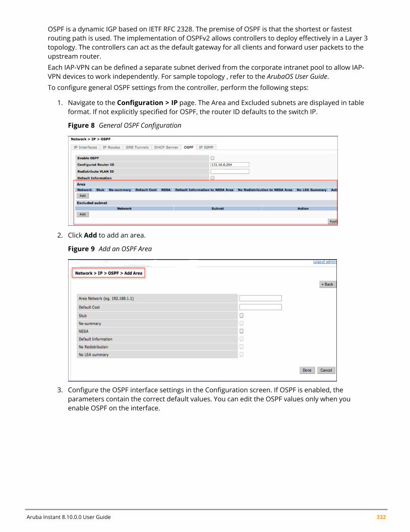
Aruba Instant 8.10.0.0 User Guide 332
OSPF is a dynamic IGP based on IETF RFC 2328. The premise of OSPF is that the shortest or fastestrouting path is used. The implementation of OSPFv2 allows controllers to deploy effectively in a Layer 3topology. The controllers can act as the default gateway for all clients and forward user packets to theupstream router.
Each IAP-VPN can be defined a separate subnet derived from the corporate intranet pool to allow IAP-VPN devices to work independently. For sample topology , refer to the ArubaOS User Guide.To configure general OSPF settings from the controller, perform the following steps:
1. Navigate to the Configuration > IP page. The Area and Excluded subnets are displayed in tableformat. If not explicitly specified for OSPF, the router ID defaults to the switch IP.
Figure 8 General OSPF Configuration
2. Click Add to add an area.
Figure 9 Add an OSPF Area
3. Configure the OSPF interface settings in the Configuration screen. If OSPF is enabled, theparameters contain the correct default values. You can edit the OSPF values only when youenable OSPF on the interface.
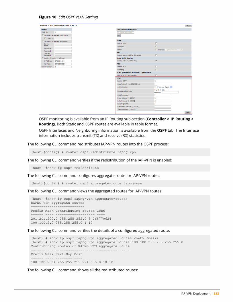
IAP-VPN Deployment | 333
Figure 10 Edit OSPF VLAN Settings
OSPF monitoring is available from an IP Routing sub-section (Controller > IP Routing >Routing). Both Static and OSPF routes are available in table format.
OSPF Interfaces and Neighboring information is available from the OSPF tab. The Interfaceinformation includes transmit (TX) and receive (RX) statistics.
The following CLI command redistributes IAP-VPN routes into the OSPF process:
(host)(config) # router ospf redistribute rapng-vpn
The following CLI command verifies if the redistribution of the IAP-VPN is enabled:
(host) #show ip ospf redistribute
The following CLI command configures aggregate route for IAP-VPN routes:
(host)(config) # router ospf aggregate-route rapng-vpn
The following CLI command views the aggregated routes for IAP-VPN routes:
(host) #show ip ospf rapng-vpn aggregate-routesRAPNG VPN aggregate routes--------------------------Prefix Mask Contributing routes Cost------ ---- ------------------- ----201.201.200.0 255.255.252.0 5 268779624100.100.2.0 255.255.255.0 1 10
The following CLI command verifies the details of a configured aggregated route:
(host) # show ip ospf rapng-vpn aggregated-routes <net> <mask>(host) # show ip ospf rapng-vpn aggregate-routes 100.100.2.0 255.255.255.0Contributing routes of RAPNG VPN aggregate route------------------------------------------------Prefix Mask Next-Hop Cost------ ---- -------- ----100.100.2.64 255.255.255.224 5.5.0.10 10
The following CLI command shows all the redistributed routes:
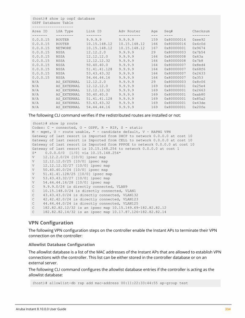
Aruba Instant 8.10.0.0 User Guide 334
(host)# show ip ospf databaseOSPF Database Table-------------------Area ID LSA Type Link ID Adv Router Age Seq# Checksum------- -------- ------- ---------- --- ---- --------0.0.0.15 ROUTER 9.9.9.9 9.9.9.9 159 0x80000016 0xee920.0.0.15 ROUTER 10.15.148.12 10.15.148.12 166 0x80000016 0x4c0d0.0.0.15 NETWORK 10.15.148.12 10.15.148.12 167 0x80000001 0x96740.0.0.15 NSSA 12.12.2.0 9.9.9.9 29 0x80000003 0x7b540.0.0.15 NSSA 12.12.12.0 9.9.9.9 164 0x80000008 0x63a0.0.0.15 NSSA 12.12.12.32 9.9.9.9 164 0x80000008 0x7b80.0.0.15 NSSA 50.40.40.0 9.9.9.9 164 0x80000007 0x8ed40.0.0.15 NSSA 51.41.41.128 9.9.9.9 164 0x80000007 0x68f60.0.0.15 NSSA 53.43.43.32 9.9.9.9 164 0x80000007 0x26330.0.0.15 NSSA 54.44.44.16 9.9.9.9 164 0x80000007 0x353N/A AS_EXTERNAL 12.12.2.0 9.9.9.9 29 0x80000003 0x8c06N/A AS_EXTERNAL 12.12.12.0 9.9.9.9 169 0x80000001 0x25e4N/A AS_EXTERNAL 12.12.12.32 9.9.9.9 169 0x80000001 0x2663N/A AS_EXTERNAL 50.40.40.0 9.9.9.9 169 0x80000001 0xab80N/A AS_EXTERNAL 51.41.41.128 9.9.9.9 169 0x80000001 0x85a2N/A AS_EXTERNAL 53.43.43.32 9.9.9.9 169 0x80000001 0x43deN/A AS_EXTERNAL 54.44.44.16 9.9.9.9 169 0x80000001 0x20fe
The following CLI command verifies if the redistributed routes are installed or not:
(host)# show ip routeCodes: C - connected, O - OSPF, R - RIP, S - staticM - mgmt, U - route usable, * - candidate default, V - RAPNG VPNGateway of last resort is Imported from DHCP to network 0.0.0.0 at cost 10Gateway of last resort is Imported from CELL to network 0.0.0.0 at cost 10Gateway of last resort is Imported from PPPOE to network 0.0.0.0 at cost 10Gateway of last resort is 10.15.148.254 to network 0.0.0.0 at cost 1S* 0.0.0.0/0 [1/0] via 10.15.148.254*V 12.12.2.0/24 [10/0] ipsec mapV 12.12.12.0/25 [10/0] ipsec mapV 12.12.12.32/27 [10/0] ipsec mapV 50.40.40.0/24 [10/0] ipsec mapV 51.41.41.128/25 [10/0] ipsec mapV 53.43.43.32/27 [10/0] ipsec mapV 54.44.44.16/28 [10/0] ipsec mapC 9.9.9.0/24 is directly connected, VLAN9C 10.15.148.0/24 is directly connected, VLAN1C 43.43.43.0/24 is directly connected, VLAN132C 42.42.42.0/24 is directly connected, VLAN123C 44.44.44.0/24 is directly connected, VLAN125C 182.82.82.12/32 is an ipsec map 10.15.149.69-182.82.82.12C 182.82.82.14/32 is an ipsec map 10.17.87.126-182.82.82.14
VPN ConfigurationThe following VPN configuration steps on the controller enable the Instant APs to terminate their VPNconnection on the controller:
Allowlist Database Configuration
The allowlist database is a list of the MAC addresses of the Instant APs that are allowed to establish VPNconnections with the controller. This list can be either stored in the controller database or on anexternal server.
The following CLI command configures the allowlist database entries if the controller is acting as theallowlist database:
(host)# allowlist-db rap add mac-address 00:11:22:33:44:55 ap-group test
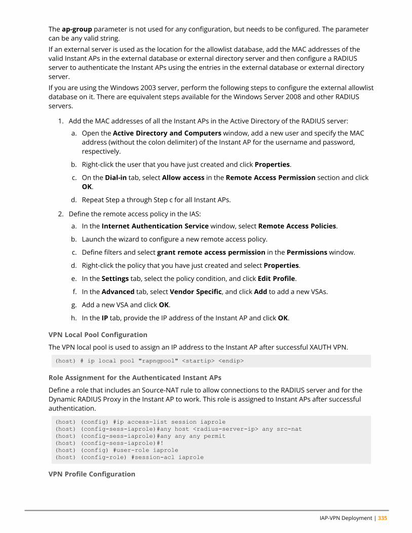
IAP-VPN Deployment | 335
The ap-group parameter is not used for any configuration, but needs to be configured. The parametercan be any valid string.
If an external server is used as the location for the allowlist database, add the MAC addresses of thevalid Instant APs in the external database or external directory server and then configure a RADIUSserver to authenticate the Instant APs using the entries in the external database or external directoryserver.
If you are using the Windows 2003 server, perform the following steps to configure the external allowlistdatabase on it. There are equivalent steps available for the Windows Server 2008 and other RADIUSservers.
1. Add the MAC addresses of all the Instant APs in the Active Directory of the RADIUS server:
a. Open the Active Directory and Computers window, add a new user and specify the MACaddress (without the colon delimiter) of the Instant AP for the username and password,respectively.
b. Right-click the user that you have just created and click Properties.
c. On the Dial-in tab, select Allow access in the Remote Access Permission section and clickOK.
d. Repeat Step a through Step c for all Instant APs.
2. Define the remote access policy in the IAS:
a. In the Internet Authentication Service window, select Remote Access Policies.
b. Launch the wizard to configure a new remote access policy.
c. Define filters and select grant remote access permission in the Permissions window.
d. Right-click the policy that you have just created and select Properties.
e. In the Settings tab, select the policy condition, and click Edit Profile.
f. In the Advanced tab, select Vendor Specific, and click Add to add a new VSAs.
g. Add a new VSA and click OK.
h. In the IP tab, provide the IP address of the Instant AP and click OK.
VPN Local Pool Configuration
The VPN local pool is used to assign an IP address to the Instant AP after successful XAUTH VPN.
(host) # ip local pool "rapngpool" <startip> <endip>
Role Assignment for the Authenticated Instant APs
Define a role that includes an Source-NAT rule to allow connections to the RADIUS server and for theDynamic RADIUS Proxy in the Instant AP to work. This role is assigned to Instant APs after successfulauthentication.
(host) (config) #ip access-list session iaprole(host) (config-sess-iaprole)#any host <radius-server-ip> any src-nat(host) (config-sess-iaprole)#any any any permit(host) (config-sess-iaprole)#!(host) (config) #user-role iaprole(host) (config-role) #session-acl iaprole
VPN Profile Configuration
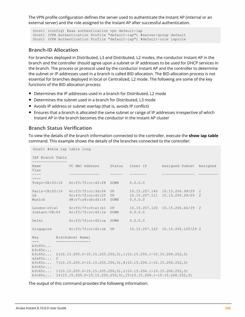
Aruba Instant 8.10.0.0 User Guide 336
The VPN profile configuration defines the server used to authenticate the Instant AP (internal or anexternal server) and the role assigned to the Instant AP after successful authentication.
(host) (config) #aaa authentication vpn default-iap(host) (VPN Authentication Profile "default-iap") #server-group default(host) (VPN Authentication Profile "default-iap") #default-role iaprole
Branch-ID AllocationFor branches deployed in Distributed, L3 and Distributed, L2 modes, the conductor Instant AP in thebranch and the controller should agree upon a subnet or IP addresses to be used for DHCP services inthe branch. The process or protocol used by the conductor Instant AP and the controller to determinethe subnet or IP addresses used in a branch is called BID allocation. The BID allocation process is notessential for branches deployed in local or Centralized, L2 mode. The following are some of the keyfunctions of the BID allocation process:
n Determines the IP addresses used in a branch for Distributed, L2 moden Determines the subnet used in a branch for Distributed, L3 moden Avoids IP address or subnet overlap (that is, avoids IP conflict)n Ensures that a branch is allocated the same subnet or range of IP addresses irrespective of which
Instant AP in the branch becomes the conductor in the Instant AP cluster
Branch Status VerificationTo view the details of the branch information connected to the controller, execute the show iap tablecommand. This example shows the details of the branches connected to the controller:
(host) #show iap table long
IAP Branch Table----------------Name VC MAC Address Status Inner IP Assigned Subnet AssignedVlan---- -------------- ------ -------- --------------- -------------Tokyo-CB:D3:16 6c:f3:7f:cc:42:f8 DOWN 0.0.0.0
Paris-CB:D3:16 6c:f3:7f:cc:3d:04 UP 10.15.207.140 10.15.206.99/29 2LA 6c:f3:7f:cc:42:25 UP 10.15.207.111 10.15.206.24/29 2Munich d8:c7:c8:cb:d3:16 DOWN 0.0.0.0
London-c0:e1 6c:f3:7f:c0:e1:b1 UP 10.15.207.120 10.15.206.64/29 2Instant-CB:D3 6c:f3:7f:cc:42:1e DOWN 0.0.0.0
Delhi 6c:f3:7f:cc:42:ca DOWN 0.0.0.0
Singapore 6c:f3:7f:cc:42:cb UP 10.15.207.122 10.15.206.120/29 2
Key Bid(Subnet Name)--- ----------------b3c65c...b3c65c...b3c65c... 2(10.15.205.0-10.15.205.250,5),1(10.15.206.1-10.15.206.252,5)a2a65c... 0b3c65c... 7(10.15.205.0-10.15.205.250,5),8(10.15.206.1-10.15.206.252,5)b3c65c...b3c65c... 1(10.15.205.0-10.15.205.250,5),2(10.15.206.1-10.15.206.252,5)b3c65c... 14(10.15.205.0-10.15.205.250,5),15(10.15.206.1-10.15.206.252,5)
The output of this command provides the following information:
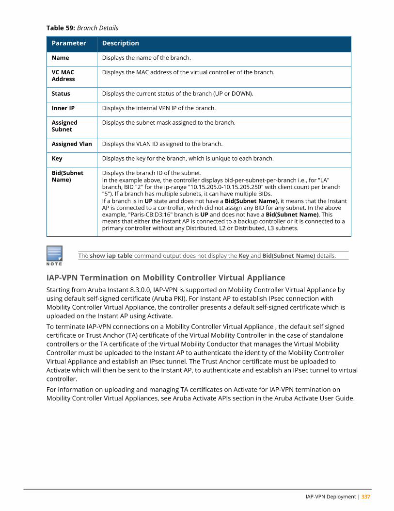
IAP-VPN Deployment | 337
Parameter Description
Name Displays the name of the branch.
VC MACAddress
Displays the MAC address of the virtual controller of the branch.
Status Displays the current status of the branch (UP or DOWN).
Inner IP Displays the internal VPN IP of the branch.
AssignedSubnet
Displays the subnet mask assigned to the branch.
Assigned Vlan Displays the VLAN ID assigned to the branch.
Key Displays the key for the branch, which is unique to each branch.
Bid(SubnetName)
Displays the branch ID of the subnet.In the example above, the controller displays bid-per-subnet-per-branch i.e., for "LA"branch, BID "2" for the ip-range "10.15.205.0-10.15.205.250" with client count per branch"5"). If a branch has multiple subnets, it can have multiple BIDs.If a branch is in UP state and does not have a Bid(Subnet Name), it means that the InstantAP is connected to a controller, which did not assign any BID for any subnet. In the aboveexample, "Paris-CB:D3:16" branch is UP and does not have a Bid(Subnet Name). Thismeans that either the Instant AP is connected to a backup controller or it is connected to aprimary controller without any Distributed, L2 or Distributed, L3 subnets.
Table 59: Branch Details
The show iap table command output does not display the Key and Bid(Subnet Name) details.
IAP-VPN Termination on Mobility Controller Virtual ApplianceStarting from Aruba Instant 8.3.0.0, IAP-VPN is supported on Mobility Controller Virtual Appliance byusing default self-signed certificate (Aruba PKI). For Instant AP to establish IPsec connection withMobility Controller Virtual Appliance, the controller presents a default self-signed certificate which isuploaded on the Instant AP using Activate.
To terminate IAP-VPN connections on a Mobility Controller Virtual Appliance , the default self signedcertificate or Trust Anchor (TA) certificate of the Virtual Mobility Controller in the case of standalonecontrollers or the TA certificate of the Virtual Mobility Conductor that manages the Virtual MobilityController must be uploaded to the Instant AP to authenticate the identity of the Mobility ControllerVirtual Appliance and establish an IPsec tunnel. The Trust Anchor certificate must be uploaded toActivate which will then be sent to the Instant AP, to authenticate and establish an IPsec tunnel to virtualcontroller.
For information on uploading and managing TA certificates on Activate for IAP-VPN termination onMobility Controller Virtual Appliances, see Aruba Activate APIs section in the Aruba Activate User Guide.
Aruba Instant 8.10.0.0 User Guide 338
Mobility Conductors (Mobility Conductor Hardware Appliance, Mobility Conductor Virtual Appliance,and conductor Controller Mode) do not support any AP termination including Campus APs, RemoteAPs and IAP-VPN tunnels.
Through Activate, you can push only one default self-signed certificate to Instant AP which can beused to establish IPsec tunnel with Mobility Controller Virtual Appliance.
IAP-VPN Deployment ScenariosThis section describes the most common IAP-VPN deployment models and provides information tocarry out the necessary configuration procedures. The examples in this section refer to more than oneDHCP profile and wired port configuration in addition to wireless SSID configuration. All these areoptional. In most networks, a single DHCP profile and wireless SSID configuration referring to a DHCPprofile is sufficient.
The following scenarios are described in this section:
n Scenario 1—IPsec: Single Datacenter Deployment with No Redundancy on page 338n Scenario 2—IPsec: Single Datacenter with Multiple Controller for Redundancy on page 343n Scenario 3—IPsec: Multiple Datacenter Deployment with Primary and Backup Controller for
Redundancy on page 348n Scenario 4—GRE: Single Datacenter Deployment with No Redundancy on page 355
Scenario 1—IPsec: Single Datacenter Deployment with NoRedundancyThis scenario includes the following configuration elements:
1. Single VPN primary configuration using IPsec.2. Split-tunneling of client traffic.3. Split-tunneling of DNS traffic from clients.4. Distributed, L3 and Centralized, L2 mode DHCP.5. RADIUS server within corporate network and authentication survivability for branch survivability.6. Wired and wireless users in L2 and L3 modes, respectively.7. Access rules defined for wired and wireless networks to permit all traffic.
TopologyFigure 11 shows the topology and the IP addressing scheme used in this scenario.
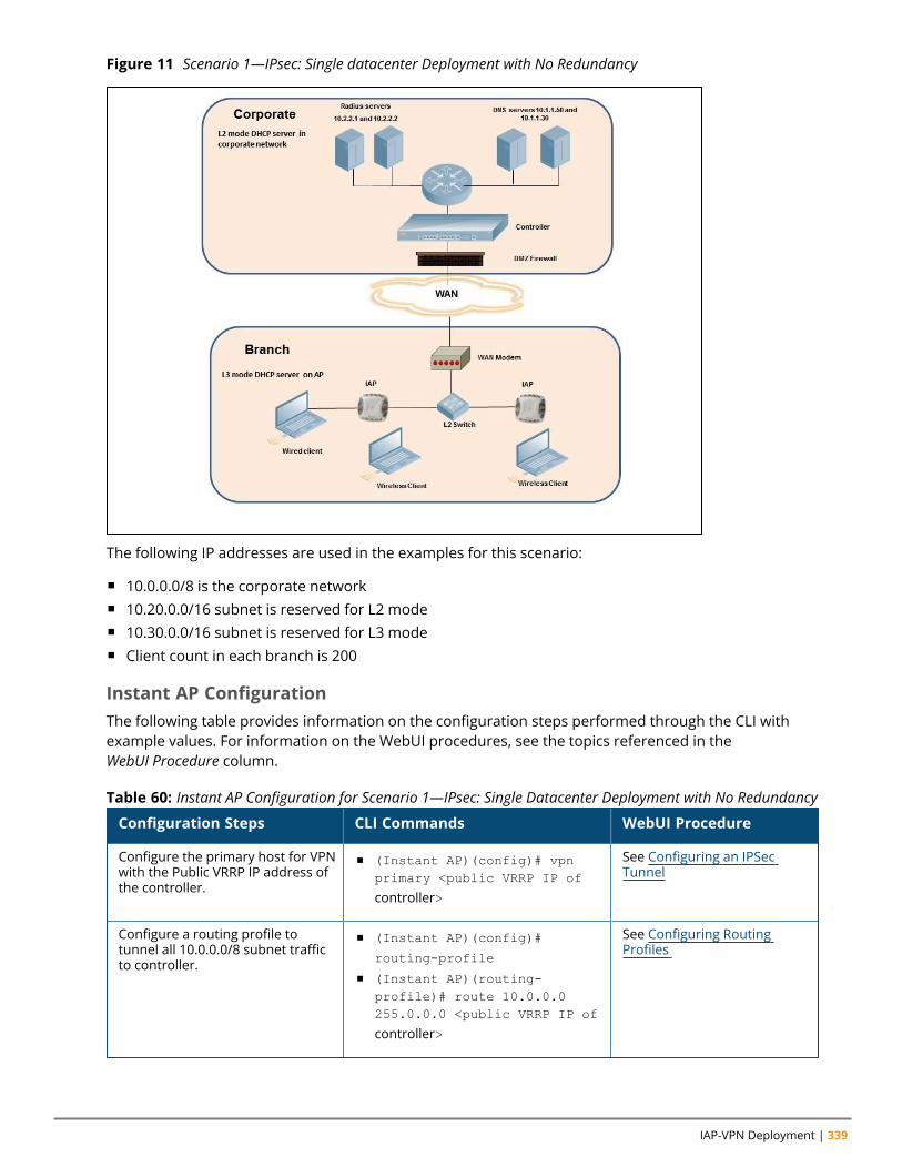
IAP-VPN Deployment | 339
Figure 11 Scenario 1—IPsec: Single datacenter Deployment with No Redundancy
The following IP addresses are used in the examples for this scenario:
n 10.0.0.0/8 is the corporate networkn 10.20.0.0/16 subnet is reserved for L2 moden 10.30.0.0/16 subnet is reserved for L3 moden Client count in each branch is 200
Instant AP ConfigurationThe following table provides information on the configuration steps performed through the CLI withexample values. For information on the WebUI procedures, see the topics referenced in theWebUI Procedure column.
Configuration Steps CLI Commands WebUI Procedure
Configure the primary host for VPNwith the Public VRRP IP address ofthe controller.
n (Instant AP)(config)# vpnprimary <public VRRP IP of
controller>
See Configuring an IPSecTunnel
Configure a routing profile totunnel all 10.0.0.0/8 subnet trafficto controller.
n (Instant AP)(config)#
routing-profile
n (Instant AP)(routing-profile)# route 10.0.0.0255.0.0.0 <public VRRP IP of
controller>
See Configuring RoutingProfiles
Table 60: Instant AP Configuration for Scenario 1—IPsec: Single Datacenter Deployment with No Redundancy
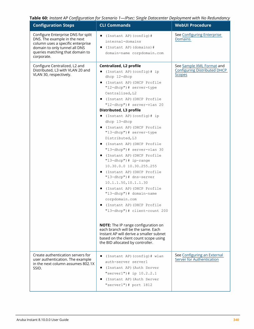
Aruba Instant 8.10.0.0 User Guide 340
Configuration Steps CLI Commands WebUI Procedure
Configure Enterprise DNS for splitDNS. The example in the nextcolumn uses a specific enterprisedomain to only tunnel all DNSqueries matching that domain tocorporate.
n (Instant AP)(config)#
internal-domains
n (Instant AP)(domains)#
domain-name corpdomain.com
See Configuring EnterpriseDomains
Configure Centralized, L2 andDistributed, L3 with VLAN 20 andVLAN 30, respectively.
Centralized, L2 profilen (Instant AP)(config)# ip
dhcp l2-dhcp
n (Instant AP)(DHCP Profile"l2-dhcp")# server-type
Centralized,L2
n (Instant AP)(DHCP Profile
"l2-dhcp")# server-vlan 20
Distributed, L3 profilen (Instant AP)(config)# ip
dhcp l3-dhcp
n (Instant AP)(DHCP Profile"l3-dhcp")# server-type
Distributed,L3
n (Instant AP)(DHCP Profile
"l3-dhcp")# server-vlan 30
n (Instant AP)(DHCP Profile"l3-dhcp")# ip-range
10.30.0.0 10.30.255.255
n (Instant AP)(DHCP Profile"l3-dhcp")# dns-server
10.1.1.50,10.1.1.30
n (Instant AP)(DHCP Profile"l3-dhcp")# domain-name
corpdomain.com
n (Instant AP)(DHCP Profile
"l3-dhcp")# client-count 200
NOTE: The IP range configuration oneach branch will be the same. EachInstant AP will derive a smaller subnetbased on the client count scope usingthe BID allocated by controller.
See Sample XML Format andConfiguring Distributed DHCPScopes
Create authentication servers foruser authentication. The examplein the next column assumes 802.1XSSID.
n (Instant AP)(config)# wlan
auth-server server1
n (Instant AP)(Auth Server
"server1")# ip 10.2.2.1
n (Instant AP)(Auth Server
"server1")# port 1812
See Configuring an ExternalServer for Authentication
Table 60: Instant AP Configuration for Scenario 1—IPsec: Single Datacenter Deployment with No Redundancy
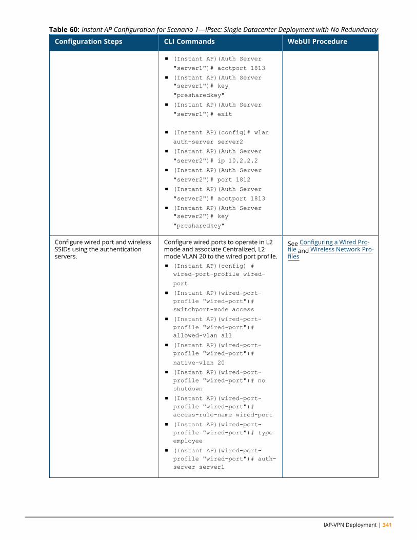
IAP-VPN Deployment | 341
Configuration Steps CLI Commands WebUI Procedure
n (Instant AP)(Auth Server
"server1")# acctport 1813
n (Instant AP)(Auth Server"server1")# key
"presharedkey"
n (Instant AP)(Auth Server
"server1")# exit
n (Instant AP)(config)# wlan
auth-server server2
n (Instant AP)(Auth Server
"server2")# ip 10.2.2.2
n (Instant AP)(Auth Server
"server2")# port 1812
n (Instant AP)(Auth Server
"server2")# acctport 1813
n (Instant AP)(Auth Server"server2")# key
"presharedkey"
Configure wired port and wirelessSSIDs using the authenticationservers.
Configure wired ports to operate in L2mode and associate Centralized, L2mode VLAN 20 to the wired port profile.n (Instant AP)(config) #
wired-port-profile wired-
port
n (Instant AP)(wired-port-profile "wired-port")#switchport-mode access
n (Instant AP)(wired-port-profile "wired-port")#allowed-vlan all
n (Instant AP)(wired-port-profile "wired-port")#
native-vlan 20
n (Instant AP)(wired-port-profile "wired-port")# noshutdown
n (Instant AP)(wired-port-profile "wired-port")#access-rule-name wired-port
n (Instant AP)(wired-port-profile "wired-port")# typeemployee
n (Instant AP)(wired-port-profile "wired-port")# auth-server server1
See Configuring a Wired Pro-file and Wireless Network Pro-files
Table 60: Instant AP Configuration for Scenario 1—IPsec: Single Datacenter Deployment with No Redundancy
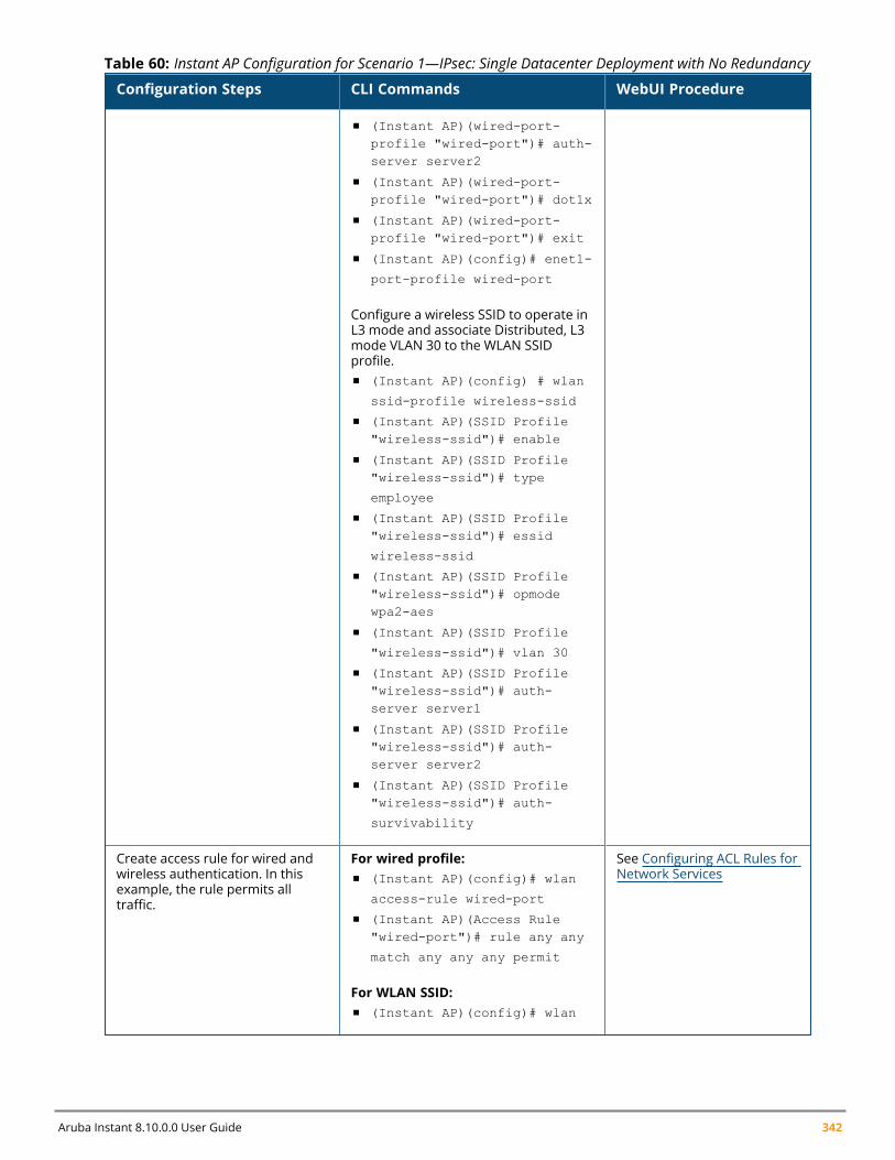
Aruba Instant 8.10.0.0 User Guide 342
Configuration Steps CLI Commands WebUI Procedure
n (Instant AP)(wired-port-profile "wired-port")# auth-server server2
n (Instant AP)(wired-port-profile "wired-port")# dot1x
n (Instant AP)(wired-port-profile "wired-port")# exit
n (Instant AP)(config)# enet1-
port-profile wired-port
Configure a wireless SSID to operate inL3 mode and associate Distributed, L3mode VLAN 30 to the WLAN SSIDprofile.n (Instant AP)(config) # wlan
ssid-profile wireless-ssid
n (Instant AP)(SSID Profile"wireless-ssid")# enable
n (Instant AP)(SSID Profile"wireless-ssid")# type
employee
n (Instant AP)(SSID Profile"wireless-ssid")# essid
wireless-ssid
n (Instant AP)(SSID Profile"wireless-ssid")# opmodewpa2-aes
n (Instant AP)(SSID Profile
"wireless-ssid")# vlan 30
n (Instant AP)(SSID Profile"wireless-ssid")# auth-server server1
n (Instant AP)(SSID Profile"wireless-ssid")# auth-server server2
n (Instant AP)(SSID Profile"wireless-ssid")# auth-
survivability
Create access rule for wired andwireless authentication. In thisexample, the rule permits alltraffic.
For wired profile:n (Instant AP)(config)# wlan
access-rule wired-port
n (Instant AP)(Access Rule"wired-port")# rule any any
match any any any permit
For WLAN SSID:n (Instant AP)(config)# wlan
See Configuring ACL Rules forNetwork Services
Table 60: Instant AP Configuration for Scenario 1—IPsec: Single Datacenter Deployment with No Redundancy
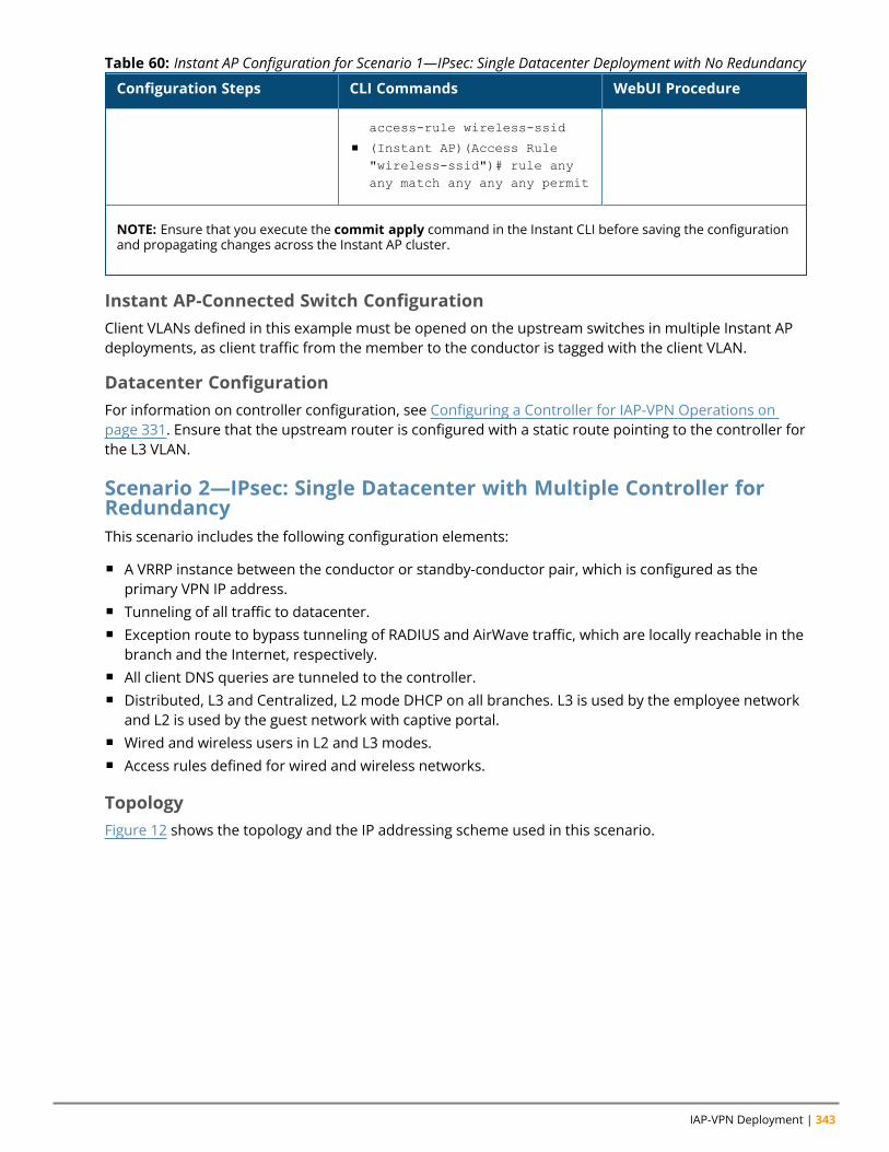
IAP-VPN Deployment | 343
Configuration Steps CLI Commands WebUI Procedure
access-rule wireless-ssid
n (Instant AP)(Access Rule"wireless-ssid")# rule anyany match any any any permit
NOTE: Ensure that you execute the commit apply command in the Instant CLI before saving the configurationand propagating changes across the Instant AP cluster.
Table 60: Instant AP Configuration for Scenario 1—IPsec: Single Datacenter Deployment with No Redundancy
Instant AP-Connected Switch ConfigurationClient VLANs defined in this example must be opened on the upstream switches in multiple Instant APdeployments, as client traffic from the member to the conductor is tagged with the client VLAN.
Datacenter ConfigurationFor information on controller configuration, see Configuring a Controller for IAP-VPN Operations onpage 331. Ensure that the upstream router is configured with a static route pointing to the controller forthe L3 VLAN.
Scenario 2—IPsec: Single Datacenter with Multiple Controller forRedundancyThis scenario includes the following configuration elements:
n A VRRP instance between the conductor or standby-conductor pair, which is configured as theprimary VPN IP address.
n Tunneling of all traffic to datacenter.n Exception route to bypass tunneling of RADIUS and AirWave traffic, which are locally reachable in the
branch and the Internet, respectively.n All client DNS queries are tunneled to the controller.n Distributed, L3 and Centralized, L2 mode DHCP on all branches. L3 is used by the employee network
and L2 is used by the guest network with captive portal.n Wired and wireless users in L2 and L3 modes.n Access rules defined for wired and wireless networks.
TopologyFigure 12 shows the topology and the IP addressing scheme used in this scenario.
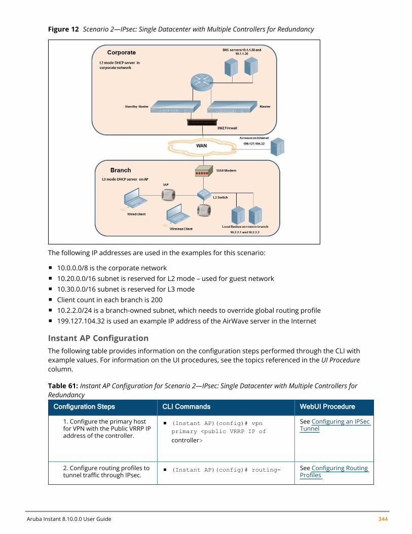
Aruba Instant 8.10.0.0 User Guide 344
Figure 12 Scenario 2—IPsec: Single Datacenter with Multiple Controllers for Redundancy
The following IP addresses are used in the examples for this scenario:
n 10.0.0.0/8 is the corporate networkn 10.20.0.0/16 subnet is reserved for L2 mode – used for guest networkn 10.30.0.0/16 subnet is reserved for L3 moden Client count in each branch is 200n 10.2.2.0/24 is a branch-owned subnet, which needs to override global routing profilen 199.127.104.32 is used an example IP address of the AirWave server in the Internet
Instant AP ConfigurationThe following table provides information on the configuration steps performed through the CLI withexample values. For information on the UI procedures, see the topics referenced in the UI Procedurecolumn.
Configuration Steps CLI Commands WebUI Procedure
1. Configure the primary hostfor VPN with the Public VRRP IPaddress of the controller.
n (Instant AP)(config)# vpnprimary <public VRRP IP of
controller>
See Configuring an IPSecTunnel
2. Configure routing profiles totunnel traffic through IPsec.
n (Instant AP)(config)# routing- See Configuring RoutingProfiles
Table 61: Instant AP Configuration for Scenario 2—IPsec: Single Datacenter with Multiple Controllers forRedundancy
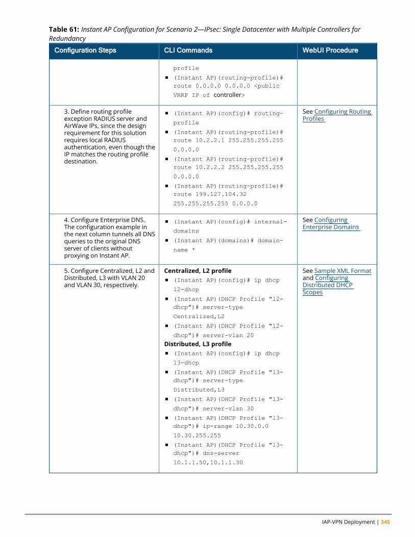
IAP-VPN Deployment | 345
Configuration Steps CLI Commands WebUI Procedure
profile
n (Instant AP)(routing-profile)#route 0.0.0.0 0.0.0.0 <public
VRRP IP of controller>
3. Define routing profileexception RADIUS server andAirWave IPs, since the designrequirement for this solutionrequires local RADIUSauthentication, even though theIP matches the routing profiledestination.
n (Instant AP)(config)# routing-
profile
n (Instant AP)(routing-profile)#route 10.2.2.1 255.255.255.255
0.0.0.0
n (Instant AP)(routing-profile)#route 10.2.2.2 255.255.255.255
0.0.0.0
n (Instant AP)(routing-profile)#route 199.127.104.32
255.255.255.255 0.0.0.0
See Configuring RoutingProfiles
4. Configure Enterprise DNS.The configuration example inthe next column tunnels all DNSqueries to the original DNSserver of clients withoutproxying on Instant AP.
n (Instant AP)(config)# internal-
domains
n (Instant AP)(domains)# domain-
name *
See ConfiguringEnterprise Domains
5. Configure Centralized, L2 andDistributed, L3 with VLAN 20and VLAN 30, respectively.
Centralized, L2 profilen (Instant AP)(config)# ip dhcp
l2-dhcp
n (Instant AP)(DHCP Profile "l2-dhcp")# server-type
Centralized,L2
n (Instant AP)(DHCP Profile "l2-
dhcp")# server-vlan 20
Distributed, L3 profilen (Instant AP)(config)# ip dhcp
l3-dhcp
n (Instant AP)(DHCP Profile "l3-dhcp")# server-type
Distributed,L3
n (Instant AP)(DHCP Profile "l3-
dhcp")# server-vlan 30
n (Instant AP)(DHCP Profile "l3-dhcp")# ip-range 10.30.0.0
10.30.255.255
n (Instant AP)(DHCP Profile "l3-dhcp")# dns-server
10.1.1.50,10.1.1.30
See Sample XML Formatand ConfiguringDistributed DHCPScopes
Table 61: Instant AP Configuration for Scenario 2—IPsec: Single Datacenter with Multiple Controllers forRedundancy
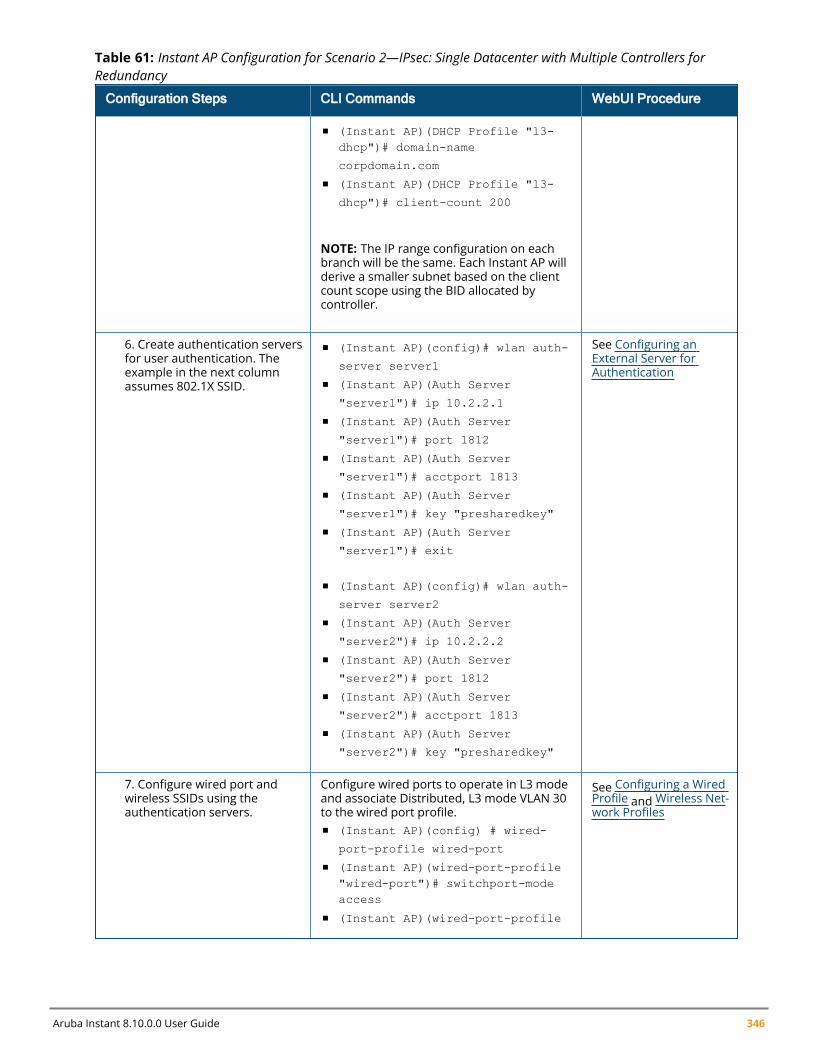
Aruba Instant 8.10.0.0 User Guide 346
Configuration Steps CLI Commands WebUI Procedure
n (Instant AP)(DHCP Profile "l3-dhcp")# domain-name
corpdomain.com
n (Instant AP)(DHCP Profile "l3-
dhcp")# client-count 200
NOTE: The IP range configuration on eachbranch will be the same. Each Instant AP willderive a smaller subnet based on the clientcount scope using the BID allocated bycontroller.
6. Create authentication serversfor user authentication. Theexample in the next columnassumes 802.1X SSID.
n (Instant AP)(config)# wlan auth-
server server1
n (Instant AP)(Auth Server
"server1")# ip 10.2.2.1
n (Instant AP)(Auth Server
"server1")# port 1812
n (Instant AP)(Auth Server
"server1")# acctport 1813
n (Instant AP)(Auth Server
"server1")# key "presharedkey"
n (Instant AP)(Auth Server
"server1")# exit
n (Instant AP)(config)# wlan auth-
server server2
n (Instant AP)(Auth Server
"server2")# ip 10.2.2.2
n (Instant AP)(Auth Server
"server2")# port 1812
n (Instant AP)(Auth Server
"server2")# acctport 1813
n (Instant AP)(Auth Server
"server2")# key "presharedkey"
See Configuring anExternal Server forAuthentication
7. Configure wired port andwireless SSIDs using theauthentication servers.
Configure wired ports to operate in L3 modeand associate Distributed, L3 mode VLAN 30to the wired port profile.n (Instant AP)(config) # wired-
port-profile wired-port
n (Instant AP)(wired-port-profile"wired-port")# switchport-modeaccess
n (Instant AP)(wired-port-profile
See Configuring a WiredProfile and Wireless Net-work Profiles
Table 61: Instant AP Configuration for Scenario 2—IPsec: Single Datacenter with Multiple Controllers forRedundancy
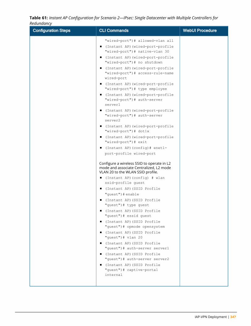
IAP-VPN Deployment | 347
Configuration Steps CLI Commands WebUI Procedure
"wired-port")# allowed-vlan all
n (Instant AP)(wired-port-profile"wired-port")# native-vlan 30
n (Instant AP)(wired-port-profile"wired-port")# no shutdown
n (Instant AP)(wired-port-profile"wired-port")# access-rule-namewired-port
n (Instant AP)(wired-port-profile"wired-port")# type employee
n (Instant AP)(wired-port-profile"wired-port")# auth-serverserver1
n (Instant AP)(wired-port-profile"wired-port")# auth-serverserver2
n (Instant AP)(wired-port-profile"wired-port")# dot1x
n (Instant AP)(wired-port-profile"wired-port")# exit
n (Instant AP)(config)# enet1-
port-profile wired-port
Configure a wireless SSID to operate in L2mode and associate Centralized, L2 modeVLAN 20 to the WLAN SSID profile.n (Instant AP)(config) # wlan
ssid-profile guest
n (Instant AP)(SSID Profile
"guest")# enable
n (Instant AP)(SSID Profile"guest")# type guest
n (Instant AP)(SSID Profile"guest")# essid guest
n (Instant AP)(SSID Profile"guest")# opmode opensystem
n (Instant AP)(SSID Profile"guest")# vlan 20
n (Instant AP)(SSID Profile"guest")# auth-server server1
n (Instant AP)(SSID Profile"guest")# auth-server server2
n (Instant AP)(SSID Profile"guest")# captive-portalinternal
Table 61: Instant AP Configuration for Scenario 2—IPsec: Single Datacenter with Multiple Controllers forRedundancy
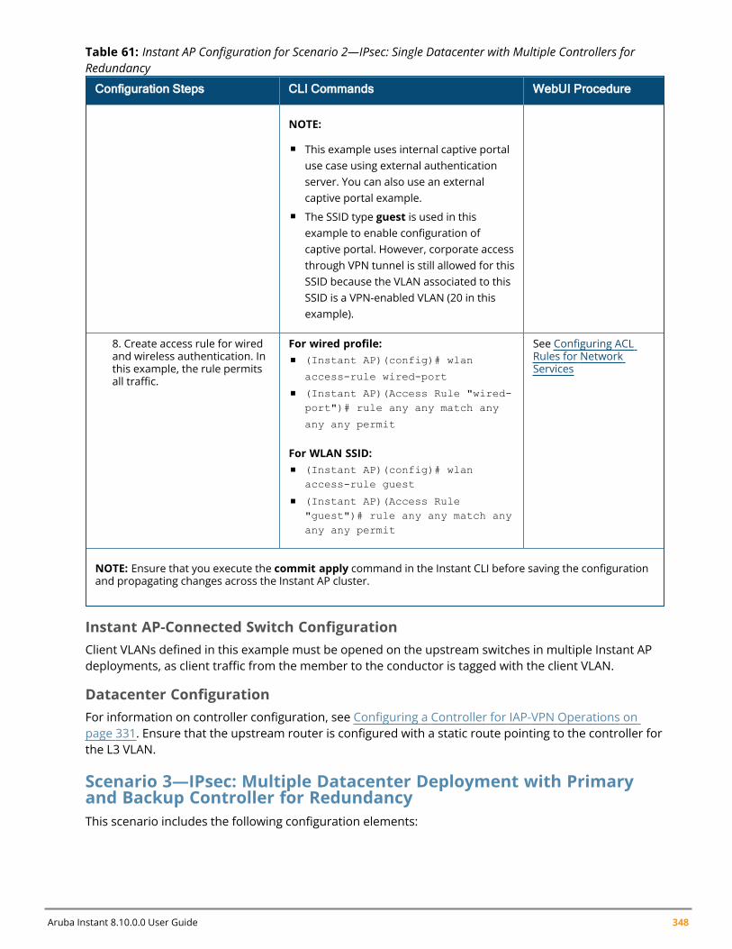
Aruba Instant 8.10.0.0 User Guide 348
Configuration Steps CLI Commands WebUI Procedure
NOTE:
n This example uses internal captive portaluse case using external authenticationserver. You can also use an externalcaptive portal example.
n The SSID type guest is used in thisexample to enable configuration ofcaptive portal. However, corporate accessthrough VPN tunnel is still allowed for thisSSID because the VLAN associated to thisSSID is a VPN-enabled VLAN (20 in thisexample).
8. Create access rule for wiredand wireless authentication. Inthis example, the rule permitsall traffic.
For wired profile:n (Instant AP)(config)# wlan
access-rule wired-port
n (Instant AP)(Access Rule "wired-port")# rule any any match any
any any permit
For WLAN SSID:n (Instant AP)(config)# wlan
access-rule guest
n (Instant AP)(Access Rule"guest")# rule any any match anyany any permit
See Configuring ACLRules for NetworkServices
NOTE: Ensure that you execute the commit apply command in the Instant CLI before saving the configurationand propagating changes across the Instant AP cluster.
Table 61: Instant AP Configuration for Scenario 2—IPsec: Single Datacenter with Multiple Controllers forRedundancy
Instant AP-Connected Switch ConfigurationClient VLANs defined in this example must be opened on the upstream switches in multiple Instant APdeployments, as client traffic from the member to the conductor is tagged with the client VLAN.
Datacenter ConfigurationFor information on controller configuration, see Configuring a Controller for IAP-VPN Operations onpage 331. Ensure that the upstream router is configured with a static route pointing to the controller forthe L3 VLAN.
Scenario 3—IPsec: Multiple Datacenter Deployment with Primaryand Backup Controller for RedundancyThis scenario includes the following configuration elements:
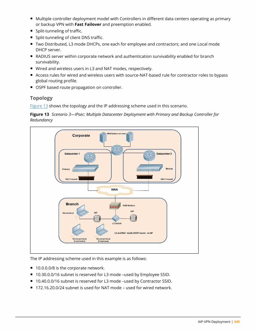
IAP-VPN Deployment | 349
n Multiple controller deployment model with Controllers in different data centers operating as primaryor backup VPN with Fast Failover and preemption enabled.
n Split-tunneling of traffic.n Split-tunneling of client DNS traffic.n Two Distributed, L3 mode DHCPs, one each for employee and contractors; and one Local mode
DHCP server.n RADIUS server within corporate network and authentication survivability enabled for branch
survivability.n Wired and wireless users in L3 and NAT modes, respectively.n Access rules for wired and wireless users with source-NAT-based rule for contractor roles to bypass
global routing profile.n OSPF based route propagation on controller.
TopologyFigure 13 shows the topology and the IP addressing scheme used in this scenario.
Figure 13 Scenario 3—IPsec: Multiple Datacenter Deployment with Primary and Backup Controller forRedundancy
The IP addressing scheme used in this example is as follows:
n 10.0.0.0/8 is the corporate network.n 10.30.0.0/16 subnet is reserved for L3 mode –used by Employee SSID.n 10.40.0.0/16 subnet is reserved for L3 mode –used by Contractor SSID.n 172.16.20.0/24 subnet is used for NAT mode – used for wired network.
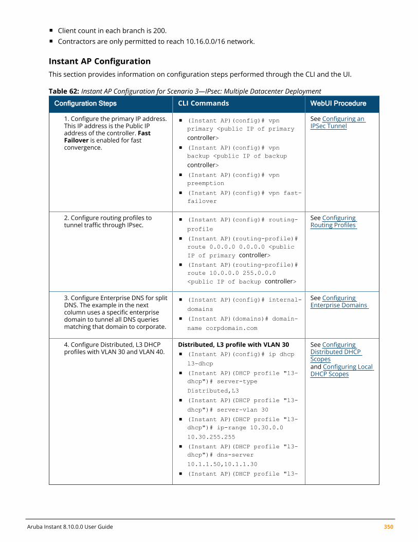
Aruba Instant 8.10.0.0 User Guide 350
n Client count in each branch is 200.n Contractors are only permitted to reach 10.16.0.0/16 network.
Instant AP ConfigurationThis section provides information on configuration steps performed through the CLI and the UI.
Configuration Steps CLI Commands WebUI Procedure
1. Configure the primary IP address.This IP address is the Public IPaddress of the controller. FastFailover is enabled for fastconvergence.
n (Instant AP)(config)# vpnprimary <public IP of primary
controller>n (Instant AP)(config)# vpn
backup <public IP of backup
controller>n (Instant AP)(config)# vpn
preemption
n (Instant AP)(config)# vpn fast-failover
See Configuring anIPSec Tunnel
2. Configure routing profiles totunnel traffic through IPsec.
n (Instant AP)(config)# routing-
profile
n (Instant AP)(routing-profile)#route 0.0.0.0 0.0.0.0 <publicIP of primary controller>
n (Instant AP)(routing-profile)#route 10.0.0.0 255.0.0.0<public IP of backup controller>
See ConfiguringRouting Profiles
3. Configure Enterprise DNS for splitDNS. The example in the nextcolumn uses a specific enterprisedomain to tunnel all DNS queriesmatching that domain to corporate.
n (Instant AP)(config)# internal-
domains
n (Instant AP)(domains)# domain-
name corpdomain.com
See ConfiguringEnterprise Domains
4. Configure Distributed, L3 DHCPprofiles with VLAN 30 and VLAN 40.
Distributed, L3 profile with VLAN 30n (Instant AP)(config)# ip dhcp
l3-dhcp
n (Instant AP)(DHCP profile "l3-dhcp")# server-type
Distributed,L3
n (Instant AP)(DHCP profile "l3-
dhcp")# server-vlan 30
n (Instant AP)(DHCP profile "l3-dhcp")# ip-range 10.30.0.0
10.30.255.255
n (Instant AP)(DHCP profile "l3-dhcp")# dns-server
10.1.1.50,10.1.1.30
n (Instant AP)(DHCP profile "l3-
See ConfiguringDistributed DHCPScopesand Configuring LocalDHCP Scopes
Table 62: Instant AP Configuration for Scenario 3—IPsec: Multiple Datacenter Deployment
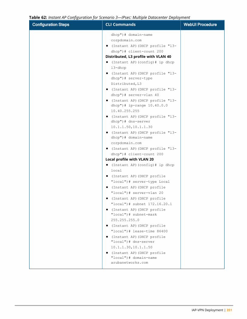
IAP-VPN Deployment | 351
Configuration Steps CLI Commands WebUI Procedure
dhcp")# domain-name
corpdomain.com
n (Instant AP)(DHCP profile "l3-
dhcp")# client-count 200
Distributed, L3 profile with VLAN 40n (Instant AP)(config)# ip dhcp
l3-dhcp
n (Instant AP)(DHCP profile "l3-dhcp")# server-type
Distributed,L3
n (Instant AP)(DHCP profile "l3-
dhcp")# server-vlan 40
n (Instant AP)(DHCP profile "l3-dhcp")# ip-range 10.40.0.0
10.40.255.255
n (Instant AP)(DHCP profile "l3-dhcp")# dns-server
10.1.1.50,10.1.1.30
n (Instant AP)(DHCP profile "l3-dhcp")# domain-name
corpdomain.com
n (Instant AP)(DHCP profile "l3-
dhcp")# client-count 200
Local profile with VLAN 20n (Instant AP)(config)# ip dhcp
local
n (Instant AP)(DHCP profile
"local")# server-type Local
n (Instant AP)(DHCP profile
"local")# server-vlan 20
n (Instant AP)(DHCP profile
"local")# subnet 172.16.20.1
n (Instant AP)(DHCP profile"local")# subnet-mask
255.255.255.0
n (Instant AP)(DHCP profile
"local")# lease-time 86400
n (Instant AP)(DHCP profile"local")# dns-server
10.1.1.30,10.1.1.50
n (Instant AP)(DHCP profile"local")# domain-namearubanetworks.com
Table 62: Instant AP Configuration for Scenario 3—IPsec: Multiple Datacenter Deployment
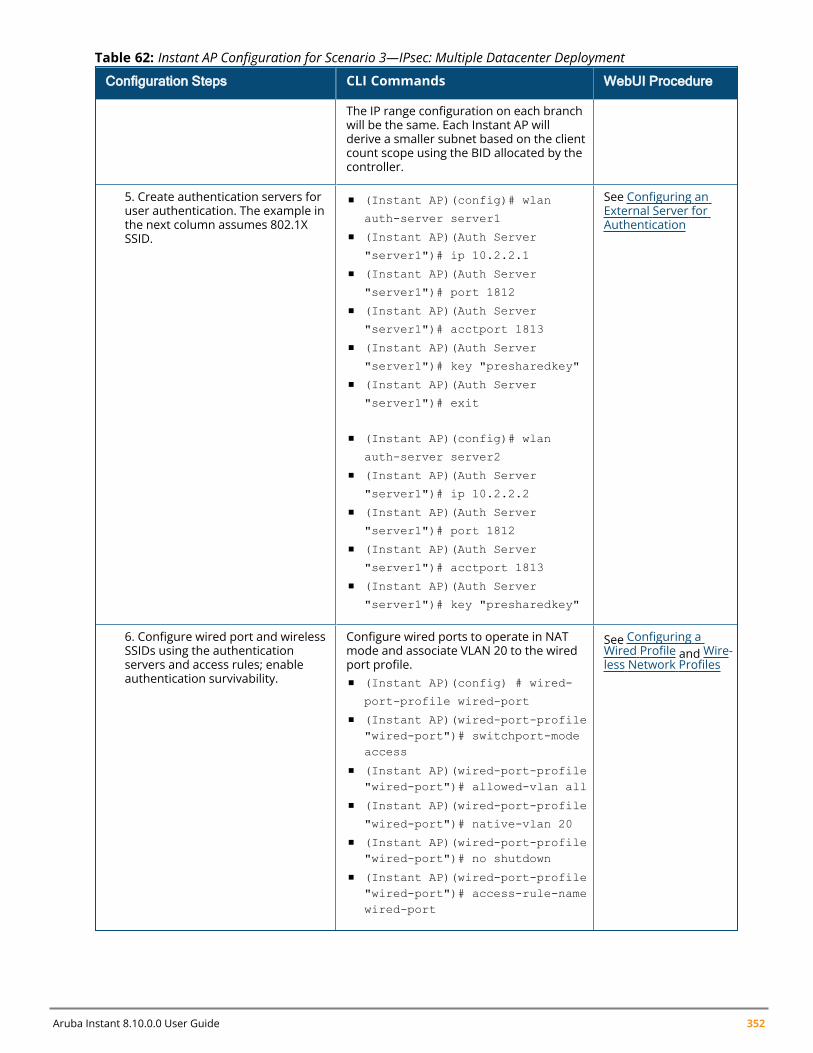
Aruba Instant 8.10.0.0 User Guide 352
Configuration Steps CLI Commands WebUI Procedure
The IP range configuration on each branchwill be the same. Each Instant AP willderive a smaller subnet based on the clientcount scope using the BID allocated by thecontroller.
5. Create authentication servers foruser authentication. The example inthe next column assumes 802.1XSSID.
n (Instant AP)(config)# wlan
auth-server server1
n (Instant AP)(Auth Server
"server1")# ip 10.2.2.1
n (Instant AP)(Auth Server
"server1")# port 1812
n (Instant AP)(Auth Server
"server1")# acctport 1813
n (Instant AP)(Auth Server
"server1")# key "presharedkey"
n (Instant AP)(Auth Server
"server1")# exit
n (Instant AP)(config)# wlan
auth-server server2
n (Instant AP)(Auth Server
"server1")# ip 10.2.2.2
n (Instant AP)(Auth Server
"server1")# port 1812
n (Instant AP)(Auth Server
"server1")# acctport 1813
n (Instant AP)(Auth Server
"server1")# key "presharedkey"
See Configuring anExternal Server forAuthentication
6. Configure wired port and wirelessSSIDs using the authenticationservers and access rules; enableauthentication survivability.
Configure wired ports to operate in NATmode and associate VLAN 20 to the wiredport profile.n (Instant AP)(config) # wired-
port-profile wired-port
n (Instant AP)(wired-port-profile"wired-port")# switchport-modeaccess
n (Instant AP)(wired-port-profile"wired-port")# allowed-vlan all
n (Instant AP)(wired-port-profile
"wired-port")# native-vlan 20
n (Instant AP)(wired-port-profile"wired-port")# no shutdown
n (Instant AP)(wired-port-profile"wired-port")# access-rule-namewired-port
See Configuring aWired Profile and Wire-less Network Profiles
Table 62: Instant AP Configuration for Scenario 3—IPsec: Multiple Datacenter Deployment
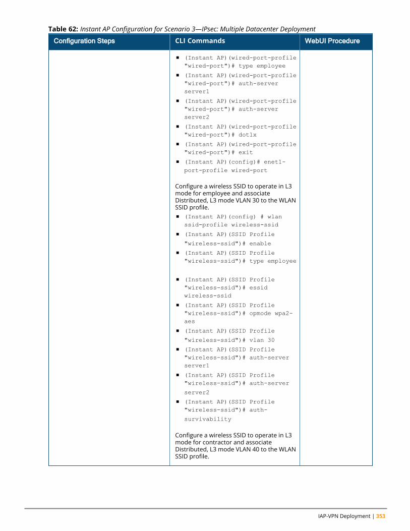
IAP-VPN Deployment | 353
Configuration Steps CLI Commands WebUI Procedure
n (Instant AP)(wired-port-profile"wired-port")# type employee
n (Instant AP)(wired-port-profile"wired-port")# auth-serverserver1
n (Instant AP)(wired-port-profile"wired-port")# auth-serverserver2
n (Instant AP)(wired-port-profile"wired-port")# dot1x
n (Instant AP)(wired-port-profile"wired-port")# exit
n (Instant AP)(config)# enet1-port-profile wired-port
Configure a wireless SSID to operate in L3mode for employee and associateDistributed, L3 mode VLAN 30 to the WLANSSID profile.n (Instant AP)(config) # wlan
ssid-profile wireless-ssid
n (Instant AP)(SSID Profile
"wireless-ssid")# enable
n (Instant AP)(SSID Profile"wireless-ssid")# type employee
n (Instant AP)(SSID Profile"wireless-ssid")# essidwireless-ssid
n (Instant AP)(SSID Profile"wireless-ssid")# opmode wpa2-aes
n (Instant AP)(SSID Profile
"wireless-ssid")# vlan 30
n (Instant AP)(SSID Profile"wireless-ssid")# auth-serverserver1
n (Instant AP)(SSID Profile"wireless-ssid")# auth-server
server2
n (Instant AP)(SSID Profile"wireless-ssid")# auth-
survivability
Configure a wireless SSID to operate in L3mode for contractor and associateDistributed, L3 mode VLAN 40 to the WLANSSID profile.
Table 62: Instant AP Configuration for Scenario 3—IPsec: Multiple Datacenter Deployment
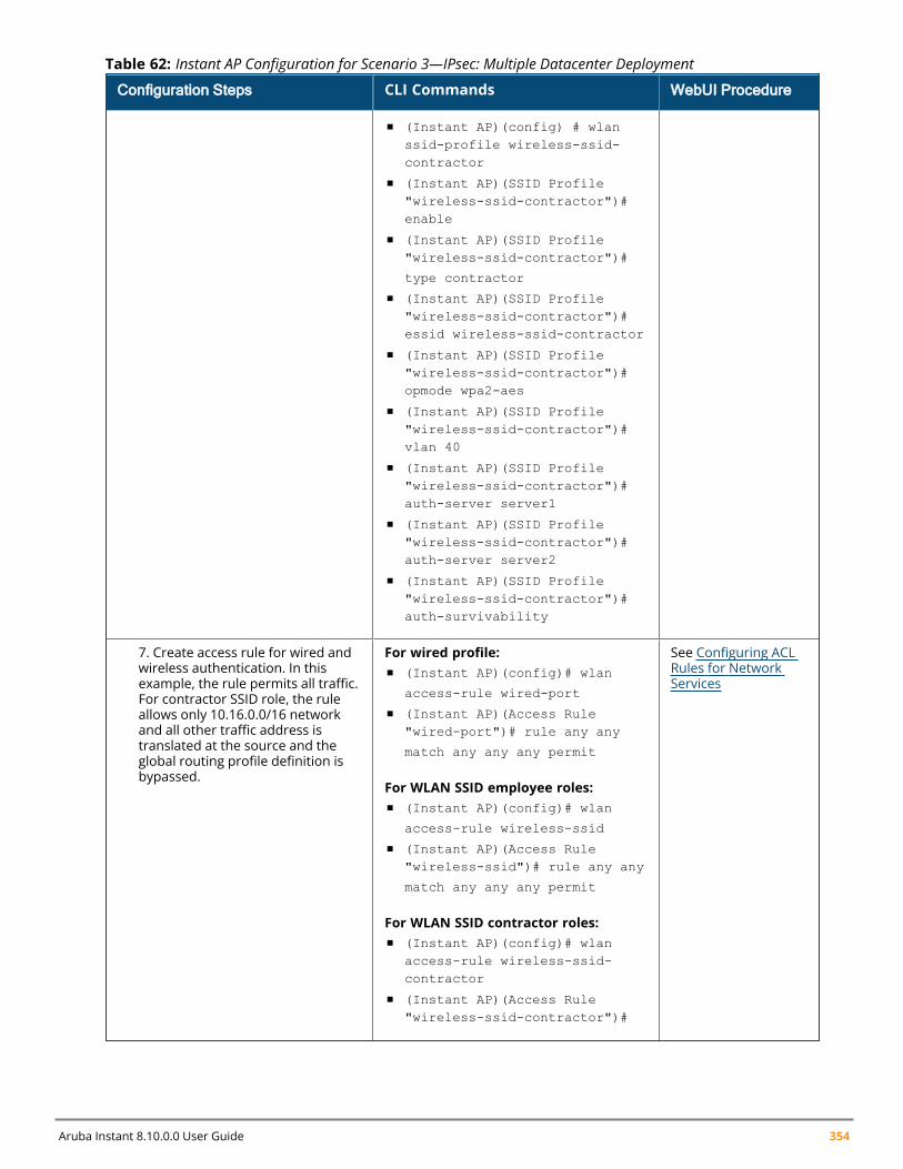
Aruba Instant 8.10.0.0 User Guide 354
Configuration Steps CLI Commands WebUI Procedure
n (Instant AP)(config) # wlanssid-profile wireless-ssid-contractor
n (Instant AP)(SSID Profile"wireless-ssid-contractor")#enable
n (Instant AP)(SSID Profile"wireless-ssid-contractor")#
type contractor
n (Instant AP)(SSID Profile"wireless-ssid-contractor")#essid wireless-ssid-contractor
n (Instant AP)(SSID Profile"wireless-ssid-contractor")#opmode wpa2-aes
n (Instant AP)(SSID Profile"wireless-ssid-contractor")#vlan 40
n (Instant AP)(SSID Profile"wireless-ssid-contractor")#auth-server server1
n (Instant AP)(SSID Profile"wireless-ssid-contractor")#auth-server server2
n (Instant AP)(SSID Profile"wireless-ssid-contractor")#auth-survivability
7. Create access rule for wired andwireless authentication. In thisexample, the rule permits all traffic.For contractor SSID role, the ruleallows only 10.16.0.0/16 networkand all other traffic address istranslated at the source and theglobal routing profile definition isbypassed.
For wired profile:n (Instant AP)(config)# wlan
access-rule wired-port
n (Instant AP)(Access Rule"wired-port")# rule any any
match any any any permit
For WLAN SSID employee roles:n (Instant AP)(config)# wlan
access-rule wireless-ssid
n (Instant AP)(Access Rule"wireless-ssid")# rule any any
match any any any permit
For WLAN SSID contractor roles:n (Instant AP)(config)# wlan
access-rule wireless-ssid-contractor
n (Instant AP)(Access Rule"wireless-ssid-contractor")#
See Configuring ACLRules for NetworkServices
Table 62: Instant AP Configuration for Scenario 3—IPsec: Multiple Datacenter Deployment
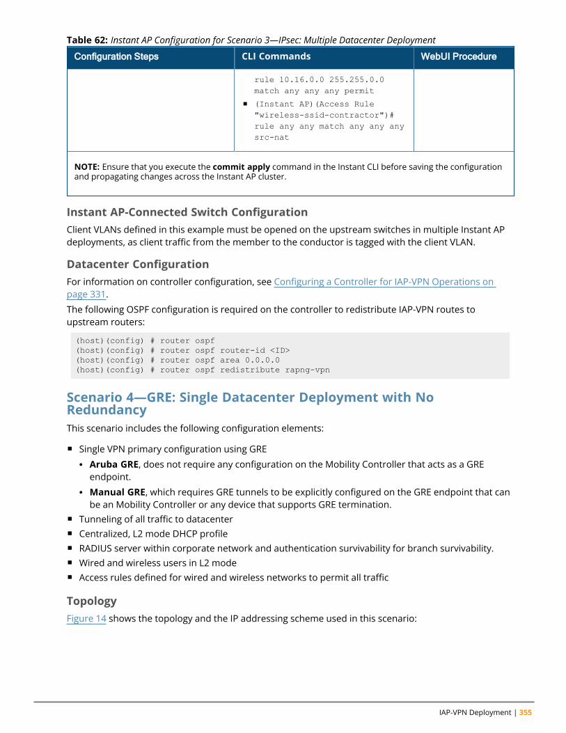
IAP-VPN Deployment | 355
Configuration Steps CLI Commands WebUI Procedure
rule 10.16.0.0 255.255.0.0match any any any permit
n (Instant AP)(Access Rule"wireless-ssid-contractor")#rule any any match any any anysrc-nat
NOTE: Ensure that you execute the commit apply command in the Instant CLI before saving the configurationand propagating changes across the Instant AP cluster.
Table 62: Instant AP Configuration for Scenario 3—IPsec: Multiple Datacenter Deployment
Instant AP-Connected Switch ConfigurationClient VLANs defined in this example must be opened on the upstream switches in multiple Instant APdeployments, as client traffic from the member to the conductor is tagged with the client VLAN.
Datacenter ConfigurationFor information on controller configuration, see Configuring a Controller for IAP-VPN Operations onpage 331.
The following OSPF configuration is required on the controller to redistribute IAP-VPN routes toupstream routers:
(host)(config) # router ospf(host)(config) # router ospf router-id <ID>(host)(config) # router ospf area 0.0.0.0(host)(config) # router ospf redistribute rapng-vpn
Scenario 4—GRE: Single Datacenter Deployment with NoRedundancyThis scenario includes the following configuration elements:
n Single VPN primary configuration using GREl Aruba GRE, does not require any configuration on the Mobility Controller that acts as a GREendpoint.
l Manual GRE, which requires GRE tunnels to be explicitly configured on the GRE endpoint that canbe an Mobility Controller or any device that supports GRE termination.
n Tunneling of all traffic to datacentern Centralized, L2 mode DHCP profilen RADIUS server within corporate network and authentication survivability for branch survivability.n Wired and wireless users in L2 moden Access rules defined for wired and wireless networks to permit all traffic
TopologyFigure 14 shows the topology and the IP addressing scheme used in this scenario:
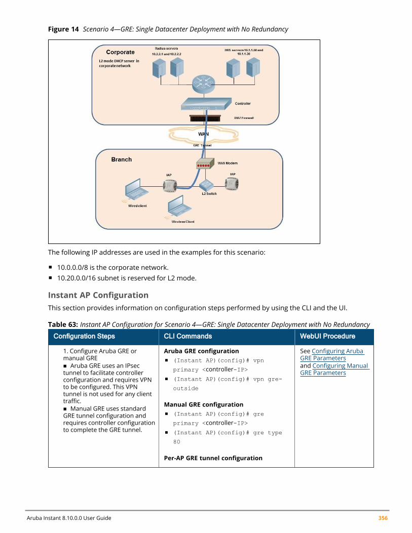
Aruba Instant 8.10.0.0 User Guide 356
Figure 14 Scenario 4—GRE: Single Datacenter Deployment with No Redundancy
The following IP addresses are used in the examples for this scenario:
n 10.0.0.0/8 is the corporate network.n 10.20.0.0/16 subnet is reserved for L2 mode.
Instant AP ConfigurationThis section provides information on configuration steps performed by using the CLI and the UI.
Configuration Steps CLI Commands WebUI Procedure
1. Configure Aruba GRE ormanual GREn Aruba GRE uses an IPsectunnel to facilitate controllerconfiguration and requires VPNto be configured. This VPNtunnel is not used for any clienttraffic.n Manual GRE uses standardGRE tunnel configuration andrequires controller configurationto complete the GRE tunnel.
Aruba GRE configurationn (Instant AP)(config)# vpn
primary <controller-IP>n (Instant AP)(config)# vpn gre-
outside
Manual GRE configurationn (Instant AP)(config)# gre
primary <controller-IP>n (Instant AP)(config)# gre type
80
Per-AP GRE tunnel configuration
See Configuring ArubaGRE Parametersand Configuring ManualGRE Parameters
Table 63: Instant AP Configuration for Scenario 4—GRE: Single Datacenter Deployment with No Redundancy
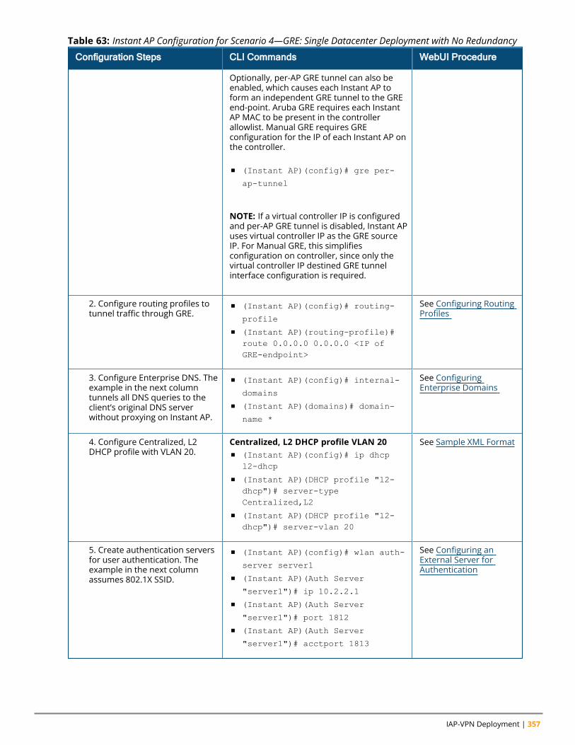
IAP-VPN Deployment | 357
Configuration Steps CLI Commands WebUI Procedure
Optionally, per-AP GRE tunnel can also beenabled, which causes each Instant AP toform an independent GRE tunnel to the GREend-point. Aruba GRE requires each InstantAP MAC to be present in the controllerallowlist. Manual GRE requires GREconfiguration for the IP of each Instant AP onthe controller.
n (Instant AP)(config)# gre per-
ap-tunnel
NOTE: If a virtual controller IP is configuredand per-AP GRE tunnel is disabled, Instant APuses virtual controller IP as the GRE sourceIP. For Manual GRE, this simplifiesconfiguration on controller, since only thevirtual controller IP destined GRE tunnelinterface configuration is required.
2. Configure routing profiles totunnel traffic through GRE.
n (Instant AP)(config)# routing-
profile
n (Instant AP)(routing-profile)#route 0.0.0.0 0.0.0.0 <IP ofGRE-endpoint>
See Configuring RoutingProfiles
3. Configure Enterprise DNS. Theexample in the next columntunnels all DNS queries to theclient’s original DNS serverwithout proxying on Instant AP.
n (Instant AP)(config)# internal-
domains
n (Instant AP)(domains)# domain-
name *
See ConfiguringEnterprise Domains
4. Configure Centralized, L2DHCP profile with VLAN 20.
Centralized, L2 DHCP profile VLAN 20n (Instant AP)(config)# ip dhcp
l2-dhcp
n (Instant AP)(DHCP profile "l2-dhcp")# server-typeCentralized,L2
n (Instant AP)(DHCP profile "l2-dhcp")# server-vlan 20
See Sample XML Format
5. Create authentication serversfor user authentication. Theexample in the next columnassumes 802.1X SSID.
n (Instant AP)(config)# wlan auth-
server server1
n (Instant AP)(Auth Server
"server1")# ip 10.2.2.1
n (Instant AP)(Auth Server
"server1")# port 1812
n (Instant AP)(Auth Server
"server1")# acctport 1813
See Configuring anExternal Server forAuthentication
Table 63: Instant AP Configuration for Scenario 4—GRE: Single Datacenter Deployment with No Redundancy
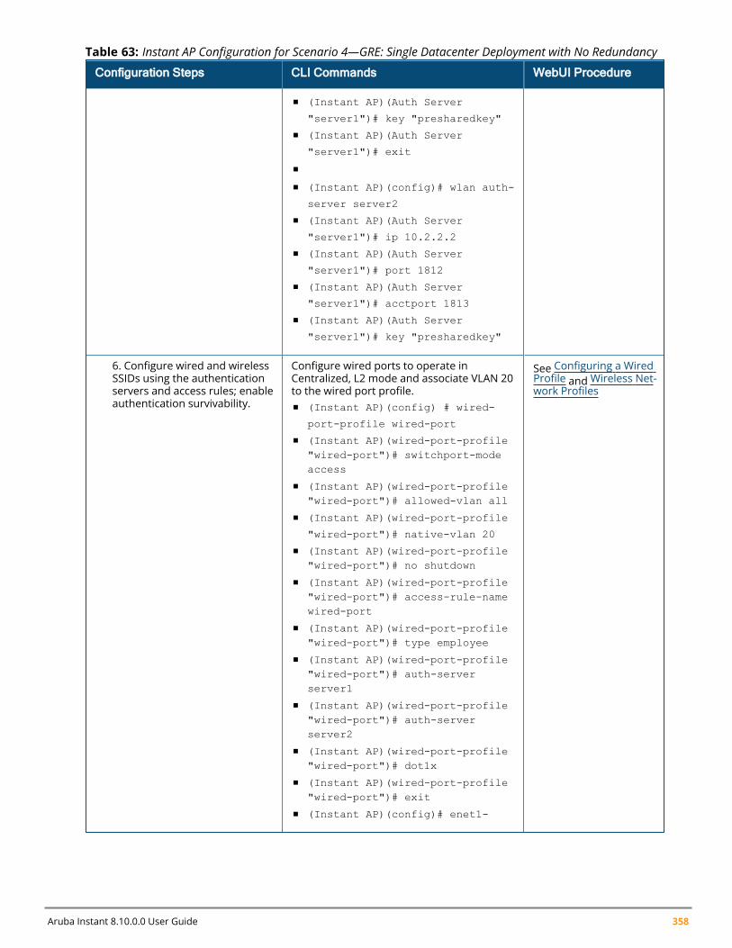
Aruba Instant 8.10.0.0 User Guide 358
Configuration Steps CLI Commands WebUI Procedure
n (Instant AP)(Auth Server
"server1")# key "presharedkey"
n (Instant AP)(Auth Server
"server1")# exit
n
n (Instant AP)(config)# wlan auth-
server server2
n (Instant AP)(Auth Server
"server1")# ip 10.2.2.2
n (Instant AP)(Auth Server
"server1")# port 1812
n (Instant AP)(Auth Server
"server1")# acctport 1813
n (Instant AP)(Auth Server
"server1")# key "presharedkey"
6. Configure wired and wirelessSSIDs using the authenticationservers and access rules; enableauthentication survivability.
Configure wired ports to operate inCentralized, L2 mode and associate VLAN 20to the wired port profile.n (Instant AP)(config) # wired-
port-profile wired-port
n (Instant AP)(wired-port-profile"wired-port")# switchport-modeaccess
n (Instant AP)(wired-port-profile"wired-port")# allowed-vlan all
n (Instant AP)(wired-port-profile
"wired-port")# native-vlan 20
n (Instant AP)(wired-port-profile"wired-port")# no shutdown
n (Instant AP)(wired-port-profile"wired-port")# access-rule-namewired-port
n (Instant AP)(wired-port-profile"wired-port")# type employee
n (Instant AP)(wired-port-profile"wired-port")# auth-serverserver1
n (Instant AP)(wired-port-profile"wired-port")# auth-serverserver2
n (Instant AP)(wired-port-profile"wired-port")# dot1x
n (Instant AP)(wired-port-profile"wired-port")# exit
n (Instant AP)(config)# enet1-
See Configuring a WiredProfile and Wireless Net-work Profiles
Table 63: Instant AP Configuration for Scenario 4—GRE: Single Datacenter Deployment with No Redundancy
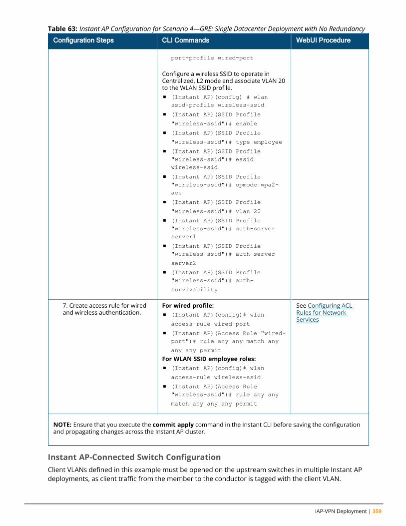
IAP-VPN Deployment | 359
Configuration Steps CLI Commands WebUI Procedure
port-profile wired-port
Configure a wireless SSID to operate inCentralized, L2 mode and associate VLAN 20to the WLAN SSID profile.n (Instant AP)(config) # wlan
ssid-profile wireless-ssid
n (Instant AP)(SSID Profile
"wireless-ssid")# enable
n (Instant AP)(SSID Profile
"wireless-ssid")# type employee
n (Instant AP)(SSID Profile"wireless-ssid")# essidwireless-ssid
n (Instant AP)(SSID Profile"wireless-ssid")# opmode wpa2-aes
n (Instant AP)(SSID Profile
"wireless-ssid")# vlan 20
n (Instant AP)(SSID Profile"wireless-ssid")# auth-serverserver1
n (Instant AP)(SSID Profile"wireless-ssid")# auth-server
server2
n (Instant AP)(SSID Profile"wireless-ssid")# auth-
survivability
7. Create access rule for wiredand wireless authentication.
For wired profile:n (Instant AP)(config)# wlan
access-rule wired-port
n (Instant AP)(Access Rule "wired-port")# rule any any match any
any any permit
For WLAN SSID employee roles:n (Instant AP)(config)# wlan
access-rule wireless-ssid
n (Instant AP)(Access Rule"wireless-ssid")# rule any any
match any any any permit
See Configuring ACLRules for NetworkServices
NOTE: Ensure that you execute the commit apply command in the Instant CLI before saving the configurationand propagating changes across the Instant AP cluster.
Table 63: Instant AP Configuration for Scenario 4—GRE: Single Datacenter Deployment with No Redundancy
Instant AP-Connected Switch ConfigurationClient VLANs defined in this example must be opened on the upstream switches in multiple Instant APdeployments, as client traffic from the member to the conductor is tagged with the client VLAN.
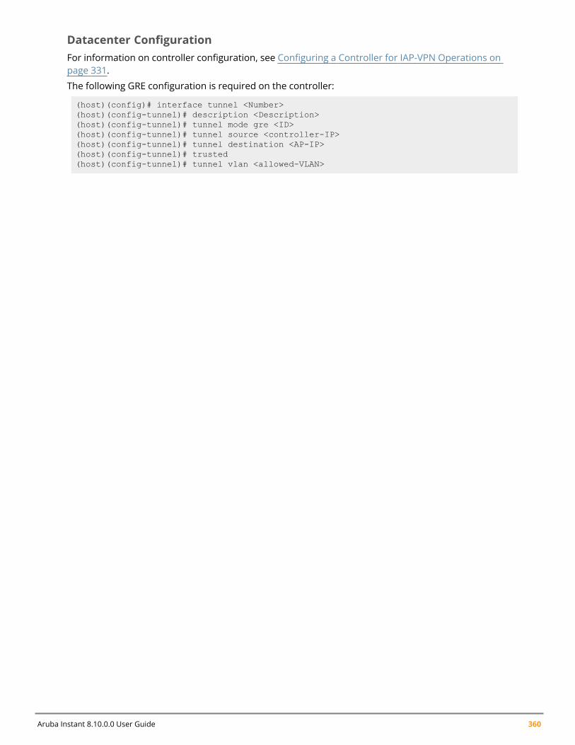
Aruba Instant 8.10.0.0 User Guide 360
Datacenter ConfigurationFor information on controller configuration, see Configuring a Controller for IAP-VPN Operations onpage 331.
The following GRE configuration is required on the controller:
(host)(config)# interface tunnel <Number>(host)(config-tunnel)# description <Description>(host)(config-tunnel)# tunnel mode gre <ID>(host)(config-tunnel)# tunnel source <controller-IP>(host)(config-tunnel)# tunnel destination <AP-IP>(host)(config-tunnel)# trusted(host)(config-tunnel)# tunnel vlan <allowed-VLAN>

Chapter 20Adaptive Radio Management
Adaptive Radio ManagementThis chapter provides the following information:
n ARM Overview on page 361n Configuring ARM Features on an Instant AP on page 362n Configuring Radio Profiles on page 368
ARM OverviewARM is an RF management technology that optimizes WLAN performance even in networks with thehighest traffic by dynamically and intelligently choosing the best 802.11 channel and transmitting powerfor each Instant AP in its current RF environment. ARM works with all standard clients, across alloperating systems, while remaining in compliance with the IEEE 802.11 standards. It does not requireany proprietary client software to achieve its performance goals. ARM ensures low-latency roaming,consistently high performance, and maximum client compatibility in a multi-channel environment. Byensuring a fair distribution of the available Wi-Fi bandwidth to mobile devices, ARM ensures that data,voice, and video applications have sufficient network resources at all times. ARM allows mixed 802.11a,802.11b, 802.11g, 802.11n, and 802.11ac client types to interoperate at the highest performance levels.
Channel or Power AssignmentThe channel or power assignment feature automatically assigns channel and power settings for all theInstant APs in the network according to changes in the RF environment. This feature automates manysetup tasks during network installation and the ongoing operations when RF conditions change.
Voice Aware ScanningThe Voice Aware scanning feature prevents an Instant AP supporting an active voice call from scanningfor other channels in the RF spectrum and allows the Instant AP to resume scanning when there are noactive voice calls. This significantly improves the voice quality when a call is in progress andsimultaneously delivers the automated RF management functions. By default, this feature is enabled.
Load Aware ScanningThe Load Aware Scanning feature dynamically adjusts scanning function to maintain uninterrupted datatransfer on resource-intensive systems when the network traffic exceeds a predefined threshold. TheInstant APs resume complete monitoring scans when the traffic drops to the normal levels. By default,this feature is enabled.
Monitoring the Network with ARMWhen ARM is enabled, an Instant AP dynamically scans all 802.11 channels within its 802.11 regulatorydomain at regular intervals and sends reports to a virtual controller on WLAN network coverage,interference, and intrusion detection.
ARM Metrics
Aruba Instant 8.10.0.0 User Guide 361

Adaptive Radio Management | 362
ARM computes coverage and interference metrics for each valid channel and chooses the bestperforming channel and transmit power settings for each Instant AP RF environment. Each Instant APgathers other metrics on its ARM-assigned channel to provide a snapshot of the current RF health state.
Configuring ARM Features on an Instant APThis section describes the following procedures for configuring ARM features:
n Band Steering on page 362n Airtime Fairness Mode on page 363n Client Match on page 363n Access Point Control on page 365
Band SteeringThe band steering feature assigns the multiple band capable clients to the most capable band on multiband Instant APs. This feature reduces co-channel interference and increases available bandwidth fordual-band clients, because there are more channels on the 6 GHz and 5 GHz band than that on the 2.4GHz band. The following procedure describes how to configure band steering parameters through theWebUI:
1. Navigate to the Configuration > RF page.2. Expand ARM.3. Select one of the following options from the Band steering mode drop-down list:
a. Prefer 5 GHz - Select this option to use band steering in the 5 GHz mode. On selecting this,the Instant AP steers the client to the 5 GHz band (if the client is 5 GHz-capable), but allowsthe client connection on the 2.4 GHz band if the client persistently attempts for 2.4 GHzassociation.
b. Force 5 GHz - Select this option to enforce 5 GHz band steering mode on the Instant APs.
c. Force 6 GHz - Select this option to enforce 6 GHz band steering mode on the Instant APs.When enabled, 6 GHz clients are only accepted by the 6 GHz radio and are blocked on the 2.4GHz and 5 GHz radio.
d. Prefer Higher Band - Select this option to use band steering in the 6 GHz and 5 GHz bandson the Instant APs. On selecting this, the Instant AP steers the 6 GHz clients to the 6 GHzband (if the client is 6 GHz-capable), but allows the client connection on the 5 GHz band if theclient persistently attempts for 5 GHz association. Similarly, the Instant AP steers the client tothe 5 GHz band (if the client is 5 GHz-capable), but allows the client connection on the 2.4GHz band if the client persistently attempts for 2.4 GHz association.
e. Balance Bands - Select this option to allow the Instant AP to balance the clients across thethree radios to best utilize the available 2.4 GHz bandwidth. This feature takes into accountthe fact that the 5 GHz band and 6 GHz has more channels than the 2.4 GHz band, and thatthe 5 GHz and 6 GHz channels can operate in 40 MHz, 80 MHz, or 160 MHz bands, while the2.4 GHz band operates in 20 MHz.
f. Disabled - Select this option if you want to allow the clients to select the band to use.
4. Click Save.
The following CLI commands configure band steering:
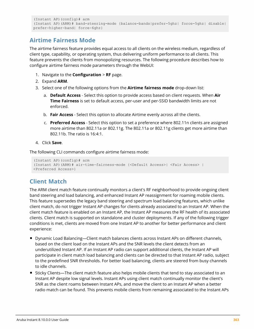
Aruba Instant 8.10.0.0 User Guide 363
(Instant AP)(config)# arm(Instant AP)(ARM)# band-steering-mode {balance-bands|prefer-5ghz| force-5ghz| disable|prefer-higher-band| force-6ghz}
Airtime Fairness ModeThe airtime fairness feature provides equal access to all clients on the wireless medium, regardless ofclient type, capability, or operating system, thus delivering uniform performance to all clients. Thisfeature prevents the clients from monopolizing resources. The following procedure describes how toconfigure airtime fairness mode parameters through the WebUI:
1. Navigate to the Configuration > RF page.2. Expand ARM.3. Select one of the following options from the Airtime fairness mode drop-down list:
a. Default Access - Select this option to provide access based on client requests. When AirTime Fairness is set to default access, per-user and per-SSID bandwidth limits are notenforced.
b. Fair Access - Select this option to allocate Airtime evenly across all the clients.
c. Preferred Access - Select this option to set a preference where 802.11n clients are assignedmore airtime than 802.11a or 802.11g. The 802.11a or 802.11g clients get more airtime than802.11b. The ratio is 16:4:1.
4. Click Save.
The following CLI commands configure airtime fairness mode:
(Instant AP)(config)# arm(Instant AP)(ARM)# air-time-fairness-mode {<Default Access>| <Fair Access> |<Preferred Access>}
Client MatchThe ARM client match feature continually monitors a client's RF neighborhood to provide ongoing clientband steering and load balancing, and enhanced Instant AP reassignment for roaming mobile clients.This feature supersedes the legacy band steering and spectrum load balancing features, which unlikeclient match, do not trigger Instant AP changes for clients already associated to an Instant AP. When theclient match feature is enabled on an Instant AP, the Instant AP measures the RF health of its associatedclients. Client match is supported on standalone and cluster deployments. If any of the following triggerconditions is met, clients are moved from one Instant AP to another for better performance and clientexperience:
n Dynamic Load Balancing—Client match balances clients across Instant APs on different channels,based on the client load on the Instant APs and the SNR levels the client detects from anunderutilized Instant AP. If an Instant AP radio can support additional clients, the Instant AP willparticipate in client match load balancing and clients can be directed to that Instant AP radio, subjectto the predefined SNR thresholds. For better load balancing, clients are steered from busy channelsto idle channels.
n Sticky Clients—The client match feature also helps mobile clients that tend to stay associated to anInstant AP despite low signal levels. Instant APs using client match continually monitor the client'sSNR as the client roams between Instant APs, and move the client to an Instant AP when a betterradio match can be found. This prevents mobile clients from remaining associated to the Instant APs
Adaptive Radio Management | 364
with less than ideal SNR, which can cause poor connectivity and reduce performance for other clientsassociated with that Instant AP.
n Band Steering—Instant APs using the client match feature monitor the SNR for clients that advertisea dual-band capability. If a client is currently associated to a 2.4 GHz radio and the Instant AP detectsthat the client has a good SNR from the 5 GHz radio or the 6 GHz radio, the Instant AP steers theclient to the 5 GHz radio or 6 GHz radio, as long as the SNR of the target radio is not significantlyworse than the 2.4 GHz SNR, and the Instant AP retains a suitable distribution of clients on each of itsradios.
n 802.11ax Awareness— 802.11ax capable clients are steered from non-802.11ax APs to 802.11ax APsfor spectral efficiency if the SNR of clients monitored on 11ax APs is stronger than he-min-snr.
n Client Capability Match—Based on the client capability match, clients are steered to appropriatechannel, for example, HT20, HT40, or VHT80.
Starting from the Instant 6.3.1.1-4.0 release, spectrum load balancing is integrated with the clientmatch feature. Client match allows the Instant APs in a cluster to be divided into several logical InstantAP RF neighborhood called domains, which share the same clients. The network determines thedistribution of clients and balances client load across channels, regardless of whether the Instant APis responding to the probe requests of wireless clients.
Client Match Support for Standalone Instant APsPreviously, client match keys were generated by the virtual controller key to differentiate whether or notInstant APs belonged to the same cluster. If the client match keys did not match, client matchfunctionality failed to take effect on standalone Instant APs within the same management VLAN.
Instant supports the client match functionality across standalone Instant APs within the samemanagement VLAN. Client match uses the wired layer 2 protocol to synchronize information exchangedbetween Instant APs. Users have an option to configure the client match keys. Instant APs verify if theframes that they broadcast contain a common client match key. Instant APs that receive these framesverify if the sender belongs to same network or if the sender and receiver both have the same clientmatch key. The receiver adds the sender’s information to the client match scope. After the sender'sinformation is added, the client match functionality takes effect for standalone Instant APs as well.
The following procedure describes how to configure client match parameters in the WebUI. When clientmatch is enabled, the dashboard in the main window displays the Client Match link on selecting anInstant AP in the Access Points tab or a client in the Clients tab. Clicking this link provides a graphicalrepresentation of radio map view of an Instant AP and the client distribution on an Instant AP radio.
The following procedure describes how to configure client match using the WebUI:
1. For client match configuration, specify the following parameters in Configuration > RF > ARM >Show advanced options:n Client match - Select Enabled to enable the Client match feature on Instant APs. When
enabled, client count will be balanced among all the channels in the same band. For moreinformation, see ARM Overview on page 361. By default, the client match feature is disabled.
When client match is enabled, ensure that Scanning is enabled.
n CM calculating interval -Specify a value for calculating the interval of Client match. The valuespecified for CM calculating interval determines the interval at which client match iscalculated. The interval is specified in seconds and the default value is 3 seconds. You can
Aruba Instant 8.10.0.0 User Guide 365
specify a value within the range of 1–600.n CM neighbor matching % - Specify a value for CM neighbor matching %. This number takes
into account the least similarity percentage to be considered as in the same virtual RFneighborhood of client match. You can specify a percentage value within the range of 20–100.The default value is 60%.
n CM threshold - Specify a value for CM threshold. This number takes acceptance client countdifference among all the channels of client match into account. When the client load onanInstant AP reaches or exceeds the threshold, client match is enabled on that Instant AP. Youcan specify a value within range of 1–255. The default value is 5.
n SLB mode - Select a mode from the SLB mode drop-down list. The SLB mode determines thebalancing strategy for client match. The following options are available:
a. Channelb. Radioc. Channel + Radio
2. Click Save.
The following CLI commands configure Client Match:
(Instant AP)(config)# arm(Instant AP)(ARM)# client-match calc-interval <seconds>(Instant AP)(ARM)# client-match calc-threshold <threshold>(Instant AP)(ARM)# client-match nb-matching <percentage>(Instant AP)(ARM)# client-match slb-mode 1
Access Point ControlThe following procedure describes how to configure access point control parameters through theWebUI:
1. For Access Point Control, configure the following parameters in Configuration > RF > ARM >Show advanced options:n Customize valid channels - Select this check box to customize valid channels for 2.4 GHz, 5
GHz, and 6 GHz radios. By default, the Instant AP uses valid channels as defined by the CountryCode (regulatory domain). On selecting the Customize valid channels check box, a list of validchannels for 2.4 GHz, 5 GHz, and 6 GHz are displayed. The valid channel customization featureis disabled by default.
n Min transmit power -Specify the minimum transmission power. The value specified forMintransmit power indicates the minimum EIRP that can range from 3 dBm to 33 dBm in 3 dBmincrements. If the minimum transmission EIRP setting configured on anInstant AP is notsupported by the Instant AP model, this value is reduced to the highest supported powersetting. The default value for minimum transmit power is 18 dBm.
n Max transmit power - Specify the maximum transmission power. The value specified forMaxtransmit power indicates the maximum EIRP that can range from 3 dBm to 33 dBm in 3 dBmincrements. If the maximum transmission EIRP configured on anInstant AP is not supported bythe Instant AP model, the value is reduced to the highest supported power setting. The defaultvalue for maximum transmit power is 127 dBm.
n Client aware - When enabled, ARM does not change channels for the Instant APs with activeclients, except for high-priority events such as RADAR or excessive noise. This feature must beenabled in most deployments for a stable WLAN. If the Client Aware mode is set to Disabled,the Instant AP may change to a more optimal channel, that may disrupt the current client
Adaptive Radio Management | 366
traffic for a while. The Client aware option is Enabled by default.
NOTE: When Client aware is disabled, channels can be changed even when the clients are active on aBSSID.
n Scanning - Select Enabled so that the Instant AP dynamically scans all 802.11 channels withinits 802.11 regulatory domain at regular intervals and reports to the Instant AP. This scanningreport includes WLAN coverage, interference, and intrusion detection data.
For client match configuration, ensure that scanning is enabled.
n Wide channel bands - Select the bands in which you want to configure 40 MHz (wide band)channels. TheWide channel bands allows administrators to configure 40 MHz channels inthe 2.4 GHz, 5 GHz, and 6 GHz bands. 40 MHz channels are two 20 MHz adjacent channels thatare bonded together. A 40 MHz channel effectively doubles the frequency bandwidth availablefor data transmission.
n 80MHz support - Enables or disables the use of 80 MHz channels on Instant APs. This featureallows ARM to assign 80 MHz channels on Instant APs with 5 GHz radios, which support a VHT.This setting is enabled by default.
Only the Instant APs that support 802.11ac can be configured with 80 MHz channels.
2. Click Save.3. Reboot the Instant AP.
The following CLI commands configure access point control parameters:
(Instant AP)(config)# arm(Instant AP)(ARM)# a-channels <5GHz-channels>(Instant AP)(ARM)# min-tx-power <power>(Instant AP)(ARM)# max-tx-power <power>(Instant AP)(ARM)# client-aware(Instant AP)(ARM)# wide-bands {none| all| 24ghz| 5 ghz| 6ghz| 24ghz,5ghz| 24ghz,6ghz|5ghz,6ghz}(Instant AP)(ARM)# scanning(Instant AP)(ARM)# 80mhz-support
For more information, see Aruba Instant 8.x CLI Reference Guide.
Verifying ARM ConfigurationThe following CLI command shows ARM configuration:
(Instant AP)# show arm config
Minimum Transmit Power :18Maximum Transmit Power :127Band Steering Mode :prefer-5ghzClient Aware :enableScanning :enableWide Channel Bands :5ghz80Mhz Support :enableAir Time Fairness Mode :fair-accessClient Match :disableCM NB Matching Percent :60CM Calculating Interval :30CM SLB Threshold :2CM SLB Balancing Mode :channel based

Aruba Instant 8.10.0.0 User Guide 367
CM max client match req :5CM max adoption :5Custom Channels :No2.4 GHz Channels----------------Channel Status------- ------1 enable2 disable3 disable4 disable5 disable6 enable7 disable8 disable9 disable10 disable11 enable12 disable13 disable1+ enable2+ disable3+ disable4+ disable5+ disable6+ disable7+ enable5.0 GHz Channels----------------Channel Status------- ------36 enable40 enable44 enable48 enable52 enable56 enable60 enable64 enable149 enable153 enable157 enable161 enable165 enable36+ enable44+ enable52+ disable60+ disable149+ enable157+ enable36E enable52E enable149E enable
Client Match for Access Points in a ZoneWhen Client match is enabled, the decision to move a client from the home Instant AP to a target InstantAP is made at the radio level. However, this proves inefficient when client match is enabled on anInstant AP or SSID operating in a specific zone, it could result in the client being moved to a targetInstant AP that does not have the same zone specific SSID as the home Instant AP.
Steering a client from a home Instant AP to a target Instant AP will be made at the SSID level instead ofthe radio level, by adding the SSID name to the client match radio database. Client Match will check if
Adaptive Radio Management | 368
the same SSID (zone specific SSID on Home Instant AP) is available on the target Instant AP before itmoves the client. This ensures that client match works as expected when zone settings are configuredon the Instant AP.
Additionally, the maximum clients threshold and the current associated client number of the SSID isadded to the client match radio database to prevent the clients from being moved to an SSID whoseassociated client number is already reached its limit.
You can use the following commands to view the SSID details stored in client match:
The show ap client-match-ssid-table command displays the client match SSID table for the currentInstant AP and its neighboring Instant APs.
The show ap client-match-ssid-table radio-mac <mac> command displays the client matchSSID table for a specific Instant AP denoted by its mac address.
Configuring Radio ProfilesThe current Radio profile is displayed as Default. The default profile cannot be deleted. The followingprocedure describes how to configure 2.4 GHz and 5 GHz radio profiles for an Instant AP using theWebUI:
1. Navigate to Configuration > RF page.2. Click Show advanced options at the bottom of the page.3. Expand Radio.4. Under 2.4 GHz band, 5 GHz band, Secondary 5 GHz band, or 6 GHz band click +.5. Configure the parameters listed in the Radio Configuration Parameters table below.6. Click OK.7. Click Save.
Parameter Description
Name Enter a name for the 2.4 GHz, 5 GHz, secondary 5 GHz, or 6 GHzradio profile.
Zone Enter the zone name for configuration. The same zone name canbe configured on a 2.4 GHz, 5 GHz, secondary 5 GHz, and 6 GHzradio profile. However, the same zone name cannot be configuredon two different 2.4 GHz, 5 GHz, secondary 5 GHz or 6 GHzprofiles.
Legacy only Click the toggle switch to run the radio in non-802.11n mode. Thisoption is disabled by default.
802.11d / 802.11h Click the toggle switch to allow the radio to advertise its 802.11d(Country Information) and 802.11h TPC capabilities. This option isdisabled by default for 2.4 GHz, 5 GHz, and secondary 5 GHz radioprofiles and enabled by default for 6 GHz radio profile.
Beacon interval Enter the Beacon period for the Instant AP in milliseconds. Thisindicates how often the 802.11 beacon management frames aretransmitted by the access point. You can specify a value within therange of 60-500. The default value is 100 milliseconds.
Table 64: Radio Configuration Parameters
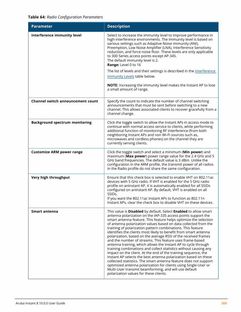
Aruba Instant 8.10.0.0 User Guide 369
Parameter Description
Interference immunity level Select to increase the immunity level to improve performance inhigh-interference environments. The Immunity level is based onvarious settings such as Adaptive Noise Immunity (ANI),Preemption, Low Noise Amplifier (LNA), Interference Sensitivityreduction, and force noise floor. These levels are only applicableto 300 Series access points except AP-345.The default immunity level is 2.Range: Level 0 to 16
The list of levels and their settings is described in the InterferenceImmunity Levels table below.
NOTE: Increasing the immunity level makes the Instant AP to losea small amount of range.
Channel switch announcement count Specify the count to indicate the number of channel switchingannouncements that must be sent before switching to a newchannel. This allows associated clients to recover gracefully from achannel change.
Background spectrum monitoring Click the toggle switch to allow the Instant APs in access mode tocontinue with normal access service to clients, while performingadditional function of monitoring RF interference (from bothneighboring Instant APs and non Wi-Fi sources such as,microwaves and cordless phones) on the channel they arecurrently serving clients.
Customize ARM power range Click the toggle switch and select a minimum (Min power) andmaximum (Max power) power range value for the 2.4 GHz and 5GHz band frequencies. The default value is 3 dBm. Unlike theconfiguration in the ARM profile, the transmit power of all radiosin the Radio profile do not share the same configuration.
Very high throughput Ensure that this check box is selected to enable VHT on 802.11acdevices with 5 GHz radio. If VHT is enabled for the 5 GHz radioprofile on anInstant AP, it is automatically enabled for all SSIDsconfigured on anInstant AP. By default, VHT is enabled on allSSIDs.If you want the 802.11ac Instant APs to function as 802.11nInstant APs, clear the check box to disable VHT on these devices.
Smart antenna This value is Disabled by default. Select Enabled to allow smartantenna polarization on the IAP-335 access points support thesmart antenna feature. This feature helps optimize the selectionof antenna polarization values based on data collected from thetraining of polarization pattern combinations. This featureidentifies the clients most likely to benefit from smart antennapolarization, based on the average RSSI of the received framesand the number of streams. This feature uses frame-basedantenna training, which allows the Instant AP to cycle throughtraining combinations and collect statistics without causing anyimpact on the client. At the end of the training sequence, theInstant AP selects the best antenna polarization based on thesecollected statistics. The smart antenna feature does not supportoptimized antenna polarization for clients using Single-User orMulti-User transmit beamforming, and will use defaultpolarization values for these clients.
Table 64: Radio Configuration Parameters
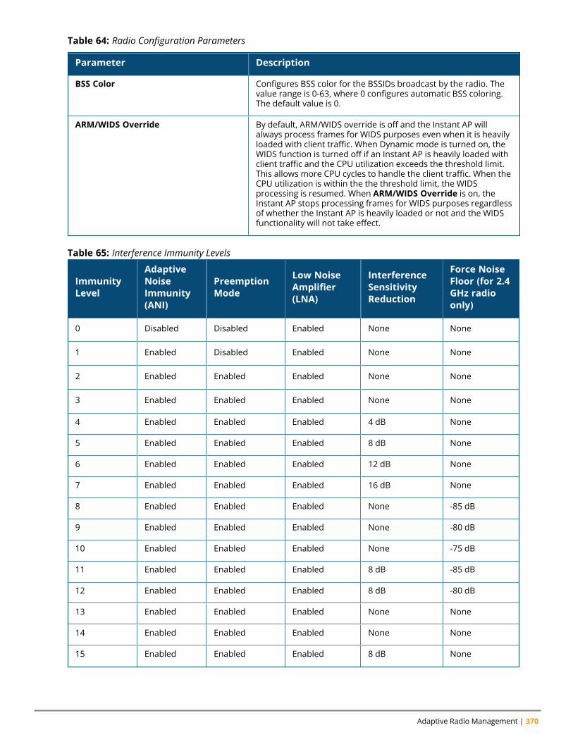
Adaptive Radio Management | 370
Parameter Description
BSS Color Configures BSS color for the BSSIDs broadcast by the radio. Thevalue range is 0-63, where 0 configures automatic BSS coloring.The default value is 0.
ARM/WIDS Override By default, ARM/WIDS override is off and the Instant AP willalways process frames for WIDS purposes even when it is heavilyloaded with client traffic. When Dynamic mode is turned on, theWIDS function is turned off if an Instant AP is heavily loaded withclient traffic and the CPU utilization exceeds the threshold limit.This allows more CPU cycles to handle the client traffic. When theCPU utilization is within the the threshold limit, the WIDSprocessing is resumed. When ARM/WIDS Override is on, theInstant AP stops processing frames for WIDS purposes regardlessof whether the Instant AP is heavily loaded or not and the WIDSfunctionality will not take effect.
Table 64: Radio Configuration Parameters
ImmunityLevel
AdaptiveNoiseImmunity(ANI)
PreemptionMode
Low NoiseAmplifier(LNA)
InterferenceSensitivityReduction
Force NoiseFloor (for 2.4GHz radioonly)
0 Disabled Disabled Enabled None None
1 Enabled Disabled Enabled None None
2 Enabled Enabled Enabled None None
3 Enabled Enabled Enabled None None
4 Enabled Enabled Enabled 4 dB None
5 Enabled Enabled Enabled 8 dB None
6 Enabled Enabled Enabled 12 dB None
7 Enabled Enabled Enabled 16 dB None
8 Enabled Enabled Enabled None -85 dB
9 Enabled Enabled Enabled None -80 dB
10 Enabled Enabled Enabled None -75 dB
11 Enabled Enabled Enabled 8 dB -85 dB
12 Enabled Enabled Enabled 8 dB -80 dB
13 Enabled Enabled Enabled None None
14 Enabled Enabled Enabled None None
15 Enabled Enabled Enabled 8 dB None
Table 65: Interference Immunity Levels
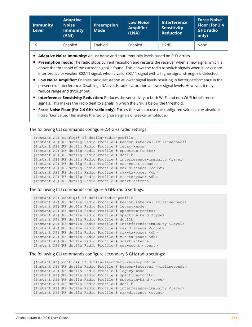
Aruba Instant 8.10.0.0 User Guide 371
ImmunityLevel
AdaptiveNoiseImmunity(ANI)
PreemptionMode
Low NoiseAmplifier(LNA)
InterferenceSensitivityReduction
Force NoiseFloor (for 2.4GHz radioonly)
16 Enabled Enabled Enabled 16 dB None
n Adaptive Noise Immunity: Adjust noise and spur immunity levels based on PHY errors.n Preemption mode: The radio stops current reception and restarts the receiver when a new signal which is
above the threshold of the current signal is found. This allows the radio to switch signals when it locks ontointerference or weaker 802.11 signal, when a valid 802.11 signal with a higher signal strength is detected.
n Low Noise Amplifier: Enables radio saturation at lower signal levels resulting in better performance in thepresence of interference. Disabling LNA avoids radio saturation at lower signal levels. However, it mayreduce range and throughput.
n Interference Sensitivity Reduction: Reduces the senstitivity to both Wi-Fi and non Wi-Fi interferencesignals. This makes the radio deaf to signals in which the SNR is below the threshold.
n Force Noise Floor (for 2.4 GHz radio only): Forces the radio to use the configured value as the absolutenoise floor value. This makes the radio ignore signals of weaker amplitude.
The following CLI commands configure 2.4 GHz radio settings:
(Instant AP)(config)# rf dot11g-radio-profile(Instant AP)(RF dot11g Radio Profile)# beacon-interval <milliseconds>(Instant AP)(RF dot11g Radio Profile)# legacy-mode(Instant AP)(RF dot11g Radio Profile)# spectrum-monitor(Instant AP)(RF dot11g Radio Profile)# dot11h(Instant AP)(RF dot11g Radio Profile)# interference-immunity <level>(Instant AP)(RF dot11g Radio Profile)# csa-count <count>(Instant AP)(RF dot11g Radio Profile)# max-distance <count>(Instant AP)(RF dot11g Radio Profile)# max-tx-power <db>(Instant AP)(RF dot11g Radio Profile)# min-tx-power <db>(Instant AP)(RF dot11g Radio Profile)# smart-antenna
The following CLI commands configure 5 GHz radio settings:
(Instant AP)(config)# rf dot11a-radio-profile(Instant AP)(RF dot11a Radio Profile)# beacon-interval <milliseconds>(Instant AP)(RF dot11a Radio Profile)# legacy-mode(Instant AP)(RF dot11a Radio Profile)# spectrum-monitor(Instant AP)(RF dot11a Radio Profile)# spectrum-band <type>(Instant AP)(RF dot11a Radio Profile)# dot11h(Instant AP)(RF dot11a Radio Profile)# interference-immunity <level>(Instant AP)(RF dot11a Radio Profile)# max-distance <count>(Instant AP)(RF dot11a Radio Profile)# max-tx-power <db>(Instant AP)(RF dot11a Radio Profile)# min-tx-power <db>(Instant AP)(RF dot11a Radio Profile)# smart-antenna(Instant AP)(RF dot11a Radio Profile)# csa-count <count>
The following CLI commands configure secondary 5 GHz radio settings:
(Instant AP)(config)# rf dot11a-secondary-radio-profile(Instant AP)(RF dot11a Radio Profile)# beacon-interval <milliseconds>(Instant AP)(RF dot11a Radio Profile)# legacy-mode(Instant AP)(RF dot11a Radio Profile)# spectrum-monitor(Instant AP)(RF dot11a Radio Profile)# spectrum-band <type>(Instant AP)(RF dot11a Radio Profile)# dot11h(Instant AP)(RF dot11a Radio Profile)# interference-immunity <level>(Instant AP)(RF dot11a Radio Profile)# max-distance <count>
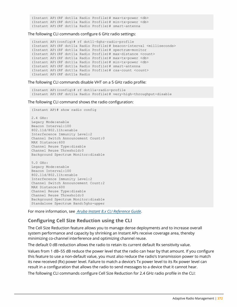
Adaptive Radio Management | 372
(Instant AP)(RF dot11a Radio Profile)# max-tx-power <db>(Instant AP)(RF dot11a Radio Profile)# min-tx-power <db>(Instant AP)(RF dot11a Radio Profile)# smart-antenna
The following CLI commands configure 6 GHz radio settings:
(Instant AP)(config)# rf dot11-6ghz-radio-profile(Instant AP)(RF dot11a Radio Profile)# beacon-interval <milliseconds>(Instant AP)(RF dot11a Radio Profile)# spectrum-monitor(Instant AP)(RF dot11a Radio Profile)# max-distance <count>(Instant AP)(RF dot11a Radio Profile)# max-tx-power <db>(Instant AP)(RF dot11a Radio Profile)# min-tx-power <db>(Instant AP)(RF dot11a Radio Profile)# smart-antenna(Instant AP)(RF dot11a Radio Profile)# csa-count <count>(Instant AP)(RF dot11a Radio
The following CLI commands disable VHT on a 5 GHz radio profile:
(Instant AP)(config)# rf dot11a-radio-profile(Instant AP)(RF dot11a Radio Profile)# very-high-throughput-disable
The following CLI command shows the radio configuration:
(Instant AP)# show radio config
2.4 GHz:Legacy Mode:enableBeacon Interval:100802.11d/802.11h:enableInterference Immunity Level:2Channel Switch Announcement Count:0MAX Distance:600Channel Reuse Type:disableChannel Reuse Threshold:0Background Spectrum Monitor:disable
5.0 GHz:Legacy Mode:enableBeacon Interval:100802.11d/802.11h:enableInterference Immunity Level:2Channel Switch Announcement Count:2MAX Distance:600Channel Reuse Type:disableChannel Reuse Threshold:0Background Spectrum Monitor:disableStandalone Spectrum Band:5ghz-upper
For more information, see Aruba Instant 8.x CLI Reference Guide.
Configuring Cell Size Reduction using the CLIThe Cell Size Reduction feature allows you to manage dense deployments and to increase overallsystem performance and capacity by shrinking an Instant APs receive coverage area, therebyminimizing co-channel interference and optimizing channel reuse.
The default 0 dB reduction allows the radio to retain its current default Rx sensitivity value.
Values from 1 dB–55 dB reduce the power level that the radio can hear by that amount. If you configurethis feature to use a non-default value, you must also reduce the radio’s transmission power to matchits new received (Rx) power level. Failure to match a device’s Tx power level to its Rx power level canresult in a configuration that allows the radio to send messages to a device that it cannot hear.
The following CLI commands configure Cell Size Reduction for 2.4 GHz radio profile in the CLI:
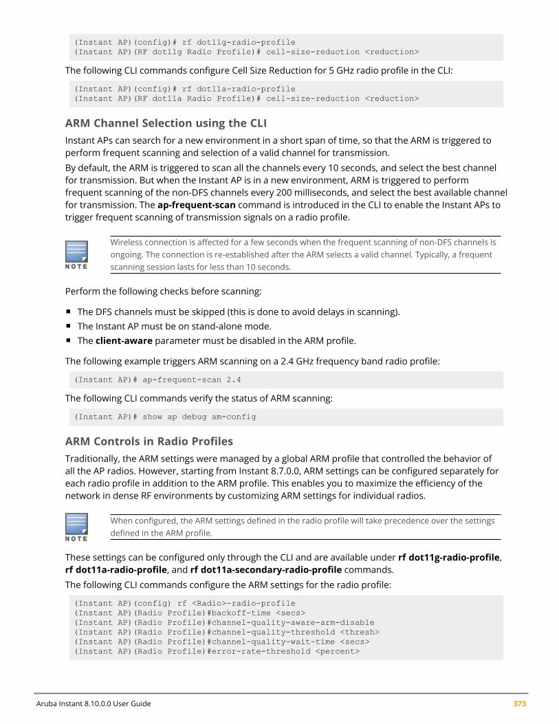
Aruba Instant 8.10.0.0 User Guide 373
(Instant AP)(config)# rf dot11g-radio-profile(Instant AP)(RF dot11g Radio Profile)# cell-size-reduction <reduction>
The following CLI commands configure Cell Size Reduction for 5 GHz radio profile in the CLI:
(Instant AP)(config)# rf dot11a-radio-profile(Instant AP)(RF dot11a Radio Profile)# cell-size-reduction <reduction>
ARM Channel Selection using the CLIInstant APs can search for a new environment in a short span of time, so that the ARM is triggered toperform frequent scanning and selection of a valid channel for transmission.
By default, the ARM is triggered to scan all the channels every 10 seconds, and select the best channelfor transmission. But when the Instant AP is in a new environment, ARM is triggered to performfrequent scanning of the non-DFS channels every 200 milliseconds, and select the best available channelfor transmission. The ap-frequent-scan command is introduced in the CLI to enable the Instant APs totrigger frequent scanning of transmission signals on a radio profile.
Wireless connection is affected for a few seconds when the frequent scanning of non-DFS channels isongoing. The connection is re-established after the ARM selects a valid channel. Typically, a frequentscanning session lasts for less than 10 seconds.
Perform the following checks before scanning:
n The DFS channels must be skipped (this is done to avoid delays in scanning).n The Instant AP must be on stand-alone mode.n The client-aware parameter must be disabled in the ARM profile.
The following example triggers ARM scanning on a 2.4 GHz frequency band radio profile:
(Instant AP)# ap-frequent-scan 2.4
The following CLI commands verify the status of ARM scanning:
(Instant AP)# show ap debug am-config
ARM Controls in Radio ProfilesTraditionally, the ARM settings were managed by a global ARM profile that controlled the behavior ofall the AP radios. However, starting from Instant 8.7.0.0, ARM settings can be configured separately foreach radio profile in addition to the ARM profile. This enables you to maximize the efficiency of thenetwork in dense RF environments by customizing ARM settings for individual radios.
When configured, the ARM settings defined in the radio profile will take precedence over the settingsdefined in the ARM profile.
These settings can be configured only through the CLI and are available under rf dot11g-radio-profile,rf dot11a-radio-profile, and rf dot11a-secondary-radio-profile commands.
The following CLI commands configure the ARM settings for the radio profile:
(Instant AP)(config) rf <Radio>-radio-profile(Instant AP)(Radio Profile)#backoff-time <secs>(Instant AP)(Radio Profile)#channel-quality-aware-arm-disable(Instant AP)(Radio Profile)#channel-quality-threshold <thresh>(Instant AP)(Radio Profile)#channel-quality-wait-time <secs>(Instant AP)(Radio Profile)#error-rate-threshold <percent>
Adaptive Radio Management | 374
(Instant AP)(Radio Profile)#error-rate-wait-time <secs>(Instant AP)(Radio Profile)#ideal-coverage-index(Instant AP)(Radio Profile)#scanning-disable
For more information on these settings, see theAruba Instant 8.7.0.x CLI Reference Guide.
Support for channels 169 and 173 on Outdoor Instant APStarting from Aruba Instant 8.4.0.0, 5 GHz band on an outdoor Instant AP includes the 169 and 173channels. These channels are currently supported only in India.
Zero-Wait DFSDynamic Frequency Selection (DFS), a mandate for radio systems operating in the 5 GHz band toidentify and avoid interference with Radar systems now supports zero-wait feature. When an 802.11radio detects radar, it vacates its channel and switches to another channel. This might result in a oneminute outage. The zero wait DFS feature provides seamless change of channels and avoids the oneminute outage. Hence, stations do not lose its connectivity when an AP moves to a DFS channel.
Mesh APs do not support zero-wait DFS feature.
510 Series, 570 Series, AP-577, AP-518, AP-575EX, AP-577EX, 530 Series, 550 Series APs support zero-wait DFS feature.
Chapter 21DPI and Application Visibility
DPI and Application VisibilityThis chapter provides the following information:
n DPI on page 375n Enabling Application Visibility on page 375n Application Visibility on page 376n Enabling URL Visibility on page 376n Configuring ACL Rules for Application and Application Categories on page 377n Configuring Web Policy Enforcement Service on page 380
DPIAppRF is Aruba's custom-built Layer 7 firewall capability. It consists of an onboard DPI and a cloud-basedWeb Policy Enforcement service that allows creating firewall policies based on types of application. TheWPE capabilities require the Instant AP to have a WPE subscription. For more information onsubscription, contact the Aruba Sales Team.
Instant APs with DPI capability analyze data packets to identify applications in use and allow you tocreate access rules to determine client access to applications, application categories, web categories,and website URLs based on web reputation. You can also define traffic-shaping policies such asbandwidth control and QoS per application for client roles. For example, you can block bandwidth-monopolizing applications on a guest role within an enterprise.
The AppRF feature provides application visibility for analyzing client traffic flow. Instant APs support thepower of both in-device packet flow identification and dynamically updated cloud-based webcategorization.
Enabling Application VisibilityEnabling AppRF visibility allows you to view the AppRF statistics for an Instant AP or the clientsassociated with an Instant AP. Full URL visibility for HTTP sessions fed to ALE is exposed as northboundAPIs which can be consumed by URL analytical engines for advanced client URL data mining andanalytics.
The webcc statistics are also periodically sent to Aruba Central. This includes the URL hostname,Application ID, Application category, Web ID, and Web Reputation information. This function is currentlysupported only for IPv4 addresses.
The following procedure describes how to enable AppRF visibility by using the WebUI:
1. Navigate to the Configuration > System > General section.2. Select All from the AppRF visibility drop-down list to view both application and web categories
charts or select either App orWebCC to view their DPI graphs separately.3. Click Save.
The following CLI command enables AppRF visibility:
Aruba Instant 8.10.0.0 User Guide 375
DPI and Application Visibility | 376
(Instant AP)(config)# dpi [app|webcc]
The following CLI command shows all the current webcc URL prefix entries:
(Instant AP)#show dpi webcc-url-prefix-table [referenced|unreferenced]
Application VisibilityThe AppRF graphs are based on DPI application and Web Policy Enforcement service, which provideapplication traffic summary for the client devices associated with an Instant AP. The AppRF link abovethe activity panel of the dashboard is displayed only if AppRF visibility is enabled in the WebUI.
The AppRF dashboard presents four different graph areas with data graphs on all client traffic andcontent filters based on App Category, Web Category, and Web Reputation. Click each category to viewthe real-time client traffic data or usage trend in the last 15 minutes or 1 minute.
The permit and denymonitoring tabs in the All Traffic and Web Content sections provide enforcementvisibility support.
n Permit represents the allowed or permitted traffic on the Instant AP.n Deny represents all the blocked URLs and traffic .
Application Categories ChartThe application categories chart displays details on the client traffic towards the application categories.By clicking the rectangle area, you can view the graphs and toggle between the chart and list views.
Applications ChartThe applications chart displays details on the client traffic towards the applications. By clicking therectangular area, you can view the graphs and toggle between the chart and list views.
Web Categories ChartsThe web categories chart displays details about the client traffic to the web categories. By clicking therectangle area, you can view the graphs and toggle between the chart and list views.
Web Reputation ChartsThe web reputation chart displays details about the client traffic to the URLs that are assigned securityratings. By clicking in the rectangle area, you can view the graphs and toggle between the chart and listviews.
Enabling URL VisibilityEnabling URL visibility allows the Instant AP to extract the full URL information of the HTTP and HTTPSsessions and periodically log them on the ALE server. Full URL visibility for HTTP sessions fed to ALE areexposed as Northbound APIs, and are used by URL analytical engines for advanced client URL datamining and analysis.
The following procedure describes how to enable URL visibility by using the WebUI:
1. Navigate to Configuration > System > General page.2. Toggle the URL visibility switch to enable.3. Click Save.
Aruba Instant 8.10.0.0 User Guide 377
The following CLI command enables URL visibility:
(Instant AP)(config)# url-visibility
Instant APs extract DPI web-based URL sessions and provide the statistics to ArubaCentral.ArubaCentral compiles this information with the AppRF feed to obtain complete details.
Configuring ACL Rules for Application and ApplicationCategoriesThis section describes the procedure for configuring access rules based on application and applicationcategories. The Application and Application rules utilize the onboard DPI engine.
n For information on configuring access rules to control access to network services, see ConfiguringACL Rules for Network Services on page 220.
n For information on configuring access rules based on web categories and web reputation, seeConfiguring Web Policy Enforcement Service on page 380.
The following procedure describes how to configure ACL rules for a user role using the WebUI:
1. Navigate to Configuration > Security > Roles section. You can also configure access rules for awired or wireless network profile by following the steps mentioned below:
a. Navigate to Configuration > Networks.
b. Select the WLAN or the Wired profile and edit the profile as required.
c. Go to the Access tab.
2. In the Roles section, select the role for which you want to configure the access rules.3. In the Access Rules for <network> section, click + to add a new rule. The New rule window is
displayed.4. Ensure that the rule type is set to Access control.5. To configure access to applications or application category, select a service from the following list:
a. Application
b. Application category
6. Based on the selected service category, configure the parameters described in the Access RuleConfiguration Parameters table below.
7. Click OK.8. Click Save.
ServiceCategory Description
Application Select the applications to which you want to allow or deny access.
Applicationcategory
Select any of the following application categories to which you want to allow or denyaccess:
Table 66: Access Rule Configuration Parameters
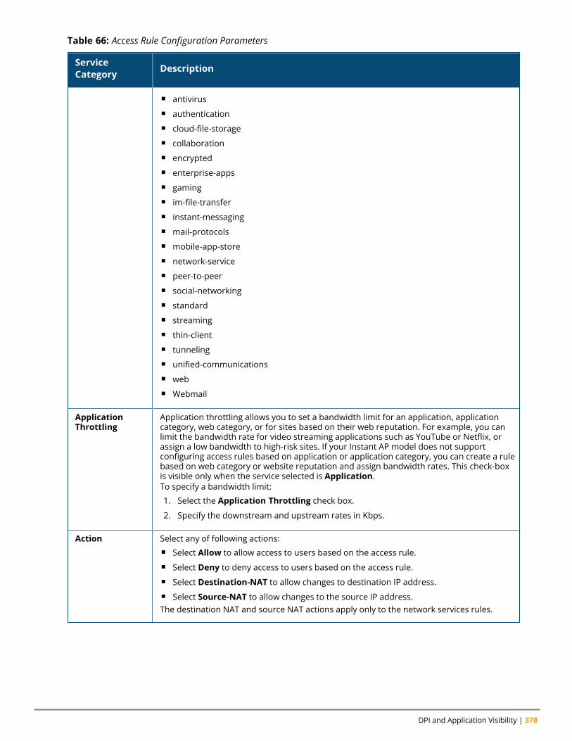
DPI and Application Visibility | 378
ServiceCategory Description
n antivirusn authenticationn cloud-file-storagen collaborationn encryptedn enterprise-appsn gamingn im-file-transfern instant-messagingn mail-protocolsn mobile-app-storen network-servicen peer-to-peern social-networkingn standardn streamingn thin-clientn tunnelingn unified-communicationsn webn Webmail
ApplicationThrottling
Application throttling allows you to set a bandwidth limit for an application, applicationcategory, web category, or for sites based on their web reputation. For example, you canlimit the bandwidth rate for video streaming applications such as YouTube or Netflix, orassign a low bandwidth to high-risk sites. If your Instant AP model does not supportconfiguring access rules based on application or application category, you can create a rulebased on web category or website reputation and assign bandwidth rates. This check-boxis visible only when the service selected is Application.To specify a bandwidth limit:
1. Select the Application Throttling check box.
2. Specify the downstream and upstream rates in Kbps.
Action Select any of following actions:n Select Allow to allow access to users based on the access rule.n Select Deny to deny access to users based on the access rule.n Select Destination-NAT to allow changes to destination IP address.n Select Source-NAT to allow changes to the source IP address.The destination NAT and source NAT actions apply only to the network services rules.
Table 66: Access Rule Configuration Parameters
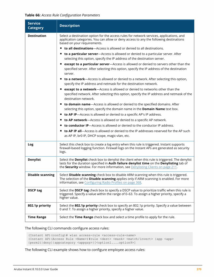
Aruba Instant 8.10.0.0 User Guide 379
ServiceCategory Description
Destination Select a destination option for the access rules for network services, applications, andapplication categories. You can allow or deny access to any the following destinationsbased on your requirements.n to all destinations—Access is allowed or denied to all destinations.n to a particular server—Access is allowed or denied to a particular server. After
selecting this option, specify the IP address of the destination server.n except to a particular server—Access is allowed or denied to servers other than the
specified server. After selecting this option, specify the IP address of the destinationserver.
n to a network—Access is allowed or denied to a network. After selecting this option,specify the IP address and netmask for the destination network.
n except to a network—Access is allowed or denied to networks other than thespecified network. After selecting this option, specify the IP address and netmask of thedestination network.
n to domain name—Access is allowed or denied to the specified domains. Afterselecting this option, specify the domain name in the Domain Name text box.
n to AP IP—Access is allowed or denied to a specific AP's IP address.n to AP network—Access is allowed or denied to a specific AP network.n to conductor IP—Access is allowed or denied to the conductor IP address.n to AP IP all—Access is allowed or denied to the IP addresses reserved for the AP such
as AP IP, br0 IP, DHCP scope, magic-vlan, etc.
Log Select this check box to create a log entry when this rule is triggered. Instant supportsfirewall-based logging function. Firewall logs on the Instant APs are generated as securitylogs.
Denylist Select the Denylist check box to denylist the client when this rule is triggered. The denylistlasts for the duration specified in Auth failure denylist time on the Denylisting tab ofthe Security window. For more information, see Denylisting Clients on page 211.
Disable scanning Select Disable scanning check box to disable ARM scanning when this rule is triggered.The selection of the Disable scanning applies only if ARM scanning is enabled. For moreinformation, see Configuring Radio Profiles on page 368.
DSCP tag Select the DSCP tag check box to specify a DSCP value to prioritize traffic when this rule istriggered. Specify a value within the range of 0–63. To assign a higher priority, specify ahigher value.
802.1p priority Select the 802.1p priority check box to specify an 802.1p priority. Specify a value between0 and 7. To assign a higher priority, specify a higher value.
Time Range Select the Time Range check box and select a time profile to apply for the rule.
Table 66: Access Rule Configuration Parameters
The following CLI commands configure access rules:
(Instant AP)(config)# wlan access-rule <access-rule-name>(Instant AP)(Access Rule <Name>)#rule <dest> <mask> <match/invert> {app <app>{permit|deny}|appcategory <appgrp>}[<option1....option9>]
The following CLI example shows how to configure employee access rules:
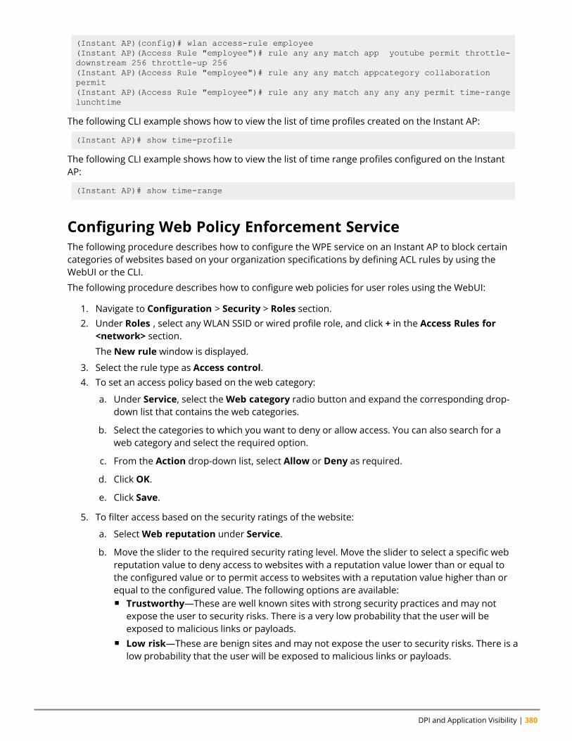
DPI and Application Visibility | 380
(Instant AP)(config)# wlan access-rule employee(Instant AP)(Access Rule "employee")# rule any any match app youtube permit throttle-downstream 256 throttle-up 256(Instant AP)(Access Rule "employee")# rule any any match appcategory collaborationpermit(Instant AP)(Access Rule "employee")# rule any any match any any any permit time-rangelunchtime
The following CLI example shows how to view the list of time profiles created on the Instant AP:
(Instant AP)# show time-profile
The following CLI example shows how to view the list of time range profiles configured on the InstantAP:
(Instant AP)# show time-range
Configuring Web Policy Enforcement ServiceThe following procedure describes how to configure the WPE service on an Instant AP to block certaincategories of websites based on your organization specifications by defining ACL rules by using theWebUI or the CLI.
The following procedure describes how to configure web policies for user roles using the WebUI:
1. Navigate to Configuration > Security > Roles section.2. Under Roles , select any WLAN SSID or wired profile role, and click + in the Access Rules for
<network> section.
The New rule window is displayed.
3. Select the rule type as Access control.4. To set an access policy based on the web category:
a. Under Service, select theWeb category radio button and expand the corresponding drop-down list that contains the web categories.
b. Select the categories to which you want to deny or allow access. You can also search for aweb category and select the required option.
c. From the Action drop-down list, select Allow or Deny as required.
d. Click OK.
e. Click Save.
5. To filter access based on the security ratings of the website:
a. SelectWeb reputation under Service.
b. Move the slider to the required security rating level. Move the slider to select a specific webreputation value to deny access to websites with a reputation value lower than or equal tothe configured value or to permit access to websites with a reputation value higher than orequal to the configured value. The following options are available:n Trustworthy—These are well known sites with strong security practices and may not
expose the user to security risks. There is a very low probability that the user will beexposed to malicious links or payloads.
n Low risk—These are benign sites and may not expose the user to security risks. There is alow probability that the user will be exposed to malicious links or payloads.

Aruba Instant 8.10.0.0 User Guide 381
n Moderate risk—These are generally benign sites, but may pose a security risk. There issome probability that the user will be exposed to malicious links or payloads.
n Suspicious—These are suspicious sites. There is a higher than average probability that theuser will be exposed to malicious links or payloads.
n High risk—These are high-risk sites. There is a high probability that the user will beexposed to malicious links or payloads.
c. From the Action drop-down list, select Allow or Deny as required.
NOTE: For a complete list of categories and information about each of these categories, visit theBrightCloud® Security Services web page.
6. To set a bandwidth limit based on web category or web reputation score, select the ApplicationThrottling check box and specify the downstream and upstream rates in Kbps. For example, youcan set a higher bandwidth for trusted sites and a low bandwidth rate for high-risk sites.
7. If required, select the following check boxes :n Logn Denylistn DSCP tagn Disable scanningn 802.1p priority
8. Click OK.9. Click Save.
Service Category Description
Web category Select any of the following web categories to which you want to allowor deny access:n real-estaten computer-and-internet-securityn financial-servicesn business-and-economyn computer-and-internet-infon auctionsn shoppingn cult-and-occultn traveln abused-drugsn adult-and-pornographyn home-and-gardenn militaryn social-networking-webn dead-sitesn individual-stock-advice-and-tools
n online-greeting-cardsn sportsn swimsuits-and-intimate-appareln questionablen kidsn hate-and-racismn personal-storagen violencen keyloggers-and-monitoringn search-enginesn internet-portalsn web-advertisementsn cheatingn grossn web-based-emailn malware-sites
Table 67: Access Rule Configuration Parameters
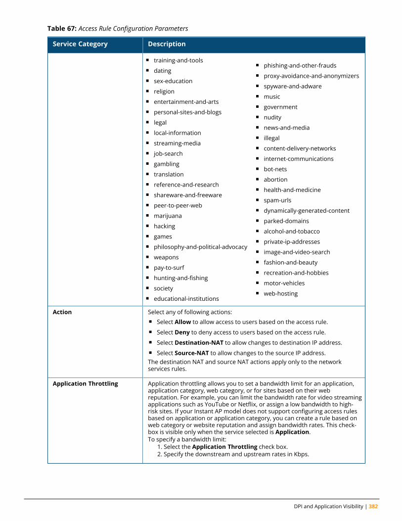
DPI and Application Visibility | 382
Service Category Description
n training-and-toolsn datingn sex-educationn religionn entertainment-and-artsn personal-sites-and-blogsn legaln local-informationn streaming-median job-searchn gamblingn translationn reference-and-researchn shareware-and-freewaren peer-to-peer-webn marijuanan hackingn gamesn philosophy-and-political-advocacyn weaponsn pay-to-surfn hunting-and-fishingn societyn educational-institutions
n phishing-and-other-fraudsn proxy-avoidance-and-anonymizersn spyware-and-adwaren musicn governmentn nudityn news-and-median illegaln content-delivery-networksn internet-communicationsn bot-netsn abortionn health-and-medicinen spam-urlsn dynamically-generated-contentn parked-domainsn alcohol-and-tobaccon private-ip-addressesn image-and-video-searchn fashion-and-beautyn recreation-and-hobbiesn motor-vehiclesn web-hosting
Action Select any of following actions:n Select Allow to allow access to users based on the access rule.n Select Deny to deny access to users based on the access rule.n Select Destination-NAT to allow changes to destination IP address.n Select Source-NAT to allow changes to the source IP address.The destination NAT and source NAT actions apply only to the networkservices rules.
Application Throttling Application throttling allows you to set a bandwidth limit for an application,application category, web category, or for sites based on their webreputation. For example, you can limit the bandwidth rate for video streamingapplications such as YouTube or Netflix, or assign a low bandwidth to high-risk sites. If your Instant AP model does not support configuring access rulesbased on application or application category, you can create a rule based onweb category or website reputation and assign bandwidth rates. This check-box is visible only when the service selected is Application.To specify a bandwidth limit:
1. Select the Application Throttling check box.2. Specify the downstream and upstream rates in Kbps.
Table 67: Access Rule Configuration Parameters
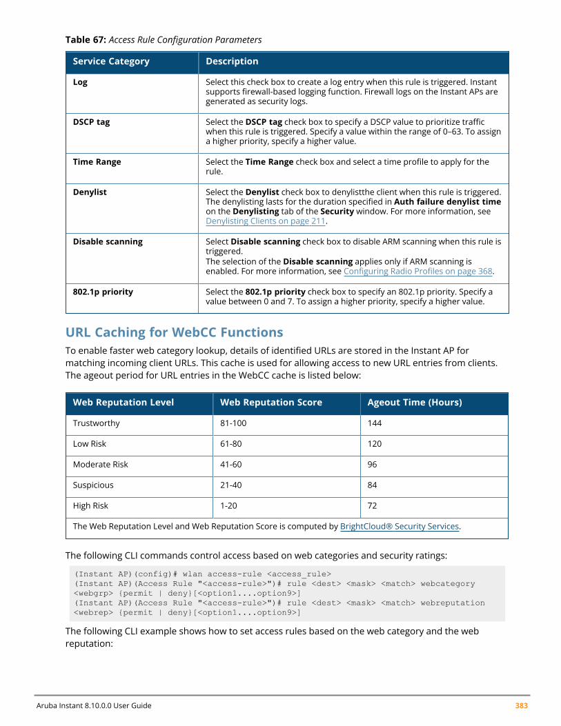
Aruba Instant 8.10.0.0 User Guide 383
Service Category Description
Log Select this check box to create a log entry when this rule is triggered. Instantsupports firewall-based logging function. Firewall logs on the Instant APs aregenerated as security logs.
DSCP tag Select the DSCP tag check box to specify a DSCP value to prioritize trafficwhen this rule is triggered. Specify a value within the range of 0–63. To assigna higher priority, specify a higher value.
Time Range Select the Time Range check box and select a time profile to apply for therule.
Denylist Select the Denylist check box to denylistthe client when this rule is triggered.The denylisting lasts for the duration specified in Auth failure denylist timeon the Denylisting tab of the Security window. For more information, seeDenylisting Clients on page 211.
Disable scanning Select Disable scanning check box to disable ARM scanning when this rule istriggered.The selection of the Disable scanning applies only if ARM scanning isenabled. For more information, see Configuring Radio Profiles on page 368.
802.1p priority Select the 802.1p priority check box to specify an 802.1p priority. Specify avalue between 0 and 7. To assign a higher priority, specify a higher value.
Table 67: Access Rule Configuration Parameters
URL Caching for WebCC FunctionsTo enable faster web category lookup, details of identified URLs are stored in the Instant AP formatching incoming client URLs. This cache is used for allowing access to new URL entries from clients.The ageout period for URL entries in the WebCC cache is listed below:
Web Reputation Level Web Reputation Score Ageout Time (Hours)
Trustworthy 81-100 144
Low Risk 61-80 120
Moderate Risk 41-60 96
Suspicious 21-40 84
High Risk 1-20 72
The Web Reputation Level and Web Reputation Score is computed by BrightCloud® Security Services.
The following CLI commands control access based on web categories and security ratings:
(Instant AP)(config)# wlan access-rule <access_rule>(Instant AP)(Access Rule "<access-rule>")# rule <dest> <mask> <match> webcategory<webgrp> {permit | deny}[<option1....option9>](Instant AP)(Access Rule "<access-rule>")# rule <dest> <mask> <match> webreputation<webrep> {permit | deny}[<option1....option9>]
The following CLI example shows how to set access rules based on the web category and the webreputation:

DPI and Application Visibility | 384
(Instant AP)(config)# wlan access-rule URLFilter(Instant AP)(Access Rule "URLFilter")# rule any any match webcategory gambling deny(Instant AP)(Access Rule "URLFilter")# rule any any match webcategory training-and-tools permit(Instant AP)(Access Rule "URLFilter")# rule any any match webreputation suspicious-sites deny
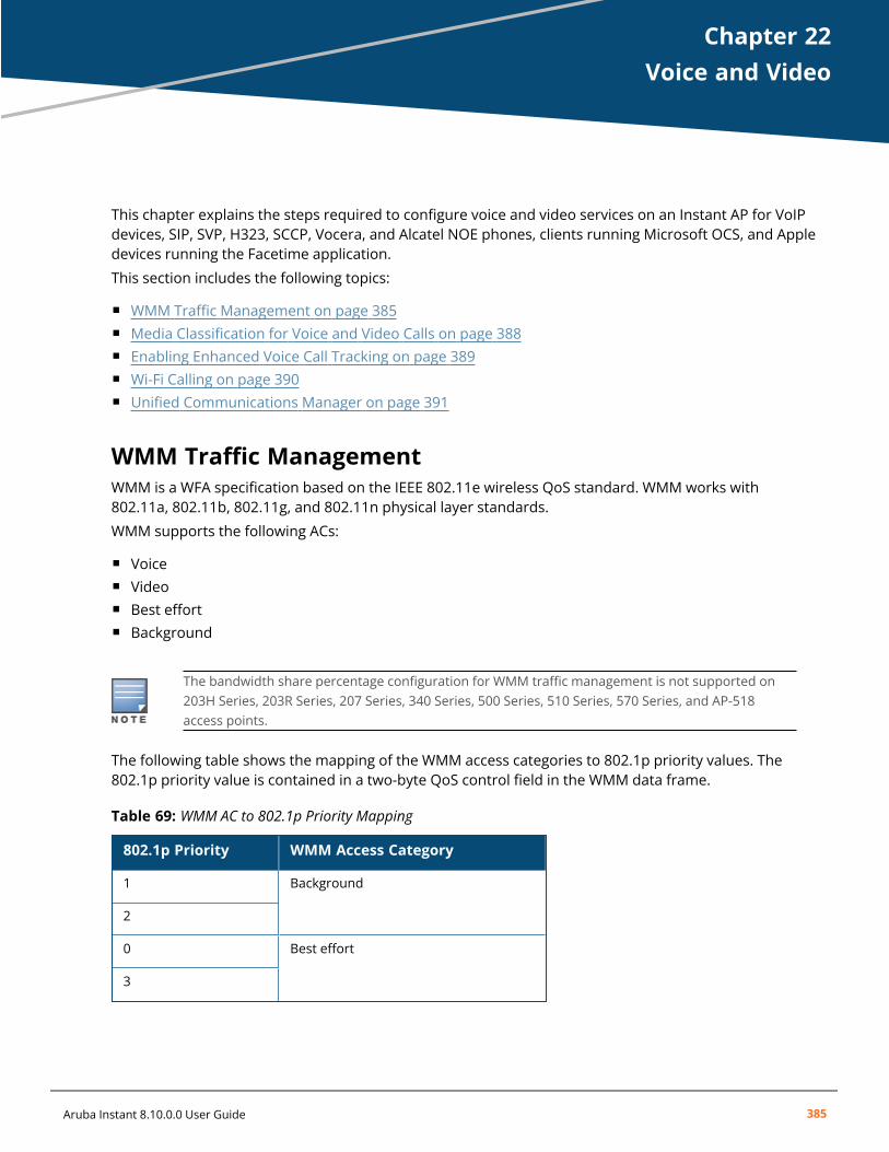
Chapter 22Voice and Video
Voice and VideoThis chapter explains the steps required to configure voice and video services on an Instant AP for VoIPdevices, SIP, SVP, H323, SCCP, Vocera, and Alcatel NOE phones, clients running Microsoft OCS, and Appledevices running the Facetime application.
This section includes the following topics:
n WMM Traffic Management on page 385n Media Classification for Voice and Video Calls on page 388n Enabling Enhanced Voice Call Tracking on page 389n Wi-Fi Calling on page 390n Unified Communications Manager on page 391
WMM Traffic ManagementWMM is a WFA specification based on the IEEE 802.11e wireless QoS standard. WMM works with802.11a, 802.11b, 802.11g, and 802.11n physical layer standards.
WMM supports the following ACs:
n Voicen Videon Best effortn Background
The bandwidth share percentage configuration for WMM traffic management is not supported on203H Series, 203R Series, 207 Series, 340 Series, 500 Series, 510 Series, 570 Series, and AP-518access points.
The following table shows the mapping of the WMM access categories to 802.1p priority values. The802.1p priority value is contained in a two-byte QoS control field in the WMM data frame.
802.1p Priority WMM Access Category
1 Background
2
0 Best effort
3
Table 69: WMM AC to 802.1p Priority Mapping
Aruba Instant 8.10.0.0 User Guide 385
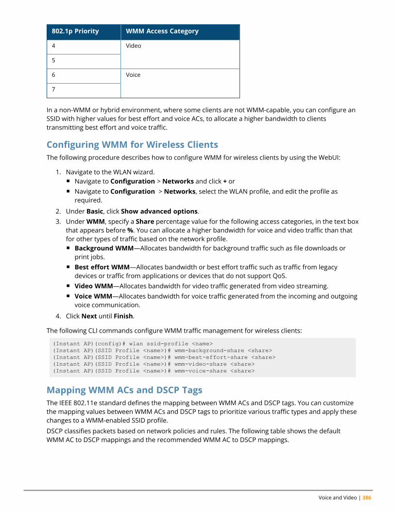
Voice and Video | 386
802.1p Priority WMM Access Category
4 Video
5
6 Voice
7
In a non-WMM or hybrid environment, where some clients are not WMM-capable, you can configure anSSID with higher values for best effort and voice ACs, to allocate a higher bandwidth to clientstransmitting best effort and voice traffic.
Configuring WMM for Wireless ClientsThe following procedure describes how to configure WMM for wireless clients by using the WebUI:
1. Navigate to the WLAN wizard.n Navigate to Configuration > Networks and click + orn Navigate to Configuration > Networks, select the WLAN profile, and edit the profile as
required.
2. Under Basic, click Show advanced options.3. UnderWMM, specify a Share percentage value for the following access categories, in the text box
that appears before%. You can allocate a higher bandwidth for voice and video traffic than thatfor other types of traffic based on the network profile.n Background WMM—Allocates bandwidth for background traffic such as file downloads or
print jobs.n Best effort WMM—Allocates bandwidth or best effort traffic such as traffic from legacy
devices or traffic from applications or devices that do not support QoS.n Video WMM—Allocates bandwidth for video traffic generated from video streaming.n Voice WMM—Allocates bandwidth for voice traffic generated from the incoming and outgoing
voice communication.
4. Click Next until Finish.
The following CLI commands configure WMM traffic management for wireless clients:
(Instant AP)(config)# wlan ssid-profile <name>(Instant AP)(SSID Profile <name>)# wmm-background-share <share>(Instant AP)(SSID Profile <name>)# wmm-best-effort-share <share>(Instant AP)(SSID Profile <name>)# wmm-video-share <share>(Instant AP)(SSID Profile <name>)# wmm-voice-share <share>
Mapping WMM ACs and DSCP TagsThe IEEE 802.11e standard defines the mapping between WMM ACs and DSCP tags. You can customizethe mapping values between WMM ACs and DSCP tags to prioritize various traffic types and apply thesechanges to a WMM-enabled SSID profile.
DSCP classifies packets based on network policies and rules. The following table shows the defaultWMM AC to DSCP mappings and the recommended WMM AC to DSCP mappings.
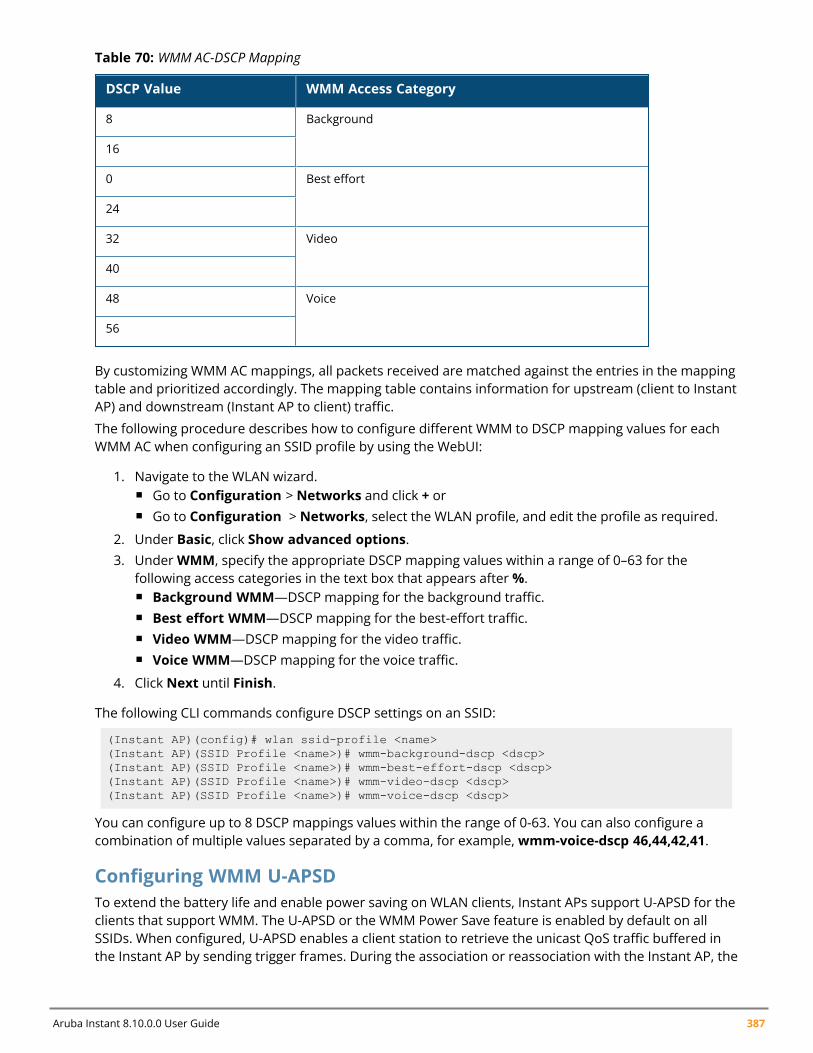
Aruba Instant 8.10.0.0 User Guide 387
DSCP Value WMM Access Category
8 Background
16
0 Best effort
24
32 Video
40
48 Voice
56
Table 70: WMM AC-DSCP Mapping
By customizing WMM AC mappings, all packets received are matched against the entries in the mappingtable and prioritized accordingly. The mapping table contains information for upstream (client to InstantAP) and downstream (Instant AP to client) traffic.
The following procedure describes how to configure different WMM to DSCP mapping values for eachWMM AC when configuring an SSID profile by using the WebUI:
1. Navigate to the WLAN wizard.n Go to Configuration > Networks and click + orn Go to Configuration > Networks, select the WLAN profile, and edit the profile as required.
2. Under Basic, click Show advanced options.3. UnderWMM, specify the appropriate DSCP mapping values within a range of 0–63 for the
following access categories in the text box that appears after%.n Background WMM—DSCP mapping for the background traffic.n Best effort WMM—DSCP mapping for the best-effort traffic.n Video WMM—DSCP mapping for the video traffic.n Voice WMM—DSCP mapping for the voice traffic.
4. Click Next until Finish.
The following CLI commands configure DSCP settings on an SSID:
(Instant AP)(config)# wlan ssid-profile <name>(Instant AP)(SSID Profile <name>)# wmm-background-dscp <dscp>(Instant AP)(SSID Profile <name>)# wmm-best-effort-dscp <dscp>(Instant AP)(SSID Profile <name>)# wmm-video-dscp <dscp>(Instant AP)(SSID Profile <name>)# wmm-voice-dscp <dscp>
You can configure up to 8 DSCP mappings values within the range of 0-63. You can also configure acombination of multiple values separated by a comma, for example,wmm-voice-dscp 46,44,42,41.
Configuring WMM U-APSDTo extend the battery life and enable power saving on WLAN clients, Instant APs support U-APSD for theclients that support WMM. The U-APSD or the WMM Power Save feature is enabled by default on allSSIDs. When configured, U-APSD enables a client station to retrieve the unicast QoS traffic buffered inthe Instant AP by sending trigger frames. During the association or reassociation with the Instant AP, the
Voice and Video | 388
station indicates the WMM Access Categories for which U-APSD is enabled. In the current release,Instant APs support U-APSD on all WMM ACs.
The following CLI commands disable U-APSD on an SSID:
(Instant AP)(config)# wlan ssid-profile <ssid_profile>(Instant AP)(SSID Profile "<ssid_profile>")# wmm-uapsd-disable
The following CLI commands re-enable U-APSD on an SSID:
(Instant AP)(config)# wlan ssid-profile <ssid_profile>(Instant AP)(SSID Profile "<ssid_profile>")# no wmm-uapsd-disable
Media Classification for Voice and Video CallsMedia classification and data prioritization for voice and video calls in Instant is handled automaticallyby the Instant AP's firewall for traffic that is allowed by wired ports and user ACLs. The firewall inspectseach UDP packet, classifies it as either Voice or Video and correspondingly sets a DSCP value for thepacket.
Traffic that is allowed in the network is configured using ACL rules. The Instant AP's firewallautomatically allows voice and video call sessions from Skype for Business and Apple Facetime. For allother Skype for Business and Facetime applications such as desktop sharing and file transfer thecorresponding ports must be opened using ACL rules.
Before media transmission, a VOIP client may initiate a Session Traversal Utilities for NAT (STUN)connectivity check and establishes a session. STUN sessions are subjected to media classification andare marked as RTP or non-RTP traffic. The RTP traffic is classified as either voice or video and re-markedwith the corresponding DSCP values configured in the SSID profile, while the non-RTP traffic isforwarded without re-marking. If data packets are found to be non-compliant with the RTP parametersrequired in the datapath for classification, the session is marked as best effort and no flags or DSCP isset.
The default DSCP values for calls prioritized by media classification is 48 for a voice session and 40for a video session.
If AppRF is enabled on the SSID, alg-rtpmust be explicitly permitted in the ACL to allow voice and videotraffic in the network. The following is the ACL entry to allow RTP traffic and configuring this is highlyrecommended:
(Instant AP)(VOIP-acl)# rule any any match app alg-rtp permit
If AppRF is enabled and alg-rtp is not allowed, no voice or video traffic will flow through the network.
When AppRF is enabled, applications must be permitted explicitly in the ACL using their app IDs for theInstant AP to allow that particular traffic to flow in the network. Allowing application traffic is necessaryfor establishing control sessions only after which a voice or video session is established. To obtain fullinspection and control of voice and video traffic you can populate an ACL permitting particular apps.The following is a recommended ACL configuration for an SSID profile:
(Instant AP)(config)# wlan access-rule VOIP-acl(Instant AP)(VOIP-acl)# rule any any match app alg-facetime permit(Instant AP)(VOIP-acl)# rule any any match app alg-facetime-audio permit(Instant AP)(VOIP-acl)# rule any any match app alg-ftp permit(Instant AP)(VOIP-acl)# rule any any match app alg-h323 permit(Instant AP)(VOIP-acl)# rule any any match app alg-jabber-audio permit
Aruba Instant 8.10.0.0 User Guide 389
(Instant AP)(VOIP-acl)# rule any any match app alg-jabber-desktop-sharing permit(Instant AP)(VOIP-acl)# rule any any match app alg-jabber-mc permit(Instant AP)(VOIP-acl)# rule any any match app alg-jabber-video permit(Instant AP)(VOIP-acl)# rule any any match app alg-noe permit(Instant AP)(VOIP-acl)# rule any any match app alg-rtp permit(Instant AP)(VOIP-acl)# rule any any match app alg-rtsp permit(Instant AP)(VOIP-acl)# rule any any match app alg-sccp permit(Instant AP)(VOIP-acl)# rule any any match app alg-sip permit(Instant AP)(VOIP-acl)# rule any any match app alg-sip-audio permit(Instant AP)(VOIP-acl)# rule any any match app alg-sip-video permit(Instant AP)(VOIP-acl)# rule any any match app alg-skype4b-app-sharing permit(Instant AP)(VOIP-acl)# rule any any match app alg-skype4b-audio permit(Instant AP)(VOIP-acl)# rule any any match app alg-skype4b-desktop-sharing permit(Instant AP)(VOIP-acl)# rule any any match app alg-skype4b-file-transfer permit(Instant AP)(VOIP-acl)# rule any any match app alg-skype4b-secure permit(Instant AP)(VOIP-acl)# rule any any match app alg-skype4b-video permit(Instant AP)(VOIP-acl)# rule any any match app alg-svp permit(Instant AP)(VOIP-acl)# rule any any match app alg-vocera permit(Instant AP)(VOIP-acl)# rule any any match app alg-wifi-calling permit(Instant AP)(VOIP-acl)# end(Instant AP)# commit apply
Alternatively, users can define an higher precedence allow-all rule in the ACL which will allow allapplication, video and voice traffic in the network without having to permit them explicitly. The followingis the ACL configuration to allow all traffic:
(Instant AP)(config)# wlan access-rule allow-all(Instant AP)(allow-all)# rule any any match any any any permit
WebRTC PrioritizationThe webRTC prioritization feature prioritizes the media traffic from webRTC sources. WebRTC is an openframework for the web that enables real time communication using a web browser. WebRTC includesthe fundamental building blocks for high-quality communication on the web like network, audio, andvideo components that are used in voice, video, and chat applications.
WebRTC prioritization provides better end user experience, dashboard visibility of all WebRTCapplications like voice, video, and application sharing, and call quality monitoring for audio calls usingupstream and downstream RTP analysis. Ensure that you enable DPI on the AP before enabling WebRTCprioritization.
Enabling Enhanced Voice Call TrackingAruba Instant provides seamless support for tracking VoIP calls in the network by using SNMP to sendthe location details of the caller to the third-party server. This feature is currently applied for trackingEmergency 911 VoIP calls.
The conductor Instant AP identifies the location from where the VoIP call was placed and sends thedetails of the location to the third-party SNMP server. You must configure the third-party server as anSNMP host and enable SNMP traps to activate the voice call tracking feature on the Instant AP. For moreinformation on configuring a third-party server as an SNMP host, see Configuring SNMP on page 503.
The conductor Instant AP will send the WLSXIAPVOICECLIENTLOCATIONUPDATE SNMP trap under thefollowing scenarios:
n The VoIP call is successful.
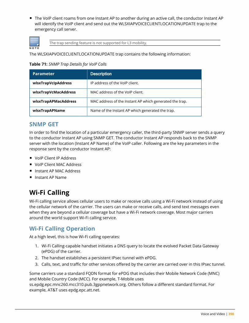
Voice and Video | 390
n The VoIP client roams from one Instant AP to another during an active call, the conductor Instant APwill identify the VoIP client and send out the WLSXIAPVOICECLIENTLOCATIONUPDATE trap to theemergency call server.
The trap sending feature is not supported for L3 mobility.
The WLSXIAPVOICECLIENTLOCATIONUPDATE trap contains the following information:
Parameter Description
wlsxTrapVcIpAddress IP address of the VoIP client.
wlsxTrapVcMacAddress MAC address of the VoIP client.
wlsxTrapAPMacAddress MAC address of the Instant AP which generated the trap.
wlsxTrapAPName Name of the Instant AP which generated the trap.
Table 71: SNMP Trap Details for VoIP Calls
SNMP GETIn order to find the location of a particular emergency caller, the third-party SNMP server sends a queryto the conductor Instant AP using SNMP GET. The conductor Instant AP responds back to the SNMPserver with the location (Instant AP Name) of the VoIP caller. Following are the key parameters in theresponse sent by the conductor Instant AP:
n VoIP Client IP Addressn VoIP Client MAC Addressn Instant AP MAC Addressn Instant AP Name
Wi-Fi CallingWi-Fi calling service allows cellular users to make or receive calls using a Wi-Fi network instead of usingthe cellular network of the carrier. The users can make or receive calls, and send text messages evenwhen they are beyond a cellular coverage but have a Wi-Fi network coverage. Most major carriersaround the world support Wi-Fi calling service.
Wi-Fi Calling OperationAt a high level, this is how Wi-Fi calling operates:
1. Wi-Fi Calling-capable handset initiates a DNS query to locate the evolved Packet Data Gateway(ePDG) of the carrier.
2. The handset establishes a persistent IPsec tunnel with ePDG.3. Calls, text, and traffic for other services offered by the carrier are carried over in this IPsec tunnel.
Some carriers use a standard FQDN format for ePDG that includes their Mobile Network Code (MNC)and Mobile Country Code (MCC). For example, T-Mobile usesss.epdg.epc.mnc260.mcc310.pub.3gppnetwork.org. Others follow a different standard format. Forexample, AT&T uses epdg.epc.att.net.
Aruba Instant 8.10.0.0 User Guide 391
Wi-Fi Calling ConfigurationThe Instant CLI allows you to enable the wi-fi calling service and also configure DNS patterns. The ACL inaccess-rules to allow IPSEC/IKE (4500 port) enables Wi-Fi calling.
The following CLI command enables Wi-Fi calling:
wlan access-rule rule any any match tcp 4500 4500 permit
The following CLI command configures DNS patterns:
(Instant AP)(config)# wificall-dns-pattern <dns_pattern>
The following CLI command shows the list of IP addresses learned by the Wi-Fi calling client during theDNS learning phase:
(Instant AP)# show datapath dns-ip-learning
Unified Communications ManagerUnified Communications Manager (UCM) is a service module introduced in Aruba Instant 8.7.0.0 thatmanages the prioritization of voice and video call traffic in the AP. It enables the prioritization andmonitoring of voice and video applications that use SIP.
Voice and video calling applications exchange SIP control packets before establishing a voice or videosession. The UCM process on the AP identifies these SIP control packets and prioritizes thecorresponding session in the datapath. These sessions are tagged with default DSCP value of 48 forvoice sessions and 40 for video sessions.
UCM does not support NAT
If a custom port is used for SIP other than port 5060, the port must be added to the list of netserviceports for UCM to function. Ports can be added to the netservice list using the CLI.
The following CLI command adds a port to the list of netservice ports on the Instant AP:(Instant AP)(config) #netservice svc-sip <port> <proto> <timeout>
Monitoring UCM operations on the Instant APUCM call data records and ongoing UCM datapath operations are logged in the AP. To view logs ofUCM processes on the AP, UCM logging must be enabled using the CLI. The following CLI operationsdescribe how to access logs related to UCM.
The following CLI command enables logging of UCM processes on the Instant AP:
(Instant AP) #ucm-logging
The following CLI command displays the UCM logs:
(Instant AP) #show log ucm
The following CLI command displays UCM call data records on the Instant AP:
(Instant AP)# show ucm cdrs
The following CLI command displays the datapath sessions for UCM packets:
(Instant AP)# show datapath session dpi

Voice and Video | 392
The datapath entries of voice and video sessions that use SIP are marked as alg-sip-audio and alg-sip-video respectively.
The following CLI command displays the UCC datapath sessions on the AP:
(Instant AP)# show datapath session ucc
Flows programmed with OpenFlow are tagged with O flag in the datapath session.
For more information on these commands, see Aruba Instant 8.x CLI Reference Guide.
Chapter 23Services
ServicesThis chapter provides information on how to configure the following services on an Instant AP:
n Configuring AirGroup on page 393n Configuring an Instant AP for RTLS Support on page 401n Configuring an Instant AP for ALE Support on page 403n Clarity Live on page 404n Deny Intra-VLAN Traffic on page 410n Integrating an Instant AP with Palo Alto Networks Firewall on page 412n Integrating an Instant AP with an XML API Interface on page 413n CALEA Integration and Lawful Intercept Compliance on page 416
Configuring AirGroupAirGroup provides a unique enterprise-class capability that leverages zero configuration networking toenable AirGroup services from mobile devices efficiently. Zero configuration networking enables servicediscovery, address assignment, and name resolution for desktop computers, mobile devices, andnetwork services. It is designed for flat, single-subnet IP networks such as wireless networking at home.The users can register their personal devices and define a group of users who can share the registereddevices. Administrators can register and manage an organization's shared devices such as printers andgrant global access to each device, or restrict access according to the username, role, or user location.
In large universities and enterprise networks, it is common for devices to connect to the network acrossVLANs. As a result, user devices on a specific VLAN cannot discover a service that resides on anotherVLAN. As the addresses used by the protocol are link-scope multicast addresses, each query oradvertisement can only be forwarded on its respective VLAN, but not across different VLANs. Broadcastand multicast traffic are usually filtered out from a WLAN network to preserve the airtime and batterylife. This inhibits the performance of AirGroup services that rely on multicast traffic. AirGroup addressesthis challenge with AirGroup technology.
The distributed AirGroup architecture allows each Instant AP to handle mDNS and DLNA queries andresponses individually instead of overloading a network with these tasks. This results in a scalableAirGroup solution.
The AirGroup solution supports both wired and wireless devices. An AirGroup device can be registeredby an administrator or a guest user.
1. The AirGroup administrator gives an end user the AirGroup operator role, which authorizes theuser to register the client devices on the ClearPass Policy Manager platform.
2. Instant APs maintain information for all AirGroup services. Instant AP queries ClearPass PolicyManager to map each device’s access privileges to the available services and responds to thequery made by a device based on contextual data such as user role, username, and location.
The following figure illustrates how AirGroup enables personal sharing of Apple devices:
Aruba Instant 8.10.0.0 User Guide 393
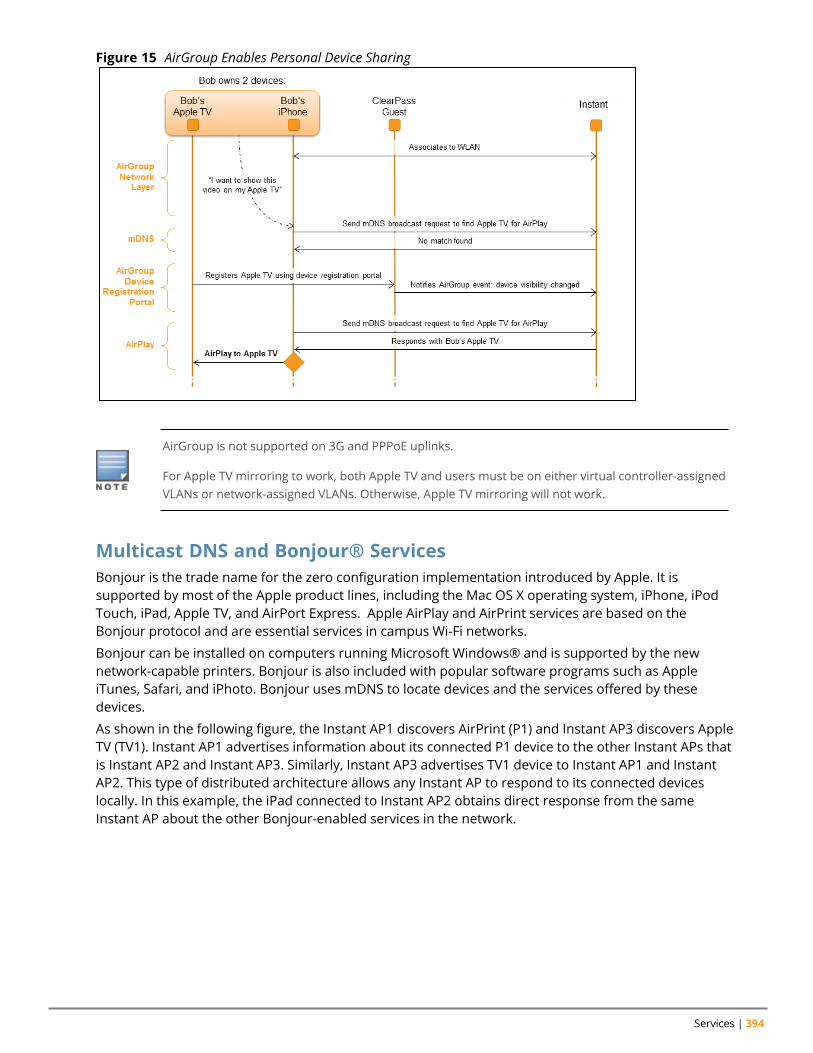
Services | 394
Figure 15 AirGroup Enables Personal Device Sharing
AirGroup is not supported on 3G and PPPoE uplinks.
For Apple TV mirroring to work, both Apple TV and users must be on either virtual controller-assignedVLANs or network-assigned VLANs. Otherwise, Apple TV mirroring will not work.
Multicast DNS and Bonjour® ServicesBonjour is the trade name for the zero configuration implementation introduced by Apple. It issupported by most of the Apple product lines, including the Mac OS X operating system, iPhone, iPodTouch, iPad, Apple TV, and AirPort Express. Apple AirPlay and AirPrint services are based on theBonjour protocol and are essential services in campus Wi-Fi networks.
Bonjour can be installed on computers running Microsoft Windows® and is supported by the newnetwork-capable printers. Bonjour is also included with popular software programs such as AppleiTunes, Safari, and iPhoto. Bonjour uses mDNS to locate devices and the services offered by thesedevices.
As shown in the following figure, the Instant AP1 discovers AirPrint (P1) and Instant AP3 discovers AppleTV (TV1). Instant AP1 advertises information about its connected P1 device to the other Instant APs thatis Instant AP2 and Instant AP3. Similarly, Instant AP3 advertises TV1 device to Instant AP1 and InstantAP2. This type of distributed architecture allows any Instant AP to respond to its connected deviceslocally. In this example, the iPad connected to Instant AP2 obtains direct response from the sameInstant AP about the other Bonjour-enabled services in the network.
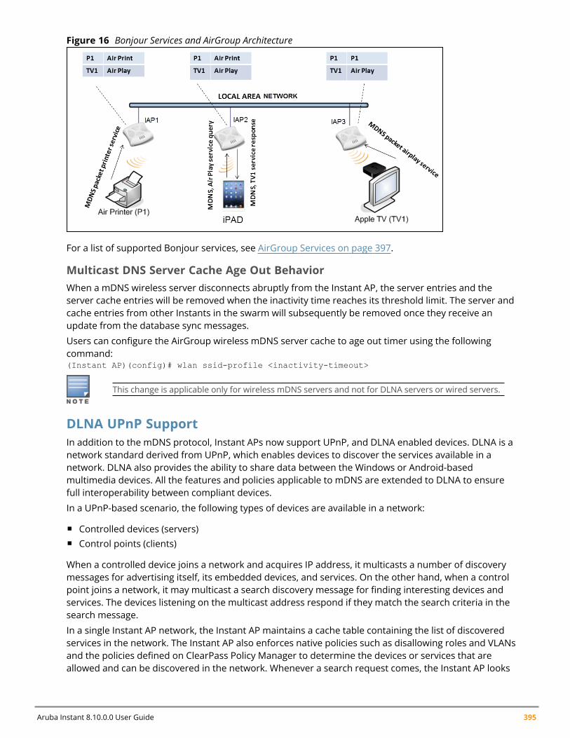
Aruba Instant 8.10.0.0 User Guide 395
Figure 16 Bonjour Services and AirGroup Architecture
For a list of supported Bonjour services, see AirGroup Services on page 397.
Multicast DNS Server Cache Age Out BehaviorWhen a mDNS wireless server disconnects abruptly from the Instant AP, the server entries and theserver cache entries will be removed when the inactivity time reaches its threshold limit. The server andcache entries from other Instants in the swarm will subsequently be removed once they receive anupdate from the database sync messages.
Users can configure the AirGroup wireless mDNS server cache to age out timer using the followingcommand:(Instant AP)(config)# wlan ssid-profile <inactivity-timeout>
This change is applicable only for wireless mDNS servers and not for DLNA servers or wired servers.
DLNA UPnP SupportIn addition to the mDNS protocol, Instant APs now support UPnP, and DLNA enabled devices. DLNA is anetwork standard derived from UPnP, which enables devices to discover the services available in anetwork. DLNA also provides the ability to share data between the Windows or Android-basedmultimedia devices. All the features and policies applicable to mDNS are extended to DLNA to ensurefull interoperability between compliant devices.
In a UPnP-based scenario, the following types of devices are available in a network:
n Controlled devices (servers)n Control points (clients)
When a controlled device joins a network and acquires IP address, it multicasts a number of discoverymessages for advertising itself, its embedded devices, and services. On the other hand, when a controlpoint joins a network, it may multicast a search discovery message for finding interesting devices andservices. The devices listening on the multicast address respond if they match the search criteria in thesearch message.
In a single Instant AP network, the Instant AP maintains a cache table containing the list of discoveredservices in the network. The Instant AP also enforces native policies such as disallowing roles and VLANsand the policies defined on ClearPass Policy Manager to determine the devices or services that areallowed and can be discovered in the network. Whenever a search request comes, the Instant AP looks
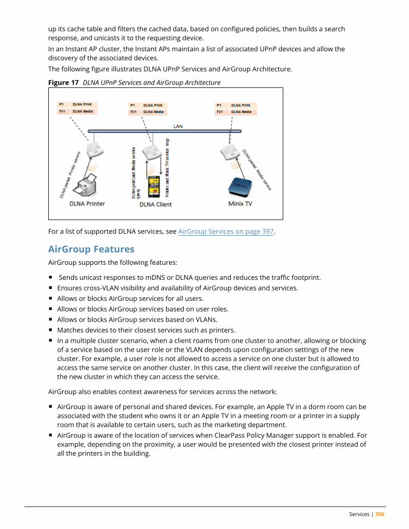
Services | 396
up its cache table and filters the cached data, based on configured policies, then builds a searchresponse, and unicasts it to the requesting device.
In an Instant AP cluster, the Instant APs maintain a list of associated UPnP devices and allow thediscovery of the associated devices.
The following figure illustrates DLNA UPnP Services and AirGroup Architecture.
Figure 17 DLNA UPnP Services and AirGroup Architecture
For a list of supported DLNA services, see AirGroup Services on page 397.
AirGroup FeaturesAirGroup supports the following features:
n Sends unicast responses to mDNS or DLNA queries and reduces the traffic footprint.n Ensures cross-VLAN visibility and availability of AirGroup devices and services.n Allows or blocks AirGroup services for all users.n Allows or blocks AirGroup services based on user roles.n Allows or blocks AirGroup services based on VLANs.n Matches devices to their closest services such as printers.n In a multiple cluster scenario, when a client roams from one cluster to another, allowing or blocking
of a service based on the user role or the VLAN depends upon configuration settings of the newcluster. For example, a user role is not allowed to access a service on one cluster but is allowed toaccess the same service on another cluster. In this case, the client will receive the configuration ofthe new cluster in which they can access the service.
AirGroup also enables context awareness for services across the network:
n AirGroup is aware of personal and shared devices. For example, an Apple TV in a dorm room can beassociated with the student who owns it or an Apple TV in a meeting room or a printer in a supplyroom that is available to certain users, such as the marketing department.
n AirGroup is aware of the location of services when ClearPass Policy Manager support is enabled. Forexample, depending on the proximity, a user would be presented with the closest printer instead ofall the printers in the building.
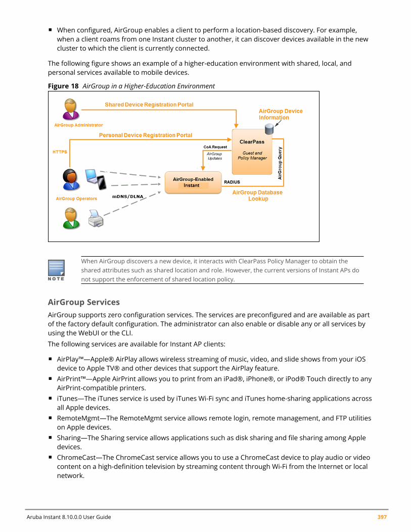
Aruba Instant 8.10.0.0 User Guide 397
n When configured, AirGroup enables a client to perform a location-based discovery. For example,when a client roams from one Instant cluster to another, it can discover devices available in the newcluster to which the client is currently connected.
The following figure shows an example of a higher-education environment with shared, local, andpersonal services available to mobile devices.
Figure 18 AirGroup in a Higher-Education Environment
When AirGroup discovers a new device, it interacts with ClearPass Policy Manager to obtain theshared attributes such as shared location and role. However, the current versions of Instant APs donot support the enforcement of shared location policy.
AirGroup ServicesAirGroup supports zero configuration services. The services are preconfigured and are available as partof the factory default configuration. The administrator can also enable or disable any or all services byusing the WebUI or the CLI.
The following services are available for Instant AP clients:
n AirPlay™—Apple® AirPlay allows wireless streaming of music, video, and slide shows from your iOSdevice to Apple TV® and other devices that support the AirPlay feature.
n AirPrint™—Apple AirPrint allows you to print from an iPad®, iPhone®, or iPod® Touch directly to anyAirPrint-compatible printers.
n iTunes—The iTunes service is used by iTunes Wi-Fi sync and iTunes home-sharing applications acrossall Apple devices.
n RemoteMgmt—The RemoteMgmt service allows remote login, remote management, and FTP utilitieson Apple devices.
n Sharing—The Sharing service allows applications such as disk sharing and file sharing among Appledevices.
n ChromeCast—The ChromeCast service allows you to use a ChromeCast device to play audio or videocontent on a high-definition television by streaming content through Wi-Fi from the Internet or localnetwork.
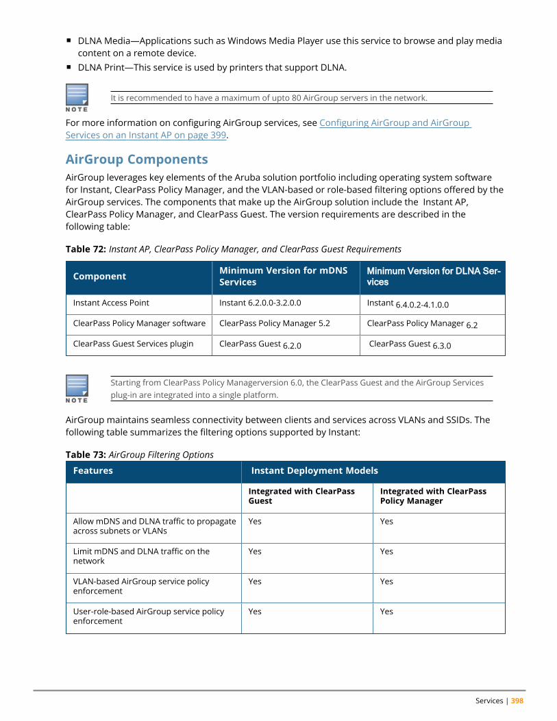
Services | 398
n DLNA Media—Applications such as Windows Media Player use this service to browse and play mediacontent on a remote device.
n DLNA Print—This service is used by printers that support DLNA.
It is recommended to have a maximum of upto 80 AirGroup servers in the network.
For more information on configuring AirGroup services, see Configuring AirGroup and AirGroupServices on an Instant AP on page 399.
AirGroup ComponentsAirGroup leverages key elements of the Aruba solution portfolio including operating system softwarefor Instant, ClearPass Policy Manager, and the VLAN-based or role-based filtering options offered by theAirGroup services. The components that make up the AirGroup solution include the Instant AP,ClearPass Policy Manager, and ClearPass Guest. The version requirements are described in thefollowing table:
Component Minimum Version for mDNSServices
Minimum Version for DLNA Ser-vices
Instant Access Point Instant 6.2.0.0-3.2.0.0 Instant 6.4.0.2-4.1.0.0
ClearPass Policy Manager software ClearPass Policy Manager 5.2 ClearPass Policy Manager 6.2
ClearPass Guest Services plugin ClearPass Guest 6.2.0 ClearPass Guest 6.3.0
Table 72: Instant AP, ClearPass Policy Manager, and ClearPass Guest Requirements
Starting from ClearPass Policy Managerversion 6.0, the ClearPass Guest and the AirGroup Servicesplug-in are integrated into a single platform.
AirGroup maintains seamless connectivity between clients and services across VLANs and SSIDs. Thefollowing table summarizes the filtering options supported by Instant:
Features Instant Deployment Models
Integrated with ClearPassGuest
Integrated with ClearPassPolicy Manager
Allow mDNS and DLNA traffic to propagateacross subnets or VLANs
Yes Yes
Limit mDNS and DLNA traffic on thenetwork
Yes Yes
VLAN-based AirGroup service policyenforcement
Yes Yes
User-role-based AirGroup service policyenforcement
Yes Yes
Table 73: AirGroup Filtering Options
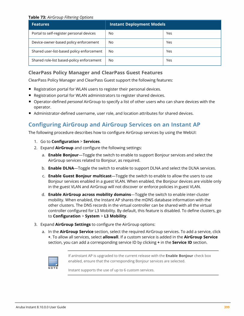
Aruba Instant 8.10.0.0 User Guide 399
Features Instant Deployment Models
Portal to self-register personal devices No Yes
Device-owner-based policy enforcement No Yes
Shared user-list-based policy enforcement No Yes
Shared role-list based-policy enforcement No Yes
Table 73: AirGroup Filtering Options
ClearPass Policy Manager and ClearPass Guest FeaturesClearPass Policy Manager and ClearPass Guest support the following features:
n Registration portal for WLAN users to register their personal devices.n Registration portal for WLAN administrators to register shared devices.n Operator-defined personal AirGroup to specify a list of other users who can share devices with the
operator.n Administrator-defined username, user role, and location attributes for shared devices.
Configuring AirGroup and AirGroup Services on an Instant APThe following procedure describes how to configure AirGroup services by using the WebUI:
1. Go to Configuration > Services.2. Expand AirGroup and configure the following settings:
a. Enable Bonjour—Toggle the switch to enable to support Bonjour services and select theAirGroup services related to Bonjour, as required.
b. Enable DLNA—Toggle the switch to enable to support DLNA and select the DLNA services.
c. Enable Guest Bonjour multicast—Toggle the switch to enable to allow the users to useBonjour services enabled in a guest VLAN. When enabled, the Bonjour devices are visible onlyin the guest VLAN and AirGroup will not discover or enforce policies in guest VLAN.
d. Enable AirGroup across mobility domains—Toggle the switch to enable inter-clustermobility. When enabled, the Instant AP shares the mDNS database information with theother clusters. The DNS records in the virtual controller can be shared with all the virtualcontroller configured for L3 Mobility. By default, this feature is disabled. To define clusters, goto Configuration > System > L3 Mobility.
3. Expand AirGroup Settings to configure the AirGroup options:
a. In the AirGroup Service section, select the required AirGroup services. To add a service, click+. To allow all services, select allowall. If a custom service is added in the AirGroup Servicesection, you can add a corresponding service ID by clicking + in the Service ID section.
If anInstant AP is upgraded to the current release with the Enable Bonjour check boxenabled, ensure that the corresponding Bonjour services are selected.
Instant supports the use of up to 6 custom services.
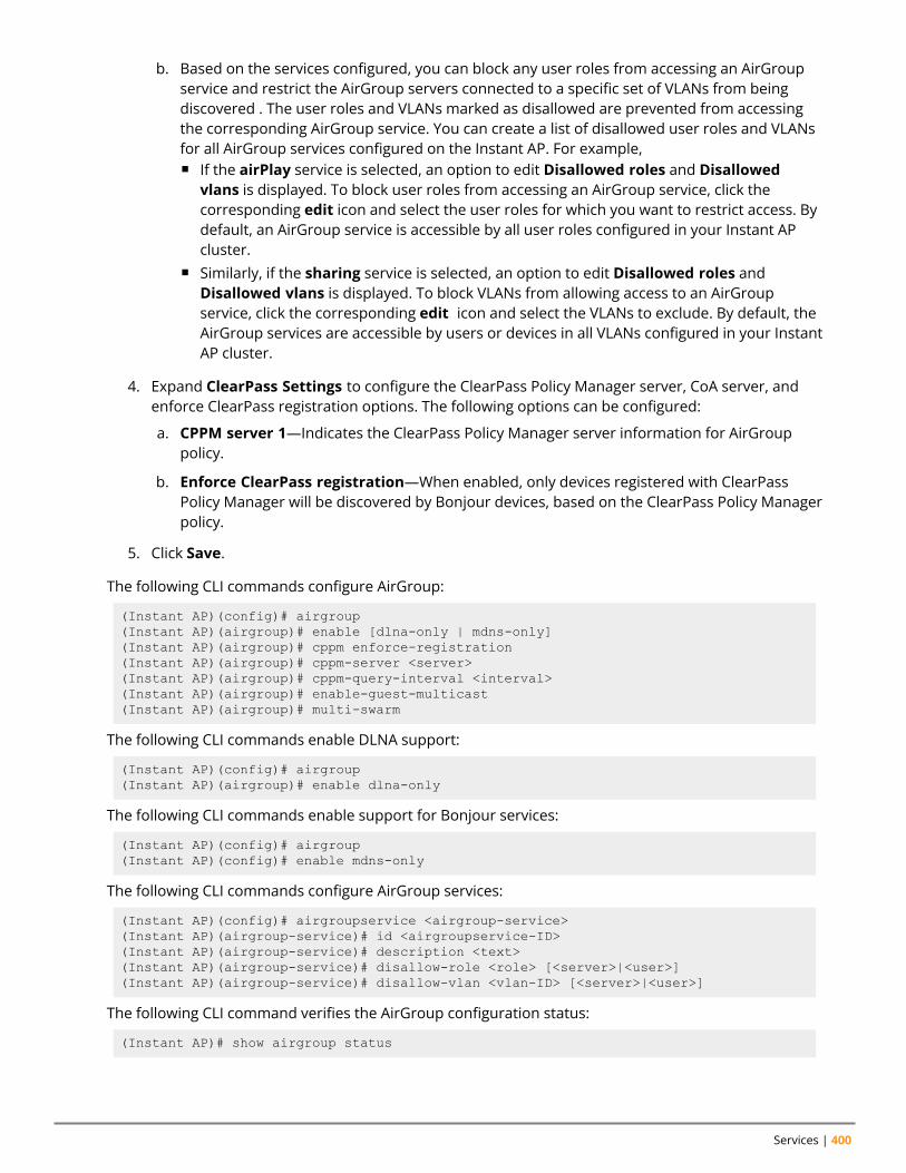
Services | 400
b. Based on the services configured, you can block any user roles from accessing an AirGroupservice and restrict the AirGroup servers connected to a specific set of VLANs from beingdiscovered . The user roles and VLANs marked as disallowed are prevented from accessingthe corresponding AirGroup service. You can create a list of disallowed user roles and VLANsfor all AirGroup services configured on the Instant AP. For example,n If the airPlay service is selected, an option to edit Disallowed roles and Disallowed
vlans is displayed. To block user roles from accessing an AirGroup service, click thecorresponding edit icon and select the user roles for which you want to restrict access. Bydefault, an AirGroup service is accessible by all user roles configured in your Instant APcluster.
n Similarly, if the sharing service is selected, an option to edit Disallowed roles andDisallowed vlans is displayed. To block VLANs from allowing access to an AirGroupservice, click the corresponding edit icon and select the VLANs to exclude. By default, theAirGroup services are accessible by users or devices in all VLANs configured in your InstantAP cluster.
4. Expand ClearPass Settings to configure the ClearPass Policy Manager server, CoA server, andenforce ClearPass registration options. The following options can be configured:
a. CPPM server 1—Indicates the ClearPass Policy Manager server information for AirGrouppolicy.
b. Enforce ClearPass registration—When enabled, only devices registered with ClearPassPolicy Manager will be discovered by Bonjour devices, based on the ClearPass Policy Managerpolicy.
5. Click Save.
The following CLI commands configure AirGroup:
(Instant AP)(config)# airgroup(Instant AP)(airgroup)# enable [dlna-only | mdns-only](Instant AP)(airgroup)# cppm enforce-registration(Instant AP)(airgroup)# cppm-server <server>(Instant AP)(airgroup)# cppm-query-interval <interval>(Instant AP)(airgroup)# enable-guest-multicast(Instant AP)(airgroup)# multi-swarm
The following CLI commands enable DLNA support:
(Instant AP)(config)# airgroup(Instant AP)(airgroup)# enable dlna-only
The following CLI commands enable support for Bonjour services:
(Instant AP)(config)# airgroup(Instant AP)(config)# enable mdns-only
The following CLI commands configure AirGroup services:
(Instant AP)(config)# airgroupservice <airgroup-service>(Instant AP)(airgroup-service)# id <airgroupservice-ID>(Instant AP)(airgroup-service)# description <text>(Instant AP)(airgroup-service)# disallow-role <role> [<server>|<user>](Instant AP)(airgroup-service)# disallow-vlan <vlan-ID> [<server>|<user>]
The following CLI command verifies the AirGroup configuration status:
(Instant AP)# show airgroup status
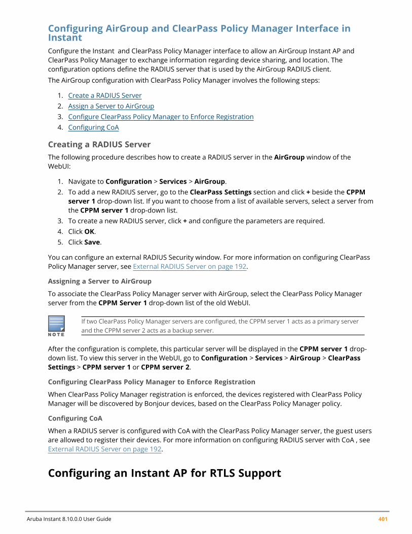
Aruba Instant 8.10.0.0 User Guide 401
Configuring AirGroup and ClearPass Policy Manager Interface inInstantConfigure the Instant and ClearPass Policy Manager interface to allow an AirGroup Instant AP andClearPass Policy Manager to exchange information regarding device sharing, and location. Theconfiguration options define the RADIUS server that is used by the AirGroup RADIUS client.
The AirGroup configuration with ClearPass Policy Manager involves the following steps:
1. Create a RADIUS Server2. Assign a Server to AirGroup3. Configure ClearPass Policy Manager to Enforce Registration4. Configuring CoA
Creating a RADIUS ServerThe following procedure describes how to create a RADIUS server in the AirGroup window of theWebUI:
1. Navigate to Configuration > Services > AirGroup.2. To add a new RADIUS server, go to the ClearPass Settings section and click + beside the CPPM
server 1 drop-down list. If you want to choose from a list of available servers, select a server fromthe CPPM server 1 drop-down list.
3. To create a new RADIUS server, click + and configure the parameters are required.4. Click OK.5. Click Save.
You can configure an external RADIUS Security window. For more information on configuring ClearPassPolicy Manager server, see External RADIUS Server on page 192.
Assigning a Server to AirGroup
To associate the ClearPass Policy Manager server with AirGroup, select the ClearPass Policy Managerserver from the CPPM Server 1 drop-down list of the old WebUI.
If two ClearPass Policy Manager servers are configured, the CPPM server 1 acts as a primary serverand the CPPM server 2 acts as a backup server.
After the configuration is complete, this particular server will be displayed in the CPPM server 1 drop-down list. To view this server in the WebUI, go to Configuration > Services > AirGroup > ClearPassSettings > CPPM server 1 or CPPM server 2.
Configuring ClearPass Policy Manager to Enforce Registration
When ClearPass Policy Manager registration is enforced, the devices registered with ClearPass PolicyManager will be discovered by Bonjour devices, based on the ClearPass Policy Manager policy.
Configuring CoA
When a RADIUS server is configured with CoA with the ClearPass Policy Manager server, the guest usersare allowed to register their devices. For more information on configuring RADIUS server with CoA , seeExternal RADIUS Server on page 192.
Configuring an Instant AP for RTLS Support
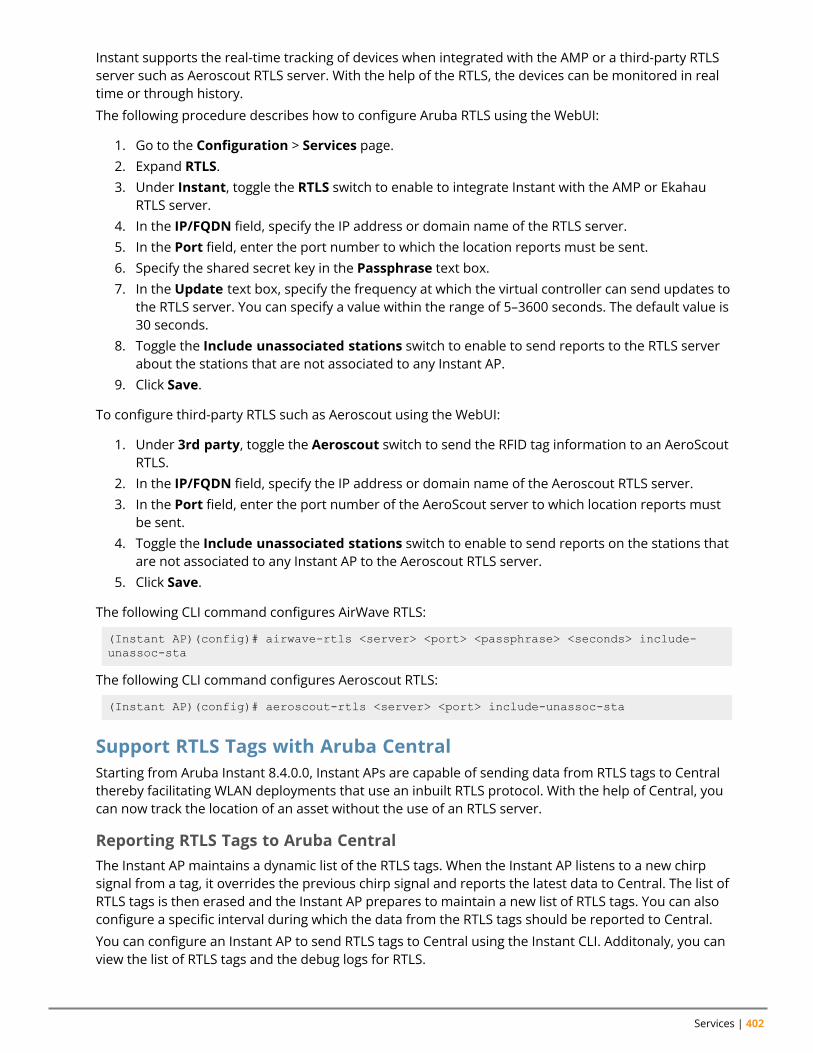
Services | 402
Instant supports the real-time tracking of devices when integrated with the AMP or a third-party RTLSserver such as Aeroscout RTLS server. With the help of the RTLS, the devices can be monitored in realtime or through history.
The following procedure describes how to configure Aruba RTLS using the WebUI:
1. Go to the Configuration > Services page.2. Expand RTLS.3. Under Instant, toggle the RTLS switch to enable to integrate Instant with the AMP or Ekahau
RTLS server.4. In the IP/FQDN field, specify the IP address or domain name of the RTLS server.5. In the Port field, enter the port number to which the location reports must be sent.6. Specify the shared secret key in the Passphrase text box.7. In the Update text box, specify the frequency at which the virtual controller can send updates to
the RTLS server. You can specify a value within the range of 5–3600 seconds. The default value is30 seconds.
8. Toggle the Include unassociated stations switch to enable to send reports to the RTLS serverabout the stations that are not associated to any Instant AP.
9. Click Save.
To configure third-party RTLS such as Aeroscout using the WebUI:
1. Under 3rd party, toggle the Aeroscout switch to send the RFID tag information to an AeroScoutRTLS.
2. In the IP/FQDN field, specify the IP address or domain name of the Aeroscout RTLS server.3. In the Port field, enter the port number of the AeroScout server to which location reports must
be sent.4. Toggle the Include unassociated stations switch to enable to send reports on the stations that
are not associated to any Instant AP to the Aeroscout RTLS server.5. Click Save.
The following CLI command configures AirWave RTLS:
(Instant AP)(config)# airwave-rtls <server> <port> <passphrase> <seconds> include-unassoc-sta
The following CLI command configures Aeroscout RTLS:
(Instant AP)(config)# aeroscout-rtls <server> <port> include-unassoc-sta
Support RTLS Tags with Aruba CentralStarting from Aruba Instant 8.4.0.0, Instant APs are capable of sending data from RTLS tags to Centralthereby facilitating WLAN deployments that use an inbuilt RTLS protocol. With the help of Central, youcan now track the location of an asset without the use of an RTLS server.
Reporting RTLS Tags to Aruba CentralThe Instant AP maintains a dynamic list of the RTLS tags. When the Instant AP listens to a new chirpsignal from a tag, it overrides the previous chirp signal and reports the latest data to Central. The list ofRTLS tags is then erased and the Instant AP prepares to maintain a new list of RTLS tags. You can alsoconfigure a specific interval during which the data from the RTLS tags should be reported to Central.
You can configure an Instant AP to send RTLS tags to Central using the Instant CLI. Additonaly, you canview the list of RTLS tags and the debug logs for RTLS.
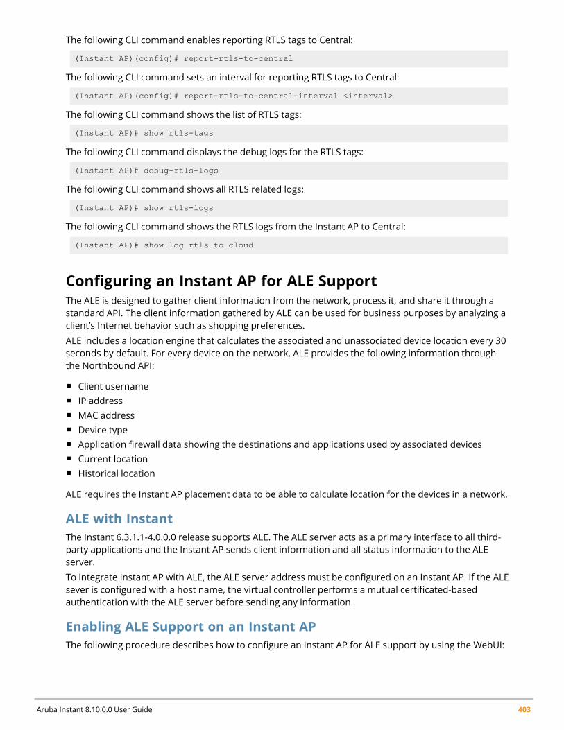
Aruba Instant 8.10.0.0 User Guide 403
The following CLI command enables reporting RTLS tags to Central:
(Instant AP)(config)# report-rtls-to-central
The following CLI command sets an interval for reporting RTLS tags to Central:
(Instant AP)(config)# report-rtls-to-central-interval <interval>
The following CLI command shows the list of RTLS tags:
(Instant AP)# show rtls-tags
The following CLI command displays the debug logs for the RTLS tags:
(Instant AP)# debug-rtls-logs
The following CLI command shows all RTLS related logs:
(Instant AP)# show rtls-logs
The following CLI command shows the RTLS logs from the Instant AP to Central:
(Instant AP)# show log rtls-to-cloud
Configuring an Instant AP for ALE SupportThe ALE is designed to gather client information from the network, process it, and share it through astandard API. The client information gathered by ALE can be used for business purposes by analyzing aclient’s Internet behavior such as shopping preferences.
ALE includes a location engine that calculates the associated and unassociated device location every 30seconds by default. For every device on the network, ALE provides the following information throughthe Northbound API:
n Client usernamen IP addressn MAC addressn Device typen Application firewall data showing the destinations and applications used by associated devicesn Current locationn Historical location
ALE requires the Instant AP placement data to be able to calculate location for the devices in a network.
ALE with InstantThe Instant 6.3.1.1-4.0.0.0 release supports ALE. The ALE server acts as a primary interface to all third-party applications and the Instant AP sends client information and all status information to the ALEserver.
To integrate Instant AP with ALE, the ALE server address must be configured on an Instant AP. If the ALEsever is configured with a host name, the virtual controller performs a mutual certificated-basedauthentication with the ALE server before sending any information.
Enabling ALE Support on an Instant APThe following procedure describes how to configure an Instant AP for ALE support by using the WebUI:
Services | 404
1. Click Configuration > Services.2. Click RTLS.3. In the Instant section, toggle the Analytics & Location Engine switch to enable.4. In the Auth Server text box, specify the ALE server name or IP address.5. In the Report interval text box, specify the reporting interval within the range of 6–60 seconds.
The Instant AP sends messages to the ALE server at the specified interval. The default interval is30 seconds.
6. Click Save.
The following CLI commands enable Instant AP integration with the ALE server:
(Instant AP)(config)# ale-server <server-name | IP-address>(Instant AP)(config)# ale-report-interval <seconds>
Verifying ALE Configuration on an Instant APThe following CLI command shows the configuration details:
(Instant AP)# show ale config
The following CLI command verifies the configuration status:
(Instant AP)# show ale status
Clarity LiveInstant AP provides support for Inline Monitoring support using Clarity Live to identify client connectivityissues and sends user debug data to AirWave. The client connectivity issues can be a problem with theclient, Radius Authentication, DHCP, DNS, or it can be delay in the network. Clarity Live is used toidentify the root cause of the problem, this feature can be used.
Inline MonitoringThis functionality of Clarity Live helps diagnose client connectivity issues. It provides the networkadministrator or engineers with more information regarding the exact stage at which the clientconnectivity fails or provides data where the dhcp or radius server is slow.
The Instant AP collects all information related to user transitions like association, authentication, anddhcp. Then, the Instant AP sends these records to a management server like AirWave. The managementserver analyzes the data and concludes which dhcp or radius server was not working efficiently causinguser connectivity issues. This enhancement allows the management server to isolate WLAN issuescaused by external servers such as dhcp or radius.
HTTPS is the data transport protocol used to communicate basic statistics or state changes to AirWave.Inline Monitoring makes use of HTTPS to send the statistics to AirWave too.
The following events are used by Instant AP to send inline monitoring (Clarity Live) updates to AirWave:
n Authentication Failure Events—The statistics or updates shared as part of this event are related tothe management frame. These frames are processed by STM and are collected in the user space.
n DHCP Failure Events—In scenarios where the DHCP Server does not respond, information about thefailure of the event can be collected by the Instant AP with the help of Clarity Live and sent toAirWave. This functionality receives client DHCP transactions from the control plane.
n DNS Failure Events—The Instant AP measures the responsiveness of each DNS server with the helpof Clarity Live. The monitoring includes minimum, maximum, and average response time of each
Aruba Instant 8.10.0.0 User Guide 405
DNS server. A maximum of 16 DNS servers can be monitored at a time and a maximum of 16DNS server entries are made in the DNS table. If there are no queries from a particular DNS serverfor a long period of time, the DNS server entry can be removed and replaced with a new DNS serverentry. The statistical data collected for the DNS server will be pushed to AirWave before the entry isreplaced by a new DNS entry.
n STA Failure Events—The station passive monitor statistic is generated when enabled on the InstantAP. The Instant AP generate the data periodically for every 60 seconds and sends it to AirWave.
All of the above clarity configurations must be enabled or disabled at the same time whether if it isby the WebUI or the CLI. AirWave will drop the message even if one of the four stats is disabled.
The following procedure describes how to configure an Instant AP to generate inline monitoringstatistics by using the WebUI:
1. Go to Configuration > Services.2. Expand Clarity. The following configuration options for the Clarity group are displayed:
a. Inline DHCP stats—Toggle the switch to enable to allow the Instant AP to generate statisticsand update messages for DHCP Failure Events.
b. Inline Sta stats—Toggle the switch to enable to allow the Instant AP to generate statisticsand update messages for STA Failure Events.
c. Inline Auth stats—Toggle the switch to enable to allow the Instant AP to generate statisticsand update messages for Authentication Failure Events.
d. Inline DNS stats—Toggle the switch to enable to allow the Instant AP to generate statisticsand update messages for DNS Failure Events.
3. Click Save.
The following CLI commands configure inline monitoring statistics using the CLI:
(Instant AP)(config)# clarity(Instant AP)(clarity)# inline-auth-stats(Instant AP)(clarity)# inline-dhcp-stats(Instant AP)(clarity)# inline-dns-stats(Instant AP)(clarity)# inline-sta-stats
Verify Clarity Configuration on Instant APThe following CLI command shows the status of the Inline Monitoring events:
(Instant AP)# show clarity config
The following CLI command shows the history of the authentication events:
(Instant AP)# show clarity history auth
The following CLI command shows the history of the DHCP events:
(Instant AP)# show clarity history dhcp
The following CLI command shows the history of the DNS events:
(Instant AP)# show clarity history dns
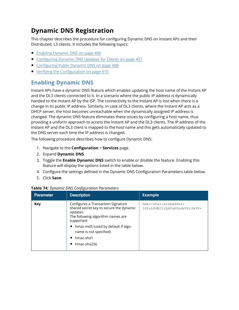
Dynamic DNS RegistrationThis chapter describes the procedure for configuring Dynamic DNS on Instant APs and theirDistributed, L3 clients. It includes the following topics:
n Enabling Dynamic DNS on page 406n Configuring Dynamic DNS Updates for Clients on page 407n Configuring Public Dynamic DNS on page 408n Verifying the Configuration on page 410
Enabling Dynamic DNSInstant APs have a dynamic DNS feature which enables updating the host name of the Instant APand the DL3 clients connected to it. In a scenario where the public IP address is dynamicallyhanded to the Instant AP by the ISP. The connectivity to the Instant AP is lost when there is achange in its public IP address. Similarly, in case of DL3 clients, where the Instant AP acts as aDHCP server, the host becomes unreachable when the dynamically assigned IP address ischanged. The dynamic DNS feature eliminates these issues by configuring a host name, thusproviding a uniform approach to access the Instant AP and the DL3 clients. The IP address of theInstant AP and the DL3 client is mapped to the host name and this gets automatically updated tothe DNS server each time the IP address is changed.
The following procedure describes how to configure Dynamic DNS:
1. Navigate to the Configuration > Services page.2. Expand Dynamic DNS.3. Toggle the Enable Dynamic DNS switch to enable or disable the feature. Enabling this
feature will display the options listed in the table below.4. Configure the settings defined in the Dynamic DNS Configuration Parameters table below.5. Click Save.
Parameter Description Example
Key Configures a Transaction Signatureshared secret key to secure the dynamicupdates.The following algorithm names aresupported:n hmac-md5 (used by default if algo-
name is not specified)n hmac-sha1n hmac-sha256
hmac-sha1:arubaddns:16YuLPdH21rQ6PuK9udsVLtJw3Y=
Table 74: Dynamic DNS Configuration Parameters
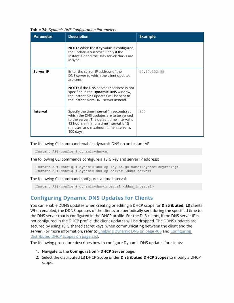
Parameter Description Example
NOTE: When the Key value is configured,the update is successful only if theInstant AP and the DNS server clocks arein sync.
Server IP Enter the server IP address of theDNS server to which the client updatesare sent.
NOTE: If the DNS server IP address is notspecified in the Dynamic DNS window,the Instant AP's updates will be sent tothe Instant APits DNS server instead.
10.17.132.85
Interval Specify the time interval (in seconds) atwhich the DNS updates are to be syncedto the server. The default time interval is12 hours, minimum time interval is 15minutes, and maximum time interval is100 days.
900
Table 74: Dynamic DNS Configuration Parameters
The following CLI command enables dynamic DNS on an Instant AP
(Instant AP)(config)# dynamic-dns-ap
The following CLI commands configure a TSIG key and server IP address:
(Instant AP)(config)# dynamic-dns-ap key <algo-name:keyname:keystring>(Instant AP)(config)# dynamic-dns-ap server <ddns_server>
The following CLI command configures a time interval:
(Instant AP)(config)# dynamic-dns-interval <ddns_interval>
Configuring Dynamic DNS Updates for ClientsYou can enable DDNS updates when creating or editing a DHCP scope for Distributed, L3 clients.When enabled, the DDNS updates of the clients are periodically sent during the specified time tothe DNS server that is configured in the DHCP profile. For the DL3 clients, if the DNS server IP isnot configured in the DHCP profile, the client updates will be dropped. The DDNS updates aresecured by using TSIG shared secret keys, when communicating between the client and theserver. For more information, refer to Enabling Dynamic DNS on page 406 and ConfiguringDistributed DHCP Scopes on page 252.
The following procedure describes how to configure Dynamic DNS updates for clients:
1. Navigate to the Configuration > DHCP Server page.2. Select the distributed L3 DHCP Scope under Distributed DHCP Scopes to modify a DHCP
scope.
3. Toggle the Dynamic DNS switch to enable.4. In the Key text box, enter the TSIG shared secret key.5. Click Next until Finish.
The following CLI commands enable DDNS for Instant AP clients:
(Instant AP)(config)# ip dhcp <profile name>(Instant AP)(DHCP profile "<name>")# dynamic-dns(Instant AP)(DHCP profile "<name>")# server-type <Distributed,L3>(Instant AP)(DHCP profile "<name>")# dynamic-dns key <algo-name:keyname:keystring>
Including Pointer Records in DDNS Client UpdatesAruba Instant supports updating of Pointer Records (PTR) by Dynamic DNS clients, along with theA (host) records. PTR resolves an IP address to a fully-qualified domain name (FQDN) as opposedto the updates of an A record. PTR updates are also called Reverse DNS records. While A (host)record maps the domain name to an IP address, PTR maps the IP address to a hostname. PTRensures that the IP address of the AP officially connects to the host. Configuring the PTR record isessential if you are using both internal or external mail servers. This record adds reliability toserver updates and allows the receiving end to check the hostname of the source IP address. Thisserves as a useful method to identify and safeguard against spammers.
The following CLI command includes pointer records as part of the DDNS updates sent by theclient:(Instant AP)(config)# dynamic-dns-ap-ptr
The following CLI command enables Distributed, L3 DHCP clients to send PTR updates to theDDNS server:(Instant AP)(config)# dynamic-dns-ptr
The following CLI command is used to view the A record updates and Pointer record updates sentby the DDNS client:(Instant AP)# show ddns clients
Configuring Public Dynamic DNSAruba Instant supports the configuration of public DDNS offered by external DDNS serviceproviders through http and https. Currently, ChangeiP, DynDNS, and No-IP are supported.Configuring this feature allows you to send periodic updates to public DDNS about changes in theIP address of the AP and clients connected to it. All updates to the public DDNS server is sentfrom the conductor AP. Public DDNS is configured at two levels:
n Instant AP - Changes made to the IP address of the AP is sent to the DDNS server.n DL3 clients - Changes made to the IP address of clients connected to the AP is sent to the
DDNS server. The AP acts as the DHCP server to the connected clients.
When configured, the AP will send IP address updates to the DDNS server at the defined timeinterval and during an IP address change event in the network.
Limitations
n Public DDNS is not supported with IPv6 addresses.n Public DDNS is not supported when OpenDNS is enabled.n Public DDNS cannot be configured if Internal DDNS is configured. Only one DDNS service can
be configured.
Configuring a Public Dynamic DNS profileTo create a DDNS server profile, use the ddns-profile command. Configure the name, serviceprovider, connection mode, update interval, and the login credentials in the DDNS profile. Amaximum of up to 3 DDNS profiles can be configured on an Instant AP.
Ensure to configure the ddns-profile parameters in the same sequence as described below. Ifthe sequence is not followed, the Instant CLI displays an error message.
Only alphanumeric characters are supported for ddnsp-password parameter.
(Instant AP) (config) ddns-profile <profile name>(Instant AP) (DDNS Profile "<profile name>") # ddnsp-service-provider <serviceprovider>(Instant AP) (DDNS Profile "<profile name>") # ddnsp-mode <mode>(Instant AP) (DDNS Profile "<profile name>") # ddnsp-interval <interval>(Instant AP) (DDNS Profile "<profile name>") # ddnsp-username <username>(Instant AP) (DDNS Profile "<profile name>") # ddnsp-password <password>(Instant AP) (DDNS Profile "<profile name>") # end
Configuring Public Dynamic DNS Updates for Instant APTo send IP address updates of the Instant AP to the DDNS server, configure the DDNS profileusing the dynamic-dns-profile command. One one DDNS profile can be configured for an AP.
The following CLI command configures a DDNS profile:
(Instant AP) (config) dynamic-dns-profile <profile name>
Configuring Public Dynamic DNS Updates for ClientsTo configure public DDNS for Distributed, L3 clients connected to the Instant AP, attach aDDNS profile to the ip dhcp profile using the ip dhcp command. Configure the DDNS profile usingthe ddns-profile parameter. Only one DDNS profile can be configured for a DHCP profile.
The following CLI command configures public DDNS for clients connected to the AP:
(Instant AP) (config) ip dhcp <profile name>(Instant AP) (DHCP Profile "<profile name>") # ddns-profile <profile name>
Sending Manual Updates to the DDNS ServerTo manually send updates to the DDNS server, use the dynamic-dns command. This allows youto add or delete entries in the public DDNS server.
The following CLI command allows you to send manual updates to the public DDNS:
(Instant AP) #dynamic-dns <operation> <mode> <service provider> <username><password> <hostname> <domain name> <host ip>
Configuring Domain Name for the Instant APThe following CLI command configures the domain name of the AP:
(Instant AP) #domainname <domain name>
Fore more information on these commands, refer to the Aruba Instant 8.x CLI Reference Guide.
Verifying the ConfigurationThe following CLI command shows the DDNS status on an Instant AP:
(Instant AP)# show ddns
The following CLI command shows the list of DDNS clients:
(Instant AP)# show ddns clients
DHCP profile name is none for the conductor Instant AP update sent.
The show running-config command displays the key in the encrypted format.
You can also configure dynamic DNS on an Instant AP or clients using the privileged executionmode in the CLI. For more information, refer to the show ddns clients command in the latestAruba Instant 8.x CLI Reference Guide.
Deny Intra-VLAN TrafficDeny Intra-VLAN Traffic feature isolates clients from one another and disables all communicationbetween peers in the VLAN network. Enable this feature to disable all peer-to-peercommunication and only allow traffic from client to gateway and allowlisted servers to flow in thenetwork. By doing so all other traffic will be dropped by the Instant AP. This will enhance thesecurity of the network and protects it from vulnerabilities.
When Deny Intra-VLAN Traffic is configured, the Instant AP learns the IP, Subnet Mask, MAC, andother essential information of the gateway and the DNS server and logs it in a subnet ofallowlisted destinations. The destination MAC of data packets sent by the client is validatedagainst this subnet table and only those destined to addresses in the subnet table are forwardedby the Instant AP. To add servers in the network, their IP or MAC address must be added to theIntra-VLAN Traffic Allowlist table to serve clients.
Deny Intra-VLAN Traffic feature has the following limitations:
1. This feature is supported only in IPv4 networks.2. This feature does not support AirGroup functionalities and affects Chromecast and Airplay
services.
Aruba recommends that both Deny Intra VLAN Traffic and ARP poison check be configured forenhanced security. To configure ARP poison check, read Configuring Firewall Settings forProtection from ARP Attacks.
The following procedure describes how to configure Deny Intra-VLAN Traffic using the WebUI.
1. Navigate to the Configuration > Networks page.2. Select a network you want to configure Deny Intra-VLAN Traffic and click on edit.3. Click on Show Advanced Options and selectMiscellaneous(for wireless profiles).4. Toggle the Deny intra VLAN traffic switch to enable or disable the feature. When
enabled, the Intra VLAN Traffic Allowlist option appears.
For servers to serve the network they must be added to the Intra-VLAN Traffic Allowlisttable. The Intra-VLAN Traffic Allowlist is a global allowlist for all WLAN SSIDs and wirednetworks configured with the feature. Servers are added to this allowlist using its IP or MACaddress. To manage the allowlist, click on Intra VLAN Traffic Allowlist
5. To add a server to the allowlist, click on Add in the Wired Server IP or Wired Server MACand enter the IP or MAC address of the wired server and click OK.
6. To delete a server from the allowlist, select the server entry from the Wired Server IP orWired Server MAC list and click Delete.
7. Click OK and save your changes.
The following CLI commands enable Deny Intra VLAN Traffic:
For WLAN SSID profiles
(Instant AP)(config) # wlan ssid-profile <profile name>(Instant AP)(SSID Profile "<profile name>") # deny-intra-vlan-traffic
For Wired network profiles
(Instant AP)(config) # wired-port-profile <profile name>(Instant AP)(wired ap profile "<profile name>") # deny-intra-vlan-traffic
Following the above syntax use the no deny-intra-vlan traffic command to disable Deny Intra-VLAN Traffic.
The following CLI commands add wired servers to the allowlist:
(Instant AP)(config) # intra-vlan-traffic-profile(Instant AP)(intra-vlan-traffic) # wired-server-ip <ip>(Instant AP)(intra-vlan-traffic) # wired-server-mac <mac>
The following CLI command shows the Intra-VLAN Traffic Allowlist of the network:
(Instant AP)(config)# show datapath subnet
The following CLI command clears all entries in the datapath subnet table:
(Instant AP)# clear datapath subnet all
The following CLI command clears all datapath subnet entries of a specific VLAN:
(Instant AP)# clear datapath subnet vlan <id>
The following CLI command clears a specific ip entry in a specific vlan of the datapath subnettable:
(Instant AP)# clear datapath subnet vlan <id> ip <ip>
Integrating an Instant AP with Palo Alto NetworksFirewallPalo Alto Networks next-generation firewall offers contextual security for all users for safeenabling of applications. A simple firewall beyond basic IP address or TCP port numbers onlyprovides a subset of the enhanced security required for enterprises to secure their networks. Inthe context of businesses using social networking sites, legacy firewalls are not able todifferentiate valid authorized users from casual social networking users.
The Palo Alto next-generation firewall is based on user ID, which provides many methods forconnecting the users to sources of identity information and associating them with firewall policyrules. For example, it provides an option to gather user information from Active Directory orLDAP server.
Integration with InstantThe functionality provided by the Palo Alto Networks firewall based on user ID requires thecollection of information from the network. Instant AP maintains the network (such as mapping IPaddress) and user information for its clients in the network and can provide the requiredinformation for the user ID on Palo Alto Networks firewall. Before sending the user-ID mappinginformation to the Palo Alto Networks firewall, the Instant AP must retrieve an API key that will beused for authentication for all APIs.
Instant AP provides the User ID mapping information to the Palo Alto Networks firewall forintegration. The client user id for authentication will not be sent to the Palo Alto Networks firewallunless it has a domain prefix. The Instant AP checks for the domain information in the clientusername for all login and logout requests sent to the Palo Alto Networks firewall. If the user idalready has a domain prefix, Instant AP forwards the request to the Palo Alto Networks firewall.Otherwise, the static client domain configured in the Palo Alto Networks firewall profile will beprefixed to the user id and then sent to the Palo Alto Networks firewall.
Instant AP and Palo Alto Networks firewall integration can be seamless with the XML-API that isavailable with Palo Alto Networks-OS 8.1 or later.
To integrate an Instant AP with Palo Alto Networks user ID, a global profile is added. This profilecan be configured on an Instant AP with Palo Alto Networks firewall information such as IPaddress, port, username, password, firewall-enabled or firewall-disabled status.
The Instant AP sends messages to Palo Alto Networks based on the type of authentication andclient status:
n After a client completes the authentication and is assigned an IP address, Instant AP sends theloginmessage.
n After a client is disconnected or dissociated from the Instant AP, the Instant AP sends a logoutmessage.
Configuring an Instant AP for PAN integrationThe following procedure describes how to configure an Instant AP for Palo Alto Networks firewallintegration by using the WebUI:
1. Navigate to Configuration > Services.2. Expand Network Integration. The Palo Alto Networks firewall configuration options are
displayed:
a. Enable—Toggle the switch to enable Palo Alto Networks firewall.
b. Username—Provide the user name of the Palo Alto Networks firewall administrator inthe text box.
c. Password—Provide the password of the Palo Alto Networks firewall administrator inthe text box.
d. IP address—Enter the Palo Alto Networks firewall IP address in the text box.
e. Port—Enter the port number within the range of 1–65,535. The default port is 443.
f. Client domain—Enter the domain name to be mapped to the client User IDs that donot have a domain name of its own.
3. Click Save.
The following CLI commands enable Palo Alto Networks firewall integration with the Instant AP:
(Instant AP)(config)# firewall-external-enforcement pan(Instant AP)(firewall-external-enforcement pan)# enable(Instant AP)(firewall-external-enforcement pan)# domain-name <name>(Instant AP)(firewall-external-enforcement pan)# ip <ip-address>(Instant AP)(firewall-external-enforcement pan)# port <port>(Instant AP)(firewall-external-enforcement pan)# user <name> <password>
Integrating an Instant AP with an XML API InterfaceThe XML API interface provides options to create and execute user management operationsseamlessly on behalf of the clients or users.
Integration with InstantThe XML API interface allows you to send specific XML commands to an Instant AP from anexternal server. These XML commands can be used to customize Instant AP client entries. Youcan use the XML API interface to add, delete, authenticate, query, or denylist a user or a client.
The user authentication is supported only for users authenticated by captive portalauthentication and not for the dot1x-authentication users.
The user add operation performed by the XML API interface is only used to modify the role ofan existing user and not to create a new user.
You can now use HTTP or HTTPS to post commands to Instant AP. The communication processusing the XML API Interface is as follows:
n An API command is issued in XML format from the server to the virtual controller.n The virtual controller processes the XML request and identifies where the client is and sends
the command to the correct member Instant AP.n Once the operation is completed, the virtual controller sends the XML response to the XML
server.n Users can use the response and take appropriate action to suit their requirements. The
response from the virtual controller is returned using the predefined formats.
Configuring an Instant AP for XML API integrationInstant AP supports the configuration of up to 8 XML API server entries. The following proceduredescribes how to configure anInstant AP for XML API integration by using the WebUI:
1. Go to Configuration > Services.2. Expand Network Integration.3. To add an XML API server, click + in the XML API Server Configuration section and specify
the following parameters:
a. Name—Enter a name for the XML API Server in the text box.
b. Subnet—Enter the subnet of the XML API Server in the text box.
c. Mask— Enter the subnet mask of the XML API Server in the text box.
d. Passphrase—Enter a passcode in the text box, to enable authorized access to the XMLAPI Server.
e. Retype—Re-enter the passcode in the text box.
4. To add multiple entries, repeat the procedure described in step 3.5. Click OK.6. Click Save.7. To edit or delete server entries, use the corresponding icons.
The following CLI commands enable XML API integration with the Instant AP:
(Instant AP)(config)# xml-api-server <xml_api_server_profile>(Instant AP)(xml-api-server <profile-name>)# ip <subnet> [mask <mask>](Instant AP)(xml-api-server)# key <key>
Creating an XML API RequestYou can now create an XML request with an appropriate authentication command and send it tothe virtual controller through HTTPS post. The format of the URL to send the XML request ishttps://<virtualcontroller-ip/auth/command.xml>
n virtualcontroller-ip: The IP address of the virtual controller that will receive the XML APIrequest
n command.xml : The XML request that contains the XML API command.
The format of the XML API request is:
xml=<aruba command="<XML API command>"><options>Value</options>...<options>Value</options></aruba>
You can specify any of the following commands in the XML request:
Parameter Description
user_add If the user entry is already present in the user table, the command willmodify the entry with the values defined in the XML request. For anexisting user, this command will update any value that is supplied, withan exception of IP and MAC address. Session time-out is only applicableto captive portal users.
user_delete This command deletes an existing user from the user table of the virtualcontroller.
NOTE: Do not use the user_delete command if the intention is to clearthe association from the virtual controller user table. If the client is dual-stack, it re-inherits the authentication state from the IPv6 address. If notdual-stack, the client reverts to the initial role.
user_authenticate This command authenticates against the server group defined in thecaptive portal profile. This is only applicable to captive portal users.
user_backlist This command blocks a user from connecting to your network. Thiscommand uses the default denylist timeout of 3600 seconds. There is nocorresponding clear command.
user_query This command fetches the status and details of a user connected to yournetwork. A dual-stack client can be queried by any of its IPv4 or IPv6addresses, but only the queried IP address is displayed in the output.
Table 75: XML API Command
Each XML API command requires certain mandatory options to successfully execute the task. Thelist of all available options are:
Parameter Description Range / Defaults
ipaddr IP address of the user in IPv4 or IPv6format.
—
Table 76: XML API Command Options
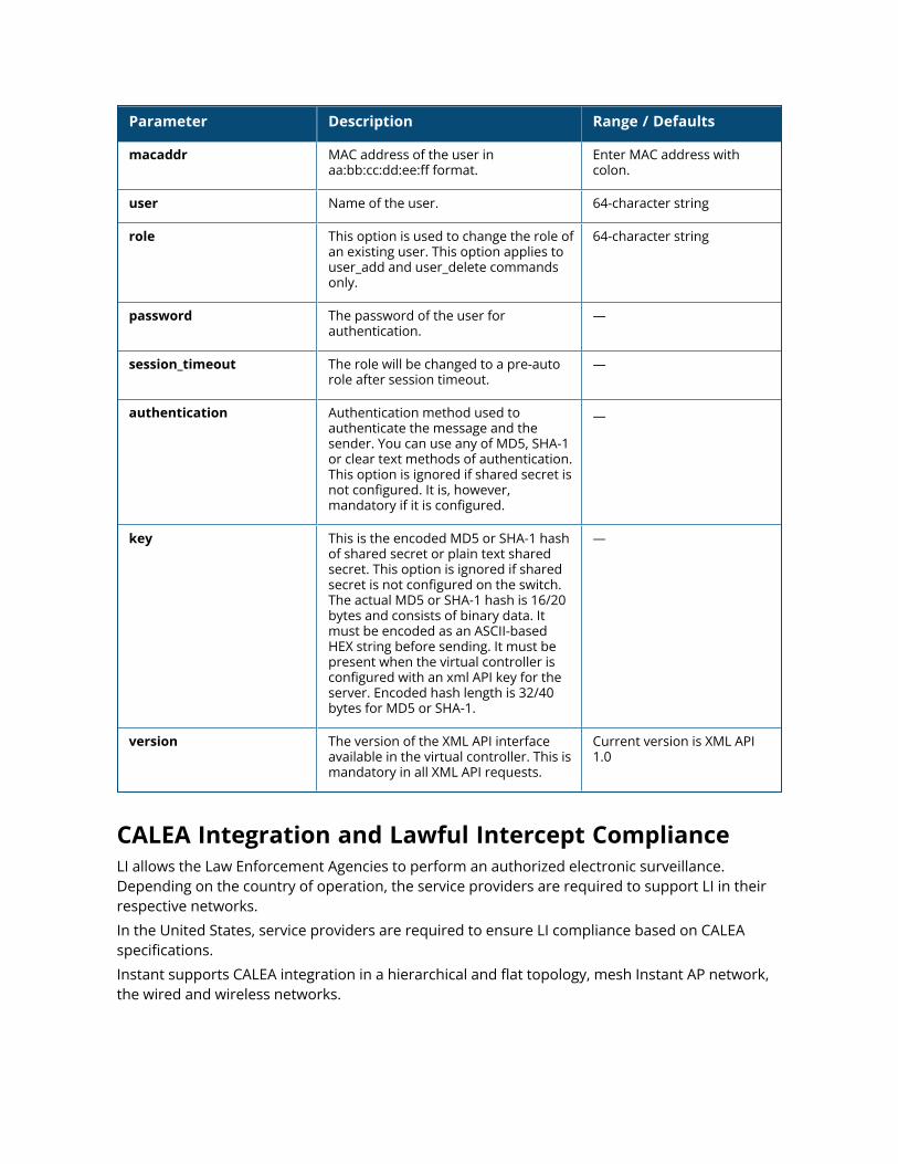
Parameter Description Range / Defaults
macaddr MAC address of the user inaa:bb:cc:dd:ee:ff format.
Enter MAC address withcolon.
user Name of the user. 64-character string
role This option is used to change the role ofan existing user. This option applies touser_add and user_delete commandsonly.
64-character string
password The password of the user forauthentication.
—
session_timeout The role will be changed to a pre-autorole after session timeout.
—
authentication Authentication method used toauthenticate the message and thesender. You can use any of MD5, SHA-1or clear text methods of authentication.This option is ignored if shared secret isnot configured. It is, however,mandatory if it is configured.
—
key This is the encoded MD5 or SHA-1 hashof shared secret or plain text sharedsecret. This option is ignored if sharedsecret is not configured on the switch.The actual MD5 or SHA-1 hash is 16/20bytes and consists of binary data. Itmust be encoded as an ASCII-basedHEX string before sending. It must bepresent when the virtual controller isconfigured with an xml API key for theserver. Encoded hash length is 32/40bytes for MD5 or SHA-1.
—
version The version of the XML API interfaceavailable in the virtual controller. This ismandatory in all XML API requests.
Current version is XML API1.0
CALEA Integration and Lawful Intercept ComplianceLI allows the Law Enforcement Agencies to perform an authorized electronic surveillance.Depending on the country of operation, the service providers are required to support LI in theirrespective networks.
In the United States, service providers are required to ensure LI compliance based on CALEAspecifications.
Instant supports CALEA integration in a hierarchical and flat topology, mesh Instant AP network,the wired and wireless networks.
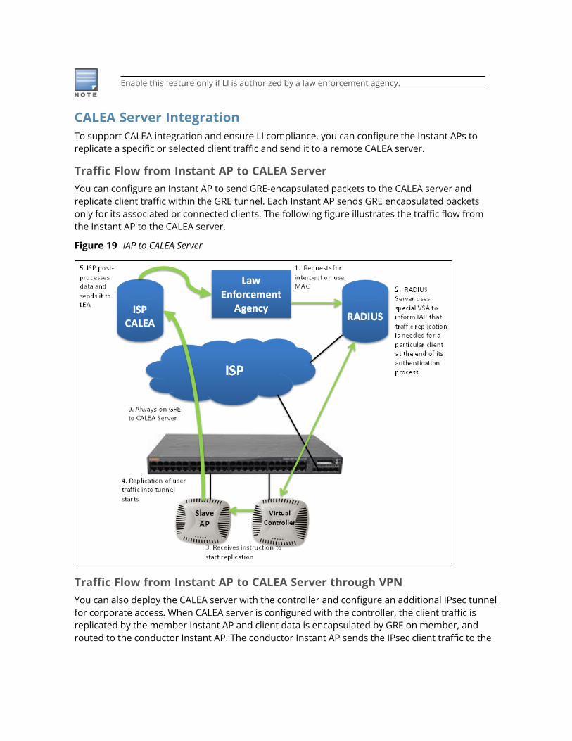
Enable this feature only if LI is authorized by a law enforcement agency.
CALEA Server IntegrationTo support CALEA integration and ensure LI compliance, you can configure the Instant APs toreplicate a specific or selected client traffic and send it to a remote CALEA server.
Traffic Flow from Instant AP to CALEA ServerYou can configure an Instant AP to send GRE-encapsulated packets to the CALEA server andreplicate client traffic within the GRE tunnel. Each Instant AP sends GRE encapsulated packetsonly for its associated or connected clients. The following figure illustrates the traffic flow fromthe Instant AP to the CALEA server.
Figure 19 IAP to CALEA Server
Traffic Flow from Instant AP to CALEA Server through VPNYou can also deploy the CALEA server with the controller and configure an additional IPsec tunnelfor corporate access. When CALEA server is configured with the controller, the client traffic isreplicated by the member Instant AP and client data is encapsulated by GRE on member, androuted to the conductor Instant AP. The conductor Instant AP sends the IPsec client traffic to the
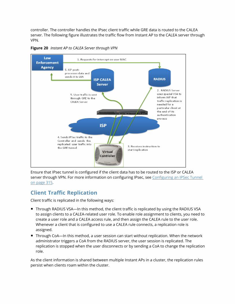
controller. The controller handles the IPsec client traffic while GRE data is routed to the CALEAserver. The following figure illustrates the traffic flow from Instant AP to the CALEA server throughVPN.
Figure 20 Instant AP to CALEA Server through VPN
Ensure that IPsec tunnel is configured if the client data has to be routed to the ISP or CALEAserver through VPN. For more information on configuring IPsec, see Configuring an IPSec Tunnelon page 315.
Client Traffic ReplicationClient traffic is replicated in the following ways:
n Through RADIUS VSA—In this method, the client traffic is replicated by using the RADIUS VSAto assign clients to a CALEA-related user role. To enable role assignment to clients, you need tocreate a user role and a CALEA access rule, and then assign the CALEA rule to the user role.Whenever a client that is configured to use a CALEA rule connects, a replication role isassigned.
n Through CoA—In this method, a user session can start without replication. When the networkadministrator triggers a CoA from the RADIUS server, the user session is replicated. Thereplication is stopped when the user disconnects or by sending a CoA to change the replicationrole.
As the client information is shared between multiple Instant APs in a cluster, the replication rulespersist when clients roam within the cluster.
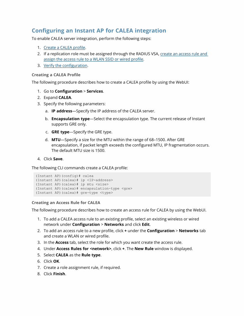
Configuring an Instant AP for CALEA integrationTo enable CALEA server integration, perform the following steps:
1. Create a CALEA profile.2. If a replication role must be assigned through the RADIUS VSA, create an access rule and
assign the access rule to a WLAN SSID or wired profile.3. Verify the configuration.
Creating a CALEA Profile
The following procedure describes how to create a CALEA profile by using the WebUI:
1. Go to Configuration > Services.2. Expand CALEA.3. Specify the following parameters:
a. IP address—Specify the IP address of the CALEA server.
b. Encapsulation type—Select the encapsulation type. The current release of Instantsupports GRE only.
c. GRE type—Specify the GRE type.
d. MTU—Specify a size for the MTU within the range of 68–1500. After GREencapsulation, if packet length exceeds the configured MTU, IP fragmentation occurs.The default MTU size is 1500.
4. Click Save.
The following CLI commands create a CALEA profile:
(Instant AP)(config)# calea(Instant AP)(calea)# ip <IP-address>(Instant AP)(calea)# ip mtu <size>(Instant AP)(calea)# encapsulation-type <gre>(Instant AP)(calea)# gre-type <type>
Creating an Access Rule for CALEA
The following procedure describes how to create an access rule for CALEA by using the WebUI.
1. To add a CALEA access rule to an existing profile, select an existing wireless or wirednetwork under Configuration > Networks and click Edit.
2. To add an access rule to a new profile, click + under the Configuration > Networks taband create a WLAN or wired profile.
3. In the Access tab, select the role for which you want create the access rule.4. Under Access Rules for <network>, click +. The New Rule window is displayed.5. Select CALEA as the Rule type.6. Click OK.7. Create a role assignment rule, if required.8. Click Finish.
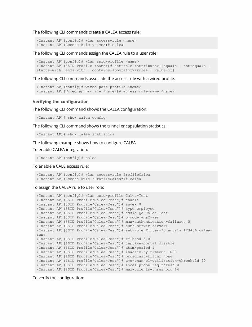
The following CLI commands create a CALEA access rule:
(Instant AP)(config)# wlan access-rule <name>(Instant AP)(Access Rule <name>)# calea
The following CLI commands assign the CALEA rule to a user role:
(Instant AP)(config)# wlan ssid-profile <name>(Instant AP)(SSID Profile <name>)# set-role <attribute>{{equals | not-equals |starts-with| ends-with | contains}<operator><role> | value-of}
The following CLI commands associate the access rule with a wired profile:
(Instant AP)(config)# wired-port-profile <name>(Instant AP)(Wired ap profile <name>)# access-rule-name <name>
Verifying the configuration
The following CLI command shows the CALEA configuration:
(Instant AP)# show calea config
The following CLI command shows the tunnel encapsulation statistics:
(Instant AP)# show calea statistics
The following example shows how to configure CALEA
To enable CALEA integration:
(Instant AP)(config)# calea
To enable a CALE access rule:
(Instant AP)(config)# wlan access-rule ProfileCalea(Instant AP)(Access Rule "ProfileCalea")# calea
To assign the CALEA rule to user role:
(Instant AP)(config)# wlan ssid-profile Calea-Test(Instant AP)(SSID Profile"Calea-Test")# enable(Instant AP)(SSID Profile"Calea-Test")# index 0(Instant AP)(SSID Profile"Calea-Test")# type employee(Instant AP)(SSID Profile"Calea-Test")# essid QA-Calea-Test(Instant AP)(SSID Profile"Calea-Test")# opmode wpa2-aes(Instant AP)(SSID Profile"Calea-Test")# max-authentication-failures 0(Instant AP)(SSID Profile"Calea-Test")# auth-server server1(Instant AP)(SSID Profile"Calea-Test")# set-role Filter-Id equals 123456 calea-test(Instant AP)(SSID Profile"Calea-Test")# rf-band 5.0(Instant AP)(SSID Profile"Calea-Test")# captive-portal disable(Instant AP)(SSID Profile"Calea-Test")# dtim-period 1(Instant AP)(SSID Profile"Calea-Test")# inactivity-timeout 1000(Instant AP)(SSID Profile"Calea-Test")# broadcast-filter none(Instant AP)(SSID Profile"Calea-Test")# dmo-channel-utilization-threshold 90(Instant AP)(SSID Profile"Calea-Test")# local-probe-req-thresh 0(Instant AP)(SSID Profile"Calea-Test")# max-clients-threshold 64
To verify the configuration:
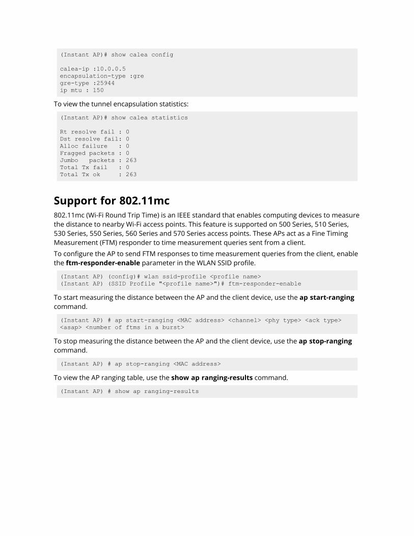
(Instant AP)# show calea config
calea-ip :10.0.0.5encapsulation-type :gregre-type :25944ip mtu : 150
To view the tunnel encapsulation statistics:
(Instant AP)# show calea statistics
Rt resolve fail : 0Dst resolve fail: 0Alloc failure : 0Fragged packets : 0Jumbo packets : 263Total Tx fail : 0Total Tx ok : 263
Support for 802.11mc802.11mc (Wi-Fi Round Trip Time) is an IEEE standard that enables computing devices to measurethe distance to nearby Wi-Fi access points. This feature is supported on 500 Series, 510 Series,530 Series, 550 Series, 560 Series and 570 Series access points. These APs act as a Fine TimingMeasurement (FTM) responder to time measurement queries sent from a client.
To configure the AP to send FTM responses to time measurement queries from the client, enablethe ftm-responder-enable parameter in the WLAN SSID profile.
(Instant AP) (config)# wlan ssid-profile <profile name>(Instant AP) (SSID Profile "<profile name>")# ftm-responder-enable
To start measuring the distance between the AP and the client device, use the ap start-rangingcommand.
(Instant AP) # ap start-ranging <MAC address> <channel> <phy type> <ack type><asap> <number of ftms in a burst>
To stop measuring the distance between the AP and the client device, use the ap stop-rangingcommand.
(Instant AP) # ap stop-ranging <MAC address>
To view the AP ranging table, use the show ap ranging-results command.
(Instant AP) # show ap ranging-results
Chapter 24SDN
SDNSDN is an architecture that uses OpenFlow. It enables software programs to manipulate the flow ofpackets in a network, and manages the traffic to suit the requirements of an application. OpenFlowenables an SDN controller by allowing dynamic manipulation of a forwarding plane of controllers androuters. In an Instant deployment scenario, OpenFlow runs on every conductor and member Instant AP.The Instant APs can connect and communicate with the OpenFlow controller over a TCP channel.However encryption between the OpenFlow agent and OpenFlow controller takes place through TLS.
Listed below are the topics included in this chapter:
n OpenFlow for WLAN on page 422n Clickstream Analysis on page 423n Wildcard ACL Support on page 424
Functionalities of SDN
InteroperabilityWith SDN and OpenFlow, it is possible to interoperate with, control, and manage third party devices inthe network.
Customization or ProgrammabilitySDN enables network programmability. This flexibility enables customers to build applications that cancontrol and manage network traffic to suit their needs.
OpenFlow for WLANEvery Instant AP interacts directly with an OpenFlow controller. An Instant AP makes wireless clientsconnected to the OpenFlow enabled port appear on the OpenFlow controller. When the Instant APlearns about a client connected to the port, the Instant AP sends a gratuitous ARP packet (enclosed in anOpenFlow protocol message) to the OpenFlow controller. Prior to this, the Instant AP exposes all WLANports and OpenFlow SSIDs as a logical port to the Openflow controller. This way, OpenFlow controllerlearns about the hosts on some ports of the Instant AP. When an OpenFlow controller pushes the flowof clients to an Instant AP, it can find out the right Instant AP to which the flow needs to be pushed.
Heuristics and RTPA SupportWhen OpenFlow agent is enabled, Instant APs can send heuristics and RTP analysis data to theOpenFlow controller. The controller runs as either Service Controller or as Central.
With the current release of Central, heuristics data is supported only for Skype for Business. Whenheuristics data is sent to Central, it either allows or denies the RTP session. Instant APs send RTPdownstream analysis data that includes jitters, delay, packet loss, and RTP count. This informationcomes directly from the driver for each Instant AP type.
SDN Skype
Aruba Instant 8.10.0.0 User Guide 422
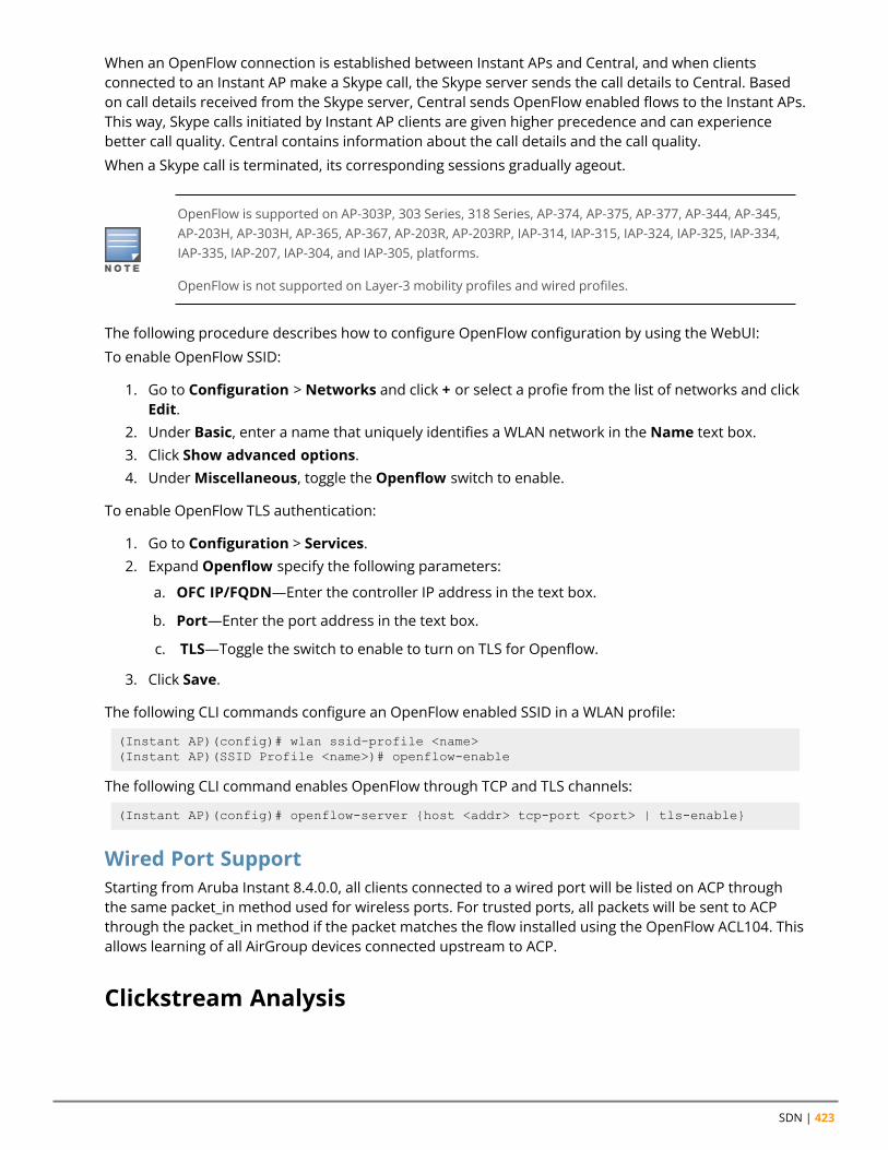
SDN | 423
When an OpenFlow connection is established between Instant APs and Central, and when clientsconnected to an Instant AP make a Skype call, the Skype server sends the call details to Central. Basedon call details received from the Skype server, Central sends OpenFlow enabled flows to the Instant APs.This way, Skype calls initiated by Instant AP clients are given higher precedence and can experiencebetter call quality. Central contains information about the call details and the call quality.
When a Skype call is terminated, its corresponding sessions gradually ageout.
OpenFlow is supported on AP-303P, 303 Series, 318 Series, AP-374, AP-375, AP-377, AP-344, AP-345,AP-203H, AP-303H, AP-365, AP-367, AP-203R, AP-203RP, IAP-314, IAP-315, IAP-324, IAP-325, IAP-334,IAP-335, IAP-207, IAP-304, and IAP-305, platforms.
OpenFlow is not supported on Layer-3 mobility profiles and wired profiles.
The following procedure describes how to configure OpenFlow configuration by using the WebUI:
To enable OpenFlow SSID:
1. Go to Configuration > Networks and click + or select a profie from the list of networks and clickEdit.
2. Under Basic, enter a name that uniquely identifies a WLAN network in the Name text box.3. Click Show advanced options.4. UnderMiscellaneous, toggle the Openflow switch to enable.
To enable OpenFlow TLS authentication:
1. Go to Configuration > Services.2. Expand Openflow specify the following parameters:
a. OFC IP/FQDN—Enter the controller IP address in the text box.
b. Port—Enter the port address in the text box.
c. TLS—Toggle the switch to enable to turn on TLS for Openflow.
3. Click Save.
The following CLI commands configure an OpenFlow enabled SSID in a WLAN profile:
(Instant AP)(config)# wlan ssid-profile <name>(Instant AP)(SSID Profile <name>)# openflow-enable
The following CLI command enables OpenFlow through TCP and TLS channels:
(Instant AP)(config)# openflow-server {host <addr> tcp-port <port> | tls-enable}
Wired Port SupportStarting from Aruba Instant 8.4.0.0, all clients connected to a wired port will be listed on ACP throughthe same packet_in method used for wireless ports. For trusted ports, all packets will be sent to ACPthrough the packet_in method if the packet matches the flow installed using the OpenFlow ACL104. Thisallows learning of all AirGroup devices connected upstream to ACP.
Clickstream Analysis
Aruba Instant 8.10.0.0 User Guide 424
Clickstream is a record of user activity on the Internet. Clickstream data is very useful as it helpsunderstand the Internet customer's behavior. Clickstream data is collected either in the form of websitelog files or in the form of direct decoding of the Internet request data payload.
When customers require HTTP payload related information of the user's web traffic, data is fed to theirclickstream analytics engine through Central. To support this, Instant APs use OpenFlow as the SDNprotocol to transfer clickstream data from the access point infrastructure to Central.
An Instant AP datapath extracts clickstream data of the HTTP session of every client, and sends it to theOpenFlow agent through a socket. The OpenFlow agent maintains this data in a ring buffer and dumps itinto the OpenFlow controller either on a full buffer basis or on a periodic timeout basis. On receivingthis message, OpenFlow controller segregates the data based on the flow type and forwards it to theclickstream application for further processing.
The Instant AP datapath can extract six TCP segments for an HTTP POST message. However, it canextract only two TCP segments for other HTTP methods such as GET, HEAD, PUT, PATCH, and DELETE.Instant does not support the extraction of HTTP methods such as TRACE, CONNECT, and OPTIONS.
You can obtain details about a clickstream data feed by executing the show openflow clickstream-statistics command on the Instant CLI.
The ring buffer size of clickstream data is modified according to the requirements of the Centraldeployments.
Wildcard ACL SupportWildcard ACLs enable ARP requests or responses to match with the ARP flow. The wildcard flow installedby OFC can be programmed to have any of the five tuple information—source IP address, destinationIP address, source port, destination port, or protocol. This flow is used to either allow, deny, or sendpacket count to the Openflow controller.
Wildcard ACL support introduces the following:
n Support for New Openflow Wildcard ACL on page 424n Wireless Client ARP Handling on page 424n Packet Out Implementation for mDNS on page 424
Support for New Openflow Wildcard ACLThe OpenFlow wildcard ACL in datapath is 104. When OpenFlow is enabled on an SSID, packets aresubjected to ACL 104 in the slow path. Depending on the packet type, the packet is copied to the userspace OFALD process. The user space then sends the data in the packet_in format to the OFC.
Wireless Client ARP HandlingOFC installs a wildcard ACL flow that allows matching ARP requests and responses. Accordingly if theARP request or response matches the ARP flow, a copy of the ARP packet is sent via PACKET_IN to OFC.
Packet Out Implementation for mDNSWhen the ARP cache times out on the OFC after 8 minutes, it sends out an ARP request to the Instant APusing the packet out protocol option. When Instant AP receives the packet out, it removes the OpenFlowheaders and sends out the ARP packet request to its downstream clients. If the client is still connectedto the SSID, it responds with an ARP response that is in turn sent to the OFC using the packet_inmethod.
Chapter 25Cluster Security
Cluster SecurityCluster security is a communication protocol that secures control plane messages between Instantaccess points. Control plane messages such as configuration, cluster join, and other messagesdistributed between the devices in a cluster are secured using this protocol. Cluster security operates onthe UDP port 4434 and uses DTLS protocol to secure messages.
This chapter describes cluster security and the procedure for configuring cluster security DTLS forsecure communication. It includes the following topics:
n Enabling Cluster Security on page 426n ZTP with Cluster Security on page 426n Low Assurance Devices on page 427n Cluster Security Debugging Logs on page 428n Verifying the Configuration on page 428
Cluster Security Using DTLSCluster security provides secure communication using DTLS. A DTLS connection is established betweenthe Instant APs communicating with each other in the cluster.
Following are some of the advantages of using DTLS for cluster security:
n Mutual authentication is done between the Instant APs in a cluster using device certificate.n Peer MAC address validation against AP allowlist can be enabled in the configuration.n Control plane messages between cluster members are transmitted securely using the DTLS
connection established.
If auto-join is enabled, backward compatibility and recovery of Instant APs is allowed on ARUBA UDPport 8211. Messages required for image synchronization and cluster security DTLS statesynchronization are the only messages allowed.
If auto-join is disabled, the MAC address of a peer Instant AP is verified against the AP allowlist duringdevice certificate validation.
Locked Mode Member Instant APA member Instant AP with non-factory default configuration and DTLS enabled in that configuration isconsidered to be in locked mode of operation. These member Instant APs will not be able to join theexisting non-DTLS cluster as backward compatibility and recovery is not allowed. This is done for securityreasons.
To recover the member Instant APs in locked mode:
Aruba Instant 8.10.0.0 User Guide 425
Cluster Security | 426
n Execute the disable-cluster-security-dtls action command on the member Instant AP , orn Factory reset the member Instant AP.
Enabling Cluster SecurityThe following procedure describes how to enable cluster security using the WebUI. Ensure that the pre-requisites following the procedure are satisfied:
1. Navigate to Configuration > System > General.2. Toggle the Cluster security switch to enable.3. Click Save.
Reboot all the Instant APs in the swarm for the configuration to take effect.
Pre-requisites1. NTP server must be reachable—If internet is reachable, pool.ntp.org will be used by default,
otherwise a static NTP server needs to be configured.2. UDP port 4434 should be permitted.
The following CLI commands enable cluster security:
(Instant AP)(config)# cluster-security(Instant AP)(cluster-security)# dtls
The following CLI commands disable cluster security DTLS:
(Instant AP)(config)# cluster-security(Instant AP)(cluster-security)# no dtls
The following CLI command changes per module logging level of cluster security:
(Instant AP)# cluster-security logging module <module_name> log-level <level>
The following CLI command sets individual log level for each module:
(Instant AP)# cluster-security logging module <module_name> log-level-individual<level>
After enabling or disabling the cluster security option, ensure that the Config Sync Status is TRUE inthe output of the show summary command, before rebooting the cluster.
Cluster security is not supported for L3 mobility.
ZTP with Cluster SecurityIn the earlier versions of Aruba Instant, it was a criteria to disable DTLS on a cluster before provisioningInstant APs through ZTP. The user had to enable DTLS on the cluster once again after ZTP was complete,which proved to be a slightly cumbersome process. A member Instant AP operating on an image thatdoes not support DTLS could not join the cluster through ZTP. Starting from Aruba Instant 8.4.0.0,certain enhancements have been made to allow a DTLS disabled member Instant AP to join aDTLS enabled cluster through ZTP.
Aruba Instant 8.10.0.0 User Guide 427
Adding Member Instant APs to DTLS Enabled ClustersIn order for ZTP to succeed when auto-join is disabled, the Instant AP should be added to the list ofallowlist APs by Central or AirWave before it joins the cluster.
The following procedure describes how to allow members to join a DTLS enabled cluster by using theInstant AP WebUI:
1. Navigate to Configuration > System > General .2. Click Show advanced options.3. Select Allow from the Non-DTLS members drop-down list.4. Click Save.
The following commands allows a member Instant AP to join a DTLS enabled cluster:
(Instant AP)(config)# cluster-security(Instant AP)(cluster-security)# no disallow-non-dtls-members
The following CLI commands prevent a DTLS disabled member Instant AP from joining a DTLS enabledcluster:
(Instant AP)(config)# cluster-security(Instant AP)(cluster-security)# disallow-non-dtls-members
The following CLI command checks if non-DTLS member Instant APs are allowed to join a DTLS enabledcluster:
(Instant AP)# show cluster-security
Low Assurance DevicesMost of the Aruba devices contain a TPM chip that securely stores keys and performs cryptographicoperations. However, some devices do not have a TPM chip. So, the unique private keys for thosedevices are stored in flash. Therefore, the level of protection for the device reduces.
To overcome this challenge, Instant has introduced a new PKI which issues device certificates to non-TPM devices. The device certificates consist of a policy OID indicating that they are issued by the PKI.Non-TPM devices are low assurance devices.
The following new features are introduced in the new PKI:
n SHA-256 is supported.n Non-TPM devices can be listed in the policy server.n Policies of new non-TPM Instant APs can be updated
A 256-bit random number generated by non-TPM devices is used to encrypt a private key that is uniqueto each device. The keys is encrypted by AES encryption. Non-TPM devices compress and store theencrypted private key file and the certificate files in Flash.The private key is maintained in an encryptedformat. APIs are provided to applications that use the private key.
The following procedure describes how to allow low assurance devices by using the WebUI:
1. Navigate to Configuration > System > General.2. Click Show advanced options.3. Toggle the Cluster security switch to enable.4. Select Allow from the Low assurance PKI drop-down list.5. Click Save.
Cluster Security | 428
The following CLI commands allows low assurance devices to join the cluster:
(Instant AP)(config)# cluster-security(Instant AP)(cluster-security)# allow-low-assurance-devices
When a DTLS connection is denied to low assurance Instant APs, the connection will not be allowedeven if the Instant AP is in the allowed Instant AP allowlist.
If a mixed mode cluster (combination of non-TPM Instant APs and regular Instant APs) is preferred,ensure to set the low assurance devices parameter to allow.
Zeroization of TPM KeysZeroization is a process that involves the erasing of sensitive parameters (electronically stored data,cryptographic keys, and critical security parameters) to prevent their disclosure when a device iscompromised.
Instant 8.4.0.0 introduces zeroization of TPM keys in FIPS-based Instant APs under circumstances thatpresent a threat to their integrity such as unauthorized removal of FIPS-based Instant APs, evidence oftampering, and so on.
The following CLI command zeroises TPM keys:
(Instant AP)# zeroize-tpm-keys
Cluster Security Debugging LogsCluster security logging is organized into modules based on functionality. The following are the coremodules which are useful and should be used for debugging:
n peer—The peer module is used to log connection initiation, renegotiation, collision and activeconnection updates. The log-level should be set to debug level while debugging any issues.
n conn—The connection module is used to log connection creation, establishment, data transfer andmaintenance updates. The log-level should be set to debug level for debugging DTLS connectionissues.
n mcap—The module capture module is used to log messages sent and received to the socket. Set log-level to debug to log only control messages. Set log-level to debug1 to log control and datamessages.
The following CLI command sets per module logging level:
(Instant AP)# cluster-security logging module <module_name> log-level <level>
Once the log-level is set, logs can be viewed using:
(Instant AP)# show log papi-handler
Verifying the ConfigurationThe following CLI command shows current cluster security configuration and running state:
(Instant AP)# show cluster-security
The following CLI command shows the cluster security statistics:

Aruba Instant 8.10.0.0 User Guide 429
(Instant AP)# show cluster-security stats
The following CLI command shows the cluster security connection table:
(Instant AP)# show cluster-security connections
The following CLI command shows the cluster security peers:
(Instant AP)# show cluster-security peers
The following CLI command shows the message handler process logs:
(Instant AP) # show log papi-handler <count>
Chapter 26Instant AP Management and Monitoring
Instant AP Management and MonitoringThis chapter provides information on provisioning, managing and monitoring Instant APs from thefollowing management servers:
n Managing an Instant AP from AirWave on page 430n Managing Instant AP from Aruba Central on page 440n WebSocket Connection on page 444n Support for REST API on page 444
Managing an Instant AP from AirWaveAirWave is a powerful platform and easy-to-use network operations system that manages Arubawireless, wired, and remote access networks, as well as wired and wireless infrastructures from a widerange of third-party manufacturers. With its easy-to-use interface, AirWave provides real-timemonitoring, proactive alerts, historical reporting, as well as fast and efficient troubleshooting. It alsooffers tools that manage RF coverage, strengthen wireless security, and demonstrate regulatorycompliance.
AirWave can be used to provision, manage, and monitor a multi-site deployment of Instant networks.For example,if you have 100 retail offices that require Instant to provide WLAN connectivity at eachoffice, AirWave can be used to provision all the 100 offices from a central site. AirWave also provides theadministrator with the ability to monitor these geographically dispersed Instant networks using anAirWave server depending on the scalability recommendations for AirWave.
The Instant APs communicate with AirWave using the HTTPS, XML, or Websocket protocol. This allows anAirWave server to be deployed in the cloud across a NAT device, such as a router.
The AirWave features available in the Instant network are described in the following sections:
Image ManagementAirWave allows you to manage firmware updates on WLAN devices by defining a minimum acceptablefirmware version for each make and model of a device. It remotely distributes the firmware image to theWLAN devices that require updates, and it schedules the firmware updates such that updating iscompleted without requiring you to manually monitor the devices.
The following models can be used to upgrade the firmware:
n Automatic—In this model, the virtual controller periodically checks for newer updates from aconfigured URL and automatically initiates upgrade of the network.
n Manual—In this model, the user can manually start a firmware upgrade for each virtual controller orset the desired firmware preference per group of devices.
Resetting an Instant APA virtual controller is added to the AirWave database either on management mode or monitor modebased on the AirWave configuration.
An Instant AP device can be reset through AirWave in theManagedmode:
Aruba Instant 8.10.0.0 User Guide 430
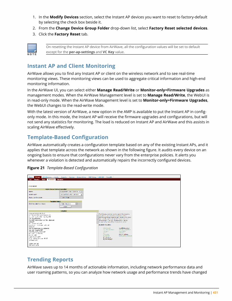
Instant AP Management and Monitoring | 431
1. In theModify Devices section, select the Instant AP devices you want to reset to factory-defaultby selecting the check box beside it.
2. From the Change Device Group Folder drop-down list, select Factory Reset selected devices.3. Click the Factory Reset tab.
On resetting the Instant AP device from AirWave, all the configuration values will be set to defaultexcept for the per-ap-settings and VC Key value.
Instant AP and Client MonitoringAirWave allows you to find any Instant AP or client on the wireless network and to see real-timemonitoring views. These monitoring views can be used to aggregate critical information and high-endmonitoring information.
In the AirWave UI, you can select eitherManage Read/Write orMonitor-only+Firmware Upgrades asmanagement modes. When the AirWave Management level is set toManage Read/Write, the WebUI isin read-only mode. When the AirWave Management level is set toMonitor-only+Firmware Upgrades,the WebUI changes to the read-write mode.
With the latest version of AirWave, a new option in the AMP is available to put the Instant AP in config-only mode. In this mode, the Instant AP will receive the firmware upgrades and configurations, but willnot send any statistics for monitoring. The load is reduced on Instant AP and AirWave and this assists inscaling AirWave effectively.
Template-Based ConfigurationAirWave automatically creates a configuration template based on any of the existing Instant APs, and itapplies that template across the network as shown in the following figure. It audits every device on anongoing basis to ensure that configurations never vary from the enterprise policies. It alerts youwhenever a violation is detected and automatically repairs the incorrectly configured devices.
Figure 21 Template-Based Configuration
Trending ReportsAirWave saves up to 14 months of actionable information, including network performance data anduser roaming patterns, so you can analyze how network usage and performance trends have changed
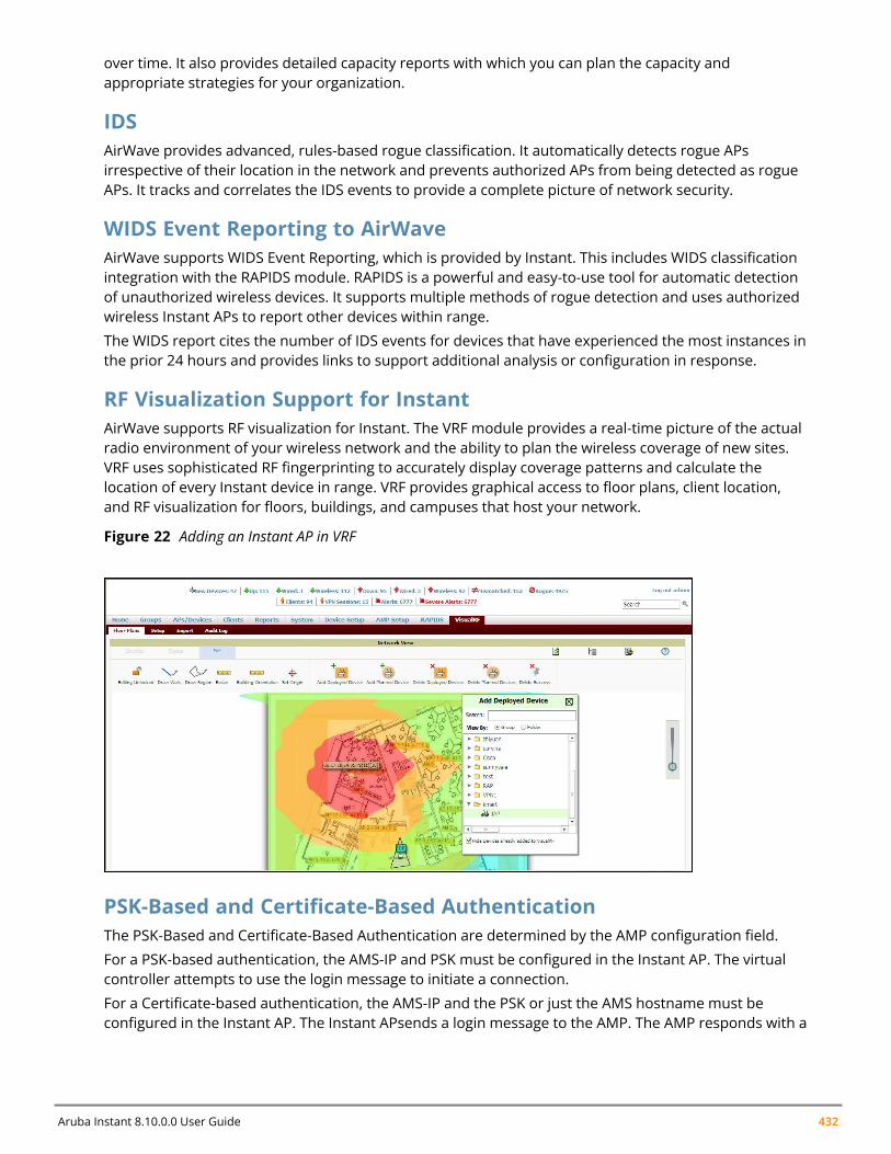
Aruba Instant 8.10.0.0 User Guide 432
over time. It also provides detailed capacity reports with which you can plan the capacity andappropriate strategies for your organization.
IDSAirWave provides advanced, rules-based rogue classification. It automatically detects rogue APsirrespective of their location in the network and prevents authorized APs from being detected as rogueAPs. It tracks and correlates the IDS events to provide a complete picture of network security.
WIDS Event Reporting to AirWaveAirWave supports WIDS Event Reporting, which is provided by Instant. This includes WIDS classificationintegration with the RAPIDS module. RAPIDS is a powerful and easy-to-use tool for automatic detectionof unauthorized wireless devices. It supports multiple methods of rogue detection and uses authorizedwireless Instant APs to report other devices within range.
The WIDS report cites the number of IDS events for devices that have experienced the most instances inthe prior 24 hours and provides links to support additional analysis or configuration in response.
RF Visualization Support for InstantAirWave supports RF visualization for Instant. The VRF module provides a real-time picture of the actualradio environment of your wireless network and the ability to plan the wireless coverage of new sites.VRF uses sophisticated RF fingerprinting to accurately display coverage patterns and calculate thelocation of every Instant device in range. VRF provides graphical access to floor plans, client location,and RF visualization for floors, buildings, and campuses that host your network.
Figure 22 Adding an Instant AP in VRF
PSK-Based and Certificate-Based AuthenticationThe PSK-Based and Certificate-Based Authentication are determined by the AMP configuration field.
For a PSK-based authentication, the AMS-IP and PSK must be configured in the Instant AP. The virtualcontroller attempts to use the login message to initiate a connection.
For a Certificate-based authentication, the AMS-IP and the PSK or just the AMS hostname must beconfigured in the Instant AP. The Instant APsends a login message to the AMP. The AMP responds with a
Instant AP Management and Monitoring | 433
randomly generated string. The Instant AP signs the string with its private key and certificate, and sendsit back to the AMP. The AMP verifies if the certificate and signature are valid.
A virtual controller is approved based on the status of the Allowlist database:
n When Allowlist is enabled, the AMP verifies if the MAC address and serial number in the loginmessage of the virtual controller and the allowlist database match. If they match, a virtual controlleris created and approved. If they do not match, no virtual controller is created.
n When Allowlist is disabled, the virtual controller is created based on the following conditions:l Presence of other virtual controller with the same organization string and PSK in the AMP.l Approval of atleast one of the virtual controller in the AMP.
Configurable Port for Instant AP and AirWave Management ServerCommunicationYou can now customize the port number of the AMP server through the server_host:server_portformat, for example, amp.aruba.com:4343.
The following example shows how to configure the port number of the AMP server:
24:de:c6:cf:63:60 (config) # ams-ip 10.65.182.15:65535
Configuring Organization StringThe Organization string is a set of colon-separated strings created by the AirWave administrator toaccurately represent the deployment of each Instant AP. This string is defined by the installationpersonnel on the site.
You can use any of the following strings:
n AMP Role—"Org Admin" (initially disabled)n AMP User—"Org Admin" (assigned to the role "Org Admin")n Folder—"Org" (under the Top folder in AMP)n Configuration Group—"Org"
You can also assign additional strings to create a hierarchy of subfolders under the folder named "Org".For example:
n subfolder1 for a folder under the "Org" foldern subfolder2 for a folder under subfolder1
Shared KeyThe Shared Secret key is an optional key used by the administrator to manually authorize the firstvirtual controller for an organization. Any string is acceptable.
The AirWave administrator can use a shared key to manually authorize the first virtual controller for anorganization. Any string is acceptable, but this string must be the same for all devices in yourorganization.
The AirWave administrator sends the shared secret key, Organization String and the AirWave IP addressto the on-site installer setting up the virtual controller and other Instant devices on the network. TheAirWave administrator then manually authorizes the virtual controller shared secret key when itappears in the APs/Devices > New list. After the virtual controller has been validated, other Instantdevices using that shared key will automatically be sent to the AirWave server, and appear in theAPs/Devices > New list.
Aruba Instant 8.10.0.0 User Guide 434
Configuring AirWave InformationThe following procedure describes how to configure AirWave information by using the WebUI.
1. Click the AirWave Set Up Now link of the main window. The System window is displayed with theAirWave parameters on the Admin tab.
2. Enter the name of your organization in the Organization name text box. The name defined forthe organization is displayed under the Groups tab in the AirWave UI.
3. Enter the IP address or domain name of the AirWave server in the AirWave server text box.4. Enter the IP address or domain name of a backup AirWave server in the AirWave backup server
text box. The backup server provides connectivity when the primary server is down. If the InstantAP cannot send data to the primary server, the virtual controller switches to the backup serverautomatically.
5. Enter the shared key in the Shared key text box and reconfirm. This shared key is used forconfiguring the first Instant AP in the Instant network.
6. Click OK.
The following CLI commands configure AirWave information:
(Instant AP)(config)# organization <name>(Instant AP)(config)# ams-ip <IP-address or domain name>(Instant AP)(config)# ams-backup-ip <IP-address or domain name>(Instant AP)(config)# ams-key <key>
Configuring for AirWave Discovery Through DHCPAirWave can be discovered through the DHCP server. You can configure this only if AirWave was notconfigured earlier or if you have deleted the precedent configuration.
On the DHCP server, the format for option 60 is “ArubaInstantAP“. The two formats for option 43 are“<organization>,<ams-ip>,<ams-key>” and “<organization>,<ams-domain>” wherein you canconfigure any domain name.
If you use the <organization>,<ams-ip>,<ams-key> format, the PSK-based authentication is used toaccess the AMP server.
If you use the <organization>,<ams-domain> format, the Instant AP resolves the domain name intotwo IP addresses—AirWave Primary and AirWave Backup.
For option 43, when you choose to enter the domain name, the IP address and key are not available.
Enabling DNS-Based Discovery of the Provisioning AMP ServerInstant APs can now automatically discover the provisioning AMP server if the DHCP option 43 andActivate cannot perform ZTP and transfer the AirWave configuration to the Instant AP.
When a domain option xxx is included in the DHCP configuration, the Instant AP will search the DNSserver records for aruba-airwave.xxx. When there is no domain option, the Instant AP will search onlythe server records for aruba-airwave.
To enable Instant APs to automatically discover the AMP server, create a DNS record for aruba-airwave.xxx or aruba-airwave in the DNS server. To use this feature on the AirWave side, enablecertificate-based login. For information on how to enable certificate-based login, see PSK-Based andCertificate-Based Authentication on page 432.
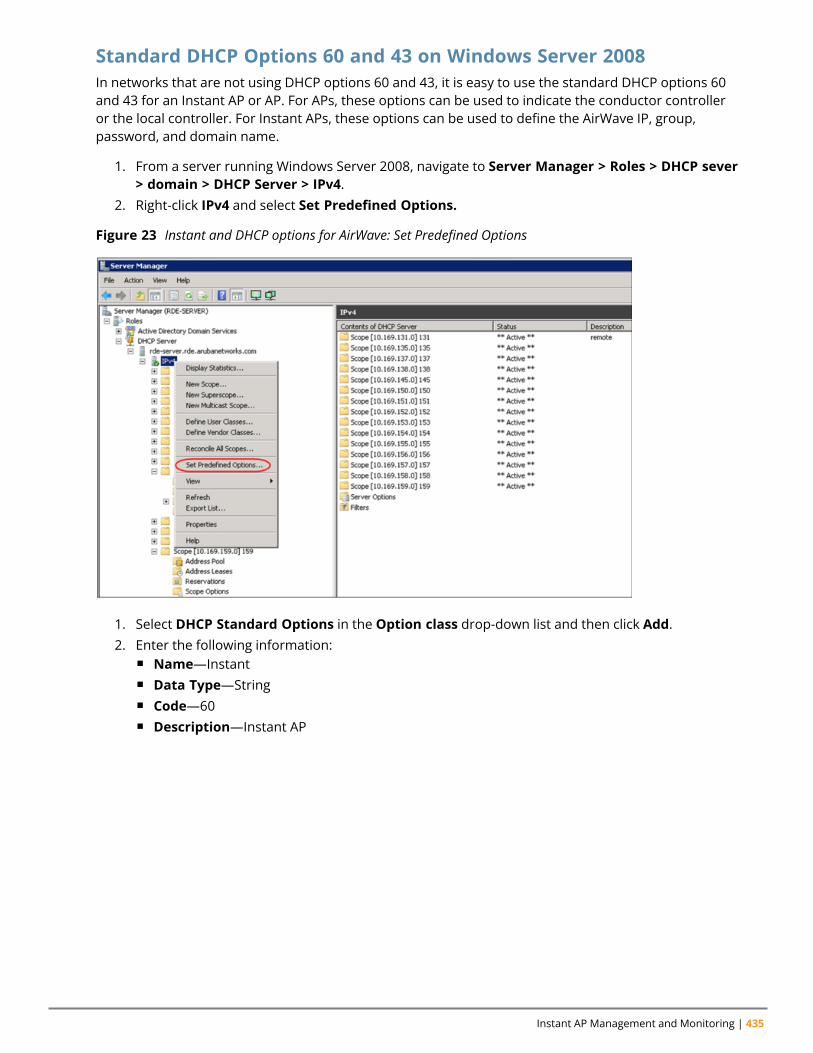
Instant AP Management and Monitoring | 435
Standard DHCP Options 60 and 43 on Windows Server 2008In networks that are not using DHCP options 60 and 43, it is easy to use the standard DHCP options 60and 43 for an Instant AP or AP. For APs, these options can be used to indicate the conductor controlleror the local controller. For Instant APs, these options can be used to define the AirWave IP, group,password, and domain name.
1. From a server running Windows Server 2008, navigate to Server Manager > Roles > DHCP sever> domain > DHCP Server > IPv4.
2. Right-click IPv4 and select Set Predefined Options.
Figure 23 Instant and DHCP options for AirWave: Set Predefined Options
1. Select DHCP Standard Options in the Option class drop-down list and then click Add.2. Enter the following information:
n Name—Instantn Data Type—Stringn Code—60n Description—Instant AP
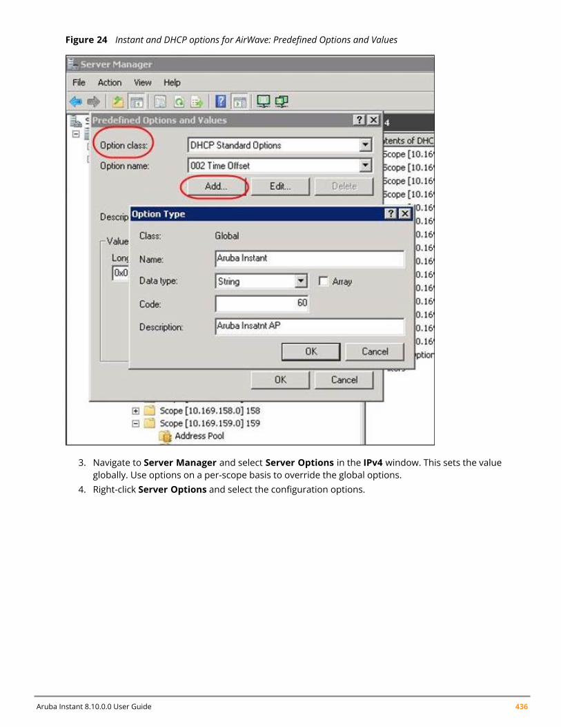
Aruba Instant 8.10.0.0 User Guide 436
Figure 24 Instant and DHCP options for AirWave: Predefined Options and Values
3. Navigate to Server Manager and select Server Options in the IPv4 window. This sets the valueglobally. Use options on a per-scope basis to override the global options.
4. Right-click Server Options and select the configuration options.
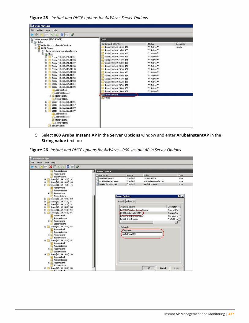
Instant AP Management and Monitoring | 437
Figure 25 Instant and DHCP options for AirWave: Server Options
5. Select 060 Aruba Instant AP in the Server Options window and enter ArubaInstantAP in theString value text box.
Figure 26 Instant and DHCP options for AirWave—060 Instant AP in Server Options
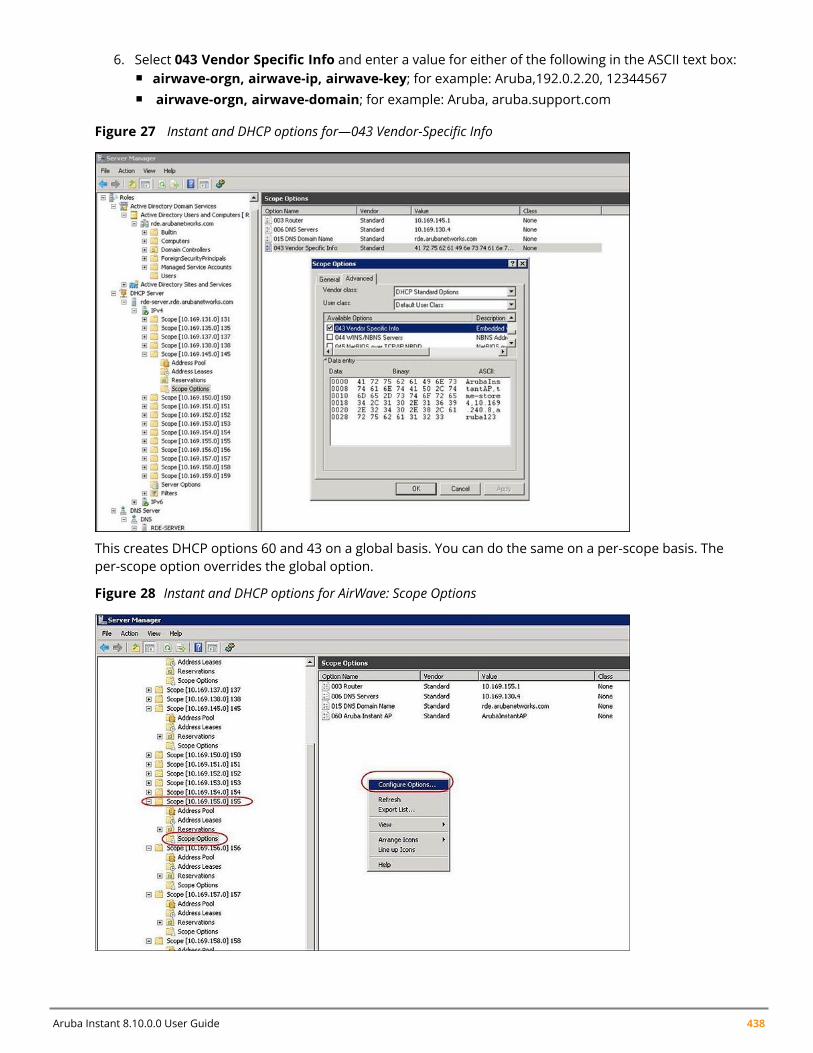
Aruba Instant 8.10.0.0 User Guide 438
6. Select 043 Vendor Specific Info and enter a value for either of the following in the ASCII text box:n airwave-orgn, airwave-ip, airwave-key; for example: Aruba,192.0.2.20, 12344567n airwave-orgn, airwave-domain; for example: Aruba, aruba.support.com
Figure 27 Instant and DHCP options for—043 Vendor-Specific Info
This creates DHCP options 60 and 43 on a global basis. You can do the same on a per-scope basis. Theper-scope option overrides the global option.
Figure 28 Instant and DHCP options for AirWave: Scope Options
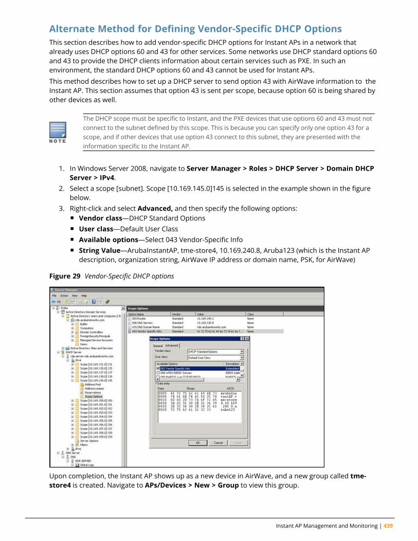
Instant AP Management and Monitoring | 439
Alternate Method for Defining Vendor-Specific DHCP OptionsThis section describes how to add vendor-specific DHCP options for Instant APs in a network thatalready uses DHCP options 60 and 43 for other services. Some networks use DHCP standard options 60and 43 to provide the DHCP clients information about certain services such as PXE. In such anenvironment, the standard DHCP options 60 and 43 cannot be used for Instant APs.
This method describes how to set up a DHCP server to send option 43 with AirWave information to theInstant AP. This section assumes that option 43 is sent per scope, because option 60 is being shared byother devices as well.
The DHCP scope must be specific to Instant, and the PXE devices that use options 60 and 43 must notconnect to the subnet defined by this scope. This is because you can specify only one option 43 for ascope, and if other devices that use option 43 connect to this subnet, they are presented with theinformation specific to the Instant AP.
1. In Windows Server 2008, navigate to Server Manager > Roles > DHCP Server > Domain DHCPServer > IPv4.
2. Select a scope [subnet]. Scope [10.169.145.0]145 is selected in the example shown in the figurebelow.
3. Right-click and select Advanced, and then specify the following options:n Vendor class—DHCP Standard Optionsn User class—Default User Classn Available options—Select 043 Vendor-Specific Infon String Value—ArubaInstantAP, tme-store4, 10.169.240.8, Aruba123 (which is the Instant AP
description, organization string, AirWave IP address or domain name, PSK, for AirWave)
Figure 29 Vendor-Specific DHCP options
Upon completion, the Instant AP shows up as a new device in AirWave, and a new group called tme-store4 is created. Navigate to APs/Devices > New > Group to view this group.
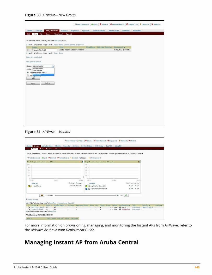
Aruba Instant 8.10.0.0 User Guide 440
Figure 30 AirWave—New Group
Figure 31 AirWave—Monitor
For more information on provisioning, managing, and monitoring the Instant APs from AirWave, refer tothe AirWave Aruba Instant Deployment Guide.
Managing Instant AP from Aruba Central
Instant AP Management and Monitoring | 441
Central uses a secure HTTPs connection and provides a strong mutual authentication mechanism usingcertificates for all communication with Instant APs. These certificates ensure the highest level ofprotection.
Starting from ArubaInstant 8.3.0.0, when you configure a static IP address for an Instant AP but theconnection to ArubaCentral server fails, the Instant AP switches from static IP to DHCP.
Provisioning an Instant AP using Aruba Central
Accessing CentralAfter you subscribe and register an Instant AP, log in to the Central dashboard to manage your InstantAP using the following URL:
http://www.arubanetworks.com/iap-motd
The Aruba Central WebUI is categorized into the following sections:
1. Monitoring2. Configuration3. Reporting4. Maintenance
These sections are layered under groups. The configuration details of the Instant APs are defined at agroup level.
Instant AP Provisioning
Obtaining Cloud Activation Key
The Instant APs obtain the cloud activation key from the Aruba Central Activate server in the followingscenarios:
n During reboot, if the Virtual Controller has the Aruba Central URL stored, it will connect directly toAruba Central using the activation key obtained from the Aruba Central Activate server. If there is noURL stored, the Virtual Controller tries to establish a connection with the Activate server every 5minutes, until a successful SSL connection is established and the activation key is obtained.
n If the Instant AP Virtual Controller has a Aruba Central URL stored, but fails to establish a connectionto Aruba Central in three attempts, the Virtual Controller reconnects to the Activate server to obtaina new activation key.
The cloud activation key obtained from the Activate server is valid for 10 days. To obtain a newactivation key, Instant APs reconnect to the Activate server after the initially assigned key expires.
Managing Subscriptions
Central maintains a subscription list for the Instant APs. If an Instant AP is not included in this list,Central identifies it as an unauthorized Instant AP and prevents it from joining the network. The serviceproviders use Central to track the subscription of each Instant AP based on its serial number and MACaddress.
The following types of subscription status are listed for the Instant APs:
n Active—Central allows the Instant AP to join the network.n Expired—Central denies the Instant AP from joining the network.
Aruba Instant 8.10.0.0 User Guide 442
If the status of a conductor Instant AP changes from active to expired, it retains its configuration andthe local WebUI comes up. The conductor Instant AP does not reload upon Central subscriptionexpiry.
If the status of a member Instant AP changes from active to expired, the Virtual Controller sets themember Instant AP to factory defaults and reboots the Instant AP.
Member Instant APs can connect to Central through WebSocket.
n Unknown—Central does not allow the Instant AP to join the network. However, it gives an option toretry the connection.
The list maintained by Central is different from the list maintained by the end users. Therefore, Centralcan prevent an Instant AP from joining the network when the subscription expires, even if the Instant APis present in the subscription list maintained by the end user.
The subscription list is dynamic and gets updated each time an Instant AP is included in Central.
Firmware ManagementFor a multiclass Instant AP network, ensure that the Instant AP can download software images from theAruba Cloud-Based Image Service. You may also need to configure HTTP proxy settings on the InstantAP if they are required for Internet access in your network. For more information about image upgradeand HTTP proxy configuration, refer to the Aruba Instant Release Notes.
Instant AP ConfigurationAny Instant AP joining a group inherits the configuration defined for the group. After you create a group,navigate to the Wireless Configuration section and create a new SSID. Aruba Central supports ZTP,which allows the network administrators to configure the Instant APs even before the hardware arrives.
After you turn on the Instant AP and connect to the uplink port, the Instant AP is displayed under thedefault group in the Central UI. You can choose to move the Instant AP to a different group that youcreated. The configuration defined in this group is automatically applied to the Instant AP.
Starting from ArubaInstant 8.3.0.0, Instant AP allows ArubaCentral to override the routing settings onInstant AP and have some control over the way Central-related traffic is routed.
Recovery Mechanism in the Event of Central Connection FailureInstant APs managed by Aruba Central require a connection with the Central server for networkoperations. In the event of a connection loss with Central, the AP tries to reach Central server using theIP address stored in its flash or by retrieving the Central server IP address from the Activate server.When Instant APs configured with a static IP address fail to reach Central, the AP initiates a self recoverymechanism and switches to local DHCP management in an attempt to connect to Central.
The switch from static IP to local DHCP will only be triggered if all of the following conditions are met:
n The AP loses connectivity with Central for more than 10 minutes.n The AP is unable to reach the default gateway using ARP ping.
Instant AP Management and Monitoring | 443
n The AP encounters TCP, SSL, or DNS error with both Activate and Central connections.n A DHCP server responds to DHCP probe requests sent by the AP.
Once the AP establishes connection with Central, it will receive configurations from Central and rebootwith the original static IP configuration.
To view the status of recovery mechanism, use the show recover status command. It displays thestatus of the recovery mechanism and cause for recovery trigger.
(Instant AP)(config)# show recover status
To view static IP address stored in the AP, use the show ap-env command.
(Instant AP)(config)# show ap-env
For more information on these commands, refer to the Aruba Instant 8.x CLI Reference Guide.
Changes to the Subscription ModelStarting from Aruba Instant 8.4.0.0, a new subscription model is introduced as a basic interface betweenInstant AP and Central. The subscription model uses a programmable telemetry interface to subscribeor unsubscribe Instant APs from Central.
Following are some of the key features of the new subscription model:
n Instant APs no longer require a firmware upgrade whenl Central adds or removes subscribed datal A new client requests datal Central dynamically manages data feed operations such as start, pause, resume, or unsubscribe.
n The subscribed data is published periodically during an assigned interval.n Any changes made to the subscribed data is immediately published to the Instant AP.n The new subscription model follows the distributed module, where Central communicates with each
device to gather reports on device monitoring, configuration, and upgrade status specific to thedevice.
Subscription for Periodic UpdatesThe telemetry interface in the new subscription model can be programmed to send periodic updatesusing the Instant CLI. The following CLI command initiates the subscription for periodic updates fromCentral:
(Instant AP)(config)# stats-update-interval
Automatic Installation of DRT UpdatesInstant APs managed by Central can now automatically download and install the latest DRT file availableon Activate. The DRT file includes the details of approved regulatory certifications and allowed RFtransmissions (channels, EIRP, and so on..) for an AP at any geographical region or country.
The automatic download and installation of DRT updates is enabled by default for Instant APs. You canuse the available CLI commands, to disable or re-enable the automatic download and installation ofDRT updates.
The following command disables the automatic download and installation of DRT updates on theInstant AP managed by Aruba Central:
(Instant AP)(config)# auto-drt-upgrade-under-central-mgmt-disable
Aruba Instant 8.10.0.0 User Guide 444
The following command re-enables the automatic download and installation of DRT updates on theInstant AP managed by Aruba Central:
(Instant AP)(config)# no auto-drt-upgrade-under-central-mgmt-disable
WebSocket ConnectionWebSocket is a protocol based on which the virtual controllers and the member Instant APs canestablish and maintain a connection with the AirWave and Central servers. A WebSocket support ismore efficient because the server does not depend on a client request to respond to an Instant AP.When a WebSocket connection is established, all the access points including virtual controllers andmembers can communicate with the server at any time. Virtual controllers can communicate with theAirWave or Central management server. Member Instant APs can communicate with application levelcomponents.
A new WebSocket capable Instant AP connects to a server through the HTTPS post. If a server supportsWebSocket, it will send an HTTP redirect message to the Instant AP. The Instant AP closes the existingHTTPS connection and connects to the server through WebSocket. If the server does not supportWebSocket, it will ignore the header and Instant APs will continue using HTTPS and XML to communicatewith the server.
The following CLI command shows the websocket status between Instant APs and AirWave:
(Instant AP)# show ap debug airwave
Support for REST APIStarting from Aruba Instant 8.5.0.0, you can configure and monitor Instant APs using REST APIs. Thisfeature is supported by Instant on both cluster and standalone modes. For more information, see ArubaInstant8.5.0.x REST API Guide.
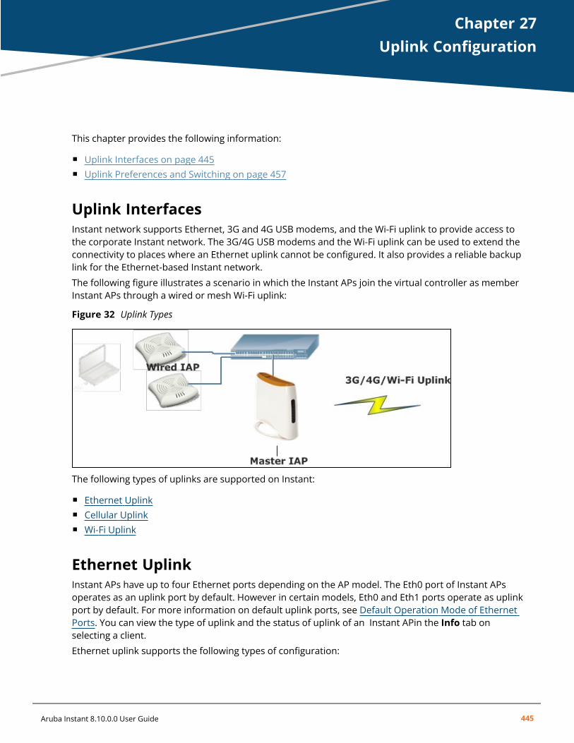
Chapter 27Uplink Configuration
Uplink ConfigurationThis chapter provides the following information:
n Uplink Interfaces on page 445n Uplink Preferences and Switching on page 457
Uplink InterfacesInstant network supports Ethernet, 3G and 4G USB modems, and the Wi-Fi uplink to provide access tothe corporate Instant network. The 3G/4G USB modems and the Wi-Fi uplink can be used to extend theconnectivity to places where an Ethernet uplink cannot be configured. It also provides a reliable backuplink for the Ethernet-based Instant network.
The following figure illustrates a scenario in which the Instant APs join the virtual controller as memberInstant APs through a wired or mesh Wi-Fi uplink:
Figure 32 Uplink Types
The following types of uplinks are supported on Instant:
n Ethernet Uplinkn Cellular Uplinkn Wi-Fi Uplink
Ethernet UplinkInstant APs have up to four Ethernet ports depending on the AP model. The Eth0 port of Instant APsoperates as an uplink port by default. However in certain models, Eth0 and Eth1 ports operate as uplinkport by default. For more information on default uplink ports, see Default Operation Mode of EthernetPorts. You can view the type of uplink and the status of uplink of an Instant APin the Info tab onselecting a client.
Ethernet uplink supports the following types of configuration:
Aruba Instant 8.10.0.0 User Guide 445
Uplink Configuration | 446
n PPPoEn DHCPn Static IP
You can use PPPoE for your uplink connectivity in both Instant AP and IAP-VPN deployments. PPPoE issupported only in a single Instant AP deployment.
Uplink redundancy with the PPPoE link is not supported.
When the Ethernet link is up, it is used as a PPPoE or DHCP uplink. After the PPPoE settings areconfigured, PPPoE has the highest priority for the uplink connections. The Instant AP can establish aPPPoE session with a PPPoE server at the ISP and get authenticated using PAP or CHAP. Dependingupon the request from the PPPoE server, either the PAP or the CHAP credentials are used forauthentication. After configuring PPPoE, reboot the Instant AP for the configuration to take effect. ThePPPoE connection is dialed after the Instant AP comes up. The PPPoE configuration is checked duringInstant AP boot and if the configuration is correct, Ethernet is used for the uplink connection.
When PPPoE is used, do not configure Dynamic RADIUS Proxy and IP address of the virtual controller.An SSID created with default VLAN is not supported with PPPoE uplink.
You can also configure an alternate Ethernet uplink to enable uplink failover when an Ethernet portfails.
Configuring PPPoE Uplink ProfileThe following procedure describes how to configure PPPoE settings from the WebUI:
1. Go to Configuration > System > Show advanced options.2. Expand Uplink.3. Under PPPoE, specify the following parameters:
a. Service name— Enter the PPPoE service name provided by your service provider in the textbox.
b. User—Enter the username for the PPPoE connection in the text box.
c. CHAP secret—Enter the secret key used for CHAP authentication in the text box. Re-type thesecret key in the Retype text box to confirm. You can use a maximum of 34 characters forthe CHAP secret key.
d. Password—Enter a password for the PPPoE connection in the text box. Retype the passwordin the Retype text box to confirm.
4. Select a value from the Local interface drop-down list to set a local interface for the PPPoEuplink connections. The selected DHCP scope will be used as a local interface on the PPPoEinterface and the Local L3 DHCP gateway IP address as its local IP address. When configured, thelocal interface acts as an unnumbered PPPoE interface and allows the entire Local L3 DHCPsubnet to be allocated to clients.
The options in the Local interface drop-down list are displayed only if a Local L3 DHCP scopeis configured on the Instant AP.
5. Click Save.6. Reboot the Instant AP for the configuration to take effect.
Aruba Instant 8.10.0.0 User Guide 447
The following CLI commands configure a PPPoE uplink connection:
(Instant AP)(config) # pppoe-uplink-profile(Instant AP)(pppoe-uplink-profile)# pppoe-svcname <service-name>(Instant AP)(pppoe-uplink-profile)# pppoe-username <username>(Instant AP)(pppoe-uplink-profile)# pppoe-passwd <password>(Instant AP)(pppoe-uplink-profile)# pppoe-chapsecret <password>(Instant AP)(pppoe-uplink-profile)# pppoe-unnumbered-local-l3-dhcp-profile <dhcp-profile>
The following CLI command shows the PPPoE configuration:
(Instant AP)# show pppoe config
PPPoE Configuration-------------------Type Value---- -----User testUserPassword 3c28ec1b82d3eef0e65371da2f39c4d49803e5b2bc88be0cService name internet03CHAP secret 8e87644deda9364100719e017f88ebceUnnumbered dhcp profile dhcpProfile1
The following CLI command shows the PPPoE status:
(Instant AP)# show pppoe status
pppoe uplink state:Suppressed.
Default Operation Mode of Ethernet PortsBased on the default Ethernet port behavior, APs with two or more Ethernet ports are classified intosingle uplink and dual uplink APs. Dual uplink APs have both Eth0 and Eth1 ports configured as uplinkports by default whereas in single uplink APs only one Ethernet port operates as an uplink port bydefault. The following table lists the classification of APs based on the default operation of their Ethernetports:
Classification AP Models
Dual Uplink APs: All Ethernet ports, Eth0and Eth1, operate as uplink ports.
AP-318, 320 Series, 330 Series, 370 Series, 510 Series, 530 Series,and 570 Series access points.
Single Uplink APs: Only one Ethernet port,Eth0, operates as uplink port.
203H Series, 203R Series, 303H Series, 303P Series, and 500HSeries access points.
When Eth0 and Eth1 ports are configured for uplink, both the ports are bonded together in a virtualinterface called bond0. Bond0 functions as a single uplink interface and provides layer 2 redundancy forthe AP by purposing one port as the active uplink port and the other port as a backup uplink port. Theoperation mode of individual Ethernet ports can be configured to operate either as an uplink ordownlink port, in both single uplink and dual uplink APs.
When a dual uplink AP is upgraded to Aruba Instant 8.8.0.0, the Eth1 configuration of the AP isretained. The upgrade to Aruba Instant 8.8.0.0 does not override the existing Eth1 configuration. Thedefault Eth1 mode is platform default and this retains the configuration.
Configuring the Operation Mode of Ethernet Ports
Uplink Configuration | 448
The Ethernet ports of an AP can be configured to operate either as an uplink port or a downlink port.The following procedure describes how to configure an Ethernet port as an uplink or downlink port:
1. Navigate to the Configuration > Access points page of the webUI.2. Select the AP you want to configure in the Access Points table and click edit.3. Click on Uplink to expand the section.4. Select the operation mode of the Eth0 port in the Eth0 mode drop-down menu. The following
modes are available:n Uplink - Configures the Eth0 port as an uplink port.n Downlink - Configures the Eth0 port as a downlink port. Configuring the Eth0 port as a
downlink port enables enet0-bridging on the Instant AP.
5. Select the operation mode of the Eth1 port in the Eth1 mode drop-down menu. The followingmodes are available:n Uplink - Configures the Eth1 port as an uplink port.n Downlink - Configures the Eth1 port as a downlink port.n Platform default - Sets the Eth1 mode to platform default. When Platform default is
configured, the Eth1 port will use the existing configuration of the AP. This means that whenan AP upgrades to Aruba Instant 8.8.0.0, the existing Eth1 configuration of the AP is retained.When an AP boots from factory reset mode, the Eth1 port will operate based on the defaultoperation mode of the platform. This is the default setting.
6. Click Save to save the configuration.7. Reboot the AP to apply the configuration.
The following commands are used to change the operation mode of Eth1 port:
n To configure the Eth1 port as an uplink port, use the enet1-mode uplink command.
(Instant AP) #enet1-mode uplink
n To configure the Eth1 port as a downlink port, use the enet1-mode downlink command.
(Instant AP) #enet1-mode downlink
For more information on enet1-mode command, refer to the Aruba Instant 8.x CLI Reference Guide.
Configuring Uplink Ports for AP-318 and 370 Series Access PointsThe Eth0 and Eth1 ports of AP-318 and 370 Series access points operate as uplink ports by default. Theeth1 port as the primary Ethernet uplink and eth0 as the backup Ethernet uplink. The primary Ethernetuplink can be changed using the preferred-uplink command. When eth0 port is configured as theprimary Ethernet uplink, the eth1 port assumes the role of backup Ethernet uplink and vice versa.
The eth1 port cannot be configured as a downlink port whereas, if required, the eth0 port can beconfigured as a downlink port by enabling enet0-bridging. When enet0-bridging is enabled on the AP,the eth0 port assumes the downlink role irrespective of the preferred uplink configuration.
The following conditions apply to AP-318 and 370 Series access points:
n The downlink parameters configured in the wired port profile will not take effect.n If LACP is configured, enet0-bridging cannot be enforced.n In Mesh scenarios, the mesh point change will only occur if uplink is down for both eth0 and eth1
ports.
Configuring Primary Ethernet Uplink Port
Aruba Instant 8.10.0.0 User Guide 449
The primary Ethernet uplink for , AP-318 and 370 Series access points can be configured using thepreferred-uplink command. When configured, the primary Ethernet uplink port will be used for uplinkand the backup Ethernet uplink will only be used if the primary Ethernet uplink is down. The uplink forthese AP platforms will fall back to a different uplink, defined in the uplink priority list, only if both theprimary and backup Ethernet link is down.
The preferred uplink command is a per-AP setting. The following CLI command configures the preferreduplink:
(Instant AP)# preferred-uplink <0,1>
Configuring Downlink Port
The eth0 port of AP-318 and 370 Series access points can be configured as a downlink port by enablingenet0-bridging. Only the eth0 port of these access points can be configured as a downlink port. If eth0is configured as the primary Ethernet uplink and enet0 bridging is enabled, the eth0 port will become adownlink port and eth1 will become the primary uplink port.
The enet0-bridging is a per-AP setting, The following CLI command configures enet0-bridging:
(Instant AP)# enet0-bridging
Viewing Ethernet Uplink Status
The show ap-env command displays the status of preferred uplink configuration:
(Instant AP)# show ap-envAntenna Type: InternalNeed usb field:Nouap_controller_less:1preferred_uplink:eth1
Multiple Ethernet UplinkInstant APs support the configuration of multiple Ethernet ports for uplink connection. One Ethernetport assumes the role of active uplink port while the other Ethernet port is used as a backup uplink port.Ports configured as uplink ports are enabled with reachability detection to identify the better uplinkconnection between them. Failover and pre-emption features are enabled by default when multipleEthernet uplink is configured.
Important Points to RememberConfiguring multiple Ethernet uplink has the following limitations:
n Supported only in standalone and mesh deployments with a single mesh portal.n Does not support multiple PPPoE connections.n Does not support static IP uplink.
Configuring Multiple Ethernet UplinkAs Instant APs support layer 2 redundancy in APs with two Ethernet uplinks, both the Eth0 and Eth1ports are bonded together virtually as bond0. Therefore before configuring multiple Ethernet uplink, theEth1 port must be removed from this virtual bond, bond0. To remove Eth1 port from the bond0, changethe operation mode of Eth1 to downlink. Read more on how to change the operation mode of the Eth1port in Configuring the Operation Mode of Ethernet Ports section.
To configure multiple ethernet uplink for an Instant AP, perform the following workflow:
Uplink Configuration | 450
1. Configure a wired port profile for the second Ethernet uplink. See Configuring a Wired Profile tolearn how to configure a wired port profile.
The following CLI command configures a wired port profile:
(Instant AP)(config)# wired-port-profile <profile name>
2. Assign an ID for native-vlan and set the port-type towan in the wired port profile.
The following CLI commands configure the native-vlan and port-type in the wired port profile:
(Instant AP)(config)# wired-port-profile <profile name>native-vlan <vlan number>port-type <wan , lan>
3. Assign the profile configured for uplink to an Ethernet port. See Assigning a Profile to EthernetPorts to learn how to assign a wired port profile to an Ethernet port.
The following CLI command assigns a port profile to the Ethernet port:
(Instant AP)(config)#enetX-port-profile <wired port profile>
4. Configure DHCP settings for the VLAN interface.
The following CLI command configures DHCP settings for the VLAN interface:
(Instant AP)(config)#interface vlan <vlan number>ip address dhcp-client
5. Enforce uplink-enforce-wired-port-vlan-setting on the AP. See Configuring Wired Port ProfileSettings for Uplink Port to learn how to enforce a wired port profile on an Ethernet port.
The following CLI command configures DHCP settings for the VLAN interface:
(Instant AP)(config)#uplink-enforce-wired-port-vlan-setting
6. Configure the priority for the uplink ports using the uplink command. See Setting an UplinkPriority to learn how to priority for Ethernet uplink ports.
The following CLI commands configure the priority of uplink interfaces:
(Instant AP)(config)#uplinkuplink-wired vlan <ID> priority <priority level>uplink-wired vlan <ID> priority <priority level>
Verifying ConfigurationUse the following commands to verify the uplink configuration:
n show IP interface brief and show ip interface detail command to view interface information.n show uplink status command to view uplink status information.
Cellular UplinkInstant supports the use of 3G and 4G USB modems to provide the Internet backhaul to an Instantnetwork. The 3G or 4G USB modems can be used to extend client connectivity to places where anEthernet uplink cannot be configured. This enables the Instant APs to automatically choose the availablenetwork in a specific region.
Aruba Instant 8.10.0.0 User Guide 451
When UML290 runs in auto-detect mode, the modem can switch from 4G network to 3G network orvice-versa based on the signal strength. To configure the UML290 for the 3G network only, manuallyset the USB type to pantech-3g. To configure the UML290 for the 4G network only, manually set the4G USB type to pantech-lte.
Configuring Cellular Uplink ProfilesThe following procedure describes how to configure 3G or 4G uplinks by using the WebUI:
1. Go to Configuration > System > show advanced settings.2. Expand Uplink.3. In the 3G/4G section, select the options from the Country and ISP drop-down lists, as required.4. Click Save.5. Reboot the Instant AP for changes to take effect.
The following CLI commands configure 3G/4G uplink manually:
(Instant AP)(config) # cellular-uplink-profile(Instant AP)(cellular-uplink-profile)# usb-type <3G-usb-type>(Instant AP)(cellular-uplink-profile)# 4g-usb-type <4g-usb>(Instant AP)(cellular-uplink-profile)# modem-country <country>(Instant AP)(cellular-uplink-profile)# modem-isp <service-provider-name>(Instant AP)(cellular-uplink-profile)# usb-auth-type <usb-authentication_type>(Instant AP)(cellular-uplink-profile)# usb-user <username>(Instant AP)(cellular-uplink-profile)# usb-passwd <password>(Instant AP)(cellular-uplink-profile)# usb-dev <device-ID>(Instant AP)(cellular-uplink-profile)# usb-tty <tty-port>(Instant AP)(cellular-uplink-profile)# usb-init <Initialization-parameter>(Instant AP)(cellular-uplink-profile)# usb-dial <dial-parameter>(Instant AP)(cellular-uplink-profile)# usb-modeswitch <usb-modem>
The following CLI command switches a modem from the storage mode to modem mode:
(Instant AP)(cellular-uplink-profile)# usb-modeswitch <usb-modem>
The following CLI command shows the cellular configuration:
(Instant AP)# show cellular config
Managing Cellular SIM PINInstant APs now support the SIM PIN management functions such as locking, unlocking, and renewingthe SIM PIN of the 3G/4G modems. In the current release, these functions can be configured onlythrough the Instant AP CLI.
To prevent any fradulent use of 3G/4G modems connected to an Instant AP, you can enable locking ofthe SIM PIN of the modems. When enabled, if an incorrect PIN code is provided in the three consecutiveattempts, the SIM PIN is locked. To unlock the PIN, the users must use the Personal Unblocking Codecode provided by your ISP.
After enabling SIM PIN lock, reboot the Instant AP to apply the SIM PIN lock configuration changes.
The following CLI command enables SIM PIN lock:
(Instant AP)# pin-enable <pin_current_used>
The following CLI command disables SIM PIN locking:
Uplink Configuration | 452
(Instant AP)# no pin-enable <pin_current_used>
The following CLI command unlocks a PIN with the PUK code provided by the operator:
(Instant AP)# pin-puk <pin_puk> <pin_new>
The following CLI command renews the PIN:
(Instant AP)# pin-renew <pin_current> <pin_new>
Cellular Uplink PreemptionInstant 8.4.0.0 introduces a preemption enhancement method for IAP-VPN wherein Instant APs candetect the reachability of a primary VPN over the Ethernet uplink by simultaneously keeping thesecondary 3G/4G uplink stable.
Users can set two Internet failover IP addresses; one for Ethernet uplink and another for cellular 3G/4Guplink. When the cellular uplink IP address is not set, it takes the IP address of the Ethernet uplink.
When the current uplink is Ethernet, the Internet failover IP address is used to detect Internetreachability of Ethernet. When the current uplink is cellular, the cellular Internet failover IP address isused to detect Internet reachability of cellular 3G/4G. In the background, the Internet failover IP addressdetects Internet reachability of Ethernet and determines whether or not a preemption must take place.
The following CLI commands configure the Internet failover IP address for a cellular 3G/4G uplink:
(Instant AP)(config)# uplink(Instant AP)(uplink)# failover-internet-ip-for-cellular-uplink
Support for Aruba USB LTE Modems in Instant APsStarting from Aruba Instant 8.10.0.0, a new Aruba USB LTE modem is introduced for Instant APs andRemote APs. The Aruba USB LTE modem supports plug-and-play provisioning. The USB modemconnects the AP to 3G and 4G networks and provides the uplink connection. The uplink connection isprovided by the SIM card in the modem and connects the AP to the internet without any manualconfiguration.
The 4G modem requires a SIM to connect the Instant AP to the Internet.
Configuration Access Point Name and Public Land MobileThe Aruba USB modem supports plug and play provisioning with most cellular provider SIMs but someSIMs may require manual configuration of APN and PLMN. To configure APN and PLMN on the for themodem, use the apn and plmn parameters in the cellular-uplink-profile command.
(Instant AP)#configure terminal(Instant AP)(config)#cellular-uplink-profile(Instant AP)(cellular-uplink-profile) # apn arubamodem(Instant AP)(cellular-uplink-profile) # plmn 46011
For more information, see Aruba Instant 8.x CLI Reference Guide.
Configuring GPSAruba modems support GPS function and the GPS information can be viewed in the output of showcellular status command.
To enable the GPS function on the modem, use the gps parameter in the cellular-uplink-profilecommand.
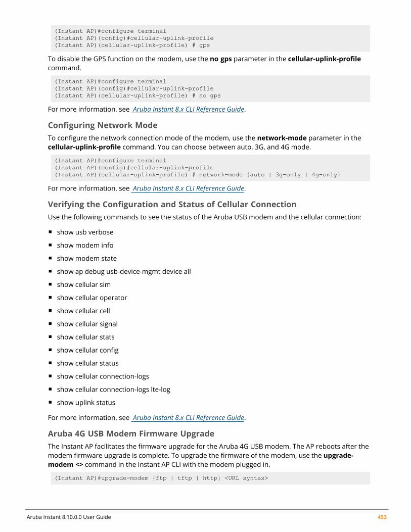
Aruba Instant 8.10.0.0 User Guide 453
(Instant AP)#configure terminal(Instant AP)(config)#cellular-uplink-profile(Instant AP)(cellular-uplink-profile) # gps
To disable the GPS function on the modem, use the no gps parameter in the cellular-uplink-profilecommand.
(Instant AP)#configure terminal(Instant AP)(config)#cellular-uplink-profile(Instant AP)(cellular-uplink-profile) # no gps
For more information, see Aruba Instant 8.x CLI Reference Guide.
Configuring Network ModeTo configure the network connection mode of the modem, use the network-mode parameter in thecellular-uplink-profile command. You can choose between auto, 3G, and 4G mode.
(Instant AP)#configure terminal(Instant AP)(config)#cellular-uplink-profile(Instant AP)(cellular-uplink-profile) # network-mode {auto | 3g-only | 4g-only}
For more information, see Aruba Instant 8.x CLI Reference Guide.
Verifying the Configuration and Status of Cellular ConnectionUse the following commands to see the status of the Aruba USB modem and the cellular connection:
n show usb verbose
n show modem info
n show modem state
n show ap debug usb-device-mgmt device all
n show cellular sim
n show cellular operator
n show cellular cell
n show cellular signal
n show cellular stats
n show cellular config
n show cellular status
n show cellular connection-logs
n show cellular connection-logs lte-log
n show uplink status
For more information, see Aruba Instant 8.x CLI Reference Guide.
Aruba 4G USB Modem Firmware UpgradeThe Instant AP facilitates the firmware upgrade for the Aruba 4G USB modem. The AP reboots after themodem firmware upgrade is complete. To upgrade the firmware of the modem, use the upgrade-modem <> command in the Instant AP CLI with the modem plugged in.
(Instant AP)#upgrade-modem {ftp | tftp | http} <URL syntax>
Uplink Configuration | 454
For more information, see Aruba Instant 8.x CLI Reference Guide.To verify the firmware download progress, use the show modem state command.
(Instant AP)#show modem state
Important Points to Remember
n Ensure that the AP is powered on during the firmware update.
n Do not reboot the AP during modem firmware upgrade.
n The modem firmware upgrade can only be done when the Aruba USB modem is plugged into theUSB port of an Aruba AP.
Wi-Fi UplinkInstant supports the use of Wi-Fi as uplink to provide internet backhaul for the Instant network. Wi-Fiuplink allows you to connect to SSIDs with open, CCMP, TKIP, PSK-CCMP, and PSK-TKIP encryption.When Wi-Fi uplink is used, the Instant AP uses MAC Address Translation (MAT) to bridge traffic betweenwireless and wired users of the AP and the uplink network. To enable or disable Wi-Fi uplink on the AP,the AP must be rebooted.
Wi-Fi Uplink is not supported on 340 Series and AP-635 access points.
Wi-Fi Uplink is not supported on AP-555 access points when split 5 GHz mode is enabled.
Configuration Guidelines
n For single-radio Instant APs, the radio serves wireless clients and the Wi-Fi uplink and for dual-radioInstant APs, both radios can be used to serve clients but only one of them can be used for the Wi-Fiuplink.
n The Wi-Fi uplink configuration only takes effect on the conductor Instant AP in cluster configurations.n To bridge traffic for Wi-Fi uplink, the access port VLAN must be the same as Wi-Fi uplink's native
VLAN and Client IP assignment should be Network Assigned. To configure the uplink VLAN of theInstant AP, see Configuring Uplink VLAN for an Instant AP.
n 802.1X Authentication is not supported in 802.11n AP platforms.n Mesh is not supported on 2.4 GHz radio. Therefore Wi-Fi uplink must be configured on the 5 GHz
radio.n Wi-Fi uplink and mesh cannot be configured on the same radio. Only the 5 GHz radio support Mesh
configuration whereas all radios, 2.4 GHz and 5 GHz support Wi-Fi Uplink.n Mesh configuration is supported only when Wi-Fi uplink is configured on the 2.4 GHz band. When Wi-
Fi uplink is configured on the 2.4 GHz radio of an Instant AP in a mesh, that AP automaticallyassumes the role of mesh portal.
n To connect an Instant AP using Wi-Fi uplink to an Instant-based WLAN, the host controller must runInstant 6.2.1.0 or later for 802.11n AP platforms and Instant 8.5.0.0 or later for 802.11ac APplatforms.
n When Wi-Fi uplink is enabled, IP assignment for clients can either be Virtual Controller managed orNetwork assigned. To configure client IP assignment, see Configuring VLAN Settings for a WLAN SSIDProfile.
Aruba Instant 8.10.0.0 User Guide 455
In Mesh deployments, the configurations made on the conductor AP/ Mesh portal is synced across alldevices in the mesh cluster. In order to enable Wi-Fi uplink only on the conductor AP/ Mesh Portal usethe disable-on-mesh-point command to disable uplink on mesh points.
Configuring Wi-Fi UplinkThe following procedure describes how to provision anInstant AP with the Wi-Fi uplink using the WebUI:
1. If you are configuring a Wi-Fi uplink after restoring factory settings on anInstant AP, connect theInstant AP to an Ethernet cable to allow the Instant AP to get the IP address. Otherwise, go to step2.
2. Go to Configuration > System > Show advanced options.3. Expand Uplink and selectWifi. The following options for Wi-Fi uplink are displayed:
a. Name(SSID)—Enter the name of the wireless network that is used for the Wi-Fi uplink in thetext box.
b. Key management—Select the type of key for uplink encryption and authentication from thedrop-down list. If the uplink wireless router uses mixed encryption, WPA2 is recommendedfor the Wi-Fi uplink.
c. Band—Select the band in which the virtual controller currently operates, from the drop-downlist. The following options are available:n 2.4 GHz (default)n 5 GHz
d. Passphrase format—Select a passphrase format from the drop-down list. The followingoptions are available:n 8–63 alphanumeric charactersn 64 hexadecimal characters
e. Passphrase—Enter a PSK passphrase in the text box
f. Click Save.
4. WhenWPA2 Enterprise orWPA Enterprise key management type is selected the 802.1Xauthentication parameters are available for configuration. The following are the 802.1X options:
a. AP1X type—Specify the 802.1X authentication protocol to be used or choose None todisable 802.1X authentication.n If TLS authentication type is selected, specify the certificate type to be used in the
Certificate type drop down list. Select User from the drop-down.n If PEAP authentication type is selected, enter the user credentials in the Username and
Password text box.
b. Validate server—Toggle the switch to enable or disable server certificate verification by theAP.
Ensure that the hexadecimal password string is exactly 64 digits in length.
If User certificate type is selected or Validate Server is enabled, the respective certificatesmust be uploaded to the Instant AP, See Uploading Certificates.
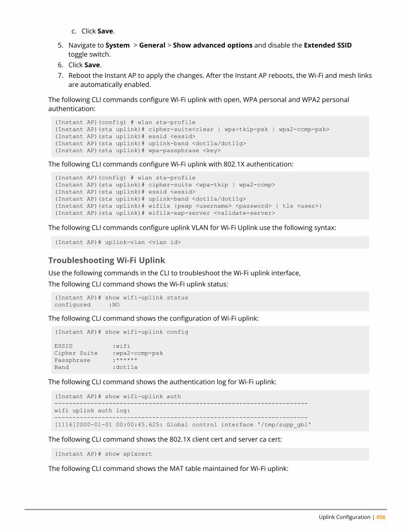
Uplink Configuration | 456
c. Click Save.
5. Navigate to System > General > Show advanced options and disable the Extended SSIDtoggle switch.
6. Click Save.7. Reboot the Instant AP to apply the changes. After the Instant AP reboots, the Wi-Fi and mesh links
are automatically enabled.
The following CLI commands configure Wi-Fi uplink with open, WPA personal and WPA2 personalauthentication:
(Instant AP)(config) # wlan sta-profile(Instant AP)(sta uplink)# cipher-suite<clear | wpa-tkip-psk | wpa2-ccmp-psk>(Instant AP)(sta uplink)# essid <essid>(Instant AP)(sta uplink)# uplink-band <dot11a/dot11g>(Instant AP)(sta uplink)# wpa-passphrase <key>
The following CLI commands configure Wi-Fi uplink with 802.1X authentication:
(Instant AP)(config) # wlan sta-profile(Instant AP)(sta uplink)# cipher-suite <wpa-tkip | wpa2-ccmp>(Instant AP)(sta uplink)# essid <essid>(Instant AP)(sta uplink)# uplink-band <dot11a/dot11g>(Instant AP)(sta uplink)# wifi1x {peap <username> <password> | tls <user>}(Instant AP)(sta uplink)# wifi1x-eap-server <validate-server>
The following CLI commands configure uplink VLAN for Wi-Fi Uplink use the following syntax:
(Instant AP)# uplink-vlan <vlan id>
Troubleshooting Wi-Fi UplinkUse the following commands in the CLI to troubleshoot the Wi-Fi uplink interface,
The following CLI command shows the Wi-Fi uplink status:
(Instant AP)# show wifi-uplink statusconfigured :NO
The following CLI command shows the configuration of Wi-Fi uplink:
(Instant AP)# show wifi-uplink config
ESSID :wifiCipher Suite :wpa2-ccmp-pskPassphrase :******Band :dot11a
The following CLI command shows the authentication log for Wi-Fi uplink:
(Instant AP)# show wifi-uplink auth----------------------------------------------------------------------wifi uplink auth log:----------------------------------------------------------------------[1116]2000-01-01 00:00:45.625: Global control interface '/tmp/supp_gbl'
The following CLI command shows the 802.1X client cert and server ca cert:
(Instant AP)# show ap1xcert
The following CLI command shows the MAT table maintained for Wi-Fi uplink:
Aruba Instant 8.10.0.0 User Guide 457
(Instant AP)# show wifi-uplink mat-table
Uplink Preferences and SwitchingThis topic describes the following procedures:
n Enforcing Uplinks on page 457n Setting an Uplink Priority on page 457n Enabling Uplink Preemption on page 458n (Instant AP)(uplink)# preemption on page 458n Viewing Uplink Status and Configuration on page 461
Enforcing UplinksThe following configuration conditions apply to the uplink enforcement:
n When an uplink is enforced, the Instant AP uses the specified uplink as the primary uplink regardlessof uplink preemption configuration and the current uplink status.
n When an uplink is enforced and multiple Ethernet ports are configured ,and if the uplink is enabledon the wired profiles, the Instant AP tries to find an alternate Ethernet link based on the priorityconfigured.
n When no uplink is enforced and preemption is not enabled, and if the current uplink fails, the InstantAP tries to find an available uplink based on the priority configured. The uplink with the highestpriority is used as the primary uplink. For example, if Wi-Fi-sta has the highest priority, it is used asthe primary uplink.
n When no uplink is enforced and preemption is enabled, and if the current uplink fails, the Instant APtries to find an available uplink based on the priority configured. If current uplink is active, the InstantAP periodically tries to use a higher-priority uplink and switches to the higher-priority uplink even ifthe current uplink is active.
You can enforce a specific uplink on an Instant AP by using the WebUI or the CLI.
In the WebUI
To enforce an uplink:
1. Go to Configuration > System > Show advanced options.2. Expand Uplink.3. UnderManagement, select the type of uplink from the Enforce uplink drop-down list. If
Ethernet uplink is selected, the Port text box is displayed.4. Specify the Ethernet interface port number.5. Click Save. The selected uplink is enforced on the Instant AP.
In the CLI
To enforce an uplink:
(Instant AP)(config)# uplink(Instant AP)(uplink)# enforce {cellular|ethernet | wifi | none}
Setting an Uplink PriorityYou can set an uplink priority by using the WebUI or the CLI.
Uplink Configuration | 458
In the WebUI
Setting an uplink priority:
1. Go to Configuration > System > Show advanced options.2. Expand Uplink.3. In the Uplink Priority List window, select the uplink, and click the up arrow or the down arrow
icons to increase or decrease the priority. By default, the eth0 uplink is set as a high-priorityuplink.
4. Click Save. The selected uplink is prioritized over other uplinks.
In the CLI
Setting an uplink priority:
(Instant AP)(config)# uplink(Instant AP)(uplink)# uplink-priority {cellular <priority> | ethernet <priority> |[port <Interface-number> <priority>] | wifi <priority>}
Setting an Ethernet uplink priority :
(Instant AP)(uplink)# uplink-priority ethernet port 0 1
Enabling Uplink PreemptionThe following configuration conditions apply to uplink preemption:
n Preemption can be enabled only when no uplink is enforced.n When preemption is disabled and the current uplink goes down, the Instant AP tries to find an
available uplink based on the uplink priority configuration.n When preemption is enabled and if the current uplink is active, the Instant AP periodically tries to use
a higher-priority uplink, and switches to a higher-priority uplink even if the current uplink is active.
You can enable uplink preemption by using WebUI or the CLI.
In the WebUI
To enable uplink preemption:
1. Go to Configuration > System > Show advanced options.2. Expand Uplink.3. UnderManagement, ensure that Enforce uplink is set to None.4. Toggle the Pre-emption switch to enable.5. Click Save.
In the CLI
To configure uplink preemption:
(Instant AP)(config)# uplink(Instant AP)(uplink)# preemption
Configuring Wired Port Profile Settings for Uplink PortThe uplink port of an Instant AP is configured to allow traffic from all VLANs configured in the networkby default. This may lead to flooding of broadcast and multicast data packets of all VLANs at the uplinkport. However, the traffic on the uplink port can be controlled by configuring uplink-enforce-wired-port-vlan-setting command. Configuring this command will enforce the settings of the wired port
Aruba Instant 8.10.0.0 User Guide 459
profile defined in enet<X>-port-profile instead of the default uplink port settings. Thereby allowing youto modify the port mode, native vlan, and allowed vlan settings for the uplink port.
The default wired port profile (wired-SetMeUp) cannot be used on an uplink port other than thedefault uplink port. If an Ethernet port other than the default uplink port is used as uplink, you mustassociate that Ethernet port with a new wired port profile with the desired configurations.
The uplink-enforce-wired-port-vlan-setting is only applicable in the following scenarios:
n Standalone Instant AP deployments.n Mesh deployments with single mesh portal.
To configure wired port profile for the uplink port,
1. Define the desired settings in the wired port profile using the corresponding enet<X>-port-profile command. Define the port number in the space of <X>.
2. Enforce the port profile configuration on the uplink port using the uplink-enforce-wired-port-vlan-setting command.
(Instant AP)(config)# uplink-enforce-wired-port-vlan-setting
For more information on CLI commands, refer to the Aruba Instant 8.x CLI Reference Guide.
Limitation:
The uplink-enforce-wired-port-vlan-setting is not supported when:
n enet0-bridging is enabled.n enet-vlan is configured.
Disable the enet-vlan configuration of the access point for this command to take effect. Whenenabled, the native-vlan configuration in the wired port profile will be used for enet-vlan.
Switching Uplinks Based on VPN and Internet AvailabilityThe default priority for uplink switchover is Ethernet and then 3G/4G. The Instant AP can switch to thelower-priority uplink if the current uplink is down.
Switching Uplinks Based on VPN StatusInstant supports switching uplinks based on the VPN status when deploying multiple uplinks (Ethernet,3G/4G, and Wi-Fi). When VPN is used with multiple backhaul options, the Instant AP switches to anuplink connection based on the VPN connection status, instead of only using the Ethernet or thephysical backhaul link.
The following configuration conditions apply to uplink switching:
n If the current uplink is Ethernet and the VPN connection is down, the Instant AP tries to reconnect toVPN. The retry time depends on the fast failover configuration and the primary or backup VPNtunnel. If this fails, the Instant AP waits for the VPN failover timeout and selects a different uplinksuch as 3G/4G or Wi-Fi.
n If the current uplink is 3G or Wi-Fi, and Ethernet has a physical link, the Instant AP periodicallysuspends user traffic to try and connect to the VPN on the Ethernet. If the Instant AP succeeds, the
Uplink Configuration | 460
Instant AP switches to Ethernet. If the Instant AP does not succeed, it restores the VPN connection tothe current uplink.
Uplink switching based on VPN status is automatically enabled if VPN is configured on the Instant AP.However, you can specify the duration in the VPN failover timeout text box of the WebUI to wait for anuplink switch. By default, this duration is set to 180 seconds. The Instant AP monitors the VPN statusand when the VPN connection is not available for 3 minutes, the uplink switches to another availableconnection (if a low-priority uplink is detected and the uplink preference is set to none). When VPNfailover timeout is set to 0 in the WebUI, the uplink does not switch over.
When uplink switching based on the Internet availability is enabled, the uplink switching based on VPNfailover is automatically disabled.
Switching Uplinks Based on Internet AvailabilityYou can configure Instant to switch uplinks based on Internet availability.
When the uplink switchover based on Internet availability is enabled, the Instant AP continuously sendsInternet Control Management Protocol packets to some well-known Internet servers. If the request istimed out due to a bad uplink connection or uplink interface failure, and the public Internet is notreachable from the current uplink, the Instant AP switches to a different connection.
You can set preferences for uplink switching by using the WebUI and the CLI.
In the WebUI
To configure uplink switching:
1. Go to Configuration > System > Show advanced options.2. Expand Uplink.3. UnderManagement, configure the following parameters:
n VPN failover timeout—To configure uplink switching based on VPN status, specify theduration to wait for an uplink switch. The default duration is set to 180 seconds.
n Internet failover—To configure uplink switching based on Internet availability, enable theInternet failover toggle switch and perform the following steps:
a. Specify the required values for the following parameters:n Max allowed test packet loss—The maximum number of ICMP test packets that
are allowed to be lost to determine if the Instant AP must switch to a different uplinkconnection. You can specify a value within the range of 1–1000.
n Secs between test packets—The frequency at which ICMP test packets are sent.You can specify a value within the range of 1–3600 seconds.
n Internet check timeout—Internet check timeout is the duration for the test packettimeout. You can specify a value within the range of 0–3600 seconds and the defaultvalue is 10 seconds.
n Internet failover IP—To configure an IP address to which the Instant AP must send Instant APpackets and verify if the Internet is reachable when the uplink is down. By default, theconductor Instant AP sends the ICMP packets to 8.8.8.8 IP address only if the out-of-serviceoperation based on Internet availability (internet-down state) is configured on the SSID.
4. Click Save.
When Internet failover is enabled, the Instant AP ignores the VPN status, although uplink switchingbased on VPN status is enabled.
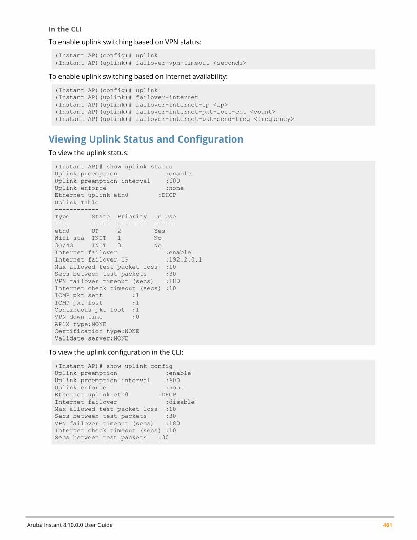
Aruba Instant 8.10.0.0 User Guide 461
In the CLI
To enable uplink switching based on VPN status:
(Instant AP)(config)# uplink(Instant AP)(uplink)# failover-vpn-timeout <seconds>
To enable uplink switching based on Internet availability:
(Instant AP)(config)# uplink(Instant AP)(uplink)# failover-internet(Instant AP)(uplink)# failover-internet-ip <ip>(Instant AP)(uplink)# failover-internet-pkt-lost-cnt <count>(Instant AP)(uplink)# failover-internet-pkt-send-freq <frequency>
Viewing Uplink Status and ConfigurationTo view the uplink status:
(Instant AP)# show uplink statusUplink preemption :enableUplink preemption interval :600Uplink enforce :noneEthernet uplink eth0 :DHCPUplink Table------------Type State Priority In Use---- ----- -------- ------eth0 UP 2 YesWifi-sta INIT 1 No3G/4G INIT 3 NoInternet failover :enableInternet failover IP :192.2.0.1Max allowed test packet loss :10Secs between test packets :30VPN failover timeout (secs) :180Internet check timeout (secs) :10ICMP pkt sent :1ICMP pkt lost :1Continuous pkt lost :1VPN down time :0AP1X type:NONECertification type:NONEValidate server:NONE
To view the uplink configuration in the CLI:
(Instant AP)# show uplink configUplink preemption :enableUplink preemption interval :600Uplink enforce :noneEthernet uplink eth0 :DHCPInternet failover :disableMax allowed test packet loss :10Secs between test packets :30VPN failover timeout (secs) :180Internet check timeout (secs) :10Secs between test packets :30
Chapter 28Intrusion Detection
Intrusion DetectionThe IDS is a feature that monitors the network for the presence of unauthorized APs and clients. It alsologs information about the unauthorized APs and clients, and generates reports based on the loggedinformation.
The IDS feature in the Instant network enables you to detect rogue APs, interfering APs, and otherdevices that can potentially disrupt network operations.
This chapter describes the following procedures:
n Detecting and Classifying Rogue APs on page 462n OS Fingerprinting on page 462n Configuring WIP and Detection Levels on page 463n Configuring IDS on page 467n Ghost Tunnel Attack Detection
Detecting and Classifying Rogue APsA rogue AP is an unauthorized device plugged into the wired side of the network.
An interfering AP is a device seen in the RF environment but it is not connected to the wired network.While the interfering AP can potentially cause RF interference, it is not considered a direct securitythreat, because it is not connected to the wired network. However, an interfering AP may be reclassifiedas a rogue AP.
To detect the rogue APs,go to Configuration > IDS in the WebUI. The built-in IDS scans for access pointsthat are not controlled by the virtual controller. These are listed and classified as either Interfering orRogue, depending on whether they are on a foreign network or your network.
OS FingerprintingThe OS Fingerprinting feature gathers information about the client that is connected to the Instantnetwork to find the operating system that the client is running on. The following is a list of advantages ofthis feature:
n Identifying rogue clients—Helps to identify clients that are running on forbidden operating systems.n Identifying outdated operating systems—Helps to locate outdated and unexpected OS in the
company network.n Locating and patching vulnerable operating systems—Assists in locating and patching specific
operating system versions on the network that have known vulnerabilities, thereby securing thecompany network.
OS Fingerprinting is enabled in the Instant network by default. The following operating systems areidentified by Instant:
n Androidn AppleTV
Aruba Instant 8.10.0.0 User Guide 462
Intrusion Detection | 463
n BlackBerryn Chrome OS and later versionsn iPodn Kindlen Linuxn OS Xn Symbiann Windows 95 and later versionsn Windows CE and later versionsn Windowsn Windows Mobilen Windows Phonen Windows ME and later versionsn Applen PlayStationn Nintendon Ascom
Configuring WIP and Detection LevelsWIP offers a wide selection of intrusion detection and protection features to protect the network againstwireless threats.
Like most other security-related features of the Instant network, the WIP can be configured on theInstant AP.
You can configure the following options:
n Infrastructure Detection Policies—Specifies the policy for detecting wireless attacks on accesspoints.
n Client Detection Policies—Specifies the policy for detecting wireless attacks on clients.n Infrastructure Protection Policies—Specifies the policy for protecting access points from wireless
attacks.n Client Protection Policies—Specifies the policy for protecting clients from wireless attacks.n Containment Methods—Prevents unauthorized stations from connecting to your Instant network.
Each of these options contains several default levels that enable different sets of policies. Anadministrator can customize, enable, or disable these options accordingly.
The following procedure describes how to configure the detection levels using the WebUI:
1. Navigate to the Configuration > IDS page.2. Go to Detection > Infrastructure section, move the slider to a desired level and configure the
following levels of detection:n Highn Mediumn Lown Off
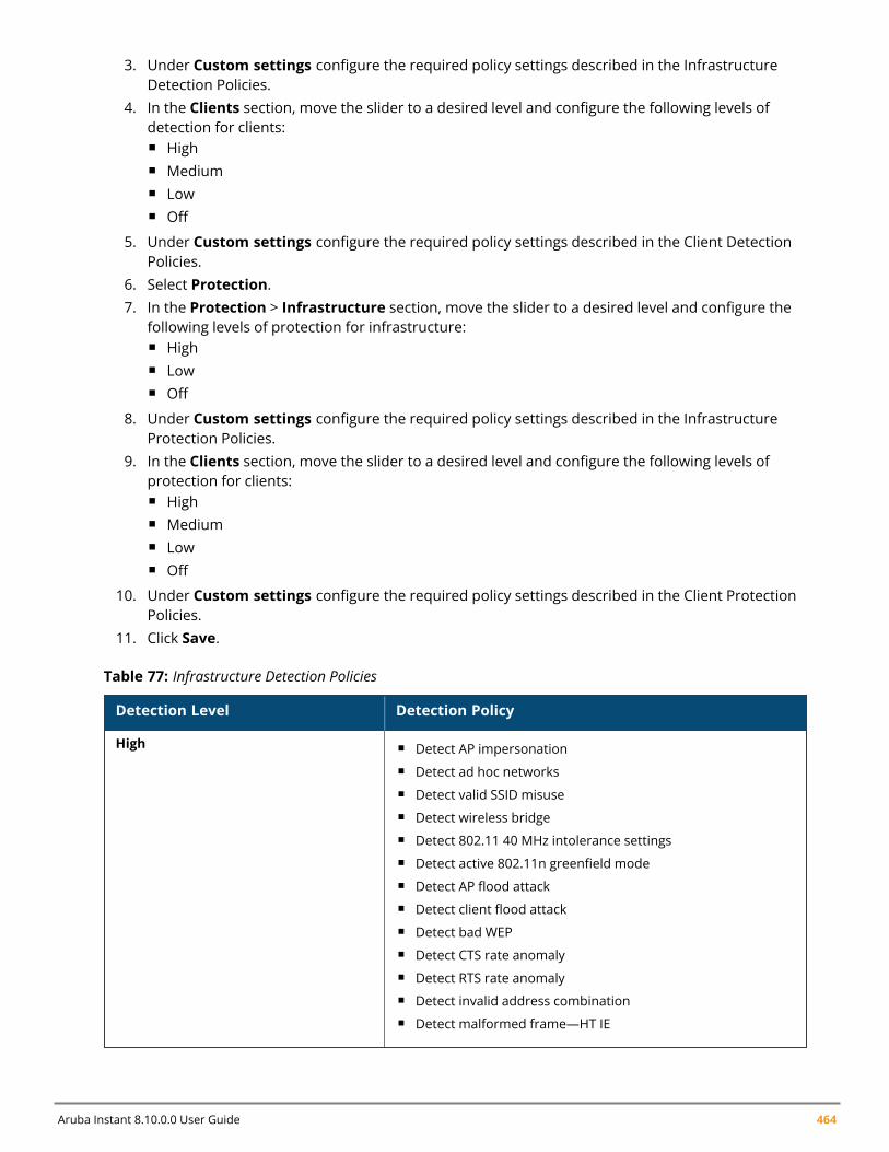
Aruba Instant 8.10.0.0 User Guide 464
3. Under Custom settings configure the required policy settings described in the InfrastructureDetection Policies.
4. In the Clients section, move the slider to a desired level and configure the following levels ofdetection for clients:n Highn Mediumn Lown Off
5. Under Custom settings configure the required policy settings described in the Client DetectionPolicies.
6. Select Protection.7. In the Protection > Infrastructure section, move the slider to a desired level and configure the
following levels of protection for infrastructure:n Highn Lown Off
8. Under Custom settings configure the required policy settings described in the InfrastructureProtection Policies.
9. In the Clients section, move the slider to a desired level and configure the following levels ofprotection for clients:n Highn Mediumn Lown Off
10. Under Custom settings configure the required policy settings described in the Client ProtectionPolicies.
11. Click Save.
Detection Level Detection Policy
High n Detect AP impersonationn Detect ad hoc networksn Detect valid SSID misusen Detect wireless bridgen Detect 802.11 40 MHz intolerance settingsn Detect active 802.11n greenfield moden Detect AP flood attackn Detect client flood attackn Detect bad WEPn Detect CTS rate anomalyn Detect RTS rate anomalyn Detect invalid address combinationn Detect malformed frame—HT IE
Table 77: Infrastructure Detection Policies
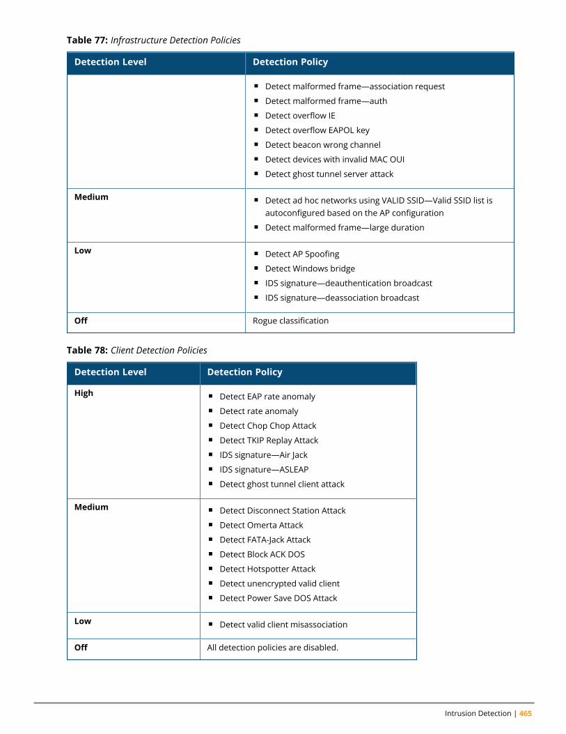
Intrusion Detection | 465
Detection Level Detection Policy
n Detect malformed frame—association requestn Detect malformed frame—authn Detect overflow IEn Detect overflow EAPOL keyn Detect beacon wrong channeln Detect devices with invalid MAC OUIn Detect ghost tunnel server attack
Medium n Detect ad hoc networks using VALID SSID—Valid SSID list isautoconfigured based on the AP configuration
n Detect malformed frame—large duration
Low n Detect AP Spoofingn Detect Windows bridgen IDS signature—deauthentication broadcastn IDS signature—deassociation broadcast
Off Rogue classification
Table 77: Infrastructure Detection Policies
Detection Level Detection Policy
High n Detect EAP rate anomalyn Detect rate anomalyn Detect Chop Chop Attackn Detect TKIP Replay Attackn IDS signature—Air Jackn IDS signature—ASLEAPn Detect ghost tunnel client attack
Medium n Detect Disconnect Station Attackn Detect Omerta Attackn Detect FATA-Jack Attackn Detect Block ACK DOSn Detect Hotspotter Attackn Detect unencrypted valid clientn Detect Power Save DOS Attack
Low n Detect valid client misassociation
Off All detection policies are disabled.
Table 78: Client Detection Policies
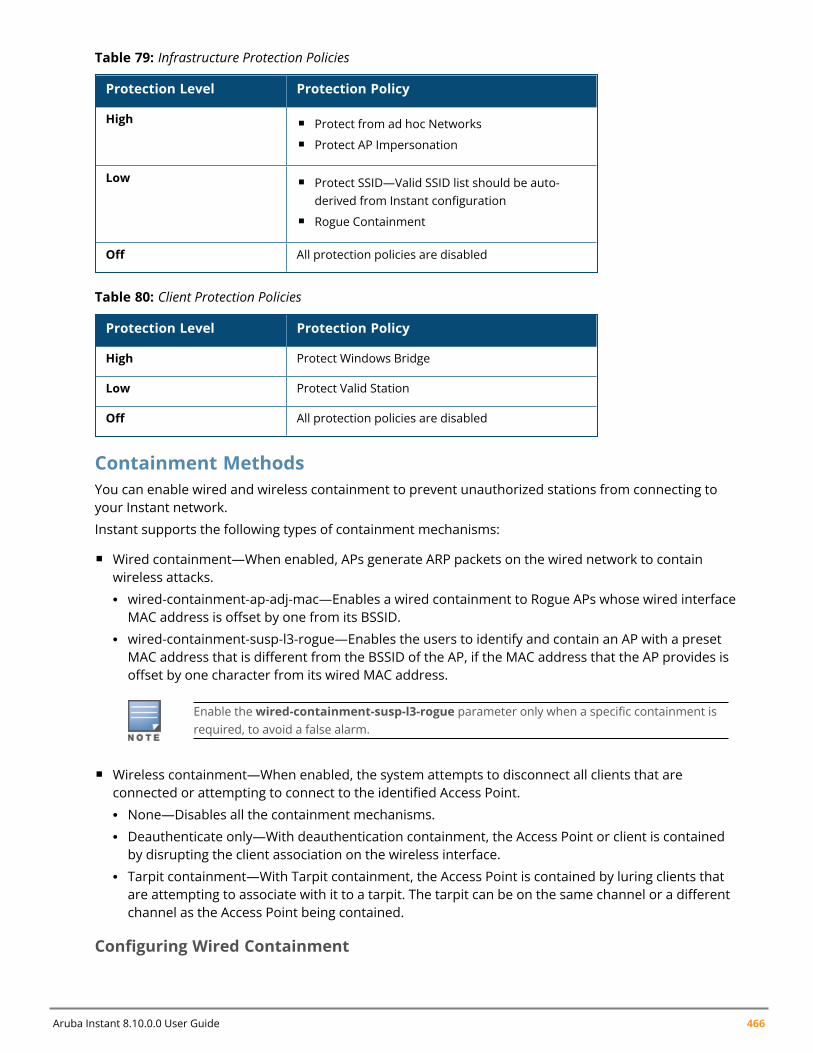
Aruba Instant 8.10.0.0 User Guide 466
Protection Level Protection Policy
High n Protect from ad hoc Networksn Protect AP Impersonation
Low n Protect SSID—Valid SSID list should be auto-derived from Instant configuration
n Rogue Containment
Off All protection policies are disabled
Table 79: Infrastructure Protection Policies
Protection Level Protection Policy
High Protect Windows Bridge
Low Protect Valid Station
Off All protection policies are disabled
Table 80: Client Protection Policies
Containment MethodsYou can enable wired and wireless containment to prevent unauthorized stations from connecting toyour Instant network.
Instant supports the following types of containment mechanisms:
n Wired containment—When enabled, APs generate ARP packets on the wired network to containwireless attacks.l wired-containment-ap-adj-mac—Enables a wired containment to Rogue APs whose wired interfaceMAC address is offset by one from its BSSID.
l wired-containment-susp-l3-rogue—Enables the users to identify and contain an AP with a presetMAC address that is different from the BSSID of the AP, if the MAC address that the AP provides isoffset by one character from its wired MAC address.
Enable thewired-containment-susp-l3-rogue parameter only when a specific containment isrequired, to avoid a false alarm.
n Wireless containment—When enabled, the system attempts to disconnect all clients that areconnected or attempting to connect to the identified Access Point.l None—Disables all the containment mechanisms.l Deauthenticate only—With deauthentication containment, the Access Point or client is containedby disrupting the client association on the wireless interface.
l Tarpit containment—With Tarpit containment, the Access Point is contained by luring clients thatare attempting to associate with it to a tarpit. The tarpit can be on the same channel or a differentchannel as the Access Point being contained.
Configuring Wired Containment
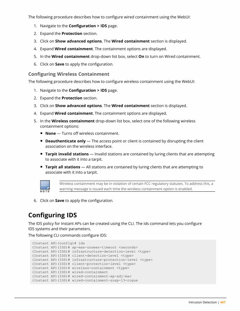
Intrusion Detection | 467
The following procedure describes how to configure wired containment using the WebUI:
1. Navigate to the Configuration > IDS page.
2. Expand the Protection section.
3. Click on Show advanced options. TheWired containment section is displayed.
4. ExpandWired containment. The containment options are displayed.
5. In theWired containment drop-down list box, select On to turn on Wired containment.
6. Click on Save to apply the configuration.
Configuring Wireless ContainmentThe following procedure describes how to configure wireless containment using the WebUI:
1. Navigate to the Configuration > IDS page.
2. Expand the Protection section.
3. Click on Show advanced options. TheWired containment section is displayed.
4. ExpandWired containment. The containment options are displayed.
5. In theWireless containment drop-down list box, select one of the following wirelesscontainment options:
n None— Turns off wireless containment.
n Deauthenticate only— The access point or client is contained by disrupting the clientassociation on the wireless interface.
n Tarpit invalid stations— Invalid stations are contained by luring clients that are attemptingto associate with it into a tarpit.
n Tarpit all stations— All stations are contained by luring clients that are attempting toassociate with it into a tarpit.
Wireless containment may be in violation of certain FCC regulatory statutes. To address this, awarning message is issued each time the wireless containment option is enabled.
6. Click on Save to apply the configuration.
Configuring IDSThe IDS policy for Instant APs can be created using the CLI. The ids command lets you configureIDS systems and their parameters.
The following CLI commands configure IDS:
(Instant AP)(config)# ids(Instant AP)(IDS)# ap-max-unseen-timeout <seconds>(Instant AP)(IDS)# infrastructure-detection-level <type>(Instant AP)(IDS)# client-detection-level <type>(Instant AP)(IDS)# infrastructure-protection-level <type>(Instant AP)(IDS)# client-protection-level <type>(Instant AP)(IDS)# wireless-containment <type>(Instant AP)(IDS)# wired-containment(Instant AP)(IDS)# wired-containment-ap-adj-mac(Instant AP)(IDS)# wired-containment-susp-l3-rogue
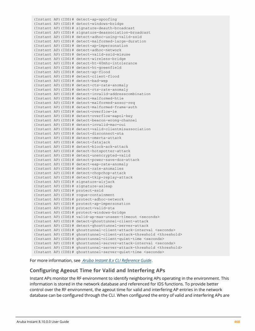
Aruba Instant 8.10.0.0 User Guide 468
(Instant AP)(IDS)# detect-ap-spoofing(Instant AP)(IDS)# detect-windows-bridge(Instant AP)(IDS)# signature-deauth-broadcast(Instant AP)(IDS)# signature-deassociation-broadcast(Instant AP)(IDS)# detect-adhoc-using-valid-ssid(Instant AP)(IDS)# detect-malformed-large-duration(Instant AP)(IDS)# detect-ap-impersonation(Instant AP)(IDS)# detect-adhoc-network(Instant AP)(IDS)# detect-valid-ssid-misuse(Instant AP)(IDS)# detect-wireless-bridge(Instant AP)(IDS)# detect-ht-40mhz-intolerance(Instant AP)(IDS)# detect-ht-greenfield(Instant AP)(IDS)# detect-ap-flood(Instant AP)(IDS)# detect-client-flood(Instant AP)(IDS)# detect-bad-wep(Instant AP)(IDS)# detect-cts-rate-anomaly(Instant AP)(IDS)# detect-rts-rate-anomaly(Instant AP)(IDS)# detect-invalid-addresscombination(Instant AP)(IDS)# detect-malformed-htie(Instant AP)(IDS)# detect-malformed-assoc-req(Instant AP)(IDS)# detect-malformed-frame-auth(Instant AP)(IDS)# detect-overflow-ie(Instant AP)(IDS)# detect-overflow-eapol-key(Instant AP)(IDS)# detect-beacon-wrong-channel(Instant AP)(IDS)# detect-invalid-mac-oui(Instant AP)(IDS)# detect-valid-clientmisassociation(Instant AP)(IDS)# detect-disconnect-sta(Instant AP)(IDS)# detect-omerta-attack(Instant AP)(IDS)# detect-fatajack(Instant AP)(IDS)# detect-block-ack-attack(Instant AP)(IDS)# detect-hotspotter-attack(Instant AP)(IDS)# detect-unencrypted-valid(Instant AP)(IDS)# detect-power-save-dos-attack(Instant AP)(IDS)# detect-eap-rate-anomaly(Instant AP)(IDS)# detect-rate-anomalies(Instant AP)(IDS)# detect-chopchop-attack(Instant AP)(IDS)# detect-tkip-replay-attack(Instant AP)(IDS)# signature-airjack(Instant AP)(IDS)# signature-asleap(Instant AP)(IDS)# protect-ssid(Instant AP)(IDS)# rogue-containment(Instant AP)(IDS)# protect-adhoc-network(Instant AP)(IDS)# protect-ap-impersonation(Instant AP)(IDS)# protect-valid-sta(Instant AP)(IDS)# protect-windows-bridge(Instant AP)(IDS)# valid-ap-max-unseen-timeout <seconds>(Instant AP)(IDS)# detect-ghosttunnel-client-attack(Instant AP)(IDS)# detect-ghosttunnel-server-attack(Instant AP)(IDS)# ghosttunnel-client-attack-interval <seconds>(Instant AP)(IDS)# ghosttunnel-client-attack-threshold <threshold>(Instant AP)(IDS)# ghosttunnel-client-quiet-time <seconds>(Instant AP)(IDS)# ghosttunnel-server-attack-interval <seconds>(Instant AP)(IDS)# ghosttunnel-server-attack-threshold <threshold>(Instant AP)(IDS)# ghosttunnel-server-quiet-time <seconds>
For more information, see Aruba Instant 8.x CLI Reference Guide.
Configuring Ageout Time for Valid and Interfering APsInstant APs monitor the RF environment to identify neighboring APs operating in the environment. Thisinformation is stored in the network database and referenced for IDS functions. To provide bettercontrol over the RF environment, the ageout time for valid and interfering AP entries in the networkdatabase can be configured through the CLI. When configured the entry of valid and interfering APs are
Intrusion Detection | 469
removed from the network database if they are not seen in the RF environment after the ageout time iselapsed.
These settings are available under the ids command. The default ageout time for valid APs is 7200seconds and interfering APs is 600 seconds.
Following is the command syntax to configure ageout time for valid APs:
(Instant AP)(config)# ids(Instant AP)(IDS)# valid-ap-max-unseen-timeout <seconds>
Following is the command syntax to configure ageout time for interfering APs:
(Instant AP)(config)# ids(Instant AP)(IDS)# ap-max-unseen-timeout <seconds>
Ghost Tunnel Attack DetectionGhost tunnel attack is a backdoor transmission method that can be used in an isolated environment. Aghost tunnel attack uses 802.11 probe request packets or beacon packets to communicate with the hostand need not establish a Wi-Fi connection.
The server side of ghost tunnel uses beacon packets to send commands to the client and the clientsends probe-request automatically in response to the server's request, thereby infecting the system.The server-side ghost tunnel attack detection system relies on identifying abnormal beacon packets andflagging the attacking server.
For the client-side ghost tunnel attack, the AP monitors the abnormal probe request packets in thewireless environment. When a client is heard by the AP, it looks for abnormal probe request packetsfrom the client. The system reports a ghost tunnel detection event with the client's MAC address whenthe alert criteria is met. If only abnormal probe request packets are monitored and there is no matchingclient, then the reported event does not contain the client's MAC address.
ConfigurationGhost tunnel attack detection can be enabled on the access point using the webUI or the CLI. However,parameters for ghost tunnel attack detection such as attack interval, attack threshold, and quiet timecan only be configured through the CLI.
Enabling Ghost Tunnel Attack DetectionTo configure ghost tunnel server attack detection on the access point using the webUI, set theInfrastructure detection setting to High in the Configuration > IDS > Detection page. For moreinformation on configuring IDS settings, see Configuring WIP and Detection Levels.
To configure ghost tunnel client attack detection on the access point using the webUI, set the Clientsdetection setting to High in the Configuration > IDS > Detection section of the webUI. For moreinformation on configuring IDS settings, see Configuring WIP and Detection Levels.
Configuring Ghost Tunnel Attack Detection ParametersParameters for identifying Ghost Tunnel attacks can only be configured using the CLI. Parameters suchas interval of probe requests to classify an attack, threshold, and time between checks are configuredusing the ids command.
The following commands configure ghost tunnel detection on the AP:
(Instant AP)(config)# ids(Instant AP)(IDS)# detect-ghosttunnel-client-attack(Instant AP)(IDS)# detect-ghosttunnel-server-attack

Aruba Instant 8.10.0.0 User Guide 470
(Instant AP)(IDS)# ghosttunnel-client-attack-interval <seconds>(Instant AP)(IDS)# ghosttunnel-client-attack-threshold <threshold>(Instant AP)(IDS)# ghosttunnel-client-quiet-time <seconds>(Instant AP)(IDS)# ghosttunnel-server-attack-interval <seconds>(Instant AP)(IDS)# ghosttunnel-server-attack-threshold <threshold>(Instant AP)(IDS)# ghosttunnel-server-quiet-time <seconds>
For more information, see Aruba Instant 8.x CLI Reference Guide.
Chapter 29Mesh Instant AP Configuration
Mesh Instant AP ConfigurationThis chapter provides the following information:
n Mesh Network Overview on page 471n Setting up Instant Mesh Network on page 473n Configuring Wired Bridging on Ethernet 0 for Mesh Point on page 474n Mesh Cluster Function on page 475n Radio Selection for Mesh Links on page 477n Fast Roaming in Mesh Networks on page 477n Mesh Scanning on page 478
Mesh Network OverviewThe Instant secure enterprise mesh solution is an effective way to expand network coverage for outdoorand indoor enterprise environments without any wires. As traffic traverses across mesh Instant APs, themesh network automatically reconfigures around broken or blocked paths. This self-healing featureprovides increased reliability and redundancy and allows the network to continue operation even whenan Instant AP stops functioning or if a connection fails.
Mesh Instant APsMesh network requires at least one valid uplink (wired or 3G) connection. Any provisioned Instant APthat has a valid uplink (wired or 3G) functions as a mesh portal, and the Instant AP without an Ethernetlink functions as a mesh point. The mesh portal can also act as a virtual controller. Mesh portals andmesh points are also known as mesh nodes, a generic term used to describe Instant APs configured formesh.
If two Instant APs have valid uplink connections, a redundancy is created in the mesh network, and mostmesh points try to mesh directly with one of the two portals. However, depending on the actualdeployment and RF environment, some mesh points may mesh through other intermediate meshpoints. In an Instant mesh network, the maximum hop count is two nodes (point > point > portal) andthe maximum number of mesh points per mesh portal is eight.
Mesh Instant APs detect the environment when they boot up, locate and associate with their nearestneighbor, to determine the best path to the mesh portal.
Instant mesh functionality is supported only on dual-radio Instant APs. On dual-radio Instant APs, the 2.4GHz radio is always used for client traffic, while the 5 GHz radio is always used for both mesh-backhauland client traffic.
The mesh network must be provisioned for the first time by plugging into the wired network. After that,the mesh service works on Instant APs like it does on any other regulatory domain.
Mesh PortalsA mesh portal is a gateway between the wireless mesh network and the enterprise wired LAN or theInternet. The mesh roles are automatically assigned based on the Instant AP configuration. A meshnetwork could have multiple mesh portals to support redundant mesh paths (mesh links between
Aruba Instant 8.10.0.0 User Guide 471
Mesh Instant AP Configuration | 472
neighboring mesh points that establish the best path to the mesh portal) from the wireless meshnetwork to the uplink.
The mesh portal broadcasts a mesh services set identifier or mesh cluster name to advertise the meshnetwork service to other mesh points in that Instant network. This is not configurable and is transparentto the user. The mesh points authenticate to the mesh portal and establish a link that is secured usingAES encryption.
The mesh portal reboots after 5 minutes when it loses its uplink connectivity to a wired network.
Mesh PointsThe mesh point establishes an all-wireless path to the mesh portal. The mesh point provides traditionalWLAN services such as client connectivity, IDS capabilities, user role association, and QoS for LAN-to-mesh communication to clients and performs mesh backhaul or network connectivity.
A mesh point also supports LAN bridging. You can connect any wired device to the downlink port ofthe mesh point. In the case of single Ethernet port platforms such as AP-505, you can convert the Eth0uplink port to a downlink port by enabling Eth0 Bridging. For additional information, see ConfiguringWired Bridging on Ethernet 0 for Mesh Point on page 474.
Automatic Mesh Role AssignmentPreviously, when a mesh point discovered that the Ethernet 0 port link was up without Ethernet 0 bridgeconfigured, the mesh point rebooted immediately. Aruba Instant supports enhanced role detectionduring Instant AP boot up and Instant AP running time.
When a mesh point discovers that the Ethernet 0 port link is up, it sends loop detection packets to checkwhether the Ethernet 0 link is available. If it is available, the mesh point reboots and becomes a meshportal. Otherwise, the mesh point does not reboot.
Mesh Role Detection During System Boot Up
If an Instant AP boots up and discovers that the Ethernet link is down, it acts as a mesh point. If theEthernet link is up, the Instant AP continues to detect if the network is reachable. In a static IP addressscenario, the Instant AP pings the gateway. If the ping is successful, the Instant AP acts as a mesh portal.Otherwise, it acts as a mesh point. In case of DHCP, if the Instant AP obtains the IP address successfully,it acts as a mesh portal. Otherwise, it acts as a mesh point. In case of IPv6, Instant APs do not supportthe static IP address but only support DHCP for detection of network reachability.
If the Instant AP has a 3G/4G USB modem plugged, it always acts as a mesh portal.
If the Instant AP is set to Ethernet 0 bridging, it always acts as a mesh point.
Mesh Role Detection During System Running Time
n Mesh Point Role Change: When a mesh point detects whether its Ethernet link is up, it continues touse Loop Protection (based on the Loop Protection for Secure Jack Port feature), to check if the loophas been detected. If the loop is detected, the Instant AP reboots. Otherwise, the Instant AP does notreboot and the mesh role continues to act as a mesh point.
You can enable enhanced mesh role detection by using the CLI:
In the CLI
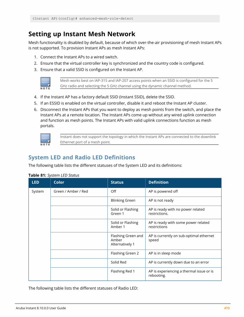
Aruba Instant 8.10.0.0 User Guide 473
(Instant AP)(config)# enhanced-mesh-role-detect
Setting up Instant Mesh NetworkMesh functionality is disabled by default, because of which over-the-air provisioning of mesh Instant APsis not supported. To provision Instant APs as mesh Instant APs:
1. Connect the Instant APs to a wired switch.2. Ensure that the virtual controller key is synchronized and the country code is configured.3. Ensure that a valid SSID is configured on the Instant AP.
Mesh works best on IAP-315 and IAP-207 access points when an SSID is configured for the 5GHz radio and selecting the 5 GHz channel using the dynamic channel method.
4. If the Instant AP has a factory default SSID (Instant SSID), delete the SSID.5. If an ESSID is enabled on the virtual controller, disable it and reboot the Instant AP cluster.6. Disconnect the Instant APs that you want to deploy as mesh points from the switch, and place the
Instant APs at a remote location. The Instant APs come up without any wired uplink connectionand function as mesh points. The Instant APs with valid uplink connections function as meshportals.
Instant does not support the topology in which the Instant APs are connected to the downlinkEthernet port of a mesh point.
System LED and Radio LED DefinitionsThe following table lists the different statuses of the System LED and its definitions:
LED Color Status Definition
System Green / Amber / Red Off AP is powered off
Blinking Green AP is not ready
Solid or FlashingGreen 1
AP is ready with no power relatedrestrictions.
Solid or FlashingAmber 1
AP is ready with some power relatedrestrictions
Flashing Green andAmberAlternatively 1
AP is currently on sub-optimal ethernetspeed
Flashing Green 2 AP is in sleep mode
Solid Red AP is currently down due to an error
Flashing Red 1 AP is experiencing a thermal issue or isrebooting.
Table 81: System LED Status
The following table lists the different statuses of Radio LED:
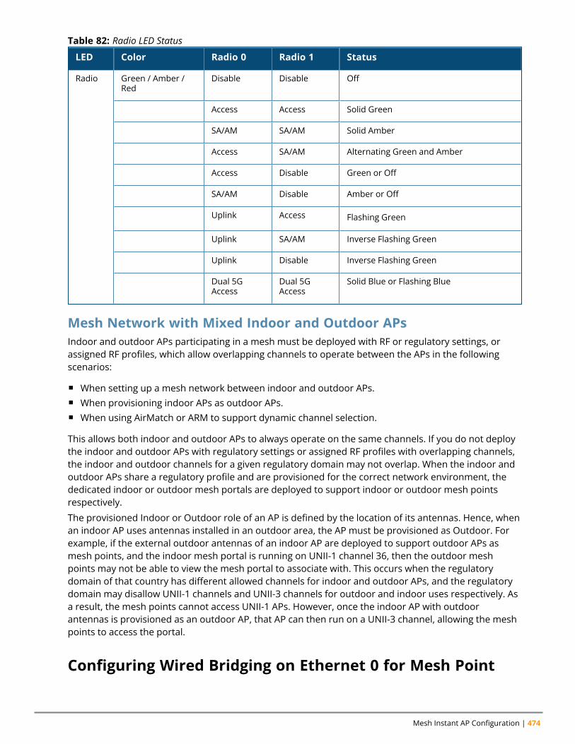
Mesh Instant AP Configuration | 474
LED Color Radio 0 Radio 1 Status
Radio Green / Amber /Red
Disable Disable Off
Access Access Solid Green
SA/AM SA/AM Solid Amber
Access SA/AM Alternating Green and Amber
Access Disable Green or Off
SA/AM Disable Amber or Off
Uplink Access Flashing Green
Uplink SA/AM Inverse Flashing Green
Uplink Disable Inverse Flashing Green
Dual 5GAccess
Dual 5GAccess
Solid Blue or Flashing Blue
Table 82: Radio LED Status
Mesh Network with Mixed Indoor and Outdoor APsIndoor and outdoor APs participating in a mesh must be deployed with RF or regulatory settings, orassigned RF profiles, which allow overlapping channels to operate between the APs in the followingscenarios:
n When setting up a mesh network between indoor and outdoor APs.n When provisioning indoor APs as outdoor APs.n When using AirMatch or ARM to support dynamic channel selection.
This allows both indoor and outdoor APs to always operate on the same channels. If you do not deploythe indoor and outdoor APs with regulatory settings or assigned RF profiles with overlapping channels,the indoor and outdoor channels for a given regulatory domain may not overlap. When the indoor andoutdoor APs share a regulatory profile and are provisioned for the correct network environment, thededicated indoor or outdoor mesh portals are deployed to support indoor or outdoor mesh pointsrespectively.
The provisioned Indoor or Outdoor role of an AP is defined by the location of its antennas. Hence, whenan indoor AP uses antennas installed in an outdoor area, the AP must be provisioned as Outdoor. Forexample, if the external outdoor antennas of an indoor AP are deployed to support outdoor APs asmesh points, and the indoor mesh portal is running on UNII-1 channel 36, then the outdoor meshpoints may not be able to view the mesh portal to associate with. This occurs when the regulatorydomain of that country has different allowed channels for indoor and outdoor APs, and the regulatorydomain may disallow UNII-1 channels and UNII-3 channels for outdoor and indoor uses respectively. Asa result, the mesh points cannot access UNII-1 APs. However, once the indoor AP with outdoorantennas is provisioned as an outdoor AP, that AP can then run on a UNII-3 channel, allowing the meshpoints to access the portal.
Configuring Wired Bridging on Ethernet 0 for Mesh Point
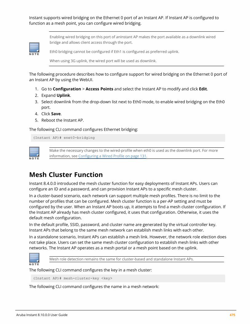
Aruba Instant 8.10.0.0 User Guide 475
Instant supports wired bridging on the Ethernet 0 port of an Instant AP. If Instant AP is configured tofunction as a mesh point, you can configure wired bridging.
Enabling wired bridging on this port of anInstant AP makes the port available as a downlink wiredbridge and allows client access through the port.
Eth0 bridging cannot be configured if Eth1 is configured as preferred uplink.
When using 3G uplink, the wired port will be used as downlink.
The following procedure describes how to configure support for wired bridging on the Ethernet 0 port ofan Instant AP by using the WebUI.
1. Go to Configuration > Access Points and select the Instant AP to modify and click Edit.2. Expand Uplink.3. Select downlink from the drop-down list next to Eth0 mode, to enable wired bridging on the Eth0
port.4. Click Save.5. Reboot the Instant AP.
The following CLI command configures Ethernet bridging:
(Instant AP)# enet0-bridging
Make the necessary changes to the wired-profile when eth0 is used as the downlink port. For moreinformation, see Configuring a Wired Profile on page 131.
Mesh Cluster FunctionInstant 8.4.0.0 introduced the mesh cluster function for easy deployments of Instant APs. Users canconfigure an ID and a password, and can provision Instant APs to a specific mesh cluster.
In a cluster-based scenario, each network can support multiple mesh profiles. There is no limit to thenumber of profiles that can be configured. Mesh cluster function is a per-AP setting and must beconfigured by the user. When an Instant AP boots up, it attempts to find a mesh cluster configuration. Ifthe Instant AP already has mesh cluster configured, it uses that configuration. Otherwise, it uses thedefault mesh configuration.
In the default profile, SSID, password, and cluster name are generated by the virtual controller key.Instant APs that belong to the same mesh network can establish mesh links with each other.
In a standalone scenario, Instant APs can establish a mesh link. However, the network role election doesnot take place. Users can set the same mesh cluster configuration to establish mesh links with othernetworks. The Instant AP operates as a mesh portal or a mesh point based on the uplink.
Mesh role detection remains the same for cluster-based and standalone Instant APs.
The following CLI command configures the key in a mesh cluster:
(Instant AP)# mesh-cluster-key <key>
The following CLI command configures the name in a mesh network:
Mesh Instant AP Configuration | 476
(Instant AP)# mesh-cluster-name <name>
The following CLI command disables mesh functionality in a network:
(Instant AP)# mesh-disable
The following CLI command displays details of the mesh cluster:
(Instant AP)# show ap mesh cluster {active | configuration | stats <IP address> |status | topology}
Configuring Multiple Mesh ClustersMesh clusters are grouped and defined by a mesh cluster profile, which provides the framework of themesh network. The mesh cluster profile contains the MSSID, authentication methods, securitycredentials, and cluster priority required for mesh points to associate with their neighbors and join thecluster. Associated mesh points store this information in flash memory. Although most meshdeployments require only a single mesh cluster profile, you can configure and apply multiple meshcluster profiles to an individual AP. If you have multiple cluster profiles, the mesh portal uses the profilewith the highest priority to bring up the mesh network. Mesh points, in contrast, go through the list ofmesh cluster profiles in order of priority to decide which profile to use to associate themselves with thenetwork. The mesh cluster priority determines the order by which the mesh cluster profiles are used.This allows you, rather than the link metric algorithm, to explicitly segment the network by definingmultiple cluster profiles.
Since the mesh cluster profile provides the framework of the mesh network, you must define andconfigure the mesh cluster profile before configuring an AP to operate as a mesh point. If you find itnecessary to define more than one mesh cluster profile, you must assign priorities to each profile toallow the mesh points to identify the primary and backup mesh cluster profiles.
If the mesh cluster profile is unavailable, the mesh point can revert to the recovery profile to bring-upthe mesh network until the cluster profile is available. You can also exclude one or more mesh clusterprofiles from an individual access point, this prevents a mesh cluster profile defined at the AP grouplevel from being applied to a specific AP.
Do not delete or modify mesh cluster profiles once you use them to provision mesh points. You canrecover the mesh point if the original cluster profile is still available. It is recommended to create a newmesh cluster profile if needed. If you modify any mesh cluster setting, you must reprovision andmanually reboot your AP for the changes to take effect.
If you configure multiple cluster profiles with different cluster priorities, you manually override the linkmetric algorithm because the priority takes precedence over the path cost. In this scenario, the meshportal uses the profile with the highest priority to bring-up the mesh network. The mesh portal storesand advertises that one profile to neighboring mesh points to build the mesh network. This profile isknown as the primary cluster profile. Mesh points, in contrast, go through the list of configured meshcluster profiles in order of priority to find the profile being advertised by the mesh portal. Once theprimary profile has been identified, the other profiles are considered backup cluster profiles. Use thisdeployment if you want to enforce a particular mesh topology rather than allowing the link metricalgorithm to determine the topology.
The following CLI command configures multiple mesh cluster profiles on an Instant AP:
(Instant AP)(config)# mesh-cluster <cluster_name_1> wpa2-psk <cluster_key_1> priority<number_1>(Instant AP)(config)# mesh-cluster <cluster_name_2> wpa2-psk <cluster_key_2> priority<number_2>(Instant AP)(config)# mesh-cluster <cluster_name_3> wpa2-psk <cluster_key_3> priority<number_3>(Instant AP)(config)# end
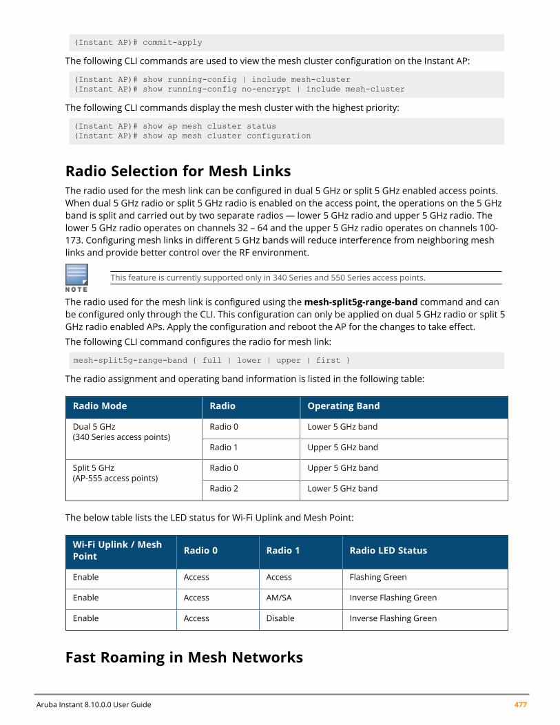
Aruba Instant 8.10.0.0 User Guide 477
(Instant AP)# commit-apply
The following CLI commands are used to view the mesh cluster configuration on the Instant AP:
(Instant AP)# show running-config | include mesh-cluster(Instant AP)# show running-config no-encrypt | include mesh-cluster
The following CLI commands display the mesh cluster with the highest priority:
(Instant AP)# show ap mesh cluster status(Instant AP)# show ap mesh cluster configuration
Radio Selection for Mesh LinksThe radio used for the mesh link can be configured in dual 5 GHz or split 5 GHz enabled access points.When dual 5 GHz radio or split 5 GHz radio is enabled on the access point, the operations on the 5 GHzband is split and carried out by two separate radios — lower 5 GHz radio and upper 5 GHz radio. Thelower 5 GHz radio operates on channels 32 – 64 and the upper 5 GHz radio operates on channels 100-173. Configuring mesh links in different 5 GHz bands will reduce interference from neighboring meshlinks and provide better control over the RF environment.
This feature is currently supported only in 340 Series and 550 Series access points.
The radio used for the mesh link is configured using themesh-split5g-range-band command and canbe configured only through the CLI. This configuration can only be applied on dual 5 GHz radio or split 5GHz radio enabled APs. Apply the configuration and reboot the AP for the changes to take effect.
The following CLI command configures the radio for mesh link:
mesh-split5g-range-band { full | lower | upper | first }
The radio assignment and operating band information is listed in the following table:
Radio Mode Radio Operating Band
Dual 5 GHz(340 Series access points)
Radio 0 Lower 5 GHz band
Radio 1 Upper 5 GHz band
Split 5 GHz(AP-555 access points)
Radio 0 Upper 5 GHz band
Radio 2 Lower 5 GHz band
The below table lists the LED status for Wi-Fi Uplink and Mesh Point:
Wi-Fi Uplink / MeshPoint Radio 0 Radio 1 Radio LED Status
Enable Access Access Flashing Green
Enable Access AM/SA Inverse Flashing Green
Enable Access Disable Inverse Flashing Green
Fast Roaming in Mesh Networks
Mesh Instant AP Configuration | 478
Instant supports fast roaming for APs deployed in a wireless mesh network. The mesh points for whichfast roaming is enabled are called mobility mesh points. Fast roaming on mesh APs is required mainly infast moving environments such as buses or the subway. To support fast roaming, mobility mesh pointsperform a scan of other mesh points in the background first and then choose the best neighbor toconnect from all the neighbors. The background scan implies when mesh is connected, the mesh pointcollects information about surrounding channels through background scanning. The mobility meshpoint scan time between radio channels is altered to be faster than the mesh point scan in a regularmesh network.
Fast roaming in mesh deployments is not supported on AP-387 and AP-518 access points.
The following CLI command enables fast roaming on a mesh point:
(Instant AP)# mesh-mobility [high|low|<number>]
Mesh ScanningInstant APs configured as mesh point APs continuously scan the RF environment for neighboring APs toeither establish an uplink connection or identify better routes to the mesh portal. A mesh point APperforms two types of scans:
n Uplink Scanning— Amesh point AP without an uplink connection scans the RF environment toidentify neighboring mesh APs or the mesh portal to establish an uplink connection. In this scanmode, the AP scans all available channels one after the another to find a link to the mesh portal. Ifthe scan on a particular channel fails or is unsuccessful, the AP retries scan on the same channelagain before moving to a different channel. The number of retries an AP attempts on a channel isdefined using themax-retries parameter in the mesh profile.
n Topology Optimization Scanning—Mesh point APs that are part of a mesh cluster performtopology optimization scans to identify better routes to the mesh portal. Topology optimizationscanning can be configured to occur at a certain interval, or when the RSSI score with theneighboring mesh AP falls below the defined threshold. The settings for optimization scanning isdefined using the link-threshold, optimize-scan-interval, and reselection-mode parameters in themesh profile.
Configuring Topology Optimization ScanningTopology optimization scanning is configured using thewlan mesh-profile command. It is a per-APsetting that must be configured on individual mesh point APs. There are two parameters in thewlanmesh-profile command that initiate the scan:
n optimize-scan-interval— The optimization scan interval parameter defines the interval at which themesh point AP must perform a scan for neighboring APs. The range is 1-100 and the value is definedin hours. The default value is 24.
The optimize-scan-interval only takes effect when the reselection-mode parameter is set toanytime.
The following CLI command configures the interval for topology optimization scanning:
(Instant AP)(config)# wlan mesh-profile(Instant AP)(Mesh Profile)# optimize-scan-interval 36

Aruba Instant 8.10.0.0 User Guide 479
n reselection-mode— This parameter allows you to initiate a topology optimization scan. Theavailable options are:l never— prevents topology optimization scanning by the mesh point AP.l subthreshold— initiates topology optimization scanning when the current uplink strength fallsbelow the link-threshold value defined.
l startup-subthreshold— initiates topology optimization scanning when the total uplink time ofthe mesh AP is less than 9 minutes. This is the default setting.
l anytime— initiates topology optimization scanning according to the interval defined in theoptimize-scan-interval parameter.
The following CLI command configures the trigger for topology optimization scanning:
(Instant AP)(config)# wlan mesh-profile(Instant AP)(Mesh Profile)# reselection-mode <never | subthreshold | startup-subthreshold | anytime>
Chapter 30Mobility and Client Management
Mobility and Client ManagementThis chapter provides the following information:
n Layer-3 Mobility Overview on page 480n Configuring Layer-3 Mobility on page 481
Layer-3 Mobility OverviewInstant APs form a single Instant network when they are in the same Layer-2 domain. As the number ofclients increase, multiple subnets are required to avoid broadcast overhead. In such a scenario, a clientmust be allowed to roam away from the Instant network to which it first connected (home network) toanother network supporting the same WLAN access parameters (foreign network) and continue itsexisting sessions.
Layer-3 mobility allows a client to roam without losing its IP address and sessions. If WLAN accessparameters are the same across these networks, clients connected to Instant APs in a given Instantnetwork can roam to Instant APs in a foreign Instant network and continue their existing sessions.Clients roaming across these networks are able to continue using their IP addresses after roaming. Youcan configure a list of virtual controller IP addresses across which Layer-3 mobility is supported.
The Aruba Instant Layer-3 mobility solution defines a Mobility Domain as a set of Instant networks, withthe same WLAN access parameters, across which client roaming is supported. The Instant network towhich the client first connects is called its home network. When the client roams to a foreign network, anInstant AP in the home network (home Instant AP) anchors all traffic to or from this client. The Instant APto which the client is connected in the foreign network (foreign Instant AP) tunnels all client traffic to orfrom the home Instant AP through a GRE tunnel.
Aruba Instant 8.10.0.0 User Guide 480
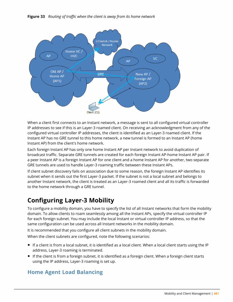
Mobility and Client Management | 481
Figure 33 Routing of traffic when the client is away from its home network
When a client first connects to an Instant network, a message is sent to all configured virtual controllerIP addresses to see if this is an Layer-3 roamed client. On receiving an acknowledgment from any of theconfigured virtual controller IP addresses, the client is identified as an Layer-3 roamed client. If theInstant AP has no GRE tunnel to this home network, a new tunnel is formed to an Instant AP (homeInstant AP) from the client's home network.
Each foreign Instant AP has only one home Instant AP per Instant network to avoid duplication ofbroadcast traffic. Separate GRE tunnels are created for each foreign Instant AP-home Instant AP pair. Ifa peer Instant AP is a foreign Instant AP for one client and a home Instant AP for another, two separateGRE tunnels are used to handle Layer-3 roaming traffic between these Instant APs.
If client subnet discovery fails on association due to some reason, the foreign Instant AP identifies itssubnet when it sends out the first Layer-3 packet. If the subnet is not a local subnet and belongs toanother Instant network, the client is treated as an Layer-3 roamed client and all its traffic is forwardedto the home network through a GRE tunnel.
Configuring Layer-3 MobilityTo configure a mobility domain, you have to specify the list of all Instant networks that form the mobilitydomain. To allow clients to roam seamlessly among all the Instant APs, specify the virtual controller IPfor each foreign subnet. You may include the local Instant or virtual controller IP address, so that thesame configuration can be used across all Instant networks in the mobility domain.
It is recommended that you configure all client subnets in the mobility domain.
When the client subnets are configured, note the following scenarios:
n If a client is from a local subnet, it is identified as a local client. When a local client starts using the IPaddress, Layer-3 roaming is terminated.
n If the client is from a foreign subnet, it is identified as a foreign client. When a foreign client startsusing the IP address, Layer-3 roaming is set up.
Home Agent Load Balancing
Aruba Instant 8.10.0.0 User Guide 482
Home Agent Load Balancing is required in large networks where multiple tunnels might terminate on asingle border or lobby Instant AP and overload it. When load balancing is enabled, the virtual controllerassigns the home Instant AP for roamed clients by applying a round robin policy. With this policy, theload for the Instant APs acting as Home Agents for roamed clients is uniformly distributed across theInstant AP cluster.
Configuring a Mobility Domain for InstantThe following procedure describes how to configure Layer-3 mobility domain by using the WebUI:
1. Go to the Configuration > System page.2. Click the Show advanced options.3. Expand L3 Mobility.4. Toggle the Home agent load balancing switch to enable. By default, home agent load balancing
is disabled.5. Click + in the Virtual Controller IP Addresses section. In the New IP address field, add the IP
address of a virtual controller that is part of the mobility domain, and click OK.6. Repeat Step 5, to add the IP addresses of all virtual controllers that form the Layer-3 mobility
domain.7. Click + in the Subnets section and specify the following:
a. IP address—Enter the client subnet in the text box.
b. Subnet mask—Enter the mask in the text box.
c. VLAN ID—Enter the VLAN ID of the home network in the text box.
d. Virtual controller IP—Enter the home virtual controller IP address for this subnet in the textbox.
8. Click OK.9. Click Save.
The following CLI commands configure a mobility domain:
(Instant AP)(config)# l3-mobility(Instant AP)(L3-mobility)# home-agent-load-balancing(Instant AP)(L3-mobility)# virtual-controller <IP-address>(Instant AP)(L3-mobility)# subnet <IP-address> <subnet-mask> <VLAN-ID> <virtual-controller-IP-address>
Chapter 31Spectrum Monitor
Spectrum MonitorThis chapter provides the following information:
n Understanding Spectrum Data on page 483n Configuring Spectrum Monitors and Hybrid Instant APs on page 488
Understanding Spectrum DataWireless networks operate in environments with electrical and RF devices that can interfere withnetwork communications. Microwave ovens, cordless phones, and even adjacent Wi-Fi networks are allpotential sources of continuous or intermittent interference. The spectrum monitor software moduleson Instant APs can examine the RF environment in which the Wi-Fi network is operating, identifyinterference, and classify its sources. An analysis of the results can then be used to quickly isolate issuesassociated with packet transmission, channel quality, and traffic congestion caused by contention withother devices operating in the same band or channel.
Spectrum monitors are Instant AP radios that gather spectrum data but do not service clients. Each SMscans and analyzes the spectrum band used by the SM's radio (2.4 GHz or 5 GHz). An Instant AP radio inhybrid Instant AP mode continues to serve clients as an access point while it analyzes spectrum analysisdata for the channel the radio uses to serve clients. You can record data for both types of spectrummonitor devices. However, the recorded spectrum is not reported to the virtual controller. A spectrumalert is sent to the virtual controller when a non-Wi-Fi interference device is detected.
The spectrum monitor is fully supported on all Instant APs or Remote APs with a few exceptions:
n Remote AP3 do not support Spectrum display in the WebUI.n AP-207, AP-203H, and AP-203RP access points do not support Spectrum Monitor.
The spectrum data is collected by each Instant AP spectrum monitor and hybrid Instant AP. Thespectrum data is not reported to the virtual controller. The Spectrum link is visible in the WebUI only ifyou have enabled the Spectrum Monitoring feature.
In the WebUISpectrum data is displayed in the following tabs:
n Overviewn 2.4 GHzn 5 GHz
OverviewThe following table describes the details displayed by the Spectrum Monitor:
Aruba Instant 8.10.0.0 User Guide 483
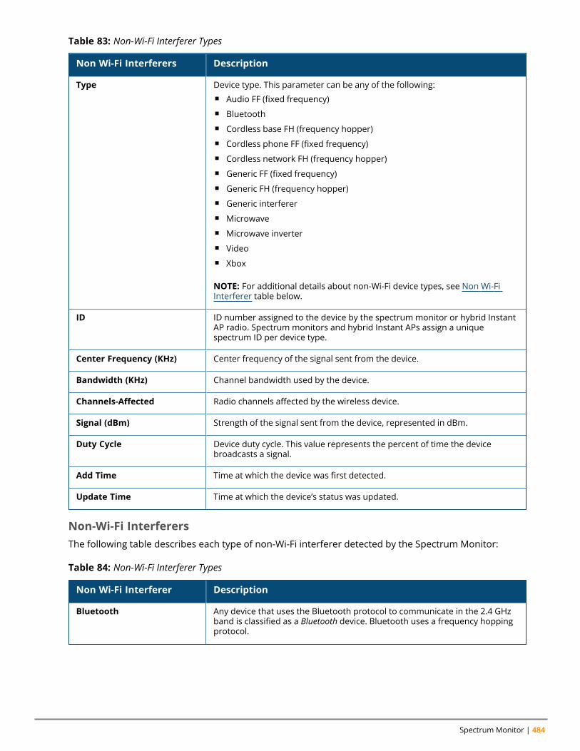
Spectrum Monitor | 484
Non Wi-Fi Interferers Description
Type Device type. This parameter can be any of the following:n Audio FF (fixed frequency)n Bluetoothn Cordless base FH (frequency hopper)n Cordless phone FF (fixed frequency)n Cordless network FH (frequency hopper)n Generic FF (fixed frequency)n Generic FH (frequency hopper)n Generic interferern Microwaven Microwave invertern Videon Xbox
NOTE: For additional details about non-Wi-Fi device types, see Non Wi-FiInterferer table below.
ID ID number assigned to the device by the spectrum monitor or hybrid InstantAP radio. Spectrum monitors and hybrid Instant APs assign a uniquespectrum ID per device type.
Center Frequency (KHz) Center frequency of the signal sent from the device.
Bandwidth (KHz) Channel bandwidth used by the device.
Channels-Affected Radio channels affected by the wireless device.
Signal (dBm) Strength of the signal sent from the device, represented in dBm.
Duty Cycle Device duty cycle. This value represents the percent of time the devicebroadcasts a signal.
Add Time Time at which the device was first detected.
Update Time Time at which the device’s status was updated.
Table 83: Non-Wi-Fi Interferer Types
Non-Wi-Fi InterferersThe following table describes each type of non-Wi-Fi interferer detected by the Spectrum Monitor:
Non Wi-Fi Interferer Description
Bluetooth Any device that uses the Bluetooth protocol to communicate in the 2.4 GHzband is classified as a Bluetooth device. Bluetooth uses a frequency hoppingprotocol.
Table 84: Non-Wi-Fi Interferer Types
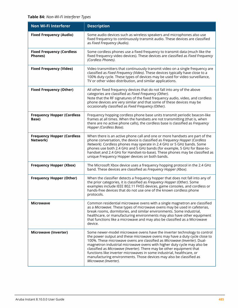
Aruba Instant 8.10.0.0 User Guide 485
Non Wi-Fi Interferer Description
Fixed Frequency (Audio) Some audio devices such as wireless speakers and microphones also usefixed frequency to continuously transmit audio. These devices are classifiedas Fixed Frequency (Audio).
Fixed Frequency (CordlessPhones)
Some cordless phones use a fixed frequency to transmit data (much like thefixed frequency video devices). These devices are classified as Fixed Frequency(Cordless Phones).
Fixed Frequency (Video) Video transmitters that continuously transmit video on a single frequency areclassified as Fixed Frequency (Video). These devices typically have close to a100% duty cycle. These types of devices may be used for video surveillance,TV or other video distribution, and similar applications.
Fixed Frequency (Other) All other fixed frequency devices that do not fall into any of the abovecategories are classified as Fixed Frequency (Other).Note that the RF signatures of the fixed frequency audio, video, and cordlessphone devices are very similar and that some of these devices may beoccasionally classified as Fixed Frequency (Other).
Frequency Hopper (CordlessBase)
Frequency hopping cordless phone base units transmit periodic beacon-likeframes at all times. When the handsets are not transmitting (that is, whenthere are no active phone calls), the cordless base is classified as FrequencyHopper (Cordless Base).
Frequency Hopper (CordlessNetwork)
When there is an active phone call and one or more handsets are part of thephone conversation, the device is classified as Frequency Hopper (CordlessNetwork). Cordless phones may operate in 2.4 GHz or 5 GHz bands. Somephones use both 2.4 GHz and 5 GHz bands (for example, 5 GHz for Base-to-handset and 2.4 GHz for Handset-to-base). These phones may be classified asunique Frequency Hopper devices on both bands.
Frequency Hopper (Xbox) The Microsoft Xbox device uses a frequency hopping protocol in the 2.4 GHzband. These devices are classified as Frequency Hopper (Xbox).
Frequency Hopper (Other) When the classifier detects a frequency hopper that does not fall into any ofthe prior categories, it is classified as Frequency Hopper (Other). Someexamples include IEEE 802.11 FHSS devices, game consoles, and cordless orhands-free devices that do not use one of the known cordless phoneprotocols.
Microwave Common residential microwave ovens with a single magnetron are classifiedas a Microwave. These types of microwave ovens may be used in cafeterias,break rooms, dormitories, and similar environments. Some industrial,healthcare, or manufacturing environments may also have other equipmentthat functions like a microwave and may also be classified as a Microwavedevice.
Microwave (Inverter) Some newer-model microwave ovens have the inverter technology to controlthe power output and these microwave ovens may have a duty cycle close to100%. These microwave ovens are classified as Microwave (Inverter). Dual-magnetron industrial microwave ovens with higher duty cycle may also beclassified as Microwave (Inverter). There may be other equipment thatfunctions like inverter microwaves in some industrial, healthcare, ormanufacturing environments. Those devices may also be classified asMicrowave (Inverter).
Table 84: Non-Wi-Fi Interferer Types

Spectrum Monitor | 486
Non Wi-Fi Interferer Description
Generic Interferer Any non-frequency hopping device that does not fall into any of the priorcategories described in this table is classified as a Generic Interferer. Forexample, a Microwave-like device that does not operate in the knownoperating frequencies used by the Microwave ovens may be classified as aGeneric Interferer. Similarly wide-band interfering devices may be classified asGeneric Interferers.
Table 84: Non-Wi-Fi Interferer Types
2.4 GHzThe following table describes the utilization and quality of a 2.4 GHz radio channel:
Non Wi-Fi Interferer Description
Quality(%) Current relative quality of the channel.
Utilization(%) The percentage of the channel being used.
WiFi (%) The percentage of the channel currently being used by Wi-Fi devices.
Bluetooth (%) Any device that uses the Bluetooth protocol to communicate in the 2.4 GHzband is classified as a Bluetooth device. Bluetooth uses a frequency hoppingprotocol.
Microwave Common residential microwave ovens with a single magnetron are classifiedas a Microwave. These types of microwave ovens may be used in cafeterias,break rooms, dormitories, and similar environments. Some industrial,healthcare, or manufacturing environments may also have other equipmentthat functions like a microwave and may also be classified as a Microwavedevice.
Microwave (Inverter) Some newer-model microwave ovens have the inverter technology to controlthe power output and these microwave ovens may have a duty cycle close to100%. These microwave ovens are classified as Microwave (Inverter). Dual-magnetron industrial microwave ovens with higher duty cycle may also beclassified as Microwave (Inverter). There may be other equipments thatfunction like inverter microwaves in some industrial, healthcare, ormanufacturing environments. Those devices may also be classified asMicrowave (Inverter).
Total nonwifi (%) The percentage of the channel currently being used by non-Wi-Fi devices.
KnownAPs Number of valid Instant APs identified on the radio channel.
UnKnowAPs Number of invalid or rogue Instant APs identified on the radio channel.
Noise Floor (dBm)
MaxAP Signal (dBm) Signal strength of the Instant AP that has the maximum signal strength on achannel.
MaxInterference(dBm) Signal strength of the non-Wi-Fi device that has the highest signal strength.
Table 85: 2.4 GHz Metrics
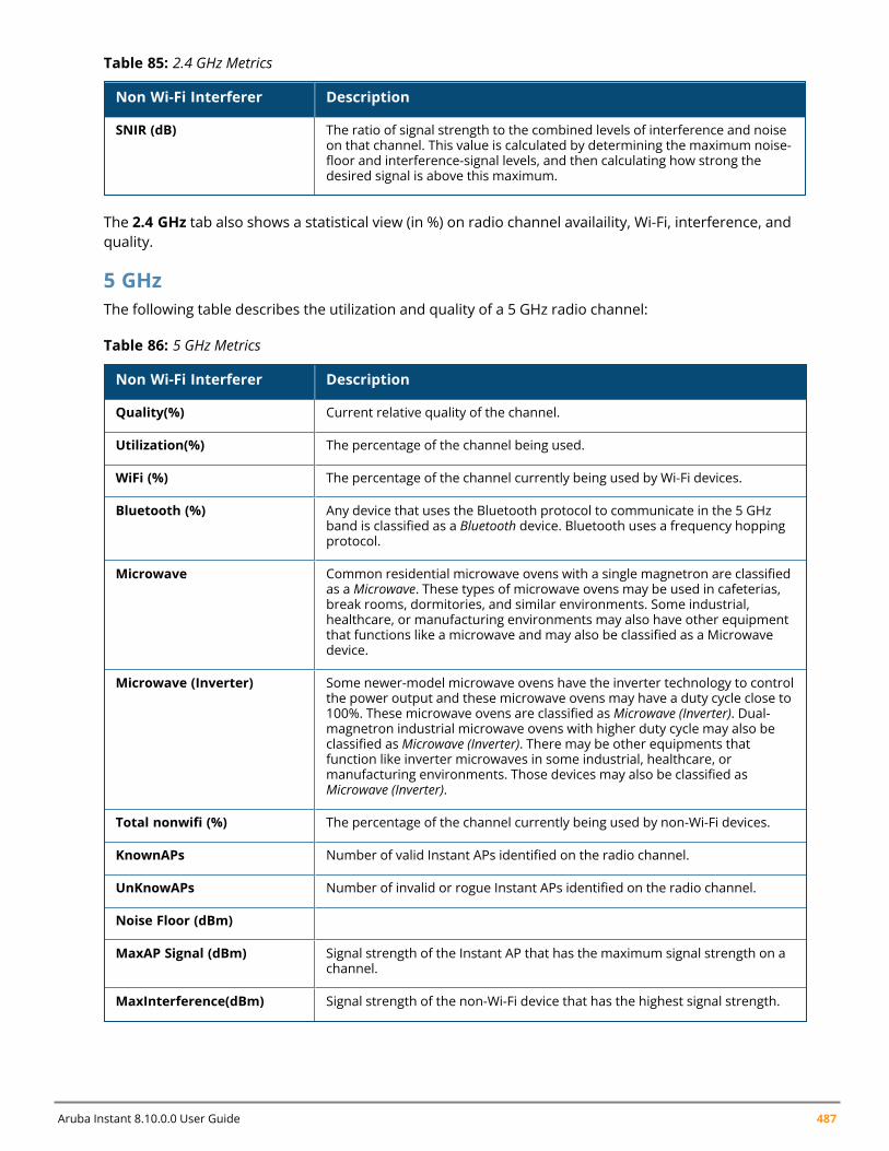
Aruba Instant 8.10.0.0 User Guide 487
Non Wi-Fi Interferer Description
SNIR (dB) The ratio of signal strength to the combined levels of interference and noiseon that channel. This value is calculated by determining the maximum noise-floor and interference-signal levels, and then calculating how strong thedesired signal is above this maximum.
Table 85: 2.4 GHz Metrics
The 2.4 GHz tab also shows a statistical view (in %) on radio channel availaility, Wi-Fi, interference, andquality.
5 GHzThe following table describes the utilization and quality of a 5 GHz radio channel:
Non Wi-Fi Interferer Description
Quality(%) Current relative quality of the channel.
Utilization(%) The percentage of the channel being used.
WiFi (%) The percentage of the channel currently being used by Wi-Fi devices.
Bluetooth (%) Any device that uses the Bluetooth protocol to communicate in the 5 GHzband is classified as a Bluetooth device. Bluetooth uses a frequency hoppingprotocol.
Microwave Common residential microwave ovens with a single magnetron are classifiedas a Microwave. These types of microwave ovens may be used in cafeterias,break rooms, dormitories, and similar environments. Some industrial,healthcare, or manufacturing environments may also have other equipmentthat functions like a microwave and may also be classified as a Microwavedevice.
Microwave (Inverter) Some newer-model microwave ovens have the inverter technology to controlthe power output and these microwave ovens may have a duty cycle close to100%. These microwave ovens are classified as Microwave (Inverter). Dual-magnetron industrial microwave ovens with higher duty cycle may also beclassified as Microwave (Inverter). There may be other equipments thatfunction like inverter microwaves in some industrial, healthcare, ormanufacturing environments. Those devices may also be classified asMicrowave (Inverter).
Total nonwifi (%) The percentage of the channel currently being used by non-Wi-Fi devices.
KnownAPs Number of valid Instant APs identified on the radio channel.
UnKnowAPs Number of invalid or rogue Instant APs identified on the radio channel.
Noise Floor (dBm)
MaxAP Signal (dBm) Signal strength of the Instant AP that has the maximum signal strength on achannel.
MaxInterference(dBm) Signal strength of the non-Wi-Fi device that has the highest signal strength.
Table 86: 5 GHz Metrics
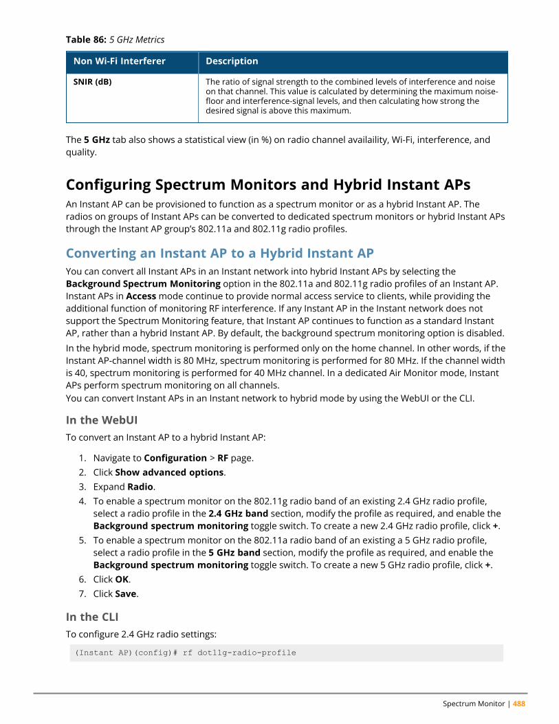
Spectrum Monitor | 488
Non Wi-Fi Interferer Description
SNIR (dB) The ratio of signal strength to the combined levels of interference and noiseon that channel. This value is calculated by determining the maximum noise-floor and interference-signal levels, and then calculating how strong thedesired signal is above this maximum.
Table 86: 5 GHz Metrics
The 5 GHz tab also shows a statistical view (in %) on radio channel availaility, Wi-Fi, interference, andquality.
Configuring Spectrum Monitors and Hybrid Instant APsAn Instant AP can be provisioned to function as a spectrum monitor or as a hybrid Instant AP. Theradios on groups of Instant APs can be converted to dedicated spectrum monitors or hybrid Instant APsthrough the Instant AP group’s 802.11a and 802.11g radio profiles.
Converting an Instant AP to a Hybrid Instant APYou can convert all Instant APs in an Instant network into hybrid Instant APs by selecting theBackground Spectrum Monitoring option in the 802.11a and 802.11g radio profiles of an Instant AP.Instant APs in Accessmode continue to provide normal access service to clients, while providing theadditional function of monitoring RF interference. If any Instant AP in the Instant network does notsupport the Spectrum Monitoring feature, that Instant AP continues to function as a standard InstantAP, rather than a hybrid Instant AP. By default, the background spectrum monitoring option is disabled.
In the hybrid mode, spectrum monitoring is performed only on the home channel. In other words, if theInstant AP-channel width is 80 MHz, spectrum monitoring is performed for 80 MHz. If the channel widthis 40, spectrum monitoring is performed for 40 MHz channel. In a dedicated Air Monitor mode, InstantAPs perform spectrum monitoring on all channels.You can convert Instant APs in an Instant network to hybrid mode by using the WebUI or the CLI.
In the WebUITo convert an Instant AP to a hybrid Instant AP:
1. Navigate to Configuration > RF page.2. Click Show advanced options.3. Expand Radio.4. To enable a spectrum monitor on the 802.11g radio band of an existing 2.4 GHz radio profile,
select a radio profile in the 2.4 GHz band section, modify the profile as required, and enable theBackground spectrum monitoring toggle switch. To create a new 2.4 GHz radio profile, click +.
5. To enable a spectrum monitor on the 802.11a radio band of an existing a 5 GHz radio profile,select a radio profile in the 5 GHz band section, modify the profile as required, and enable theBackground spectrum monitoring toggle switch. To create a new 5 GHz radio profile, click +.
6. Click OK.7. Click Save.
In the CLITo configure 2.4 GHz radio settings:
(Instant AP)(config)# rf dot11g-radio-profile
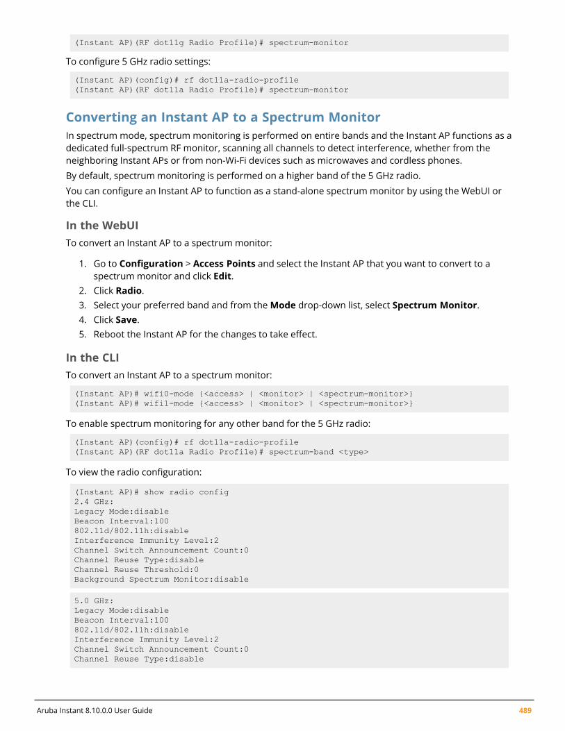
Aruba Instant 8.10.0.0 User Guide 489
(Instant AP)(RF dot11g Radio Profile)# spectrum-monitor
To configure 5 GHz radio settings:
(Instant AP)(config)# rf dot11a-radio-profile(Instant AP)(RF dot11a Radio Profile)# spectrum-monitor
Converting an Instant AP to a Spectrum MonitorIn spectrum mode, spectrum monitoring is performed on entire bands and the Instant AP functions as adedicated full-spectrum RF monitor, scanning all channels to detect interference, whether from theneighboring Instant APs or from non-Wi-Fi devices such as microwaves and cordless phones.
By default, spectrum monitoring is performed on a higher band of the 5 GHz radio.
You can configure an Instant AP to function as a stand-alone spectrum monitor by using the WebUI orthe CLI.
In the WebUITo convert an Instant AP to a spectrum monitor:
1. Go to Configuration > Access Points and select the Instant AP that you want to convert to aspectrum monitor and click Edit.
2. Click Radio.3. Select your preferred band and from theMode drop-down list, select Spectrum Monitor.4. Click Save.5. Reboot the Instant AP for the changes to take effect.
In the CLITo convert an Instant AP to a spectrum monitor:
(Instant AP)# wifi0-mode {<access> | <monitor> | <spectrum-monitor>}(Instant AP)# wifi1-mode {<access> | <monitor> | <spectrum-monitor>}
To enable spectrum monitoring for any other band for the 5 GHz radio:
(Instant AP)(config)# rf dot11a-radio-profile(Instant AP)(RF dot11a Radio Profile)# spectrum-band <type>
To view the radio configuration:
(Instant AP)# show radio config2.4 GHz:Legacy Mode:disableBeacon Interval:100802.11d/802.11h:disableInterference Immunity Level:2Channel Switch Announcement Count:0Channel Reuse Type:disableChannel Reuse Threshold:0Background Spectrum Monitor:disable
5.0 GHz:Legacy Mode:disableBeacon Interval:100802.11d/802.11h:disableInterference Immunity Level:2Channel Switch Announcement Count:0Channel Reuse Type:disable

Spectrum Monitor | 490
Channel Reuse Threshold:0Background Spectrum Monitor:disableStandalone Spectrum Band:5ghz-upper
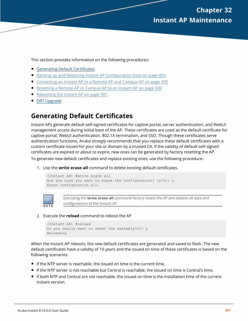
Chapter 32Instant AP Maintenance
Instant AP MaintenanceThis section provides information on the following procedures:
n Generating Default Certificatesn Backing up and Restoring Instant AP Configuration Data on page 493n Converting an Instant AP to a Remote AP and Campus AP on page 495n Resetting a Remote AP or Campus AP to an Instant AP on page 500n Rebooting the Instant AP on page 501n DRT Upgrade
Generating Default CertificatesInstant APs generate default self-signed certificates for captive portal, server authentication, and WebUImanagement access during initial boot of the AP. These certificates are used as the default certificate forcaptive portal, WebUI authentication, 802.1X termination, and SSO. Though these certificates serveauthentication functions, Aruba strongly recommends that you replace these default certificates with acustom certificate issued for your site or domain by a trusted CA. If the validity of default self-signedcertificates are expired or about to expire, new ones can be generated by factory resetting the AP.
To generate new default certificates and replace existing ones, use the following procedure:
1. Use thewrite erase all command to delete existing default certificates.
(Instant AP) #write erase allAre you sure you want to erase the configuration? (y/n): yErase configuration all.
Executing thewrite erase all command factory resets the AP and deletes all data andconfigurations of the Instant AP.
2. Execute the reload command to reboot the AP
(Instant AP) #reloadDo you really want to reset the system(y/n): yReloading
When the Instant AP reboots, the new default certificates are generated and saved to flash. The newdefault certificates have a validity of 10 years and the issued on time of these certificates is based on thefollowing scenarios:
n If the NTP server is reachable, the issued on time is the current time.n If the NTP server is not reachable but Central is reachable, the issued on time is Central’s time.n If both NTP and Central are not reachable, the issued on time is the installation time of the current
Instant version.
Aruba Instant 8.10.0.0 User Guide 491
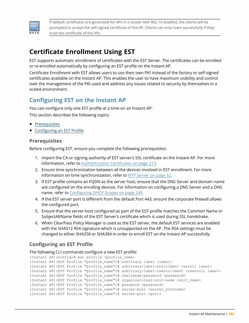
Instant AP Maintenance | 492
If default certificates are generated for APs in a cluster with 802.1X enabled, the clients will beprompted to accept the self-signed certificate of the AP. Clients can only roam successfully if theytrust the certificate of the APs.
Certificate Enrollment Using ESTEST supports automatic enrollment of certificates with the EST Server. The certificates can be enrolledor re-enrolled automatically by configuring an EST profile on the Instant AP.
Certificate Enrollment with EST allows users to use their own PKI instead of the factory or self-signedcertificates available on the Instant AP. This enables the user to have maximum visibility and controlover the management of the PKI used and address any issues related to security by themselves in ascaled environment.
Configuring EST on the Instant APYou can configure only one EST profile at a time on an Instant AP:
This section describes the following topics:
n Prerequisitesn Configuring an EST Profile
PrerequisitesBefore configuring EST, ensure you complete the following prerequisites:
1. Import the CA or signing authority of EST server's SSL certificate on the Instant AP. For moreinformation, refer to Authentication Certificates on page 213.
2. Ensure time synchronization between all the devices involved in EST enrollment. For moreinformation on time synchronization, refer to NTP Server on page 52.
3. If EST profile contains an FQDN as the server host, ensure that the DNS Server and domain nameare configured on the enrolling devices. For information on configuring a DNS Server and a DNSname, refer to Configuring DHCP Scopes on page 249.
4. If the EST server port is different from the default Port 443, ensure the corporate firewall allowsthe configured port.
5. Ensure that the server-host configured as part of the EST profile matches the Common Name orSubjectAltName fields of the EST Server’s certificate which is used during SSL handshake.
6. When ClearPass Policy Manager is used as the EST server, the default EST services are enabledwith the SHA512 RSA signature which is unsupported on the AP. The RSA settings must bechanged to either SHA256 or SHA384 in order to enroll EST on the Instant AP successfully.
Configuring an EST ProfileThe following CLI commands configure a new EST profile:(Instant AP)(config)# est profile <profile_name>(Instant AP)(EST Profile "profile_name")# arbitrary label <label>(Instant AP)(EST Profile "profile_name")# arbitrary-label-enrollment <enroll label>(Instant AP)(EST Profile "profile_name")# arbitrary-label-reenrollment <reenroll label>(Instant AP)(EST Profile "profile_name")# challenge-password <password>(Instant AP)(EST Profile "profile_name")# organizational-unit-name <unit_name>(Instant AP)(EST Profile "profile_name")# password <passowrd>(Instant AP)(EST Profile "profile_name")# server-host <server_hostname>(Instant AP)(EST Profile "profile_name")# server-port <port>
Aruba Instant 8.10.0.0 User Guide 493
(Instant AP)(EST Profile "profile_name")# trust-anchor <trust_anchor>(Instant AP)(EST Profile "profile_name")# username <username>(Instant AP)(EST Profile "profile_name")# end(Instant AP)# commit apply
The following CLI command activates an EST profile on the Instant AP:(Instant AP)(config)# est-activate <profile_name>
The following CLI command is used to view the EST status on the Instant AP:(Instant AP)# show est status
Support for Using EST Certificate with RADSECAruba Instant allows EST certificates to be used in RADSEC applications under the following scenarios:
n Custom certificates are not assigned to RADSEC.n An EST profile is configured and activated. The EST certificate enrollment is successful and the EST CA
certificate chain is downloaded.n RADSEC is allowed to use the EST certificate by using the configuration command radsec use-est-
certificate.
When all the above conditions are met, RADSEC will use EST enrolled client certificate and the CAcertificate chain downloaded from the EST server.
Backing up and Restoring Instant AP Configuration DataYou can back up the Instant AP configuration data and restore the configuration when required.
Viewing Current ConfigurationThe following procedure describes how to view the current configuration on the Instant AP:
1. In the WebUI, navigate toMaintenance > Configuration > Current Configuration.2. In the CLI, enter the following command at the command prompt:
(Instant AP)# show running-config
Backing up Configuration DataThe following procedure describes how to back up configuration data using the WebUI:
1. Navigate to theMaintenance > Configuration page.2. Click Backup Configuration.3. Click Continue to confirm the backup. The instant.cfg containing the Instant AP configuration data
will be saved in your local file system.
The following CLI command shows the configuration that is backed up by the Instant AP:
(Instant AP)# show backup-config
Restoring Configuration Data1. Navigate to theMaintenance > Configuration page.2. Click Restore Configuration.3. Click Browse to browse your local system and select the configuration file.

Instant AP Maintenance | 494
4. Click Restore Now.5. Click Restore Configuration to confirm restoration. The configuration is restored and the Instant
AP reboots to load the new configuration.
The following CLI command restores the Instant AP configuration:
(Instant AP)(config)# copy config tftp://x.x.x.x/confgi.cfg
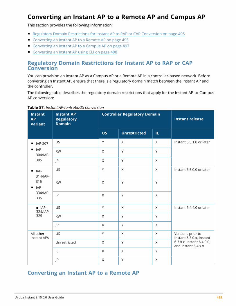
Aruba Instant 8.10.0.0 User Guide 495
Converting an Instant AP to a Remote AP and Campus APThis section provides the following information:
n Regulatory Domain Restrictions for Instant AP to RAP or CAP Conversion on page 495n Converting an Instant AP to a Remote AP on page 495n Converting an Instant AP to a Campus AP on page 497n Converting an Instant AP using CLI on page 498
Regulatory Domain Restrictions for Instant AP to RAP or CAPConversionYou can provision an Instant AP as a Campus AP or a Remote AP in a controller-based network. Beforeconverting an Instant AP, ensure that there is a regulatory domain match between the Instant AP andthe controller.
The following table describes the regulatory domain restrictions that apply for the Instant AP-to-CampusAP conversion:
InstantAPVariant
Instant APRegulatoryDomain
Controller Regulatory DomainInstant release
US Unrestricted IL
n IAP-207n IAP-
304/IAP-305
US Y X X Instant 6.5.1.0 or later
RW X Y Y
JP X Y X
n IAP-314/IAP-315
n IAP-334/IAP-335
US Y X X Instant 6.5.0.0 or later
RW X Y Y
JP X Y X
n IAP-324/IAP-325
US Y X X Instant 6.4.4.0 or later
RW X Y Y
JP X Y X
All otherInstant APs
US Y X X Versions prior toInstant 6.3.0.x, Instant6.3.x.x, Instant 6.4.0.0,and Instant 6.4.x.x
Unrestricted X Y X
IL X X Y
JP X Y X
Table 87: Instant AP-to-ArubaOS Conversion
Converting an Instant AP to a Remote AP
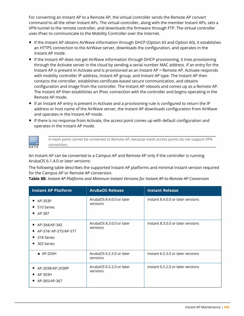
Instant AP Maintenance | 496
For converting an Instant AP to a Remote AP, the virtual controller sends the Remote AP convertcommand to all the other Instant APs. The virtual controller, along with the member Instant APs, sets aVPN tunnel to the remote controller, and downloads the firmware through FTP. The virtual controlleruses IPsec to communicate to the Mobility Controller over the Internet.
n If the Instant AP obtains AirWave information through DHCP (Option 43 and Option 60), it establishesan HTTPS connection to the AirWave server, downloads the configuration, and operates in theInstant AP mode.
n If the Instant AP does not get AirWave information through DHCP provisioning, it tries provisioningthrough the Activate server in the cloud by sending a serial number MAC address. If an entry for theInstant AP is present in Activate and is provisioned as an Instant AP > Remote AP, Activate respondswith mobility controller IP address, Instant AP group, and Instant AP type. The Instant AP thencontacts the controller, establishes certificate-based secure communication, and obtainsconfiguration and image from the controller. The Instant AP reboots and comes up as a Remote AP.The Instant AP then establishes an IPsec connection with the controller and begins operating in theRemote AP mode.
n If an Instant AP entry is present in Activate and a provisioning rule is configured to return the IPaddress or host name of the AirWave server, the Instant AP downloads configuration from AirWaveand operates in the Instant AP mode.
n If there is no response from Activate, the access point comes up with default configuration andoperates in the Instant AP mode.
A mesh point cannot be converted to Remote AP, because mesh access points do not support VPNconnection.
An Instant AP can be converted to a Campus AP and Remote AP only if the controller is runningArubaOS 6.1.4.0 or later versions:
The following table describes the supported Instant AP platforms and minimal Instant version requiredfor the Campus AP or Remote AP conversion.Table 88: Instant AP Platforms and Minimum Instant Versions for Instant AP-to-Remote AP Conversion
Instant AP Platform ArubaOS Release Instant Release
n AP-303Pn 510 Seriesn AP-387
ArubaOS 8.4.0.0 or laterversions
Instant 8.4.0.0 or later versions
n AP-344/AP-345n AP-374/ AP-375/AP-377n 318 Seriesn 303 Series
ArubaOS 8.3.0.0 or laterversions
Instant 8.3.0.0 or later versions
n AP-203H ArubaOS 6.5.3.0 or laterversions
Instant 6.5.3.0 or later versions
n AP-203R/AP-203RPn AP-303Hn AP-365/AP-367
ArubaOS 6.5.2.0 or laterversions
Instant 6.5.2.0 or later versions
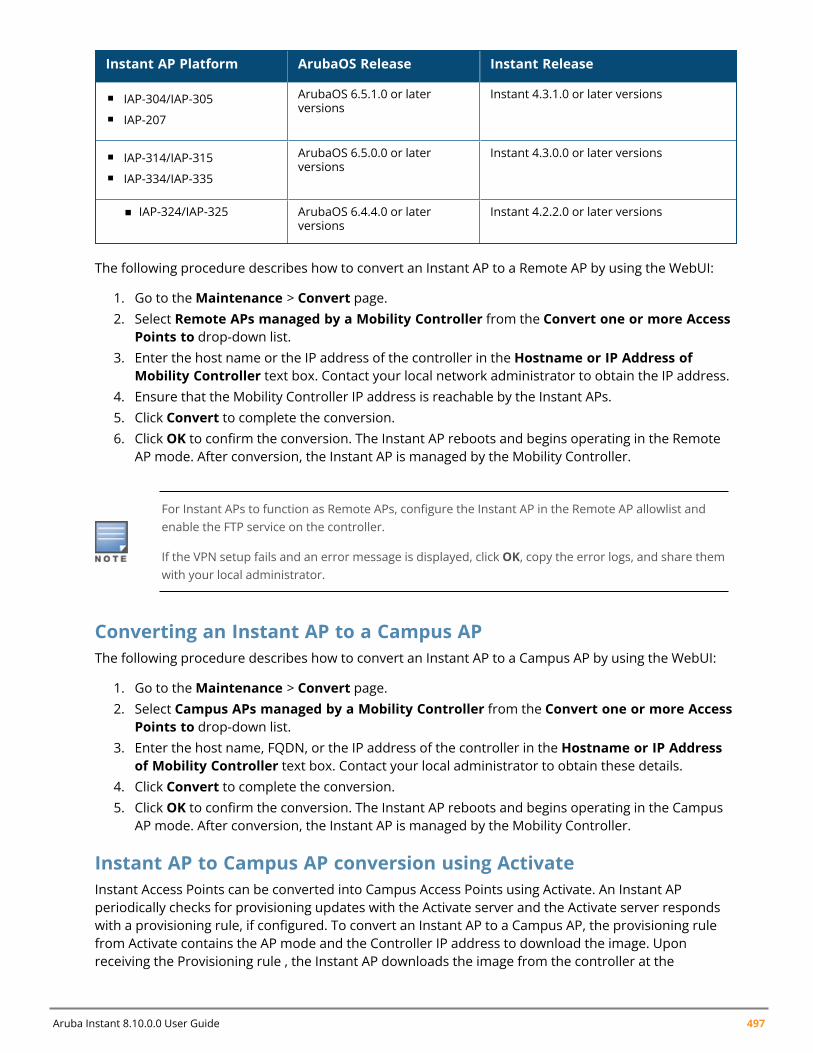
Aruba Instant 8.10.0.0 User Guide 497
Instant AP Platform ArubaOS Release Instant Release
n IAP-304/IAP-305n IAP-207
ArubaOS 6.5.1.0 or laterversions
Instant 4.3.1.0 or later versions
n IAP-314/IAP-315n IAP-334/IAP-335
ArubaOS 6.5.0.0 or laterversions
Instant 4.3.0.0 or later versions
n IAP-324/IAP-325 ArubaOS 6.4.4.0 or laterversions
Instant 4.2.2.0 or later versions
The following procedure describes how to convert an Instant AP to a Remote AP by using the WebUI:
1. Go to theMaintenance > Convert page.2. Select Remote APs managed by a Mobility Controller from the Convert one or more Access
Points to drop-down list.3. Enter the host name or the IP address of the controller in the Hostname or IP Address of
Mobility Controller text box. Contact your local network administrator to obtain the IP address.4. Ensure that the Mobility Controller IP address is reachable by the Instant APs.5. Click Convert to complete the conversion.6. Click OK to confirm the conversion. The Instant AP reboots and begins operating in the Remote
AP mode. After conversion, the Instant AP is managed by the Mobility Controller.
For Instant APs to function as Remote APs, configure the Instant AP in the Remote AP allowlist andenable the FTP service on the controller.
If the VPN setup fails and an error message is displayed, click OK, copy the error logs, and share themwith your local administrator.
Converting an Instant AP to a Campus APThe following procedure describes how to convert an Instant AP to a Campus AP by using the WebUI:
1. Go to theMaintenance > Convert page.2. Select Campus APs managed by a Mobility Controller from the Convert one or more Access
Points to drop-down list.3. Enter the host name, FQDN, or the IP address of the controller in the Hostname or IP Address
of Mobility Controller text box. Contact your local administrator to obtain these details.4. Click Convert to complete the conversion.5. Click OK to confirm the conversion. The Instant AP reboots and begins operating in the Campus
AP mode. After conversion, the Instant AP is managed by the Mobility Controller.
Instant AP to Campus AP conversion using ActivateInstant Access Points can be converted into Campus Access Points using Activate. An Instant APperiodically checks for provisioning updates with the Activate server and the Activate server respondswith a provisioning rule, if configured. To convert an Instant AP to a Campus AP, the provisioning rulefrom Activate contains the AP mode and the Controller IP address to download the image. Uponreceiving the Provisioning rule , the Instant AP downloads the image from the controller at the
Instant AP Maintenance | 498
Controller IP address. The Instant AP then erases all configurations, reboots with the new image andconverts itself into a Campus AP. The Instant AP now operates as a Campus AP and searches for acontroller to connect with.
The converted Campus APs can be enabled with Zero Touch Provisioning for easy installation or can bebound to a controller. This is done by configuring the IAP to CAP provisioning rule in the ActivateServer. For information on configuring provisioning rules in Activate, refer to the Aruba Activate UserGuide.
Campus AP with ZTP enabledIn this mode, the Instant AP receives the provisioning rule from Activate and downloads the image fromthe controller at the Controller IP address. It then reboots as a Campus AP with ZTP enabled andsearches for a controller to connect with using ZTP. Campus APs enabled with ZTP can be provisioned toany network with a Controller without any manual configuration changes. To enable ZTP on CampusAPs, uncheck the Persist Controller IP checkbox when configuring a IAP to CAP Provisioning rule inActivate.
Campus AP bound to a ControllerIn this mode, the Instant AP receives the provisioning rule from Activate , downloads the image from thecontroller at the Controller IP address, saves the IP address and is bound to that controller. The InstantAP then reboots as a Campus AP and is bound with the Controller. Campus APs bound to a controller donot perform standard controller discovery and cannot be provisioned in another network withoutmanual configuration changes. To bind the Campus AP to the Controller, select the Persist ControllerIP checkbox when configuring a IAP to CAP Provisioning rule in Activate.
The following CLI command shows logs related to provision update with Activate:
(Instant AP)# show log provision
Converting an Instant AP using CLIThe following CLI command converts an Instant AP to a Remote AP or Campus AP:
(Instant AP)# convert-aos-ap <mode> <controller-IP-address>
The following CLI command converts an Instant AP to a stand-alone Instant AP or to provision an InstantAP in the cluster mode:
(Instant AP)# swarm-mode <mode>
Converting an Instant AP to Stand-Alone ModeThis feature allows you to deploy an Instant AP as an autonomous Instant AP, which is a separate entityfrom the existing virtual controller cluster in the Layer 2 domain.
When an Instant AP is converted to function in stand-alone mode, it cannot join a cluster of Instant APseven if the Instant AP is in the same VLAN. If the Instant AP is in the cluster mode, it can form a clusterwith other virtual controller Instant APs in the same VLAN.
The following procedure describes how to deploy an Instant AP as a stand-alone or autonomous InstantAP using the WebUI:
1. Go to theMaintenance > Convert page.2. Convert one or more Access Points to—Select Standalone AP from the drop-down list.3. Access Point to Convert—Select the access point you want to convert from the drop-down list.
Aruba Instant 8.10.0.0 User Guide 499
4. Click Convert to complete the conversion. The Instant AP now operates in the stand-alone mode.5. Click Close.
Converting an Instant AP to Single AP ModeSingle AP mode is a new AP deployment mode suitable for Instant deployments with only one AP in asite. This mode is a type of standalone AP deployment with additional security when the AP is directlyfacing a WAN connection. When configured as a single AP, the AP will not send or receive managementframes such as mobility packets, roaming packets, hierarchy beacons through the uplink port.
The following procedure describes how to configure single AP mode on an Instant AP using the webUI:
1. Navigate to theMaintenance > Convert page.2. In the Convert one or more Access Points to drop down menu, select Single AP.3. In the Access Point to convert drop down menu, select the access point you want to convert.4. Click on Convert and select OK in the confirmation screen.5. The AP will reboot and deploy as a single AP.
The following CLI command deploys an Instant AP as a single AP:
(Instant AP)# swarm-mode single-ap
Reboot the AP for the configuration to take effect.
The following CLI commands verify the single AP mode configuration:
(Instant AP)# show swarm mode
(Instant AP)# show ap-env
For more information on CLI commands, refer to the Aruba Instant 8.x CLI Reference Guide.
Recommended Configurations for Teleworker DeploymentFor enhanced security in teleworker deployments, Aruba recommends the following procedures:
n Disabling Local Management of the AP and Managing the AP Through a Secured Tunneln Blocking Client Access to IP Addresses Reserved for the AP
Disabling Local Management of the AP and Managing the AP Through a SecuredTunnelIn teleworker deployments, it is recommended to turn off local management on the AP and manage itthrough the secured tunnel with the VPN controller. The following procedure describes how toconfigure this setup:
1. Disable local management of the AP using the disable-local-management-when-remotely-managed command. This command denies all WebUI and SSH communications received by theAP through the uplink port. This can be done only through the CLI.
(Instant AP)# configure terminal(Instant AP)(config)# disable-local-management-when-remotely-managed
Instant AP Maintenance | 500
2. Enable the AP to be managed by the VPN concentrator using the WebUI and the CLI.
n The following procedure describes how to configure a trusted tunnel in the WebUI:a. Navigate to the Configuration > Security page.b. Expand Firewall Settings and then Firewall tab.c. Toggle the Tunnel Trusted switch to enable or disable the feature. Set it to enable to
turn on trusted tunnel.d. Click Save.
n The following CLI commands configure a trusted tunnel using the CLI:
(Instant AP)# configure terminal(Instant AP)(config)# firewall(Instant AP)(firewall)# tunnel-trusted
Blocking Client Access to IP Addresses Reserved for the APFor enhanced security in teleworker deployments, the access to IP addresses reserved for the AP mustbe restricted for clients. To disable client access to IP addresses reserved for the AP, add a deny all ruleto active user roles using the apip-all alias as the destination IP address. The apip-all is an alias thatincludes all IP addresses used by the Instant AP such as br0 IP, DHCP scope, magic-vlan, etc. This can bedone using the WebUI and the CLI .
The following procedure describes how to block clients from accessing the IP addresses reserved for theAP using the webUI:
1. Navigate to the Configuration > Security page.2. Expand Roles.3. Under Roles, select the role for which you want to assign the firewall rule and click on + in the
Access Rules for <role name> box.4. In the new rule window,
a. Select Access control in the Rule type drop-down list.
b. Select Network under Service and select any from the drop-down menu.
c. Select Deny under Action.
d. Select to AP IP all under Destination.
e. Click Okay to save the rule.
5. Click Save to save the configuration.
The following CLI commands configure a deny all rule for AP IP all addresses:
(Instant AP)# configure terminal(Instant AP)(config)# wlan access-rule <rule name>(Instant AP)(firewall)# rule apip-all 0.0.0.0 match any any deny
The following CLI commands verify the security configurations:
(Instant AP)# show amp-audit
(Instant AP)# show firewall
For more information on CLI commands, refer to the Aruba Instant 8.x CLI Reference Guide.
Resetting a Remote AP or Campus AP to an Instant AP
Aruba Instant 8.10.0.0 User Guide 501
The reset knob located on the rear of an Instant AP can be used to reset the Instant AP to factory defaultsettings.
To reset an Instant AP, perform the following steps:
1. Turn off the Instant AP.2. Press and hold the reset knob using a small and narrow object such as a paperclip.3. Turn on the Instant AP without releasing the reset knob. The power LED flashes within 5 seconds
indicating that the reset is completed.4. Release the reset knob. The Instant AP reboots with the factory default settings.
Rebooting the Instant APIf you encounter any problem with the Instant APs, you can reboot all Instant APs or a selected InstantAP in a network using the WebUI:
1. Go to theMaintenance > Reboot page.2. In the Select the access point you wish to reboot drop-down list, select the Instant AP that you
want to reboot and click Reboot. To reboot all the Instant APs in the network, click Reboot Allfrom the drop-down list and click Reboot.
3. Click OK to continue. The Access Points are rebootingmessage is displayed indicating that thereboot is in progress.
4. Click OK.
DRT UpgradeThe DRT upgrade feature installs and upgrades the DRT file for an Instant AP. When new certificationsare available for Instant APs, the subsequent releases will automatically receive support for these certs.Only the newer version of the DRT file is used for an upgrade.
Instant supports DRT upgrade from AirWave, over HTTPs and WebSocket. Instant APs can report theDRT upgrade status to AirWave and AirWave can also display the DRT upgrade status to users.
The DRT file is installed under the following scenarios:
Instant AP Boot UpThe DRT information is stored at two locations, one in the image file, and another in the flash memory.Every time an Instant AP boots up, it compares the DRT version at both the locations and uses thenewer version of DRT in the flash.
Install DRT File In a ClusterWhen all the Instant APs in a cluster finish downloading the DRT table, the conductor Instant APcommunicates to the member Instant APs to upgrade the DRT file. After the member Instant APsupgrade the DRT file, the conductor Instant AP proceeds with DRT upgrade. There is a timeoutmechanism set during the download and upgrade process. When a member Instant AP has finished DRTdownloading from the conductor Instant AP, but has not received an upgrade command within 5minutes, the member Instant AP will attempt to upgrade the DRT file without waiting. Similarly, if themember Instant AP has not finished downloading within 5 minutes, the conductor Instant AP will notwait for these members. It will continue with the rest of the upgrade process.
The DRT version can be upgraded by using the WebUI:
Instant AP Maintenance | 502
1. Navigate to theMaintenance > Regulatory page.2. To manually upgrade an Instant AP's DRT version, select the DRT file or update a URL in the
Manual section.3. If you are using a DRT file, select the DRT file radio button, click Browse, and then click Upgrade
Now.4. If you are using a DRT URL, select the DRT URL radio button and enter the link in the URL text
box.5. Click Upgrade Now.
If a new version of DRT is displayed in the Automatic section, upgrade it by clicking Upgrade Now.
The following CLI command upgrades an Instant AP cluster with the new DRT version:
upgrade-drt <url>
The following CLI command resets the DRT version on an Instant AP:
reset drt
The following CLI command shows the status of DRT version on an Instant AP:
show drt state
Instant supports DRT upgrade from AirWave, over HTTPs and WebSocket. Instant APs can report theDRT upgrade status to AirWave and AirWave can also display the DRT upgrade status to users.
Release Type IdentifierRelease type identifiers are displayed along with the software version information. These tags indicatethe maintenance period of the software version. There are two types of releases:
n LSR - Long supported release. Long supported releases extend support for patches up to 5 years.
n SSR - Short supported release. Short supported releases extend support for up to 2 years.
This information is displayed alongside the version number of the software and can be viewed in theInstant webUI and the CLI.
ExampleThe following is the output of show version command. The release type tag is displayed after the releaseversion information.
(Instant SP)# show versionAruba Operating System Software.ArubaOS (MODEL: 635), Version 8.10.0.0 LSRWebsite: http://www.arubanetworks.com(c) Copyright 2022 Hewlett Packard Enterprise Development LP.Compiled on 2022-03-20 at 07:48:57 PDT (build 83616) by jenkinsFIPS Mode :disabled
Chapter 33Monitoring Devices and Logs
Monitoring Devices and LogsThis chapter describes the following topics:
n Configuring SNMP on page 503n Configuring Syslog Servers on page 506n Configuring TFTP Dump Server on page 507n Running Debug Commands on page 508n Uplink Bandwidth Monitoring on page 511n WAN Link Health Monitoring on page 512
Configuring SNMPThis section provides the following information:
n SNMP Parameters for Instant AP on page 503n Configuring SNMP on page 504n Configuring SNMP Traps on page 505
SNMP Parameters for Instant APInstant supports SNMPv1, SNMPv2, and SNMPv3 for reporting purposes only. An Instant AP cannot useSNMP to set values in an Aruba system.
You can configure the following parameters for an Instant AP:
Parameter Description
Community Strings for SNMPV1 and SNMPV2 An SNMP community string is a text string that acts asa password, and is used to authenticate messages sentbetween the virtual controller and the SNMP agent.
If you are using SNMPv3 to obtain values from the Instant AP, you can configure the following parameters:
Name A string representing the name of the user.
Authentication Protocol An indication of whether messages sent on behalf ofthis user can be authenticated, and if so, the type ofauthentication protocol used. This can take one of thetwo values:n MD5—HMAC-MD5-96 Digest Authentication
Protocoln SHA—HMAC-SHA-96 Digest Authentication Protocol
Table 89: SNMP Parameters for Instant AP
Aruba Instant 8.10.0.0 User Guide 503
Monitoring Devices and Logs | 504
Parameter Description
Authentication protocol password If messages sent on behalf of this user can beauthenticated, a (private) authentication key is usedwith the authentication protocol. This is a stringpassword for MD5 or SHA based on the conditionsmentioned above.
Privacy protocol An indication of whether messages sent on behalf ofthis user can be protected from disclosure, and if so,the type of privacy protocol that is used. This takes thevalue of CBC-DES symmetric encryption.
Privacy protocol password If messages sent on behalf of this user can beencrypted or decrypted with DES, the (private) privacykey with the privacy protocol is used.
Table 89: SNMP Parameters for Instant AP
Configuring SNMPThe following procedure describes how to configure SNMPv1, SNMPv2, and SNMPv3 community stringsby using the WebUI.
Creating Community Strings for SNMPv1 and SNMPv2
The following procedure describes how to create community strings for SNMPv1 and SNMPv2:
1. Go to Configuration > System.2. Click the Show advanced options link.3. ExpandMonitoring and select SNMP.4. In the Community Strings for SNMPV1 and SNMPV2 table, click + .5. In the Edit Community String text box, enter the community string and click OK.6. To delete a community string, select the string and click delete.7. Click Save.
Creating Community Strings for SNMPv3
The following procedure describes how to create community strings for SNMPv3:
1. Go to Configuration > System.2. Click the Show advanced options link.3. ExpandMonitoring and select SNMP. 4. In the Users for SNMPV3 table, click + and configure the following options:
a. Name—Enter the name of the user in the text box.
b. Authentication Protocol—Select the type of authentication protocol from the drop-downlist.
c. Password—Enter the authentication password in the text box.
d. Retype—Retype the password in the text box to confirm.
e. Privacy Protocol—Select the type of privacy protocol from the drop-down list.
f. Password—Enter the privacy protocol password in the text box and retype the password in
Aruba Instant 8.10.0.0 User Guide 505
the Retype text box to confirm.
g. Click OK.
5. To edit the details for a particular user, select the user and click edit.6. To delete a particular user, select the user and click delete.7. Click Save.
The following CLI commands configure an SNMP engine ID and host:
(Instant AP)(config)# snmp-server engine-id <engine-ID>(Instant AP)(config)# host <ipaddr> version {1 <name> udp-port <port>}|{2c|3 <name>[inform] [udp-port <port>]}
The following CLI command configures SNMPv1 and SNMPv2 community strings:
(Instant AP)(config)# snmp-server community <password>
The following CLI command configures SNMPv3 community strings:
(Instant AP)(config)# snmp-server user <name> <auth-protocol> <password> <privacy-protocol> <password>
The following CLI command shows SNMP configuration:
(Instant AP)# show snmp-configurationEngine ID:D8C7C8C44298Community Strings-----------------Name----SNMPv3 Users------------Name Authentication Type Encryption Type---- ------------------- ---------------SNMP Trap Hosts---------------IP Address Version Name Port Inform---------- ------- ---- ---- ------
Configuring SNMP TrapsInstant supports the configuration of external trap receivers. Only the Instant AP acting as the virtualcontroller generates traps. The traps for Instant AP cluster are generated with virtual controller IP as thesource IP, if virtual controller IP is configured. The OID of the traps is 1.3.6.1.4.1.14823.2.3.3.1.200.2.X.
The following procedure describes how to configure SNMP traps by using the WebUI:
1. Navigate to Configuration > System.2. Click Show advanced options.3. ExpandMonitoring.4. Go to the SNMP section.5. Under SNMP Trap Receivers, click + and update the following information in the window that is
displayed:n IP address—Enter the IP Address of the new SNMP Trap receiver.n Version—Select the SNMP version— v1, v2c, v3 from the drop-down list. The version specifies
the format of traps generated by the access point.
Monitoring Devices and Logs | 506
n Community/Username—Specify the community string for SNMPv1 and SNMPv2c traps and ausername for SNMPv3 traps.
n Port—Enter the port to which the traps are sent. The default value is 162.n Inform—When enabled, traps are sent as SNMP INFORMmessages. It is applicable to SNMPv3
only. The default value is Yes.
6. Click OK. The trap receiver information will be displayed in the SNMP Trap Receivers window.7. Click Save.
The following CLI command configures SNMP traps:
(Instant AP)(config)# snmp-server host <IP-address> {version 1 | version 2 | version3} <name> udp-port <port> inform
Configuring Syslog ServersThe following procedure describes how to specify a syslog server for sending syslog messages to theexternal servers by using the WebUI:
1. Go to Configuration > System.2. Click Show advanced options.3. ExpandMonitoring.4. In the Syslog server text box which is in the Servers section, enter the IP address of the syslog
servers to which you want to send system logs. Up to of 3 syslog servers can be configured for theAP, each one separated by a comma in the following format: syslog server 1, syslog server 2,syslog server 3.
The syslog source address is sent individually by the Instant APs in the cluster and never thevirtual controller IP. Even the member Instant AP sends the syslog source address from itsactual IP address.
5. In the Syslog Facility Levels section, select the required values to configure syslog facility levels.Syslog Facility is an information field associated with a syslog message. It is an application oroperating system component that generates a log message. The following seven facilities aresupported by Syslog:n System—Log about configuration and system status.n Ap-Debug—Detailed log about the Instant AP device.n User—Important logs about client.n Network—Log about change of network; for example, when a new Instant AP is added to a
network.n User-Debug—Detailed logs about client debugging.n Security—Log about network security; for example, when a client connects using wrong
password.n Wireless—Log about radio.
6. The logging levels in the Syslog Dialog box are described in the Logging Levels table below.7. Click Save.
The following table describes the logging levels in the Syslog drop-down list, in order of severity fromthe most severe to the least severe.
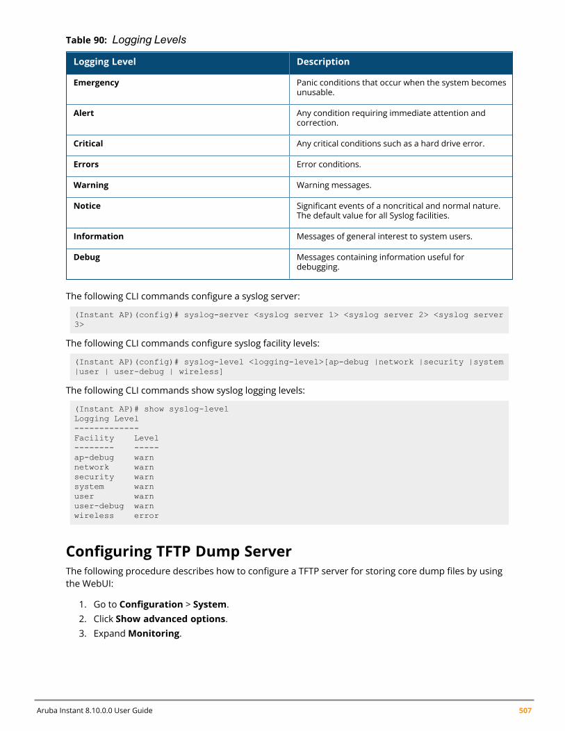
Aruba Instant 8.10.0.0 User Guide 507
Logging Level Description
Emergency Panic conditions that occur when the system becomesunusable.
Alert Any condition requiring immediate attention andcorrection.
Critical Any critical conditions such as a hard drive error.
Errors Error conditions.
Warning Warning messages.
Notice Significant events of a noncritical and normal nature.The default value for all Syslog facilities.
Information Messages of general interest to system users.
Debug Messages containing information useful fordebugging.
Table 90: Logging Levels
The following CLI commands configure a syslog server:
(Instant AP)(config)# syslog-server <syslog server 1> <syslog server 2> <syslog server3>
The following CLI commands configure syslog facility levels:
(Instant AP)(config)# syslog-level <logging-level>[ap-debug |network |security |system|user | user-debug | wireless]
The following CLI commands show syslog logging levels:
(Instant AP)# show syslog-levelLogging Level-------------Facility Level-------- -----ap-debug warnnetwork warnsecurity warnsystem warnuser warnuser-debug warnwireless error
Configuring TFTP Dump ServerThe following procedure describes how to configure a TFTP server for storing core dump files by usingthe WebUI:
1. Go to Configuration > System.2. Click Show advanced options.3. ExpandMonitoring.
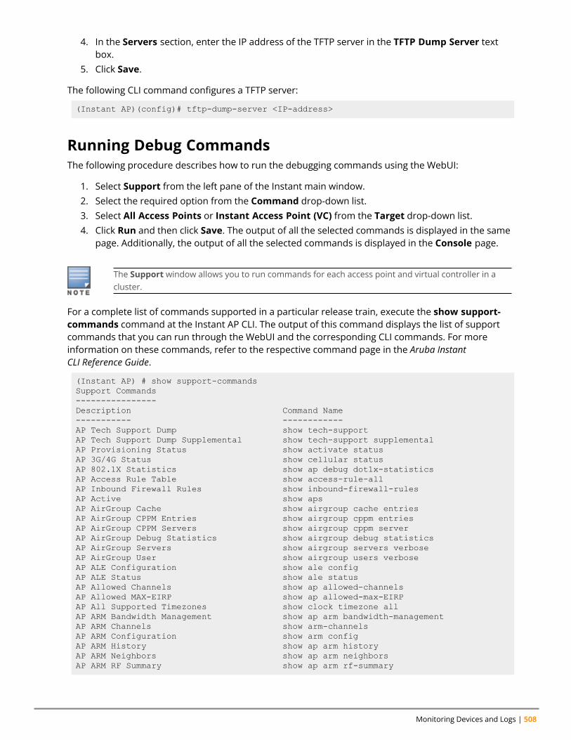
Monitoring Devices and Logs | 508
4. In the Servers section, enter the IP address of the TFTP server in the TFTP Dump Server textbox.
5. Click Save.
The following CLI command configures a TFTP server:
(Instant AP)(config)# tftp-dump-server <IP-address>
Running Debug CommandsThe following procedure describes how to run the debugging commands using the WebUI:
1. Select Support from the left pane of the Instant main window.2. Select the required option from the Command drop-down list.3. Select All Access Points or Instant Access Point (VC) from the Target drop-down list.4. Click Run and then click Save. The output of all the selected commands is displayed in the same
page. Additionally, the output of all the selected commands is displayed in the Console page.
The Support window allows you to run commands for each access point and virtual controller in acluster.
For a complete list of commands supported in a particular release train, execute the show support-commands command at the Instant AP CLI. The output of this command displays the list of supportcommands that you can run through the WebUI and the corresponding CLI commands. For moreinformation on these commands, refer to the respective command page in the Aruba InstantCLI Reference Guide.
(Instant AP) # show support-commandsSupport Commands----------------Description Command Name----------- ------------AP Tech Support Dump show tech-supportAP Tech Support Dump Supplemental show tech-support supplementalAP Provisioning Status show activate statusAP 3G/4G Status show cellular statusAP 802.1X Statistics show ap debug dot1x-statisticsAP Access Rule Table show access-rule-allAP Inbound Firewall Rules show inbound-firewall-rulesAP Active show apsAP AirGroup Cache show airgroup cache entriesAP AirGroup CPPM Entries show airgroup cppm entriesAP AirGroup CPPM Servers show airgroup cppm serverAP AirGroup Debug Statistics show airgroup debug statisticsAP AirGroup Servers show airgroup servers verboseAP AirGroup User show airgroup users verboseAP ALE Configuration show ale configAP ALE Status show ale statusAP Allowed Channels show ap allowed-channelsAP Allowed MAX-EIRP show ap allowed-max-EIRPAP All Supported Timezones show clock timezone allAP ARM Bandwidth Management show ap arm bandwidth-managementAP ARM Channels show arm-channelsAP ARM Configuration show arm configAP ARM History show ap arm historyAP ARM Neighbors show ap arm neighborsAP ARM RF Summary show ap arm rf-summary

Aruba Instant 8.10.0.0 User Guide 509
AP ARM Scan Times show ap arm scan-timesAP ARP Table show arpAP Association Table show ap associationAP Authentication Frames show ap debug auth-trace-bufAP Auth-Survivability Cache show auth-survivability cached-infoAP Auth-Survivability Debug Log show auth-survivability debug-logAP BSSID Table show ap bss-tableAP Captive Portal Domains show captive-portal-domainsAP Captive Portal Auto White List show captive-portal auto-white-listAP Client Match Status show ap debug client-matchAP Client Match History show ap client-match-historyAP Client Match Action show ap client-match-actionsAP Client Match Live show ap client-match-liveAP Client Match Triggers show ap client-match-triggersAP Client Table show ap debug client-tableAP Client View show ap client-viewAP Country Codes show country-codesAP CPU Details show cpu detailsAP CPU Utilization show cpuAP Crash Info show ap debug crash-infoAP Current Time show clockAP Current Timezone show clock timezoneAP Datapath ACL Table Allocation show datapath acl-allocationAP Datapath ACL Tables show datapath acl-allAP Datapath Bridge Table show datapath bridgeAP Datapath DMO session show datapath dmo-sessionAP Datapath DMO station show datapath dmo-stationAP Datapath Dns Id Map show datapath dns-id-mapAP Datapath Multicast Table show datapath mcastAP Datapath Nat Pool show datapath nat-poolAP Datapath Route Table show datapath routeAP Datapath Session Table show datapath sessionAP Datapath DPI Session Table show datapath session dpiAP Datapath DPI Session Table Verbose show datapath session dpi verboseAP Datapath Statistics show datapath statisticsAP Datapath User Table show datapath userAP Datapath VLAN Table show datapath vlanAP DPI Debug statistics show dpi debug statisticsAP Daylight Saving Time show clock summer-timeAP Derivation Rules show derivation-rulesAP Driver Configuration show ap debug driver-configAP Election Statistics show election statisticsAP External Captive Portal Status show external-captive-portalAP Environment Variable show ap-envAP ESSID Table show networkAP Flash Configuration show ap flash-configAP IGMP Group Table show ip igmpAP Interface Counters show interface countersAP Interface Status show port statusAP Internal DHCP Status show dhcp-allocationAP IP Interface show ip interface briefAP IP Route Table show ip routeAP L3 Mobility Datapath show l3-mobility datapathAP L3 Mobility Events log show log l3-mobilityAP L3 Mobility Status show l3-mobility statusAP LACP Status show lacp statusAP Log All show log debugAP Log AP-Debug show log ap-debugAP Log Conversion show log convertAP Log Driver show log driverAP Log Kernel show log kernelAP Log Network show log networkAP Log PPPd show log pppdAP Log Rapper show log rapper

Monitoring Devices and Logs | 510
AP Log Rapper Counter show log rapper-counterAP Log Rapper Brief show log rapper-briefAP Log Sapd show log sapdAP Log Security show log securityAP Log System show log systemAP Log Tunnel Status Management show log apifmgrAP Log Upgrade show log upgradeAP Log User-Debug show log user-debugAP Log User show log userAP Log VPN Tunnel show log vpn-tunnelAP Log Wireless show log wirelessAP Management Frames show ap debug mgmt-framesAP Memory Allocation State Dumps show malloc-state-dumpsAP Memory Utilization show memoryAP Mesh Counters show ap mesh countersAP Mesh Link show ap mesh linkAP Mesh Neighbors show ap mesh neighboursAP Monitor Active Laser Beams show ap monitor active-laser-beamsAP Monitor AP Table show ap monitor ap-listAP Monitor ARP Cache show ap monitor ARP CacheAP Monitor Client Table show ap monitor sta-listAP Monitor Containment Information show ap monitor containment-infoAP Monitor Potential AP Table show ap monitor pot-ap-listAP Monitor Potential Client Table show ap monitor pot-sta-listAP Monitor Router show ap monitor routersAP Monitor Scan Information show ap monitor scan-infoAP Monitor Status show ap monitor statusAP Persistent Clients show ap debug persistent-clientsAP PMK Cache show ap pmkcacheAP PPPoE uplink debug show pppoe debug-logsAP PPPoE uplink status show pppoe statusAP Processes show processAP Radio 0 Client Probe Report show ap client-probe-report 0AP Radio 0 Stats show ap debug radio-stats 0AP Radio 0 info show ap debug radio-info 0AP Radio 1 Client Probe Report show ap client-probe-report 1AP Radio 1 Stats show ap debug radio-stats 1AP Radio 1 info show ap debug radio-info 1AP RADIUS Statistics show ap debug radius-statisticsAP Termination RADIUS Statistics show ap debug radius-statistics terminationAP Shaping Table show ap debug shaping-tableAP Sockets show socketAP STM Configuration show ap debug stm-configAP Swarm State show swarm stateAP System Status show ap debug system-statusAP System Summary show summary supportAP Uplink Status show uplink statusAP User Table show clientsAP Valid Channels show valid-channelsAP Version show versionAP Virtual Beacon Report show ap virtual-beacon-reportAP VPN Config show vpn configAP VPN Status show vpn statusAP IAP-VPN Retry Counters show vpn tunnelsAP Wired Port Settings show wired-port-settingsAP Wired User Table show clients wiredAP Checksum show ap checksumAP Spectrum AP table show ap spectrum ap-listAP Spectrum channel table show ap spectrum channel-detailsAP Spectrum channel metrics show ap spectrum channel-metricsAP Spectrum channel summary show ap spectrum channel-summaryAP Spectrum client table show ap spectrum client-listAP Spectrum device duty cycle show ap spectrum device-duty-cycleAP Spectrum non-wifi device history show ap spectrum device-history
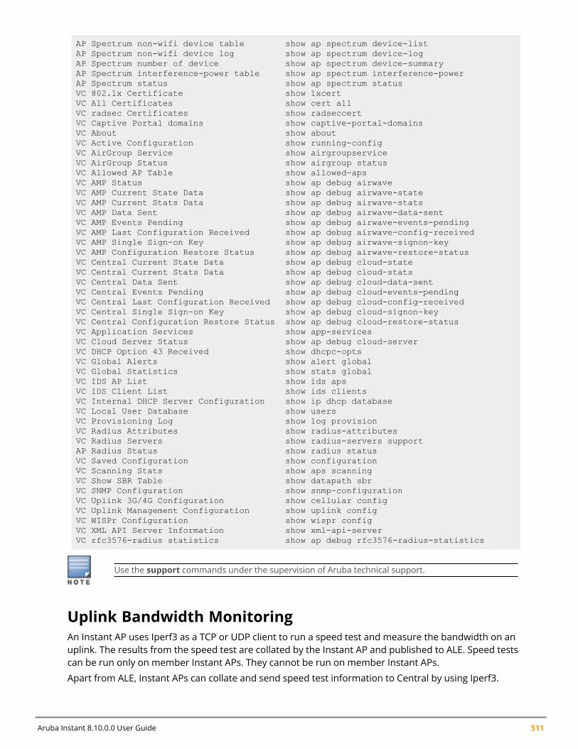
Aruba Instant 8.10.0.0 User Guide 511
AP Spectrum non-wifi device table show ap spectrum device-listAP Spectrum non-wifi device log show ap spectrum device-logAP Spectrum number of device show ap spectrum device-summaryAP Spectrum interference-power table show ap spectrum interference-powerAP Spectrum status show ap spectrum statusVC 802.1x Certificate show 1xcertVC All Certificates show cert allVC radsec Certificates show radseccertVC Captive Portal domains show captive-portal-domainsVC About show aboutVC Active Configuration show running-configVC AirGroup Service show airgroupserviceVC AirGroup Status show airgroup statusVC Allowed AP Table show allowed-apsVC AMP Status show ap debug airwaveVC AMP Current State Data show ap debug airwave-stateVC AMP Current Stats Data show ap debug airwave-statsVC AMP Data Sent show ap debug airwave-data-sentVC AMP Events Pending show ap debug airwave-events-pendingVC AMP Last Configuration Received show ap debug airwave-config-receivedVC AMP Single Sign-on Key show ap debug airwave-signon-keyVC AMP Configuration Restore Status show ap debug airwave-restore-statusVC Central Current State Data show ap debug cloud-stateVC Central Current Stats Data show ap debug cloud-statsVC Central Data Sent show ap debug cloud-data-sentVC Central Events Pending show ap debug cloud-events-pendingVC Central Last Configuration Received show ap debug cloud-config-receivedVC Central Single Sign-on Key show ap debug cloud-signon-keyVC Central Configuration Restore Status show ap debug cloud-restore-statusVC Application Services show app-servicesVC Cloud Server Status show ap debug cloud-serverVC DHCP Option 43 Received show dhcpc-optsVC Global Alerts show alert globalVC Global Statistics show stats globalVC IDS AP List show ids apsVC IDS Client List show ids clientsVC Internal DHCP Server Configuration show ip dhcp databaseVC Local User Database show usersVC Provisioning Log show log provisionVC Radius Attributes show radius-attributesVC Radius Servers show radius-servers supportAP Radius Status show radius statusVC Saved Configuration show configurationVC Scanning Stats show aps scanningVC Show SBR Table show datapath sbrVC SNMP Configuration show snmp-configurationVC Uplink 3G/4G Configuration show cellular configVC Uplink Management Configuration show uplink configVC WISPr Configuration show wispr configVC XML API Server Information show xml-api-serverVC rfc3576-radius statistics show ap debug rfc3576-radius-statistics
Use the support commands under the supervision of Aruba technical support.
Uplink Bandwidth MonitoringAn Instant AP uses Iperf3 as a TCP or UDP client to run a speed test and measure the bandwidth on anuplink. The results from the speed test are collated by the Instant AP and published to ALE. Speed testscan be run only on member Instant APs. They cannot be run on member Instant APs.
Apart from ALE, Instant APs can collate and send speed test information to Central by using Iperf3.
Monitoring Devices and Logs | 512
You may choose to configure and execute a speed test profile during boot time and additionally atspecific time intervals using the configuration mode or execute the speed test at any preferred timeusing the privileged EXEC mode in the CLI.
The following CLI commands configure and automatically run speed tests at specific time intervals:
(Instant AP)(config)# speed-test(Instant AP)(speed-test)# include-reverse(Instant AP)(speed-test)# server-ip <server>(Instant AP)(speed-test)# server-port <port>(Instant AP)(speed-test)# on-boot(Instant AP)(speed-test)# omit(Instant AP)(speed-test)# protocol <tcp/udp>(Instant AP)(speed-test)# parallel(Instant AP)(speed-test)# time-interval <interval>(Instant AP)(speed-test)# bandwidth <bandwidth>(Instant AP)(speed-test)# sec-to-measure <secs>(Instant AP)(speed-test)# window
The following CLI command configures and executes a speed test at any preferred time:
(Instant AP)(config)# speed-test 10.17.144.8 tcp include-reverse sec-to-measure 10server-port 5201 parallel 10 omit 1 window 512
The following CLI command shows the speed test results:
(Instant AP)# show speed-test data
The following CLI command shows the uplink bandwidth counter:
(Instant AP)# show ale statsALE Stats---------Type Value---- -----VC package 0RSSI package 0APPRF package 0URLv package 0STATE package 0STAT package 0UPLINK BW package 0Total 0
WAN Link Health MonitoringStarting from Instant 8.3.0.0, Instant APs support the WAN Link Health Monitoring feature for theService Assurance application. The Service Assurance application helps run various tests to determinethe network performance and reachability of hosts that are configured by the customer.
WAN Link Health Monitoring supports Aruba Central WAN Health Monitoring feature. It helps ArubaCentral customers get periodic statistics on reachability, connectivity, and Instant AP performance.
WAN Link Health Monitoring supports only IPv4 addresses. It does not support IPv6 addresses in thisrelease.
From Central, customers can send request (using the Clarity > Health Checks page or API interface) torun the following performance and reachability test suites:
Aruba Instant 8.10.0.0 User Guide 513
n Reachabilityl Ping/ICMP test for reachability
o Supports up to five host names/IP addresses.o Response information for the Ping test containing the number of transmitted and received
packets, and response time are sent.n Connectivity
l TCP Connect test for connectivity to hostsl Supports maximum of five host name/IP address and port combinations. Only IPv4 addresses aresupported.
n Performancel Iperf (UDP/TCP) test for WAN speed/performance
o Supports maximum of five host IPs as input.o Response contains the important parameters parsed from iperf3 response.
l wget (webpage load) tests for Instant AP performanceo Supports up to five valid URLs.o Download rate and download bytes are sent back in response along with the
The execution time for each test can be up to 36 seconds. Central customers can configure anyof these tests that can be run on demand or at scheduled intervals for any branch or site.
Instant APs support a maximum of four test suites with five hosts each. On-demand policies areprioritized against periodic policies.
On-Demand PoliciesAn on-demand policy is executed once when a request is received. It is not stored on the AP. Forexample, when a network admin finds a problem and wants to troubleshoot it, the admin user can sendan on-demand policy to run some tests and check the results to troubleshoot the problem.
n Each Instant AP can handle one on-demand policy at a time. If there is an on-demand policy inprogress and another on-demand policy request is received by anInstant AP, Central receives a NACKresponse.
n If an Instant AP is executing a periodic policy and an on-demand policy request is received, then theon-demand policy is executed after executing the periodic policy.
Periodic PoliciesPeriodic policies are run periodically based on a schedule and periodicity. Up to 4 periodic policies canbe added for an Instant AP. The schedule is defined at policy level and periodicity is defined test suitelevel. They can be used to monitor a given branch or site for various parameters, and get the requiredstatistics.
Points to Note:
n Central customers must have an API Gateway or Clarity Health Check license.n The user from the customer’s branch or site must have admin access to Instant AP and Central.n This feature is supported only on Instant APs.n IPv6 address is not supported.

Monitoring Devices and Logs | 514
n Central customers can set thresholds so that the application can trigger notifications when setthresholds are reached.
n Central customers can monitor the network performance data.n The policy entries are cleared when Central connection goes DOWN.n If a device restarts or Central connection goes DOWN and then restores, then Central takes care to
resend the policies to the same device or a different device.n When a policy request is received and no test is running at that time, all the tests in the request are
run sequentially. The order in which tests are executed (if configured) is reachability, connectivity,and then performance tests.
n When a test is already running and a new policy request is seen, NACK response is sent to ArubaCentral and the policy is rejected.
Aruba Central sends the customer-configured tests and the associated data to Instant AP devices asprotocol buffer messages. The Instant APs parse the protocol buffer messages and converts them into apolicy. Instant APs then run these tests sequentially, collate the test results, and send them as protocolbuffer messages to Central.
Verification of WAN Link Health Monitoring StatusThe following CLI command shows the WAN Link Health Monitoring status:
(Instant AP) #show lhm status
The following command shows the Health Checks sent from Central to Instant AP:
(Instant AP) #show lhm policy
Troubleshooting WAN Link Health MonitoringThe following command shows trace logs of WAN Link Health Monitoring process:
(Instant AP) #trace component LHM sub-component ALL(Instant AP) #trace level DEBUG LHM(Instant AP) #show trace log lhm <no_of_lines>
These commands are for troubleshooting purpose only and must be disabled after that.
Chapter 34Hotspot Profiles
Hotspot ProfilesThis chapter contains the following topics:
n Understanding Hotspot Profiles on page 515n Configuring Hotspot Profiles on page 517n Sample Configuration on page 534
In the current release, Instant supports the hotspot profile configuration only through the CLI.
Understanding Hotspot ProfilesHotspot 2.0 R1 is a WFA specification based on the 802.11u protocol, which allows wireless clients todiscover hotspots using management frames (such as beacon, association request, and associationresponse), connect to networks, and roam between networks without additional authentication.
Hotspot 2.0 provides the following services:
n Network discovery and selection—Allows the clients to discover suitable and available networks byadvertising the access network type, roaming consortium, and venue information through themanagement frames. For network discovery and selection, GAS and ANQP are used.
n QOS Mapping—Provides a mapping between the network-layer QoS packet marking and over- the-airQoS frame marking based on user priority.
Starting from Aruba Instant 8.3.0.0, the Hotspot 2.0 R2 is introduced. This feature is supported on allInstant APs except the 5xx series access points. This release supports the following new features:
n Online Sign-Up—Mobile devices use Online Sign-Up (OSU) for registration and credential provisioningto obtain secure network access using the service provider's OSU server.
n WNM Subscription Remediation—Subscription remediation is a process that Home Service Providersuse to correct, update, and resolve subscription issues. WNM(11v) is used for SubscriptionRemediation.
n When a hotspot is configured in a network:n The clients search for available hotspots using the beacon management frame.n When a hotspot is found, the client sends queries to obtain information about the type of network
authentication and IP address, and IP address availability using the GAS action frames.n Based on the response of the advertisement server (response to the GAS Action Frames), the relevant
hotspot is selected and the client attempts to associate with it.n Based on the authentication mode used for mobility clients, the client authenticates to access the
network.
GAS
Aruba Instant 8.10.0.0 User Guide 515
Hotspot Profiles | 516
GAS is a request-response protocol, that provides L2 transport mechanism between a wireless clientand a server in the network prior to authentication. It helps to determine an 802.11 infrastructurebefore associating clients and allows clients to send queries to multiple 802.11 networks in parallel.
An Instant AP can include its SP Organization Identifier indicating the identity of the SP in beacons andprobe responses to clients. When a client recognizes an Instant AP's OI, it attempts to associate to thatInstant AP using the security credentials corresponding to that SP. If the client does not recognize theAP’s OI, the client sends a GAS query to the Instant AP to request more information about the networkbefore associating. A client transmits a GAS Query using a GAS Initial Request frame and the Instant APprovides the query response or information on how to receive the query response in a GAS InitialResponse frame. To transmit a GAS query for any advertisement protocol, the advertisement protocolID must include the advertisement protocol information element with details of the advertisementprotocol and its corresponding advertisement control.
ANQPANQP provides a range of information, such as IP address type and availability, roaming partnersaccessible through a hotspot, and the EAP method supported for authentication, for a query andresponse protocol. The ANQP Information Elements provide additional data that can be sent from anInstant AP to the client to identify the Instant AP's network and service provider. If a client requests thisinformation through a GAS query, the hotspot Instant AP sends the ANQP capability list in the GAS InitialResponse frame indicating support for the following IEs:
n Venue Namen Domain Namen Network Authentication Typen Roaming Consortium Listn Network Access Identifier Realmn 3GPP Cellular Network Datan IP Address Availability
H2QPThe H2QP profiles provide a range of information on Hotspot 2.0 elements such as hotspot protocoland port, operating-class, operator names, WAN status, OSU provider list, and uplink and downlinkmetrics.
Information Elements and Management FramesThe Hotspot 2.0 configuration supports the following IEs:
n Interworking IE—Provides information about the Interworking service capabilities such as theInternet availability in a specific service provider network.
n Advertisement Protocol IE—Provides information about the advertisement protocol that a client canuse for communication with the advertisement servers in a network.
n Roaming Consortium IE—Provides information about the service provider network for roamingclients, which can be used to authenticate with the Instant AP.
The IEs are included in the following Management Frames when 802.11u is enabled:
n Beacon Framen Probe Request Frame
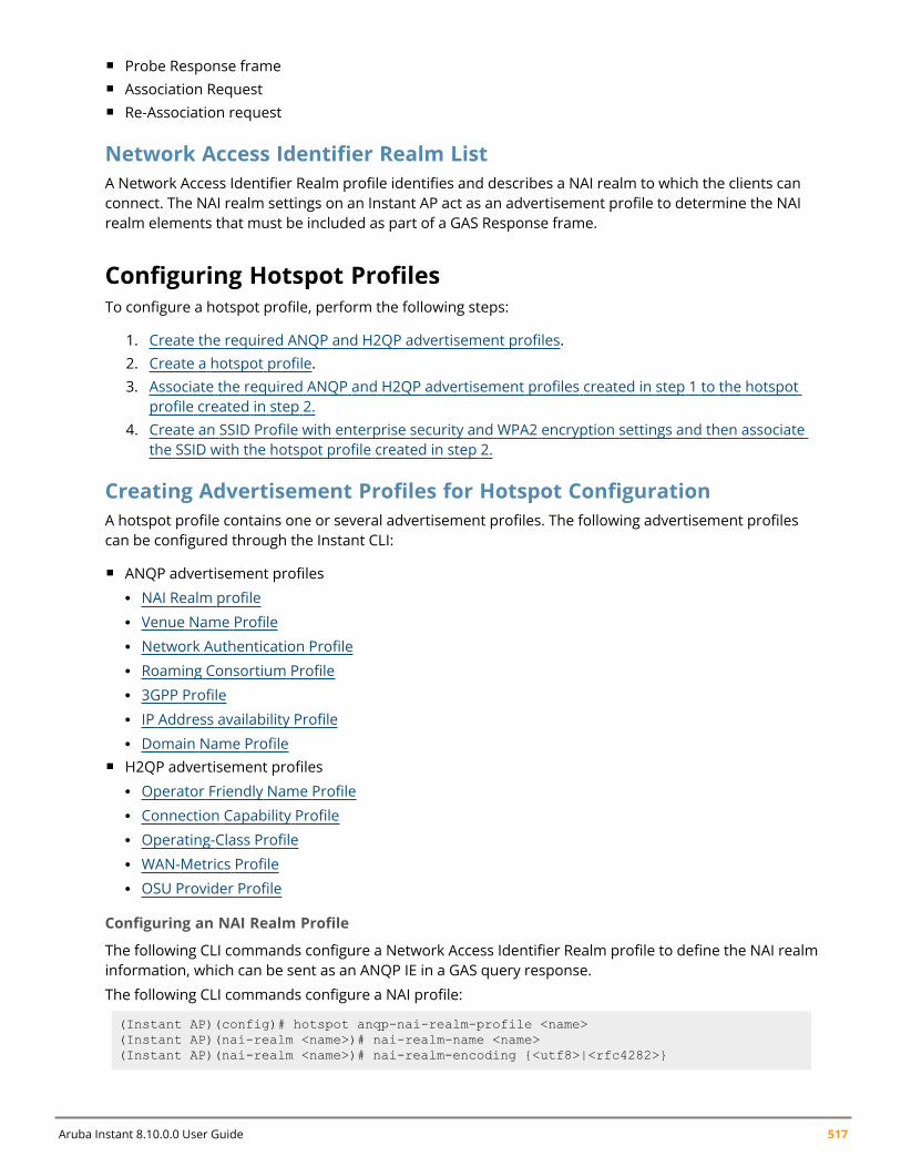
Aruba Instant 8.10.0.0 User Guide 517
n Probe Response framen Association Requestn Re-Association request
Network Access Identifier Realm ListA Network Access Identifier Realm profile identifies and describes a NAI realm to which the clients canconnect. The NAI realm settings on an Instant AP act as an advertisement profile to determine the NAIrealm elements that must be included as part of a GAS Response frame.
Configuring Hotspot ProfilesTo configure a hotspot profile, perform the following steps:
1. Create the required ANQP and H2QP advertisement profiles.2. Create a hotspot profile.3. Associate the required ANQP and H2QP advertisement profiles created in step 1 to the hotspot
profile created in step 2.4. Create an SSID Profile with enterprise security and WPA2 encryption settings and then associate
the SSID with the hotspot profile created in step 2.
Creating Advertisement Profiles for Hotspot ConfigurationA hotspot profile contains one or several advertisement profiles. The following advertisement profilescan be configured through the Instant CLI:
n ANQP advertisement profilesl NAI Realm profilel Venue Name Profilel Network Authentication Profilel Roaming Consortium Profilel 3GPP Profilel IP Address availability Profilel Domain Name Profile
n H2QP advertisement profilesl Operator Friendly Name Profilel Connection Capability Profilel Operating-Class Profilel WAN-Metrics Profilel OSU Provider Profile
Configuring an NAI Realm Profile
The following CLI commands configure a Network Access Identifier Realm profile to define the NAI realminformation, which can be sent as an ANQP IE in a GAS query response.
The following CLI commands configure a NAI profile:
(Instant AP)(config)# hotspot anqp-nai-realm-profile <name>(Instant AP)(nai-realm <name>)# nai-realm-name <name>(Instant AP)(nai-realm <name>)# nai-realm-encoding {<utf8>|<rfc4282>}
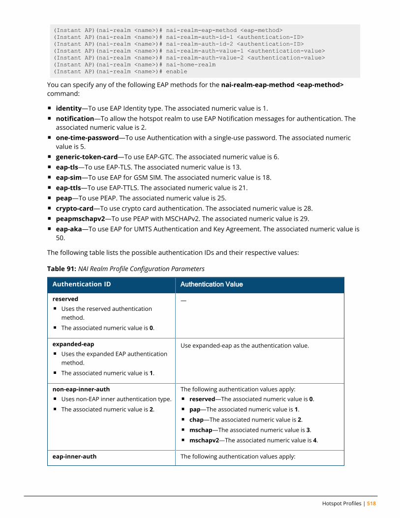
Hotspot Profiles | 518
(Instant AP)(nai-realm <name>)# nai-realm-eap-method <eap-method>(Instant AP)(nai-realm <name>)# nai-realm-auth-id-1 <authentication-ID>(Instant AP)(nai-realm <name>)# nai-realm-auth-id-2 <authentication-ID>(Instant AP)(nai-realm <name>)# nai-realm-auth-value-1 <authentication-value>(Instant AP)(nai-realm <name>)# nai-realm-auth-value-2 <authentication-value>(Instant AP)(nai-realm <name>)# nai-home-realm(Instant AP)(nai-realm <name>)# enable
You can specify any of the following EAP methods for the nai-realm-eap-method <eap-method>command:
n identity—To use EAP Identity type. The associated numeric value is 1.n notification—To allow the hotspot realm to use EAP Notification messages for authentication. The
associated numeric value is 2.n one-time-password—To use Authentication with a single-use password. The associated numeric
value is 5.n generic-token-card—To use EAP-GTC. The associated numeric value is 6.n eap-tls—To use EAP-TLS. The associated numeric value is 13.n eap-sim—To use EAP for GSM SIM. The associated numeric value is 18.n eap-ttls—To use EAP-TTLS. The associated numeric value is 21.n peap—To use PEAP. The associated numeric value is 25.n crypto-card—To use crypto card authentication. The associated numeric value is 28.n peapmschapv2—To use PEAP with MSCHAPv2. The associated numeric value is 29.n eap-aka—To use EAP for UMTS Authentication and Key Agreement. The associated numeric value is
50.
The following table lists the possible authentication IDs and their respective values:
Authentication ID Authentication Value
reservedn Uses the reserved authentication
method.n The associated numeric value is 0.
—
expanded-eapn Uses the expanded EAP authentication
method.n The associated numeric value is 1.
Use expanded-eap as the authentication value.
non-eap-inner-authn Uses non-EAP inner authentication type.n The associated numeric value is 2.
The following authentication values apply:n reserved—The associated numeric value is 0.n pap—The associated numeric value is 1.n chap—The associated numeric value is 2.n mschap—The associated numeric value is 3.n mschapv2—The associated numeric value is 4.
eap-inner-auth The following authentication values apply:
Table 91: NAI Realm Profile Configuration Parameters
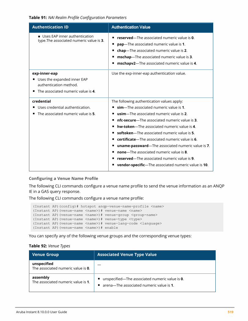
Aruba Instant 8.10.0.0 User Guide 519
Authentication ID Authentication Value
n Uses EAP inner authenticationtype.The associated numeric value is 3.
n reserved—The associated numeric value is 0.n pap—The associated numeric value is 1.n chap—The associated numeric value is 2.n mschap—The associated numeric value is 3.n mschapv2—The associated numeric value is 4.
exp-inner-eapn Uses the expanded inner EAP
authentication method.n The associated numeric value is 4.
Use the exp-inner-eap authentication value.
credentialn Uses credential authentication.n The associated numeric value is 5.
The following authentication values apply:n sim—The associated numeric value is 1.n usim—The associated numeric value is 2.n nfc-secure—The associated numeric value is 3.n hw-token—The associated numeric value is 4.n softoken—The associated numeric value is 5.n certificate—The associated numeric value is 6.n uname-passward—The associated numeric value is 7.n none—The associated numeric value is 8.n reserved—The associated numeric value is 9.n vendor-specific—The associated numeric value is 10.
Table 91: NAI Realm Profile Configuration Parameters
Configuring a Venue Name Profile
The following CLI commands configure a venue name profile to send the venue information as an ANQPIE in a GAS query response.
The following CLI commands configure a venue name profile:
(Instant AP)(config)# hotspot anqp-venue-name-profile <name>(Instant AP)(venue-name <name>)# venue-name <name>(Instant AP)(venue-name <name>)# venue-group <group-name>(Instant AP)(venue-name <name>)# venue-type <type>(Instant AP)(venue-name <name>)# venue-lang-code <language>(Instant AP)(venue-name <name>)# enable
You can specify any of the following venue groups and the corresponding venue types:
Venue Group Associated Venue Type Value
unspecifiedThe associated numeric value is 0.
—
assemblyThe associated numeric value is 1.
n unspecified—The associated numeric value is 0.n arena—The associated numeric value is 1.
Table 92: Venue Types
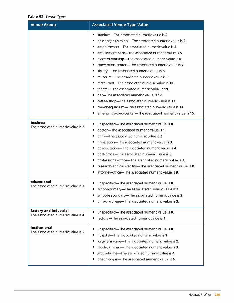
Hotspot Profiles | 520
Venue Group Associated Venue Type Value
n stadium—The associated numeric value is 2.n passenger-terminal—The associated numeric value is 3.n amphitheater—The associated numeric value is 4.n amusement-park—The associated numeric value is 5.n place-of-worship—The associated numeric value is 6.n convention-center—The associated numeric value is 7.n library—The associated numeric value is 8.n museum—The associated numeric value is 9.n restaurant—The associated numeric value is 10.n theater—The associated numeric value is 11.n bar—The associated numeric value is 12.n coffee-shop—The associated numeric value is 13.n zoo-or-aquarium—The associated numeric value is 14.n emergency-cord-center—The associated numeric value is 15.
businessThe associated numeric value is 2.
n unspecified—The associated numeric value is 0.n doctor—The associated numeric value is 1.n bank—The associated numeric value is 2.n fire-station—The associated numeric value is 3.n police-station—The associated numeric value is 4.n post-office—The associated numeric value is 6.n professional-office—The associated numeric value is 7.n research-and-dev-facility—The associated numeric value is 8.n attorney-office—The associated numeric value is 9.
educationalThe associated numeric value is 3.
n unspecified—The associated numeric value is 0.n school-primary—The associated numeric value is 1.n school-secondary—The associated numeric value is 2.n univ-or-college—The associated numeric value is 3.
factory-and-industrialThe associated numeric value is 4.
n unspecified—The associated numeric value is 0.n factory—The associated numeric value is 1.
institutionalThe associated numeric value is 5.
n unspecified—The associated numeric value is 0.n hospital—The associated numeric value is 1.n long-term-care—The associated numeric value is 2.n alc-drug-rehab—The associated numeric value is 3.n group-home—The associated numeric value is 4.n prison-or-jail—The associated numeric value is 5.
Table 92: Venue Types
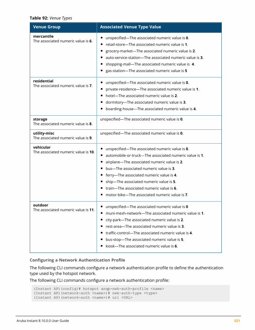
Aruba Instant 8.10.0.0 User Guide 521
Venue Group Associated Venue Type Value
mercantileThe associated numeric value is 6.
n unspecified—The associated numeric value is 0.n retail-store—The associated numeric value is 1.n grocery-market—The associated numeric value is 2.n auto-service-station—The associated numeric value is 3.n shopping-mall—The associated numeric value is 4.n gas-station—The associated numeric value is 5
residentialThe associated numeric value is 7.
n unspecified—The associated numeric value is 0.n private-residence—The associated numeric value is 1.n hotel—The associated numeric value is 2.n dormitory—The associated numeric value is 3.n boarding-house—The associated numeric value is 4.
storageThe associated numeric value is 8.
unspecified—The associated numeric value is 0.
utility-miscThe associated numeric value is 9.
unspecified—The associated numeric value is 0.
vehicularThe associated numeric value is 10.
n unspecified—The associated numeric value is 0.n automobile-or-truck—The associated numeric value is 1.n airplane—The associated numeric value is 2.n bus—The associated numeric value is 3.n ferry—The associated numeric value is 4.n ship—The associated numeric value is 5.n train—The associated numeric value is 6.n motor-bike—The associated numeric value is 7.
outdoorThe associated numeric value is 11.
n unspecified—The associated numeric value is 0n muni-mesh-network—The associated numeric value is 1.n city-park—The associated numeric value is 2.n rest-area—The associated numeric value is 3.n traffic-control—The associated numeric value is 4.n bus-stop—The associated numeric value is 5.n kiosk—The associated numeric value is 6.
Table 92: Venue Types
Configuring a Network Authentication Profile
The following CLI commands configure a network authentication profile to define the authenticationtype used by the hotspot network.
The following CLI commands configure a network authentication profile:
(Instant AP)(config)# hotspot anqp-nwk-auth-profile <name>(Instant AP)(network-auth <name>)# nwk-auth-type <type>(Instant AP)(network-auth <name>)# url <URL>
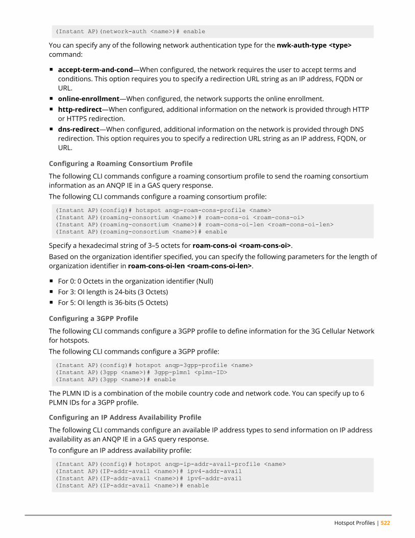
Hotspot Profiles | 522
(Instant AP)(network-auth <name>)# enable
You can specify any of the following network authentication type for the nwk-auth-type <type>command:
n accept-term-and-cond—When configured, the network requires the user to accept terms andconditions. This option requires you to specify a redirection URL string as an IP address, FQDN orURL.
n online-enrollment—When configured, the network supports the online enrollment.n http-redirect—When configured, additional information on the network is provided through HTTP
or HTTPS redirection.n dns-redirect—When configured, additional information on the network is provided through DNS
redirection. This option requires you to specify a redirection URL string as an IP address, FQDN, orURL.
Configuring a Roaming Consortium Profile
The following CLI commands configure a roaming consortium profile to send the roaming consortiuminformation as an ANQP IE in a GAS query response.
The following CLI commands configure a roaming consortium profile:
(Instant AP)(config)# hotspot anqp-roam-cons-profile <name>(Instant AP)(roaming-consortium <name>)# roam-cons-oi <roam-cons-oi>(Instant AP)(roaming-consortium <name>)# roam-cons-oi-len <roam-cons-oi-len>(Instant AP)(roaming-consortium <name>)# enable
Specify a hexadecimal string of 3–5 octets for roam-cons-oi <roam-cons-oi>.
Based on the organization identifier specified, you can specify the following parameters for the length oforganization identifier in roam-cons-oi-len <roam-cons-oi-len>.
n For 0: 0 Octets in the organization identifier (Null)n For 3: OI length is 24-bits (3 Octets)n For 5: OI length is 36-bits (5 Octets)
Configuring a 3GPP Profile
The following CLI commands configure a 3GPP profile to define information for the 3G Cellular Networkfor hotspots.
The following CLI commands configure a 3GPP profile:
(Instant AP)(config)# hotspot anqp-3gpp-profile <name>(Instant AP)(3gpp <name>)# 3gpp-plmn1 <plmn-ID>(Instant AP)(3gpp <name>)# enable
The PLMN ID is a combination of the mobile country code and network code. You can specify up to 6PLMN IDs for a 3GPP profile.
Configuring an IP Address Availability Profile
The following CLI commands configure an available IP address types to send information on IP addressavailability as an ANQP IE in a GAS query response.
To configure an IP address availability profile:
(Instant AP)(config)# hotspot anqp-ip-addr-avail-profile <name>(Instant AP)(IP-addr-avail <name>)# ipv4-addr-avail(Instant AP)(IP-addr-avail <name>)# ipv6-addr-avail(Instant AP)(IP-addr-avail <name>)# enable
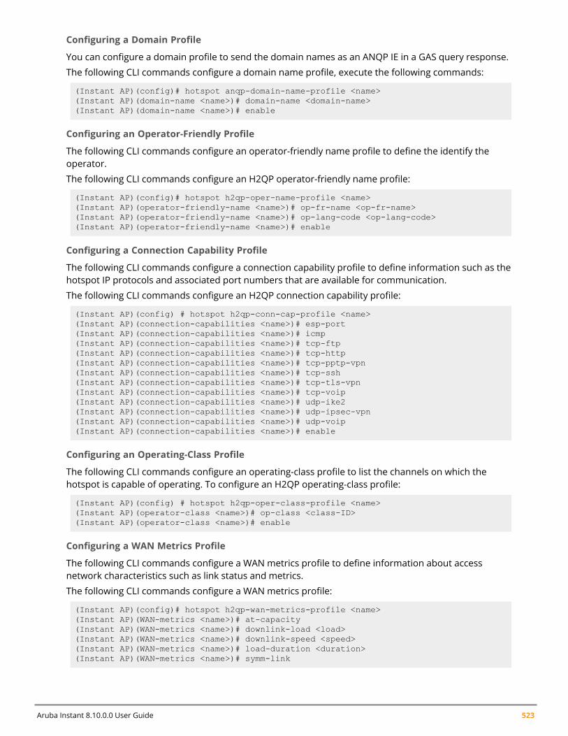
Aruba Instant 8.10.0.0 User Guide 523
Configuring a Domain Profile
You can configure a domain profile to send the domain names as an ANQP IE in a GAS query response.
The following CLI commands configure a domain name profile, execute the following commands:
(Instant AP)(config)# hotspot anqp-domain-name-profile <name>(Instant AP)(domain-name <name>)# domain-name <domain-name>(Instant AP)(domain-name <name>)# enable
Configuring an Operator-Friendly Profile
The following CLI commands configure an operator-friendly name profile to define the identify theoperator.
The following CLI commands configure an H2QP operator-friendly name profile:
(Instant AP)(config)# hotspot h2qp-oper-name-profile <name>(Instant AP)(operator-friendly-name <name>)# op-fr-name <op-fr-name>(Instant AP)(operator-friendly-name <name>)# op-lang-code <op-lang-code>(Instant AP)(operator-friendly-name <name>)# enable
Configuring a Connection Capability Profile
The following CLI commands configure a connection capability profile to define information such as thehotspot IP protocols and associated port numbers that are available for communication.
The following CLI commands configure an H2QP connection capability profile:
(Instant AP)(config) # hotspot h2qp-conn-cap-profile <name>(Instant AP)(connection-capabilities <name>)# esp-port(Instant AP)(connection-capabilities <name>)# icmp(Instant AP)(connection-capabilities <name>)# tcp-ftp(Instant AP)(connection-capabilities <name>)# tcp-http(Instant AP)(connection-capabilities <name>)# tcp-pptp-vpn(Instant AP)(connection-capabilities <name>)# tcp-ssh(Instant AP)(connection-capabilities <name>)# tcp-tls-vpn(Instant AP)(connection-capabilities <name>)# tcp-voip(Instant AP)(connection-capabilities <name>)# udp-ike2(Instant AP)(connection-capabilities <name>)# udp-ipsec-vpn(Instant AP)(connection-capabilities <name>)# udp-voip(Instant AP)(connection-capabilities <name>)# enable
Configuring an Operating-Class Profile
The following CLI commands configure an operating-class profile to list the channels on which thehotspot is capable of operating. To configure an H2QP operating-class profile:
(Instant AP)(config) # hotspot h2qp-oper-class-profile <name>(Instant AP)(operator-class <name>)# op-class <class-ID>(Instant AP)(operator-class <name>)# enable
Configuring a WAN Metrics Profile
The following CLI commands configure a WAN metrics profile to define information about accessnetwork characteristics such as link status and metrics.
The following CLI commands configure a WAN metrics profile:
(Instant AP)(config)# hotspot h2qp-wan-metrics-profile <name>(Instant AP)(WAN-metrics <name>)# at-capacity(Instant AP)(WAN-metrics <name>)# downlink-load <load>(Instant AP)(WAN-metrics <name>)# downlink-speed <speed>(Instant AP)(WAN-metrics <name>)# load-duration <duration>(Instant AP)(WAN-metrics <name>)# symm-link
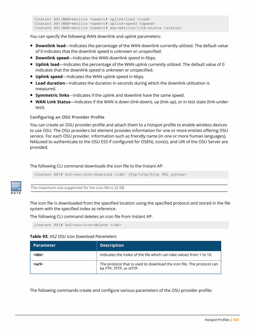
Hotspot Profiles | 524
(Instant AP)(WAN-metrics <name>)# uplink-load <load>(Instant AP)(WAN-metrics <name>)# uplink-speed <speed>(Instant AP)(WAN-metrics <name>)# wan-metrics-link-status <status>
You can specify the following WAN downlink and uplink parameters:
n Downlink load—Indicates the percentage of the WAN downlink currently utilized. The default valueof 0 indicates that the downlink speed is unknown or unspecified.
n Downlink speed—Indicates the WAN downlink speed in Kbps.n Uplink load—Indicates the percentage of the WAN uplink currently utilized. The default value of 0
indicates that the downlink speed is unknown or unspecified.n Uplink speed—Indicates the WAN uplink speed in Kbps.n Load duration—Indicates the duration in seconds during which the downlink utilization is
measured.n Symmetric links—Indicates if the uplink and downlink have the same speed.n WAN Link Status—Indicates if the WAN is down (link-down), up (link-up), or in test state (link-under-
test).
Configuring an OSU Provider Profile
You can create an OSU provider profile and attach them to a hotspot profile to enable wireless devicesto use OSU. The OSU providers list element provides information for one or more entities offering OSUservice. For each OSU provider, information such as friendly name (in one or more human languages),NAI(used to authenticate to the OSU ESS if configured for OSEN), icon(s), and URI of the OSU Server areprovided.
Downloading Icon Files to Instant AP
The following CLI command downloads the icon file to the Instant AP:
(Instant AP)# hs2-osu-icon-download <idx> <ftp/tftp/http URL syntax>
The maximum size supported for the icon file is 32 KB.
The icon file is downloaded from the specified location using the specified protocol and stored in the filesystem with the specified index as reference.
The following CLI command deletes an icon file from Instant AP:
(Instant AP)# hs2-osu-icon-delete <idx>
Parameter Description
<idx> Indicates the index of the file which can take values from 1 to 16.
<url> The protocol that is used to download the icon file. The protocol canbe FTP, TFTP, or HTTP.
Table 93: HS2 OSU Icon Download Parameters
Configuring OSU Provider Profile Parameters
The following commands create and configure various parameters of the OSU provider profile:
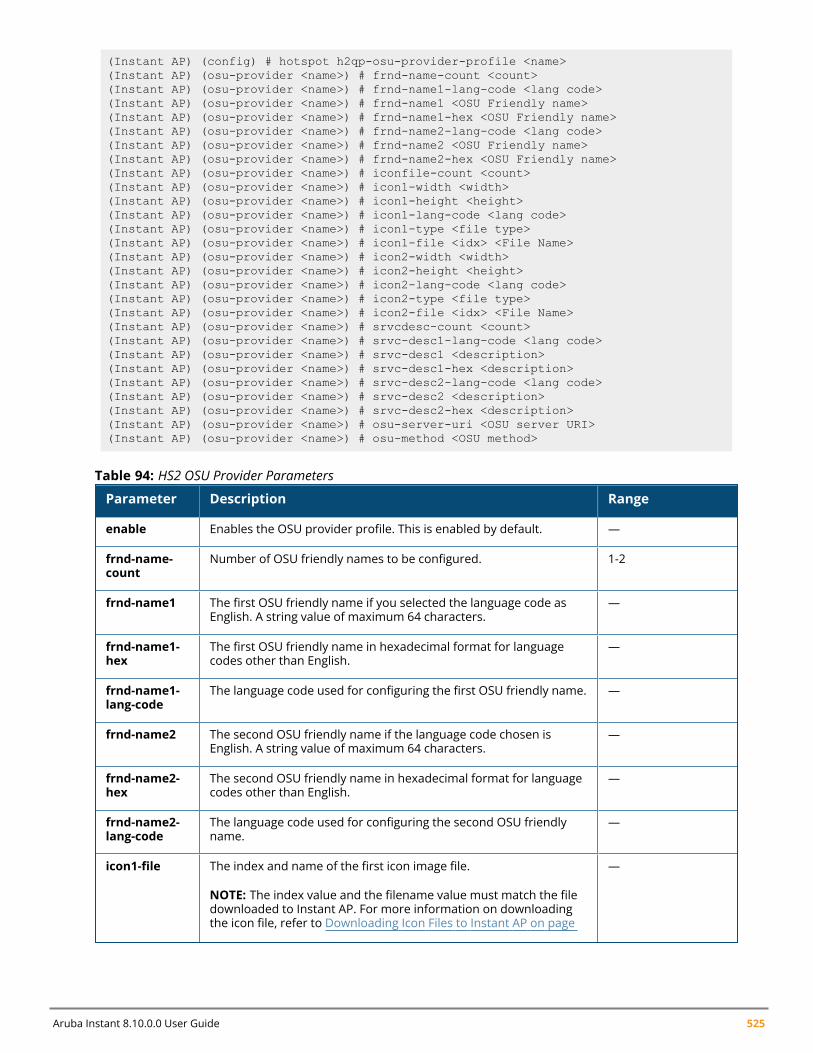
Aruba Instant 8.10.0.0 User Guide 525
(Instant AP) (config) # hotspot h2qp-osu-provider-profile <name>(Instant AP) (osu-provider <name>) # frnd-name-count <count>(Instant AP) (osu-provider <name>) # frnd-name1-lang-code <lang code>(Instant AP) (osu-provider <name>) # frnd-name1 <OSU Friendly name>(Instant AP) (osu-provider <name>) # frnd-name1-hex <OSU Friendly name>(Instant AP) (osu-provider <name>) # frnd-name2-lang-code <lang code>(Instant AP) (osu-provider <name>) # frnd-name2 <OSU Friendly name>(Instant AP) (osu-provider <name>) # frnd-name2-hex <OSU Friendly name>(Instant AP) (osu-provider <name>) # iconfile-count <count>(Instant AP) (osu-provider <name>) # icon1-width <width>(Instant AP) (osu-provider <name>) # icon1-height <height>(Instant AP) (osu-provider <name>) # icon1-lang-code <lang code>(Instant AP) (osu-provider <name>) # icon1-type <file type>(Instant AP) (osu-provider <name>) # icon1-file <idx> <File Name>(Instant AP) (osu-provider <name>) # icon2-width <width>(Instant AP) (osu-provider <name>) # icon2-height <height>(Instant AP) (osu-provider <name>) # icon2-lang-code <lang code>(Instant AP) (osu-provider <name>) # icon2-type <file type>(Instant AP) (osu-provider <name>) # icon2-file <idx> <File Name>(Instant AP) (osu-provider <name>) # srvcdesc-count <count>(Instant AP) (osu-provider <name>) # srvc-desc1-lang-code <lang code>(Instant AP) (osu-provider <name>) # srvc-desc1 <description>(Instant AP) (osu-provider <name>) # srvc-desc1-hex <description>(Instant AP) (osu-provider <name>) # srvc-desc2-lang-code <lang code>(Instant AP) (osu-provider <name>) # srvc-desc2 <description>(Instant AP) (osu-provider <name>) # srvc-desc2-hex <description>(Instant AP) (osu-provider <name>) # osu-server-uri <OSU server URI>(Instant AP) (osu-provider <name>) # osu-method <OSU method>
Parameter Description Range
enable Enables the OSU provider profile. This is enabled by default. —
frnd-name-count
Number of OSU friendly names to be configured. 1-2
frnd-name1 The first OSU friendly name if you selected the language code asEnglish. A string value of maximum 64 characters.
—
frnd-name1-hex
The first OSU friendly name in hexadecimal format for languagecodes other than English.
—
frnd-name1-lang-code
The language code used for configuring the first OSU friendly name. —
frnd-name2 The second OSU friendly name if the language code chosen isEnglish. A string value of maximum 64 characters.
—
frnd-name2-hex
The second OSU friendly name in hexadecimal format for languagecodes other than English.
—
frnd-name2-lang-code
The language code used for configuring the second OSU friendlyname.
—
icon1-file The index and name of the first icon image file.
NOTE: The index value and the filename value must match the filedownloaded to Instant AP. For more information on downloadingthe icon file, refer to Downloading Icon Files to Instant AP on page
—
Table 94: HS2 OSU Provider Parameters
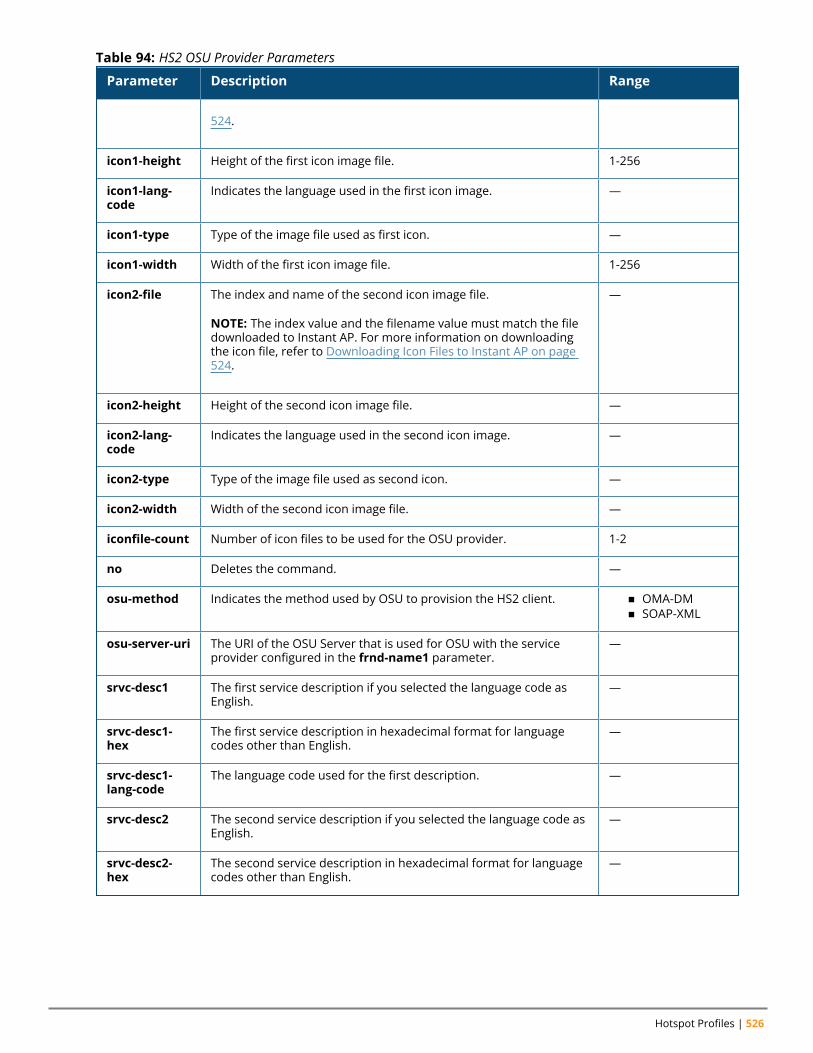
Hotspot Profiles | 526
Parameter Description Range
524.
icon1-height Height of the first icon image file. 1-256
icon1-lang-code
Indicates the language used in the first icon image. —
icon1-type Type of the image file used as first icon. —
icon1-width Width of the first icon image file. 1-256
icon2-file The index and name of the second icon image file.
NOTE: The index value and the filename value must match the filedownloaded to Instant AP. For more information on downloadingthe icon file, refer to Downloading Icon Files to Instant AP on page524.
—
icon2-height Height of the second icon image file. —
icon2-lang-code
Indicates the language used in the second icon image. —
icon2-type Type of the image file used as second icon. —
icon2-width Width of the second icon image file. —
iconfile-count Number of icon files to be used for the OSU provider. 1-2
no Deletes the command. —
osu-method Indicates the method used by OSU to provision the HS2 client. n OMA-DMn SOAP-XML
osu-server-uri The URI of the OSU Server that is used for OSU with the serviceprovider configured in the frnd-name1 parameter.
—
srvc-desc1 The first service description if you selected the language code asEnglish.
—
srvc-desc1-hex
The first service description in hexadecimal format for languagecodes other than English.
—
srvc-desc1-lang-code
The language code used for the first description. —
srvc-desc2 The second service description if you selected the language code asEnglish.
—
srvc-desc2-hex
The second service description in hexadecimal format for languagecodes other than English.
—
Table 94: HS2 OSU Provider Parameters
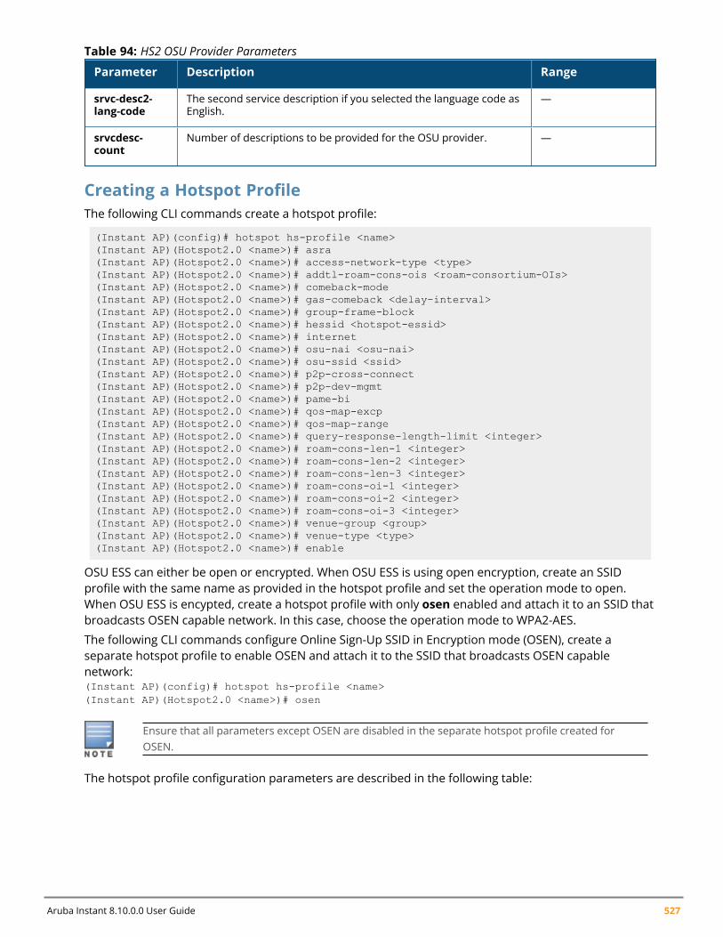
Aruba Instant 8.10.0.0 User Guide 527
Parameter Description Range
srvc-desc2-lang-code
The second service description if you selected the language code asEnglish.
—
srvcdesc-count
Number of descriptions to be provided for the OSU provider. —
Table 94: HS2 OSU Provider Parameters
Creating a Hotspot ProfileThe following CLI commands create a hotspot profile:
(Instant AP)(config)# hotspot hs-profile <name>(Instant AP)(Hotspot2.0 <name>)# asra(Instant AP)(Hotspot2.0 <name>)# access-network-type <type>(Instant AP)(Hotspot2.0 <name>)# addtl-roam-cons-ois <roam-consortium-OIs>(Instant AP)(Hotspot2.0 <name>)# comeback-mode(Instant AP)(Hotspot2.0 <name>)# gas-comeback <delay-interval>(Instant AP)(Hotspot2.0 <name>)# group-frame-block(Instant AP)(Hotspot2.0 <name>)# hessid <hotspot-essid>(Instant AP)(Hotspot2.0 <name>)# internet(Instant AP)(Hotspot2.0 <name>)# osu-nai <osu-nai>(Instant AP)(Hotspot2.0 <name>)# osu-ssid <ssid>(Instant AP)(Hotspot2.0 <name>)# p2p-cross-connect(Instant AP)(Hotspot2.0 <name>)# p2p-dev-mgmt(Instant AP)(Hotspot2.0 <name>)# pame-bi(Instant AP)(Hotspot2.0 <name>)# qos-map-excp(Instant AP)(Hotspot2.0 <name>)# qos-map-range(Instant AP)(Hotspot2.0 <name>)# query-response-length-limit <integer>(Instant AP)(Hotspot2.0 <name>)# roam-cons-len-1 <integer>(Instant AP)(Hotspot2.0 <name>)# roam-cons-len-2 <integer>(Instant AP)(Hotspot2.0 <name>)# roam-cons-len-3 <integer>(Instant AP)(Hotspot2.0 <name>)# roam-cons-oi-1 <integer>(Instant AP)(Hotspot2.0 <name>)# roam-cons-oi-2 <integer>(Instant AP)(Hotspot2.0 <name>)# roam-cons-oi-3 <integer>(Instant AP)(Hotspot2.0 <name>)# venue-group <group>(Instant AP)(Hotspot2.0 <name>)# venue-type <type>(Instant AP)(Hotspot2.0 <name>)# enable
OSU ESS can either be open or encrypted. When OSU ESS is using open encryption, create an SSIDprofile with the same name as provided in the hotspot profile and set the operation mode to open.When OSU ESS is encypted, create a hotspot profile with only osen enabled and attach it to an SSID thatbroadcasts OSEN capable network. In this case, choose the operation mode to WPA2-AES.
The following CLI commands configure Online Sign-Up SSID in Encryption mode (OSEN), create aseparate hotspot profile to enable OSEN and attach it to the SSID that broadcasts OSEN capablenetwork:(Instant AP)(config)# hotspot hs-profile <name>(Instant AP)(Hotspot2.0 <name>)# osen
Ensure that all parameters except OSEN are disabled in the separate hotspot profile created forOSEN.
The hotspot profile configuration parameters are described in the following table:
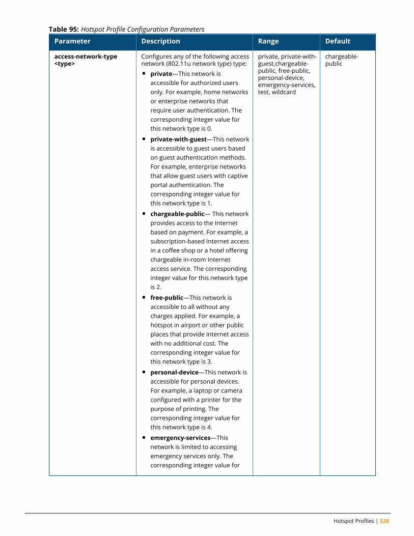
Hotspot Profiles | 528
Parameter Description Range Default
access-network-type<type>
Configures any of the following accessnetwork (802.11u network type) type:n private—This network is
accessible for authorized usersonly. For example, home networksor enterprise networks thatrequire user authentication. Thecorresponding integer value forthis network type is 0.
n private-with-guest—This networkis accessible to guest users basedon guest authentication methods.For example, enterprise networksthat allow guest users with captiveportal authentication. Thecorresponding integer value forthis network type is 1.
n chargeable-public— This networkprovides access to the Internetbased on payment. For example, asubscription-based Internet accessin a coffee shop or a hotel offeringchargeable in-room Internetaccess service. The correspondinginteger value for this network typeis 2.
n free-public—This network isaccessible to all without anycharges applied. For example, ahotspot in airport or other publicplaces that provide Internet accesswith no additional cost. Thecorresponding integer value forthis network type is 3.
n personal-device—This network isaccessible for personal devices.For example, a laptop or cameraconfigured with a printer for thepurpose of printing. Thecorresponding integer value forthis network type is 4.
n emergency-services—Thisnetwork is limited to accessingemergency services only. Thecorresponding integer value for
private, private-with-guest,chargeable-public, free-public,personal-device,emergency-services,test, wildcard
chargeable-public
Table 95: Hotspot Profile Configuration Parameters
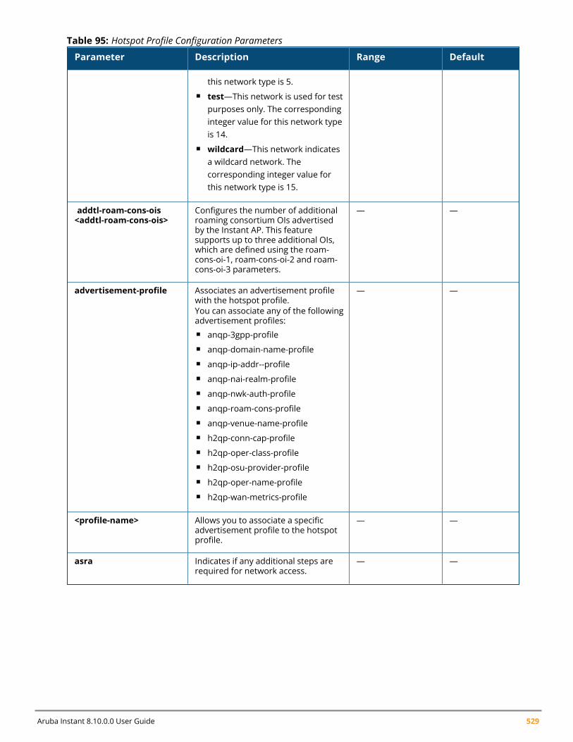
Aruba Instant 8.10.0.0 User Guide 529
Parameter Description Range Default
this network type is 5.n test—This network is used for test
purposes only. The correspondinginteger value for this network typeis 14.
n wildcard—This network indicatesa wildcard network. Thecorresponding integer value forthis network type is 15.
addtl-roam-cons-ois<addtl-roam-cons-ois>
Configures the number of additionalroaming consortium OIs advertisedby the Instant AP. This featuresupports up to three additional OIs,which are defined using the roam-cons-oi-1, roam-cons-oi-2 and roam-cons-oi-3 parameters.
— —
advertisement-profile Associates an advertisement profilewith the hotspot profile.You can associate any of the followingadvertisement profiles:n anqp-3gpp-profilen anqp-domain-name-profilen anqp-ip-addr--profilen anqp-nai-realm-profilen anqp-nwk-auth-profilen anqp-roam-cons-profilen anqp-venue-name-profilen h2qp-conn-cap-profilen h2qp-oper-class-profilen h2qp-osu-provider-profilen h2qp-oper-name-profilen h2qp-wan-metrics-profile
— —
<profile-name> Allows you to associate a specificadvertisement profile to the hotspotprofile.
— —
asra Indicates if any additional steps arerequired for network access.
— —
Table 95: Hotspot Profile Configuration Parameters
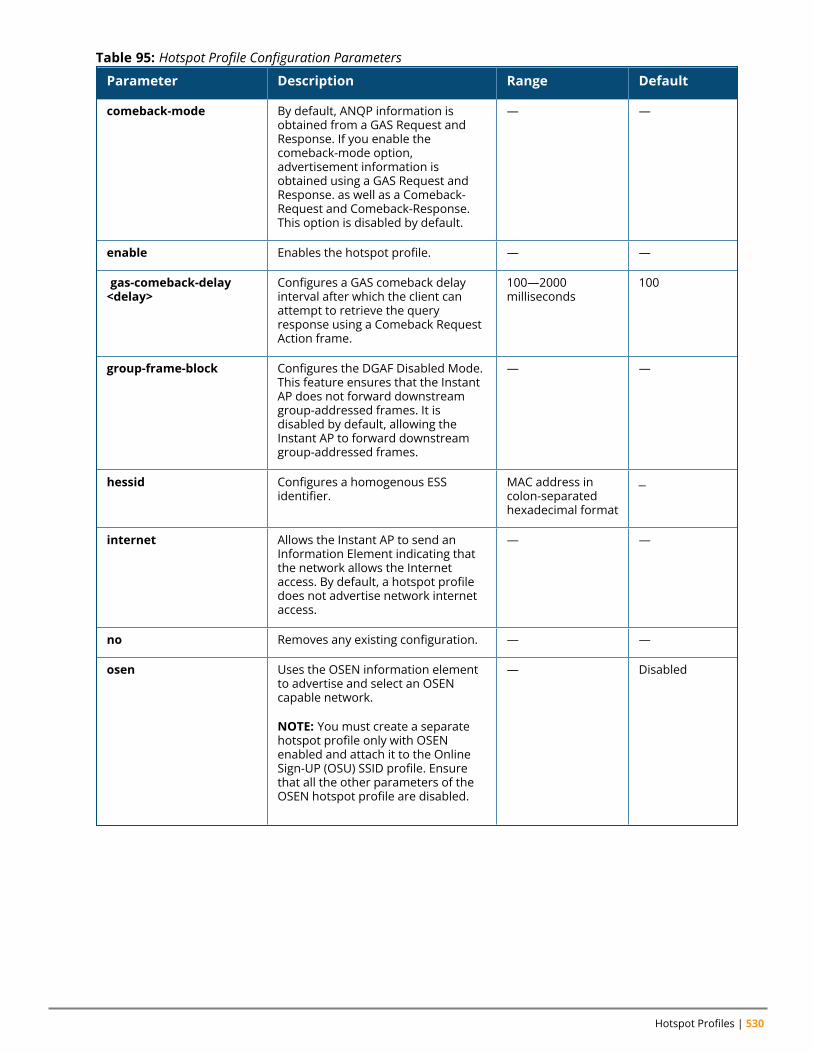
Hotspot Profiles | 530
Parameter Description Range Default
comeback-mode By default, ANQP information isobtained from a GAS Request andResponse. If you enable thecomeback-mode option,advertisement information isobtained using a GAS Request andResponse. as well as a Comeback-Request and Comeback-Response.This option is disabled by default.
— —
enable Enables the hotspot profile. — —
gas-comeback-delay<delay>
Configures a GAS comeback delayinterval after which the client canattempt to retrieve the queryresponse using a Comeback RequestAction frame.
100—2000milliseconds
100
group-frame-block Configures the DGAF Disabled Mode.This feature ensures that the InstantAP does not forward downstreamgroup-addressed frames. It isdisabled by default, allowing theInstant AP to forward downstreamgroup-addressed frames.
— —
hessid Configures a homogenous ESSidentifier.
MAC address incolon-separatedhexadecimal format
—
internet Allows the Instant AP to send anInformation Element indicating thatthe network allows the Internetaccess. By default, a hotspot profiledoes not advertise network internetaccess.
— —
no Removes any existing configuration. — —
osen Uses the OSEN information elementto advertise and select an OSENcapable network.
NOTE: You must create a separatehotspot profile only with OSENenabled and attach it to the OnlineSign-UP (OSU) SSID profile. Ensurethat all the other parameters of theOSEN hotspot profile are disabled.
— Disabled
Table 95: Hotspot Profile Configuration Parameters
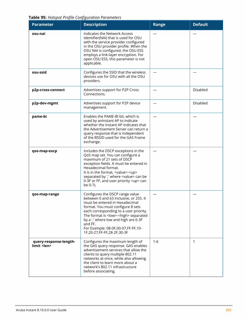
Aruba Instant 8.10.0.0 User Guide 531
Parameter Description Range Default
osu-nai Indicates the Network AccessIdentifier(NAI) that is used for OSUwith the service provider configuredin the OSU provider profile. When theOSU NAI is configured, the OSU ESSemploys a link-layer encryption. Foropen OSU ESS, this parameter is notapplicable.
— —
osu-ssid Configures the SSID that the wirelessdevices use for OSU with all the OSUproviders.
— —
p2p-cross-connect Advertises support for P2P CrossConnections.
— Disabled
p2p-dev-mgmt Advertises support for P2P devicemanagement.
— Disabled
pame-bi Enables the PAME-BI bit, which isused by anInstant AP to indicatewhether the Instant AP indicates thatthe Advertisement Server can return aquery response that is independentof the BSSID used for the GAS Frameexchange.
— —
qos-map-excp Includes the DSCP exceptions in theQoS map set. You can configure amaximum of 21 sets of DSCPexception fields. It must be entered inHexadecimal format.It is in the format, <value>-<up>separated by ',' where <value> can be0-3F or FF, and user priority <up> canbe 0-7).
— —
qos-map-range Configures the DSCP range valuebetween 0 and 63 inclusive, or 255. Itmust be entered in Hexadecimalformat. You must configure 8 setseach corresponding to a user priority.The format is <low>-<high> separatedby a ',' where low and high are 0-3Fand FF.For Example: 08-0F,00-07,FF-FF,10-1F,20-27,FF-FF,28-2F,30-3F
— —
query-response-length-limit <len>
Configures the maximum length ofthe GAS query response. GAS enablesadvertisement services that allow theclients to query multiple 802.11networks at once, while also allowingthe client to learn more about anetwork’s 802.11 infrastructurebefore associating.
1-6 1
Table 95: Hotspot Profile Configuration Parameters
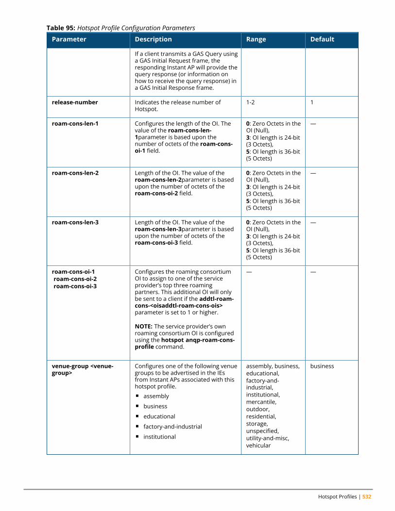
Hotspot Profiles | 532
Parameter Description Range Default
If a client transmits a GAS Query usinga GAS Initial Request frame, theresponding Instant AP will provide thequery response (or information onhow to receive the query response) ina GAS Initial Response frame.
release-number Indicates the release number ofHotspot.
1-2 1
roam-cons-len-1 Configures the length of the OI. Thevalue of the roam-cons-len-1parameter is based upon thenumber of octets of the roam-cons-oi-1 field.
0: Zero Octets in theOI (Null),3: OI length is 24-bit(3 Octets),5: OI length is 36-bit(5 Octets)
—
roam-cons-len-2 Length of the OI. The value of theroam-cons-len-2parameter is basedupon the number of octets of theroam-cons-oi-2 field.
0: Zero Octets in theOI (Null),3: OI length is 24-bit(3 Octets),5: OI length is 36-bit(5 Octets)
—
roam-cons-len-3 Length of the OI. The value of theroam-cons-len-3parameter is basedupon the number of octets of theroam-cons-oi-3 field.
0: Zero Octets in theOI (Null),3: OI length is 24-bit(3 Octets),5: OI length is 36-bit(5 Octets)
—
roam-cons-oi-1roam-cons-oi-2roam-cons-oi-3
Configures the roaming consortiumOI to assign to one of the serviceprovider’s top three roamingpartners. This additional OI will onlybe sent to a client if the addtl-roam-cons-<oisaddtl-roam-cons-ois>parameter is set to 1 or higher.
NOTE: The service provider’s ownroaming consortium OI is configuredusing the hotspot anqp-roam-cons-profile command.
— —
venue-group <venue-group>
Configures one of the following venuegroups to be advertised in the IEsfrom Instant APs associated with thishotspot profile.n assemblyn businessn educationaln factory-and-industrialn institutional
assembly, business,educational,factory-and-industrial,institutional,mercantile,outdoor,residential,storage,unspecified,utility-and-misc,vehicular
business
Table 95: Hotspot Profile Configuration Parameters

Aruba Instant 8.10.0.0 User Guide 533
Parameter Description Range Default
n mercantilen outdoorn residentialn storagen unspecifiedn utility-and-miscn vehicular
NOTE: This parameter only definesthe venue group advertised in the IEsfrom hotspot Instant APs. To definethe venue group to be included inANQP responses, use anqp-venue-name-profile <profile-name>command.
venue-type <venue-type> Specifies the venue type to beadvertised in the IEs from Instant APsassociated with this hotspot profile.The complete list of supported venuetypes is described in Creating aHotspot Profile on page 527This parameter only defines thevenue type advertised in the IEs fromhotspot Instant APs. To define thevenue type to be included in ANQPresponses, use the hotspot anqp-venue-name-profile <profile-name>command.
— —
Table 95: Hotspot Profile Configuration Parameters
Associating an Advertisement Profile to a Hotspot ProfileThe following CLI commands associate a hotspot profile with an advertisement profile:
(Instant AP)(config)# hotspot hs-profile <name>(Instant AP)(Hotspot2.0 <name>)# advertisement-protocol <protocol>(Instant AP)(Hotspot2.0 <name>)# advertisement-profile anqp-3gpp <name>(Instant AP)(Hotspot2.0 <name>)# advertisement-profile anqp-domain-name <name>(Instant AP)(Hotspot2.0 <name>)# advertisement-profile anqp-ip-addr-avail <name>(Instant AP)(Hotspot2.0 <name>)# advertisement-profile anqp-nai-realm <name>(Instant AP)(Hotspot2.0 <name>)# advertisement-profile anqp-nwk-auth <name>(Instant AP)(Hotspot2.0 <name>)# advertisement-profile anqp-roam-cons <name>(Instant AP)(Hotspot2.0 <name>)# advertisement-profile anqp-venue-name <name>(Instant AP)(Hotspot2.0 <name>)# advertisement-profile h2qp-conn-cap <name>(Instant AP)(Hotspot2.0 <name>)# advertisement-profile h2qp-oper-class <name>(Instant AP)(Hotspot2.0 <name>)# advertisement-profile h2qp-oper-name <name>(Instant AP)(Hotspot2.0 <name>)# advertisement-profile h2qp-osu-provider <name>
The configuration parameters for associating an advertisement profile with a hotspot profile aredescribed in the following table:
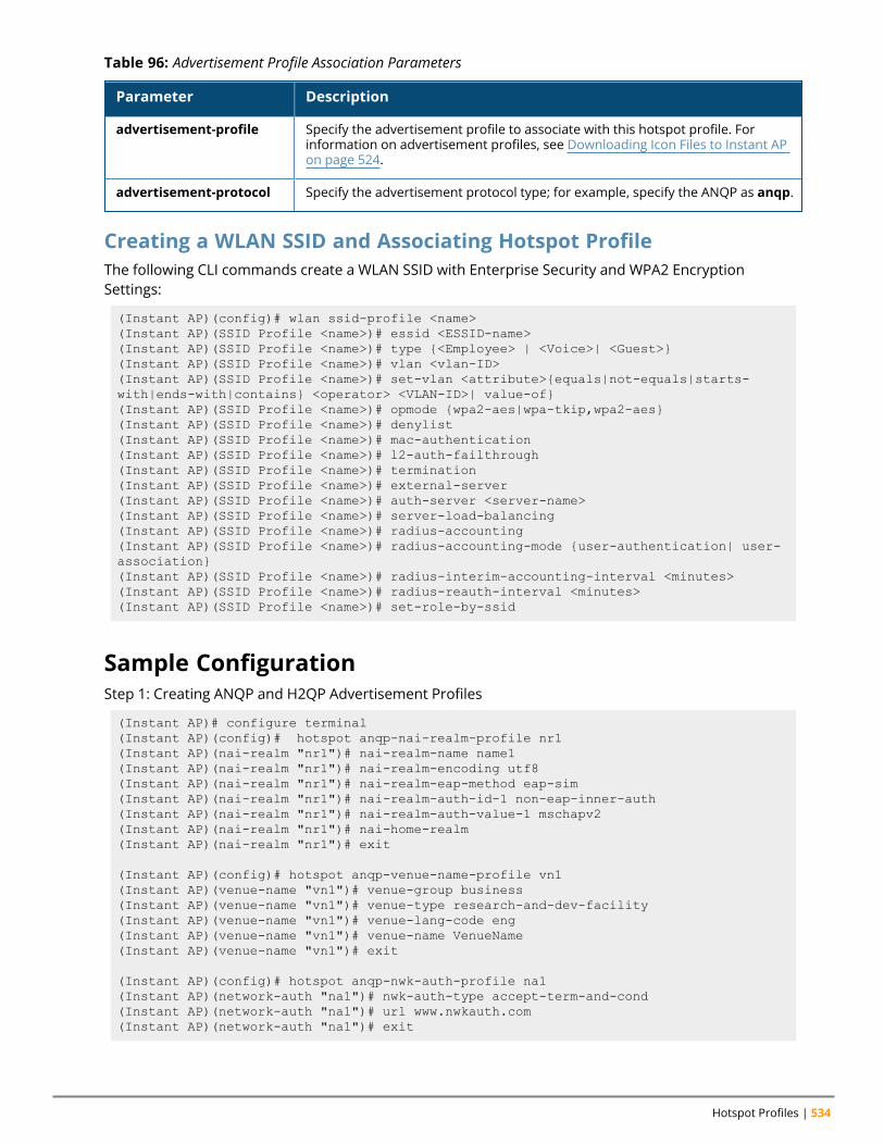
Hotspot Profiles | 534
Parameter Description
advertisement-profile Specify the advertisement profile to associate with this hotspot profile. Forinformation on advertisement profiles, see Downloading Icon Files to Instant APon page 524.
advertisement-protocol Specify the advertisement protocol type; for example, specify the ANQP as anqp.
Table 96: Advertisement Profile Association Parameters
Creating a WLAN SSID and Associating Hotspot ProfileThe following CLI commands create a WLAN SSID with Enterprise Security and WPA2 EncryptionSettings:
(Instant AP)(config)# wlan ssid-profile <name>(Instant AP)(SSID Profile <name>)# essid <ESSID-name>(Instant AP)(SSID Profile <name>)# type {<Employee> | <Voice>| <Guest>}(Instant AP)(SSID Profile <name>)# vlan <vlan-ID>(Instant AP)(SSID Profile <name>)# set-vlan <attribute>{equals|not-equals|starts-with|ends-with|contains} <operator> <VLAN-ID>| value-of}(Instant AP)(SSID Profile <name>)# opmode {wpa2-aes|wpa-tkip,wpa2-aes}(Instant AP)(SSID Profile <name>)# denylist(Instant AP)(SSID Profile <name>)# mac-authentication(Instant AP)(SSID Profile <name>)# l2-auth-failthrough(Instant AP)(SSID Profile <name>)# termination(Instant AP)(SSID Profile <name>)# external-server(Instant AP)(SSID Profile <name>)# auth-server <server-name>(Instant AP)(SSID Profile <name>)# server-load-balancing(Instant AP)(SSID Profile <name>)# radius-accounting(Instant AP)(SSID Profile <name>)# radius-accounting-mode {user-authentication| user-association}(Instant AP)(SSID Profile <name>)# radius-interim-accounting-interval <minutes>(Instant AP)(SSID Profile <name>)# radius-reauth-interval <minutes>(Instant AP)(SSID Profile <name>)# set-role-by-ssid
Sample ConfigurationStep 1: Creating ANQP and H2QP Advertisement Profiles
(Instant AP)# configure terminal(Instant AP)(config)# hotspot anqp-nai-realm-profile nr1(Instant AP)(nai-realm "nr1")# nai-realm-name name1(Instant AP)(nai-realm "nr1")# nai-realm-encoding utf8(Instant AP)(nai-realm "nr1")# nai-realm-eap-method eap-sim(Instant AP)(nai-realm "nr1")# nai-realm-auth-id-1 non-eap-inner-auth(Instant AP)(nai-realm "nr1")# nai-realm-auth-value-1 mschapv2(Instant AP)(nai-realm "nr1")# nai-home-realm(Instant AP)(nai-realm "nr1")# exit
(Instant AP)(config)# hotspot anqp-venue-name-profile vn1(Instant AP)(venue-name "vn1")# venue-group business(Instant AP)(venue-name "vn1")# venue-type research-and-dev-facility(Instant AP)(venue-name "vn1")# venue-lang-code eng(Instant AP)(venue-name "vn1")# venue-name VenueName(Instant AP)(venue-name "vn1")# exit
(Instant AP)(config)# hotspot anqp-nwk-auth-profile na1(Instant AP)(network-auth "na1")# nwk-auth-type accept-term-and-cond(Instant AP)(network-auth "na1")# url www.nwkauth.com(Instant AP)(network-auth "na1")# exit
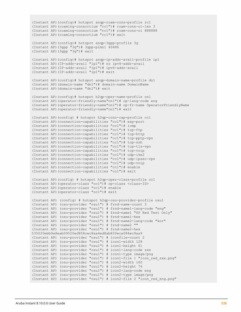
Aruba Instant 8.10.0.0 User Guide 535
(Instant AP)(config)# hotspot anqp-roam-cons-profile rc1(Instant AP)(roaming-consortium "rc1")# roam-cons-oi-len 3(Instant AP)(roaming-consortium "rc1")# roam-cons-oi 888888(Instant AP)(roaming-consortium "rc1")# exit
(Instant AP)(config)# hotspot anqp-3gpp-profile 3g(Instant AP)(3gpp "3g")# 3gpp-plmn1 40486(Instant AP)(3gpp "3g")# exit
(Instant AP)(config)# hotspot anqp-ip-addr-avail-profile ip1(Instant AP)(IP-addr-avail "ip1")# no ipv4-addr-avail(Instant AP)(IP-addr-avail "ip1")# ipv6-addr-avail(Instant AP)(IP-addr-avail "ip1")# exit
(Instant AP)(config)# hotspot anqp-domain-name-profile dn1(Instant AP)(domain-name "dn1")# domain-name DomainName(Instant AP)(domain-name "dn1")# exit
(Instant AP)(config)# hotspot h2qp-oper-name-profile on1(Instant AP)(operator-friendly-name"on1")# op-lang-code eng(Instant AP)(operator-friendly-name"on1")# op-fr-name OperatorFriendlyName(Instant AP)(operator-friendly-name"on1")# exit
(Instant AP)(config) # hotspot h2qp-conn-cap-profile cc1(Instant AP)(connection-capabilities "cc1")# esp-port(Instant AP)(connection-capabilities "cc1")# icmp(Instant AP)(connection-capabilities "cc1")# tcp-ftp(Instant AP)(connection-capabilities "cc1")# tcp-http(Instant AP)(connection-capabilities "cc1")# tcp-pptp-vpn(Instant AP)(connection-capabilities "cc1")# tcp-ssh(Instant AP)(connection-capabilities "cc1")# tcp-tls-vpn(Instant AP)(connection-capabilities "cc1")# tcp-voip(Instant AP)(connection-capabilities "cc1")# udp-ike2(Instant AP)(connection-capabilities "cc1")# udp-ipsec-vpn(Instant AP)(connection-capabilities "cc1")# udp-voip(Instant AP)(connection-capabilities "cc1")# enable(Instant AP)(connection-capabilities "cc1")# exit
(Instant AP)(config) # hotspot h2qp-oper-class-profile oc1(Instant AP)(operator-class "oc1")# op-class <class-ID>(Instant AP)(operator-class "oc1")# enable(Instant AP)(operator-class "oc1")# exit
(Instant AP) (config) # hotspot h2qp-osu-provider-profile osu1(Instant AP) (osu-provider "osu1") # frnd-name-count 2(Instant AP) (osu-provider "osu1") # frnd-name1-lang-code "eng"(Instant AP) (osu-provider "osu1") # frnd-name1 "SP Red Test Only"(Instant AP) (osu-provider "osu1") # frnd-name1-hex(Instant AP) (osu-provider "osu1") # frnd-name2-lang-code "kor"(Instant AP) (osu-provider "osu1") # frnd-name2 ""(Instant AP) (osu-provider "osu1") # frnd-name2-hex535020ebb9a8eab09520ed858cec8aa4ed8ab820eca084ec9aa9(Instant AP) (osu-provider "osu1") # iconfile-count 2(Instant AP) (osu-provider "osu1") # icon1-width 128(Instant AP) (osu-provider "osu1") # icon1-height 61(Instant AP) (osu-provider "osu1") # icon1-lang-code zxx(Instant AP) (osu-provider "osu1") # icon1-type image/png(Instant AP) (osu-provider "osu1") # icon1-file 1 "icon_red_zxx.png"(Instant AP) (osu-provider "osu1") # icon2-width 160(Instant AP) (osu-provider "osu1") # icon2-height 76(Instant AP) (osu-provider "osu1") # icon2-lang-code eng(Instant AP) (osu-provider "osu1") # icon2-type image/png(Instant AP) (osu-provider "osu1") # icon2-file 2 "icon_red_eng.png"
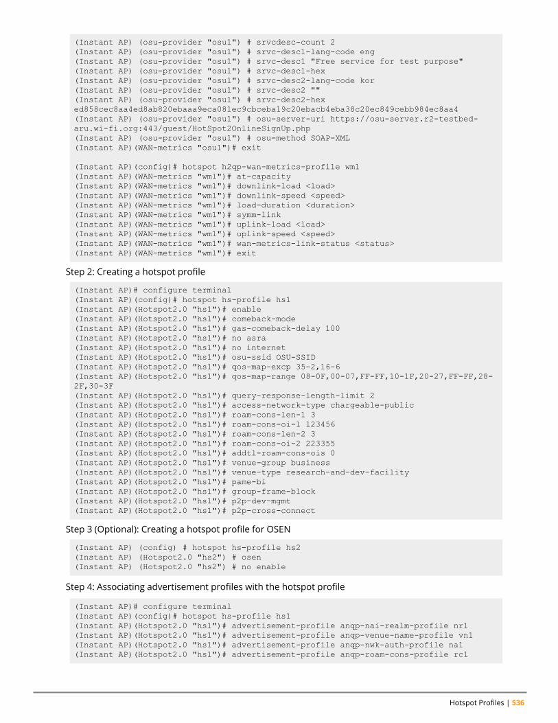
Hotspot Profiles | 536
(Instant AP) (osu-provider "osu1") # srvcdesc-count 2(Instant AP) (osu-provider "osu1") # srvc-desc1-lang-code eng(Instant AP) (osu-provider "osu1") # srvc-desc1 "Free service for test purpose"(Instant AP) (osu-provider "osu1") # srvc-desc1-hex(Instant AP) (osu-provider "osu1") # srvc-desc2-lang-code kor(Instant AP) (osu-provider "osu1") # srvc-desc2 ""(Instant AP) (osu-provider "osu1") # srvc-desc2-hexed858cec8aa4ed8ab820ebaaa9eca081ec9cbceba19c20ebacb4eba38c20ec849cebb984ec8aa4(Instant AP) (osu-provider "osu1") # osu-server-uri https://osu-server.r2-testbed-aru.wi-fi.org:443/guest/HotSpot2OnlineSignUp.php(Instant AP) (osu-provider "osu1") # osu-method SOAP-XML(Instant AP)(WAN-metrics "osu1")# exit
(Instant AP)(config)# hotspot h2qp-wan-metrics-profile wm1(Instant AP)(WAN-metrics "wm1")# at-capacity(Instant AP)(WAN-metrics "wm1")# downlink-load <load>(Instant AP)(WAN-metrics "wm1")# downlink-speed <speed>(Instant AP)(WAN-metrics "wm1")# load-duration <duration>(Instant AP)(WAN-metrics "wm1")# symm-link(Instant AP)(WAN-metrics "wm1")# uplink-load <load>(Instant AP)(WAN-metrics "wm1")# uplink-speed <speed>(Instant AP)(WAN-metrics "wm1")# wan-metrics-link-status <status>(Instant AP)(WAN-metrics "wm1")# exit
Step 2: Creating a hotspot profile
(Instant AP)# configure terminal(Instant AP)(config)# hotspot hs-profile hs1(Instant AP)(Hotspot2.0 "hs1")# enable(Instant AP)(Hotspot2.0 "hs1")# comeback-mode(Instant AP)(Hotspot2.0 "hs1")# gas-comeback-delay 100(Instant AP)(Hotspot2.0 "hs1")# no asra(Instant AP)(Hotspot2.0 "hs1")# no internet(Instant AP)(Hotspot2.0 "hs1")# osu-ssid OSU-SSID(Instant AP)(Hotspot2.0 "hs1")# qos-map-excp 35-2,16-6(Instant AP)(Hotspot2.0 "hs1")# qos-map-range 08-0F,00-07,FF-FF,10-1F,20-27,FF-FF,28-2F,30-3F(Instant AP)(Hotspot2.0 "hs1")# query-response-length-limit 2(Instant AP)(Hotspot2.0 "hs1")# access-network-type chargeable-public(Instant AP)(Hotspot2.0 "hs1")# roam-cons-len-1 3(Instant AP)(Hotspot2.0 "hs1")# roam-cons-oi-1 123456(Instant AP)(Hotspot2.0 "hs1")# roam-cons-len-2 3(Instant AP)(Hotspot2.0 "hs1")# roam-cons-oi-2 223355(Instant AP)(Hotspot2.0 "hs1")# addtl-roam-cons-ois 0(Instant AP)(Hotspot2.0 "hs1")# venue-group business(Instant AP)(Hotspot2.0 "hs1")# venue-type research-and-dev-facility(Instant AP)(Hotspot2.0 "hs1")# pame-bi(Instant AP)(Hotspot2.0 "hs1")# group-frame-block(Instant AP)(Hotspot2.0 "hs1")# p2p-dev-mgmt(Instant AP)(Hotspot2.0 "hs1")# p2p-cross-connect
Step 3 (Optional): Creating a hotspot profile for OSEN
(Instant AP) (config) # hotspot hs-profile hs2(Instant AP) (Hotspot2.0 "hs2") # osen(Instant AP) (Hotspot2.0 "hs2") # no enable
Step 4: Associating advertisement profiles with the hotspot profile
(Instant AP)# configure terminal(Instant AP)(config)# hotspot hs-profile hs1(Instant AP)(Hotspot2.0 "hs1")# advertisement-profile anqp-nai-realm-profile nr1(Instant AP)(Hotspot2.0 "hs1")# advertisement-profile anqp-venue-name-profile vn1(Instant AP)(Hotspot2.0 "hs1")# advertisement-profile anqp-nwk-auth-profile na1(Instant AP)(Hotspot2.0 "hs1")# advertisement-profile anqp-roam-cons-profile rc1
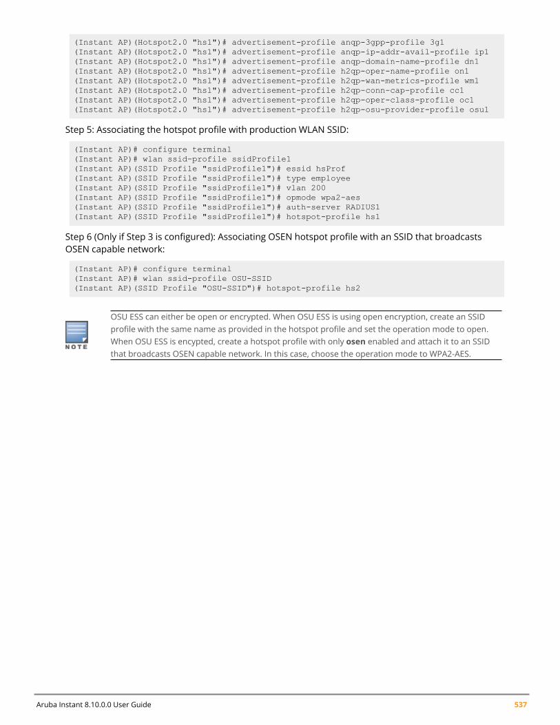
Aruba Instant 8.10.0.0 User Guide 537
(Instant AP)(Hotspot2.0 "hs1")# advertisement-profile anqp-3gpp-profile 3g1(Instant AP)(Hotspot2.0 "hs1")# advertisement-profile anqp-ip-addr-avail-profile ip1(Instant AP)(Hotspot2.0 "hs1")# advertisement-profile anqp-domain-name-profile dn1(Instant AP)(Hotspot2.0 "hs1")# advertisement-profile h2qp-oper-name-profile on1(Instant AP)(Hotspot2.0 "hs1")# advertisement-profile h2qp-wan-metrics-profile wm1(Instant AP)(Hotspot2.0 "hs1")# advertisement-profile h2qp-conn-cap-profile cc1(Instant AP)(Hotspot2.0 "hs1")# advertisement-profile h2qp-oper-class-profile oc1(Instant AP)(Hotspot2.0 "hs1")# advertisement-profile h2qp-osu-provider-profile osu1
Step 5: Associating the hotspot profile with production WLAN SSID:
(Instant AP)# configure terminal(Instant AP)# wlan ssid-profile ssidProfile1(Instant AP)(SSID Profile "ssidProfile1")# essid hsProf(Instant AP)(SSID Profile "ssidProfile1")# type employee(Instant AP)(SSID Profile "ssidProfile1")# vlan 200(Instant AP)(SSID Profile "ssidProfile1")# opmode wpa2-aes(Instant AP)(SSID Profile "ssidProfile1")# auth-server RADIUS1(Instant AP)(SSID Profile "ssidProfile1")# hotspot-profile hs1
Step 6 (Only if Step 3 is configured): Associating OSEN hotspot profile with an SSID that broadcastsOSEN capable network:
(Instant AP)# configure terminal(Instant AP)# wlan ssid-profile OSU-SSID(Instant AP)(SSID Profile "OSU-SSID")# hotspot-profile hs2
OSU ESS can either be open or encrypted. When OSU ESS is using open encryption, create an SSIDprofile with the same name as provided in the hotspot profile and set the operation mode to open.When OSU ESS is encypted, create a hotspot profile with only osen enabled and attach it to an SSIDthat broadcasts OSEN capable network. In this case, choose the operation mode to WPA2-AES.
Chapter 35Mobility Access Switch Integration
Mobility Access Switch IntegrationThis chapter provides the following information:
n Mobility Access Switch Overview on page 538n Configuring Instant APs for Mobility Access Switch Integration on page 539
Mobility Access Switch OverviewThe Aruba Mobility Access Switch enables a secure, role-based network access for wired users anddevices, independent of their location or application. Installed in wiring closets, the Mobility AccessSwitch delivers up to 384 wire-speed Gigabit Ethernet switch ports and operates as a wired access pointwhen deployed with an Aruba Mobility Controller.
As a wired access point, users and their devices are authenticated and assigned a unique role by theMobility Controller. These roles are applied irrespective of whether the user is a Wi-Fi client, or isconnected to a port on the Mobility Access Switch. The use of Mobility Access Switch allows anenterprise workforce to have a consistent and secure access to network resources based on the type ofusers, client devices, and connection method used.
Instant supports S3500 and S2500 Mobility Access Switch models.
For more information on Mobility Access Switches, refer to ArubaOS User Guide.
Mobility Access Switch Integration with an Instant APYou can integrate an Instant AP with a Mobility Access Switch by connecting it directly to the switch port.The following integration features can be applied while integrating Mobility Access Switch with an InstantAP:
n Rogue AP containment—When a rogue Instant AP is detected by an Instant AP, it sends the MACAddress of the rogue Instant AP to the Mobility Access Switch. The Mobility Access Switch blackliststhe MAC address of the rogue Instant AP and turns off the PoE on the port.
n PoE prioritization—When an Instant AP is connected directly into the switch port, the switchincreases the PoE priority of the port. This is done only if the PoE priority is set by default in theMobility Access Switch.
The PoE Prioritization and Rogue AP Containment features are available for Instant 7.2 release on ArubaMobility Access Switches.
n GVRP Integration—Configuring GVRP enables the switch to dynamically register or unregister VLANinformation received from a GVRP applicant such as an Instant AP. GVRP also enables the switch topropagate the registered VLAN information to the neighboring switches in the network.
The associated static VLANs used in wired and wireless profiles are propagated to the upstreamMobility Access Switch using GVRP messages.
Aruba Instant 8.10.0.0 User Guide 538
Mobility Access Switch Integration | 539
For information on steps to integrate Mobility Access Switch with an Instant AP, see Configuring InstantAPs for Mobility Access Switch Integration on page 539.
Configuring Instant APs for Mobility Access SwitchIntegrationWhen an Instant AP is integrated with a Mobility Access Switch, the LLDP is enabled. Using this protocol,the Instant APs instruct the switch to turn off the ports where rogue Instant APs are connected, performactions such as increasing the PoE priority, and configure the VLANs on the ports to which the InstantAPs are connected.
The following procedure describes how to enable Mobility Access Switch integration either by using theWebUI:
1. Navigate to Configuration > System > General.2. Enable theMAS integration toggle switch.3. Click Save.
The following CLI command enables the Mobility Access Switch integration:
(Instant AP)(config)# mas-integration
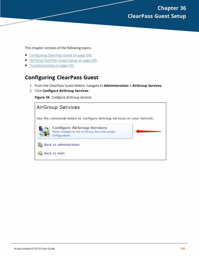
Chapter 36ClearPass Guest Setup
ClearPass Guest SetupThis chapter consists of the following topics:
n Configuring ClearPass Guest on page 540n Verifying ClearPass Guest Setup on page 545n Troubleshooting on page 545
Configuring ClearPass Guest1. From the ClearPass Guest WebUI, navigate to Administration > AirGroup Services.2. Click Configure AirGroup Services.
Figure 34 Configure AirGroup Services
Aruba Instant 8.10.0.0 User Guide 540
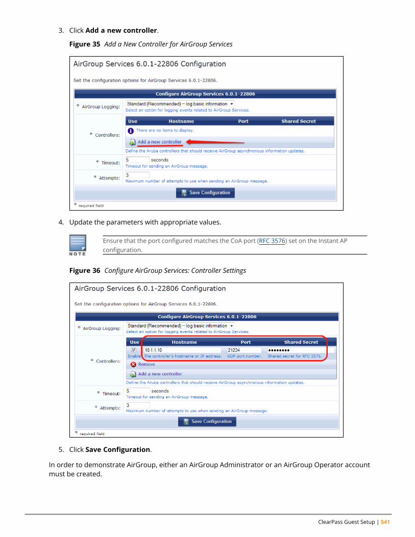
ClearPass Guest Setup | 541
3. Click Add a new controller.
Figure 35 Add a New Controller for AirGroup Services
4. Update the parameters with appropriate values.
Ensure that the port configured matches the CoA port (RFC 3576) set on the Instant APconfiguration.
Figure 36 Configure AirGroup Services: Controller Settings
5. Click Save Configuration.
In order to demonstrate AirGroup, either an AirGroup Administrator or an AirGroup Operator accountmust be created.
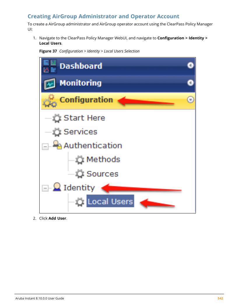
Aruba Instant 8.10.0.0 User Guide 542
Creating AirGroup Administrator and Operator AccountTo create a AirGroup administrator and AirGroup operator account using the ClearPass Policy ManagerUI:
1. Navigate to the ClearPass Policy Manager WebUI, and navigate to Configuration > Identity >Local Users.
Figure 37 Configuration > Identity > Local Users Selection
2. Click Add User.
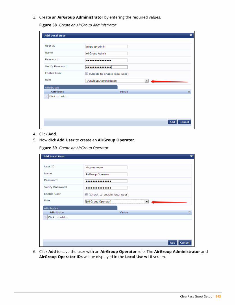
ClearPass Guest Setup | 543
3. Create an AirGroup Administrator by entering the required values.
Figure 38 Create an AirGroup Administrator
4. Click Add.5. Now click Add User to create an AirGroup Operator.
Figure 39 Create an AirGroup Operator
6. Click Add to save the user with an AirGroup Operator role. The AirGroup Administrator andAirGroup Operator IDs will be displayed in the Local Users UI screen.
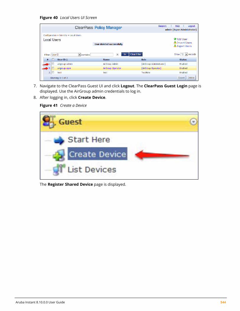
Aruba Instant 8.10.0.0 User Guide 544
Figure 40 Local Users UI Screen
7. Navigate to the ClearPass Guest UI and click Logout. The ClearPass Guest Login page isdisplayed. Use the AirGroup admin credentials to log in.
8. After logging in, click Create Device.
Figure 41 Create a Device
The Register Shared Device page is displayed.
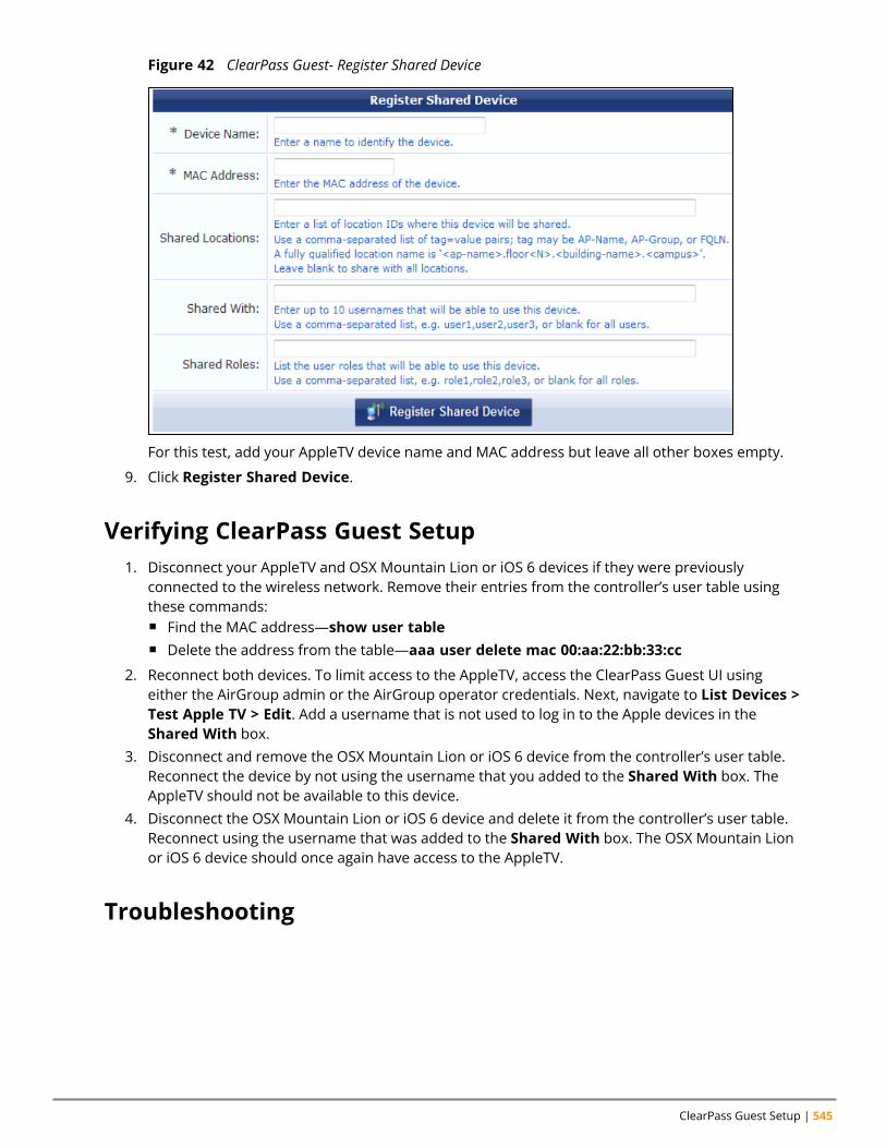
ClearPass Guest Setup | 545
Figure 42 ClearPass Guest- Register Shared Device
For this test, add your AppleTV device name and MAC address but leave all other boxes empty.
9. Click Register Shared Device.
Verifying ClearPass Guest Setup1. Disconnect your AppleTV and OSX Mountain Lion or iOS 6 devices if they were previously
connected to the wireless network. Remove their entries from the controller’s user table usingthese commands:n Find the MAC address—show user tablen Delete the address from the table—aaa user delete mac 00:aa:22:bb:33:cc
2. Reconnect both devices. To limit access to the AppleTV, access the ClearPass Guest UI usingeither the AirGroup admin or the AirGroup operator credentials. Next, navigate to List Devices >Test Apple TV > Edit. Add a username that is not used to log in to the Apple devices in theShared With box.
3. Disconnect and remove the OSX Mountain Lion or iOS 6 device from the controller’s user table.Reconnect the device by not using the username that you added to the Shared With box. TheAppleTV should not be available to this device.
4. Disconnect the OSX Mountain Lion or iOS 6 device and delete it from the controller’s user table.Reconnect using the username that was added to the Shared With box. The OSX Mountain Lionor iOS 6 device should once again have access to the AppleTV.
Troubleshooting

Aruba Instant 8.10.0.0 User Guide 546
Table 97: Troubleshooting
Problem Solution
Limiting devices has no effect. Ensure IPv6 is disabled.
Apple Macintosh running Mountain Lion can useAirPlay but iOS devices cannot.
Ensure IPv6 is disabled.
Glossary of Terms
Appendix A
Glossary of Terms
The following table provides a brief description of the terminology used in this guide.
3DES
Triple Data Encryption Standard. 3DES is a symmetric-key block cipher that applies the DES cipheralgorithm three times to each data block.
3G
Third Generation of Wireless Mobile Telecommunications Technology. See W-CDMA.
3GPP
Third Generation Partnership Project. 3GPP is a collaborative project aimed at developing globallyacceptable specifications for third generation mobile systems.
4G
Fourth Generation of Wireless Mobile Telecommunications Technology. See LTE.
802.11
802.11 is an evolving family of specifications for wireless LANs developed by a working group of theInstitute of Electrical and Electronics Engineers (IEEE). 802.11 standards use the Ethernet protocoland Carrier Sense Multiple Access with collision avoidance (CSMA/CA) for path sharing.
802.11 bSec
802.11 bSec is an alternative to 802.11i. The difference between bSec and standard 802.11i is thatbSec implements Suite B algorithms wherever possible. Notably, Advanced Encryption Standard-Counter with CBC-MAC is replaced by Advanced Encryption Standard - Galois/Counter Mode, and theKey Derivation Function (KDF) of 802.11i is upgraded to support SHA-256 and SHA-384.
802.11a
802.11a provides specifications for wireless systems. Networks using 802.11a operate at radiofrequencies in the 5 GHz band. The specification uses a modulation scheme known as orthogonalfrequency-division multiplexing (OFDM) that is especially well suited to use in office settings. Themaximum data transfer rate is 54 Mbps.
802.11ac
802.11ac is a wireless networking standard in the 802.11 family that provides high-throughputWLANs on the 5 GHz band.
Aruba Instant 8.10.0.0 User Guide 547
Aruba Instant 8.10.0.0 User Guide 548
802.11b
802.11b is a WLAN standard often called Wi-Fi and is backward compatible with 802.11. Instead ofthe Phase-Shift Keying (PSK) modulation method used in 802.11 standards, 802.11b usesComplementary Code Keying (CCK) that allows higher data speeds and makes it less susceptible tomultipath-propagation interference. 802.11b operates in the 2.4 GHz band and the maximum datatransfer rate is 11 Mbps.
802.11d
802.11d is a wireless network communications specification for use in countries where systems usingother standards in the 802.11 family are not allowed to operate. Configuration can be fine-tuned atthe Media Access Control (MAC) layer level to comply with the rules of the country or district in whichthe network is to be used. Rules are subject to variation and include allowed frequencies, allowedpower levels, and allowed signal bandwidth. 802.11d facilitates global roaming.
802.11e
802.11e is an enhancement to the 802.11a and 802.11b specifications that enhances the 802.11Media Access Control layer with a coordinated Time Division Multiple Access (TDMA) construct. Itadds error-correcting mechanisms for delay-sensitive applications such as voice and video. The802.11e specification provides seamless interoperability between business, home, and publicenvironments such as airports and hotels, and offers all subscribers high-speed Internet access withfull-motion video, high-fidelity audio, and VoIP.
802.11g
802.11g offers transmission over relatively short distances at up to 54 Mbps, compared with the 11Mbps theoretical maximum of 802.11b standard. 802.11g employs Orthogonal Frequency DivisionMultiplexing (OFDM), the modulation scheme used in 802.11a, to obtain higher data speed.Computers or terminals set up for 802.11g can fall back to speed of 11 Mbps, so that 802.11b and802.11g devices can be compatible within a single network.
802.11h
802.11h is intended to resolve interference issues introduced by the use of 802.11a in somelocations, particularly with military Radar systems and medical devices. Dynamic Frequency Selection(DFS) detects the presence of other devices on a channel and automatically switches the network toanother channel if and when such signals are detected. Transmit Power Control (TPC) reduces theradio frequency (RF) output power of each network transmitter to a level that minimizes the risk ofinterference.
802.11i
802.11i provides improved encryption for networks that use 802.11a, 802.11b, and 802.11gstandards. It requires new encryption key protocols, known as Temporal Key Integrity Protocol (TKIP)and Advanced Encryption Standard (AES).
802.11j
802.11j is a proposed addition to the 802.11 family of standards that incorporates Japaneseregulatory extensions to 802.11a; the main intent is to add channels in the radio frequency (RF) bandof 4.9 GHz to 5.0 GHz.
Glossary of Terms | 549
802.11k
802.11k is an IEEE standard that enables APs and client devices to discover the best available radioresources for seamless BSS transition in a WLAN.
802.11m
802.11m is an Initiative to perform editorial maintenance, corrections, improvements, clarifications,and interpretations relevant to documentation for 802.11 family specifications.
802.11n
802.11n is a wireless networking standard to improve network throughput over the two previousstandards, 802.11a and 802.11g. With 802.11n, there will be a significant increase in the maximumraw data rate from 54 Mbps to 600 Mbps with the use of four spatial streams at a channel width of40 MHz.
802.11r
802.11r is an IEEE standard for enabling seamless BSS transitions in a WLAN. 802.11r standard is alsoreferred to as Fast BSS transition.
802.11u
802.11u is an amendment to the IEEE 802.11 WLAN standards for connection to external networksusing common wireless devices such as smartphones and tablet PCs. The 802.11u protocol provideswireless clients with a streamlined mechanism to discover and authenticate to suitable networks,and allows mobile users to roam between partner networks without additional authentication. An802.11u-capable device supports the Passpoint technology from the Wi-Fi Alliance Hotspot 2.0 R2Specification that simplifies and automates access to public Wi-Fi.
802.11v
802.11v is an IEEE standard that allows client devices to exchange information about the networktopology and RF environment. This information is used for assigning best available radio resourcesfor the client devices to provide seamless connectivity.
802.1Q
802.1Q is an IEEE standard that enables the use of VLANs on an Ethernet network. 802.1Q supportsVLAN tagging.
802.1X
802.1X is an IEEE standard for port-based network access control designed to enhance 802.11 WLANsecurity. 802.1X provides an authentication framework that allows a user to be authenticated by acentral authority.
802.3af
802.3af is an IEEE standard for Power over Ethernet (PoE) version that supplies up to 15.4W of DCpower. See PoE.
802.3at
802.3at is an IEEE standard for PoE version that supplies up to 25.5W of DC power. See PoE+.
Aruba Instant 8.10.0.0 User Guide 550
A-MPDU
Aggregate MAC Protocol Data Unit. A-MPDU is a method of frame aggregation, where several MPDUsare combined into a single frame for transmission.
A-MSDU
Aggregate MAC Service Data Unit. A-MSDU is a structure containing multiple MSDUs, transportedwithin a single (unfragmented) data MAC MPDU.
AAA
Authentication, Authorization, and Accounting. AAA is a security framework to authenticate users,authorize the type of access based on user credentials, and record authentication events andinformation about the network access and network resource consumption.
ABR
Area Border Router. ABR is used for establishing connection between the backbone networks andthe Open Shortest Path First (OSPF) areas. ABR is located near the border of one or more OSPFareas.
AC
Access Category. As per the IEEE 802.11e standards, AC refers to various levels of traffic prioritizationin Enhanced Distributed Channel Access (EDCA) operation mode. The WLAN applications prioritizetraffic based on the Background, Best Effort, Video, and Voice access categories. AC can also refer toAlternating Current, a form of electric energy that flows when the appliances are plugged to a wallsocket.
ACC
Advanced Cellular Coexistence. The ACC feature in APs enable WLANs to perform at peak efficiencyby minimizing interference from 3G/4G/LTE networks, distributed antenna systems, and commercialsmall cell/femtocell equipment.
Access-Accept
Response from the RADIUS server indicating successful authentication and containing authorizationinformation.
Access-Reject
Response from RADIUS server indicating that a user is not authorized.
Access-Request
RADIUS packet sent to a RADIUS server requesting authorization.
Accounting-Request
RADIUS packet type sent to a RADIUS server containing accounting summary information.
Accounting-Response
RADIUS packet sent by the RADIUS server to acknowledge receipt of an Accounting-Request.
ACE
Access Control Entry. ACE is an element in an ACL that includes access control information.
Glossary of Terms | 551
ACI
Adjacent Channel Interference. ACI refers to interference or interruptions detected on abroadcasting channel, caused by too much power on an adjacent channel in the spectrum.
ACL
Access Control List. ACL is a common way of restricting certain types of traffic on a physical port.
Active Directory
Microsoft Active Directory. The directory server that stores information about a variety of things,such as organizations, sites, systems, users, shares, and other network objects or components. Italso provides authentication and authorization mechanisms, and a framework within which relatedservices can be deployed.
ActiveSync
Mobile data synchronization app developed by Microsoft that allows a mobile device to besynchronized with either a desktop or a server running compatible software products.
ad hoc network
An ad hoc network is a network composed of individual devices communicating with each otherdirectly. Many ad hoc networks are Local Area Networks (LANs) where computers or other devicesare enabled to send data directly to one another rather than going through a centralized accesspoint.
ADO
Active X Data Objects is a part of Microsoft Data Access Components (MDACs) that enables clientapplications to access data sources through an (Object Linking and Embedding Database) OLE DBprovider. ADO supports key features for building client-server and Web-based applications.
ADP
Aruba Discovery Protocol. ADP is an Aruba proprietary Layer 2 protocol. It is used by the APs toobtain the IP address of the TFTP server from which it downloads the AP boot image.
AES
Advanced Encryption Standard. AES is an encryption standard used for encrypting and protectingelectronic data. The AES encrypts and decrypts data in blocks of 128 bits (16 bytes), and can use keysof 128 bits, 192 bits, and 256 bits.
AIFSN
Arbitrary Inter-frame Space Number. AIFSN is set by the AP in beacon frames and probe responses.AIFS is a method of prioritizing a particular category of traffic over the other, for example prioritizingvoice or video messages over email.
AirGroup
The application that allows the end users to register their personal mobile devices on a local networkand define a group of friends or associates who are allowed to share them. AirGroup is primarilydesigned for colleges and other institutions. AirGroup uses zero configuration networking to allowApple mobile devices, such as the AirPrint wireless printer service and the AirPlay mirroring service,to communicate over a complex access network topology.
Aruba Instant 8.10.0.0 User Guide 552
AirWave Management Client
AirWave Management Client is a Windows software utility that enables client devices (such as alaptop) to act as passive RF sensors and augments the AirWave RAPIDS module.
ALE
Analytics and Location Engine. ALE gives visibility into everything the wireless network knows. Thisenables customers and partners to gain a wealth of information about the people on their premises.This can be very important for many different verticals and use cases. ALE includes a location enginethat calculates associated and unassociated device location periodically using context streams,including RSSI readings, from WLAN controllers or Instant clusters.
ALG
Application Layer Gateway. ALG is a security component that manages application layer protocolssuch as SIP, FTP and so on.
AM
Air Monitor. AM is a mode of operation supported on wireless APs. When an AP operates in the AirMonitor mode, it enhances the wireless networks by collecting statistics, monitoring traffic, detectingintrusions, enforcing security policies, balancing wireless traffic load, self-healing coverage gaps, andmore. However, clients cannot connect to APs operating in the AM mode.
AMON
Advanced Monitoring. AMON is used in Aruba WLAN deployments for improved networkmanagement, monitoring and diagnostic capabilities.
AMP
AirWave Management Platform. AMP is a network management system for configuring, monitoring,and upgrading wired and wireless devices on your network.
ANQP
Access Network Query Protocol. ANQP is a query and a response protocol for Wi-Fi hotspot services.ANQP includes information Elements (IEs) that can be sent from the AP to the client to identify the APnetwork and service provider. The IEs typically include information about the domain name of the APoperator, the IP addresses available at the AP, and information about potential roaming partnersaccessible through the AP. If the client responds with a request for a specific IE, the AP will send aGeneric Advertisement Service (GAS) response frame with the configured ANQP IE information.
ANSI
American National Standards Institute. It refers to the ANSI compliance standards for products,systems, services, and processes.
API
Application Programming Interface. Refers to a set of functions, procedures, protocols, and tools thatenable users to build application software.
app
Short form for application. It generally refers to the application that is downloaded and used onmobile devices.
Glossary of Terms | 553
ARM
Adaptive Radio Management. ARM dynamically monitors and adjusts the network to ensure that allusers are allowed ready access. It enables full utilization of the available spectrum to supportmaximum number of users by intelligently choosing the best RF channel and transmit power for APsin their current RF environment.
ARP
Address Resolution Protocol. ARP is used for mapping IP network address to the hardware MACaddress of a device.
Aruba Activate
Aruba Activate is a cloud-based service that helps provision your Aruba devices and maintain yourinventory. Activate automates the provisioning process, allowing a single IT technician to easily andrapidly deploy devices throughout a distributed enterprise network.
ASCII
American Standard Code for Information Interchange. An ASCII code is a numerical representation ofa character or an action.
B-RAS
Broadband Remote Access Server. A B-RAS is a server that facilitates and converges traffic frommultiple Internet traffic resources such as cable, DSL, Ethernet, or Broadband wireless.
band
Band refers to a specified range of frequencies of electromagnetic radiation.
BGP
Border Gateway Protocol. BGP is a routing protocol for exchanging data and information betweendifferent host gateways or autonomous systems on the Internet.
BLE
Bluetooth Low Energy. The BLE functionality is offered by Bluetooth® to enable devices to run forlong durations with low power consumption.
BMC
Beacon Management Console. BMC manages and monitors beacons from the BLE devices. The BLEdevices are used for location tracking and proximity detection.
BPDU
Bridge Protocol Data Unit. A BPDU is a data message transmitted across a local area network todetect loops in network topologies.
BRE
Basic Regular Expression. The BRE syntax standards designed by the IEEE provides extension to thetraditional Simple Regular Expressions syntax and allows consistency between utility programs suchas grep, sed, and awk.
Aruba Instant 8.10.0.0 User Guide 554
BSS
Basic Service Set. A BSS is a set of interconnected stations that can communicate with each other.BSS can be an independent BSS or infrastructure BSS. An independent BSS is an ad hoc network thatdoes not include APs, whereas the infrastructure BSS consists of an AP and all its associated clients.
BSSID
Basic Service Set Identifier. The BSSID identifies a particular BSS within an area. In infrastructure BSSnetworks, the BSSID is the MAC address of the AP. In independent BSS or ad hoc networks, the BSSIDis generated randomly.
BYOD
Bring Your Own Device. BYOD refers to the use of personal mobile devices within an enterprisenetwork infrastructure.
CA
Certificate Authority or Certification Authority. Entity in a public key infrastructure system that issuescertificates to clients. A certificate signing request received by the CA is converted into a certificatewhen the CA adds a signature generated with a private key. See digital certificate.
CAC
Call Admission Control. CAC regulates traffic volume in voice communications. CAC can also be usedto ensure or maintain a certain level of audio quality in voice communications networks.
CALEA
Communications Assistance for Law Enforcement Act. To comply with the CALEA specifications andto allow lawful interception of Internet traffic by the law enforcement and intelligence agencies, thetelecommunications carriers and manufacturers of telecommunications equipment are required tomodify and design their equipment, facilities, and services to ensure that they have built-insurveillance capabilities.
Campus AP
Campus APs are used in private networks where APs connect over private links (LAN, WLAN, WAN orMPLS) and terminate directly on controllers. Campus APs are deployed as part of the indoor campussolution in enterprise office buildings, warehouses, hospitals, universities, and so on.
captive portal
A captive portal is a web page that allows the users to authenticate and sign in before connecting toa public-access network. Captive portals are typically used by business centers, airports, hotellobbies, coffee shops, and other venues that offer free Wi-Fi hotspots for the guest users.
CCA
Clear Channel Assessment. In wireless networks, the CCA method detects if a channel is occupied orclear, and determines if the channel is available for data transmission.
CDP
Cisco Discovery Protocol. CDP is a proprietary Data Link Layer protocol developed by Cisco Systems.CDP runs on Cisco devices and enables networking applications to learn about the neighboringdevices directly connected to the network.
Glossary of Terms | 555
CDR
Call Detail Record. A CDR contains the details of a telephone or VoIP call, such as the origin anddestination addresses of the call, the start time and end time of the call, any toll charges that wereadded through the network or charges for operator services, and so on.
CEF
Common Event Format. The CEF is a standard for the interoperability of event or log-generatingdevices and applications. The standard syntax for CEF includes a prefix and a variable extensionformatted as key-value pairs.
CGI
Common Gateway Interface. CGI is a standard protocol for exchanging data between the webservers and executable programs running on a server to dynamically process web pages.
CHAP
Challenge Handshake Authentication Protocol. CHAP is an authentication scheme used by PPPservers to validate the identity of remote clients.
CIDR
Classless Inter-Domain Routing. CIDR is an IP standard for creating and allocating unique identifiersfor networks and devices. The CIDR IP addressing scheme is used as a replacement for the older IPaddressing scheme based on classes A, B, and C. With CIDR, a single IP address can be used todesignate many unique IP addresses. A CIDR IP address ends with a slash followed by the IP networkprefix, for example, 192.0.2.0/24.
ClearPass
ClearPass is an access management system for creating and enforcing policies across a network toall devices and applications. The ClearPass integrated platform includes applications such as PolicyManager, Guest, Onboard, OnGuard, Insight, Profile, QuickConnect, and so on.
ClearPass Guest
ClearPass Guest is a configurable ClearPass application for secure visitor network accessmanagement.
ClearPass Policy Manager
ClearPass Policy Manager is a baseline platform for policy management, AAA, profiling, networkaccess control, and reporting. With ClearPass Policy Manager, the network administrators canconfigure and manage secure network access that accommodates requirements across multiplelocations and multivendor networks, regardless of device ownership and connection method.
CLI
Command-Line Interface. A console interface with a command line shell that allows users to executetext input as commands and convert these commands to appropriate functions.
CN
Common Name. CN is the primary name used to identify a certificate.
Aruba Instant 8.10.0.0 User Guide 556
CNA
Captive Network Assistant. CNA is a popup page shown when joining a network that has a captiveportal.
CoA
Change of Authorization. The RADIUS CoA is used in the AAA service framework to allow dynamicmodification of the authenticated, authorized, and active subscriber sessions.
CoS
Class of Service. CoS is used in data and voice protocols for classifying packets into different types oftraffic (voice, video, or data) and setting a service priority. For example, voice traffic can be assigned ahigher priority over email or HTTP traffic.
CPE
Customer Premises Equipment. It refers to any terminal or equipment located at the customerpremises.
CPsec
Control Plane Security. CPsec is a secure form of communication between a controller and APs toprotect the control plane communications. This is performed by means of using public-key self-signed certificates created by each master controller.
CPU
Central Processing Unit. A CPU is an electronic circuitry in a computer for processing instructions.
CRC
Cyclic Redundancy Check. CRC is a data verification method for detecting errors in digital data duringtransmission, storage, or retrieval.
CRL
Certificate Revocation List. CRL is a list of revoked certificates maintained by a certification authority.
cryptobinding
Short for cryptographic binding. A procedure in a tunneled EAP method that binds together thetunnel protocol and the tunneled authentication methods, ensuring the relationship between acollection of data assets. Cryptographic binding focuses on protecting the server; mutualcryptographic binding protects both peer and server.
CSA
Channel Switch Announcement. The CSA element enables an AP to advertise that it is switching to anew channel before it begins transmitting on that channel. This allows the clients, which supportCSA, to transition to the new channel with minimal downtime.
CSMA/CA
Carrier Sense Multiple Access / Collision Avoidance. CSMA/CA is a protocol for carrier transmission innetworks using the 802.11 standard. CSMA/CA aims to prevent collisions by listening to thebroadcasting nodes, and informing devices not to transmit any data until the broadcasting channel isfree.
Glossary of Terms | 557
CSR
Certificate Signing Request. In PKI systems, a CSR is a message sent from an applicant to a CA toapply for a digital identity certificate.
CSV
Comma-Separated Values. A file format that stores tabular data in the plain text format separated bycommas.
CTS
Clear to Send. The CTS refers to the data transmission and protection mechanism used by the802.11 wireless networking protocol to prevent frame collision occurrences. See RTS.
CW
Contention Window. In QoS, CW refers to a window set for access categories based on the type oftraffic. Based on the type and volume of the traffic, the minimum and maximum values can becalculated to provide a wider window when necessary.
DAI
Dynamic ARP inspection. A security feature that validates ARP packets in a network.
DAS
Distributed Antenna System. DAS is a network of antenna nodes strategically placed around ageographical area or structure for additional cellular coverage.
dB
Decibel. Unit of measure for sound or noise and is the difference or ratio between two signal levels.
dBm
Decibel-Milliwatts. dBm is a logarithmic measurement (integer) that is typically used in place of mWto represent receive-power level. AMP normalizes all signals to dBm, so that it is easy to evaluateperformance between various vendors.
DCB
Data Center Bridging. DCB is a collection of standards developed by IEEE for creating a convergeddata center network using Ethernet.
DCE
Data Communication Equipment. DCE refers to the devices that establish, maintain, and terminatecommunication network sessions between a data source and its destination.
DCF
Distributed Coordination Function. DCF is a protocol that uses carrier sensing along with a four-wayhandshake to maximize the throughput while preventing packet collisions.
DDMO
Distributed Dynamic Multicast Optimization. DDMO is similar to Dynamic Multicast Optimization(DMO) where the multicast streams are converted into unicast streams on the AP instead of thecontroller, to enhance the quality and reliability of streaming videos, while preserving the bandwidthavailable to non-video clients.
Aruba Instant 8.10.0.0 User Guide 558
DES
Data Encryption Standard. DES is a common standard for data encryption and a form of secret keycryptography, which uses only one key for encryption and decryption.
designated router
Designated router refers to a router interface that is elected to originate network link advertisementsfor networks using the OSPF protocol.
destination NAT
Destination Network Address Translation. Destination NAT is a process of translating the destinationIP address of an end route packet in a network. Destination NAT is used for redirecting the trafficdestined to a virtual host to the real host, where the virtual host is identified by the destination IPaddress and the real host is identified by the translated IP address.
DFS
Dynamic Frequency Selection. DFS is a mandate for radio systems operating in the 5 GHz band to beequipped with means to identify and avoid interference with Radar systems.
DFT
Discrete Fourier Transform. DFT converts discrete-time data sets into a discrete-frequencyrepresentation. See FFT.
DHCP
Dynamic Host Configuration Protocol. A network protocol that enables a server to automaticallyassign an IP address to an IP-enabled device from a defined range of numbers configured for a givennetwork.
DHCP snooping
DHCP snooping enables the switch to monitor and control DHCP messages received from untrusteddevices that are connected to the switch.
digital certificate
A digital certificate is an electronic document that uses a digital signature to bind a public key with anidentity—information such as the name of a person or an organization, address, and so forth.
Digital wireless pulse
A wireless technology for transmitting large amounts of digital data over a wide spectrum offrequency bands with very low power for a short distance. Ultra Wideband radio can carry a hugeamount of data over a distance up to 230 ft at very low power (less than 0.5 mW), and has the abilityto carry signals through doors and other obstacles that tend to reflect signals at more limitedbandwidths and a higher power.
Disconnect-Ack
Disconnect-Ack is a NAS response packet to a Disconnect-Request, which indicates that the sessionwas disconnected.
Disconnect-Nak
Disconnect-Nak is NAS response packet to a Disconnect-Request, which indicates that the sessionwas not disconnected.
Glossary of Terms | 559
Disconnect-Request
Disconnect-Request is a RADIUS packet type sent to a NAS requesting that a user or session bedisconnected.
distribution certificate
Distribution certificate is used for digitally signing iOS mobile apps to enable enterprise appdistribution. It verifies the identity of the app publisher.
DLNA
Digital Living Network Alliance. DLNA is a set of interoperability guidelines for sharing digital mediaamong multimedia devices.
DMO
Dynamic Multicast Optimization. DMO is a process of converting multicast streams into unicaststreams over a wireless link to enhance the quality and reliability of streaming videos, whilepreserving the bandwidth available to non-video clients.
DN
Distinguished Name. A series of fields in a digital certificate that, taken together, constitute theunique identity of the person or device that owns the digital certificate. Common fields in a DNinclude country, state, locality, organization, organizational unit, and the “common name”, which isthe primary name used to identify the certificate.
DNS
Domain Name System. A DNS server functions as a phone book for the intranet and Internet users. Itconverts human-readable computer host names into IP addresses and IP addresses into hostnames. It stores several records for a domain name such as an address 'A' record, name server (NS),and mail exchanger (MX) records. The Address 'A' record is the most important record that is storedin a DNS server, because it provides the required IP address for a network peripheral or element.
DOCSIS
Data over Cable Service Interface Specification. A telecommunication standard for Internet accessthrough cable modem.
DoS
Denial of Service. DoS is any type of attack where the attackers send excessive messages to floodtraffic and thereby preventing the legitimate users from accessing the service.
DPD
Dead Peer Detection. A method used by the network devices to detect the availability of the peerdevices.
DPI
Deep Packet Inspection. DPI is an advanced method of network packet filtering that is used forinspecting data packets exchanged between the devices and systems over a network. DPI functionsat the Application layer of the Open Systems Interconnection (OSI) reference model and enablesusers to identify, categorize, track, reroute, or stop packets passing through a network.
Aruba Instant 8.10.0.0 User Guide 560
DRT
Downloadable Regulatory Table. The DRT feature allows new regulatory approvals to be distributedfor APs without a software upgrade or patch.
DS
Differentiated Services. The DS specification aims to provide uninterrupted quality of service bymanaging and controlling the network traffic, so that certain types of traffic get precedence.
DSCP
Differentiated Services Code Point. DSCP is a 6-bit packet header value used for traffic classificationand priority assignment.
DSL
Digital Subscriber Line. The DSL technology allows the transmission of digital data over telephonelines. A DSL modem is a device used for connecting a computer or router to a telephone line thatoffers connectivity to the Internet.
DSSS
Direct-Sequence Spread Spectrum. DSSS is a modulation technique used for reducing overall signalinterference. This technique multiplies the original data signal with a pseudo random noisespreading code. Spreading of this signal makes the resulting wideband channel more noisy, therebyincreasing the resistance to interference. See FHSS.
DST
Daylight Saving Time. DST is also known as summer time that refers to the practice of advancingclocks, so that evenings have more daylight and mornings have less. Typically clocks are adjustedforward one hour near the start of spring and are adjusted backward in autumn.
DTE
Data Terminal Equipment. DTE refers to a device that converts user information into signals or re-converts the received signals.
DTIM
Delivery Traffic Indication Message. DTIM is a kind of traffic indication map. A DTIM intervaldetermines when the APs must deliver broadcast and multicast frames to their associated clients inpower save mode.
DTLS
Datagram Transport Layer Security. DTLS communications protocol provides communicationssecurity for datagram protocols.
dynamic authorization
Dynamic authorization refers to the ability to make changes to a visitor account’s session while it is inprogress. This might include disconnecting a session or updating some aspect of the authorizationfor the session.
dynamic NAT
Dynamic Network Address Translation. Dynamic NAT maps multiple public IP addresses and usesthese addresses with an internal or private IP address. Dynamic NAT helps to secure a network by
Glossary of Terms | 561
masking the internal configuration of a private network.
EAP
Extensible Authentication Protocol. An authentication protocol for wireless networks that extendsthe methods used by the PPP, a protocol often used when connecting a computer to the Internet.EAP can support multiple authentication mechanisms, such as token cards, smart cards, certificates,one-time passwords, and public key encryption authentication.
EAP-FAST
EAP – Flexible Authentication Secure Tunnel (tunneled).
EAP-GTC
EAP – Generic Token Card. (non-tunneled).
EAP-MD5
EAP – Method Digest 5. (non-tunneled).
EAP-MSCHAP
EAP Microsoft Challenge Handshake Authentication Protocol.
EAP-MSCHAPv2
EAP Microsoft Challenge Handshake Authentication Protocol Version 2.
EAP-PEAP
EAP–Protected EAP. A widely used protocol for securely transporting authentication data across anetwork (tunneled).
EAP-PWD
EAP-Password. EAP-PWD is an EAP method that uses a shared password for authentication.
EAP-TLS
EAP–Transport Layer Security. EAP-TLS is a certificate-based authentication method supportingmutual authentication, integrity-protected ciphersuite negotiation and key exchange between twoendpoints. See RFC 5216.
EAP-TTLS
EAP–Tunneled Transport Layer Security. EAP-TTLS is an EAP method that encapsulates a TLS session,consisting of a handshake phase and a data phase. See RFC 5281.
EAPoL
Extensible Authentication Protocol over LAN. A network port authentication protocol used in IEEE802.1X standards to provide a generic network sign-on to access network resources.
ECC
Elliptical Curve Cryptography or Error correcting Code memory. Elliptical Curve Cryptography is apublic-key encryption technique that is based on elliptic curve theory used for creating faster,smaller, and more efficient cryptographic keys. Error Correcting Code memory is a type of computerdata storage that can detect and correct the most common kinds of internal data corruption. ECC
Aruba Instant 8.10.0.0 User Guide 562
memory is used in most computers where data corruption cannot be tolerated under anycircumstances, such as for scientific or financial computing.
ECDSA
Elliptic Curve Digital Signature Algorithm. ECDSA is a cryptographic algorithm that supports the useof public or private key pairs for encrypting and decrypting information.
EDCA
Enhanced Distributed Channel Access. The EDCA function in the IEEE 802.11e Quality of Servicestandard supports differentiated and distributed access to wireless medium based on traffic priorityand Access Category types. See WMM and WME.
EIGRP
Enhanced Interior Gateway Routing Protocol. EIGRP is a routing protocol used for automating routingdecisions and configuration in a network.
EIRP
Effective Isotropic Radiated Power or Equivalent Isotropic Radiated Power. EIRP refers to the outputpower generated when a signal is concentrated into a smaller area by the Antenna.
ESI
External Services Interface. ESI provides an open interface for integrating security solutions thatsolve interior network problems such as viruses, worms, spyware, and corporate compliance.
ESS
Extended Service Set. An ESS is a set of one or more interconnected BSSs that form a single subnetwork.
ESSID
Extended Service Set Identifier. ESSID refers to the ID used for identifying an extended service set.
Ethernet
Ethernet is a network protocol for data transmission over LAN.
EULA
End User License Agreement. EULA is a legal contract between a software application publisher orauthor and the users of the application.
FCC
Federal Communications Commission. FCC is a regulatory body that defines standards for theinterstate and international communications by radio, television, wire, satellite, and cable.
FFT
Fast Fourier Transform. FFT is a frequency analysis mechanism that aims at faster conversion of adiscrete signal in time domain into a discrete frequency domain representation. See also DFT.
FHSS
Frequency Hopping Spread Spectrum. FHSS is transmission technique that allows modulation andtransmission of a data signal by rapidly switching a carrier among many frequency channels in a
Glossary of Terms | 563
random but predictable sequence. See also DSSS.
FIB
Forwarding Information Base. FIB is a forwarding table that maps MAC addresses to ports. FIB isused in network bridging, routing, and similar functions to identify the appropriate interface forforwarding packets.
FIPS
Federal Information Processing Standards. FIPS refers to a set of standards that describe documentprocessing, encryption algorithms, and other information technology standards for use within non-military government agencies, and by government contractors and vendors who work with theseagencies.
firewall
Firewall is a network security system used for preventing unauthorized access to or from a privatenetwork.
FQDN
Fully Qualified Domain Name. FQDN is a complete domain name that identifies a computer or hoston the Internet.
FQLN
Fully Qualified Location Name. FQLN is a device location identifier in the format:APname.Floor.Building.Campus.
frequency allocation
Use of radio frequency spectrum as regulated by governments.
FSPL
Free Space Path Loss. FSPL refers to the loss in signal strength of an electromagnetic wave thatwould result from a line-of-sight path through free space (usually air), with no obstacles nearby tocause reflection or diffraction.
FTP
File Transfer Protocol. A standard network protocol used for transferring files between a client andserver on a computer network.
GARP
Generic Attribute Registration Protocol. GVRP is a LAN protocol that allows the network nodes toregister and de-register attributes, such as network addresses, with each other.
GAS
Generic Advertisement Service. GAS is a request-response protocol, which provides Layer 2transport mechanism between a wireless client and a server in the network prior to authentication.It helps in determining a wireless network infrastructure before associating clients, and allows clientsto send queries to multiple 802.11 networks in parallel.
gateway
Gateway is a network node that allows traffic to flow in and out of the network.
Aruba Instant 8.10.0.0 User Guide 564
Gbps
Gigabits per second.
GBps
Gigabytes per second.
GET
GET refers HTTP request method or an SNMP operation method. The GET HTTP request methodsubmits data to be processed to a specified resource. The GET SNMP operation method obtainsinformation from the Management Information Base (MIB).
GHz
Gigahertz.
GMT
Greenwich Mean Time. GMT refers to the mean solar time at the Royal Observatory in Greenwich,London. GMT is the same as Coordinated Universal Time (UTC) standard, written as an offset of UTC+/- 00:00.
goodput
Goodput is the application level throughput that refers to the ratio of the total bytes transmitted orreceived in the network to the total air time required for transmitting or receiving the bytes.
GPS
Global Positioning System. A satellite-based global navigation system.
GRE
Generic Routing Encapsulation. GRE is an IP encapsulation protocol that is used to transport packetsover a network.
GTC
Generic Token Card. GTC is a protocol that can be used as an alternative to MSCHAPv2 protocol. GTCallows authentication to various authentication databases even in cases where MSCHAPv2 is notsupported by the database.
GVRP
GARP VLAN Registration Protocol or Generic VLAN Registration Protocol. GARP is an IEEE 802.1Q-compliant protocol that facilitates VLAN registration and controls VLANs within a larger network.
H2QP
Hotspot 2.0 Query Protocol.
hot zone
Wireless access area created by multiple hotspots that are located in close proximity to one another.Hot zones usually combine public safety APs with public hotspots.
hotspot
Hotspot refers to a WLAN node that provides Internet connection and virtual private network (VPN)access from a given location. A business traveler, for example, with a laptop equipped for Wi-Fi can
Glossary of Terms | 565
look up a local hotspot, contact it, and get connected through its network to reach the Internet.
HSPA
High-Speed Packet Access.
HT
High Throughput. IEEE 802.11n is an HT WLAN standard that aims to achieve physical data rates ofclose to 600 Mbps on the 2.4 GHz and 5 GHz bands.
HTTP
Hypertext Transfer Protocol. The HTTP is an application protocol to transfer data over the web. TheHTTP protocol defines how messages are formatted and transmitted, and the actions that the wservers and browsers should take in response to various commands.
HTTPS
Hypertext Transfer Protocol Secure. HTTPS is a variant of the HTTP that adds a layer of security onthe data in transit through a secure socket layer or transport layer security protocol connection.
IAS
Internet Authentication Service. IAS is a component of Windows Server operating systems thatprovides centralized user authentication, authorization, and accounting.
ICMP
Internet Control Message Protocol. ICMP is an error reporting protocol. It is used by network devicessuch as routers, to send error messages and operational information to the source IP address whennetwork problems prevent delivery of IP packets.
IDS
Intrusion Detection System. IDS monitors a network or systems for malicious activity or policyviolations and reports its findings to the management system deployed in the network.
IEEE
Institute of Electrical and Electronics Engineers.
IGMP
Internet Group Management Protocol. Communications protocol used by hosts and adjacent routerson IP networks to establish multicast group memberships.
IGMP snooping
IGMP snooping prevents multicast flooding on Layer 2 network by treating multicast traffic asbroadcast traffic. Without IGMP snooping, all streams could be flooded to all ports on that VLAN.When multicast flooding occurs, end-hosts that happen to be in the same VLAN would receive all thestreams only to be discarded without snooping.
IGP
Interior Gateway Protocol. IGP is used for exchanging routing information between gateways withinan autonomous system (for example, a system of corporate local area networks).
Aruba Instant 8.10.0.0 User Guide 566
IGRP
Interior Gateway Routing Protocol. IGRP is a distance vector interior routing protocol used by routersto exchange routing data within an autonomous system.
IKE
Internet Key Exchange. IKE is a key management protocol used with IPsec protocol to establish asecure communication channel. IKE provides additional feature, flexibility, and ease of configurationfor IPsec standard.
IKEv1
Internet Key Exchange version 1. IKEv1 establishes a secure authenticated communication channelby using either the pre-shared key (shared secret), digital signatures, or public key encryption. IKEv1operates in Main and Aggressive modes. See RFC 2409.
IKEv2
Internet Key Exchange version 2. IKEv2 uses the secure channel established in Phase 1 to negotiateSecurity Associations on behalf of services such as IPsec. IKEv2 uses pre-shared key and DigitalSignature for authentication. See RFC 4306.
IoT
Internet of Things. IoT refers to the internetworking of devices that are embedded with electronics,software, sensors, and network connectivity features allowing data exchange over the Internet.
IPM
Intelligent Power Monitoring. IPM is a feature supported on certain APs that actively measures thepower utilization of an AP and dynamically adapts to the power resources.
IPS
Intrusion Prevention System. The IPS monitors a network for malicious activities such as securitythreats or policy violations. The main function of an IPS is to identify suspicious activity, log theinformation, attempt to block the activity, and report it.
IPsec
Internet Protocol security. IPsec is a protocol suite for secure IP communications that authenticatesand encrypts each IP packet in a communication session.
IPSG
Internet Protocol Source Guard. IPSG restricts IP address from untrusted interface by filtering trafficbased on list of addresses in the DHCP binding database or manually configured IP source bindings.It prevents IP spoofing attacks.
IrDA
An industry-sponsored organization set up in 1993 to create international standards for thehardware and software used in infrared communication links. In this special form of radiotransmission, a focused ray of light in the infrared frequency spectrum, measured in terahertz (THz),or trillions of hertz (cycles per second), is modulated with information and sent from a transmitter toa receiver over a relatively short distance.
Glossary of Terms | 567
ISAKMP
Internet Security Association and Key Management Protocol. ISAKMP is used for establishing SecurityAssociations and cryptographic keys in an Internet environment.
ISP
Internet Service Provider. An ISP is an organization that provides services for accessing and using theInternet.
JSON
JavaScript Object Notation. JSON is an open-standard, language-independent, lightweight data-interchange format used to transmit data objects consisting of attribute–value pairs. JSON uses a"self-describing" text format that is easy for humans to read and write, and that can be used as adata format by any programming language.
Kbps
Kilobits per second.
KBps
Kilobytes per second.
keepalive
Signal sent at periodic intervals from one device to another to verify that the link between the twodevices is working. If no reply is received, data will be sent by a different path until the link isrestored. A keepalive can also be used to indicate that the connection should be preserved so thatthe receiving device does not consider it timed out and drop it.
L2TP
Layer-2 Tunneling Protocol. L2TP is a networking protocol used by the ISPs to enable VPNoperations.
LACP
Link Aggregation Control Protocol. LACP is used for the collective handling of multiple physical portsthat can be seen as a single channel for network traffic purposes.
LAG
Link Aggregation Group . A LAG combines a number of physical ports together to make a single high-bandwidth data path. LAGs can connect two switches to provide a higher-bandwidth connection to apublic network.
LAN
Local Area Network. A LAN is a network of connected devices within a distinct geographic area suchas an office or a commercial establishment and share a common communications line or wirelesslink to a server.
LCD
Liquid Crystal Display. LCD is the technology used for displays in notebook and other smallercomputers. Like LED and gas-plasma technologies, LCDs allow displays to be much thinner than thecathode ray tube technology.
Aruba Instant 8.10.0.0 User Guide 568
LDAP
Lightweight Directory Access Protocol. LDAP is a communication protocol that provides the ability toaccess and maintain distributed directory information services over a network.
LDPC
Low-Density Parity-Check. LDPC is a method of transmitting a message over a noisy transmissionchannel using a linear error correcting code. An LDPC is constructed using a sparse bipartite graph.
LEAP
Lightweight Extensible Authentication Protocol. LEAP is a Cisco proprietary version of EAP used inwireless networks and Point-to-Point connections.
LED
Light Emitting Diode. LED is a semiconductor light source that emits light when an electric currentpasses through it.
LEEF
Log Event Extended Format. LEEF is a type of customizable syslog event format. An extended log filecontains a sequence of lines containing ASCII characters terminated by either the sequence LF orCRLF.
LI
Lawful Interception. LI refers to the procedure of obtaining communications network data by theLaw Enforcement Agencies for the purpose of analysis or evidence.
LLDP
Link Layer Discovery Protocol. LLDP is a vendor-neutral link layer protocol in the Internet Protocolsuite used by network devices for advertising their identity, capabilities, and neighbors on an IEEE802 local area network, which is principally a wired Ethernet.
LLDP-MED
LLDP–Media Endpoint Discovery. LLDP-MED facilitates information sharing between endpoints andnetwork infrastructure devices.
LMS
Local Management Switch. In multi-controller networks, each controller acts as an LMS andterminates user traffic from the APs, processes, and forwards the traffic to the wired network.
LNS
L2TP Network Server. LNS is an equipment that connects to a carrier and handles the sessions frombroadband lines. It is also used for dial-up and mobile links. LNS handles authentication and routingof the IP addresses. It also handles the negotiation of the link with the equipment and establishes asession.
LTE
Long Term Evolution. LTE is a 4G wireless communication standard that provides high-speed wirelesscommunication for mobile phones and data terminals. See 4G.
Glossary of Terms | 569
MAB
MAC Authentication Bypass. Endpoints such as network printers, Ethernet-based sensors, cameras,and wireless phones do not support 802.1X authentication. For such endpoints, MAC AuthenticationBypass mechanism is used. In this method, the MAC address of the endpoint is used to authenticatethe endpoint.
MAC
Media Access Control. A MAC address is a unique identifier assigned to network interfaces forcommunications on a network.
MAM
Mobile Application Management. MAM refers to software and services used to secure, manage, anddistribute mobile applications used in enterprise settings on mobile devices like smartphones andtablet computers. Mobile Application Management can apply to company-owned mobile devices aswell as BYOD.
Mbps
Megabits per second
MBps
Megabytes per second
MCS
Modulation and Coding Scheme. MCS is used as a parameter to determine the data rate of a wirelessconnection for high throughput.
MD4
Message Digest 4. MD4 is an earlier version of MD5 and is an algorithm used to verify data integritythrough the creation of a 128-bit message digest from data input.
MD5
Message Digest 5. The MD5 algorithm is a widely used hash function producing a 128-bit hash valuefrom the data input.
MDAC
Microsoft Data Access Components. MDAC is a framework of interrelated Microsoft technologiesthat provides a standard database for Windows OS.
MDM
Mobile Device Management. MDM is an administrative software to manage, monitor, and securemobile devices of the employees in a network.
mDNS
Multicast Domain Name System. mDNS provides the ability to perform DNS-like operations on thelocal link in the absence of any conventional unicast DNS server. The mDNS protocol uses IPmulticast User Datagram Protocol (UDP) packets, and is implemented by the Apple Bonjour andLinux NSS-mDNS services. mDNS works in conjunction with DNS Service Discovery (DNS-SD), acompanion zero-configuration technique specified. See RFC 6763.
Aruba Instant 8.10.0.0 User Guide 570
MFA
Multi-factor Authentication. MFA lets you require multiple factors, or proofs of identity, whenauthenticating a user. Policy configurations define how often multi-factor authentication will berequired, or conditions that will trigger it.
MHz
Megahertz
MIB
Management Information Base. A hierarchical database used by SNMP to manage the devices beingmonitored.
microwave
Electromagnetic energy with a frequency higher than 1 GHz, corresponding to wavelength shorterthan 30 centimeters.
MIMO
Multiple Input Multiple Output. An antenna technology for wireless communications in whichmultiple antennas are used at both source (transmitter) and destination (receiver). The antennas ateach end of the communications circuit are combined to minimize errors and optimize data speed.
MISO
Multiple Input Single Output. An antenna technology for wireless communications in which multipleantennas are used at the source (transmitter). The antennas are combined to minimize errors andoptimize data speed. The destination (receiver) has only one antenna.
MLD
Multicast Listener Discovery. A component of the IPv6 suite. It is used by IPv6 routers for discoveringmulticast listeners on a directly attached link.
MPDU
MAC Protocol Data Unit. MPDU is a message exchanged between MAC entities in a communicationsystem based on the layered OSI model.
MPLS
Multiprotocol Label Switching. The MPLS protocol speeds up and shapes network traffic flows.
MPPE
Microsoft Point-to-Point Encryption. A method of encrypting data transferred across PPP-based dial-up connections or PPTP-based VPN connections.
MS-CHAP
Microsoft Challenge Handshake Authentication Protocol. MS-CHAP is Password-based, challenge-response, mutual authentication protocol that uses MD4 and DES encryption.
MS-CHAPv1
Microsoft Challenge Handshake Authentication Protocol version 1. MS-CHAPv1 extends the userauthentication functionality provided on Windows networks to remote workstations. MS-CHAPv1supports only one-way authentication.
Glossary of Terms | 571
MS-CHAPv2
Microsoft Challenge Handshake Authentication Protocol version 2. MS-CHAPv2 is an enhancedversion of the MS-CHAP protocol that supports mutual authentication.
MSS
Maximum Segment Size. MSS is a parameter of the options field in the TCP header that specifies thelargest amount of data, specified in bytes, that a computer or communications device can receive ina single TCP segment.
MSSID
Mesh Service Set Identifier. MSSID is the SSID used by the client to access a wireless mesh network.
MSTP
Multiple Spanning Tree Protocol. MSTP configures a separate Spanning Tree for each VLAN groupand blocks all but one of the possible alternate paths within each spanning tree.
MTU
Maximum Transmission Unit. MTU is the largest size packet or frame specified in octets (eight-bitbytes) that can be sent in networks such as the Internet.
MU-MIMO
Multi-User Multiple-Input Multiple-Output. MU-MIMO is a set of multiple-input and multiple-outputtechnologies for wireless communication, in which users or wireless terminals with one or moreantennas communicate with each other.
MVRP
Multiple VLAN Registration Protocol. MVRP is a Layer 2 network protocol used for automaticconfiguration of VLAN information on switches.
mW
milliWatts. mW is 1/1000 of a Watt. It is a linear measurement (always positive) that is generally usedto represent transmission.
NAC
Network Access Control. NAC is a computer networking solution that uses a set of protocols todefine and implement a policy that describes how devices can secure access to network nodes whenthey initially attempt to connect to a network.
NAD
Network Access Device. NAD is a device that automatically connects the user to the preferrednetwork, for example, an AP or an Ethernet switch.
NAK
Negative Acknowledgement. NAK is a response indicating that a transmitted message was receivedwith errors or it was corrupted, or that the receiving end is not ready to accept transmissions.
NAP
Network Access Protection. The NAP feature in the Windows Server allows network administrators todefine specific levels of network access based on identity, groups, and policy compliance. The NAP
Aruba Instant 8.10.0.0 User Guide 572
Agent is a service that collects and manages health information for NAP client computers. If a client isnot compliant, NAP provides a mechanism to automatically bring the client back into compliance andthen dynamically increase its level of network access.
NAS
Network Access Server. NAS provides network access to users, such as a wireless AP, network switch,or dial-in terminal server.
NAT
Network Address Translation. NAT is a method of remapping one IP address space into another bymodifying network address information in Internet Protocol (IP) datagram packet headers while theyare in transit across a traffic routing device.
NetBIOS
Network Basic Input/Output System. A program that lets applications on different computerscommunicate within a LAN.
netmask
Netmask is a 32-bit mask used for segregating IP address into subnets. Netmask defines the classand range of IP addresses.
NFC
Near-Field Communication. NFC is a short-range wireless connectivity standard (ECMA-340, ISO/IEC18092) that uses magnetic field induction to enable communication between devices when theytouch or are brought closer (within a few centimeters of distance). The standard specifies a way forthe devices to establish a peer-to-peer (P2P) network to exchange data.
NIC
Network Interface Card. NIC is a hardware component that allows a device to connect to thenetwork.
Nmap
Network Mapper. Nmap is an open-source utility for network discovery and security auditing. Nmapuses IP packets to determine such things as the hosts available on a network and their services,operating systems and versions, types of packet filters/firewalls, and so on.
NMI
Non-Maskable Interrupt. NMI is a hardware interrupt that standard interrupt-masking techniques inthe system cannot ignore. It typically occurs to signal attention for non-recoverable hardware errors.
NMS
Network Management System. NMS is a set of hardware and/or software tools that allow an ITprofessional to supervise the individual components of a network within a larger networkmanagement framework.
NOE
New Office Environment. NOE is a proprietary VoIP protocol designed by Alcatel-Lucent Enterprise.

Glossary of Terms | 573
NTP
Network Time Protocol. NTP is a protocol for synchronizing the clocks of computers over a network.
OAuth
Open Standard for Authorization. OAuth is a token-based authorization standard that allowswebsites or third-party applications to access user information, without exposing the usercredentials.
OCSP
Online Certificate Status Protocol. OCSP is used for determining the current status of a digitalcertificate without requiring a CRL.
OFDM
Orthogonal Frequency Division Multiplexing. OFDM is a scheme for encoding digital data on multiplecarrier frequencies.
OID
Object Identifier. An OID is an identifier used to name an object. The OIDs represent nodes ormanaged objects in a MIB hierarchy. The OIDs are designated by text strings and integer sequencesand are formally defined as per the ASN.1 standard.
OKC
Opportunistic Key Caching. OKC is a technique available for authentication between multiple APs in anetwork where those APs are under common administrative control. Using OKC, a station roamingto any AP in the network will not have to complete a full authentication exchange, but will insteadjust perform the 4-way handshake to establish transient encryption keys.
onboarding
The process of preparing a device for use on an enterprise network, by creating the appropriateaccess credentials and setting up the network connection parameters.
OpenFlow
OpenFlow is an open communications interface between control plane and the forwarding layers ofa network.
OpenFlow agent
OpenFlow agent. OpenFlow is a software module in Software-Defined Networking (SDN) that allowsthe abstraction of any legacy network element, so that it can be integrated and managed by the SDNcontroller. OpenFlow runs on network devices such as switches, routers, wireless controllers, andAPs.
Optical wireless
Optical wireless is combined use of conventional radio frequency wireless and optical fiber fortelecommunication. Long-range links are provided by using optical fibers; the links from the long-range endpoints to end users are accomplished by RF wireless or laser systems. RF wireless at UltraHigh Frequencies and microwave frequencies can carry broadband signals to individual computersat substantial data speeds.
Aruba Instant 8.10.0.0 User Guide 574
OSI
Open Systems Interconnection. OSI is a reference model that defines a framework forcommunication between the applications in a network.
OSPF
Open Shortest Path First. OSPF is a link-state routing protocol for IP networks. It uses a link-staterouting algorithm and falls into the group of interior routing protocols that operates within a singleAutonomous System (AS).
OSPFv2
Open Shortest Path First version 2. OSPFv2 is the version 2 of the link-state routing protocol, OSPF.See RFC 2328.
OUI
Organizationally Unique Identifier. Synonymous with company ID or vendor ID, an OUI is a 24-bit,globally unique assigned number, referenced by various standards. The first half of a MAC address isOUI.
OVA
Open Virtualization Archive. OVA contains a compressed installable version of a virtual machine.
OVF
Open Virtualization Format. OVF is a specification that describes an open-standard, secure, efficient,portable and extensible format for packaging and distributing software for virtual machines.
PAC
Protected Access Credential. PAC is distributed to clients for optimized network authentication.These credentials are used for establishing an authentication tunnel between the client and theauthentication server.
PAP
Password Authentication Protocol. PAP validates users by password. PAP does not encryptpasswords for transmission and is thus considered insecure.
PAPI
Process Application Programming Interface. PAPI controls channels for ARM and Wireless IntrusionDetection System (WIDS) communication to the master controller. A separate PAPI control channelconnects to the local controller where the SSID tunnels terminate.
PBR
Policy-based Routing. PBR provides a flexible mechanism for forwarding data packets based onpolices configured by a network administrator.
PDU
Power Distribution Unit or Protocol Data Unit. Power Distribution Unit is a device that distributeselectric power to the networking equipment located within a data center. Protocol Data Unit containsprotocol control Information that is delivered as a unit among peer entities of a network.
Glossary of Terms | 575
PEAP
Protected Extensible Authentication Protocol. PEAP is a type of EAP communication that addressessecurity issues associated with clear text EAP transmissions by creating a secure channel encryptedand protected by TLS.
PEF
Policy Enforcement Firewall. PEF also known as PEFNG provides context-based controls to enforceapplication-layer security and prioritization. The customers using Aruba mobility controllers can availPEF features and services by obtaining a PEF license. PEF for VPN users—Customers with PEF for VPNlicense can apply firewall policies to the user traffic routed to a controller through a VPN tunnel.
PEFNG
Policy Enforcement Firewall. PEF also known as PEFNG provides context-based controls to enforceapplication-layer security and prioritization. The customers using Aruba mobility controllers can availPEF features and services by obtaining a PEF license. PEF for VPN users—Customers with PEF for VPNlicense can apply firewall policies to the user traffic routed to a controller through a VPN tunnel.
PEFV
Policy Enforcement Firewall. PEF also known as PEFNG provides context-based controls to enforceapplication-layer security and prioritization. The customers using Aruba mobility controllers can availPEF features and services by obtaining a PEF license. PEF for VPN users—Customers with PEF for VPNlicense can apply firewall policies to the user traffic routed to a controller through a VPN tunnel.
PFS
Perfect Forward Secrecy. PFS refers to the condition in which a current session key or long-termprivate key does not compromise the past or subsequent keys.
PHB
Per-hop behavior. PHB is a term used in DS or MPLS. It defines the policy and priority applied to apacket when traversing a hop (such as a router) in a DiffServ network.
PIM
Protocol-Independent Multicast. PIM refers to a family of multicast routing protocols for IP networksthat provide one-to-many and many-to-many distribution of data over a LAN, WAN, or the Internet.
PIN
Personal Identification Number. PIN is a numeric password used to authenticate a user to a system.
PKCS#n
Public-key cryptography standard n. PKCS#n refers to a numbered standard related to topics incryptography, including private keys (PKCS#1), digital certificates (PKCS#7), certificate signingrequests (PKCS#10), and secure storage of keys and certificates (PKCS#12).
PKI
Public Key Infrastructure. PKI is a security technology based on digital certificates and the assurancesprovided by strong cryptography. See also certificate authority, digital certificate, public key, privatekey.
Aruba Instant 8.10.0.0 User Guide 576
PLMN
Public Land Mobile Network. PLMS is a network established and operated by an administration or bya Recognized Operating Agency for the specific purpose of providing land mobiletelecommunications services to the public.
PMK
Pairwise Master Key. PMK is a shared secret key that is generated after PSK or 802.1X authentication.
PoE
Power over Ethernet. PoE is a technology for wired Ethernet LANs to carry electric power required forthe device in the data cables. The IEEE 802.3af PoE standard provides up to 15.4 W of power on eachport.
PoE+
Power over Ethernet+. PoE+ is an IEEE 802.3at standard that provides 25.5W power on each port.
POST
Power On Self Test. An HTTP request method that requests data from a specified resource.
PPP
Point-to-Point Protocol. PPP is a data link (layer 2) protocol used to establish a direct connectionbetween two nodes. It can provide connection authentication, transmission encryption, andcompression.
PPPoE
Point-to-Point Protocol over Ethernet. PPPoE is a method of connecting to the Internet, typically usedwith DSL services, where the client connects to the DSL modem.
PPTP
Point-to-Point Tunneling Protocol. PPTP is a method for implementing virtual private networks. Ituses a control channel over TCP and a GRE tunnel operating to encapsulate PPP packets.
private key
The part of a public-private key pair that is always kept private. The private key encrypts thesignature of a message to authenticate the sender. The private key also decrypts a message that wasencrypted with the public key of the sender.
PRNG
Pseudo-Random Number Generator. PRNG is an algorithm for generating a sequence of numberswhose properties approximate the properties of sequences of random numbers.
PSK
Pre-shared key. A unique shared secret that was previously shared between two parties by using asecure channel. This is used with WPA security, which requires the owner of a network to provide apassphrase to users for network access.
PSU
Power Supply Unit. PSU is a unit that supplies power to an equipment by converting mains AC to low-voltage regulated DC power.
Glossary of Terms | 577
public key
The part of a public-private key pair that is made public. The public key encrypts a message and themessage is decrypted with the private key of the recipient.
PVST
Per-VLAN Spanning Tree. PVST provides load balancing of VLANs across multiple ports resulting inoptimal usage of network resources.
PVST+
Per-VLAN Spanning Tree+. PVST+ is an extension of the PVST standard that uses the 802.1Q trunkingtechnology.
QoS
Quality of Service. It refers to the capability of a network to provide better service and performanceto a specific network traffic over various technologies.
RA
Router Advertisement. The RA messages are sent by the routers in the network when the hosts sendmulticast router solicitation to the multicast address of all routers.
Radar
Radio Detection and Ranging. Radar is an object-detection system that uses radio waves todetermine the range, angle, or velocity of objects.
RADIUS
Remote Authentication Dial-In User Service. An Industry-standard network access protocol forremote authentication. It allows authentication, authorization, and accounting of remote users whowant to access network resources.
RAM
Random Access Memory.
RAPIDS
Rogue Access Point identification and Detection System. An AMP module that is designed to identifyand locate wireless threats by making use of all of the information available from your existinginfrastructure.
RARP
Reverse Address Resolution Protocol. RARP is a protocol used by a physical machine in a local areanetwork for determining the IP address from the ARP table or cache of the gateway server.
Regex
Regular Expression. Regex refers to a sequence of symbols and characters defining a search pattern.
Registration Authority
Type of Certificate Authority that processes certificate requests. The Registration Authority verifiesthat requests are valid and comply with certificate policy, and authenticates the user's identity. TheRegistration Authority then forwards the request to the Certificate Authority to sign and issue thecertificate.
Aruba Instant 8.10.0.0 User Guide 578
Remote AP
Remote APs extend corporate network to the users working from home or at temporary work sites.Remote APs are deplyed at branch office sites and are connected to the central network on a WANlink.
REST
Representational State Transfer. REST is a simple and stateless architecture that the web services usefor providing interoperability between computer systems on the Internet. In a RESTful web service,requests made to the URI of a resource will elicit a response that may be in XML, HTML, JSON orsome other defined format.
RF
Radio Frequency. RF refers to the electromagnetic wave frequencies within a range of 3 kHz to 300GHz, including the frequencies used for communications or Radar signals.
RFC
Request For Comments. RFC is a commonly used format for the Internet standards documentss.
RFID
Radio Frequency Identification. RFID uses radio waves to automatically identify and track theinformation stored on a tag attached to an object.
RIP
Routing Information Protocol. RIP prevents the routing loops by limiting the number of hops allowedin a path from source to destination.
RJ45
Registered Jack 45. RJ45 is a physical connector for network cables.
RMA
Return Merchandise Authorization. RMA is a part of the product returning process that authorizesusers to return a product to the manufacturer or distributor for a refund, replacement, or repair. Thecustomers who want to return a product within its Warranty period contact the manufacturer toinitiate the product returning process. The manufacturer or the seller generates an authorizationnumber for the RMA, which is used by the customers, when returning a product to the warehouse.
RMON
Remote Monitoring. RMON provides standard information that a network administrator can use tomonitor, analyze, and troubleshoot a group of distributed LANs.
RoW
Rest of World. RoW or RW is an operating country code of a device.
RSA
Rivest, Shamir, Adleman. RSA is a cryptosystem for public-key encryption, and is widely used forsecuring sensitive data, particularly when being sent over an insecure network such as the Internet.
Glossary of Terms | 579
RSSI
Received Signal Strength Indicator. RSSI is a mechanism by which RF energy is measured by thecircuitry on a wireless NIC (0-255). The RSSI is not standard across vendors. Each vendor determinesits own RSSI scale/values.
RSTP
Rapid Spanning Tree Protocol. RSTP provides significantly faster spanning tree convergence after atopology change, introducing new convergence behaviors and bridge port roles to do this.
RTCP
RTP Control Protocol. RTCP provides out-of-band statistics and control information for an Real-TimeTransport Protocol session.
RTLS
Real-Time Location Systems. RTLS automatically identifies and tracks the location of objects orpeople in real time, usually within a building or other contained area.
RTP
Real-Time Transport Protocol. RTP is a network protocol used for delivering audio and video over IPnetworks.
RTS
Request to Send. RTS refers to the data transmission and protection mechanism used by the 802.11wireless networking protocol to prevent frame collision occurrences. See CTS.
RTSP
Real Time Streaming Protocol. RTSP is a network control protocol designed for use in entertainmentand communications systems to control streaming media servers.
RVI
Routed VLAN Interface. RVI is a switch interface that forwards packets between VLANs.
RW
Rest of World. RoW or RW is an operating country code of a device.
SA
Security Association. SA is the establishment of shared security attributes between two networkentities to support secure communication.
SAML
Security Assertion Markup Language. SAML is an XML-based framework for communicating userauthentication, entitlement, and attribute information. SAML enables single sign-on by allowingusers to authenticate at an identity provider and then access service providers without additionalauthentication.
SCEP
Simple Certificate Enrollment Protocol. SCEP is a protocol for requesting and managing digitalcertificates.
Aruba Instant 8.10.0.0 User Guide 580
SCP
Secure Copy Protocol. SCP is a network protocol that supports file transfers between hosts on anetwork.
SCSI
Small Computer System Interface. SCSI refers to a set of interface standards for physical connectionand data transfer between a computer and the peripheral devices such as printers, disk drives, CD-ROM, and so on.
SD-WAN
Software-Defined Wide Area Network. SD-WAN is an application for applying SDN technology to WANconnections that connect enterprise networks across disparate geographical locations.
SDN
Software-Defined Networking. SDN is an umbrella term encompassing several kinds of networktechnology aimed at making the network as agile and flexible as the virtualized server and storageinfrastructure of the modern data center.
SDR
Server Derivation Rule. An SDR refers to a role assignment model used by the controllers runningArubaOS to assign roles and VLANs to the WLAN users based on the rules defined under a servergroup. The SDRs override the default authentication roles and VLANs defined in the AAA and VirtualAP profiles.
SDU
Service Data Unit. SDU is a unit of data that has been passed down from an OSI layer to a lower layerand that has not yet been encapsulated into a PDU by the lower layer.
SFP
The Small Form-factor Pluggable. SFP is a compact, hot-pluggable transceiver that is used for bothtelecommunication and data communications applications.
SFP+
Small Form-factor Pluggable+. SFP+ supports up to data rates up to 16 Gbps.
SFTP
Secure File Transfer Protocol. SFTP is a network protocol that allows file access, file transfer, and filemanagement functions over a secure connection.
SHA
Secure Hash Algorithm. SHA is a family of cryptographic hash functions. The SHA algorithm includesthe SHA, SHA-1, SHA-2 and SHA-3 variants.
SIM
Subscriber Identity Module. SIM is an integrated circuit that is intended to securely store theInternational Mobile Subscriber Identity (IMSI) number and its related key, which are used foridentifying and authenticating subscribers on mobile telephony devices.
Glossary of Terms | 581
SIP
Session Initiation Protocol. SIP is used for signaling and controlling multimedia communicationsession such as voice and video calls.
SIRT
Security Incident Response Team. SIRT is responsible for reviewing as well as responding tocomputer security incident reports and activity.
SKU
Stock Keeping Unit. SKU refers to the product and service identification code for the products in theinventory.
SLAAC
Stateless Address Autoconfiguration. SLAAC provides the ability to address a host based on anetwork prefix that is advertised from a local network router through router advertisements.
SMB
Server Message Block or Small and Medium Business. Server Message Block operates as anapplication-layer network protocol mainly used for providing shared access to files, printers, serialports, and for miscellaneous communications between the nodes on a network.
SMS
Short Message Service. SMS refers to short text messages (up to 140 characters) sent and receivedthrough mobile phones.
SMTP
Simple Mail Transfer Protocol. SMTP is an Internet standard protocol for electronic mailtransmission.
SNIR
Signal-to-Noise-Plus-Interference Ratio. SNIR refers to the power of a central signal of interestdivided by the sum of the interference power and the power of the background noise. SINR isdefined as the power of a certain signal of interest divided by the sum of the interference power(from all the other interfering signals) and the power of some background noise.
SNMP
Simple Network Management Protocol. SNMP is a TCP/IP standard protocol for managing devices onIP networks. Devices that typically support SNMP include routers, switches, servers, workstations,printers, modem racks, and more. It is used mostly in network management systems to monitornetwork-attached devices for conditions that warrant administrative attention.
SNMPv1
Simple Network Management Protocol version 1. SNMPv1 is a widely used network managementprotocol.
SNMPv2
Simple Network Management Protocol version 2. SNMPv2 is an enhanced version of SNMPv1, whichincludes improvements in the areas of performance, security, confidentiality, and manager-to-manager communications.
Aruba Instant 8.10.0.0 User Guide 582
SNMPv2c
Community-Based Simple Network Management Protocol version 2. SNMPv2C uses the community-based security scheme of SNMPv1 and does not include the SNMPv2 security model.
SNMPv3
Simple Network Management Protocol version 3. SNMPv3 is an enhanced version of SNMP thatincludes security and remote configuration features.
SNR
Signal-to-Noise Ratio. SNR is used for comparing the level of a desired signal with the level ofbackground noise.
SNTP
Simple Network Time Protocol. SNTP is a less complex implementation of NTP. It uses the same , butdoes not require the storage of state over extended periods of time.
SOAP
Simple Object Access Protocol. SOAP enables communication between the applications running ondifferent operating systems, with different technologies and programming languages. SOAP is anXML-based messaging protocol for exchanging structured information between the systems thatsupport web services.
SoC
System on a Chip. SoC is an Integrated Circuit that integrates all components of a computer or otherelectronic system into a single chip.
source NAT
Source NAT changes the source address of the packets passing through the router. Source NAT istypically used when an internal (private) host initiates a session to an external (public) host.
SSH
Secure Shell. SSH is a network protocol that provides secure access to a remote device.
SSID
Service Set Identifier. SSID is a name given to a WLAN and is used by the client to access a WLANnetwork.
SSL
Secure Sockets Layer. SSL is a computer networking protocol for securing connections betweennetwork application clients and servers over the Internet.
SSO
Single Sign-On. SSO is an access-control property that allows the users to log in once to accessmultiple related, but independent applications or systems to which they have privileges. The processauthenticates the user across all allowed resources during their session, eliminating additional loginprompts.
Glossary of Terms | 583
STBC
Space-Time Block Coding. STBC is a technique used in wireless communications to transmit multiplecopies of a data stream across a number of antennas and to exploit the various received versions ofthe data to improve the reliability of data transfer.
STM
Station Management. STM is a process that handles AP management and user association.
STP
Spanning Tree Protocol. STP is a network protocol that builds a logical loop-free topology forEthernet networks.
SU-MIMO
Single-User Multiple-Input Multiple-Output. SU-MIMO allocates the full bandwidth of the AP to asingle high-speed device during the allotted time slice.
subnet
Subnet is the logical division of an IP network.
subscription
A business model where a customer pays a certain amount as subscription price to obtain access toa product or service.
SVP
SpectraLink Voice Priority. SVP is an open, straightforward QoS approach that has been adopted bymost leading vendors of WLAN APs. SVP favors isochronous voice packets over asynchronous datapackets when contending for the wireless medium and when transmitting packets onto the wiredLAN.
SWAN
Structured Wireless-Aware Network. A technology that incorporates a Wireless Local Area Network(WLAN) into a wired Wide Area Network (WAN). SWAN technology can enable an existing wirednetwork to serve hundreds of users, organizations, corporations, or agencies over a large geographicarea. SWAN is said to be scalable, secure, and reliable.
TAC
Technical Assistance Center.
TACACS
Terminal Access Controller Access Control System. TACACS is a family of protocols that handlesremote authentication and related services for network access control through a centralized server.
TACACS+
Terminal Access Controller Access Control System+. TACACS+ provides separate authentication,authorization, and accounting services. It is derived from, but not backward compatible with,TACACS.
Aruba Instant 8.10.0.0 User Guide 584
TCP
Transmission Control Protocol. TCP is a communication protocol that defines the standards forestablishing and maintaining network connection for applications to exchange data.
TCP/IP
Transmission Control Protocol/ Internet Protocol. TCP/IP is the basic communication language orprotocol of the Internet.
TFTP
Trivial File Transfer Protocol. The TFTP is a software utility for transferring files from or to a remotehost.
TIM
Traffic Indication Map. TIM is an information element that advertises if any associated stations havebuffered unicast frames. APs periodically send the TIM within a beacon to identify the stations thatare using power saving mode and the stations that have undelivered data buffered on the AP.
TKIP
Temporal Key Integrity Protocol. A part of the WPA encryption standard for wireless networks. TKIP isthe next-generation Wired Equivalent Privacy (WEP) that provides per-packet key mixing to addressthe flaws encountered in the WEP standard.
TLS
Transport Layer Security. TLS is a cryptographic protocol that provides communication security overthe Internet. TLS encrypts the segments of network connections above the Transport Layer by usingasymmetric cryptography for key exchange, symmetric encryption for privacy, and messageauthentication codes for message integrity.
TLV
Type-length-value or Tag-Length-Value. TLV is an encoding format. It refers to the type of data beingprocessed, the length of the value, and the value for the type of data being processed.
ToS
Type of Service. The ToS field is part of the IPv4 header, which specifies datagrams priority andrequests a route for low-delay, high-throughput, or a highly reliable service.
TPC
Transmit Power Control. TPC is a part of the 802.11h amendment. It is used to regulate the powerlevels used by 802.11a radio cards.
TPM
Trusted Platform Module. TPM is an international standard for a secure cryptoprocessor, which is adedicated microcontroller designed to secure hardware by integrating cryptographic keys intodevices.
TSF
Timing Synchronization Function. TSF is a WLAN function that is used for synchronizing the timers forall the stations in a BSS.
Glossary of Terms | 585
TSPEC
Traffic Specification. TSPEC allows an 802.11e client or a QoS-capable wireless client to signal itstraffic requirements to the AP.
TSV
Tab-Separated Values. TSV is a file format that allows the exchange of tabular data betweenapplications that use different internal data formats.
TTL
Time to Live. TTL or hop limit is a mechanism that sets limits for data expiry in a computer ornetwork.
TTY
TeleTypeWriter. TTY-enabled devices allow telephones to transmit text communications for peoplewho are deaf or hard of hearing as well as transmit voice communication.
TXOP
Transmission Opportunity. TXOP is used in wireless networks supporting the IEEE 802.11e Quality ofService (QoS) standard. Used in both EDCA and HCF Controlled Channel Access modes of operation,TXOP is a bounded time interval in which stations supporting QoS are permitted to transfer a seriesof frames. TXOP is defined by a start time and a maximum duration.
U-APSD
Unscheduled Automatic Power Save Delivery. U-APSD is a part of 802.11e and helps considerably inincreasing the battery life of VoWLAN terminals.
UAM
Universal Access Method. UAM allows subscribers to access a wireless network after theysuccessfully log in from a web browser.
UCC
Unified Communications and Collaboration. UCC is a term used to describe the integration of variouscommunications methods with collaboration tools such as virtual whiteboards, real-time audio andvideo conferencing, and enhanced call control capabilities.
UDID
Unique Device Identifier. UDID is used to identify an iOS device.
UDP
User Datagram Protocol. UDP is a part of the TCP/IP family of protocols used for data transfer. UDPis typically used for streaming media. UDP is a stateless protocol, which means it does notacknowledge that the packets being sent have been received.
UDR
User Derivation Rule. UDR is a role assignment model used by the controllers running ArubaOS toassign roles and VLANs to the WLAN users based on MAC address, BSSID, DHCP-Option, encryptiontype, SSID, and the location of a user. For example, for an SSID with captive portal in the initial role, aUDR can be configured for scanners to provide a role based on their MAC OUI.
Aruba Instant 8.10.0.0 User Guide 586
UHF
Ultra high frequency. UHF refers to radio frequencies between the range of 300 MHz and 3 GHz. UHFis also known as the decimeter band as the wavelengths range from one meter to one decimeter.
UI
User Interface.
UMTS
Universal Mobile Telecommunication System. UMTS is a third generation mobile cellular system fornetworks. See 3G.
UPnP
Universal Plug and Play. UPnp is a set of networking protocols that permits networked devices, suchas personal computers, printers, Internet gateways, Wi-Fi APs, and mobile devices to seamlesslydiscover each other's presence on the network and establish functional network services for datasharing, communications, and entertainment.
URI
Uniform Resource Identifier. URI identifies the name and the location of a resource in a uniformformat.
URL
Uniform Resource Locator. URL is a global address used for locating web resources on the Internet.
USB
Universal Serial Bus. USB is a connection standard that offers a common interface forcommunication between the external devices and a computer. USB is the most common port used inthe client devices.
UTC
Coordinated Universal Time. UTC is the primary time standard by which the world regulates clocksand time.
UWB
Ultra-Wideband. UWB is a wireless technology for transmitting large amounts of digital data over awide spectrum of frequency bands with very low power for a short distance.
VA
Virtual Appliance. VA is a pre-configured virtual machine image, ready to run on a hypervisor.
VBR
Virtual Beacon Report. VBR displays a report with the MAC address details and RSSI information of anAP.
VHT
Very High Throughput. IEEE 802.11ac is an emerging VHT WLAN standard that could achieve physicaldata rates of close to 7 Gbps for the 5 GHz band.
Glossary of Terms | 587
VIA
Virtual Intranet Access. VIA provides secure remote network connectivity for Android, Apple iOS, MacOS X, and Windows mobile devices and laptops. It automatically scans and selects the best secureconnection to the corporate network.
VLAN
Virtual Local Area Network. In computer networking, a single Layer 2 network may be partitioned tocreate multiple distinct broadcast domains, which are mutually isolated so that packets can onlypass between them through one or more routers; such a domain is referred to as a Virtual LocalArea Network, Virtual LAN, or VLAN.
VM
Virtual Machine. A VM is an emulation of a computer system. VMs are based on computerarchitectures and provide functionality of a physical computer.
VoIP
Voice over IP. VoIP allows transmission of voice and multimedia content over an IP network.
VoWLAN
Voice over WLAN. VoWLAN is a method of routing telephone calls for mobile users over the Internetusing the technology specified in IEEE 802.11b. Routing mobile calls over the Internet makes themfree, or at least much less expensive than they would be otherwise.
VPN
Virtual Private Network. VPN enables secure access to a corporate network when located remotely. Itenables a computer to send and receive data across shared or public networks as if it were directlyconnected to the private network, while benefiting from the functionality, security, and managementpolicies of the private network. This is done by establishing a virtual point-to-point connectionthrough the use of dedicated connections, encryption, or a combination of the two.
VRD
Validated Reference Design. VRDs are guides that capture the best practices for a particulartechnology in field.
VRF
VisualRF. VRF is an AirWave Management Platform (AMP) module that provides a real-time, network-wide views of your entire Radio Frequency environment along with floor plan editing capabilities. VRFalso includes overlays on client health to help diagnose issues related to clients, floor plan, or aspecific location.
VRF Plan
VisualRF Plan. A stand-alone Windows client used for basic planning procedures such as adding afloor plan, provisioning APs, and generating a Bill of Materials report.
VRRP
Virtual Router Redundancy Protocol. VRRP is an election protocol that dynamically assignsresponsibility for a virtual router to one of the VRRP routers on a LAN.
Aruba Instant 8.10.0.0 User Guide 588
VSA
Vendor-Specific Attribute. VSA is a method for communicating vendor-specific information betweenNASs and RADIUS servers.
VTP
VLAN Trunking Protocol. VTP is a Cisco proprietary protocol for propagating VLANs on a LAN.
W-CDMA
Wideband Code-Division Multiple Access. W-CDMA is a third-generation (3G) mobile wirelesstechnology that promises much higher data speeds to mobile and portable wireless devices.
walled garden
Walled garden is a feature that allows blocking of unauthorized users from accessing networkresources.
WAN
Wide Area Network. WAN is a telecommunications network or computer network that extends over alarge geographical distance.
WASP
Wireless Application Service Provider. WASP provides a web-based access to applications andservices that would otherwise have to be stored locally and makes it possible for customers to accessthe service from a variety of wireless devices, such as a smartphone or Personal Digital Assistant(PDA).
WAX
Wireless abstract XML. WAX is an abstract markup language and a set of tools that is designed tohelp wireless application development as well as portability. Its tags perform at a higher level ofabstraction than that of other wireless markup languages such as HTML, HDML, WML, XSL, andmore.
web service
Web services allow businesses to share and process data programmatically. Developers who want toprovide integrated applications can use the API to programmatically perform actions that wouldotherwise require manual operation of the user interface.
WEP
Wired Equivalent Privacy. WEP is a security protocol that is specified in 802.11b and is designed toprovide a WLAN with a level of security and privacy comparable to what is usually expected of awired LAN.
WFA
Wi-Fi Alliance. WFA is a non-profit organization that promotes Wi-Fi technology and certifies Wi-Fiproducts if they conform to certain standards of interoperability.
Wi-Fi
Wi-Fi is a technology that allows electronic devices to connect to a WLAN network, mainly using the2.4 GHz and 5 GHz radio bands. Wi-Fi can apply to products that use any 802.11 standard.
Glossary of Terms | 589
WIDS
Wireless Intrusion Detection System. WIDS is an application that detects the attacks on a wirelessnetwork or wireless system.
WiMAX
Worldwide Interoperability for Microwave Access. WiMAX refers to the implementation of IEEE802.16 family of wireless networks standards set by the WiMAX forum.
WIP
Wireless Intrusion Protection. The WIP module provides wired and wireless AP detection,classification, and containment. It detects Denial of Service (DoS) and impersonation attacks, andprevents client and network intrusions.
WIPS
Wireless Intrusion Prevention System. WIPS is a dedicated security device or integrated softwareapplication that monitors the radio spectrum of WLAN network for rogue APs and other wirelessthreats.
WISP
Wireless Internet Service Provider. WISP allows subscribers to connect to a server at designatedhotspots using a wireless connection such as Wi-Fi. This type of ISP offers broadband service andallows subscriber computers called stations, to access the Internet and the web from anywherewithin the zone of coverage provided by the server antenna, usually a region with a radius of severalkilometers.
WISPr
Wireless Internet Service Provider Roaming. The WISPr framework enables the client devices to roambetween the wireless hotspots using different ISPs.
WLAN
Wireless Local Area Network. WLAN is a 802.11 standards-based LAN that the users access through awireless connection.
WME
Wireless Multimedia Extension. WME is a Wi-Fi Alliance interoperability certification, based on theIEEE 802.11e standard. It provides basic QoS features to IEEE 802.11 networks. WMM prioritizestraffic according to four ACs: voice (AC_VO), video (AC_VI), best effort (AC_BE) and background (AC_BK). See WMM.
WMI
Windows Management Instrumentation. WMI consists of a set of extensions to the Windows DriverModel that provides an operating system interface through which instrumented componentsprovide information and notification.
WMM
Wi-Fi Multimedia. WMM is also known as WME. It refers to a Wi-Fi Alliance interoperabilitycertification, based on the IEEE 802.11e standard. It provides basic QoS features to IEEE 802.11networks. WMM prioritizes traffic according to four ACs: voice (AC_VO), video (AC_VI), best effort (AC_BE), and background (AC_BK).
Aruba Instant 8.10.0.0 User Guide 590
WPA
Wi-Fi Protected Access. WPA is an interoperable wireless security specification subset of the IEEE802.11 standard. This standard provides authentication capabilities and uses TKIP for dataencryption.
WPA2
Wi-Fi Protected Access 2. WPA2 is a certification program maintained by IEEE that oversees standardsfor security over wireless networks. WPA2 supports IEEE 802.1X/EAP authentication or PSKtechnology, but includes advanced encryption mechanism using CCMP that is referred to as AES.
WSDL
Web Service Description Language. WSDL is an XML-based interface definition language used todescribe the functionality provided by a web service.
WSP
Wireless Service Provider. The service provider company that offers transmission services to users ofwireless devices through Radio Frequency (RF) signals rather than through end-to-end wirecommunication.
WWW
World Wide Web.
X.509
X.509 is a standard for a public key infrastructure for managing digital certificates and public-keyencryption. It is an essential part of the Transport Layer Security protocol used to secure web andemail communication.
XAuth
Extended Authentication. XAuth provides a mechanism for requesting individual authenticationinformation from the user, and a local user database or an external authentication server. It providesa method for storing the authentication information centrally in the local network.
XML
Extensible Markup Language. XML is a markup language that defines a set of rules for encodingdocuments in a format that is both human-readable and machine-readable.
XML-RPC
XML Remote Procedure Call. XML-RPC is a protocol that uses XML to encode its calls and HTTP as atransport mechanism. Developers who want to provide integrated applications can use the API toprogrammatically perform actions that would otherwise require manual operation of the userinterface.
ZTP
Zero Touch Provisioning. ZTP is a device provisioning mechanism that allows automatic and quickprovisioning of devices with a minimal or at times no manual intervention.