artificial vision with wirelessly powered subretinal electronic implant alpha-ims
TRANSCRIPT

, 20130077, published 20 February 2013280 2013 Proc. R. Soc. B Barbara Wilhelm and Eberhart ZrennerKoitschev, Akos Kusnyerik, Helmut Sachs, Andreas Schatz, Krunoslav T. Stingl, Tobias Peters,Florian Gekeler, Udo Greppmaier, Stephanie Hipp, Gernot Hörtdörfer, Christoph Kernstock, Assen Katarina Stingl, Karl Ulrich Bartz-Schmidt, Dorothea Besch, Angelika Braun, Anna Bruckmann, implant alpha-IMSArtificial vision with wirelessly powered subretinal electronic
Supplementary data
tml http://rspb.royalsocietypublishing.org/content/suppl/2013/02/18/rspb.2013.0077.DC1.h
"Data Supplement"
Referenceshttp://rspb.royalsocietypublishing.org/content/280/1757/20130077.full.html#ref-list-1
This article cites 32 articles, 9 of which can be accessed free
This article is free to access
Subject collections
(179 articles)neuroscience � (5 articles)biotechnology � (13 articles)bioengineering �
Articles on similar topics can be found in the following collections
Email alerting service hereright-hand corner of the article or click Receive free email alerts when new articles cite this article - sign up in the box at the top
http://rspb.royalsocietypublishing.org/subscriptions go to: Proc. R. Soc. BTo subscribe to
on February 20, 2013rspb.royalsocietypublishing.orgDownloaded from
on February 20, 2013rspb.royalsocietypublishing.orgDownloaded from
rspb.royalsocietypublishing.org
ResearchCite this article: Stingl K, Bartz-Schmidt KU,
Besch D, Braun A, Bruckmann A, Gekeler F,
Greppmaier U, Hipp S, Hortdorfer G, Kernstock
C, Koitschev A, Kusnyerik A, Sachs H, Schatz A,
Stingl KT, Peters T, Wilhelm B, Zrenner E. 2013
Artificial vision with wirelessly powered
subretinal electronic implant alpha-IMS. Proc R
Soc B 280: 20130077.
http://dx.doi.org/10.1098/rspb.2013.0077
Received: 13 January 2013
Accepted: 25 January 2013
Subject Areas:neuroscience, biotechnology, bioengineering,
opthalmology
Keywords:artificial vision, neuroprosthetics, retinitis
pigmentosa, electronic implants
Author for correspondence:Eberhart Zrenner
e-mail: [email protected]
Electronic supplementary material is available
at http://dx.doi.org/10.1098/rspb.2013.0077 or
via http://rspb.royalsocietypublishing.org.
& 2013 The Authors. Published by the Royal Society under the terms of the Creative Commons AttributionLicense http://creativecommons.org/licenses/by/3.0/, which permits unrestricted use, provided the originalauthor and source are credited.
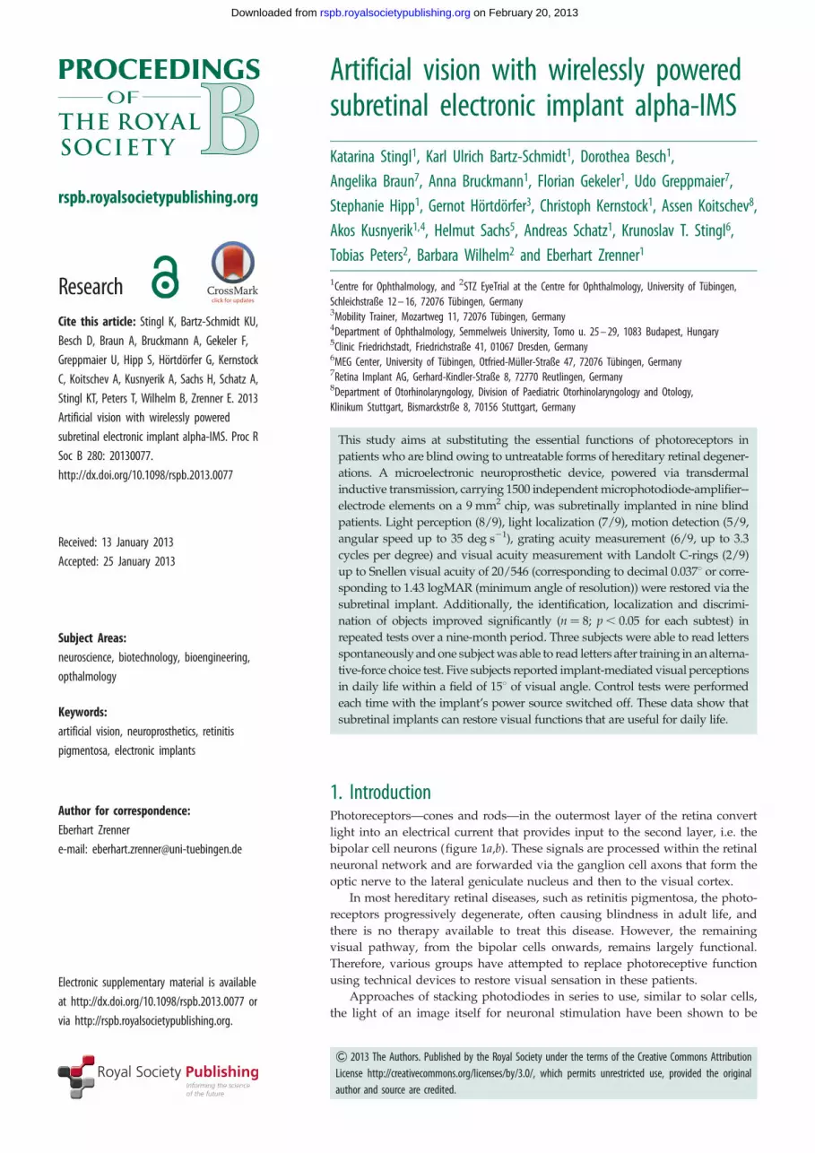
Artificial vision with wirelessly poweredsubretinal electronic implant alpha-IMS
Katarina Stingl1, Karl Ulrich Bartz-Schmidt1, Dorothea Besch1,Angelika Braun7, Anna Bruckmann1, Florian Gekeler1, Udo Greppmaier7,Stephanie Hipp1, Gernot Hortdorfer3, Christoph Kernstock1, Assen Koitschev8,Akos Kusnyerik1,4, Helmut Sachs5, Andreas Schatz1, Krunoslav T. Stingl6,Tobias Peters2, Barbara Wilhelm2 and Eberhart Zrenner1
1Centre for Ophthalmology, and 2STZ EyeTrial at the Centre for Ophthalmology, University of Tubingen,Schleichstraße 12 – 16, 72076 Tubingen, Germany3Mobility Trainer, Mozartweg 11, 72076 Tubingen, Germany4Department of Ophthalmology, Semmelweis University, Tomo u. 25 – 29, 1083 Budapest, Hungary5Clinic Friedrichstadt, Friedrichstraße 41, 01067 Dresden, Germany6MEG Center, University of Tubingen, Otfried-Muller-Straße 47, 72076 Tubingen, Germany7Retina Implant AG, Gerhard-Kindler-Straße 8, 72770 Reutlingen, Germany8Department of Otorhinolaryngology, Division of Paediatric Otorhinolaryngology and Otology,Klinikum Stuttgart, Bismarckstrße 8, 70156 Stuttgart, Germany
This study aims at substituting the essential functions of photoreceptors in
patients who are blind owing to untreatable forms of hereditary retinal degener-
ations. A microelectronic neuroprosthetic device, powered via transdermal
inductive transmission, carrying 1500 independent microphotodiode-amplifier--
electrode elements on a 9 mm2 chip, was subretinally implanted in nine blind
patients. Light perception (8/9), light localization (7/9), motion detection (5/9,
angular speed up to 35 deg s21), grating acuity measurement (6/9, up to 3.3
cycles per degree) and visual acuity measurement with Landolt C-rings (2/9)
up to Snellen visual acuity of 20/546 (corresponding to decimal 0.0378 or corre-
sponding to 1.43 logMAR (minimum angle of resolution)) were restored via the
subretinal implant. Additionally, the identification, localization and discrimi-
nation of objects improved significantly (n¼ 8; p , 0.05 for each subtest) in
repeated tests over a nine-month period. Three subjects were able to read letters
spontaneously and one subject was able to read letters after training in an alterna-
tive-force choice test. Five subjects reported implant-mediated visual perceptions
in daily life within a field of 158 of visual angle. Control tests were performed
each time with the implant’s power source switched off. These data show that
subretinal implants can restore visual functions that are useful for daily life.
1. IntroductionPhotoreceptors—cones and rods—in the outermost layer of the retina convert
light into an electrical current that provides input to the second layer, i.e. the
bipolar cell neurons (figure 1a,b). These signals are processed within the retinal
neuronal network and are forwarded via the ganglion cell axons that form the
optic nerve to the lateral geniculate nucleus and then to the visual cortex.
In most hereditary retinal diseases, such as retinitis pigmentosa, the photo-
receptors progressively degenerate, often causing blindness in adult life, and
there is no therapy available to treat this disease. However, the remaining
visual pathway, from the bipolar cells onwards, remains largely functional.
Therefore, various groups have attempted to replace photoreceptive function
using technical devices to restore visual sensation in these patients.
Approaches of stacking photodiodes in series to use, similar to solar cells,
the light of an image itself for neuronal stimulation have been shown to be

sclerachoroid
vitreous
image
epir
etin
al
subretinal
pupil
retinaganglion cells
amacrine cellshorizontal cells
(a) (b) (c)cones rods
iris
cornea
lens
conjunctiva
maculaoptic nerve
nerve fibresbipolar cells
photoreceptors
Figure 1. Human eye. (a) The structures of the eye and (b) the retinal layers in detail. (c) The function of photoreceptors lost because of hereditary degeneration canbe partially replaced by a subretinal chip. The chip carries a microphotodiode array with amplifiers and electrodes on a 3 mm � 3 mm area and is surgically placedsubretinally in the location corresponding to the layer of degenerated photoreceptors.
(a) (b)
(c) (d )
cable chip
coil
rspb.royalsocietypublishing.orgProcR
SocB280:20130077
2
on February 20, 2013rspb.royalsocietypublishing.orgDownloaded from
feasible in vitro [1]. However, complicated goggles with
high-luminance laser stimulators are necessary for providing
sufficiently bright images to drive such passive light sensors.
While some groups favour an epiretinal [2] or suprachoroidal
[3,4] approach for stimulating primarily ganglion cells, we aimed
to restore visual function in these patients by the means of sub-
retinally implanted microelectronic devices that use light-
sensitive detector arrays and amplifiers to convert light into sig-
nals that can stimulate the bipolar cell neurons [5] via tiny metal
electrodes (figure 1c). Following preclinical work [6–10] and a
clinical pilot trial using a cable-bound implant (2005–2009)
[11,12], we report here the first results from implants equipped
with wireless power and signal transmission (figure 2), which
allows the patients to use the implant at home or outdoors, pro-
viding a diamond-shaped visual field of 158 across chip corners.
Figure 2. The alpha-IMS subretinal implant. (a,b) The subdermal coil behindthe ear provides power and sends control signals via a subdermal cable and athin intraocular foil to the chip in the eye. (c) The chip is placed surgicallybeneath the fovea and contains 1500 pixels (independent microphotodiode-amplifier-electrode elements) on a 3 mm � 3 mm area. Via a thin blackcable, a small battery pack (not shown) powers the primary external coil,(d ) which is magnetically kept in place above the subdermal coil behindthe ear and provides power and signals via transdermal electric induction.
2. Methods(a) Subretinal alpha-IMS visual implantThe implant’s core is an active subretinal chip with 1500 pixels
(see figure 1 and electronic supplementary material, figures S1
and S2). Each pixel has a photodiode, which is used to analyse
the brightness of the incoming light, an amplification circuit
and an electrode for charge transfer to the adjacent retinal
layers. The chip typically records images five to seven times
per second (working frequency of 5–7 Hz, adjustable in a wide
range) and provides the bipolar cells with a ‘point-by-point elec-
trical image’ of the luminance distribution, typically consisting of
1 ms pulses with amplitudes that are correlated with the lumi-
nance at each point. From the bipolar cells onwards, the signal
is processed via the remaining visual pathway. The chip size is
approximately 3 mm � 3 mm and is approximately 70 mm thin
when placed on polyimide foil (thickness approx. 17 mm),
which leaves the subretinal space in the upper temporal periph-
ery through the choroid and the sclera. The foil is connected to
the power supply cable, which, after a loop in the orbit, leads
to the retroauricularly placed subdermal coil (figure 2). Here,
the inductive transfer of energy and control signals from the
skin to the implant are provided via an external coil from a bat-
tery pack in the handheld control unit. This battery pack (see the
electronic supplementary material, figure S3) has two knobs for
adjusting the amplification and the gain of the amplifiers,
thereby adjusting the overall brightness and contrast of the per-
ception according to the particular luminance conditions. This
adjustment is performed by the patient after training and is
based on subjective perception.
The biocompatibility results [8–10,13] as well as the surgical
implantation procedures [14,15] were previously published.
The chip is positioned beneath the foveal region at a prede-
fined position based on optical coherence tomography,
fluorescein angiography and retinal pigment clustering ([16];
figure 2c). The implant provides a diamond-shaped visual field
of 108 � 108, diagonally 158. The implant, called alpha-IMS is
manufactured by Retina Implant AG (Reutlingen, Germany)
with the electronic chip design provided by the Institute for
Microelectronics, Stuttgart (IMS), Germany.
(b) PatientsNine patients (four females, five males) aged 46.9 + 7.2 years
(35–62 years) years participated in the first module, which

60 cm
(a)
S2 S3 S4 S5 S6 S7 S8 S9
(b)
(c)
light yes
yes
no
no
no
yes yes yes yes
yesyes
no
yesno
no
no
3° per sec 7° per sec 5° per sec 5° per sec35° per sec
yes
yes yes
yes
yes
yes
0.33 cpd 0.1 cpd 0.3 cpd 0.5 cpd 3.3 cpd 1.0 cpd
0.01 0.04no no no
no
no
location
motion
grating acuity
Landolt C
Figure 3. Screen tasks. (a) Using a projector-screen set-up*. (b) Light perception threshold, light source localization, motion detection, grating acuity (spatialresolution of periodic stripe pattern) and visual acuity (standardized Landolt C-shaped optotypes) were assessed. A four-alternative-forced-choice mode (4AFC)was applied, except for light perception where a 2AFC was used. (c) Light perception with the implant was possible in eight subjects, light source localizationwas possible in seven subjects, motion detection (angular speed up to 35 deg s21) was possible in five subjects, grating acuity measurement (up to 3.3 cpd) waspossible in six subjects, and visual acuity measurement with Landolt C-rings was possible in two subjects (20/2000 and 20/546, corresponding to gap sizes of 1.68and 0.458 visual angle). At least 75% (in 2AFC) or 62.5% (in 4AFC) correct responses were required to pass the test (‘yes’). *Grating acuity measurement and LandoltC-ring tests were carried out on a table with subject S5 using a set-up similar to that shown in figure 4.
rspb.royalsocietypublishing.orgProcR
SocB280:20130077
3
on February 20, 2013rspb.royalsocietypublishing.orgDownloaded from
completes the monocentric part of a multicentre trial (www.clin-
icaltrials.gov, NCT01024803). The patients received the
subretinal visual implant in one eye (the one with the worst
visual function). Visual function prior to implantation was
light perception without correct light source localization (eight
patients) or complete blindness (no light perception, one patient)
caused by hereditary retinal diseases (eight patients with retinitis
pigmentosa, one patient with cone–rod dystrophy). None of the
subjects had other eye diseases that might affect the visual
pathway. The electronic supplementary material, and table S1
provides more details on the patients’ characteristics.
Written informed consent in accordance with the declaration
of Helsinki was obtained from all the subjects prior to inclusion
in the study.
(c) Efficacy testingAs specified by the study protocol, the following efficacy tests were
performed: (i) standardized screen tasks [17,18], including tests of
visual acuity (figure 3a,b); (ii) table tasks of activities of daily living
(ADL; figure 4c,d); (iii) letter recognition; and (iv) reports of the
experience with the visual implant in daily life. As a control, all
the tests except patient reported use in daily life were administered
in two conditions, implant power source ‘ON’ and ‘OFF’, in a ran-
domized order, and the subjects were masked to the condition.
The other eye was always occluded during the tests. Distance-
corrected refraction was provided for the study eye by means of
regular spectacles. The tasks were performed repeatedly during
up to 18 visits in the nine-month period. A detailed description
and explanation of the testing procedures are the subjects of a
recent publication [19].
(i) Standardized screen tasksFor measurements of the very basic visual functions, the basic
assessment of light and motion test was applied [17]. The subtests
of the test battery are designed as two- or four-alternative-forced-
choice tests measuring (i) light perception threshold in full field
illumination, (ii) light source localization and (iii) motion detection
with a moving random dot pattern (figure 3b).
The standardized basic grating acuity (BaGA) test [20] was used
for grating acuity, also in a two- or four-alternative-forced-choice
mode (at least 12 trials in each test), where a black-and-white striped
pattern was presented at spatial frequencies of 0.1, 0.33, 1.0 and 3.3
cycles per degree (cpd), and the patient was asked to report on the
grid orientation. If a patient passed some, but not all, of the prede-
fined spatial frequencies, we manually applied striped patterns of
0.4, 0.5 cpd, etc., from a POWERPOINT-based presentation. A ratio of
1 : 5 of the thickness of the white : black stripes was used, as this
ratio was generally the most acceptable for the patients.
Subsequently, visual acuity with Landolt C-rings was tested
by an automated Freiburg acuity and contrast test [18] or a
manual POWERPOINT-based presentation of 12 contrast-reversed,
standardized Landolt C-rings for each gap size in four possible
gap directions.
Subject S5 had difficulties if the grating pattern and Landolt
C-rings were presented on the screen. Therefore, for this subject,
we used a paper-grating pattern and paper Landolt C-rings in reverse
contrast on a table (black background). The spatial and visual
resolutions were calculated for the corresponding eye distance.
The dynamic range of the chip’s sensitivity to saturation
spans is approximately two log units and is adjustable within a
luminance range of 1 to 100.000 cd m22. The luminance range
provided by the projector on the screen was adjustable by
means of neutral density filters in steps of 0.15 log units and
ranged between 200 and 2000 cd m22 on the white target and
0.5–20 cd m22 on the background.
(ii) Table tasks of activities of daily livingWe used a standardized approach on a table to document the
identification, discrimination and localization of objects of daily
4.0(a) (b)*
*
*
*
**
score for table tasks of ADL score for table tasks of ADL
3.53.02.52.01.51.00.5
geometric forms:how many?
geometric forms:which?
geometric forms:where?
table setting:how many?
table setting:which?
table setting:where?
mea
n of
sco
res
+ s
.d.
0
(c) (d )
onoff on
off
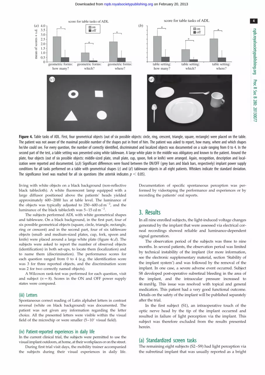
Figure 4. Table tasks of ADL. First, four geometrical objects (out of six possible objects: circle, ring, crescent, triangle, square, rectangle) were placed on the table.The patient was not aware of the maximal possible number of the shapes put in front of him. The patient was asked to report, how many, where and which shapeshe/she could see. For every question, the number of correctly identified, discriminated and localized objects was documented on a scale ranging from 0 to 4. In thesecond part of the test, a table setting was presented using white tableware. A large white plate in the middle was obligatory and known to the patient. Around theplate, four objects (out of six possible objects: middle-sized plate, small plate, cup, spoon, fork or knife) were arranged. Again, recognition, description and local-ization were reported and documented. (a,b) Significant differences were found between the ON/OFF (grey bars and black bars, respectively) implant power supplyconditions for all tasks performed on a table with geometrical shapes (c) and (d ) tableware objects in all eight patients. Whiskers indicate the standard deviation.The significance level was reached for all six questions (the asterisk indicates p , 0.05).
rspb.royalsocietypublishing.orgProcR
SocB280:20130077
4
on February 20, 2013rspb.royalsocietypublishing.orgDownloaded from
living with white objects on a black background (non-reflective
black tablecloth). A white fluorescent lamp equipped with a
large diffusor positioned above the patients’ heads yielded
approximately 600–2000 lux at table level. The luminance of
the objects was typically adjusted to 250–600 cd m22, and the
luminance of the black tablecloth was 5–15 cd m22.
The subjects performed ADL with white geometrical shapes
and tableware. On a black background, in the first part, four of
six possible geometrical objects (square, circle, triangle, rectangle,
ring or crescent) and in the second part, four of six tableware
objects (small- and medium-sized plates, cup, fork, spoon and
knife) were placed around a large white plate (figure 4c,d). The
subjects were asked to report the number of observed objects
(identification) in both set-ups, to locate them (localization) and
to name them (discrimination). The performance scores for
each question ranged from 0 to 4 (e.g. the identification score
was 3 for three reported objects, and the discrimination score
was 2 for two correctly named objects).
A Wilcoxon rank-test was performed for each question, visit
and subject (n ¼ 8). Scores in the ON and OFF power supply
states were compared.
(iii) LettersSpontaneous correct reading of Latin alphabet letters in contrast
reversal (white on black background) was documented. The
patient was not given any information regarding the letter
choice. All the presented letters were visible within the visual
field of the microchip or were smaller (5–108 visual field).
(iv) Patient-reported experiences in daily lifeIn the current clinical trial, the subjects were permitted to use the
visual implant outdoors, at home, at their workplaces or on the street.
During first trial visit days, the mobility trainer accompanied
the subjects during their visual experiences in daily life.
Documentation of specific spontaneous perception was per-
formed by videotaping the performance and experiences or by
recording the patients’ oral reports.
3. ResultsIn all nine enrolled subjects, the light-induced voltage changes
generated by the implant that were assessed via electrical cor-
neal recordings showed reliable and luminance-dependent
signal generation.
The observation period of the subjects was three to nine
months. In several patients, the observation period was limited
by technical instability of the implant (for more information,
see the electronic supplementary material, section ‘Stability of
the implant system’) and was followed by the removal of the
implant. In one case, a severe adverse event occurred. Subject
S8 developed post-operative subretinal bleeding in the area of
the implant, and the intraocular pressure increased to
46 mmHg. This issue was resolved with topical and general
medication. This patient had a very good functional outcome.
Details on the safety of the implant will be published separately
after the trial.
In the first subject (S1), an intraoperative touch of the
optic nerve head by the tip of the implant occurred and
resulted in failure of light perception via the implant. This
subject was therefore excluded from the results presented
herein.
(a) Standardized screen tasksThe remaining eight subjects (S2–S9) had light perception via
the subretinal implant that was usually reported as a bright

rspb.royalsocietypublishing.orgProcR
SocB280:20130077
5
on February 20, 2013rspb.royalsocietypublishing.orgDownloaded from
tilted square when looking at a homogeneously illuminated
area. Light perception thresholds improved in the power ON
compared with the power OFF state in all eight subjects (S2–
S9). Seven subjects were able to localize a light wedge (figure
3b) on the screen, and five subjects were able to detect the
motion of dot patterns (figure 3b) with an angular speed of
up to 35 deg s21. Grating acuity was successfully measured
in six subjects, with a maximum of 3.3 cpd. Visual acuity
was assessable with standardized Landolt C-rings in two sub-
jects with the following results: 0.01 and 0.037 (decimal),
corresponding to 20/2000 and 20/546 Snellen acuity or
visual angles of 1.68 and 0.458, or log(MAR) 2 and 1.43 respect-
ively. The best function for each subject, as well as the set-up
for the screen tasks, is presented in figure 3.
Light localization, motion detection, grating acuity and
Landolt C-rings tasks failed to achieve significant response
rates when the power supply was switched off.
(b) Table tasks of activities of daily livingFor all the following tasks, significant differences between the
power ON and OFF scores were found: geometrical shape
identification ( p ¼ 0.012), discrimination ( p ¼ 0.018) and
localization ( p ¼ 0.012) and tableware object identification,
discrimination and localization ( p ¼ 0.012 each), as illustrated
in figure 4a,b.
(c) Recognition of lettersThree subjects (S2, S6 and S8) were able to read at least
several letters (e.g. T, V, L, I, O) spontaneously. Subject S4
needed some training to correctly discriminate among three
letters in a three-alternative-forced-choice test. The patients
reported seeing the letters as complete entities.
(d) Patient reports of experiences in daily lifeIn the current implant, no colour vision is available. As all the
microphotodiodes have equal spectral sensitivity, the electro-
des address all three retinal cone pathways simultaneously.
Five of the eight subjects (S2, S4, S5, S6 and S8) reported various
implant-mediated visual perceptions in daily life [21]. In the
near-vision range, the most relevant reports included the recog-
nition of facial characteristics, such as mouth shapes (smiles) or
the presence/absence of glasses, and differentiation between
the contours of people and clothing patterns (striped patterns,
black jacket versus white shirt). At home or at work, it was poss-
ible to visually localize or distinguish objects, such as telephones,
cutlery, parts of the meal (light noodles versus dark beef), red
wine versus white wine, and other objects, including door
knobs, signs on doors, washbasins or wastebaskets.
In the far-vision range, the most frequently reported per-
ception was finding the line of the horizon and objects along
the horizon, such as houses or trees. A river was described as
a bright, reflecting stripe. Cars on the street were localized on
the basis of bright reflections from their surfaces; the same
was true of glass windows in general. One patient reported
recognizing stopping and moving cars at night due to their
headlights, as well as recognition of the course of the street
according to the alignment of the streetlights. Another patient
reported seeing the contours of the heads of his colleagues
during a work meeting. Other objects of appropriate contrast
and size (within the 108–158 visual field) were also recog-
nized, such as a dark, square-shaped carpet in the next
room, the stalk of a sunflower or a white goose swimming
in a certain direction. One patient was able to read the letters
of restaurant signs and store names.
Short movie sketches of some of the experiences are
available via the electronic supplementary material, video S1.
(e) Safety commentThe implantation surgery was successful in all cases with
regards to placing the implant subretinally on the posterior
eye pole. The intraoperative touch of the optic nerve in the
first subject and one serious adverse event (subretinal post-
operative bleeding with an increase of intraocular pressure
up to 43 mmHg in S8, which was resolved without sequelae)
present relevant complications of the technique in the pre-
sented group of patients. A detailed description of safety is
discussed in a separate publication.
4. DiscussionThis study showed that a subretinal implant can restore var-
ious visual functions in blind patients with hereditary retinal
degeneration, as proved by standardized psychophysical
laboratory testing, as well as by the subjects’ own reports of
their daily living activities and by observations of their
performance indoors and outdoors.
So far, our approach using subretinal electronic implants
is the only one that has successfully mediated images in a
trial with freely moving blind persons by means of a light
sensor array that moves with the eye. All the other current
approaches require an extraocular camera that does not link
image capture to eye movements, which, therefore, does
not allow the utilization of microsaccades for refreshing the
perceived images. Although the restoration of vision
described here is limited, blind persons with no alternative
therapy options regard this type of artificial vision as an
improvement in everyday life.
(a) Light and movement perceptionLight perception via the implant was possible in all subjects
except S1 (mentioned earlier) during the standardized tasks
with full field stimulation. If full field light stimulation on
the chip is applied, a tilted homogeneous white-yellowish
square with an approximately 158 diagonal visual field is per-
ceived. This field corresponds to the slightly tilted placing of
the chip on the posterior pole of the eye. Parts of this visual
area may be missing if retinal holes, insufficient vasculariza-
tion of the overlying retina (retinal ischemia is a hallmark of
hereditary retinal disease), or an intrinsic inability of the
retina to process electrical signals owing to degenerative pro-
cesses are present, as observed in subject S3. To overcome this
difficulty as best we could, we developed a pre-operative
planning procedure for optimal chip positioning on the
fundus [16]. However, even with a smaller visual field,
some fairly challenging tasks were performed correctly.
Image perception with the chip has a ‘blinking’ character-
istic owing to the working frequency of the implant. In the
majority of the subjects, this frequency was set to 5 Hz, mean-
ing that image capture takes place five times per second with a
1 ms duration. However, some subjects preferred a higher fre-
quency (up to 15 Hz) for more continuous perception. Two
subjects could use frequencies of only 1–2 Hz because their

rspb.royalsocietypublishing.or
6
on February 20, 2013rspb.royalsocietypublishing.orgDownloaded from
images faded quickly at higher frequencies. This phenomenon
may have been owing either to individual variances in neur-
onal refractory time during the electrical stimulation of a
degenerated retina or to altered microsaccades that help to
maintain stable perception in the healthy eyes.
Movement detection with the implant is limited not only by
not fully restored retinal processing mechanisms but also by
the working frequency of the device. Currently, the maximum
recognizable speed is 358 per second, which is comparable to
that of a car moving at 22 km h21 at a distance of 10 m.
gProcR
SocB280:20130077
(b) Visual acuityPreclinical work [6] has shown that spatial resolution of electri-
cal stimuli on the retina closer than 50 mm will be difficult
to achieve. Assuming that 18 of visual angle corresponds to
280 mm of retinal distance [22,23], the density of the sensors
(70 mm � 70 mm) is approximately four sensors per degree,
resulting in a maximum decimal visual acuity of 0.06–0.08
(depending on the axial eye length). A visual acuity of 0.4 is
needed for normal reading without visual aids, and a visual
acuity of approximately 0.1 is needed for self-sustained orien-
tation and navigation [24]. Values below 0.3 are considered
‘low vision’, and a visual acuity of less than 0.02 is defined as
blindness according to German law. Therefore, our chip is
technically able to transform blindness into low vision.
When we asked our subjects about the quality of the arti-
ficial vision, they described blurred images of the world in
grey tones, which is reminiscent of unfocused images from
an older black-and-white television set.
Grating acuity, in which the examinee is asked to identify
the direction of stripes in a pattern (horizontal, etc.), is valuable
for measuring spatial frequency resolution. In contrast to
visual acuity, which is measured classically by optotypes
such as letters, numbers or Landolt C-rings, grating acuity
uses a larger field of view and is therefore measurable inde-
pendently of foveal function or the recognition of optotypes
and thus may provide the best general description of retinal
resolution in artificial vision. A healthy human eye can resolve
up to 30 grating periods within 18 of visual angle (30 cpd).
Except for subjects S2 and S3, a grating acuity test was possible
in all subjects in our trial, only two of whom achieved visual
acuity with standard optotypes when using the implant
(Landolt C-rings). S2 had a narrowed area of perception
owing to a retinal hole, which may have led to failure in the
grating acuity test. Instead of a periodic stripe pattern, she
was able to differentiate a single stripe direction of 0.58visual angle; however, owing to scatter, the image of the line
on the retina may have been broader. S3 had generally weak
perception via the implant and could use it only at a frequency
of 1–2 Hz owing to fading of the image at higher frequencies.
The 3.3 cpd correctly recognized by subject S8 represents
the limit of resolution that is possible with the subretinal chip
currently in use. A conversion of 3.3 cpd to decimal visual
acuity yields 0.1. We are treating this value with caution
because it may be achievable only in special circumstances.
The chip has four rows of electrodes per degree and, accord-
ing to the Nyquist–Shannon sampling theorem, only half of
this value, i.e. 2 cpd, can be resolved with certainty. Aliasing
effects may arise if the spatial frequency of the grating is
higher than that of the electrodes, causing perception of a
lower-frequency pattern (Moire effect), which then can be
distinguished correctly.
The standard visual acuity as measured by Landolt
C-rings in our trial was as high as 0.037 decimal (20/546)
and was reproducible. Visual acuity with Landolt C-rings is
derived from the visual angle of gap size in the ‘C’ ring.
A visual acuity of 0.037 corresponds to a visual angle of
0.458 or a retinal distance of 126 mm, indicating that a seg-
ment of 1.8 subretinal sensors is sufficient for perception of
the gap in the Landolt ring. Only three subjects succeeded
in spontaneously reading letters. Surprisingly, this was not
directly related to successful performance in the Landolt
C-ring test, possibly because the gap in the Landolt ring is
smaller than the gaps in regular letters.
(c) Activities in daily lifeConcerning the table tasks of activities in daily life, there was
a significant improvement in visual function when the
implant was activated. However, the degree of success dif-
fered from one subject to another. The detection of objects
and their localization (‘how many?’ and ‘where?’) was more
easily accomplished than shape recognition. Clearly, dis-
crimination of objects requires a larger area of available
visual field than localization and some useable spatial
resolution. Subjects S3 and S7 practically failed in this task
because both experienced pronounced fading, i.e. their
implants allowed for non-fading perception at only 1 Hz
within a reduced visual area.
An adjustment in chip sensitivity is possible across a wide
range of luminance, from 1 to 100.000 cd m22, which allows
most patients to use the implant at night time and in dimly
illuminated rooms, as well as outside on a bright sunny
day. In the laboratory, for tests at the table, an object lumi-
nance of approximately 2000 cd m22 was chosen according
to the study plan. This relatively high value has three
advantages: first, during screening for inclusion all patients
undergo the same test to check the inclusion criterion
‘visual functions not appropriate for localization of objects,
self-sustained navigation and orientation’ at high contrast
levels; second, as high light levels can directly stimulate
photosensitive melanopsin-containing ganglion cells, testing
at high luminance levels excludes spatial perception in our
subjects via such ganglion cells during screening; and third,
some implants produce stronger perception and some pro-
duce weaker perception, depending on individual retinal
states. At high-illumination levels with good contrast, the
implants can be tested in comparable conditions, as chip
sensitivity can easily be downregulated.
Five subjects reported useable visual experiences in daily
life with the implant. They found this the most important and
rewarding aspect. Only subjects S3 and S7 were unable to use
the implant in daily life due to fading. S9 did not reach a sub-
jectively relevant level of visual function in daily life, despite
good results in the standardized tests.
(d) Other current approaches in humansWorldwide, several approaches to vision restoration via elec-
tronic implants are currently being tested [25–28]. Implants
are under development that localize the electrical stimulation
to subretinal [11,29–31], epiretinal [2] or suprachoroidal [3,4]
space, or to cortical [32] or optic nerve [33] neurons. Not all of
these devices have yet reached the clinical trial stage; cur-
rently, only the epiretinal Argus II (Second Sight Medical
Products Inc.) prosthesis, which has received the CE mark
rspb.royalsocietypublishing.orgProcR
SocB280:20130077
7
on February 20, 2013rspb.royalsocietypublishing.orgDownloaded from
(conforms with European Community legislative require-
ments such as safety) for use in Europe, and the subretinal
alpha-IMS (Retina Implant AG) implant have been the
subjects of long-term clinical studies.
The epiretinal prosthesis uses an external camera affixed
to spectacles. It transfers a decoded electrical signal directly
to the ganglion cells, the third visual pathway neurons, via
60 electrodes. This approach does not primarily involve the
bipolar cells. Because the epiretinal array consists only of elec-
trodes and has no light-sensitive elements, it does not require
a clear cornea or lens. Accommodation and magnification are
accomplished by zooming in the camera system, which
can improve visual perception if focused on details [2].
Another advantage of the epiretinal approach is easier surgi-
cal insertion; the median implant surgery time is 4 h [2]
compared with 6–8 h in the case of the subretinal implant.
The epiretinal system has also shown long-term stability in
the follow-ups of patients wearing the epiretinal prosthesis
for up to 2.7 years [2]. By contrast, there are other advan-
tages of subretinal implants. The epiretinal approaches
bypass the neurons of the middle retinal layer, whereas sub-
retinal implants make use of the natural processing power of
the bipolar and amacrine cells that process a substantial
amount of visual information, such as motion and contrast.
The use of an external camera eliminates the chance of
using natural eye movements, which are important not only
for visual search but also for preventing image fading on the
retina through small involuntary eye movements that refresh
images during visual perception. Thus, patients with an exter-
nal camera may require continuous head movements to avoid
image fading. Patients with subretinal light-sensitive implants,
however, perceive the shapes of objects naturally from the first
day of implantation onwards without reorganization of the
spatial assignments of electrodes by an image processor and
without scanning movements of the head. Our subretinal
approach with autonomously functioning pixels allows a
high electrode density of 1500 electrodes versus 60 electrodes
in the epiretinal approach.
5. SummaryThis monocentric study has shown that the wirelessly driven
implant alpha-IMS, positioned in the subfoveolar subretinal
space can restore useful vision in daily life for at least two-
thirds of the blind patients investigated. The multicentre
phase of the clinical study of the subretinal implant alpha-
IMS (Retina Implant AG) has already begun at additional
centres in Oxford, Hong Kong, London, Budapest and
other centres. In particular, long-term stability and safety,
as well as the development of visual recognition abilities
via learning effects, over a longer observation period will
be addressed in future patients who receive this implant.
The study was approved by the local ethics committee and was carriedout according to the German medicinal product law and EN ISO 14155.
The authors thank the staff of the Retina Implant AG, Reutlingen,Germany, especially W. Wrobel, R. Rubow, A. Hekmat, A. Harscher,S. Kibbel, R. Rudorf, C. Eipper, C. Jansen, M. Kokelmann, G. Blaess,H. Wagner and E. Nestler for organizational background support inthe trial and R. Hofer for graphical design. This work was supportedby Retina Implant AG, Reutlingen, Germany. This study is also partof the research programme of the Bernstein Center for ComputationalNeuroscience, Tubingen and was funded by the German Federal Min-istry of Education and Research (BMBF; FKZ: 01GQ1002).
References
1. Mathieson K et al. 2012 Photovoltaic retinalprosthesis with high pixel density. Nat. Photonics 6,391 – 397. (doi:10.1038/nphoton.2012.104)
2. Humayun MS et al. 2012 Interim results fromthe international trial of second sight’s visualprosthesis. Ophthalmology 119, 779 – 788.(doi:10.1016/j.ophtha.2011.09.028)
3. Ohta J et al. 2007 Laboratory investigation ofmicroelectronics-based stimulators for large-scalesuprachoroidal transretinal stimulation (STS). J. NeuralEng. 4, S85 – 91. (doi:10.1088/1741-2560/4/1/S10)
4. Guenther T, Lovell NH, Suaning GJ. 2012Bionic vision: system architectures: a review.Expert Rev. Med. Devices 9, 33 – 48. (doi:10.1586/erd.11.58)
5. Eickenscheidt M, Jenkner M, Thewes R, Fromherz P,Zeck G. 2012 Electrical stimulation of retinalneurons in epiretinal and subretinal configurationusing a multicapacitor array. J. Neurophysiol. 107,2742 – 2755. (doi:10.1152/jn.00909.2011)
6. Stett A, Barth W, Weiss S, Haemmerle H, Zrenner E.2000 Electrical multisite stimulation of the isolatedchicken retina. Vision Res. 40, 1785 – 1795. (doi:10.1016/S0042-6989(00)00005-5)
7. Fromherz P, Stett A. 1995 Silicon-neuron junction:capacitive stimulation of an individual neuron on a
silicon chip. Phys. Rev. Lett. 75, 1670 – 1673.(doi:10.1103/PhysRevLett.75.1670)
8. Schwahn H, Gekeler F, Kohler K, Kobuch K, SachsHG, Schulmeyer F, Jakob W, Gabel VP, Zrenner E.2001 Studies on the feasibility of a subretinal visualprosthesis: data from Yucatan micropig and rabbit.Graefe’s Arch. Clin. Exp. Ophthalmol. 239, 961 – 967.(doi:10.1007/s004170100368)
9. Kohler K, Hartmann JA, Werts D, Zrenner E. 2001Histological studies of retinal degeneration andbiocompatibility of subretinal implants. Ophthalmologe98, 364 – 368. (doi:10.1007/s003470170142)
10. Guenther E, Troger B, Schlosshauer B, Zrenner E.1999 Long-term survival of retinal cell cultures onretinal implant materials. Vision Res. 39, 3988 –3994. (doi:10.1016/S0042-6989(99)00128-5)
11. Zrenner E et al. 2011 Subretinal electronic chipsallow blind patients to read letters and combinethem to words. Proc. R. Soc. B 278, 1489 – 1497.(doi:10.1098/rspb.2010.1747)
12. Stingl K et al. 2010 Subretinal electronic chips canrestore useful visual functions in blind retinitispigmentosa patients. Biomed. Tech. (Berl.) 55,(Suppl. 1). (doi:10.1515/BMT.2010.435)
13. Gekeler F et al. 2007 Compound subretinalprostheses with extra-ocular parts designed for
human trials: successful long-term implantation inpigs. Graefes Arch. Clin. Exp. Ophthalmol. 245,230 – 241. (doi:10.1007/s00417-006-0339-x)
14. Besch D, Sachs H, Szurman P, Gulicher D, Wilke R,Reinert S, Zrenner E, Bartz-Schmidt KU, Gekeler F.2008 Extraocular surgery for implantation of anactive subretinal visual prosthesis with externalconnections: feasibility and outcome in sevenpatients. Br. J. Ophthalmol. 92, 1361 – 1368.(doi:10.1136/bjo.2007.131961)
15. Sachs H, Bartz-Schmidt KU, Gabel VP, Zrenner E,Gekeler F. 2010 Subretinal implant: the intraocularimplantation technique. Nova Acta Leopoldina NF III379, 217 – 223.
16. Kusnyerik A et al. 2012 Positioning of electronicsubretinal implants in blind retinitis pigmentosapatients through multimodal assessment ofretinal structures. Invest. Ophthalmol. Vis. Sci. 53,3748 – 3755. (doi:10.1167/iovs.11-9409)
17. Bach M, Wilke M, Wilhelm B, Zrenner E, Wilke R. 2010Basic quantitative assessment of visual performance inpatients with very low vision. Invest. Ophthalmol. Vis.Sci. 51, 1255 – 1260. (doi:10.1167/iovs.09-3512)
18. Bach M. 1996 The Freiburg visual acuity test: automaticmeasurement of visual acuity. Optom. Vis. Sci. 73,49 – 53. (doi:10.1097/00006324-1996 01000-00008)

rspb.royalsocietypublishing.orgProcR
SocB280:20130077
8
on February 20, 2013rspb.royalsocietypublishing.orgDownloaded from
19. Stingl K et al. 2013 Safety, efficacy of subretinalvisual implants in humans: methodological aspects.Clin. Exp. Opt. 96, 4 – 13. (doi:10.1111/j.1444-0938.2012.00816.x)
20. Wilke R, Bach M, Wilhlem B, Durst W, Trauzettel-Klosinski S, Zrenner E. 2008 Testing visual functionsin patients with visual prostheses. Artificial Sight.(doi:10.1007/978-0-387-49331-2_5)
21. Stingl K et al. 2012 What can blind patients see indaily life with the subretinal alpha-IMS implant?Current overview from the clinical trial in Tubingen.Ophthalmologe 109, 136 – 141. (doi:10.1007/s00347-011-2479-6)
22. Drasdo N, Fowler C. 1974 Non-linear projection ofthe retinal image in a wide-angle schematic eye.Br. J. Ophthalmol. 58, 709 – 14. (doi:10.1136/bjo.58.8.709)
23. Hirsch J, Curcio CA. 1989 The spatial resolutioncapacity of human foveal retina. Vision Res. 29,1095 – 1101. (doi:10.1016/0042-6989(89)90058-8)
24. Trauzettel-Klosinski S. 2009 Rehabilitation of lesionsin the visual pathways. Klin. Monbl. Augenheilkd.226, 897 – 907. (doi:10.1055/s-0028-1109874)
25. Zrenner E. 2002 Will retinal implants restore vision?Science 295, 1022 – 1025. (doi:10.1126/science.1067996)
26. Zrenner E. 2012 Artificial vision: solar cells for theblind. Nat. Photonics 6, 344 – 345. (doi:10.1038/nphoton.2012.114)
27. Rizzo JF et al. 2001 Retinal prosthesis: anencouraging first decade with major challengesahead. Ophthalmology 108, 13 – 14. (doi:10.1016/S0161-6420(00)00430-9)
28. Weiland JD, Cho AK, Humayun MS. 2011 Retinalprostheses: current clinical results and future needs.Ophthalmology 118, 2227 – 2237. (doi:10.1016/j.ophtha.2011.08.042)
29. Stingl K, Greppmaier U, Wilhelm B, Zrenner E. 2010Subretinal visual implants. Klin. Monbl. Augenheilkd.227, 940 – 945. (doi:10.1055/s-0029-1245830)
30. Rizzo 3rd JF et al. 2011 Overview of the Bostonretinal prosthesis: challenges and opportunities torestore useful vision to the blind’. Conf. Proc. IEEEEng. Med. Biol. Soc. 2011, 7492 – 7495. (doi:10.1109/IEMBS.2011.6093610)
31. Chow AY, Bittner AK, Pardue MT. 2010 Theartificial silicon retina in retinitis pigmentosapatients (an American OphthalmologicalAssociation thesis). Trans. Am. Ophthalmol. Soc.108, 120 – 154.
32. Schmidt EM, Bak MJ, Hambrecht FT, Kufta CV,O’Rourke DK, Vallabhanath P 1996 Feasibility of avisual prosthesis for the blind based on intracorticalmicrostimulation of the visual cortex. Brain 119,507 – 522. (doi:10.1093/brain/119.2.507)
33. Brelen ME, Vince V, Gerard B, Veraart C, Delbeke J.2010 Measurement of evoked potentials afterelectrical stimulation of the human optic nerve.Invest. Ophthalmol. Vis. Sci. 51, 5351 – 5355.(doi:10.1167/iovs.09-4346)