apartment operations and maintenance manual - melbourne
TRANSCRIPT
Apartment Operations and Maintenance Manual
PROBUILD-39-375-2.0 Page 1
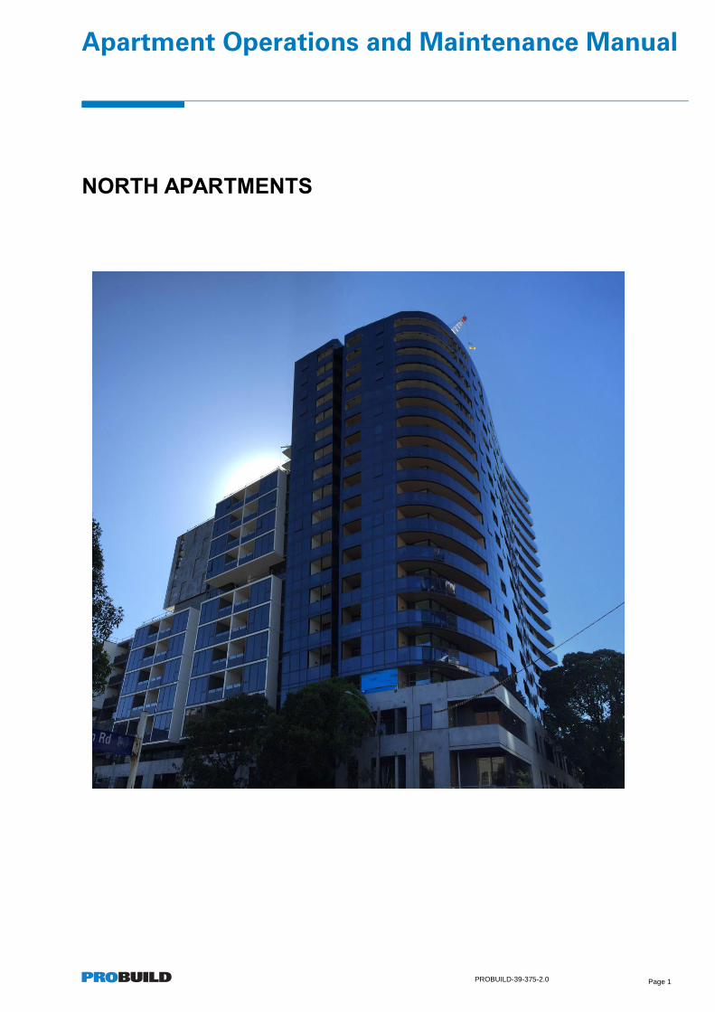
NORTH APARTMENTS
Apartment Operations and Maintenance Manual
PROBUILD-39-375-2.0 Page 2
Contents
NORTH APARTMENTS 1
1.0 INTRODUCTION 5
2.0 SAFETY IN YOUR APARTMENT 6
2.1. Emergency Evacuation Procedure 6
2.2. Fire System 6
2.3. Emergency Lighting System 6
2.4. Balcony and Terrace Furniture 6
2.5. Car Park Entry/Exit 6
3.0 OPERATION OF YOUR APARTMENT 7
3.1. General Notes on Warranties 7
3.2. Cleaning and Maintenance 7
3.3. Condensation in Apartments 8
3.4. Drainage System 8
4.0 APPLIANCES 9
4.1. Cook Top (Gas) 9
4.2. Oven 9
4.3. Range Hood 9
4.4. Dishwasher 10
4.5. Air Conditioning 10
5.0 SYSTEMS 11
5.1. Bathroom & Laundry Exhaust 11
5.2. Kitchen Exhaust 11
5.3. Switchboard 11
5.4. TV Connections 12
5.5. Phone and Data Connections (NBN) 12
5.6. Sprinkler System 12
5.7. Smoke Detectors 12
5.8. Thermal Detectors 12
5.9. Hose Reels / Fire Extinguishers / Fire Hydrants / Fire Escape Doors 13
5.10. Garbage Disposal 13
5.11. Security System – Remotes, Fobs and Keys 13
5.12. Pedestrian Access and Intercom System 14
6.0 FITTINGS AND FIXTURES 15
Apartment Operations and Maintenance Manual
PROBUILD-39-375-2.0 Page 3
6.1. Light Fittings 15
6.2. Hot Water System 15
6.3. Cold Water 15
6.4. Laundries 15
6.5. Carpet 15
6.6. Painted Surfaces 16
6.7. Inter-tenancy Walls: 17
6.8. Kitchen and Bathroom Joinery 17
6.9. Bedroom Wardrobes 18
6.10. Stone Bench tops & Splashbacks 18
6.11. Shower Screens 19
6.12. Mirrors 19
6.13. Tiled Surfaces 20
6.14. Timber Floors 20
6.15. Hardware 21
7.0 WINDOWS AND BALCONIES 22
7.1. Windows, Glazed sliding, Glazed swing and Aluminium Window Frames 22
7.2. Curtain Wall Glazing – North Tower 22
7.3. Winter Gardens, Balconies and Terraces 23
8.0 MISCELLANEOUS 25
8.1. Storage Cages 25
8.2. Bike Racks 25
8.3. Pool, Sauna, Gym and Changerooms 25
9.0 SUSTAINABLILITY 26
9.1. Master Off Ceiling Light Switch 26
9.2. Rainwater Collection System 26
9.3. Solar Power 26
9.4. Energy Monitoring 26
10.0 FAULT OR ISSUE RESOLUTION 27
10.1. What to do if I have a fault or issue? 27
10.2. Appliance fault or issue? 27
10.3. Other fault or issue. 27
10.4. Fault Rectification Process / Issue ID user manual 27
11.0 ISSUES ID USER MANUAL 28
12.0 ISSUE NOTIFICATION PROCESS 30
Apartment Operations and Maintenance Manual
PROBUILD-39-375-2.0 Page 4
13.0 APPENDIX 31
13.1. Electricity and Hot Water Supply – WINEnergy 31
13.2. Phone and Internet Connections – NBN Users Guide 31
13.3. Rangehood Operation Manual 31
13.4. Cooktop Operation Manual 31
13.5. Oven Operation Manual 31
13.6. Air Conditioner Manual 31
13.7. Intercom Manual 31
13.8. Apartment Smoke Detector Technical Data Sheet 31
13.9. Material Finishes Schedule 31
Apartment Operations and Maintenance Manual
PROBUILD-39-375-2.0 Page 5
1.0 INTRODUCTION
Welcome to your new apartment at North, 23-33 Blackwood St, North Melbourne 3051, developed by United Asia
Group, designed by SJB Architects and constructed by Probuild Pty Ltd. There are 449 apartments over 19 levels
with retail on ground floor and a 3 level basement carpark. In addition, North Apartments also incorporates
consulting suites on level 1 and Leukaemia Foundation ‘Building of Hope’ on part of level 2, both accessed from
Flemington Road.
The apartments have been designed to maximise natural light, provide both spacious open plan living areas and
complement an inner city lifestyle with contemporary building amenities.
The purpose of this Operations and Maintenance Manual is to provide you with information on your new home to
make the transition to living at North Apartments as smooth and as enjoyable as possible.
In this document you will find useful information on your apartment features including basic appliance operation and
important warranty information, fixture and finishes care and maintenance instructions, local area contacts and
building management. Living in an apartment community may be a new experience for some of the residents, so
we invite you to read through this manual carefully as it contains many responses to frequently asked questions
applicable to high rise buildings.
First time apartment residents are often not aware of certain aspects of apartment living that, in some instances,
can be dangerous to yourself and/or others. Please familiarise yourself with the emergency evacuation procedure in
the safety section of this manual. Pay particular attention when entering and exiting through the car park, pressure
differences when opening and closing doors/windows and strong wind gusts on balconies, which can blow outdoor
furniture into glass or over balustrades.
The nature of apartment living may mean you are exposed to new and different sounds in your apartment, which
may take a period of adjustment. Examples include noise from outside, from other apartments, or from mechanical
systems such as lifts and vents. Your apartment has been designed and tested by an acoustic professional to
ensure partitions and systems are within acceptable limits. Exercise common courtesy throughout the building,
particularly when moving around communal areas or when making use of your balcony; excessive inhabitant noise
is not acceptable by law. Please make yourself aware of owner corporation by-laws relating to the ‘quiet enjoyment’
and ‘noise pollution’ in and around your apartment. You should contact your Building Manager for guidance in the
case of excessive noise.
Your apartment is your responsibility, however if an issue arises which is not referred to in this manual and it is not
able to be resolved, then the Building Manager may be able to assist. Please note that the Building Manager’s
responsibility is to manage the common property.
Common facilities available for the exclusive use of residents include the ground floor garden, gym and sauna,
together with the Pool and BBQ area located on level 6. Refer to the Building Management and Owners
Corporatation rules for further details.
Accordingly, you will need to have your own insurance policy, be it either a householders / landlord’s or Tenants
policy in order to cover your fittings and contents. You should ensure that this policy covers your legal liability within
your apartment.
In all cases with faults or other issues / queries related to your apartment or the complex contact the
Building Manager first who will assist to rectify the situation.
Apartment Operations and Maintenance Manual
PROBUILD-39-375-2.0 Page 6
2.0 SAFETY IN YOUR APARTMENT
2.1. Emergency Evacuation Procedure
To report an emergency, call “000” on any fixed or mobile phone.
You are advised to familiarise yourself with emergency exits and review the Emergency Evacuation Plan included
in your Apartment Pack. You may wish to display this plan up in your apartment for future reference.
In the event of an emergency, listen for the following audible notifications to know when to evacuate:
– “Beep, Beep, Beep” - Wait in your apartment, but prepare to evacuate.
– “Whoop, Whoop, Whoop, Emergency, Evacuate Now” - Evacuate the building.
Evacuation speakers are located throughout the building, including one speaker in every bedroom.
Evacuate via the emergency exit stairs. Do not use the lift in the event of a fire.
2.2. Fire System
The central fire alarm can be activated by one of the following:
– Sprinkler head activation in apartments, common areas or car park;
– Thermal and/or smoke detector activated in a common area;
– Fire manual call point (Break Glass) located in common areas;
The Fire Brigade will be called automatically if the central fire alarm is activated.
The audible smoke detectors in your apartment lounge and bedrooms will not activate the central fire alarm and the
fire brigade will not be called.
2.3. Emergency Lighting System
Battery powered backup lighting will activate in the common area lobbies in the event of a power outage. There are
no emergency lights in your apartment. Keep a battery torch in an accessible place of your apartment i.e. kitchen
drawer, for use in the event of a power outage. You need only evacuate the building during a power failure if the
evacuation alarm sounds.
2.4. Balcony and Terrace Furniture
Apartment buildings from time to time are exposed to strong wind gusts and updrafts. Strong wind gusts have been
known to move and uplift furniture and other items on balconies and terrace areas. This can create a potential risk
to people and property from falling objects.
It is recommended that all outdoor furniture is secured to prevent movement from uplift by wind and also to exercise
care to avoid leaving any item on a balcony which may be susceptible to wind. Residents are reminded of their Duty
of Care to ensure the safety of other occupants and the general public. If mechanical fixings are intended to secure
anything on balconies they must be properly installed by a qualified tradesman to ensure that waterproof
membranes etc. are not compromised or damaged. Please consult with the Building Manager and Owners
Corporation and ensure written approval is issued before any such fixings are installed.
2.5. Car Park Entry/Exit
The car park entry is a high frequency traffic area at North. With 280 car parks and 139 bicycle spaces all using the
car park entry on Blackwood Street, it is very important to exercise caution when moving through the industrial tilt
door. Do not ‘tail-gate’ other vehicles entering and exiting the car park and be alert for pedestrians and cyclists
Apartment Operations and Maintenance Manual
PROBUILD-39-375-2.0 Page 7
3.0 OPERATION OF YOUR APARTMENT
3.1. General Notes on Warranties
Strict adherence to the operating and maintenance requirements noted in this manual, as well as appliance
operating manuals included in the apartment packs, will ensure the useful and proper operating life of your
appliances and systems. Strict adherence will also ensure applicable levels of cover and periods of manufacturer
warranties will not be voided.
It should be noted that Probuild’s (Builder) warranty does not cover the following:
– Any defects resulting from overloading, misuse, negligence, accident or other cause beyond the direct control of
Probuild. Refer to the Probuild Body Corporate Operation and Maintenance manuals for details of allowable
structural loadings etc.;
– Any defects resulting from the installation of any accessories or options undertaken by others;
– Any rectification, modification or other work required due to alterations performed by others;
– Any consequential damages or repair work necessitated due to continued usage after a defect has, or should
have become apparent to the purchaser or user i.e. protracted unreasonable water damage as a result of a water
leak failing to be repaired in a timely manner;
– Deterioration or exposure or damage due to natural causes and is limited to correction against defects in materials
or workmanship i.e. carpet fading through excessive exposure to sunlight etc;
– It is the responsibility and obligation of the purchaser to properly service and maintain the property. Light fittings,
filters etc. that are the subject to normal wear and tear type processes are not covered. To maintain warranty the
purchaser must adhere to a reasonable maintenance and service schedule as described within this manual and
as per normal property management processes. This maintenance and servicing is at the owner or tenant’s
expense. Failure to adhere to this maintenance and service regime may void warranty;
– Warranty will not be considered applicable if Probuild is not notified of an existing or alleged defect during the
applicable warranty period.
3.2. Cleaning and Maintenance
As the apartment owner, you are responsible for the cleaning and maintenance of your apartment, including (where
applicable) your balcony, terrace, garage, storage area.
The Apartment Operations Manual aims to provide a helpful guide on the cleaning and maintenance of your
apartment, which can be carried out safely and easily.
In all instances you should refer to the product manufactures cleaning and maintenance guides that are included in
your Operations and Maintenance pack.
Any work to be carried out where there is a potential fall risk, must be carried out by a qualified tradesperson in
accordance with all relevant legislation, codes and guidelines.
For your safety, as well as that of other residents and the general public:
– Consult the product manufacturer’s recommended cleaning and maintenance guide manual;
– Untrained or unlicensed persons should not attempt to service or alter electrical, communications, gas, water or
plumbing fixtures or services. Licensed tradespeople must be used at all times to complete these works;
– Children should always be supervised particularly on balconies or external areas;
– Do not stand on furniture to clean, service or repair any item. It is suggested you use an approved work
platform suitable for the task;
– Do not stand on a raised platform, air conditioner condenser or object of any height on balconies adjacent to
windows or stairs;
– Do not lean out of windows or over balconies to clean, service or repair any item.
Apartment Operations and Maintenance Manual
PROBUILD-39-375-2.0 Page 8
3.3. Condensation in Apartments
Condensation may occur on cold surfaces if the internal air humidity of your apartment is too high. When humid air
comes in contact with a cold surface i.e. a window, vapour is extracted from the cooling air and forms condensation.
Condensation can cause water damage or mould if left unchecked. Room heaters, steam from cooking, washing
dishes or clothes, steam from bathrooms or drying damp clothes in a tumble dryer all increase air humidity within
your apartment.
Abnormal heating of apartments i.e. above 23, will create unavoidable condensation. Damage from condensation
in this instance will be the sole responsibility of the user.
Condensation can be avoided if humid air is removed and replaced by drier air. This can be achieved by natural or
mechanical ventilation, as per the following instructions:
– Use exhaust fans in bathrooms and ensuites when showering, and in laundries when tumble drying clothes;
– Run kitchen rangehood at all times when cooking;
– Simultaneous use of bathroom/ensuite exhaust fans with the kitchen rangehood may require additional fresh air
to run efficiently and prevent condensation, in which case open one window in the living room;
– Open windows and doors throughout apartment where available, weather permitting;
– If cold weather prevents opening of windows and doors at night, use natural ventilation during the day to dry out
the apartment;
– Use the dehumidification setting on your air conditioner. Please note that extended use of your air conditioner
may result in higher electricity and running costs. You need only use the air conditioner when weather conditions
prevent natural ventilation and condensation begins to form on cold surfaces within your apartment. Your air
conditioner will run most efficiently with all windows and doors closed;
3.4. Drainage System
The stormwater drainage system at North Apartments, including floor drains located on your balcony, have been
designed to comply Building Code of Australia (BCA) and local planning conditions. In the event of a major
downpour, residents and the Building Manager should be aware that the drainage system may not have capacity to
deal with excessive water volumes for a period of time. This situation is similar to suburban streets where the
design capacity of the drainage system is unable to cope with high intensity storms and local flooding may occur. In
order to provide the best opportunity to minimise the likelihood of local flooding to any part of the property, it is
important that drains and overflows / outlets are kept clean and clear.
Probuild recommends regular monthly cleaning of the overflow drainage systems, especially prior to a major
downpour. It is the residents’ responsibility to maintain their own balcony floor drains and overflows. Drains are
typically located below the airconditoner condenser. This inner city location is subject to windblown debris, including
plastic bags, leaf matter etc. that can block drains and overflows. Reasonable preventative maintenance is
essential and we recommend that the floor wastes and overflows are immediately cleaned if any blockage is
observed. Owners and tenants should arrange for monthly inspections and cleaning if the apartment is left
unoccupied.
Evidence of reasonable maintenance will be required by Probuild in all cases of water related damage or defects.
Apartment Operations and Maintenance Manual
PROBUILD-39-375-2.0 Page 9
4.0 APPLIANCES
Your new apartment includes high quality appliances by Ilve and Artusi. For the fastest servicing of appliances, all
faults should be directed to the relevant manufacturer’s service department using the contact details listed below.
The manufacturer's information and instruction booklets for each appliance are included in the apartment packs.
The building manager has been provided with a copy of all installation manuals for your appliances, should a
licenced technician need to remove or replace any units. All servicing, removal or replacement of any appliances
must be performed by a licenced technician to ensure warranties will not be voided.
Please ensure the circuit breakers in your apartment electrical switchboard must be switched ON before your
appliance will operate. Refer to the ‘Switchboard’ section in this manual for further information.
4.1. Cook Top (Gas)
Make: ILVE
Model: ILGP46X
The cook top is located in the kitchen within the bench top. It is controlled via push down knobs. The cook top
contains 4 Gas Burners. The powerpoint and gas isolation valve for the cooktop is located behind the cutlery
drawer. Open the drawer fully and lift to remove (no tools required).
For more detailed instructions, refer to the attached user’s manual.
Warranty: 2 years
Contact: Eurolinx Pty Ltd
Phone: 1300 856 411
Apartment cooktop gas usage is not individually metered. The cost of cooktop gas usage for the entire building is
administered by the body corporate. Contact the body corporate for further information.
4.2. Oven
Make: ILVE
Model: ILO690X
For more detailed instructions, refer to the attached user’s manual.
Warranty: 2 years
Contact: Eurolinx Pty Ltd
Phone: 1300 856 411
4.3. Range Hood
Make: Artusi
Model: AUM60
The range hood is located over the cook top. To operate the range hood please see the user manual for basic
operating instructions.
To ensure correct operation of the range hood:
– The metal grease filter must be cleaned at least once a month with soapy water or in a dishwasher.
– Check mountings for vibration monthly.
Apartment Operations and Maintenance Manual
PROBUILD-39-375-2.0 Page 10
For more detailed instructions, refer to the attached user’s manual.
Warranty: 2 years
Contact: Eurolinx Pty Ltd
Phone: 1300 856 411
4.4. Dishwasher
Make: ILVE
Model: IVDSI/2
The dishwasher is located below the kitchen bench and is built into the joinery. To operate the dishwasher, please
refer to the user’s manual for dishwasher basic operating instructions.
For more detailed instructions, refer to the attached user’s manual.
Warranty: 2 years
Contact: Eurolinx Pty Ltd
Phone: 1300 856 411
4.5. Air Conditioning
Make: Mitsubshi Electric
Model: MSZ-G Series (Refer to serial number on unit for Model Number)
The air conditioning system is controlled via a wireless remote control. Filters in head units should be removed and
cleaned regularly to maintain optimum level of operation.
The system contains a condenser unit which is located externally on your balcony. For the system to function
correctly, please ensure that nothing is kept in front of the fan on the condenser unit and that it is not used as a seat
or climbing device. Please note black condensers (installed to some apartments) were a custom order and cannot
be upgraded or replaced in black.
Please refer to attached operating instructions for further information including heating and cooling capacities and
energy ratings.
Please refer to attached operating instructions for further information.
Warranty: 5 Years
Contact: Mitsubishi Electric
Phone: 1300 292 732
Quote: (Model Number / Seriel Number) – located on unit
Apartment Operations and Maintenance Manual
PROBUILD-39-375-2.0 Page 11
5.0 SYSTEMS
The following section provides a basic description of the exhaust air, fire alarm / sprinkler system, smoke & thermal
detectors, garbage, TV connections and data points (NBN), security and intercom systems incorporated in your
new apartment. For the fastest servicing of systems, all faults should be directed to your Building Manager.
If the Building Manager is unable to rectify the fault on your behalf, the Building Manager will be able to assist with
logging the fault to Probuild using the ‘IssueID’ website.
5.1. Bathroom & Laundry Exhaust
Your apartment is fitted with exhaust fans located in all bathrooms and laundry (where applicable). The exhaust fan
is activated by turning lights on/off in a bathroom. All exhaust fans are fitted with a ‘run-on’ timer; fans will
continue running for a short period of time after lights have been switched off.
The bathrooms, laundries and ensuites are exhausted via the exhaust fan located in the ceiling space. The air is
drawn through ceiling mounted grilles and is exhausted to an exterior weatherproof louvre.
To ensure correct operation of the exhaust system:
– Check air inlets for obstructions at all times. Remove dust build up from the face of the grille with a broom or
vacuum;
– Switch the light/fan on and place a piece of toilet paper flat against the grille. The paper will be held in position
by the suction if the fan is operating correctly.
– Do not rotate the ceiling grilles. Each grille has been tested and balanced; adjusting the grille opening size may
result in poor performance or breakdowns.
5.2. Kitchen Exhaust
The kitchen range hood exhaust is expelled externally via ductwork located in the ceiling void. The ductwork is
exhausted to an exterior weatherproof louvre, which is located above a window or on a balcony wall. The
rangehood ductwork is independent to the bathroom/ensuite/laundry ductwork. Refer to the Rangehood Operation
Manual for more information.
5.3. Switchboard
Each apartment has an individual switchboard. All lighting and power circuits are protected by a residual current
device (RCD).
All circuit breakers must be switched to the "ON" position for normal operation.
It is a regulatory requirement that no items are placed in front of switchboard panels at any time.
If the power trips, turn the circuit breaker back on. If the power trips a circuit more than once, speak to the building
manager or licensed electrician.
Should your safety switch trip for any reason, follow the steps listed below;
– Turn off all power points (GPO’s), lights and unplug all appliances;
– Reset the safety switch;
– If the switch will not reset, contact a licenced electrician as a fault exists with the wiring or the switch itself;
– Turn on the GPO’s one at a time or until the safety switch trips. If the safety switch trips this is the faulty outlet;
– Plug the appliances back into the GPO’s one at a time or until the safety switch trips. If the safety switch trips,
the fault is with the appliance. Have the appliance repaired by a qualified service representative or dispose of the
appliance appropriately;
Please note that a licenced electrician must be engaged to locate and fix any fault with the power supply or
switchboard.
Apartment Operations and Maintenance Manual
PROBUILD-39-375-2.0 Page 12
5.4. TV Connections
Your apartment is fitted with TV connection points in the living room and bedrooms. Each connection point is
compatible with both Free-To-Air and Pay TV. The connection and subscription to the pay TV is at the occupants
cost and arrangement.
5.5. Phone and Data Connections (NBN)
Your apartment is fitted with an NBN Co. fibre optic Network Termination Device (NTD). This is located in a
bedroom wardrobe. The CAT6 phone/data outlets located below the NTD are connected to outlets in the living
room, bedrooms and study (where applicable) for phone or data connection. Connection to internet and/or
telephone provider is at the residents own cost and arrangement. Connection can be organised through most
consumer phone and internet providers.
Refer to the relevant NBN manual, located in the appendix for details relating to NBN Co. hardware installed in your
apartment.
5.6. Sprinkler System
Apartment owners and occupiers are not required to carry out any maintenance or servicing of sprinkler equipment.
Maintenance and servicing is the responsibility of the Building Management and/or representatives. However,
apartment owners and occupiers must adhere to the following warnings:
– Do not touch or knock the sprinkler under any circumstance;
– Exercise extreme caution when moving furniture or other equipment into or around your apartment;
– Do not under any circumstances paint the sprinkler heads;
– Do not hang items from the sprinkler heads (e.g. Christmas decorations);
– Sprinkler heads should not be removed under any circumstances, except by qualified personnel;
– Do not store materials within 500mm of any sprinkler head; this includes the sprinkler heads in the storage
facilities throughout the car park; and
– If a leak occurs to a sprinkler head, advise the Building Manager immediately.
5.7. Smoke Detectors
Your apartment has been fitted with “Legrand 643084” smoke detectors within 1.5m of each bedroom. They are
connected to a 240V power supply via your apartment switchboard with a rechargeable battery back-up. If the
smoke detector begins to beep intermittently, this indicates that the backup battery is discharged and requires
replacing or that the battery has not been installed correctly. Replacement of the backup batteries is the
responsibility of the occupier. We recommend battery power is checked bi-annually at the commencement and
conclusion of daylight savings. Please refer to smoke detector data sheet included in your Apartment Pack for
further information.
The smoke detectors in the apartments are not linked to the building fire panel. These are internal to your
apartment only and if activated will not cause a general fire alarm. However you must remember that the detectors
in the passageways & common areas on each level are linked, and accordingly at no time should you allow smoke
from your apartment to enter the common passageway. Smoke detector activation in the passageways will set off
an alarm which will automatically call the fire brigade. In the instance of a false alarm being activated by a resident
you may be charged for the Fire Brigade call out. This can be a large cost. The smoke detectors should not be
covered or tampered with.
5.8. Thermal Detectors
There are thermal detectors located in lift lobbies, passageways and common areas. These detectors will initiate
the fire alarm upon activation. Thermal detectors are a photo optical analog addressable unit based with a heat
sensing element detecting rapid rises in temperature. The thermal detectors should not be covered, painted or
tampered with. In the instance of a false alarm, the responsible individuals may be charged for the Fire Brigade call
out.
Apartment Operations and Maintenance Manual
PROBUILD-39-375-2.0 Page 13
5.9. Hose Reels / Fire Extinguishers / Fire Hydrants / Fire Escape Doors
No fire-fighting equipment is supplied in your apartment, however you may wish to purchase a fire extinguisher or
blanket. Wall-mounted fire extinguishers are located in corridors on all residential levels. Fire Hose Reels are
located throughout the carpark and on ground floor. Fire Hose Reels should only be used in the case of an
emergency; they are not for general use.
Fire Hydrants are located on every level in the stair core. These are for Fire Brigade use only and under no
circumstances should be used by residents or their guests. Use of any Fire Hydrant will activate the fire booster
pumps and result in the fire brigade being called. In the instance of a false alarm being activated by a resident you
would likely be charged for the Fire Brigade call out.
Fire escape doors are clearly marked and must not be held open or obstructed in anyway. Residents can enter the
stairwell from any level, however can only exit the stairwell at ground level. Entering the stairwell via the fire escape
doors will not activate the alarm.
Smoke doors are located in the corridors on every floor. These doors are magnetically held open but will close (but
not lock) when the fire alarm is activated.
The hose reels, fire extinguishers, fire hydrants and fire escape doors should not be covered or tampered with.
5.10. Garbage Disposal
Garbage chutes are located near the lift lobbies on each floor.
The Southern refuse room has individual chutes for general waste and recycling.
The Northern refuse room has a single chute, with a switch to select general waste or recycling.
Please follow the operating instructions below to minimise blockages and ensure safe and clean operation for all
residents:
– Never place any part of your body inside the chute;
– Bottles, glass, cartons, cigarette butts, ignition sources or fluids must not be disposed directly via the waste
chute;
– All waste should be contained in tied plastic bags. Bags must be less than 35cm in width and weigh less than
3kg;
– Pull open the door and hold, whilst placing bagged waste into the chute. Gently close the chute door and the
garbage will fall into the large garbage bin located on the ground floor;
– The chute door must remain closed to form both a fire seal and to reduce odours permeating the lobby space;
– Contact the Building Manager to report garbage chute blockages or damage;
– Please make note of any correspondence from the Building Manager, whom will notify you of any blockages or
scheduled maintenance/cleaning of the chute. The chute must not be used if blocked or closed for
maintenance; and
– Misuse may cause the garbage disposal system to fail and may result in costs to individuals responsible.
5.11. Security System – Remotes, Fobs and Keys
Each apartment is supplied with two (2) security remotes. If you own a car space, you will be supplied with one
additional ‘vehicle fob’ to access the car park. Leave the additional vehicle fob within your car. For security reasons
the building address must not be marked on the remotes or fobs.
To enter the building, hold the remote against any of the card readers to unlock doors. To select your level in the
lift, hold the remote against the black rectangle on the button panel before pressing any buttons. The lift will allow
access to your apartment level, level 6 and basements. Ground can be selected without using a remote. You will
need to take your remote to open doors into communal areas, including the gymnasium and sauna, garden terrace
and level 6 pool.
Apartment Operations and Maintenance Manual
PROBUILD-39-375-2.0 Page 14
To enter the car park, press the button on the remote to open the gate. If you have purchased a car park, swipe the
vehicle fob on the boom gate card reader to open the boom gate. You will need to swipe the vehicle fob again to
exit the boom gate. The vehicle fob will only operate the boom gates. Please note the security system prevents
additional vehicles entering the car park on one vehicle fob.
Each apartment is supplied with two (2) copies of front door key and two (2) copies of the mailbox key. The key
system is a restricted system; should you require additional copies of keys they must by arranged through the
Building Manager. Keys cannot be used to access corridors from the fire stair.
5.12. Pedestrian Access and Intercom System
Guests can gain access to the building via the Urmet video intercom system located at the main entrance lobbies.
To call an apartment, the guest will need to type in the apartment number and then press the bell button e.g. for
apartment 09 on level 10, they will type in 1009 and then the bell button.
To grant access, press the ‘key’ button on your apartment intercom, this will:
– Unlock the front door
– Grant lift access with a pre-determined time to your apartment level.
Please note guests will not have access to the building’s common facilities without escort from a resident.
For more detailed instructions, refer to the attached Urmet user guide.
Apartment Operations and Maintenance Manual
PROBUILD-39-375-2.0 Page 15
6.0 FITTINGS AND FIXTURES
The following section provides a basic description of some of the materials and fixtures used in the construction of
your new apartment. Basic care and maintenance requirements are also described.
6.1. Light Fittings
Light fittings in your apartment are long life energy efficient LEDs. These lights are different to traditional fixtures
with light globes. If a light fails, the complete fitting will need to be replaced. Please contact LPA on (03) 8410-1500
to purchase a new fitting.
In your apartment are the following lights:
- Living and bedrooms: LPA Piccolo 9 Watt LPADAA35C
- Bathrooms: LPA 15ABEL 13 Watt LPAGC13
- Kitchen Strip: LPA5660 14.4 w/m LPH5050
- Living Walls: LPA ZeroLED LPA390/34
- Balcony: LPA AfroLED LPA203D
6.2. Hot Water System
Hot water is supplied through the central hot water plant. Hot water is individualy metered in each apartment.
Meters and isolation valves are located in access panels within the corridor ceilings. Please contact the Building
Manager if you wish to isolate hot water to your apartment.
The maximum water temperature in bathrooms can be controlled via a tempering valve in the bathroom ceiling
access panel. This should only be adjusted by a licensed plumber. There is no need to service the tempering valve,
unless deemed necessary by a licenced plumber.
6.3. Cold Water
Cold water meters and isolation valves are located in the water meter cupboards in the corridors. Please contact
the Building Manager if you wish to isolate cold water to your apartment.
6.4. Laundries
All apartments are fitted with washing machine taps, a waste pipe and a power point, located in the dedicated
laundry cupboard.
For apartments fitted with a laundry trough, washing machine taps are located within the trough. Thread the water
hoses through a cut-out in the side of the trough.
The trough has a tamper resistant catch on the door. Open the door slightly then press the catch to open the door
fully.
Ensure the machine water hoses are firmly tightened to prevent leaks and always turn off the taps when the
machine is not in use. Ensure the machine waste hose is securely installed into the waste pipe to prevent flooding.
6.5. Carpet
The carpet installed in your apartment is a Godfrey Hirst product with a fibre content of 80% Wool and 20%
Synthetic.
Cleaning Methods and Frequency
Vacuum Cleaning:
– Locations with a light flow of traffic - Daily, or as required (minimum once per week)
Apartment Operations and Maintenance Manual
PROBUILD-39-375-2.0 Page 16
– Locations with frequent traffic - Daily or 2 to 3 times per week
Stains and Stain Removal
Stains can be:
– Absorbed: Penetrate the fibres (e.g. coffee)
– Built Up : On outside of fibres, usually stiff/ hard (e.g. Paint, chewing gum)
– Compound: Combination of the above two (e.g. blood)
Removal Methods:
– Mechanical: Scooping up, absorption in tissues
– Solvent: Recommended shampoo or dry cleaning solvent for carpets
– Digestion: Enzymes
Procedure:
Act Quickly
Blot or scoop up
Treat stain with recommended agents, small amounts at a time (check first for bleaching or colour transfer)
Work from edge of stain inwards
Do not rub, do not over-wet
Absorb stain in wad of tissues weighed down until stain is completely removed (repeat procedure if
necessary)
Use a professional carpet cleaning company if the above measures do not remove the stain. Stain removal is not
covered under warranty.
6.6. Painted Surfaces
Quality Dulux paints have been used in your apartment. Appropriate care and cleaning must be followed to ensure
that the appearance and integrity of your paintwork is maintained. The paint colour within your apartment is White
on White (PCWF8). The walls of the apartments are low sheen, ceilings are flat and the skirtings and door frames
are semi-gloss aqua enamel.
Cleaning and Care for Scuffs
If a scuff or mark appears on a finished surface, it can easily be removed by using a damp cloth (preferably cold
water), wiping the affected area, and then wiping over with a dry cloth. This method is applicable to both acrylic
systems used on this project. For stubborn stains or marks – only mild detergent may be used such as Sugar Soap.
Note: When cleaning scuffs and marks etc, avoid using harsh detergents or solvents, as they may cause
the paint finish to dull its color or lose its sheen.
– Stubborn but minor scuffs and marks can be touched up using the correct paint color and sheen level (this can
be brushed or rolled).
Note: A major scuff or mark (especially if located on a broad wall or ceiling), may result in a repaint of the
affected area(s).
Damage:
If actual damage occurs, i.e.: divot in wall etc, then please note the following method:
– Repair damaged substrate (fill with approved filler: i.e.; for timber, plaster etc to achieve a uniform, smooth
patch;
Apartment Operations and Maintenance Manual
PROBUILD-39-375-2.0 Page 17
– Allow to dry;
– Sand patch to featheredge to minimize irregularities;
– It can then be touched up using the correct paint color and sheen level: (this can be brushed or rolled
depending on how big or small the affected area is).
Note: Major damage (especially if located on a broad wall or ceiling), may result in a repaint of the affected
area(s).
Avoid using BluTac or adhesive tape on painted surfaces as it may leave stains or cause the paint to flake upon
removal.
6.7. Inter-tenancy Walls:
Inter-tenancy walls are not to be penetrated as this will diminish the acoustic and fire integrity of the walls.
If services, furniture or art is required to be mounted into/onto an inter-tenancy wall, please seek advice from the
Building Manager.
6.8. Kitchen and Bathroom Joinery
General Care:
Joinery surfaces, including the front door and side panel, will dent or scratch if treated roughly. The joinery finish is
Eggerboard to all carcass joinery.
Particular care should be taken when moving furniture or heavy objects in the vicinity of joinery.
Cabinet carcass cleaning and care instructions
Wash down with warm water with a small amount of detergent. For the best results use streak free glass
cleaner with a soft cloth.
Abrasive cleaners; such as JIF, AJAX, BRASSO, SCOURER PADS, STEEL WOOL Etc, should never be
used. These may cause scratching and discolouration to surfaces.
Joinery Doors and Panels Cleaning and Care instructions:
Whilst your doors are made from a High Moisture Resistant Particleboard (MR MDF) and as with any wood based
panel cannot be made totally waterproof, care should be taken to wipe up spills immediately, ensuring the doors are
not exposed to high or continuous levels of moisture, steam and humidity. Stains to doors & panels should be
cleaned as follows:
Using a mild household spray wipe down the doors or panel with a soft cloth taking care not to rub too hard.
Dry using a soft cloth so as not to leave any solvent on the door or panel.
You may also use Mentholated Spirit on a soft cloth, using a circular cleaning motion. Thoroughly clean over
the wider area with water and detergent on a damp cloth afterwards to remove any residual Mentholated
Spirit.
Always ensure that you refer to the recommendations provided by the cleaning product manufacturer before
use.
To ensure that your Warranty will not be void, DO NOT use any of the following on doors & panels: Commercial
Cleaning Products, Abrasive Cleaners, Scouring Pads or Abrasive Papers, Acids and Alkalis, Solvents, Thinners,
Turpentine (Turps), Ammonia, Bleach, Acetone, M.E.K. and any other cleaning agents containing Organic Solvents
or the above mentioned products.
The hinges to the joinery are manufactured by Hettich and Hafele, which are covered by a Hafele lifetime warranty.
Hinges can be cleaned and maintained by cleaning with a dry polishing cloth, and do not recommend the use of
any chemical cleaning agents. Do not apply any oil or grease to the hinges. Hinges should be checked and
tightened and adjust every 6 months.
Apartment Operations and Maintenance Manual
PROBUILD-39-375-2.0 Page 18
Hinges should be wiped down with a soft, dry, clean cloth and should never be washed with moisture as this
may remove the oil film that maintains functionality and durability.
Scratches and Cuts:
To repair severe cuts and scratches, use a wax stick of matching colour. Scratches are not covered under a
warranty.
6.9. Bedroom Wardrobes
Care and maintenance for wardrobe internals, wardrobe doors and wardrobe sliding tracks systems:
Apply a mild soap, detergent or commercial solvents to all surface using a clean, dry cloth or sponge
saturated with a cleaning solution
Care should be taken to avoid contact with frames, hardware and associated materials when using solvents
to ensure no adverse effects.
When using commercial solvents the manufactures directions and warnings should be adhered to at all
times.
All surfaces should be rinsed with clean water after cleaning solutions have been applied.
A squeegee, chamois or suitable clean, lint free cloth may be used to dry all surfaces immediately after
applying cleaning solutions or water.
Under no circumstances should harsh cleaners, alkaline solutions, blades scrapers, abrasive or similar tools
be used on any surfaces.
Ensure tracks are kept clean and free from dust and debris to allow wheels to slide easily.
Warning: Excessive amounts of cleaning fluid and water should not be applied to melamine surfaces due
to the nature of this product. Melamine board will absorb excessive water or cleaning fluid and swell and
the edge stripping may peel as a result.
6.10. Stone Bench tops & Splashbacks
Your kitchen comes with a natural stone benchtop and splashback. Routine cleaning should involve wiping with a damp cloth or sponge with warm soapy water (mild detergent) or a specialised stone cleaner.
Harsh or abrasive products (including scourers), products that contain acidity such as citric acid & products
containing bleach should be avoided. Also avoid the use of thinners or mineral turpentine as these will damage the
stone.
Simple protection measures are the most effective way to ensure the natural appearance of the stone featured in
your apartment is maintained.
Use a chopping board, place mats, and coasters to protect the surface from scratching, dulling or heat
marks;
Avoid sitting / standing on bench tops and vanities;
Wipe up spills immediately, to avoid potential absorption into stone;
Substances such as Soap, detergents, abrasive or harsh chemicals or cleaners, solvents, toothpaste, tea
coffee, alcohol, vinegar, and citrus juices can stain, etch or dull the stone. Lipstick, industrial and laundry
markers and ink are unlikely to be removable;
Avoid resting steel or items which may rust on the stone to prevent rust markings;
Apartment Operations and Maintenance Manual
PROBUILD-39-375-2.0 Page 19
Do not use acids, wax, sealers, steam cleaners or petroleum products on stone;
Do not rest hot items such as saucepans and fry pans on stone as they can cause the stone to break.
Only simple and routine care is required to maintain this product. In most cases, water and soap or mild
detergent will be sufficient to maintain the surface. Re-sealing is not required. If necessary use a non-scratch
or delicate scrub pad to aid cleaning. Thoroughly rinse with clean water following this process to remove any
residue.
6.11. Shower Screens
Your shower screens have been provided by AJN Glass. The manufacturer's recommended cleaning method for
Shower screens is as follows:
1. Rinse glass to remove loose dirt.
2. Apply mild soap, mild detergent or in extreme cases commercial solvents to glass either by spraying or using a
clean, grit free cloth or sponge saturated with the cleaning solution. Care should be taken to avoid solvent
contact with the glazing sealants, aluminium framing or other materials that may be affected by solvents.
3. The glass surface should then be cleaned immediately with generous amounts of clean water, removing the
cleaning solution from the glass. In no case should a blade, scrapper, steel wool, or any other similar tool be
applied to the glass surface.
4. Using a squeegee of a clean lint free cloth, remove the water from the glass surface.
REMEMBER:
Ensure glass and associated hardware is as clean as practically possible, as staining may occur.
Any household cleaning agents (ammonia based) available and recommended for glass can be used,
except on mirrors and mirror trims.
Do not use harsh abrasives on any above mentioned surfaces as this may cause surface starches.
Avoid any heavy or sharp blows to shower panels, paying particular attention to the edges, as these are
particularly vulnerable to breakage.
Do not remove any silicone caulking for any reason as removal may cause leakages and possible damage.
6.12. Mirrors
Your mirrors have been provided by IJF Australia. The manufacturer's recommended cleaning method for mirrors is
as follows:
1. Rinse glass to remove loose dirt.
2. Apply mild soap or mild detergent to glass either by spraying or using a clean, grit free cloth or sponge
saturated with the cleaning solution. Care should be taken to avoid solvent contact with the glazing sealants, or
other materials that may be affected by solvents.
3. The glass surface should then be cleaned immediately with generous amounts of clean water, removing the
cleaning solution from the glass. In no case should a blade, scrapper, steel wool, or any other similar tool be
applied to the glass surface.
4. Using a squeegee of a clean lint free cloth, remove the water from the glass surface.
REMEMBER:
Ensure glass shelf unit is as clean as practically possible, as staining may occur.
Apartment Operations and Maintenance Manual
PROBUILD-39-375-2.0 Page 20
Any household cleaning agents (ammonia based) available and recommended for glass can be used,
except for mirrors, mirror trims and frameless shower screen hinges.
Mentholated spirits and/or water should only be used on mirrors, mirror trims and frameless shower screen
hinges. Simply apply on dirty areas and wipe off with a clean lint free cloth.
Do not use harsh abrasives on any above mentioned surfaces as this may cause surface scratches to both
the mirror and steel shelf surround.
Powdercoated finished surfaces should be regularly washed down with water to maintain their attractive
appearance. In no case should a blade, scrapper, steel wool, or any other similar tool be applied to the glass
surface.
Do not remove any silicone caulking for any reason as removal may cause leakages and possible damage.
6.13. Tiled Surfaces
Ceramic tiled surfaces to wet areas can be extremely slippery when wet. Please take care when moving
about on tiled floors especially when wet. We advise that a floor mat should always be placed outside the
shower to dry off upon.
Care and Maintenance of Ceramic Tiles
On polished materials, especially if of very light, uniform colour, a protective treatments recommended to
make maintenance even simpler
This treatment is easy to carry out and involves applying products specifically developed for vitrified
stoneware to the perfectly clean dry tiles.
These products, distributed by a large number of specialists companies are easy to obtain and the packs
specifically state that they are “ for Vitrified Stoneware”
The tiles are easy to look after and do not require any special care.
The maintenance procedures simply have to be adapted to the way the floor / walls are used
For effective maintenance you are advised
– not to leave dirt on the floor / walls for too long
– always to use neutral or alkaline detergents
– to rinse with clean water
Care and maintenance of grout
Immediately wipe up spills and messes from the area
Use pH balanaced cleaners and soapless detergents for daily cleaning
Avoid acidic cleaners as they will ‘eat away’ at the grout over time
Coloured grout can be discoloured through the use of acidic cleaners of time
Do not remove any silicone caulking for any reason as removal may cause leakages and possible
damage
6.14. Timber Floors
Your timber floor has been laid with a flooring system supplied by George Feathers.
Apartment Operations and Maintenance Manual
PROBUILD-39-375-2.0 Page 21
Preventative care:
It is recommended you place a dirt trapping mat at the internal entrance of your apartment to keep all dirt
and grit off the floors.
Use high density felt floor protectors on the underside of all moving furniture or furniture that may be moved
from time to time to help prevent premature wear and scratches.
Install protective clear vinyl chair mats under any office chairs or castor wheels that may be used in areas
where timber flooring is installed.
When moving heavy items/ furniture around, rigid protective sheets must be used and avoid any scraping of
materials.
Regular maintenance:
Vacuum (Bristles down) or sweep your floor regularly to remove grit or objects that may scratch the surface
of the floor.
Fortnightly mopping with a timber floor cleaning product such as WOCA Natural Floor Soap, applied with a
string mop. Note that water should not pool or be left on timber for extended periods of time.
Bi-annual mopping with a timber floor cleaning product such as WOCA Natural Floor Refresher Soap,
appied with a string mop. Note that water should not pool or be left on timber for extended periods of time.
Do not use wax, polish, or abrasive cleaners such as steel wool, scouring powder or extremely stiff bristled
brushes.
Timber flooring can and will become slippery when wet. Immediately wipe up any spills that may have
occurred.
Occasional maintenance:
It is important to re-coat your flooring using an approved coating if the flooring starts to show dull spots or
signs of wear. This job is most often carried out by a qualified tradesperson.
6.15. Hardware
Door hardware and furniture and sanitary hardware is manufactured and supplied by Designer Doorware and Astral
Walker respectively.
Cleaning is recommended with a soft lint free cloth without the use of any chemicals or abrasive substances.
Lubricate any internal mechanisms with an aerosol lubricant and/or
Lubricate ‘sticky’ locks with dry powder graphite sprinkled on the key
The front entry door to your apartment is a fire rated door and cannot be obstructed or held open. The closer on the
apartment front door is gassed as required under fire regulations.
Refer any maintenance of this closer or the door to the Building Manager.
Apartment Operations and Maintenance Manual
PROBUILD-39-375-2.0 Page 22
7.0 WINDOWS AND BALCONIES
7.1. Windows, Glazed sliding, Glazed swing and Aluminium Window Frames
The cleaning of your windows and aluminium window frames is the responsibility of the resident except for external
cleaning of windows that are not adjacent to a balcony. The glazing, framing and hardware do require regular
cleaning to maintain its life and appearance.
As a general rule use a soft, clean grit free cloth (to avoid scratching or marking the surface) or
recommended cleaning equipment. Use water with a mild detergent and/or cleaning solutions which are
recommended glass cleaners.
Do not clean the glass when the glass is hot or in direct sunlight.
Do not allow cleaning solutions to contact the edges of laminated glass or insulating glass units.
Abrasive cleaners, powder based cleaners,scouring pads or other harsh materials should not be used to
clean windows or other glass products.
Powdercoat aluminium finishes should be cleaned with a pH-neutral detergent solution at the same
frequency as the windows.
Do not use strong solvent type cleaners on the coating. Where it is necessary to remove materials from the
surface such as adhesive and a solvent is necessary, the weakest possible solvent should be used. The
only solvent recommended are methylated spirits, white spirits or Isopropanol. Ensure contact time for the
solvent is minimal, and that the solvent is thoroughly rinsed from the surface.
A small test area should be checked prior to solvent cleaning to ensure no damage to the film or colour
change will occur.
After cleaning, rinse the film thoroughly with fresh water.
It is recommended that all glazed sliding door tracks are vacuumed weekly to remove all dirt and debris from
the area. A small soft bristled brush may be used if vacuuming is not sufficient. If the roller appears to be
stiff, Vaseline on the bearing can free the stiffness up.
All locks should be inspected at minimum every 6 months and cleaned every 12 months. A small amount of
powdered graphite may be placed on the key and inserted into the lock if there are any signs of resistance
inserting or removing the key.
For awning windows if relevant, the stays may become stiff if the window is not operated at least once a week. If
stiffness occurs, a light oil spray lubricant should be applied to the joints of the stays. After the lubricant has been
applied the window should be opened and closed at least ten times to remove the stiffness.
Window winders should be cleaned at least every twelve months with a mild detergent in water followed by clean
fresh water.
The cleaning of windows and aluminium window frames is the responsibility of the resident except for external
cleaning of windows that are not adjacent to a balcony. The glazing, framing and hardware require regular cleaning
to maintain its life and appearance.
7.2. Curtain Wall Glazing – North Tower
The cleaning of your windows and aluminium window frames is the responsibility of the resident except for external
cleaning of windows that are not adjacent to a balcony. The glazing, framing and hardware do require regular
cleaning to maintain its life and appearance.
Apartment Operations and Maintenance Manual
PROBUILD-39-375-2.0 Page 23
As a general rule use a soft, clean grit free cloth (to avoid scratching or marking the surface) or
recommended cleaning equipment. Use water with a mild detergent and/or cleaning solutions which are
recommended glass cleaners.
Do not use any additives that contain hydrofluoric acid, or have the possibility of forming hydrofluoric acid.
Hydrofluoric acid is highly corrosive liquid and is a contact poison. Hydofluoric acid will quickly and
permanently damange the glass surface.
It is important to note the normal presence of a haze on coated glass on some conditions – if encountered,
consult the manufacture before cleaning. The coated surface of the glass will be to the interior. Extra care
must ben taken whilst cleaning this surface to prevent damange to the coating.
Ensure gloves are worn and jewellery and watches are removed before cleaning.
Flood the glass surface generously with recommended cleaning product - clear liquid Windex (or similar), or
a mixture of one part vinegar with ten parts water.
Wipe dry with a dry, clean, lint free towel or cloth. Do not use a squeegee on the coated (interior) surface.
To prevent streaking, stop wiping when the glass is almost dry and there is a uniform film of moisture left on
the glass surface. The moisture wil quickly evaporate leaving a clean surface.
Powdercoat aluminium finishes should be cleaned with a pH-neutral detergent solution at the same
frequency as the windows.
Do not use strong solvent type cleaners on the coating. Where it is necessary to remove materials from the
surface such as adhesive and a solvent is necessary, the weakest possible solvent should be used. The
only solvent recommended are methylated spirits, white spirits or Isopropanol. Ensure the contact time for
the solvent is minimal, and that the solvent is thoroughly rinsed from the surface.
A small test area should be checked prior to solvent cleaning to ensure no damage to the film or colour
change will occur.
After cleaning, rinse the film thoroughly with fresh water.
7.3. Winter Gardens, Balconies and Terraces
Winter Gardens, balconies and terraces are finished with Tiles - refer to 6.13 for all maintenance details.
The cleaning of the balcony/terrace area is the responsibility of the resident.
Depending on your apartment, your balcony will be finished with powder coated aluminium or glazed balustrades.
The manufacturer’s care and maintenance instructions for powder coated balustrades are as follows:
Surfaces should be washed down regularly with water to maintain their attractive appearance.
Where regular maintenance does not remove all the dirt which may be adhering to the surface, warm water
and a non-abrasive kitchen detergent can be applied with a soft cloth or soft bristle brush. Do not use
abrasive tools on the coating.
To prevent shiny spots do not press too hard.
Rinse with fresh clean water immediately afterwards to remove all traces of detergent.
The manufacturer’s care and maintenance instructions for glazed balustrades are as follows:
Apartment Operations and Maintenance Manual
PROBUILD-39-375-2.0 Page 24
In order to maintain a clean glass surface, cleaning must be performed on a regular basis
Rinse glass to remove loose dirt
Apply mild soap, mild detergent or in extreme cases commercial solvents using a spray bottle, clean cloth or
sponge
Avoid solvent contact with glazing sealants
Immediately clean glass surface with generous amounts of water ensuring all detergents and solvents are
completely removed. In no case should a blade, scraper, steel wool, or similar tool be applied to the glass
surface.
Follow solvent manufacturers directions and warnings at all times
External painting on apartment balconies features a Dulux Acra-Tex coating. All Acra-Tex texture coatings will
respond to a periodical surface clean with mild household detergent (biodegradable). The manufacturer’s care and
maintenance instructions are as follows:
General dirt and grime should be periodically washed off using water
Prepare a bucket of warm water mixed with a moderate amount of household detergent. Caustic-based
preparations should not be used, as they will often remove not only the grim but a good part of your paint
coverings as well.
Apply to the entire painted area with a soft bristle brush, or broom or soft cloth.
Light marking and tough stains can be cleaned using a mild household detergent such as Ajax
If more aggressive/abrasive cleaning products are used, care must be exercised and the manufacturers
instructions must be followed at all times.
Rinse thoroughly with clean water to ensure all traces of cleaning products are removed.
Apartment Operations and Maintenance Manual
PROBUILD-39-375-2.0 Page 25
8.0 MISCELLANEOUS
8.1. Storage Cages
Your apartment may come with a storage cage that is located in Basement 1.
A P-Bolt is provided with your storage cage however tenants are required to provide their own locks to secure the
cages. For fire safety purposes, items must not be stored on top of the storage cage.
Refer to owners’ corporation rules for restrictions on items stored in these cages.
8.2. Bike Racks
Bicycle storage racks are located on Basement Level 1 Upper. There are 139 bicycle storage racks in 4 separate
rooms.
8.3. Pool, Sauna, Gym and Changerooms
Common facilities on Ground Floor include the courtyard garden, gym, sauna and changerooms.
Common facilities on Level 6 include a BBQ, pool, spa and resident leisure/seating areas.
Common facilities are available for the peaceful enjoyment of all residents. Guests of North Apartments are also
welcome to use the facilities if escorted by a resident. Please exercise common courtesy and keep noise to a
minium when using these facilities whilst walking to/from the list.
The common areas and amenities are managed by the Owner’s Corporation and Building Manager. The guidelines
around their use may be changed and updated from time to time at the discretion of the Owner’s Corporation and
Building Management. Hours of use of common areas and amenities are stipulated in the Body Corporate Rules.
Apartment Operations and Maintenance Manual
PROBUILD-39-375-2.0 Page 26
9.0 SUSTAINABLILITY
9.1. Master Off Ceiling Light Switch
All apartments at North have a “MSTR” switch adjacent to the front door. This switch turns off all ceiling lights,
making it very easy to conserve power when you leave your apartment. The kitchen LED strip can be left on, even if
the “MSTR” switch is turned off.
9.2. Rainwater Collection System
North has a rainwater harvesting system with a 38,000L storage tank on B1. The tank supplies supply fresh water
to gardens, common area toilets and the pool.
9.3. Solar Power
North has a 28kW solar power system, located on the level 19 roof. The solar power system ‘back-feeds’ electricity
into common area lighting and power. Generating power on-site helps reduce body corporate running costs and
demand on the electricity grid.
9.4. Energy Monitoring
All apartments can obtain information from the WIN Energy brouchure in the apartment manual packs.
The TV screens located in the North and South lobbies provide up-to-date information on energy usage across the
entire building, including the amount of electricity being produced by the solar panels.
Apartment Operations and Maintenance Manual
PROBUILD-39-375-2.0 Page 27
10.0 FAULT OR ISSUE RESOLUTION
On occasion, issues may arise with the different aspects of your apartment and require rectification under statutory
warranties. In this situation the follow process needs to be followed;
10.1. What to do if I have a fault or issue?
In the first instance you are to review the applicable section of this Manual and accompanying Operation /
Maintenance Manuals. You will find trouble shooting and basic fault finding tips to assist in rectifying issues.
If the issue cannot be resolved contact the building manager. They will inspect the issue and advice further action if
required.
10.2. Appliance fault or issue?
If you experience a fault with any of the appliances in your apartment; Cook Top / Oven / Air Conditioner etc. you
are to contact the appropriate supplier listed in this manual and arrange a service call out under the appliance
warranty. Reference numbers for the appliances can be found under section 3.0 of this manual and must be quoted
when placing a service call.
PLEASE NOTE: If the fault is not covered under warranty i.e. damage caused through mistreatment / No
fault found – appliance operating as required, you may be charged a service call out fee.
10.3. Other fault or issue.
If the Building Manager determines that the fault requires further action from Probuild please report the issue via
our web based notification system IssuesID (www.probuild.issuesid.com).
Using your apartment log in details (building name and apartment Number) eg: [insert building name 1025] and
password 123456. On the initial login you will be prompted to complete your personal details including contact
details and change your password. Please complete the notification form in full, including any photos and
description of the issue. Once logged and received by Probuild you will be notified of the further action required.
If you require assistance completing the form or accessing the website please contact the Building Manager.
10.4. Fault Rectification Process / Issue ID user manual
Once the issue has been logged with Probuild, a representative from our Customer Care Team will contact you to
arrange a suitable time to access your apartment to inspect and rectify the fault where applicable.
PLEASE NOTE: If the fault is as a result of damage caused through mistreatment / No fault found, you may
be charged a service call out fee.
Apartment Operations and Maintenance Manual
PROBUILD-39-375-2.0 Page 28
11.0 ISSUES ID USER MANUAL
System Login:
Log onto the website: www.probuild.issuesid.com
Click on: USER LOGIN
At the login page enter the username and password issued to you. Once logged in you will be asked to change
your password and update your personal details i.e. Name / email / contact details as a security measure.
Once logged in there are three tab options:
My Profile:
Your personal details with your contact details, username and password. If your details
changes they can be edited here. You can also update / change your password.
Issues:
This is the default screen and lists the details of all issues raised and the status. From
this screen you can also log new issues.
Message Board:
This is your INBOX of messages received from Probuild regarding any issues logged.
HOW TO LOG AN ISSUE:
Navigate to probuild.issuesid.com
Click on: USER LOGIN
Enter your username and password where prompted and click Login
Click on the button to create a new issue
Select Room/Location:
Click on beside the apartment number to expand the list of rooms / locations. Select the applicable room/ location
where the issue is located. This will assist so that we can arrange the correct trade to rectify the issue where
required.
Description
Enter the description of the issue you are logging –type a description of the issue in as much detail to assist us in
identifying the cause and arrange rectification by the appropriate trade where required.
Adding Images:
Apartment Operations and Maintenance Manual
PROBUILD-39-375-2.0 Page 29
Add an image of the issue by clicking inside the Browse Image square and selecting a photo to upload from your
list on the computer.
You can also perform the same with the ‘add sketch’ button to add a quick drawing of the works required if you
prefer.
Access:
To assist Probuild in organizing the best time to review and rectify the reported issue, please note your preferred
access days / times.
To allow access in your absence, you can tick the consent checkbox and leave a key with the Building Manager on
a prearranged day / time and allow Probuild to access your apartment to review the issue and rectify where
required.
Press the ‘Submit’’ button to log the issue.
An email will be sent to Probuild. After assessing the reported issue Probuild will be in contact with you to
determine the next course of action.
Apartment Operations and Maintenance Manual
PROBUILD-39-375-2.0 Page 30
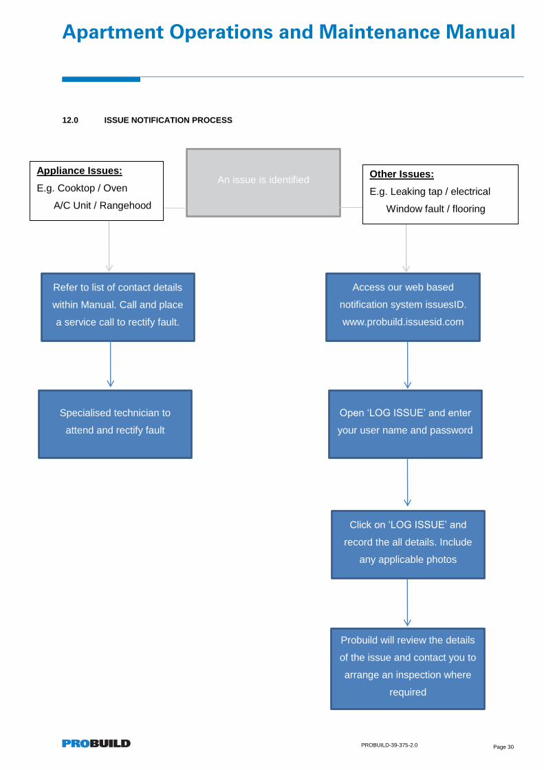
12.0 ISSUE NOTIFICATION PROCESS
An issue is identified
Open ‘LOG ISSUE’ and enter
your user name and password
Click on ‘LOG ISSUE’ and
record the all details. Include
any applicable photos
Refer to list of contact details
within Manual. Call and place
a service call to rectify fault.
Access our web based
notification system issuesID.
www.probuild.issuesid.com
Specialised technician to
attend and rectify fault
Probuild will review the details
of the issue and contact you to
arrange an inspection where
required
Other Issues:
E.g. Leaking tap / electrical
Window fault / flooring
Appliance Issues:
E.g. Cooktop / Oven
A/C Unit / Rangehood
Apartment Operations and Maintenance Manual
PROBUILD-39-375-2.0 Page 31
13.0 APPENDIX
13.1. Electricity and Hot Water Supply – WINEnergy
13.2. Phone and Internet Connections – NBN Users Guide
13.3. Rangehood Operation Manual
13.4. Cooktop Operation Manual
13.5. Oven Operation Manual
13.6. Air Conditioner Manual
13.7. Intercom Manual
13.8. Apartment Smoke Detector Technical Data Sheet
13.9. Material Finishes Schedule


1.
Electricity & Hot Water Hello North Apartments!
The electricity to North Apartments, 23 – 33 Blackwood St, North Melbourne, is supplied via a private embedded electricity network. WINenergy has been engaged to manage this
embedded network on your behalf.
WINenergy now bring our centre of excellence in metering, billing and customer service to deliver you hot water on demand.
You can create electricity and hot water service accounts for your apartment by
speaking to our friendly customer service team on:
1300 791 970 Monday – Friday, 8.00am to 5.00pm
or by completing the ‘Get Connected’ form on
www.winenergy.com.au. Should you need further assistance you can also email us at

Electricity WINenergy is not an energy retailer but manager of embedded networks and operates similar sites throughout Australia.
• Discounts to your electricity account We offer a 21.0% discount when you pay via direct debit. Pricing is based on the Standing Offer Tariff published by the local retailer for your area.
• No lock in contracts There are no fixed term contracts to allow you flexibility to suit ever changing lifestyles.
• Quick connection We offer same day or next day energisation of your apartment. Because your meter is already an embedded network meter, there is no lengthy installation process to delay your connection.
• Freedom of choice Should you choose a market retailer you are required to advise them that your tenancy is in an embedded network. No fee for the decommissioning of the embedded network meter will be charged to you by WINenergy.
• Standard Energisation Fee This fee is applied for standard energisation of your electricity supply. A standard energisation occurs when the completed WINenergy ‘Get Connected’ online form is received by 2pm on a business day for energisation on the following business day, or a subsequent nominated date. The standard Energisation Fee of $35 Ex GST* will appear on your first bill from WINenergy.
• Priority Energisation Fee A priority energisation occurs when the WINenergy ’Get Connected’ form is received before 2pm on a business day for energisation to be completed that same day; or if received after 2pm, for energisation to be made on the following business day. The Priority Energisation Fee of $125 Ex GST* will appear on your first bill from WINenergy.
• New Connection Fee to the Private Embedded Network This fee may be charged for a first-time connection to the private embedded network. If applicable, it will be charged to the first occupant or owner of a new premise on their first bill. For more information see: Residential Tenancies Act 1997 (Vic) s 53 (1)(a).
Hot Water • WINenergy is the sole hot water service provider for your building An account needs to be created with WINenergy in order to receive hot water supply to your apartment. Please call 1300 791 970 or visit www.winenergy.com.au. Set up for hot water is free!
Interpreter services are available to you by calling 13 14 50.
Yours Sincerely,
Customer Service Team
* These Fees may be updated from time to time to reflect market changes and economic conditions, by notice to you.


1© 2015 nbn co ltd | ABN 86 136 533 741For nbn™ fibre installations after 19th Dec 2013
Useful information about your nbn™ supplied equipment
Your user guide
Before performing any maintenance please read the important safety warnings on the back cover.
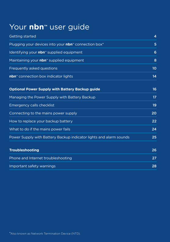
Your nbn™ user guideGetting started 4
Plugging your devices into your nbn™ connection box* 5
Identifying your nbn™ supplied equipment 6
Maintaining your nbn™ supplied equipment 8
Frequently asked questions 10
nbn™ connection box indicator lights 14
Optional Power Supply with Battery Backup guide 16
Managing the Power Supply with Battery Backup 17
Emergency calls checklist 19
Connecting to the mains power supply 20
How to replace your backup battery 22
What to do if the mains power fails 24
Power Supply with Battery Backup indicator lights and alarm sounds 25
Troubleshooting 26
Phone and Internet troubleshooting 27
Important safety warnings 28
*Also known as Network Termination Device (NTD).
3© 2015 nbn co ltd | ABN 86 136 533 741
Your nbn™ user guideCongratulations on connecting to the nbn™ network. With your new fibre optic connection, you’ll be able to access the benefits of fast and reliable phone and internet services, including:**
• A brighter future – your family can access knowledge from across the world and learn like never before, offering you and your kids a brighter future
• Everyone online at once – with the nbn™ network, the whole family can enjoy all the benefits of high speed internet, even with lots of devices connected at the same time**
• Entertainment without the wait – with the nbn™ network, you can quickly access the content you need, when you need it – whether you’re video streaming, online gaming or watching live news and sport**
This booklet gives you the information you need to ensure your nbn™ supplied equipment stays in good working order. It also outlines the things you can do if your system is not working properly.
** Your experience including the speeds actually achieved over the nbn™ network, depends on the technology over which services are delivered to your premises and some factors outside our control (like your equipment quality, software, broadband plans and how your service provider designs its network).
4 © 2015 nbn co ltd | ABN 86 136 533 741
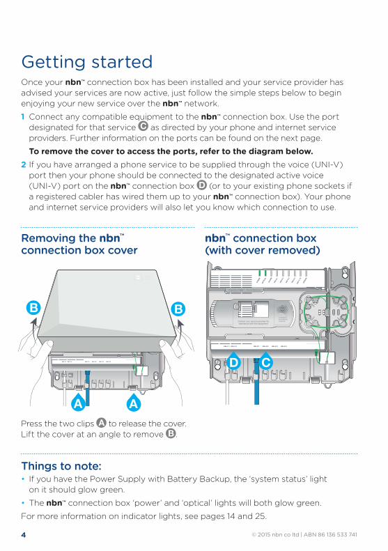
Getting startedOnce your nbn™ connection box has been installed and your service provider has advised your services are now active, just follow the simple steps below to begin enjoying your new service over the nbn™ network.
1 Connect any compatible equipment to the nbn™ connection box. Use the port designated for that service C as directed by your phone and internet service providers. Further information on the ports can be found on the next page.
To remove the cover to access the ports, refer to the diagram below.2 If you have arranged a phone service to be supplied through the voice (UNI-V)
port then your phone should be connected to the designated active voice (UNI-V) port on the nbn™ connection box D (or to your existing phone sockets if a registered cabler has wired them up to your nbn™ connection box). Your phone and internet service providers will also let you know which connection to use.
Press the two clips A to release the cover. Lift the cover at an angle to remove B .
Things to note:• If you have the Power Supply with Battery Backup, the ‘system status’ light
on it should glow green.
• The nbn™ connection box ‘power’ and ‘optical’ lights will both glow green.
For more information on indicator lights, see pages 14 and 25.
Removing the nbn™ connection box cover
Property of NBNCo - Do not Remove
Contact your service provider forassistance with this equipment
Property of nbn™ - Do not Remove
nbn™ connection box (with cover removed)
D C
Property of NBNCo - Do not Remove
Contact your service provider forassistance with this equipment
Property of NBNCo - Do not Remove
B B
A A
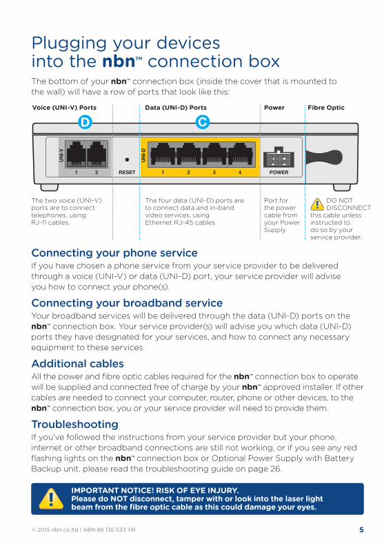
5© 2015 nbn co ltd | ABN 86 136 533 741
Plugging your devices into the nbn™ connection boxThe bottom of your nbn™ connection box (inside the cover that is mounted to the wall) will have a row of ports that look like this:
UNI-D
UNI-V
1 21 2 RESET POWER3 4
The two voice (UNI-V) ports are to connect telephones, using RJ-11 cables.
The four data (UNI-D) ports are to connect data and in-band video services, using Ethernet RJ-45 cables.
Port for the power cable from your Power Supply.
DO NOT DISCONNECT this cable unless instructed to do so by your service provider.
Voice (UNI-V) Ports Power Fibre OpticData (UNI-D) Ports
CD
Connecting your phone service If you have chosen a phone service from your service provider to be delivered through a voice (UNI-V) or data (UNI-D) port, your service provider will advise you how to connect your phone(s).
Connecting your broadband service Your broadband services will be delivered through the data (UNI-D) ports on the nbn™ connection box. Your service provider(s) will advise you which data (UNI-D) ports they have designated for your services, and how to connect any necessary equipment to these services.
Additional cablesAll the power and fibre optic cables required for the nbn™ connection box to operate will be supplied and connected free of charge by your nbn™ approved installer. If other cables are needed to connect your computer, router, phone or other devices, to the nbn™ connection box, you or your service provider will need to provide them.
TroubleshootingIf you’ve followed the instructions from your service provider but your phone, internet or other broadband connections are still not working, or if you see any red flashing lights on the nbn™ connection box or Optional Power Supply with Battery Backup unit, please read the troubleshooting guide on page 26.
IMPORTANT NOTICE! RISK OF EYE INJURY. Please do NOT disconnect, tamper with or look into the laser light beam from the fibre optic cable as this could damage your eyes.
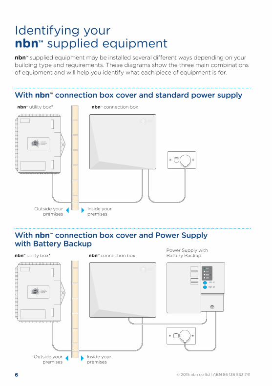
6 © 2015 nbn co ltd | ABN 86 136 533 741
Identifying your nbn™ supplied equipmentnbn™ supplied equipment may be installed several different ways depending on your building type and requirements. These diagrams show the three main combinations of equipment and will help you identify what each piece of equipment is for.
With nbn™ connection box cover and standard power supply
Contact your service provider forassistance with this equipment
Property of NBNCo - Do not Remove
Contact your service provider forassistance with this equipment
Property of nbn - Do not Remove
SYSTEMSTATUS
BATTERYPOWER
REPLACEBATTERY
ALARMSILENCE
ALARMSILENCE
BATTERYEMERGENCY
USE
Property of NBNCo - Do not Remove
Contact your service provider forassistance with this equipment
Property of nbn - Do not Remove
SYSTEMSTATUS
BATTERYPOWER
REPLACEBATTERY
ALARMSILENCE
ALARMSILENCE
BATTERYEMERGENCY
USE
SYSTEMSTATUS
BATTERYPOWER
REPLACEBATTERY
ALARMSILENCE
ALARMSILENCE
BATTERYEMERGENCY
USE
Property of NBNCo - Do not Remove
Contact your service provider forassistance with this equipment
Property of nbn - Do not Remove
SYSTEMSTATUS
BATTERYPOWER
REPLACEBATTERY
ALARMSILENCE
ALARMSILENCE
BATTERYEMERGENCY
USE
Contact your service provider forassistance with this equipment
Property of NBNCo - Do not Remove
Contact your service provider forassistance with this equipment
Property of nbn - Do not Remove
nbn™ connection box
Inside your premises
Outside your premises
nbn™ utility box*
With nbn™ connection box cover and Power Supply with Battery Backup
Contact your service provider forassistance with this equipment
Property of NBNCo - Do not Remove
Contact your service provider forassistance with this equipment
Property of nbn - Do not Remove
SYSTEMSTATUS
BATTERYPOWER
REPLACEBATTERY
ALARMSILENCE
ALARMSILENCE
BATTERYEMERGENCY
USE
Property of NBNCo - Do not Remove
Contact your service provider forassistance with this equipment
Property of nbn - Do not Remove
SYSTEMSTATUS
BATTERYPOWER
REPLACEBATTERY
ALARMSILENCE
ALARMSILENCE
BATTERYEMERGENCY
USE
SYSTEMSTATUS
BATTERYPOWER
REPLACEBATTERY
ALARMSILENCE
ALARMSILENCE
BATTERYEMERGENCY
USE
Property of NBNCo - Do not Remove
Contact your service provider forassistance with this equipment
Property of nbn - Do not Remove
SYSTEMSTATUS
BATTERYPOWER
REPLACEBATTERY
ALARMSILENCE
ALARMSILENCE
BATTERYEMERGENCY
USE
Contact your service provider forassistance with this equipment
Property of NBNCo - Do not Remove
Contact your service provider forassistance with this equipment
Property of nbn - Do not Remove
nbn™ utility box* nbn™ connection boxPower Supply with Battery Backup
Inside your premises
Outside your premises
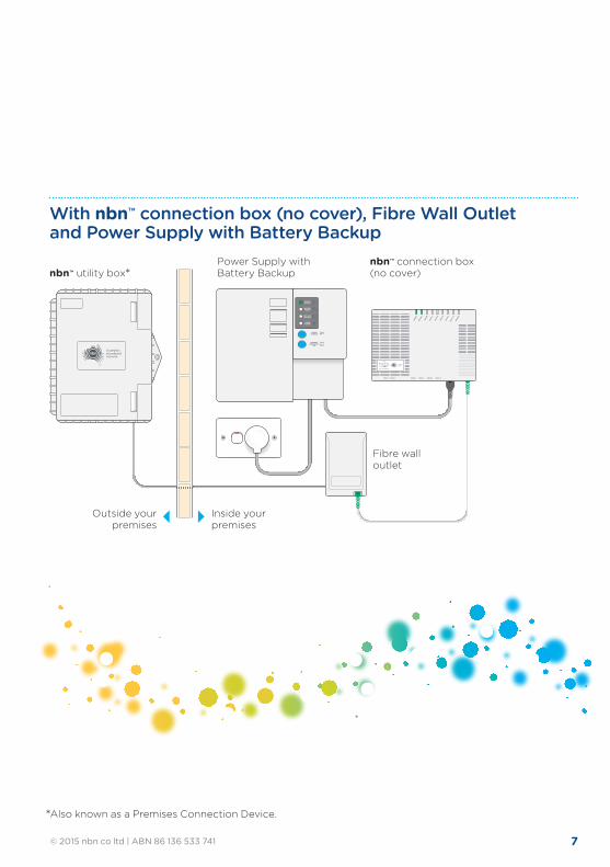
7© 2015 nbn co ltd | ABN 86 136 533 741
* Also known as a Premises Connection Device.
With nbn™ connection box (no cover), Fibre Wall Outlet and Power Supply with Battery Backup
SYSTEMSTATUS
BATTERYPOWER
REPLACEBATTERY
ALARMSILENCE
ALARMSILENCE
BATTERYEMERGENCY
USE
NTD
Property of nbn™
Do not remove
nbn™ utility box*
Inside your premises
Outside your premises
nbn™ connection box (no cover)
Power Supply with Battery Backup
Fibre wall outlet
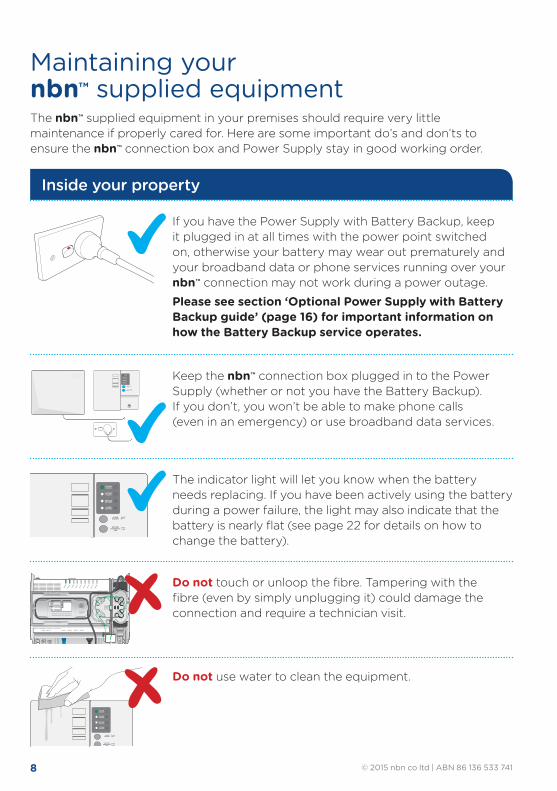
8 © 2015 nbn co ltd | ABN 86 136 533 741
ALARMSILENCE
SYSTEMSTATUS
BATTERYPOWER
REPLACEBATTERY
ALARMSILENCE
BATTERYEMERGENCY
USE
Maintaining your nbn™ supplied equipmentThe nbn™ supplied equipment in your premises should require very little maintenance if properly cared for. Here are some important do’s and don’ts to ensure the nbn™ connection box and Power Supply stay in good working order.
Do not touch or unloop the fibre. Tampering with the fibre (even by simply unplugging it) could damage the connection and require a technician visit.
Do not use water to clean the equipment.
Inside your property
SYSTEMSTATUS
BATTERYPOWER
REPLACEBATTERY
ALARMSILENCE
ALARMSILENCE
BATTERYEMERGENCY
USE
SYSTEMSTATUS
BATTERYPOWER
REPLACEBATTERY
ALARMSILENCE
ALARMSILENCE
BATTERYEMERGENCY
USE
Contact your service provider forassistance with this equipment
Property of NBNCo - Do not Remove
Contact your service provider forassistance with this equipment
Property of nbn™ - Do not Remove
Contact your service provider forassistance with this equipment
Property of NBNCo - Do not Remove
Contact your service provider forassistance with this equipment
Property of nbn™ - Do not Remove
Property of NBNCo - Do not Remove
Contact your service provider forassistance with this equipment
Property of nbn™ - Do not Remove
SYSTEMSTATUS
BATTERYPOWER
REPLACEBATTERY
ALARMSILENCE
ALARMSILENCE
BATTERYEMERGENCY
USE
Property of NBNCo - Do not Remove
Contact your service provider forassistance with this equipment
Property of nbn™ - Do not Remove
SYSTEMSTATUS
BATTERYPOWER
REPLACEBATTERY
ALARMSILENCE
ALARMSILENCE
BATTERYEMERGENCY
USE
ALARMSILENCE
SYSTEMSTATUS
BATTERYPOWER
REPLACEBATTERY
ALARMSILENCE
BATTERYEMERGENCY
USE
Contact your service provider forassistance with this equipment
Property of NBNCo - Do not Remove
Contact your service provider forassistance with this equipment
Property of nbn - Do not Remove
SYSTEMSTATUS
BATTERYPOWER
REPLACEBATTERY
ALARMSILENCE
ALARMSILENCE
BATTERYEMERGENCY
USE
Property of NBNCo - Do not Remove
Contact your service provider forassistance with this equipment
Property of nbn - Do not Remove
SYSTEMSTATUS
BATTERYPOWER
REPLACEBATTERY
ALARMSILENCE
ALARMSILENCE
BATTERYEMERGENCY
USE
SYSTEMSTATUS
BATTERYPOWER
REPLACEBATTERY
ALARMSILENCE
ALARMSILENCE
BATTERYEMERGENCY
USE
Property of NBNCo - Do not Remove
Contact your service provider forassistance with this equipment
Property of nbn - Do not Remove
SYSTEMSTATUS
BATTERYPOWER
REPLACEBATTERY
ALARMSILENCE
ALARMSILENCE
BATTERYEMERGENCY
USE
Contact your service provider forassistance with this equipment
Property of NBNCo - Do not Remove
Contact your service provider forassistance with this equipment
Property of nbn - Do not Remove
If you have the Power Supply with Battery Backup, keep it plugged in at all times with the power point switched on, otherwise your battery may wear out prematurely and your broadband data or phone services running over your nbn™ connection may not work during a power outage.
Please see section ‘Optional Power Supply with Battery Backup guide’ (page 16) for important information on how the Battery Backup service operates.
Keep the nbn™ connection box plugged in to the Power Supply (whether or not you have the Battery Backup). If you don’t, you won’t be able to make phone calls (even in an emergency) or use broadband data services.
The indicator light will let you know when the battery needs replacing. If you have been actively using the battery during a power failure, the light may also indicate that the battery is nearly flat (see page 22 for details on how to change the battery).
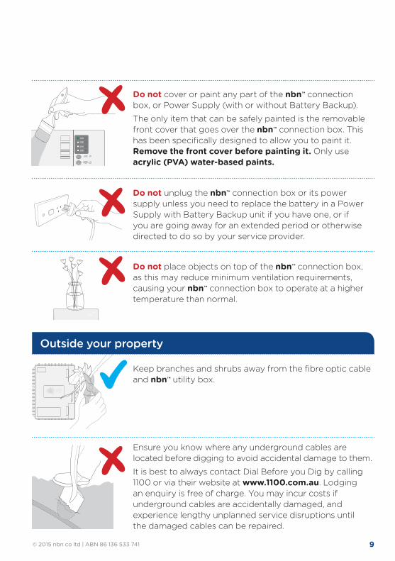
9© 2015 nbn co ltd | ABN 86 136 533 741
ALARMSILENCE
SYSTEMSTATUS
BATTERYPOWER
REPLACEBATTERY
ALARMSILENCE
BATTERYEMERGENCY
USE
Do not cover or paint any part of the nbn™ connection box, or Power Supply (with or without Battery Backup).
The only item that can be safely painted is the removable front cover that goes over the nbn™ connection box. This has been specifically designed to allow you to paint it. Remove the front cover before painting it. Only use acrylic (PVA) water-based paints.
Do not unplug the nbn™ connection box or its power supply unless you need to replace the battery in a Power Supply with Battery Backup unit if you have one, or if you are going away for an extended period or otherwise directed to do so by your service provider.
Do not place objects on top of the nbn™ connection box, as this may reduce minimum ventilation requirements, causing your nbn™ connection box to operate at a higher temperature than normal.
Outside your property
Ensure you know where any underground cables are located before digging to avoid accidental damage to them.
It is best to always contact Dial Before you Dig by calling 1100 or via their website at www.1100.com.au. Lodging an enquiry is free of charge. You may incur costs if underground cables are accidentally damaged, and experience lengthy unplanned service disruptions until the damaged cables can be repaired.
Keep branches and shrubs away from the fibre optic cable and nbn™ utility box.
10 © 2015 nbn co ltd | ABN 86 136 533 741
I’ve accidentally damaged the nbn™ connection box. What do I do? The nbn™ connection box and its cover, Power Supply with Battery Backup, standard power supply and the fibre optic cable on your property are your responsibility to keep in good condition, just as you are responsible for your other services such as power, phone and gas.
If you happen to accidentally damage any part of the nbn™ supplied equipment or cable, please contact your service provider to have it repaired. You may be charged for the repair.
Is the nbn™ connection box installed in my home or premises safe? The nbn™ connection box and its power supply only use fixed cables. That means they are not designed to nor intended to emit any wireless radiation.
Rest assured the nbn™ connection box and its power supply have been tested to ensure they meet:
• Australian Safety and Emission requirements in accordance with AS/NZS CISPR22 and AS/NZS 60950-1.
• These are the same standards consumer appliances are required to comply with.
• Both the nbn™ connection box and power supply have passed these tests.
The nbn™ connection box also has a laser warning label on it, in accordance with Australian standards. The warning on the label is the same one required for CD and laser pointing devices, laser ‘spirit’ level tools etc.
The nbn™ connection box is designed to automatically turn off its laser in cases when the optical fibre is pulled out or broken. The automatic switch off happens within thousandths of a second of a break occurring. nbn nevertheless recommends that you stay away from fallen or broken cables as a precaution because it’s not always possible to tell whether a fallen or broken cable is a safe cable, or an unsafe cable.
Is the nbn™ fibre optic cable safe? Fibre optic cables do not conduct electricity. However, there are other safety hazards associated with handling the fibre optic cable. This is why you must never disconnect, tamper with or look directly into the laser light beamed from the fibre optic cable.
Although the laser light found inside the fibre optic cabling may appear invisible, you should always assume the light is present even if you cannot see it.
Who can I contact for assistance? If you have any questions, need help or to report a fault please call your service provider.
FAQs
11© 2015 nbn co ltd | ABN 86 136 533 741
If I’m going away for a while – can I unplug my service to save power? nbn recommends leaving your nbn™ supplied equipment connected and powered at all times. You may shorten the life of your battery if you leave the Power Supply with Battery Backup unplugged for an extended period of time. However, if you are away for an extended period, and do not want to leave the nbn™ supplied equipment plugged in, please be sure to disconnect the battery by following these steps (refer to diagram on pages 22–23):
1 Turn off at the power point and disconnect the power supply from the mains power.
2 Open the front cover of the Power Supply with Battery Backup A .
3 Disconnect the red ‘+’ plug from the battery B .
When returning, please remember to reconnect the battery. If you don’t, your phone and broadband data services won’t work during a power failure, you may hear audible alarms and your service provider may be alerted that your battery needs servicing.
Can I plug the power supply into a power board? Yes, however nbn prefers the nbn™ connection box and power supply is connected to fixed power point where possible. However in the event this is not possible then the power supply can be plugged into a double adapter, extension cord or power board as long as they are safe.
What if I want to move the nbn™ connection box?If you need to have the nbn™ connection box or the cables relocated, contact your service provider. They should be able to advise you of the cost and arrange for a technician to move the equipment. When considering relocating nbn™ supplied equipment or cables you should keep these things in mind: 1 The equipment must be protected from water, steam or excessive heat.
2 The location must be well ventilated, preferably near a fixed power point and easy for you to check the indicator lights.
3 The equipment must be positioned in a location away from busy areas and protected from risk of damage. There should also be sufficient light for you to see if the device is functioning correctly.
4 You may be charged for the relocation cost.
12 © 2015 nbn co ltd | ABN 86 136 533 741
Can I connect other devices to the unused ports on the nbn™ connection box? Unlike modem/routers you might be familiar with from ADSL and cable broadband services, each port on the nbn™ connection box is reserved for a separate service. This allows you to have up to four separate broadband data and up to two separate phone services through one connection box. If you only order one broadband service, then only one port will be active. If you connect one of your devices to an unused nbn™ connection box port, your devices won’t be connected to a phone or internet service.
I have a monitored home or premises security system. Will it work over the nbn™ network?It is expected that most monitored security systems will operate over the nbn™ network. However, if you would like to use an existing system, you should check with your security provider to ensure that your particular equipment and service is nbn™ network compatible. You should test your alarm the same day that your service over the nbn™ network is activated by your service provider, and also check that your in-premises wiring is correctly connected up to your service over the nbn™ network.
For further information on alarms and the nbn™ network, visit nbn.com.au/alarms
Can I install in-home cabling myself?nbn will professionally install the cabling from the street to your nbn™ connection box (for more information on what’s included in a standard installation please visit nbn.com.au/fibreinstallation). If you choose to install additional permanent phone or data cabling through wall, floor or ceiling cavities it must be done by a cabler registered with an Australian Communications and Media Authority (ACMA) accredited industry registrar.
Your service provider may also be able to recommend a registered cabler in your area. Other non-permanent cabling such as plugging your own router or phone into the nbn™ connection box can be done yourself.
How do I care for the nbn™ connection box cover?You can clean the nbn™ connection box cover by removing the cover and wiping it clean with a damp cloth and mild all-purpose cleaner. Do not use a damp cloth on internal equipment or cables.
Can I lock the nbn™ connection box cover?A locking feature is available to restrict access if desired. nbn recommends a cable tie or small padlock to stop unwanted access. Please note: Your service provider should not lock the cover, as you may need to access the ports or lights inside the cover for troubleshooting or if you decide to change providers/devices.
13© 2015 nbn co ltd | ABN 86 136 533 741
How do I open my nbn™ connection box cover?To remove the cover, press the two clips at the base of the box (either together or one at a time). Pull the base of the cover out, and then up to remove it completely. To reattach the cover, simply place the top over the base then lightly guide the cover down and back until it clips into place. Do not touch or uncoil the cables that have been installed inside the cover as this could affect the performance of your service.
Can I remove my Power Supply with Battery Backup if I no longer want the Battery Backup service and only want the standard power supply?No, this is currently not possible. However you can advise your service provider that you no longer want the Battery Backup service which means you can remove the battery (provided no other users of nbn™ approved services are using the Battery Backup service on your premises) and your service provider will stop sending you battery alarm reminders. If you do this, your services will only operate if the power is switched on at the power point; they won’t work during a power failure.
I only have the standard power supply. Can I add a Power Supply with Battery Backup if my circumstances change or I move into a home that does not have the capability and I require this service?Yes this is possible – please contact your service provider to discuss your needs and arrange an appointment for the installation of the Power Supply with Battery Backup. Please note that until your Power Supply with Battery Backup is installed, your services will not operate during a power failure or when the power for the nbn™ connection box is switched off at the power point.
I have moved into a house with nbn™ fibre already installed. Do I need to do anything to make sure the Battery Backup service is working?If you move into a house where nbn™ fibre is available, please let your preferred service provider know whether you require the Battery Backup service when arranging your services over the nbn™ network.
If you do require it, your service provider may need to arrange nbn to install a Power Supply with Battery Backup if there is not already one there in the house. Your service provider will also remind you when the battery is worn out and needs to be changed.
You can check if the Power Supply with Battery Backup has a working battery installed in it by checking if there are any visual light alarms on the unit and opening the power supply cover to see if a battery is installed. Please follow the instructions on page 22.
If you don’t require the Battery Backup service, and there is already a Power Supply Unit with Battery Backup installed, then your service provider can turn off the reminders to replace the battery.
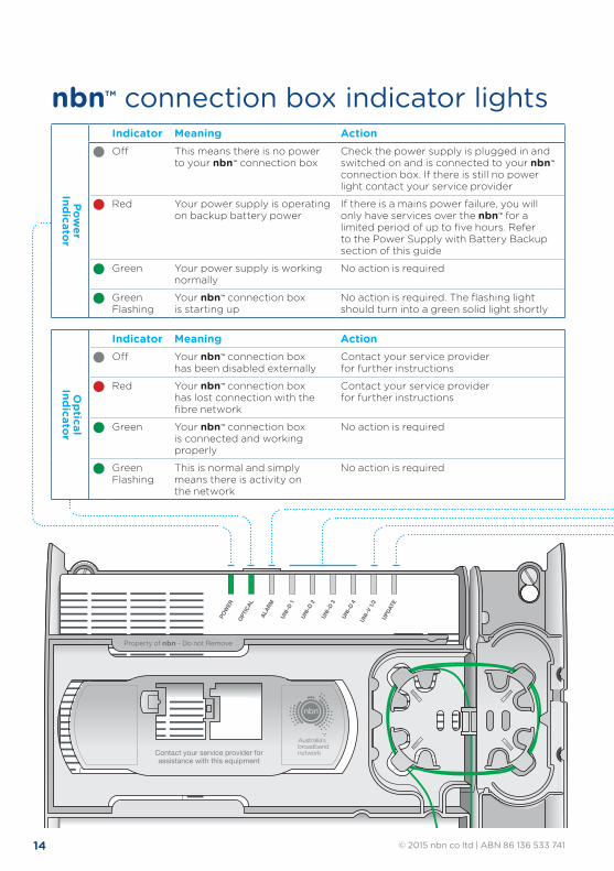
14 © 2015 nbn co ltd | ABN 86 136 533 741
Contact your service provider forassistance with this equipment
Property of NBNCo - Do not Remove
Contact your service provider forassistance with this equipment
Property of nbn - Do not Remove
SYSTEMSTATUS
BATTERYPOWER
REPLACEBATTERY
ALARMSILENCE
ALARMSILENCE
BATTERYEMERGENCY
USE
Property of NBNCo - Do not Remove
Contact your service provider forassistance with this equipment
Property of nbn - Do not Remove
SYSTEMSTATUS
BATTERYPOWER
REPLACEBATTERY
ALARMSILENCE
ALARMSILENCE
BATTERYEMERGENCY
USE
SYSTEMSTATUS
BATTERYPOWER
REPLACEBATTERY
ALARMSILENCE
ALARMSILENCE
BATTERYEMERGENCY
USE
Property of NBNCo - Do not Remove
Contact your service provider forassistance with this equipment
Property of nbn - Do not Remove
SYSTEMSTATUS
BATTERYPOWER
REPLACEBATTERY
ALARMSILENCE
ALARMSILENCE
BATTERYEMERGENCY
USE
Contact your service provider forassistance with this equipment
Property of NBNCo - Do not Remove
Contact your service provider forassistance with this equipment
Property of nbn - Do not Remove
Power
Indicator
Indicator Meaning ActionOff This means there is no power
to your nbn™ connection boxCheck the power supply is plugged in and switched on and is connected to your nbn™ connection box. If there is still no power light contact your service provider
Red Your power supply is operating on backup battery power
If there is a mains power failure, you will only have services over the nbn™ for a limited period of up to five hours. Refer to the Power Supply with Battery Backup section of this guide
Green Your power supply is working normally
No action is required
Green Flashing
Your nbn™ connection box is starting up
No action is required. The flashing light should turn into a green solid light shortly
Optical
Indicator
Indicator Meaning ActionOff Your nbn™ connection box
has been disabled externallyContact your service provider for further instructions
Red Your nbn™ connection box has lost connection with the fibre network
Contact your service provider for further instructions
Green Your nbn™ connection box is connected and working properly
No action is required
Green Flashing
This is normal and simply means there is activity on the network
No action is required
nbn™ connection box indicator lights
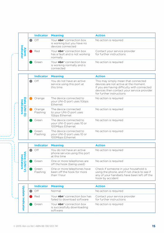
15© 2015 nbn co ltd | ABN 86 136 533 741
Alarm
Indicator
Indicator Meaning ActionOff Your nbn™ connection box
is working but you have no devices connected
No action is required
Red Your nbn™ connection box has a fault and is not working normally
Contact your service provider for further instructions
Green Your nbn™ connection box is working normally and is connected
No action is required
Data (U
NI-D
) Indicators
Indicator Meaning ActionOff You do not have an active
service using this port at this time
This may simply mean that connected devices are not active at the moment. If you are having difficulty with connected devices then contact your service provider for further instructions
Orange The device connected to your UNI-D port uses 1Gbps Ethernet
No action is required
Orange Flashing
The device connected to your UNI-D port uses 1Gbps Ethernet
No action is required
Green The device connected to your UNI-D port uses 10 or 100Mbps Ethernet
No action is required
Green Flashing
The device connected to your UNI-D port uses 10 or 100Mbps Ethernet
No action is required
Voice (UN
I-V)
IndicatorsIndicator Meaning ActionOff You do not have an active
phone service using this port at this time
No action is required
Green One or more telephones are off the hook (being used)
No action is required
Green Flashing
One or more telephones have been off the hook for more than 1 hour
Check if someone in your household is using the phone, and if not check to see if any of your handsets have been left off the hook by accident
Update Indicator
Indicator Meaning ActionOff Normal No action is required
Red Your nbn™ connection box has failed to download software
Contact your service provider for further instructions
Green Your nbn™ connection box is successfully downloading software
No action is required
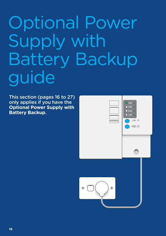
16
SYSTEMSTATUS
BATTERYPOWER
REPLACEBATTERY
ALARMSILENCE
ALARMSILENCE
BATTERYEMERGENCY
USE
Optional Power Supply with Battery Backup guideThis section (pages 16 to 27) only applies if you have the Optional Power Supply with Battery Backup.

17© 2015 nbn co ltd | ABN 86 136 533 741
The Power Supply with Battery Backup:
• Provides a steady 12V power supply to your nbn™ connection box.
• Provides battery backup power to the nbn™ connection box (when fitted with a working battery).
• During a power outage, battery backup will last for approximately five hours (including the battery emergency reserve).
It is always good to have another way of calling someone during a power outage in the case of emergency such as a charged mobile phone.
To ensure that your phone (or data) services continue to operate during a power outage please note:
• Only standard corded phones (that don’t need to be plugged into a power point) will work during a power outage, and only if your phone service is also provided over the nbn™ connection box’s voice (UNI-V) port. All other devices require their own battery backup to operate during a power outage.
• If your phone plugs into a separate router/gateway from your phone or internet service provider, you won’t be able to make calls unless that router/gateway also has its own battery backup.
• Examples of devices that require their own battery backup include wireless routers, all mains powered phones, computers or modem/routers.
• Uninterruptable power supply (UPS) systems help power devices during a power outage and are readily available through technology retailers.
Your service provider should explain how your services can work with nbn’s Battery Backup and what additional solutions you may need to power your other devices.
How long Battery Backup lastsIf you have a Power Supply with Battery Backup, your nbn™ connection box will continue to be powered for approximately five hours during a power outage.• When approximately 40% of the battery charge is remaining (after about
3 to 3.5 hours), the power supply will automatically turn off to preserve the remaining charge for emergency use.
• When you need to use the remaining charge press the emergency reserve button and within a few minutes your services will operate for the remaining approximately 1.5 to 2 hours.
• Extremely cold conditions (less than -1 degrees Celsius) may cause the battery to run out more quickly.
Managing the Power Supply with Battery Backup
18 © 2015 nbn co ltd | ABN 86 136 533 741
Keeping your backup battery topped upTo ensure the backup battery works when you need it, please maintain it by following the advice given in this guide.
• Regularly check the battery indicators lights and pay attention to audible alarms, (see page 25 for a guide to indicator lights and alarms) as these may indicate a problem with your battery.
• When your battery is used as indicated in the nbn™ User Guide, it will age to about 70% of its original capacity in around three to five years.
• A battery can age sooner if not kept at room temperature (around 20 degrees). Warmer temperatures can accelerate aging of the battery.
• Turning the power on and off frequently will cause the battery to age earlier and reach 70% of its capacity in around one to two years.
• Please ensure the battery is replaced when needed (or as arranged with your service provider).
Options for extending your Battery BackupIf approximately five hours of battery backup isn’t enough for your needs, you can add additional capacity by plugging the power cord of the Power Supply with Battery Backup unit into an Uninterruptable Power Supply (UPS) – itself a type of battery backup unit. These are readily available through technology retailers. Your service provider should explain how your services can work with nbn’s Battery Backup and what additional solutions you may need to power your other devices.
The UPS must supply a 230V 50Hz AC waveform in accordance with AS60038-2000. Refer to your UPS manufacturer for confirmation.
To set up a UPS, please:
• Follow the instructions provided by the UPS manufacturer to initially set up the UPS system.
• Switch off the power at the power point that the nbn™ connection box power supply is connected to.
• Unplug the nbn™ Power Supply power cord from the power point and plug it into the UPS.
• Plug the UPS power cord to the fixed power point.
• Turn on the power point.
• Follow the UPS manufacturer’s instructions on operating the UPS.
Your service provider should explain how your services can work with battery backup and what solutions you may need for your devices. You should discuss the use of any UPS with your service provider.
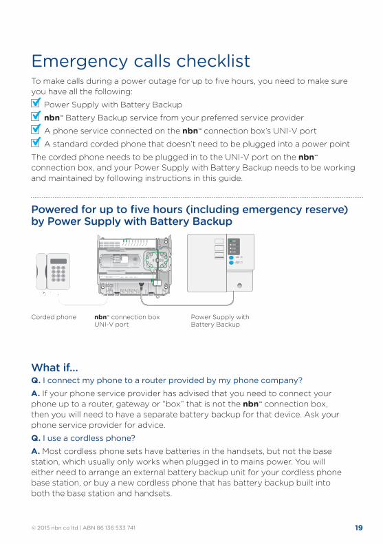
19© 2015 nbn co ltd | ABN 86 136 533 741
Property of NBNCo - Do not Remove
Contact your service provider forassistance with this equipment
Property of nbn™ - Do not Remove
SYSTEMSTATUS
BATTERYPOWER
REPLACEBATTERY
ALARMSILENCE
ALARMSILENCE
BATTERYEMERGENCY
USE
Property of NBNCo - Do not Remove
Contact your service provider forassistance with this equipment
Property of nbn™ - Do not Remove
SYSTEMSTATUS
BATTERYPOWER
REPLACEBATTERY
ALARMSILENCE
ALARMSILENCE
BATTERYEMERGENCY
USE
To make calls during a power outage for up to five hours, you need to make sure you have all the following:
Power Supply with Battery Backup
nbn™ Battery Backup service from your preferred service provider
A phone service connected on the nbn™ connection box’s UNI-V port
A standard corded phone that doesn’t need to be plugged into a power point
The corded phone needs to be plugged in to the UNI-V port on the nbn™ connection box, and your Power Supply with Battery Backup needs to be working and maintained by following instructions in this guide.
Power Supply with Battery Backup
nbn™ connection box UNI-V port
Corded phone
Powered for up to five hours (including emergency reserve) by Power Supply with Battery Backup
Emergency calls checklist
What if…Q. I connect my phone to a router provided by my phone company? A. If your phone service provider has advised that you need to connect your phone up to a router, gateway or “box” that is not the nbn™ connection box, then you will need to have a separate battery backup for that device. Ask your phone service provider for advice.
Q. I use a cordless phone? A. Most cordless phone sets have batteries in the handsets, but not the base station, which usually only works when plugged in to mains power. You will either need to arrange an external battery backup unit for your cordless phone base station, or buy a new cordless phone that has battery backup built into both the base station and handsets.
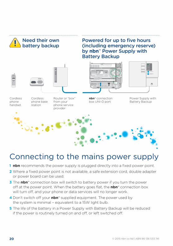
20 © 2015 nbn co ltd | ABN 86 136 533 741
1 nbn recommends the power supply is plugged directly into a fixed power point.
2 Where a fixed power point is not available, a safe extension cord, double adapter or power board can be used.
3 The nbn™ connection box will switch to battery power if you turn the power off at the power point. When the battery goes flat, the nbn™ connection box will turn off, and your phone or data services will no longer work.
4 Don’t switch off your nbn™ supplied equipment. The power used by the system is minimal – equivalent to a 15W light bulb.
5 The life of the battery in a Power Supply with Battery Backup will be reduced if the power is routinely turned on and off, or left switched off.
Connecting to the mains power supply
Power Supply with Battery Backup
nbn™ connection box UNI-D port
Cordless phone handset
Cordless phone base station
Router or “box” from your phone service provider
Property of NBNCo - Do not Remove
Contact your service provider forassistance with this equipment
Property of nbn™ - Do not Remove
SYSTEMSTATUS
BATTERYPOWER
REPLACEBATTERY
ALARMSILENCE
ALARMSILENCE
BATTERYEMERGENCY
USE
Property of NBNCo - Do not Remove
Contact your service provider forassistance with this equipment
Property of nbn™ - Do not Remove
SYSTEMSTATUS
BATTERYPOWER
REPLACEBATTERY
ALARMSILENCE
ALARMSILENCE
BATTERYEMERGENCY
USE
Property of NBNCo - Do not Remove
Contact your service provider forassistance with this equipment
Property of nbn™ - Do not Remove
SYSTEMSTATUS
BATTERYPOWER
REPLACEBATTERY
ALARMSILENCE
ALARMSILENCE
BATTERYEMERGENCY
USE
Property of NBNCo - Do not Remove
Contact your service provider forassistance with this equipment
Property of nbn™ - Do not Remove
SYSTEMSTATUS
BATTERYPOWER
REPLACEBATTERY
ALARMSILENCE
ALARMSILENCE
BATTERYEMERGENCY
USE
Powered for up to five hours (including emergency reserve) by nbn™ Power Supply with Battery Backup
Need their own battery backup
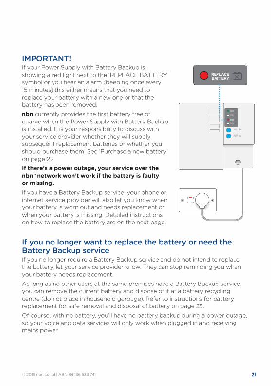
21© 2015 nbn co ltd | ABN 86 136 533 741
IMPORTANT! If your Power Supply with Battery Backup is showing a red light next to the ‘REPLACE BATTERY’ symbol or you hear an alarm (beeping once every 15 minutes) this either means that you need to replace your battery with a new one or that the battery has been removed.
nbn currently provides the first battery free of charge when the Power Supply with Battery Backup is installed. It is your responsibility to discuss with your service provider whether they will supply subsequent replacement batteries or whether you should purchase them. See ‘Purchase a new battery’ on page 22.
If there’s a power outage, your service over the nbn™ network won’t work if the battery is faulty or missing. If you have a Battery Backup service, your phone or internet service provider will also let you know when your battery is worn out and needs replacement or when your battery is missing. Detailed instructions on how to replace the battery are on the next page.
If you no longer want to replace the battery or need the Battery Backup serviceIf you no longer require a Battery Backup service and do not intend to replace the battery, let your service provider know. They can stop reminding you when your battery needs replacement.
As long as no other users at the same premises have a Battery Backup service, you can remove the current battery and dispose of it at a battery recycling centre (do not place in household garbage). Refer to instructions for battery replacement for safe removal and disposal of battery on page 23.
Of course, with no battery, you’ll have no battery backup during a power outage, so your voice and data services will only work when plugged in and receiving mains power.
SYSTEMSTATUS
BATTERYPOWER
REPLACEBATTERY
ALARMSILENCE
ALARMSILENCE
BATTERYEMERGENCY
USE
SYSTEMSTATUS
BATTERYPOWER
REPLACEBATTERY
ALARMSILENCE
ALARMSILENCE
BATTERYEMERGENCY
USE
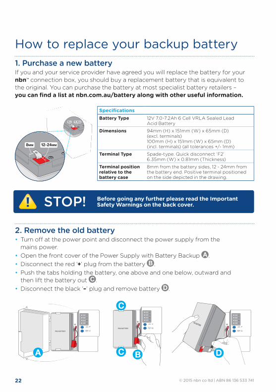
22 © 2015 nbn co ltd | ABN 86 136 533 741
ALARMSILENCE
SYSTEMSTATUS
BATTERYPOWER
REPLACEBATTERY
ALARMSILENCE
BATTERYEMERGENCY
USE
ALARMSILENCE
SYSTEMSTATUS
BATTERYPOWER
REPLACEBATTERY
ALARMSILENCE
BATTERYEMERGENCY
USE
ALARMSILENCE
SYSTEMSTATUS
BATTERYPOWER
REPLACEBATTERY
ALARMSILENCE
BATTERYEMERGENCY
USE
D
ALARMSILENCE
SYSTEMSTATUS
BATTERYPOWER
REPLACEBATTERY
ALARMSILENCE
BATTERYEMERGENCY
USE
ALARMSILENCE
SYSTEMSTATUS
BATTERYPOWER
REPLACEBATTERY
ALARMSILENCE
BATTERYEMERGENCY
USE
ALARMSILENCE
SYSTEMSTATUS
BATTERYPOWER
REPLACEBATTERY
ALARMSILENCE
BATTERYEMERGENCY
USE
A
ALARMSILENCE
SYSTEMSTATUS
BATTERYPOWER
REPLACEBATTERY
ALARMSILENCE
BATTERYEMERGENCY
USE
ALARMSILENCE
SYSTEMSTATUS
BATTERYPOWER
REPLACEBATTERY
ALARMSILENCE
BATTERYEMERGENCY
USE
ALARMSILENCE
SYSTEMSTATUS
BATTERYPOWER
REPLACEBATTERY
ALARMSILENCE
BATTERYEMERGENCY
USE
C
C B
1. Purchase a new batteryIf you and your service provider have agreed you will replace the battery for your nbn™ connection box, you should buy a replacement battery that is equivalent to the original. You can purchase the battery at most specialist battery retailers – you can find a list at nbn.com.au/battery along with other useful information.
2. Remove the old battery• Turn off at the power point and disconnect the power supply from the
mains power.• Open the front cover of the Power Supply with Battery Backup A .• Disconnect the red ‘+’ plug from the battery B .• Push the tabs holding the battery, one above and one below, outward and
then lift the battery out C .• Disconnect the black ‘–’ plug and remove battery D .
How to replace your backup battery
SpecificationsBattery Type 12V 7.0-7.2Ah 6 Cell VRLA Sealed Lead
Acid Battery
Dimensions 94mm (H) x 151mm (W) x 65mm (D) (excl. terminals) 100mm (H) x 151mm (W) x 65mm (D) (incl. terminals) (all tolerances +/- 1mm)
Terminal Type Spade-type. Quick disconnect ‘F2’ 6.35mm (W) x 0.81mm (Thickness)
Terminal position relative to the battery case
8mm from the battery sides, 12 - 24mm from the battery end. Positive terminal positioned on the side depicted in the drawing.
12-24MM8MM
12-24MM8MM
STOP! Before going any further please read the Important Safety Warnings on the back cover.
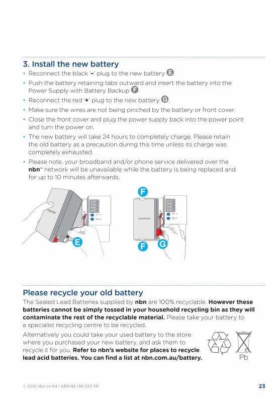
23© 2015 nbn co ltd | ABN 86 136 533 741
Please recycle your old batteryThe Sealed Lead Batteries supplied by nbn are 100% recyclable. However these batteries cannot be simply tossed in your household recycling bin as they will contaminate the rest of the recyclable material. Please take your battery to a specialist recycling centre to be recycled.
Alternatively you could take your used battery to the store where you purchased your new battery, and ask them to recycle it for you. Refer to nbn’s website for places to recycle lead acid batteries. You can find a list at nbn.com.au/battery. Pb
ALARMSILENCE
SYSTEMSTATUS
BATTERYPOWER
REPLACEBATTERY
ALARMSILENCE
BATTERYEMERGENCY
USE
ALARMSILENCE
SYSTEMSTATUS
BATTERYPOWER
REPLACEBATTERY
ALARMSILENCE
BATTERYEMERGENCY
USE
ALARMSILENCE
SYSTEMSTATUS
BATTERYPOWER
REPLACEBATTERY
ALARMSILENCE
BATTERYEMERGENCY
USE
F
GF
ALARMSILENCE
SYSTEMSTATUS
BATTERYPOWER
REPLACEBATTERY
ALARMSILENCE
BATTERYEMERGENCY
USE
ALARMSILENCE
SYSTEMSTATUS
BATTERYPOWER
REPLACEBATTERY
ALARMSILENCE
BATTERYEMERGENCY
USE
ALARMSILENCE
SYSTEMSTATUS
BATTERYPOWER
REPLACEBATTERY
ALARMSILENCE
BATTERYEMERGENCY
USE
E
3. Install the new battery• Reconnect the black ‘–’ plug to the new battery E .
• Push the battery retaining tabs outward and insert the battery into the Power Supply with Battery Backup F .
• Reconnect the red ‘+’ plug to the new battery G .
• Make sure the wires are not being pinched by the battery or front cover.
• Close the front cover and plug the power supply back into the power point and turn the power on.
• The new battery will take 24 hours to completely charge. Please retain the old battery as a precaution during this time unless its charge was completely exhausted.
• Please note, your broadband and/or phone service delivered over the nbn™ network will be unavailable while the battery is being replaced and for up to 10 minutes afterwards.
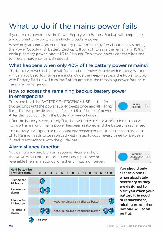
24 © 2015 nbn co ltd | ABN 86 136 533 741
If your mains power fails, the Power Supply with Battery Backup will beep once and automatically switch to its backup battery power.
When only around 40% of the battery power remains (after about 3 to 3.5 hours), the Power Supply with Battery Backup will turn off to save the remaining 40% of backup battery power (about 1.5 to 2 hours). This saved power can then be used to make emergency calls if needed.
What happens when only 40% of the battery power remains? The battery power indicator will flash and the Power Supply with Battery Backup will begin to beep four times a minute. Once the beeping stops, the Power Supply with Battery Backup will turn itself off to preserve the remaining power for use in case of an emergency.
How to access the remaining backup battery power in emergencies Press and hold the BATTERY EMERGENCY USE button for two seconds until the power supply beeps once and all 4 lights flash. This will provide around a further 1.5 to 2 hours of power. After this, you can’t turn the battery power off again.
After the battery is completely flat, the BATTERY EMERGENCY USE button will not work again until mains power has been restored and the battery is recharged.
The battery is designed to be continually recharged until it has reached the end of its life and needs to be replaced - estimated to occur every three to five years if used in accordance with the guidelines.
Alarm silence function You can silence audible alarm sounds. Press and hold the ALARM SILENCE button to temporarily silence or re-enable the alarm sounds for either 24 hours or longer:
You should only silence alarms when absolutely necessary as they are designed to alert you when your battery is in need of replacement, missing or running low and will soon be flat.
What to do if the mains power fails
ALARMSILENCE
BATTERYEMERGENCY
USE
ALARMSILENCE
BATTERYEMERGENCY
USE
1Hold button for time (seconds) 2 3 4 5 6 7 8 9 10 11 12 13 14 15
Silence for24 hours
Re-enablealarm
Re-enablealarm
Silence for24 hours+ Keep holding alarm silence button
Keep holding alarm silence button
= 1 Beep
1Hold button for time (seconds) 2 3 4 5 6 7 8 9 10 11 12 13 14 15
Silence for24 hours
Re-enablealarm
Re-enablealarm
Silence for24 hours+ Keep holding alarm silence button
Keep holding alarm silence button
= 1 Beep= 1 Beep
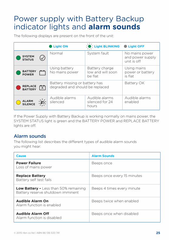
25© 2015 nbn co ltd | ABN 86 136 533 741
The following displays are present on the front of the unit:
If the Power Supply with Battery Backup is working normally on mains power, the SYSTEM STATUS light is green and the BATTERY POWER and REPLACE BATTERY lights are off.
Alarm soundsThe following list describes the different types of audible alarm sounds you might hear:
Power supply with Battery Backup indicator lights and alarm sounds
Light ON Light BLINKING Light OFF
SYSTEM STATUS
Normal System fault No mains power and power supply unit is off
BATTERY POWER
Using battery No mains power
Battery charge low and will soon be flat
Using mains power or battery is flat
REPLACE BATTERY
Battery missing or battery has degraded and should be replaced
Battery OK
ALARM SILENCE
Audible alarms silenced
Audible alarms silenced for 24 hours
Audible alarms enabled
Cause Alarm Sounds
Power Failure Loss of mains power
Beeps once
Replace Battery Battery self test fails
Beeps once every 15 minutes
Low Battery – Less than 50% remaining Battery reserve shutdown imminent
Beeps 4 times every minute
Audible Alarm On Alarm function is enabled
Beeps twice when enabled
Audible Alarm Off Alarm function is disabled
Beeps once when disabled
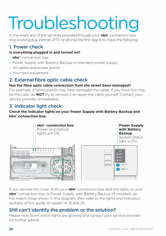
26 © 2015 nbn co ltd | ABN 86 136 533 741
In the event any of the services provided through your nbn™ connection box stop working (e.g. internet, IPTV or phone) the first step is to check the following:
1. Power checkIs everything plugged in and turned on?• nbn™ connection box• Power Supply with Battery Backup or standard power supply• All cables and power points• Your own equipment
2. External fibre optic cable checkHas the fibre optic cable connection from the street been damaged?For example, a fallen branch may have damaged the cable. If you think this may be the case, do NOT try to remove it or repair the cable yourself. Contact your service provider immediately.
3. Indicator light checkCheck the indicator lights on your Power Supply with Battery Backup and nbn™ connection box.
If you remove the cover from your nbn™ connection box and the lights on your nbn™ connection box or Power Supply with Battery Backup (if installed) do not match those shown in this diagram, then refer to the lights and indicators sections of this guide on pages 14–15 and 25.
Still can’t identify the problem or the solution? Please note down which lights are glowing and contact your service provider for further advice.
Power Supply with Battery Backup System Status light is ON
nbn™ connection box Power and Optical lights are ON
SYSTEMSTATUS
BATTERYPOWER
REPLACEBATTERY
ALARMSILENCE
ALARMSILENCE
BATTERYEMERGENCY
USE
SYSTEMSTATUS
BATTERYPOWER
REPLACEBATTERY
ALARMSILENCE
ALARMSILENCE
BATTERYEMERGENCY
USE
Contact your service provider forassistance with this equipment
Property of NBNCo - Do not Remove
Contact your service provider forassistance with this equipment
Property of nbn™ - Do not Remove
Contact your service provider forassistance with this equipment
Property of NBNCo - Do not Remove
Contact your service provider forassistance with this equipment
Property of nbn™ - Do not Remove
Property of NBNCo - Do not Remove
Contact your service provider forassistance with this equipment
Property of nbn™ - Do not Remove
SYSTEMSTATUS
BATTERYPOWER
REPLACEBATTERY
ALARMSILENCE
ALARMSILENCE
BATTERYEMERGENCY
USE
Property of NBNCo - Do not Remove
Contact your service provider forassistance with this equipment
Property of nbn™ - Do not Remove
SYSTEMSTATUS
BATTERYPOWER
REPLACEBATTERY
ALARMSILENCE
ALARMSILENCE
BATTERYEMERGENCY
USE
SYSTEMSTATUS
BATTERYPOWER
REPLACEBATTERY
ALARMSILENCE
ALARMSILENCE
BATTERYEMERGENCY
USE
SYSTEMSTATUS
BATTERYPOWER
REPLACEBATTERY
ALARMSILENCE
ALARMSILENCE
BATTERYEMERGENCY
USE
Contact your service provider forassistance with this equipment
Property of NBNCo - Do not Remove
Contact your service provider forassistance with this equipment
Property of nbn™ - Do not Remove
Contact your service provider forassistance with this equipment
Property of NBNCo - Do not Remove
Contact your service provider forassistance with this equipment
Property of nbn™ - Do not Remove
Property of NBNCo - Do not Remove
Contact your service provider forassistance with this equipment
Property of nbn™ - Do not Remove
SYSTEMSTATUS
BATTERYPOWER
REPLACEBATTERY
ALARMSILENCE
ALARMSILENCE
BATTERYEMERGENCY
USE
Property of NBNCo - Do not Remove
Contact your service provider forassistance with this equipment
Property of nbn™ - Do not Remove
SYSTEMSTATUS
BATTERYPOWER
REPLACEBATTERY
ALARMSILENCE
ALARMSILENCE
BATTERYEMERGENCY
USE
Troubleshooting
27© 2015 nbn co ltd | ABN 86 136 533 741
If you have a phone service which plugs into the nbn™ connection box’s UNI-V port, please check the following:
Phone troubleshooting
Things to check ResolutionIs your phone (or if applicable, home phone wiring and wall sockets) connected to the correct voice (UNI-V) port on the nbn™ connection box?
If you have only ordered one phone service, then only one of the UNI-V ports on the nbn™ connection box will be activated.
Has the phone service ever worked? If not, please contact your retail service provider to enquire whether it has been activated correctly.
Is there a dial tone? If not, contact your phone service provider for assistance with checking if the service is activated correctly & the phone is plugged into the right port.
If there is a dial tone but calls still don’t work, are there any other tones or noises on the line that suggest the phone service isn’t working normally?
These may suggest electrical interference or a fault. Contact your service provider for assistance.
If you have been plugging your phone in to an existing wall socket, does it work if you unplug it and plug it in to the voice (UNI-V) port of the nbn™ connection box?
If so, you may need to get a registered cabler to connect your wall socket wiring to the nbn™ connection box.
If you are using a phone extension cord, have you tried removing the phone extension cord and plugging the phone in directly to the voice (UNI-V) port of the nbn™ connection box?
The extension cord may be faulty.
If it still doesn’t work, have you tried plugging a different phone (including a different phone cord) in to the nbn™ connection box?
The handset may be faulty.
Internet troubleshootingThings to check ResolutionHas the broadband service ever worked? If not, please contact your service provider to
enquire whether the service has been activated correctly.
Is your equipment plugged in to the right UNI-D port on the nbn™ connection box?
If you have only ordered one broadband service, only one UNI-D port will be activated on the nbn™ connection box.
Have you tried turning the equipment you have plugged in to the nbn™ connection box off and on?
Sometimes equipment like wireless routers may have stopped working and this can be resolved by turning the power off and on.
Have you tried using another Ethernet cable between the nbn™ connection box and your equipment?
It’s possible the Ethernet cable is faulty and is not connecting your equipment properly to the nbn™ connection box.
If you are using a wireless router, have you tried testing the service over the nbn™ network by connecting a laptop or desktop PC to the correct UNI-D port on the nbn™ connection box directly via an Ethernet cable?
This will help you identify whether the nbn™ network service itself is not working or whether it’s a problem with something else like your router.
If your phone or broadband still does not work, contact your service provider for assistance.
28
© 2015 nbn co ltd. ‘nbn’, ‘bring it on’ and the Aurora device are trademarks of nbn co ltd, ABN 86 136 533 741. All rights reserved. Not for general distribution.
NBN764_FUG_0615
For more information: 1800 687 626 | nbn.com.au | [email protected]
Please read these notes carefully before attempting to fit or replace a battery in your power supply.
Important safety warnings
To reduce the risk of fire or electric shock, do not remove the cover of the Power Supply with Battery Backup except to service the battery. There are no user serviceable parts inside the Power Supply with Battery Backup except the battery.
Please read this user guide about your nbn™ connection box thoroughly before attempting to fit or replace a battery in your Power Supply with Battery Backup.
To avoid electric shock when servicing the battery, first switch the power point off and unplug the power cord from the wall.
Because of the battery, there will still be live electrical components inside the Power Supply with Battery Backup, even when the power cord is disconnected from the wall or the power point is switched off. So follow the instructions on servicing the battery carefully.
During a mains power failure, the Power Supply with Battery Backup only powers the nbn™ connection box. It will not power any other devices such as cordless phone base stations, alarms or other devices that do not have their own backup batteries.
Never turn the power off to your power supply even if you have a Battery Backup service. Leaving the power switched off may prevent you making phone calls or using broadband services, and if you have a Battery Backup service, will shorten the lifespan of your battery.
To prevent the risk of fire or electric shock, your Power Supply with Battery Backup should be installed in a reasonably warm, dry indoor area, free of condensation and excessive dust.

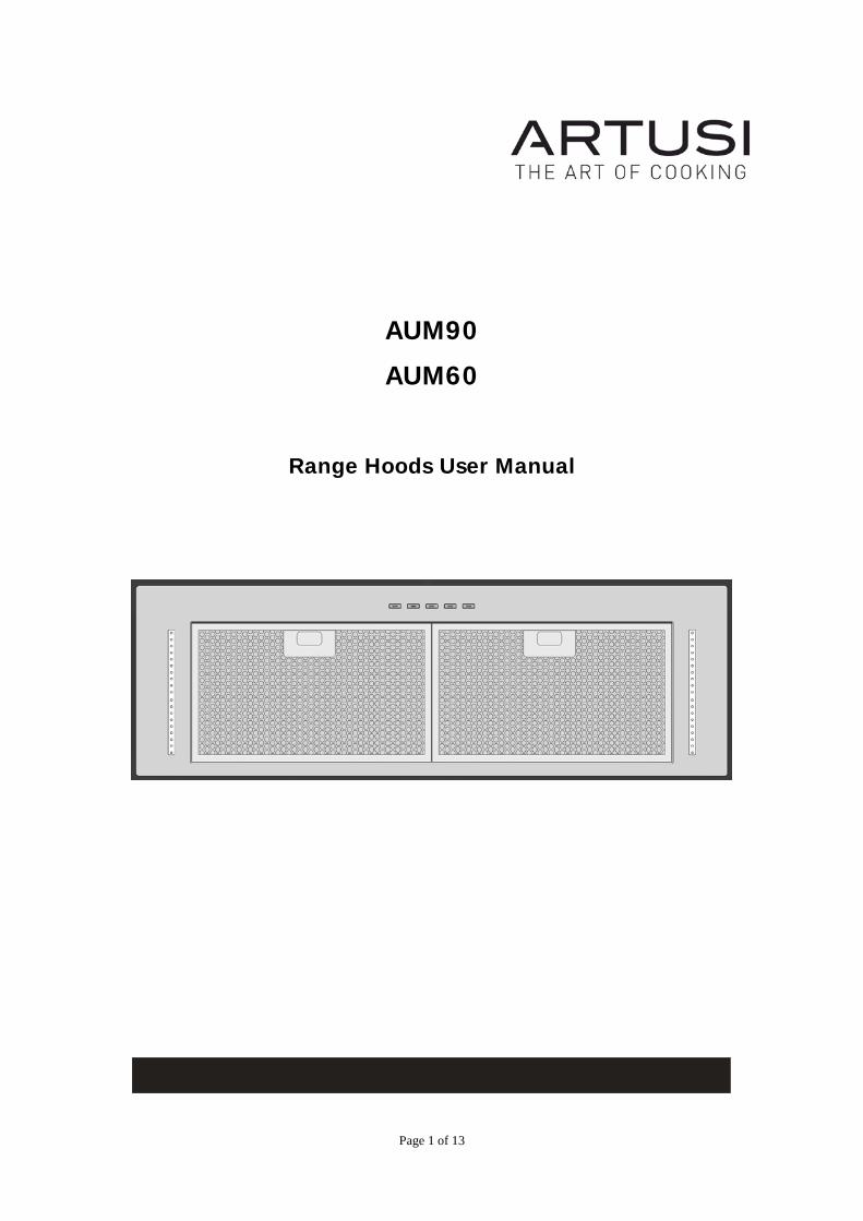
Page 1 of 13
AUM90
AUM60
Range Hoods User Manual

Page 2 of 13
IMPORTANT SAFETY INFORMATION
**Read the complete manual carefully before installation**
Warnings: TO REDUCE THE RISK OF FIRE, ELECTRICAL SHOCK OR PERSONAL INJURY, PLEASE OBSERVE THE FOL-LOWING: 1. Installation and electrical work must be done by a qualified person in accordance with all ap-plicable codes and standards 2. If the supply cord is damaged, it must be replaced by the manufacturer, its service agent or a similarly qualified person to avoid a hazard. Any modifications that may be required to the electrical system for the installation of the range hood must only be made by qualified electri-cians. 3. Before servicing or cleaning unit, switch power off at the service panel. Lock panel to prevent power from being switched on accidentally. 4. Use this unit only in the manner intended by the manufacturer. 5. Sufficient air is needed for combustion and exhausting of gases through the chimney of fuel burning equipment to prevent back drafting. Follow the heating equipment manufacturer's guidelines and safety standards, and the local code authorities. 6. When cutting or drilling into wall or ceiling, be carefully to do not damage existing electrical wiring and other hidden utilities. 7. Ducted fans must always be vented to the outdoors. 8. To reduce the risk of fire, use only metal ductwork. 9. This unit must be grounded. TO REDUCE THE RISK OF A RANGE TOP GREASE FIRE: 1. Never leave surface units unattended at high settings. Boil-overs cause smoke and greasy spillovers that may ignite. Heat oils slowly on low or medium settings. 2. Always turn hood ON when cooking at high heat. 3. Clean ventilating fans frequently. Grease should not be allowed to accumulate on fan or filter. 4. Use proper pan size. Always use cookware appropriate for the size of the surface element.
Page 3 of 13
WARNING
TO REDUCE THE RICK OF INJURY TO PERSONS IN THE EVENT OF A RANGE TOP GREASE FIRE, OBSERVE THE FOLLOWING: 1. SMOTHER FLAMES with a close-fitting lid, cookie sheet or metal tray, and then turn off the burner. If the flames do not go out immediately, evacuate and call the fire department. 2. NEVER PICK UP A FLAMING PAN. – You may be burned. 3. DO NOT USE WATER, including wet dishcloths or towels – a violent steam explosion will result. 4. Use an extinguisher ONLY if: You know you have a Class ABC extinguisher and you already know how to operate it. The fire is small and contained in the area where it started. The fire department is being called. You can fight the fire with your back to an exit.
CAUTION
1. To reduce the risk of fire and to properly exhaust air, be sure to duct air outside. Do not vent exhaust air into spaces within walls or ceiling or into attics, crawl spaces or garages. 2. Take care when using cleaning agents or detergents. 3. Avoid using food products that produce flames under the range hood. 4. The range hood must only be used for the exhaust of cooking fumes in home kitchens. The manufacturer disclaims all liability for any other use of the appliance. 5. Two installers are recommended because of the large size and weight of this hood. 6. Use with approved cord-connection kit only. 7. Please read specification label on product for further information and requirements.
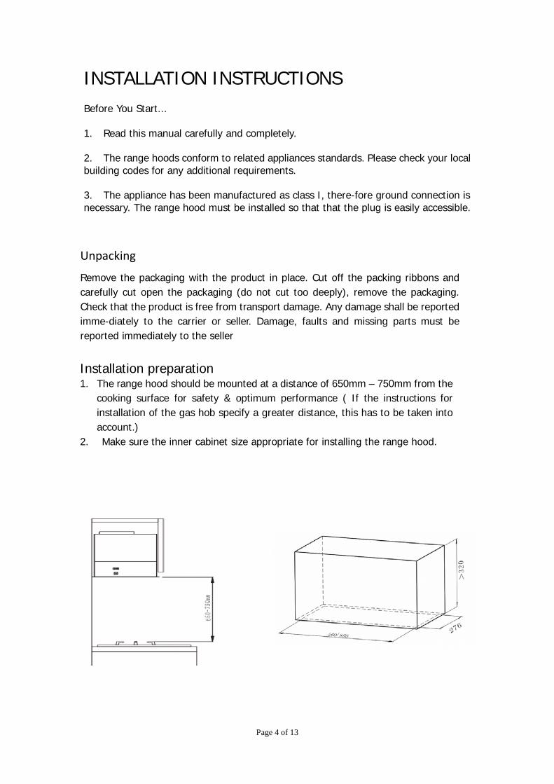
Page 4 of 13
INSTALLATION INSTRUCTIONS Before You Start... 1. Read this manual carefully and completely. 2. The range hoods conform to related appliances standards. Please check your local building codes for any additional requirements. 3. The appliance has been manufactured as class I, there-fore ground connection is necessary. The range hood must be installed so that that the plug is easily accessible.
Unpacking
Remove the packaging with the product in place. Cut off the packing ribbons and carefully cut open the packaging (do not cut too deeply), remove the packaging. Check that the product is free from transport damage. Any damage shall be reported imme-diately to the carrier or seller. Damage, faults and missing parts must be reported immediately to the seller
Installation preparation 1. The range hood should be mounted at a distance of 650mm – 750mm from the
cooking surface for safety & optimum performance ( If the instructions for installation of the gas hob specify a greater distance, this has to be taken into account.)
2. Make sure the inner cabinet size appropriate for installing the range hood.
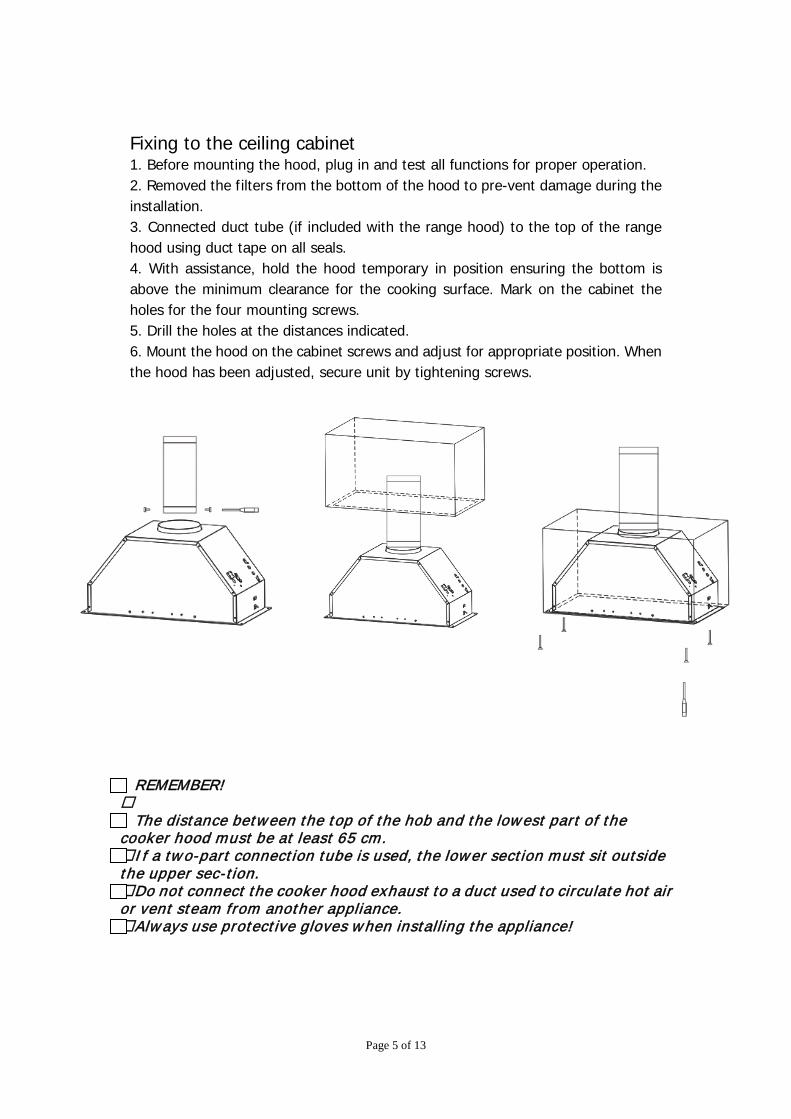
Page 5 of 13
REMEMBER! The distance between the top of the hob and the lowest part of the cooker hood must be at least 65 cm. I f a two-part connection tube is used, the lower section must sit outside the upper sec-tion. Do not connect the cooker hood exhaust to a duct used to circulate hot air or vent steam from another appliance. Always use protective gloves when installing the appliance!
Fixing to the ceiling cabinet 1. Before mounting the hood, plug in and test all functions for proper operation. 2. Removed the filters from the bottom of the hood to pre-vent damage during the installation. 3. Connected duct tube (if included with the range hood) to the top of the range hood using duct tape on all seals. 4. With assistance, hold the hood temporary in position ensuring the bottom is above the minimum clearance for the cooking surface. Mark on the cabinet the holes for the four mounting screws. 5. Drill the holes at the distances indicated. 6. Mount the hood on the cabinet screws and adjust for appropriate position. When the hood has been adjusted, secure unit by tightening screws.
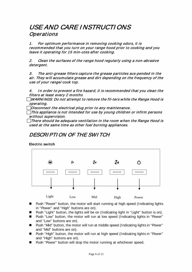
Page 6 of 13
USE AND CARE INSTRUCTIONS Operations 1. For optimum performance in removing cooking odors, it is recommended that you turn on your range hood prior to cooking and you leave it operating for 15 min-utes after cooking. 2. Clean the surfaces of the range hood regularly using a non-abrasive detergent. 3. The anti-grease filters capture the grease particles sus-pended in the air. They w ill accumulate grease and dirt depending on the frequency of the use of your range/ cook top. 4. In order to prevent a fire hazard, it is recommended that you clean the filters at least every 2 months WARNINGS: Do not attempt to remove the fil-ters while the Range Hood is operating. Disconnect the electrical plug prior to any maintenance. This appliance is not intended for use by young children or infirm persons w ithout supervision. There should be adequate ventilation in the room when the Range Hood is used at the same time as other fuel burning appliances.
DESCRIPTION OF THE SWITCH Electric switch
Push “Power” button, the motor will start running at high speed (Indicating lights
in “Power” and “High” buttons are on). Push “Light” button, the lights will be on (Indicating light in “Light” button is on). Push “Low” button, the motor will run at low speed (Indicating lights in “Power”
and “Low” buttons are on). Push “Mid” button, the motor will run at middle speed (Indicating lights in “Power”
and “Mid” buttons are on). Push “High” button, the motor will run at high speed (Indicating lights in “Power”
and “High” buttons are on). Push “Power” button will stop the motor running at whichever speed.
Light Low Mid High Power
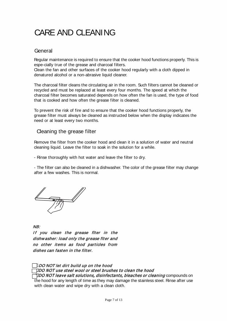
Page 7 of 13
CARE AND CLEANING General
DO NOT let dirt build up on the hood DO NOT use steel wool or steel brushes to clean the hood DO NOT leave salt solutions, disinfectants, bleaches or clean ing compounds on the hood for any length of time as they may damage the stainless steel. Rinse after use with clean water and wipe dry with a clean cloth.
Regular maintenance is required to ensure that the cooker hood functions properly. This is espe-cially true of the grease and charcoal filters. Clean the fan and other surfaces of the cooker hood regularly with a cloth dipped in denatured alcohol or a non-abrasive liquid cleaner. The charcoal filter cleans the circulating air in the room. Such filters cannot be cleaned or recycled and must be replaced at least every four months. The speed at which the charcoal filter becomes saturated depends on how often the fan is used, the type of food that is cooked and how often the grease filter is cleaned. To prevent the risk of fire and to ensure that the cooker hood functions properly, the grease filter must always be cleaned as instructed below when the display indicates the need or at least every two months.
Cleaning the grease filter Remove the filter from the cooker hood and clean it in a solution of water and neutral cleaning liquid. Leave the filter to soak in the solution for a while. - Rinse thoroughly with hot water and leave the filter to dry. - The filter can also be cleaned in a dishwasher. The color of the grease filter may change after a few washes. This is normal.
NB: I f you clean the grease flter in the dishwasher: load only the grease flter and no other items as food particles from dishes can fasten in the filter.
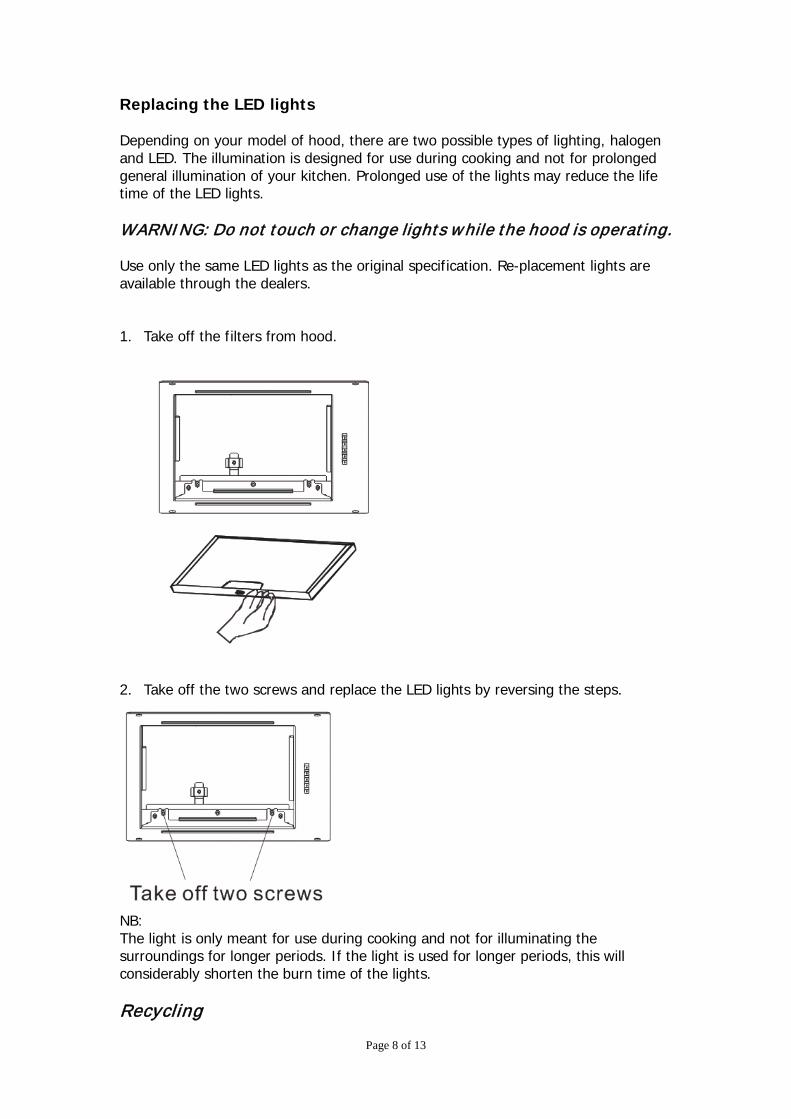
Page 8 of 13
Replacing the LED lights Depending on your model of hood, there are two possible types of lighting, halogen and LED. The illumination is designed for use during cooking and not for prolonged general illumination of your kitchen. Prolonged use of the lights may reduce the life time of the LED lights. WARNING: Do not touch or change lights while the hood is operating. Use only the same LED lights as the original specification. Re-placement lights are available through the dealers. 1. Take off the filters from hood.
2. Take off the two screws and replace the LED lights by reversing the steps.
NB: The light is only meant for use during cooking and not for illuminating the surroundings for longer periods. If the light is used for longer periods, this will considerably shorten the burn time of the lights. Recycling
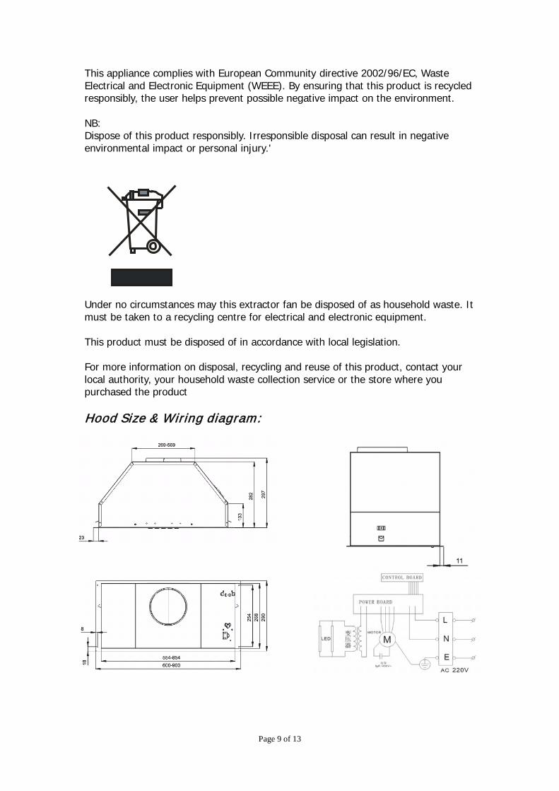
Page 9 of 13
This appliance complies with European Community directive 2002/96/EC, Waste Electrical and Electronic Equipment (WEEE). By ensuring that this product is recycled responsibly, the user helps prevent possible negative impact on the environment. NB: Dispose of this product responsibly. Irresponsible disposal can result in negative environmental impact or personal injury.' Under no circumstances may this extractor fan be disposed of as household waste. It must be taken to a recycling centre for electrical and electronic equipment. This product must be disposed of in accordance with local legislation. For more information on disposal, recycling and reuse of this product, contact your local authority, your household waste collection service or the store where you purchased the product Hood Size & Wiring diagram:

Page 10 of 13
Trouble Shooting Guide Problem Possible Reason Solution
Hood doesn't turn on. No electrical supply. Check the plug is connect-ed.
Check the plug is connect-ed. Power cord is damaged Contact technician service
Poor Airflow
Aluminum grease filters clogged
Clean the filters and replace when dry.
Charcoal filters clogged. Re-circulating mode only.
Replace the charcoal filters.
Hood is vibrating Hood is not secured in place Check the installation of
hood.Tighten mounting screws.
Motor running but no air flow
Butterfly valve jammed. Contact technician service
Motor stops after a few minutes
High temperature safety device activated.
The kitchen is not sufficient-ly ventilated.
The hood is installed too near the cooking surface.
The hood must be at least 61cm (24”) from the stove
Strong cooking smell.
Fan speed too low Use one of the higher set-tings.
Charcoal filters not installed. n re-circulating mode, char-coal filters must be installed.
Oil dripping onto stove.
Aluminum grease filter satu-rated.
Wash the aluminum grease filters
Whirring sound Something in contact with fan blade.
Contact technician service
Lights are working but
fan isn't
Contact technician service
Fan is working but lights are not
Contact technician service
GUARANTEE AND SERVICE! Before booking a service call, read the Trouble Shooting Guide above , for more information on guarantee and service conditions, please contact local dealer.

Page 11 of 13
Page 12 of 13
Page 13 of 13


INSTRUCTION MANUAL FOR GAS COOKTOPS
MODELS ILGP32X, ILGP64X, ILGP75X, ILGP96X

OPEN 24/7ILVE ACCESSORIES ONLINE SHOP
-VY�H�^PKL�YHUNL�VM�JVɈLL�THJOPULZ��WVKZ��HUK�V[OLY�03=,�HJJLZZVYPLZ�H[�[OL�JSPJR�VM�H�I\[[VU�ZOVW�PS]L�JVT�H\
IT AUS FRDear customer,We thank you and con-gratulate you on yourchoice.This new carefully de-signed product, manu-factured with the highestquality materials, has beencarefully tested to satisfyall your cooking demands.We would therefore requestyou to read and follow theseeasy instructions whichwill allow you to obtain ex-cellent results right fromthe start.May we wish you all thevery best with your modernappliance!
THE MANUFACTURER
Chère cliente, Cher client,merci et sincères félici-tations pour le choix quevous avez fait.Ce nouveau produit,développé avec soin etfabriqué avec des matièresde toute première qualité,a été soigneusement rodépour satisfaire toutes Vosexigences d’une cuissonparfaite.Veuillez lire attentivementles instructions simplesportées sur cette notice quivous permettront d’obte-nir d’excellents résultatsdès la première utilisation.Nous vous souhaitons uneentière et pleine satisfac-tion quant à l’utilisationde cet appareil moderne.
LE CONSTRUCTEURIndexInstructionsfor use
Installation 4Use 4-8
Instructionsfor the installater
Electrical connection4
User characteristics44-4
IndexNoticed’emploiInstallation 4Mode d’emploi 4-8
Modalitésd’installation
Branchement
Caractéristiques
Caro Cliente,sentitamente La ringra-ziamo e ci congratuliamoper la scelta da Lei fatta.Questo nuovo prodotto,accuratamente progettatoe costruito con materiali diprimissima qualità, è statoaccuratamente collaudatoper poter soddisfare tuttele Sue esigenze di unaperfetta cottura.La preghiamo pertanto dileggere e rispettare le faciliistruzioni che Le permet-teranno di raggiungereeccellenti risultati sin dallaprima utilizzazione.Con questo moderno ap-parecchio Le formuliamo inostri più vivi auguri.
IL COSTRUTTORE
Indice
Istruzioniper l’utenteInstallazione 4Uso 4-8Manutenzione 3
Istruzioni perl’installatore
Installazione 3Collegamento gas 3Collegamentoelettrico 42Caratteristicheutilizzatori 44-47
2 Maintenance 32 Entretien 32
6 Installation 36 Installation 368 Gas connection 38 Connexion gaz 38
2 électrique 42
7 utilisateurs 44-47THIS APPLIANCE IS CONCEIVED FOR DOMESTIC USE ONLY. THE MANUFACTURER SHALL NOT IN ANY WAY BE HELD RESPONSIBLE
FOR WHATEVER INJURIES OR DAMAGES ARE CAUSED BY INCORRECT INSTALLATION OR BY UNSUITABLE, WRONG OR ABSURD USE.
T HIS APPLIANCE IS NOT INTENDED FOR USE BY PERSONS (INCLUDING CHILDREN) WITH REDUCED PHYSICAL, SENSORY OR MENTAL CAPABILITIES, OR LACK OF EX PERIENCE AND K NOWLEDGE
, UNLESS THEY HAVE BEEN GIVEN SUPERVISION OR INSTRUCTION CONCERNING USE OF THE APPLIANCE BY A PERSON RESPONSIBLE FOR THEIR SAFETY . C HILDREN SHOULD BE SUPERVISED TO ENSURE THAT THEY DO NOT PLAY WITH THE APPLIANCE .
QUESTO PRODOTTO È STATO CONCEPITO PER UN IMPIEGO DI TIPO DOMESTICO. IL COSTRUTTOREDECLINA OGNI RESPONSABILITÀ
NEL CASO DI EVENTUALI DANNI A COSE O PERSONE DERIVANTI DA UNA NON CORRETTA INSTALLAZIONE O DA USO IMPROPRIO, ERRONEO OD ASSURDO.
L’ APPARECC HIO NON DEVE ESSERE USATO DA PERSONE (COMPRESI BAMBINI) CON RIDOTTE CAPACITÀ FISIC HE,
SENSORIALI O MENTALI, O DA PERSONE CHE MANCANO DELL ’ESPERIENZA E DELLE CONOSCENZE NECESSARIE SE NON SOTTO LA SUPERVISIONE O DIETRO ISTRUZIONI SULL ’USO DELL ’APPARECC HIO DA PARTE DI UNA PERSONA RESPONSABILE PER LA LORO SICUREZZA . I BAMBINI DEVONO ESSERE CONTROLLATI PER ASSICURARSI CHE NON GIOC HINO CON L’ APPARECC HIO .
CE PRODUIT EST CONÇU EXCLUSIVEMENT POUR USAGE DOMESTIQUE. LE CONSTRUCTEUR DÉCLINE TOUTE RESPONSABILITÉ
POUR DOMMAGES ET BLESSURES CAUSÉES PAR UNE INSTALLATION INCORRECTE OU PAR UN USAGE IMPROPRE, ERRONÉ OU ABSURDE.
L’ APPAREIL NE DOIT PAS Ê TRE UTILISÉ PAR DES PERSONNES (EN FANTS INCLUS) DISPOSANT DE CAPACITÉS P HYSIQUES ,
SENSORIELLES OU MENTALES RÉDUITES, OU PAR DES PERSONNES N’AY ANT PAS L’ EXPÉRIENCE OU LES CONNAISSANCES REQUISES, SI CE N’ EST SOUS LA SURVEILLANCE D’ UNE PERSONNE RESPONSABLE DE LEUR SÉCURITÉ OU APRÈS AVOIR REÇU DE CELLE -CI LES INSTRUCTIONS RELATIVES À L’ UTILISATION DE L’ APPAREIL . L ES EN FANTS DOIVENT Ê TRE SURVEILLÉS, AF IN DE S’ ASSURER QU ’ILS NE JOUENT PAS AVEC L’ APPAREIL .If the supply cord is damaged, it must be
replaced by the manufacturer or its service
avoid a hazard.WHERE THIS APPLIANCE IS INSTALLED IN MARINE CRAFT OR IN CARAVANS, IT SHALL NOT BE USED AS A SPACE HEATER.DO NOT SPRAY AEROSOLS IN THE VICINITYOF THIS APPLIANCE WHILE IT IS IN OPERATION.
2DO NOT USE OR STORE FLAMMABLE MATERIALSNEAR THIS APPLIANCE.DO NOT MODIFY THIS APPLIANCE.
IT AUS FRIstruzioniper l’utenteInstallazioneTutte le operazioni rela-tive all’installazione (al-lacciamento elettrico, al-lacciamento gas, adat-tamento al tipo di gas,conseguenti regolazioni,ecc.) devono essere ese-guite da personale quali-
vigenti. Per le istruzioni
riservata all’installatore.
UsoBruciatori gas (Figg. 1-3).L'accensione del bruciatoreavviene avvicinando una
superiore dello stessopremendo e ruotando insenso antiorario la ma-nopola corrispondente sinoa farne coincidere l'indicecon la posizione di mas-simo. Ad accensione av-
secondo la necessità. Laposizione di minimo sitrova al termine delle rota-zione antioraria. Neimodelli con accensioneautomatica agire sulla ma-nopola come sopradescritto, premendo con-temporaneamente l'ap-posito pulsante. Nei modellicon accensione automatica/simultanea (a una mano) è
descritto sulla solamanopola corrispondente.La scarica elettrica fracandelina e bruciatore dàluogo all'accensione delbruciatore interessato. Adaccensione avvenuta rila-sciare immediatamente il
ma secondo necessità.L’accensione del bruciatorenei modelli con sicurezzatermoelettrica avviene come
Instructionsfor useInstallationAll the operations con-cerned with the installation(electrical and gasconnections, adaptation totype of gas, necessaryadjustments, etc.) must be
personel, in terms withthe standards in force.
kindly read the parttitled, Instructions for the installer.
UseGas burners (Fig. 1-3).The ignition of the gasburner is carried out by
upper part holes of theburner, pressing androtating the correspondingknob in an anti-clockwisemanner, until the maxi-mum position has coincidedwith the marker. When thegas burner has been turned
according to need. Theminimum position is foundat the end of the anti-clockwise rotationdirection.In models with automaticignition, push the controlknob down to initiate theignition spark, then turnthe knob to maximum �ame.For models with automatic/simultaneous (with onehand) ignition, it is
described above using thecorresponding knob. Theelectric spark between theignition plug and theburner provides theignition of the burner itself.After ignition, immediatelyrelease the push-button and
to need.For models with athermoelectric safety
Noticed’emploiInstallationToutes les opérations rela-tives à l’installation(branchement électrique,raccordement gaz,adaptation au type de gaz,réglages nécessaires, etc...)
des spécialistes suivant lesnormes en vigueur.Pour les instructions spéci-
concerne les modalitésd’installation.
Mode d’emploiBrûleurs à gaz (Fig. 1-3). Onallume le brûleur en ap-
aux trous de sa partiesupérieure en poussant ettournant dans le senscontraire des aiguilles d’unemontre la manette corre-spondant jusqu’à faire coïn-cider l’aiguille avec laposition de maximum.Quand le bruleur est en
selon la nécéssité. La po-sition de minimum se
contraire au sens des aiguil-les d’une montre.Pour les modèles à allu-mage automatique tourner
la manette comme indiquèci-dessus, en poussant enmeme temps le bouton
spècial. Pour les modèles àallumage automatique/simultané (à une main), il
correspondant, comme il estindiqué ci-dessus. La dé-charge électrique entre lapetite bougie et le brûleurallume le brûleur interessé.Quand le brûleur estallumé, lâcher la manette, et
nécéssité.Dans le cas de modèlesdoués de sûreté thermo-
carried out by authorised
4
IT AUS FRnei diversi casi sopra de-scritti tenendo premuta afondo la manopola nellaposizione di massimo percirca 3/5 secondi. Nelrilasciare la manopola as-sicurarsi che il bruciatorerimanga acceso.N.B. - si consiglia di usarepentole di diametro adattoai bruciatori evitando che la
fuoriesca dal fondo dellestesse- non lasciare pentole vuotesul fuoco acceso- sui piani Crystal non usareaccessori di cottura allagriglia.Al termine della cottura èbuona norma provvedereanche alla chiusura del rubi-netto principale delcondotto e/o della bombola.
system, the burner isignited as in the variouscases described above,keeping the knob fullypressed on the maximumposition for approximately3/5 seconds. After releasingthe knob, make sure theburner is actually lit.N.B. - we recommend theuse of pots and pans with adiameter matching that ofthe burner, thus preventing
from the bottom part andsurrounding the pot- do not leave any empty
- do not use any tools forgrill-cooking on Crystalhobs.
is also a good norm to closethe main gas pipe tap and/or cylinder.
électrique, l'allumage dubrûleur a lieu comme dansles cas décrits ci-dessus enappuyant à fond sur lamanette placée à la positionmaximale pendant environ3/5 secondes. Au momentoù vous relâchez la manette,assurez-vous que le brûleurest allumé.N.B.: - on Vous conseilled’utiliser des casserolesavec un diamètre propor-tionné aux brûleurs évitant
déborde de leur fond- ne laissez jamais de cas-seroles vides sur le feu al-lumé- n'employez pas d'usten-siles pour cuisson grill surles plaques dessus verre.
fermer le robinet principaldu conduit et/ou de la bou-teille.Modelli con bruciatore Dual
WokAlcuni modelli sono dotati di un bruciatore Dual Wok. E’ possibile accendere la fiamma centrale (F1) ruotando e premendo la manopola in senso orario, oppure accendere tutto il bruciatore (F2), come indicato in figura qui sotto.
Modèles avec Dual WokCertains modèles sont munis d’un brûleur Dual Wok. Il est possible d’allumer la flamme centrale (F1) en tournant et en pressant la bouton dans le sens horaire, ou allumer tout le brûleur (F1) de la façon indiquée sur la figure ci-dessous.
6
IT AUS FR
termoelettrica non azionare l’accensione oltre 15 secondi. Se dopo 15 secondi il bruciatore non si è acceso, aprire la porta del locale e attendere almeno un minuto prima di ritentare.nei piani senza sicurezza in caso di estinzione delle fiamme di un bruciatore chiudere il rubinetto corrispondente e non ritentare l’accensione prima di un minuto.
Piastre elettriche / Elementi riscaldanti vetroceramici (Figg. 2-2a-3). Ruotare la manopola sulla posizione corrispondente alle necessità di cottura tenendo presente che a numero maggiore corrisponde maggiore erogazione di calore, vedi tabella “utilizzo piastre elettriche”/elementi riscaldanti vetroceramici.La lampada spia accesa segnala l’inserimento della piastra. Va comunque considerato normale, per certi tipi di lampada, il permanere di una leggera luminescenza anche a comandi disinseriti.
Pour de certains types de voyants lumineux la permanence d’une légère luminiscence même à commandes déconnectées est tout à fait normale.
- nei piani con sicurezza
-
Importante- l’uso dell’apparecchio
produce calore e umidità nella stanza in cui è installato. Assicurarsi che la cucina sia sufficientemente ventilata; mantener e aperti i fori di ventilazione naturale o installare dispositivi meccanici di ventilazione (es. cappa).
- L’uso prolungato dell’appar ecchio può richiedere ulterior e ventilazione, per esempio l’apertura di una finestra.
Important- use of the appliance produces
heat and moisture in the room where it is installed. Make sure the kitchen is sufficiently ventilated; keep natural ventilation holes open or install mechanical ventilation devices (such as a hood).
- Prolonged use of the appliance may require additional ventilation, such as opening a window.
Important- L’utilisation de l’appareil produit de
la chaleur et de l’humidité dans le local d’installation. S’assurer que la cuisine est suffisamment aérée ; ne pas obstruer les orifices d’aération naturelle ou installer des dispositifs mécaniques d’aération (ex. une hotte).
- L’utilisation prolongée de l’appareil peut exiger un supplément d’aération, comme l’ouverture d’une fenêtre.
Va comunque considerato normale, per certi tipi di lampada, il permanere di una leggera luminescenza anche a comandi disinseriti.
Important
protection do not keep the ignite button pushed for more than 15 seconds. If the burner has not ignited after 15 seconds, open the door of the room and wait at least one minute before making a further attempt.
should the burner flame go out close the corresponding gas cock and wait at least one minute before making any attempt to ignite it.
Electrical plates / Vitroceramic heating elements (Fig. 2-2a-3). Rotate the knob towards the position required for cooking and bear in mind that the higher the number, the higher the heat output. See table “use of electrical plates”/ heating elements vitroceramic. The pilot light signals that the plate is “on”. Some types of pilot lights will maintain some slight luminescence even after disconnection. That is quite normal.
Important
thermoélectrique, ne pas activer l’allumage pendant plus de 15 secondes. Si , après 15 secondes le brûleur ne s’est pas allumé, ouvrir la porte de la pièce et attendre au moins une minute avant de réessayer.
pas dotées de sécurité, en cas d’extinction des flammes d’un brûleur, fermer le robinet correspondant et attendre au moins une minute avant de réessayer.
Plaque électriques / Eléments de chau�e vitrocéramiques (Fig. 2-2a3). Tourner le bouton dans la position correspondante aux nécessités de cuisson, en gardant à l’esprit que la position maximum correspond à la plus grand émission de chaleur, voir tableau “utilisation plaques électriques”/eléments de chau�e vitrocéramiques. Le voyant lumineux allumé indique le fonctionnement de la plaque. Pour de certains types de voyants lumineux la permanence d’une légère luminiscence même à commandes déconnectées est tout à fait normale.
- on floors with thermoelectric
- on floors without protection,
- sur les plaques dotées de sécurité
- sur les plaques qui ne sont
protection do not keep the ignite button pushed for more than 15 seconds. If the burner has not ignited after 15 seconds, open the door of the room and wait at least one minute before making a further attempt.
should the burner flame go out close the corresponding gas cock and wait at least one minute before making any attempt to ignite it.
Electrical plates / Vitroceramic heating element(Fig. 2-2a-3). Rotate the knob towards the position required for cooking and bear in mind that the higher the number, the higher the heat output. See ta“use of electrical plates”/ heatiing
light signals that the plate is “on”. Some types of pilot lights will maintain some slight luminescence even after disconnection. That is quite normal.
elements vitroceramic. The pil
- on floors with thermoelectric
- on floors without protection,
-
Abnormal OperationAny of the following are considered to be abnormal operation and may require servicing:Yellow tipping of the hob burner �ame.Sooting up of cooking utensils.Burners not igniting properly.Burners failing to remain alight.Burners extinguished by cupboard doors.Gas valves, which are di�cult to turn.In case the appliance fails to operate correctly, contact the authorised personnel in your area”.
non azionare l’accensione oltre 15 secondi. Se dopo 15 secondi il bruciatore non si è acceso, aprire la porta del locale e attendere almeno un minuto prima di ritentare.nei piani senza sicurezza in caso di estinzione delle fiamme di un bruciatore chiudere il rubinetto corrispondente e non ritentare l’accensione prima di un minuto.
Piastre elettriche / Elementi riscaldanti vetroceramici (Figg. 2-2a-3). Ruotare la manopola sulla posizione corrispondente alle necessità di cottura tenendo presente che a numero maggiore corrisponde maggiore erogazione di calore, vedi tabella “utilizzo piastre elettriche”/elementi riscaldanti vetroceramici.La lampada spia accesa segnala l’inserimento della piastra. Va comunque considerato normale, per certi tipi di lampada, il permanere di una leggera luminescenza anche a comandi disinseriti.
Important
protection do not keep the ignite button pushed for more than 15 seconds. If the burner has not ignited after 15 seconds, open the door of the room and wait at least one minute before making a further attempt.
should the burner flame go out close the corresponding gas cock and wait at least one minute before making any attempt to ignite it.
Electrical plates / Vitroceramic heating elements (Fig. 2-2a-3). Rotate the knob towards the position required for cooking and bear in mind that the higher the number, the higher the heat output. See table “use of electrical plates”/ heating elements vitroceramic. The pilot light signals that the plate is “on”. Some types of pilot lights will maintain some slight luminescence even after disconnection. That is quite normal.
Important
thermoélectrique, ne pas activer l’allumage pendant plus de 15 secondes. Si , après 15 secondes le brûleur ne s’est pas allumé, ouvrir la porte de la pièce et attendre au moins une minute avant de réessayer.
pas dotées de sécurité, en cas d’extinction des flammes d’un brûleur, fermer le robinet correspondant et attendre au moins une minute avant de réessayer.
Plaque électriques / Eléments de chauffe vitrocéramiques (Fig. 2-2a3). Tourner le bouton dans la position correspondante aux nécessités de cuisson, en gardant à l’esprit que la position maximum correspond à la plus grand émission de chaleur, voir tableau “utilisation plaques électriques”/eléments de chauffe vitrocéramiques. Le voyant lumineux allumé indique le fonctionnement de la plaque. Pour de certains types de voyants lumineux la permanence d’une légère luminiscence même à commandes déconnectées est tout à fait normale.
- nei piani con sicurezza
-
- on floors with thermoelectric
- on floors without protection,
- sur les plaques dotées de sécurité
- sur les plaques qui ne sont
IT GB FRImportante Important
protection do not keep the ignite button pushed for more than 15 seconds. If the burner has not ignited after 15 seconds, open the door of the room and wait at least one minute before making a further attempt.
should the burner flame go out close the corresponding gas cock and wait at least one minute before making any attempt to ignite it.
Electrical plates / Vitroceramic heating elements (Fig. 2-2a-3). Rotate the knob towards the position required for cooking and bear in mind that the higher the number, the higher the heat output. See table “use of electrical plates”/ heating elements vitroceramic. The pilot light signals that the plate is “on”. Some types of pilot lights will maintain some slight luminescence even after disconnection. That is quite normal.
Important
thermoélectrique, ne pas activer l’allumage pendant plus de 15 secondes. Si , après 15 secondes le brûleur ne s’est pas allumé, ouvrir la porte de la pièce et attendre au moins une minute avant de réessayer.
pas dotées de sécurité, en cas d’extinction des flammes d’un brûleur, fermer le robinet correspondant et attendre au moins une minute avant de réessayer.
Plaque électriques / Eléments de chauffe vitrocéramiques (Fig. 2-2a3). Tourner le bouton dans la position correspondante aux nécessités de cuisson, en gardant à l’esprit que la position maximum correspond à la plus grand émission de chaleur, voir tableau “utilisation plaques électriques”/eléments de chauffe vitrocéramiques. Le voyant lumineux allumé indique le fonctionnement de la plaque.
- on floors with thermoelectric
- on floors without protection,
- sur les plaques dotées de sécurité
- sur les plaques qui ne sont
IT GB FRImportante
termoelettrica non azionare l’accensione oltre 15 secondi. Se dopo 15 secondi il bruciatore non si è acceso, aprire la porta del locale e attendere almeno un minuto prima di ritentare.nei piani senza sicurezza in caso di estinzione delle fiamme di un bruciatore chiudere il rubinetto corrispondente e non ritentare l’accensione prima di un minuto.
Piastre elettriche / Elementi riscaldanti vetroceramici (Figg. 2-2a-3). Ruotare la manopola sulla posizione corrispondente alle necessità di cottura tenendo presente che a numero maggiore corrisponde maggiore erogazione di calore, vedi tabella “utilizzo piastre elettriche”/elementi riscaldanti vetroceramici.La lampada spia accesa segnala l’inserimento della piastra.
- nei piani con sicurezza
-
IT GB FRImportante
termoelettrica non azionare l’accensione oltre 15 secondi. Se dopo 15 secondi il bruciatore non si è acceso, aprire la porta del locale e attendere almeno un minuto prima di ritentare.nei piani senza sicurezza in caso di estinzione delle fiamme di un bruciatore chiudere il rubinetto corrispondente e non ritentare l’accensione prima di un minuto.
Piastre elettriche / Elementi riscaldanti vetroceramici (Figg. 2-2a-3). Ruotare la manopola sulla posizione corrispondente alle necessità di cottura tenendo presente che a numero maggiore corrisponde maggiore erogazione di calore, vedi tabella “utilizzo piastre elettriche”/elementi riscaldanti vetroceramici.La lampada spia accesa segnala l’inserimento della piastra. Va comunque considerato normale, per certi tipi di lampada, il permanere di una leggera luminescenza anche a comandi disinseriti.
Important Important
thermoélectrique, ne pas activer l’allumage pendant plus de 15 secondes. Si , après 15 secondes le brûleur ne s’est pas allumé, ouvrir la porte de la pièce et attendre au moins une minute avant de réessayer.
pas dotées de sécurité, en cas d’extinction des flammes d’un brûleur, fermer le robinet correspondant et attendre au moins une minute avant de réessayer.
Plaque électriques / Eléments de chauffe vitrocéramiques (Fig. 2-2a3). Tourner le bouton dans la position correspondante aux nécessités de cuisson, en gardant à l’esprit que la position maximum correspond à la plus grand émission de chaleur, voir tableau “utilisation plaques électriques”/eléments de chauffe vitrocéramiques. Le voyant lumineux allumé indique le fonctionnement de la plaque. Pour de certains types de voyants lumineux la permanence d’une légère luminiscence même à commandes déconnectées est tout à fait normale.
- nei piani con sicurezza
-
sur les plaques dotées de sécurité
- sur les plaques qui ne sont
8
IT AUS FR
Fig. 1 - Abb. 1 - Afb. 1
pesciera 20x32corona Ø 20-32rapido Ø 20-26semirapido Ø 14-20ausiliario Ø 10-14
wok Ø 20-32mmrapid Ø 20-26mmsemi-rapid auxiliarypoisson 20x32wok Ø 20-32rapide Ø 20-26semirapide Ø 14-20auxiliaire Ø 10-14
wok Ø 20-32schnell Ø 20-26halbschnell Ø 14-20hilfbrenner Ø 10-14pesciera 20x32corona Ø 20-32rápido Ø 20-26semirápido Ø 14-20auxiliar Ø 10-14vis 20x32wok Ø 20-32snel Ø 20-26matig snel Ø 14-20sudderpit Ø 10-14pesciera 20x32coroa Ø 20-32rápido Ø 20-26semi-rápido Ø 14-20auxiliar Ø 10-14 Fig. 2 - Abb. 2 - Afb. 2
DISINSERITOSWITCHED OFF
DEBRANCHEABGESCHALTET
DESCONECTADOUITGESCHAKELD
DESLIGADO
GASGAZ
PIASTRE ELETTRICHEELECTRICAL PLATESPLAQUE ELECTRIQUESKOCHPLATTENPLACAS ELÉCTRICASELEKTRISCHE KOOKPLATENCHAPAS ELÉCTRICAS
* with reduction grid
Warning: To ensure a safeworking distance is maintainedbetween the control knobs and the pot, it is recommendedthat large pots are not used on the central, front burner of the 6 burner model. Always centralise pots overthe burners and check that the pot is not too close to the control knobs.
*
*
*
*
*
*
*
NON FISSARE INTENSAMENTELA LAMPADA ALOGENA.
DO NOT STARE AT THE HALOGEN LAMP.
NE PAS FIXER INTENSÉMENT LA LAMPE HALOGÈNE.
10
Ø 14-20mmØ 10-14mm
N.B. Nell’uso di piastre elettriche /elementi riscaldanti vetroceramici si consigliano recipienti a fondo piatto con diametro uguale o leggermente superiore a quello della piastra.• evitare trabocchi di liquido;
pertanto ad ebollizione avvenuta o comunque a liquido riscaldato ridurre l’erogazione di calore;
• non lasciare inserite le piastre elettriche a vuoto o con pentole o tegami vuoti;
• al termine della cottura riportare la manopola in posizione di chiuso e/o disinserito.
Al verificarsi di una anche minima frattura della superficie del piano vetroceramico di cottura disinserire immediatamente l’alimentazione elettrica.
N.B.: When using electrical plates / heating elements vitroceramic, we recommend flat bottom recipients with a diameter equal or slightly larger than that of the plate itself. • avoid liquid overflow. Therefore,
after boiling or heating liquids, reduce the heat output;
• do not leave the electrical plates on with empty pots and pans;
• when cooking is finished, rotate the knob back into closing and/or disconnected position.
In the event of even a slight fracture on the cooking vitroceramic surface, disconnect the electric power supply immediately.
N.B. Dans l’emploi des plaques électriques / eléments de chauffe vitrocéramiques on Vous conseille des récipients à fond plat avec le diamètre égal ou legèrement superieur à celui de la plaque. • éviter les débordements de liquide;
ainsi après l’ébullition ou même, quand le liquide a été réchauffé, réduire l’émission de la chaleur;
• ne pas laisser les plaques électriques branchées à vide ou avec des casseroles ou des poêles vides;
• à cuisson terminée, tourner le bouton jusqu’à la position de fermeture et/ ou déconnexion.
Si vous constatez l’apparition d’une fissure, même légère, sur la surface du plan vitrocéramique de cuisson, débranchez immédiatement l’appareil.
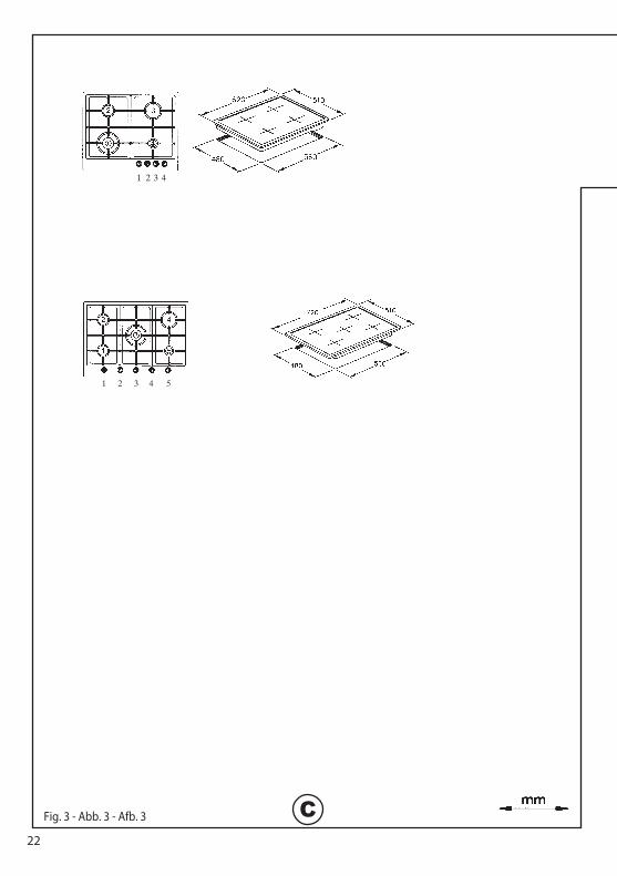
1 2 3 4 5
Fig. 3 - Abb. 3 - Afb. 3 C
1 2 3 4
22
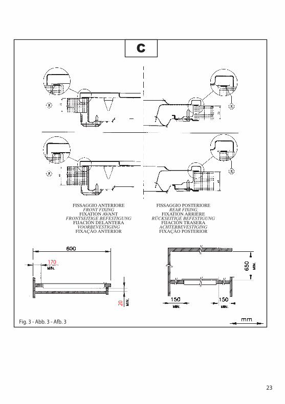
Fig. 3 - Abb. 3 - Afb. 3
FISSAGGIO ANTERIOREFRONT FIXING
FIXATION AVANTFRONTSEITIGE BEFESTIGUNG
FIJACIÓN DELANTERAVOORBEVESTIGING
FIXAÇÃO ANTERIOR
FISSAGGIO POSTERIOREREAR FIXING
FIXATION ARRIÉRERÜCKSEITIGE BEFESTIGUNG
FIJACIÓN TRASERAACHTERBEVESTIGINGFIXAÇÃO POSTERIOR
C
170
20
23
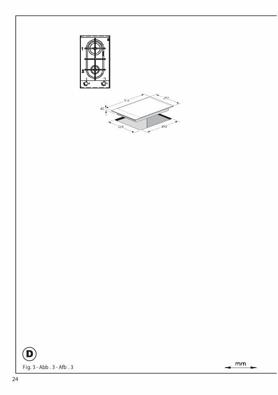
Fig. 3 - Abb . 3 - Afb . 3
D
24
1 2
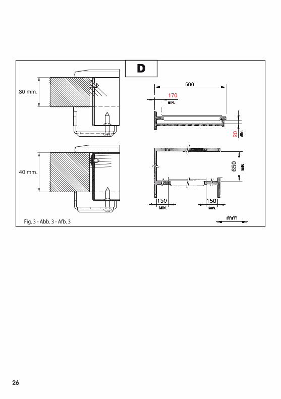
Fig. 3 - Abb. 3 - Afb. 3
D
650
40 mm.
30 mm.170
20
26
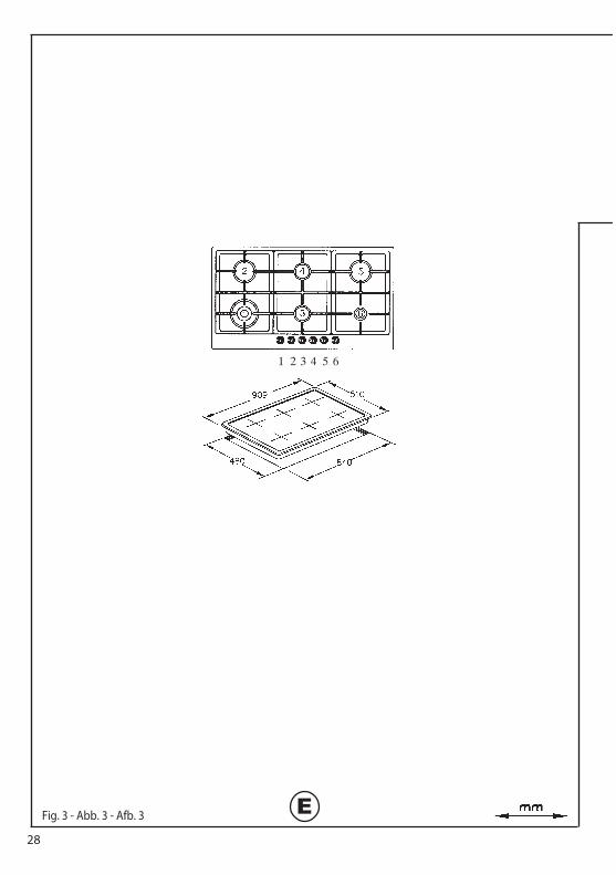
1 2 3 4 5 6
Fig. 3 - Abb. 3 - Afb. 3 E28
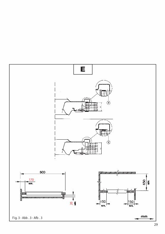
Fig. 3 - Abb . 3 - Afb . 3
E
29
170
20
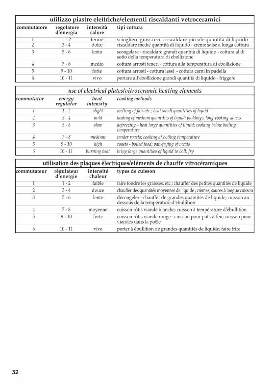
IT GB FRutilizzo piastre elettriche/elementi riscaldanti vetroceramicicommutatore regolatore intensità tipi cottura
d’energia calore1 1 - 2 tenue sciogliere grassi ecc.; riscaldare piccole quantità di liquido2 3 - 4 dolce riscaldare medie quantità di liquido - creme salse a lunga cottura3 5 - 6 lento scongelare - riscaldare grandi quantità di liquido - cottura al di
sotto della temperatura di ebollizione4 7 - 8 medio cottura arrosti teneri - cottura alla temperatura di ebollizione5 9 - 10 forte cottura arrosti - cottura lessi - cottura carni in padella6 10 - 11 vivo portare all’ebollizione grandi quantità di liquido - friggere
utilisation des plaques électriques/eléments de chauffe vitrocéramiquescommutateur régulateur intensité types de cuisson
d’energie chaleur1 1 - 2 faible faire fondre les graisses, etc.; chauffer des petites quantités de liquide2 3 - 4 douce chauffer des quantités moyennes de liquide ; crèmes, sauces à longue cuisson3 5 - 6 lente décongeler - chauffer de grandes quantités de liquide; cuisson au
dessous de la température d’ébullition4 7 - 8 moyenne cuisson rôtis viande blanche; cuisson à température d’ébullition5 9 - 10 forte cuisson rôtis viande rouge - cuisson pour pots-à-feu; cuisson pour
viandes dans la poêle6 10 - 11 vive porter à ébullition de grandes quantités de liquide; faire frire
use of electrical plates/vitroceramic heating elementscommutator energy heat cooking methods
regulator intensity1 1 - 2 slight melting of fats etc.; heat small quantities of liquid2 3 - 4 mild heating of medium quantities of liquid; puddings, long-cooking sauces3 5 - 6 slow defreezing - heat large quantities of liquid; cooking below boiling
temperature4 7 - 8 medium tender roasts; cooking at boiling temperature5 9 - 10 high roasts - boiled food; pan-frying of meats6 10 - 11 burning heat bring large quantities of liquid to boil; fry
32
IT AUS FRManutenzioneGas/ElettricoPr ima d i ogni operaz ionedisinser ire elettr icamentel'apparecch iatura . Per unamaggiore durata dell'ap-parecch iatura è indispen-sabile eseguire per iodica-mente un'accurata pul iziagenerale tenendo presentequanto segue:• le part i in vetro, acc iaio
e/o smaltate devonoessere pul ite conprodott i idonei(reper ibili in commer-cio) non abras ivi ocorros ivi. Ev itare pro-dotti a base d i cloro(varech ina, ecc.)
• ev itare d i lasc iare sulpiano lavoro sostanzeacide o alcal ine (aceto,sale, succo d i l imone, ecc .)
• gl i spart ifiamma ed icoperchietti (part i mo-bili del bruc iatore) van-no frequentemente la-vat i con acqua bollentee deters ivo avendo curadi togliere ogni even-tuale incrostaz ione,asciugati accuratamen-te, controllare che nes-suno de i for i dello spar-tifiamma r isult i otturatoanche parz ialmente.
• le p iastre elettr iche sipul iscono con uno stro-finaccio um ido e s i un-gono leggermente conolio lubr ificante quandosono ancora t iepide.
• le gr iglie inox del p ianodi lavoro dopo esserestate r iscaldate assumo-no una coloraz ione blua-stra che non ne deter iorala qual ità. Per r iportarleall'aspetto or iginale usa-re un prodotto legger-mente abras ivo.
N .B.- L'eventuale lubr ifica-zione dei rub inetti deve es-sere esegu ita da personalequal ificato al quale è benerivolgers i in caso d i anoma-lie di funz ionamento.Controllare per iodicamen
MaintenanceGas/ElectricalPrior to any operation,disconnect the appliancefrom the electricalsystem.For long-life to theequipment, a generalcleaning operation musttake place periodically,bearing in mind thefollowing:• the glass, steel and/or
enamelled parts mustbe cleaned withsuitable non-abrasiveor corrosive products(found on the market).Avoid chlorine-baseproducts (bleach, etc.);
• avoid leaving acid oralkaline substances onthe working area(vinegar, salt, lemonjuice, etc.).
• the wall ba�e and thesmall covers (mobileparts of the burner)must be washedfrequently withboiling water anddetergent, taking careto remove everypossible encrustation.Dry carefully andcheck that none of theburner holes is fully orpartially clogged;
• the electrical parts arecleaned with a dampcloth and are lightlygreased withlubricating oil whenstill warm.
• the stainless steel gridsof the working area,after having beenheated, take on abluish tint which doesnot deteriorate thequality. To bringcolour back to itsoriginal state, use aslightly abrasiveproduct.
N.B.- Cleaning of thetaps must be carried outby quali�ed personnel,who must be consulted
EntretienGaz/ÉlectricAvant de toute opèrat ion,débrancher l’appare il dureseau électr ique. Pourassurer une longue v ie ál’appare il il fautabsolument e�ectuer detemps en temps un net-toyage général so igneuxen gardant à l’espr it ce quisuit:• les part ies en v itre, ac ier
et/ou éma illées do iventetre nettoyées avec desprodu its appropr iés(fac iles à trouver ans lesmagas ins) non abras ifsni corros ifs. Ev iter lesprodu its qu i contien-nent du chlore (eau deJavel .etc,)
• év iter de la isser sur latable de trava il des sub-stances ac ides ou al-calines (v inaigre, sel, jusde citron, etc .)
• les or ifices du bruleûr etles chapeaux (p iècesmobiles du bruleur)doivent etre frequem-ment lavés avec del’eau bou illante et dudétergent, en ayant so ind’enlever tout incru-station, ensu ite ilsdoivent etre essuyéssoigneusement, en con-trolant que tous lestrous so ient débouchés .
• les plaques électr iquesdoivent être nettoyéesavec un torchon hum i-de et un peu hu iléesquand elles sont encoretièdes.
• les gr illes inox du plande trava il après avo irété chau�ées prennentune couleur bleuâtrequi ne deter ieoure pasleur qual ité. Pour leurrendre leur aspect or igi-nal employer un pro-duit un peu abras if.
N .B.: - Le gra issage even-tuel des rob inets do it etrefaite par des spéc ialités,qui doivent etre appelés
34
IT AUS FRte lo stato d i conservaz io-ne del tubo �ess ibile d ialimentaz ione gas. In casodi perd ite richiederel'immed iato intervento delpersonale qual ificato perla sost ituz ione.
Manutenzionesuper�cievetroceramica(F ig.-4a) Pr ima d i tuttorimuovere res idui dicibo e spruzz i di grassodalla superf icie dicottura con unrasch ietto. Success iva-mente pul ire nella zonacalda con S idol o Stahlf ixcon carta da cuc ina, indirisciacquare con acqua easciugare con unostraccio pul ito.Tracce d i fogl i di allum i-nio, d i oggetti di plast ica,zucchero o c ibifortemente saccar iferidevono essere r imosseimmed iatamente dallazona calda d i cottura conun rasch ietto per ev itarepossibili dann i allasuperf icie del p iano.In nessun caso usare spu-gne o stro�nacci abrasivi;evitare anche l’uso di deter-sivi chimici aggressivi comeFornospray o smacchiatori.
in case of anyfunctioning anomaly.Check periodically thestate of conservation ofthe �exible gas feed pipe.In case of leakage, callimmediately thequali�ed technicians forits replacement.
Maintenancevitroceramic surface(Fig.-4a) First of all removestray food bits and greasedrops from the cookingsurface with the specialscraper (�g. 4). Then cleanthe hot area as best aspossible with SIDOL,STAHLFIX or other sim-ilar products with a paper-towel, then rinse againwith water and dry with aclean cloth.Pieces of aluminum foil andplastic material which haveinadvertently melted orsugar remains or highlysacchariferous food have tobe removed immediatelyfrom the hot cooking areawith the special scraper(�g. 4).-This is to avoid anypossible damage to thesurface of the top.Under no circumstancesshould abrasive sponges orirritating chemicaldetergents be used such asoven sprays or spotremovers.
en cas d’anomal ie de fon-ctionnement. Controler detemps en temps l’état deconservat ion du condu it�ex ible d’al imentationgaz. Si il y a des fu itesremplacerimmed iatement. Danstous les cas ne pas oubl ierde la changer avant ladate l imite indiquée sur letube.
Entretien surfacevitrocéramique(F ig.-4a) Avant toutenlever les restes denourr iture et les g icléesde gra isse de la surfacede cu isson avec unepaillette métall ique.Nettoyer ensu ite dans lazone chaude avec S idolou Stahf ix et du pap ierde cu isine, r incer par del’eau et essuyer avec unchi�on propre .Les traces d’alum inium,d’objets en plast ique, desucre ou de nourr ituretrès r iche en sucredoivent être enlevésinstamment da la zonechaude de cu isson parl’a ide d’une pa illette mé-tall ique pour év iter depossible dégâts à la sur-face du plan .N’ut iliser absolumentpas d’éponges ou detorchons abras ifs; év iterauss i l’emplo i dedétergents ch imiquesagress ifs comme Forno-spray ou de dégra is-seurs .
NE PAS UTILISER DE NETTOYEURS À VAPEUR
DO NOT USE STEAM CLEANERS
NON UTILIZZARE PULITORI A VAPORE
36
IT AUS FRIstruzioniper l’installatoreInstallazioneQuesto apparecch ionon è provv isto di undispositivo d i scar icodel prodott i della com-bustione. Si raccoman-da che s ia installato in
areati secondo le d i-sposizioni di legge v i-genti. La quant itàd'ar ia necessar ia allacombust ione non deveessere infer iore a 2 .0m3/h per ogn i kW d ipotenza installato .Ved i tabella potenzebruciatori.
Instructionsfor the installer
InstallationThis appliance is notprovided with a combu-stion product discharge.It is recommended that itbe installed in
places, in terms of thelaws in force. Thequantity of air which isnecessary for combu-stion must not be below2.0 m3/h for each kW ofinstalled power.See table of burnerpower.
Modalitésd’installation
InstallationCet appare il n’est paspourvu de d ispositif d’é-vacuat ion des produ itsde la combust ion. Ondoit donc l’ installer dans
samment aerés su ivantles d ispositions des lo isen v igueur . La quant itèd’a ir nécéssa ire à la com-bustion ne do it pas etreinfér ieure à 2 .0 m 3/hpour chaque kW depuissance installer . Vo irtableau pu issancesbrûleurs .
Posizionamento(F ig. 4). L'apparecch io èprev isto per essere incas-sato in un p iano d ilavoro come illustrato
Pr ima d i inser ire il p ianopred isporre laguarn izione di tenuta
su tutto il per imetrodella foratura d’ incasso.
Positioning(Fig. 4). The applianceworking area as illustrated on the
Before positioning the hob, around the entire periphery of the hole
cut in the worktop.
PositionnementL’appare il est prévupour etre encastré dansun plan de trava ilcomme indiqué dans la
Avant d’ installer le plande cu isson, placer le jo intd’étanché ité sur toutle pér imètre de l’ouver-ture.
NB: l’apparecchio è in Classe 3 di installazione.Le condizioni di regola-zione dell’apparecchio sono indicate nella ta ga dati fissata al carter .
N.B.: l’appareil appar-tient à la Classe 3 d’in-stallation.Les modalités de r églage de l’appar eil sont indi-quées sur la plaque des données fixée au carter.
Note: the device is in installation class 3.The appliance’s adjustment parameters are shown on the plate attached to its housing.
38
WHEN THE APPLIANCE IS INSTALLED SO THAT THE BASE CAN BE TOUCHED, A PROTECTING SHIELD MUST BE FITTED. THIS SHIELD MUST BE AT LEAST20MM FROM THE LOWEST PART OF THE APPLIANCE AND BE CAPABLE OF WITHSTANDING THE APPLIANCE TEMPERATURES.
This appliance shall be installed only by authorised persons and in accordance withthe manufacturer's installation instructions,
municipal building codes,electrical wiring regulations, local water supply regulations, AS 5601- Gas Installations and any other statutory regulations. statutory regulations.Not for use in marine craft,caravans or mobile homesunless each burner is �ttedwith �ame safeguard.
Posizionamento(Fig. 4). L'apparecchio èprevisto per essere incas-sato in un piano dilavoro come illustratonell'apposita figura.Prima di inserire il pianopredisporre laguarnizione di tenuta
su tutto il perimetrodella foratura d’incasso.
Positioning(Fig. 4). The appliancecan be fitted into aworking area asillustrated on thecorresponding figure.Before positioning the hob,fit the seal around theentire periphery of the holecut in the worktop.
PositionnementL’appareil est prévupour etre encastré dansun plan de travailcomme indiqué dans lafig. 4.Avant d’installer le plande cuisson, placer le jointd’étanchéité sur toutle périmètre de l’ouver-ture.
IT GB FRIstruzioniper l’installatoreInstallazioneQuesto apparecchionon è provvisto di undispositivo di scaricodel prodotti della com-bustione. Si raccoman-da che sia installato inlocali sufficientementeareati secondo le di-sposizioni di legge vi-genti. La quantitàd'aria necessaria allacombustione non deveessere inferiore a 2.0m3/h per ogni kW dipotenza installato.Vedi tabella potenzebruciatori.
Instructionsfor the installerInstallationThis appliance is notprovided with a combu-stion product discharge.It is recommended that itbe installed insufficiently aeratedplaces, in terms of thelaws in force. Thequantity of air which isnecessary for combu-stion must not be below2.0 m3/h for each kW ofinstalled power.See table of burnerpower.
Modalitésd’installationInstallationCet appareil n’est paspourvu de dispositif d’é-vacuation des produitsde la combustion. Ondoit donc l’installer dansdes endroits suffi-samment aerés suivantles dispositions des loisen vigueur. La quantitèd’air nécéssaire à la com-bustion ne doit pas etreinférieure à 2.0 m3/hpour chaque kW depuissance installer. Voirtableau puissancesbrûleurs.
IT AUS FRGas connection(Fig. 5) Connect theappliance to the gascylinder or to the install-ation according to theprescribed standards inforce, and ensurebeforehand, that theappliance matches thetype of gas available.Otherwise, see"Adaptation to varioustypes of gas".Furthermore, check thatthe feed pressure fallswithin the valuesdescribed on the table:"User chacteristics".Rigid/semi rigid metalconnectionCarry out the connection
pipes) so as to obtaincounter stress the innerparts of the appliance.N.B. - when the instal-lation has been carriedout, check the perfectsealing of the entireconnection system, byusing a soapy solution.
Collegamento gas(F ig. 5) Collegarel'apparecch iatura allabombola o all' impiantosecondo le prescr izionidelle norme in v igoreaccertandos iprevent ivamente che l'ap-parecch iatura s iapred isposta al t ipo d i gasdisponibile. In casocontrar io ved i: "Adatta-mento a d iverso t ipo d i
la press ione di al imen-tazione r ientri nei valor iriportat i nella tabella: "Ca-ratter istiche utilizzator i".Allacciamento metallicorigido/semirigidoEsegu ire l'allacc iamentocon raccord i e tubi me-
modo da non provocaresollec itazioni agl i organ iinterni all'apparecch io.N .B. - Ad installaz ioneult imata controllare, conuna soluz ione saponosa,la perfetta tenuta d i tuttoil s istema d icollegamento .
Collegamento elettrico
l’allacc iamento elettr ico ac-certars i che:• le caratter istiche del-
l’ impianto s iano tal i dasodd isfare quanto indi-cato sulla targa matr ico-la appl icata sul fondodel p iano;
Connexion gaz
nexion de l’appare il à labouteille ou à l’ instal-lation selon les prescr ip-tions des normes en v i-gueur s’assurant àl’avance que l’appare ilest reglé pour le type degaz d isponible. En cascontraire vo ir: “Adapta-tion à un type de gaz
press ion d’al imentationcorrespond aux valeursdu tableau: “Caractér i-stiques ut ilisateurs” .Branchement métalliquerigide/semirigide
avec des raccords à con-duits métall iques (meme
provoquer de contra intesaux organes internes à l’ap-pareil.N .B.: - Quand l’ installat ionest term inée, controler,avec une solut ion savon-neuse, la parfa ite eton-cheité de tout le système debranchement .
•
Fig. 5
ISO 7/1ISO 228/1 (FR)
For Connection with a
The hotplate can be connected with a Flexible Hose, which complies withAS/NZS 1869 (Australian Approved), 10mm ID, class B or D, no more than 1.2m long and in accordance with AS5601. Ensure that the Hose does not contact the hot surfaces of the hotplate, oven, dishwasher or other appliance that may be installed underneath or next to the hotplate. WARNING: Ensurethat the hose assembly is restrained from accidental contact with
should not be subjected to abrasion, kinking or permanentdeformationand should be able to be inspected along its entire
must be used and connections tested for gas leaks. The supply connection point shall be accessible with the appliance installed.Before Leaving Check all connections for gas leaks with soap andwater. DO NOT use a naked �ame for detecting leaks. Ignite all burners both individually and concurrently to ensure correct operation of gas valves, burners and ignition. Turn gas taps to low �ame position and observe stability of the �ame for each burner individually and concurrently. When satis�ed with the hotplate, pleaseinstruct the user on the correct method of operation. In case the appliance fails to operate correctly after all checks have been carried out, refer to the authorised service provider in your area”.40
°
C of the ambient temperature.
• l’ impianto s ia mun ito di
to di terra secondo lenorme e le d isposizionidi legge in v igore. Lamessa a terra è obbl iga-toria a term ini di legge.
Nel caso che l’apparec-chiatura non s ia mun ita dicavo e/o d i relat iva sp inautilizzare mater iale idoneoper l’assorb imento indica-to in targa matr icola e perla temperatura d i lavoro . Ilcavo in nessun punto do-vrà ragg iungere una tem-peratura super iore d i 50°C a quella amb iente.
• l’ installat ion a une
cace su ivant les nor-mes et les d ispositionsde lo i en v igueur . Lamise à terre est obl iga-toire aux termes de laloi.
Si l’appare il n’a pas decâble et /ou de pr ise cor-respondante, ne ut iliserque des câbles et des pr i-ses, selon les données in-diquées sur la plaque s i-gnalétique et à la tempé-rature de trava il. Le câblene devra jama is atteindreune température supé-rieure de 50 °C à celle del’amb iance.
Se il cavo dialimentazione èdanneggiato, esso deveessere sostituito dalcostruttore o dal suoservizio assistenza tecnicao comunque da una
similare, in modo daprevenire ogni rischio.
To avoid all risk, ifthe powercable becomesdamaged, it mustonly be replaced bythe manufacturer, byan authorised servicecentre, or by aqual ectrician.
Si le câbled’alimentation estendommagé, leconstructeur, le serviced’assistance techniqueou un technicienqu devra leremplacer d’évitertoute sorte de risque.
If connecting directly to the mains power supply,fit a multi-pole switch of a suitable size for the rated capacity with a clearance distance which completely disconnects the power line under overvoltage category III conditions, consistently with the rules of installation (the yellow/green earth wir must not be interrupted). The plug or omnipolar switch must be easily reached on the installed equipment.
Per il collegamento diret-to alla rete è necessario interporre un interruttoreomnipolare dimensionato per il carico di targa che assicuri la sconnessione della rete con una distan-za di apertura dei contatti che consenta la discon-nessione completa nelle condizioni della categoria
formemente alle regole di installazione (il cavo di terra giallo/verde non deve essere interrotto). La presa o l’interruttore om-nipolare devono essere facilmente reggiungibili con l’apparecchiatura installata.
Pour le raccordementdirect au réseau, il faut prévoir un interrupteur omnipolaire d’une puissance adaptée aux donneés figurant sur la plaque pour décon-necterl’appareil en cas debesoin; conformément aux règles d’installation, la distance d’ouver-ture des contacts doit permettre une décon-nexion complète dans les conditions de surtension de la catégorie III (le câble jaune et vert de mis à la terre ne doit pas être interrompu). La prise ou l’interrupteuromnipolaire doivent être facilement accessibles aprè la mise enplace de l’appareil.
di sovratensione III, con-
Data LabelThe Data Label is located on the bottom cover of the appliance. Where the bottom cover is notvisible in the installed position, a duplicate Data Label is supplied to adhere in an accessiblearea adjacent to the appliance. Ensure that the available gas supply matches the gas types listed on the Data Label.
Electrical connection (Fig. 6) Prior to carryingout the electrical connection,please ensure that the plant characteristics are such as to follow what is indicated on the data label placed at the bottom of the working area;
42
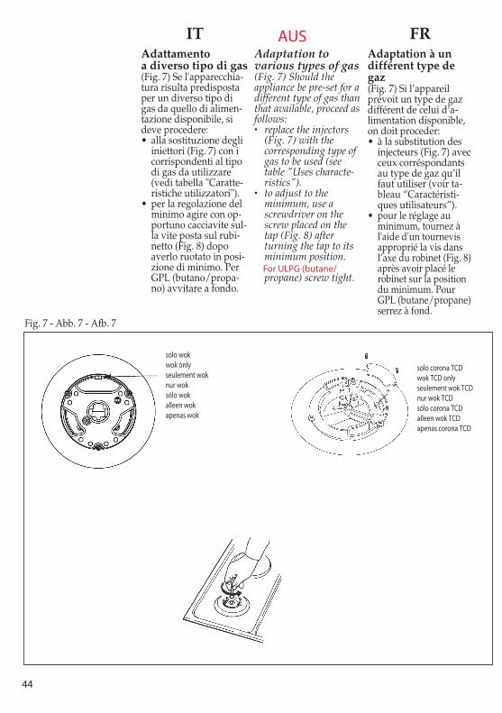
For ULPG (butane/
solo wokwok onlyseulement woknur woksólo wokalleen wokapenas wok
solo corona TCDwok TCD onlyseulement wok TCDnur wok TCDsólo corona TCDalleen wok TCDapenas corona TCD
44
AUS
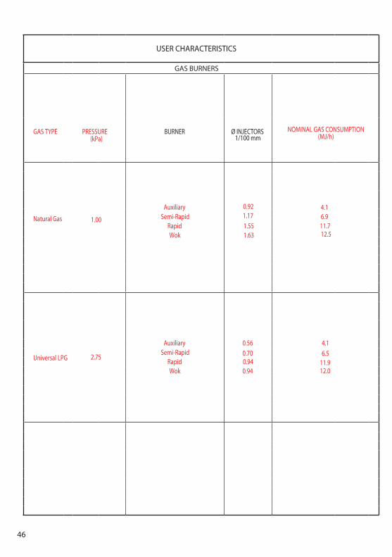
USER CHARACTERISTICS
GAS BURNERS
BURNER Ø INJECTORSGAS TYPE PRESSURE (kPa) 1/100 mm
NOMINAL GAS CONSUMPTION(MJ/h)
Natural Gas 1.00
Auxiliary 0.92 4.1Semi-Rapid 1.17 6.9
Rapid 1.55 11.7Wok 1.63 12.5
Universal LPG 2.75
0.560.700.940.94
46
AuxiliarySemi-Rapid
RapidWok
4.16.5
11.912.0
IT GB FR PIASTRA ELETTRICA - ELECTRIC PLATE - PLAQUES ELECTRIQUES - ELEKTROKOCHSTELLEN - PLACA ELÉCTRICA - ELEKTRISCHE KOOKPLAAT - CHAPA ELÉCTRICA
ALIMENTAZIONE TIPO W REGOLAZIONEFEED TYPE W ADJUSTMENTALIMENTATION TYPE W REGLAGESPEISUNG TYP W REGELUNGALIMENTACION TIPO W REGULACIONVOEDING TYPE W REGELINGALIMENTAÇÃO TIPO W REGULAÇÃO
commutatore (0÷6) - commutator (0÷6)commutateur (0÷6) - Kommutator (0÷6) -
normale - normal conmutador (0÷6) - aan/uit schakelaar (0÷6) -normal - normal comutador (0÷6)normal - normaal 1000
normal regolatore d’energia (0÷11) - energy regulator (0÷11) -Ø145 régulateur d'énergie (0÷11) - Energieregler (0÷11) -
regulador d'energia (0÷11) - energie regelaar (0÷11) -regulador d'energía (0÷11)
~ 230 Vcommutatore (0÷6) - commutator (0÷6)
commutateur (0÷6) - Kommutator (0÷6) -rapida - fast conmutador (0÷6) - aan/uit schakelaar (0÷6)
rapide - schnell comutador (0÷6)rápida - snel 1500
rápida regolatore d’energia (0÷11) - energy regulator (0÷11) -Ø145 régulateur d'énergie (0÷11) - Energieregler (0÷11) -
regulador d'energía (0÷11) - energie regelaar (0÷11) -regulador d'energia (0÷11)
50
Eurolinx Pty Limited A.B.N. 50 001 473 347 trading as ILVE (“ILVE”)Office:48-50 Moore Street, Leichhardt N.S.W 2040 Post:Locked Bag 3000, Annandale, N.S.W 2038 P: 1300 856 411
WARRANTY REGISTRATIONYour ongoing satisfaction with your ILVE product is important to us. We ask that you complete the enclosed Warranty Registration Card and return it to us so that we have a record of the ILVE product purchased by you, Alternitivley, you can now register your warranty online at http://support.eurolinx.com.au/
PRIVACYILVE respects your privacy and is committed to handling your personal information in accordance with the National Privacy Principles and the Privacy Act 1988 (Cth). A copy of the ILVE Privacy Policy is available at www.ilve.com.au. ILVE will not disclose any personal information set out in the Warranty Registration Card (“Personal Information”) without your consent unless required by:1. law;2. any ILVE related company;3. any service provider which provide services to ILVE or assist ILVE in providing services (including repair and warranty services) to customers. Our purpose in collecting the Personal Information is to keep a record of the ILVE product purchased by you, in order to provide a better warranty service to you in the unlikely event that there is a problem with your ILVE product. ILVE may contact you at any one or more of the addresses, email addresses or telephone numbers set out in the Warranty Registration Card. Please contact ILVE on 1300 694 583 should you not wish to be contacted by ILVE.
WARRANTY1. WarrantyILVE warrants that each ILVE product will remain, for a period of twenty four (24) months computed from the date of purchase of the ILVE product, free from defects arising in the manufacture of the ILVE product (“Warranty”). Except for consumer guarantees setout in the Competition and Consumer Act 2010 (Cth) (“Act”), ILVE does not make any further warranties or representations in relation to ILVE products.
2. What is not Covered by the Warranty.
The Warranty does not apply if an ILVE product is defective by a factor other than a defect arising in the manufacture of the ILVE product, including but not limited to:(a) damage through misuse (including failure to maintain, service or use with proper care), neglect, accident or ordinary wear and tear (including deterioration of parts and accessories and glass breakage);(b) use for purpose for which the ILVE product was not sold or designed;(c) use or installation which is not in accordance with any specified instructions for use or installation;(d) use or operation after a defect has occurred or been discovered;(e) damage through freight, transportation or handling in transit (other than when ILVE is responsible);(f) damage through exposure to chemicals, dusts, residues, excessive voltage, heat, atmospheric conditions or other forces or environmental factors outside the control or ILVE;(g) repair, modification or tampering by the purchaser or any person other than ILVE, an employee of ILVE or an authorised ILVE service contractor*;(h) use of parts, components or accessories which have not been supplied or specifically approved by ILVE.(i) damage to surface coatings caused by cleaning or maintenance using products not recommended in the ILVE product handbook provided to the purchaser upon purchase of the ILVE product;(j) damage to the base of an electric oven due to items having been placed on the base of the oven cavity or covering the base, such as aluminium foil (this impedes the transfer of heat from the element to the oven cavity and can result in irreparable damage); or(k) damages, dents or other cosmetic imperfections not affecting the performance of the ILVE in respect of an ILVE product purchased as a “factory second” or from displayThe Warranty does not extend to light globes used in ILVE products.3. Domestic UseEach ILVE product is made for domestic use. This Warranty may not extend to ILVE products used for commercial purposes.4. Time for Claim under the WarrantyYou must make any claim under this Warranty within twenty eight (28) days after the occurrence of an event which gives rise to a claim pursuant to the Warranty, by booking a service call on the telephone number below.
Continued over...
36 ILVE Operating Manual
5. Proof of PurchaseCustomers must retain proof of purchase in order to be eligible to make a warranty claim in respect of an ILVE product.
6. Claiming under the WarrantyCustomers will bear the cost of claiming under this Warranty unless ILVE determines the expenses are reasonable, in which case the customer must claim those expenses by providing written evidence of each expense to ILVE at the address on the Warranty Registration Card.
7. Statutory Rights(a) These terms and conditions do not affect your statutory rights.(b) The limitations on the Warranty set out in this document do not exclude or limit the application of the consumer guarantees set out in the Act or any other equivalent or corresponding legislation in the relevant jurisdiction where to do so would:(i) contravene the law of the relevant jurisdiction; or (ii) cause any part of the Warranty to be void.(c) ILVE excludes indirect or consequential loss of any kind (including, without limitation, loss of use of the ILVE product) and (other than expressly provided for in these terms and conditions) subject to all terms,conditions and warranties implied by custom, the general law, the Act or other statute.(d) The liability of ILVE to you for a breach of any express or non-excludable implied term, condition or warranty is limited at the option of ILVE to:
(i) replacing or repairing the defective part of the ILVE product;(ii) paying the cost of replacing or repairing the defective part of the ILVE product;(iii) replacing the ILVE product; or(iv) paying the cost of replacing the ILVE product.(e) Our goods come with guarantees that cannot be excluded under the Australian Consumer Law. You are entitled to a replacement or refund for a major failure and for compensation for any other reasonably foreseeable loss or damage. You are also entitled to have the goods repaired or replaced if the goods fail to be of acceptable quality and the failure does not amount to a major failure.
8. DefectsAny part of an ILVE product deemed to be defective and replaced by ILVE is the property of ILVE. ILVE reserves the right to inspect and test ILVE products in order to determine the extent of any defect and the validity of a claim under the Warranty.*For your closest ILVE authorised service agent please contact ILVE on 1300 856 411 or visit http://support.ilve.com.au/ orEmail: [email protected]
ALL SERVICE CALLS MUST BE BOOKED THROUGH THE ILVE SERVICE AND WARRANTY DEPARTMENT ON 1300 856 411
01062014
37ILVE Operating Manual
Please complete and send to ILVE at: REPLY PAID 83617 LEICHHARDT NSW 2040
Last Name: First Name:
Address:
State: Postcode: Email:
Home Phone: Mobile:
Purchase Date: / / (Please attach proof of purchase to validate warranty)
MODEL NUMBER SERIAL NUMBER (if you cannot locate the serial number please call ILVE on 1300 85 64 11)
1
2
3
4
WARRANTY REGISTRATION CARD01062014
01062014
Warranty Card tear off
warranty cardBu
ilt-in
CO
OKt
OPS
warranty card continued
Built
-in C
OO
KtO
PS
ilve.com.auilve.com.au
Eurolinx Pty Limited A.B.N. 50 001 473 347 trading as ILVE (“ILVE”)Office:48-50 Moore Street, Leichhardt N.S.W 2040 Post:Locked Bag 3000, Annandale, N.S.W 2038 P: 1300 856 411
WARRANTY REGISTRATIONYour ongoing satisfaction with your ILVE product is important to us. We ask that you complete the enclosed Warranty Registration Card and return it to us so that we have a record of the ILVE product purchased by you, Alternitivley, you can now register your warranty online at http://support.eurolinx.com.au/
PRIVACYILVE respects your privacy and is committed to handling your personal information in accordance with the National Privacy Principles and the Privacy Act 1988 (Cth). A copy of the ILVE Privacy Policy is available at www.ilve.com.au. ILVE will not disclose any personal information set out in the Warranty Registration Card (“Personal Information”) without your consent unless required by:1. law;2. any ILVE related company;3. any service provider which provide services to ILVE or assist ILVE in providing services (including repair and warranty services) to customers. Our purpose in collecting the Personal Information is to keep a record of the ILVE product purchased by you, in order to provide a better warranty service to you in the unlikely event that there is a problem with your ILVE product. ILVE may contact you at any one or more of the addresses, email addresses or telephone numbers set out in the Warranty Registration Card. Please contact ILVE on 1300 694 583 should you not wish to be contacted by ILVE.
WARRANTY1. WarrantyILVE warrants that each ILVE product will remain, for a period of twenty four (24) months computed from the date of purchase of the ILVE product, free from defects arising in the manufacture of the ILVE product (“Warranty”). Except for consumer guarantees setout in the Competition and Consumer Act 2010 (Cth) (“Act”), ILVE does not make any further warranties or representations in relation to ILVE products.
2. What is not Covered by the Warranty.
The Warranty does not apply if an ILVE product is defective by a factor other than a defect arising in the manufacture of the ILVE product, including but not limited to:(a) damage through misuse (including failure to maintain, service or use with proper care), neglect, accident or ordinary wear and tear (including deterioration of parts and accessories and glass breakage);(b) use for purpose for which the ILVE product was not sold or designed;(c) use or installation which is not in accordance with any specified instructions for use or installation;(d) use or operation after a defect has occurred or been discovered;(e) damage through freight, transportation or handling in transit (other than when ILVE is responsible);(f) damage through exposure to chemicals, dusts, residues, excessive voltage, heat, atmospheric conditions or other forces or environmental factors outside the control or ILVE;(g) repair, modification or tampering by the purchaser or any person other than ILVE, an employee of ILVE or an authorised ILVE service contractor*;(h) use of parts, components or accessories which have not been supplied or specifically approved by ILVE.(i) damage to surface coatings caused by cleaning or maintenance using products not recommended in the ILVE product handbook provided to the purchaser upon purchase of the ILVE product;(j) damage to the base of an electric oven due to items having been placed on the base of the oven cavity or covering the base, such as aluminium foil (this impedes the transfer of heat from the element to the oven cavity and can result in irreparable damage); or(k) damages, dents or other cosmetic imperfections not affecting the performance of the ILVE in respect of an ILVE product purchased as a “factory second” or from displayThe Warranty does not extend to light globes used in ILVE products.3. Domestic UseEach ILVE product is made for domestic use. This Warranty may not extend to ILVE products used for commercial purposes.4. Time for Claim under the WarrantyYou must make any claim under this Warranty within twenty eight (28) days after the occurrence of an event which gives rise to a claim pursuant to the Warranty, by booking a service call on the telephone number below.
Continued over...
36 ILVE Operating Manual
5. Proof of PurchaseCustomers must retain proof of purchase in order to be eligible to make a warranty claim in respect of an ILVE product.
6. Claiming under the WarrantyCustomers will bear the cost of claiming under this Warranty unless ILVE determines the expenses are reasonable, in which case the customer must claim those expenses by providing written evidence of each expense to ILVE at the address on the Warranty Registration Card.
7. Statutory Rights(a) These terms and conditions do not affect your statutory rights.(b) The limitations on the Warranty set out in this document do not exclude or limit the application of the consumer guarantees set out in the Act or any other equivalent or corresponding legislation in the relevant jurisdiction where to do so would:(i) contravene the law of the relevant jurisdiction; or (ii) cause any part of the Warranty to be void.(c) ILVE excludes indirect or consequential loss of any kind (including, without limitation, loss of use of the ILVE product) and (other than expressly provided for in these terms and conditions) subject to all terms,conditions and warranties implied by custom, the general law, the Act or other statute.(d) The liability of ILVE to you for a breach of any express or non-excludable implied term, condition or warranty is limited at the option of ILVE to:
(i) replacing or repairing the defective part of the ILVE product;(ii) paying the cost of replacing or repairing the defective part of the ILVE product;(iii) replacing the ILVE product; or(iv) paying the cost of replacing the ILVE product.(e) Our goods come with guarantees that cannot be excluded under the Australian Consumer Law. You are entitled to a replacement or refund for a major failure and for compensation for any other reasonably foreseeable loss or damage. You are also entitled to have the goods repaired or replaced if the goods fail to be of acceptable quality and the failure does not amount to a major failure.
8. DefectsAny part of an ILVE product deemed to be defective and replaced by ILVE is the property of ILVE. ILVE reserves the right to inspect and test ILVE products in order to determine the extent of any defect and the validity of a claim under the Warranty.*For your closest ILVE authorised service agent please contact ILVE on 1300 856 411 or visit http://support.ilve.com.au/ orEmail: [email protected]
ALL SERVICE CALLS MUST BE BOOKED THROUGH THE ILVE SERVICE AND WARRANTY DEPARTMENT ON 1300 856 411
01062014
37ILVE Operating Manual
Please complete and send to ILVE at: REPLY PAID 83617 LEICHHARDT NSW 2040
Last Name: First Name:
Address:
State: Postcode: Email:
Home Phone: Mobile:
Purchase Date: / / (Please attach proof of purchase to validate warranty)
MODEL NUMBER SERIAL NUMBER (if you cannot locate the serial number please call ILVE on 1300 85 64 11)
1
2
3
4
WARRANTY REGISTRATION CARD01062014
01062014
Warranty Card tear off
warranty card
Built
-in C
OO
KtO
PS
warranty card continued
Built
-in C
OO
KtO
PS
ilve.com.auilve.com.au

(\Z[YHSPH�5H[PVUHS�;LSLWOVUL�5\TILY������4@03=,��� ������5L^�ALHSHUK�;LSLWOVUL�5\TILY������������
03=,�ZOV^YVVTZ�HYL�VWLU�KHPS`�MYVT� HT��WT�HUK�:H[\YKH`Z���HT��WT �>(�I`�HWWVPU[TLU[�VUS`�VU�:H[\YKH`Z� PS]L�JVT�H\
5:>� �(*;��/LHK�6ɉJL�������4VVYL�:[YLL[� 3LPJOOHYK[-������� ���
=0*��;(:� �:(�����;VVYHR�9VHK� *HTILY^LSS-���� �� �����
83+�����*H]LUKPZO�9VHK�*VVYWHYVV�-������ ������
>(� �5;<UP[�������/V^L�:[YLL[6ZIVYUL�7HYR�-���� ���� ���
5L^�ALHSHUK76�)V_�������:VJRI\YU�*OYPZ[JO\YJO-��������� ��


INSTRUCTION MANUAL FOR BUILT-IN OVENS

OPEN 24/7ILVE ACCESSORIES ONLINE SHOP
-VY�H�^PKL�YHUNL�VM�JVɈLL�THJOPULZ��WVKZ��HUK�V[OLY�03=,�HJJLZZVYPLZ�H[�[OL�JSPJR�VM�H�I\[[VU�ZOVW�PS]L�JVT�H\
ES NL PTDE
SEHR GEEHRTER
KUNDE,
wir danken Ihnen und be-
glückwünschen Sie zu Ihrer
Wahl.
Dieses neue Produkt, sorg-
fältig entworfen und mit
erstklassigen Materialien
hergestellt, wurde genau
geprüft um alle Ihre Forder-
ungen an ein perfektes Ko-
chen zu erfüllen.
Wir bitten Sie deshalb die
einfachen Anweisungen zu
lesen und einzuhalten, da-
mit von der ersten An-
wendung an ausgezeichnete
Ergebnisse erreicht werden
können.
DER HERSTELLER
ESTIMADO
CLIENTE,
Le agradecemos mucho y le
felicitamos por su elección.
Este nuevo producto,
cuidadosamente estudiado
y fabricado con materiales
de primera calidad, ha sido
probado a conciencia para
poder satisfacer todas sus
exigencias de una perfecta
cocción.
Por lo tanto le rogamos lea
y siga detenidamente estas
sencillas instrucciones que
le permitirán llegar a
resultados excelentes desde
la primera utilización.
EL FABRICANTE
GEACHTE KLANT,
wij danken u en feliciteren
u met de door u gedane
keuze.
Dit nieuwe produkt, zorg-
vuldig ontworpen en ge-
construeerd uit materialen
van de allerbeste kwaliteit,
is gedegen uitgetest om al
uw eisen voor een perfect
kookresultaat te kunnen be-
vredigen.
Wij verzoeken u daarom de
eenvoudige instructies te
lezen en te respecteren,
welke u in staat zullen
stellen om al vanaf het
eerste gebruik uitstekende
resultaten te bereiken.
DE FABRIKANT
ESTIMADO
CLIENTE,
Agradecemos, muito since-
ramente a sua escolha, e
aproveitamos a ocasião para
o felicitar.
Este novo produto, que foi
projectado com grande
atenção e construído com os
melhores materiais, foi ve-
rificado e aprovado, de
maneira a dar-lhe total
satisfação para um co-
zinhado perfeito.
Por conseguinte, pedimos
que leia e siga as instruções
que lhe permitirão alcançar
excelentes resultados desde
o início da sua utilização.
O FABRICANTE
IMPORTANTE
La placa de características
del horno se encuentra
disponible junto con el apa-
rato. En esta placa, visible
abriendo la puerta, se
muestran todos los datos de
identificación del aparato a
los que se deverá hacer
referencia para el pedido de
piezas de repuesto.
IMPORTANTE
A placa com as caracterí-
sticas do forno é acessível
também com o aparelho in-
stalado. Nesta placa, visível
abrindo a porta, estão refe-
ridos todos os dados de
identificação do aparelho
aos quais se deverá fazer
referência para pedidos de
peças de substituição.
WICHTIG
Das Typenschild mit den
technischen Merkmalen des
Backofens ist auch bei
installiertem Gerät zugäng-
lich. Auf diesem Typen-
schild, das bei Öffnen der
Ofentür sichtbar ist, sind
auch alle Kenndaten des
Geräts aufgeführt, die bei
eventuellen Ersatzteilbe-
stellungen angegeben
werden müssen.
BELANGRIJK:
“Het typeplaatje van de
oven is ook bereikbaar als
het apparaat geïnstalleerd
is. Op dit plaatje, dat u kunt
zien als u de deur opent,
staan alle identificatiege-
gevens van het apparaat,
waarnaar u dient te ver-
wijzen bij het bestellen van
vervangingsonderdelen”.
IT GB FR
CARO CLIENTE,
sentitamente La ringrazia-
mo e ci congratuliamo per
la scelta da Lei fatta.
Questo nuovo prodotto ac-
curatamente progettato e
costruito con materiali di
primissima qualità, è stato
accuratamente collaudato
per poter soddisfare tutte le
esigenze di una perfetta cot-
tura. La preghiamo pertanto
di leggere e rispettare le
facili istruzioni che Le
permetteranno di raggiun-
gere eccellenti risultati fin
dalla primissima utilizza-
zione.
IL COSTRUTTORE
IMPORTANTE
La targhetta delle caratte-
ristiche del forno è accessi-
bile anche ad apparecchio
installato. In questa targhet-
ta, visibile aprendo la porta,
sono riportati tutti i dati di
identificazione dell’appa-
recchio a cui si dovrà fare
riferimento per richiesta di
ricambi.
DEAR
CUSTOMER,
We thank you and con-
gratulate you on your
choice.
This new carefully designed
product, manufactured with
the highest quality mate-
rials, has been carefully
tested to satisfy all your
cooking demands.
We would therefore request
you to read and follow
these easy instructions
which will allow you to
obtain excellent results
right from the start.
THE MANUFACTURER
CHÈRE CLIENTE,
CHER CLIENT,
Merci et sincères félici-
tations pour le choix que
vous avez fait.
Ce nouveau produit, conçu
avec soin et fabriqué avec
des matièrs de toute
première qualité, a été
soigneusement testé pour
satisfaire toutes vos exi-
gences d’une cuisson par-
faite.
Nous vous prions de bien
vous vouloir lire et suivre
des simples instructions,
que vous permettront d’at-
teindre d’excellents ré-
sultats dès la prémière
utilisation.
LE CONSTRUCTEUR
IMPORTANT
“Il est possible d’accéder à
la plaque des caractéristi-
ques du four même lorsque
l’appareil est installé. Cette
plaque, que l’on voit en
ouvrant la porte, présente
toutes les données d’identi-
fication de l’appareil qu’il
est nécessaire de citer pour
toute demande de pièces de
rechange”.
IMPORTANT
The oven’s data plate is
accessible even with the
oven fully installed. The
plate is visible simply by
opening the door. Always
quote the details from it to
identify the appliance when
ordering spare parts.
2
ES NL PTDE
INDICE
Primera utilización pag. 7
Paneles autolimpiantes 9
Respeto por el medio
ambiente 11
Panel de control 13-15
Instrucciones de
funcionamiento:
- Cocción convencional 15
- Cocción ventilada 17
- Cocción al grill 19
Termostato 21
Temporizador 21
Temporizador
electrónico 25
Cambio de la bombilla 29
Desmontaje
de la puerta horno 31
PARA EL INSTALADOR
Encastre del horno 33
Conexión eléctrica 35
INHOUD
Eerste gebruik pag. 7
Zelfreinigende panelen 9
Respect voor het milieu 11
Bedieningspaneel 13-15
Werkingsinstructies:
- Traditionele bereidingen 15
- Bereiding met ventilatie 17
- Bereiding met grill 19
Thermostaat 21
Timer 21
Elektronische timer 25
Vervanging lampje 29
Demontage
van de ovendeur 31
VOOR DE INSTALLATEUR
Inbouw van de oven 33
Elektrische aansluiting 35
INDICE
Primeira utilização pág. 7
Painéis autolimpantes 9
Respeito do ambiente 11
Painel comandos 13-15
Instruções de
funcionamento:
- Cozedura convencional 15
- Cozedura ventilada 17
- Cozedura ao gril 19
Termóstato 21
Temporizador 21
Timer electrónico 25
Substituição da lâmpada 29
Desmontagem
da porta forno 31
PARA O INSTALADOR
Encastre do forno 33
Ligação eléctrica 35
INDEX
Erstmalige Benutzung S. 7
Selbstreinigende Platten 9
Umweltverträglichkeit 11
Bedienblende 13-15
Betriebsanleitung:
- Konventionelles Backen 15
- Umluftbacken 17
- Grillen 19
Thermostat 21
Zeitschalter 21
Elektronische Zeitschaltuhr 25
Auswechslung der
Ofenbeleuchtung 29
Ausbauen der Ofentür 31
FÜR DEN INSTALLATEUR
Einbau des Backofens 33
Stromanschluß 35
DIT PRODUKT IS ALS HUISHOUDELIJK APPARAAT GEDACHT. VOOR BESCHADIGINGEN AAN SPULLEN OF PERSONEN DIE
AAN VERKEERDE INSTALLATIE, MISBRUIK OF VERKEERDE GEBRUIK ZIJN TE WIJTEN, NEEMT DE FABRIKANT GEEN VERANTWOORDELIJKHEID OP ZICH.
DIT APPARAAT IS NIET BEDOELD VOOR GEBRUIK DOOR PERSONEN (MET INBEGRIP VAN KINDEREN) MET VERLAAGDE FYSIEKE, SENSORISCHE
OF MENTALE VERMOGENS, OF MET GEBREK AAN ERVARING EN KENNIS, TENZIJ ZIJ LEIDING OF INSTRUCTIES HEBBEN ONTVANGEN BETREFFENDE HET GEBRUIK VAN HET APPARAAT DOOR MIDDEL VAN EEN PERSOON DIE VOOR HUN VEILIGHEID VERANTWOORDELIJK IS. KINDEREN MOETEN WORDEN GECONTROLEERD OM TE GARANDEREN DAT ZIJ NIET MET HET APPARAAT SPELEN.
ESTE PRODUCTO FUE CONCEBIDO PARA UN USO DE TIPO DOMÉSTICO. EL CONSTRUCTOR DECLINA CUALQUIER RESPONSABILIDAD
EN EL CASO DE DAÑOS EVENTUALES A COSAS O PERSONAS QUE DERIVEN DE UNA INSTALACIÓN INCORRECTA O DE UN USO IMPROPIO, ERRADO O ABSURDO.
NO PUEDEN UTILIZAR EL APARATO PERSONAS (INCLUIDOS NIÑOS) CON CAPACIDADES FÍSICAS, SENSORIALES O MENTALES REDUCIDAS, NI
PERSONAS QUE NO DISPONGAN DE LA EXPERIENCIA Y DE LOS CONOCIMIENTOS NECESARIOS, A MENOS QUE ESTÉN BAJO LA SUPERVISIÓN DE UNA PERSONA RESPONSABLE DE SU SEGURIDAD O HAYAN RECIBIDO LAS INSTRUCCIONES NECESARIAS SOBRE LA UTILIZACIÓN DEL APARATO. LOS NIÑOS TIENEN QUE ESTAR CONTROLADOS PARA ASEGURARSE DE QUE NO JUEGAN CON EL APARATO.
ESTE PRODUTO FOI CONCEBIDO PARA UMA UTILIZAÇÃO DE TIPO DOMÉSTICA. O FABRICANTE DECLINA TODAS AS
RESPONSABILIDADES NO CASO DE EVENTUAIS DANOS A COISAS OU PESSOAS DERIVADOS DE UMA INSTALAÇÃO INCORRECTA OU DE USO IMPRÓPRIO, ERRÓNEO OU ABSURDO.
O APARELHO NÃO DEVE SER USADO POR PESSOAS (INCLUSIVE CRIANÇAS) COM CAPACIDADES FÍSICAS, SENSORIAIS OU MENTAIS REDUZIDAS, OU POR PESSOAS QUE NÃO TENHAM EXPERIÊNCIAS NEM CONHECIMENTO NECESSÁRIO A NÃO SER QUE SEJAM SUPERVISIONADAS E INSTRUÍDAS, SOBRE
O USO DO APARELHO, POR UMA PESSOA RESPONSÁVEL PELA SEGURANÇA DAS MESMAS
. AS CRIANÇAS DEVEM SER CONTROLADAS PARA CONTROLADAS PARA SE TER CERTEZA DE QUE NÃO BRINQUEM COM O APARELHO.
DIESES PRODUKT IST ALS HAUSHALTSGERÄT GEDACHT. FÜR SCHADEN AN SACHEN ODER PERSONEN, DIE AUF FALSCHE
INSTALLATION BZW. UNGEEIGNETEN GEBRAUCH ODER MISSBRAUCH ZURÜCKZUFÜHREN SIND, ÜBERNIMMT DER HERSTELLER KEINERLEI VERANTWORTUNG.
DAS GERÄT DARF NICHT VON PERSONEN (EINSCHLIESSLICH KINDERN) MIT EINGESCHRÄNKTER KÖRPERLICHER ODER GEISTLICHER
KAPAZITÄT ODER PERSONEN OHNE ERFAHRUNG UND DIE NOTWENDIGEN KENNTNISSE BENUTZT WERDEN, ES SEI DENN, DIES GESCHIEHT UNTER DER AUFSICHT ODER NACH UNTERWEISUNG IM GEBRAUCH DES GERÄTS DURCH EINER FÜR DEREN SICHERHEIT VERANTWORTLICHEN PERSON. KINDER SIND ZU BEAUFSICHTIGEN, UM SICHERZUSTELLEN, DASS SIE NICHT MIT DEM GERÄT SPIELEN.
IT GB FR
INDICE
Primo utilizzo pag. 6
Pannelli autopulenti 8
Rispetto dell’ambiente 10
Frontale comandi 12-14
Istruzioni di
funzionamento:
- cottura con la funzione
“convenzione” 14
- cottura con la funzione
“ventilato” 16
- cottura alla griglia 18
Termostato 20
Temporizzatore 20
Timer elettronico 24
Sostituzione lampada 28
Smontaggio della porta del
forno 30
PER L’INSTALLATORE
Incasso del forno 32
Allacciamento elettrico 34
CONTENTS
First use pag. 6
Self-cleaning panel 8
Respect for the
environment 10
Control panel 12-14
Instructions for use:
- conventional cooking 14
- fan cooking 16
- grill cooking 18
Thermostat 20
Cooking timer 20
Electronic timer 24
Light replacement 28
Removing the oven door 30
INSTALLATION
INSTRUCTIONS
Flush fitting 32
Electrical connections 34
INDEX
Première utilisation pag. 6
Panneaux autonettoyants 8
Respect
de l’environnement 10
Panneau de commande 12-14
Instructions pour le
fonctionnement:
- cuisson conventionnelle 14
- cuissson ventilée 16
- cuissson au gril 18
Thermostat 20
Temporisateur 20
Temporisateur electronique 24
Remplacement de la lampe 28
Demontage
de la porte du four 30
POUR L’INSTALLATEUR
Encastrement du four 32
Branchement electrique 34
THIS APPLIANCE IS CONCEIVED FOR DOMESTIC USE ONLY. THE MANUFACTURER SHALL NOT IN ANY WAY BE HELD RESPONSIBLE
FOR WHATEVER INJURIES OR DAMAGES ARE CAUSED BY INCORRECT INSTALLATION OR BY UNSUITABLE, WRONG OR ABSURD USE.
THIS APPLIANCE IS NOT INTENDED FOR USE BY PERSONS (INCLUDING CHILDREN) WITH REDUCED
PHYSICAL, SENSORY OR MENTAL CAPABILITIES, OR LACK OF EXPERIENCE AND KNOWLEDGE, UNLESS THEY HAVE BEEN GIVEN SUPERVISION OR INSTRUCTION CONCERNING USE OF THE APPLIANCE BY A PERSON RESPONSIBLE FOR THEIR SAFETY. CHILDREN SHOULD BE SUPERVISED TO ENSURE THAT THEY DO NOT PLAY WITH THE APPLIANCE.
QUESTO PRODOTTO È STATO CONCEPITO PER UN IMPIEGO DI TIPO DOMESTICO. IL COSTRUTTORE DECLINA OGNI
RESPONSABILITÀ NEL CASO DI EVENTUALI DANNI A COSE O PERSONE DERIVANTI DA UNA NON CORRETTA INSTALLAZIONE O DA USO IMPROPRIO, ERRONEO OD ASSURDO.
L’APPARECCHIO NON DEVE ESSERE USATO DA PERSONE (COMPRESI BAMBINI) CON RIDOTTE CAPACITÀ FISICHE,
SENSORIALI O MENTALI, O DA PERSONE CHE MANCANO DELL’ESPERIENZA E DELLE CONOSCENZE NECESSARIE SE NON SOTTO LA SUPERVISIONE O DIETRO ISTRUZIONI SULL’USO DELL’APPARECCHIO DA PARTE DI UNA PERSONA RESPONSABILE PER LA LORO SICUREZZA. I BAMBINI DEVONO ESSERE CONTROLLATI PER ASSICURARSI CHE NON GIOCHINO CON L’APPARECCHIO.
CE PRODUIT EST CONÇU EXCLUSIVEMENT POUR USAGE DOMESTIQUE. LE CONSTRUCTEUR DÉCLINE TOUTE RESPONSABILITÉ
POUR DOMMAGES ET BLESSURES CAUSÉES PAR UNE INSTALLATION INCORRECTE OU PAR UN USAGE IMPROPRE, ERRONÉ OU ABSURDE.
L’APPAREIL NE DOIT PAS ÊTRE UTILISÉ PAR DES PERSONNES (ENFANTS INCLUS) DISPOSANT DE CAPACITÉS PHYSIQUES,
SENSORIELLES OU MENTALES RÉDUITES, OU PAR DES PERSONNES N’AYANT PAS L’EXPÉRIENCE OU LES CONNAISSANCES REQUISES, SI CE N’EST SOUS LA SURVEILLANCE D’UNE PERSONNE RESPONSABLE DE LEUR SÉCURITÉ OU APRÈS AVOIR REÇU DE CELLE-CI LES INSTRUCTIONS RELATIVES À L’UTILISATION DE L’APPAREIL. LES ENFANTS DOIVENT ÊTRE SURVEILLÉS, AFIN DE S’ASSURER QU’ILS NE JOUENT PAS AVEC L’APPAREIL.
LA PULIZIA E LA MANUTEN-ZIONE NON DEVONO ESSERE EFFETTUATE DAI BAMBINI
SENZA SUPERVISIONE. VIETATO AP-PORRE CARTA STAGNOLA, PENTOLE O SIMILI A CONTATTO CON LA BASE INTERNA DEL FORNO PER CUCINARE. L’AZIONE DEL RISCALDAMENTO DEL-LA RESISTENZA INFERIORE PROVOCA IL SURRISCALDAMENTO DELLA PARTE BASSA DEL FORNO PROVOCANDONE IL DANNEGGIAMENTO E ADDIRITTU-RA GRAVI CONSEGUENZE (RISCHIO DI INCENDIO) ANCHE SUL MOBILE DI SUP-PORTO DEL FORNO.
CHILDREN SHOULD NOT CLEAN OR PERFORM MAINTENANCE WITHOUT
SUPERVISION. DO NOT PLACE TIN FOIL, PANS OR SIMILAR IN CONTACT WITH THE INNER BASE OF THE OVEN TO COOK. THE HEATING ACTION OF THE LOWER RESISTANCE CAUSES THE LOWER PART OF THE OVEN TO OVERHEAT, LEADING TO DAMAGE AND EVEN SERIOUS CONSEQUENCES (FIRE RISK) ALSO TO THE UNIT IN WHICH THE OVEN IS INSTALLED.
LE NETTOYAGE ET L’ENTRETIEN NE DOIVENT PAS ETRE EFFECTUES PAR DES ENFANTS
SANS LA SUPERVISION D’UN ADULTE. INTERDICTION DE POSER DU PAPIER ALUMINIUM, DES CASSEROLES OU AUTRES, AU CONTACT DE LA BASE INTERNE DU FOUR POUR CUISINER. LE RÉCHAUFFEMENT INFÉRIEUR PROVOQUE LA SURCHAUFFE DE LA PARTIE INFÉRIEURE DU FOUR ; CELA PEUT ENTRAÎNER SA DÉTÉRIORATION VOIRE DES CONSÉQUENCES GRAVES (RISQUE D’INCENDIE) POUR LE MEUBLE DE SUPPORT DU FOUR.4
ES NL PTDE
INDICE
Primera utilización pag. 7
Paneles autolimpiantes 9
Respeto por el medio
ambiente 11
Panel de control 13-15
Instrucciones de
funcionamiento:
- Cocción convencional 15
- Cocción ventilada 17
- Cocción al grill 19
Termostato 21
Temporizador 21
Temporizador
electrónico 25
Cambio de la bombilla 29
Desmontaje
de la puerta horno 31
PARA EL INSTALADOR
Encastre del horno 33
Conexión eléctrica 35
INHOUD
Eerste gebruik pag. 7
Zelfreinigende panelen 9
Respect voor het milieu 11
Bedieningspaneel 13-15
Werkingsinstructies:
- Traditionele bereidingen 15
- Bereiding met ventilatie 17
- Bereiding met grill 19
Thermostaat 21
Timer 21
Elektronische timer 25
Vervanging lampje 29
Demontage
van de ovendeur 31
VOOR DE INSTALLATEUR
Inbouw van de oven 33
Elektrische aansluiting 35
INDICE
Primeira utilização pág. 7
Painéis autolimpantes 9
Respeito do ambiente 11
Painel comandos 13-15
Instruções de
funcionamento:
- Cozedura convencional 15
- Cozedura ventilada 17
- Cozedura ao gril 19
Termóstato 21
Temporizador 21
Timer electrónico 25
Substituição da lâmpada 29
Desmontagem
da porta forno 31
PARA O INSTALADOR
Encastre do forno 33
Ligação eléctrica 35
INDEX
Erstmalige Benutzung S. 7
Selbstreinigende Platten 9
Umweltverträglichkeit 11
Bedienblende 13-15
Betriebsanleitung:
- Konventionelles Backen 15
- Umluftbacken 17
- Grillen 19
Thermostat 21
Zeitschalter 21
Elektronische Zeitschaltuhr 25
Auswechslung der
Ofenbeleuchtung 29
Ausbauen der Ofentür 31
FÜR DEN INSTALLATEUR
Einbau des Backofens 33
Stromanschluß 35
DIT PRODUKT IS ALS HUISHOUDELIJK APPARAAT GEDACHT. VOOR BESCHADIGINGEN AAN SPULLEN OF PERSONEN DIE
AAN VERKEERDE INSTALLATIE, MISBRUIK OF VERKEERDE GEBRUIK ZIJN TE WIJTEN, NEEMT DE FABRIKANT GEEN VERANTWOORDELIJKHEID OP ZICH.
DIT APPARAAT IS NIET BEDOELD VOOR GEBRUIK DOOR PERSONEN (MET INBEGRIP VAN KINDEREN) MET VERLAAGDE FYSIEKE, SENSORISCHE
OF MENTALE VERMOGENS, OF MET GEBREK AAN ERVARING EN KENNIS, TENZIJ ZIJ LEIDING OF INSTRUCTIES HEBBEN ONTVANGEN BETREFFENDE HET GEBRUIK VAN HET APPARAAT DOOR MIDDEL VAN EEN PERSOON DIE VOOR HUN VEILIGHEID VERANTWOORDELIJK IS. KINDEREN MOETEN WORDEN GECONTROLEERD OM TE GARANDEREN DAT ZIJ NIET MET HET APPARAAT SPELEN.
ESTE PRODUCTO FUE CONCEBIDO PARA UN USO DE TIPO DOMÉSTICO. EL CONSTRUCTOR DECLINA CUALQUIER RESPONSABILIDAD
EN EL CASO DE DAÑOS EVENTUALES A COSAS O PERSONAS QUE DERIVEN DE UNA INSTALACIÓN INCORRECTA O DE UN USO IMPROPIO, ERRADO O ABSURDO.
NO PUEDEN UTILIZAR EL APARATO PERSONAS (INCLUIDOS NIÑOS) CON CAPACIDADES FÍSICAS, SENSORIALES O MENTALES REDUCIDAS, NI
PERSONAS QUE NO DISPONGAN DE LA EXPERIENCIA Y DE LOS CONOCIMIENTOS NECESARIOS, A MENOS QUE ESTÉN BAJO LA SUPERVISIÓN DE UNA PERSONA RESPONSABLE DE SU SEGURIDAD O HAYAN RECIBIDO LAS INSTRUCCIONES NECESARIAS SOBRE LA UTILIZACIÓN DEL APARATO. LOS NIÑOS TIENEN QUE ESTAR CONTROLADOS PARA ASEGURARSE DE QUE NO JUEGAN CON EL APARATO.
ESTE PRODUTO FOI CONCEBIDO PARA UMA UTILIZAÇÃO DE TIPO DOMÉSTICA. O FABRICANTE DECLINA TODAS AS
RESPONSABILIDADES NO CASO DE EVENTUAIS DANOS A COISAS OU PESSOAS DERIVADOS DE UMA INSTALAÇÃO INCORRECTA OU DE USO IMPRÓPRIO, ERRÓNEO OU ABSURDO.
O APARELHO NÃO DEVE SER USADO POR PESSOAS (INCLUSIVE CRIANÇAS) COM CAPACIDADES FÍSICAS, SENSORIAIS OU MENTAIS REDUZIDAS, OU POR PESSOAS QUE NÃO TENHAM EXPERIÊNCIAS NEM CONHECIMENTO NECESSÁRIO A NÃO SER QUE SEJAM SUPERVISIONADAS E INSTRUÍDAS, SOBRE
O USO DO APARELHO, POR UMA PESSOA RESPONSÁVEL PELA SEGURANÇA DAS MESMAS
. AS CRIANÇAS DEVEM SER CONTROLADAS PARA CONTROLADAS PARA SE TER CERTEZA DE QUE NÃO BRINQUEM COM O APARELHO.
DIESES PRODUKT IST ALS HAUSHALTSGERÄT GEDACHT. FÜR SCHADEN AN SACHEN ODER PERSONEN, DIE AUF FALSCHE
INSTALLATION BZW. UNGEEIGNETEN GEBRAUCH ODER MISSBRAUCH ZURÜCKZUFÜHREN SIND, ÜBERNIMMT DER HERSTELLER KEINERLEI VERANTWORTUNG.
DAS GERÄT DARF NICHT VON PERSONEN (EINSCHLIESSLICH KINDERN) MIT EINGESCHRÄNKTER KÖRPERLICHER ODER GEISTLICHER
KAPAZITÄT ODER PERSONEN OHNE ERFAHRUNG UND DIE NOTWENDIGEN KENNTNISSE BENUTZT WERDEN, ES SEI DENN, DIES GESCHIEHT UNTER DER AUFSICHT ODER NACH UNTERWEISUNG IM GEBRAUCH DES GERÄTS DURCH EINER FÜR DEREN SICHERHEIT VERANTWORTLICHEN PERSON. KINDER SIND ZU BEAUFSICHTIGEN, UM SICHERZUSTELLEN, DASS SIE NICHT MIT DEM GERÄT SPIELEN.
DIE REINIGUNG UND WARTUNG DÜRFEN NICHT VON UNBEAUFSICHTIGTEN
KINDERN VORGENOMMEN WERDEN. STANIOLPAPIER, TÖPFE ODER ÄHNLICHES DARF NICHT IN KONTAKT MIT DER INNEREN BASIS DES BACKOFENS GERATEN. DAS AUFHEIZEN DES UNTEREN WIDERSTANDS FÜHRT ZU EINER ÜBERHITZUNG DES UNTEREN TEILS DES BACKOFENS, BESCHÄDIGT IHN UND FÜHRT SOGAR ZU SCHWERWIEGENDEN FOLGEN (BRANDRISIKO) FÜR DAS MÖBELSTÜCK, DAS DEN BACKOFEN TRÄGT.
LOS NIÑOS NO PUEDEN EFECTUAR LAS OPERACIONES DE LIMPIEZA Y MANTENIMIENTO
A MENOS QUE ESTÉN BAJO SUPERVISIÓN. PROHIBIDO PONER PAPEL DE ALUMINIO, CAZUELAS U OTROS OBJETOS SIMILARES EN CONTACTO CON LA BASE INTERNA DEL HORNO PARA COCINAR. LA ACCIÓN DEL CALENTAMIENTO DE LA RESISTENCIA INFERIOR PROVOCA EL RECALENTAMIENTO DE LA PARTE BAJA DEL HORNO DAÑÁNDOLO O INCLUSO PROVOCANDO CONSECUENCIAS GRAVES (RIESGO DE INCENDIO) EN EL MUEBLE DE SOPORTE DEL HORNO.
DE REINIGING EN HET ONDERHOUD MAG NIET WORDEN UITGEVOERD DOOR
KINDEREN ZONDER TOEZICHT. HET IS VERBODEN ALUMINIUMFOLIE, PANNEN OF DERGELIJKE IN AANRAKING TE LATEN KOMEN MET DE INTERNE BASIS VAN DE OVEN OM TE KOKEN. DE VERWARMENDE WERKING VAN DE ONDERSTE WEERSTAND VEROORZAAKT DE OVERVERHITTING VAN HET ONDERSTE GEDEELTE VAN DE OVEN, WAARDOOR DEZE BESCHADIGD KAN WORDEN EN DIT KAN ZELFS ERNSTIGE GEVOLGEN HEBBEN (BRANDGEVAAR), OOK VOOR HET MEUBEL WAAROP DE OVEN GEPLAATST IS.
A LIMPEZA E A MANUTENÇÃO NÃO DEVEM SER REALIZADAS POR CRIANÇAS SEM
SUPERVISÃO. É PROIBIDO COLOCAR PAPEL ALUMÍNIO, TACHOS OU SIMILARES EM CONTACTO COM A BASE INTERNA DO FORNO PARA COZINHAR. A ACÇÃO DO AQUECIMENTO DA RESISTÊNCIA INFERIOR PROVOCA O SUPERAQUECIMENTO DA PARTE BAIXA DO FORNO CAUSANDO-LHE DANOS E ATÉ GRAVES, CONSEQUÊNCIAS (RISCO DE INCÊNDIO) INCLUSIVE NO MÓVEL DE SUPORTE DO FORNO.
5
ES NL PTDE
PRIMERA
UTILIZACIÓN
El horno se limpia a fondo
con agua y jabón y se
enjuaga cuidadosamente.
Para sacar los armazones
laterales en los hornos con
paredes lisas proceder como
se ilustra en la figura.
Recalentar el horno alre-
dedor de 30 minutos a la
máxima temperatura; serán
así eliminados todos los
residuos grasos ya que po-
drían causar olores desagra-
dables durante la fase de
cocción.
ERSTMALIGE
BENUTZUNG
Der Backofen muss gründ-
lich mit Seifenwasser ge-
säubert werden. Wie auf
der Abbildung dargestellt
vorgehen, um bei den Öfen
mit glatten Wänden die
seitlichen Backbleche her-
auszunehmen.
Den Backofen für etwa 30
Minuten auf Höchsttempe-
ratur aufheizen; auf diese
Weise werden alle fett-
haltigen Bearbeitungsrück-
stände eliminiert, die beim
Backen unangenehme Ge-
rüche verursachen könnten.
EERSTE GEBRUIK
De oven moet grondig wor-
den schoongemaakt met
water en zeep, en zorgvuldig
worden afgespoeld. Voor
het verwijderen van de zij-
frames in ovens met gladde
wanden dient u te werk te
gaan zoals op de afbeelding
wordt geïllustreerd.
Verwarm de oven ge-
durende ongeveer 30 minu-
ten op de hoogste tempe-
ratuur; zodoende worden
alle achtergebleven vetten
geëlimineerd die onaange-
name geuren zouden kunnen
veroorzaken tijdens het
bereiden van voedsel.
rança antes de proceder a
qualquer operação de lim-
peza do forno tirar sempre a
ficha da tomada de corrente
ou tirar a linha de alimen-
tação do aparelho. Além
disso evite usar substâncias
ácidas ou alcalinas (sumos
de limão, vinagre, etc.).
Evitar a utilização de
produtos à base de cloro,
ácidos ou abrasivos espe-
cialmente para a limpeza
das paredes envernizadas.
moet altijd de stekker uit
het stopcontact worden ge-
haald of moet de voeding
van het apparaat worden
afgekoppeld alvorens de
oven te gaan schoonmaken.
Gebruik bovendien geen
zure of alkaline stoffen (ci-
troensap, azijn, zout, enz.).
Gebruik geen producten op
chloorbasis, of zure of
schurende producten, voor-
al voor het reinigen van
gelakte oppervlakken.
Como precaución de segu-
ridad, antes de proceder con
cualquier operación de lim-
pieza del horno quitar
siempre el enchufe de la
toma de corriente o quitar la
línea de alimentación del
aparato. Además evitar el
uso de sustancias ácidas o
alcalinas (jugos de limón,
vinagre, sal, tomates, etc.).
Evitar el uso de productos a
base de cloro, ácidos o
abrasivos especialmente
para la limpieza de las
paredes barnizadas.
Als Sicherheitsvorkehrung
muss vor jeder Reinigung
des Backofens immer das
Stromnetz abgeschaltet
werden. Zum Reinigen
dürfen keine sauren oder
alkalischen Substanzen ver-
wendet werden (Zitronen-
saft, Essig, Salz, usw.).
Chlorhaltige Produkte, so-
wie Säuren oder Scheuer-
mittel sind ebenfalls zu
vermeiden, dies gilt vor
allem für die Reinigung der
lackierten Wände.
PRIMEIRA
UTILIZAÇÃO
O forno deve ser limpo a
fundo com água e sabão e
depois cuidadosamente se-
cado com um pno. Para tirar
as estruturas laterais nos
fornos com paredes lisas
proceder como ilustrado na
figura.
Aquecer o forno à máxima
temperatura por cerca de 30
minutos; assim serão elimi-
nados todos os resíduos de
gorduras de fabrico que po-
deriam causar cheiros desa-
gradáveis ao cozinhar.
Als veiligheidmaatregel
Como precaução de segu-
IT GB FR
PRIMO UTILIZZO
Il forno va pulito a fondo
con acqua e sapone e ri-
sciacquato accuratamente.
Per togliere i telai laterali
nei forni con pareti lisce
procedere come illustrato in
figura.
Riscaldare il forno per circa
30 minuti alla massima
temperatura; verranno così
eliminati tutti i residui
grassi di lavorazione che
potrebbero causare sgrade-
voli odori in fase di cottura.
PREMIERE
UTILISATION
Le four doit être nettoyé à
fond à l’eau et au savon,
puis rincé méticuleusement.
Pour enlever les cadres la-
téraux dans les fours à pa-
rois lisses, procéder comme
indiqué sur la figure.
Il convient de n’insérer la
nourriture que lorsque le
four a atteint la température
préétablie, c’est-à-dire
quand s’éteint le voyant
lumineux.
THE FIRST TIME
YOU USE THE
OVEN
Clean the oven thoroughly
with soapy water and rinse
well. To remove the lateral
frames from smooth-walled
ovens, proceed as shown in
the figure.
Operate the oven for about
30 minutes at maximum
temperature to burn off all
traces of grease which
might otherwise create
unpleasant smells when
cooking.
A titre de précaution, avant
d’effectuer toute opération
de nettoyage du four quelle
qu’elle soit, débrancher
toujours la fiche de la prise
de courant ou couper la
ligne d’alimentation de
l’appareil. Veiller à ne pas
utiliser de substances acides
ou alcalines (jus de citron,
vinaigre, sel, tomate, etc.).
Ne pas utiliser de produits à
base de chlore, acides ou
abrasifs, surtout pour le
nettoyage des parois
peintes.
As a safety precaution,
before cleaning the oven,
always disconnect the plug
from the power socket or
the power cable from the
oven. Do not use acid or
alkaline substances to clean
the oven (lemon juice,
vinegar, salt, tomatoes etc.).
Do not use chlorine based
products, acids or abrasive
products to clean the
painted surfaces of the
oven.
rezza prima di procedere a
qualsiasi operazione di puli-
zia del forno staccare sem-
pre la spina della presa di
corrente o togliere la linea
di alimentazione dell’appa-
recchio. Inoltre evitare di u-
sare sostanze acide o alcali-
ne (succhi di limone, aceto,
sale, pomodori ecc.). Evita-
re di usare prodotti a base di
cloro, acidi o abrasivi spe-
cialmente per la pulizia del-
le pareti verniciate.
Come precauzione di sicu-
Non usare per la pulizia materiali ruvidi abrasivi o UDVFKLHWWL� PHWDOOLFL� DI¿ODWL�per pulire le porte di vetro del forno dato che possono JUDI¿DUH� OD� VXSHU¿FLH� H�causare la frantumazione del vetro.
Importante:Non utilizzare pulitori a vapore per la pulizia dell’apparecchio.
Important:Do not use steam cleaners to clean the appliance.
Important:N’utilisez pas de jet de vapeur pour nettoyer l’appareil.
Do not use rough abrasives or sharp metal scrapers to clean the glass door of the oven because they could scratch the surface and cause the glass to shatter.
Evitez les matériaux rêches, abrasifs, ou les racloirs métalliques tranchants pour nettoyer la porte en verre du four car ils peuvent rayer la surface et faire voler le verre en éclats.
6
ES NL PTDE
PAINÉIS DE
AUTOLIMPEZA
CATALÍTICOS
Os nossos fornos com pare-
des lisas têm a possibilidade
de montar dentro da mufla
painéis de autolimpeza que
recobrem as paredes.
Estes painéis especiais, que
se engancham às paredes
antes dos bastidores late-
rais, estão recobertos de um
esmalte especial catalítico
microporoso que oxida e
vaporiza gradualmente os
salpicos de óleo e gorduras
eliminando-as durante o
funcionamento acima dos
200° C.
Se depois de uma cozedura
de alimentos com muito
gordura o forno não estiver
limpo, fazê-lo funcionar a
vazio à máxima temperatu-
ra por um tempo máximo
de 60
Os painéis de autilimpeza
não devem ser lavados nem
limpos com produtos abra-
sivos ou produtos que con-
tenham na sua composição
ácidos ou álcalinos.
KATALYSERENDE
ZELFREINIGENDE
PANELEN
In onze ovens met gladde
wanden kunnen in de
moffel zelfreinigende pane-
len worden geplaatst die de
wanden afdekken.
Deze speciale panelen, die
aan de wanden moeten
worden bevestigd voordat
de zijframes worden ge-
plaatst (afb. ...), zijn bedekt
met speciale microporeuze,
katalytische lak die ge-
leidelijk de olie- en vet-
spatten oxideert en laat
verdampen, zodat ze ge-
ëlimineerd worden bij be-
reidingen boven 200° C.
Als de oven na het bereiden
van erg vet voedsel niet
schoon is, laat hem dan
leeg functioneren op de
maximum temperatuur ge-
durende maximaal 60
minuten”.
De zelfreinigende panelen
mogen niet afgewassen of
schoongemaakt worden
met schurende producten of
met zuur- of
alkalihoudende producten.
PANELES
CATALÍTICOS
AUTOLIMPIANTES
Nuestros hornos provistos
de paredes lisas, tienen la
posibilidad de llevar mon-
tados en su interior paneles
autolimpiantes que
recubran dichas paredes.
Estos paneles especiales,
que se enganchan a las pa-
redes antes de los
bastidores laterales, están
recubiertos de un especial
esmalte catalítico
microporoso que oxida y
vaporiza gradualmente las
salpicaduras de aceite y
grasa eliminándolas du-
rante las cocciones por
encima de los 200° C.
Si después de una cocción
de alimentos muy grasos el
horno no está limpio,
hacerlo funcionar en vacío
a la máxima temperatura
por un tiempo máximo de
60 minutos.
Los paneles autolimpiantes
no deben ser lavados ni
limpiados con productos
abrasivos o productos que
contengan ácidos o álcali.
SELBST-
REINIGENDE
KATALYTISCHE
PLATTEN
Unsere Backöfen mit glat-
ten Wänden bieten die
Möglichkeit, in der Muffel
selbstreinigende Platten zu
montieren, mit denen die
Wände verkleidet werden.
Diese Spezialplatten, die
vor den seitlichen Rahmen
an den Wänden eingehängt
werden, sind mit einem
mikroporösen katalytischen
Speziallack bedeckt, der
oxidiert, die Öl- und Fett-
spritzer nach und nach ver-
dampfen lässt, und so bei
den Backvorgängen über
200°C eliminiert.
Sollte der Ofen nach dem
Backen sehr fetthaltiger
Speisen nicht sauber sein,
lässt man ihn maximal 60
Minuten lang leer bei
Höchsttemperatur einge-
schaltet.
Die selbstreinigenden
Platten dürfen weder ge-
waschen, noch mit
scheuernden oder säure-
haltigen bzw. alkalischen
Produkten gereinigt
werden.
IT GB FR
PANNEAUX
AUTONETTOYANTS
CATALYTIQUES
Nos fours à parois lisses
peuvent être munis, à l’inté-
rieur, de panneaux auto-
nettoyants qui recouvrent
les parois.
Devant être accrochés sur
les parois, avant les châssis
latéraux, ces panneaux spé-
ciaux sont recouverts d’un
émail spécial catalytique
microporeux qui provoque
l’oxydation et l’évaporation
graduelles des écla-
boussures d’huile et de
graisse qui sont ainsi éli-
minées pendant les cuissons
à plus de 200° C.
Si le four n’est pas propre
après la cuisson d’aliments
très gras, le faire fonction-
ner à vide à la température
maximum pendant 60 mi-
nutes maximum.
Les panneaux autonet-
toyants ne doivent être ni
lavés, ni nettoyés avec des
produits abrasifs ou des
produits contenant des
acides ou des alcalis.
SELF-CLEANING
CATALYTIC
PANELS
Our smooth walled ovens
can be fitted with self-
cleaning panels to cover the
inside walls.
These special panels are
simply hooked on to the
walls before the side frames
are fitted. They are coated
in a special, micro-porous
catalytic enamel which
oxidises and gradually va-
porises splashes of grease
and oil at cooking tempe-
ratures above 200° C.
If the oven is not clean after
cooking fatty foods, operate
the empty oven for 60 mi-
nutes (max.) at maximum
temperature.
Never wash or clean self-
cleaning panels with abra-
sive, acid, or alkaline
products.
PANNELLI
AUTOPULENTI
CATALICI
I nostri forni con pareti li-
sce hanno la possibilità di
montare all’interno della
muffola dei pannelli auto-
pulenti che ricoprono le
pareti.
Questi speciali pannelli, da
agganciare alle pareti prima
dei telai laterali, sono rico-
perti di uno speciale smalto
catalitico microporoso che
ossida e vaporizza gradual-
mente gli schizzi di olio e
grasso eliminandoli durante
le cotture sopra i 200° C.
Se dopo una cottura di cibi
molto grassi il forno non è
pulito, farlo funzionare a
vuoto alla massima tempe-
ratura per un tempo massi-
mo di 60 minuti.
I pannelli autopulenti non
devono essere lavati né pu-
liti con prodotti abrasivi o
prodotti contenenti acidi o
alcali.
8
ES NL PTDE
RESPEITO PELO
AMBIENTE
A documentação do presen-
te aparelho utiliza papel
embranquecido, sem cloro,
ou papel reciclado com a
finalidade de contribuir
para a protecção do
ambiente
As embalagens são conce-
bidas para não poluir o am-
biente; podendo ser recupe-
radas ou recicladas sendo
produtos ecológicos. Reci-
clando a embalagem,
contribuirá a uma poupança
das matérias-primas e a
uma redução do volume dos
refugos industriais e do-
mésticos.
RESPECT VOOR
HET MILIEU
De documentatie die bij dit
apparaat hoort is gemaakt
van zonder chloor gebleekt
papier of van recycling-
papier, als bijdrage tot de
milieubescherming
De verpakkingen zijn zo
ontwikkeld dat ze het
milieu niet schaden; zij
kunnen opnieuw gebruikt of
gerecycled worden, aange-
zien het om ecologische
producten gaat.
Door de verpakking te re-
cyclen wordt een bijdrage
geleverd aan de besparing
van grondstoffen en aan de
beperking van het volume
industrieel en huisvuil.
RESPETO POR EL
MEDIO AMBIENTE
La documentación de este
aparato utiliza papel
blanqueado, sin cloro, o
papel reciclado con el fin
de contribuir a la protección
del medio ambiente
Los embalajes están conce-
bidos para no dañar el
medio ambiente; pueden ser
recuperados o reciclados
siendo productos ecoló-
gicos. Reciclando el emba-
laje, se contribuirá a un
ahorro de materias primas y
a una reducción del volú-
men de los desechos in-
dustriales y domésticos.
UMWELTVER-
TRÄGLICHKEIT
Als Beitrag zum Umwelt-
schutz wurde die Doku-
mentation dieses Geräts auf
chlorfrei gebleichtes oder
Recycling-Papier gedruckt.
Bei der Verpackung wurde
auf deren Umweltverträg-
lichkeit Wert gelegt; sie
kann gesammelt oder re-
cycelt werden, da es sich
um umweltschonendes
Material handelt.
Durch Recycling der Ver-
packung wird zur Redu-
zierung des Rohstoffver-
brauchs und des Volumens
von Industrie- und Haus-
müll beigetragen.
IT GB FR
RESPECT DE
L’ENVIRONNEMENT
La documentation de cet
appareil est imprimée sur
du papier blanchi, sans
chlore ou sur du papier re-
cyclé, de façon à contribuer
à la sauvegarde de l’envi-
ronnement.
Les emballages sont conçus
pour ne pas nuire à l’en-
vironnement; ils peuvent
être récupérés ou recyclés,
car il s’agit de produits
écologiques.
Le fait de recycler l’em-
ballage permet de consom-
mer moins de matières
premières et de réduire le
volume des déchets indu-
striels et domestiques.
RESPECT FOR THE
ENVIRONMENT
The documentation pro-
vided with this oven has
been printed on chlorine
free bleached paper or re-
cycled paper to show
respect for the environ-
ment.
The packaging has also
been designed to avoid en-
vironmental impact. Pack-
aging material is ecological
and can be re-used or
recycled.
By recycling the packaging,
you will help save raw ma-
terials as well as reducing
the bulk of domestic and
industrial waste.
RISPETTO
DELL’AMBIENTE
La documentazione del pre-
sente apparecchio utilizza
carta sbiancata, senza cloro,
oppure carta riciclata allo
scopo di contribuire alla
protezione dell’ambiente
Gli imballaggi sono conce-
piti per non danneggiare
l’ambiente; possono essere
recuperati o riciclati essen-
do prodotti ecologici.
Riciclando l’imballaggio, si
contribuirà ad un risparmio
di materie prime e ad una
riduzione del volume degli
scarti industriali e dome-
stici.
10
ES NL PTDE
FUNÇÕES PAINEL
DE COMANDOS
SÍMBOLOS FUNÇÕES
NO COMUTADOR
Lâmpada do forno (perma-
nece sempre acesa durante
o funcionamento).
Resistência inferior. Regu -
lação do termóstato de
50°C ao MAX.
Resistência superior e infe-
rior. Regulação do termó-
stato de 50°C ao MAX.
Resistência superior, infe-
rior com ventilador. Regu-
lação do termóstato desde
50°C ao MAX.
Resistência circular com
ventilador. Regulação do
termóstato desde 50°C ao
MAX.
Ventilador para descongela-
ção. Regulação do termó-
stato a 0°C.
Resistência inferior com
ventilador. Regulação do
termóstato desde 50°C ao
MAX.
Dupla resistência superior
com ventilador (grill de
grande superfície) Regula-
ção do termóstato desde
50°C até 200° C.
Dupla resistência superior
(grill de grande superfície)
Regulação do termóstato
desde 50° até 200° C.
FUNCTIES
BEDIENINGSPANEEL
FUNCTIE-SYMBOLEN
OP DE SCHAKELAAR
Ovenverlichting (blijft altijd
branden tijdens de
werking).
Onderwarmte. Instelling
van de thermostaat van
50°C tot MAX.
Bovenwarmte en onderwarmte.
Instelling van de thermostaat
van 50°C tot MAX.
Bovenwarmte, onder-
warmte met ventilator. In-
stelling van de thermostaat
van 50°C tot MAX.
Rond verwarmingselement
met ventilator. Instelling
van de thermostaat van
50°C tot MAX.
Ventilator voor het ont-
dooien. Instelling van de
thermostaat op 0°C.
Onderste verwarmingsele-
ment met ventilator. In-
stelling van de thermostaat
van 50°C tot max.
Dubbel bovenste verwarm-
ingselement met ventilator
(grill met groot oppervlak).
Instelling van de thermo-
staat van 50°C tot 200°C.
Dubbel bovenste ver-
warmingselement (grill met
groot oppervlak). Instelling
van de thermostaat van
50°C tot 200°C.
FUNCIONES
PANEL DE
MANDOS
SÍMBOLOS DEL PANEL
DE CONTROL
Bombilla horno (queda
siempre encendida durante
el funcionamiento).
Resistencia inferior. Regu-
lación del termostato entre
50° C y MAX.
Resistencia superior e infe-
rior. Regulación del termo-
stato entre 50° C y MAX.
Resistencia superior, infe-
rior con ventilador. Regula-
ción del termostato entre
50° C y MAX.
Resistencia circular con
ventilador. Regulación del
termostato entre 50° C y
MAX.
Ventilador para desconge-
lación. Regulación del ter-
mostato a 0° C.
Resistencia inferior con
ventilador. Regulación del
termostato entre 50° C y
MAX.
Doble resistencia superior
con ventilador (grill gran
superficie). Regulación del
termostato entre 50° C y
200° C.
Doble resistencia superior
(grill gran superficie). Re-
gulación del termostato en-
tre 50° C y 200° C.
BEDIENTAFEL-
FUNKTIONEN
FUNKTIONSSYMBOLE
AM SCHALTER
Ofenbeleuchtung (bleibt
während des Betriebs
immer eingeschaltet).
Unterhitze. Einstellung des
Thermostats von 50°C auf
MAX.
Ober- und Unterhitze. Ein-
stellung des Thermostats
von 50°C auf MAX.
Oberhitze, Unterhitze mit
Ventilator. Einstellung des
Thermostats von 50°C auf
MAX.
Heißluft mit Ventilator.
Einstellung des Thermostats
von 50°C auf MAX.
Ventilatorbetrieb zum Auf-
tauen von Tiefkühlkost.
Einstellung des Thermostats
auf 0°C.
Unterhitze mit Ventilator.
Einstellung des Thermostats
von 50°C auf MAX.
Doppelte Oberhitze mit
Ventilator (großflächiger
Grill). Einstellung des
Thermostats von 50° auf
200°C.
Doppelte Oberhitze (groß-
flächiger Grill). Einstellung
des Thermostats von 50°auf 200°C.
IT GB FR
FONCTIONS DU
PANNEAU DE
COMMANDE
SYMBOLES DES
FONCTIONS SUR LE
COMMUTATEUR
Lampe du four (reste al-
lumée pendant la marche).
Résistance inférieure.
Régulation du thermostat de
50° C à MAX.
Résistance inférieure et su-
périeure. Réglage du ther-
mostat de 50° C à MAX.
Résistance supérieure, infé-
rieure avec ventilateur. Ré-
glage du thermostat de
50°C à MAX.
Résistance circulaire avec
ventilateur. Réglage du
thermostat de 50° C à
MAX.
Ventilateur pour décongé-
lation. Réglage du thermo-
stat à 0° C.
Résistance inférieure avec
ventilateur. Réglage du
thermostat de 50°C à MAX.
Double résistance supé-
rieure avec ventilateur (grill
à grande surface). Réglage
du thermostat de 50° à
200°C.
Double résistance supé-
rieure (grill à grande sur-
face). Réglage du thermo-
stat de 50° à 200°C.
CONTROL PANEL
FUNCTIONS
FUNCTION SYMBOLS
ON THE SELECTOR
Oven light (stays on while
oven is in use).
Bottom heating element.
Thermostat setting from
50°C to MAX.
Top and bottom heating
elements. Thermostat
setting from 50°C to MAX.
Top and bottom heating
elements with fan. Thermo-
stat setting from 50°C to
MAX.
Circular heating element
with fan. Thermostat setting
from 50°C to MAX.
Fan for defrosting. Thermo-
stat setting at 0°C.
Bottom heating element
with fan. Thermostat
setting from 50°C to MAX.
Double top heating element
with fan ( large area grill).
Thermostat setting from
50°C to 200°C.
Double top heating element
(large area grill). Thermo-
stat setting from 50°C to
200°C.
FUNZIONI
PANNELLO
COMANDI
SIMBOLI FUNZIONI SUL
COMMUTATORE
Lampada forno (rimane
sempre accesa durante il
funzionamento).
Resistenza inferiore. Rego-
lazione del termostato da
50° C a MAX.
Resistenza superiore ed in-
feriore. Regolazione del ter-
mostato da 50° C a MAX.
Resistenza superiore, infe-
riore con ventilatore. Rego-
lazione del termostato da
50° C a MAX.
Resistenza circolare con
ventilatore. Regolazione del
termostato da 50° C a MAX.
Ventilatore per scongela-
mento. Regolazione del ter-
mostato a 0° C.
Resistenza inferiore con
ventilatore. Regolazione del
termostato da 50° C a MAX.
Doppia resistenza superiore
con ventilatore (grill grande
superficie). Regolazione del
termostato da 50° a 200° C.
Doppia resistenza superiore
(grill grande superficie). Re-
golazione del termostato da
50° a 200° C.
Resistenza superiore con ventilatore. Regolazione del termostato da 50° a 200° C.
Top heating element with fan. Thermostat setting from 50°C to 200°C.
Résistance supérieure avec ventilateur. Réglage du thermostat de 50° à 200°C.
12
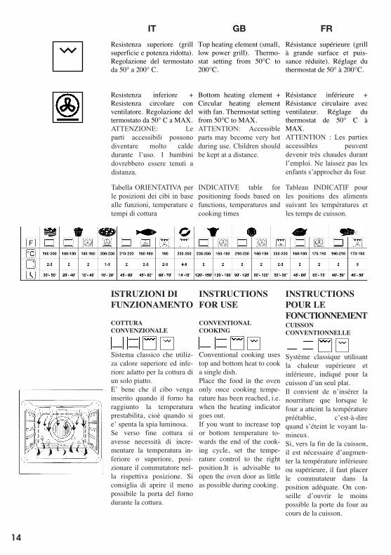
ES NL PTDE
INSTRUÇÕES DE
FUNCIONAMENTO
MODO
CONVENCIONAL
Modo clássico que utiliza
calor superior e inferior
adequado para cozinhar um
só prato.
É bem que os alimentos
sejam introduzidos quando
o forno atingiu a tempera-
tura preestabelecida, isto é
quando se desligou o visor
luminoso.
Se para o fim da cozedura
se tivesse a necessidade de
aumentar a temperatura in-
ferior ou superior, posi-
cionar o comutador na
respectiva posição. Acon-
selha-se de abrir o menos
possível a porta do forno
durante a cozedura
WERKINGS-
INSTRUCTIES
TRADITIONELE
BEREIDING
Klassiek systeem dat ge–
bruik maakt van boven- en
onderwarmte; geschikt voor
bereiding van één gerecht.
Het voedsel dient bij voor–
keur in de oven te worden
gezet wanneer deze al de
ingestelde temperatuur heeft
bereikt, d.w.z. wanneer het
indicatielampje uitgegaan
is.
Als de temperatuur van de
boven- of onderwarmte
tegen het einde van de
bereiding verhoogd moet
worden, dient de schakelaar
op de betreffende stand te
worden gezet. Men raadt
aan de deur van de oven zo
weinig mogelijk open te
maken tijdens de bereiding.
INSTRUCCIONES DE
FUNCIONAMIENTO
COCCIÓN
CONVENCIONAL
Sistema clásico que utiliza
calor superior e inferior
apto para la cocción de un
solo plato.
Es mejor que el alimento
sea introducido cuando el
horno haya alcanzado la
temperatura preestablecida,
es decir, cuando se haya
apagado el indicador lumi-
noso.
Si hacia el final de la
cocción fuese necesario
aumentar la temperatura
inferior o superior, girar el
mando hasta situarlo en la
posición correspondiente.
Se aconseja abrir lo menos
posible la puerta del horno
durante la cocción.
BETRIEBS-
ANLEITUNG
KONVENTIONELLES
BACKEN
Klassisches System, bei
dem Unter- oder Oberhitze
verwendet wird, die für das
Garen nur eines Gerichts
geeignet ist.
Die Speisen sollten mög-
lichst eingeschoben werden,
wenn der Backofen bereits
die vorgegebene Tempe-
ratur erreicht hat, das heißt,
nach Erlöschen der Kon-
trolllampe.
Wenn die Unter- oder Ober-
hitze gegen Ende des Back-
vorgangs erhöht werden
muss, ist der Schalter in die
jeweilige gewünschte Po-
sition zu bringen. Während
des Backvorgangs sollte die
Ofentür möglichst wenig
geöffnet werden.
Oberhitze (Grill mit redu-
zierter Fläche und
Leistung). Einstellung des
Thermostats von 50° auf
200°C.
Unterhitze + Heißluft mit
Ventilator. Einstellung des
Thermostats von 50°C auf
MAX.
Resistencia superior (grill
superficie y potencia reduci-
da). Regulación del termo-
stato entre 50° C y 200° C.
Resistencia inferior +
Resistencia circular con
ventilador. Regulación del
termostato entre 50° C y
MAX.
Bovenste verwarmingsele-
ment (grill met beperkt op-
pervlak en vermogen). In-
stelling van de thermostaat
van 50°C tot 200°C.
Onderwarmte + Rond
verwarmingselement met
ventilator. Instelling van de
thermostaat van 50°C tot
MAX.
Resistência superior (grill
superfície potência reduzi-
da). Regulação do termó-
stato desde 50° até 200° C.
Resistência inferior +
Resistência circular com
ventilador. Regulação do
termóstato desde 50°C ao
MAX.
IT GB FR
INSTRUCTIONS
POUR LE
FONCTIONNEMENT
CUISSON
CONVENTIONNELLE
Système classique utilisant
la chaleur supérieure et
inférieure, indiqué pour la
cuisson d’un seul plat.
Il convient de n’insérer la
nourriture que lorsque le
four a atteint la température
préétablie, c’est-à-dire
quand s’éteint le voyant lu-
mineux.
Si, vers la fin de la cuisson,
il est nécessaire d’augmen-
ter la température inférieure
ou supérieure, il faut placer
le commutateur dans la
position adéquate. On con-
seille d’ouvrir le moins
possible la porte du four au
cours de la cuisson.
INSTRUCTIONS
FOR USE
CONVENTIONAL
COOKING
Conventional cooking uses
top and bottom heat to cook
a single dish.
Place the food in the oven
only once cooking tempe-
rature has been reached, i.e.
when the heating indicator
goes out.
If you want to increase top
or bottom temperature to-
wards the end of the cook-
ing cycle, set the tempe-
rature control to the right
position.It is advisable to
open the oven door as little
as possible during cooking.
ISTRUZIONI DI
FUNZIONAMENTO
COTTURA
CONVENZIONALE
Sistema classico che utiliz-
za calore superiore ed infe-
riore adatto per la cottura di
un solo piatto.
E’ bene che il cibo venga
inserito quando il forno ha
raggiunto la temperatura
prestabilita, cioè quando si
e’ spenta la spia luminosa.
Se verso fine cottura si
avesse necessità di incre-
mentare la temperatura in-
feriore o superiore, posi-
zionare il commutatore nel-
la rispettiva posizione. Si
consiglia di aprire il meno
possibile la porta del forno
durante la cottura.
Resistenza superiore (grill
superficie e potenza ridotta).
Regolazione del termostato
da 50° a 200° C.
Resistenza inferiore +
Resistenza circolare con
ventilatore. Regolazione del
termostato da 50° C a MAX.
Top heating element (small,
low power grill). Thermo-
stat setting from 50°C to
200°C.
Bottom heating element +
Circular heating element
with fan. Thermostat setting
from 50°C to MAX.
Résistance supérieure (grill
à grande surface et puis-
sance réduite). Réglage du
thermostat de 50° à 200°C.
Résistance inférieure +
Résistance circulaire avec
ventilateur. Réglage du
thermostat de 50° C à
MAX.
ES NL PTDE
INSTRUÇÕES DE
FUNCIONAMENTO
MODO
CONVENCIONAL
Modo clássico que utiliza
calor superior e inferior
adequado para cozinhar um
só prato.
É bem que os alimentos
sejam introduzidos quando
o forno atingiu a tempera-
tura preestabelecida, isto é
quando se desligou o visor
luminoso.
Se para o fim da cozedura
se tivesse a necessidade de
aumentar a temperatura in-
ferior ou superior, posi-
cionar o comutador na
respectiva posição. Acon-
selha-se de abrir o menos
possível a porta do forno
durante a cozedura
WERKINGS-
INSTRUCTIES
TRADITIONELE
BEREIDING
Klassiek systeem dat ge–
bruik maakt van boven- en
onderwarmte; geschikt voor
bereiding van één gerecht.
Het voedsel dient bij voor–
keur in de oven te worden
gezet wanneer deze al de
ingestelde temperatuur heeft
bereikt, d.w.z. wanneer het
indicatielampje uitgegaan
is.
Als de temperatuur van de
boven- of onderwarmte
tegen het einde van de
bereiding verhoogd moet
worden, dient de schakelaar
op de betreffende stand te
worden gezet. Men raadt
aan de deur van de oven zo
weinig mogelijk open te
maken tijdens de bereiding.
INSTRUCCIONES DE
FUNCIONAMIENTO
COCCIÓN
CONVENCIONAL
Sistema clásico que utiliza
calor superior e inferior
apto para la cocción de un
solo plato.
Es mejor que el alimento
sea introducido cuando el
horno haya alcanzado la
temperatura preestablecida,
es decir, cuando se haya
apagado el indicador lumi-
noso.
Si hacia el final de la
cocción fuese necesario
aumentar la temperatura
inferior o superior, girar el
mando hasta situarlo en la
posición correspondiente.
Se aconseja abrir lo menos
posible la puerta del horno
durante la cocción.
BETRIEBS-
ANLEITUNG
KONVENTIONELLES
BACKEN
Klassisches System, bei
dem Unter- oder Oberhitze
verwendet wird, die für das
Garen nur eines Gerichts
geeignet ist.
Die Speisen sollten mög-
lichst eingeschoben werden,
wenn der Backofen bereits
die vorgegebene Tempe-
ratur erreicht hat, das heißt,
nach Erlöschen der Kon-
trolllampe.
Wenn die Unter- oder Ober-
hitze gegen Ende des Back-
vorgangs erhöht werden
muss, ist der Schalter in die
jeweilige gewünschte Po-
sition zu bringen. Während
des Backvorgangs sollte die
Ofentür möglichst wenig
geöffnet werden.
Oberhitze (Grill mit redu-
zierter Fläche und
Leistung). Einstellung des
Thermostats von 50° auf
200°C.
Unterhitze + Heißluft mit
Ventilator. Einstellung des
Thermostats von 50°C auf
MAX.
Resistencia superior (grill
superficie y potencia reduci-
da). Regulación del termo-
stato entre 50° C y 200° C.
Resistencia inferior +
Resistencia circular con
ventilador. Regulación del
termostato entre 50° C y
MAX.
Bovenste verwarmingsele-
ment (grill met beperkt op-
pervlak en vermogen). In-
stelling van de thermostaat
van 50°C tot 200°C.
Onderwarmte + Rond
verwarmingselement met
ventilator. Instelling van de
thermostaat van 50°C tot
MAX.
Resistência superior (grill
superfície potência reduzi-
da). Regulação do termó-
stato desde 50° até 200° C.
Resistência inferior +
Resistência circular com
ventilador. Regulação do
termóstato desde 50°C ao
MAX.
ATTENZIONE: Le parti accessibili possono diventare molto calde durante l’uso. I bambini dovrebbero essere tenuti a distanza.
ATTENTION: Accessible parts may become very hot during use. Children should be kept at a distance.
ATTENTION : Les parties accessibles peuvent devenir très chaudes durant l’emploi. Ne laissez pas les enfants s’approcher du four.
Tabella ORIENTATIVA per le posizioni dei cibi in base alle funzioni, temperature e tempi di cottura
INDICATIVE table for positioning foods based on functions, temperatures and cooking times
Tableau INDICATIF pour les positions des aliments suivant les températures et les temps de cuisson.
14
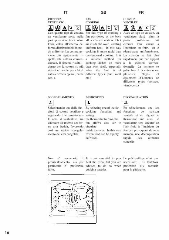
ES NL PTDE
Não é necessário o prévio
aquecimento, mas para a
pastelaria é preferível fazê-
lo.
Voorverwarming is niet
nodig; bij bereiding van ge-
bak echter wel.
Nota:
No es necesario el preca-
lentamiento, pero para la
repostería es preferible
hacerlo.
Ein Vorheizen des Ofens ist
eigentlich nicht notwendig,
aber für Patisserie dennoch
empfehlenswert.
MODO
VENTILADO
Com este tipo de cozedura,
um ventilador colocado na
parte posterior faz circular
o ar quente dentro do forno,
distribuindo-o em modo
uniforme. A cozedura faz-
se mais rapidamente
respeito à cozedura
convencional.
Modo indicado para cozi-
nhar utilizando várias prate-
leiras e também para ali-
mentos de natureza diferen-
te (peixe, carne etc.).
BEREIDING MET
VENTILATIE
Bij dit type bereiding zorgt
een ventilator, die in het
bovenste gedeelte geplaatst
is, ervoor dat de warme
lucht in de oven circuleert,
waarbij deze op
gelijkmatige wijze verspreid
wordt. Het gerecht wordt
zo, ten opzichte van de
traditionele bereidingswijze,
sneller gaar. Het systeem is
geschikt voor de bereiding
op meer dan één verdieping
en ook voor verschillende
soorten voedsel (vis, vlees,
etc.)
COCCIÓN
VENTILADA:
Con este tipo de cocción,
un ventilador situado en la
parte trasera hace circular
el aire caliente dentro del
horno, distribuyéndolo de
manera uniforme. La
cocción se produce más
rápidamente con respecto a
la cocción convencional.
El sistema es idóneo para la
cocción de alimentos de
distintas clases (pescado,
carne, etc. ) también unos
encima de otros.
UMLUFT
BACKEN
Bei dieser Garart bringt der
Ventilator, der sich im
hinteren Ofenteil befindet,
heiße Umluft in den Ofen
und verteilt diese
gleichmäßig, wobei die
Garzeit geringer als beim
konventionellen Backen ist.
Diese Methode eignet sich
zum Garen auf mehreren
Einschubhöhen, auch von
Speisen unterschiedlicher
Art (Fisch, Fleisch usw.).
AUFTAUEN
Falls eine der Umluft-
funktionen ausgewählt und
der Thermostat auf Null
gestellt wird, führt der
Ventilator Kaltluft in den
Ofen und fördert das
schnelle Auftauen der
Tiefkühlkost.
DESCONGELACIÓN
Seleccionando una de las
funciones de cocción
ventilada y ajustando el
termostato sobre el cero, el
ventilador hace circular aire
frío dentro del horno,
facilitando de esta manera
una descongelación rápida
de los alimentos
congelados.
ONTDOOIEN
Door één van de functies
van de bereiding met
ventilatie te kiezen en de
thermostaat op nul te zetten,
laat de ventilator koude
lucht in de oven circuleren,
waardoor diepvriespro-
ducten snel ontdooid
worden.
DESCONGELAÇÃO
Seleccionar uma das
funções de cozedura
ventilada e regulando o
termóstato no zero, o
ventilador fará circular
dentro do forno o ar frio,
favorecendo assim uma
rápida descongelação dos
alimentos congelados.
IT GB FR
Le préchauffage n’est pas
nécessaire; il est toutefois
préférable d’y recourir
pour la pâtisserie.
It is not essential to pre-
heat the oven, but you are
advised to do so when
cooking pastries.
Non e’ necessario il
preriscaldamento, ma per
pasticceria e’ preferibile
farlo.
SCONGELAMENTO
Selezionando una delle fun-
zioni di cottura ventilato e
regolando il termostato sul-
lo zero, il ventilatore farà
circolare all’interno del for-
no aria fredda, favorendo
così un rapido scongela-
mento dei cibi congelati.
CUISSON
VENTILEE
Avec ce type de cuisson, un
ventilateur placé dans la
partie postérieure fait
circuler l’air chaud à
l’intérieur du four, en le
répartissant uniformément.
La cuisson se fait plus
rapidement que par rapport
à la cuisson conven-
tionnelle. Le système se
prête bien à la cuisson sur
plusieurs étages et
également d’aliments de
différents types (poisson,
viande, etc.)
FAN
COOKING
For this type of cooking a
fan positioned at the back
allows the circulation of hot
air inside the oven, creating
uniform heat. In this way
cooking is more rapid than
conventional cooking. It is
a suitable method for
cooking dishes on more
than one shelf, especially
when the food is of
different types (fish, meat
etc.)
COTTURA
VENTILATO
Con questo tipo di cottura,
un ventilatore posto nella
parte posteriore fa circolare
l’aria calda all’interno del
forno, distribuendola in mo-
do uniforme. La cottura av-
viene più rapidamente ri-
spetto alla cottura conven-
zionale. Il sistema risulta i-
doneo per la cottura su più
ripiani ed anche per cibi di
natura diversa (pesce, carne
ecc. ).
DEFROSTING
By selecting one of the fan
cooking functions and
setting
the thermostat to zero, the
fan allows cold air to
circulate
inside the oven. In this way
frozen food can be rapidly
defrosted.
DECONGELATION
En sélectionnant une des
fonctions de cuisson
ventilée et en réglant le
thermostat sur zéro, le
ventilateur fera circuler de
l’air froid à l’intérieur du
four, en provoquant de cette
manière une décongélation
rapide des aliments
congelés.
16
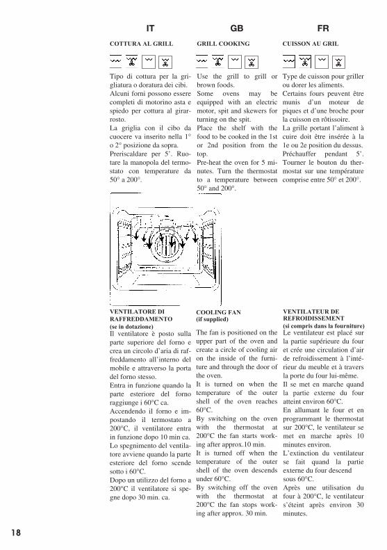
MODO GRIL
Modo indicado paragrelhados ou para gratinaralimentos.Alguns fornos podem estarequipados com motor eespeto giratório paraassados ou churrasco.Para uma utilizaçãocorrecta do Grill, inserirsempre a grelha na 1… ou 2…posição de cima no forno.Aquecer previamente por 5minutos. Rodar o botão dotermóstato com temperatu-ras desde 50 até 200 .
BEREIDING MET GRILL
Type bereiding voor hetgrillen of bruinen van voed-sel.Enkele ovens kunnen eenmotortje hebben om destang voor bereiding aan hetspit te laten draaien.Het rooster met het voedseldat bereid moet wordenmoet op het 1e of 2e niveauvan bovenaf in de ovenworden geschoven.Voorverwarmen gedurende5 minuten. De thermo-staatknop op temperaturenvan 50 tot 200 draaien.
COCCIÓN AL GRILL
Tipo de cocción para asaral grill o para dorar losalimentos.Nota:Algunos hornos puedenestar equipados con un mo-tor giratorio y un espetónpara la cocción en el asador.La parrilla con el alimentoa cocinar debe posicionarseen la 1a o 2a posición de ar-riba.Precalentar durante 5Ê ygirar el termostato hastasituarlo a temperaturasentre 50 y 200 C.
GRILLEN
Zum Grillen oder Bräunender Speisen.Einige Backöfen sind kom-plett mit Stabmotor undDrehspieß für Spießbratenausgestattet.Der Rost mit dem Gargutwird in der 1. oder 2.Schiene von oben einge-schoben.Den Backofen 5 Minutenvorheizen. Den Thermostat-Drehgriff auf Temperaturenvon 50 bis 200 drehen.
KÜHLVENTILATOR
Der Kühventilator befindetsich auf der oberen Seitedes Backofens und dient zurKühlung sowohl des Ein-baumöbels als auch derBackofentüre.Der Ventilator schaltet sichselbstättig ein, wenn dasäußere Gehäuse des Back-ofens eine Temperatur von60 C überschreitet.Wird der Backofen z.B. auf200 C eingestellt, schaltetsich die Kühlung nach etwa10 Min ein.Der Ventilator schaltet sichselbstättig aus, wenn dasäußere Gehäuse des Back-ofens eine Temperatur von60 C wieder überschreitet.z.B. schaltet sich die Kühl-ung nach Betrieb auf 200 Cnach etwa 30 Min. aus.
VENTILADOR DEENFRIAMIENTO
El ventilador está situado enla parte superior del horno ycrea una circulación de airede enfriamiento dentro delmueble y a través de lapuerta del propio horno. Sepone en marcha cuando laparte exterior del hornoalcanza los 60 C aprox.Encendiendo el horno yllevando el termostato a200 C, el ventilador sepone en marcha al cabo deunos 10 minutos. Elventilador se apaga cuandola temperatura de la parteexterior del hornodesciende por debajo de los60 C. Después de utilizar elhorno a 200 C el ventiladorse apaga al cabo de unos 30minutos.
KOELVENTILATOR
De ventilator is in hetbovenste gedeelte van deoven geplaatst en zorgtervoor dat de koelluchtbinnenin het inbouwmeubelen door de deur van de ovenzelf circuleert.Deze begint te werkenwanneer de buitenkant vande oven ongeveer 60 C is.Door de oven aan te zettenen de thermostaat op 200 Cte zetten, begint de ven-tilator na ongeveer 10 min.te lopen. De ventilatorwordt uitgeschakeld zodrade buitenkant van de ovenonder de 60 C daalt.Na de oven op 200 C tehebben gebruikt, gaat deventilator na ongeveer 30min. uit.
VENTILADOR DEARREFECIMENTO(falls mitgeliefert)
(si forma parte del equipo base)(Indien bijgeleverd)
(se for fornecido)O ventilador está situado naparte superior do forno eprocura um circulo de ar dearrefecimento dentro domóvel e através da porta dopróprio forno.Entra em função quando aparte exterior do fornoatinge os 60 C aprox.Acendendo o forno eprogramando o termóstato a200 C, o ventilador entraem função após 10 min.aprox.A desligação do ventiladorefectua-se quando a parteexterior do forno baixa paralá dos 60 C.Depois de uma utilizaçãodo forno a 200 C o ventila-dor desliga-se após 30 min.aprox.
CUISSON AU GRIL
Type de cuisson pour grillerou dorer les aliments.Certains fours peuvent êtremunis dÊun moteur depiques et dÊune broche pourla cuisson en rôtissoire.La grille portant lÊaliment àcuire doit être insérée à la1e ou 2e position du dessus.Préchauffer pendant 5Ê.Tourner le bouton du ther-mostat sur une températurecomprise entre 50 et 200 .
GRILL COOKING
Use the grill to grill orbrown foods.Some ovens may beequipped with an electricmotor, spit and skewers forturning on the spit.Place the shelf with thefood to be cooked in the 1stor 2nd position from thetop.Pre-heat the oven for 5 mi-nutes. Turn the thermostatto a temperature between50 and 200 .
COTTURA AL GRILL
Tipo di cottura per la gri-gliatura o doratura dei cibi.Alcuni forni possono esserecompleti di motorino asta espiedo per cottura al girar-rosto.La griglia con il cibo dacuocere va inserito nella 1o 2 posizione da sopra.Preriscaldare per 5Ê. Ruo-tare la manopola del termo-stato con temperature da50 a 200 .
VENTILATORE DIRAFFREDDAMENTO
Il ventilatore è posto sullaparte superiore del forno ecrea un circolo dÊaria di raf-freddamento allÊinterno delmobile e attraverso la portadel forno stesso.Entra in funzione quando laparte esteriore del fornoraggiunge i 60 C ca.Accendendo il forno e im-postando il termostato a200 C, il ventilatore entrain funzione dopo 10 min ca.Lo spegnimento del ventila-tore avviene quando la parteesteriore del forno scendesotto i 60 C.Dopo un utilizzo del forno a200 C il ventilatore si spe-gne dopo 30 min. ca.
COOLING FAN
The fan is positioned on theupper part of the oven andcreate a circle of cooling airon the inside of the furni-ture and through the door ofthe oven.It is turned on when thetemperature of the outershell of the oven reaches60 C.By switching on the ovenwith the thermostat at200 C the fan starts work-ing after approx.10 min.It is turned off when thetemperature of the outershell of the oven descendsunder 60 C.By switching off the ovenwith the thermostat at200 C the fan stops work-ing after approx. 30 min.
VENTILATEUR DEREFROIDISSEMENT
(se in dotazione)(if supplied)
(si compris dans la fourniture)Le ventilateur est placé surla partie supérieure du fouret crée une circulation dÊairde refroidissement à lÊinté-rieur du meuble et à traversla porte du four lui-même.Il se met en marche quandla partie externe du fouratteint environ 60 C.En allumant le four et enprogrammant le thermostatsur 200 C, le ventilateur semet en marche après 10minutes environ.LÊextinction du ventilateurse fait quand la partieexterne du four descendsous 60 C.Après une utilisation dufour à 200 C, le ventilateursÊéteint après environ 30minutes.
18
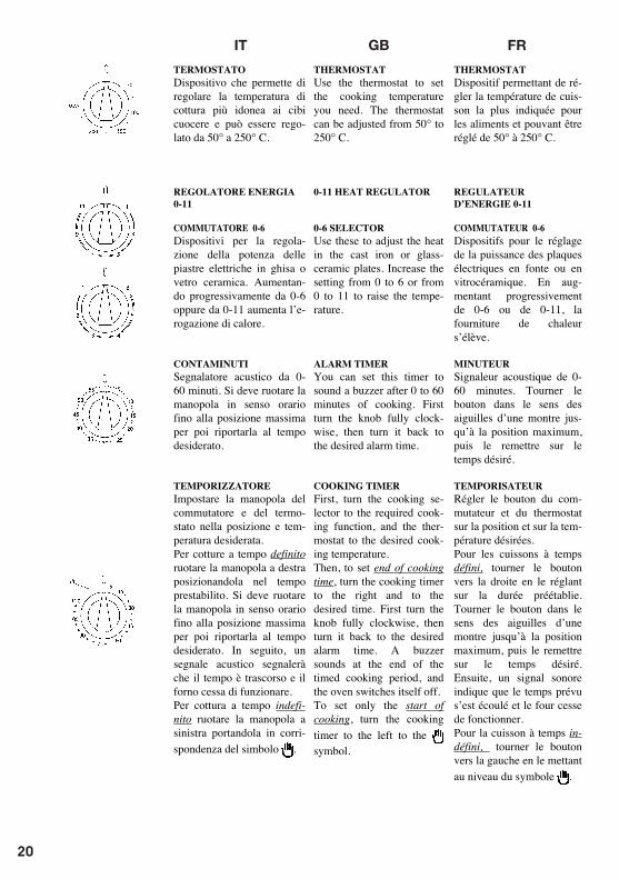
ES NL PTDE
TERMÓSTATO
Dispositivo que permite
regular a temperatura de
acordo com o tipo e forma
dos alimentos a cozinhar e
que pode ser regulado desde
50° até 250° C.
REGULADOR ENERGIA 0-
11
COMUTADOR 0-6
Dispositivos para a regula-
ção da potência das placas
eléctricas ou vitrocerâ-
micas. Aumentando pro-
gressivamente desde 0-6 ou
então desde 0-11 aumenta a
distribuição de calor.
CONTADOR DE MINUTOS
Sinalizador acústico desde
0-60 minutos. Rodar no
sentido horário até à
posição máxima para
depois o levar ao tempo
desejado.
TEMPORIZADOR
Programar o botão do co-
mutador e do termóstato na
posição e temperatura dese-
jada.
Para cozinhar a tempo
definido rodar o botão para
a direita colocando-o no
tempo preestabelecido. A
seguir, um sinal acústico in-
dicará que passou o tempo e
o forno deixa de funcionar.
Rodar no sentido horário
até à posição máxima para
depois o levar ao tempo
desejado.
Para cozinhar a tempo inde-
finido rodar o botão para a
esquerda levando-o à cor-
respondência com o sím-
bolo .
THERMOSTAAT
Mechanisme waarmee de
meest geschikte bereidings-
temperatuur voor het
voedsel kan worden inge-
steld, kan worden ingesteld
tussen 50° en 250° C.
ENERGIEREGELAAR 0-11
SCHAKELAAR 0-6
Mechanismen voor de re-
geling van het vermogen
van de elektrische, gie-
tijzeren of glaskeramische
platen. Door hen geleidelijk
te verhogen van 0-6 of van
0-11 neemt de warmte-
afgifte toe.
MINUTENTELLER
Geluidsalarm van 0-60 mi-
nuten. De knop moet met de
klok mee gedraaid worden
tot in de uiterste positie,
waarna hij op de gewenste
tijd kan worden gedraaid.
TIMER
Stel de knop van de schake-
laar en van de thermostaat
in de gewenste stand en op
de gewenste temperatuur.
Voor bereidingen met een
vaste bereidingstijd moet de
knop naar rechts op de ge-
wenste tijd worden ge-
draaid. De knop moet met
de klok mee gedraaid
worden tot in de uiterste po-
sitie, waarna hij op de ge-
wenste tijd kan worden
gedraaid. Vervolgens zal
een geluidssignaal waar-
schuwen dat de tijd ver-
streken is, en stopt de
werking van de oven.
Voor bereidingen zonder
vaste bereidingstijd moet
de knop naar links worden
gedraaid op het
symbool.
TERMOSTATO:
Dispositivo que permite
regular la temperatura de
cocción más idónea para los
alimentos a cocinar y
puede ser regulado desde
50° a 250° C.
REGULADOR DE
ENERGÍA 0-11
SELECTOR 0-6
Dispositivos para la regu-
lación de la potencia de las
placas eléctricas de hierro o
vitrocerámica. Aumentando
progresivamente desde 0-6
o desde 0-11 aumenta el
suministro de calor.
MINUTERO
Indicador acústico desde 0-
60 minutos. Se debe girar el
mando en el sentido de las
agujas del reloj hasta su
posición máxima, para des-
pués colocarlo en el tiempo
deseado.
TEMPORIZADOR:
Situar el selector de po-
tencia y el termostato en la
posición y temperatura de-
seadas.
Para cocciones con tiempo
definido girar el mando a la
derecha posicionándolo en
el tiempo preestablecido. Se
debe girar el mando en
sentido horario hasta la
posición máxima para luego
volverla a colocar en el
tiempo desiderado.Después
una señal acústica indicará
que el tiempo ha trans-
currido y el horno dejará de
funcionar.
Para la cocción con tiempo
indefinido girar el mando
hacia la izquierda colocán-
dolo en correspondencia
con el símbolo .
THERMOSTAT
Temperaturregler, mit dem
die je nach Gargut geeig-
nete Gartemperatur einge-
stellt wird, und der auf
Temperaturen zwischen 50°und 250° C eingestellt
werden kann.
ENERGIEREGLER 0-11
UMSCHALTER 0-6
Leistungsregler der elektri-
schen Platten aus Gusseisen
oder Glaskeramik. Bei
Erhöhung der Leistungs-
stufen von 0-6 bzw. von 0-
11 wird die Wärmeabgabe
erhöht.
KURZZEITMESSER
Alarmuhr 0-60 Minuten.
Der Drehgriff muss bis zum
Anschlag im Uhrzeigersinn
gedreht, und dann auf die
gewünschte Zeit eingestellt
werden.
ZEITSCHALTER
Den Drehgriff des Um-
schalters und des Thermo-
stats in die gewünschte
Stellung und Temperatur
drehen.
Für bestimmte Garzeiten
den Drehgriff nach rechts
drehen und auf die
vorgegebene Zeit einstellen.
Der Drehgriff muss bis zum
Anschlag im Uhrzeigersinn
gedreht, und dann auf die
gewünschte Zeit eingestellt
werden. Bei Ablauf der
eingestellten Zeit ertönt ein
Signalton und der Backofen
wird ausgeschaltet.
Für unbestimmte Garzeiten
wird der Drehgriff nach
links auf das Symbol
gedreht.
IT GB FR
THERMOSTAT
Dispositif permettant de ré-
gler la température de cuis-
son la plus indiquée pour
les aliments et pouvant être
réglé de 50° à 250° C.
REGULATEUR
D’ENERGIE 0-11
COMMUTATEUR 0-6
Dispositifs pour le réglage
de la puissance des plaques
électriques en fonte ou en
vitrocéramique. En aug-
mentant progressivement
de 0-6 ou de 0-11, la
fourniture de chaleur
s’élève.
MINUTEUR
Signaleur acoustique de 0-
60 minutes. Tourner le
bouton dans le sens des
aiguilles d’une montre jus-
qu’à la position maximum,
puis le remettre sur le
temps désiré.
TEMPORISATEUR
Régler le bouton du com-
mutateur et du thermostat
sur la position et sur la tem-
pérature désirées.
Pour les cuissons à temps
défini, tourner le bouton
vers la droite en le réglant
sur la durée préétablie.
Tourner le bouton dans le
sens des aiguilles d’une
montre jusqu’à la position
maximum, puis le remettre
sur le temps désiré.
Ensuite, un signal sonore
indique que le temps prévu
s’est écoulé et le four cesse
de fonctionner.
Pour la cuisson à temps in-
défini, tourner le bouton
vers la gauche en le mettant
au niveau du symbole .
THERMOSTAT
Use the thermostat to set
the cooking temperature
you need. The thermostat
can be adjusted from 50° to
250° C.
0-11 HEAT REGULATOR
0-6 SELECTOR
Use these to adjust the heat
in the cast iron or glass-
ceramic plates. Increase the
setting from 0 to 6 or from
0 to 11 to raise the tempe-
rature.
ALARM TIMER
You can set this timer to
sound a buzzer after 0 to 60
minutes of cooking. First
turn the knob fully clock-
wise, then turn it back to
the desired alarm time.
COOKING TIMER
First, turn the cooking se-
lector to the required cook-
ing function, and the ther-
mostat to the desired cook-
ing temperature.
Then, to set end of cooking
time, turn the cooking timer
to the right and to the
desired time. First turn the
knob fully clockwise, then
turn it back to the desired
alarm time. A buzzer
sounds at the end of the
timed cooking period, and
the oven switches itself off.
To set only the start of
cooking, turn the cooking
timer to the left to the
symbol.
TERMOSTATO
Dispositivo che permette di
regolare la temperatura di
cottura più idonea ai cibi
cuocere e può essere rego-
lato da 50° a 250° C.
REGOLATORE ENERGIA
0-11
COMMUTATORE 0-6
Dispositivi per la regola-
zione della potenza delle
piastre elettriche in ghisa o
vetro ceramica. Aumentan-
do progressivamente da 0-6
oppure da 0-11 aumenta l’e-
rogazione di calore.
CONTAMINUTI
Segnalatore acustico da 0-
60 minuti. Si deve ruotare la
manopola in senso orario
fino alla posizione massima
per poi riportarla al tempo
desiderato.
TEMPORIZZATORE
Impostare la manopola del
commutatore e del termo-
stato nella posizione e tem-
peratura desiderata.
Per cotture a tempo definito
ruotare la manopola a destra
posizionandola nel tempo
prestabilito. Si deve ruotare
la manopola in senso orario
fino alla posizione massima
per poi riportarla al tempo
desiderato. In seguito, un
segnale acustico segnalerà
che il tempo è trascorso e il
forno cessa di funzionare.
Per cottura a tempo indefi-
nito ruotare la manopola a
sinistra portandola in corri-
spondenza del simbolo .
20
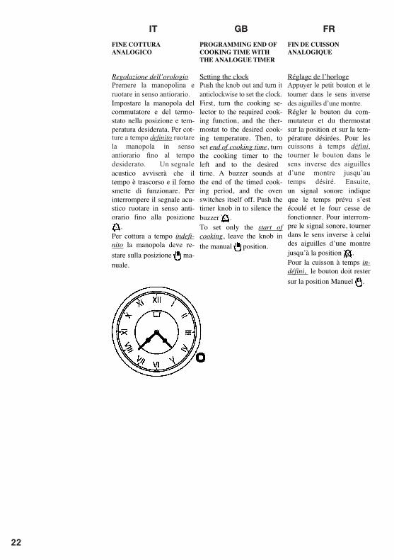
ES NL PTDE
Den kleinen Drehgriff Drücken und im Gegenseitigersinn drehen.
Apretar el mando y girarlo en el sentido antihorario de las agujas del reloj.
Puxar o botãozinho e rodar no sentido esquerda dos ponteiros do relógio.
ziehn im Gegenseitigersinndefinido girar el mando en el sentido antihorario de las agujas del reloj hasta el tiempo deseado. Una señal
po definido rodá-lo no sentido
Drukken de knop draai hem met de klok mee linksom am de tijd in te stellen.Zet de knop van de schakelaar en van de thermostaat in de gewenste stand en op de gewenste temperatuur.Voor bereidingen met vaste bereidingstijd drukt u op de knop en draait hem trek de knop naar u toe, en draai in tegen gestelde richting om de tijd in te stellen. Een geluidssignaal waarschuwt als de tijd verstreken is, en de werking van de oven stopt. Het geluidssignaal wordt afgezet door de knop tegen de klok in te draaien tot in de stand .Voor bereidingen zonder vaste bereidingstijd moet deknop op de stand handbediening blijven staan.
IT GB FR
Premere la manopolina e ruotare in senso antiorario.
Push the knob out and turn it anticlockwise to set the clock.
Appuyer le petit bouton et le tourner dans le sens inverse des aiguilles d’une montre.
ture a tempo definito ruotare la manopola in senso antiorario fino al tempo desiderato. Un segnale
cuissons à temps défini, tourner le bouton dans le sens inverse des aiguilles d’une montre jusqu’au temps désiré. Ensuite,
22
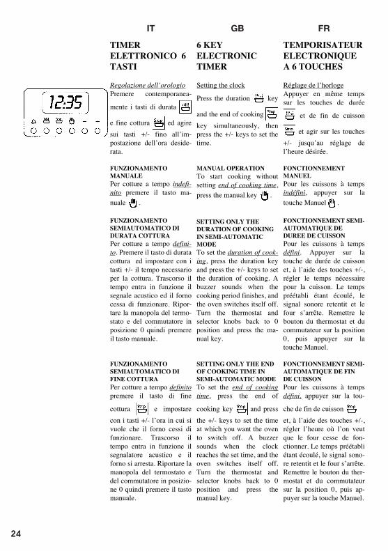
ES NL PTDE
TIMER
ELECTRÓNICO 6
TECLAS
Regulação do relógio
Carregar simultaneamente
nas teclas de duração e
fim cozedura e agir
sobre as teclas +/- até à
programação da hora
desejada.
FUNCIONAMENTO
MANUAL
Para cozinhar a tempo inde-
finido carregar na tecla
manual .
FUNCIONAMENTO SEMI-
AUTOMÁTICO DE
DURAÇÃO DE
COZINHADO
Para cozinhar a tempo defi-
nido. Carregar na tecla de
duração de cozinhado e pro-
gramar com as teclas +/- o
tempo necessário para o co-
zinhado. Passado o tempo
entra em função o sinal acú-
stico e o forno deixa de fun-
cionar. Tornar a levar o bo-
tão do termóstato e do comu-
tador à posição 0 em seguida
carregar na tecla manual.
FUNCIONAMENTO SEMI-
AUTOMÁTICO FIM DE
COZINHADO
Para cozinhar a tempo
definido carregar na tecla
fim de cozinhado e pro-
gramar com as teclas +/- a
hora na qual se pretende que
o forno deixe de funcionar.
Passado o tempo entra em
função o sinalizador acústico
e o forno deixa de funcionar.
Tornar a levar o botão do
termóstato e do comutador à
posição 0 em seguida
carregar na tecla manual.
ELEKTRONISCHE
TIMER 6
TOETSEN
Stellen van de klok
Druk tegelijkertijd op de
toetsen voor de duur
en einde bereiding en
bedien de toetsen +/- totdat
de gewenste tijd is
ingesteld.
HANDBEDIENING
Druk op de handbedienings-
toets voor bereidingen zon-
der vaste bereidingstijd .
HALFAUTOMATISCHE
BEDIENING VAN DE
BEREIDINGSDUUR
Voor bereidingen met vaste
bereidingstijd, druk op de
toets van de bereidingsduur
en stel met de toetsen +/- de
gewenste tijd in. Nadat deze
tijd verstreken is, klinkt er
een geluidssignaal en stopt
de werking van de oven.
Zet de thermostaatknop en
de schakelaar in de stand 0,
en druk vervolgens op de
handbedieningstoets.
HALFAUTOMATISCHE
BEDIENING EINDE
BEREIDING
Voor bereidingen met vaste
bereidingstijd, druk op de
toets voor einde bereiding
en stel met de toetsen +/
- de tijd in waarop de
werking van de oven moet
stoppen. Nadat de tijd ver-
streken is, klinkt er een
geluidssignaal en stopt de
oven. Zet de thermostaatknop
en de schakelaar terug in de
stand 0 en druk vervolgens
op de handbedieningstoets.
TEMPORIZADOR
ELECTRÓNICO
DE 6 TECLAS:
Regulación del reloj
Apretar simultáneamente las
teclas de duración y fin
de cocción , y pulsar las
teclas +/- hasta la pro-
gramación de la hora deseada.
FUNCIÓNAMIENTO
MANUAL:
Para cocciones con tiempo
indefinido apretar la tecla
manual .
FUNCIONAMIENTO
SEMIAUTOMÁTICO DE
DURACIÓN COCCIÓN:
Para cocciones con tiempo
definido. Apretar la tecla de
duración cocción y progra-
mar con las teclas +/- el
tiempo necesario para la coc-
ción. Transcurrido el tiempo
entra en funcionamiento la
señal acústica y el horno deja
de funcionar. Volver a
colocar el mando del termo-
stato y del selector de
potencia en posición 0 luego
apretar la tecla manual.
FUNCIONAMIENTO
SEMIAUTOMÁTICO DE
FIN COCCIÓN:
Para cocciones con tiempo
definido apretar la tecla de
fin cocción y programar
con las teclas +/- la hora en
la cual se quiere que el
horno deje de funcionar.
Transcurrido el tiempo entra
en funcionamiento el indica-
dor acústico y el horno se
para. Volver a colocar el
mando del termostato y del
selector de potencia en
posición 0, luego apretar la
tecla manual.
ELEKTRONISCHE
ZEITSCHALTUHR
MIT 6 TASTEN
Einstellung der Uhr
Gleichzeitig die Tasten für
Gardauer und Garende
drücken und die
Tasten +/- betätigen, bis die
gewünschte Uhrzeit einge-
stellt ist.
MANUALBETRIEB
Für unbestimmte Garzeiten
die Taste Manualbetrieb
drücken .
HALBAUTOMATISCHER
BETRIEB GARDAUER
Für bestimmte Garzeiten.
Die Taste für Gardauer
drücken und mit den Tasten
+/- die erforderliche Garzeit
einstellen. Nach Ablauf der
eingestellten Garzeit ertönt
der Signalton und der Back-
ofen wird ausgeschaltet.
Den Drehgriff des Thermo-
stats und des Umschalters
wieder auf 0 stellen und
dann die Taste für den
Manualbetrieb drücken.
HALBAUTOMATISCHER
BETRIEB GARENDE
Für bestimmte Garzeiten die
Taste für Garende
drücken und mit den Tasten
+/- die Uhrzeit einstellen, in
der der Backofen ausge-
schaltet werden soll. Nach
Ablauf der eingestellten Gar-
zeit ertönt der Signalton und
der Backofen wird ausge-
schaltet. Den Drehgriff des
Thermostats und des Um-
schalters wieder auf 0 stellen
und dann die Taste für den
Manualbetrieb drücken.
IT GB FR
TEMPORISATEUR
ELECTRONIQUE
A 6 TOUCHES
Réglage de l’horloge
Appuyer en même temps
sur les touches de durée
et de fin de cuisson
et agir sur les touches
+/- jusqu’au réglage de
l’heure désirée.
FONCTIONNEMENT
MANUEL
Pour les cuissons à temps
indéfini, appuyer sur la
touche Manuel .
FONCTIONNEMENT SEMI-
AUTOMATIQUE DE
DUREE DE CUISSON
Pour les cuissons à temps
défini. Appuyer sur la
touche de durée de cuisson
et, à l’aide des touches +/-,
régler le temps nécessaire
pour la cuisson. Le temps
préétabli étant écoulé, le
signal sonore retentit et le
four s’arrête. Remettre le
bouton du thermostat et du
commutateur sur la position
0, puis appuyer sur la
touche Manuel.
FONCTIONNEMENT SEMI-
AUTOMATIQUE DE FIN
DE CUISSON
Pour les cuissons à temps
défini, appuyer sur la tou-
che de fin de cuisson
et, à l’aide des touches +/-,
régler l’heure où l’on veut
que le four cesse de fon-
ctionner. Le temps préétabli
étant écoulé, le signal sono-
re retentit et le four s’arrête.
Remettre le bouton du ther-
mostat et du commutateur
sur la position 0, puis ap-
puyer sur la touche Manuel.
6 KEY
ELECTRONIC
TIMER
Setting the clock
Press the duration key
and the end of cooking
key simultaneously, then
press the +/- keys to set the
time.
MANUAL OPERATION
To start cooking without
setting end of cooking time,
press the manual key .
SETTING ONLY THE
DURATION OF COOKING
IN SEMI-AUTOMATIC
MODE
To set the duration of cook-
ing, press the duration key
and press the +/- keys to set
the duration of cooking. A
buzzer sounds when the
cooking period finishes, and
the oven switches itself off.
Turn the thermostat and
selector knobs back to 0
position and press the ma-
nual key.
SETTING ONLY THE END
OF COOKING TIME IN
SEMI-AUTOMATIC MODE
To set the end of cooking
time, press the end of
cooking key and press
the +/- keys to set the time
at which you want the oven
to switch off. A buzzer
sounds when the clock
reaches the set time, and the
oven switches itself off.
Turn the thermostat and
selector knobs back to 0
position and press the
manual key.
TIMER
ELETTRONICO 6
TASTI
Regolazione dell’orologio
Premere contemporanea-
mente i tasti di durata
e fine cottura ed agire
sui tasti +/- fino all’im-
postazione dell’ora deside-
rata.
FUNZIONAMENTO
MANUALE
Per cotture a tempo indefi-
nito premere il tasto ma-
nuale .
FUNZIONAMENTO
SEMIAUTOMATICO DI
DURATA COTTURA
Per cotture a tempo defini-
to. Premere il tasto di durata
cottura ed impostare con i
tasti +/- il tempo necessario
per la cottura. Trascorso il
tempo entra in funzione il
segnale acustico ed il forno
cessa di funzionare. Ripor-
tare la manopola del termo-
stato e del commutatore in
posizione 0 quindi premere
il tasto manuale.
FUNZIONAMENTO
SEMIAUTOMATICO DI
FINE COTTURA
Per cotture a tempo definito
premere il tasto di fine
cottura e impostare
con i tasti +/- l’ora in cui si
vuole che il forno cessi di
funzionare. Trascorso il
tempo entra in funzione il
segnalatore acustico e il
forno si arresta. Riportare la
manopola del termostato e
del commutatore in posizio-
ne 0 quindi premere il tasto
manuale.
24
ES NL PTDE
FUNCIONAMENTO
AUTOMÁTICO
Para cozinhar a tempo
definido carregar na tecla de
duração de cozinhado
e programar com as teclas
+/- o tempo necessário para
cozinhar. Carregar na tecla
fim de cozinhado e
programar a hora na qual se
deseja que o forno deixe de
funcionar.
Ao fim do programa o
símbolo AUTO lampeja,
coloca-se em função o sinal
acústico que deverá ser
desligado carregando uma
tecla qualquer.
CONTADOR DE MINUTOS
Carregar na tecla conta-mi-
nutos e seleccionar o tempo
de cozinhado adequado
com a tecla +/-. Ao fim do
tempo programado, coloca-
se em função o sinal
acústico que pode ser
interrompido carregando
uma das teclas quaisquer.
ERROS DE
PROGRAMAÇÃO
Tem-se um erro de progra-
mação se a hora indicada
pelo relógio estiver compre-
endida entre a hora de
início e a hora do fim de
cozinhado. O erro será sina-
lizado acusticamente e me-
diante o lampejo intermi-
tente do símbolo AUTO. O
erro de programação pode
ser corrigido variando a
duração ou o tempo de
cozinhado.
ANULAMENTO
PROGRAMA
Um programa pode ser
anulado carregando no
botão do funcionamento
manual.
AUTOMATISCHE
WERKING
Voor bereidingen met een
vaste bereidingstijd, druk
op de toets van de be-
reidingsduur en stel
met de toetsen +/- de tijd in
die nodig is voor de
bereiding. Druk op de toets
van einde bereiding en
stel het tijdstip in waarop u
wilt dat de oven stopt.
Aan het einde van het
programma knippert het
symbool AUTO en klinkt
het geluidssignaal; dit kan
door indrukken van een
willekeurige toets worden
afgezet.
MINUTENTELLER
Druk op de toets van de mi-
nutenteller en stel de ge-
wenste bereidingstijd in met
de toets +/-. Aan het einde
van de ingestelde tijd wordt
het geluidssignaal inge-
schakeld, dat kan worden
afgezet door op een wille-
keurige toets te drukken.
PROGRAMMEER-
FOUTEN
Er is sprake van een pro-
grammeerfout als de tijd die
door de klok wordt aan-
gegeven tussen het begin- en
het eindtijdstip van de be-
reiding ligt. Deze fout wordt
gesignaleerd door een ge-
luidssignaal en door het
knipperen van het symbool
AUTO. Verkeerde instellin-
gen kunnen worden ge-
corrigeerd door de duur of de
bereidingstijd te veranderen.
ANNULEREN
PROGRAMMA
Het is mogelijk een
programma te annuleren
door op de knop van de
handbediening te drukken.
FUNCIONAMIENTO
AUTOMÁTICO:
Para cocciones con tiempo
definido apretar la tecla de
duración de cocción y
programar con las teclas +/
- el tiempo necesario para
la cocción. Apretar la tecla
de fin cocción y pro-
gramar la hora en la cual se
quiere que el horno se pare.
Al final del programa el
símbolo AUTO parpadea,
se pone en funcionamiento
la señal acústica que deberá
ser apagada apretando cual-
quier tecla .
MINUTERO:
Apretar la tecla del minute-
ro y seleccionar el tiempo
de cocción deseado con la
tecla +/-. Al final del
tiempo programado se
pone en funcionamiento la
señal acústica que puede
ser interrumpida apretando
cualquier tecla.
ERRORES DE
PROGRAMACIÓN
Tenemos un error de pro-
gramación si la hora indi-
cada por el reloj está com-
prendida entre la hora de
inicio y la hora de fin
cocción. El error será seña-
lado acústicamente y me-
diante el parpadeo inter-
mitente del símbolo
AUTO. El error de progra-
mación puede ser corregido
variando la duración o el
tiempo de cocción.
ANULACIÓN DE UN
PROGRAMA:
Un programa puede ser
anulado apretando el botón
del funcionamiento ma-
nual.
AUTOMATIKBETRIEB
Für bestimmte Garzeiten.
Die Taste für Gardauer
drücken und mit den
Tasten +/- die erforderliche
Garzeit einstellen. Die
Taste für Garende drücken
und die Uhrzeit ein-
stellen, in der der Backofen
ausgeschaltet werden soll.
Bei Programmende blinkt
das Symbol AUTO und es
ertönt der Signalton, der
durch Drücken einer be-
liebigen Taste abgestellt
wird.
KURZZEITMESSER
Die Taste des Kurzzeit-
messers drücken und mit
der Taste +/- die ge-
wünschte Garzeit einstellen.
Nach Ablauf der einge-
stellten Garzeit ertönt der
Signalton, der durch
Drücken einer beliebigen
Taste abgestellt werden
kann.
PROGRAMMIERUNGS-
FEHLER
Ein Programmierungsfehler
liegt vor, wenn die von der
Uhr angezeigte Uhrzeit
zwischen Garbeginn und
Garende liegt. Der Fehler
wird durch einen Warnton
und durch Blinken des
Symbols AUTO signali-
siert. Der Program-
mierungsfehler kann durch
Änderung der Gardauer
oder der Garzeit korrigiert
werden.
LÖSCHEN EINES
PROGRAMMS
Ein Programm kann durch
Drücken der Manualbetrieb-
Taste gelöscht werden.
IT GB FR
FONCTIONNEMENT
AUTOMATIQUE
Pour les cuissons à temps
défini, appuyer sur la
touche de durée cuisson
et, à l’aide des touches
+/-, régler le temps
nécessaire à la cuisson.
Appuyer sur la touche de
fin de cuisson et régler
l’heure où l’on veut que le
four s’arrête.
A la fin du programme, le
symbole AUTO clignote et
le signal sonore qui retentit
alors doit être interrompu
en appuyant sur n’importe
quelle touche.
MINUTEUR
Appuyer sur la touche du
minuteur et sélectionner le
temps de cuisson désiré
avec la touche +/-. Le temps
préétabli étant écoulé, le
signal sonore qui retentit
alors peut être interrompu
en appuyant sur n’importe
quelle touche.
ERREURS DE
PROGRAMMATION
Il y a erreur de programma-
tion si l’heure indiquée par
l’horloge est comprise entre
l’heure de début et l’heure de
fin de cuisson. L’erreur est
indiquée par un signal sonore
et par le clignotement du
symbole AUTO. L’erreur de
programmation peut être
corrigée en modifiant la
durée ou le temps de cuisson.
ANNULATION DU
PROGRAMME
Un programme peut être an-
nulé en appuyant sur le
bouton de fonctionnement
manuel.
FULLY AUTOMATIC
OPERATION
To set the end of cooking
time, press the duration key
and press the +/- keys
to set the duration of
cooking. Press the end of
cooking key and press
the +/- keys to set the time
at which you want the oven
to switch off.
When you finish setting
these times, the AUTO
symbol flashes and the
buzzer sounds. Press any
key to silence it.
ALARM TIMER
Press the alarm timer key
and press the +/- keys to set
the required duration of
cooking. The buzzer sounds
when the cooking time
ends. Press any key to
silence it.
PROGRAMMING
ERRORS
You cannot program in a
cooking period which starts
earlier than the time
displayed on the clock. If
you try to do so, the buzzer
sounds and the AUTO
symbol flasher. Simply
change the duration or
cooking time to correct the
error.
CANCELLING A COOKING
PROGRAMME
To cancel a cooking
programme, simply press
the manual key.
FUNZIONAMENTO
AUTOMATICO
Per cotture a tempo definito
premere il tasto di durata
cottura e impostare
con i tasti +/- il tempo
necessario per la cottura.
Premere il tasto di fine
cottura e impostare
l’ora in cui si vuole che il
forno si arresti.
Al termine del programma
il simbolo AUTO lampeg-
gia, si mette in funzione il
segnale acustico che dovrà
essere spento premendo un
tasto qualsiasi.
CONTAMINUTI
Premere il tasto contaminati
e selezionare il tempo di
cottura desiderato con il
tasto +/-. Al termine del
tempo impostato si mette in
funzione il segnale acustico
che può essere interrotto
premendo uno qualsiasi dei
tasti.
ERRORI DI
PROGRAMMAZIONE
Si ha un errore di program-
mazione se l’ora indicata
dall’orologio è compresa tra
l’ora di inizio e l’ora di fine
cottura. L’errore sarà segna-
lato acusticamente e me-
diante il lampeggio inter-
mittente del simbolo
AUTO. L’errore di impo-
stazione può essere corretto
variando la durata o il tem-
po di cottura.
ANNULLAMENTO
PROGRAMMA
Un programma può essere
annullato premendo il
pulsante del funzionamento
manuale.
26
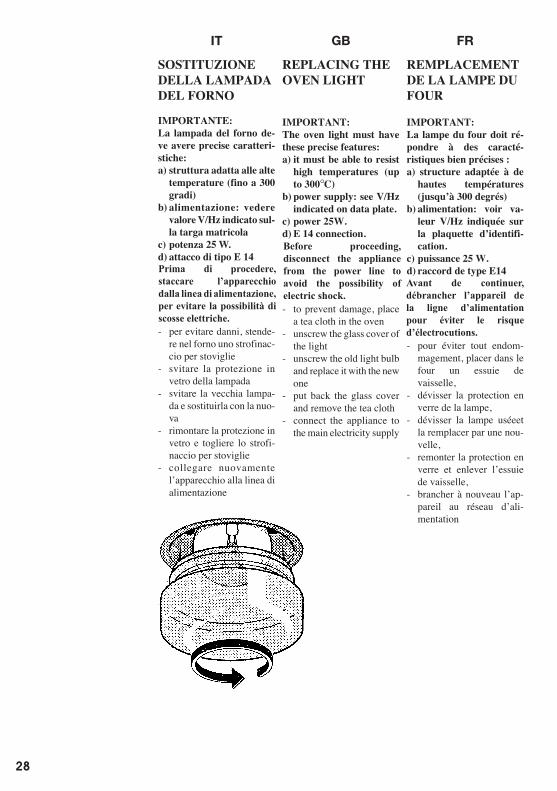
ES NL PTDE
AUSWECHSLUNG
DER OFEN-
BELEUCHTUNG
WICHTIG:
Die Ofenbeleuchtung
muss folgende Merkmale
aufweisen:
a) h o c h t e m p e r a t u r -
beständig (bis zu 300
Grad)
b) Stromversorgung: siehe
Anschlusswerte V/Hz
auf dem Typenschild.
c) Leistung 25 W
d) Sockel E 14
- Zur Vermeidung von
Schadensfällen, ist im
Ofen ein Geschirrtuch
auszubreiten
- Lampenabdeckung aus
Glas abschrauben
- Alte Lampe abschrauben
und mit einer neuen Be-
leuchtung auswechseln
- L a m p e n a b d e c k u n g
wieder anmontieren und
Geschirrtuch entfernen
- Das Gerät erneut an das
Stromnetz anschlie§en
CAMBIO DE LA
BOMBILLA DEL
HORNO
IMPORTANTE:
La bombilla del horno
debe tener unas caracte-
rísticas bien determi-
nadas:
a) estructura apta para
las altas temperaturas
(hasta 300 grados)
b) alimentación: véase el
valor V/Hz indicado en
la chapa de matrícula.
c) potencia 25 W.
d) casquillo de tipo E14
- para evitar daños, poner
en el horno un trapo para
vajillas
- desenroscar la protección
en vidrio de la bombilla
- desenroscar la vieja bom-
billa y cambiarla por la
nueva
- montar de nuevo la pro-
tección en vidrio y quitar
el trapo para vajillas
- enchufar de nuevo el apa-
rato a la línea de alimen-
tación.
HET VERVANGEN
VAN HET LAMPJE
VAN DE OVEN
BELANGRIJK:
Het lampje van de oven
dient de volgende ken-
merken te bezitten:
a) een structuur die ge-
schikt is voor hoge tem-
peraturen (tot 300°C).
b) voeding: zie de waarde
V/Hz die wordt ver-
meld op de typeplaat
c) vermogen 25 W.
d) aanhechting van het
type E 14
- om schade te voorkomen,
dient men een theedoek in
de oven te leggen.
- draai de glazen be-
scherming van de lamp los
- draai het oude lampje los
en vervang het met een
nieuw
- breng de glazen be-
scherming weer aan en
verwijder de theedoek
- sluit het apparaat weer op
de stroom aan.
SUBSTITUIÇÃO
DA LÂMPADA DO
FORNO
IMPORTANTE:
A lâmpada do forno deve
haver características exac-
tas:
a) estrutura adequada às
altas temperaturas (até
300 graus)
b) alimentação: vide valor
V/Hz indicado na placa
de matrícula.
c) potência 25 W.
d) casquilho tipo E 14
- para evitar danos, estender
no forno um pano da louça
- desapertar a protecção em
vidro da lâmpada
- desapertar a lâmpada
velha e substituí-la com a
nova
- tornar a montar a pro-
tecção em vidro e tirar o
pano da louça
- ligar novamente o apa-
relho à linha de alimen-
tação
IT GB FR
SOSTITUZIONE
DELLA LAMPADA
DEL FORNO
IMPORTANTE:
La lampada del forno de-
ve avere precise caratteri-
stiche:
a) struttura adatta alle alte
temperature (fino a 300
gradi)
b) alimentazione: vedere
valore V/Hz indicato sul-
la targa matricola
c) potenza 25 W.
d) attacco di tipo E 14
- per evitare danni, stende-
re nel forno uno strofinac-
cio per stoviglie
- svitare la protezione in
vetro della lampada
- svitare la vecchia lampa-
da e sostituirla con la nuo-
va
- rimontare la protezione in
vetro e togliere lo strofi-
naccio per stoviglie
- collegare nuovamente
l’apparecchio alla linea di
alimentazione
REPLACING THE
OVEN LIGHT
IMPORTANT:
The oven light must have
these precise features:
a) it must be able to resist
high temperatures (up
to 300°C)
b) power supply: see V/Hz
indicated on data plate.
c) power 25W.
d) E 14 connection.
- to prevent damage, place
a tea cloth in the oven
- unscrew the glass cover of
the light
- unscrew the old light bulb
and replace it with the new
one
- put back the glass cover
and remove the tea cloth
- connect the appliance to
the main electricity supply
REMPLACEMENT
DE LA LAMPE DU
FOUR
IMPORTANT:
La lampe du four doit ré-
pondre à des caracté-
ristiques bien précises :
a) structure adaptée à de
hautes températures
(jusqu’à 300 degrés)
b) alimentation: voir va-
leur V/Hz indiquée sur
la plaquette d’identifi-
cation.
c) puissance 25 W.
d) raccord de type E14
- pour éviter tout endom-
magement, placer dans le
four un essuie de
vaisselle,
- dévisser la protection en
verre de la lampe,
- dévisser la lampe uséeet
la remplacer par une nou-
velle,
- remonter la protection en
verre et enlever l’essuie
de vaisselle,
- brancher à nouveau l’ap-
pareil au réseau d’ali-
mentation
Prima di procedere, staccare l’apparecchio dalla linea di alimentazione, per evitare la possibilità di scosse elettriche.
Before proceeding, disconnect the appliance from the power line to avoid the possibility of electric shock.
Avant de continuer, débrancher l’appareil de la ligne d’alimentation pour éviter le risque d’électrocutions.
28
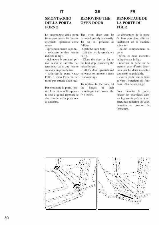
ES NL PTDE
DESMONTAGEM
DA PORTA FORNO
A desmontagem da porta
forno pode ser facilmente
efectuada operando como a
seguir se indica:
- abrir totalmente a porta;
- elevar as duas alavancas
indicadas na fig.;
- fechar a porta no primeiro
disparo de batida determi-
nado pelas duas alavancas
levantadas anteriormente;
- elevar a porta para cima e
para a parte de fora do for-
no para a extrair das sedes;
Para tornar a montar a
porta, inserir as dobradiças
nas sedes apropriadas e em
seguida tornar a levar as
duas alavancas na posição
de fecho.
DEMONTAGE VAN
DE OVENDEUR
De ovendeur kan gemakke-
lijk worden gedemonteerd,
als volgt:
- open de deur helemaal;
- til de twee hendeltjes die
worden aangeduid op afb.
op;
- sluit de deur op de eerste
stand die wordt veroorzaakt
door de twee hendeltjes die
zojuist zijn opgetild;
- til de deur naar boven en
naar buiten op, om hem van
zijn plaats te halen;
Om de deur weer te plaat-
sen moeten de scharnieren
in hun behuizingen worden
geplaatst en moeten de twee
hendeltjes weer worden
teruggezet in de sluitende
positie.
DESMONTAJE DE
LA PUERTA DEL
HORNO
El desmontaje de la puerta
del horno puuede ser fácil-
mente efectuado obrando
como sigue:
- abrir totalmente la puerta;
- alzar las dos palanquitas
indicas en fig.;
- volver a cerrar la puerta
después de la primera pa-
rada, consecuencia de la
subida previa de las dos pa-
lanquitas;
- alzar la puerta hacia
arriba y hacia el exterior
del horno para extraerla;
Para volver a montar la
puerta, introducir las bi-
sagras en las apropiadas
sedes y luego volver a co-
locar las dos palanquitas en
la posición de cierre.
AUSBAUEN DER
OFENTÜR
Die Backofentür kann
mühelos ausgebaut werden.
Dazu folgendermaßen vor-
gehen:
- die Tür ganz öffnen;
- die zwei auf Abb. dar-
gestellten Hebel anheben;
- die Tür wieder bis zur
ersten, von den zwei zuvor
angehobenen Hebeln be-
stimmten Einrastung
schließen;
- die Tür nach oben und
nach außen anheben und
herausnehmen;
Um die Tür wieder ein-
zubauen, die Scharniere
wieder einsetzen und dann
die zwei Hebel in Schließ-
stellung bringen..
IT GB FR
DEMONTAGE DE
LA PORTE DU
FOUR
Le démontage de la porte
du four peut être effectué
facilement de la manière
suivante :
- ouvrir complètement la
porte;
- lever les deux manettes
indiquées sur la fig.;
- refermer la porte sur le
premier cran d’arrêt déter-
miné par les deux manettes
soulevées au préalable;
- lever la porte vers le haut
et vers l’extérieur du four
pour l’ôter de son siège;
Pour remonter la porte,
insérer les charnières dans
les logements prévus à cet
effet, puis remettre les deux
manettes en position de
fermeture.
REMOVING THE
OVEN DOOR
The oven door can be
removed quickly and easily.
To do so, proceed as
follows:
- Open the door fully.
- Lift the two levers shown
in fig.
- Close the door as far as
the first stop (caused by the
raised levers).
- Lift the door upwards and
outwards to remove it from
its mountings.
To replace fit the door, fit
the hinges in their
mountings and lower the
two levers.
SMONTAGGIO
DELLA PORTA
FORNO
Lo smontaggio della porta
forno può essere facilmente
effettuato operando come
segue:
- aprire totalmente la porta;
- sollevare le due levette
indicate in fig.;
- richiudere la porta sul pri-
mo scatto di arresto de-
terminato dalle due levette
sollevate in precedenza;
- sollevare la porta verso
l’alto e verso l’esterno del
forno per estrarla dalle sedi;
Per rimontare la porta, inse-
rire le cerniere nelle apposi-
te sedi e quindi riportare le
due levette nella posizione
di chiusura.
30
IT GB FR
POUR
L’INSTALLATEUR
Encastrement du four
Le four peut être installé
sous un plan de cuisson ou
dans une colonne. Les
dimensions de l’encastre-
ment doivent correspondre
à celles qui sont indiquées
sur la figure.
Le matériau avec lequel le
meuble est réalisé doit être
en mesure de résister à la
chaleur. Le four doit être
centré par rapport aux pa-
rois du meuble et fixé avec
les vis et les douilles four-
nies à cet effet.
Pour associer le four avec
les plans de cuisson poly-
valents à gaz et combinés
électriques, voir les
instructions jointes.
INSTALLATION
INSTRUCTIONS
Flush fitting
The oven can be installed
under a work top or in a
cooking column. Figure
shows the installation di-
mensions.
Make sure that surrounding
materials are heat resistant.
Align the oven centrally
with respect to the side
walls of the units surround-
ing it and fix it in place
with the screws and Allen
screws provided.
See the accompanying in-
structions for combining
the oven with multi-
functional gas or gas-
electric cookers.
PER
L’INSTALLATORE
Incasso del forno
Il forno può essere installa-
to sotto un piano di cottura
oppure in colonna. Le di-
mensioni dell’incasso devo-
no essere come riportato in
figura.
Il materiale del mobile deve
essere in grado di resistere
al calore. Il forno deve esse-
re centrato rispetto alle pa-
reti del mobile e fissato con
le viti e bussole che sono
fornite in dotazione.
Per l’abbinamento del
forno con i piani di
cottura polivalenti gas o
combi elettrici vedere le
istruzioni allegate.
ES NL PTDE
PARA O
INSTALADOR
Encastre do forno
O forno pode ser instalado
debaixo de um plano de
cozedura ou então na
coluna. As dimensões de
encastre devem ser como
referido na figura.
O material do móvel deve
ser capaz de resistir ao
calor. O forno deve ser
centrado respeito ás paredes
do móvel e fixado com os
parafusos e buchas que são
fornecidas em dotação.
Para a união do forno
com os planos de cozedura
polivalentes gás ou
combinados eléctricos ver
as instruções em anexo.
VOOR DE
INSTALLATEUR
Inbouw van de oven
De oven kan worden ge-
ïnstalleerd onder een kook-
plaat of in een hoge kast.
De inbouwafmetingen
moeten overeenstemmen
met de maten van af-
beelding.
Het materiaal van het
meubel moet hittebestendig
zijn. De oven moet tussen
de wanden van het meubel
worden gecentreerd, en
worden vastgezet met de
inbusschroeven die bij de
oven geleverd zijn.
Voor de combinatie van
de oven met gas- of
gemengde kookplaten, zie
de bijgaande instructies.
PARA EL
INSTALADOR:
Encastre del horno
El horno puede ser insta-
lado debajo de la encimera
o en una columna. Las
dimensiones del encastre
deben ser como se muestra
en figura.
El material del mueble debe
ser capaz de resistir al calor.
El horno debe ser centrado
respecto de las paredes del
mueble y fijado con los tor-
nillos y casquillos sumini-
strados junto con el pro-
ducto.
Para la combinación del
horno con las placas de
cocción polivalentes gas o
combi eléctricos ver las
instrucciones anexas.
FÜR DEN
INSTALLATEUR
Einbau des Backofens
Der Ofen kann unter einem
Kochfeld oder in einen
Schrank eingebaut werden.
Die Einbaumaße müssen
den auf der Abbildung dar-
gestellten entsprechen. Das
Möbelmaterial muss hitze-
beständig sein. Der Back-
ofen muss zu den Möbel-
wänden zentriert, und mit
den mitgelieferten Schrau-
ben und Buchsen befestigt
werden.
Für die Kombination des
Backofens mit den Gas-
oder Gas/Elektrokombi-
kochfeldern siehe bei-
liegende Anleitungen.
ALLACCIAMENTI GAS OD ELETTRICI
GAS OR ELECTRICAL CONNECTIONS
RACCORDEMENTS GAZ OU ÉLECTRIQUES
GAS- BZW. STROMANSCHLÜSSE
CONEXIONES DE GAS O ELÉCTRICAS
GAS- OF ELEKTRISCHE AANSLUITINGEN
LIGAÇÕES DO GÁS OU ELÉCTRICAS
Inserire le bussole in dotazione sui fori presenti in facciata.
Insert the bushings provided in the holes in the face.
Introduisez les douilles fournies dans les trous de la façade.
Fissare con le quattro viti in dotazione le boccole al mobile avendo cura di non forzare troppo pena la rottura della boccola stessa.
Use the four screws provided to fasten the bushings to the cabinet, taking care not to over tighten and break the bushing.
Fixez les douilles au meuble avec les quatre vis fournies en veillant à ne pas trop forcer sous peine de casser les douilles.
32
IT GB FR
BRANCHEMENT
ELECTRIQUE
Avant d’effectuer le bran-
chement électrique, s’assu-
rer que :
- les caractéristiques de l’in-
stallation permettent de re-
specter ce qui est indiqué
sur la plaque d’identifica-
tion qui est appliquée sur le
devant du four;
- l’installation est munie
d’un raccordement à la pri-
se de terre conforme aux
normes et aux dispositions
prévues par la loi. La mise à
la terre est obligatoire aux
termes de la loi.
Le câble ne doit en aucun
cas atteindre une
température supérieure de
plus de 50° C par rapport à
la température ambiante.
Si un appareil fixe n’a pas
de cordon d’alimentation et
de fiche ou d’autre dispositif
assurant la déconnexion du
secteur, avec une distance
d’ouverture des contacts
ELECTRICAL
CONNECTIONS
Before connecting the oven
to the mains power supply,
make sure that:
- The supply voltage corre-
sponds to the specifications
on the data plate on the
front of the oven.
- The mains supply has an
efficient earth (ground)
connection complying with
all applicable laws and re-
gulations. Correct earthing
(grounding) is a legal requi-
rement.
The power cable should
never reach a temperature
50° C above ambient tem-
perature at any point along
its length.
If a fixed appliance is not
provided with a power cable
and plug, or some other
device permitting it to be
disconnected from the
mains electricity supply,
with a gap between the
contacts big enough to
ALLACCIAMENTO
ELETTRICO
Prima di effettuare l’allac-
ciamento elettrico accertarsi
che:
- le caratteristiche dell’im-
pianto siano tali da soddi-
sfare quanto indicato sulla
targa matricola applicata sul
fronte del forno;
- l’impianto sia munito di
un efficace collegamento di
terra secondo le norme e le
disposizioni di legge in vi-
gore. La messa a terra è ob-
bligatoria a termini di leg-
ge.
Il cavo in nessun punto
dovrà raggiungere una
temperatura superiore di
50° C quella ambiente.
Se un apparecchio fisso non
è provvisto di cavo di ali-
mentazione e di spina, o di
altro dispositivo che assicu-
ri la disconnessione dalla
rete, con una distanza di
apertura dei contatti che con-
senta la disconnessione
SASO
H05RR-F 3x1,5 mm² H05RR-F 3x2,5 mm²
H05VV-F 3x1,5 mm² H05VV-F 3x2,5 mm²
H05RN-F 3x1,5 mm² H05RN-F 3x2,5 mm²
H05V2V2-F 3x1,5 mm² H05V2V2-F 3x2,5 mm²
CABLE TYPES AND MINIMAL DIAMETERSTIPI E DIAMETRO MINIMO DEI CAVI
TYPES ET DIAMÈTRE MINIMAUX DES CÂBLES
ES NL PTDE
PARA O
INSTALADOR
Encastre do forno
O forno pode ser instalado
debaixo de um plano de
cozedura ou então na
coluna. As dimensões de
encastre devem ser como
referido na figura.
O material do móvel deve
ser capaz de resistir ao
calor. O forno deve ser
centrado respeito ás paredes
do móvel e fixado com os
parafusos e buchas que são
fornecidas em dotação.
Para a união do forno
com os planos de cozedura
polivalentes gás ou
combinados eléctricos ver
as instruções em anexo.
VOOR DE
INSTALLATEUR
Inbouw van de oven
De oven kan worden ge-
ïnstalleerd onder een kook-
plaat of in een hoge kast.
De inbouwafmetingen
moeten overeenstemmen
met de maten van af-
beelding.
Het materiaal van het
meubel moet hittebestendig
zijn. De oven moet tussen
de wanden van het meubel
worden gecentreerd, en
worden vastgezet met de
inbusschroeven die bij de
oven geleverd zijn.
Voor de combinatie van
de oven met gas- of
gemengde kookplaten, zie
de bijgaande instructies.
PARA EL
INSTALADOR:
Encastre del horno
El horno puede ser insta-
lado debajo de la encimera
o en una columna. Las
dimensiones del encastre
deben ser como se muestra
en figura.
El material del mueble debe
ser capaz de resistir al calor.
El horno debe ser centrado
respecto de las paredes del
mueble y fijado con los tor-
nillos y casquillos sumini-
strados junto con el pro-
ducto.
Para la combinación del
horno con las placas de
cocción polivalentes gas o
combi eléctricos ver las
instrucciones anexas.
FÜR DEN
INSTALLATEUR
Einbau des Backofens
Der Ofen kann unter einem
Kochfeld oder in einen
Schrank eingebaut werden.
Die Einbaumaße müssen
den auf der Abbildung dar-
gestellten entsprechen. Das
Möbelmaterial muss hitze-
beständig sein. Der Back-
ofen muss zu den Möbel-
wänden zentriert, und mit
den mitgelieferten Schrau-
ben und Buchsen befestigt
werden.
Für die Kombination des
Backofens mit den Gas-
oder Gas/Elektrokombi-
kochfeldern siehe bei-
liegende Anleitungen.
ALLACCIAMENTI GAS OD ELETTRICI
GAS OR ELECTRICAL CONNECTIONS
RACCORDEMENTS GAZ OU ÉLECTRIQUES
GAS- BZW. STROMANSCHLÜSSE
CONEXIONES DE GAS O ELÉCTRICAS
GAS- OF ELEKTRISCHE AANSLUITINGEN
LIGAÇÕES DO GÁS OU ELÉCTRICAS
34
IT GB FR
BRANCHEMENT
ELECTRIQUE
Avant d’effectuer le bran-
chement électrique, s’assu-
rer que :
- les caractéristiques de l’in-
stallation permettent de re-
specter ce qui est indiqué
sur la plaque d’identifica-
tion qui est appliquée sur le
devant du four;
- l’installation est munie
d’un raccordement à la pri-
se de terre conforme aux
normes et aux dispositions
prévues par la loi. La mise à
la terre est obligatoire aux
termes de la loi.
Le câble ne doit en aucun
cas atteindre une
température supérieure de
plus de 50° C par rapport à
la température ambiante.
Si un appareil fixe n’a pas
de cordon d’alimentation et
de fiche ou d’autre dispositif
assurant la déconnexion du
secteur, avec une distance
d’ouverture des contacts
ELECTRICAL
CONNECTIONS
Before connecting the oven
to the mains power supply,
make sure that:
- The supply voltage corre-
sponds to the specifications
on the data plate on the
front of the oven.
- The mains supply has an
efficient earth (ground)
connection complying with
all applicable laws and re-
gulations. Correct earthing
(grounding) is a legal requi-
rement.
The power cable should
never reach a temperature
50° C above ambient tem-
perature at any point along
its length.
If a fixed appliance is not
provided with a power cable
and plug, or some other
device permitting it to be
disconnected from the
mains electricity supply,
with a gap between the
contacts big enough to
ALLACCIAMENTO
ELETTRICO
Prima di effettuare l’allac-
ciamento elettrico accertarsi
che:
- le caratteristiche dell’im-
pianto siano tali da soddi-
sfare quanto indicato sulla
targa matricola applicata sul
fronte del forno;
- l’impianto sia munito di
un efficace collegamento di
terra secondo le norme e le
disposizioni di legge in vi-
gore. La messa a terra è ob-
bligatoria a termini di leg-
ge.
Il cavo in nessun punto
dovrà raggiungere una
temperatura superiore di
50° C quella ambiente.
Se un apparecchio fisso non
è provvisto di cavo di ali-
mentazione e di spina, o di
altro dispositivo che assicu-
ri la disconnessione dalla
rete, con una distanza di
apertura dei contatti che con-
senta la disconnessione
SASO
H05RR-F 3x1,5 mm² H05RR-F 3x2,5 mm²
H05VV-F 3x1,5 mm² H05VV-F 3x2,5 mm²
H05RN-F 3x1,5 mm² H05RN-F 3x2,5 mm²
H05V2V2-F 3x1,5 mm² H05V2V2-F 3x2,5 mm²
CABLE TYPES AND MINIMAL DIAMETERSTIPI E DIAMETRO MINIMO DEI CAVI
TYPES ET DIAMÈTRE MINIMAUX DES CÂBLES
ES NL PTDE
PARA O
INSTALADOR
Encastre do forno
O forno pode ser instalado
debaixo de um plano de
cozedura ou então na
coluna. As dimensões de
encastre devem ser como
referido na figura.
O material do móvel deve
ser capaz de resistir ao
calor. O forno deve ser
centrado respeito ás paredes
do móvel e fixado com os
parafusos e buchas que são
fornecidas em dotação.
Para a união do forno
com os planos de cozedura
polivalentes gás ou
combinados eléctricos ver
as instruções em anexo.
VOOR DE
INSTALLATEUR
Inbouw van de oven
De oven kan worden ge-
ïnstalleerd onder een kook-
plaat of in een hoge kast.
De inbouwafmetingen
moeten overeenstemmen
met de maten van af-
beelding.
Het materiaal van het
meubel moet hittebestendig
zijn. De oven moet tussen
de wanden van het meubel
worden gecentreerd, en
worden vastgezet met de
inbusschroeven die bij de
oven geleverd zijn.
Voor de combinatie van
de oven met gas- of
gemengde kookplaten, zie
de bijgaande instructies.
PARA EL
INSTALADOR:
Encastre del horno
El horno puede ser insta-
lado debajo de la encimera
o en una columna. Las
dimensiones del encastre
deben ser como se muestra
en figura.
El material del mueble debe
ser capaz de resistir al calor.
El horno debe ser centrado
respecto de las paredes del
mueble y fijado con los tor-
nillos y casquillos sumini-
strados junto con el pro-
ducto.
Para la combinación del
horno con las placas de
cocción polivalentes gas o
combi eléctricos ver las
instrucciones anexas.
FÜR DEN
INSTALLATEUR
Einbau des Backofens
Der Ofen kann unter einem
Kochfeld oder in einen
Schrank eingebaut werden.
Die Einbaumaße müssen
den auf der Abbildung dar-
gestellten entsprechen. Das
Möbelmaterial muss hitze-
beständig sein. Der Back-
ofen muss zu den Möbel-
wänden zentriert, und mit
den mitgelieferten Schrau-
ben und Buchsen befestigt
werden.
Für die Kombination des
Backofens mit den Gas-
oder Gas/Elektrokombi-
kochfeldern siehe bei-
liegende Anleitungen.
ALLACCIAMENTI GAS OD ELETTRICI
GAS OR ELECTRICAL CONNECTIONS
RACCORDEMENTS GAZ OU ÉLECTRIQUES
GAS- BZW. STROMANSCHLÜSSE
CONEXIONES DE GAS O ELÉCTRICAS
GAS- OF ELEKTRISCHE AANSLUITINGEN
LIGAÇÕES DO GÁS OU ELÉCTRICAS
35
ES NL PTDE
LIGAÇÃO
ELÉCTRICA
Antes de efectuar a ligação
eléctrica certificar-se que:
- as características da insta-
lação sejam tais que possam
satisfazer quanto indicado
na placa da matrícula apli-
cada na fronte do forno;
- a instalação esteja dotada
de uma eficaz ligação a ter-
ra segundo as normas e as
disposições de lei em vigor.
A ligação a terra é obriga-
tória nos termos da lei.
O cabo em nenhum ponto
deverá atingir uma tempera-
tura superior de 50° C a-
quela ambiente.
Se um aparelho fixo não
estiver equipado com cabo
de alimentação e ficha, ou
outro dispositivo que
garanta a desactivação da
rede, com uma distância de
abertura dos contactos que
permita a desactivação com-
pleta nas condições da cate-
goria de sobretensão III,
ELEKTRISCHE
AANSLUITING
Controleer, voordat u de
elektrische aansluiting tot
stand brengt, of:
- de eigenschappen van de
elektrische installatie over-
eenstemmen met de ge-
gevens op het typeplaatje
op de voorzijde van de
oven;
- de installatie goed geaard
is volgens de geldende
voorschriften en wettelijke
bepalingen. De aarding is
volgens de wet verplicht.
De kabel mag in geen geval
meer dan 50° warmer
worden dan de
omgevingstemperatuur.
Als een vast apparaat niet
beschikt over een
voedingskabel en stekker of
over een ander systeem dat
de afkoppeling van het
elektriciteitsnet garandeert
(met een afstand tussen de
contacten die in
overspanningscategorie III
CONEXIÓN
ELÉCTRICA
Antes de efectuar la cone-
xión eléctrica cerciorarse de
que:
- las características de la in-
stalación se correspondan
con las indicadas en la
placa situada en la parte
frontal del horno;
- la instalación esté provista
de una eficaz conexión a
tierra según las normas y
las disposiciones de la ley
en vigor. La conexión a
tierra es obligatoria según la
ley.
El cable en ningún punto
deberá alcanzar una tempe-
ratura superior de 50° C a
temperatura ambiente.
Si un aparato fijo no está
provisto de cable de
alimentación con enchufe,
en la red de alimentación
debe incluirse un dispositi-
vo de corte, instalado con
arreglo a las disposiciones
vigentes y con una distancia
STROM-
ANSCHLUSS
Vor der Durchführung des
Stromanschluss muss si-
chergestellt werden, dass:
- die Eigenschaften der
Stromnetzes mit den
Werten auf dem vorne am
Ofen angebrachten Typen-
schild übereinstimmen;
- das Stromnetz gemäß den
geltenden Bestimmungen
und Rechtsvorschriften ge-
erdet ist. Die Erdung ist ge-
setzlich vorgeschrieben.
Das Kabel darf an keiner
Stelle eine Temperatur von
über 50° C erreichen.
Wenn ein Standgerät nicht
mit Netzkabel und -stecker
oder einer sonstigen
Vorrichtung ausgestattet ist,
das die Trennung vom Netz
gewährleistet, und dessen
Öffnungsweg der Kontakte
die vollständige Trennung
unter den Bedingungen der
Überspannungskategorie III
gestattet, so müssen diese
400V 3N *5 x 1,5 mm
2
400V 2N *4 x 2,5 mm
2
230V 3 *4 x 2,5 mm
2
230V *3 x 4 mm
2
SASO
H05RR-F 3x1,5 mm² H05RR-F 3x2,5 mm²
H05VV-F 3x1,5 mm² H05VV-F 3x2,5 mm²
H05RN-F 3x1,5 mm² H05RN-F 3x2,5 mm²
H05V2V2-F 3x1,5 mm² H05V2V2-F 3x2,5 mm²
KABELTYPES EN MINIMALE DOORSNEDEN
KABELTYPEN UND MINIMALE DURCHMESSERTIPOS Y DIÁMETRO MÍNIMO DE LOS CABLES
TIPOS E DIÁMETRO MÍNIMO DOS CABOS
IT GB FR
N.B. Le fabricant décline
toute responsabilité si les
indications présentées dans
ce document et les normes
adoptées habituellement en
matière de prévention des
accidents du travail ne sont
pas respectées.
N.B. The manufacturer de-
clines all responsibility for
damage or injury if the
above instructions and nor-
mal safety precautions are
not respected.
N.B. Il costruttore declina
ogni responsabilità nel caso
che quanto sopra e le usuali
norme antinfortunistiche
non vengano rispettate.
permettant une déconnexion
complète dans les conditions
de la catégorie de surtension
III, ces dispositifs de
déconnexion doivent être
prévus dans le réseau
d ’ a l i m e n t a t i o n
conformément aux normes
d’installation.
guarantee class III
overvoltage protection, then
such a device must be fitted
to the power supply in
compliance with the
regulations governing
electrical installations.
completa nelle condizioni
della categoria di
sovratensione III, tali
dispositivi di disconnessione
devono essere previsti nella
rete di alimentazione confor-
memente alle regole di in-
stallazione.
La spina o l’interruttore onnipolare devono essere facilmente raggiungibili con l’apparecchiatura installata.
Durante l’uso l’apparecchio diventa molto caldo. Si dovrebbe fare attenzione a non toccare gli elementi riscaldanti all’interno del forno
Se il forno ha la sonda carne in dotazione, utilizzare solamente la sonda raccomandata per questo forno.
I diversi livelli di cottura dove possono essere riposte griglie e leccarde sono indicati nella tebellina di pagina 14.
The omnipolar plug or switch must be easy to reach when the appliance is installed.
The unit becomes very hot during use. Be careful not to touch the heating elements inside the oven.
If the oven came with a meat probe, use only the probe recommended for this oven.
The different cooking levels where grids and drip pans can be placed are shown in the table on page 14.
La prise ou l’interrupteur omnipolaire doivent être facilement accessibles après l’installation de l’appareil.
Pendant son utilisation, l’appareil devient très chaud. Veillez à ne pas toucher les éléments chauffants à l’intérieur du four.
Si le four est équipé de la sonde à viande, utilisez uniquement la sonde préconisée pour ce four.
Les différents niveaux de cuisson auxquels on peut placer des grilles et des lèches-frites sont indiqués dans le tableau de la page 14.
37
La Casa costruttrice declina ogni responsabilità per le possibili inesattezze contenute nel presenteopuscolo, imputabili ad errori di stampa o di trascrizione. Si riserva il diritto di apportare ai propriprodotti quelle modifiche che ritiene necessarie o utili, senza pregiudicare le caratteristiche essenziali.
Dans un souci constant d’amélioration qualitative, le constructeur se réserve la possibilité d’apporter àses produits les modifications utiles, sans compromettre ses caractéristiques essentielles.Le constructeur décline toutes responsabilité pour d’eventuelles inexactitudes contenues dans cettenotice, imputables à des erreurs d’impression ou de transcription.
El fabricante declina toda responsabilidad por las posibles inexactitudes contenidas en el presentedocumento, imputables a errores de impresión o relacionadas. El fabricante se reserva el derecho deaportar a sus propios productos aquellas modificaciones que se considere necesarias o útiles, sinperjudicar las características esenciales.
O Fabricante não assume nenhuma responsabilidade acerca de eventuais inexactidões contidas napresente publicação, devidas a erros de impressão ou de transcrição. Reserva-se o direito de efectuarnos próprios produtos as eventuais modificações que considerar necessárias ou úteis, sem prejudicaras características essenciais.
Il contenuto del presente manuale è generico e non tutte le funzionalità descritte potrebbero essere incluse nel vostro prodotto.
Der inhalt dieses handbuchs ist allgemeingültig und nicht alle beschriebenen funktionen könnten in ihrem produkt eingeschlossen sein.
De inhoud van deze handleiding is algemeen en het kan zijn dat niet alle functies die erin beschreven worden ook deel uitmaken van uw product.
The contents of this manual are generic and not all the functions described may be available on your product.
El contenido de este manual es genérico y no todas las funcionalidades descritas podrían estar incluidas en su producto.
O conteúdo do presente manual é genérico e pode acontecer que nem todas as funcionalidades descritas estejam incluídas no vosso produto.
Le contenu du présent manuel est générique et certaines des fonctions qui y sont décrites pourraient ne pas être disponibles sur votre produit.
Cod. 2.000.00.3 - 7ed
Warranty Card
Eurolinx Pty Limited A.B.N. 50 001 473 347 trading as ILVE (“ILVE”)6ɉJL!������4VVYL�:[YLL[��3LPJOOHYK[�5�:�>������7VZ[!3VJRLK�)HN�������(UUHUKHSL��5�:�>������7!�������������
WARRANTY REGISTRATION@V\Y�VUNVPUN�ZH[PZMHJ[PVU�^P[O�`V\Y�03=,�WYVK\J[�PZ�PTWVY[HU[�[V�\Z��>L�HZR�[OH[�`V\�JVTWSL[L�[OL�LUJSVZLK�>HYYHU[`�9LNPZ[YH[PVU�*HYK�HUK�YL[\YU�P[�[V�\Z�ZV�[OH[�^L�OH]L�H�YLJVYK�VM�[OL�03=,�WYVK\J[�W\YJOHZLK�I`�`V\�
PRIVACY03=,�YLZWLJ[Z�`V\Y�WYP]HJ`�HUK�PZ�JVTTP[[LK�[V�OHUKSPUN�`V\Y�WLYZVUHS�PUMVYTH[PVU�PU�HJJVYKHUJL�^P[O�[OL�5H[PVUHS�7YP]HJ`�7YPUJPWSLZ�HUK�[OL�7YP]HJ`�(J[�� ����*[O���(�JVW`�VM�[OL�03=,�7YP]HJ`�7VSPJ`�PZ�H]HPSHISL�H[�^^ �̂PS]L�JVT�H\��03=,�^PSS�UV[�KPZJSVZL�HU`�WLYZVUHS�PUMVYTH[PVU�ZL[�V\[�PU�[OL�>HYYHU[`�9LNPZ[YH[PVU�*HYK��¸7LYZVUHS�0UMVYTH[PVU¹��^P[OV\[�`V\Y�JVUZLU[�\USLZZ�YLX\PYLK�I`!���SH^"���HU`�03=,�YLSH[LK�JVTWHU`"���HU`�ZLY]PJL�WYV]PKLY�^OPJO�WYV]PKL�ZLY]PJLZ�[V�03=,�VY�HZZPZ[�03=,�PU�WYV]PKPUN�ZLY]PJLZ��PUJS\KPUN�YLWHPY�HUK�^HYYHU[`�ZLY]PJLZ��[V�J\Z[VTLYZ��6\Y�W\YWVZL�PU�JVSSLJ[PUN�[OL�7LYZVUHS�0UMVYTH[PVU�PZ[V�RLLW�H�YLJVYK�VM�[OL�03=,�WYVK\J[�W\YJOHZLK�I`�`V\��PU�VYKLY�[V�WYV]PKL�H�IL[[LY�^HYYHU[`�ZLY]PJL�[V�`V\�PU�[OL�\USPRLS`�L]LU[�[OH[�[OLYL�PZ�H�WYVISLT�^P[O�`V\Y�03=,�WYVK\J[��03=,�TH`�JVU[HJ[�`V\�H[�HU`�VUL�VY�TVYL�VM�[OL�HKKYLZZ��LTHPS�HKKYLZZ�VY�[LSLWOVUL�U\TILYZ�ZL[�V\[�PU�[OL�>HYYHU[`�9LNPZ[YH[PVU�*HYK��7SLHZL�JVU[HJ[�03=,�VU������� ������ZOV\SK�`V\�UV[�^PZO�[V�IL�JVU[HJ[LK�I`�03=,�
WARRANTY���>HYYHU[`03=,�^HYYHU[Z�[OH[�LHJO�03=,�WYVK\J[�^PSS�YLTHPU��MVY�H�WLYPVK�VM�[^LU[`�MV\Y������TVU[OZ�JVTW\[LK�MYVT�[OL�KH[L�VM�W\YJOHZL�VM�[OL�03=,�WYVK\J[��MYLL�MYVT�KLMLJ[Z�HYPZPUN�PU�[OL�THU\MHJ[\YL�VM�[OL�03=,�WYVK\J[��¸>HYYHU[`¹���,_JLW[�MVY�JVUZ\TLY�N\HYHU[LLZ�ZL[V\[�PU�[OL�*VTWL[P[PVU�HUK�*VUZ\TLY�(J[�������*[O���¸(J[¹���03=,�KVLZ�UV[�THRL�HU`�M\Y[OLY�^HYYHU[PLZ�VY�YLWYLZLU[H[PVUZ�PU�YLSH[PVU�[V�03=,�WYVK\J[Z�
���>OH[�PZ�UV[�*V]LYLK�I`�[OL�>HYYHU[ �̀;OL�>HYYHU[`�KVLZ�UV[�HWWS`�PM�HU�03=,�WYVK\J[�PZ�KLMLJ[P]L�I`�H�MHJ[VY�V[OLY�[OHU�H�KLMLJ[�HYPZPUN�PU�[OL�THU\MHJ[\YL�VM�[OL�03=,�WYVK\J[��
PS]L�JVT�H\
PUJS\KPUN�I\[�UV[�SPTP[LK�[V!�H��KHTHNL�[OYV\NO�TPZ\ZL��PUJS\KPUN�MHPS\YL�[V�THPU[HPU��ZLY]PJL�VY�\ZL�^P[O�WYVWLY�JHYL���ULNSLJ[��HJJPKLU[�VY�VYKPUHY`�^LHY�HUK�[LHY��PUJS\KPUN�KL[LYPVYH[PVU�VM�WHY[Z�HUK�HJJLZZVYPLZ�HUK�NSHZZ�IYLHRHNL�"�I��\ZL�MVY�W\YWVZL�MVY�^OPJO�[OL�03=,�WYVK\J[�^HZ�UV[�ZVSK�VY�KLZPNULK"�J��\ZL�VY�PUZ[HSSH[PVU�^OPJO�PZ�UV[�PU�HJJVYKHUJL�^P[O�HU`�ZWLJPÄLK�PUZ[Y\J[PVUZ�MVY�\ZL�VY�PUZ[HSSH[PVU"�K��\ZL�VY�VWLYH[PVU�HM[LY�H�KLMLJ[�OHZ�VJJ\YYLK�VY�ILLU�KPZJV]LYLK"�L��KHTHNL�[OYV\NO�MYLPNO[��[YHUZWVY[H[PVU�VY�OHUKSPUN�PU�[YHUZP[��V[OLY�[OHU�^OLU�03=,�PZ�YLZWVUZPISL�"�M��KHTHNL�[OYV\NO�L_WVZ\YL�[V�JOLTPJHSZ��K\Z[Z��YLZPK\LZ��L_JLZZP]L�]VS[HNL��OLH[��H[TVZWOLYPJ�JVUKP[PVUZ�VY�V[OLY�MVYJLZ�VY�LU]PYVUTLU[HS�MHJ[VYZ�V\[ZPKL�[OL�JVU[YVS�VY�03=,"�N��YLWHPY��TVKPÄJH[PVU�VY�[HTWLYPUN�I`�[OL�W\YJOHZLY�VY�HU`�WLYZVU�V[OLY�[OHU�03=,��HU�LTWSV`LL�VM�03=,�VY�HU�H\[OVYPZLK�03=,�ZLY]PJL�JVU[YHJ[VY�"�O��\ZL�VM�WHY[Z��JVTWVULU[Z�VY�HJJLZZVYPLZ�^OPJO�OH]L�UV[�ILLU�Z\WWSPLK�VY�ZWLJPÄJHSS`�HWWYV]LK�I`�03=,��P��KHTHNL�[V�Z\YMHJL�JVH[PUNZ�JH\ZLK�I`�JSLHUPUN�VY�THPU[LUHUJL�\ZPUN�WYVK\J[Z�UV[�YLJVTTLUKLK�PU�[OL�03=,�WYVK\J[�OHUKIVVR�WYV]PKLK�[V�[OL�W\YJOHZLY�\WVU�W\YJOHZL�VM�[OL�03=,�WYVK\J["�Q��KHTHNL�[V�[OL�IHZL�VM�HU�LSLJ[YPJ�V]LU�K\L�[V�P[LTZ�OH]PUN�ILLU�WSHJLK�VU�[OL�IHZL�VM�[OL�V]LU�JH]P[`�VY�JV]LYPUN�[OL�IHZL��Z\JO�HZ�HS\TPUP\T�MVPS��[OPZ�PTWLKLZ�[OL�[YHUZMLY�VM�OLH[�MYVT�[OL�LSLTLU[�[V�[OL�V]LU�JH]P[`�HUK�JHU�YLZ\S[�PU�PYYLWHYHISL�KHTHNL�"�VY�R��KHTHNLZ��KLU[Z�VY�V[OLY�JVZTL[PJ�PTWLYMLJ[PVUZ�UV[�HɈLJ[PUN�[OL�WLYMVYTHUJL�VM�[OL�03=,�PU�YLZWLJ[�VM�HU�03=,�WYVK\J[�W\YJOHZLK�HZ�H�¸MHJ[VY`�ZLJVUK¹�VY�MYVT�KPZWSH`;OL�>HYYHU[`�KVLZ�UV[�L_[LUK�[V�SPNO[�NSVILZ�\ZLK�PU�03=,�WYVK\J[Z����+VTLZ[PJ�<ZL,HJO�03=,�WYVK\J[�PZ�THKL�MVY�KVTLZ[PJ�\ZL��;OPZ�>HYYHU[`�TH`�UV[�L_[LUK�[V�03=,�WYVK\J[Z�\ZLK�MVY�JVTTLYJPHS�W\YWVZLZ����;PTL�MVY�*SHPT�\UKLY�[OL�>HYYHU[`@V\�T\Z[�THRL�HU`�JSHPT�\UKLY�[OPZ�>HYYHU[`�^P[OPU�[^LU[`�LPNO[������KH`Z�HM[LY�[OL�VJJ\YYLUJL�VM�HU�L]LU[�^OPJO�NP]LZ�YPZL�[V�H�JSHPT�W\YZ\HU[�[V�[OL�>HYYHU[ �̀�I`�IVVRPUN�H�ZLY]PJL�JHSS�VU�[OL�[LSLWOVUL�U\TILY�ILSV �̂
*VU[PU\LK�V]LY���
3 ILVE Operating Manual
���7YVVM�VM�7\YJOHZL*\Z[VTLYZ�T\Z[�YL[HPU�WYVVM�VM�W\YJOHZL�PU�VYKLY�[V�IL�LSPNPISL�[V�THRL�H�^HYYHU[`�JSHPT�PU�YLZWLJ[�VM�HU�03=,�WYVK\J[�
���*SHPTPUN�\UKLY�[OL�>HYYHU[`*\Z[VTLYZ�^PSS�ILHY�[OL�JVZ[�VM�JSHPTPUN�\UKLY�[OPZ�>HYYHU[`�\USLZZ�03=,�KL[LYTPULZ�[OL�L_WLUZLZ�HYL�YLHZVUHISL��PU�^OPJO�JHZL�[OL�J\Z[VTLY�T\Z[�JSHPT�[OVZL�L_WLUZLZ�I`�WYV]PKPUN�^YP[[LU�L]PKLUJL�VM�LHJO�L_WLUZL�[V�03=,�H[�[OL�HKKYLZZ�VU�[OL�>HYYHU[`�9LNPZ[YH[PVU�*HYK�
���:[H[\[VY`�9PNO[Z�H��;OLZL�[LYTZ�HUK�JVUKP[PVUZ�KV�UV[�HɈLJ[�`V\Y�Z[H[\[VY`�YPNO[Z��I��;OL�SPTP[H[PVUZ�VU�[OL�>HYYHU[`�ZL[�V\[�PU�[OPZ�KVJ\TLU[�KV�UV[�L_JS\KL�VY�SPTP[�[OL�HWWSPJH[PVU�VM�[OL�JVUZ\TLY�N\HYHU[LLZ�ZL[�V\[�PU�[OL�(J[�VY�HU`�V[OLY�LX\P]HSLU[�VY�JVYYLZWVUKPUN�SLNPZSH[PVU�PU�[OL�YLSL]HU[�Q\YPZKPJ[PVU�^OLYL�[V�KV�ZV�^V\SK!�P��JVU[YH]LUL�[OL�SH^�VM�[OL�YLSL]HU[�Q\YPZKPJ[PVU"�or �PP��JH\ZL�HU`�WHY[�VM�[OL�>HYYHU[`�[V�IL�]VPK��J��03=,�L_JS\KLZ�PUKPYLJ[�VY�JVUZLX\LU[PHS�SVZZ�VM�HU`�RPUK��PUJS\KPUN��^P[OV\[�SPTP[H[PVU��SVZZ�VM�\ZL�VM�[OL�03=,�WYVK\J[��HUK��V[OLY�[OHU�L_WYLZZS`�WYV]PKLK�MVY�PU�[OLZL�[LYTZ�HUK�JVUKP[PVUZ��Z\IQLJ[�[V�HSS�[LYTZ�JVUKP[PVUZ�HUK�^HYYHU[PLZ�PTWSPLK�I`�J\Z[VT��[OL�NLULYHS�SH �̂�[OL�(J[�VY�V[OLY�Z[H[\[L��K��;OL�SPHIPSP[`�VM�03=,�[V�`V\�MVY�H�IYLHJO�VM�HU`�L_WYLZZ�VY�UVU�L_JS\KHISL�PTWSPLK�[LYT��JVUKP[PVU�VY�^HYYHU[`�PZ�SPTP[LK�H[�[OL�VW[PVU�VM�03=,�[V!
�P��YLWSHJPUN�VY�YLWHPYPUN�[OL�KLMLJ[P]L�WHY[�VM�[OL�03=,�WYVK\J["�PP��WH`PUN�[OL�JVZ[�VM�YLWSHJPUN�VY�YLWHPYPUN�[OL�KLMLJ[P]L�WHY[�VM�[OL�03=,�WYVK\J["�PPP��YLWSHJPUN�[OL�03=,�WYVK\J["�VY�P]��WH`PUN�[OL�JVZ[�VM�YLWSHJPUN�[OL�03=,�WYVK\J[��L��6\Y�NVVKZ�JVTL�^P[O�N\HYHU[LLZ�[OH[�JHUUV[�IL�L_JS\KLK�\UKLY�[OL�(\Z[YHSPHU�*VUZ\TLY�3H �̂�@V\�HYL�LU[P[SLK�[V�H�YLWSHJLTLU[�VY�YLM\UK�MVY�H�THQVY�MHPS\YL�HUK�MVY�JVTWLUZH[PVU�MVY�HU`�V[OLY�YLHZVUHIS`�MVYLZLLHISL�SVZZ�VY�KHTHNL��@V\�HYL�HSZV�LU[P[SLK�[V�OH]L�[OL�NVVKZ�YLWHPYLK�VY�YLWSHJLK�PM�[OL�NVVKZ�MHPS�[V�IL�VM�HJJLW[HISL�X\HSP[`�HUK�[OL�MHPS\YL�KVLZ�UV[�HTV\U[�[V�H�THQVY�MHPS\YL�
���+LMLJ[Z(U`�WHY[�VM�HU�03=,�WYVK\J[�KLLTLK�[V�IL�KLMLJ[P]L�HUK�YLWSHJLK�I`�03=,�PZ�[OL�WYVWLY[`�VM�03=,��03=,�YLZLY]LZ�[OL�YPNO[�[V�PUZWLJ[�HUK�[LZ[�03=,�WYVK\J[Z�PU�VYKLY�[V�KL[LYTPUL�[OL�L_[LU[�VM�HU`�KLMLJ[�HUK�[OL�]HSPKP[`�VM�H�JSHPT�\UKLY�[OL�>HYYHU[ �̀�;V�SVJH[L�`V\Y�JSVZLZ[�03=,�H\[OVYPZLK�ZLY]PJL�HNLU[�WSLHZL�JVU[HJ[�03=,�VU��������������VY�]PZP[�O[[W!��Z\WWVY[�PS]L�JVT�H\�
ALL SERVICE CALLS MUST BE BOOKED THROUGH THE ILVE SERVICE AND >(99(5;@�+,7(9;4,5;�65�������������
��������
Warranty Card JVU[PU\LK PS]L�JVT�H\
4ILVE Operating Manual
7SLHZL�JVTWSL[L�HUK�ZLUK�[V�03=,�H[!���9,73@�7(0+������ 3,0*//(9+;�5:>�����
3HZ[�5HTL! -PYZ[�5HTL!
(KKYLZZ!
:[H[L! 7VZ[JVKL! ,THPS!
/VTL�7OVUL! 4VIPSL!
7\YJOHZL�+H[L!���������������������������������������������������������������������������������������7SLHZL�H[[HJO�WYVVM�VM�W\YJOHZL�[V�]HSPKH[L�^HYYHU[`�
46+,3�5<4),9 :,90(3�5<4),9� �PM�`V\�JHUUV[�SVJH[L�[OL�ZLYPHS�U\TILY�WSLHZL�JHSS�03=,�VU���������������
�
2
3
�
>(99(5;@�9,.0:;9(;065�*(9+��������
��������
Warranty Card tear off

(\Z[YHSPH�5H[PVUHS�;LSLWOVUL�5\TILY������4@03=,��� ������5L^�ALHSHUK�;LSLWOVUL�5\TILY������������
03=,�ZOV^YVVTZ�HYL�VWLU�KHPS`�MYVT� HT��WT�HUK�:H[\YKH`Z���HT��WT �>(�I`�HWWVPU[TLU[�VUS`�VU�:H[\YKH`Z� PS]L�JVT�H\
5:>� �(*;��/LHK�6ɉJL�������4VVYL�:[YLL[� 3LPJOOHYK[-������� ���
=0*��;(:� �:(�����;VVYHR�9VHK� *HTILY^LSS-���� �� �����
83+�����*H]LUKPZO�9VHK�*VVYWHYVV�-������ ������
>(� �5;<UP[�������/V^L�:[YLL[6ZIVYUL�7HYR�-���� ���� ���
5L^�ALHSHUK76�)V_�������:VJRI\YU�*OYPZ[JO\YJO-��������� ��

INSTRUCTION MANUAL FOR BUILT-IN OVEN
TOUCH CONTROL PANEL
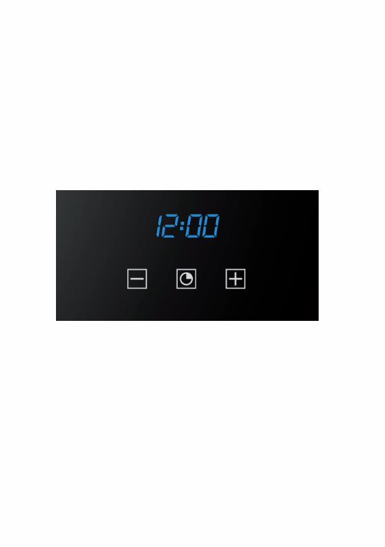
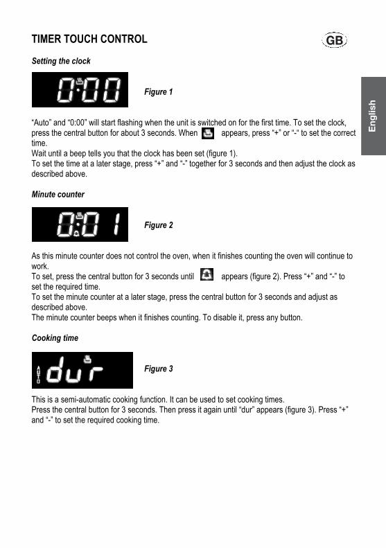
TIMER TOUCH CONTROL Setting the clock Figure 1 “Auto” and “0:00” will start flashing when the unit is switched on for the first time. To set the clock, press the central button for about 3 seconds. When appears, press “+” or “-“ to set the correct time. Wait until a beep tells you that the clock has been set (figure 1). To set the time at a later stage, press “+” and “-” together for 3 seconds and then adjust the clock as described above. Minute counter Figure 2 As this minute counter does not control the oven, when it finishes counting the oven will continue to work. To set, press the central button for 3 seconds until appears (figure 2). Press “+” and “-” to set the required time. To set the minute counter at a later stage, press the central button for 3 seconds and adjust as described above. The minute counter beeps when it finishes counting. To disable it, press any button. Cooking time Figure 3 This is a semi-automatic cooking function. It can be used to set cooking times. Press the central button for 3 seconds. Then press it again until “dur” appears (figure 3). Press “+” and “-” to set the required cooking time.
Eng
lish
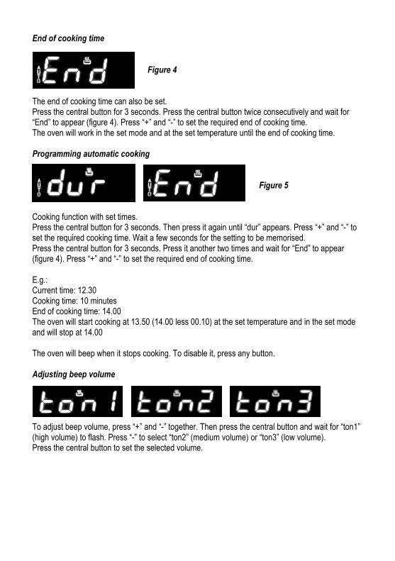
End of cooking time Figure 4 The end of cooking time can also be set. Press the central button for 3 seconds. Press the central button twice consecutively and wait for “End” to appear (figure 4). Press “+” and “-” to set the required end of cooking time. The oven will work in the set mode and at the set temperature until the end of cooking time. Programming automatic cooking Figure 5 Cooking function with set times. Press the central button for 3 seconds. Then press it again until “dur” appears. Press “+” and “-” to set the required cooking time. Wait a few seconds for the setting to be memorised. Press the central button for 3 seconds. Press it another two times and wait for “End” to appear (figure 4). Press “+” and “-” to set the required end of cooking time. E.g.: Current time: 12.30 Cooking time: 10 minutes End of cooking time: 14.00 The oven will start cooking at 13.50 (14.00 less 00.10) at the set temperature and in the set mode and will stop at 14.00 The oven will beep when it stops cooking. To disable it, press any button. Adjusting beep volume To adjust beep volume, press “+” and “-” together. Then press the central button and wait for “ton1” (high volume) to flash. Press “-” to select “ton2” (medium volume) or “ton3” (low volume). Press the central button to set the selected volume.

OPEN 24/7ILVE ACCESSORIES ONLINE SHOP
-VY�H�^PKL�YHUNL�VM�JVɈLL�THJOPULZ��WVKZ��HUK�V[OLY�03=,�HJJLZZVYPLZ�H[�[OL�JSPJR�VM�H�I\[[VU�ZOVW�PS]L�JVT�H\

(\Z[YHSPH�5H[PVUHS�;LSLWOVUL�5\TILY������4@03=,��� ������5L^�ALHSHUK�;LSLWOVUL�5\TILY������������
03=,�ZOV^YVVTZ�HYL�VWLU�KHPS`�MYVT� HT��WT�HUK�:H[\YKH`Z���HT��WT �>(�I`�HWWVPU[TLU[�VUS`�VU�:H[\YKH`Z� PS]L�JVT�H\
5:>� �(*;��/LHK�6ɉJL�������4VVYL�:[YLL[� 3LPJOOHYK[-������� ���
=0*��;(:� �:(�����;VVYHR�9VHK� *HTILY^LSS-���� �� �����
83+�����*H]LUKPZO�9VHK�*VVYWHYVV�-������ ������
>(� �5;<UP[�������/V^L�:[YLL[6ZIVYUL�7HYR�-���� ���� ���
5L^�ALHSHUK76�)V_�������:VJRI\YU�*OYPZ[JO\YJO-��������� ��


MSZ-GE SeriesQuality that brings comfort to life!
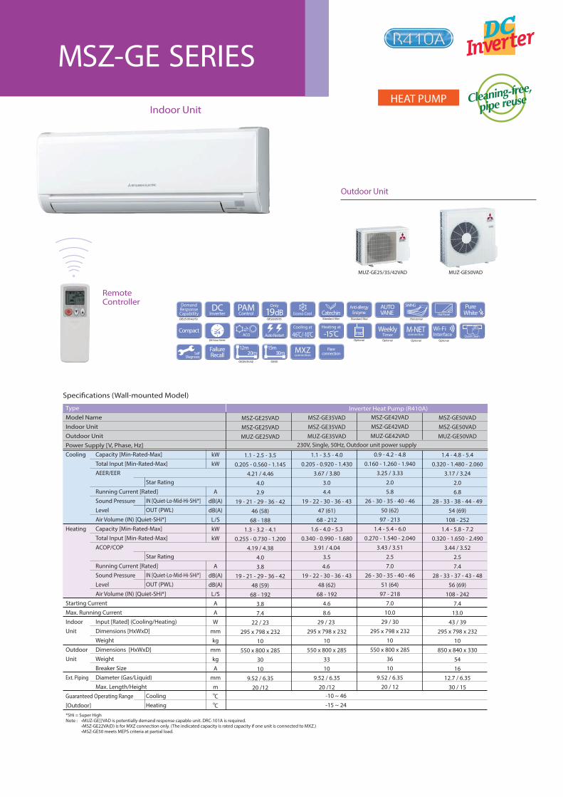
Outdoor Unit
Indoor Unit
RemoteController
MSZ-GE SERIESHEAT PUMP
Specifications (Wall-mounted Model)
Type
Model NameIndoor Unit Outdoor Unit Power Supply [V, Phase, Hz]
MSZ-GE25VAD
MSZ-GE25VADMUZ-GE25VAD
1.1 - 2.5 - 3.50.205 - 0.560 - 1.145
4.21 / 4.464.02.9
19 - 21 - 29 - 36 - 4246 (58)
68 - 1881.3 - 3.2 - 4.1
0.255 - 0.730 - 1.2004.19 / 4.38
4.03.8
19 - 21 - 29 - 36 - 4248 (59)
68 - 1923.87.4
22 / 23295 x 798 x 232
10550 x 800 x 285
3010
9.52 / 6.3520 /12
MSZ-GE35VAD
MSZ-GE35VADMUZ-GE35VAD
1.1 - 3.5 - 4.00.205 - 0.920 - 1.430
3.67 / 3.803.04.4
19 - 22 - 30 - 36 - 4347 (61)
68 - 2121.6 - 4.0 - 5.3
0.340 - 0.990 - 1.6803.91 / 4.04
3.54.6
19 - 22 - 30 - 36 - 4348 (62)
68 - 1924.68.6
29 / 23 295 x 798 x 232
10550 x 800 x 285
3310
9.52 / 6.3520 /12
MSZ-GE50VAD
MSZ-GE50VADMUZ-GE50VAD
1.4 - 4.8 - 5.40.320 - 1.480 - 2.060
3.17 / 3.242.06.8
28 - 33 - 38 - 44 - 4954 (69)
108 - 2521.4 - 5.8 - 7.2
0.320 - 1.650 - 2.4903.44 / 3.52
2.57.4
28 - 33 - 37 - 43 - 4856 (69)
108 - 2427.4
13.043 / 39
295 x 798 x 23210
850 x 840 x 3305416
12.7 / 6.3530 / 15
MSZ-GE42VAD
MSZ-GE42VADMUZ-GE42VAD
0.9 - 4.2 - 4.80.160 - 1.260 - 1.940
3.25 / 3.332.05.8
26 - 30 - 35 - 40 - 4650 (62)
97 - 2131.4 - 5.4 - 6.0
0.270 - 1.540 - 2.0403.43 / 3.51
2.57.0
26 - 30 - 35 - 40 - 4651 (64)
97 - 2187.0
10.029 / 30
295 x 798 x 23210
550 x 800 x 2853610
9.52 / 6.3520 / 12
Inverter Heat Pump (R410A)
Capacity [Min-Rated-Max]
Total Input [Min-Rated-Max]
AEER/EER
Running Current [Rated]
Sound Pressure
Level
Air Volume (IN) [Quiet-SHi*]
Capacity [Min-Rated-Max]
Total Input [Min-Rated-Max]
ACOP/COP
Running Current [Rated]
Sound Pressure
Level
Air Volume (IN) [Quiet-SHi*]
Input [Rated] (Cooling/Heating)
Dimensions [HxWxD]
Weight
Dimensions [HxWxD]
Weight
Breaker Size
Diameter (Gas/Liquid)
Max. Length/Height
Star Rating
IN [Quiet-Lo-Mid-Hi-SHi*]OUT (PWL)
Star Rating
IN [Quiet-Lo-Mid-Hi-SHi*]OUT (PWL)
CoolingHeating
kWkW
AdB(A)dB(A)
L/SkWkW
AdB(A)dB(A)
L/SAAW
mmkg
mmkgA
mmmoCoC
230V, Single, 50Hz, Outdoor unit power supply
MUZ-GE25/35/42VAD MUZ-GE50VAD
-10 ~ 46-15 ~ 24
Cooling
Heating
Starting Current
Max. Running Current
Indoor
Unit
Outdoor
Unit
Ext. Piping
Guaranteed Operating Range
[Outdoor]*SHi = Super HighNote : •MUZ-GE]]VAD is potentially demand response capable unit. DRC-101A is required.
•MSZ-GE22VA(D) is for MXZ connection only. (The indicated capacity is rated capacity if one unit is connected to MXZ.)•MSZ-GE50 meets MEPS criteria at partial load.
MXZconnection
DCInverter
PAMControl Econo Cool
AUTOVANE Flat Panel
Auto Restart
Cooling at
46 C̊/-10 C̊ Quick Clean
SelfDiagnosis
FailureRecall
Flareconnection30m
15m20m
12m
PureWhite
24-hour timer
ACO
SWING
Horizontal
WeeklyTimerOptional
M-NETconnection
Optional
Only
19dBGE22/25/35
Heating at
-15̊COptional
GE25/35/42 GE50
CatechinStandard filter Standard filter
Anti-allergyEnzyme
Compact
DemandResponseCapabilityGE25/35/42/50
Optional
Wi-FiInterface
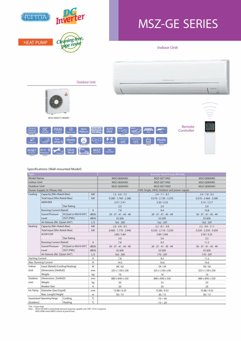
Specifications (Wall-mounted Model)
Type
Model NameIndoor Unit Outdoor Unit Power Supply [V, Phase, Hz]
MSZ-GE60VAD
MSZ-GE60VADMUZ-GE60VAD
1.5 - 6.0 - 7.50.280 - 1.760 - 2.380
3.37 / 3.412.57.8
29 - 37 - 41 - 45 - 4955 (69)
163 - 3052.0 - 6.8 - 9.3
0.460 - 1.770 - 2.9403.80 / 3.84
3.07.8
29 - 37 - 41 - 45 - 4955 (69)
163 - 3057.8
14.548 / 62
325 x 1,100 x 23816
880 x 840 x 3305020
15.88 / 6.3530 / 15
MSZ-GE80VAD
MSZ-GE80VADMUZ-GE80VAD
2.4 - 7.8 - 9.20.570 - 2.460 - 3.580
3.14 / 3.172.0
10.830 - 37 - 41 - 45 - 49
55 (69)162 - 297
2.2 - 9.0 - 11.10.520 - 2.550 - 3.650
3.50 / 3.53 2.5
11.230 - 37 - 41 - 45 - 49
55 (69)170 - 297
11.216.6
58 / 58325 x 1,100 x 238
16880 x 840 x 330
5320
15.88 / 9.5230 / 15
MSZ-GE71VAD
MSZ-GE71VADMUZ-GE71VAD
2.4 - 7.1 - 8.70.570 - 2.130 - 3.370
3.30 / 3.332.09.4
30 - 37 - 41 - 45 - 4955 (69)
162 - 2972.2 - 8.1 - 9.9
0.520 - 2.110 - 3.2503.80 / 3.84
3.09.5
30 - 37 - 41 - 45 - 4955 (69)
170 - 2979.5
16.658 / 58
325 x 1,100 x 23816
880 x 840 x 3305320
15.88 / 9.5230 / 15
-10 ~ 46-15 ~ 24
Inverter Heat Pump (R410A)
Cooling
Heating
Starting Current
Max. Running Current
Indoor
Unit
Outdoor
Unit
Ext. Piping
Guaranteed Operating Range
[Outdoor]*SHi = Super HighNote : •MUZ-GE]]VAD is potentially demand response capable unit. DRC-101A is required. •MSZ-GE80 meets MEPS criteria at partial load.
Capacity [Min-Rated-Max]
Total Input [Min-Rated-Max]
AEER/EER
Running Current [Rated]
Sound Pressure
Level
Air Volume (IN) [Quiet-SHi*]
Capacity [Min-Rated-Max]
Total Input [Min-Rated-Max]
ACOP/COP
Running Current [Rated]
Sound Pressure
Level
Air Volume (IN) [Quiet-SHi*]
Input [Rated] (Cooling/Heating)
Dimensions [HxWxD]
Weight
Dimensions [HxWxD]
Weight
Breaker Size
Diameter (Gas/Liquid)
Max. Length/Height
Star Rating
IN [Quiet-Lo-Mid-Hi-SHi*]OUT (PWL)
Star Rating
IN [Quiet-Lo-Mid-Hi-SHi*]OUT (PWL)
CoolingHeating
kWkW
AdB(A)dB(A)
L/SkWkW
AdB(A)dB(A)
L/SAAW
mmkg
mmkgA
mmmoCoC
230V, Single, 50Hz, Outdoor unit power supply
FailureRecall
Flareconnection30m
15m
SWING
Vertical
DCInverter
PAMControl Econo Cool
AUTOVANE
NanoPlatinum
Flat Panel
SWING
Horizontal
Wide Long
Auto Restart
SelfDiagnosis
24-hour timer
ACOWeekly
TimerOptional
M-NETconnection
Optional
Optional
Cooling at
-10̊CHeating at
-15̊CPure
WhiteWeekly
Timer
Built-in
MXZconnection
Powerful
DemandResponseCapability
GE60/71/80
Optional
Wi-FiInterface
Outdoor Unit
Indoor Unit
RemoteController
MSZ-GE SERIESHEAT PUMP
MUZ-GE60/71/80VAD
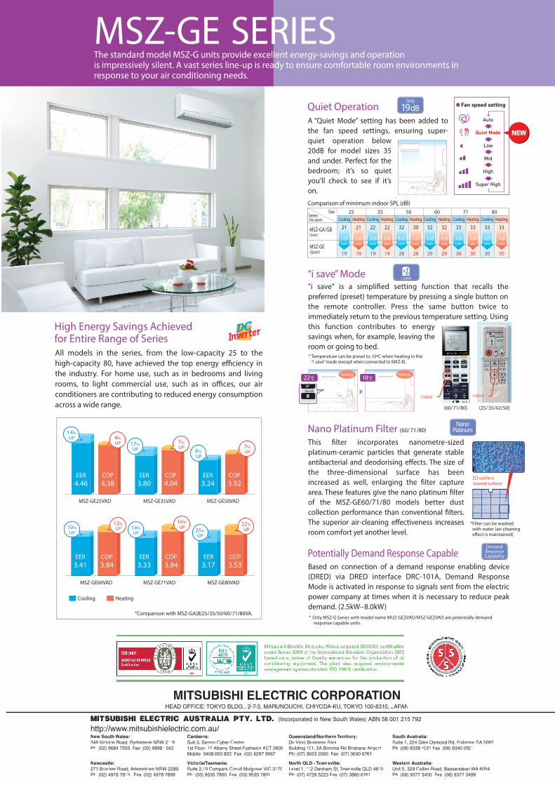
MITSUBISHI ELECTRIC CORPORATIONAAHEAD OFFICE: TOKYO BLDG., 2-YY 7-3, MA77 RUNOUCHI, CHIYOYY DA-KU, TOKYOYY 100-8310, JAPANPP
MITSUBISHI ELECTRIC AUSTRALIA PTY. LTD. (Incorporated in New South Wales) ABN 58 001 215 792
http://www.mitsubishielectric.com.au/
New South Wales:348 Victoria Road, Rydalmere NSW 2116Ph: (02) 9684 7555 Fax: (02) 9898 1043
Newcastle:271 Brunker Road, Adamstown NSW 2289Ph: (02) 4978 7813 Fax: (02) 4978 7899
Canberra:Suit 3, Serron Cyber Centre 1st Floor, 12 Albany Street Fyshwick ACT 2609Mobile: 0408 650 822 Fax: (02) 6297 9067
Victoria/T// asmania:TTSuite 2,10 Compark Circuit Mulgrave VIC 3170Ph: (03) 9535 7800 Fax: (03) 9535 7801
Queensland/Northern TeTT rritory:Da Vinci Business ParkBuilding 101, 2A Boronia Rd Brisbane AirportPh: (07) 3623 2000 Fax: (07) 3630 6761
North QLD - ToTT wnsville:Level 1, 112 Denham St, ToTT wnsville QLD 4810Ph: (07) 4728 5223 Fax: (07) 3860 6761
South Australia:Suite 1, 224 Glen Osmond Rd, Fullarton SA 5063Ph: (08) 8338 1001 Fax: (08) 8340 0501
Western Australia:Unit 5, 329 Collier Road, Bassendean WA 6054WWPh: (08) 9377 3400 Fax: (08) 9377 3499
60 71 80Cooling Cooling CoolingHeating Heating Heating
29
3dBLess
32
29
3dBLess
32
30
3dBLess
33
30
3dBLess
33
30
3dBLess
33
30
3dBLess
33
High Energy Savings Achievedfor Entire Range of SeriesAll models in the series, from the low-capacity 25 to the high-capacity 80, have achieved the top energy efficiency in the industry. For home use, such as in bedrooms and living rooms, to light commercial use, such as in offices, our air conditioners are contributing to reduced energy consumption across a wide range.
*Comparison with MSZ-GA(B)25/35/50/60/71/80VA.
Cooling Heating
COP
4.38EER
3.80COP
4.04EER
3.24COP
3.52
MSZ-GE25VAD MSZ-GE35VAD MSZ-GE50VAD
EER
4.46
Based on connection of a demand response enabling device (DRED) via DRED interface DRC-101A, Demand Response Mode is activated in response to signals sent from the electric power company at times when it is necessary to reduce peak demand. (2.5kW–8.0kW)
Potentially Demand Response Capable
A “Quiet Mode” setting has been added to the fan speed settings, ensuring super-quiet operation below 20dB for model sizes 35 and under. Perfect for the bedroom; it’s so quiet you’ll check to see if it’s on.
Quiet OperationOnly
19dB
Size 25 35 50Cooling Cooling CoolingHeating Heating Heating
( Low )
(Quiet )
Series( Fan speed )
MSZ-GE19
2dBLess
21
19
2dBLess
21
19
3dBLess
22
28
4dBLess
32
28
2dBLess
30
19
3dBLess
22MSZ-GA/GB
Comparison of minimum indoor SPL (dB)
EER
3.41COP
3.84COP
3.84EER
3.17COP
3.53
MSZ-GE60VAD MSZ-GE71VAD MSZ-GE80VAD
EER
3.33
8%
UP
7%
UP
10%
UP
12%
UP 14%
UP25%
UP
22%
UP
14%
UP 4%
UP 17%
UP
7%
UP
16%
UP
* Temperature can be preset to 10ºC when heating in the “i save” mode (except when connected to MXZ-8).
i save
"i save" is a simplified setting function that recalls the preferred (preset) temperature by pressing a single button on the remote controller. Press the same button twice to immediately return to the previous temperature setting. Using this function contributes to energy savings when, for example, leaving the room or going to bed.
“i save” Mode i save
22oc 18ocHeating Heating
i save
(60/71/80) (25/35/42/50)
DemandResponseCapability
This filter incorporates nanometre-sized platinum-ceramic particles that generate stable antibacterial and deodorising effects. The size of the three-dimensional surface has been increased as well, enlarging the filter capture area. These features give the nano platinum filter of the MSZ-GE60/71/80 models better dust collection performance than conventional filters. The superior air-cleaning effectiveness increases room comfort yet another level.
Nano Platinum Filter (60/71/80)Nano
Platinum
*Filter can be washed with water (air-cleaning effect is maintained)
3D surface (waved surface)
* Only MSZ-G Series with model name MUZ-GE]]VAD/MSZ-GE]]VAD are potentially demand response capable units.
MSZ-GE SERIESThe standard model MSZ-G units provide excellent energy-savings and operationis impressively silent. A vast series line-up is ready to ensure comfortable room environments in response to your air conditioning needs.


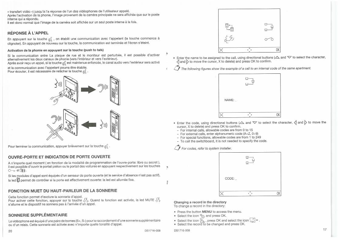
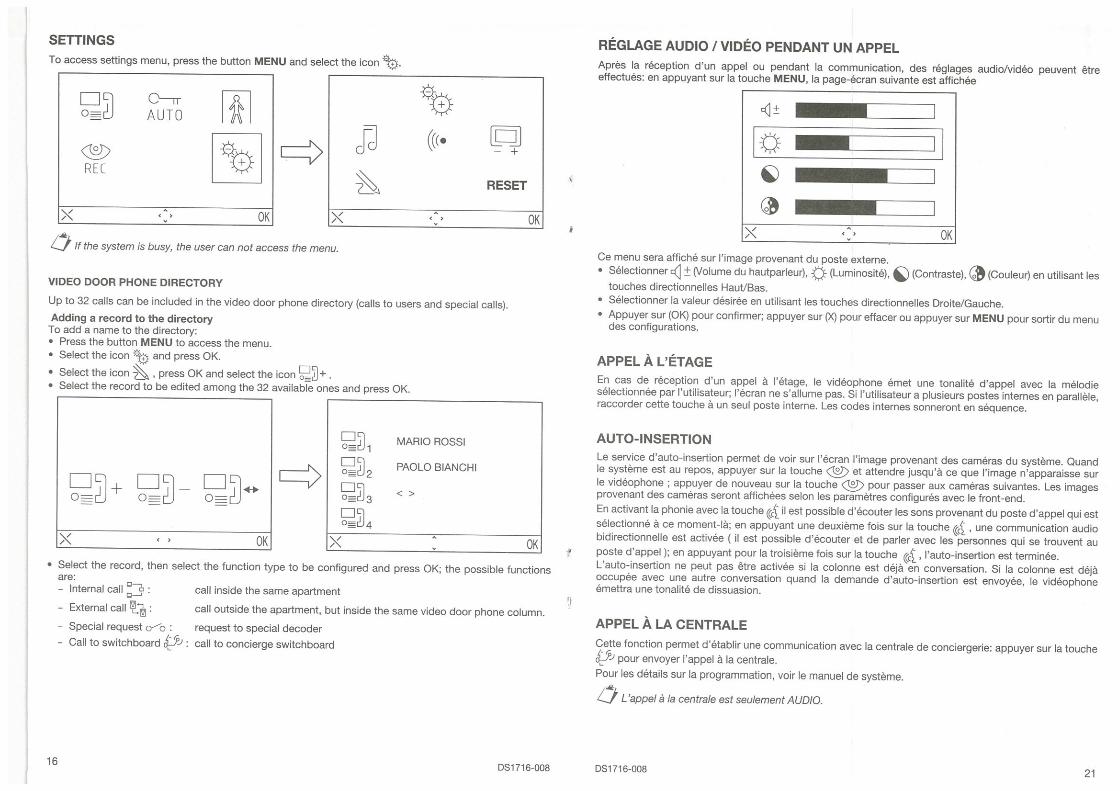
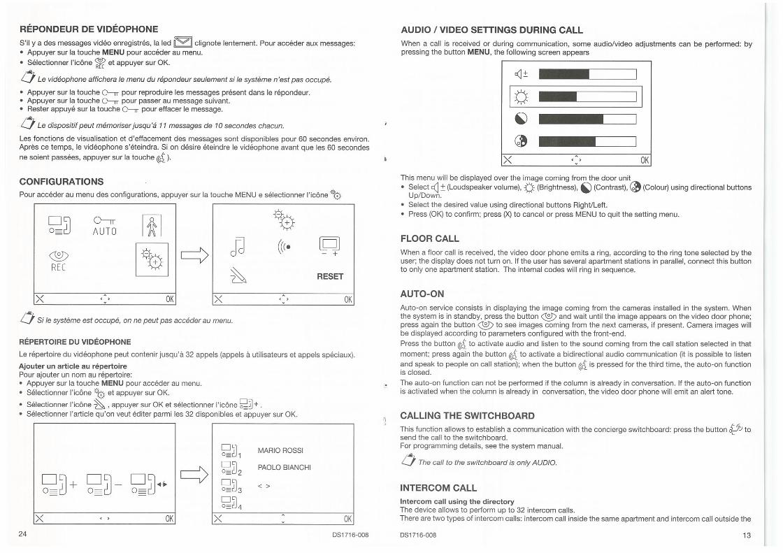
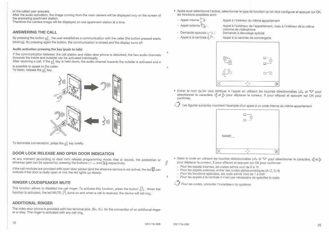
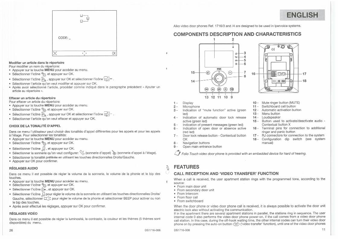
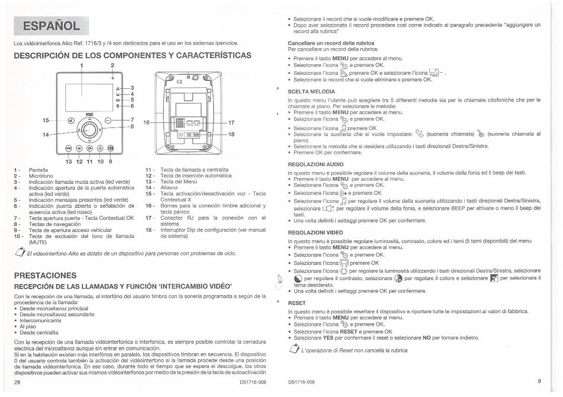
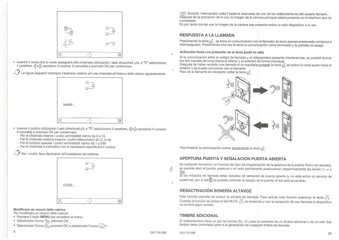
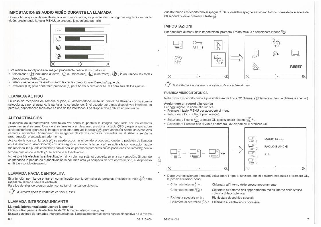
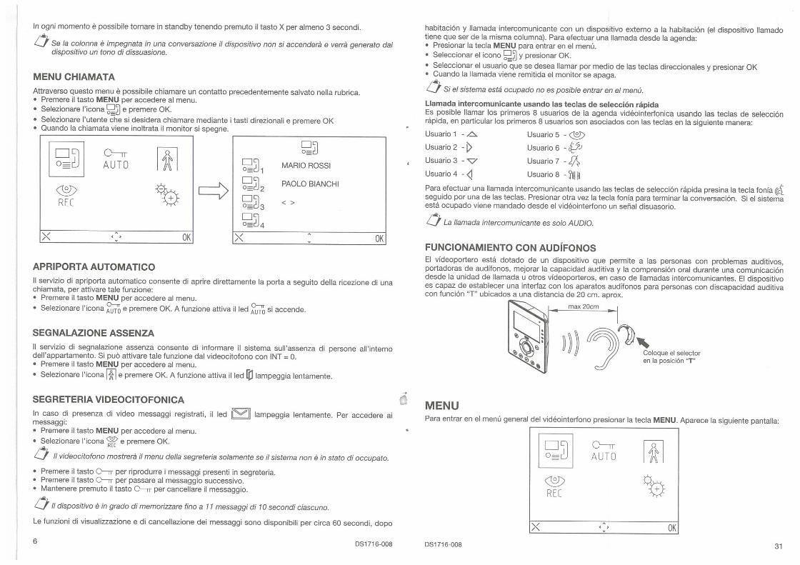
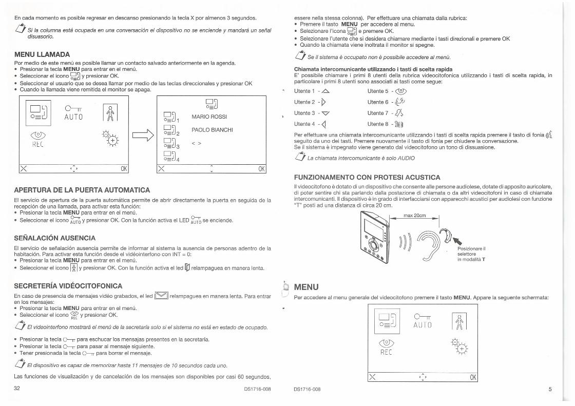
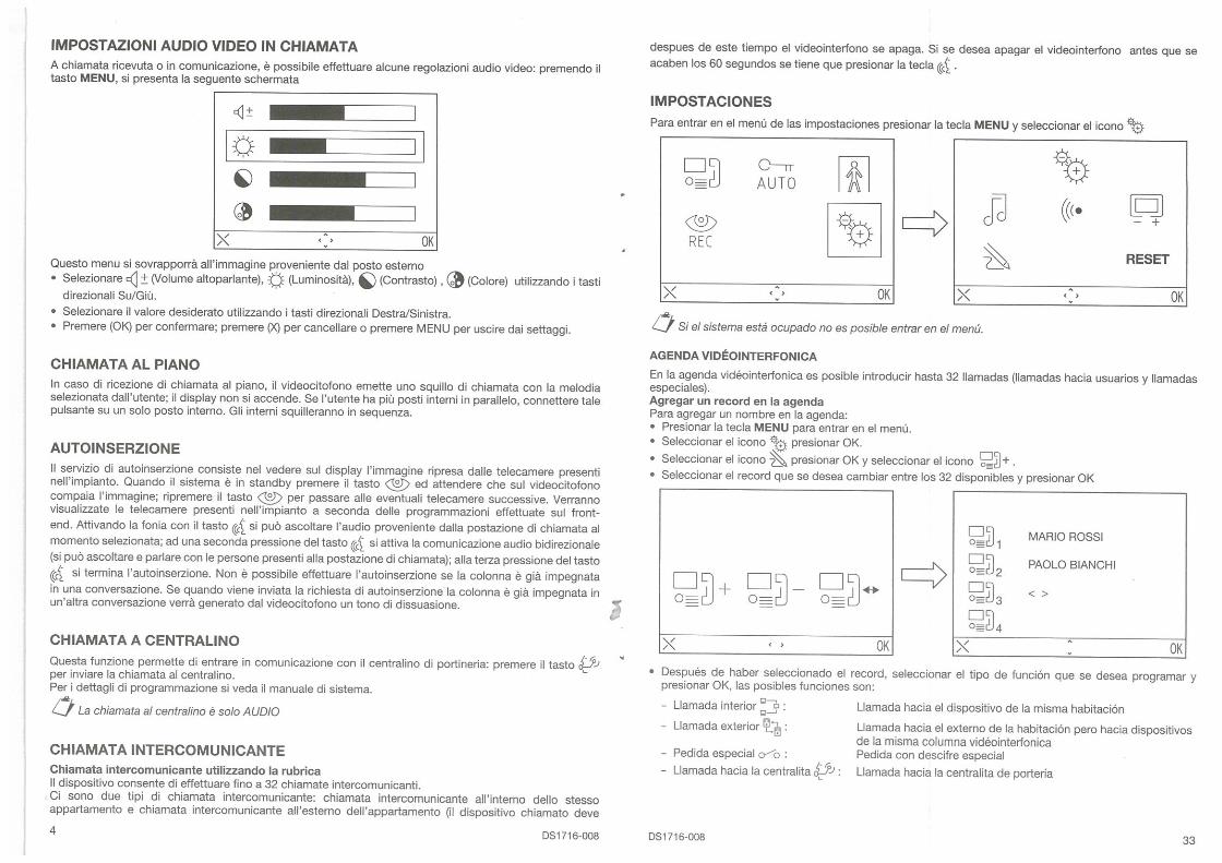
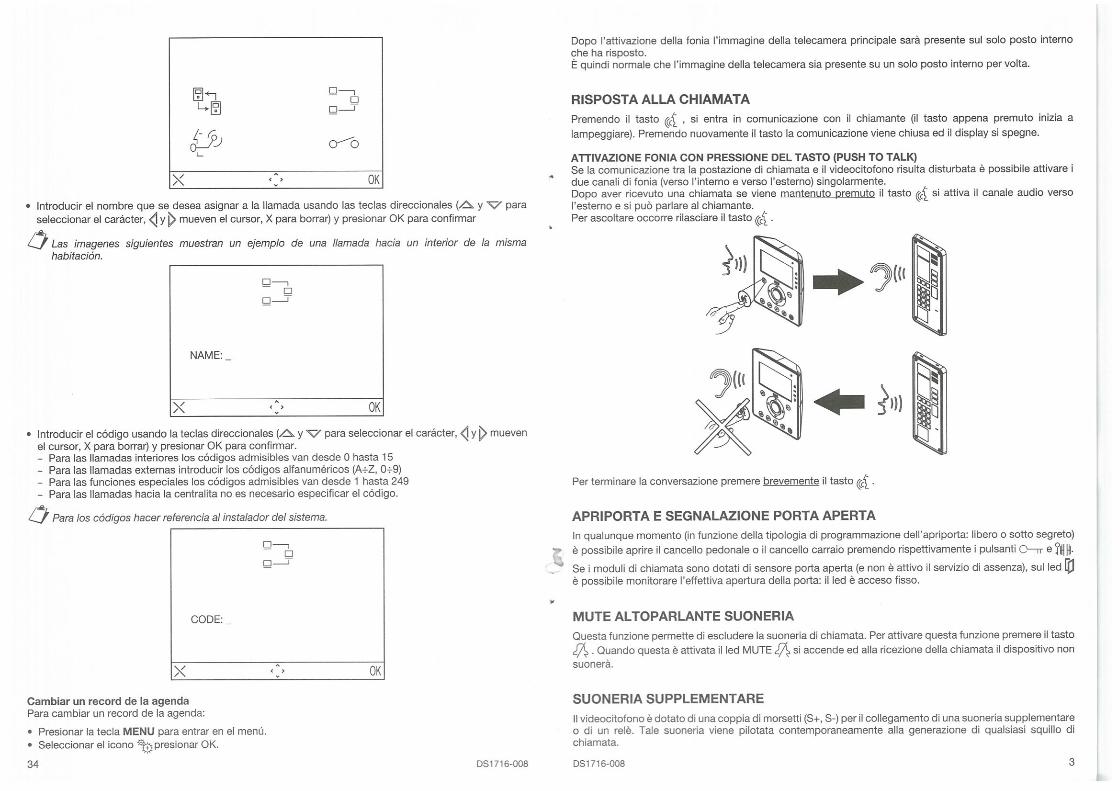
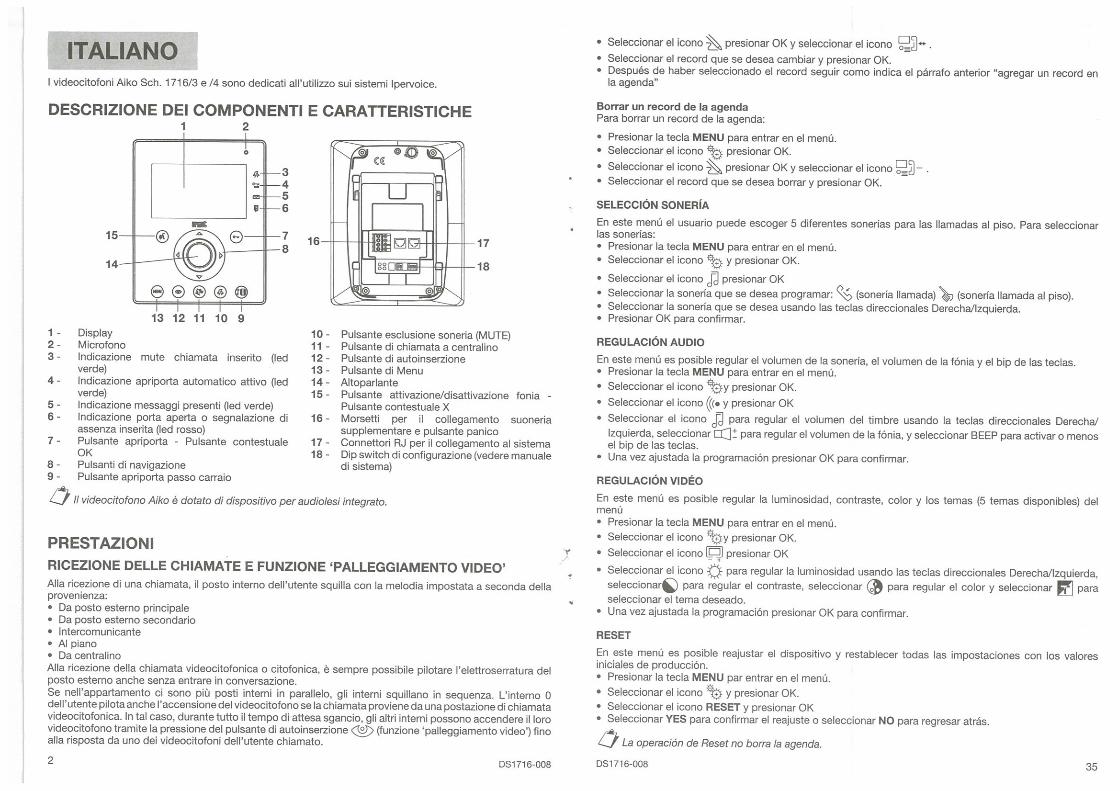
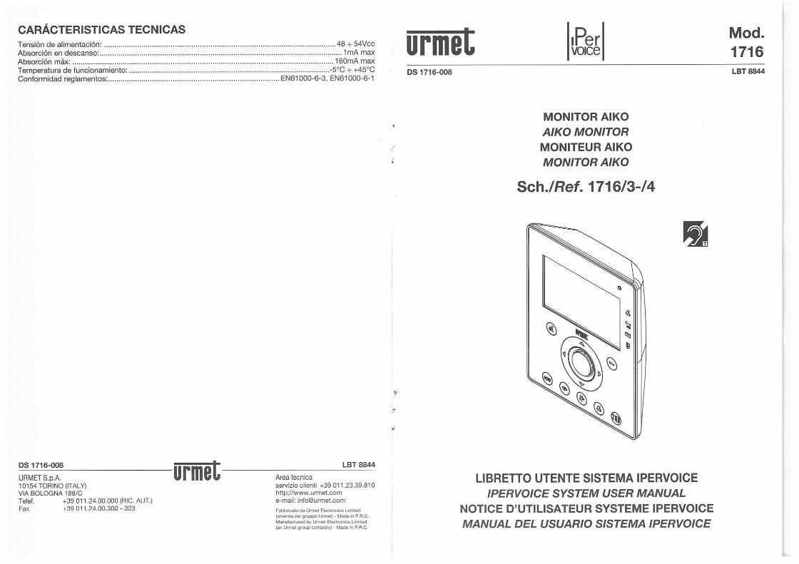

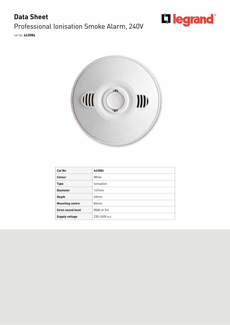
Professional Ionisation Smoke Alarm, 240V CAT NO. 643084
Cat No 643084
Colour White
Type Ionisation
Diameter 147mm
Depth 49mm
Mounting centre 84mm
Siren sound level 85db at 3m
Supply voltage 230-240V a.c.
Data Sheet
IonisationIonisation smoke alarms 'feel' the smoke. They detect invisible particles of combustion, eg from cooking toast. They activate more quickly for fast, flaming fires with little visible smoke.
Advantages■ Very good with fast flaming fires with little visible smoke■ Less prone to false alarms caused by dust and steam■ Suitable for general use■ Interconnectable – up to 20 units■ Surface mounting for easy fit-off■ Power and alarm indicator■ Easy access for wiring■ Hush/Test button■ 9V battery back-up included■ Low battery indication (audio and visual)■ Duct cover to protect the device during installation■ Smoke detector interface (643086) available separately to interconnect
with other appliances, circuits and systems e.g. lighting and exhaust fans
Product specifications
Cat No 643084 Quantity
Single Barcode 5321001424666 1
Inner Barcode 5321001424628 6
Outer Barcode 5321001424635 24
HPM Legrand - AUS1300 369 777www.legrand.com.auABN 31 000 102 661
HPM Legrand - NZ0800 476 009www.legrand.co.nz
Refer to your group buying office, HPM Legrand Sales Representative or HPM Legrand Sales Office for pricing.
* Specifications may change without notice
Professional Ionisation Smoke Alarm, 240V CAT NO. 643084
Data Sheet
03/14

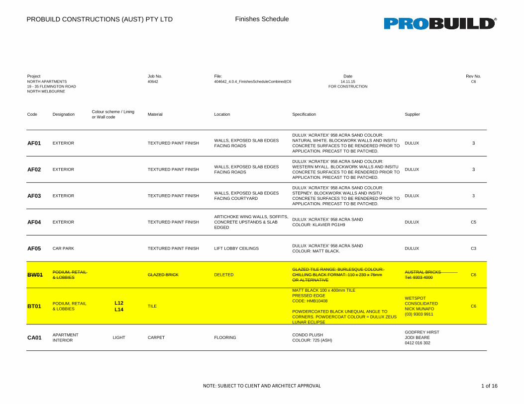
PROBUILD CONSTRUCTIONS (AUST) PTY LTD Finishes Schedule
Project Job No. File: Date Rev No.NORTH APARTMENTS 40642 404642_4.0.4_FinishesScheduleCombined(C6) 14.11.15 C619 - 35 FLEMINGTON ROAD FOR CONSTRUCTIONNORTH MELBOURNE
Code DesignationColour scheme / Lining or Wall code
Material Location Specification Supplier
AF01 EXTERIOR TEXTURED PAINT FINISHWALLS, EXPOSED SLAB EDGES FACING ROADS
DULUX ‘ACRATEX’ 958 ACRA SAND COLOUR: NATURAL WHITE. BLOCKWORK WALLS AND INSITU CONCRETE SURFACES TO BE RENDERED PRIOR TO APPLICATION. PRECAST TO BE PATCHED.
DULUX 3
AF02 EXTERIOR TEXTURED PAINT FINISHWALLS, EXPOSED SLAB EDGES FACING ROADS
DULUX ‘ACRATEX’ 958 ACRA SAND COLOUR: WESTERN MYALL. BLOCKWORK WALLS AND INSITU CONCRETE SURFACES TO BE RENDERED PRIOR TO APPLICATION. PRECAST TO BE PATCHED.
DULUX 3
AF03 EXTERIOR TEXTURED PAINT FINISHWALLS, EXPOSED SLAB EDGES FACING COURTYARD
DULUX ‘ACRATEX’ 958 ACRA SAND COLOUR: STEPNEY. BLOCKWORK WALLS AND INSITU CONCRETE SURFACES TO BE RENDERED PRIOR TO APPLICATION. PRECAST TO BE PATCHED.
DULUX 3
AF04 EXTERIOR TEXTURED PAINT FINISHARTICHOKE WING WALLS, SOFFITS, CONCRETE UPSTANDS & SLAB EDGED
DULUX ‘ACRATEX’ 958 ACRA SANDCOLOUR: KLAVIER PG1H9
DULUX C5
AF05 CAR PARK TEXTURED PAINT FINISH LIFT LOBBY CEILINGSDULUX ‘ACRATEX’ 958 ACRA SAND COLOUR: MATT BLACK.
DULUX C3
BW01 PODIUM, RETAIL & LOBBIES
GLAZED BRICK DELETEDGLAZED TILE RANGE: BURLESQUE COLOUR: CHILLING BLACK FORMAT: 110 x 230 x 76mmOR ALTERNATIVE
AUSTRAL BRICKS Tel: 9303 4000
C6
BT01 PODIUM, RETAIL & LOBBIES
L12 L14
TILE
MATT BLACK 100 x 400mm TILEPRESSED EDGECODE: HMB10408
POWDERCOATED BLACK UNEQUAL ANGLE TO CORNERS. POWDERCOAT COLOUR = DULUX ZEUS LUNAR ECLIPSE
WETSPOT CONSOLIDATEDNICK MUNAFO(03) 9303 9911
C6
CA01 APARTMENT INTERIOR
LIGHT CARPET FLOORINGCONDO PLUSH COLOUR: 725 (ASH)
GODFREY HIRST JODI BEARE 0412 016 302
NOTE: SUBJECT TO CLIENT AND ARCHITECT APPROVAL 1 of 16
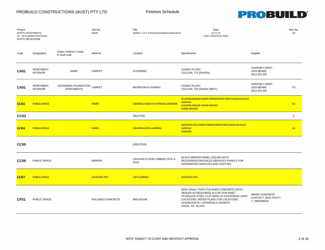
PROBUILD CONSTRUCTIONS (AUST) PTY LTD Finishes Schedule
Project Job No. File: Date Rev No.NORTH APARTMENTS 40642 404642_4.0.4_FinishesScheduleCombined(C6) 14.11.15 C619 - 35 FLEMINGTON ROAD FOR CONSTRUCTIONNORTH MELBOURNE
Code DesignationColour scheme / Lining or Wall code
Material Location Specification Supplier
CA01 APARTMENT INTERIOR
DARK CARPET FLOORINGCONDO PLUSH COLOUR: 775 (RAVEN)
GODFREY HIRST JODI BEARE 0412 016 302
CA01 APARTMENT INTERIOR
LEUKAEMIA FOUNDATION APARTMENTS
CARPET BEDROOM FLOORINGCONDO PLUSH COLOUR: 720 (SNOW DRIFT)
GODFREY HIRST JODI BEARE 0412 016 302
C5
CC01 PUBLIC SPACE PAINT GENERAL PAINT TO TYPICAL CORIDOR
PLASTER BOARD PAINT FINISH WITH TWO COATS OF FLAT
ACRYLIC
COLOUR: DULUX “VIVID WHITE”
CODE: PW1H9
C6
CC03 DELETED 2
CC04 PUBLIC SPACE PAINT GROUND LEVEL LOBBIES
ACOUSTIC PLY PAINT FINISH WITH TWO COATS OF FLAT
ACRYLIC
COLOUR:
C6
CC05 (DELETED)
CC06 PUBLIC SPACE MIRRORGROUND FLOOR LOBBIES (NTH & STH)
BLACK MIRROR PANEL CEILING WITH RECESSED/CONCEALED SERVICES PANELS FOR INTEGRATED SERVICES AND LIGHTING
CC07 PUBLIC SPACE ACOUSTIC PLY LIFT LOBBIES ACOUSTIC PLY
CF01 PUBLIC SPACE POLISHED CONCRETE MAILROOM
NOM 100mm THICK POLISHED CONCRETE (WITH SEALER AS REQUIRED) ALLOW FOR INSET STAINLESS STEEL FLAT BARS AT EXPANSION JOINT LOCATIONS. REFER PLANS FOR LOCATIONS.AGGREGRATE: LISTERFIELD GRANITEOXIDE: 4% BLACK
IMAGE CONCRETECONTACT: NICK PRATTT. 0409188033
NOTE: SUBJECT TO CLIENT AND ARCHITECT APPROVAL 2 of 16
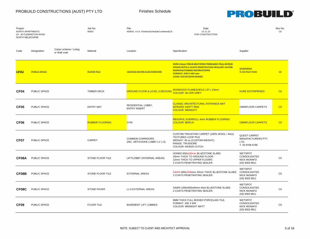
PROBUILD CONSTRUCTIONS (AUST) PTY LTD Finishes Schedule
Project Job No. File: Date Rev No.NORTH APARTMENTS 40642 404642_4.0.4_FinishesScheduleCombined(C6) 14.11.15 C619 - 35 FLEMINGTON ROAD FOR CONSTRUCTIONNORTH MELBOURNE
Code DesignationColour scheme / Lining or Wall code
Material Location Specification Supplier
CF02 PUBLIC SPACE FLOOR TILE CHANGE ROOMS & BATHROOMS
NOM 15mm THICK RECTIFIED TERRAZZO TILE, HONED
FINISH WITH 2 COATS PENETRATING SEALANT AS PER
MANUFACTURERS INSTRUCTIONS
FORMAT: 400 X 400 mm
CODE: TGP/EV2090 HONED
SIGNORINO
T: 03 9427 9100 C5
CF04 PUBLIC SPACE TIMBER DECK GROUND FLOOR & LEVEL 6 DECKINGMODWOOD FLAMESHEILD 137 x 23mmCOLOUR: SILVER GREY
KURE ENTERPRISES C6
CF05 PUBLIC SPACE ENTRY MATRESIDENTIAL LOBBY,ENTRY INSERT
CLASSIC ARCHITECTURAL ENTRANCE MATINTEGRA VANTT 5500COLOUR: MIDNIGHT
OMNIFLOOR CARPETS C6
CF06 PUBLIC SPACE RUBBER FLOORING GYMREGUPOL EVERROLL 4mm RUBBER FLOORING COLOUR: BERLIN OMNIFLOOR CARPETS C6
CF07 PUBLIC SPACE CARPETCOMMON CORRIDORS(INC. ARTICHOKE LOBBY LV 1-5)
CUSTOM TRAVATINO CARPET (100% WOOL / 44oz)TEXTURED LOOP PILEWEIGHT: 45 oz (CUSTOM WEIGHT)RANGE: TRUSSORECOLOUR: 64/3020 CUTCH
QUEST CARPET MANUFACTURERS PTY. LTD.T. 03 9706 6795
CF08A PUBLIC SPACE STONE FLOOR TILE LIFT/LOBBY (INTERNAL AREAS)
HONED 600x200mm BLUESTONE SLABS. 20mm THICK TO GROUND FLOOR. 12mm THICK TO UPPER FLOORS2 COATS PENETRATING SEALER.
WETSPOT CONSOLIDATEDNICK MUNAFO(03) 9303 9911
C5
CF08B PUBLIC SPACE STONE FLOOR TILE EXTERNAL AREASSAWN 600x200mmx 20mm THICK BLUESTONE SLABS. 2 COATS PENETRATING SEALER.
WETSPOT CONSOLIDATEDNICK MUNAFO(03) 9303 9911
C5
CF08C PUBLIC SPACE STONE PAVER Lv 6 EXTERNAL AREASSAWN 1000x500x40mm thick BLUESTONE SLABS. 2 COATS PENETRATING SEALER.
WETSPOT CONSOLIDATEDNICK MUNAFO(03) 9303 9911
C5
CF09 PUBLIC SPACE FLOOR TILE BASEMENT LIFT LOBBIES
8MM THICK FULL BODIED PORCELAIN TILE. FORMAT: 300 X 600COLOUR: MIDNIGHT MATT
WETSPOT CONSOLIDATEDNICK MUNAFO(03) 9303 9911
C5
NOTE: SUBJECT TO CLIENT AND ARCHITECT APPROVAL 3 of 16
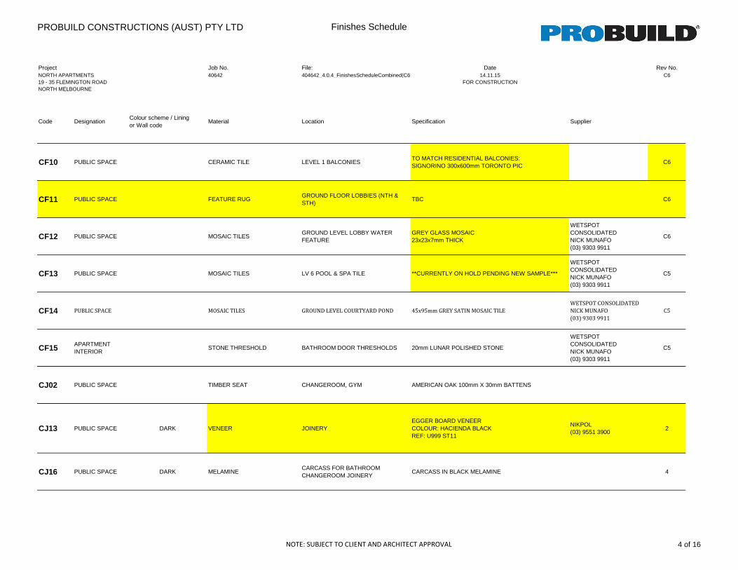
PROBUILD CONSTRUCTIONS (AUST) PTY LTD Finishes Schedule
Project Job No. File: Date Rev No.NORTH APARTMENTS 40642 404642_4.0.4_FinishesScheduleCombined(C6) 14.11.15 C619 - 35 FLEMINGTON ROAD FOR CONSTRUCTIONNORTH MELBOURNE
Code DesignationColour scheme / Lining or Wall code
Material Location Specification Supplier
CF10 PUBLIC SPACE CERAMIC TILE LEVEL 1 BALCONIESTO MATCH RESIDENTIAL BALCONIES:SIGNORINO 300x600mm TORONTO PIC
C6
CF11 PUBLIC SPACE FEATURE RUGGROUND FLOOR LOBBIES (NTH & STH)
TBC C6
CF12 PUBLIC SPACE MOSAIC TILESGROUND LEVEL LOBBY WATER FEATURE
GREY GLASS MOSAIC23x23x7mm THICK
WETSPOT CONSOLIDATEDNICK MUNAFO(03) 9303 9911
C6
CF13 PUBLIC SPACE MOSAIC TILES LV 6 POOL & SPA TILE **CURRENTLY ON HOLD PENDING NEW SAMPLE***
WETSPOT CONSOLIDATEDNICK MUNAFO(03) 9303 9911
C5
CF14 PUBLIC SPACE MOSAIC TILES GROUND LEVEL COURTYARD POND 45x95mm GREY SATIN MOSAIC TILE
WETSPOT CONSOLIDATED
NICK MUNAFO
(03) 9303 9911
C5
CF15 APARTMENT INTERIOR
STONE THRESHOLD BATHROOM DOOR THRESHOLDS 20mm LUNAR POLISHED STONE
WETSPOT CONSOLIDATEDNICK MUNAFO(03) 9303 9911
C5
CJ02 PUBLIC SPACE TIMBER SEAT CHANGEROOM, GYM AMERICAN OAK 100mm X 30mm BATTENS
CJ13 PUBLIC SPACE DARK VENEER JOINERYEGGER BOARD VENEERCOLOUR: HACIENDA BLACKREF: U999 ST11
NIKPOL(03) 9551 3900
2
CJ16 PUBLIC SPACE DARK MELAMINECARCASS FOR BATHROOM CHANGEROOM JOINERY
CARCASS IN BLACK MELAMINE 4
NOTE: SUBJECT TO CLIENT AND ARCHITECT APPROVAL 4 of 16
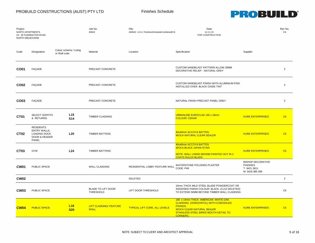
PROBUILD CONSTRUCTIONS (AUST) PTY LTD Finishes Schedule
Project Job No. File: Date Rev No.NORTH APARTMENTS 40642 404642_4.0.4_FinishesScheduleCombined(C6) 14.11.15 C619 - 35 FLEMINGTON ROAD FOR CONSTRUCTIONNORTH MELBOURNE
Code DesignationColour scheme / Lining or Wall code
Material Location Specification Supplier
CO01 FAÇADE PRECAST CONCRETECUSTOM SANDBLAST PATTERN ALLOW 30MM DECORATIVE RELIEF - NATURAL GREY
2
CO02 FAÇADE PRECAST CONCRETECUSTOM SANDBLAST FINISH WITH ALUMINIUM FINS INSTALLED OVER. BLACK OXIDE TINT
2
CO03 FAÇADE PRECAST CONCRETE NATURAL FINISH PRECAST PANEL GREY 2
CT01 SELECT SOFFITS & RETURNS
L15 S14
TIMBER CLADDINGURBANLINE EUROCLAD 155 x 18mmCOLOUR: CEDAR
KURE ENTERPRISES C6
CT02
RESIDENTS ENTRY WALLS, LOADING DOCK DOOR & HEADER PANEL
L20 TIMBER BATTENS40x40mm ACCOYA BATTENWOCA NATURAL CLEAR SEALER
KURE ENTERPRISES C6
CT03 GYM L24 TIMBER BATTENS
40x40mm ACCOYA BATTENWOCA BLACK JAPAN STAIN
NOTE: WALL LINING BEHIND PAINTED OUT IN 2 COATS DULUX BLACK
KURE ENTERPRISES C6
CW01 PUBLIC SPACE WALL CLADDING RESIDENTIAL LOBBY FEATURE WALLWATERSTONE POLISHED PLASTERCODE: P49
BISHOP DECORATIVE FINISHEST. 9421 3811M. 0418 385 399
CW02 DELETED 2
CW03 PUBLIC SPACEBLADE TO LIFT DOOR THRESHOLD
LIFT DOOR THRESHOLD
10mm THICK MILD STEEL BLADE POWDERCOAT OR ANODISED FINISH COLOUR: BLACK. (CJ12 DELETED)TO EXTEND 50MM BEYOND TIMBER WALL CLADDING
C6
CW04 PUBLIC SPACEL16 S20
LIFT CLADDING/ FEATURE WALL
TYPICAL LIFT CORE, ALL LEVELS
180 x 14mm THICK AMERICAN WHITE OAK CLADDING (HORIZONTAL) WITH CONCEALED FIXINGS. WOCA CLEAR NATURAL SEALER STAINLESS STEEL BIRDS MOUTH DETAIL TO CORNERS.
KURE ENTERPRISES C6
NOTE: SUBJECT TO CLIENT AND ARCHITECT APPROVAL 5 of 16
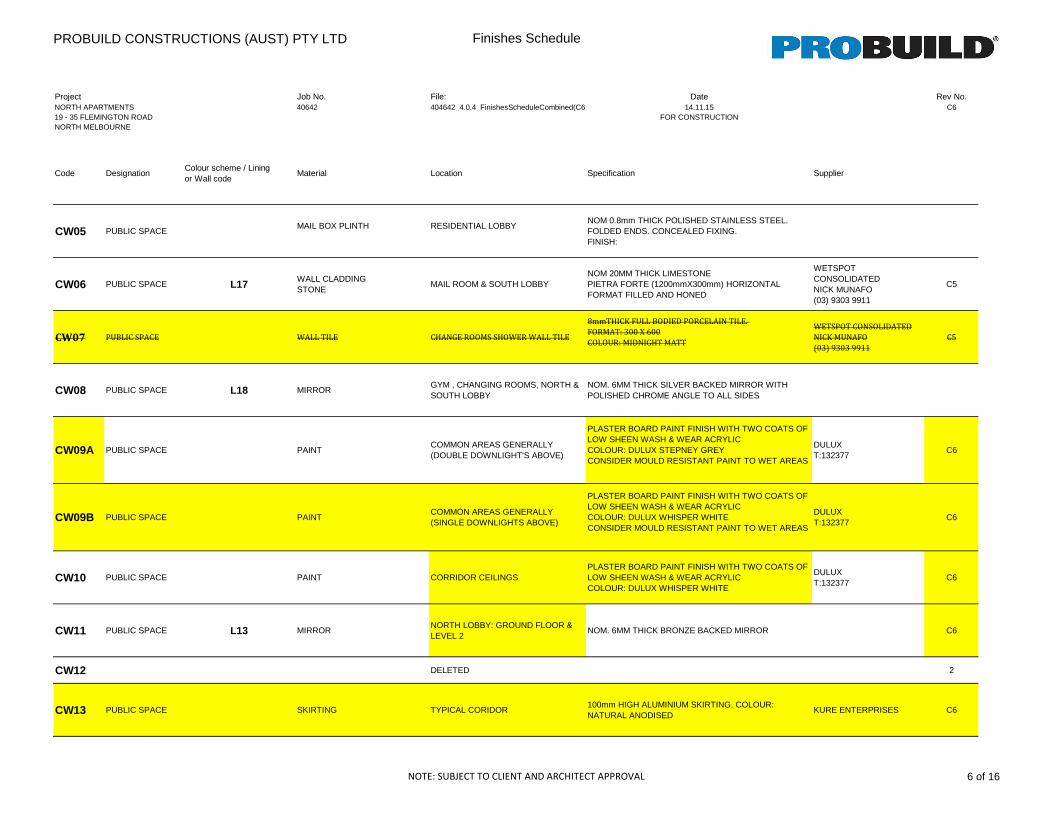
PROBUILD CONSTRUCTIONS (AUST) PTY LTD Finishes Schedule
Project Job No. File: Date Rev No.NORTH APARTMENTS 40642 404642_4.0.4_FinishesScheduleCombined(C6) 14.11.15 C619 - 35 FLEMINGTON ROAD FOR CONSTRUCTIONNORTH MELBOURNE
Code DesignationColour scheme / Lining or Wall code
Material Location Specification Supplier
CW05 PUBLIC SPACEMAIL BOX PLINTH RESIDENTIAL LOBBY
NOM 0.8mm THICK POLISHED STAINLESS STEEL. FOLDED ENDS. CONCEALED FIXING.FINISH:
CW06 PUBLIC SPACE L17 WALL CLADDINGSTONE
MAIL ROOM & SOUTH LOBBY NOM 20MM THICK LIMESTONEPIETRA FORTE (1200mmX300mm) HORIZONTAL FORMAT FILLED AND HONED
WETSPOT CONSOLIDATEDNICK MUNAFO(03) 9303 9911
C5
CW07 PUBLIC SPACE WALL TILE CHANGE ROOMS SHOWER WALL TILE
8mmTHICK FULL BODIED PORCELAIN TILE.
FORMAT: 300 X 600
COLOUR: MIDNIGHT MATT
WETSPOT CONSOLIDATED
NICK MUNAFO
(03) 9303 9911
C5
CW08 PUBLIC SPACE L18 MIRRORGYM , CHANGING ROOMS, NORTH & SOUTH LOBBY
NOM. 6MM THICK SILVER BACKED MIRROR WITH POLISHED CHROME ANGLE TO ALL SIDES
CW09A PUBLIC SPACE PAINTCOMMON AREAS GENERALLY(DOUBLE DOWNLIGHT'S ABOVE)
PLASTER BOARD PAINT FINISH WITH TWO COATS OF LOW SHEEN WASH & WEAR ACRYLICCOLOUR: DULUX STEPNEY GREYCONSIDER MOULD RESISTANT PAINT TO WET AREAS
DULUXT:132377
C6
CW09B PUBLIC SPACE PAINTCOMMON AREAS GENERALLY(SINGLE DOWNLIGHTS ABOVE)
PLASTER BOARD PAINT FINISH WITH TWO COATS OF LOW SHEEN WASH & WEAR ACRYLICCOLOUR: DULUX WHISPER WHITECONSIDER MOULD RESISTANT PAINT TO WET AREAS
DULUXT:132377
C6
CW10 PUBLIC SPACE PAINT CORRIDOR CEILINGSPLASTER BOARD PAINT FINISH WITH TWO COATS OF LOW SHEEN WASH & WEAR ACRYLICCOLOUR: DULUX WHISPER WHITE
DULUXT:132377
C6
CW11 PUBLIC SPACE L13 MIRRORNORTH LOBBY: GROUND FLOOR & LEVEL 2
NOM. 6MM THICK BRONZE BACKED MIRROR C6
CW12 DELETED 2
CW13 PUBLIC SPACE SKIRTING TYPICAL CORIDOR100mm HIGH ALUMINIUM SKIRTING. COLOUR: NATURAL ANODISED
KURE ENTERPRISES C6
NOTE: SUBJECT TO CLIENT AND ARCHITECT APPROVAL 6 of 16
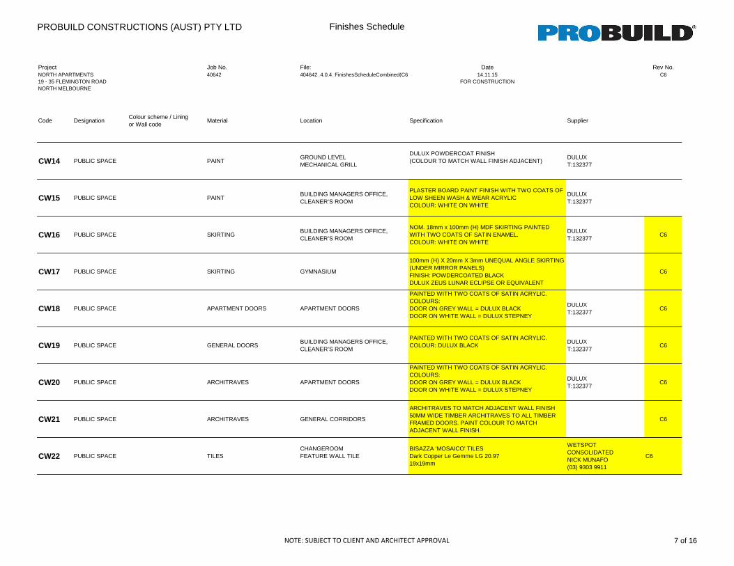
PROBUILD CONSTRUCTIONS (AUST) PTY LTD Finishes Schedule
Project Job No. File: Date Rev No.NORTH APARTMENTS 40642 404642_4.0.4_FinishesScheduleCombined(C6) 14.11.15 C619 - 35 FLEMINGTON ROAD FOR CONSTRUCTIONNORTH MELBOURNE
Code DesignationColour scheme / Lining or Wall code
Material Location Specification Supplier
CW14 PUBLIC SPACE PAINTGROUND LEVELMECHANICAL GRILL
DULUX POWDERCOAT FINISH(COLOUR TO MATCH WALL FINISH ADJACENT)
DULUXT:132377
CW15 PUBLIC SPACE PAINTBUILDING MANAGERS OFFICE, CLEANER’S ROOM
PLASTER BOARD PAINT FINISH WITH TWO COATS OF LOW SHEEN WASH & WEAR ACRYLIC COLOUR: WHITE ON WHITE
DULUXT:132377
CW16 PUBLIC SPACE SKIRTINGBUILDING MANAGERS OFFICE, CLEANER’S ROOM
NOM. 18mm x 100mm (H) MDF SKIRTING PAINTED WITH TWO COATS OF SATIN ENAMEL. COLOUR: WHITE ON WHITE
DULUXT:132377
C6
CW17 PUBLIC SPACE SKIRTING GYMNASIUM
100mm (H) X 20mm X 3mm UNEQUAL ANGLE SKIRTING (UNDER MIRROR PANELS)FINISH: POWDERCOATED BLACKDULUX ZEUS LUNAR ECLIPSE OR EQUIVALENT
C6
CW18 PUBLIC SPACE APARTMENT DOORS APARTMENT DOORS
PAINTED WITH TWO COATS OF SATIN ACRYLIC. COLOURS:DOOR ON GREY WALL = DULUX BLACKDOOR ON WHITE WALL = DULUX STEPNEY
DULUXT:132377
C6
CW19 PUBLIC SPACE GENERAL DOORSBUILDING MANAGERS OFFICE, CLEANER’S ROOM
PAINTED WITH TWO COATS OF SATIN ACRYLIC. COLOUR: DULUX BLACK
DULUXT:132377
C6
CW20 PUBLIC SPACE ARCHITRAVES APARTMENT DOORS
PAINTED WITH TWO COATS OF SATIN ACRYLIC. COLOURS:DOOR ON GREY WALL = DULUX BLACKDOOR ON WHITE WALL = DULUX STEPNEY
DULUXT:132377
C6
CW21 PUBLIC SPACE ARCHITRAVES GENERAL CORRIDORS
ARCHITRAVES TO MATCH ADJACENT WALL FINISH50MM WIDE TIMBER ARCHITRAVES TO ALL TIMBER FRAMED DOORS. PAINT COLOUR TO MATCH ADJACENT WALL FINISH.
C6
CW22 PUBLIC SPACE TILESCHANGEROOMFEATURE WALL TILE
BISAZZA 'MOSAICO' TILESDark Copper Le Gemme LG 20.9719x19mm
WETSPOT CONSOLIDATEDNICK MUNAFO(03) 9303 9911
C6
NOTE: SUBJECT TO CLIENT AND ARCHITECT APPROVAL 7 of 16
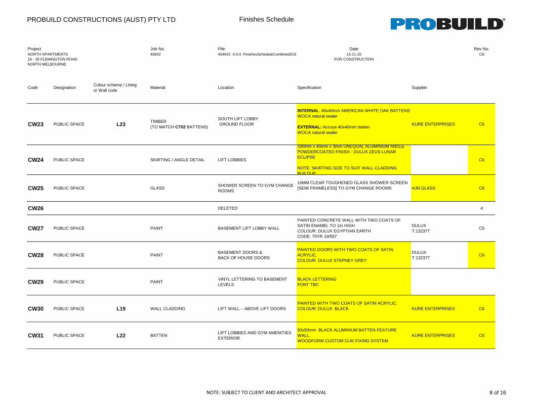
PROBUILD CONSTRUCTIONS (AUST) PTY LTD Finishes Schedule
Project Job No. File: Date Rev No.NORTH APARTMENTS 40642 404642_4.0.4_FinishesScheduleCombined(C6) 14.11.15 C619 - 35 FLEMINGTON ROAD FOR CONSTRUCTIONNORTH MELBOURNE
Code DesignationColour scheme / Lining or Wall code
Material Location Specification Supplier
CW23 PUBLIC SPACE L23TIMBER (TO MATCH CT02 BATTENS)
SOUTH LIFT LOBBY GROUND FLOOR
INTERNAL: 40x40mm AMERICAN WHITE OAK BATTENSWOCA natural sealer
EXTERNAL: Accoya 40x40mm battenWOCA natural sealer
KURE ENTERPRISES C6
CW24 PUBLIC SPACE SKIRTING / ANGLE DETAIL LIFT LOBBIES
100mm x 40mm x 3mm UNEQUAL ALUMINIUM ANGLEPOWDERCOATED FINISH - DULUX ZEUS LUNAR ECLIPSE
NOTE: SKIRTING SIZE TO SUIT WALL CLADDING BUILDUP
C6
CW25 PUBLIC SPACE GLASSSHOWER SCREEN TO GYM CHANGE ROOMS
10MM CLEAR TOUGHENED GLASS SHOWER SCREEN[SEMI FRAMELESS] TO GYM CHANGE ROOMS AJN GLASS C6
CW26 DELETED 4
CW27 PUBLIC SPACE PAINT BASEMENT LIFT LOBBY WALL
PAINTED CONCRETE WALL WITH TWO COATS OF SATIN ENAMEL TO 1m HIGHCOLOUR: DULUX EGYPTIAN EARTHCODE: 70YR 19/557
DULUXT:132377
C5
CW28 PUBLIC SPACE PAINTBASEMENT DOORS &BACK OF HOUSE DOORS
PAINTED DOORS WITH TWO COATS OF SATIN ACRYLIC. COLOUR: DULUX STEPNEY GREY
DULUXT:132377
C6
CW29 PUBLIC SPACE PAINTVINYL LETTERING TO BASEMENT LEVELS
BLACK LETTERINGFONT TBC
CW30 PUBLIC SPACE L19 WALL CLADDING LIFT WALL – ABOVE LIFT DOORSPAINTED WITH TWO COATS OF SATIN ACRYLIC. COLOUR: DULUX BLACK KURE ENTERPRISES C6
CW31 PUBLIC SPACE L22 BATTENLIFT LOBBIES AND GYM AMENITIES EXTERIOR.
50x50mm BLACK ALUMINIUM BATTEN FEATURE WALL. WOODFORM CUSTOM CLIK FIXING SYSTEM
KURE ENTERPRISES C6
NOTE: SUBJECT TO CLIENT AND ARCHITECT APPROVAL 8 of 16
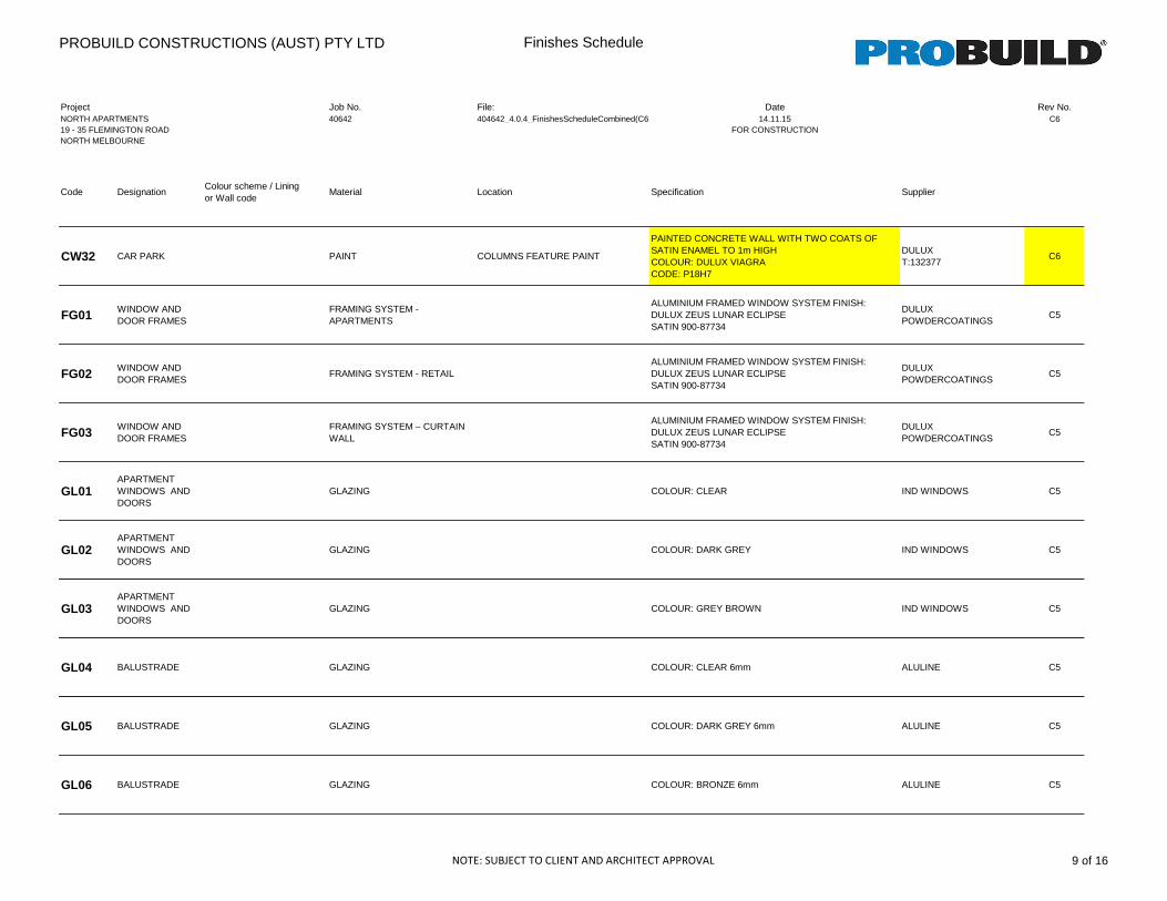
PROBUILD CONSTRUCTIONS (AUST) PTY LTD Finishes Schedule
Project Job No. File: Date Rev No.NORTH APARTMENTS 40642 404642_4.0.4_FinishesScheduleCombined(C6) 14.11.15 C619 - 35 FLEMINGTON ROAD FOR CONSTRUCTIONNORTH MELBOURNE
Code DesignationColour scheme / Lining or Wall code
Material Location Specification Supplier
CW32 CAR PARK PAINT COLUMNS FEATURE PAINT
PAINTED CONCRETE WALL WITH TWO COATS OF SATIN ENAMEL TO 1m HIGHCOLOUR: DULUX VIAGRACODE: P18H7
DULUXT:132377
C6
FG01 WINDOW AND DOOR FRAMES
FRAMING SYSTEM - APARTMENTS
ALUMINIUM FRAMED WINDOW SYSTEM FINISH:DULUX ZEUS LUNAR ECLIPSE SATIN 900-87734
DULUX POWDERCOATINGS
C5
FG02 WINDOW AND DOOR FRAMES
FRAMING SYSTEM - RETAILALUMINIUM FRAMED WINDOW SYSTEM FINISH:DULUX ZEUS LUNAR ECLIPSE SATIN 900-87734
DULUX POWDERCOATINGS
C5
FG03 WINDOW AND DOOR FRAMES
FRAMING SYSTEM – CURTAIN WALL
ALUMINIUM FRAMED WINDOW SYSTEM FINISH:DULUX ZEUS LUNAR ECLIPSE SATIN 900-87734
DULUX POWDERCOATINGS
C5
GL01APARTMENT WINDOWS AND DOORS
GLAZING COLOUR: CLEAR IND WINDOWS C5
GL02APARTMENT WINDOWS AND DOORS
GLAZING COLOUR: DARK GREY IND WINDOWS C5
GL03APARTMENT WINDOWS AND DOORS
GLAZING COLOUR: GREY BROWN IND WINDOWS C5
GL04 BALUSTRADE GLAZING COLOUR: CLEAR 6mm ALULINE C5
GL05 BALUSTRADE GLAZING COLOUR: DARK GREY 6mm ALULINE C5
GL06 BALUSTRADE GLAZING COLOUR: BRONZE 6mm ALULINE C5
NOTE: SUBJECT TO CLIENT AND ARCHITECT APPROVAL 9 of 16
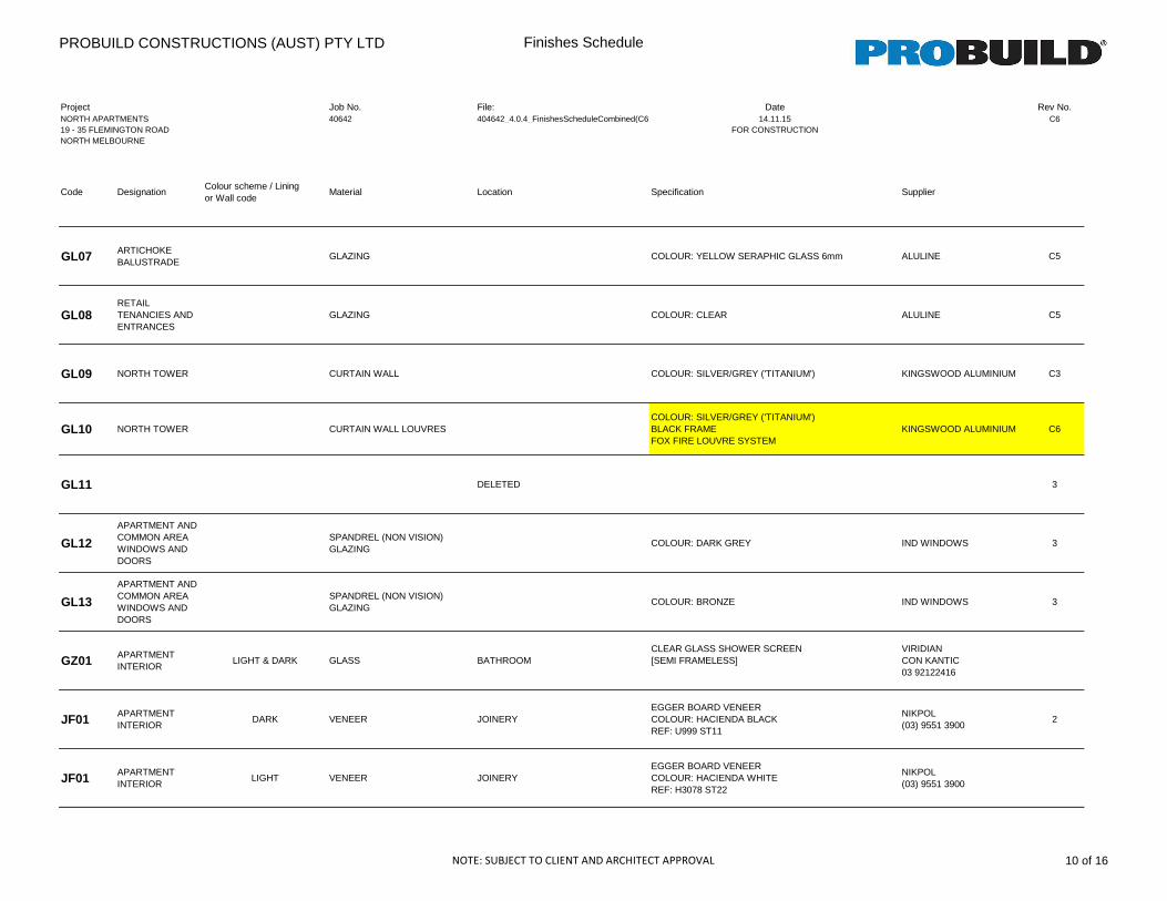
PROBUILD CONSTRUCTIONS (AUST) PTY LTD Finishes Schedule
Project Job No. File: Date Rev No.NORTH APARTMENTS 40642 404642_4.0.4_FinishesScheduleCombined(C6) 14.11.15 C619 - 35 FLEMINGTON ROAD FOR CONSTRUCTIONNORTH MELBOURNE
Code DesignationColour scheme / Lining or Wall code
Material Location Specification Supplier
GL07 ARTICHOKE BALUSTRADE
GLAZING COLOUR: YELLOW SERAPHIC GLASS 6mm ALULINE C5
GL08RETAIL TENANCIES AND ENTRANCES
GLAZING COLOUR: CLEAR ALULINE C5
GL09 NORTH TOWER CURTAIN WALL COLOUR: SILVER/GREY ('TITANIUM') KINGSWOOD ALUMINIUM C3
GL10 NORTH TOWER CURTAIN WALL LOUVRESCOLOUR: SILVER/GREY ('TITANIUM')BLACK FRAMEFOX FIRE LOUVRE SYSTEM
KINGSWOOD ALUMINIUM C6
GL11 DELETED 3
GL12
APARTMENT AND COMMON AREA WINDOWS AND DOORS
SPANDREL (NON VISION) GLAZING
COLOUR: DARK GREY IND WINDOWS 3
GL13
APARTMENT AND COMMON AREA WINDOWS AND DOORS
SPANDREL (NON VISION) GLAZING
COLOUR: BRONZE IND WINDOWS 3
GZ01 APARTMENT INTERIOR
LIGHT & DARK GLASS BATHROOMCLEAR GLASS SHOWER SCREEN[SEMI FRAMELESS]
VIRIDIANCON KANTIC03 92122416
JF01 APARTMENT INTERIOR
DARK VENEER JOINERYEGGER BOARD VENEERCOLOUR: HACIENDA BLACKREF: U999 ST11
NIKPOL(03) 9551 3900
2
JF01 APARTMENT INTERIOR
LIGHT VENEER JOINERYEGGER BOARD VENEERCOLOUR: HACIENDA WHITEREF: H3078 ST22
NIKPOL(03) 9551 3900
NOTE: SUBJECT TO CLIENT AND ARCHITECT APPROVAL 10 of 16
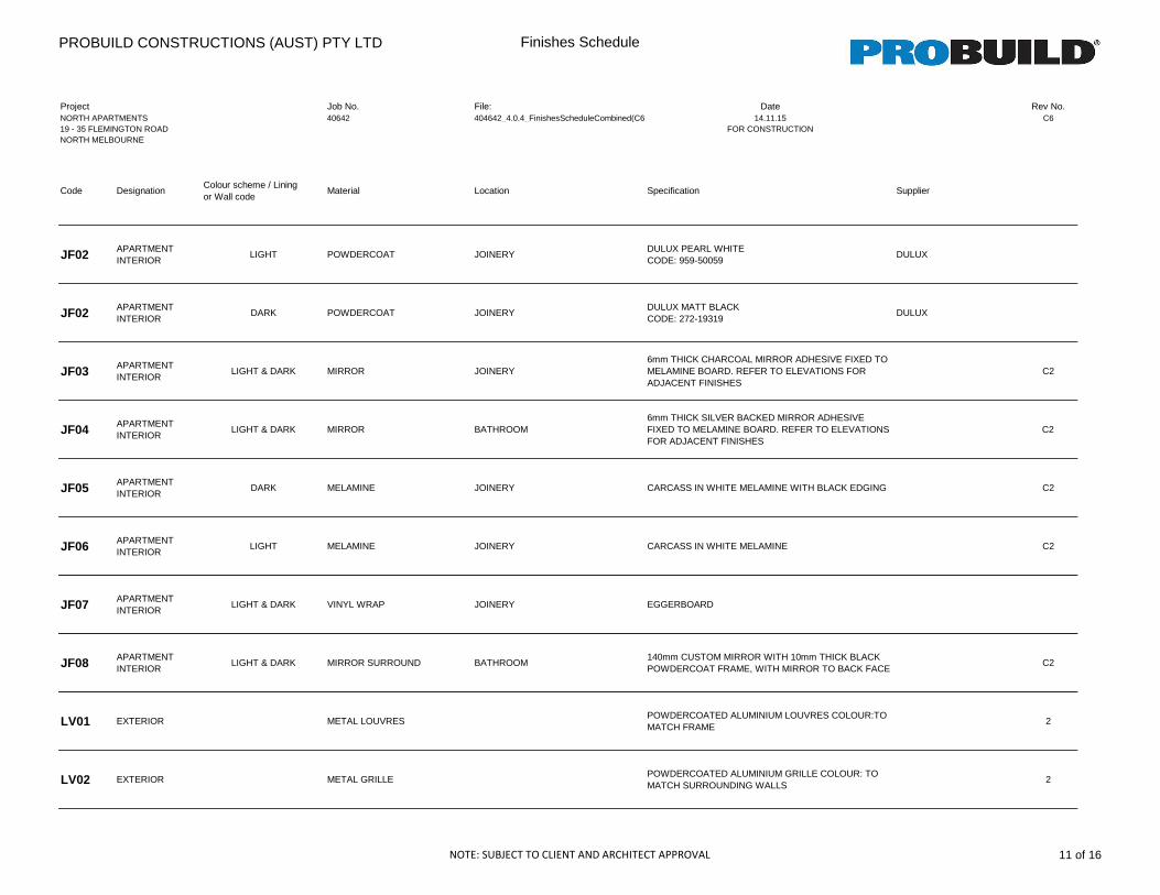
PROBUILD CONSTRUCTIONS (AUST) PTY LTD Finishes Schedule
Project Job No. File: Date Rev No.NORTH APARTMENTS 40642 404642_4.0.4_FinishesScheduleCombined(C6) 14.11.15 C619 - 35 FLEMINGTON ROAD FOR CONSTRUCTIONNORTH MELBOURNE
Code DesignationColour scheme / Lining or Wall code
Material Location Specification Supplier
JF02 APARTMENT INTERIOR
LIGHT POWDERCOAT JOINERYDULUX PEARL WHITECODE: 959-50059
DULUX
JF02 APARTMENT INTERIOR
DARK POWDERCOAT JOINERYDULUX MATT BLACKCODE: 272-19319
DULUX
JF03 APARTMENT INTERIOR
LIGHT & DARK MIRROR JOINERY6mm THICK CHARCOAL MIRROR ADHESIVE FIXED TO MELAMINE BOARD. REFER TO ELEVATIONS FOR ADJACENT FINISHES
C2
JF04 APARTMENT INTERIOR
LIGHT & DARK MIRROR BATHROOM6mm THICK SILVER BACKED MIRROR ADHESIVE FIXED TO MELAMINE BOARD. REFER TO ELEVATIONS FOR ADJACENT FINISHES
C2
JF05 APARTMENT INTERIOR
DARK MELAMINE JOINERY CARCASS IN WHITE MELAMINE WITH BLACK EDGING C2
JF06 APARTMENT INTERIOR
LIGHT MELAMINE JOINERY CARCASS IN WHITE MELAMINE C2
JF07 APARTMENT INTERIOR
LIGHT & DARK VINYL WRAP JOINERY EGGERBOARD
JF08 APARTMENT INTERIOR
LIGHT & DARK MIRROR SURROUND BATHROOM140mm CUSTOM MIRROR WITH 10mm THICK BLACK POWDERCOAT FRAME, WITH MIRROR TO BACK FACE
C2
LV01 EXTERIOR METAL LOUVRESPOWDERCOATED ALUMINIUM LOUVRES COLOUR:TO MATCH FRAME
2
LV02 EXTERIOR METAL GRILLEPOWDERCOATED ALUMINIUM GRILLE COLOUR: TO MATCH SURROUNDING WALLS
2
NOTE: SUBJECT TO CLIENT AND ARCHITECT APPROVAL 11 of 16
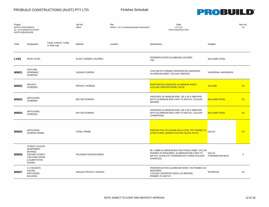
PROBUILD CONSTRUCTIONS (AUST) PTY LTD Finishes Schedule
Project Job No. File: Date Rev No.NORTH APARTMENTS 40642 404642_4.0.4_FinishesScheduleCombined(C6) 14.11.15 C619 - 35 FLEMINGTON ROAD FOR CONSTRUCTIONNORTH MELBOURNE
Code DesignationColour scheme / Lining or Wall code
Material Location Specification Supplier
LV03 ROOF LEVEL PLANT SCREEN LOUVRESPOWDERCOATED ALUMINIUM LOUVRES TBC
WILLIAMS STEEL
MW01FEATURE OPERABLE SCREENS
FAÇADE SCREENCUSTOM PATTERNED PERFORATED ANODISED ALUMINIUM SHEET COLOUR: BRONZE
UNIVERSAL ANODISERS
MW02 PRIVACY SCREENS
PRIVACY SCREENPERFORATED ANODISED ALUMINIUM SHEET COLOUR: PEWTER PEARL SATIN
ALULINE C6
MW03 ARTICHOKE SCREENS
BATTEN SCREENANODISED ALUMINIUM NOM. 100 X 50 X 5MM RHS WITH ALUMINIUM END CAPS TO MATCH. COLOUR: BRONZE
WILLIAMS STEEL C6
MW04 ARTICHOKE SCREENS
BATTEN SCREENANODISED ALUMINIUM NOM. 100 X 50 X 5MM RHS WITH ALUMINIUM END CAPS TO MATCH. COLOUR: CHAMPAGNE
WILLIAMS STEEL C6
MW05 ARTICHOKE SCREEN FRAME
STEEL FRAMEPAINTED POLYCILOXANE MILD STEEL PFC FRAME TO STRUCTURAL DESIGN COLOUR: BLACK SATIN
DULUX C6
MW06
STREET ACCESS APARTMENT ENTRIES, OXFORD STREET CAR PARK DOOR & SUBSTATION DOORS
PALISADE FENCE/SCREEN
95 x 25MM ALUMINIUM BOX SECTIONS (70MM C/C) ON FRAMES AS REQUIRED. ALUMINIUM END CAPS TO MATCH. DURALLOY POWDERCOAT FINISH COLOUR: CHARCOAL
DULUX POWDERCOATINGS
4
MW07
3 x FACADES FACING ARTICHOKE BUILDING
ANGLED PRIVACY SCREEN
POWDERCOATED ALUMINIUM SHEET ON FRAMES AS REQUIRED COLOUR: INTERPON D2015 LUX BRONZEFRAMES TO MATCH
INTERPON C5
NOTE: SUBJECT TO CLIENT AND ARCHITECT APPROVAL 12 of 16
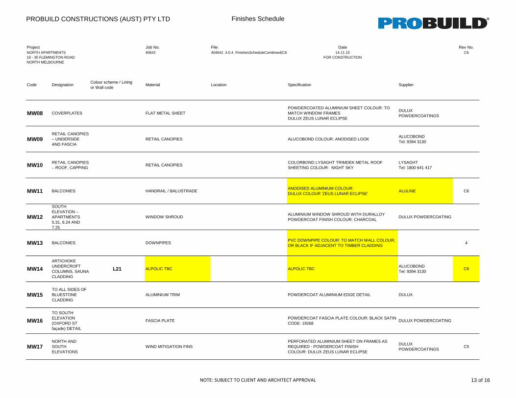
PROBUILD CONSTRUCTIONS (AUST) PTY LTD Finishes Schedule
Project Job No. File: Date Rev No.NORTH APARTMENTS 40642 404642_4.0.4_FinishesScheduleCombined(C6) 14.11.15 C619 - 35 FLEMINGTON ROAD FOR CONSTRUCTIONNORTH MELBOURNE
Code DesignationColour scheme / Lining or Wall code
Material Location Specification Supplier
MW08 COVERPLATES FLAT METAL SHEETPOWDERCOATED ALUMINIUM SHEET COLOUR: TO MATCH WINDOW FRAMESDULUX ZEUS LUNAR ECLIPSE
DULUX POWDERCOATINGS
MW09RETAIL CANOPIES – UNDERSIDE AND FASCIA
RETAIL CANOPIES ALUCOBOND COLOUR: ANODISED LOOKALUCOBOND Tel: 9394 3130
MW10 RETAIL CANOPIES – ROOF, CAPPING
RETAIL CANOPIESCOLORBOND LYSAGHT TRIMDEK METAL ROOF SHEETING COLOUR: NIGHT SKY
LYSAGHT Tel: 1800 641 417
MW11 BALCONIES HANDRAIL / BALUSTRADEANODISED ALUMINIUM COLOUR: DULUX COLOUR 'ZEUS LUNAR ECLIPSE'
ALULINE C6
MW12
SOUTH ELEVATION – APARTMENTS 5.31, 6.24 AND 7.25
WINDOW SHROUDALUMINIUM WINDOW SHROUD WITH DURALLOY POWDERCOAT FINISH COLOUR: CHARCOAL
DULUX POWDERCOATING
MW13 BALCONIES DOWNPIPESPVC DOWNPIPE COLOUR: TO MATCH WALL COLOUR, OR BLACK IF ADJACENT TO TIMBER CLADDING
4
MW14
ARTICHOKE UNDERCROFT COLUMNS, SAUNA CLADDING
L21 ALPOLIC TBC ALPOLIC TBCALUCOBOND Tel: 9394 3130
C6
MW15TO ALL SIDES OF BLUESTONE CLADDING
ALUMINIUM TRIM POWDERCOAT ALUMINIUM EDGE DETAIL DULUX
MW16
TO SOUTH ELEVATION (OXFORD ST façade) DETAIL
FASCIA PLATEPOWDERCOAT FASCIA PLATE COLOUR: BLACK SATIN CODE: 19268
DULUX POWDERCOATING
MW17NORTH AND SOUTH ELEVATIONS
WIND MITIGATION FINSPERFORATED ALUMINIUM SHEET ON FRAMES AS REQUIRED - POWDERCOAT FINISH COLOUR: DULUX ZEUS LUNAR ECLIPSE
DULUX POWDERCOATINGS
C5
NOTE: SUBJECT TO CLIENT AND ARCHITECT APPROVAL 13 of 16
PROBUILD CONSTRUCTIONS (AUST) PTY LTD Finishes Schedule
Project Job No. File: Date Rev No.NORTH APARTMENTS 40642 404642_4.0.4_FinishesScheduleCombined(C6) 14.11.15 C619 - 35 FLEMINGTON ROAD FOR CONSTRUCTIONNORTH MELBOURNE
Code DesignationColour scheme / Lining or Wall code
Material Location Specification Supplier
MW18
3 x FACADES FACING ARTICHOKE BUILDING
ANGLED PRIVACY SCREENPOWDERCOATED ALUMINIUM SHEET ON FRAMES AS REQUIRED COLOUR: INTERPON FRENCH CHAMPAGNE D2015
INTERPON C5
MW19 APARTMENT INTERIOR
SKIRTING WINDOW HOBS ONLY100mm HIGH POWDERCOATED ALUMINIUM SKIRTING. COLOUR TO MATCH WINDOW FRAMESDULUX ZEUS LUNAR ECLIPSE
DULUXT:132377
C5
PA01 APARTMENT INTERIOR
LIGHT & DARK PAINT GENERAL WALLS
PLASTERBOARD PAINT FINISH WITH 2 COATS OFLOW SHEEN ACRYLIC 'WASH AND WEAR'COLOUR: DULUX ‘WHITE ON WHITE’CODE: PCWF8
DULUX C5
PA02 APARTMENT INTERIOR
LIGHT & DARK PAINT GENERAL DOORS
2 COATS SEMI GLOSS ACRYLIC PAINTCOLOUR: DULUX ‘WHITE ON WHITE’CODE: PCWF8
DULUX C5
PA03 APARTMENT INTERIOR
LIGHT & DARK PAINT GENERAL SKIRTING
100mm HIGH, NOM. 18mm TIMBER OR MDF WITH 2COATS OF SEMI GLOSS ACRYLICCOLOUR: DULUX ‘WHITE ON WHITE’CODE: PCWF8
DULUX C5
PA04 APARTMENT INTERIOR
LIGHT & DARK PAINT GENERAL CEILING
PLASTERBOARD PAINT FINISH With 2 COATS OFFLAT ACRYLIC ''BERGER GOLD'COLOUR: DULUX ‘WHITE ON WHITE’CODE: PCWF8
DULUX C6
PE01 VARIES PAINT FINISH DELETED FINISHES REFERENCEDULUX ACRYLIC TEXTURE PAINT COLOUR: NATURAL
WHITE. (FINE / MEDIUM / FULL COVER TO DEPEND ON
CLOSEST MATCH TO ACRATEX. SAMPLES TO BE APPROVED)
DULUX C6
PE02 VARIES PAINT FINISH DELETED FINISHES REFERENCEDULUX ACRYLIC TEXTURE PAINT COLOUR: WESTERN
MYALL. (FINE / MEDIUM / FULL COVER TO DEPEND ON
CLOSEST MATCH TO ACRATEX. SAMPLES TO BE APPROVED)
DULUX C6
PE03 VARIES PAINT FINISH DELETED FINISHES REFERENCEDULUX ACRYLIC TEXTURE PAINT COLOUR: BLACK. (FINE /
MEDIUM / FULL COVER TO DEPEND ON CLOSEST MATCH TO
ACRATEX. SAMPLES TO BE APPROVED)
DULUX C6
SJ01 APARTMENT INTERIOR
LIGHT STONE KITCHEN BENCHTOP & SPLASHBACKCARRARA WHITE HONED MARBLECLEAR SEALER FINISHCAULK: PASCO HYPERSIL 912 'LIGHT GREY'
WETSPOT CONSOLIDATEDNICK MUNAFO(03) 9303 9911
C6
NOTE: SUBJECT TO CLIENT AND ARCHITECT APPROVAL 14 of 16
PROBUILD CONSTRUCTIONS (AUST) PTY LTD Finishes Schedule
Project Job No. File: Date Rev No.NORTH APARTMENTS 40642 404642_4.0.4_FinishesScheduleCombined(C6) 14.11.15 C619 - 35 FLEMINGTON ROAD FOR CONSTRUCTIONNORTH MELBOURNE
Code DesignationColour scheme / Lining or Wall code
Material Location Specification Supplier
SJ01 APARTMENT INTERIOR
DARK STONE KITCHEN BENCHTOP & SPLASHBACKGRIGIO CARNICO HONED MARBLECLEAR SEALER FINISHCAULK: PASCO HYPSERIL 912 'VOLCANO'
WETSPOT CONSOLIDATEDNICK MUNAFO(03) 9303 9911
C6
SJ02APARTMENT
INTERIORLIGHT STONE BENCHTOP (DELETED) WHITE GRANITE C2
SJ02APARTMENT
INTERIORDARK STONE BENCHTOP (DELETED) BLACK GRANITE C2
ST01 PODIUM AND LOBBIES
L10 S17 S19
BLUESTONE WALL CLADDING
NOM 12mm THICK BLUESTONE TILE. HONED FINISH. FINISH WITH 2 COATS PENETRATING SEALANT AS PER MANUFACTURERS INSTRUCTIONS. ALLOW TO MITRE CORNERS OF THRESHOLD & WALL SLABS
BLACK POWDERCOATED REVERSE ANGLE AT CORNERS. COLOUR = DULUX ZEUS LUNAR ECLIPSE
WETSPOT CONSOLIDATEDNICK MUNAFO(03) 9303 9911
C6
ST02 LEVEL 8, 13 & 18 ROOF
BALLAST PEBBLE BALLAST WHITEDÉCOR PEBBLE TEL: 03 9803 3344
C3
ST02 LEVEL 8, 13 & 18 ROOF
BALLAST PEBBLE BALLAST GREYDÉCOR PEBBLE TEL: 03 9803 3344
C3
T01 APARTMENT INTERIOR
LIGHT TIMBER FLOORING
GEORGE FEATHERS TIMBER FLOORBOARD'COLOUR: S0858 190mm wideCAULK: PASCO HYPERSIL 912 'BEIGE'
GEORGE FEATHERSJESS LANGDON(03) 9429 4589
C6
T01 APARTMENT INTERIOR
DARK TIMBER FLOORING
GEORGE FEATHERS TIMBER FLOORBOARD'COLOUR: S0859 190mm wideCAULK: PASCO HYPERSIL 912 'BLACK'
GEORGE FEATHERSJESS LANGDON(03) 9429 4589
C6
NOTE: SUBJECT TO CLIENT AND ARCHITECT APPROVAL 15 of 16
PROBUILD CONSTRUCTIONS (AUST) PTY LTD Finishes Schedule
Project Job No. File: Date Rev No.NORTH APARTMENTS 40642 404642_4.0.4_FinishesScheduleCombined(C6) 14.11.15 C619 - 35 FLEMINGTON ROAD FOR CONSTRUCTIONNORTH MELBOURNE
Code DesignationColour scheme / Lining or Wall code
Material Location Specification Supplier
TL01 APARTMENT INTERIOR
LIGHT TILE BATHROOM
CERAMIC TILECODE: R10801C13NATSILVERSIZE: 600 x 600mmGROUT: MAPEI 111CAULK: PASCO HYPERSIL 912 'LIGHT GREY'
SIGNORINODAVID COMPAGNINO(03) 9427 9100
C6
TL01 APARTMENT INTERIOR
DARK TILE BATHROOM
CERAMIC TILECODE: QBLACK SP NATSIZE: 600 x 600mmGROUT: MAPEI 114CAULK: PASCO HYPERSIL 912 'BLUESTONE'
SIGNORINODAVID COMPAGNINO(03) 9427 9100
C6
TL02APARTMENT INTERIOR & COMMON AREAS
LIGHT AND DARK TILEAPARTMENT BALCONIES & GROUND FLOOR SAUNA & GYM CHANGE AMENITIES (Wall & Floor)
CERAMIC TILETOTONTO PIC BLACK MATTSIZE: 300 x 600mmGROUT: MAPEI 120CAULK: PASCO HYPSERSIL 912 'SLATE GREY'
WETSPOT CONSOLIDATEDNICK MUNAFO(03) 9303 9911
C6
TL03 APARTMENT BALCONY
APARTMENTS G.14 & G.20 TILEBALCONY TILE (NEW FINISHES REFERENCE)
TIMBER-LOOK TILE TO SELECT APARTMENT BALCONIES1200x198x11mm TEXTURED PORCELAINGREY COLOUR
WETSPOT CONSOLIDATEDNICK MUNAFO(03) 9303 9911
C6
TL10 APARTMENT INTERIOR
LEUKAEMIA FOUNDATION APARTMENTS
TILE BATHROOM FEATURE WALL
CERAMIC TILEDARK FEATURE TILECODE: Q BLACK SP NATSIZE: 300 x 600mmGROUT: MAPEI 114CAULK: PASCO HYPERSIL 912 'SLATE GREY'
WETSPOT CONSOLIDATEDNICK MUNAFO(03) 9303 9911
C6
TL11 APARTMENT INTERIOR
LEUKAEMIA FOUNDATION APARTMENTS
TILE BATHROOM
CERAMIC TILEMATT WHITESIZE: 100 x 400mmGROUT: MAPEI 111CAULK: PASCO HYPERSIL 912 'WHITE'
WETSPOT CONSOLIDATEDNICK MUNAFO(03) 9303 9911
C6
VF01 APARTMENT INTERIOR
LEUKAEMIA FOUNDATION APARTMENTS
VINYL LIVING AREA COMPACT VINYL FLOOR COVERINGACCZENT RUBYFINISH: NATURAL GREY 3755 037
TARKETT AUSTRALIAJACKI MACCULLAGH1300 851 484
C5
VF02 APARTMENT INTERIOR
LEUKAEMIA FOUNDATION APARTMENTS
VINYL BATHROOMS & LAUNDRIES
COMPACT VINYL FLOOR COVERINGSAFETREAD UNIVERSALFINISH: VENUS 3820 110NOTE COVED SKIRTS TO MATCH FLOORS. RETURN 100mm UP WALL
TARKETT AUSTRALIAJACKI MACCULLAGH1300 851 484
C5
NOTE: SUBJECT TO CLIENT AND ARCHITECT APPROVAL 16 of 16