anveshana 2012 agastya international foundation synopsys
TRANSCRIPT
Anveshana student project technical record 2011-12 Page 0
ANVESHANA 2012
STUDENT PROJECTS TECHNICAL RECORD
Released on the occasion of
Science & Engineering Fair of Selected Projects
at
SHIKSHAKARA SADANA, BANGALORE
On
7th & 8th February 2012
Organised by
Agastya International Foundation
In support with
Synopsys
Anveshana student project technical record 2011-12 Page 1
CONTENTS
1. PREFACE
2. ABOUT AGASTYA INTERNATIONAL FOUNDATION
3. LIST OF PROJECTS EXHIBITED IN THE FAIR
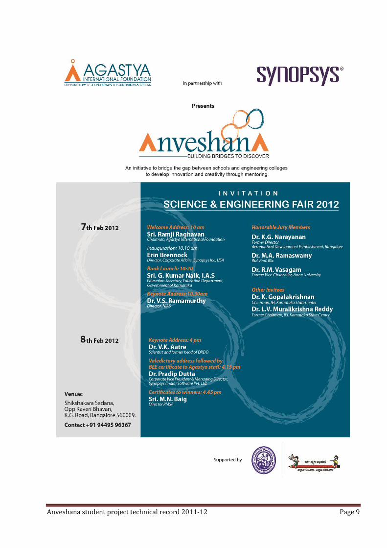
4. COPY OF INVITATION
5. PROGRAM CHART
6. PROJECT DESCRIPTION
Anveshana student project technical record 2011-12 Page 2
FOREWORD
Anveshana is the culmination of several months of effort and
collaboration between College students and School pupils in the spirit of
scientific enquiry. Thanks to the sponsorship of Synopsys and Agastya
Foundation, a bridge of knowledge and mentoring has been built
between college students and school students at a scale that has possibly
not been attempted before. The results have been gratifying in terms of
the in terms of both the quantity and quality of responses. The number of
concepts that were proposed by the collaborating teams, the diverse
nature of the subjects covered the depth to which some these
manifested and the final output in terms of models have proved the
worth of the effort overwhelmingly.
This book is a documentation of the output and while it is not exhaustive,
it definitely seeks to capture the output. Often a large project such as
Anveshana involving hundreds of students and mentors and a copious
output does not get well documented and this book is to ensure the
concepts methodology and output are well documented.
We at Agastya believe you will enjoy going through the book as much as
we enjoyed putting it together.
Anveshana team

Anveshana student project technical record 2011-12 Page 3
ABOUT AGASTYA
Agastya runs world's largest mobile hands-on science education program for disadvantaged
children and teachers.
The Prime Minister's National Knowledge Commission
(http://knowledgecommission.gov.in/downloads/recommendations/PMLetterM&S.pdf) has
recommended the Agastya model for nationwide dissemination, and the Clinton Global Initiative
has commended Agastya for its long term "commitment to action."
Agastya's mission to unlock the creative potential of poor children and teachers across India is
being achieved through:
61 Mobile Science Vans which take science education to the village doorstep
30 rural Science Centers
172-acre Creativity Lab campus in AP (2 hours from Bangalore) where we have built science and art labs and a discovery center, and operate an eco-restoration program.
Agastya has reached over 5 million children and 150,000 teachers in several states, and is
supported by scientists and educators from the Indian Institute of Science, DRDO and TIFR. Our
2020 goal is to touch 50 million children and 1 million teachers. By clicking on the following links
you can watch the Agastya Mobile Lab in action:
http://video.google.com/videosearch?q=agastya+vision&emb=0&aq=f# and the film *Spirit of
Agastya http://agastya.org/albums/albums/spirit.html
* (documents Agastya Foundation's efforts at 'sparking curiosity' in India's rural children. Over 60
of their mobile labs travel more than 600,000 kilometres per year taking low-cost experiments and
lessons in science, math, ecology, and art to children in remote rural areas)
How Agastya International Foundation has positively affected the lives of disadvantaged
children:
Rote-based, didactic and uninspiring education in India has deprived over 250 million
disadvantaged children of the tools to overcome poverty. Instead, it has produced education
apathy, a high dropout rate and youth that lack skills and confidence, creative-thinking and
problem-solving abilities. Most schools do not have labs. Opportunities for participative, hands-on
learning that sparks curiosity, and stimulates and empowers children and teachers are almost
non-existent. Teacher training is divorced from the realities of the school classroom. Seeing little
value in education, rural parents prefer to send their children to work in farms, thus perpetuating
a cycle of poverty.

Anveshana student project technical record 2011-12 Page 4
Operating one of the largest hands-on science education programs in the world, Agastya offers
disadvantaged children access to dynamic hands-on education that makes learning fun, awakens
curiosity, encourages questioning, enhances understanding, and fosters creative-thinking,
problem-solving and communication skills.
Agastya’s vision of ‘a creative India’ - ‘tinkerers, creators, solution-seekers …humane, anchored
and connected’ – is being achieved through its mission to spark the creative temper among
millions of disadvantaged children. Using experiential and hands-on, child-centric learning,
teacher education and scalable methods, Agastya aims to bring about a shift in five vital
behaviours - ‘Yes to Why,’ ‘Looking to Observing,’ ‘Passiveness to Exploring,’ ‘Text-book to Hands-
on,’ and ‘Fear to Confidence’ – through following highly innovative and effective outreach
channels:
Mobile Science Labs take education to the village doorstep.
Science Fairs promote learning in communities.
Interactive Science Centers and Teacher Education sustain multiplier effects.
Youth-led Young Instructor Leader programs promote self-belief and leadership.
Agastya Creativity Lab at Gudivanka Village, Kuppam, Andhra Pradesh, India
Agastya’s unique 172 acre rural Creativity Lab (factory of ideas) boasts science, model-making, art
and ecology labs, a Discovery Center and teacher education center. Learning’s are disseminated
via the outreach channels; new ideas are evaluated and assimilated, e.g., 1) Toy science with
Cambridge University, 2) Engineering in Schools with Museum of Science, Boston. Children directly
impact content and design through Q & As and other channels to improve the quality of their
learning experience. Real-time impact monitoring and evaluation is done continuously.
Looking Forward…
Increase in college admissions, participation in science projects and competitions; demand for
school labs and hands-on learning, and national interest in Agastya programs indicate that Agastya
is positively impacting the lives of disadvantaged children. The Prime Minister’s National
Knowledge Commission has recommended India-wide scale up of the Agastya model; the Clinton
Global Initiative has recognised Agastya’s ‘commitment to action’.
Agastya’s Objective:
Spark curiosity, creative-thinking and problem-solving skills
Raise the confidence and self-belief of children and teachers
Train and motivate teachers and governments to embrace hands-on learning methods
Improve the quality of child-teacher interaction
Expose children to new ways of learning (project-based, activity-based, learning-by-doing methods)
Anveshana student project technical record 2011-12 Page 5
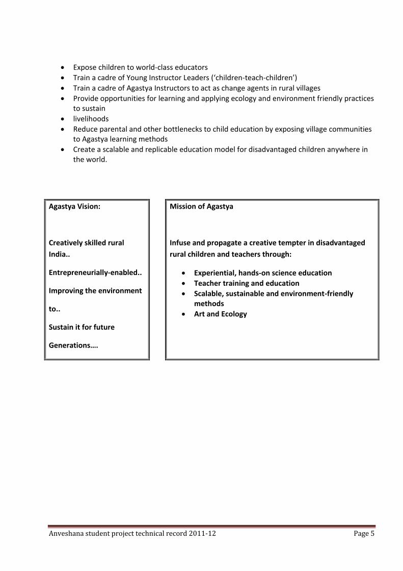
Expose children to world-class educators
Train a cadre of Young Instructor Leaders (‘children-teach-children’)
Train a cadre of Agastya Instructors to act as change agents in rural villages
Provide opportunities for learning and applying ecology and environment friendly practices to sustain
livelihoods
Reduce parental and other bottlenecks to child education by exposing village communities to Agastya learning methods
Create a scalable and replicable education model for disadvantaged children anywhere in the world.
Agastya Vision:
Creatively skilled rural
India..
Entrepreneurially-enabled..
Improving the environment
to..
Sustain it for future
Generations….
Mission of Agastya
Infuse and propagate a creative tempter in disadvantaged
rural children and teachers through:
Experiential, hands-on science education
Teacher training and education
Scalable, sustainable and environment-friendly methods
Art and Ecology
Anveshana student project technical record 2011-12 Page 6
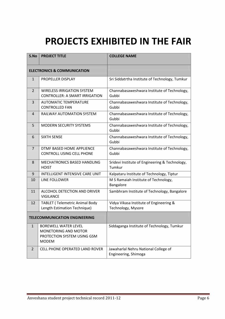
PROJECTS EXHIBITED IN THE FAIR S.No PROJECT TITLE COLLEGE NAME
ELECTRONICS & COMMUNICATION
1 PROPELLER DISPLAY Sri Siddatrtha Institute of Technology, Tumkur
2 WIRELESS IRRIGATION SYSTEM CONTROLLER: A SMART IRRIGATION
Channabasaweshwara Institute of Technology, Gubbi
3 AUTOMATIC TEMPERATURE CONTROLLED FAN
Channabasaweshwara Institute of Technology, Gubbi
4 RAILWAY AUTOMATION SYSTEM Channabasaweshwara Institute of Technology, Gubbi
5 MODERN SECURITY SYSTEMS Channabasaweshwara Institute of Technology, Gubbi
6 SIXTH SENSE Channabasaweshwara Institute of Technology, Gubbi
7 DTMF BASED HOME APPLIENCE CONTROLL USING CELL PHONE
Channabasaweshwara Institute of Technology, Gubbi
8 MECHATRONICS BASED HANDLING HOIST
Sridevi Institute of Engineering & Technology, Tumkur
9 INTELLIGENT INTENSIVE CARE UNIT Kalpataru Institute of Technology, Tiptur
10 LINE FOLLOWER M S Ramaiah Institute of Technology, Bangalore
11 ALCOHOL DETECTION AND DRIVER VIGILANCE
Sambhram Institute of Technology, Bangalore
12 TABLET ( Telemetric Animal Body Length Estimation Technique)
Vidya Vikasa Institute of Engineering & Technology, Mysore
TELECOMMUNICATION ENGINEERING
1 BOREWELL WATER LEVEL MONETORING AND MOTOR PROTECTION SYSTEM USING GSM MODEM
Siddaganga Institute of Technology, Tumkur
2 CELL PHONE OPERATED LAND ROVER Jawaharlal Nehru National College of Engineering, Shimoga
Anveshana student project technical record 2011-12 Page 7
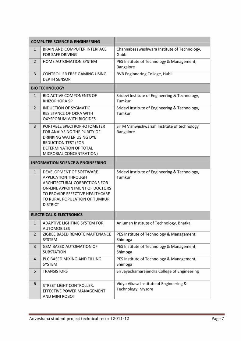
COMPUTER SCIENCE & ENGINEERING
1 BRAIN AND COMPUTER INTERFACE FOR SAFE DRIVING
Channabasaweshwara Institute of Technology, Gubbi
2 HOME AUTOMATION SYSTEM PES Institute of Technology & Management, Bangalore
3 CONTROLLER FREE GAMING USING DEPTH SENSOR
BVB Enginnering College, Hubli
BIO TECHNOLOGY
1 BIO ACTIVE COMPONENTS OF RHIZOPHORA SP
Sridevi Institute of Engineering & Technology, Tumkur
2 INDUCTION OF SYGMATIC RESISTANCE OF OKRA WITH OXYSPORUM WITH BIOCIDES
Sridevi Institute of Engineering & Technology, Tumkur
3 PORTABLE SPECTROPHOTOMETER FOR ANALYSING THE PURITY OF DRINKING WATER USING DYE REDUCTION TEST (FOR DETERMINATION OF TOTAL MICROBIAL CONCENTRATION)
Sir M Vishweshwariah Institute of technology Bangalore
INFORMATION SCIENCE & ENGINEERING
1 DEVELOPMENT OF SOFTWARE APPLICATION THROUGH ARCHITECTURAL CORRECTIONS FOR ON-LINE APPOINTMENT OF DOCTORS TO PROVIDE EFFECTIVE HEALTHCARE TO RURAL POPULATION OF TUMKUR DISTRICT
Sridevi Institute of Engineering & Technology, Tumkur
ELECTRICAL & ELECTRONICS
1 ADAPTIVE LIGHTING SYSTEM FOR AUTOMOBILES
Anjuman Institute of Technology, Bhatkal
2 ZIGBEE BASED REMOTE MAITENANCE SYSTEM
PES Institute of Technology & Management, Shimoga
3 GSM BASED AUTOMATION OF SUBSTATION
PES Institute of Technology & Management, Shimoga
4 PLC BASED MIXING AND FILLING SYSTEM
PES Institute of Technology & Management, Shimoga
5 TRANSISTORS Sri Jayachamarajendra College of Engineering
6 STREET LIGHT CONTROLLER, EFFECTIVE POWER MANAGEMENT AND MINI ROBOT
Vidya Vikasa Institute of Engineering & Technology, Mysore
Anveshana student project technical record 2011-12 Page 8
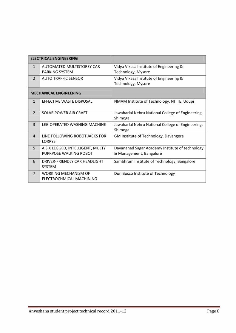
ELECTRICAL ENGINEERING
1 AUTOMATED MULTISTOREY CAR PARKING SYSTEM
Vidya Vikasa Institute of Engineering & Technology, Mysore
2 AUTO TRAFFIC SENSOR Vidya Vikasa Institute of Engineering & Technology, Mysore
MECHANICAL ENGINEERING
1 EFFECTIVE WASTE DISPOSAL NMAM Institute of Technology, NITTE, Udupi
2 SOLAR POWER AIR CRAFT Jawaharlal Nehru National College of Engineering, Shimoga
3 LEG OPERATED WASHING MACHINE Jawaharlal Nehru National College of Engineering, Shimoga
4 LINE FOLLOWING ROBOT JACKS FOR LORRYS
GM Institute of Technology, Davangere
5 A SIX LEGGED, INTELLIGENT, MULTY PUPRPOSE WALKING ROBOT
Dayananad Sagar Academy Institute of technology & Management, Bangalore
6 DRIVER-FRIENDLY CAR HEADLIGHT SYSTEM
Sambhram Institute of Technology, Bangalore
7 WORKING MECHANISM OF ELECTROCHMICAL MACHINING
Don Bosco Institute of Technology
Anveshana student project technical record 2011-12 Page 9
Anveshana student project technical record 2011-12 Page 10
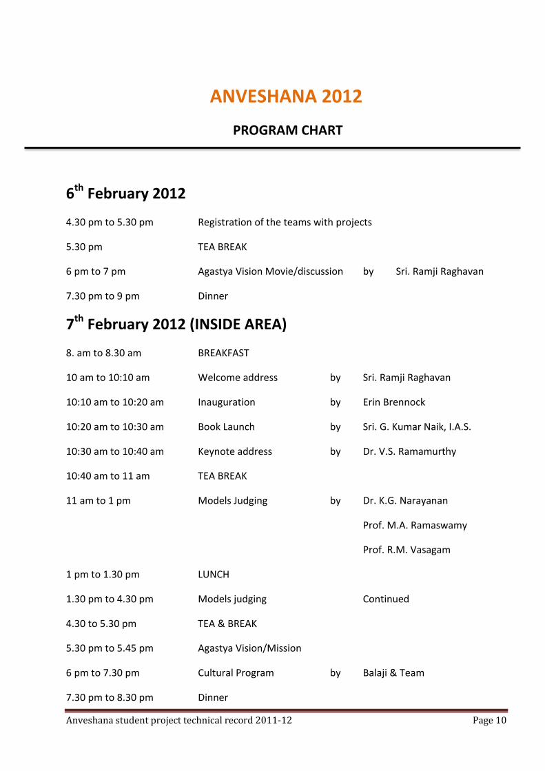
ANVESHANA 2012
PROGRAM CHART
6th February 2012
4.30 pm to 5.30 pm Registration of the teams with projects
5.30 pm TEA BREAK
6 pm to 7 pm Agastya Vision Movie/discussion by Sri. Ramji Raghavan
7.30 pm to 9 pm Dinner
7th February 2012 (INSIDE AREA)
8. am to 8.30 am BREAKFAST
10 am to 10:10 am Welcome address by Sri. Ramji Raghavan
10:10 am to 10:20 am Inauguration by Erin Brennock
10:20 am to 10:30 am Book Launch by Sri. G. Kumar Naik, I.A.S.
10:30 am to 10:40 am Keynote address by Dr. V.S. Ramamurthy
10:40 am to 11 am TEA BREAK
11 am to 1 pm Models Judging by Dr. K.G. Narayanan
Prof. M.A. Ramaswamy
Prof. R.M. Vasagam
1 pm to 1.30 pm LUNCH
1.30 pm to 4.30 pm Models judging Continued
4.30 to 5.30 pm TEA & BREAK
5.30 pm to 5.45 pm Agastya Vision/Mission
6 pm to 7.30 pm Cultural Program by Balaji & Team
7.30 pm to 8.30 pm Dinner
Anveshana student project technical record 2011-12 Page 11
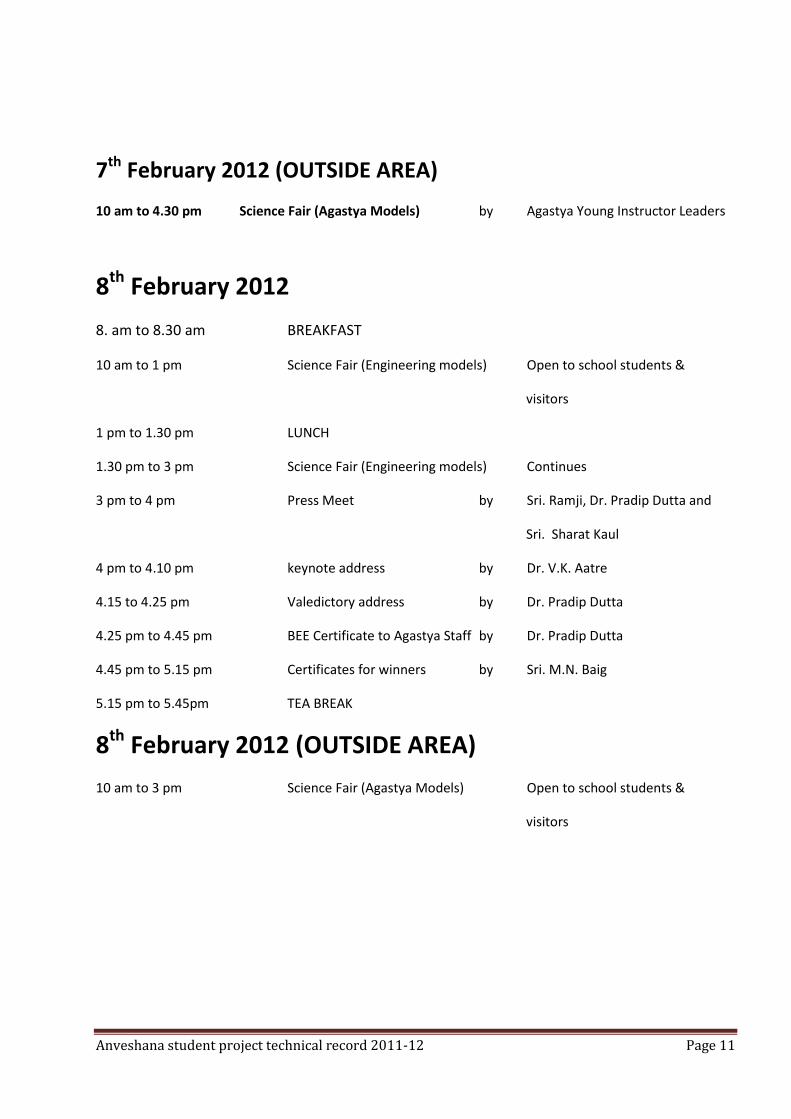
7th February 2012 (OUTSIDE AREA)
10 am to 4.30 pm Science Fair (Agastya Models) by Agastya Young Instructor Leaders
8th February 2012
8. am to 8.30 am BREAKFAST
10 am to 1 pm Science Fair (Engineering models) Open to school students &
visitors
1 pm to 1.30 pm LUNCH
1.30 pm to 3 pm Science Fair (Engineering models) Continues
3 pm to 4 pm Press Meet by Sri. Ramji, Dr. Pradip Dutta and
Sri. Sharat Kaul
4 pm to 4.10 pm keynote address by Dr. V.K. Aatre
4.15 to 4.25 pm Valedictory address by Dr. Pradip Dutta
4.25 pm to 4.45 pm BEE Certificate to Agastya Staff by Dr. Pradip Dutta
4.45 pm to 5.15 pm Certificates for winners by Sri. M.N. Baig
5.15 pm to 5.45pm TEA BREAK
8th February 2012 (OUTSIDE AREA)
10 am to 3 pm Science Fair (Agastya Models) Open to school students &
visitors
Anveshana student project technical record 2011-12 Page 12
PROPELLER LED DISPLAY COLLEGE: SRI SIDDHARTHA INSTITUTE OF TECHNOLOGY, TUMKUR
GUIDE: SANDRA
COLLEGE STUDENTS: CHETHAN M, VINAYAKA T K, PRAMOD N.M
SCHOOL STUDENTS: JAYASURYA, RAVI NAIK FROM SIDDAGANGA MATT SCHOOL
ABSTRACT:
This project is a special kind of circular led display. With the help some mechanical assembly, LED count, hardware requirement, and hence overall cost is cut to very affordable price. Also, maintenance and repairing of the display is so easy, that anyone having a little electronics knowledge can take care of this. All the synchronizing can be implemented through software. First of its kind, made using the 20-pin 8051 series microcontroller, this project use the principle of space multiplexing. This propeller display is mechanically scanned and displays the characters in digital format. Made from scrap it can be used anywhere and everywhere and the most amazing fact about this display is its crystal clear display. This display consists of just 8 bright LED’s which are rotated to show the display. For building this project, requirement is just a small 20 pin microcontroller, a position encoder, and LED’s. This display can show the messages, which will require a whopping 525 LED’s. So hardware and cost minimization is achieved.
SUMMARY
Innovative method of display using only 7 LED’s
WIRELESS IRRIGATION SYSTEM CONTROLLER A
SMART IRRIGATION COLLEGE: CHANNABASAVESHWARA INSTITUTE OF TECHNOLOGY,GUBBI
GUIDE: HARISH S, K V JYOTHI PRAKASH
COLLEGE STUDENTS: ABHISHEK B N, ARJUN AMBEKAR
SCHOOL STUDENTS: JAGADISH GJC TUMKUR, JNANESHWARI & SHWETHA BHOOMI SCHOOL GUBBI
ABSTRACT India is a land of villages; main occupation of the people here is agriculture. Farmers in India face many problems in irrigating their land, like load shedding, improper power distribution etc... Due to the unscheduled power distribution the rural areas may get approximately 2 to 6 hrs. of 3 phase power supply/day. Most of the submersible and any other kind of irrigation pumps require three phase power, but three phase supply is limited to rural as well as urban areas.
Anveshana student project technical record 2011-12 Page 13
The agricultural land is far away from the farmer’s house and if the farmer wants to irrigate his land he has to go to the pump house and has to check for the availability of the 3 phase power and then he can turn on the pump. If he is not in the farm or is away from the irrigating area then he will never get the actual status of the motor, water flow, availability of the power, fluctuations in the voltage etc... This may lead to the motor burnouts, wastage of power and wastage of water. Farmer cultivates many crops that require different amount of the water. The farm is elaborated and different types of plant are cultivated and to irrigate these areas the pipes are attached to the valves nearer to these areas and the water is supplied. Thus to supply water to different regions more no. of valves are required throughout the farm and these valves are mechanically controlled. Hence, while irrigating, farmer has to be there all the time in his farm. Considering the effects of the above problems on the farmers, we have developed a device which can control the whole irrigation system remotely using wireless communication. The device consists of a remote which will be with the farmer and a controlling unit at the pump house which controls the pump and the valves. Introduction to wireless irrigation system controller:
The device consists of two modules one is the portable remote which will be with the farmer and another one is the fixed module in the pump house. The remote consist of a transceiver, a microcontroller and the user interface for the farmer in the remote is provided with the indication LEDs, ON/OFF switch and region selection switches. Farmer will continuously get updated with the availability of power in the pump house in his remote. When there is no sufficient power to switch on the irrigation motor then, the farmer will get NO 3 PHASE indication. When there is a 3 PHASE, he then gets the 3 PHASE indication. Then he can switch ON/OFF the motor and can control the valve of the region which is to be irrigated using the remote. He will also get the indication regarding the status of the motor, water flow and the region which is irrigating. The device in the pump house consist of 3 phase monitoring unit, water flow monitoring unit, a transceiver unit, valve controlling unit and a controlling unit. All the controlling actions such as switching on/off of the motor, controlling of the valves are done by the microcontroller. It also monitors the power and water flow. Any fluctuations in the power or no water from the pump will end up with shutting down of the motor. And the same will be noticed to the farmer. Advantages over conventional irrigation methods/system: 1) By using wireless system controller, farmer can control the pump remotely. 2) Farmer can get the real time status of the power, motor, water flow and also the indication of the region which is irrigating. 3) *It protects the motor burnouts by monitoring the power and water flow. 4) **This device can eliminate AUTO STARETR and SINGLE PHASE PROTECTOR which is used in the conventional motor control system and hence minimizes the cost. (Auto starter is used to turn on the motor automatically when the power arrives. Since many motors works on 3 phases it requires single phase protector to avoid motor burnout due to sudden trip
Anveshana student project technical record 2011-12 Page 14
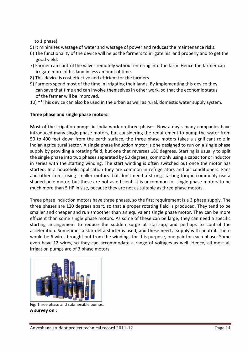
to 1 phase) 5) It minimizes wastage of water and wastage of power and reduces the maintenance risks. 6) The functionality of the device will helps the farmers to irrigate his land properly and to get the good yield. 7) Farmer can control the valves remotely without entering into the farm. Hence the farmer can irrigate more of his land in less amount of time. 8) This device is cost effective and efficient for the farmers. 9) Farmers spend most of the time in irrigating their lands. By implementing this device they can save that time and can involve themselves in other work, so that the economic status of the farmer will be improved. 10) **This device can also be used in the urban as well as rural, domestic water supply system. Three phase and single phase motors: Most of the irrigation pumps in India work on three phases. Now a day’s many companies have introduced many single phase motors, but considering the requirement to pump the water from 50 to 400 feet down from the earth surface, the three phase motors takes a significant role in Indian agricultural sector. A single phase induction motor is one designed to run on a single phase supply by providing a rotating field, but one that reverses 180 degrees. Starting is usually to split the single phase into two phases separated by 90 degrees, commonly using a capacitor or inductor in series with the starting winding. The start winding is often switched out once the motor has started. In a household application they are common in refrigerators and air conditioners. Fans and other items using smaller motors that don't need a strong starting torque commonly use a shaded pole motor, but these are not as efficient. It is uncommon for single phase motors to be much more than 5 HP in size, because they are not as suitable as three phase motors. Three phase induction motors have three phases, so the first requirement is a 3 phase supply. The three phases are 120 degrees apart, so that a proper rotating field is produced. They tend to be smaller and cheaper and run smoother than an equivalent single phase motor. They can be more efficient than some single phase motors. As some of these can be large, they can need a specific starting arrangement to reduce the sudden surge at start-up, and perhaps to control the acceleration. Sometimes a star-delta starter is used, and these need a supply with neutral. There would be 6 wires brought out from the windings for this purpose, one pair for each phase. Some even have 12 wires, so they can accommodate a range of voltages as well. Hence, all most all irrigation pumps are of 3 phase motors.
Fig: Three phase and submersible pumps.
A survey on :
Anveshana student project technical record 2011-12 Page 15
a) How much water an agricultural crop plant consumes:
Farmer cultivates many crops that would consume different amount of water for different crops. Farmer grows many crops like paddy, areca nut, coffee, wheat etc. Crops like paddy consumes more water, crop like coffee needs less water. The influence of the crop type on the crop water need is important in two ways: (A) The crop type has an influence on the daily water needs of a fully grown crop; i.e. the peak daily water needs: a fully developed maize crop will need more water per day than a fully developed crop of onions. (B) The crop type has an influence on the duration of the total growing season of the crop. There are short duration crops, e.g. peas, with duration of the total growing season of 90-100 days and longer duration crops, e.g. melons, with duration of the total growing season of 120-160 days. And then there are, of course, the perennial crops that are in the field for many years, such as fruit trees, coconut etc... While, for example, the daily water need of melons may be less than the daily water need of peas, the seasonal water need of melons will be higher than that of beans because the duration of the total growing season of melons is much longer. Hence, it is important to supply the water in very efficient manner to get the good yield of the crops. And it needs proper and continuous maintenance from the farmer, but in the present environment it is very difficult to fulfill the water needs of the agricultural crop.
b) Load shedding and power cuts:
To grow the crop efficiently and to increase the yield of the crops, water has to be supplied in the regular intervals, but due to the power cuts and load shedding, crops doesn’t get sufficient amount of water. Hence, the yield decreases or the crop may not able to yield. This has the major impact on the farmer’s economic condition. Because of globalization and privatization more concentration is put towards the industries. Most of the industries were established in urban areas. Because of the industries facilities and infrastructures in the urban areas, population densities are more in urban areas and hence these areas get more electricity. Since the power generated from all the sources is less when compared to consumption, government provides more power to the urban areas and to balance the power problems it enforces load shedding in rural areas. Today rural areas are put to 7-11 hours of load shedding and some areas get only 7-9 hours of electricity. Thus the load shedding has the major impact on the farmer’s life, even though after load shedding, the supplied power is unscheduled and the required 3 phase supply is provided at the night time.

Anveshana student project technical record 2011-12 Page 16
c) Cost of Pumps and accessories:
Cost of the water pumps is more than 4000 INR; depend upon the size and power.
Cost of the single phase protector is between 500-3000 INR; depend upon the quality.
Cost of the auto starter is around 500-3000 INR; depend upon the quality.
Cost of the valves to guide the water is around 25-500 INR; depend upon the size and quality.
Cost of the pipes to guide the water is around 250-1000 INR/piece depends upon the size, length and quality.
By looking at the above three surveys we came to know about consumption of water by plants, how load shedding is enforced on rural areas and cost of the pump and accessories. According to the above 3 survey, to obtain the good yield of the crops it is necessary to supply the water properly in the available duration of the power supply in very less amount of the cost. To accomplish this we have developed a device to overcome the above problems in the best possible way. How wireless irrigation system controller works: Wireless irrigation system controller consists of two modules:
One is the portable remote which will be with the farmer.
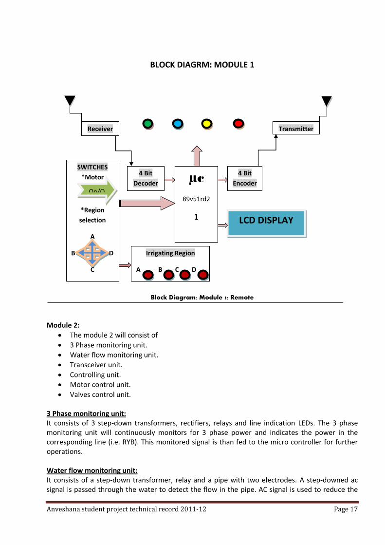
A fixed module in the pump house. Module 1: Remote The receiver of the remote operates at radio frequencies will receives the message from the module 2. It is then decoded to 4 bit wide data, which is fed to the microcontroller. Microcontroller reads the data and performs the corresponding operation. For example if the data is indicating the NO 3 PHASE situation then the GREEN LED in the remote will glow, indicating that 3 phase is not there and the same will be displayed on the LCD DISPLAY. Similarly when 3 phase power is there, then BLUE LED will glow. Then the farmer can switch on the motor by using motor ON/OFF switch on the front panel of the remote which sends the particular 4 bit encoded data to the MODULE 2 by means of RF transmitter. Then the MOTOR ON indication ‘YELLOW LED’ will glow in the remote. If motor is lifting the water then RED LED will glow in the remote so that farmer can ensure that motor is running smoothly. Then the farmer can open the valve of region which is to be irrigated and the region is also indicated in the remote.
Anveshana student project technical record 2011-12 Page 17
BLOCK DIAGRM: MODULE 1
Block Diagram: Module 1: Remote
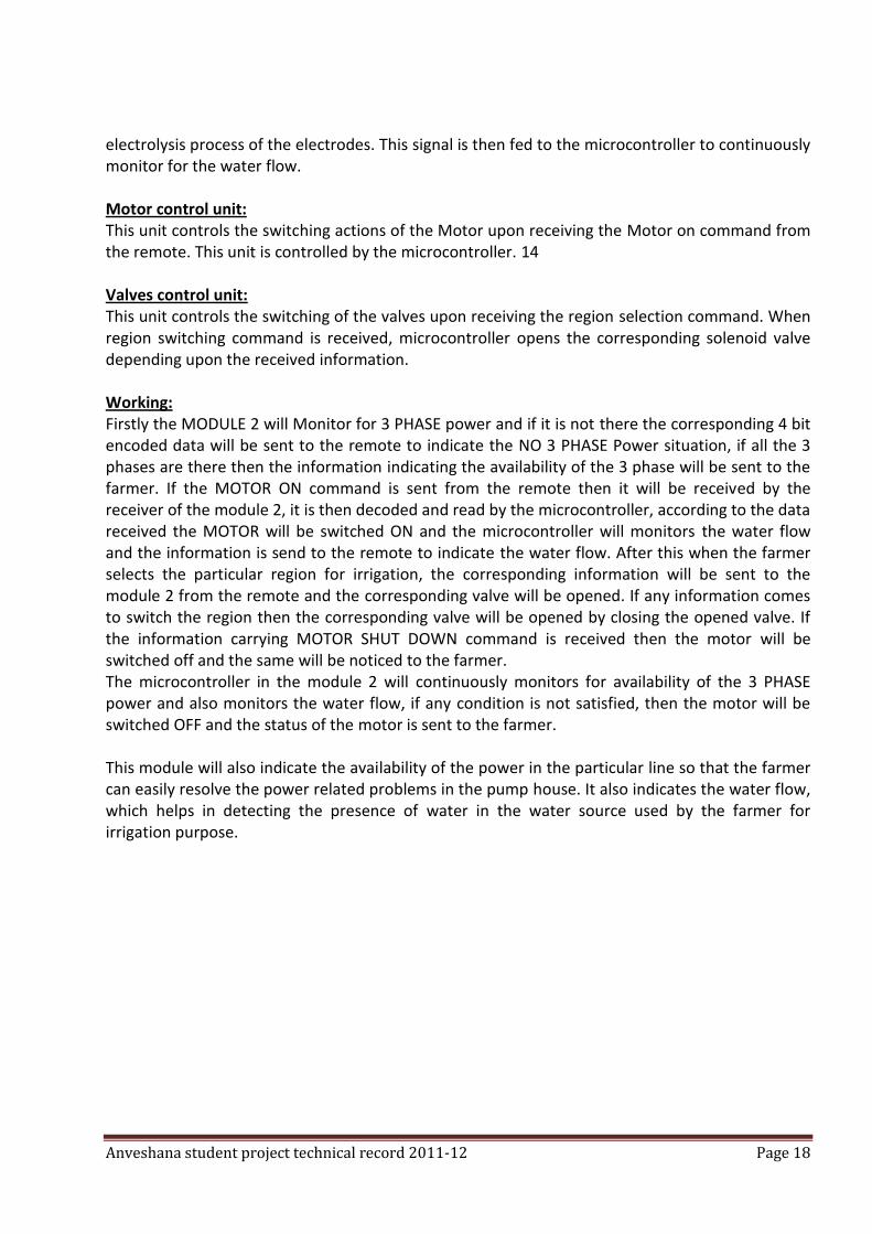
Module 2:
The module 2 will consist of
3 Phase monitoring unit.
Water flow monitoring unit.
Transceiver unit.
Controlling unit.
Motor control unit.
Valves control unit. 3 Phase monitoring unit: It consists of 3 step-down transformers, rectifiers, relays and line indication LEDs. The 3 phase monitoring unit will continuously monitors for 3 phase power and indicates the power in the corresponding line (i.e. RYB). This monitored signal is than fed to the micro controller for further operations. Water flow monitoring unit: It consists of a step-down transformer, relay and a pipe with two electrodes. A step-downed ac signal is passed through the water to detect the flow in the pipe. AC signal is used to reduce the
µc
89v51rd2
1
4 Bit
Encoder
Receiver
SWITCHES
*Motor
*Region
selection
A
B D
C
On/O
4 Bit
Decoder
Transmitter
LCD DISPLAY
Irrigating Region
A B C D
Anveshana student project technical record 2011-12 Page 18
electrolysis process of the electrodes. This signal is then fed to the microcontroller to continuously monitor for the water flow. Motor control unit: This unit controls the switching actions of the Motor upon receiving the Motor on command from the remote. This unit is controlled by the microcontroller. 14 Valves control unit: This unit controls the switching of the valves upon receiving the region selection command. When region switching command is received, microcontroller opens the corresponding solenoid valve depending upon the received information. Working: Firstly the MODULE 2 will Monitor for 3 PHASE power and if it is not there the corresponding 4 bit encoded data will be sent to the remote to indicate the NO 3 PHASE Power situation, if all the 3 phases are there then the information indicating the availability of the 3 phase will be sent to the farmer. If the MOTOR ON command is sent from the remote then it will be received by the receiver of the module 2, it is then decoded and read by the microcontroller, according to the data received the MOTOR will be switched ON and the microcontroller will monitors the water flow and the information is send to the remote to indicate the water flow. After this when the farmer selects the particular region for irrigation, the corresponding information will be sent to the module 2 from the remote and the corresponding valve will be opened. If any information comes to switch the region then the corresponding valve will be opened by closing the opened valve. If the information carrying MOTOR SHUT DOWN command is received then the motor will be switched off and the same will be noticed to the farmer. The microcontroller in the module 2 will continuously monitors for availability of the 3 PHASE power and also monitors the water flow, if any condition is not satisfied, then the motor will be switched OFF and the status of the motor is sent to the farmer. This module will also indicate the availability of the power in the particular line so that the farmer can easily resolve the power related problems in the pump house. It also indicates the water flow, which helps in detecting the presence of water in the water source used by the farmer for irrigation purpose.
Anveshana student project technical record 2011-12 Page 19
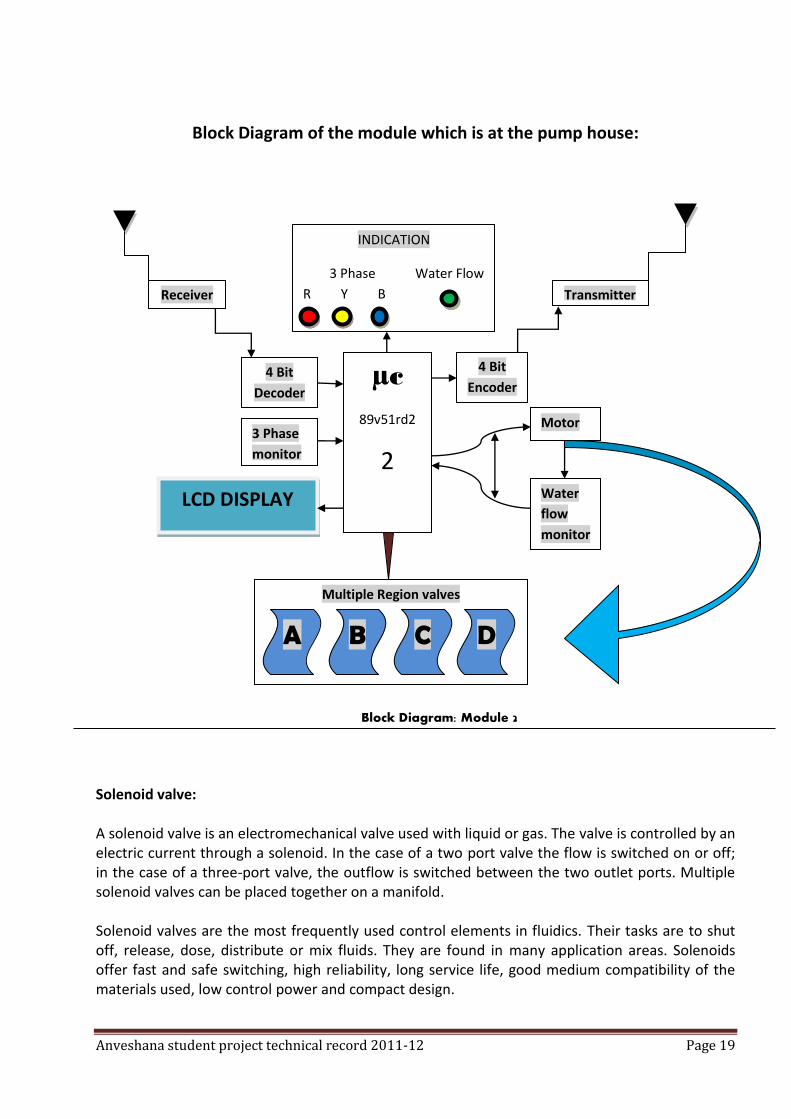
Block Diagram of the module which is at the pump house:
Block Diagram: Module 2
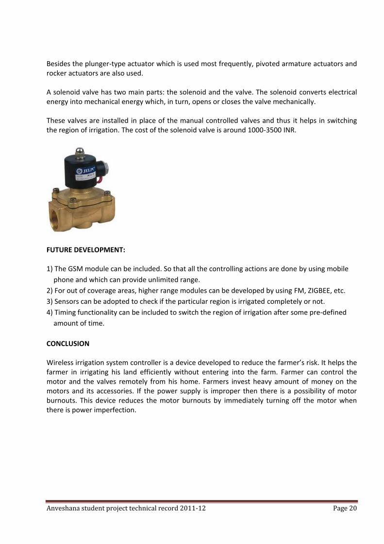
Solenoid valve: A solenoid valve is an electromechanical valve used with liquid or gas. The valve is controlled by an electric current through a solenoid. In the case of a two port valve the flow is switched on or off; in the case of a three-port valve, the outflow is switched between the two outlet ports. Multiple solenoid valves can be placed together on a manifold. Solenoid valves are the most frequently used control elements in fluidics. Their tasks are to shut off, release, dose, distribute or mix fluids. They are found in many application areas. Solenoids offer fast and safe switching, high reliability, long service life, good medium compatibility of the materials used, low control power and compact design.
µc
89v51rd2
2 3 Phase
monitor
Water
flow
monitor
Motor
INDICATION
3 Phase Water Flow
R Y B
4 Bit
Decoder
4 Bit
Encoder
Receiver Transmitter
Multiple Region valves
LCD DISPLAY
A B
C
D
Anveshana student project technical record 2011-12 Page 20
Besides the plunger-type actuator which is used most frequently, pivoted armature actuators and rocker actuators are also used. A solenoid valve has two main parts: the solenoid and the valve. The solenoid converts electrical energy into mechanical energy which, in turn, opens or closes the valve mechanically. These valves are installed in place of the manual controlled valves and thus it helps in switching the region of irrigation. The cost of the solenoid valve is around 1000-3500 INR.
FUTURE DEVELOPMENT: 1) The GSM module can be included. So that all the controlling actions are done by using mobile
phone and which can provide unlimited range.
2) For out of coverage areas, higher range modules can be developed by using FM, ZIGBEE, etc.
3) Sensors can be adopted to check if the particular region is irrigated completely or not.
4) Timing functionality can be included to switch the region of irrigation after some pre-defined
amount of time.
CONCLUSION Wireless irrigation system controller is a device developed to reduce the farmer’s risk. It helps the farmer in irrigating his land efficiently without entering into the farm. Farmer can control the motor and the valves remotely from his home. Farmers invest heavy amount of money on the motors and its accessories. If the power supply is improper then there is a possibility of motor burnouts. This device reduces the motor burnouts by immediately turning off the motor when there is power imperfection.
Anveshana student project technical record 2011-12 Page 21
AUTOMATIC TEMPERATURE CONTROLLED FAN COLLEGE: CHANNABASAVESHWARA INSTITUTE OF TECHNOLOGY, GUBBI
GUIDE: K V JYOTHI PRAKASH
COLLEGE STUDENTS: SHRINIDHI.S, SUVARNA.D.S
SCHOOL STUDENTS: ASHOK GJC TUMKUR, MOULYA, MEGHANA BHOOMI SCHOOL, GUBBI
ABSTRACT: It control's the rotation of the fan according to temperature variation .as temperature increases, the rotation of the fan increases and vice-versa. We used thermistor, which produces the varying voltage according to temperature along with voltage divider circuit. We can replace thermistor by biomedical thermistor's which generates varying voltage for mall change in temperature. SUMMARY: It deals with the varying the speed of the fan according to temperature.
RAILWAY AUTOMATION SYSTEM
COLLEGE: CHANNABASAVESHWARA INSTITUTE OF TECHNOLOGY, GUBBI GUIDE: K V JYOTHI PRAKASH COLLEGE STUDENTS: SUNIL R, VINUTHAN B, VINYAS K V, NARTHAN L SCHOOL STUDENTS: LIKITH KUMAR GJC TUMKUR, PAVAN RAJ, SHARVARI SHANKAR BHOOMI SCHOOL, GUBBI
ABSTRACT:
Railways are one of the most used modes of transport in India. Millions of people travel everyday
by train from one place to another. As the dependency on this mode of transport is more, the
passengers must have enough facilities on board the train for their journey. One of the main
problems the passengers face on the train is the lack of information of the arriving station details,
the passengers are left in a dilemma about their arrival of next destination station. This causes a
great amount of difficulty among the passengers. Hence here we propose an embedded system
solution for the better understanding of this public transportation system.
INTRODUCTION
Railways are one of the most used modes of transport in India. Every year about 7.3 billion people
travel by train in India alone. About 17,000 trains travel in India every day. It generates a large
amount of revenue for the railways as well as for the nation. Even though the railways have grown
into such a big infrastructure it still lacks many basic features for the comfort travel of the people.
One of the main problems the passengers face on the train is the lack of information of the
Anveshana student project technical record 2011-12 Page 22
arriving station details, the passengers are left in a dilemma about their arrival of next destination
station. This causes a great amount of difficulty among the passengers. Hence a proper system
must be implemented for the proper guidance for the passengers.
In the proposed method, each compartment of the train will have a LCD display which displays the
information about the arrival of the next railway station, and the details of the later station and its
distance from its previous station. Whenever a station is approaching, the LCD will automatically
display the arriving station details. As it stops at the station, it starts to display the basic
information about that particular town or city. This is achieved by radio communication between
the train and the railway station.
Apart from this, the train compartments will also have a verbal announcement along with the LCD
display for playing the message through audio. The LCD display could be used to display
advertisements through the train’s journey. This will generate large amount of revenue for the
railways.
PRESENT SCENAR
In the present day situation, one of the main problems the passengers face on the train is the lack
of information of the arriving station details. Whenever a person on board the train, he or she will
come to know of the arriving station only when they arrive at the station, so there will be a huge
rush in getting down the train. This problem is considerably more while travelling at night. Thus
the present system has failed in making the railways system customer friendly. Keeping all these
disadvantages in mind, here we have proposed an embedded system based solution for making
railway system more user-friendly.
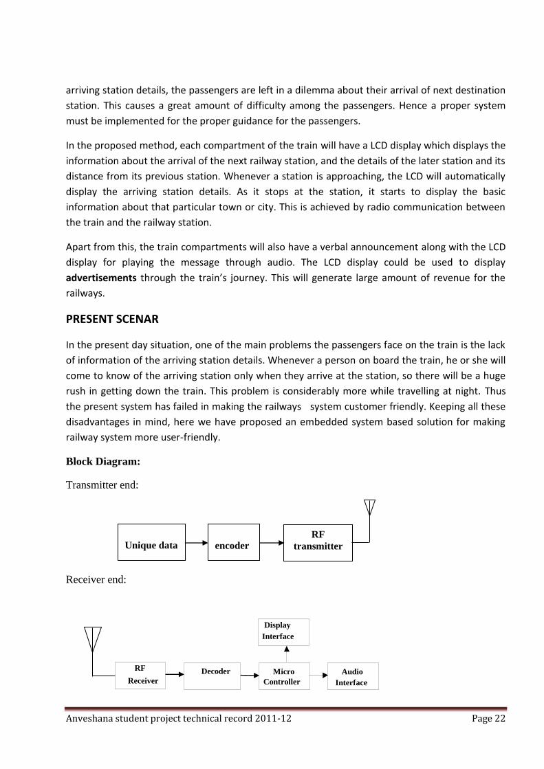
Block Diagram:
Transmitter end:
Receiver end:
Unique data
encoder RF
transmitter
Micro Controller
Audio
Interface
Display
Interface
RF
Receiver
Decoder
D
Anveshana student project technical record 2011-12 Page 23
APPROACH & IMPLEMENTATION
In the proposed embedded system, a master controller unit would be installed at each railway
station. The master controller will have a RF transmitter-receiver which will always transmit a
sequence of code in the form of a RF signal around a radius of 3-4 kms. Each railway station will
have a specific code allotted to it so that an approaching train would identify the station and
display the corresponding details about the station.
The train will have a controller unit which would consists of a microcontroller, RF receiver etc.
When the train approaches a railway station, the train will receive the station’s signal through its
RF receiver and decode the data and compare the code with an inbuilt database of railway
stations and its codes and then displays the corresponding railway station’s information onto the
LCD display placed at each compartment.
An LCD display and audio speakers will be installed at each compartment of the train, all these
units will be connected to the microcontroller which will display on LCD and play audio of the
designated message. The microcontroller will be connected to the RF transmitter-receiver via the
encoder-decoder unit which will simultaneously encode the signal and transmit the data using the
RF transmitter and also will receive the signal from the station using the RF receiver and decode
the received signal, this ensures security as the information would be coded in a particular format.
The LCD will be of a single-line or a two-line display,
As with respect to the LCD display in the train, it would display the basic information of the
arriving station such as,
The name of the arriving station.
The distance between arriving station and the next arriving station.
The approx. time required to travel between them.
The type of microcontroller used would be of 8051 architecture. Here it is the heart of the system
which processes all the data from or to the RF module via the encoders/decoders, and also
displays the messages onto the LCD.
For more enhanced features, the LCD could be used to display advertisements through the train’s
journey. This will generate large amount of revenue for the railways.
Anveshana student project technical record 2011-12 Page 24
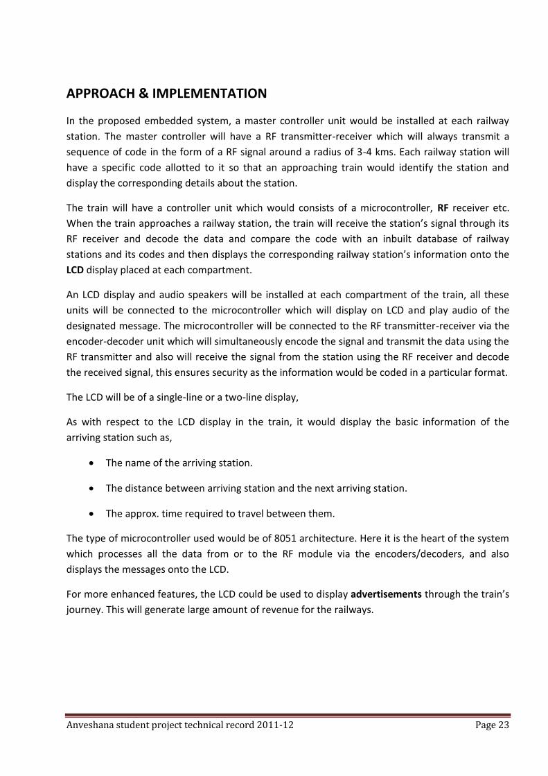
MICROCONTROLLER:
A microcontroller (sometimes abbreviated µC or MCU) is a small computer on a single integrated
circuit containing a processor core, memory, and programmable input/output peripherals.
Program memory in the form of NOR flash or OTP ROM is also often included on chip, as well as a
typically small amount of RAM. Microcontrollers are designed for embedded applications.
Microcontrollers operate in real time (predictable, though not necessarily fast) response to events
in the embedded system they are controlling.
In this system, the microcontroller recognises the operation selected by the user and sends a
specific corresponding code to the encoder.
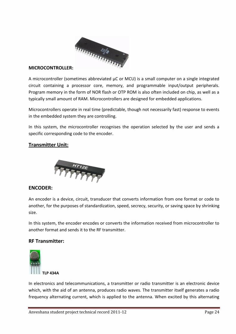
Transmitter Unit:
ENCODER:
An encoder is a device, circuit, transducer that converts information from one format or code to
another, for the purposes of standardization, speed, secrecy, security, or saving space by shrinking
size.
In this system, the encoder encodes or converts the information received from microcontroller to
another format and sends it to the RF transmitter.
RF Transmitter:
TLP 434A
In electronics and telecommunications, a transmitter or radio transmitter is an electronic device
which, with the aid of an antenna, produces radio waves. The transmitter itself generates a radio
frequency alternating current, which is applied to the antenna. When excited by this alternating
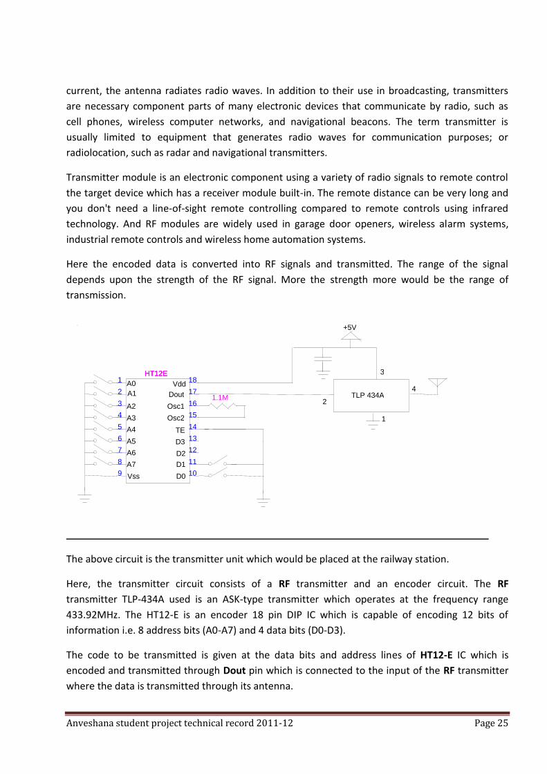
Anveshana student project technical record 2011-12 Page 25
current, the antenna radiates radio waves. In addition to their use in broadcasting, transmitters
are necessary component parts of many electronic devices that communicate by radio, such as
cell phones, wireless computer networks, and navigational beacons. The term transmitter is
usually limited to equipment that generates radio waves for communication purposes; or
radiolocation, such as radar and navigational transmitters.
Transmitter module is an electronic component using a variety of radio signals to remote control
the target device which has a receiver module built-in. The remote distance can be very long and
you don't need a line-of-sight remote controlling compared to remote controls using infrared
technology. And RF modules are widely used in garage door openers, wireless alarm systems,
industrial remote controls and wireless home automation systems.
Here the encoded data is converted into RF signals and transmitted. The range of the signal
depends upon the strength of the RF signal. More the strength more would be the range of
transmission.
The above circuit is the transmitter unit which would be placed at the railway station.
Here, the transmitter circuit consists of a RF transmitter and an encoder circuit. The RF
transmitter TLP-434A used is an ASK-type transmitter which operates at the frequency range
433.92MHz. The HT12-E is an encoder 18 pin DIP IC which is capable of encoding 12 bits of
information i.e. 8 address bits (A0-A7) and 4 data bits (D0-D3).
The code to be transmitted is given at the data bits and address lines of HT12-E IC which is
encoded and transmitted through Dout pin which is connected to the input of the RF transmitter
where the data is transmitted through its antenna.
2
3
1
4 TLP 434A
A0 A1
A2 A3 A4 A5 A6 A7 Vss D0
D1 D2 D3
Osc1 Osc2
Vdd
TE
Dout 1.1M
+5V
1 2 3 4 5 6 7 8 9
18 17 16 15 14 13 12 11 10
HT12E HT12E HT12E
Anveshana student project technical record 2011-12 Page 26
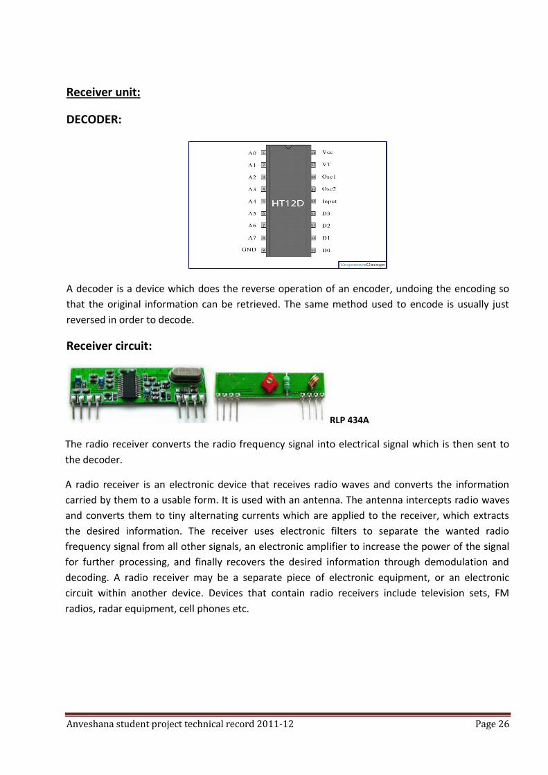
Receiver unit:
DECODER:
A decoder is a device which does the reverse operation of an encoder, undoing the encoding so
that the original information can be retrieved. The same method used to encode is usually just
reversed in order to decode.
Receiver circuit:
RLP 434A
The radio receiver converts the radio frequency signal into electrical signal which is then sent to
the decoder.
A radio receiver is an electronic device that receives radio waves and converts the information
carried by them to a usable form. It is used with an antenna. The antenna intercepts radio waves
and converts them to tiny alternating currents which are applied to the receiver, which extracts
the desired information. The receiver uses electronic filters to separate the wanted radio
frequency signal from all other signals, an electronic amplifier to increase the power of the signal
for further processing, and finally recovers the desired information through demodulation and
decoding. A radio receiver may be a separate piece of electronic equipment, or an electronic
circuit within another device. Devices that contain radio receivers include television sets, FM
radios, radar equipment, cell phones etc.
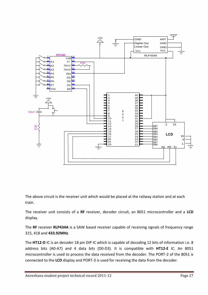
Anveshana student project technical record 2011-12 Page 27
The above circuit is the receiver unit which would be placed at the railway station and at each
train.
The receiver unit consists of a RF receiver, decoder circuit, an 8051 microcontroller and a LCD
display.
The RF receiver RLP434A is a SAW based receiver capable of receiving signals of frequency range
315, 418 and 433.92MHz.
The HT12-D IC is an decoder 18 pin DIP IC which is capable of decoding 12 bits of information i.e. 8
address bits (A0-A7) and 4 data bits (D0-D3). It is compatible with HT12-E IC. An 8051
microcontroller is used to process the data received from the decoder. The PORT-2 of the 8051 is
connected to the LCD display and PORT-3 is used for receiving the data from the decoder.
A1
A2
A3
A4
A5
A6
A7
Vss D0
D1
D2
D3
Osc1
Osc2
Vdd
Din
GND
Digital Out
Linear Out
Vcc Vcc
GND
GND
ANT
RLP434A
1
2345678910
22
11121314151617181920 21
23242526
2728293031323334353637383940
8
0
5
1
DB0DB1DB2DB3
DB4DB5
DB6DB7
RS RW En
1
3
16
152
LCD
VT51K
1
2
3
4
5
6
7
8
9
18
17
16
15
14
13
12
11
10
HT12DHT12DHT12D
+5V
+5V
10uF
8.2
K
Anveshana student project technical record 2011-12 Page 28
Here the RF signal received by the RF receiver RLP434A is passed onto the HT12-D decoder IC
which checks the received signal 3 times and the data is given to the PORT-3 of 8051
microcontroller where it compares the data with its inbuilt database of information and the
corresponding message is displayed on the LCD display.
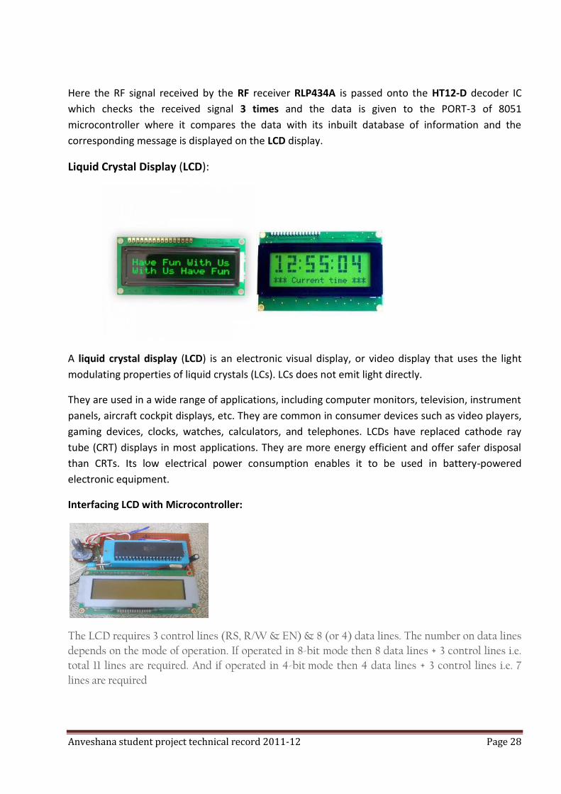
Liquid Crystal Display (LCD):
A liquid crystal display (LCD) is an electronic visual display, or video display that uses the light
modulating properties of liquid crystals (LCs). LCs does not emit light directly.
They are used in a wide range of applications, including computer monitors, television, instrument
panels, aircraft cockpit displays, etc. They are common in consumer devices such as video players,
gaming devices, clocks, watches, calculators, and telephones. LCDs have replaced cathode ray
tube (CRT) displays in most applications. They are more energy efficient and offer safer disposal
than CRTs. Its low electrical power consumption enables it to be used in battery-powered
electronic equipment.
Interfacing LCD with Microcontroller:
The LCD requires 3 control lines (RS, R/W & EN) & 8 (or 4) data lines. The number on data lines
depends on the mode of operation. If operated in 8-bit mode then 8 data lines + 3 control lines i.e.
total 11 lines are required. And if operated in 4-bit mode then 4 data lines + 3 control lines i.e. 7
lines are required
Anveshana student project technical record 2011-12 Page 29
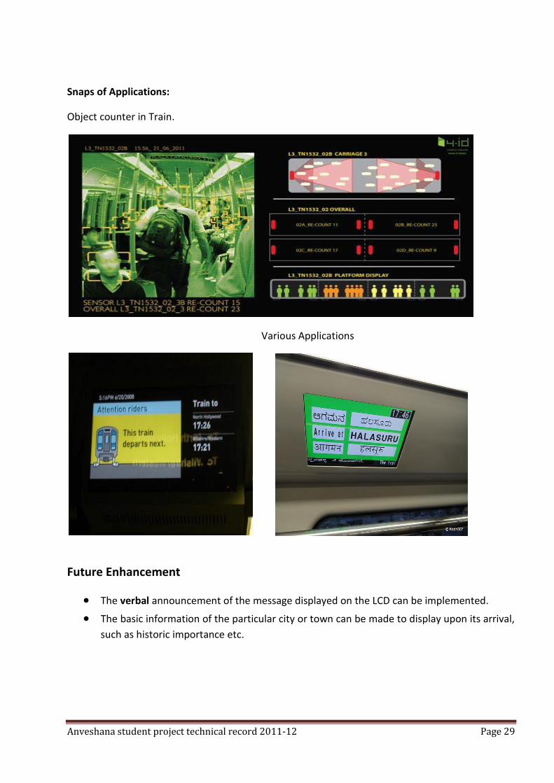
Snaps of Applications:
Object counter in Train.
Various Applications
Future Enhancement
The verbal announcement of the message displayed on the LCD can be implemented.
The basic information of the particular city or town can be made to display upon its arrival,
such as historic importance etc.
Anveshana student project technical record 2011-12 Page 30
CONCLUSION
Thus, by implementing the proposed embedded system the passengers can be assured of tension-
free journey where they would get arrival information about all the stations throughout the train’s
journey.
As in the present system, there is no prior information about the arrival of the station in the train;
this causes discomfort among the people during getting down of the train when the station
arrives. Also in the railway stations there is no precise information about the arriving trains.
Therefore our system provides the passengers, the information about the arrival station in each
and every compartment which in turn helps the passengers for their comfort journey.
Also additional features like displaying the basic details about the arriving city or town, LCD
displays are used as a source of income by displaying advertisements through the train’s journey.
Hence by adopting the proposed “RAILWAY AUTOMATION SYSTEM”, the functioning and
understanding of the railway system can be made much simpler.
MODERN SECURITY SYSTEMS COLLEGE: CHANNABASAVESHWARA INSTITUTE OF TECHNOLOGY, GUBBI
GUIDE: K V JYOTHI PRAKASH
COLLEGE STUDENTS: RAKESH K, MADHUMOHAN H S, PRASHANTH K R
SCHOOL STUDENTS: MANOJ KUMAR GJC TUMKUR, CHANDAN RAMESH, TEJAS BHOOMI SCHOOL, GUBBI
ABSTRACT: OUTDOOR BLOCK DISCRIPTION
IR transmitter will be transmitting IR rays continuously and the output pin of IR receiver will always be high. Whenever an unauthorized person passes in between these two, it gets interrupted and for a momentary time the output pin of the receiver will go low, the time period of this will be very small in terms of microseconds so this pulse is given to the trigger pin of the mono-stable multivibrator and the time period of pulse is increased. The output of multi vibrator is given to micro-controller which is programmed in such a way that on reception of a pulse it will send a data which will be the address of the specific home in which interruption has taken place. The data from micro controller is given to the encoder which in turn will be transmitted using a RF transmitter. IN DOOR BLOCK DESCRIPTION
The data transmitted from the RF transmitter is received by the RF receiver and sent to the decoder which will check the address line of the encoder and will decode the data. Then the data
Anveshana student project technical record 2011-12 Page 31
from the decoder is sent to micro controller which is programmed in such a way that on receiving the data it will display the name or address of the home in which interruption has taken place in the LCD screen and a red led will glow indicating the danger. This whole arrangement is kept in a central place within the home.
SUMMARY:
It can be implemented to many homes. Each home will have its own outdoor and indoor circuit. On interruption in any one home message will be displayed in every home on their LCD screen kept inside their home. We have made it for three homes.
SIXTH SENSE
COLLEGE: CHANNABASAVESHWARA INSTITUTE OF TECHNOLOGY, GUBBI GUIDE: K V JYOTHI PRAKASH COLLEGE STUDENTS: VINUTHAN B, SRINIVAS H V, SHWETHA K, RAGHU T H SCHOOL STUDENTS: BHOOMI SCHOOL, GUBBI
ABSTRACT In this modern age, technology has played a very important role in the day to day activities of
everyone’s life. So, here we propose an embedded based solution which makes the use of devices,
computers more user-friendly. In the proposed system, the gestures made by the user is
recognized by a micro-controller and is transmitted wirelessly to another micro-controller which
then controls functions and applications in a computer, home-appliances etc.
INTRODUCTION
Technology has a great impact in every field. As the name of our project 'SIXTH SENSE' implies, it is
the feature which makes the user operate and control the surrounding environment in an easy
and efficient way.
People say, "Necessity is the mother of inventions", but "comfort" is the mother of our invention.
Nowadays people give their priority to the technology that provides them comfort.
Our proposed system allows the user to control home appliances like TV, fans, lights, etc without
using switches and perform computer operations such as mouse control, play games, view photos
and play music without using keyboard and mouse. We believe this system will help handicapped
people to use the technology, reducing difficulty of operation of controlling the devices.
APPROACH & IMPLEMENTATION
The proposed system mainly consists of a transmitter section and receiver section.
Anveshana student project technical record 2011-12 Page 32
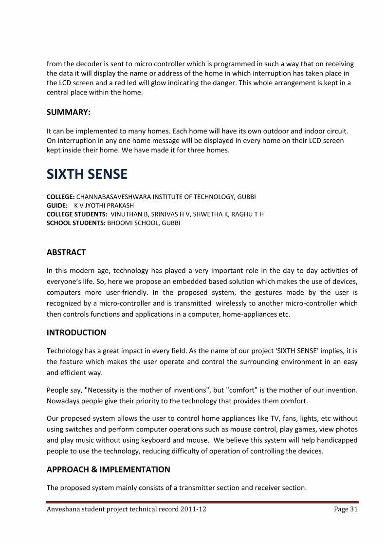
Transmitter section:
The transmitter section is a wrist held device that can be mounted on the wrist of an arm. This
device is used to recognize the actions made by the user. The transmitter unit consists of sensing
medium, micro-controller, encoder and a RF transmitter. The different gestures made by the
user’s hands are recognized by the micro-controller and the data is encoded using an encoder
HT12-E and is transmitted using a RF transmitter TLP 434A.
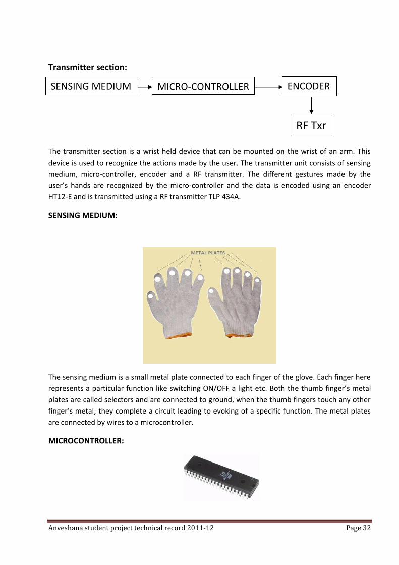
SENSING MEDIUM:
The sensing medium is a small metal plate connected to each finger of the glove. Each finger here
represents a particular function like switching ON/OFF a light etc. Both the thumb finger’s metal
plates are called selectors and are connected to ground, when the thumb fingers touch any other
finger’s metal; they complete a circuit leading to evoking of a specific function. The metal plates
are connected by wires to a microcontroller.
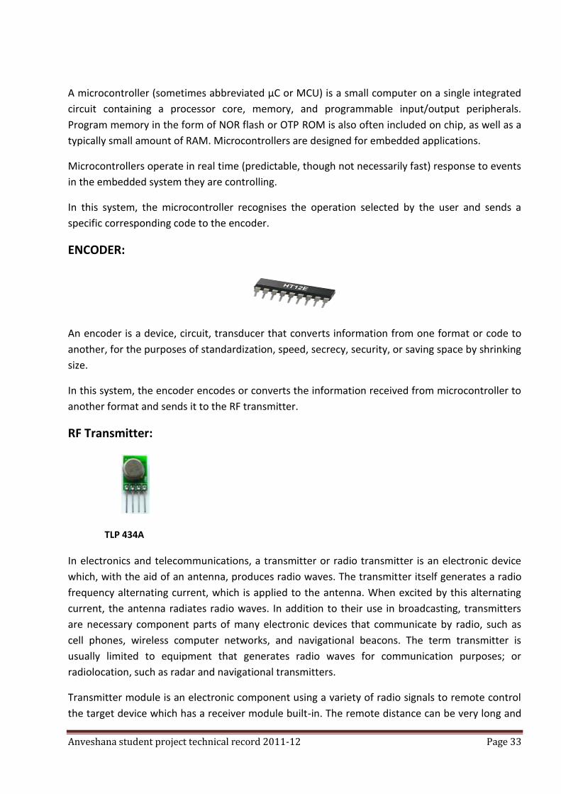
MICROCONTROLLER:
ENCODER MICRO-CONTROLLER SENSING MEDIUM
RF Txr
Anveshana student project technical record 2011-12 Page 33
A microcontroller (sometimes abbreviated µC or MCU) is a small computer on a single integrated
circuit containing a processor core, memory, and programmable input/output peripherals.
Program memory in the form of NOR flash or OTP ROM is also often included on chip, as well as a
typically small amount of RAM. Microcontrollers are designed for embedded applications.
Microcontrollers operate in real time (predictable, though not necessarily fast) response to events
in the embedded system they are controlling.
In this system, the microcontroller recognises the operation selected by the user and sends a
specific corresponding code to the encoder.
ENCODER:
An encoder is a device, circuit, transducer that converts information from one format or code to
another, for the purposes of standardization, speed, secrecy, security, or saving space by shrinking
size.
In this system, the encoder encodes or converts the information received from microcontroller to
another format and sends it to the RF transmitter.
RF Transmitter:
TLP 434A
In electronics and telecommunications, a transmitter or radio transmitter is an electronic device
which, with the aid of an antenna, produces radio waves. The transmitter itself generates a radio
frequency alternating current, which is applied to the antenna. When excited by this alternating
current, the antenna radiates radio waves. In addition to their use in broadcasting, transmitters
are necessary component parts of many electronic devices that communicate by radio, such as
cell phones, wireless computer networks, and navigational beacons. The term transmitter is
usually limited to equipment that generates radio waves for communication purposes; or
radiolocation, such as radar and navigational transmitters.
Transmitter module is an electronic component using a variety of radio signals to remote control
the target device which has a receiver module built-in. The remote distance can be very long and
Anveshana student project technical record 2011-12 Page 34
you don't need a line-of-sight remote controlling compared to remote controls using infrared
technology. And RF modules are widely used in garage door openers, wireless alarm systems,
industrial remote controls and wireless home automation systems.
Here the encoded data is converted into RF signals and transmitted. The range of the
signal depends upon the strength of the RF signal. More the strength, more would be the
range of transmission.
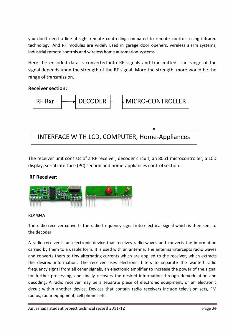
Receiver section:
The receiver unit consists of a RF receiver, decoder circuit, an 8051 microcontroller, a LCD
display, serial interface (PC) section and home-appliances control section.
RF Receiver:
RLP 434A
The radio receiver converts the radio frequency signal into electrical signal which is then sent to
the decoder.
A radio receiver is an electronic device that receives radio waves and converts the information
carried by them to a usable form. It is used with an antenna. The antenna intercepts radio waves
and converts them to tiny alternating currents which are applied to the receiver, which extracts
the desired information. The receiver uses electronic filters to separate the wanted radio
frequency signal from all other signals, an electronic amplifier to increase the power of the signal
for further processing, and finally recovers the desired information through demodulation and
decoding. A radio receiver may be a separate piece of electronic equipment, or an electronic
circuit within another device. Devices that contain radio receivers include television sets, FM
radios, radar equipment, cell phones etc.
RF Rxr DECODER MICRO-CONTROLLER
INTERFACE WITH LCD, COMPUTER, Home-Appliances
Anveshana student project technical record 2011-12 Page 35
DECODER:
A decoder is a device which does the reverse operation of an encoder, undoing the encoding so
that the original information can be retrieved. The same method used to encode is usually just
reversed in order to decode.
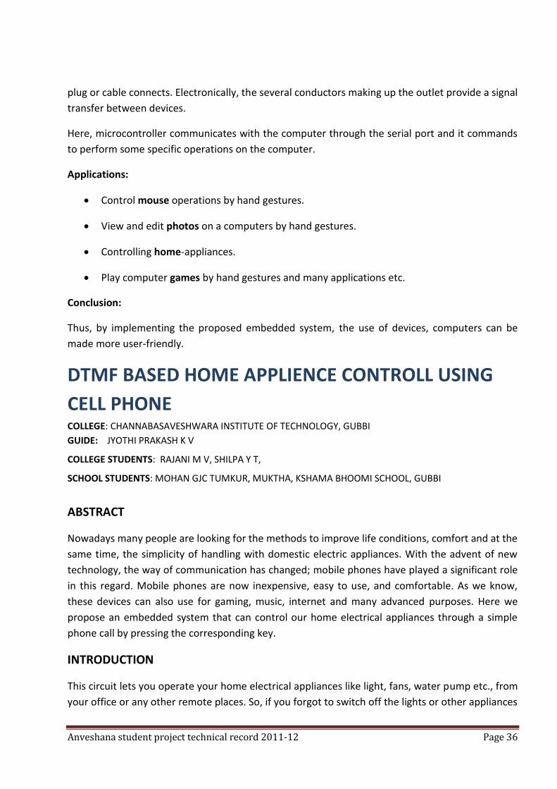
Liquid Crystal Display (LCD):
A liquid crystal display (LCD) is an electronic visual display, or video display that uses the light
modulating properties of liquid crystals (LCs). LCs does not emit light directly.
They are used in a wide range of applications, including computer monitors, television, instrument
panels, aircraft cockpit displays, etc. They are common in consumer devices such as video players,
gaming devices, clocks, watches, calculators, and telephones. LCDs have replaced cathode ray
tube (CRT) displays in most applications. They are more energy efficient and offer safer disposal
than CRTs. Its low electrical power consumption enables it to be used in battery-powered
electronic equipment.
COMPUTER SERIAL PORT INTERFACE:
In computer hardware, a port serves as an interface between the computer and other computers
or peripheral devices. Physically, a port is a specialized outlet on a piece of equipment to which a
Anveshana student project technical record 2011-12 Page 36
plug or cable connects. Electronically, the several conductors making up the outlet provide a signal
transfer between devices.
Here, microcontroller communicates with the computer through the serial port and it commands
to perform some specific operations on the computer.
Applications:
Control mouse operations by hand gestures.
View and edit photos on a computers by hand gestures.
Controlling home-appliances.
Play computer games by hand gestures and many applications etc.
Conclusion:
Thus, by implementing the proposed embedded system, the use of devices, computers can be
made more user-friendly.
DTMF BASED HOME APPLIENCE CONTROLL USING
CELL PHONE COLLEGE: CHANNABASAVESHWARA INSTITUTE OF TECHNOLOGY, GUBBI
GUIDE: JYOTHI PRAKASH K V
COLLEGE STUDENTS: RAJANI M V, SHILPA Y T,
SCHOOL STUDENTS: MOHAN GJC TUMKUR, MUKTHA, KSHAMA BHOOMI SCHOOL, GUBBI
ABSTRACT
Nowadays many people are looking for the methods to improve life conditions, comfort and at the
same time, the simplicity of handling with domestic electric appliances. With the advent of new
technology, the way of communication has changed; mobile phones have played a significant role
in this regard. Mobile phones are now inexpensive, easy to use, and comfortable. As we know,
these devices can also use for gaming, music, internet and many advanced purposes. Here we
propose an embedded system that can control our home electrical appliances through a simple
phone call by pressing the corresponding key.
INTRODUCTION
This circuit lets you operate your home electrical appliances like light, fans, water pump etc., from
your office or any other remote places. So, if you forgot to switch off the lights or other appliances
Anveshana student project technical record 2011-12 Page 37
while going out, it helps you to turn off appliances with your cell phone. The cell phone work as a
remote control for your home appliances. You can control the desired appliances by pressing
corresponding key.
THE PURPOSE OF THE CIRCUIT
The purpose of our project is to develop DTMF signal controlled house monitoring system based
on microcontroller. The device is connected to phone line and is controlled by signal emitted by
the DTMF decoder in stationary or mobile phones. In presence of incoming call, the device pick up
the call by auto- receive. User can press buttons or keys and control the system remotely.
Functions of the keys should know initially.
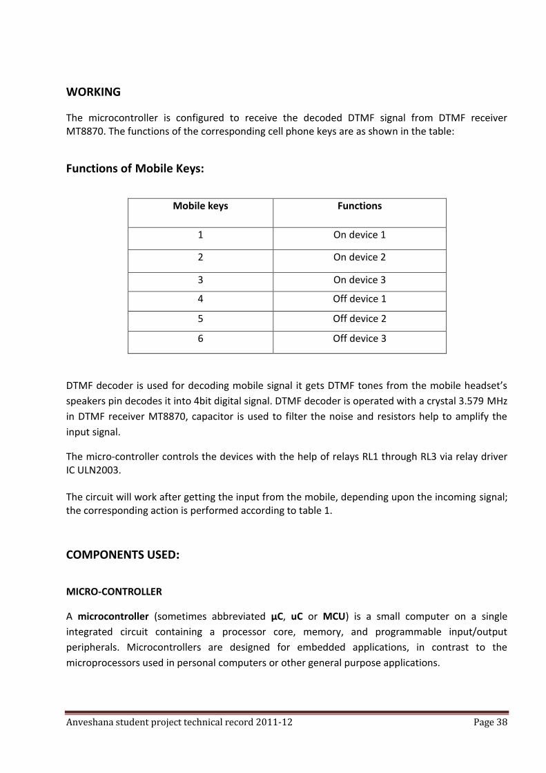
CIRCUIT DESCRIPTION
The block diagram shows the cell phone based remote control. It comprises microcontroller-
AT89C51, DTMF decoder-MT8870 and a few discrete components.
There are two sections in the project, one is transmitter section and another one is receiver
section.
BLOCK DIAGRAM:
DTMF
DECOD
ER
(MT887
MICRO-
CONTROLLER
AT89C51
RELAY FOR DEVICE 1
RELAY FOR DEVICE 2
RELAY FOR DEVICE N
Anveshana student project technical record 2011-12 Page 38
WORKING
The microcontroller is configured to receive the decoded DTMF signal from DTMF receiver MT8870. The functions of the corresponding cell phone keys are as shown in the table:
Functions of Mobile Keys:
Mobile keys Functions
1 On device 1
2 On device 2
3 On device 3
4 Off device 1
5 Off device 2
6 Off device 3
DTMF decoder is used for decoding mobile signal it gets DTMF tones from the mobile headset’s
speakers pin decodes it into 4bit digital signal. DTMF decoder is operated with a crystal 3.579 MHz
in DTMF receiver MT8870, capacitor is used to filter the noise and resistors help to amplify the
input signal.
The micro-controller controls the devices with the help of relays RL1 through RL3 via relay driver IC ULN2003. The circuit will work after getting the input from the mobile, depending upon the incoming signal; the corresponding action is performed according to table 1.
COMPONENTS USED:
MICRO-CONTROLLER
A microcontroller (sometimes abbreviated µC, uC or MCU) is a small computer on a single
integrated circuit containing a processor core, memory, and programmable input/output
peripherals. Microcontrollers are designed for embedded applications, in contrast to the
microprocessors used in personal computers or other general purpose applications.
Anveshana student project technical record 2011-12 Page 39
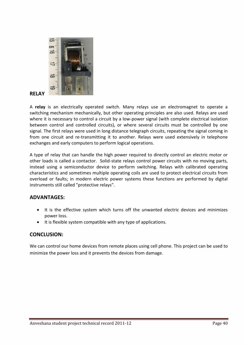
D TMF DECODER
Dual-tone multi-frequency signaling (DTMF) is used for telecommunication signaling over analog
telephone lines in the voice-frequency band between telephone handsets and other
communications devices and the switching center. The version of DTMF that is used in push-
button telephones for tone dialing is known as Touch-Tone.
KEYPAD:
The DTMF keypad is laid out in a 4×4 matrix, with each row representing a low frequency, and each column representing a high frequency. Pressing a single key (such as '1') will send a sinusoidal tone for each of the two frequencies (697 and 1209Hz). The original keypads had levers inside, so each button activated two contacts. The multiple tones are the reason for calling the system multi-frequency. These tones are then decoded by the switching center to determine which key was pressed.
DTMF keypad frequencies (with sound clips)
1209 Hz 1336 Hz 1477 Hz 1633 Hz
697 Hz 1 2 3 A
770 Hz 4 5 6 B
852 Hz 7 8 9 C
Anveshana student project technical record 2011-12 Page 40
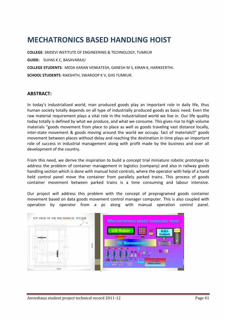
RELAY
A relay is an electrically operated switch. Many relays use an electromagnet to operate a switching mechanism mechanically, but other operating principles are also used. Relays are used where it is necessary to control a circuit by a low-power signal (with complete electrical isolation between control and controlled circuits), or where several circuits must be controlled by one signal. The first relays were used in long distance telegraph circuits, repeating the signal coming in from one circuit and re-transmitting it to another. Relays were used extensively in telephone exchanges and early computers to perform logical operations.
A type of relay that can handle the high power required to directly control an electric motor or other loads is called a contactor. Solid-state relays control power circuits with no moving parts, instead using a semiconductor device to perform switching. Relays with calibrated operating characteristics and sometimes multiple operating coils are used to protect electrical circuits from overload or faults; in modern electric power systems these functions are performed by digital instruments still called "protective relays".
ADVANTAGES:
It is the effective system which turns off the unwanted electric devices and minimizes power loss.
It is flexible system compatible with any type of applications.
CONCLUSION:
We can control our home devices from remote places using cell phone. This project can be used to
minimize the power loss and it prevents the devices from damage.
Anveshana student project technical record 2011-12 Page 41
MECHATRONICS BASED HANDLING HOIST
COLLEGE: SRIDEVI INSTITUTE OF ENGINEERING & TECHNOLOGY, TUMKUR
GUIDE: SUHAS K.C, BASAVARAJU
COLLEGE STUDENTS: MEDA KARAN VENKATESH, GANESH M S, KIRAN K, HARIKEERTHI.
SCHOOL STUDENTS: RAKSHITH, SWAROOP K V, GHS TUMKUR.
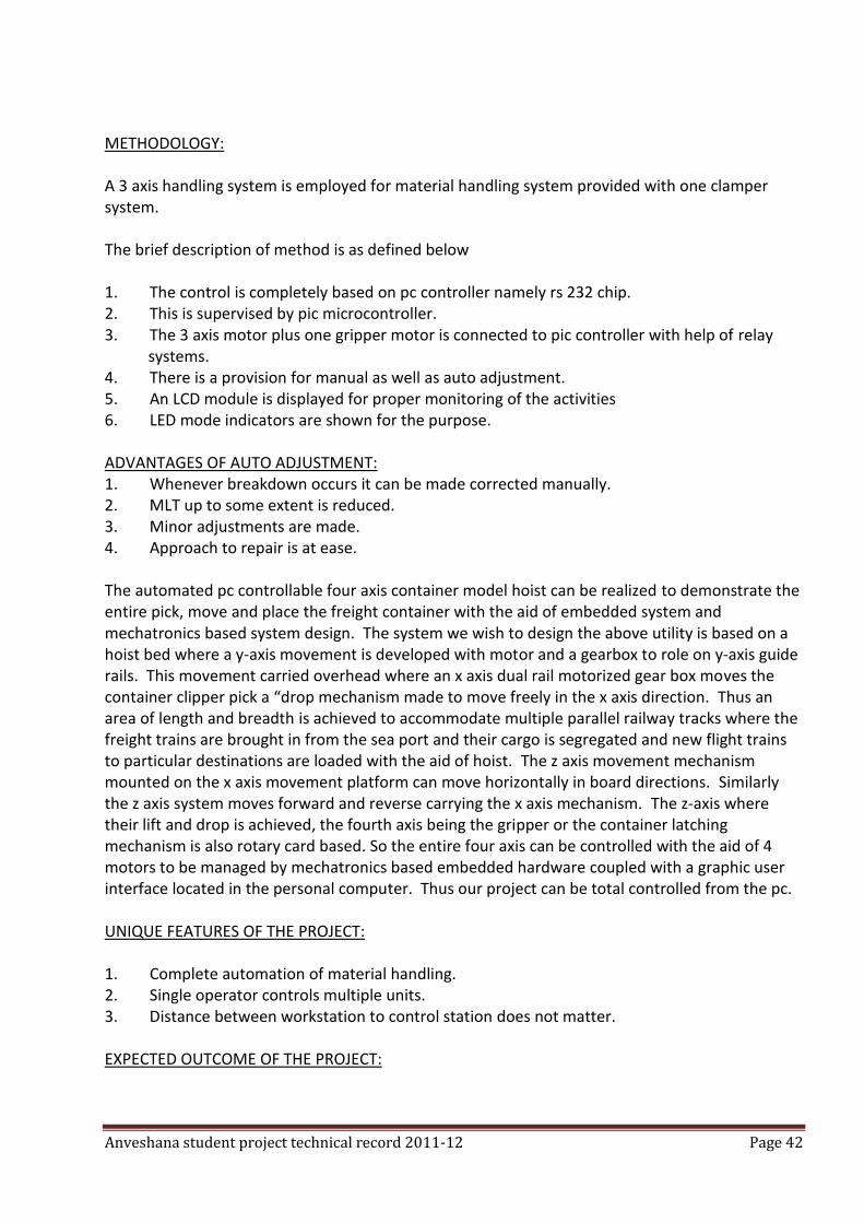
ABSTRACT:
In today’s industrialized world, man produced goods play an important role in daily life, thus human society totally depends on all type of industrially produced goods as basic need. Even the raw material requirement plays a vital role in the industrialized world we live in. Our life quality today totally is defined by what we produce, and what we consume. This gives rise to high volume materials “goods movement from place to place as well as goods traveling vast distance locally, inter-state movement & goods moving around the world we occupy. fact of materials€“ goods movement between places without delay and reaching the destination in time plays an important role of success in industrial management along with profit made by the business and over all development of the country. From this need, we derive the inspiration to build a concept trial miniature robotic prototype to address the problem of container management in logistics (company) and also in railway goods handling section which is done with manual hoist controls, where the operator with help of a hand held control panel move the container from parallely parked trains. This process of goods container movement between parked trains is a time consuming and labour intensive. Our project will address this problem with the concept of preprogramed goods container movement based on data goods movement control manager computer. This is also coupled with operation by operator from a pc along with manual operation control panel.
Anveshana student project technical record 2011-12 Page 42
METHODOLOGY: A 3 axis handling system is employed for material handling system provided with one clamper system. The brief description of method is as defined below 1. The control is completely based on pc controller namely rs 232 chip. 2. This is supervised by pic microcontroller. 3. The 3 axis motor plus one gripper motor is connected to pic controller with help of relay systems. 4. There is a provision for manual as well as auto adjustment. 5. An LCD module is displayed for proper monitoring of the activities 6. LED mode indicators are shown for the purpose. ADVANTAGES OF AUTO ADJUSTMENT: 1. Whenever breakdown occurs it can be made corrected manually. 2. MLT up to some extent is reduced. 3. Minor adjustments are made. 4. Approach to repair is at ease. The automated pc controllable four axis container model hoist can be realized to demonstrate the entire pick, move and place the freight container with the aid of embedded system and mechatronics based system design. The system we wish to design the above utility is based on a hoist bed where a y-axis movement is developed with motor and a gearbox to role on y-axis guide rails. This movement carried overhead where an x axis dual rail motorized gear box moves the container clipper pick a “drop mechanism made to move freely in the x axis direction. Thus an area of length and breadth is achieved to accommodate multiple parallel railway tracks where the freight trains are brought in from the sea port and their cargo is segregated and new flight trains to particular destinations are loaded with the aid of hoist. The z axis movement mechanism mounted on the x axis movement platform can move horizontally in board directions. Similarly the z axis system moves forward and reverse carrying the x axis mechanism. The z-axis where their lift and drop is achieved, the fourth axis being the gripper or the container latching mechanism is also rotary card based. So the entire four axis can be controlled with the aid of 4 motors to be managed by mechatronics based embedded hardware coupled with a graphic user interface located in the personal computer. Thus our project can be total controlled from the pc. UNIQUE FEATURES OF THE PROJECT: 1. Complete automation of material handling. 2. Single operator controls multiple units. 3. Distance between workstation to control station does not matter. EXPECTED OUTCOME OF THE PROJECT:

Anveshana student project technical record 2011-12 Page 43
1. Manual labour is replaced by the machine there by reducing the regular labour cost as well as output rate is improved.
2. The lead time for manufacture i.e., the time between the order acceptance and delivery is least, with automation.
3. Safety of both labour and product is achieved. 4. Reduces the inventory and wip ratio. 5. Increases the velocity of the job, since non-value added activities in the process are
reduced. 6. Material handling time can be reduced upto 55%-60% and hence handling cost reduced to
25%-30%
APPLICATION OF THE PROJECT: 1. Railway yard. 2. Mining places where the poisonous gases and men cannot enter. 3. Nuclear power plant to check the position of the moderators, electrodes & fuel rods. 4. Loading and unloading from ships. 5. Marine industries. 6. Good container management. 7. Material handling in heavy & small scale industries.
SUMMARY:
1. Complete automation of material handling.
2. Single operator controls multiple units.
3. Distance between workstation to control station does not matter.
INTELLIGENT INTENSIVE CARE UNIT
COLLEGE: KALPATARU INSTITUTE OF TECHNOLOGY, TIPTUR
GUIDE: SUHAS K.C, BASAVARAJU
COLLEGE STUDENTS: SHASHIDHAR P, SHRIKANTH S P
SCHOOL STUDENTS: RAMU, ARUN GHS HONNAVALLI
ABSTRACT:
Machines best replace humans when it comes to handling monotonous and tedious jobs that require little intelligence and lots of patience. When the same tedious work becomes essential for survival, comes in the
real importance of all the modern science and technology.
Anveshana student project technical record 2011-12 Page 44
The best example of the above fact is seen in an intensive care unit (ICU) where a continuous
monitoring of patients health is required; and negligence of the slightest degree may lead to
misfortune. Giving the same medicine twice by different visiting nurses or doctors, giving the
wrong medicine to the wrong patient, inability to take immediate decisions to tackle an
unexpected emergency due to the non-feasibility of a doctor sitting near the patient all the time
are some of the fatal shortcomings on the side of the caretakers.
Semi-intelligent devices measuring dynamic information-bearing body signals like the heartbeat and body temperature, monitoring the level of normalcy and real time streaming of relevant information to intelligent humans and to a database for quick and reliable reference along with a fool proof security system which allows only authorized persons to enter, conceptualizes an ICU that will set new standards in healthcare. Intelligent intensive care unit is an environment created to match the standard which the above
system is intended to achieve. The much-needed quick transfer of data and control signals
between the various system components has to be wireless to result in an amicable and easily
scalable environment. Hence Bluetooth turns out to be a natural solution to the problem.
SUMMARY
Through this, it is shown how Bluetooth can be used to manage as critical applications such as an
ICU. it is these in situations, where Bluetooth stands out as a necessity, not as a luxury, that the
real power of Bluetooth is really exploited. We sincerely hope that a commercial implementation
of our project would make a hospital user-friendlier place.
In fact, the very broad foundations of our project, namely, to use a person involuntary action,
which take place all the time, to bring comfort and uplift his or other people life can be used in
many different ways. One immediate application that we could think of was a home application, in
which devices such as television, air-conditioner, music system, etc. would identify the user and
then play themselves according to his preferences set. Definitely, proximity detection plays a very
big role in such an application, as in ours too.
After having gone through the entire development of this concept, we came across some really
nice ideas. Some improvements possible we thought could be very useful were:
(i) A proper track of the RSSI of a user cold kept so as determining his intentions more
completely (not only proximity detection, but intention detection).
(ii) additional functionality could be built into the dynamic patient monitor to let a patient
in distress call somebody for help through the ICU security an monitoring system
Anveshana student project technical record 2011-12 Page 45
LINE FOLLOWER COLLEGE: M S RAMIAH INSTITUTE OF TECHNOLOGY, BANGALORE
GUIDE:
COLLEGE STUDENTS: ASHISH K K, MANU KUMAR S
SCHOOL STUDENTS:
ABSTRACT
The idea is to develop a basic line follower robot. The concept is simple and universally tried and tested. However, it serves a major point to high-school students. The whole idea of Engineering is to develop application oriented end products, and through a line follower, various aspects like programming, robot mechanics, and the idea of a micro-controller can be introduced to the high-school students. The basic idea, as of now, is to develop a primitive robot, and have a controller, through which the wheels are controlled for movement. Additionally, a light-sensing device can be used to identify a particular line/strip, and make the robot move, only if a particular condition is satisfied. Here, the objective is to follow a line.
SUMMARY
To develop a practical application oriented line following robot, and in the process, highlight the
presence of engineering aspects in everyday life and innovation.
ALCOHOL DETECTION AND DRIVER VIGILANCE COLLEGE: SAMBHRAM INSTITUTE OF TECHNOLOGY, YELAHANKA
GUIDE: PROF.P. ANU THOMAS
COLLEGE STUDENTS: CHARUSMITHA V DESHPANDE, LALITHA S
SCHOOL STUDENTS: HEMACHANDRA DALVI S, ANJALI SINGH, SOUHARDA SCHOOL, YELAHANKA
ABSTRACT
The aim of this project is to prevent the road accidents caused by drunken/sleeping drivers. Here we are capturing a number of images of the driver which are analysed using image processing techniques. Based on this analysis of driver’s facial image and eye position, the module will give an alert message to the driver. If the driver is judged to be drunk or sleeping from his images, then the module will shut down the engine of the vehicle, thereby not allowing the driver to start the vehicle. This project can be effectively modified to pass information to police control room or other safety
Anveshana student project technical record 2011-12 Page 46
authorities and help them in reducing the number of road accidents. The total cost of the project is Rs.6000, which can be reduced to Rs.2500 by using a central server for communication.
BIBLIOGRAPHY: 1) IEEE transactions on speech & audio processing, vol.7, Jan.1999. 2) IEEE transaction on power delivery, July 1996. 3) A vector quantisation approach to speaker recognition, AT & T technical journal, vol.66, April 1987. 4) www.bb-elec.com 5) www.lvr.com
SUMMARY:
This project is automatic drunken/sleeping driver detection in real time to prevent road accidents.
It detects the alertness of the driver by analysing his facial image, eye position and alcohol content
in the air.
TABLET (TELEMETRIC ANIMAL BODY LENGTH ESTIMATION TECHNIQUE) COLLEGE: VIDYA VIKAS INSTITUTE OFSCIENCE & TECHNOLOGY, MYSORE
GUIDE: SUHAS, G NARAYANASWAMY
COLLEGE STUDENTS: ABHISHEK R, SRINATH K V, KOUSHIK N AITHAL, ASHUTOSH R
SCHOOL STUDENTS:
ABSTRACT:
To determine body length of animals at motion An image of animal is captured using high definition camera where parallel laser beam are taken as reference. Further using caed tools, length of animal are determined. In many bio-medical applications it becomes necessary to find the length of the animals. But it is difficult when animals are at motion and when they are ferocious. There is no technique available to do this as of now. Our method is one such tool. Two lasers are mounted on t-shaped bar, one foot apart where a HD camera is placed in between them, laser beam are incident on an animal whose body length is to be found out. Image of it is captured. Using caed tools, a reference line is drawn to the image. Using ratio and proportion, animal length is found.
Anveshana student project technical record 2011-12 Page 47
Using this technique an image of a cow which was 20 feet far was captured. The image was interfaced to software. The reference distance of lasers appeared to be 1cm apart while a reference line of animal body appeared to be 6.5cm in length. Therefore the length of cow was determined as 6.6feet. Length of ferocious animals and animals which are at motion can be determined easily from a far and safe distance.
SUMMARY:
It is sometimes impossible to catch the ferocious animal/moving animal and to determine its
length using measuring tape. Hence using this tablet (telemetric animal body length estimation
technique) approximate length of the animal from a far and safe distance can be determined.
BORE WELL WATER LEVEL MONITORING AND MOTOR PROTECTION SYSTEM USING GSM MODEM
COLLEGE: SIDDAGANGA INSTITUTE OF TECHNOLOGY, TUMKUR
GUIDE: Dr. K VISHWANATH
COLLEGE STUDENTS: GURUNATH REDDY M, SRIHARSHA K
SCHOOL STUDENTS:
INTRODUCTION: "India is an agriculture based country with farming and related activities constituting to a huge chunk of the GDP and employment. Even though the government has several initiatives for helping the farmers there isn’t much the adoption of technology in that has happened over the years. Farming has been slow due to the infrastructure, learning curve and cost involved. With technological advancements, the mobile phone has become a multifunctional device. Its applications have gone beyond voice and data communication. In this document i would be describing design on “bore well water level monitoring and motor protection system using GSM modem”.
OBJECTIVE: Using mobile communication network (GSM) we can intimate the farmer about the depth of water level in the bore. If the water level in the bore well falls below a certain value then there is a chance of motor getting air locked or even tends to burnt off. To avoid such incidents this application is useful. The ground water level in India is depleting day by day. It is very difficult to predict the water level in the ground. So many motors get burnt or air locked due to this problem. The power supply is also very erratic in our country. It is very difficult for the farmers to get into
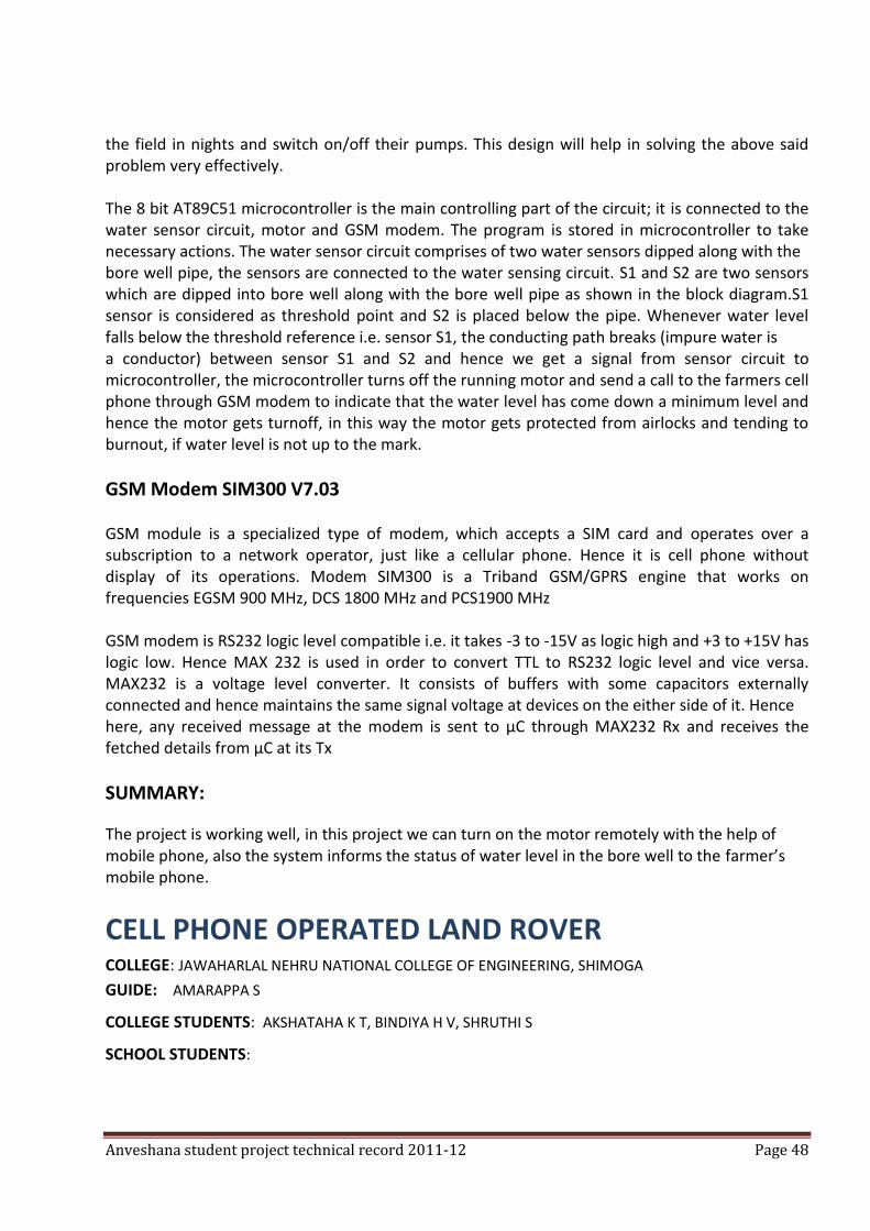
Anveshana student project technical record 2011-12 Page 48
the field in nights and switch on/off their pumps. This design will help in solving the above said problem very effectively. The 8 bit AT89C51 microcontroller is the main controlling part of the circuit; it is connected to the water sensor circuit, motor and GSM modem. The program is stored in microcontroller to take necessary actions. The water sensor circuit comprises of two water sensors dipped along with the bore well pipe, the sensors are connected to the water sensing circuit. S1 and S2 are two sensors which are dipped into bore well along with the bore well pipe as shown in the block diagram.S1 sensor is considered as threshold point and S2 is placed below the pipe. Whenever water level falls below the threshold reference i.e. sensor S1, the conducting path breaks (impure water is a conductor) between sensor S1 and S2 and hence we get a signal from sensor circuit to microcontroller, the microcontroller turns off the running motor and send a call to the farmers cell phone through GSM modem to indicate that the water level has come down a minimum level and hence the motor gets turnoff, in this way the motor gets protected from airlocks and tending to burnout, if water level is not up to the mark.
GSM Modem SIM300 V7.03 GSM module is a specialized type of modem, which accepts a SIM card and operates over a subscription to a network operator, just like a cellular phone. Hence it is cell phone without display of its operations. Modem SIM300 is a Triband GSM/GPRS engine that works on frequencies EGSM 900 MHz, DCS 1800 MHz and PCS1900 MHz GSM modem is RS232 logic level compatible i.e. it takes -3 to -15V as logic high and +3 to +15V has logic low. Hence MAX 232 is used in order to convert TTL to RS232 logic level and vice versa. MAX232 is a voltage level converter. It consists of buffers with some capacitors externally connected and hence maintains the same signal voltage at devices on the either side of it. Hence here, any received message at the modem is sent to μC through MAX232 Rx and receives the fetched details from μC at its Tx
SUMMARY:
The project is working well, in this project we can turn on the motor remotely with the help of mobile phone, also the system informs the status of water level in the bore well to the farmer’s mobile phone.
CELL PHONE OPERATED LAND ROVER COLLEGE: JAWAHARLAL NEHRU NATIONAL COLLEGE OF ENGINEERING, SHIMOGA
GUIDE: AMARAPPA S
COLLEGE STUDENTS: AKSHATAHA K T, BINDIYA H V, SHRUTHI S
SCHOOL STUDENTS:
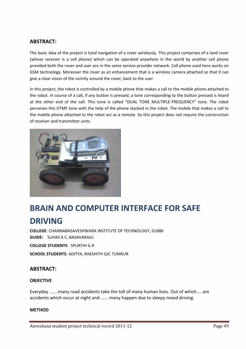
Anveshana student project technical record 2011-12 Page 49
ABSTRACT:
The basic idea of the project is total navigation of a rover wirelessly. This project comprises of a land rover
(whose receiver is a cell phone) which can be operated anywhere in the world by another cell phone
provided both the rover and user are in the same service provider network. Cell phone used here works on
GSM technology. Moreover the rover as an enhancement that is a wireless camera attached so that it can
give a clear vision of the vicinity around the rover, back to the user.
In this project, the robot is controlled by a mobile phone that makes a call to the mobile phone attached to
the robot. In course of a call, if any button is pressed, a tone corresponding to the button pressed is heard
at the other end of the call. This tone is called “DUAL TONE MULTIPLE-FREQUENCY” tone. The robot
perceives this DTMF tone with the help of the phone stacked in the robot. The mobile that makes a call to
the mobile phone attached to the robot act as a remote. So this project does not require the construction
of receiver and transmitter units.
BRAIN AND COMPUTER INTERFACE FOR SAFE
DRIVING COLLEGE: CHANNABASAVESHWARA INSTITUTE OF TECHNOLOGY, GUBBI
GUIDE: SUHAS K.C, BASAVARAJU
COLLEGE STUDENTS: SPURTHI G.R
SCHOOL STUDENTS: ADITYA, RAKSHITH GJC TUMKUR
ABSTRACT:
OBJECTIVE
Everyday .......many road accidents take the toll of many human lives. Out of which.... are accidents which occur at night and ...... many happen due to sleepy mood driving. METHOD
Anveshana student project technical record 2011-12 Page 50
By analysing the EGG signals of the brain of the driver and warning them by alarm. EXPERIMENT The common structure of a brain computer interface is as following: 1) Signal acquisition: the eeg signals are obtained from the brain through invasive or non-invasive methods (for example, electrodes). After, the signal is amplified and sampled. 2) Signal pre-processing: once the signals are acquired, it is necessary to clean them. 3) Signal classification: once the signals are cleaned, the will be processed and classified to find out which kind of mental task the subject is performing. 4) Computer interaction: once the signals are classified, they will be used by an appropriate algorithm for the development of a certain application. CONCLUSION Road accidents at night times can be reduced to a large extent.
HOME AUTOMATION SYSTEM COLLEGE: PES INSTITUTE OF TECHNOLOGY, BANGALORE
GUIDE: NONE
COLLEGE STUDENTS: DEEPAK KARKI, ANANYA, ABHISHEK JAIN
SCHOOL STUDENTS: SIDDARTH, VARUN BALAJI, NATIONAL PUBLIC SCHOOL HSR LAYOUT
OBJECTIVE
The aim of the project, as the name suggests is to control all (or at least most) of the electronic devices remotely (sitting anywhere in the world) just through your laptop or your smart phone. today's automation systems are extremely costly and are hence limited to the rich and first class of the society; our aim is to build a cheap version of the automation system so that the working middle class who forms the bulk of the society can better their lifestyle. Not only that well focused and smart use of these systems can help us save energy by switching off forgotten devices any time anywhere.
METHODS
The project can be divided basically into two halves, the base module and the controller module. The base module consists of a computer with parallel ports. We know that parallel ports can be controlled using software program's [written in visual basic, c etc.]. Hence our first step was to write a program to control the parallel ports. In turn parallel ports can be used to control electronic components like LED's (i.e. digital control), we have extended this basic idea in our own manner, to control household devices using our program. For this extension to be possible, we made the following modifications: from the parallel ports we get a +5v output, this is amplified to

Anveshana student project technical record 2011-12 Page 51
+12v using an amplifier relay board, the relays of the board are connected to a spike buster (power strip) with a 220v input. All devices to be controlled are plugged into the spike buster, which is in turn controlled by the parallel port based on our program. Hence we see that all a-c devices in the home can be controlled using the base module, as far as they are plugged into the spike buster. But now the question arises that how to control the devices remotely? This can be done using our controller module, which happens to be just a mobile or a laptop. The controller module links to the base module over the internet and accesses the software program that controls the parallel ports of the base. Hence remote control of the objects is complete.
CONCLUSION So the project link up is as follows: controller to base module to program to the parallel ports to amplifier relay to spike buster to devices.
BIBLIOGRAPHY
The project has come up as a solution to problems faced by today's techies, bachelors and the travelling class. We extended all existing ideas such as control of LED's and remote desktop control to give it a more application based perspective. We have integrated random ideas in the most unusual way to achieve our goal of cheap and efficient version of the home automation systems. Being our own original modification to existing ideas there is no particular source for our project.
SUMMARY:
The key highlights of our project are: 1. The cost: extremely cheap, considering that the people who require it already have a computer at home and a mobile in hand. The rest of the system can be setup for not more than Rs.2000/- compared to the ones costing 10 lacks in the market. 2. The simplicity: the project is really simple in design and concept. But yet the idea is most original and innovative. 3. Application: unlike readymade systems, once the person has the design in hand he can customize it to his liking. 4. DIY: the simplicity makes it a do it yourself kind of project where people can make their own at home. This is really good as it can help save electricity. not only that, it will encourage travellers to keep plants and even pets like fish at house, whose water and food requirements can be taken care by automation systems.
Anveshana student project technical record 2011-12 Page 52
CONTROLLER FREE GAMING USING DEPTH SENSOR
COLLEGE: B.V.BHOOMAREDDI COLLEGE OF ENGG & TECH, HUBLI. GUIDE: DR. UMA MUDENAGUDI, COLLEGE STUDENTS: GIRISH SHIRIGANNAVAR,PAVAN SHINDE,PRAMOD RAMDURG &AKSHAY HARTI SCHOOL STUDENTS: ANAND M ULLAGADDI, RAMALINGESHWARA HIGH SCHOOL & AMRUTH B MUSARI
,CHETHAN PUBLIC SCHOOL, HUBLI.
ABSTRACT
In this project, We have addressed the problem of interactive gaming using the depth sensor like KINECT. KINECT is a 3d depth sensor which gives the depth information of the scene with the help of its infrared ray projector and infrared camera, because of which the actions of user in three dimensions are possible to detect. KINECT sensor has got applications in human computer interaction, gaming field, natural user interfaces, and health care etc. We acknowledge a naturalistic way of controlling a game which has made us to think about a new way of communicating with computers, unlike the traditional methods like keyboard, mouse, or joystick. Here we control the virtual world as we do in the physical world and the user feels as if he is inside the game i.e. in virtual gaming environment. KINECT sensor acts as the input device. The data of a user is taken from the sensor to get feature (key) points on the body of the user, which in turn constitute the skeleton, which is used to get avatar (character in the virtual world) into the system. The 3d motion of the avatar is analysed to determine the gestures that user uses to control the game. We use different open source software tools like OPENGL to render graphics, OPENNI for sensor data processing, cinema4d to create 3d models and gaming environment, OPENAL for sound effects and MS visual C++ ide. We demonstrate this new way of controlling through the soccer penalty shootout game and a car test driving game.
SUMMARY
We have demonstrated a new way of gaming by designing a soccer penalty shootout game, ball
game and a car test drive game.

Anveshana student project technical record 2011-12 Page 53
BIO ACTIVE COMPONENTS OF RHIZOPHORA SP
COLLEGE: SRIDEVI INSTITUTE OF ENGINEERING & TECHNOLOGY, TUMKUR GUIDE: DR GOVIDAPPA M, MS SHWETA V. BHAT COLLEGE STUDENTS: ANU M.S & BAVITHA SCHOOL STUDENTS: SOMYASHREE K.C & VARSHINI.N, SHRIDEVI VIDYA MANDIRA, TUMKUR.
ABSTRACT
Rhozophorine is an alkoloid. The present investigation is aim to isolate an alkaliod. Rhizophorine from two species of Rhizophora we will use different parts for isolation of alkoliod using different methods. partial purification will be done by different method. Primary phytochemical analysis will be done for alll plant extracts. Biophysical characterisation will be done for target alkaloid to know their structure by HPLC, GC, NMR, X-Ray Crystalography etc. The alkaloid will be evaluated against cancer cell lines to known more molecular mechanism by various methods such as cytotoxicity, DNA ladder, tunnel method etc. The literature survey showing that revials that their no works of isolation, characterisation, and anticancer activity of rhizophorine alkliods. The present will prove the mechanism of anticancer activity of alkaliod from rhizophora sp.
SUMMARY
We identify most potent anticancer alkaloid from two different species of rhizophara that can be used as another alternative drug for cancer treatment. All natural products doesn\'t have any side effects.
INDUCTION OF SYGMATIC RESISTANCE OF OKRA WITH OXYSPORUM WITH BIOCIDES COLLEGE: SRIDEVI INSTITUTE OF ENGINEERING & TECHNOLOGY, TUMKUR GUIDE: DR.M.GOVINDAPPA COLLEGE STUDENTS: SANGEETHA M,SANMATHI K,VINAY G P &FAREED CHOWDARY SCHOOL STUDENTS: VIDYASHREE H P & DEEKSHITHA R
ABSTRACT
Okra wilt is sever disease in tumkur district of karnataka and it cause yield loss. Present investigation is aim to find out a suitable remedial measure to control the disease with bio control agent environment. We will isolate different types of soil of okra in tumkur district we will screen all bio control agent against target, pathogen fusarium oxysporum in invitro condition promisied bio control agent will try against the target disease under green house conditions to know the mechanism of disease control by bio-control agent we analyse the induction of resistance in the host plant by knowing the defence enzyme concentration, it will proves how the bio control agent

Anveshana student project technical record 2011-12 Page 54
suppress the pathogen establishment in contracting the disease.
SUMMARY
Okra wilt is severe disease in tumkur dist of Karnataka and it cause yield loss.
Our aim is to find out a suitable remedial measure to control the disease with bio control agent.
PORTABLE SPECTROPHOTOMETER FOR ANALYSING THE PURITY OF DRINKING WATER USING DYE REDUCTION TEST (FOR DETERMINATION OF TOTAL MICROBIAL CONCENTRATION) COLLEGE: SIR M VISVESVARAYA INSTITUTE OF TECHNOLOGY GUIDE: DR. H G NAGENDRA, PROF AND HEAD, DEPT OF BIOTECHNOLOGY COLLEGE STUDENTS: NITISH SATHYANARAYANAN, JANANI C, SHREYAS UDUPI & ABHISHEK S V SCHOOL STUDENTS:
ABSTRACT
Waterborne diseases are caused by pathogenic microorganisms that are most commonly transmitted in contaminated fresh water used for drinking and cooking. According to the world health organization, it accounts for an estimated 4.1% of the total daly (disability-adjusted life year) global burden of disease, causing about 1.8 million human deaths annually. The world health organization estimates that 88% of that burden is attributable to unsafe water supply, sanitation and hygiene, and it mainly affects children in developing countries. Though there are various instruments and protocols available for checking the purity of drinking
water, there is a greater need to develop a cost effective, accurate, and portable (which works on
battery power) and a device which could be used by the common man to assess the quality of
drinking water on a daily basis.
METHODS
The methylene blue reduction test (MBRT) or resazurin dye reduction test is based on the fact that the colour is imparted to water upon addition of a the dye the removal of the oxygen from water and the formation of reducing substances during bacterial metabolism causes the colour to disappear. The disappearance of the colour is dependent of the on number of microorganisms. The agencies responsible for the oxygen consumption are the bacteria. Though certain species of bacteria have considerably more influence than others, it is generally assumed that the greater

Anveshana student project technical record 2011-12 Page 55
the number of bacteria, the quicker will the oxygen be consumed, and in turn the sooner will the colour disappear. Thus, the time of reduction is taken as a measure of the number of organisms in the given sample, although actually it is likely that it is more truly a measure of the total metabolic reactions proceeding at the cell surface of the bacteria. The quantification of the colour can be done through measuring optical absorbance of the dye at specific wavelength with the help of a coloromerter or spectrophotometer to assess the concentration of microbes indirectly. The biomass estimation (without dye) of microbes can be done at 560 nm and the optimal absorbance of methylene blue is between 609 to 660 nm while resazurin is between 570 to 600 nm. The spectrophotometer can be used to determine the absorbance. Though there are numerous portable high precision devices available from reputed brands like konica-minolta, these devices are often expensive due to various facilities it offers. Thus, there is a need to develop a cost effective portable spectrophotometer.
PRINCIPAL, CONSTRUCTION AND WORKING OF A PORTABLE SPECTROPHOTOMETER
PRINCIPLE
The amount of light passing through the medium is obtained by beer-lamberts law.
The law states that there is a logarithmic dependence between the transmission (or
transmissivity), t, of light through a substance and the product of the absorption coefficient of the
substance, î±, and the distance the light travels through the material (i.e., the path length),
The transmission (or transmissivity) is expressed in terms of an absorbance. A simplified version
can be given by the equation. Hence we can calculate the absorbance if we can find the
absorption coefficient of the substance (î±), and the distance the light travels through the material
( â ) .
The distance travelled through the medium ( â ) can be designed as required, absorption
coefficient of the substance (î±) can be calculated or obtained by the using microcontroller.
CONSTRUCTION
The basic block diagram is as shown in the figure. Infrared LEDs are used for the detection; it is
made to pass through the test sample. IF photo diode accepts the transmitted light and converts it
into equivalent electrical signal, this is given to the amplifier to amplify the signal and this signal is
measured using measuring instruments.
The measurement can be done using a voltmeter or a better method is to use microcontroller to
take the values and calculate the absorption value as obtained in a standard spectrophotometer.
Anveshana student project technical record 2011-12 Page 56
WORKING
The value of î± (stated in the equation) is not calculated but it is compared to a standard value
which is obtained under an actual spectrophotometer and stored in the microcontroller.
1. Firstly the voltmeter is connected as the measuring device, several numbers of samples are
taken and they are tested using a standard spectrophotometer available in the labs. These
samples are also measured using this device and the corresponding voltmeter reading is noted
down in a tabular column. The number of samples determine the accuracy of the device, hence
more number of samples help in increasing the accuracy.
2. The experimentally determined values are fed to the microcontroller and stored in the
memory, this information is later used to compare the obtained value with the standard value and
display the result using a LCD or LED display.
3. The voltmeter is replaced by the microcontroller and the sample is placed in the test area.
The reading obtained at the input terminal of the microcontroller is compared with the standard
value stored in the memory to obtain the value of î±.
HYPOTHESIS
The dye reduction test and subsequent determination of spectral absorbance gives a gross
concentration of the concentration of microorganisms, which can be used to assess the purity of
drinking water on a daily basis even by a common man.
ADVANTAGES
The kit also has advantages like 1. Cost effective - a handmade device expected to cost between 300-500 INR but the cost can
be considerably brought down by automation. 2. Portable which generally uses 9v dawns from battery 3. Less weight in the size of a pen 4. Use of micro controllers increases the accuracy. 5. Ease of operation.
LIMITATIONS
The methodology cannot distinguish between different types of pathogens and also un harmful
microorganisms.

Anveshana student project technical record 2011-12 Page 57
BIBLIOGRAPHY
1. The reduction of methylene blue in milk and influence of light hugh robinson biochem j. 1930; 24(3): 579–584 2. Application of methylene blue dye reduction test, (MBRT) to determine growth and death rates of microorganisms, Subir Kumar Nandy and K. V. Venkatesh*, African journal of microbiology research vol. 4(1) pp. 061-070 January, 2010 3. The methylene blue reduction test: evaluation of a screening method for glucose-6-phosphate dehydrogenase deficiencyam J trop med HYG November 1974 23:1197-1202 4. Quantification of metabolically active biomass using methylene blue dye reduction test (MBRT): measurement of CFU, in about 200 s, Prashant Bapat, Subir Kumar Nandy Pramod Wangikar, K.V.
Venkatesh,http://dspace.library.iitb.ac.in/jspui/bitstream/10054/936/1/4932.pdf
5. http://www.foodsci.uoguelph.ca/dairyedu/resazurin.html 6. Temperature compensated tests for raw milk supplies ii. The methylene blue test, l. f. l. clegg, article first published online: 11 mar 2008, volume 12, issue 2, pages 79–86, November 1949
SUMMARY
This methodology is a cost effective, accurate and can be used by a common man for
determination of purity of drinking water.
DEVELOPMENT OF SOFTWARE APPLICATION THROUGH
ARCHITECTURAL CORRECTIONS FOR ON-LINE
APPOINTMENT OF DOCTORS TO PROVIDE EFFECTIVE
HEALTHCARE TO RURAL POPULATION OF TUMKUR
DISTRICT.
COLLEGE: SHRIDEVI INSTITUTE OF ENGINEERING AND TECHNOLOGY, TUMKUR.
GUIDE: SRI. LOKESH.S & DR.G.PANDURANGA MURTHY COLLEGE STUDENTS: SAI PRASAD.B, VARUN.N, LINGRAJ KRISHNA .S.M & MANNAN JOHAR SCHOOL STUDENTS: PREETHAM .M & MANNAN JOHAR.
ABSTRACT
1. To develop appropriate software application based on the database obtained during interaction programs at identified regions of tumkur district.
2. To evaluate the existing software for their performance towards fulfilment of needs for people of project area.
3. To reduce the delay of getting appointment with the doctors and better service. a) Complete information regarding the patient is maintained.
Anveshana student project technical record 2011-12 Page 58
b) Complete information regarding the appointment is maintained. c) Complete awareness of the patient to the doctor.
4. To make rural people aware of medical services provided by the government more easily.
5. To know all health care centres providing services properly by the government as per the standard especially to give rural people more flexible way to get appointment with doctors.
6. To evaluate modified software application for its efficiency towards providing effective health care facilities and information through this technology.
7. The modified â software architecture will be recommended for implementation for other regions of the state/country.
SUMMARY An efficient, appropriate and flexible software application along with ease of use tools, more
flexibility will be developed for providing effective health care facilities through this modified/
revised technology for rural people (especially, women and children) to get doctor’s appointment
in all health care centres.
a) All the information regarding the services provided health care centers are available to rural
people.
b) Rural people can easily get appointment with doctors using simple sms or telephone call.
c) Rural people can get immediate service in case of emergency.
d) To reduce the time delays to get appointment with the doctors besides, this modified software
technology will definitely help to save lives of the patients in villages by providing prior
information to doctors about the patient, so that the doctor is available in time to serve the
society.
ADAPTIVE LIGHTING SYSTEM FOR AUTOMOBILES
COLLEGE: ANJUMAN INSTITUTE OF TECHNOLOGY AND MANAGEMENT, BHATKAL.
GUIDE: PROF. ANIL KADLE.
COLLEGE STUDENTS: THAMEEMUL RAHMAN.M & ABDUL AZEEZ.
SCHOOL STUDENTS: AHAMAD DAYAB KASIMJI & MOHAMMAD MUFIZ ANJUMAN SCHOOL.
ABSTRACT
Adaptive lighting system for automobiles needs no manual operation of switching high beam and
low beam when there is vehicle coming from front at night. It detects itself whether there is a light
from front coming vehicle or not. Do the switching operation automatically. When there is high
Anveshana student project technical record 2011-12 Page 59
beam from front coming vehicle, it automatically switches to the low beam and when the vehicle
passes it automatically switch back to high beam. The sensitiveness of the adaptive lighting system
depends upon the sensor used.
In our project we have used four led for indication/representing the high beam and low beam. The
off condition of led represents the high beam; on condition of led represent the low beam.
COMPONENTS
1. LDR
2. RESISTOR
3. ZENER DIODE
4. LED
5. RELAY
6. HEADLIGHT BULB
7. ATMEGA8 MICROCONTROLLER
8. MICROCONTROLLER KIT
PRINCIPLE OF OPERATION (UNDER OPPOSITE LIGHT)
LDR senses the opposite vehicles light in the following condition.
In high beam condition: the vehicle headlight flashes two times. The vehicle headlight is
made to low beam.
In low beam condition: the vehicle headlight keeps in low beam itself.
In dark condition: the vehicle headlight is now made to high beam.
TEST CONDITION OF ADC
FULL DARK:
~ VOLTAGE 4.89 01 VOLTAGE 1000.494
LOW BEAM:
~ VOLTAGE 3.9 01 VOLTAGE 797.94
HIGH BEAM:
~ VOLTAGE 2.5 01 VOLTAGE 511.5
ADVANTAGES
Anveshana student project technical record 2011-12 Page 60
High reliable good performance
Less expensive
Low power consumption
Safe driving
Provide good vision for vehicle drivers.
SUMMARY
In the modern world vehicles are coming with well-tuned, but even driving at night time is difficult because of low vision due to the opposite vehicle headlight. So the adaptive lighting system will be efficient for vehicle. And we can expect a good vision also due to this adaptive lighting system.
ZIGBEE BASED REMOTE MAITENANCE SYSTEM
COLLEGE: PES INSTITUTE OF TECHNOLOGY & MANAGEMENT SHIVAMOGGA
GUIDE: Mr. SHIVUKUMAR B.E., M.TECH
COLLEGE STUDENTS: KIRAN KUMAR D V,RANGANATH B S, CHETHAN BASAVRAJ H G & SRIDHAR P G
SCHOOL STUDENTS: KEERTHI KUMAR D V & ABHISHEK
ABSTRACT
In this present work, a substation is automated using GSM technology. Here an electric circuit
model is designed to detect critical conditions in substation such as under voltage, over voltage,
short circuit in the receiving side of the substation transformer and also temperature rise in the
winding of substation transformer. An arrangement is also made to send message to an
authenticated person by using GSM technology. When above said conditions are detected.
The critical model consists of two bulbs which are considered as two substation transformer. A
microcontroller is used to detect critical conditions and GSM modem is connected to
microcontroller for communicating with authenticated person.
INTRODUCTION
A substation is a part of an electrical generation, transmission, and distribution system, where
voltage is transformed from high to low, or the reverse and power is transformed without altering
its frequency. Electric power may flow through several substations between generating plant and
consumer, and may be changed in voltage in several steps.
A substation that has a step-up transformer increases the voltage while decreasing the current,
while a step-down transformer decreases the voltage while increasing the current for domestic
and commercial distribution. The word substation comes from the days before the distribution
Anveshana student project technical record 2011-12 Page 61
system became a grid. The first substations were connected to only one power station where the
generators were housed, and were subsidiaries of that power station.
Automation is the use of control systems and information technologies to reduce the need for
human work in the production of goods and services. In the scope of industrialization, automation
is a step beyond mechanization. Whereas mechanization provided human operators with
machinery to assist them with the muscular requirements of work, automation greatly decreases
the need for human sensory and mental requirements as well. Automation plays an increasingly
important role in the world economy and in daily experience.
Monitoring has generally been applied to specific and individuals pieces of substation equipment
rather than as complete substation monitoring systems. This document and the references
attempt to show a greater benefit from using a value based, risk management logic to select
monitoring appropriate for the specific circumstances and based on sound engineering and
economic judgment. Principles described can be used for the selection of monitoring for
components or equipment on power systems as well as in numerous other situations.
This contribution shows how the link between failures causes and required monitoring can be
developed. It shows how the risks associated with equipment functional failure can be quantified
and how monitoring can be shown to be of economic value if applied appropriately. Monitoring
can be used for many purposes. The most obvious is to determine the condition of the equipment.
Recognize that monitoring can take many forms including manual inspections; continuous
monitoring with a change in status/condition, periodic automated monitoring.
Monitoring should be applied when a cost/benefit value results from its use over alternatives
without monitoring. Monitoring can provide benefits in at least the following areas, each of which
should be considered in the evaluation. Inclusion of all existing visible or intangible costs and all
expected benefits allows for a more accurate assessment of the value of monitoring.
It is useful to monitor the voltage, current & temperature from respective suitable transducers
from various points. The analogy signals received/generated are then fed to the ADC unit filtering
and signal conversion. The data received is digitized and the information about critical conditions
such as under voltage, over voltage, short circuit and temperature should be sent to the preferred
person from the GSM. In these ways the proposed substation monitoring system prove helpful to
monitor & safeguard the electrical systems.
Moreover this is equipped with under voltage, over voltage & temperature sensors. So when ever
these conditions are detected, it automatically terminates the power to the output. Hence
protecting the load is also equipped with fine/temp detectors/hence protecting the expensive
power transistors.
In the present work, a substation is automated using GSM technology. Here an electric circuit
model is designed to detect critical conditions in the substation such as under voltage, over
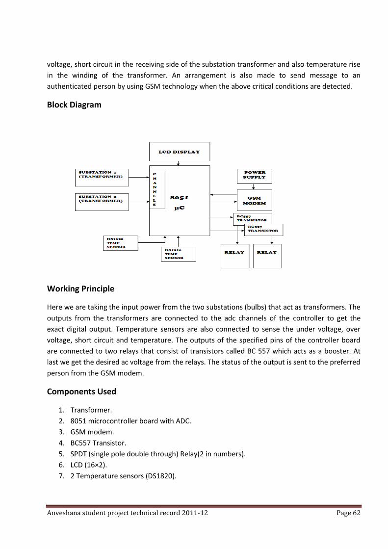
Anveshana student project technical record 2011-12 Page 62
voltage, short circuit in the receiving side of the substation transformer and also temperature rise
in the winding of the transformer. An arrangement is also made to send message to an
authenticated person by using GSM technology when the above critical conditions are detected.
Block Diagram
Working Principle
Here we are taking the input power from the two substations (bulbs) that act as transformers. The
outputs from the transformers are connected to the adc channels of the controller to get the
exact digital output. Temperature sensors are also connected to sense the under voltage, over
voltage, short circuit and temperature. The outputs of the specified pins of the controller board
are connected to two relays that consist of transistors called BC 557 which acts as a booster. At
last we get the desired ac voltage from the relays. The status of the output is sent to the preferred
person from the GSM modem.
Components Used
1. Transformer.
2. 8051 microcontroller board with ADC.
3. GSM modem.
4. BC557 Transistor.
5. SPDT (single pole double through) Relay(2 in numbers).
6. LCD (16×2).
7. 2 Temperature sensors (DS1820).
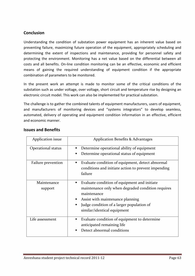
Anveshana student project technical record 2011-12 Page 63
Conclusion
Understanding the condition of substation power equipment has an inherent value based on
preventing failure, maximizing future operation of the equipment, appropriately scheduling and
determining the extent of inspections and maintenance, providing for personnel safety and
protecting the environment. Monitoring has a net value based on the differential between all
costs and all benefits. On-line condition monitoring can be an effective, economic and efficient
means of gaining the required understanding of equipment condition if the appropriate
combination of parameters to be monitored.
In the present work an attempt is made to monitor some of the critical conditions of the
substation such as under voltage, over voltage, short circuit and temperature rise by designing an
electronic circuit model. This work can also be implemented for practical substation.
The challenge is to gather the combined talents of equipment manufacturers, users of equipment,
and manufacturers of monitoring devices and “systems integrators” to develop seamless,
automated, delivery of operating and equipment condition information in an effective, efficient
and economic manner.
Issues and Benefits
Application issue Application Benefits & Advantages
Operational status Determine operational ability of equipment
Determine operational status of equipment
Failure prevention Evaluate condition of equipment, detect abnormal
conditions and initiate action to prevent impending
failure
Maintenance
support
Evaluate condition of equipment and initiate
maintenance only when degraded condition requires
maintenance
Assist with maintenance planning
Judge condition of a larger population of
similar/identical equipment
Life assessment
Evaluate condition of equipment to determine
anticipated remaining life
Detect abnormal conditions
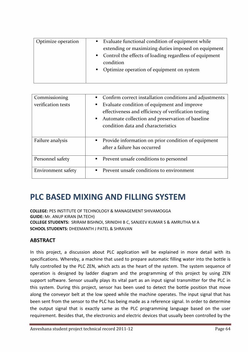
Anveshana student project technical record 2011-12 Page 64
Optimize operation
Evaluate functional condition of equipment while
extending or maximizing duties imposed on equipment
Control the effects of loading regardless of equipment
condition
Optimize operation of equipment on system
Commissioning
verification tests
Confirm correct installation conditions and adjustments
Evaluate condition of equipment and improve
effectiveness and efficiency of verification testing
Automate collection and preservation of baseline
condition data and characteristics
Failure analysis Provide information on prior condition of equipment
after a failure has occurred
Personnel safety Prevent unsafe conditions to personnel
Environment safety Prevent unsafe conditions to environment
PLC BASED MIXING AND FILLING SYSTEM
COLLEGE: PES INSTITUTE OF TECHNOLOGY & MANAGEMENT SHIVAMOGGA GUIDE: Mr. ANUP KIRAN (M.TECH)
COLLEGE STUDENTS: SRIRAM BISHNOI, SRINIDHI B C, SANJEEV KUMAR S & AMRUTHA M A
SCHOOL STUDENTS: DHEEMANTH J PATEL & SHRAVAN
ABSTRACT
In this project, a discussion about PLC application will be explained in more detail with its
specifications. Whereby, a machine that used to prepare automatic filling water into the bottle is
fully controlled by the PLC ZEN, which acts as the heart of the system. The system sequence of
operation is designed by ladder diagram and the programming of this project by using ZEN
support software. Sensor usually plays its vital part as an input signal transmitter for the PLC in
this system. During this project, sensor has been used to detect the bottle position that move
along the conveyor belt at the low speed while the machine operates. The input signal that has
been sent from the sensor to the PLC has being made as a reference signal. In order to determine
the output signal that is exactly same as the PLC programming language based on the user
requirement. Besides that, the electronics and electric devices that usually been controlled by the
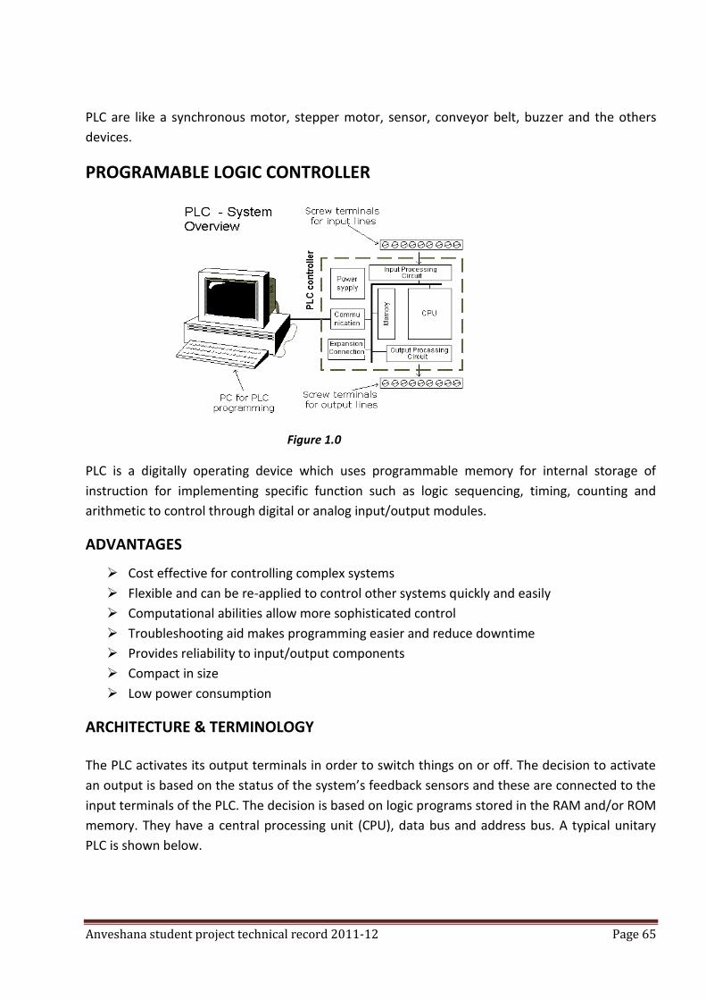
Anveshana student project technical record 2011-12 Page 65
PLC are like a synchronous motor, stepper motor, sensor, conveyor belt, buzzer and the others
devices.
PROGRAMABLE LOGIC CONTROLLER
Figure 1.0
PLC is a digitally operating device which uses programmable memory for internal storage of
instruction for implementing specific function such as logic sequencing, timing, counting and
arithmetic to control through digital or analog input/output modules.
ADVANTAGES
Cost effective for controlling complex systems
Flexible and can be re-applied to control other systems quickly and easily
Computational abilities allow more sophisticated control
Troubleshooting aid makes programming easier and reduce downtime
Provides reliability to input/output components
Compact in size
Low power consumption
ARCHITECTURE & TERMINOLOGY
The PLC activates its output terminals in order to switch things on or off. The decision to activate
an output is based on the status of the system’s feedback sensors and these are connected to the
input terminals of the PLC. The decision is based on logic programs stored in the RAM and/or ROM
memory. They have a central processing unit (CPU), data bus and address bus. A typical unitary
PLC is shown below.
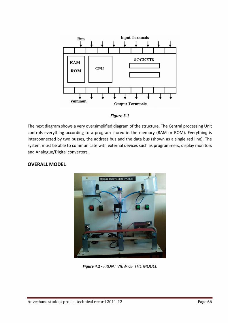
Anveshana student project technical record 2011-12 Page 66
Figure 3.1
The next diagram shows a very oversimplified diagram of the structure. The Central processing Unit
controls everything according to a program stored in the memory (RAM or ROM). Everything is
interconnected by two busses, the address bus and the data bus (shown as a single red line). The
system must be able to communicate with external devices such as programmers, display monitors
and Analogue/Digital converters.
OVERALL MODEL
Figure 4.2 - FRONT VIEW OF THE MODEL
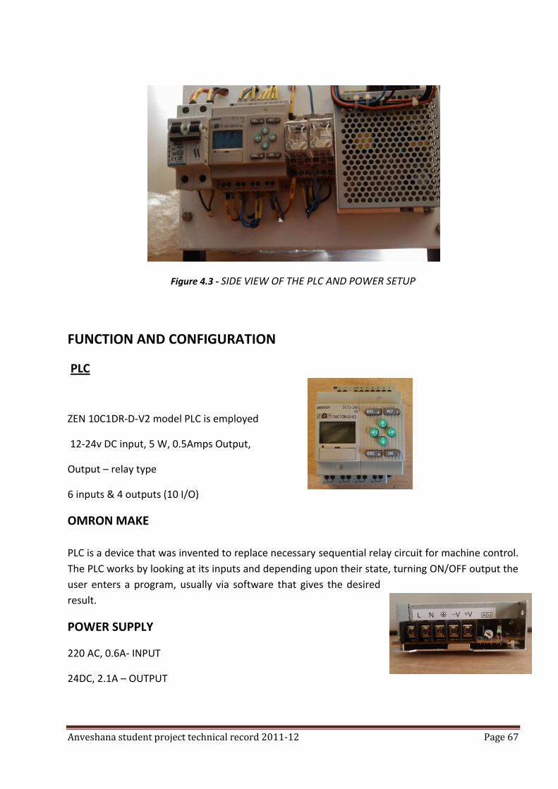
Anveshana student project technical record 2011-12 Page 67
Figure 4.3 - SIDE VIEW OF THE PLC AND POWER SETUP
FUNCTION AND CONFIGURATION
PLC
ZEN 10C1DR-D-V2 model PLC is employed
12-24v DC input, 5 W, 0.5Amps Output,
Output – relay type
6 inputs & 4 outputs (10 I/O)
OMRON MAKE
PLC is a device that was invented to replace necessary sequential relay circuit for machine control.
The PLC works by looking at its inputs and depending upon their state, turning ON/OFF output the
user enters a program, usually via software that gives the desired
result.
POWER SUPPLY
220 AC, 0.6A- INPUT
24DC, 2.1A – OUTPUT
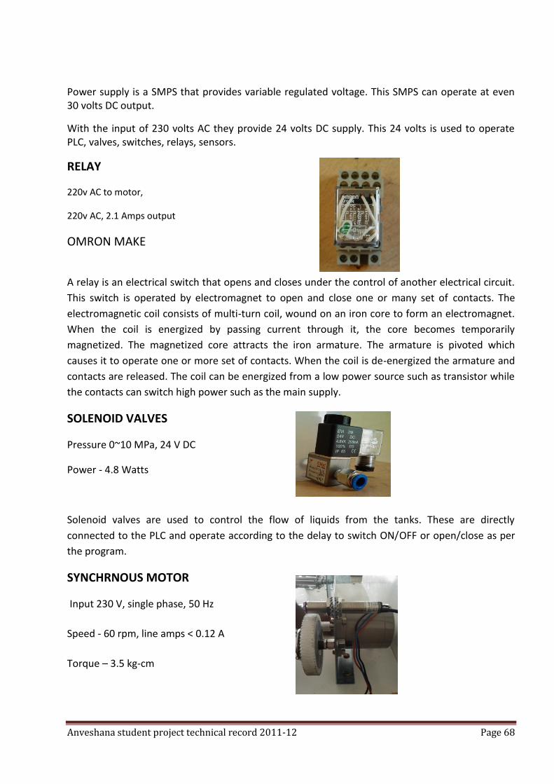
Anveshana student project technical record 2011-12 Page 68
Power supply is a SMPS that provides variable regulated voltage. This SMPS can operate at even 30 volts DC output.
With the input of 230 volts AC they provide 24 volts DC supply. This 24 volts is used to operate PLC, valves, switches, relays, sensors.
RELAY
220v AC to motor,
220v AC, 2.1 Amps output
OMRON MAKE
A relay is an electrical switch that opens and closes under the control of another electrical circuit.
This switch is operated by electromagnet to open and close one or many set of contacts. The
electromagnetic coil consists of multi-turn coil, wound on an iron core to form an electromagnet.
When the coil is energized by passing current through it, the core becomes temporarily
magnetized. The magnetized core attracts the iron armature. The armature is pivoted which
causes it to operate one or more set of contacts. When the coil is de-energized the armature and
contacts are released. The coil can be energized from a low power source such as transistor while
the contacts can switch high power such as the main supply.
SOLENOID VALVES
Pressure 0~10 MPa, 24 V DC
Power - 4.8 Watts
Solenoid valves are used to control the flow of liquids from the tanks. These are directly
connected to the PLC and operate according to the delay to switch ON/OFF or open/close as per
the program.
SYNCHRNOUS MOTOR
Input 230 V, single phase, 50 Hz
Speed - 60 rpm, line amps < 0.12 A
Torque – 3.5 kg-cm
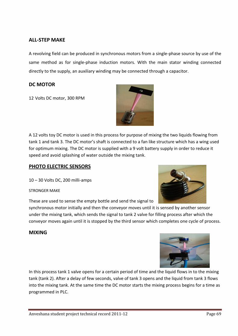
Anveshana student project technical record 2011-12 Page 69
ALL-STEP MAKE
A revolving field can be produced in synchronous motors from a single-phase source by use of the
same method as for single-phase induction motors. With the main stator winding connected
directly to the supply, an auxiliary winding may be connected through a capacitor.
DC MOTOR
12 Volts DC motor, 300 RPM
A 12 volts toy DC motor is used in this process for purpose of mixing the two liquids flowing from
tank 1 and tank 3. The DC motor’s shaft is connected to a fan like structure which has a wing used
for optimum mixing. The DC motor is supplied with a 9 volt battery supply in order to reduce it
speed and avoid splashing of water outside the mixing tank.
PHOTO ELECTRIC SENSORS
10 – 30 Volts DC, 200 milli-amps
STRONGER MAKE
These are used to sense the empty bottle and send the signal to
synchronous motor initially and then the conveyor moves until it is sensed by another sensor
under the mixing tank, which sends the signal to tank 2 valve for filling process after which the
conveyor moves again until it is stopped by the third sensor which completes one cycle of process.
MIXING
In this process tank 1 valve opens for a certain period of time and the liquid flows in to the mixing
tank (tank 2). After a delay of few seconds, valve of tank 3 opens and the liquid from tank 3 flows
into the mixing tank. At the same time the DC motor starts the mixing process begins for a time as
programmed in PLC.
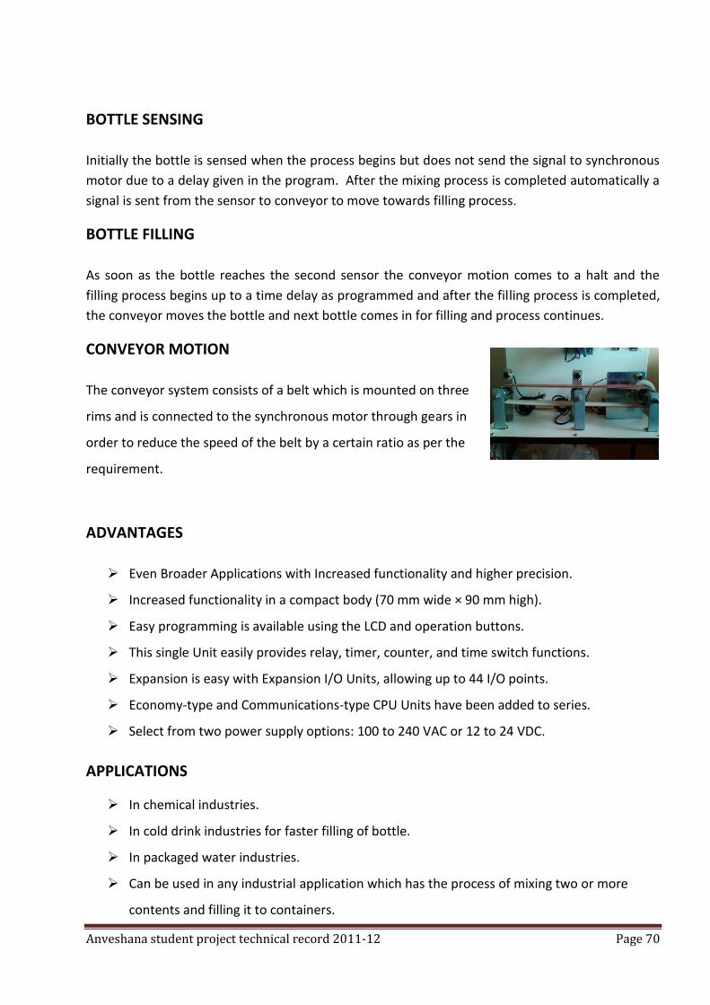
Anveshana student project technical record 2011-12 Page 70
BOTTLE SENSING
Initially the bottle is sensed when the process begins but does not send the signal to synchronous
motor due to a delay given in the program. After the mixing process is completed automatically a
signal is sent from the sensor to conveyor to move towards filling process.
BOTTLE FILLING
As soon as the bottle reaches the second sensor the conveyor motion comes to a halt and the
filling process begins up to a time delay as programmed and after the filling process is completed,
the conveyor moves the bottle and next bottle comes in for filling and process continues.
CONVEYOR MOTION
The conveyor system consists of a belt which is mounted on three
rims and is connected to the synchronous motor through gears in
order to reduce the speed of the belt by a certain ratio as per the
requirement.
ADVANTAGES
Even Broader Applications with Increased functionality and higher precision.
Increased functionality in a compact body (70 mm wide × 90 mm high).
Easy programming is available using the LCD and operation buttons.
This single Unit easily provides relay, timer, counter, and time switch functions.
Expansion is easy with Expansion I/O Units, allowing up to 44 I/O points.
Economy-type and Communications-type CPU Units have been added to series.
Select from two power supply options: 100 to 240 VAC or 12 to 24 VDC.
APPLICATIONS
In chemical industries.
In cold drink industries for faster filling of bottle.
In packaged water industries.
Can be used in any industrial application which has the process of mixing two or more
contents and filling it to containers.
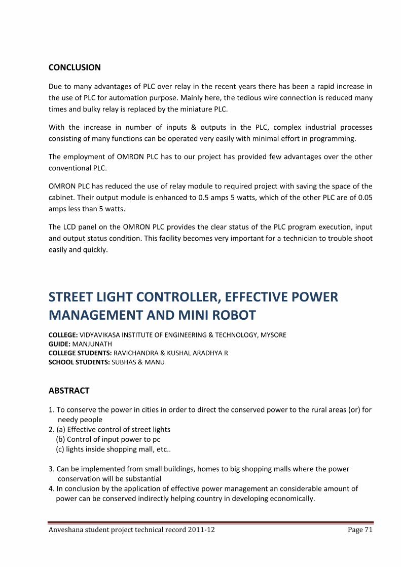
Anveshana student project technical record 2011-12 Page 71
CONCLUSION
Due to many advantages of PLC over relay in the recent years there has been a rapid increase in
the use of PLC for automation purpose. Mainly here, the tedious wire connection is reduced many
times and bulky relay is replaced by the miniature PLC.
With the increase in number of inputs & outputs in the PLC, complex industrial processes
consisting of many functions can be operated very easily with minimal effort in programming.
The employment of OMRON PLC has to our project has provided few advantages over the other
conventional PLC.
OMRON PLC has reduced the use of relay module to required project with saving the space of the
cabinet. Their output module is enhanced to 0.5 amps 5 watts, which of the other PLC are of 0.05
amps less than 5 watts.
The LCD panel on the OMRON PLC provides the clear status of the PLC program execution, input
and output status condition. This facility becomes very important for a technician to trouble shoot
easily and quickly.
STREET LIGHT CONTROLLER, EFFECTIVE POWER MANAGEMENT AND MINI ROBOT COLLEGE: VIDYAVIKASA INSTITUTE OF ENGINEERING & TECHNOLOGY, MYSORE GUIDE: MANJUNATH COLLEGE STUDENTS: RAVICHANDRA & KUSHAL ARADHYA R SCHOOL STUDENTS: SUBHAS & MANU
ABSTRACT
1. To conserve the power in cities in order to direct the conserved power to the rural areas (or) for needy people 2. (a) Effective control of street lights (b) Control of input power to pc (c) lights inside shopping mall, etc.. 3. Can be implemented from small buildings, homes to big shopping malls where the power conservation will be substantial 4. In conclusion by the application of effective power management an considerable amount of power can be conserved indirectly helping country in developing economically.
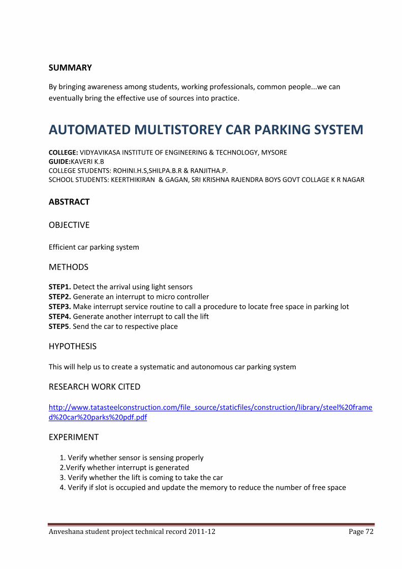
Anveshana student project technical record 2011-12 Page 72
SUMMARY
By bringing awareness among students, working professionals, common people...we can
eventually bring the effective use of sources into practice.
AUTOMATED MULTISTOREY CAR PARKING SYSTEM
COLLEGE: VIDYAVIKASA INSTITUTE OF ENGINEERING & TECHNOLOGY, MYSORE GUIDE:KAVERI K.B COLLEGE STUDENTS: ROHINI.H.S,SHILPA.B.R & RANJITHA.P. SCHOOL STUDENTS: KEERTHIKIRAN & GAGAN, SRI KRISHNA RAJENDRA BOYS GOVT COLLAGE K R NAGAR
ABSTRACT OBJECTIVE Efficient car parking system
METHODS
STEP1. Detect the arrival using light sensors STEP2. Generate an interrupt to micro controller STEP3. Make interrupt service routine to call a procedure to locate free space in parking lot STEP4. Generate another interrupt to call the lift STEP5. Send the car to respective place
HYPOTHESIS
This will help us to create a systematic and autonomous car parking system
RESEARCH WORK CITED
http://www.tatasteelconstruction.com/file_source/staticfiles/construction/library/steel%20framed%20car%20parks%20pdf.pdf
EXPERIMENT
1. Verify whether sensor is sensing properly 2.Verify whether interrupt is generated 3. Verify whether the lift is coming to take the car 4. Verify if slot is occupied and update the memory to reduce the number of free space
Anveshana student project technical record 2011-12 Page 73
BIBILIOGRAPHY
1.http://electrofriends.com/projects/microcontrollers/automated-multistoried-car-parking-system/ 2.http://en.wikipedia.org/wiki/multi-storey_car_park 3.www.hbeonlabs.com 4.http://www.seminarprojects.com/thread-multi-level-car-parking-system-a-presentation 5.http://projectsworld.wordpress.com/2010/05/12/microcontroller-based-multi-story-car-parking-system/ 6.http://www.tatasteelconstruction.com/file_source/staticfiles/construction/library/steel%20framed%20car%20parks%20pdf.pdf
SUMMARY Car arrival using light sensors is detected, Interrupt generated to micro controller, free space is
allocated in parking lot by calling interrupt service routine and lift is called, car is sent to
respective space.
AUTO TRAFFIC SENSOR
COLLEGE: VIDYAVIKASA INSTITUTE OF ENGINEERING & TECHNOLOGY, MYSORE GUIDE: KAVERI M A COLLEGE STUDENTS: MEGHANA.R, PADMINI.P, NANDINI.B.B & BHAVYASHREE. M.V
SCHOOL STUDENTS: YOGESH & LINGRAJU, GHS VINAYAKA NAGAR, PADUVARAHALLI, MYSORE.
ABSTRACT
OBJECTIVE
To build up software this guides vehicle in traffic
METHODS
1. Detect the obstacle in front of the vehicle by using infrared radiation sensors 2. Relative distance between vehicle and obstacle is measured while vehicle is moving. 3. At particular distance from obstacle called slow down distance, vehicle slows down its
speed. 4. As distance further decrease, at deviation distance, vehicle gets deviate and start moving. 5. If it again faces an obstacle, it will stop.
Anveshana student project technical record 2011-12 Page 74
HYPOTHESIS
This will help to avoid accidents without human effort.
WORK SITED 1. http://www.societyofrobots.com/microcontroller_tutorial.shtml 2 http://www.8051projects.net/ 3. http://science.howstuffworks.com/robot.htm 4 http://training.gov.au/trainingcomponentfiles/release
EXPERIMENT
1. Verify whether sensor is sensing the obstacle. 2. Verify whether vehicle is moving 3. Verify whether vehicle slow down at slow down distance 4. Verify whether vehicle take deviation in deviation distance.
5. Verify whether vehicle stop moving, if it faces obstacle a BIBILIOGRAPHY
1. http://www.societyofrobots.com/microcontroller_tutorial.shtml 2. http://www.8051projects.net/ 3. http://science.howstuffworks.com/robot.htm 4. http://training.gov.au/trainingcomponentfiles/release
SUMMARY
The project mainly aims at preventing accidents without human help and reducing human effort in transportation of goods.
EFFECTIVE WASTE DISPOSAL
COLLEGE: NMAM INSTITUTE OF TECHNOLOGY, NITTE, UDUPI. GUIDE: DR. MURALIDHAR R
COLLEGE STUDENTS: ASHUTOSH BHAT, SAGAR GOURISHANKAR KAMBLE. SCHOOL STUDENTS: ASHWIN S BHAT, CALVIN J ARANHA & DEEKSHIT, BELAMANU GOVT SCHOOL
ABSTRACT
OBJECTIVE Effective disposal of waste with the use of minimum resources (less man power)
Anveshana student project technical record 2011-12 Page 75
METHODS
1. We propose a concept of point-to-point collection of waste. 2. Where with the help of autonomous robots effective collection & segregation of waste is done by categorizing the waste according to bio-degradable or non-bio-degradable.
HYPOTHESIS
Humans usually are not willing to interact with the waste produced, which results improper disposal of waste and its segregation. Due to this piles of waste is seen everywhere. This results in severe health problems among the community. This situation can be changed by involving machines (autonomous robots) which will replace humans and do the work more effectively.
SOLUTION
1. Use of autonomous robots/machines to play a human\'s role in waste handling. 2. Improved quality of human life by not performing the undesirable jobs. 3. The robots will help us achieve flexibility & high productivity in the long run. 4. They can perform a given task with high accuracy and repeatability. 5. Couple these with a effective source of power, such as solar power where in solar panels could be used for providing a 24 hr. uninterrupted power supply.
RESEARCH WORK CITED
1.Robotics workshop on line following robots 2.Tapping of non-conventional energy.
EXPERIMENT
1.CENTRIFUGAL SEPARATOR
This machine works on the principle of centrifugal forces which can be used to separate masses of different density. The waste is loaded into to the separator, the machine rotates at a high velocity due to which the mass with high density can be differentiated and removed. Same process is repeated for next mass. This method can be effectively used for separating metals of different density.
2. LINE FOLLOWING ROBOT
The robot can be programmed to follow a predefined line based on the code. The code enables the sensors to follow a line i.e a white line on a black roads surface. This robot can be coded to stop at certain points, intervals to collect the waste from the garbage cans kept in front of the houses.
Anveshana student project technical record 2011-12 Page 76
3. ROBOTIC ARM
This is fixed on top of the line following robot which can be coded to perform any given task like, lifting the bin and pouring the waste into the baggage provided, and placing the bin back to its original place.
CONCLUSION Smart and effective disposal of waste, without human interaction with it. This ultimately results in hygienic surroundings, better standard of living.
SUMMARY
With the help of this project we are trying to introduce an effective method by which we can not only collect garbage, but also segregate it according to whether it’s degradable or not mainly using robots.
SOLAR POWER AIR CRAFT COLLEGE: JAWAHARLAL NEHRU NATIONAL COLLEGE OF ENGINEERING. GUIDE: ADITYA KUMAR MISHRA, SCIENTIST, DRDO, MINISTRY OF DEFENCE, GOVERNMENT OF INDIA. COLLEGE STUDENTS: AMAN KUMAR CHOUDHARY, SABYASACHI CHOUDHURY , NAROTTAM KUMAR & NITESH KUMAR. SCHOOL STUDENTS: SHAN & YOGESH, GHS DURGIGUDDI, SHIVMOGA.
ABSTRACT
Objective-design a aircraft which run on solar energy
METHOD
By using EPP carbon rod, and balsa aerodynamic shape is given.
By using electric motor and servo motor make the design able to fly.
CONCLUSION
Aircraft runs by utilizing the solar energy very efficiently.
SUMMARY
It is solar based aircraft which run by utilizing solar energy. This energy is converted into electrical
energy by using solar cell .the power generated is used to run the air craft.
Basically a set of batteries will be charged for actual flight.
Anveshana student project technical record 2011-12 Page 77
LEG OPERATED WASHING MACHINE
COLLEGE: JAWAHARLAL NEHRU NATIONAL COLLEGE OF ENGINEERING GUIDE: DR.L.K. SRIPATHI COLLEGE STUDENTS: PAWAN KUMAR M.P, MANJUNATH.P.J & VIJAYARAJA B.G
SCHOOL STUDENTS:SHANKAR SHANNA V, RAMAKRISHNA VIDYANIKETHAN & VISHAK L S ARBINDO
SCHOOL, SHIVMOGA.
ABSTRACT
The proposed project deals with the conservation of electricity using leg operated washing machine. The device consists of a pedal to drive the machine. A belt drive is used to transfer the power from the pedal to shaft the shaft is connected to churning setup, basically it’s a porous stainless steel cylinder where there is provision for water to enter into the cylinder and take part in washing process. The washing process is carried out in a closed stainless steel box, which also acts as water reservoir. Here the operator while using the machine can look into the box through a transparent window provided at one side. By this one can be able to judge when to and how much to change the water. Once the operator is satisfied with the washing process, he can use it as a drier by draining the water out through the outlet. Driver needs more speed which can be given by changing the gear provided near the pedal. Thus our device provides additional benefit of physical exercise and keeps the operator fit
SUMMARY
To minimize the present time energy crisis
LINE FOLLOWING ROBOT JACKS FOR LORRYS
COLLEGE: G M INSTITUTE OF TECHNOLOGY, DHAVANGERE. GUIDE: SURESH BABHU S, RAGHURAM & HARSHA H M COLLEGE STUDENTS: PAWAN KUMAR M.P, MANJUNATH.P.J & VIJAYARAJA B.G SCHOOL STUDENTS: RAKESH A R & MANOJ H R , TARALABAU CENTRAL SCHOOL.
ABSTRACT
To reduce the manufacturing time ant transportation time
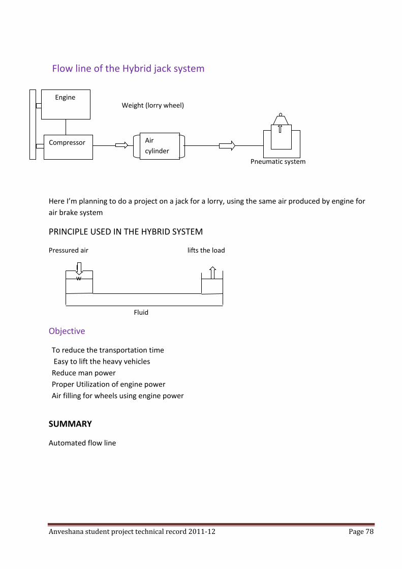
Anveshana student project technical record 2011-12 Page 78
Flow line of the Hybrid jack system
Weight (lorry wheel)
Pneumatic system
Here I’m planning to do a project on a jack for a lorry, using the same air produced by engine for
air brake system
PRINCIPLE USED IN THE HYBRID SYSTEM
Pressured air lifts the load
P
w
Fluid
Objective
To reduce the transportation time
Easy to lift the heavy vehicles
Reduce man power
Proper Utilization of engine power
Air filling for wheels using engine power
SUMMARY
Automated flow line
Engine
Air
cylinder
Compressor
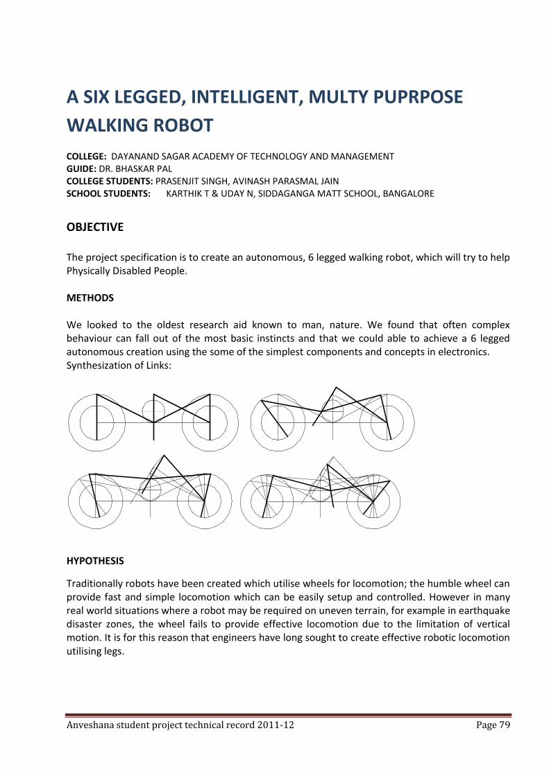
Anveshana student project technical record 2011-12 Page 79
A SIX LEGGED, INTELLIGENT, MULTY PUPRPOSE
WALKING ROBOT
COLLEGE: DAYANAND SAGAR ACADEMY OF TECHNOLOGY AND MANAGEMENT GUIDE: DR. BHASKAR PAL COLLEGE STUDENTS: PRASENJIT SINGH, AVINASH PARASMAL JAIN SCHOOL STUDENTS: KARTHIK T & UDAY N, SIDDAGANGA MATT SCHOOL, BANGALORE
OBJECTIVE The project specification is to create an autonomous, 6 legged walking robot, which will try to help Physically Disabled People. METHODS We looked to the oldest research aid known to man, nature. We found that often complex behaviour can fall out of the most basic instincts and that we could able to achieve a 6 legged autonomous creation using the some of the simplest components and concepts in electronics. Synthesization of Links:
HYPOTHESIS
Traditionally robots have been created which utilise wheels for locomotion; the humble wheel can provide fast and simple locomotion which can be easily setup and controlled. However in many real world situations where a robot may be required on uneven terrain, for example in earthquake disaster zones, the wheel fails to provide effective locomotion due to the limitation of vertical motion. It is for this reason that engineers have long sought to create effective robotic locomotion utilising legs.
Anveshana student project technical record 2011-12 Page 80
RESEARCH WORK CITED
Mobile robots have become more and more useful. They play dominant roles in remote and dangerous operations. For instance, two Mars Exploration Rovers, Spirit and Opportunity, have been performing missions on Mars since 2004 [1]. Although most mobile robots are wheeled robots due to their design and construction advantages, legged robots sometimes have benefits over the wheel robots especially on natural terrain. Leg mechanisms have evolved through natural selection so that animals can travel in any kind of terrain and access essentially any place on the earth’s surface [2]. With a well-designed leg mechanism, legged robots could traverse unlevel and rough terrain more effectively than wheeled robots. Legged robots can jump or step over holes and small obstacles. They can turn around within a small space too. In addition, legged robots have fewer tendencies to damage the ground than wheeled robots [3]. On the other hand, legged robots require complex control algorithms particularly in gait selection and control. Each leg must continuously load and unload the weight within a short time [2]. Legged robots may also have some problems, for example, they can slip on wet surfaces, or one of their legs can get stuck in a hole [3]. In order to develop legged robots to operate in a dynamic environment, more research needs to be done. But the use of intelligent software such as cognitive architectures can help [4-8].
DATA
FORWARD MOTION
When both the motors rotate in the clockwise direction, the robot moves in the forward direction.
BACKWARD DIRECTION
When both the motors move in anticlockwise direction the robot moves in backward direction.
LEFT TURN
When the motor on the left side rotates in the anticlockwise direction and the motor on the right side rotates in the clockwise direction then the robot will take a left turn.
RIGHT TURN
When the motor on the right side rotates in the anticlockwise direction and the motor on the left side rotates in the clockwise direction then the robot will take right turn.
Observations, Conclusion:
When we embarked upon this project it was both an exciting and daunting prospect. The idea was quite unique and very ambitious. We knew from the start that a good sound design was critical for us to have any chance of achieving our goal and that a good source for research was imperative. So we looked to the oldest research aid known to man, nature. We found that often complex behaviour can fall out of the most basic instincts and that we could achieve a 6 legged autonomous creation using the some of the simplest components and concepts in electronics.
Anveshana student project technical record 2011-12 Page 81
We split up the tasks between the team very early on and this helped us to achieve an excellent design very quickly. This meant that before we entered the work to start the build we could collate our research and data and add our own thoughts to each other’s designs. When we finally entered the work the designs were realised very quickly and we were able to spend most of our time perfecting the mechanics of the robot.
The fact that we made all of the boards “plug and play” means that upgrading the robots behaviour and hardware will be quick and easy. It can now be used as a test bed for further research into instinctive behaviour. For example one more small modification to the existing circuit can easily be added to make the robot sense objects and reverse away.
BIBLIOGRAPHY
1. F. Naderi, D. J. McCleese, and J. F. Jordan, Jr., "Mars exploration," IEEE Robotics & Automation Magazine, vol. 13, pp. 72-82, 2006.
2. S. Pinker, How the Mind Works. New York, NY: Norton & Company, 1997. D. J. Todd, Walking Machines: An Introduction to Legged Robots. New York: Chapman and Hall, 1985.
3. A. G. H. Barett Mitchell, Brian C. Williams, "Search-based foot placement for quadrupedal traversal of challenging terrain," in 2007 IEEE International Conference on Robotics and Automation Roma, Italy, 2007.
4. K. V. Karl C. Kulling, Cristina M. Wilcox, "A foot placement planning algorithm for a walking quadruped rover," in AIAA Infotech@Aerospace 2007 Conference and Exhibit Rohnert Park, CA, 2007.
5. P. D. N. John R. Rebula, Brian V Bonnlander, Matthew J. Johnson, Jerry E. Pratt, "A controller for the LittleDog quadruped walking on rough terrain," in 2007 IEEE International Conference on Robotics and Automation Roma, Italy, 2007.
6. D. Pongas, M. Mistry, and S. Schaal, "A robust quadruped walking gait for traversing rough terrain," in 2007 IEEE International Conference on Robotics and Automation, Roma, Italy, 2007, pp. 1474-1479.
7. Y. Go, Y. Xiaolei, and A. Bowling, "Navigability of multi-legged robots," IEEE/ASME Transactions on Mechatronics, vol. 11, pp. 1-8, 2006.
8. Youcef Zennir and P. Couturier, "Multiactor approach and hexapod robot learning," in 2005 IEEE International Symposium on Computational Intelligence in Robotics and Automation, Espoo, Finland, 2005.
SUMMARY:
All in all we are very happy with how the project has turned out and very proud of what we have achieved. It has been a great learning experience and an excellent stepping stone towards our solo project.
We are feeling great that we could able to impart intelligent and intellectual concept to the school children who could able to understand the complicated concepts very easily. This whole project is making lot of sense to us that not only the school children could able to deliver effectively but also it has given wonderful learning for the stepping stone to our future thinking
Anveshana student project technical record 2011-12 Page 82
DRIVER-FRIENDLY CAR HEADLIGHT SYSTEM
COLLEGE: SAMBHRAM INSTITUTE OF TECHNOLOGY, BANGALORE GUIDE: PROF. M.V.CHAKRAPANI & DR. R.CHANDRASHEKAR COLLEGE STUDENTS: VINOD KUMAR R & BHARATH KUMAR A.B. SCHOOL STUDENTS: LAKHMISHREE P &BHARAT KUMAR P.
ABSTRACT
OBJECTIVE To light the road ahead of the car in the steering direction.
METHOD By providing a swivelling headlight synchronised with the steering angle of the car.
HYPOTHESIS Accident possibility is reduced with improved visibility.
RESEARCH
Two wheelers have headlights mounted on the handle bar and turn along with the handle bar into direction of the road curve. In a car, the headlights are fixed. The light beam does not get oriented properly during a turn. Though night driving constitutes only 25% of all driving, night time accidents account for 47% of all accidents. About 25% of road accidents occurring at night occur during turning. Providing headlamps aligned with steering wheel increases illumination in the turning direction thereby reducing the possibility of accidents by about one-third. High end auto manufacturers have incorporated expensive systems to orient light beams optimally in cars like bmw, audi etc.
FABRICATION OF THE MODEL & EXPERIMENT
A model was designed & fabricated. The headlights were synchronised with the steering wheel using mechanics & electronics, and can swivel through a curve of 15 degrees at different speeds by mounting infra-red sensors, receivers, transmitter & the swivel able headlamps on the Ackerman steering gear in the model.
Anveshana student project technical record 2011-12 Page 83
DATA The total cost of the model including bought out components is Rs.7000. If a minimum of 500 units is produced, the cost per unit would come down to Rs.2000.
OBSERVATIONS
The system improves illumination by 300% in the direction of the road curve.
CONCLUSION Incorporating a system similar to the model designed & fabricated in existing cars, vans & trucks will reduce night time road accidents on road curves by about one-third.
BIBLIOGRAPHY 1. Mechanical engineering design by Joseph E Shigley & Charles R Mischke, Tata Mcgraw Hill,2003. 2. Automobile engineering by R.B. Gupta & Satya Prakashan, 1984. 3. Machine design by R.L. Norton, Pearson education asia, 2001. 4. Mechatronics by Dan Necsulescu, Pearson pub., 2007.
SUMMARY
A working model car steering-cum-headlamp system has been designed & fabricated. In the
model, the headlamps are synchronised with the steering wheel of the car & illuminate the road in
the direction of turning. This low cost system can be incorporated in existing cars, vans & trucks at
about rs.2000 per unit to improve road curve visibility & reduce night time accidents.
WORKING MECHANISM OF ELECTROCHMICAL MACHINING COLLEGE: DON BOSCO INSTITUTE OF TECHNOLOGY GUIDE: MR. SHIVANNA & PROF. GC VIJAYAKUMAR COLLEGE STUDENTS: MOHAMMED NASRULLA BASHA, AADITHYA B S & ANTARANG KUMAR SCHOOL STUDENTS: ZOHRA BANU V A & VINAY H S
ABSTRACT
To demonstrate the working mechanism of electrochemical machining Electrochemical machining (ECM) is a non-traditional method of machining conductive materials. It is based on the electrolysis process. The material removal takes place when electricity is passed through the tool and the work piece which act as electrodes and an electrolyte is made to flow between them.
Anveshana student project technical record 2011-12 Page 84
METHOD/EXPERIMENT
Performing the machining operation using model. A model has been made based on the construction of actual ECM machine. The effort has been made in making the model work similar to the real machine. Though the model does the machining, it is not as fast or as efficient as the actual machine, but is sufficient enough to demonstrate the working mechanism of ECM.
OBSERVATIONS
The material removal rate (MRR) is directly proportional to the current passing through the electrodes. The MRR also depends upon the flow rate of electrolyte and the standoff distance between tool and the work piece.
CONCLUCION
The ECM process can be clearly explained using this model. It will act as a teaching tool for both engineering students and also to the school students as ECM is an application of electrolysis process that is thought in school level, and it also has its application in engineering field.
BIBLIOGRAPHY
* Nonconventional machining by P K Mishra. * Wikipedia * www.youtube.com
SUMMARY
ECM is a non-traditional method of machining conductive materials. The model can demonstrate
the working mechanism of the ECM process by mocking the actual ECM machine. This model can
be used as a teaching tool for both engineering and school students.