annular flow: a mechanistic suite of co-validated methods for two-phase flow and...
TRANSCRIPT
1
ANNULAR FLOW: A MECHANISTIC SUITE OF CO-VALIDATED METHODS FOR TWO-PHASE FLOW AND BOILING/CONDENSATION HEAT TRANSFER
Andrea Cioncolini* and John R. Thome *Author for correspondence
School of Mechanical, Aerospace and Civil Engineering, University of Manchester,
M1 3BB-Manchester, United Kingdom,
E-mail: [email protected]
ABSTRACT
The present paper focuses on the unified modeling suite for annular flow that the authors have been developing in the last few years. Annular two-phase flow is one of the most important of the gas-liquid two-phase flow regimes because of the large range of industrial applications in which it occurs, such as refrigeration and air conditioning systems, nuclear reactors and chemical processing plants, and high heat flux cooling applications. Sound design and safe operation of two-phase flow systems require accurate modelling of annular flows, and this motivated the development of the mechanistic modelling suite for annular two-phase flows that is discussed here. First, the unified suite of annular flow prediction methods is presented, illustrating in particular the most recent updates. Then, selected results for convective evaporation and condensation in tubes and channels are presented and discussed. Presently, the annular flow suite includes prediction methods for the void fraction, the entrained liquid fraction, the pressure gradient, and a turbulence model for momentum and heat transport inside the annular liquid film. This turbulence model, in particular, allows prediction of the local average liquid film thicknesses and the local heat transfer coefficients during convective evaporation and condensation. The benefit of a unified modeling suite is that all the included prediction methods are consistently formulated and are proven to work well together, and provide a platform for continued advancement based on the other models in the suite.
NOMENCLATURE Bo (-) Bond number d (m) tube diameter dc (m) core flow diameter e (-) entrained liquid fraction ftp (-) two-phase Fanning friction factor g (ms-2) acceleration of gravity G (kgm-2s-1) mass flux h (Wm-2K-1) heat transfer coefficient Jg (ms-1) superficial gas velocity Jl (ms-1) superficial liquid velocity kl (Wm-1K-1) liquid thermal conductivity Nu (-) Nusselt number Prl (-) liquid Prandtl number Relf (-) liquid film Reynolds number t (m) average liquid film thickness
t+ (-) dimensionless average liquid film thickness Vc (ms-1) core flow velocity V* (ms-1) velocity wall scale Wec (-) core flow Weber number x (-) vapor quality y* (m) length wall scale Special characters ε (-) cross sectional void fraction τw (Pa) wall shear stress µl (kgm-1s-1) liquid viscosity ρc (kgm-3) core density ρg (kgm-3) vapor density ρl (kgm-3) liquid density σ (kgs-2) surface tension
INTRODUCTION
Annular flow is one of the most important flow regimes in gas-liquid and vapor-liquid two-phase flows in tubes and channels. In annular flow, a thin film of liquid flows along the channel wall, surrounding a central gas or vapor core that flows in the centre of the channel carrying entrained liquid droplets in suspension. The shear of the gas or vapor core continuously atomizes the liquid film, while entrained liquid droplets are continuously deposited back onto the liquid film after being accelerated in the gas or vapor core, which flows faster than the liquid film. This continuous exchange of liquid between the liquid film and the gas or vapor core yields a tight mass and linear momentum coupling between the phases that makes the analysis and the modeling of annular flows particularly challenging.
Notwithstanding the extensive investigations carried out to date, mostly driven by nuclear reactor cooling applications, annular flow is still actively studied in the nuclear industry as more accurate and reliable prediction methods are required for several cutting-edge applications, such as nuclear reactor fuel optimization, nuclear reactor power uprates, and nuclear systems transient and safety analysis. Additional practical applications where the accurate modeling of annular two-phase flow is crucial for a sound design and safe operation include air conditioning and refrigeration systems, chemical processing plants, microscale heat sinks used in the thermal management of microelectronics circuits and high energy physics particle
12th International Conference on Heat Transfer, Fluid Mechanics and Thermodynamics
663

2
detectors, and high heat flux cooling applications, such as nuclear fusion reactors and power electronics.
The purpose of this paper is to present the mechanistic modeling suite for annular flow that the authors have been developing over the last few years [1-9]. The great advantage of a unified suite of prediction methods is that all the models included are formulated consistently and are proven to work well together, thus providing a framework for analysis, modeling and future development. Presently, this annular flow modeling suite includes prediction methods for the void fraction, the entrained liquid fraction, the wall shear stress and associated frictional pressure gradient and the average liquid film thickness. Moreover, the modeling suite contains an algebraic turbulence model for the transport of linear momentum and heat through the liquid film that allows prediction of the heat transfer coefficient during convective evaporation and condensation. Notably, this algebraic turbulence model represents a change in paradigm in the modeling of turbulence in shear-driven thin liquid films, from the simple extrapolation of existing single-phase flow theories to a new modeling approach that considers the thin liquid film as a fluid-bounded flow, as will be described in the following. All prediction methods included in the annular flow modeling suite are semi-empirical minimal models, designed using simple physical arguments and calibrated with extensive experimental databanks collected from the open literature. The underlying experimental databank presently contains 11498 data points collected from 99 literature studies that cover conventional and microscale channels, both circular and non-circular geometry, several fluids including water and refrigerants, and operating conditions of interest for most industrial applications. The underlying experimental databank is continuously expanded, and new experiments designed to supply additional data at the operating conditions not covered in existing studies. The unified annular flow modeling suite is still work in progress, and current developments include the upgrade of the pressure drop model to better account for viscous dissipation at small and microscale, the upgrade of the heat transfer model to include nucleation at the channel wall during convective evaporation and better account for non-circular channels, and the addition of a new model to predict dryout during convective evaporation. As will be shown, the prediction methods included in the unified annular flow suite are generally much simpler than existing prediction methods, and contain a minimal number of adjustable fitting parameters. Moreover, the unified annular flow modeling suite provides predictions of the main two-phase flow parameters that generally outperform in accuracy existing leading correlations and prediction methods.
OVERVIEW OF THE ANNULAR FLOW MODELS
In the following, the annular flow prediction methods developed for the void fraction, the entrained liquid fraction, the pressure drop and for the heat transfer coefficient are presented and described. These annular flow models can be used either as stand-alone prediction methods, or they can be
integrated to provide a unified modeling suite for general design applications involving annular flows
Void Fraction
The void fraction is one of the most important parameters used to characterize channel two-phase flows, and is required as input for determining numerous other key flow parameters, such as the two-phase density and viscosity and the cross-sectional average velocities of the liquid and gas phases. Besides, the void fraction is required to predict the acceleration and gravitational components of the pressure gradient, so that a void fraction prediction model is required as input in any pressure drop prediction method. The new void fraction prediction method specifically derived by the authors for annular flows [5] reads as follows:
17.0;110;10)1(1
13 <<<<<<
−+=
−− ερρ
ε
lg
n
n
xxh
xh (1)
Where ε is the void fraction, x is the vapor quality, and the dimensionless parameters h and n are functions of the gas to liquid density ratio as follows:
5150.01
2186.01
)(6513.03487.0
)(129.3129.2−
−−
+=
+−=
lg
lg
n
h
ρρ
ρρ (2)
As can be seen, this new prediction method is strongly simplified with respect to most existing void fraction correlations, as it depends only on the vapor quality and on the gas to liquid density ratio. Assuming the void fraction to depend only on the vapor quality and on the gas to liquid density ratio can be regarded as a minimal model, which represents the maximum simplification possible but still retains the essential physics of the problem. Minimal models are typically used as a starting point in mathematical modeling and are normally upgraded on an as-needed basis with the inclusion of additional influencing parameters to improve their accuracy and predictive capability. All prediction methods currently included in the unified modeling suite are minimal models.
Figure 1 Void fraction: selected measurements for annular flow vs. predictions of Eq. (1) (further details in Cioncolini and
Thome [5]).
0 0.1 0.2 0.3 0.4 0.5 0.6 0.7 0.8 0.9 10.7
0.75
0.8
0.85
0.9
0.95
1
Vapor Quality
Voi
d Fr
actio
n
Water-air; 45.5mm; 0.1 MPaWater-air; 15.0mm; 2.1 MPaR410a; 1.05mm; 2.6 MPa
Eq. (1)
12th International Conference on Heat Transfer, Fluid Mechanics and Thermodynamics
664

3
In particular, the functional form in Eq. (1) was selected to capture the growing and saturating trend of the void fraction versus the vapor quality as shown in the data presented in Figure 1. As can be seen, the the void fraction depicts a growing and saturating trend with vapor quality, with the rate of growth modulated by the gas to liquid density ratio, which in turn depends on the fluid considered and operating pressure. In particular, at low values of the density ratio (typical of low operating pressures) the rate of growth is a strong function of vapor quality and the growth is very fast at low vapor qualities and very slow at high vapor qualities. As the density ratio increases, however, the dependence of the rate of growth on vapor quality becomes milder and the growth of the void fraction becomes more uniform as the vapor quality changes. In the limit of ρgρl
-1 → 1-, typical of saturated fluids close to the critical state, the void fraction tends to the vapor quality ε → x+ and the rate of growth loses its dependence on vapor quality. The functional form in Eq. (1) is the Hill function, a good candidate to reproduce a growing and saturating trend which was originally proposed in the modeling of biochemical kinetics [10], and is now frequently used in mathematical physiology [11]. The functional form assumed for the parameters h and n in Eq. (2) guarantees that both parameters converge to unity as the density ratio goes to one, so that in the limit of ρgρl
-1 → 1- typical of saturated fluids close to the critical state then the void fraction ε → x+, as required by asymptotical consistency. The numerical coefficients and exponents for the parameters h and n in Eq. (2) were empirically fitted using a large experimental void fraction databank collected from the open literature, which contains 2673 data points for annular flow that cover 8 fluids (water-steam, R410a, water-air, water-argon, water-nitrogen, water plus alcohol-air, alcohol-air and kerosene-air), operating pressures in the range of 0.1-7.0 MPa, tube diameters from 1.05 mm to 45.5 mm (thus spanning from microscale to macroscale) and both circular and non-circular channels in adiabatic and evaporating flow conditions. The void fraction prediction method in Eq. (1) is specifically designed for annular flows, and is therefore limited to void fraction values in the range of 0.7-1.0 that typically characterize annular flows. More details are provided in Cioncolini and Thome [5].
Figure 2 Void fraction: measured annular flow data for circular
tubes vs. predictions of Eq. (1) (further details in Cioncolini and Thome [5]).
A comparison between measured void fraction data for circular tubes and predictions is shown in Figure 2. Notwithstanding its simplicity, the annular flow void fraction prediction method in Eq. (1) fits the underlying experimental databank (2673 data points) with a mean absolute error of 1.8%, capturing 92% of the data points to within ±5% and outperforming existing and more complicated correlations. Notably, this void fraction prediction method does not depend on the tube diameter and fits both macroscale and microscale data, thus showing that there appears to be no macro-to-microscale transition for the void fraction in annular flow, at least down to diameters of about 1 mm. A similar conclusion is also provided by the annular flow heat transfer model discussed later on.
Figure 3 Void fraction: measured annular flow data for non-circular channels vs. predictions of Eq. (1) (further details in
Cioncolini and Thome [5]).
Void fraction data for non-circular channels are compared with the predictions of the annular flow method, Eq. (1), in Figure 3. In particular, Jones and Zuber [12] measured the void fraction in a rectangular channel (4.98 mm side, 63.5 mm height and aspect ratio of 12.75) with water-air at low pressure. Hori et al. [13] performed their measurements using water in evaporating flow conditions in a channel designed to mimic an inner subchannel of a pressurized water nuclear reactor fuel bundle. Takenaka and Asano [14] tested adiabatic water-air at low pressure in a tight lattice rod bundle geometry for nuclear reactor applications, while Morooka et al. [15] used low pressure evaporating water in a rod bundle designed to simulate a boiling water nuclear reactor fuel assembly. Finally, Das et al. [16] performed their measurements with adiabatic water-air at low pressure in a concentric annulus. As can be seen in Figure 3, the comparison between measured data and predictions of the annular flow model in Eq. (1) are quite satisfactory, suggesting that not only the channel size but also its cross sectional shape is of second order importance when it comes to the void fraction in annular flows.
Entrained Liquid Fraction
The entrained liquid fraction e is a dimensionless flow parameter specific to annular flows, bounded between 0 and 1 and defined as the ratio of the mass flow rate Γle of the liquid droplets entrained in the gas flow to the total liquid mass flow rate Γl in the channel as follows:
0.65 0.7 0.75 0.8 0.85 0.9 0.95 10.65
0.7
0.75
0.8
0.85
0.9
0.95
1
Void Fraction: Predicted
Voi
d Fr
actio
n: M
easu
red
- 5 %
+ 5 %
0.65 0.7 0.75 0.8 0.85 0.9 0.95 10.65
0.7
0.75
0.8
0.85
0.9
0.95
1
Void Fraction: PredictedV
oid
Frac
tion:
Mea
sure
d
Jones&Zuber (1975)Hori et al. (1995)Takenaka&Asano (2005)Morooka et al. (1989)Das et al. (2002)
+ 5 %
- 5 %
12th International Conference on Heat Transfer, Fluid Mechanics and Thermodynamics
665

4
l
leeΓΓ
= (3)
The accurate knowledge of the entrained liquid fraction e is required in most thermal-fluid predictions and simulations involving annular flows, such as the frictional and static pressure gradients, the convective heat transfer, the onset of dryout in boiling channels, the post-dryout heat transfer and the effectiveness of nuclear reactor core cooling, particularly during transient and accident scenarios. Values of the entrained liquid fraction close to 0+ are characteristic of annular flows with an almost perfect segregation between liquid and gas, where most of the liquid is concentrated in the film and there is a weak mass and momentum coupling between the phases. On the contrary, values of the entrained liquid fraction close to 1- are typical of annular flows near the transition to dispersed mist flow, where most of the liquid is in the form of entrained droplets and there is a strong mass and momentum coupling between the phases.
The origin of the entrained liquid droplets in annular flows is related to the morphology of the interface between the liquid film and the gas core, which is highly dynamic and irregularly shaped as a result of the aerodynamic interaction between the liquid film and the gas core. Schematically, two types of surface disturbance are typically considered to characterize the interface morphology in annular flow: ripple waves and disturbance waves. Ripple waves are low amplitude, low velocity and short-lived ripples that appear on top of the liquid film. Disturbance waves, also called roll waves, also appear periodically on the surface of the liquid film and slide along the top of the liquid film at a velocity much higher than that of the liquid film surface itself. Disturbance waves typically form complete rings around the channel, their amplitude can be several times the average liquid film thickness, they tend to live for long axial distances and thus they enhance the transport of liquid mass in the direction of the flow. When the hydrodynamic conditions are appropriate, the crests of the disturbance waves are sheared-off and atomized by the gas flow, and liquid droplets become entrained in the gas flow in a process that resembles the wind-induced atomization of ocean waves, as shown schematically in Figure 4:
Figure 4 Schematic representation of droplet entrainment resulting from the shearing-off of disturbance wave crests, from
Thome and Cioncolini [17].
After being entrained, the droplets are accelerated in the gas core and eventually redeposited back onto the liquid film. Under steady-state adiabatic flow conditions, the rate of droplet entrainment is balanced by the rate of droplet deposition, so
that no net mass transfer takes place between the liquid film and the gas core and the entrained liquid fraction e becomes constant in value, or a slow varying function along the channel if the pressure drop is high enough to trigger a significant flow acceleration. Nonetheless, a net exchange of linear momentum from the gas core to the liquid film is always taking place, since the droplets that are entrained leave the liquid film with a velocity that is typically lower than the velocity of the droplets that are redeposited after being accelerated in the gas core.
The entrained liquid fraction prediction method originally proposed for adiabatic annular flows in Cioncolini and Thome [3] and successively improved and generalized in Cioncolini and Thome [6] to include evaporating flows and non-circular channels reads as follows:
( )51
209.28395.0
1010
6.2791
<<
+=−−
c
c
WeforWee (4)
Where the core flow Weber number Wec is defined as:
σ
ρ dJWe gc
c
2
= (5)
The droplet-laden core flow density ρc is calculated neglecting the slip between the carrier gas phase and the entrained liquid droplets as follows:
lg
c xexxex
ρρ
ρ )1()1(
−+
−+= (6)
While the gas superficial velocity Jg is defined as:
gg
GxJρ
= (7)
Since the core flow density in Eq. (6) depends on the entrained liquid fraction e, in principle an iterative calculation would be required to use this prediction method. As described in Cioncolini and Thome [6], however, the method can be implemented as an explicit predictor-corrector scheme. A preliminary value for the core flow Weber number is first obtained using Eq. (5) and approximating the core flow density ρc with the gas density ρg. This yields a preliminary value for the entrained liquid fraction that can be used to refine the core flow Weber number and finally correct the value of the entrained liquid fraction.
The key idea in this model for the entrained liquid fraction prediction was to regard annular flows as a special form of a liquid atomization process, where a high velocity confined spray (gas and entrained liquid droplets) flows in the centre of the channel dragging and atomizing the annular liquid film that streams along the channel wall. In particular, the aerodynamic interaction between the liquid film and the droplet-laden gas core was assumed to control the liquid film atomization process, so that the core flow Weber number (representing the ratio of the disrupting aerodynamic force to the surface tension
12th International Conference on Heat Transfer, Fluid Mechanics and Thermodynamics
666
5
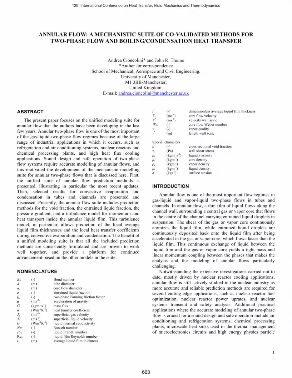
retaining force) was identified as the controlling dimensionless group in the entrainment process. The functional form of Eq. (4) is a generalized logistic function that yields a sigmoid profile typical of the data trend, as shown in Figure 5. The numerical coefficient and exponents in Eq. (4) were empirically fitted using a large experimental entrained liquid fraction databank collected from the open literature, which contains 2460 data points collected from 37 different literature studies that cover 8 fluids (water-steam, R113, R12, water-air, genklene-air, ethanol-air, water-helium and silicon-air), operating pressures in the range of 0.1‒20.0 MPa, tube diameters from 5.0 mm to 95.3 mm, adiabatic and evaporating flow conditions (uniform and non-uniform heating), circular and non-circular channels (annuli and rod bundles) and both vertical and horizontal tubes.
Figure 5 Entrained liquid fraction: measured data for vertical circular tubes vs. core flow Weber number (further details in
Cioncolini and Thome [6]).
It is worth noting that the entrained liquid fraction prediction method in Eq. (4) is particularly simple, as it depends on just one dimensionless group, the Weber number. This is marked contrast with most of the available correlations for the entrained liquid fraction, which are unnecessarily complicated in their formulations. Besides, it is well known that the Weber number is a controlling dimensionless group in atomization processes, so that the prediction method in Eq. (4) is not only simple in its formulation, it is also physically plausible.
Figure 6 Entrained liquid fraction: measured data vs. predictions of Eq. (4) (further details in Thome and Cioncolini
[17]).
A comparison between measured entrained liquid fraction data for circular tubes and predictions is shown in Figure 6. The entrained liquid fraction prediction method, Eq. (4), fits these data (2460 data points) with a mean absolute error of 34% and capturing 8 points out of 10 to within ±50%, outperforming existing prediction methods as discussed in Cioncolini and Thome [6]. These figures are still relatively large, however, and this reflects the difficulties encountered in measuring the entrained liquid fraction, and the fact that all measuring techniques proposed and used to date are quite invasive and significantly perturb the flow. The accurate measurement of the entrained liquid fraction is an area that definitely deserves further development in the future, as well as the development of new measuring techniques for small and microchannels, as no data are currently available for tube diameters below 5.0 mm.
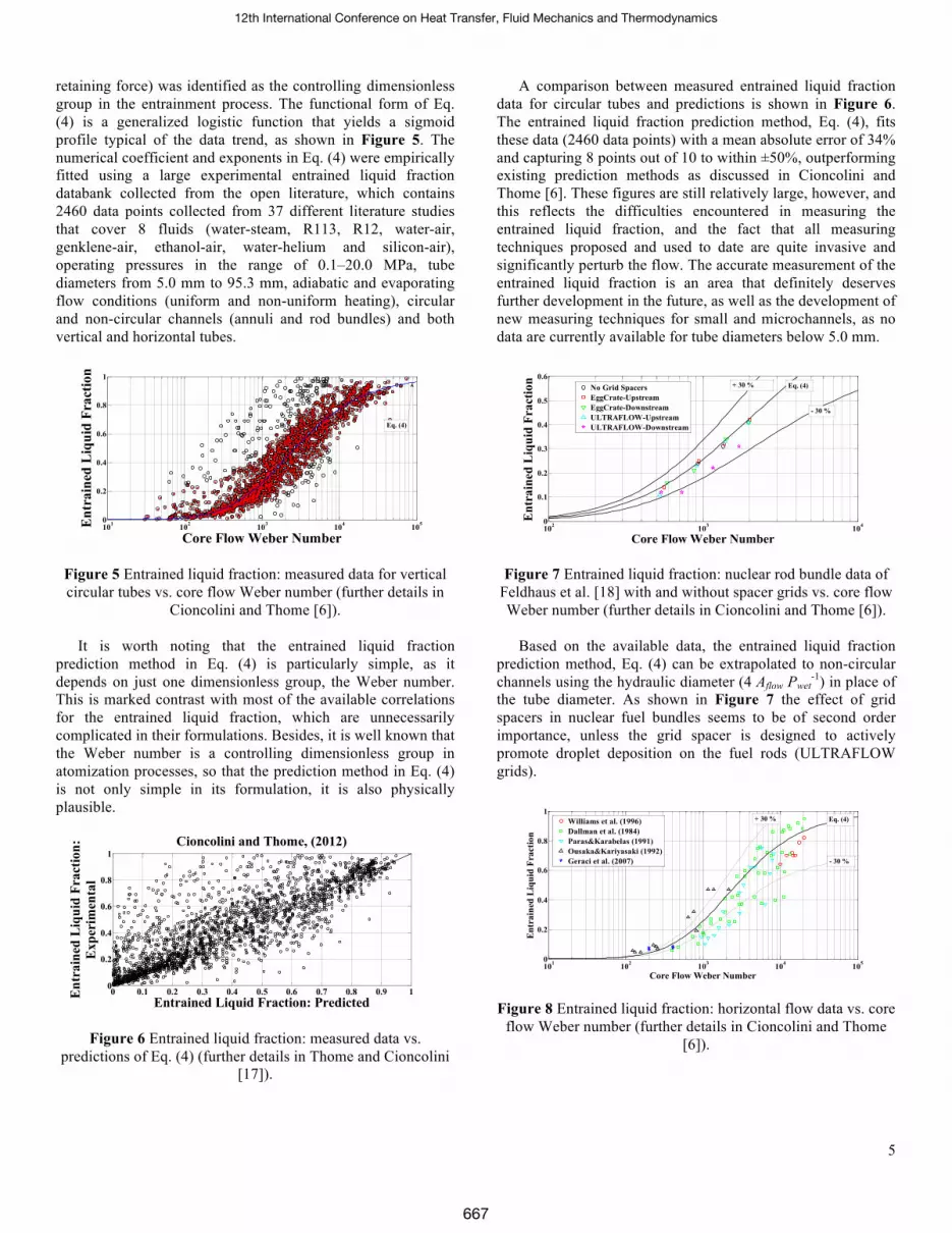
Figure 7 Entrained liquid fraction: nuclear rod bundle data of
Feldhaus et al. [18] with and without spacer grids vs. core flow Weber number (further details in Cioncolini and Thome [6]).
Based on the available data, the entrained liquid fraction
prediction method, Eq. (4) can be extrapolated to non-circular channels using the hydraulic diameter (4 Aflow Pwet
-1) in place of the tube diameter. As shown in Figure 7 the effect of grid spacers in nuclear fuel bundles seems to be of second order importance, unless the grid spacer is designed to actively promote droplet deposition on the fuel rods (ULTRAFLOW grids).
Figure 8 Entrained liquid fraction: horizontal flow data vs. core flow Weber number (further details in Cioncolini and Thome
[6]).
101 102 103 104 1050
0.2
0.4
0.6
0.8
1
Core Flow Weber Number
Ent
rain
ed L
iqui
d Fr
actio
n
Eq. (4)
0 0.1 0.2 0.3 0.4 0.5 0.6 0.7 0.8 0.9 10
0.2
0.4
0.6
0.8
1
Entrained Liquid Fraction: PredictedEnt
rain
ed L
iqui
d Fr
actio
n:E
xper
imen
tal
Cioncolini and Thome, (2012)
102 103 1040
0.1
0.2
0.3
0.4
0.5
0.6
Core Flow Weber NumberE
ntra
ined
Liq
uid
Frac
tion
No Grid SpacersEggCrate-UpstreamEggCrate-DownstreamULTRAFLOW-UpstreamULTRAFLOW-Downstream
Eq. (4)
- 30 %
+ 30 %
101 102 103 104 1050
0.2
0.4
0.6
0.8
1
Core Flow Weber Number
Entr
aine
d Li
quid
Fra
ctio
n
Williams et al. (1996)Dallman et al. (1984)Paras&Karabelas (1991)Ousaka&Kariyasaki (1992)Geraci et al. (2007)
Eq. (4)+ 30 %
- 30 %
12th International Conference on Heat Transfer, Fluid Mechanics and Thermodynamics
667

6
If annular flow is entered from intermittent flow, as happens in evaporative channels, the present prediction method can be applied from about 50 diameters downstream of the onset of annular flow, while it tends to underpredict the entrained liquid fraction if applied close to the transition since the breakdown of liquid slugs (churn flow) tends to entrain a lot of liquid until deposition has time to eliminate it. As a rule of thumb, the onset of annular flow can be estimated as the point in the channel where the void fraction reaches about ε ≈ 0.7. Based on available data taken in diabatic flow conditions, the axial power profile along the heated channel seems to be of second order importance on the entrained liquid fraction, so that only the total power supplied is relevant, but not its actual axial profile.
Moreover, as shown in Figure 8, the entrained liquid fraction prediction method, Eq. (4) can be extrapolated to horizontal and inclined channels, at least as a first approximation. In particular, the data included in Figure 8 (Williams et al., 1996; Dallman et al., 1984; Paras and Karabelas, 1991; Ousaka and Kariyasaki, 1992; Geraci et al., 2007 [19-23]) cover low pressure air-water flows in horizontal circular tubes, covering diameter values from 25.4 mm to 95.3 mm. Geraci et al. [23], in particular, tested channel inclinations of 0°, 20°, 45°, 70° and 85°with respect to the horizontal. More details are provided in Cioncolini and Thome [6].
Pressure Drop
The annular flow pressure drop prediction method proposed in Cioncolini et al. [2] reads as follows:
)(4
172.02 372.02
elsmacrochannBofor
WeV
f ccc
wtp
≥
== −
ρτ
(8)
)(4
0196.02 318.0372.02
elsmicrochannBofor
WeV
f lfccc
wtp
≤
== − Reρτ
(9)
Where ftp is the two-phase Fanning friction factor. The droplet-laden core flow average velocity Vc is calculated neglecting the slip between the carrier gas phase and the entrained liquid droplets as follows:
ερgc
xGV = (10)
The core flow Weber number Wec is defined in Eq. (5), while the Bond number Bo and the liquid film Reynolds number Relf are calculated as:
( )σ
ρρ 2dgBo gl −= (11)
( )( )l
lfdGxeµ
−−= 11Re (12)
Where σ is the surface tension and g is the acceleration of gravity. As can be seen, the macro-to-microscale transition is assumed to occur at Bo ≈ 4, according to Kew and Cornwell [24], so that Eq. (8) is valid for macroscale tubes while Eq. (9)
holds for micro-channels. Using the two-phase Fanning friction factor given by either Eq. (8) or Eq. (9), the two-phase frictional pressure gradient is calculated as follows:
224cc
tpw
fr
Vdf
ddzdP
ρτ
==⎟⎠
⎞⎜⎝
⎛ (13)
Figure 9 Pressure gradient: measured macroscale data vs. predictions of Eq. (16) [top], and measured microscale data vs. predictions of Eq. (16) [bottom] (further details in Cioncolini et
al. [2]).
For inclined flow, the gravitational pressure gradient is calculated as:
( )[ ] )sin(1 θερερ gdzdP
glgr
+−=⎟⎠
⎞⎜⎝
⎛ (14)
Where θ is the channel inclination with respect to the horizontal (θ = 0 for horizontal flow), while the acceleration pressure gradient is calculated as follows:
⎪⎭
⎪⎬⎫
⎪⎩
⎪⎨⎧
+−
+−
−−=⎟
⎠
⎞⎜⎝
⎛
gglacc
xxxex
xxedzdG
dzdP
ρερερε
2222 )1(
)1()1()1( (15)
Finally, the total pressure gradient is calculated adding the friction, acceleration and gravitation contributions:
graccfrtot dzdP
dzdP
dzdP
dzdP
⎟⎠
⎞⎜⎝
⎛+⎟⎠
⎞⎜⎝
⎛+⎟⎠
⎞⎜⎝
⎛=⎟⎠
⎞⎜⎝
⎛ (16)
1
10
100
1000
1 10 100 1000
Total Pressure Gradient-Experimental [kPa/m]
Tota
l Pre
ssur
e G
radi
ent-P
redi
cted
[k
Pa/m
]
+ 50%
- 50%
10
100
1000
10000
10 100 1000 10000
Total Pressure Gradient-Experimental [kPa/m]
Tota
l Pre
ssur
e G
radi
ent-P
redi
cted
[k
Pa/m
]
+ 50%
- 50%
12th International Conference on Heat Transfer, Fluid Mechanics and Thermodynamics
668

7
Both Eqs. (8) and (9) are based on a pressure drop databank for annular flows that contains about 3900 data points, covering 8 fluids and tube diameters from 0.517 mm to 31.7 mm, thus spanning macroscale and microscale channels. A comparison between measured pressure gradient data and predictions is shown in Figure 9. The functional form of Eqs. (8) and (9) was derived using dimensional analysis and a multiple regression technique to identify the most influential dimensionless groups on the two-phase Fanning friction factor. Notably, the Fanning friction factor in macroscale channels depends only on the core flow Weber number, while in microchannels the friction factor depends on both the core flow Weber number and on the liquid film Reynolds number, the latter accounting for enhanced viscous dissipation in the liquid film at small scale. As such, there appears to be a macro-to-microscale transition for the pressure drop in annular flow, apparently triggered by scale effects on the viscous dissipation in the liquid film. On the other hand, as already discussed, there appears to be no macro-to-microscale transition for the void fraction in annular flow, and a similar conclusion holds as well for the heat transfer coefficient during convective evaporation, as will be discussed in the next paragraph. In other words, the pressure drop in annular flows seems to be affected by miniaturization effects, while the other annular flow parameters appear to be unaffected by scale effects. The pressure drop model is currently being upgraded to better resolve the viscous dissipation in the liquid film, and better resolve these scale effects.
As can be noticed, the core flow Weber number is the controlling dimensionless group in the prediction methods for the entrained liquid fraction and for the frictional pressure gradient. In the two-phase flow literature the Weber number is typically used in the analysis of multiphase flows characterized by an interface separating two different fluids. In particular, the Weber number is a controlling dimensionless group in spray theory in general, in the study of liquid atomization and in the study of surface tension waves on shear-driven liquid films. In annular two-phase flow, the core flow can be considered as a spray interacting with the liquid film, which is shear-driven by the core flow and characterized by surface tension waves appearing at its surface. The tips of such waves are atomized by the core flow, giving rise to the entrainment. As such, the emergence of the Weber number as a characterizing group for annular flows appears consistent with annular flow phenomena.
Heat Transfer Coefficient
The heat transfer effectiveness in annular flows strongly depends on the turbulence structure in the annular liquid film, which affects the transport of linear momentum and heat through the liquid film. In their study, Cioncolini and Thome [4] focused on convective evaporation in annular flow in the absence of wall nucleation and proposed a new algebraic turbulence model for the transport of linear momentum and heat through the annular liquid film. Algebraic models are simple turbulence models that rely on the Boussinesq assumption and consider the turbulent shear stress to be proportional to the symmetric part of the mean velocity gradient and the turbulent heat flux to be proportional to the
mean temperature gradient. The constants of proportionality are flow-dependent and are expressed with empirically derived algebraic relations that involve the length scale of the mean flow. In contrast with single-phase wall-bounded flow theory, normally extrapolated to two-phase flows in most existing studies, the authors assumed that the flow in the shear-driven annular liquid film is mostly affected by the interaction of the liquid film with the shearing gas-entrained droplet core flow. In other words, the liquid film was assumed to behave as a fluid-bounded flow, such as a jet or a wake, with a negligible influence of the bounding channel wall. Since the characteristic length scale of jets and wakes is normally assumed to be proportional to their width, the characteristic length scale of the liquid film was thus assumed to be proportional to its average thickness, instead of the distance from the channel wall used in single-phase wall-bounded flow theory.
The physical plausibility of this approach was later confirmed by Cioncolini et al. [9], who using available measurements of the velocity profile showed that the turbulence structure in shear-driven annular liquid films is different from the turbulence structure typical of single-phase wall bounded flows. In particular, as shown in Figure 10, turbulence in the annular liquid film does not reach as close to the channel wall as it does in single-phase flows, and the turbulent viscosity is lower than the corresponding turbulent viscosity in single-phase wall bounded flows, thus suggesting that the turbulence intensity in shear-driven annular liquid films is somewhat weaker than the corresponding turbulence intensity in single-phase wall bounded flows.
Figure 10 Velocity profile measurements in annular liquid films vs. universal velocity profile for wall-bounded single-
phase flow (further details in Cioncolini et al. [9]). The heat transfer equation proposed by the authors for
convective evaporation in annular flow reads as follows:
1.6Pr86.0;80010
Pr0776.0 52.090.0
≤≤≤≤
==
+
+
l
ll
t
tkthNu (17)
Where h is the convective evaporation heat transfer coefficient, kl is the liquid thermal conductivity, Nu is a Nusselt number based on the average liquid film thickness t, Prl is the liquid Prandtl number and t+ is the dimensionless liquid film thickness defined as:
0 10 20 30 40 50 60 70 80 90 1000
5
10
15
20
25
30
35
Dimensionless Distance from Wall y+
Dim
ensi
onle
ss V
eloc
ity V
+
V+ = y+
Universal Velocity Profile
12th International Conference on Heat Transfer, Fluid Mechanics and Thermodynamics
669

8
l
w
l
l
l
l VV
ytVytt
ρτ
ρµ
µρ
====+ **
**
* ;; (18)
Where ρl and µl are the liquid density and viscosity, y* and V* are the length and velocity wall scales and τw is the wall shear stress. According to the authors, the dimensionless liquid film thickness is empirically predicted as follows:
⎟⎟
⎠
⎞
⎜⎜
⎝
⎛=+
lflft Re0165.0,2Re
max (19)
As can be noticed, Eq. (17) is formally analogous to a Dittus-Boelter like heat transfer equation, since the dimensionless liquid film thickness t+ can be interpreted as a Reynolds number for the liquid film, with the velocity wall scale V* as characteristic velocity and the average liquid film thickness t as the characteristic dimension.
The experimental databank used to derive Eq. (17) contains 1311 data points that cover 9 fluids, including water, hydrocarbons (propane R290 and isobutane R600a), chlorofluorocarbon refrigerants (CFCs: R12), hydrogenated fluorocarbons refrigerants (HFCs: R32, R134a, R236fa and R245fa) and hydrogenated chlorofluorocarbon refrigerants (HCFCs: R22). The collected data cover 12 tube diameter values from 1.03 mm to 14.4 mm spanning from ‘micro’ to ‘macroscale’.
Figure 11 Heat transfer coefficient during convective evaporation: predictions of Eq. (17) vs. measured data (further
details in Cioncolini and Thome [4]).
A comparison between measured heat transfer coefficient data and predictions is shown in Figure 11. As can be seen, the proposed heat transfer model fits these data quite satisfactorily, the mean absolute percentage error is 13%, and 6 points out of 10 are captured within ±15 %. Importantly, the convective heat transfer model shows that there appears to be no macro-to-microscale transition for annular flow, at least down to diameters of about 1 mm. More details are provided in Cioncolini and Thome [4]. The heat transfer model has been recently extended to horizontal channels characterized by an asymmetric liquid film distribution induced by gravity [8], which in turns yields a peripheral variation of the heat transfer coefficient around the tube.
Overall, the unified annular flow modeling suite is currently based on a large experimental databank collected from 99 literature studies that contains 11498 data points, and additional work is being performed to expand the underlying database and further improve the annular flow models. Current work includes the upgrade of the pressure drop model, to better account for the viscous dissipation in the annular liquid film at small and microscale, the upgrade of the heat transfer model to better account for condensation and wall nucleation during convective boiling, and the addition of a brand new model to predict dryout during convective evaporation in tubes and channels. Selected results for convective evaporation and condensation in tubes and channels, both macroscale and microscale, are presented below. The entire suite of methods was used to generate the predictions presented below.
SELECTED RESULTS
Selected results for convective evaporation and condensation in circular and non-circular channels, both macroscale and microscale, are presented below. It is worth highlighting that the experimental data used in the comparisons that follow are independent data, not used in the calibration of the prediction methods of the unified modelling suite.
Convective Evaporation in Circular Tubes
Selected convective evaporation results for circular tubes are presented in Figures 12-14.
Figure 12 Convective evaporation heat transfer coefficient vs. vapor quality for refrigerant R22 data of Shin et al. [25] (heat flux: 25.0 kW/m2; saturation temperature: 285 K-12 °C; tube
diameter: 7.7 mm).
As can be seen in Figures 12-14, the comparison is for the most part quite satisfactory. In particular, the authors’ convective heat transfer model predicts a dependence of the heat transfer coefficient on mass flux but not on heat flux, as typically happens with convective boiling when wall nucleation is suppressed.
101 102100
101
102
Heat Transfer Coefficient: Experimental [kW/m2K]
Hea
t Tra
nsfe
r C
oeff
icie
nt:
Pred
icte
d [k
W/m
2 K]
+ 30 %
- 30 %
0.2 0.4 0.6 0.8 14.5
5
5.5
6
6.5
7
7.5
8
Vapor Quality
Hea
t Tra
nsfe
r C
oeff
icie
nt [k
W/m
2 K]
G=424 kg/m2sG=583 kg/m2sG=742 kg/m2s
12th International Conference on Heat Transfer, Fluid Mechanics and Thermodynamics
670

9
0.2 0.3 0.4 0.5 0.6 0.7 0.81000
2000
3000
4000
5000
6000
7000
8000
9000
10000
Vapor Quality
Hea
t Tra
nsfe
r C
oeff
icie
nt [W
/m2 K
]
G=200 kg/m2sG=400 kg/m2sG=600 kg/m2s
0.2 0.3 0.4 0.5 0.6 0.7 0.81000
2000
3000
4000
5000
6000
7000
8000
9000
Vapor Quality
Hea
t Tra
nsfe
r C
oeff
icie
nt [W
/m2 K
]
G=200 kg/m2sG=300 kg/m2sG=400 kg/m2sG=750 kg/m2s
Figure 13 Convective evaporation heat transfer coefficient vs. vapor quality for refrigerant R22 data of Shin et al. [25] (mass flux: 742 kg/m2s; saturation temperature: 285 K-12 °C; tube
diameter: 7.7 mm).
Figure 14 Convective evaporation heat transfer coefficient vs. vapor quality for H2O data of Kenning and Cooper [26] (mass flux: 135 kg/m2s; saturation temperature: 417 K-144 °C; tube
diameter: 14.4 mm).
Convective Condensation in Circular Tubes
As noted, among others, by Shah [27] and experimentally verified by Sun and Hewitt [28], there is no significant difference between forced convective condensation and forced convective evaporation, at least as long as nucleation at the channel wall is suppressed during the boiling process. As such, the unified annular flow modeling suite, and more generally any prediction methods designed for forced convective evaporation in the absence of wall nucleation, can be applied as well to forced convective condensation (or should be able to as a validation of the approach).
Selected convective condensation results are presented in Figures 15-17. As can be seen, the comparison is for the most part quite satisfactory.
Figure 15 Convective condensation heat transfer coefficient
vs. vapor quality for refrigerant R236ea data of Cavallini et al. [29] (saturation temperature: 313 K-40 °C; tube diameter: 8.0
mm).
Figure 16 Convective condensation heat transfer coefficient vs. vapor quality for refrigerant R134a data of Cavallini et al. [29] (saturation temperature: 313 K-40 °C; tube diameter: 8.0
mm).
CONCLUSIONS
The unified modeling suite for annular two-phase flow that the authors have and continue to develop was presented, illustrating each single model currently included in the suite. The unified modelling suite predictions were then compared with selected heat transfer coefficient measurements in evaporation and condensation, including data for water and refrigerants in both conventional and microchannels. Satisfactory agreement was found between data and predictions. This provides a robust set of methods that are proven to work well together in a situation where the various flow parameters are interrelated, and that can be used in general design and analysis applications involving annular two-phase flows.
0.2 0.3 0.4 0.5 0.6 0.74.5
5
5.5
6
6.5
7
7.5
8
8.5
Vapor Quality
Hea
t Tra
nsfe
r C
oeff
icie
nt [k
W/m
2 K]
qw=18kW/m2
qw=25kW/m2
qw=30kW/m2
0.19 0.2 0.21 0.22 0.23 0.2413.5
14
14.5
15
15.5
16
Vapor Quality
Hea
t Tra
nsfe
r C
oeff
icie
nt [k
W/m
2 K]
qw=46 kW/m2
qw=71 kW/m2
qw=100 kW/m2
12th International Conference on Heat Transfer, Fluid Mechanics and Thermodynamics
671

10
0.2 0.3 0.4 0.5 0.6 0.7 0.81000
2000
3000
4000
5000
6000
7000
8000
9000
Vapor Quality
Hea
t Tra
nsfe
r C
oeff
icie
nt [W
/m2 K
]
G=200 kg/m2sG=400 kg/m2sG=600 kg/m2sG=750 kg/m2s
Figure 17 Convective condensation heat transfer coefficient vs. vapor quality for refrigerant R22 data of Cavallini et al.
[29] (saturation temperature: 313 K-40 °C; tube diameter: 8.0 mm).
REFERENCES [1] Cioncolini, A., Thome, J.R., and Lombardi, C., Algebraic
turbulence modeling in adiabatic gas-liquid annular two-phase flow, International Journal of Multiphase Flow, vol. 35, pp. 580-596, 2009.
[2] Cioncolini, A., Thome, J.R., and Lombardi, C., Unified macro-to-microscale method to predict two-phase frictional pressure drops of annular flows, International Journal of Multiphase Flow, vol. 35, pp. 1138-1148, 2009.
[3] Cioncolini, A., and Thome, J.R., Prediction of the entrained liquid fraction in vertical annular gas-liquid two-phase flow, International Journal of Multiphase Flow, vol. 36, pp. 293-302, 2010.
[4] Cioncolini, A., and Thome, J.R., Algebraic turbulence modeling in adiabatic and evaporating annular two-phase flow, International Journal of Heat and Fluid Flow, vol. 32, pp. 805-817, 2011.
[5] Cioncolini, A., and Thome, J.R., Void fraction prediction in annular two-phase flow, International Journal of Multiphase Flow, vol. 43, pp. 72-84, 2012.
[6] Cioncolini, A., and Thome, J.R., Entrained liquid fraction prediction in adiabatic and evaporating annular two-phase flow, Nuclear Engineering and Design, vol. 243, pp. 200-213, 2012.
[7] Cioncolini, A., and Thome, J.R., Liquid film circumferential asymmetry prediction in horizontal annular two-phase flow, International Journal of Multiphase Flow, vol. 51, pp. 44-54, 2013.
[8] Mauro, A.W., Cioncolini, A., Thome, J.R., and Mastrullo, R., Asymmetric annular flow in horizontal circular macro-channels: basic modeling of the liquid film distribution and heat transfer around the tube perimeter in convective boiling, International Journal of Heat and Mass Transfer, vol. 77, pp. 897-905, 2014.
[9] Cioncolini, A., Del Col, D., and Thome, J.R., An indirect criterion for the laminar to turbulent flow transition in shear-driven annular liquid films, International Journal of Multiphase Flow, vol. 75, pp. 26-38, 2015.
[10] Hill, A.V., The possible effects of the aggregation of the molecules of haemoglobin on its dissociation curves, Journal of Physiology, vol. 40, pp. iv-vii, 1910.
[11] Murray, J.D., Mathematical Biology, Springer-Verlag, New York, 2002.
[12] Jones, O.C., and Zuber, N., The interrelation between void fraction fluctuations and flow patterns in two-phase flow, International Journal of Multiphase Flow, vol. 2, pp. 273-306, 1975.
[13] Hori, K., Akiyama, Y., Miyazaki, K., Kurosu, T., and Sugiyama, S., Void fraction in a single channel simulating one subchannel of a PWR fuel assembly, In: Two-Phase Flow Modeling and Experimentation 1995, Celata, G.P., and Shah, R.K. (Editors), ETS, Italy, 1013-1027, 1995.
[14] Takenaka, N., and Asano, H., Quantitative CT-reconstruction of void fraction distributions in two-phase flow by neutron radiography. Nuclear Instrumentation and Methods in Physics Research A, vol. 542, pp. 387-391, 2005.
[15] Morooka, S., Ishizuka, T., Iizuka, M., and Yoshimura, K., Experimental study on void fraction in a simulated BWR fuel assembly, Nuclear Engineering and Design, vol. 114, pp. 91-98, 1989.
[16] Das, G., Das, P.K., Purohit, N.K., and Mitra, A.K., Liquid holdup in concentric annuli during cocurrent gas-liquid upflow, Canadian Journal of Chemical Engineering, vol. 80, pp. 153-157, 2002.
[17] Thome, J.R., and Cioncolini, A., Encyclopedia of Two-Phase Heat Transfer and Flow I: Fundamentals and Methods, Volume 3: Flow Boling in Macro and Microchannels, World Scientific Publishing, Singapore, 2015.
[18] Feldhaus, G., Azzopardi, B.J., and Zeggel, W., Annular flow experiments in rod bundles with spacers, Nuclear Engineering and Design, vol. 213, pp. 199-207, 2002.
[19] Williams, L.R., Dykhno, L.A., and Hanratty, T.J., Droplet flux distributions and entrainment in horizontal gas-liquid flows, International Journal of Multiphase Flow, vol. 22, pp. 1-18, 1996.
[20] Dallman, J.C., Laurinat, and J.E., Hanratty, T.J, Entrainment for horizontal annular gas-liquid flow, International Journal of Multiphase Flow, vol. 10, pp. 677-690, 1984.
[21] Paras, S.V., and Karabelas, A.J., Droplet entrainment and deposition in horizontal annular flow, International Journal of Multiphase Flow, vol.17, pp. 455-468, 1991.
[22] Ousaka, A., and Kariyasaki, A., Distribution of entrainment flow rate for air-water annular two-phase flow in a horizontal tube, JSME International Journal Series II, vol. 35, pp. 354-360,1992.
[23] Geraci, G., Azzopardi, B.J., and van Maanen, H.R.E., Inclination effects on circumferential film flow distribution in annular gas/liquid flows, AIChE Journal, vol. 53, pp. 1144-1150, 2007.
[24] Kew, P., and Cornwell, K., Correlations for prediction of boiling heat transfer in small diameter channels, Applied Thermal Engineering, vol. 17, pp. 705-715, 1997.
[25] Shin, J.Y., Kim, M.S., and Ro, S.T., Experimental study on forced convective boiling heat transfer of pure refrigerants and refrigerant mixtures in a horizontal tube, International Journal of Refrigeration, vol. 20, pp. 267-275, 1997.
[26] Kenning, D.B.R., and Cooper, M.G., Saturated flow boiling of water in vertical tubes, International Journal of Heat and Mass Transfer, vol. 32, pp. 445-458, 1989.
[27] Shah, M.M., A general correlation for heat transfer during film condensation inside pipes, International Journal of Heat and Mass Transfer vol. 22, pp. 547-556, 1979.
[28] Sun, G., and Hewitt, G.F., Evaporation and condensation of steam-water in a vertical tube, Nuclear Engineering and Design vol. 207, pp. 137-145, 2001.
[29] Cavallini, A., Censi, G., Del Col, D., Doretti, L., Longo, G.A., and Rossetto, L., Experimental investigation on condensation heat transfer and pressure drop on new HFC refrigerants (R134a, R125, R32, R410a, R236ea) in a horizontal smooth tube, International Journal of Refrigeration, vol. 24, pp. 73-87., 2001.
12th International Conference on Heat Transfer, Fluid Mechanics and Thermodynamics
672