analysis of the impact of hard pvd coatings on the abrasion
TRANSCRIPT
AiMTAdvances in Military Technology
Vol. 15, No. 1, 2020, pp. 85-95ISSN 1802-2308, eISSN 2533-4123
DOI 10.3849/aimt.01333
Analysis of the Impact of Hard PVD Coatings on the Abrasion Resistance of the Compressor Blades
P. Fördös* and J. Čerňan
Air Transport Department, University of Žilina, Slovak Republic
The manuscript was received on 16 June 2019 and was accepted after revision for publication as technical information on 27 February 2020.
Abstract:
The article deals with the application of PVD (Physical Vapour Deposition) coatings onto the surface of compressor blades. In sandy or dusty conditions, compressor blades are the first obstacle for particles which are being sucked into the jet engine. Compres-sor blades equipped with a protective layer should have greater resistance against erosive and abrasive damage. To support this theory, an empirical experiment had to be conducted. Based on the data acquired from the experiment, we were able to summarise the effectiveness of coatings applied.
Keywords:
abrasion, blade, coating, compressor blade, erosion, jet engine, PVD
1. Introduction
The gas turbine engines operate in one of the harshest environments, which enforces the continuous development of the applied materials. Aircraft engine parts are exposed to severe mechanical loads, high temperature, as well as corrosion and erosion. Since the early stages of modern engine construction, their producers have been applying protective coating systems in order to enhance their durability and to maximize the exploitation of the properties of the used materials [1].
Modern engine construction together with the technological advancement lead to the evolution of the new coating types and to the improvement of the formerly used coatings. In the front part of the engine, the so-called cold section, including the fan and the compressor, the abrasion and erosion resistant coatings and seals are typically employed. Cold section parts such as fan blades, compressor blades and impellers are made of composites, titanium-aluminium alloys, titanium and heat resistant steels [2].
The development tendencies in obtaining highly reliable jet engines are closely connected with an increase in the engine’s capacity, its efficiency, lifetime and a de-crease in the fuel consumption. These may be achieved by applying high temperature
* Corresponding author: Air Transport Department, University of Žilina, Univerzitná 8215/1,
010 26 Žilina, Slovak Republic. E-mail: [email protected]
86 DOI 10.3849/aimt.01333
inlets, an increase in pressure, using more durable materials and enhancing the method of part manufacture [2, 3].
The main objective of this article is to show the possibility of protecting the compressor blades with PVD (Physical Vapour Deposition) coating, thus prolonging their lifetime. These coatings are implemented onto the desired object in order to im-prove its resistance to wear, drag, abrasion and erosion. Blades with thin film implemented on their surface were subjected to an experiment. The experiment pro-cess and its outcome is described further in this article. Within the last decades, a significant progress has occurred in the improvement of the PVD coating properties. The process of implementing a coating became easier and cheaper as it was in the past, though it is still a very complex procedure.
2. Effect of Dusty/Sandy Environment
Helicopters, especially those in military use, most often perform flights at lower alti-tudes, and the specificity of tasks performed by them requires their performance from the hastily made and thus not always adequately prepared landing areas. However, this can also relate to helicopters for civil use, performing agricultural aviation services or being used by the fire brigade, border guard or air rescue, because they are sometimes forced to operate flights at altitudes from a few to several feet and use unpaved run-ways [4, 5].
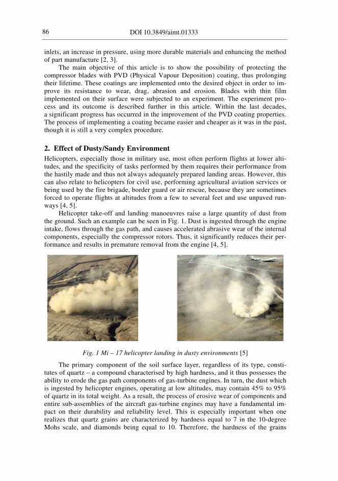
Helicopter take-off and landing manoeuvres raise a large quantity of dust from the ground. Such an example can be seen in Fig. 1. Dust is ingested through the engine intake, flows through the gas path, and causes accelerated abrasive wear of the internal components, especially the compressor rotors. Thus, it significantly reduces their per-formance and results in premature removal from the engine [4, 5].
Fig. 1 Mi – 17 helicopter landing in dusty environments [5]
The primary component of the soil surface layer, regardless of its type, consti-tutes of quartz – a compound characterised by high hardness, and it thus possesses the ability to erode the gas path components of gas-turbine engines. In turn, the dust which is ingested by helicopter engines, operating at low altitudes, may contain 45% to 95% of quartz in its total weight. As a result, the process of erosive wear of components and entire sub-assemblies of the aircraft gas-turbine engines may have a fundamental im-pact on their durability and reliability level. This is especially important when one realizes that quartz grains are characterized by hardness equal to 7 in the 10-degree Mohs scale, and diamonds being equal to 10. Therefore, the hardness of the grains

Advances in Military Technology, 2020, vol. 15, no. 1, pp. 85-95 87
exceeds the analogous indicators of the materials used to produce aircraft gas turbine engines. However, the granulometric composition, which is a heterogeneity indicator of dust grains, largely depends on the ground type and structure [5].
In the dust conditions of the operating environment of helicopter and propeller gas-turbine engines, intense wear of sub-assemblies in their gas paths occurs. Howev-er, the most intense degradation of components takes place within their compressors and bearing systems [5]. Compressor blades in Fig. 2 show an example of intense abrasive wear on their surface.
Ingested dust particles not only change the shape of profiles of the surrounded blades, but they also settle in the compressor’s inlet part, disrupting the air flow, mak-ing it very difficult for the aircraft gas turbine engine to operate correctly [6].
Fig. 2 Leading edges of the blades of the first stage compressor. a), b), c) and d) damage of the top part of the blade. e) crack propagating from the leading edge [5]
The deterioration is not always felt by the aircraft crew, because it can only be observed by measuring the temperature in front of the turbine, when the engine is at maximum speed. Therefore, together with the increased erosive degradation of the rotor’s unit, the limit for stable operation of the compressor and its operating range line changes, resulting in a significant decrease in the limit of its stable operation [5].
This type of damage occurs as a result of wear, both the friction and impact ones. The first of them occurs when dust particles cut the blade in the direction of the trail-ing edge. The particles move with the air, pressed (as a result of aerodynamic and centrifugal forces that affect them) to the surface of rotating aerofoils, cutting into their material with sharp edges, and moving on their surface [5].
However, the second one occurs when dust particles, under the influence of iner-tia forces, strike their operating surface, which is characteristic for wear of the initial stages of the compressor’s rotors [5].
3. Physical Vapour Deposition
Thin coating technology is a large branch of the generic technology that has to do with surface modifications and coatings. In the surface modification process, the properties of the surface of the substrate material are changed, as exemplified by the hardening of steel surface by introducing carbon or nitrogen to the surface. In the process that in-volves the application of a coating, the substrate material and the coating may be quite different, as exemplified by the deposition of aluminium or chromium on polymer surfaces or deposition of a hard coating of titanium nitride on tool bits [6].
Adhesion can be defined as the ability of two materials (especially two different materials) to merge together. Only when excellent adhesion of the coating to the sub-

88 DOI 10.3849/aimt.01333
strate is ensured, maximal utilization of the coating can be accomplished. The physi-cochemical properties and adhesion of the thin layer to the base material are closely related. The adhesion of the thin layers is determined by the bond of the layer atoms together with the surface atoms of the base material and it is affected by the stress in the layer. In order to achieve high-quality adhesion, it is necessary to clean the surface thoroughly before applying the coating to a specified surface. This will ensure that the incident atoms bind directly to the atoms of the substrate [6, 7].
One of the most important parameters of the layer is good adhesion. This parame-ter characterizes the properties of the entire system. In order to achieve the best possible connection, it is necessary to focus mainly on the formation of the binding forces of a given nature and the size of forces between the layer and the substrate. The size of the binding forces is influenced by these parameters: the kinetic energy of the impinging atoms and ions on the surface changes in the deposition parameters, the properties of the substrate structure and the state and the purity of the surface at the time of the layer formation. The methods currently used for detecting adhesion-cohesive behaviour are based on the generation of tension that serves to overcome the binding forces at the interface of the thin layer and the substrate. In practice, the intru-sion test (Mercedes test) and scratch test (Scratch test) are used to determine adhesion [8, 9]. PVD methods:
• evaporation, • sputtering, • ion plating.
We will take a closer look at one particular sputtering method, which was used to coat compressor blades. The blades were later used for testing. The coating of com-pressor blades with this method was provided by the STATON Company.
3.1. Magnetron Sputtering
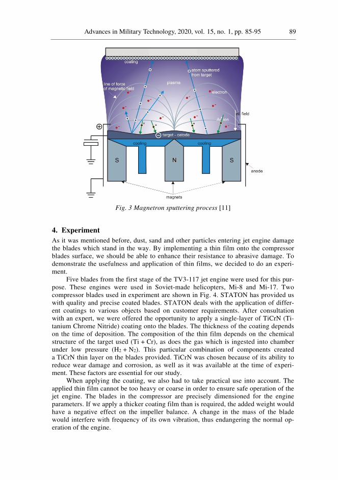
It is an advanced sputtering technology. This process takes place in a vacuum chamber and under strict procedures. The principle is to connect the target as a cathode and then to apply voltage. In front of the target, a magnetic field of the specified shape is creat-ed by means of an electromagnet or permanent magnet (magnetron). A strong magnet is placed under the target. This magnet is water-cooled to avoid overheating. Working gas is then fed into the chamber, which in most cases is argon. After the voltage is applied, a glow discharge (plasma) is ignited in front of the target in the argon filled environment. The discharge is seen as a source of light energy. Based on argon bom-bardment on the target surface, its material is deposited onto the substrate surface. The magnetic field streamlines help with the argon ionization in the plasma and subse-quently improves sputtering [9, 10]. Detailed magnetron sputtering process can be seen in Fig. 3.
Electrons which leave the space in front of the target in sputtering, have to move along a trajectory that follows the magnetic field lines due to the Lorentz force. In this way, the electron path near the target is significantly extended. Their residence time in the discharge area is also prolonged and the likelihood of ionizing additional working gas atoms is increased. This phenomenon keeps the discharge at a lower pressure (by tenths of Pa) and lower voltage (by hundreds of V). The lower pressure in the working chamber is positively reflected in the increased purity of the formed layer [12].
Advances in Military Technology, 2020, vol. 15, no. 1, pp. 85-95 89
Fig. 3 Magnetron sputtering process [11]
4. Experiment
As it was mentioned before, dust, sand and other particles entering jet engine damage the blades which stand in the way. By implementing a thin film onto the compressor blades surface, we should be able to enhance their resistance to abrasive damage. To demonstrate the usefulness and application of thin films, we decided to do an experi-ment.
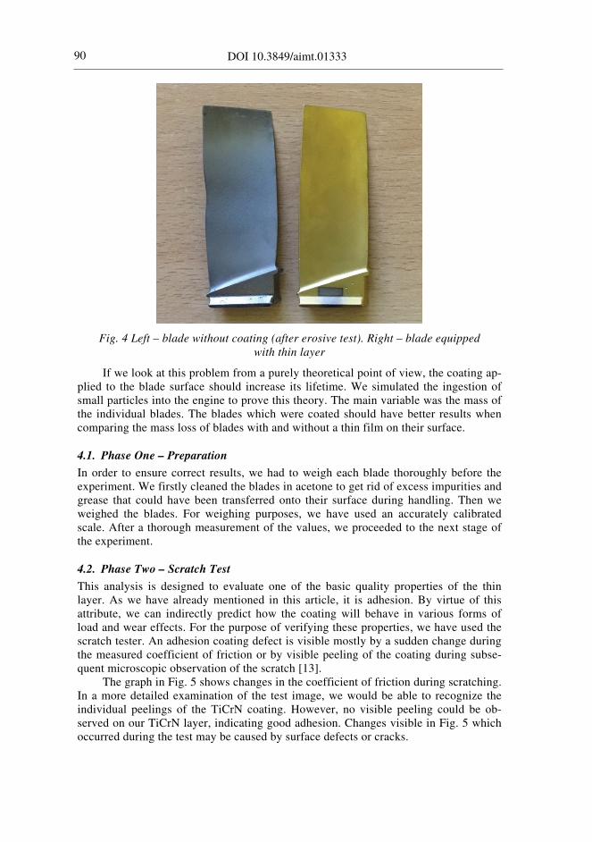
Five blades from the first stage of the TV3-117 jet engine were used for this pur-pose. These engines were used in Soviet-made helicopters, Mi-8 and Mi-17. Two compressor blades used in experiment are shown in Fig. 4. STATON has provided us with quality and precise coated blades. STATON deals with the application of differ-ent coatings to various objects based on customer requirements. After consultation with an expert, we were offered the opportunity to apply a single-layer of TiCrN (Ti-tanium Chrome Nitride) coating onto the blades. The thickness of the coating depends on the time of deposition. The composition of the thin film depends on the chemical structure of the target used (Ti + Cr), as does the gas which is ingested into chamber under low pressure (H2 + N2). This particular combination of components created a TiCrN thin layer on the blades provided. TiCrN was chosen because of its ability to reduce wear damage and corrosion, as well as it was available at the time of experi-ment. These factors are essential for our study.
When applying the coating, we also had to take practical use into account. The applied thin film cannot be too heavy or coarse in order to ensure safe operation of the jet engine. The blades in the compressor are precisely dimensioned for the engine parameters. If we apply a thicker coating film than is required, the added weight would have a negative effect on the impeller balance. A change in the mass of the blade would interfere with frequency of its own vibration, thus endangering the normal op-eration of the engine.
90 DOI 10.3849/aimt.01333
Fig. 4 Left – blade without coating (after erosive test). Right – blade equipped with thin layer
If we look at this problem from a purely theoretical point of view, the coating ap-plied to the blade surface should increase its lifetime. We simulated the ingestion of small particles into the engine to prove this theory. The main variable was the mass of the individual blades. The blades which were coated should have better results when comparing the mass loss of blades with and without a thin film on their surface.
4.1. Phase One – Preparation
In order to ensure correct results, we had to weigh each blade thoroughly before the experiment. We firstly cleaned the blades in acetone to get rid of excess impurities and grease that could have been transferred onto their surface during handling. Then we weighed the blades. For weighing purposes, we have used an accurately calibrated scale. After a thorough measurement of the values, we proceeded to the next stage of the experiment.
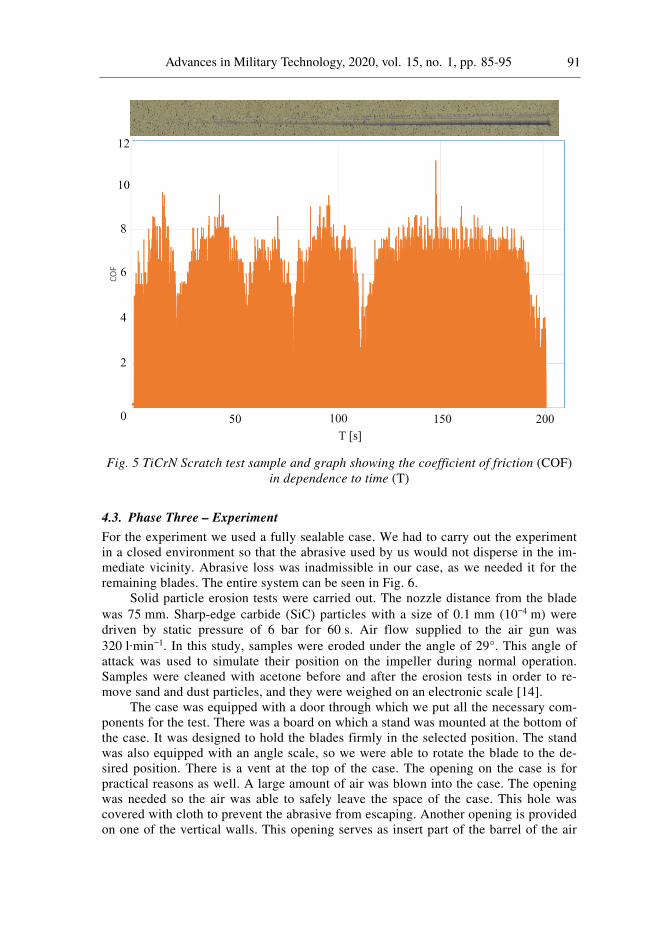
4.2. Phase Two – Scratch Test
This analysis is designed to evaluate one of the basic quality properties of the thin layer. As we have already mentioned in this article, it is adhesion. By virtue of this attribute, we can indirectly predict how the coating will behave in various forms of load and wear effects. For the purpose of verifying these properties, we have used the scratch tester. An adhesion coating defect is visible mostly by a sudden change during the measured coefficient of friction or by visible peeling of the coating during subse-quent microscopic observation of the scratch [13].
The graph in Fig. 5 shows changes in the coefficient of friction during scratching. In a more detailed examination of the test image, we would be able to recognize the individual peelings of the TiCrN coating. However, no visible peeling could be ob-served on our TiCrN layer, indicating good adhesion. Changes visible in Fig. 5 which occurred during the test may be caused by surface defects or cracks.
Advances in Military Technology, 2020, vol. 15, no. 1, pp. 85-95 91
Fig. 5 TiCrN Scratch test sample and graph showing the coefficient of friction (COF) in dependence to time (T)
4.3. Phase Three – Experiment
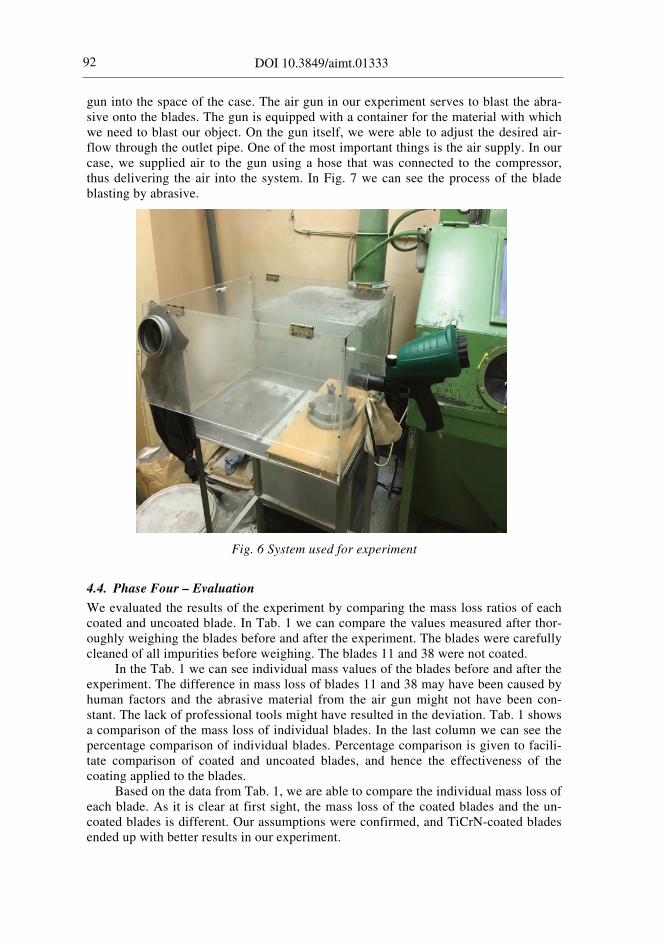
For the experiment we used a fully sealable case. We had to carry out the experiment in a closed environment so that the abrasive used by us would not disperse in the im-mediate vicinity. Abrasive loss was inadmissible in our case, as we needed it for the remaining blades. The entire system can be seen in Fig. 6.
Solid particle erosion tests were carried out. The nozzle distance from the blade was 75 mm. Sharp-edge carbide (SiC) particles with a size of 0.1 mm (10−4 m) were driven by static pressure of 6 bar for 60 s. Air flow supplied to the air gun was 320 l·min−1. In this study, samples were eroded under the angle of 29°. This angle of attack was used to simulate their position on the impeller during normal operation. Samples were cleaned with acetone before and after the erosion tests in order to re-move sand and dust particles, and they were weighed on an electronic scale [14].
The case was equipped with a door through which we put all the necessary com-ponents for the test. There was a board on which a stand was mounted at the bottom of the case. It was designed to hold the blades firmly in the selected position. The stand was also equipped with an angle scale, so we were able to rotate the blade to the de-sired position. There is a vent at the top of the case. The opening on the case is for practical reasons as well. A large amount of air was blown into the case. The opening was needed so the air was able to safely leave the space of the case. This hole was covered with cloth to prevent the abrasive from escaping. Another opening is provided on one of the vertical walls. This opening serves as insert part of the barrel of the air
92 DOI 10.3849/aimt.01333
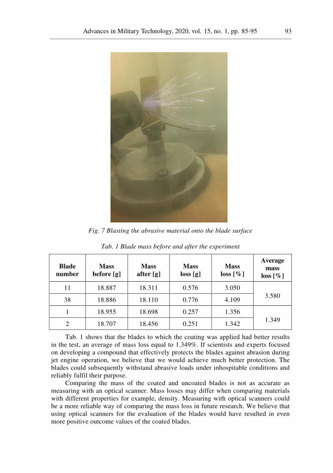
gun into the space of the case. The air gun in our experiment serves to blast the abra-sive onto the blades. The gun is equipped with a container for the material with which we need to blast our object. On the gun itself, we were able to adjust the desired air-flow through the outlet pipe. One of the most important things is the air supply. In our case, we supplied air to the gun using a hose that was connected to the compressor, thus delivering the air into the system. In Fig. 7 we can see the process of the blade blasting by abrasive.
Fig. 6 System used for experiment
4.4. Phase Four – Evaluation
We evaluated the results of the experiment by comparing the mass loss ratios of each coated and uncoated blade. In Tab. 1 we can compare the values measured after thor-oughly weighing the blades before and after the experiment. The blades were carefully cleaned of all impurities before weighing. The blades 11 and 38 were not coated.
In the Tab. 1 we can see individual mass values of the blades before and after the experiment. The difference in mass loss of blades 11 and 38 may have been caused by human factors and the abrasive material from the air gun might not have been con-stant. The lack of professional tools might have resulted in the deviation. Tab. 1 shows a comparison of the mass loss of individual blades. In the last column we can see the percentage comparison of individual blades. Percentage comparison is given to facili-tate comparison of coated and uncoated blades, and hence the effectiveness of the coating applied to the blades.
Based on the data from Tab. 1, we are able to compare the individual mass loss of each blade. As it is clear at first sight, the mass loss of the coated blades and the un-coated blades is different. Our assumptions were confirmed, and TiCrN-coated blades ended up with better results in our experiment.
Advances in Military Technology, 2020, vol. 15, no. 1, pp. 85-95 93
Fig. 7 Blasting the abrasive material onto the blade surface
Tab. 1 Blade mass before and after the experiment
Blade
number
Mass
before [g]
Mass
after [g]
Mass
loss [g]
Mass
loss [%]
Average
mass
loss [%]
11 18.887 18.311 0.576 3.050 3.580
38 18.886 18.110 0.776 4.109
1 18.955 18.698 0.257 1.356 1.349
2 18.707 18.456 0.251 1.342
Tab. 1 shows that the blades to which the coating was applied had better results in the test, an average of mass loss equal to 1.349%. If scientists and experts focused on developing a compound that effectively protects the blades against abrasion during jet engine operation, we believe that we would achieve much better protection. The blades could subsequently withstand abrasive loads under inhospitable conditions and reliably fulfil their purpose.
Comparing the mass of the coated and uncoated blades is not as accurate as measuring with an optical scanner. Mass losses may differ when comparing materials with different properties for example, density. Measuring with optical scanners could be a more reliable way of comparing the mass loss in future research. We believe that using optical scanners for the evaluation of the blades would have resulted in even more positive outcome values of the coated blades.
94 DOI 10.3849/aimt.01333
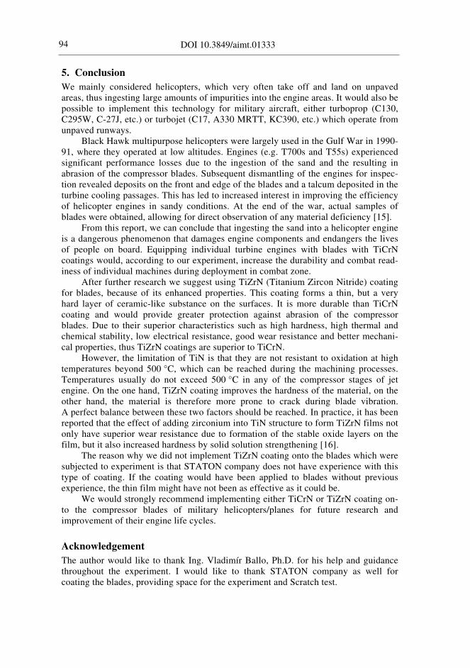
5. Conclusion
We mainly considered helicopters, which very often take off and land on unpaved areas, thus ingesting large amounts of impurities into the engine areas. It would also be possible to implement this technology for military aircraft, either turboprop (C130, C295W, C-27J, etc.) or turbojet (C17, A330 MRTT, KC390, etc.) which operate from unpaved runways.
Black Hawk multipurpose helicopters were largely used in the Gulf War in 1990-91, where they operated at low altitudes. Engines (e.g. T700s and T55s) experienced significant performance losses due to the ingestion of the sand and the resulting in abrasion of the compressor blades. Subsequent dismantling of the engines for inspec-tion revealed deposits on the front and edge of the blades and a talcum deposited in the turbine cooling passages. This has led to increased interest in improving the efficiency of helicopter engines in sandy conditions. At the end of the war, actual samples of blades were obtained, allowing for direct observation of any material deficiency [15].
From this report, we can conclude that ingesting the sand into a helicopter engine is a dangerous phenomenon that damages engine components and endangers the lives of people on board. Equipping individual turbine engines with blades with TiCrN coatings would, according to our experiment, increase the durability and combat read-iness of individual machines during deployment in combat zone.
After further research we suggest using TiZrN (Titanium Zircon Nitride) coating for blades, because of its enhanced properties. This coating forms a thin, but a very hard layer of ceramic-like substance on the surfaces. It is more durable than TiCrN coating and would provide greater protection against abrasion of the compressor blades. Due to their superior characteristics such as high hardness, high thermal and chemical stability, low electrical resistance, good wear resistance and better mechani-cal properties, thus TiZrN coatings are superior to TiCrN.
However, the limitation of TiN is that they are not resistant to oxidation at high temperatures beyond 500 °C, which can be reached during the machining processes. Temperatures usually do not exceed 500 °C in any of the compressor stages of jet engine. On the one hand, TiZrN coating improves the hardness of the material, on the other hand, the material is therefore more prone to crack during blade vibration. A perfect balance between these two factors should be reached. In practice, it has been reported that the effect of adding zirconium into TiN structure to form TiZrN films not only have superior wear resistance due to formation of the stable oxide layers on the film, but it also increased hardness by solid solution strengthening [16].
The reason why we did not implement TiZrN coating onto the blades which were subjected to experiment is that STATON company does not have experience with this type of coating. If the coating would have been applied to blades without previous experience, the thin film might have not been as effective as it could be.
We would strongly recommend implementing either TiCrN or TiZrN coating on-to the compressor blades of military helicopters/planes for future research and improvement of their engine life cycles.
Acknowledgement
The author would like to thank Ing. Vladimír Ballo, Ph.D. for his help and guidance throughout the experiment. I would like to thank STATON company as well for coating the blades, providing space for the experiment and Scratch test.
Advances in Military Technology, 2020, vol. 15, no. 1, pp. 85-95 95
References
[1] ROLLS-ROYCE. The Jet Engine. Birmingham: Rolls Royce Technical Publicat, 1996. 288 p. ISBN 0-902121-23-5.
[2] HETMAŃCZYK, M. SWADŹBA, L. and MENDALA, B. Advanced Materials and Protective Coatings in Aero-Engines Applications. Journal of Achievements in Materials and Manufacturing Engineering [on-line], 2007, vol. 24, no. 1, p. 372-373. [viewed 2008-02-12]. Available from: http://www.jamme.acmsse.h2.pl/ papers_vol24_1/24148.pdf
[3] CUMPSTY, N.A. Jet Propulsion: A Simple Guide to the Aerodynamic and Ther-modynamic Design and Performance of Jet Engines (2nd rev. ed.). Cambridge: Cambridge University Press, 2003. 318 p. ISBN 0-521-54144-1.
[4] FAA Foreign Objects Debris [on-line]. 38 p. [viewed 2019-02-06]. Available from: https://www.faa.gov/aircraft/air_cert/design_approvals/engine_prop/media/ engine_malf_famil.doc
[5] SZCZEPANKOWSKI, A., SZYMCZAK, J. and PRZYSOWA, R. The Effect of a Dusty Environment upon Performance and Operating Parameters of Aircraft Gas Turbine Engines [on-line]. p. 1-14. [viewed 2019-02-06]. Available from: http://www.seevccc.rs/IDX/Bojan/nicko_rr/MP-AVT-272-06.pdf
[6] HUGHES, M. What Is PVD Coating? [on-line]. Semicore [viewed 2019-03-13]. Available from: http://www.semicore.com/what-is-pvd-coating
[7] PVD Coatings (in Slovak) [on-line]. [viewed 2019-03-10]. Available from: kmi2.uniza.sk/wp-content/uploads/2010/02/CVDPVD-a-difuzne vrstvy_teoria.pdf
[8] Thin layers (in Czech) [on-line]. [viewed 2019-03-10]. Available from: https://www.opi.zcu.cz/tenke_vrstvy_sma.pdf
[9] MATTOX, M.D. Handbook of Physical Vapour Deposition (PVD) Processing. Amsterdam: Elsevier, 2010. 792 p. ISBN 978-0-8155-2037-5.
[10] BUNSHAH, R.F. Handbook of Deposition Technologies for Films and Coatings (2nd ed.). New Jersey: Noyes Publications, 1994. 861 p. ISBN 0-8155-1337-2.
[11] SREE HARSHA, K.S. Principles of Vapor Deposition of Thin Films. Elsevier Science, 2006. 1176 p. ISBN 978-0-08-044699-8.
[12] PVD (Physical Vapour Deposition) [on-line]. Technical University of Košice [viewed 2019-03-12]. Available from: http://www.sjf.tuke.sk/inmf/NW/moznosti/pvd.html
[13] KADLÍČEK, T. Scratch test [on-line]. Prague: Czech Technical University in Prague. 16 p. [viewed 2019-03-17]. Available from: http://ksm.fsv.cvut.cz/ ~nemecek/teaching/dmpo/clanky/2015/Kadlicek_zav%20prace_Scratch%20test.pdf
[14] ÇOBAN, O. Solid Particle Erosion Behaviour of Volcanic Ash/PVC Composites. Acta Physica Polonica A, 2015, vol. 127, no. 4, p. 998-1001.
[15] SMIALEK, J., ARCHER F.A. and GARLICK R.G. Turbine Aerofoil Degrada-tion in the Persian Gulf War. Journal of the Minerals, Metals & Materials Society, 1994, vol. 46, no. 12, p. 39-41. DOI 10.1007/BF03222663.
[16] CHINSAKOLTHANAKORN, S. BURANAWONG, A. WITIT-ANUN, N. CHAIYAKUN, S and LIMSUWAN, P. Characterization of Nanostructured TiZrN Thin Films Deposited by Reactive DC Magnetron Co-sputtering. Procedia Engineering, 2012, vol. 32, p. 571-576. DOI 10.1016/j.proeng.2012.01.1310.