analysis of coir fiber acoustical characteristics
TRANSCRIPT

This article appeared in a journal published by Elsevier. The attachedcopy is furnished to the author for internal non-commercial researchand education use, including for instruction at the authors institution
and sharing with colleagues.
Other uses, including reproduction and distribution, or selling orlicensing copies, or posting to personal, institutional or third party
websites are prohibited.
In most cases authors are permitted to post their version of thearticle (e.g. in Word or Tex form) to their personal website orinstitutional repository. Authors requiring further information
regarding Elsevier’s archiving and manuscript policies areencouraged to visit:
http://www.elsevier.com/copyright

Author's personal copy
Analysis of coir fiber acoustical characteristics
Mohammad Hosseini Fouladi a,⇑, Md. Ayub b, Mohd Jailani Mohd Nor b
a School of Engineering, Taylor’s University College, 47500 Subang Jaya, Selangor, Malaysiab Department of Mechanical and Materials Engineering, Faculty of Engineering, Universiti Kebangsaan Malaysia, 43600 Bangi, Selangor, Malaysia
a r t i c l e i n f o
Article history:Received 9 December 2009Received in revised form 3 August 2010Accepted 16 September 2010Available online 12 October 2010
Keywords:Coir fiberAcoustic absorption coefficientPorous materialDelany–Bazley modelBiot–Allard model
a b s t r a c t
Coir fiber from coconut husk is an important agricultural waste in Malaysia. Acoustic absorption coeffi-cient of the fiber as a porous material is studied in this paper. Two types of fiber are investigated, freshfrom wet market and industrial prepared mixed with binder. Moreover two analytical models, namely;Delany–Bazley and Biot–Allard are used for analysis. Experimental measurements in impedance tubeare conducted to validate the analytical outcomes. Results show that fresh coir fiber has an averageabsorption coefficient of 0.8 at f > 1360 Hz and 20 mm thickness. Increasing the thickness is improvedthe sound absorption in lower frequencies, having the same average at f > 578 Hz and 45 mm thickness.Delany–Bazley technique can be used for both types of fiber while Biot–Allard method is compensated forthe industrial prepared fiber considering the binder additive. This form generally shows poor acousticalabsorption in low frequencies. Inevitably, fiber has to be mixed with additives in commercial use toenhance its characteristics such as stiffness, unti-fungus and flammability. Hence other approaches suchas adding air gap or perforated plate should be used to improve the acoustical properties of industrialtreated coir fiber.
� 2010 Elsevier Ltd. All rights reserved.
1. Introduction
Porous materials are widely used as sound absorbing sub-stances in noise control engineering. They consist of various syn-thetic materials like glass wool to minerals and agri-based foamsand fibers. Delany and Bazley [1] studied the impedance and wavepropagation properties of fibrous materials. They normalized theseproperties into dimensionless groups and developed a simpleempirical approach that is still a good and fast approximation tothe solution. Dunn and Davern [2] utilized the same method to de-fine empirical relations between characteristics impedance andpropagation constant of porous foam materials and multilayerabsorbers. Qunli [3] gathered a large amount of experimental dataand calculated those relations for foam materials with a widerrange of flow resistivity. Miki [4] showed that sometimes the realpart of surface impedance that is computed by Delany and Bazleymodel converges to negative values at low frequencies. He modi-fied that model to have a real positive value even in widerfrequency range. Moreover he [5] generalized those with respectto porosity, tortuosity and the pore shape factor ratio.
The microscopic modeling of sound propagation in porousmaterials is extremely complicated. Nearly 50 years ago, Biotestablished the theoretical explanation of saturated porous mate-rials which is easier to be used [6,7]. His model is believed to be
the most accurate and detailed description till now. Johnson et al.[8] described the concept of tortuosity as a structural factordepending on the geometry of porous frame. They defined a char-acteristic dimension that is useful to assess bulk modulus of air ina porous material. Attenborough [9,10] and Allard [11] improvedthe explanation of sound propagation in porous materials andmade a full description on previous techniques including Biot’smodel and its application. The transfer matrix modeling of soundpropagation in layered media was introduced by Brekhovskikh[12] and extended by Allard [11] for sound propagation in porousmaterials having elastic frames. Brouard et al. [13] generalizedthis technique as a standard approach for sound propagationmodeling in various layered stratified media. It was necessary tohave sufficient information about the acoustic field at the layerboundaries. Attenborough et al. [14] modeled a multilayer med-ium consisting of granular surface and porous substrate. The gran-ular media was characterized by uniform slit-pores within a rigidsolid matrix and boundary conditions were applied at interfaces.Attenborough and Buser [15] suggested a rigid frame model tostudy the acoustical properties of light snow. This model was fur-ther extended by Marco et al. [16] for higher densities. Boltonet al. [17] utilized the Biot theory to calculate transmission lossof lined double panels at arbitrary angles of incidence. Theyshowed that in order to have a greater transmission loss, it isgenerally better not to attach the lining materials directly to thefacing panels. Goransson [18] established a 3D finite element for-mulation based on Biot theory to model the wave propagation
0003-682X/$ - see front matter � 2010 Elsevier Ltd. All rights reserved.doi:10.1016/j.apacoust.2010.09.007
⇑ Corresponding author. Tel.: +60 356295265; fax: +60 359265522.E-mail address: [email protected] (M. Hosseini Fouladi).
Applied Acoustics 72 (2011) 35–42
Contents lists available at ScienceDirect
Applied Acoustics
journal homepage: www.elsevier .com/locate /apacoust

Author's personal copy
through porous media. His proposed model was applicable fornoise transmission analysis in transportation vehicles. Chenet al. [19] studied the effects of different surface shapes and per-forated plates on the acoustic absorption of panels. They used afinite element system derived from the Galerkin residual methodand Helmholtz wave propagation equation. Oh and Kim [20]implemented foamed aluminum to reduce the interior soundpressure of an enclosure. The interior sound field was definedby Green’s function and the optimum thickness of foam was esti-mated to have the best attenuation in a desired frequency range.Lee and Chen [21] developed a new technique to calculate theacoustic transmission of multilayer absorbers consisting of differ-ent layers of porous materials, air gap and perforated plate. Theeffect of back surface acoustic impedance of each layer was con-sidered accordingly. Results showed that their technique wasmore accurate than the conventional method which considerssurface acoustic impedance of back airspaces or porous materialas rigid wall impedance even when they were actually backedwith perforated plate. Moreover, they [22] studied the effects ofinner structure of multilayer absorbers on their acoustic charac-teristic. Results described that having more materials in front orbehind the perforated plate will enhance the acoustic absorptionat higher and lower frequencies, respectively. In addition, havinglonger transmission path for the incident sound in absorbers willimprove the acoustic absorption. Bo and Tianning [23] extendedthe Biot–Allard model to better describe the acoustic characteris-tics of sintered fiber metal. They proposed a new formula to cal-culate the bulk modulus of air inside the pores based onconvective heat transfer concept inside a tube. Kidner and Hansen[24] recently reviewed different theories and techniques whichare currently used to study acoustic waves in porous media.
Utilization of agricultural waste materials enhances economicsby booming retrieve industry in one hand and reducing the needfor non-degradable synthetic matters on the other hand. Ersoyand Kucuk [25] experimentally investigated the sound absorptionfeature of tea leaf fiber as an industrial waste material. The goodacoustic absorption aspect of that fiber with respect to otherabsorbers was noticed. Coconut is one of the most important har-vests in Malaysia. Coir fiber from coconut husk is one of the hardestnatural fibers having high amount of lignin [26]. The sound absorp-tion attribute of coir fiber was investigated previously in Automo-tive Research Group laboratories, Universiti Kebangsaan Malaysia[27–29]. Those studies covered simulation approach with programWinFLAG™ and experimental observations in reverberation room.The purpose of current study was implementing analytical tech-niques to illuminate the acoustical characteristics of coir fiber.Experiments were also conducted in impedance tube to validatethe results.
2. Methodology
Two methods were utilized for analytical acoustical analysis ofcoir fiber in normal incidence. Firstly, the fast approximation;Delany–Bazley technique was implemented. Characteristic imped-ance and propagation coefficient of coir fiber were estimated usingempirical equations. Secondly, Biot–Allard model for elastic porousmaterial was applied. Coir fiber structure was described by charac-teristic length function and acoustical properties were calculatedbased on two compressional waves.
2.1. Delany–Bazley model
The characteristic impedance Zm, propagation constant cm andsurface acoustic impedance Um of a layer of homogeneous porousmaterial can be obtained as [1,2]:
Zm ¼ q0c0 1þ c1fq0
r
� �c2� �
� i c3fq0
r
� �c4� �� �
ð1Þ
cm ¼ k0 c5fq0
r
� �c6
þ i 1þ c7fq0
r
� �c8� �� �
ð2Þ
Cm ¼ ZmcothðcmtmÞ ð3Þ
where f and c0 are frequency and speed of sound, r flow resistivity,c1–c8 Delany–Bazley regression constants, q0 and k0 ¼ 2pf
c0density
and wave number of air and tm is thickness of the layer. Based onthese equations, Zm and cm depend mainly on frequency of analysisand flow resistivity of the porous media. Having the surface acousticimpedance, acoustic absorption coefficient a of the layer can be cal-culated [30]:
a ¼ 4Rr=q0c0
ðRr=q0c0 þ 1Þ2 þ ðXr=q0c0Þ2ð4Þ
where Rr and Xr are real and imaginary components of Um. Theimportance of this model is simplicity and application for a widerange of materials with 0:01 < fq0
r < 1:0
2.2. Biot–Allard model
In this section, the Allard model and his extensions to Biot the-ory is the source of formulations [11]. Coir structure (frame) wasassumed as elastic cylindrical fibers; hence both fiber and air hadmotions. Viscous characteristic length K depending only on theframe geometry was defined as:
K ¼ 12prl
ð5Þ
Denominator of Eq. (5) is total perimeter of fiber per unit vol-ume of material. r is diameter of fiber and l total length of fiberper unit volume of material defined by:
l ¼ 1pr2 � qbulk
qfiber
ð6Þ
qbulk and qfiber are bulk density of porous material and density of fi-ber, respectively, and their ratio accounts for the fraction of fiber ex-ist in porous material. The frequency dependent bulk modulus of airKf(x) inside the pores can be evaluated as:
Kf ðxÞ ¼cP0
c� ðc� 1Þ 1þ 8gjK0
2B2xq0
1þ jq0xB2K0
2
16g
� 1=2� ��1 ð7Þ
where x is angular frequency, c is for air as the ratio of specific heatat constant pressure to specific heat at constant volume, P0 atmo-spheric pressure, g air viscosity, B2 Prandtl number, and K0 is ther-mal characteristic length. Stresses were attributed as forces appliedon the frame or the air per unit area of porous material. Biot devel-oped stress–strain relations from the energy of deformation. Allardobtained the elasticity coefficients P, Q and R based on Biot’s exper-iments as below:
P ¼ 43
N þ Kb þð1�uÞ
uKf ð8Þ
Q ¼ kf ð1�uÞ ð9ÞR ¼ uKf ð10Þ
where N is shear modulus of frame (or material because air does nothave contribution to shear force), u porosity of material and Kb isbulk modulus of the frame defined as:
Kb ¼2Nðv þ 1Þ3ð1� 2vÞ ð11Þ
36 M. Hosseini Fouladi et al. / Applied Acoustics 72 (2011) 35–42
Author's personal copy
m is Poisson coefficient which together with shear modulus N wereutilized to characterize the dynamic rigidity of the elastic solid. Theequations of motion in an elastic medium were acquired from thekinetic energy derivation. For an elastic porous material, the inertialcoupling between the frame and fluid were identified by parame-ters q�11;q�12 and q�22 as follows:
q�11 ¼ qbulk þ qa � jru2 GðxÞx
ð12Þ
q�12 ¼ �qa þ jru2 GðxÞx
ð13Þ
q�22 ¼ uq0 þ qa � jru2 GðxÞx
ð14Þ
where
GðxÞ ¼ 1þ 4j/21gq0x
r2K2u2
!1=2
ð15Þ
qa ¼ q0uð/1 � 1Þ ð16Þ
qa is an inertial coupling term and /1 � 1ffiffiffiup [31] is tortuosity ofmaterial. The imaginary components of Eqs. (12)–(14) are attrib-uted to viscous damping as a result of relative motions of air andporous material. Coupling between air and frame is not so muchin ordinary air saturated porous materials and two compressionalwaves are considered propagating in that media; frame-borne andair-borne waves. The air-borne wave mostly transmits in air whileframe-borne propagates in both of them. Moreover, there is onerotational wave called as shear wave. The rotational wave is alsoframe-borne and considered while sound propagates in porousmaterial at oblique incidence. Only normal sound propagationsare studied in this paper and rotational wave is not considered here.Using the above mentioned formulae with scalar wave potentials,the squared wave numbers of two compressional waves d2
1 and d22
were derived as:
d21 ¼
x2
2ðPR� Q 2ÞPq�22 þ Rq�11 � 2Qq�12 �
ffiffiffiffiDph i
ð17Þ
d22 ¼
x2
2ðPR� Q 2ÞPq�22 þ Rq�11 � 2Qq�12 þ
ffiffiffiffiDph i
ð18Þ
where
D ¼ ðPq�22 þ Rq�11 � 2Qq�12Þ2 � 4ðPR� Q 2Þðq�11q
�22 � q�12
2Þ ð19Þ
The wave numbers were useful to calculate the velocity ratios offrame and air also to determine the corresponding characteristicimpedances. Therefore ratio of velocities li for the two waves wereidentified as:
li ¼Pd2
i �x2q�11
x2q�12 � Qdi2; where i ¼ 1;2 ð20Þ
As the two waves propagate in both media, four characteristicimpedances corresponding to transmission in air Za
i or frame Zfi
were defined using the above formula:
Zai ¼ Rþ Q
li
� �di
ux; where i ¼ 1;2 ð21Þ
Zfi ¼ ðP þ QliÞ
di
x; where i ¼ 1;2 ð22Þ
The surface impedance at normal incidence Z of material is afunction of these characteristic impedances. Extension of velocityequations for the two incident and two reflected compressionalwaves in a material with thickness l where utilized to deriveparameter Z as below:
Z ¼ �jðZf
1Za2l2 � Zf
2Za1l1Þ
Dð23Þ
where
D ¼ ð1�uþul2Þ Zf1 � ð1�uÞZa
1l1
h itgd2tm þ ð1�u
þul1Þ Za2l2ð1�uÞ � Zf
2
h itgd1tm ð24Þ
Therefore sound propagation of normal incident waves in elas-tic material was modeled implementing the above mentioned for-mulation. Although this modeling was complicated compared toempirical one, but resonances within the frame of porous materialcould only be detected using this technique. Both methods wereemployed to study the acoustical characteristics of coir fiber. Out-comes of each routine were investigated and results compared.
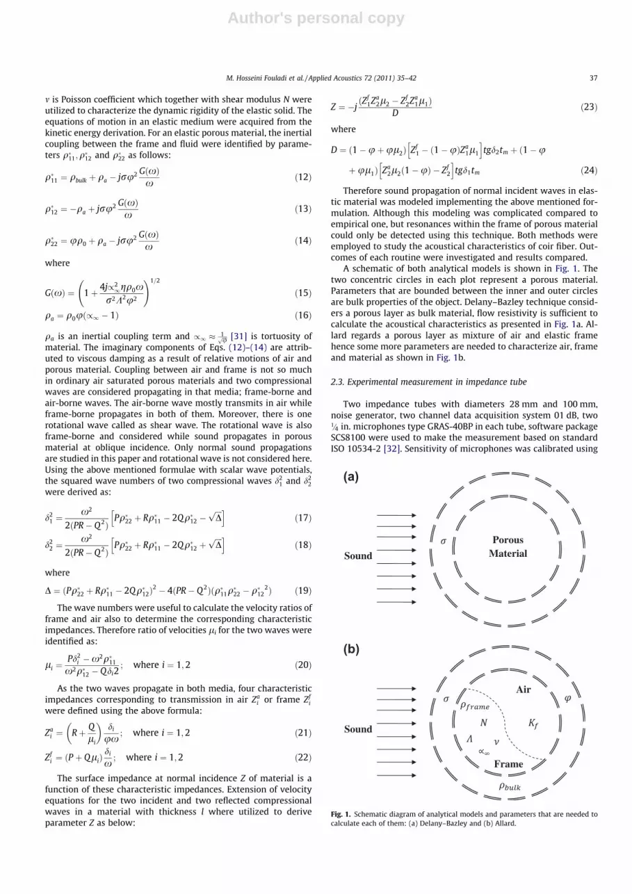
A schematic of both analytical models is shown in Fig. 1. Thetwo concentric circles in each plot represent a porous material.Parameters that are bounded between the inner and outer circlesare bulk properties of the object. Delany–Bazley technique consid-ers a porous layer as bulk material, flow resistivity is sufficient tocalculate the acoustical characteristics as presented in Fig. 1a. Al-lard regards a porous layer as mixture of air and elastic framehence some more parameters are needed to characterize air, frameand material as shown in Fig. 1b.
2.3. Experimental measurement in impedance tube
Two impedance tubes with diameters 28 mm and 100 mm,noise generator, two channel data acquisition system 01 dB, two1=4 in. microphones type GRAS-40BP in each tube, software packageSCS8100 were used to make the measurement based on standardISO 10534-2 [32]. Sensitivity of microphones was calibrated using
Porous Material Sound
Air
Frame
Sound
(a)
(b)
Fig. 1. Schematic diagram of analytical models and parameters that are needed tocalculate each of them: (a) Delany–Bazley and (b) Allard.
M. Hosseini Fouladi et al. / Applied Acoustics 72 (2011) 35–42 37

Author's personal copy
calibrator type GRAS-42AB at 114 dB level and 1 kHz. The tubewith small diameter was for high frequency range 1600–6300 Hzwhilst the bigger one for low frequency 31.5–1600 Hz data acqui-sition. Photo of the system and two prepared samples is shown inFig. 2. Noise generator transmitted a random noise into the tubes.Interior sound pressure spectrum was measured by the two micro-phones and transfer functions between them calculated. The
acoustical absorption coefficient was calculated from these trans-fer functions and distances between the microphones and absorbersample (coir fiber here). The frequency span of experiment was100–5000 Hz with 3 Hz resolution and it took about 10 s for theinstrument to acquire the absorption spectrum.
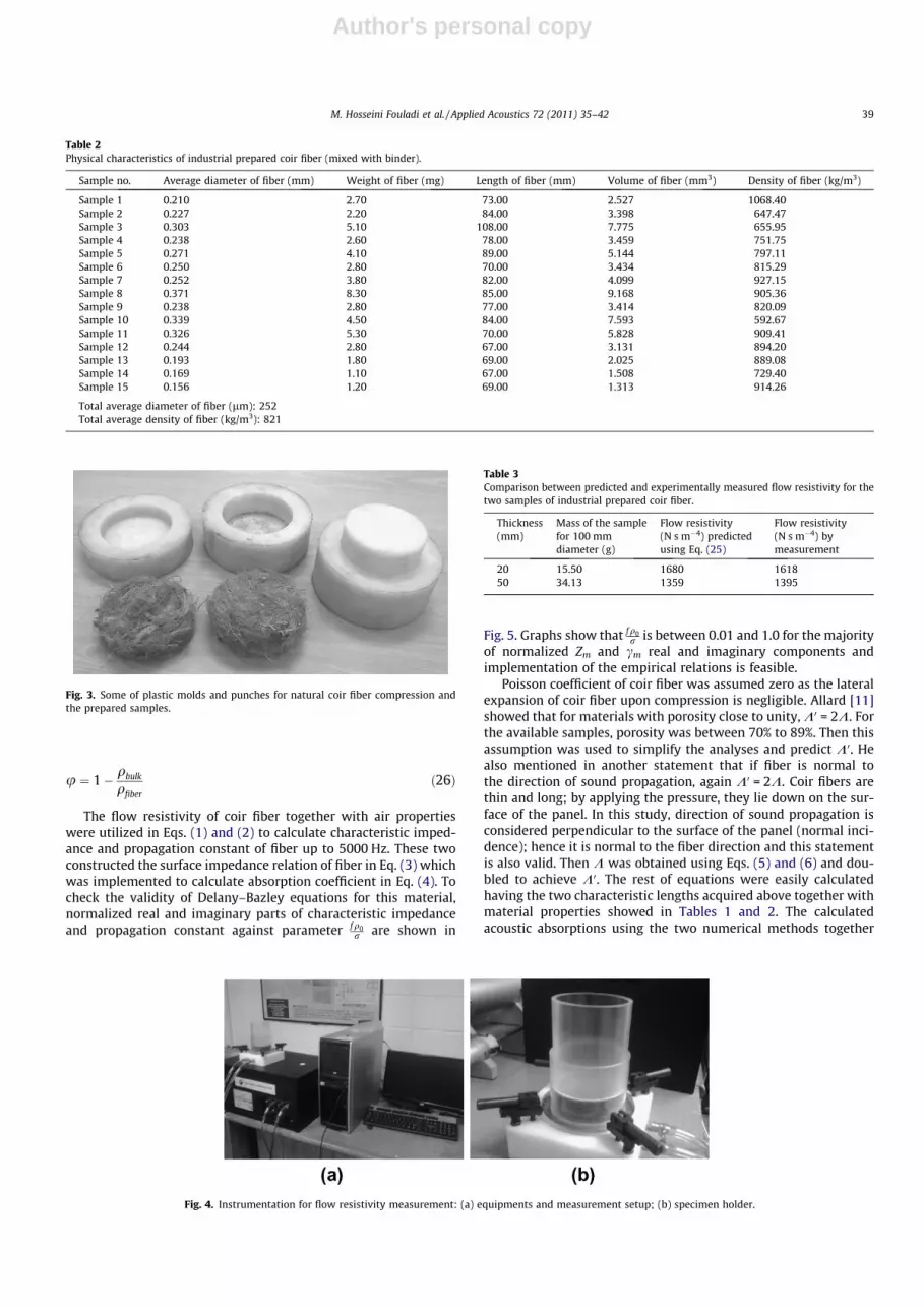
Two types of coir fiber were used for experiment and their char-acteristics are shown in Tables 1 and 2. First one was natural fiberfrom fresh coconut husk available in wet market. Second one wasthe industrial prepared fiber mixed with binder to keep it in shape.Numbers of 15 samples from each type were selected to obtain anaverage value for density and fiber diameter. The industrial onewas ready to be cut and positioned inside the impedance tubesbut natural type needed compression in order to attach together.Therefore various plastic molds and punches with different depthwere fabricated as shown in Fig. 3. A compression machine pressedthese samples with an average pressure of 20 kg/cm2.
2.4. Flow resistivity measurement
The experimental set up for the flow resistivity measurement isshown in Fig. 4. AMTEC C522 air flow resistance test system is usedwhich operates in compliance with the ASTM C522 specificationsas ‘‘test method for airflow resistance of acoustical material”[33]. Test system package comprises of sample holder, data acqui-sition system including vacuum pump and software package C522.This system may be used for airflow and differential pressure mea-surements ranges between 0–15 lpm and 0–294.1 Pa, respectively.Measurements were set up for four flow point 1–4 lpm with threesequential repeated tests for every sample to get an average flowresistivity data.
3. Results and observations
Mass, thickness and fiber diameter of each sample determinedthe amount of flow resistivity and porosity of that sample. Flowresistivity of fiber was estimated from empirical Eq. (25) havingbulk density of sample and diameter of fiber [34]:
r ¼ 490q1:61
bulk
dfiberð25Þ
Moreover, flow resistivity was measured experimentally for the20 and 50 mm industrial coir fiber samples and compared to thenumerical values as shown in Table 3. It proved that Eq. (25)may be used to predict flow resistivity of coir fiber. Porosity of eachsample was calculated as [35]:
Fig. 2. Experimental measurement of coir fiber acoustic absorption: (a) twoindustrial coir fiber samples that were used inside the two correspondingimpedance tubes and (b) instrumentation consisting of small and large tubes,noise generator and two channel data acquisition system 01 dB.
Table 1Physical characteristics of natural coir fiber that is obtained from wet market.
Sample no. Average diameter of fiber (mm) Weight of fiber (mg) Length of fiber (mm) Volume of fiber (mm3) Density of fiber (kg/m3)
Sample 1 0.256 4.90 97.00 5.003 979.36Sample 2 0.276 1.50 48.60 2.899 517.39Sample 3 0.360 2.00 52.00 5.290 378.05Sample 4 0.177 1.00 85.00 2.090 478.37Sample 5 0.287 2.80 77.00 4.979 562.39Sample 6 0.388 6.00 65.50 7.754 773.80Sample 7 0.526 9.80 75.00 16.289 601.62Sample 8 0.303 2.10 78.00 5.609 374.39Sample 9 0.220 1.50 76.50 2.898 517.64Sample 10 0.268 1.40 65.00 3.674 381.06Sample 11 0.202 0.80 50.00 1.607 497.87Sample 12 0.220 1.10 56.50 2.153 510.87Sample 13 0.190 0.80 62.00 1.751 456.93Sample 14 0.187 0.90 65.00 1.778 506.20Sample 15 0.232 1.60 73.00 3.093 517.25
Total average diameter of fiber (lm): 273Total average density of fiber (kg/m3): 537
38 M. Hosseini Fouladi et al. / Applied Acoustics 72 (2011) 35–42
Author's personal copy
u ¼ 1� qbulk
qfiberð26Þ
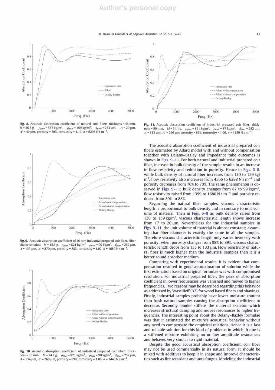
The flow resistivity of coir fiber together with air propertieswere utilized in Eqs. (1) and (2) to calculate characteristic imped-ance and propagation constant of fiber up to 5000 Hz. These twoconstructed the surface impedance relation of fiber in Eq. (3) whichwas implemented to calculate absorption coefficient in Eq. (4). Tocheck the validity of Delany–Bazley equations for this material,normalized real and imaginary parts of characteristic impedanceand propagation constant against parameter fq0
r are shown in
Fig. 5. Graphs show that fq0r is between 0.01 and 1.0 for the majority
of normalized Zm and cm real and imaginary components andimplementation of the empirical relations is feasible.
Poisson coefficient of coir fiber was assumed zero as the lateralexpansion of coir fiber upon compression is negligible. Allard [11]showed that for materials with porosity close to unity, K0 = 2K. Forthe available samples, porosity was between 70% to 89%. Then thisassumption was used to simplify the analyses and predict K0. Healso mentioned in another statement that if fiber is normal tothe direction of sound propagation, again K0 = 2K. Coir fibers arethin and long; by applying the pressure, they lie down on the sur-face of the panel. In this study, direction of sound propagation isconsidered perpendicular to the surface of the panel (normal inci-dence); hence it is normal to the fiber direction and this statementis also valid. Then K was obtained using Eqs. (5) and (6) and dou-bled to achieve K0. The rest of equations were easily calculatedhaving the two characteristic lengths acquired above together withmaterial properties showed in Tables 1 and 2. The calculatedacoustic absorptions using the two numerical methods together
Table 2Physical characteristics of industrial prepared coir fiber (mixed with binder).
Sample no. Average diameter of fiber (mm) Weight of fiber (mg) Length of fiber (mm) Volume of fiber (mm3) Density of fiber (kg/m3)
Sample 1 0.210 2.70 73.00 2.527 1068.40Sample 2 0.227 2.20 84.00 3.398 647.47Sample 3 0.303 5.10 108.00 7.775 655.95Sample 4 0.238 2.60 78.00 3.459 751.75Sample 5 0.271 4.10 89.00 5.144 797.11Sample 6 0.250 2.80 70.00 3.434 815.29Sample 7 0.252 3.80 82.00 4.099 927.15Sample 8 0.371 8.30 85.00 9.168 905.36Sample 9 0.238 2.80 77.00 3.414 820.09Sample 10 0.339 4.50 84.00 7.593 592.67Sample 11 0.326 5.30 70.00 5.828 909.41Sample 12 0.244 2.80 67.00 3.131 894.20Sample 13 0.193 1.80 69.00 2.025 889.08Sample 14 0.169 1.10 67.00 1.508 729.40Sample 15 0.156 1.20 69.00 1.313 914.26
Total average diameter of fiber (lm): 252Total average density of fiber (kg/m3): 821
Fig. 3. Some of plastic molds and punches for natural coir fiber compression andthe prepared samples.
Fig. 4. Instrumentation for flow resistivity measurement: (a) equipments and measurement setup; (b) specimen holder.
Table 3Comparison between predicted and experimentally measured flow resistivity for thetwo samples of industrial prepared coir fiber.
Thickness(mm)
Mass of the samplefor 100 mmdiameter (g)
Flow resistivity(N s m�4) predictedusing Eq. (25)
Flow resistivity(N s m�4) bymeasurement
20 15.50 1680 161850 34.13 1359 1395
M. Hosseini Fouladi et al. / Applied Acoustics 72 (2011) 35–42 39
Author's personal copy
with experimental results for natural fiber are shown in Figs. 6–8.According to Wang et al. [36], the frame elasticity should be con-sidered only if the porous material has large flow resistivity. Other-wise, sound field cannot cause resonance of the solid frame andfluid–structure coupling is difficult to achieve. For the coir fibersamples with very low flow resistivity (much less than10,000 N s m�4), the sound field is not that effective to put theframe into vibration. Therefore resonances should be attributedto the vibrations of the saturated air and are presented in acousticabsorption plots in Figs. 6–8. Peaks were predicted very well by theanalytical Allard model while the empirical Delany–Bazley tech-nique just indicated the overall pattern. As shown in Fig. 6, theaverage absorption coefficient for 20 mm thickness was around0.8 while f > 1360 Hz. Increasing the thickness of material en-hanced the sound absorption in lower frequencies having the sameaverage for f > 940 Hz and f > 578 Hz in Figs. 7 and 8, respectively.
Some compensation was considered in the Allard model to beuseful for the industrial prepared coir fiber mixed with binder. It
was assumed that binder became part of fibers, covered their sur-faces and filled the porosity between them. Therefore based onanalyses, it was derived that the new diameter of fibers mixed withbinder in the porous material increased as:
dmix ¼ dfiber þ ðdfiberuÞ ð27Þ
The new unit volume of material was wholly occupied by fiber–binder mixture and the total length developed as:
Lmix ¼1
pr2mix
ð28Þ
where rmix ¼ dmix2 and the new perimeter of mixture was multiplied
by porosity to calculate the new viscous characteristic length asbelow:
Kmix ¼1
2prmixlmixuð29Þ
0.01
0.1
1
10
0.001 0.01 0.1 1 100.01
0.1
1
10
0.001 0.01 0.1 1 10
0.01
0.1
1
10
0.001 0.01 0.1 1 100.01
0.1
1
10
0.001 0.01 0.1 1 10
fρ0/σ
[R/ρ
0C
0]-1
αC
0/ω
fρ0/σ
fρ0/σ
fρ0/σ
αC0/ω=0.1687(fρ0/σ)-0.595
R2=1 [βC0/ω]-1=0.0873(fρ0/σ)-0.595
R2=1
X/ρ
0C
0[β
C0/ω
]-1
[R/ρ0C0]-1=0.0495(fρ0 /σ)-0.754
R2=1 X/ρ0C0=0.0757(fρ0 /σ)-0.732
R2=1
(a) (b)
(d)(c)
Fig. 5. (a) Normalized real component of characteristic impedance, (b) normalized imaginary component of characteristic impedance, (c) normalized real component ofpropagation coefficient, and (d) normalized imaginary component of propagation coefficient.
0
0.2
0.4
0.6
0.8
1
0 1000 2000 3000 4000 5000
Freq. (Hz)
Abs
orpt
ion
Coe
ffic
ient
Impedance tubeAllard Delany-Bazley
Fig. 6. Acoustic absorption coefficient of natural coir fiber: thickness = 20 mm,M = 20.5 g, qfiber = 537 kg/m3, qbulk = 130 kg/m3, dfiber = 273 lm, K = 17 lm,K0 = 34 lm, porosity = 76%, tortuosity = 1.15, r = 4566 N s m�4.
0
0.2
0.4
0.6
0.8
1
0 1000 2000 3000 4000 5000
Freq. (Hz)
Abs
orpt
ion
Coe
ffic
ient
Impedance tube
Allard
Delany-Bazley
Fig. 7. Acoustic absorption coefficient of natural coir fiber: thickness = 30 mm,M = 36 g, qfiber = 537 kg/m3, qbulk = 153 kg/m3, dfiber = 273 lm, K = 19 lm,K0 = 38 lm, porosity = 71%, tortuosity = 1.18, r = 5910 N s m�4.
40 M. Hosseini Fouladi et al. / Applied Acoustics 72 (2011) 35–42
Author's personal copy
The acoustic absorption coefficient of industrial prepared coirfibers estimated by Allard model with and without compensationtogether with Delany–Bazley and impedance tube outcomes isshown in Figs. 9–11. For both natural and industrial prepared coirfiber, increase in bulk density of the sample results in an increasein flow resistivity and reduction in porosity. Hence in Figs. 6–8,while bulk density of natural fiber increases from 130 to 159 kg/m3, flow resistivity also increases from 4566 to 6298 N s m�4 andporosity decreases from 76% to 70%. The same phenomenon is ob-served in Figs. 9–11; bulk density changes from 87 to 99 kg/m3,flow resistivity raised from 1359 to 1680 N s m�4 and porosity re-duced from 89% to 88%.
Regarding the natural fiber samples, viscous characteristiclength is proportional to bulk density and in contrary to unit vol-ume of material. Then in Figs. 6–8 as bulk density raises from130 to 159 kg/m3, viscous characteristic length shows increasefrom 17 to 20 lm. Nevertheless for the industrial samples inFigs. 9–11, the unit volume of material is almost constant; assum-ing that fiber diameter is exactly the same in all the samples.Therefore viscous characteristic length only varies inversely withporosity; when porosity changes from 88% to 89%, viscous charac-teristic length drops from 135 to 133 lm. Flow resistivity of natu-ral fiber is much higher than the industrial samples then it is abetter sound absorber medium.
Comparing with experimental results, it is evident that com-pensation resulted in good approximation of solution while thefirst estimation based on original formulae was with compromisedresolution. For industrial prepared fiber, the peak of absorptioncoefficient in lower frequencies was vanished and moved to higherfrequencies. Two reasons may be described regarding this behavioras addressed by Wassilieff [37] for wood based fibers and shavings.Firstly, industrial samples probably have lower moisture contentthan fresh natural samples causing the absorption coefficient todecrease. Secondly, binder stiffens the material skeleton whichincreases structural damping and moves resonances to higher fre-quencies. The interesting point about the Delany–Bazley formulaewas that it estimated the mixture’s acoustical behavior withoutany need to compensate the empirical relations. Hence it is a fastand reliable solution for this kind of problems in which, frame isa stiffened mixture exhibiting no or low amplitude resonancesand behaves very similar to rigid material.
Despite the good acoustical absorption coefficient, coir fibermay not be used commercially in its natural form. It should bemixed with additives to keep it in shape and improve characteris-tics such as fire retardant and unti-fungus. Modeling the industrial
0
0.2
0.4
0.6
0.8
1
0 1000 2000 3000 4000 5000
Freq. (Hz)
Abs
orpt
ion
Coe
ffic
ient
Impedance tube
Allard
Delany-Bazley
Fig. 8. Acoustic absorption coefficient of natural coir fiber: thickness = 45 mm,M = 56.3 g, qfiber = 537 kg/m3, qbulk = 159 kg/m3, dfiber = 273 lm, K = 20 lm,K0 = 40 lm, porosity = 70%, tortuosity = 1.19, r = 6298 N s m�4.
0
0.2
0.4
0.6
0.8
1
0 1000 2000 3000 4000 5000
Freq. (Hz)
Abs
orpt
ion
Coe
ffic
ient
Impedance tube
Allard with compensation
Allard without compensation
Delany-Bazley
Fig. 9. Acoustic absorption coefficient of 20 mm industrial prepared coir fiber. Fibercharacteristics: M = 15.5 g, qfiber = 821 kg/m3, qbulk = 99 kg/m3, dfiber = 252 lm,K = 135 lm, K0 = 270 lm, porosity = 88%, tortuosity = 1.07, r = 1680 N s m�4.
0
0.2
0.4
0.6
0.8
1
0 1000 2000 3000 4000 5000
Freq. (Hz)
Abs
orpt
ion
Coe
ffic
ient
Impedance tubeAllard with compensationAllard without compensationDelany-Bazley
Fig. 10. Acoustic absorption coefficient of industrial prepared coir fiber: thick-ness = 35 mm, M = 24.7 g, qfiber = 821 kg/m3, qbulk = 90 kg/m3, dfiber = 252 lm,K = 134 lm, K0 = 268 lm, porosity = 89%, tortuosity = 1.06, r = 1440 N s m�4.
0
0.2
0.4
0.6
0.8
1
0 1000 2000 3000 4000 5000
Freq. (Hz)
Abs
orpt
ion
Coe
ffic
ient
Impedance tube
Allard with compensation
Allard without compensation
Delany-Bazley
Fig. 11. Acoustic absorption coefficient of industrial prepared coir fiber: thick-ness = 50 mm, M = 34.1 g, qfiber = 821 kg/m3, qbulk = 87 kg/m3, dfiber = 252 lm,K = 133 lm, K0 = 266 lm, porosity = 89%, tortuosity = 1.06, r = 1359 N s m�4.
M. Hosseini Fouladi et al. / Applied Acoustics 72 (2011) 35–42 41

Author's personal copy
prepared coir fiber was an interesting approach since this is theuseful type of material for market. Absorption coefficient was im-proved by increasing the thickness. Other strategies such as mak-ing multilayer panel adding air gap and perforated plate may beutilized to further enhance the absorption coefficient.
4. Conclusions
Acoustic absorption of coir fiber was investigated for naturalfresh samples and industrial prepared fibers mixed with binder.Two analytical approaches were implemented for analyses,namely; Allard analytical model based on wave transmission andDelany–Bazley technique that is derived from empirical equations.Experiments were also conducted in impedance tube to supportthe analyses. The Allard technique had the advantage that not onlyshowed overall pattern but also predicted resonances very well.But formulation was complicated and compensations would beconsidered for industrial fibers. The Delany–Bazley method was agood approximation for overall broadband trend of acousticalbehavior. Moreover it was easy to use without need to modifyany part of formulae for stiffened industrial type which generallyhad lower peaks. Natural fiber had an average absorption of 0.8for f > 1360 Hz, f > 940 Hz and f > 578 Hz at thicknesses of20 mm, 30 mm and 45 mm, respectively. Modeling the industrialfiber is vital and inevitable since natural coir fiber has to be en-hanced for commercial use. This includes characteristic such asstiffness, fire retardant, unti-fungus and flammability. Here, binderwas the only additive utilized by manufacturer to attach fibers to-gether and adding stiffness. These samples had lower acousticabsorption, peaks were flattened and move to higher frequencies.They exhibited weak absorption at low frequencies and tacticssuch as adding air gap or perforated plate are necessary to improvethis shortcoming.
References
[1] Delany ME, Bazley EN. Acoustical properties of fibrous materials. Appl Acoust1970;3:105–16.
[2] Dunn IP, Davern WA. Calculation of acoustic impedance of multilayerabsorbers. Appl Acoust 1986;19:321–34.
[3] Qunli W. Empirical relations between acoustical properties and flow resistivityof porous plastic open-cell foam. Appl Acoust 1988;25:141–8.
[4] Miki Y. Acoustical properties of porous materials, modifications of Delany–Bazley models. J Acoust Soc Jpn 1990;11:1 (E).
[5] Miki Y. Acoustical properties of porous materials, generalization of empiricalmodels. J Acoust Soc Jpn 1990;11:1 (E).
[6] Biot MA. Theory of propagation of elastic waves in a fluid-saturated poroussolid. I. Low frequency range. J Acoust Soc Am 1956;28(2):168–78.
[7] Biot MA. Theory of propagation of elastic waves in a fluid-saturated poroussolid. II. Higher frequency range. J Acoust Soc Am 1956;28(2):179–91.
[8] Johnson DL, Koplik J, Dashen R. Theory of dynamic permeability and tortuosityin fluid-saturated porous media. J Fluid Mech 1987;176:379–402.
[9] Attenborough K. The prediction of oblique-incidence behavior of fibrousabsorbents. J Sound Vib 1971;14:183–91.
[10] Attenborough K. Acoustical characteristics of porous materials. Phys Rep1982;82:179–227.
[11] Allard JF. Propagation of sound in porous media. Elsevier Applied Science;1993.
[12] Brekhovskikh LM. Waves in layered media. New York: Academic Press; 1960.[13] Brouard B, Lafarge D, Allard JF. A general method of modeling sound
propagation in layered media. J Sound Vib 1995;183(1):129–42.[14] Attenborough K, Sabatier JM, Frederickson C. The sound field within a rigid
porous layer. Appl Acoust 1995;45:283–96.[15] Attenborough K, Buser O. On the application of rigid-porous models to
impedance data for snow. J Sound Vib 1988;124:315–27.[16] Marco O, Buser O, Villemain P. Analysis of a rigid frame model of porous media
for the acoustic properties of dense snow. J Sound Vib 1996;196(4):439–51.[17] Bolton JS, Shiau NM, Kang YJ. Sound transmission through multi-panel
structures lined with elastic porous materials. J Sound Vib 1996;191(3):317–47.
[18] Goransson P. A 3-D, symmetric, finite element formulation of the Biotequations with application to acoustic wave propagation through an elasticporous medium. Int J Numer Methods Eng 1998;41:167–92.
[19] Chen WH, Lee FC, Chiang DM. On the acoustic absorption of porous materialswith different surface shapes and perforated plates. J Sound Vib 2000;237(2):337–55.
[20] Oh JE, Kim W. Interior noise reduction of enclosure using predictedcharacteristics of porous material. JSME Int J Ser C 2001;44(3):883–9.
[21] Lee FC, Chen WH. Acoustic transmission analysis of multi-layer absorbers. JSound Vib 2001;248(4):621–34.
[22] Lee FC, Chen WH. On the acoustic absorption of multi-layer absorbers withdifferent inner structures. J Sound Vib 2003;259(4):761–77.
[23] Bo Z, Tianning C. Calculation of sound absorption characteristics of poroussintered fiber metal. Appl Acoust 2009;70:337–46.
[24] Kidner MRF, Hansen CH. A comparison and review of theories of the acousticsof porous materials. Int J Acoust Vib 2008;13(3):112–9.
[25] Ersoy S, Kucuk H. Investigation of industrial tea-leaf-fibre waste material forits sound absorption properties. Appl Acoust 2009;70:215–20.
[26] Abdul Khalil HPS, Siti Alwani M, Mohd Omar AK. Cell walls of tropical fibers.BioResources 2006;1(2):220–32.
[27] Nor MJM, Jamaludin N, Tamiri FM. A preliminary study of sound absorptionusing multi-layer coconut coir fibers. Electr J Tech Acoust 2004. <http://www.webcenter.ru/~eeaa/ejta/>.
[28] Zulkifli R, Nor MJM, Tahir MFM, Ismail AR, Nuawi MZ. Acoustic properties ofmultilayer coir fibres sound absorption panel. J Appl Sci 2008;8(20):3709–14.
[29] Mohd Tamiri F. Rekabentuk dan pengujian panel penyerap bunyi semi-aktifmenggunakan bahan sabut kelapa (design and testing of semi-active soundabsorption panel using coir fiber material). Master thesis, Department ofMechanical and Materials Eng, Faculty of Engineering, Universiti KebangsaanMalaysia; 2005.
[30] Jinkyo L, George W, Swenson J. Compact sound absorbers for low frequencies.Noise Control Eng J 1992;38:109–17.
[31] Attenborough K. Models for the acoustical characteristics of air filled granularmaterials. Acta Acust 1993;1:213–26.
[32] ISO 10534-2. Determination of sound absorption coefficient and impedance inimpedance tubes – part 2: transfer function method; 1998.
[33] ASTM C522. Standard test method for airflow resistance of acousticalmaterials; 2003.
[34] Ballagh KO. Acoustical properties of wool. Appl Acoust 1996;48(2):101–20.[35] Kino N, Ueno T, Suzuki Y, Makino H. Investigation of non-acoustical
parameters of compressed melamine foam materials. Appl Acoust 2009;70:595–604.
[36] Wang CN, Kuo YM, Chen SK. Effects of compression on the sound absorption ofporous materials with an elastic frame. Appl Acoust 2008;69:31–9.
[37] Wassilieff C. Sound absorption of wood-based materials. Appl Acoust1996;48(4):339–56.
42 M. Hosseini Fouladi et al. / Applied Acoustics 72 (2011) 35–42