analysis of a fully matched saturated doherty amplifier with excellent efficiency
TRANSCRIPT

328 IEEE TRANSACTIONS ON MICROWAVE THEORY AND TECHNIQUES, VOL. 56, NO. 2, FEBRUARY 2008
Analysis of a Fully Matched Saturated DohertyAmplifier With Excellent Efficiency
Jangheon Kim, Student Member, IEEE, Junghwan Moon, Young Yun Woo, Sungchul Hong, Ildu Kim,Jungjoon Kim, and Bumman Kim, Fellow, IEEE
Abstract—A saturated Doherty amplifier based on class-F ampli-fiers is analyzed in terms of its load modulation behavior, efficiency,and linearity. Simulations included the amplitude ratio and phasedifference between the fundamental and third harmonic voltages,the current/voltage waveforms, load lines, and the third-order in-termodulation amplitudes/phases of the carrier and peaking am-plifiers. The saturated Doherty power amplifier was implementedusing two Eudyna EGN010MK GaN HEMTs with a 10-W peakenvelope power. For a 2.14-GHz forward-link wideband code-divi-sion multiple-access signal, the Doherty amplifier delivers an excel-lent efficiency of 52.4% with an acceptable linearity of 28.3 dBcat an average output power of 36 dBm. Moreover, the amplifier canprovide the high linearity performance of 50 dBc using the dig-ital feedback predistortion technique.
Index Terms—Doherty amplifier, efficiency, linearization, poweramplifier (PA), wideband code division multiple access (WCDMA).
I. INTRODUCTION
CURRENT wireless communication systems, such as codedivision multiple access (CDMA) 2000, wideband code
division multiple access (WCDMA), wireless local area net-work (WLAN), and worldwide interoperability for microwaveaccess (WiMAX), are intended to maximize the data rate in afast moving environment. The modulated signals of these sys-tems vary rapidly and have high peak-to-average power ratios(PAPRs). In order to linearly amplify the signals, the amplifieris operated in a backoff region, thus the efficiency is rather poor.Therefore, techniques that can improve the linearity and effi-ciency of the base-station power amplifier (PA) are an importantissue in the research community [1], [2].
Improving the efficiency of the PA has been studied using ef-ficiency enhancement techniques such as envelope eliminationand restoration (EER), polar modulation, and envelope tracking
Manuscript received August 3, 2007; revised October 30, 2007. This workwas supported by the Korean Government under Korea Science and EngineeringFoundation (KOSEF) MOST Grant R01-2007-000-20377-0 and by the Centerfor Broadband Orthogonal Frequency Division Multiplex Mobile Access, Po-hang University of Science and Technology under the Information TechnologyResearch Center Program of the Korean Ministry of Information Technology,supervised by the Institute for Information Technology Advancement (IITA-2007-C1090-0701-0037).
J. Kim, J. Moon, I. Kim, J. Kim, and B. Kim are with the Department of Elec-trical Engineering, Pohang University of Science and Technology, Gyeongbuk790-784, Korea (e-mail: [email protected]; [email protected];[email protected]; [email protected]; [email protected]).
Y. Y. Woo and S. Hong are with the Telecommunication Research and De-velopment Center, Samsung Electronics Company Ltd., Suwon, Gyeonggi 442-742, Korea (e-mail: [email protected]; [email protected]).
Color versions of one or more of the figures in this paper are available onlineat http://ieeexplore.ieee.org.
Digital Object Identifier 10.1109/TMTT.2007.914361
(ET) [3]–[5]. These techniques could provide excellent effi-ciency performance using a complicated enveloped amplifierand/or switching amplifier, and high linearity performance canbe achieved with the help of a digital predistortion technique.Moreover, Doherty amplifier techniques have been extensivelystudied to improve efficiency, and could provide the advantageof improving the efficiency and linearity simultaneously usinga simple circuit in comparison with the other techniques [1],[2], [6]–[20].
Suzuki et al. [17], [18] have developed a Doherty amplifierwith the class-F filter at the back of the matching circuit. Theharmonic-controlled matching topology could provide high ef-ficiency, but the matching circuit cannot easily satisfy the funda-mental, second, and third harmonic impedances simultaneously,as shown by Goto et al. [19]. The circuit topology presented in[19] has the harmonic control circuit (HCC) located in front ofthe matching circuit; this can control the impedance for the ap-propriate saturated operation. Moreover, they have developeda Doherty amplifier with a combination of class-F and inverseclass-F amplifiers, and the amplifier can provide high efficiencyat broad power levels. However, the amplifier could not gen-erate peak efficiency of the carrier amplifier-only operation atthe peak power level and has bad linearity in the high powerregion. These characteristics indicate that the amplifier has animproper load modulation and improper harmonic cancellationbetween the carrier and peaking amplifiers.
In our approach, a saturated Doherty amplifier using the in-verse class-F amplifier was developed to maximize efficiency[20]. The fully matched output matching network is discussed,including the HCC of the saturated amplifier and the harmonic-controlled load modulation behavior of the Doherty amplifier.Based on the behaviors, the operation behavior of the saturatedDoherty amplifier was analyzed with finite harmonic contentsaccording to the power levels, including the efficiency and lin-earity. In order to verify our analyses and simulations, the sat-urated Doherty amplifier was implemented and compared withthe class-F saturated amplifier and linear Doherty amplifier forcontinuous wave (CW) and WCDMA 1FA signals. The resultsclearly show that the saturated Doherty amplifier has excellentefficiency with acceptable linearity. The digital feedback pre-distortion (DFBPD) technique was applied to achieve high lin-earity performance, satisfying the system specifications.
II. OPERATION PRINCIPLE OF THE SATURATED
DOHERTY AMPLIFIER
The fundamental operation principle of Doherty amplifier hasbeen well described in previous literature [1], [2], [6]–[13]. Theefficiency of the Doherty amplifier was maximized using the
0018-9480/$25.00 © 2008 IEEE

KIM et al.: ANALYSIS OF FULLY MATCHED SATURATED DOHERTY AMPLIFIER WITH EXCELLENT EFFICIENCY 329
Fig. 1. Schematic diagram of the saturated Doherty amplifier.
Fig. 2. (a) Operational diagram of the saturated Doherty amplifier. (b) Fun-damental current and voltage versus input drive voltage (solid line: the carrieramplifier/dot line: the peaking amplifier).
class-F amplifiers for the Doherty cells. Due to the saturatedoperation of the class-F amplifier, the proposed Doherty ampli-fier is called the saturated Doherty amplifier. Fig. 1 shows theschematic diagram of the fully matched saturated Doherty am-plifier including the HCC and offset lines. This section analyzesthe load modulation behavior, efficiency, and linearity of the sat-urated Doherty amplifier in a practical design.
A. Load Modulation Behavior of Saturated Doherty Amplifier
Fig. 2(a) shows an operational diagram of the saturated Do-herty amplifier. For the Doherty operation, the carrier amplifieris biased at pinchoff, and the peaking amplifier below pinchoff.The current and voltage waveforms at the devices of the car-rier and peaking amplifiers are transformed by each harmonicimpedance of the HCC. Theoretically, high efficiency can be
achieved in class-F operation by generating half-sinusoidal cur-rent and square-wave voltage waveforms. These waveforms canbe realized by creating zero impedance at all even harmonicsand infinite impedance at all odd harmonics. However, all har-monic contents cannot be controlled in a practical design. More-over, the amplifier cannot operate in the saturation state for allpower levels. Thus, an HCC has been employed in front ofthe output matching circuit, as shown in Fig. 3(a). The HCCincludes both the arm shunt stubs for a better harmonic trapand tuning line for compensating the de-tuning effect of the de-vices’s parasitic components [21], [22]. For proper Doherty op-eration, the offset line at the back of the output matching circuithas also been employed [9].
The analyses of the design are based on the following assump-tions.
1) Each current source is linearly proportional to the inputvoltage.
2) The current waveform depends on the bias point of eachamplifier.
3) The voltage waveform depends only on the fundamentaland third harmonic components.
4) The maximally flat voltage waveform is generated by a1/9 amplitude ratio and 180 phase difference between thefundamental and third harmonic voltage components [23],[24].
5) The output capacitance of the device is sufficiently smallto control the harmonic components.
6) The Doherty amplifier can properly modulate the loadimpedance using the uneven power drive [13], [14].
Fig. 2(b) represents the fundamental current and voltage ac-cording to input drive voltage. Since the current and voltagewaveforms represent the half-sinusoidal current and maximallyflat voltage waveforms, and are and
, respectively. At the low power region, where only the carrier amplifier is active, the funda-
mental and dc currents of the amplifier are
(1)
(2)
where and are and , respec-tively.
In order to analyze the load modulation behavior of the satu-rated Doherty amplifier, we use and ,as shown in Fig. 2(a). The load impedance of the carrier ampli-fier is given by
(3)
where
Due to the maximally flat voltage waveform, the fundamentalvoltage component has a 9/8 times larger impedance than thatof the class-B amplifier. Thus, the load impedance of each am-plifier is designed to have a 9/8 times larger impedance.

330 IEEE TRANSACTIONS ON MICROWAVE THEORY AND TECHNIQUES, VOL. 56, NO. 2, FEBRUARY 2008
At the higher power region , bothamplifiers are active. The fundamental and dc currents of thepeaking amplifier are expressed as
(4)
(5)
(6)
where
The conduction angle represents the bias point of the peakingamplifier, and is the uneven power drive ratio. The load im-pedances of the carrier and peaking amplifiers are given by
(7)
(8)
The fundamental load impedance of the carrier amplifier mod-ulates to , and the load impedance of the peakingamplifier modulates to , while maintaining the secondharmonic short and third harmonic open impedances.
The load modulation behavior of the fully matched outputmatching network was explored using the ADS simulator ac-cording to the load impedance change. Fig. 3(b) represents thefundamental, second, and third harmonic impedances of the car-rier amplifier according to the changes of the load impedancefrom 100 to 50 and offset line length. The output matchingnetwork should transform a 100- load impedance toat the device, and the suitable offset line for the transforma-tion is 118 . In the circuit, the second and third harmonic im-pedances maintain nearly short and open impedances, respec-tively, for the offset line change, and the output matching net-work can be modulated from to for the load changeof 100 to 50 . Fig. 3(c) shows the fundamental impedance andsecond and third harmonic impedances of the peaking ampli-fier according to the load impedance change of to 50 . Theoutput impedance of the peaking amplifier is transformed to afairly high impedance (28 to 245 for the 118 offset line)for the turn-off mode using another offset line at the junctionof the carrier and peaking amplifiers. The output matching net-work can be modulated from a very high impedance tofor the load change of to 50 , and the second and thirdharmonic impedances maintain the nearly short and open im-pedances, respectively. These results demonstrate the HCC infront of the output matching circuit can successfully control thesecond and third harmonic impedances for the load modulationand offset line change, and the current and voltage waveforms,
Fig. 3. (a) Fully matched output matching network including the HCC.(b) Load modulation behavior of the carrier amplifier including the HCC.(c) Load modulation behavior of the peaking amplifier including the HCC.
which are caused by the harmonic impedances, can be properlytransformed.
B. Saturated Operation and Efficiency of the SaturatedDoherty Amplifier
The saturation operation for all power levels was exploredby defining saturation state and insufficient saturation state in

KIM et al.: ANALYSIS OF FULLY MATCHED SATURATED DOHERTY AMPLIFIER WITH EXCELLENT EFFICIENCY 331
Fig. 4. Efficiency versus input drive level according to the bias point of thepeaking amplifier.
terms of amplitude ratio/phase difference between the funda-mental and third harmonic voltage components. The amplituderatio and relative phase difference are expressed as
(9)
(10)
(11)
where and are magnitudes of the fundamental and thirdharmonic voltages, respectively. and are the phases ofthe fundamental and third harmonic voltages, respectively. Thesaturation state should satisfy the half-sinusoidal current andmaximally flat voltage waveforms with andat low drive levels. and values of the saturated Dohertyamplifier have been investigated using the ADS simulator, aspresented in Section III.
The efficiency analysis assumes that each current source islinearly proportional to the input voltage, as shown in Fig. 2(b).Thus, the efficiency analysis can be carried out using only thefundamental and dc components according to each current andvoltage waveform [13], [21], [23]. At the low power region (
), the RF and dc powers are given by
(12)
(13)
Fig. 5. Load lines of each amplifier. (a) Carrier amplifier. (b) Peaking amplifier.
From (12) and (13), the efficiency becomes
(14)
where the turn-on voltage of the peaking amplifier ( ) isset to .
The carrier amplifier continues the insufficient saturationstate until the input drive level. At this level,the amplifier has a class-B peak efficiency due to the largeload impedance, as shown in Fig. 4. The load lines are slightlyelliptical for the low drive levels, and the load line reachesthe minimum allowable voltage at the drive level, as shown inFig. 5(a). The amplifier reaches the saturation state above thisdrive level and, as shown in Fig. 4, the efficiency increasesfrom the class-B peak efficiency (point A) to the class-F peakefficiency (point B). The load line changes from the slightlyelliptical to the quasi-“L” curve at the turn-on voltage, as shownin Fig. 5(a), but the line cannot make the perfect “L” curve be-cause harmonic voltage control is limited to the third harmonic.This state illustrates that the amplifier has the half-sinusoidalcurrent and maximally flat voltage signals, and the efficiencycan reach 88%.

332 IEEE TRANSACTIONS ON MICROWAVE THEORY AND TECHNIQUES, VOL. 56, NO. 2, FEBRUARY 2008
TABLE IOPERATION STATE OF THE CARRIER AND PEAKING AMPLIFIERS ACCORDING TO EACH POWER LEVEL
At the higher power region ( ), bothamplifiers are active. The RF and dc powers are the sum of thetwo amplifiers and are given by
(15)
(16)
From (15) and (16), the efficiency becomes
(17)
where
Since the load impedances of both amplifiers decrease, theload lines of the carrier amplifier move up while maintainingthe quasi-“L” curves, as shown in Fig. 5(a), and the amplifierreaches the saturation state in this region. On the other hand,the current and voltage swings of the peaking amplifier increasein proportion to the drive level due to the proper load mod-ulation, but the amplifier maintains the insufficient saturationstate until reaching the minimum allowable output voltage level(point C). In these situations, the load lines of the amplifier areslightly elliptical until reaching the minimum allowable outputvoltage level, where the load line becomes the quasi-“L” curve,as shown in Fig. 5(b). The peaking amplifier reaches the satura-tion state after reaching the minimum allowable output voltagelevel, and both amplifiers have the half-sinusoidal current andmaximally flat voltage waveforms at the maximum drive level(point D). The efficiency of the saturated Doherty amplifier, theaverage efficiency of the two amplifiers, is high due to the re-duced overlap region between the current and voltage wave-forms, since the peaking amplifier has a class-C bias, as shownin Fig. 5 [25], [26]. The operation states of the Doherty ampli-fier are summarized in Table I.
C. Linearity of the Saturated Doherty Amplifier
The linearity of the saturated Doherty amplifier is worse thanthat of conventional Doherty amplifier because both amplifiersare operated as saturated amplifiers to maximize efficiency, andthe linearity mechanism is complicated due to the harmonic can-cellation of the saturated amplifiers. In the low power region,the linearity of the amplifier is entirely determined by the car-rier amplifier like the conventional one. Moreover, the carrieramplifier has a larger impedance than that of the conventionalone and the amplifier reaches saturation at a lower input drivelevel. Thus, the linearity is worse than the conventional Dohertyamplifier’s.
In the high power region, the linearity is improved by the har-monic cancellation from the two amplifiers at appropriate gatebiases like the conventional Doherty amplifier [10]–[13]. Dueto the linearity improvement mechanism, the Doherty ampli-fier can operate more linearly than the switching or saturatedamplifiers. The cancellation mechanism is investigated in termsof the amplitude and phase of the third-order intermodulations(IM3s) of the saturated Doherty amplifier using the ADS simu-lator in Section III. The nonlinear characteristics of the saturatedDoherty amplifier is compared with the AM/AM and AM/PMcharacteristics of the class-F saturated and linear Doherty am-plifiers in Section IV.
III. SIMULATION RESULTS
A. CW Test of the Saturated Doherty Amplifier
The behavior of the saturated Doherty amplifier was investi-gated through ADS simulation using the OKI 0.1-W KGF1284MESFET model. The gate voltage of the carrier amplifier wasset to 2.4 V (class-B bias), and the gate voltage of the peakingamplifier was fixed at 2.9 V (class-C bias). The drain biasvoltage was 3.6 V. The fully matched output matching net-work was constructed including the HCC to control the secondand third harmonic components together with the proper loadmodulation, as shown in Fig. 3(a).
Fig. 6 shows the amplitude ratio and phase differencebetween the fundamental and third harmonic voltages as
a function of the output power level. For low power levelsbelow an output power of 15 dBm, the third harmonic voltagecomponents of the carrier and peaking amplifiers are negligiblysmall, indicating that both amplifiers are in the insufficientsaturation state. As the power increases above an output powerof 19 dBm, the carrier amplifier approaches the maximally flatvoltage waveform ( and condition) andreaches the saturation state. On the other hand, the peaking am-plifier is in the insufficient saturation state for all power levels.In the high power region (the power region of 19–25 dBm),the drain voltage of of the carrier amplifier reaches themaximum voltage swing, and the third harmonic components
KIM et al.: ANALYSIS OF FULLY MATCHED SATURATED DOHERTY AMPLIFIER WITH EXCELLENT EFFICIENCY 333
Fig. 6. Amplitude ratio (�) and phase difference (�) between the fundamentaland third harmonic voltages as a function of the input power level.
Fig. 7. Simulated time-domain current and voltage waveforms of each ampli-fier according to the power level. (a) Carrier amplifier. (b) Peaking amplifier.
increase since the voltage waveform is further flattened. In thesame power region, the peaking amplifier does not satisfy thesaturation conditions, thus, the amplifier is in the insufficientsaturation state. However, at the maximum power level of25 dBm, the peaking amplifier has a large third harmonicvoltage and the proper phase relationship, and reaches thesaturation state.
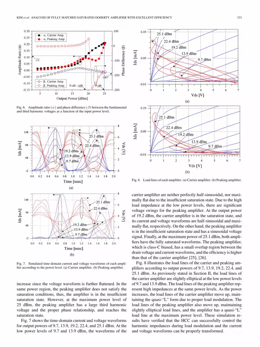
Fig. 7 shows the time-domain current and voltage waveformsfor output powers of 9.7, 13.9, 19.2, 22.4, and 25.1 dBm. At thelow power levels of 9.7 and 13.9 dBm, the waveforms of the
Fig. 8. Load lines of each amplifier. (a) Carrier amplifier. (b) Peaking amplifier.
carrier amplifier are neither perfectly half-sinusoidal, nor maxi-mally flat due to the insufficient saturation state. Due to the highload impedance at the low power levels, there are significantvoltage swings for the peaking amplifier. At the output powerof 19.2 dBm, the carrier amplifier is in the saturation state, andits current and voltage waveforms are half-sinusoidal and maxi-mally flat, respectively. On the other hand, the peaking amplifieris in the insufficient saturation state and has a sinusoidal voltagesignal. Finally, at the maximum power of 25.1 dBm, both ampli-fiers have the fully saturated waveforms. The peaking amplifier,which is class-C biased, has a small overlap region between thedrain voltage and current waveforms, and the efficiency is higherthan that of the carrier amplifier [25], [26].
Fig. 8 illustrates the load lines of the carrier and peaking am-plifiers according to output powers of 9.7, 13.9, 19.2, 22.4, and25.1 dBm. As previously stated in Section II, the load lines ofthe carrier amplifier are slightly elliptical at the low power levelsof 9.7 and 13.9 dBm. The load lines of the peaking amplifier rep-resent high impedances at the same power levels. As the powerincreases, the load lines of the carrier amplifier move up, main-taining the quasi-“L” form due to proper load modulation. Theload lines of the peaking amplifier also move up, maintainingslightly elliptical load lines, and the amplifier has a quasi-“L”load line at the maximum power level. These simulation re-sults have verified that the HCC can successfully control theharmonic impedances during load modulation and the currentand voltage waveforms can be properly transformed.

334 IEEE TRANSACTIONS ON MICROWAVE THEORY AND TECHNIQUES, VOL. 56, NO. 2, FEBRUARY 2008
Fig. 9. (a) Fundamental current and voltage components. (b) Drain efficiencyas a function of the output power.
Fig. 9(a) shows the fundamental current and voltage com-ponents of the carrier and peaking amplifiers as a function ofthe output power level. Due to the proper load modulation, thefundamental currents of both amplifiers increase the same asthat of the ideal Doherty amplifier of Fig. 2(b). The efficiencyis improved over the saturated amplifier across broad outputpower levels, as shown in Fig. 9(b). However, the fundamentalcurrent of the peaking amplifier does not turn on abruptly, asshown in the peaking transition region of Fig. 9(a) because ofthe soft turn-on and turn-off characteristic of the MESFET. Dueto the same reason, the fundamental carrier voltage increasessmoothly and the voltage cannot reach the level at theturn-on power level. Thus, the carrier amplifier cannot operatein the perfect saturation state. As a result, the Doherty amplifiercannot reach peak efficiency at the middle output power level.
B. Two-Tone Test of the Saturated Doherty Amplifier
Fig. 10(a) shows the IM3 amplitudes of the carrier andpeaking amplifiers and their phase difference. As already statedin Section II, the carrier amplifier has relatively poor linearitywith the high IM3 amplitudes in the low power region. In the
Fig. 10. Two-tone simulated results of the saturated Doherty amplifier. (a) IM3amplitudes of each amplifier and phase difference. (b) IMD3.
high power region, the IM3 amplitudes of both amplifiers arethe same, and the phase difference is maintained approximately180 . The third-order intermodulation distortion (IMD3) isreduced by the harmonic cancellation mechanism, as shownin Fig. 10(b). The IMD3 of the Doherty amplifier is 41 dBc,which is an improvement of approximately 18 dB at the outputpower of 19 dBm. This result demonstrates that the saturatedDoherty amplifier can operate as a reasonably linear amplifierwith very high efficiency in spite of the saturated operation,while the class-F amplifier cannot.
IV. IMPLEMENTATION AND MEASUREMENT RESULTS
Section III has analyzed the fully matched output matchingnetwork of the saturated Doherty amplifier and explored its op-eration. To validate the behavior, a 2.14-GHz fully matched sat-urated Doherty amplifier based on a finite class-F harmonic con-trol scheme was implemented using two Eudyna EGN010MKGaN HEMTs with a 10-W peak envelop power (PEP). The am-plifier was optimized to get as high an efficiency as possiblewhile having the proper Doherty operation. The matching im-pedances for the source and load wereand , respectively. The suitable offset linefor the peaking amplifier was 10.2 and the transformed output

KIM et al.: ANALYSIS OF FULLY MATCHED SATURATED DOHERTY AMPLIFIER WITH EXCELLENT EFFICIENCY 335
Fig. 11. Measured drain efficiency performance of the class-F, linear Doherty,and saturated Doherty amplifiers for 2.14-GHz CW signal.
impedance was 328 . Gate biases for the carrier and peakingamplifiers were set to V and V at
V. The performance of the amplifier was comparedby fabricating class-F and linear Doherty amplifiers using thesame devices. The class-F amplifier has the same HCC and isbiased for class-B operation. The linear Doherty amplifier isdesigned to maximize both linearity and efficiency without theHCC.
A. CW and WCDMA Test of the Saturated Doherty Amplifier
Fig. 11 shows the drain efficiency of the class-F, linearDoherty, and saturated Doherty amplifiers for a CW signal.The drain efficiency of the saturated Doherty amplifier isimproved over broad average output power levels comparedwith the class-F and linear Doherty amplifiers. In particular,the saturated Doherty amplifier delivers the excellent efficiencyof 54.2% at the 6-dB backed-off power level of 37 dBm,while the class-F and linear Doherty amplifier provide 35.2%and 39.5%, respectively. Fig. 12(a) illustrates the measuredadjacent channel leakage ratios (ACLRs) of the class-F, linearDoherty, and saturated Doherty amplifiers at an offset of2.5 MHz for a 2.14-GHz forward-link WCDMA 1FA signal.In comparison with the class-F amplifier, the saturated Dohertyamplifier delivers significantly improved ACLR performancedue to the cancellation mechanism in spite of its saturatedoperation. At the 7-dB backed-off power level of 36 dBm, thesaturated Doherty amplifier delivers 28.3 dBc, which is animprovement of 6.5 dB. However, the linearity of the saturatedDoherty amplifier is poorer than the linear Doherty amplifier’s.Thus, a linearization technique, such as the digital predistortiontechnique, is required to achieve high linearity performance.Fig. 12(b) shows the drain efficiency of the Doherty amplifiersfor the WCDMA signal. The drain efficiency of the saturatedDoherty amplifier is very high over broad average output powerlevels and is 52.4% at an average output power of 36 dBm.
These experimental results show that the saturated Dohertyamplifier can provide higher efficiency and linearity than theclass-F amplifier. Moreover, the saturated Doherty amplifier hasvery high efficiency with an acceptable linearity, which can be
Fig. 12. Measured performances of the class-F, linear Doherty, and saturatedDoherty amplifiers for 2.14-GHz forward-link WCDMA signal. (a) ACLR.(b) Drain efficiency.
linearized to the level suitable for the linear power amplifier(LPA) of a base-station application. This will be presented inthe Section IV-B.
B. Linearization Performance of the SaturatedDoherty Amplifier
In order to verify the suitability of the saturated Doherty am-plifier as the main block of the base-station LPA, we have em-ployed the DFBPD linearization technique to enhance linearityto the level of the system specification. The used signal is a2.14-GHz forward-link WCDMA 1FA signal and 7.4-dB PAPRat the 0.01% level of the complementary cumulative distribu-tion function (CCDF). The DFBPD has two 256-entry AM/AMand AM/PM lookup tables (LUTs), which were programmedvia MATLAB using the DFBPD algorithm [27].
Prior to applying the linearization technique, we have inves-tigated the memoryless AM/AM and AM/PM characteristics ofthe saturated Doherty amplifier and compared with the class-Fand linear Doherty amplifiers, as shown in Fig. 13. The AM/AMcharacteristic of the linear Doherty amplifier shows the standardbehavior with a moderate compression at a high power level,

336 IEEE TRANSACTIONS ON MICROWAVE THEORY AND TECHNIQUES, VOL. 56, NO. 2, FEBRUARY 2008
Fig. 13. Measured nonlinear characteristics of the class-F, linear Doherty, andsaturated Doherty amplifiers. (a) AM/AM and (b) AM/PM characteristics.
Fig. 14. Measured WCDMA spectra before and after the DFBPD lineariza-tion of the saturated Doherty amplifier at an average output power of 36 dBm.(i) Without a digital predistorter. (ii) Digital feedback predistorter.
while the AM/PM characteristic increase. The AM/AM charac-teristic of the class-F amplifier has an expansion from the low
TABLE IIMEASURED PERFORMANCE AT AN AVERAGE OUTPUT
POWER = 36 dBm FOR FORWARD-LINK WCDMA 1FA SIGNAL
Fig. 15. Measured: (a) AM/AM and (b) AM/PM characteristics of the saturatedDoherty amplifier after the DFBPD linearization at an average output power of36 dBm.
power level to the middle power level and a serious compres-sion at the high power level, and the AM/PM characteristics hasserious phase variation from the low power level. On the otherhand, the AM/AM characteristic of the saturated Doherty ampli-fier has a larger expansion at high power than the class-F ampli-fier, and compression at a high power level due to the differentsaturation behaviors of both carrier and peaking amplifiers. Inaddition, the AM/PM characteristic shows an abrupt phase dif-ference at the lower power level due to earlier saturation than theclass-F amplifier, and a reduced phase difference at the middlepower level due to the harmonic cancellation.

KIM et al.: ANALYSIS OF FULLY MATCHED SATURATED DOHERTY AMPLIFIER WITH EXCELLENT EFFICIENCY 337
Fig. 14 shows the measured spectra before and after the lin-earizations by the DFBPD technique. The ACLR at an offsetof 2.5 MHz after the linearization is 50 dBc, which is an im-provement of approximately 21.7 dB at an average output powerof 36 dBm. This result satisfies the linearity specification, whichrequires an ACLR of 45 dBc at a 5-MHz offset and an ACLRof 50 dBc at a 10-MHz offset. The linearization results aresummarized in Table II. Fig. 15 represents the AM/AM andAM/PM characteristics after the linearization, and the nonlinearcharacteristics are successfully linearized to an acceptable levelby the predistortion technique due to the rather good linearity ofthe saturated Doherty amplifier.
V. CONCLUSION
We have discussed the harmonic controlled load modulationbehavior for the fully matched output matching network in-cluding the HCC of the saturated Doherty amplifier. The outputmatching topology maintains the second short and third openimpedances during load modulation and allows the proper sat-urated Doherty operation. We have analyzed the efficiency andlinearity of the Doherty amplifier in a practical design using sim-ulated amplitude ratios and phase differences between the fun-damental and third harmonic voltages, the current/voltage wave-forms, load lines, and the IM3 amplitudes/phases of the carrierand peaking amplifiers. The proper saturated Doherty operationwas observed with high efficiency and acceptable linearity. ADoherty PA with the class-F HCC was implemented using twoEudyna EGN010MK GaN HEMTs. For a 2.14-GHz WCDMAsignal, the Doherty amplifier delivers an excellent efficiency of52.4% with an acceptable linearity of 28.3 dBc at an averageoutput power of 36 dBm, and the linearity could be improved to
50 dBc using the DFBPD technique, which is acceptable forLPA application.
The analyses and measured results show that the saturatedDoherty amplifier can deliver very high efficiency with accept-able linearity by using the matching network topology. We be-lieve that the saturated Doherty amplifier is the most suitableone for the main amplifier of the highly efficient base station.
REFERENCES
[1] S. C. Cripps, Advanced Techniques in RF Power Amplifier Design.Norwood, MA: Artech House, 2002.
[2] P. B. Kenington, High-Linearity RF Amplifier Design. Norwood,MA: Artech House, 2000.
[3] F. H. Raab, B. E. Sigmon, R. G. Myers, and R. M. Jackson, “L-bandtransmitter using Kahn EER technique,” IEEE Trans. Microw. TheoryTech., vol. 46, no. 12, pp. 2220–2225, Dec. 1998.
[4] J.-H. Chen, P. Fedorenko, and J. S. Kenney, “A low voltage W-CDMApolar transmitter with digital envelope path gain compensation,” IEEEMicrow. Wireless Compon. Lett., vol. 16, no. 7, pp. 428–430, Jul. 2006.
[5] D. F. Kimball, J. Jeong, C. Hsia, P. Draxler, S. Lanfranco, W. Nagy, K.Linthicum, L. E. Larson, and P. M. Asbeck, “High-efficiency envelope-tracking W-CDMA base-station amplifier using GaN HFETs,” IEEETrans. Microw. Theory Tech., vol. 54, no. 11, pp. 3848–3856, Nov.2006.
[6] W. H. Doherty, “A new high efficiency power amplifier for modulatedwaves,” Proc. IRE, vol. 24, no. 9, pp. 1163–1182, Sep. 1936.
[7] F. H. Raab, “Efficiency of Doherty RF power-amplifier systems,” IEEETrans. Broadcast., vol. BC-33, no. 3, pp. 77–83, Sep. 1987.
[8] M. Iwamoto, A. Williams, P. Chen, A. G. Metzger, L. E. Larson, and P.M. Asbeck, “An extended Doherty amplifier with high efficiency overa wide power range,” IEEE Trans. Microw. Theory Tech., vol. 49, no.12, pp. 2472–2479, Dec. 2001.
[9] Y. Yang, J. Yi, Y. Y. Woo, and B. Kim, “Optimum design for lin-earity and efficiency of microwave Doherty amplifier using a new loadmatching technique,” Microw. J., vol. 44, no. 12, pp. 20–36, Dec. 2001.
[10] B. Kim, Y. Yang, J. Yi, J. Nam, Y. Y. Woo, and J. Cha, “Efficiency en-hancement of linear power amplifier using load modulation technique,”in Int. Microw. Opt. Technol. Symp. Dig., Jun. 2001, pp. 505–508.
[11] Y. Yang, J. Cha, B. Shin, and B. Kim, “A fully matched N -way Do-herty amplifier with optimized linearity,” IEEE Trans. Microw. TheoryTech., vol. 51, no. 3, pp. 986–993, Mar. 2003.
[12] B. Shin, J. Cha, J. Kim, Y. Y. Woo, J. Yi, and B. Kim, “Linear poweramplifier based on 3-way Doherty amplifier with predistorter,” in IEEEMTT-S Int. Microw. Symp. Dig., Jun. 2004, pp. 2027–2030.
[13] J. Kim, J. Cha, I. Kim, and B. Kim, “Optimum operation of asym-metrical-cells-based linear Doherty power amplifiers—Uneven powerdrive and power matching,” IEEE Trans. Microw. Theory Tech., vol.53, no. 5, pp. 1802–1809, May 2005.
[14] J. Kim, J. Cha, I. Kim, B. Kim, S. Y. Noh, and C. S. Park, “Advanceddesign methods of Doherty amplifier for wide bandwidth, high effi-ciency base station power amplifiers,” in Proc. IEEE Eur. Microw.Conf., Paris, France, Oct. 2005, pp. 963–966.
[15] Y. Zhao, M. Iwamoto, L. E. Larson, and P. M. Asbeck, “Doherty ampli-fier with DSP control to improve performance in CDMA operation,” inIEEE MTT-S Int. Microw. Symp. Dig., Jun. 2003, vol. 2, pp. 687–690.
[16] Y. Zhao, A. G. Metzger, P. J. Zampardi, M. Iwamoto, and P. M. As-beck, “Linearity improvement of HBT-based Doherty power ampli-fiers based on a simple analytical model,” IEEE Trans. Microw. TheoryTech., vol. 54, no. 12, pp. 4479–4488, Dec. 2006.
[17] Y. Suzuki, T. Hirota, and T. Nojima, “Highly efficient feed-forwardamplifier using a class-F Doherty amplifier,” in IEEE MTT-S Int. Mi-crow. Symp. Dig., Jun. 2003, pp. 77–80.
[18] Y. Suzuki, S. Mizuta, T. Hirota, and Y. Yamao, “Linearized Dohertyamplifier using a new digital predistorter compensating frequency-de-pendent intermodulation distortion for mobile radio,” in Proc.Commun. 2004/5th Int. Multi-Dimensional Mobile Commun. Symp.,Aug.–Sep. 2004, pp. 558–562.
[19] S. Goto, T. Kunii, A. Inoue, K. Izawa, T. Ishikawa, and Y. Matsuda,“Efficiency enhancement of Doherty amplifier with combination ofclass-F and inverse class-F schemes for S-band base station applica-tion,” in IEEE MTT-S Int. Microw. Symp. Dig., Jun. 2004, pp. 839–842.
[20] J. Kim, B. Kim, and Y. Y. Woo, “Advanced design of linear Dohertyamplifier for high efficiency using saturation amplifier,” in IEEE MTT-SInt. Microw. Symp. Dig., Jun. 2007, pp. 1573–1576.
[21] Y. Y. Woo, Y. Yang, and B. Kim, “Analysis and experiments for high-efficiency class-F and inverse class-F power amplifiers,” IEEE Trans.Microw. Theory Tech., vol. 54, no. 5, pp. 1969–1974, May 2006.
[22] Y. Y. Woo, Y. Yang, I. Kim, and B. Kim, “Efficiency comparison be-tween highly efficient class-F and inverse class-F power amplifiers,”IEEE Micro., vol. 7, no. 3, pp. 100–110, Jun. 2007.
[23] F. H. Raab, “Class-F power amplifiers with maximally flat waveforms,”IEEE Trans. Microw. Theory Tech., vol. 45, no. 11, pp. 2007–2012,Nov. 1997.
[24] P. Colantonio, F. Giannini, G. Leuzzi, and E. Limiti, “On the class-Fpower amplifier design,” Int. J. RF Microw. Comput.-Aided Eng., vol.9, no. 2, pp. 129–149, 1999.
[25] F. H. Raab, “Class-F power amplifiers with reduced conduction an-gles,” IEEE Trans. Broadcast., vol. 44, no. 4, pp. 455–459, Dec. 1998.
[26] F. H. Raab, “Class-E, class-C, and class-F power amplifiers based upona finite number of harmonics,” IEEE Trans. Microw. Theory Tech., vol.49, no. 8, pp. 1462–1468, Aug. 2001.
[27] Y. Y. Woo, J. Kim, J. Yi, S. Hong, I. Kim, J. Moon, and B. Kim,“Adaptive digital feedback predistortion technique for linearizingpower amplifiers,” IEEE Trans. Microw. Theory Tech., vol. 55, no. 5,pp. 932–940, May 2007.
Jangheon Kim (S’07) received the B.S. degreein electronics and information engineering fromChon-buk National University, Chonju, Korea, in2003, and is currently working toward Ph.D. degreeat the Pohang University of Science and Technology(POSTECH), Pohang, Gyeongbuk, Korea.
His current research interests include highlylinear and efficient RF PA design, memory-effectcompensation techniques, and digital predistortion(DPD) techniques.

338 IEEE TRANSACTIONS ON MICROWAVE THEORY AND TECHNIQUES, VOL. 56, NO. 2, FEBRUARY 2008
Junghwan Moon received the B.S. degree in elec-trical and computer engineering from the Universityof Seoul, Seoul, Korea, in 2006, and is currentlyworking toward the Ph.D. degree at the PohangUniversity of Science and Technology (POSTECH),Pohang, Gyeongbuk, Korea.
His current research interests include highlylinear and efficient RF PA design, memory-effectcompensation techniques, and digital predistortion(DPD) techniques.
Young Yun Woo received the B.S. degree in elec-trical and computer engineering from the Universityof Seoul, Seoul, Korea, in 2006, and is currentlyworking toward the Ph.D. degree at the PohangUniversity of Science and Technology (POSTECH),Pohang, Gyeongbuk, Korea.
In 2007, he joined the Samsung Electronics Com-pany Ltd., Suwon, Gyeunggi, Korea. His currentresearch interests include RF PA design, LPA systemdesign, and digital predistortion (DPD) techniquesfor linearizing high PAs.
Sungchul Hong received the B.S. degree in electricaland electronic engineering from Yonsei University,Seoul, Korea, in 2003, and the Master degree in elec-trical engineering from the Pohang University of Sci-ence and Technology (POSTECH), Pohang, Korea in2007.
In 2007, he joined the Samsung Electronics Com-pany Ltd., Suwon, Gyeunggi, Korea. His researchinterests include design of PAs, digital predistortion(DPD) techniques, and highly efficient transmittersystems.
Ildu Kim received the B.S. degree in electronicsand information engineering from Chon-nam Na-tional University, Kwangju, Korea, in 2004, andis currently working toward the Ph.D. degree atthe Pohang University of Science and Technology(POSTECH), Pohang, Korea.
His current research interests include highly linearand efficient RF PAs and transmitter design for basestations.
Jungjoon Kim received the B.S. degree in electricalengineering from Han-Yang University, Ansan,Korea, in 2007, and is currently working toward theM.S. degree at the Pohang University of Scienceand Technology (POSTECH), Pohang, Gyeongbuk,Korea.
His current research interests include RF PA de-sign and linearity and efficiency improvement tech-niques.
Bumman Kim (M’78–SM’97–F’07) receivedthe Ph.D. degree in electrical engineering fromCarnegie–Mellon University, Pittsburgh, PA, in1979.
From 1978 to 1981, he was engaged in fiber-opticnetwork component research with GTE LaboratoriesInc. In 1981, he joined the Central Research Labora-tories, Texas Instruments Incorporated, where he wasinvolved in development of GaAs power field-ef-fect transistors (FETs) and monolithic microwaveintegrated circuits (MMICs). He has developed a
large-signal model of a power FET, dual-gate FETs for gain control, high-powerdistributed amplifiers, and various millimeter-wave MMICs. In 1989, he joinedthe Pohang University of Science and Technology (POSTECH), Pohang,Gyungbuk, Korea, where he is a Namko Professor with the Department ofElectrical Engineering, and Director of the Microwave Application ResearchCenter, involved in device and circuit technology for RF integrated circuits(RFICs). He was a Visiting Professor of electrical engineering with the Cali-fornia Institute of Technology, Pasadena, in 2001. He has authored over 200technical papers.
Dr. Kim is a member of the Korean Academy of Science and Technologyand the Academy of Engineering of Korea. He was an associate editor for theIEEE TRANSACTIONS ON MICROWAVE THEORY AND TECHNIQUES and a Distin-guished Lecturer of the IEEE Microwave Theory and Techniques Society (IEEEMTT-S).