analysis and design of millimeter-wave circularly polarized substrate integrated travelling-wave...
TRANSCRIPT

Analysis and Design of Millimeter-Wave Circularly
Polarized Substrate Integrated Travelling-Wave
Antennas
Halim Boutayeb, Ke Wu
To cite this version:
Halim Boutayeb, Ke Wu. Analysis and Design of Millimeter-Wave Circularly Polarized Sub-strate Integrated Travelling-Wave Antennas. Progress In Electromagnetics Research, 2014, pp.67-77. <hal-00986257>
HAL Id: hal-00986257
https://hal.archives-ouvertes.fr/hal-00986257
Submitted on 2 May 2014
HAL is a multi-disciplinary open accessarchive for the deposit and dissemination of sci-entific research documents, whether they are pub-lished or not. The documents may come fromteaching and research institutions in France orabroad, or from public or private research centers.
L’archive ouverte pluridisciplinaire HAL, estdestinee au depot et a la diffusion de documentsscientifiques de niveau recherche, publies ou non,emanant des etablissements d’enseignement et derecherche francais ou etrangers, des laboratoirespublics ou prives.

Progress In Electromagnetics Research C, Vol. 49, 67–77, 2014
Analysis and Design of Millimeter-Wave Circularly Polarized
Substrate Integrated Travelling-Wave Antennas
Halim Boutayeb* and Ke Wu
Abstract—Circularly polarized millimeter-wave travelling-wave antennas, using substrate integratedcircuits (SICs) technology, are designed, fabricated and tested. By using the SICs technology, compactantennas with low losses in the feeding structure and with good design accuracy are obtained. Theelementary antenna which is composed of two inclined slots is characterized by full-wave simulations.This characterization is used for the design and development of linear antenna arrays with above 16 dBgain and low side lobe level (< −25 dB), using different power aperture distributions, namely uniform,Tchebychev and Taylor. Experimental results are presented at 77 GHz showing that the proposedantennas present good performances in terms of impedance matching, gain and axial ratio. Theseantennas have potential applications in integrated transceivers for communication and radar systems atmillimeter-wave frequencies.
1. INTRODUCTION
Using millimeter-wave (mm-wave) frequencies has important advantages including broad bandwidthand high data rate, small antenna size with high directivity, and good spectral/angular resolution,depending on their applications. There are several frequency bands in the mm-wave range which havebeen approved by the Federal Communications Commission (FCC) for wireless communications andautomotive radar [1–4]. The 77-GHz band has been allocated for automotive radar, but it can be usedfor other applications such as short-range surveillance, microwave imaging, and ultra-high-speed datatransmission.
The communication industries have been witnessing enormous growth in the field of wireless localarea networks (WLAN). In the quest for more available bandwidth, much attention is paid to millimeter-wave frequencies. In particular, the unlicensed band at 60 GHz is of special interest, because of the highatmospheric attenuation due to oxygen absorption of 10 to 15 dB per km, which makes it unsuitablefor long range communication (> 1 km) but suitable for short range communications, where radio cellsare better defined and small, as inter-channel interference is less so that frequencies can be reused moreoften [5].
Low-cost and high-performance technologies are critical for communication in the mm-wave band.The Substrate Integrated Circuits (SICs) present a platform where all passive and active elements of acomplete system can be integrated on a single substrate with the same processing technique [6]. Suchintegration is achieved with the use of discrete metallic via and air hole arrays to simulate equivalentelectrical walls for designing, for example, substrate integrated waveguides (SIW), couplers, filters andantennas on a substrate [7–12]. Nowadays, this technique is largely studied and developed by researchersaround the world.
With the use of the SICs technique, a radar front-end system at 24 GHz was designed and fabricatedin [13] and a 24 GHz integrated multifunctional platform which capable of time-agile operations between
Received 30 January 2014, Accepted 8 April 2014, Scheduled 14 April 2014
* Corresponding author: Halim Boutayeb ([email protected]).The authors are with the Ecole Polytechnique de Montreal, 2500 Ch. de Polytechnique, Pav. Lassonde, Montreal, Quebec, H3T 1J4,Canada.

68 Boutayeb and Wu
radio communications and radar modes has been presented in [14]. These integrated systems can beimproved by optimizing the transmitting and receiving antennas. Since in these works, the two antennasare linearly polarized, the receiving power is dependent on the position of the system and therefore theisolation between the two antennas can become bad if the antennas are close to each other. Anotherdrawback is that for the uniform standing wave slot array, the side lobes level cannot be less than−13 dB. Finally, the standing wave array used in [13] leads generally to narrow frequency bandwidth.
Circularly polarized antennas are particularly interesting for communication and radar systems.Besides that there is no need for the antenna’s orientation as they also reduce considerably the multipathfading and thus increase the spectral efficiency of RF systems. In addition, when receiving andtransmitting antennas are used with circular polarization, the isolation between the two antennas can bemaximized. Furthermore, travelling-wave antenna arrays often lead to wider frequency bandwidth thanstanding wave or leaky wave counterparts. It should also be noted that these antennas are based on adesign method which permits complete control of the main beam’s orientation, gain and side lobe levels.In this contribution, we propose a complete analyze and design procedure for new circularly polarizedsubstrate integrated travelling-wave antenna arrays operating at 60GHz and 77 GHz, completing ourprevious work [15]. Linearly polarized SIW travelling-wave antennas have been presented in [16, 17].In [18], travelling-wave circularly polarized SIW antennas have been proposed at 16GHz by using doublepairs of slots. In this work, a single pair of slots inspired by the radiation unit proposed in [19, 20] forrectangular waveguides is used for developing new SIW travelling wave antennas.
The remainder of the paper is organized as follows: Section 2 provides the characterization ofcircularly polarized antenna element using double inclined slots. The synthesis procedure of lineartraveling-wave antennas is presented in Section 2. Sections 3 and 4 present the design techniques forthe SIW and transitions. Sections 5 and 6 present numerical and experimental results and compare theperformances of different arrays. It is shown that a good agreement is obtained between simulated andmeasured data. Finally, concluding remarks are given in Section 7.
2. CHARACTERIZATION OF AN ELEMENT OF THE ARRAY
Figure 1(a) shows a radiation unit. This circularly polarized element consists of two closely spacedinclined radiating slots, perpendicular to each other and cut on an (Substrate Integrated Waveguide)SIW. Figure 1(b) shows the equivalent (Rectangular Waveguide) RWG antenna. Analyzing theequivalent RWG antenna instead of the SIW antenna allows reducing the simulation and analysis times.After the analysis process, the results must be transformed to be adapted for the synthesis of a SIWarray.
A series of simulations based on a finite element method (HFSS14 software) were carried out forthe characterization of the equivalent RWG radiating element. The waveguide is designed at 60 GHzusing a Rogers RT=Duroid 6002 substrate (εr = 2.94) with a thickness of b = 30 mil. Here it should be
Increase θIncrease x
By varying S can we obtain
AR 0.8 dB and |S |11 -15 dB?
Save S andparameters
NO
YE S
IncreaseL
21
<_
o
<_
Initialization
θ=47 , x=0.2mmL=1 mm
(a) (b) (c)
Figure 1. (a) Antenna element composed of two inclined slots on a SIW. (b) Classical rectangularwaveguide model. (c) Algorithm for characterizing double slots element.

Progress In Electromagnetics Research C, Vol. 49, 2014 69
noted that the thickness has been chosen sufficiently high in order for an antenna element to be able toreach high maximum radiation. The waveguide has a width of a = 2.43 mm.
The optimization procedure is outlined in Figure 2.The parameters of the double inclined radiating slots, as shown in Figure 1(b), were varied in order
to obtain a large range of values for the transmission coefficient |S21|. For each obtained value of |S21|,the radiating element must have a good performance in terms of circular polarization and return loss.The Axial Ratio requirement (AR < 0.8) is fulfilled by a proper choice of the spacing S, and the elementexcitation is controlled by the length (L) and the width (ws) of the slots. The starting point for x mustbe chosen so that for each L in the range of interest, the slots do not overlap and remain inside thewaveguide borders. In our simulations, it was not possible to obtain |S21| smaller than 0.6 due to thelimitation of the length L. However, as it will be shown later in the paper, the obtained range for |S21|is enough for our array synthesis.
After completing the optimization procedure for the single elements, one can see in Figure 2(a) themagnitude of the transmission coefficient as a function of the slot length L, for different values of ws,
(a) (b)
Figure 2. (a) Magnitude of |S21| versus length L for different parameters (ws, x and θ) of optimizedslots. (b) Spacing between slots versus length L for different parameters (ws, x and θ) of optimizedslots.
(a) (b)
Figure 3. (a) Phase of S21 versus length L for different parameters (ws, x and θ) of optimized slots.(b) Phase of the electric field on the first slot versus length L for different parameters (ws, x and θ) ofoptimized slots.

70 Boutayeb and Wu
θ, and x. It is possible to obtain value of |S21| ranging between 0.6 and 0.99. The spacing S versusthe length L is shown in Figure 2(b), whereas Figures 3(a) and (b) present the phase of S21 and thephase of the electric field on the first slot, respectively. The phase of the electric field on the first slot iscalculated at the position within the slot that gives the maximum amplitude of the electric field. Theresults in Figures 3(a) and (b) are required for determining the spacing between the array elements. Itshould be noted than more than 120 simulations were carried out for the characterization part.
3. SIW ARRAY SYNTHESIS
For the design of a travelling-wave linear array with a given distribution, it is possible to calculatethe value of |S21| for each element of the array. Table 1 shows the required value of |S21| for eachelement of a 15-element array with different aperture distributions. Then, it will be possible to comparethe performance in terms of efficiency of these 15-element arrays with the array designed in [19, 20]at 7.5GHz. In Table 1, the values indicated in bold Italic cannot be reached by using the radiatingelement characterized in the previous subsection. From this, in our design, we consider that the lastarray elements are repeated by using the last feasible element. According to Table 1, the binomialaperture distribution has 5 non feasible elements. Thus, the binomial distribution was not designed.
For broadside radiation, the array elements should have an equiphase excitation. Thus, the distancebetween element n and element n− 1(Dn) must correspond to a full guided wavelength (λg) multipliedby a correction factor which takes into account the phase of the transmission coefficient of element n−1(ϕn−1), and the difference between the phases of the electric fields on elements n and n− 1 (∆αn). Thedistance Dn can be written as follows:
Dn = λg
(
1 +ϕn−1
2π+
∆αn
2π
)
(1)
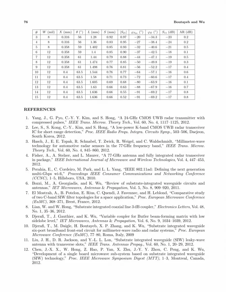
Table A1 in the Annex presents the dimensions of a 60 GHz array with 15 elements and Taylordistribution. The phase parameters and the axial ratio of each array element are also reported in thistable. The radiating elements were characterized for operating at 60 GHz, but the design dimensionswere changed by using adequate translation factors for the designs of other antennas presented in thispaper and operating at 77 GHz. From this, it is not necessary to repeat the characterization made at60GHz for designing the 77 GHz arrays.
Table 1. |S21| parameter for the different elements of the arrays.
|S21| for the different elementsDistributions
Uniform Tchebychev Binomial Taylor
|S21| (1) 0.9375 0.9981 0.9999 0.992
|S21| (2) 0.9333 0.9888 0.999 0.983
|S21| (3) 0.9286 0.9672 0.9948 0.969
|S21| (4) 0.9231 0.9364 0.9817 0.952
|S21| (5) 0.9167 0.9047 0.9516 0.931
|S21| (6) 0.9091 0.8778 0.8983 0.906
|S21| (7) 0.9000 0.8534 0.8221 0.879
|S21| (8) 0.8889 0.8254 0.7294 0.847
|S21| (9) 0.8750 0.7884 0.6291 0.813
|S21| (10) 0.8571 0.7359 0.5283 0.773
|S21| (11) 0.8333 0.6594 0.4317 0.729
|S21| (12) 0.8000 0.5549 0.3418 0.678
|S21| (13) 0.7500 0.4278 0.2595 0.624
|S21| (14) 0.6667 0.2876 0.1847 0.552
|S21| (15) 0.5000 0.1428 0.1169 0.529

Progress In Electromagnetics Research C, Vol. 49, 2014 71
Once the rectangular waveguide arrays are designed, it is necessary to apply modifications to obtainthe equivalent SIW arrays. This is done by taking into account the changes in the propagation constantand the radiation loss of the SIW. Indeed, SIWs and RWGs have different propagation constants, calledβg,SIW and βg,RWG. This difference must be taken into account for determining the distance betweenthe elements in the SIW array. The relation between the distances Dn calculated for RWG arrays andthose of SIW arrays can be written as:
Dn,SIW =βg,RWG
βg,SIWDn,RWG (2)
where the propagation constants βg,RWG and βg,SIW were calculated numerically (using HFSS simulator).PSIW and PRWG are the power distributions in an SIW and its equivalent rectangular waveguide,
respectively. To obtain the equivalent SIW array from our optimized RWG array, we must also takeinto account the relationship between PSIW and PRWG as follows:
PSIW(zn) = PRWG(zn)e−2αzn (3)
where α is the radiation loss constant and zn is the position of element n of the array
zn =
n∑
i=1
Dn (4)
The radiation loss constant α of the SIW is calculated numerically. The parameters of each radiatingelement in the SIW array are modified to satisfy the required aperture power distribution (uniform,Tchebychev or Taylor distributions).
In a travelling-wave antenna, each element radiates a portion of the incident power and the leftoverpasses to the next radiating element. As it is impossible for the last element to radiate 100% power,in order to have no reflection, the antenna can be terminated in a matching load. However, shortcircuit terminations were enough for the 60 GHz and 77GHz arrays since the residual power reachingthe termination was less than 5% for these two antennas.
4. DESIGN OF THE SIWS
In the design of the SIW, the metallic via dimensions and the period must be chosen such that theTE 10 mode exists but not the TE 20 mode. It is also important to have low radiating loss. Accordingto [6], for an SIW made with metallic cylinders of diameter d and with period p, these conditions areachieved when the design parameters fit with the following:
p > d (5)p
λc
< 0.25 (6)
4.1. SIW at 60 GHz
The dimensions of an SIW made with metallic cylinders were optimized for operating at 60 GHz. a, b,and εr are respectively the waveguide width, the substrate thickness, and the substrate permittivity.The following are the optimized parameters: a = 2.43mm, b = 0.762mm, p = 1.4mm, and d = 0.81mm,and εr = 2.94. With these parameters, the cutoff frequency of the TE 10 mode, fcTE10
, is around 40GHzand the cutoff frequency of the TE 20 mode is around 75GHz. A quasi-linear behavior of the propagationconstant was observed in the frequency band from 1.2 × fcTE10
to 1.9 × fcTE10. A component working
in this frequency band will suffer less from dispersion and may have larger frequency bandwidth.
4.2. SIW at 77 GHz
The same procedure was done for an SIW operating at 77 GHz. The optimized dimensions area = 2.43 mm, b = 0.508mm, p = 1.4mm and d = 1.24mm. For these dimensions, the cutoff frequenciesof the TE 10 and TE 20 modes are 49 GHz and 98 GHz, respectively. Again, the frequency of 77 GHzis located in the center of the frequency bandwidth with a quasi-linear behavior of the propagationconstant.

72 Boutayeb and Wu
5. DESIGN OF THE TRANSITIONS
This section presents the design of transitions between an SIW and connectors used for measurements.
5.1. Transition at 60 GHz
A WR15/SIW transition as shown in Figure 4 has been designed for the antenna operating at 60 GHz.The optimized transition gives a return loss less than −10 dB in the band 55 GHz–65 GHz.
WR15
3.76 mm
2.43 mm
1.88 mm
Figure 4. WR15/SIW optimized transition at 60 GHz.
5.2. Transition at 77 GHz
A WR10/SIW transition developed at the Poly-Grames research center has been used for the antennasoperating at 77 GHz.
6. NUMERICAL RESULTS
Simulations that follow were performed with Ansoft HFSS. Return losses and axial ratios of the designed60GHz arrays are plotted in Figures 5(a) and (b). These results show that the operating bandwidths arefixed by the axial ratio curves. The obtained gains in the broadside direction are plotted in Figure 5(c).The realized gain takes into account the power reflected at the input array port as well as the dielectriclosses. Figures 6(a)–(c) show the computed results for the 77 GHz arrays.
The radiating features of the designed arrays 60GHz and 77GHz are summarized in Table 2.In this table, the best performances are indicated in bold. From these results, the lower side lobe
Table 2. performances for antennas operating at 60 and 77 GHz.
Operating frequency PerformancesDistributions
Uniform Tchebychev Taylor
60GHz
Gain 16.73 dB 16.23 dB 16.47 dB
AR 1.06 dB 1.53 dB 0.06 dB
|S11| −15.2dB −13.5 dB −13.5 dB
SLL −17 dB −25 dB −26.6 dB
77GHz
Gain 16.2 dB 15.7 dB 16.7 dB
AR 0.94 dB 2.2 dB 1.7 dB
|S11| −15.5 dB −15.3 dB −15.1 dB
SLL −14.8 dB −23.5 dB −25.8dB

Progress In Electromagnetics Research C, Vol. 49, 2014 73
(a)
(b) (c)
Figure 5. Antennas operating at 60 GHz: (a) simulated return loss, (b) axial ratio at broadsidedirection, and (c) gain at broadside direction versus frequency for different aperture distributions.
(a)
(b) (c)
Figure 6. Antennas operating at 77 GHz: (a) simulated return loss, (b) axial ratio at broadsidedirection, and (c) gain at broadside direction versus frequency for different aperture distributions.
level is obtained with the Tchebychev or Taylor aperture distributions, as expected. Furthermore, theoptimized antennas with Taylor distribution give a better compromise for low side lobes and goodcircular polarization. This is probably due to the fact that arrays with Taylor distribution are easierto design than those with the Tchebychev distribution, as this can be deducted from Table 1. Indeed,Table 1 shows that it is easier to achieve the design rules for the Taylor distribution since fewer numberof required values of |S21| are unfeasible.
It should be noted that for all the designed 15-element arrays the obtain radiation efficiency isabout 78%, whereas it is more than 90% for a similar antenna array operating 7.5 GHz as proposedin [19, 20]. This is due to the increase of the radiation loss at millimeter waves and the higher dielectricloss of the substrate material that is used here. To increase the radiation efficiency other better materialshould be used.

74 Boutayeb and Wu
7. EXPERIMENTAL RESULTS
To validate the proposed analysis, arrays operating at 77 GHz were fabricated. Figure 7 shows a photoof the prototype array with uniform distribution. The measured and simulated return losses for uniformand Taylor distributions are plotted in Figure 8, showing that a good impedance matching is obtainedwith the fabricated antennas.
The measured axial ratios are reported in Figure 8(b), showing that, at 77 GHz, a better circularpolarization characteristic is obtained for the antenna with uniform distribution.
Figure 7. Photo of a fabricated 77 GHz array antenna.
75 75.5 76 76.5 77 77.5 78 78.5 79Frequency (GHz)
TaylorUniform
(a) (b)
0
2
4
6
8
10
12
14
16
18
20
Axi
al R
atio
(dB
)
Figure 8. (a) Measured return loss, (b) measured axial ratio.
(a) (b)
Figure 9. Simulated and measured radiation patterns at 77 GHz: (a) for uniform distribution, (b) forTaylor distribution.

Progress In Electromagnetics Research C, Vol. 49, 2014 75
Figure 10. Measured gain at broadside direction versus frequency for Taylor and uniform distributions.
Experimental as well as numerical results for the radiation pattern are plotted in Figures 9(a)and (b), for uniform and Taylor distributions, respectively. A good agreement is obtained betweenthe simulated and measured results. The measured gain versus frequency is shown in Figure 10. Thediscrepancies between simulated and experimental results, in particular, the observed lower gains in thefabricated antennas compared to the simulated results are probably due to tolerance in the dielectricconstant of the substrate, the tolerances in the fabrication and the tolerance in the antenna alignmentduring measurement.
8. CONCLUSION
This paper has presented the analysis and synthesis of millimeter-wave substrate integrated travelling-wave linear antenna arrays with circular polarization. Antenna arrays with different power distributions,including the transitions and terminations, are analyzed and designed for communication and radarsystems at 60GHz and 77 GHz.
Full-wave simulation results show that the optimized antennas present good performances in termsof impedance matching, gain and axial ratio. The design method allows the control of the main beam’sorientation, gain and side lobe levels. Furthermore, experimental results were presented to validate theproposed designs and techniques. It should be noted that the gain can be increased by using a powerdivider and several linear arrays. Indeed, gains above 30 dB are required in radar applications.
ACKNOWLEDGMENT
The authors wish to thank Ms. Hoda Nematollahi and the technicians of Poly-Grames researchcentre. The authors wish also to thank NSERC, FQRNT and Centre de Recherche En ElectroniqueRadiofrequence (CREER).
APPENDIX A.
Table A1. 60GHz Array dimensions for 15 elements with Taylor distribution.
# W (mil) X (mm) θ (◦) L (mm) S (mm) |S21| ϕS21(◦) ϕE (◦) S11 (dB) AR (dB)
1 8 0.291 54 1.05 0.98 0.99 −8 −29.6 −29 0.4
2 8 0.291 54 1.16 0.92 0.98 −12 −32.8 −29 0.2
76 Boutayeb and Wu
# W (mil) X (mm) θ (◦) L (mm) S (mm) |S21| ϕS21(◦) ϕE (◦) S11 (dB) AR (dB)
3 8 0.316 56 1.28 0.92 0.97 −20 −34.3 −23 0.2
4 8 0.316 56 1.36 0.83 0.95 −27 −38.4 −24 0.2
5 8 0.358 59 1.402 0.85 0.93 −32 −40.6 −21 0.5
6 12 0.358 59 1.4 0.85 0.90 −37 −42.5 −18 0.1
7 12 0.358 61 1.44 0.79 0.88 −44 −47.1 −19 0.5
8 12 0.358 61 1.474 0.77 0.85 −50 −49.8 −19 0.3
9 12 0.358 61 1.498 0.76 0.81 −56 −52.2 −17 0.4
10 12 0.4 63.5 1.544 0.76 0.77 −64 −57.1 −16 0.6
11 12 0.4 63.5 1.58 0.71 0.73 −72 −60.6 −17 0.4
12 12 0.4 63.5 1.605 0.69 0.68 −80 −63.9 −16 0.1
13 12 0.4 63.5 1.63 0.66 0.63 −88 −67.9 −16 0.7
14 12 0.4 63.5 1.636 0.66 0.55 −91 −69.2 −17 0.8
15 12 0.4 63.5 1.636 0.66 0.52 −91 −69.2 −17 0.8
REFERENCES
1. Yang, J., G. Pyo, C.-Y. Y. Kim, and S. Hong, “A 24-GHz CMOS UWB radar transmitter withcompressed pulses,” IEEE Trans. Microw. Theory Tech., Vol. 60, No. 4, 1117–1125, 2012.
2. Lee, S., S. Kong, C.-Y.. Kim, and S. Hong, “A low-power K-band CMOS UWB radar transceiverIC for short range detection,” Proc. IEEE Radio Frequ. Integra. Circuits Symp., 503–506, Daejeon,South Korea, 2012.
3. Hasch, J., E. E. Topak, R. Schnabel, T. Zwick, R. Weigel, and C. Waldschmidt, “Millimeter-wavetechnology for automotive radar sensors in the 77 GHz frequency band,” IEEE Trans. Microw.Theory Tech., Vol. 60, No. 4, 845–860, 2012.
4. Fisher, A., A. Stelzer, and L. Maurer, “A 77-GHz antenna and fully integrated radar transceiverin package,” IEEE International Journal of Microwave and Wireless Technologies, Vol. 4, 447–453,2012.
5. Perahia, E., C. Cordeiro, M. Park, and L. L. Yang, “IEEE 802.11ad: Defining the next generationmulti-Gbps wi-fi,” Proceedings IEEE Consumer Communications and Networking Conference(CCNC), 1–5, Hillsboro, USA, 2010.
6. Bozzi, M., A. Georgiadis, and K. Wu, “Review of substrate-integrated waveguide circuits andantennas,” IET Microwaves, Antennas & Propagation, Vol. 5, No. 8, 909–920, 2011.
7. El Mostrah, A., B. Potelon, E. Rius, C. Quendi, J. Favennec, and H. Leblond, “Comparative studyof two C-band SIW filter topologies for a space application,” Proc. European Microwave Conference(EuMC), 368–371, Brest, France, 2012.
8. Lian, W. and W. Hong, “Substrate integrated coaxial line 3 dB coupler,” Electronics Letters, Vol. 48,No. 1, 35–36, 2012.
9. Djerafi, T., J. Gauthier, and K. Wu, “Variable coupler for Butler beam-forming matrix with lowsidelobe level,” IET Microwaves, Antennas & Propagation, Vol. 6, No. 9, 1034–1039, 2012.
10. Djerafi, T., M. Daigle, H. Boutayeb, X. P. Zhang, and K. Wu, “Substrate integrated waveguidesix-port broadband front-end circuit for millimeter-wave radio and radar systems,” Proc. EuropeanMicrowave Conference (EuMC), 77–80, Roma, Italy, 2009
11. Liu, J. H., D. R. Jackson, and Y.-L. L. Lon, “Substrate integrated waveguide (SIW) leaky-waveantenna with transverse slots,” IEEE Trans. Antennas Propag., Vol. 60, No. 1, 20–29, 2012.
12. Chen, J.-X. X., W. Hong, Z. Hao, P. Yan, X. Zhu, J.-Y. Y. Zhou, C. Peng, and K. Wu,“Development of a single board microwave sub-system based on substrate integrated waveguide(SIW) technology,” Proc. IEEE Microwave Symposium Digest (MTT), 1–3, Montreal, Canada,2012.

Progress In Electromagnetics Research C, Vol. 49, 2014 77
13. Li, Z. and K. Wu, “24-GHz frequency-modulation continuous-wave radar front-end system-on-substrate,” IEEE Trans. Microw. Theory Tech., Vol. 56, No. 2, 278–285, 2008.
14. Han, L. and K. Wu, “24-GHz integrated radio and radar system capable of time-agile wirelesscommunication and sensing,” IEEE Trans. Microw. Theory Tech., Vol. 60, No. 3, 619–631, 2012.
15. Nematollahi, H., H. Boutayeb, and K. Wu, “Mm-wave circularly polarized SIW traveling-waveantennas,” Proc. European Microwave Conference (EuMC), Roma, Italy, 2009.
16. Zhang, Q. F. and Y. L. Lu, “45◦ linearly polarized substrate integrated waveguide-fed slot arrayantennas,” Proc. IEEE Microwave and Millimeter Wave Technology (ICMMT), Vol. 3, 1214–1217,Nanjing, China, 2008.
17. Peters, F. D., S. O. Tatu, and T. Denidni, “Design of beamforming slot antenna arraysusing substrate integrated waveguide,” Proc. IEEE Antennas and Propag. Society Intern Symp.(APSURSI), 1–2, Spokane, USA, 2011.
18. Chen, P., W. Hong, Z. Kuai, and J. Xu, “A substrate integrated waveguide circular polarized slotradiator and its linear array,” IEEE Antennas Wireless Propag. Lett., Vol. 8, 1536–1225, 2009.
19. Montisci, G., “Design of circularly polarized waveguide slot linear arrays,” IEEE Trans. AntennasPropag., Vol. 54, No. 10, 3025–3029, Oct. 2006.
20. Montisci, G., M. Musa, and G. Mazzarella, “Waveguide slot antennas form circularly polarizedradiated field,” IEEE Trans. Antennas Propag., Vol. 52, No. 2, 619–623, Feb. 2004.