an automated framework for validating firewall policy enforcement
TRANSCRIPT

An Automated Framework for Validating FirewallPolicy Enforcement
Adel El-Atawy∗, Taghrid Samak∗, Zein Wali∗, Ehab Al-Shaer∗,Sheng Li†∗School of Computer Science, Telecommunication, and Information Systems
DePaul UniversityChicago, Illinois 60604
Email: {aelatawy, taghrid, zwali, ehab}@cs.depaul.edu†Cisco
San Jose, California 95134Email: {fclin, chpham, sheli}@cisco.com
Abstract
The implementation of network security devices such as firewalls and IDSs are constantly being improved toaccommodate higher security and performance standards. Using reliable and yet practical techniques for testing thefunctionality of firewall devices particularly after new filtering implementation or optimization becomes necessaryto assure proven security. Generating random traffic to testthe functionality of firewall matching is inefficient andinaccurate as it requires an exponential number of test cases for a reasonable coverage. In addition, in most casesthe policies used during testing are limited and manually generated representing fixed policy profiles.
In this paper, we present a framework for automatic testing of the firewall policy enforcement or implementationusing efficient random traffic and policy generation techniques. Our framework is a two-stage architecture thatprovides a satisfying coverage of the firewall operational states. A large variety of policies are randomly generatedaccording to custom profiles and also based on the grammar of the access control list. Testing packets are thengenerated intelligently and proportional to the critical regions of the generated policies to validate the firewallenforcement for such policies. We describe our implementation of the framework based on Cisco IOS, whichincludes the policy generation, test cases generation, capturing and analyzing firewall output, and creating detailedtest reports. Our evaluation results show that the automated security testing is not only achievable but it also offersa dramatically higher degree of confidence than random or manual testing.
I. INTRODUCTION
Firewalls work as filtering devices at the boundary of different (sub)networks based on policies or access controllists (ACL). They are important security devices as they protect the internal network from attacks and unauthorizedtraffic. Due to the persistent effort to enhance and optimizefirewall protection and performance respectively,firewalls undergo continuous modification to their internaldesign and implementation to deploy new optimizedfiltering algorithms, or adding new features into the ACL as firewall policies evolves syntactically and semantically.This increases the chance of software bugs that might invalidate the filtering decision, thereby causing securityviolations. Therefore, firewalls devices with new softwarereleases require thorough validation to uncover errors inthe implementation or malfunctioning components.
The problem of testing a firewall has two stages:
• Generating random policies (i.e., ACLs) with different configurations such as rule complexity, rule interaction,filtering criteria, etc, and
• generating packets to test the implementation of the deviceunder test (DUT) using these policies.
Both problems must be addressed to claim that every aspect ofthe firewall enforcement is validated. Our frameworkhandles both problems using intelligent policy generationand policy segmentation techniques.
The problem of policy generation has two sides of its own. Thefirst one, is to generate rules that conform withthe syntax specification of the firewall. The other side of theproblem is to generate rules that use different fieldvalues, different complexities (i.e., number of optional parameters/fields used) and covering a wide range of ruleinter-relations (i.e., overlapping, super/subsets, etc). The former problem is solved by specifying the syntax using atailored form of augmented context-free grammar. The latter is addressed by generating the rules based on a neutral

representation (i.e., a finite state automaton accepting the grammar), thus separating the policy generation logicfrom the specifics of the language. Using this approach, bothaspects of the problem are targeted simultaneouslyand policies with a customizable nature can be generated following any user-specified ACL syntax.
Testing the firewall by exhaustively injecting all possiblepackets into the firewall will be enough. It is a simpleoperation to enumerate all possible values in the packet header fields, but it is not feasible due to the number ofpackets needed (even if we restricted these packets to ranges with relevant addresses and ports). Restricting thedomain even further (by confining packets to realistic values and tuning the encoding) will only reduce the requiredtesting time from about4× 1013 years for the complete address space, to 4.5 years (using onebillion packets persecond). As seen in the Table I, the savings can be huge but theneeded time is still prohibitive. Random samplingcan be used but its one-sided error probability (i.e., probability of faulty firewall passes the test, or having a false-negative) is impractically high. Therefore, we introduce the concept of policy segmentation in order to achieve asmart criteria for packet selection.
Span method Number of values Time on a 1G packet/secsystem. (years)
Entire traffic space 1.2676x1030 4.0169x10¹³
Only relevant traffic 7.555x10²² 2.394x10⁶
(using class C network)Using some optimizations 1.44x10¹⁷ 4.566
TABLE I
REQUIRED TIME TO EXHAUSTIVELY TEST DIFFERENT ADDRESS SPACES
In the next section, an overview of related work is provided.Section III discusses the system framework and itsdifferent modules. The policy generation is discussed in section IV. The test data generator will be discussed insection V. The reporting capabilities of the framework willbe shown in section VI. In section VII the system willbe evaluated, followed by conclusion and future work.
II. RELATED WORK
Product testing is considered not only the most important but also the most expensive and time consuming phasein any production line. Testing techniques are categorizedinto: black-box “functional” and white-box “structural”testing. In black-box testing, the knowledge of the internal structure/implementation of the component under testis not used or in most cases it is not even known to the tester orhidden by the component owner. This test canbe done exhaustively but in most cases the samples needed to perform the test is impractically large. Therefore,only a subset of the input data is selected. The data selection is done from the input domain boundaries and withineach domain the sample data is selected statistically [2], [5]. In white-box testing, the internal structure or theimplementation must be known because the whole test is basedon this knowledge where the samples are selectedto test all possible cases or states in the implementation [2], [4].
Mostly, network devices (like switches, routers, network balancers and firewalls) are tested using the black-box”functional” testing concept. Usually, this test is divided into sub-tests: auditing, build verification, availability,manageability and security tests [8].
The firewall, as a network device, follows the previous testing procedure but due to its nature it has a littledifferent testing approach. Firewall errors can be categorized into four error types: security, implementation, policyand capability errors [11]. Each error type has its own detection techniques. Generally, we can categorize the firewalltesting techniques into two approaches, theoretical approaches [7], [10], [12] and practical approaches [11], [3],[6].
In the theoretical approach, the testing is based on a formalmodel of the firewall and the surrounding network.Vigna proposes in [10] a firewall testing methodology based on a formal model of networks that allows the testengineer to model the network environment of the firewall. This allows to formally prove that the topology of thenetwork provides the needed protection against attacks. Also, Jurjens et al in [7] used a CASE tool to model

Fig. 1. System framework: A high level view
the firewall and the surrounding network then test cases are generated to test the firewall against a list of securityvulnerabilities. Others, in the same camp, like Wool [12] introduced a tool capable of analyzing configurationparameters from real environments. This firewall analyzer was based on the work of Mayer, Wool and Ziskind [1].The analyzer is fed with the firewall configuration files and the firewall routing table then it uses this informationto simulate the firewall behavior. The simulation is done totally off-line without sending any packets.
In the practical approach: most of the previous work providemethodologies to perform penetration testing againstthe firewall. Ranum [9] identifies two kinds of testing methods: checklist and design-oriented testing. Checklisttesting is equivalent to penetration testing in running a list of vulnerability scanners against the firewall. Design-oriented testing is quite different; we ask who implementedthe firewall “why do they think the firewall will protectthe network (or not)” and based on their answers a set of test cases are designed to check their claims. In [3] theauthors present a methodology to test the firewall security vulnerability using two tests one is automated using asecurity analysis tool called SATAN while the other test is manual which is based on interacting with the firewall.Haeni in [6] describes a methodology to perform firewall penetration testing. The test was structured in four steps,indirect information collection, direct information collection, attack from the outside and attack from the inside. InICSA labs, a firewall is being tested against a pre-defined setof firewall violations (i.e., firewall logging capability,firewall security vulnerability, firewall policy, etc.) which are described by Walsh in [11] and the one that passestheir test get certified.
Most of the previously mentioned efforts tried to address this problem from different points of view but no workwas published about testing whether the firewall implementsthe policy correctly or not. Also, none of the abovementioned tools and models generate real policies that can set different environments for the firewall to operateunder.
III. SYSTEM FRAMEWORK
An external view of the system shows three components: The Engine, the Spy, and the User Interface. The Engineis the core and it is where most of the processing takes place.The Spy resides behind the firewall to report backto the Engine how the firewall handled the traffic, and the UserInterface is a light weight front end to the engine.
From a design point of view, the architecture of our system consists of the following main modules: Policygenerator, Segmentation/analysis module, Test packet generator, post-test analysis module. Other helper modulesinclude the BNF parser, traffic injection module, policy compiler, and the spy process (see Fig 1).
A typical test cycle starts with specifying all parameters for policy (e.g., grammar, policy size, etc) and trafficgeneration (e.g., number of packet, injection rate, etc), and system configuration (e.g., firewall type and address).Then, when the test is initiated, the testing engine will generate a policy, analyze the policy for traffic selection andload it into the firewall. The digested policy (in the form of segments, will be discussed in detail in section V-B)will be used to generate packets that will be in turn injectedto the firewall. The outcome of the firewall will be

Fig. 2. Detailed System Architecture
monitored by the Spy process. Afterwards, the resulting packets will be analyzed and a report will be generated.The cycle of policy generation and traffic injection can be repeated as the administrator wishes. A more detaileddiagram showing the exact implementation of the system is shown in Fig 2. The following is a description of eachcomponent:
• BNF Parser (Policy Grammar Parser): This core module reads the grammar specification of the DeviceUnder Test (DUT), and builds the Finite State Automaton (FSA) that accepts this grammar. The grammar isprovided in an augmented BNF format. All relations and restrictions on field values and among fields areincorporated into this specification.
• Policy Generation Module This module is responsible for generating different policies according to a setof parameters (including the grammar specification) as provided by the user. These policies would be usedto configure the firewall for the test. Optionally, the user can load policies manually overriding this modulefunctionality. The output of this module is a policy in plaintext that follows the firewall specific syntax.
• Policy Parsing, Checking and Compiling This module parses a policy, and compiles it into an internalrepresentation of constraints on packet header field bits.
• Segmentation ModuleThe segmentation algorithm builds a list of segments that isequivalent to the compiledpolicy. Using the rule-rule intersections and overlaps, different areas are identified, and the segments are formed.See section V-B for details.
• Segment Weight AnalyzerThe segments are analyzed and each is assigned a weight basedon a number offactors such as the number of rules intersecting in the segment and the size of the segment address space. Thesegment weight is a measure of the criticality of the segment.
• Test Packet GeneratorThis module generates test packets distributed in proportion to the segment weight. Forexample, segments that involve many interacting rules willpotentially receive more test packets than others.

Fig. 3. The internal design of the Spy module. Its interaction with the firewall and Engine is illustrated
Each test packet carries test case information that includes a packet sequence number, the test session ID, anda signature to avoid confusion with other cross-traffic packets.
• Spy: firewall monitoring tool The Spy is a stand alone program that resides behind the firewall. It sniffs alloutgoing packets, and collects them based on the Engine’s request. When a test starts, the spy is informed bythe test session ID. All packets are tested for this value, and if found they are marked in a bitmap. When thetest is over, the Spy will compare the expected with the actual firewall behavior and errors if any will be sentback to the engine for analysis. The bitmap that represents the expected behavior (sent from the Engine to theSpy prior to the test), and the bitmap of the discrepancies (sent from the Spy to the Engine after the test) areboth compressed to save communication overhead.The Spy is built to manage several tests simultaneously, each can be coming from a different Engine. Thus,it has to be designed to support such a high traffic volume, without dropping packets due to overload (designshown in Fig 3). It is split into three processes; (1) Captureprocess: reads all packets from the media,and forwards packets that has the framework signature into the next process, (2) DeMux process: takes alltest packets that were captured, and demultiplexes them into their corresponding threads, and (3) The MainProcess: that communicates with the Engine, receives the test requests, creates a thread for each test, createsthe appropriate pipes/queues for these threads, and informs the DeMux process about the new test ID’s.
• Post-Test AnalyzerThe collected information (by the spy) are then returned to the Engine where analysis isperformed and a report is generated that shows the errors (ifany). Several hints are extracted showing whereand why the errors might have occurred. This is provided to the user as a distribution of errors and their typesover different segments, rules, and fields.
IV. POLICY GENERATION
In this section, we present the design details of the modulesresponsible for the first phase of the testing cycle;namely, Policy Generation. The modules involved are the BNFgrammar parser, the policy checker/compiler, andthe policy generation module.
A. Policy Grammar
Describing a general grammar that can accommodate all possible access-control list syntaxes is not as simpleas it seems. Specifying only the syntax can be a headache but astraightforward task. However, specifying thesemantics of the different clauses in the grammar (i.e., how each of these tokens and clauses interact to form thefinal ACE constraint that correspond to its actual effect in filtering traffic) is another problem. Extra embeddedannotations are needed to describe these semantics to the grammar parser and the policy generator afterwards.
Among the annotations needed: which field is this clause/token configuring? If this is a literal, does it have aspecial meaning (e.g., “accept”, “permit”, “any”)? Can this value be representedby a literal, can we use lookup

S := "access-list" Policy-Number action SrcAddr [opt1]Policy-Number\FieldID(100) := \number(1,99)action\FieldID(0) := "permit"\V(1) | "deny"\V(0)SrcAddr\FieldID(2) := IPany | IPpairIPany := "any"\Trans("IP","op","any")IPpair := \IPvalue\Trans("IP","op","IPsubnet") [OptMask]OptMask := \IPmask\Trans("IP","op","IPmask")opt1\FieldID(80) := "log"\V(1)
Fig. 4. A simple access-control list syntax
files for this task (e.g., protocol and port names)? Is this token applicable for all protocols (e.g., ICMP qualifiersare only valid with ICMP specified as the protocol, the same goes for TCP extra control bits)?
From a theoretical point of view, adding all of the annotations needed for the above mentioned tweaks will notresult in a more powerful grammar. It will still be a CFG (context free grammar). This observation is necessary inorder to guarantee that a simple PDA (PushDown Automaton) can recognize this grammar successfully (i.e., acceptsany policy that follows this grammar). Simply, this is dealtwith a graph (represents the finite state automaton) andthe ordinary stack of recursive calls for the accompanying stack required to convert the FSA to a PDA.
An example of a simple access-list syntax that supports constraints only for the source address can be writtenas follows:
The grammar has two sets of symbols; terminal and non-terminal symbols. Some special terms are included inthe grammar to express the semantics and field relations. In our implementation, some of the general properties ofthe grammar are:
• Literal terminal symbols are enclosed with double quotes and are an exact string that will appear in the ruledefinition.
• Non-terminal symbols are defined by following lines in the grammar.• Each line defines a non-terminal.• Square brackets ”[ ]” enclose optional fields.• Each symbol followed by a “\“ represents an operation on the field that will be performed by the parser.• Round brackets ”()” are used to hold parameters for operations.• Symbols starting by a “\“ are special fields that are predefined in the parser.
Special keywords/operations in the grammar are:
• \FieldID(n) Indicates the field number (n) to be used in inter-field dependency reference. Those numbers arepredefined and will be used to retrieve the physical positionof the field in later stages.
• \num(n1,n2) An integer range fromn1 to n2.• \V(x) The value of the current token isx. For example, “tcp”\V(6) means the word “tcp” has the value of 6.• IPvalueSpecial handling for IPs, in parsing and generation.• IPmaskSpecial handling for subnet masks, in parsing and generation.• Trans This is required to specify non-simple handling of data in the rule. For example, conditions with
inequalities over port values, and the subnet mask effect ofIP addresses.The parser deals with the symbols associated with theTransoperator according to its following parameters. For
each such symbol, the context must be defined. The way the parser should deal with the symbol should be givenas well. The parser has a set of predefined methods that will beused to perform the operation over the field. Threeparameters must be provided to theTransoperator. The first parameter refers to the context of the symbol (IP, port,protocol). The second parameter corresponds to the type of the last parameter which is the action to apply.
In the same sense a more complex grammar is defined in Fig 5. To be able to accommodate the “extended accesslist” features, some extra keywords have been added. For example, \Lookup, and\Cond are needed to specifyextra options. The former is used in cases where a list of constants has no special handling but their value, so theyare retrieved from a file. Typical use can be for port and protocol names (instead of listing them using the “\V”keyword). The latter is used for these clauses that only appear when another field has been given a certain value.This takes places more often when clauses depend on the protocol value. It is associated with a non-terminal, and

S := "access-list" Policy-Number action protocol SrcAddr RT [Logging]RT := RT1 | RT2RT1 := [SrcPort] DestAddr L3Extra RL4RT2 := DestAddr L3Extra RT2bRT2b := RL4 | FragmentsL3Extra := [Prec] [Tos]RL4 := [DestPort] [FIN] [PSH] [SYN] [URG] [AckRstEst] [igmpquals] [icmpquals]AckRstEst := [ACK] [RST] | [Established]
Policy-Number\FieldID(100) := \number(100,199)action\FieldID(0) := "permit"\V(1) | "deny"\V(0)protocol\FieldID(1) := \number(0,255) | \Lookup("number","protocols.txt")SrcAddr\FieldID(2) := IPaddrDestAddr\FieldID(3) := IPaddrSrcPort\FieldID(4) := PortDestPort\FieldID(5) := Port
IPaddr := IPany | IPhost | IPpairIPany := "any"\Translate("IP","operator","any")IPhost := "host" \IPvalue\Translate("IP","operator","IPhost")IPpair := \IPvalue\Translate("IP","operator","IPsubnet") \IPmask\Translate("IP","operator","IPmask")
Port \Cond(1,17) := PortOp1|PortOp2|PortOp3|PortOp4|PortOp5Port \Cond(1,6) := PortOp1|PortOp2|PortOp3|PortOp4|PortOp5PortOp1 := "eq" Y\Translate("port","operator","eq")PortOp2 := "lt" Y\Translate("port","operator","lt")PortOp3 := "range" Y\Translate("port","operator","ge") Y\Translate("port","operator","le")PortOp4 := "gt" Y\Translate("port","operator","gt")PortOp5 := "neq" Y\Translate("port","operator","ne")Y \Cond(1,17) := \number(0,65535) | \Lookup("number","udpports.txt")Y \Cond(1,6) := \number(0,65535) | \Lookup("number","tcpports.txt")
icmpquals\FieldID(6)\Cond(1,1) := \number(0,255) \number(0,255) | \Lookup("number","icmpquals.txt")
igmpquals\FieldID(19)\Cond(1,2) := \number(0,15) | Lookup("number","igmpquals.txt")
Prec\FieldID(7) := "precedence" \number(0,7)Tos\FieldID(8) := "tos" \number(0,15)
Logging\FieldID(80) := "log"\V(1)
Established\Cond(1,6)\FieldID(9) := "established"ACK\FieldID(11)\Cond(1,6) := "ack\V(1)FIN\FieldID(12)\Cond(1,6) := "fin"\V(1)PSH\FieldID(13)\Cond(1,6) := "psh"\V(1)RST\FieldID(14)\Cond(1,6) := "rst"\V(1)SYN\FieldID(15)\Cond(1,6) := "syn"\V(1)URG\FieldID(16)\Cond(1,6) := "urg"\V(1)
Fragments\FieldID(10) := "fragments"\V(1)\\EndRules
Fig. 5. A more complex access-control list syntax
given in the form ofCond(ID, v). This translates to: this grammar line is only defined if fieldID was assignedthe valuev.
B. BNF Graph
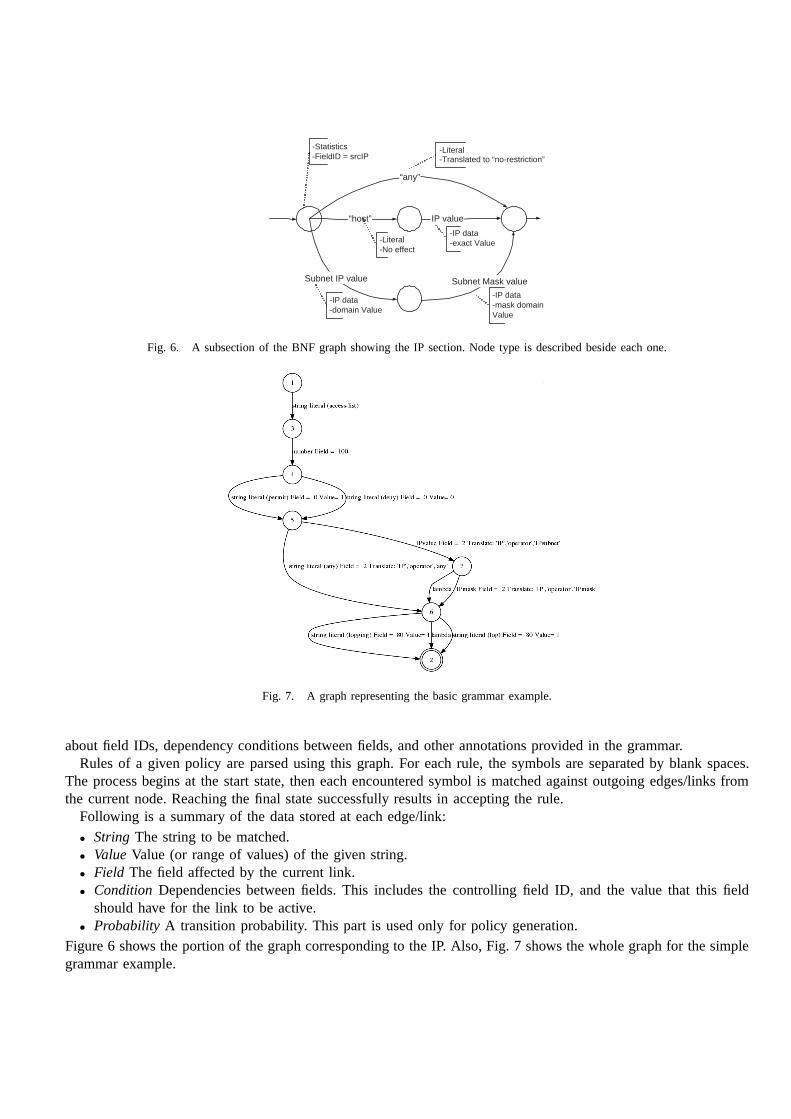
The BNF graph is a directed graph corresponding to the FSA of the grammar. The graph has a starting state,which has no incoming edges, and a final state, which has no outgoing edges. The final state is the only acceptingstate in the graph. In between those nodes, the graph is generated according to the given grammar syntax. Thegraph is used for parsing, checking and compiling input policies to the system. It is also used in the process ofpolicy generation. In this section the structure of the graph is presented. The following section explain how thisgraph is used for policy generation.
Each node represents a field in the grammar (or a symbol). Outgoing edges from a graph node control thetransition between nodes, according to values allowed for the corresponding field. The links also store information
“any”
“host” IP value
Subnet IP value Subnet Mask value
-Statistics -FieldID = srcIP
-Literal -Translated to “no-restriction”
-Literal -No effect
-IP data -exact Value
-IP data -domain Value
-IP data -mask domain Value
Fig. 6. A subsection of the BNF graph showing the IP section. Node type is described beside each one.
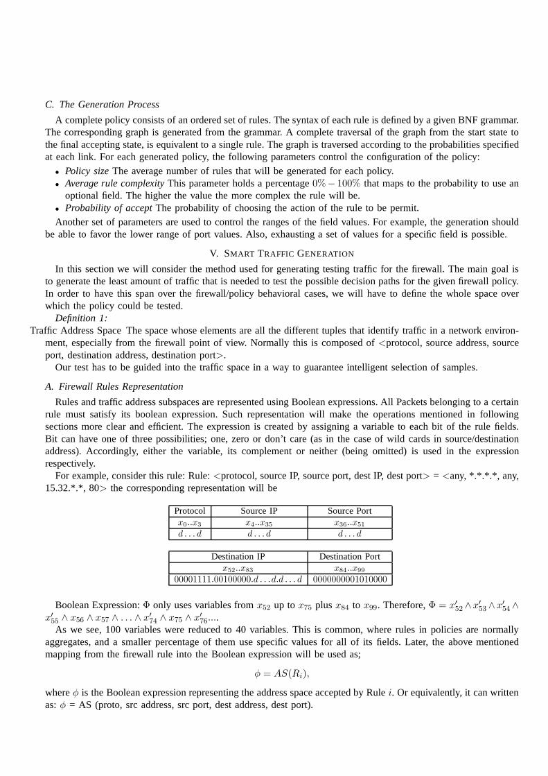
Fig. 7. A graph representing the basic grammar example.
about field IDs, dependency conditions between fields, and other annotations provided in the grammar.Rules of a given policy are parsed using this graph. For each rule, the symbols are separated by blank spaces.
The process begins at the start state, then each encounteredsymbol is matched against outgoing edges/links fromthe current node. Reaching the final state successfully results in accepting the rule.
Following is a summary of the data stored at each edge/link:
• String The string to be matched.• ValueValue (or range of values) of the given string.• Field The field affected by the current link.• Condition Dependencies between fields. This includes the controllingfield ID, and the value that this field
should have for the link to be active.• Probability A transition probability. This part is used only for policy generation.
Figure 6 shows the portion of the graph corresponding to the IP. Also, Fig. 7 shows the whole graph for the simplegrammar example.
C. The Generation Process
A complete policy consists of an ordered set of rules. The syntax of each rule is defined by a given BNF grammar.The corresponding graph is generated from the grammar. A complete traversal of the graph from the start state tothe final accepting state, is equivalent to a single rule. Thegraph is traversed according to the probabilities specifiedat each link. For each generated policy, the following parameters control the configuration of the policy:
• Policy sizeThe average number of rules that will be generated for each policy.• Average rule complexityThis parameter holds a percentage0%− 100% that maps to the probability to use an
optional field. The higher the value the more complex the rulewill be.• Probability of acceptThe probability of choosing the action of the rule to be permit.
Another set of parameters are used to control the ranges of the field values. For example, the generation shouldbe able to favor the lower range of port values. Also, exhausting a set of values for a specific field is possible.
V. SMART TRAFFIC GENERATION
In this section we will consider the method used for generating testing traffic for the firewall. The main goal isto generate the least amount of traffic that is needed to test the possible decision paths for the given firewall policy.In order to have this span over the firewall/policy behavioral cases, we will have to define the whole space overwhich the policy could be tested.
Definition 1:Traffic Address Space The space whose elements are all the different tuples that identify traffic in a network environ-
ment, especially from the firewall point of view. Normally this is composed of<protocol, source address, sourceport, destination address, destination port>.
Our test has to be guided into the traffic space in a way to guarantee intelligent selection of samples.
A. Firewall Rules Representation
Rules and traffic address subspaces are represented using Boolean expressions. All Packets belonging to a certainrule must satisfy its boolean expression. Such representation will make the operations mentioned in followingsections more clear and efficient. The expression is createdby assigning a variable to each bit of the rule fields.Bit can have one of three possibilities; one, zero or don’t care (as in the case of wild cards in source/destinationaddress). Accordingly, either the variable, its complement or neither (being omitted) is used in the expressionrespectively.
For example, consider this rule: Rule:<protocol, source IP, source port, dest IP, dest port> = <any, *.*.*.*, any,15.32.*.*, 80> the corresponding representation will be
Protocol Source IP Source Portx0..x3 x4..x35 x36..x51
d . . . d d . . . d d . . . d
Destination IP Destination Portx52..x83 x84..x99
00001111.00100000.d . . .d.d . . . d 0000000001010000
Boolean Expression:Φ only uses variables fromx52 up tox75 plusx84 to x99. Therefore,Φ = x′
52∧x′
53∧x′
54∧
x′
55∧ x56 ∧ x57 ∧ . . . ∧ x′
74∧ x75 ∧ x′
76....
As we see, 100 variables were reduced to 40 variables. This iscommon, where rules in policies are normallyaggregates, and a smaller percentage of them use specific values for all of its fields. Later, the above mentionedmapping from the firewall rule into the Boolean expression will be used as;
φ = AS(Ri),
whereφ is the Boolean expression representing the address space accepted by Rulei. Or equivalently, it can writtenas:φ = AS (proto, src address, src port, dest address, dest port).

B. Traffic Address Space Segmentation
In order to investigate the behavior as thoroughly as possible while keeping the traffic size at a minimum, itis needed to identify the different possible interactions between rules of the firewall policy in order to generatea small set of packets (>= 1) for each different interaction. This can be achieved by intersecting all the trafficaddress spaces matching the rules of the policy.
Definition 2: A Segmentis a subset of the total Traffic Address Space. In a Segment, each of the member elements(i.e., packets, or header tuples) conforms to exactly the same setof policy rules, and no non-member element canconform to this exact set of rules.In other words, packets belong to the same segment are identical from the point of view of all the rules in thepolicy.
Each segment is identified by the following information fields:• AS (Address Space):The Boolean expression representing the address space.• Rin (Rules inside):Ordered list of rules applying to this space.• Rout (Rules outside):Ordered list of rules not applying to this space (i.e., complement ofRin; P −Rin).• Reff (Rules effective):Ordered list of rules that contributed to the final expression of the segment.• OR (Owner rule):The first rule in this list will be taken as the owner of the segment.• ACT (Action): Firewall action to be taken for this space. This is taken as the action of the first rule in the
Rin list.
Algorithm 1 procedure DoSegmentation (R, defAct, InitDomain)1: SEGLIST ← Λ2: AddSegment (InitDomain,Λ ,Λ , defAct)3: for all rules: i = 1 to n do4: for segments:j = SEGLIST.Count downto1 do5: S = SEGLISTj
6: IncSeg ← S.AS ∧AS(Ri) {Included part of the segment}7: ExcSeg ← S.AS ∼ AS(Ri) {Excluded part of the segment}8: if IncSeg 6= Seg.AS then {Segment not contained in the Rule’s AS}9: if IncSeg 6= Φ then
10: AddSegment (IncSeg, S.Rin ∪ {Ri}, S.Rout, S.Reff ∪ {Ri})11: AddSegment (ExcSeg, S.Rin, S.Rout ∪ {Ri}, S.Reff ∪ {Ri})12: else{there is no intersection between the rule and the segment}13: AddSegment (ExcSeg, S.Rin, S.Rout ∪ {Ri}, S.Reff ∪ {Ri})14: end if15: else{Segment is inside the Rule’s AS}16: AddSegment (IncSeg, S.Rin ∪ {Ri}, S.Rout, S.Reff )17: end if18: SEGLIST.Delete (Segment j){delete the original segment}19: end for20: end for21: return SEGLIST
The segmentation algorithm constructs a list of segments - (SEGLIST)- according to the rules interaction.Whenever a segment is identified, it calls the AddSegment subroutine to add it. AddSegment takes the policyrules (Ri), the default action of the firewall (named defAct), and the initial domain (named InitDomain) which isthe total traffic address space under consideration. IfRin is an empty list, the action (ACT) of the segment is setto the default (defAct), otherwise it takes the action used in the first rule (assuming rule priorities are their orderin the policy). Similarly, if theRin is non-empty, the first rule is taken as the owner rule (OR).
In Segmentation algorithm( V-B), the first initial segment is initialized, and added to SEGLIST at lines 1 and2. Then we loop over the rules to impose their effect on all theexisting segments. We loop in reversed order

over the segments to prevent the newly added segment from being processed in the current iteration. We usethree variables just for the sake of readability of the algorithm (i.e., S, IncSeg, ExcSeg). Respectively, they arethe currently processed segment, the Included address space between the segment by the Rule, and the excludedspace with respect to the rule. Having three cases between the segment and the rule’s address space, we either splitthe segment into included area and excluded area, leave the segment space intact as an excluded segment (if therule doesn’t intersect at all this rule), or leave the segment space unmodified as an included space (if the rule is asuperset of the segment).
The conditional adding or modification of segments are necessary to prevent the creation of empty segments.Omitting these two lines guarantees exponential run time inthe number of policy rules because there will be adeterministic growth of the number of segments by doubling the number of segments after processing each of then rules, resulting in a list of2n segments.
1) Choosing the Initial Domain::Until this point we have assumed that the initial domain/space will be theentire possible traffic address space (i.e., corresponding to: the boolean expression:True). This is an easy option tostart with, but might not be always a practical choice. More efficient choices can be made based on our knowledge(or the amount we would like to involve) of the network. Also,it can differ on wether a robustness test of thefirewall is needed as well (i.e., invalid packets are correctly rejected).
Option 1: Using the complete space:This is the simplest space to start with, but it includes packets that wemight not be interested in. For example, packets with equal source and destination, or packets having the destinationaddress equals the firewall’s incoming interface address. Also, this set makes it possible to select packets that mightbe invalid with respect to the used protocol. For example, a TCP packet with all control flag bits set, or havingsource and destination addresses both equal to zero in a normal packet, etc. But on the plus side, this options yieldsa lower number of segments due to the simplicity of the original domain. In general, this option should not be usedexcept for completeness of all testing scenarios.
Option 2: Using the complete network space, with valid packets only: Just adding the protocol constraintsto the space before applying segmentations decreases the size of the space several orders of magnitude (from2148
down to2124). The packets that result from segments built over this space are guaranteed to be valid, and acceptableby any network device. This is a recommended starting point for general firewall testing.
Option 3: Restriction to network address space:We can start with the traffic address space corresponding to<any, *.*.*.*, any, ”my network range”, any>. Starting with this initial segment, is intuitive as it is expected therewill be no packets reaching this firewall except those havingthe firewall protected network’s address range (therouters upstream towards the global network will not forward to the firewall except those relevant to my network).However, at least the address spaces of the multicast trafficmust be added. We achieve this extension by ORingtheAS of the network’s range mentioned above, with theAS equivalent to:<UDP, *.*.*.*, any, 224.*.*.*/4, any>for multicast traffic.
Option 4: Restriction to a range of source and destination addresses:A logical extension is to test usingonly packets with a specific range of source and destination addresses. Of course this is typically to be used(along with the previous option) for firewalls that are already installed in a network and need to be tested withoutdisconnecting/reconnecting to the network.
C. Analysis and complexity:
Although the algorithm shown is quite simple, it can yield exponential running time in the general case (i.e.,where the Boolean functions are not representing firewall rules, but general expressions). In the case of firewallrules, we have multiple restrictions amongst the Boolean variables involved. For example:
• We cannot specify theith bit of the source address to be equal to some value, without fixing the values of the(i− 1) previous bits.
• The variables representing the ports are either all mentioned in the Boolean expression of the rule or all takento be ”don’t care” values. Same applies for the protocol field.
The exponential number of segments occurs in the case where every rule intersects with - at least - a constant ratioof the segments existing from the previous rules. This is a case that is not to be found in a practical firewall policy.

D. Measuring the importance of segments:
It is essential to have a measure for the relevance of each segment, as this leads us to decide how dense thetesting should be within a segment. Measuring the importance of the segment (i.e., the probability that any elementwill be matched incorrectly by the firewall) can depend on (and not limited to) the following factors:
1) Number of rules in the segment (overlapping rules):As the number of rules intersecting at the segmentincreases, so will the importance of the traffic addresses inthis segment. The region that is common to manyrules can be thought of critical, as handling more overlaps can be harder to the firewall to process.
2) Number of rules affecting the segment shape (effective/boundary rules):When a rule intersects non-triviallywith a segment splitting it into two non-empty segments, this rule becomes a member of the set of effectiverules with respect to this segment. As the number of rules in this list increase, the matching will have atendency to have more decisions to make for packets within the segment.
3) The owner rule’s (OR) importance:As the first rule of a segment (owner rule) is considered more important,the whole segment can be judged as having higher tendency of being as important as well, as packets in thissegment were designed by the administrator to hit the owner rule.
4) Cumulative weights of all contributing rules:Each rule will be having a weight (depending on factors shownbelow). Also, not all rule weights contribute with the same weight, as we are concerned with the top rules ineach segment more than the lower ones. So, there will be a coefficient for each rule that depends on its orderin the segment. As a rule become more complex, it can affect the filtering algorithm in its decision process.
5) Area of the segment:As the area (i.e., number of traffic address space elements the segment covers) increases,its selectivity (and so its criticalness) decreases, and also our ability to test it exhaustively decreases as well.This means as the area increases the portion of the address space to be tested decreases, consequently itsweight. The area can be obtained by checking the number of variables in the expression representing theaddress space, or the count of different satisfying assignments.
The total testing density of a segment ought to become a function of all of the above shown factors.
ρ(S) = w1|S.Rin| + w2|S.Reff | +
w3weight(S.OR) +
w4Σr∈Rinc(order(r)).weight(r) +
w5log2(‖S.AS‖)−1
Some of these effects can be combined together to simplify the expression:The third term (summation of rules’ weights) is already covering the first two terms, as it sums over all the weightsof the rules. So, we can increase thec(1) to take care of the second term. Also, by incrementing thec coefficientsin the third term, we can compensate for the first term. The fourth and fifth can be combined as well. Moreover,depending on the suspected implementation that is to be tested, it can be possible to see that taking the logarithmof the address space in another base makes more sense. The resulting expression would be:
ρ(S) = w1Σr∈S.Rinc(order(r)).weight(r)
E. Rule Weight:
The segment weight is directly affected by the weights of contributing rules as shown above. Giving each rulein the policy a weight will be easier than that of the segmentsshown above. The factors affecting the weight of arule are (and not limited to) the following:
1) The area the rule covers:As the rule gets more general, its weight decreases. The morespecific the rule themore it is critical to the system and easier to test exhaustively.
2) Number of fields used:More options make packet matching harder. Consequently, making errors more possible.This can also be reasoned as follows; every rule is a decisiontree with many levels depending on the numberof criteria in the rule. Each node in the tree has a chance in being evaluated in error. Therefore, to reach aleaf in such (skewed) tree, the algorithm will face more possible errors as the number of criteria increase.
3) The number of rules superseding this rule in the policy dependency graph:As another parameter to theimportance of the rule, we take the number of subset rules (orcorrelated rules as well) that come before itin the policy. The order of a rule in the policy is not the correct value to be taken, as it is not the real orderof the rule (as we can move it higher as long as no intersectingrule is encountered).
Weight(Ri) = α.‖Ri.AS‖+ β.♯(Higherrules)
VI. REPORTING
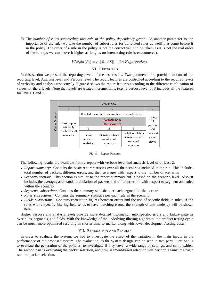
In this section we present the reporting levels of the test results. Two parameters are provided to control thereporting level; Analysis level and Verbose level. The report features are controlled according to the required levelsof verbosity and analysis respectively. Figure 8 shows the report features according to the different combination ofvalues for the 2 levels. Note that levels are treated incrementally, (e.g., a verbose level of 3 includes all the featuresfor levels 1 and 2).
Fig. 8. Report Features
The following results are available from a report with verbose level and analysis level of at least 2.
• Report summary:Contains the basic report statistics over all the scenariosincluded in the run. This includestotal number of packets, different errors, and their averages with respect to the number of scenarios
• Scenario section:This section is similar to the report summary but is based on the scenario level. Also, itincludes the averages and standard deviation of packets anddifferent errors with respect to segment and ruleswithin the scenario
• Segments subsection:Contains the summary statistics per each segment in the scenario• Rules subsections:Contains the summary statistics per each rule in the scenario• Fields subsections:Contains correlation figures between errors and the use of specific fields in rules. If the
rules with a specific filtering field tends to have matching errors, the strength of this tendency will be shownhere.
Higher verbose and analysis levels provide more detailed information into specific errors and failure patternsover rules, segments, and fields. With the knowledge of the underlying filtering algorithm, the product testing cyclecan be much more optimized resulting in shorter time to market along with lower development/testing costs.
VII. E VALUATION AND RESULTS
In order to evaluate the system, we had to investigate the effect of the variation in the main inputs in theperformance of the proposed system. The evaluation, as the system design, can be seen in two parts. First one isto evaluate the generation of the policies, to investigate if they cover a wide range of settings, and complexities.The second part is evaluating the packet selection, and how segment-based selection will perform against the basicrandom packet selection.

0
500
1000
1500
2000
2500
3000
3500
4000
0 200 400 600 800 1000 1200
Policy Size (# of Rules)
# o
f S
egm
ents
Fig. 9. Number of resulting segments versus the size of policies used. Settings used
A. Policy Generation Evaluation
To evaluate a random generator, the basic factor is how random and unpredictable the output is. However, in ourcase the output size is not large enough for such metric to be of use. Besides, for policies generated to be of morepractical use we have to make them more redundant and less random. Thus, we will focus our evaluation on howthe generated policies follow the required guidelines and properties provided by the test administrator (e.g., policysize, rule complexity, etc.), and how well the generated policies cover different field values and rule structures (e.g.,distinct port values, average rule complexity, use of specific clauses, etc.).
1) Segmentation module:Another point that has to be analyzed is the segmentation step in the testing cycle.As obvious from the definition of segments, they are more in number than the number of rules in the policy. Thequestion is how high can their number be relative to the number of rules. We used a set of generated policies,and performed segmentation on them, and kept the count of therules and segments. In Fig 9, we can see that thenumber of segments grows with the number of rules in a policy in a more or less linear fashion. Finding an exactrelation between both involves many other factors, like grammar structure, features, and complexity. Also, policygeneration options affect the policies in nature. Thus, we can write down a very simple formula that governs therelation to be| Segments(P ) |= c. | P |, where1 ≤ c ≤ 5 and its exact values depends on the above mentionedinputs. For the, more than 250, policies involved in the study it never surpassed this bound. The subset of policiesused in Fig 9 were generated from a grammar that forced rules not to have any special filtering clauses (e.g., tosvalue, ICMP qualifiers, ACK or SYN flags, etc.). This caused the overlapping between rules to be highly probable,and this is the reason we can not find any policies with| Segments(P ) |≈| P | (i.e., high proportion of distinctrules). If complex grammars are to be used, the number of segments will drop even further and the values ofc
might approach unity.
B. Packet Selection Evaluation
Comparison will be, mainly, against the random sampler testing mechanism. The operation of the random sampleris as follows: Given an available testing time, calculate the number of possible test packets to be sent, spread thesepackets uniformly over the whole traffic address space of theinvestigated firewall. In contrast to the randomtechnique, the proposed technique chooses where to concentrate the samples, and where to allow them to be moresparse; based on the result of the space segmentation. The graphs show the effect of some of the parameters ofthe system; the effectiveness of the segment weight function in predicting the error rate, the policy style (i.e., , theinterrelation between the rules within the policy), and theeffect of the segment size skewness.
The first (second) graph shows the absolute (relative to random sampler) effect of the effectiveness of the weightfunction in predicting the probability of error within a segment. As a measure of this effectiveness the correlationbetween the two vectors (the weight function, and the actualerror probability) is taken. It can be seen that any nonnegative correlation gives a gain over the random sampler. It still gives better results even with zero correlation,this can be attributed to the following; sampling within each segment guarantees a better distribution and ensuresthat the segments with higher probabilities can not be skipped as in the case of random sampling where wholesegments might be skipped. Take into consideration that in these two graphs as well as the second one, we tried

Effect of segment weight formula accuracy (correlation) on the technique effectiveness
0
0.1
0.2
0.3
0.4
0.5
0.6
0.7
0.8
0.9
1
1.E-09 1.E-08 1.E-07 1.E-06
Average fault density over all segments (Total Samples = 10^7 packets)
Pro
ba
bilit
y o
f m
iss
ing
all f
au
lts
RANDCor=0Cor=0.1Cor=0.2Cor=0.5Cor=1
(a) Effect of fault probability predic-tion accuracy on overall performance (ab-solute)
Effect of segment formula accuracy (correlation) on the technique effectiveness
0.00%
10.00%
20.00%
30.00%
40.00%
50.00%
60.00%
70.00%
80.00%
90.00%
100.00%
1.E-10 1.E-09 1.E-08 1.E-07 1.E-06
Failure RatioAverage fault ratio
Ad
va
nta
ge
ov
er
RA
ND
OM
Sa
mp
lin
g
Cor 0.0 vs RANDCor 0.5 vs RANDCor 1.0 vs RAND
(b) Effect of fault probability predictionaccuracy on overall performance (relative)
Effect of policy style on performance (segment sizes normalized)
0.00%
10.00%
20.00%
30.00%
40.00%
50.00%
60.00%
Distinct 1 Distinct 2 Overlap 1 Overlap 2 Corel 1 Corel 2
Policy Style
Ga
in o
ve
r ra
nd
om
(p
erc
en
tag
e)
(c) Effect of policy style on the overallperformance
Effect of Segment Size Distribution
0.00%
10.00%
20.00%
30.00%
40.00%
50.00%
60.00%
70.00%
80.00%
90.00%
100.00%
Low Mid High
Skewness
Gain
(%
) o
ver
Ran
do
m
(d) Effect of segment size distribution onthe overall performance
to be as conservative as we can; all tiny segments were removed to smoothen the effect of high density sampledsegments.
It is worth mentioning that this evaluation does not take into consideration the nature of common implementationerrors; they mostly cause errors in whole regions rather than have them randomly dispersed in a segment or more.In other words, if there exist an error in the implementationit is highly probable that whole segments (or rules)will be mishandled by the firewall. Thus a single packet per segment will be able to capture the error. In contrastwith random sampling that might not even assign a sample fromsuch erroneous segment. By a simple calculationwe can find that the probability the random sampler will miss hitting an erroneous segment is close to 100% evenafter using millions of packets (See Table II). We can write down the probability that the random sampler will missthe segment as follows:P (miss) = (1 − 2s−S)N , wheres andS are the sizes of the segment and total space inbits, andN is the number of packets to use.
Secondly, the policy style is investigated in the third graph. After removing very high weighted segments, aswell as tiny segments (those below a threshold are tested exhaustively, thus causing our technique to be superiorover the random sampler and hiding the effect of the correlation, style and any other parameters), all styles behavequite well. Of course there is a general tendency that those policies with high interaction and/or many very specificrules (e.g., where all tuples are specified) would give better performance for our technique rather than the naive
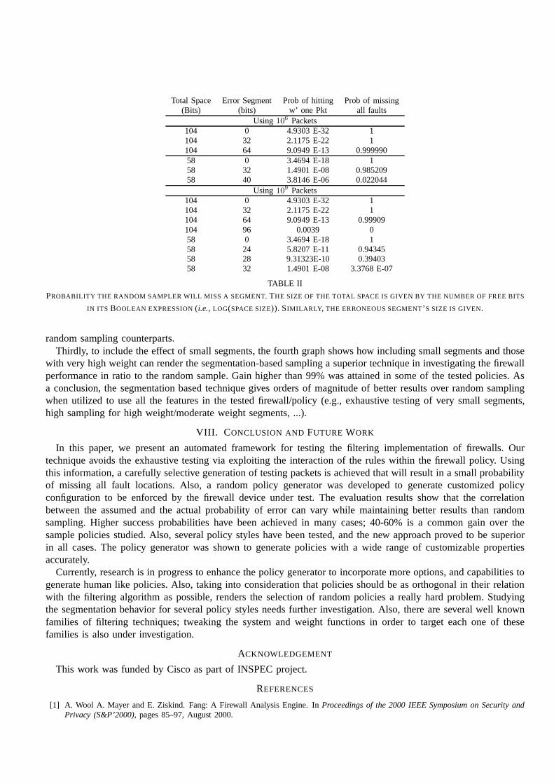
Total Space Error Segment Prob of hitting Prob of missing(Bits) (bits) w’ one Pkt all faults
Using 106 Packets
104 0 4.9303 E-32 1104 32 2.1175 E-22 1104 64 9.0949 E-13 0.99999058 0 3.4694 E-18 158 32 1.4901 E-08 0.98520958 40 3.8146 E-06 0.022044
Using 109 Packets
104 0 4.9303 E-32 1104 32 2.1175 E-22 1104 64 9.0949 E-13 0.99909104 96 0.0039 058 0 3.4694 E-18 158 24 5.8207 E-11 0.9434558 28 9.31323E-10 0.3940358 32 1.4901 E-08 3.3768 E-07
TABLE II
PROBABILITY THE RANDOM SAMPLER WILL MISS A SEGMENT. THE SIZE OF THE TOTAL SPACE IS GIVEN BY THE NUMBER OF FREE BITS
IN ITS BOOLEAN EXPRESSION(i.e., LOG(SPACE SIZE)). SIMILARLY , THE ERRONEOUS SEGMENT’ S SIZE IS GIVEN.
random sampling counterparts.Thirdly, to include the effect of small segments, the fourthgraph shows how including small segments and those
with very high weight can render the segmentation-based sampling a superior technique in investigating the firewallperformance in ratio to the random sample. Gain higher than 99% was attained in some of the tested policies. Asa conclusion, the segmentation based technique gives orders of magnitude of better results over random samplingwhen utilized to use all the features in the tested firewall/policy (e.g., exhaustive testing of very small segments,high sampling for high weight/moderate weight segments, ...).
VIII. C ONCLUSION AND FUTURE WORK
In this paper, we present an automated framework for testingthe filtering implementation of firewalls. Ourtechnique avoids the exhaustive testing via exploiting theinteraction of the rules within the firewall policy. Usingthis information, a carefully selective generation of testing packets is achieved that will result in a small probabilityof missing all fault locations. Also, a random policy generator was developed to generate customized policyconfiguration to be enforced by the firewall device under test. The evaluation results show that the correlationbetween the assumed and the actual probability of error can vary while maintaining better results than randomsampling. Higher success probabilities have been achievedin many cases; 40-60% is a common gain over thesample policies studied. Also, several policy styles have been tested, and the new approach proved to be superiorin all cases. The policy generator was shown to generate policies with a wide range of customizable propertiesaccurately.
Currently, research is in progress to enhance the policy generator to incorporate more options, and capabilities togenerate human like policies. Also, taking into consideration that policies should be as orthogonal in their relationwith the filtering algorithm as possible, renders the selection of random policies a really hard problem. Studyingthe segmentation behavior for several policy styles needs further investigation. Also, there are several well knownfamilies of filtering techniques; tweaking the system and weight functions in order to target each one of thesefamilies is also under investigation.
ACKNOWLEDGEMENT
This work was funded by Cisco as part of INSPEC project.
REFERENCES
[1] A. Wool A. Mayer and E. Ziskind. Fang: A Firewall AnalysisEngine. InProceedings of the 2000 IEEE Symposium on Security andPrivacy (S&P’2000), pages 85–97, August 2000.

[2] W. Richards Adrion, Martha A. Branstad, and John C. Cherniavsky. Validation, Verification, and Testing of Computer Software. ACMComputer Survey, 14(2):159–192, 1982.
[3] K. Al-Tawil and I. Al-Kaltham. Evaluation and Testing ofInternet Firewalls.International Journal of Network Management, 9(3):135–149, 1999.
[4] B. Beizer. Software testing techniques (2nd ed.). Van Nostrand Reinhold Co., New York, NY, USA, 1990.[5] B. Beizer. Black-Box Testing Techniques for Functional Testing of Software and Systems. Wiley-VCH, 1995.[6] R. Haeni. Firewall penetration testing. Technical report, The George Washington University Cyberspace Policy Institute, 2033 K St,
Suite 340N, Washington, DC, 20006, US, January 1997.[7] J. Jurjens and G. Wimmel. Specification-Based Testing of Firewalls. InProceedings of the 4th International Conference on Perspectives
of System Informatics (PSI’02), pages 308–316, 2001.[8] Microsoft. Network devices testing guidance. Microsoft Technet, March 2005. http://www.microsoft.com/technet/itsolutions/
wssra/raguide/NetworkDevices/igndbg4.mspx.[9] M .Ranum. On the topic of firewall testing.
[10] G. Vigna. A formal model for firewall testing.[11] J. Walsh. Firewall testing: An in depth analysis. ICSA Labs Techncial report, June 2004. www.icsalabs.com/icsa/docs/html/communities/
firewalls/pdf/fwwhitepaper.pdf.[12] A. Wool. Architecting the Lumeta Firewall Analyzer. InProceedings of the 10th USENIX Security Symposium, August 2001.